
Transmissions, Final Drive And Propeller Shaft Page F-1
Page F-1
Section F
Transmissions, Final Drive And Propeller Shaft
ATTENTION
HSV vehicles are equipped with a Supplemental Restraint System (SRS). An SRS consists of seat belt pre-
tensioners (fitted to all front seats), a driver’s-side air bag , a passenger’s-side air bag and left and right hand
side air bags. Refer to CAUTIONS, Section 12M Occupant Protection System in the MY 2005 VZ Coupe Series
Service Information before performing any service operation on or around SRS components, the steering
mechanism or wiring. Failure to follow the CAUTIONS could result in personal injury or unnecessary SRS
system repairs.
1 Purpose...................................................................................................................................................2
2 Transmissions........................................................................................................................................3
2.1 Automatic Transmission....................................................................................................................................... 3
Electrical Diagnosis............................................................................................................................................... 3
Hydraulic/Mechanical Diagnosis.......................................................................................................................... 3
On-vehicle Servicing.............................................................................................................................................. 3
Unit Repair.............................................................................................................................................................. 3
2.2 Manual Transmission ............................................................................................................................................ 4
Service Operations ................................................................................................................................................ 4
Clutch...................................................................................................................................................................... 4
3 Final Drive & Drive Shafts .....................................................................................................................5
3.1 General Information............................................................................................................................................... 5
3.2 Final Drive Assembly Identification...................................................................................................................... 6
3.3 Service Operations ................................................................................................................................................ 7
3.4 Diagnosis................................................................................................................................................................ 8
3.5 Specifications......................................................................................................................................................... 9
4 Propeller Shafts & Universal Joints ...................................................................................................10
4.1 General Information............................................................................................................................................. 10
4.2 Service Operations .............................................................................................................................................. 11
4.3 Diagnosis.............................................................................................................................................................. 12
4.4 Specifications....................................................................................................................................................... 13
5 Rear Final Drive and Drive Shafts ......................................................................................................14
5.1 General Information............................................................................................................................................. 14
5.2 Major Service Operations.................................................................................................................................... 15
Final Drive Assembly Unit Repair....................................................................................................................... 15
Reassemble ..................................................................................................................................................... 15
5.3 Pinion Flange ....................................................................................................................................................... 22
Replace (Vehicles With a Rear Rubber Coupling)............................................................................................. 22
Using Old Oil Seal............................................................................................................................................ 22
6 Special Tools ........................................................................................................................................25
Techline

Transmissions, Final Drive And Propeller Shaft Page F-2
Page F-2
1 Purpose
The purpose of this bulletin is to provide information on the transmission assemblies fitted to the HSV VZ Coupe models.
This information is designed to supplement the information contained in the Holden VZ Coupe series Service Manuals,
and details are given where differences occur between the HSV models and standard Holden models. A series of
instruction drawings describe the design changes and indicate specific part numbers, fitting instructions and relevant
notes for vehicle servicing.
NOTE
If specific technical data on a HSV model is not
contained in this supplement, obtain data for that
model from the relevant Holden VZ Coupe
Service Manual Supplement. References are
made throughout this section to Holden Service
Manuals, to assist in providing information for
specific service operations.
When hoisting (or jacking) HSV models,
ensure that the liftin g head of the hoist lifts on
the chassis before the arm of the hoist
contacts the side-skirt

Transmissions, Final Drive And Propeller Shaft Page F-3
Page F-3
2 Transmissions
2.1 Automatic Transmission
The Hydra-Matic 4L65-E automatic transmission fitted to HSV VZ GTO models carries over from HSV 297 kW Clubsport
VZ series models.
For general information relating to the Hydra-Matic 4L65-E automatic transmission fitted to HSV VZ Coupe models
refer to Section 7D1 – Hydra-Matic 4L65-E Automatic Transmission – General Information, in the Holden MY 2005 VZ
Series Service Information.
Electrical Diagnosis
The Hydra-Matic 4L65-E automatic transmission fitted to HSV VZ GTO models carries over from HSV 297 kW
Clubsport VZ series models. For information relating to the electrical diagnosis of the Hydra-Matic 4L65-E
automatic transmission fitted to HSV VZ GTO Coupe models refer to
Section 7D2 – Hydra-Matic 4L65-E Automatic Transmission – Electrical Diagnosis, in the Holden MY 2005 VZ Series
Service Information.
Hydraulic/Mechanical Diagnosis
For information relating to diagnosis of the Hydra-Matic 4L65-E hydraulic/mechanical
automatic transmission fitted to HSV VZ Coupe models refer to
Section 7D3 – Hydra-Matic 4L65-E Automatic Transmission – Hydraulic/mechanical Diagnosis, in the Holden MY 2005
VZ Series Service Information.
On-vehicle Servicing
For information relating to on-vehicle servicing of the Hydra-Matic 4L65-E automatic transmission fitted to HSV VZ Coupe
models refer to Section 7D4 – Hydra-Matic 4L65-E Automatic Transmission – On-vehicle Servicing, in the Holden MY
2005 VZ Series Service Information.
Unit Repair
For information relating to unit repair of the Hydra-Matic 4L65-E automatic transmission fitted to HSV VZ Coupe models
refer to Section 7D5 – Hydra-Matic 4L65-E Automatic Transmission – Unit Repair, in the Holden MY 2005 VZ Series
Service Information.

Transmissions, Final Drive And Propeller Shaft Page F-4
Page F-4
2.2 Manual Transmission
Service Operations
All HSV VZ manual vehicles come fitted with the standard Holden M12 6 speed manual transmission. Service operations
for this transmission are detailed in the Holden VZ series Service Supplement,
refer to Section 7B3 – Manual Transmission – Gen III V8 Engine.
Clutch
HSV VZ vehicles use the GEN IV LS2 V8 engine, coupled to an M12 T56 manual trans and fitted with a unique flywheel,
clutch and pressure plate assembly. (Holden part number 12570806). These clutch assemblies are to be serviced in
accordance with the procedures contained in the relevant Holden Service Information,
refer to Section 7A2 – Clutch – Gen III V8 Engine.

Transmissions, Final Drive And Propeller Shaft Page F-5
Page F-5
3 Final Drive & Drive Shafts
3.1 General Information
Independent rear suspension is fitted as standard equipment on all HSV VZ GTO models.
All HSV VZ GTO models both manual and auto transmissions are fitted with final drive ratio of 3.46:1.
Production option G80 Limited Slip Differential (LSD), also referred to as a Spin Resistant Differential (SRD), is fitted a
standard equipment on all HSV VZ Coupe models.
For information relating to final drives fitted to HSV VZ Coupe models not provided in this section refer to
Section 4B Final Drive and Drive Shafts in the Holden MY 2005 VZ Series Service Information .
Body Type Engine Transmission Ratio ABS LSD Lubricant I.D. Code
Automatic
4L65-E
(P/O M32)
HSV
Coupe, Gen IV V8
(P/O LS2) Manual T56
(P/O M12)
3.46:1 Y Y Synthetic+ TZA

Transmissions, Final Drive And Propeller Shaft Page F-6
Page F-6
3.2 Final Drive Assembly Identification
The type of differential fitted to this final assembly can be identified by referring to the identification label attached to the
RH side of the carrier housing.
The identification tag carries the Holden part number for the final drive assembly, final drive ratio and the serial number of
the assembly.
The code number and bar code is used for production identification of the final drive assembly.
Engine Type Transmission Type LSD/ABS ID Code
HSV 297 kW Manual Yes/Yes TZA
HSV 297 kW Automatic Yes/Yes TZA

Transmissions, Final Drive And Propeller Shaft Page F-7
Page F-7
3.3 Service Operations
All service operations for the final drive and the drive shafts fitted to HSV VZ Coupe models carry over from Holden VZ
Series models.
For information relating to service operations on the final drive and drive shafts fitted to HSV VZ Coupe models refer to
Section 4B Final Drive and Drive Shafts in the Holden MY 2005 VZ Series Service Information.

Transmissions, Final Drive And Propeller Shaft Page F-8
Page F-8
3.4 Diagnosis
All diagnosis for the final drive and the drive shafts fitted to HSV VZ Coupe models carry over from Holden VZ Series
models.
For information relating to diagnosis of the final drive and drive shafts fitted to HSV Coupe models refer to
Section 4B1 Final Drive and Drive Shafts in the Holden MY 2005 VZ Series Service Information.

Transmissions, Final Drive And Propeller Shaft Page F-9
Page F-9
3.5 Specifications
All specifications for the final drive and the drive shafts fitted to HSV Coupe models carry over from Holden VZ Series
models.
For information relating to specifications of the final drive and drive shafts fitted to HSV Coupe Series 3 models refer to
Section 4B Final Drive and Drive Shafts in the Holden MY 2005 VZ Series Service Information.

Transmissions, Final Drive And Propeller Shaft Page F-10
Page F-10
4 Propeller Shafts & Universal
Joints
4.1 General Information
The propeller shaft assembly fitted to HSV Coupe Series 3 models carry over from Holden VZ Series models.
For information relating to propeller shaft and universal joints fitted to HSV VZ Coupe Series 3 models refer to
Section 4C Propeller Shaft and Universal Joints in the Holden VZ Service Information.

Transmissions, Final Drive And Propeller Shaft Page F-11
Page F-11
4.2 Service Operations
All service operations for the propeller shaft and universal joints fitted to HSV VZ Coupe models carry over from Holden
VZ Series models.
For information relating to service operations on the propeller shaft and universal joints fitted to HSV VZ Coupe models
refer to Section 4C Propeller Shaft and Universal Joints in the Holden MY 2005 VZ Series Service Information.

Transmissions, Final Drive And Propeller Shaft Page F-12
Page F-12
4.3 Diagnosis
All diagnosis for the propeller shaft and universal joints fitted to HSV VZ Coupe models carry over from Holden VZ
Series models.
For information relating to diagnosis of the propeller shaft and universal joints fitted to HSV VZ Coupe models refer to
Section 4C Propeller Shaft and Universal Joints in the Holden MY 2005 VZ Series Service Information.

Transmissions, Final Drive And Propeller Shaft Page F-13
Page F-13
4.4 Specifications
All specifications for the propeller shaft and universal joints fitted to HSV VZ Coupe models carry over from Holden VZ
Series models.
For information relating to specifications of the propeller shaft and universal joints fitted to HSV VZ Coupe models refer to
Section 4C Propeller Shaft and Universal Joints in the Holden MY 2005 VZ Series Service Information.

Transmissions, Final Drive And Propeller Shaft Page F-14
Page F-14
5 Rear Final Drive and Drive
S hafts
ATTENTION
Before performing any service operation or other procedure described in this Section, refer to Section 00
Warnings, Cautions and Notes for correct w orkshop practices with regard to safety and/or property damage.
5.1 General Information
The final drive and drive shafts fitted to MY 2005 HSV VZ vehicles, carries over from MY 2004 Holden VYII vehicles,
except for the following items:
• With the increased output from the GEN IV V8 (LS2) engine, both the front and rear propeller shaft rubber
couplings have larger diameters. This has resulted in an increased pitch circle diameter (PCD) change from 96 to
110 mm for the attaching bolts.
• With the increased PCD for the propeller shaft rubber couplings, a revised design final drive pinion flange is now
fitted, that results in two new special tools being released. These tools are used to:
a Hold the pinion flange when loosening/tightening the pinion flange nut.
b Remove the pinion flange from the final drive pinion when replacing the flange, the oil seal or when
undertaking a final drive overhaul procedure.
Both new tools have the earlier and later PCD dimension holes included, which allows them to be used on this and
earlier model vehicles. The procedure for fitment and use of these new tools is the same as detailed in the MY 2005
Holden VZ Service Information, Section 4B Final Drive and Drive Shafts.
Refer to 6 Special Tools in this Section for the new tool details.
• To enable the final drive pinion bearing preload to be measured, the fabricated wooden disc requires some
modification to allow it to be used on the revised diameter pinion flange. Refer to 6 Special Tools in this Section for
the necessary changes.
• Both drive shafts are now fitted with a plunge type constant velocity joint at the inner and outer locations.
This means that the same servicing procedure for the inner constant velocity joint (plunge type) detailed in the MY
2005 Holden VZ Service Information, Section 4B Final Drive and Drive Shafts, can now be adopted for any of the
four, drive shaft constant velocity joints fitted to MY 2005 HSV VZ vehicles.
• A revised procedure has been developed to select the hypoid pinion positioning shim. This has resulted in a
changed dimension spacer to be used, which is incorporated into pinion set gauge kit, tool number DT-47737. In
addition, with the changed dimensions of the inner pinion bearing, a revised tool has been developed to remove the
bearing cup from the final drive housing. Details of these revised tools and the procedures relating to their use is
provided here, in the sub-section, "Hypoid Pinion Shim Selection" and "Pinion Installation".
Transmissions, Final Drive And Propeller Shaft Page F-15
Page F-15
5.2 Major Service Operations
Final Drive Assembly Unit Repair
Reassemble
Hypoid Pinion Shim Selection
The pinion positioning shim is located between pinion rear (inner) bearing cup and carrier housing.
If the ring gear and pinion or the pinion rear bearing assembly are replaced, pinion depth must be rechecked with pinion
setting gauge, Tool No. DT-47737. This set includes a dummy pinion spacer, Tool No. DT-47696 and dummy arbour Tool
No. AU408.
The gauge and arbour provide a nominal or 'zero' pinion as a gauging reference.
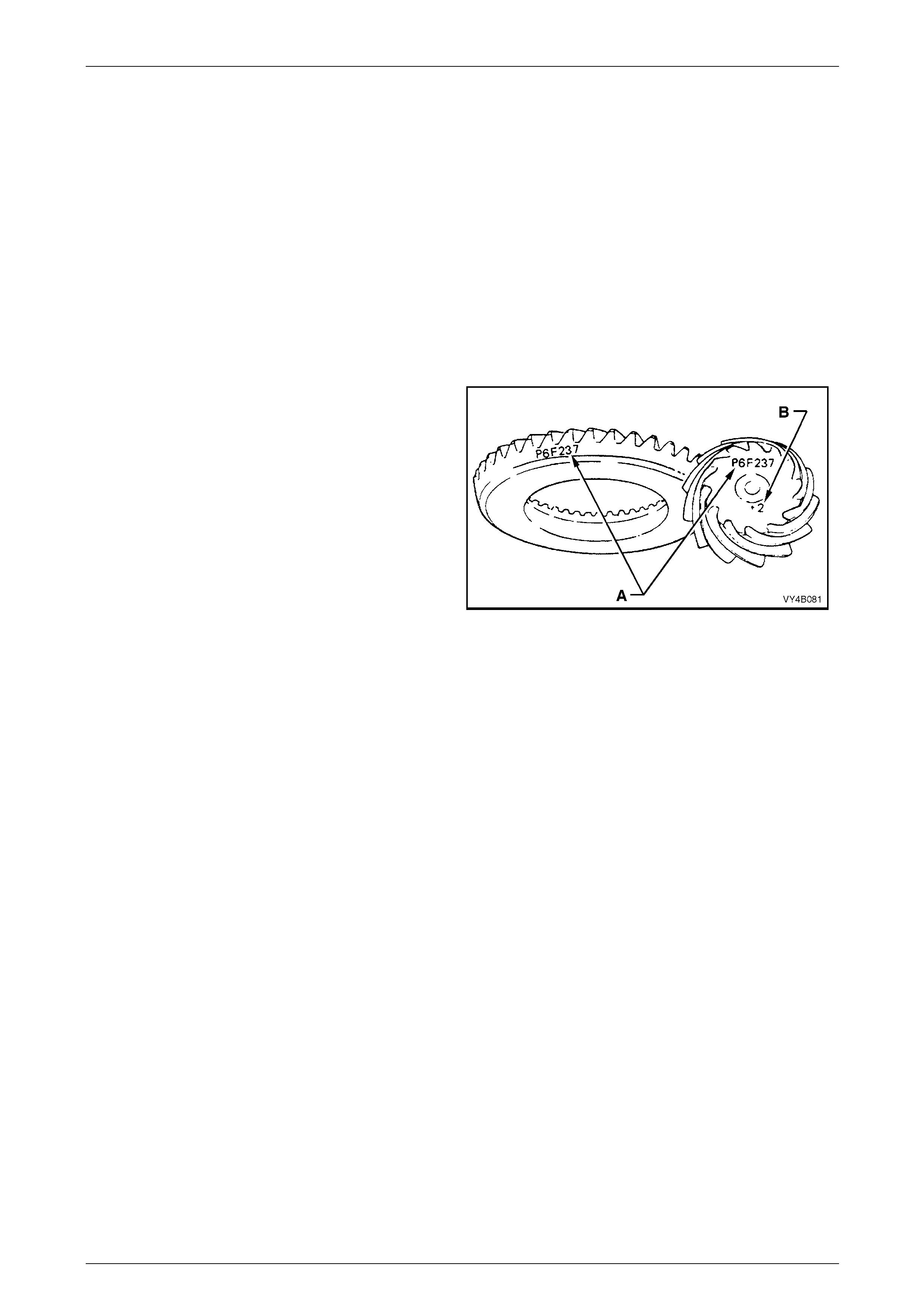
NOTES
• If a new gear set is to be installed, check
that the same matching number (‘A’) appears
on both the pinion and the ring gear, with
either a white or yellow marker.
• The pinion installation marking figure is
indicated by ‘B’, again with either a white or
yellow marker.
Figure 4B1 – 1
1 Inspect pinion bearing cups/cones for nicks and burrs. Replace if damaged.
2 Lubricate pinion front and rear bearings with the recommended differential carrier lubricant. Do not use engine or
other oils, as a misleading rotating torque can be obtained.
NOTE
Make sure that both pinion bearings used on the
dummy pinion to determine the pinion positioning
shim thickness, are those that will be used on the
final reassembly.
3 Install the spacer, Tool No. DT-47696, to the dummy pinion, supplied as part of DT-47737, then install the rear
(inner) pinion bearing onto the dummy pinion.
4 Install dummy pinion and rear (inner) bearing into the carrier housing. Fit front (outer) bearing to dummy pinion,
then install the dummy pinion thrust collar and nut (included in pinion set gauge kit DT-47737).
Transmissions, Final Drive And Propeller Shaft Page F-16
Page F-16
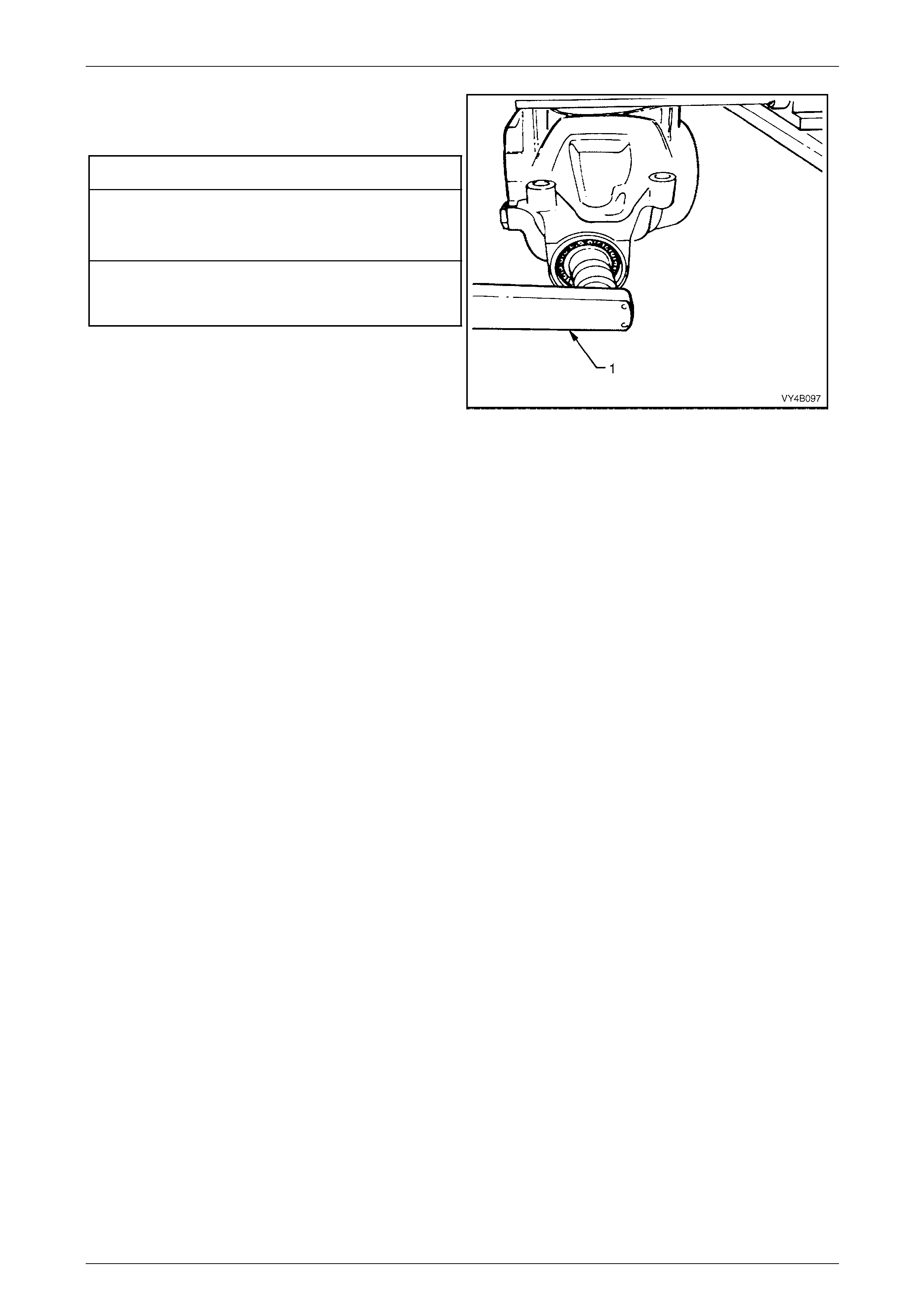
5 Tighten nut on end of dummy pinion, using a
commercially available, dial type torque wrench (1),
until the specified rotational torque is obtained.
Dummy Pinion Rotational Torque Specification
New Bearings (No Pinion Oil Seal Installed)
Timken Koyo
1.4 – 2.0 N.m 1.5 – 1.9 N.m
Used Bearings (No Pinion Oil Seal Installed)
Timken Koyo
0.7 – 1.2 N.m 0.7 – 1.2 N.m
6 Rotate dummy pinion back and forth during tightening
to ensure that bearings settle in their cups.
Figure 4B1 – 2
NOTES
• Once the specified preload is reached,
remove the gauge block from the rear of the
dummy pinion (that allowed the pinion bearing
preload tightening process to be done).
Rotate the pinion approximately 50 turns in
each direction, then re-check the bearing
preload, readjusting as required, to achieve
the specified figure.
• Pinion bearing pre-load is very important
because it retains the pinion in its correct
relationship to the ring gear.
• Bearings that are installed with insufficient or
no pre-load will, after a comparatively short
period of running, develop end play. This will
cause noisy operation on overrun and could
be responsible for scuffing of the ring gear
and pinion teeth.
• Bearings that have too much pre-load, may
become pitted or flaked and result in
premature failure. It is therefore vital that
bearings are pre-loaded to the specified
torque specification.
Transmissions, Final Drive And Propeller Shaft Page F-17
Page F-17
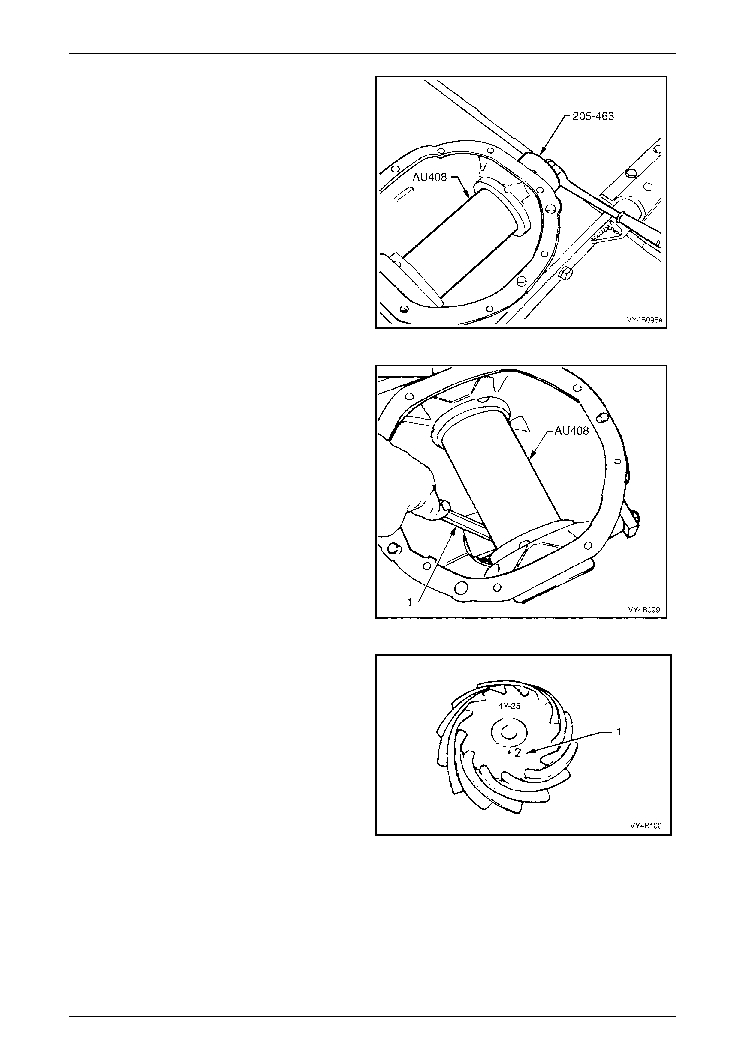
7 Position arbour Tool No. AU408 (part of pinion height
setting gauge, DT-47737) in carrier assembly and
install screw adjusters with side bearing cups. Adjust
screw adjusters to lightly clamp arbour, using Tool No.
205-463.
NOTE
Ensure that arbour is free of any burrs that may
damage bearing cups.
Figure 4B1 – 3
8 Check clearance between arbour (Tool No. AU408)
and head of dummy pinion with a feeler gauge (1).
Record this dimension.
Figure 4B1 – 4
9 On the end of the pinion, a drive pinion installation
marking figure (1) is applied with either a white or
yellow marker. A zero marking ('0') indicates that shim
size equal to the dimension measured in Step 8 is the
correct size for this carrier/pinion combination.
A positive marking, e.g. +3, means that a thickness
measurement equivalent to this numerical marking
must be subtracted from shim size measured in
Step 8. Refer to the following chart for specific details.
A negative marking, e.g. –3, means that a thickness
measurement equivalent to this numerical marking
must be added to the shim size measured in Step 8.
Refer to the following chart for specific details. Figure 4B1 – 5
Transmissions, Final Drive And Propeller Shaft Page F-18
Page F-18
Pinion
Marking Shim Thickness
Required
– 4 Add 0.100 mm to the Step 9 measurement
– 3 Add 0.075 mm to the Step 9 measurement.
– 2 Add 0.050 mm to the Step 9 measurement.
– 1 Add 0.025 mm to the Step 9 measurement.
0 Size as measured in Step 9.
+ 1 Subtract 0.025 mm from the Step 9 measurement.
+ 2 Subtract 0.050 mm from the Step 9 measurement
+ 3 Subtract 0.075 mm from the Step 9 measurement.
+ 4 Subtract 0.100 mm from the Step 9 measurement
Pinion positioning shims are serviced in thicknesses of 0.2 mm
to 0.75 mm in 0.025 mm increments. They are also dimensioned
differently, depending on the pinion bearing used.
10 Remove dummy pinion and arbour from carrier assembly.
Pinion Installation
1 Select pinion positioning shim stack as determined in
the Hypoid Pinion Positioning Shim Selection
procedure, in this Section.
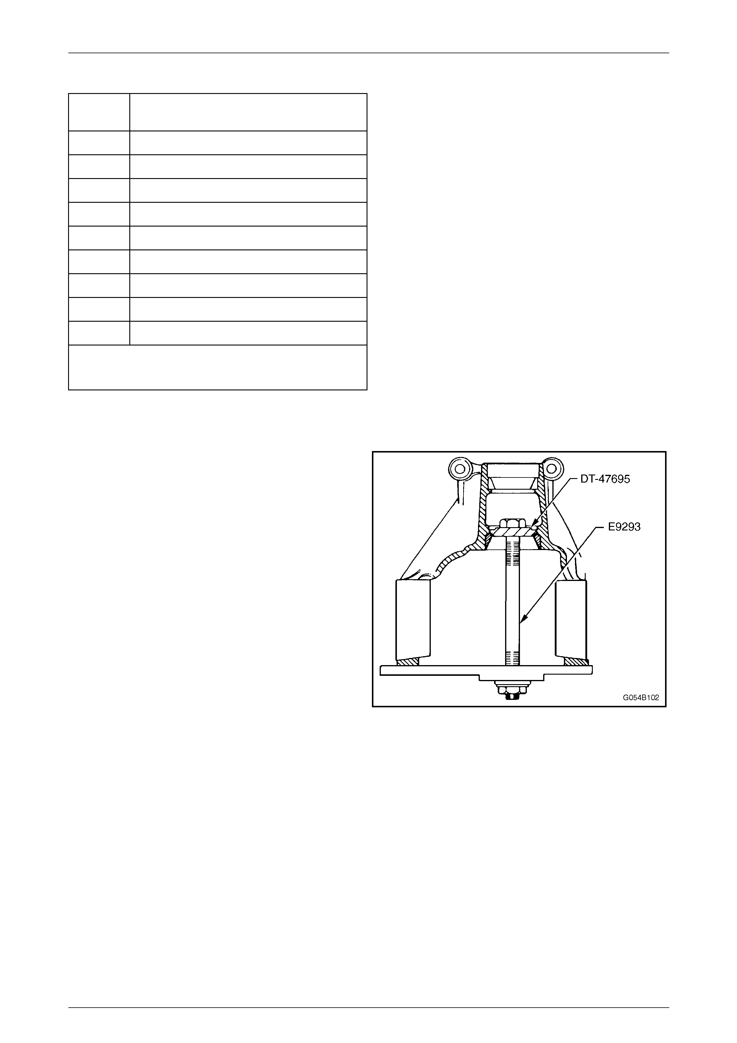
2 Remove pinion rear (inner) bearing cup, using Tool
No. E9293 and adaptor, Tool No. DT-47695.
Figure 4B1 – 6
Transmissions, Final Drive And Propeller Shaft Page F-19
Page F-19
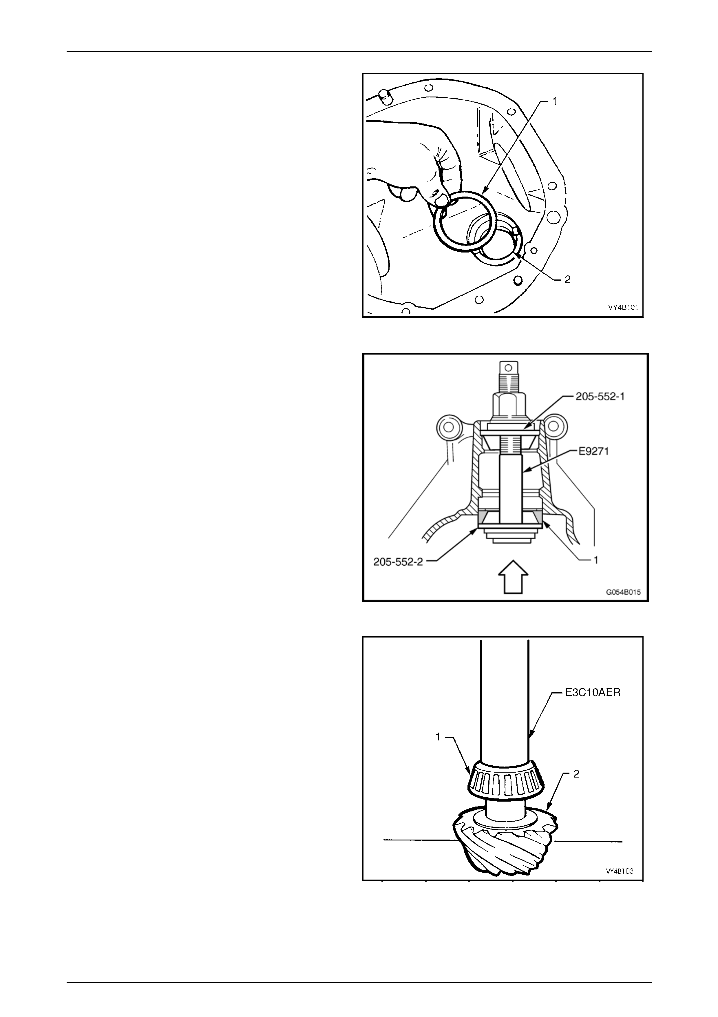
3 Install the selected pinion positioning shim/s (1) into
pinion rear bearing cup bore (2).
Figure 4B1 – 7
4 Reinstall pinion rear (inner) bearing cup using Tool No.
E9271 and adaptors 205-552-1 and 205-552-2.
Figure 4B1 – 8
5 Press rear bearing inner race against the shoulder of
the pinion, using Tool No. E3C10AER.
NOTES
• To avoid possible damage to the pinion gear
teeth when pressing the bearing on, ensure
that the press plates are perfectly flat, free of
burrs and foreign matter prior to installing the
rear bearing.
• Locate bearing inner race squarely on the
pinion and press only on inner race surface.
• Only lubricate the bearing with the
recommended differential carrier lubricant.
Figure 4B1 – 9
Transmissions, Final Drive And Propeller Shaft Page F-20
Page F-20
6 Place the pinion in the carrier.
7 Lubricate pinion front bearing with the recommended differential carrier lubricant and assemble the collapsible
pinion bearing spacer and front bearing onto pinion, while supporting pinion head.
8 Install pinion flange and the original pinion flange
retaining nut.
9 Install Tool No. DT-47735 to the pinion flange.
NOTE
Use either the rear coupling to pinion flange
retaining bolts with a 25 mm spacer (e.g. flat
washers) installed first or use three bolts M12 x
1.5 x 40, with the thread extending to within 12
mm of the head.
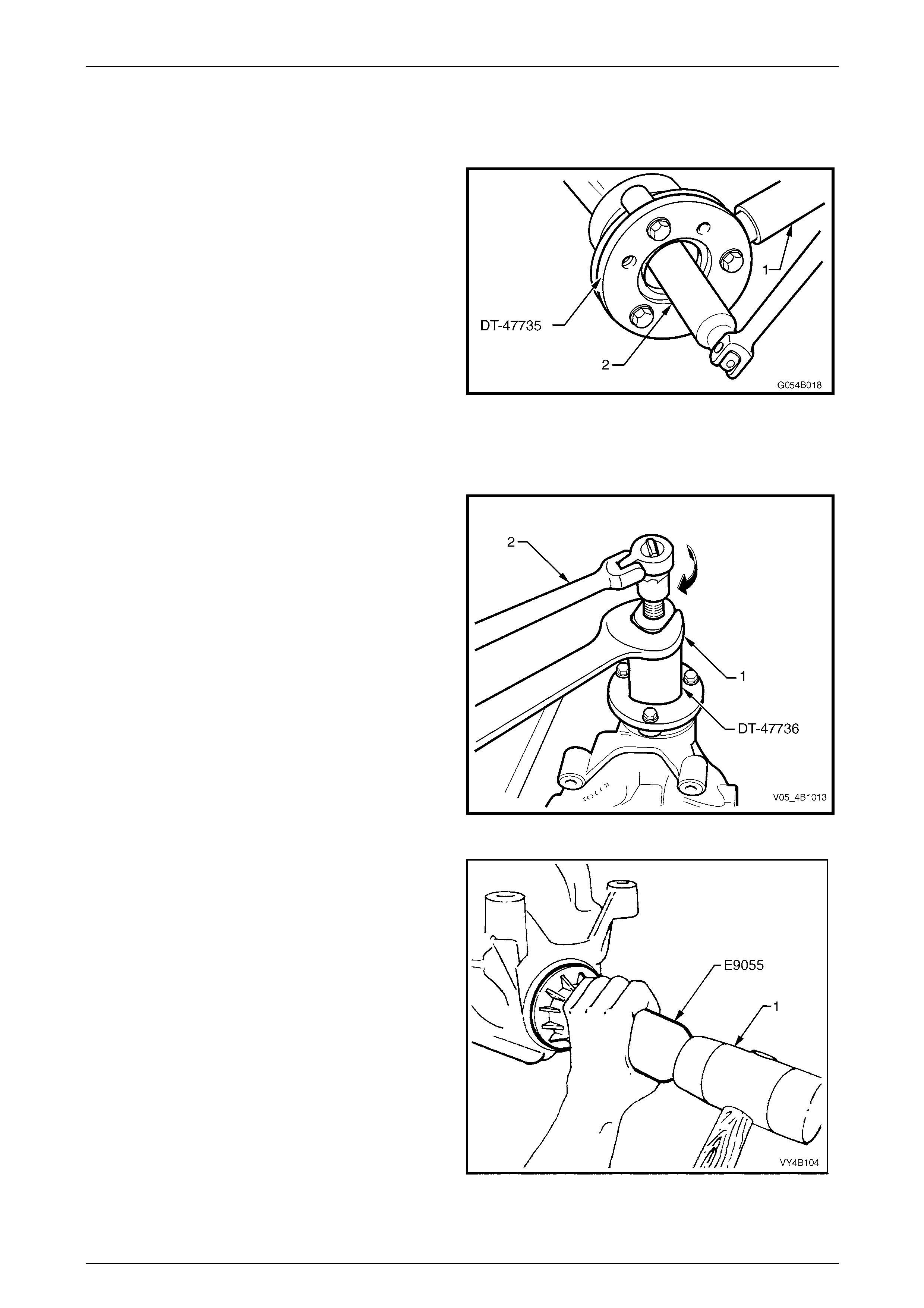
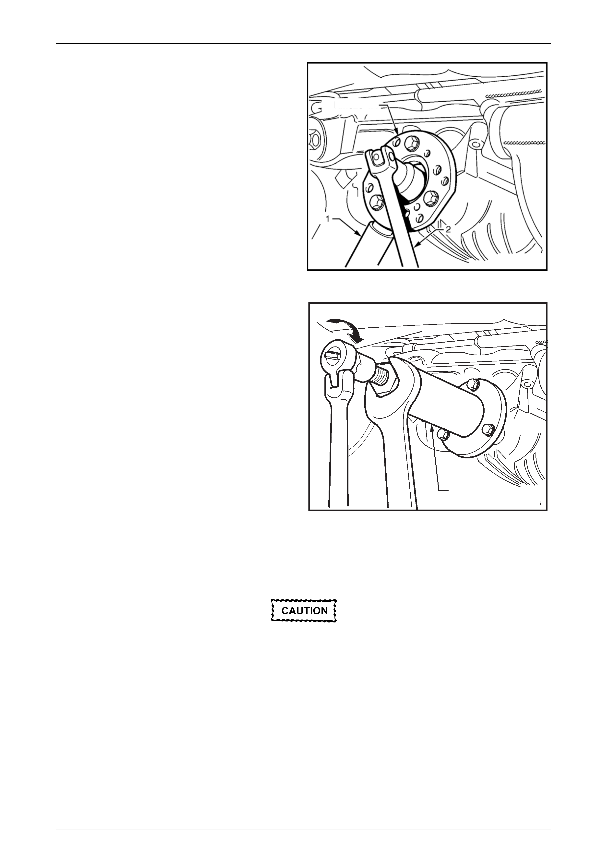
10 Using a suitable length of pipe (1) to over the holding
tool tang, tighten retaining nut until pinion front bearing
is squarely engaged on the pinion shaft and not
cocked.
11. Remove the pinion flange retaining nut, using a
commercially available, 30 mm deep socket (2) and
socket bar.
Figure 4B1 – 10
12 Install extractor, Tool No. DT-47736 to the pinion
flange using the same three bolts used to secure the
flange holding tool, DT-47735 (refer step 9).
13 While holding the extractor tool with a suitable spanner
(1), withdraw pinion flange by tightening the forcing
screw in the direction indicated, using suitable socket
equipment (2).
Figure 4B1 – 11
14 Lubricate pinion oil seal lips and the pinion oil seal
bore in the carrier housing with Mobilgrease XHP 222
or equivalent grease.
15 Install oil seal into carrier bore using Tool No. E9055
and a plastic faced hammer (1) until the seal fits flush
to 0.25 mm below carrier housing surface.
Figure 4B1 – 12
Transmissions, Final Drive And Propeller Shaft Page F-21
Page F-21
16 Reinstall pinion flange and fit a NEW retaining nut.
17 Hold pinion flange using Tool No. DT-47735 and a
suitable length of pipe (1).
18 Gradually tighten the retaining nut while rotating pinion
in both directions to seat bearings.
If the retaining nut is over-tightened and pre-
load exceeded, it w ill be necessary to remove
the pinion from the carrier and a new
collapsible spacer installed. Under no
circumstances must the retaining nut be
backed off to decrease the p re-lo ad reading. Figure 4B1 – 13
19 Check bearing pre-load frequently by removing flange holding tool (DT-47735) and installing a pulley and string to
the pinion flange. Refer to 6 Special Tools at the end of this Section for pulley details.
20 Using a spring scale, measure rotational torque.
21 Continue to tighten the nut until specified torque is achieved.
Pinion Rotational Torque Specification
New Bearings (With Pinion Oil Seal Installed)
Timken Koyo
1.4 – 2.4 N.m 1.5 – 2.1 N.m
Used Bearings (With Pinion Oil Seal Installed)
Timken Koyo
0.7 – 1.2 N.m 0.7 – 1.2 N.m
22 The torque figure is calculated by multiplying the radius of the pulley by the spring balance reading.
Example: If the pulley diameter is 152 mm, the radius is 76 mm which equals 0.076 m. The spring balance reading is
25 N. Therefore, the pre-load equals 0.076 m x 25 N = 1.9 Nm.
Transmissions, Final Drive And Propeller Shaft Page F-22
Page F-22
5.3 Pinion Flange
LT Section 05-290 – 1
Replace (Vehicles With a Rear Rubber Coupling)
ATTENTION
The following fasteners MUST be replaced when p erformin g these operations:
Drive shaft attaching bolts.
Using Old Oil Seal
Resulting from production tolerances in the
length of the pinion flange, it is essential that
the following method be used when installing
a new pinion flange.
1 Raise the vehicle and support in a safe manner. Refer to Section 0A General Information in this Service Information
for the location of recommended lifting and support points.
2 Remove propeller shaft, refer Section 4C1 Propeller Shaft and Universal Joints, in the Holden MY 2005 VZ Series
Service Information.
3 Remove both drive shafts, refer 3 Final Drive & Drive Shafts, in this Section.
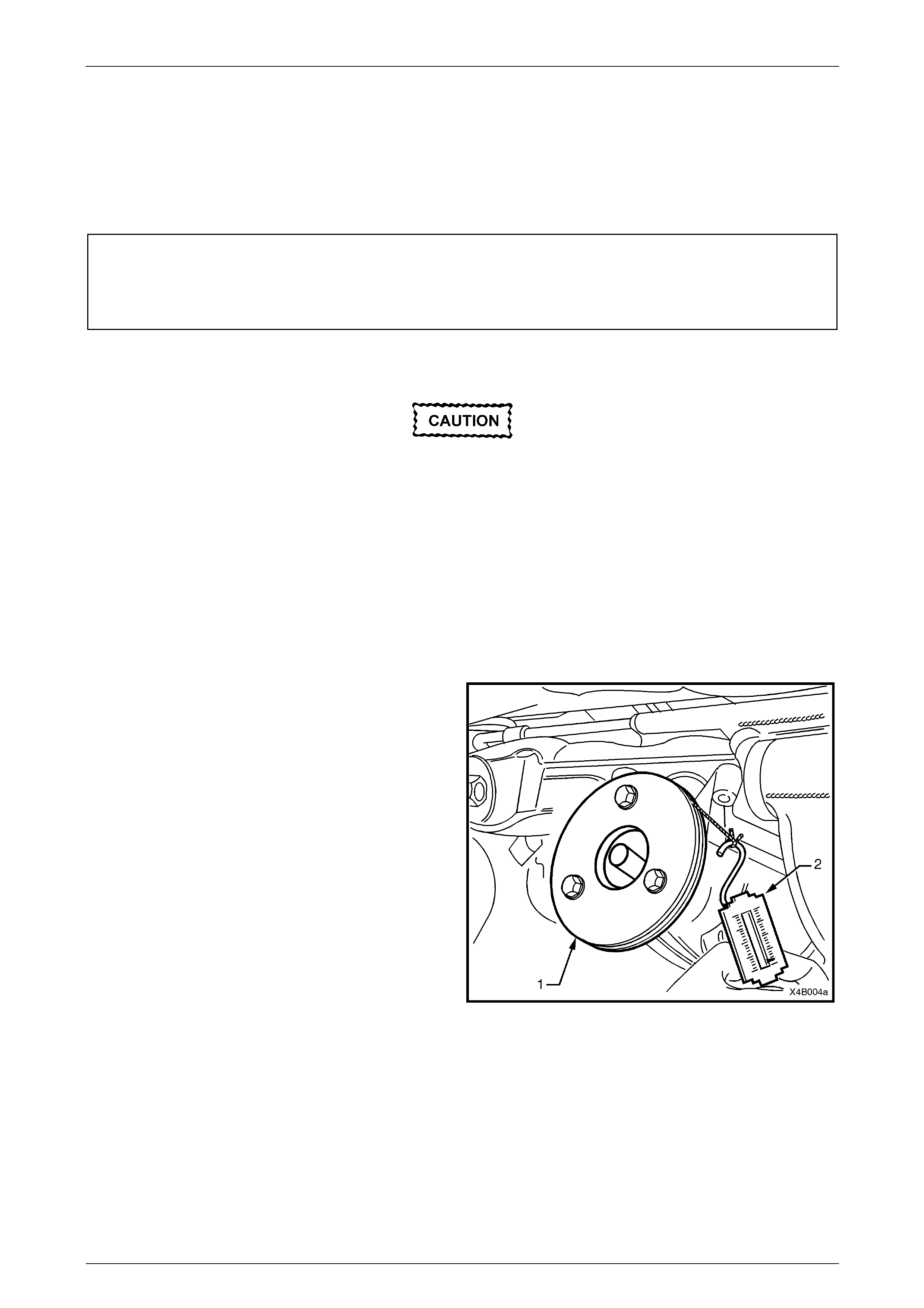
4 Check and record pre-load at pinion flange as follows:
a Fit a pulley (1) to pinion flange, using three
suitable bolts and attach a cord around pulley
and to a spring scale (2).
NOTE
• Use either the rear coupling to pinion flange
retaining bolts with a 25 mm spacer (e.g. flat
washers) installed first or use three bolts M12
x 1.5 x 40, with the thread extending to within
12 mm of the head.
• For details of the fabricated pulley, refer
6 Special Tools at end of this Section.
b Start rotation of pulley and whilst in motion
(approximately 50-60 rpm) note and record
reading of spring balance.
This pre-load reading includes pinion bearings,
side bearings, meshing effect of gear set and
pinion oil seal.
To determine pre-load, multiply reading on spring
balance by radius of pulley.
Figure 4B1 – 14
Example: With a pulley diameter of 152 mm, the radius is 76 mm, which equals 0.076 m. With a spring balance reading
of 25 N, the pre-load equals 0.076 m x 25 N = 1.9 Nm.
5 Remove pulley from pinion flange.
Transmissions, Final Drive And Propeller Shaft Page F-23
Page F-23
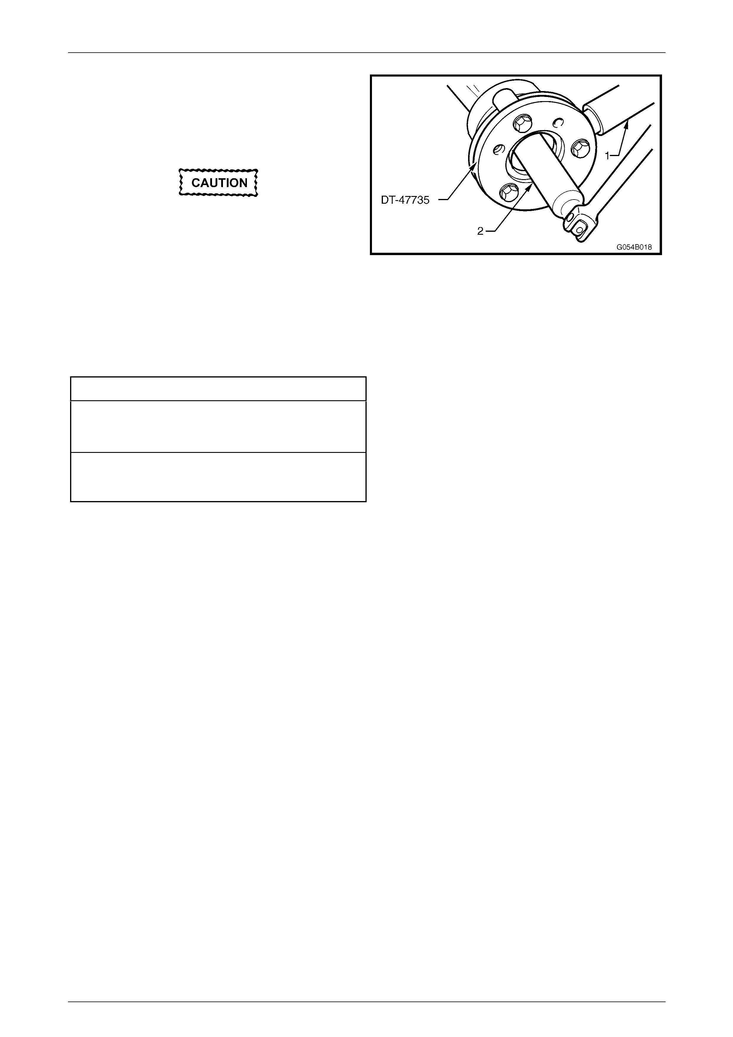
6 Attach Tool No. DT-47735 to the pinion flange, using
three suitable bolts to hold pinion flange.
NOTE
• If not done before, drill out holes stamped
‘B’ on Tool No. DT-47735 to 12.5 mm.
• Use either the rear coupling to pinion flange
retaining bolts with a 25 mm spacer (e.g. flat
washers) installed first or use three bolts M12
x 1.5 x 40, with the thread extending to within
12 mm of the head.
7 Insert a suitable length of pipe (1) over the tang of the
installed tool for leverage, then remove the pinion
flange retaining nut, using a commercially available, 30
mm deep socket and socket bar (2).
8 Remove Tool No. DT-47735 from the pinion flange.
DT- 47735
Figure 4B1 – 15
9 Place drain tray beneath differential carrier.
10 Install extractor, Tool No. DT - 47736 to the pinion
flange using the same three bolts used in step 6.
NOTE
• If not done before, drill out holes stamped
‘B’ on Tool No. DT - 47736 to 12.5 mm.
• If using the original propeller shaft coupling
bolts, they must have a 25 mm spacer fitted
to each, so the tool is clamped to the pinion
flange. If this is not done, the screw thread on
the extractor Tool No. DT - 47736 will not be
long enough to fully remove the pinion flange.
11 While holding the extractor tool with a suitable
spanner, withdraw pinion flange by tightening the
forcing screw in the direction shown.
DT - 47736
Figure 4B1 – 16
12 Ensure that pinion shaft thread is free from burrs, oil, dirt or grease, then coat splines and seal surface of a new
pinion flange with the recommended rear axle lubricant.
13 Install the new pinion flange and a new retaining nut.
The pinion flange is an interference fit on
pinion shaft splines and should only be pulled
into place by tightening the retaining nut. Do
not used force or a hammer the flange during
the installation process.

Transmissions, Final Drive And Propeller Shaft Page F-24
Page F-24
14 Tighten flange retaining nut gradually until pinion shaft end play is reduced to approximately 0.50 mm.
Should the retaining nut be over-tightened
and the pre-load exceeded, it will be
necessary to remove the differential carrier
assembly and install a new collapsible
spacer. Under no circumstances must the
retaining nut be backed off to decrease the
pre-load setting.
15 Attach pulley to the new pinion flange and using a spring balance, check pre-load. Continue tightening nut while
alternatively turning pinion to seat bearings, until the pre-load figure recorded previously (Step 4b) is reached.
Further increase this original pre-load reading by 0.5 Nm.
NOTE
Rotate pinion an extra 30 – 40 turns and re-check
the preload to ensure that no change has
occurred.
16 Reinstall drive shafts, refer to 3 Final Drive & Drive Shafts, in this Section.
17 Reinstall propeller shaft, refer to Section 4C1 Propeller Shaft and Universal Joints, in the Holden MY 2005 VZ
Series Service Information.
18 If removed previously, reconnect exhaust system, in reverse to the removal procedure.
Refer to Section 8B Exhaust System, in the Holden MY 2005 VZ Series Service Information, for details.
19 Lower vehicle to the ground.
20 Check lubricant level and top up as necessary with the recommended lubricant,
refer to Section 4B1 Final Drive and Drive Shafts in the MY 2005 VZ Series Service Information.
21 Start vehicle and check for exhaust leaks.
Transmissions, Final Drive And Propeller Shaft Page F-25
Page F-25
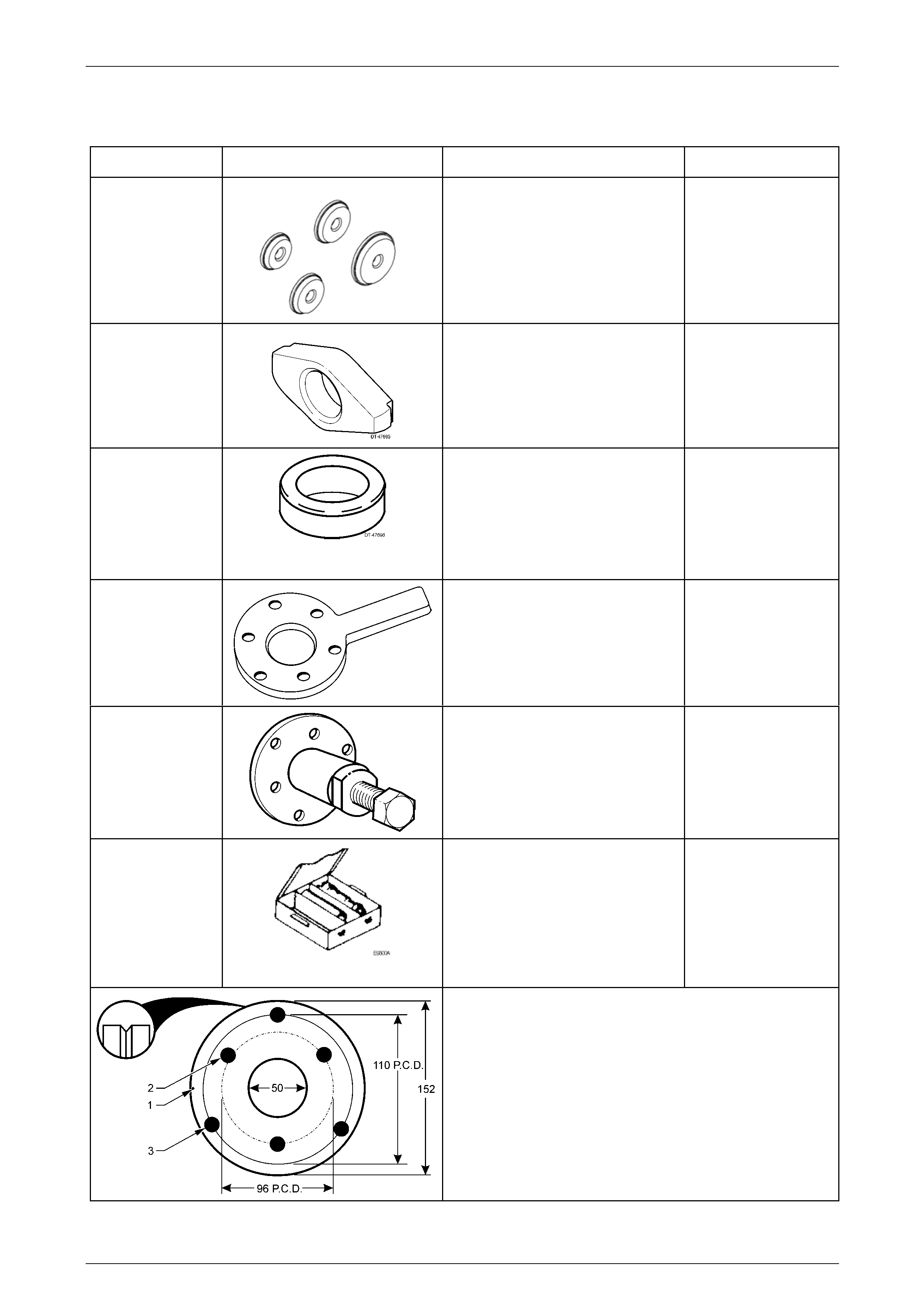
6 Special Tools
Tool Number Illustration Description Classification
205-552
Pinion Bearing Cup Adaptors
Used to install the pinion bearing
cups, in conjunction with Remover/
Installer E9271.
Previously released.
Unique
DT-47695
Rear Pinion Bearing Cup Remover
Used in conjunction with remover
E9293 to remove the rear (inner)
pinion bearing cup.
DT-47696
Spacer
Used in conjunction with the dummy
pinion from DT-47737 when checking
pinion position. Included in pinion
height setting gauge, DT-47737.
Previously released.
Unique
DT-47735
Holding Tool
Used to hold the final drive pinion
flange when loosening/tightening the
pinion nut.
New release
Unique
DT-47736
Extractor Tool
Used to remove the final drive pinion
flange.
New release.
Unique
DT-47737
Pinion Height Setting Gauge
Includes dummy pinion, 3C10E/11,
Pad, 3C10E/13, Sleeve, 3C10E/14,
Dummy Pinion Spacer DT-47696,
Forcing Nut, 6651/13 and Arbour
AU408.
New Assembly.
Unique
Pinion Flange Pulley
Fabricated from a 13 mm thick piece of wood or mild steel.
1 Form a 90° groove around the perimeter, 1.5 mm deep.
2 Drill a small hole (1) and attach a one metre length of thin
twine at this point.
3 Drill two sets of three, 13 mm holes on a pitch circle
diameter of 96 mm (2) and 110 mm (3), 120° apart, as
shown.