
Headlining and Interior Trim Page 1A8–1
Page 1A8–1
Section 1A8
Headlining and Interior Trim
ATTENTION
Before performing any service operation or other procedure described in this Section, refer to Section 00
Warnings, Cautions and Notes for correct workshop practices with regard to safety and/or property damage.
1 General Information ...............................................................................................................................9
1.1 Description............................................................................................................................................................. 9
Sedan...................................................................................................................................................................... 9
Wagon................................................................................................................................................................... 10
AWD Wagon ......................................................................................................................................................... 10
Coupe.................................................................................................................................................................... 10
Utility..................................................................................................................................................................... 11
Regular Cab.......................................................................................................................................................... 11
Crew Cab and AWD Crew Cab............................................................................................................................ 11
2 Service Operations – Sedan................................................................................................................12
2.1 Components Chart............................................................................................................................................... 12
2.2 Assist Handle Assembly ..................................................................................................................................... 14
Remove................................................................................................................................................................. 14
Reinstall................................................................................................................................................................ 14
2.3 Centre Pillar Lower Trim ..................................................................................................................................... 15
Remove................................................................................................................................................................. 15
Reinstall................................................................................................................................................................ 15
2.4 Centre Pillar Upper Trim Assembly.................................................................................................................... 16
Remove................................................................................................................................................................. 16
Reinstall................................................................................................................................................................ 17
2.5 Side Sill Trim and Plate....................................................................................................................................... 18
Remove................................................................................................................................................................. 18
Reinstall................................................................................................................................................................ 18
2.6 Windshield Side Garnish..................................................................................................................................... 19
Remove................................................................................................................................................................. 19
Reinstall................................................................................................................................................................ 19
2.7 Body Hinge Pillar Trim Assembly....................................................................................................................... 20
Remove................................................................................................................................................................. 20
Reinstall................................................................................................................................................................ 20
2.8 Body Lock Pillar Garnish .................................................................................................................................... 21
Remove................................................................................................................................................................. 21
Reinstall................................................................................................................................................................ 22
2.9 Rear Window Upper Garnish .............................................................................................................................. 23
Remove................................................................................................................................................................. 23
Reinstall................................................................................................................................................................ 23
2.10 Rear Window Trim Panel Assembly................................................................................................................... 24
Remove................................................................................................................................................................. 24
Disassemble......................................................................................................................................................... 24
Reassemble.......................................................................................................................................................... 25
Reinstall................................................................................................................................................................ 25
Techline

Headlining and Interior Trim Page 1A8–2
Page 1A8–2
2.11 Convenience Net.................................................................................................................................................. 26
Remove................................................................................................................................................................. 26
Reinstall................................................................................................................................................................ 26
2.12 Rear End Trim Panel Assembly.......................................................................................................................... 27
Remove................................................................................................................................................................. 27
Reinstall................................................................................................................................................................ 27
2.13 Sunshade Assembly............................................................................................................................................ 28
Remove................................................................................................................................................................. 28
Reinstall................................................................................................................................................................ 28
2.14 Roof Console........................................................................................................................................................ 29
Remove................................................................................................................................................................. 29
Reinstall................................................................................................................................................................ 29
2.15 Headlining Assembly........................................................................................................................................... 30
Remove................................................................................................................................................................. 30
Reinstall................................................................................................................................................................ 31
2.16 Driver Footrest..................................................................................................................................................... 32
Remove................................................................................................................................................................. 32
Reinstall................................................................................................................................................................ 32
2.17 Front Floor Carpet Assembly.............................................................................................................................. 33
Remove................................................................................................................................................................. 33
Reinstall................................................................................................................................................................ 34
2.18 Rear Compartment Floor Panel Carpet Assembly............................................................................................ 35
Remove................................................................................................................................................................. 35
Disassemble......................................................................................................................................................... 35
Reassemble.......................................................................................................................................................... 35
Reinstall................................................................................................................................................................ 35
2.19 Quarter Inner Rear Side Carpet .......................................................................................................................... 36
Remove................................................................................................................................................................. 36
Reinstall................................................................................................................................................................ 37
2.20 Rear Seat-back Panel Carpet.............................................................................................................................. 38
Remove................................................................................................................................................................. 38
Reinstall................................................................................................................................................................ 38
3 Service Operations – Wagon...............................................................................................................39
3.1 Components Chart............................................................................................................................................... 39
3.2 Assist Handle Assembly ..................................................................................................................................... 41
Remove................................................................................................................................................................. 41
Reinstall................................................................................................................................................................ 41
3.3 Centre Pillar Lower Trim ..................................................................................................................................... 42
Remove................................................................................................................................................................. 42
Reinstall................................................................................................................................................................ 42
3.4 Centre Pillar Upper Trim Assembly.................................................................................................................... 43
Remove................................................................................................................................................................. 43
Reinstall................................................................................................................................................................ 43
3.5 Side Sill Trim and Plate....................................................................................................................................... 44
Remove................................................................................................................................................................. 44
Reinstall................................................................................................................................................................ 44
3.6 Windshield Side Garnish..................................................................................................................................... 45
Remove................................................................................................................................................................. 45
Reinstall................................................................................................................................................................ 45
3.7 Body Hinge Pillar Trim Assembly....................................................................................................................... 46
Remove................................................................................................................................................................. 46
Reinstall................................................................................................................................................................ 46
3.8 Quarter Inner Upper Trim.................................................................................................................................... 47
Remove................................................................................................................................................................. 47
Reinstall................................................................................................................................................................ 47

Headlining and Interior Trim Page 1A8–3
Page 1A8–3
3.9 Quarter Inner Trim Panel Assembly................................................................................................................... 48
Remove................................................................................................................................................................. 48
Disassemble......................................................................................................................................................... 49
Quarter Inner Trim Panel Stowage Door.......................................................................................................... 49
Stowage Door Latch Assembly........................................................................................................................ 50
Quarter Inner Trim Panel Vent ......................................................................................................................... 50
Reinstall................................................................................................................................................................ 51
3.10 Body Lock Pillar Lower Trim............................................................................................................................... 52
Remove................................................................................................................................................................. 52
Reinstall................................................................................................................................................................ 52
3.11 Body Lock Pillar Garnish Assembly .................................................................................................................. 53
Remove................................................................................................................................................................. 53
Reinstall................................................................................................................................................................ 54
3.12 Body Rear Corner Garnish Assembly................................................................................................................ 55
Remove................................................................................................................................................................. 55
Reinstall................................................................................................................................................................ 55
3.13 Rear Window Upper Garnish .............................................................................................................................. 56
Remove................................................................................................................................................................. 56
Reinstall................................................................................................................................................................ 56
3.14 Rear End Trim Panel............................................................................................................................................ 57
Remove................................................................................................................................................................. 57
Reinstall................................................................................................................................................................ 57
3.15 Sunshade Assembly............................................................................................................................................ 58
Remove................................................................................................................................................................. 58
Reinstall................................................................................................................................................................ 58
3.16 Roof Console........................................................................................................................................................ 59
Remove................................................................................................................................................................. 59
Reinstall................................................................................................................................................................ 59
3.17 Headlining Assembly........................................................................................................................................... 60
Remove................................................................................................................................................................. 60
Reinstall................................................................................................................................................................ 61
3.18 Driver Footrest..................................................................................................................................................... 62
Remove................................................................................................................................................................. 62
Reinstall................................................................................................................................................................ 62
3.19 Front Floor Carpet Assembly.............................................................................................................................. 63
Remove................................................................................................................................................................. 63
Reinstall................................................................................................................................................................ 64
3.20 Rear Floor Filler Panel......................................................................................................................................... 65
Remove................................................................................................................................................................. 65
Reinstall................................................................................................................................................................ 65
3.21 Rear Compartment Floor Panel Carpet Assembly............................................................................................ 66
Remove................................................................................................................................................................. 66
Disassemble......................................................................................................................................................... 66
Reassemble.......................................................................................................................................................... 66
Reinstall................................................................................................................................................................ 66
3.22 Luggage Tie Down Rails ..................................................................................................................................... 67
Remove................................................................................................................................................................. 67
Reinstall................................................................................................................................................................ 67
3.23 Luggage Shade Assembly .................................................................................................................................. 68
Remove................................................................................................................................................................. 68
Reinstall................................................................................................................................................................ 68
4 Service Operations – AWD Wagon.....................................................................................................69
4.1 Components Chart............................................................................................................................................... 69
4.2 Assist Handle Assembly ..................................................................................................................................... 71
Remove................................................................................................................................................................. 71
Reinstall................................................................................................................................................................ 71

Headlining and Interior Trim Page 1A8–4
Page 1A8–4
4.3 Centre Pillar Lower Trim ..................................................................................................................................... 72
Remove................................................................................................................................................................. 72
Reinstall................................................................................................................................................................ 72
4.4 Centre Pillar Upper Trim Assembly.................................................................................................................... 73
Remove................................................................................................................................................................. 73
Reinstall................................................................................................................................................................ 73
4.5 Side Sill Trim and Plate....................................................................................................................................... 74
Remove................................................................................................................................................................. 74
Reinstall................................................................................................................................................................ 74
4.6 Windshield Side Garnish..................................................................................................................................... 75
Remove................................................................................................................................................................. 75
Reinstall................................................................................................................................................................ 75
4.7 Body Hinge Pillar Trim Assembly....................................................................................................................... 76
Remove................................................................................................................................................................. 76
Reinstall................................................................................................................................................................ 76
4.8 Quarter Inner Upper Trim.................................................................................................................................... 77
Remove................................................................................................................................................................. 77
Reinstall................................................................................................................................................................ 77
4.9 Quarter Inner Trim Panel Assembly................................................................................................................... 78
Remove................................................................................................................................................................. 78
Disassemble......................................................................................................................................................... 80
Quarter Inner Trim Panel Stowage Door.......................................................................................................... 81
Stowage Door Latch Assembly........................................................................................................................ 82
Quarter Inner Trim Speaker Grille.................................................................................................................... 82
Quarter Inner Trim Panel Vent ......................................................................................................................... 83
Front Cup Holder.............................................................................................................................................. 84
Accessory Power Socket.................................................................................................................................. 84
Convenience Net Retainer Hooks.................................................................................................................... 86
Rear Cup Holder and Strap.............................................................................................................................. 86
Centre Storage Liner........................................................................................................................................ 87
Insulator ........................................................................................................................................................... 87
Reinstall................................................................................................................................................................ 88
4.10 Body Lock Pillar Lower Trim............................................................................................................................... 89
Remove................................................................................................................................................................. 89
Reinstall................................................................................................................................................................ 89
4.11 Body Lock Pillar Garnish Assembly .................................................................................................................. 90
Remove................................................................................................................................................................. 90
Reinstall................................................................................................................................................................ 91
4.12 Body Rear Corner Garnish Assembly................................................................................................................ 92
Remove................................................................................................................................................................. 92
Reinstall................................................................................................................................................................ 92
4.13 Rear Window Upper Garnish .............................................................................................................................. 93
Remove................................................................................................................................................................. 93
Reinstall................................................................................................................................................................ 93
4.14 Rear End Trim Panel............................................................................................................................................ 94
Remove................................................................................................................................................................. 94
Reinstall................................................................................................................................................................ 94
4.15 Sunshade Assembly............................................................................................................................................ 95
Remove................................................................................................................................................................. 95
Reinstall................................................................................................................................................................ 95
4.16 Roof Console........................................................................................................................................................ 96
Remove................................................................................................................................................................. 96
Reinstall................................................................................................................................................................ 96
4.17 Headlining Assembly........................................................................................................................................... 97
Remove................................................................................................................................................................. 97
Reinstall................................................................................................................................................................ 98

Headlining and Interior Trim Page 1A8–5
Page 1A8–5
4.18 Driver Footrest..................................................................................................................................................... 99
Remove................................................................................................................................................................. 99
Reinstall................................................................................................................................................................ 99
4.19 Front Floor Carpet Assembly............................................................................................................................ 100
Remove............................................................................................................................................................... 100
Reinstall.............................................................................................................................................................. 101
4.20 Rear Floor Filler Panel....................................................................................................................................... 102
Remove............................................................................................................................................................... 102
Reinstall.............................................................................................................................................................. 102
4.21 Rear Compartment Floor Panel Carpet Assembly.......................................................................................... 103
Remove............................................................................................................................................................... 103
Disassemble....................................................................................................................................................... 103
Reassemble........................................................................................................................................................ 103
Reinstall.............................................................................................................................................................. 103
4.22 Luggage Tie Down Rails ................................................................................................................................... 104
Remove............................................................................................................................................................... 104
Reinstall.............................................................................................................................................................. 105
4.23 Luggage Shade Assembly ................................................................................................................................ 106
Remove............................................................................................................................................................... 106
Reinstall.............................................................................................................................................................. 106
4.24 Convenience Net................................................................................................................................................ 107
Remove............................................................................................................................................................... 107
Reinstall.............................................................................................................................................................. 107
5 Service Operations – Coupe .............................................................................................................108
5.1 Components Chart............................................................................................................................................. 108
5.2 Side Sill Trim and Plate..................................................................................................................................... 110
Remove............................................................................................................................................................... 110
Reinstall.............................................................................................................................................................. 110
5.3 Quarter Trim Panel Assembly........................................................................................................................... 111
Remove............................................................................................................................................................... 111
Disassemble....................................................................................................................................................... 111
Radio Speaker Grille...................................................................................................................................... 112
Quarter Trim Panel Insulator Assembly.......................................................................................................... 112
Quarter Trim Panel Armrest Insert Assembly................................................................................................. 113
Reinstall.............................................................................................................................................................. 114
5.4 Centre Pillar Upper Trim Assembly.................................................................................................................. 115
Remove............................................................................................................................................................... 115
Reinstall.............................................................................................................................................................. 115
5.5 Windshield Side Garnish................................................................................................................................... 116
Remove............................................................................................................................................................... 116
Reinstall.............................................................................................................................................................. 116
5.6 Body Hinge Pillar Trim Assembly..................................................................................................................... 117
Remove............................................................................................................................................................... 117
Reinstall.............................................................................................................................................................. 117
5.7 Body Rear Corner Garnish................................................................................................................................ 118
Remove............................................................................................................................................................... 118
Reinstall.............................................................................................................................................................. 119
5.8 Rear Window Trim Panel Assembly................................................................................................................. 120
Remove............................................................................................................................................................... 120
Disassemble....................................................................................................................................................... 121
Reassemble........................................................................................................................................................ 121
Reinstall.............................................................................................................................................................. 121
5.9 Rear End Trim Panel Assembly........................................................................................................................ 122
Remove............................................................................................................................................................... 122
Reinstall.............................................................................................................................................................. 122
5.10 Sunshade Assembly.......................................................................................................................................... 123
Remove............................................................................................................................................................... 123
Reinstall.............................................................................................................................................................. 123

Headlining and Interior Trim Page 1A8–6
Page 1A8–6
5.11 Headlining Assembly......................................................................................................................................... 124
Remove............................................................................................................................................................... 124
Reinstall.............................................................................................................................................................. 125
5.12 Driver Footrest................................................................................................................................................... 126
Remove............................................................................................................................................................... 126
Reinstall.............................................................................................................................................................. 126
5.13 Front Floor Carpet Assembly............................................................................................................................ 127
Remove............................................................................................................................................................... 127
Reinstall.............................................................................................................................................................. 128
5.14 Rear Compartment Floor Panel Carpet Assembly.......................................................................................... 129
Remove............................................................................................................................................................... 129
Disassemble....................................................................................................................................................... 129
Reassemble........................................................................................................................................................ 129
Reinstall.............................................................................................................................................................. 129
5.15 Quarter Inner Rear Side Carpet ........................................................................................................................ 130
Remove............................................................................................................................................................... 130
Reinstall.............................................................................................................................................................. 131
5.16 Fuel Tank Cage Carpet...................................................................................................................................... 132
Remove............................................................................................................................................................... 132
Reinstall.............................................................................................................................................................. 132
6 Service Operations – Utility...............................................................................................................133
6.1 Components Chart............................................................................................................................................. 133
6.2 Assist Handle Assembly ................................................................................................................................... 134
Remove............................................................................................................................................................... 134
Reinstall.............................................................................................................................................................. 134
6.3 Centre Pillar Lower Trim ................................................................................................................................... 135
Remove............................................................................................................................................................... 135
Reinstall.............................................................................................................................................................. 135
6.4 Body Lock Pillar Upper Trim Assembly........................................................................................................... 136
Remove............................................................................................................................................................... 136
Reinstall.............................................................................................................................................................. 136
6.5 Side Sill Trim and Plate..................................................................................................................................... 137
Remove............................................................................................................................................................... 137
Reinstall.............................................................................................................................................................. 137
6.6 Windshield Side Garnish................................................................................................................................... 138
Remove............................................................................................................................................................... 138
Reinstall.............................................................................................................................................................. 138
6.7 Body Hinge Pillar Trim Assembly..................................................................................................................... 139
Remove............................................................................................................................................................... 139
Reinstall.............................................................................................................................................................. 139
6.8 Seat-back Body Panel Trim............................................................................................................................... 140
Remove............................................................................................................................................................... 140
Reinstall.............................................................................................................................................................. 140
6.9 Sunshade Assembly.......................................................................................................................................... 141
Remove............................................................................................................................................................... 141
Reinstall.............................................................................................................................................................. 141
6.10 Headlining Assembly......................................................................................................................................... 142
Remove............................................................................................................................................................... 142
Reinstall.............................................................................................................................................................. 142
6.11 Driver Footrest................................................................................................................................................... 143
Remove............................................................................................................................................................... 143
Reinstall.............................................................................................................................................................. 143
6.12 Front Floor Carpet Assembly............................................................................................................................ 144
Remove............................................................................................................................................................... 144
Reinstall.............................................................................................................................................................. 145

Headlining and Interior Trim Page 1A8–7
Page 1A8–7
7 Service Operations – Regular Cab ...................................................................................................146
7.1 Components Chart............................................................................................................................................. 146
7.2 Assist Handle Assembly ................................................................................................................................... 147
Remove............................................................................................................................................................... 147
Reinstall.............................................................................................................................................................. 147
7.3 Centre Pillar Lower Trim ................................................................................................................................... 148
Remove............................................................................................................................................................... 148
Reinstall.............................................................................................................................................................. 148
7.4 Body Lock Pillar Upper Trim Assembly........................................................................................................... 149
Remove............................................................................................................................................................... 149
Reinstall.............................................................................................................................................................. 150
7.5 Side Sill Trim and Plate..................................................................................................................................... 151
Remove............................................................................................................................................................... 151
Reinstall.............................................................................................................................................................. 151
7.6 Windshield Side Garnish................................................................................................................................... 152
Remove............................................................................................................................................................... 152
Reinstall.............................................................................................................................................................. 152
7.7 Body Hinge Pillar Trim Assembly..................................................................................................................... 153
Remove............................................................................................................................................................... 153
Reinstall.............................................................................................................................................................. 153
7.8 Seat-back Body Panel Trim Assembly............................................................................................................. 154
Remove............................................................................................................................................................... 154
Disassemble....................................................................................................................................................... 155
Reassembly........................................................................................................................................................ 155
Reinstall.............................................................................................................................................................. 155
7.9 Sunshade Assembly.......................................................................................................................................... 156
Remove............................................................................................................................................................... 156
Reinstall.............................................................................................................................................................. 156
7.10 Headlining Assembly......................................................................................................................................... 157
Remove............................................................................................................................................................... 157
Reinstall.............................................................................................................................................................. 157
7.11 Driver Footrest................................................................................................................................................... 158
Remove............................................................................................................................................................... 158
Reinstall.............................................................................................................................................................. 158
7.12 Front Floor Carpet Assembly............................................................................................................................ 159
Remove............................................................................................................................................................... 159
Reinstall.............................................................................................................................................................. 160
8 Service Operations – Crew Cab and AWD Crew Cab.....................................................................161
8.1 Components Chart............................................................................................................................................. 161
8.2 Assist Handle Assembly ................................................................................................................................... 163
Remove............................................................................................................................................................... 163
Reinstall.............................................................................................................................................................. 163
8.3 Centre Pillar Lower Trim ................................................................................................................................... 164
Remove............................................................................................................................................................... 164
Reinstall.............................................................................................................................................................. 164
8.4 Centre Pillar Upper Trim Assembly.................................................................................................................. 165
Remove............................................................................................................................................................... 165
Reinstall.............................................................................................................................................................. 165
8.5 Side Sill Trim and Plate..................................................................................................................................... 166
Remove............................................................................................................................................................... 166
Reinstall.............................................................................................................................................................. 166
8.6 Windshield Side Garnish................................................................................................................................... 167
Remove............................................................................................................................................................... 167
Reinstall.............................................................................................................................................................. 167
8.7 Body Hinge Pillar Trim Assembly..................................................................................................................... 168
Remove............................................................................................................................................................... 168
Reinstall.............................................................................................................................................................. 168

Headlining and Interior Trim Page 1A8–8
Page 1A8–8
8.8 Rocker Panel Cover Extension......................................................................................................................... 169
Remove............................................................................................................................................................... 169
Reinstall.............................................................................................................................................................. 169
8.9 Body Lock Pillar Garnish .................................................................................................................................. 170
Remove............................................................................................................................................................... 170
Reinstall.............................................................................................................................................................. 170
8.10 Upper Cross Beam Cover ................................................................................................................................. 171
Remove............................................................................................................................................................... 171
Reinstall.............................................................................................................................................................. 171
8.11 Sunshade Assembly.......................................................................................................................................... 172
Remove............................................................................................................................................................... 172
Reinstall.............................................................................................................................................................. 172
8.12 Roof Console...................................................................................................................................................... 173
Remove............................................................................................................................................................... 173
Reinstall.............................................................................................................................................................. 173
8.13 Headlining Assembly......................................................................................................................................... 174
Remove............................................................................................................................................................... 174
Reinstall.............................................................................................................................................................. 175
8.14 Driver Footrest................................................................................................................................................... 176
Remove............................................................................................................................................................... 176
Reinstall.............................................................................................................................................................. 176
8.15 Front Floor Carpet Assembly............................................................................................................................ 177
Remove............................................................................................................................................................... 177
Reinstall.............................................................................................................................................................. 178
8.16 Tunnel Carpet..................................................................................................................................................... 179
Remove............................................................................................................................................................... 179
Reinstall.............................................................................................................................................................. 179
8.17 Jack Box............................................................................................................................................................. 180
Remove............................................................................................................................................................... 180
Reinstall.............................................................................................................................................................. 181
9 Clearances Specifications.................................................................................................................182
9.1 Interior Trim Clearances, Sedan....................................................................................................................... 182
9.2 Interior Trim Clearances, Wagon...................................................................................................................... 183
9.3 Interior Trim Clearances, AWD Wagon ............................................................................................................ 184
9.4 Interior Trim Clearances, Coupe....................................................................................................................... 185
9.5 Interior Trim Clearances, Utility........................................................................................................................ 186
9.6 Interior Trim Clearances, Regular Cab............................................................................................................. 187
9.7 Interior Trim Clearances, Crew Cab and AWD Crew Cab............................................................................... 188
10 Torque Wrench Specifications..........................................................................................................189
10.1 Sedan.................................................................................................................................................................. 189
10.2 Wagon................................................................................................................................................................. 190
10.3 AWD Wagon ....................................................................................................................................................... 191
10.4 Coupe.................................................................................................................................................................. 192
10.5 Utility................................................................................................................................................................... 193
10.6 Regular Cab........................................................................................................................................................ 194
10.7 Crew Cab and AWD Crew Cab.......................................................................................................................... 195

Headlining and Interior Trim Page 1A8–9
Page 1A8–9
1 General Information
1.1 Description
This Section describes the trim panels and garn ishes fitted to the bod y interior as well as the headlining and carpets.
For the trim fitted to the doors and rear compartment lid or liftgate, refer respectively to
Section 1A5 Front and Rear Door Assemblies and Section 1A4 Hood, Rear Compartment Lid, Liftgate and Endgate.
For the instrument panel and console components, refer to Section 1A3 Instrument Panel and Console.
A complete overview of all trim components is covered by this Section, the components are illustrated and identified at
the start of the service operations Section for each vehicle type. Although there is a com m on design of components
between all body styles, some components are unique to specific vehicle type. Illustrations are provided for each vehicl e
type interior trim clearances specifications.
NOTE
When working on the interior trim, clean hands
are essential and protective covering must be
placed over the interior trim.
For accurate installation and mating of ad jacent components, a locating pin is a feature of some trims, panels an d
garnishes. Care must be taken not to damage the locating pin when removing and installing these comp onents.
On some models, the centre pillar upper trim features a front seat belt sash height adjuster cover.
On high level equipment models, the rear window trim panel assembly features radio speaker grilles.
The sunshade features a vanity mirror and on high level equipment mode ls, an illuminated vanity mirror wit h cover.
The roof console features two map lamps, a concealed sunglasses holder a nd where fitted, a sunroof switch. For
vehicles without a roof console, a dome lamp is fitted.
Sedan
The headlining, unique to Sedan vehicles, is of the one-piece moulded type with a cut-out for the fitment of the roof
console and the sunroof as applicable. When a sunroof is fitted, two configurations may occur:
• If an online sunroof is fitted, it can be identified by the absence of a rubber trim ring between the sunroof and the
roof panel. A rigid headlining with a cut-out for the fitment of the sunroof is installed and it can be removed using
the normal procedure.
• If a Holden By Design (HBD) sunroof is fitted, it can be identified by the presence of a rubber trim ring between the
sunroof and the roof panel. A new headlinin g is created using pieces of the original headlining and a new piece of
cloth, the headlining is then installed with adhesive. Removal may damage the headlining and extreme care is
required.
NOTE
If a HBD sunroof is fitted, service procedures are
not covered in this Section and a new headlining
may have to be manufactured by a motor
trimmer.
The front floor carpet assembly features perforatio ns at the front edge to fa cilitate the removal and installation procedure.
The rear compartment floor panel carpet ass embl y and quarter inner rear side carpets are uni que to Sedan vehicles. The
rear seat-back panel carpet features an open ing for a ski hatch.

Headlining and Interior Trim Page 1A8–10
Page 1A8–10
Wagon
The headlining is of the one-p iece mo ulded type with a cut-out for the fitment of the roof console and is unique to Wagon
vehicles. If a Holden By Design (HBD) sunro of is fitted, a new headlinin g is created using pieces of the original
headlining and a new piece of cloth, the headlining is then installed with adhesive. Removal may damage the headlining
and extreme care is required.
NOTE
If a HBD sunroof is fitted, service procedures are
not covered in this Section and a new headlining
may have to be manufactured by a motor
trimmer.
The front floor carpet assembly features perforatio ns at the front edge to fa cilitate the removal and installation procedure.
On each side of the rear compartment, the quarter inner trim panels incorporate a stowage compartment.
The rear compartment features a luggage shade assembly and a luggage tie down rail al ong the left-hand and right-hand
sides.
AWD Wagon
The headlining, unique to AWD Wagon vehic les, is of the on e-piece moulded type with a cut-out for the fitment of the
roof console and the sunroof as applicable. For vehicles without a sunroof, the headlining is attached to the roof at centre
pillar level, using hook an d loop type fasteners.
When a sunroof is fitted, two configurations ma y occur:
• If an online sunroof is fitted, it can be identified by the absence of a rubber trim ring between the sunroof and the
roof panel. A rigid headlining with a cut-out for the fitment of the sunroof is installed and it can be removed using
the normal procedure.
• If a Holden By Design (HBD) sunroof is fitted, it can be identified by the presence of a rubber trim ring between the
sunroof and the roof panel. A new headlinin g is created using pieces of the original headlining and a new piece of
cloth, the headlining is then installed with adhesive. Removal may damage the headlining and extreme care is
required.
NOTE
If a HBD sunroof is fitted, service procedures are
not covered in this Section and a new headlining
may have to be manufactured by a motor
trimmer.
The front floor carpet assembly features perforatio ns at the front edge to fa cilitate the removal and installation procedure.
On each side of the rear compartment, the quarter inner trim panels feature three lu ggage hooks and a front and re ar
cup holder. An accessory power socket is fitted to the right-hand quarter inner trim panel and for high level vehicles, the
left-hand quarter inner trim panel has a speaker grille fitted in plac e of the stowage door.
The rear compartment features a luggage sh ade assembly and along both sides, a luggage tie down rail.
Coupe
The centre pillar upper trim features a front seat belt sash height adjuster cover.
The quarter trim panel assembly features a heat-staked radio speaker grille and a leather armrest insert.
The rear window trim panel assembly features two radio speaker grilles.
The headlining is of the one-piece moulded type with a cut-out for the fitment of the roof dome lamp and is unique to
Coupe vehicles. The rear of the headlining is attached to the roof using hook and loop type fasteners.
The front floor carpet assembly features perforatio ns at the front edge to fa cilitate the removal and installation procedure.
The rear compartment floor panel carpet ass embl y and quarter inner rear side carpets are uni que to Coupe vehicles, a
fuel tank cage carpet is also fitted.

Headlining and Interior Trim Page 1A8–11
Page 1A8–11
Utility
A stowage net is fitted to the seat-back body panel trim assembly.
The headlining is of the one-piece moulded type with a cut-out for the fitment of the roof dome lamp.
The front floor carpet assembly features perforatio ns at the front edge to fa cilitate the removal and installation procedure.
Regular Cab
Two storage pocket panels are fitted to the seat-back body panel trim assembly and secured with speed clips.
The headlining is of the one-piece moulded type with a cut-out for the fitment of the roof dome lamp.
The front floor carpet assembly features perforatio ns at the front edge to fa cilitate the removal and installation procedure.
Crew Cab and AWD Crew Cab
Where fitted, the roof console features t wo map lamps and a concealed sunglasses holder. Crew Cab with no roof
console have a roof dome lamp fitted.
The headlining is of the one-p iece mo ulded type with a cut-out for the fitment of the roof console or a cut-out for the
fitment of the roof dome lamp and is unique to Cre w Cab vehicles. The rear of the head lining is attached to the roof using
hook and loop t ype fasteners.
The front floor carpet assembly features perforatio ns at the front edge to fa cilitate the removal and installation procedure.
Two jack boxes are fitted on each side of the vehic le, under the rear seat. These jack boxes form part of the vehicles
safety structure and must be fitted using the correct procedure to ensure the structural integrity of the vehicle is
maintained.
A carpet tunnel is glued to the floor panel bet wee n the two jack boxes, under the rear seat.
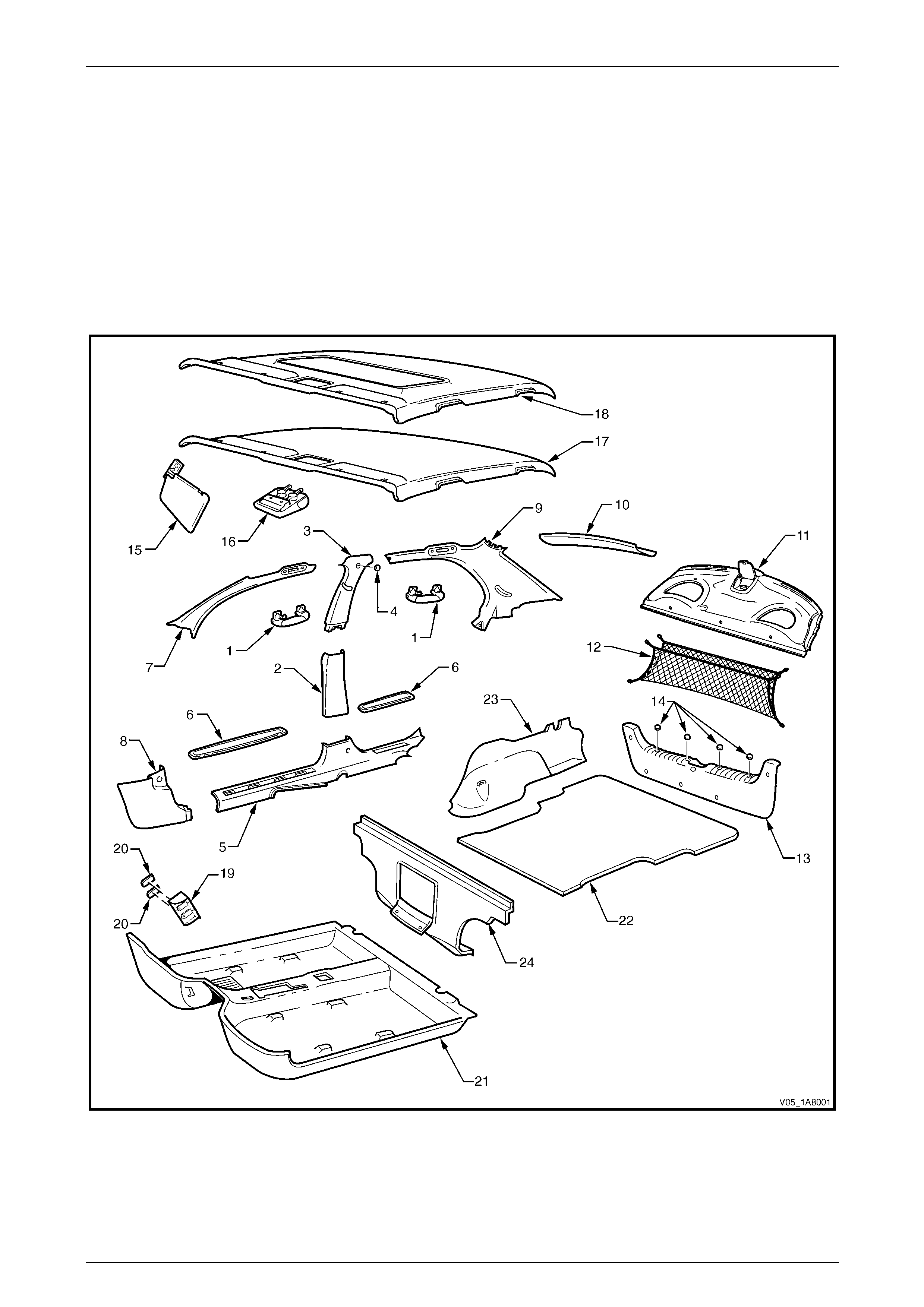
Headlining and Interior Trim Page 1A8–12
Page 1A8–12
2 Service Operations – Sedan
2.1 Components Chart
The headlining and interior trim components for Sedan vehicles are displayed in the following chart to assist with their
identification, refer to Figure 1A8 – 1.
For the service procedures of the rear compartment lid carpet,
refer to Section 1A4 Hood, Rear Compartment Lid, Liftgate and Endgate.
For the service procedures of the front and re ar door trim panel assemblies,
refer to Section 1A5 Front and Rear Door Assemblies.
Figure 1A8 – 1

Headlining and Interior Trim Page 1A8–13
Page 1A8–13
Legend
1 Assist Handle Assembly
2 Centre Pillar Lower Trim
3 Centre Pillar Upper Trim Assembly
4 Screw Cap
5 Side Sill Trim
6 Side Sill Trim Plate
7 Windshield Side Garnish
8 Body Hinge Pillar Trim Assembly
9 Body Lock Pillar Garnish
10 Rear Window Upper Garnish
11 Rear Window Trim Panel Assembly
12 Convenience Net
13 Rear End Trim Panel Assembly
14 Screw Caps
15 Sunshade Assembly
16 Roof Console
17 Headlining Assembly (without sunroof)
18 Headlining Assembly (with sunroof)
19 Driver Footrest
20 Screw Cap
21 Front Floor Carpet Assembly
22 Rear Compartment Floor Panel Carpet Assembly
23 Quarter Inner Rear Side Carpet
24 Rear Seat-back Panel Carpet
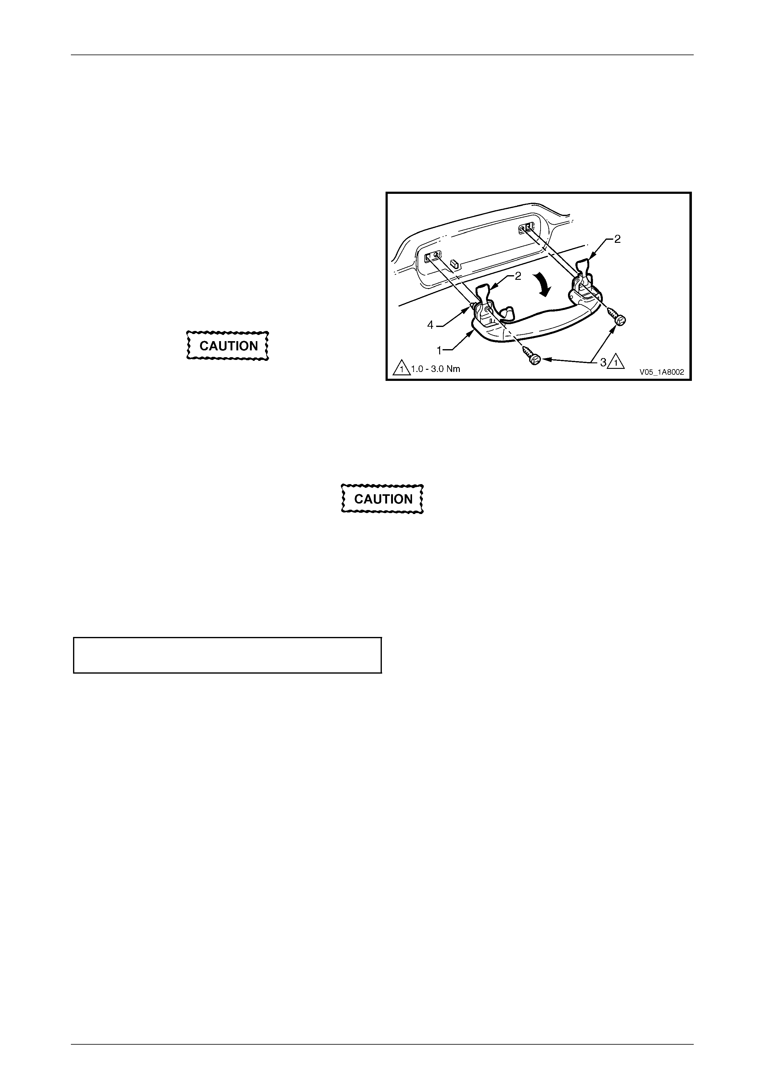
Headlining and Interior Trim Page 1A8–14
Page 1A8–14
2.2 Assist Handle Assembly
LT Section — 14–100
Remove
NOTE
This procedure is app licable to the front and rear
assist handle assemblies.
1 Pull the assist handle (1) into the down position.
2 Prise open the assist handle two screw covers (2) and
remove the two attaching screws (3).
When removing the assist handle assembly,
take care not to damage the locating pin s (4).
3 Remove the assist handle assembly.
Figure 1A8 – 2
Reinstall
Take care not to damage the locating pin
when fitting the assist handle assembly.
1 Ensure the locating pins are correctl y align ed with the locating holes.
2 Position the hook over the locating pin.
3 Tighten the assist handle two attaching screws to the correct torque specification.
Assist handle attaching screw
torque specification.....................................1.0 – 3.0 Nm

Headlining and Interior Trim Page 1A8–15
Page 1A8–15
2.3 Centre Pillar Lower Trim
LT Section — 14–100
Remove
1 Using your fingers, lever the top of the centre pill ar
lower trim (1) away from the front door opening
weatherstrip and pull the trim to ward the centre of the
car, disengaging the two retaining clips (2).
2 Lift the centre pillar lower trim upward, out of the side
sill trim (3) and remove.
3 As required, remove the retaining clips from the
vehicle and fit to the trim.
Figure 1A8 – 3
Reinstall
1 Locate the centre pillar lo wer trim (1) into the side sill trim (3), refer to Figure 1A8 – 3.
2 Locate the two retaining clips (2) into their slots in the centre pillar, then push in firml y ens uring the two clips are
secured to the centre pillar.
3 Ensure the front and rear door opening weatherstrips fit neatly over the outer edges of centre pillar lower trim.
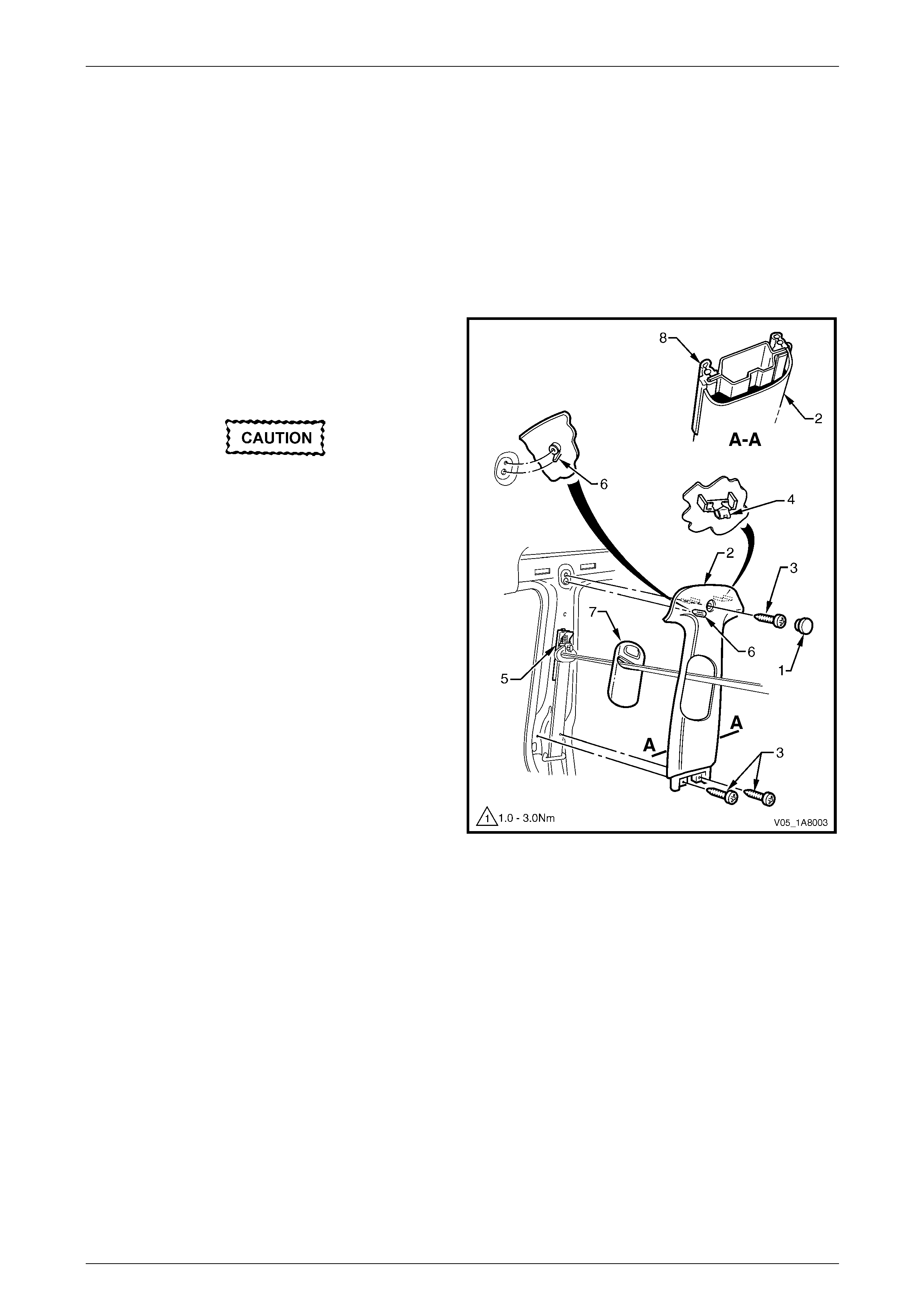
Headlining and Interior Trim Page 1A8–16
Page 1A8–16
2.4 Centre Pillar Upper Trim Assembly
LT Section — 14–100
Remove
1 Remove the following components as required:
a Centre pillar lower trim, refer to 2.3 Centre Pillar Lower Tr im.
b Front seat belt lower bolt, refer to Section 12M Occupant Protection System.
2 Remove the screw cap (1) from the upper attachment
of the centre pillar upper trim assembly (2).
3 Remove the three screws (3) attaching the centre
pillar upper trim assembly.
When removing the centre pillar upper trim
assembly, take care not to damage the
locating pin (6) below the upper attaching
screw position.
4 Pull the upper edge of the centre pillar upper trim
assembly away from the headlining assembly to
disengage the two retaining clips (4) and the seatbelt
guide adjuster assembly (5), if fitted.
5 Feed the seatbelt and anchor plate thro ugh the centre
pillar upper trim assembly and remove the centre pillar
upper trim assembly.
6 If required, remove the seatbelt adjuster trim (7) by
gently spreading the outer edges of the centre pillar
upper trim assembly and lifting out the seatbelt
adjuster trim.
7 As required, remove the retaining clips from the
vehicle and fit to the trim.
Figure 1A8 – 4
Headlining and Interior Trim Page 1A8–17
Page 1A8–17
Reinstall
Reinstallation of the centre pillar upper trim assembly is the reverse of the removal procedure, noting the following:
1 If fitted, ensure the seatbelt adjuster trim (7) and the seatbelt guide adjuste r assembl y (5) are in the fully up position
and are correctly aligned prior to installing the centre pillar upper trim assembly (2), refer to Figure 1A8 – 4.
Take care not to snap off the locating pin
when fitting the centre pillar upper trim
assembly.
2 Ensure the locating pin belo w the upper attaching screw position in the centre pillar up per trim assembly is correctly
aligned with the locating hole in the centre pillar.
3 Ensure the centre pillar upper trim assembl y two retaining clips are secured to the centre pillar.
4 Ensure the leading edge of the centre pillar upper trim assembly engages the front door opening weatherstrip
assembly (8).
5 Check the seatbelt operation prior to tightening the centre pillar u pp er trim assemb ly attaching screws.
6 Tighten the centre pillar uppe r trim assembly three attaching screws to the specified torque.
Centre pillar upper trim assembly
attaching screw torque specification...........1.0 – 3.0 Nm
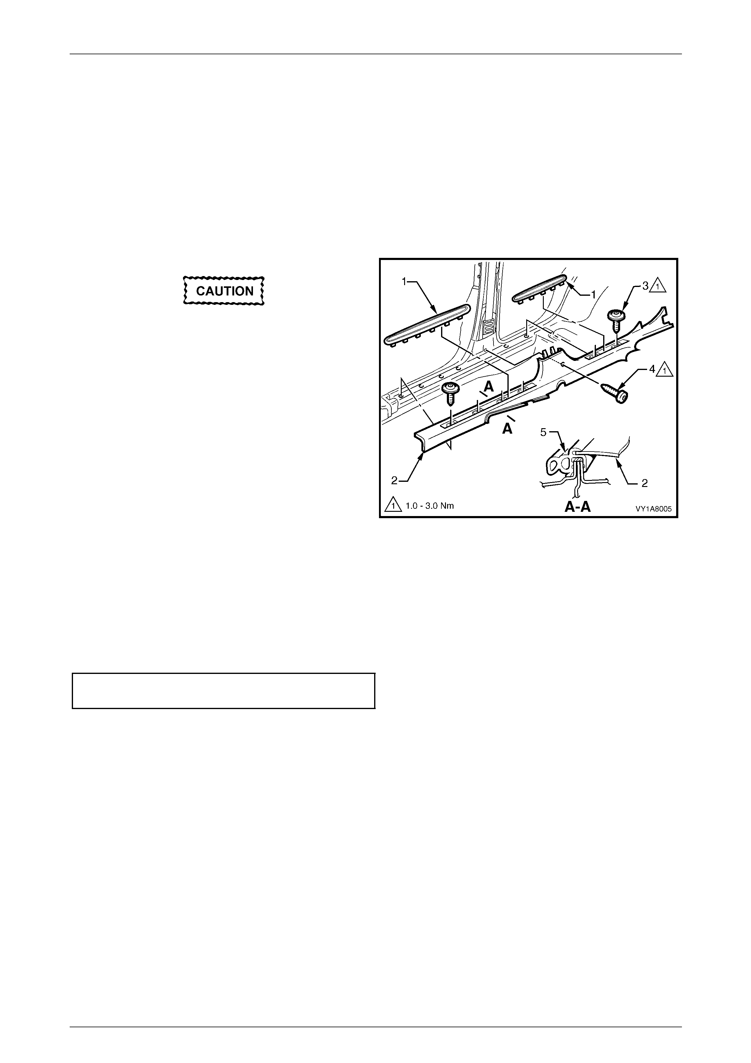
Headlining and Interior Trim Page 1A8–18
Page 1A8–18
2.5 Side Sill Trim and Plate
LT Section — 14–100
Remove
1 Remove the following components as required:
a Centre pillar lower trim, refer to 2.3 Centre Pillar Lower Tr im.
b Front seat outer front cover and outer rear cover, refer to Section 1A7 Seat Assemblies.
During the following procedure take care not
to snap the sill trim plates.
2 Carefully lever the front and rear side si ll trim
plates (1) from the side sill trim (2), starting at the front
of each plate and moving rearward.
3 Remove the Torx screw (3), six places, attachin g the
side sill trim, four in the front door opening an d two in
the rear door opening.
4 Remove the Torx screw (4) attaching the side sill trim
to the centre pillar.
5 Remove the side sill trim through the front door
opening by lifting the front and sliding the rear out from
under the rear seat cushion. Figure 1A8 – 5
Reinstall
Reinstallation of the side sill trim and plate is the reverse of the removal procedure, noting the following:
1 Ensure the outer edge of the side sil l trim (2) enga ges the fr ont and rear door opening weatherstrips (5), refer to
Figure 1A8 – 5.
2 Tighten the Torx screws attaching the side sill trim to the correct torque specification.
Side sill trim attaching Torx screw
torque specification.....................................1.0 – 3.0 Nm

Headlining and Interior Trim Page 1A8–19
Page 1A8–19
2.6 Windshield Side Garnish
LT Section — 14–100
Remove
1 Remove the following components as required:
a Front assist handle assembly, refer to 2.2 Assist Handle Assembly.
b Partially remove the centre pill ar upper trim assembly by removing the upper attaching screw, refer to
2.4 Centre Pillar Upper Trim Assembly.
When removing the windshield side garnish,
take care not to damage the locating pin (3).
2 Starting at the upper rear edge of the windshield side
garnish (1) disengage the three retai nin g clips (2).
3 Remove the windshield side garnish.
4 As required, remove the retaining clips from the
vehicle and fit to the garnish.
Figure 1A8 – 6
Reinstall
Reinstallation of the windshield side garnish is the reverse of the removal procedure, noting the following:
Take care not to snap off the locating pin
when fitting the windshield side garnish.
1 Ensure the windshield side ga rnish locating pin is aligned with the locating h ole i n the hinge pillar inner panel.
2 Ensure the outer edge of the winds hield side garnish (1) engages the front door opening weatherstrip (4 ), refer to
Figure 1A8 – 6.
3 Ensure the three retaining clips are secured to the hinge pillar inner panel.

Headlining and Interior Trim Page 1A8–20
Page 1A8–20
2.7 Body Hinge Pillar Trim Assembly
LT Section — 14–100
Remove
1 Partially remove the side sill trim, refer to 2.5 Side Sill Trim and Plate.
2 Remove the two attaching screws (1) from the body
hinge pillar trim assembly (2).
3 Disengage the body hinge pillar trim clip (3) by pul ling
the lower edge of the body hinge p illar trim assembly
rearward and away from the sheetmetal.
4 Remove the body hinge pillar trim assembly.
5 If required, remove the body hinge pillar trim clip a nd
the two nut inserts (4).
Figure 1A8 – 7
Reinstall
Reinstallation of the body hinge pillar trim assembl y is the reverse of the removal procedure, noting the following:
1 Ensure the body hinge pil lar trim clip is correctly engaged in the hinge pillar inner panel.
2 Ensure the nut inserts are in good condition and correctly located in the hinge pillar inner panel.
3 Ensure the outer edge of the body hinge pillar trim assembl y engages the front door opening weatherstrip (5), refer
to Figure 1A8 – 7.
4 Tighten the body hinge pillar trim assembly two attaching screws to the correct torque specification.
Body hinge pillar trim assembly
attaching screw torque specification...........0.7 – 1.0 Nm
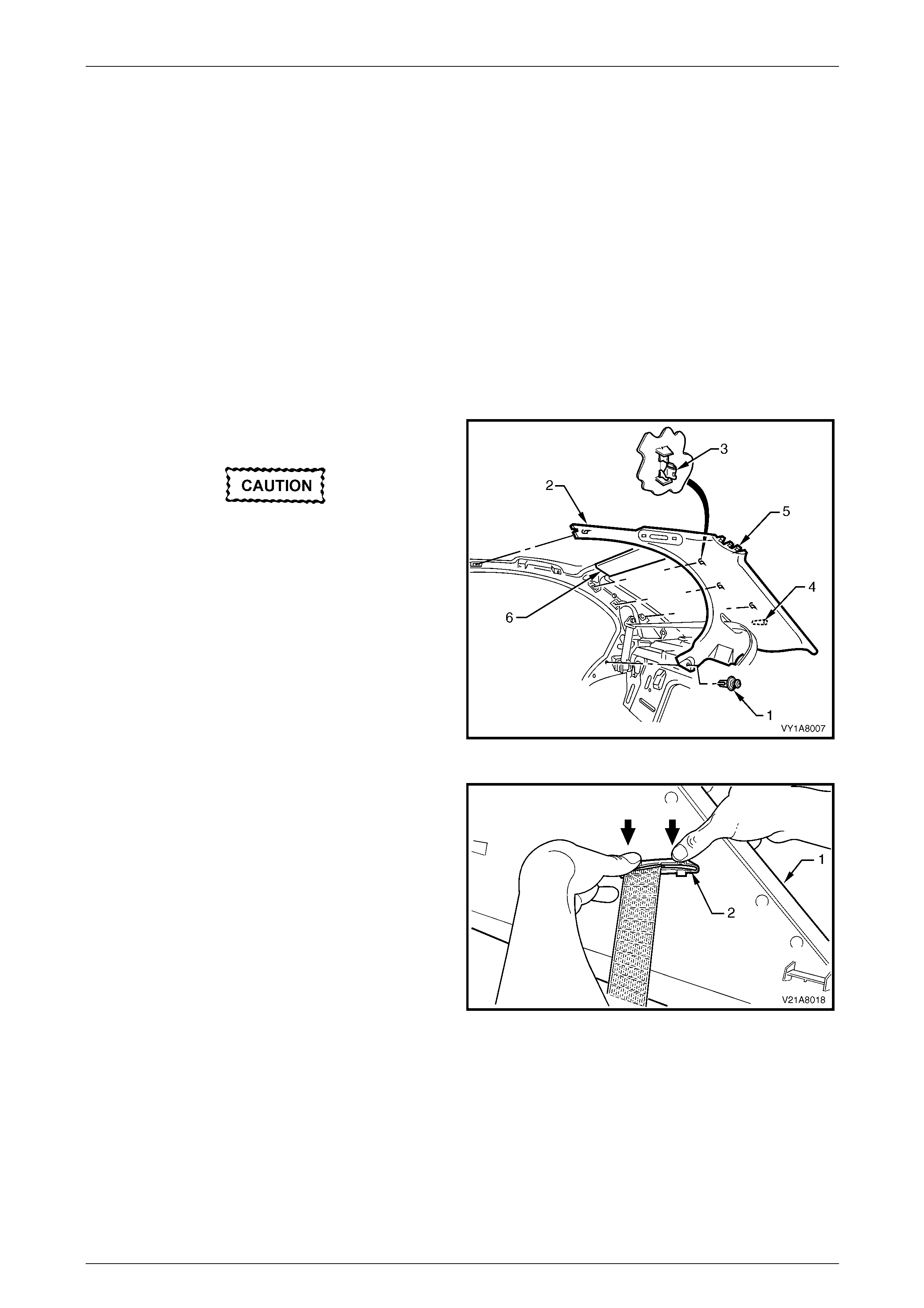
Headlining and Interior Trim Page 1A8–21
Page 1A8–21
2.8 Body Lock Pillar Garnish
LT Section — 14–120
Remove
1 Remove the following components as required:
a Rear assist handle, refer to 2.2 Assist Handle Assembly.
b Roof rail courtesy and reading lamps, refer to Section 12B Lighting System.
c Partially remove the centre pill ar upper trim by removing the upper attaching screw,
refer to 2.4 Centre Pillar Upper Trim Assembly.
d Rear seat cushion and rear seat-back assembly, refer to Section 1A7 Seat Assemblies.
e Rear seat belt lower attaching bolt, refer to Section 12M Occupant Protection System.
2 Remove the retainer (1) from the lo wer edge of the
body lock pillar garnish (2).
When removing the body lock pillar garnish,
take care not to damage the locating pin (4)
or the locating lugs (5) fitting under the rear
window upper garnish (6).
3 Pull the front edge of the body lock pillar gar nish away
from the body lock pillar and working rearward
disengage the four retaining clips (3).
4 Slide the body lock pillar garnish to disengage the
three locating lugs (5) from under the rear window
upper garnish (6) and partially remove.
Figure 1A8 – 8
5 With the body lock pillar garnish (1) partially removed,
disengage the seat belt escutcheo n (2) from the body
lock pillar garnish and feed the seat belt and anchor
plate through the opening.
6 Remove the body lock pillar garnish.
7 As required, remove the retaining clips from the
vehicle and fit to the garnish.
Figure 1A8 – 9

Headlining and Interior Trim Page 1A8–22
Page 1A8–22
Reinstall
Reinstallation of the body lock pillar garnish is the reverse of the removal procedure, noti ng the following:
When fitting the body lock pillar garnish take
care of the following:
• do not snap off the locating pi n
• if a sunroof is fitted to the vehicle, do not
crush or dent the sunroof rear drain tubes.
1 Ensure the body lock pillar garnish locating pin is aligned with the locating hole in the body lock pillar inner panel.
2 Ensure the body lock pillar garnish is fully engaged i nto the rear window upper garnish.
3 Ensure the leading edge of the bod y lock pillar garnish eng ages the rear door opening weatherstrip.
4 Ensure the body lock pillar garnish retainer and the four retaining cli ps are secured to the body lock pillar inner
panel.
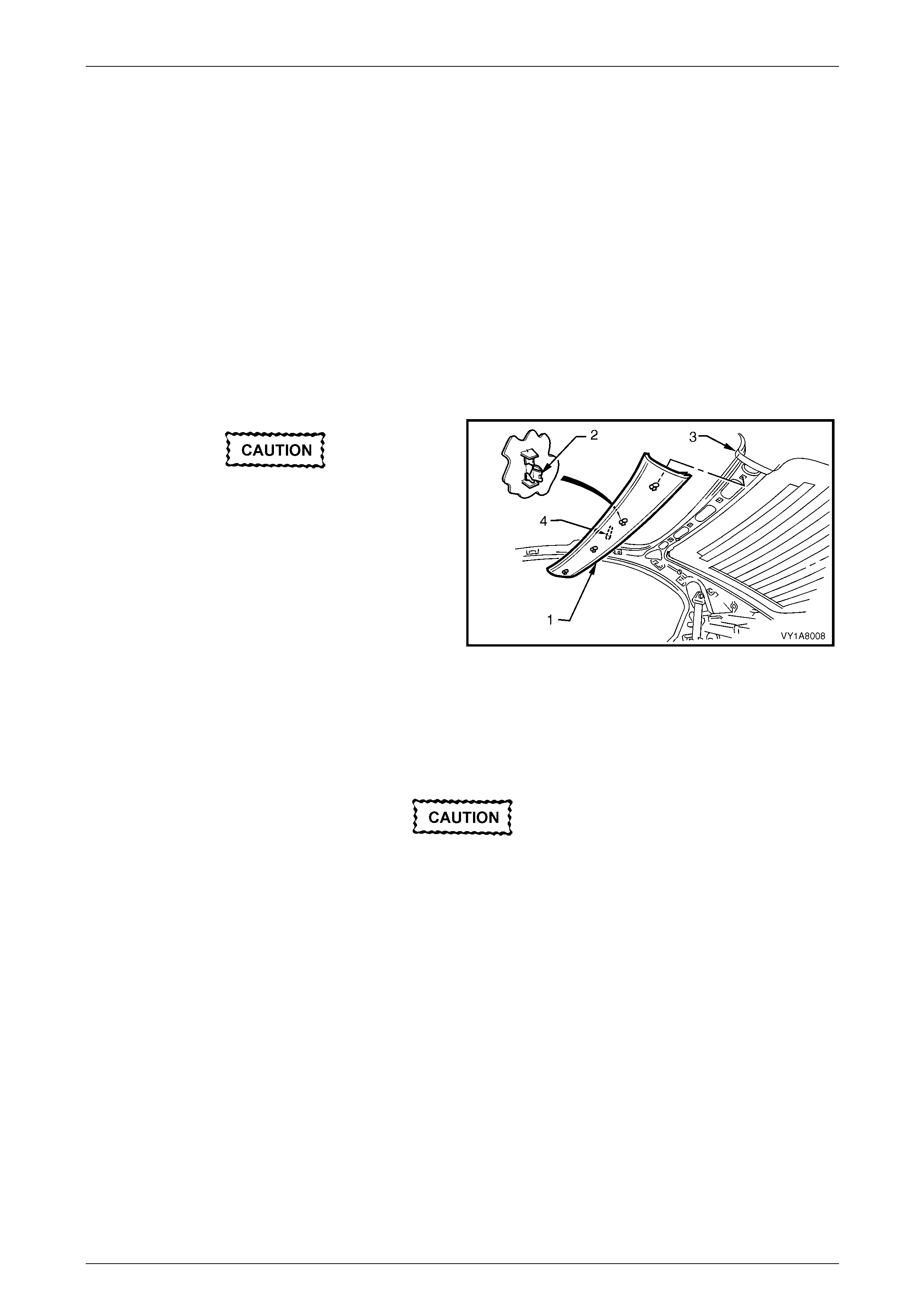
Headlining and Interior Trim Page 1A8–23
Page 1A8–23
2.9 Rear Window Upper Garnish
LT Section — 14–120
Remove
1 Remove the following components as required:
a Rear seat cushion and rear seat-back assembly, refer to Section 1A7 Seat Assemblies.
b Rear assist handle, on one si de of the vehicle, refer to 2.2 Assist Handle Assembly.
c Roof rail courtesy and reading lamps, on the same side of the vehicle, refer to Section 12B Lighting System.
d Partially remove the centre pill ar upper trim by removing the upper attaching screw, on the same side of the
vehicle, refer to 2.4 Centre Pillar Upper Trim Assembly.
e Body lock pillar garnish, on th e same side of the vehicle, refer to 2.8 Body Lock Pillar Garnish.
When removing the rear window upper
garnish, take care no t to damage the locating
pin (4).
2 Starting from the end that has the body l ock pillar
garnish removed, lever the rear window upper
garnish (1) away from the headlining to dis engage the
four retaining clips (2) from the roof rear panel.
3 Remove the rear window upper garnish away from the
remaining body lock pill ar garnish (3).
4 As required, remove the retaining clips from the
vehicle and fit to the garnish.
Figure 1A8 – 10
Reinstall
Reinstallation of the rear window upper garnish is the reverse of the removal proc edure, noting the following:
Take care not to snap off the locating pin
when fitting the rear window upper garnish.
1 Ensure the rear window upper garnish locating pin is aligned with the locating hole in the roof rear panel.
2 Ensure there is a neat fit between the outer edge of the body lock pillar garnish and the rear window upper garnish.
3 Ensure the rear window upper garnish four retaining clips are secured to the roof rear pa nel.
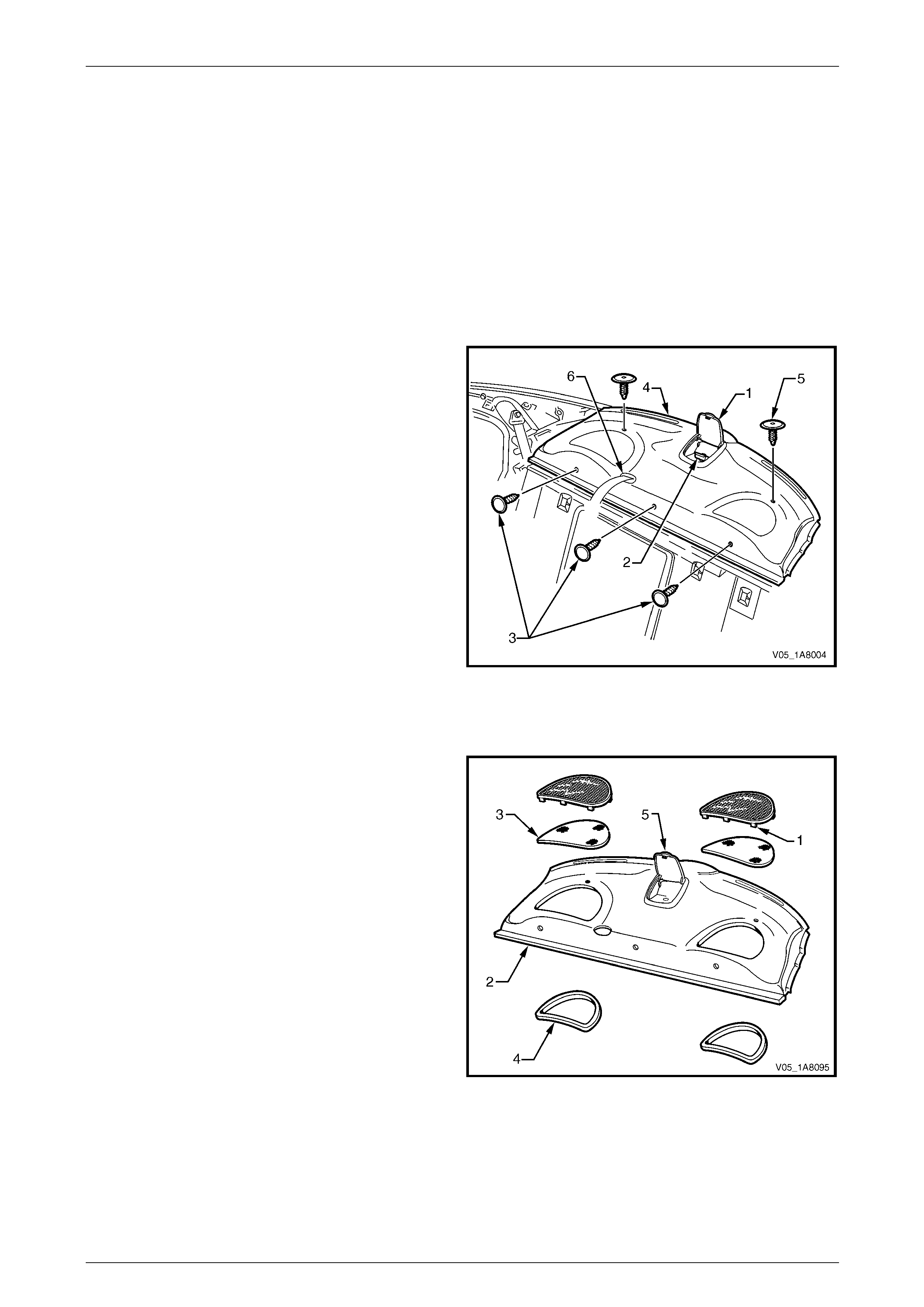
Headlining and Interior Trim Page 1A8–24
Page 1A8–24
2.10 Rear Window Trim Panel Assembly
LT Section — 14–460
Remove
1 Remove the following components as required:
a Rear seat cushion and rear seat-back assembly, refer to Section 1A7 Seat Assemblies.
b Remove the rear centre seat belt lower bolt, refer to Section 12M Occupant Protection System.
c Partially remove the bod y lock pillar garnish on both sides, refer to 2.8 Body Lock Pillar Garnish.
2 Open the receptacle cover (1) and remove the child
seat anchor (2), refer to Section 12M Occupant
Protection System.
3 Remove the three retainers (3) attaching the forward
edge of the rear window trim panel assemb ly (4).
4 Remove the two retainers (5) attaching the upper
surface of the rear window trim panel assembly.
5 Lift the front edge of the rear window trim panel
assembly, then remove the rear centre seat belt
escutcheon (6) and feed the rear centre seat belt and
anchor plate through the op ening.
6 Remove the rear window trim panel assembly.
Figure 1A8 – 11
Disassemble
1 Bend the tab (1), nine places, of the speaker grille to a
vertical position and remove the speaker grille from
the rear window trim panel assembly (2).
2 Remove the dust seal (3) from the speaker grille.
3 Remove the speaker seal (4) from the rear windo w
trim panel assembly.
4 If required, repeat for the opposite side.
NOTE
The child seat anchor receptacle (5) is part of
the rear window trim panel assembly and is not
serviced separately.
Figure 1A8 – 12

Headlining and Interior Trim Page 1A8–25
Page 1A8–25
Reassemble
Reassembly of the rear window trim panel assembly is the reverse of the disassembly procedur e, noting the following:
1 Ensure the speaker seal and dust seal are correctly fitted.
2 Bend the nine tabs to a horizontal position to retain the speaker grille in p osition.
Reinstall
Reinstallation of the rear window trim panel assembly is the reverse of the removal procedure, noting the following:
1 Ensure the speaker seals do not foul on the speaker assemblies.
2 Ensure the rear window trim panel assemb ly retainers are secured to the rear windo w panel assembly.
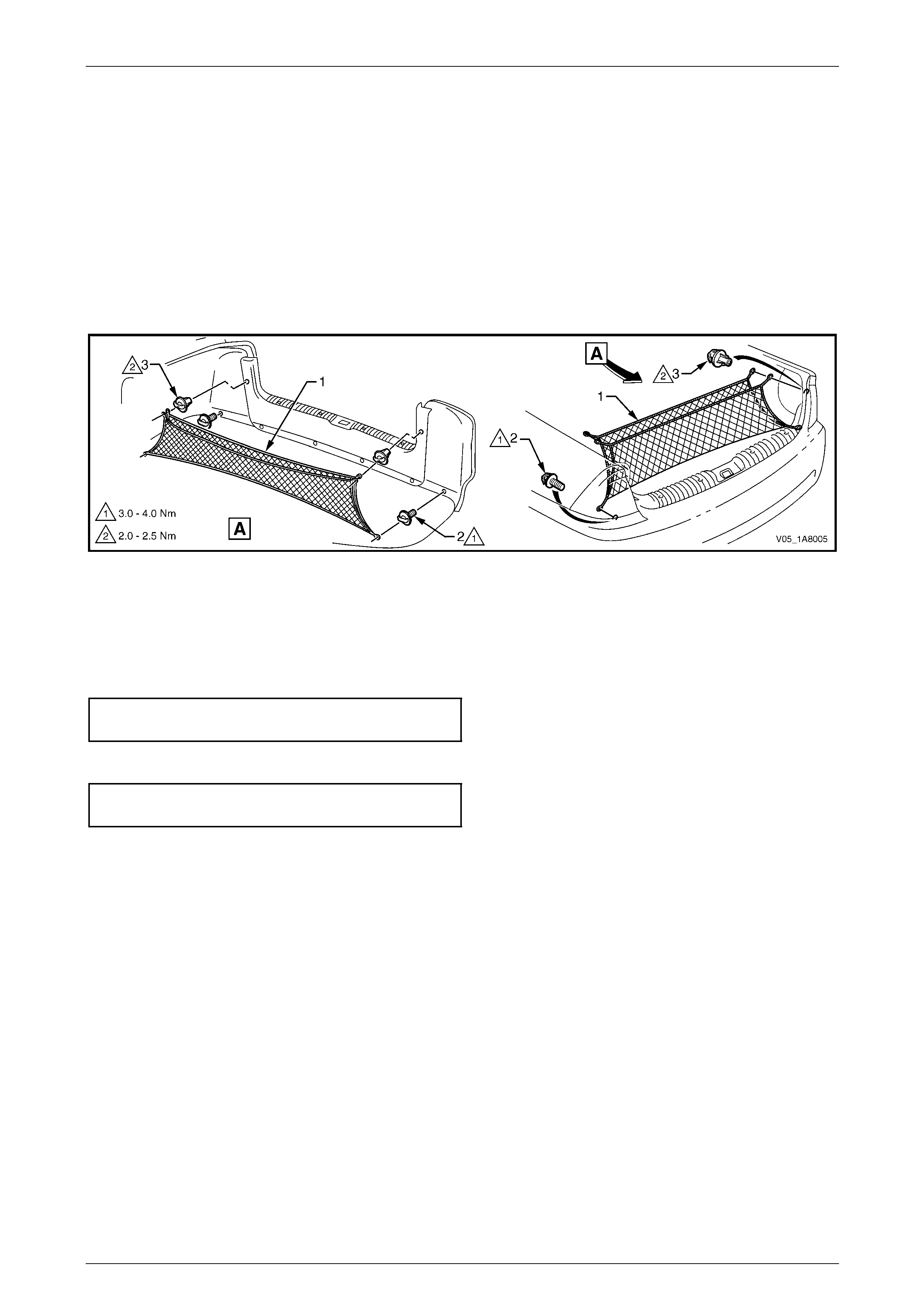
Headlining and Interior Trim Page 1A8–26
Page 1A8–26
2.11 Convenience Net
LT Section — 14–480
Remove
1 Carefully unhook the conv enience net (1) from the two lower retainer hooks (2) and the two upper retainer
hooks (3).
2 Remove the convenience net from the rear co mpartment.
3 If required, unscrew and remove the two upper and the two lower retainer hooks.
Figure 1A8 – 13
Reinstall
Reinstallation of the convenie nce net is the reverse of the removal procedure, noting the following:
1 Tighten the two lower retainer hooks to the correct torque specification.
Convenience net lower retainer hook
torque specification.....................................3.0 – 4.0 Nm
2 Tighten the two upper retainer hooks to the correct torque specification.
Convenience net upper retainer hook
torque specification.....................................2.0 – 2.5 Nm
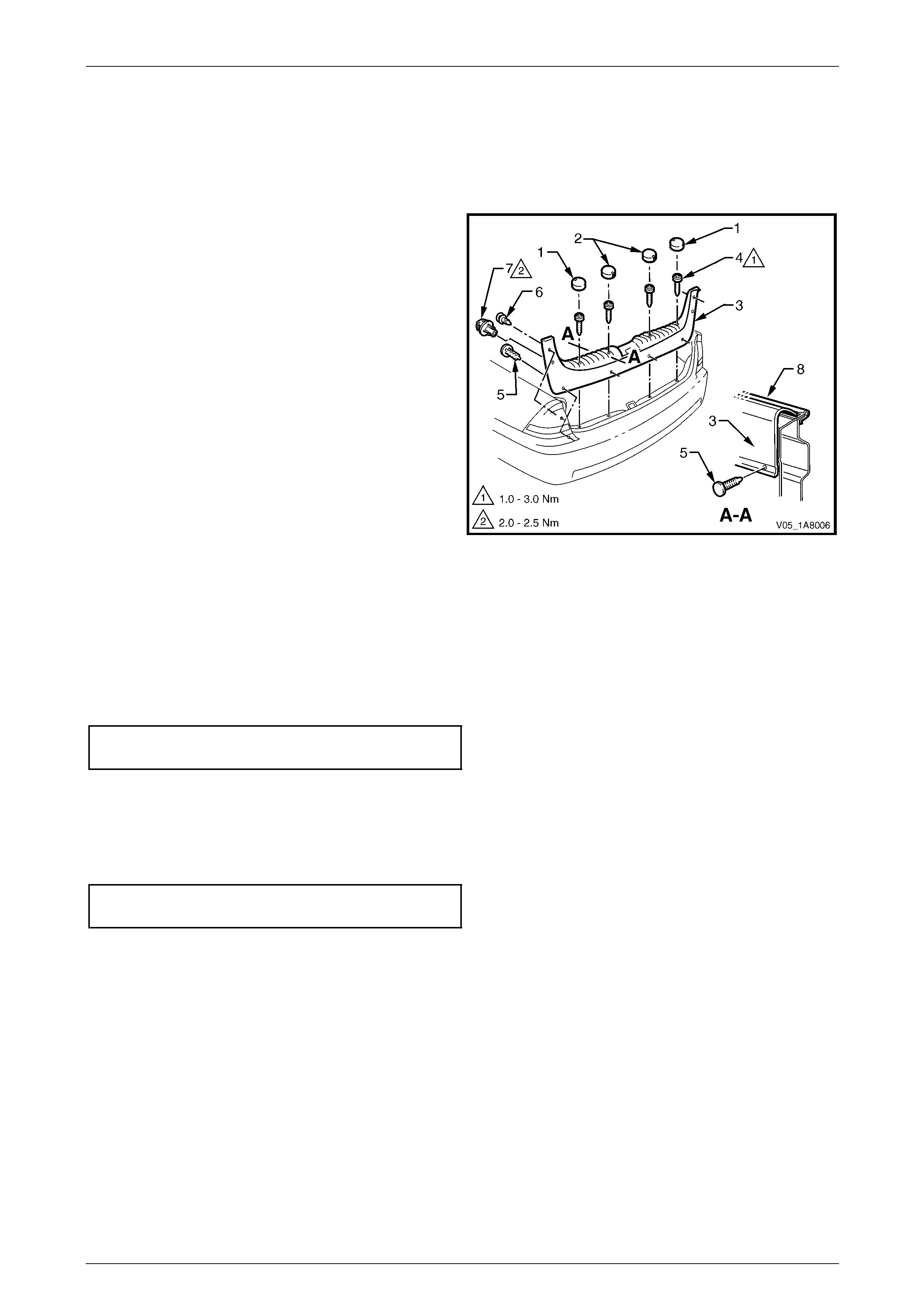
Headlining and Interior Trim Page 1A8–27
Page 1A8–27
2.12 Rear End Trim Panel Assembly
LT Section — 14–120
Remove
1 Where fitted, remove the convenience net, refer to
2.11 Convenience Net.
2 Remove the four screw caps (1 and 2) from the rear
end trim panel (3).
3 Remove the four attaching screws (4) along the ribb ed
upper surface of the rear end trim panel.
4 Remove the retainer (5), four places, along the lower
inner edge of the rear end trim panel.
5 Remove the retainer (6), t wo places, attaching the
upper sides of the rear end trim panel.
6 Remove the convenience net upper retainer hook (7),
two places.
7 Carefully lift the rear end trim panel ov er the rear
compartment lid latch and clear of the rear
compartment.
Figure 1A8 – 14
Reinstall
Reinstallation of the rear end trim panel assembly is the reverse of the removal procedure, noting the following:
1 Ensure the outer edge of rear end trim panel (3) engages the rear compartment lid weatherstrip (8), refer to
Figure 1A8 – 14.
2 Tighten the four attaching screws to the correct torque specification.
Rear end trim panel attaching screw
torque specification.....................................1.0 – 3.0 Nm
3 Ensure the screw caps are correctly fitted with the notch on the outer caps (1) pointing for ward and the notch on
the inner caps (2) pointing rearward.
4 Ensure the retainers are secured to the rear end panel assembl y.
5 Tighten the convenienc e net two upper retainer hooks to the correct torque specification.
Convenience net upper retainer hook
torque specification.....................................2.0 – 2.5 Nm
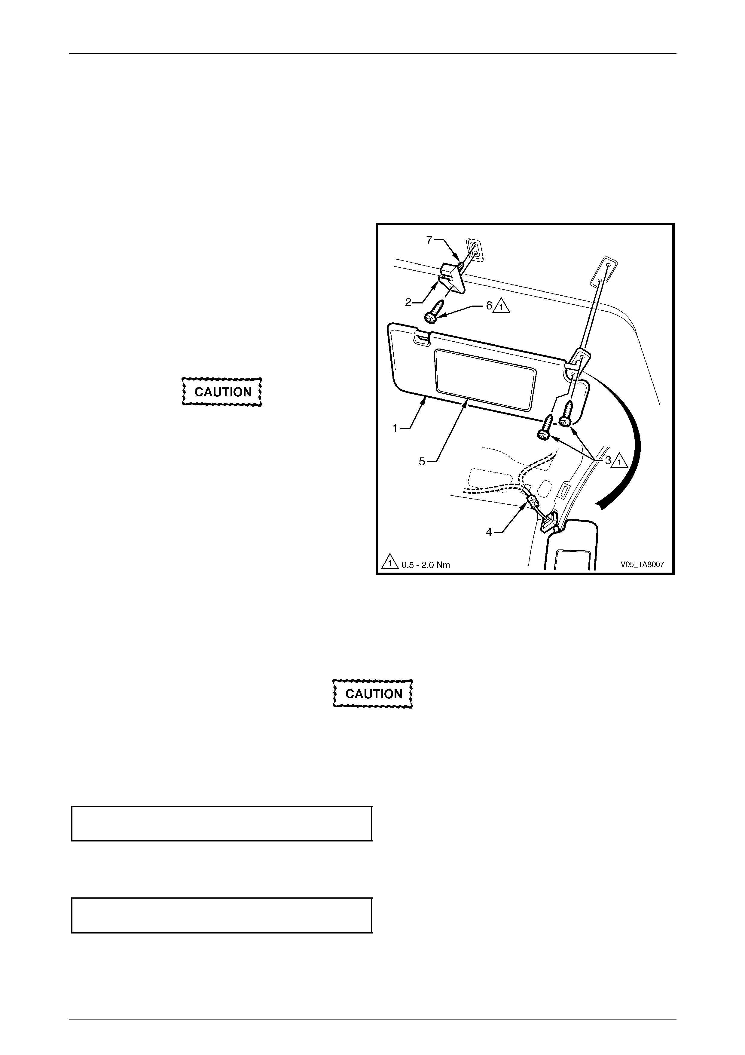
Headlining and Interior Trim Page 1A8–28
Page 1A8–28
2.13 Sunshade Assembly
LT Section — 14–050
Remove
1 If illuminated vanity mirrors are fitted, remove the fuse F6 from the passenger compartme nt fuse and re lay panel
assembly, refer to Section 12O Fuses, Relays and Wiring Harnesses.
2 Disconnect the sunshade assembly (1) from the
sunshade support (2) and rotate to gain acce ss.
3 Remove the two Torx screws (3) attaching the
sunshade assembly.
4 Pull the sunshade assembly away from the headlining
assembly and if fitted, disconnect the harnes s
connector (4) from the illuminated vanity mirrors (5).
5 Remove the sunshade assembly.
When removing the sunshade support, take
care not to damage the locating pin (7).
6 Remove the Torx screw (6) from the sunshade support
and pull the support from the headlining assembly.
Figure 1A8 – 15
Reinstall
Reinstallation of the sunshad e assemb ly is the reverse of the removal procedure, noting the following:
Take care not to damage the locating pin
when fitting the sunshade support.
1 Ensure the sunshade support locati ng pin is aligned with the locating h ole in the roof panel.
2 Tighten the Torx screw attaching the sunshade support to the correct torque specification.
Sunshade support attaching Torx screw
torque specification.....................................0.5 – 2.0 Nm
3 If illuminated vanity mirrors are fitted, connect the harness connector to the sunshade ass embl y.
4 Tighten the sunshade ass embly two attaching Torx scre ws to the correct torque specific ation.
Sunshade assembly attaching screw
torque specification.....................................0.5 – 2.0 Nm

Headlining and Interior Trim Page 1A8–29
Page 1A8–29
2.14 Roof Console
LT Section — 02–780
Remove
1 Remove the fuse F6 from the passenger compartment fuse and relay panel ass embl y,
refer to Section 12O Fuses, Relays and Wiring Harnesses.
2 Open the compartment door (1) of the roof console.
3 Remove the two attaching screws (2) from inside the
roof console.
4 Close the compartment door.
5 Using your hand, pull down to disengage the front of
the roof console from the roof header pane l.
Figure 1A8 – 16
6 Slide the roof console (1) in a forward motion to allow
the two locator arms (2) to clear the headlini ng.
7 Disconnect the harness from the roof console
connector (3) and remove.
NOTE
For replacement of the map lamp bulbs, refer to
Section 12B Lighting System.
Figure 1A8 – 17
Reinstall
Reinstallation of the roof console is the reverse of the removal procedure, noting the following:
1 Ensure the harness is securely connecte d to the roof console connector.
2 Ensure the two locator arms are correctly inserted and the roof console is secure d to the roof panel.
3 Tighten the roof console two attaching screws to the correct torque specification.
Roof console attaching screw
torque specification.....................................1.0 – 2.0 Nm

Headlining and Interior Trim Page 1A8–30
Page 1A8–30
2.15 Headlining Assembly
LT Section — 14–150
Remove
NOTE
If the vehicle is fitted with a sunroof, note the
following:
• Where an online sunroof is fitted, a rigid
headlining is installed and can be removed
using the normal procedure.
• Where a Holden By Design (HBD) sunroof is
fitted, a new headlining ha d to be created a nd
installed with adhesive. Extreme care is
required as the removal may damage the
headlining, then requiring a new one to be
created by a motor trimmer. The procedure
for this headlining is not covered in this
Section.
1 Remove the fuse F6 from the passenger compartment fuse and relay panel ass embl y,
refer to Section 12O Fuses, Relays and Wiring Harnesses.
2 Place protective covering ov er both front seats and the interior trim.
3 Remove the following components as required:
a Rear seat cushion and rear seat-back assembly, refer to Section 1A7 Seat Assemblies.
b Windshield side garnish on b oth sides, refer to 2.6 Windshield Side Garnish.
c Body lock pillar garnish on b oth sides, refer to 2.8 Body Lock Pillar Garnis h.
d Rear window upper garnish, refer to 2.9 Rear Window Upper Garnish.
e Sunshade assembly on both sides, refer to 2.13 Sunshade Assembl y.
f Roof console, refer to 2.14 Roof Console.
4 Disconnect the headlining assembly wiring harness (1) from the bod y wiring harness connector (2), located above
and slightly forward of the right-hand centre pillar, refer to Figure 1A8 – 18.
NOTE
It may be necessary to flex the headlining
assembly (3) down slightly to gain access to the
harness connector.
5 With the aid of an assistant, flex the headlining assembly (3) to disengage the corners from the ‘D’ tabs (4), in four
places on the sides of the roof panel.
6 Ease the headlining assembly from its position on the roof panel and turn the he adlining assembly so that it can be
passed through the passenger side front door opening and remove it from inside the vehicle.
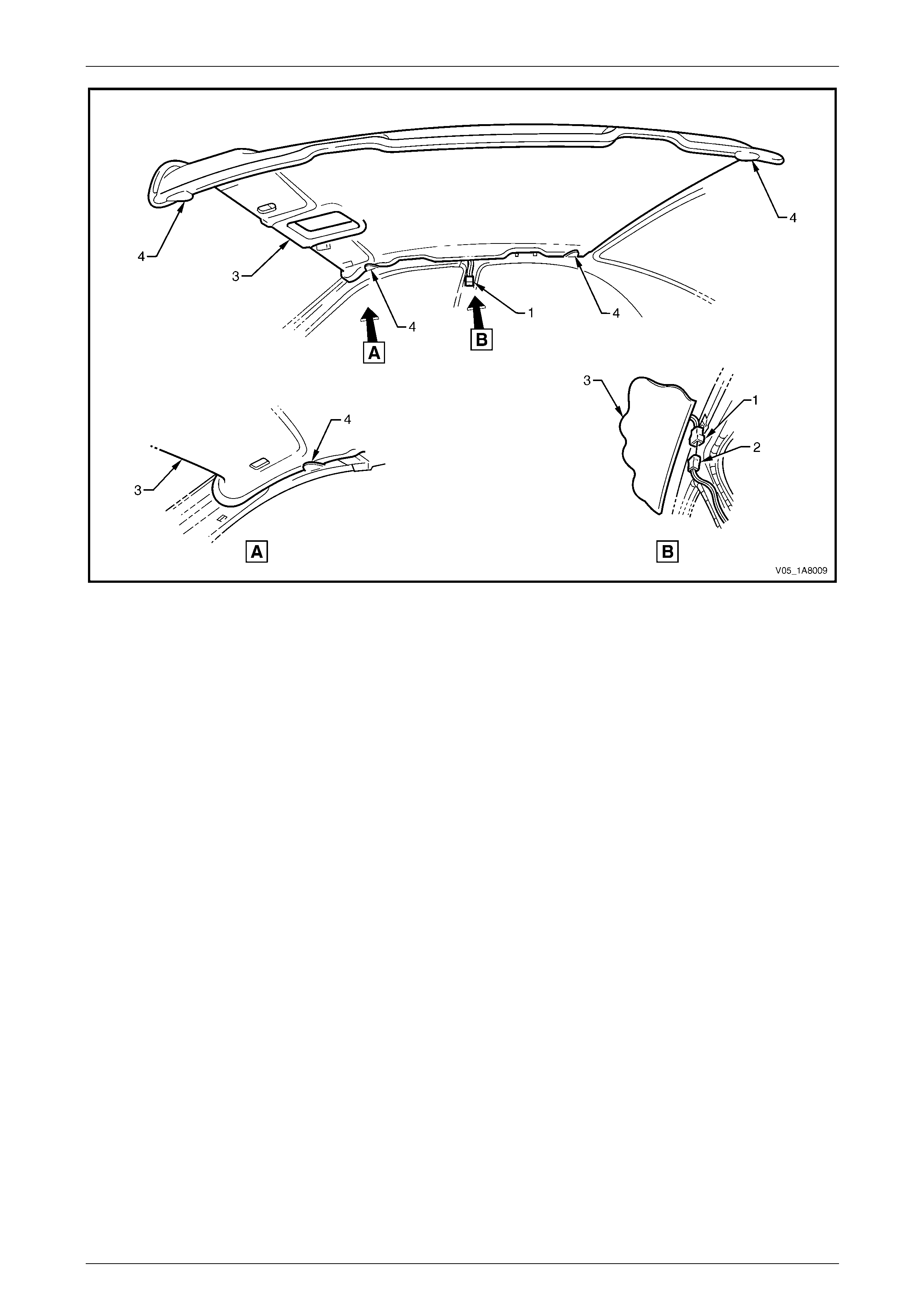
Headlining and Interior Trim Page 1A8–31
Page 1A8–31
Figure 1A8 – 18
Reinstall
Reinstallation of the headlining assembly is the reverse of the removal pro c edure, noting the following:
1 Temporarily support the headlining assembly on the ‘D’ tabs (4) before the trim components are installed,
refer to Figure 1A8 – 18.
2 Ensure the headlining assembly harness connector is securely connected to the body wiring harness connector.

Headlining and Interior Trim Page 1A8–32
Page 1A8–32
2.16 Driver Footrest
LT Section — 14–475
Remove
1 Prise the two screw covers (1) and remove from the
driver footrest.
2 Remove the two screws (2) attaching the driver
footrest (3) to the footrest mounting bracket (4).
3 Remove the footrest pad.
Figure 1A8 – 19
Reinstall
Reinstallation of the driver footrest is the reverse of the removal procedure, noting the following:
Tighten the two screws attaching the driver footrest to the correct torque specification.
Driver footrest attaching screw
torque specification.....................................2.0 – 5.0 Nm

Headlining and Interior Trim Page 1A8–33
Page 1A8–33
2.17 Front Floor Carpet Assembly
LT Section — 14–475
Remove
On vehicles equipped with side impact
airbags, disable the occupant protection
system before performing the following
operation. Refer to Section 12M Occupant
Protection System.
1 Remove the following components as required:
a Rear seat cushion, refer to Section 1A7 Seat Assemblies.
b Side sill trims on both sides, refer to 2.5 Side Sill Trim and Plate.
c Front seat belt lower attaching bolts, refer to Section 12M Occupant Protection System.
d Body hinge pillar trim assembly on both sides, refer to 2.7 Body Hinge Pillar Trim Assembly.
e Both front seat assemblies, refer to Section 1A7 Seat Assemblies.
f Driver footrest, refer to 2.16 Driver Footrest.
g Remove the park brake lever cover by grasping the cover firmly by hand and sliding the co ver over the park
brake lever, refer to Section 5A Service and Park Braking System.
h Instrument panel lower trim plate assembly, right-hand and left-hand,
refer to Section 1A3 Instrument Panel and Consol e.
i Instrument panel compartment, refer to Section 1A3 Instrument Panel and Console.
j Instrument panel lower trim panel, refer to Section 1A3 Instrument Panel and Consol e.
k Floor console assembly, refer to Section 1A3 Instrument Panel an d Console.
2 Disconnect the inflatable restraint control module (SDM) wiring harness,
refer to Section 12M Occupant Protection System.
3 Remove the two retaining clips (1) from the front floor
carpet assembly (2) by rotating the clips counter-
clockwise and lifting clear of the attaching studs.
NOTE
To facilitate the removal and installation
procedure, the front floor carpet assembly is
perforated from the front edge (3), through the
centre of the evaporator drain cut-out, to the
forward edge of the lower radio bracket cut-
out (4).
Figure 1A8 – 20

Headlining and Interior Trim Page 1A8–34
Page 1A8–34
4 From inside the left-hand footwell, grasp the edge of
the hole in the front floor carpet assembly around the
evaporator drain hose (4) and tear open the perforated
line (3) by pulling the carpet awa y from the
transmission tunnel.
5 Slide the remaining flap of carpet out from under the
heating, ventilation and air-conditioning (HVAC)
unit (5) and into the right-hand footwell.
6 Carefully manoeuvre the front floor carp et and
insulator assembly out of the vehicle.
Figure 1A8 – 21
Reinstall
Reinstallation of the front floor carpet assembly is the reverse of the removal procedure, noting the following:
1 If a new front floor carpet assembly is being fitted, prior to installation, cut along the perforated line that runs from
the carpet forward edge (3) to the forward edge of the lower radio bracket cut-out (4), refer to F igure 1A8 – 20.
2 Ensure all the cut-outs in the front floor carpet assembl y are correctly alig ned, then install the two retaining clips
and the front seat belt lower attaching bolts, refer to Section 12M Occupant Protection System , to secure the front
floor carpet assembly prior to installing the seats and c onsole.
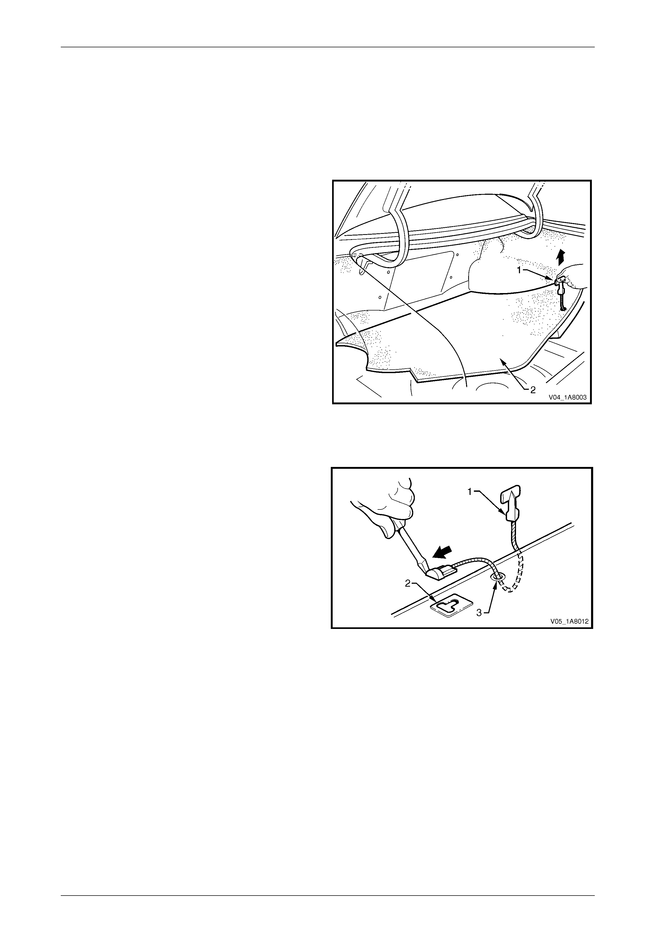
Headlining and Interior Trim Page 1A8–35
Page 1A8–35
2.18 Rear Compartment Floor Panel Carpet
Assembly
LT Section — 14–480
Remove
1 Open the rear compartment lid.
2 Grasp the strap (1) on the rear compartment floor
panel carpet assembly (2) and lift the rear edge
upward.
3 Lift and remove the rear compartment floor panel
carpet assembly from the rear compartment.
Figure 1A8 – 22
Disassemble
1 Lever the strap (1) out of the slot (2) in the rear
compartment floor panel carpet assembly and remove.
2 Feed the strap through the hole (3) in the rear
compartment floor panel carpet assembly and remove.
Figure 1A8 – 23
Reassemble
Reassembly of the rear compartment floor panel carpet assembly is the reverse of the disassembly procedur e.
Reinstall
Reinstallation of the rear com partment floor panel carpet assembly is the reverse of the removal procedure.
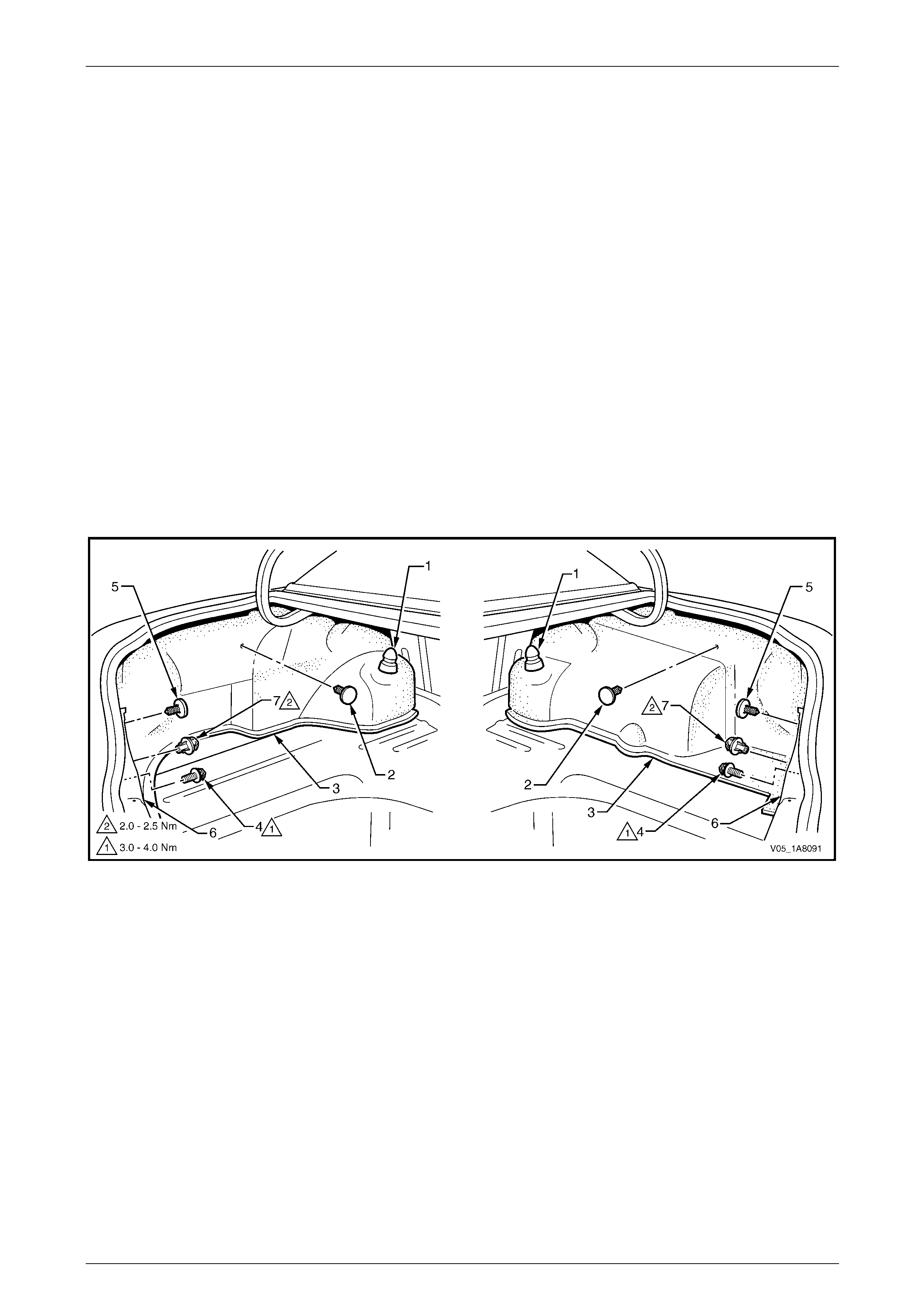
Headlining and Interior Trim Page 1A8–36
Page 1A8–36
2.19 Quarter Inner Rear Side Carpet
LT Section — 14–480
Remove
1 Remove the following components as required:
a Convenience net, refer to 2.11 Convenience Net.
b Rear compartment floor pan el carp et assembly,
refer to 2.18 Rear Compartment Floor Panel Carpet Assembly.
c Jack on the left-hand side.
2 Carefully prise off the rear shock absorb er access hole cover (1), refer to Figure 1A8 – 24.
3 Remove the retainer (2) securing the q uarter inner rear side carpet (3) and if fitted, the convenience net lower
retainer hook (4).
4 Remove the retainer (5) attaching the upper side of the rear end trim panel (6) and the convenience net upper
retainer hook (7).
5 Unhook the carpet flap from the rear compartment lid hinge bracket.
6 Carefully pull the carpet from behind the outer edge of the rear en d trim panel and remove.
Figure 1A8 – 24
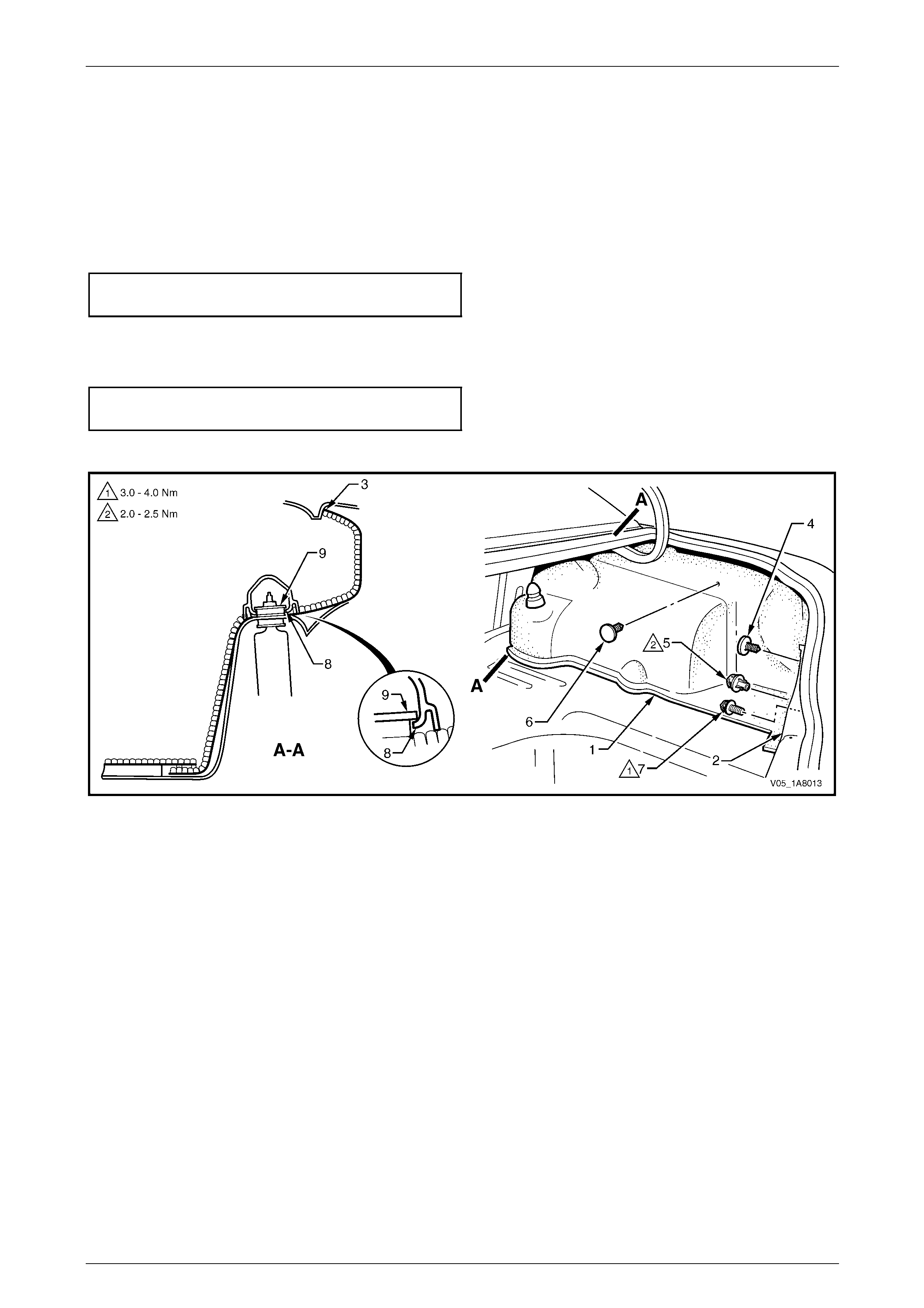
Headlining and Interior Trim Page 1A8–37
Page 1A8–37
Reinstall
Reinstallation of the quarter inner rear side carpet is the reverse of the removal procedure, noting the following:
1 Ensure the quarter inner rear side carpet (1) is correctly position ed behind the outer edge of the rear end trim
panel (2), the flap is hooked over the rear co mpartment lid hinge bracket and the carpet upp er dart (3) engaged in
the quarter panel inner assembl y, refer to Figure 1A8 – 25.
2 Ensure the retainer (4) secures the upper side of the rear end trim panel and tighten the conve nie nce net upper
retainer hook (5) to the correct torque specification.
Convenience net upper retainer hook
torque specification.....................................2.0 – 2.5 Nm
3 Ensure the retainer (6) is secured to the quar ter panel inner assembly.
4 If fitted, tighten the convenience net lower retainer hook (7) to the correct torque specification.
Convenience net lower retainer hook
torque specification.....................................3.0 – 4.0 Nm
5 Install the rear shock absorber access hole cover by engaging the lip (8) over the washer (9).
Figure 1A8 – 25
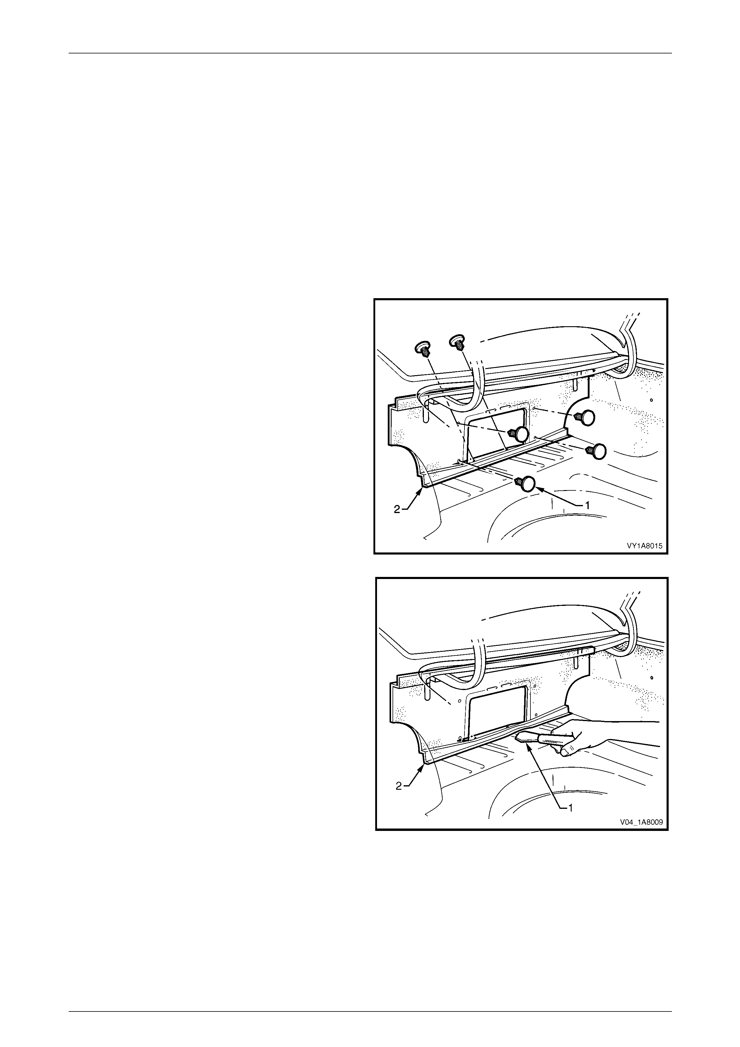
Headlining and Interior Trim Page 1A8–38
Page 1A8–38
2.20 Rear Seat-back Panel Carpet
LT Section — 14–480
Remove
1 Remove the following components as required:
a Rear end trim panel assembly, refer to 2.12 Rear End Trim Panel Assembly.
b Rear compartment floor pan el carp et assembly,
refer to 2.18 Rear Compartment Floor Panel Carpet Assembly.
c Partially remove the front of the quarter inner rear side carpet on both sides,
refer to 2.19 Quarter Inner Rear Side Carpet.
2 Lower the rear seat-back centre armrest assembly, refer to Section 1A7 Seat Assemblies .
3 Carefully remove the six retai ners (1) from the rear
seat-back panel carpet (2).
Figure 1A8 – 26
4 Using a knife or paint scraper (1), carefully prise along
the lower edge of the rear seat-back panel ca rpet (2).
5 Remove the rear seat-back panel carpet.
Figure 1A8 – 27
Reinstall
Reinstallation of the rear seat-back panel carpet is the reverse of the removal procedure, noting the following:
1 Use the existing adhesive bea d along the lower edge to refasten the rear seat-back panel carpet to the vehicle. If
required, add a bead of hot melt adhesive.
2 Ensure the rear seat-back panel carpet is fitted behind the quarter inner rear side carpet.
3 Ensure the six retainers are se cure d to the rear seat back.
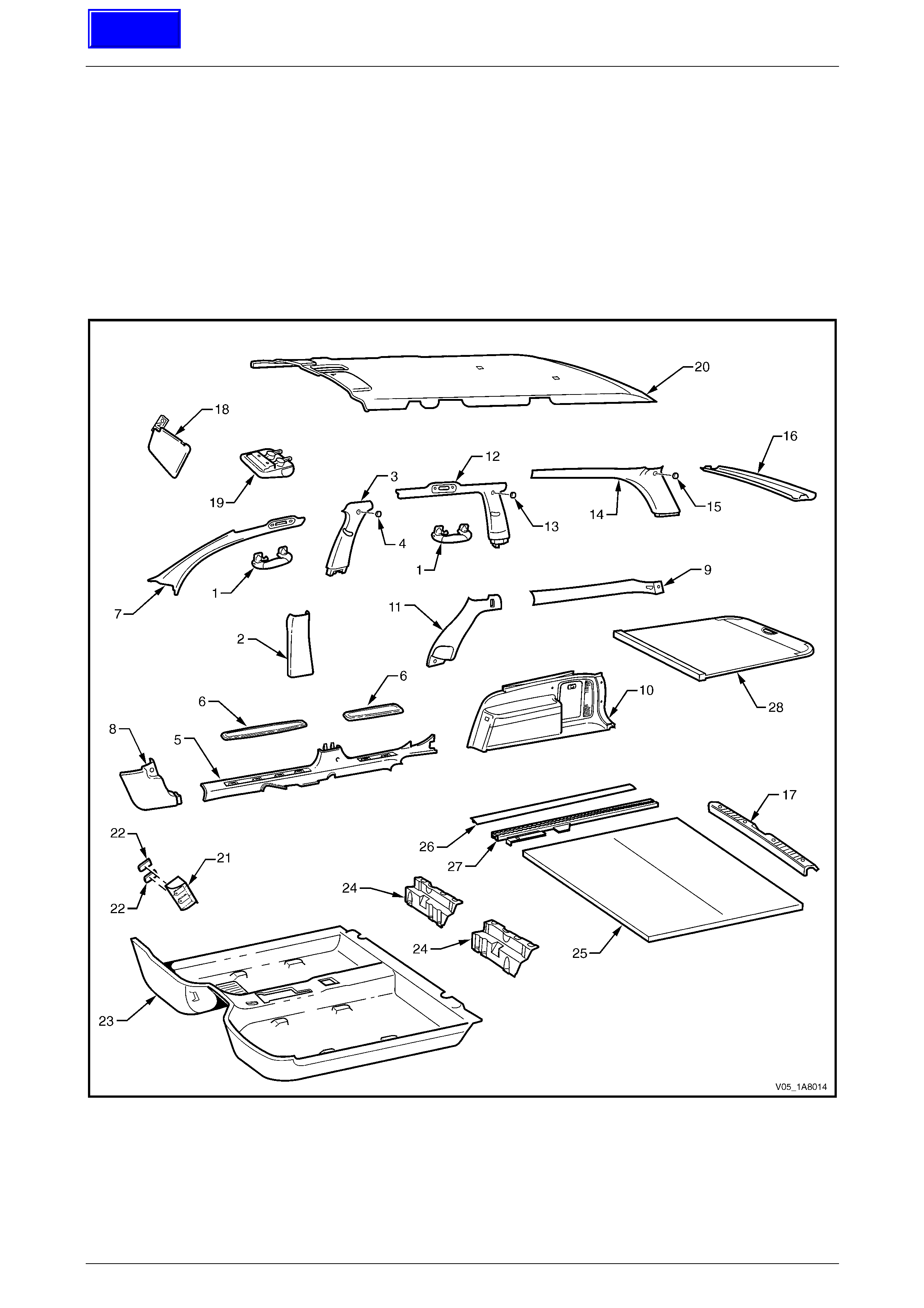
Headlining and Interior Trim Page 1A8–39
Page 1A8–39
3 Service Operations – Wagon
3.1 Components Chart
The headlining and interior trim components for Wagon vehicles are displayed in the following chart to assist with their
identification, refer to Figure 1A8 – 28.
For the service procedures of the liftgate trim, refer to Section 1A4 Ho od, Rear Compartment Lid, Liftgate and Endgate.
For the service procedures of the front and re ar door trim panel assemblies,
refer to Section 1A5 Front and Rear Door Assemblies.
Figure 1A8 – 28
Techline

Headlining and Interior Trim Page 1A8–40
Page 1A8–40
Legend
1 Assist Handle Assembly
2 Centre Pillar Lower Trim
3 Centre Pillar Upper Trim Assembly
4 Screw Cap
5 Side Sill Trim
6 Side Sill Trim Plate
7 Windshield Side Garnish
8 Body Hinge Pillar Trim Assembly
9 Quarter Inner Upper Trim
10 Quarter Inner Trim Panel Assembly
11 Body Lock Pillar Lower Trim
12 Body Lock Pillar Garnish Assembly
13 Screw Cap
14 Body Rear Corner Garnish Assembly
15 Screw Cap
16 Rear Window Upper Garnish
17 Rear End Trim Panel Assembly
18 Sunshade Assembly
19 Roof Console
20 Headlining Assembly
21 Driver Footrest
22 Screw Cap
23 Front Floor Carpet Assembly
24 Rear Floor Filler Panel
25 Rear Compartment Floor Panel Carpet Assembly
26 Luggage Tie Down Rail Cover
27 Luggage Tie Down Rail
28 Luggage Shade Assembly

Headlining and Interior Trim Page 1A8–41
Page 1A8–41
3.2 Assist Handle Assembly
LT Section — 14–100
Remove
NOTE
This procedure is app licable to the front and rear
assist handle assemblies.
1 Pull the assist handle (1) into the down position.
2 Prise open the assist handle two screw covers (2) and
remove the two attaching screws (3).
When removing the assist handle assembly,
take care not to damage the locating pin s (4).
3 Remove the assist handle assembly.
Figure 1A8 – 29
Reinstall
Take care not to damage the locating pin
when fitting the assist handle assembly.
1 Ensure the locating pins are correctl y align ed with the locating holes.
2 Position the hook over the locating pin.
3 Tighten the assist handle two attaching screws to the correct torque specification.
Assist handle attaching screw
torque specification.....................................1.0 – 3.0 Nm

Headlining and Interior Trim Page 1A8–42
Page 1A8–42
3.3 Centre Pillar Lower Trim
LT Section — 14–100
Remove
1 Using your fingers, lever the top of the centre pill ar
lower trim (1) away from the front door opening
weatherstrip and pull the trim to ward the centre of the
car, disengaging the two retaining clips (2).
2 Lift the centre pillar lower trim upward, out of the side
sill trim (3) and remove.
3 As required, remove the retaining clips from the
vehicle and fit to the trim.
Figure 1A8 – 30
Reinstall
1 Locate the centre pillar lo wer trim (1) into the side sill trim (3), refer to Figure 1A8 – 30.
2 Locate the two retaining clips (2) into their slots in the centre pillar, then push in firml y ens uring the two clips are
secured to the centre pillar.
3 Ensure the front and rear door opening weatherstrips fit neatly over the outer edges of centre pillar lower trim.

Headlining and Interior Trim Page 1A8–43
Page 1A8–43
3.4 Centre Pillar Upper Trim Assembly
LT Section — 14–100
Remove
1 Remove the following components as required:
a Centre pillar lower trim, refer to 3.3 Centre Pillar Lower Tr im.
b Front seat belt lower bolt, refer to Section 12M Occupant Protection System.
2 Remove the screw cap (1) from the upper attachment
of the centre pillar upper trim assembly (2).
3 Remove the three screws (3) attaching the centre
pillar upper trim assembly.
When removing the centre pillar upper trim
assembly, take care not to damage the
locating pin (6) below the upper attaching
screw position.
4 Pull the upper edge of the centre pillar upper trim
assembly away from the headlining assembly to
disengage the two retaining clips (4) and the seatbelt
guide adjuster assembly (5), if fitted.
5 Feed the seatbelt and anchor plate thro ugh the centre
pillar upper trim assembly and remove the centre pillar
upper trim assembly.
6 If required, remove the seatbelt adjuster trim (7) by
gently spreading the outer edges of the centre pillar
upper trim assembly and lifting out the seatbelt
adjuster trim.
7 As required, remove the retaining clips from the
vehicle and fit to the trim.
Figure 1A8 – 31
Reinstall
Reinstallation of the centre pillar upper trim assembly is the reverse of the removal procedure, noting the following:
1 If fitted, ensure the seatbelt adjuster trim (7) and the seatbelt guide adjuste r assembl y (5) are in the fully up position
and are correctly aligned prior to installing the centre pillar upper trim assembly (2), refer to Figure 1A8 – 31.
Take care not to snap off the locating pin
when fitting the centre pillar upper trim
assembly.
2 Ensure the locating pin belo w the upper attaching screw position in the centre pillar up per trim assembly is correctly
aligned with the locating hole in the centre pillar.
3 Ensure the leading edge of the centre pillar upper trim assembly engages the front door opening weatherstrip
assembly (8).
4 Ensure the centre pillar upper trim assembl y two retaining clips are secured to the centre pillar.
5 Check the seatbelt operation prior to tightening the centre pillar u pp er trim assemb ly attaching screws.
6 Tighten the centre pillar uppe r trim assembly three attaching screws to the specified torque.
Centre pillar upper trim assembly
attaching screw torque specification...........1.0 – 3.0 Nm
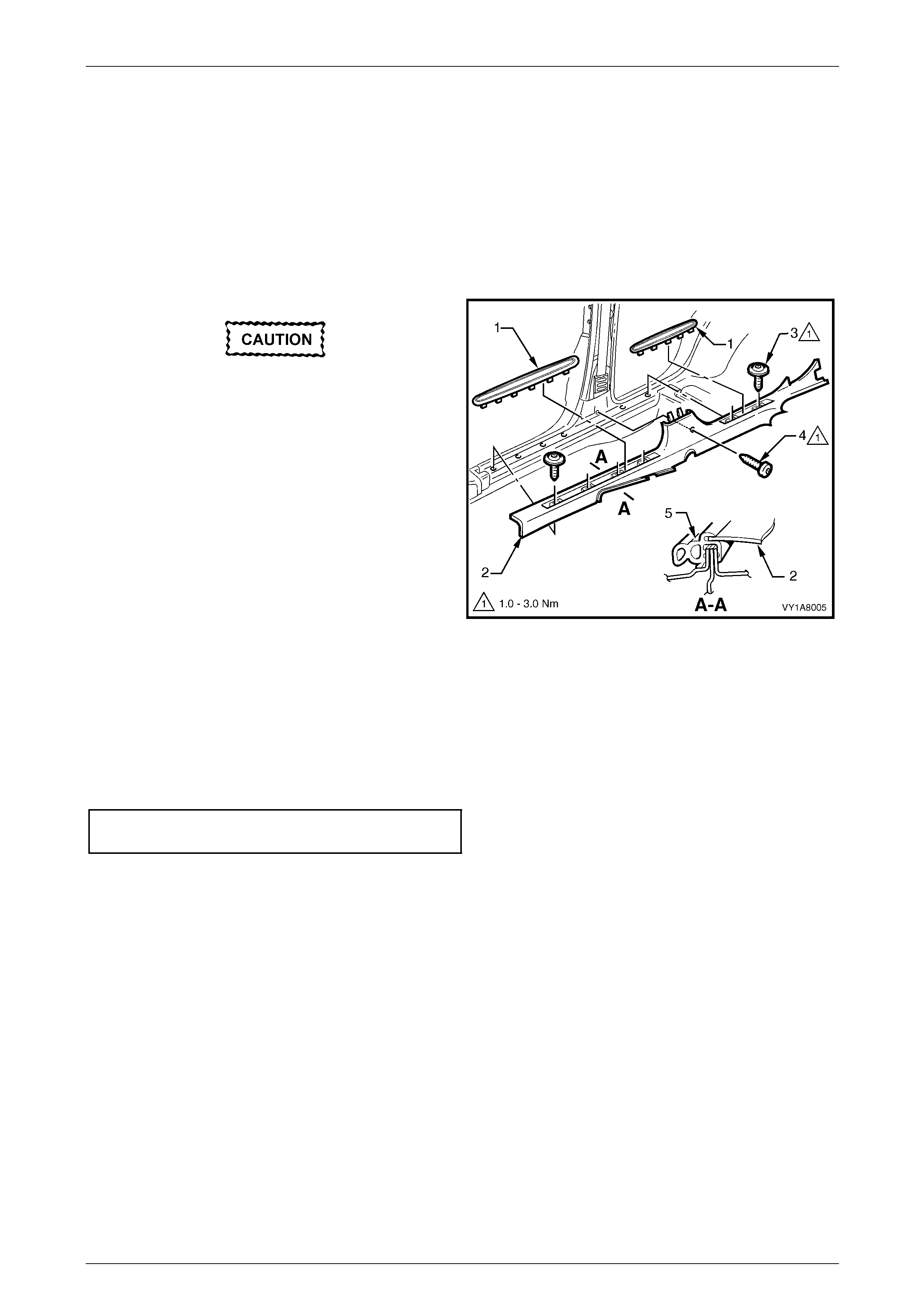
Headlining and Interior Trim Page 1A8–44
Page 1A8–44
3.5 Side Sill Trim and Plate
LT Section — 14–100
Remove
1 Remove the following components as required:
a Centre pillar lower trim , refer to 3.3 Centre Pillar Lower Trim.
b Front seat outer front cover and outer rear cover, refer to Section 1A7 Seat Assemblies.
During the following procedure take care not
to snap the sill trim plates.
2 Carefully lever the front and rear side si ll trim
plates (1) from the side sill trim (2), starting at the front
of each plate and moving rearward.
3 Remove the Torx screw (3), six places, attachin g the
side sill trim, four in the front door opening an d two in
the rear door opening.
4 Remove the Torx screw (4) attaching the side sill trim
to the centre pillar.
5 Remove the side sill trim through the front door
opening by lifting the front and sliding the rear out from
under the rear seat cushion. Figure 1A8 – 32
Reinstall
Reinstallation of the side sill trim and plate is the reverse of the removal procedure, noting the following:
1 Ensure the outer edge of the side sil l trim (2) enga ges the fr ont and rear door opening weatherstrips (5), refer to
Figure 1A8 – 32.
2 Tighten the Torx screws attaching the side sill trim to the correct torque specification.
Side sill trim attaching Torx screw
torque specification.....................................1.0 – 3.0 Nm

Headlining and Interior Trim Page 1A8–45
Page 1A8–45
3.6 Windshield Side Garnish
LT Section — 14–100
Remove
1 Remove the following components as required:
a Front assist handle assembly, refer to 3.2 Assist Handle Assembly.
b Partially remove the centre pill ar upper trim assembly by removing the upper attaching screw,
refer to 3.4 Centre Pillar Upper Trim Assembly.
When removing the windshield side garnish,
take care not to damage the locating pin (3).
2 Starting at the upper rear edge of the windshield side
garnish (1) disengage the three retai nin g clips (2).
3 Remove the windshield side garnish.
4 As required, remove the retaining clips from the
vehicle and fit to the garnish.
Figure 1A8 – 33
Reinstall
Reinstallation of the windshield side garnish is the reverse of the removal procedure, noting the following:
Take care not to snap off the locating pin
when fitting the windshield side garnish.
1 Ensure the windshield side ga rnish locating pin is aligned with the locating h ole i n the hinge pillar inner panel.
2 Ensure the outer edge of the winds hield side garnish (1) engages the front door opening weath erstrip (4 ),
refer to Figure 1A8 – 33.
3 Ensure the three retaining clips are secured to the hinge pillar inner panel.

Headlining and Interior Trim Page 1A8–46
Page 1A8–46
3.7 Body Hinge Pillar Trim Assembly
LT Section — 14–100
Remove
1 Partially remove the side sill trim, refer to 3.5 Side Sill Trim and Plate
2 Remove the two attaching screws (1) from the body
hinge pillar trim assembly (2).
3 Disengage the body hinge pillar trim clip (3) by pul ling
the lower edge of the body hinge p illar trim assembly
rearward and away from the sheetmetal.
4 Remove the body hinge pillar trim assembly.
5 If required, remove the body hinge pillar trim clip a nd
the two nut inserts (4).
Figure 1A8 – 34
Reinstall
Reinstallation of the body hinge pillar trim assembl y is the reverse of the removal procedure, noting the following:
1 Ensure the body hinge pil lar trim clip is correctly engaged in the hinge pillar inner panel.
2 Ensure the nut inserts are in good condition and correctly located in the hinge pillar inner panel.
3 Ensure the outer edge of the body hinge pillar trim assembl y engages the front door opening weatherstrip (5), refer
to Figure 1A8 – 34.
4 Tighten the body hinge pillar trim assembly two attaching s c rews to the correct torque specification.
Body hinge pillar trim assembly
attaching screw torque specification...........0.7 – 1.0 Nm

Headlining and Interior Trim Page 1A8–47
Page 1A8–47
3.8 Quarter Inner Upper Trim
LT Section — 14–130
Remove
1 Partially remove the bod y lock pillar lower trim (1) by
removing the upper attaching screw (2).
2 Remove the screw (3) attaching the quarter inner
upper trim (4).
When removing the quarter inner upper trim,
take care not to damage the locating pin (5).
3 Pull the rear edge of the quarter inner upper trim away
from the quarter inner panel assembly and working
forward, disengage the four retaining clips (6).
4 Slide the quarter inner upper trim from under the body
lock pillar lower trim and remove.
5 As required, remove the retaining clips from the
vehicle and fit to the trim. Figure 1A8 – 35
Reinstall
Reinstallation of the quarter inner upper trim is the reverse of the removal, noting the following:
Take care not to snap off the locating pin
when fitting the quarter inner upper trim.
1 Ensure the quarter inner upper trim locating pin is aligned with the locating hol e in the quarter inner panel
assembly.
2 Ensure the quarter inner upper trim four retaining clips are secured to the quarter inner pa nel assembly.
3 Tighten the screw attaching the quarter inn er upper trim to the correct torque specification.
Quarter inner upper trim attaching screw
torque specification.....................................1.0 – 3.0 Nm
4 Tighten the upper screw attaching the body lock pillar lower trim to the correct torque specification.
Body lock pillar lower trim upper
attaching screw torque specification...........1.0 – 3.0 Nm
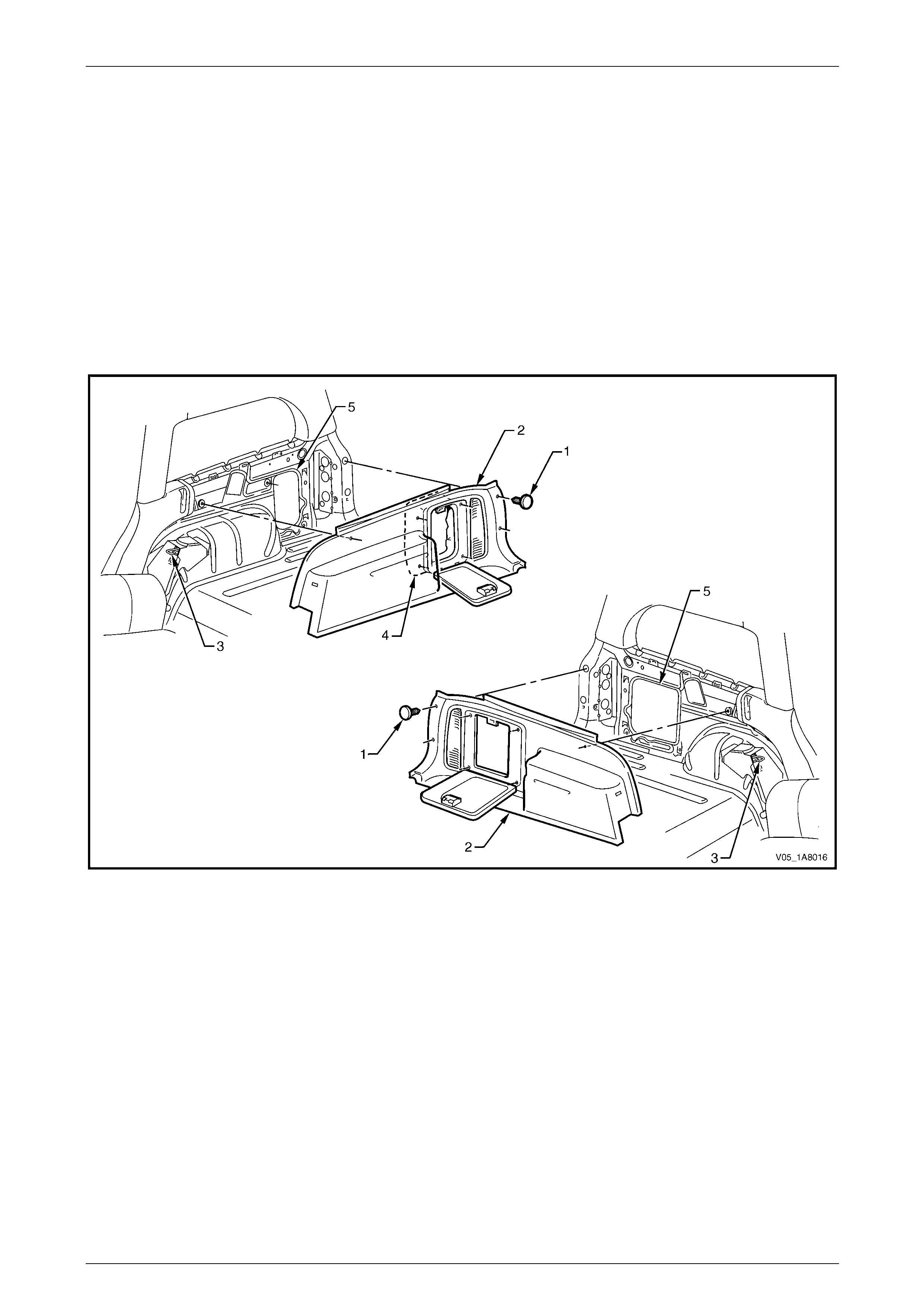
Headlining and Interior Trim Page 1A8–48
Page 1A8–48
3.9 Quarter Inner Trim Panel Assembly
LT Section — 14–490
Remove
1 Fold forward the rear seat back, refer to Section 1A7 Seat Assemblies .
2 Remove the quarter inner upper trim , refer to 3.8 Quarter Inner Upper Trim.
3 Loosen the rear end trim pane l, refer to 3.14 Rear En d Trim Panel.
4 Remove the retainer (1), seven places, securing the quarter inner trim panel assembly (2), refer to Figure 1A8 – 36
5 Lift the quarter inner trim panel assembly forward over the rear seat-back striker (3) and remove.
Figure 1A8 – 36
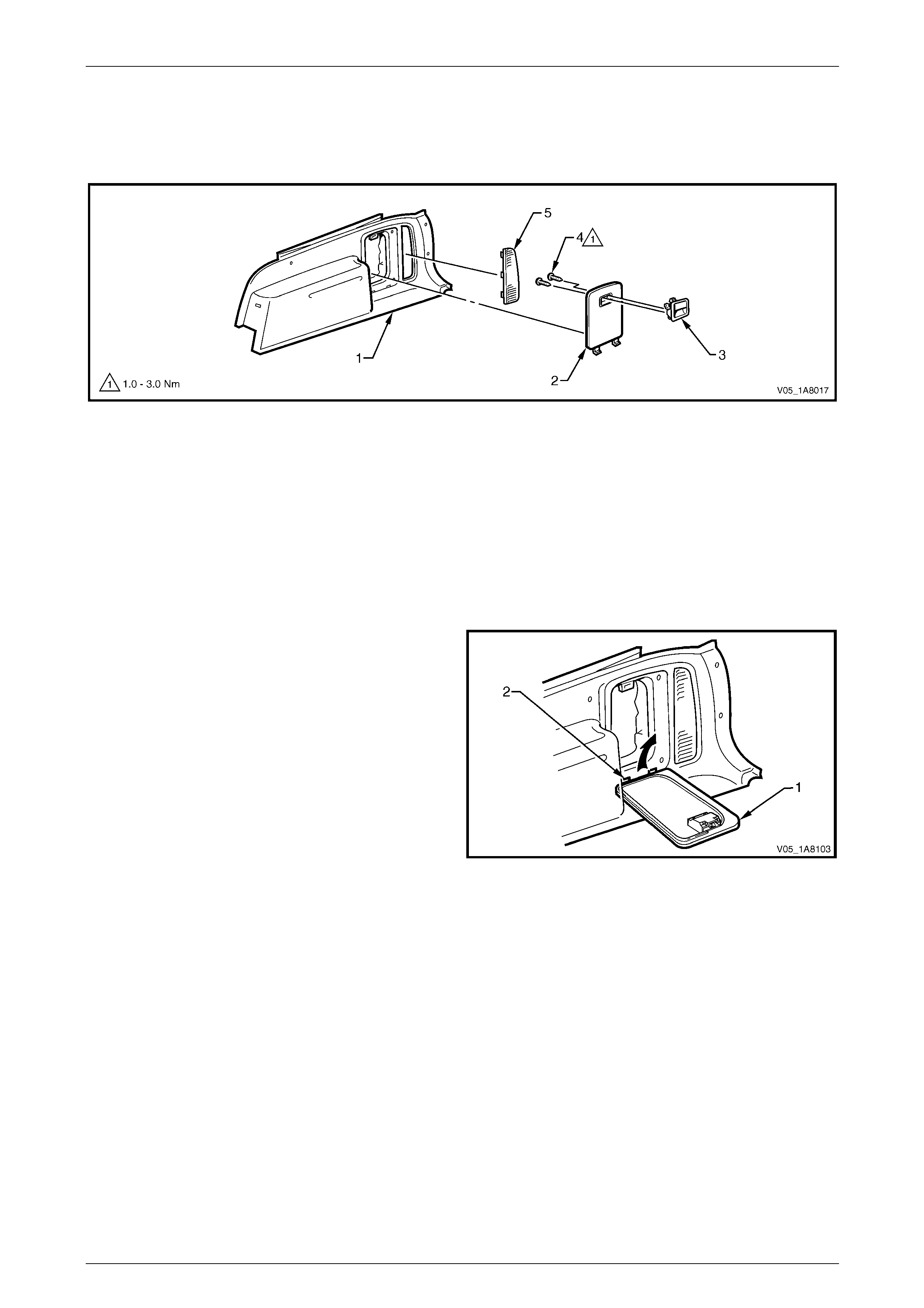
Headlining and Interior Trim Page 1A8–49
Page 1A8–49
Disassemble
To disassemble the quarter inner trim panel assembly, remove all the components attached to the qu arter inner trim
panel foundation (1) as describe d in this Section, refer to Figure 1A8 – 37.
Figure 1A8 – 37
Legend
1 Quarter Inner Trim Panel Foundation
2 Quarter Inner Trim Panel Stowage Door
3 Stowage Door Latch Assembly
4 Latch Assembly Screw
5 Quarter Inner Trim Panel Vent
Quarter Inner Trim Panel Stowage Door
Remove
1 Open the quarter inner trim panel stowage door (1) to
a position lower than horizontal.
2 Remove the stowage door vertically, dis engaging the
retaining lugs (2).
Figure 1A8 – 38
Reinstall
Reinstallation of the quarter inner trim stowage door is the reverse of the removal procedure.
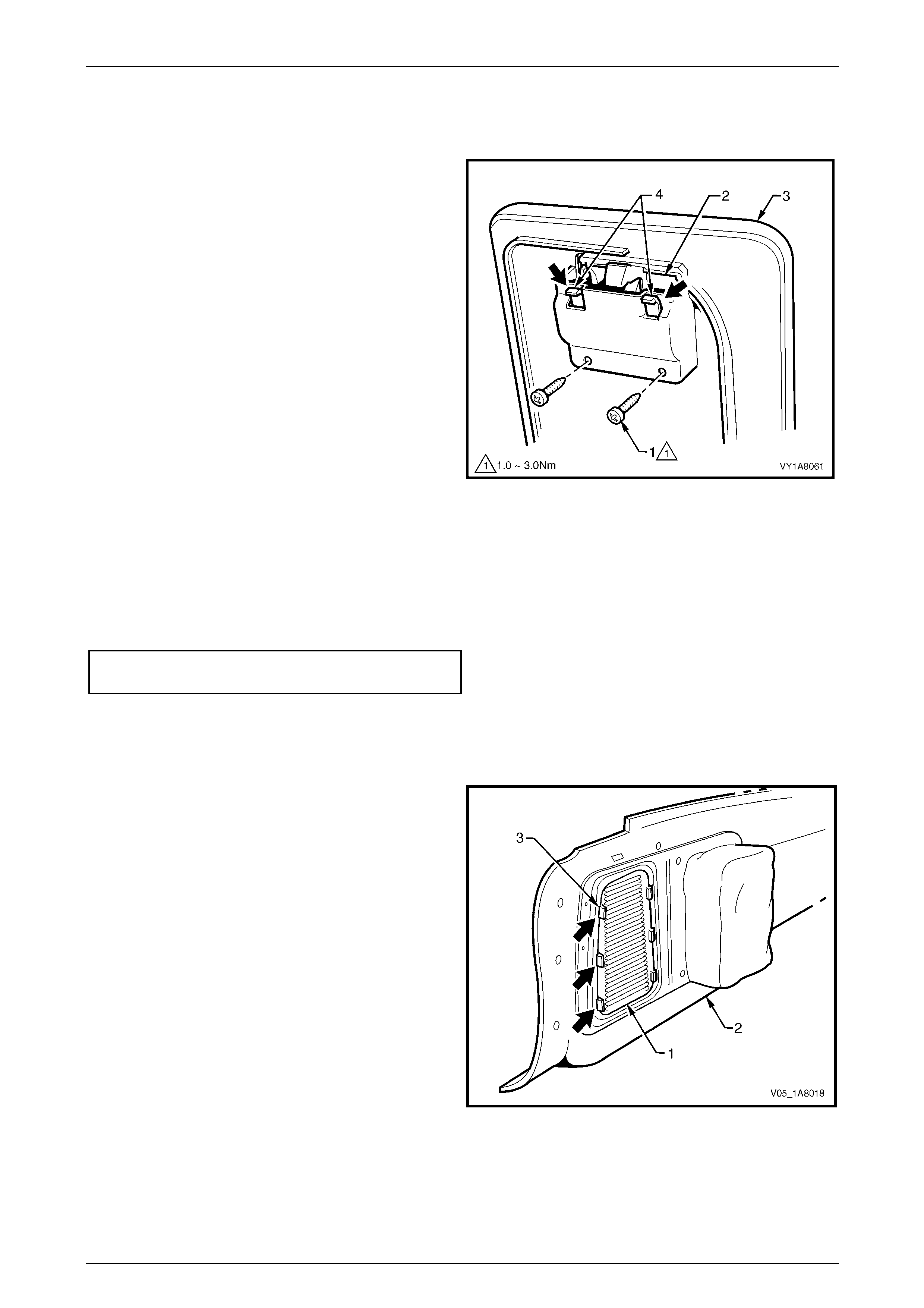
Headlining and Interior Trim Page 1A8–50
Page 1A8–50
Stowage Door Latch As sembly
Remove
1 Remove the two screws (1) attaching the latc h
assembly (2) to the quarter inner trim panel stowage
door (3).
2 Push down on the two retaining lugs (4) and eject the
handle.
Figure 1A8 – 39
Reinstall
Reinstallation of the stowage door latch assembly is the reverse of the removal procedure, noting the following:
1 Ensure the latch assembly is pressed firmly into the quarter inner trim panel stowage door.
2 Tighten the two screws attaching the stowage door latch assembly to the correct torque specification.
Stowage door latch assembly
attaching screw torque specification...........1.0 – 3.0 Nm
Quarter Inner Trim Panel Vent
Remove
1 Release the vent (1) from the quarter inner trim panel
assembly (2) by depressing the rear tabs (3).
2 Remove the vent to the rear of the quarter inner trim
panel assembly.
Figure 1A8 – 40
Reinstall
Reinstallation of the quarter inner trim panel vent is the reverse of the removal procedure, noting the following:
Ensure the vent is secured to the quarter inne r trim panel assembly.

Headlining and Interior Trim Page 1A8–51
Page 1A8–51
Reinstall
Reinstallation of the quarter inner trim panel assembly is the reverse of the removal procedur e, noting the following:
1 Feed the quarter inner trim panel stowage bag (4) into the quarter panel inner assembly opening (5), so that it does
not interfere with the final fitment of the quarter inner trim panel assembly, refer to Figure 1A8 – 36.
2 Ensure the outer edge of the quarter i nn er trim pane l assembly engages the liftgate open ing weatherstrip.
3 Ensure the seven retainers ar e secured to the quarter panel inner assembly.

Headlining and Interior Trim Page 1A8–52
Page 1A8–52
3.10 Body Lock Pillar Lower Trim
LT Section — 14–130
Remove
1 Remove the following components as required:
a Quarter inner upper trim, refer to 3.8 Quarter Inner Upper Trim.
b Quarter inner trim panel assembly, refer to 3.9 Quarter Inner Trim Panel Assembly.
c Rear seat bolster assembly, refer to Section 1A7 Seat Assemblies.
2 Remove the lower retainer (1) securing the b od y lock
pillar lower trim (2).
NOTE
The upper attaching screw (3) has been
previously removed to allo w for the quarter inner
upper trim removal.
3 Pull the lower edge of the body lock pillar lower trim,
away from the lock pillar to disengage the retaining
clip (4).
4 Remove the body lock pillar lower trim.
5 As required, remove the retaining clip from the vehicle
and fit to the trim.
Figure 1A8 – 41
6 If required, spread the luggage shade attaching spring
clip (1) open through the holes in the body lock pillar
lower trim (2) and lever out with a screwdriver to
remove the spring clip.
Figure 1A8 – 42
Reinstall
Reinstallation of the body lock pillar lo wer trim is the reverse of the removal procedure, noting the following:
1 If removed, replace the luggage shade attachi ng spring clip into the body lock pillar l ower trim.
2 Ensure the leading edge of the bod y lock pillar lower trim engages the re ar door opening weatherstrip.
3 Ensure the retaining clip and the lower retainer are secured to the quarter panel inner assembly.
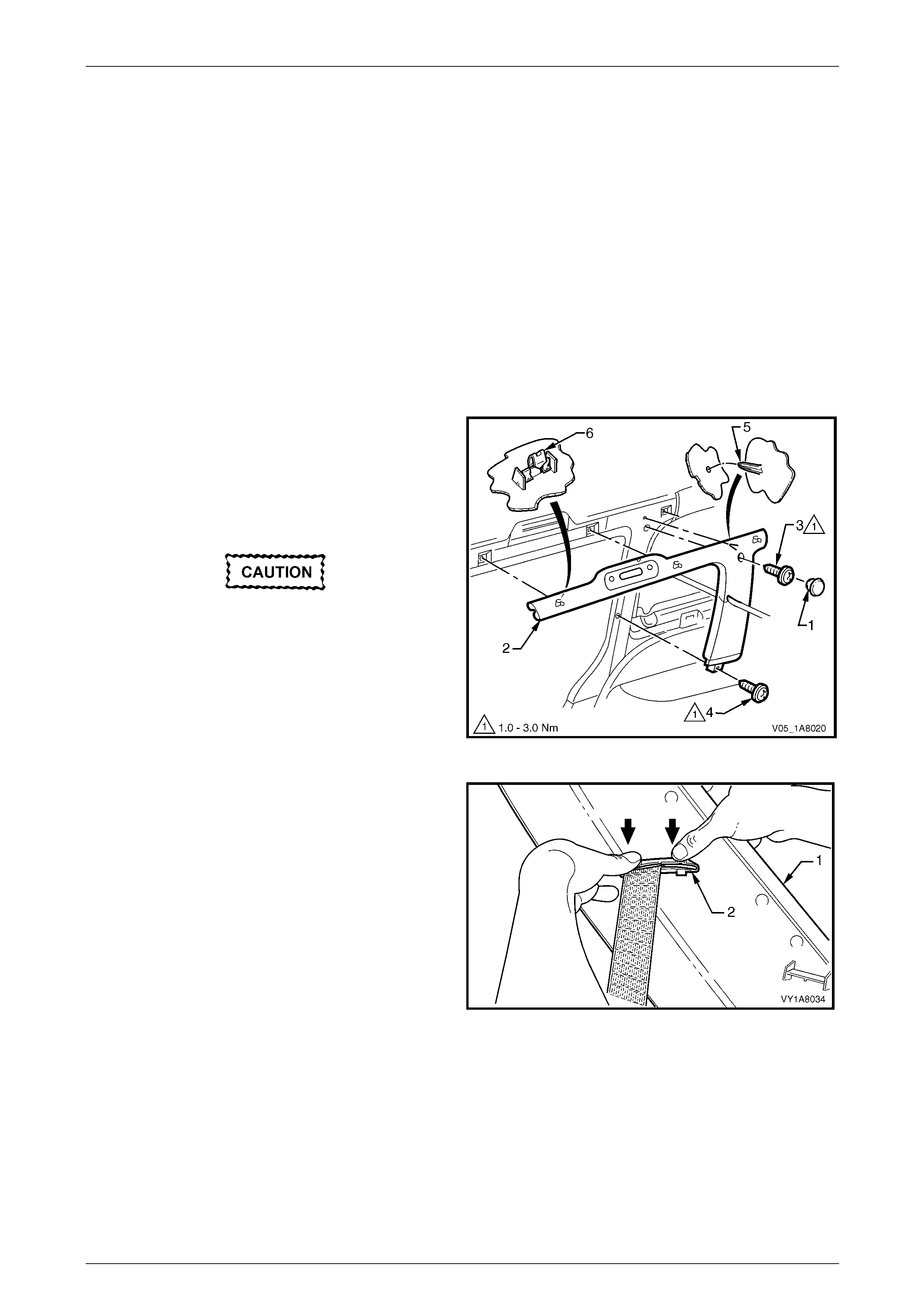
Headlining and Interior Trim Page 1A8–53
Page 1A8–53
3.11 Body Lock Pillar Garnish Assembly
LT Section — 14–130
Remove
1 Remove the following components as required:
a Rear assist handle assembl y, refer to 3.2 Assist Handle Assembly.
b Roof rail courtesy and reading lamps, refer to Section 12B Lighting System.
c Partially remove the centre pillar upper trim assembly by removing the upper attaching screw, refer to
3.4 Centre Pillar Upper Trim Assembly.
d Partially remove the body lock pillar lower trim by removing the upper attaching screw, refer to
3.10 Body Lock Pillar Lower Tr im.
e Rear seat belt lower bolt, refer to Section 12M Occupant Protection System.
2 Remove the screw cap (1) from the body lock pillar
garnish (2).
3 Remove the upper screw (3) attaching the body lock
pillar garnish.
4 Remove the lower screw (4) from the body lock pillar
garnish.
When removing the body lock pillar garnish,
take care not to damage the locating pin (5).
5 Lever the front edge of the body lock pillar garnish
away from the centre pillar and working rearward to
disengage the three retaini ng clips (6).
Figure 1A8 – 43
6 With the body lock pillar garnish (1) partially removed,
disengage the seat belt escutcheo n (2) from the body
lock pillar garnish and feed the seat belt and anchor
plate through the opening.
7 Remove the body lock pillar garnish.
8 As required, remove the retaining clips from the
vehicle and fit to the garnish.
Figure 1A8 – 44

Headlining and Interior Trim Page 1A8–54
Page 1A8–54
Reinstall
Reinstallation of the body lock pillar garnish assembly is the reverse of the removal procedure, noting the follo wing:
Take care not to snap off the locating pin
when fitting the body lock pillar garnish.
1 Ensure the body lock pillar garnish locating pin is aligned with the locating hole in the quarter panel inner assembly.
2 Ensure the leading edge of the bod y lock pillar garnish eng ages the rear door opening weatherstrip.
3 Ensure the three retaining clips are secur ed to the quarter panel inner assembl y.
4 Tighten the upper and lower screws attaching the body lock pillar garnish to the correct torque specification.
Body lock pillar garnish
attaching screw torque specification...........1.0 – 3.0 Nm
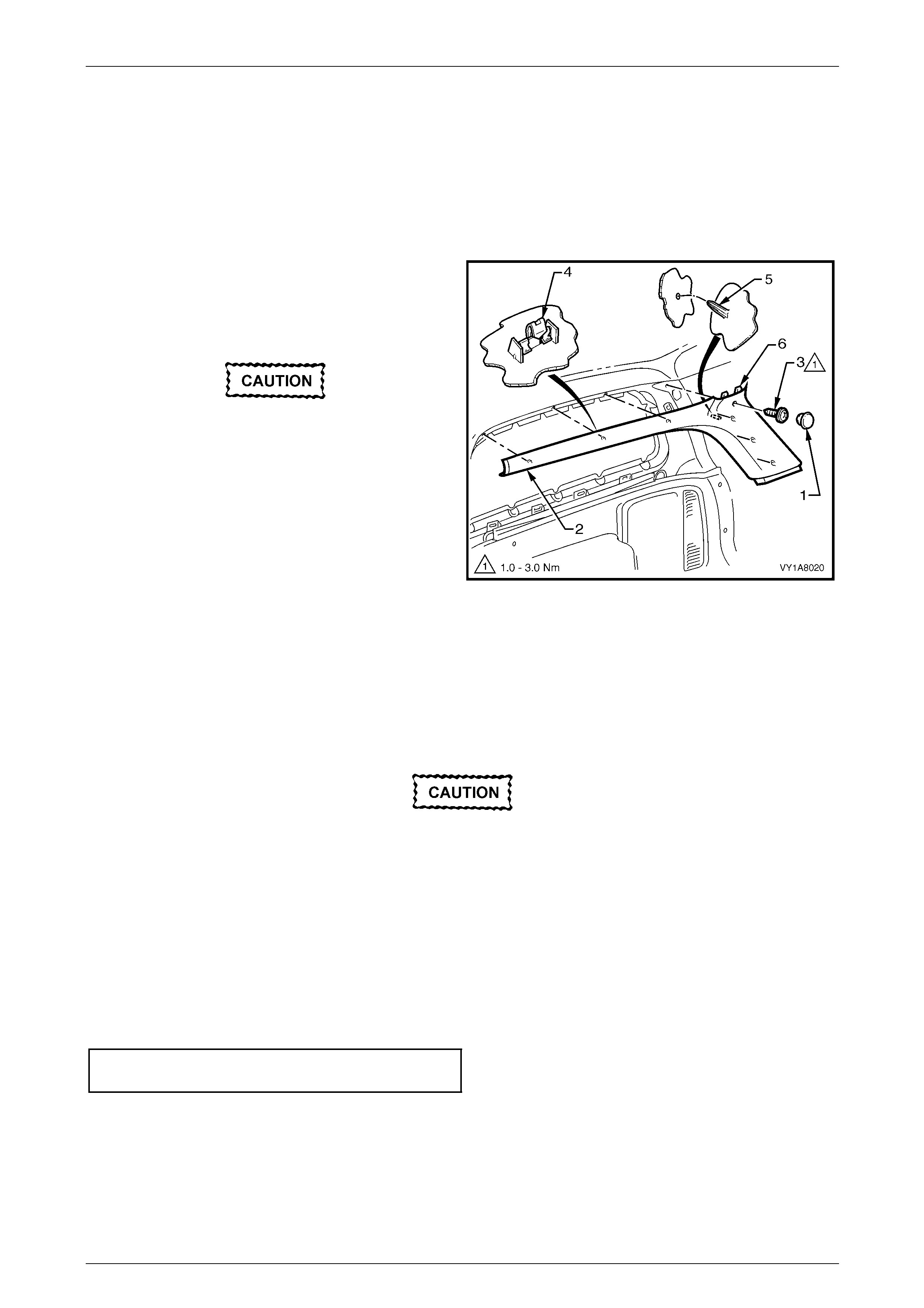
Headlining and Interior Trim Page 1A8–55
Page 1A8–55
3.12 Body Rear Corner Garnish Assembly
LT Section — 14–130
Remove
1 Remove the quarter inner upper trim , refer to 3.8 Quarter Inner Upper Trim.
2 Remove the screw cap (1) from the body rear corner
garnish (2).
3 Remove the screw (3) attaching the body rear corner
garnish.
When removing the body rear corner garnish,
take care not to damage the locating pin (5)
or the locating lugs (6) fitting under the rear
window upper garnish.
4 Starting at the lower rear edge, lever the rear corner
garnish to disengage the si x retaining clips (4).
5 Slide out the rear corner garnish to disenga ge the
locating lugs (6) from under the rear window upper
garnish.
6 Slide the rear corner garnish rearward to disengage it
from the body lock pillar garnish and remove.
7 As required, remove the retaining clips from the
vehicle and fit to the garnish.
Figure 1A8 – 45
Reinstall
Reinstallation of the body rear corner garnish assembly is the reverse of the removal procedure, noting the following:
Take care not to snap off the locating pin or
the locating lugs when fitting the body rear
corner garnish.
1 Ensure the body rear corner garnish locating pin is aligned wit h the locating hole in the quarter panel inner
assembly.
2 Ensure the body rear corner garnish locating lugs are fitted und er the rear window upper garnish.
3 Ensure the outer edge of the body rear corner garnish engages the liftgate ope ning weatherstrip.
4 Ensure the six retaining clips are secured to the quarter panel inner assembly.
5 Tighten the screw attaching the body re ar corner garnish to t he correct torque specification.
Body rear corner garnish
attaching screw torque specification...........1.0 – 3.0 Nm

Headlining and Interior Trim Page 1A8–56
Page 1A8–56
3.13 Rear Window Upper Garnish
LT Section — 14–130
Remove
1 Remove the following components as required:
a Quarter inner upper trim, on one side of the vehicle, refer to 3.8 Quarter Inner Upper Trim.
b Body rear corner garnish assembly, on the same side of the vehicle,
refer to 3.12 Body Rear Corner Garnish Assembly.
When removing the rear window upper
garnish, take care no t to damage the locating
pin (3).
2 Starting from the end that has the body re ar corner
garnish assembly removed, lever the rear window
upper garnish (1) away from the headlining to
disengage the three retaining clips (2) from the roof
rear panel.
3 Slide out the rear window upper garnish from the
remaining body rear corner g arnish assembly and
remove.
4 As required, remove the retaining clips from the
vehicle and fit to the garnish.
Figure 1A8 – 46
Reinstall
Reinstallation of the rear window upper garnish is the reverse of the removal proc edure, noting the following:
Take care not to snap off the locating pin
when fitting the rear window upper garnish.
1 Ensure the rear window upper garnish locating pin is aligned with the locating hole in the roof rear panel.
2 Ensure the outer edge of the rear window upper garnish engages the liftgate opening weatherstrip.
3 Ensure that there is a neat fit between the outer edge of the body rear corner garnish assembly and the rear
window upper garnish.
4 Ensure the three retaining clips are secur ed to the roof rear panel.

Headlining and Interior Trim Page 1A8–57
Page 1A8–57
3.14 Rear End Trim Panel
LT Section — 14–130
Remove
1 Gain access to the rear end trim panel (1) by opening
the rear compartment floor panel carpet assembly (2)
and using the hook (3) to retain it in the open position.
Figure 1A8 – 47
2 Remove the attaching screw (1), four places, along the
ribbed upper surface of the rear end trim panel (2).
When removing the rear end trim panel, take
care not to damage the locating pin (3).
3 Remove the rear end trim panel.
4 If required remove the rear end trim panel se al (4).
Figure 1A8 – 48
Reinstall
Reinstallation of the rear end trim panel is the reverse of the removal procedure, noting the following:
1 Ensure the rear end trim panel seal (4) is cor rectly fitted, refer to Figure 1A8 – 48.
Take care not to snap off the locating pin
when fitting the rear end trim panel.
2 Ensure the rear end trim panel locating pin is aligned with the locating hole in the rear end panel assembly.
3 Ensure the outer edge of rear end trim panel (2) engages the liftgate openi ng weatherstrip (5).
4 Tighten the four screws attaching the rear en d trim panel to the correct torque specifications.
Rear end trim panel attaching screw
torque specification.....................................1.0 – 3.0 Nm

Headlining and Interior Trim Page 1A8–58
Page 1A8–58
3.15 Sunshade Assembly
LT Section — 14–050
Remove
1 If illuminated vanity mirrors are fitted, remove the fuse F6 from the passenger compartme nt fuse and re lay panel
assembly, refer to Section 12O Fuses, Relays and Wiring Harnesses.
2 Disconnect the sunshade assembly (1) from the
sunshade support (2) and rotate to gain acce ss.
3 Remove the sunshade assembly two attaching Torx
screws (3).
4 Pull the sunshade away from the hea dlining assembly
and if fitted, disconnect the harness connecto r (4) from
the illuminated vanit y mirrors ( 5).
5 Remove the sunshade.
When removing the sunshade support, take
care not to damage the locating pin (7).
6 Remove the Torx screw (6) from the sunshade support
and pull the support from the headlining assembly.
Figure 1A8 – 49
Reinstall
Reinstallation of the sunshad e assemb ly is the reverse of the removal procedure, noting the following:
Take care not to damage the locating pin
when fitting the sunshade support.
1 Ensure the sunshade support locati ng pin is aligned with the locating h ole in the roof panel.
2 Tighten the Torx screw attaching the sunshade support to the correct torque specification.
Sunshade support attaching Torx screw
torque specification.....................................0.5 – 2.0 Nm
3 If illuminated vanity mirrors are fitted, connect the harness connector to the sunshade ass embl y.
4 Tighten the sunshade ass embly two attaching Torx scre ws to the correct torque specific ation.
Sunshade assembly attaching screw
torque specification.....................................0.5 – 2.0 Nm
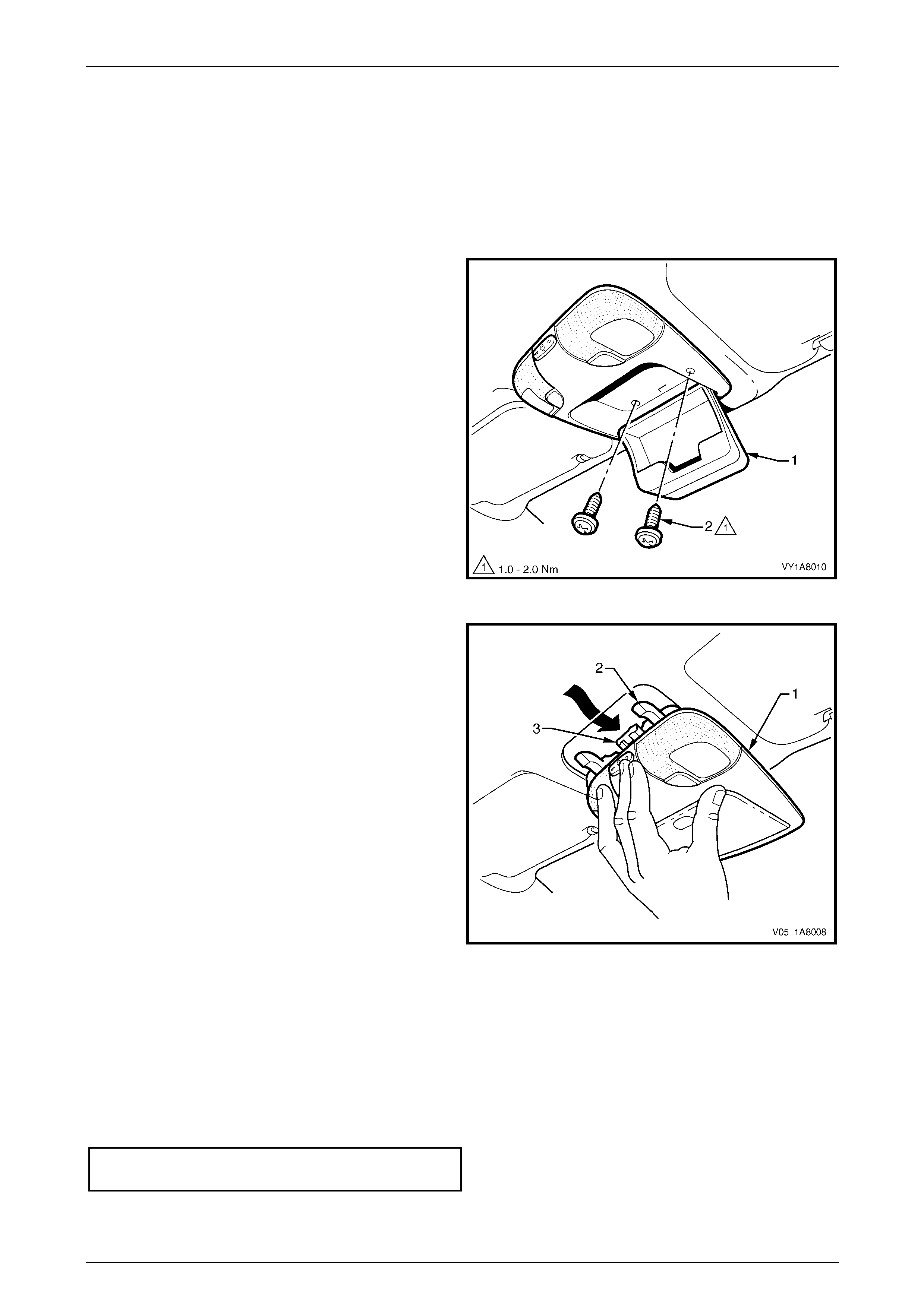
Headlining and Interior Trim Page 1A8–59
Page 1A8–59
3.16 Roof Console
LT Section — 02–780
Remove
1 Remove the fuse F6 from the passenger compartment fuse and relay panel ass embl y,
refer to Section 12O Fuses, Relays and Wiring Harnesses.
2 Open the compartment door (1) of the roof console.
3 Remove the two attaching screws (2) from inside the
roof console.
4 Close the compartment door.
5 Using your hand, pull down to disengage the front of
the roof console from the roof header pane l.
Figure 1A8 – 50
6 Slide the roof console (1) in a forward motion to allow
the two locator arms (2) to clear the headlini ng.
7 Disconnect the harness from the roof console
connector (3) and remove.
NOTE
For replacement of the map lamp bulbs, refer to
Section 12B Lighting System.
Figure 1A8 – 51
Reinstall
Reinstallation of the roof console is the reverse of the removal procedure, noting the following:
1 Ensure the harness is securely connecte d to the roof console connector.
2 Ensure the two locator arms are correctly inserted and the roof console is secure d to the roof panel.
3 Tighten the roof console two attaching screws to the correct torque specification.
Roof console attaching screw
torque specification.....................................1.0 – 2.0 Nm

Headlining and Interior Trim Page 1A8–60
Page 1A8–60
3.17 Headlining Assembly
LT Section — 14–150
Remove
NOTE
If the vehicle is fitted with a Holden By Design
(HBD) sunroof, a new headlining had to be
created and installed with adhesive. Extreme
care is required as the removal may damage the
headlining, then requiring a new one to be
created by a motor trimmer. The procedure for
this headlining is not covered in this Section..
1 Remove the fuse F6 from the passenger compartment fuse and relay panel ass embl y,
refer to Section 12O Fuses, Relays and Wiring Harnesses.
2 Place protective covering ov er both front seats and the interior trim.
3 Remove the following components as required:
a Windshield side garnish on b oth sides, refer to 3.6 Windshield Side Garnish.
b Body lock pillar garnish assembly on both sides, refer to 3.11 Body Lock Pillar Garnish Assembly.
c Body rear corner garnish assembly on both sides, refer to 3.12 Body Rear Corner Garnish Assembly.
d Rear window upper garnish, refer to 3.13 Rear Window Upper Garnish.
e Sunshade assembly on both sides, refer to 3.15 Sunshade Assembl y.
f Roof console, refer to 3.16 Roof Console.
g Rear compartment courtesy lamp from the h eadlining assembly, refer to Section 12B Lighting S ystem.
4 Disconnect the headlining assembly wiring harness (1) from the bod y wiring harness connector (2), located above
and slightly forward of the right-hand centre pillar, refer to Figure 1A8 – 52.
NOTE
It may be necessary to flex the headlining
assembly (4) down slightly to gain access to the
harness connector.
5 Using a suitable trim clip removal too l, carefully prise out the three retainers (3) attaching the headlining
assembly (4) to the roof bow panels.
6 With the aid of an assistant, flex the headlining assembly to disengage the corners from the ‘D’ tabs (5), in four
places on the sides of the roof panel.
7 With the liftgate open, ease the head lining assembly from its position on th e roof panel and remove it from inside
the vehicle through the liftgate opening.
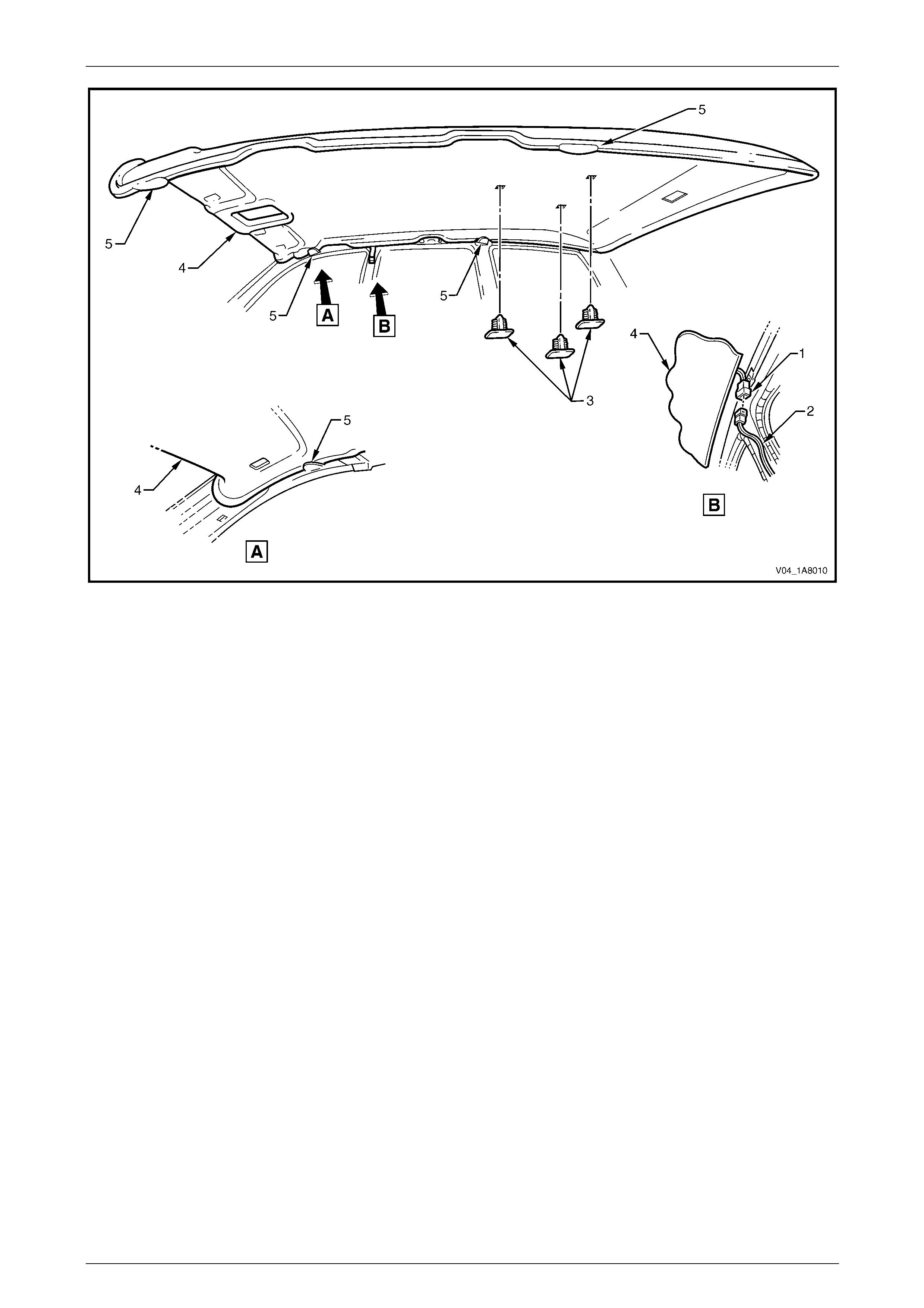
Headlining and Interior Trim Page 1A8–61
Page 1A8–61
Figure 1A8 – 52
Reinstall
Reinstallation of the headlining assembly is the reverse of the removal procedure, noting the follo wing:
1 Temporaraly support the headlining assem bly on the ‘D’ tabs (5) before the trim components are insta lled, refer to
Figure 1A8 – 52.
2 Ensure the headlining assembly harness connector is securely connected to the body wiring harness connector.
3 Ensure the headlining assembly three retainers are secured to the roof bow panels.

Headlining and Interior Trim Page 1A8–62
Page 1A8–62
3.18 Driver Footrest
LT Section — 14–475
Remove
1 Prise the two screw covers (1) and remove from the
driver footrest.
2 Remove the two screws (2) attaching the driver
footrest (3) to the footrest mounting bracket (4).
3 Remove the footrest pad.
Figure 1A8 – 53
Reinstall
Reinstallation of the driver footrest is the reverse of the removal procedure, noting the following:
Tighten the two screws attaching the driver footrest to the correct torque specification.
Driver footrest attaching screw
torque specification.....................................2.0 – 5.0 Nm
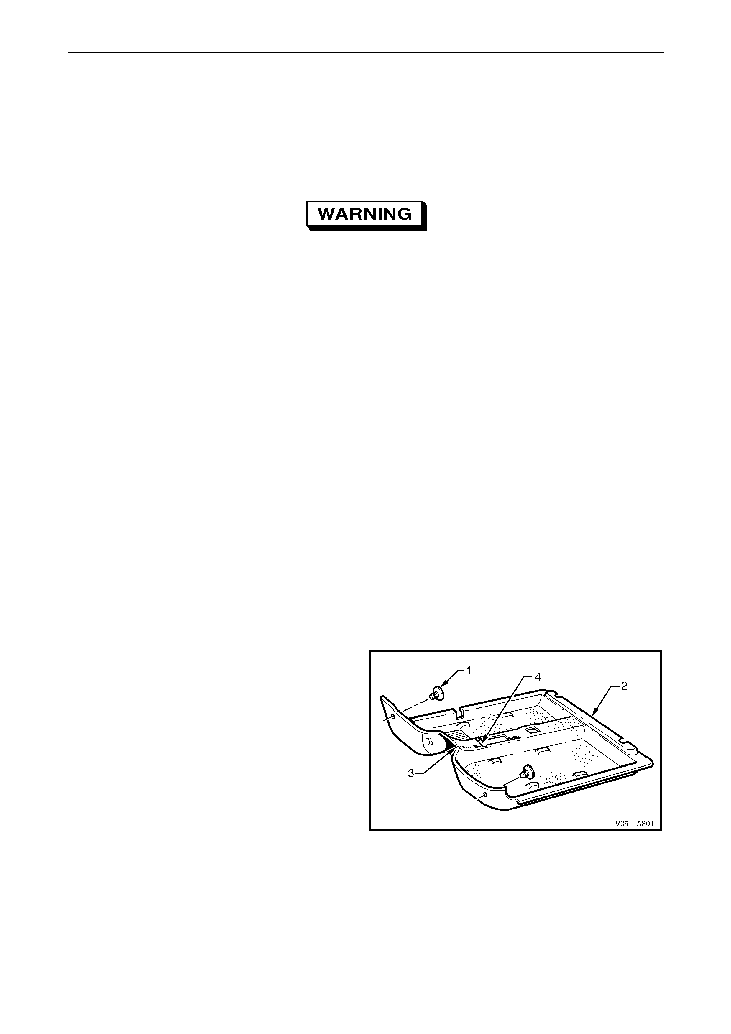
Headlining and Interior Trim Page 1A8–63
Page 1A8–63
3.19 Front Floor Carpet Assembly
LT Section — 14–475
Remove
On vehicles equipped with side impact
airbags, disable the occupant protection
system before performing the following
operation. Refer to Section 12M Occupant
Protection System.
1 Remove the following components as required:
a Rear seat cushion, refer to Section 1A7 Seat Assemblies.
b Side sill trims on both sides, refer to 3.5 Side Sill Trim and Plate.
c Front seat belt lower attaching bolts, refer to Section 12M Occupant Protection System.
d Body hinge pillar trim assembly on both sides, refer to 3.7 Body Hinge Pillar Trim Assembly.
e Both front seat assemblies, refer to Section 1A7 Seat Assemblies.
f Driver footrest, refer to 3.18 Driver Footrest.
g Remove the park brake lever cover by grasping the cover firmly by hand and sliding the co ver over the park
brake lever, refer to Section 5A Service and Park Braking System.
h Instrument panel lower trim plate assembly, right-hand and left-hand,
refer to Section 1A3 Instrument Panel and Consol e.
i Instrument panel compartment, refer to Section 1A3 Instrument Panel and Console.
j Instrument panel lower trim panel, refer to Section 1A3 Instrument Panel and Consol e.
k Floor console assembly, refer to Section 1A3 Instrument Panel an d Console.
2 Disconnect the inflatable restraint control module (SDM) wiring harness,
refer to Section 12M Occupant Protection System.
3 Remove the two retaining clips (1) from the front floor
carpet assembly (2) by rotating the clips counter-
clockwise and lifting clear of the attaching studs.
NOTE
To facilitate the removal and installation
procedure, the front floor carpet assembly is
perforated from the front edge (3), through the
centre of the evaporator drain cut-out, to the
forward edge of the lower radio bracket cut-
out (4).
Figure 1A8 – 54
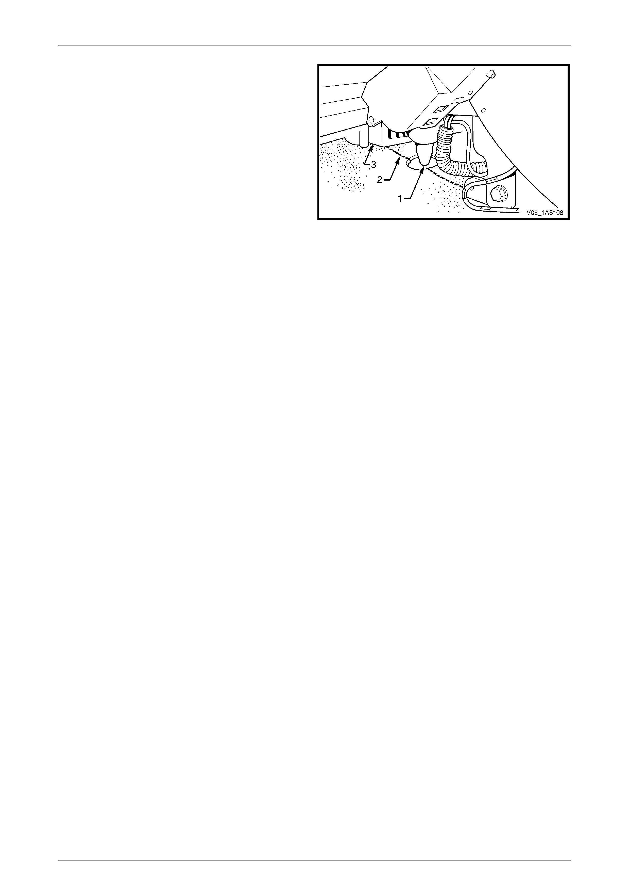
Headlining and Interior Trim Page 1A8–64
Page 1A8–64
4 From inside the left-hand footwell, grasp the edge of
the hole in the front floor carpet assembly around the
evaporator drain hose (1) and tear open the perforated
line (2) by pulling the carpet awa y from the
transmission tunnel.
5 Slide the remaining flap of carpet out from under the
heating, ventilation and air-conditioning (HVAC)
unit (3) and into the right-hand footwell.
6 Carefully manoeuvre the front floor carp et and
insulator assembly out of the vehicle.
Figure 1A8 – 55
Reinstall
Reinstallation of the front floor carpet assembly is the reverse of the removal procedure, noting the following:
1 If a new front floor carpet assembly is being fitted, prior to installation, cut along the perforated line that runs from
the carpet forward edge (3) to the forward edge of the lower radio bracket cut-out (4), refer to F igure 1A8 – 54.
2 Ensure all the cut-outs in the front floor carpet assembl y are correctly alig ned, then install the two retaining clips
and the front seat belt lower attaching bolts, refer to Section 12M Occupant Protection System , to secure the front
floor carpet assembly prior to installing the seats and c onsole.

Headlining and Interior Trim Page 1A8–65
Page 1A8–65
3.20 Rear Floor Filler Panel
LT Section — 14–490
Remove
1 Remove the following components as required:
a Side sill trim, refer to 3.5 Side Sill Trim and Plate.
b Rear seat cushion, refer to Section 1A7 Seat Assemblies.
c Partially peel back the rear section of the front floor carpet, refer to 3.19 Front Floor Carpet Assembly.
2 Using a 4.5 mm drill-bit, carefully drill out the pop-
rivets (1) attaching the rear floor filler panel (2) to the
front and rear floor panel assemblies.
3 Remove the rear floor filler panel from the vehicle.
Figure 1A8 – 56
Reinstall
Reinstallation of the rear floor filler panel is the reverse of the removal procedure, noting the following:
Use new 4.8 mm dome-head pop-rivets to attach the rear floor filler panel.
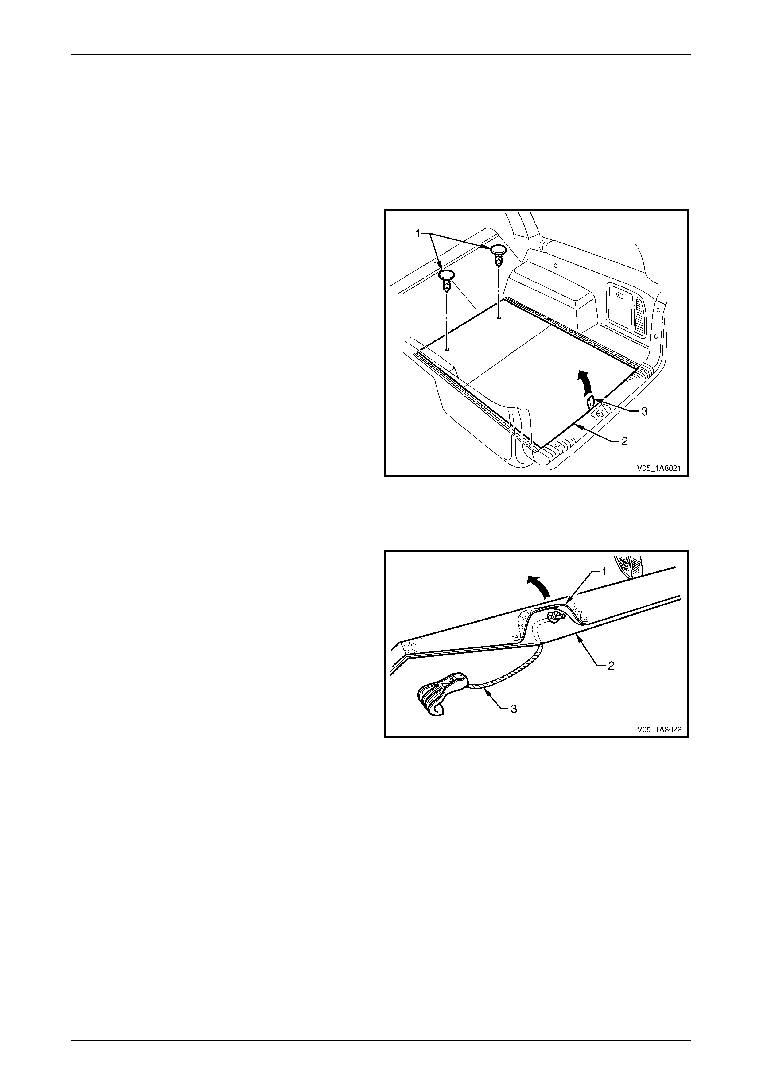
Headlining and Interior Trim Page 1A8–66
Page 1A8–66
3.21 Rear Compartment Floor Panel Carpet
Assembly
LT Section — 14–490
Remove
1 Fold forward the rear seat back.
2 Remove the two retainers (1) from the front of the rear
compartment floor panel carpet assembly (2).
3 Grasp the rear compartment floor panel carpet
handle (3) and lift the rear edg e upward.
4 Lift the rear compartment floor panel carpet assembly
and remove through the liftgate opening.
Figure 1A8 – 57
Disassemble
1 With the aid of a heat gun, prise the carpet (1) from
the rear compartment floor carpet baseboard (2) to
expose the knot of the hook and cord ass embly (3).
2 Undo or cut the knot and remove the hook and cord
assembly from the rear compartment floor carpet
baseboard.
Figure 1A8 – 58
Reassemble
1 Feed the cord assembly through the hole in the baseboard and tie a knot to retain.
2 Apply contact adhesive to the exposed area on the baseboard and press the carpet down firmly on the baseboard.
Reinstall
Reinstallation of the rear com partment floor panel carpet assembly is the reverse of the removal procedure, noting the
following:
Ensure the rear compartment floor panel carpet assembly two retainers are secured to the rear floor panel assembl y.
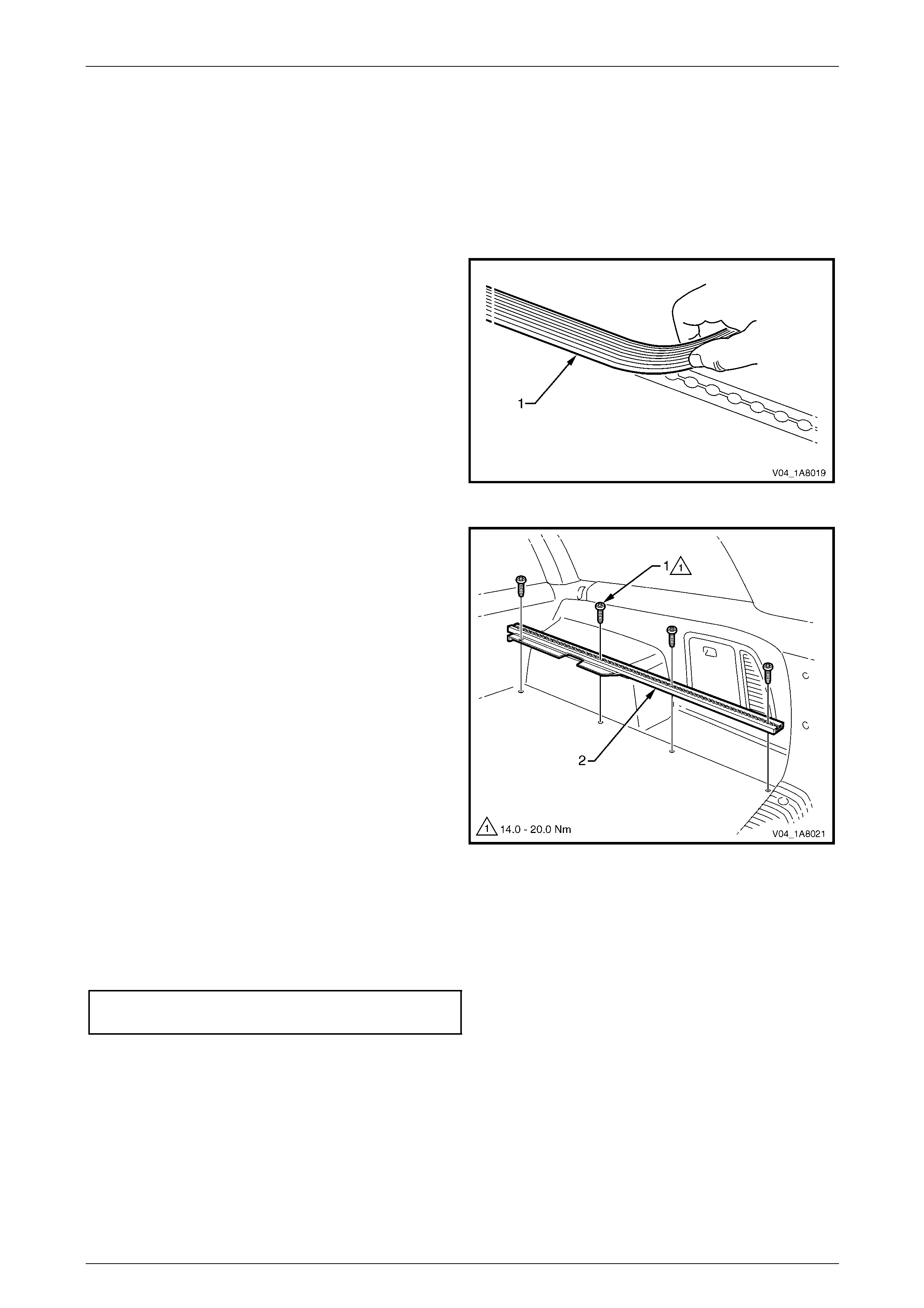
Headlining and Interior Trim Page 1A8–67
Page 1A8–67
3.22 Luggage Tie Down Rails
LT Section — 14–490
Remove
1 Remove the rear compartment floor pane l carpet assembly,
refer to 3.21 Rear Compartment Floor Panel Carpet Assembly.
2 If fitted, remove the luggage tie down rail cover (1).
Figure 1A8 – 59
3 Remove the four Torx screws (1) attaching the
luggage tie down rail (2) to the vehicle.
4 Remove the luggage tie down rail through the liftgate
opening.
5 If required, repeat the procedure for the tie down rail
on the opposite side of the vehicle.
Figure 1A8 – 60
Reinstall
Reinstallation of the luggage tie down rails is the reverse of the removal proced ure, noting the following:
Tighten the four Torx screws attaching each luggage tie do wn rail to the correct torque specification.
Luggage tie down rail attaching
Torx screw torque specification...............14.0 – 20.0 Nm
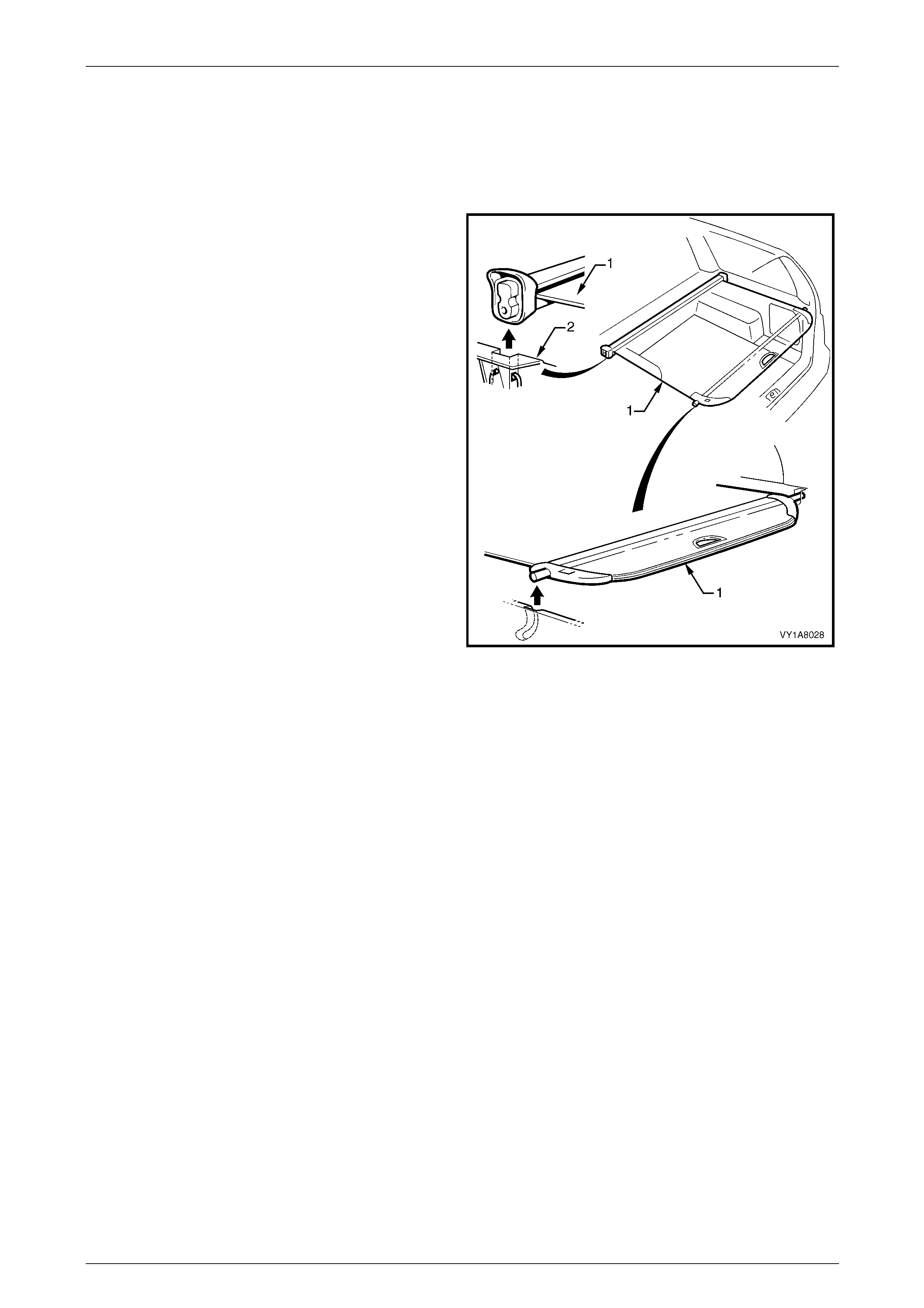
Headlining and Interior Trim Page 1A8–68
Page 1A8–68
3.23 Luggage Shade Assembly
LT Section — AA–000
Remove
1 Retract the luggage shade assembl y (1).
2 Unclip the luggage shade assembly from the body lock
pillar lower trim (2), by lifting vertically.
3 Remove the luggage shade assembly through the
liftgate opening.
Figure 1A8 – 61
Reinstall
Reinstallation of the luggage shade assembly is the reverse of the removal procedure.
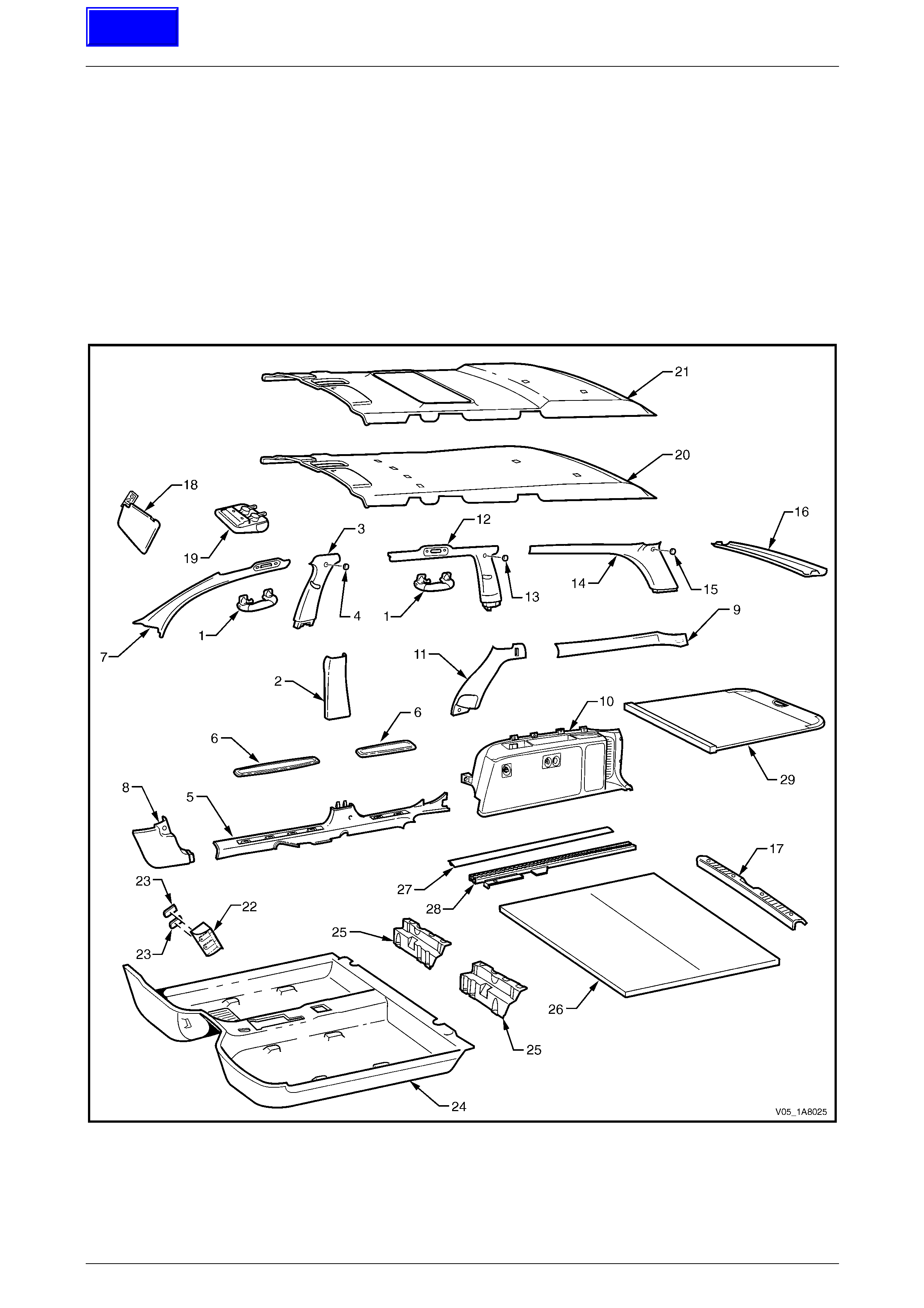
Headlining and Interior Trim Page 1A8–69
Page 1A8–69
4 Service Operations –
AWD Wagon
4.1 Components Chart
The headlining and interior trim components for AWD Wagon vehicles are displayed in the following chart to assist with
their identification, refer to Figure 1A8 – 62.
For the service procedures of the liftgate trim, refer to Section 1A4 Hood, Rear Compartment Lid, Liftgate and Endgate.
For the service procedures of the front and re ar door trim panel assemblies,
refer to Section 1A5 Front and Rear Door Assemblies.
Figure 1A8 – 62
Techline

Headlining and Interior Trim Page 1A8–70
Page 1A8–70
Legend
1 Assist Handle Assembly
2 Centre Pillar Lower Trim
3 Centre Pillar Upper Trim Assembly
4 Screw Cap
5 Side Sill Trim
6 Side Sill Trim Plate
7 Windshield Side Garnish
8 Body Hinge Pillar Trim Assembly
9 Quarter Inner Upper Trim
10 Quarter Inner Trim Panel Assembly
11 Body Lock Pillar Lower Trim
12 Body Lock Pillar Garnish Assembly
13 Screw Cap
14 Body Rear Corner Garnish Assembly
15 Screw Cap
16 Rear Window Upper Garnish
17 Rear End Trim Panel Assembly
18 Sunshade Assembly
19 Roof Console
20 Headlining Assembly (without sunroof)
21 Headlining Assembly (with sunroof)
22 Driver Footrest
23 Screw Cap
24 Front Floor Carpet Assembly
25 Rear Floor Filler Panel
26 Rear Compartment Floor Panel Carpet Assembly
27 Luggage Tie Down Rail Cover
28 Luggage Tie Down Rail
29 Luggage Shade Assembly

Headlining and Interior Trim Page 1A8–71
Page 1A8–71
4.2 Assist Handle Assembly
LT Section — 14–100
Remove
NOTE
This procedure is app licable to the front and rear
assist handle assemblies.
1 Pull the assist handle (1) into the down position.
2 Prise open the assist handle two screw covers (2) and
remove the two attaching screws (3).
When removing the assist handle assembly,
take care not to damage the locating pin s (4).
3 Remove the assist handle assembly.
Figure 1A8 – 63
Reinstall
Take care not to damage the locating pin
when fitting the assist handle assembly.
1 Ensure the locating pins are correctl y align ed with the locating holes.
2 Position the hook over the locating pin.
3 Tighten the assist handle two attaching screws to the correct torque specification.
Assist handle attaching screw
torque specification.....................................1.0 – 3.0 Nm
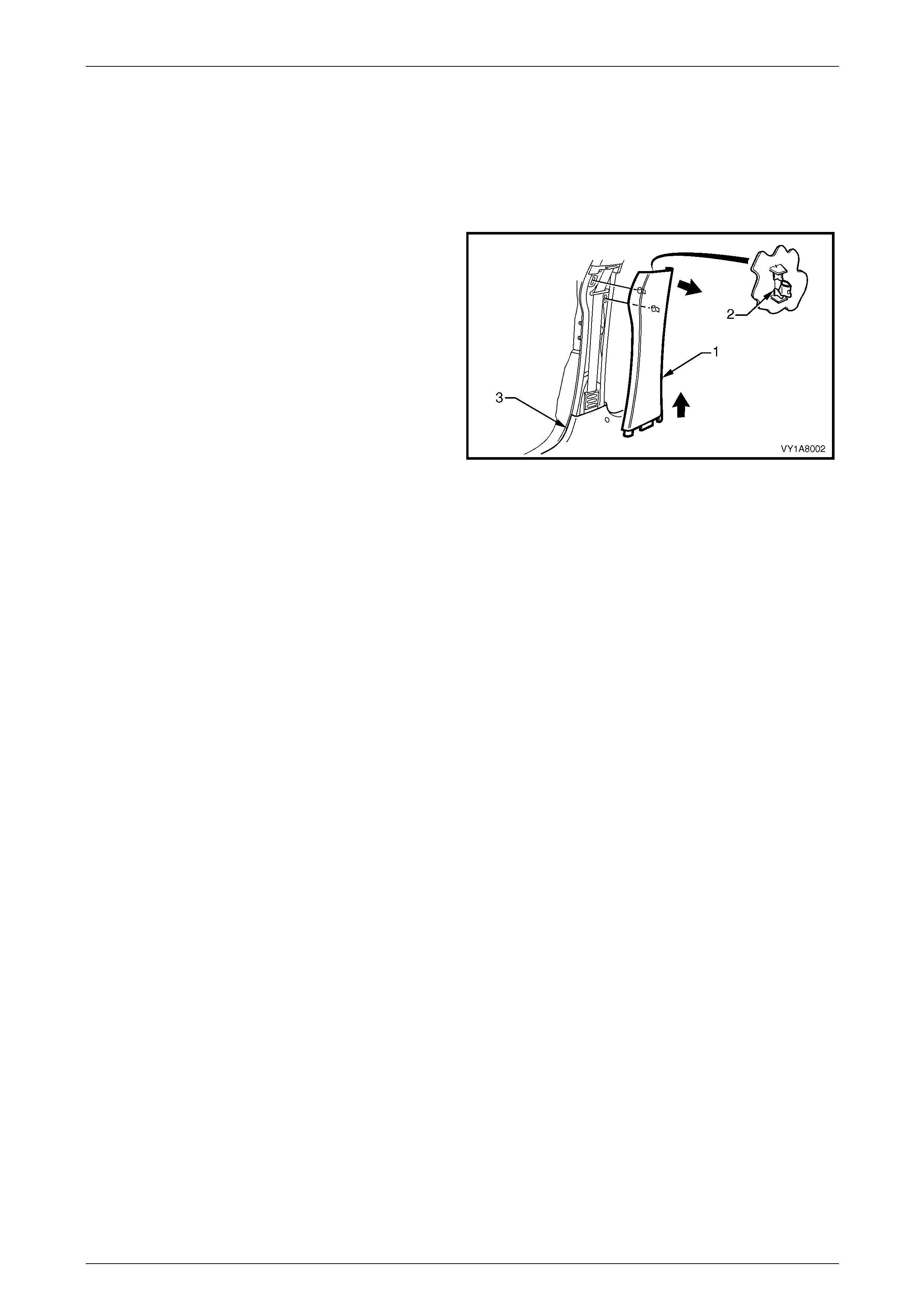
Headlining and Interior Trim Page 1A8–72
Page 1A8–72
4.3 Centre Pillar Lower Trim
LT Section — 14–100
Remove
1 Using your fingers, lever the top of the centre pill ar
lower trim (1) away from the front door opening
weatherstrip and pull the trim to ward the centre of the
car, disengaging the two retaining clips (2).
2 Lift the centre pillar lower trim upward, out of the side
sill trim (3) and remove.
3 As required, remove the retaining clips from the
vehicle and fit to the trim.
Figure 1A8 – 64
Reinstall
1 Locate the centre pillar lo wer trim (1) into the side sill trim (3)., refer to Figure 1A8 – 6 4
2 Locate the two retaining clips (2) into their slots in the centre pillar, then push in firml y ens uring the two clips are
secured to the centre pillar.
3 Ensure the front and rear door opening weatherstrips fit neatly over the outer edges of centre pillar lower trim.
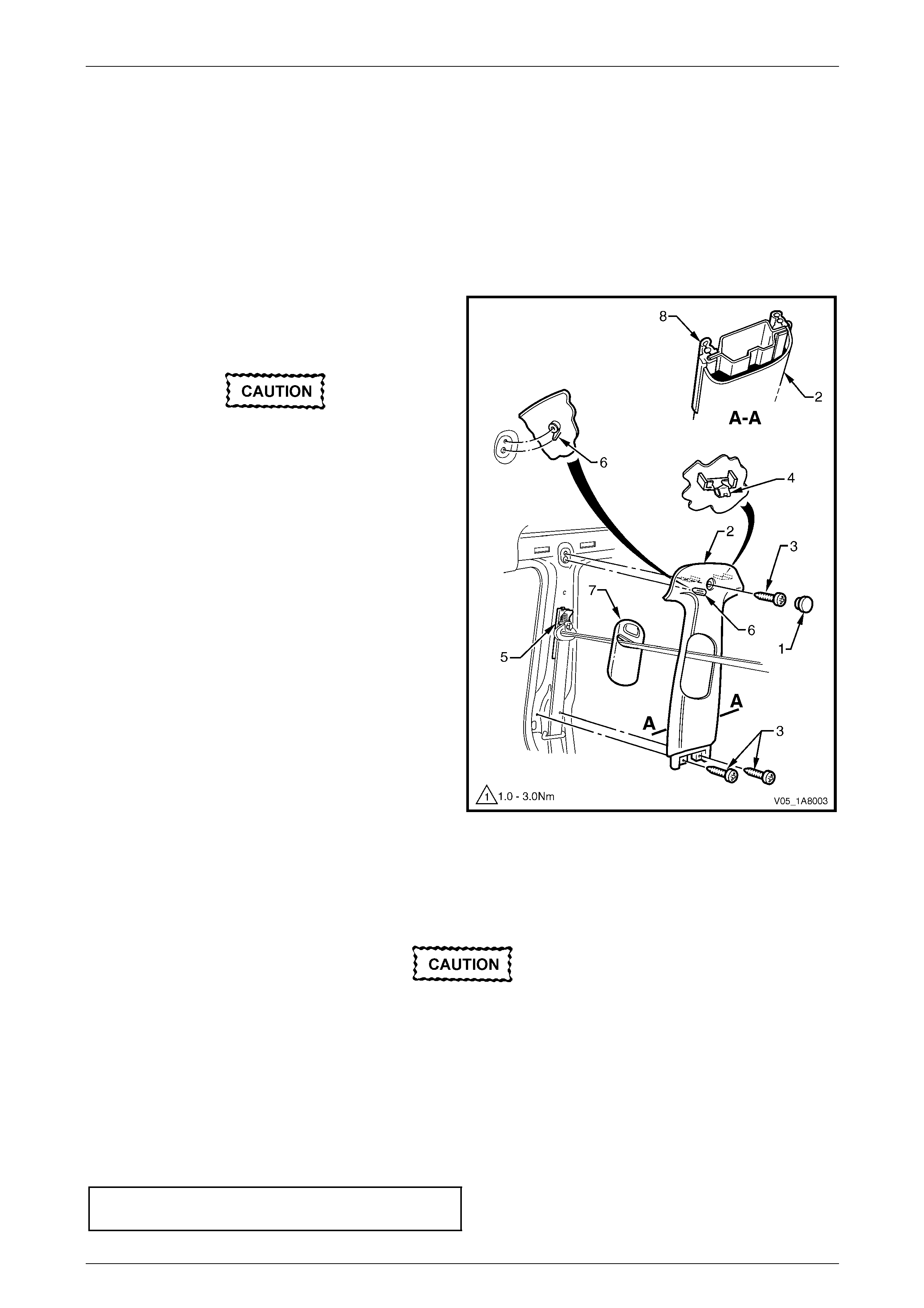
Headlining and Interior Trim Page 1A8–73
Page 1A8–73
4.4 Centre Pillar Upper Trim Assembly
LT Section — 14–100
Remove
1 Remove the following components as required:
a Centre pillar lower trim, refer to 4.3 Centre Pillar Lower Tr im.
b Front seat belt lower bolt, refer to Section 12M Occupant Protection System.
2 Remove the screw cap (1) from the upper attachment
of the centre pillar upper trim assembly (2).
3 Remove the three screws (3) attaching the centre
pillar upper trim assembly.
When removing the centre pillar upper trim
assembly, take care not to damage the
locating pin (6) below the upper attaching
screw position.
4 Pull the upper edge of the centre pillar upper trim
assembly away from the headlining assembly to
disengage the two retaining clips (4) and the seatbelt
guide adjuster assembly (5), if fitted.
5 Feed the seatbelt and anchor plate thro ugh the centre
pillar upper trim assembly and remove the centre pillar
upper trim assembly.
6 If required, remove the seatbelt adjuster trim (7) by
gently spreading the outer edges of the centre pillar
upper trim assembly and lifting out the seatbelt
adjuster trim.
7 As required, remove the retaining clips from the
vehicle and fit to the trim.
Figure 1A8 – 65
Reinstall
Reinstallation of the centre pillar upper trim assembly is the reverse of the removal procedure, noting the following:
1 If fitted, ensure the seatbelt adjuster trim (7) and the seatbelt guide adjuste r assembl y (5) are in the fully up position
and are correctly aligned prior to installing the centre pillar upper trim assembly (2), refer to Figure 1A8 – 65.
Take care not to snap off the locating pin
when fitting the centre pillar upper trim
assembly.
2 Ensure the locating pin belo w the upper attaching screw position in the centre pillar up per trim assembly is correctly
aligned with the locating hole in the centre pillar.
3 Ensure the centre pillar upper trim assembl y two retaining clips are secured to the centre pillar.
4 Ensure the leading edge of the centre pillar upper trim assembly engages the front door opening weatherstrip
assembly (8).
5 Check the seatbelt operation prior to tightening the centre pillar u pp er trim assemb ly attaching screws.
6 Tighten the centre pillar uppe r trim assembly three attaching screws to the specified torque.
Centre pillar upper trim assembly
attaching screw torque specification...........1.0 – 3.0 Nm

Headlining and Interior Trim Page 1A8–74
Page 1A8–74
4.5 Side Sill Trim and Plate
LT Section — 14–100
Remove
1 Remove the following components as required:
a Remove the centre pillar lower trim , refer to 4.3 Centre Pillar Lower Trim.
b Front seat outer front cover and outer rear cover, refer to Section 1A7 Seat Assemblies.
During the following procedure take care not
to snap the sill trim plates.
2 Carefully lever the front and rear side si ll trim
plates (1) from the side sill trim (2), starting at the front
of each plate and moving rearward.
3 Remove the Torx screw (3), six places, attachin g the
side sill trim, four in the front door opening an d two in
the rear door opening.
4 Remove the Torx screw (4) attaching the side sill trim
to the centre pillar.
5 Remove the side sill trim through the front door
opening by lifting the front and sliding the rear out from
under the rear seat cushion. Figure 1A8 – 66
Reinstall
Reinstallation of the side sill trim and plate is the reverse of the removal procedure, noting the following:
1 Ensure the outer edge of the side sil l trim (2) enga ges the fr ont and rear door opening weatherstrips (5), refer to
Figure 1A8 – 66.
2 Tighten the Torx screws attaching the side sill trim to the correct torque specification.
Side sill trim attaching Torx screw
torque specification.....................................1.0 – 3.0 Nm
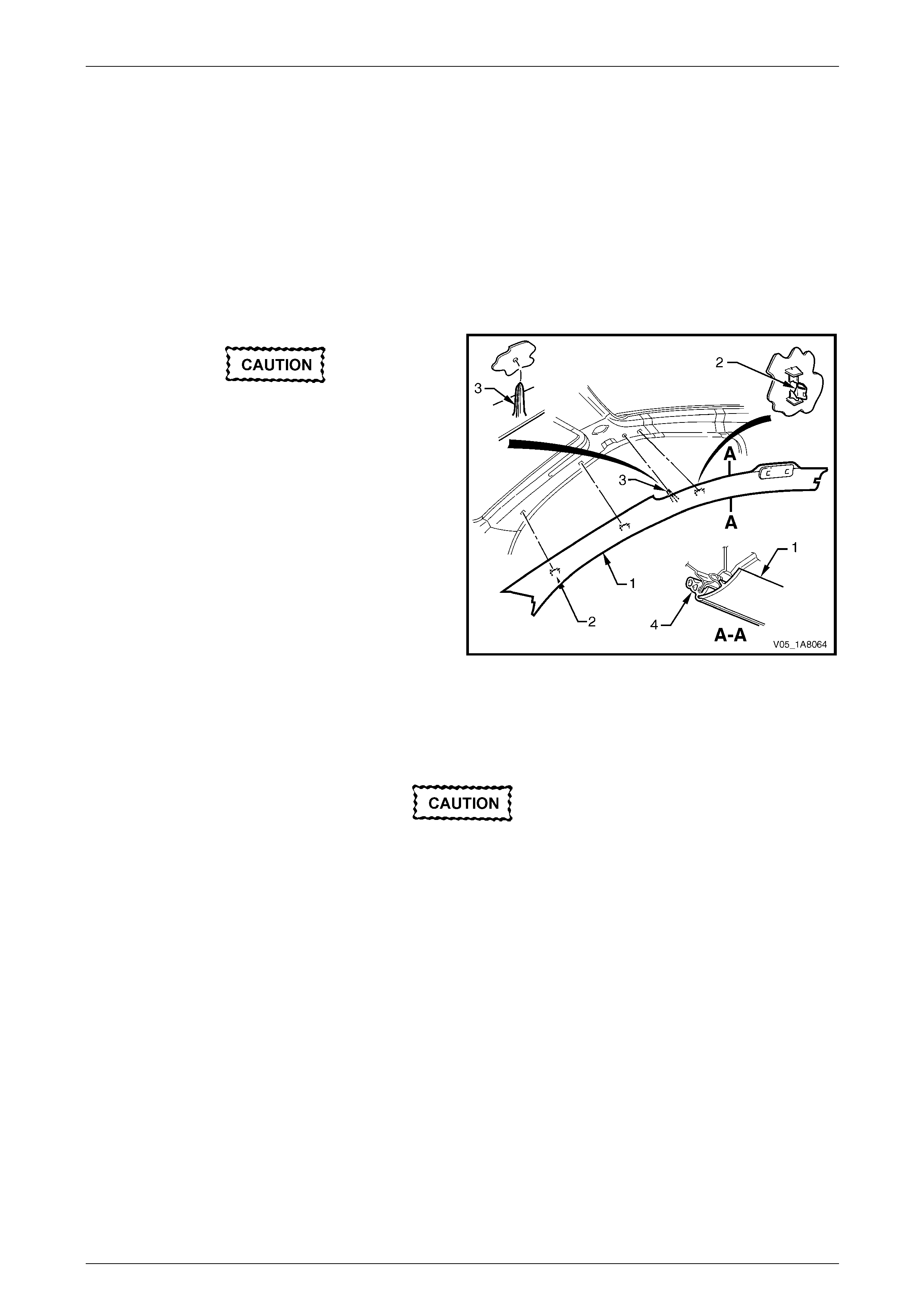
Headlining and Interior Trim Page 1A8–75
Page 1A8–75
4.6 Windshield Side Garnish
LT Section — 14–100
Remove
1 Remove the following components as required:
a Front assist handle assembly, refer to 4.2 Assist Handle Assembly.
b Partially remove the centre pill ar upper trim assembly by removing the upper attaching screw,
refer to 4.4 Centre Pillar Upper Trim Assembly.
When removing the windshield side garnish,
take care not to damage the locating pin (3).
2 Starting at the upper rear edge of the windshield side
garnish (1) disengage the three retai nin g clips (2).
3 Remove the windshield side garnish.
4 As required, remove the retaining clips from the
vehicle and fit to the garnish.
Figure 1A8 – 67
Reinstall
Reinstallation of the windshield side garnish is the reverse of the removal procedure, noting the following:
Take care not to snap off the locating pin
when fitting the windshield side garnish.
1 Ensure the windshield side ga rnish locating pin is aligned with the locating h ole i n the hinge pillar inner panel.
2 Ensure the outer edge of the winds hield side garnish (1) engages the front door opening weatherstrip (4 ), refer to
Figure 1A8 – 67.
3 Ensure the three retaining clips are secured to the hinge pillar inner panel.

Headlining and Interior Trim Page 1A8–76
Page 1A8–76
4.7 Body Hinge Pillar Trim Assembly
LT Section — 14–100
Remove
1 Partially remove the side sill trim, refer to 4.5 Side Sill Trim and Plate.
2 Remove the two attaching screws (1) from the body
hinge pillar trim assembly (2).
3 Disengage the body hinge pillar trim clip (3) by pul ling
the lower edge of the body hinge p illar trim assembly
rearward and away from the sheetmetal.
4 Remove the body hinge pillar trim assembly.
5 If required, remove the body hinge pillar trim clip a nd
the two nut inserts (4).
Figure 1A8 – 68
Reinstall
Reinstallation of the body hinge pillar trim assembl y is the reverse of the removal procedure, noting the following:
1 Ensure the body hinge pil lar trim clip is correctly engaged in the hinge pillar inner panel.
2 Ensure the nut inserts are in good condition and correctly located in the hinge pillar inner panel.
3 Ensure the outer edge of the body hinge pillar trim assembl y engages the front door opening weatherstrip (5), refer
to Figure 1A8 – 68.
4 Tighten the body hinge pillar trim assembly two attaching s c rews to the correct torque specification.
Body hinge pillar trim assembly
attaching screw torque specification...........0.7 – 1.0 Nm
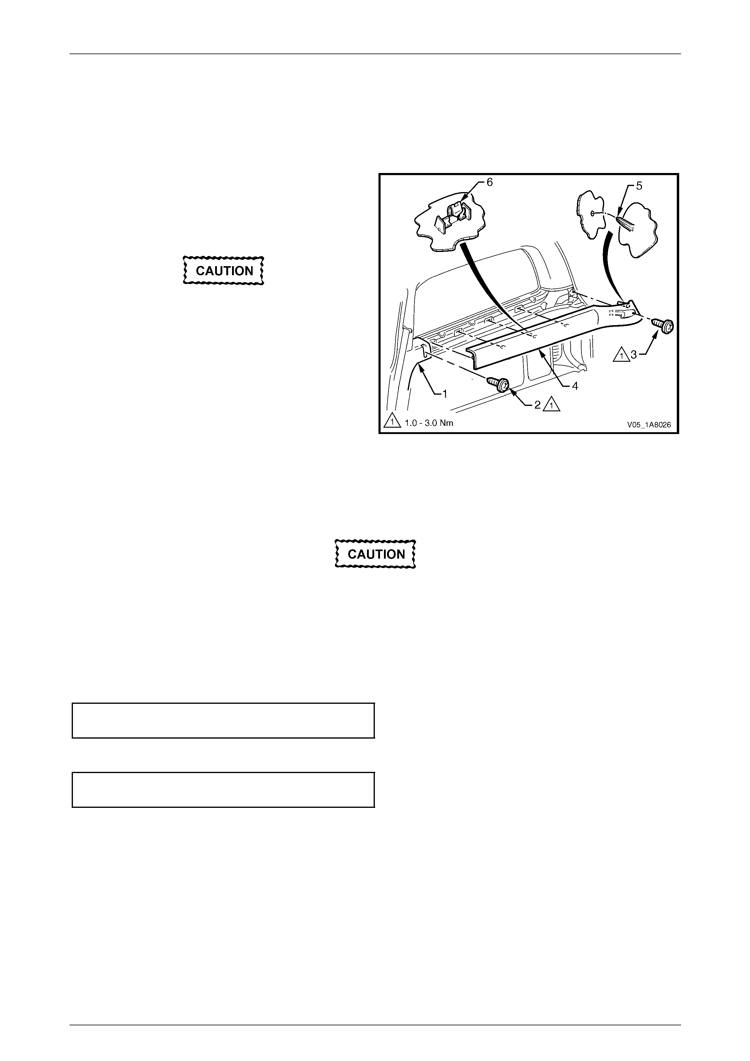
Headlining and Interior Trim Page 1A8–77
Page 1A8–77
4.8 Quarter Inner Upper Trim
LT Section — 14–130
Remove
1 Partially remove the bod y lock pillar lower trim (1) by
removing the upper attaching screw (2).
2 Remove the screw (3) attaching the quarter inner
upper trim (4).
When removing the quarter inner upper trim,
take care not to damage the locating pin (5).
3 Pull the rear edge of the quarter inner upper trim away
from the quarter inner panel assembly and working
forward, disengage the four retaining clips (6).
4 Slide the quarter inner upper trim from under the body
lock pillar lower trim and remove.
5 As required, remove the retaining clips from the
vehicle and fit to the trim. Figure 1A8 – 69
Reinstall
Reinstallation of the quarter inner upper trim is the reverse of the removal, noting the following:
Take care not to snap off the locating pin
when fitting the quarter inner upper trim.
1 Ensure the quarter inner upper trim locating pin is aligned with the locating hol e in the quarter inner panel
assembly.
2 Ensure the quarter inner upper trim four retaining clips are secured to the quarter inner pa nel assembly.
3 Tighten the screw attaching the quarter inn er upper trim to the correct torque specification.
Quarter inner upper trim attaching screw
torque specification.....................................1.0 – 3.0 Nm
4 Tighten the upper screw attaching the body lock pillar lower trim to the correct torque specification.
Body lock pillar lower trim upper
attaching screw torque specification...........1.0 – 3.0 Nm
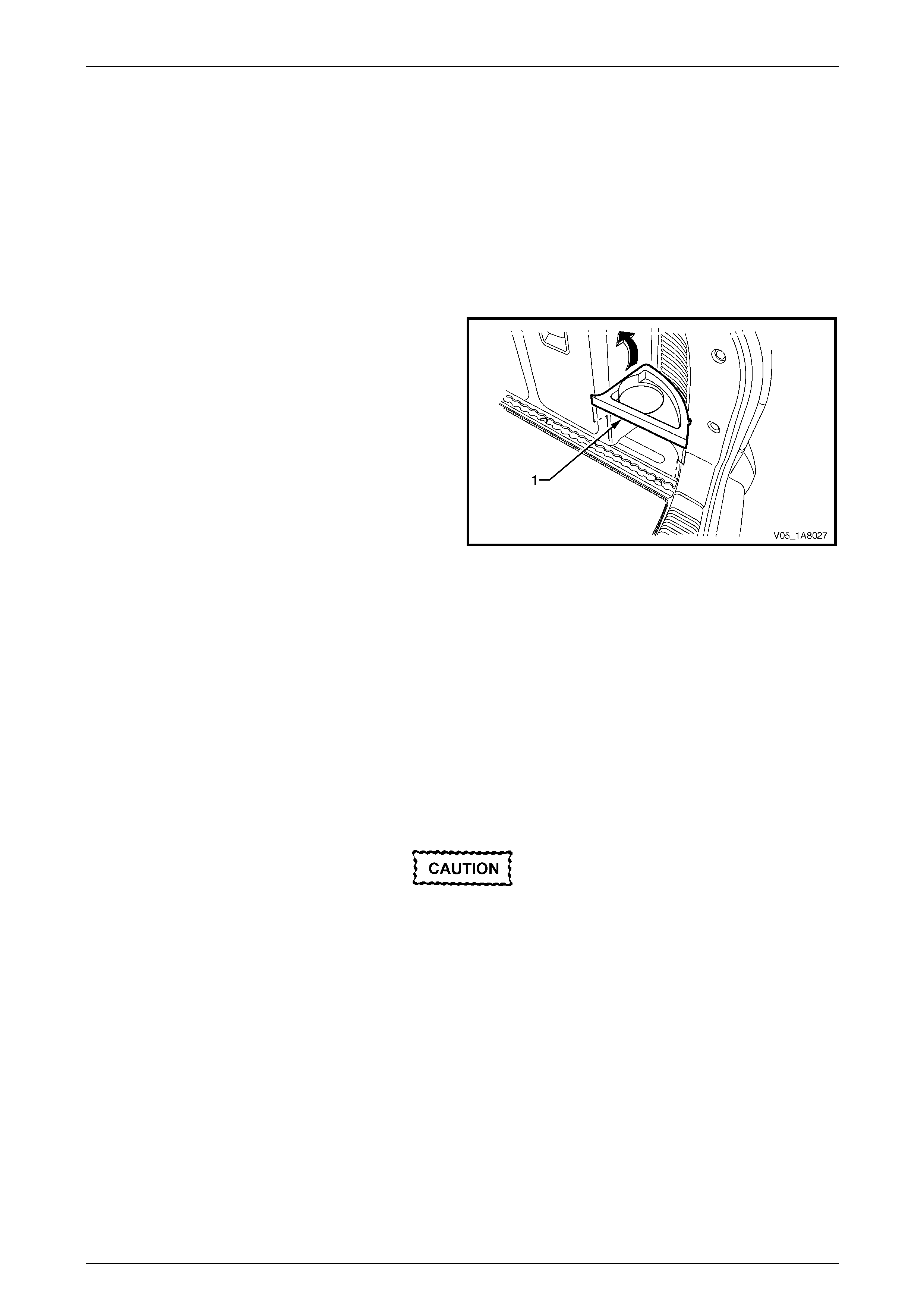
Headlining and Interior Trim Page 1A8–78
Page 1A8–78
4.9 Quarter Inner Trim Panel Assembly
LT Section — 14–490
Remove
1 Fold forward the rear seat back, refer to Section 1A7 Seat Assemblies .
2 Remove the quarter inner upper trim , refer to 4.8 Quarter Inner Upper Trim.
3 Loosen the rear end trim pane l, refer to 4.14 Rear En d Trim Panel.
4 Lift out the rear cup holder (1) and rem ove.
Figure 1A8 – 70
5 Remove the retainer (1), two places, securing the quarter inner trim panel assembly (3), refer to Figure 1A 8 – 71.
6 Remove the attaching screw (2), four places, along the top edge of the quarter inner trim panel ass embly.
7 Pull the forward edge of the body lock pillar lower trim (4) to disengage the retaining clip, then swing forward to
uncover the attaching screw (5).
NOTE
The body lock pill ar lower trim (4) upper attaching
screw was previously removed for the quarter
inner upper trim removal.
8 Remove the attaching screw on the for ward edge of the quarter inner trim panel assembly.
When removing the quarter inner trim panel
assembly, take care not to damage the
locating pin (6).
7 Lift the quarter inner trim panel assembly forward over the rear seat-back striker (7).
8 For the right-hand side quart er inn er trim pa nel assembly, disconnect the accessory power socket connector (8).
9 Remove the quarter inner trim panel assembly.

Headlining and Interior Trim Page 1A8–79
Page 1A8–79
Figure 1A8 – 71
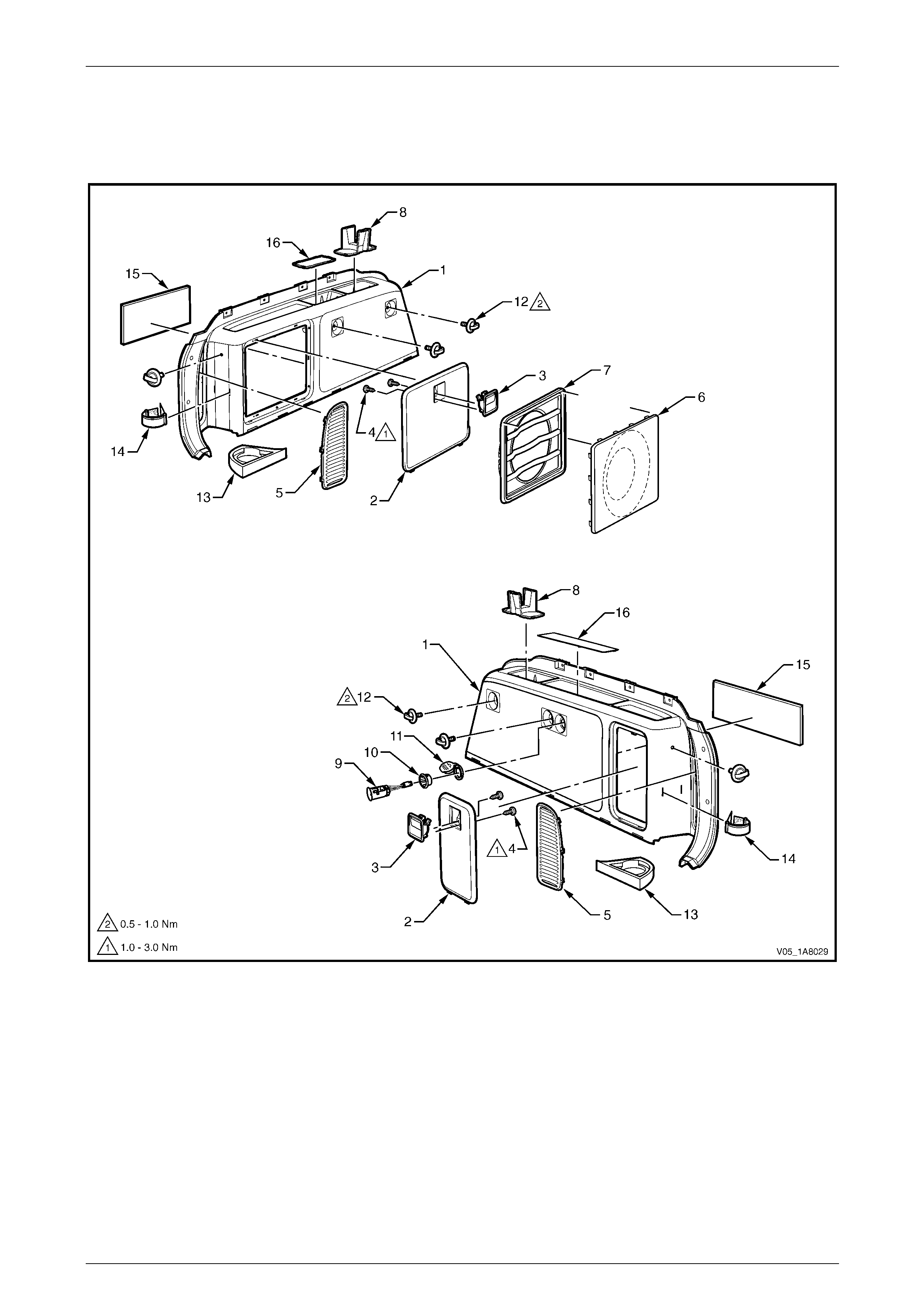
Headlining and Interior Trim Page 1A8–80
Page 1A8–80
Disassemble
To disassemble the quarter inner trim panel assembly, remove all the components attached to the qu arter inner trim
panel foundation (1) as describe d in this Section, refer to Figure 1A8 – 72.
Figure 1A8 – 72
Legend
1 Quarter Inner Trim Panel
Foundation
2 Quarter Inner Trim Panel
Stowage Door (where fitted)
3 Stowage Door Latch Assembly
4 Latch Assembly Screw
5 Quarter Inner Trim Panel Vent
6 Speaker Grille (where fitted)
7 Speaker Grille Housing (where fitted)
8 Front Cup Holder
9 Accessory Power Socket
10 Accessory Power Socket Bezel
11 Accessory Power Socket cover
12 Convenience Net Retainer Hook
13 Rear Cup Holder
14 Rear Cup Holder Strap
15 Centre Storage Insulator
16 Quarter Inner Trim Panel Insulator
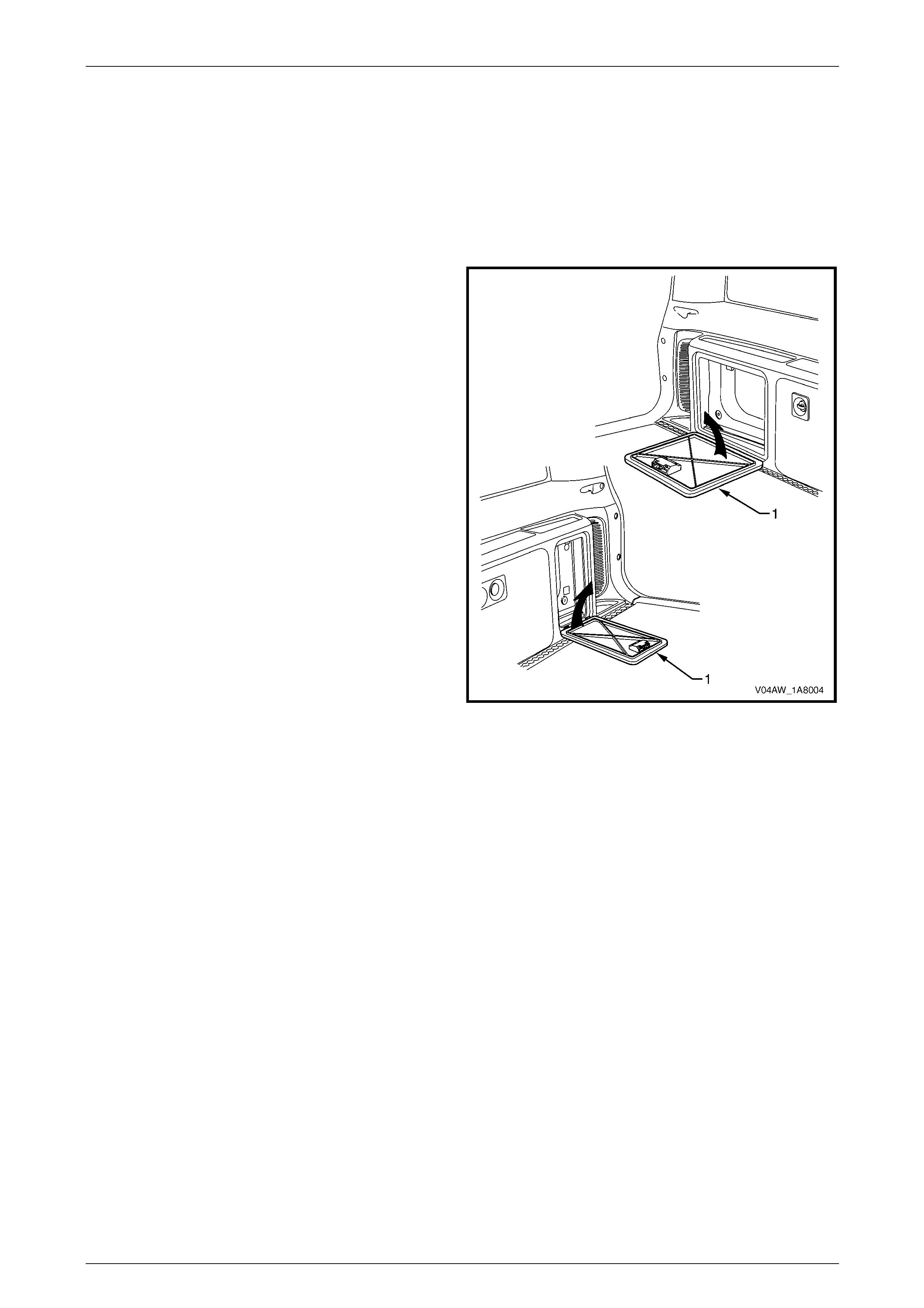
Headlining and Interior Trim Page 1A8–81
Page 1A8–81
Quarter Inner Trim Panel Stowage Door
NOTE
On High Level vehicles, the stowage door on the
left-hand side quarter inner trim panel is rep laced
by a speaker grille.
Remove
1 Open the quarter inner trim sto wage door (1) .
2 Lift the stowage door slightly to detach the hinges from
the quarter inner trim panel foundation.
3 Remove the stowage door from the quarter inner trim
panel foundation.
Figure 1A8 – 73
Reinstall
Reinstallation of the quarter inner trim stowage door is the reverse of the removal procedure.
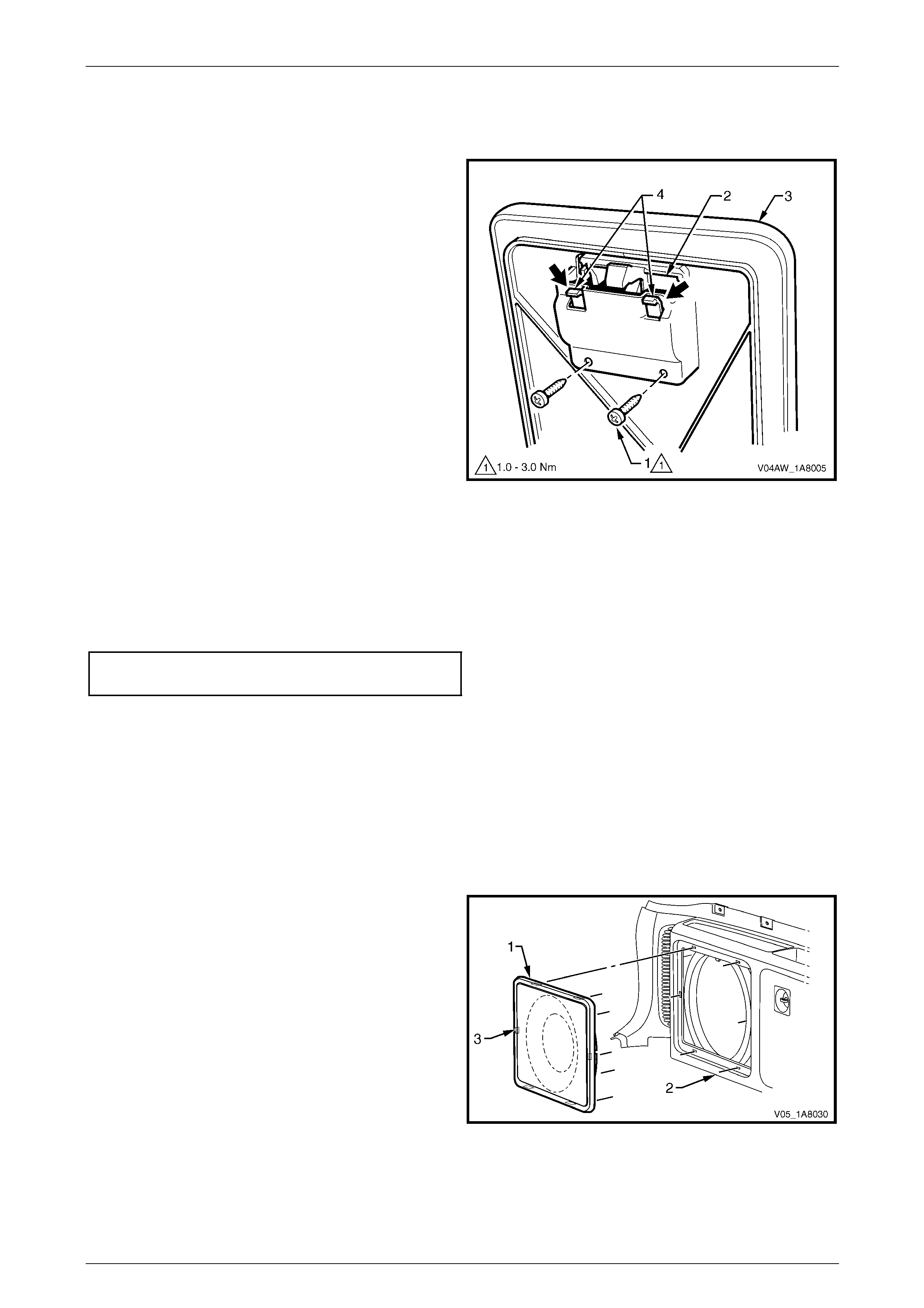
Headlining and Interior Trim Page 1A8–82
Page 1A8–82
Stowage Door Latch As sembly
Remove
1 Remove the two screws (1) attaching the latc h
assembly (2) to the quarter inner trim panel stowage
door (3).
2 Push down on the two retaining lugs (4) and remove
the handle from the quarter inner trim panel stowage
door.
Figure 1A8 – 74
Reinstall
Reinstallation of the stowage door latch assembly is the reverse of the removal procedure, noting the following:
1 Ensure the latch assembly is pressed firmly into the quarter inner trim panel stowage door.
2 Tighten the two screws attaching the stowage door latch assembly to the correct torque specification.
Stowage door latch assembly
attaching screw torque specification...........1.0 – 3.0 Nm
Quarter Inner Trim Speaker Grille
NOTE
For service operations relating to the subwoofer
speaker and subwoofer amplifier, refer to
Section 12D Entertainment System.
Remove
1 Carefully prise the quarter inn er trim speaker grille (1)
from the quarter inner trim panel assembly (2),
releasing the retaining clip (3), six places.
Figure 1A8 – 75
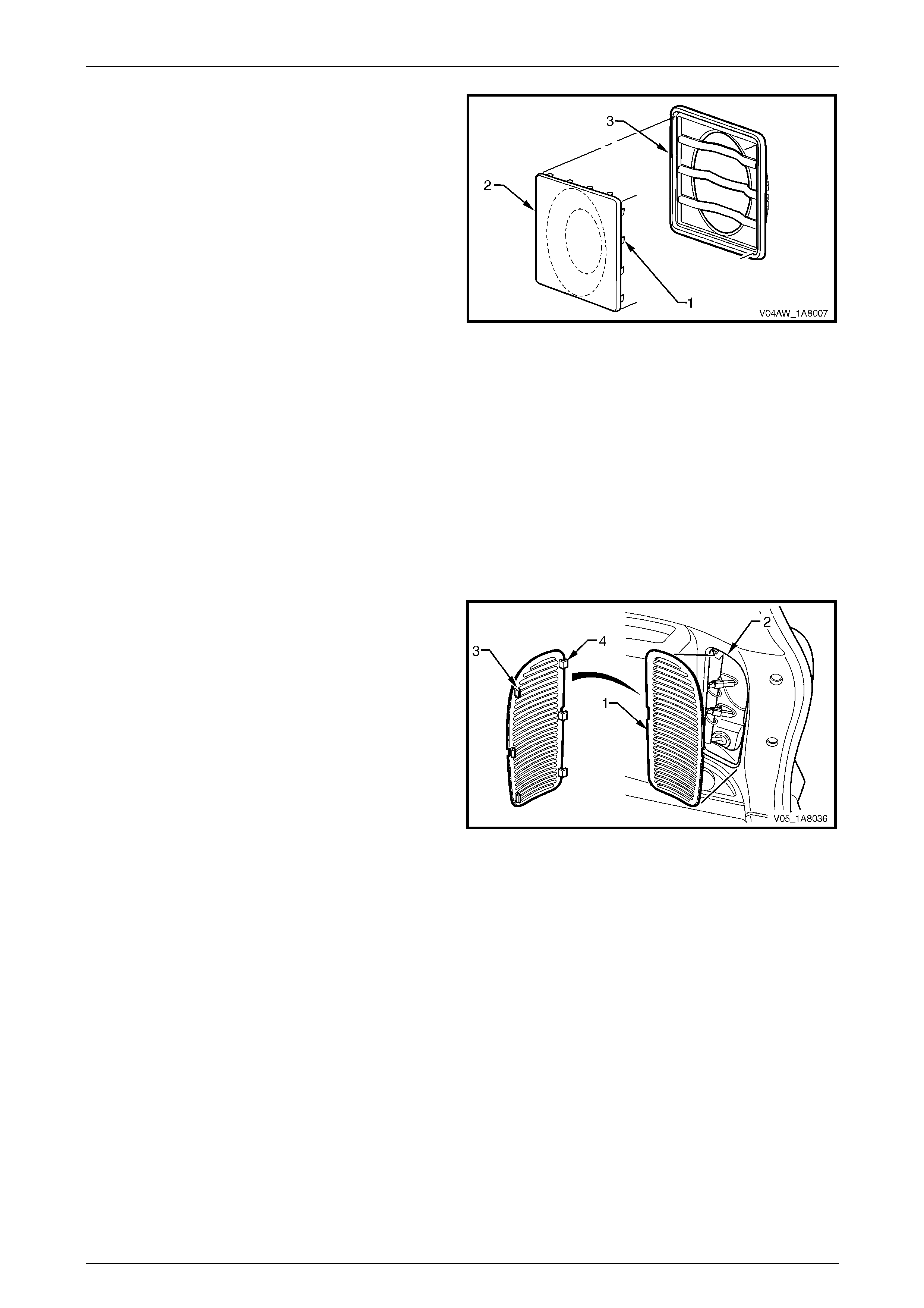
Headlining and Interior Trim Page 1A8–83
Page 1A8–83
2 If required, straighten the tab (1), sixteen places, on
the speaker grille (2) and remove the speaker grille
from the speaker grille housing (3).
Figure 1A8 – 76
Reinstall
Reinstallation of the quarter inner trim speaker grille is the reverse of the removal pr ocedure, noting the following:
1 Ensure the edge of the speaker grille is correctly seated in the speaker gri lle housing.
2 If removed, bend the sixteen tabs and ensure the speaker grille is secured to the speaker grille ho using.
3 Ensure the speaker grille six retaining clips are secure d to the quarter inner trim panel assembly.
Quarter Inner Trim Panel Vent
Remove
1 Lever the centre of the rear edge of the vent (1) away
from the quarter inner trim panel assembly (2) to
release the three rear clips (3).
2 Disengage the three front lugs (4) and remove the
vent from the quarter inner trim panel assembly.
Figure 1A8 – 77
Reinstall
Reinstallation of the quarter inner trim panel vent is the reverse of the removal procedure, noting the following:
1 Ensure the three front lugs are eng aged in the quarter inne r trim panel assembly.
2 Ensure the three rear clips secure the vent to the quarter in ner trim panel assembly.
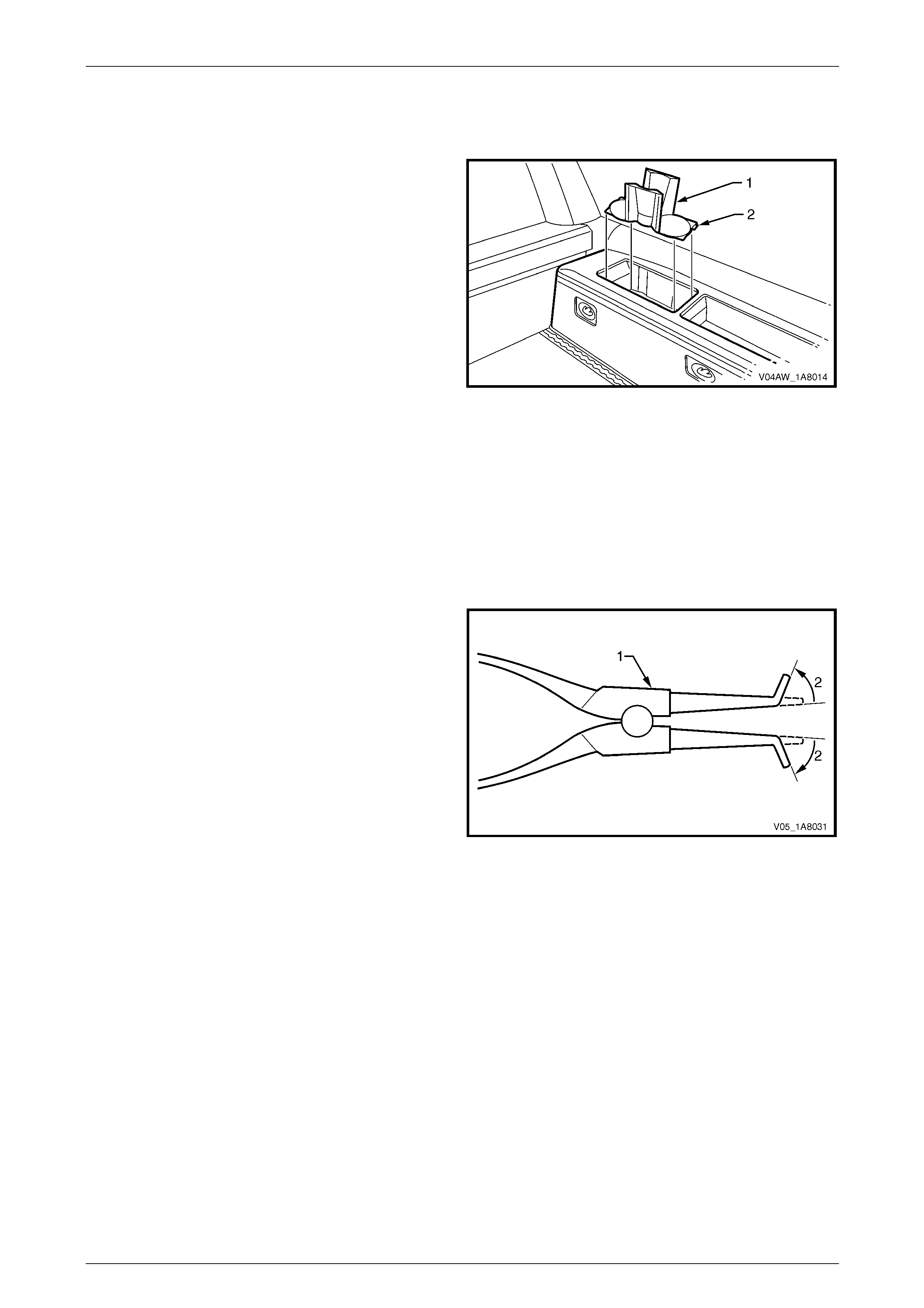
Headlining and Interior Trim Page 1A8–84
Page 1A8–84
Front Cup Holder
Remove
1 Remove the front cup holder (1) by disengagin g the
retaining lug (2) securing the cup hold er to the quarter
inner trim panel assembly.
Figure 1A8 – 78
Reinstall
Reinstallation of the front cup holder is the reverse of the removal procedure, noting the following:
Ensure the lug is correctly engaged in the quarter inner trim panel assembly.
Accessory Power Socket
Remove
1 Remove the rear compartment power outlet fuse F37
from the engine compartment fuse and relay panel
assembly, refer to Section 12O Fuses, Relays and
Wiring Harnesses.
2 To remove the accessory power socket, modify a pair
of external circlip pliers (1) by bending the tips outward
to an angle (2) bet ween 60° and 90°.
Figure 1A8 – 79

Headlining and Interior Trim Page 1A8–85
Page 1A8–85
3 Insert the modified circlip pliers (1) into the accessory
power socket (2) and locate the circlip pl iers tips onto
the two retaining tabs (3).
4 Depress the two tabs with the circlip pliers and prise
the accessory power socket out from the bezel (4)
using a fine, flat-blade screwdriver.
5 Disconnect the wiring connector (5) and remove the
accessory power socket.
Figure 1A8 – 80
During the following operation, take care not
to break the bezel retaining tabs (1).
6 Carefully remove the bezel (2 ) and cover (3) from the
quarter inner trim panel.
NOTE
The accessory power socket must be removed
before performing this step as its removal
releases the bezel retaining t abs.
7 If required, slide the cover to separate it from the
bezel.
Figure 1A8 – 81
Reinstall
Reinstallation of the accessor y power socket is the reverse of the removal procedure, noting the following:
1 Ensure the bezel is correctly located in the right-hand quarter inner trim panel.
2 Ensure the accessory power socket is correctly aligned, as it can only be installed in one orientation.
2 Ensure the accessory power socket is secure d with the two retaining tabs.
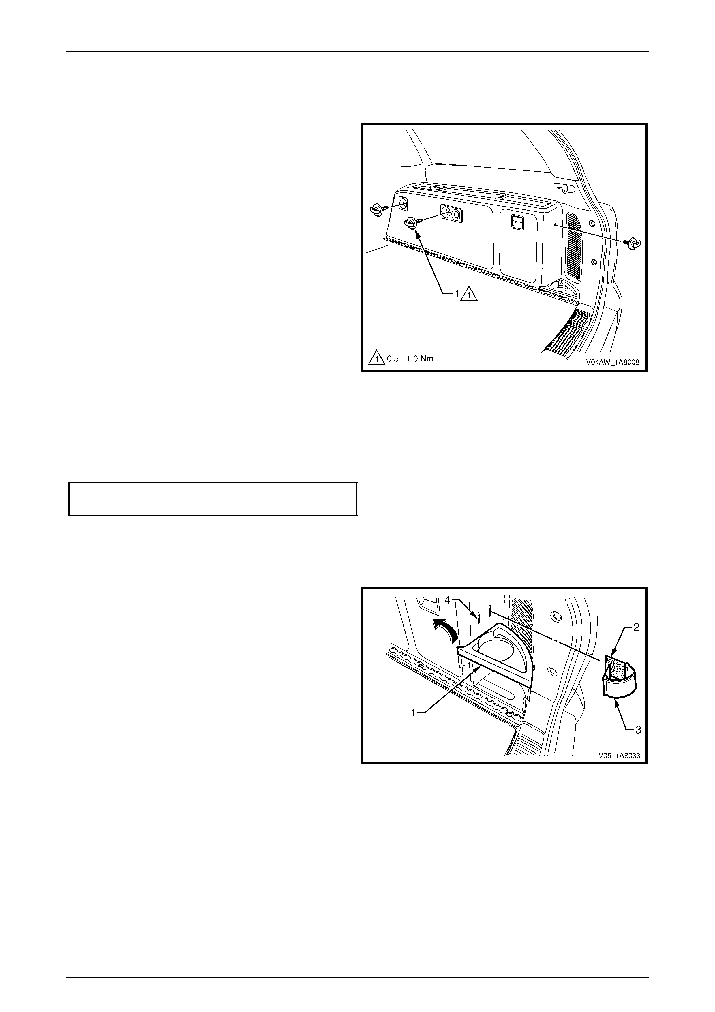
Headlining and Interior Trim Page 1A8–86
Page 1A8–86
Convenience Net Retainer Hooks
Remove
1 Unscrew the three convenience net retainer hooks (1)
from the quarter inner trim panel assembly.
Figure 1A8 – 82
Reinstall
Reinstallation of the convenie nce net retainer hooks is the reverse of the removal proced ure, notin g the following:
Tighten the convenience net three retainer hooks to the correct torque specification.
Convenience net retainer hook
torque specification.....................................0.5 – 1.0 Nm
Rear Cup Holder and Strap
Remove
1 As required, lift out the rear cup holder (1) an d
remove.
2 From the inner side of the quarter inner trim panel,
disengage the hook and l oop fasteners (2) and
remove the rear cup holder strap (3) by feeding it
through the two slots (4).
Figure 1A8 – 83
Reinstall
Reinstallation of the rear cup holder and strap is the reverse of the removal proc edure, noting the follo wing:
1 Ensure the rear cup holder strap is secured to the quarter inner trim panel.
2 Ensure the rear cup holder is correctl y seated.
NOTE
The right-hand and left-hand side rear cup
holders are not intercha ngeable.
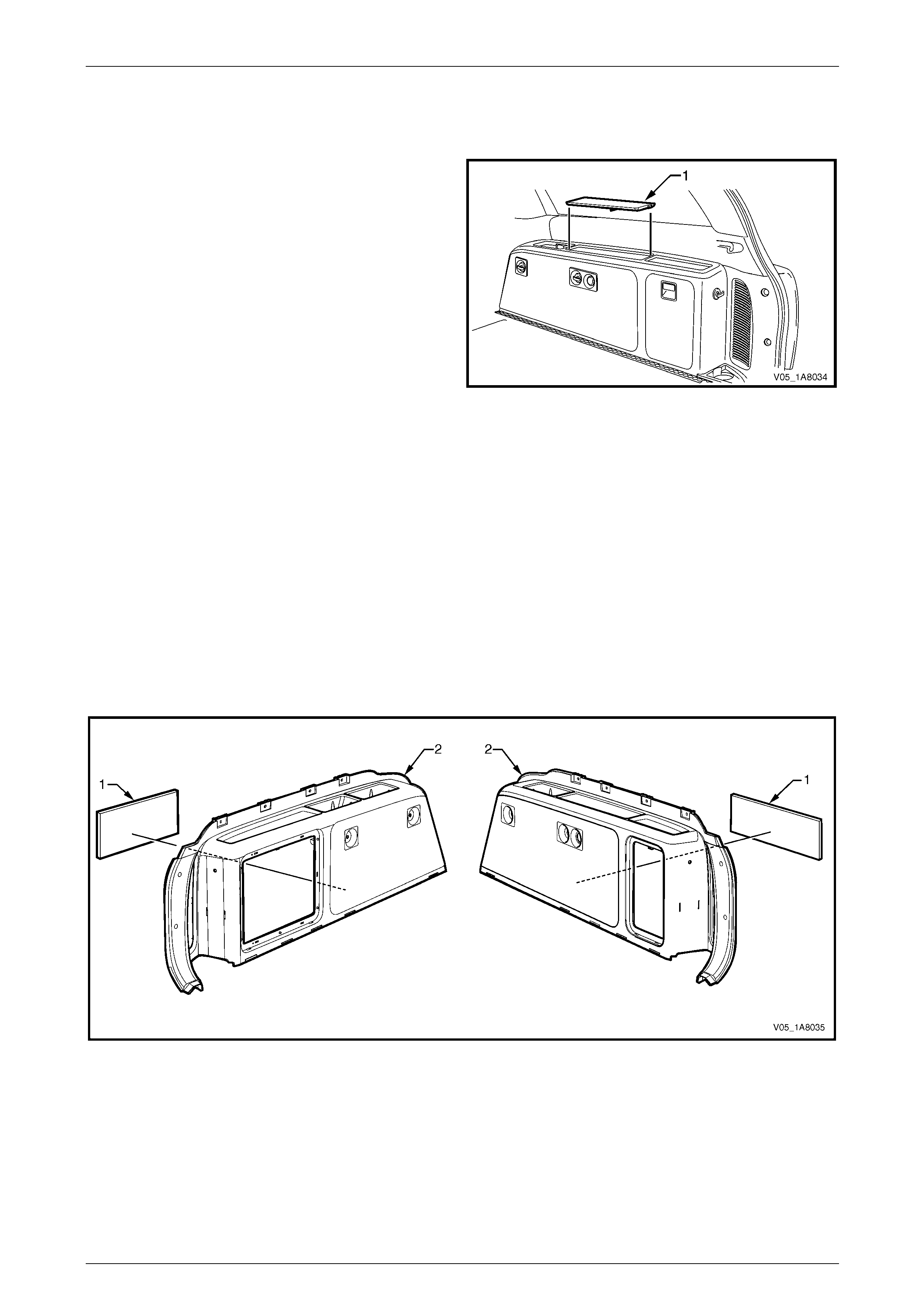
Headlining and Interior Trim Page 1A8–87
Page 1A8–87
Centre Storage Liner
Remove
1 Lift out the centre storage liner (1) from the quarter
inner panel assembly and remove.
Figure 1A8 – 84
Reinstall
Reinstallation of the centre storage liner is the reverse of the removal procedur e.
NOTE
The right-hand and left-hand side centre storage
liners are not interchangeable.
Insulator
Remove
1 Carefully peel the insulator (1) away from the back of the quarter inner panel assembly (2), refer to
Figure 1A8 – 85.
Figure 1A8 – 85
Reinstall
Reinstallation of the insul ator is the reverse of the removal procedure, noting the following:
1 Apply contact adhesive to the insulator as required.
2 Ensure the correct size insulator is fitted to the appropriate side quarter inner panel assembly.
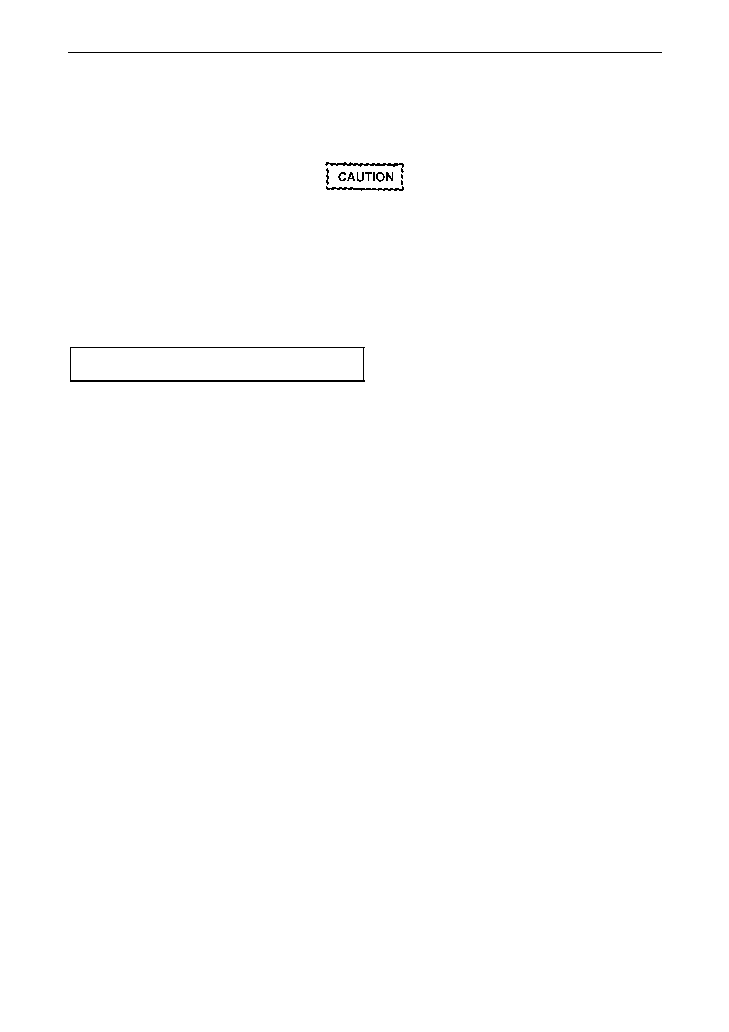
Headlining and Interior Trim Page 1A8–88
Page 1A8–88
Reinstall
Reinstallation of the quarter inner trim panel assembly is the reverse of the removal procedur e, noting the following:
1 For the right-hand side quart er inn er trim pa nel assembly, ensure the acc essory power socket is securely
connected to the harness connector.
Take care not to snap off the locating pin
when fitting the quarter inner trim panel
assembly.
2 Ensure the locating pin is correctly aligned with the correspondi ng locating hole in the quarter panel inner
assembly.
3 Ensure the outer edge of the quarter i nn er trim pane l assembly engages the liftgate open ing weatherstrip.
4 Tighten the four screws (2) and the forward screw (5) attaching the quarter inner trim panel assembly to the correct
torque specification, refer to Figure 1A8 – 7 1.
Quarter inner trim panel assembly
attaching screw torque specification...........3.0 – 5.0 Nm
5 Ensure the two retainers (1) are secured to the qu arter panel inner assembly.
6 Ensure the rear cup holder is correctl y seated.
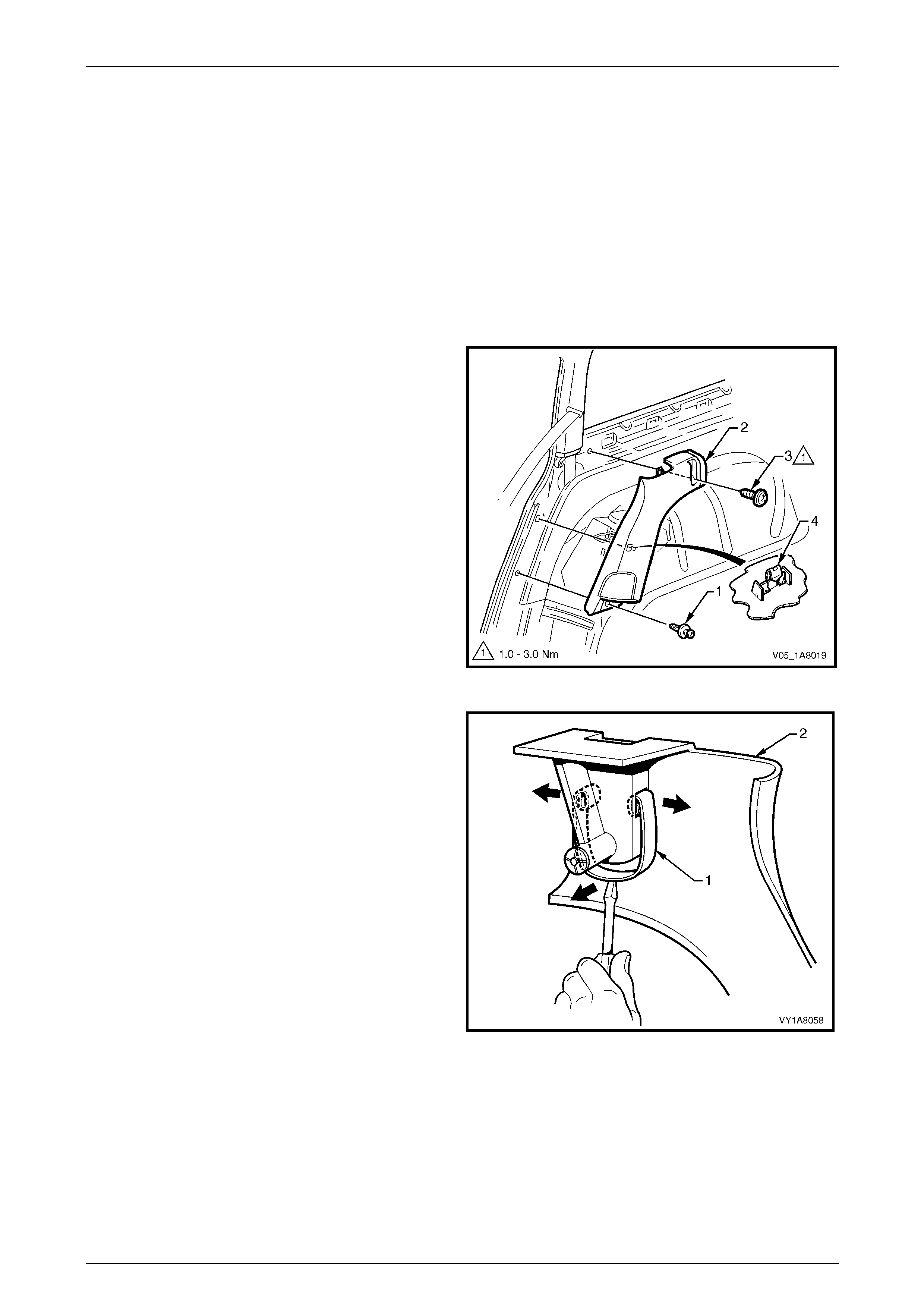
Headlining and Interior Trim Page 1A8–89
Page 1A8–89
4.10 Body Lock Pillar Lower Trim
LT Section — 14–130
Remove
1 Remove the following components as required:
a Quarter inner upper trim, refer to 4.8 Quarter Inner Upper Trim.
c Quarter inner trim panel assembly, refer to 4.9 Quarter Inner Trim Panel Assembly.
d Rear seat bolster assembly, refer to Section 1A7 Seat Assemblies.
2 Remove the lower retainer (1) securing the b od y lock
pillar lower trim (2).
NOTE
To allow for the quarter inner trim pane l removal,
the upper attaching screw (3) has been
previously removed and the retaining clip (4)
disengaged.
3 Remove the body lock pillar lower trim.
4 As required, remove the retaining clip from the vehicle
and fit to the trim.
Figure 1A8 – 86
5 If required, spread the luggage shade attaching spring
clip (1) open through the holes in the body lock pillar
lower trim (2).and lever out with a screwdriver to
remove the spring clip.
Figure 1A8 – 87
Reinstall
Reinstallation of the body lock pillar lo wer trim is the reverse of the removal procedure, noting the following:
1 If removed, replace the luggage shade attachi ng spring clip into the body lock pillar l ower trim.
2 Ensure the leading edge of the bod y lock pillar lower trim engages the re ar door opening weatherstrip.
3 Ensure the retainer is secured to the quarter panel inner assembly.

Headlining and Interior Trim Page 1A8–90
Page 1A8–90
4.11 Body Lock Pillar Garnish Assembly
LT Section — 14–130
Remove
1 Remove the following components as required:
a Rear assist handle assembl y, refer to 4.2 Assist Handle Assembly.
b Roof rail courtesy and reading lamps, refer to Section 12B Lighting System.
c Partially remove the centre pillar upper trim assembly by removing the upper attaching screw, refer to
4.4 Centre Pillar Upper Trim Assembly.
d Partially remove the body lock pillar lower trim by removing the upper attaching screw, refer to
4.10 Body Lock Pillar Lower Tr im.
e Remove the rear seat belt lower bolt, refer to Section 12M Occupant Protection System.
2 Remove the screw cap (1) from the body lock pillar
garnish (2).
3 Remove the upper screw (3) attaching the body lock
pillar garnish.
4 Remove the lower screw (4) from the body lock pillar
garnish.
When removing the body lock pillar garnish,
take care not to damage the locating pin (5).
5 Lever the front edge of the body lock pillar garnish
away from the centre pillar and working rearward to
disengage the three retaini ng clips (6).
Figure 1A8 – 88
6 With the body lock pillar garnish (1) partially removed,
disengage the seat belt escutcheo n (2) from the body
lock pillar garnish and feed the seat belt and anchor
plate through the opening.
7 Remove the body lock pillar garnish.
8 As required, remove the retaining clips from the
vehicle and fit to the garnish.
Figure 1A8 – 89
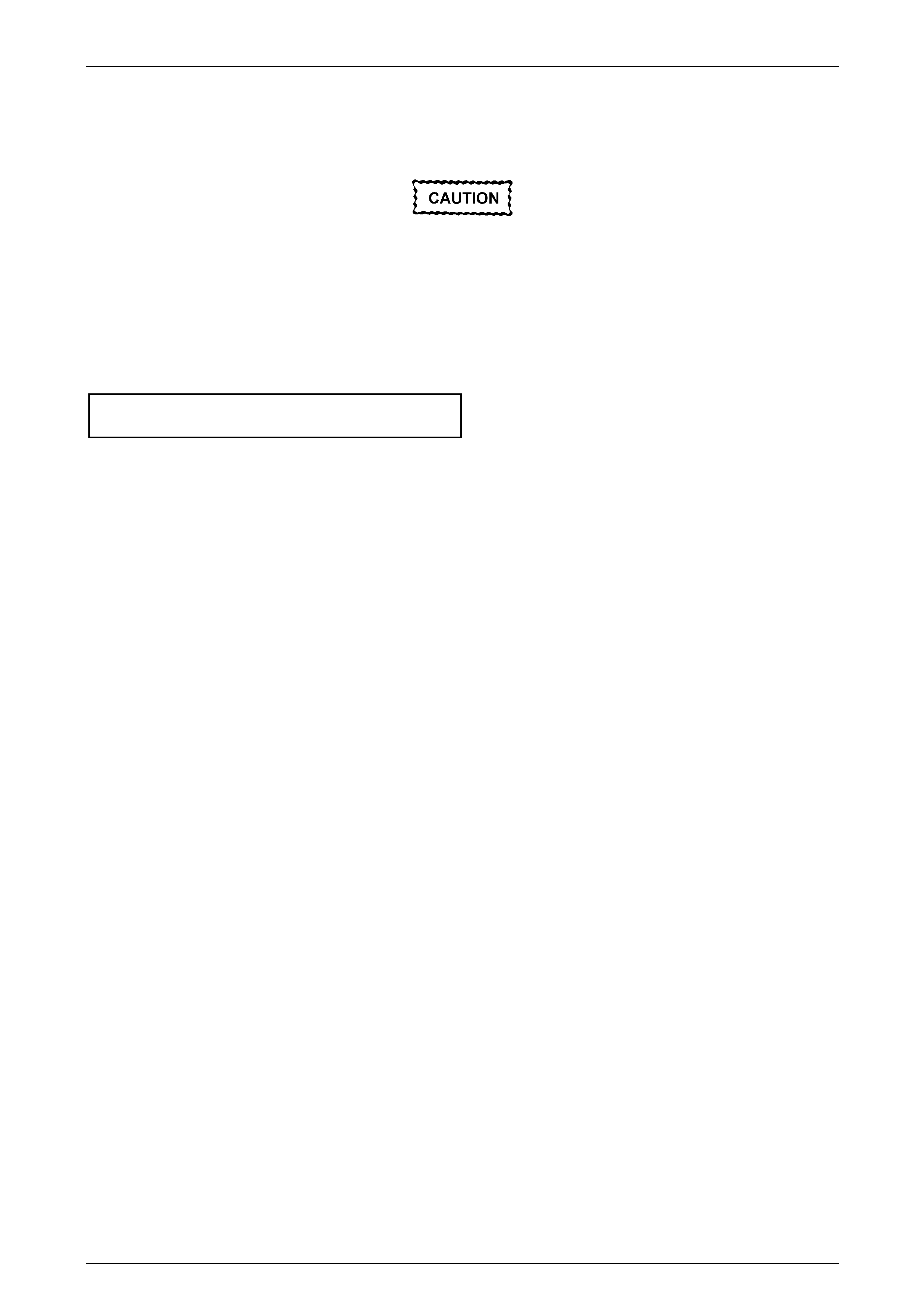
Headlining and Interior Trim Page 1A8–91
Page 1A8–91
Reinstall
Reinstallation of the body lock pillar garnish assembly is the reverse of the removal procedure, noting the follo wing:
Take care not to snap off the locating pin
when fitting the body lock pillar garnish.
1 Ensure the body lock pillar garnish locating pin is aligned with the locating hole in the quarter panel inner assembly.
2 Ensure the leading edge of the bod y lock pillar garnish eng ages the rear door opening weatherstrip.
3 Ensure the three retaining clips are secur ed to the quarter panel inner assembl y.
4 Tighten the upper and lower screws attaching the body lock pillar garnish to the correct torque specification.
Body lock pillar garnish
attaching screw torque specification...........1.0 – 3.0 Nm

Headlining and Interior Trim Page 1A8–92
Page 1A8–92
4.12 Body Rear Corner Garnish Assembly
LT Section — 14–130
Remove
1 Remove the quarter inner upper trim , refer to 4.8 Quarter Inner Upper Trim.
2 Remove the screw cap (1) from the body rear corner
garnish (2).
3 Remove the screw (3) attaching the body rear corner
garnish.
When removing the body rear corner garnish,
take care not to damage the locating pin (5)
or the locating lugs (6) fitting under the rear
window upper garnish.
4 Starting at the lower rear edge, lever the rear corner
garnish to disengage the si x retaining clips (4).
5 Slide out the rear corner garnish to disenga ge the
locating lugs (6) from under the rear window upper
garnish.
6 Slide the rear corner garnish rearward to disengage it
from the body lock pillar garnish and remove.
7 As required, remove the retaining clips from the
vehicle and fit to the garnish.
Figure 1A8 – 90
Reinstall
Reinstallation of the body rear corner garnish assembly is the reverse of the removal procedure, noting the following:
Take care not to snap off the locating pin or
the locating lugs when fitting the body rear
corner garnish.
1 Ensure the body rear corner garnish locating pin is aligned wit h the locating hole in the quarter panel inner
assembly.
2 Ensure the body rear corner garnish locating lugs are fitted und er the rear window upper garnish.
3 Ensure the outer edge of the body rear corner garnish engages the liftgate ope ning weatherstrip.
4 Ensure the six retaining clips are secured to the quarter panel inner assembly.
5 Tighten the screw attaching the body re ar corner garnish to t he correct torque specification.
Body rear corner garnish
attaching screw torque specification...........1.0 – 3.0 Nm

Headlining and Interior Trim Page 1A8–93
Page 1A8–93
4.13 Rear Window Upper Garnish
LT Section — 14–130
Remove
1 Remove the following components as required:
a Quarter inner upper trim, on one side of the vehicle, refer to 4.8 Quarter Inner Upper Trim.
b Body rear corner garnish assembly, on the same side of the vehicle,
refer to 4.12 Body Rear Corner Garnish Assembly.
When removing the rear window upper
garnish, take care no t to damage the locating
pin (3).
2 Starting from the end that has the body re ar corner
garnish assembly removed, lever the rear window
upper garnish (1) away from the headlining to
disengage the three retaining clips (2) from the roof
rear panel.
3 Slide out the rear window upper garnish from the
remaining body rear corner g arnish assembly and
remove.
4 As required, remove the retaining clips from the
vehicle and fit to the garnish.
Figure 1A8 – 91
Reinstall
Reinstallation of the rear window upper garnish is the reverse of the removal proc edure, noting the following:
Take care not to snap off the locating pin
when fitting the rear window upper garnish.
1 Ensure the rear window upper garnish locating pin is aligned with the locating hole in the roof rear panel.
2 Ensure the outer edge of the rear window upper garnish engages the liftgate opening weatherstrip.
3 Ensure that there is a neat fit between the outer edge of the body rear corner garnish assembly and the rear
window upper garnish.
4 Ensure the three retaining clips are secur ed to the roof rear panel.
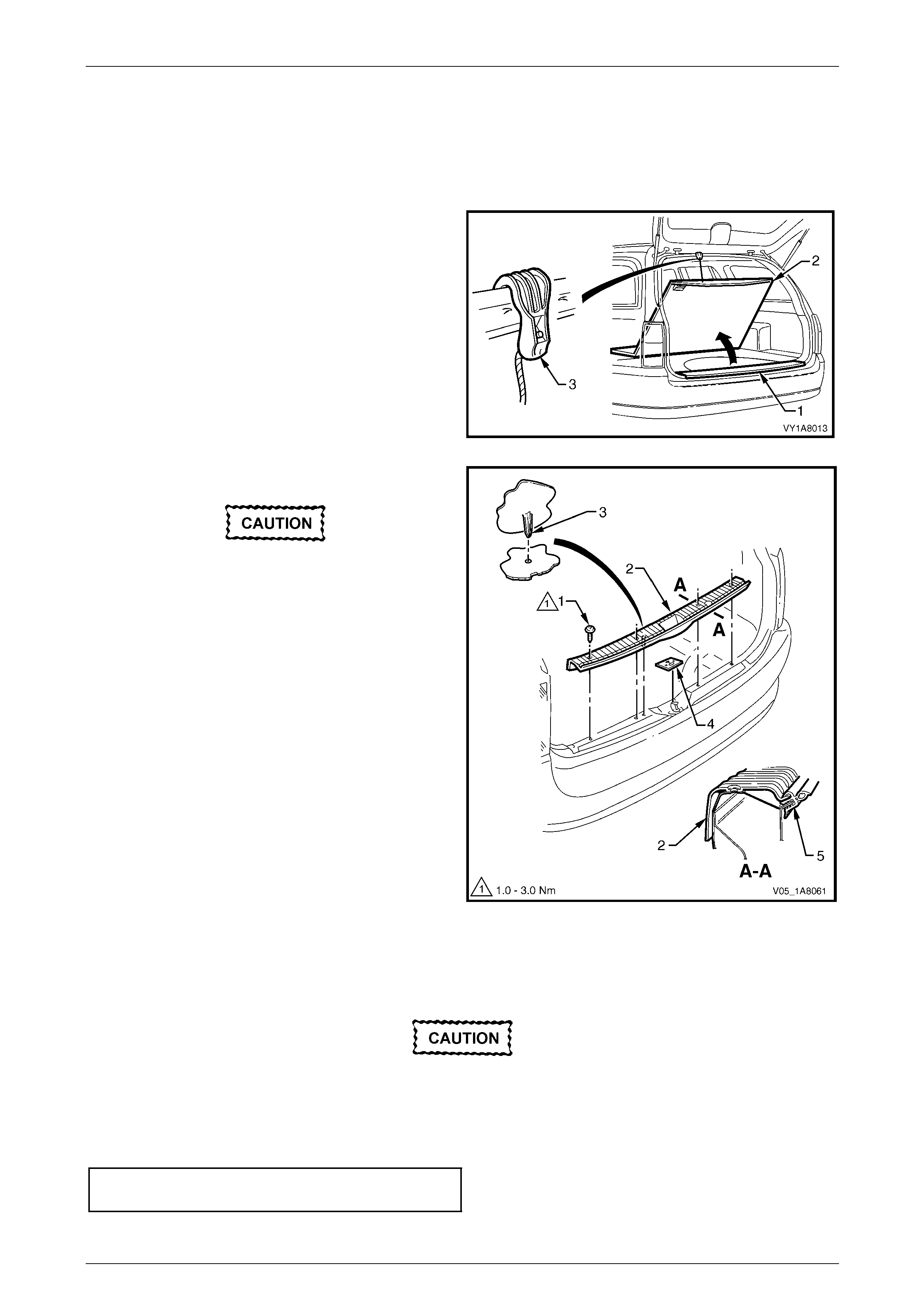
Headlining and Interior Trim Page 1A8–94
Page 1A8–94
4.14 Rear End Trim Panel
LT Section — 14–130
Remove
1 Gain access to the rear end trim panel (1) by opening
the rear compartment floor panel carpet assembly (2)
and using the hook (3) to retain it in the open position.
Figure 1A8 – 92
2 Remove the attaching screw (1), four places, along the
ribbed upper surface of the rear end trim panel (2).
When removing the rear end trim panel, take
care not to damage the locating pin (3).
3 Remove the rear end trim panel.
4 If required remove the rear end trim panel se al (4).
Figure 1A8 – 93
Reinstall
Reinstallation of the rear end trim panel is the reverse of the removal procedure, noting the following:
1 Ensure the rear end trim panel seal (4) is cor rectly fitted, refer to Figure 1A8 – 93.
Take care not to snap off the locating pin
when fitting the rear end trim panel.
2 Ensure the rear end trim panel locating pin is aligned with the locating hole in the rear end panel assembly.
3 Ensure the outer edge of rear end trim panel (2) engages the liftgate openi ng weatherstrip (5).
4 Tighten the four screws attaching the rear en d trim panel to the correct torque specifications.
Rear end trim panel attaching screw
torque specification.....................................1.0 – 3.0 Nm
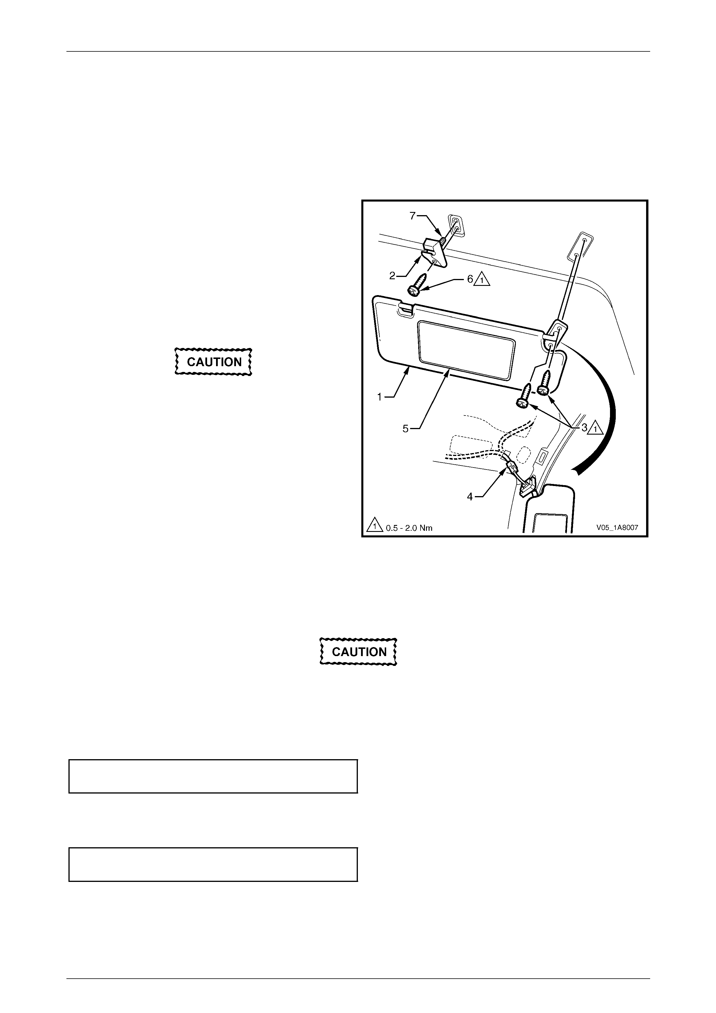
Headlining and Interior Trim Page 1A8–95
Page 1A8–95
4.15 Sunshade Assembly
LT Section — 14–050
Remove
1 If illuminated vanity mirrors are fitted, remove the fuse F6 from the passenger compartme nt fuse and re lay panel
assembly, refer to Section 12O Fuses, Relays and Wiring Harnesses.
2 Disconnect the sunshade assembly (1) from the
sunshade support (2) and rotate to gain acce ss.
3 Remove the sunshade assembly two attaching Torx
screws (3).
4 Pull the sunshade away from the hea dlining assembly
and if fitted, disconnect the harness connecto r (4) from
the illuminated vanit y mirrors ( 5).
5 Remove the sunshade.
When removing the sunshade support, take
care not to damage the locating pin (7).
6 Remove the Torx screw (6) from the sunshade support
and pull the support from the headlining assembly.
Figure 1A8 – 94
Reinstall
Reinstallation of the sunshad e assemb ly is the reverse of the removal procedure, noting the following:
Take care not to damage the locating pin
when fitting the sunshade support.
1 Ensure the sunshade support locati ng pin is aligned with the locating h ole in the roof panel.
2 Tighten the Torx screw attaching the sunshade support to the correct torque specification.
Sunshade support attaching Torx screw
torque specification.....................................0.5 – 2.0 Nm
3 If illuminated vanity mirrors are fitted, connect the harness connector to the sunshade ass embl y.
4 Tighten the sunshade ass embly two attaching Torx scre ws to the correct torque specific ation.
Sunshade assembly attaching screw
torque specification.....................................0.5 – 2.0 Nm

Headlining and Interior Trim Page 1A8–96
Page 1A8–96
4.16 Roof Console
LT Section — 02–780
Remove
1 Remove the fuse F6 from the passenger compartment fuse and relay panel ass embl y,
refer to Section 12O Fuses, Relays and Wiring Harnesses.
2 Open the compartment door (1) of the roof console.
3 Remove the two attaching screws (2) from inside the
roof console.
4 Close the compartment door.
5 Using your hand, pull down to disengage the front of
the roof console from the roof header pane l.
Figure 1A8 – 95
6 Slide the roof console (1) in a forward motion to allow
the two locator arms (2) to clear the headlini ng.
7 Disconnect the harness from the roof console
connector (3) and remove.
NOTE
For replacement of the map lamp bulbs, refer to
Section 12B Lighting System.
Figure 1A8 – 96
Reinstall
Reinstallation of the roof console is the reverse of the removal procedure, noting the following:
1 Ensure the harness is securely connecte d to the roof console connector.
2 Ensure the two locator arms are correctly inserted and the roof console is secure d to the roof panel.
3 Tighten the roof console two attaching screws to the correct torque specification.
Roof console attaching screw
torque specification.....................................1.0 – 2.0 Nm

Headlining and Interior Trim Page 1A8–97
Page 1A8–97
4.17 Headlining Assembly
LT Section — 14–150
Remove
NOTE
If the vehicle is fitted with a sunroof, note the
following:
• Where an online sunroof is fitted, a rigid
headlining is installed and can be removed
using the normal procedure.
• Where a Holden By Design (HBD) sunroof is
fitted, a new headlining ha d to be created a nd
installed with adhesive. Extreme care is
required as the removal may damage the
headlining, then requiring a new one to be
created by a motor trimmer. The procedure
for this headlining is not covered in this
Section.
1 Remove the fuse F6 from the passenger compartment fuse and relay panel ass embl y,
refer to Section 12O Fuses, Relays and Wiring Harnesses.
2 Place protective covering ov er both front seats and the interior trim.
3 Remove the following components as required:
a Remove on both sides the windshield side garnish, refer to 4.6 Windshield Side Garn ish .
b Body lock pillar garnish assembly on both sides, refer to 4.11 Body Lock Pillar Garnish Assembly.
c Body rear corner garnish assembly on both sides, refer to 4.12 Body Rear Corner Garnish Assembly.
d Rear window upper garnish, refer to 4.13 Rear Window Upper Garnish.
e Sunshade assembly on both sides, refer to 4.15 Sunshade Assembl y.
f Roof console, refer to 3.16 Roof Console.
g Rear compartment courtesy lamp from the h eadlining assembly, refer to Section 12B Lighting S ystem.
4 Disconnect the headlining assembly wiring harness (1) from the bod y wiring harness connector (2), located above
and slightly forward of the right-hand centre pillar, refer to Figure 1A8 – 97.
NOTE
It may be necessary to flex the headlining
assembly (4) down slightly to gain access to the
harness connector.
5 Using a suitable trim clip removal too l, carefully prise out the three retainers (3) attaching the headlining
assembly (4) to the roof bow panels.
6 With the aid of an assistant, flex the headlining assembly to disengage the corners from the ‘D’ tabs (5), in four
places on the sides of the roof panel.
7 For vehicles without a sunroof, disengage the four hook and loo p fasteners (6) attaching the front section of the
headlining assembly by gently pulling down the headlining assembly in one side and working across to the other
side.
8 With the liftgate open, ease the head lining assembly from its position on th e roof panel and remove it from inside
the vehicle through the liftgate opening.
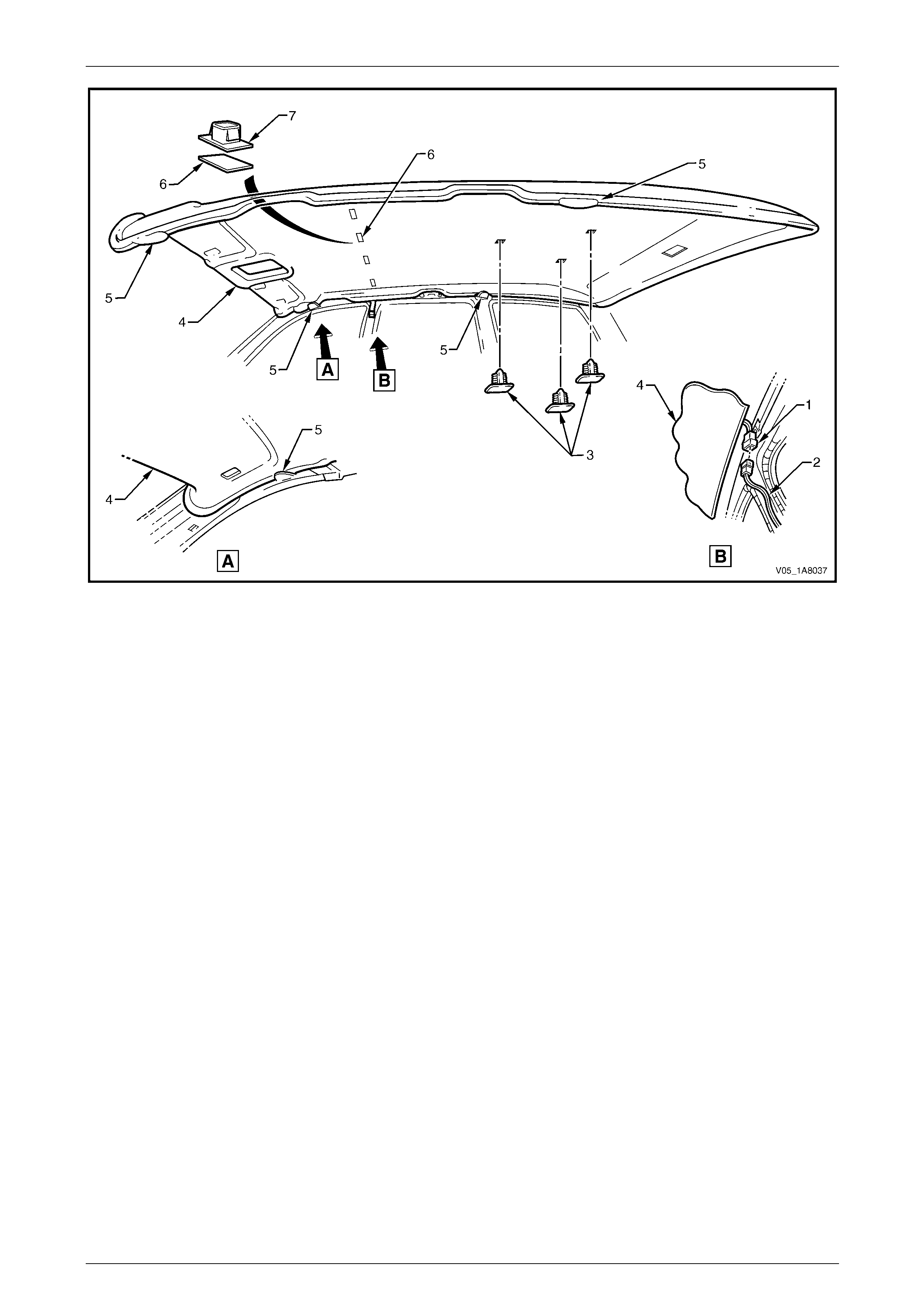
Headlining and Interior Trim Page 1A8–98
Page 1A8–98
Figure 1A8 – 97
Reinstall
Reinstallation of the headlining assembly is the reverse of the removal procedure, noting the follo wing:
1 As required, replace the clips (7) from the roof bo w and the fasteners (6) from the headlining, refer to
Figure 1A8 – 97
2 Temporaraly support the headlining assem bly on the ‘D’ tabs (5) before the trim components are installed.
3 Ensure the headlining assembly harness connector is securely connected to the body wiring harness connector.
4 Ensure the headlining assembly three retainers (3) and the four hook and loop fasteners (6) are secured to the roof
bow panels.
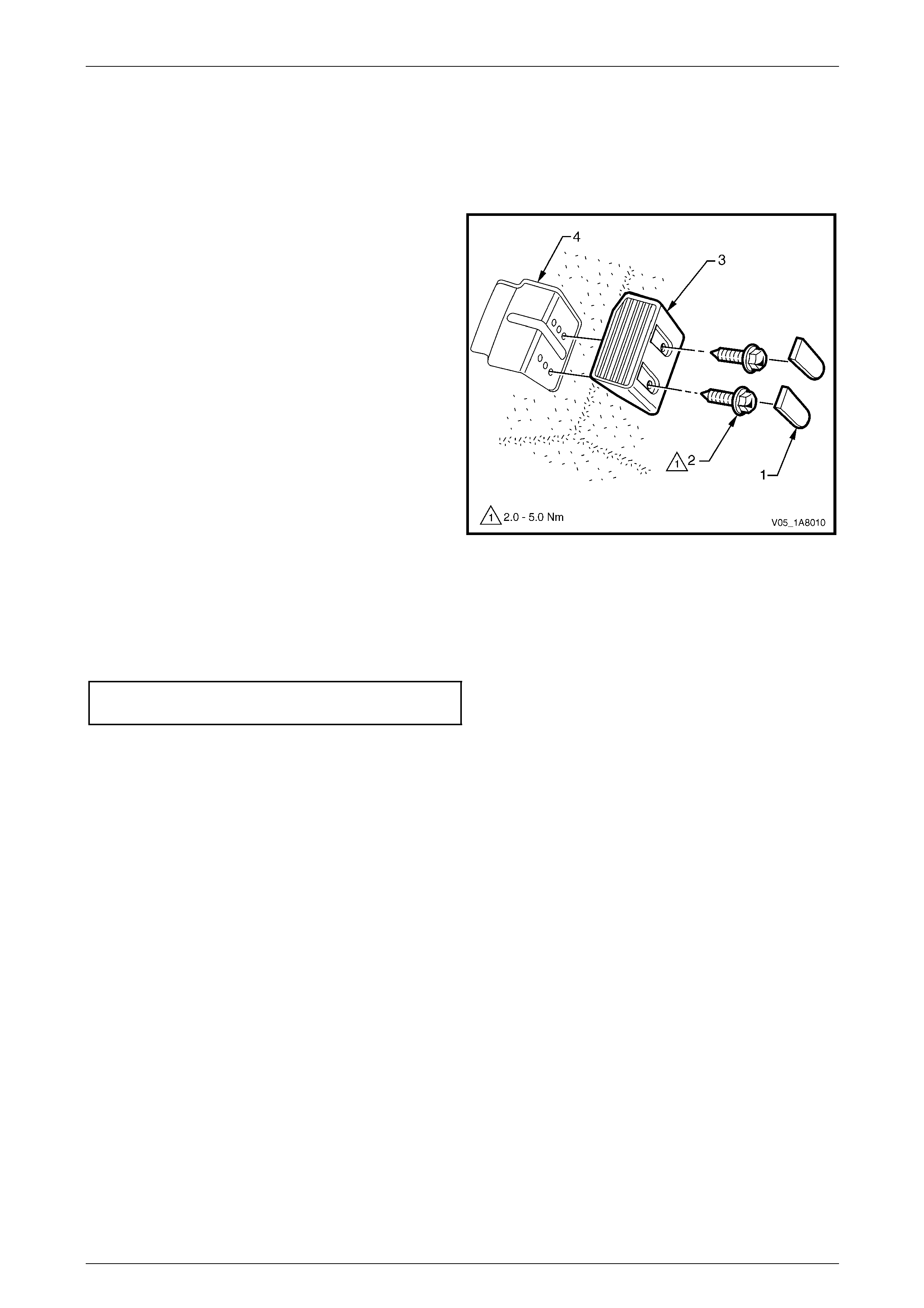
Headlining and Interior Trim Page 1A8–99
Page 1A8–99
4.18 Driver Footrest
LT Section — 14–475
Remove
1 Prise the two screw covers (1) and remove from the
driver footrest.
2 Remove the two screws (2) attaching the driver
footrest (3) to the footrest mounting bracket (4).
3 Remove the footrest pad.
Figure 1A8 – 98
Reinstall
Reinstallation of the driver footrest is the reverse of the removal procedure, noting the following:
Tighten the two screws attaching the driver footrest to the correct torque specification.
Driver footrest attaching screw
torque specification.....................................2.0 – 5.0 Nm

Headlining and Interior Trim Page 1A8–100
Page 1A8–100
4.19 Front Floor Carpet Assembly
LT Section — 14–475
Remove
On vehicles equipped with side impact
airbags, disable the occupant protection
system before performing the following
operation. Refer to Section 12M Occupant
Protection System.
1 Remove the following components as required:
a Rear seat cushion, refer to Section 1A7 Seat Assemblies.
b Side sill trims on both sides, refer to 4.5 Side Sill Trim and Plate.
c Front seat belt lower attaching bolts, refer to Section 12M Occupant Protection System.
d Body hinge pillar trim assembly on both sides, refer to 4.7 Body Hinge Pillar Trim Assembly.
e Both front seats, refer to Section 1A7 Seat Assemblies.
f Driver footrest, refer to 4.18 Driver Footrest.
g Remove the park brake lever cover by grasping the cover firmly by hand and sliding the co ver over the park
brake lever, refer to Section 5A Service and Park Braking System.
h Instrument panel lower trim plate assembly, right-hand and left-hand,
refer to Section 1A3 Instrument Panel and Consol e.
i Instrument panel compartment, refer to Section 1A3 Instrument Panel and Console.
j Instrument panel lower trim panel, refer to Section 1A3 Instrument Panel and Consol e.
k Floor console assembly, refer to Section 1A3 Instrument Panel an d Console.
2 Disconnect the inflatable restraint control module (SDM) wiring harness,
refer to Section 12M Occupant Protection System.
3 Remove the two retaining clips (1) from the front floor
carpet assembly (2) by rotating the clips counter-
clockwise and lifting clear of the attaching studs.
NOTE
To facilitate the removal and installation
procedure, the front floor carpet assembly is
perforated from the front edge (3), through the
centre of the evaporator drain cut-out, to the
forward edge of the lower radio bracket cut-
out (4).
Figure 1A8 – 99

Headlining and Interior Trim Page 1A8–101
Page 1A8–101
4 From inside the left-hand footwell, grasp the edge of
the hole in the front floor carpet assembly around the
evaporator drain hose (1) and tear open the perforated
line (2) by pulling the carpet awa y from the
transmission tunnel.
5 Slide the remaining flap of carpet out from under the
heating, ventilation and air-conditioning (HVAC)
unit (3) and into the right-hand footwell.
6 Carefully manoeuvre the front floor carp et and
insulator assembly out of the vehicle.
Figure 1A8 – 100
Reinstall
Reinstallation of the front floor carpet assembly is the reverse of the removal procedure, noting the following:
1 If a new front floor carpet assembly is being fitted, prior to installation, cut along the perforated line that runs from
the carpet forward edge (3) to the forward edge of the lower radio bracket cut-out (4), refer to F igure 1A8 – 99.
2 Ensure all the cut-outs in the front floor carpet assembl y are correctly alig ned, then install the two retaining clips
and the front seat belt lower attaching bolts, refer to Section 12M Occupant Protection System , to secure the front
floor carpet assembly prior to installing the seats and c onsole.
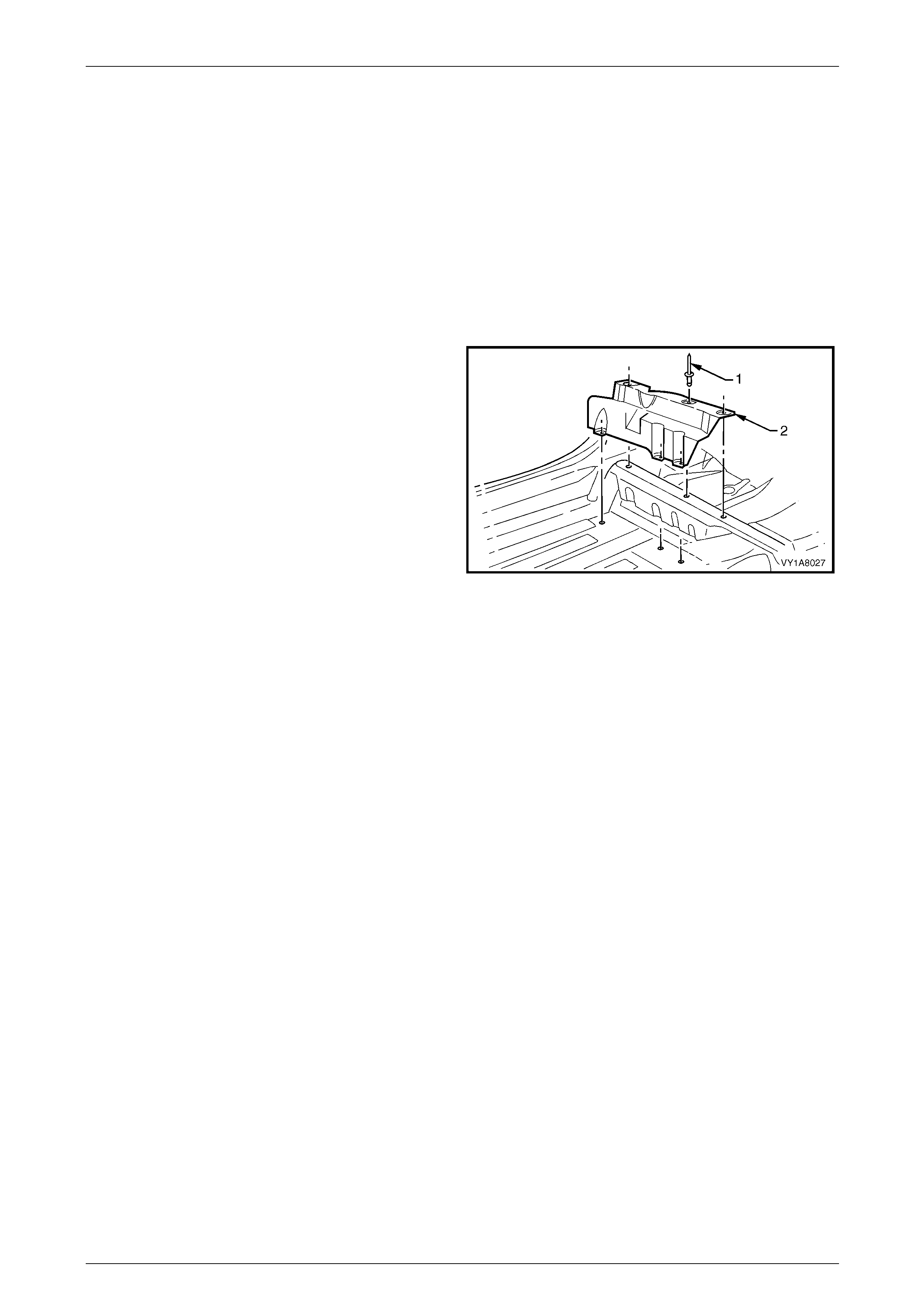
Headlining and Interior Trim Page 1A8–102
Page 1A8–102
4.20 Rear Floor Filler Panel
LT Section — 14–490
Remove
1 Remove the following components as required:
a Side sill trim, refer to 4.5 Side Sill Trim and Plate.
b Rear seat cushion, refer to Section 1A7 Seat Assemblies.
c Partially peel back the rear section of the front floor carpet, refer to 4.19 Front Floor Carpet Assembly.
5 Using a 4.5 mm drill-bit, carefully drill out the pop-
rivets (1) attaching the rear floor filler panel (2) to the
front and rear floor panel assemblies.
6 Remove the rear floor filler panel from the vehicle.
Figure 1A8 – 101
Reinstall
Reinstallation of the rear floor filler panel is the reverse of the removal procedure, noting the following:
Use new 4.8 mm dome-head pop-rivets to attach the rear floor filler panel.

Headlining and Interior Trim Page 1A8–103
Page 1A8–103
4.21 Rear Compartment Floor Panel Carpet
Assembly
LT Section — 14–490
Remove
1 Fold forward the rear seat back.
2 Remove the two retainers (1) from the front of the rear
compartment floor panel carpet assembly (2).
3 Grasp the rear compartment floor panel carpet
handle (3) and lift the rear edg e upward.
4 Lift the rear compartment floor panel carpet assembly
and remove through the liftgate opening.
Figure 1A8 – 102
Disassemble
1 With the aid of a heat gun, prise the carpet (1) from
the rear compartment floor carpet baseboard (2) to
expose the knot of the hook and cord ass embly (3).
2 Undo or cut the knot and remove the hook and cord
assembly from the rear compartment floor carpet
baseboard.
Figure 1A8 – 103
Reassemble
1 Feed the cord assembly through the hole in the baseboard and tie a knot to retain.
2 Apply contact adhesive to the exposed area on the baseboard and press the carpet down firmly on the baseboard.
Reinstall
Reinstallation of the rear com partment floor panel carpet assembly is the reverse of the removal procedure, noting the
following:
Ensure the rear compartment floor panel carpet assembly two retainers are secured to the rear floor panel assembl y.
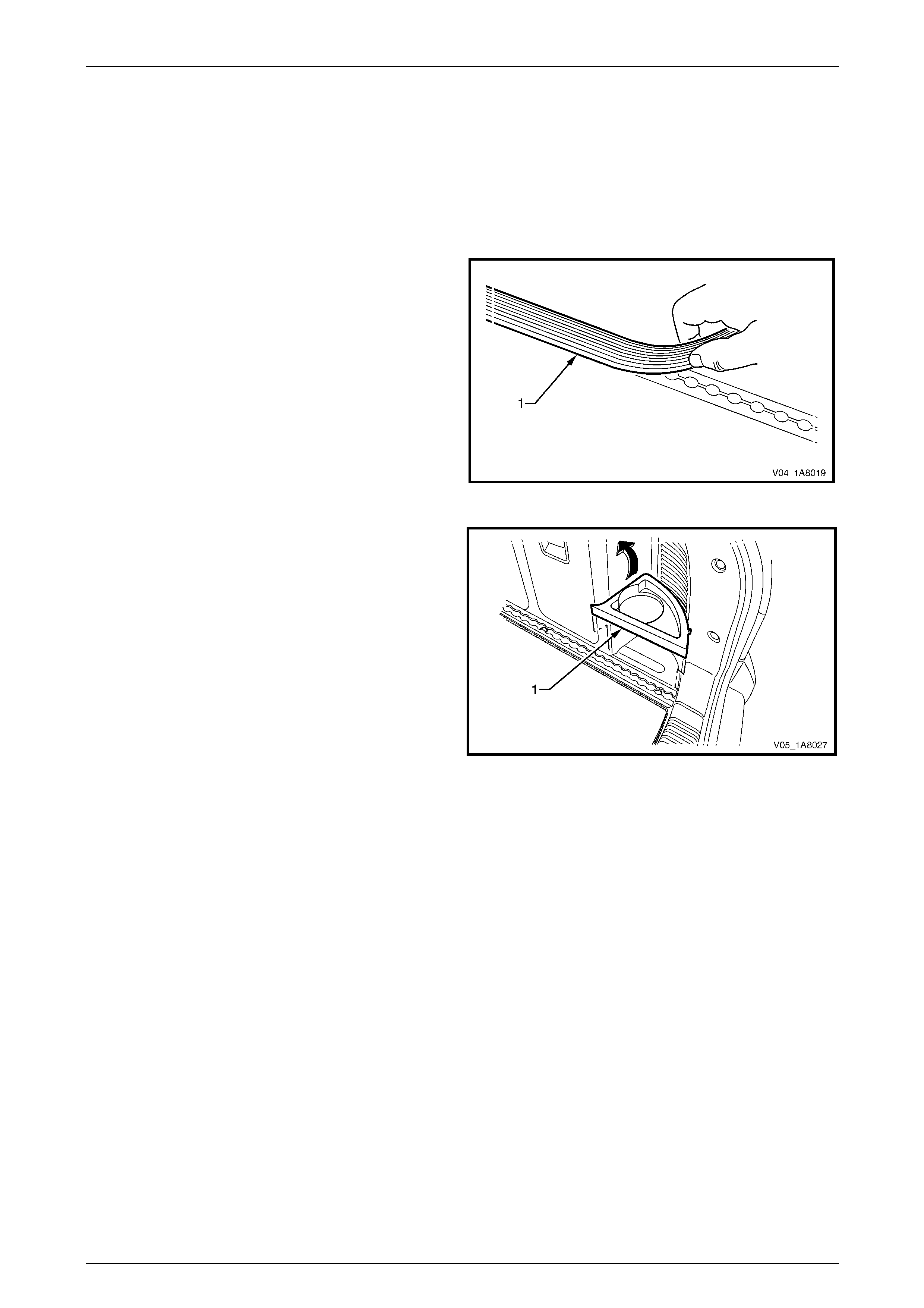
Headlining and Interior Trim Page 1A8–104
Page 1A8–104
4.22 Luggage Tie Down Rails
LT Section — 14–490
Remove
1 Remove the rear compartment floor pane l carpet assembly,
refer to 4.21 Rear Compartment Floor Panel Carpet Assembly.
2 If fitted, remove the luggage tie down rail cover (1).
Figure 1A8 – 104
3 Lift out the rear cup holder (1) and rem ove.
Figure 1A8 – 105
4 For the right-hand side, refer to Figure 1A8 – 106.
a Remove the four Torx screws (1) attaching the right-hand luggage tie down rail (2) to the vehicl e.
b Disengage the rear section of the luggage tie down rail from the quarter inn er trim pane l assembly (3) and
remove through the liftgate opening.
5 For the left-hand side, refer to Figure 1A8 – 106.
a Remove the quarter inner trim panel assembl y (4), refer to 4.9 Quarter Inner Tr im Panel Assembly.
b Remove the four Torx screws (5) attaching the left-hand l uggage tie down rail (6) to the vehicle.
c Remove the luggage tie down rail through the liftgate opening.
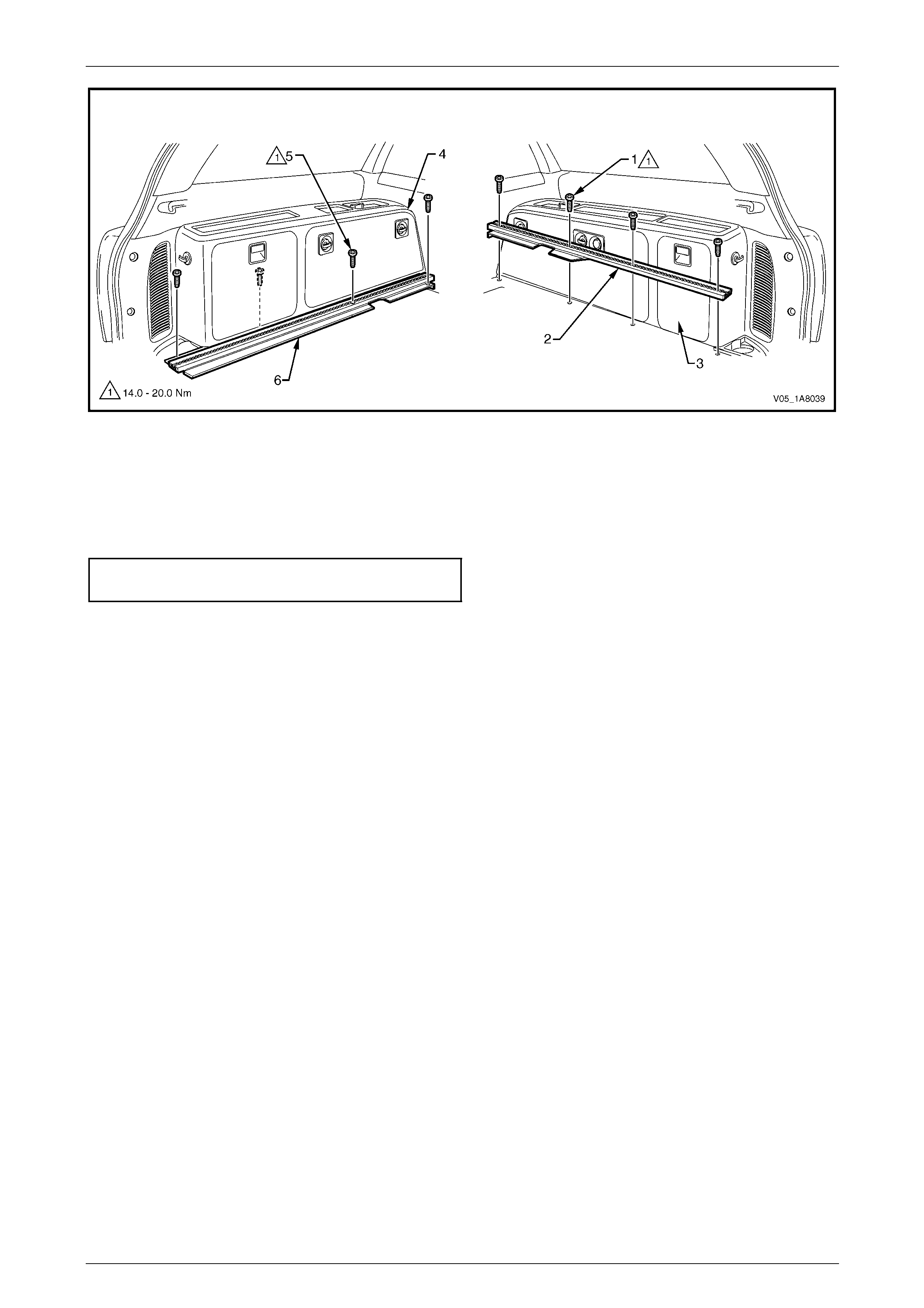
Headlining and Interior Trim Page 1A8–105
Page 1A8–105
Figure 1A8 – 106
Reinstall
Reinstallation of the luggage tie down rails is the reverse of the removal proced ure, noting the following:
Tighten the Torx screws attaching each luggage tie down rail to the correct torque specification.
Luggage tie down rail attaching
Torx screw torque specification...............14.0 – 20.0 Nm
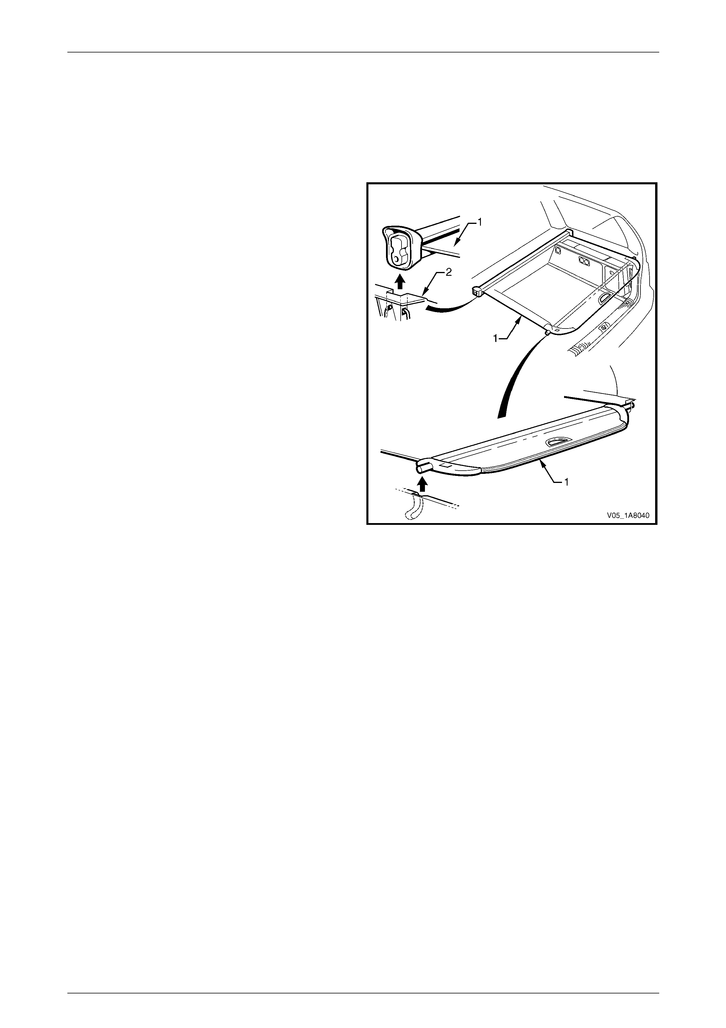
Headlining and Interior Trim Page 1A8–106
Page 1A8–106
4.23 Luggage Shade Assembly
LT Section — AA–000
Remove
1 Retract the luggage shade assembl y (1).
2 Unclip the luggage shade assembly from the body lock
pillar lower trim (2), by lifting vertically.
3 Remove the luggage shade assembly through the
liftgate opening.
Figure 1A8 – 107
Reinstall
Reinstallation of the luggage shade assembly is the reverse of the removal procedure.
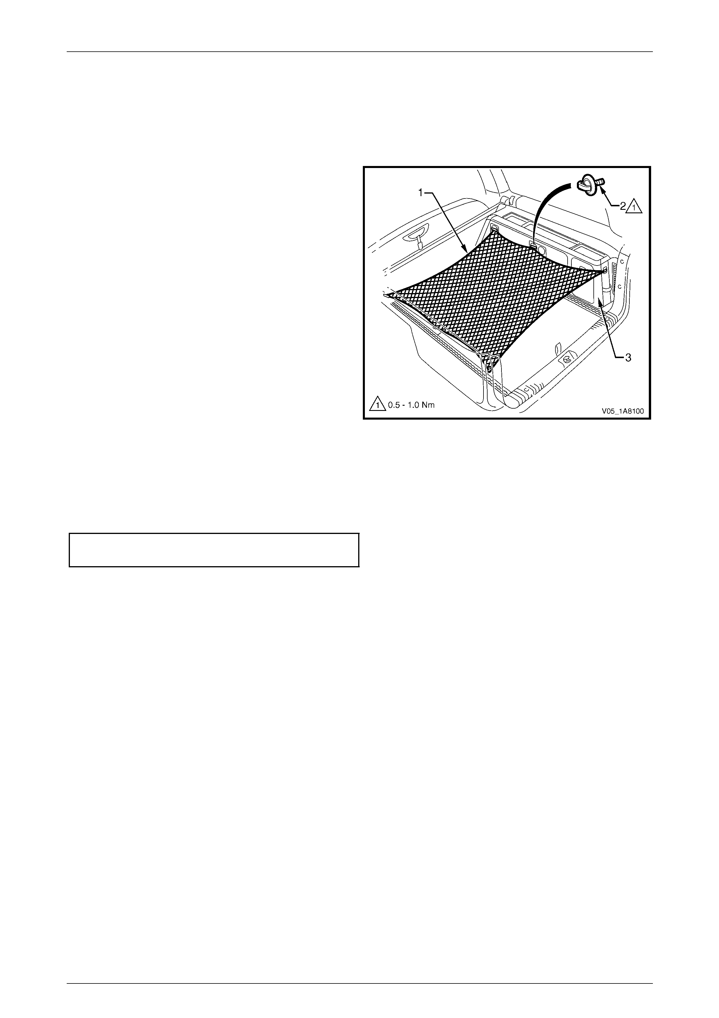
Headlining and Interior Trim Page 1A8–107
Page 1A8–107
4.24 Convenience Net
LT Section — 14–490
Remove
1 Carefully unhook the conv enience net (1) from the
three retainer hooks (2) attached to the quarter inner
trim panel assembly (3) on each side of the v ehicle.
2 Remove the convenience net from the rear
compartment.
3 As required, unscrew the three retainer hooks from the
quarter inner trim panel assembly, on each side of the
vehicle.
Figure 1A8 – 108
Reinstall
Reinstallation of the convenie nce net is the reverse of the removal procedure, noting the following:
As required, tighten the six ret ain er hooks to the correct torque specification.
Convenience net retainer hook
torque specification.....................................0.5 – 1.0 Nm
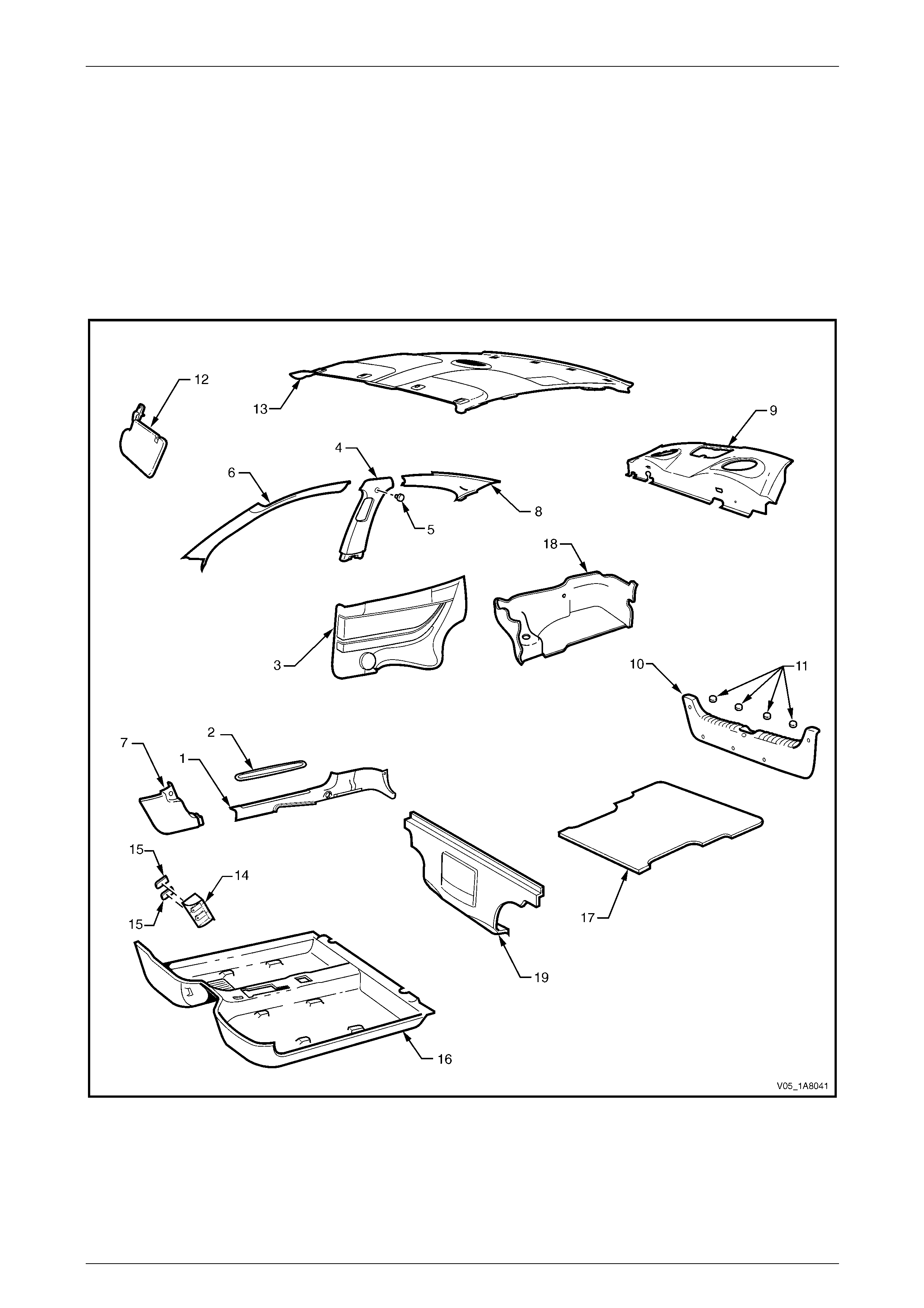
Headlining and Interior Trim Page 1A8–108
Page 1A8–108
5 Service Operations – Coupe
5.1 Components Chart
The headlining and interior trim components for Coupe ve hicles are displayed in the fo llowing chart to assist with their
identification, refer to Figure 1A8 – 109.
For the service procedures of the rear compartment lid carpet,
refer to Section 1A4 Hood, Rear Compartment Lid, Liftgate and Endgate.
For the service procedures of the front door trim panel assembly, refer to Section 1A5 Front and Rear Door Assemblies.
Figure 1A8 – 109

Headlining and Interior Trim Page 1A8–109
Page 1A8–109
Legend
1 Side Sill Trim
2 Side Sill Trim Plate
3 Quarter Trim Panel Assembly
4 Centre Pillar Upper Trim Assembly
5 Screw Cap
6 Windshield Side Garnish
7 Body Hinge Pillar Trim Assembly
8 Body Rear Corner Garnish
9 Rear Window Trim Panel Assembly
10 Rear End Trim Panel Assembly
11 Screw Caps
12 Sunshade Assembly
13 Headlining Assembly
14 Driver Footrest
15 Screw Cap
16 Front Floor Carpet Assembly
17 Rear Compartment Floor Panel Carpet Assembly
18 Quarter Inner Rear Side Carpet
19 Rear Seat-back Panel Carpet
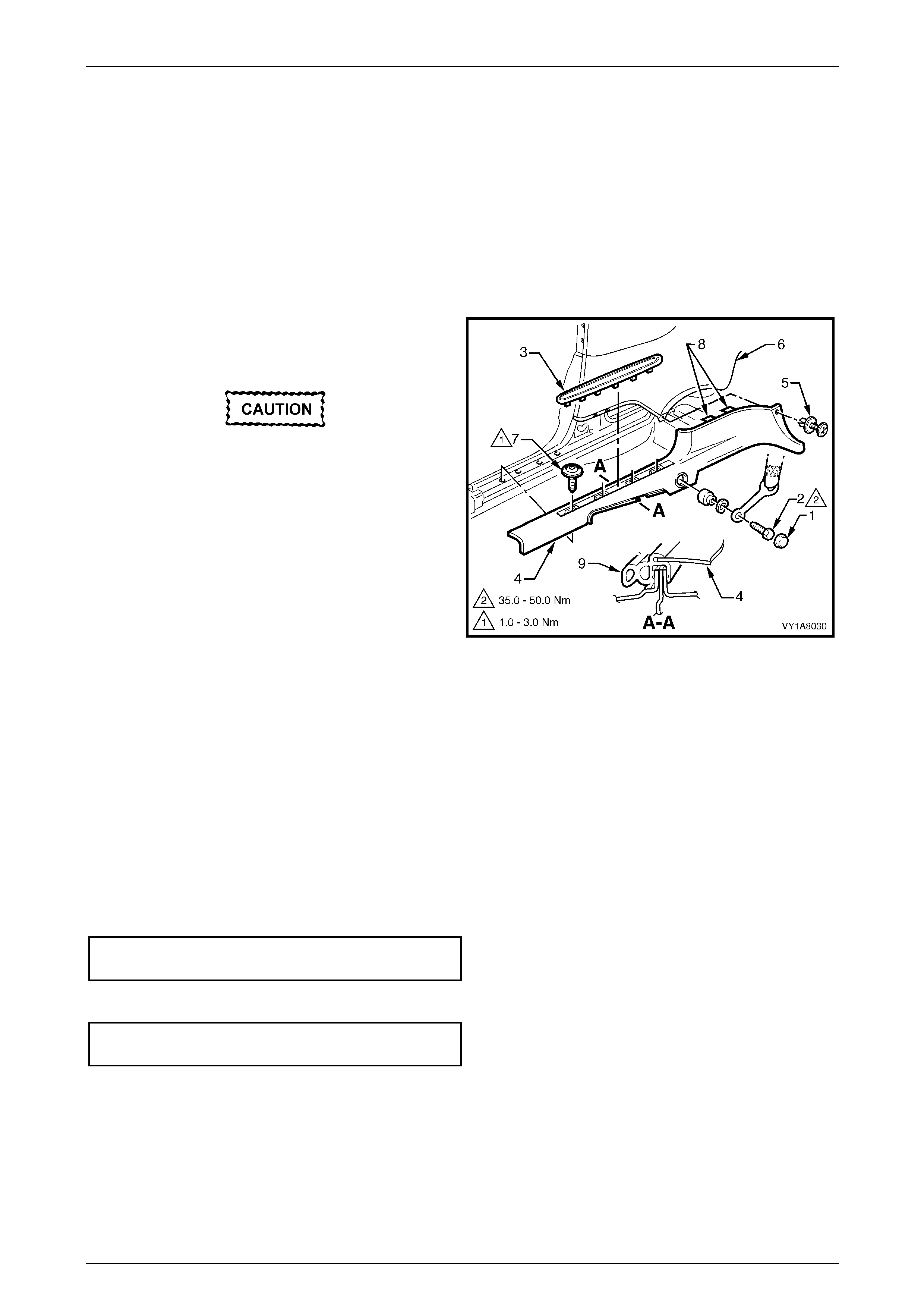
Headlining and Interior Trim Page 1A8–110
Page 1A8–110
5.2 Side Sill Trim and Plate
LT Section — 14–100
Remove
1 Remove the following components as required:
a Rear seat cushion, refer to Section 1A7 Seat Assemblies.
b Front seat outer front cover and outer rear cover, refer to Section 1A7 Seat Assemblies.
2 Prise the cap (1) off and then remove the front seat
belt lower attaching bolt (2), for further information
refer to Section 12M Occupant Protection System.
During the following procedure take care not
to snap the sill trim plate.
3 Carefully lever the side sill trim plate (3) from the side
sill trim (4), starting at the front of the plate and moving
rearward.
4 Remove the retainer (5) securing the re ar of the side
sill trim to the rear quarter trim panel (6).
5 Remove the screw (7), four places, attaching the side
sill trim.
6 Carefully disengag e the two clips (8) securing the rear
of the side sill trim to the lower edge of the rear quarter
trim panel by pulling the rear edge of the sid e sill trim
towards the centre of the vehicle.
7 Remove the side sill trim through the front door
opening.
Figure 1A8 – 110
Reinstall
Reinstallation of the side sill trim and plate is the reverse of the removal procedure, noting the following:
1 Ensure the outer edge of the side sil l trim en gages the door opening weatherstrip (9), refer to
Figure 1A8 – 110.
2 Ensure the two clips (8) engage the lower edge of the rear quarter trim panel and the ret ainer (5) is secured.
3 Tighten the four screws (7) attaching the side sill trim to the correct torque specification.
Side sill trim attaching screw
torque specification.....................................1.0 – 3.0 Nm
4 Tighten the front seat belt lower attaching bolt (2) to the correct torque specification.
Front seat belt lower attaching bolt
torque specification ................................35.0 – 50.0 Nm
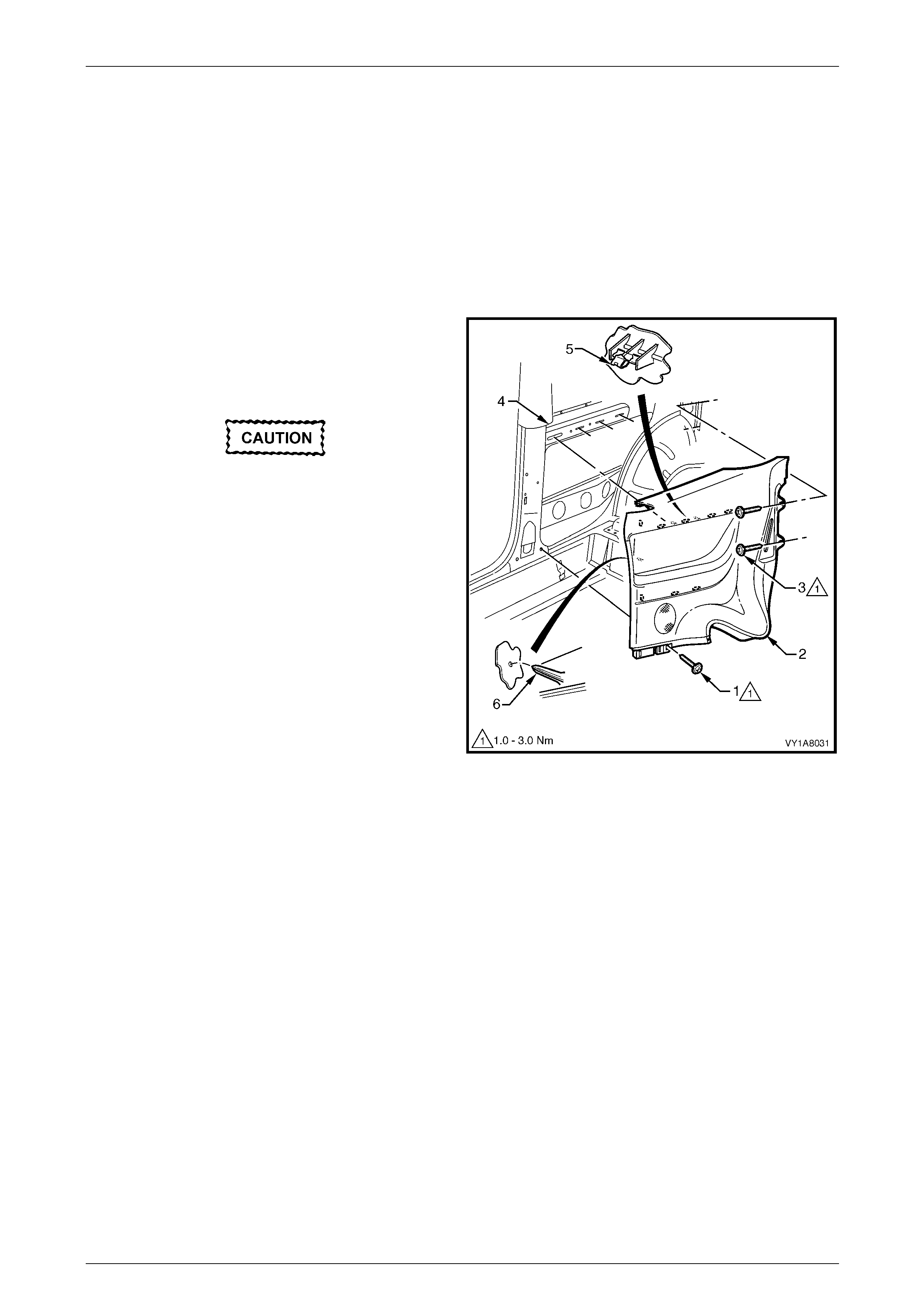
Headlining and Interior Trim Page 1A8–111
Page 1A8–111
5.3 Quarter Trim Panel Assembly
LT Section — 14–130
Remove
1 Remove the following components as required:
a Rear seat cushion assembly and rear seat-back assembly, refer to Section 1A7 Seat Assemblies.
b Side sill trim, refer to 5.2 Side Sill Trim and Plate.
2 Remove the screw (1) from the lower edge of the
quarter trim panel assembly (2).
3 Remove the two screws (3) from the rear edge of the
quarter trim panel assembly.
When removing the quarter trim panel
assembly, take care not to damage the three
locating pins (6).
4 Starting at the lower edge of the centre pillar upper
trim assembly (4) and moving alternately clockwise
and counter clockwise, disengage the eight attaching
clips (5) by carefully manoeuvring the quarter trim
panel assembly away from the quarter panel inner
assembly.
5 Remove the quarter trim panel assembly.
6 As required, remove the retaining clips from the
vehicle and fit to the trim.
Figure 1A8 – 111
Disassemble
To disassemble the quarter trim panel assem bl y, remove all the components attached to the quarter trim panel
foundation (1) as described in this Section, refer to Figure 1A8 – 112.
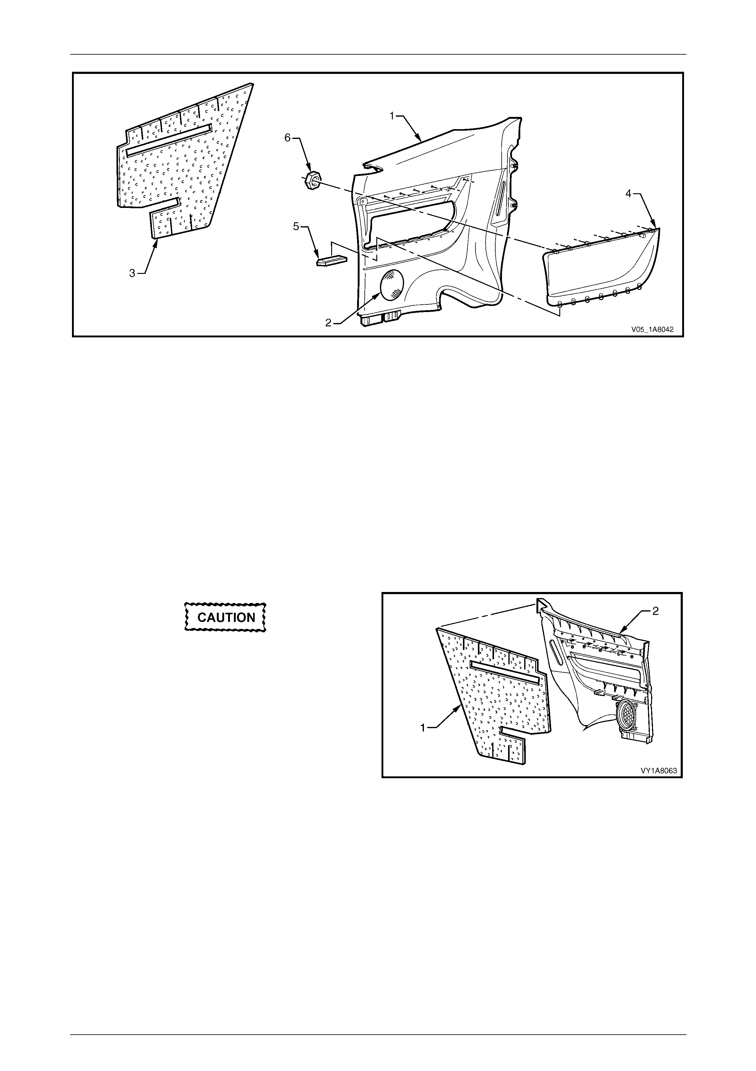
Headlining and Interior Trim Page 1A8–112
Page 1A8–112
Figure 1A8 – 112
Legend
1 Quarter Trim Panel Foundation
2 Radio Speaker Grille
3 Quarter Trim Panel Insulator Assembly
4 Quarter Trim Panel Armrest Insert Assembly
5 Armrest Insert Assembly Retainer (seven places)
6 Armrest Insert Assembly Nut (seven places)
Radio Speaker Grille
The radio speaker grill e is permanently heat-staked to the quarter trim panel assembly and cannot be serviced
separately.
Quarter Trim
Panel Insulator Assembly
Remove
Take care not to tear the insulator (1) and
retain on it as much adh esive as possible. Do
not fold the insulator and store in a flat
location with the adhesive facing away from
other surfaces.
Peel the insulator assembly (1) slo wly across the quarter
trim panel (2) and remove.
Figure 1A8 – 113
Reinstall
1 If required, apply additional hot melt adhesive with a high softening point (e.g. 90°C).
2 Locate the insulator assembly centrally on the back of the quarter trim panel foundation and press firmly into
position.
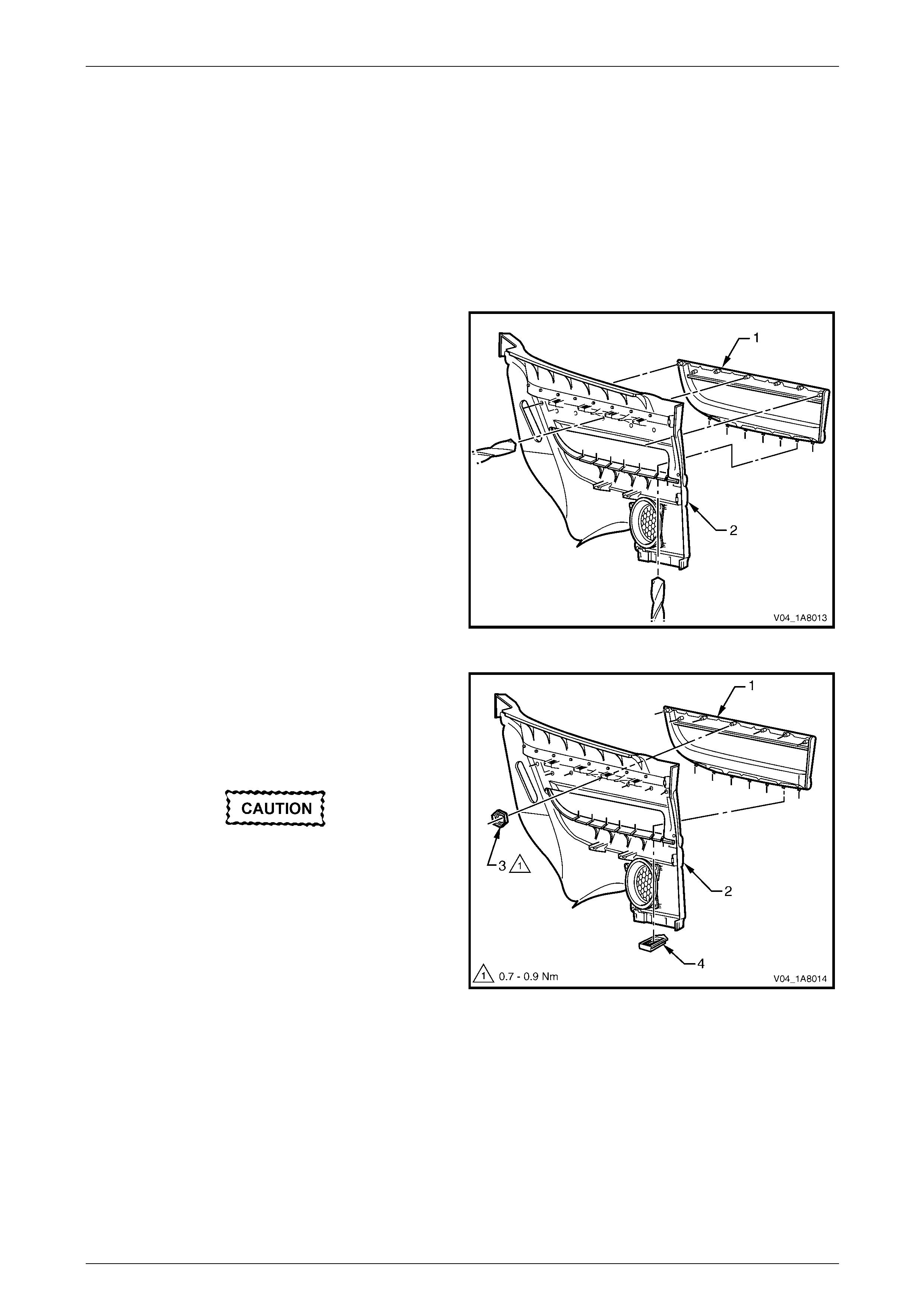
Headlining and Interior Trim Page 1A8–113
Page 1A8–113
Quarter Trim
Panel Armrest Insert Assembly
Remove
NOTE
If a heat staked armrest insert assembly is
removed from the quarter trim panel assembly, it
must be replaced.
1 Partially peel back the upper portion of the insulator assembly from the quarter trim panel assembly, refer to
Quarter Trim Panel Insulator Assembly in this Section.
2 If the armrest insert assembly (1) is retained to the
quarter trim panel (2) using heat stakes, drill out the
heat-stakes, in fourteen places, retaining the armrest
insert assembly to the quarter trim panel.
Figure 1A8 – 114
3 If the armrest insert assembly (1) is retained to the
quarter trim panel (2) using speed nuts and clips,
proceed as follows:
a Remove the retainer (4), seven places, b y slidin g
and pulling it away from the quarter trim panel.
Take care when removing the speed nut (3),
as the rotating action may cut off the shaft to
which the nut is attached, requiring the
replacement of the quarter trim panel armrest
insert assembly.
b Using side-cutters, cut the speed nut (3), seven
places, attaching the armrest insert assembly to
the quarter trim panel then remove from the lugs
and discard. Figure 1A8 – 115
4 Prise the armrest insert assembly from quarter trim panel assembly and remove.
Headlining and Interior Trim Page 1A8–114
Page 1A8–114
Reinstall
NOTE
All replacement quarter trim panel armrest insert
assemblies are supplied with nuts and clips.
Reinstallation of the quarter trim armrest insert assembly is the reverse of the removal procedure, noting the following:
1 Ensure the armrest insert assembly is sitting flush against the quarter trim panel along the entire top contacting
surface.
2 Tighten the seven new speed nuts attaching the quarter trim panel armrest insert assembly to the correct torque
specification.
Quarter trim panel armrest
insert assembly attaching
speed nut torque specification ....................0.7 – 0.9 Nm
3 Ensure the quarter trim panel armrest insert assembly is secured with the seven retaini ng clips.
Reinstall
Reinstallation of the quarter trim panel assembly is the reverse of the removal procedure, noting the following:
Take care not to snap off the locating pins
when fitting the quarter trim panel assembly.
1 Ensure the quarter trim panel assembly three locating pins are aligned with the locating holes in the quart er panel
inner assembly.
2 Ensure the leading edge of the quarter trim panel assembly engages the door opening weatherstrip.
3 Ensure the eight retaining clips are secure d to the quarter panel inner assembly.
4 Tighten the screws attaching the qu arter trim panel assembly to the correct torque spec ification.
Quarter trim panel assembly
attaching screw torque specification...........1.0 – 3.0 Nm
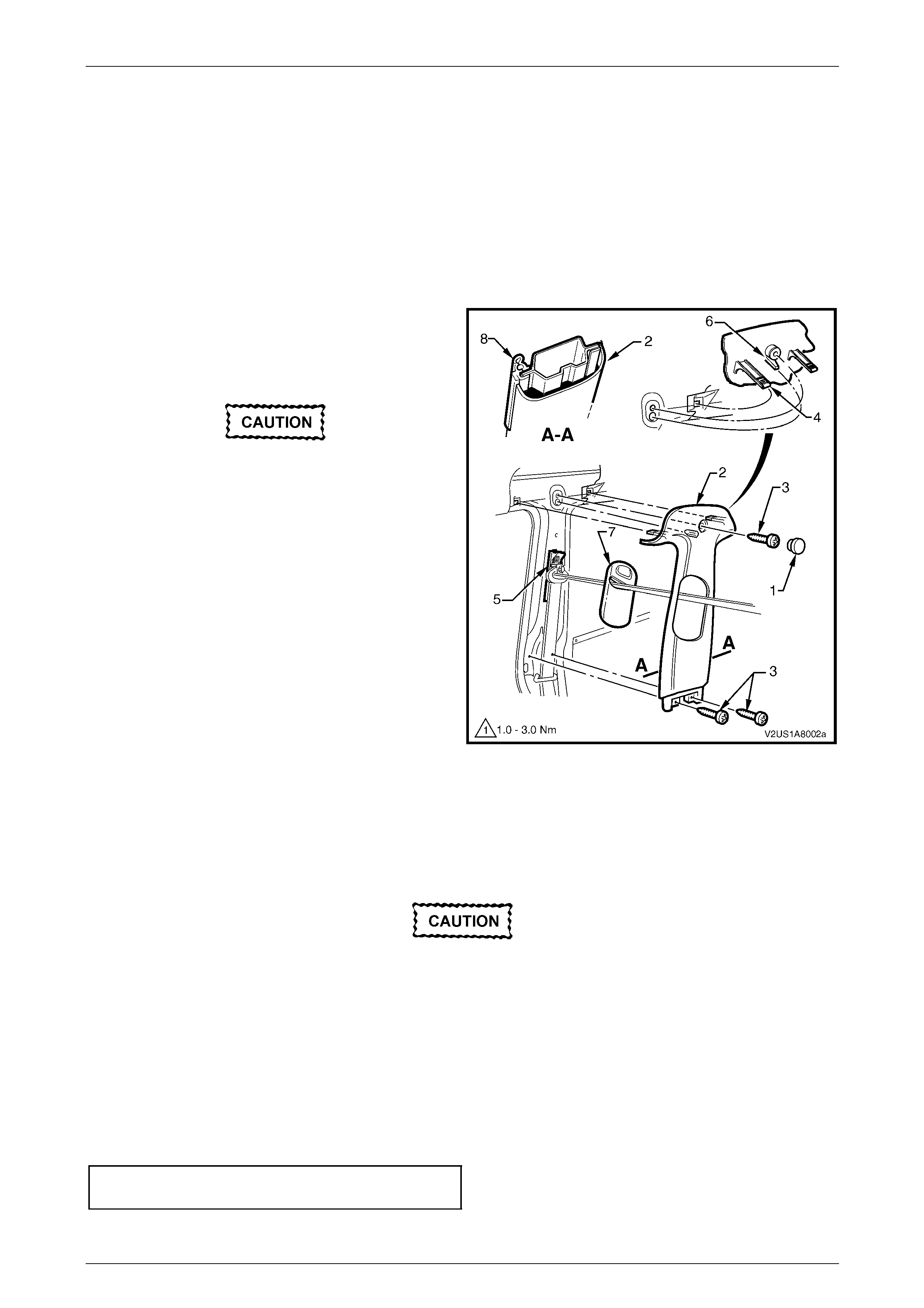
Headlining and Interior Trim Page 1A8–115
Page 1A8–115
5.4 Centre Pillar Upper Trim Assembly
LT Section — 14–100
Remove
1 Remove the following components as required:
a Side sill trim, refer to 5.2 Side Sill Trim and Plate.
b Quarter trim panel assembly, refer to 5.3 Quarter Trim Panel Assembly.
2 Remove the screw cap (1) from the upper attachment
of the centre pillar upper trim assembly (2).
3 Remove the three screws (3) attaching the centre
pillar upper trim assembly.
When removing the centre pillar upper trim
assembly, take care not to damage the
locating pin (6) below the upper attaching
screw position.
4 Pull the upper edge of the centre pillar upper trim
assembly away from the headlining assembly to
disengage the two retaining clips (4) and the seatbelt
guide adjuster assembly (5).
5 Feed the seatbelt and anchor plate thro ugh the centre
pillar upper trim assembly and remove the centre pillar
upper trim assembly.
6 If required, remove the seatbelt adjuster trim (7) by
gently spreading the outer edges of the centre pillar
upper trim assembly and lifting out the seatbelt
adjuster trim.
7 As required, remove the retaining clips from the
vehicle and fit to the trim. Figure 1A8 – 116
Reinstall
Reinstallation of the centre pillar upper trim assembly is the reverse of the removal procedure, noting the following:
1 Ensure the seatbelt adjuster trim (7) and the seatbelt guide adjuster assembly (5) are in the fully up position and
are correctly aligned prior to installing the centre pillar upper trim assembly (2), refer to Figure 1A8 – 116.
Take care not to snap off the locating pin
when fitting the centre pillar upper trim
assembly.
2 Ensure the locating pin belo w the upper attaching screw position in the centre pillar up per trim assembly is correctly
aligned with the locating hole in the centre pillar.
3 Ensure the leading edge of the centre pillar upper trim assembly engages the front door opening weatherstrip
assembly (8).
4 Ensure the centre pillar upper trim assembl y two retaining clips are secured to the centre pillar.
5 Check the seatbelt operation prior to tightening the centre pillar u pp er trim assemb ly attaching screws.
6 Tighten the centre pillar uppe r trim assembly three attaching screws to the specified torque.
Centre pillar upper trim assembly
attaching screw torque specification...........1.0 – 3.0 Nm
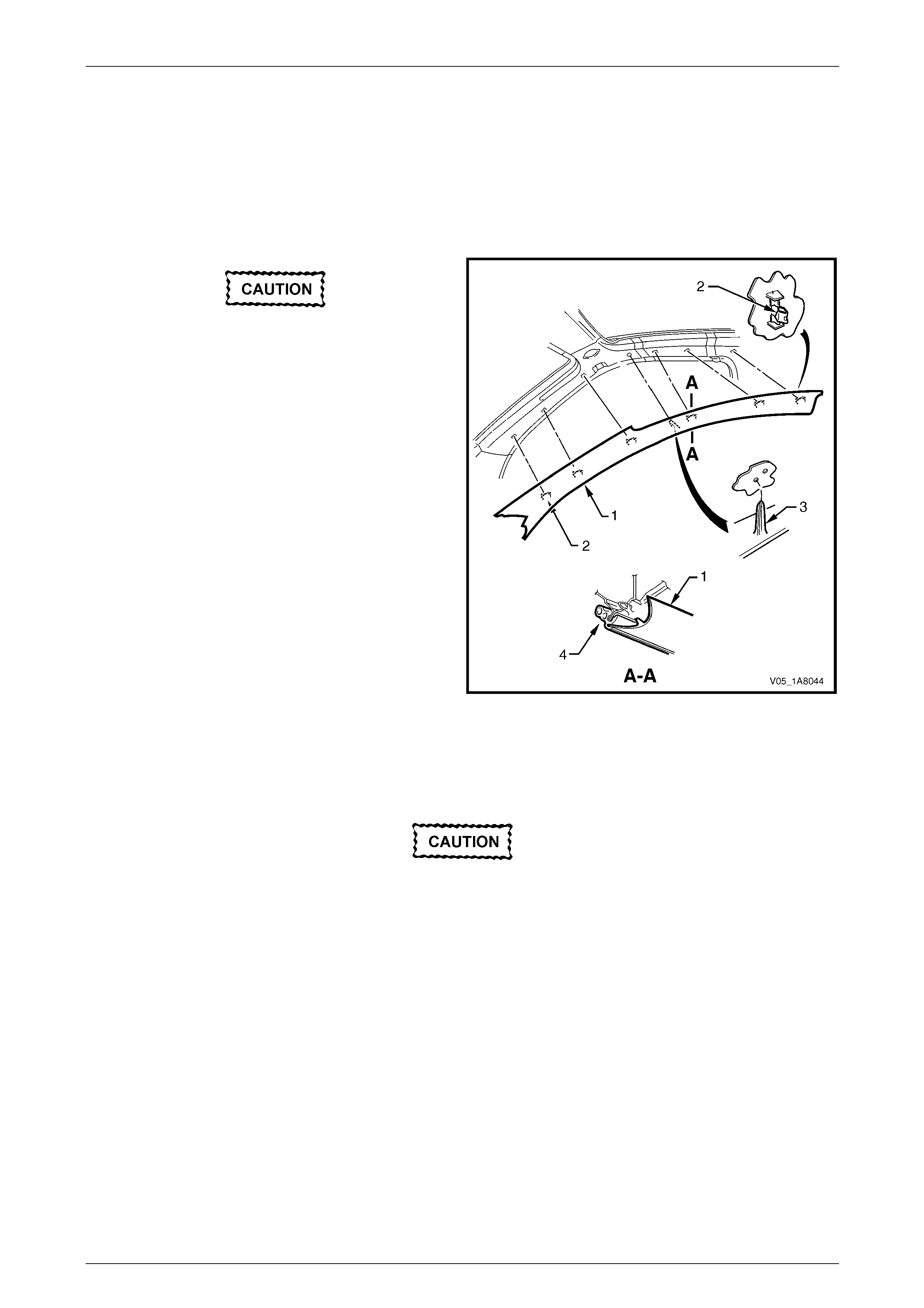
Headlining and Interior Trim Page 1A8–116
Page 1A8–116
5.5 Windshield Side Garnish
LT Section — 14–100
Remove
1 Partially remove the centre pill ar upper trim assembly by removing the upper attaching screw,
refer to 5.4 Centre Pillar Upper Trim Assembly.
When removing the windshield side garnish,
take care not to damage the locating pin (3).
2 Starting at the upper rear edge of the windshield side
garnish (1) disengage the si x retaining clips (2).
3 Remove the windshield side garnish.
4 As required, remove the retaining clips from the
vehicle and fit to the garnish.
Figure 1A8 – 117
Reinstall
Reinstallation of the windshield side garnish is the reverse of the removal procedure, noting the following:
Take care not to snap off the locating pin
when fitting the windshield side garnish.
1 Ensure the windshield side ga rnish locating pin is aligned with the locating h ole i n the hinge pillar inner panel.
2 Ensure the outer edge of the winds hield side garnish (1) engages the front door opening weatherstrip (4 ), refer to
Figure 1A8 – 117.
3 Ensure the six retaining clips are secured to the hinge p illar inner panel.
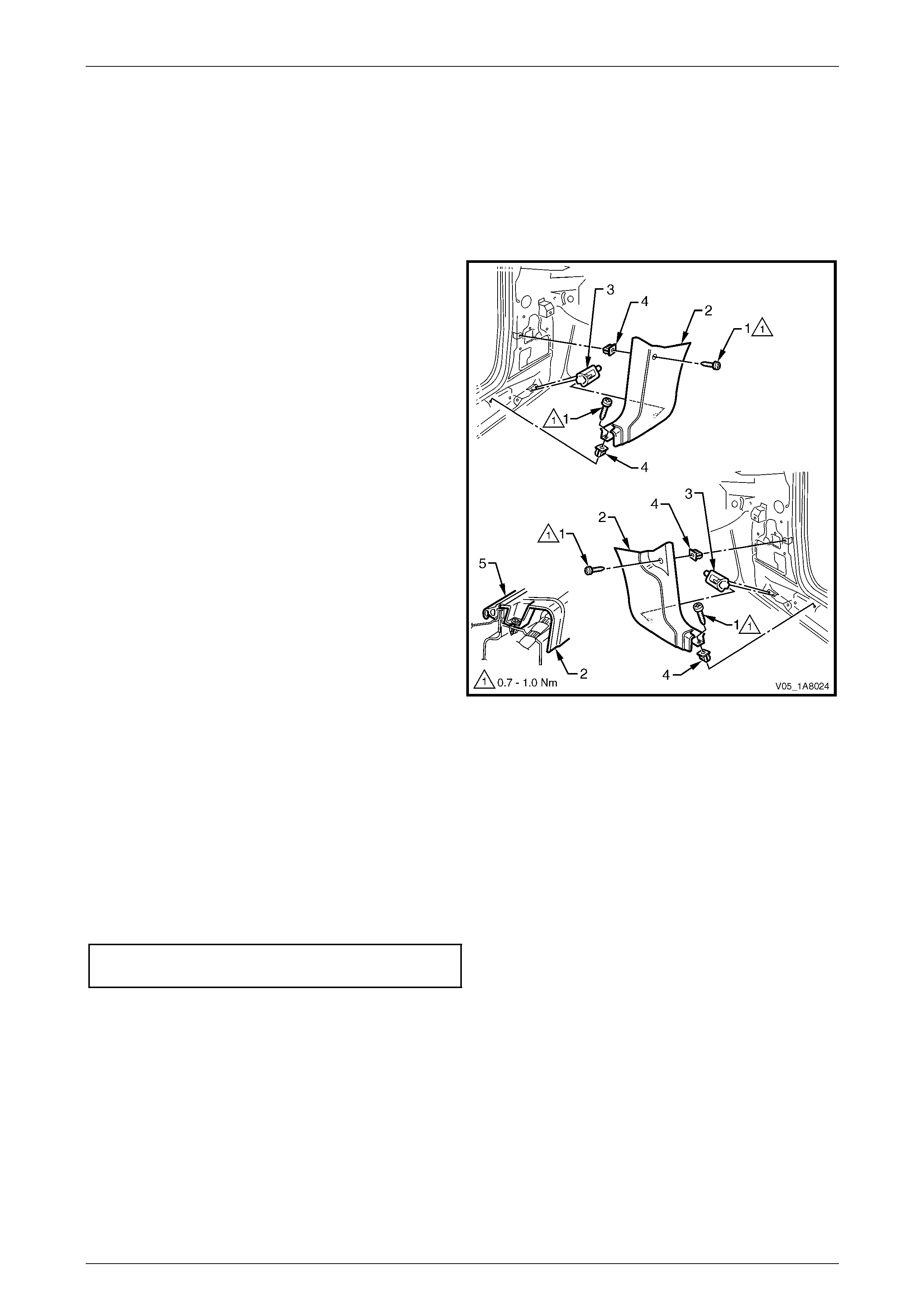
Headlining and Interior Trim Page 1A8–117
Page 1A8–117
5.6 Body Hinge Pillar Trim Assembly
LT Section — 14–100
Remove
1 Partially remove the side sill trim, refer to 5.2 Side Sill Trim and Plate.
2 Remove the two attaching screws (1) from the body
hinge pillar trim assembly (2).
3 Disengage the body hinge pillar trim clip (3) by pul ling
the lower edge of the body hinge p illar trim assembly
rearward and away from the sheetmetal.
4 Remove the body hinge pillar trim assembly.
5 If required, remove the body hinge pillar trim clip a nd
the two nut inserts (4).
Figure 1A8 – 118
Reinstall
Reinstallation of the body hinge pillar trim assembl y is the reverse of the removal procedure, noting the following:
1 Ensure the body hinge pil lar trim clip is correctly engaged in the hinge pillar inner panel.
2 Ensure the nut inserts are in good condition and correctly located in the hinge pillar inner panel.
3 Ensure the outer edge of the body hinge pillar trim assembl y engages the front door opening weatherstrip (5), refer
to Figure 1A8 – 118.
4 Tighten the body hinge pillar trim assembly two attaching screws to the correct torque specification.
Body hinge pillar trim assembly
attaching screw torque specification...........0.7 – 1.0 Nm
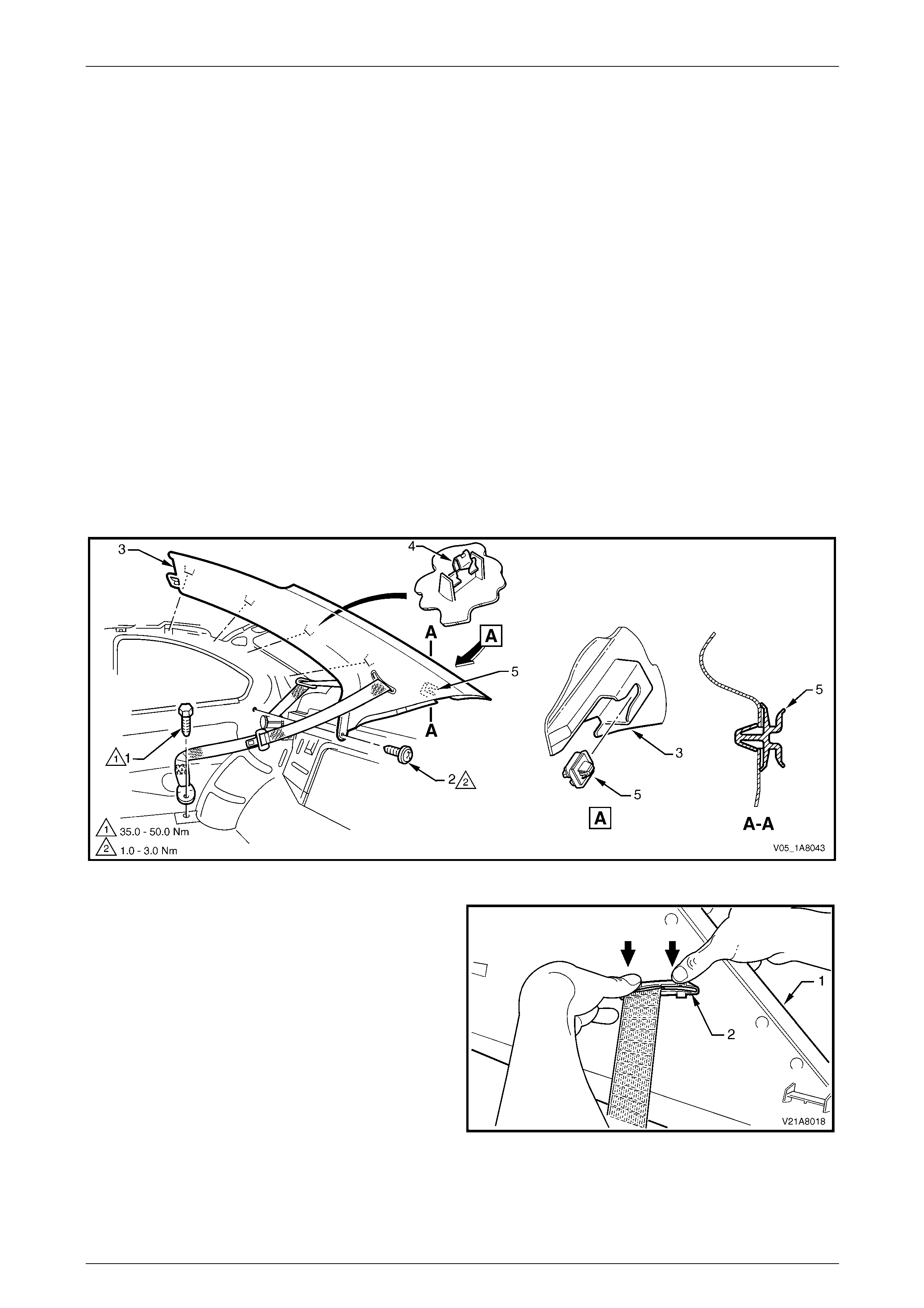
Headlining and Interior Trim Page 1A8–118
Page 1A8–118
5.7 Body Rear Corner Garnish
LT Section — 14–120
Remove
1 Remove the following components as required:
a Rear seat cushion and rear seat-back assembly, refer to Section 1A7 Seat Assemblies.
b Partially remove the rear portion of the side sill trim to enable the removal of the quarter trim panel, refer to
5.2 Side Sill Trim and Plate.
c Quarter trim panel assembly, refer to 5.3 Quarter Trim Panel Assembly.
d Centre pillar upper trim assembly, refer to 5.4 Centre Pillar Upper Tr im Assembly.
2 Remove the rear seat belt lower attaching bolt (1), refer to Figure 1A8 – 119.
3 Remove the screw (2) from the lower edge of the body rear corner garnish (3).
4 Pull the front edge of the body rear corner garnish away from the body lock pillar and working rearward, disengage
the four retaining clips (4).
5 Carefully slide the bod y rear corner garnish forward to disengage it from the retainer (5) which is attached to the
body lock pillar and move the body rear corner garnish away from the body lock pillar.
Figure 1A8 – 119
6 From the back of the body rear corner garnish (1)
disengage the seat belt escutcheo n (2) and feed the
seat belt and anchor plate through the opening.
7 Remove the body rear corner garnish.
8 As required, remove the retaining clips from the
vehicle and fit to the garnish.
9 If required, prise the retainer (5) from the body lock
pillar with a fine, flat-blade screwdriver, refer to
Figure 1A8 – 119.
Figure 1A8 – 120
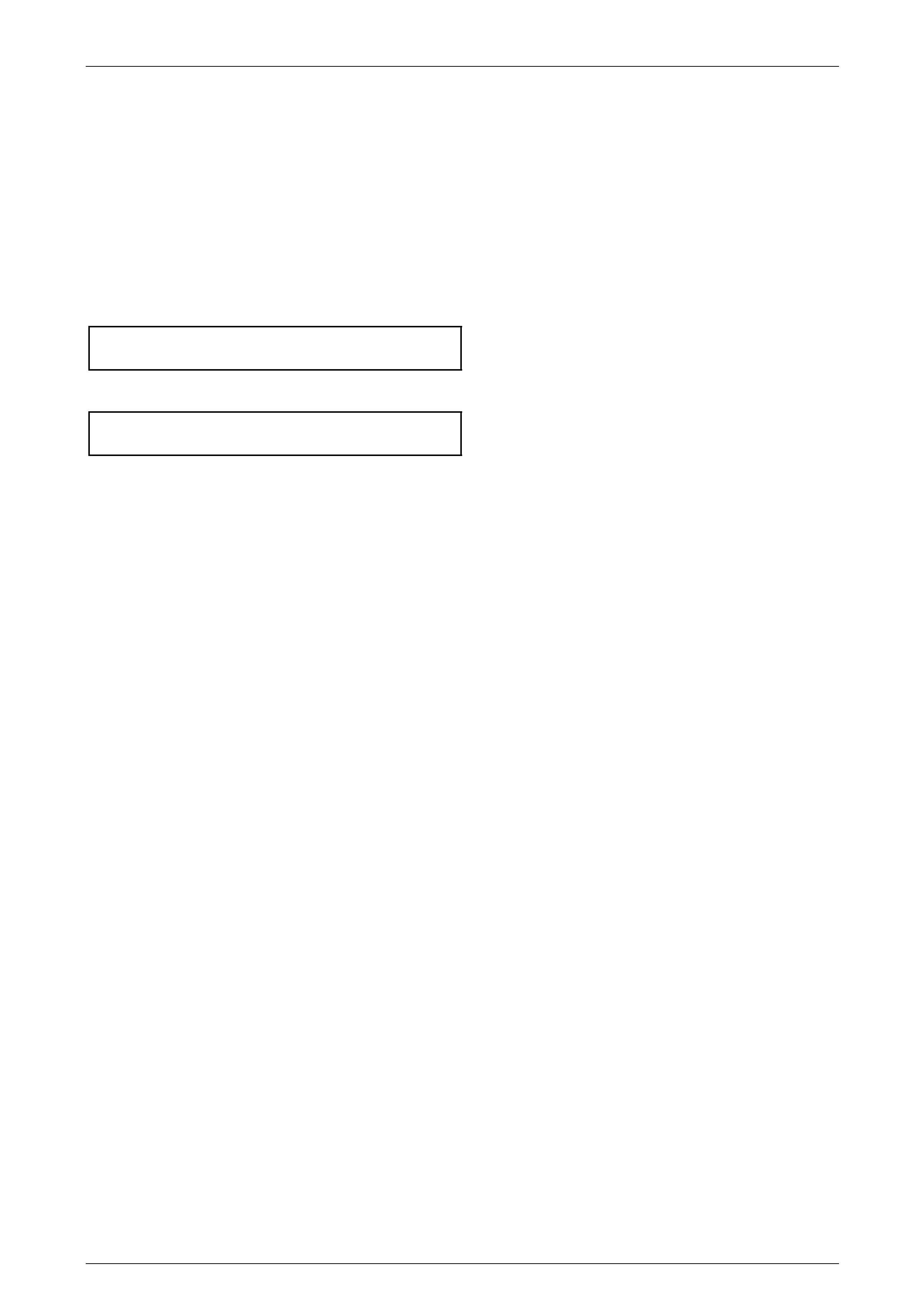
Headlining and Interior Trim Page 1A8–119
Page 1A8–119
Reinstall
Reinstallation of the body rear corner garnis h is the reverse of the removal procedure, n oting the following:
1 If removed, install the retainer onto the body lock pillar.
2 Slide the body rear corner garnish re arward to engage it with the retainer.
3 Ensure the four retaining clips are aligned with their corresponding holes in the body lock pillar and tap the body
rear corner garnish into place.
4 Ensure the outer edge of the body rear corner garnish engages the door opening weatherstrip.
5 Tighten the screw attaching the body re ar corner garnish to the correct torque specification.
Body rear corner garnish
attaching screw torque specification...........1.0 – 3.0 Nm
6 Tighten the rear seat belt lower attaching bolt to the correct torque specification.
Rear seat belt lower attaching bolt
torque specification.................................35.0 – 50.0 Nm
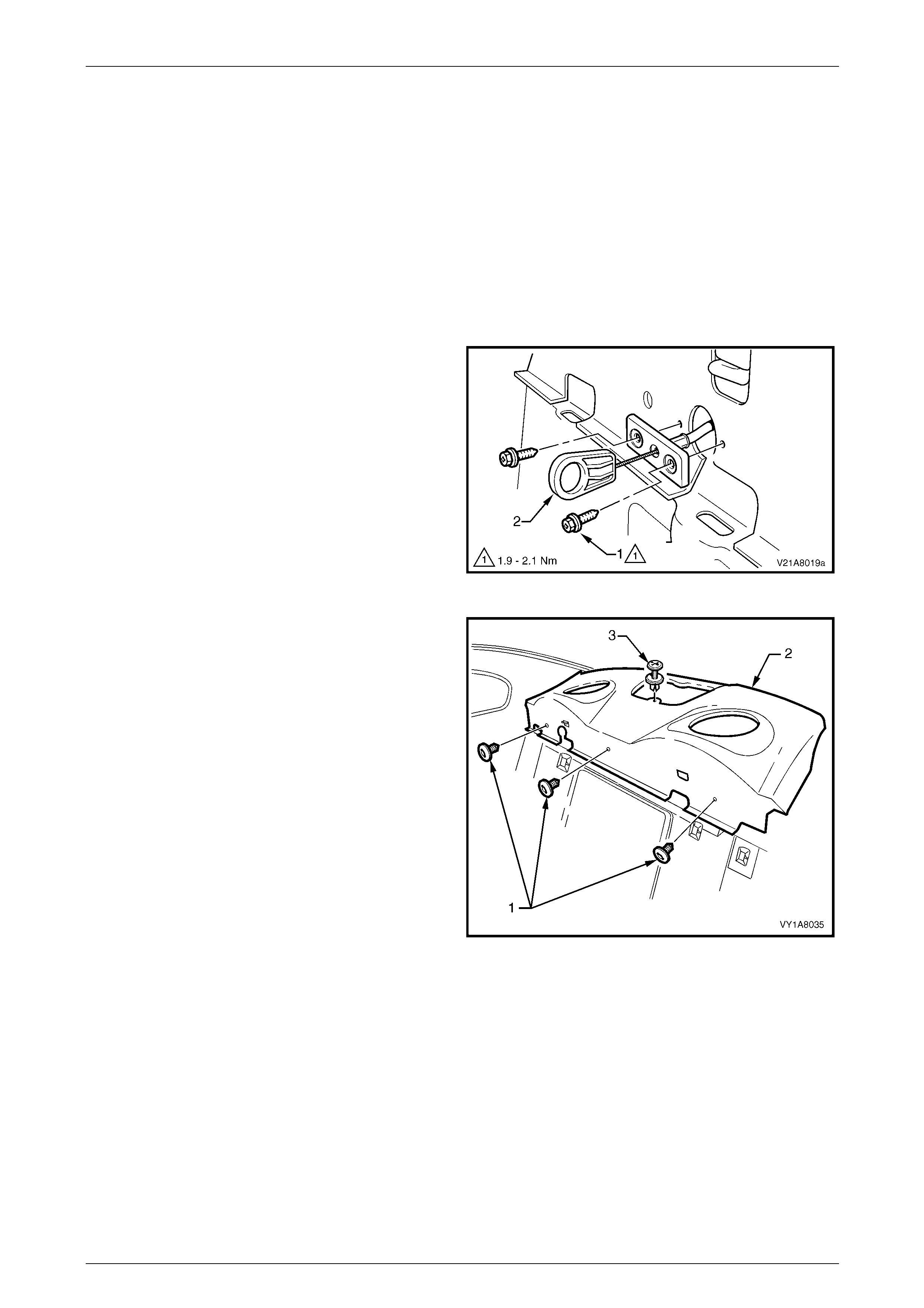
Headlining and Interior Trim Page 1A8–120
Page 1A8–120
5.8 Rear Window Trim Panel Assembly
LT Section — 14–460
Remove
1 Remove the following components as required:
a Rear seat cushion and rear seat-back assembly, refer to Section 1A7 Seat Assemblies.
b Partially remove the bod y lock pillar garnish on both sides, refer to 5.7 Body Rear Corner Garnish.
c High mount stop lamp assembly, refer to Section 12B Lighting System.
2 Remove the two screws (1) attaching the rea r
compartment lid emergency release cable
assembly (2).
3 Pull the rear compartment lid emergenc y release cable
assembly away from the rear window trim panel
assembly.
Figure 1A8 – 121
4 Remove the three retainers (1) attaching the forward
edge of the rear window trim panel assemb ly (2).
5 Remove the retainer (3) attaching the upper surface of
the rear window trim panel assembly.
6 Lift the front edge of the rear window trim panel
assembly and feed the rear compartment lid
emergency release ca ble through the slot in the parcel
shelf.
7 Remove the rear window trim panel assembly.
Figure 1A8 – 122
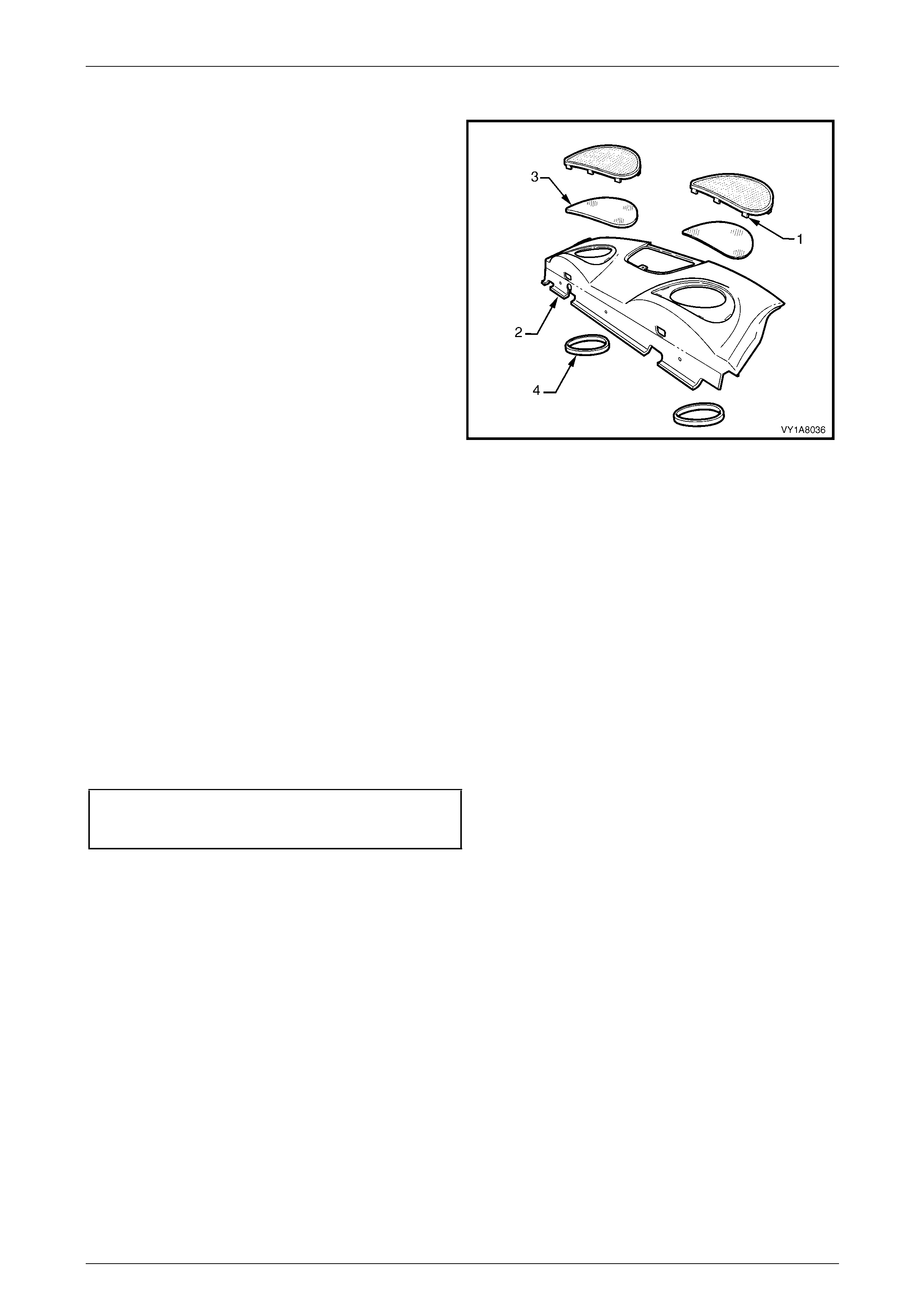
Headlining and Interior Trim Page 1A8–121
Page 1A8–121
Disassemble
1 Bend the tab (1), nine places, of the speaker grille to a
vertical position and remove the speaker grille from
the rear window trim panel assembly (2).
2 Remove the dust seal (3) from the speaker grille.
3 Remove the speaker seal (4) from the rear windo w
trim panel assembly.
4 If required, repeat for the opposite side.
Figure 1A8 – 123
Reassemble
Reassembly of the rear window trim panel assembly is the reverse of the disassembly procedur e, noting the following:
1 Ensure the speaker seal and dust seal are correctly fitted.
2 Bend the nine tabs to a horizontal position to retain the speaker grille in p osition.
Reinstall
Reinstallation of the rear window trim panel assembly is the reverse of the removal procedure, noting the following:
1 Ensure the speaker seals do not foul on the speaker assemblies.
2 Ensure the rear window trim panel assemb ly retainers are secured to the rear windo w panel assembly.
3 Tighten the two screws attaching the rear c ompartme nt lid emergency release cable assembly to the correct torque
specification.
Rear compartment lid emergency
release cable assembly
attaching screw torque specification...........1.9 – 2.1 Nm
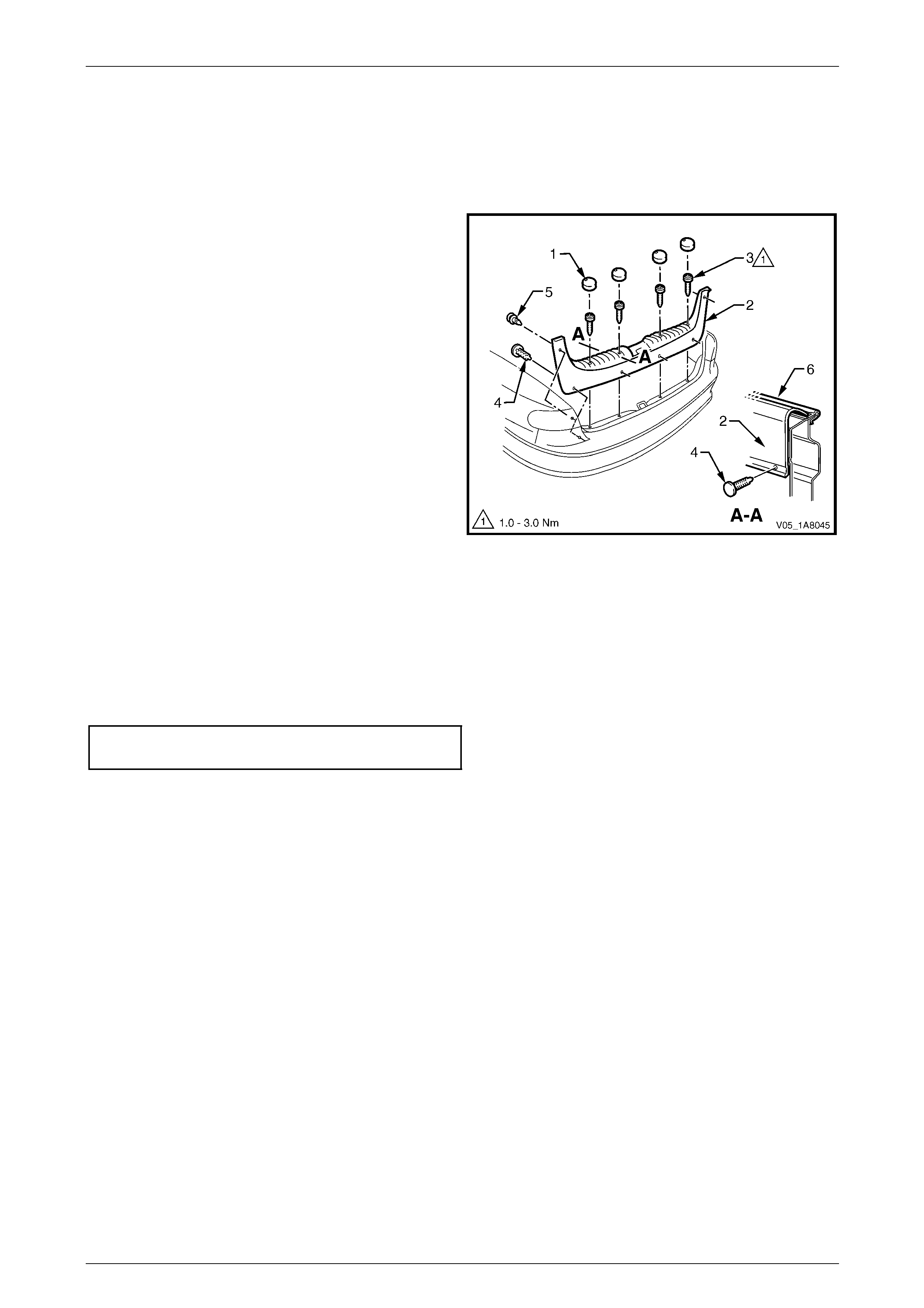
Headlining and Interior Trim Page 1A8–122
Page 1A8–122
5.9 Rear End Trim Panel Assembly
LT Section — 14–120
Remove
1 Remove the four screw caps (1) from the rear end trim
panel (2).
2 Remove the four attaching screws (3) along the ribb ed
upper surface of the rear end trim panel.
3 Remove the retainer (4), four places, along the lower
inner edge of the rear end trim panel.
4 Remove the retainer (5), t wo places, attaching the
upper sides of the rear end trim panel.
5 Carefully lift the rear end trim panel ov er the rear
compartment lid latch and clear of the rear
compartment.
Figure 1A8 – 124
Reinstall
Reinstallation of the rear end trim panel assembly is the reverse of the removal procedure, noting the following:
1 Ensure the outer edge of rear end trim panel (2) engages the rear compartment lid weatherstrip (6), refer to
Figure 1A8 – 124.
2 Tighten the four attaching screws to the correct torque specification.
Rear end trim panel attaching screw
torque specification.....................................1.0 – 3.0 Nm
3 Ensure the screw caps are correctly inserted with the notch pointing towards the front of the vehicle.
4 Ensure the retainers are secured to the rear end panel assembl y.
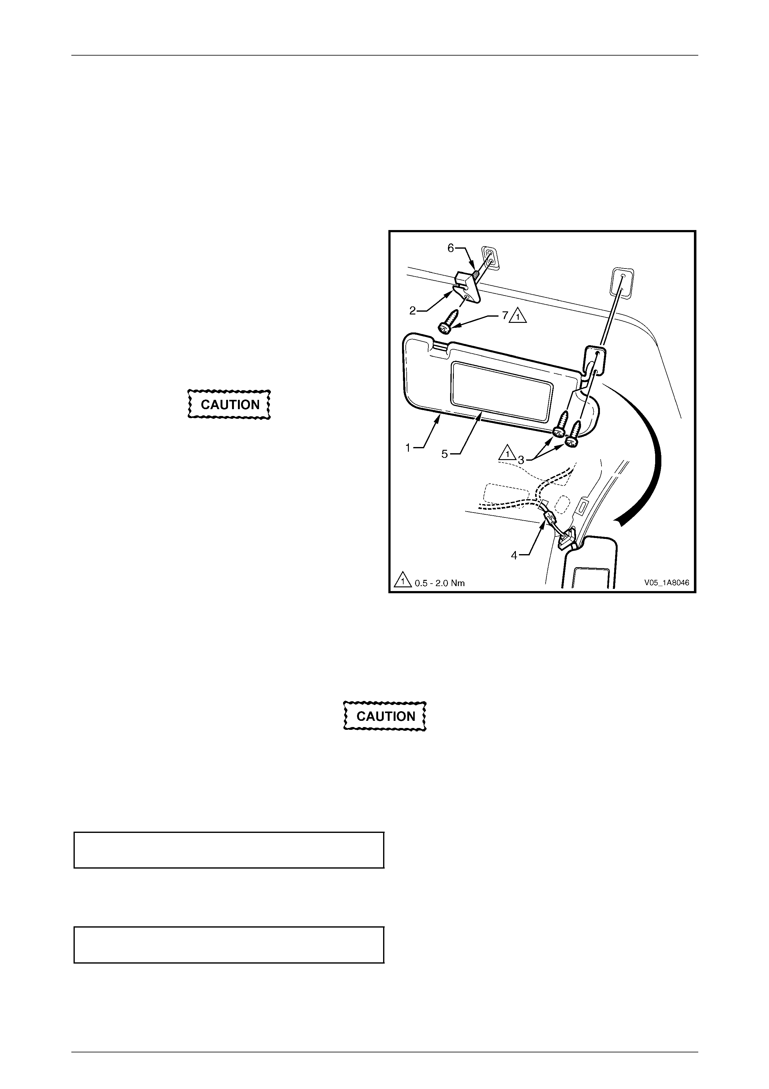
Headlining and Interior Trim Page 1A8–123
Page 1A8–123
5.10 Sunshade Assembly
LT Section — 14–050
Remove
1 Remove the fuse F6 from the passenger compartment fuse and relay panel ass embl y,
refer to Section 12O Fuses, Relays and Wiring Harnesses.
2 Disconnect the sunshade assembly (1) from the
sunshade support (2) and rotate to gain acce ss.
3 Remove the sunshade assembly two attaching Torx
screws (3).
4 Pull the sunshade assembly away from the headlining
assembly and disconnect the harness connector (4)
from the illuminated vanity mirrors (5).
5 Remove the sunshade assembly.
When removing the sunshade support, take
care not to damage the locating pin (6).
6 Remove the Torx screw (7) from the sunshade support
and pull the support from the headlining assembly.
Figure 1A8 – 125
Reinstall
Reinstallation of the sunshad e assemb ly is the reverse of the removal procedure, noting the following:
Take care not to damage the locating pin
when fitting the sunshade support.
1 Ensure the sunshade support locati ng pin is aligned with the locating h ole in the roof panel.
2 Tighten the Torx screw attaching the sunshade support to the correct torque specification.
Sunshade support attaching Torx screw
torque specification.....................................0.5 – 2.0 Nm
3 Connect the harness connector to the sunshade assembly.
4 Tighten the sunshade ass embly two attaching Torx scre ws to the correct torque specific ation.
Sunshade assembly attaching screw
torque specification.....................................0.5 – 2.0 Nm

Headlining and Interior Trim Page 1A8–124
Page 1A8–124
5.11 Headlining Assembly
LT Section — 14–150
Remove
1 Remove the fuse F6 from the passenger compartment fuse and relay panel ass embl y,
refer to Section 12O Fuses, Relays and Wiring Harnesses.
2 Move both front seats to the rear access position.
3 Place protective covering ov er both front seats and the interior trim.
4 Remove the following components as required:
a Rear seat cushion and rear seat-back assembly, refer to Section 1A7 Seat Assemblies.
b Windshield side garnish on b oth sides, refer to 5.5 Windshield Side Garnish.
c Body lock pillar garnish on b oth sides, refer to 5.7 Body Rear Corner Garnish.
d Sunshade assembly on both sides, refer to 5.10 Sunshade Assembl y.
e Dome lamp assembly, refer to Section 12B Lighting System.
5 Disconnect the headlining assembly wiring harness (1) from the bod y wiring harness connector (2), located above
and slightly forward of the right-hand centre pillar, refer to Figure 1A8 – 126.
NOTE
It may be necessary to flex the headlining
assembly (3) down slightly to gain access to the
harness connector.
6 With the aid of an assistant, flex the headlining assembly to disengage the corners from the ‘D’ tabs (4), in four
places on the sides of the roof panel.
7 Disengage the four hook and l oop fasteners (5) attaching the rear edge of the headlining assembly by gently
pulling down the headli ning assembly in one corner a nd working across the rear edge.
8 Ease the headlining assembly from its position on the roof panel and turn the he adlining assembly so that it can be
passed through the passenger side door opening and remove it from inside the vehicle.
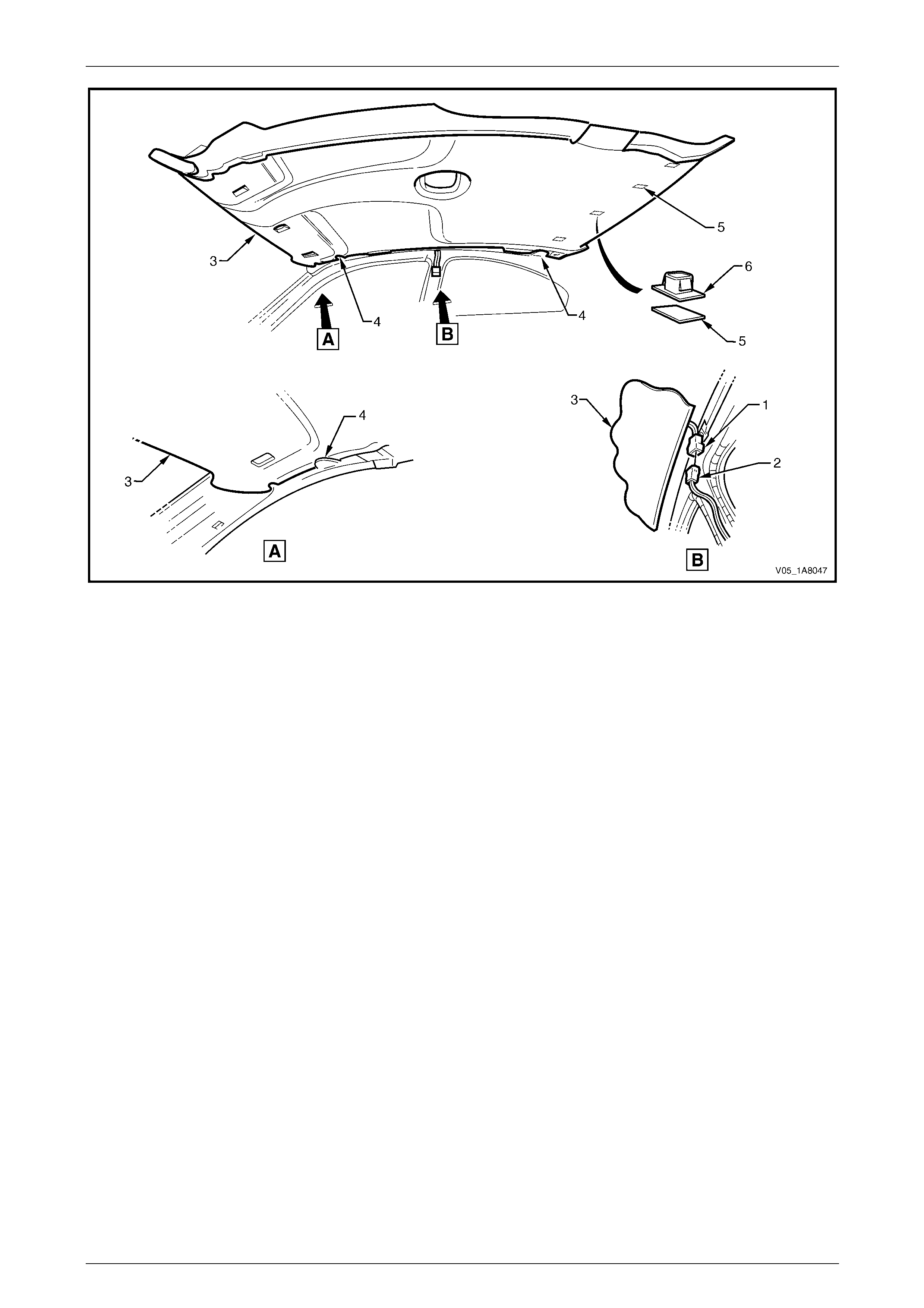
Headlining and Interior Trim Page 1A8–125
Page 1A8–125
Figure 1A8 – 126
Reinstall
Reinstallation of the headlining assembly is the reverse of the removal pro c edure, noting the following:
1 Replace the clips (6) from the roof bow and t he fasteners (5) from the headlining as requ ired, refer to
Figure 1A8 – 126.
2 Temporarily support the headlining assembly on the ‘D’ tabs (4) before the trim components are installed.
3 Ensure the headlining assembly harness connector is securely connected to the body wiring harness connector.
4 Ensure the hook and loop fasteners at the rear edge of the headlining ass embly are secured to the roof panel.

Headlining and Interior Trim Page 1A8–126
Page 1A8–126
5.12 Driver Footrest
LT Section — 14–475
Remove
1 Prise the two screw covers (1) and remove from the
driver footrest.
2 Remove the two screws (2) attaching the driver
footrest (3) to the footrest mounting bracket (4).
3 Remove the footrest pad.
Figure 1A8 – 127
Reinstall
Reinstallation of the driver footrest is the reverse of the removal procedure, noting the following:
Tighten the two screws attaching the driver footrest to the correct torque specification.
Driver footrest attaching screw
torque specification.....................................2.0 – 5.0 Nm
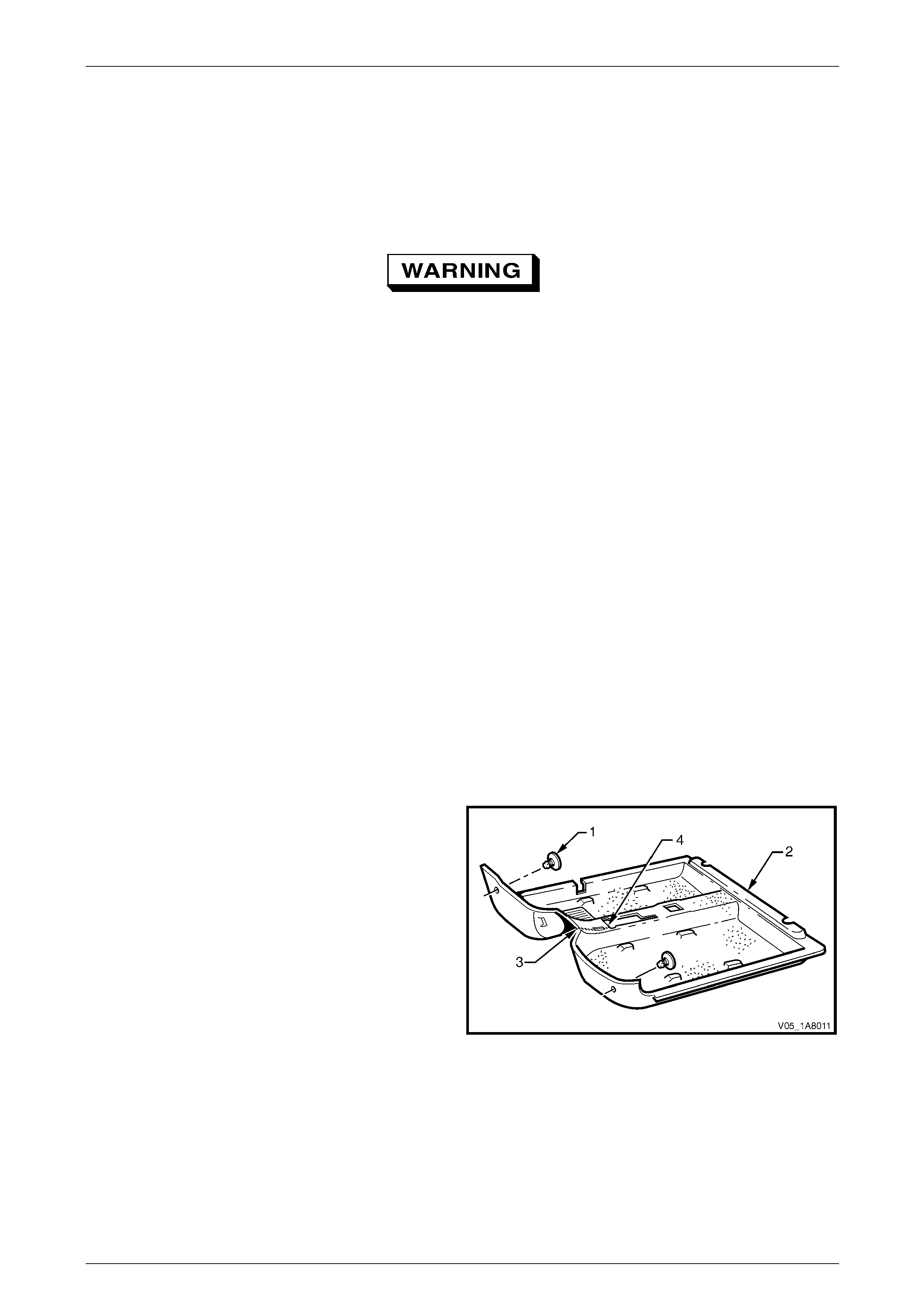
Headlining and Interior Trim Page 1A8–127
Page 1A8–127
5.13 Front Floor Carpet Assembly
LT Section — 14–475
Remove
Disable the occupant protection system
before performing the following operation.
Refer to Section 12M Occupant Protection
System.
1 Remove the following components as required:
a Rear seat cushion, refer to Section 1A7 Seat Assemblies.
b Side sill trims on both sides, refer to 5.2 Side Sill Trim and Plate.
c Body hinge pillar trim assembly on both sides, refer to 5.6 Body Hinge Pillar Trim Assembly.
d Quarter trim panel assembly on both sides, refer to 5.3 Quarter Trim Panel Assembly.
e Both front seat assemblies, refer to Section 1A7 Seat Assemblies.
f Driver footrest, refer to 5.12 Driver Footrest.
g Remove the park brake lever cover by grasping the cover firmly by hand and sliding the co ver over the park
brake lever, refer to Section 5A Service and Park Braking System.
h Instrument panel lower trim plate assembly, right-hand and left-hand,
refer to Section 1A3 Instrument Panel and Consol e.
i Instrument panel compartment, refer to Section 1A3 Instrument Panel and Console.
j Instrument panel lower trim panel, refer to Section 1A3 Instrument Panel and Consol e.
k Floor console assembly, refer to Section 1A3 Instrument Panel an d Console.
2 Disconnect the inflatable restraint control module (SDM) wiring harness,
refer to Section 12M Occupant Protection System.
3 Remove the two retaining clips (1) from the front floor
carpet assembly (2) by rotating the clips counter-
clockwise and lifting clear of the attaching studs.
NOTE
To facilitate the removal and installation
procedure, the front floor carpet assembly is
perforated from the front edge (3), through the
centre of the evaporator drain cut-out, to the
forward edge of the lower radio bracket cut-
out (4).
Figure 1A8 – 128

Headlining and Interior Trim Page 1A8–128
Page 1A8–128
4 From inside the left-hand footwell, grasp the edge of
the hole in the front floor carpet assembly around the
evaporator drain hose (1) and tear open the perforated
line (2) by pulling the carpet awa y from the
transmission tunnel.
5 Slide the remaining flap of carpet out from under the
heating, ventilation and air-conditioning (HVAC)
unit (3) and into the right-hand footwell.
6 Carefully manoeuvre the front floor carp et and
insulator assembly out of the vehicle.
Figure 1A8 – 129
Reinstall
Reinstallation of the front floor carpet assembly is the reverse of the removal procedure, noting the following:
1 If a new front floor carpet assembly is being fitted, prior to installation, cut along the perforated line that runs from
the carpet forward edge (3) to the forward edge of the lower radio bracket cut-out (4), refer to F igure 1A8 – 128.
2 Ensure all the cut-outs in the front floor carpet assembl y are correctly alig ned, then install the two retaining clips
and the front seat belt lower attaching bolts, refer to Section 12M Occupant Protection System , to secure the front
floor carpet assembly prior to installing the seats and c onsole.
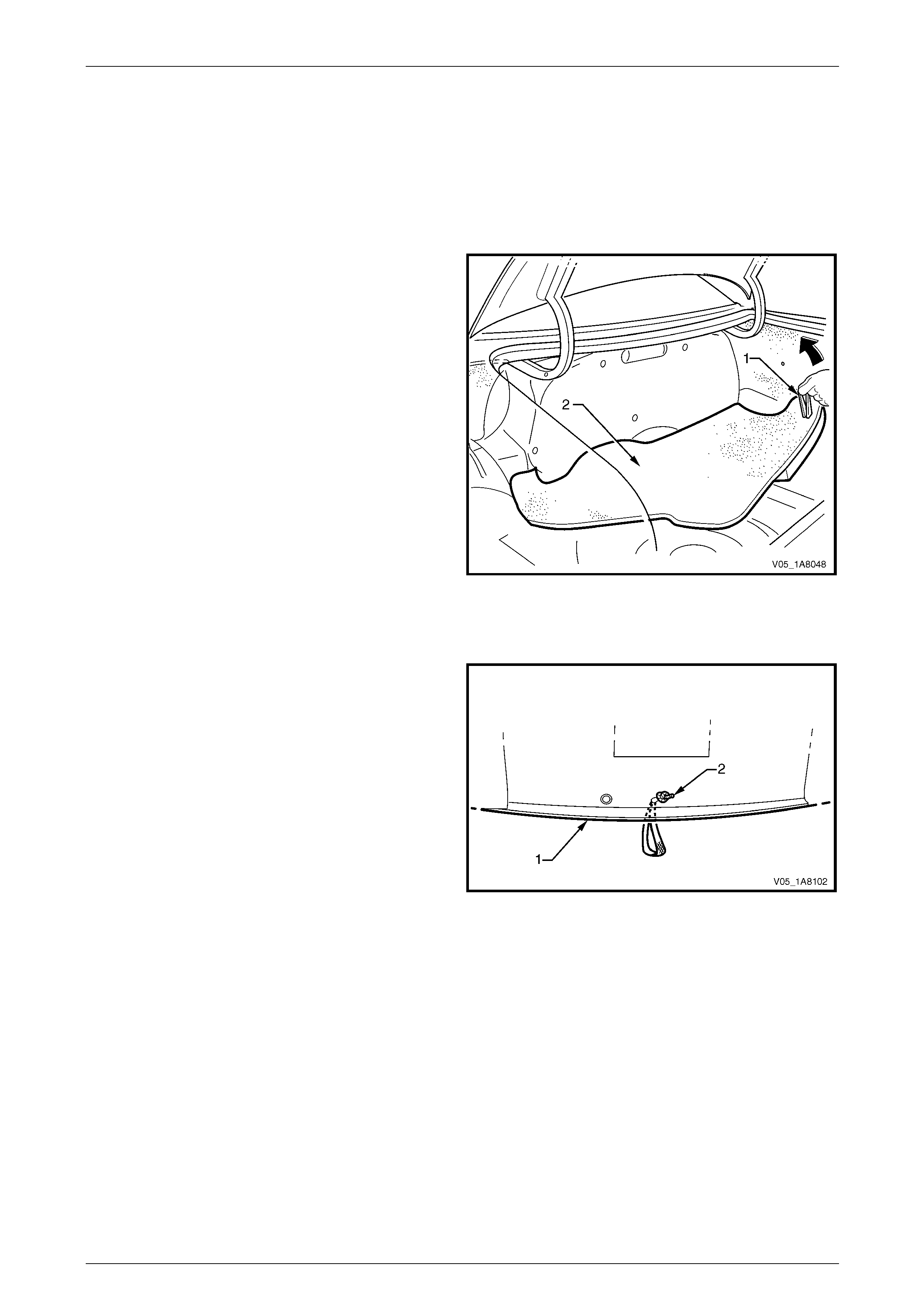
Headlining and Interior Trim Page 1A8–129
Page 1A8–129
5.14 Rear Compartment Floor Panel Carpet
Assembly
LT Section — 14–480
Remove
1 Open the rear compartment lid.
2 Grasp the strap (1) on the rear compartment floor
panel carpet assembly (2) and lift the rear edge
upward.
3 Lift and remove the rear compartment floor panel
carpet assembly from the rear compartment.
Figure 1A8 – 130
Disassemble
1 From the underside of the rear compartment floor
panel carpet baseboard (1) u ndo or cut the knot (2), if
required.
2 Feed the strap through the hole in the carpet
baseboard and remove.
Figure 1A8 – 131
Reassemble
Feed the strap through the hole in the carpet baseboard and tie a secure knot.
Reinstall
Reinstallation of the rear com partment floor panel carpet assembly is the reverse of the removal procedure.
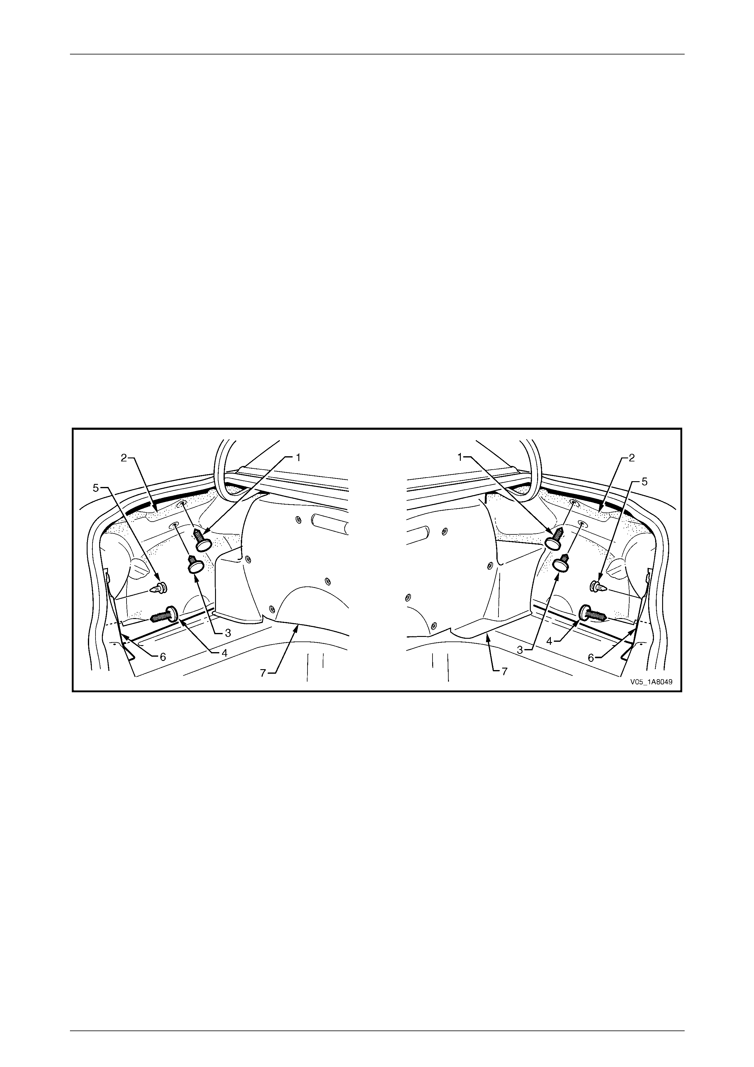
Headlining and Interior Trim Page 1A8–130
Page 1A8–130
5.15 Quarter Inner Rear Side Carpet
LT Section — 14–480
Remove
1 Remove the rear compartment floor pane l carpet assembly,
refer to 5.14 Rear Compartment Floor Panel Carpet Assembly.
2 Carefully remove the upper retainer (1) securing the top of the quarter inne r rear side carpet (2).
NOTE
The upper retainer is inserted in a rubber
grommet fitted to the quarter panel inner
assembly. As required, remove the grommet from
the upper retainer and refit to the panel.
3 Remove the two retainers (3 and 4) securing the carpet.
4 Remove the retainer (5) attaching the upper side of the rear end trim panel (6).
5 Carefully pull the carpet from behind the outer edge of the rear end trim pa nel.
6 Disengage the carpet from behind the fuel tank cage carpet (7) and remov e.
Figure 1A8 – 132
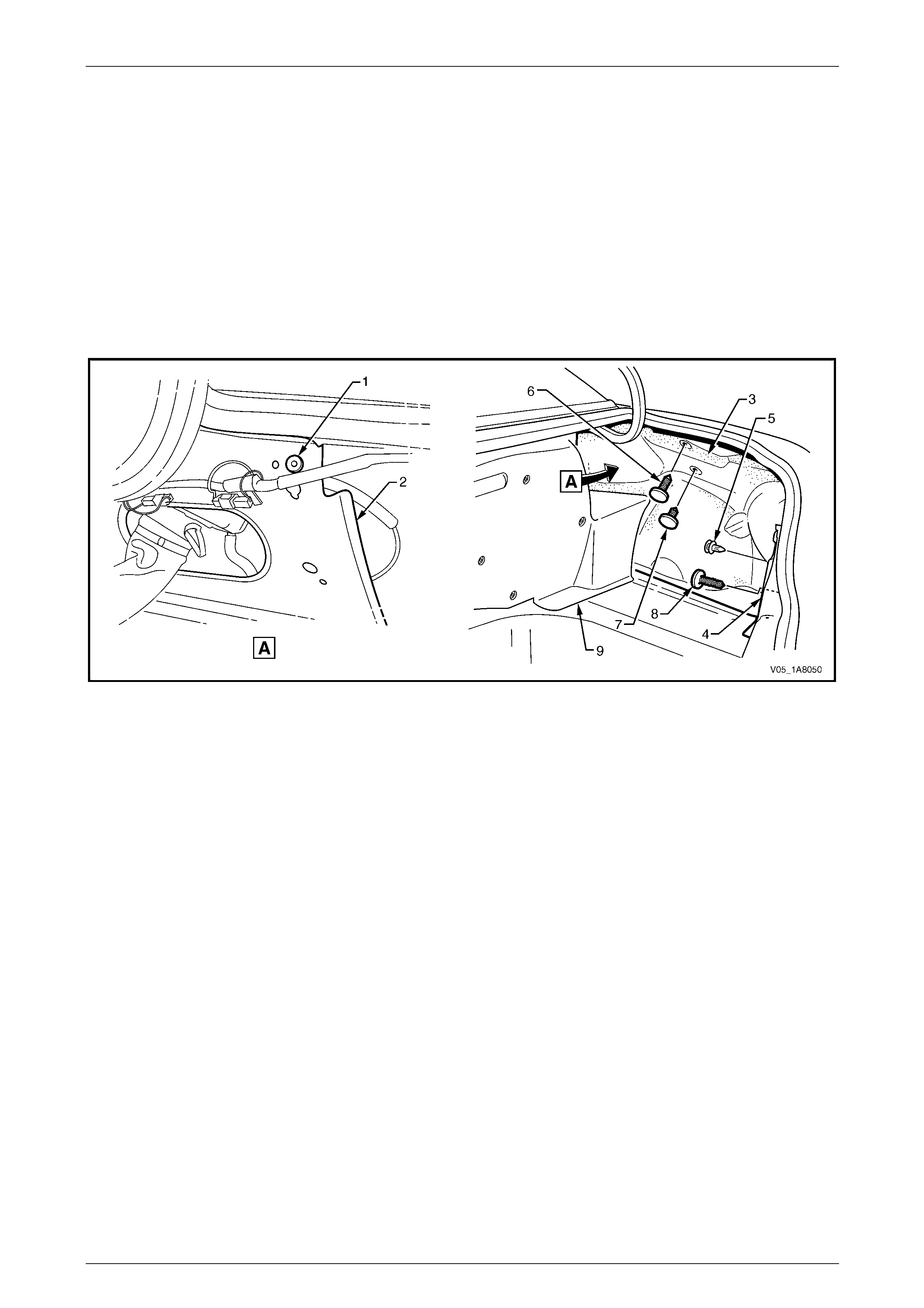
Headlining and Interior Trim Page 1A8–131
Page 1A8–131
Reinstall
Reinstallation of the quarter inner rear side carpet is the reverse of the removal procedure, noting the following:
1 Ensure the rubber grommet (1) is fitted to its location on the quarter panel inner assembly (2), refer to
Figure 1A8 – 133.
2 Ensure the quarter inner rear side carpet (3) is correctly position ed behind the outer edge of the rear end trim
panel (4).
3 Ensure the retainer (5) secures the upper side of the rear end trim panel.
4 Ensure the two retainers (6 and 7) are secured to the quarter panel inner assembly and the retainer (8) secured to
the rear end panel assembly.
5 Ensure the quarter inner rear side carpet is engaged behind the fuel tank cage car pet (9).
Figure 1A8 – 133
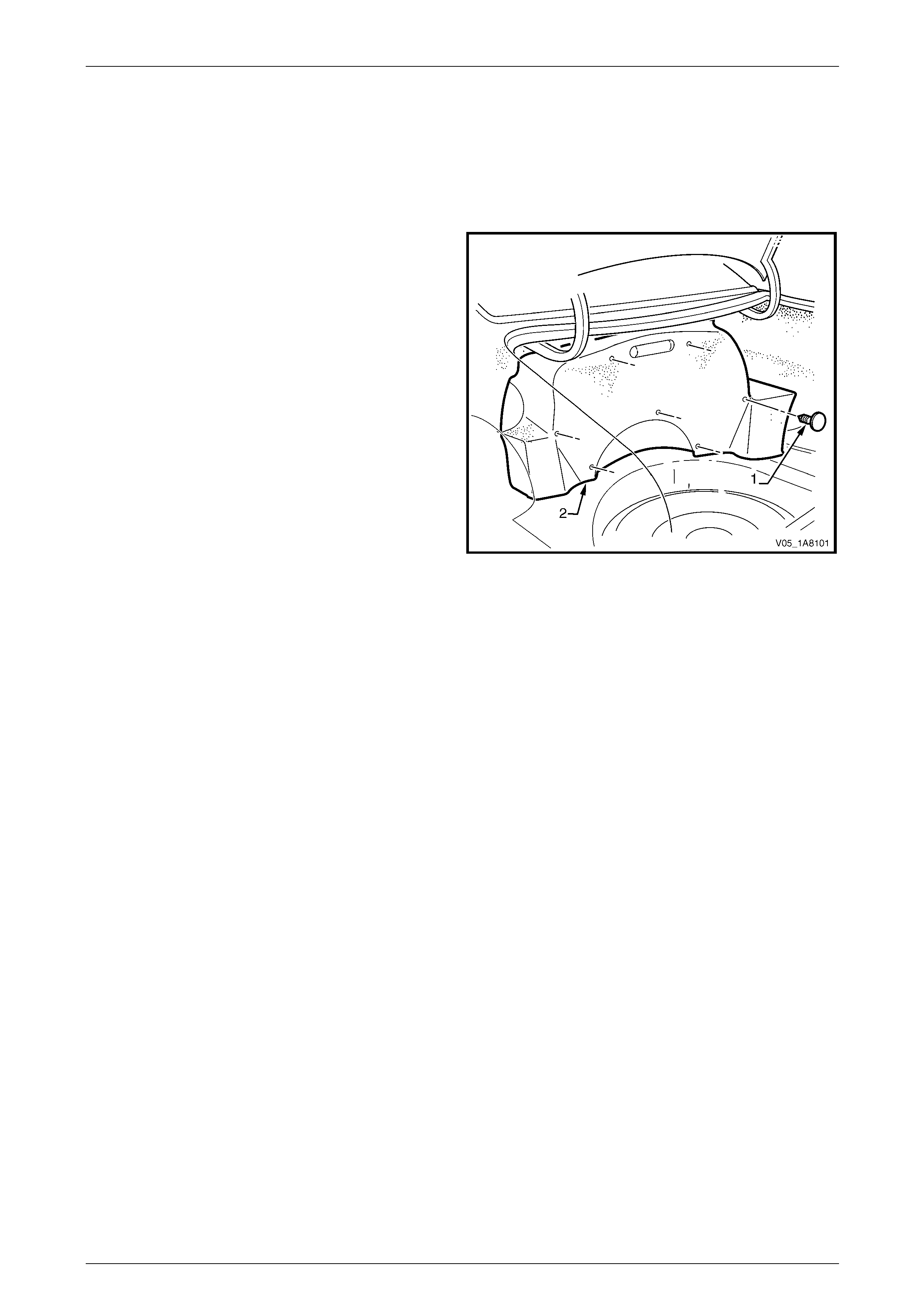
Headlining and Interior Trim Page 1A8–132
Page 1A8–132
5.16 Fuel Tank Cage Carpet
LT Section — 14–480
Remove
1 Carefully remove the retainer (1), seven places,
securing the carpet (2) to the fuel tank cage.
2 Remove the fuel tank cage carpet.
Figure 1A8 – 134
Reinstall
Reinstallation of the fuel tank cage carpet is the reverse of the removal pro cedure, noting the following:
Ensure the retainers are secured to the fuel tank cage.
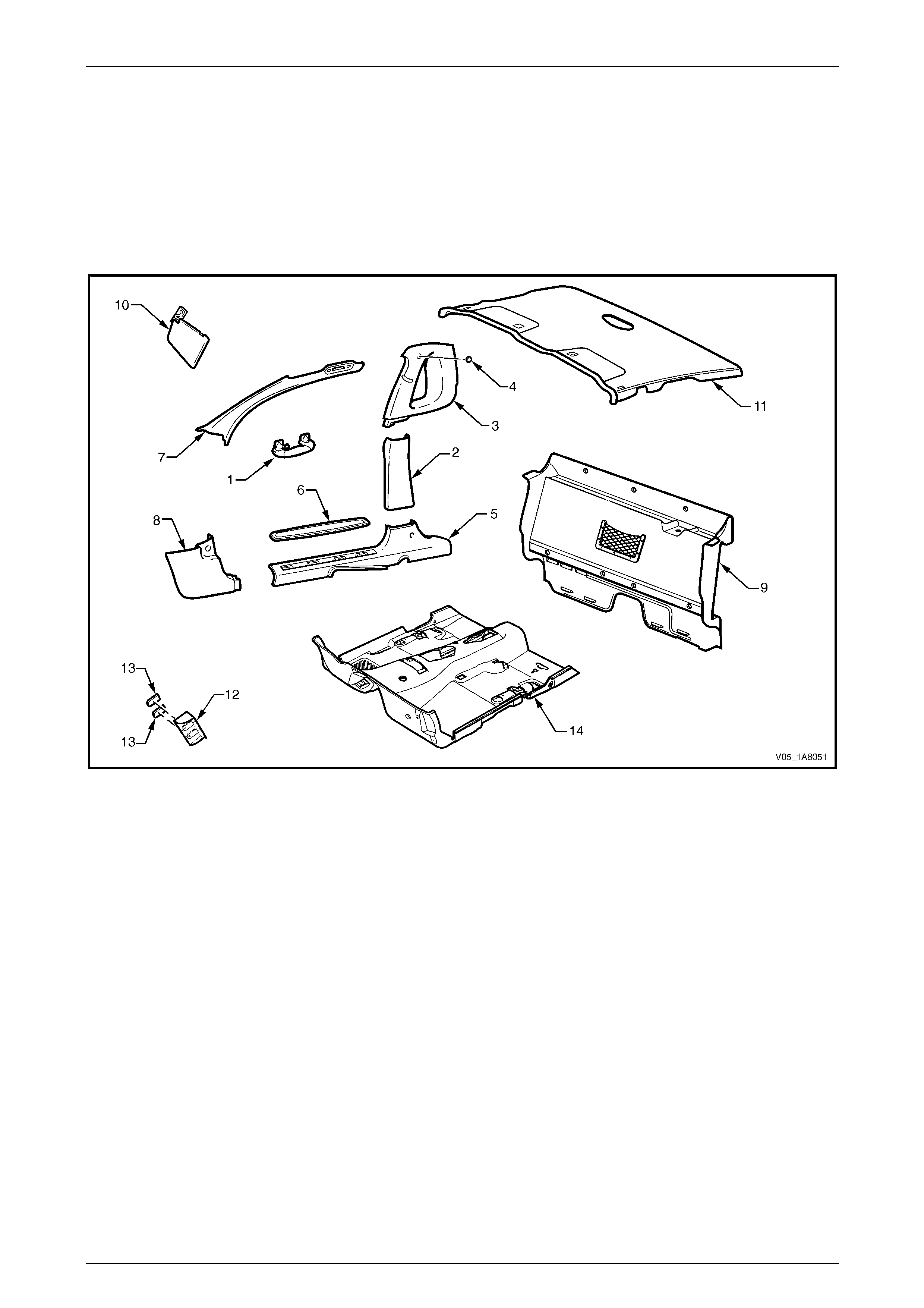
Headlining and Interior Trim Page 1A8–133
Page 1A8–133
6 Service Operations – Utility
6.1 Components Chart
The headlining and interior trim components for Utility vehicles are displayed in the following chart to assist with their
identification, refer to Figure 1A8 – 135.
For the service procedures of the door trim pane l assemblies, refer to Section 1A5 Front and Rear Door Assemblies.
Figure 1A8 – 135
Legend
1 Assist Handle Assembly
2 Centre Pillar Lower Trim
3 Body Lock Pillar Upper Trim Assembly
4 Screw Cap
5 Side Sill Trim
6 Side Sill Trim Plate
7 Windshield Side Garnish
8 Body Hinge Pillar Trim Assembly
9 Seat-back Body Panel Trim
10 Sunshade Assembly
11 Headlining Assembly
12 Driver Footrest
13 Screw Cap
14 Floor Carpet Assembly

Headlining and Interior Trim Page 1A8–134
Page 1A8–134
6.2 Assist Handle Assembly
LT Section — 14–100
Remove
1 Pull the assist handle (1) into the down position.
2 Prise open the assist handle two screw covers (2) and
remove the two attaching screws (3).
When removing the assist handle assembly,
take care not to damage the locating pin s (4).
3 Remove the assist handle assembly.
Figure 1A8 – 136
Reinstall
Take care not to damage the locating pin
when fitting the assist handle assembly.
1 Ensure the locating pins are correctl y align ed with the locating holes.
2 Position the hook over the locating pin.
3 Tighten the assist handle two attaching screws to the correct torque specification.
Assist handle attaching screw
torque specification.....................................1.0 – 3.0 Nm
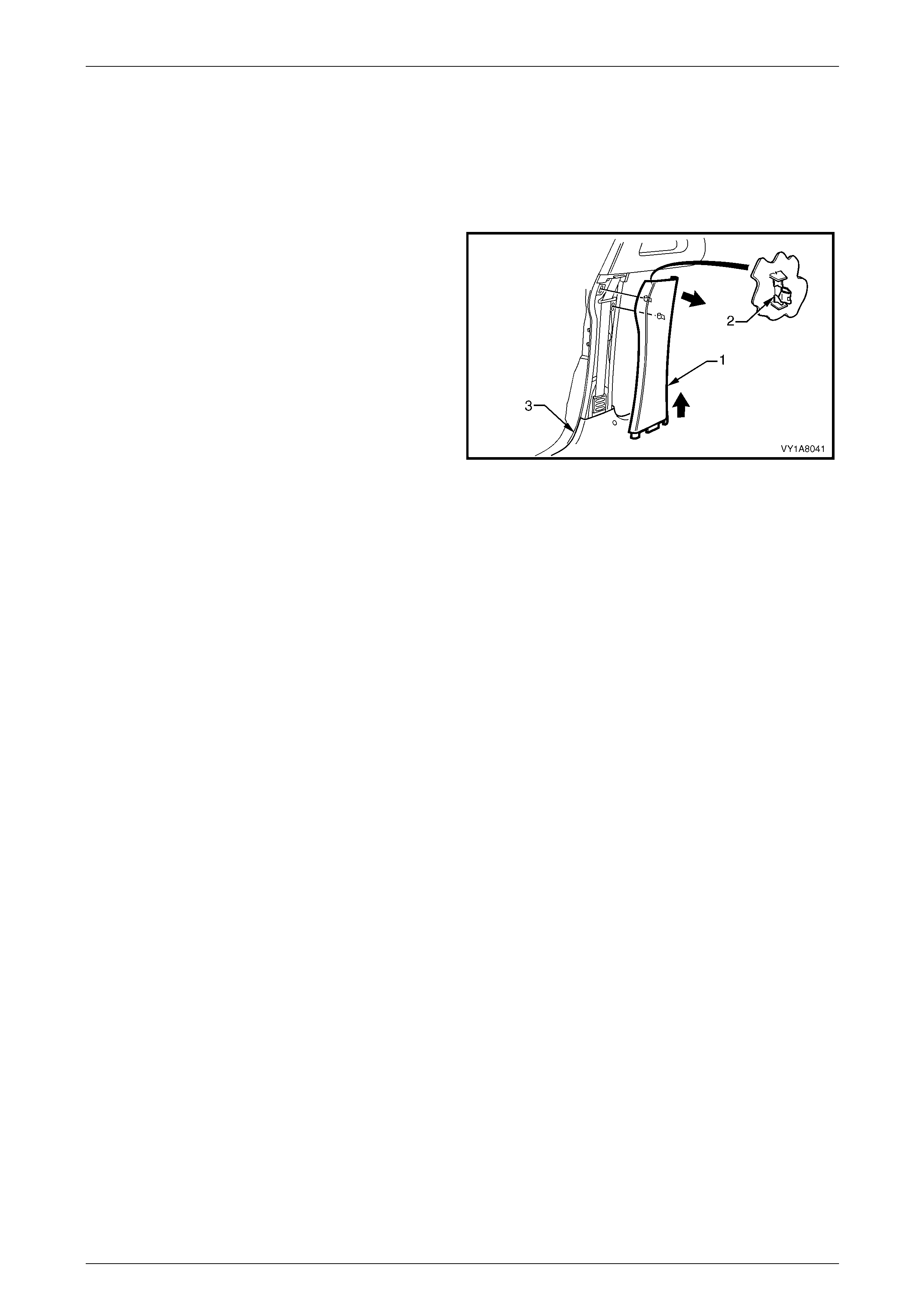
Headlining and Interior Trim Page 1A8–135
Page 1A8–135
6.3 Centre Pillar Lower Trim
LT Section — 14–100
Remove
1 Using your fingers, lever the top of the centre pill ar
lower trim (1) away from the door opening weatherstrip
and pull the trim toward the centre of the car,
disengaging the two retaining clips (2).
2 Lift the centre pillar lower trim upward, out of the side
sill trim (3) and remove.
3 As required, remove the retaining clips from the
vehicle and fit to the trim.
Figure 1A8 – 137
Reinstall
1 Locate the centre pillar lo wer trim (1) into the side sill trim (3), refer to Figure 1A8 – 137.
2 Locate the two retaining clips (2) into their slots in the centre pillar, then push in firml y ens uring the two clips are
secured to the centre pillar.
3 Ensure the door opening weatherstrip fits neatly over the outer edge of centre pillar lower trim.
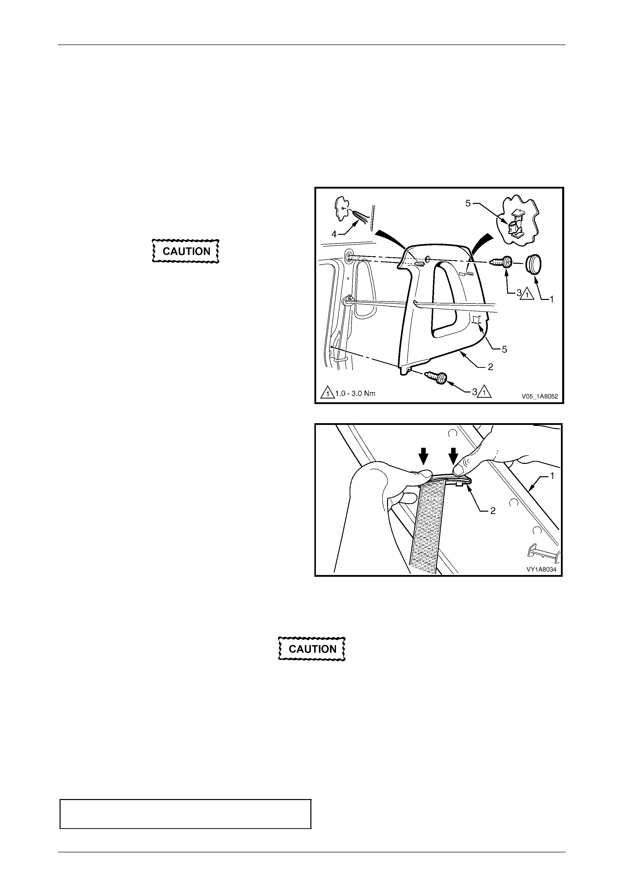
Headlining and Interior Trim Page 1A8–136
Page 1A8–136
6.4 Body Lock Pillar Upper Trim Assembly
LT Section — 14–100
Remove
1 Remove the following components as required:
a Centre pillar lower trim, refer to 6.3 Centre Pillar Lower Tr im.
b Seat belt lower bolt, refer to Section 12M Occupant Protection System.
2 Remove the screw cap (1) from the upper attachment
of the body lock pillar upper trim (2).
3 Remove the two screws (3) attaching the body lock
pillar upper trim.
When removing the body lock pillar upper
trim assembly, take care not to damage the
locating pin (4) below the upper attaching
screw position.
4 Pull the upper edge of the body lock pillar upper trim
away from the headlining to disengage the two
retaining clips (5) at the rear of the body lock pillar
upper trim.
Figure 1A8 – 138
5 With the body lock pillar upper trim (1) partially
removed, disengage the seat belt escutcheo n (2) from
the body lock pillar upper trim and feed the seat belt
and anchor plate through the ope ning.
6 Remove the body lock pillar upper trim.
7 As required, remove the retaining clips from the
vehicle and fit to the trim.
Figure 1A8 – 139
Reinstall
Reinstallation of the body lock pillar upper trim assembly is the reverse of the removal procedure, noting the following:
Take care not to snap off the locating pin
when fitting the body lock pillar upper trim
assembly.
1 Ensure the locating pin belo w the upper attaching screw position in the body lock pillar u pper trim is correctly
aligned with the locating hole in the centre pillar.
2 Ensure the body lock pillar upper trim two retaining clips are secured to the centre pillar.
3 Ensure the leading edge of the body lock pillar upper trim assembly enga ges the door opening weatherstrip
assembly.
4 Check the seatbelt operation prior to tightening the body lock pillar upper trim attaching screws.
5 Tighten the body lock pillar upper trim two attaching screws to the specified torque.
Body lock pillar upper trim assembl y
attaching screw torque specification...........1.0 – 3.0 Nm
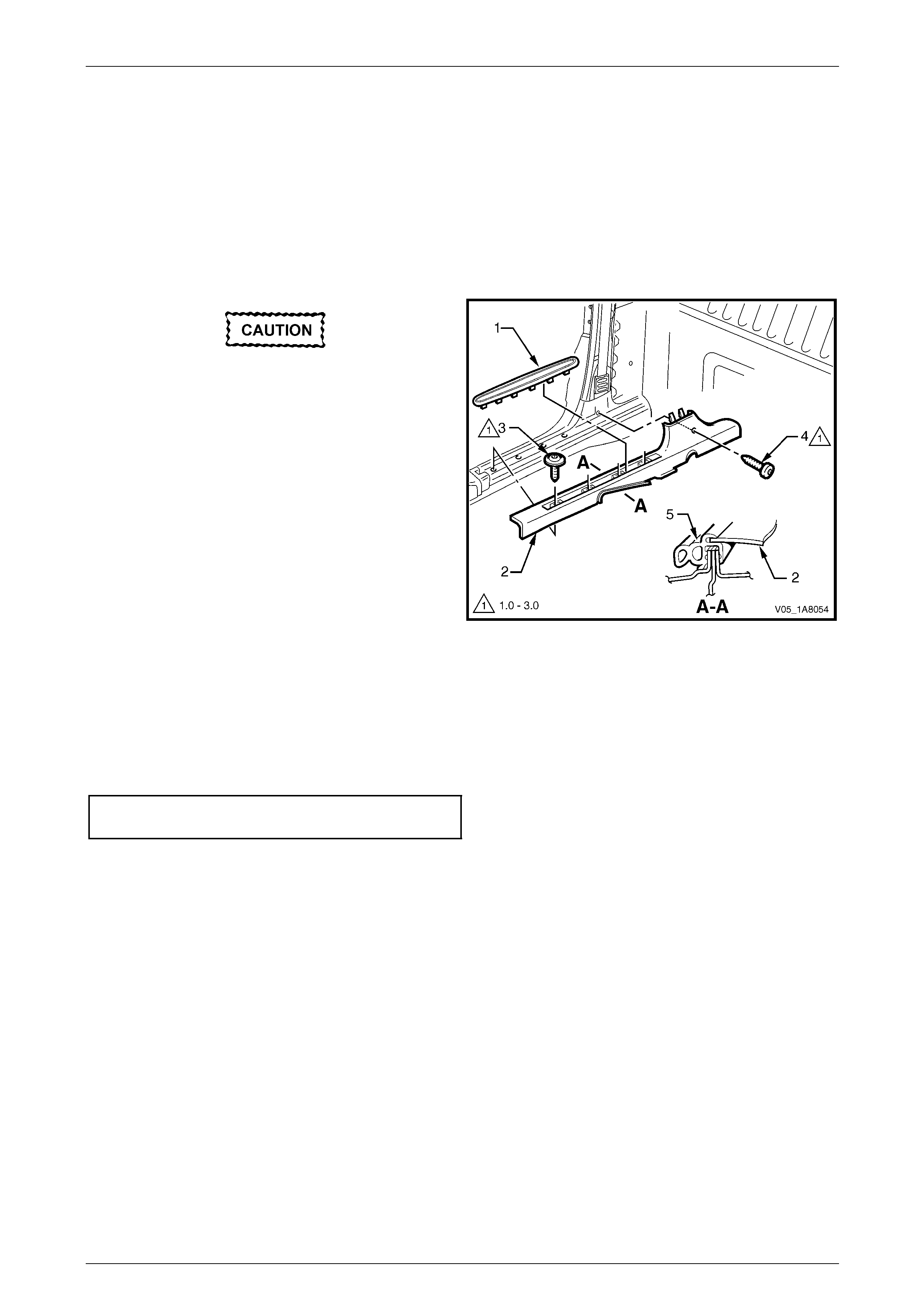
Headlining and Interior Trim Page 1A8–137
Page 1A8–137
6.5 Side Sill Trim and Plate
LT Section — 14–100
Remove
1 Remove the following components as required:
a Centre pillar lower trim, refer to 6.3 Centre Pillar Lower Tr im.
b Front seat outer front cover, refer to Section 1A7 Seat Assemblies.
During the following procedure take care not
to snap the sill trim plates.
2 Carefully lever the side sill trim plate (1) from the side
sill trim (2), starting at the front of the plate and moving
rearward.
3 Remove the Torx screw (3), four places, attaching the
side sill trim to the door opening.
4 Remove the Torx screw (4) attaching the side sill trim
to the centre pillar.
5 Remove the side sill trim.
Figure 1A8 – 140
Reinstall
Reinstallation of the side sill trim and plate is the reverse of the removal procedure, noting the following:
1 Ensure the outer edge of the side sil l trim (2) enga ges the door opening weatherstrip (5), refer to Figure 1A8 – 140.
2 Tighten the Torx screws attaching the side sill trim to the correct torque specification.
Side sill trim attaching Torx screw
torque specification.....................................1.0 – 3.0 Nm

Headlining and Interior Trim Page 1A8–138
Page 1A8–138
6.6 Windshield Side Garnish
LT Section — 14–100
Remove
1 Remove the following components as required:
a Front assist handle assembly, refer to 6.2 Assist Handle Assembly.
b Partially remove the body lock pillar upper trim assembly by removing the upper attaching screw,
refer to 6.4 Body Lock Pillar Upper Trim Assembly.
When removing the windshield side garnish,
take care not to damage the locating pin (3).
2 Starting at the upper rear edge of the windshield side
garnish (1) disengage the three retai nin g clips (2).
3 Remove the windshield side garnish.
4 As required, remove the retaining clips from the
vehicle and fit to the garnish.
Figure 1A8 – 141
Reinstall
Reinstallation of the windshield side garnish is the reverse of the removal procedure, noting the following:
Take care not to snap off the locating pin
when fitting the windshield side garnish.
1 Ensure the windshield side ga rnish locating pin is aligned with the locating h ole i n the hinge pillar inner panel.
2 Ensure the outer edge of the winds hield side garnish (1) engages the front door opening weatherstrip (4 ), refer to
Figure 1A8 – 141.
3 Ensure the three retaining clips are secured to the hinge pillar inner panel.

Headlining and Interior Trim Page 1A8–139
Page 1A8–139
6.7 Body Hinge Pillar Trim Assembly
LT Section — 14–100
Remove
1 Partially remove the side sill trim, refer to 6.5 Side Sill Trim and Plate.
2 Remove the two attaching screws (1) from the body
hinge pillar trim assembly (2).
3 Disengage the body hinge pillar trim clip (3) by pul ling
the lower edge of the body hinge p illar trim assembly
rearward and away from the sheetmetal.
4 Remove the body hinge pillar trim assembly.
5 If required, remove the body hinge pillar trim clip a nd
the two nut inserts (4).
Figure 1A8 – 142
Reinstall
Reinstallation of the body hinge pillar trim assembl y is the reverse of the removal procedure, noting the following:
1 Ensure the body hinge pil lar trim clip is correctly engaged in the hinge pillar inner panel.
2 Ensure the nut inserts are in good condition and correctly located in the hinge pillar inner panel.
3 Ensure the outer edge of the body hinge pillar trim assembl y engages the front door opening weatherstrip (5), refer
to Figure 1A8 – 142.
4 Tighten the body hinge pillar trim assembly two attaching screws to the correct torque specification.
Body hinge pillar trim assembly
attaching screw torque specification...........0.7 – 1.0 Nm
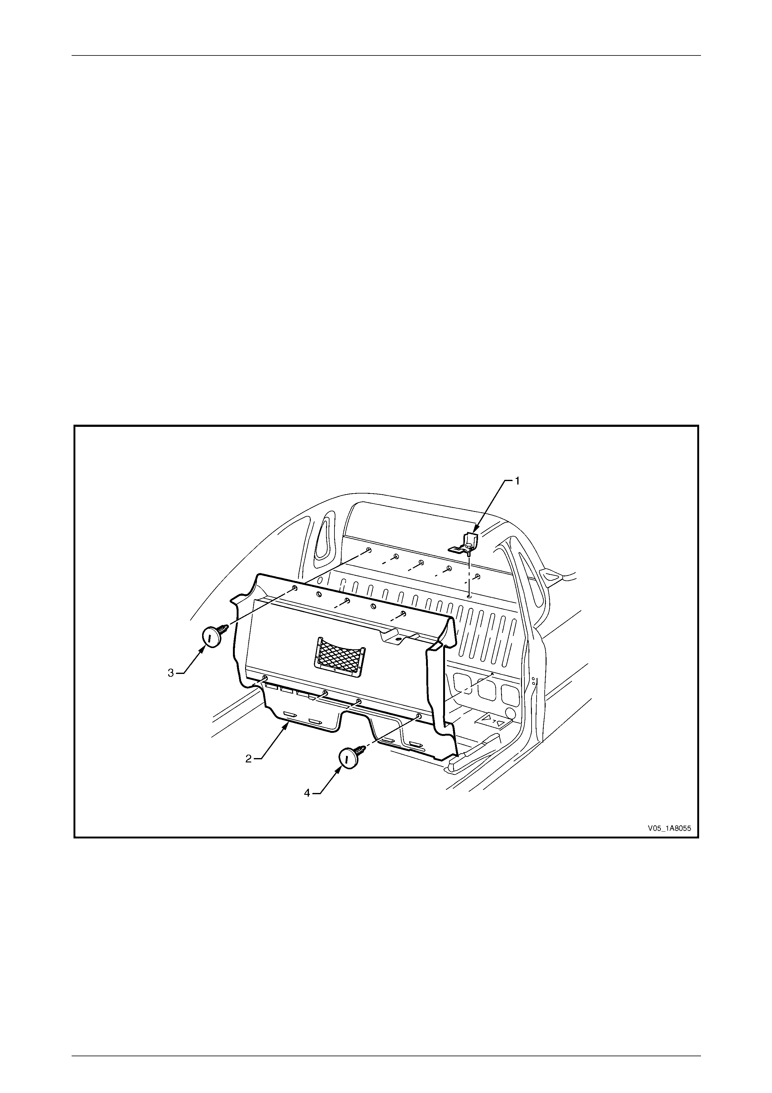
Headlining and Interior Trim Page 1A8–140
Page 1A8–140
6.8 Seat-back Body Panel Trim
LT Section — 14–460
Remove
1 Remove the following components as required:
a Body lock pillar upper trim assembly on both sides, refer to 6.4 Body Lock Pillar Upper Trim Assembly.
b Side sill trim on both sides, refer to 6.5 Side Sill Trim and Plate.
c Floor console assembly, refer to Section 1A3 Instrument Panel an d Console.
d Move the passenger and driver seat to the forward position and remove the jack handle from its location
behind the passenger seat.
2 Remove the child seat anchor (1) from the seat-back body panel trim (2),shown in Figure 1A8 – 14 3 and refer to
Section 12M Occupant Protection System.
3 Remove the retainer (3), five places, and retainer (4), four places, securing the upper part of the seat-back bod y
panel trim to the seat-back panel.
4 Carefully remove the seat-back body panel trim.
Figure 1A8 – 143
Reinstall
Reinstallation of the seat-back body panel trim is the revers e of the removal procedure, noting the following:
Ensure the retainers are secured to the sea t -back panel.

Headlining and Interior Trim Page 1A8–141
Page 1A8–141
6.9 Sunshade Assembly
LT Section — 14–050
Remove
1 Disconnect the sunshade assembly (1) from the
sunshade support (2) and rotate to gain acce ss.
2 Remove the two Torx screws (3) attaching the
sunshade assembly.
3 Pull the sunshade away from the hea dlining assembly
and remove.
When removing the sunshade support, take
care not to damage the locating pin (5).
4 Remove the Torx screw (4) from the sunshade support
and pull the support from the headlining assembly.
Figure 1A8 – 144
Reinstall
Reinstallation of the sunshad e assemb ly is the reverse of the removal procedure, noting the following:
Take care not to damage the locating pin
when fitting the sunshade support.
1 Ensure the sunshade support locati ng pin is aligned with the locating h ole in the roof panel.
2 Tighten the Torx screw attaching the sunshade support to the correct torque specification.
Sunshade support attaching
Torx screw torque specification...................0.5 – 2.0 Nm
3 Tighten the sunshade ass embly two attaching Torx scre ws to the correct torque specific ation.
Sunshade assembly attaching
screw torque specification...........................0.5 – 2.0 Nm
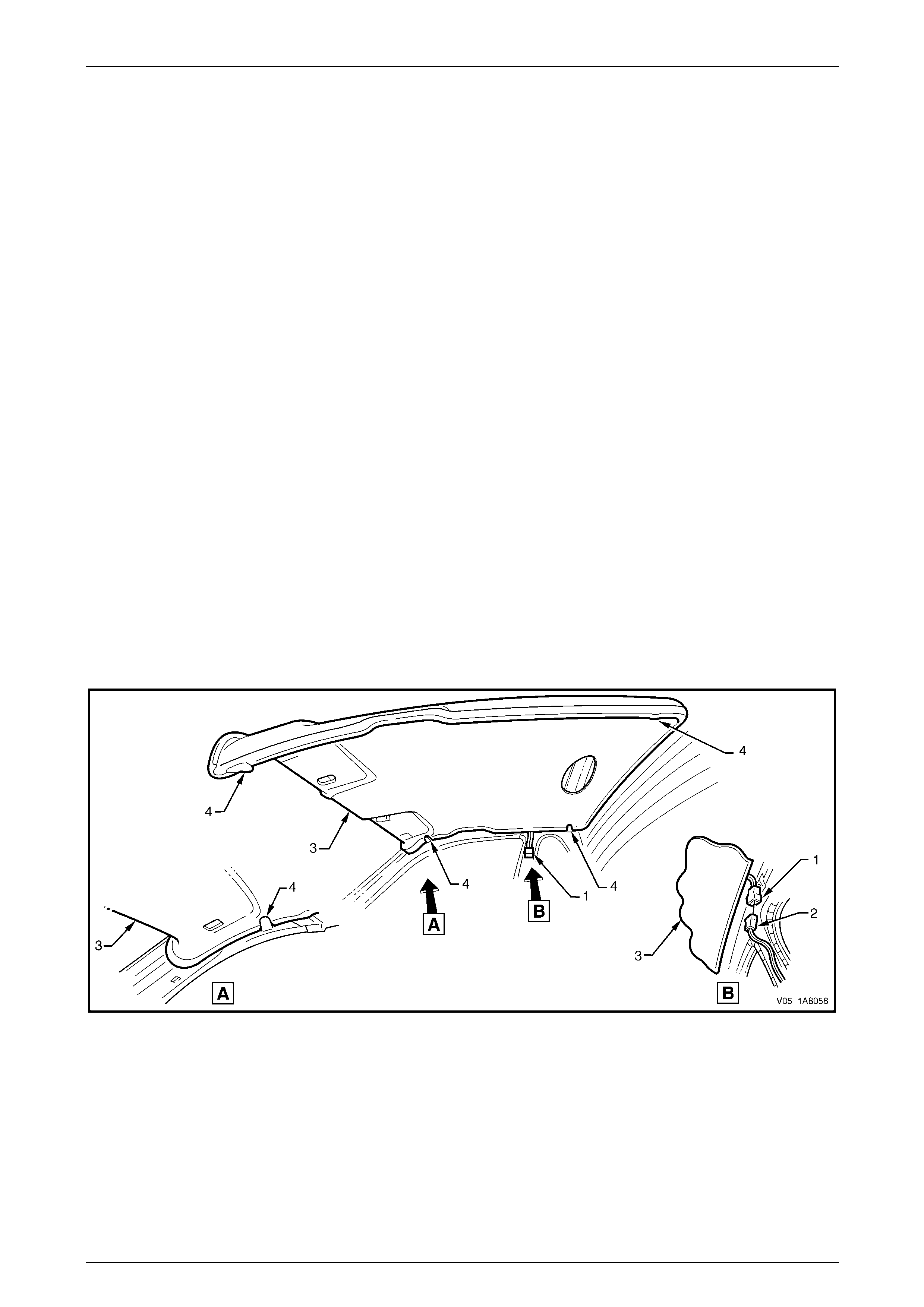
Headlining and Interior Trim Page 1A8–142
Page 1A8–142
6.10 Headlining Assembly
LT Section — 14–150
Remove
1 Remove the fuse F6 from the passenger compartment fuse and relay panel ass embl y,
refer to Section 12O Fuses, Relays and Wiring Harnesses.
2 Place protective covering ov er both seats and the interior trim.
3 Remove the following components as required:
a Body lock pillar upper trim on both sid es, refer to 6.4 Bod y Lock Pillar Upper Trim Assembly.
b Windshield side garnish on b oth sides, refer to 6.6 Windshield Side Garnish.
c Sunshade assembly on both sides, refer to 6.9 Sunshade Assembly.
d Dome lamp assembly, refer to Section 12B Lighting System.
4 Disconnect the headlining assembly wiring harness (1) from the bod y wiring harness connector (2), located above
and slightly forward of the right-hand centre pillar, refer to Figure 1A8 – 145.
NOTE
It may be necessary to flex the headlining
assembly (3) down slightly to gain access to the
harness connector.
5 With the aid of an assistant, flex the headlini ng assembly to disengage the corners from the four ‘D’ tabs (4) on the
sides of the roof panel.
6 Ease the headlining assembly from its position on the roof panel and turn the assem bly so that it can be passed
through the passenger side door opening and remove it from inside the vehicle.
Figure 1A8 – 145
Reinstall
Reinstallation of the headlining assembly is the reverse of the removal pro c edure, noting the following:
1 Temporarily support the headlining assembly on the ‘D’ tabs (4) before the trim components are installed, refer to
Figure 1A8 – 145.
2 Ensure the headlining assembly harness connector is securely connected to the body wiring harness connector.

Headlining and Interior Trim Page 1A8–143
Page 1A8–143
6.11 Driver Footrest
LT Section — 14–475
Remove
1 Prise the two screw covers (1) and remove from the
driver footrest.
2 Remove the two screws (2) attaching the driver
footrest (3) to the footrest mounting bracket (4).
3 Remove the footrest pad.
Figure 1A8 – 146
Reinstall
Reinstallation of the driver footrest is the reverse of the removal procedure, noting the following:
Tighten the two screws attaching the driver footrest to the correct torque specification.
Driver footrest attaching screw
torque specification.....................................2.0 – 5.0 Nm
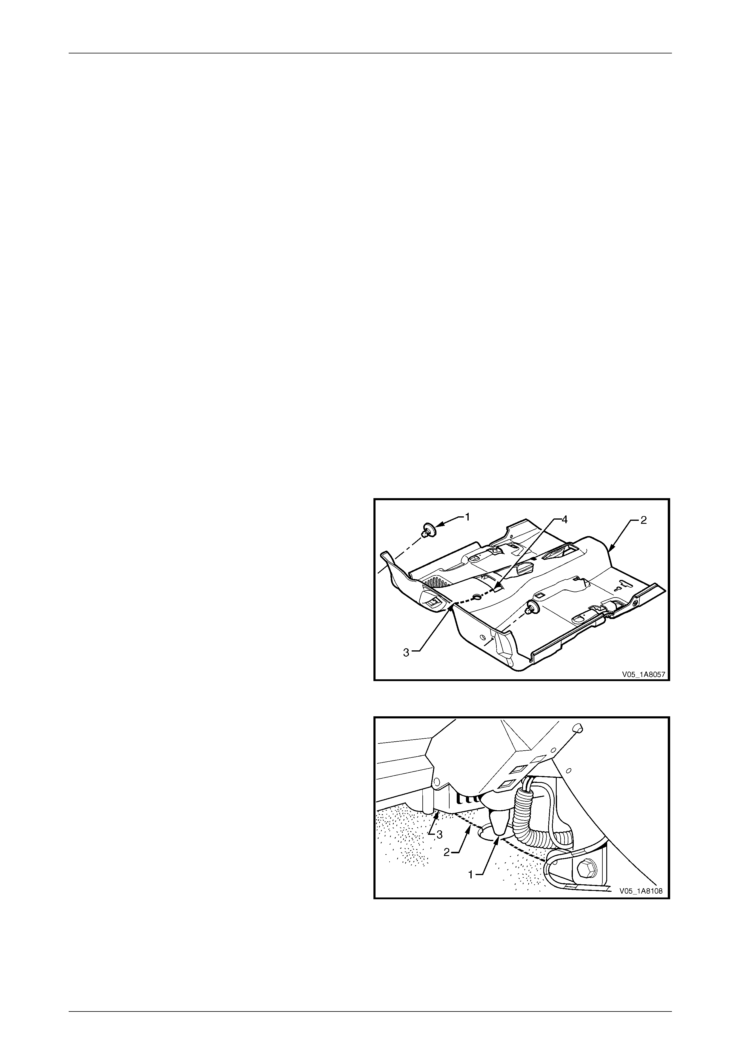
Headlining and Interior Trim Page 1A8–144
Page 1A8–144
6.12 Front Floor Carpet Assembly
LT Section — 14–475
Remove
1 Remove the following components as required:
a Side sill trims on both sides, refer to 6.5 Side Sill Trim and Plate.
b Seat belt lower attaching bolts, refer to Section 12M Occupant Protection System.
c Body hinge pillar trim assembly on both sides, refer to 6.7 Body Hinge Pillar Trim Assembly.
d Both seat assemblies, refer to Section 1A7 Seat Assemblies.
e Driver footrest, refer to 6.11 Driver Footrest.
f Remove the park brake lever cover by graspi ng the cover firmly by hand and sliding the cover over the p ark
brake lever, refer to Section 5A Service and Park Braking System.
g Instrument panel lower trim plate assembly, right-hand and left-hand,
refer to Section 1A3 Instrument Panel and Consol e.
h Instrument panel compartment, refer to Section 1A3 Instrument Panel and Console.
i Instrument panel lower trim panel, refer to Section 1A3 Instrument Panel and Consol e.
j Floor console assembly, refer to Section 1A3 Instrument Panel an d Console.
2 Disconnect the inflatable restraint control module (SDM) wiring harness,
refer to Section 12M Occupant Protection System.
3 Remove the two retaining clips (1) from the front floor
carpet assembly (2) by rotating the clips counter-
clockwise and lifting clear of the attaching studs.
NOTE
To facilitate the removal and installation
procedure, the front floor carpet assembly is
perforated from the front edge (3), through the
centre of the evaporator drain cut-out, to the
forward edge of the lower radio bracket cut-
out (4).
Figure 1A8 – 147
4 From inside the left-hand footwell, grasp the edge of
the hole in the front floor carpet assembly around the
evaporator drain hose (1) and tear open the perforated
line (2) by pulling the carpet awa y from the
transmission tunnel.
5 Slide the remaining flap of carpet out from under the
heating, ventilation and air-conditioning (HVAC)
unit (3) and into the right-hand footwell.
6 Carefully manoeuvre the front floor carp et and
insulator assembly out of the vehicle.
Figure 1A8 – 148

Headlining and Interior Trim Page 1A8–145
Page 1A8–145
Reinstall
Reinstallation of the front floor carpet assembly is the reverse of the removal procedure, noting the following:
1 If a new front floor carpet assembly is being fitted, prior to installation, cut along the perforated line that runs from
the carpet forward edge (3) to the forward edge of the lower radio bracket cut-out (4), refer to F igure 1A8 – 147.
2 Ensure all the cut-outs in the front floor carpet assembl y are correctly alig ned, then install the two retaining clips
and the front seat belt lower attaching bolts, refer to Section 12M Occupant Protection System , to secure the front
floor carpet assembly prior to installing the seats and c onsole.

Headlining and Interior Trim Page 1A8–146
Page 1A8–146
7 Service Operations – Regular
Cab
7.1 Components Chart
The headlining and interior trim components for Regul ar Cab vehicles are displa yed in the following chart to assist with
their identification, refer to Figure 1A8 – 149.
For the service procedures of the door trim pane l assemblies, refer to Section 1A5 Front and Rear Door Assemblies.
Figure 1A8 – 149
Legend
1 Assist Handle Assembly
2 Centre Pillar Lower Trim
3 Body Lock Pillar Upper Trim Assembly
4 Screw Cap
5 Side Sill Trim
6 Side Sill Trim Plate
7 Windshield Side Garnish
8 Body Hinge Pillar Trim Assembly
9 Seat-back Body Panel Trim Assembly
10 Storage Pocket Panel
11 Sunshade Assembly
12 Headlining Assembly
13 Driver Footrest
14 Screw Cap
15 Floor Carpet Assembly
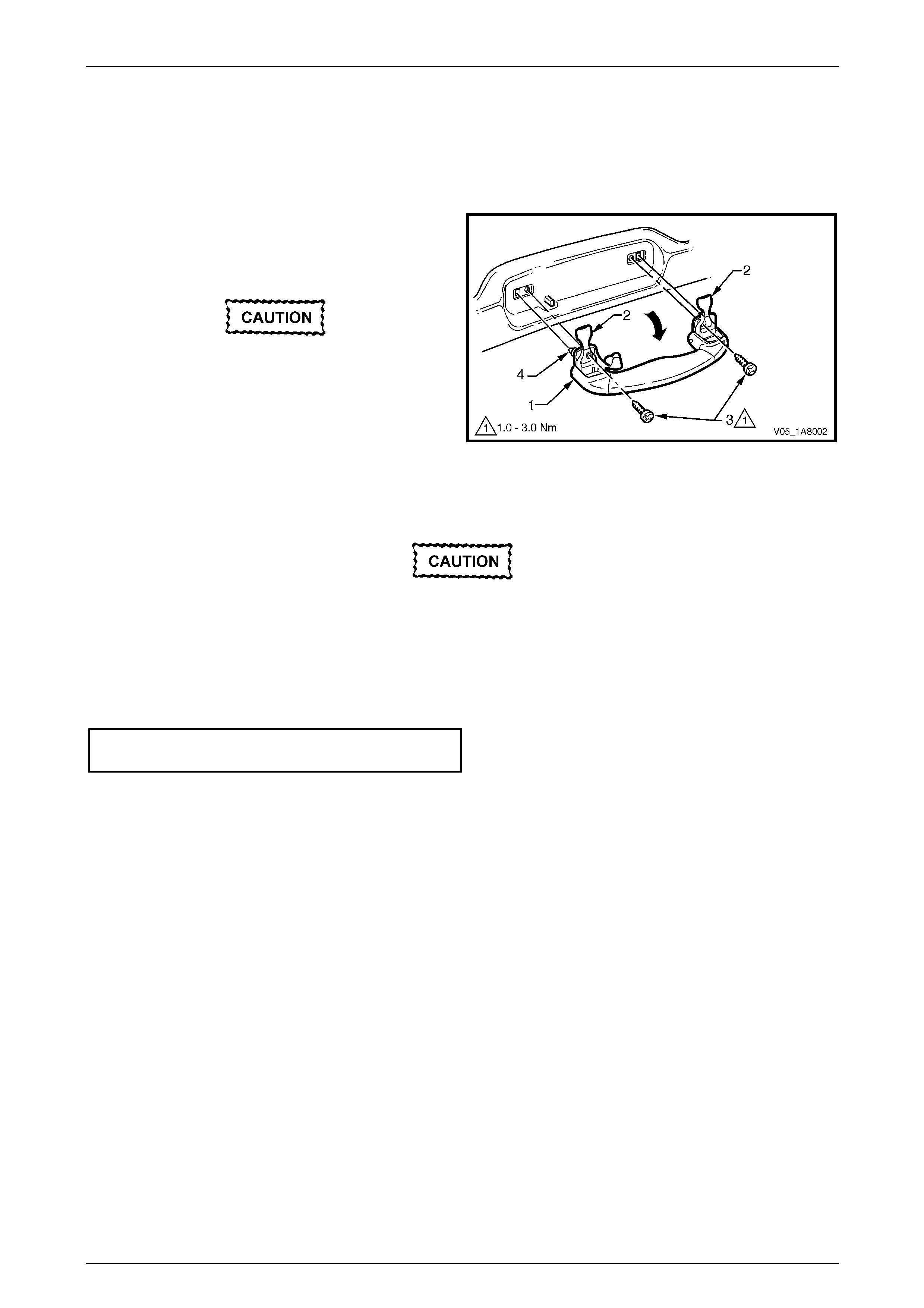
Headlining and Interior Trim Page 1A8–147
Page 1A8–147
7.2 Assist Handle Assembly
LT Section — 14–100
Remove
1 Pull the assist handle (1) into the down position.
2 Prise open the assist handle two screw covers (2) and
remove the two attaching screws (3).
When removing the assist handle assembly,
take care not to damage the locating pin s (4).
3 Remove the assist handle assembly.
Figure 1A8 – 150
Reinstall
Take care not to damage the locating pin
when fitting the assist handle assembly.
1 Ensure the locating pins are correctl y align ed with the locating holes.
2 Position the hook over the locating pin.
3 Tighten the assist handle two attaching screws to the correct torque specification.
Assist handle attaching screw
torque specification.....................................1.0 – 3.0 Nm

Headlining and Interior Trim Page 1A8–148
Page 1A8–148
7.3 Centre Pillar Lower Trim
LT Section — 14–100
Remove
1 Using your fingers, lever the top of the centre pill ar
lower trim (1) away from the door opening weatherstrip
and pull the trim toward the centre of the car,
disengaging the two retaining clips (2).
2 Lift the centre pillar lower trim upward, out of the side
sill trim (3) and remove.
3 As required, remove the retaining clips from the
vehicle and fit to the trim.
Figure 1A8 – 151
Reinstall
1 Locate the centre pillar lo wer trim (1) into the side sill trim (3), refer to Figure 1A8 – 151.
2 Locate the two retaining clips (2) into their slots in the centre pillar, then push in firml y ens uring the two clips are
secured to the centre pillar.
3 Ensure the door opening weatherstrip fits neatly over the outer edge of centre pillar lower trim.
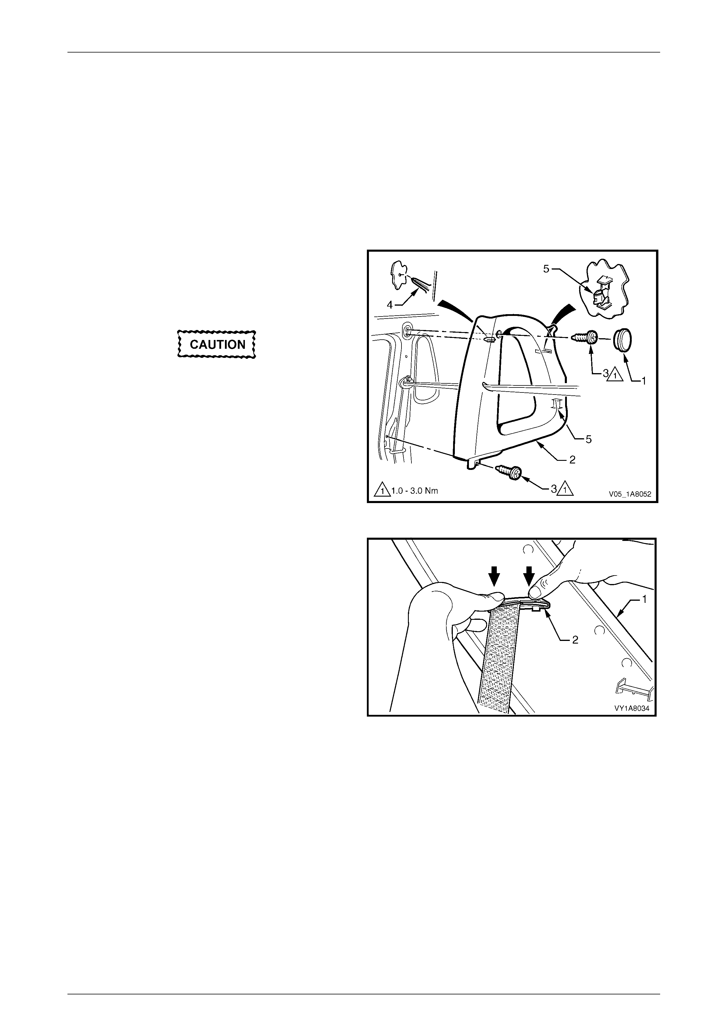
Headlining and Interior Trim Page 1A8–149
Page 1A8–149
7.4 Body Lock Pillar Upper Trim Assembly
LT Section — 14–100
Remove
1 Remove the following components as required:
a Centre pillar lower trim, refer to 7.3 Centre Pillar Lower Tr im.
b Seat belt lower bolt, refer to Section 12M Occupant Protection System.
2 Remove the screw cap (1) from the upper attachment
of the body lock pillar upper trim (2).
3 Remove the two screws (3) attaching the body lock
pillar upper trim.
When removing the body lock pillar upper
trim assembly, take care not to damage the
locating pin (4) below the upper attaching
screw position.
4 Pull the upper edge of the body lock pillar upper trim
away from the headlining to disengage the two
retaining clips (5) at the rear of the body lock pillar
upper trim.
Figure 1A8 – 152
5 With the body lock pillar upper trim (1) partially
removed, disengage the seat belt escutcheo n (2) from
the body lock pillar upper trim and feed the seat belt
and anchor plate through the ope ning.
6 Remove the body lock pillar upper trim.
7 As required, remove the retaining clips from the
vehicle and fit to the trim.
Figure 1A8 – 153
Headlining and Interior Trim Page 1A8–150
Page 1A8–150
Reinstall
Reinstallation of the body lock pillar upper trim assembly is the reverse of the removal procedure, noting the following:
Take care not to snap off the locating pin
when fitting the body lock pillar upper trim
assembly.
1 Ensure the locating pin belo w the upper attaching screw position in the body lock pillar u pper trim is correctly
aligned with the locating hole in the centre pillar.
2 Ensure the body lock pillar upper trim two retaining clips are secured to the centre pillar.
3 Ensure the leading edge of the body lock pillar upper trim assembly enga ges the door opening weatherstrip
assembly.
4 Check the seatbelt operation prior to tightening the body lock pillar upper trim attaching screws.
5 Tighten the body lock pillar upper trim two attaching screws to the specified torque.
Body lock pillar upper trim assembl y
attaching screw torque specification...........1.0 – 3.0 Nm
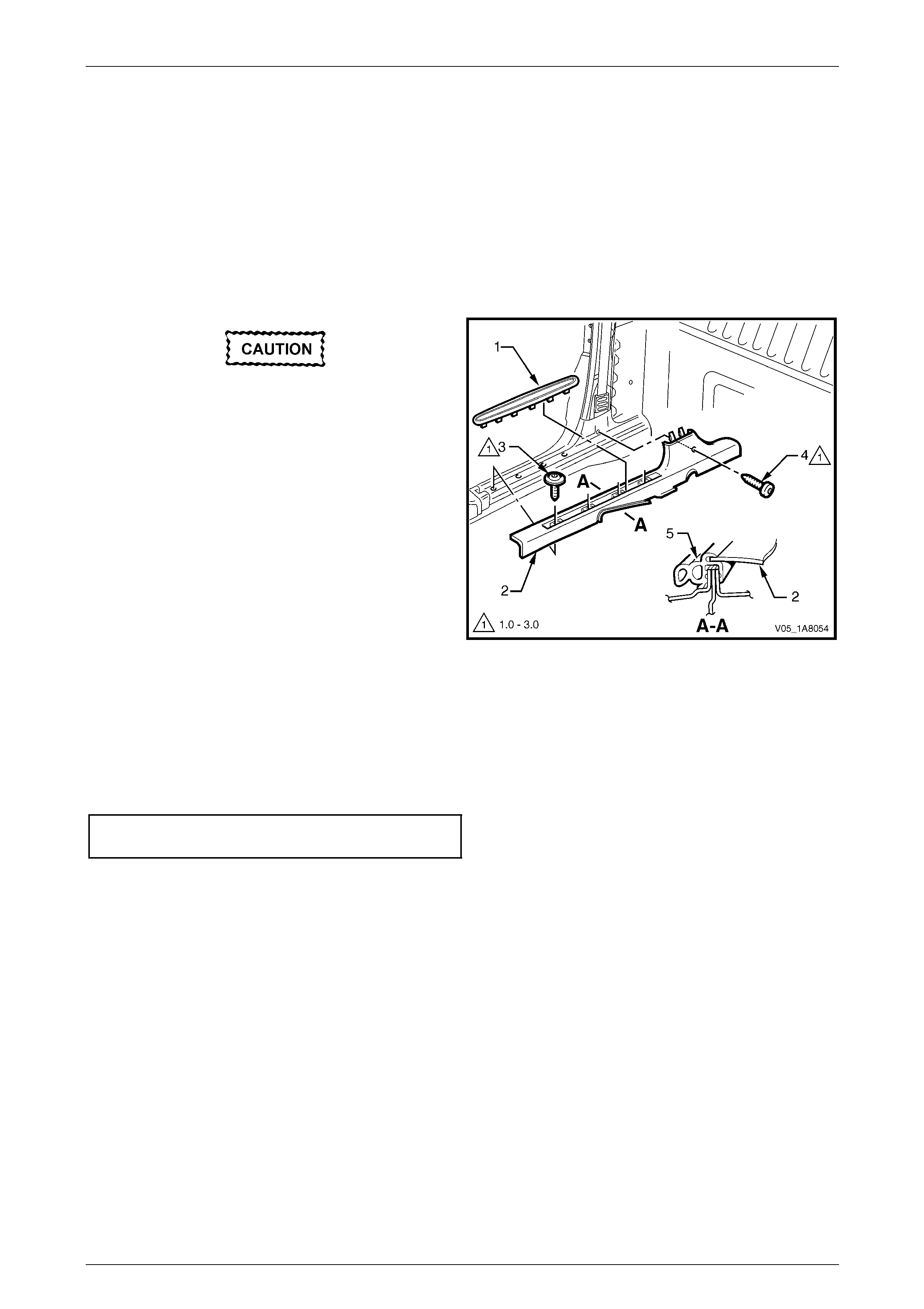
Headlining and Interior Trim Page 1A8–151
Page 1A8–151
7.5 Side Sill Trim and Plate
LT Section — 14–100
Remove
1 Remove the following components as required:
a Centre pillar lower trim, refer to 7.3 Centre Pillar Lower Tr im.
b Front seat outer front cover, refer to Section 1A7 Seat Assemblies.
During the following procedure take care not
to snap the sill trim plates.
2 Carefully lever the side sill trim plate (1) from the side
sill trim (2), starting at the front of the plate and moving
rearward.
3 Remove the Torx screw (3), four places, attaching the
side sill trim to the door opening.
4 Remove the Torx screw (4) attaching the side sill trim
to the centre pillar.
5 Remove the side sill trim.
Figure 1A8 – 154
Reinstall
Reinstallation of the side sill trim and plate is the reverse of the removal procedure, noting the following:
1 Ensure the outer edge of the side sil l trim (2) enga ges the door opening weatherstrip (5), refer to Figure 1A8 – 154.
2 Tighten the Torx screws attaching the side sill trim to the correct torque specification.
Side sill trim attaching Torx screw
torque specification.....................................1.0 – 3.0 Nm

Headlining and Interior Trim Page 1A8–152
Page 1A8–152
7.6 Windshield Side Garnish
LT Section — 14–100
Remove
1 Remove the following components as required:
a Front assist handle assembly, refer to 7.2 Assist Handle Assembly.
b Partially remove the bod y lock pillar upper trim assembly by removing the upper attaching screw, refer to
7.4 Body Lock Pillar Upper Trim Assembly.
When removing the windshield side garnish,
take care not to damage the locating pin (3).
2 Starting at the upper rear edge of the windshield side
garnish (1) disengage the three retai nin g clips (2).
3 Remove the windshield side garnish.
4 As required, remove the retaining clips from the
vehicle and fit to the garnish.
Figure 1A8 – 155
Reinstall
Reinstallation of the windshield side garnish is the reverse of the removal procedure, noting the following:
Take care not to snap off the locating pin
when fitting the windshield side garnish.
1 Ensure the windshield side ga rnish locating pin is aligned with the locating h ole i n the hinge pillar inner panel.
2 Ensure the outer edge of the winds hield side garnish (1) engages the front door opening weatherstrip (4 ), refer to
Figure 1A8 – 155.
3 Ensure the three retaining clips are secured to the hinge pillar inner panel.

Headlining and Interior Trim Page 1A8–153
Page 1A8–153
7.7 Body Hinge Pillar Trim Assembly
LT Section — 14–100
Remove
1 Partially remove the side sill trim, refer to 7.5 Side Sill Trim and Plate.
2 Remove the two attaching screws (1) from the body
hinge pillar trim assembly (2).
3 Disengage the body hinge pillar trim clip (3) by pul ling
the lower edge of the body hinge p illar trim assembly
rearward and away from the sheetmetal.
4 Remove the body hinge pillar trim assembly.
5 If required, remove the body hinge pillar trim clip a nd
the two nut inserts (4).
Figure 1A8 – 156
Reinstall
Reinstallation of the body hinge pillar trim assembl y is the reverse of the removal procedure, noting the following:
1 Ensure the body hinge pil lar trim clip is correctly engaged in the hinge pillar inner panel.
2 Ensure the nut inserts are in good condition and correctly located in the hinge pillar inner panel.
3 Ensure the outer edge of the body hinge pillar trim assembl y engages the front door opening weatherstrip (5), refer
to Figure 1A8 – 156.
4 Tighten the body hinge pillar trim assembly two attaching screws to the correct torque specification.
Body hinge pillar trim assembly
attaching screw torque specification...........0.7 – 1.0 Nm
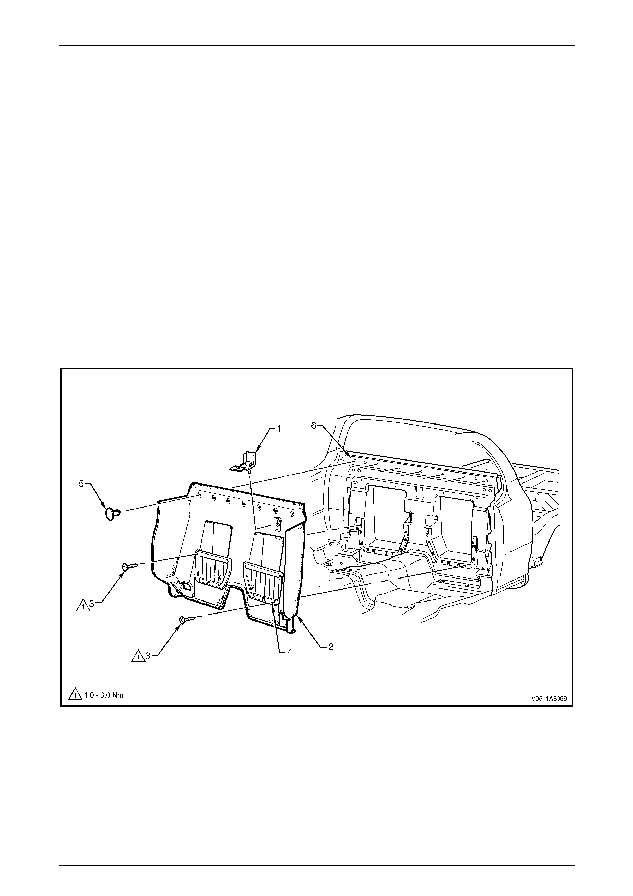
Headlining and Interior Trim Page 1A8–154
Page 1A8–154
7.8 Seat-back Body Panel Trim Assembly
LT Section — 14–460
Remove
1 Remove the following components as required:
a Body lock pillar upper trim assembly on both sides, refer to 7.4 Body Lock Pillar Upper Trim Assembly.
b Side sill trim on both sides, refer to 7.5 Side Sill Trim and Plate.
c Floor console assembly, refer to Section 1A3 Instrument Panel an d Console.
d Move the passenger and driver seat to the forward position and remove the jack handle from its location
behind the passenger seat.
2 Remove the child seat anchors (1) from the seat-back body panel trim assembly (2), shown in Figure 1A8 – 157
and refer to Section 12M Occupant Protection System.
3 Remove the screw (3), four places each side, attaching the storage pocket panels (4).
4 Remove the retainer (5), seven places, securing the seat-back body panel trim assembly to the seat-back
panel (6).
5 Carefully remove the seat-back body panel trim assembly.
Figure 1A8 – 157
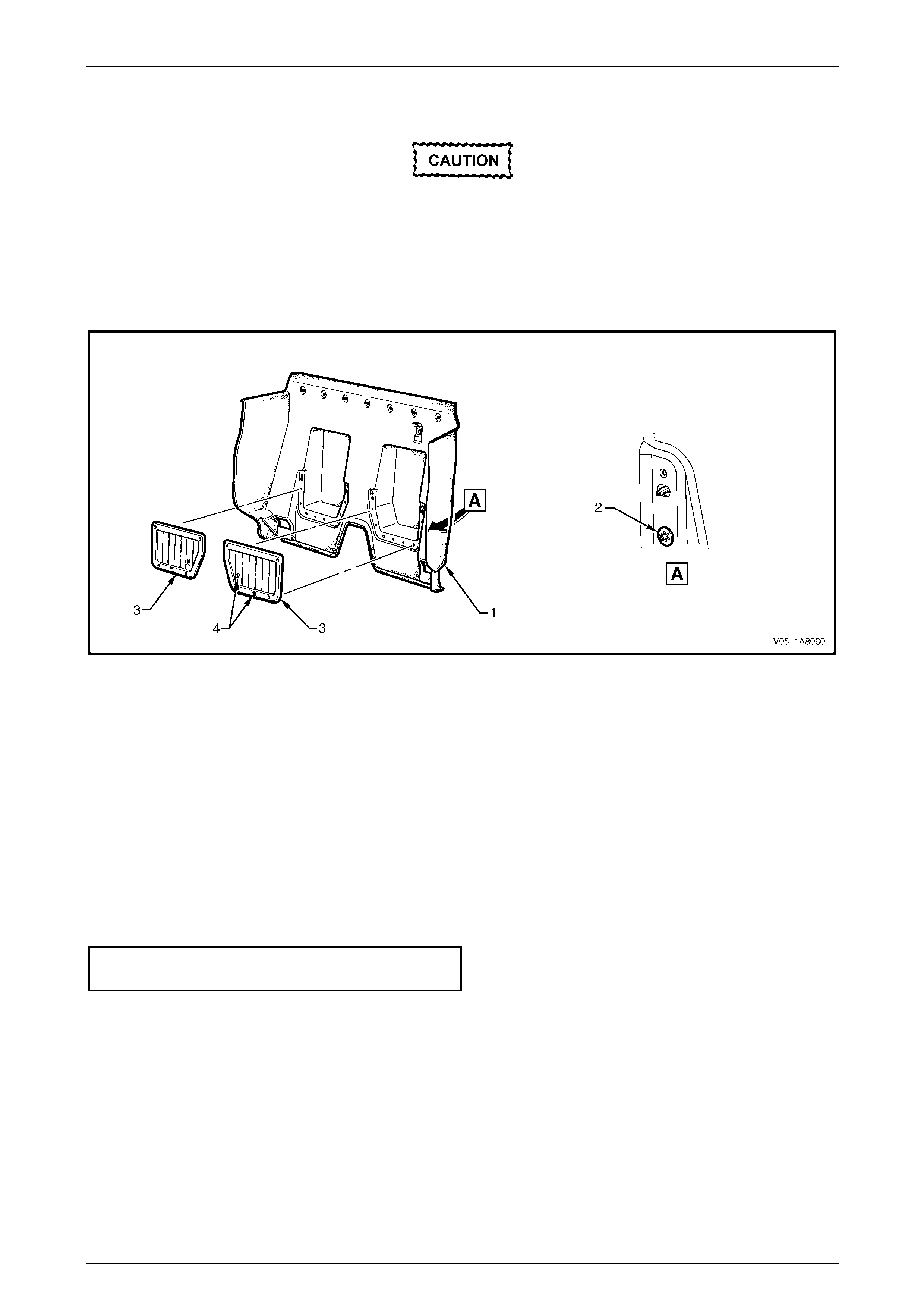
Headlining and Interior Trim Page 1A8–155
Page 1A8–155
Disassemble
Take care when removing the speed clips (2),
as the storage panel pocket plastic pins to
which they are fitted can easily be bro ken.
1 From the rear of the seat-back body panel trim assembl y (1), using side-cutters cut the speed clip (2), four places,
securing each storage pocket panel (3), then remove from the lugs and discard, refer to Figure 1A8 – 158.
2 Gently pull the storage pocket panel forward and remove from the seat-back body pane l trim assembly.
Figure 1A8 – 158
Reassembly
1 Position the storage pocket panels (3) to the seat-back body panel trim assembly with the hooks (4) for the jack
handle facing forward, refer to Figure 1A8 – 158.
2 Fit four new speed clips to secure each storage p ocket panel to the seat-back bo dy panel trim assembly.
Reinstall
Reinstallation of the seat-back body panel trim assembly is the reverse of the removal procedure, noting the following:
1 Ensure the seven retainers ar e secured to the seat-back panel.
2 Tighten the eight screws attaching both storage pocket panels to the correct torque specif ication.
Storage pocket panels attaching screw
torque specification.....................................1.0 – 3.0 Nm

Headlining and Interior Trim Page 1A8–156
Page 1A8–156
7.9 Sunshade Assembly
LT Section — 14–050
Remove
1 Disconnect the sunshade assembly (1) from the
sunshade support (2) and rotate to gain acce ss.
2 Remove the two Torx screws (3) attaching the
sunshade assembly.
3 Pull the sunshade away from the hea dlining assembly
and remove.
When removing the sunshade support, take
care not to damage the locating pin (5).
4 Remove the Torx screw (4) from the sunshade support
and pull the support from the headlining assembly.
Figure 1A8 – 159
Reinstall
Reinstallation of the sunshad e assemb ly is the reverse of the removal procedure, noting the following:
Take care not to damage the locating pin
when fitting the sunshade support.
1 Ensure the sunshade support locati ng pin is aligned with the locating h ole in the roof panel.
2 Tighten the Torx screw attaching the sunshade support to the correct torque specification.
Sunshade support attaching
Torx screw torque specification...................0.5 – 2.0 Nm
3 Tighten the sunshade ass embly two attaching Torx scre ws to the correct torque specific ation.
Sunshade assembly attaching
screw torque specification...........................0.5 – 2.0 Nm

Headlining and Interior Trim Page 1A8–157
Page 1A8–157
7.10 Headlining Assembly
LT Section — 14–150
Remove
1 Remove the fuse F6 from the passenger compartment fuse and relay panel ass embl y,
refer to Section 12O Fuses, Relays and Wiring Harnesses.
2 Place protective covering ov er both seats and the interior trim.
3 Remove the following components as required:
a Body lock pillar upper trim on both sid es, refer to 7.4 Bod y Lock Pillar Upper Trim Assembly.
b Windshield side garnish on b oth sides, refer to 7.6 Windshield Side Garnish.
c Sunshade assembly on both sides, refer to 7.9 Sunshade Assembly.
d Dome lamp assembly, refer to Section 12B Lighting System.
4 Disconnect the headlining assembly harness (1) from the body wiring harness connector (2), located above and
slightly forward of the right-hand centre pillar, refer to Figure 1A8 – 160.
NOTE
It may be necessary to flex the headlining
assembly (3) down slightly to gain access to the
harness connector.
5 With the aid of an assistant, flex the headlini ng assembly to disengage the corners from the four ‘D’ tabs (4) on the
sides of the roof panel.
6 Ease the headlining assembly from its position on the roof panel and turn the assem bly so that it can be passed
through the passenger side door opening and remove it from inside the vehicle.
Figure 1A8 – 160
Reinstall
Reinstallation of the headlining assembly is the reverse of the removal pro c edure, noting the following:
1 Temporarily support the headlining assembly on the ‘D’ tabs (4) before the trim components are installed, refer to
Figure 1A8 – 160.
2 Ensure the headlining assembly harness connector is securely connected to the body wiring harness connector.

Headlining and Interior Trim Page 1A8–158
Page 1A8–158
7.11 Driver Footrest
LT Section — 14–475
Remove
1 Prise the two screw covers (1) and remove from the
driver footrest.
2 Remove the two screws (2) attaching the driver
footrest (3) to the footrest mounting bracket (4).
3 Remove the footrest pad.
Figure 1A8 – 161
Reinstall
Reinstallation of the driver footrest is the reverse of the removal procedure, noting the following:
Tighten the two screws attaching the driver footrest to the correct torque specification.
Driver footrest attaching screw
torque specification.....................................2.0 – 5.0 Nm
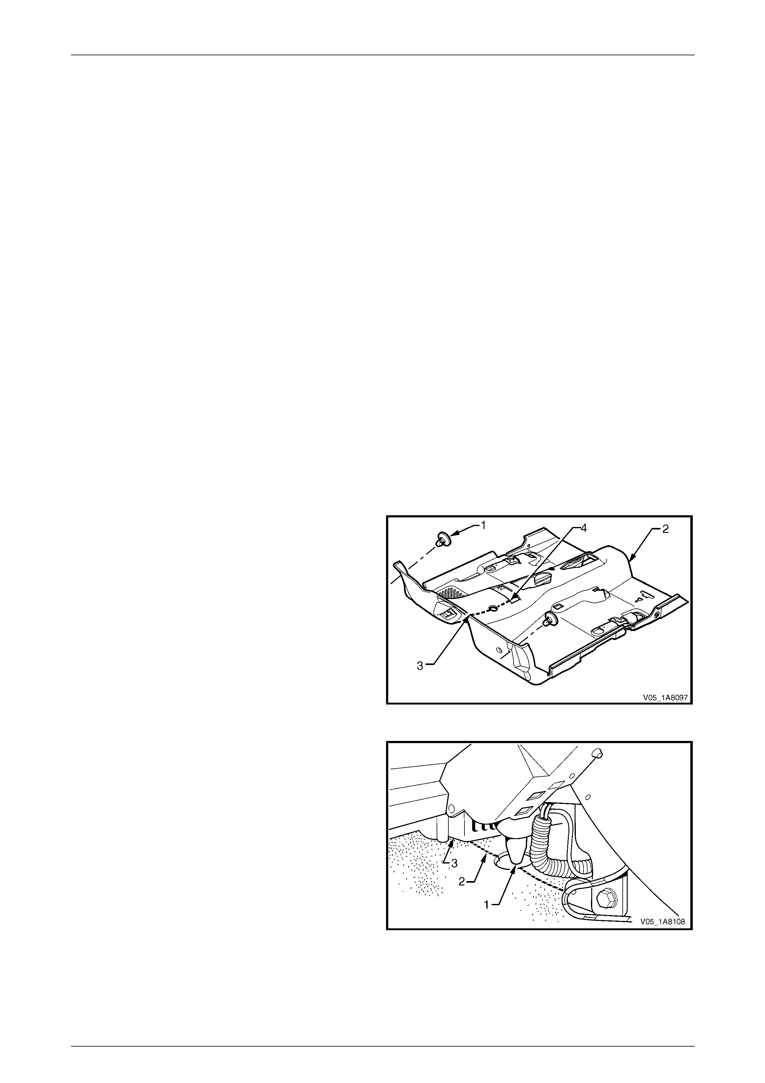
Headlining and Interior Trim Page 1A8–159
Page 1A8–159
7.12 Front Floor Carpet Assembly
LT Section — 14–475
Remove
1 Remove the following components as required:
a Side sill trims on both sides, refer to 7.5 Side Sill Trim and Plate.
b Seat belt lower attaching bolts, refer to Section 12M Occupant Protection System.
c Body hinge pillar trim assembly on both sides, refer to 7.7 Body Hinge Pillar Trim Assembly.
d Both seat assemblies, refer to Section 1A7 Seat Assemblies.
e Driver footrest, refer to 7.11 Driver Footrest.
f Remove the park brake lever cover by graspi ng the cover firmly by hand and sliding the cover over the p ark
brake lever, refer to Section 5A Service and Park Braking System.
g Instrument panel lower trim plate assembly, right-hand and left-hand,
refer to Section 1A3 Instrument Panel and Consol e.
h Instrument panel compartment, refer to Section 1A3 Instrument Panel and Console.
i Instrument panel lower trim panel, refer to Section 1A3 Instrument Panel and Consol e.
j Floor console assembly, refer to Section 1A3 Instrument Panel an d Console.
2 Disconnect the inflatable restraint control module (SDM) wiring harness,
refer to Section 12M Occupant Protection System.
3 Remove the two retaining clips (1) from the front floor
carpet assembly (2) by rotating the clips counter-
clockwise and lifting clear of the attaching studs.
NOTE
To facilitate the removal and installation
procedure, the front floor carpet assembly is
perforated from the front edge (3), through the
centre of the evaporator drain cut-out, to the
forward edge of the lower radio bracket cut-
out (4).
Figure 1A8 – 162
4 From inside the left-hand footwell, grasp the edge of
the hole in the front floor carpet assembly around the
evaporator drain hose (1) and tear open the perforated
line (2) by pulling the carpet awa y from the
transmission tunnel.
5 Slide the remaining flap of carpet out from under the
heating, ventilation and air-conditioning (HVAC)
unit (3) and into the right-hand footwell.
6 Carefully manoeuvre the front floor carp et and
insulator assembly out of the vehicle.
Figure 1A8 – 163

Headlining and Interior Trim Page 1A8–160
Page 1A8–160
Reinstall
Reinstallation of the front floor carpet assembly is the reverse of the removal procedure, noting the following:
1 If a new front floor carpet assembly is being fitted, prior to installation, cut along the perforated line that runs from
the carpet forward edge (3) to the forward edge of the lower radio bracket cut-out (4), refer to F igure 1A8 – 162.
2 Ensure all the cut-outs in the front floor carpet assembl y are correctly alig ned, then install the two retaining clips
and the seat belt lower attaching bolts, refer to Section 12M Occupant Protection System, to secure the front floor
carpet assembly prior to installing the seats and console.
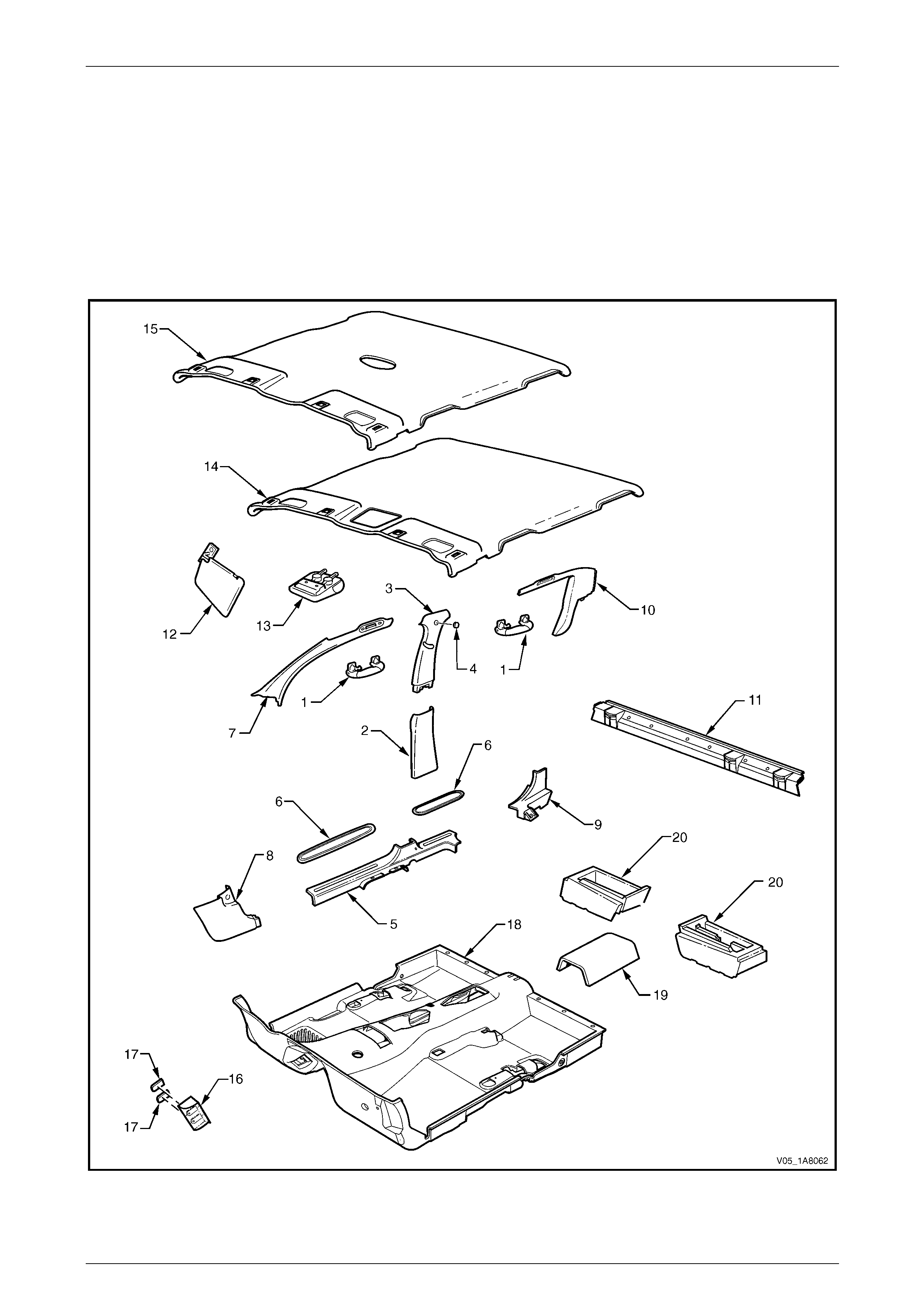
Headlining and Interior Trim Page 1A8–161
Page 1A8–161
8 Service Operations – Crew Cab
and AWD Crew Cab
8.1 Components Chart
The headlining and interior trim components for Crew Cab vehicles are displayed in the following chart to assist with their
identification, refer to Figure 1A8 – 164.
For the service procedures of the door trim pane l assemblies, refer to Section 1A5 Front and Rear Door Assemblies.
Figure 1A8 – 164

Headlining and Interior Trim Page 1A8–162
Page 1A8–162
Legend
1 Assist Handle Assembly
2 Centre Pillar Lower Trim
3 Centre Pillar Upper Trim Assembly
4 Screw Cap
5 Side Sill Trim
6 Side Sill Trim Plate
7 Windshield Side Garnish
8 Body Hinge Pillar Trim Assembly
9 Rocker Panel Extension
10 Body Lock Pillar Garnish
11 Upper Cross Beam Cover
12 Sunshade Assembly
13 Roof Console (where fitted)
14 Headlining Assembly (with roof console)
15 Headlining Assembly (with dome lamp)
16 Driver Footrest
17 Screw Cap
18 Floor Carpet Assembly
19 Carpet Tunnel
20 Jack Box

Headlining and Interior Trim Page 1A8–163
Page 1A8–163
8.2 Assist Handle Assembly
LT Section — 14–100
Remove
NOTE
This procedure is app licable to the front and rear
assist handle assemblies.
1 Pull the assist handle (1) into the down position.
2 Prise open the assist handle two screw covers (2) and
remove the two attaching screws (3).
When removing the assist handle assembly,
take care not to damage the locating pin s (4).
3 Remove the assist handle assembly.
Figure 1A8 – 165
Reinstall
Take care not to damage the locating pin
when fitting the assist handle assembly.
1 Ensure the locating pins are correctl y align ed with the locating holes.
2 Position the hook over the locating pin.
3 Tighten the assist handle two attaching screws to the correct torque specification.
Assist handle attaching screw
torque specification.....................................1.0 – 3.0 Nm

Headlining and Interior Trim Page 1A8–164
Page 1A8–164
8.3 Centre Pillar Lower Trim
LT Section — 14–100
Remove
1 Using your fingers, lever the top of the centre pill ar
lower trim (1) away from the front door opening
weatherstrip and pull the trim to ward the centre of the
car, disengaging the two retaining clips (2).
2 Lift the centre pillar lower trim upward, out of the side
sill trim (3) and remove.
3 As required, remove the retaining clips from the
vehicle and fit to the trim.
Figure 1A8 – 166
Reinstall
1 Locate the centre pillar lo wer trim (1) into the side sill trim (3), refer to Figure 1A8 – 166.
2 Locate the two retaining clips (2) into their slots in the centre pillar, then push in firml y ens uring the two clips are
secured to the centre pillar.
3 Ensure the front and rear door opening weatherstrips fit neatly over the outer edges of centre pillar lower trim.

Headlining and Interior Trim Page 1A8–165
Page 1A8–165
8.4 Centre Pillar Upper Trim Assembly
LT Section — 14–100
Remove
1 Remove the following components as required:
a Remove the centre pillar lower trim, refer to 8.3 Centre Pillar Lo wer Trim.
b Remove the front seat belt lower bolt, refer to Section 12M Occupant Prot ection System.
2 Remove the screw cap (1) from the upper attachment
of the centre pillar upper trim assembly (2).
3 Remove the three screws (3) attaching the centre
pillar upper trim assembly.
When removing the centre pillar upper trim
assembly, take care not to damage the
locating pin (6) below the upper attaching
screw position.
4 Pull the upper edge of the centre pillar upper trim
assembly away from the headlining assembly to
disengage the two retaining clips (4) and the seatbelt
guide adjuster assembly (5), if fitted.
5 Feed the seatbelt and anchor plate thro ugh the centre
pillar upper trim assembly and remove the centre pillar
upper trim assembly.
6 If required, remove the seatbelt adjuster trim (7) by
gently spreading the outer edges of the centre pillar
upper trim assembly and lifting out the seatbelt
adjuster trim.
7 As required, remove the retaining clips from the
vehicle and fit to the trim.
Figure 1A8 – 167
Reinstall
Reinstallation of the centre pillar upper trim assembly is the reverse of the removal procedure, noting the following:
1 If fitted, ensure the seatbelt adjuster trim (7) and the seatbelt guide adjuste r assembl y (5) are in the fully up position
and are correctly aligned prior to installing the centre pillar upper trim assembly (2), refer to Figure 1A8 – 167.
Take care not to snap off the locating pin
when fitting the centre pillar upper trim
assembly.
2 Ensure the locating pin belo w the upper attaching screw position in the centre pillar up per trim assembly is correctly
aligned with the locating hole in the centre pillar.
3 Ensure the centre pillar upper trim assembl y two retaining clips are secured to the centre pillar.
4 Ensure the leading edge of the centre pillar upper trim assembly engages the front door opening weatherstrip
assembly (8).
5 Check the seatbelt operation prior to tightening the centre pillar u pp er trim assemb ly attaching screws.
6 Tighten the centre pillar uppe r trim assembly three attaching screws to the specified torque.
Centre pillar upper trim assembly
attaching screw torque specification...........1.0 – 3.0 Nm
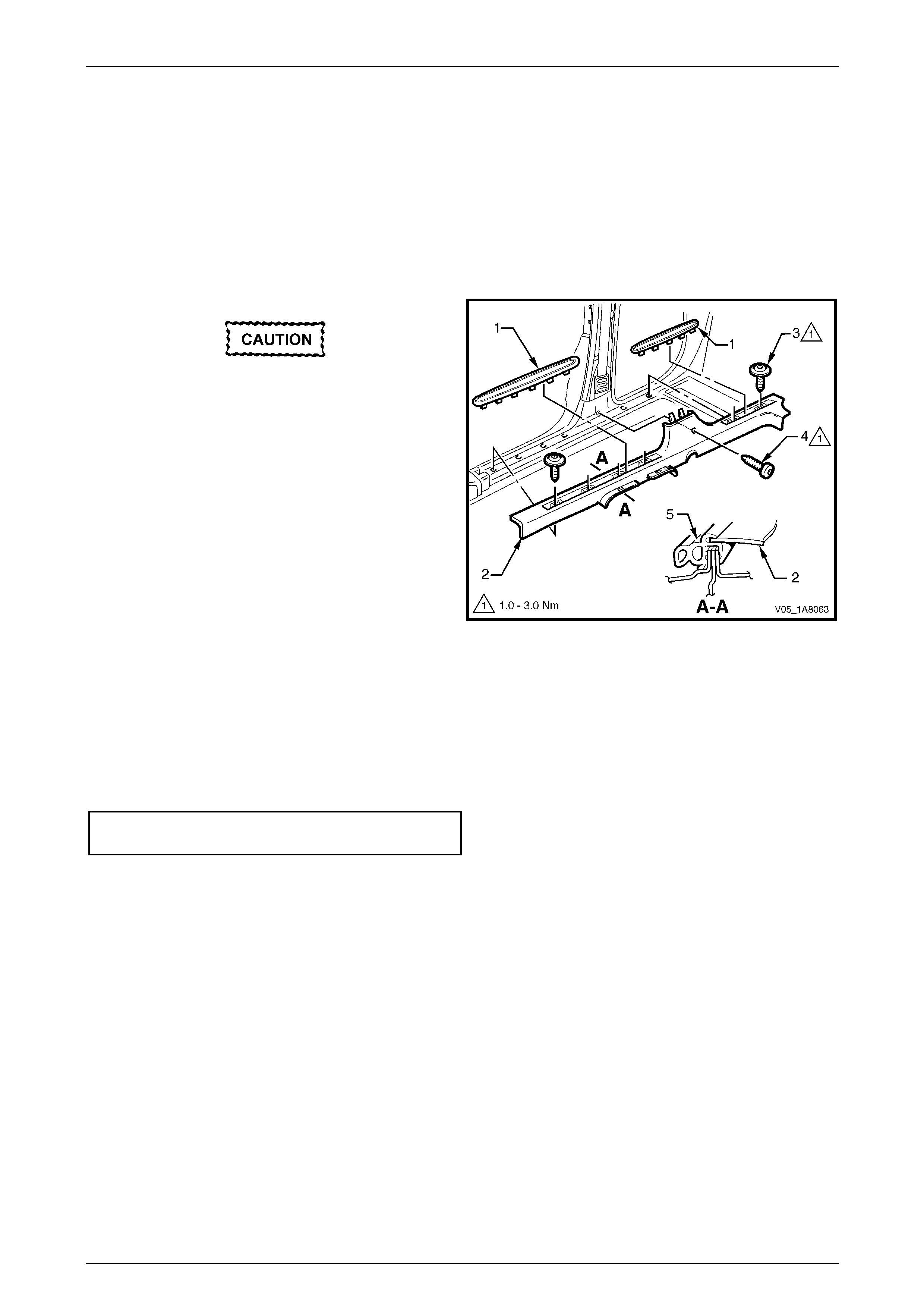
Headlining and Interior Trim Page 1A8–166
Page 1A8–166
8.5 Side Sill Trim and Plate
LT Section — 14–100
Remove
1 Remove the following components as required:
a Centre pillar lower trim, refer to 8.3 Centre Pillar Lower Tr im.
b Front seat outer front cover, refer to Section 1A7 Seat Assemblies.
During the following procedure take care not
to snap the sill trim plates.
2 Carefully lever the front and rear side si ll trim
plates (1) from the side sill trim (2), starting at the front
of each plate and moving rearward.
3 Remove the Torx screw (3), six places, attachin g the
side sill trim, four in the front door opening an d two in
the rear door opening.
4 Remove the Torx screw (4) attaching the side sill trim
to the centre pillar.
5 Remove the side sill trim through the front door
opening by lifting the front and sliding the rear out from
under the rear seat cushion. Figure 1A8 – 168
Reinstall
Reinstallation of the side sill trim and plate is the reverse of the removal procedure, noting the following:
1 Ensure the outer edge of the side sil l trim (2) enga ges the fr ont and rear door opening weatherstrips (5), refer to
Figure 1A8 – 168.
2 Tighten the Torx screws attaching the side sill trim to the correct torque specification.
Side sill trim attaching Torx screw
torque specification.....................................1.0 – 3.0 Nm

Headlining and Interior Trim Page 1A8–167
Page 1A8–167
8.6 Windshield Side Garnish
LT Section — 14–100
Remove
1 Remove the following components as required:
a Front assist handle assembly, refer to 8.2 Assist Handle Assembly.
b Partially remove the centre pill ar upper trim assembly by removing the upper attaching screw, refer to
8.4 Centre Pillar Upper Trim Assembly.
When removing the windshield side garnish,
take care not to damage the locating pin (3).
2 Starting at the upper rear edge of the windshield side
garnish (1) disengage the three retai nin g clips (2).
3 Remove the windshield side garnish.
4 As required, remove the retaining clips from the
vehicle and fit to the garnish.
Figure 1A8 – 169
Reinstall
Reinstallation of the windshield side garnish is the reverse of the removal procedure, noting the following:
Take care not to snap off the locating pin
when fitting the windshield side garnish.
1 Ensure the windshield side ga rnish locating pin is aligned with the locating h ole i n the hinge pillar inner panel.
2 Ensure the outer edge of the winds hield side garnish (1) engages the front door opening weatherstrip (4 ), refer to
Figure 1A8 – 169.
3 Ensure the three retaining clips are secured to the hinge pillar inner panel.

Headlining and Interior Trim Page 1A8–168
Page 1A8–168
8.7 Body Hinge Pillar Trim Assembly
LT Section — 14–100
Remove
1 Partially remove the side sill trim, refer to 8.5 Side Sill Trim and Plate.
2 Remove the two attaching screws (1) from the body
hinge pillar trim assembly (2).
3 Disengage the body hinge pillar trim clip (3) by pul ling
the lower edge of the body hinge p illar trim assembly
rearward and away from the sheetmetal.
4 Remove the body hinge pillar trim assembly.
5 If required, remove the body hinge pillar trim clip a nd
the two nut inserts (4).
Figure 1A8 – 170
Reinstall
Reinstallation of the body hinge pillar trim assembl y is the reverse of the removal procedure, noting the following:
1 Ensure the body hinge pil lar trim clip is correctly engaged in the hinge pillar inner panel.
2 Ensure the nut inserts are in good condition and correctly located in the hinge pillar inner panel.
3 Ensure the outer edge of the body hinge pillar trim assembl y engages the front door opening weatherstrip (5), refer
to Figure 1A8 – 170.
4 Tighten the body hinge pillar trim assembly two attaching screws to the correct torque specification.
Body hinge pillar trim assembly
attaching screw torque specification...........0.7 – 1.0 Nm
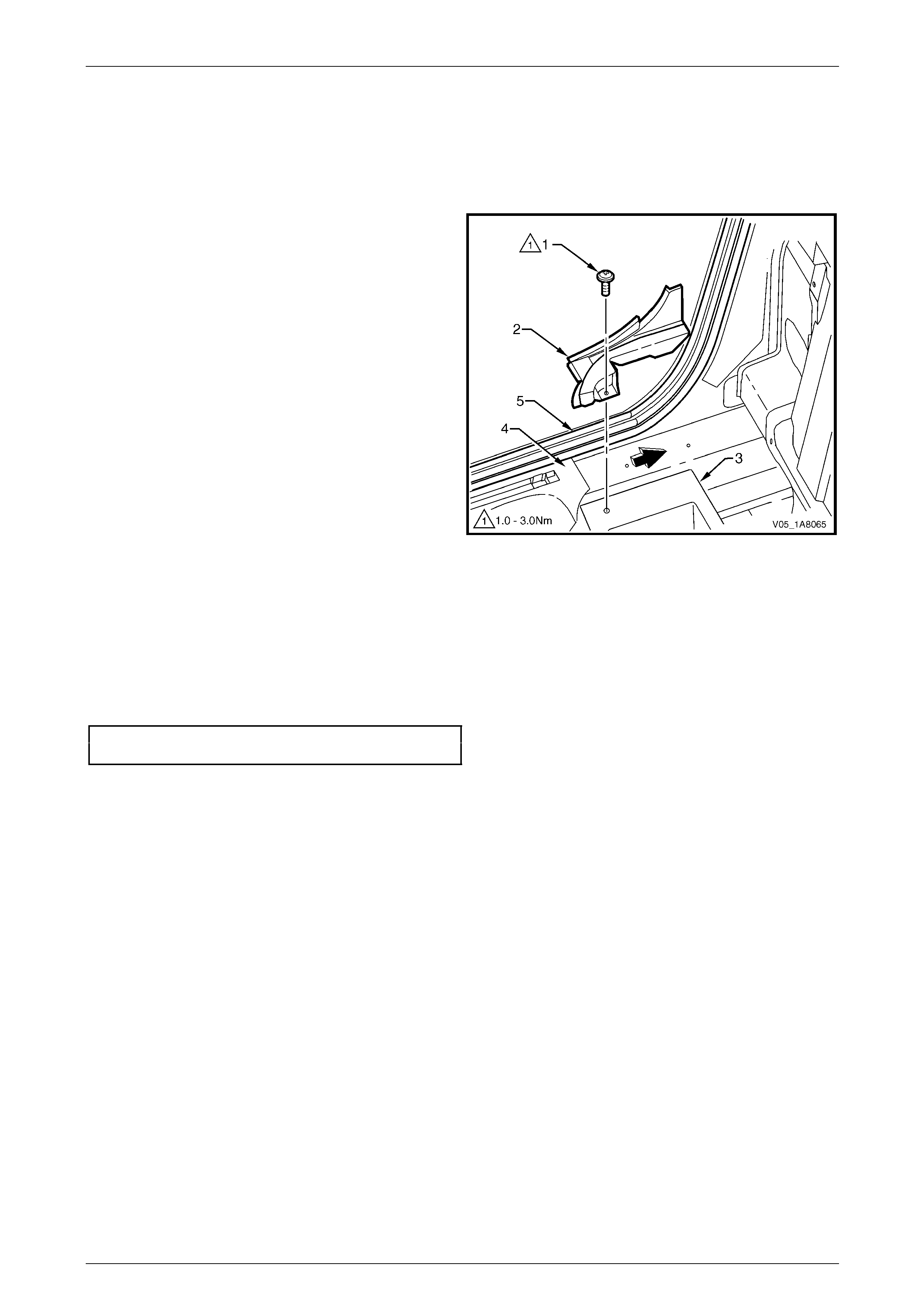
Headlining and Interior Trim Page 1A8–169
Page 1A8–169
8.8 Rocker Panel Cover Extension
LT Section — 14–100
Remove
1 Lift the rear seat cushion to the raised position.
2 Remove the screw (1) attaching the rocker panel
cover extension (2) to the jack box (3).
3 Slide the rocker panel cover extension rearward to
disengage it from the side sill trim (4).
4 Raise the front of the rocker panel cover extension
and pull it forward to remove.
Figure 1A8 – 171
Reinstall
Reinstallation of the rocker panel cover extension is the reverse of the removal pr ocedure, noting the following:
1 Ensure the outer edge of the rocker panel cover extension (2) engages the rear door opening weatherstrip (5) and
the side sill trim (4), refer to Figure 1A8 – 171.
2 Tighten the rocker panel cover extension attaching screw to the correct torque specification.
Rocker panel extension attaching
screw torque specification...........................1.0 – 3.0 Nm
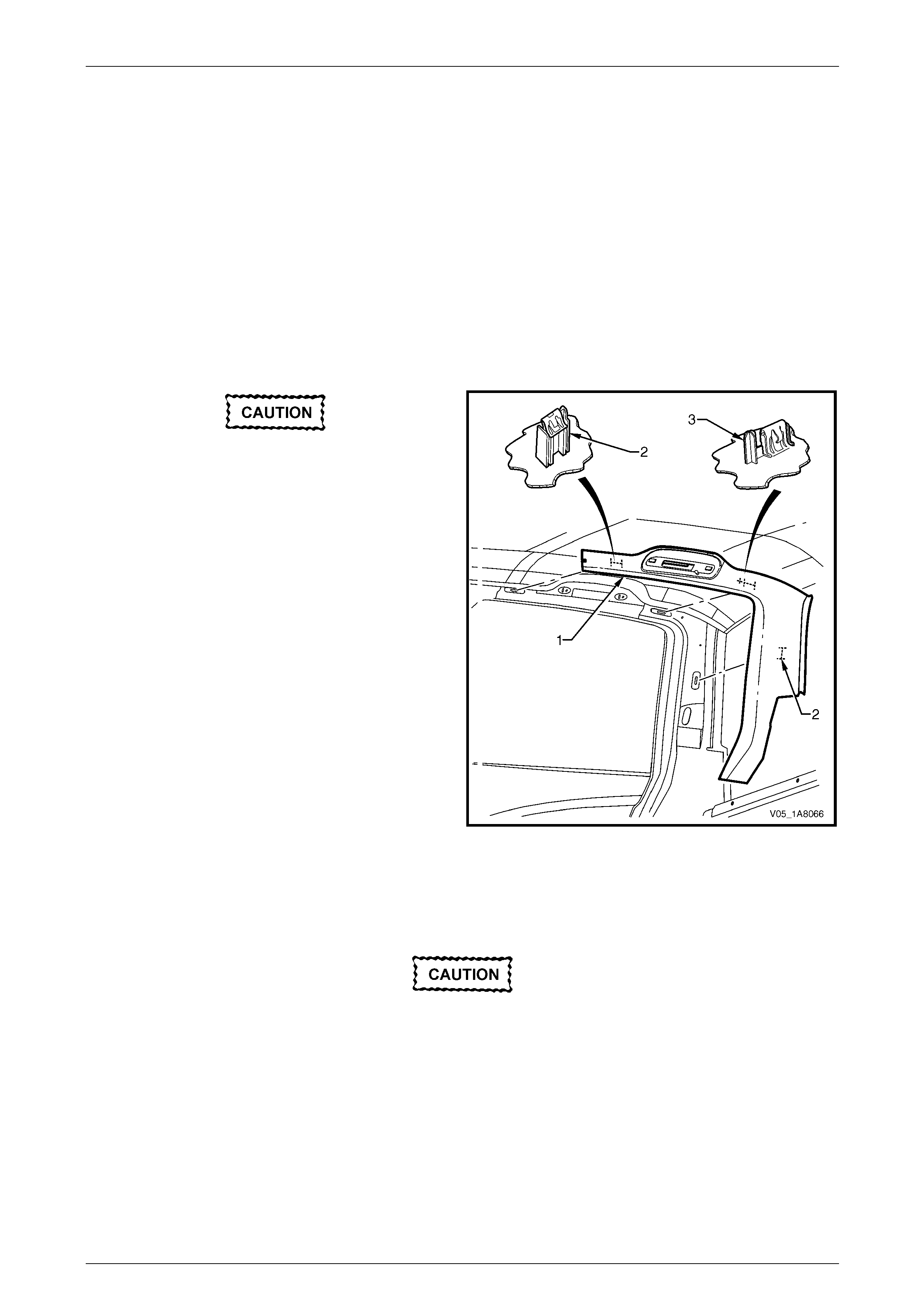
Headlining and Interior Trim Page 1A8–170
Page 1A8–170
8.9 Body Lock Pillar Garnish
LT Section — 14–120
Remove
1 Remove the following components as required:
a Rear assist handle assembl y, refer to 8.2 Assist Handle Assembly.
b Partially remove the centre pill ar upper trim assembly by removing the upper attaching screw, refer to
8.4 Centre Pillar Upper Trim Assembly.
c Roof rail courtesy and reading lamps, refer to Section 12B Lighting System.
d Rear seat-back assembly, refer to Section 1A7 Seat Assemblies.
When removing the body lock pillar garnish,
take care not to damage the locating pin (3).
2 Beginning at the front of the body lock pillar
garnish (1), carefully pull it away from the quarter
panel inner assembly to disengage the three retaining
clips (2) and remove.
3 As required, remove the retaining clips from the
vehicle and fit to the garnish.
Figure 1A8 – 172
Reinstall
Reinstallation of the body lock pillar garnish is the reverse of the removal procedure, noti ng the following:
Take care not to snap off the locating pin
when fitting the body lock pillar garnish.
1 Ensure the body lock pillar garnish locating pin is aligned with the locating hole in the quarter panel inner assembly.
2 Ensure the leading edge of the bod y lock pillar garnish eng ages the rear door opening weatherstrip.
3 Ensure the three retaining clips are secur ed to the quarter panel inner assembl y.
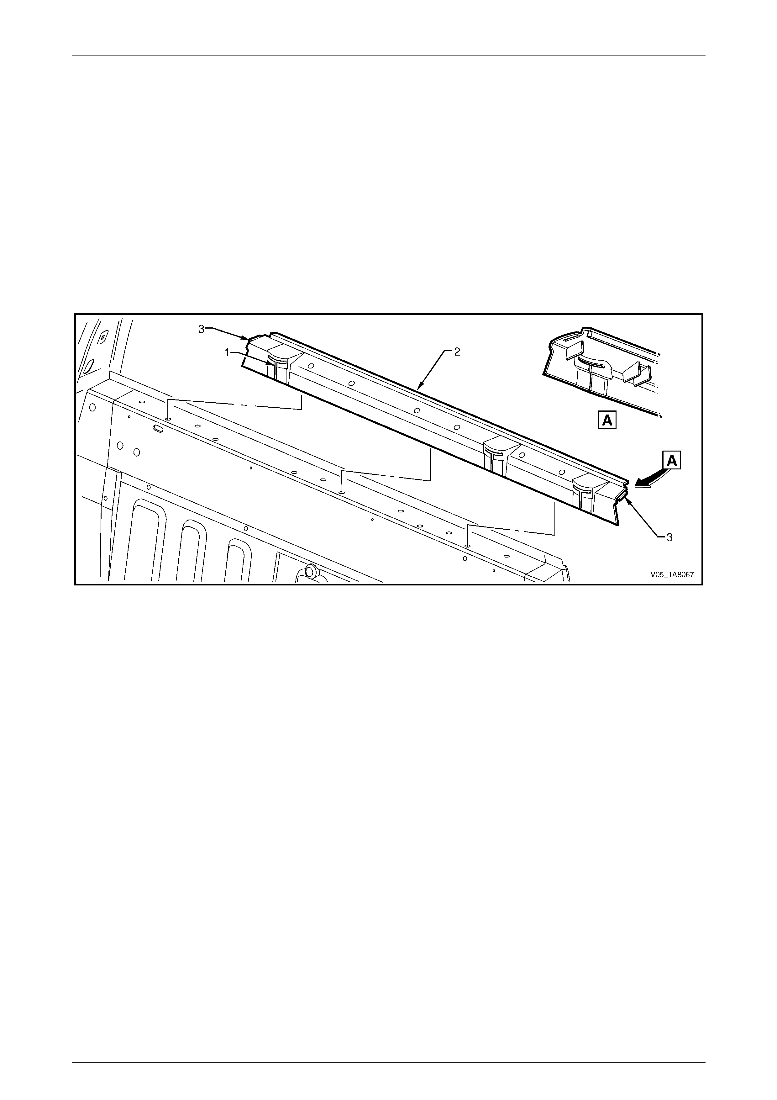
Headlining and Interior Trim Page 1A8–171
Page 1A8–171
8.10 Upper Cross Beam Cover
LT Section — 14–460
Remove
1 Remove the following components as required:
a Body lock pillar garnish, refer to 8.9 Body Lock Pillar Garn ish.
b Rear seat-back head restraint assemblies and sleeves, refer to Section 1A7 Seat Assemblies.
2 Manoeuvre each seat belt webbing through the three slots (1) in the upper cross beam cover (2), refer to
Figure 1A8 – 173.
3 Lift the upper cross beam cover from the rear body upper inner panel assembly and remove.
Figure 1A8 – 173
Reinstall
Reinstallation of the upper cross beam cover is the reverse of the removal procedure, not ing the following:
1 Ensure the seat belt webbings are not twisted when feeding them through th e slots in the upper cross beam cover.
2 Ensure the upper cross beam cover locating tabs (3) engage in the body lock pillar garnish, refer to
Figure 1A8 – 173.
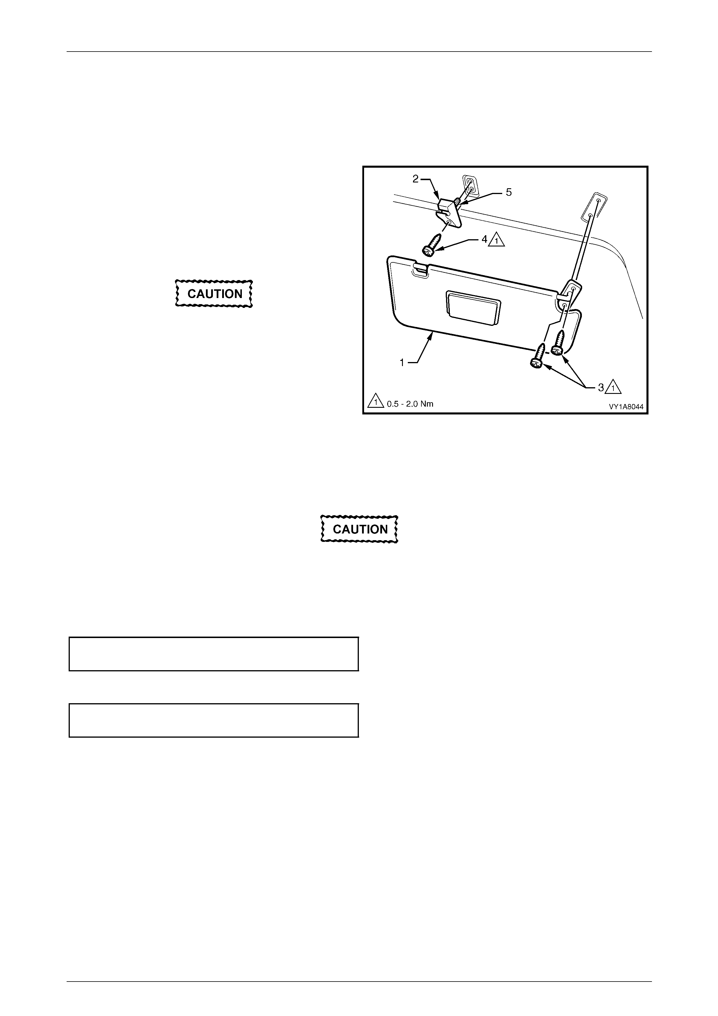
Headlining and Interior Trim Page 1A8–172
Page 1A8–172
8.11 Sunshade Assembly
LT Section — 14–050
Remove
1 Disconnect the sunshade assembly (1) from the
sunshade support (2) and rotate to gain acce ss.
2 Remove the two Torx screws (3) attaching the
sunshade assembly.
3 Pull the sunshade away from the hea dlining assembly
and remove.
When removing the sunshade support, take
care not to damage the locating pin (5).
4 Remove the Torx screw (4) from the sunshade support
and pull the support from the headlining assembly.
Figure 1A8 – 174
Reinstall
Reinstallation of the sunshad e assemb ly is the reverse of the removal procedure, noting the following:
Take care not to damage the locating pin
when fitting the sunshade support.
1 Ensure the sunshade support locati ng pin is aligned with the locating h ole in the roof panel.
2 Tighten the Torx screw attaching the sunshade support to the correct torque specification.
Sunshade support attaching
Torx screw torque specification...................0.5 – 2.0 Nm
3 Tighten the sunshade ass embly two attaching Torx scre ws to the correct torque specific ation.
Sunshade assembly attaching
screw torque specification...........................0.5 – 2.0 Nm
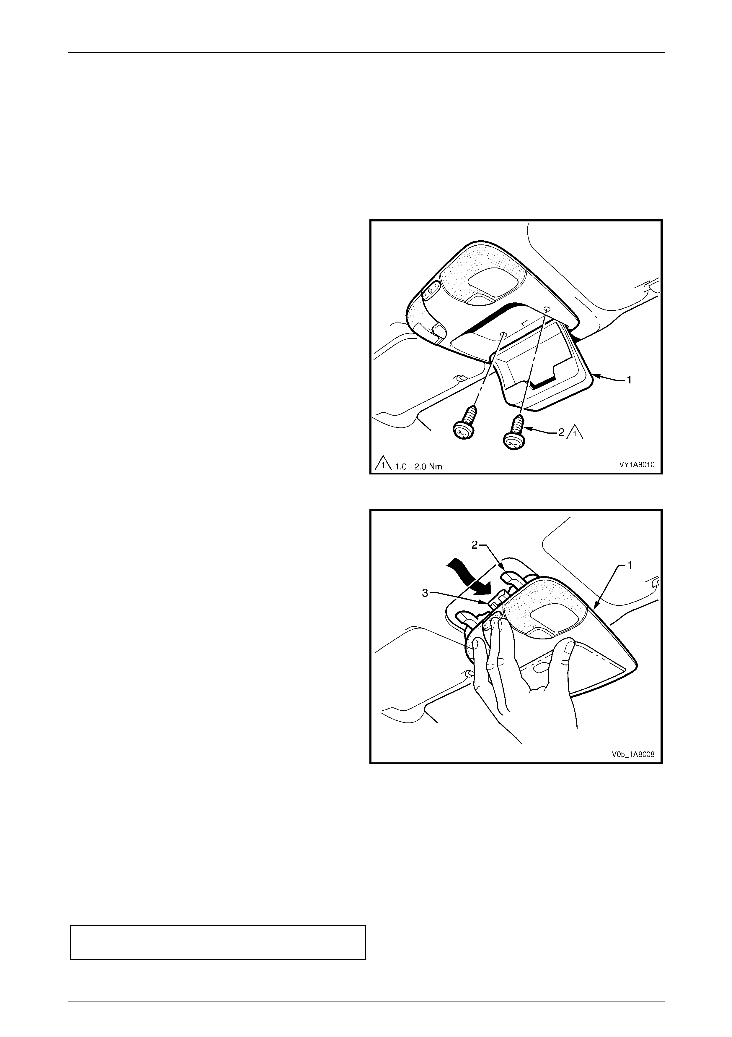
Headlining and Interior Trim Page 1A8–173
Page 1A8–173
8.12 Roof Console
LT Section — 02–780
Remove
1 Remove the fuse F6 from the passenger compartment fuse and relay panel ass embl y,
refer to Section 12O Fuses, Relays and Wiring Harnesses.
2 Open the compartment door (1) of the roof console.
3 Remove the two attaching screws (2) from inside the
roof console.
4 Close the compartment door.
5 Using your hand, pull down to disengage the front of
the roof console from the roof header pane l.
Figure 1A8 – 175
6 Slide the roof console (1) in a forward motion to allow
the two locator arms (2) to clear the headlini ng.
7 Disconnect the harness from the roof console
connector (3) and remove.
NOTE
For replacement of the map lamp bulbs, refer to
Section 12B Lighting System.
Figure 1A8 – 176
Reinstall
Reinstallation of the roof console is the reverse of the removal procedure, noting the following:
1 Ensure the harness is securely connecte d to the roof console connector.
2 Ensure the two locator arms are correctly inserted and the roof console is secure d to the roof panel.
3 Tighten the roof console two attaching screws to the correct torque specification.
Roof console attaching screw
torque specification.....................................1.0 – 2.0 Nm

Headlining and Interior Trim Page 1A8–174
Page 1A8–174
8.13 Headlining Assembly
LT Section — 14–150
Remove
1 Remove the fuse F6 from the passenger compartment fuse and relay panel ass embl y,
refer to Section 12O Fuses, Relays and Wiring Harnesses.
2 Place protective covering ov er both front seats and the interior trim.
3 Remove the following components as required:
a Rear seat-back assembly, refer to Section 1A7 Seat Assemblies.
b Windshield side garnish on b oth sides, refer to 8.6 Windshield Side Garnish.
c Body lock pillar garnish on b oth sides, refer to 8.9 Body Lock Pillar Garnis h.
d Sunshade assembly on both sides, refer to 8.11 Sunshade Assembl y.
e Roof console, where fitted, refer to 8.12 Roof Console.
f Dome lamp assembly, where fitted, refer to Section 12B Lighting System.
4 Disconnect the headlining assembly harness (1) from the body harness con nector (2), located above and slightly
forward of the right-hand centr e pill ar, refer to Figure 1A8 – 177.
NOTE
It may be necessary to flex the headlining
assembly (3) down slightly to gain access to the
harness connector.
5 With the aid of an assistant, flex the headlining assembly to disengage the corners from the ‘D’ tabs (4), in four
places on the sides of the roof panel.
6 Disengage the hook and l oop fastener (5), four places, attaching the rear e dge of the headlining assembly by
gently pulling down the headlining assembly in one corner and working across the rear edge.
7 Ease the headlining assembly from its position on the roof panel and turn the he adlining assembly so that it can be
passed through the passenger side front door opening and remove it from inside the vehicle.
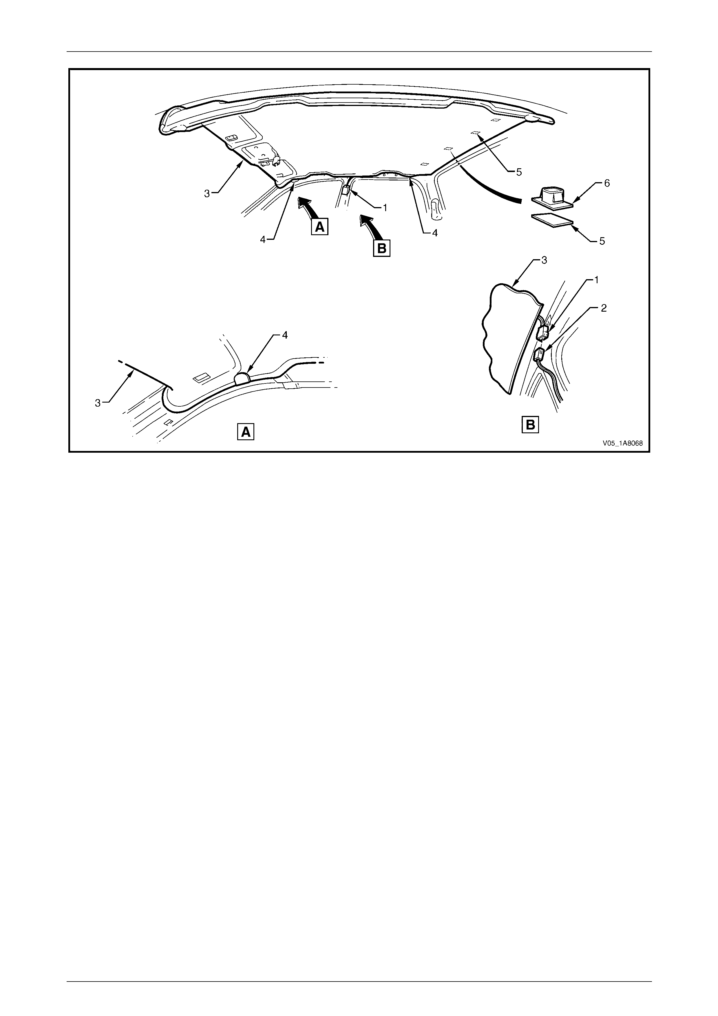
Headlining and Interior Trim Page 1A8–175
Page 1A8–175
Figure 1A8 – 177
Reinstall
Reinstallation of the headlining assembly is the reverse of the removal pro c edure, noting the following:
1 As required, replace the clips (6) from the roof bo w and the fasteners (5) from the headlining, refer to
Figure 1A8 – 177.
2 Temporarily support the headlining assembly on the ‘D’ tabs (4) before the trim components are installed.
3 Ensure the headlining assembly harness connector is securely connected to the body wiring harness connector.
4 Ensure the hook and loop fasteners at the rear edge of the headlining ass embly are secured to the roof panel.

Headlining and Interior Trim Page 1A8–176
Page 1A8–176
8.14 Driver Footrest
LT Section — 14–475
Remove
1 Prise the two screw covers (1) and remove from the
driver footrest.
2 Remove the two screws (2) attaching the driver
footrest (3) to the footrest mounting bracket (4).
3 Remove the footrest pad.
Figure 1A8 – 178
Reinstall
Reinstallation of the driver footrest is the reverse of the removal procedure, noting the following:
Tighten the two screws attaching the driver footrest to the correct torque specification.
Driver footrest attaching screw
torque specification.....................................2.0 – 5.0 Nm
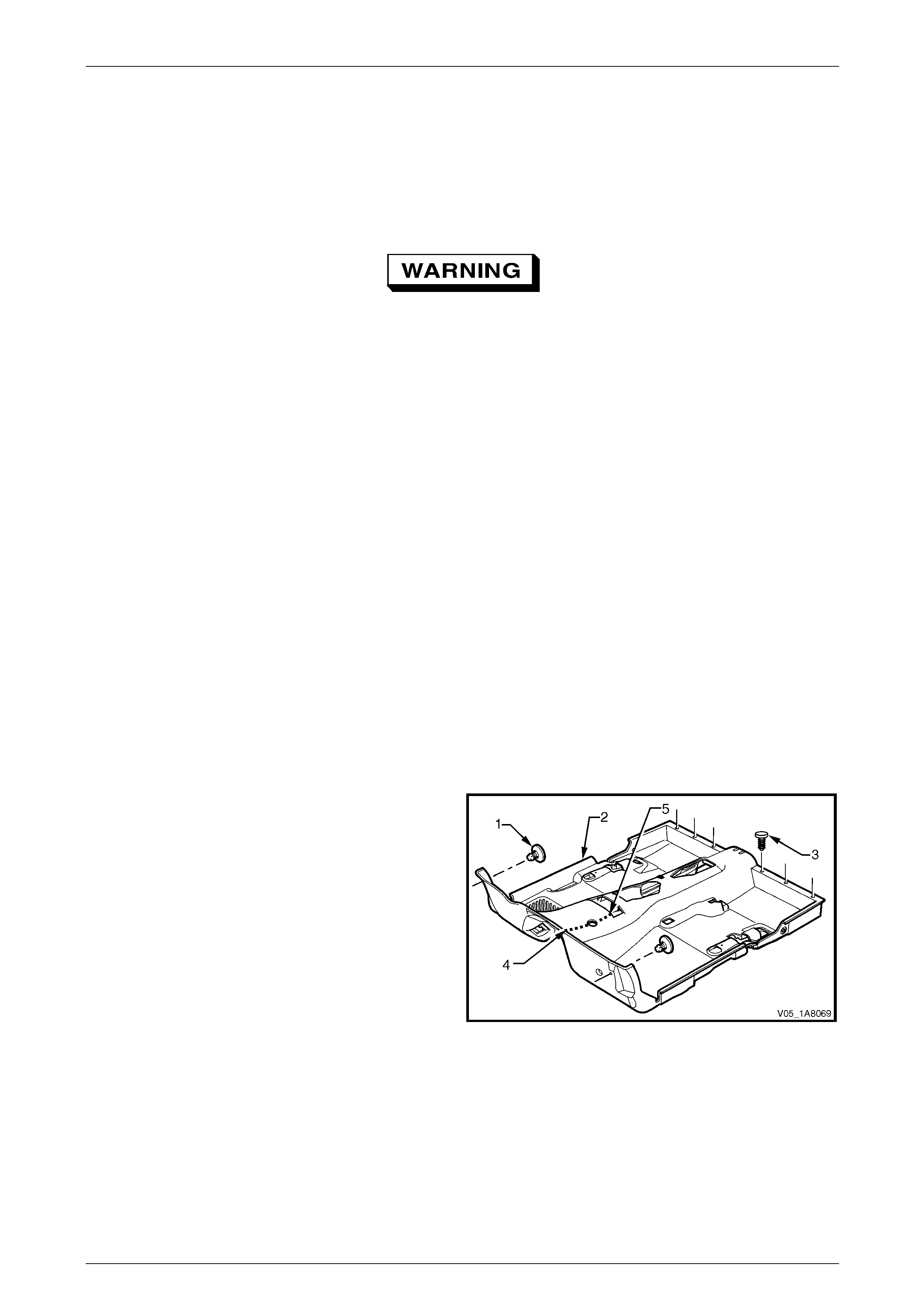
Headlining and Interior Trim Page 1A8–177
Page 1A8–177
8.15 Front Floor Carpet Assembly
LT Section — 14–475
Remove
On vehicles equipped with side impact
airbags, disable the occupant protection
system before performing the following
operation. Refer to Section 12M Occupant
Protection System.
1 Remove the following components as required:
a Side sill trims on both sides, refer to 8.5 Side Sill Trim and Plate.
b Seat belt lower attaching bolts, refer to Section 12M Occupant Protection System.
c Body hinge pillar trim assembly on both sides, refer to 8.7 Body Hinge Pillar Trim Assembly.
d Both front seat assemblies, refer to Section 1A7 Seat Assemblies.
e Driver footrest, refer to 8.14 Driver Footrest.
f Remove the park brake lever cover by graspi ng the cover firmly by hand and sliding the cover over the p ark
brake lever, refer to Section 5A Service and Park Braking System.
g Instrument panel lower trim plate assembly, right-hand and left-hand,
refer to Section 1A3 Instrument Panel and Consol e.
h Instrument panel compartment, refer to Section 1A3 Instrument Panel and Console.
i Instrument panel lower trim panel, refer to Section 1A3 Instrument Panel and Consol e.
j Floor console assembly, refer to Section 1A3 Instrument Panel an d Console.
2 Disconnect the inflatable restraint control module (SDM) wiring harness,
refer to Section 12M Occupant Protection System.
3 Remove the two retaining clips (1) from the front floor
carpet assembly (2) by rotating the clips counter-
clockwise and lifting clear of the attaching studs.
4 Remove the six retaining clips (3) securing the rear
section of the front floor carpet assembly to the jack
boxes.
NOTE
To facilitate the removal and installation
procedure, the front floor carpet assembly is
perforated from the front edge (4), through the
centre of the evaporator drain cut-out, to the
forward edge of the lower radio bracket cut-
out (5).
Figure 1A8 – 179

Headlining and Interior Trim Page 1A8–178
Page 1A8–178
5 From inside the left-hand footwell, grasp the edge of
the hole in the front floor carpet assembly around the
evaporator drain hose (1) and tear open the perforated
line (2) by pulling the carpet awa y from the
transmission tunnel.
6 Slide the remaining flap of carpet out from under the
heating, ventilation and air-conditioning (HVAC)
unit (3) and into the right-hand footwell.
7 Carefully manoeuvre the front floor carp et and
insulator assembly out of the vehicle.
Figure 1A8 – 180
Reinstall
Reinstallation of the front floor carpet assembly is the reverse of the removal procedure, noting the following:
1 If a new front floor carpet assembly is being fitted, prior to installation, cut along the perforated line that runs from
the carpet forward edge (3) to the forward edge of the lower radio bracket cut-out (4), refer to F igure 1A8 – 179.
2 Ensure that all the cut-outs in the front floor carpet assembly are correctly aligned, then install the two forward
retaining clips (1), the six retai nin g clips (3) securing the rear section and the front seat belt lower attaching bolts,
refer to Section 12M Occupant Protection System, to secure the front floor carpet assem bl y , prior to installing the
seats and console.

Headlining and Interior Trim Page 1A8–179
Page 1A8–179
8.16 Tunnel Carpet
LT Section — 14–475
Remove
1 Remove the following components as required:
a Rear seat cushion, refer to Section 1A7 Seat Assemblies.
b Rocker panel cover extension, refer to 8.8 Rocker Pan el C over Extension.
c Seatbelt retractors, refer to Section 12M Occupant Protection System.
d Jack box on both sides, refer to 8.17 Jack Box.
2 Pull the tunnel carpet (1) to separate it from the floor
panel (2).
3 Clean-up the floor panel and remove residual glue as
required.
Figure 1A8 – 181
Reinstall
Reinstallation of the front floor carpet assembly is the reverse of the removal procedure, noting the following:
1 Ensure the contact surface is clean and free of grease.
2 When reinstalling the front floor carpet assembly proceed as applicabl e:
• If a new tunnel carpet is being fitted, remove the backing paper and adhere the carpet to the floor panel.
• If the same tunnel carpet is being fitted, apply contact adhesive as required, then adhere the carpet to the
floor panel.
3 Position the tunnel carpet on the floor panel with the front floor carpet assembly overlapping.
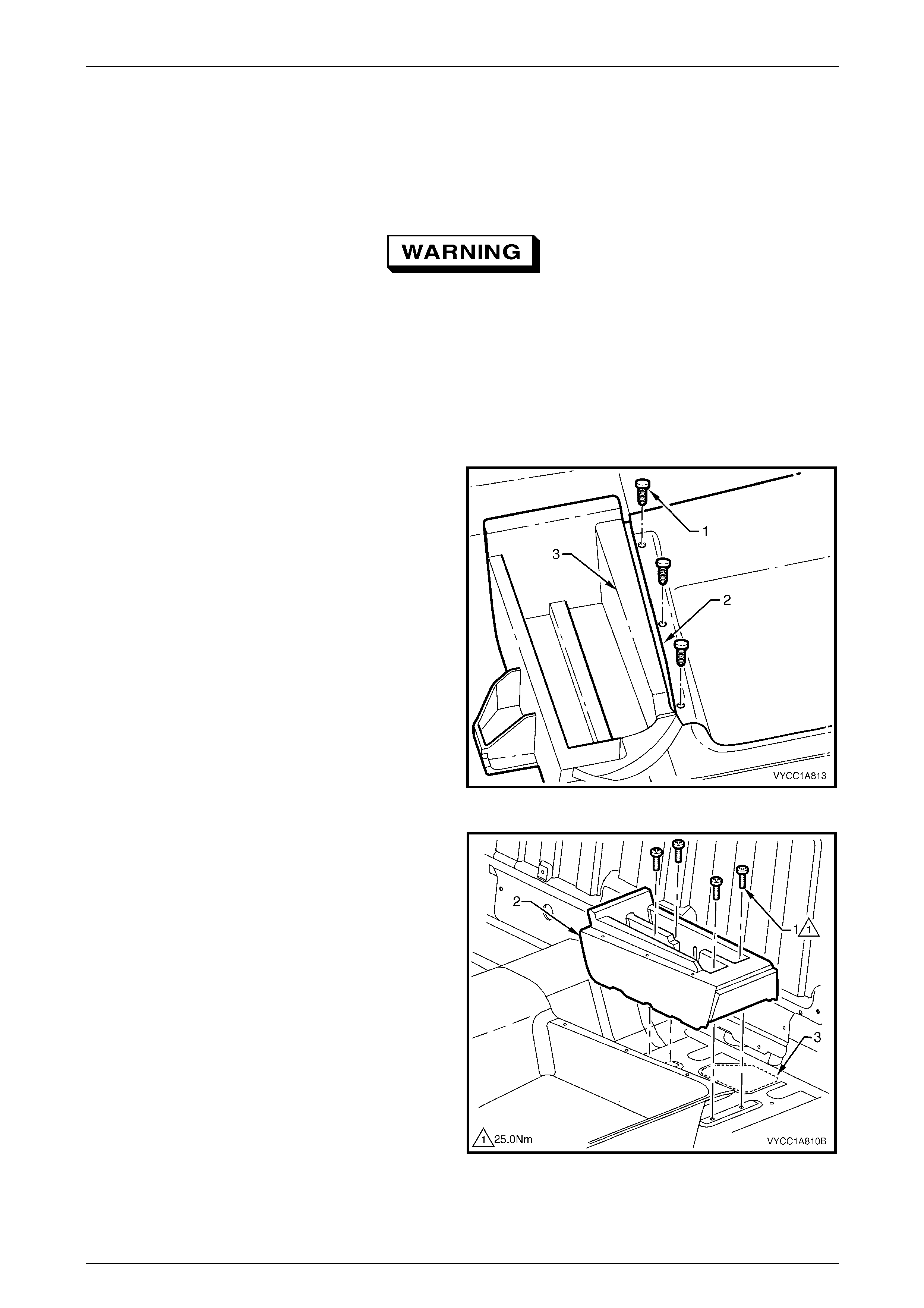
Headlining and Interior Trim Page 1A8–180
Page 1A8–180
8.17 Jack Box
LT Section — XX–XXX
Remove
The jack box forms p art of the vehicle's safety
structure and it is not to be cleaned with
solvents. If damaged, it must be replaced.
1 Remove the following components as required:
a Rear seat cushion, refer to Section 1A7 Seat Assemblies.
b Rocker panel cover extension, refer to 8.8 Rocker Pan el C over Extension.
c Seatbelt retractors, refer to Section 12M Occupant Protection System.
2 Remove the three fasteners (1) attaching the rear
section of the front floor carpet assembly (2) to the
jack box (3) and peel the carpet back slig htly.
Figure 1A8 – 182
3 Remove the four Torx screws (1) from the base of the
jack box (2).
NOTE
A bead of mastic sealer is applied around the
rear section of the jack box to seal the carriage
hole (3) in the floor pan. It may require some
effort to release the bond from the mastic sealer.
4 Lift the jack box slightly and slide it towards the rear of
the vehicle, then lift it up to remove.
Figure 1A8 – 183
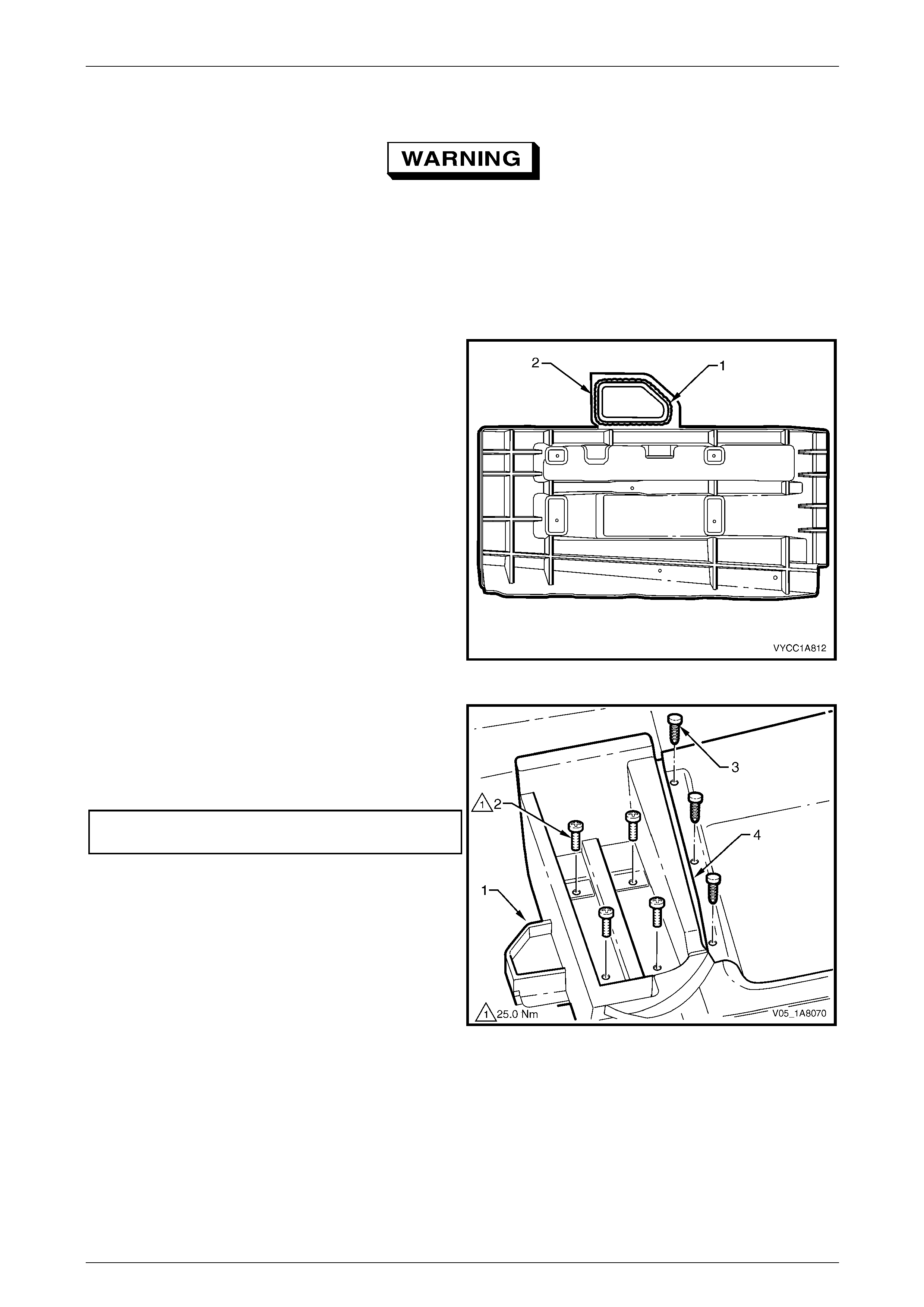
Headlining and Interior Trim Page 1A8–181
Page 1A8–181
Reinstall
The jack box forms p art of the vehicle's safety
structure and it must be installed using the
correct fasteners, sealers and screw torques.
The jack box is not to be cleaned with
solvents and if damaged, it must be replaced.
Ensure the jack and brace are secured in the
left-hand side jack box as per the owners
manual instructions.
1 Apply a bead of mastic sealer (1) or similar, around
the rear section of the jack box (2) in the location
shown.
Figure 1A8 – 184
2 While holding the rear section of the jack box (1) up
slightly to avoid the mastic sealer contacting the floor
panel, slide the jack box forward into position.
3 Install the four Torx screws (2) attaching the jack box
and tighten to the correct torque specification.
Jack box attaching Torx screw
torque specification........................................... 25.0 Nm
4 Secure the three fasteners (3) attaching the rear
section of the front floor carpet assembly (4) to the
jack box.
Figure 1A8 – 185
5 Reinstall the following components as required:
a Seatbelt retractors, refer to Section 12M Occupant Protection System.
b Rocker panel extension cover, refer to 8.8 Rocker Pan el Cover Extension.
c Rear seat cushion, refer to Section 1A7 Seat Assemblies.
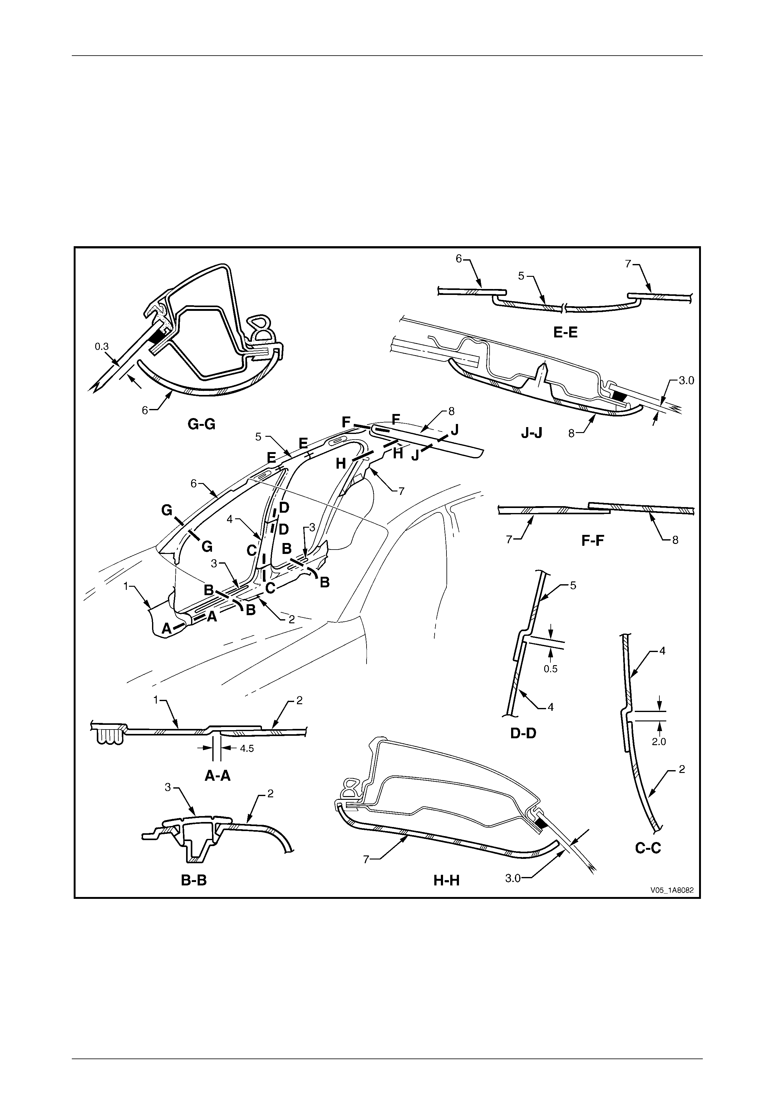
Headlining and Interior Trim Page 1A8–182
Page 1A8–182
9 Clearances Specifications
9.1 Interior Trim Clearances, Sedan
The interior trim clearances for Sedan vehicles are provided in Figure 1A8 – 186. All measurements are in millimetres
and the values given represen t the optimal clearance between the trim panels or garnishes, where no clearance is
indicated there must be contact between the parts.
Before checking the interior trim clearances, ensure the trim panels and garnishes are correctly attached and secured to
the vehicle.
Figure 1A8 – 186
Legend
1 Body Hinge Pillar Trim
Assembly
2 Side Sill Trim
3 Side Sill Trim Plate
4 Centre Pillar Lower Trim
5 Centre Pillar Upper Trim Assembly
6 Windshield Side Garnish
7 Body Lock Pillar Garnish
8 Rear Window Upper Garnish
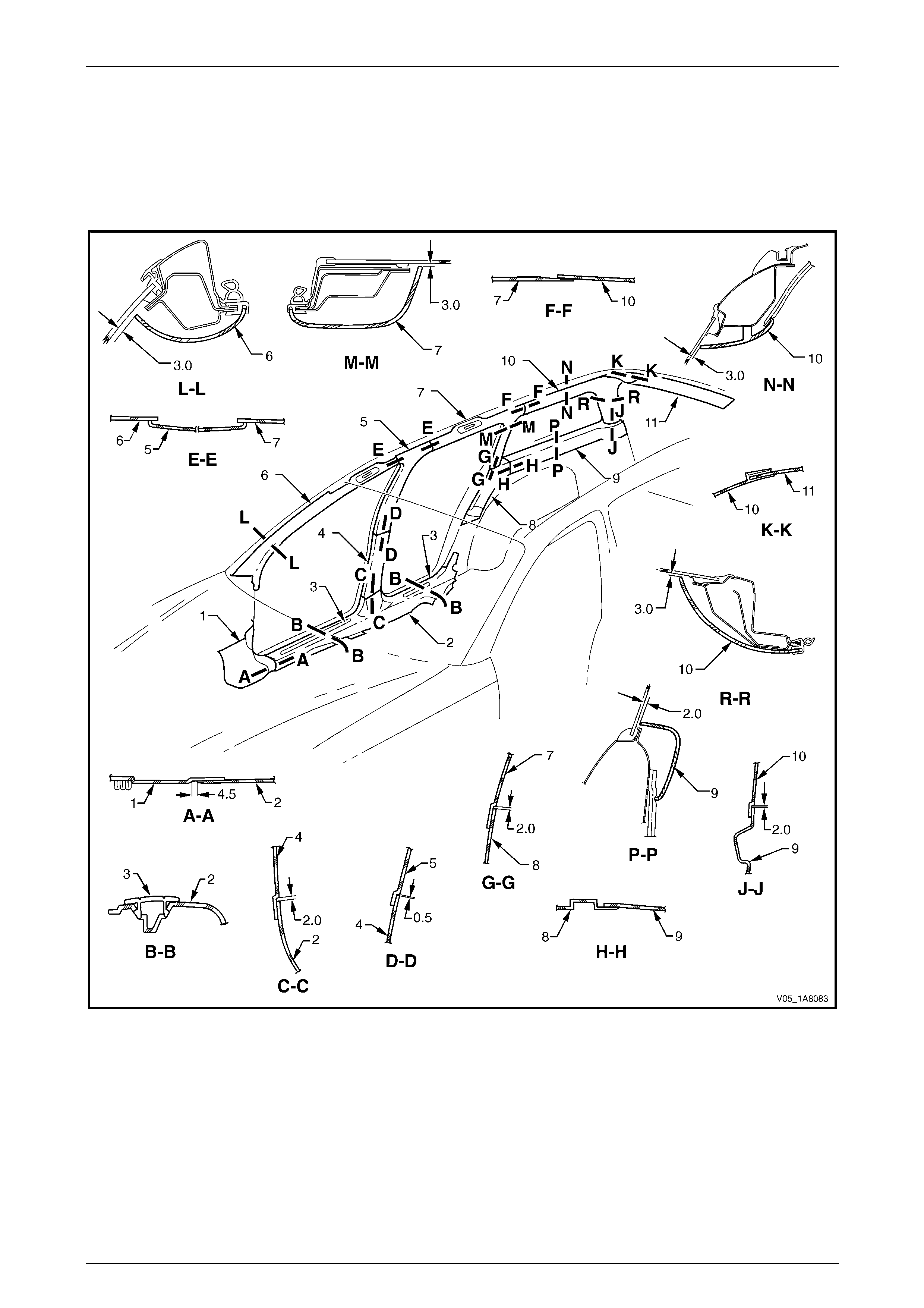
Headlining and Interior Trim Page 1A8–183
Page 1A8–183
9.2 Interior Trim Clearances, Wagon
The interior trim clearances for Wagon vehi cles are provided in Figure 1A8 – 187. All measurements are in millimetres
and the values given represen t the optimal clearance bet ween the trim panels or gar nishes, where no clearance is
indicated there must be contact between the parts.
Before checking the interior trim clearances, ensure the trim panels and garnishes are correctly attached and secured to
the vehicle.
Figure 1A8 – 187
Legend
1 Body Hinge Pillar Trim
Assembly
2 Side Sill Trim
3 Side Sill Trim Plate
4 Centre Pillar Lower Trim
5 Centre Pillar Upper Trim Assembly
6 Windshield Side Garnish
7 Body Lock Pillar Garnish Assembly
8 Body Lock Pillar Lower Trim
9 Quarter Inner Upper Trim
10 Body Rear Corner Garnish Assembly
11 Rear Window Upper Garnish
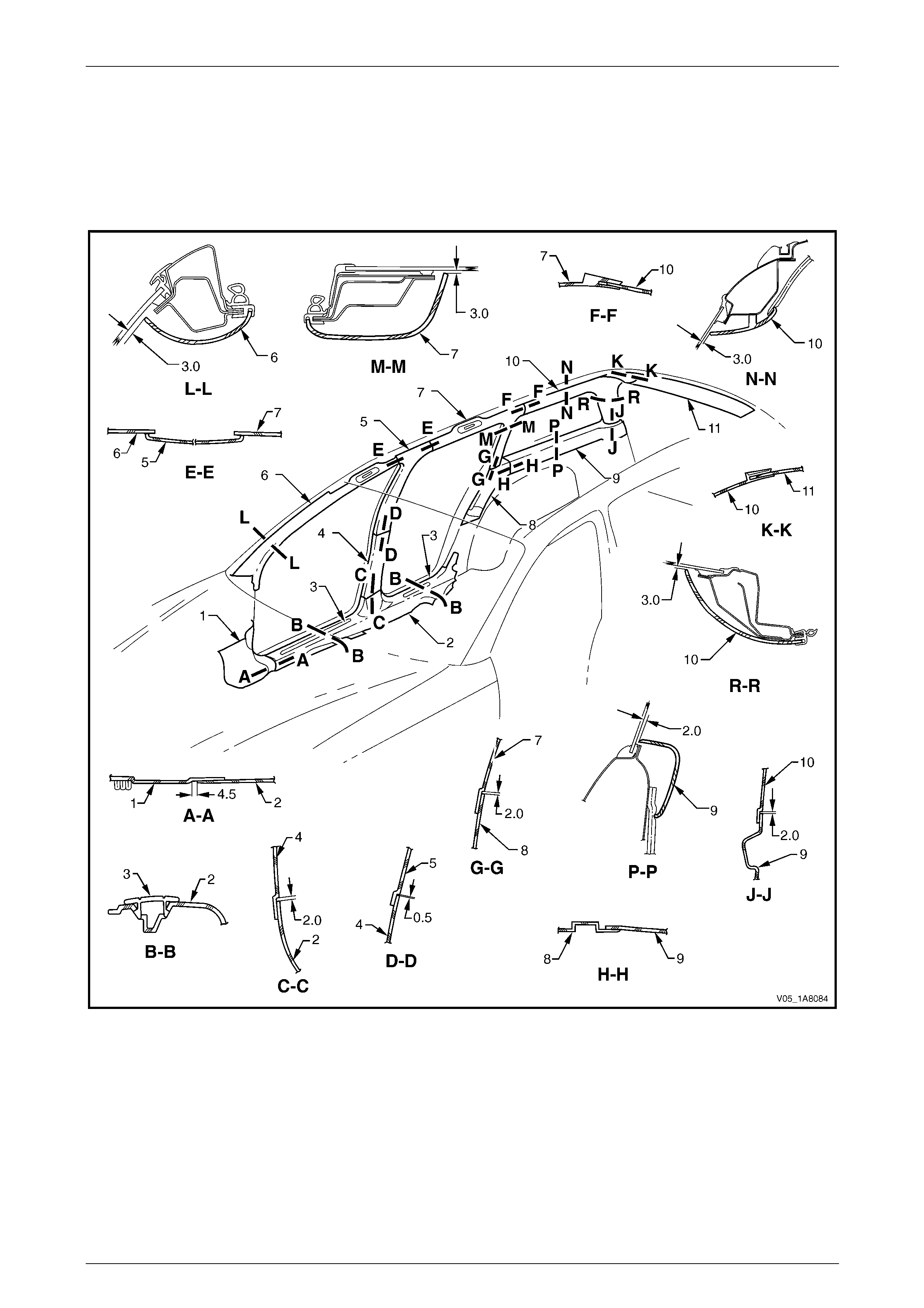
Headlining and Interior Trim Page 1A8–184
Page 1A8–184
9.3 Interior Trim Clearances, AWD Wagon
The interior trim clearances for AWD Wagon vehic les are provided in Figure 1A8 – 188. All measurements are in
millimetres and the values given represent the optimal clearance between the trim panels or garnishes, where no
clearance is indicated there must be contact between the parts.
Before checking the interior trim clearances, ensure the trim panels and garnishes are correctly attached and secured to
the vehicle.
Figure 1A8 – 188
Legend
1 Body Hinge Pillar Trim
Assembly
2 Side Sill Trim
3 Side Sill Trim Plate
4 Centre Pillar Lower Trim
5 Centre Pillar Upper Trim Assembly
6 Windshield Side Garnish
7 Body Lock Pillar Garnish Assembly
8 Body Lock Pillar Lower Trim
9 Quarter Inner Upper Trim
10 Body Rear Corner Garnish Assembly
11 Rear Window Upper Garnish
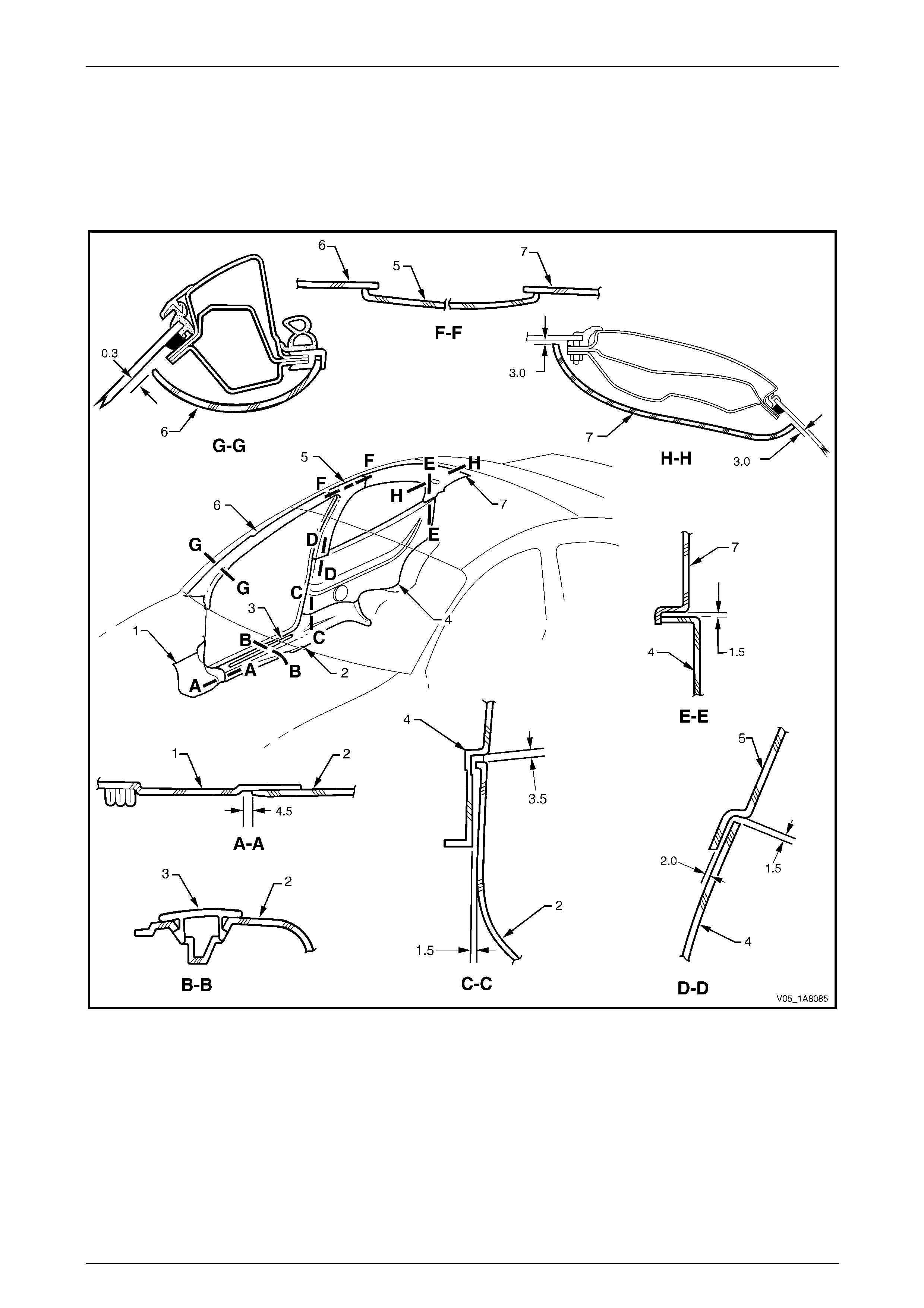
Headlining and Interior Trim Page 1A8–185
Page 1A8–185
9.4 Interior Trim Clearances, Coupe
The interior trim clearances for Coupe vehicles are provided in Figure 1A8 – 189. All measurements are in millimetres
and the values given represen t the optimal clearance between the trim panels or garnishes, where no clearance is
indicated there must be contact between the parts.
Before checking the interior trim clearances, ensure the trim panels and garnishes are correctly attached and secured to
the vehicle.
Figure 1A8 – 189
Legend
1 Body Hinge Pillar Trim
Assembly
2 Side Sill Trim
3 Side Sill Trim Plate
4 Quarter Trim Panel Assembly
5 Centre Pillar Upper Trim Assembly
6 Windshield Side Garnish
7 Body Rear Corner Garnish
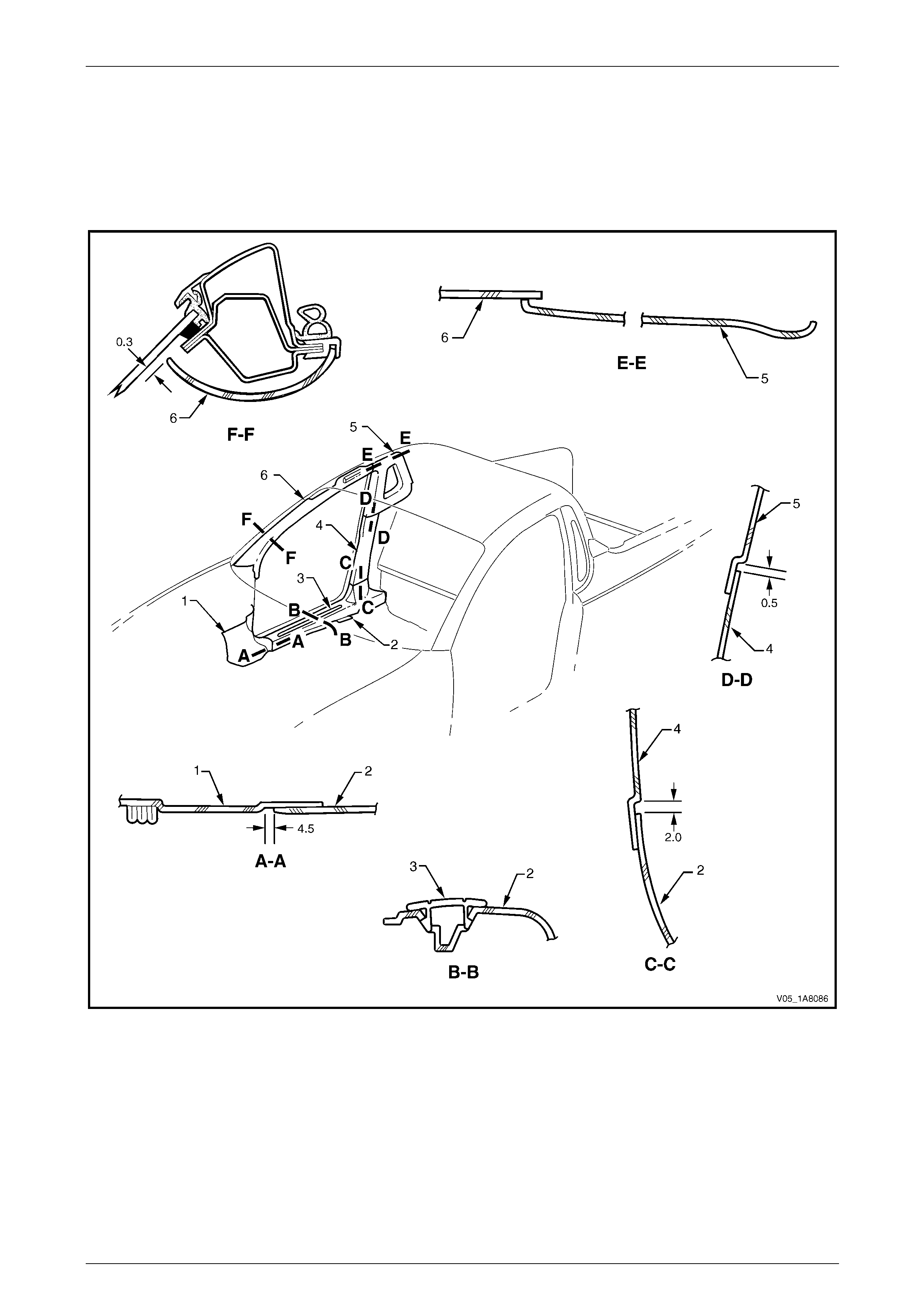
Headlining and Interior Trim Page 1A8–186
Page 1A8–186
9.5 Interior Trim Clearances, Utility
The interior trim clearances for Utility vehicles are provided in Figure 1A8 – 190. All measurements are in millimetres and
the values given represent the optimal clearance bet ween the trim panels or garnis hes, where no clearance is indicated
there must be contact between the parts.
Before checking the interior trim clearances, ensure the trim panels and garnishes are correctly attached and secured to
the vehicle.
Figure 1A8 – 190
Legend
1 Body Hinge Pillar Trim
Assembly
2 Side Sill Trim
3 Side Sill Trim Plate
4 Centre Pillar Lower Trim 5 Body Lock Pillar Upper Trim Assembly
6 Windshield Side Garnish
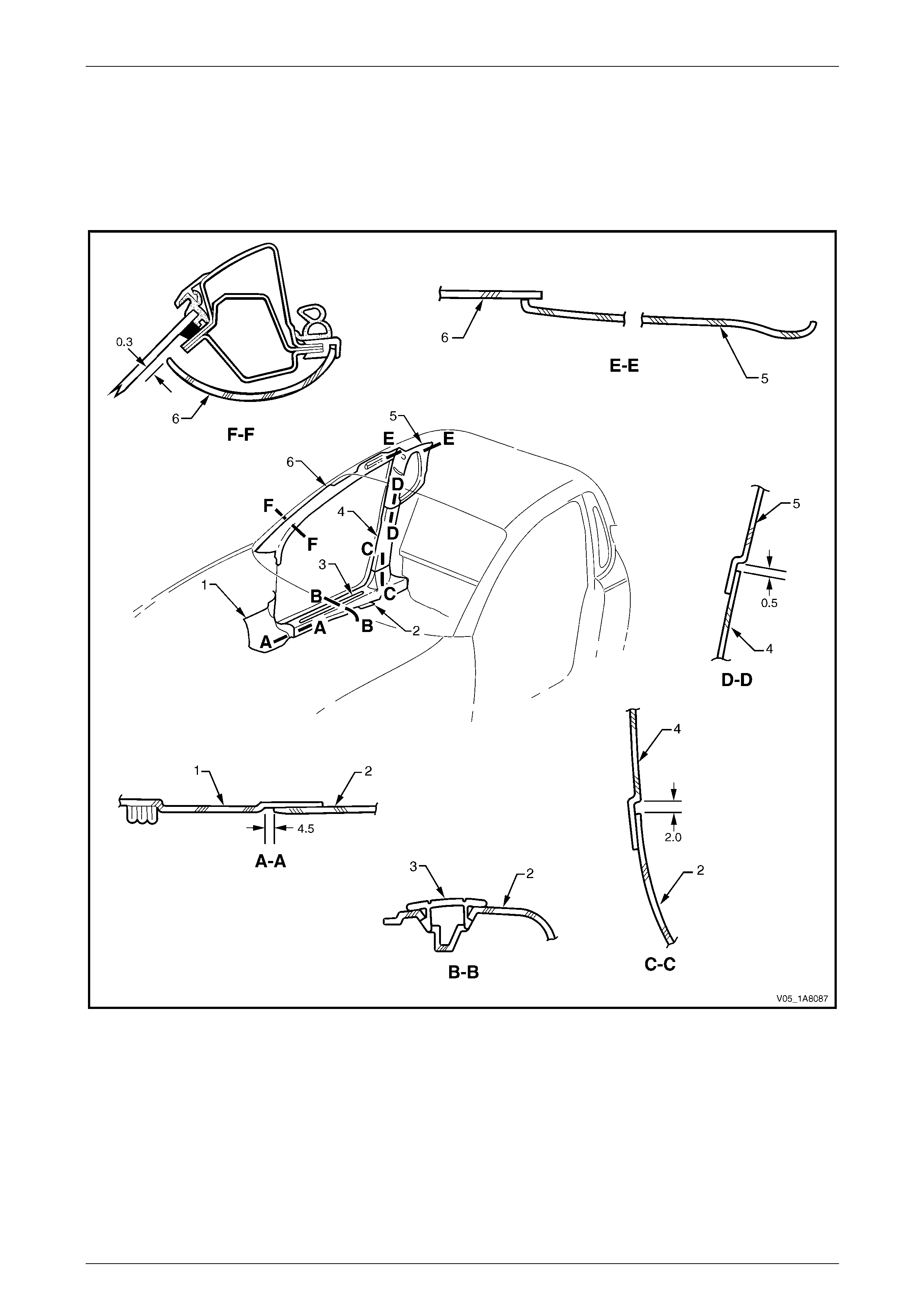
Headlining and Interior Trim Page 1A8–187
Page 1A8–187
9.6 Interior Trim Clearances, Regular Cab
The interior trim clearances for Regular Cab vehicl es are provided in Figure 1A8 – 191. All measurements are in
millimetres and the values given represent the optimal clearance between the trim panels or garnishes, where no
clearance is indicated there must be contact between the parts.
Before checking the interior trim clearances, ensure the trim panels and garnishes are correctly attached and secured to
the vehicle.
Figure 1A8 – 191
Legend
1 Body Hinge Pillar Trim
Assembly
2 Side Sill Trim
3 Side Sill Trim Plate
4 Centre Pillar Lower Trim 5 Body Lock Pillar Upper Trim Assembly
6 Windshield Side Garnish
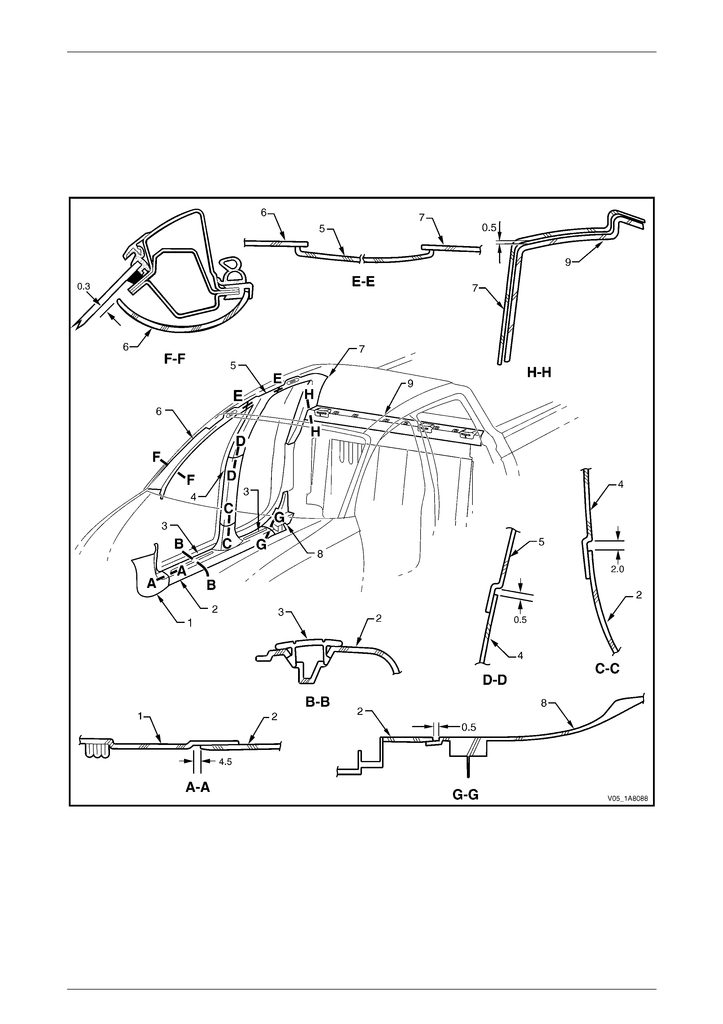
Headlining and Interior Trim Page 1A8–188
Page 1A8–188
9.7 Interior Trim Clearances, Crew Cab and
AWD Crew Cab
The interior trim clearances for Crew Cab vehicles are provided in Figure 1A8 – 192. All measurements are in millimetres
and the values given represen t the optimal clearance bet ween the trim pan els or garnishes, where no clearanc e is
indicated there must be contact between the parts.
Before checking the interior trim clearances, ensure the trim panels and garnishes are correctly attached and secured to
the vehicle.
Figure 1A8 – 192
Legend
1 Body Hinge Pillar Trim
Assembly
2 Side Sill Trim
3 Side Sill Trim Plate
4 Centre Pillar Lower Trim
5 Centre Pillar Upper Trim Assembly
6 Windshield Side Garnish
7 Body Lock Pillar Garnish
8 Rocker Panel Extension
9 Upper Cross Beam Cover

Headlining and Interior Trim Page 1A8–189
Page 1A8–189
10 Torque Wrench Specifications
10.1 Sedan
Assist Handle Attaching Screw......................................................1.0 – 3.0 Nm
Centre Pillar Upper Trim Assembly Attaching Screw ....................1.0 – 3.0 Nm
Side Sill Trim Attaching Torx Screw ..............................................1.0 – 3.0 Nm
Body Hinge Pillar Trim Assembly Attaching Screw .......................0.7 – 1.0 Nm
Convenience Net Lower Retainer Hook ........................................3.0 – 4.0 Nm
Convenience Net Upper Retainer Hook ........................................2.0 – 2.5 Nm
Rear End Trim Panel Attaching Screw..........................................1.0 – 3.0 Nm
Sunshade Support Attaching Torx Screw......................................0.5 – 2.0 Nm
Sunshade Assembly Attaching Screw...........................................0.5 – 2.0 Nm
Roof Console Attaching Screw......................................................1.0 – 2.0 Nm
Driver Footrest Attaching Screw....................................................2.0 – 5.0 Nm

Headlining and Interior Trim Page 1A8–190
Page 1A8–190
10.2 Wagon
Assist Handle Attaching Screw......................................................1.0 – 3.0 Nm
Centre Pillar Upper Trim Assembly Attaching Screw ....................1.0 – 3.0 Nm
Side Sill Trim Attaching Torx Screw ..............................................1.0 – 3.0 Nm
Body Hinge Pillar Trim Assembly Attaching Screw .......................0.7 – 1.0 Nm
Quarter Inner Upper Trim Attaching Screw ...................................1.0 – 3.0 Nm
Body Lock Pillar Lower Trim Upper Attaching Screw....................1.0 – 3.0 Nm
Stowage Door Latch Assembly Attaching Screw...........................1.0 – 3.0 Nm
Body Lock Pillar Garnish Attaching Screw ....................................1.0 – 3.0 Nm
Body Rear Corner Garnish Attaching Screw.................................1.0 – 3.0 Nm
Rear End Trim Panel Attaching Screw..........................................1.0 – 3.0 Nm
Sunshade Support Attaching Torx Screw......................................0.5 – 2.0 Nm
Sunshade Assembly Attaching Screw...........................................0.5 – 2.0 Nm
Roof Console Attaching Screw......................................................1.0 – 2.0 Nm
Driver Footrest Attaching Screw....................................................2.0 – 5.0 Nm
Luggage Tie Down Rail Attaching Torx Screw..........................14.0 – 20.0 Nm

Headlining and Interior Trim Page 1A8–191
Page 1A8–191
10.3 AWD Wagon
Assist Handle Attaching Screw......................................................1.0 – 3.0 Nm
Centre Pillar Upper Trim Assembly Attaching Screw ....................1.0 – 3.0 Nm
Side Sill Trim Attaching Torx Screw ..............................................1.0 – 3.0 Nm
Body Hinge Pillar Trim Assembly Attaching Screw .......................0.7 – 1.0 Nm
Quarter Inner Upper Trim Attaching Screw ...................................1.0 – 3.0 Nm
Body Lock Pillar Lower Trim Upper Attaching Screw....................1.0 – 3.0 Nm
Stowage Door Latch Assembly Attaching Screw...........................1.0 – 3.0 Nm
Convenience Net Retainer Hook...................................................0.5 – 1.0 Nm
Quarter Inner Trim Panel Assembly Attaching Screw ...................3.0 – 5.0 Nm
Body Lock Pillar Garnish Attaching Screw ....................................1.0 – 3.0 Nm
Body Rear Corner Garnish Attaching Screw.................................1.0 – 3.0 Nm
Rear End Trim Panel Attaching Screw..........................................1.0 – 3.0 Nm
Sunshade Support Attaching Torx Screw......................................0.5 – 2.0 Nm
Sunshade Assembly Attaching Screw...........................................0.5 – 2.0 Nm
Roof Console Attaching Screw......................................................1.0 – 2.0 Nm
Driver Footrest Attaching Screw....................................................2.0 – 5.0 Nm
Luggage Tie Down Rail Attaching Torx Screw..........................14.0 – 20.0 Nm

Headlining and Interior Trim Page 1A8–192
Page 1A8–192
10.4 Coupe
Side Sill Trim Attaching Screw ......................................................1.0 – 3.0 Nm
Front Seat Belt Lower Attaching Bolt.........................................35.0 – 50.0 Nm
Quarter Trim Panel Armrest Insert Assembly
Attaching Speed Nut .....................................................................0.7 – 0.9 Nm
Quarter Trim Panel Assembly Attaching Screw .............................1.0 – 3.0 Nm
Centre Pillar Upper Trim Assembly Attaching Screw ....................1.0 – 3.0 Nm
Body Hinge Pillar Trim Assembly Attaching Screw .......................0.7 – 1.0 Nm
Body Rear Corner Garnish Attaching Screw.................................1.0 – 3.0 Nm
Rear Seat Belt Lower Attaching Bolt .........................................35.0 – 50.0 Nm
Rear Compartment Lid Emergency
Release Cable Assembly Attaching Screw....................................1.9 – 2.1 Nm
Rear End Trim Panel Attaching Screw..........................................1.0 – 3.0 Nm
Sunshade Support Attaching Torx Screw......................................0.5 – 2.0 Nm
Sunshade Assembly Attaching Screw...........................................0.5 – 2.0 Nm
Roof Console Attaching Screw......................................................1.0 – 2.0 Nm

Headlining and Interior Trim Page 1A8–193
Page 1A8–193
10.5 Utility
Assist Handle Attaching Screw......................................................1.0 – 3.0 Nm
Body Lock Pillar Upper Trim Assembly Attaching Screw...............1.0 – 3.0 Nm
Side Sill Trim Attaching Torx Screw ..............................................1.0 – 3.0 Nm
Body Hinge Pillar Trim Assembly Attaching Screw .......................0.7 – 1.0 Nm
Sunshade Support Attaching Torx Screw......................................0.5 – 2.0 Nm
Sunshade Assembly Attaching Screw...........................................0.5 – 2.0 Nm
Driver Footrest Attaching Screw....................................................2.0 – 5.0 Nm

Headlining and Interior Trim Page 1A8–194
Page 1A8–194
10.6 Regular Cab
Assist Handle Attaching Screw......................................................1.0 – 3.0 Nm
Body Lock Pillar Upper Trim Assembly Attaching Screw...............1.0 – 3.0 Nm
Side Sill Trim Attaching Torx Screw ..............................................1.0 – 3.0 Nm
Body Hinge Pillar Trim Assembly Attaching Screw .......................0.7 – 1.0 Nm
Storage Pocket Panels Attaching Screw.......................................1.0 – 3.0 Nm
Sunshade Support Attaching Torx Screw......................................0.5 – 2.0 Nm
Sunshade Assembly Attaching Screw...........................................0.5 – 2.0 Nm
Driver Footrest Attaching Screw....................................................2.0 – 5.0 Nm

Headlining and Interior Trim Page 1A8–195
Page 1A8–195
10.7 Crew Cab and AWD Crew Cab
Assist Handle Attaching Screw......................................................1.0 – 3.0 Nm
Centre Pillar Upper Trim Assembly Attaching Screw ....................1.0 – 3.0 Nm
Side Sill Trim Attaching Torx Screw ..............................................1.0 – 3.0 Nm
Body Hinge Pillar Trim Assembly Attaching Screw .......................0.7 – 1.0 Nm
Rocker Panel Extension Attaching Screw .....................................1.0 – 3.0 Nm
Sunshade Support Attaching Torx Screw......................................0.5 – 2.0 Nm
Sunshade Assembly Attaching Screw...........................................0.5 – 2.0 Nm
Roof Console Attaching Screw......................................................1.0 – 2.0 Nm
Driver Footrest Attaching Screw....................................................2.0 – 5.0 Nm
Jack Box Attaching Torx Screw............................................................25.0 Nm