
Wipers, Washers and Horn Page 12N–1
Page 12N–1
Section 12N
Wipers, Washers and Horn
ATTENTION
Before performing any service operation or other procedure described in this Section, refer to Section 00
Warnings, Cautions and Notes for correct workshop practices with regard to safety and/or property damage.
1 General Information ...............................................................................................................................7
1.1 Front Wiper Assemblies........................................................................................................................................ 7
Wiper Assemblies.................................................................................................................................................. 7
Wiper Motor............................................................................................................................................................ 7
1.2 Rear Wiper Assembly, Wagon.............................................................................................................................. 8
Wiper Assembly..................................................................................................................................................... 8
Wiper Motor............................................................................................................................................................ 8
1.3 Rear Wiper Assembly, AWD Wagon..................................................................................................................... 9
Rear Wiper Assembly............................................................................................................................................ 9
Rear Wiper Control Module................................................................................................................................. 10
Rear Wiper Motor Assembly............................................................................................................................... 11
Rear Wiper Ramp................................................................................................................................................. 11
Functional Operation........................................................................................................................................... 11
Intermittent Wipe Cycle Operation.................................................................................................................... 11
Continuous Wipe Mode.................................................................................................................................... 12
1.4 Washer Assemblies............................................................................................................................................. 13
Washer Assemblies, Except Wagon and AWD Wagon..................................................................................... 13
Washer Assemblies, Wagon and AWD Wagon ................................................................................................. 13
Washer Control, Wagon................................................................................................................................... 13
Washer Control, AWD Wagon.......................................................................................................................... 13
Front Washer Operation................................................................................................................................... 13
Rear Washer Operation ................................................................................................................................... 13
1.5 Horn Assemblies.................................................................................................................................................. 14
Horn Assembly..................................................................................................................................................... 14
Description ....................................................................................................................................................... 14
Horn Relay....................................................................................................................................................... 14
Steering Wheel Horn Contact........................................................................................................................... 14
Theft-deterrent Horn Assembly.......................................................................................................................... 14
Description ....................................................................................................................................................... 14
Theft-deterrent Horn Relay............................................................................................................................... 14
2 Preliminary Test – Front Wipers and Washers..................................................................................15
2.1 Test Front Wipers and Washers Assemblies .................................................................................................... 15
Introduction.......................................................................................................................................................... 15
Test Description................................................................................................................................................... 15
Diagnostic Table Notes ....................................................................................................................................... 15
Diagnostic Table.................................................................................................................................................. 16
3 Diagnostics – Front Wipers and Washers.........................................................................................17
3.1 Prerequisites........................................................................................................................................................ 17
Safety Requirements ........................................................................................................................................... 17
Equipment ............................................................................................................................................................ 17
Testing Procedures ............................................................................................................................................. 17
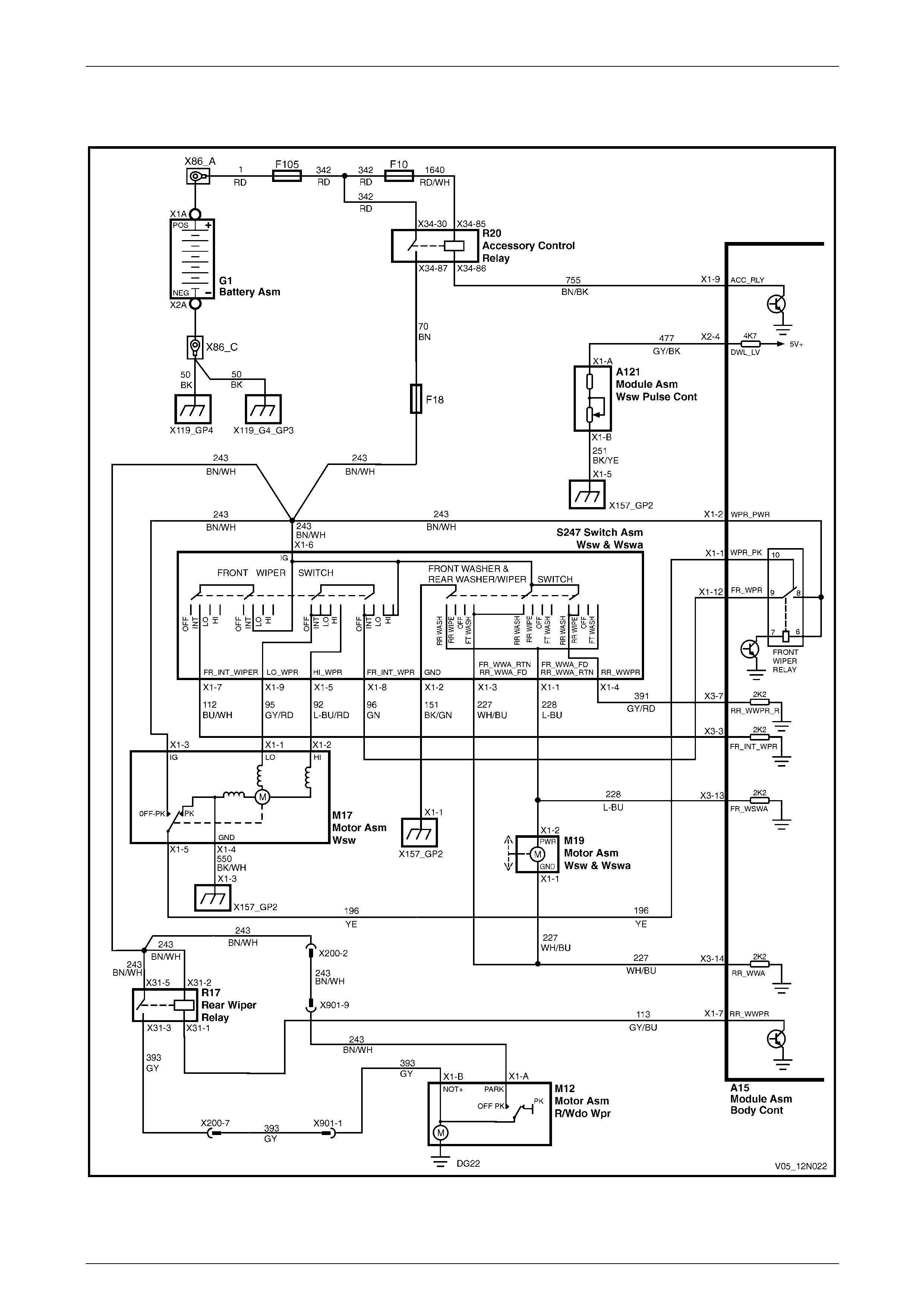
3.2 Wiring Diagram – Front Wiper/Washer, Except Wagon and AWD Wagon...................................................... 18
3.3 Wiring Diagram – Front Wiper/Washer, Wagon................................................................................................. 19
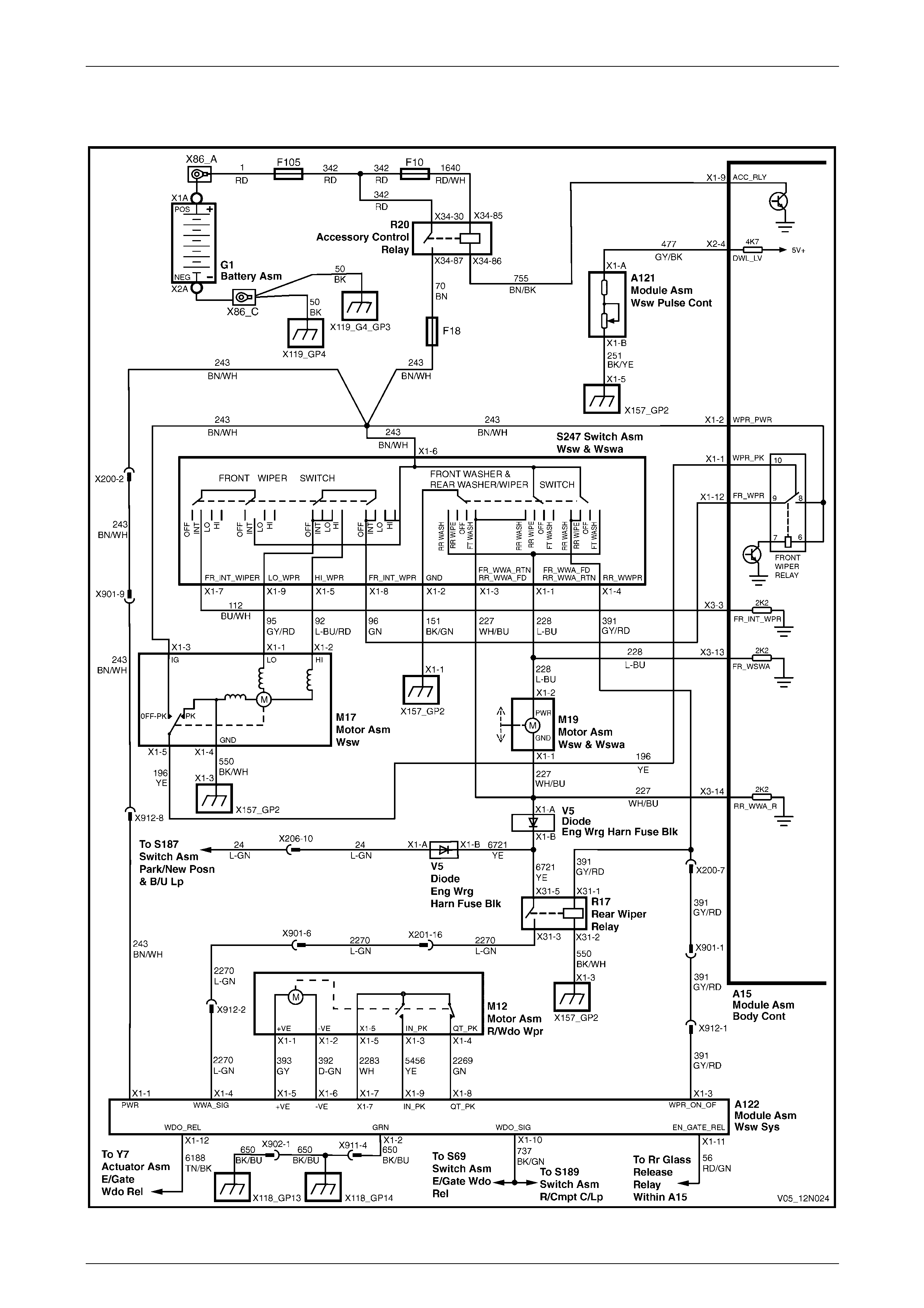
3.4 Wiring Diagram – Front Wiper/Washer, AWD Wagon....................................................................................... 20

Wipers, Washers and Horn Page 12N–2
Page 12N–2
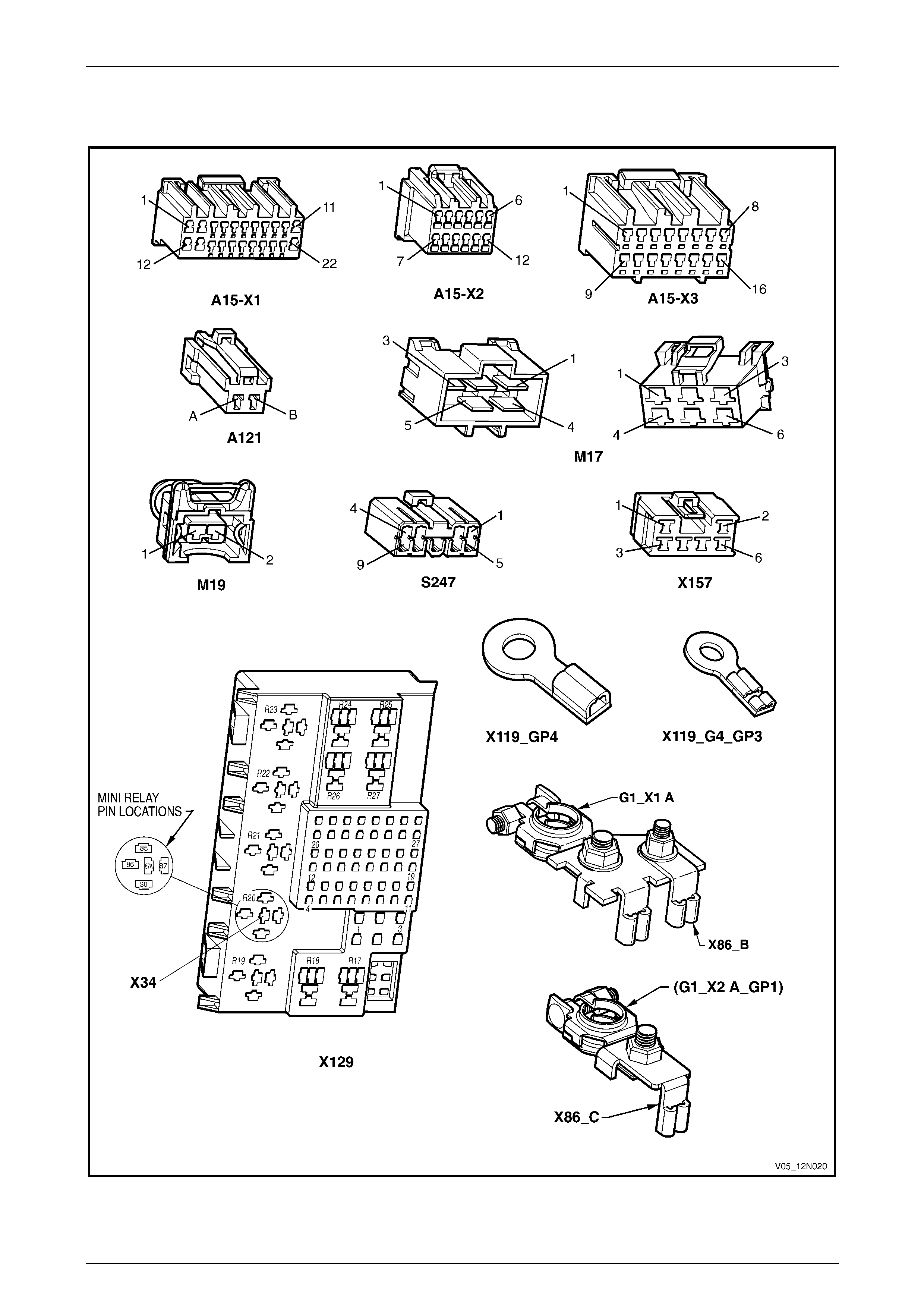
3.5 Connector Diagrams – Front Wiper/Washer...................................................................................................... 21
3.6 Diagnose Front Wiper Motor Wiring System Malfunction................................................................................ 22
Introduction.......................................................................................................................................................... 22
Electrical Test Description.................................................................................................................................. 22
Diagnostic Table Notes ....................................................................................................................................... 23
Diagnostic Table.................................................................................................................................................. 23
3.7 Diagnose Front Wiper Motor Assembly Operation........................................................................................... 25
Introduction.......................................................................................................................................................... 25
Electrical Test Description.................................................................................................................................. 25
Diagnostic Table Notes ....................................................................................................................................... 25
Diagnostic Table.................................................................................................................................................. 26
3.8 Diagnose Front Washer Pump and Wiring System Malfunction...................................................................... 27
Introduction.......................................................................................................................................................... 27
Electrical Test Description.................................................................................................................................. 27
Diagnostic Table Notes ....................................................................................................................................... 27
Diagnostic Table.................................................................................................................................................. 28
4 Preliminary Test – Rear Wipers and Washers, Wagon and AWD Wagon ......................................29
4.1 Test Rear Wiper and Washer Assembly ............................................................................................................ 29
Introduction.......................................................................................................................................................... 29
Test Description................................................................................................................................................... 29
Diagnostic Table Notes ....................................................................................................................................... 29
Diagnostic Table.................................................................................................................................................. 30
5 Diagnostics – Rear Wiper and Washer, Wagon ................................................................................31
5.1 Prerequisites........................................................................................................................................................ 31
Safety Requirements ........................................................................................................................................... 31
Equipment ............................................................................................................................................................ 31
Testing Procedures ............................................................................................................................................. 31
5.2 Wiring Diagram – Rear Wiper/Washer................................................................................................................ 32
5.3 Connector Diagrams – Rear Wiper/Washer....................................................................................................... 33
5.4 Diagnose Rear Wiper Motor Wiring System Malfunction................................................................................. 34
Introduction.......................................................................................................................................................... 34
Electrical Test Description.................................................................................................................................. 34
Diagnostic Table Notes ....................................................................................................................................... 34
Diagnostic Table.................................................................................................................................................. 35
5.5 Diagnose Rear Wiper Motor Assembly Operation............................................................................................ 36
Introduction.......................................................................................................................................................... 36
Electrical Test Description.................................................................................................................................. 36
Diagnostic Table Notes ....................................................................................................................................... 36
Diagnostic Table.................................................................................................................................................. 37
5.6 Diagnose Washer Pump and Rear Washer Wiring System Malfunction......................................................... 38
Introduction.......................................................................................................................................................... 38
Electrical Test Description.................................................................................................................................. 38
Diagnostic Table Notes ....................................................................................................................................... 38
Diagnostic Table.................................................................................................................................................. 38
6 Diagnostics – Rear Wiper and Washer, AWD Wagon.......................................................................39
6.1 Prerequisites........................................................................................................................................................ 39
Safety Requirements ........................................................................................................................................... 39
Equipment ............................................................................................................................................................ 39
Testing Procedures ............................................................................................................................................. 39
6.2 Wiring Diagram – Rear Wiper/Washer................................................................................................................ 40
6.3 Wiring Diagram – Rear Wiper Control Module .................................................................................................. 41
6.4 Connector Diagrams – Rear Wiper/Washer....................................................................................................... 42

Wipers, Washers and Horn Page 12N–3
Page 12N–3
6.5 Diagnose Rear Wiper Motor Wiring System Malfunction................................................................................. 44
Introduction.......................................................................................................................................................... 44
Electrical Test Description.................................................................................................................................. 44
Diagnostic Table Notes ....................................................................................................................................... 45
Diagnostic Table.................................................................................................................................................. 45
6.6 Diagnose Rear Wiper Motor Assembly Operation............................................................................................ 47
Introduction.......................................................................................................................................................... 47
Electrical Test Description.................................................................................................................................. 47
Diagnostic Table Notes ....................................................................................................................................... 47
Diagnostic Table.................................................................................................................................................. 48
Wiper Motor Limit Switches Malfunction Table................................................................................................. 49
6.7 Diagnose Rear Wiper and Liftgate Interface Operation.................................................................................... 50
Introduction.......................................................................................................................................................... 50
Electrical Test Description.................................................................................................................................. 50
Diagnostic Table Notes ....................................................................................................................................... 50
Diagnostic Table.................................................................................................................................................. 51
6.8 Diagnose Washer Pump and Rear Washer Wiring System Malfunction......................................................... 52
Introduction.......................................................................................................................................................... 52
Test Description................................................................................................................................................... 52
Diagnostic Table Notes ....................................................................................................................................... 52
Diagnostic Table.................................................................................................................................................. 52
7 Diagnostics – Horn...............................................................................................................................53
7.1 Prerequisites........................................................................................................................................................ 53
Equipment ............................................................................................................................................................ 53
Testing Procedures ............................................................................................................................................. 53
7.2 Wiring Diagram – Horn Assembly...................................................................................................................... 54
7.3 Connector Diagrams – Horn Assembly ............................................................................................................. 55
7.4 Diagnose Horn and Wiring System Malfunction............................................................................................... 56
Introduction.......................................................................................................................................................... 56
Electrical Test Description.................................................................................................................................. 56
Diagnostic Table Notes ....................................................................................................................................... 57
Diagnostic Table.................................................................................................................................................. 57
8 Service Operations – Front Wiper Assemblies, Except Coupe.......................................................59
8.1 Front Wiper Blade Insert ..................................................................................................................................... 59
Replace................................................................................................................................................................. 59
8.2 Front Wiper Blade Assembly.............................................................................................................................. 60
Remove................................................................................................................................................................. 60
Reinstall................................................................................................................................................................ 60
8.3 Fro nt Wiper Arm Assembly ................................................................................................................................. 61
Remove................................................................................................................................................................. 61
Reinstall................................................................................................................................................................ 62
8.4 Plenum Cover Assembly..................................................................................................................................... 63
Remove................................................................................................................................................................. 63
Disassemble......................................................................................................................................................... 63
Reassemble.......................................................................................................................................................... 64
Reinstall................................................................................................................................................................ 64
8.5 Front Wiper Motor Assembly and Linkages...................................................................................................... 65
Remove................................................................................................................................................................. 65
Reinstall................................................................................................................................................................ 65

Wipers, Washers and Horn Page 12N–4
Page 12N–4
9 Service Operations – Front Wiper Assemblies, Coupe....................................................................67
9.1 Front Wiper Blade Insert ..................................................................................................................................... 67
Replace................................................................................................................................................................. 67
9.2 Front Wiper Blade Assembly.............................................................................................................................. 68
Remove................................................................................................................................................................. 68
Reinstall................................................................................................................................................................ 68
9.3 Fro nt Wiper Arm Assembly ................................................................................................................................. 69
Remove................................................................................................................................................................. 69
Reinstall................................................................................................................................................................ 69
9.4 Plenum Cover Assembly..................................................................................................................................... 70
Remove................................................................................................................................................................. 70
Reinstall................................................................................................................................................................ 71
9.5 Front Wiper Motor Assembly and Linkages...................................................................................................... 72
Remove................................................................................................................................................................. 72
Reinstall................................................................................................................................................................ 73
10 Service Operations – Rear Wiper Assembly, Wagon .......................................................................74
10.1 Rear Wiper Blade Insert ...................................................................................................................................... 74
Replace................................................................................................................................................................. 74
10.2 Rear Wiper Blade Assembly ............................................................................................................................... 75
Remove and Reinstall.......................................................................................................................................... 75
10.3 Rear Wiper Arm Assembly.................................................................................................................................. 76
Remove................................................................................................................................................................. 76
Reinstall................................................................................................................................................................ 76
10.4 Rear Wiper Motor Assembly............................................................................................................................... 77
Remove................................................................................................................................................................. 77
Reinstall................................................................................................................................................................ 78
11 Service Operations – Rear Wiper Assembly, AWD Wagon..............................................................79
11.1 Rear Wiper Blade Insert ...................................................................................................................................... 79
Replace................................................................................................................................................................. 79
11.2 Rear Wiper Blade Assembly ............................................................................................................................... 80
Remove................................................................................................................................................................. 80
Reinstall................................................................................................................................................................ 80
11.3 Rear Wiper Arm Assembly.................................................................................................................................. 81
Remove................................................................................................................................................................. 81
Reinstall................................................................................................................................................................ 81
11.4 Rear Wiper Ramp................................................................................................................................................. 82
Remove................................................................................................................................................................. 82
Reinstall................................................................................................................................................................ 82
11.5 Rear Wiper Control Module................................................................................................................................. 83
Remove................................................................................................................................................................. 83
Reinstall................................................................................................................................................................ 83
11.6 Rear Wiper Motor Assembly............................................................................................................................... 84
Remove................................................................................................................................................................. 84
Reinstall................................................................................................................................................................ 85
12 Service Operations – Washer Assemblies, Sedan and Utility.........................................................86
12.1 Washer Reservoir Assembly............................................................................................................................... 86
Remove................................................................................................................................................................. 86
Reinstall................................................................................................................................................................ 87
Filling the Washer Reservoir Assembly............................................................................................................. 87
12.2 Front Washer Hose and Nozzle Assemblies...................................................................................................... 88
Remove................................................................................................................................................................. 88
Reinstall................................................................................................................................................................ 89
Spray Pattern Check............................................................................................................................................ 89

Wipers, Washers and Horn Page 12N–5
Page 12N–5
13 Service Operations – Washer Assemblies, Wago n ..........................................................................90
13.1 Washer Reservoir Assembly............................................................................................................................... 90
Remove................................................................................................................................................................. 90
Reinstall................................................................................................................................................................ 91
Filling the Washer Reservoir Assembly............................................................................................................. 91
13.2 Front Washer Hose and Nozzle Assemblies...................................................................................................... 92
Remove................................................................................................................................................................. 92
Reinstall................................................................................................................................................................ 93
Spray Pattern Check............................................................................................................................................ 93
13.3 Rear Washer Hose and Nozzle Assembly.......................................................................................................... 94
Introduction.......................................................................................................................................................... 94
Remove................................................................................................................................................................. 94
Front Section.................................................................................................................................................... 94
Rear Section .................................................................................................................................................... 95
Reinstall................................................................................................................................................................ 97
Front Section.................................................................................................................................................... 97
Rear Section .................................................................................................................................................... 97
Spray Pattern Check............................................................................................................................................ 97
14 Service Operations – Washer Assemblies, AWD Wagon.................................................................98
14.1 Washer Reservoir Assembly............................................................................................................................... 98
Remove and Reinstall.......................................................................................................................................... 98
14.2 Front Washer Hose and Nozzle Assemblies...................................................................................................... 99
Remove and Reinstall.......................................................................................................................................... 99
14.3 Rear Washer Hose and Nozzle Assembly........................................................................................................ 100
Introduction........................................................................................................................................................ 100
Remove............................................................................................................................................................... 100
Front Section.................................................................................................................................................. 100
Rear Section .................................................................................................................................................. 101
Reinstall.............................................................................................................................................................. 103
Front Section.................................................................................................................................................. 103
Rear Section .................................................................................................................................................. 103
Spray Pattern Check.......................................................................................................................................... 104
15 Service Operations – Washer Assemblies, Coupe.........................................................................105
15.1 Washer Reservoir Assembly............................................................................................................................. 105
Remove............................................................................................................................................................... 105
Reinstall.............................................................................................................................................................. 106
Filling the Washer Reservoir Assembly........................................................................................................... 106
15.2 Front Washer Hose and Nozzle Assemblies.................................................................................................... 107
Remove............................................................................................................................................................... 107
Reinstall.............................................................................................................................................................. 108
Spray Pattern Check.......................................................................................................................................... 108
16 Service Operations – Wipers and Washers Control Switch ..........................................................109
16.1 Wipers and Washers Control Switch, Except Wagon and AWD Wagon....................................................... 109
Remove............................................................................................................................................................... 109
Reinstall.............................................................................................................................................................. 111
16.2 Wipers and Washers Control Switch Testing, Except Wagon and AWD Wagon ......................................... 112
Test Procedure................................................................................................................................................... 112
16.3 Wipers and Washers Control Switch, Wagon and AWD Wagon.................................................................... 113
Remove and Reinstall........................................................................................................................................ 113
16.4 Wipers and Washers Control Switch Testing, Wagon and AWD Wagon...................................................... 114
Test Procedure................................................................................................................................................... 114

Wipers, Washers and Horn Page 12N–6
Page 12N–6
17 Service Operations – Horn................................................................................................................115
17.1 Horn Assembly................................................................................................................................................... 115
Remove............................................................................................................................................................... 115
Reinstall.............................................................................................................................................................. 115
17.2 Theft-deterrent Horn Assembly........................................................................................................................ 116
Remove............................................................................................................................................................... 116
Reinstall.............................................................................................................................................................. 116
Test ..................................................................................................................................................................... 116
18 Torque Wrench Specifications..........................................................................................................117
18.1 Torque Wrench Specifications, Except Wagon and AWD Wagon................................................................. 117
18.2 Torque Wrench Specifications, Wagon ........................................................................................................... 118
18.3 Torque Wrench Specifications, AWD Wagon.................................................................................................. 119
19 Special Tools ......................................................................................................................................120

Wipers, Washers and Horn Page 12N–7
Page 12N–7
1 General Information
This Section describes the service, testing procedures and diagnosis for the wipers and washer systems as well as the
horns fitted to MY 2005 VZ Series vehicles.
1.1 Front Wiper Assemblies
Wiper Assemblies
The two front wiper assemblies consist each of a wiper blade secured to a wiper arm which is attached to a drive spindle
part of linkages attached to the plenum cham ber an d driven by the front wiper motor assembly.
A one piece plenum cover is fitted to Seda n, W agon and Utility vehicles. The front washer nozzle assemblies and part of
the front washer hose are secured to the plenum cover. An air deflector and a water deflector are attached to the plenum
cover.
A two pieces plenum cover is fitted to Coupe vehicles and the washer nozzle assemblies a re mounted in the hood
assembly. A water deflector is attached to the plenum chamber.
The front wiper assemblies are operated via the wipers and washers control s witch assembl y fitted to the steering
column. The operation inclu ding the intermittent dwell function is controlled by the body control module (BCM), refer to
Section 12J Body Control Module.
The wipers and washers control switch in the variable intermittent position decreases or increases the frequency the
wiper motor is actuated, through the détente. The wipers and washers control s witch has seven increments, and the
dwell time is determined via a combination of vehicle road speed and the wiper control stalk.
Wiper Motor
The front wiper motor assembly operates in one direction to drive the front wiper arms for the wiping of the windshield.
The front wiper motor assembly has three modes of operati on:
• intermittent wipe cycle,
• continuous low speed wipe mode, and
• continuous high speed wipe mode.
With the ignition switch in the ACC or ON position, and the wipers and washers control switch is moved to the position 1
or 2, power is directly supplied to the front wiper motor for low or high speed wipe operation. When the wipers and
washers control switch is moved to the INT position, power is supplied to the front wiper motor via the bo dy control
module (BCM) for intermittent wipe operatio n.
When the wipers and washers control switch is moved to the OFF position, the park s witch included in the front wiper
motor assembly supplies power to the front wiper motor via the BCM until the front wiper arms reach the park position. At
this point the park switch opens and disconnects the power supply to the front wiper motor and the front wiper arms
remain stationary at the park position.
For a complete wiring diagram of the front wiper system, refer to:
• 3.2 Wiring Diagram – Front Wiper/Washer, Except Wagon, or
• 3.3 Wiring Diagram – Front Wiper/Washer, Wagon, or
• 3.4 Wiring Diagram – Front Wiper/Washer, AWD Wagon.

Wipers, Washers and Horn Page 12N–8
Page 12N–8
1.2 Rear Wiper Assembly, Wagon
Wiper Assembly
The rear wiper assembly consists of a wiper blade secured to a wiper arm which is attached directly to the rear wiper
motor driveshaft.
The rear wiper motor assembly is attached to the liftgate ass embl y and drives the rear wiper arm assembly directly
through the motor driveshaft.
The rear wiper assembly is operated via the wipers and washers control switch assembly fitted to the steering column,
the operation is controlled by the BCM, refer to Section 12J Body Control Module.
With the ignition switch in the ON or ACC position the functions of the rear wiper are as follows:
• When the rear wiper switch is ON and the ne utral or drive gear is selected, the rear wiper activates intermittently at
8 second intervals.
• When the rear wiper switch is ON and the reverse gear is selected, the intermittent operation of the rear wiper goes
into continuous wipe mode until t he reverse gear is deselected.
• When the rear washer is selected, the rear wiper action is continuous wipe mode until the rear washer switch is
released.
Wiper Motor
The rear wiper motor is install ed in the liftgate and is directly linked to the rear wiper arm via a driveshaft.
With the ignition switch in the ACC or ON position and the wipers and washers control switch is moved to the rear wiper
ON position, power is supplied to the rear wiper motor via the body control module (BCM) and the rear wiper relay.
When the wipers and washers control switch is moved from the ON to OFF position, the park switch inclu ded in the rear
wiper motor assembly supplies power to the rear wiper motor until the rear wiper arm reaches the park position. At this
point the park switch contacts open and disconnects the power supply to the rear wiper motor and the rear wiper arm
remains stationary at the park position.
For a complete wiring diagram of the rear wiper system, refer to 5.2 Wiring Diagram – Rea r W iper/Washer.
Wipers, Washers and Horn Page 12N–9
Page 12N–9
1.3 Rear Wiper Assembly, AWD Wagon
Rear Wiper Assembly
The rear wiper assembl y cons ists of a wiper blade secured to the rear wiper arm which is attached to the rear wiper
motor shaft.
The rear wiper motor assembly is attached to the liftgate ass embl y and drives the rear wiper arm assembly directly
through the motor driveshaft.
A rear wiper ramp is located below the liftgate window to provide support for the wiper arm in the park position.
Protective clear PVC tape is applied to the liftgate where the wiper blade is resting.
The rear wiper assembly operation is not controlled by the BCM as in other Wagon ve hicles. The control functions have
been transferred to a rear wiper control module (A122).
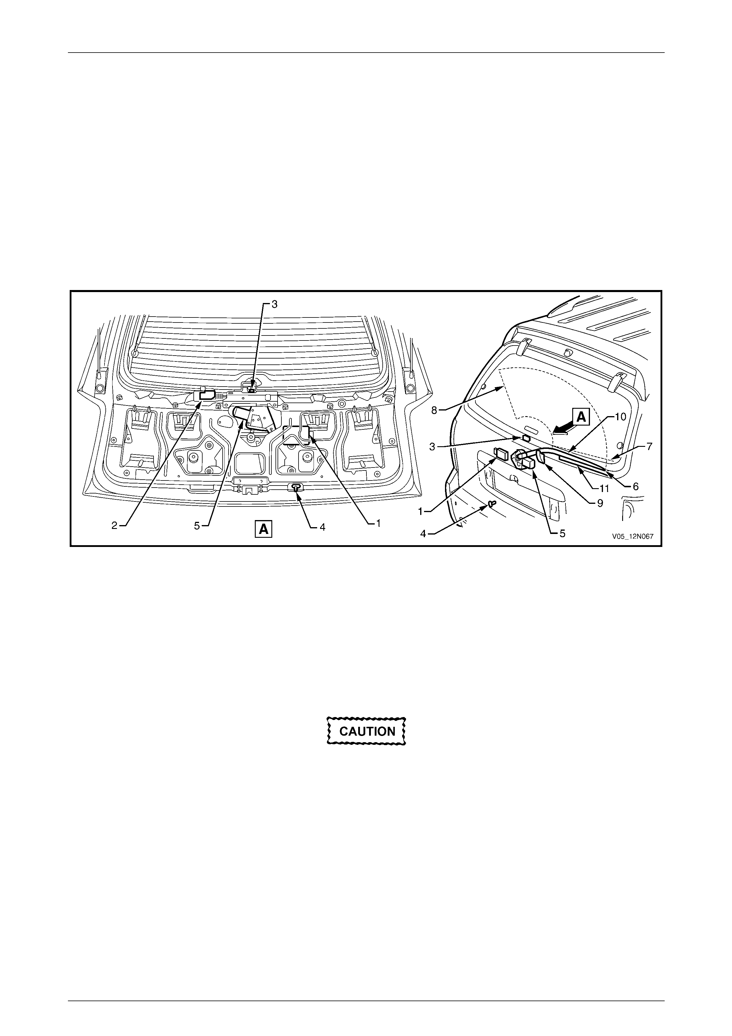
Figure 12N – 1
Legend
1 Rear Wiper Control Module A122
2 Liftgate Window Release Actuator Y7
3 Liftgate Window Microswitch S69
4 Liftgate Switch S189
5 Rear Wiper Motor Assembly M12
6 Rear Wiper Arm Offscreen Park
Position
7 Wipe Sweep Start (Rear Wiper Arm
Onscreen Park Position)
8 Full Wipe Sweep (Rear Wiper Arm
Furthest Onscreen Park Position)
9 Rear Wiper Ramp
10 Rear Wiper Arm
11 Protective Tape
When the rear wiper has been operating,
before turning off the ignition switch ensure
the rear wiper arm is in the offscreen park
position. If failing to do so, the situation could
arise where the liftgate window could be
opened with the rear wiper stopped on the
glass panel and vehicle damage co uld occur.
When the rear wiper is not in operation it parks below the liftgate window, the arm (10) resting on th e rear wiper ramp (9),
refer to Figure 12N – 1. This parking position enables the hinged liftgate window to be opened o utward with the rear
wiper positioned clear of the glass panel.
With the ignition switch in the ON or ACC position and the li ftgate is open, when the wipers and washers control switch is
moved to the rear wiper ON position, the rear wiper will not operate. For the rear wiper to be operational again, close the
liftgate, then move the wipers and washers control switch in the OFF position and back to the rear wiper ON position.
The same condition applies if the liftgate window is open when the wipers and washers control switch is moved to the
rear wiper ON position.
Wipers, Washers and Horn Page 12N–10
Page 12N–10
If the rear wiper is operating, the liftgate windo w can not be ope ned.
If the liftgate window is closed and the liftgate only is opened while the rear wiper is operating, the wipe mode will not
stop. Move the wipers and washers control switch in the OFF position to stop the operation of the rear wiper; the
operation can not be restarte d before the liftgate is closed.
With the ignition switch in the ON or ACC position the functions of the rear wiper are as follows:
• When the wipers and washers control switch is moved to the rear wiper ON position, the rear wiper activates
intermittently at 9 second intervals.
• When the wipers and washers control switch is moved to the rear wiper ON position and the reverse g ear is
selected, the intermittent operation of the rear wiper goes into continuous wipe mode until the reverse gear is
deselected.
• When the rear washer is selected, the rear wiper action is continuous wipe mode until the rear washer switch is
released.
• When the rear wiper is operating and the rear washer is selected, the intermittent operation of the rear wiper goes
into continuous wipe mode until the rear washer switch is released.
• When the wipers and washers control switch is moved from the rear wiper ON to OFF position, the rear wiper
suspends for one second in the furthest on-screen park position then returns to the off-screen park position.
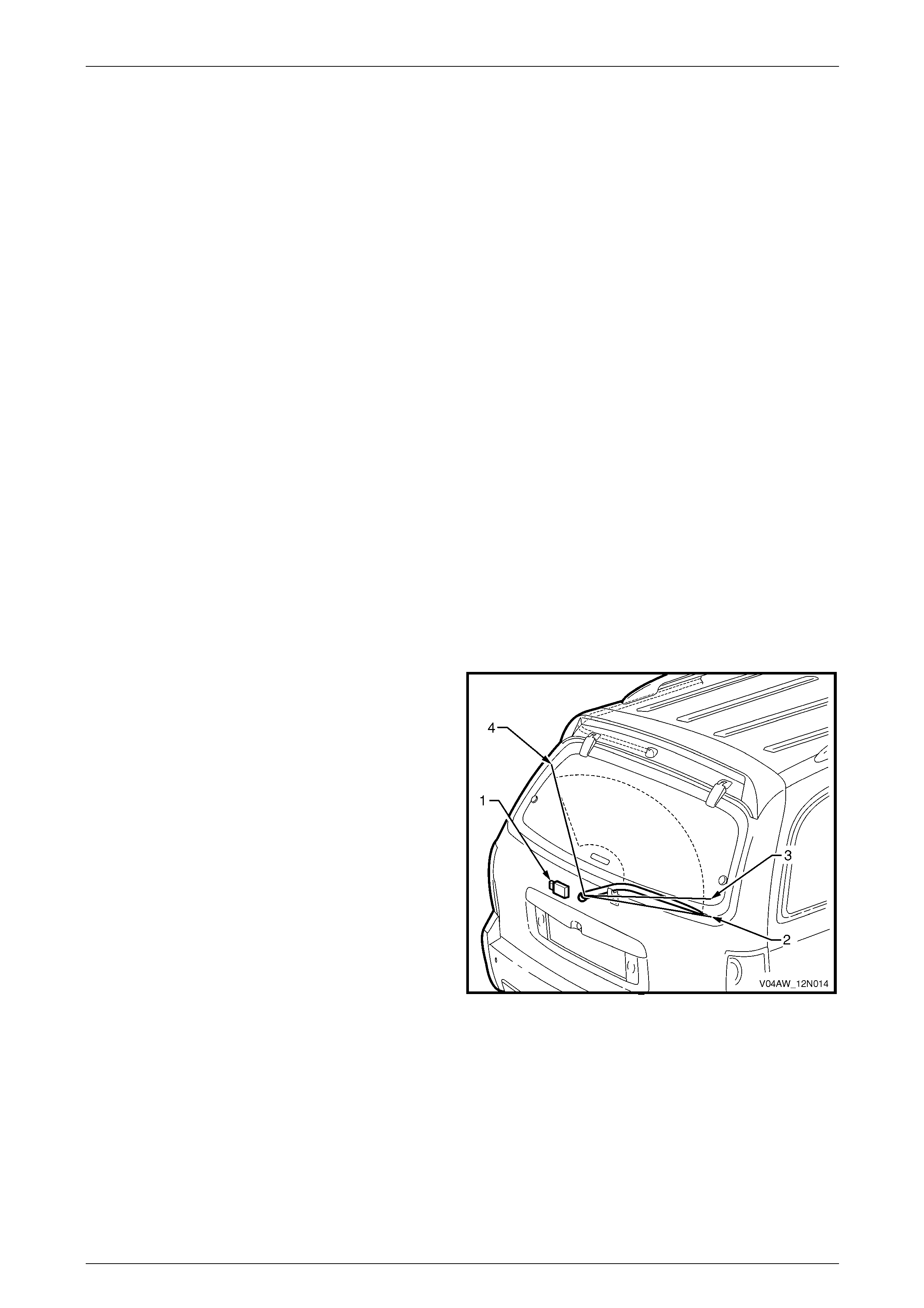
Rear Wiper Control Module
The rear wiper control module (1) is installed in the liftgate. It controls the various functions of the rear wiper / washer.
The rear wiper control modul e also provides a link with the liftgate window release actuator (2), the liftgate window
microswitch (3) (within the latch) and the liftgate switch (4) refer to Figure 12N – 1.
For a description and functions of the liftgate window release actuator, liftgate window microswitch and liftgate switch
refer to Section 1A4 Hood, Rear Compartment Lid, Liftgate and Endgate.
The rear wiper module will inhibit the rear wiper operation if the liftgate and/or the liftgate window are open.
The rear wiper module triggers the liftgate window release. The liftgate window release actuator solenoid is inhibited if
the rear wiper switch or the rear washer switch is ON.
Before permitting the wiper motor to operate, the rear wiper
control module (1) monitors the positions of both the liftgate
and the liftgate window latch.
The rear wiper control module also monitors the rear wiper
three park positions:
• rear wiper offscreen park position (2),
• rear wiper onscreen park position (3), and
• rear wiper furthest onscreen park position (4).
Figure 12N – 2

Wipers, Washers and Horn Page 12N–11
Page 12N–11
Rear Wiper Motor Assembly
The rear wiper motor assembly (5) is introduced to suit the opening liftgate window and offscreen parking (6) of the rear
wiper arm, refer to Figure 12N – 1.
The rear wiper motor assembly has forward park and reverse park limit switches mec ha nically linked to the wiper arm
driveshaft. The forward park limit switch determines when the wiper arm is at the start of the wipe sweep (7) (onscreen
park position), while the revers e park limit switch determines when the wiper arm has reached the full wipe sweep (8)
(furthest onscreen park position).
The rear wiper motor assembly operates e ith er in the forward direction to drive the rear wiper arm for the wiping of the
liftgate window, or in the reverse direction to drive the re ar wiper arm to the offscreen park position, refer to
Figure 12N – 3.
Rear Wiper Ramp
The rear wiper ramp (9) is attached to the liftgate bel ow the liftgate window for the offscreen parking of the rear wiper
arm (10), refer to Figure 12N – 1.
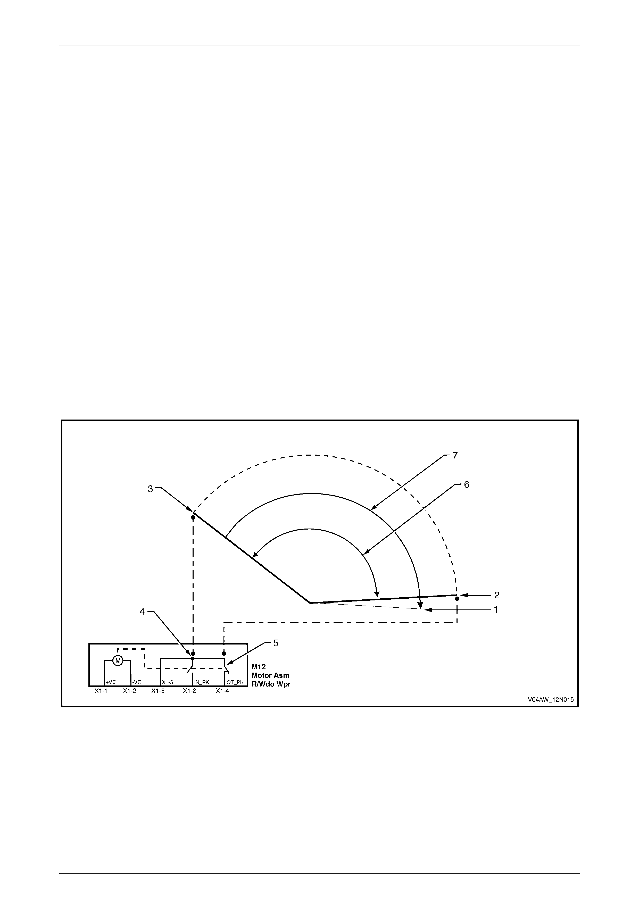
Functional Operation
For the rear wiper assembly functional oper ation description, refer to Figure 12N – 3.
For a complete wiring diagram of the rear wiper system, refer to 6.2 Wiring Diagram – Rea r W iper/Washer and
6.3 Wiring Diagram – Rear Wiper Control Module.
Intermittent Wipe Cycle Operation
A wipe cycle consists of the rear wiper arm movement from the onscreen park position (2) to the furthest onscreen park
position (3) and back to the onscreen park position (2).
With the ignition switch in the ACC or ON position and the wipers and washers control switch is moved to the rear wiper
ON position, the rear wiper motor operates in the forward direction (6) for one wipe cycle and then waits for 9 seconds
before resuming the next wipe cycle. This procedure is repeated until the wipers and washers control switch is moved to
the OFF position.
During this cycle, the rear wiper control module suppl ies power to the rear wiper motor. The forward park limit switch (5)
in the rear wiper motor opens when the rear wiper arm leaves the onscreen park position (2) and moves in the forward
direction (6) towards the furthest onscreen park position (3). The reverse park limit switch (4) in the motor closes when
the rear wiper arm reaches the furthest onscreen p ark position (3), then it opens when the rear wiper arm leaves this
position (3) and returns towards the onscreen park pos ition (2). The forward park limit s witch (5) in the rear wiper motor
closes when the rear wiper arm reaches the onscreen park position (2). At this point the rear wiper control module
disconnects the power to the rear wiper motor and the rear wiper arm remains stationary at the onscreen park
position (2) for 9 seconds until the next wipe cycle occurs.
When the wipers and washers control switch is moved from the rear wiper ON position to the OF F position the following
occurs.
• If the rear wiper arm is in the onscreen park position (2), the rear wiper control module supplies power to the rear
wiper motor. The rear wiper arm moves in the forward direc t ion (6) towards the furthest onscreen park position (3)
where it stops. The reverse park limit switch (4) in the motor closes when the rear wiper arm reaches the furthest
onscreen park position (3) and the rear wiper arm remains stationary for 1 second. T hen the rear wiper control
module reverses polarit y to the rear wiper motor which turns in the reverse direction (7). The reverse park limit
switch (4) opens when the rear wiper arm leaves the furthest onscreen park position (3) and moves all the way to
the offscreen park position (1).
• If the rear wiper arm is moving towards the furthest onscreen park position (3), it continues to move to this position
where it stops. The reverse park limit switch (4) in the motor closes when the rear wiper arm reaches the furthest
onscreen park position (3) and the rear wiper arm remains stationary for 1 second. T hen the rear wiper control
module reverses polarit y to the rear wiper motor which turns in the reverse direction (7). The reverse park limit
switch (4) opens when the rear wiper arm leaves the furthest onscreen park position (3) and moves all the way to
the offscreen park position (1).
• If the rear wiper arm is moving towards the onscreen park position (2), the rear wiper control mod ule supplies
power to the rear wiper motor until the rear wiper arm reaches the furthest onscreen park position (3) where it
stops. The reverse park limit switch (4) in the motor closes when the rear wiper arm reaches the furthest onscreen
park position (3) and the rear wiper arm remains stationary for 1 second. T hen the rear wiper control module
reverses polarity to the rear wiper motor which turns in the reverse direction (7). The reverse park limit switch (4)
opens when the rear wiper arm leaves the furthest onscreen park position (3) and moves all the way to the
offscreen park position (1).
Wipers, Washers and Horn Page 12N–12
Page 12N–12
Continuous Wipe Mode
With the ignition switch in the ON position, the rear wiper operates in continuous wipe mode when:
• the wipers and washers control switch is pushed and held forward, or
• the wipers and washers control switch is in the rear wiper ON position and the reverse gear is selected.
During this wipe mode, the rear wiper motor operates in the forward directi on (6). The rear wiper arm moves continuously
between the furthest onscreen park position (3) and the onscreen park pos ition (2). The reverse park limit switch (4) and
the forward park limit switch (5) in the rear wiper motor close and re-op en alternatively as the rear wiper arm reaches the
two park positions (2 and 3). The rear wiper control module supplies constant power to the rear wiper motor.
When the wipers and washers control switch is released from the forward position the following occurs.
• If the rear wiper/washer switch is in the OFF position, the rear wiper motor continues to operate in the f orward
direction (6) until the rear wiper arm reaches the furthest onscreen park position (3) where it stops. The reverse
park limit switch (4) in the motor closes when the rear wiper arm reaches the furthest onscreen park position (3)
and the rear wiper arm remains stationar y for 1 second. Then the rear wiper control modul e reverses polarity to the
rear wiper motor which turns in the reverse direction (7). The reverse park limit switch (4) opens when the rear
wiper arm leaves the furthest onscreen park position (3) and moves al l the way to the offscreen park position (1).
• If the rear wiper/washer switch is in the ON position, the rear wiper motor continues to operate in the forward
direction (6) until the rear wiper arm reaches the onscreen park position (2). The forward park limit switch (5) in the
motor closes when the rear wiper arm reache s the onscreen park position (2). At this point the rear wiper control
module disconnects the power to the rear wiper motor and the rear wiper arm remains stationary at the o nscreen
park position (2) for 9 seconds until the next intermittent wipe cycle occurs.
When the reverse gear is deselected, the rear wiper motor continues to operate in the forward direction (6) until the rea r
wiper arm reaches the onscreen park position (2). The forward park limit switch (5) in the motor closes when the rear
wiper arm reaches the onscreen park positio n (2). At this point the rear wiper control module disconnects the power to
the rear wiper motor and the rear wiper arm remains stationary at the onscreen park position (2) for 9 seconds until the
next intermittent wipe cycle occurs.
Figure 12N – 3
Legend
1 Rear Wiper Arm Offscreen Park
Position
2 Rear Wiper Arm Onscreen Park
Position
3 Rear Wiper Arm Furthest Onscreen
Park Position
4 Rear Wiper Motor Reverse Park Limit
Switch
5 Rear Wiper Motor Forward Park Limit
Switch
6 Rear Wiper Motor Forward Direction
7 Rear Wiper Motor Reverse Direction

Wipers, Washers and Horn Page 12N–13
Page 12N–13
1.4 Washer Assemblies
Washer Assemblies, Except Wagon and AWD Wagon
The washer reservoir assembl y has the washer pump attached to it and is located belo w the right-hand front wheelhouse
panel assembly.
The washer nozzles are a dual outlet t ype and are mounted to the plenum cover assembly. For Cou pe vehicles the
washer nozzles are mounted to the hoo d assembly.
The washer pump assembly is operate d via the wipers and washers control switch fitted to the steering column; the
operation is controlled by the (BCM), refer to Section 12J Body Control Module.
With the ignition switch in the ACC or ON position, the accessor y control relay within the passenger compartment fuse
and relay panel assembly, is activated. When the wipers and washers control switch is pulled and held back, power is
supplied to the washer motor until the wipers and washers control switch is released.
For a complete wiring diagram of the washer system, refer to 3.2 Wiring Diagram – Front Wiper/Washer, Except Wagon.
Washer Assemblies, Wagon and AWD Wagon
Wagon vehicles have a rear wash er for the liftgate window as well as the windshield fro nt washers.
Wagon vehicles have a single washer reservoir and a comm on washer pump with dual outlet used for the front washers
and the rear washer.
The washer reservoir assembl y has the washer pump attached to it and is located belo w the right-hand front wheelhouse
panel assembly.
The front washer nozzles are a dual outlet type and are mounted to the plenum cov er assembly. The single outlet type
rear washer nozzle is mounted to the liftgate above the rear window.
Washer Control, Wagon
The washer pump assembly is operated via the wipers and washers control switch assembly fitted to the steering
column, the operation is controlled by the BCM, refer to Section 12J Body Control Module.
For a complete wiring diagram of the washer system, refer to 5.2 Wiring Diagram – Rear Wiper/Washer
Washer Control, AWD Wagon
The washer pump assembly is operated via the wipers and washers control switch assembly fitted to the steering
column; a one way valve is fitted just prior to the rear washer nozzle. The rear washer operation is controlle d by the rear
wiper control module.
For a complete wiring diagram of the washer system, refer to 6.2 Wiring Diagram – Rear Wiper/Washer.
Front Washer Operation
With the ignition switch in the ACC or ON position, the accessor y control relay within the passenger compartment fuse
and relay panel assembly, is activated. When the wipers and washers control switch is pulled and held back on front
wash position, power is supplied to the washer motor until the switch is released.
The washer pump motor forces the fluid to the outlet leading to the front washer nozzles.
Rear Washer Operation
With the ignition switch in the ACC or ON position, the accessor y control relay within the passenger compartment fuse
and relay panel assembly, is activated. When the wipers and washers control switch is pushed and held forward on rear
wash position, power is supplied to the washer motor until the switch is released.
To feed the fluid to the rear washer nozzle, the polarity is reversed to the washer pump motor, making it spin in the
reverse direction and forcing fluid to the outlet leading to the rear washer nozzle.

Wipers, Washers and Horn Page 12N–14
Page 12N–14
1.5 Horn Assemblies
Horn Assembly
Description
Two trumpet type horns are fitted to the vehicle.
The trumpet type dual horns are fitted behind the front bumper fascia with the high-note horn on the right-hand side and
the low-note horn on the left-hand side.
The horn assembly is operated via the steering wheel horn contact, the operation is controlled by the BCM, refer to
Section 12J Body Control Module.
Power is supplied to the horn assembly when the horn relay located within the pass enger compartment fuse and relay
panel assembly is activated. The horn relay is activated by a circuit which is closed when the steering wheel horn contact
switch is pushed in.
For a complete wiring diagram of the horn system, refer to 7.2 Wiring Diagram – Horn Assembly.
Horn Relay
The horn relay is locate d in the engine compartment fuse and rela y panel assembly,
refer to Section 12O Fuses, Relays and Wiring Harnesses.
Steering Wheel Horn Contact
The horn contact is incorporated into th e steering wheel inflatable restraint module in the centre of the steering wheel.
The horn contact is not serviced separatel y; for all servic e operations, refer to Section 12M Occupant Protection System.
Theft-deterrent Horn Assembly
Description
The theft-deterrent horn is a disc type horn located at the rear of the engine bay and is attached to the front left-hand
wheelhouse panel ass embly.
Power is supplied to the theft-deterrent horn assembly when the theft-deterrent horn relay located within the BCM is
activated. The operation of the theft-deterrent horn is controlled by the BCM, refer to Section 12J Body Contro l Module.
For a complete wiring diagram of the theft-deterrent horn system, refer to 7.2 Wiring Diagram – Horn Assembl y.
Theft-deterrent Horn Relay
The theft-deterrent horn relay is located in the BCM; for details refer to Section 12J Body Control Module.

Wipers, Washers and Horn Page 12N–15
Page 12N–15
2 Preliminary Test – Front Wipers
and Washers
2.1 Test Front Wipers and Washers
Assemblies
Introduction
The preliminary test is used to aid in localising the malfunction in the front wipers and washers wiring system and
confirms the serviceability of the wipers and washers control switch.
For a complete wiring diagram of the front wipers and washers wiring circuits, refer to:
• 3.2 Wiring Diagram – Front Wiper/Washer, Except Wagon and AWD Wagon, or
• 3.3 Wiring Diagram – Front Wiper/Washer, Wagon, or
• 3.4 Wiring Diagram – Front Wiper/Washer, AWD Wagon.
Test Description
The following numbers refer to the step numbers in the diagnostic table:
1 Checks if the accessories operate. Isolates if the accessory control relay and/or associated circuits is at fault.
2 Checks if the wipers operate with the wipers and washers control s witch in position 1 and position 2.
3 Checks if the washers operate with the wipers functioning.
4 Checks if the wipers and washers control switch is serviceable. Isolates whether the wipers and washers control
switch or the washers wiring system is at fault.
5 Checks if the washers operate with the wipers not functioning.
6 Checks if the wipers and washers control switch is serviceable. Isolates whether the wipers and washers control
switch or the wipers wiring system is at fault.
7 Checks if the fuse F18 within the passenger compartment fuse and relay panel assembly is serviceable.
8 Checks if battery voltage is delivered to switch connector S247 – X1 pin 6, with the ignition switch in the ACC or
ON position. Isolates whether the battery power supply circuits 243 or 70 are at fault.
9 Checks if the wipers and washers control switch is serviceable. Isolates whether the wipers and washers control
switch or the wipers and washers wiring systems are at fault.
Diagnostic Table Notes
1 To diagnose the accessory control rel ay and associated wiring circuits, refer to Section 12J Body Control Module.
2 To test and/or replace the wipers and washers control switch,
refer to 16 Service Operations – Wipers and Washers Cont rol Switch.
3 To diagnose the front washers wiring system ,
refer to 3.8 Diagnose Front Washer Pump and Wiring System Malfunction.
4 To diagnose the front wipers wiring s ystem, refer to 3.6 Diagnose F r ont Wiper Motor Wiring System Malfunction.
5 Refer to Section 12O Fuses, Relays and Wiring Harnesses for harness routeing.
6 For wiring harness repairs, refer to Section 12P Wiring Diag rams.

Wipers, Washers and Horn Page 12N–16
Page 12N–16
Diagnostic Table
Step Action Yes No
1 1 Switch the ignition to the ACC or ON position.
2 Check if the accessories operate (eg. radi o).
Do the accessories operate? Go to Step 2
Diagnose the
accessory control
relay and associated
circuits
(refer to Note 1)
2 With the ignition switch in the ACC or ON position, switch the wipers
and washers control switch in the position 1 then position 2.
Do the wipers operate, with the switch in both positions? Go to Step 3 Go to Step 5
3 With the ignition switch in the ACC or ON position, pull back and hold
the wipers and washers control switch.
Do the washers operate? System serviceable Go to Step 4
4 Test the wipers and washers control switch S247, (refer to Note 2).
Is the wipers and washers control s witch serviceable?
Diagnose the
washers wiring
system
(refer to Note 3)
Replace the wipers
and washers control
switch
(refer to Note 2)
5 With the ignition switch in the ACC or ON position, pull back and hold
the wipers and washers control switch.
Do the washers operate? Go to Step 6 Go to Step 7
6 Test the wipers and washers control switch S247, (refer to Note 2).
Is the wipers and washers control s witch serviceable? Diagnose the wipers
wiring system
(refer to Note 4)
Replace the wipers
and washers control
switch
(refer to Note 2)
7 Check the wipers and washers fuse F18 within the passenger
compartment fuse and relay panel assembly, (refer to Note 5).
Is the fuse serviceable?
Go to Step 8
Replace the fuse,
if the fuse blows
again check for a
short to ground in
circuit 243
(refer to Note 5)
8 1 Remove the wipers and washers control switch S247, (refer to
Note 2).
2 With the ignition switch in the ACC or ON position, backprobe
connector S247-X1 pin 6 with a test lamp.
Does the test lamp illuminate? Go to Step 9
Repair or replace
circuits 243 or 70
(refer to Note 6)
9 Test the wipers and washers control switch S247, (refer to Note 2).
Is the wipers and washers control s witch serviceable?
Diagnose the wipers
and the washers
wiring systems
(refer to Note 4 and
Note 3)
Replace the wipers
and washers control
switch
(refer to Note 2)
When all diagno sis an d repairs are completed, check the system for correct operati on.

Wipers, Washers and Horn Page 12N–17
Page 12N–17
3 Diagnostics – Front Wipers and
Washers
3.1 Prerequisites
Safety Requirements
When operating the front wipers and washers
as part of any steps in the diagnostic tables,
ensure that fingers and limbs are clear of
moving parts.
Equipment
The following equipment is required to diagnose the front wipers and washers:
• an unpowered test lamp with a current draw of less than 3 A, and
• a digital multimeter with a minimum impe dance of 10 MΩ.
Testing Procedures
Adhere to the following points when
performing diagnostic testing on
components:
• Take care when using testing equipment
to diagnose wiring harness connectors.
Backprobe the connector to avoid terminal
damage.
• When tests are required on connector
terminals, use the adapters in the
connector adapter kit KM–609 to prevent
damage to the terminals.
• Unless the multimeter being used has an
auto-ranging function, ensure the correct
range is selected.
• When backpro bing connectors, ensure the
test lamp ground lead is connected to an
appropriate ground point on the vehicle.
Ensure this ground point is not part of the
circuit being tested.
NOTE
Perform the front wipers and washers pr eliminary
test before diagnosing the wiring systems, refer
to 2.1 Test Front Wipers and Washers
Assemblies.
When following the steps in the di agnostic tables,
perform them in the order cited. If the required
nominal value or result is not achi eved, rectif y t he
problem before proceeding.
Wipers, Washers and Horn Page 12N–18
Page 12N–18
3.2 Wiring Diagram – Front Wiper/Washer,
Except Wagon and AWD Wagon
Figure 12N – 4
Wipers, Washers and Horn Page 12N–19
Page 12N–19
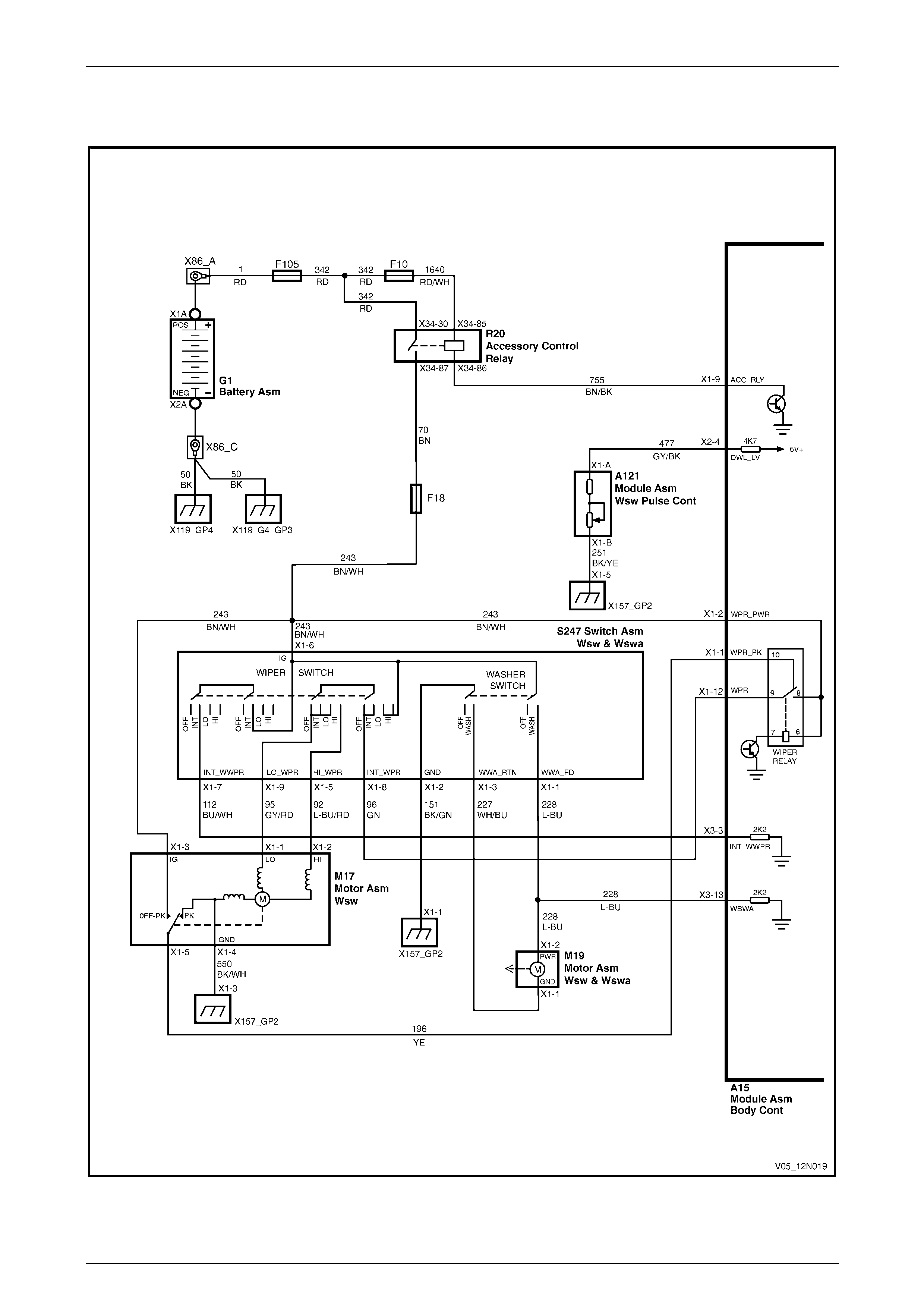
3.3 Wiring Diagram – Front Wiper/Washer,
Wagon
Figure 12N – 5
Wipers, Washers and Horn Page 12N–20
Page 12N–20
3.4 Wiring Diagram – Front Wiper/Washer,
AWD Wagon
Figure 12N – 6
Wipers, Washers and Horn Page 12N–21
Page 12N–21
3.5 Connector Diagrams – Front
Wiper/Washer
Figure 12N – 7
Wipers, Washers and Horn Page 12N–22
Page 12N–22
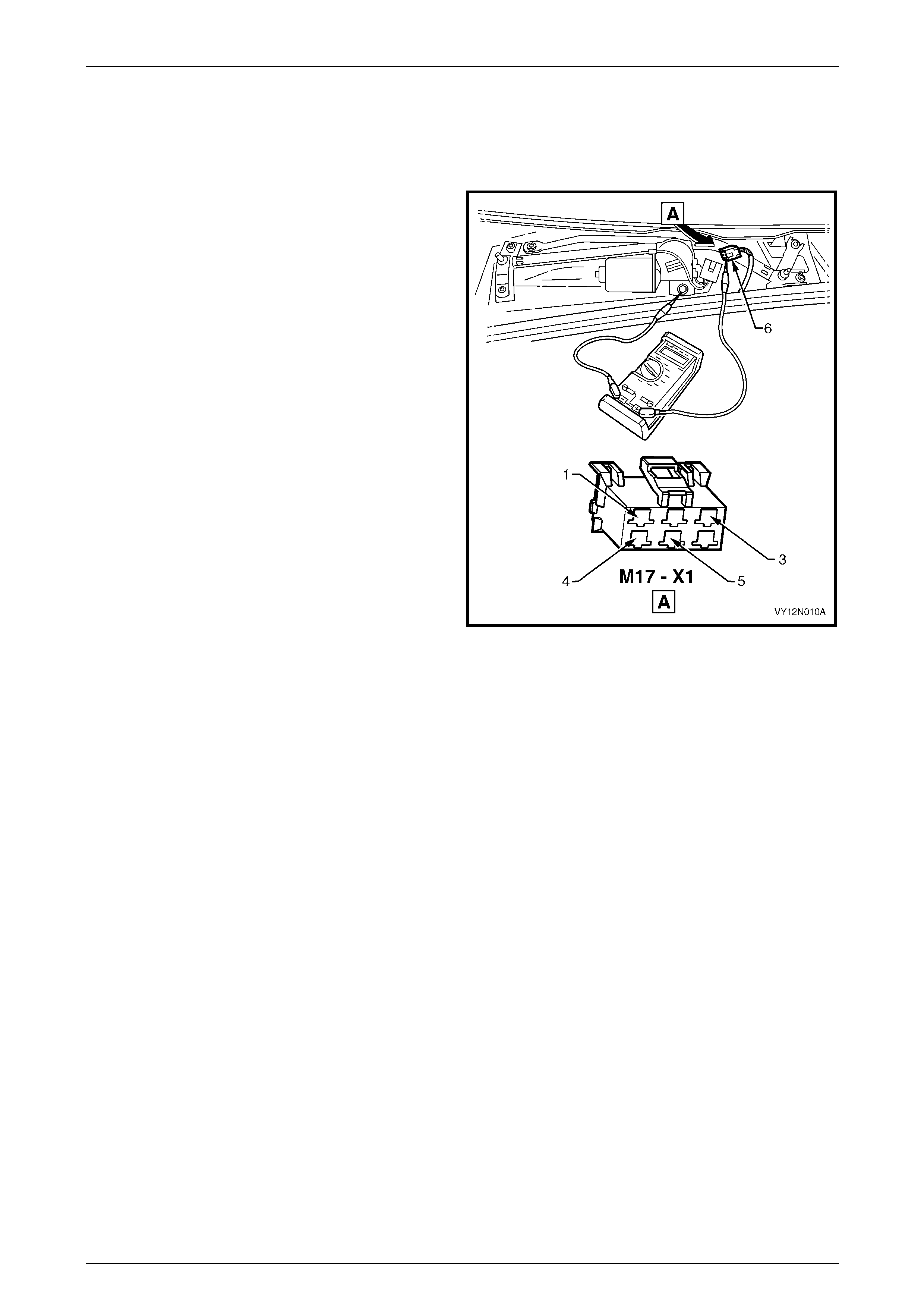
3.6 Diagnose Front Wiper Motor Wiring
System Malfunction
Introduction
The following operation checks the front wiper motor
assembly wiring at the front wiper motor connector
M17 – X1 (6), as an aid to diagnosing a fault in the front
wiper motor assembly system. This test confirms the
serviceability of the front wiper motor assembly wiring
system.
For a complete wiring diagram of the front wiper motor
assembly circuits, refer to:
• 3.2 Wiring Diagram – Front Wiper/Washer, Except
Wagon and AWD Wagon, or
• 3.3 Wiring Diagram – Front Wiper/Washer, Wagon, or
• 3.4 Wiring Diagram – Front Wiper/Washer, AWD
Wagon.
For connector pin location,
refer to: 3.5 Connector Diagrams – Front Wiper/W asher.
NOTE
The operation of the front wiper intermittent dwell
is controlled by the body co ntrol module A 15 and
can be checked with a Tech 2, refer to
Section 12J Body Control Module.
Figure 12N – 8
Electrical Test Description
The following numbers refer to the step numbers in the diagnostic table:
1 Checks if the front wipers and washers preliminary test has been performed.
2 Checks if battery voltage is delivered to connector M17 – X1 pin 3, with the ignition switch in the ACC or ON
position. Isolates if the battery po wer supply circuit 243 is at fault.
3 Checks if battery voltage is delivered to connector M17 – X1 pin 1, with the ignition switch in the ACC or ON
position and the wipers and washers control switch in position 1 (low speed).
4 Checks if the front wiper motor assembly ground circuit is serviceable. Isolates if the front wiper motor assembly
ground circuit 550 is at fault.
5 Checks if the front wiper motor assembly M17 is serviceable.
6 Checks if battery voltage is delivered to connector M17 – X1 pin 1, with the ignition switch in the ACC or ON
position and the wipers and washers control switch in position 1 (low speed). Isolates if the battery power supply
circuit 95 is at fault.
7 Checks if battery voltage is delivered to connector M17 – X1 pin 2, with the ignition switch in the ACC or ON
position and the wipers and washers control switch in position 2 (high speed). Isolates if the battery power supply
circuit 92 is at fault.
8 Checks if battery voltage is delivered to connector M17 – X1 pin 1, with the ignition switch in the ACC or ON
position and the wipers and washers control switch in INT position. Isolates whether the battery power supply
circuit 96 or 112 is at fault.
9 Checks if the front wiper motor assembly circuit 196 is serviceable. Isolates if the front wiper motor assembly
circuit 196 is at fault.

Wipers, Washers and Horn Page 12N–23
Page 12N–23
Diagnostic Table Notes
1 To perform the front wipers and washers preliminary test, refer to 2.1 Test Front Wipers and Washers Assemblies.
2 For removal of the front wiper arm assemblies, plenum cove r assembly and replacement of the front wiper motor
assembly, refer to:
• 8 Service Operations – Front Wiper Assemblies, Except Coupe, or
• 9 Service Operations – Front Wiper Assemblies, Coupe.
3 For all wiring harness fault diagnosis, refer to Section 12P Wiring Diagrams.
4 For wiring harness repair, refer to Section 12P Wiring Diagrams.
5 To diagnose the front wiper motor assembl y, refer to 3.7 Diagnose Front Wiper Motor Assembly Operation.
Diagnostic Table
Step Action Yes No
1 Has the front wipers and washers preliminary test been performed?
Go to Step 2
Perform the
preliminary test
(refer to Note 1)
2 1 Remove the front wiper arm assemblies, (refer to Note 2).
2 Remove the plenum cover assembly, (refer to Note 2).
3 Switch the ignition to the ACC or ON position.
4 Backprobe connector M17 – X1 pin 3 with a test lamp, (refer to
Note 3).
Does the test lamp illuminate? Go to Step 3
Repair or replace
circuit 243
(refer to Note 4)
3 1 With the ignition in the ACC or ON position, switch the wipers
and washers control switch to position 1 (lo w speed).
2 Backprobe connector M17 – X1 pin 1 with a test lamp, (refer to
Note 3).
Does the test lamp illuminate? Go to Step 4 Go to Step 6
4 1 Disconnect connector M17 – X1 from the front wiper motor.
2 With a multimeter, check for continuity of the ground circuit 550
between connector M17 – X1 pin 4 and ground connector GP2,
(refer to Note 3).
Does the multimeter indicate continuity? Go to Step 5
Repair or replace
ground circuit 550
(refer to Note 4)
5 Diagnoses the front wiper motor assembly M17, (refer to Note 5).
Is the front wiper motor assembly serviceable?
For further diagnosis
refer to Section 12J
Body Control
Module
Replace the front
wiper motor
assembly
(refer to Note 2)
6 1 Disconnect connector M17 – X1 from the front wiper motor.
2 Switch the ignition to the ACC or ON position and the wipers and
washers control switch to position 1 (low speed).
3 With a multimeter, probe with the positive le ad to connector
M17 – X1 pin 1 and the negati v e lead to a ground point, (refer to
Note 3).
Does the multimeter indicate battery voltage? Go to Step 7
Repair or replace
circuit 95
(refer to Note 4)

Wipers, Washers and Horn Page 12N–24
Page 12N–24
Step Action Yes No
7 1 With the ignition in the ACC or ON position, switch the wipers
and washers control switch to position 2 (high speed).
2 With a multimeter, probe with the positive le ad to connector
M17 – X1 pin 2 and the negati v e lead to a ground point, (refer to
Note 3).
Does the multimeter indicate battery voltage? Go to Step 8
Repair or replace
circuit 92
(refer to Note 4)
8 1 With the ignition in the ACC or ON position, switch the wipers
and washers control switch to INT position.
2 With a multimeter, probe with the positive le ad to connector
M17 – X1 pin 1 and the negati v e lead to a ground point, (refer to
Note 3).
Does the multimeter indicate battery voltage? Go to Step 9
Repair or replace
circuit 96 or 112
(refer to Note 4)
9 1 Disconnect the body control module connector A15 – X1.
2 With a multimeter, check for continuity of the circuit 196 between
connector M17 – X1 pin 5 and connector A15 – X1 pin 1, (refer
to Note 3).
Does the multimeter indicate contin uity?
System serviceable,
for further diagnosis
refer to Section 12J
Body Control
Module
Repair or replace
circuit 196
(refer to Note 4)
When all diagno sis an d repairs are completed, check the system for correct operati on.
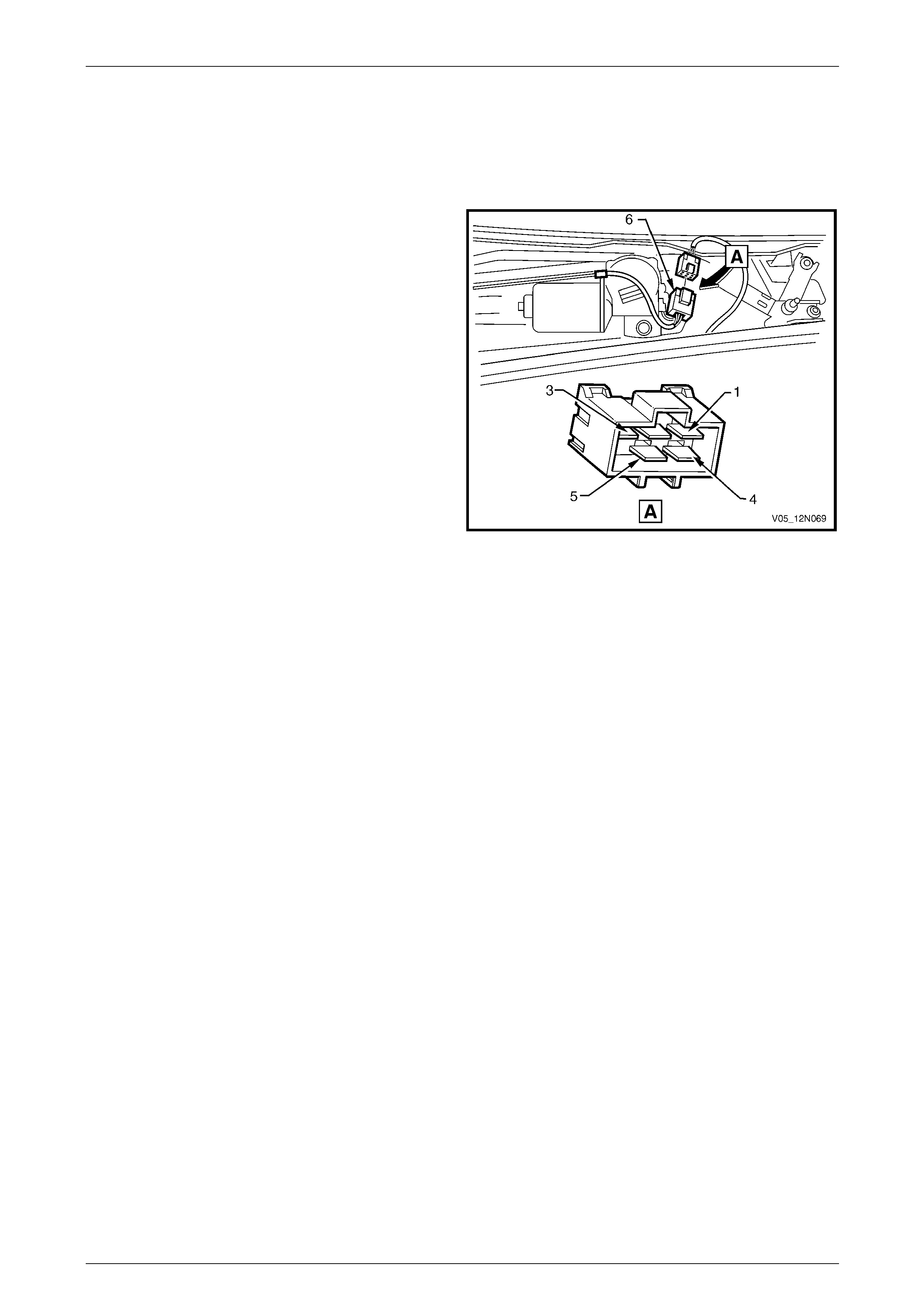
Wipers, Washers and Horn Page 12N–25
Page 12N–25
3.7 Diagnose Front Wiper Motor Assembly
Operation
Introduction
This test checks the operation of the front wiper motor
assembly at the motor connector M17 – X1 (6) and confirm s
the serviceability of the front wiper motor assembl y.
The test diagnoses four functions:
• the low-speed drive,
• the high-speed drive,
• the off PARK position, and
• the PARK position.
For a diagram of the front wiper motor assembly, refer to:
• 3.2 Wiring Diagram – Front Wiper/Washer, Except
Wagon and AWD Wagon, or
• 3.3 Wiring Diagram – Front Wiper/Washer, Wagon, or
• 3.4 Wiring Diagram – Front Wiper/Washer, AWD
Wagon.
For pins numbering within the motor connect or
M17 – X1 (6), refer to Figure 12N – 9.
NOTE
If there is a fault in the wiper system and the
following test proves the front wiper motor
assembly is serviceable, refer to 3.6 Diagnose
Front Wiper Motor Wiring System Malfunction.
Figure 12N – 9
Electrical Test Description
The following numbers refer to the step numbers in the diagnostic table:
1 Checks the low speed operation of the front wiper motor assembly. Isolates if the circuit within the front wiper motor
assembly is serviceable between the motor connector M17 – X1 pin 1 and pin 4.
2 Checks the high speed operation of the front wiper motor assembly. Isolates if the circuit within the front wiper
motor assembly is serviceable between the motor connector M17 – X1 pin 2 and pin 4.
3 Checks if there is continuity within the front wiper motor contacts when the motor rotates past the PARK position.
Isolates whether the contacts within the motor assembly are faulty or the circuit 196 is shorted to ground.
4 Checks if the wiper linkages are stoping at the park position. Isolates if the contacts within the motor assembly are
faulty.
Diagnostic Table Notes
1 For all wiring harness fault diagnosis, refer to Section 12P Wiring Diagrams.
2 For removal of the front wiper arm assemblies, plenum cove r assembly and replacement of the front wiper motor
assembly, refer to:
• 8 Service Operations – Front Wiper Assemblies, Except Coupe, or
• 9 Service Operations – Front Wiper Assemblies, Coupe.

Wipers, Washers and Horn Page 12N–26
Page 12N–26
Diagnostic Table
Step Action Yes No
1 1 Remove the front wiper arm assemblies, (refer to Note 2).
2 Remove the plenum cover assembly, (refer to Note 2).
3 Disconnect the front wiper motor connector M17 – X1.
4 Connect a fused jumper lead from the vehicle battery positive
terminal to the motor connector M17 – X1 pin 1 and a lead from
the motor connector M17 – X1 pin 4 to a ground point, (refer to
Note 1).
Does the front wiper motor assembly operate at low speed? Go to Step 2
Replace the front
wiper motor
assembly (refer to
Note 2)
2 Connect a fused jumper lead from the vehicle battery positive terminal
to the motor connector M17 – X1 pin 2 and a lead from the motor
connector M17 – X1 pin 4 to a ground po int, (refer to Note 1).
Does the front wiper motor assembl y operate at high speed? Go to Step 3
Replace the front
wiper motor
assembly (refer to
Note 2)
3 1 Connect a fused jumper lead from the vehicle battery positive
terminal to the motor connector M17 – X1 pin 1 and a lead from
the motor connector M17 – X1 pin 4 to a ground point, (refer to
Note 1).
2 Allow the motor to turn the linkages appro ximately 1/4 of a turn
past the PARK position and disconnect the lead from the motor
connector M17 – X1 pin 1.
3 Connect a test lamp between the battery positive terminal and
the motor connector M17 – X1 pin 5, (refer to Note 1).
Does the test lamp illuminate?
Replace the front
wiper motor
assembly (refer to
Note 2) Go to Step 4
4 1 Connect motor connector M17 – X1 pins 1 and 5 together with a
fused jumper lead.
2 Connect a fused jumper lead from the vehicle battery positive
terminal to the motor connector M17 – X1 pin 3 and a lead from
the motor connector M17 – X1 pin 4 to a ground point, (refer to
Note 1).
Does the front wiper motor assembly turn the linkages to the PARK
position and then stop?
The front wiper
motor assembly is
serviceable
Replace the front
wiper motor
assembly (refer to
Note 2)
When all diagno sis an d repairs are completed, check the system for correct operati on.

Wipers, Washers and Horn Page 12N–27
Page 12N–27
3.8 Diagnose Front Washer Pump and
Wiring System Malfunction
Introduction
This test confirms the serviceability of the washer reservoir pump assembly and the associated wiring system.
For a complete wiring diagram of the pump and front washer circuits, refer to:
• 3.2 Wiring Diagram – Front Wiper/Washer, Except Wagon and AWD Wagon, or
• 3.3 Wiring Diagram – Front Wiper/Washer, Wagon, or
• 3.4 Wiring Diagram – Front Wiper/Washer, AWD Wagon.
For connector pin location, refer to: 3.5 Connector Diagrams – Front W iper/W asher.
Electrical Test Description
The following numbers refer to the step numbers in the diagnostic table:
1 Checks if the front wipers and washers preliminary test has been performed.
2 Checks if battery voltage is supplied to the washer pump assembly.
3 Checks if the washer hose or nozzle assemblies are blocked. Isolates whether the washer hose, nozzle assemblies
or washer pump assembly are at fault.
4 Checks if battery voltage is supplied to connector M19 – X1 pin 2. Isolates whether the battery supply circuit 228 or
the ground circuits 227 or 151 are faulty.
Diagnostic Table Notes
1 To perform the front wipers and washers preliminary test, refer to 2.1 Test Front Wipers and Washers Assemblies.
2 For all wiring harness fault diagnosis, refer to Section 12P Wiring Diagrams.
3 For the replacement of the front washer hose, front washer nozzle assemblies or washer pump assembly, refer to:
• 12 Service Operations – Washer Assemblies, Sedan and Utility, or
• 13 Service Operations – Washer Assemblies, Wagon, or
• 14 Service Operations – Washer Assemblies, AWD Wagon, or
• 15 Service Operations – Washer Assemblies, Coupe.
4 For wiring harness repairs, refer to Section 12P Wiring Diag rams.

Wipers, Washers and Horn Page 12N–28
Page 12N–28
Diagnostic Table
Step Action Yes No
1 Has the front wipers and washers preliminary test been performed?
Go to Step 2
Perform the
preliminary test
(refer to Note 1)
2 1 If required, hoist the vehicle, refer to Section 0A General
Information.
2 From beneath the vehicle disconnect connector M19 – X1 from
the washer pump.
3 With a multimeter, probe with the positive le ad to connector
M19 – X1 pin 2 and the negati v e lead to pin 1, (refer to Note 2).
4 Switch the ignition to the ACC or ON position.
5 Pull back and hold the wipers and washers control switch.
Does the reading on the multim eter indicate battery voltage? Go to Step 3 Go to Step 4
3 Is there a blockage in either the washer hos e or nozzle assemblies? Repair or replace
the washer hose or
nozzle assemblies
(refer to Note 3)
Replace the washer
pump assembly
(refer to Note 3)
4 1 Probe connector M19 – X1 pin 2 with the positive lead of a
multimeter and the negative lead to a ground point, (refer to
Note 2).
2 With the ignition in the ACC or ON position, pull back and hold
the wipers and washers control switch.
Does the multimeter indicate battery voltage?
Repair or replace
circuit 227 or 151
(refer to Note 4)
for further diagnosis,
refer to Section 12J
Body Control
Module
Repair or replace
circuit 228
(refer to Note 4)
for further diagnosis,
refer to Section 12J
Body Control
Module
When all diagno sis an d repairs are completed, check the system for correct operati on.

Wipers, Washers and Horn Page 12N–29
Page 12N–29
4 Preliminary Test – Rear Wipers
and Washers, Wagon and AWD
Wagon
4.1 Test Rear Wiper and Washer Assembly
Introduction
The preliminary test is used to aid in localising the malfunc tion in the rear wiper and washer wiring system and confirms
the serviceability of the wipers and washers control switch.
For a complete wiring diagram of the rear wiper and washer wiring circuits, refer to:
• 5.2 Wiring Diagram – Rear Wiper/Wash er ,or
• 6.2 Wiring Diagram – Rear Wiper/Wash er.
Test Description
The following numbers refer to the step numbers in the diagnostic table:
1 Checks if the front wipers and washers operate.
2 Checks if the rear wiper operates.
3 Checks if the rear washer operates with the rear wiper not functioning.
4 Checks if the wipers and washers control switch is serviceable. Isolates whether the wipers and washers control
switch or the rear wiper and the rear washer wiring systems are at fault.
5 Checks if the rear wiper relay within the passenger compartment fuse and relay panel assembly, is serviceable.
Isolates if the rear wiper relay is at fault.
6 Checks if the wipers and washers control switch is serviceable. Isolates whether the wipers and washers control
switch or the rear wiper wiring system is at fault.
7 Checks if the rear washer operates with the rear wiper functioning.
8 Checks if the wipers and washers control switch is serviceable. Isolates whether the wipers and washers control
switch or the rear washer wiring system is at fault.
Diagnostic Table Notes
1 To test the front wipers and washers, refer to 2.1 Test Front Wipers and Washers Assemblies.
2 To test and/or replace the wipers and washers control switch,
refer to 16 Service Operations – Wipers and Washers Cont rol Switch.
3 To diagnose the rear wiper wiring system, refer to:
• 5.4 Diagnose Rear Wiper Motor W iring System Malfunction, or
• 6.5 Diagnose Rear Wiper Motor W iring System Malfunction.
4 To diagnose the rear washer wiring system, refer to:
• 5.6 Diagnose Washer Pump and R ear W asher Wiring System Malfunction, or
• 6.8 Diagnose Washer Pump and R ear W asher Wiring System Malfunction.
5 Refer to Section 12O Fuses, Relays and Wiring Harnesses for harness routeing.

Wipers, Washers and Horn Page 12N–30
Page 12N–30
Diagnostic Table
Step Action Yes No
1 1 Switch the ignition to the ACC or ON position.
2 Check if the front wipers and washers operate.
Do the front wipers and washers oper ate? Go to Step 2
Test the front wipers
and washers
(refer to Note 1)
2 With the ignition switch in the ACC or ON position, switch the wipers
and washers control switch in the rear wiper ON position.
Does the rear wiper operate? Go to Step 7 Go to Step 3
3 With the ignition switch in the ACC or ON position, push forward and
hold the wipers and washers control switch in the rear wash position.
Does the rear washer operate? Go to Step 5 Go to Step 4
4 Test the wipers and washers control switch S247, (refer to Note 2).
Is the wipers and washers control s witch serviceable?
Diagnose the rear
wiper and the rear
washer wiring
systems
(refer to Note 3 and
Note 4)
Replace the wipers
and washers control
switch
(refer to Note 2)
5 Check the rear wiper relay within the passenger compartment fuse and
relay panel assembly, (refer to Note 5).
Is the rear wiper relay serviceable? Go to Step 6
Replace the rear
wiper relay
(refer to Note 5)
6 Test the wipers and washers control switch S247, (refer to Note 2).
Is the wipers and washers control s witch serviceable? Diagnose the rear
wiper wiring system
(refer to Note 3)
Replace the wipers
and washers control
switch
(refer to Note 2)
7 With the ignition switch in the ACC or ON position, push forward and
hold the wipers and washers control switch on rear wash position.
Does the rear washer operate? System serviceable Go to Step 8
8 Test the wipers and washers control switch S247, (refer to Note 2).
Is the wipers and washers control s witch serviceable?
Diagnose the rear
washer wiring
system
(refer to Note 4)
Replace the wipers
and washers control
switch
(refer to Note 2)
When all diagno sis an d repairs are completed, check the system for correct operati on.

Wipers, Washers and Horn Page 12N–31
Page 12N–31
5 Diagnostics – Rear Wiper and
Wa s h e r, Wa g o n
5.1 Prerequisites
Safety Requirements
When operating the rear wiper and washer as
part of any steps in the diagnostic tables,
ensure that fingers and limbs are clear of
moving parts.
Equipment
The following equipment is re quired to diagnose the rear wiper an d washer:
• an unpowered test lamp with a current draw of less than 3 A, and
• a digital multimeter with a minimum impe dance of 10 MΩ.
Testing Procedures
Adhere to the following points when
performing diagnostic testing on
components:
• Take care when using testing equipment
to diagnose wiring harness connectors.
Backprobe the connector to avoid terminal
damage.
• When tests are required on connector
terminals, use the adapters in the
connector adapter kit KM–609 to prevent
damage to the terminals.
• Unless the multimeter being used has an
auto-ranging function, ensure the correct
range is selected.
• When backpro bing connectors, ensure the
test lamp ground lead is connected to an
appropriate ground point on the vehicle.
Ensure this ground point is not part of the
circuit being tested.
NOTE
Perform the rear wiper and washer preliminary
test before diagnosing the wiring systems, refer
to 4.1 Test Rear Wiper and Washer Assembly.
When following the steps in the di agnostic tables,
perform them in the order cited. If the required
nominal value or result is not achi eved, rectif y t he
problem before proceeding.
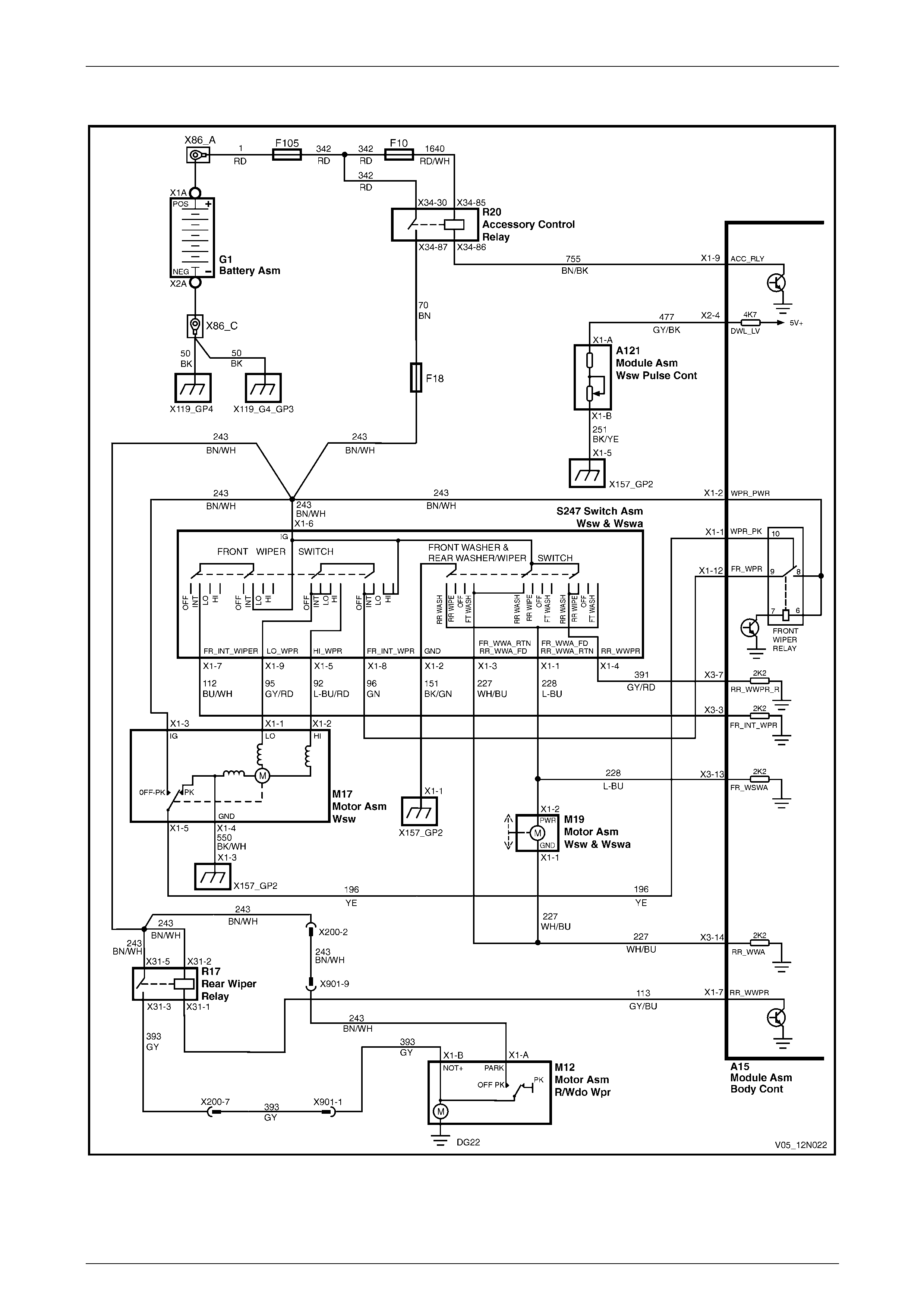
Wipers, Washers and Horn Page 12N–32
Page 12N–32
5.2 Wiring Diagram – Rear Wiper/Washer
Figure 12N – 10
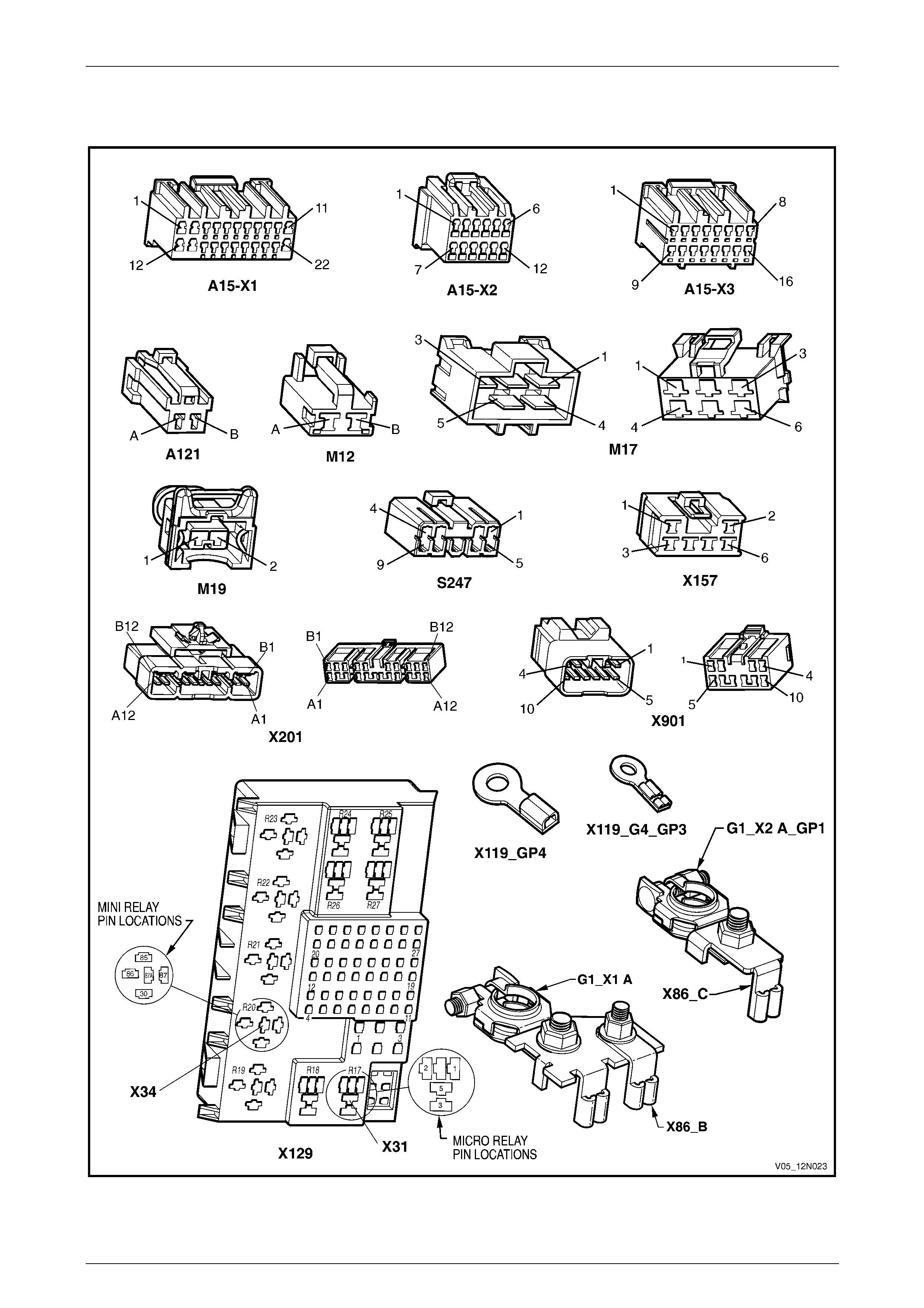
Wipers, Washers and Horn Page 12N–33
Page 12N–33
5.3 Connector Diagrams – Rear
Wiper/Washer
Figure 12N – 11
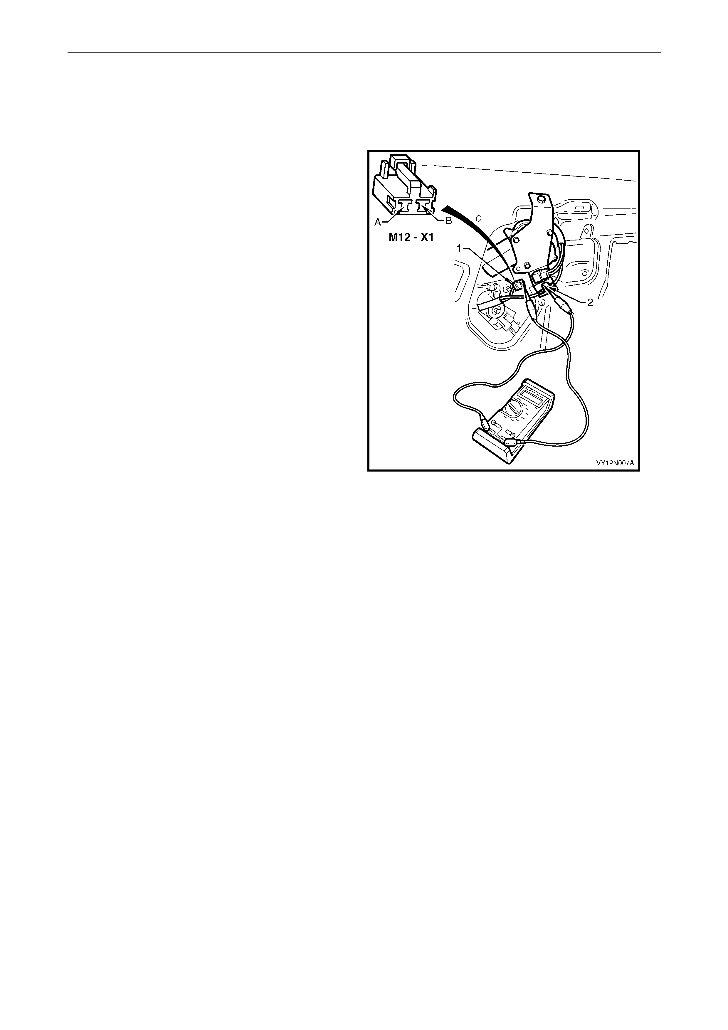
Wipers, Washers and Horn Page 12N–34
Page 12N–34
5.4 Diagnose Rear Wiper Motor Wiring
System Malfunction
Introduction
The following operation checks the rear wiper motor
assembly wiring at the rear wiper motor connector
M12 – X1 (1), as an aid to diagnosing a fault in the rear
wiper motor assembly system. This test confirms the
serviceability of the rear wiper motor assembly wiring
system.
For a complete wiring diagram of the wiper motor assemb ly
circuits, refer to 5.2 Wiring Diagram – Rear Wiper/Washer.
For connector pin location,
refer to 5.3 Connector Diagrams – Rear Wiper/W asher.
NOTE
The attachment screw (2) provides body ground
for the rear wiper motor assembly and can be
used as ground point for this test.
Figure 12N – 12
Electrical Test Description
The following numbers refer to the step numbers in the diagnostic table:
1 Checks if the rear wiper and washer prelimi nary test has been performed.
2 Checks if there is battery voltage at connector M12 – X1 pin A, with the ignition switch in the ACC or ON position.
Isolates if the electrical circuit 243 supplying the rear wiper motor assembly is at fault.
3 Checks if there is battery voltage at connector M12 – X1 pin B, with the ignition switch in the ACC or ON position
and the wipers and washers control switch in the rear wipe position. Isolates whether the electrical circuits 113, 391
or 393 are at fault.
4 Checks if the rear wiper motor assembly is serviceable.
Diagnostic Table Notes
1 To perform the rear wiper and washer preliminary test, refer to 4.1 Test Rear Wiper and Washer Assembly.
2 To remove the liftgate window lower garnish and lower trim panel,
refer to Section 1A4 Hood, Rear Compartment Lid, Liftgate and Endgate.
3 For all wiring harness fault diagnosis, refer to Section 12P Wiring Diagrams.
4 For wiring harness repairs, refer to Section 12P Wiring Diag rams.
5 To diagnose the rear wiper motor assemb ly, refer to 5.5 Diagnose Rear Wiper Motor Assembly Operation.
6 To replace the rear wiper motor assembly, refer to 10.4 Rear Wiper Motor Assembly.

Wipers, Washers and Horn Page 12N–35
Page 12N–35
Diagnostic Table
Step Action Yes No
1 Has the rear wiper and washer prelimi nary test been performed?
Go to Step 2
Perform the
preliminary test
(refer to Note 1)
2 1 Remove the liftgate windo w lower garnish and lower trim panel,
(refer to Note 2).
2 Switch the ignition to the ACC or ON position.
3 Backprobe connector M12 – X1 pin A with a test lamp, (refer to
Note 3).
Does the test lamp illuminate? Go to Step 3
Repair or replace
circuit 243
(refer to Note 4)
3 1 With the ignition switch in the ACC or ON position, switch the
wipers and washers control switch to the rear wiper ON position.
2 Backprobe connector M12 – X1 pin B with a test lamp, (refer to
Note 3).
Does the test lamp illuminate? Go to Step 4
Repair or replace
circuit 113, 391 or
393
(refer to Note 4)
for further diagnosis,
refer to Section 12J
Body Control
Module
4 Diagnose the rear wiper motor assembly M12, (refer to Note 5).
Is the rear wiper motor serviceable?
System serviceable
for further diagnosis,
refer to Section 12J
Body Control
Module
Replace the rear
wiper motor
assembly
(refer to Note 6)
When all diagno sis an d repairs are completed, check the system for correct operati on.
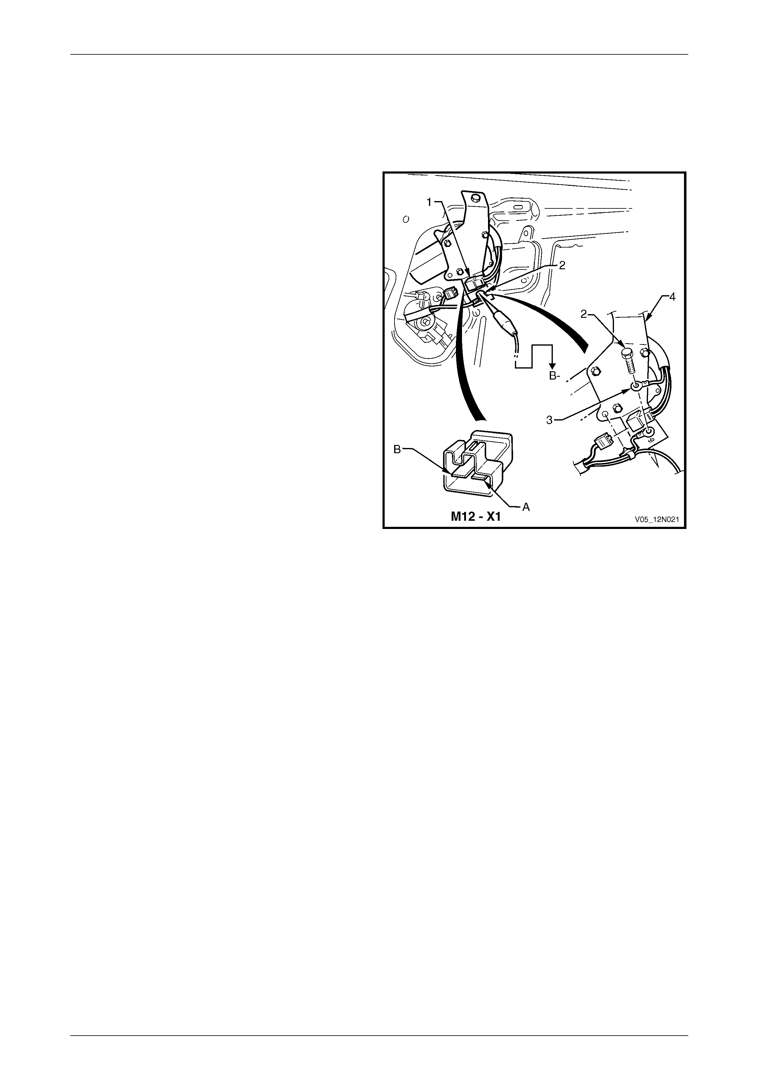
Wipers, Washers and Horn Page 12N–36
Page 12N–36
5.5 Diagnose Rear Wiper Motor Assembly
Operation
Introduction
This test checks the operation of the rear wiper motor
assembly at the motor connector M12 – X1 (1) and confirm s
the serviceability of the rear wiper motor assembl y.
NOTE
The attachment screw (2) provides body ground
for the rear wiper motor assembly connector (3).
The test diagnoses two functions:
• the wiper drive and
• the PARK position.
For a diagram of the rear wiper motor assembly,
refer to 5.2 Wiring Diagram – Rear Wiper/W asher.
For pins numbering within the motor connector M12 – X1,
refer to Figure 12N – 13.
NOTE
If there is a fault in the rear wiper system and the
following test proves the rear wiper motor
assembly is serviceable, refer to 5.4 Diagnose
Rear Wiper Motor Wiring System Malfunction.
Figure 12N – 13
Electrical Test Description
The following numbers refer to the step numbers in the diagnostic table:
1 Checks the drive operatio n of the rear wiper motor assembly.
2 Checks the drive operatio n of the rear wiper motor assembly. Isolates if the circuit within the rear wiper motor
assembly is serviceable between the motor connector M12 – X1 pin B and the ground connector.
3 Checks if the ground connection of the rear wiper motor assembly is effective. Isolates if the ground connection of
the rear wiper motor assembly is at fault.
4 Checks if the rear wiper motor shaft stops at the park position. Isolates if the contacts within the rear motor
assembly are faulty.
Diagnostic Table Notes
1 To remove the rear wiper arm assembly, refer to 10.3 Rear Wiper Arm Assembly.
2 To remove the liftgate window lower garnish and the liftgate lower trim panel,
refer to Section 1A4 Hood, Rear Compartment Lid, Liftgate and Endgate.
3 For all wiring harness fault diagnosis, refer to Section 12P Wiring Diagrams.
4 To view the components referred to in the table, refer to F igure 12N – 13.
5 For removal or replacement of the rear wiper motor assembly, refer to 10.4 Rear Wiper Motor Assembly.

Wipers, Washers and Horn Page 12N–37
Page 12N–37
Diagnostic Table
Step Action Yes No
1 1 Remove the rear wiper arm assembly, (refer to Note 1).
2 Remove the liftgate windo w lower garnish and the liftgate lower
trim panel, (refer to Note 2).
3 Disconnect the rear wiper motor connector M12 – X1.
4 Connect a fused jumper lead from the vehicle battery positive
terminal to the motor connector M12 – X1 pin B, (refer to Note 3).
Does the rear wiper motor assembly operate? Go to Step 4 Go to Step 2
2 1 Connect a fused jumper lead from the vehicle battery negative
terminal to the motor ground connector (3), (refer to Note 3 and
Note 4).
2 Connect a fused jumper lead from the vehicle battery positive
terminal to the motor connector M12 – X1 pin B, (refer to Note 3).
Does the rear wiper motor assembly operate? Go to Step 3
Replace the rear
wiper motor
assembly
(refer to Note 5)
3 1 Remove the screw (2) attaching the ground connector to the
liftgate assembly, (refer to Note 3 and Note 4).
2 Check and clean the ground connector, the attachin g screw and
bracket (4) and reinstall.
3 Connect a fused jumper lead from the vehicle battery positive
terminal to the motor connector M12 – X1 pin B, (refer to Note 3).
Does the rear wiper motor assembly operate? Go to Step 4
Ensure the bracket
is grounded to
vehicle
4 1 Connect a bridging wire between the wiper motor connector
M12 – X1 pins A and B.
2 Connect a fused jumper lead from the vehicle battery positive
terminal to the motor connector M12 – X1 pin A, (refer to Note 3).
3 Allow the motor shaft to turn approximately 1/4 of a turn past the
PARK position, then disconnect the bridging wire from the motor
connector M12 – X1 pin B.
Does the rear wiper motor shaft continue to rotate, reach the park
position and then stop?
The rear wiper
motor assembly is
serviceable
Replace the rear
wiper motor
assembly
(refer to Note 5)
When all diagno sis an d repairs are completed, check the system for correct operati on.

Wipers, Washers and Horn Page 12N–38
Page 12N–38
5.6 Diagnose Washer Pump and Rear
Washer Wiring System Malfunction
Introduction
This test confirms the serviceability of the washer pump assembly and the associated wiring system for the rear washer.
For a complete wiring diagram of the washer pump a nd rear washer circuits,
refer to 5.2 Wiring Diagram – Rear Wiper/W asher.
For connector pin location, refer to 5.3 Connector Diagrams – Rear Wiper/Washer.
Electrical Test Description
The following numbers refer to the step numbers in the diagnostic table:
1 Checks if the rear wiper and washer prelimi nary test has been performed.
2 Checks if battery voltage is supplied to the washer pump assembly.
3 Checks if the rear washer hose and/or nozzle assembly are blocked. Isolates whether the rear washer hose, nozzle
assembly or washer pump assembly are at fault.
4 Checks if battery voltage is supplied to connector M19 – X1 pin 1. Isolates whether the battery supply circuits 227
or 391 or the ground circuits 228 or 151 are at fault.
Diagnostic Table Notes
1 To perform the rear wiper and washer preliminary test, refer to 4.1 Test Rear Wiper and Washer Assembly.
2 For all wiring harness fault diagnosis, refer to Section 12P Wiring Diagrams.
3 For the replacement of the rear washer hose, rear washer nozzle assembly or washer pump assembly, refer to
13 Service Operations – Washer Assemblies, Wagon.
4 For wiring harness repairs, refer to Section 12P Wiring Diagrams.
Diagnostic Table
Step Action Yes No
1 Has the rear wiper and washer prelimi nary test been performed?
Go to Step 2
Perform the
preliminary test
(refer to Note 1)
2 1 If required, hoist the vehicle, refer to Section 0A General
Information.
2 From beneath the vehicle disconnect connector M19 – X1 from
the washer pump.
3 With a multimeter, probe with the positive le ad to connector
M19 – X1 pin 1 and the negati v e lead to pin 2, (refer to Note 2).
4 Switch the ignition to the ACC or ON position.
5 Push forward and hold the wipers and washers control switch on
rear wash position.
Does the multimeter indicate battery voltage? Go to Step 3 Go to Step 4
3 Is there a blockage in either the rear washer hose or nozzle assembly? Repair / replace the
rear washer hose or
nozzle assembly
(refer to Note 3)
Replace the washer
pump assembly
(refer to Note 3)
4 1 Probe connector M19 – X1 pin 1 with the positive lead of a
multimeter and the negative lead to a ground point, (refer to
Note 2).
2 With the ignition in the ACC or ON position, push forward and
hold the wipers and washers control switch on rear wash
position.
Does the multimeter indicate battery voltage?
Repair or replace
circuit 228 or 151
(refer to Note 4)
for further diagnosis
refer to Section 12J
Body Control
Module
Repair or replace
circuit 227 or 391
(refer to Note 4)
for further diagnosis,
refer to Section 12J
Body Control
Module
When all diagno sis an d repairs are completed, check the system for correct operati on.

Wipers, Washers and Horn Page 12N–39
Page 12N–39
6 Diagnostics – Rear Wiper and
Washer, AWD Wagon
6.1 Prerequisites
Safety Requirements
When operating the rear wiper and washer as
part of any steps in the diagnostic tables,
ensure fingers and limbs are clear of moving
parts.
Equipment
The following equipment is re quired to diagnose the rear wiper an d washer:
• an unpowered test lamp with a current draw of less than 3 A, and
• a digital multimeter with a minimum impe dance of 10 MΩ.
Testing Procedures
Adhere to the following points when
performing diagnostic testing on
components:
• Take care when using testing equipment
to diagnose wiring harness connectors.
Backprobe the connector to avoid terminal
damage.
• When tests are required on connector
terminals, use the adapters in the
connector adapter kit KM–609 to prevent
damage to the terminals.
• Unless the multimeter being used has an
auto-ranging function, ensure the correct
range is selected.
• When backpro bing connectors, ensure the
test lamp ground lead is connected to an
appropriate ground point on the vehicle.
Ensure this ground point is not part of the
circuit being tested.
NOTE
Perform the rear wiper and washer preliminary
test before diagnosing the wiring systems, refer
to 4.1 Test Rear Wiper and Washer Assembly.
When following the steps in the di agnostic tables,
perform them in the order cited. If the required
nominal value or result is not achi eved, rectif y t he
problem before proceeding.
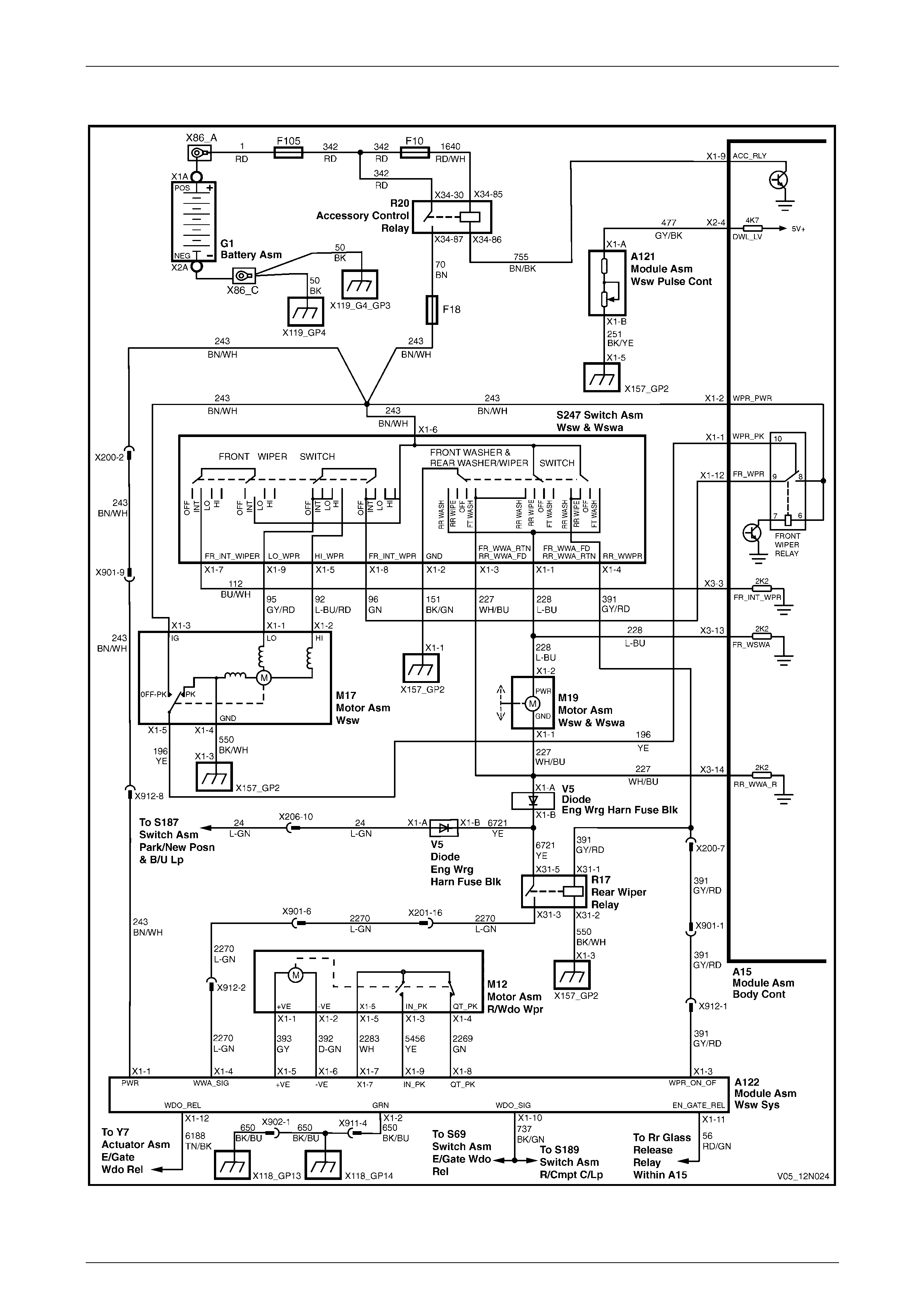
Wipers, Washers and Horn Page 12N–40
Page 12N–40
6.2 Wiring Diagram – Rear Wiper/Washer
Figure 12N – 14
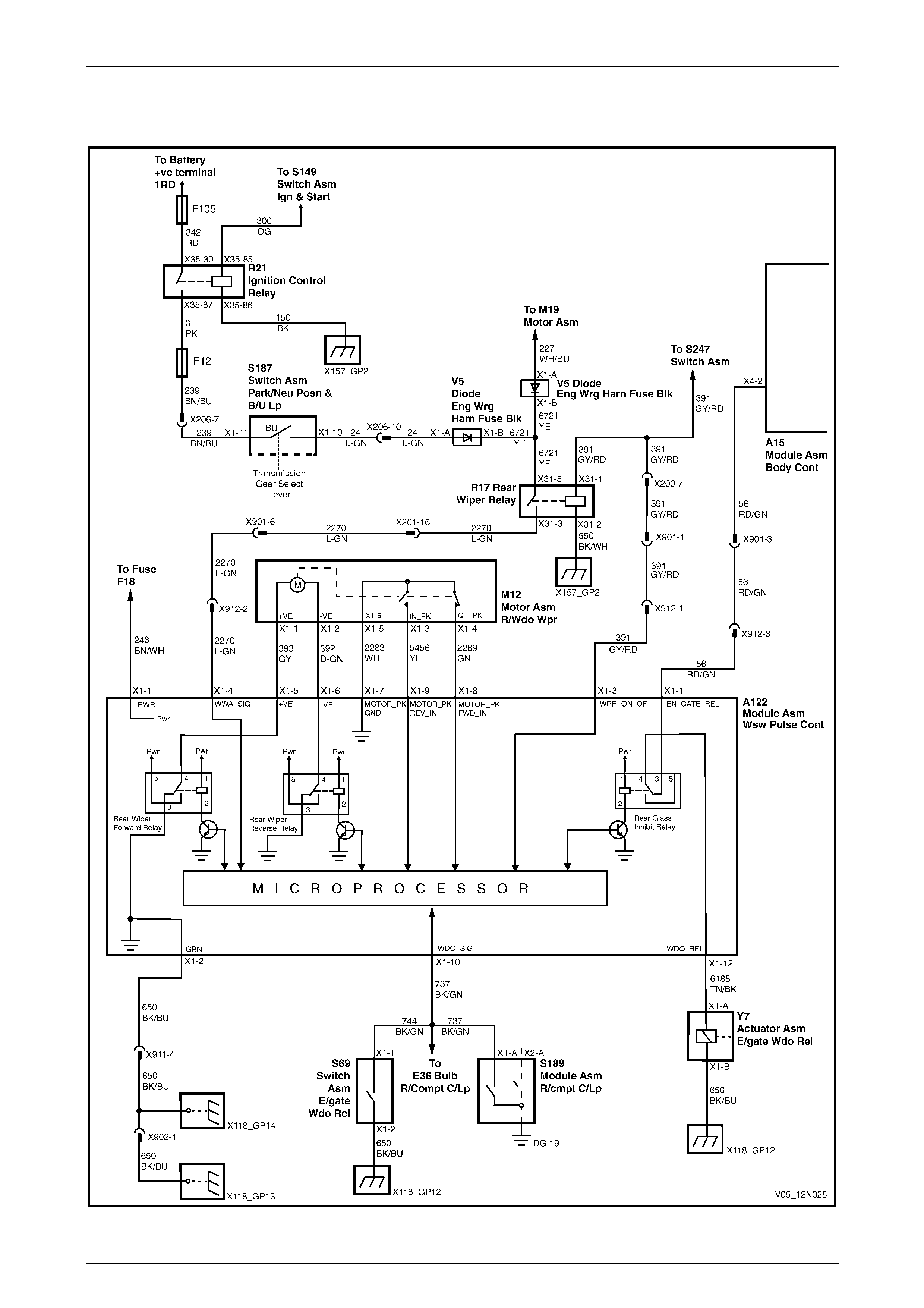
Wipers, Washers and Horn Page 12N–41
Page 12N–41
6.3 Wiring Diagram – Rear Wiper Control
Module
Figure 12N – 15
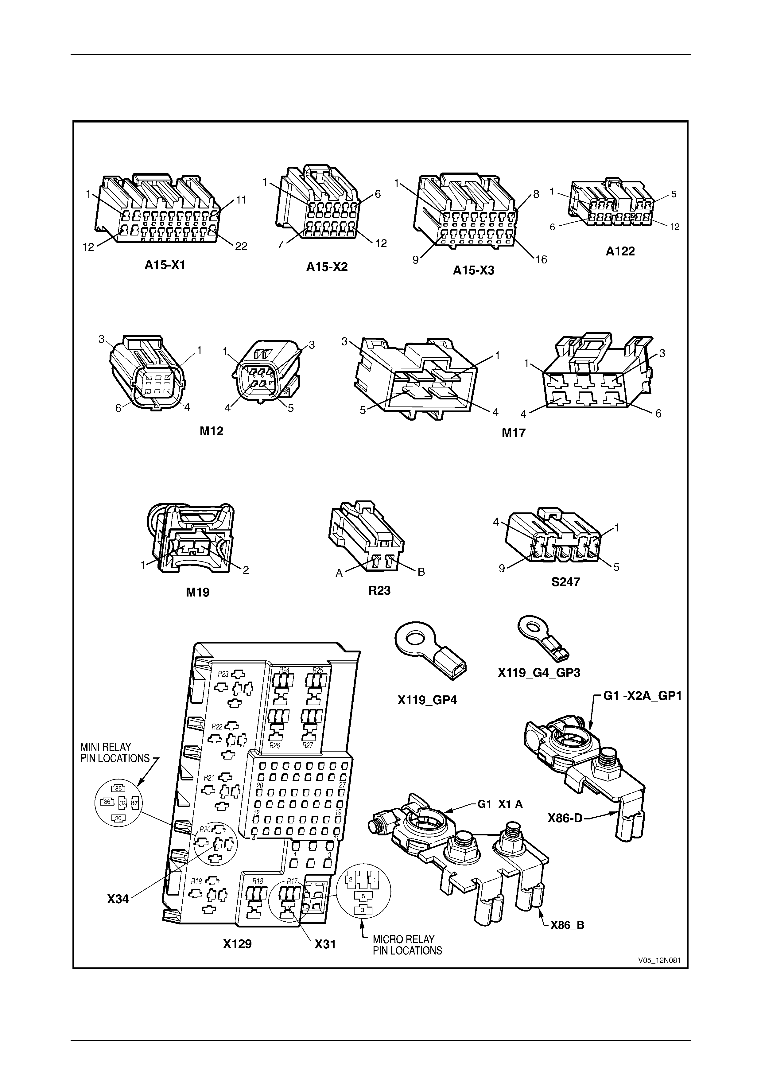
Wipers, Washers and Horn Page 12N–42
Page 12N–42
6.4 Connector Diagrams – Rear
Wiper/Washer
Figure 12N – 16
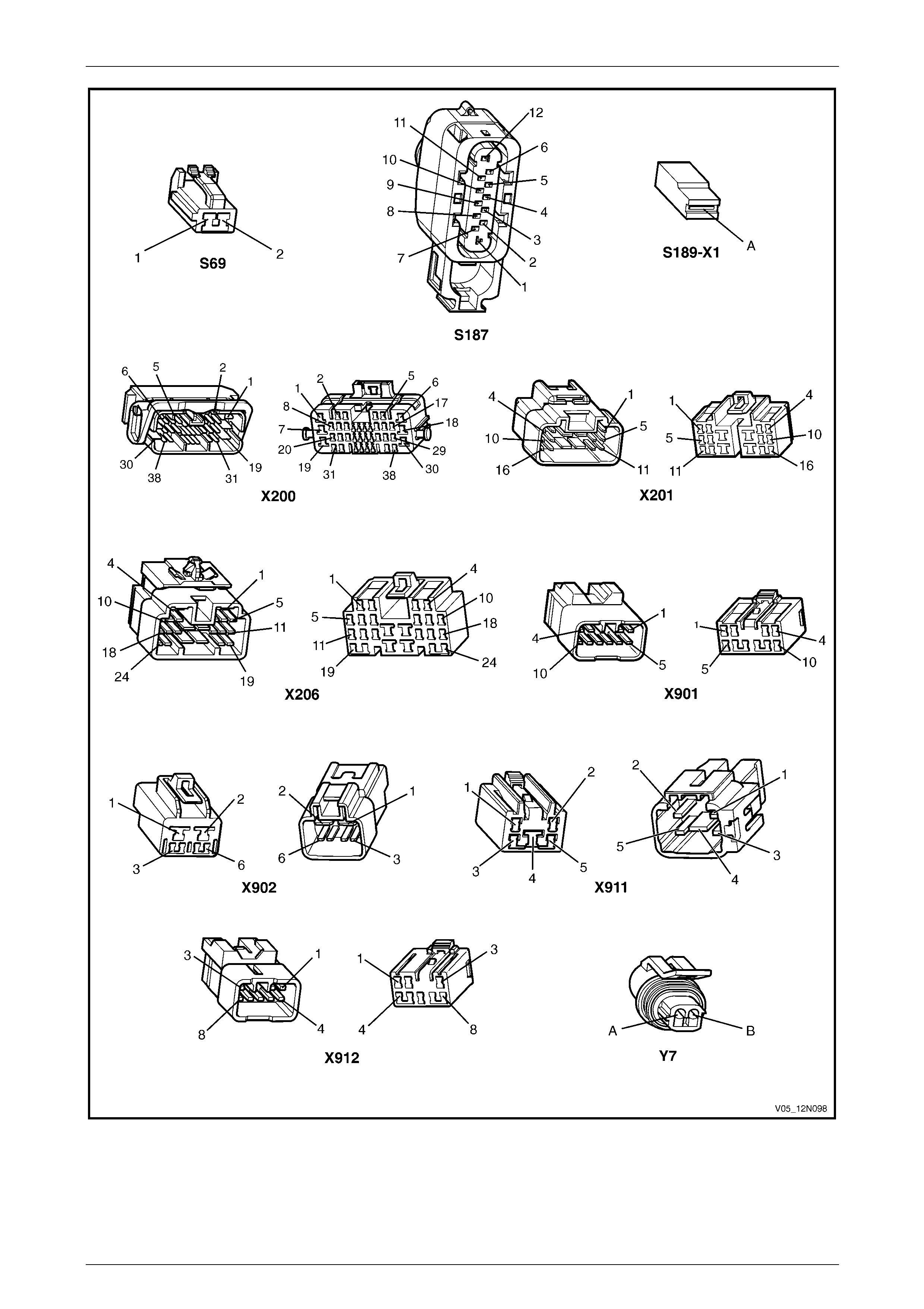
Wipers, Washers and Horn Page 12N–43
Page 12N–43
Figure 12N – 17
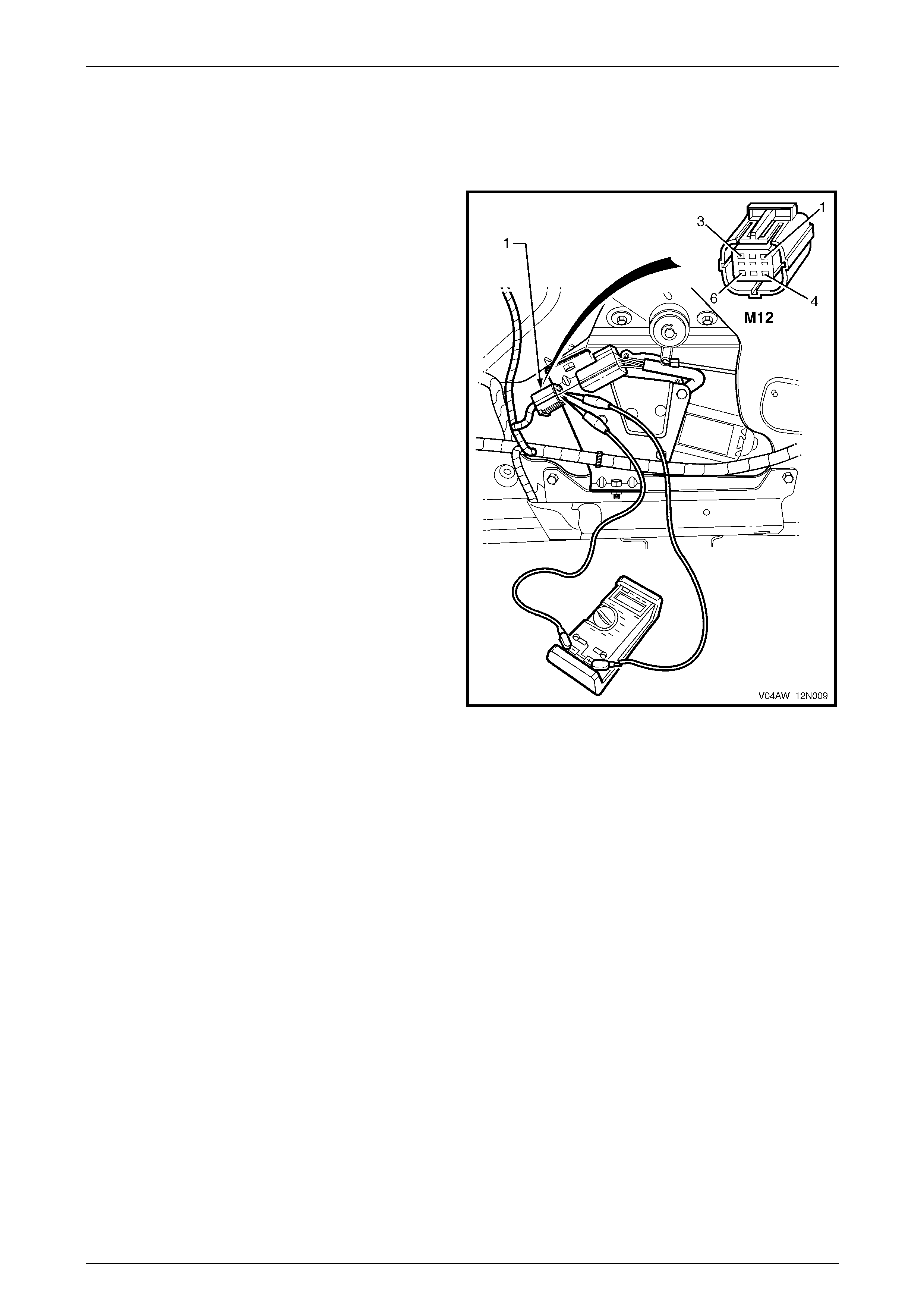
Wipers, Washers and Horn Page 12N–44
Page 12N–44
6.5 Diagnose Rear Wiper Motor Wiring
System Malfunction
Introduction
The following operation checks the rear wiper motor
assembly wiring at the connector M12 – X1 (1) and at the
control module connector A122 – X1, as an a id to
diagnosing a fault in the wiper motor assembly system. This
test confirms the serviceability of the rear wiper motor
assembly wiring system.
For a complete wiring diagram of the wiper motor assemb ly
circuits, refer to 6.2 Wiring Diagram – Rear Wiper/Washer
and 6.3 Wiring Diagram – Rear Wiper Control Module.
For connector pin location,
refer to 6.4 Connector Diagrams – Rear Wiper/W asher.
Figure 12N – 18
Electrical Test Description
The following numbers refer to the step numbers in the diagnostic table:
1 Checks if the rear wiper and washer prelimi nary test has been performed.
2 Checks if the rear wiper operates with the liftgate window and liftgate closed.
3 Checks if there is battery voltage at connector A122 – X1 pin 1. Isolates if the battery power circuit 243 is at fault.
4 Checks if there is battery voltage at connector A122 – X1 pin 3. Isolates if the power supply circuit 391 is at fault.
5 Checks if the control module ground circuit is serviceable. Isolates if the ground circuit 650 is at fault.
6 Checks if the rear wiper motor assembly is serviceable.
7 Checks the wiring harness between connectors M12 – X1 and A122 – X1. Isolates whether circuits 393, 392, 2283,
5456 or 2269 are at fault.
8 Checks if the rear wiper operates in the continuous wipe mode with the wipers and washers switch held to rear
wash position.
9 Checks if there is battery voltage at connector A122 – X1 pin 4. Isolates whether the rear wiper control module
A122, or the power supply circuits 2270, 6721, 227, 550 or 391, or diode V5 are at fault.
10 Checks if the rear wiper operates in the continuous wipe mode with the reverse gear engaged.
11 Checks if the park neutral and back up lamp switch and associated circuits are serviceable.
12 Checks if there is battery voltage at connector A122 – X1 pin 4. Isolates whether the rear wiper control
module A122, or the power supply circuit 6721 or 24, or diode V5 is at fault.

Wipers, Washers and Horn Page 12N–45
Page 12N–45
Diagnostic Table Notes
1 To perform the rear wiper and washer preliminary test, refer to 4.1 Test Rear Wiper and Washer Assembly.
2 To remove the liftgate lower trim panel, refer to Section 1A4 Hood, Rear Compartment Lid, Liftgate and Endgate.
3 For all wiring harness fault diagnosis, refer to Section 12P Wiring Diagrams.
4 For wiring harness repairs, refer to Section 12P Wiring Diagrams.
5 To diagnose the rear wiper motor assemb ly, refer to 6.6 Diagnose Rear Wiper Motor Assembly Operation.
6 To replace the rear wiper motor assembly, refer to 11.6 Rear Wiper Motor Assembly.
7 For the replacement of the rear wiper control module, refer to 11.5 Rear Wiper Control Module.
8 To check and replace/repair the park neutral and back up lamp switch and associated circuits, refer to:
• Section 7E4 Automatic Tr ansmission – 5L40E – On-Vehicle Servicing , or
• Section 7C4 Automatic Transmission – 4L60E – On-Vehicle Servicing.
Diagnostic Table
Step Action Yes No
1 Has the rear wiper and washer prelimi nary test been performed?
Go to Step 2
Perform the
preliminary test
(refer to Note 1)
2 1 With the liftgate window and liftgate closed, switch the ignition to
the ACC or ON position.
2 Switch the wipers and washers control switch S247 to the rear
wiper ON position.
Does the rear wiper operate in the intermittent mode? Go to Step 8 Go to Step 3
3 1 Remove the liftgate lower trim panel, (refer to Note 2).
2 With the ignition in the ACC or ON position and the wipers and
washers control switch in the rear wiper ON position, backpr obe
connector A122 – X1 pin 1 with a test lamp, (refer to Note 3).
Does the test lamp illuminate? Go to Step 4
Repair or replace
circuit 243
(refer to Note 4)
4 With the ignition in the ACC or ON position and the wipers and
washers control switch in the rear wiper ON position, backpr obe
connector A122 – X1 pin 3 with a test lamp, (refer to Note 3).
Does the test lamp illuminate? Go to Step 5
Repair or replace
circuit 391
(refer to Note 4)
5 1 Disconnect connector A122 – X1 from the control module.
2 With a multimeter, check for continuity of the ground circuit 650
between connector A122 – X1 pin 2 and ground points
X118 – GP13 and X118 – GP14, (refer to Note 3).
Is the ground circuit 650 serviceable? Go to Step 6
Repair or replace
ground circuit 650
(refer to Note 4)
6 1 Disconnect connector M12 – X1 from the rear wiper motor.
2 Diagnoses the rear wiper motor assembly M12, (refer to Note 5).
Is the rear wiper motor assembly serviceable? Go to Step 7
Replace the rear
wiper motor
assembly
(refer to Note 6)

Wipers, Washers and Horn Page 12N–46
Page 12N–46
Step Action Yes No
7 With a multimeter, check for serviceability of the wiring harness
between connectors M12 – X1 and A122 – X1, (refer to Note 3).
Is the wiring harness serviceable a nd is there continuity between the
connectors as follows:
• M12 – X1 pin 1 and A122 – X1 pin 5
• M12 – X1 pin 2 and A122 – X1 pin 6
• M12 – X1 pin 3 and A122 – X1 pin 9
• M12 – X1 pin 4 and A122 – X1 pin 8
• M12 – X1 pin 5 and A122 – X1 pin 7.
Replace the rear
wiper control
module
(refer to Note 7)
Repair or replace
circuits 393, 392,
2283, 5456 or 2269
(refer to Note 4)
8 With the ignition in the ACC or ON position, push forward and hold the
wipers and washers control switch in the rear washer position.
Does the rear wiper operate in the continuous wipe mode? Go to Step 10 Go to Step 9
9 1 If required, remove the liftgate lower trim panel, (refer to Note 2).
2 With the ignition in the ACC or ON position and the wipers and
washers control switch in the rear washer position, backprobe
connector A122 – X1 pin 4 with a test lamp, (refer to Note 3).
Does the test lamp illuminate?
Replace the rear
wiper control
module
(refer to Note 7)
Repair or replace
circuits 2270,6721,
227, 550 or 391, or
diode V5
(refer to Note 4)
10 1 With the ignition in the ACC position, switch the wipers and
washers control switch to the rear wiper ON position.
2 Engage the reverse gear.
Does the rear wiper operate in the continuous wipe mode? System serviceable Go to Step 11
11 Check the park neutral and back up lamp switch and associated
circuits, (refer to Note 8).
Is the park neutral and back up lamp switch and associated circuits
serviceable? Go to Step 12
Replace or repair
the park neutral and
back up lamp switch
and associated
circuits
(refer to Note 8)
12 1 If required, remove the liftgate lower trim panel, (refer to Note 2).
2 With the ignition in the ACC position, the wipers and washers
control switch in the rear wiper ON position and the reverse gear
engaged, backprobe connector A122 – X1 pin 4 with a test lamp,
(refer to Note 3).
Does the test lamp illuminate?
Replace the rear
wiper control
module
(refer to Note 7)
Repair or replace
circuits 6721, 24, or
diode V5
(refer to Note 3)
When all diagno sis an d repairs are completed, check the system for correct operati on.
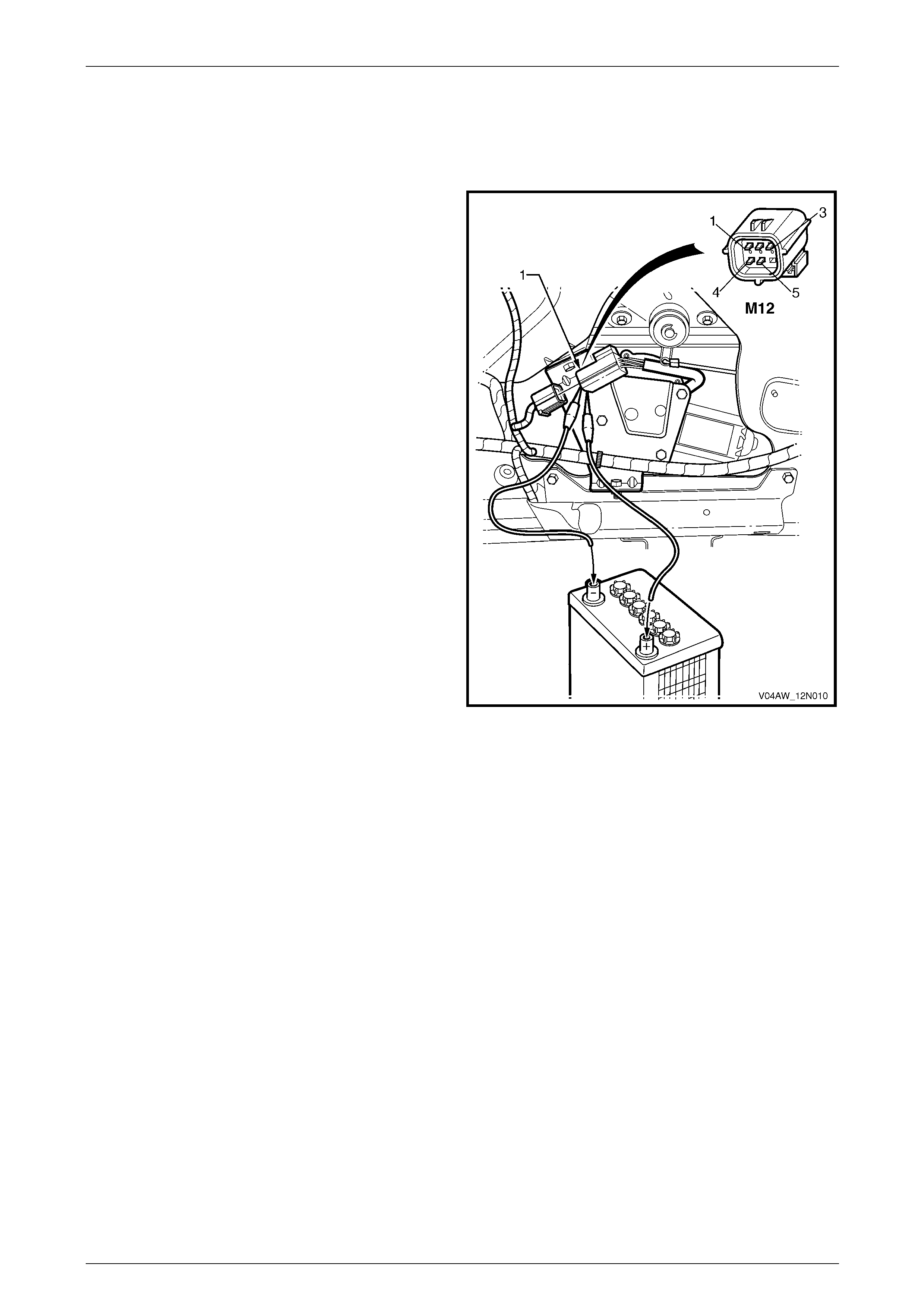
Wipers, Washers and Horn Page 12N–47
Page 12N–47
6.6 Diagnose Rear Wiper Motor Assembly
Operation
Introduction
This test checks the operation of the rear wiper motor
assembly at the motor connector M12 – X1 (1) and confirm s
the serviceability of the rear wiper motor assembl y.
The test diagnoses four functions:
• the wiper forward drive,
• the wiper reverse drive,
• the reverse park limit switch operation, and
• the forward park limit switch operation.
For a diagram of the rear wiper motor assembly, refer to
6.2 Wiring Diagram – Rear Wiper/Wash er.
For pin numbering within the motor connector M12 – X1 (1)
refer to Figure 12N – 19.
NOTE
If there is a fault in the rear wiper system, and
the following test proves the rear wiper motor
assembly is serviceable, refer to
6.5 Diagnose Rear Wiper Motor W iring System.
When performing the following test lift the rear wiper arm
away from the liftgate window and keep it attached to the
motor spigot. While the motor is operating, monitor the
movement of the rear wiper arm as a guide for the park
positions.
Using a digital multimeter, monitor the rea di ngs to determine
if the motor park limit switches are closing when required.
For a description of the rear wiper park positions and
operation, refer to 1.3 Rear Wiper Assembl y, AWD Wagon.
Figure 12N – 19
Electrical Test Description
The following numbers refer to the step numbers in the diagnostic table:
1 Checks the rear wiper motor assembly forward operation. Isolates if the circuit within the rear wiper motor assembly
is serviceable bet ween motor connector M12 – X1 pins 1 and 2.
2 Checks the rear wiper motor assembly reverse operation. Isolates if the circuit within the rear wiper motor assembly
is serviceable bet ween motor connector M12 – X1 pins 2 and 1.
3 Checks the rear wiper motor assembly reverse park limit switch operation. Isolates if the circuit within the rear wiper
motor assembly is serviceable between motor connector M12 – X1 pins 3 and 5.
4 Checks the rear wiper motor assembly forward park limit switch operation. Isolates if the circuit within the rear wiper
motor assembly is serviceable between motor connector M12 – X1 pins 4 and 5.
Diagnostic Table Notes
1 Refer to Section 12O Fuses, Relays and Wiring Harnesses for harness routeing.
2 To remove the liftgate window lower garnish and the liftgate lower trim panel,
refer to Section 1A4 Hood, Rear Compartment Lid, Liftgate and Endgate.
3 For replacement of the rear wiper motor assembly, refer to 11.6 Rear Wiper Motor Assembly.

Wipers, Washers and Horn Page 12N–48
Page 12N–48
Diagnostic Table
Step Action Yes No
1 1 Remove the rear wiper fuse F18 from the passenger
compartment fuse and relay panel assembly, (refer to Note 1).
2 Remove the liftgate windo w lower garnish and the liftgate lower
trim panel, (refer to Note 2).
3 Disconnect the rear wiper motor connector M12 – X1.
4 Connect a fused jumper lead from the vehicle battery negative
terminal to the motor connector M12 – X1 pin 2, (refer to
Note 1).
5 Connect a fused jumper lead from the vehicle battery positive
terminal to the motor connector M12 – X1 pin 1, (refer to
Note 1).
Does the rear wiper motor operate in the forward direction? Go to Step 2
Replace the rear
wiper motor
assembly
(refer to Note 3)
2 1 Connect a fused jumper lead from the vehicle battery negative
terminal to the motor connector M12 – X1 pin 1, (refer to
Note 1).
2 Connect a fused jumper lead from the vehicle battery positive
terminal to the motor connector M12 – X1 pin 2, (refer to
Note 1).
Does the wiper motor operate in the revers e direction? Go to Step 3
Replace the rear
wiper motor
assembly
(refer to Note 3)
3 1 Connect a fused jumper lead from the vehicle battery negative
terminal to the motor connector M12 – X1 pin 2, (refer to
Note 1).
2 Connect a fused jumper lead from the vehicle battery positive
terminal to the motor connector M12 – X1 pin 1, (refer to
Note 1).
3 With the rear wiper motor operating in the for ward d irection,
using a multimeter probe bet wee n motor connector M12 – X1
pins 3 and 5, (refer to Note 1).
Does the multimeter indicate continuity when the motor reverse park
limit switch closes? (at rear wiper arm full wipe sweep position). Go to Step 4
Replace the rear
wiper motor
assembly
(refer to Note 3)
4 With the rear wiper motor operating in the forward direction, using a
multimeter probe bet ween motor connector M12 – X1 pins 4 and 5,
(refer to Note 1).
Does the multimeter indicate continuity when the motor forward park
limit switch closes? (at rear wiper arm wipe sweep start).
NOTE
After this test has been completed, operate the rear wiper
for a wipe cycle and s witch the wipers a nd washers control
switch to the OFF position for the rear wiper arm to park in
the offscreen park position. The rear wiper
motor assembly is
serviceable
Replace the rear
wiper motor
assembly
(refer to Note 3)
When all diagno sis an d repairs are completed, check the system for correct operati on.

Wipers, Washers and Horn Page 12N–49
Page 12N–49
Wiper Motor Limit Switches Malfunction Table
The following table provides a guide as to how the rear wiper arm will behave if the rear wiper motor park limit switches
contacts malfunction.
Switch Position Rear Wiper Motor Park Limit Switch Fail Rear Wiper and Motor Action
Rear wiper switch
from OFF to ON Forward park limit switch
or
Reverse park limit switch
or
Forward and reverse park limit switches
The rear wiper arm may have an initial 9 second
delay in the on-screen park position after the first
cycle.
Then the rear wiper motor and rear wiper arm
operate continuously.
Rear wiper switch
from ON to OFF Forward park limit switch
or
Reverse park limit switch
or
Forward and reverse park limit switches
The rear wiper motor and rear wiper arm will
continue to operate continuously.
After 12 seconds have elapsed, the rear wiper
control module cuts off power supply to the rear
wiper motor and the rear wiper arm stops anywher e
on the liftgate window.
Rear washer switch
from OFF to ON Forward park limit switch
or
Reverse park limit switch
The rear wiper motor and rear wiper arm operate
continuously.
Rear washer switch
from OFF to ON Forward and reverse park limit switches The rear wiper arm may have an initial 9 second
delay in the on-screen park position after the first
cycle.
Then the rear wiper motor and rear wiper arm
operate continuously.
Rear washer switch
from ON to OFF Forward park limit switch
or
Reverse park limit switch
or
Forward and reverse park limit switches
The rear wiper motor and rear wiper arm continue to
operate continuously.
After 12 seconds have elapsed, the rear wiper
control module cuts off power supply to the rear
wiper motor and the rear wiper arm stops anywher e
on the liftgate window.

Wipers, Washers and Horn Page 12N–50
Page 12N–50
6.7 Diagnose Rear Wiper and Liftgate
Interface Operation
Introduction
The following diagnosis checks the rear wiper motor assembly operation combined with the state (open or close) of the
liftgate window and liftgate assembly. The rear wiper control module controls this operation by receiving an inp ut signal
from the liftgate window switch S69 when the liftgate window is open and from the liftgate switch S189 when the liftgate
is open and energises the liftgate window actuator Y7 to open the liftgate window when the rear wiper arm is in the
offscreen park position. For a description of the liftgate asse mbly and its components,
refer to Section 1A4 Hood, Rear Compartment Lid, Liftgate and Endgate.
This test confirms the serviceability of the wiring system between the rear wiper control module A122 and the liftgate
assembly.
For a complete wiring diagram of the rear wiper control mod ule circuits,
refer to 6.3 Wiring Diagram – Rear Wiper Control Module.
For connector pin location, refer to 6.4 Connector Diagrams – Rear Wiper/Washer.
Electrical Test Description
The following numbers refer to the step numbers in the diagnostic table:
1 Checks if the liftgate window opens with the wipers and washers control switch S247 in the OFF position.
2 Checks if the liftgate window actuator Y7 is serviceable.
3 Checks the liftgate window actuator harness between connectors A122 – X1 pin 12 and Y7 – X1 pi n A. Isolates if
circuit 6188 is at fault.
4 Checks the liftgate window actuator harness between connectors Y7 – X1 pin B and ground. Isolates if circuit 650
is at fault.
5 Checks if the rear wiper motor operates with the liftgate window open and the liftgate closed.
6 Checks if the liftgate window switch S69 is serviceable.
7 Checks the liftgate window switch harness between connectors A122 – X1 pin 10 an d S69 – X1 pin 1. Isolates if
the circuits 737 or 744 are at fault.
8 Checks the liftgate window switch harness between connector S69 – X1 pin 2 and ground. Isolates if the circuit 650
is at fault.
9 Checks if the rear wiper motor operates with the liftgate window closed and the liftgate open.
10 Checks if the liftgate switch S189 is serviceable.
11 Checks the liftgate switch harness between connectors A122 – X1 pin 10 and S189 – X1 pin A. Isolates if the
circuit 737 is at fault.
Diagnostic Table Notes
1 For all wiring harness fault diagnosis, refer to Section 12P Wiring Diagrams.
2 For wiring harness repairs, refer to Section 12P Wiring Diagrams.
3 Refer to Section 12O Fuses, Relays and Wiring Harnesses for harness routeing.
4 If at any time the fault is deemed to be intermittent, refer to Section 12P Wiring Diagra m s.
5 For the replacement of the rear wiper control module, refer to 11.5 Rear Wiper Control Module.
6 Refer to Section 1A4 Hood, Rear Compartment Lid, Liftgate and Endgate for liftgate compon ents.

Wipers, Washers and Horn Page 12N–51
Page 12N–51
Diagnostic Table
Step Action Yes No
1 With the liftgate window and liftgate closed, switch the ignition to the
ACC or ON position and the wipers and washers control switch to the
rear wiper OFF position.
Does the liftgate windo w open when activated? Go to Step 5 Go to Step 2
2 1 Remove the liftgate lower trim panel, (refer to Note 6).
2 Check the liftgate window actuator Y7, (refer to Note 6).
Is the liftgate window actuator Y7 serviceable? Go to Step 3
Replace the liftgate
window actuator Y7
(refer to Note 6)
3 With a multimeter, check the liftgate window actuator harness for
continuity between connectors A122 – X1 pin 12 and Y7 – X1 pin A,
(refer to Note 1).
Does the multimeter indicate continuity? Go to Step 4
Repair or replace
circuit 6188 (refer to
Note 2)
4 With a multimeter, check the liftgate window actuator ground circuit for
continuity between connector Y7 – X1 pin B and ground point
X118_GP12 (refer to Note 1).
Does the multimeter indicate contin uity?
Replace the rear
wiper control
module (refer to
Note 5)
Repair or replace
ground circuit 650
(refer to Note 2)
5 1 Lift the rear wiper arm away from the rear wiper ramp and the
liftgate window.
2 With the liftgate window open and the liftgate closed, s witch the
ignition to the ACC or ON position and the wipers and washers
control switch to the rear wiper ON position.
Does the rear wiper operate? Go to Step 6 Go to Step 9
6 1 Remove the liftgate lower trim panel, (refer to Note 6).
2 Check the liftgate window switch S69, (refer to Note 6).
Is the liftgate window switch S69 serviceable? Go to Step 7
Replace the liftgate
window switch S69
(refer to Note 6)
7 With a multimeter, check the liftgate windo w switch S69 har ness for
continuity between connectors A122 – X1 pin 10 and S69 – X1 pin 1
(refer to Note 1).
Does the multimeter indicate continuity? Go to Step 8
Repair or replace
circuits 737 or 744
(refer to Note 2)
8 With a multimeter, check the liftgate window switch S69 ground circuit
for continuity between connector S69 – X1 pin 2 and ground point
X118_GP12 (refer to Note 1).
Does the multimeter indicate contin uity?
Replace the rear
wiper control
module (refer to
Note 5)
Repair or replace
ground circuit 650
(refer to Note 2)
9 With the liftgate window closed and the liftgate open, switch the
ignition to the ACC or ON position and the wipers and washers control
switch to the rear wiper ON position .
Does the rear wiper operate? Go to Step 10 System service able
10 Check the liftgate switch S189, (refer to Note 6).
Is the liftgate window switch S189 serviceable? Go to Step 11
Replace the liftgate
switch S189 (refer to
Note 6)
11 1 Remove the liftgate lower trim panel, (refer to Note 6).
2 With a multimeter, check the liftgate switch S189 harness for
continuity between connectors A122 – X1 pin 10 and S189 – X1
pin A (refer to Note 1).
Does the multimeter indicate contin uity?
Replace the rear
wiper control
module (refer to
Note 5)
Repair or replace
circuits 737 (refer to
Note 2)
When all diagno sis an d repairs are completed, check the system for correct operati on.

Wipers, Washers and Horn Page 12N–52
Page 12N–52
6.8 Diagnose Washer Pump and Rear
Washer Wiring System Malfunction
Introduction
This test confirms the serviceability of the washer pump assembly, the wipers and washers control switch and the
associated wiring system for the rear washer.
For a complete wiring diagram of the washer pump a nd rear washer circuits,
refer to 6.2 Wiring Diagram – Rear Wiper/W asher.
For connector pin location, refer to 6.4 Connector Diagrams – Rear Wiper/Washer.
Test Description
The following numbers refer to the step numbers in the diagnostic table:
1 Checks if the rear wiper and washer prelimi nary test has been performed.
2 Checks if battery voltage is supplied to the washer pump assembly.
3 Checks if the rear washer hose or nozzle assembly are blocked. Isolates whether the rear washer hose, nozzle
assembly or washer pump assembly are at fault.
4 Checks if battery voltage is supplied to connector M19 – X1 pin 1. Isolates whether the battery supply circuits 227,
6721 or 391 or the ground circuits 228 or 1 51 are faulty.
Diagnostic Table Notes
1 To perform the rear wiper and washer preliminary test, refer to 4.1 Test Rear Wiper and Washer Assembly.
2 For all wiring harness fault diagnosis, refer to Section 12P Wiring Diagrams.
3 For the replacement of the rear washer hose, rear washer nozzle assembly and washer pump assembly, refer to
14 Service Operations – Washer Assemblies, AWD Wagon.
4 For wiring harness repairs, refer to Section 12P Wiring Diagrams.
Diagnostic Table
Step Action Yes No
1 Has the rear wiper and washer prelimi nary test been performed?
Go to Step 2
Perform the
preliminary test
(refer to Note 1)
2 1 If required, hoist the vehicle, refer to Section 0A General
Information.
2 From beneath the vehicle, disconnect conn ector M19 – X1 from
the washer pump.
3 With a multimeter, probe with the positive le ad to connector
M19 – X1 pin 1 and the negati v e lead to pin 2, (refer to Note 2).
4 Switch the ignition to the ACC or ON position.
5 Push forward and hold the wipers and washers control switch on
rear wash position.
Does the multimeter indicate battery voltage? Go to Step 3 Go to Step 4
3 Is there a blockage in either the rear washer hose or nozzle assembly? Repair / replace the
rear washer hose or
nozzle assembly
(refer to Note 3)
Replace the washer
pump assembly
(refer to Note 3)
4 1 Probe connector M19 – X1 pin 1 with the positive lead of a
multimeter and the negative lead to a ground point, (refer to
Note 2).
2 Switch the ignition to the ACC or ON position.
3 Push forward and hold the wipers and washers control switch on
rear wash position.
Does the multimeter indicate battery voltage?
Repair or replace
circuit 228 or 151
(refer to Note 3)
for further diagnosis
refer to Section 12J
Body Control
Module
Repair or replace
circuit 227, 6721 or
391 (refer to Note 3)
for further diagnosis
refer to Section 12J
Body Control
Module
When all diagno sis an d repairs are completed, check the system for correct operati on.

Wipers, Washers and Horn Page 12N–53
Page 12N–53
7 Diagnostics – Horn
7.1 Prerequisites
Equipment
A digital multimeter with a minimum impe dance of 10 MΩ is required to diagnose the horn assembly.
Testing Procedures
Adhere to the following points when
performing diagnostic testing on
components:
• Take care when using testing equipment
to diagnose wiring harness connectors.
Backprobe the connector to avoid terminal
damage.
• When tests are required on connector
terminals, use the adapters in the
connector adapter kit KM–609 to prevent
damage to the terminals.
• Unless the multimeter being used has an
auto-ranging function, ensure the correct
range is selected.
• When backpro bing connectors, ensure the
test lamp ground lead is connected to an
appropriate ground point on the vehicle.
Ensure this ground point is not part of the
circuit being tested.
NOTE
When following the steps in the di agnostic tables,
perform them in the order cited. If the required
nominal value or result is not achi eved, rectif y t he
problem before proceeding.
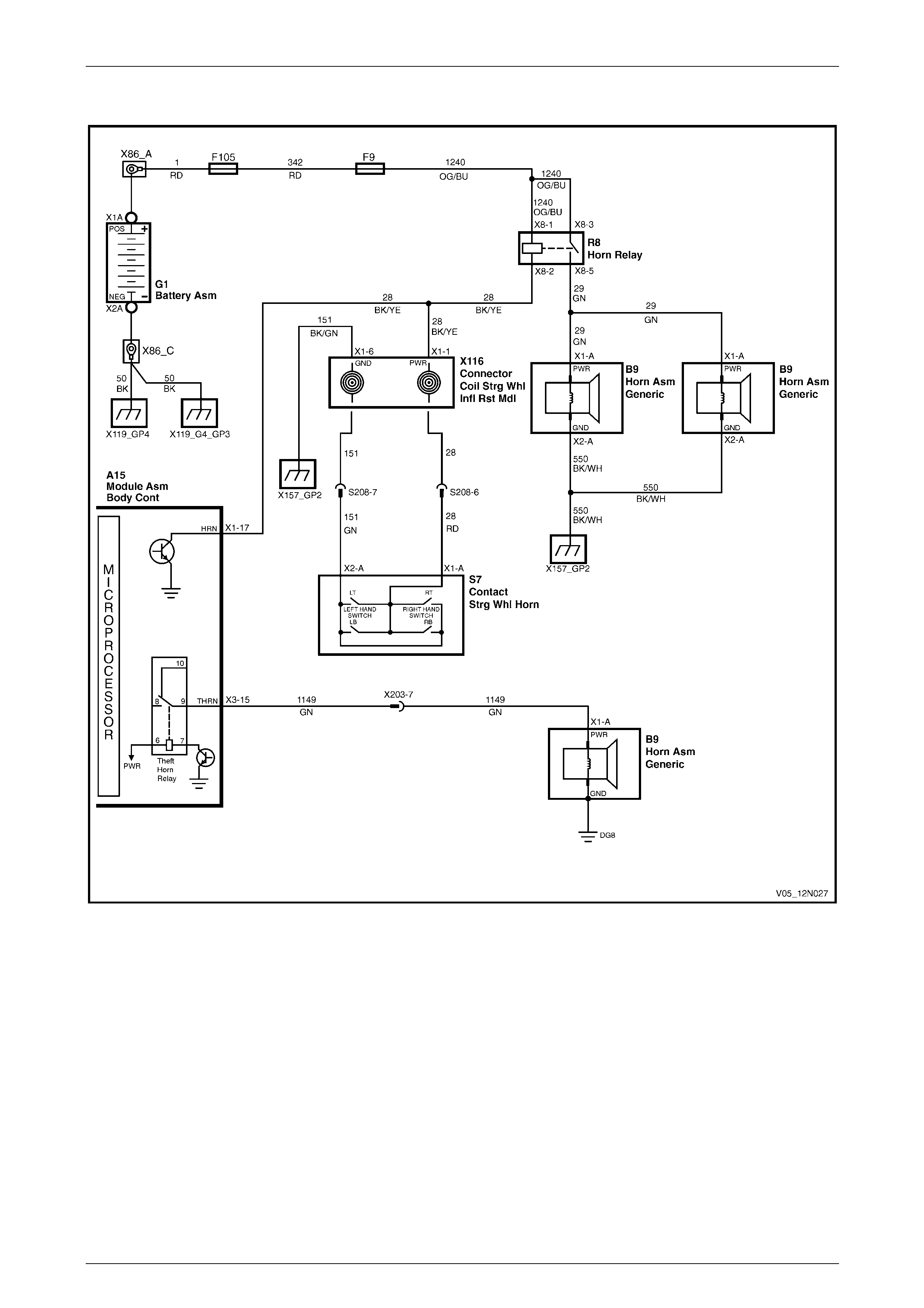
Wipers, Washers and Horn Page 12N–54
Page 12N–54
7.2 Wiring Diagram – Horn Assembly
Figure 12N – 20
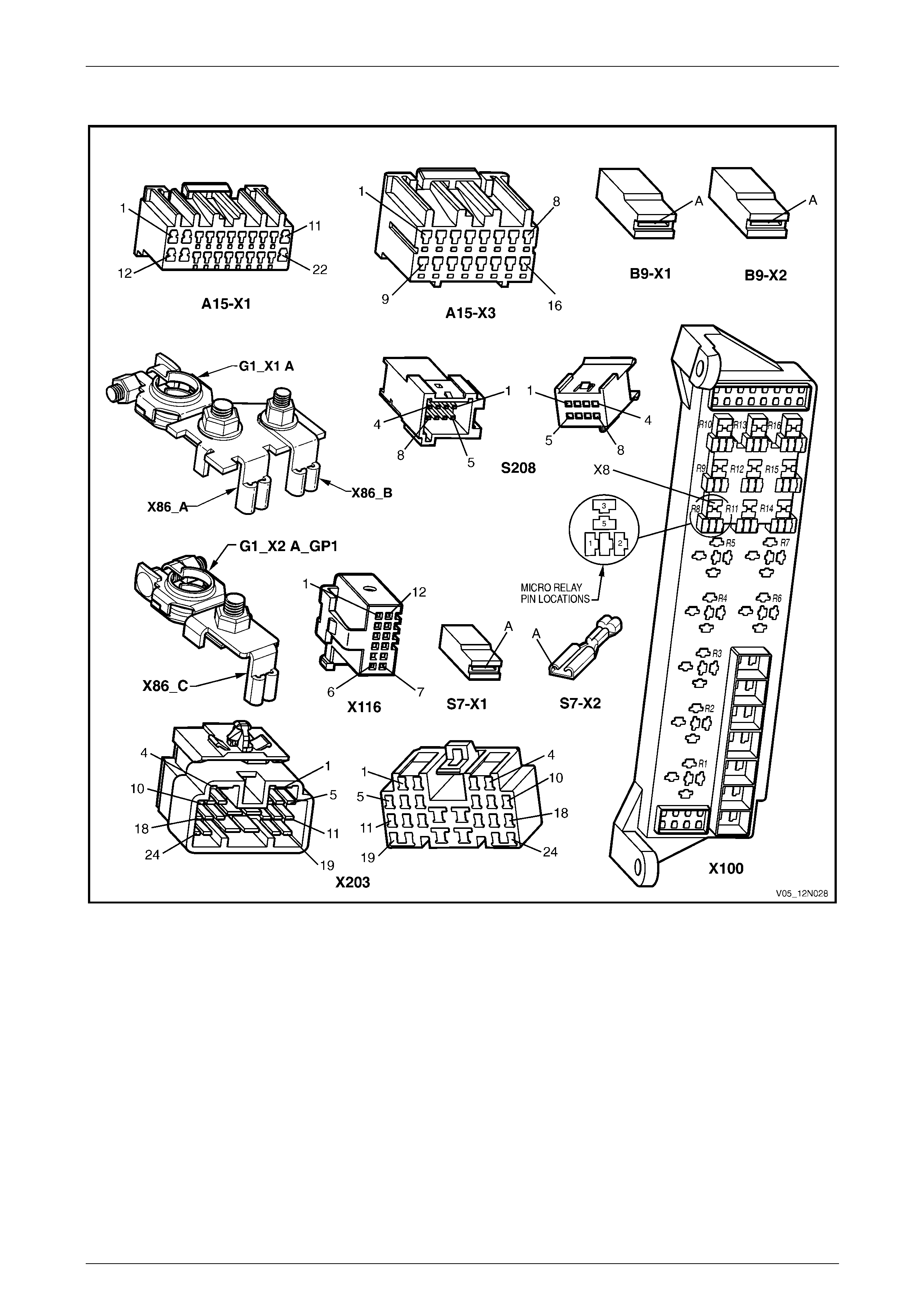
Wipers, Washers and Horn Page 12N–55
Page 12N–55
7.3 Connector Diagrams – Horn Assembly
Figure 12N – 21

Wipers, Washers and Horn Page 12N–56
Page 12N–56
7.4 Diagnose Horn and Wiring System
Malfunction
Introduction
This test checks the operation of the horn assembly at connectors B9 – X1 and B9 – X2 and confirms the serviceabilit y of
the horn assembly, steering wheel coil, steering wheel horn contact and associated circuits.
There are four ranges in voltage affecting the horn assembly operation:
• 0 Volt,
• below 9 Volt,
• between 9 and 11 Volt, or
• above 11 Volt.
For a complete wiring diagram of the horn circuits refer to 7.2 Wiring Diagram – Horn Assembly.
For connector pin location, refer to 7.3 Connector Diagrams – Horn Assembly.
Electrical Test Description
The following numbers refer to the step numbers in the diagnostic table:
1 Checks if the horn fuse F9 within the passenger compartment fuse and relay panel assembly is serviceable.
2 Checks if the horn relay within the engine compartment fuse and relay panel assembly is serviceable.
3 Checks the voltage supplied to the horn assembly as follows:
• checks if there is no voltage reading on the multimeter,
• checks if there is a low voltage reading on the multimeter above 0 V to less than 9 V,
• checks if the system operates correctly, with a normal voltage reading on the multimeter of 9 – 11 V, and
• checks if there is a high voltage reading on the multimeter above 11 V, caused by a faulty horn assembly.
4 Checks if there is battery voltage through connectors B9 – X1 and X2. Isolates if the horn assembly is at fault.
5 Checks if the horn assembly ground circuit 550 is serviceable.
6 Checks the circuit continuity between connector X116 – X1 pins 1 and 6 on the connector coil steering wheel
inflatable restraint module.
7 Checks the circuit continuity between harness connector S208 pins 6 and 7 on the steeri ng wheel inflatable
restraint module. Isolates if the connector coil steering wheel inflatable restraint module is at fault.
8 Checks the circuit continuity between harness connectors S208 pin 6 and S7 – X1 pin A, then between connectors
S208 pin 7 and S7 – X2 pin A.
9 Checks the circuit continuity between connector X116 – X1 pin 1 and harness connector S208 pin 6 on the
connector coil steering wheel inflatable restraint module , then bet ween conn ectors X116 – X1 pin 6 and S208
pin 7. Isolates whether the steering wheel horn contact S7 within the steering wheel inflatable restraint module
or/and the connector coil steering wheel inflatable restraint module is/are at fault.
10 Checks if there is battery voltage through connector X116 – X1 pins 1 and 6. Isolates whether there is a fault in
circuit 1240, 28 or 151 or in circuit 1240 or 29 .
11 Checks if battery voltage is delivered to connector B9 – X1. Isolates if the horn assembly is at fault, or if there is a
fault in ground circuit 550 or in po wer supply circuit 1240 or 29.

Wipers, Washers and Horn Page 12N–57
Page 12N–57
Diagnostic Table Notes
1 Refer to Section 12O Fuses, Relays and Wiring Harnesses for harness routeing.
2 For all wiring harness fault diagnosis, refer to Section 12P Wiring Diagrams.
3 If there is a fault in the horn assembly system and the following test proves the system is serviceable, for further
diagnosis refer to Section 12J Body Control Module.
4 For replacement of the horn assembly, refer to 17.1 Horn Assembly.
5 For wiring harness repairs, refer to Section 12P Wiring Diagrams.
6 For removal of the steering column covers, refer to Section 9 Steering.
7 For removal / replacement of the steering wheel inflatable restraint module,
refer to Section 12M Occupant Protection System.
8 If at any time the fault is deemed to be intermittent, refer to Section 12P Wiring Diagra m s.
Diagnostic Table
Step Action Yes No
1 Check the horn fuse F9 within the passenger compartment fuse and
relay panel assembly, (refer to Note 1).
Is the fuse serviceable?
Go to Step 2
Replace the fuse,
if the fuse blows
again check for a
short to ground in
circuit 1240
(refer to Note 1)
2 Check the horn relay within the engine comp artment fuse and relay
panel assembly, (refer to Note 1).
Is the relay serviceable? Go to Step 3 Replace the relay
(refer to Note 1)
1 If required, hoist the vehicle, refer to Section 0A General
Information.
2 From beneath the vehicle, reac h up between the bumper bar and
the front end panel assembly. With a multimeter, backprobe with
the positive lead to connector B9 – X1 pin A, and with the
negative lead to connector B9 – X2 pin A, (refer to Note 2).
3 Press the steering wheel hor n contact to activate the horn
assembly.
Does the multimeter indicate voltage as follows:
• 0 V
Go to Step 4
• above 0 V to less than 9 V
Go to Step 11
• 9 – 11 V
System serviceable
(refer to Note 3)
3
• above 11 V Replace the horn
assembly
(refer to Note 4)
4 1 Disconnect connectors B9 – X1 and X2 from the horn.
2 With a multimeter, probe with the positive le ad to connector
B9 – X1 pin A and with the negative lea d to conn ector B9 – X2
pin A, (refer to Note 2).
3 Press the steering wheel hor n contact to activate the horn
assembly.
Does the multimeter indicate battery voltage?
Replace the horn
assembly
(refer to Note 4) Go to Step 5

Wipers, Washers and Horn Page 12N–58
Page 12N–58
Step Action Yes No
5 With a multimeter, check for continuity of the ground circuit 550
between connector B9 – X2 pi n A and ground point X157_ G P2, (refer
to Note 2).
Does the multimeter indicate continuity? Go to Step 6
Repair or replace
ground circuit 550
(refer to Note 5)
6 1 Remove the steering column covers (refer to Note 6).
2 Disconnect connector X116 – X1 from the rear of the connector
coil steering wheel inflat able restraint module.
3 Probe between connector X11 6 – X1 pins 1 and 6 on the
connector coil steering wheel inflatable restraint module, (refer to
Note 2).
4 Press the steering wheel hor n contact to activate the horn
assembly.
Does the multimeter indicate contin uity? Go to Step 10 Go to Step 7
7 1 Remove the steering wheel inflatable restraint module (refer to
Note 7).
2 Disconnect the harness connector S208.
3 Probe between steering wheel inflatable restraint module
harness connector S208 pins 6 and 7, (refer to Note 2).
4 Press the steering wheel hor n contact to activate the horn
assembly.
Does the multimeter indicate contin uity?
Replace the
connector coil
steering wheel
inflatable restraint
module
(refer to Note 7) Go to Step 8
8 1 Probe between harness connector S208 pin 6 and connector
S7 – X1 pin A on the steering wheel inflat able restraint module,
(refer to Note 2).
2 Probe between harness connector S208 pin 7 and connector
S7 – X2 pin A on the steering wheel inflat able restraint module,
(refer to Note 2).
Does the multimeter indicate continuity in each step? Go to Step 9
Repair or replace
circuit 28 or 151
(refer to Note 5)
9 1 Probe between connector X11 6 – X1 pin 1 and harness
connector S208 pin 6 on the connector coil steering wheel
inflatable restraint module, (refer to Note 2).
2 Probe between connector X11 6 – X1 pin 6 and harness
connector S208 pin 7 on the connector coil steering wheel
inflatable restraint module, (refer to Note 2).
Does the multimeter indicate continuity in each step?
Replace the steering
wheel inflatable
restraint module
(refer to Note 7)
Replace the steering
wheel inflatable
restraint module and
the connector coil
steering wheel
inflatable restraint
module
(refer to Note 7)
10 With a multimeter, probe with the positive lead to connector X116 – X1
pin 1 and with the negative lead to connector X116 – X1 pin 6, (refer to
Note 2).
Does the multimeter indicate battery voltage?
Repair or replace
circuit 1240 or 29
(refer to Note 5)
Repair or replace
circuit 1240, 28 or
151
(refer to Note 5)
11 1 Disconnect connector B9 – X1 from the horn.
2 With a multimeter, probe connector B9 – X1 pin A with the
positive lead and with the negative le ad to body ground, (refer to
Note 2).
3 Press the steering wheel hor n contact to activate the horn
assembly.
Does the multimeter indicate battery voltage?
Replace the horn
assembly
(refer to Note 4),
if the new horn does
not operate, repair
or replace circuit
550
(refer to Note 5)
Repair or replace
circuit 1240 or 29
(refer to Note 5)
When all diagno sis an d repairs are completed, check the system for correct operati on.
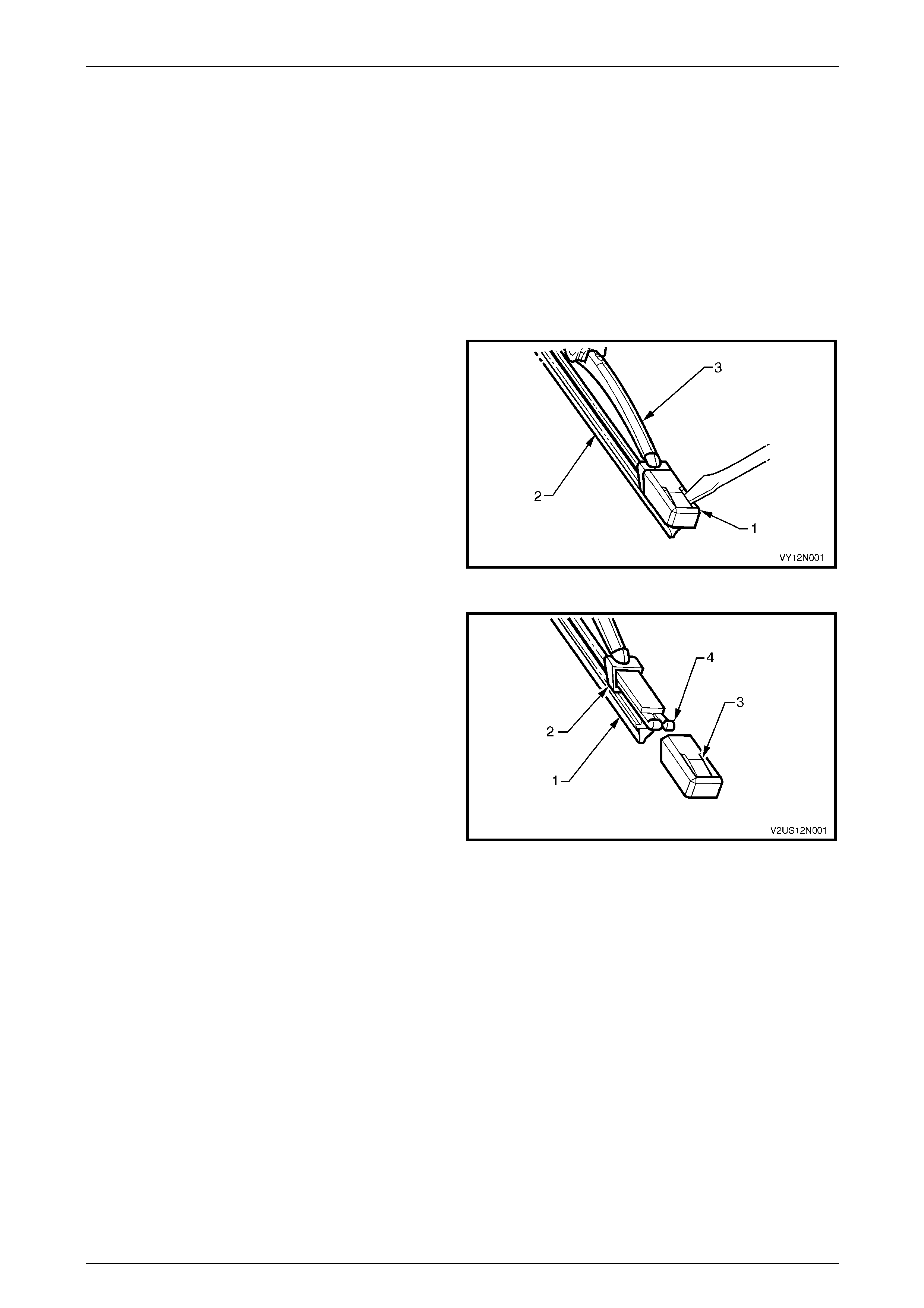
Wipers, Washers and Horn Page 12N–59
Page 12N–59
8 Service Operations – Front
Wiper Assemblies, Except
Coupe
8.1 Front Wiper Blade Insert
LT Section — 10–505
Replace
1 Using a small scre wdriver, lift the retention l ug and
slide the end cap (1) off the front wiper insert (2), on
both ends of the front wiper blade (3).
NOTE
Do not re-use the end cap. The replacement
insert will be supplied with end caps fitted.
2 Slide the insert out of the front wiper blade and
discard.
Figure 12N – 22
3 Remove the end caps from the insert (1) and slide the
insert into the front wiper blade ensur ing the insert
passes through each metal claw (2).
4 Assemble the new end cap onto the ends of the insert,
ensuring the retention lug (3) on the end cap is located
securely behind the two upturned ends of the metal
rails (4).
Figure 12N – 23

Wipers, Washers and Horn Page 12N–60
Page 12N–60
8.2 Front Wiper Blade Assembly
LT Section — 10–505
Remove
1 With the engine hood lo wered, lift the front wiper arm
assembly (2) from the glass.
2 Remove the front wiper blade assembly (1) from the
arm by lifting up the retainer (3) on the front wiper
blade assembly and pulli ng the blade assembly out of
the arm.
Figure 12N – 24
Reinstall
1 Slide the front wiper blade assembl y i nto the front wiper arm until the front wiper blade retainer locks into position.
2 Lower the front wiper arm assembly onto the windshield.
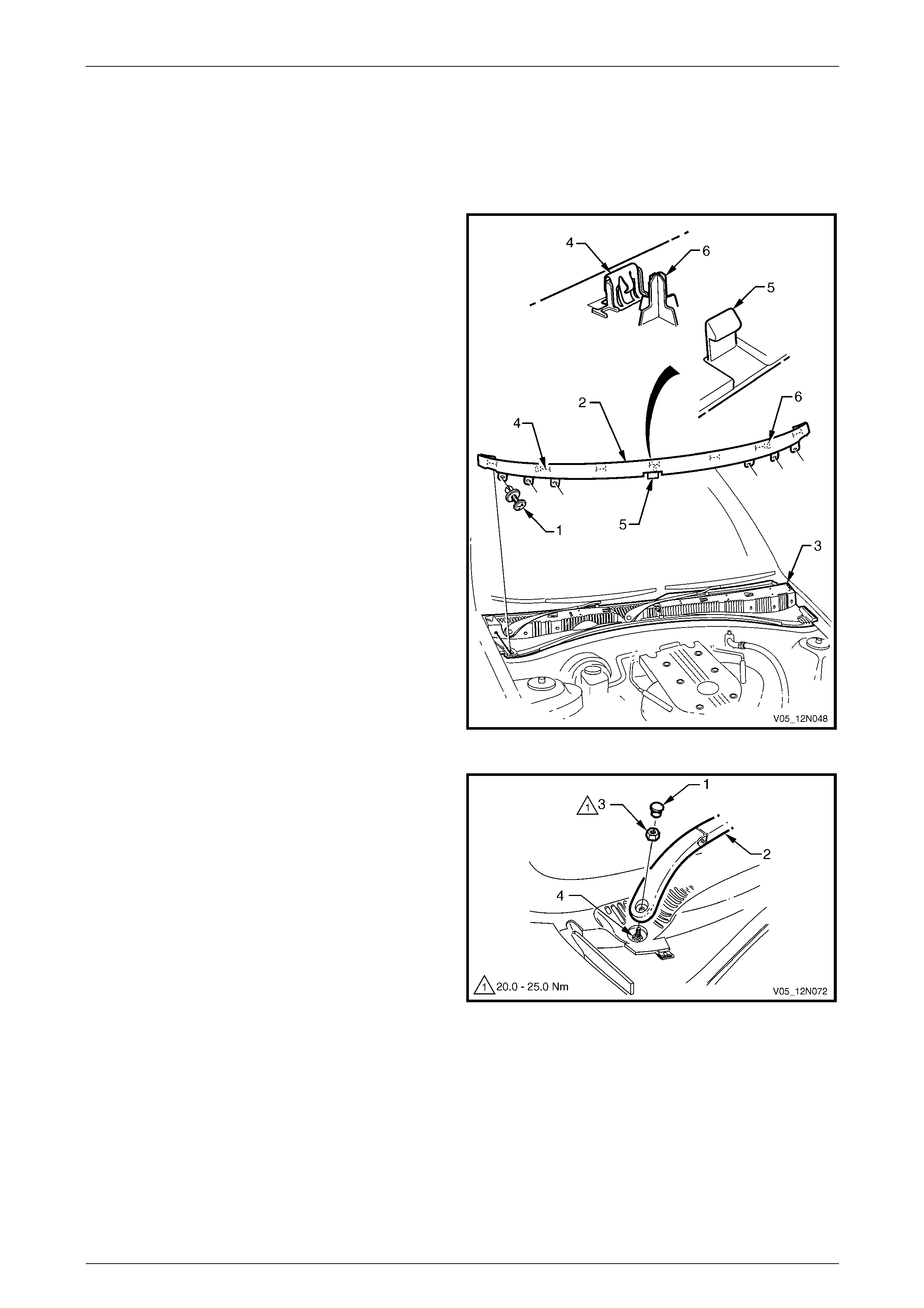
Wipers, Washers and Horn Page 12N–61
Page 12N–61
8.3 Front Wiper A r m Assem b ly
LT Section — 10–505
Remove
1 Ensure the front wiper motor and linkages are in the
park position.
2 Open the engine hood.
3 Remove the retainer (1), six places, secur ing the air
deflector assembly (2) to the plenum cover
assembly (3).
4 Pull the air deflector assembly along the top edge to
release the seven clips (4) and rele ase the clip (5) in
the centre of the bottom edge.
5 Remove the air deflector assembly taking care not to
damage the three locating pins (6) and not to contact
the rear edge of the engine ho od.
6 As required, remove the retaining clips from the
vehicle and fit to the plenum cover assembly.
Figure 12N – 25
7 Using a small scre wdriver or scribe, gentl y pr y the
cap (1) from the front wiper arm assembly (2).
8 Remove the nut (3) attaching the front wiper arm
assembly to the drive spindle (4).
9 Remove the front wiper arm assembly from the drive
spindle, taking care not to allow the wiper arm to
contact the rear edge of the engine hood.
10 If required, remove the wiper blade assembl y from the
front wiper arm,
refer to 8.2 Front Wiper Blade Assembly.
Figure 12N – 26
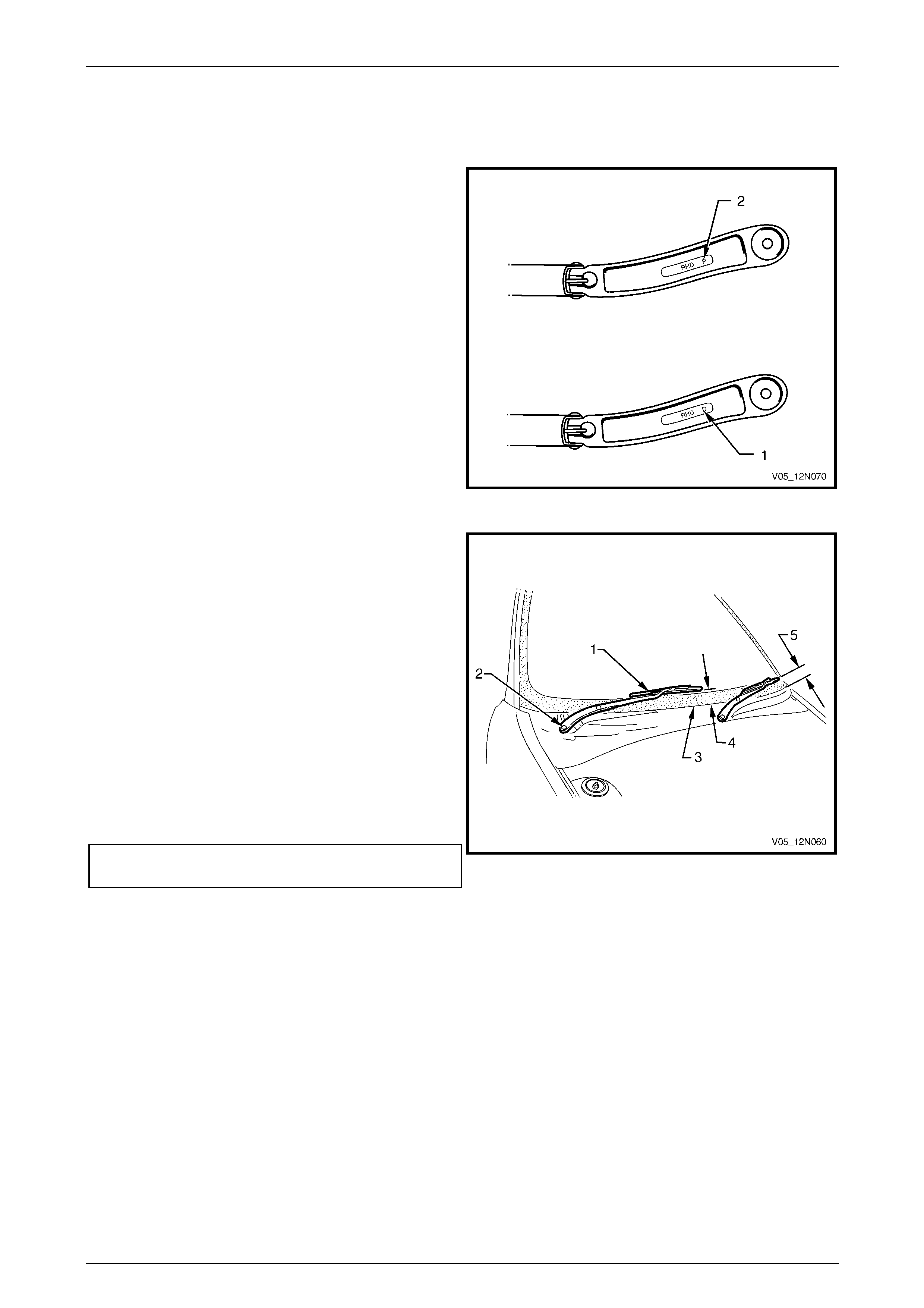
Wipers, Washers and Horn Page 12N–62
Page 12N–62
Reinstall
Reinstallation of the front wiper arm assembly is the reverse of the removal procedure, noting the following:
1 Ensure the front wiper motor and linkages are in the
park position.
NOTE
There is a specific front wiper arm for each side
of the vehicle. The arms are identified by the
letters RHD for right-hand driv e veh icles foll o wed
by ‘D’ for the driver side (1) and ‘P’ for the
passenger side (2), located on the underside of
the arm.
2 Ensure the correct front wiper arm and blade
assemblies are being fitted to each side of the vehicle.
Figure 12N – 27
NOTE
This illustration sho ws the front wiper assemb lies
with the hood removed, this is for clarity only.
The procedure can be performed with the hood
fitted and open.
3 Install the front wiper arm assembly (1) onto the drive
spindle (2) so the blade is positioned with the tip
above the edge of the plenum cover assembly (3)
within the following limits:
• right-hand blade 25 mm +10/-0 mm (4)
• left-hand blade 40 mm +10/-0 mm (5)
4 Install the nut attaching the front wiper arm assembly
to the drive spindle and tighten to the correct torque
specification.
Front wiper arm assembly attaching
nut torque specification...........................20.0 – 25.0 Nm
Figure 12N – 28
5 Ensure both outer ends of the air deflector engage the windshield reveal moulding assembly.
6 Check the front wiper for correct operation.
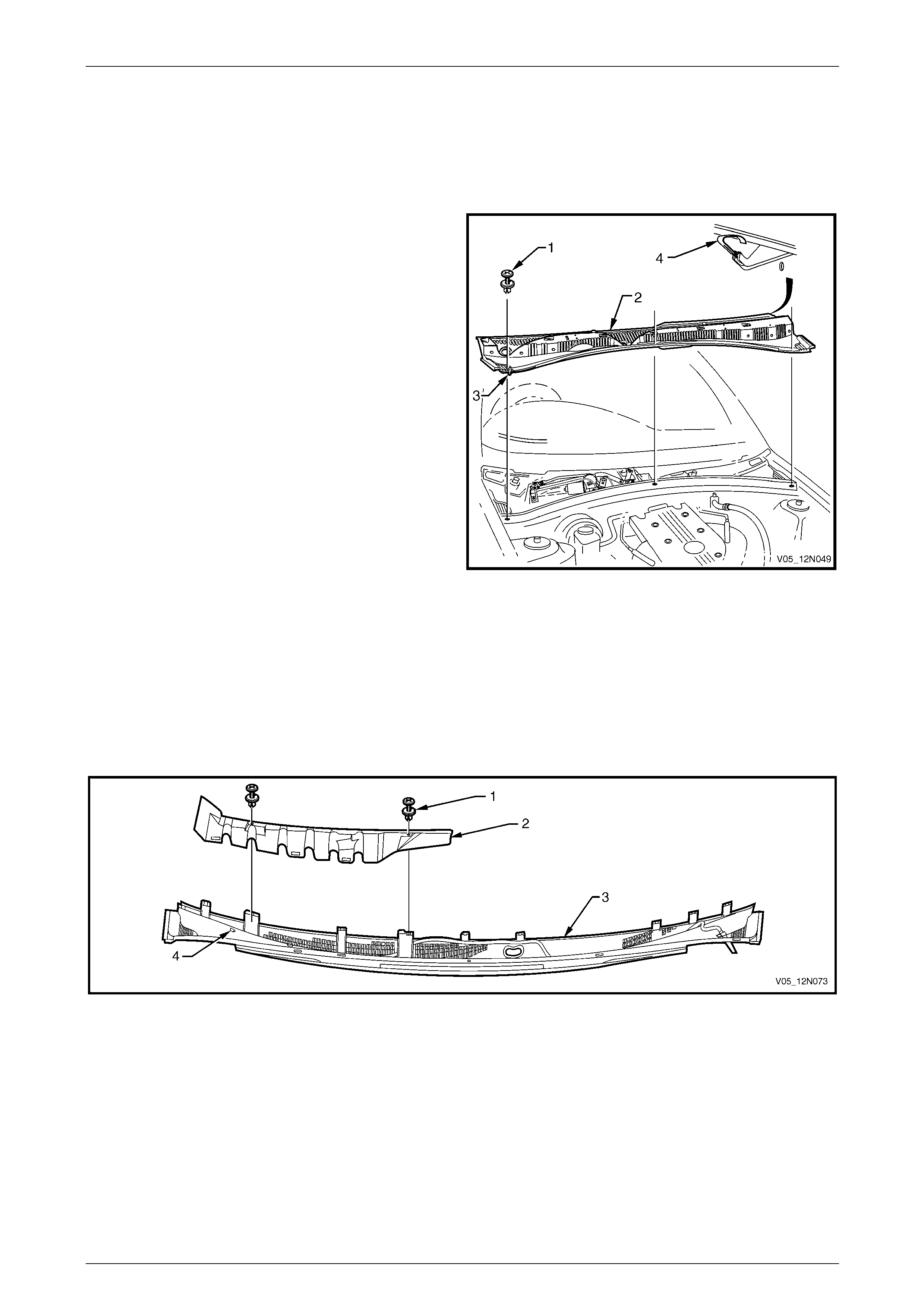
Wipers, Washers and Horn Page 12N–63
Page 12N–63
8.4 Plenum Cover Assembly
LT Section — 10–510
Remove
1 Remove the air deflector assembly and the front wiper
arm assemblies,
refer to 8.3 Front Wiper Arm Assembly.
2 Remove the retainer (1), three places, securing the
plenum cover assembly (2) to the plenum chamber.
3 Disconnect the front washer hose from the connector
joint (3).
4 Lift the plenum cover assembly up, while pul ling
forward to release the nine retaini ng tabs (4) securing
it to the windshield. Manoeuvre the cover away from
the engine hood hinge, an d lift out.
Figure 12N – 29
Disassemble
1 Remove the two fasteners (1) securing the water deflector (2) to the plenum cover assembly (3), refer to
Figure 12N – 30.
2 Pull the water deflector up and forward to release the three retaining lugs (4) securing it to the plenum cover
assembly.
3 Remove the water deflector.
Figure 12N – 30
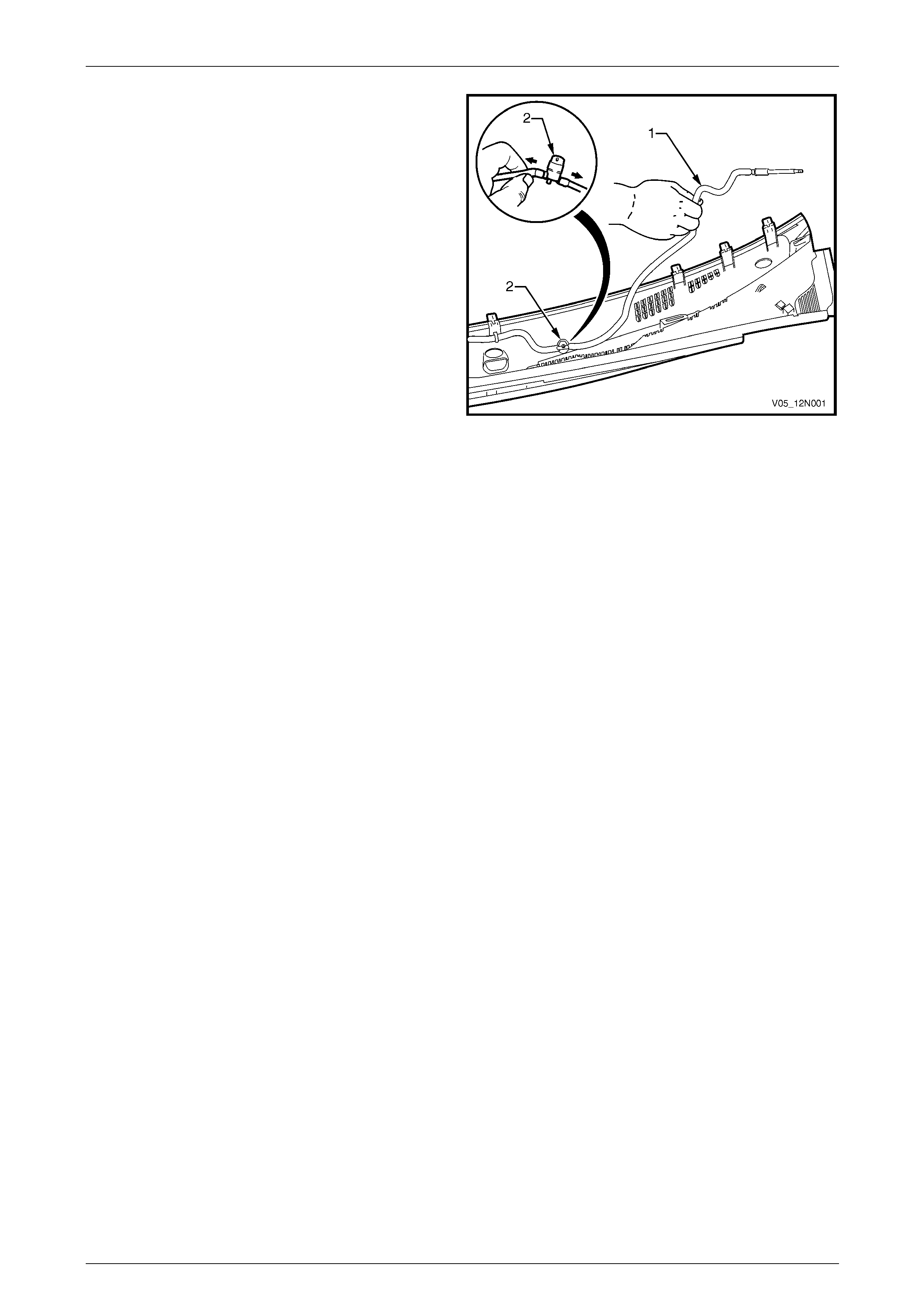
Wipers, Washers and Horn Page 12N–64
Page 12N–64
4 Unclip the front washer hose (1) from the fasteners
securing it to the plenum cover assembly.
5 Pull the front washers (2) out from the plenum cover
assembly.
6 Separate the front washer hose from the front
washers.
Figure 12N – 31
Reassemble
Reassembly of the plenum cover assembly is the reverse of the disassembly procedure, noting the following:
1 Ensure the water deflector is secured to the plenum cover assembly with the three retaining lugs engaged.
2 Ensure the front washers are pushed fully up and secured in the plenum cover assembly.
Reinstall
Reinstallation of the plenum cover assembly is the reverse of the removal procedure, noting the following:
1 Ensure the seal along the rear edge of the plenum cover assembly fits snug along the windshield.
2 Ensure the front washer hose is reconnected at the front edge of the plenum cover assembly.
3 Ensure the plenum chamber cover is secured to the plenum chamber and the windshield.
4 Check the spray pattern of the front washers on the windshield, adjust if necessary, refer to:
• 12.2 Front Washer Hose and Nozzle Assemblies, or
• Wagon – 13.2 Front Washer Hose and Nozzle Assemb lies, or
• AWD Wagon – 14.2 Front Washer Hose and Nozzle Assemblies.
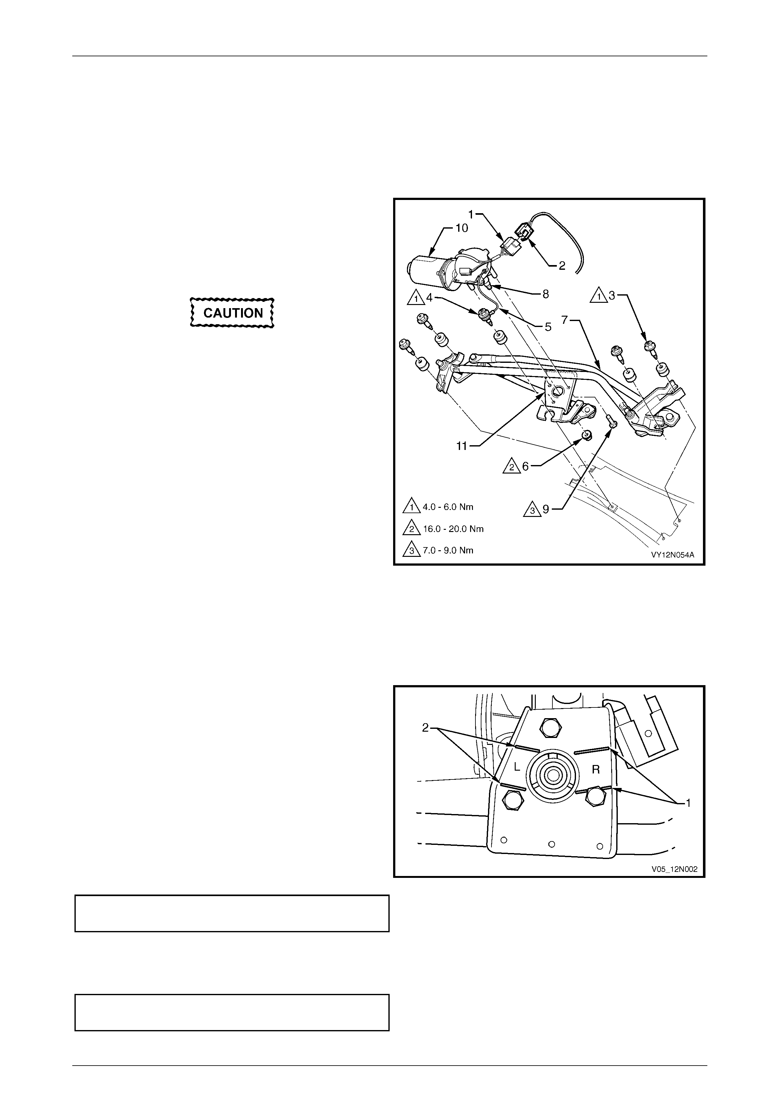
Wipers, Washers and Horn Page 12N–65
Page 12N–65
8.5 Front Wiper Motor Assembly and
Linkages
LT Section — 10–506
Remove
1 Remove the plenum cover assembly, refer to
8.4 Plenum Cover Assembly.
2 Squeeze the tang at the main wiring harness
connector (2) and disconnect the front wiper motor
harness connector (1).
The screw (4) attaching the front wiper motor
and ground strap (5) is secured to the strap
by a spacer and cannot be separated.
3 Remove the five fasteners (3 and 4) attaching the front
wiper motor assembly and linkages to the plenum
chamber and remove the front wiper motor assembly
and linkages.
4 If required, remove the front wiper motor from the
wiper linkages as follows:
a Remove the nut (6) attaching the front wiper
linkages (7) to the front wiper motor pivot (8).
b Remove the screw (9), three places, attaching
the front wiper motor (10) to the bracket (11) on
the front wiper linkages.
c Separate the front wiper motor from the front
wiper linkages.
Figure 12N – 32
Reinstall
Reinstallation of the front wiper motor assembly is the reverse of the removal procedure, noting the following:
1 If the front wiper motor has been removed from the
linkages:
a The front wiper motor pivot must be installed in
the park position, by aligning the pivot within the
lines on the mounting bracket marked R (1).
NOTE
The lines on the mounting bracket marked L (2)
are used for left-hand drive vehicles only.
b Ensure the screws attaching the front wiper
motor to the wiper linkages are tighten ed to the
correct torque specification.
Front wiper motor to linkages attaching
screw torque specification...........................7.0 – 9.0 Nm
c Ensure the nut attaching the front wiper motor
pivot is tightened to the correct torque
specification.
Front wiper motor pivot to linkages
attaching nut torque specification............16.0 – 20.0 Nm
Figure 12N – 33

Wipers, Washers and Horn Page 12N–66
Page 12N–66
2 Secure the front wiper motor assembly and linkages to the plenum chamber, ensure all fasteners are tightened to
the correct torque specification.
Front wiper motor and linkages assembl y
attaching screw torque specification...........4.0 – 6.0 Nm
Ensure the wires from the front wiper motor
harness are free and do not foul the front
wiper linkages.
3 Operate the front wiper motor assembly before installing the front wiper arms to ensure it is in the correct park
position.
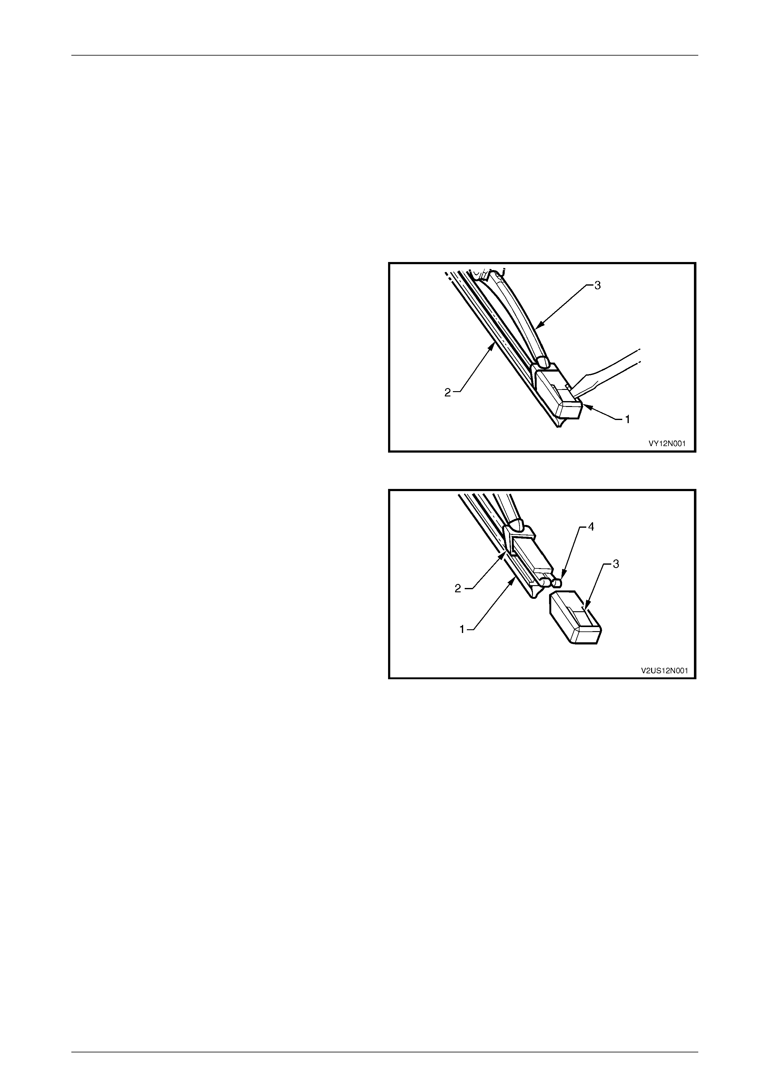
Wipers, Washers and Horn Page 12N–67
Page 12N–67
9 Service Operations – Front
Wiper Assemblies, Coupe
9.1 Front Wiper Blade Insert
LT Section — 10–505
Replace
1 Using a small scre wdriver, lift the retention l ug and
slide the end cap (1) off the front wiper insert (2), on
both ends of the front wiper blade (3).
NOTE
Do not re-use the end cap. The replacement
insert will be supplied with end caps fitted.
2 Slide the insert out of the front wiper blade and
discard.
Figure 12N – 34
3 Remove the end caps from the insert (1) and slide the
insert into the front wiper blade ensur ing the insert
passes through each metal claw (2).
4 Assemble the new end cap onto the ends of the insert,
ensure the retention lug (3) on the end cap is located
securely behind the two upturned ends of the metal
rails (4).
Figure 12N – 35
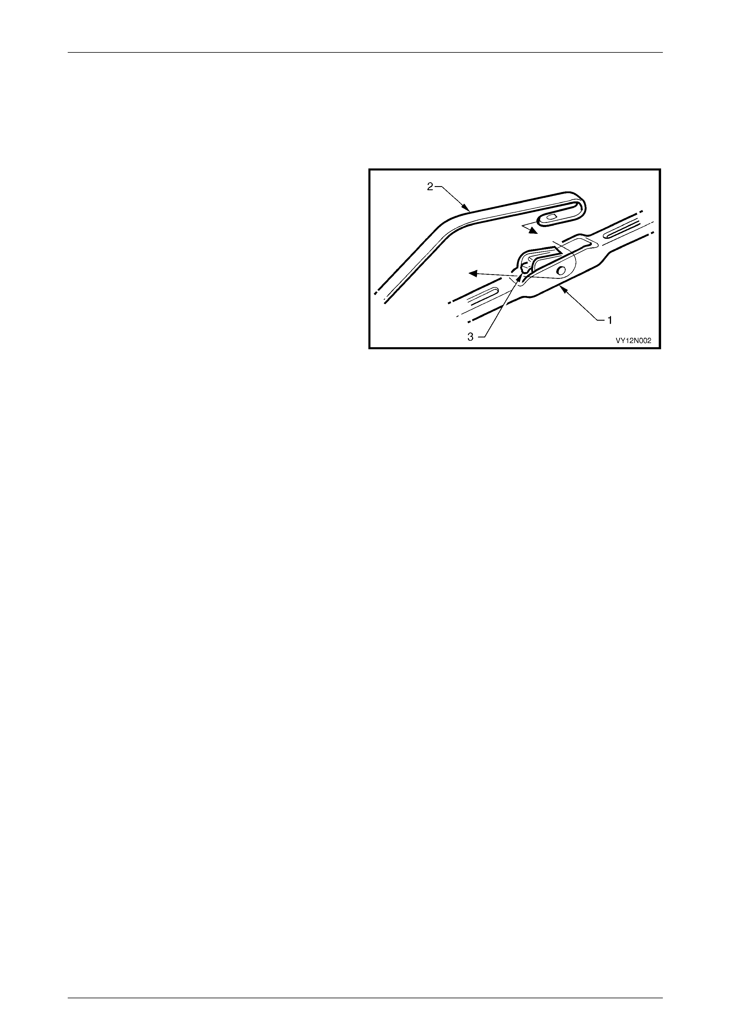
Wipers, Washers and Horn Page 12N–68
Page 12N–68
9.2 Front Wiper Blade Assembly
LT Section — 10–505
Remove
1 With the engine hood lo wered, lift the front wiper arm
assembly (2) from the glass.
2 Remove the front wiper blade assembly (1) from the
arm by lifting up the retainer (3) on the front wiper
blade assembly and pulli ng the blade assembly out of
the arm.
Figure 12N – 36
Reinstall
1 Slide the front wiper blade assembl y i nto the front wiper arm until the front wiper blade retainer locks into position.
2 Lower the front wiper arm assembly onto the windshield.
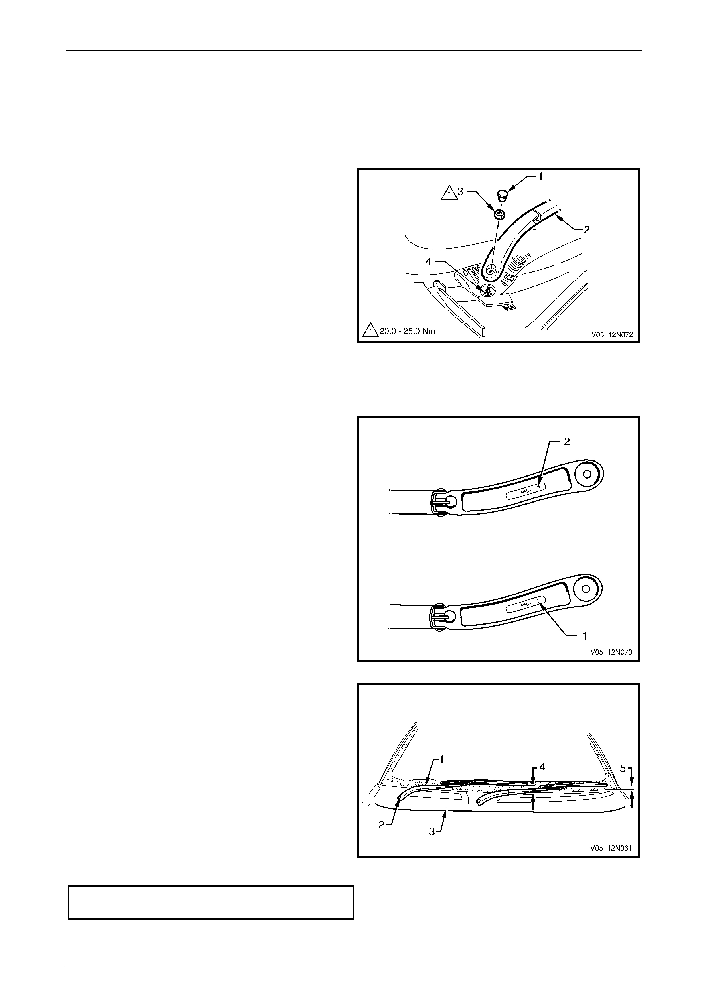
Wipers, Washers and Horn Page 12N–69
Page 12N–69
9.3 Front Wiper A r m Assem b ly
LT Section — 10–505
Remove
1 Ensure the front wiper motor and linkages are in the
park position.
2 Open the engine hood.
3 Using a small scre wdriver or scribe, gentl y pr y the
cap (1) from the front wiper arm assembly (2).
4 Remove the nut (3) attaching the front wiper arm
assembly to the drive spindle (4).
5 Remove the front wiper arm assembly from the drive
spindle, taking care not to allow the front wiper arm to
contact the rear edge of the engine hood.
6 If required, remove the wiper blade assembl y from the
front wiper arm,
refer to 9.2 Front Wiper Blade Assembly. Figure 12N – 37
Reinstall
Reinstallation of the front wiper arm assembly is the reverse of the removal procedure, noting the following:
1 Ensure the front wiper motor and linkages are in the
park position. NOTE
There is a specific front wiper arm for each side
of the vehicle. The arms are identified by the
letters RHD for right-hand driv e veh icles foll o wed
by ‘D’ for the driver side (1) and ‘P’ for the
passenger side (2), located on the underside of
the arm.
2 Ensure the correct front wiper arm and blade
assemblies are being fitted to each side of the vehicle.
Figure 12N – 38
NOTE
This illustration shows the wiper assemblies with
the hood removed, this is for clarity only. The
procedure can be performed with the hood fitted
and open.
3 Install the wiper arm assembly (1) onto the drive
spindle (2) so the blade is positioned with the tip
above the edge of the plenum cover assembly (3)
within the following limits:
• right-hand blade 25 mm +10/-0 mm (4)
• left-hand blade 40 mm +10/-0 mm (5)
4 Install the nut attaching the wiper arm assembly to the
drive spindle and tighten to the correct torque
specification.
Front wiper arm assembly attaching
nut torque specification...........................20.0 – 25.0 Nm
5 Check the wiper for correct operation.
Figure 12N – 39
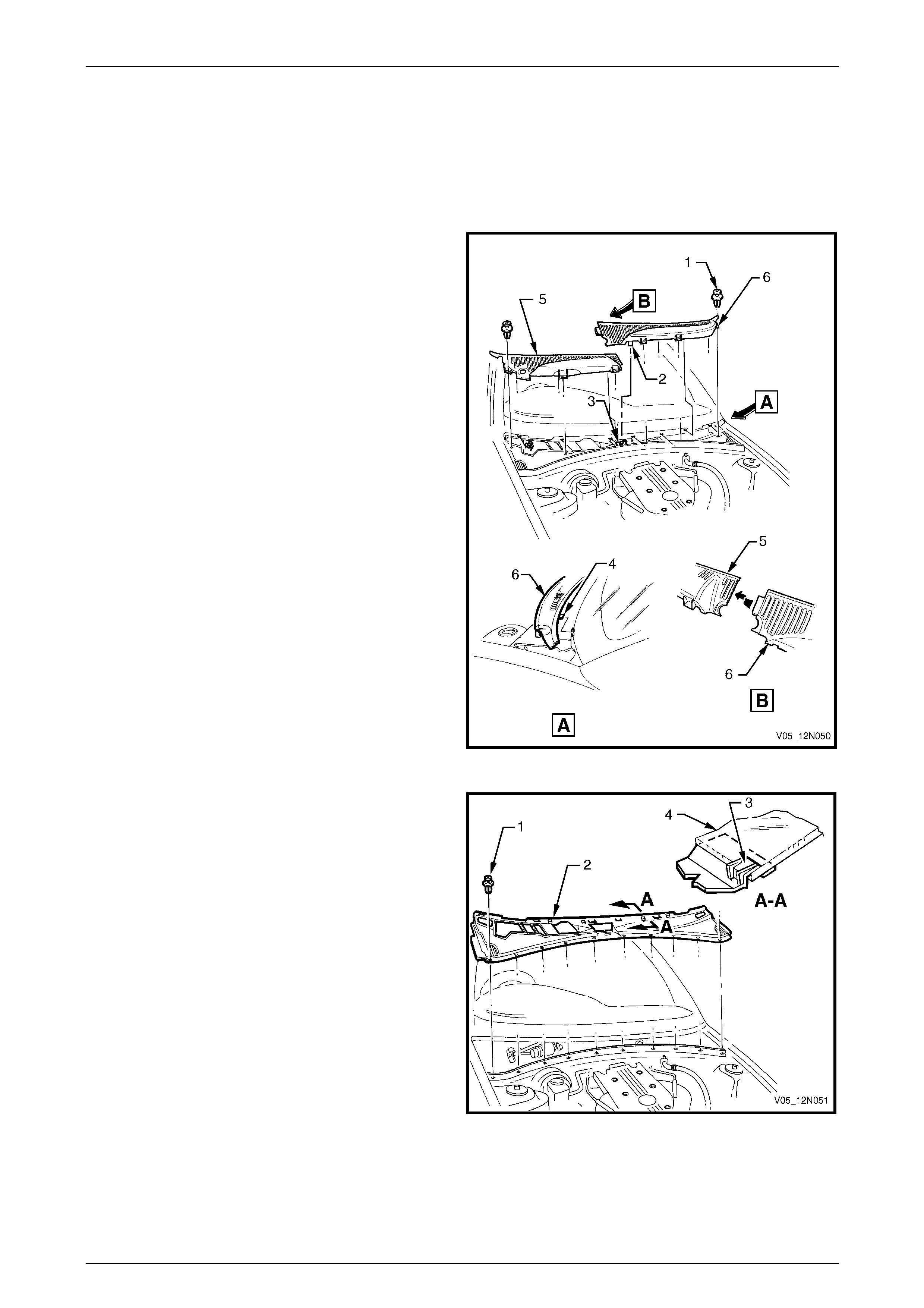
Wipers, Washers and Horn Page 12N–70
Page 12N–70
9.4 Plenum Cover Assembly
LT Section — 10–510
Remove
1 Remove the front wiper arm assemblies, refer to
9.3 Front Wiper Arm Assembly.
2 Remove the retainer (1), six places, secur ing the
plenum chamber covers to the plenum chamber.
3 Disengage the locating tab (2) from the hole in the
plenum water deflector (3).
4 Pull the plenum chamber covers forward to release the
retaining tabs (4) securing them to the plenum water
deflector.
5 Lift the right-hand plenum chamber cover (5) upwards
while manoeuvring the cover away from the engine
hood hinge, and remove the plenum cover.
6 Remove the left-hand side plenum chamber cover (6)
using the same process as for the right-hand.
Figure 12N – 40
7 Remove the retainer (1), ten places, securing the
plenum water deflector assembly (2) to the plenum
chamber.
8 Pull the plenum water deflector assembly forward to
release it from the tabs (3) securing it to the
windshield (4), and rem ove th e plenum water deflector
assembly.
Figure 12N – 41

Wipers, Washers and Horn Page 12N–71
Page 12N–71
Reinstall
Reinstallation of the plenum chamber cover assembly is the reverse of the removal procedure, noting the following:
1 Ensure the plenum water deflector assembly (2) is secured to the plenum chamber and the retainin g tabs (3) are
engaged under the windshield, refer to Figure 12N – 41.
2 When installing the plenum chamber covers ensure the locating tab (2) and retaining tabs (4) are inserted prior to
fitment of the retainers (1), refer to Figure 12N – 40.
NOTE
Install the left-hand plenum chamber cover (6)
before the right-hand cover (5).
3 Ensure the plenum chamber covers are secured to the plenum chamber and the windshield.
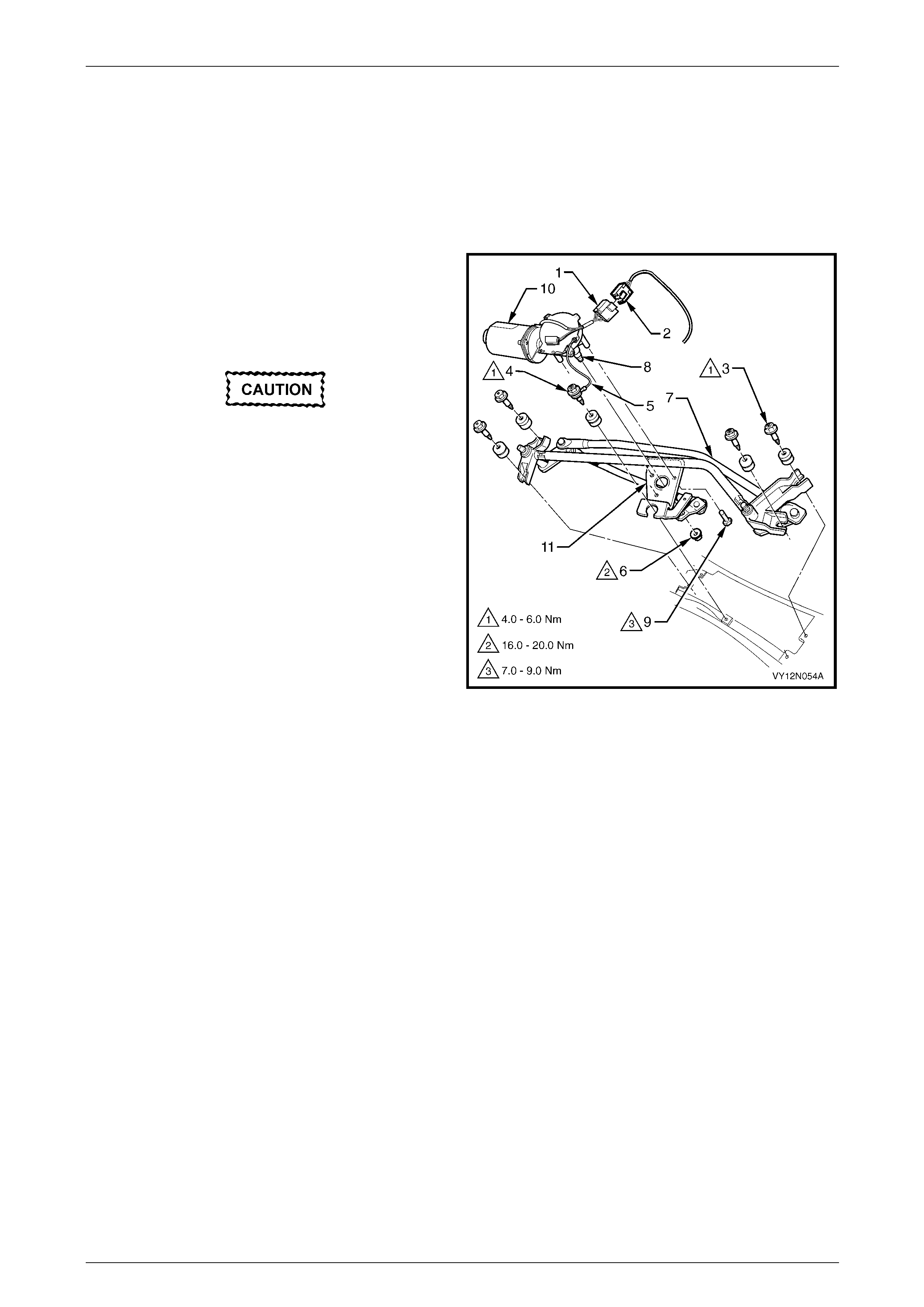
Wipers, Washers and Horn Page 12N–72
Page 12N–72
9.5 Front Wiper Motor Assembly and
Linkages
LT Section — 10–506
Remove
1 Remove the plenum cover assembly, refer to
9.4 Plenum Cover Assembly.
2 Squeeze the tang at the main wiring harness
connector (2) and disconnect the front wiper motor
harness connector (1).
The screw (4) attaching the front wiper motor
and ground strap (5) is secured to the strap
by a spacer and cannot be separated.
3 Remove the five fasteners (3 and 4) attaching the front
wiper motor assembly and linkages to the plenum
chamber and remove the front wiper motor assembly
and linkages.
4 If required, remove the front wiper motor from the
wiper linkages as follows:
a Remove the nut (6) attaching the front wiper
linkages (7) to the front wiper motor pivot (8).
b Remove the screw (9), three places, attaching
the front wiper motor (10) to the bracket (11) on
the front wiper linkages.
c Separate the front wiper motor from the front
wiper linkages.
Figure 12N – 42
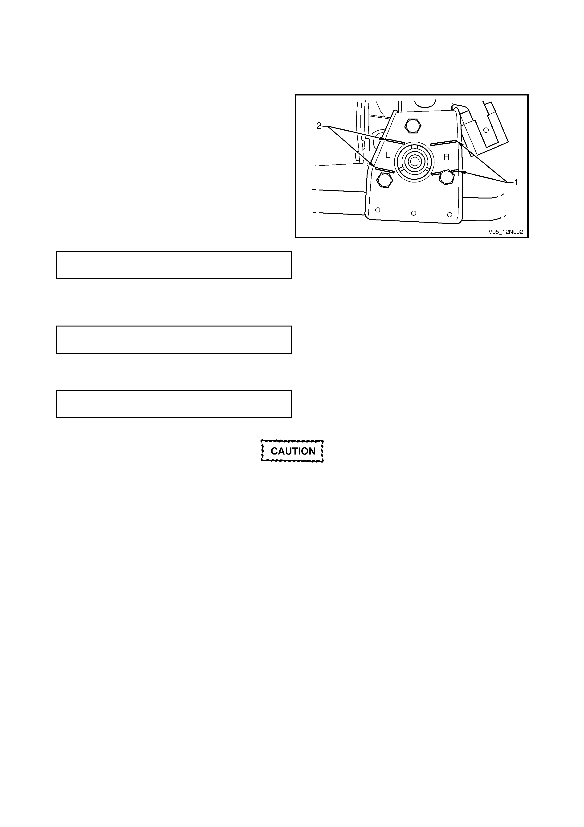
Wipers, Washers and Horn Page 12N–73
Page 12N–73
Reinstall
Reinstallation of the front wiper motor assembly is the reverse of the removal procedure, noting the following:
1 If the front wiper motor has been removed from the
linkages:
a The front wiper motor pivot must be installed in
the park position, by aligning the pivot within the
lines on the mounting bracket marked R (1).
NOTE
The lines on the mounting bracket marked L (2)
are used for left–hand drive vehicles only.
b Ensure the screws attaching the front wiper
motor to the wiper linkages are tighten ed to the
correct torque specification.
Front wiper motor to linkages attaching
screw torque specification...........................7.0 – 9.0 Nm
c Ensure the nut attaching the front wiper motor
pivot is tightened to the correct torque
specification.
Front wiper motor pivot to linkages
attaching nut torque specification............16.0 – 20.0 Nm
Figure 12N – 43
2 Secure the front wiper motor assembly and linkages to the plenum chamber, ensure all fasteners are tightened to
the correct torque specification.
Front wiper motor and linkages assembly
attaching screw torque specification...........4.0 – 6.0 Nm
Ensure the wires from the front wiper motor
harness are free and do not foul the front
wiper linkages.
3 Operate the front wiper motor assembly before installing the front wiper arms to ensure it is in the correct park
position.

Wipers, Washers and Horn Page 12N–74
Page 12N–74
10 Service Operations – Rear Wiper
Assembly, Wagon
10.1 Rear Wiper Blade Insert
LT Section — 10–525
Replace
The replacement procedure of the rear wiper blade insert for Wagon vehicles is identical t o the replacement procedure
for the front wiper blade insert, refer to 8.1 Front Wiper Blade Insert.

Wipers, Washers and Horn Page 12N–75
Page 12N–75
10.2 Rear Wiper Blade Assembly
LT Section — 10–525
Remove and Reinstall
The removal and reinstallation procedure of the rear wiper bla de assembly for Wagon vehicles is identic al to the removal
and reinstallation procedure for the front wiper blade assemblies , refer to 8.2 Front Wiper Bla de Assembly.

Wipers, Washers and Horn Page 12N–76
Page 12N–76
10.3 Rear Wiper Arm Assembly
LT Section — 10–525
Remove
Ensure the rear wiper motor assembly is in
the park position.
1 Lift the cap (1) and remove the nut (2) attaching the
rear wiper arm assembly (3) to the rear wiper motor
pivot (8).
2 Remove the rear wiper arm assembly from the rear
wiper motor pivot.
3 If required, remove the cover (4), nut (5), cap (6) and
outer spacer (7) from the rear wiper motor pivot.
4 If required, remove the wiper blade assembl y from the
rear wiper arm,
refer to 10.2 Rear Wiper Blade Assembly.
Figure 12N – 44
Reinstall
Reinstallation of the rear wiper arm assembly is the reverse of the removal procedure, noting the following:
Ensure the rear wiper motor assembly is in
the park position.
1 If removed, reinstall the rear wiper motor outer
spacer (1), cap (2) and attaching nut (3). Tighten the
nut to the correct torque specification.
Rear window wiper motor ass embly
attaching nut torque specification................4.0 – 6.0 Nm
2 If removed, reinstall the cover (4), then install the rear
wiper arm assembly (5) onto the rear wiper motor
pivot (6) so the wiper blade (7) rests against the glass
moulding (8).
3 Install the nut (9) attaching the rear wiper arm
assembly to the motor pivot and tighten to the correct
torque specification.
Rear window wiper arm ass embly
attaching nut torque specification............20.0 – 25.0 Nm
4 Push the trim cap (10) onto the rear wiper arm
assembly.
5 Check the rear wiper for correct operation.
NOTE
Ensure the rear wiper arm assembly does not
wipe over the glass moulding in the park
position. If so, reposition the wiper arm and
perform steps 4 – 7.
Figure 12N – 45
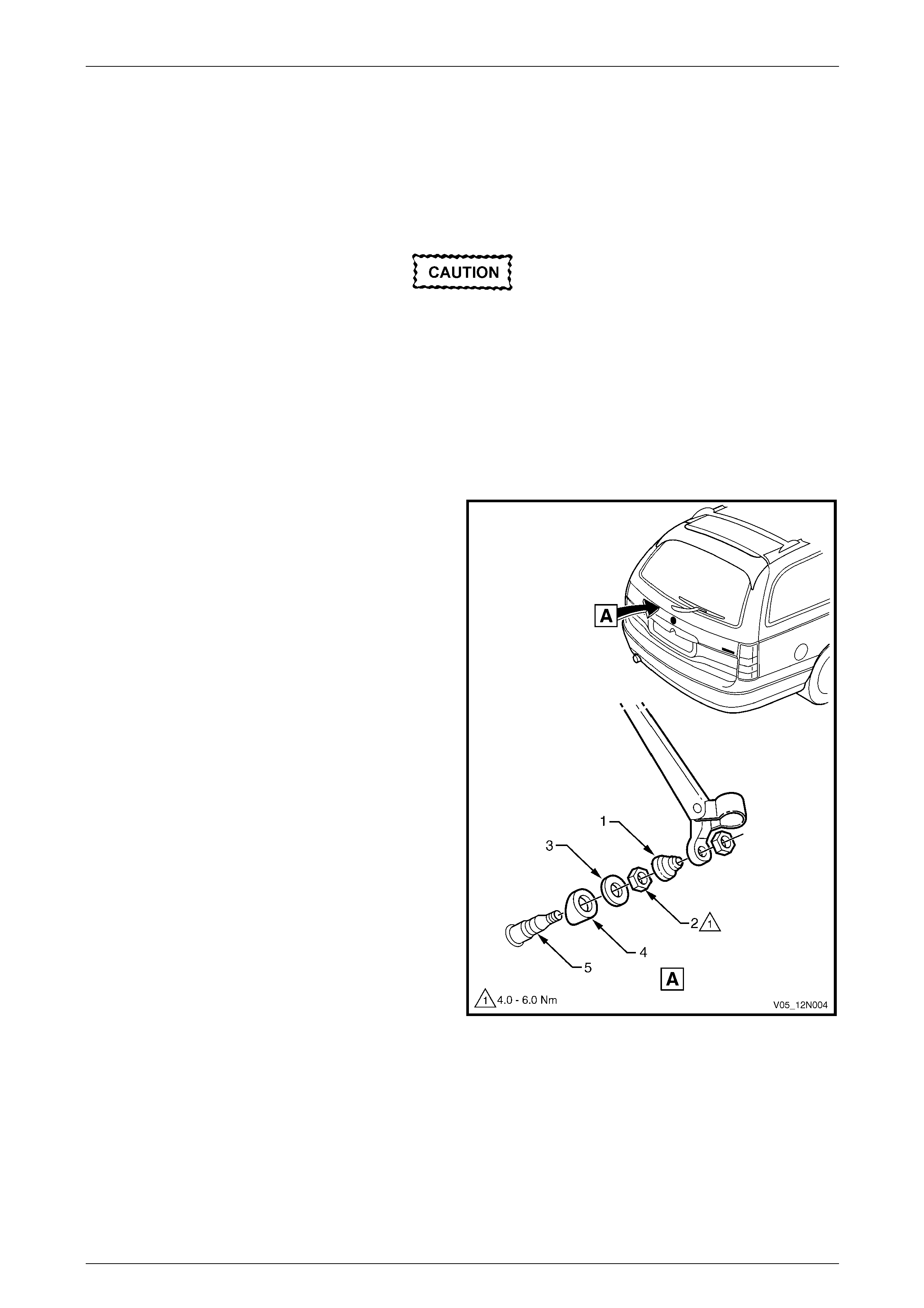
Wipers, Washers and Horn Page 12N–77
Page 12N–77
10.4 Rear Wiper Motor Assembly
LT Section — 10–525
Remove
Ensure the rear wiper motor assembly is in
the park position.
1 Remove the following components as required:
a Rear wiper fuse F18 from the passenger compartment fuse and relay panel assembly.
Refer to Section 12O Fuses, Relays and Wir ing.
b Rear wiper arm assembly, refer to 10.3 Rear Wiper Arm Assembly.
c Liftgate window lower garnish, and the liftgate lower trim panel,
refer to Section 1A4 Hood, Rear Compartment Lid, Liftgate and Endgate.
2 Remove the cover (1), nut (2), cap (3) and outer
spacer (4) from the rear wiper motor pivot (5).
Figure 12N – 46
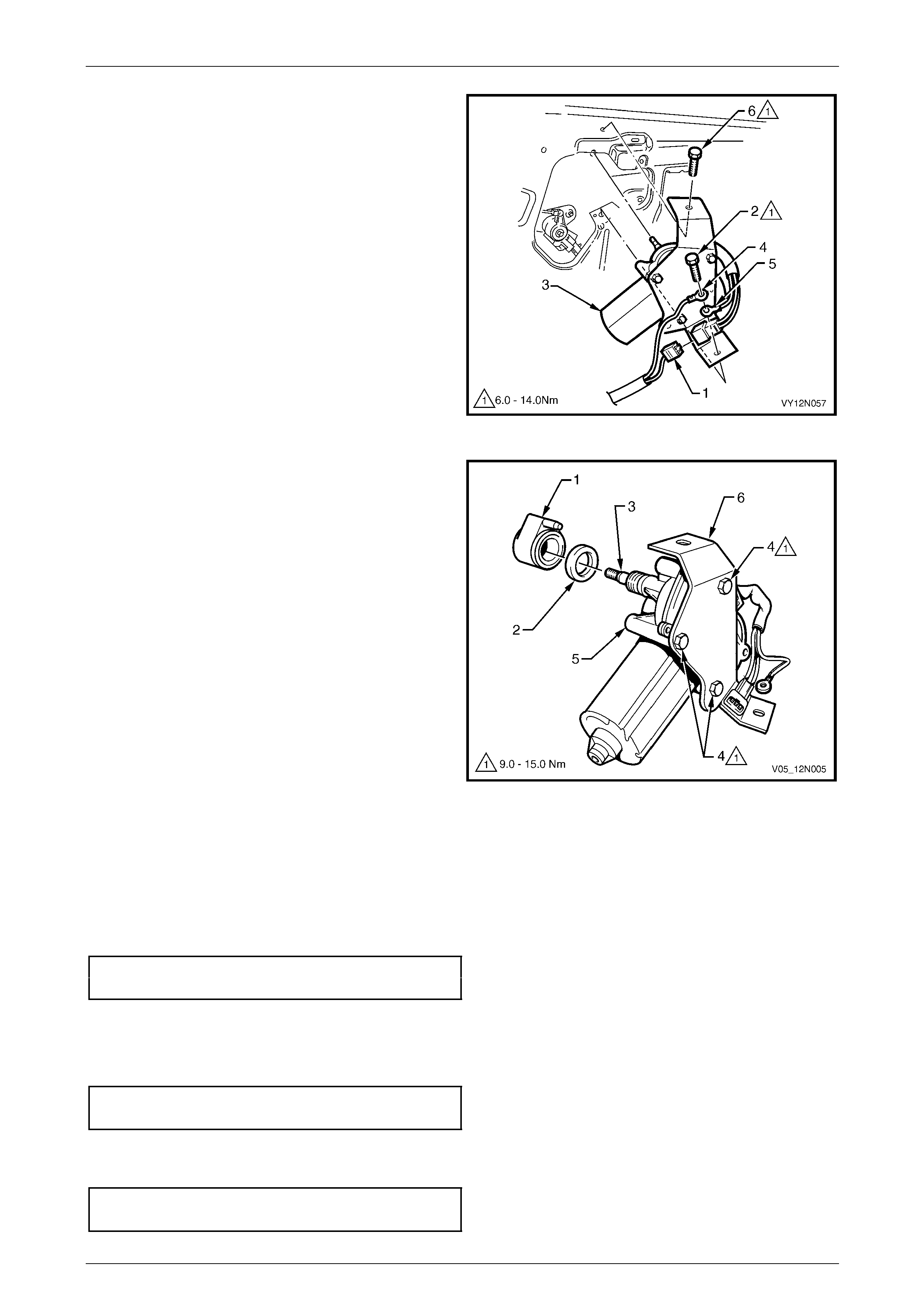
Wipers, Washers and Horn Page 12N–78
Page 12N–78
3 Disconnect the rear wiper wiring harness
connector (1).
4 Remove the screw (2) attaching the rear wiper motor
assembly (3), liftgate harness ground connection (4)
and motor assembly ground connectio n (5) to the
liftgate assembly.
5 Remove the screw (6) and remove the motor
assembly from the liftgate assembly.
Figure 12N – 47
6 Remove the inner spacer (1) and the c ap (2) from the
wiper motor pivot (3).
7 Remove the three screws (4) and separate the rear
wiper motor (5) from the attaching bracket (6).
Figure 12N – 48
Reinstall
Reinstallation of the rear wiper motor assembly is the reverse of the removal procedure, noting the following:
1 Ensure the cap (2) and the inner spacer (1) are installed correctly, refer to Figure 12N – 48.
2 Tighten the three screws (4) attaching the r ear window wiper motor assembly to the correct torque sp ecification.
Rear window wiper motor assembly
attaching screw torque specification.........9.0 – 15.0 Nm
3 To ensure sound ground connectio n, the re ar wiper motor ground connector (5) must be installed before the liftgate
harness ground connector (4), refer to F igure 12N – 4 7.
4 Tighten the rear wiper motor bracket attaching screws (2 and 6) to the correct torque specification.
Rear window wiper motor br acket
attaching screw torque specification.........6.0 – 14.0 Nm
5 Ensure the outer spacer (4) and cap (3) are correctly fitted onto the wiper motor shaft, tighten the motor attaching
nut (2) to the correct torque specification, refer to Figure 12N – 46.
Rear window wiper motor ass embly
attaching nut torque specification................4.0 – 6.0 Nm

Wipers, Washers and Horn Page 12N–79
Page 12N–79
11 Service Operations – Rear Wiper
Assembly, AWD Wagon
11.1 Rear Wiper Blade Insert
LT Section — 10–525
Replace
1 Lift the rear wiper arm (1) away from the rear wiper ramp (2), refer to Figure 12N – 49.
2 Move the end of the rear wiper blade (3) outward a nd disengage the insert (4) from the rear wiper blade claw (5).
3 Slide the insert out of the rear wiper blade and discard.
4 Slide the new insert into the rear wiper blade ensuring the insert pass es through each rear wiper blade claw.
5 If required, replace the clear protective tape on the liftgate located at the resting position of the rear wiper blade.
6 Position the rear wiper arm on the rear wiper ramp.
Figure 12N – 49
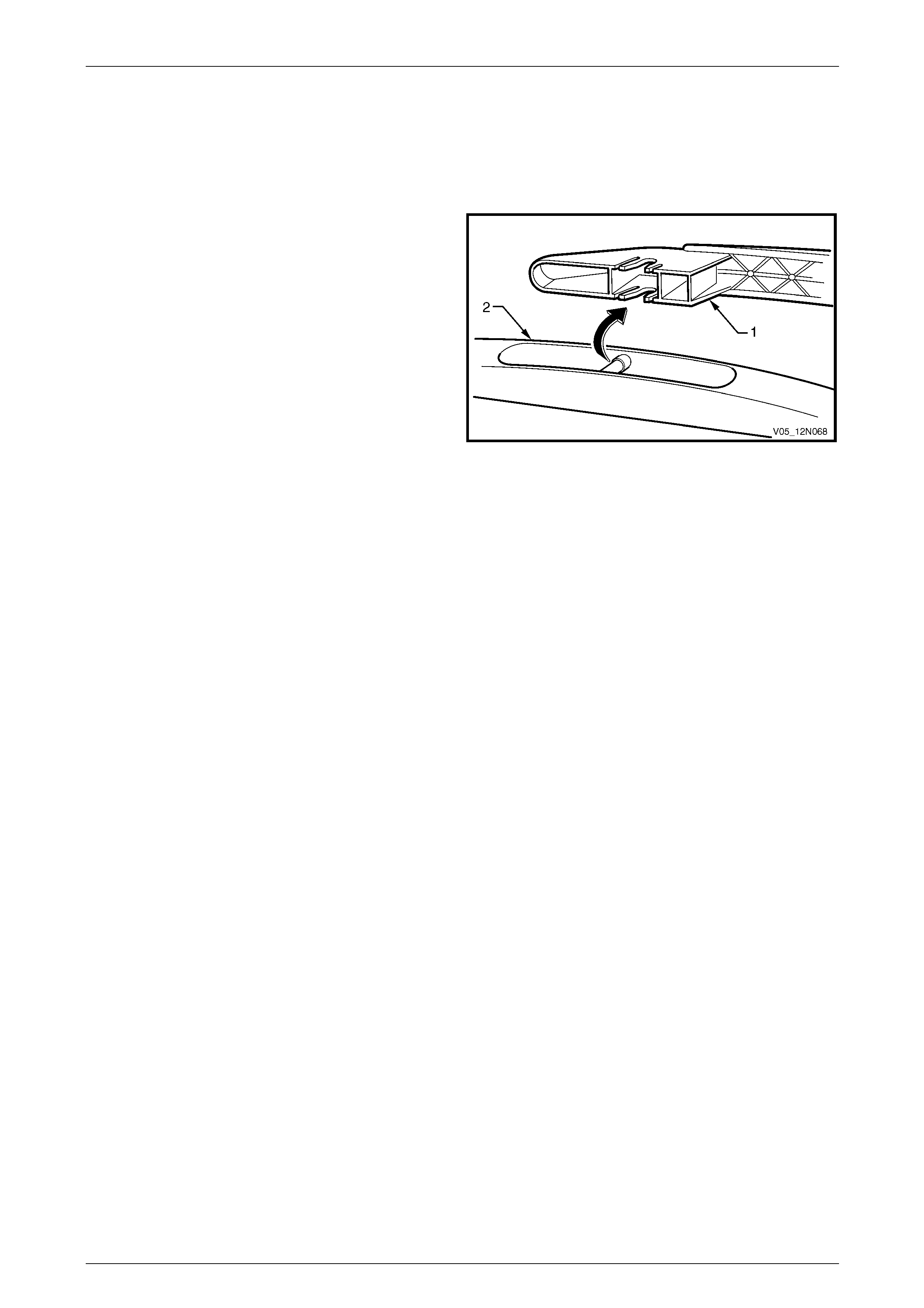
Wipers, Washers and Horn Page 12N–80
Page 12N–80
11.2 Rear Wiper Blade Assembly
LT Section — 10–525
Remove
1 Lift the rear wiper arm assembly (1) from the liftgate.
2 Pull the blade assembly (2) out of the arm assembl y
and remove.
Figure 12N – 50
Reinstall
1 Push the rear wiper blade assembly into the front wiper arm assembl y and ensure it is secured.
2 Lower the rear wiper arm assembly onto the liftgate.
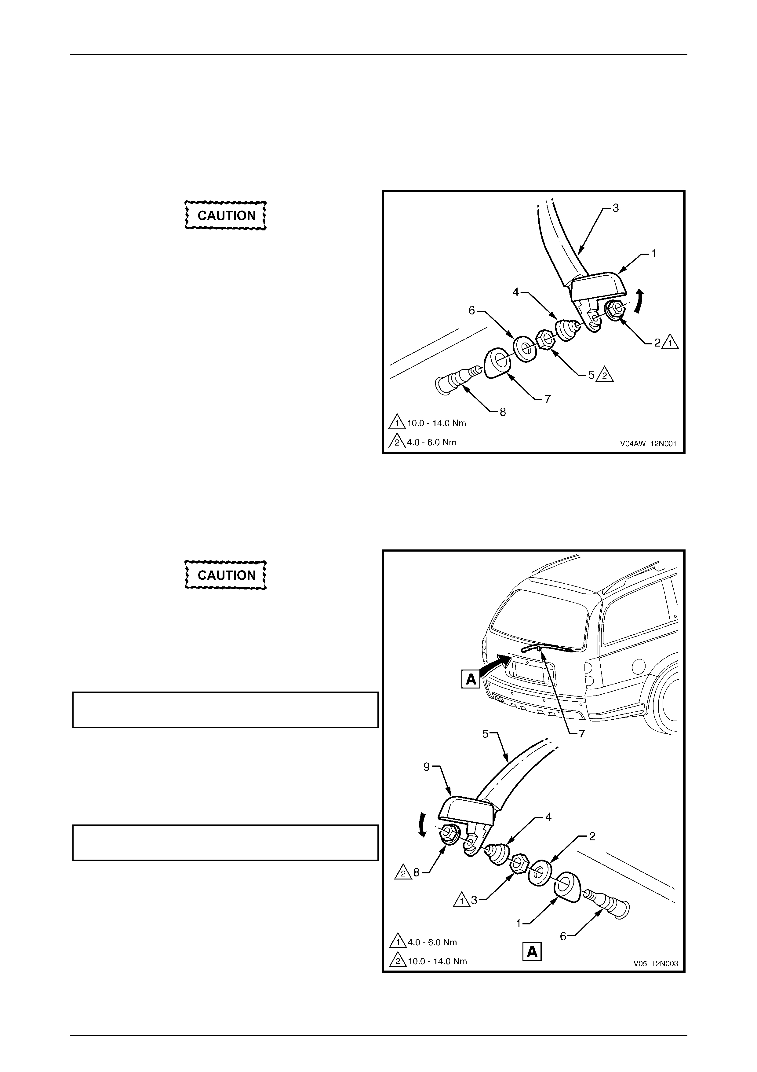
Wipers, Washers and Horn Page 12N–81
Page 12N–81
11.3 Rear Wiper Arm Assembly
LT Section — 10–525
Remove
Ensure the rear wiper motor assembly is in
the offscreen park position.
1 Lift the cap (1) and remove the nut (2) attaching the
rear wiper arm assembly (3) to the rear wiper motor
pivot (8).
2 Remove the rear wiper arm assembly from the rear
wiper motor pivot.
3 If required, remove the cover (4), nut (5), cap (6) and
outer spacer (7) from the rear wiper motor pivot.
4 If required, remove the wiper blade assembl y from the
rear wiper arm,
refer to 11.2 Rear Wiper Blade Assembly.
Figure 12N – 51
Reinstall
Reinstallation of the rear wiper arm assembly is the reverse of the removal procedure, noting the following:
Ensure the rear wiper motor assembly is in
the offscreen park position.
1 If removed, reinstall the rear wiper motor outer
spacer (1), cap (2) and attaching nut (3). Tighten the
nut to the correct torque specification.
Rear window wiper motor ass embly
attaching nut torque specification................4.0 – 6.0 Nm
2 If removed, reinstall the cover (4), then install the rear
wiper arm assembly (5) onto the rear wiper motor
pivot (6) so the arm rests on the rear wiper ramp (7).
3 Tighten the nut (8) attaching the rear wiper arm
assembly to the correct torque specification.
Rear window wiper arm ass embly
attaching nut torque specification............10.0 – 14.0 Nm
4 Push the trim cap (9) onto the rear wiper arm
assembly.
5 Check the rear wiper for correct operation.
NOTE
Ensure the rear wiper arm assembly parks in the
offscreen position on the rear wiper ramp;
reposition the wiper arm if required. Figure 12N – 52
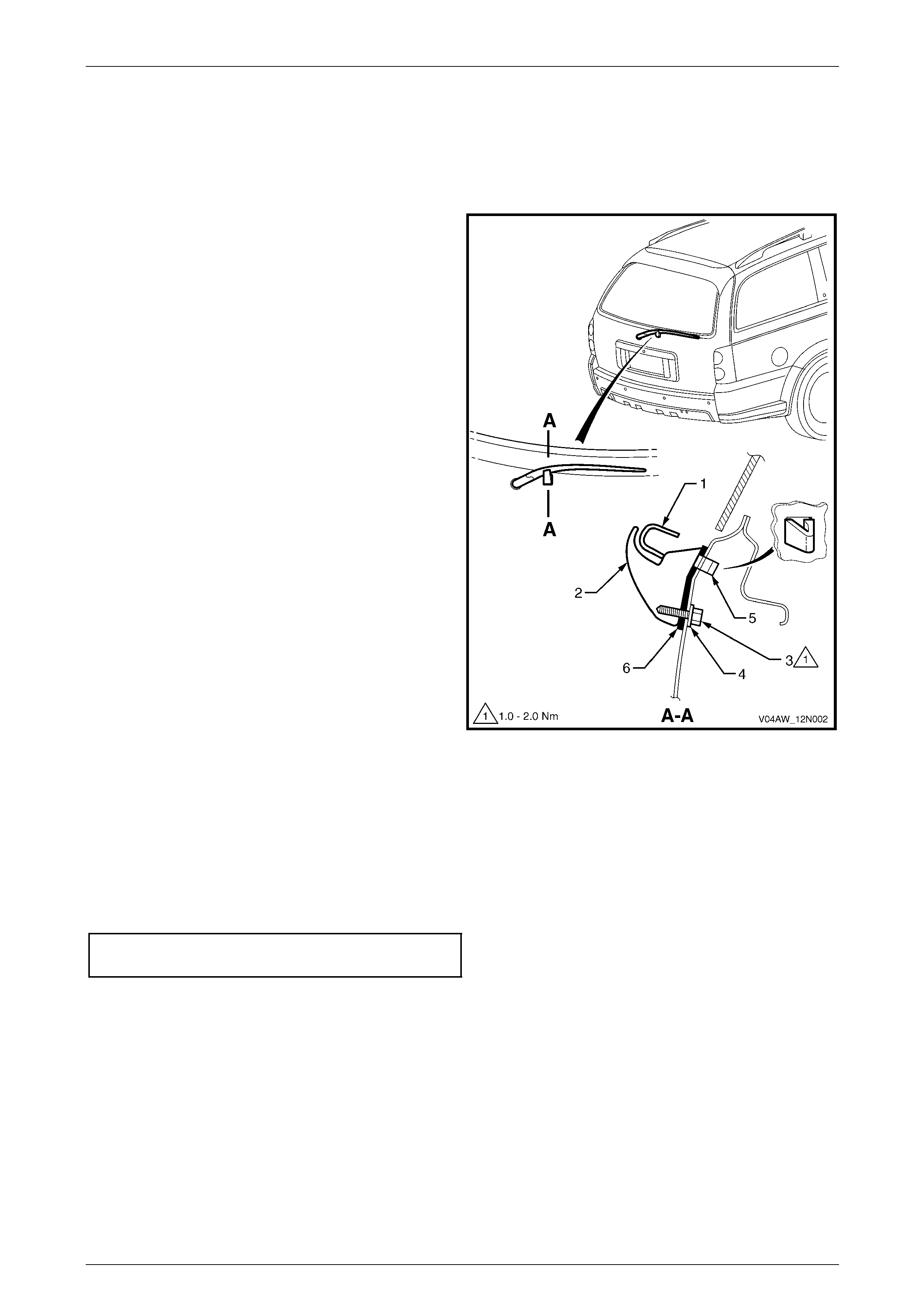
Wipers, Washers and Horn Page 12N–82
Page 12N–82
11.4 Rear Wiper Ramp
LT Section — 10–525
Remove
1 Remove the liftgate lower trim panel, refer to
Section 1A4 Hood, Rear Compartment Lid, Liftgate
and Endgate.
2 Lift the rear wiper arm (1) away from the rear wiper
ramp (2).
3 Remove the attaching screw (3) and washer (4) from
the inner side of the liftgate panel.
4 Depress the tang (5), then remove the rear wiper ramp
and seal (6) from the liftgate.
Figure 12N – 53
Reinstall
Reinstallation of the rear wiper ramp is the reverse of the removal procedure, noting the following:
1 Ensure the seal (6) is not damaged an d replace if necessary, refer to Figure 12N – 53.
2 Position the rear wiper ramp (2) and seal on the liftgate with the tang (5) inserted in the locating hole.
3 Tighten the screw (3) attaching the rear wiper ramp to the correct torque specification.
Rear window wiper ramp attaching screw
torque specification.....................................1.0 – 2.0 Nm
4 Ensure the rear wiper arm is parking properly on the rear wiper ramp.
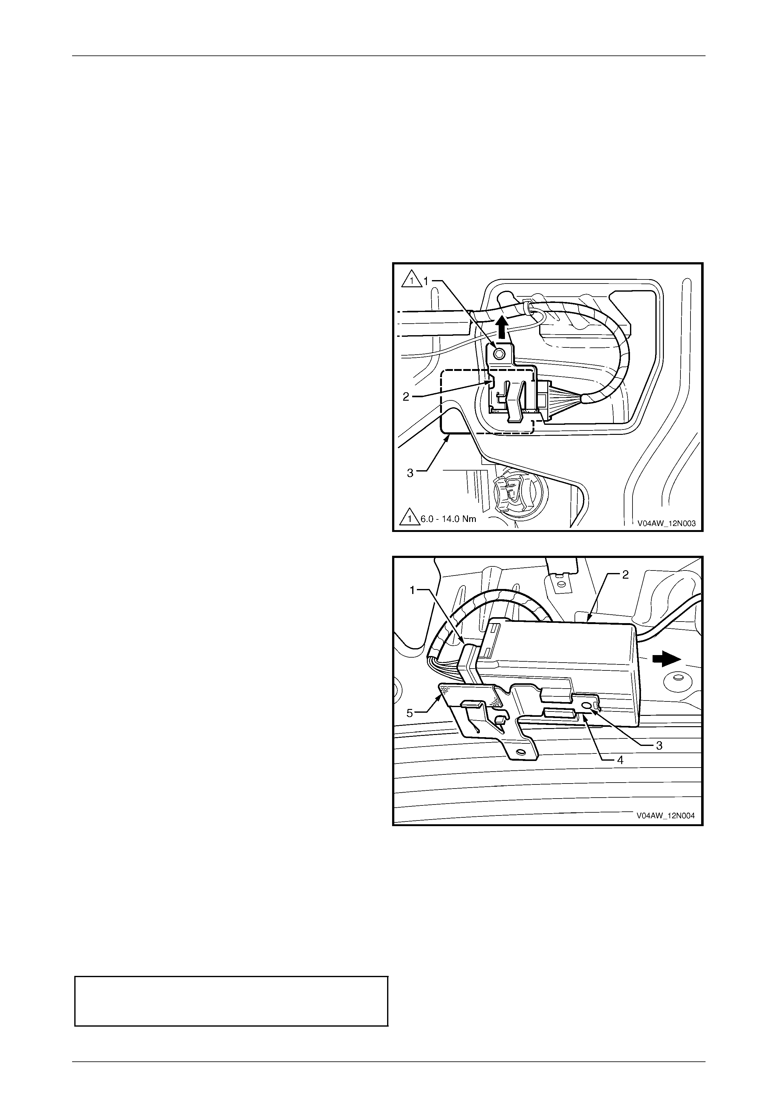
Wipers, Washers and Horn Page 12N–83
Page 12N–83
11.5 Rear Wiper Control Module
LT Section — 10–525
Remove
1 Remove the following components as required:
a Rear wiper fuse F18 from the passenger compartment fuse and relay panel assembly.
Refer to Section 12O Fuses, Relays and Wir ing.
b Liftgate lower trim panel, refer to Section 1A4 Hood, Rear C ompartme nt Li d, Liftgate and Endgate.
2 Remove the attaching screw (1) securing the support
bracket (2) and control module (3) to the liftgate.
3 Pull to disengage the support bracket and control
module from the liftgate.
Figure 12N – 54
4 Remove the connector (1) from the control modu le (2).
5 Disengage the tab (3) and slid e the control module to
separate it from the support bracket (4).
NOTE
Check if the protective tape (5) fitted to the
support bracket has not been damaged during
the removal procedure.
Figure 12N – 55
Reinstall
Reinstallation of the rear wiper control module is the reverse of the removal procedur e, noting the following:
1 Check if the protective tape is fitted to the support bracket and is not d ama ged, replace if necessary.
2 Ensure the rear wiper control module is securely fitted to the support bracket with the tab engaged.
3 Ensure the support bracket is correctly fitted and securely attached to the liftgate. Tighten the attaching screw to
the correct torque specification.
Rear window wiper control module
support bracket attaching screw
torque specification...................................6.0 – 14.0 Nm
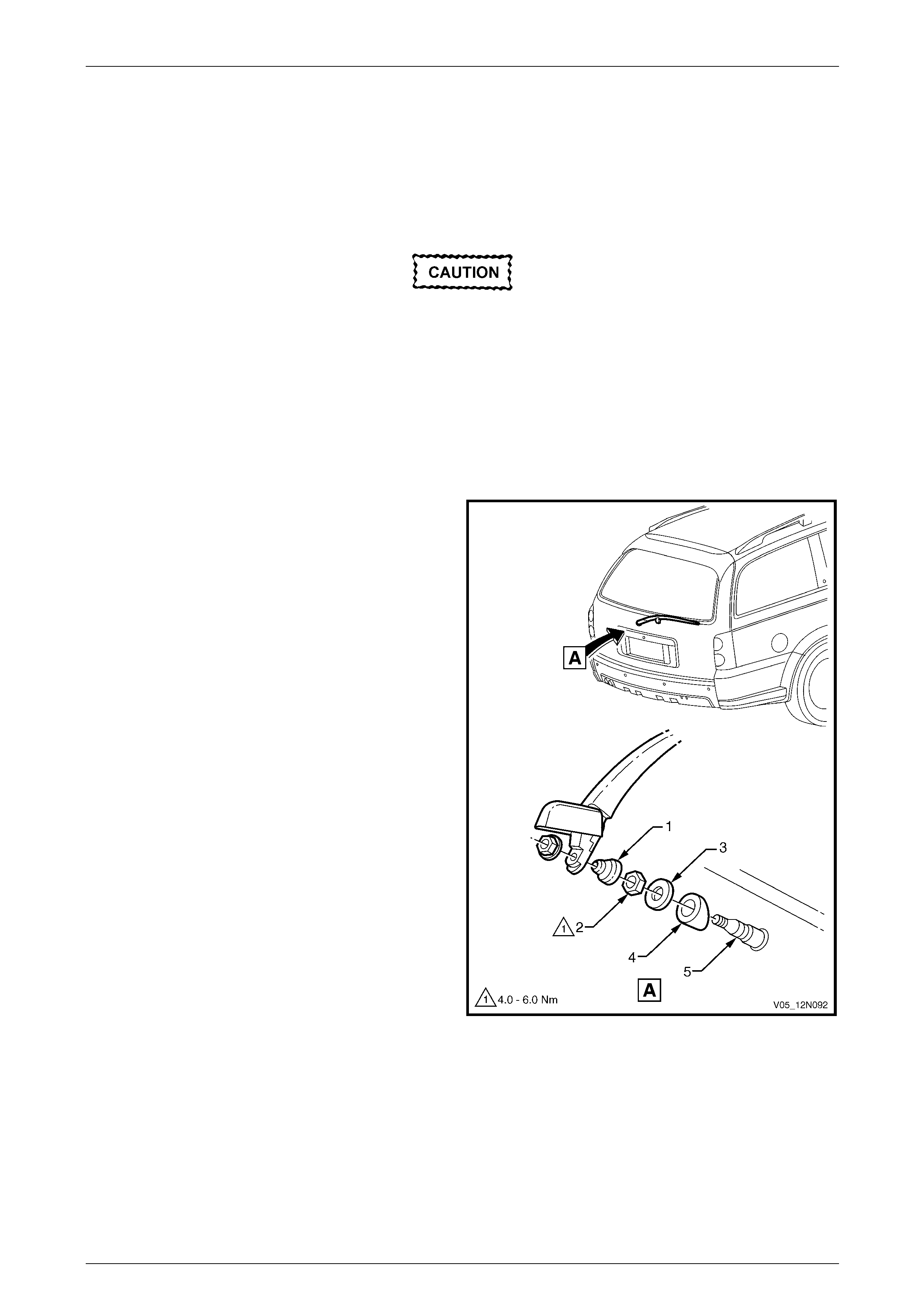
Wipers, Washers and Horn Page 12N–84
Page 12N–84
11.6 Rear Wiper Motor Assembly
LT Section — 10–525
Remove
Ensure the rear wiper motor assembly is in
the offscreen park position.
1 Remove the following components as required:
a Rear wiper fuse F18 from the passenger compartment fuse and relay panel assembly.
Refer to Section 12O Fuses, Relays and Wir ing.
b Rear wiper arm assembly, refer to 11.3 Rear Wiper Arm Assembly.
c Liftgate window lower garnish, and the liftgate lower trim panel,
refer to Section 1A4 Hood, Rear Compartment Lid, Liftgate and Endgate.
2 Remove the cover (1), nut (2), cap (3) and outer
spacer (4) from the rear wiper motor spigot (5).
Figure 12N – 56
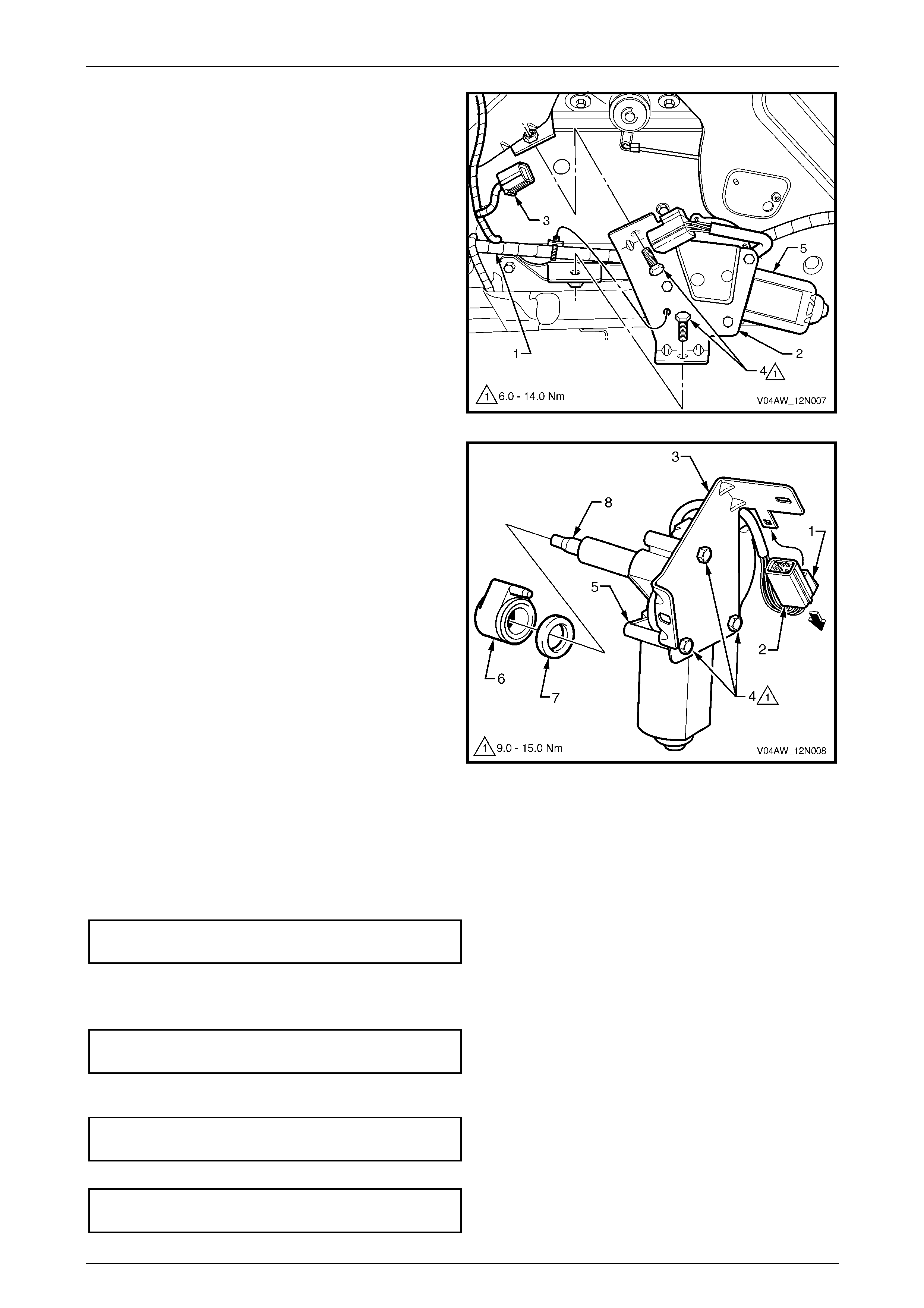
Wipers, Washers and Horn Page 12N–85
Page 12N–85
3 Unclip the liftgate harness (1) from the motor attaching
bracket (2).
4 Disconnect the motor wiring harness connector (3).
5 Remove the two screws (4) and remove the motor
assembly (5) with the attaching bracket, from the
liftgate.
Figure 12N – 57
6 Press the tab (1) and pull to remove the wiring
connector (2) from the motor attaching bracket (3).
7 Remove the three screws (4) and separate the rear
wiper motor (5) from the attaching bracket.
8 Remove the inner spacer (6) and the c ap (7) from the
rear wiper motor spigot (8).
Figure 12N – 58
Reinstall
Reinstallation of the rear wiper motor assembly is the reverse of the removal procedure, noting the following:
1 Ensure the cap (7) and the inner spacer (6) are fitted correctly onto the rear wiper motor spigot (8),
refer to Figure 12N – 58.
2 Tighten the three screws (4) attaching the r ear window wiper motor assembly to the correct torque sp ecification.
Rear window wiper motor assembly
attaching screw torque specification.........9.0 – 15.0 Nm
3 Ensure the wiring connector (2) is secured to the attaching bracket.
4 Tighten the two screws (4) attaching the rear window wiper motor bracket to the correct torque specification,
refer to Figure 12N – 57.
Rear window wiper motor br acket
attaching screw torque specification.........6.0 – 14.0 Nm
5 Ensure the outer spacer (4), cap (3) and nut (2) are fitted correctly onto the rear wiper motor spigot (5), refer to
Figure 12N – 56. Tighten the rear window wiper motor assembly attaching nut to the correct torque specification.
Rear window wiper motor ass embly
attaching nut torque specification................4.0 – 6.0 Nm
6 Tighten the rear window wiper arm assembly attaching nut (6) to the correct torque specification.
Rear window wiper arm ass embly
attaching nut torque specification............10.0 – 14.0 Nm
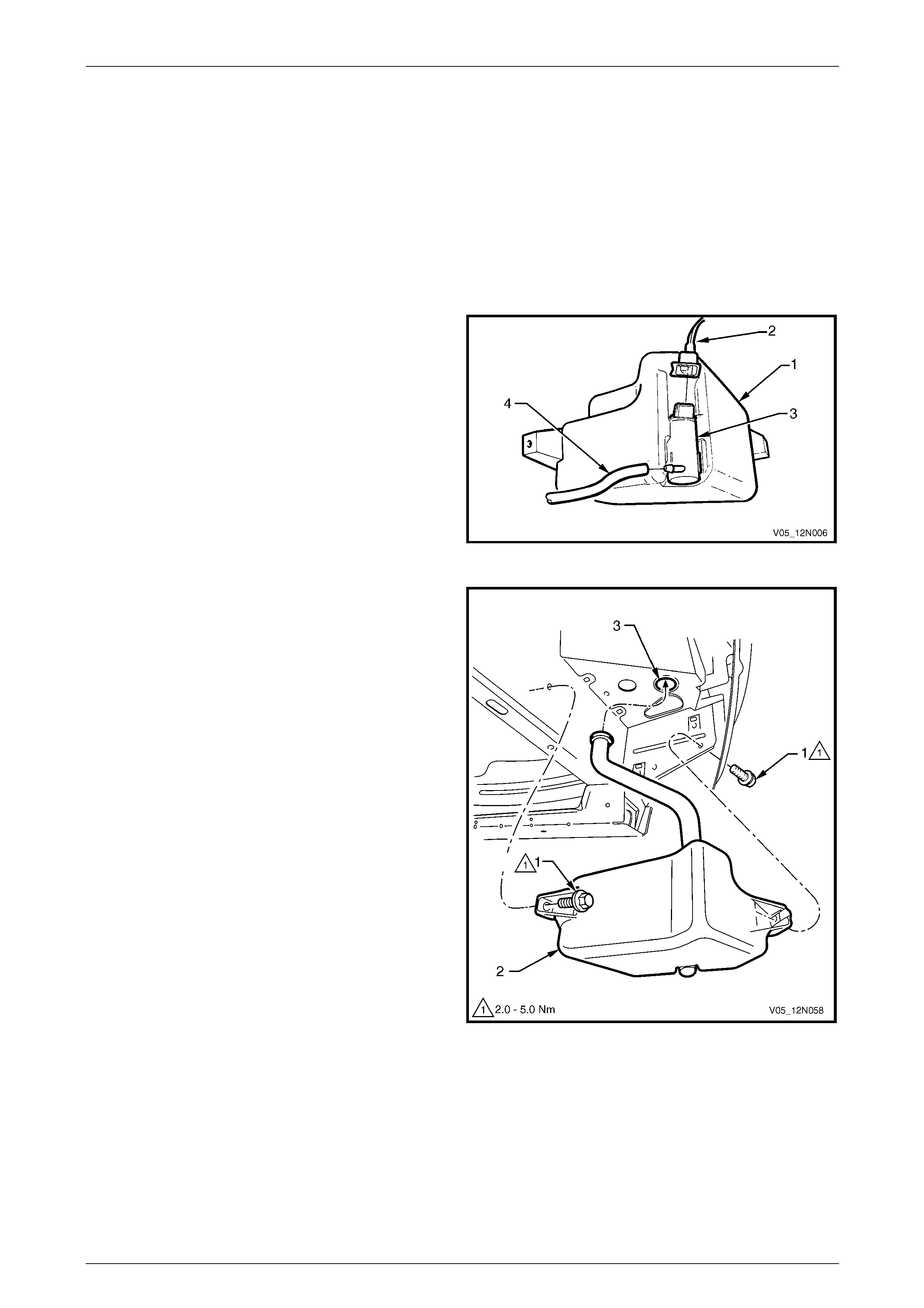
Wipers, Washers and Horn Page 12N–86
Page 12N–86
12 Service Operations – Washer
Assemblies, Sedan and Utility
12.1 Washer Reservoir Assembly
LT Section — 10–500
Remove
1 If required, remove the front right-hand road whe el,
refer to Section 10 Wheels and T yres.
2 Reach between the bumper a ssembly and the washer
reservoir assembly (1) and disconn ect the wiring
harness connector (2) from the washer pump
assembly (3).
3 Place a container under the washer reservoir
assembly, and disconnect the washer hose (4) from
the washer pump assembly.
4 Allow the washer fluid to drain from the washer
reservoir assembly.
Figure 12N – 59
5 Remove the two attaching screws (1) securing the
washer reservoir assembly (2).
6 Lower the washer reservoir assembl y and manoeuvre
the filler neck down through the hole in the fr ont
wheelhouse panel (3). If required remove the battery
to allow more space, refer to Section 12A Battery.
7 Unclip the washer pump from the washer reservoir.
Figure 12N – 60
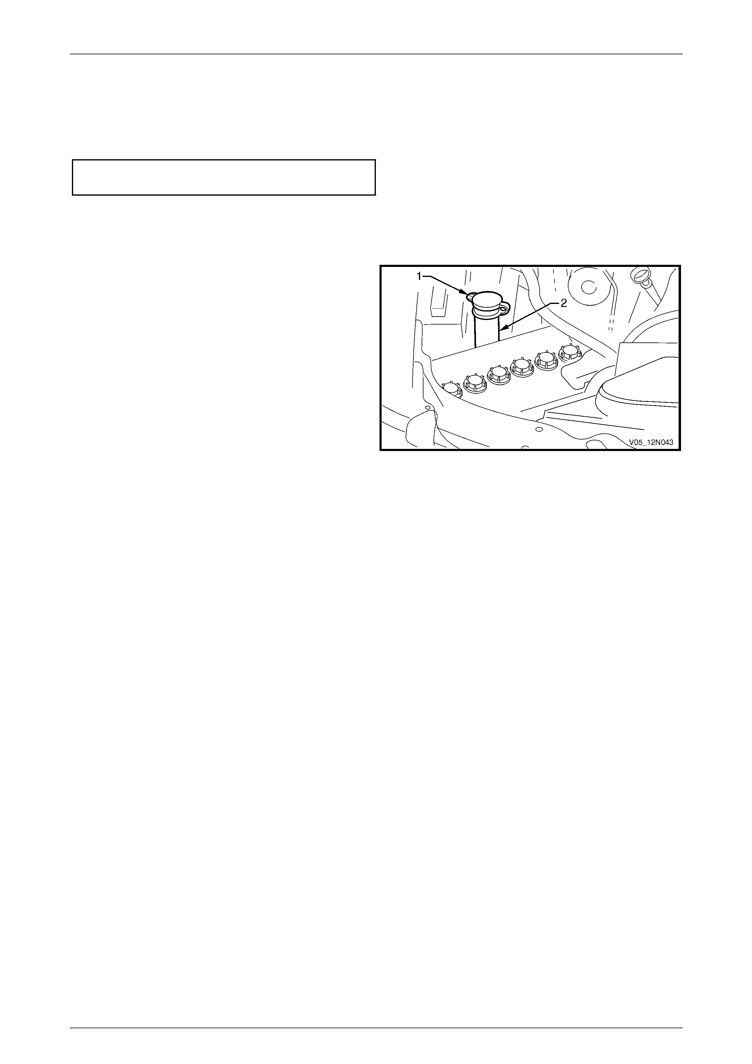
Wipers, Washers and Horn Page 12N–87
Page 12N–87
Reinstall
Reinstallation of the washer reservoir assembly is the reverse of the removal procedure, notin g the following:
1 Ensure the washer reservoir assemb ly attaching screws are tightened to the correct torque specification.
Washer reservoir attaching screw
torque specification.....................................2.0 – 5.0 Nm
2 Ensure the washer hose is installe d before filling the washer reservoir ass embly.
Filling the Washer Reservoir Assembly
1 Open the flip top cap (1) located within the engine bay
at the top of the washer reservoir assembly (2).
2 Fill the washer reservoir assembl y with the correct
amount of Optikleen or equivalent.
3 Secure the flip top cap.
Figure 12N – 61
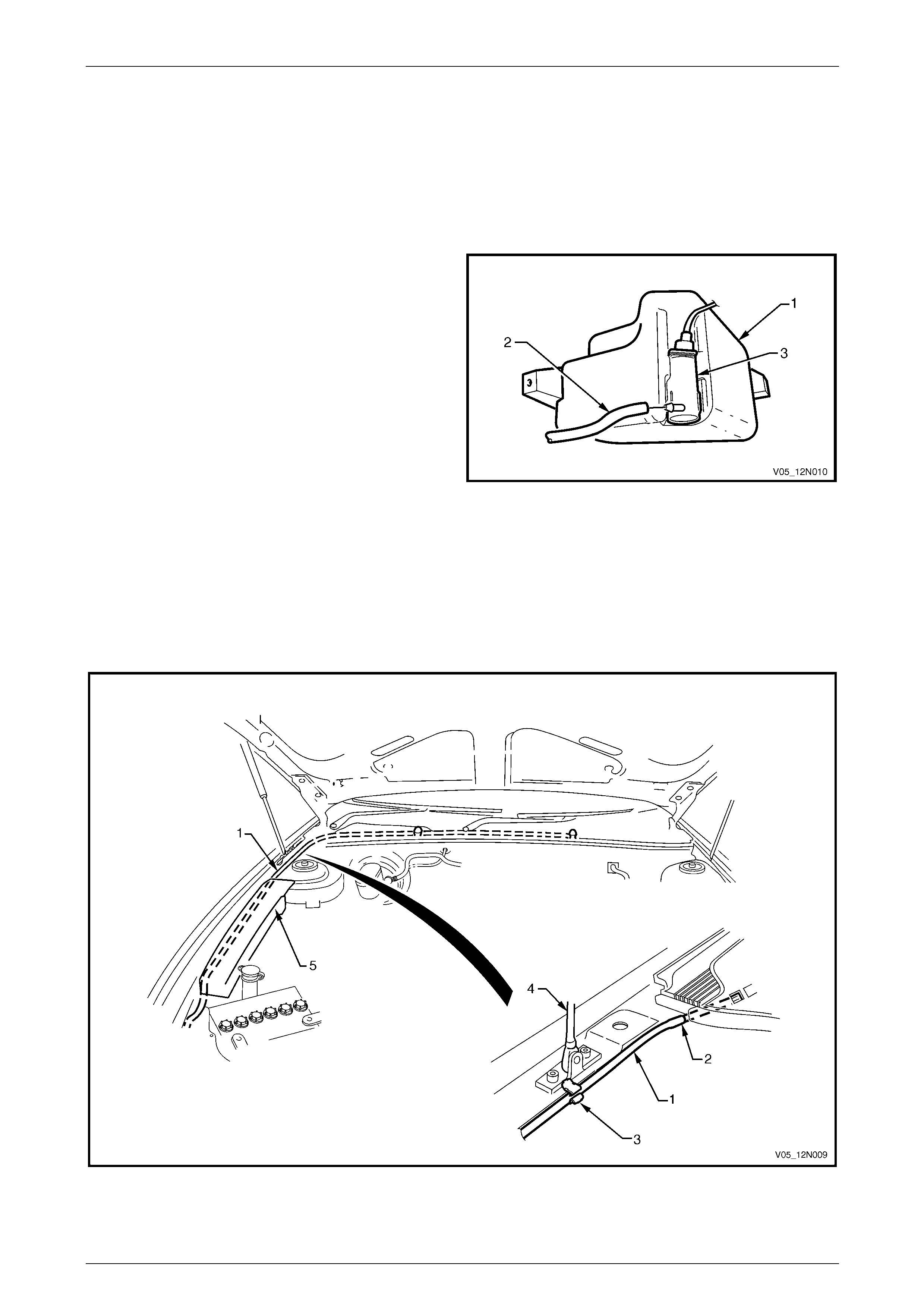
Wipers, Washers and Horn Page 12N–88
Page 12N–88
12.2 Front Washer Hose and Nozzle
Assemblies
LT Section — 10–500
Remove
1 Place a container underneath the washer reservoir
assembly (1).
2 Reach between the bumper a ssembly and the washer
reservoir assembly and disconnect the front wash er
hose (2) from the washer pump assembly (3).
3 Allow the washer fluid to drain from the washer
reservoir assembly.
Figure 12N – 62
4 Split the front washer hose (1) at the point (2) before it enters the plenum chamber, refer to Figure 12N – 63.
5 Unclip the front washer hose from the fastener (3) adjacent to the hood strut (4).
6 Carefully pull the front washer hose from be hind the engine compartment fuse and relay panel assembly (5) and
remove the front washer hose.
7 Remove the section of the front washer hose and the two front washers located within the plenum chamber,
refer to 8.4 Plenum Cover Assembly.
Figure 12N – 63

Wipers, Washers and Horn Page 12N–89
Page 12N–89
Reinstall
Reinstallation of the front washer hose an d the two front washers is the reverse of the removal procedure, noting the
following:
1 Connect the front washer hose to the washer pump assembl y befor e filling the washer reservoir assembly.
2 For information on filling the washer reservoir assembly, refer to 12.1 Washer Reservoir Assembly.
3 Check the front washers spray pattern on the windshield as detailed in this Section, refer to Spray Pattern Check.
Spray Pattern Check
1 Check the front washers spray pattern on the windshield and ensure the washer fluid strikes the glass panel within
a 100 mm diameter of the target points, refer to Figure 12N – 64.
2 If required, use a pin inserted into the ba ll of the front washer nozzle and swivel to correct the aim of the jet.
Figure 12N – 64
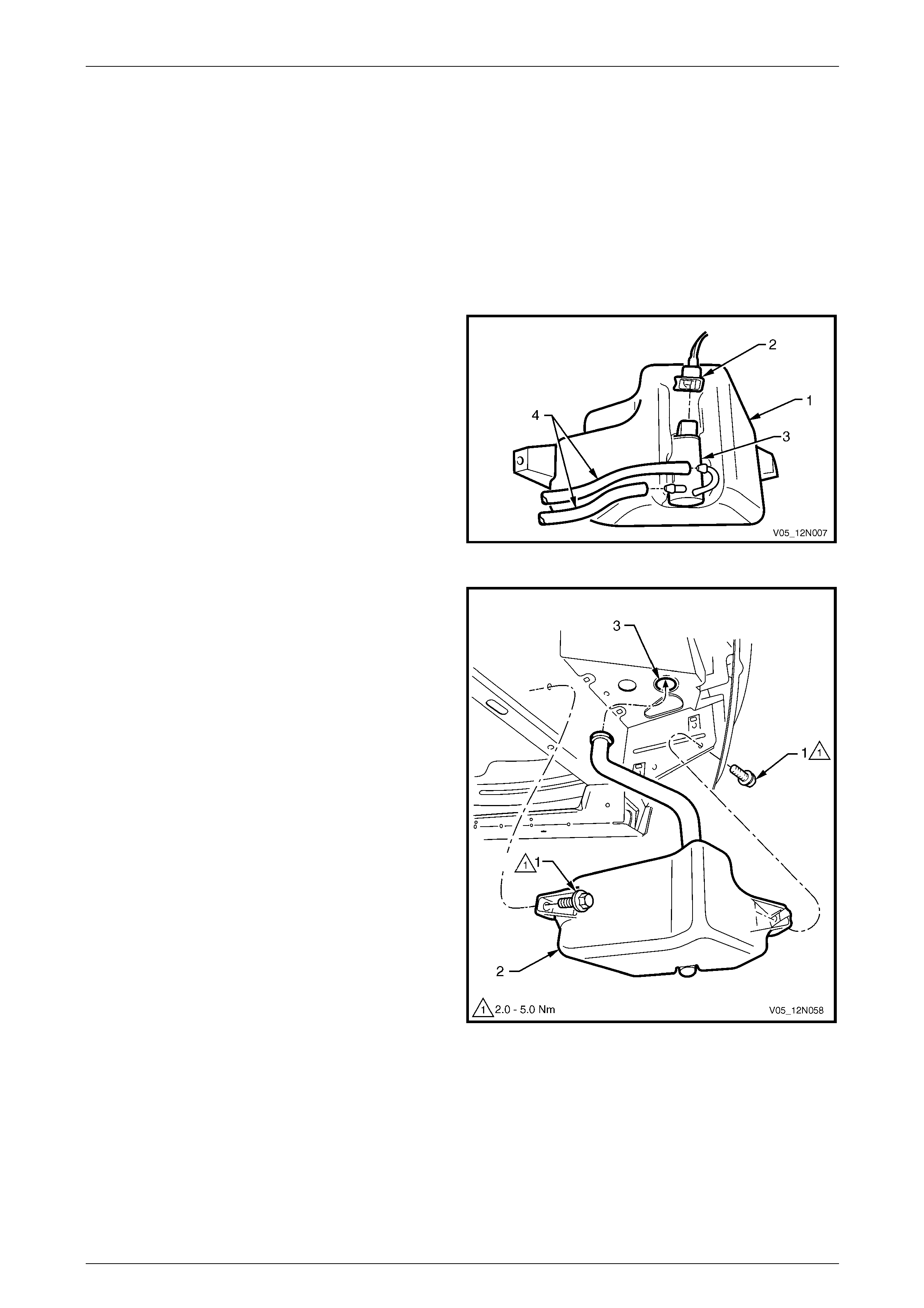
Wipers, Washers and Horn Page 12N–90
Page 12N–90
13 Service Operations – Washer
Assemblies, Wagon
13.1 Washer Reservoir Assembly
LT Section — 10–500
Remove
1 If required, remove the front right-hand road whe el,
refer to Section 10 Wheels and T yres.
2 Reach between the bumper a ssembly and the washer
reservoir assembly (1) and disconn ect the wiring
harness connector (2) from the washer pump
assembly (3).
3 Place a container under the washer reservoir
assembly, make note of the position of the two washer
hoses (4) and disconnect them from the washer pump
assembly.
4 Allow the washer fluid to drain from the washer
reservoir assembly.
Figure 12N – 65
5 Remove the two attaching screws (1) securing the
washer reservoir assembly (2).
6 Lower the washer reservoir assembl y and manoeuvre
the filler neck down through the hole in the fr ont
wheelhouse panel (3). If required remove the battery
to allow more space, refer to Section 12A Battery.
7 Unclip the washer pump from the washer reservoir.
Figure 12N – 66
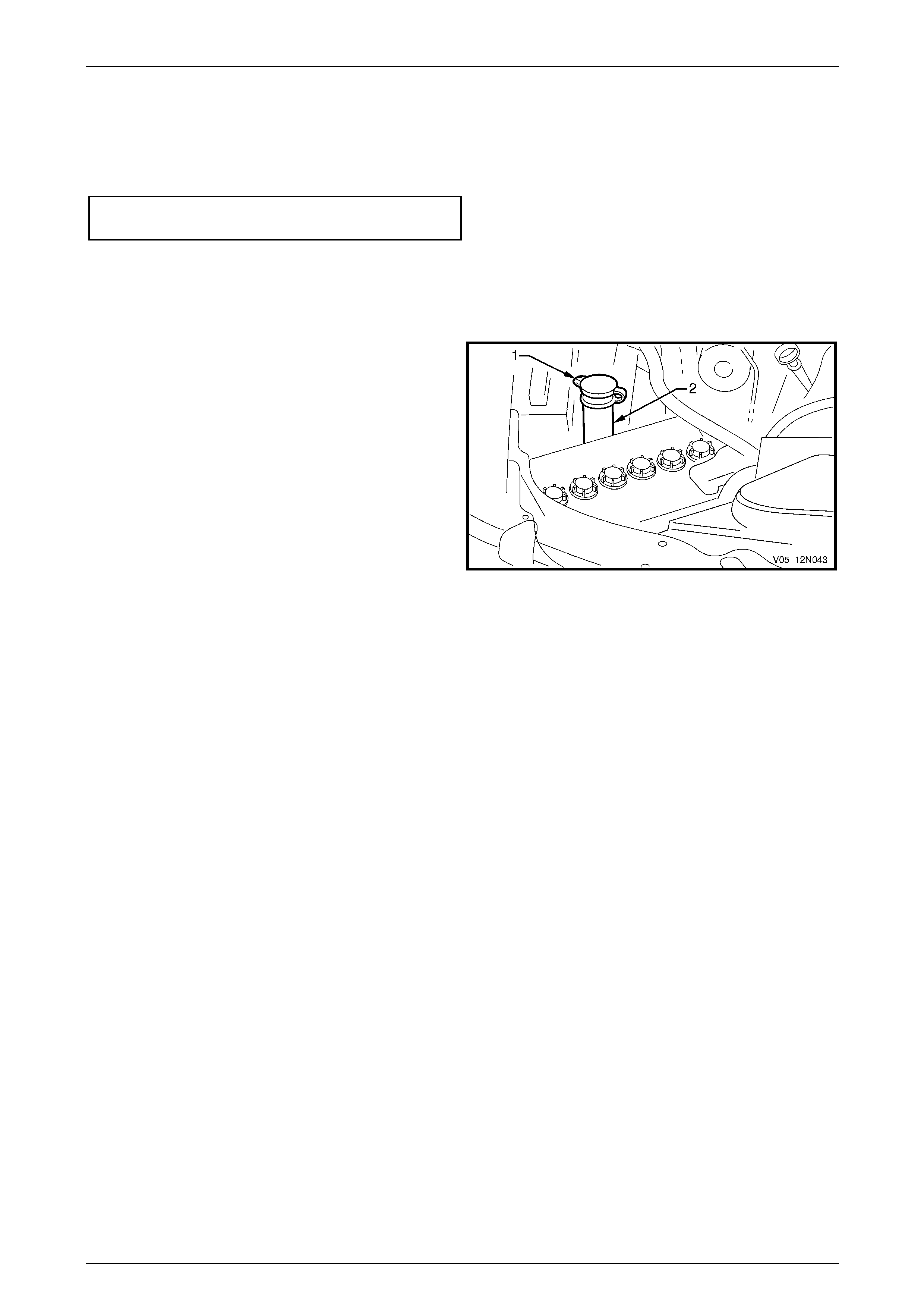
Wipers, Washers and Horn Page 12N–91
Page 12N–91
Reinstall
Reinstallation of the washer reservoir assembly is the reverse of the removal procedure, notin g the following:
1 Ensure the washer reservoir assemb ly attaching screws are tightened to the correct torque specification.
Washer reservoir attaching screw
torque specification.....................................2.0 – 5.0 Nm
2 Ensure the two washer hoses are insta lled in their respective position, as noted during removal, before filling the
washer reservoir assembly.
Filling the Washer Reservoir Assembly
1 Open the flip top cap (1) located within the engine bay
at the top of the washer reservoir assembly (2).
2 Fill the washer reservoir assembl y with the correct
amount of Optikleen or equivalent.
3 Secure the flip top cap.
Figure 12N – 67
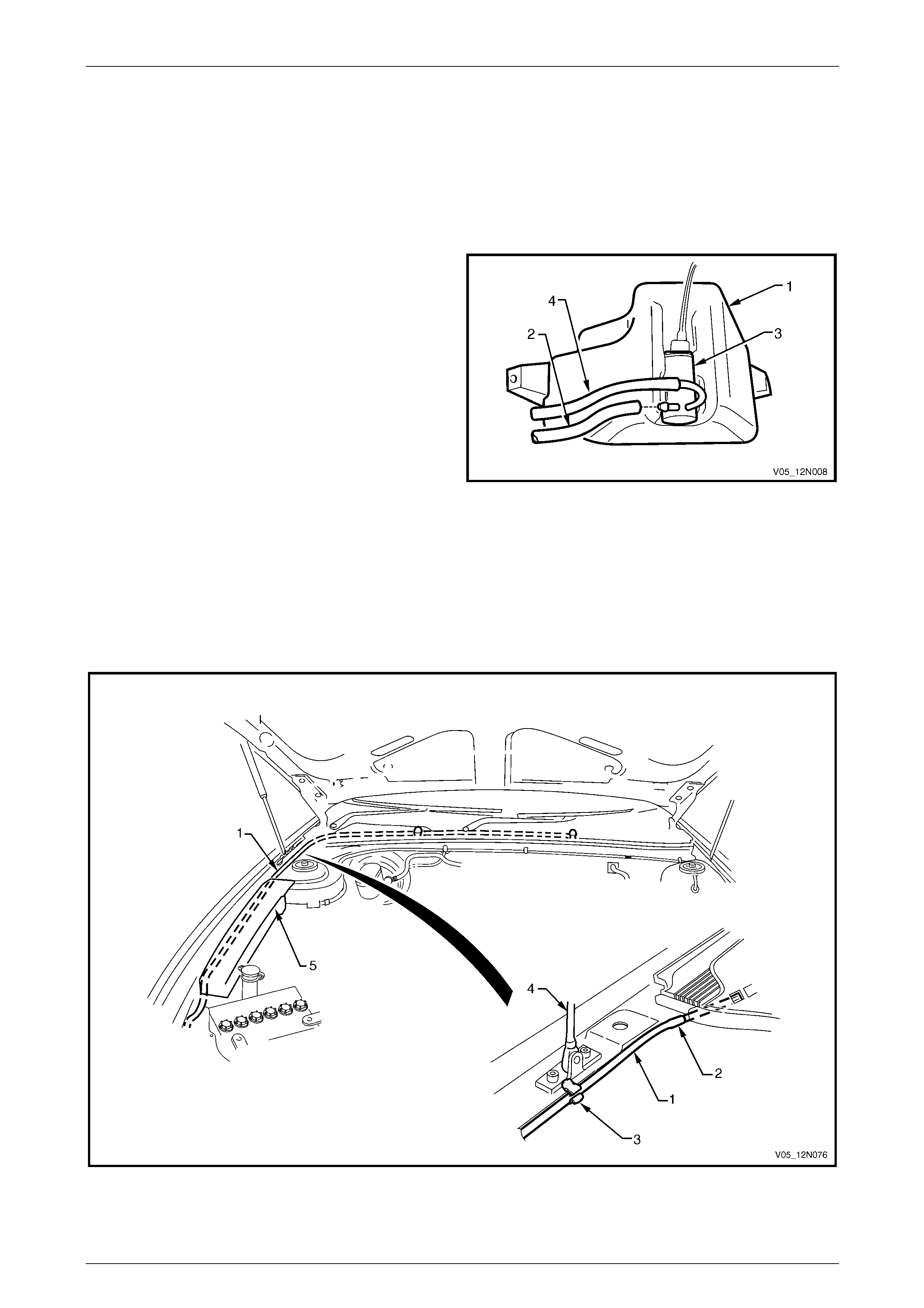
Wipers, Washers and Horn Page 12N–92
Page 12N–92
13.2 Front Washer Hose and Nozzle
Assemblies
LT Section — 10–500
Remove
1 Place a container underneath the washer reservoir
assembly (1).
2 Reach between the bumper a ssembly and the washer
reservoir assembly and disconnect the front wash er
hose (2) from the washer pump assembly (3).
NOTE
A rear washer hose (4) is also fitted to the
washer pump, do not disconnect it unless
required.
3 Allow the washer fluid to drain from the washer
reservoir assembly. Figure 12N – 68
4 Split the front washer hose (1) at the point (2) before it enters the plenum chamber, refer to Figure 12N – 69.
5 Unclip the front washer hose from the fastener (3) adjacent to the hood strut (4).
6 Carefully pull the front washer hose from be hind the engine compartment fuse and relay panel assembly (5) and
remove the front washer hose.
7 Remove the section of the front washer hose and the two front washers located within the plenum chamber, refer to
8.4 Plenum Cover Assembly.
Figure 12N – 69
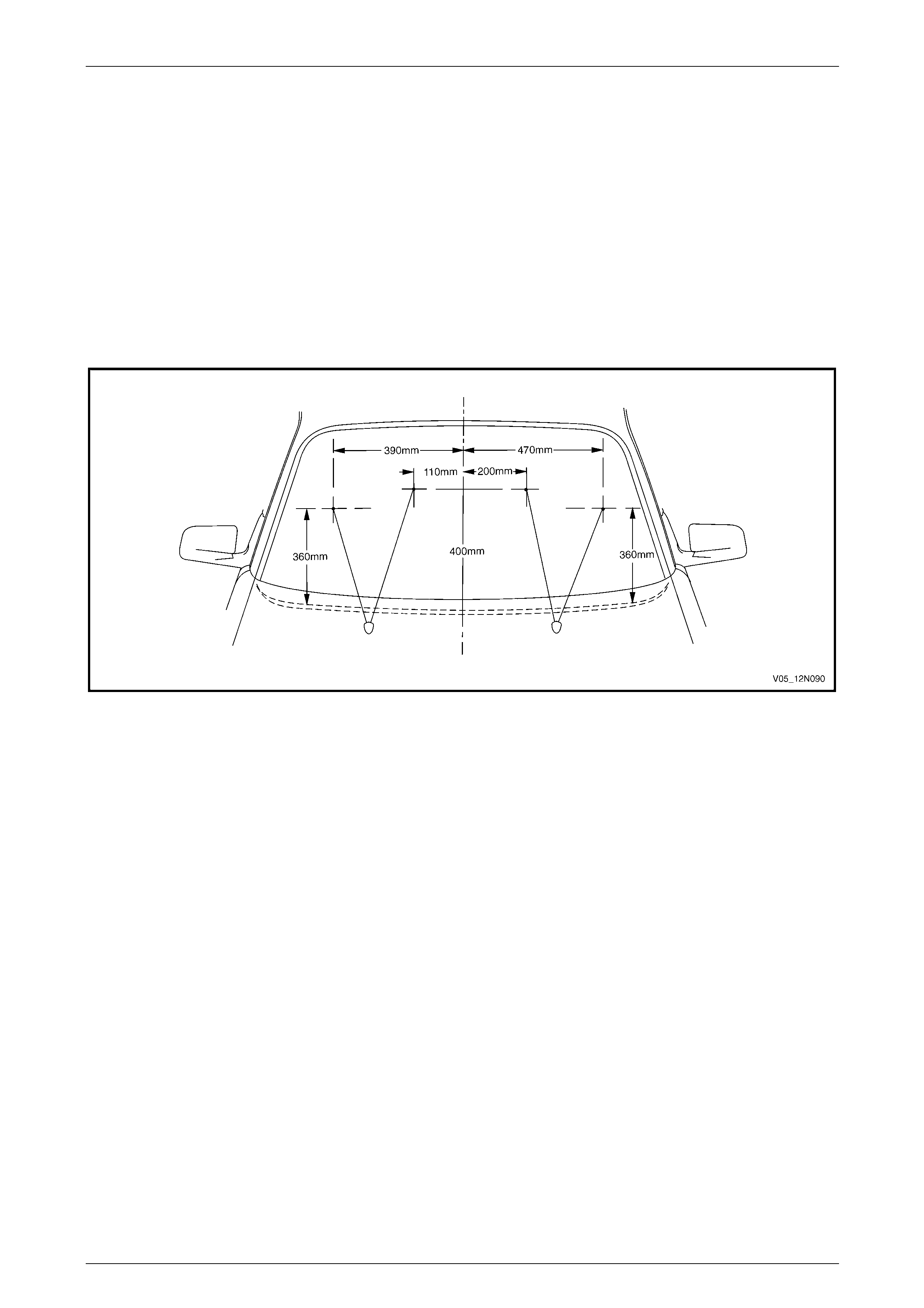
Wipers, Washers and Horn Page 12N–93
Page 12N–93
Reinstall
Reinstallation of the front washer hose an d the two front washers is the reverse of the removal procedure, noting the
following:
1 Connect the front washer hose to the washer pump assembl y befor e filling the washer reservoir assembly.
2 For information on filling the washer reservoir assembly, refer to 13.1 Washer Reservoir Assembly.
3 Check the front washers spray pattern on the windshield as detailed in this Section, refer to Spray Pattern Check.
Spray Pattern Check
1 Check the front washers spray pattern on the windshield and ensure the washer fluid strikes the glass panel within
a 100 mm diameter of the target points, refer to Figure 12N – 70.
2 If required, use a pin inserted into the ba ll of the front washer nozzle and swivel to correct the aim of the jet.
Figure 12N – 70
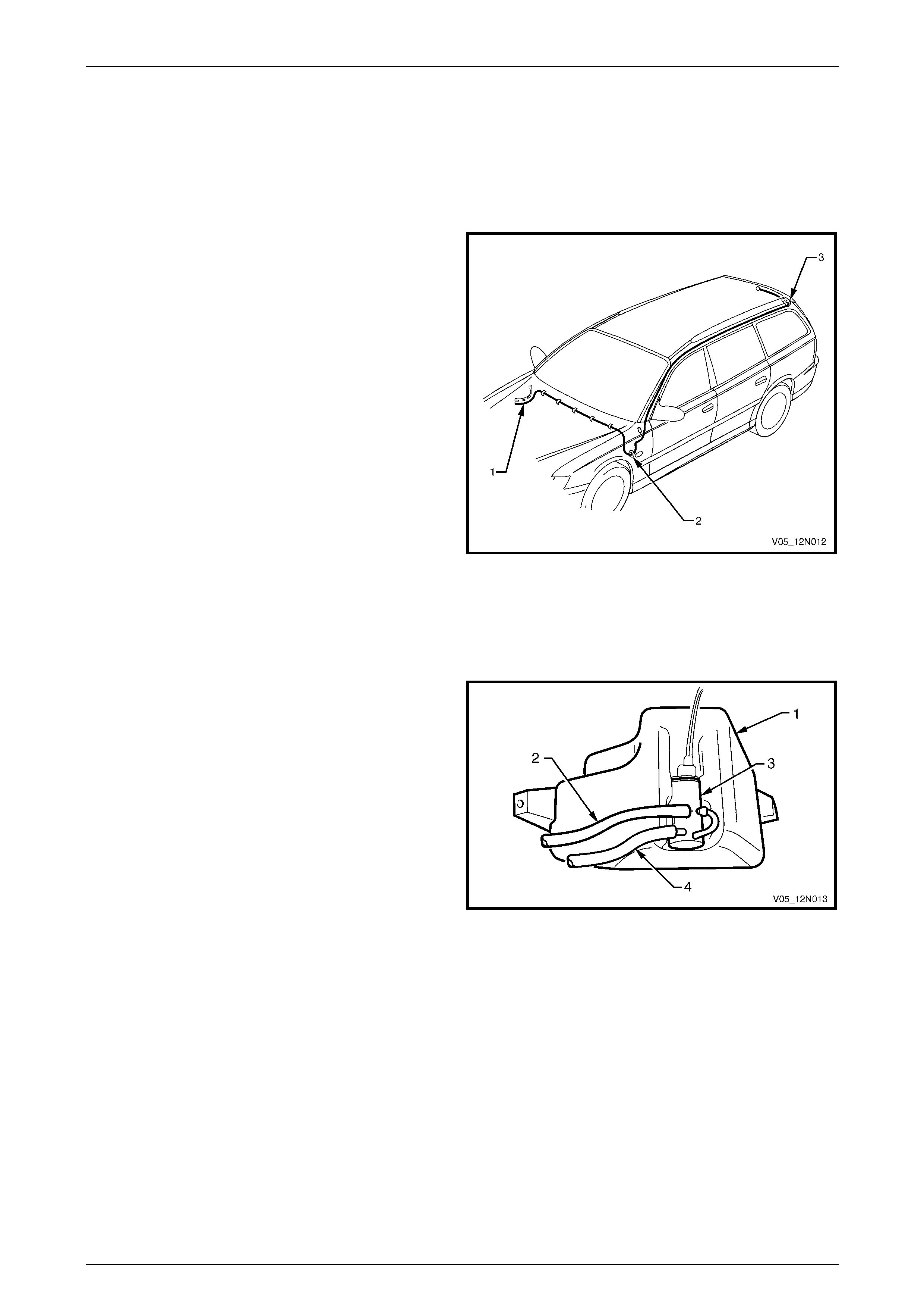
Wipers, Washers and Horn Page 12N–94
Page 12N–94
13.3 Rear Washer Hose and Nozzle Assembly
LT Section — 10–500
Introduction
The rear washer hose (1) in the Wagon vehicles is routed
around the engine bay, through the firewall (2) and along
the left-hand side of the vehicle between the roof bows and
the roof panel. The rear washer hose then enters the liftgate
via a grommet (3) linking the rear quarter panel and the
liftgate.
The rear washer hose can be split in two sections (front and
rear) at a point in the engine bay just prior to the firewall.
Figure 12N – 71
Remove
Front Section
1 Place a container underneath the washer reservoir
assembly (1).
2 Reach between the bumper a ssembly and the washer
reservoir assembly and disconnect the rear wash er
hose (2) from the washer pump assembly (3).
NOTE
A front washer hose (4) is also fitted to the
washer pump assembly, do not disconnect it
unless required.
3 Allow the washer fluid to drain from the washer
reservoir assembly. Figure 12N – 72
4 Unclip the rear washer hose (1) from the three clips (2) on the underside of the main wiring harness (3) around the
strut tower and remove from the clips along the firewall (4), refer to Figure 12N – 73.
NOTE
Before it crosses the firewall, the rear washer
hose can be disconnected at joint (6) and split in
two sections if required.
5 Carefully pull the rear washer hose from behind the engine compartme nt fuse pa nel (5) and remove from the
engine bay.
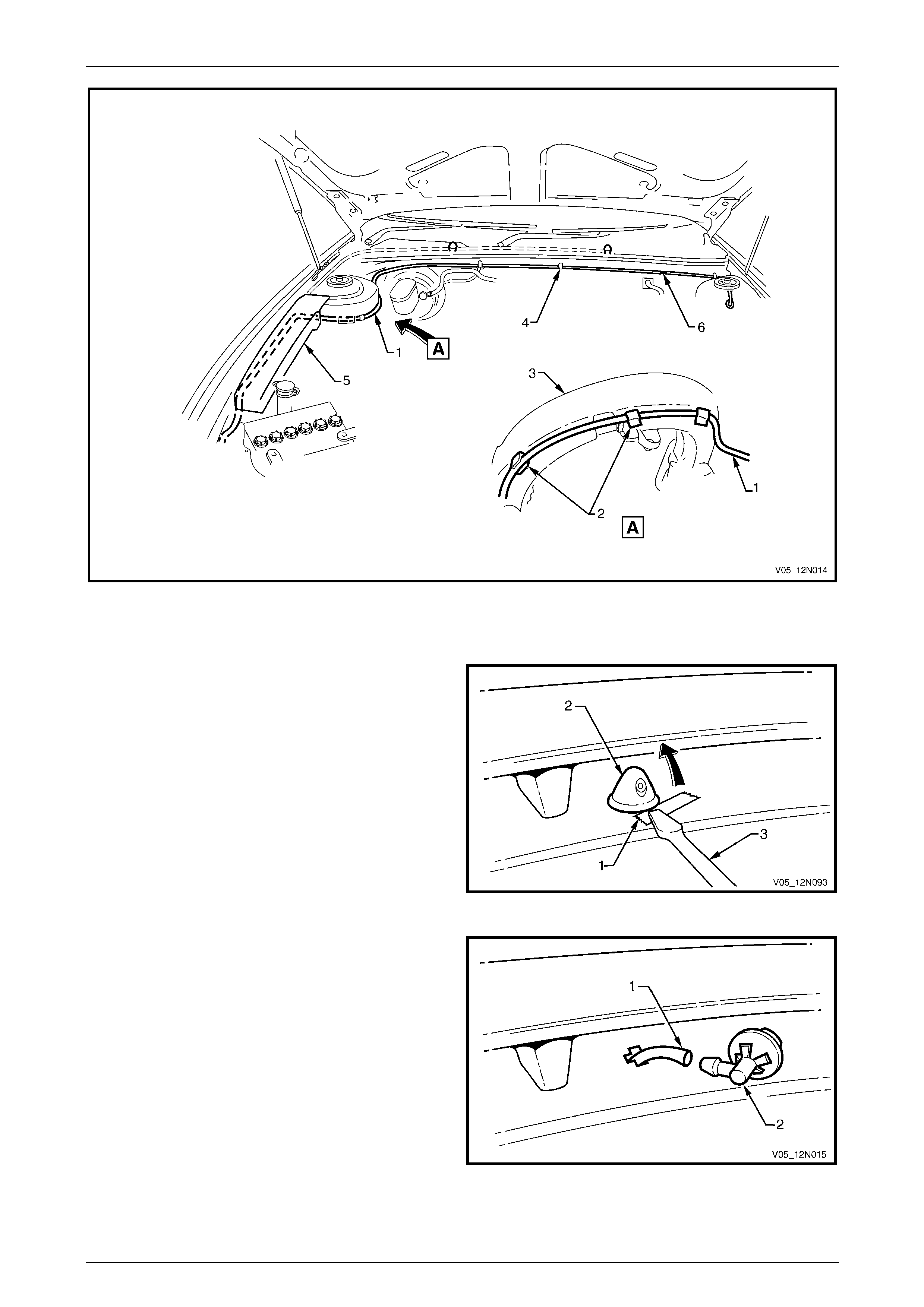
Wipers, Washers and Horn Page 12N–95
Page 12N–95
Figure 12N – 73
Rear Section
1 Place a piece of tape (1) or similar to protect the
paintwork adjacent to the rear window washer nozzle
assembly (2) and using a fine flat blade screwdriver,
prise the rear washer nozzle from the liftgate
assembly.
Figure 12N – 74
2 Disconnect the rear washer hose (1) from the rear
washer nozzle assembly (2).
Figure 12N – 75
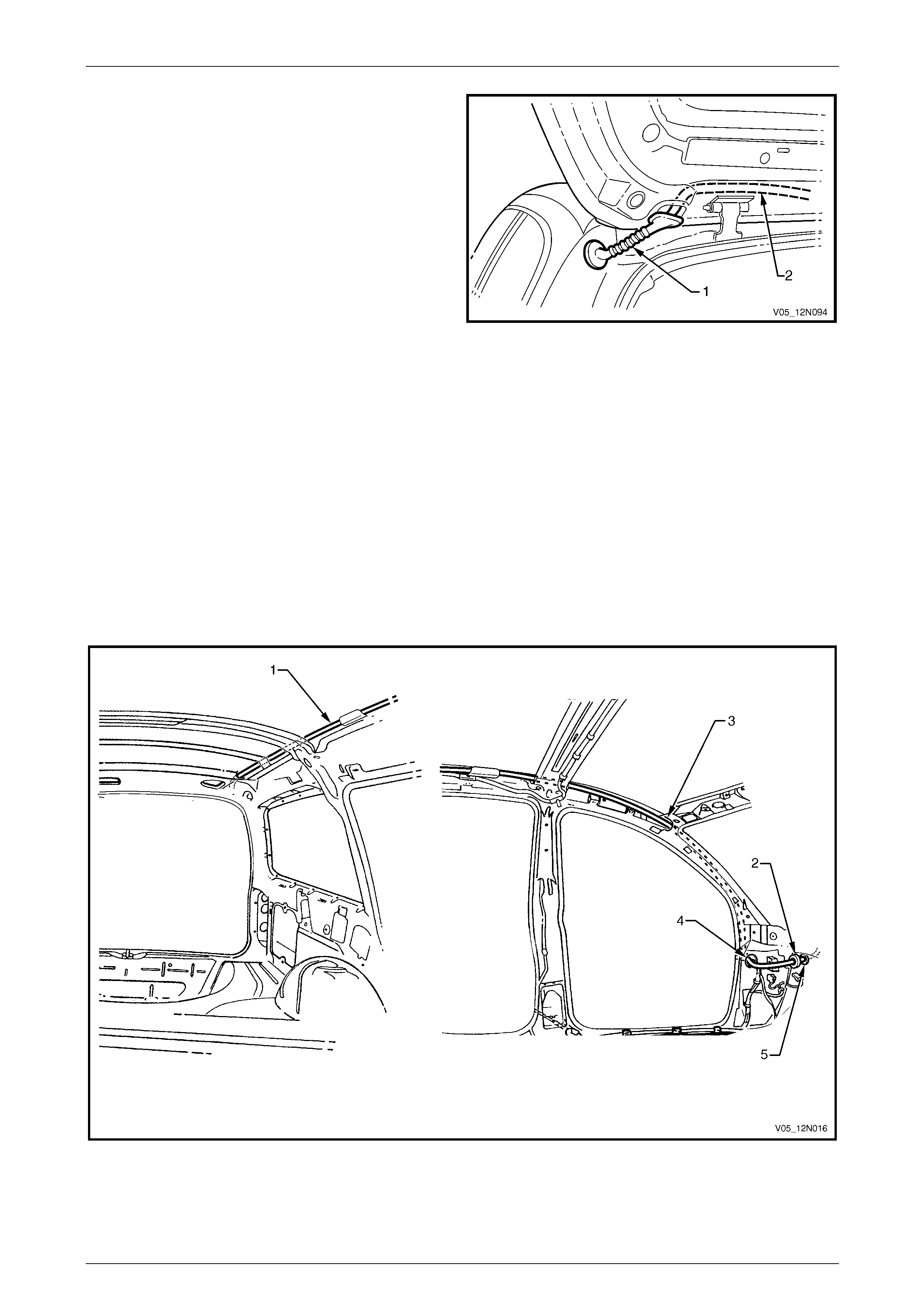
Wipers, Washers and Horn Page 12N–96
Page 12N–96
3 Disconnect the rubber grommet (1) from the liftgate
assembly and if required from the rear quarter panel.
4 Withdraw the rear washer hose (2) from the liftgate.
Figure 12N – 76
5 Remove the Instrument Panel Compartment assembly, refer to Section 1A3 Instrument Panel an d Console.
6 Before removal, attach a piece of string to the end of the rear washer hose ( 1) to help guide the replacement hose,
refer to Figure 12N – 77.
7 If required, to facilitate the removal of the rear washer hose remove the following,
refer to Section 1A8 Headlining and Interior Trim:
• windshield side garnish
• body lock pillar garnish
• body rear corner garnish.
8 Remove the rubber grommet (2) from the fire wall.
9 Carefully withdra w the rear washer hose from the vehicl e by feeding it out through the holes (3 and 4) in the hinge
pillar inner panel assembly and the hole (5) in the firewall.
Figure 12N – 77
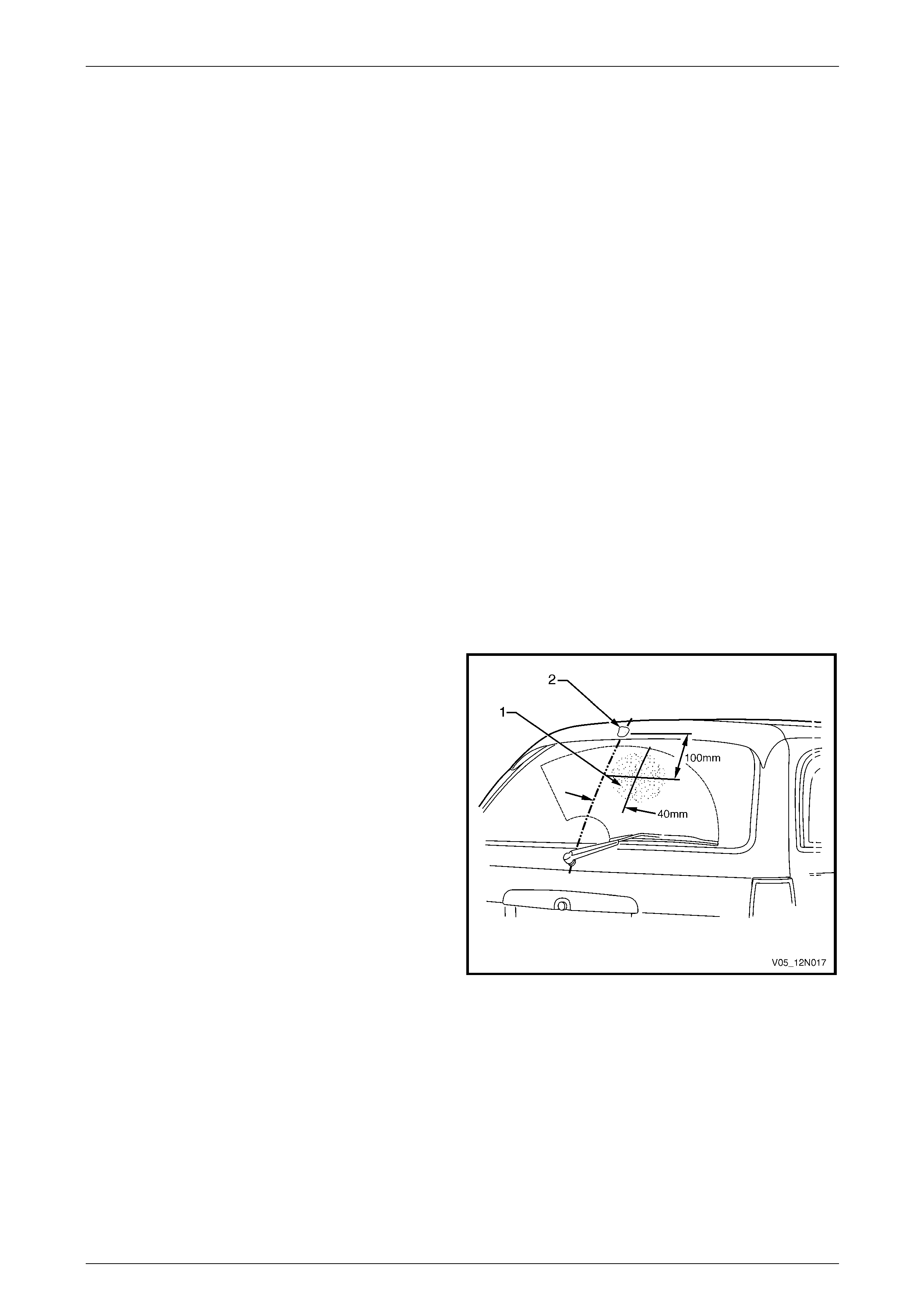
Wipers, Washers and Horn Page 12N–97
Page 12N–97
Reinstall
Reinstallation of the rear washer hose and the rear washer is the reverse of the removal procedure, noting the follo wing.
NOTE
If the rear washer hose has been split in two
sections (front and rear), ensure the t wo sections
are reconnected.
Front Section
1 Ensure the rear washer hose is secured with the clips on the underside of the main wiring harness and along the
firewall.
2 Connect the rear washer hose to the washer pump assem bl y befor e filling the washer reservoir assembly.
3 For information on filling the washer reservoir assembly, refer to 13.1 Washer Reservoir Assembly.
Rear Section
1 Use the string attached to the rear washer hose during the removal procedure to guide the replacement hose back
through the correct path.
2 Ensure the rubber grommet (2) is fitted to the firewall, refer to Figure 12N – 77.
3 Ensure the grommet (1) is secured to the liftgate assembly, refer to Figure 12N – 76.
4 Ensure the rear washer nozzle is connected to the rear washer hose, correctly orientated and secured to the
liftgate assembly.
5 Check the rear washer spray pattern on the rear window as detailed in this Section, refer to Spray Pattern Check.
Spray Pattern Check
1 Check the rear washer spray pattern and ensure the
washer fluid strikes the glass panel within a 100 mm
diameter (1) of the target point,
2 If required, use a pin inserted into the ba ll of the rear
washer nozzle (2) and swivel to correct the aim of the
jet.
Figure 12N – 78

Wipers, Washers and Horn Page 12N–98
Page 12N–98
14 Service Operations – Washer
Assemblies, AWD Wagon
14.1 Washer Reservoir Assembly
LT Section — 10–500
Remove and Reinstall
The removal and reinstallatio n proce dures of the washer reservoir assembly for AWD Wagon vehicles are identical to the
removal and reinstallation procedures for Wagon vehicles, refer to 13.1 Washer Reservoir Assembly.

Wipers, Washers and Horn Page 12N–99
Page 12N–99
14.2 Front Washer Hose and Nozzle
Assemblies
LT Section — 10–500
Remove and Reinstall
The removal and reinstallatio n proce dures of the front washer hose and nozzle assemblies for AWD Wagon vehicles are
identical to the removal and reinstall atio n pro c edures for Wagon vehicles,
refer to 13.2 Front Washer Hose and Nozzle Assemblies.
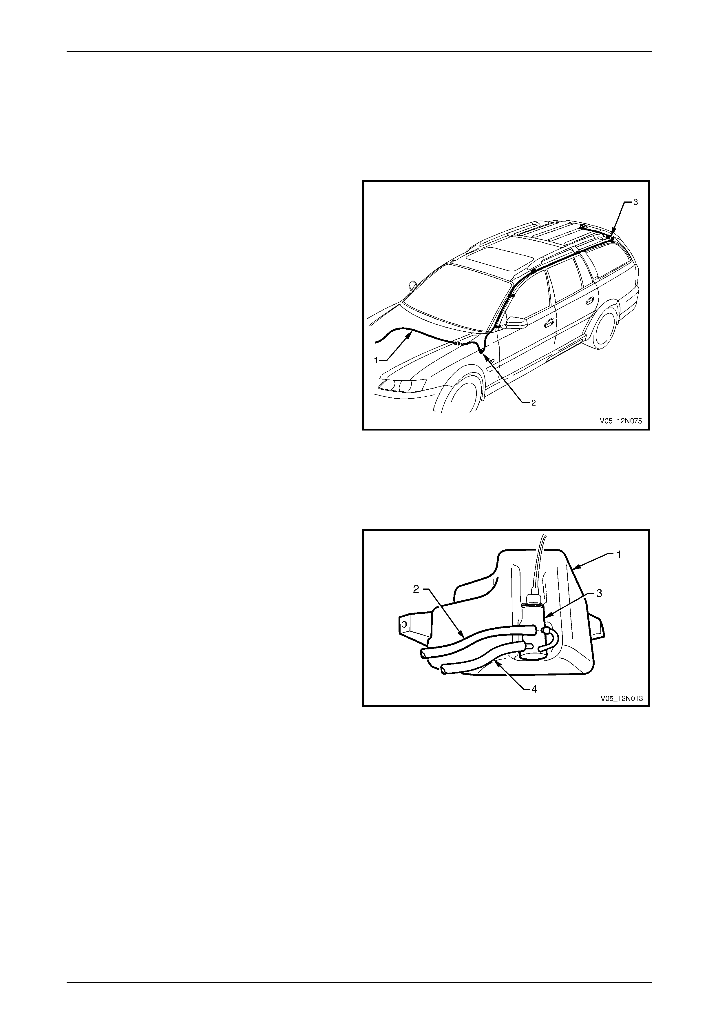
Wipers, Washers and Horn Page 12N–100
Page 12N–100
14.3 Rear Washer Hose and Nozzle Assembly
LT Section — 10–500
Introduction
The rear washer hose (1) in the AWD W agon vehicles is
routed around the engine bay, through the fire wall (2) and
along the left-hand side of the vehicle between the roof
bows and the roof panel. The rear washer hose then enters
the liftgate via a grommet (3) linking the rear quarter pan el
and the liftgate.
The rear washer hose can be split in two sections (front and
rear) at a point in the engine bay just prior to the firewall.
Figure 12N – 79
Remove
Front Section
1 Place a container underneath the washer reservoir
assembly (1).
2 Reach between the bumper a ssembly and the washer
reservoir assembly and disconnect the rear wash er
hose (2) from the washer pump assembly (3).
NOTE
A front washer hose (4) is also fitted to the
washer pump assembly, do not disconnect it
unless required.
3 Allow the washer fluid to drain from the washer
reservoir assembly. Figure 12N – 80
4 Unclip the rear washer hose (1) from the clips (2) on the underside of the main wiring harness (3) around the strut
tower and remove from the clips along the firewall (4), refer to Figure 12N – 81.
NOTE
Before it crosses the firewall, the rear washer
hose can be disconnected at joint (6) and split in
two sections if required.
5 Carefully pull the rear washer hose from behind the engine compartme nt fuse pa nel (5) and remove from the
engine bay.
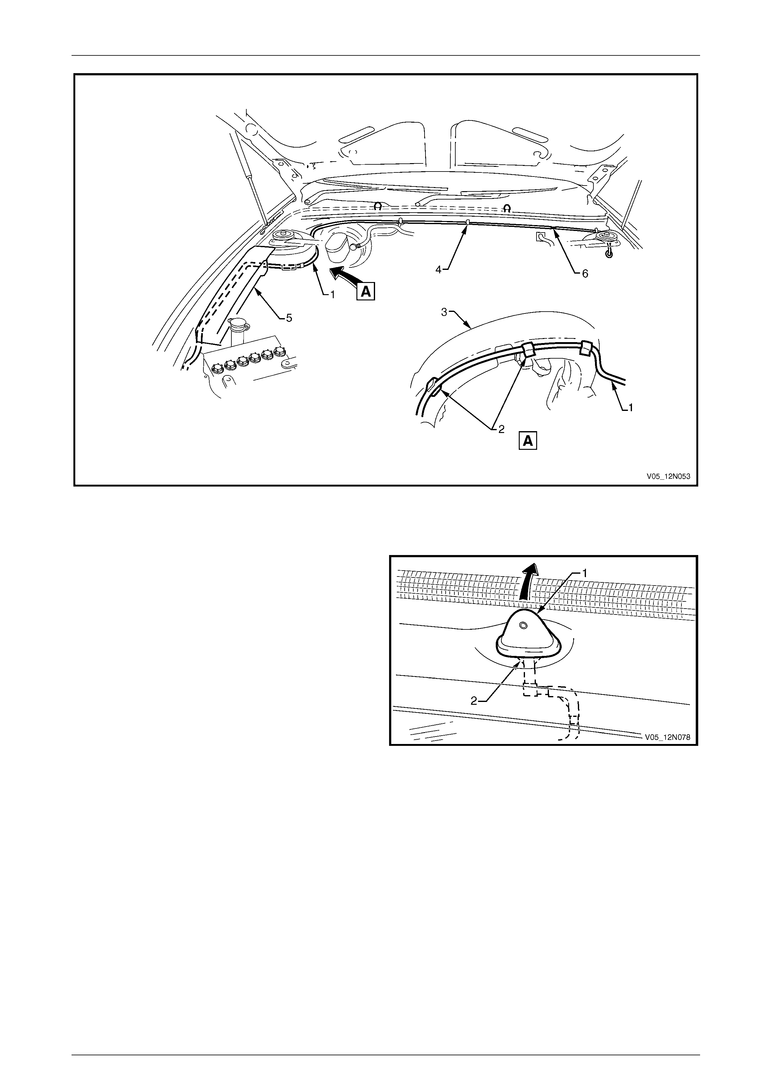
Wipers, Washers and Horn Page 12N–101
Page 12N–101
Figure 12N – 81
Rear Section
1 Remove the liftgate windo w upper garnis h to get
access to the base of the rear window washer nozzle
assembly (1), refer to Section 1A4 Hood, Rear
Compartment Lid, Liftgate and Endgate.
2 From inside the liftgate, using long nose pliers depress
the retaining tongues (2) and release the rear window
washer nozzle assembly from the liftgate panel.
Figure 12N – 82
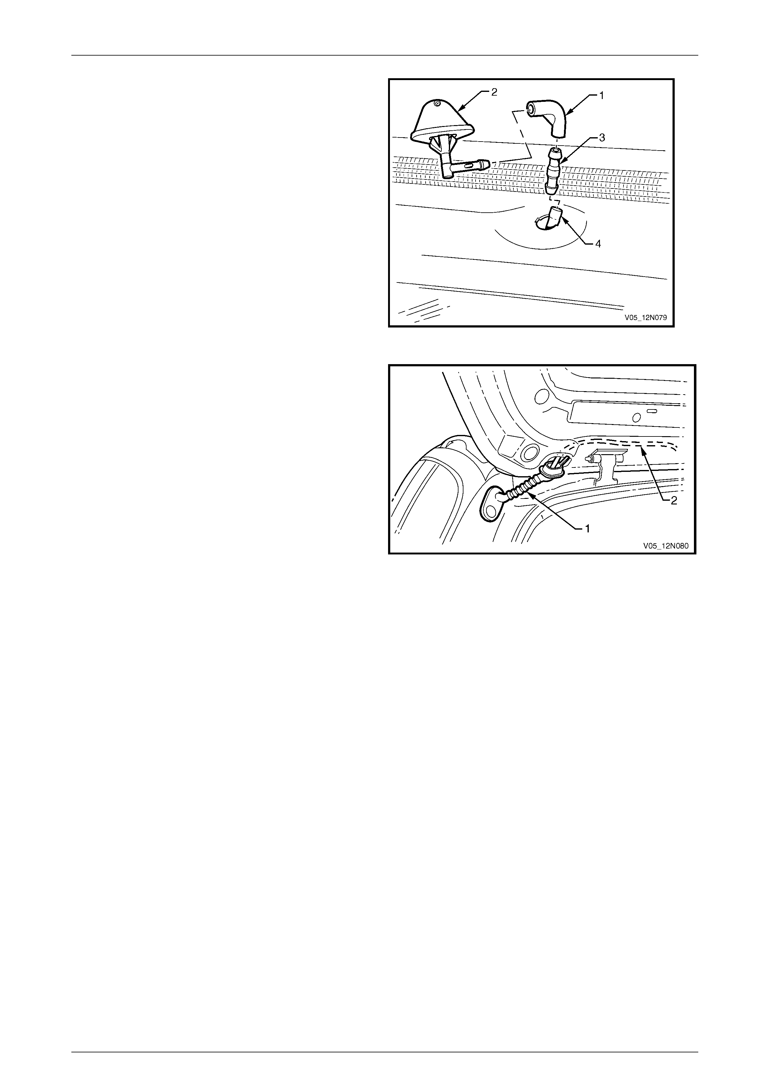
Wipers, Washers and Horn Page 12N–102
Page 12N–102
3 Disconnect the rubber elbow (1) from the rear window
washer nozzle assembly (2) and from the one way
valve (3).
4 If required, disconnect the one way valv e from the rear
washer hose (4).
Figure 12N – 83
5 Disconnect the rubber grommet (1) from the liftgate
assembly and if required from the rear quarter panel.
6 Withdraw the rear washer hose (2) from the liftgate.
Figure 12N – 84
7 Remove the Instrument Panel Compartment assembly, refer to Section 1A3 Instrument Panel an d Console.
8 Remove the windshield side g arnish, refer to Section 1A8 Headlining and Interior Trim.
9 If required, to facilitate the removal of the rear washer hose remove the following,
refer to Section 1A8 Headlining and Interior Trim:
• body lock pillar garnish
• body rear corner garnish.
10 Before removal, attach a piece of string to the end of the rear washer hose ( 1) to help guide the replacement hose,
refer to Figure 12N – 77.
11 Remove the rubber grommet (2) from the firewall.
12 Release the rear washer hose from the securin g clips (3 and 4) above the front door opening.
13 Carefully withdra w the rear washer hose from the vehicle by feeding it out through the holes (5 and 6) i n the hinge
pillar inner panel assembly and the hole (6) in the firewall.
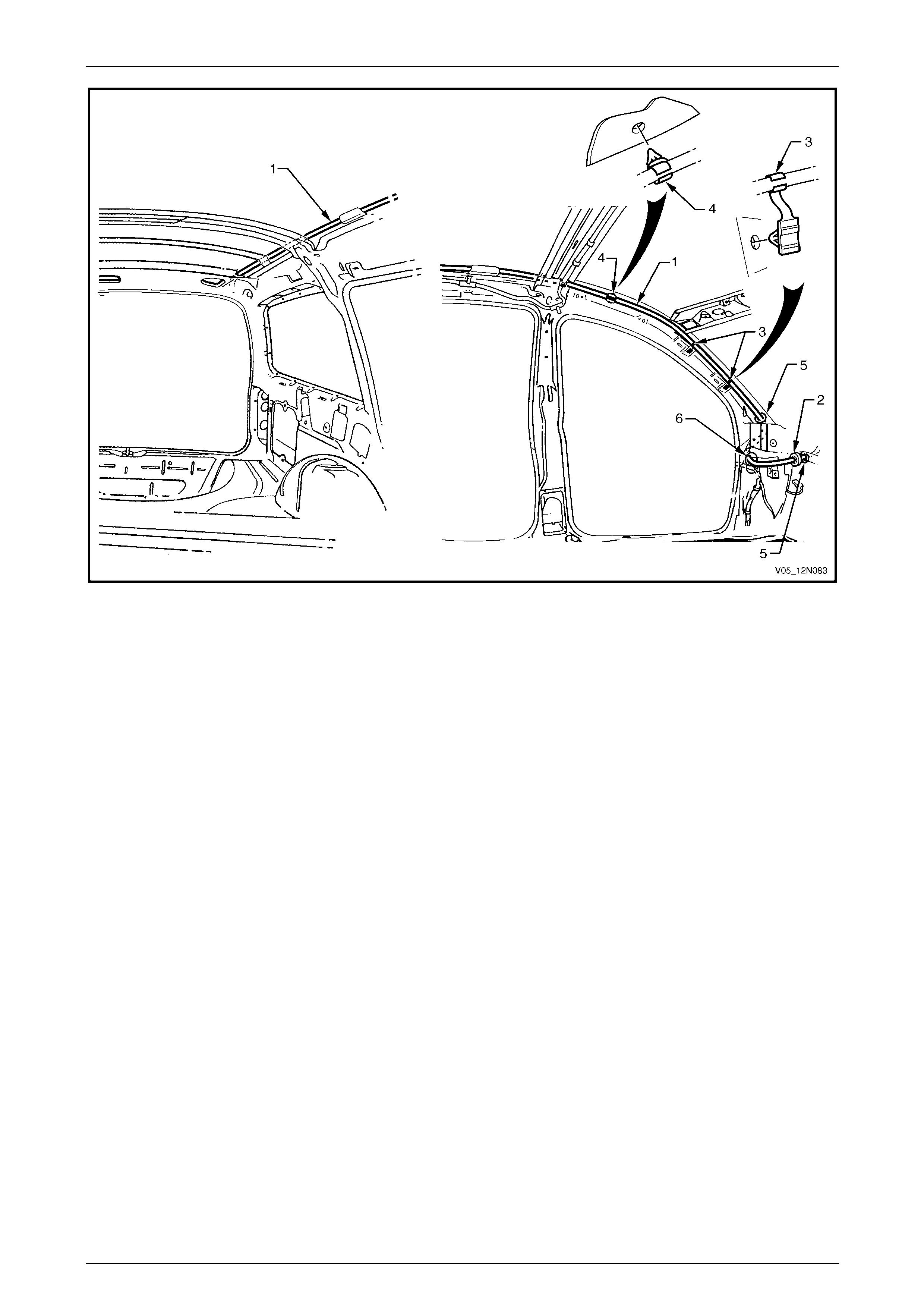
Wipers, Washers and Horn Page 12N–103
Page 12N–103
Figure 12N – 85
Reinstall
Reinstallation of the rear washer hose and the rear washer is the reverse of the removal procedure, noting the follo wing.
NOTE
If the rear washer hose has been split in two
sections (front and rear), ensure the t wo sections
are reconnected.
Front Section
1 Ensure the rear washer hose is secured with the clips on the underside of the main wiring harness and along the
firewall.
2 Connect the rear washer hose to the washer pump assem bl y befor e filling the washer reservoir assembly.
3 For information on filling the washer reservoir assembly, refer to 14.1 Washer Reservoir Assembly.
Rear Section
1 Use the string attached to the rear washer hose during the removal procedure to guide the replacement rear
washer hose (1) back through the correct path, refer to Figure 12N – 85.
2 Ensure the rubber grommet (2) is fitted to the firewall.
3 Ensure the rear washer hose is fitted to the securing cli ps (3 and 4).
4 Ensure the grommet (1) is secured to the liftgate assembly, refer to Figure 12N – 84.
5 Ensure the rear washer hose, one way valve and rubber e lbow are all connected to the rear window washer
nozzle.
6 Ensure the rear windo w washer nozzl e is correctly orientated and secured to the liftgate assembl y.
7 Check the rear washer spray pattern on the rear window as detailed in this Section, refer to Spray Pattern Check.
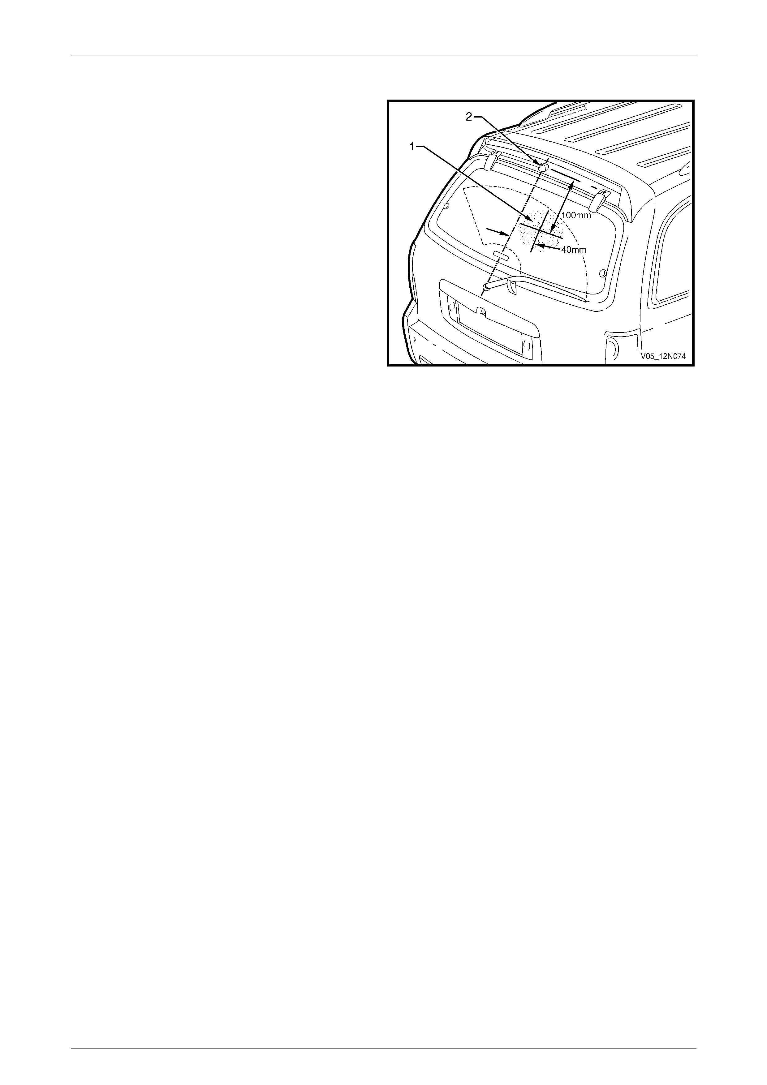
Wipers, Washers and Horn Page 12N–104
Page 12N–104
Spray Pattern Check
1 Check the rear washer spray pattern and ensure the
washer fluid strikes the glass panel within a 100 mm
diameter (1) of the target point.
2 If required, use a pin inserted into the ba ll of the rear
washer nozzle (2) and swivel to correct the aim of the
jet.
Figure 12N – 86

Wipers, Washers and Horn Page 12N–105
Page 12N–105
15 Service Operations – Washer
Assemblies, Coupe
15.1 Washer Reservoir Assembly
LT Section — 10–500
Remove
1 If required, remove the front right-hand road whe el,
refer to Section 10 Wheels and T yres.
2 Reach between the bumper a ssembly and the washer
reservoir assembly (1) and disconn ect the wiring
harness connector (2) from the washer pump
assembly (3).
3 Place a container under the washer reservoir
assembly, and disconnect the washer hose (4) from
the washer pump assembly.
4 Allow the washer fluid to drain from the washer
reservoir assembly.
Figure 12N – 87
5 Remove the two attaching screws (1) securing the
washer reservoir assembly (2).
6 Lower the washer reservoir assembl y and manoeuvre
the filler neck down through the hole in the fr ont
wheelhouse panel (3). If required remove the battery
to allow more space, refer to Section 12A Battery.
7 Unclip the washer pump from the washer reservoir.
Figure 12N – 88

Wipers, Washers and Horn Page 12N–106
Page 12N–106
Reinstall
Reinstallation of the washer reservoir assembly is the reverse of the removal procedure, notin g the following:
1 Ensure the washer reservoir assemb ly attaching screws are tightened to the correct torque specification.
Washer reservoir attaching screw
torque specification.....................................2.0 – 5.0 Nm
2 Ensure the washer hose is installe d before filling the washer reservoir ass embly.
Filling the Washer Reservoir Assembly
1 Open the flip top cap (1) located within the engine bay
at the top of the washer reservoir assembly (2).
2 Fill the washer reservoir assembl y with the correct
amount of Optikleen or equivalent.
3 Secure the flip top cap.
Figure 12N – 89
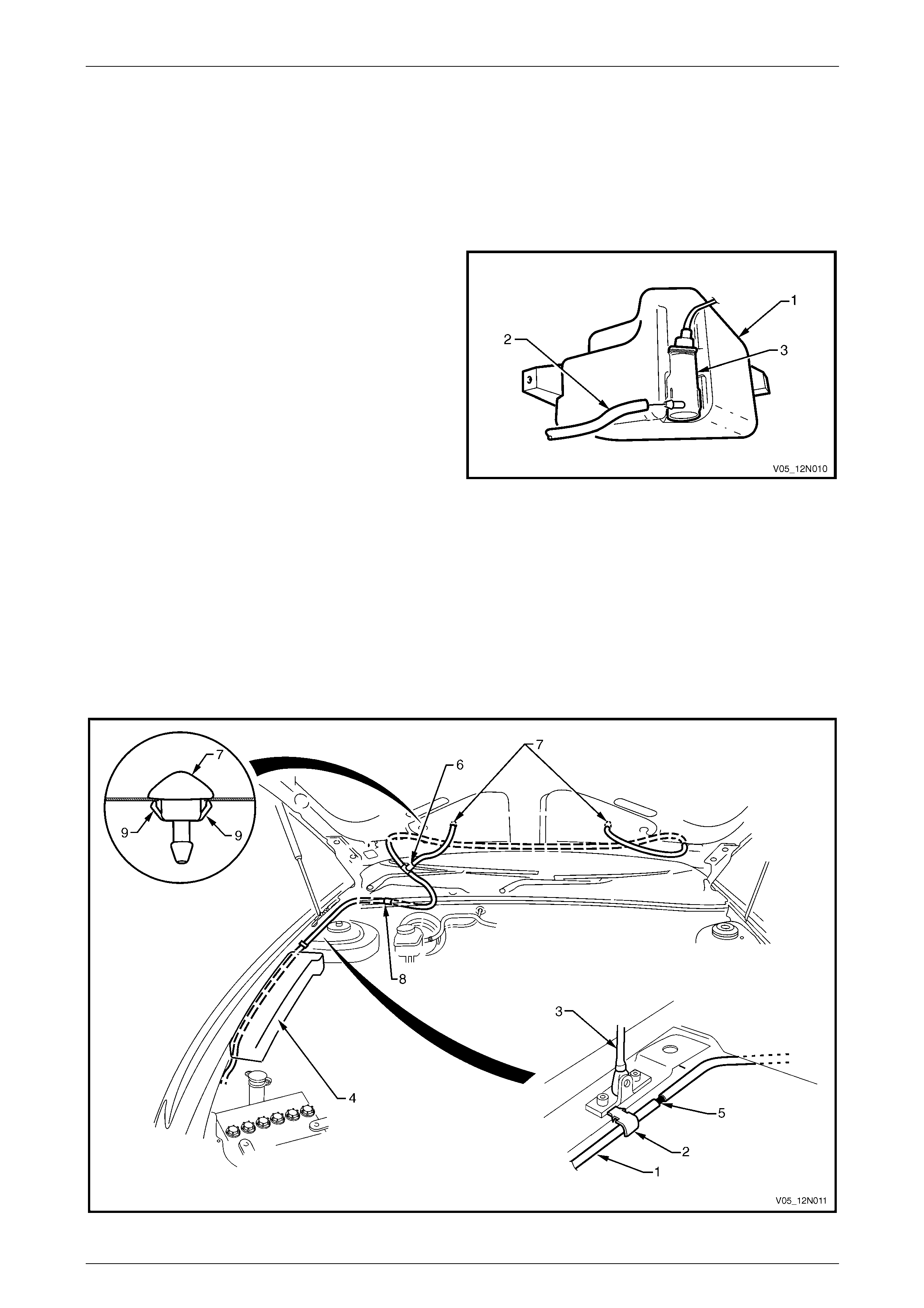
Wipers, Washers and Horn Page 12N–107
Page 12N–107
15.2 Front Washer Hose and Nozzle
Assemblies
LT Section — 10–500
Remove
1 Place a container underneath the washer reservoir
assembly (1).
2 Reach between the bumper a ssembly and the washer
reservoir assembly and disconnect the front wash er
hose (2) from the washer pump assembly (3).
3 Allow the washer fluid to drain from the washer
reservoir assembly.
Figure 12N – 90
4 Unclip the front washer hose (1) from the fastener (2) adjacent to the hood strut (3), refer to Figure 12N – 91.
5 Carefully pull the front washer hose from be hind the engine compartment fuse and relay panel assembly (4).
6 If required, disconnect the front washer hose from the joiner (5) and/or from the T joiner (6).
7 Separate the front washer hose from the two washer nozzles (7) located within the hood.
8 Unclip the front washer hose from the clip (8) on the fire wall below the weathershield.
9 Remove the fasteners from the hood insulator, and remove the insulator,
refer to Section 1A4 Hood, Rear Compartment Lid, Liftgate and Endgate.
10 Remove the front washer hose from the vehicle.
11 With a pair of pliers, squeeze the tangs (9) on the base of the front washer nozzle assembly and push the nozzle
out through the top of the hood.
Figure 12N – 91
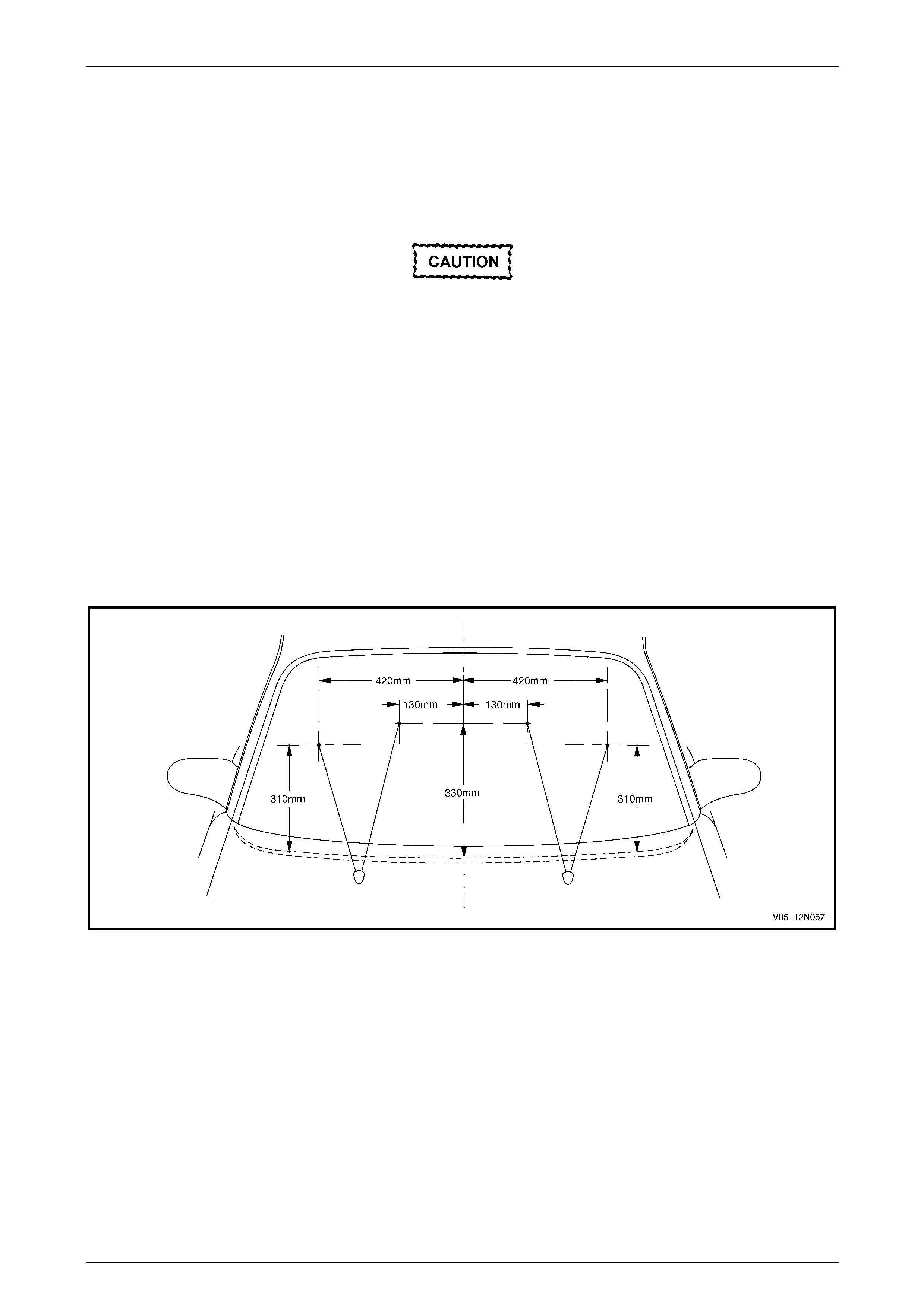
Wipers, Washers and Horn Page 12N–108
Page 12N–108
Reinstall
Reinstallation of the front washer hose an d the two front washers is the reverse of the removal procedure, noting the
following:
1 Ensure the tangs (9) are securing the two front washer nozzles (7) to the hood, refer to Figure 12N – 91.
2 Ensure the front washer hose (1) is connected to the joiner (5) and T joiner (6).
When secured in position, the front washer
hose must lay over all other cables,
harnesses an d hoses.
3 Ensure the front washer hose is secured with the fastener (2) adjacent to the hood strut (3) and the clip (8) on the
fire wall below the weathershield.
4 Connect the front washer hose to the washer pump assembl y befor e filling the washer reservoir assembly.
5 For information on filling the washer reservoir assembly, refer to 15.1 Washer Reservoir Assembly.
6 Check the front washers spray pattern on the windshield as detailed in this Section, refer to Spray Pattern Check.
Spray Pattern Check
1 Check the front washers spray pattern on the windshield and ensure the washer fluid strikes the glass panel within
a 100 mm diameter of the target points, refer to Figure 12N – 92.
2 If required, use a pin inserted into the ba ll of the front washer nozzle and swivel to correct the aim of the jet.
Figure 12N – 92
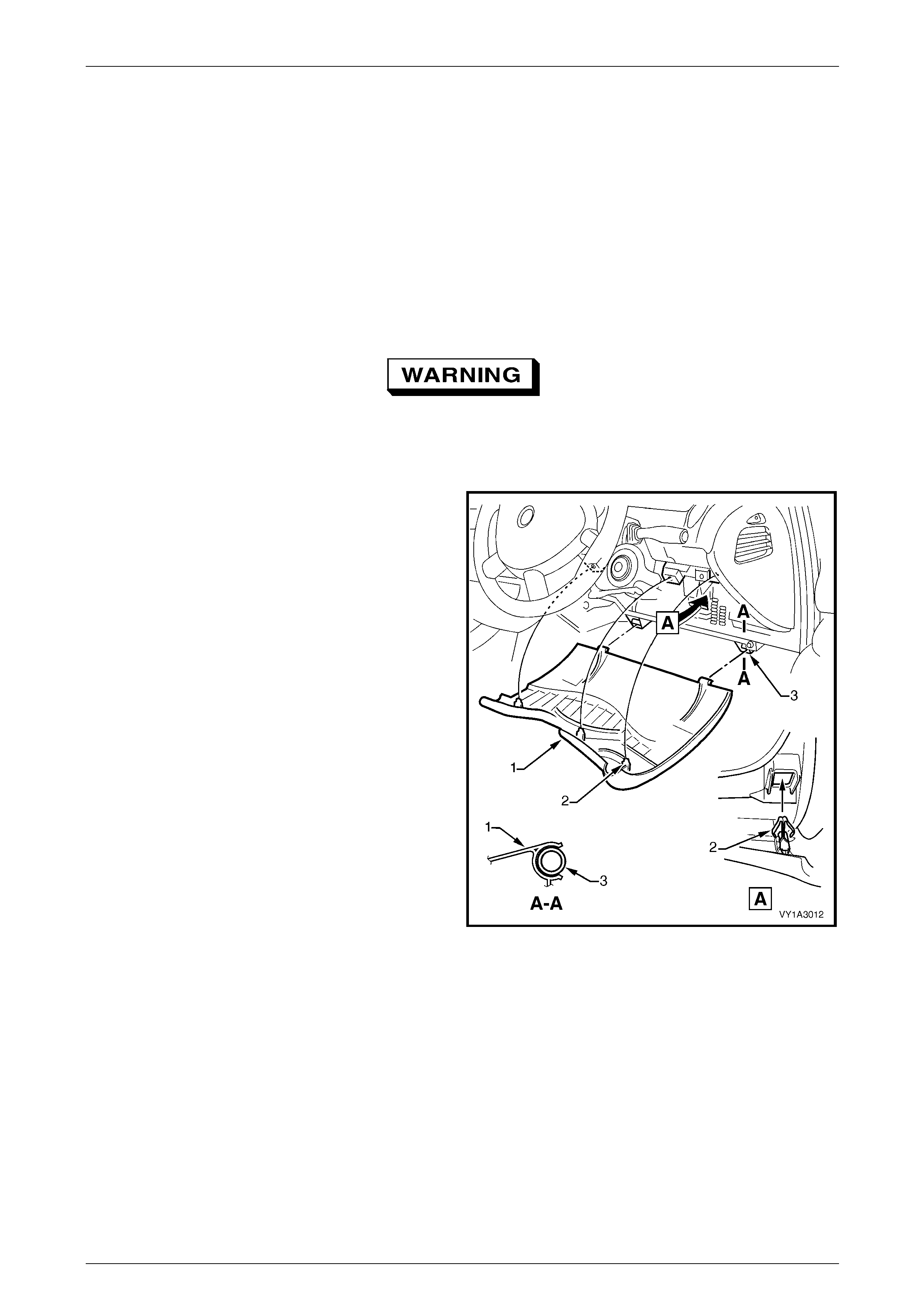
Wipers, Washers and Horn Page 12N–109
Page 12N–109
16 Service Operations – Wipers and
Washers Control Switch
16.1 Wipers and Washers Control Switch,
Except Wagon and AWD Wagon
LT Section — 06–250
Remove
Disable the occupant protection system
before starting the removal procedure of the
wipers and washers control switch. Refer to
Section 12M Occupant Protection System.
1 Turn the ignition to the OFF position, and remove the
ignition key from the ignition switch.
2 Gain access to the passenger compartment fuse and
relay panel assembly, grasp the upper edge of the
instrument panel lower trim panel assembly ( 1) and
disengage the three clips (2). Swing the panel
assembly open.
3 Remove the wiper and washer fuse F18 from the
passenger compartment fuse and relay panel
assembly. Refer to Section 12O Fuses, Relays and
Wiring Harnesses.
Figure 12N – 93
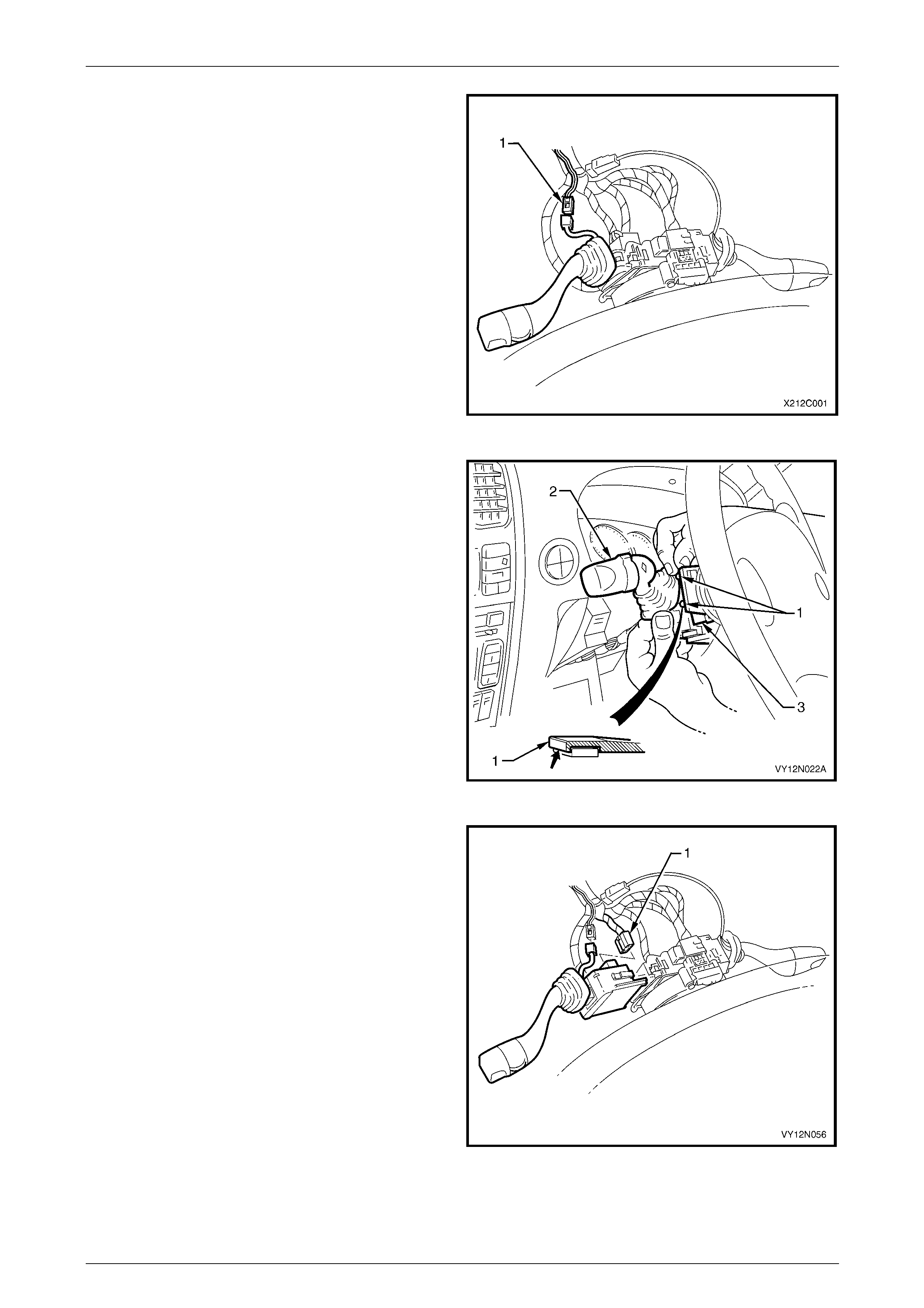
Wipers, Washers and Horn Page 12N–110
Page 12N–110
4 Remove the steering column upp er and lower covers,
refer to Section 9 Steering.
5 On vehicles fitted with intermittent dwell control,
disconnect the harness connector (1) from the wiper
dwell control switch connector by depressing the
retaining tang and pulling the connectors apart.
Figure 12N – 94
6 Depress the retaining tangs (1) on the switch
assembly and withdraw the wipers and washers
control switch (2) from the switch housing on the
steering column (3).
Figure 12N – 95
7 Lift up the harness connector retaining tangs on either
side of the wipers and washers control switch body
and pull the connector (1) from the switch.
8 Remove the wipers and washers control switch.
Figure 12N – 96

Wipers, Washers and Horn Page 12N–111
Page 12N–111
Reinstall
Reinstallation of the wipers and washers control switch is the reverse of the removal procedur e, noting the following:
1 If required, test the wiper and washer switch as detailed in this section prior to reinstallatio n,
refer to 16.2 Wipers and Washers Control Switch Testing, Except Wagon and AWD Wagon.
2 Ensure the harness connector is secured to the wipers and washers control switch.
3 Ensure the wipers and washers control switch is properly inserted and secured to the housing o n the ste ering
column.
4 If fitted, ensure the wiper dwell control switch connector is secured.
NOTE
The wiper dwell control connector, on the switch
side, is wrapped in foam for anti–rattle protection.
If the foam wrap is damaged during the removal
or test procedures, it must be replaced with a
suitable alternative.
5 Check the operation of all the wipers and washers control switch functions.
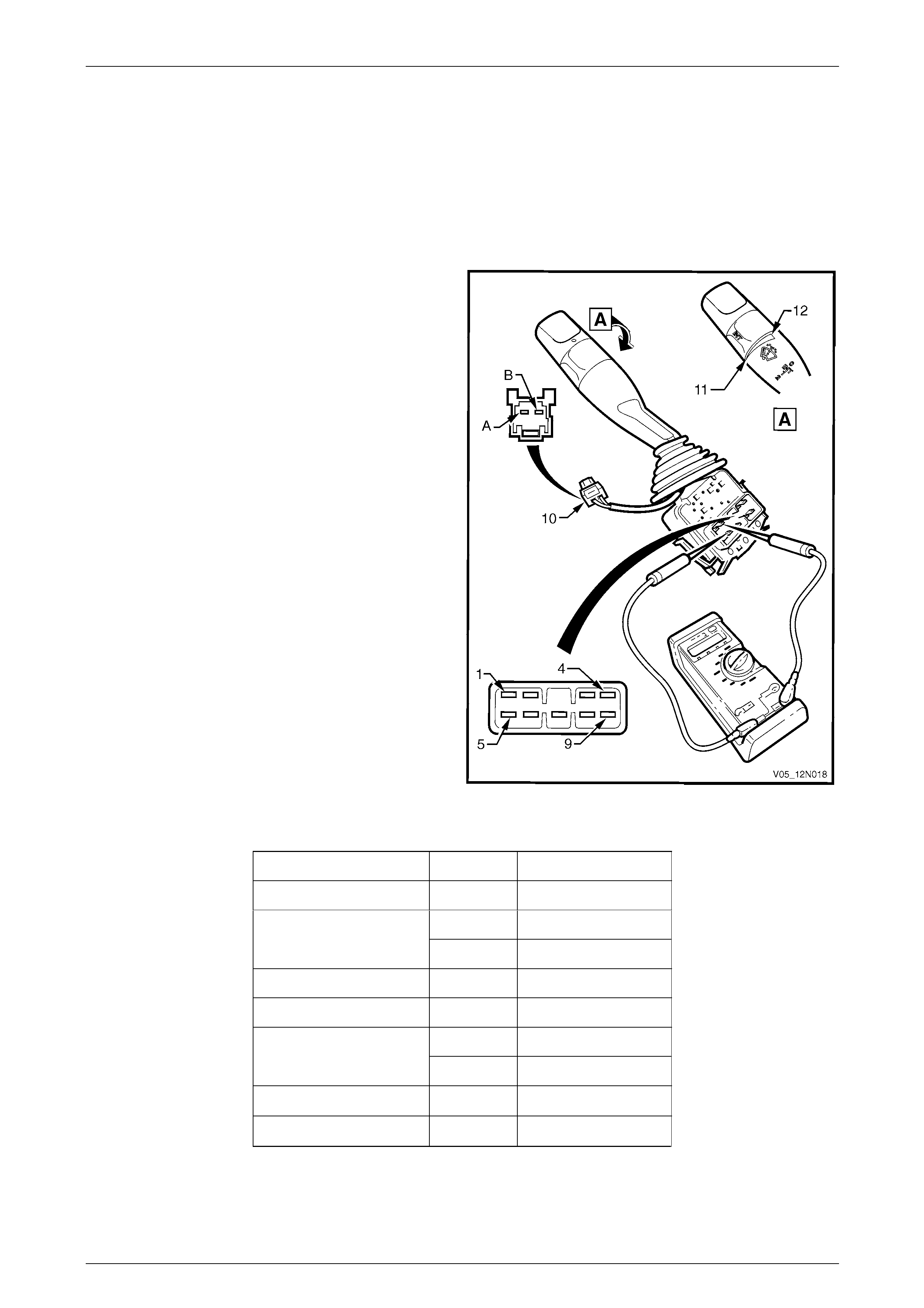
Wipers, Washers and Horn Page 12N–112
Page 12N–112
16.2 Wipers and Washers Control Switch
Testing, Except Wagon and AWD Wagon
Test Procedure
1 If required, disconnect the wipers and washers control switch as detailed in this Section, but do not unclip and
remove it from the steering column, as it provides a stable platform with which to carry out the testing,
refer to 16.1 Wipers and Washers Control Switch, Except Wagon and AW D Wagon.
2 Referring to the following chart, check the
serviceability of the wipers and washers control switch
with a multimeter by probing the various pin
combinations as follows:
a Place the switch into the positions as detailed in
the following chart.
b Place the multimeter probe tip s onto the
corresponding pins.
c Take the reading and compare it with the
indication in the chart.
3 If the reading differs from the following chart, or there
is continuity between any two pins other than the
combinations listed, the switch assembly is faulty.
4 Check the intermittent dwell control as follo ws:
a Turn the wipers and washers control switch in
the INT (maximum dwell time position) (11) .
b Place the multimeter probe tips onto the pins A
and B on the dwell control connector A121 –
X1 (10).
c Take the reading, and compare it with the chart
below.
d Repeat the check with the wipers and washers
control switch turned to INT (minimum dwell time
position) (12).
5 If the wipers and washers control switch fails any part
of the test, replace it with a serviceable item. Figure 12N – 97
Switch Position Pins Indication if O.K.
0 (Off) 8 and 9 Continuity
8 and 9 Continuity
INT 6 and 7 Continuity
1 (Low Speed) 6 and 9 Continuity
2 (High Speed) 5 and 6 Continuity
1 and 6 Continuity
Wash 2 and 3 Continuity
INT on max. dwell time. A and B 476 Ω to 889 Ω
INT on min. dwell time. A and B 4204 Ω to 6528 Ω

Wipers, Washers and Horn Page 12N–113
Page 12N–113
16.3 Wipers and Washers Control Switch,
Wagon and AWD Wagon
LT Section — 06–250
Remove and Reinstall
The removal and reinstallation procedures of the wipers and washers control switch for wagon vehicles are identica l to
the removal and reinstallation procedures for sedan vehicles,
refer to 16.1 Wipers and Washers Control Switch, Except Wagon and AW D Wagon.
If required, test the wiper and washer switch as detailed in this section prior to reinstallation,
refer to 16.4 Wipers and Washers Control Switch Testing, Wagon and AWD Wagon.
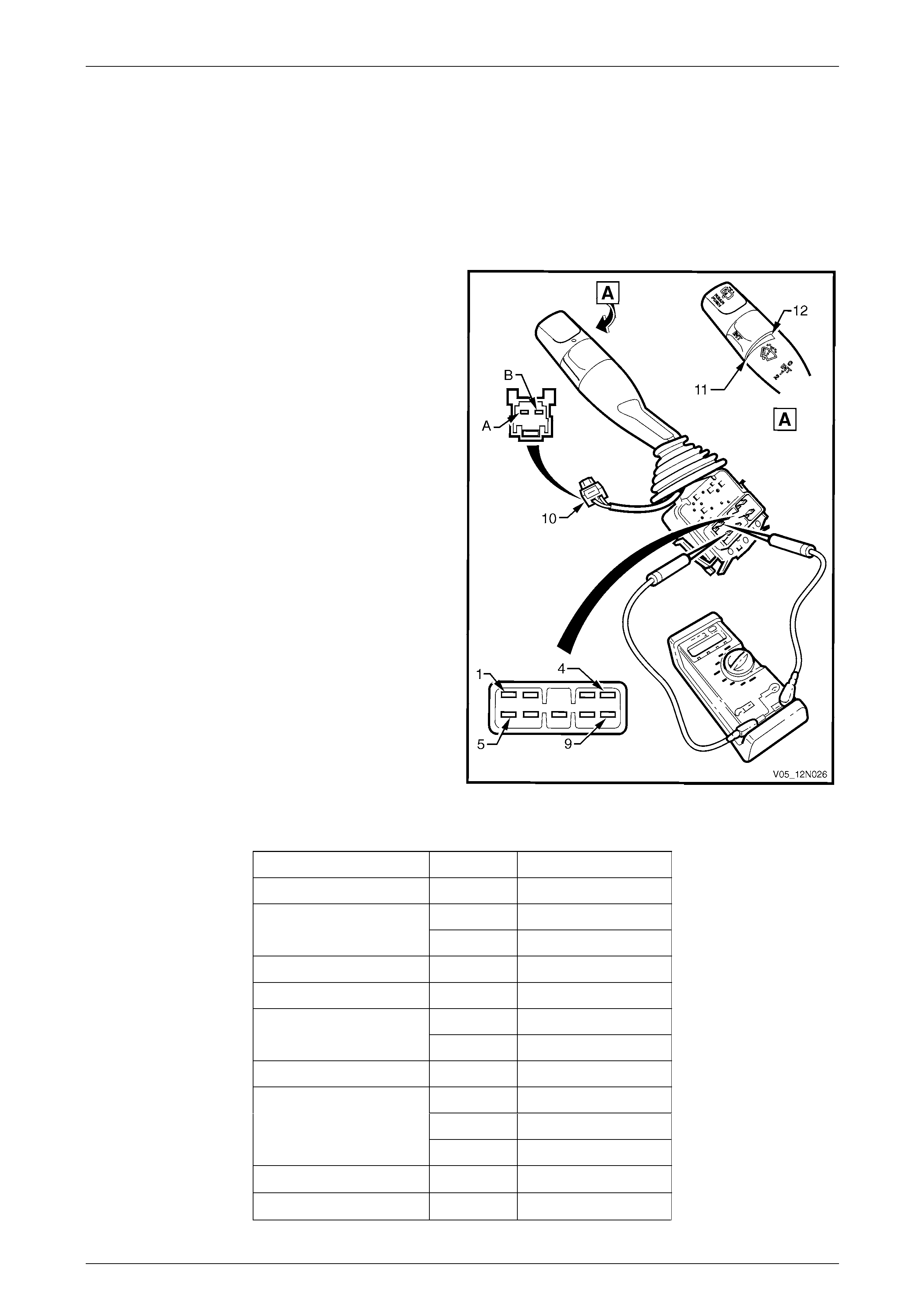
Wipers, Washers and Horn Page 12N–114
Page 12N–114
16.4 Wipers and Washers Control Switch
Testing, Wagon and AWD Wagon
Test Procedure
1 If required, disconnect the wipers and washers control switch as detailed in this Section, but do not unclip and
remove it from the steering column, as it provides a stable platform with which to carry out the testing,
refer to 16.3 Wipers and Washers Control Switch, Wagon and AWD Wagon.
2 Referring to the following chart, check the
serviceability of the wipers and washers control switch
with a multimeter by probing the various pin
combinations as follows:
a Place the switch into the positions as detailed in
the following chart.
b Place the multimeter probe tip s onto the
corresponding pins.
c Take the reading and compare it with the
indication in the chart.
3 If the reading differs from the following chart, or there
is continuity between any two pins other than the
combinations listed, the switch assembly is faulty.
4 Check the intermittent dwell control as follo ws:
a Turn the wipers and washers control switch in
the INT (maximum dwell time position) (11) .
b Place the multimeter probe tips onto the pins A
and B on the dwell control connector A121 –
X1 (10).
c Take the reading, and compare it with the chart
below.
d Repeat the check with the wipers and washers
control switch turned to INT (minimum dwell time
position) (12).
5 If the wipers and washers control switch fails any part
of the test, replace it with a serviceable item. Figure 12N – 98
Switch Position Pins Indication if O.K.
0 (Off) 8 and 9 Continuity
8 and 9 Continuity
INT 6 and 7 Continuity
1 (Low Speed) 6 and 9 Continuity
2 (High Speed) 5 and 6 Continuity
1 and 6 Continuity
Front Wash 2 and 3 Continuity
Rear Wiper 4 and 6 Continuity
3 and 6 Continuity
4 and 6 Continuity
Rear Wash
1 and 2 Continuity
INT on max. dwell time. A and B 476 Ω to 889 Ω
INT on min. dwell time. A and B 4204 Ω to 6528 Ω
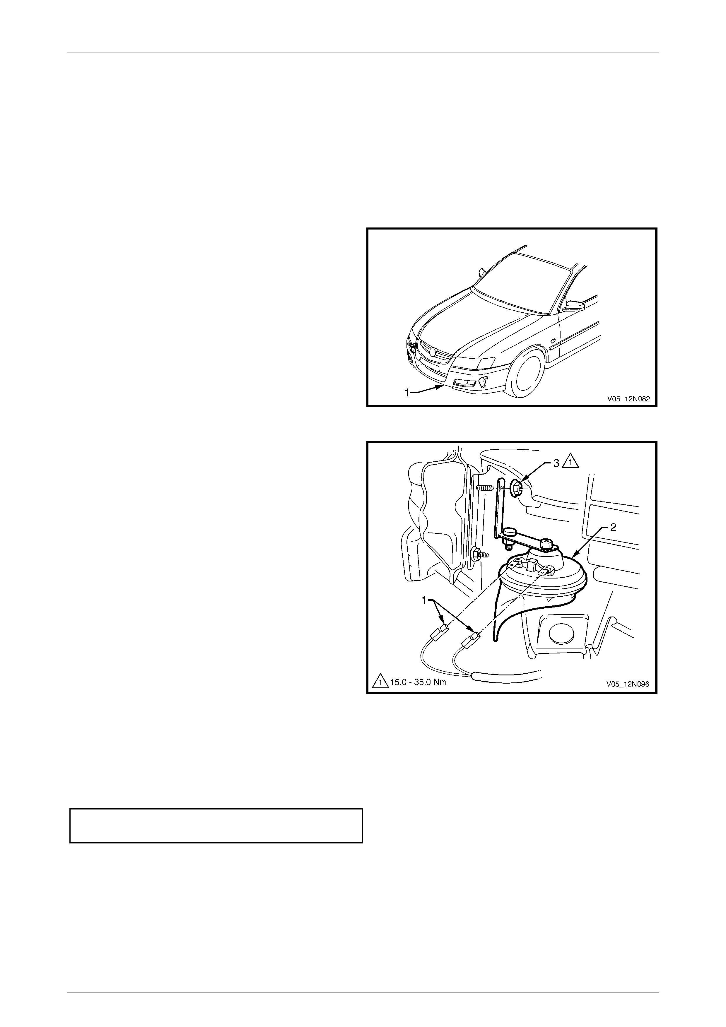
Wipers, Washers and Horn Page 12N–115
Page 12N–115
17 Service Operations – Horn
17.1 Horn Assembly
LT Section — 02–400
Remove
1 For ease of access, raise the vehicle, refer to
Section 0A General Information.
2 If required remove the front bumper fascia
assembly (1), refer to Section 1D Bumper Bars.
Figure 12N – 99
3 Disconnect the wiring harness connectors (1) from the
horn assembly (2).
4 Unscrew the horn attaching nut (3) and remove the
horn assembly.
Figure 12N – 100
Reinstall
Reinstallation of the horn ass embly is the reverse of the removal procedure, noting the following:
Ensure the nut attaching the horn assembly is tightened to the correct torque specification.
Horn assembly attaching nut
torque specification.................................15.0 – 35.0 Nm
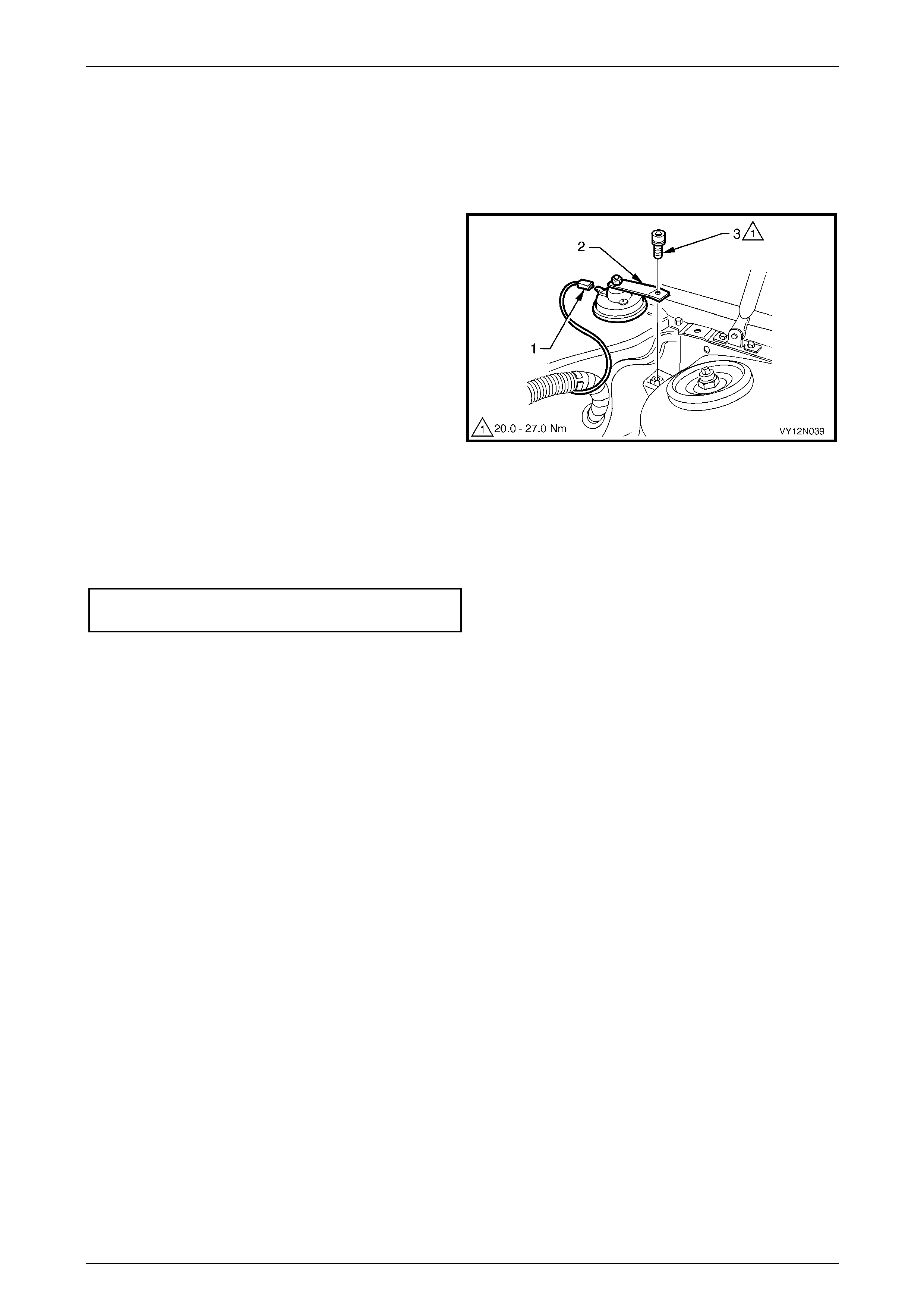
Wipers, Washers and Horn Page 12N–116
Page 12N–116
17.2 Theft-deterrent Horn Assembly
LT Section — 09–552
Remove
1 Disconnect the wiring harness connector (1) from the
theft-deterrent horn assembly (2).
2 Unscrew the attaching bolt (3) and remove the
theft-deterrent horn assembly.
Figure 12N – 101
Reinstall
Reinstallation of the theft-deterrent hor n assembly is the reverse of the removal procedure, noting the following:
Ensure the theft-deterrent horn attaching bolt is tightened to the correct torque specification.
Theft-deterrent horn attaching bolt
torque specification.................................20.0 – 27.0 Nm
Test
The test for the theft-deterrent horn assembly is included within the entry deterrent system diagnostic chart,
refer to Section 12J Body Control Module.

Wipers, Washers and Horn Page 12N–117
Page 12N–117
18 Torque Wrench Specifications
18.1 Torque Wrench Specifications, Except
Wagon and AWD Wagon
Front Wiper Arm Assembly Attaching Nut.................................20.0 – 25.0 Nm
Front Wiper Motor to Linkages Attaching Screw ...........................7.0 – 9.0 Nm
Front Wiper Motor Pivot to Linkages Attaching Nut...................16.0 – 20.0 Nm
Front Wiper Motor and Linkages Assembly Attaching Screw........4.0 – 6.0 Nm
Washer Reservoir Attaching Screw...............................................2.0 – 5.0 Nm
Horn Assembly Attaching Nut....................................................15.0 – 35.0 Nm
Theft-deterrent Horn Attaching Bolt...........................................20.0 – 27.0 Nm

Wipers, Washers and Horn Page 12N–118
Page 12N–118
18.2 Torque Wrench Specifications, Wagon
Front Wiper Arm Assembly Attaching Nut.................................20.0 – 25.0 Nm
Front Wiper Motor to Linkages Attaching Screw ...........................7.0 – 9.0 Nm
Front Wiper Motor Pivot to Linkages Attaching Nut...................16.0 – 20.0 Nm
Front Wiper Motor and Linkages Assembly Attaching Screw........4.0 – 6.0 Nm
Rear Window Wiper Motor Assembly Attaching Nut .....................4.0 – 6.0 Nm
Rear Window Wiper Arm Assembly Attaching Nut....................20.0 – 25.0 Nm
Rear Window Wiper Motor Assembly Attaching Screw...............9.0 – 15.0 Nm
Rear Window Wiper Motor Bracket Attaching Screw ..................6.0 – 14.0 Nm
Washer Reservoir Attaching Screw...............................................2.0 – 5.0 Nm
Horn Assembly Attaching Nut....................................................15.0 – 35.0 Nm
Theft-deterrent Horn Attaching Bolt...........................................20.0 – 27.0 Nm

Wipers, Washers and Horn Page 12N–119
Page 12N–119
18.3 Torque Wrench Specifications, AWD
Wagon
Front Wiper Arm Assembly Attaching Nut.................................20.0 – 25.0 Nm
Front Wiper Motor to Linkages Attaching Screw ...........................7.0 – 9.0 Nm
Front Wiper Motor Pivot to Linkages Attaching Nut...................16.0 – 20.0 Nm
Front Wiper Motor and Linkages Assembly Attaching Screw........4.0 – 6.0 Nm
Rear Window Wiper Motor Assembly Attaching Nut .....................4.0 – 6.0 Nm
Rear Window Wiper Arm Assembly Attaching Nut ...................10.0 – 14.0 Nm
Rear Window Wiper Ramp Attaching Screw.................................1.0 – 2.0 Nm
Rear Window Wiper Control Module
Support Bracket Attaching Screw................................................6.0 – 14.0 Nm
Rear Window Wiper Motor Assembly Attaching Screw...............9.0 – 15.0 Nm
Rear Window Wiper Motor Bracket Attaching Screw ..................6.0 – 14.0 Nm
Washer Reservoir Attaching Screw...............................................2.0 – 5.0 Nm
Horn Assembly Attaching Nut....................................................15.0 – 35.0 Nm
Theft-deterrent Horn Attaching Bolt...........................................20.0 – 27.0 Nm
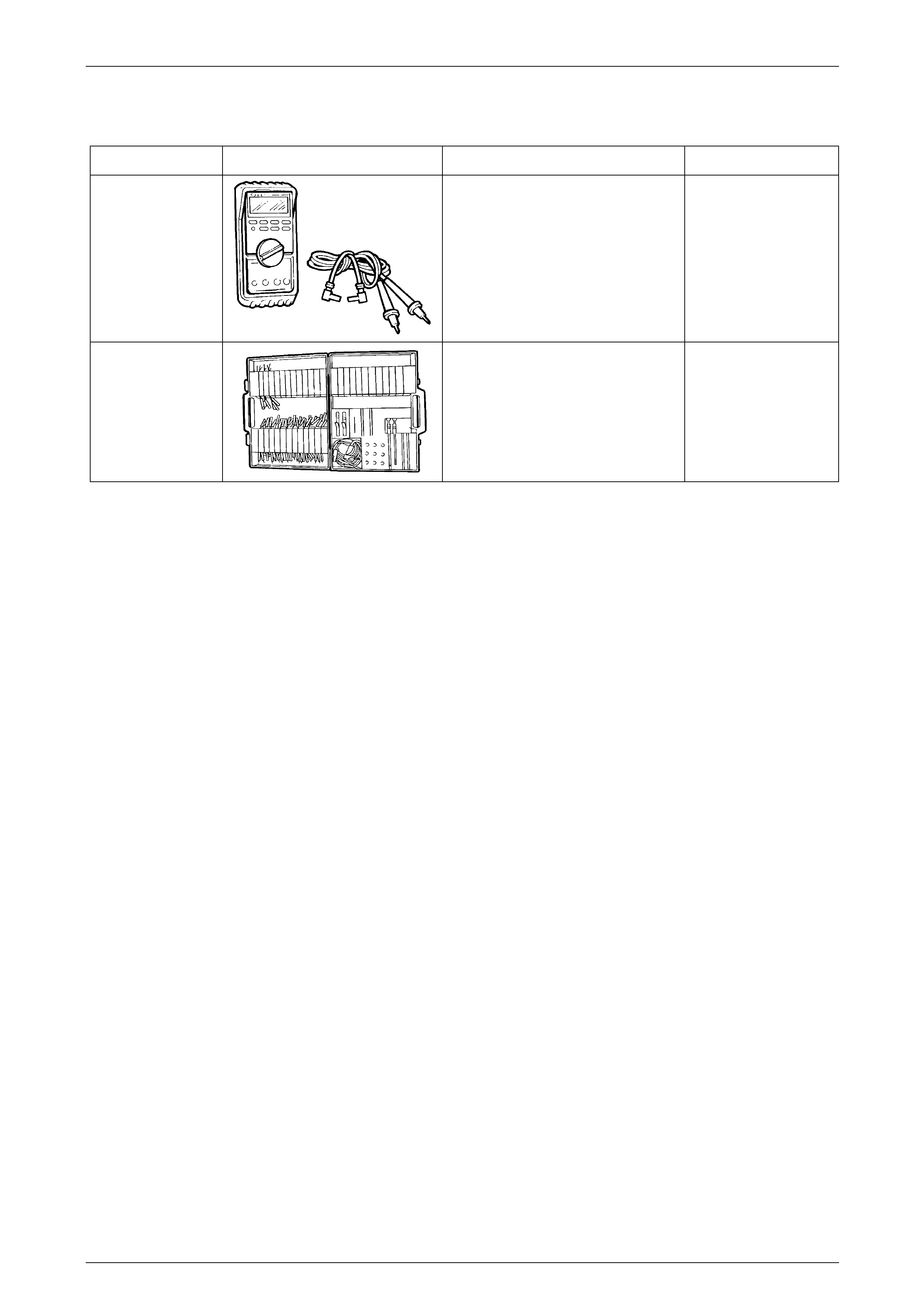
Wipers, Washers and Horn Page 12N–120
Page 12N–120
19 Special Tools
Tool Number Illustration Description Tool Classification
J39200
(3588)
Digital Multimeter.
Tool no. J39200 previously released,
or use commercially available
equivalent. Must have 10 meg ohm
input impedance.
Previously released.
Available.
KM-609
(J35616-A)
Electronic Kit.
Used in conjunction with a multimeter
for measuring voltages and
resistances without damaging wiring
harness connectors.
Desirable.