
Body Control Module Page 12J–1
Page 12J–1
Section 12J
Body Control Module
ATTENTION
Before performing any service operation or other procedure described in this section, refer to Section 00
Warnings, Cautions and Notes for correct w orkshop practices with regard to safety and/or property damage.
1 General Information.............................................................................................................................14
1.1 Abbreviations....................................................................................................................................................... 14
1.2 Body Control Module........................................................................................................................................... 15
1.3 Body Control Module Models............................................................................................................................. 16
1.4 Body Control Module Features........................................................................................................................... 17
Feature Table Key................................................................................................................................................ 17
Feature Table........................................................................................................................................................ 17
2 System Operation.................................................................................................................................21
2.1 Body Control Module Operating Modes ............................................................................................................ 21
Battery Saver Mode.............................................................................................................................................. 21
Pre-delivery Mode................................................................................................................................................ 21
2.2 Serial Data Communication – V6........................................................................................................................ 22
System Overview ................................................................................................................................................. 22
V6 Serial Data Block Diagram.......................................................................................................................... 23
The GM LAN Bus System ................................................................................................................................ 24
UART Communications.................................................................................................................................... 24
Serial Data Bus ................................................................................................................................................ 24
Data Bus Device Polling................................................................................................................................... 25
Tech 2 and the Data Link Connector................................................................................................................ 25
Inputs and Outputs.............................................................................................................................................. 25
GM LAN Data Bus............................................................................................................................................ 25
Serial Data Signal – Primary UART.................................................................................................................. 25
Serial Data Signals – Secondary and Tertiary UART....................................................................................... 25
Data Bus Device Polling................................................................................................................................... 26
Data Messages ................................................................................................................................................ 26
Pow ertrain Interface Module............................................................................................................................... 26
2.3 Serial Data Communication – GEN III V8........................................................................................................... 27
System Overview ................................................................................................................................................. 27
GEN III V8 Serial Data Block Diagram............................................................................................................. 28
UART and Class 2 Serial Data Bus.................................................................................................................. 29
Data Bus Device Polling................................................................................................................................... 29
Tech 2 and the Data Link Connector................................................................................................................ 29
Inputs and Outputs.............................................................................................................................................. 30
Class 2 Serial Data Signal................................................................................................................................ 30
Serial Data Signal – Primary UART.................................................................................................................. 30
Serial Data Signal – Secondary and Tertiary UART......................................................................................... 30
Data Bus Device Polling................................................................................................................................... 30
Data Messages ................................................................................................................................................ 30
Pow ertrain Interface Module............................................................................................................................... 30
Techline
Techline
Techline

Body Control Module Page 12J–2
Page 12J–2
2.4 Serial Data Communication – GEN IV V8........................................................................................................... 31
System Overview ................................................................................................................................................. 31
GEN IV V8 Serial Data Block Diagram............................................................................................................. 32
The GM LAN Bus System ................................................................................................................................ 33
UART Communications.................................................................................................................................... 33
Serial Data Bus ................................................................................................................................................ 33
Data Bus Device Polling................................................................................................................................... 34
Tech 2 and the Data Link Connector................................................................................................................ 34
Inputs and Outputs.............................................................................................................................................. 34
GM LAN Data Bus............................................................................................................................................ 34
Serial Data Signal – Primary UART.................................................................................................................. 34
Serial Data Signals – Secondary and Tertiary UART....................................................................................... 34
Data Bus Device Polling................................................................................................................................... 35
Data Messages ................................................................................................................................................ 35
Pow ertrain Interface Module............................................................................................................................... 35
2.5 Remote Receiver / Key ........................................................................................................................................ 36
System Operation ................................................................................................................................................ 36
Unlocking.......................................................................................................................................................... 36
Locking............................................................................................................................................................. 36
Rear Compartment Lid Release....................................................................................................................... 36
Remote Coded Key Battery Failure.................................................................................................................. 36
Circuit Operation.................................................................................................................................................. 37
2.6 Accessory Power Control ................................................................................................................................... 38
System Operation ................................................................................................................................................ 38
Accessory Relay Shutdown Options................................................................................................................. 38
Wiper Control of the Accessory Relay.............................................................................................................. 38
Circuit Operation.................................................................................................................................................. 38
Radio On and Ignition Switch Input.................................................................................................................. 39
2.7 Central Door Locking .......................................................................................................................................... 40
System Operation ................................................................................................................................................ 40
Door Locking.................................................................................................................................................... 40
Door Unlocking................................................................................................................................................. 40
Deadlocking...................................................................................................................................................... 40
Single-stage and Two-stage Unlocking............................................................................................................ 41
System Check ...................................................................................................................................................... 42
Key Locking...................................................................................................................................................... 42
Remote Coded Key Check............................................................................................................................... 42
Deadlocking Check .......................................................................................................................................... 42
Door-lock Failure Warning................................................................................................................................ 42
Auto Door-lock in Drive .................................................................................................................................... 43
Overheating Prevention.................................................................................................................................... 43
Functional Description of Door Locking/Unlocking Operation........................................................................... 43
Functional Diagram of Door Locking/Unlocking Operation............................................................................... 45
Circuit Operation.................................................................................................................................................. 46
Unlocking.......................................................................................................................................................... 46
Locking............................................................................................................................................................. 47
Door Input Signals............................................................................................................................................ 48
2.8 Rear Compartment Lid Release.......................................................................................................................... 49
System Operation ................................................................................................................................................ 49
Circuit Operation.................................................................................................................................................. 49
Power Supplies ................................................................................................................................................ 49
Inputs ............................................................................................................................................................... 49
Outputs............................................................................................................................................................. 50

Body Control Module Page 12J–3
Page 12J–3
2.9 Theft Deterrent System........................................................................................................................................ 51
System Operation ................................................................................................................................................ 51
V6 and GEN IV V8 Engine ............................................................................................................................... 51
GEN III V8 Engine............................................................................................................................................ 51
Battery.............................................................................................................................................................. 52
Security Status Indicator................................................................................................................................... 52
Circuit Operation.................................................................................................................................................. 53
Power Supplies ................................................................................................................................................ 53
Turn Signal Lamp Power.................................................................................................................................. 53
Inputs ............................................................................................................................................................... 53
Outputs............................................................................................................................................................. 54
2.10 Entry Deterrent System....................................................................................................................................... 55
System Operation ................................................................................................................................................ 55
Arming the System........................................................................................................................................... 55
Triggered Operation......................................................................................................................................... 55
Disarming Procedure........................................................................................................................................ 56
Multi-function Display (MFD) Trigger Point Displays ........................................................................................ 56
Remote Rear Compartment Release ............................................................................................................... 56
Loss of Vehicle Battery Power .......................................................................................................................... 56
Circuit Operation.................................................................................................................................................. 57
Power Supplies ................................................................................................................................................ 57
Inputs ............................................................................................................................................................... 57
Outputs............................................................................................................................................................. 58
2.11 Power Window System ....................................................................................................................................... 59
System Operation ................................................................................................................................................ 59
System Active................................................................................................................................................... 59
System Inactive................................................................................................................................................ 59
Automatic Down Operation of Front Windows.................................................................................................. 59
Lockout Switch................................................................................................................................................. 60
Circuit Operation.................................................................................................................................................. 60
Ignition ON Input Signal ................................................................................................................................... 60
Driver and Front Passenger Window-down Circuit........................................................................................... 61
Driver and Front Passenger Window-up Circuit................................................................................................ 61
Rear Passenger Window Operation................................................................................................................. 61
2.12 Wiper System Intermittent Function .................................................................................................................. 62
System Operation ................................................................................................................................................ 62
Level 1 Vehicles............................................................................................................................................... 62
Level 2 and 3 Vehicles and AWD Wagon......................................................................................................... 62
Rear Wiper Operation AWD Wagon................................................................................................................. 62
Circuit Operation.................................................................................................................................................. 63
Intermittent Wiper Switch.................................................................................................................................. 63
Wiper Dwell Controller...................................................................................................................................... 63
Vehicle Speed and Reverse Gear.................................................................................................................... 63
Window Washer Switch.................................................................................................................................... 64
Rear Wiper Switch............................................................................................................................................ 64
Rear Washer Switch......................................................................................................................................... 64
2.13 Dome Lamp Delay Control.................................................................................................................................. 65
System Operation ................................................................................................................................................ 65
Level 1 Vehicles............................................................................................................................................... 65
Level 2 and 3 Vehicles ..................................................................................................................................... 65
Circuit Operation – Level 1 Vehicles.................................................................................................................. 66
Inputs ............................................................................................................................................................... 66
Circuit Operation – Level 2 and 3 Vehicles........................................................................................................ 67
Inputs ............................................................................................................................................................... 67

Body Control Module Page 12J–4
Page 12J–4
2.14 Automatic Lamp Control..................................................................................................................................... 68
System Operation ................................................................................................................................................ 68
Automatic Lights On......................................................................................................................................... 68
Automatic Lights Off......................................................................................................................................... 68
Approach Illumination....................................................................................................................................... 69
Circuit Operation – Lights On............................................................................................................................. 69
Inputs ............................................................................................................................................................... 69
Power Supplies ................................................................................................................................................ 70
Ground Circuits ................................................................................................................................................ 70
Circuit Operation – Lights Off............................................................................................................................. 70
Inputs ............................................................................................................................................................... 70
Power Supplies ................................................................................................................................................ 71
Ground Circuits ................................................................................................................................................ 71
2.15 Instrument Dimming Control .............................................................................................................................. 72
System Operation ................................................................................................................................................ 72
Circuit Operation.................................................................................................................................................. 72
Inputs ............................................................................................................................................................... 73
2.16 Air-conditioning Interface ................................................................................................................................... 74
System Operation ................................................................................................................................................ 74
Circuit Operation.................................................................................................................................................. 74
Inputs ............................................................................................................................................................... 74
Outputs............................................................................................................................................................. 74
Blower Motor.................................................................................................................................................... 74
2.17 Occupant Protection System Deployment Vehicle Shutdown......................................................................... 75
System Operation ................................................................................................................................................ 75
OPS Deployment Signals................................................................................................................................. 75
2.18 Priority Key System............................................................................................................................................. 76
Operating Parameters ......................................................................................................................................... 76
Parameter Checks............................................................................................................................................ 76
Circuit Operation.................................................................................................................................................. 77
2.19 Pow er Antenna Control....................................................................................................................................... 78
System Operation ................................................................................................................................................ 78
Power Antenna................................................................................................................................................. 78
Circuit Operation.................................................................................................................................................. 79
Antenna Up Switch Input Signal....................................................................................................................... 79
Antenna Up Memory Height............................................................................................................................. 79
Antenna Down.................................................................................................................................................. 79
Antenna Auto-down.......................................................................................................................................... 79
2.20 Heated Rear Window ........................................................................................................................................... 80
System Operation ................................................................................................................................................ 80
Delay Timer...................................................................................................................................................... 80
Circuit Operation.................................................................................................................................................. 80
Heated Rear Window Switch Input Signal........................................................................................................ 80
2.21 Rear Lamp Failure Warning System................................................................................................................... 81
System Operation ................................................................................................................................................ 81
Components Monitored.................................................................................................................................... 81
Circuit Operation.................................................................................................................................................. 82
Ground Circuit Monitoring................................................................................................................................. 82
Rear Lamp Failure Warning Lamp ................................................................................................................... 82
Inputs ............................................................................................................................................................... 82
2.22 Hazard Lamp Control........................................................................................................................................... 83
System Operation ................................................................................................................................................ 83
Circuit Operation.................................................................................................................................................. 83

Body Control Module Page 12J–5
Page 12J–5
3 Wiring Diagrams and Connector Charts............................................................................................84
3.1 Wiring Diagrams – V6.......................................................................................................................................... 84
Ignition Key, RX Sensor, Common Power and Grounds.................................................................................. 84
Accessory Power Circuit..................................................................................................................................... 85
UART and GM LAN Communications – 5 Speed Automatic............................................................................. 86
UART and GM LAN Communications – 4 Speed Automatic with ESP............................................................ 87
UART and GM LAN Communications – 4 Speed Automatic with without ESP .............................................. 88
Central Door Locking .......................................................................................................................................... 89
Entry Deterrent, Warning Horns and Rear Compartment Solenoid................................................................. 90
Entry Deterrent, Warning Horns and Rear Lift Glass Solenoid – AWD Wagon only...................................... 91
Power Windows – Two Door Vehicles............................................................................................................... 92
Power Windows – Four Door Vehicles .............................................................................................................. 93
Wiper Systems Intermittent Function – Utility, Regular & Crew Cab and Sedan, Level 1............................. 94
Wiper Systems Intermittent Function – Sedan, Level 2 and 3 ......................................................................... 95
Wiper Systems Intermittent Function – Wagon, Level 1................................................................................... 96
Wiper Systems Intermittent Function – Wagon, Level 2................................................................................... 97
Wiper Systems Intermittent Function – AWD Wagon, Level 1......................................................................... 98
Wiper Systems Intermittent Function – AWD Wagon, Level 2......................................................................... 99
Dome Lamp Delay Control – Utility, Regular & Crew Cab, Level 1................................................................ 100
Dome Lamp Delay Control – Sedan and Wagon, Level 1............................................................................... 101
Dome Lamp Delay Control – Sedan and Wagon, Level 2 and 3..................................................................... 102
Automatic Lamp Control – Level 1................................................................................................................... 103
Automatic Lamp Control – Level 2 and 3......................................................................................................... 104
HVAC – Heated Rear Window and Air conditioning Interface – Level 1........................................................ 105
Radio and Pow er Antenna Control – Level 1................................................................................................... 106
Radio and Pow er Antenna Control – Level 2 and 3 ........................................................................................ 106
Rear Lamp Failure System – Level 3................................................................................................................ 107
Hazard Lamp Control, Theft / Turn Signal Lamp Flasher............................................................................... 108
3.2 Connector Charts – V6 ...................................................................................................................................... 109
3.3 Wiring Diagrams – GEN III V8 ........................................................................................................................... 113
Ignition Key, RX Sensor, Common Power and Grounds................................................................................ 113
Accessory Power Circuit................................................................................................................................... 114
UART and Class 2 Communications................................................................................................................ 115
Central Door Locking ........................................................................................................................................ 116
Entry Deterrent, Warning Horns and Rear Compartment Solenoid............................................................... 117
Entry Deterrent, Warning Horns and Rear Lift Glass Solenoid – AWD Wagon Only ................................... 118
Power Windows – Two Door Vehicles............................................................................................................. 119
Power Windows – Four Door Vehicles ............................................................................................................ 120
Wiper Systems Intermittent Function – Utility, Regular & Crew Cab and Sedan, Level 1........................... 121
Wiper Systems Intermittent Function – Sedan, Level 2 and 3 ....................................................................... 122
Wiper Systems Intermittent Function – Wagon, Level 1................................................................................. 123
Wiper Systems Intermittent Function – Wagon, Level 2 and 3...................................................................... 124
Wiper Systems Intermittent Function – AWD Wagon, Level 2....................................................................... 125
Dome Lamp Delay Control – Utility, Regular & Crew Cab, Level 1................................................................ 126
Dome Lamp Delay Control – Sedan and Wagon, Level 1............................................................................... 127
Dome Lamp Delay Control – Sedan and Wagon, Level 2 and 3..................................................................... 128
Dome Lamp Delay Control – Coupe, Level 2 and 3......................................................................................... 129
Automatic Lamp Control – Level 1................................................................................................................... 130
Automatic Lamp Control – Level 2 and 3......................................................................................................... 131
HVAC – Heated Rear Window and Air conditioning Interface – Level 1........................................................ 132
Radio and Pow er Antenna Control – Level 1................................................................................................... 133
Radio and Pow er Antenna Control – Level 2 and 3 ........................................................................................ 133
Rear Lamp Failure System – Level 3................................................................................................................ 134
Hazard Lamp Control, Theft / Turn Signal Lamp Flasher............................................................................... 135
3.4 Connector Charts – GEN III V8.......................................................................................................................... 136

Body Control Module Page 12J–6
Page 12J–6
3.5 Wiring Diagrams – GEN IV V8........................................................................................................................... 140
Ignition Key, RX Sensor, Common Power and Grounds................................................................................ 140
Accessory Power Circuit................................................................................................................................... 141
UART and GM LAN Communications – 4 Speed Automatic with ESP.......................................................... 142
Central Door Locking ........................................................................................................................................ 143
Entry Deterrent, Warning Horns and Rear Compartment Solenoid............................................................... 144
Entry Deterrent, Warning Horns and Rear Lift Glass Solenoid – AWD Wagon only.................................... 145
Power Windows – Two Door Vehicles............................................................................................................. 146
Power Windows – Four Door Vehicles ............................................................................................................ 147
Wiper Systems Intermittent Function – Utility, Regular & Crew Cab and Sedan, Level 1........................... 148
Wiper Systems Intermittent Function – Sedan, Level 2 and 3 ....................................................................... 149
Wiper Systems Intermittent Function – Wagon, Level 1................................................................................. 150
Wiper Systems Intermittent Function – Wagon, Level 2................................................................................. 151
Wiper Systems Intermittent Function – AWD Wagon, Level 1....................................................................... 152
Wiper Systems Intermittent Function – AWD Wagon, Level 2....................................................................... 153
Dome Lamp Delay Control – Utility, Regular & Crew Cab, Level 1................................................................ 154
Dome Lamp Delay Control – Sedan and Wagon, Level 1............................................................................... 155
Dome Lamp Delay Control – Sedan and Wagon, Level 2 and 3..................................................................... 156
Automatic Lamp Control – Level 1................................................................................................................... 157
Automatic Lamp Control – Level 2 and 3......................................................................................................... 158
HVAC – Heated Rear Window and Air conditioning Interface – Level 1........................................................ 159
Radio and Pow er Antenna Control – Level 1................................................................................................... 160
Radio and Pow er Antenna Control – Level 2 and 3 ........................................................................................ 160
Rear Lamp Failure System – Level 3................................................................................................................ 161
Hazard Lamp Control, Theft / Turn Signal Lamp Flasher............................................................................... 162
3.6 Connector Charts – GEN IV V8......................................................................................................................... 163
3.7 Connector Information ...................................................................................................................................... 167
BCM Location and Wiring Connectors ............................................................................................................ 167
BCM Connector Pin Identification.................................................................................................................... 167
Legend – Circuit Type .................................................................................................................................... 170
Explanation of Terms ..................................................................................................................................... 170
4 Tech 2 Information .............................................................................................................................171
4.1 Connecting Tech 2 For System Diagnosis ...................................................................................................... 171
4.2 Tech 2 Test Modes and Displays...................................................................................................................... 172
4.3 Normal Mode...................................................................................................................................................... 173
4.4 Diagnostic Trouble Codes ................................................................................................................................ 174
Read DTC Information....................................................................................................................................... 174
Read Alarm Codes............................................................................................................................................. 174
Clear DTC and Alarm Codes ............................................................................................................................. 174
4.5 Data Display ....................................................................................................................................................... 175
Inputs and Outputs............................................................................................................................................ 175
BCM Internal Status........................................................................................................................................... 177
Serial Data Inputs............................................................................................................................................... 178
Priority 1 User Settings ..................................................................................................................................... 178
Priority 2 User Settings ..................................................................................................................................... 179
Alarm / Theft Deterrent...................................................................................................................................... 179
Central Door Locking ........................................................................................................................................ 180
Power Windows................................................................................................................................................. 181
Wipers................................................................................................................................................................. 181
Headlamps.......................................................................................................................................................... 182
Instrument Illumination..................................................................................................................................... 182
Interior Illumination ........................................................................................................................................... 183
Rear Lamp Failure.............................................................................................................................................. 183
Air-conditioning Interface ................................................................................................................................. 184
Antenna............................................................................................................................................................... 184
System Identification......................................................................................................................................... 185

Body Control Module Page 12J–7
Page 12J–7
4.6 Snapshot ............................................................................................................................................................ 186
4.7 Miscellaneous Tests.......................................................................................................................................... 187
Lamps ................................................................................................................................................................. 187
Interior Lamp.................................................................................................................................................. 187
Headlamps..................................................................................................................................................... 188
Indicators........................................................................................................................................................ 188
Instrument Illumination................................................................................................................................... 188
Auto Lights On................................................................................................................................................ 188
Rear Lamp Bulb Fail....................................................................................................................................... 189
Rear Stop Lamp Bulb Fail .............................................................................................................................. 189
Rear Lamp Fuse Fail...................................................................................................................................... 189
Data Bus Isolator ............................................................................................................................................... 190
Central Locking.................................................................................................................................................. 190
Rear Compartment............................................................................................................................................. 190
Wipers................................................................................................................................................................. 191
Front Wipers................................................................................................................................................... 191
Rear Wiper..................................................................................................................................................... 191
Power Windows................................................................................................................................................. 192
Driver’s Window Auto-down............................................................................................................................ 192
Front Passenger’s Window Auto-down........................................................................................................... 192
Power Window Relay ..................................................................................................................................... 193
Antenna............................................................................................................................................................... 193
Horn .................................................................................................................................................................... 193
Interior Illumination Relay................................................................................................................................. 194
Accessory Relay ................................................................................................................................................ 194
Security System................................................................................................................................................. 195
Security LED .................................................................................................................................................. 195
Theft Deterrent Horn ...................................................................................................................................... 195
Key Priority..................................................................................................................................................... 195
4.8 Program.............................................................................................................................................................. 196
User Settings...................................................................................................................................................... 196
Instrument Illumination................................................................................................................................... 196
Options............................................................................................................................................................... 197
Antenna Height Memory................................................................................................................................. 197
Set Key to Priority 1........................................................................................................................................... 197
Learn BCM Settings........................................................................................................................................... 197
Program Learnt BCM Settings.......................................................................................................................... 197
4.9 Security............................................................................................................................................................... 198
BCM Link to ECM/PCM/PIM............................................................................................................................... 198
Security Information.......................................................................................................................................... 199
Program.............................................................................................................................................................. 199
5 Diagnostics.........................................................................................................................................200
5.1 Introduction........................................................................................................................................................ 200
5.2 Prerequisites to Diagnosis and Troubleshooting........................................................................................... 201
Preliminary System Requirements................................................................................................................... 201
Pre-delivery Mode.............................................................................................................................................. 201
Safety Requirements ......................................................................................................................................... 201
Equipment and Checking.................................................................................................................................. 201
5.3 Diagnostic Trouble Code Definitions............................................................................................................... 202
Current Diagnostic Trouble Codes................................................................................................................... 202
History Diagnostic Trouble Codes................................................................................................................... 202
5.4 Description of Diagnostic Trouble Codes ....................................................................................................... 203
Multiple Diagnostic Trouble Code Fault Condition......................................................................................... 203
5.5 Intermittent Fault Conditions............................................................................................................................ 204
Description......................................................................................................................................................... 204

Body Control Module Page 12J–8
Page 12J–8
5.6 Diagnostic System Check................................................................................................................................. 205
Description......................................................................................................................................................... 205
Test Description ............................................................................................................................................. 205
Diagnostic Table............................................................................................................................................. 205
5.7 Symptoms Diagnostics Table........................................................................................................................... 206
5.8 Diagnostic Trouble Code List........................................................................................................................... 207
5.9 Serial Data Communications ............................................................................................................................ 209
DTC Description................................................................................................................................................. 209
Circuit Description............................................................................................................................................. 209
Diagnostic Table................................................................................................................................................ 209
Test Description ............................................................................................................................................. 209
Diagnostic Table Notes .................................................................................................................................. 209
Diagnostic Table............................................................................................................................................. 210
5.10 Remote Receiver / Key ...................................................................................................................................... 213
Circuit Description............................................................................................................................................. 213
Remote Coded Key Battery Failure................................................................................................................ 213
Preliminary Diagnostic Table............................................................................................................................ 213
Test Description ............................................................................................................................................. 213
Diagnostic Table Notes .................................................................................................................................. 213
Diagnostic Table............................................................................................................................................. 214
Main Diagnostic Table....................................................................................................................................... 215
Test Description ............................................................................................................................................. 215
Diagnostic Table Notes .................................................................................................................................. 215
Diagnostic Table............................................................................................................................................. 215
5.11 Accessory Power Control ................................................................................................................................. 216
Circuit Description............................................................................................................................................. 216
Diagnostic Table................................................................................................................................................ 216
Test Description ............................................................................................................................................. 216
Diagnostic Table Notes .................................................................................................................................. 216
Diagnostic Table............................................................................................................................................. 217
5.12 Central Door Locking ........................................................................................................................................ 219
System Overview ............................................................................................................................................... 219
Unlocking the Doors Using the Driver’s Door Micro switch............................................................................. 219
Locking the Doors Using the Driver’s Door Micro switch................................................................................ 219
Door Locking System Test Overview............................................................................................................... 219
Diagnostic Trouble Codes ................................................................................................................................ 220
Conditions for Setting the DTC....................................................................................................................... 220
Conditions for Clearing the DTC..................................................................................................................... 220
Preliminary Diagnostic Table............................................................................................................................ 220
Test Description ............................................................................................................................................. 220
Diagnostic Table Notes .................................................................................................................................. 220
Diagnostic Table............................................................................................................................................. 221
Unlocking the Driver’s Door Using the Door Lock Diagnostic Table............................................................ 223
Test Description ............................................................................................................................................. 223
Diagnostic Table Notes .................................................................................................................................. 223
Diagnostic Table............................................................................................................................................. 223
Unlocking the Driver’s Door Using the Door Snib Diagnostic Table............................................................. 225
Test Description ............................................................................................................................................. 225
Diagnostic Table Notes .................................................................................................................................. 225
Diagnostic Table............................................................................................................................................. 225
Unlocking / Locking the Front Passenger’s Doors Using the Door Snib Diagnostic Table........................ 227
Test Description ............................................................................................................................................. 227
Diagnostic Table Notes .................................................................................................................................. 227
Diagnostic Table............................................................................................................................................. 227

Body Control Module Page 12J–9
Page 12J–9
Deadlocking the Vehicle’s Doors Diagnostic Table........................................................................................ 229
Test Description ............................................................................................................................................. 229
Diagnostic Table Notes .................................................................................................................................. 229
Diagnostic Table............................................................................................................................................. 229
Auto-door Locking (Gearshift In and Out of Park Position) Diagnostic Table ............................................. 230
Test Description ............................................................................................................................................. 230
Diagnostic Table Notes .................................................................................................................................. 230
Diagnostic Table............................................................................................................................................. 230
Door Ajar Switches Diagnostic Table .............................................................................................................. 231
Test Description ............................................................................................................................................. 231
Diagnostic Table Notes .................................................................................................................................. 231
Diagnostic Table............................................................................................................................................. 232
Rear Compartment Release Diagnostic Table................................................................................................. 233
Test Description ............................................................................................................................................. 233
Diagnostic Table Notes .................................................................................................................................. 233
Diagnostic Table............................................................................................................................................. 233
5.13 Theft Deterrent System...................................................................................................................................... 235
Circuit Description............................................................................................................................................. 235
V6 and GEN IV V8 Engines............................................................................................................................ 235
GEN III V8 Engine.......................................................................................................................................... 235
Diagnostic Table................................................................................................................................................ 236
Test Description ............................................................................................................................................. 236
Diagnostic Table Notes .................................................................................................................................. 236
Diagnostic Table............................................................................................................................................. 236
5.14 Entry Deterrent System..................................................................................................................................... 239
Circuit Description............................................................................................................................................. 239
Preliminary Diagnostic Table............................................................................................................................ 239
Test Description ............................................................................................................................................. 239
Diagnostic Table Notes .................................................................................................................................. 239
Diagnostic Table............................................................................................................................................. 240
Main Diagnostic Table....................................................................................................................................... 242
Test Description ............................................................................................................................................. 242
Diagnostic Table Notes .................................................................................................................................. 242
Diagnostic Table............................................................................................................................................. 242
Horn Diagnostic Table....................................................................................................................................... 244
Test Description ............................................................................................................................................. 244
Diagnostic Table Notes .................................................................................................................................. 244
Diagnostic Table............................................................................................................................................. 244
5.15 Power Window System ..................................................................................................................................... 246
Circuit Description............................................................................................................................................. 246
Introduction........................................................................................................................................................ 246
Preliminary Diagnostic Table............................................................................................................................ 246
Test Description ............................................................................................................................................. 246
Diagnostic Table Notes .................................................................................................................................. 247
Diagnostic Table............................................................................................................................................. 247
Main Power Diagnostic Table........................................................................................................................... 249
Test Description ............................................................................................................................................. 249
Diagnostic Table Notes .................................................................................................................................. 249
Diagnostic Table............................................................................................................................................. 249
Front Window Diagnostic Table....................................................................................................................... 251
Test Description ............................................................................................................................................. 251
Diagnostic Table Notes .................................................................................................................................. 251
Diagnostic Table............................................................................................................................................. 251
Rear Windows Diagnostic Table ...................................................................................................................... 254
Test Description ............................................................................................................................................. 254
Diagnostic Table Notes .................................................................................................................................. 254
Diagnostic Table............................................................................................................................................. 254

Body Control Module Page 12J–10
Page 12J–10
5.16 Wiper Systems Intermittent Function .............................................................................................................. 257
Circuit Description............................................................................................................................................. 257
Preliminary Diagnostic Table – Front Wiper, Level 1...................................................................................... 257
Test Description ............................................................................................................................................. 257
Diagnostic Table............................................................................................................................................. 257
Preliminary Diagnostic Table – Front Wiper, Level 2 and 3 ........................................................................... 259
Test Description ............................................................................................................................................. 259
Diagnostic Table............................................................................................................................................. 259
Preliminary Diagnostic Table – Rear Wiper, Wagon....................................................................................... 261
Test Description ............................................................................................................................................. 261
Diagnostic Table Notes .................................................................................................................................. 261
Diagnostic Table............................................................................................................................................. 262
Preliminary Diagnostic Table – Rear Wiper, AWD Wagon.............................................................................. 263
Test Description ............................................................................................................................................. 263
Diagnostic Table............................................................................................................................................. 263
Intermittent Diagnostic Table – Front Wipers, Level 1 ................................................................................... 264
Test Description ............................................................................................................................................. 264
Diagnostic Table Notes .................................................................................................................................. 264
Diagnostic Table............................................................................................................................................. 264
Intermittent Diagnostic Table – Front Wiper, Level 2 and 3........................................................................... 266
Test Description ............................................................................................................................................. 266
Diagnostic Table Notes .................................................................................................................................. 266
Diagnostic Table............................................................................................................................................. 266
Intermittent Diagnostic Table – Rear Wiper, Wagon....................................................................................... 269
Test Description ............................................................................................................................................. 269
Diagnostic Table Notes .................................................................................................................................. 269
Diagnostic Table............................................................................................................................................. 269
Intermittent Diagnostic Table – Rear Wiper, AWD Wagon ............................................................................. 271
Test Description ............................................................................................................................................. 271
Diagnostic Table Notes .................................................................................................................................. 271
Diagnostic Table............................................................................................................................................. 271
Road Speed Diagnostic Table........................................................................................................................... 272
Test Description ............................................................................................................................................. 272
Diagnostic Table Notes .................................................................................................................................. 272
Diagnostic Table............................................................................................................................................. 272
5.17 Dome Lamp Delay Control................................................................................................................................ 273
Circuit Description............................................................................................................................................. 273
Level 1 vehicles.............................................................................................................................................. 273
Level 2 and 3 vehicles.................................................................................................................................... 273
Coupe............................................................................................................................................................. 273
All vehicles ..................................................................................................................................................... 273
Battery Saver Mode........................................................................................................................................ 273
Preliminary Diagnostic Table – Utility and Regular & Crew Cab Level 1...................................................... 274
Test Description ............................................................................................................................................. 274
Diagnostic Table Notes .................................................................................................................................. 274
Diagnostic Table............................................................................................................................................. 274
Preliminary Diagnostic Table – Sedan and Wagon, Level 1........................................................................... 276
Test Description ............................................................................................................................................. 276
Diagnostic Table Notes .................................................................................................................................. 276
Diagnostic Table............................................................................................................................................. 276
Preliminary Diagnostic Table – Sedan and Wagon, Level 2 and 3 ................................................................ 278
Test Description ............................................................................................................................................. 278
Diagnostic Table Notes .................................................................................................................................. 278
Diagnostic Table............................................................................................................................................. 278

Body Control Module Page 12J–11
Page 12J–11
Preliminary Diagnostic Table – Coupe............................................................................................................. 280
Test Description ............................................................................................................................................. 280
Diagnostic Table Notes .................................................................................................................................. 280
Diagnostic Table............................................................................................................................................. 280
Main Diagnostic Table – Utility and Regular & Crew Cab Level 1 ................................................................. 282
Test Description ............................................................................................................................................. 282
Diagnostic Table Notes .................................................................................................................................. 282
Diagnostic Table............................................................................................................................................. 282
Main Diagnostic Table – Sedan and Wagon, Level 1...................................................................................... 284
Test Description ............................................................................................................................................. 284
Diagnostic Table Notes .................................................................................................................................. 284
Diagnostic Table............................................................................................................................................. 284
Main Diagnostic Table – Sedan and Wagon, Level 2 and 3............................................................................ 286
Test Description ............................................................................................................................................. 286
Diagnostic Table Notes .................................................................................................................................. 286
Diagnostic Table............................................................................................................................................. 286
Main Diagnostic Table – Coupe........................................................................................................................ 288
Test Description ............................................................................................................................................. 288
Diagnostic Table Notes .................................................................................................................................. 288
Diagnostic Table............................................................................................................................................. 288
5.18 Automatic Lamp Control................................................................................................................................... 290
Circuit Description............................................................................................................................................. 290
Automatic Lamps Off...................................................................................................................................... 290
Automatic Lamps On...................................................................................................................................... 290
Adjustment ..................................................................................................................................................... 290
Approach Illumination..................................................................................................................................... 290
Preliminary Diagnostic Table............................................................................................................................ 291
Test Description ............................................................................................................................................. 291
Diagnostic Table............................................................................................................................................. 291
Sunload Sensor Diagnostic Table.................................................................................................................... 292
Test Description ............................................................................................................................................. 292
Diagnostic Table Notes .................................................................................................................................. 292
Diagnostic Table............................................................................................................................................. 292
Lamps On / Lamps Off Diagnostic Table......................................................................................................... 294
Test Description ............................................................................................................................................. 294
Diagnostic Table Notes .................................................................................................................................. 294
Diagnostic Table............................................................................................................................................. 294
5.19 Instrument Dimming Control ............................................................................................................................ 296
Circuit Description............................................................................................................................................. 296
Preliminary Diagnostic Table............................................................................................................................ 296
Test Description ............................................................................................................................................. 296
Diagnostic Table............................................................................................................................................. 296
Main Diagnostic Table....................................................................................................................................... 297
Test Description ............................................................................................................................................. 297
Diagnostic Table Notes .................................................................................................................................. 297
Diagnostic Table............................................................................................................................................. 297
5.20 Air-conditioning Interface ................................................................................................................................. 298
Circuit Description............................................................................................................................................. 298
Preliminary Diagnostic Table............................................................................................................................ 298
Test Description ............................................................................................................................................. 298
Diagnostic Table............................................................................................................................................. 299
Main Diagnostic Table....................................................................................................................................... 300
Test Description ............................................................................................................................................. 300
Diagnostic Table Notes .................................................................................................................................. 300
Diagnostic Table............................................................................................................................................. 300

Body Control Module Page 12J–12
Page 12J–12
5.21 OPS Deployment Vehicle Shutdown................................................................................................................ 302
Circuit Description............................................................................................................................................. 302
Diagnostic Table................................................................................................................................................ 302
Test Description ............................................................................................................................................. 302
Diagnostic Table Notes .................................................................................................................................. 302
Diagnostic Table............................................................................................................................................. 303
5.22 Priority Key System........................................................................................................................................... 304
Circuit Description............................................................................................................................................. 304
Diagnostic Table................................................................................................................................................ 304
Test Description ............................................................................................................................................. 304
Diagnostic Table Notes .................................................................................................................................. 304
Diagnostic Table............................................................................................................................................. 305
5.23 Pow er Antenna Control..................................................................................................................................... 307
Circuit Description............................................................................................................................................. 307
Diagnostic Table................................................................................................................................................ 307
Test Description ............................................................................................................................................. 307
Diagnostic Table Notes .................................................................................................................................. 307
Diagnostic Table............................................................................................................................................. 307
5.24 Heated Rear Window ......................................................................................................................................... 308
Circuit Description............................................................................................................................................. 308
Preliminary Diagnostic Table............................................................................................................................ 308
Test Descriptions............................................................................................................................................ 308
Diagnostic Table............................................................................................................................................. 308
Main Diagnostic Table....................................................................................................................................... 309
Test Descriptions............................................................................................................................................ 309
Diagnostic Table Notes .................................................................................................................................. 309
Diagnostic Table............................................................................................................................................. 309
5.25 Rear Lamp Failure Warning System................................................................................................................. 311
Circuit Description............................................................................................................................................. 311
Preliminary Diagnostic Table............................................................................................................................ 311
Test Descriptions............................................................................................................................................ 311
Diagnostic Table............................................................................................................................................. 312
Main Diagnostic Table....................................................................................................................................... 313
Test Descriptions............................................................................................................................................ 313
Diagnostic Table Notes .................................................................................................................................. 313
Diagnostic Table............................................................................................................................................. 313
5.26 Hazard Lamp Control......................................................................................................................................... 315
Circuit Description............................................................................................................................................. 315
Preliminary Diagnostic Table............................................................................................................................ 315
Test Descriptions............................................................................................................................................ 315
Diagnostic Table............................................................................................................................................. 315
Main Diagnostic Table....................................................................................................................................... 316
Test Descriptions............................................................................................................................................ 316
Diagnostic Table Notes .................................................................................................................................. 316
Diagnostic Table............................................................................................................................................. 316

Body Control Module Page 12J–13
Page 12J–13
6 Service Operations.............................................................................................................................318
6.1 Body Control Module......................................................................................................................................... 318
Mounting Location............................................................................................................................................. 318
BCM Preliminary Information............................................................................................................................ 318
Remove............................................................................................................................................................... 319
Access to BCM Without Disconnection.......................................................................................................... 319
Removal......................................................................................................................................................... 319
Reinstall.............................................................................................................................................................. 320
Original BCM.................................................................................................................................................. 320
Replacement BCM (New)............................................................................................................................... 320
BCM Relearn Procedure.................................................................................................................................... 320
6.2 Remote Coded Key............................................................................................................................................ 321
Key Replacement............................................................................................................................................... 321
6.3 Power Window A and B Door Pillar Wiring Loom Connectors...................................................................... 322
A Pillar X500 and X600 Connectors.................................................................................................................. 322
Remove.......................................................................................................................................................... 322
Reinstall ......................................................................................................................................................... 322
B Pillar X700 and X800 Connectors.................................................................................................................. 323
Remove.......................................................................................................................................................... 323
Reinstall ......................................................................................................................................................... 323
6.4 Bulb Re-learn Procedure Rear Lamp Warning Failure System...................................................................... 324
7 Torque Wrench Specifications .........................................................................................................325
8 Special Tools ......................................................................................................................................326

Body Control Module Page 12J–14
Page 12J–14
1 General Information
1.1 Abbreviations
The following abbreviations are used in this Section:
ABD Automatic Brake Differential
ABS Anti-lock Brakes
BCM Body Control Module
CTS Cooling Temperature Sensor
DLC Data Link Connector
ECM Engine Control Module
EBD Electronic Brake Distribution
EBL Electronic Boot Release
ECC Electronic Cruise Control
ESP Electronic Stability Program
ETC Electronic Throttle Control
FRPA Front and Rear Park Assist
HVAC Heating, Ventilation and Air Conditioning
GMLAN General Motors Local Area Network
INS Instrument Cluster
MFD Multi-function Display
MIW Message Identifier Word
OCC Occupant Climate Control
OPS Occupant Protection System
PCM Powertrain Control Module
PIM Powertrain Interface Module
PWM Pulse Width Modulation
RF Radio Frequency
RPA Rear Park Assist
SDIL Soft Dimming Interior Lights
SDM Sensing Diagnostic Module
TCM Transmission Control Module
TCS Traction Control System
TPM Tyre Pressure Monitor
UART Universal Asynchronous Receiver and Transmitter
VDC Vehicle Dynamic Control
VSS Vehicle Speed Sensor
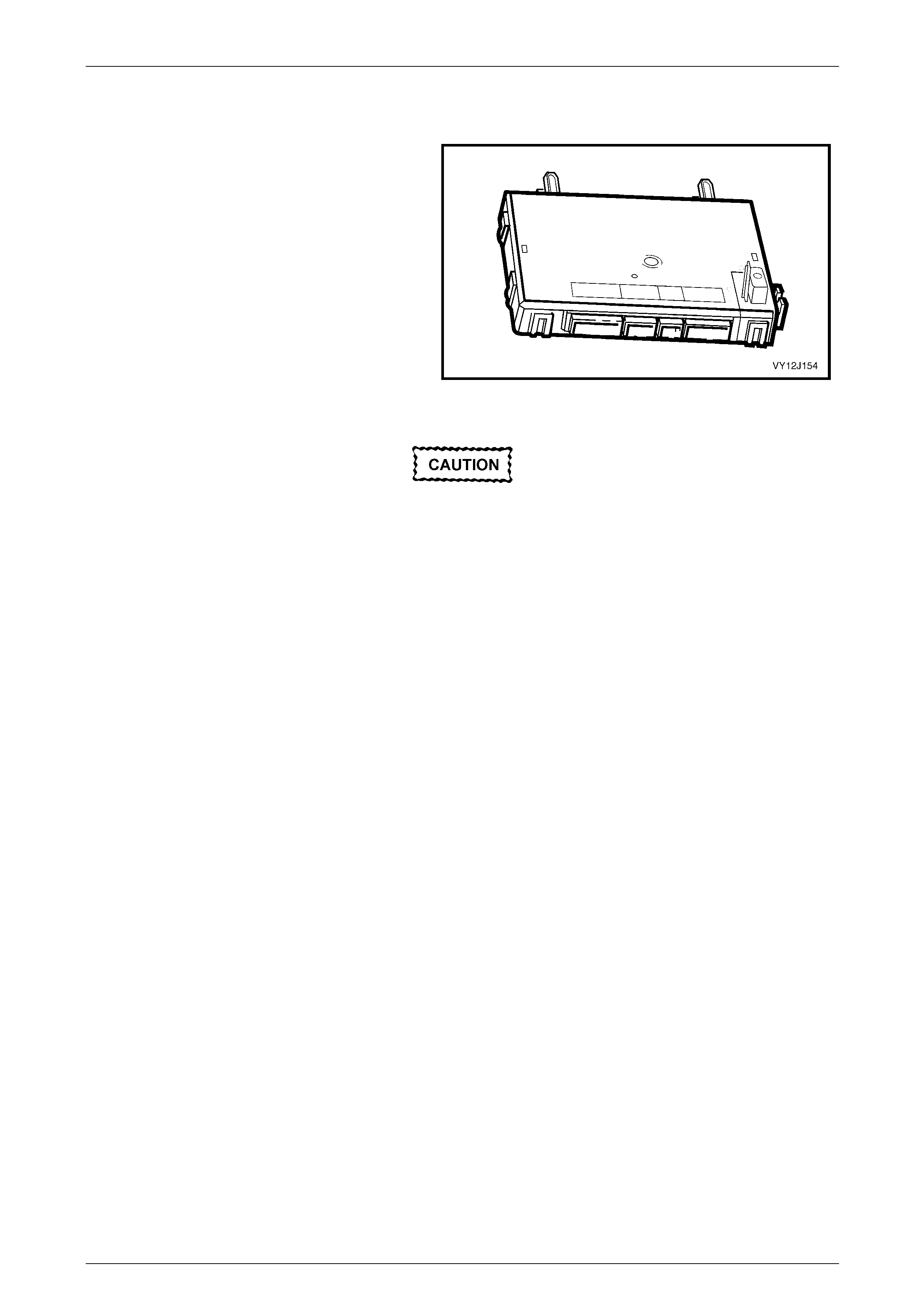
Body Control Module Page 12J–15
Page 12J–15
1.2 Body Control Module
The body control module (BCM) controls various vehicle
electrical systems or features from one central module,
instead of using individual modules for each system or
feature.
The BCM is located beneath the instrument cluster to
the right of the steering column. The BCM is mounted
vertically, refer to Figure 12J – 98.
The BCM fitted to the various levels of vehicle is
physically the same, but with different functions enabled
via the BCM software.
Figure 12J – 1
Disconnect and remove all vehicle modules (after
disconnecting the battery) before performing any
welding, anywhere on the vehicle. Refer to
Section 00 Warnings Cautions and Notes. Failing
to do this can cause permanent damage to the
modules.

Body Control Module Page 12J–16
Page 12J–16
1.3 Body Control Module Models
Vehicle
Levels Vehicle
Models BCM
Levels
1 Ute
Reg Cab Low
1 Executive
Acclaim SV6 / SV8
S, SS
Crewman (All)
Mid
2 Berlina Lux
3 Calais
Monaro CV8 Lux
1 Adventra SX Mid
2 Adventra CX / LX Lux

Body Control Module Page 12J–17
Page 12J–17
1.4 Body Control Module Features
NOTE
Each model BCM includes a pre-delivery mode,
which sets the battery saver timer to a shorter
period of 3 minutes until the vehicle has travelled
above 20 km/h for a cumulative period of
30 minutes. After this period, the battery saver
timer sets to 1 hour.
The following list provides a summary of the features available on all level BCM’s.
• Remote deadlocking via remote key, two LOCK switch presses within 10 seconds.
• Battery saver feature; turns off all internal lamps after 1 hour (default setting) of the ignition being switched off.
• Key off courtesy lamp; courtesy lamp comes on for 30 seconds when the ignition is switched off.
• Disablement of the in-vehicle rear compartment release switch when the security system is armed.
• Approach illumination entry, headlamps and / or park lamps are turned on for 30 seconds (dependent on headlamp
switch position) when the vehicle is unlocked via the remote key.
Feature Table Key
Feature available 9
Feature not available X
Feature selectable by user U
Feature Table
Feature Function Description
Low
Mid
Lux
High
A
WD
W
agon
Accessory power control
(delay accessories bus) Power to the audio system, windscreen
wiper and other accessories is removed
when the ignition is switched off.
9 9 9 9 9
Air conditioning interface system
(A/C switch) Momentary pressing of this switch
activates the air conditioning system.
NOTE
On Lux, High and AWD Wagon BCM’s,
this is controlled by the occupant climate
control module.
9 9 X X X
Airbag deployment vehicle shutdown Upon airbag deployment, the doors
unlock and the dome lamp illuminates for
10 seconds after the vehicle stops.
Engine and fuel pump turned off.
9 9 9 9 9
Approach
illumination Operates during darkened
conditions. The headlamps illuminate for 30 seconds
when the remote key unlocks the doors in
low light conditions.
9 9 9 9 9
Automatic
door-locking Selectable from instrument
cluster menu. All doors lock automatically when the
gearshift lever is moved out of the Park
position.
U U U U U
Automatic
lights off Turns off exterior lights
after a set period. With the park lamps, headlamps or auto
lamps on, the selected lamps remain on
after key off and the drivers door open for
a user adjustable period before switching
off automatically.
9 9 9 9 9

Body Control Module Page 12J–18
Page 12J–18
Feature Function Description
Low
Mid
Lux
High
A
WD
W
agon
Automatic
lights on Turns lights on and off
automatically. The sun sensor automatically determines
when to turn on or off the headlamps
according to light conditions The wiper
switch position can force the lights to
come on earlier than normal.
9 9 9 9 9
Reduced standing current. After the vehicle has entered Battery
Saver mode, the battery current reduces
to less than 30 mA. The time to invoke
this mode is 10 seconds after remote
lock, key lock via driver’s door or 1 hour
after the ignition has been switched off.
9 9 9 9 9
Battery saver
Pre-delivery 3-minute
cutout. This mode exists on the vehicle until it
has travelled a total of 30 minutes at
speeds above 20 km/h.
9 9 9 9 9
Central
locking –
keyless entry
• Selectable whether
remote entry
operates driver only
or both doors.
• Engages door
deadlocks when
LOCK key button is
pressed twice.
• Releases both door
deadlocks when
unlocking vehicle.
• Operates exterior
lamps to show
location of car at
night.
• Enables or disables
the alarm system.
• Remote rear
compartment lid
release in glove box
disabled when
vehicle is locked.
• Applies a rolling
security code for
increased security.
• Horn chirps if either
door is ajar when
remote locking is
initiated.
Pressing the LOCK / UNLOCK key button
down will lock / unlock all doors
simultaneously.
Separate driver’s door only unlock, called
“2 stage unlock” is selectable from the
instrument cluster menu. If single stage
unlock is selected all door will unlock
when UNLOCK button is pressed.
A second press of the LOCK button
within the required time activates each
door deadlock.
9 9 9 9 9
Central locking – remote rear compartment
release. A separate button on the key releases the
rear compartment. X 9 9 9 9
Dome and
courtesy
lamp control
Entry delay, central locking
and ignition off courtesy
illumination.
The dome lamp is switched on from
various sources. Lamp shut-off timing is
triggered by ignition key switch off and
the driver’s door being opened and
closed.
9 9 9 9 9

Body Control Module Page 12J–19
Page 12J–19
Feature Function Description
Low
Mid
Lux
High
A
WD
W
agon
Entry
deterrent
system
Vehicle immobilisation and
entry alarm. A range of security features provides the
highest level of security to the vehicle.
NOTE
No audible horn alarm fitted to level 1
vehicles.
9 9 9 9 9
Heated rear
window Control with delay. A timed 15 minute heating period
commences once this switch is activated.
NOTE
On Lux, High and AWD Wagon BCM’s,
this is controlled by the occupant climate
control module.
9 9 X X X
Instrument dimming control Holding the dimming switch on the
headlamp switch assembly in either the
Increase or Decrease position changes
instrumentation illumination.
9 9 9 9 9
Intermittent
wiper control Road speed dependent
variable dwell options. The intermittent wiper dwell time reduces
as the vehicle speed increases. X X U U U
Power
window
system
• Controls the vehicles
power windows
automatic functions.
• With driver and
passenger express
down.
• Windows remain
operative for a short
period after ignition is
switched off.
The express down feature operates when
the power window switches are held
down for more than 0.4 second.
X 9 9 9 9
Power
antenna
control
With height adjustment and
height memory. The radio antenna is height and drive
direction is controlled by the BCM when it
receives a radio request signal. The
height can be set and stored for Priority 1
and 2 keys.
X X 9 9 9

Body Control Module Page 12J–20
Page 12J–20
Feature Function Description
Low
Mid
Lux
High
A
WD
W
agon
Priority key
automatically
applies
personalised
vehicle
settings for
two people
The BCM stores individual
settings for the following:
• Climate control,
• Sound system,
• Trip computer,
• Over speed alert,
• Transmission power–
economy mode,
• Instrument dimmer
level,
• Headlamps off time
delay,
• Accessories
shutdown control via
driver’s door opening
or ignition off,
• Dome lamp and
courtesy lamp timers,
• Single stage and two
stage unlock,
• Horn chirp when
LOCK and UNLOCK
button press,
• Speed dependant
wipers,
• Automatic lights on
setting (Early, Normal
and Late), and
• Memory seats.
Putting either Key 1 or 2 in the ignition
switch selects the choices made in the
systems listed.
X X 9 9 9
With speed interlock. The rear compartment cannot be
released at speeds over 20 km/h. X 9 9 9 NA Rear
compartment
release Disabled when armed. Rear compartment lid opening (by
pressing the switch in the glove box) is
disabled when the theft deterrent system
is armed, using the remote coded key
and doors locked via door lock barrel.
X 9 9 9 NA
Serial data interface The vehicle contains control modules that
communicate via a serial data system.
This permits Tech 2 interaction to enable
high-level diagnostic fault analysis.
9 9 9 9 9
Theft deterrent Engine is disabled to immobilise vehicle
when the key is removed from the
ignition. This will occur 30 seconds after
ignition off and is indicated by the theft
deterrent LED on the instrument cluster
flashing.
9 9 9 9 9

Body Control Module Page 12J–21
Page 12J–21
2 System Operation
2.1 Body Control Module Operating Modes
Battery Saver Mode
The BCM battery saver mode provides vehicle battery protection through reduced current consumption. After a preset
delay period controlled by the BCM’s internal shut down timer, the BCM:
• De-energises the interior illumination relay, which supplies battery voltage to all interior lamps including the dome
lamp, ignition lock, instrument panel compartment and rear compartment lamps. This protects the battery when:
• A lamp is mistakenly left on because a door is left open, or
• A faulty illumination circuit or component is causing excess current consumption.
• De-energises the power window relay. This action is separate from the normal Power Window Off Delay function.
• Disables the BCM inputs normally not required when the ignition is off.
• De-energises the accessories relay.
The battery saver delay period has a default value of 60 minutes, however it can be set from 3 – 180 minutes using
Tech 2. The delay period starts when the ignition is switched off.
If the BCM is in battery saver mode, all the BCM inputs are re-enabled when:
• The hood, rear compartment lid or any door is opened,
• The BCM receives a valid RF key lock, unlock or rear compartment signal from the remote coded key,
• The ignition switch is turned on or to the accessories position,
• The doors are unlocked via the driver’s door micro switch,
• The deadlock switch is operated,
• Tech 2 is communicating with the BCM,
• The headlamp switch is cycled from off to on or from on to off,
• The rear compartment release switch, located in the glove box, is operated,
• The alarm is activated (if fitted),
• Hazard switch on, or
• Accessories on via radio trigger.
Pre-delivery Mode
To provide additional battery protection the vehicle is delivered with the BCM in pre-delivery mode. In this mode, the
battery saver period is set to 3 minutes.
Pre-delivery mode is disabled once the vehicle has travelled for a total of 30 minutes at speeds above 20 km/h. This
value is estimated to be the equivalent period prior to customer delivery.
Pre-delivery mode may also be enabled and disabled using Tech 2.

Body Control Module Page 12J–22
Page 12J–22
2.2 Serial Data Communication – V6
System Overview
Vehicles that are fitted with a HFV6 engine use GM LAN (General Motors Local Area Network) serial data
communications system for powertrain components. The modules use GM LAN communications to transfer information
between each other and bi directionally to the powertrain interface module (PIM). GM LAN has a major advantage over
the former Class 2 system of data communication in that it transfers data much faster.
Refer to the system block diagram Figure 12J – 2 showing how the control modules within the vehicle are connected to
the BCM via the GM LAN and UART (Bus Master) systems.
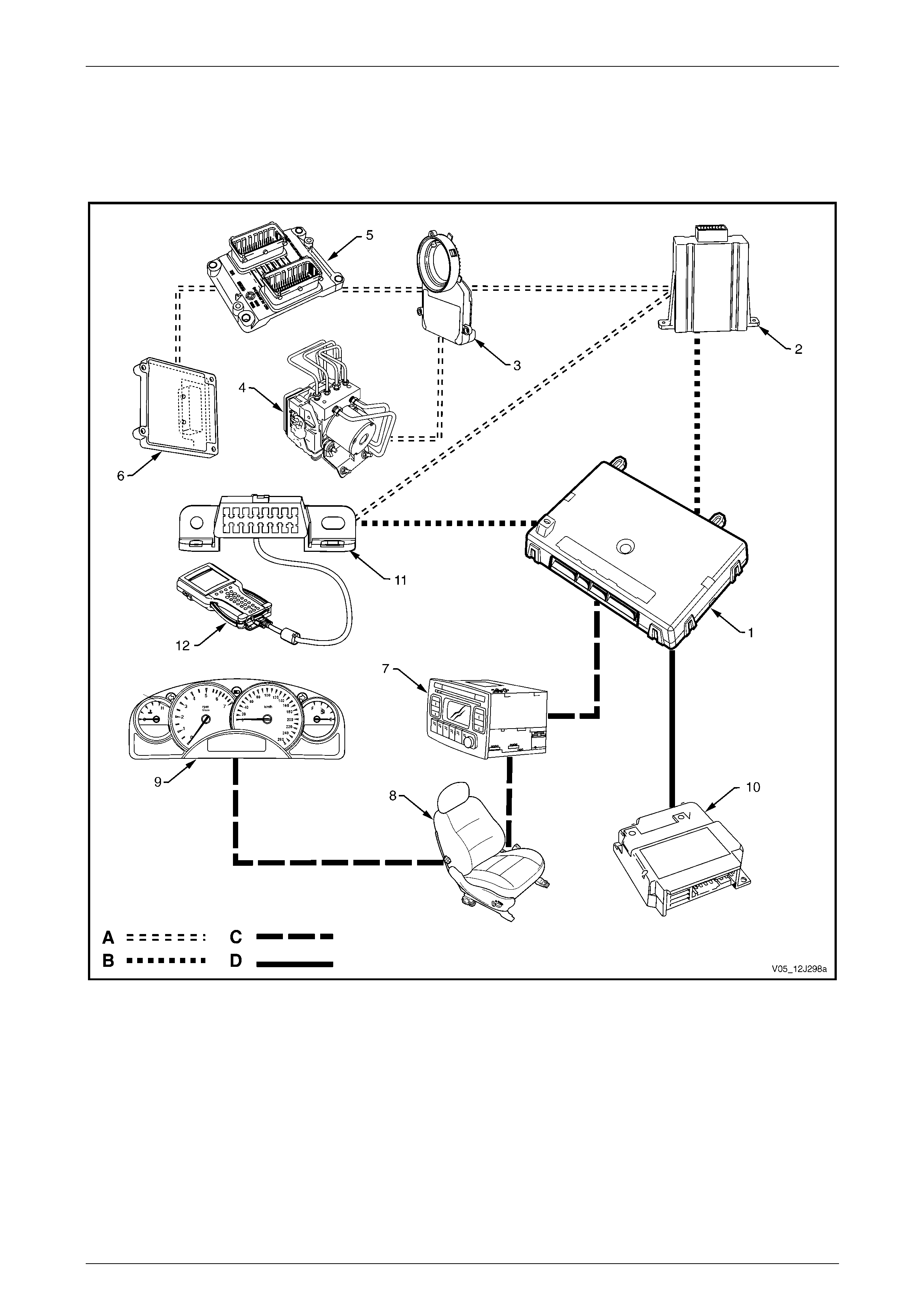
Body Control Module Page 12J–23
Page 12J–23
V6 Serial Data Block Diagram
NOTE
Serial data components shown in the block
diagram will vary depending on vehicle options.
Figure 12J – 2
Legend
1 Body Control Module (BCM)
2 Powertrain Interface Module (PIM)
3 Steering Angle Sensor (SAS)
4 ABS-TCS / ESP Electronic Control Unit
5 Engine Control Module (ECM)
6 Transmission Control Module (TCM)
7 Audio Head Unit (AHU)
8 Memory Seat Module (MSM)
9 Instrument Cluster
10 Occupant Protection System Sensing and Diagnostic
Module (SDM)
11 Data Link Connector
12 Tech 2 Diagnostic Tool
A GM LAN serial data circuit
B Primary UART serial data circuit
C Secondary UART serial data circuit
D Tertiary UART serial data circuit

Body Control Module Page 12J–24
Page 12J–24
The GM LAN Bus System
The term GM LAN means the various engine and vehicle control modules are linked together on a common twisted pair
bi directional data bus.
The advantages of using GM LAN are:
• Fewer sensors and signal wires are necessary due to the multiple uses of common sensor signals.
• Fewer wires are needed in the cable harnesses.
• Smaller wiring harnesses results in an overall vehicle weight reduction.
• Fewer plug-in terminals are required in the control unit connectors.
• Improved reliability and serviceability is achieved.
The GM LAN bus system communicates between the ECM, TCM, ABS / TCS and PIM via a dual wire network, which is a
high-speed differential bus with a transmission speed of 500K bits / second. It is designed as a dual wire system
comprising one tan / black wire (CAN-High) and another tan wire (CAN-Low). The wires are twisted together to prevent
electro-magnetic interference being caused to other control units within the vehicle. The twisting of these wires eliminates
any magnetic fields that are created by the rapid voltage changes on the lines.
GM LAN module’s have various vehicle peripheral devices such as sensors and switches connected to them. The
module either reads data from these peripheral devices, or sends commands to them. The timing as to when data is read
from or sent to it is most often determined by either engine or vehicle operating conditions, which is received from other
control modules connected to the GM LAN.
Data transmitted from any module is sent to all GM LAN control modules connected to the bus. Each control module has
to assess whether the data it receives is required for it to process and if necessary, to act upon it.
UART Communications
Tech 2 and the vehicle system body control modules communicate with and between each other using serial data. Serial
data transfers information, one bit at a time, over a single line called the UART data bus.
The UART bus is a 5-volt data line that toggles the voltage to ground (0 V) at a fixed bit pulse-width during
communication and transmits data at the frequency of 8.2 kilobits per second (8192 bits/second) to all modules
connected to it. When there is no communication on the data line, the system voltage remains constant at 5 V.
Serial Data Bus
The serial data bus is divided into three sections, these being:
• Primary data bus.
The BCM uses the primary data bus, circuit 800, for communication with the Powertrain Interface Module (PIM) A5.
• Secondary data bus.
The BCM uses the secondary data bus, circuit 1061 for communication with the remaining modules, except the
OPS / SDM module A65.
• Tertiary data bus.
The BCM uses the tertiary data bus, circuit 774, for communication with the Occupant Protection System OPS /
SDM A65.

Body Control Module Page 12J–25
Page 12J–25
Data Bus Device Polling
The BCM periodically polls (surveys) each device on the Primary, Secondary and Tertiary data buses, which includes the
BCM itself, and requests each module’s status data. The following devices and control modules are polled:
Primary Serial Data Bus
• PIM (A5).
• Tech 2 diagnostic scan tool.
Secondary Serial Data Bus
• instrument cluster (P3).
• audio head unit (A133)
• memory seat module (A21)
• HVAC (A14)
Tertiary Serial Data Bus
• Occupant protection system (OPS) and sensing and diagnostic module (SDM) A65.
The BCM polls each of the above listed devices for a status update every 300 milliseconds with the exception of the PIM
and radio, which are polled twice every 300 milliseconds. An internal, software controlled switch (within the BCM) can
isolate the secondary data bus and the tertiary data bus from the primary data bus if a short circuit appears on either the
secondary or tertiary data buses. When this switch is opened by the BCM, this permits the vehicle to start and run for
short distances with limited facilities available to the driver such as instrumentation, radio, etc.
Tech 2 and the Data Link Connector
The DLC provides an interface between Tech 2 and the two data bus systems. The X40 Data Link Connector (DLC)
provides the facility for Tech 2 to communicate to the vehicle’s control modules via the GM LAN and Bus Master UART
systems.
Tech 2 communicates with the ECM and other powertrain control modules via its own direct connection to the GM LAN
via the DLC. It also communicates with the BCM via the DLC’s Primary UART Bus.
Inputs and Outputs
To aid in the following description, refer to 3 Wiring Diagrams and Connector Charts.
GM LAN Data Bus
The GM LAN twisted pair data bus is connected to CAN_LO and CAN_HI between the PIM and the ECU, ABS / TCS,
TCM and the SAS control modules. The GM LAN data bus is also available at the data link connector (DLC)
Serial Data Signal – Primary UART
The BCM primary serial data bus A15 – X2 pin 5 is connected to the PIM A5 – X1 pin 10 and the data link connector
(DLC) to Tech 2 via circuit 800. It is through the Primary UART Bus the BCM communicates with the PIM and with
Tech 2 when it is connected to the DLC.
Serial Data Signals – Secondary and Tertiary UART
The BCM secondary serial data bus A15 – X2 pin 9 is connected to the instrument cluster (P3), the audio head
unit (A133), the memory seat module (A21) and the HVAC module (A14) via circuit 1061.
The BCM tertiary serial data bus A15 – X2 pin 6 is connected to the OPS / SDM module (A65) via circuit 774. It is
through circuits 1061 and 774 the BCM communicates with these devices after successful theft deterrent
communications has occurred between the PIM and BCM.
The secondary and tertiary serial data buses are isolated from the primary serial data bus within the BCM if the BCM
does not receive an OK To Start message from the PIM within 0.5 second of the ignition being switched to the ON
position. If there is still no acknowledgment from the PIM after this time, this isolation continues for a 5 second period
before the BCM re-commences polling.

Body Control Module Page 12J–26
Page 12J–26
Data Bus Device Polling
The BCM controls all modules on the UART serial data communication system. The BCM periodically polls (surveys)
each device on the data bus, including the BCM itself, and requests status data. The following devices and control
modules are polled:
• powertrain interface module (PIM),
• instrument cluster,
• occupant protection system (OPS) sensing and diagnostic module (SDM),
• blower motor and A/C compressor module (HVAC),
• audio system head unit (AHU),
• memory seat module (MSM),
• Tech 2 diagnostic scan tool, and
• the BCM itself.
The BCM polls each device for a status update every 300 milliseconds, with the exception of the PIM and radio which are
polled twice every 300 milliseconds.
Data Messages
Any device connected to the bus can use the data provided by each device.
Each device has a unique response message identifier word (MIW) for ease of identification. The BCM polls each device
with a serial data message that includes the device MIW. The device responds with a serial data message including its
MIW with the data, which is retrieved and used by any device requiring it.
Powertrain Interface Module
The powertrain interface module (PIM) is the hardware and serial communications interface between the engine ECM
and powertrain, braking, traction control and steering control modules that are connected to the GM LAN data bus. The
PIM acts as a transparent bi-directional translation device that allows data to flow between the above modules on the
GM LAN data bus and converts this data to UART serial data protocols for the BCM to process and act on.
Refer to Section 6E1 Powertrain Interface Module – V6 for further detailed information.

Body Control Module Page 12J–27
Page 12J–27
2.3 Serial Data Communication – GEN III V8
System Overview
GEN III V8 vehicles use both the UART bus master system to communicate between the BCM and various body modules
and Class 2 communications to communicate between the powertrain interface module (PIM) and the powertrain control
module (PCM).
Class 2 uses a different communications language to UART, therefore direct communication between the modules is
incompatible and requires an interface module PIM to convert Class 2 communication into UART and UART into Class 2.
Refer to Section 6E3 Powertrain Interface Module GEN III V8 for further details.
Refer to the system block diagram Figure 12J – 3 showing how the control modules within the vehicle are connected to
the BCM via the Class 2 and UART (Bus Master) system.
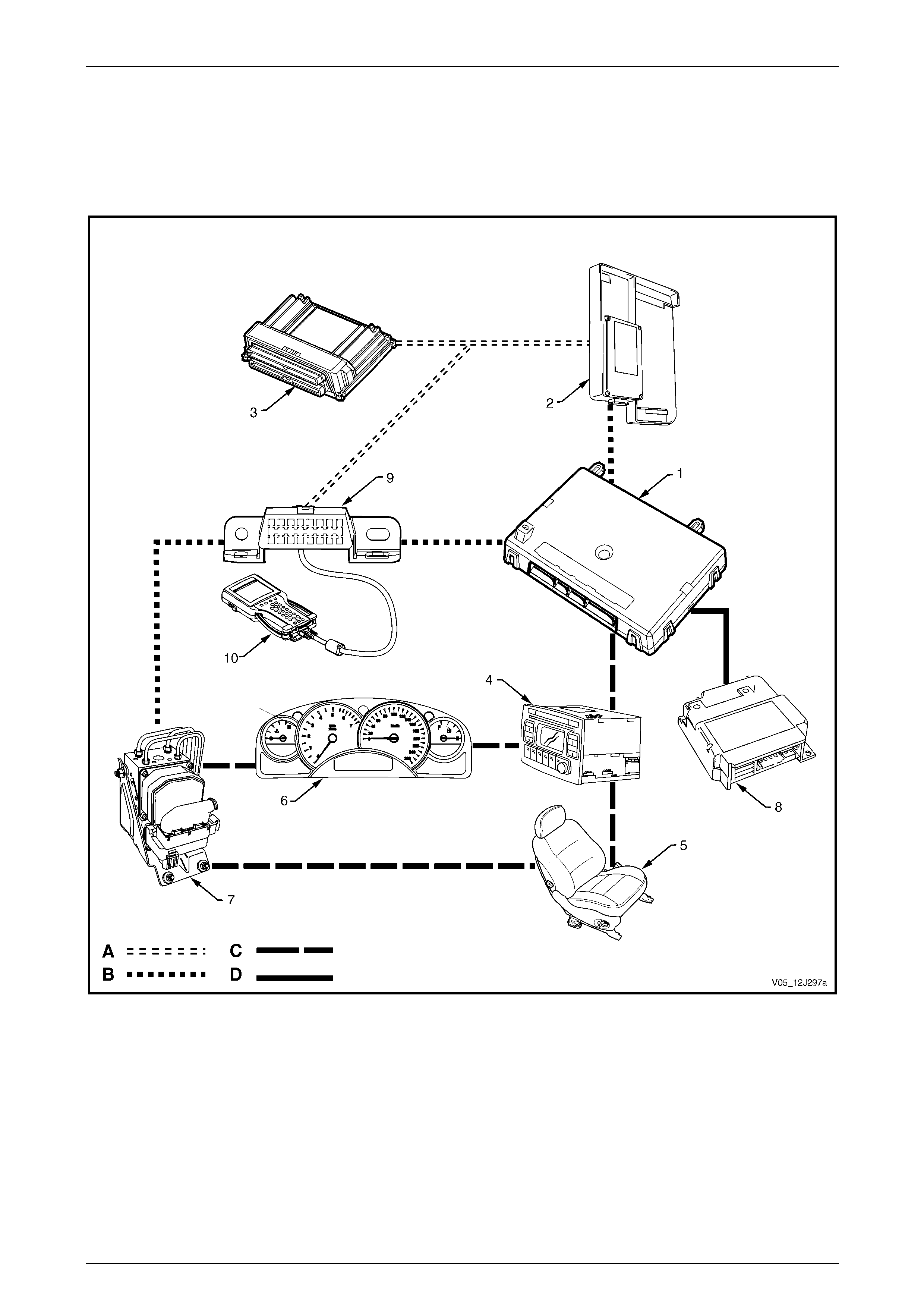
Body Control Module Page 12J–28
Page 12J–28
GEN III V8 Serial Data Block Diagram
NOTE
Serial Data Components shown in the block
diagram will vary depending on vehicle options.
Figure 12J – 3
Legend
1 Body Control Module (BCM)
2 Powertrain Interface Module (PIM)
3 Powertrain Control Module (PCM)
4 Audio Head Unit (AHU)
5 Memory Seat Module (MSM)
6 Instrument Cluster
7 Antilock Brake System (ABS)
8 Occupant Protection System Sensing and Diagnostic Module (SDM)
9 Data Link Connector
10 Tech 2 Diagnostic Tool
A Class 2 data circuit
B Primary UART serial data circuit
C Secondary UART serial data circuit
D Tertiary UART serial data circuit

Body Control Module Page 12J–29
Page 12J–29
UART and Class 2 Serial Data Bus
Tech 2 and the vehicle system control modules communicate with and between each other using serial data. Serial data
transfers information, one bit at a time, over a single line called the universal asynchronous receive and transmit UART
data bus. UART is a communications protocol that has a master module, which controls the message traffic on the serial
data bus. The body control module is the UART bus master.
The UART bus is a 5-volt data line that toggles the voltage to ground (0 V) at a fixed bit pulse-width during
communication and transmits data at the frequency of 8.2 kilobits per second (8192 bits/second) to all modules
connected to it. When there is no communication on the data line, the system voltage remains constant at 5 V.
The PIM communicates with the PCM using Class 2 data communications. This type of communications toggles the data
line from 0 V to 7 V with either a short or long pulse width at an average frequency of 10.4 kilobits per second. In Class 2
communications, where there is no communications on the data line, the system voltage is 0 V. Class 2 communication
protocol enables communications directly between the modules on the bus without the need for a bus master.
The serial data bus is divided into three sections, these being:
• Primary data bus.
The BCM uses the primary data bus, circuit 800, for communication with the powertrain interface module PIM A5.
• Secondary data bus.
The BCM uses the secondary data bus, circuit 1061 for communication with the remaining modules, except the
OPS / SDM module A65.
• Tertiary data bus.
The BCM uses the tertiary data bus, circuit 774, for communication with the occupant protection system OPS /
SDM A65.
Data Bus Device Polling
The BCM periodically polls (surveys) each device on the primary, secondary and tertiary data buses, which includes the
BCM itself, and requests each module’s status data. The following devices and control modules are polled:
Primary Serial Data Bus
• PIM (A5).
• Tech 2 diagnostic scan tool.
Secondary Serial Data Bus
• instrument cluster (P3).
• audio head unit (A133)
• memory seat module (A21)
• HVAC (A14)
Tertiary Serial Data Bus
• occupant protection system (OPS) and sensing and diagnostic module (SDM) A65.
The BCM polls each of the above listed devices for a status update every 300 milliseconds with the exception of the PIM
and radio, which are polled twice every 300 milliseconds. An internal, software controlled switch (within the BCM) can
isolate the secondary data bus and the tertiary data bus from the primary data bus if a short circuit appears on either the
secondary or tertiary data buses. When this switch is opened by the BCM, this permits the vehicle to start and run for
short distances with limited facilities available to the driver such as instrumentation, radio, etc.
Tech 2 and the Data Link Connector
The DLC provides an interface between Tech 2 and the two data bus systems. The X40 Data Link Connector (DLC)
provides the facility for Tech 2 to communicate to the vehicle’s control modules via the GM LAN and Bus Master
systems.
Tech 2 communicates with the BCM via the DLC’s primary UART bus as well as the receiving bi-directional Class 2 data
communications from the PIM and PCM. Tech 2 is able to communicate with both UART and Class 2 control modules.

Body Control Module Page 12J–30
Page 12J–30
Inputs and Outputs
To aid in the following description, refer to 3 Wiring Diagrams and Connector Charts.
Class 2 Serial Data Signal
Class 2 serial data flows bi-directional between the PIM A5 – X1 pin 7 and the PCM A84 – X1 pin 58 and is also present
at the data link connector (DLC) to Tech 2 via circuit 1045.
Serial Data Signal – Primary UART
The BCM primary serial data bus A15 – X2 pin 5, is connected to the PIM A5 – X1 pin 6 and the data link connector
(DLC) to Tech 2 via circuit 800. It is through the primary UART Bus the BCM communicates with the PIM and with Tech 2
when it is connected to the DLC.
Serial Data Signal – Secondary and Tertiary UART
The BCM secondary serial data bus A15 – X2 pin 9, is connected to the instrument cluster (P3), the audio head
unit (A133), the memory seat module (A21) and the HVAC module (A14) via circuit 1061.
The BCM tertiary serial data bus A15 – X2 pin 6 is connected to the OPS / SDM module (A65) via circuit 774. It is
through circuits 1061 and 774 the BCM communicates with these devices after successful theft deterrent
communications has occurred between the PIM and BCM.
The secondary and tertiary serial data buses are isolated from the primary serial data bus within the BCM if the BCM
does not receive an OK To Start message from the PIM within 0.5 second of the ignition being switched to the ON
position. If there is still no acknowledgment from the PIM after this time, this isolation continues for a 5 second period
before the BCM re-commences polling.
Data Bus Device Polling
The BCM controls all modules on the UART serial data communication system. The BCM periodically polls (surveys)
each device on the data bus, including the BCM itself, and requests status data. The following devices and control
modules are polled:
• powertrain interface module (PIM),
• instrument cluster,
• antilock brake / traction control system (ABS/TCS) module,
• occupant protection system (OPS) sensing and diagnostic module (SDM),
• blower motor and A/C compressor module (HVAC),
• audio system head unit (AHU),
• memory seat module (MSM),
• Tech 2 diagnostic scan tool, and
• the BCM itself.
The BCM polls each device for a status update every 300 milliseconds, with the exception of the PIM and radio which are
polled twice every 300 milliseconds.
Data Messages
Any device connected to the bus can use the data provided by each device.
Each device has a unique response message identifier word (MIW) for ease of identification. The BCM polls each device
with a serial data message that includes the device MIW. The device responds with a serial data message including its
MIW with the data, which is retrieved and used by any device requiring it.
Powertrain Interface Module
The powertrain interface module (PIM) is the hardware and serial communications interface between the powertrain
control module (PCM) connected together via the Class 2 data bus. The PIM acts as a transparent bi-directional
translation device that allows data to flow between the PCM and converts this data to UART serial data protocols for the
BCM to process and act on.
Refer to Section 6E3 Powertrain Interface Module GEN III V8 for further detailed information.

Body Control Module Page 12J–31
Page 12J–31
2.4 Serial Data Communication – GEN IV V8
System Overview
Vehicles that are fitted with a GEN IV V8 engine use GM LAN (General Motors Local Area Network) serial data
communications system for powertrain components. The modules use GM LAN communications to transfer information
between each other and bi directionally to the powertrain interface module (PIM). GM LAN has a major advantage over
the former Class 2 system of data communication in that it transfers data much faster.
Refer to the system block diagram Figure 12J – 4 showing how the control modules within the vehicle are connected to
the BCM via the GM LAN and UART (Bus Master) systems.
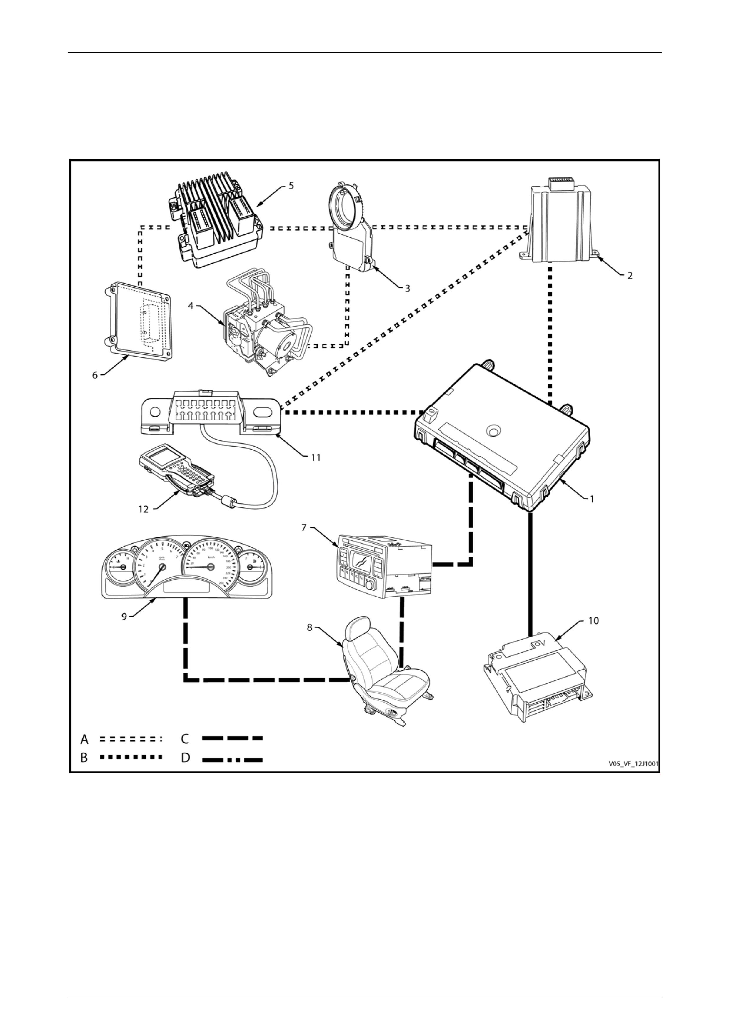
Body Control Module Page 12J–32
Page 12J–32
GEN IV V8 Serial Data Block Diagram
NOTE
Serial data components shown in the block
diagram will vary depending on vehicle options.
Figure 12J – 4
Legend
1 Body Control Module (BCM)
2 Powertrain Interface Module (PIM)
3 Steering Angle Sensor (SAS)
4 ABS-TCS / ESP Electronic Control Unit
5 Engine Control Module (ECM)
6 Transmission Control Module (TCM)
7 Audio Head Unit (AHU)
8 Memory Seat Module (MSM)
9 Instrument Cluster
10 Occupant Protection System Sensing and Diagnostic
Module (SDM)
11 Data Link Connector
12 Tech 2 Diagnostic Tool
A GM LAN serial data circuit
B Primary UART serial data circuit
C Secondary UART serial data circuit
D Tertiary UART serial data circuit

Body Control Module Page 12J–33
Page 12J–33
The GM LAN Bus System
The term GM LAN means the various engine and vehicle control modules are linked together on a common twisted pair
bi directional data bus.
The advantages of using GM LAN are:
• Fewer sensors and signal wires are necessary due to the multiple uses of common sensor signals.
• Fewer wires are needed in the cable harnesses.
• Smaller wiring harnesses results in an overall vehicle weight reduction.
• Fewer plug-in terminals are required in the control unit connectors.
• Improved reliability and serviceability is achieved.
The GM LAN bus system communicates between the ECM, TCM, ABS / TCS and PIM via a dual wire network, which is a
high-speed differential bus with a transmission speed of 500K bits / second. It is designed as a dual wire system
comprising one tan / black wire (CAN-High) and another tan wire (CAN-Low). The wires are twisted together to prevent
electro-magnetic interference being caused to other control units within the vehicle. The twisting of these wires eliminates
any magnetic fields that are created by the rapid voltage changes on the lines.
GM LAN module’s have various vehicle peripheral devices such as sensors and switches connected to them. The
module either reads data from these peripheral devices, or sends commands to them. The timing as to when data is read
from or sent to it is most often determined by either engine or vehicle operating conditions, which is received from other
control modules connected to the GM LAN.
Data transmitted from any module is sent to all GM LAN control modules connected to the bus. Each control module has
to assess whether the data it receives is required for it to process and if necessary, to act upon it.
UART Communications
Tech 2 and the vehicle system body control modules communicate with and between each other using serial data. Serial
data transfers information, one bit at a time, over a single line called the UART data bus.
The UART bus is a 5-volt data line that toggles the voltage to ground (0 V) at a fixed bit pulse-width during
communication and transmits data at the frequency of 8.2 kilobits per second (8192 bits/second) to all modules
connected to it. When there is no communication on the data line, the system voltage remains constant at 5 V.
Serial Data Bus
The serial data bus is divided into three sections, these being:
• Primary data bus.
The BCM uses the primary data bus, circuit 800, for communication with the Powertrain Interface Module (PIM) A5.
• Secondary data bus.
The BCM uses the secondary data bus, circuit 1061 for communication with the remaining modules, except the
OPS / SDM module A65.
• Tertiary data bus.
The BCM uses the tertiary data bus, circuit 774, for communication with the Occupant Protection System OPS /
SDM A65.

Body Control Module Page 12J–34
Page 12J–34
Data Bus Device Polling
The BCM periodically polls (surveys) each device on the Primary, Secondary and Tertiary data buses, which includes the
BCM itself, and requests each module’s status data. The following devices and control modules are polled:
Primary Serial Data Bus
• PIM (A5).
• Tech 2 diagnostic scan tool.
Secondary Serial Data Bus
• instrument cluster (P3).
• audio head unit (A133)
• memory seat module (A21)
• HVAC (A14)
Tertiary Serial Data Bus
• Occupant protection system (OPS) and sensing and diagnostic module (SDM) A65.
The BCM polls each of the above listed devices for a status update every 300 milliseconds with the exception of the PIM
and radio, which are polled twice every 300 milliseconds. An internal, software controlled switch (within the BCM) can
isolate the secondary data bus and the tertiary data bus from the primary data bus if a short circuit appears on either the
secondary or tertiary data buses. When this switch is opened by the BCM, this permits the vehicle to start and run for
short distances with limited facilities available to the driver such as instrumentation, radio, etc.
Tech 2 and the Data Link Connector
The DLC provides an interface between Tech 2 and the two data bus systems. The X40 Data Link Connector (DLC)
provides the facility for Tech 2 to communicate to the vehicle’s control modules via the GM LAN and Bus Master UART
systems.
Tech 2 communicates with the ECM and other powertrain control modules via its own direct connection to the GM LAN
via the DLC. It also communicates with the BCM via the DLC’s Primary UART Bus.
Inputs and Outputs
To aid in the following description, refer to 3 Wiring Diagrams and Connector Charts.
GM LAN Data Bus
The GM LAN twisted pair data bus is connected to CAN_LO and CAN_HI between the PIM and the ECU, ABS / TCS,
TCM and the SAS control modules. The GM LAN data bus is also available at the data link connector (DLC)
Serial Data Signal – Primary UART
The BCM primary serial data bus A15 – X2 pin 5 is connected to the PIM A5 – X1 pin 10 and the data link connector
(DLC) to Tech 2 via circuit 800. It is through the Primary UART Bus the BCM communicates with the PIM and with
Tech 2 when it is connected to the DLC.
Serial Data Signals – Secondary and Tertiary UART
The BCM secondary serial data bus A15 – X2 pin 9 is connected to the instrument cluster (P3), the audio head
unit (A133), the memory seat module (A21) and the HVAC module (A14) via circuit 1061.
The BCM tertiary serial data bus A15 – X2 pin 6 is connected to the OPS / SDM module (A65) via circuit 774. It is
through circuits 1061 and 774 the BCM communicates with these devices after successful theft deterrent
communications has occurred between the PIM and BCM.
The secondary and tertiary serial data buses are isolated from the primary serial data bus within the BCM if the BCM
does not receive an OK To Start message from the PIM within 0.5 second of the ignition being switched to the ON
position. If there is still no acknowledgment from the PIM after this time, this isolation continues for a 5 second period
before the BCM re-commences polling.

Body Control Module Page 12J–35
Page 12J–35
Data Bus Device Polling
The BCM controls all modules on the UART serial data communication system. The BCM periodically polls (surveys)
each device on the data bus, including the BCM itself, and requests status data. The following devices and control
modules are polled:
• powertrain interface module (PIM),
• instrument cluster,
• occupant protection system (OPS) sensing and diagnostic module (SDM),
• blower motor and A/C compressor module (HVAC),
• audio system head unit (AHU),
• memory seat module (MSM),
• Tech 2 diagnostic scan tool, and
• the BCM itself.
The BCM polls each device for a status update every 300 milliseconds, with the exception of the PIM and radio which are
polled twice every 300 milliseconds.
Data Messages
Any device connected to the bus can use the data provided by each device.
Each device has a unique response message identifier word (MIW) for ease of identification. The BCM polls each device
with a serial data message that includes the device MIW. The device responds with a serial data message including its
MIW with the data, which is retrieved and used by any device requiring it.
Powertrain Interface Module
The powertrain interface module (PIM) is the hardware and serial communications interface between the engine ECM
and powertrain, braking, traction control and steering control modules that are connected to the GM LAN data bus. The
PIM acts as a transparent bi-directional translation device that allows data to flow between the above modules on the
GM LAN data bus and converts this data to UART serial data protocols for the BCM to process and act on.
Refer to Section 6E4 Powertrain Interface Module - GEN IV V8 for further detailed information.
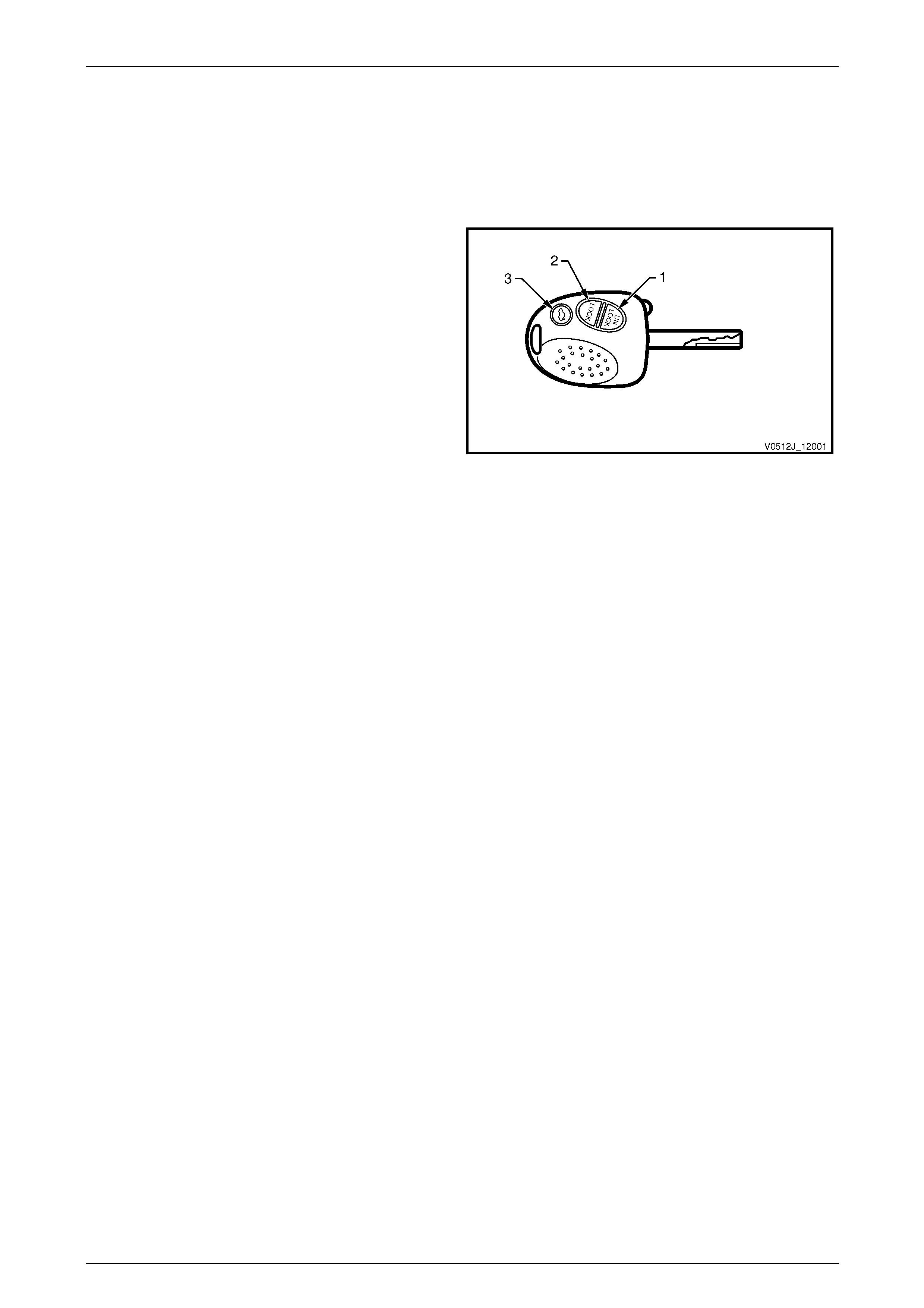
Body Control Module Page 12J–36
Page 12J–36
2.5 Remote Receiver / Key
System Operation
Unlocking
When operating the UNLOCK button (1) on the remote
coded key, a radio signal radiates from the key. If the
UNLOCK button is operated for 0.25 second within
approximately 4 metres of the driver’s side B-pillar, the BCM
receives an Unlock Request signal from the remote key
receiver, which is located in the instrument panel between
the demist ducts.
The BCM then:
• Unlocks all the doors (single-stage unlock) or the
driver’s door only (two-stage unlock),
• Disarms the theft and entry deterrent systems,
• Turns on the dome lamp in low light level conditions,
• Flashes the turn signal lamps twice,
• Horn chirps twice if selected, and
• Turns on headlamps (if headlamps are not in the off
position).
Figure 12J – 5
Locking
When operating the LOCK button (2) on the remote coded key for 0.25 second within approximately 4 metres of the
driver’s side B-pillar, a Lock Request signal is received by the BCM via the remote receiver.
The BCM then:
• Locks all the doors,
• Arms the theft and entry deterrent systems,
• Turns the dome lamp off if it is illuminated,
• Flashes the turn signal lamps once, and
• Horn chirps once if selected
NOTE
The vehicle cannot be locked if any front door is
open or ajar.
Rear Compartment Lid Release
When operating the rear compartment lid release button (3) on the remote coded key for 0.5 second within approximately
2 metres of the rear compartment lid, the BCM checks the vehicle speed is less than 20 km/h before activating the rear
compartment lock actuator to release the lid.
Remote Coded Key Battery Failure
The remote coded key is powered by it’s own internal battery. If this battery fails, no RF signal is transmitted when
operating the lock, unlock and rear compartment release buttons. However, the slip ring has the ability to power the key
when the key is inserted into the ignition switch and turned on, or to the start position. This enables theft deterrent
disarming.

Body Control Module Page 12J–37
Page 12J–37
Circuit Operation
To aid in the following description, refer to 3 Wiring Diagrams and Connector Charts.
NOTE
• The circuit diagrams shown are to aid in
interpreting the operation of the circuit and
therefore, only the main connectors and wiring
colours are shown.
• For complete circuits details refer to either the
relevant diagnostic section or
Section 12P Wiring Diagrams.
When operating the remote coded key, an RF signal is transmitted to the remote key receiver. This receiver transfers the
received data from receiver B55 – X1 pin 2 to A15 – X2 pin 1, via circuit 218. The receiver ground connection is from
receiver B55 – X1 pin 7 to A15 – X1 pin 14, circuit 219. The BCM responds to the received signal based on the frequency
of the RF signal (the button on the key that is pressed).
NOTE
The remote key receiver is also referred as the
sensor assembly headlamp auto control
assembly (B55) due to the incorporated light level
monitoring function.

Body Control Module Page 12J–38
Page 12J–38
2.6 Accessory Power Control
System Operation
The coil of the accessory control relay is switched to ground by the BCM when the ignition is turned to either the ACC or
ON positions. When the relay is energised, power is supplied to the radio, windscreen wiper systems and other
accessories, if fitted.
NOTE
The accessory relay will remain off when the
ignition switch is in the OFF position.
Accessory Relay Shutdown Options
The accessory relay can be triggered to remove battery power to the accessories by either:
• Switching the ignition switch to the OFF position, or
• Opening the driver’s door.
The driver’s choice of what action affects the relay can be selected through the instrument cluster’s MFD or using Tech 2.
The default option is set to Door Open.
However, if the accessory power relay had removed power and the radio is switched on, the BCM will energise the
accessory control relay for an additional period of 63 minutes. If the radio is switched off during this time frame, the
accessory control relay will be switched off immediately.
Wiper Control of the Accessory Relay
If the intermittent wiper system is in operation when the BCM is ready to disable the accessory relay, the relay can only
be disabled when the wiper park signal has been sensed by the BCM. If this signal is not sensed within 3 seconds of a
door shutting or the ignition being switched off, the BCM will automatically disable the relay.
Circuit Operation
To aid in the following description, refer to 3 Wiring Diagrams and Connector Charts.
NOTE
• The circuit diagrams shown are to aid in
interpreting the operation of the circuit and
therefore, only the main connectors and wiring
colours are shown.
• For complete circuits details refer to either the
relevant diagnostic section or
Section 12P Wiring Diagrams.

Body Control Module Page 12J–39
Page 12J–39
Radio On and Ignition Switch Input
When the ignition switch is turned to either the ACC or the ON positions, a 12 V supply from the ignition switch is
detected by the BCM at either A15 – X3 pin 4, (accessories request via circuit 4), or A15 – X3 pin 2 (ignition request via
circuit 300).
When either of these ignition switch positions is selected, the BCM then provides a ground connection to the accessory
control relay at A15 – X1 pin 9 via circuit 755. This causes its relay contacts to close, supplying 12 V to the BCM
accessory circuits, including:
• The front wipers, circuit 243, via fuse F18,
• The rear wiper system, also circuit 243, via fuse F18,
• The radio and, circuit 43, and
• The accessory socket, circuit 143.
Radio
If the radio is switched on while the ignition switch remains in the off position, the BCM will detect a radio request signal
with 12 V appearing at A15 – X3 pin 10 from circuit 314. The BCM will then energise the accessory control relay for 63
minutes while monitoring for other radio switch activations to occur, which will reset the 63-minute timer back to
63 minutes.
Depending on the option selected in which to disable the accessories control relay, the BCM will disable it when 0 V is
detected at BCM A15 – X3 pin 4 (accessories request via circuit 4) is no longer valid, or when 0 V is detected at A15 –
X4 pin 19 when the driver’s door is opened circuit 746.
Wipers
If the front wiper is in operation after initiating the disabling of the accessory power, the BCM will continue to monitor the
operation of the wiper park switch at BCM input A15 – X1 pin 1 through circuit 196. When 12 V is detected, the accessory
control relay is then disabled. If the wiper park signal is not detected within 3 seconds, the BCM will automatically disable
the relay.

Body Control Module Page 12J–40
Page 12J–40
2.7 Central Door Locking
System Operation
The central door locking system provides for locking or unlocking of all doors and the liftgate, enhanced locking or
deadlocking of the doors as well as single-stage and two-stage unlocking.
With all vehicles, it is possible to deadlock the doors via the remote coded key.
Reversible motors controlled by BCM relays operate the door and liftgate locks. These relays apply battery voltage to one
side of each motor and ground to the other side.
The central door locking system has five operational phases:
• Lock to unlock,
• Deadlock to unlock,
• Unlock to lock,
• Lock to deadlock, and
• Deadlock to lock.
Door Locking
The following triggers are used to activate this system:
• The driver's door-lock actuator, which is mechanically linked to the interior door snib and the door latch.
• The front passenger’s door-lock actuator, which is mechanically linked to the interior snib button.
• The micro switches in the driver’s door key barrel, which are also mechanically linked to the door latch and
therefore, to the actuators.
• The LOCK button on the remote coded key when all the doors are closed.
Door Unlocking
The following triggers are used to activate the system:
• Any door-lock actuator (snib) being pulled upwards.
• The micro switch in the driver’s door key barrel operating when the key is rotated.
• The UNLOCK button being pressed on the remote coded key.
If the battery becomes completely discharged, unlocking of the driver’s door latch is still possible by placing the key in the
door lock and rotating it. This action will still open the driver’s door if the door snibs held down.
Deadlocking
Deadlocking provides for mechanical jamming of the door-lock actuators. The deadlocking feature applies to all four
doors, but not to the rear compartment lid or liftgate. This is achieved electrically using the driver’s door lock micro switch
or by an RF signal from the remote key.
Deadlocking is engaged by two sequential operations of the door-lock micro switch or pressing the lock button on the
remote coded key twice within 10 seconds.
If the remote coded key is used, the turn signal lamps illuminate for three seconds when deadlocking is successful.
If the vehicle is already deadlocked, pressing the LOCK button on the remote coded key causes the turn signal lamps to
illuminate for 3 seconds. This indicates the vehicle is already deadlocked.
If the vehicle is locked but not deadlocked, pressing the LOCK button on the remote coded key over ten seconds after
the previous press does not deadlock the doors and the turn signal lamps will flash briefly. This indicates the doors are
only locked. Pressing the LOCK button again within a 10 second period deadlocks the doors and the turn signal lamps
illuminate for 3 seconds.

Body Control Module Page 12J–41
Page 12J–41
After deadlocking, outside unlocking at the driver’s door is achieved by turning the key in the driver’s door-lock to the
unlock position or pressing the UNLOCK button on the remote coded key. If two-stage unlocking is enabled, pressing the
remote coded key button removes the deadlock on all doors, but only unlocks the driver’s door.
If the electrical system fails after the system has been engaged, the driver’s door-lock cylinder can be moved
independently of the actuator. This allows unlocking of the driver’s door latch.
The rear compartment lid or liftgate can be locked or unlocked when mechanical deadlocking is actuated, leaving the
doors secured.
NOTE
Central locking and deadlocking by pressing the
LOCK button on the remote coded key is not
possible when the ignition is on. Central locking is
possible by pushing down the snibs on either
front doors when the ignition is on.
Single-stage and Two-stage Unlocking
The BCM is capable of operating in either single-stage unlock or two-stage unlock mode.
With Tech 2, the BCM can be programmed to operate in either two-stage or single-stage unlock, depending on the
vehicle’s owner or operator requirements. This can also be programmed via the instrument cluster MFD.
If a faulty circuit exists on either the lock or unlock signal inputs, the opposing input is still able to perform its function.
This enables the doors to be unlocked when a faulty circuit exists on the lock input or vice versa.
If the lock / unlock system is operated several times in a defined time period, the system times out. After a fixed time
delay, the system re-activates as normal. This action is to protect the door-locking actuator motors.
NOTE
Central locking and deadlocking by pressing the
LOCK button on the remote coded key is inhibited
while the ignition is switched on.
Central locking is possible by pushing down
the snibs on either of the doors when the
ignition is on. The theft deterrent system
also affects operation of this system.
Refer to 5.13 Theft Deterrent System.
Single-stage Unlock
In single-stage unlock mode, when the remote coded key UNLOCK button is pressed for 0.25 seconds or longer, the
BCM unlocks all doors simultaneously.
Two-stage Unlock
This mode can be enabled or disabled by the customer, refer to Section 12C Instrumentation.
In the two-stage unlock mode, pressing the remote coded key UNLOCK button for 0.25 seconds sends a signal to the
remote receiver. When the BCM receives the unlock request from the remote receiver, it unlocks the driver’s door only. If
the remote coded key unlock button is pressed again for 0.25 seconds, the BCM unlocks all passenger doors.
If the remote coded key is pressed continuously for 0.5 seconds, the BCM unlocks all doors; first, the driver’s door, then
all passenger doors.

Body Control Module Page 12J–42
Page 12J–42
System Check
Key Locking
Figure 12J – 6 shows the key positions on the driver’s door
for the various key-locking functions. One lock operation to
position A locks the vehicle. Two lock operations to
position A deadlocks the vehicle. One operation to position
B unlocks the vehicle.
Deadlocking means securing the vehicle by
electro-mechanically inhibiting door-lock snib operation.
Even though the electronic theft deterrent system (using
the remote coded key) can activate the door-locks, it does
not automatically deadlock the doors.
Figure 12J – 6
Remote Coded Key Check
Check the remote coded key locks all doors when the key
LOCK button is pressed within approximately 4 metres of
the driver’s side B-pillar.
If the vehicle is programmed for two-stage unlock, the
driver's side door unlocks, the passenger doors
undeadlock and the liftgate unlocks when the key unlock
button is pressed. Pressing the UNLOCK button again
unlocks all the passenger doors.
If the vehicle is programmed for single-stage unlock, a
single press of the UNLOCK button unlocks all doors and
the liftgate
If this check is not satisfactory, refer to
5.10 Remote Receiver / Key for a more detailed diagnosis
before continuing with the central locking system check.
Figure 12J – 7
Deadlocking Check
1 Open all windows.
2 Close all doors.
3 Use the key to operate the deadlock from the driver’s door.
4 Check that all door snibs are locked in position and cannot be pulled up.
NOTE
The snib buttons can be pulled up slightly, but
they will be under tension.
Door-lock Failure Warning
If a door fails to lock due to a mechanical or electrical fault, the system alerts the driver by giving a five short horn chirps
and the turn signal lamps do not flash when the remote lock button is pressed.

Body Control Module Page 12J–43
Page 12J–43
Auto Door-lock in Drive
NOTE
This is only applicable for vehicles fitted with
automatic transmission.
This feature applies only to automatic transmission vehicles and can be enabled or disabled by the customer.
Refer to Section 12C Instrumentation.
The BCM provides automatic locking of the doors when the ignition is on and the gearshift lever is moved out of the P
(park) position. The gearshift transition is detected by the BCM via the serial data bus.
The door-locks will unlock when the ignition is off and the gearshift lever is moved into the P (park) position.
NOTE
Only the driver’s door unlocks if two-stage unlock
is enabled.
NOTE
Auto door locking is inhibited while any door is
open.
Overheating Prevention
If there are multiple door-locking operations within a defined time period, the central door locking system will be
deactivated and remain inoperative for a defined time period. This is to prevent the door actuators from overheating. After
a fixed time delay, the system will re-activate and operate as normal.
Functional Description of Door Locking/Unlocking Operation
Refer to Figure 12J – 8 for the following description:
Door Unlocking
The door locks can be activated by either:
• Remote coded key (LOCK or UNLOCK buttons),
• Remote coded key being rotated to the unlock position in the door lock, and
• Internal door snib being pulled upwards
Each door lock is fitted with a reversible electric motor that is mechanically coupled to a threaded shaft that moves the
door locking mechanism up and down, together with the cam that operates a micro switch within the door lock actuator
that controls the direction of the motor operation.
There are three BCM relays that control the operation of the door locks; these being:
• Drivers Door Unlock relay
• Passenger Door Unlock relay
• All Doors Lock relay

Body Control Module Page 12J–44
Page 12J–44
The Stage 1 sequence of operation shows the driver’s door lock in the locked position. The driver door unlock relay is the
controlling device that initiates the unlocking action. In its static state, both of the motor coil’s connections are connected
to battery ground via X1 pin 5 on the lock and through to A15 – X4 pin 8 on the BCM.
When Stage 2 unlocking is required, this means the BCM has detected that an unlocking action is required from either
the remote coded key button being pressed, the key being rotated in the door lock, or the internal door snib has been
lifted upward from within the vehicle; if deadlocking has not been applied.
Once an unlock requirement has been detected, the BCM energises the driver door relay coil for approximately 750
milliseconds, which applies 12 V to X1 pin 2 on the driver lock actuator. Within 500 milliseconds of this occurring, the
door locking motor moves from the lock position to the unlock position.
In stage 3, once it has reached its limit, the cam on the lock shaft activates its micro switch, which changes the X1 pin 1
motor coil supply voltage over to a different supply connected to the all door lock relay. At this point, the motor stops
rotating as it reaches its physical limit. Approximately 250 milliseconds later, the drivers door unlock relay de-energises,
resulting in 0 V (ground) appearing across the terminals of the motor.
The Stage 3 diagram shows the static state of the locks and the all door lock and driver door unlock relays in the
unlocked position.
Stage 4 shows the transition stage of the driver’s lock while door locking is in progress. To commence this process, the
BCM responds to a locking request by activating the all door lock relay for approximately 750 milliseconds as shown in
the diagram. This then puts 12 V on the lock’s motor X1 pin 6 via internal wiring to produce reverse current flow to the
motor through X1 pin 2 to the BCM’s de-energised driver door unlock relay A15 – X4 pin 8.
Once the motor has driven to its Lock position, the door lock cam then releases the micro switch, which prepares the
motor coil circuit to again respond to the Unlock command as described in Stage 2 previously. Some 250 milliseconds
later, the all door lock relay de-energises and the battery voltage is removed from the motor via door lock X1 pin 6.
Stage 5 reflects the initial Stage 1 condition being achieved, with the system shown in the Lock condition.
The same process can be applied for the operation of the passenger door locking mechanism.
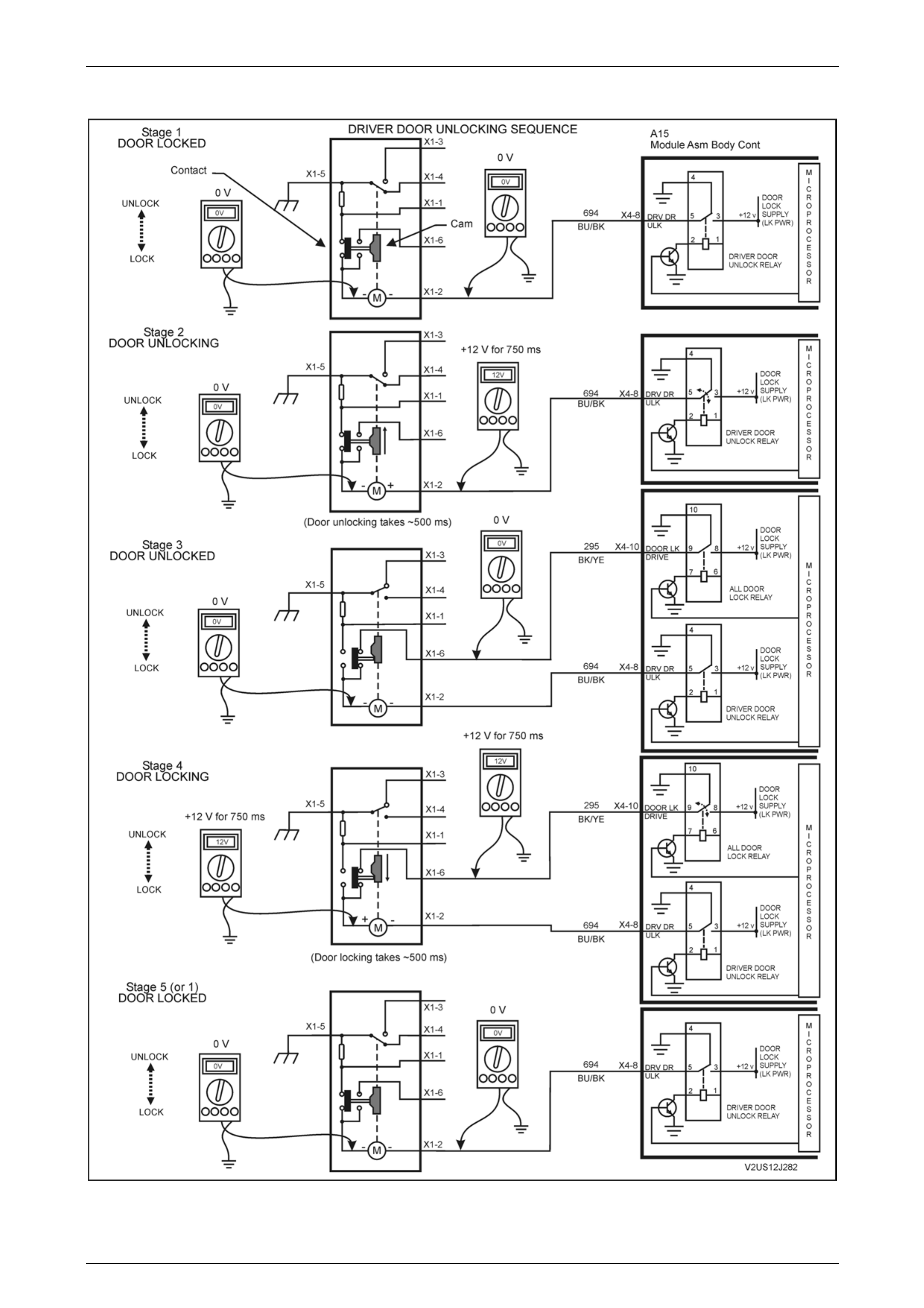
Body Control Module Page 12J–45
Page 12J–45
Functional Diagram of Door Locking/Unlocking Operation
Figure 12J – 8

Body Control Module Page 12J–46
Page 12J–46
Circuit Operation
To aid in the following description, refer to 3 Wiring Diagrams and Connector Charts.
NOTE
• The circuit diagrams shown are to aid in
interpreting the operation of the circuit and
therefore, only the main connectors and wiring
colours are shown.
• For complete circuits details refer to either the
relevant diagnostic section or
Section 12P Wiring Diagrams.
Unlocking
Driver’s Door Unlock Input Signal
When unlocking the doors and liftgate from the driver’s door-lock or door snib, BCM A15 – X4 pin 16 is connected to
ground. This causes the voltage on A15 – X4 pin 16 to be pulled low to less than 0.2 V, which is seen by the BCM as a
driver’s door unlock request signal.
NOTE
Manually activating any unlock request circuit
triggers all doors to be unlocked.
Passenger Door Unlock Input Signal
When unlocking the doors using any passenger door interior lock button, A15 – X4 pin 5 is connected to ground. This
causes the voltage on A15 – X4 pin 5 to be pulled low to less than 0.2 V, which is seen by the BCM as a passenger door
unlock request signal.
A low voltage at A15 – X4 pin 16 or X4 pin 5 is seen by the BCM as a system unlock request and the BCM energises the
internal passenger door unlock relay for approximately 0.75 second. The relay contacts close and battery voltage is
applied to:
• X1 pin 2 of each of the door-lock actuators, and
• The liftgate lock actuator Y23 – X1 pin 3 in wagon models.
The opposite terminal of the door-lock actuators, X1 pin 1, is connected to ground within the BCM, via A15 – X4 pin 9,
the internal all doors deadlock relay contacts and A15 – X1 pin 11. This causes the door-lock actuator to rotate from the
lock to the unlock position, and the door-lock actuator switch contacts to change from X1 pin 1 to X1 pin 6. The rotation of
the passenger door-lock actuator motor armatures also causes the door-lock snib button to change from the lock to the
unlock position. The liftgate lock actuator motor is grounded via A15 – X4 pin 10 and the BCM internal all doors lock relay
contacts.
Two-stage Unlock
If the BCM is operating in the two-stage unlock mode and the remote coded key UNLOCK button is depressed for
0.25 second, the BCM activates the microprocessor within the BCM. This causes the driver’s door unlock relay to toggle
to the unlock state, unlocking the driver’s door only.
If the remote coded key unlock button is again depressed for 0.25 second, the BCM toggles the passenger door unlock
relay contacts to the unlock state and the passenger doors and liftgate unlock.
If the remote coded key is depressed continuously for 0.5 second, the BCM unlocks all doors: first, the driver’s door, then
the passenger doors and liftgate.

Body Control Module Page 12J–47
Page 12J–47
Single-stage Unlock
If the BCM is operating in the single-stage unlock mode and the remote coded key button is depressed for 0.25 second,
the BCM toggles both the driver’s door unlock relay and the passenger door unlock relay to the unlock state and all doors
and the liftgate unlock.
Deadlock to Unlock Operation
When manually unlocking the doors at the driver’s door-lock from the deadlock to the unlock position, the Driver’s Door
Lock Switch micro switch contact sends this ground signal to the A15 – X4 pin 16 via circuit 781. This low voltage at A15
– X4 pin 16 is seen by the BCM as the Driver’s Door Unlock Request signal. The BCM then energises both the Driver’s
Door unlock relay and the Passenger door unlock relay for approximately 0.75 second. This causes battery voltage to be
applied to X1 pin 2 of each door-lock actuator and to X1 pin 3 of the liftgate actuator through circuit 694.
Initially, actuator X1 pin 6 is connected to ground through A15 – X4 pin 10, the internal all doors lock relay contacts. This
causes the passenger and the rear passenger door-lock actuators to rotate and move from the deadlock position,
through the lock position to the unlock position. As this movement occurs, the passenger door-lock actuators contacts
momentarily switch from X1 pin 6 to X1 pin 1 before switching back to X1 pin 6 and the door snib buttons are moved to
the unlock position.
Locking
Front Door Lock Request Input Signal
With the doors closed, all doors and the liftgate can be mechanically locked via the driver’s or front passenger’s interior
door snib or a single locking operation of the driver’s door-lock using the key.
Either of these actions with the snib causes the driver’s door lock switch micro switch contacts to change to the lock
position, which connects A15 – X4 pin 20 to ground from circuit 650. This changes the voltage on A15 – X4 pin 20 to less
than 0.2 V, which is seen by the BCM as a system lock request.
A lock request triggers the BCM to energise the internal all doors lock relay for approximately 0.75 second. The relay
contacts close and apply battery voltage through A15 – X4 pin 10 of the BCM to X1 pin 6 of each door-lock actuator and
to X1 pin 1 of the liftgate actuator. Connector X1 pin 2 of each passenger door actuator and X1 pin 3 of the liftgate
actuator is connected to ground through A15 – X4 pin 1 and the internal passenger door unlock relay contacts. X1 pin 2
of the driver’s door-lock actuator is connected to ground through A15 – X4 pin 8 and the internal driver’s door unlock
relay contacts.
These connections energise the door-lock actuators to rotate to the lock position, which moves the all passenger door-
lock snib buttons to the lock position and changes the switch contacts from X1 pin 6 to X1 pin 1.
Deadlock Request Input Signal
When the ignition is off and the driver’s door is closed, the doors can be deadlocked by two sequential lock operations of
the driver’s door-lock. If the driver’s door is open, or if the ignition is on, the doors will not deadlock.
Two sequential lock operations cause the driver’s door lock switch micro switch contacts to change to the lock position
and connect A15 – X4 pin 17 to ground from circuit 650. This changes the voltage on A15 – X4 pin 17 to less than 0.2 V,
which is seen by the BCM as the system deadlock request. The BCM then energises the internal all doors lock relay and
all doors deadlock relay for approximately 0.75 second, which supplies battery voltage to X1 pin 6 and X1 pin 1 of the
door-lock actuators.
Connector X1 pin 2 of each passenger door-lock motor is connected to ground within the BCM, via A15 – X4 pin 1 and
the internal passenger door unlock relay contacts. Connector X1 pin 2 of the driver’s door-lock motor is connected to
ground within the BCM, via A15 – X4 pin 8 and the driver’s door unlock relay contacts.
These connections energise the door-lock actuator motors to rotate to the deadlock position. This rotation causes the
actuator switch contacts to change from X1 pin 6 to X1 pin 1 and back to X1 pin 6 and moves the door snib buttons to the
lock position.
NOTE
The liftgate actuator is designed to lock but not to
deadlock.

Body Control Module Page 12J–48
Page 12J–48
Remote Coded Key – Locking
When locking the doors using the remote coded key, the signal from the LOCK button is transmitted by radio
transmission to the remote key receiver unit located within the vehicle. The key’s decoded signal then activates the BCM
microprocessor, which energises the all doors lock relay, which then provides battery voltage to all of the vehicle’s door
locks and the liftgate.
If any door does not lock, either A15 – X4 pin 16 unlock request or A15 – X4 pin 5 passenger’s doors unlock request
remains low and this low voltage is seen by the BCM as an unsuccessful attempt to lock all doors.
If the BCM detects the driver’s door is open, the BCM then momentarily sounds the theft deterrent horns to alert the
driver that vehicle locking failed.
Door Input Signals
Door Ajar Switch Input Signal
The BCM uses the door ajar switch input signal to determine if the driver’s door is open or closed. When the door is
open, the door ajar switch grounds A15 – X4 pin 19 via circuit 746. This causes the voltage at A15 – X4 pin 19 to be
pulled low to less than 0.2 V, which is seen by the BCM as the driver’s door ajar input signal.
Passenger’s Door Ajar Switch Input Signal
The BCM uses the passenger’s door ajar switch input signal to determine if a passenger’s door is open. If either rear
doors or the front passenger’s door is open, A15 – X4 pin 4 is grounded through circuit 745. This causes the voltage at
A15 – X4 pin 4 to be pulled low to less than 0.2 V, which is seen by the BCM as the passenger door ajar input signal.

Body Control Module Page 12J–49
Page 12J–49
2.8 Rear Compartment Lid Release
System Operation
Pressing either the rear compartment release switch located in the instrument panel compartment or the rear
compartment release button on the remote coded key, releases the rear compartment (sedan and wagons) or rear glass
liftgate (AWD wagons). Pressing the rear compartment release button on the remote coded key transmits an RF output
signal. The remote receiver detects this signal and the BCM activates the microprocessor within the BCM to control the
operation of the rear compartment lid release.
The rear compartment release switch is disabled when the theft deterrent system is armed via:
• the remote code key,
• the driver’s door micro switch, and
• the vehicle deadlock.
The rear compartment release switch is only enabled when the theft deterrent system is disarmed either by pressing the
UNLOCK button on the remote coded key, or the slip ring receiving a valid security code when the ignition is turned on.
The BCM monitors the rear compartment release switch and remote rear compartment signal and stops the rear
compartment release operating if the vehicle speed is above 20 km/h.
Circuit Operation
To aid in the following description, refer to 3 Wiring Diagrams and Connector Charts.
NOTE
• The circuit diagrams shown are to aid in
interpreting the operation of the circuit and
therefore, only the main connectors and wiring
colours are shown.
• For complete circuits details refer to either the
relevant diagnostic section or
Section 12P Wiring Diagrams.
Power Supplies
Battery voltage is applied to the BCM A15 – X1 pin 10, through fusible link F104 and fuse F29 via circuit 740.
Inputs
Serial Data Signal — V6 and GEN IV V8
The serial data bus A15 – X2 pin 5 is connected to the PIM A5 – X1 pin 10, via circuit 800. This serial data bus line
supplies the BCM with serial data relating to the speed of the vehicle. The PIM receives GM LAN data from the ECM and
translates this data to UART serial data for transmission to the primary UART bus for input to the BCM.
Serial Data Signal — GEN III V8
The serial data bus A15 – X2 pin 5 is connected to the PIM A5 – X1 pin 6 via circuit 800. A Class 2 serial data is
connected between PIM A5 – X1 pin 7, via circuit 1049, and PCM A84 – X1 pin 58. This serial data bus line supplies the
BCM with serial data relating to the speed of the vehicle.
Security and Central Door Locking Status Signals
The BCM internal status includes the state of both theft deterrent and entry deterrent system (Armed, Disarmed,
Triggered, Passively armed) and the central locking system (locked, unlocked etc).
If the BCM detects the theft deterrent system as armed or the central locking as deadlocked, the rear compartment
release function will be inhibited.

Body Control Module Page 12J–50
Page 12J–50
Rear Compartment Release Button Input
Pressing the rear compartment release switch causes the contacts to close, connecting A15 – X3 pin 8 to ground via
circuit 1576. This causes the voltage at A15 – X3 pin 8 to be reduced to less than 0.2 V, which is seen by the BCM as a
rear compartment release switch input signal. The BCM will not actuate the rear compartment release relay if the vehicle
speed is greater than 20 km/h, the entry deterrent system is armed via the remote coded key, or the driver’s door-lock
micro switch is deadlocked.
Remote Coded Key Input
The radio frequency (RF) signal transmitted by the remote coded key is received by the BCM through the remote key
receiver. After pressing the remote coded key rear compartment release button for 0.5 seconds the rear compartment
lock actuator will activate providing the vehicle’s speed is less than 20 km/h.
Outputs
Sedan and Wagon
The BCM activates the rear compartment lock actuator by energising the internal boot solenoid relay. Power from A15 –
X4 pin 2 is applied to Y29 – X1 pin A of the rear compartment release actuator assembly via circuit 56. The ground circuit
for the rear compartment release solenoid is via the body and main wiring harness.
AWD Wagon
The BCM activates the rear glass liftgate lock actuator by energising the internal boot solenoid relay. Power from A15 –
X4 pin 2 is applied to the end gate release input of the washer system module A122 – X1 pin 11 via circuit 56. The
window release output signal from the washer system module A122 – X1 pin 12 via circuit 6188 is applied to Y7 – X1 pin
A when the rear wiper is in the off glass / park position. The ground circuit for the rear glass liftgate release solenoid is via
circuit 650 to vehicle chassis ground.

Body Control Module Page 12J–51
Page 12J–51
2.9 Theft Deterrent System
System Operation
The theft deterrent system uses a remote coded key to arm and disarm the system. The remote coded key is also used
to electrically lock or unlock all doors and the rear compartment lid (sedan and wagon) or rear glass liftgate (AWD
wagon).
V6 and GEN IV V8 Engine
When the ignition is turned on, the BCM sends the PIM an encrypted BCM / Key security code. The security code is
received via the slip ring, or the by remote receiver in the event of no slip ring communication. The powertrain interface
module (PIM) sends this encrypted security code to the engine control module (ECM). The ECM compares the received
security code with its own security code, and if valid, the ECM returns an OK to Start message to the BCM via the PIM. If
the BCM does not receive an OK to Start message from the ECM via the PIM within 0.5 second of the ignition ON signal,
the BCM isolates the secondary data bus and a DTC will be set. Refer to 5.8 Diagnostic Trouble Code List.
Isolation of the secondary/tertiary data bus eliminates the possibility of a device failure, other than the BCM and the PIM,
causing a problem on the bus and inhibiting theft deterrent communications. This continues until the ECM responds with
an acknowledgment or for a maximum of 5 seconds, after which the BCM switches to the standard polling sequence.
Following successful anti-theft communications, the BCM begins sequential polling of devices on the bus and normal
system operation is established.
When the ignition is off, the BCM continues to poll, allowing for Tech 2 communications and external control of the bus
prior to the ignition being switched on.
GEN III V8 Engine
When the ignition is turned on, the BCM sends the PIM an encrypted BCM / Key security code. The security code is
received via the slip ring, or the by remote receiver in the event of no slip ring communication. The PIM compares the
received security code with the PCM stored security code and if the codes match, the PIM allows engine cranking and
sends a separate encrypted security code to the PCM. The PCM compares this code with its stored security code and if
the codes match, the PCM allows injector fuelling to continue. The PCM returns an OK to Start message to the BCM via
the PIM. If the BCM does not receive an OK to Start message from the PIM within 0.5 second of the ignition ON signal,
the BCM isolates the secondary data bus and a DTC will be set. Refer to 5.8 Diagnostic Trouble Code List.
Isolation of the secondary/tertiary data bus eliminates the possibility of a device failure, other than the BCM and the PIM,
causing a problem on the bus and inhibiting theft deterrent communications. This continues until the PIM responds with
an acknowledgment or for a maximum of 5 seconds, after which the BCM switches to the standard polling sequence.
Following successful anti-theft communications, the BCM begins sequential polling of devices on the bus and normal
system operation is established.
When the ignition is off, the BCM continues to poll, allowing for Tech 2 communications and external control of the bus
prior to the ignition being switched on.
Armed
The theft deterrent system can be armed actively, by pressing the LOCK button on the remote coded key or passively,
when the BCM automatically arms the system 30 seconds after the ignition is turned off.
When the theft deterrent system is armed, the start relay located in the engine compartment relay housing is disabled
preventing the engine from being started.

Body Control Module Page 12J–52
Page 12J–52
Disarmed
The theft deterrent system can be disarmed by pressing the UNLOCK button on the remote coded key which will unlock
the doors, turn the interior dome lamp on and disarm the system for 30 seconds. The same actions can be accomplished
by inserting the remote coded key into the ignition switch and turning the ignition on.
With the theft deterrent in the disarmed state the PIM is live and can be interrogated by the ECM or PCM.
NOTE
On V6 theft deterrent is disarmed at the BCM,
however the ECM does not become active until
the ignition key is turned on.
The BCM then reads a security code (serial data output) from the remote coded key contact pin via the ignition switch slip
ring. If a valid key is authenticated at the slip ring then the BCM will initiate communications with the PIM as soon as the
ignition switch is turned to the ON position.
NOTE
Both the V6 and GEN III V8 systems allow up to
1 second of cranking time if the code is invalid.
This usually results in the engine starting but then
dying after 2 – 3 seconds. Normally this allows for
fuel priming and reduces start delays while the
security message is being validated. Engine
crank is then disabled until the next ignition cycle
of key off – key on.
NOTE
If the engine cranks briefly when the ignition
switch is turned to the START position, there may
be a faulty slip ring. Press the unlock button on
the remote coded key to disarm the theft
deterrent system.
Remote Coded Key
The theft deterrent system uses a remote coded key to arm / disarm the system and electrically lock or unlock all doors
including the station wagon liftgate or the sedan rear compartment lid lock.
The radio frequency (RF) signal transmitted by the remote coded key is received by the BCM through the remote key
receiver that is located in the instrument panel between the demist ducts.
After pressing the remote coded key LOCK button to arm the theft deterrent system, the turn signal lamps flash once and
the security status indicator LED begins to flash. After disarming the system by pressing the key, UNLOCK button, the
turn signal lamps flash twice and the security status indicator LED stops flashing.
NOTE
Passive arming of the system does not
automatically operate the door-locks or flash the
turn signal lamps.
Battery
The remote coded key is powered by its own internal battery. If this battery fails, the slip ring can power the key when it is
inserted into the ignition switch and turned on or to the start position.
Security Status Indicator
The security status indicator LED indicates the state of the system. When flashing, the LED indicates the system is
armed and the vehicle cannot be started. When the BCM is disarmed, the LED is turned off and the engine can be
started. The security status indicator LED is located in the instrument cluster assembly,
refer to Section 12C Instrumentation.

Body Control Module Page 12J–53
Page 12J–53
Circuit Operation
To aid in the following description, refer to 3 Wiring Diagrams and Connector Charts.
NOTE
• The circuit diagrams shown are to aid in
interpreting the operation of the circuit and
therefore, only the main connectors and wiring
colours are shown.
• For complete circuits details refer to either
the relevant diagnostic section or
Section 12P Wiring Diagrams.
Power Supplies
Battery voltage is applied to the BCM A15 – X1 pin 10 at all times from fusible link F104 and fuse F29, circuit 740.
Turn Signal Lamp Power
Battery voltage is applied to A15 – X1 pin 13 at all times from fusible link F102 and fuse F7, circuits 442 and 140.
Inputs
Ignition Sw itch ON Input Signal
The BCM uses this input signal to determine when the ignition is turned on or to the start position. When the ignition is
turned on or to the start position, battery voltage is applied to A15 – X3 pin 2 from the ignition switch, circuit 300.
Slip Ring Signal
The BCM reads a security code (serial data output) from the remote coded key contact pin via the ignition switch slip ring
S149 – X2 pin A to the BCM A15 – X2 pin 7. If a valid key is authenticated at the slip ring the BCM will initiate
communications with the PIM when the ignition switch is turned to the On position.
BCM and PIM Serial Data Communication – V6 and GEN IV V8
When the ignition is turned on, the BCM communicates using UART serial data with the PIM via the serial data
communication line A15 – X2 pin 5 and A5 – X1 pin 10, circuit 800.
BCM and PIM Serial Data Communication – GEN III V8
When the ignition is turned on, the BCM communicates using UART serial data with the PIM via the serial data
communication line A15 – X2 pin 5 and A5 – X1 pin 6, circuit 800.
Driver's Door Ajar Switch
The BCM uses this input signal to determine if the driver's door is opened or closed. The BCM must sense the driver's
door is closed before the theft deterrent system can be actively armed.
When the door is open (or not fully closed), the door ajar switch grounds A15 – X4 pin 19 via circuit 746. This causes the
voltage at A15 – X4 pin 19 to be pulled low to less than 0.2 V. This low voltage at A15 – X4 pin 19 is seen by the BCM as
the driver's door ajar input signal.
NOTE
Passive arming of the system will also occur if the
drivers door has been closed and not opened for
30 seconds. The security status indicator LED will
begin to flash when passive arming occurs.

Body Control Module Page 12J–54
Page 12J–54
Outputs
Left-hand Turn Signal Lamps
The BCM controls the operation of the left-hand turn signal lamps by pulsing the BCM internal hazard / theft indicator
relay. This causes the relay contacts to close and open a number of times applying battery voltage intermittently from
A15 – X1 pin13 to A15 – X1 pin 4 and the left-hand turn signal lamps via circuit 1314.
Right-hand Turn Signal Lamps
The BCM controls the operation of the right-hand turn signal lamps through the same relay used to control the left-hand
turn signal lamps. Pulsing of the BCM hazard / theft indicator relay causes the indicator relay contacts to close and open
a number of times. This applies battery voltage intermittently from A15 – X1 pin 13 to A15 – X1 pin 3 and the right-hand
turn signal lamps via circuit 1315.
Security Status Indicator LED
The security status indicator LED continuously flashes while the system is armed. The BCM controls the operation of the
security status indicator LED applied at P3 – X1 pin 9 via an internal switch within the BCM A15 – X1 pin 21, circuit 264.

Body Control Module Page 12J–55
Page 12J–55
2.10 Entry Deterrent System
System Operation
The BCM entry deterrent system is designed to deter unwanted access to the vehicle's passenger compartment. The
system provides an audible warning and visual warning of unauthorised entry to the vehicle (in all levels vehicles other
than level 1).
Arming of the theft and entry deterrent systems is by pressing the LOCK button on the remote coded key.
The Low Series BCM includes an option to enable the entry deterrent feature. This feature is End Of Line (EOL) or
Tech 2 programmable. The option requires a patch harness to enable sensing of rear compartment and hood switches
and fitment of anti-theft horns.
NOTE
• The entry deterrent system does not arm
passively.
• The remote coded key also incorporates a
rear compartment release function button.
Arming the System
Upon pressing the LOCK button on the remote coded key, the system will arm 10 seconds after locking the doors. The
output signal from the key activates the BCM microprocessor if the ignition is off and the vehicle road speed input
indicates the speed is zero. One continuous press on a remote coded key button should cause only one arm / disarm
operation. It is not possible to arm the system or remote lock the doors with the driver' s door open.
When the system is armed, the following actions take place:
• All doors and the liftgate lock,
• All turn signal lamps flash once,
• The power antenna retracts (where applicable)
• The power window system deactivates, and
• The dome light is switched off provided it has not been turned on by another system.
Triggered Operation
Once the entry deterrent system is armed, it is triggered by any one of the following inputs:
• Hood opening (circuit 263),
• Rear compartment lid opening (circuit 744),
• Drivers door being opened (circuit 746),
• Passenger and any rear doors being opened (circuit 745), and
• The ignition being switched on (circuit 300).
If any of the previous conditions exist at the time of the system arming, they are ignored until the fault condition is
cleared.
Once triggered, the system operates as follows:
• All turn signal lamps flash at a frequency of one flash every two seconds,
• All vehicle horns pulse at a frequency of one pulse per second,
• The dome light flashes at a frequency of one flash every two seconds, and
• The turn signal lamps and dome lamp flash, and the horn/s sound for 30 seconds.

Body Control Module Page 12J–56
Page 12J–56
Disarming Procedure
The system is disarmed by:
• Pressing the UNLOCK button on the remote coded key which generates an RF output signal to activate the BCM
via circuit 218, or
• Turning the ignition on if the remote coded key is not working due to a flat battery. This allows the BCM to provide a
power supply to the remote coded key, enabling reading of the key security code.
The following actions occur when the system is disarmed:
• All doors and the liftgate unlock.
• All turn signal lamps flash twice, but if the system has been triggered since being armed, they will flash three times.
• The dome light is activated for 30 seconds (default) during low light conditions.
• The power window system remains enabled for 45 seconds before shutting down.
Multi-function Display (MFD) Trigger Point Displays
The instrument clusters MFD displays the codes of the triggered points. The BCM sends the information to the
instrument cluster via the serial communications bus. The Alarm Activated screen is displayed first for 1 second, followed
by the trigger point screens.
The trigger point screens are also displayed for 1 second. If more than one trigger point has been activated the MFD will
display each trigger point screen in sequence for 1 second, returning to the Alarm Activated screen.
Refer to Section 12C Instrumentation.
The trigger points are driver’s door, passenger door, rear compartment lid, hood and hotwire.
NOTE
Alarm codes are stored in the BCM until they are
cleared by Tech 2.
Remote Rear Compartment Release
The rear compartment release solenoid is activated when the rear compartment button on the remote coded key has
been pressed continuously for more than 0.5 second and the vehicle road speed is less than or equal to 20 km/h per
hour. The RF output signal from the remote coded key activates the BCM microprocessor.
The remote rear compartment release function can also operate while the entry deterrent is armed without triggering the
system. When the rear compartment input is inhibited from triggering the entry deterrent system, the hood input is also
inhibited. After the rear compartment has been closed for 30 seconds, the system re-arms the rear compartment and the
hood sensing.
Loss of Vehicle Battery Power
If there is a re-connection of battery power to the BCM, the theft and entry deterrent systems resume in the same state
as when the battery power was disconnected, except if the system was disarmed. If the system was disarmed, it will
default to passive arm.

Body Control Module Page 12J–57
Page 12J–57
Circuit Operation
To aid in the following description, refer to 3 Wiring Diagrams and Connector Charts.
NOTE
• The circuit diagrams shown are to aid in
interpreting the operation of the circuit and
therefore, only the main connectors and wiring
colours are shown.
• For complete circuits details refer to either the
relevant diagnostic section or
Section 12P Wiring Diagrams.
Power Supplies
Battery Power
Battery voltage is applied constantly to the BCM through A15 – X1 pin 10 from fusible link F104 and fuse F29 via circuit
740.
Turn Signal Lamp Power
Battery voltage is applied to A15 – X1 pin 13 at all times from fusible link F102 and fuse F7 via circuit 140.
Inputs
Ignition Sw itch On Input Signal
The BCM uses this input signal to determine when the ignition is turned on or to the start position. When the ignition is
turned on or turned to the start position, battery voltage is applied to A15 – X3 pin 2 from the ignition switch via circuit
300.
Driver's Door Ajar Switch Input Signal
The BCM uses this input signal to determine if the driver's door is open or closed. When the door is open, the door ajar
switch grounds A15 – X4 pin 19 via circuit 746. This causes the voltage at A15 – X4 pin 19 to be pulled low to less than
0.2 V (driver's door ajar). This low voltage at A15 – X4 pin 19 is seen by the BCM as the driver's door ajar input signal.
Passenger’s Door Ajar Switch Input Signal
The BCM uses this input signal to determine if any of the passenger doors are open or if all passenger doors are closed.
If the right-hand rear, left-hand rear, or front passenger door is open, A15 – X4 pin 4 is grounded through circuit 745. This
causes the voltage at A15 – X4 pin 4 is pulled low to less than 0.2 V. This low voltage at A15 – X4 pin 4 is seen by the
BCM as the passenger door ajar input signal.
Hood Open Switch Input Signal
The BCM uses this input signal to determine if the hood is open or closed. When the hood is closed, battery voltage from
A15 – X2 pin 11, via circuit 109 passes through the hood switch to A15 – X3 pin 11, via circuit 263. This voltage at A15 –
X3 pin 11 is seen by the BCM as the hood closed input signal. In the event of an open circuit in either circuit 109 or 263,
the BCM internal pull down resistor ensures the voltage at the input to the microprocessor is less than 0.2 V. This low
voltage at the microprocessor is seen as the hood open signal. This is to ensure that if either of these two circuits is
tampered with, the alarm will be triggered.
When the hood is opened, the theft deterrent hood open switch closes and grounds the A15 – X3 pin 11 through circuit
263. This action causes the voltage at the A15 – X3 pin 11 to be pulled low, less than 0.2 V (hood open). This low voltage
at A15 – X3 pin 11 is seen by the BCM as the hood open input signal.
Rear Compartment Lamp Switch Input Signal for Sedan Models
The BCM uses this input signal to determine if the rear compartment is open or closed. When the rear compartment is
open, the rear compartment lamp switch grounds A15 – X4 pin 6 through circuit 744. This causes the voltage at BCM
A15 – X4 pin 6 to be pulled low to less than 0.2 V. This low voltage at A15 – X4 pin 6 is seen by the BCM as the rear
compartment open input signal.

Body Control Module Page 12J–58
Page 12J–58
Vehicle Speed Signal
The vehicle speed is received from the ECM or PCM via the PIM and the serial data communications bus to the A15 –
X2 pin 5 and circuit 800.
Remote Coded Key RF Signals
When the LOCK, UNLOCK or rear compartment button on the remote coded key is pressed, the remote coded key
transmits a radio frequency (RF) signal. When the BCM receives one of these signals, it determines from the signal
characteristics by which button was pressed.
Rear Compartment Release Input Signals
Pressing the rear compartment lock switch in the instrument panel compartment causes the switch contacts to close,
connecting BCM A15 – X3 pin 8 to ground via circuit 1576. This causes the voltage at A15 – X3 pin 8 to be pulled low to
less than 0.2 V. This low voltage at A15 – X3 pin 8 is seen by the BCM as the rear compartment release switch input
signal.
NOTE
The BCM will not activate the rear compartment
lock solenoid if the vehicle speed is above 20
kilometres per hour.
Outputs
Dome Lamp
Battery voltage is applied to all interior lamps through fuse F6, circuit 1140 and interior illumination relay X129. The
opposite sides of the dome lamps are connected to ground via circuit 660 and A15 – X4 pin 22. The BCM controls the
operation of the dome lamps connected to this ground circuit by energising the BCM dome light control relay. This
causes the internal relay contacts to close, completing the circuit to ground.
Horn Relay
The BCM can operate the vehicle horn/s by pulsing the horn relay coil to ground through A15 – X1 pin 17, circuit 28.
Theft-deterrent Horn Relay
The BCM controls the operation of the theft-deterrent horn by pulsing the theft horn relay coil to ground through A15 – X3
pin 15, circuit 1149.
Left-hand Turn Signal Lamps
The BCM controls the operation of the left-hand turn signal lamps by pulsing the BCM internal hazard/theft indicator
relay. This allows battery voltage from A15 – X1 pin 13 to be applied in pulses to the left-hand turn signal lamps via A15 –
X1 pin 4, circuit 1314.
Right-hand Turn Signal Lamps
The BCM controls the operation of the right-hand turn signal lamps by pulsing the BCM internal hazard/theft indicator
relay. This allows battery voltage from A15 – X1 pin 13 to be applied in pulses to the right-hand turn signal lamps via A15
– X1 pin 3, circuit 1315.
Rear Compartment Release Actuator
The BCM activates the rear compartment actuator solenoid Y29 by energising the BCM internal rear compartment lid
solenoid relay. This applies battery voltage through the rear compartment lid solenoid relay contacts and A15 – X4 pin 2,
to the rear compartment actuator solenoid Y29 via circuit 56. The ground circuit for the rear compartment actuator
solenoid is via the body and main wiring harness.
Rear Liftgate Glass AWD
The BCM activates the rear glass liftgate lock actuator by energising the internal boot solenoid relay. Power from A15 –
X4 pin 2 is applied to the end gate release input of the washer system module A122 – X1 pin 11 via circuit 56. The
window release output signal from the washer system module A122 – X1 pin 12 via circuit 6188 is applied to Y7 – X1 pin
A when the rear wiper is in the off glass / park position. The ground circuit for the rear glass liftgate release solenoid is via
circuit 650 to vehicle chassis ground.
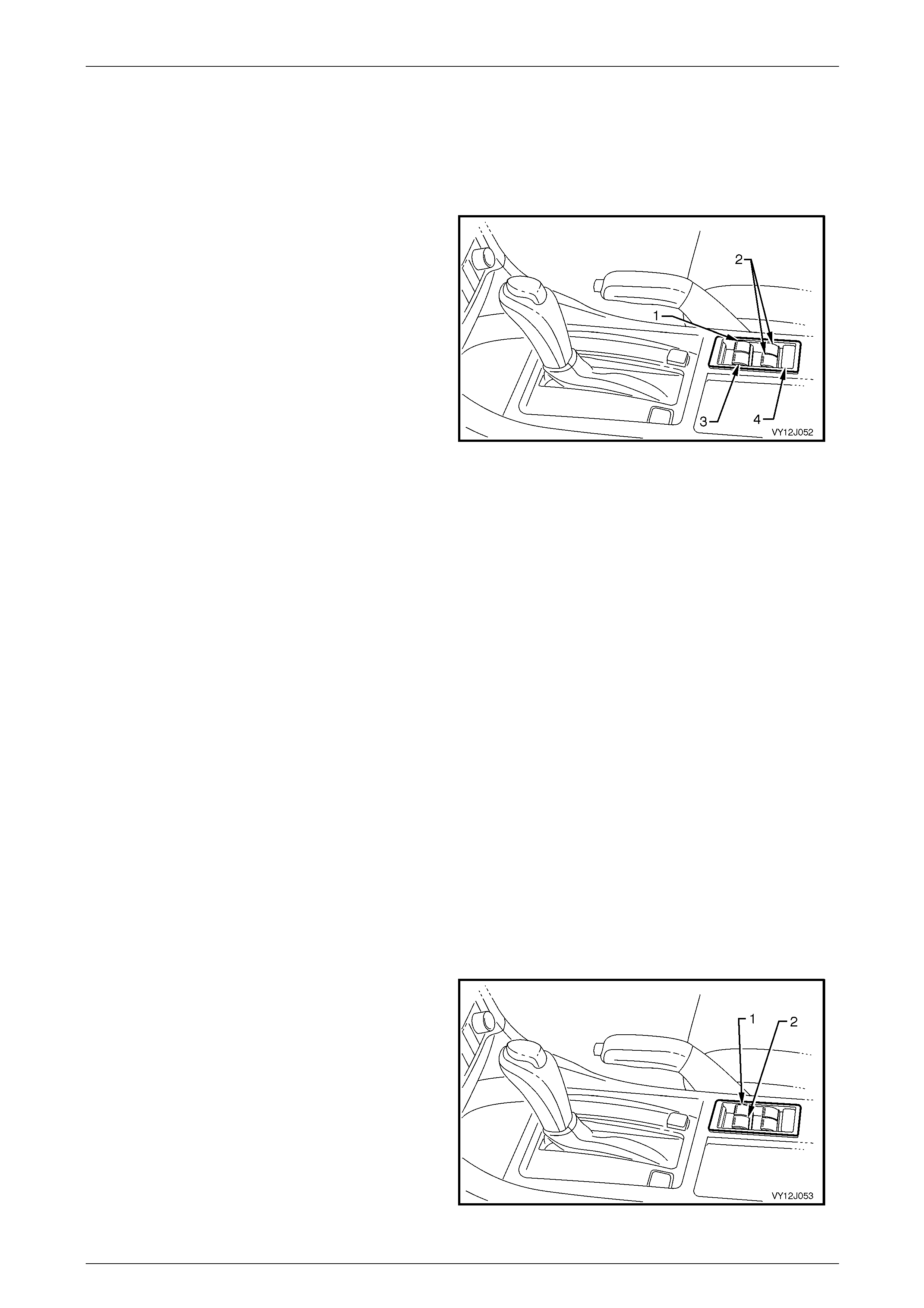
Body Control Module Page 12J–59
Page 12J–59
2.11 Power Window System
System Operation
The BCM controls the operation of the power window relay, which controls the power supply to all window motors and the
automatic down function of the driver and front passenger windows.
Legend
1 Driver’s Window Switch
2 Rear Passenger Window Switches (Left and Right-
hand)
3 Front Passenger Window Switch
4 Lockout Switch
Figure 12J – 9
System Active
NOTE
Before the rear power windows can operate, the
lockout switch must be closed. An illuminated
light emitting diode (LED) in each of the window
rocker switches indicates the system is
energised.
All switches are energised when the ignition is on. When the ignition is turned off, all window switches remain energised
for 45 seconds after a door is opened or for 60 minutes if no doors are opened. If a power window switch is activated
during the 45-second period, the period recommences.
The 60-minute delay is cancelled when the doors are locked.
NOTE
If the BCM has entered battery saver mode,
power is removed from the window system when
the ignition is switched off.
System Inactive
The window switch LED's are not illuminated when the system is inactive.
Automatic Down Operation of Front Windows
The driver and front passenger windows are activated when the DOWN button is pressed for more than 0.4 second.
1 With the ignition on, press the driver’s window
switch (1) to the DOWN position for more than
0.4 second and release it.
The window will continue to lower until it is in the fully down
position.
2 Interrupt the automatic down feature by:
a operating the window UP switch momentarily
b pressing the DOWN switch again. The window
stops when the DOWN button is released.
The same operations apply to the front passenger’s
window and switch (2).
Figure 12J – 10
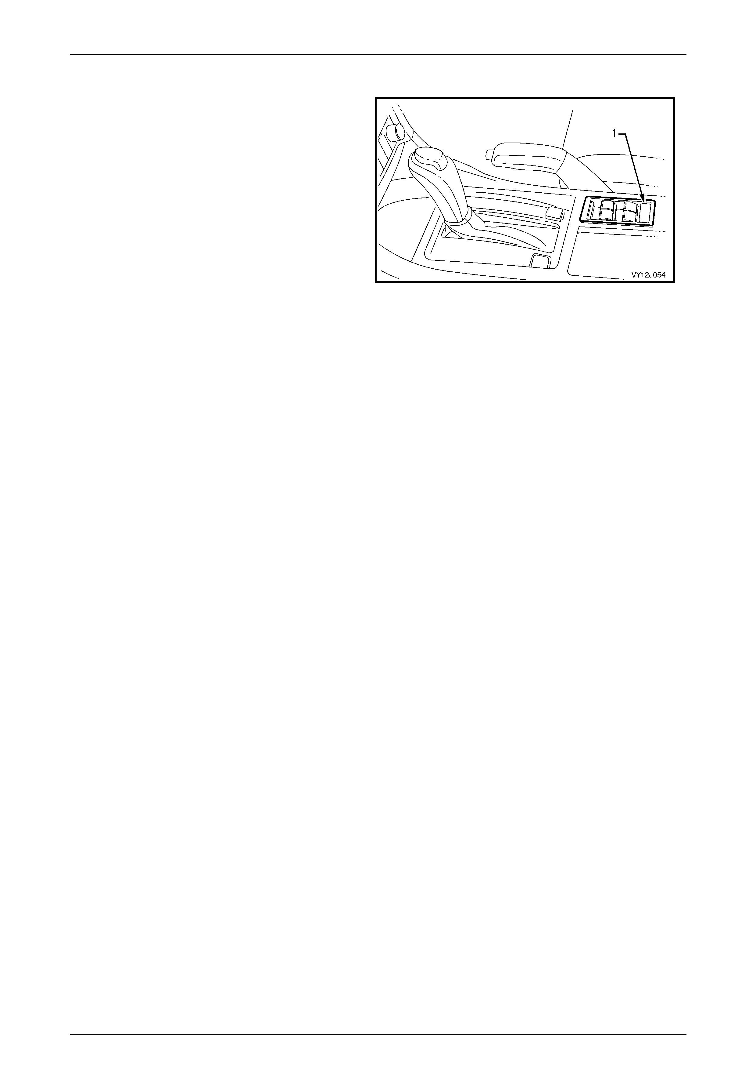
Body Control Module Page 12J–60
Page 12J–60
Lockout Switch
The lockout switch affects the operation of the rear
windows only. When the lockout switch is closed, the rear
windows can be raised or lowered from the centre console
switch or from the rocker switches in the rear doors.
Check the operation of the lockout switch as follows:
1 T urn on the ignition.
2 Check the LED’s are illuminated in all door
switches.
3 Open and close the rear windows using the
rocker switches located in the rear doors.
4 Press the lockout switch button (1) in the centre
of the switch console.
5 Check the LED’s are not illuminated.
6 Check the rear windows can only be raised and
lowered from the centre console switch.
Figure 12J – 11
Circuit Operation
To aid in the following description, refer to 3 Wiring Diagrams and Connector Charts.
NOTE
• The circuit diagrams shown are to aid in
interpreting the operation of the circuit and
therefore, only the main connectors and wiring
colours are shown.
• For complete circuits details refer to either the
relevant diagnostic section or
Section 12P Wiring Diagrams.
A permanent-magnet motor operates each of the power window mechanisms to raise or lower the window glass. The
direction in which the motor turns depends on the polarity of the voltage applied to the motor terminals. The power
window switches control the voltage polarity.
Ignition ON Input Signal
When the ignition is turned on or to the start position, battery voltage from the ignition switch is applied to A15 – X3 pin 2
via circuit 300.
When the BCM receives an ignition ON input, it energises the power window relay by grounding the relay coil through
A15 – X1 pin 8 and circuit 1351.
When the power window relay coil is energised, the relay contacts close and power is applied to the power window
switches via circuit breaker F1. The opposite side of each window switch LED is connected to ground, therefore they
illuminate, indicating the system is energised.
NOTE
The power window lockout switch in the centre
console must be closed to activate the rear door
window switches.

Body Control Module Page 12J–61
Page 12J–61
Driver and Front Passenger Window-down Circuit
NOTE
Pressing the switch for less than 0.4 seconds
does not engage the automatic down feature.
When the right front window down switch is pressed for less than 0.4 seconds current from the power window relay,
circuit 638 passes through the power window switch to A15 – X4 pin 12. From A15 – X4 pin 12, the current passes
through the contacts of the BCM right front window relay to the right front window motor via A15 – X4 pin 13 and circuit
667. The opposite side of the motor is grounded through circuit 666, the right front window switch and circuit 650.
The BCM senses the length of time the button is operated, at A15 – X4 pin 12. If the window down switch is pressed for
more than 0.4 second, the BCM energises the internal relay to allow the window to lower fully.
This auto-down feature also applies to the left front window. The voltage from the power window relay is applied through
S222 – X1 pin 13 of the left front window switch to A15 – X4 pin 26, circuit 1136, then through the BCM relay contacts
and A15 – X4 pin 25, circuit 165 to one side of the left front power window motor. The opposite side of the motor is
connected to ground on circuit 164 via switch S222 – X1 pin 12 and S222 – X1 pin 9 to circuit 650.
Window -down Input Signal
When the right front window down switch is pressed, voltage from the power window relay to window switch S222 – X1
pin 10, circuit 638 is applied to A15 – X4 pin 12 indicating the window down signal input. When the left front window down
switch is pressed, voltage from the power window relay to window switch S222 – X1 pin 10, circuit 638 is applied to A15 –
X4 pin 26 indicating the window down signal input.
When the BCM receives a right front or left front window down input signal that is present at either A15 – X4 pin 12 or X4
pin 26 for more than 0.4 seconds, the BCM’s internal relays will become energised and the auto down function will be
activated. The internal relay contacts change over, allowing battery voltage from the A15 – X4 pin 11, through the internal
relay contacts and A15 – X4 pin 13 or A15 – X4 pin 25 to one side of the either the right front or left front power window
motor on circuit 667 or circuit 165.
If the window is moving down and the down switch is again pressed, the BCM microprocessor senses this voltage at A15
– X4 pin 12 or A15 – X4 pin 26 and de-energises the internal relay. The relay contacts open and the motor stops when
the switch is released.
If the window up button is momentarily pulled up while the window in moving down, a positive battery supply is present on
both sides of the motor armature and the motor stops. If the up button is continuously pressed while the window is
moving down, the window-down function is cancelled and the window moves up.
The power window motors each contain an internal overload thermal breaker which is activated (opens) if the power
window switch is held in the Up or Down position for more than approximately 20 seconds. This prevents overheating of
the power window motor. After a cool-down time of approximately 40 seconds, the thermal breaker closes again and
allows normal motor operation.
Driver and Front Passenger Window-up Circuit
Right Front Window -up Input Signal
By pulling up and holding the right front window up button, battery voltage from the power window relay is applied to the
right front window motor through switch S222 – X1 pin 7 and circuit 666. Circuit 667 is connected to ground through A15
– X4 pin 13, A15 – X4 pin 12, the power window switch and circuit 650. This causes the motor armature to rotate and
raise the window while the button on the power window-up switch is pressed.
Left Front Window-up Input Signal
By pulling up and holding the left front window up button, battery voltage from the power window relay is applied to the
left front window motor through switch S222 – X1 pin 12 and circuit 164. Circuit 165 is connected to ground through A15
– X4 pin 25, A15 – X4 pin 26, the power window switch and circuit 650. This causes the motor armature to rotate and
raise the window while the button on the power window-up switch is pressed.
Rear Passenger Window Operation
Power is supplied to all the centre console power window switches from the power window relay. Power is supplied to the
rear window switches when the lockout switch is closed.
By pressing the appropriate down or up window switch, battery voltage is applied to the window motor through the lockout
switch and the window switch contacts. The other side of the motor is connected to ground through circuit 650 and the
motor armature rotates while the motor switch is pressed.

Body Control Module Page 12J–62
Page 12J–62
2.12 Wiper System Intermittent Function
System Operation
This system controls the front intermittent wiper and the rear wiper function. The front wiper dwell on Level 2 and 3
vehicles is dependent on the vehicle road speed as well as the position of the adjustable potentiometer (located on the
wiper control stalk). Within limits, the faster the vehicle’s speed, the shorter the dwell time.
The operation of the intermittent rear wiper is independent of the operation of the front intermittent wiper except when the
vehicle is stationary with the ignition switch in the ACC position. In this situation, the front and rear intermittent wipers are
synchronised. Due to a different wipe action between the front and rear wipers, the rear wiper starts 0.25 second before
the front wiper.
The rear wiper has an optional function of wiping continuously when the vehicle is in reverse gear when the wiper /
washer switch is turned to the rear wiper position.
The front and rear wipers use a wipe after wash function. When a washer pump switch is pressed for more than
0.5 second, the associated wipers sweep continuously, at low speed, until the washer pump has been deactivated. The
wiper is then energised for a calculated time period to enable the wiper sweeps to be completed, as follows:
• One additional sweep if the wiper / washer is pressed for less than 1 second.
• Two additional sweeps if the wiper / washer is pressed for less than 1.5 seconds.
• Three additional sweeps if the wiper / washer is pressed for more than 1.5 seconds.
To perform the correct number of additional sweeps, the wiper motor park switch is monitored by the BCM via circuit 196.
This ensures the wipers are de-energised at the optimum time.
Level 1 Vehicles
The wiper system is fitted with the road-speed dependent fixed-dwell wiper system, noting the following:
• Communication between the PCM and the BCM on vehicles with GEN III V8 engines is via the PIM.
• Communication between the ECU and the BCM on vehicles with a V6 and GEN IV V8 engines is via the PIM.
• If the ignition switch is turned to the accessories position and the vehicle enters Battery Saver Mode, the
intermittent wipers will not operate.
NOTE
The intermittent wiper relay is internal to the
BCM.
Level 2 and 3 Vehicles and AWD Wagon
The wiper system is fitted with the road-speed dependent variable-dwell wiper system, noting the following:
• Communication between the PCM and the BCM on vehicles with GEN III V8 engines is via the PIM.
• Communication between the ECM and the BCM on vehicles with a V6 and GEN IV V8 engines is via the PIM.
• If the ignition switch is turned to the accessories position and the vehicle enters Battery Saver Mode, the
intermittent wipers will not operate.
• The variations in the dwell time are determined by the vehicle road speed. The faster the vehicle travels the shorter
the dwell time.
Rear Wiper Operation AWD Wagon
The rear wiper operation is not controlled by the BCM as in other Wagon vehicles. The wiper control functions for the
AWD Wagon are controlled by the rear wiper control module A122. This module is installed in the liftgate and is the link
with the liftgate window release actuator, the liftgate window micro switch and the liftgate switch. The rear wiper will not
operate if the liftgate glass window is in the open position as sensed by the liftgate window micro switch S69.
Refer to Section 12N Wiper, Washer and Horn for a more detailed systems operation.

Body Control Module Page 12J–63
Page 12J–63
Circuit Operation
To aid in the following description, refer to 3 Wiring Diagrams and Connector Charts.
NOTE
• The circuit diagrams shown are to aid in
interpreting the operation of the circuit and
therefore, only the main connectors and wiring
colours are shown.
• For complete circuits details refer to either the
relevant diagnostic section or
Section 12P Wiring Diagrams.
Intermittent Wiper Switch
Placing the wiper / washer switch in the INT position applies battery voltage to A15 – X3 pin 3, circuit 112 via:
• Fusible link F105
• Accessory control relay contacts
• Fuse F18
• Circuit 243, and
• The wiper washer switch INT contacts.
Battery voltage at A15 – X3 pin 3 is seen by the BCM as the intermittent wiper input signal and triggers the BCM to
energise the front wiper relay. This applies battery voltage from fuse F18 and A15 – X1 pin 2, to the wiper motor low
speed circuit via:
• A15 – X1 pin 12
• Circuit 96
• Wiper / washer intermittent terminals, and
• Circuit 95.
This voltage supply causes the wiper motor armature to rotate, which changes the wiper motor park switch from contacts
A - B to contacts A - C. Voltage from fuse F18 is now applied through contacts A - C and circuit 196 to A15 – X1 pin 1.
Once the wiper motor park switch enter the parked region, the park switch contacts change back to A - B which changes
the input at A15 – X1 pin 1 to ground through circuit 196, the park switch contacts A - B and circuit 550. The voltage at
A15 – X1 pin 1 is now less than 0.2 V, which is seen by the BCM as the park switch, input signal and the BCM turns off
the intermittent wiper relay to stop the wiper motor.
Wiper Dwell Controller
A15 – X2 pin 4 is connected to ground through, circuit 477, the wiper dwell-controller and circuit 251. Adjusting the switch
from slow to fast causes the potentiometer (variable resistor) inside the controller to vary in resistance, which changes
the voltage at A15 – X2 pin 4 within a range of approximately 0.6 to 2.5 V. As the voltage increases, the dwell time
decreases.
NOTE
If the battery is disconnected then connected, it is
necessary for the dwell potentiometer to be
rotated from one extreme to the other to enable
the BCM to re-learn the range values and
properly calculate the dwell values.
Vehicle Speed and Reverse Gear
The vehicle speed is received from the ECM or PCM via the PIM and the serial data communications bus to the A15 –
X2 pin 5 and circuit 800. A15 – X2 pin 5 also receives data relating to the selection of reverse gear.

Body Control Module Page 12J–64
Page 12J–64
Window Washer Switch
When the washer pump switch is activated, battery voltage is applied to the washer pump M19 – X1 pin 2 and A15 – X3
pin 13, via fuse F18, circuit 243 and the washer switch contacts and circuit 228. This causes the voltage at A15 – X3 pin
13 to increase from 0 to12 V, which is seen by the BCM as the washer switch input signal. The length of time that this
voltage is present at A15 – X3 pin 13 determines the number of additional wiper sweeps.
The BCM determines the number of completed wiper sweeps by monitoring the voltage at A15 – X1 pin 1, park switch
input; the voltage at A15 – X1 pin 1 changes from 12 V to less than 0.2 V at the completion of each sweep.
Rear Wiper Switch
Placing the wiper washer switch in the rear wipe position causes battery voltage, via fusible link F105, the accessory
control relay contacts, fuse F18, circuit 243 and the wiper washer switch rear contacts to be applied to A15 – X3 pin 7,
circuit 391. This voltage at A15 –X3 pin 7 is seen by the BCM as the rear wiper input signal.
Rear Washer Switch
When the rear washer pump switch is activated, battery voltage is applied to the washer pump M19 – X1 pin 2 and A15 –
X3 pin 14 via fuse F18, circuit 243 and the washer switch contacts, circuit 227. This causes the voltage at A15 – X3 pin
14 to increase from less than 0.2 – 12 V, which is seen by the BCM as the rear washer switch input signal.

Body Control Module Page 12J–65
Page 12J–65
2.13 Dome Lamp Delay Control
System Operation
Level 1 Vehicles
The interior lighting operates when the dome lamp switch is set to the DOOR position and any door is opened. The
interior lighting will turn off after 30 second (default) period when a door is closed or immediately after the remote coded
key LOCK button is pressed locking all doors.
The interior lighting delay time can be set to a desired value between 0 to 255 seconds by using Tech 2 or Mode Select
in the MFD.
Level 2 and 3 Vehicles
The interior lighting operates for a 30 second (default) period after:
• a door is opened and then closed,
• the ignition is switched from the ON position to either the ACC or OFF position, or
• with the operation of central door unlocking.
When the dome lamp switch is set to the DOOR position, the interior lighting operation depends on the sun load
sensor. Like the headlight controls, the dome lamps do not operate under bright conditions such as a sunny day,
(refer to 2.14 Automatic Lamp Control for more details. The interior lighting can be adjusted to operate under three sun
load sensor conditions – Early, Normal or Late. This is a customer selectable option, which can be changed using Tech 2
or Mode Select in the MFD.
The interior lighting delay time can be set to a desired value between 0 to 255 seconds by using Tech 2 or Mode Select
in the MFD.
NOTE
If the Auto Lock in Drive feature is being used,
the interior delay time will follow the Door
Open / Close and Central Door Unlocking setting
and not the Ignition OFF setting.

Body Control Module Page 12J–66
Page 12J–66
Circuit Operation – Level 1 Vehicles
To aid in the following description, refer to 3 Wiring Diagrams and Connector Charts.
NOTE
• The circuit diagrams shown are to aid in
interpreting the operation of the circuit and
therefore, only the main connectors and wiring
colours are shown.
• For complete circuits details refer to either the
relevant diagnostic section or
Section 12P Wiring Diagrams.
Inputs
Power circuit
Battery voltage is applied to all interior lamps via fuse F6, circuit 1140, the interior illumination relay and circuit 149.
Ignition Sw itch ON
The BCM uses this input signal to determine when the ignition switch is in the IGN or START position. When the ignition
switch is in the IGN or START position, battery voltage is applied to the A15 – X3 pin 2 from the ignition switch via circuit
300.
Driver’s Door Open
When the driver’s door is opened, A15 – X4 pin 19 is connected to ground via circuit 746 and the driver’s door ajar
switch. This changes the voltage at A15 – X4 pin 19 to less than 0.2 V, which is seen by the BCM as the driver's door
input signal.
Passenger Door Open
When any passenger door is opened, A15 – X4 pin 4 is connected to ground via circuit 745 and the passenger door ajar
switch. This causes the voltage at A15 – X4 pin 4 to be pulled to less than 0.2 V, which is seen by the BCM as the
passenger door open input signal.
Dome On Signal
When the dome lamp switch is in the ON position, battery voltage is applied to ground via circuit 1140, the interior
illumination relay, circuit 149, the dome lamp switch contacts and circuit 650. The ignition lock cylinder lamp is grounded
on the same circuit as the dome lamp and illuminates in conjunction with the dome lamp.
Dome Door Signal
When the dome lamp switch is positioned in the DOOR position, battery voltage is applied to A15 – X4 pin 22 from fuse
F6 via circuit 1140, the interior illumination relay, circuit 149, dome lamp switch contacts and circuit 660. Battery voltage
at A15 – X4 pin 22 is seen by the BCM as the dome lamp door input signal. When a door ajar switch closes, the BCM
switches on the dome lamp by closing the dome light control relay contacts, completing the circuit to ground.

Body Control Module Page 12J–67
Page 12J–67
Circuit Operation – Level 2 and 3 Vehicles
To aid in the following description, refer to 3 Wiring Diagrams and Connector Charts.
NOTE
• The circuit diagrams shown are to aid in
interpreting the operation of the circuit and
therefore, only the main connectors and wiring
colours are shown.
• For complete circuits details refer to either the
relevant diagnostic section or
Section 12P Wiring Diagrams.
Inputs
Power circuit
Battery voltage is applied to all interior lights via fuse F6, circuit 1140, the interior illumination relay (controlled by the
BCM battery saver mode) and circuit 149.
For Level 2 and 3 vehicles, the opposite side of the dome lamps is connected to ground via circuit 660 and A15 – X4
pin 22. The BCM controls the operation of these dome lamps by switching the internal dome light control relay.
Energising the dome light control relay closes the relay contacts, which complete the circuit to ground.
Ignition Sw itch On
The BCM uses this input signal to determine when the ignition switch is in the ON or START position. When the ignition
switch is in the ON or START position, battery voltage is applied to the A15 – X3 pin 2 from the ignition switch via
circuit 300.
Driver’s Door Open
When the driver’s door is opened, A15 – X4 pin 19 is connected to ground via circuit 746 and the driver’s door ajar
switch. This changes the voltage at A15 – X4 pin 19 to less than 0.2 V, which is seen by the BCM as the driver's door
input signal.
Passenger Door Open
When any passenger door is opened, A15 – X4 pin 4 is connected to ground via circuit 745 and the passenger door ajar
switch. This causes the voltage at A15 – X4 pin 4 to be pulled to less than 0.2 V, which is seen by the BCM as the
passenger door open input signal.
Dome ON Signal
When the dome lamp switch is in the ON position, battery voltage is applied to A15 – X4 pin 21 from fuse F6 via circuit
1140, the interior illumination relay, circuit 149, the dome lamp switch contacts and circuit 157. Battery voltage at A15 –
X4 pin 21 is seen by the BCM as the dome lamp switch on input signal.
Dome Door Signal
When the dome lamp switch is in the DOOR position, battery voltage is applied to A15 – X4 pin 3 from fuse F6 via circuit
1140, the interior illumination relay, circuit 149, dome lamp switch contacts, and circuit 328. Battery voltage at A15 – X4
pin 3 is seen by the BCM as the dome lamp door input signal. When the dome lamp is switched to DOOR, the opposite
side of the dome lamp is connected to ground via circuit 660 and A15 – X4 pin 22. When a door ajar switch closes, the
BCM switches on the dome lamp by closing the dome light control relay contacts, completing the circuit to ground.

Body Control Module Page 12J–68
Page 12J–68
2.14 Automatic Lamp Control
System Operation
This system includes the following features:
• Automatic lights on,
• Automatic lights off, and
• Approach Illumination.
The automatic lights on and off control using the sun load sensor, turns the vehicle headlamps on and off, depending on
the outside light level.
When the headlamp switch is in the AUTO position and the ignition is switched off, the operation of the headlamps is the
same as the AUTO lights off operation.
Automatic Lights On
This feature works only while the headlamp switch is in the AUTO position and the ignition is on. The lights operate as
normal in other switch positions.
Light Level On / Off Adjustment
A light sensor B55 (sun load sensor) is mounted in the instrument panel pad of the vehicle to monitor the amount of light
in front of the vehicle. The BCM monitors the output of the sun load sensor and determines when the light levels are low
enough to turn the headlights on. Tech 2 can be used to select several different ON / OFF light levels to suit customer
preferences. The light levels can also be adjusted by the customer to Early / Normal / Late modes via the instrument
cluster MFD, using the trip computer switch, refer to Section 12C Instrumentation.
Automatic Lights Off
The automatic lights off feature automatically switches the headlamps and park lamps off after the driver leaves the
vehicle.
NOTE
Since this system is safety related, it is
mandatory the BCM light control outputs default
to the ON state in the event of a system failure,
when the ignition switch is in the ON position.
This gives direct control of the lights to the
headlamp switch.
Activation
All the following events must occur to switch the lights off automatically:
1 The vehicle road speed input to the BCM is less than 10 km/h for MY05 vehicles, or 17km/h for MY06 vehicles, and
there has not been a sudden loss of speed (ignition being switched off with the vehicle travelling above 10 km/h).
2 The BCM senses the ignition switch is turned from the IGN position to the OFF position and remains in the OFF
position.
3 The headlamp switch has not been turned on after the ignition switch was turned off.
4 The BCM senses the driver's door is open.
When the ignition switch is turned back to the ON position, the lights revert to the position selected by the headlamp
switch and the mode of headlamp operation (i.e. high beam, low beam or fog lamps). This is determined by the position
of the relevant switches.

Body Control Module Page 12J–69
Page 12J–69
Lights Off Delay
There is a delay period before the automatic lights off feature turns off the vehicle lights. This time period can be set via
the instrument cluster MFD, with the trip computer switch, refer to Section 12C Instrumentation. The delay period can be
set for the Priority 1 and Priority 2 keys. The time delay is recalled when the UNLOCK button on the remote is pressed
and a Priority 1 or a Priority 2 key is used.
A maximum lights off delay of 180 seconds can be set, with the default setting of 1 second. The time delay period resets
to the default value whenever the battery is disconnected or power is removed from the sensor assembly.
The delay period adjustment is possible only when road speed input to the BCM is zero and is dependent on the priority
key system.
Deactivation
Turning the headlamp switch to OFF deactivates the automatic lights system.
Approach Illumination
The approach illumination feature in the BCM turns on the headlamps and / or park lamps for 30 seconds when the doors
are unlocked with the remote coded key.
This provides additional customer security when approaching the vehicle at night. The lights will turn off again if the
vehicle is locked with the remote coded key within 30 seconds of the approach illumination being activated.
When the approach feature is activated, subsequent operation of the remote coded key UNLOCK button will reactivate
the lights to remain on for a further 30 seconds.
The approach illumination feature only operates during dark conditions. The BCM monitors the output of the sun load
sensor and determines when the light levels are low enough to enable the approach illumination feature.
The lights resume normal operation when the ignition is switched to the IGN position.
Tech 2 can enable and disable the approach illumination. The customer can also enable or disable the approach
illumination via the instrument cluster MFD, with the trip computer switch, refer to Section 12C Instrumentation.
Circuit Operation – Lights On
To aid in the following description, refer to 3 Wiring Diagrams and Connector Charts.
NOTE
• The circuit diagrams shown are to aid in
interpreting the operation of the circuit and
therefore, only the main connectors and wiring
colours are shown.
• For complete circuits details refer to either the
relevant diagnostic section or
Section 12P Wiring Diagrams.
Inputs
Sun Load Sensor Control / Remote Coded Key
The sun load sensor produces a voltage proportional to the amount of ambient light. This voltage can vary between 0 V
and 5 V. The BCM monitors the voltage on A15 – X2 pin 2, circuit 1784 to determine the light level. Tech 2 should be
used to measure the performance of the sun load sensor.
The BCM monitors the input at A15 – X2 pin 1, circuit 218 to determine when the UNLOCK button on the remote coded
key has been pressed.
Ignition Sw itch ON
The BCM uses this input signal to determine whether the ignition switch is in the IGN or OFF position. When the ignition
switch is switched on, battery voltage is applied to A15 – X3 pin 2 from the ignition switch via circuit 300.

Body Control Module Page 12J–70
Page 12J–70
Power Supplies
Battery voltage is applied to the low and high beam relays from fusible link F102, circuit 442 and fuses F30 and F31.
Battery voltage is applied to the park lamp relay from fusible link F102, circuit 442 and fuse F4, circuit 840.
The BCM controls the operation of the exterior lights by switching the internal ground circuits for the relays. If the ambient
light level is low, or the approach illumination has been activated, the BCM energises the ground circuits, turning the
lights on. If the ambient light level is high, the BCM opens the ground circuit, turning the lights off.
Ground Circuits
High Beam Relay Ground Circuit
The ground circuit for the high beam headlamp relay coil is via circuit 1969, through the turn signal and headlamp dip
switch assembly, circuit 10 and through the headlamp switch contacts. From the headlamp switch contacts, it passes
through circuit 103 to A15 – X1 pin 6. From A15 – X1 pin 6, the circuit is grounded via an internal BCM control circuit.
Low Beam Relay Ground Circuit
For Level 1 vehicles inc level 1 AWD, the ground circuit for the low beam headlamp relay coil is via circuit 1970, through
the turn signal and headlamp dip switch assembly, circuit 10 and through the headlamp switch contacts. From the
headlamp switch contacts, it passes through circuit 306 to A15 – X2 pin 10. From A15 – X2 pin 10, the circuit is grounded
via an internal BCM control circuit.
For Level 2 and 3 vehicles, the ground circuit for the low beam headlamp relay coil is via circuit 10 and through the
headlamp switch contacts. From the headlamp switch contacts, it passes through circuit 306 to A15 – X2 pin 10. From
A15 – X2 pin 10, the circuit is grounded via an internal BCM control circuit.
Park Lamp Relay Ground Circuit
With the headlamp switch in the AUTO position the ground circuit for the park lamp relay coil is via circuit 13, the closed
park lamp contacts in the headlamp switch, and to ground via circuit 103 to A15 – X1 pin 6. From A15 – X1 pin 6, the
circuit is grounded via an internal BCM control circuit.
Circuit Operation – Lights Off
Inputs
Headlamp Switch Input Signal
The BCM monitors the voltage on A15 – X2 pin 10 to determine the position of the headlamp switch. When the
headlamps or park lamps are on, the voltage at A15 – X2 pin 10 is less than 0.2 V. When the automatic lights system has
turned the lights off, the voltage at A15 – X2 pin 10 will be 12 V. If the headlamp swit ch is turned off, the voltage at A15 –
X2 pin 10 drops to less than 0.2 V. The BCM sees this low voltage at as a change in status of the headlamp switch and
turns the automatic lights system off. The lights turn back on when another change in switch status occurs.
Driver’s Door Ajar Input Signal
When the driver’s door is open, A15 – X4 pin 19 is grounded via circuit 746 and the driver's door ajar switch. This pulls
the voltage at A15 – X4 pin 19 low to less than 0.2 V. This low voltage at A15 – X4 pin 19 is seen by the BCM as the
driver's door ajar input signal.
Vehicle Speed Signal
The vehicle speed is received from the ECM or PCM via the PIM and the serial data communications bus to the A15 –
X2 pin 5 via circuit 800.
Ignition Sw itch ON Input Signal
The BCM uses this input signal to determine if the ignition switch is in either the IGN or START position. When the
ignition switch is in either the IGN or START position, battery voltage is applied to the A15 – X3 pin 2 from the ignition
switch via circuit 300.

Body Control Module Page 12J–71
Page 12J–71
Power Supplies
Battery voltage, through fusible link F102 and circuit 442, is applied to the low beam relay, high beam relay and, if fitted,
fog lamp relay.
Battery voltage is applied to the park lamp relay from fusible link F102 circuit 442 and fuse F4, circuit 840.
The BCM controls the operation of the exterior light circuits by enabling its internal control circuit, which provides the
ground circuit for the relays.
Ground Circuits
High Beam Relay Ground Circuit
The ground circuit for the high beam headlamp relay is via circuit 1969, through the turn signal and headlamp dip switch
assembly and circuit 10, through the headlamp switch contacts and circuit 306 to A15 – X2 pin 10. From A15 – X2 pin 10,
the circuit is grounded via an internal BCM control circuit.
Low Beam Relay Ground Circuit – Level 1 Vehicles
With the headlamp switch in the AUTO position, the ground circuit for the low beam headlamp relay is via circuit 1970,
through the turn signal and headlamp dip switch assembly and circuit 10, through the headlamp switch contacts and
circuit 306 to A15 – X2 pin 10. From A15 – X2 pin 10 the circuit is grounded via an internal BCM control circuit.
Low Beam Relay Ground Circuit – Level 2 and Level 3 Vehicles
With the headlamp switch in the AUTO position, the ground circuit for the low beam headlamp relay is via circuit 10,
through the headlamp switch contacts and circuit 306 to A15 – X2 pin 10. From A15 – X2 pin 10 the circuit is grounded
via an internal BCM control circuit.
Park Lamps Relay Ground Circuit
With the headlamp switch in the AUTO position, the ground circuit for the park lamps relay is through circuit 13, the
closed park lamps contacts in the light switch, through circuit 306 to A15 – X2 pin 10. From A15 – X2 pin 10, the circuit is
grounded via an internal BCM control circuit.

Body Control Module Page 12J–72
Page 12J–72
2.15 Instrument Dimming Control
System Operation
The BCM controls the illumination level of the instrument cluster, radio, all dash and centre console illumination and
occupant climate control (OCC), via the secondary serial data bus.
The illumination level is adjusted by moving the spring loaded control lever on the headlamp switch. The lever operates
two momentary contact switches in the headlamp switch. The dimmer drives to full load, giving maximum illumination
intensity, when the ignition is on and the park lamps are switched off.
When the park lamps are switched on, the dimmer operates to the level previously set and provides the voltage variation
compensation required to maintain the same brightness, irrespective of the ignition switch position.
The instrument illumination intensity is also dependent on the priority key system; this intensity can be set for Priority 1
and Priority 2 keys. The setting is recalled when the UNLOCK button on the remote coded key is pressed, and is
dependent on which priority key is used.
To decrease instrument cluster and trip computer illumination intensity, the switch control lever must be held down for the
required time for the BCM to make the adjustment. To increase illumination intensity, the switch control lever must be
held up until the desired illumination level is reached.
Circuit Operation
To aid in the following description, refer to 3 Wiring Diagrams and Connector Charts.
NOTE
• The circuit diagrams shown are to aid in
interpreting the operation of the circuit and
therefore, only the main connectors and wiring
colours are shown.
• For complete circuits details refer to either the
relevant diagnostic section or
Section 12P Wiring Diagrams.
The BCM controls instrument illumination by regulating the current flow through the instrument illumination circuit. This is
achieved by regulating the ground-circuit duty-cycle, adjusting the on time versus off time. As the on time increases, the
current flowing through the circuit increases. As this current flow increases, illumination intensity increases.
The level of illumination for the instrument cluster and the radio is transmitted on the secondary serial data bus by the
BCM. The instrument and the radio interpret this illumination level and control the illumination accordingly.
Battery voltage is applied to the heater and A/C module assembly illumination from the park lamp relay, through fuse F11
and circuit 32. Battery voltage is applied to the instrument cluster from the ignition switch via fuse F13. The ground circuit
for the illumination is via circuit 230 through A15 – X1 pin 5.
NOTE
Only the instrument cluster, radio and climate
control have SDI controlled variable intensity
lighting. All other switch or dash illumination is
directly connected to Pulse Width Modulation
(PWM) ground from A15 – X1 pin 5.

Body Control Module Page 12J–73
Page 12J–73
Inputs
Park Lamp Switch
When the park lamps are turned on, the park lamps relay coil is grounded through circuit 13, the park lamp switch
contacts, circuit 306, A15 – X2 pin 10 and to ground via an internal switch. Approximately 2.5 V is present at A15 – X2
pin 3 due to the dividing-network dimmer resistors (in the headlamp switch assembly) and the BCM internal resistor. This
indicates to the BCM the park lamps are turned on and the BCM activates internal switching to turn on the instrument
illumination lamps.
Ignition Sw itch Input Signal
When the ignition switch is in the IGN or START position, battery voltage is applied to A15 – X3 pin 2 via circuit 300. This
causes the voltage at A15 – X3 pin 2 to increase from less than 0.2 V with the ignition switched OFF to 12 V with the
ignition switched to the IGN or START position. This voltage at A15 – X3 pin 2 is seen by the BCM as the ignition on
input signal.
Instrument Illumination On / Off
A15 – X2 pin 3 is connected to ground when the headlamp switch is in the PARK position. The ground connection is via
circuit 44, two 2.7 kΩ series resistors (in the headlamp switch control lever mechanism), the headlamp switch contacts,
circuit 306, A15 – X2 pin 10 and an internal BCM control circuit.
With the headlamp switch in the OFF position, the voltage at A15 – X2 pin 3 is approximately 8.0 V.
With the headlamp switch in the PARK position, the voltage at the A15 – X2 pin 3 is approximately 2.5 V.
From this, the BCM determines the park lamps are turned on and activates internal switching to turn on the instrument
illumination lamps. When the BCM detects the lamps are turned off, the instrument dimming output is set to full
brightness for the trip computer illumination.
Illumination Brightness
When the headlamp switch control lever is held up, both resistors are shorted and the voltage at A15 – X2 pin 3 is
approximately 0.2 V.
When the headlamp switch control lever is held down, one of the two series resistors are shorted and the voltage at A15
– X2 pin 3 is approximately 1.5 V.
The BCM then controls the instrument illumination level through A15 – X1 pin 5 and circuit 230.

Body Control Module Page 12J–74
Page 12J–74
2.16 Air-conditioning Interface
System Operation
Level 1 (excluding 'SS') vehicles are fitted with a manual air-conditioning system, which incorporates an air-conditioning
interface within the BCM. Level 1 'SS', Level 2 and Level 3 vehicles are fitted with occupant climate control (OCC), which
does not use an interface. Refer to Section 2D HVAC Occupant Climate Control (Auto A/C)
Circuit Operation
The air-conditioning interface is used to turn the air-conditioning system on and off. The BCM reads the signal from the
momentary action air-conditioning switch; monitors the fan speed and the ignition switch position. If these signals are
satisfactory, the BCM requests the PCM for GEN III V8 and the ECM for V6 and GEN IV V8 , to activate the air-
conditioning compressor. The air-conditioning status LED is turned on by the BCM when the air-conditioning system is
active and toggles with the air-conditioning select switch. The status is remembered when the ignition or the blower is
switched off. The status resets to off when the battery is disconnected. If the blower is off and the air-conditioning select
button is pressed, the air-conditioning status comes on the next time the blower is switched on. Turning the ignition off
cancels this button press function.
The blower fan is controlled by the blower fan inhibit relay. The BCM controls the output of this relay only allowing
operation with the ignition in the ON position. Therefore, operation of this relay is inhibited while the ignition switch is in
the ACC or START position.
To aid in the following description, refer to 3 Wiring Diagrams and Connector Charts.
NOTE
• The circuit diagrams shown are to aid in
interpreting the operation of the circuit and
therefore, only the main connectors and wiring
colours are shown.
• For complete circuits details refer to either the
relevant diagnostic section or
Section 12P Wiring Diagrams.
Inputs
Air Conditioning Switch
Pressing the air-conditioning switch causes battery voltage to be applied to A15 – X3 pin 5 via the ignition control relay
contacts and fuse F13, circuit 539, the A/C switch and circuit 66. This voltage is seen by the BCM as the air-conditioning
switch request input signal.
Outputs
Air Conditioning Status LED
When the air-conditioning system is operating the BCM applies a ground at A15 – X1 pin 19 (circuit 762) which will cause
the air-conditioning LED to illuminate within the heating and A/C module assembly A60.
Blower Motor
Blow er Motor input signal
The BCM uses the blower motor input signal to monitor the operating state of the blower motor. When the blower motor
is running, BCM input A15 – X3 pin 9 is pulled to ground via circuit 63, the blower switch, circuit 188 and the blower
inhibit relay. This causes the voltage at A15 – X3 pin 9 to change from battery voltage to less than 0.3 V, which is seen
by the BCM as the blower on signal.

Body Control Module Page 12J–75
Page 12J–75
2.17 Occupant Protection System
Deployment Vehicle Shutdown
System Operation
OPS Deployment Signals
If the occupant protection system (OPS) deploys, the sensing diagnostic module (SDM) sends signals, via the tertiary
serial data bus, to shutdown various vehicle systems. The BCM monitors this serial data via the tertiary serial data bus
and performs the following actions when the specific data signals are identified and the vehicle speed is 0 km/h for longer
than 10 seconds are:
• The dome lamp is turned on continuously.
• All doors are unlocked.
The dome lamps are switched off when the ignition switch is cycled from off to on or when the BCM is reset due to
battery disconnection.
NOTE
The PIM also monitors this serial data via the
tertiary serial data bus and performs a vehicle
shutdown under the same conditions.
NOTE
The OPS Deployment system incorporates
circuits that include inputs and outputs from the
dome lamp control and central door locking and
serial data bus that have been described in
previous BCM sections.
If the dome lamp control and central door locking
systems are functioning correctly and a problem
may exists within the OPS system refer to
Section 12M Occupant Protection System.

Body Control Module Page 12J–76
Page 12J–76
2.18 Priority Key System
Operating Parameters
The BCM remembers two sets of key operating parameters. These operating parameters are recalled when a specific
remote coded key is used. When a Priority 1 remote coded key is used, the BCM recalls the operating parameters
related to the Priority 1 key. When a Priority 2 key is used, the BCM recalls the operating parameters related to the
Priority 2 key.
The operating parameters recalled are for the following functions:
• time delay for automatic headlamps off,
• antenna height memory,
• instrument dimmer level,
• two-stage unlock,
• lock status indicator,
• auto-lock in drive,
• courtesy lamp time delay,
• ignition on courtesy lamp delay,
• accessory control (ignition off or door opening),
• horn chirps,
• speed dependent wipers,
• approach lamp time delay, and
• daylight sensitivity.
These operating parameters are recalled when the UNLOCK button on the remote coded key is pressed or when the
ignition is turned to the ACC position. All operating parameters are maintained on a last used basis.
Parameter Checks
The BCM also communicates with other modules via the serial data bus, ensuring that each module is in the correct
mode. The following modules use the priority information:
• trip computer, mode and over speed setting,
• occupant climate control settings, (Level 2 and 3 vehicles only.)
• memory seats,
• power switch position (not fitted to Coupe vehicles), and
• audio system volume, tone and presets.

Body Control Module Page 12J–77
Page 12J–77
Circuit Operation
To aid in the following description, refer to 3 Wiring Diagrams and Connector Charts.
NOTE
• The circuit diagrams shown are to aid in
interpreting the operation of the circuit and
therefore, only the main connectors and wiring
colours are shown.
• For complete circuits details refer to either
the relevant diagnostic section or
Section 12P Wiring Diagrams.
NOTE
• The priority key system incorporates circuits
that include inputs and outputs from many
BCM systems and the BCM serial data bus
that have been described in previous BCM
sections.
• If all these systems are functioning correctly
and a problem may exists within the priority
key system refer to 5.22 Priority Key System.
When the ignition is switched on or the UNLOCK button on the remote coded key is activated, the BCM sends serial data
via the secondary serial data bus to the trip computer and the OCC module and via the primary serial data bus to the
PIM. This serial data indicates to the module whether the Priority 1 key or the Priority 2 key is in use. Each module then
adapts its operating mode to suit the Priority 1 or Priority 2 key settings.

Body Control Module Page 12J–78
Page 12J–78
2.19 Power Antenna Control
System Operation
Two inputs from the BCM control the power antenna:
• Input 1 provides power to the antenna motor.
• Input 2 controls the antenna mast direction (up or down).
The power antenna assembly incorporates maximum and minimum height limit switches and a slip clutch.
Power Antenna
When the BCM senses a radio ON signal, the antenna mast extends to the same height as it was when last in operation
(for the Priority key used) provided the antenna memory height option is enabled. If the battery is disconnected, the
antenna height memory setting defaults to 5 seconds of mast upward travel, which raises the antenna approximately
600 mm.
The antenna mast height memory is dependent on correct battery voltage; a clean antenna mast and no kinks in the
mast drive cord. The height memory is also dependent on the priority key system. A tolerance of plus or minus 100 mm is
acceptable for the mast height.
The antenna mast is moved when an antenna UP or DOWN signal is sensed from the switches on the radio. However,
these switches do not operate if the BCM does not sense the radio ON signal or when the ignition switch is not in either
the ACC or IGN position.
The antenna operates as follows when the radio is off:
1 If the ignition is turned off, there is a delay of approximately 15 seconds before the antenna mast fully retracts.
2 If the ignition is turned to the ACC or the IGN position and the radio is switched off, the antenna mast will fully
retract after 3 seconds.
The antenna mast also retracts when the theft deterrent system is armed or a CD is played.
During engine starting, the radio ON signal is momentarily lost. During this time, the BCM assumes the signal is still
active as it senses ignition and accessories inputs, as well as the radio status signal. This ensures unaffected antenna
operation and control during engine cranking.
Antenna Height – Priority Key System
Antenna height memory can be set and stored for the Priority 1 and Priority 2 keys. When the UNLOCK button on the
remote coded key is pressed, the antenna height is recalled based on the priority key (1 or 2) that is used.
The information for antenna height memory is communicated between the radio and the BCM via the secondary serial
data bus.

Body Control Module Page 12J–79
Page 12J–79
Circuit Operation
To aid in the following description, refer to 3 Wiring Diagrams and Connector Charts.
NOTE
• The circuit diagrams shown are to aid in
interpreting the operation of the circuit and
therefore, only the main connectors and wiring
colours are shown.
• For complete circuits details refer to either the
relevant diagnostic section or
Section 12P Wiring Diagrams.
Antenna Up Switch Input Signal
When the antenna UP switch is pressed, the radio / CD player sends an antenna UP signal to the BCM via the secondary
serial data bus.
The BCM then applies battery voltage to the antenna direction relay in the power antenna assembly from A15 – X4 pin 7
via circuit 161. This energises the antenna direction relay causing the relay contacts to switch to the antenna UP position.
As battery voltage is also applied to the antenna motor from A15 – X4 pin 23, circuit 160, the antenna motor rotates
driving the antenna mast upward. The ground circuit for the power antenna motor is via the antenna internal ground lead.
Antenna Up Memory Height
When the audio head unit is turned on and the radio mode is selected, battery voltage is applied to A15 – X3 pin 10 from
the radio via circuit 314. This causes the voltage at A15 – X3 pin 10 to increase from less than 1.0 V (radio OFF) to
battery voltage (radio ON).
This radio ON signal triggers the BCM to apply battery voltage to the antenna direction relay from A15 – X4 pin 7 via
circuit 161. This energises the antenna direction relay, which switches the relay contacts to the antenna UP position. The
BCM also energises its internal relay, which supplies battery voltage to the power antenna motor for enough time to allow
the antenna motor armature to rotate and drive the antenna mast to the same height it was when last operated.
NOTE
If the power supply via fuse F29 to the BCM is
disconnected, antenna memory is lost and will
need to be reset.
Antenna Down
The down travel of the power antenna is also controlled by the BCM. When the antenna down switch is depressed, the
audio head unit sends a DOWN input signal to the BCM through the secondary serial data bus. The BCM does not apply
battery voltage to the antenna direction relay, so the relay contacts remain in the DOWN position. As battery voltage is
applied to the antenna motor from A15 – X4 pin 23, the antenna motor armature rotates, driving the antenna mast down.
Antenna Auto-down
The antenna mast fully retracts when the audio head unit is switched to the off, the theft deterrent system is armed or a
CD is played. The BCM applies a drive voltage from A15 – X4 pin 23 to the antenna motor armature which will cause the
antenna to fully retract within 3 seconds.

Body Control Module Page 12J–80
Page 12J–80
2.20 Heated Rear Window
System Operation
Delay Timer
This system imposes a time limit on the heating of the rear window to avoid excess load on the vehicle battery.
The heating operation is controlled using the heated rear window switch located in the instrument facia. This is a
momentary contact switch, which toggles power on or off when it is pressed. The heating is timed to continue for
15 minutes and every new activation of the heated rear window switch resets the delay timer.
Heating the rear window is only available when the ignition is on; it defaults back to OFF when the ignition is switched to
OFF.
Circuit Operation
To aid in the following description, refer to 3 Wiring Diagrams and Connector Charts.
NOTE
• The circuit diagrams shown are to aid in
interpreting the operation of the circuit and
therefore, only the main connectors and wiring
colours are shown.
• For complete circuits details refer to either the
relevant diagnostic section or
Section 12P Wiring Diagrams.
Control of the heated rear window is through the defog relay. This relay is located on the fuse panel and is connected in
parallel with the heated-rear-window indicator lamp in the instrument cluster.
Heated Rear Window Switch Input Signal
Pressing the heated-rear-window switch closes the switch contacts and connects A15 – X2 pin 12 to circuit 539 via circuit
292. This increases the voltage at A15 – X2 pin 12 to over 3.5 V, which is seen by the BCM as the heated rear window
switch input signal.
After the heated rear window switch is pressed to the on position, the BCM controls the operation of the system.
Power is applied to the defog relay coil from the output of the ignition control relay, via fuse F13 and circuit 539. The BCM
timer circuit energises a transistor, which connects the defog relay pull-in coil circuit to ground through A15 – X1 pin 18
via circuit 681. This causes the relay contacts to close, supplying battery voltage from fuse F22 through circuit 40 to the
heated rear window via circuit 293.
The ground connection for the heated rear window is via circuit 1850.
Demisting of the rear window can only occur when the ignition is on and defaults to off when the ignition is switched off.

Body Control Module Page 12J–81
Page 12J–81
2.21 Rear Lamp Failure Warning System
System Operation
Components Monitored
This system monitors the tail, stop and licence plate lamps for bulb failures, as well as the integrity of the park lamp (F4)
and stop lamp (F5) fuses protecting these systems. The system does not sense trailer lights and will not be affected if
they are connected to the vehicle.
Bulb failures are detected within the following circuit loads (at 12 V):
• Tail lamps – 5 W (2x) = 10 W
• Stop lamps – 21 W (2x) + 18 Watt (1x) = 60 W
• Licence plate lamps – 5 W (2x) = 10 W
A rear lamp bulb or system failure warning is conveyed to the driver via an animated warning display in the MFD of the
instrument cluster with the following indications:
• Steady illumination of the warning icon with tail / park lamps turned on indicates a rear tail-lamp failure.
• Steady illumination of the warning icon while the brake pedal is pressed indicates a rear stop-lamp failure.
• The BCM illuminates the rear lamp warning lamp via the secondary serial data bus if battery voltage is not present
at either A15 – X3 pin 5 or A15 – X3 pin 12 when the ignition is turned to the on position. This determines that one
of the supply fuses has failed.
• The system only operates while the ignition is on but a warning-lamp test of 1.2 seconds is performed when the
ignition is switched on. Detected failures are cleared when the ignition is switched off.
All current warnings in the MFD are displayed in a cycle until the driver acknowledges each by pressing the trip computer
switch MODE button.
NOTE
• If the battery is disconnected during
any service operation, a bulb re-learn
procedure must be carried out. Refer to
6.4 Bulb Re-learn Procedure Rear Lamp
Warning Failure System.
• The ABS (V6 and GEN IV V8) or ABS / TCS
(GEN III V8) must be functional for the rear
lamp failure to operate.

Body Control Module Page 12J–82
Page 12J–82
Circuit Operation
To aid in the following description, refer to 3 Wiring Diagrams and Connector Charts.
NOTE
• The circuit diagrams shown are to aid in
interpreting the operation of the circuit and
therefore, only the main connectors and wiring
colours are shown.
• For complete circuits details refer to either the
relevant diagnostic section or
Section 12P Wiring Diagrams.
Ground Circuit Monitoring
The BCM monitors the ground circuit current flow to the stop, tail and licence plate lamps. The ground circuit for the stop
and tail lamps is through the BCM between A15 – X4 pin 24 via circuit 1251 and A15 – X1 pin 11 via circuit 151.
Rear Lamp Failure Warning Lamp
When the ignition switch is turned to the on position, battery voltage is applied to the instrument cluster. The instrument
cluster module tests the rear lamp failure warning light by illuminating it for approximately 1.5 seconds. In the event of a
stop, tail or licence plate lamp failure, the BCM sends a serial data signal via the serial data bus to the instrument cluster
module which turns the rear lamp failure light on. A large bulb with a flashing exclamation mark is shown on the MFD in
the instrument cluster.
When the MODE button on the trip computer is pressed, the animated symbol reverts to a small bulb failure icon on the
right of the MFD. For details regarding these warning messages, refer to Section 12C Instrumentation.
Inputs
Park Lamp Fuse
Battery voltage is applied to A15 – X3 pin 12 from fuse F4 via circuit 840. If battery voltage is not available at A15 – X3
pin 12 when the ignition switch is in the ON position, the BCM determines the park lamp fuse (or circuit) has failed. The
Rear Lamp Fuse Fail and animated warning will be activated in the MFD of the instrument cluster via the secondary serial
data bus. When the MODE button on the trip computer is pressed, the animated symbol reverts to a small fuse failure
icon on the left of the MFD. The small icon remains illuminated until the problem is rectified.
Park Lamp Switch
When the park lamps are turned on, the instrument dimming series resistors are connected to ground via the park lamp
switch contacts, A15 – X2 pin 10 and an internal BCM transistor switched to ground. The voltage at A15 – X2 pin 3 of the
BCM is approximately 2.5 V, which is seen by the BCM as the park lamps on input signal.
With the park lamps on, the BCM monitors the current flowing from A15 – X4 pin 24 to A15 – X1 pin 11. If the current flow
does not match the learnt current flow, the BCM sends a message via the secondary serial data bus to the instrument
cluster to display the Rear Lamp Bulb Fail.
Stop Lamp Fuse
Battery voltage is applied to A15 – X3 pin 5 through circuit 640, and fuse F5. If the battery voltage is not sensed at A15 –
X3 pin 5 when the ignition switch is in the on position, the BCM determines the stop lamp fuse (or circuit) has failed and
displays the animated warning in the MFD of the instrument cluster, via the secondary serial data bus.
Stop Lamp Switch
When the brake pedal is depressed, the stop lamp switch contacts close and battery voltage is applied to the ABS (V6) or
ABS / TCS (GEN III V8) module from fuse F5, through circuit 640, the stop lamp switch contacts and circuit 20. This
action causes the ABS (V6) or ABS / TCS (GEN III V8) module to send a serial data signal to the BCM via the secondary
serial data bus. This serial data is interpreted by the BCM as the stop lamp switch input signal. With the stop lamps on,
the BCM monitors the current flowing between A15 – X4 pin 24 and A15 – X1 pin 11. If the current flow does not match
the learnt current flow, the BCM sends a message via the secondary serial data bus to the MFD in the instrument cluster
to display the Rear Lamp Fuse Fail warning.

Body Control Module Page 12J–83
Page 12J–83
2.22 Hazard Lamp Control
System Operation
Pressing the remote coded key LOCK button to arm the theft deterrent system and lock the doors, signals the BCM to
drive the turn signal lamps to simultaneously flash once. Pressing the LOCK button on the remote again activates the
deadlock function and signals the BCM to turn on the turn signal lamps continuously for approximately 3 seconds.
Pressing the key UNLOCK button signals the BCM to drive the turn signal lamps to simultaneously flash twice.
NOTE
Passive arming of the system does not signal the
BCM to operate the door-locks or flash the turn
signal lamps.
As the hazard-warning switch is activated, the BCM senses the input and uses an internal relay to simultaneously flash
the turn signal lamps.
Circuit Operation
To aid in the following description, refer to 3 Wiring Diagrams and Connector Charts.
NOTE
• The circuit diagrams shown are to aid in
interpreting the operation of the circuit and
therefore, only the main connectors and wiring
colours are shown.
• For complete circuits details refer to either the
relevant diagnostic section or
Section 12P Wiring Diagrams.
As the remote coded key is operated it sends an RF signal to the BCM, the BCM senses a valid RF signal. If a valid lock
signal is detected, the BCM will pulse the left side turn signal lamps once via circuit 1314 and the right side turn signal
lamps via circuit 1315.
As the hazard-warning switch is activated, the hazard lamp control input circuit 111 is pulled to ground via A15 – X3
pin 16. The BCM senses this input and drives the internal hazard indicator relay to pulse 12 V to circuits 1314 and 1315.
Power applied to the internal hazard / theft relay is via fuse F7, circuit 140 and A15 – X1 pin 13.
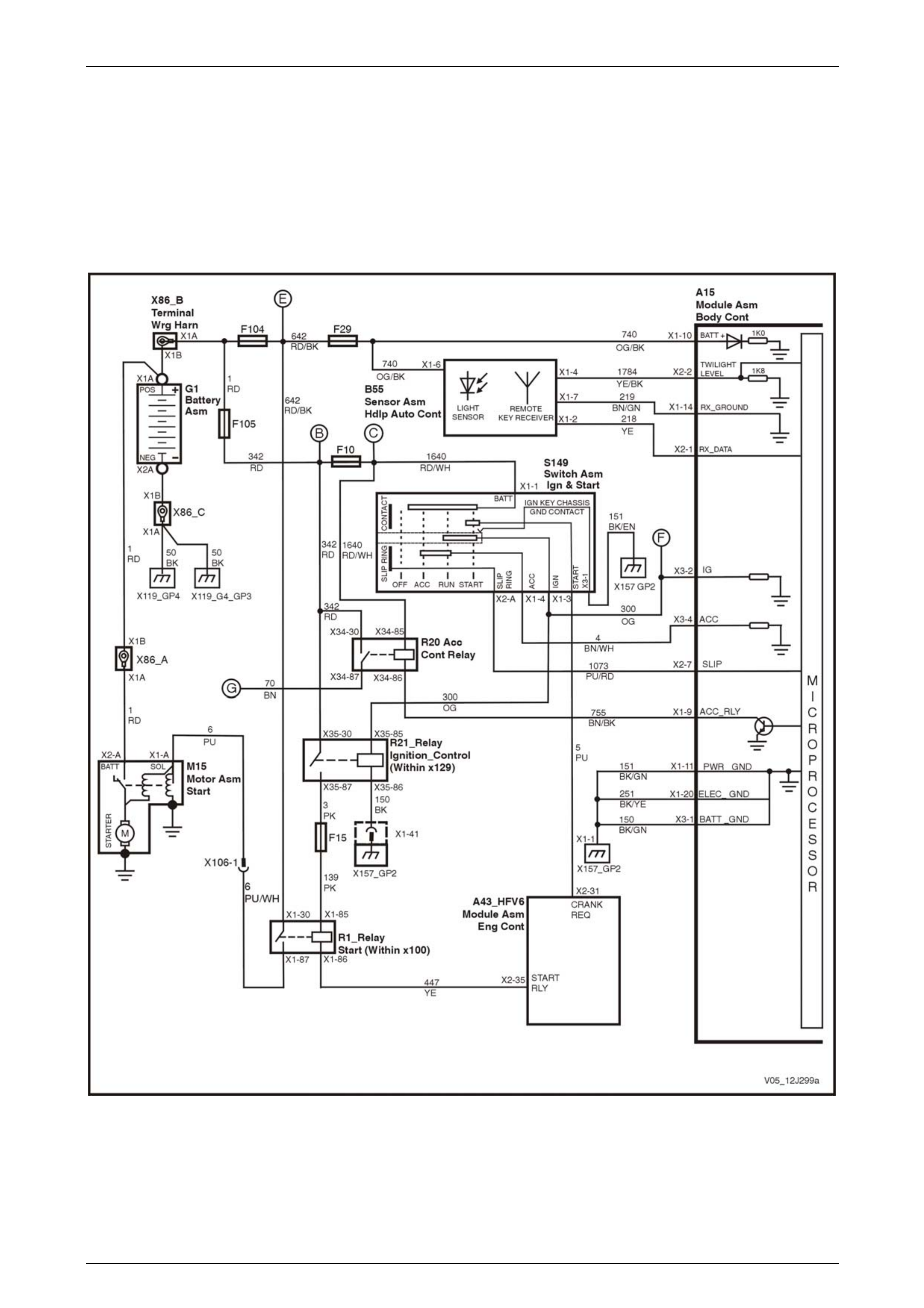
Body Control Module Page 12J–84
Page 12J–84
3 Wiring Diagrams and Connector
Charts
3.1 Wiring Diagrams – V6
Ignition Key, RX Sensor, Common Power and Grounds
Figure 12J – 12

Body Control Module Page 12J–85
Page 12J–85
Accessory Power Circuit
Figure 12J – 13
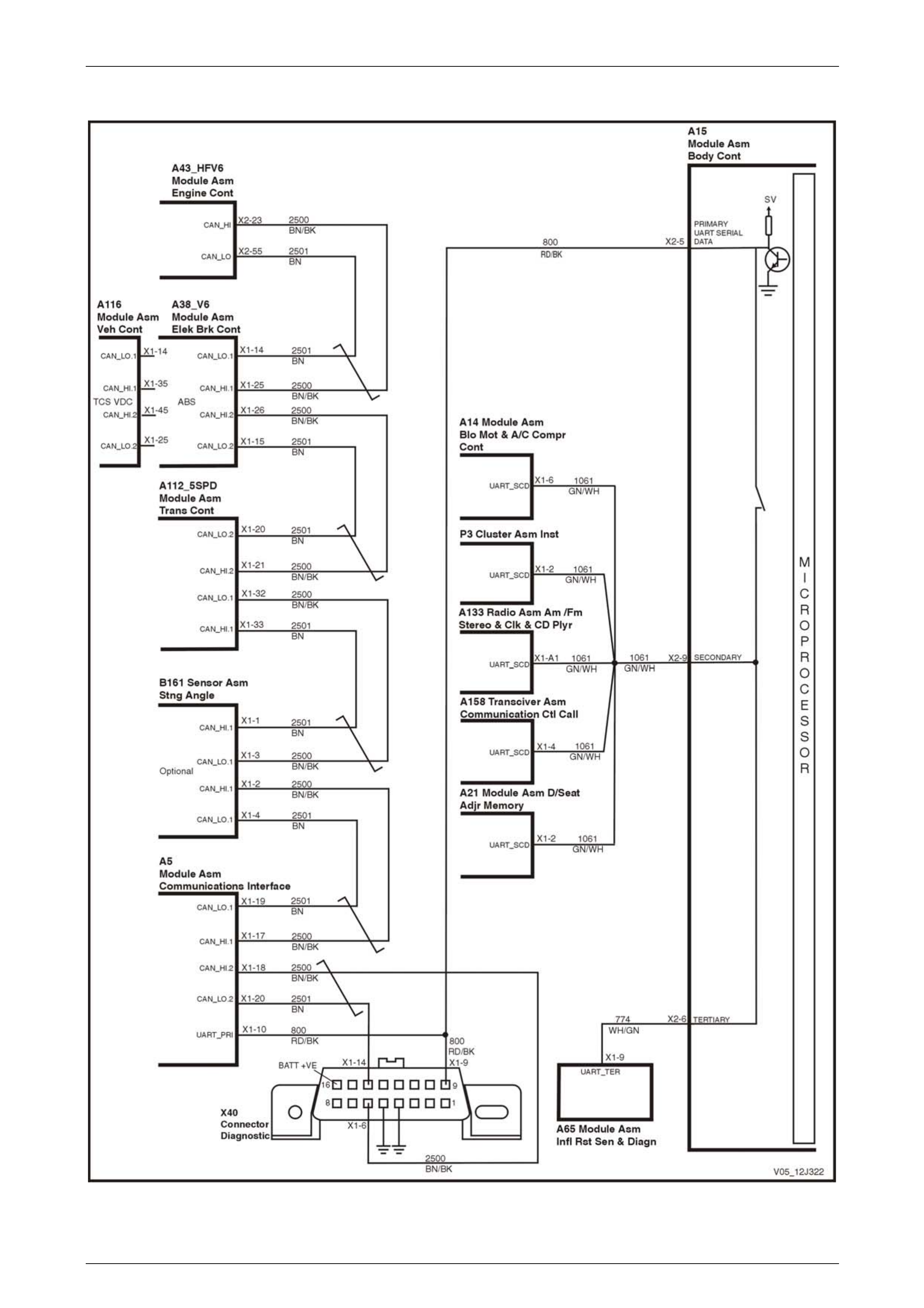
Body Control Module Page 12J–86
Page 12J–86
UART and GM LAN Communications – 5 Speed Automatic
Figure 12J – 14

Body Control Module Page 12J–87
Page 12J–87
UART and GM LAN Communications – 4 Speed Automatic with ESP
Figure 12J – 15
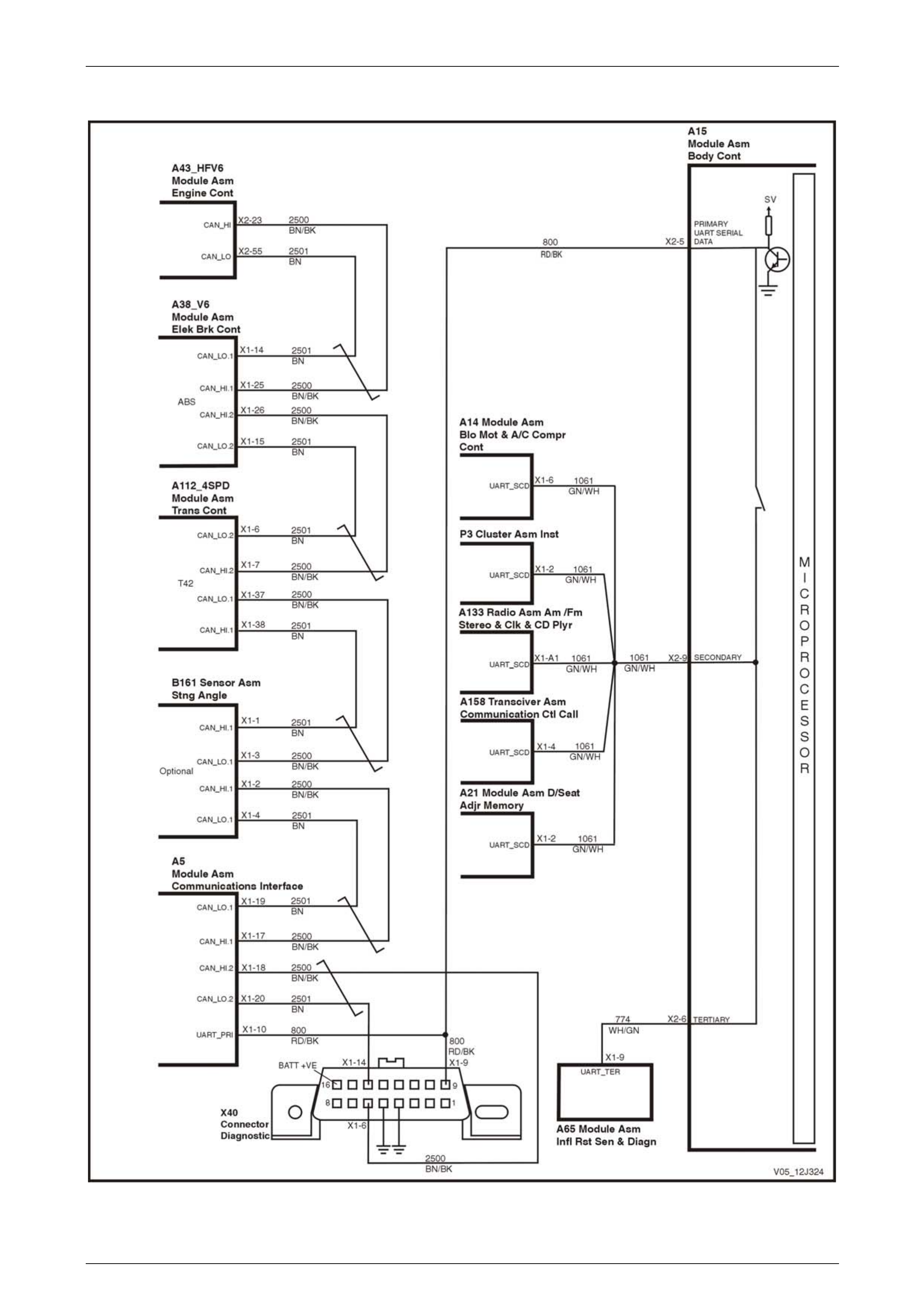
Body Control Module Page 12J–88
Page 12J–88
UART and GM LAN Communications – 4 Speed Automatic with without ESP
Figure 12J – 16

Body Control Module Page 12J–89
Page 12J–89
Central Door Locking
Figure 12J – 17

Body Control Module Page 12J–90
Page 12J–90
Entry Deterrent, Warning Horns and Rear Compartment Solenoid
Figure 12J – 18

Body Control Module Page 12J–91
Page 12J–91
Entry Deterrent, Warning Horns and Rear Lift Glass Solenoid – AWD Wagon only
Figure 12J – 19
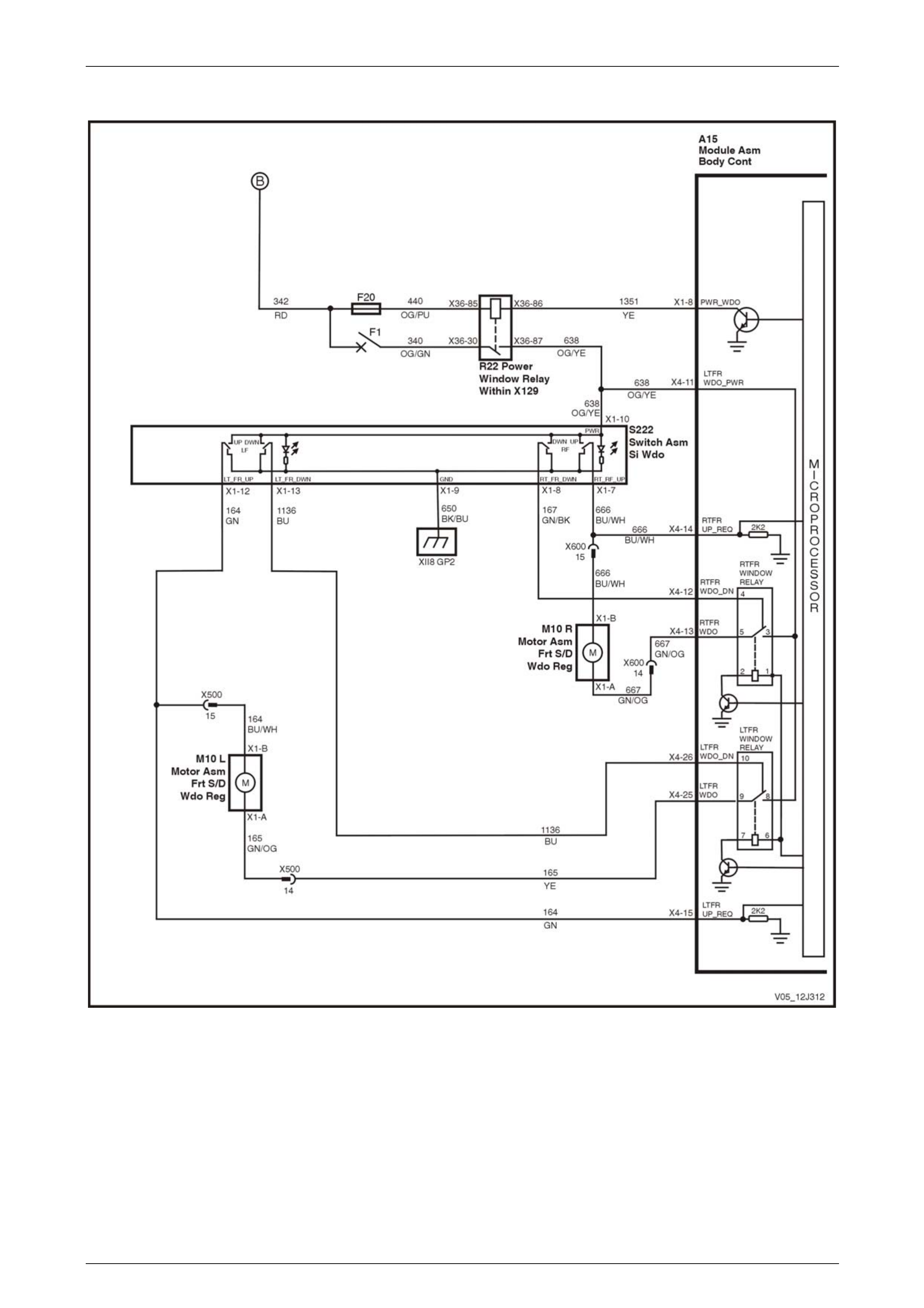
Body Control Module Page 12J–92
Page 12J–92
Power Windows – Two Door Vehicles
Figure 12J – 20

Body Control Module Page 12J–93
Page 12J–93
Power Windows – Four Door Vehicles
Figure 12J – 21

Body Control Module Page 12J–94
Page 12J–94
Wiper Systems Intermittent Function – Utility, Regular & Crew Cab and Sedan, Level 1
Figure 12J – 22
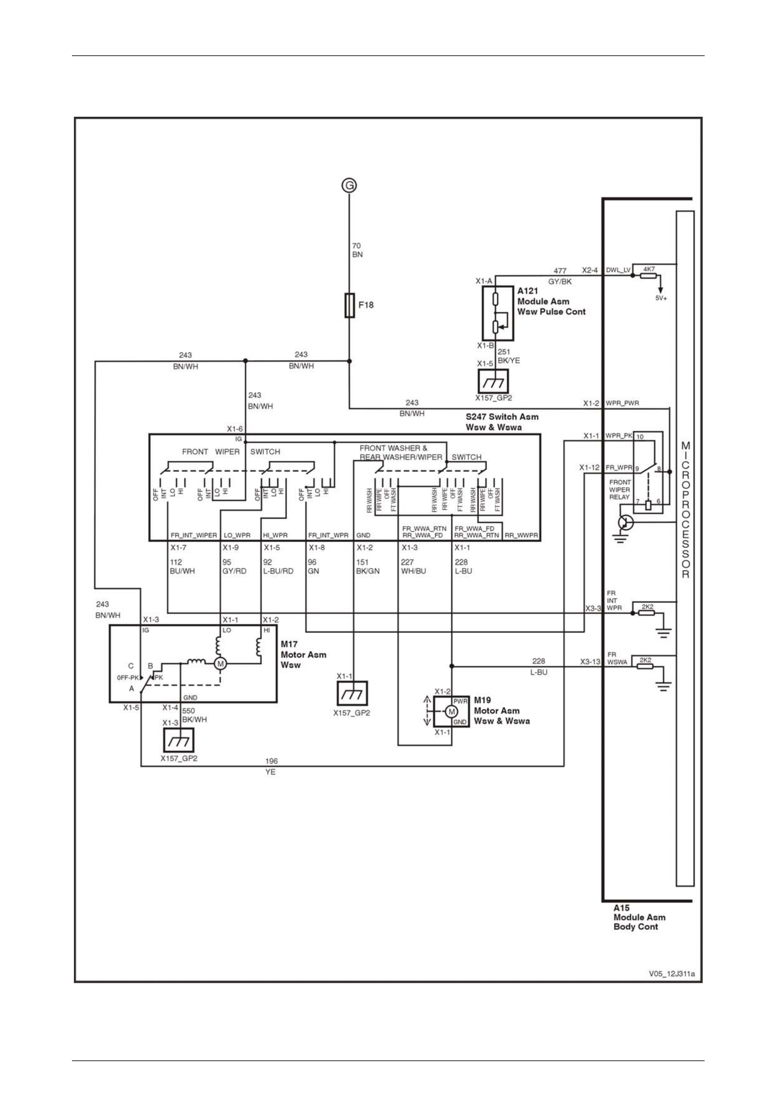
Body Control Module Page 12J–95
Page 12J–95
Wiper Systems Intermittent Function – Sedan, Level 2 and 3
Figure 12J – 23

Body Control Module Page 12J–96
Page 12J–96
Wiper Systems Intermittent Function – Wagon, Level 1
Figure 12J – 24
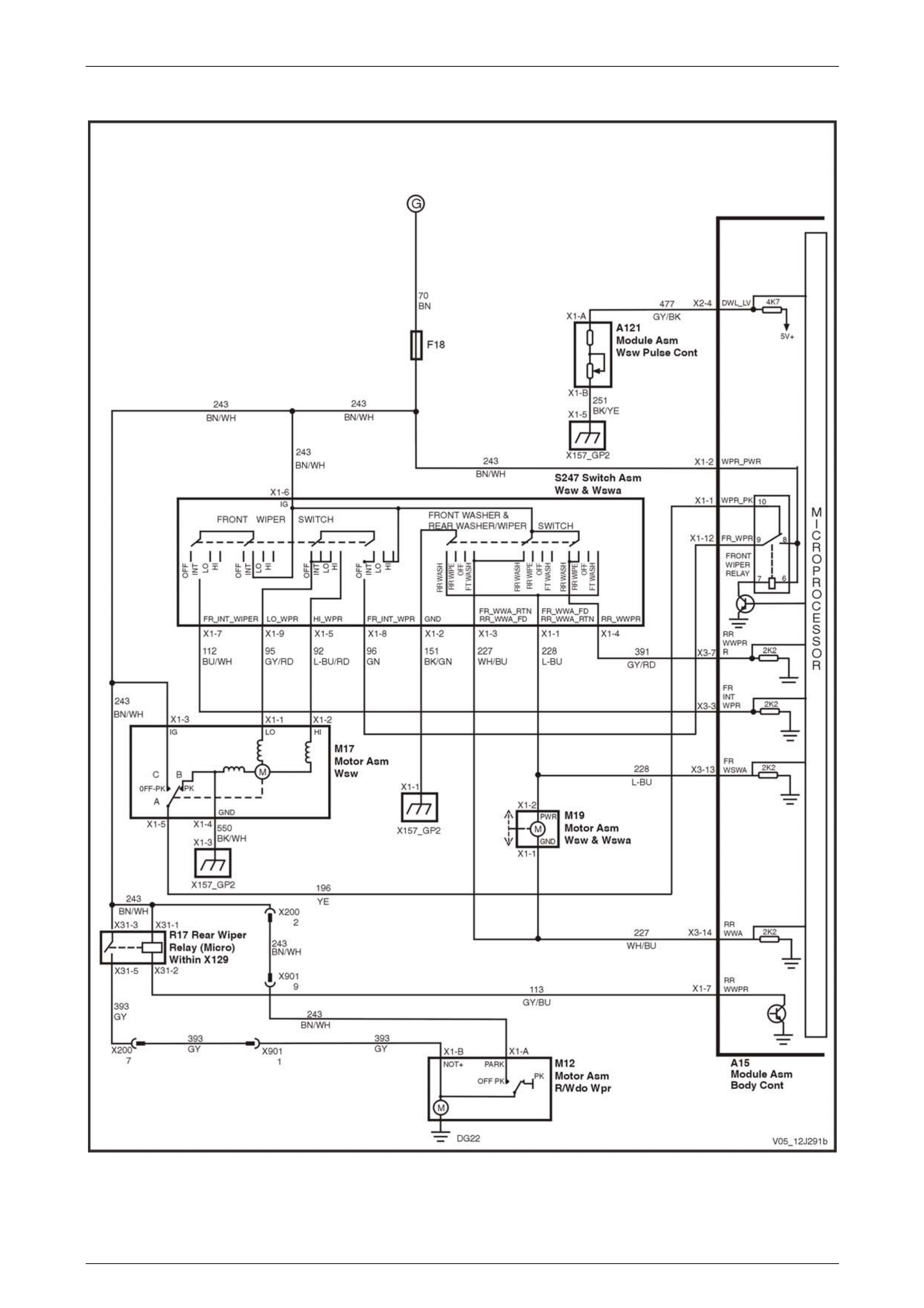
Body Control Module Page 12J–97
Page 12J–97
Wiper Systems Intermittent Function – Wagon, Level 2
Figure 12J – 25
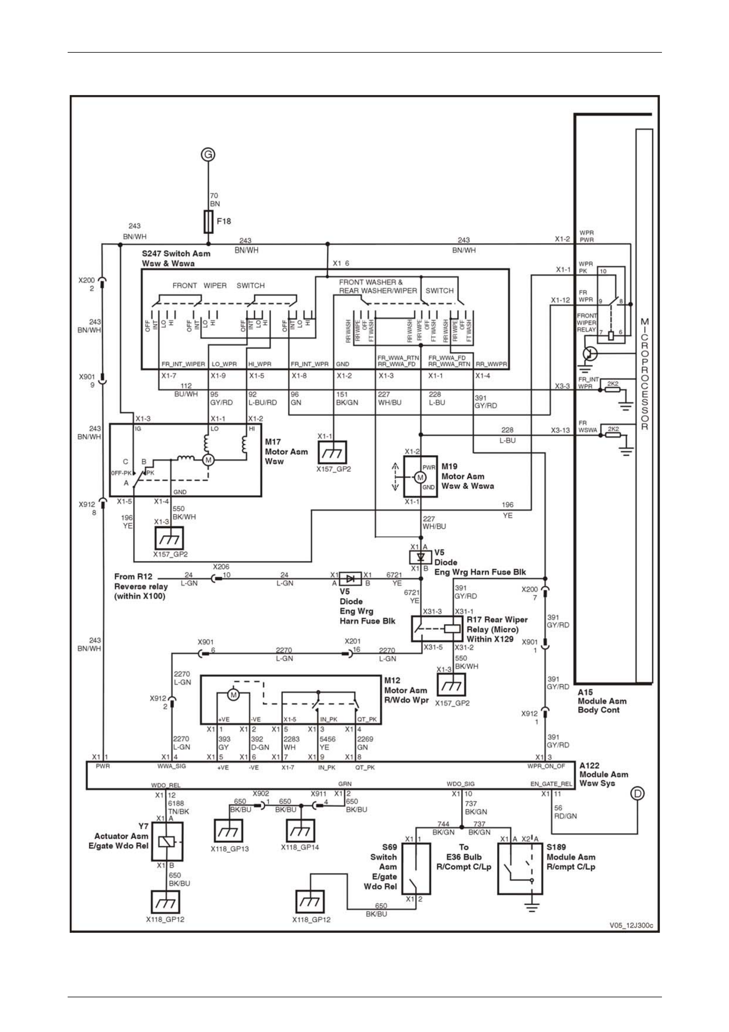
Body Control Module Page 12J–98
Page 12J–98
Wiper Systems Intermittent Function – AWD Wagon, Level 1
Figure 12J – 26

Body Control Module Page 12J–99
Page 12J–99
Wiper Systems Intermittent Function – AWD Wagon, Level 2
Figure 12J – 27

Body Control Module Page 12J–100
Page 12J–100
Dome Lamp Delay Control – Utility, Regular & Crew Cab, Level 1
Figure 12J – 28

Body Control Module Page 12J–101
Page 12J–101
Dome Lamp Delay Control – Sedan and Wagon, Level 1
Figure 12J – 29

Body Control Module Page 12J–102
Page 12J–102
Dome Lamp Delay Control – Sedan and Wagon, Level 2 and 3
Figure 12J – 30

Body Control Module Page 12J–103
Page 12J–103
Automatic Lamp Control – Level 1
Figure 12J – 31
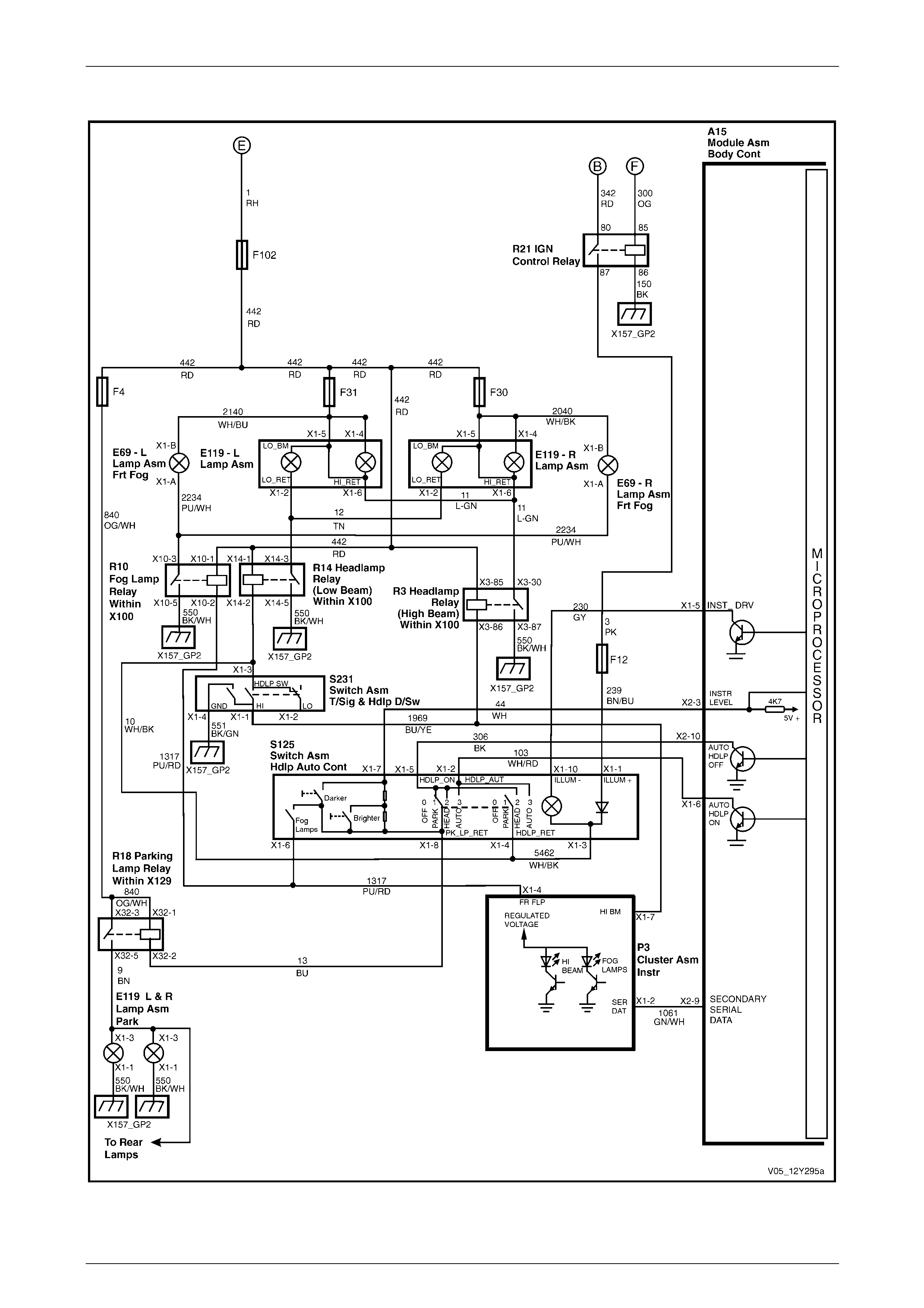
Body Control Module Page 12J–104
Page 12J–104
Automatic Lamp Control – Level 2 and 3
Figure 12J – 32

Body Control Module Page 12J–105
Page 12J–105
HVAC – Heated Rear Window and Air conditioning Interface – Level 1
Figure 12J – 33
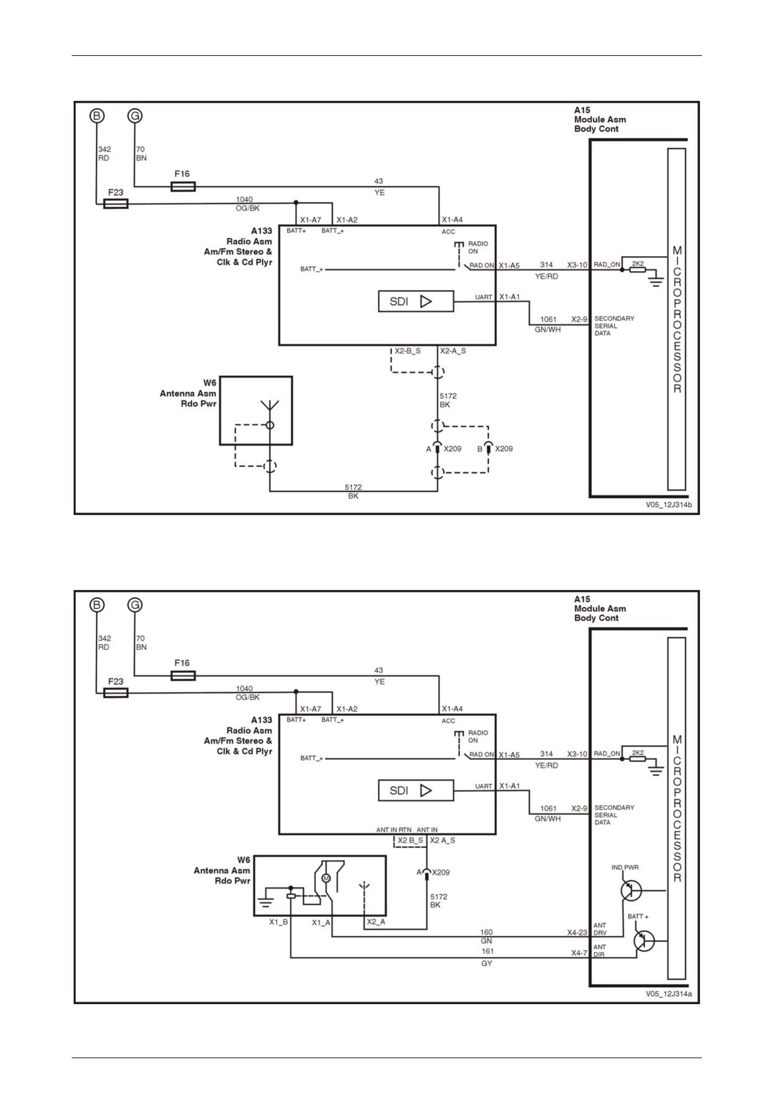
Body Control Module Page 12J–106
Page 12J–106
Radio and Power Antenna Control – Level 1
Figure 12J – 34
Radio and Power Antenna Control – Level 2 and 3
Figure 12J – 35

Body Control Module Page 12J–107
Page 12J–107
Rear Lamp Failure System – Level 3
Figure 12J – 36

Body Control Module Page 12J–108
Page 12J–108
Hazard Lamp Control, Theft / Turn Signal Lamp Flasher
Figure 12J – 37
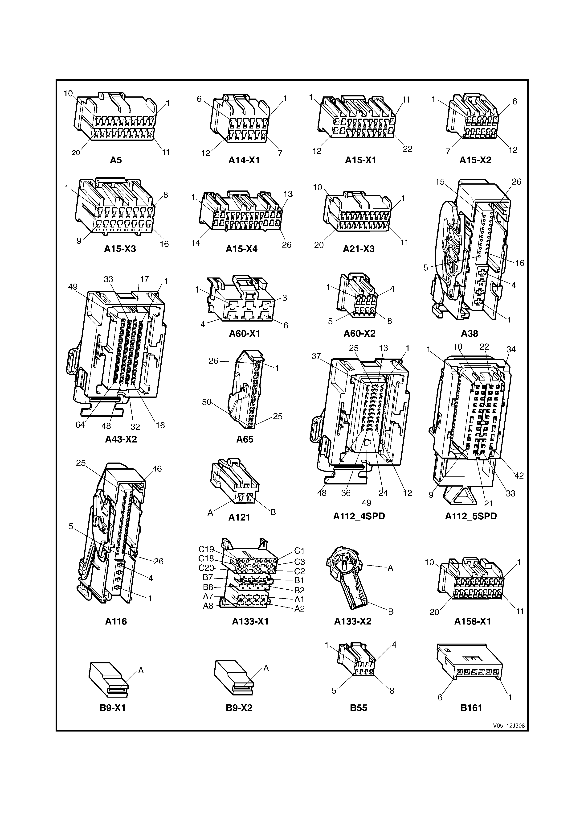
Body Control Module Page 12J–109
Page 12J–109
3.2 Connector Charts – V6
Figure 12J – 38
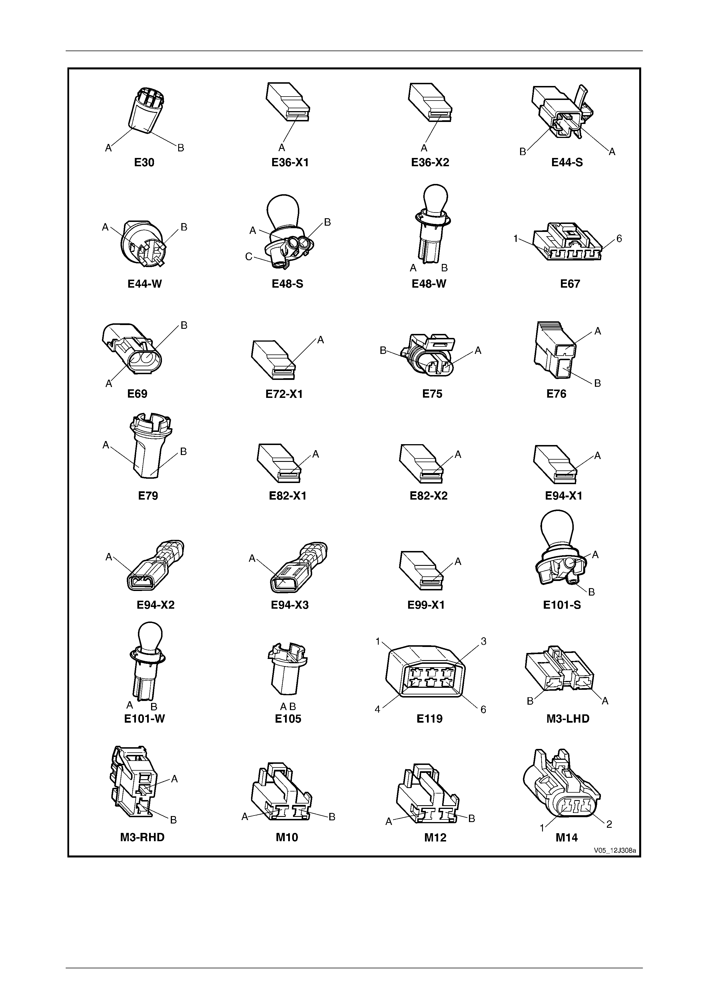
Body Control Module Page 12J–110
Page 12J–110
Figure 12J – 39
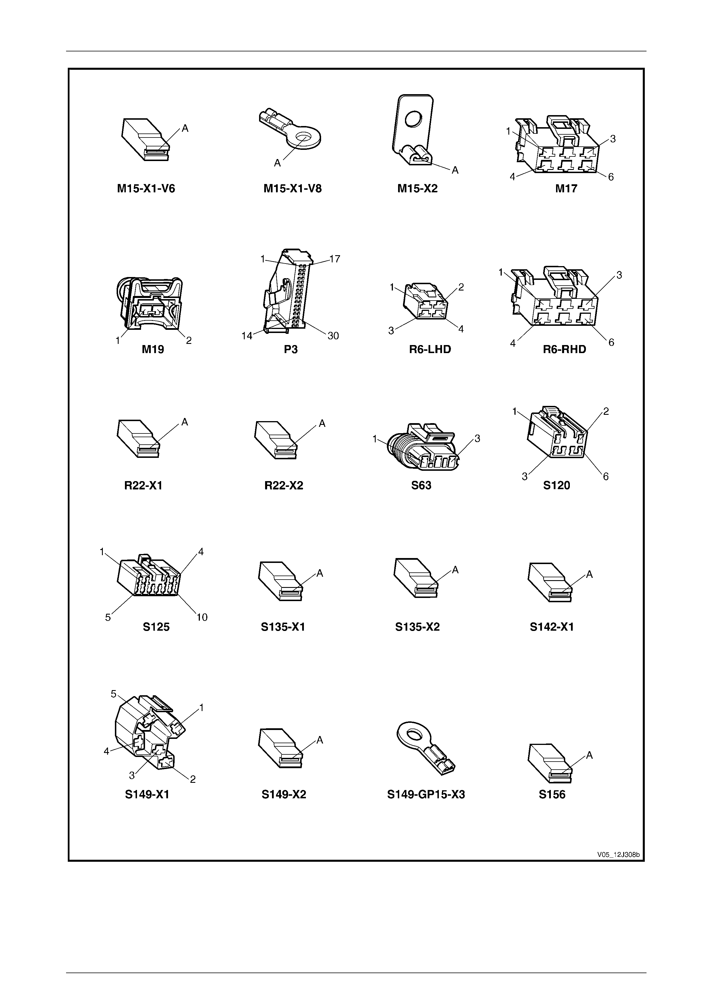
Body Control Module Page 12J–111
Page 12J–111
Figure 12J – 40
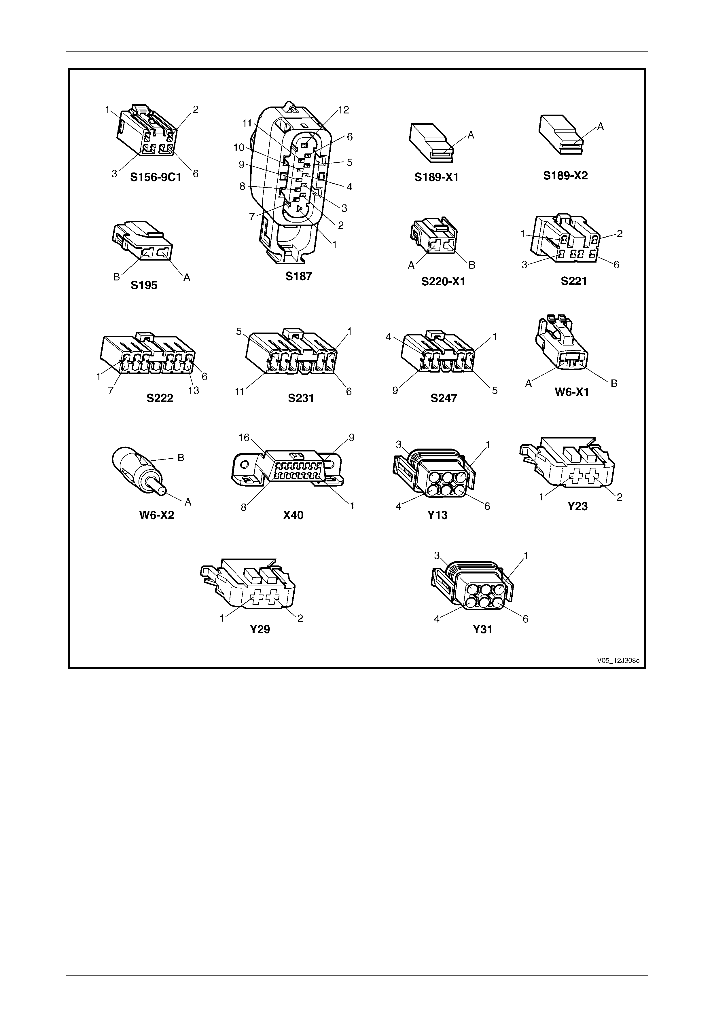
Body Control Module Page 12J–112
Page 12J–112
Figure 12J – 41
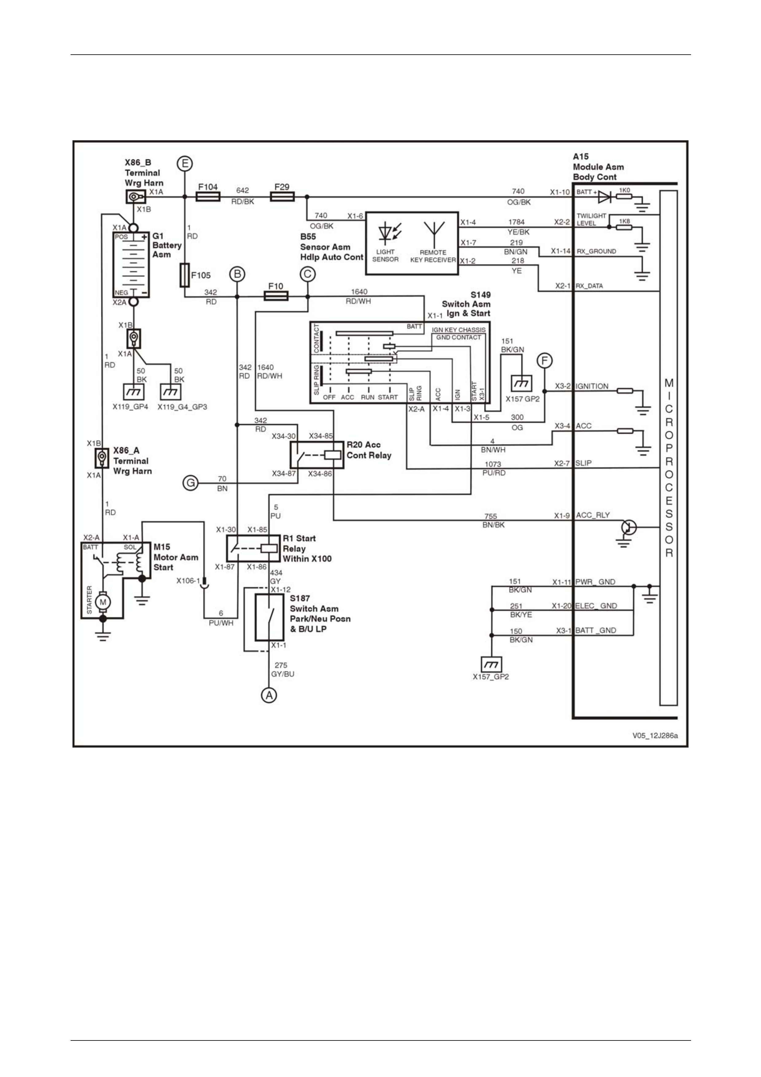
Body Control Module Page 12J–113
Page 12J–113
3.3 Wiring Diagrams – GEN III V8
Ignition Key, RX Sensor, Common Power and Grounds
Figure 12J – 42

Body Control Module Page 12J–114
Page 12J–114
Accessory Power Circuit
Figure 12J – 43
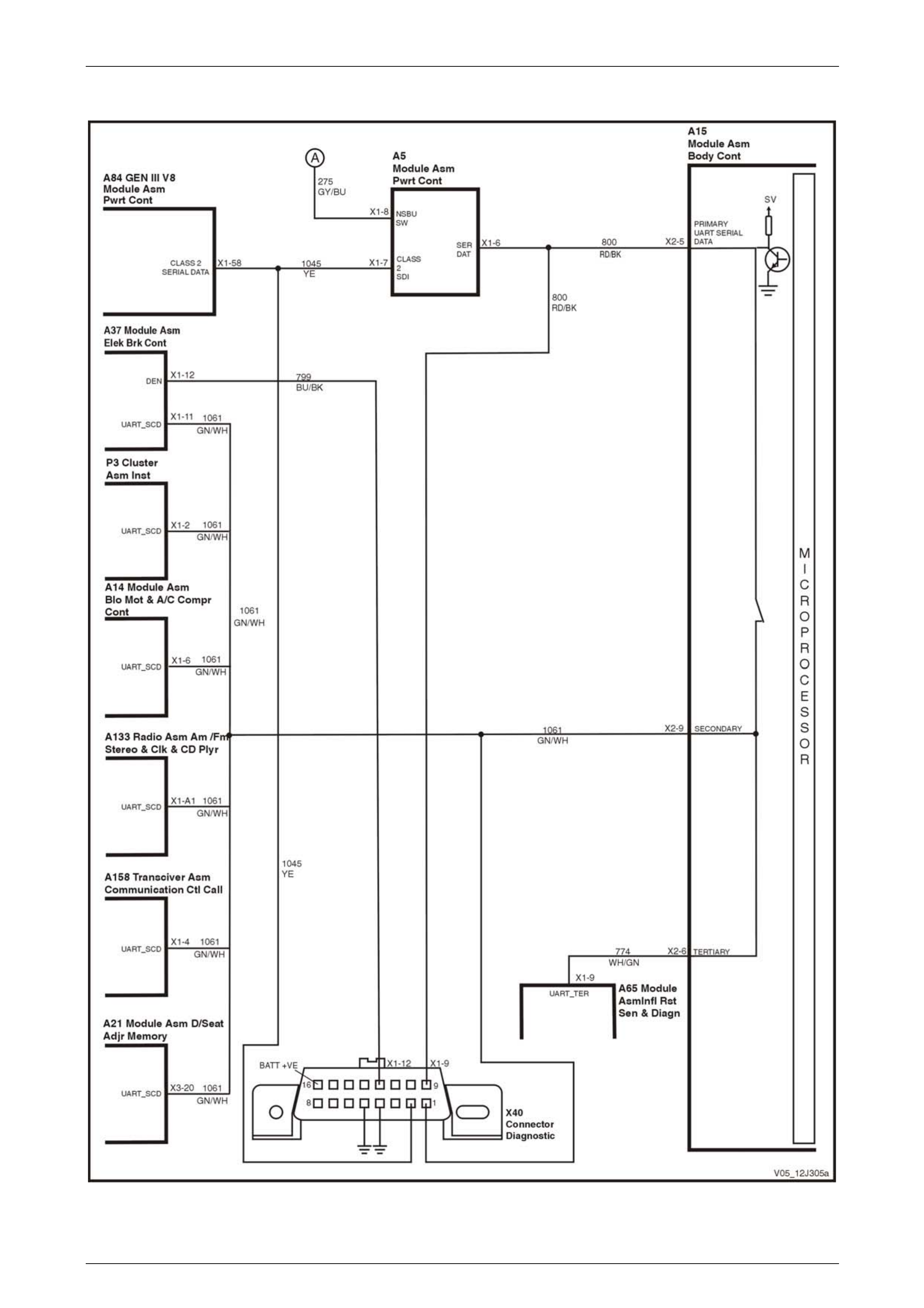
Body Control Module Page 12J–115
Page 12J–115
UART and Class 2 Communications
Figure 12J – 44
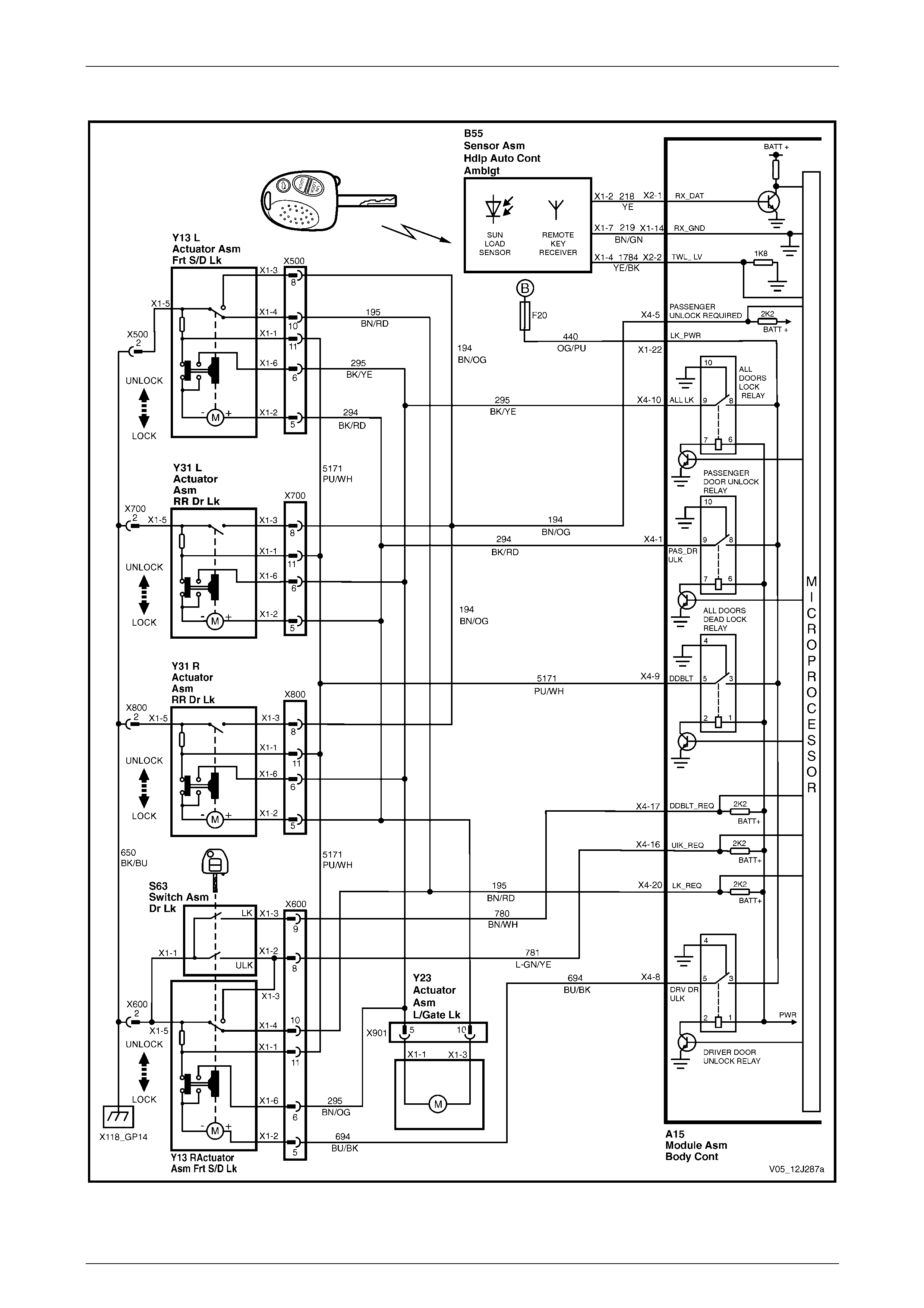
Body Control Module Page 12J–116
Page 12J–116
Central Door Locking
Figure 12J – 45
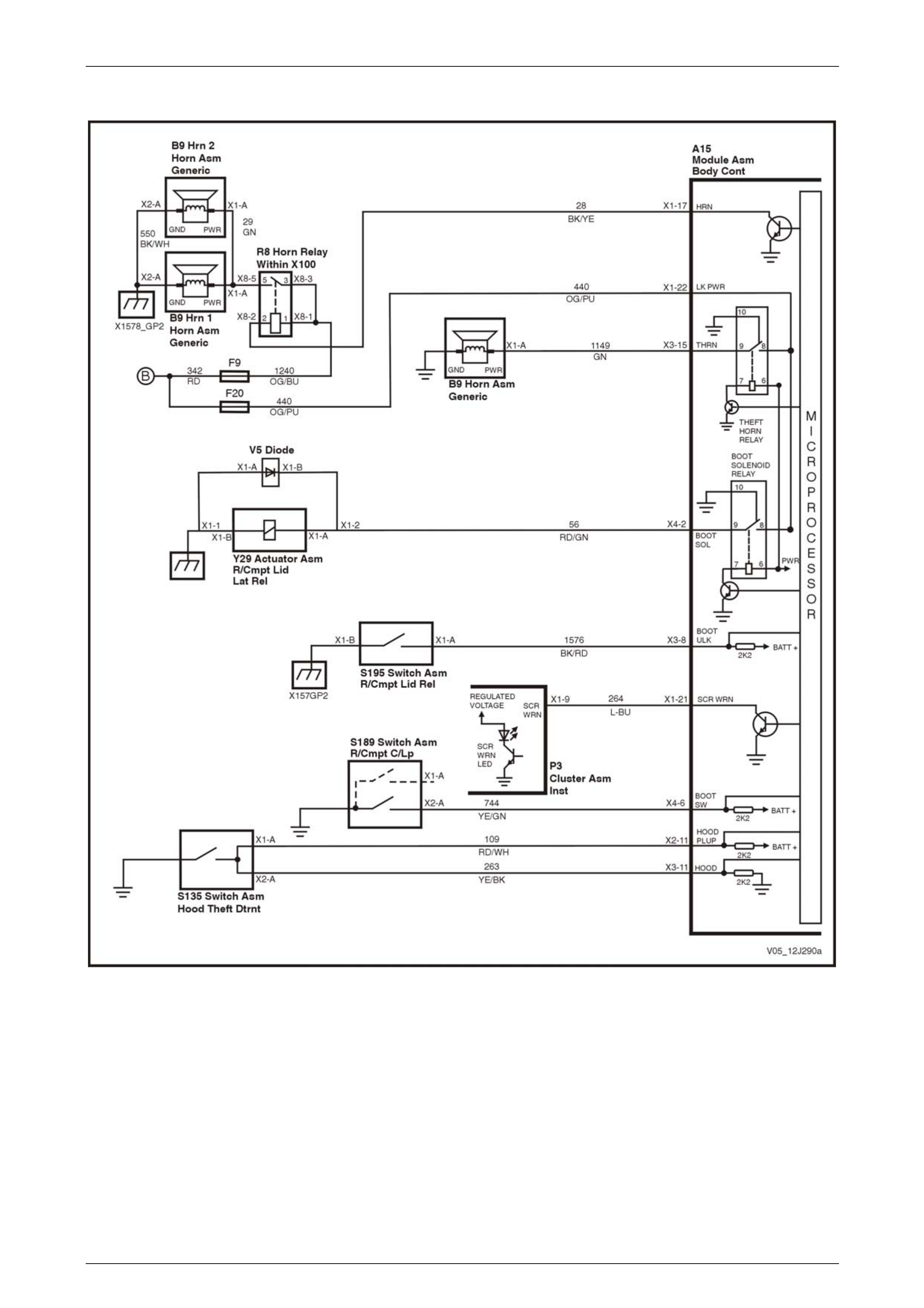
Body Control Module Page 12J–117
Page 12J–117
Entry Deterrent, Warning Horns and Rear Compartment Solenoid
Figure 12J – 46
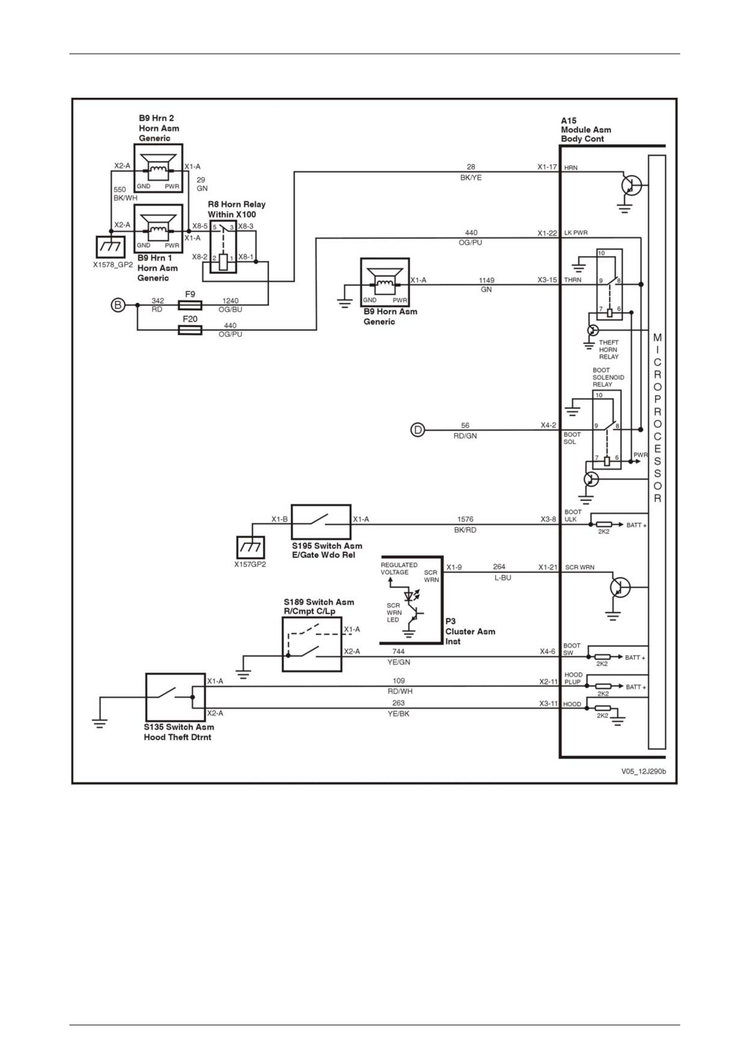
Body Control Module Page 12J–118
Page 12J–118
Entry Deterrent, Warning Horns and Rear Lift Glass Solenoid – AWD Wagon Only
Figure 12J – 47

Body Control Module Page 12J–119
Page 12J–119
Power Windows – Two Door Vehicles
Figure 12J – 48
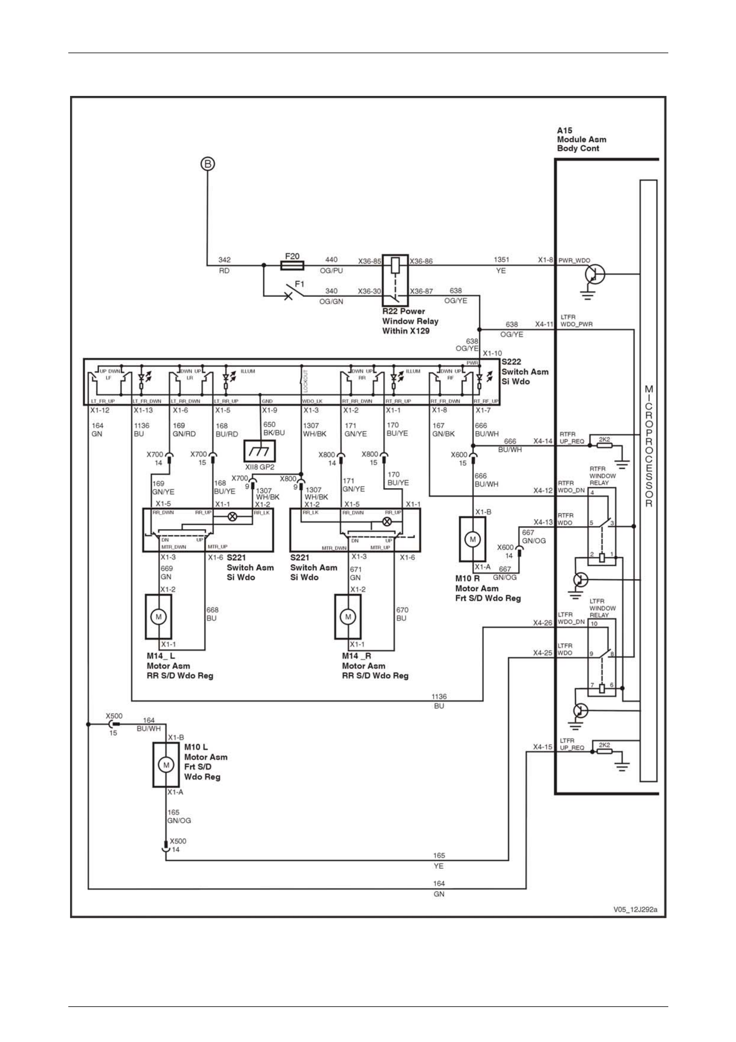
Body Control Module Page 12J–120
Page 12J–120
Power Windows – Four Door Vehicles
Figure 12J – 49

Body Control Module Page 12J–121
Page 12J–121
Wiper Systems Intermittent Function – Utility, Regular & Crew Cab and Sedan, Level 1
Figure 12J – 50
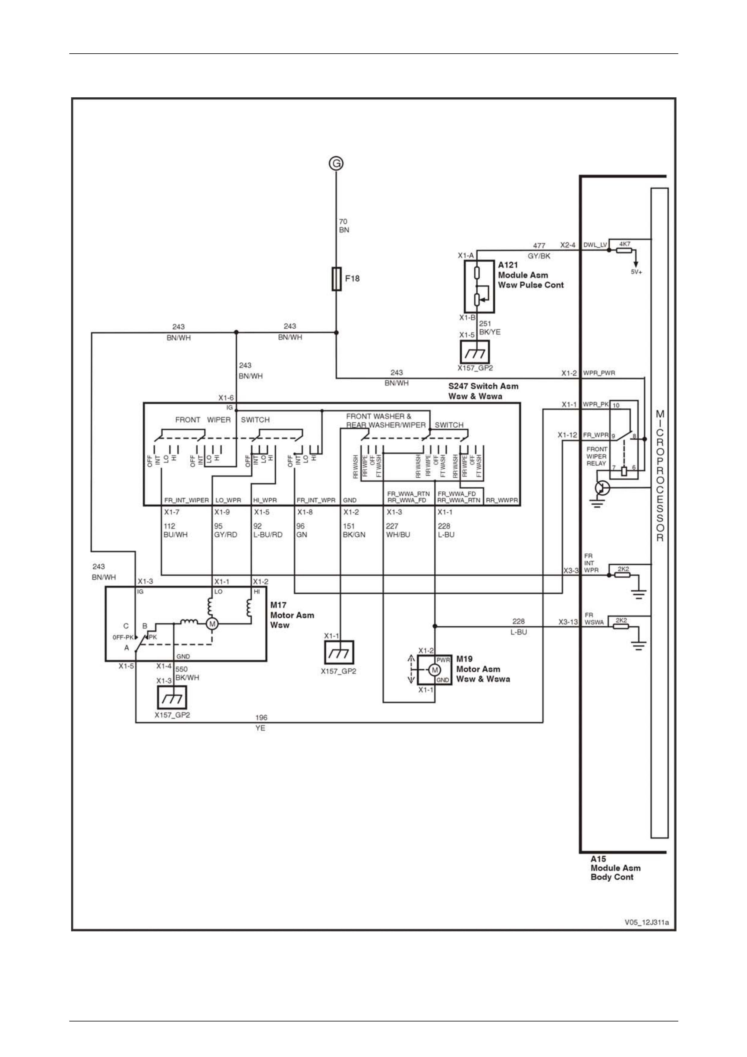
Body Control Module Page 12J–122
Page 12J–122
Wiper Systems Intermittent Function – Sedan, Level 2 and 3
Figure 12J – 51
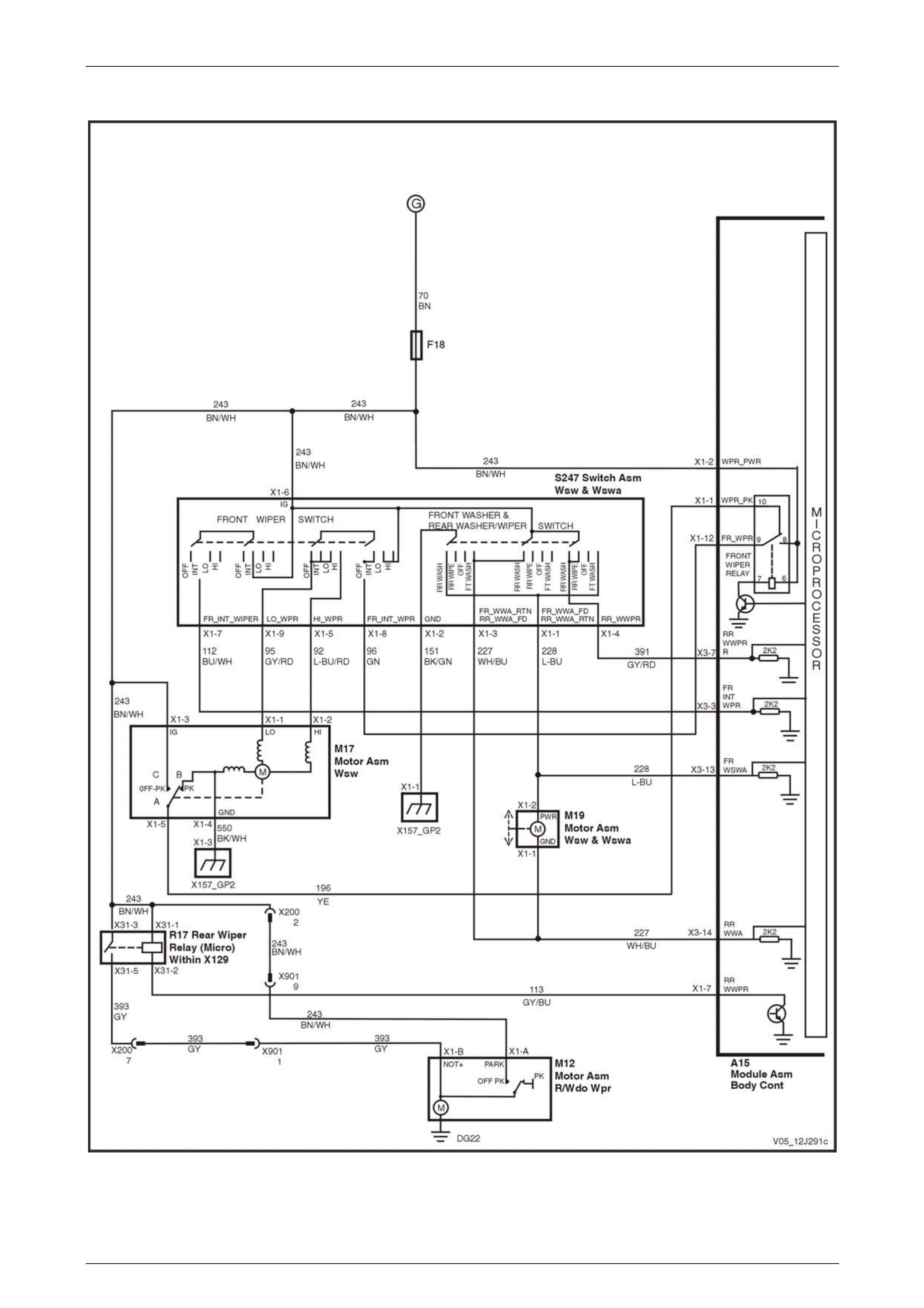
Body Control Module Page 12J–123
Page 12J–123
Wiper Systems Intermittent Function – Wagon, Level 1
Figure 12J – 52

Body Control Module Page 12J–124
Page 12J–124
Wiper Systems Intermittent Function – Wagon, Level 2 and 3
Figure 12J – 53

Body Control Module Page 12J–125
Page 12J–125
Wiper Systems Intermittent Function – AWD Wagon, Level 2
Figure 12J – 54
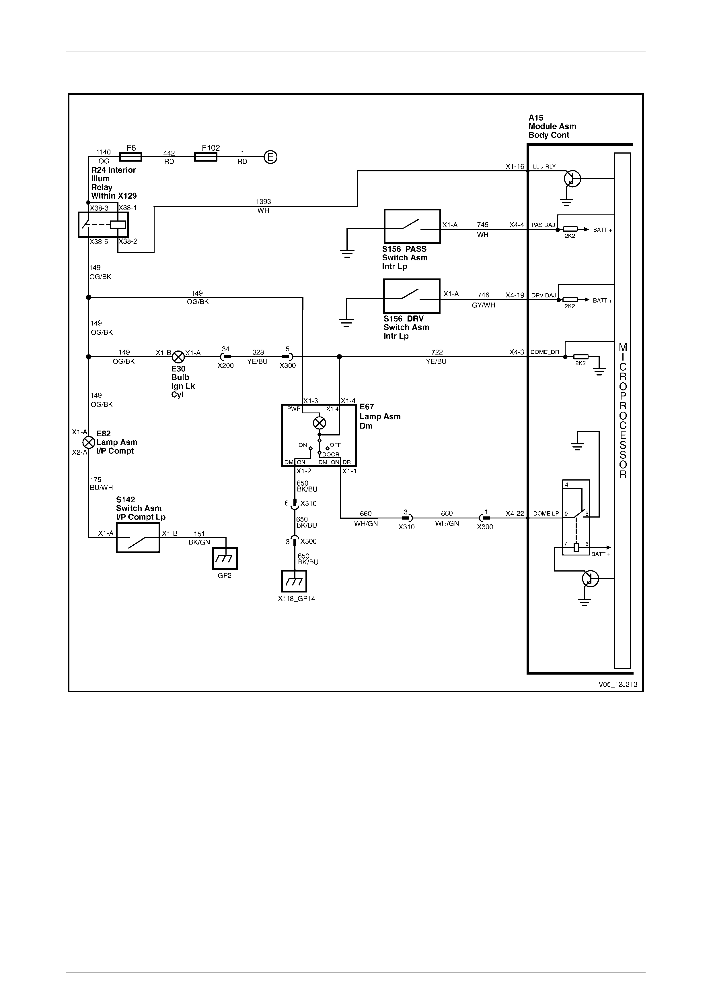
Body Control Module Page 12J–126
Page 12J–126
Dome Lamp Delay Control – Utility, Regular & Crew Cab, Level 1
Figure 12J – 55

Body Control Module Page 12J–127
Page 12J–127
Dome Lamp Delay Control – Sedan and Wagon, Level 1
Figure 12J – 56
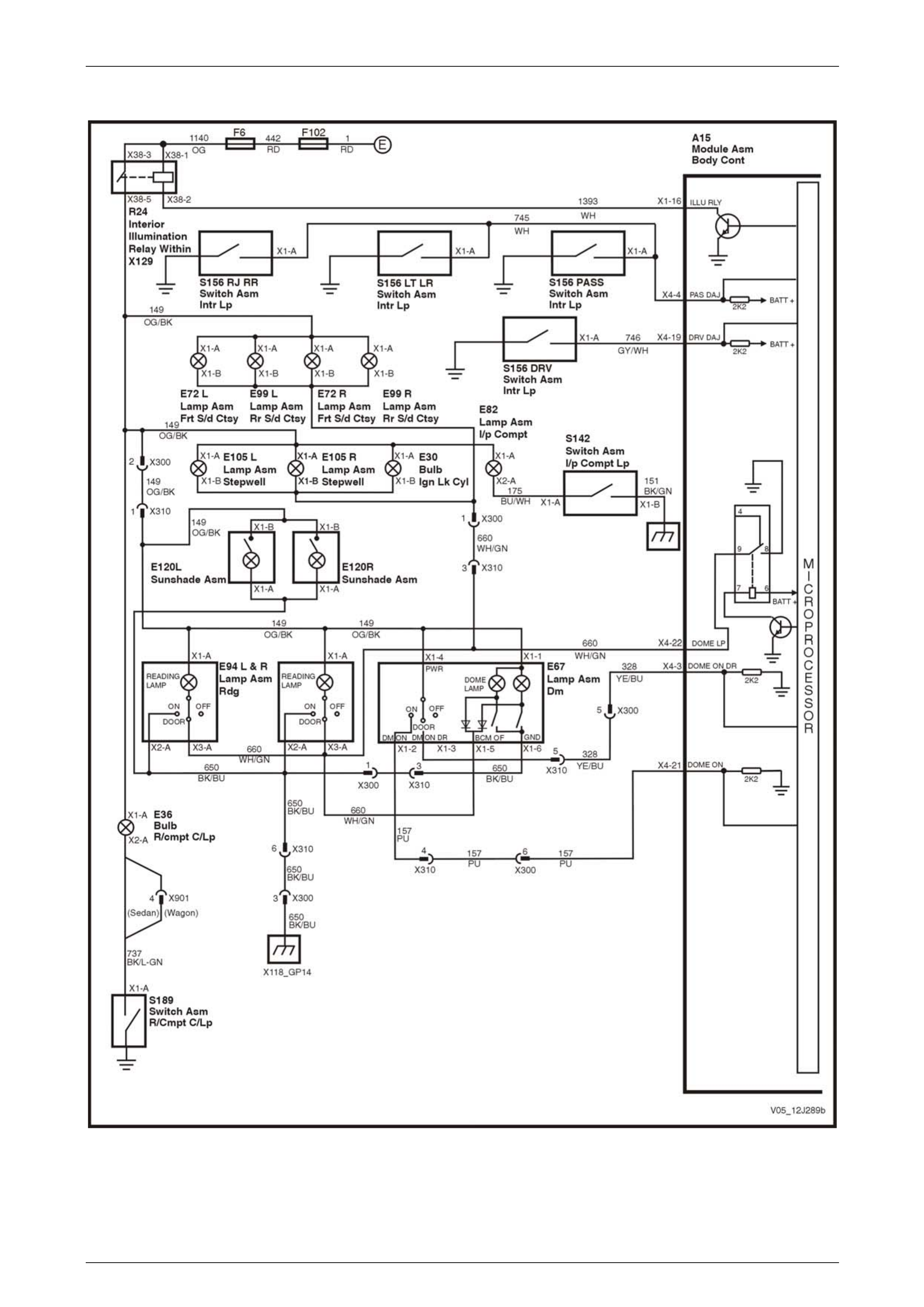
Body Control Module Page 12J–128
Page 12J–128
Dome Lamp Delay Control – Sedan and Wagon, Level 2 and 3
Figure 12J – 57
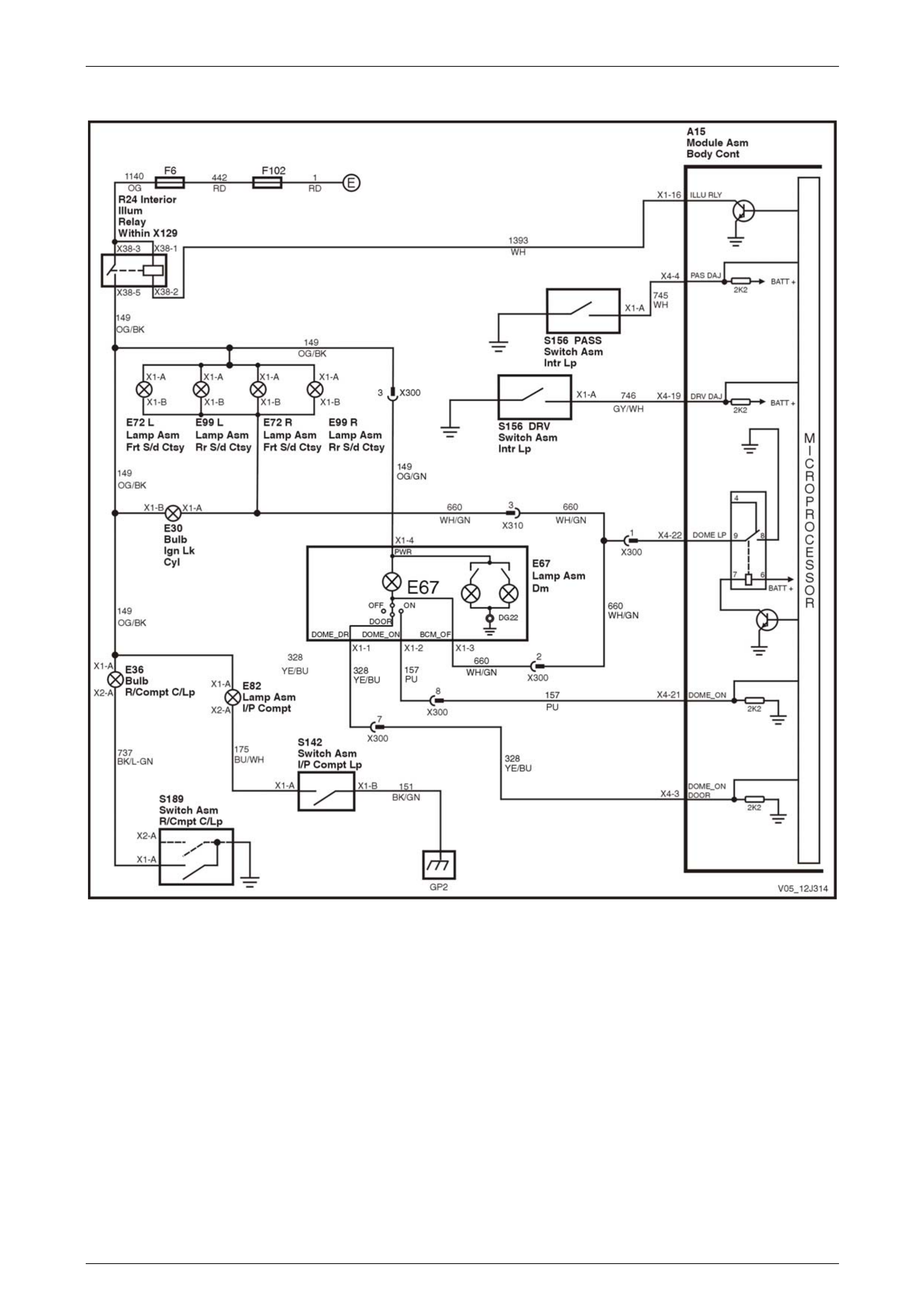
Body Control Module Page 12J–129
Page 12J–129
Dome Lamp Delay Control – Coupe, Level 2 and 3
Figure 12J – 58
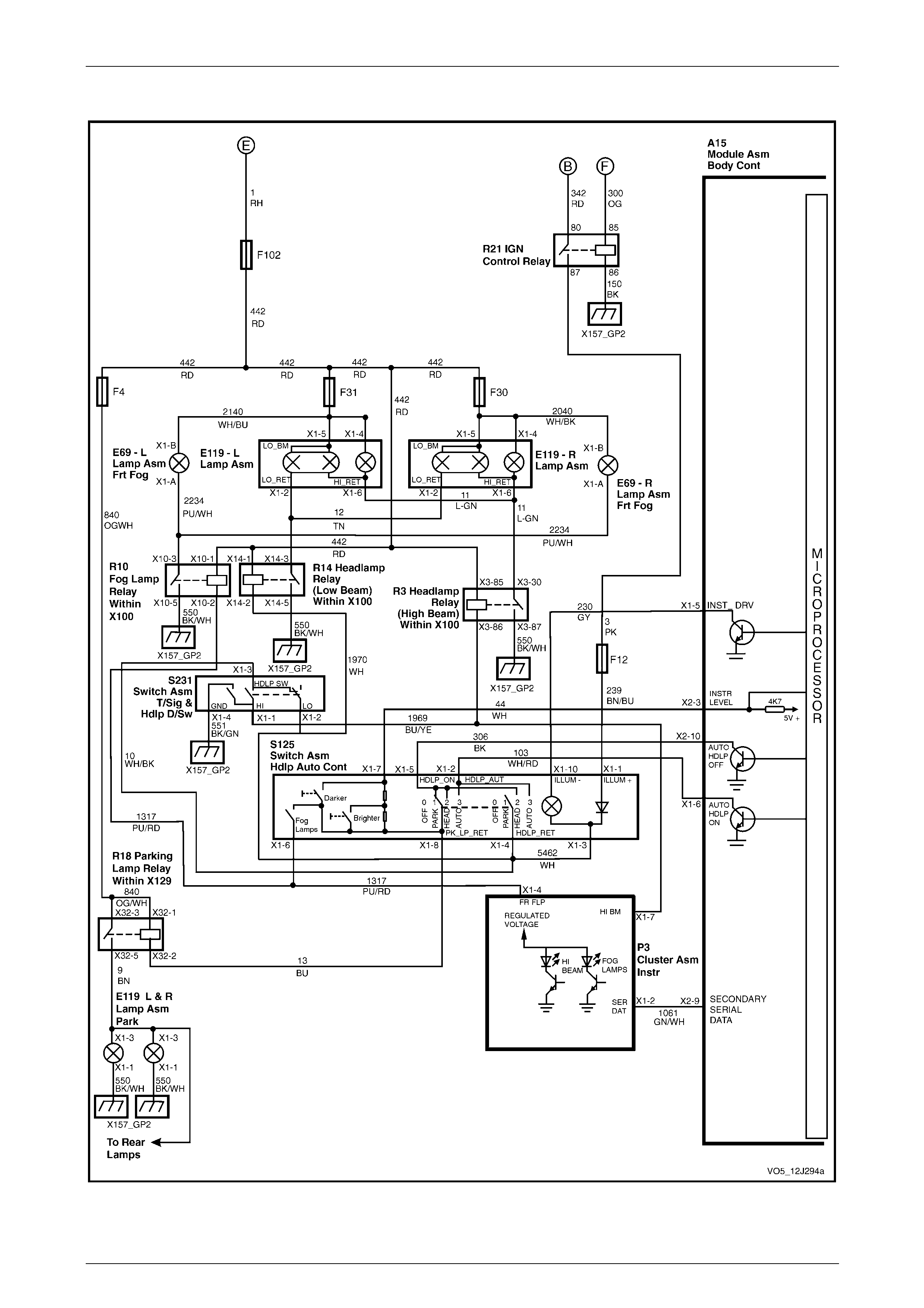
Body Control Module Page 12J–130
Page 12J–130
Automatic Lamp Control – Level 1
Figure 12J – 59

Body Control Module Page 12J–131
Page 12J–131
Automatic Lamp Control – Level 2 and 3
Figure 12J – 60

Body Control Module Page 12J–132
Page 12J–132
HVAC – Heated Rear Window and Air conditioning Interface – Level 1
Figure 12J – 61
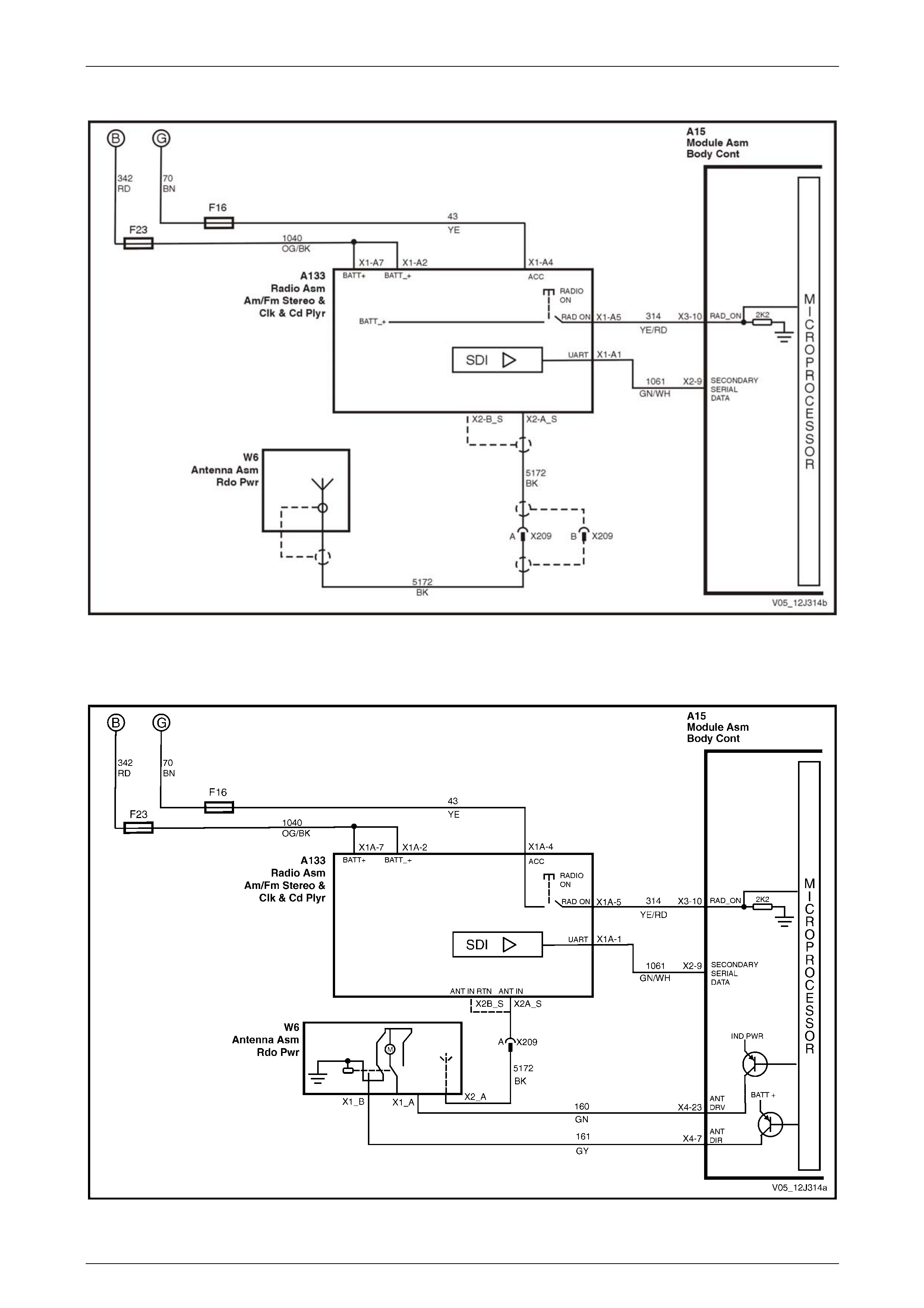
Body Control Module Page 12J–133
Page 12J–133
Radio and Power Antenna Control – Level 1
Figure 12J – 62
Radio and Power Antenna Control – Level 2 and 3
Figure 12J – 63
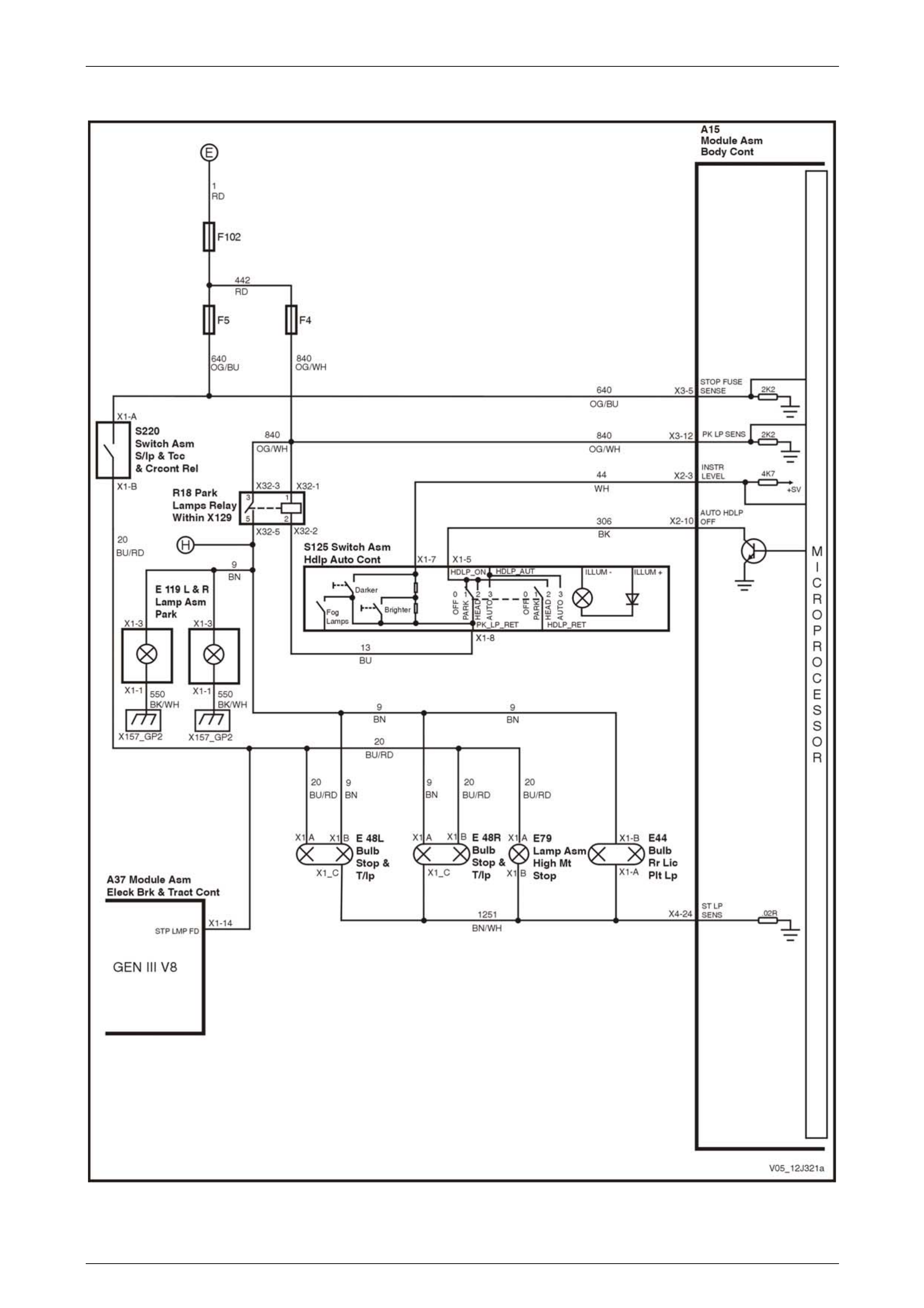
Body Control Module Page 12J–134
Page 12J–134
Rear Lamp Failure System – Level 3
Figure 12J – 64
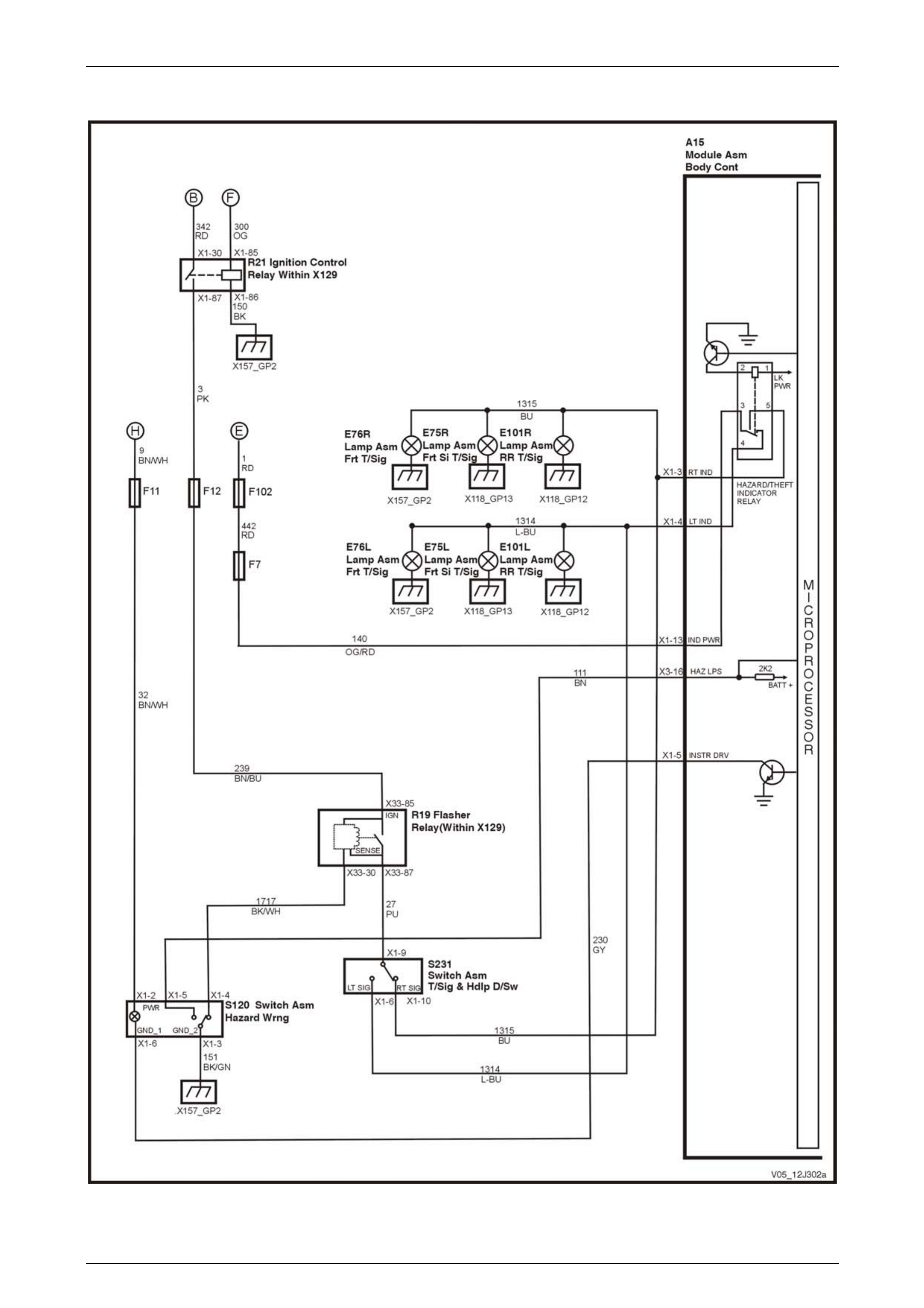
Body Control Module Page 12J–135
Page 12J–135
Hazard Lamp Control, Theft / Turn Signal Lamp Flasher
Figure 12J – 65
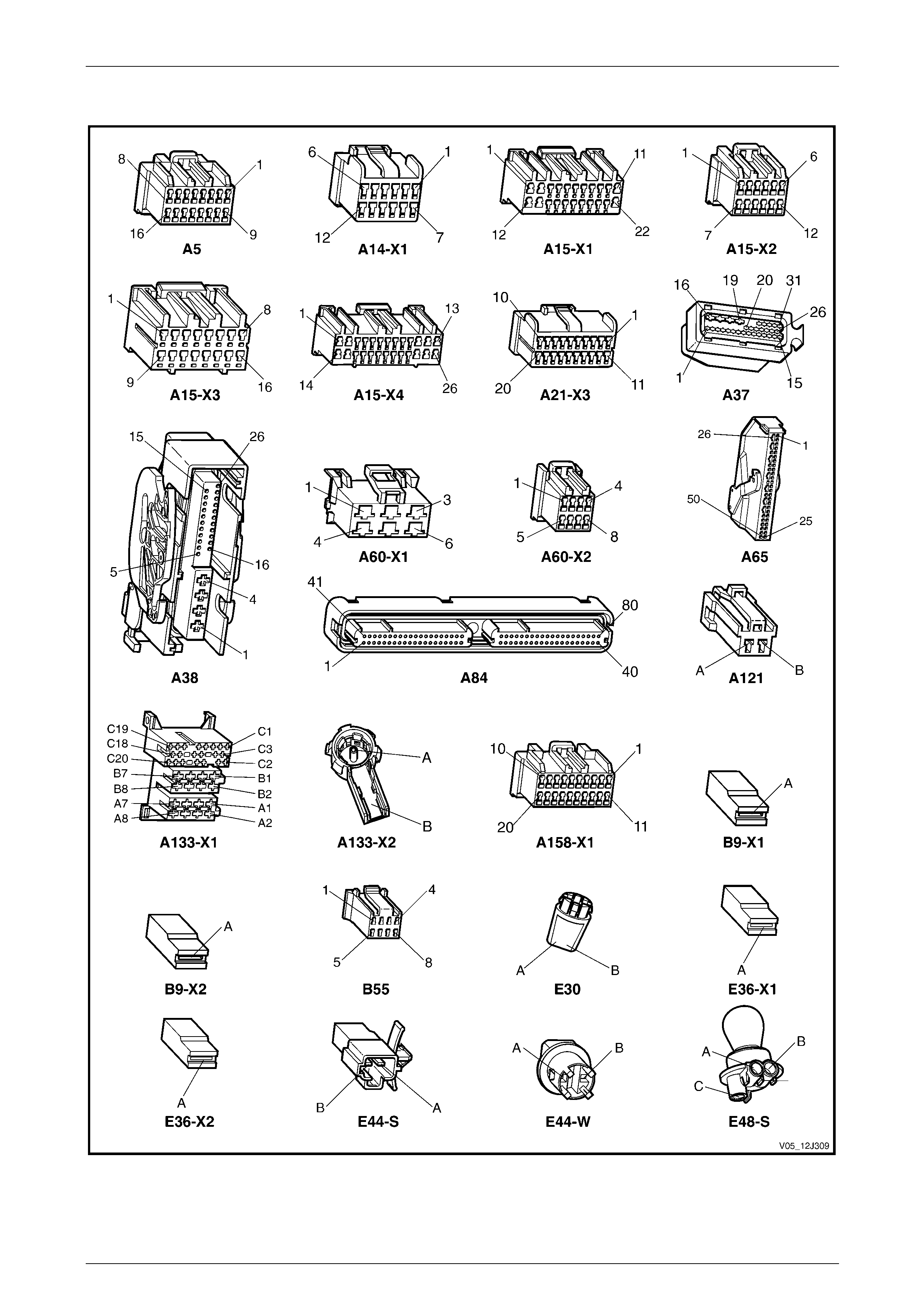
Body Control Module Page 12J–136
Page 12J–136
3.4 Connector Charts – GEN III V8
Figure 12J – 66
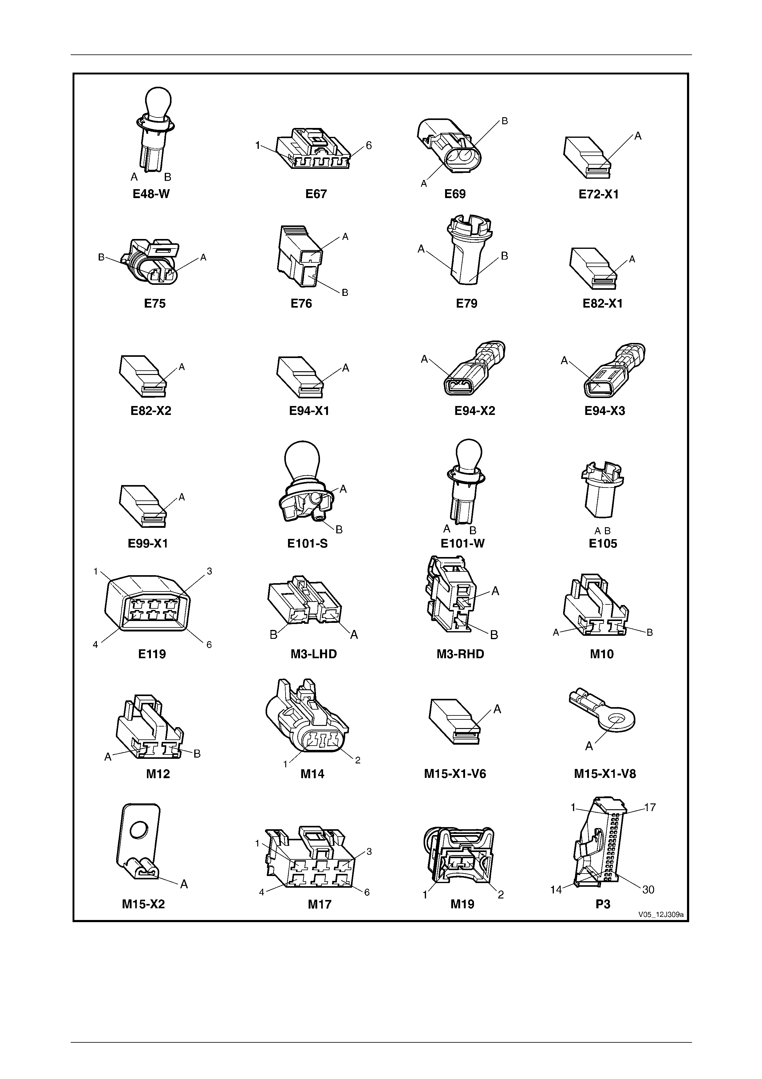
Body Control Module Page 12J–137
Page 12J–137
Figure 12J – 67
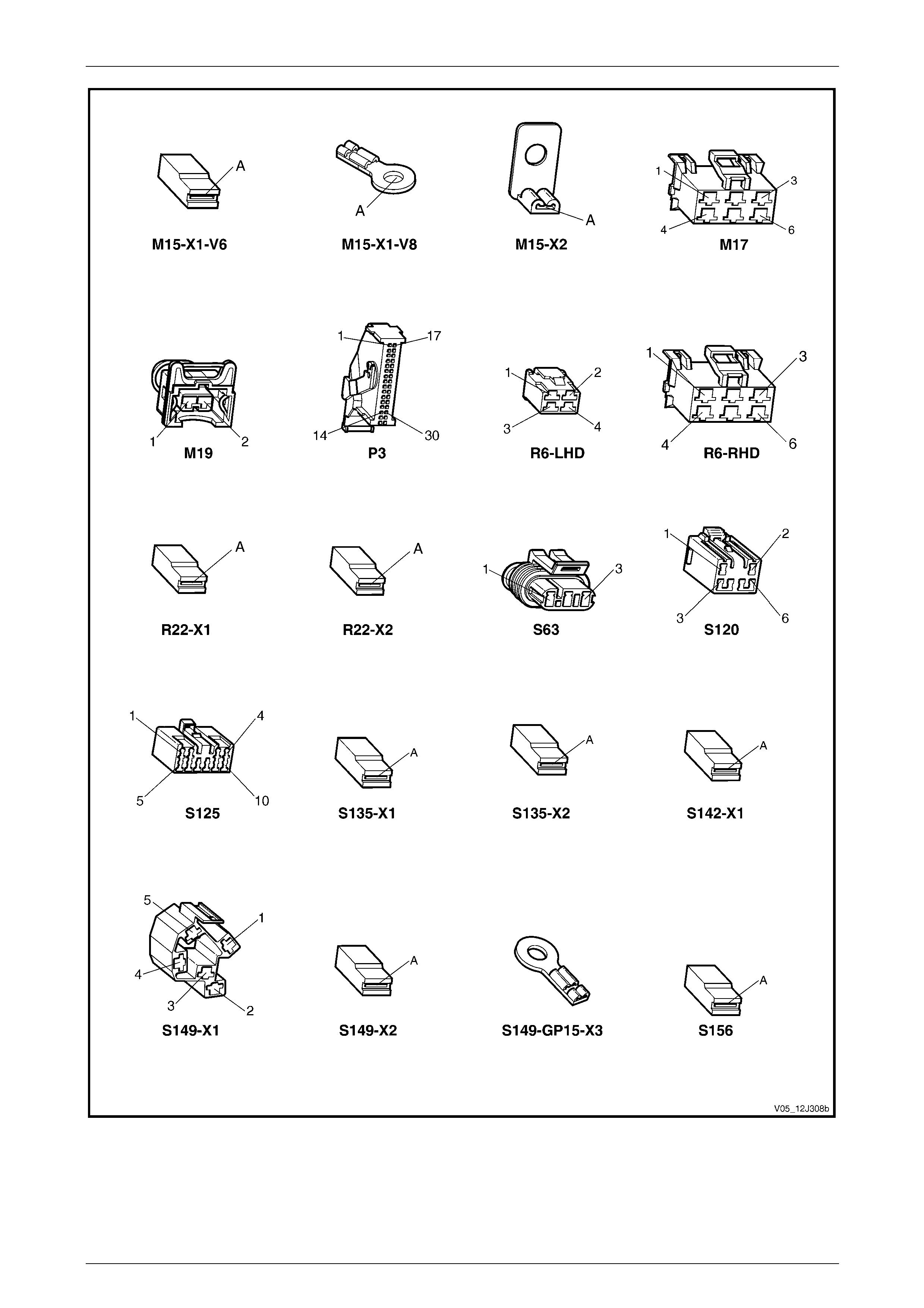
Body Control Module Page 12J–138
Page 12J–138
Figure 12J – 68
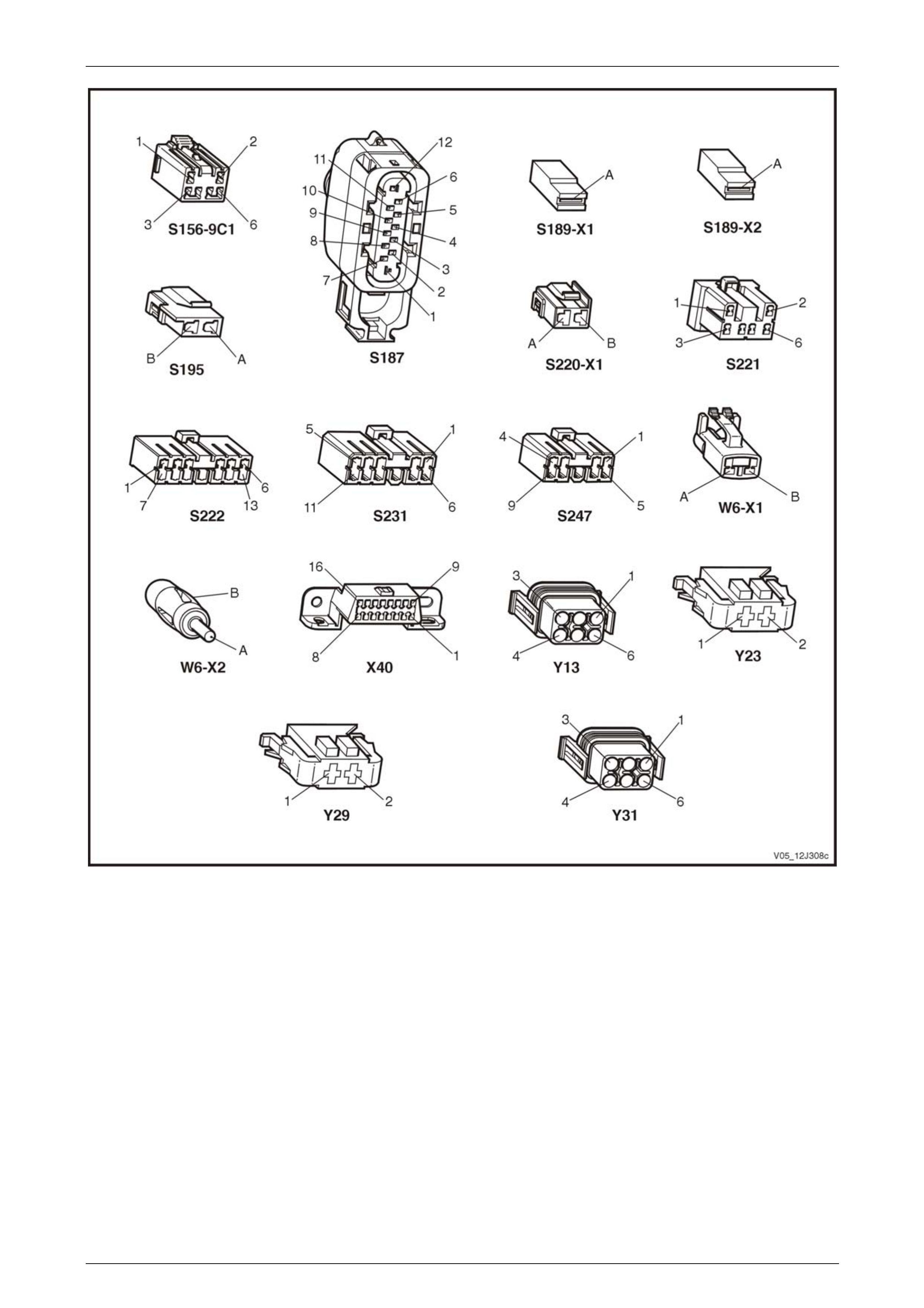
Body Control Module Page 12J–139
Page 12J–139
Figure 12J – 69
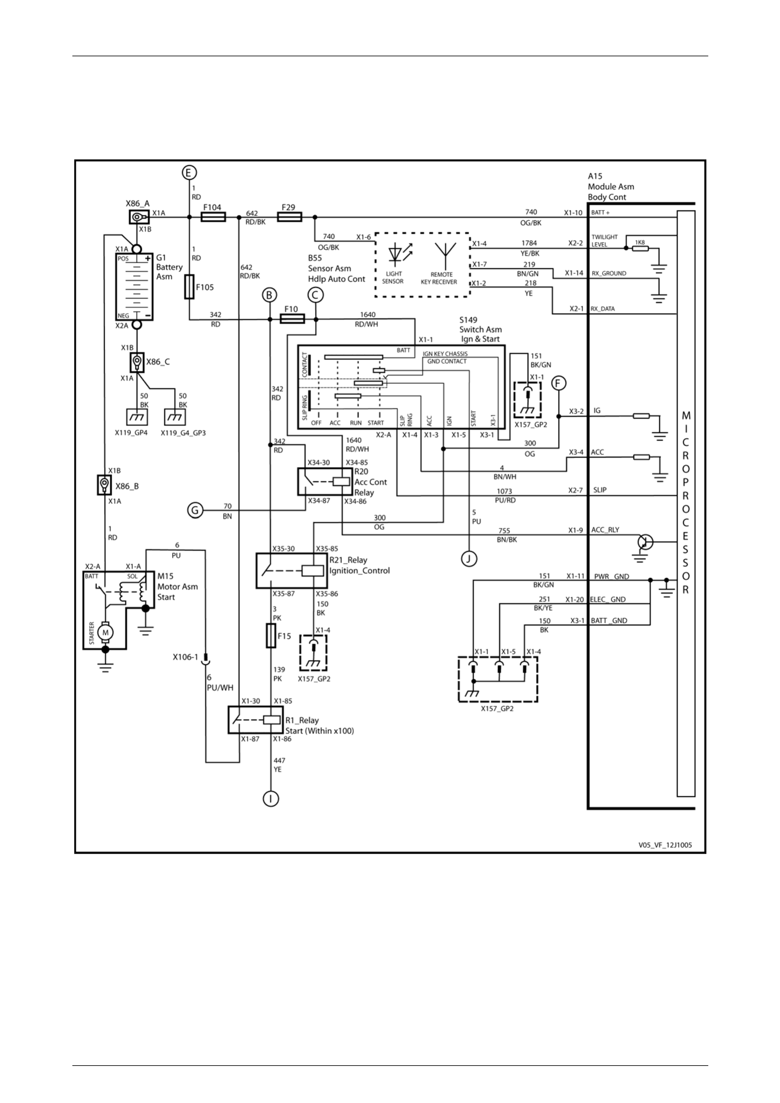
Body Control Module Page 12J–140
Page 12J–140
3.5 Wiring Diagrams – GEN IV V8
Ignition Key, RX Sensor, Common Power and Grounds
Figure 12J – 70
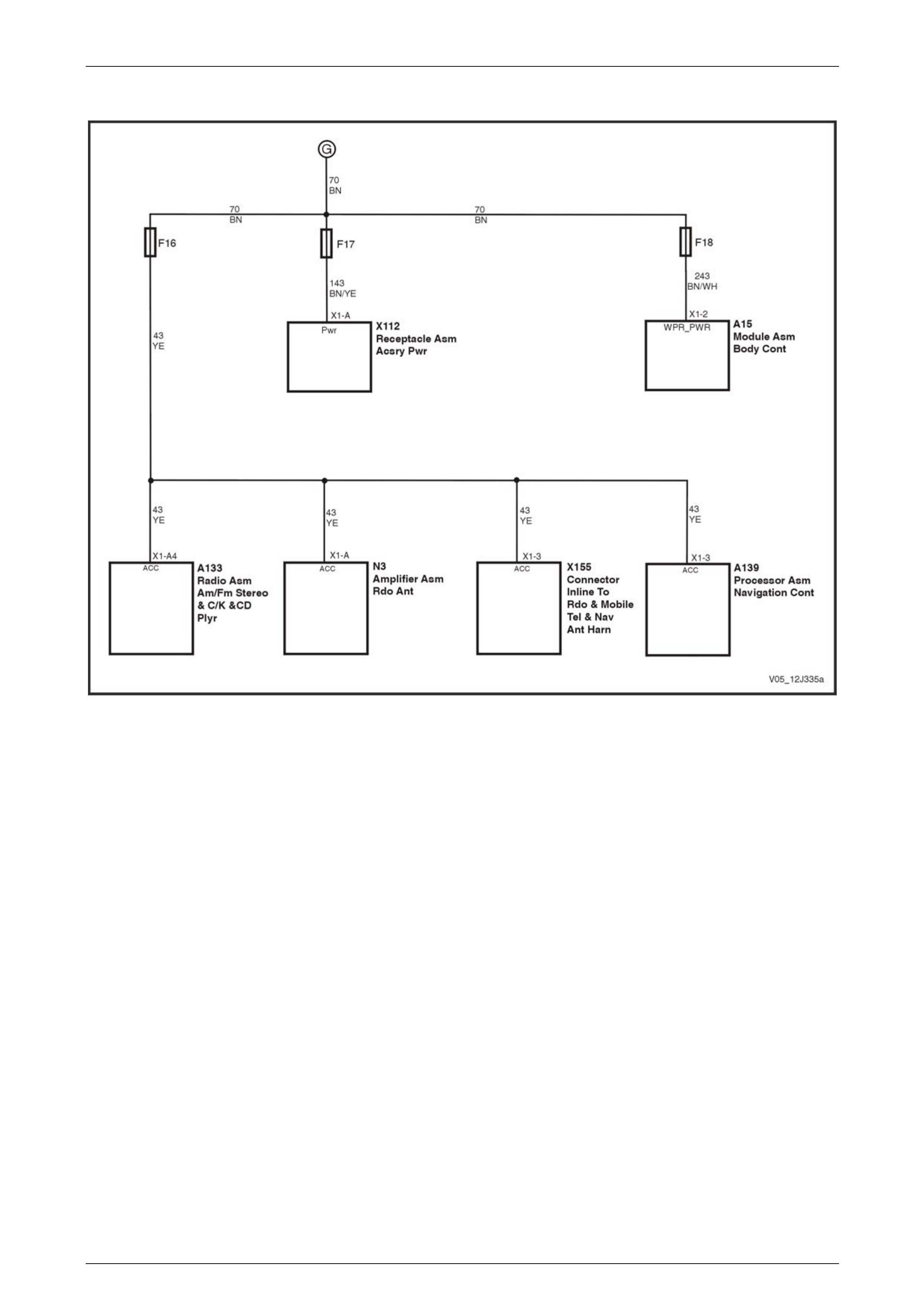
Body Control Module Page 12J–141
Page 12J–141
Accessory Power Circuit
Figure 12J – 71
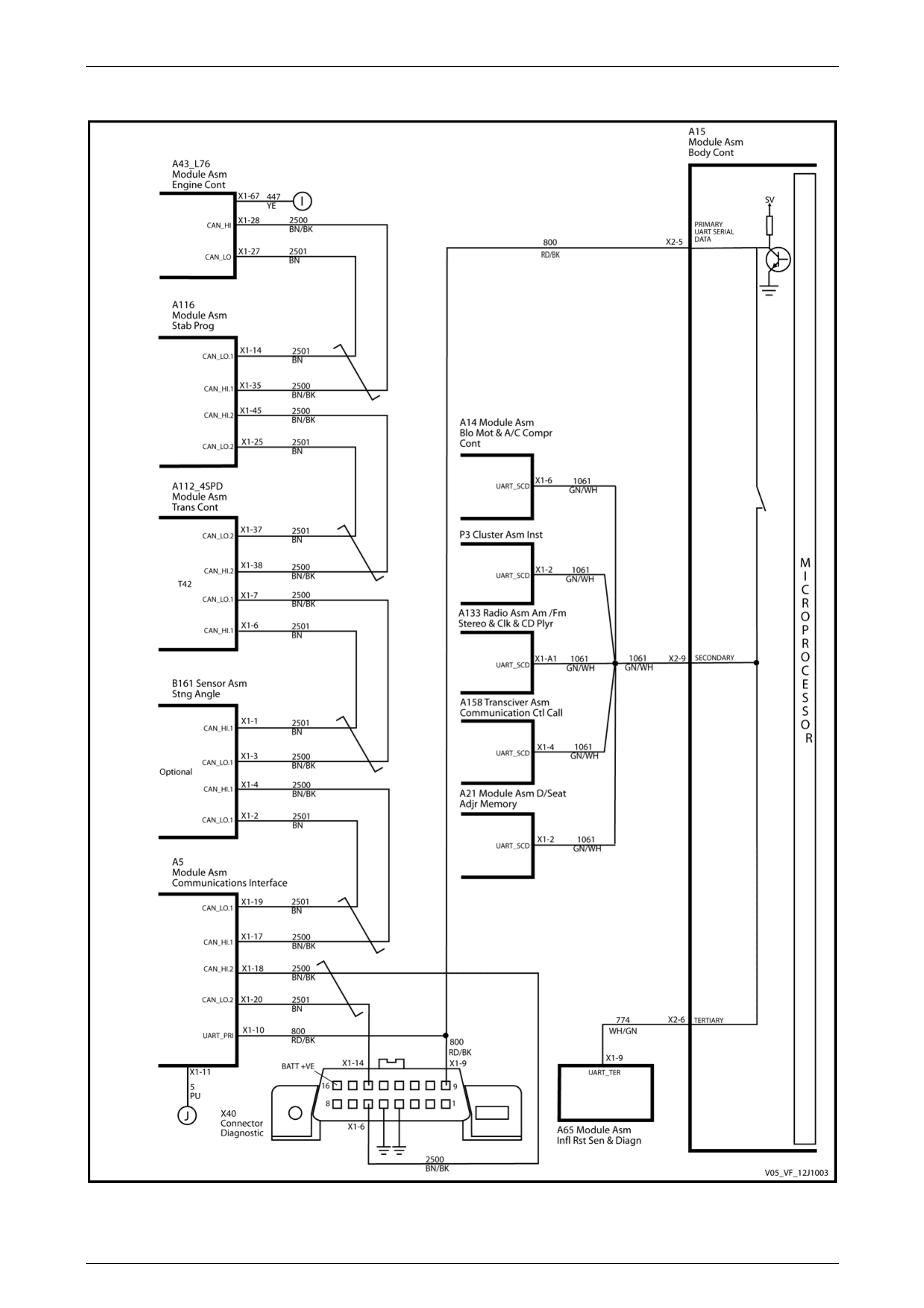
Body Control Module Page 12J–142
Page 12J–142
UART and GM LAN Communications – 4 Speed Automatic with ESP
Figure 12J – 72

Body Control Module Page 12J–143
Page 12J–143
Central Door Locking
Figure 12J – 73

Body Control Module Page 12J–144
Page 12J–144
Entry Deterrent, Warning Horns and Rear Compartment Solenoid
Figure 12J – 74

Body Control Module Page 12J–145
Page 12J–145
Entry Deterrent, Warning Horns and Rear Lift Glass Solenoid – AWD Wagon only
Figure 12J – 75

Body Control Module Page 12J–146
Page 12J–146
Power Windows – Two Door Vehicles
Figure 12J – 76

Body Control Module Page 12J–147
Page 12J–147
Power Windows – Four Door Vehicles
Figure 12J – 77
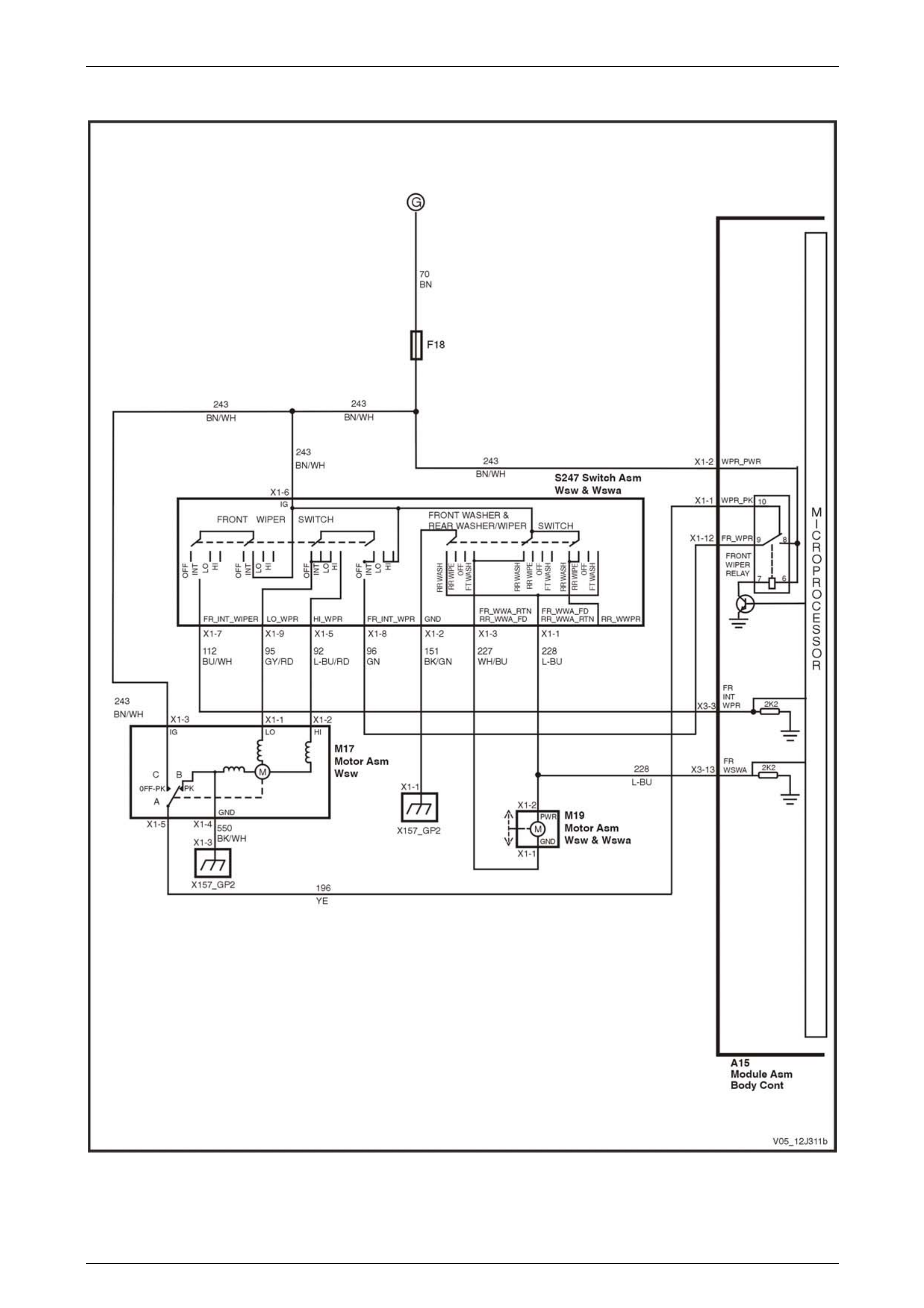
Body Control Module Page 12J–148
Page 12J–148
Wiper Systems Intermittent Function – Utility, Regular & Crew Cab and Sedan, Level 1
Figure 12J – 78

Body Control Module Page 12J–149
Page 12J–149
Wiper Systems Intermittent Function – Sedan, Level 2 and 3
Figure 12J – 79

Body Control Module Page 12J–150
Page 12J–150
Wiper Systems Intermittent Function – Wagon, Level 1
Figure 12J – 80

Body Control Module Page 12J–151
Page 12J–151
Wiper Systems Intermittent Function – Wagon, Level 2
Figure 12J – 81

Body Control Module Page 12J–152
Page 12J–152
Wiper Systems Intermittent Function – AWD Wagon, Level 1
Figure 12J – 82
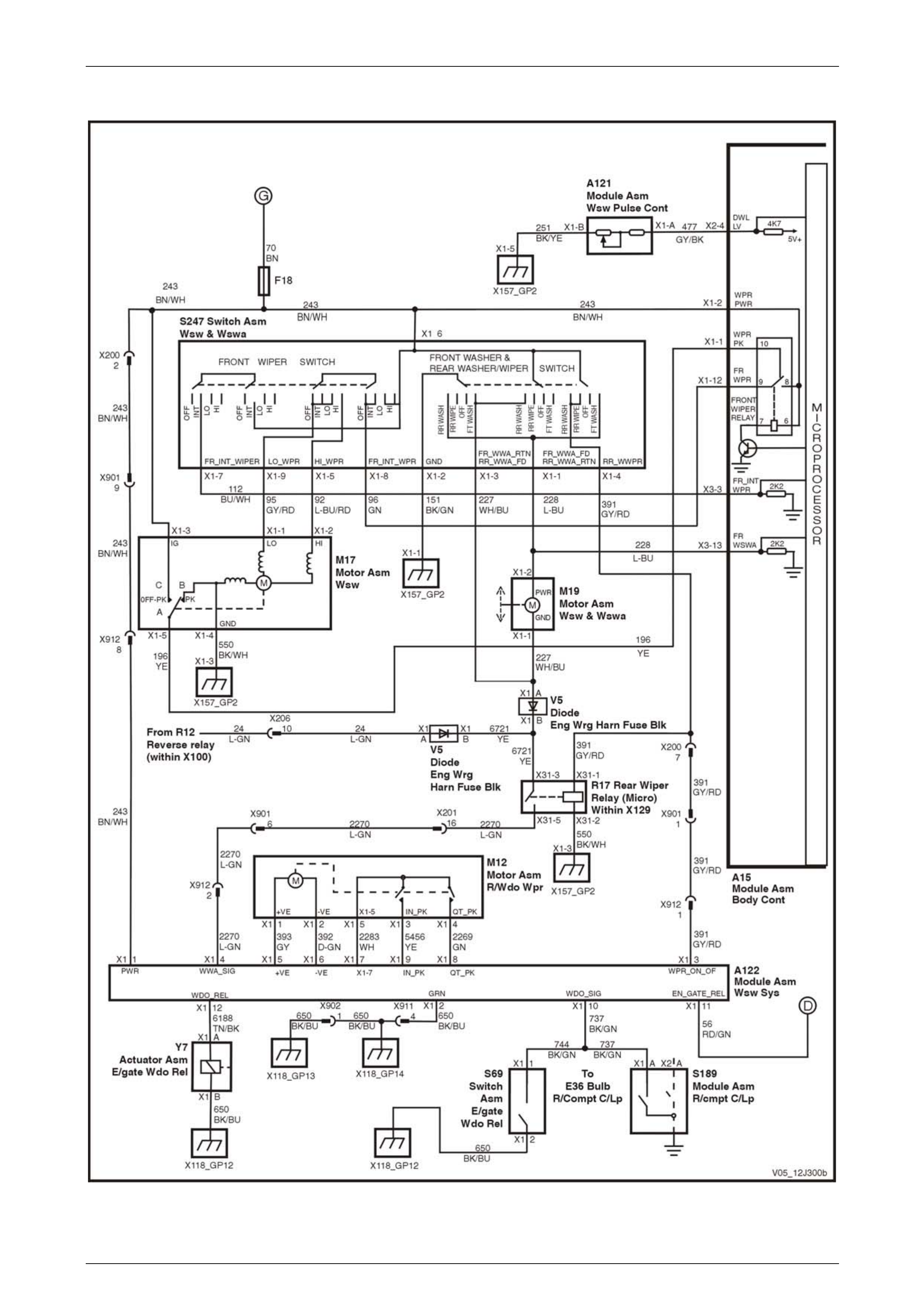
Body Control Module Page 12J–153
Page 12J–153
Wiper Systems Intermittent Function – AWD Wagon, Level 2
Figure 12J – 83

Body Control Module Page 12J–154
Page 12J–154
Dome Lamp Delay Control – Utility, Regular & Crew Cab, Level 1
Figure 12J – 84
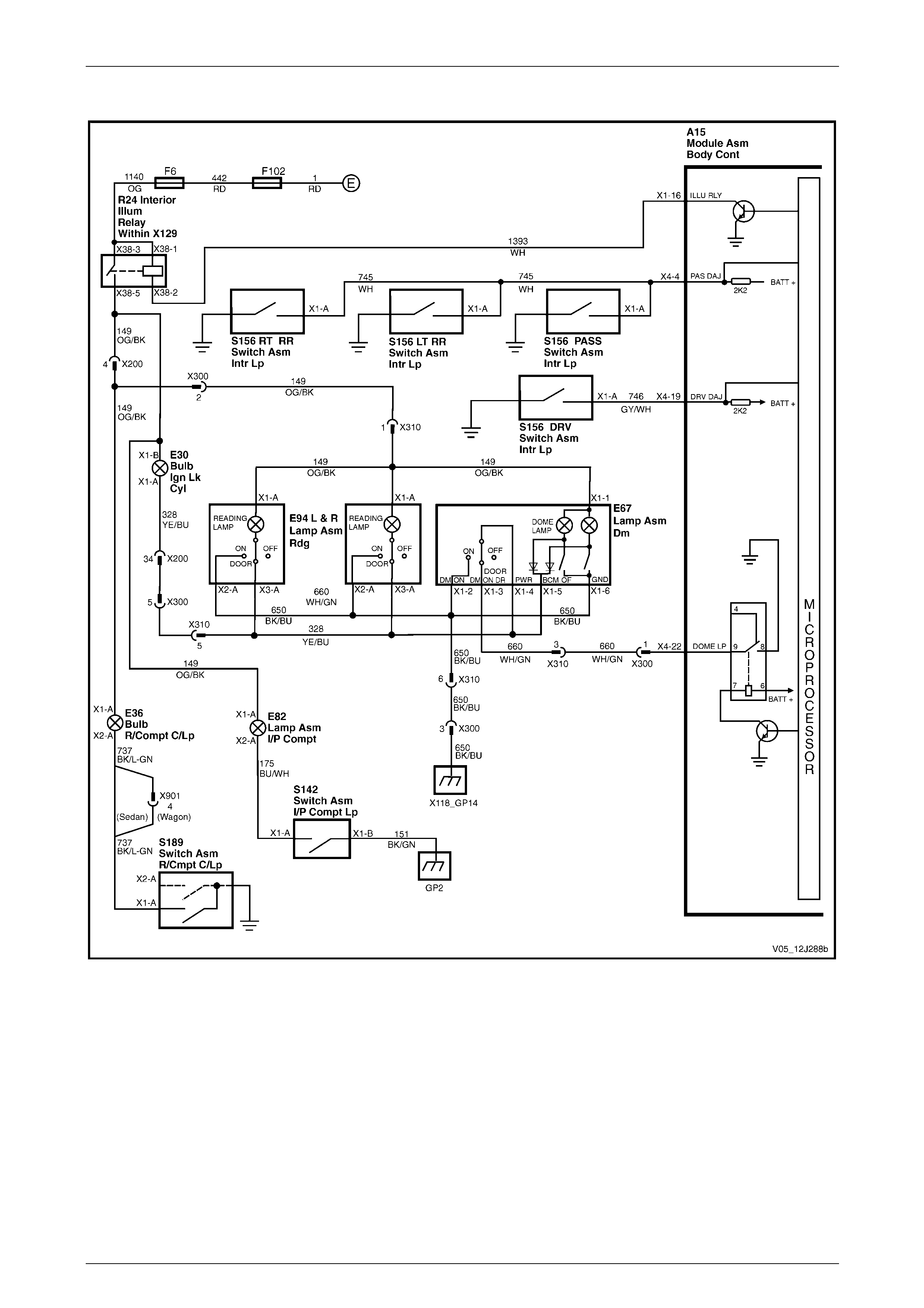
Body Control Module Page 12J–155
Page 12J–155
Dome Lamp Delay Control – Sedan and Wagon, Level 1
Figure 12J – 85

Body Control Module Page 12J–156
Page 12J–156
Dome Lamp Delay Control – Sedan and Wagon, Level 2 and 3
Figure 12J – 86

Body Control Module Page 12J–157
Page 12J–157
Automatic Lamp Control – Level 1
Figure 12J – 87

Body Control Module Page 12J–158
Page 12J–158
Automatic Lamp Control – Level 2 and 3
Figure 12J – 88
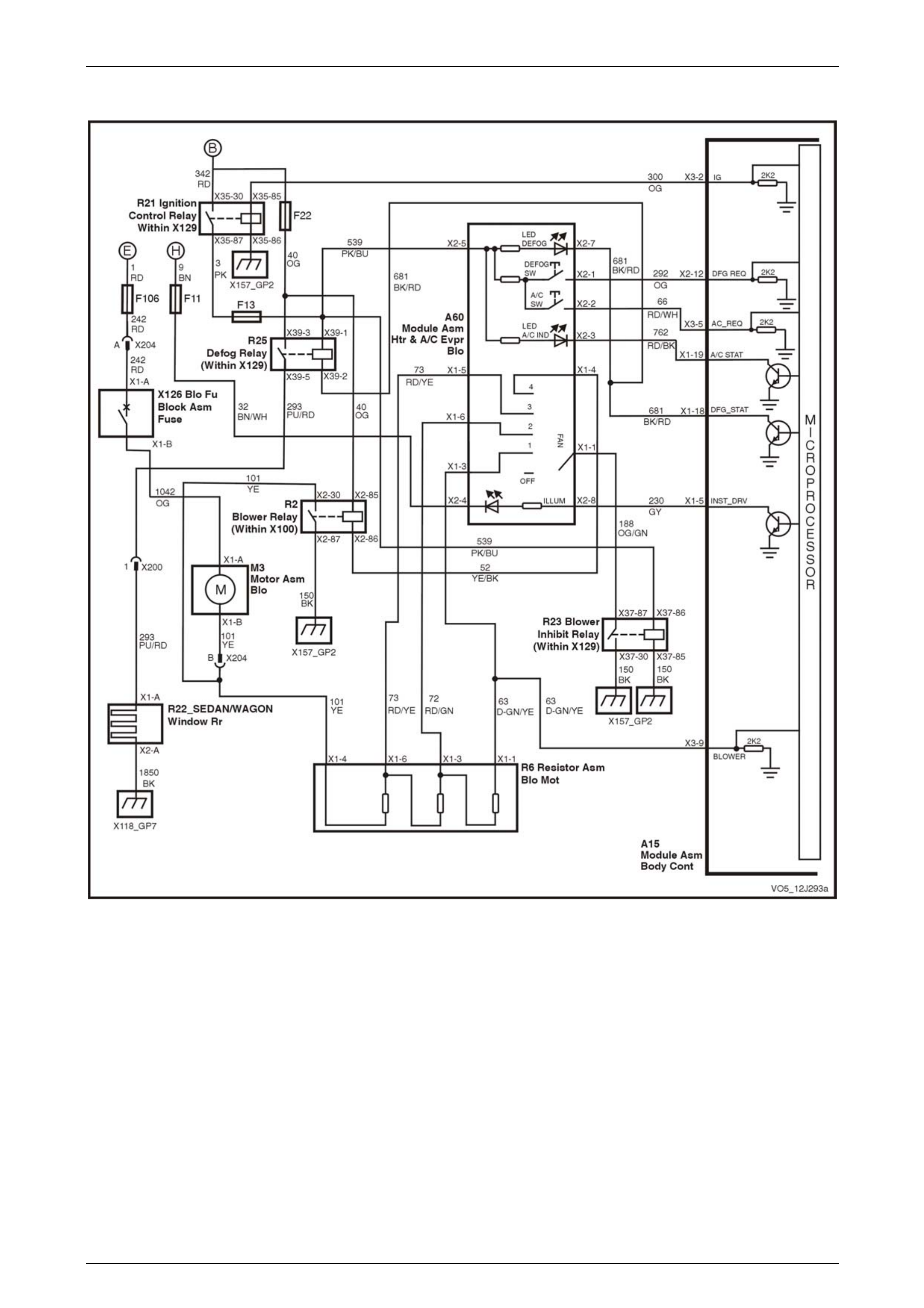
Body Control Module Page 12J–159
Page 12J–159
HVAC – Heated Rear Window and Air conditioning Interface – Level 1
Figure 12J – 89

Body Control Module Page 12J–160
Page 12J–160
Radio and Power Antenna Control – Level 1
Figure 12J – 90
Radio and Power Antenna Control – Level 2 and 3
Figure 12J – 91
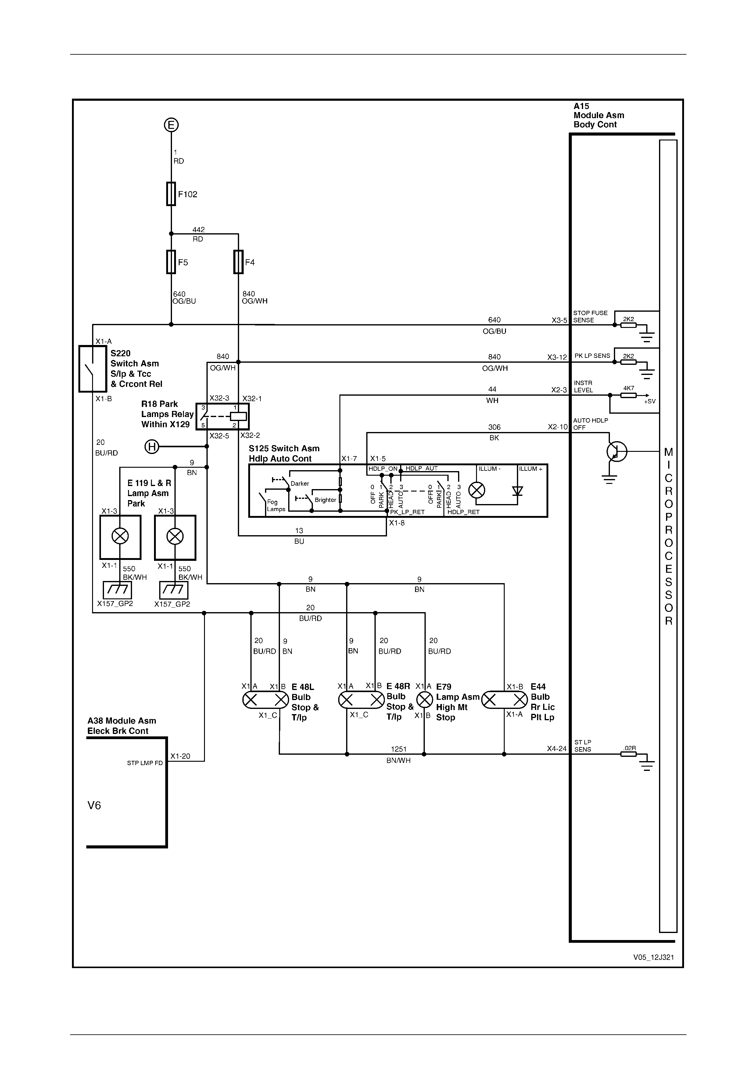
Body Control Module Page 12J–161
Page 12J–161
Rear Lamp Failure System – Level 3
Figure 12J – 92

Body Control Module Page 12J–162
Page 12J–162
Hazard Lamp Control, Theft / Turn Signal Lamp Flasher
Figure 12J – 93
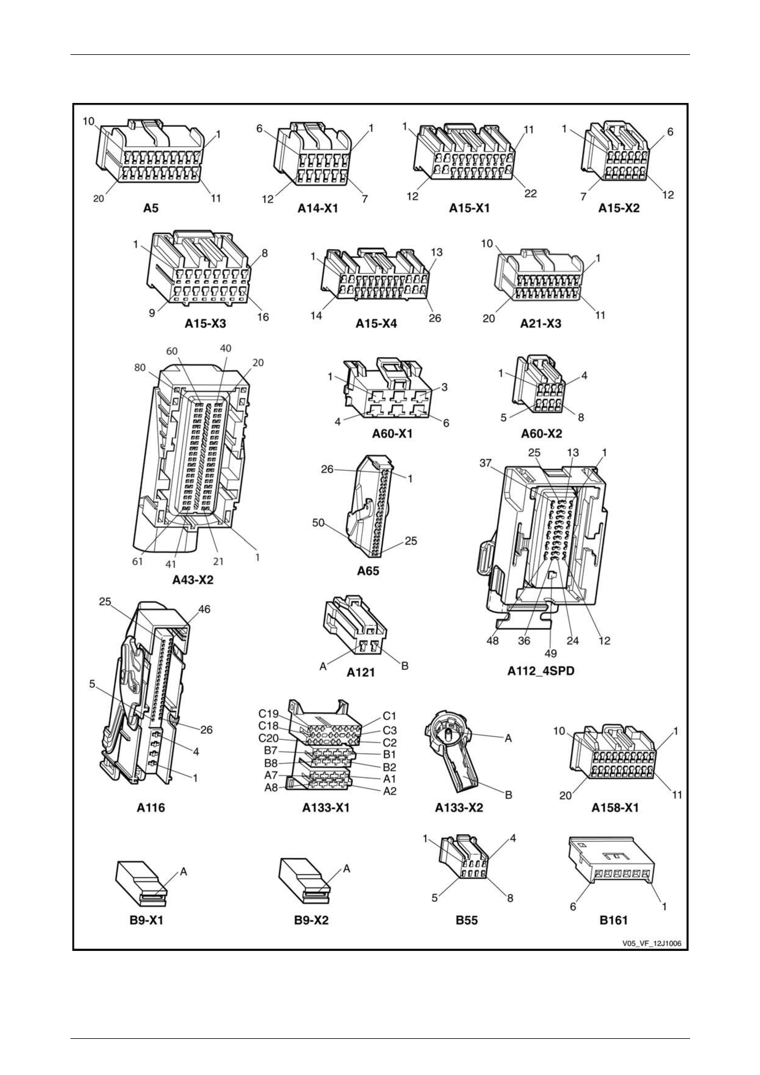
Body Control Module Page 12J–163
Page 12J–163
3.6 Connector Charts – GEN IV V8
Figure 12J – 94

Body Control Module Page 12J–164
Page 12J–164
Figure 12J – 95
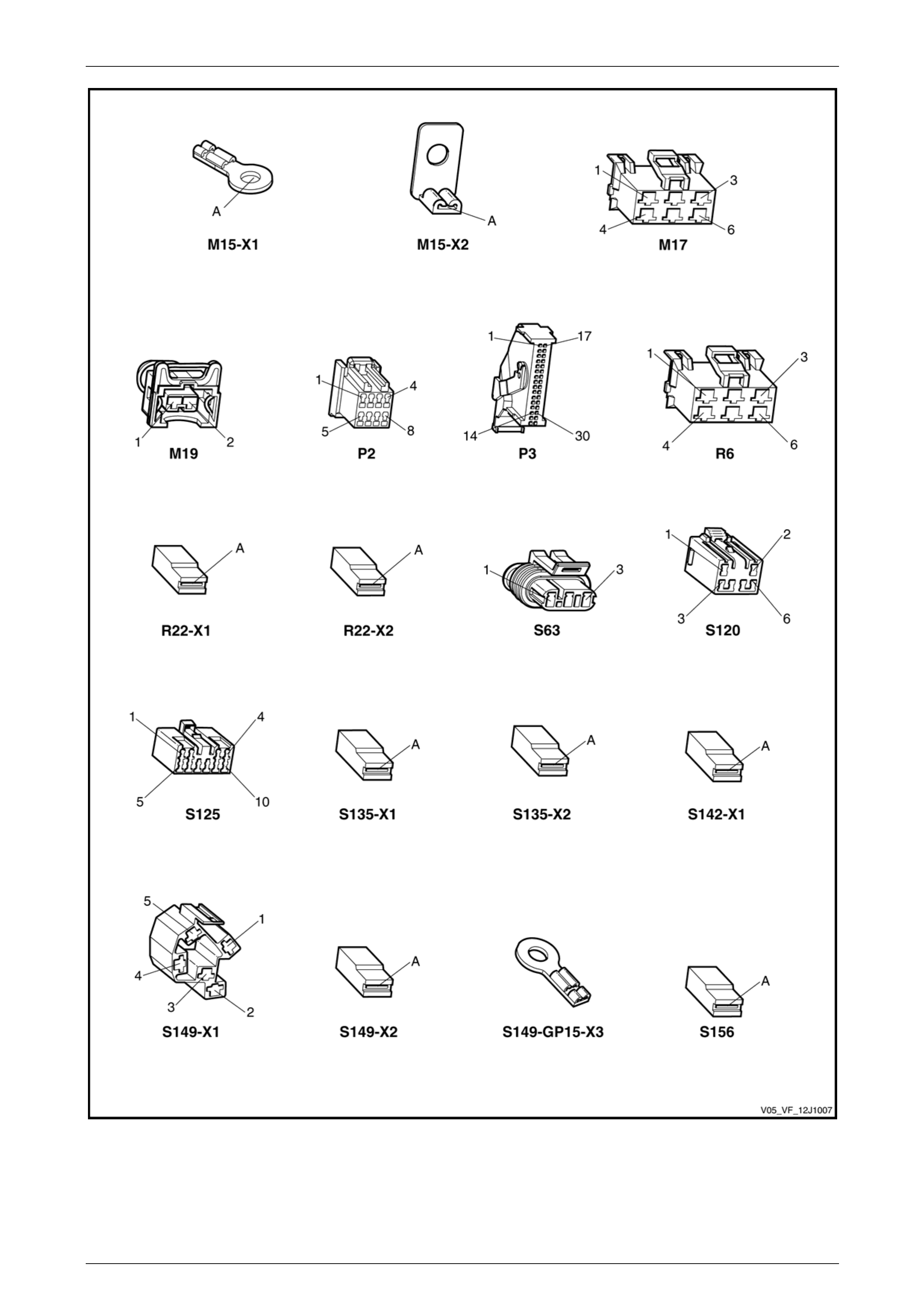
Body Control Module Page 12J–165
Page 12J–165
Figure 12J – 96

Body Control Module Page 12J–166
Page 12J–166
Figure 12J – 97
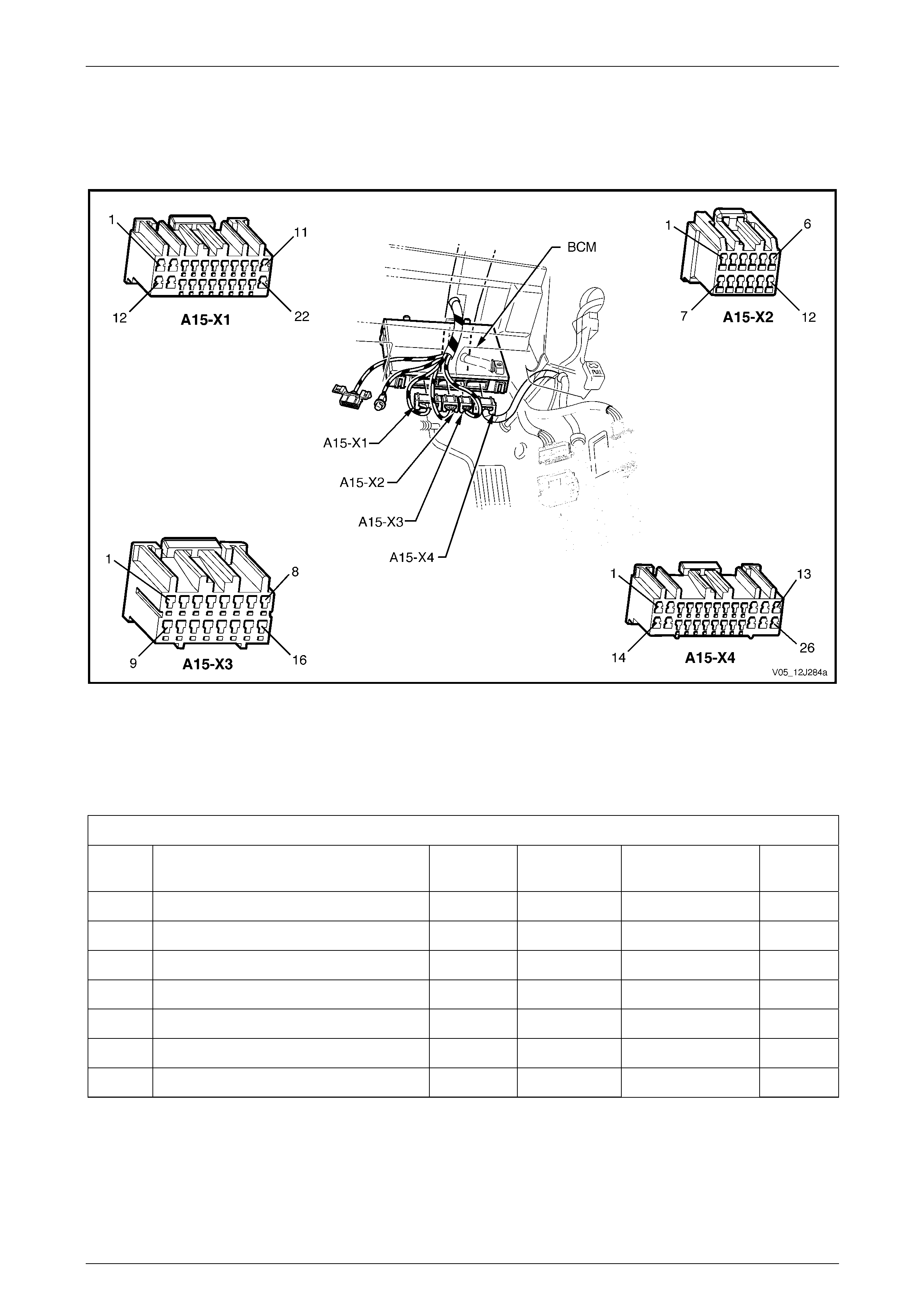
Body Control Module Page 12J–167
Page 12J–167
3.7 Connector Information
BCM Location and Wiring Connectors
Figure 12J – 98
BCM Connector Pin Identification
The following tables represent the connector wiring for the various models of BCM. An explanation of these terms follows
these tables.
A15 Connector X1
Pin
No. Description Circuit Wire Colour Active
Signal Circuit
Type
X1–1 Front wiper park switch 196 YE Switch to B+ O
X1–2 Intermittent front wiper motor power 243 BN / WH ACC and IGN P
X1–3 Right turn signal lamp drive 1315 BU Switch to B+ O
X1–4 Left turn signal lamp drive 1314 L-BU Switch to B+ O
X1–5 Instrument illumination drive 230 GY Switch to GND O
X1–6 Auto headlamps on 103 WH / RD Switch to GND PD/O
X1–7 Rear wiper drive 113 GY / BU Switch to GND PD/O

Body Control Module Page 12J–168
Page 12J–168
A15 Connector X1
Pin
No. Description Circuit Wire Colour Active
Signal Circuit
Type
X1–8 Power window drive 1351 YE Switch to GND PD/O
X1–9 Accessories relay 755 BN / BK Switch to GND PD/O
X1–10 Battery power (+) 740 OG / BK Always active P
X1–11 Power ground 151 BK / GN GRD GND
X1–12 Front wiper drive 96 GN Switch to GND PD/O
X1–13 Internal BCM relay battery power 140 OG / RD Always active P
X1–14 Receiver ground 219 BN / GN GND GND
X1–15 Not used — — — —
X1–16 Interior illumination relay 1393 WH Switch to GND PD/O
X1–17 Horn drive 28 BK / YE Switch to GND PD/O
X1–18 Demist status (Level 1) 681 BK / RD Switch to GRD PD/O
X1–19 Air conditioner LED (Level 1) 762 RD / BK Switch to GRD PD/O
X1–20 Electronic ground 251 BK / YE GRD GND
X1–21 Security status LED 264 L-BU Switch to GND O
X1–22 Door-lock power 440 OG / PU Always active P
A15 Connector X2
Pin
No. Description Circuit Wire Colour Active
Signal Circuit
Type
X2–1 Receiver data 218 YE COMMS I
X2–2 Twilight level 1784 YE / BK 0 – 5 V I
X2–3 Instrument dim setting 44 WH 0 – 5 V PUI
X2–4 Wiper dwell level 477 GY / BK 0 – 5 V PUI
X2–5 Primary UART serial data bus 800 RD / BK COMMS I/O
X2–6 Tertiary UART serial data bus 774 WH / GN COMMS I/O
X2–7 Slip ring 1073 PU / RD COMMS I/O
X2–8 Not used — — — —
X2–9 Secondary UART serial data bus 1061 GN / WH COMMS I/O
X2–10 Auto headlamps off 306 BK Switch to GND PD/O
X2–11 Hood pull up 109 RD / WH RES to B+ PPU
X2–12 Demist request 292 OG Pull to B+ I

Body Control Module Page 12J–169
Page 12J–169
A15 Connector X3
Pin No. Description Circuit W i re Colour Active
Circuit Circuit
Type
X3–1 Battery ground 150 BK Always GND GND
X3–2 Ignition power 300 OG Pull to B+ PD,P
X3–3 Front intermittent wiper / washer position 112 BU / WH Pull to B+ PPD
X3–4 Accessories power 4 BN / WH Pull to B+ PD,P
A/C Switch (Level 1 vehicles) 66 RD / WH
X3–5 Stop lamp fuse (Levels 2 and 3 vehicles) 640 OG / BU Pull to B+ PPD
X3–6 Not used — — — —
X3–7 Rear wiper request 391 GY / RD Pull to B+ PPD
X3–8 Boot unlock request 1576 BK / RD Pull to GND PPU
X3–9 Air conditioner blower switch 63 D-GN / YE RES to B+ PPU
X3–10 Radio on 314 YE / RD Pull to B+ PPD
X3–11 Hood open 263 YE / BK Pull to GRD PPD
X3–12 Park lamp sense (Level 3) 840 OG / WH Pull to B+ PPD
X3–13 Front wash / wipe 228 L-BU Pull to B+ PPD
X3–14 Rear wash (except AWD wagon) 227 WH / BU Pull to B+ PPD
X3–15 Theft horn drive 1149 GN Switch to B+ O
X3–16 Hazard lamps 111 BN Pull to GND PPU
A15 Connector X4
Pin No. Description Circuit Wire Colour Active
Signal Circuit
Type
X4–1 Passenger door unlock drive 294 BK / RD Switch to B+ PPU
X4–2 Boot solenoid 56 RD / GN Switch to B+ PPU
X4–3 Dome lamp on (Except Level 1 Utility and
Reg Cab) 328 YE / BU Pull to B+ PPD
X4–3 Dome lamp on (Level 1 Utility and Reg
Cab) 722 YE / BU Pull to B+ PPD
X4–4 Passenger’s door ajar 745 WH Pull to GND PPU
X4–5 Passenger door unlock request 194 BN / OG Pull to GND PPU
X4–6 Boot switch 744 YE / GN Pull to GND PPU
X4–7 Antenna direction 161 GY Switch to B+ O
X4–8 Driver’s door unlock drive 694 BU / BK Switch to B+ O
X4–9 Deadlock drive 5171 PU / WH Switch to B+ O
X4–10 All door-lock drive 295 BK / YE Switch to B+ O
X4–11 Passenger window power 638 OG / YE Active via switch P
X4–12 Driver window down request 167 GN / BK Pull to B+ PPD
X4–13 Driver window motor 667 GN / OG Switch to B+ O
X4–14 Driver window up request 666 BU / W H Pull to B+ PPD

Body Control Module Page 12J–170
Page 12J–170
A15 Connector X4
Pin No. Description Circuit Wire Colour Active
Signal Circuit
Type
X4–15 Passenger window up request 164 GN Pull to B+ PPD
X4–16 Driver’s door unlock request 781 L-GN / YE Pull to GND PPU
X4–17 Deadbolt request 780 BN / WH Pull to GND PPU
X4–18 Not Used — — — —
X4–19 Driver’s door ajar 746 GY / WH Pull to B+ PPU
X4–20 Lock request 195 BN / RD Pull to B+ PPU
X4–21 Dome lamp switch on (Levels 2 and 3) 157 PU Pull to B+ PPD
X4–22 Dome lamp drive 660 WH / GN Switch to GND O
X4–23 Antenna drive 160 GN Switch to B+ O
X4–24 Stop / tail light sensor 1251 BN / WH GND return PD
X4–25 Passenger side window motor 165 YE Switch to B+ O
X4–26 Passenger window down request 1136 BU Pull to B+ PPD
Legend – Circuit Type
GND Ground PD Pull Down PU Pull Up
O Output I Input PPU Pulsed Pull Up
P Power I/O Input / Output PPD Pulsed Pull Down
Explanation of Terms
For terms used in the Active Signal column, the description of these is provided below.
Active Signal Description
Pull to B+ The BCM terminal has battery voltage applied to it through an external device such as a
motor winding. It operates this device by pulling its voltage to ground through an internal
switching transistor.
Pull to GND This BCM terminal usually has an external switch connected to it, which applies a vehicle
ground to the terminal when pressed.
ACC and IGN Battery voltage associated when either of these Ignition switch positions is selected appears
here.
Switch to B+ The BCM terminal has internally switched battery voltage applied to it.
Switch to GND The BCM terminal switches to ground whatever is connected to it via an internal transistor.
Always Active This terminal generally has a permanent battery or ground connection applied to it.
COMMS Serial data communications takes place on these terminals.
0 – 5 V Varying voltage variations occur on these terminals over the range of voltage specified.
RES to B+ This term applies to the hood resistance divider circuit that is used to determine the state of
security within the engine compartment.
Active via switch These BCM terminals have battery voltage applied to them when the switch connected to
them is operated.
GND return The BCM terminal connects the rear stop lamps through a current sensing resistor to
vehicle ground to determine if a lamp has failed or not.
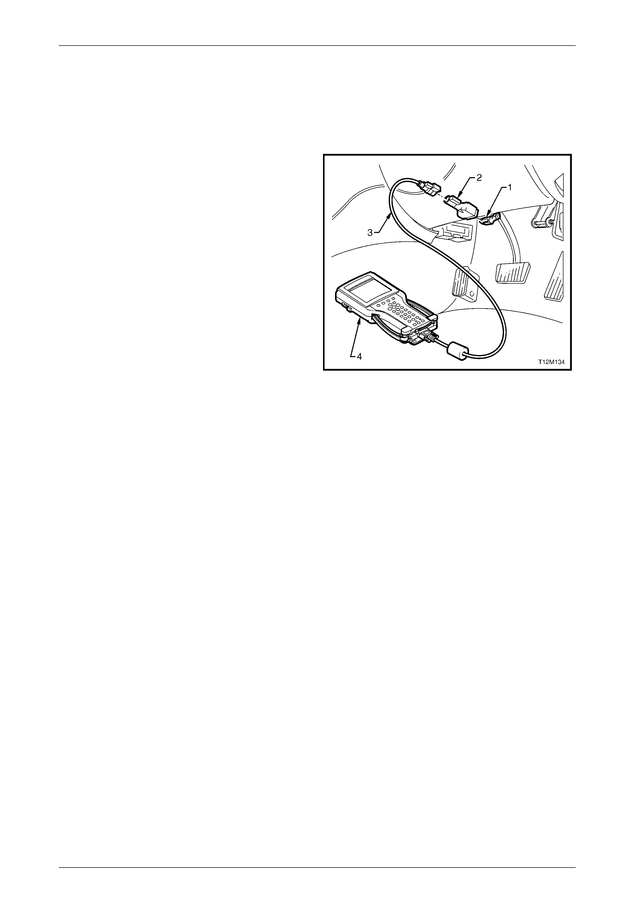
Body Control Module Page 12J–171
Page 12J–171
4 Tech 2 Information
4.1 Connecting Tech 2 For System
Diagnosis
Tech 2 (4), with the appropriate software, cables (3) and
adaptors (2), is capable of reading the BCM serial data when
connected to the Data Link Connector (DLC) (1). The DLC is
connected to the instrument panel lower right-hand trim, to
the right of the steering column.
For additional general information on connecting and
operating Tech 2, refer to Section 0C Tech 2.
Figure 12J – 99

Body Control Module Page 12J–172
Page 12J–172
4.2 Tech 2 Test Modes and Displays
A prerequisite of this diagnostic section is for the user to be familiar with the proper use of Tech 2. The following
pages illustrate only the major Tech 2 screen displays and provide a brief explanation of their function for diagnosing
the BCM system. If additional information is required on the operation of Tech 2, reference should be made to either
Section 0C Tech 2 or the Tech 2 User’s Guide.
With the ignition turned off, connect the Tech 2 to the Data Link Connector (DLC) using the DLC Adaptor, refer to
either Section 0C Tech 2 or the Tech 2 User’s Guide.

Body Control Module Page 12J–173
Page 12J–173
4.3 Normal Mode
NOTE
Only the data relevant to the level of BCM
installed and vehicle configuration will be
displayed.
On Tech 2 select:
Body / Body Control Module / Normal Mode
The Normal Mode data list is used to view serial data being sent to and from the BCM. The Normal Mode data list is as
follows.
Tech 2 Display Range Remarks
Ignition Switch Off = 0 V
On = 12 V Displays the current status of the ignition switch.
Ignition Off Time XX min Displays the length of time in minutes since the ignition was
last switched off.
Accessories Switch On / Off Displays the current status of the accessories switch.
Instrument Lamps 0% – 100% Displays the instrument cluster illumination level.
Lights On Yes / No Displays the current status of the headlamp switch.
Sun Load Between 0 and 254 Displays the ambient light level as detected by the sun sensor.
Rear Compartment Closed / Open Displays the status of the rear compartment lid switch.
Rear Lamp Fuse Fail Okay / Failed Displays the status of the rear lamp fuse.
Rear Brake Bulb Fail Okay / Failed Displays the status of the stop lamps.
Rear Lamp Bulb Fail Okay / Failed Displays the status of the rear park lamps.
Front Wiper Status On / Off Displays the status of the front wiper drive.
A/C Request
(Air Conditioning) On / Off Displays the status of the air conditioner.
Alarm Inactive / Triggered Indicates if an alarm has been activated.
Alarm Trigger Source Driver’s Door / Passenger’s
Door / Rear Compartment /
Bonnet / Ignition / Not
Detected
Indicates the source of a triggered alarm.
Key Priority 1 / 2 Displays the priority key in use.
BCM DTC Status No DTC / DTCs Set Indicates if any BCM DTC have been set.
MFD Message
(Multi-Function Display) Yes / No Indicates when a message is sent to the instrument cluster.

Body Control Module Page 12J–174
Page 12J–174
4.4 Diagnostic Trouble Codes
On Tech 2 select:
Body / Body Control Module / Diagnostic Trouble Codes
Read DTC Information
• From the Diagnostic Trouble Codes screen, select Read DTC Information and press the Enter key.
• Refer to 5.8 Diagnostic Trouble Code List.
• Press the Exit key to return to the Diagnostic Trouble Codes screen.
Each DTC is allocated a number from 0 to 29.
Read Alarm Codes
• From the Diagnostic Trouble Codes screen, select Read Alarm Codes and press the Enter key.
• Only History Alarm Codes are displayed. Information on the number of times the Alarm has occurred and the
number of ignition cycles since the last occurrence are not displayed.
• Press the Exit key to return to the Diagnostic Trouble Codes screen.
Clear DTC and Alarm Codes
• From the Diagnostic Trouble Codes screen, select Clear DTCs and Alarm Codes and press the Enter key.
• Confirm the action as instructed by Tech 2.
NOTE
Tech 2 will display Clear DTCs and Alarm Codes
Failed if any DTC or Alarm Codes are still current.

Body Control Module Page 12J–175
Page 12J–175
4.5 Data Display
NOTE
Only the data relevant to the level of BCM
installed and vehicle configuration will be
displayed.
On Tech 2 select:
Body / Body Control Module / Data Display
The Data Display screen provides a further breakdown to individual data lists for the following BCM functions.
The serial data for each function can be viewed by selecting the item and pressing the Enter key. The list can be scrolled
by using the Up and Down arrow keys. Press the Exit key to exit the data list.
• Inputs and Outputs • Central Door Locking • Rear Lamp Failure
• BCM Internal Status • Power Windows • Air Conditioning Interface
• Serial Data Inputs • Wipers • Antenna
• Priority 1 User Settings • Headlamps • System Identification
• Priority 2 User Settings • Instrument Illumination • User Settings
• Alarm / Theft Deterrent • Interior Illumination
Inputs and Outputs
The Inputs and Outputs data list is as follows. Press the Exit key at any time to return to the Data Display screen.
NOTE
Only the data relevant to the level of BCM
installed and vehicle configuration will be
displayed.
Tech 2 Display Unit Range
Battery Voltage Volts
Ignition Switch On / Off
Accessory Switch On / Off
Accessory Relay On / Off
Interior Illumination Relay On / Off
Slip Ring Enabled Yes / No
Remote Key Function Boot Release Request / Lock Request / Unlock Request
Remote Key Number 1 / 2
Remote Key Status Valid Key / Invalid Code
Remote Key Priority 1 / 2
Key Priority Signal 1 / 2
Driver's Door Open / Closed
Passenger Doors Open / Closed
Bonnet Open / Closed
Rear Compartment Status Open / Closed
Rear Compartment Release Switch On / Off
Rear Compartment Solenoid Drive On / Off
Driver’s Door Unlock Switch On / Off
Passenger Door Unlock Switch On / Off
Lock Switch On / Off

Body Control Module Page 12J–176
Page 12J–176
Tech 2 Display Unit Range
Deadlock Switch On / Off
Driver’s Door Unlock Drive On / Off
Passenger Door Unlock Drive On / Off
Door Lock Drive On / Off
Deadlock Drive On / Off
Horn On / Off
Indicators On / Off
Hazard Warning Switch On / Off
Theft Deterrent Horn On / Off
Security LED On / Off
Power Window Relay Disabled / Enabled
Right Front Window Switch Off / Down / Up / Invalid
Right Front Window Auto Down Inactive / Active
Left Front Window Switch Off / Up / Down / Invalid
Left Front Window Auto Down Inactive / Active
Front Wiper Intermittent Switch On / Off
Front Wiper Intermittent Switch Voltage Volts
Intermittent Wiper Drive On / Off
Front Washer Pump Switch On / Off
Front Wiper Park Switch On / Off
Rear Wiper Switch On / Off
Rear Wiper Drive Not Present / Present
Rear Washer Pump Switch On / Off
Heated Rear Window Switch On / Off
Heated Rear Window Drive On / Off
Headlamp Switch On / Off
Headlamp Drive On / Off
Auto Headlamp Drive On / Off
Ambient Light Lux
Sun Load W/m2
Dome Lamp Switch On / Off / Door / Invalid
Dome Lamp Drive On / Off
Instrument Illumination Switch Off / Down / Up / Invalid
Instrument Illumination Switch Voltage Volts
Instrument Illumination Level % 35 – 100%
Rear Brake Lamp Fuse Failed / Okay
Rear Park Lamp Fuse Failed / Okay
Rear Brake Lamp Current Amps
Rear Park Lamp Current Amps
Radio Status On / Off
Antenna Off / Down / Up
A/C Switch (Air Conditioning) On / Off
A/C Blower Switch (Air Conditioning) On / Off
A/C Indicator (Air Conditioning) On / Off
Serial Data Bus Isolation Normal / Data Cutoff

Body Control Module Page 12J–177
Page 12J–177
BCM Internal Status
The BCM Internal Status data list is as follows. Press the Exit key at any time to return to the Data Display screen.
NOTE
Only the data relevant to the level of BCM
installed and vehicle configuration will be
displayed.
Tech 2 Display Unit Range
Headlamp Switch On / Off
Right Front Window Auto Down Yes / No
Right Front Window Auto Down Timer Seconds
Left Front Window Auto Down Yes / No
Left Front Window Auto Down Timer Seconds
Filtered Ambient Light Lux
Filtered Sun Load W/m2
Front Wiper Dwell Time Seconds
Central Door Locking Unlocked / Unlocking / Locked / Locking / Deadlocked /
Undeadlocking / Deadlocking / Driver’s Door Unlocking /
Unlocking Door / Locking Failed / Unlocking Failed / Driver
Unlocking Failed
Rear Park and Brake Lamp Current A
Rear Park Lamp Current A
Rear Brake Lamp Current A
Instrument Illumination Switch Off / Down / Up / Invalid
Instrument Illumination Level % 35 – 100%
Antenna Height Target Seconds
Antenna Height Setting Seconds
Auto Lights Delay Seconds
Pre Delivery Mode Disabled / Enabled
Battery Saver Shutdown Time Minutes
Autolock in Drive Yes / No
Antenna Height Memory On / Off
Door Lock Indication Turn signal lamps / Horn and Turn signal lamps
Rear Wiper Continuous in Reverse Yes / No
Security Status Passive Armed / Disarmed / Armed / Triggered
DTC Status No DTC / DTCs Set

Body Control Module Page 12J–178
Page 12J–178
Serial Data Inputs
The Serial Data Inputs data list is as follows. Press the Exit key at any time to return to the Data Display screen.
NOTE
Only the data relevant to the level of BCM
installed and vehicle configuration will be
displayed.
NOTE
Tech 2 will display PCM Theft Status when
diagnostics checks are performed on V6 vehicles.
Read as ECM Theft Status.
Tech 2 Strings Unit Range
Vehicle Speed km/h
PRNDL Switch • Invalid / 1 / 2 / 3 / D / N / R / P (4 speed automatic)
• Invalid / L / 2 / 3 / 4 / D / N / R / P (5 speed automatic)
PCM Theft Status Start / No Start
SRS Deployed This Ignition Cycle Yes / No
Radio On / Off
Antenna Required Yes / No
Antenna Switch Off / Down / Up
Stop Lamp Switch On / Off
Priority 1 User Settings
The Priority 1 User Settings data list is as follows. Press the Exit key at any time to return to the Data Display screen.
NOTE
Only the data relevant to the level of BCM
installed and vehicle configuration will be
displayed.
Tech 2 Display Unit Range
Instrument Illumination Level % 35 – 100%
Antenna Height Memory Seconds
Approach Illumination Seconds 0 to 90
Headlamps Auto Off Delay Seconds 0 to 180
Interior Lamp Timeout Seconds 0 to 255
Ignition Off Interior Lamp Timeout Seconds 0 to 255
Two Stage Unlock Yes / No
Door Lock Indication Turn signal lamps / Horn and Turn signal lamps
Autolock in Drive Yes / No
Accessory Relay Timeout Ignition Off / Driver’s Door
Auto Headlamps Early / Normal / Late

Body Control Module Page 12J–179
Page 12J–179
Priority 2 User Settings
The Priority 2 User Settings data list is as follows. Press the Exit key at any time to return to the Data Display screen.
NOTE
Only the data relevant to the level of BCM
installed and vehicle configuration will be
displayed.
Tech 2 Display Unit Range
Instrument Illumination Level % 35 – 100%
Antenna Height Memory Seconds
Approach Illumination Seconds 0 to 90
Headlamps Auto Off Delay Seconds 0 to 180
Interior Lamp Timeout Seconds 0 to 255
Ignition Off Interior Lamp Timeout Seconds 0 to 255
Two Stage Unlock Yes / No
Door Lock Indication Turn signal lamps / Horn and Turn signal lamps
Autolock in Drive Yes / No
Accessory Relay Timeout Ignition Off / Driver’s Door
Auto Headlamps Early / Normal / Late
Alarm / Theft Deterrent
The Alarm / Theft Deterrent data list is as follows. Press the Exit key at any time to return to the Data Display screen.
NOTE
Only the data relevant to the level of BCM
installed and vehicle configuration will be
displayed.
Tech 2 will display PCM Theft Status when
diagnostics checks are performed on V6 vehicles.
Read as ECM Theft Status.
Tech 2 Display Unit Range
Battery Voltage Volts
Ignition Switch On / Off
Accessory Switch On / Off
Slip Ring Enabled Yes / No
Remote Key Function Boot Release Request / Lock Request / Unlock Request
Remote Key Number 1 / 2
Remote Key Status Valid Key / Invalid Code
Driver's Door Open / Closed
Passenger Doors Open / Closed
Bonnet Open / Closed
Rear Compartment Status Open / Closed
Horn On / Off
Indicators On / Off
Theft Deterrent Horn On / Off
Security LED On / Off
Security Status Passive Armed / Disarmed / Armed / Triggered
PCM Theft Status Start / No Start
DTC Status No DTC / DTCs Set

Body Control Module Page 12J–180
Page 12J–180
Central Door Locking
The Central Door Locking data list is as follows. Press the Exit key at any time to return to the Data Display screen.
NOTE
Only the data relevant to the level of BCM
installed and vehicle configuration will be
displayed.
Tech 2 Strings Unit Range
Battery Voltage Volts
Ignition Switch On / Off
Accessory Switch On / Off
Slip Ring Enabled Yes / No
Remote Key Function Boot Release Request / Lock Request / Unlock Request
Remote Key Number 1 / 2
Remote Key Status Valid Key / Invalid Code
Remote Key Priority 1 / 2
Key Priority Signal 1 / 2
Driver's Door Open / Closed
Passenger Doors Open / Closed
Bonnet Open / Closed
Rear Compartment Status Closed / Open
Rear Compartment Release Switch On / Off
Rear Compartment Solenoid Drive On / Off
Central Door Locking Unlocked / Unlocking / Locked / Locking / Deadlocked /
Undeadlocking / Deadlocking / Driver’s Door Unlocking /
Unlocking Door / Locking Failed / Unlocking Failed / Driver
Unlocking Failed
Driver’s Door Unlock Switch On / Off
Passenger’s Door Unlock Switch On / Off
Lock Switch On / Off
Deadlock Switch On / Off
Driver’s Door Unlock Drive On / Off
Passenger Doors Unlock Drive On / Off
Door Lock Drive On / Off
Deadlock Drive On / Off
Autolock in Drive Yes / No
Horn On / Off
Indicators On / Off
Security LED On / Off
Door Lock Indication Turn signal lamps / Horn and Turn signal lamps
DTC Status No DTC / DTCs Set

Body Control Module Page 12J–181
Page 12J–181
Power Windows
The Power Windows data list is as follows. Press the Exit key at any time to return to the Data Display screen.
NOTE
Only the data relevant to the level of BCM
installed and vehicle configuration will be
displayed.
Tech 2 Display Unit Range
Battery Voltage Volts
Ignition Switch On / Off
Accessory Switch On / Off
Power Window Relay Disabled / Enabled
Right Front Window Switch Off / Down / Up / Invalid
Right Front Window Auto Down Inactive / Active
Right Front Window Auto Down Timer Seconds
Left Front Window Switch Off / Up / Down / Invalid
Left Front Window Auto Down Inactive / Active
Left Front Window Auto Down Timer Seconds
DTC Status No DTC / DTCs Set
Wipers
The Wipers data list is as follows. Press the Exit key at any time to return to the Data Display screen.
NOTE
Only the data relevant to the level of BCM
installed and vehicle configuration will be
displayed.
Tech 2 Strings Unit Range
Battery Voltage Volts
Ignition Switch On / Off
Accessory Switch On / Off
Accessory Relay On / Off
Front Wiper Intermittent Switch On / Off
Intermittent Wiper Drive On / Off
Front Wiper Intermittent Switch Voltage Volts
Front Wiper Dwell Time Seconds
Front Washer Pump Switch On / Off
Front Wiper Park Switch On / Off
Rear Wiper Switch On / Off
Rear Wiper Drive Not Present / Present
Rear Washer Pump Switch On / Off
PRNDL Switch • Invalid / 1 / 2 / 3 / D / N / R / P (4 speed automatic)
• Invalid / L / 2 / 3 / 4 / D / N / R / P (5 speed automatic)
Rear Wiper Continuous in Reverse Yes / No
DTC Status No DTC / DTCs Set

Body Control Module Page 12J–182
Page 12J–182
Headlamps
The Headlamps data list is as follows. Press the Exit key at any time to return to the Data Display screen.
NOTE
Only the data relevant to the level of BCM
installed and vehicle configuration will be
displayed.
Tech 2 Display Unit Range
Battery Voltage Volts
Ignition Switch On / Off
Accessory Switch On / Off
Headlamp Switch On / Off
Headlamp Drive On / Off
Auto Headlamp Drive On / Off
Ambient Light Lux
Sun Load W/m2
Auto Lights Delay Seconds
DTC Status No DTC / DTCs Set
Instrument Illumination
The Instrument Illumination data list is as follows. Press the Exit key at any time to return to the Data Display screen.
NOTE
Only the data relevant to the level of BCM
installed and vehicle configuration will be
displayed.
Tech 2 Display Unit Range
Battery Voltage Volts
Ignition Switch On / Off
Accessory Switch On / Off
Headlamp Switch On / Off
Instrument Illumination Switch Off / Down / Up / Invalid
Instrument Illumination Switch Voltage Volts
Instrument Illumination Level % 35 – 100%
DTC Status No DTC / DTCs Set

Body Control Module Page 12J–183
Page 12J–183
Interior Illumination
The Interior Illumination data list is as follows. Press the Exit key at any time to return to the Data Display screen.
NOTE
Only the data relevant to the level of BCM
installed and vehicle configuration will be
displayed.
Tech 2 Strings Unit Range
Battery Voltage Volts
Ignition Switch On / Off
Accessory Switch On / Off
Interior Illumination Relay On / Off
Driver's Door Open / Closed
Passenger Doors Open / Closed
Dome Lamp Switch On / Off / Door / Invalid
Dome Lamp Drive On / Off
Pre Delivery Mode Disabled / Enabled
Battery Saver Shutdown Time Minutes
DTC Status No DTC / DTCs Set
Rear Lamp Failure
The Rear Lamp Failure data list is as follows. Press the Exit key at any time to return to the Data Display screen.
NOTE
Only the data relevant to the level of BCM
installed and vehicle configuration will be
displayed.
Tech 2 Display Unit Range
Battery Voltage Volts
Ignition Switch On / Off
Accessory Switch On / Off
Rear Brake Lamp Fuse Failed / Okay
Rear Park Lamp Fuse Failed / Okay
Rear Park and Brake Lamp Current Amps
Rear Park Lamp Current Amps
Rear Brake Lamp Current Amps
DTC Status No DTC / DTCs Set

Body Control Module Page 12J–184
Page 12J–184
Air-conditioning Interface
The Air Conditioning Interface data list is as follows. Press the Exit key at any time to return to the Data Display screen.
NOTE
Only the data relevant to the level of BCM
installed and vehicle configuration will be
displayed.
Tech 2 Display Unit Range
Battery Voltage Volts
Ignition Switch On / Off
Accessory Switch On / Off
A/C Switch (Air Conditioning) On / Off
A/C Blower Switch (Air Conditioning) On / Off
A/C Indicator (Air Conditioning) On / Off
Serial Data Bus Isolation Normal / Data Cutoff
DTC Status No DTC / DTCs Set
Antenna
The Antenna data list is as follows. Press the Exit key at any time to return to the Data Display screen.
NOTE
Only the data relevant to the level of BCM
installed and vehicle configuration will be
displayed.
Tech 2 Display Unit Range
Battery Voltage Volts
Ignition Switch On / Off
Accessory Switch On / Off
Accessory Relay On / Off
Radio Status On / Off
Antenna Off / Down / Up
Antenna Height Target Seconds
Antenna Height Setting Seconds
DTC Status No DTC / DTCs Set

Body Control Module Page 12J–185
Page 12J–185
System Identification
The System Identification data list is as follows. Press the Exit key at any time to return to the Data Display screen.
NOTE
Only the data relevant to the level of BCM
installed and vehicle configuration will be
displayed.
Tech 2 display Unit Ran ge
Identifier BCM Diagnostic Data Identifier
0101 = Low, 0201 = Mid, 0301 = Lux, 0401 = High
Partnumber Eight-digit number
Software Version Number Six-digit number
Production Date Six-digit number
TAG Number The last six digits of the Vehicle Identification Number
(VIN).
VAP Process Number Two-digit number indicating if programming was EOL (12)
or by Tech 2 (99).
Barcode (BCM Level) BCM Level
YA = Low, YB = Mid, YD = Lux, YF = High
Barcode (Serial Number) BCM Serial Number

Body Control Module Page 12J–186
Page 12J–186
4.6 Snapshot
Tech 2 can be used to record system information that is occurring at a particular moment in time, before and after a
forced manual trigger. For more details, refer to Section 0C Tech 2.
On Tech 2 select:
Body / Body Control Module / Snapshot
Tech 2 will then display the Inputs and Outputs data list.
• Scroll through the data list using the Up and Down arrow keys.
• Make the required selection and press the Enter key to continue.

Body Control Module Page 12J–187
Page 12J–187
4.7 Miscellaneous Tests
Tech 2 can be used to verify correct operation of the various BCM functions to assist in isolating a fault condition. Tech 2
can be used to force various functions on or off and monitors the response.
On Tech 2 select:
Body / Body Control Module / Miscellaneous Tests
• Scroll through the Miscellaneous Tests list using the Up and Down arrow keys.
NOTE
Only the Miscellaneous Tests relevant to the level
of BCM installed and vehicle configuration will be
displayed.
• Make the required selection and press the Enter key to continue.
NOTE
Some Miscellaneous Tests will set DTC’s. On
completion of a test, ensure that any DTC set
during the test are cleared. Refer to
4.4 Diagnostic Trouble Codes.
Lamps
The Lamps tests are performed using Tech 2 and allow the switching of various lamps to verify correct operation.
NOTE
Only the data relevant to the level of BCM
installed and vehicle configuration will be
displayed.
Whilst Tech 2 screens displays and makes
reference to “Indicators”, the service information
and diagnostics tables naming is “Turn Signal
Lamps”.
On Tech 2 select:
Body / Body Control Module / Miscellaneous Tests / Lamps
Scroll through the Lamps list using the Up and Down arrow keys. Make the required selection and press the Enter key to
continue.
Interior Lamp
• Use the Up and Down arrow keys to scroll through the list and highlight Interior Lamp.
• Press the Enter key to select the test function. Follow any test precondition instructions as detailed on the Tech 2
screen.
• Once the test function has been highlighted and selected, Tech 2 will display the current serial data associated with
the selected test function and the current status of the interior lamp at the bottom of the screen.
• Use the On and Off soft keys on Tech 2 to test the interior lamp. Verify the interior lamp status on the Tech 2
display also changes as the lamp is turned on and off. If the interior lamp fails to operate as expected,
refer to 5.17 Dome Lamp Delay Control.
• Press the Quit soft key or the Exit key to exit the test and return to the Lamps screen.

Body Control Module Page 12J–188
Page 12J–188
Headlamps
• Use the Up and Down arrow keys to scroll through the list and highlight Headlamps.
• Press the Enter key to select the test function. Follow any test precondition instructions as detailed on the Tech 2
screen.
• Once the test function has been highlighted and selected, Tech 2 will display the current serial data associated with
the selected test function and the current status of the headlamps at the bottom of the screen.
• Use the On and Off soft keys on Tech 2 to test the headlamps. Verify the status of the headlamps on the Tech 2
display also changes as the headlamps are turned on and off. If the headlamps fail to operate as expected,
refer to 5.18 Automatic Lamp Control.
• Press the Quit soft key or the Exit key to exit the test and return to the Lamps screen.
Indicators
NOTE
Whilst Tech 2 screens displays and makes
reference to “Indicators”, the service information
and diagnostics tables naming is “Turn Signal
Lamps”.
• Use the Up and Down arrow keys to scroll through the list and highlight Indicators.
• Press the Enter key to select the test function. Follow any test precondition instructions as detailed on the Tech 2
screen.
• Once the test function has been highlighted and selected, Tech 2 will display the current serial data associated with
the selected test function and the current status of the indicators at the bottom of the screen.
• Use the On and Off soft keys on Tech 2 to test the indicators. Verify the status of the indicators on the Tech 2
display also changes as the indicators are turned on and off. Note that when turned on using the Tech 2 soft key,
the indicators will extinguish after a few seconds. If the indicators fail to operate as expected,
refer to 5.26 Hazard Lamp Control.
• Press the Quit soft key or the Exit key to exit the test and return to the Lamps screen.
Instrument Illumination
• Use the Up and Down arrow keys to scroll through the list and highlight Instrument Illumination.
• Press the Enter key to select the test function. Follow any test precondition instructions as detailed on the Tech 2
screen.
• Once the test function has been highlighted and selected, Tech 2 will display the current serial data associated with
the selected test function and the current status of the instrument illumination at the bottom of the screen.
• Use the Increase and Decrease soft keys on Tech 2 to vary the illumination level and verify the illumination level of
the instruments changes accordingly. Verify the illumination level status on the Tech 2 display also changes as the
illumination level is increased and decreased. If the instrument illumination fails to operate as expected,
refer to 5.19 Instrument Dimming Control.
• Press the Quit soft key or the Exit key to exit the test and return to the Lamps screen.
Auto Lights On
• Use the Up and Down arrow keys to scroll through the list and highlight Auto Lights On.
• Press the Enter key to select the test function. Follow any test precondition instructions as detailed on the Tech 2
screen.
• Once the test function has been highlighted and selected, Tech 2 will display the current serial data associated with
the selected test function and the current status of the Auto Lights On function at the bottom of the screen.
• Use the On and Off soft keys on Tech 2 to test the Auto Lights On function. Verify the status of the Auto Lights On
function on the Tech 2 display also changes as the headlamps are turned on and off. If the auto lights on function
fails to operate as expected, refer to 5.18 Automatic Lamp Control.
• Press the Quit soft key or the Exit key to exit the test and return to the Lamps screen.

Body Control Module Page 12J–189
Page 12J–189
Rear Lamp Bulb Fail
• Use the Up and Down arrow keys to scroll through the list and highlight Rear Lamp Bulb Fail.
• Press the Enter key to select the test function. Follow any test precondition instructions as detailed on the Tech 2
screen.
• Once the test function has been highlighted and selected, Tech 2 will display the current serial data associated with
the selected test function and the current status of the rear lamp bulb at the bottom of the screen.
• Use the On and Off soft keys on Tech 2 to test the rear lamp bulb monitoring circuit. Verify the status of the rear
lamp bulb on the Tech 2 display also changes as the lights are turned on and off. Note that a chime will sound
when the On soft key is pressed. If the rear lamp bulb fail function does not operate as expected,
refer to 5.25 Rear Lamp Failure Warning System.
• Press the Quit soft key or the Exit key to exit the test and return to the Lamps screen.
Rear Stop Lamp Bulb Fail
• Use the Up and Down arrow keys to scroll through the list and highlight Rear Stop Lamp Bulb Fail.
• Press the Enter key to select the test function. Follow any test precondition instructions as detailed on the Tech 2
screen.
• Once the test function has been highlighted and selected, Tech 2 will display the current serial data associated with
the selected test function and the current status of the rear stop lamp bulbs at the bottom of the screen.
• Use the On and Off soft keys on Tech 2 to test the rear stop lamp bulbs monitoring circuit. Verify the status of the
rear lamp bulb on the Tech 2 display also changes as the lights are turned on and off. Note that a chime will sound
when the On soft key is pressed. If the rear stop lamp bulb fail function does not operate as expected,
refer to 5.25 Rear Lamp Failure Warning System.
• Press the Quit soft key or the Exit key to exit the test and return to the Lamps screen.
Rear Lamp Fuse Fail
NOTE
The rear lamp fuse circuit monitors the correct
operation of both the stop lamps fuse and the
park lamps fuse.
• Use the Up and Down arrow keys to scroll through the list and highlight Rear Lamp Fuse Fail.
• Press the Enter key to select the test function. Follow any test precondition instructions as detailed on the Tech 2
screen.
• Once the test function has been highlighted and selected, Tech 2 will display the current serial data associated with
the selected test function and the current status of the rear lamp fuse monitoring circuit at the bottom of the screen.
• Use the On and Off soft keys on Tech 2 to test the rear stop lamp fuse monitoring circuit. Verify the status of the
fuse on the Tech 2 display also changes as the test is conducted. Note that a chime will sound when the On soft
key is pressed. If the rear stop lamp fuse fail function does not operate as expected,
refer 5.25 Rear Lamp Failure Warning System.
• Press the Quit soft key or the Exit key to exit the test and return to the Lamps screen.

Body Control Module Page 12J–190
Page 12J–190
Data Bus Isolator
The Data Bus Isolator test is performed using Tech 2. T he data bus isolator is a switch located in the BCM and can be
forced open or closed by Tech 2. In the open position, the switch isolates the secondary data bus and the tertiary data
bus from the primary serial data bus.
On Tech 2 select:
Body / Body Control Module / Miscellaneous Tests / Data Bus
• Follow any test precondition instructions as detailed on the Tech 2 screen.
• Once the test function has been highlighted and selected, Tech 2 will display the current serial data associated with
the selected test function and the current data bus isolator status at the bottom of the screen.
• With the engine running, press the Cutoff soft key every 2 seconds for a period in excess of 10 seconds and verify
the SRS warning indicator in the instrument cluster illuminates.
• Press the Normal soft key to ensure the data bus isolator is in the closed position. If the data bus isolator function
fails to operate as expected, refer to 5.9 Serial Data Communications.
• Press the Quit soft key or the Exit key to exit the test and return to the Miscellaneous Tests screen.
NOTE
If the SRS warning indicator illuminates, this
will also cause the SDM to set a DTC.
Ensure that all DTC are cleared. Refer to
Section 12M Occupant Protection System.
Central Locking
The Central Locking test is performed using Tech 2 and tests the operation of all door lock actuators.
On Tech 2 select:
Body / Body Control Module / Miscellaneous Tests / Central Locking
• Follow any test precondition instructions as detailed on the Tech 2 screen.
• Once the test function has been highlighted and selected, Tech 2 will display the current serial data associated with
the selected test function and the current status of the central locking system at the bottom of the screen.
• Press the Lock Deadlock soft key and check that all doors lock. Verify the status indicated on the Tech 2 screen
indicates Locked.
• Press the Lock Deadlock soft key again and listen for the sound of the deadlock actuator operating. Verify the
status indicated on the Tech 2 screen indicates Deadlocked.
• Press the Unlock Drv./All soft key and check the driver’s door (two-stage unlock selected) or all doors unlock. Verify
the status indicated on the Tech 2 screen indicates DD Unlocked (two-stage unlock selected) or Unlocked. If two-
stage unlock is selected, press the Unlock Drv./All soft key again and check that all doors are now unlocked. If the
central locking function fails to operate as expected, refer to 5.12 Central Door Locking.
• Press the Quit soft key or the Exit key to exit the test and return to the Miscellaneous Tests screen.
Rear Compartment
The Rear Compartment test is performed using Tech 2 and tests the operation of the rear compartment lid release
solenoid.
On Tech 2 select:
Body / Body Control Module / Miscellaneous Tests / Rear Compartment
• Follow any test precondition instructions as detailed on the Tech 2 screen.
• Once the test function has been highlighted and selected, Tech 2 will display the current serial data associated with
the selected test function and the current status of the rear compartment lid release solenoid at the bottom of the
screen.
• Press the Open soft key and check the solenoid operates and opens the rear compartment. Verify the status
indicated on the Tech 2 screen indicates Open.
• Close the rear compartment lid and verify the status indicated on the Tech 2 screen changes to Closed. If the rear
compartment release solenoid fails to operate as expected, refer to 5.12 Central Door Locking.
• Press the Quit soft key or the Exit key to exit the test and return to the Miscellaneous Tests screen.

Body Control Module Page 12J–191
Page 12J–191
Wipers
The Wiper tests are performed using Tech 2, and allow the switching of the front and rear wipers to verify their correct
operation.
NOTE
Only the tests relevant to the level of BCM
installed and vehicle configuration will be
displayed.
On Tech 2 select:
Body / Body Control Module / Miscellaneous Tests / Wipers
Scroll through the Wipers list using the Up and Down arrow keys. To select the required test, press the Enter key.
Front Wipers
• Use the Up and Down arrow keys to scroll through the list and highlight Front Wipers.
• Press the Enter key to select the test function. Follow any test precondition instructions as detailed on the Tech 2
screen.
• Once the test function has been highlighted and selected, Tech 2 will display the current serial data associated with
the selected test function and the current status of the front wipers at the bottom of the screen.
• Use the On and Off soft keys on Tech 2 to test the front wipers. Verify the status of the front wipers on the Tech 2
display also changes as the wipers are turned on and off. If the front wipers fail to operate as expected,
refer to 5.16 Wiper Systems Intermittent Function.
• Press the Quit soft key or the Exit key to exit the test and return to the Wiper Tests screen.
Rear Wiper
• Use the Up and Down arrow keys to scroll through the list and highlight Rear Wiper.
• Press the Enter key to select the test function. Follow any test precondition instructions as detailed on the Tech 2
screen.
• Once the test function has been highlighted and selected, Tech 2 will display the current serial data associated with
the selected test function and the current status of the rear wiper at the bottom of the screen.
• Use the On and Off soft keys on Tech 2 to test the rear wiper. Verify the status of the rear wiper on the Tech 2
display also changes as the wiper is turned on and off. If the rear wiper fails to operate as expected,
refer to 5.16 Wiper Systems Intermittent Function.
• Press the Quit soft key or the Exit key to exit the test and return to the Wiper Tests screen.

Body Control Module Page 12J–192
Page 12J–192
Power Windows
The power Windows tests are performed using Tech 2 and allow the testing of the power windows to verify correct
operation.
NOTE
Only the tests relevant to the level of BCM
installed and vehicle configuration will be
displayed.
On Tech 2 select:
Body / Body Control Module / Miscellaneous Tests / Power Window s
Scroll through the Power Windows list using the Up and Down arrow keys. To select the required test, press the Enter
key.
Driver’s Window Auto-down
The Driver’s Window Auto Down test is performed using Tech 2 and verifies the correct operation of the driver’s window
and associated circuit.
• Use the Up and Down arrow keys to scroll through the list and highlight Driver Window.
• Follow any test precondition instructions as detailed on the Tech 2 screen.
• Once the test function has been highlighted and selected, Tech 2 will display the current serial data associated with
the selected test function and the current status of the driver’s window auto down signal at the bottom of the screen.
• Press the Down soft key and check the window lowers completely. Verify the status indicated on the Tech 2 screen
indicates Active.
• Raise the window.
• Press the Down soft key again. As the window is lowering, press the Stop soft key and check the window stops.
Verify the status indicated on the Tech 2 screen changes to Inactive. If the driver’s window auto down test function
fails to operate as expected, refer to 5.15 Power Window System
• Press the Quit soft key or the Exit key to exit the test and return to the Miscellaneous Tests screen.
Front Passenger’s Window Auto-down
The Front Passenger’s Window Auto Down test is performed using Tech 2 and verifies the correct operation of the front
passenger’s window and associated circuit.
• Use the Up and Down arrow keys to scroll through the list and highlight Front Passenger’s Window.
• Follow any test precondition instructions as detailed on the Tech 2 screen.
• Once the test function has been highlighted and selected, Tech 2 will display the current serial data associated with
the selected test function and the current status of the front passenger’s window auto down signal at the bottom of
the screen.
• Press the Down soft key and check the window lowers completely. Verify the status indicated on the Tech 2 screen
indicates Active.
• Raise the window.
• Press the Down soft key again. As the window is lowering, press the Stop soft key and check the window stops.
Verify the status indicated on the Tech 2 screen changes to Inactive. If the front passenger’s window auto down
test function fails to operate as expected, refer to 5.15 Power Window System
• Press the Quit soft key or the Exit key to exit the test and return to the Miscellaneous Tests screen.

Body Control Module Page 12J–193
Page 12J–193
Power Window Relay
The Power Window Relay test is performed using Tech 2 and allows the testing of the power windows and associated
circuits to verify their correct operation.
• Use the Up and Down arrow keys to scroll through the list and highlight Pow er Window Relay.
• Follow any test precondition instructions as detailed on the Tech 2 screen.
• Once the test function has been highlighted and selected, Tech 2 will display the current serial data associated with
the selected test function and the current status of the power window relay at the bottom of the screen.
• While raising or lowering the driver’s window, press the Disable soft key and check the window stops. Verify the
status indicated on the Tech 2 screen changes to Disabled.
• Press the Enable soft key and check the window commences to move again. Verify the status indicated on the
Tech 2 screen changes to Enabled. If the power window relay test function fails to operate as expected,
refer to 5.15 Power Window System
• Press the Quit soft key or the Exit key to exit the test and return to the Miscellaneous Tests screen.
Antenna
The Antenna test is performed using Tech 2 and verifies the correct operation of the power antenna and associated
circuit.
On Tech 2 select:
Body / Body Control Module / Miscellaneous Tests / Antenna
• Follow any test precondition instructions as detailed on the Tech 2 screen.
• Once the test function has been highlighted and selected, Tech 2 will display the current serial data associated with
the selected test function and the current status of the antenna at the bottom of the screen.
• Use the Up and Down soft keys to raise and lower the antenna. Verify the status indicated on the Tech 2 screen
changes as the antenna is raised and lowered. If the antenna test function fails to operate as expected,
refer to 5.23 Power Antenna Control.
• Press the Quit soft key or the Exit key to exit the test and return to the Miscellaneous Tests screen.
Horn
The Horn test is performed using Tech 2 and verifies correct operation of the horn and associated circuit.
On Tech 2 select:
Body / Body Control Module / Miscellaneous Tests / Horn
• Follow any test precondition instructions as detailed on the Tech 2 screen.
• Once the test function has been highlighted and selected, Tech 2 will display the current serial data associated with
the selected test function and the current status of the horn at the bottom of the screen.
• Use the On and Off soft keys to test the horn operation. Verify the status indicated on the Tech 2 screen changes
as the horn is operated. If the horn test function fails to operate as expected, refer to 5.14 Entry Deterrent System.
• Press the Quit soft key or the Exit key to exit the test and return to the Miscellaneous Tests screen.

Body Control Module Page 12J–194
Page 12J–194
Interior Illumination Relay
The Interior Illumination Relay test is performed using Tech 2 and verifies the correct operation of the interior light and
associated circuit.
On Tech 2 select:
Body / Body Control Module / Miscellaneous Tests / Interior Illumination Relay
• Follow any test precondition instructions as detailed on the Tech 2 screen.
• Once the test function has been highlighted and selected, Tech 2 will display the current serial data associated with
the selected test function and the current status of the interior illumination relay at the bottom of the screen.
• Press the On soft key and check the interior lights illuminate. Verify the status indicated on the Tech 2 screen
changes to On.
• Press the Off soft key and check the interior lights extinguish. Verify the status indicated on the Tech 2 screen
changes to Off. If the interior illumination relay test function fails to operate as expected,
refer to 5.17 Dome Lamp Delay Control.
• Press the Quit soft key or the Exit key to exit the test and return to the Miscellaneous Tests screen.
Accessory Relay
The Accessory Relay test is performed using Tech 2 and verifies the correct operation of the accessory relay and
associated circuit.
On Tech 2 select:
Body / Body Control Module / Miscellaneous Tests / Accessory Relay
• Follow any test precondition instructions as detailed on the Tech 2 screen.
• Once the test function has been highlighted and selected, Tech 2 will display the current serial data associated with
the selected test function and the current status of the accessory relay at the bottom of the screen.
• With the audio system operating, press the Off soft key and check the audio system stops operating. Verify the
status indicated on the Tech 2 screen changes to Off.
• Press the On soft key and check the audio system resumes operation. Verify the status indicated on the Tech 2
screen changes to On. If the accessory relay test function fails to operate as expected,
refer to 5.11 Accessory Power Control.
• Press the Quit soft key or the Exit key to exit the test and return to the Miscellaneous Tests screen.

Body Control Module Page 12J–195
Page 12J–195
Security System
The Security System tests are performed using Tech 2 and allow the testing of the vehicle anti-theft system to verify
correct operation.
NOTE
Only the data relevant to the level of BCM
installed and vehicle configuration will be
displayed.
On Tech 2 select:
Body / Body Control Module / Miscellaneous Tests / Security System
Scroll through the Security System list using the Up and Down arrow keys. To select the required test, press the Enter
key.
Security LED
• Use the Up and Down arrow keys to scroll through the list and highlight Security LED.
• Press the Enter key to select the test function. Follow any test precondition instructions as detailed on the Tech 2
screen.
• Once the test function has been highlighted and selected, Tech 2 will display the current serial data associated with
the selected test function and the current status of the Security LED at the bottom of the screen.
• Use the On and Off soft keys on Tech 2 to test the operation of the LED. Verify the status of the LED on the Tech 2
display also changes as the Security LED is turned on and off. If the Security LED test function fails to operate as
expected, refer to 5.13 Theft Deterrent System.
• Press the Quit soft key or the Exit key to exit the test and return to the Security System screen.
Theft Deterrent Horn
• Use the Up and Down arrow keys to scroll through the list and highlight Theft Deterrent Horn.
• Press the Enter key to select the test function. Follow any test precondition instructions as detailed on the Tech 2
screen.
• Once the test function has been highlighted and selected, Tech 2 will display the current serial data associated with
the selected test function and the current status of the theft deterrent horn at the bottom of the screen.
• Use the On and Off soft keys on Tech 2 to test the operation of the theft deterrent horn. Verify the status of the horn
on the Tech 2 display also changes as the theft deterrent horn is turned on and off. If the theft deterrent horn fails to
operate as expected, refer to 5.14 Entry Deterrent System.
• Press the Quit soft key or the Exit key to exit the test and return to the Security System screen.
Key Priority
• Use the Up and Down arrow keys to scroll through the list and highlight Key Priority.
• Press the Enter key to select the test function. Follow any test precondition instructions as detailed on the Tech 2
screen.
• Once the test function has been highlighted and selected, Tech 2 will display the current serial data associated with
the selected test function and the current key priority status at the bottom of the screen.
• With the audio system operating, use the Priority 1 and Priority 2 soft keys on Tech 2 to test the operation of the
key priority function. As the soft keys are pressed the audio system will change to reflect the priority key chosen. If
the key priority function fails to operate as expected, refer to 5.22 Priority Key System.
• Press the Quit soft key or the Exit key to exit the test and return to the Security System screen.

Body Control Module Page 12J–196
Page 12J–196
4.8 Program
The Tech 2 can be used to program various BCM User Settings and Options to suit individual owner requirements.
On Tech 2 select:
Body / Body Control Module / Program
Scroll through the Program list using the Up and Down arrow keys. To select the required item, press the Enter key.
User Settings
NOTE
Only the data relevant to the level of BCM
installed and vehicle configuration will be
displayed.
On Tech 2 select:
Body / Body Control Module / Program / User Settings
• The User Settings screen will be displayed showing the current settings for the vehicle.
• To modify any item, select the item using the Up and Down arrow keys, and press the Modify soft key or the Enter
key. The appropriate screen will then be displayed.
• When all user setting changes have been made, press the Program soft key to initiate the programming process.
• Press the Confirm soft key when notified the programming has been completed successfully.
Instrument Illumination
NOTE
The default instrument illumination setting is 35%.
• From the User Settings screen, select Instrument Illumination and press the Enter key.
• Use the Left and Right arrow keys to scroll across the number displayed on the Tech 2 screen and modify using the
numeral keys.
• When selected, press the Enter key to return to the User Settings screen.
• To return to the User Settings screen without changing the selection shown, press the Exit key.

Body Control Module Page 12J–197
Page 12J–197
Options
NOTE
Only the data relevant to the level of BCM
installed and vehicle configuration will be
displayed.
On Tech 2 select:
Body / Body Control Module / Program / Options
• The Options screen will be displayed showing the current option selection for the vehicle.
• To modify any item, select the item using the Up and Down arrow keys and press the Modify soft key or the Enter
key. The appropriate screen will then be displayed.
• When all option changes have been made, press the Program soft key to initiate the programming process.
• Press the Confirm soft key when notified the programming has been completed successfully.
Antenna Height Memory
NOTE
The default Antenna Height Memory setting is
Enable.
• From the Options screen, select Antenna Height Memory and press the Enter key.
• Use the Up and Down arrow keys to highlight the selection required.
• When selected, press the Enter key to return to the Options screen.
• To return to the Options screen without changing the selection shown, press the Exit key.
Set Key to Priority 1
This function allows the priority key in the ignition switch to be set as the Priority 1 key.
NOTE
Only the data relevant to the level of BCM
installed and vehicle configuration will be
displayed.
On Tech 2 select:
Body / Body Control Module / Program / Set Key to Priority 1
To return to the Program screen without changing the selection shown, press the Exit key.
Learn BCM Settings
The following process allows the Tech 2 to learn the vehicle BCM settings to enable a replacement BCM to be
programmed with the same settings.
On Tech 2 select:
Body / Body Control Module / Program / Learn BCM Settings
• Press the Okay soft key to initiate the process.
• When notified the process is completed, press the Confirm soft key to return to the Program screen.
• To return to the Program screen without learning the BCM settings, press the Exit key.
Program Learnt BCM Settings
The following process allows the Tech 2 to program the learnt BCM settings into a replacement BCM.
On Tech 2 select:
Body / Body Control Module / Program / Program Learnt BCM Settings
• Press the Okay soft key to initiate the process.
• To return to the Program screen without programming the BCM, press the Exit key.
• When notified the process is completed, press the Confirm soft key to return to the Program screen.

Body Control Module Page 12J–198
Page 12J–198
4.9 Security
The Tech 2 can be used to view and program various vehicle security information.
On Tech 2 select:
Body / Body Control Module / Security
Scroll through the Security list using the Up and Down arrow keys. To select the required item, press the Enter key.
BCM Link to ECM/PCM/PIM
NOTE
It is only possible to perform the BCM Link
procedure after TIS approval (Enable
Programming) and the (BCM) Security Code
have been obtained. The (BCM) security code
information is contained on the IMPORTANT
SECURITY INFORMATION card issued with the
vehicle when new. Refer to Section 0C Tech 2 for
further details to enable programming.
The following procedure should be carried out after replacement of a BCM, PCM, ECM or PIM to allow the replaced
module to be linked with the other modules.
On Tech 2 select:
Body / Body Control Module / Security / BCM Link to ECM/PCM/PIM
• Scroll through the list using the Up and Down arrow keys. To select the required item, press the Enter key.
• To return to the Security screen without changing the selection shown, press the Exit key.
• Obtain TIS approval when this screen is displayed.
• When TIS approval has been obtained, return to this screen.
• Scroll through the list using the Up and Down arrow keys. To select the required item, press the Enter key.
• Enter the six-digit (BCM) security code, including any leading zeros, using the numeral keys on Tech 2.
• Press the Enter key to continue.
• Follow the instructions as shown on the Tech 2 screen.
• When notified the process is completed, press the Confirm soft key to return to the Security screen.

Body Control Module Page 12J–199
Page 12J–199
Security Information
NOTE
The (BCM) Security Code is required to access
the Security Information. The security code is
contained on the IMPORTANT SECURITY
INFORMATION card issued with the vehicle
when new.
The security information relevant to the current vehicle fit for the following items can be accessed using Tech 2:
• Radio PIN Number,
• TIS Hardware Key Number, and
• Mechanical Key Number.
On Tech 2 select:
Body / Body Control Module / Security / Security Information
• Enter the six-digit (BCM) security code, including any leading zeros, using the numeral keys on Tech 2.
• Press the Enter key to continue.
• Tech 2 screen displays the relevant security information.
• Press the Quit soft key to return to the Security screen.
Program
The Program function allows:
• The Radio Pin Number to be changed if the audio system head unit has been replaced,
• The Door Key number to be changed if door locks have been replaced, and
• The programming of a new key.
On Tech 2 select:
Body / Body Control Module / Security / Program
Scroll through the Program list using the Up and Down arrow keys. To select the required item, press the Enter key.

Body Control Module Page 12J–200
Page 12J–200
5 Diagnostics
5.1 Introduction
The body control module (BCM) diagnostic procedures are organised in a logical structure that begins with the Diagnostic
System Check followed by the Symptoms Diagnostic Table Refer to 5.6 Diagnostic System Check
The diagnostic system check directs the diagnostic procedure to the appropriate diagnostic trouble code (DTC) that are
displayed on Tech 2 as well as directing fault finding to the symptoms diagnostic table where there are no DTC’s
displayed for the specific BCM function.
The symptoms diagnostic table will then direct the technician to detailed fault finding procedures in the specific faulty
BCM functional area.
These specific BCM functional area diagnostic tables will than enable the technician to fault find down to component or
circuit level to the item that is faulty.
In most causes these specific functional area Diagnostic Tables have both Preliminary and Main Diagnostic Tables that
will direct fault finding through a logical process of eliminating serviceable systems and components.

Body Control Module Page 12J–201
Page 12J–201
5.2 Prerequisites to Diagnosis and
Troubleshooting
Preliminary System Requirements
Before proceeding with system checks, ensure the following:
• No moisture is present in the wiring harness connections in the A-pillars.
• Sound ground connections are available for all functioning components, particularly at the body ground connection
(adjacent to the battery).
• The battery is in good condition and charged above 11.5 V.
Pre-delivery Mode
To provide additional battery protection, the vehicle is delivered with the BCM in pre-delivery mode. In this mode, the
battery saver period is set to 3 minutes. For further information, refer to 2.1 Body Control Module Operating Modes.
Pre-delivery mode is disabled once the vehicle has travelled for a total of 30 minutes at speeds above 20 km/h.
Pre-delivery mode can be enabled or disabled by using the trip computer buttons with the multi-function display (MFD) or
by using Tech 2.
Safety Requirements
When carrying out work that involves the risk of an electrical short circuit, disconnect the battery,
refer to Section 00 Warnings, Cautions and Notes.
To avoid the risk of being caught in the mechanism, do not touch mechanical components during function checks.
Equipment and Checking
When undertaking wiring checks or measurements on electrical systems, any digital multimeter that is used MUST have
a minimum impedance of 10 M Ω.
When undertaking wiring checks or measurements on electrical systems, any 12 V test lamp that is used MUST be of an
LED type that will not load up the circuit being checked or cause any damage to the BCM.
Exercise care when taking readings from wiring harness connectors. Backprobe connectors wherever possible to avoid
terminal damage and subsequent connection failure.
When carrying out wiring checks as directed by the diagnostic charts, use the adaptors contained in connector test
adaptor kit Tool No. KM609 rather than probe terminals and connectors using incorrect sized multimeter connections.
This prevents spreading the terminals and damaging the wiring harness.
NOTE
Some steps in the diagnostic charts test for an
abnormal or false signal. This method is used
when the normal or correct signal is of limited
diagnostic value. NOTE
Ensure the ignition is turned off and the battery
ground lead is disconnected before any test
requiring disconnection or reconnection of any
BCM connector.
• When checking the system, follow the exact
order of the test steps.
• If the required nominal value is not achieved
in any stage, the problem must be rectified
before proceeding further.
• Check the correct multimeter range is
selected before the test is carried out, unless
the multimeter being used has an auto
ranging function.
• To lower the BCM so as to gain access to
wiring harness connectors, refer to
6 Service Operations
• Testing various systems requires access to
specific wiring harness connectors. For the
location of these connectors, refer to
Section 12O Fuses, Relays and Wiring
Harnesses.

Body Control Module Page 12J–202
Page 12J–202
5.3 Diagnostic Trouble Code Definitions
The BCM constantly performs self-diagnostic tests on the vehicles body control system. When the BCM detects a fault
condition in the vehicles body control operating parameters, the BCM sets a DTC to represents that fault condition. In
addition, DTCs are classified as either Current or History DTC.
Current Diagnostic Trouble Codes
A DTC is a Current DTC if the fault condition that triggers that DTC is present during the last BCM self-diagnostics.
History Diagnostic Trouble Codes
A DTC is a History DTC if the fault condition that triggers that DTC is not present during the last BCM self-diagnostics.

Body Control Module Page 12J–203
Page 12J–203
5.4 Description of Diagnostic Trouble Codes
The diagnostic system check directs the diagnostic procedure to the appropriate diagnostic trouble code (DTC) tables if
there is a DTC currently stored in the BCM. The BCM has a total of 29 trouble codes that relate to problems within serial
data communications, theft deterrent, tail / stop lamp failure, door lock / unlock overload, power antenna circuit overload
and general power supply shorts and variations. Refer to 5.8 Diagnostic Trouble Code List
The diagnostic tables locate a faulty circuit or component through a logic based on the process of elimination. These
diagnostic tables are developed with the following assumptions:
• the vehicle functioned correctly at the time of assembly,
• there are no multiple faults, and
• the problem currently exists.
Understanding and the correct use of the diagnostic tables are essential to reduce diagnostic time and to prevent
miss-diagnosis.
Multiple Diagnostic Trouble Code Fault Condition
Some fault conditions trigger multiple component DTCs even if the fault condition exists only on a single component. If
there are multiple DTCs stored in the BCM, the service technician must view and record all DTCs logged.
Relationships between the logged DTCs can then be analysed to determine the source of the fault condition. Always
begin the diagnostic process with the DTC Table of the fault condition that may trigger other DTCs to set.
The following fault conditions may trigger multiple DTCs:
• A fault in the serial data communication circuit.
• A system voltage that is too low may cause incorrect engine management system operation or engine management
component malfunction.
• A system voltage that is too high may damage the BCM and/or other vehicle body management components.
• Fault condition in the BCM Read Only Memory (ROM) or Random Access Memory (RAM).
• Fault condition in the BCM internal circuitry or programming.
• Improperly connected sensor or component wiring connector.
• An electrical fault condition in the following shared BCM electrical circuits trigger DTCs in components or sensors
that share in the faulty shared circuit. Test the electrical circuit of the appropriate sensors or components to isolate
the fault condition.
• 5 V Reference Circuit,
• Low Reference Circuit, or
• Ignition Control Voltage Circuit.
If there are no obvious faults to begin a multiple DTC fault condition diagnostic procedure, diagnose the DTCs in the
following order unless directed otherwise:
1 Always start with the lowest numbered Component Level DTCs such as:
• sensor DTCs,
• solenoid DTCs, or
• relay DTCs.
2 Then follow with system level DTCs such as:
• data communications DTCs,
• theft deterrent DTCs, or
• rear tail and stop lamp failure DTCs.

Body Control Module Page 12J–204
Page 12J–204
5.5 Intermittent Fault Conditions
Description
A fault condition is intermittent if one of the following conditions exists:
• the fault condition is not always present,
• the fault condition cannot be presently duplicated, or
• there is no Current DTC but a History DTC is stored.
Checks Actions
Preliminary • Gather information from the customer regarding the conditions that trigger the
intermittent fault such as:
• At what engine or ambient temperature range does the fault occur?
• Does the fault occur when operating aftermarket electrical equipment inside
the vehicle?
• Does the fault occur on rough roads or in wet road conditions?
• If the intermittent fault is a start and then stall condition, check the theft deterrent
system, refer to 5.13 Theft Deterrent System
Tech 2 Tests The following are lists of Tech 2 diagnostic tests that may be used to diagnose
intermittent faults:
• Wriggle test the suspected wiring harness and connectors while observing the
Tech 2 operating parameters. If the Tech 2 read-out fluctuates during this
procedure, check the tested wiring harness circuit for a loose connection.
• Observe the Freeze Frame / Failure Records for the suspected history DTC and
then operate the vehicle in the conditions that triggers the intermittent fault while
an assistant observes the suspected Tech 2 operating parameter data.
• Capture and store data in the Snapshot mode when the fault occurs. The stored
data may be played back at a slower rate to aid in diagnostics. Refer to
Section 0C Tech 2 for more information on the Snapshot function.
• Compare the engine operating parameters of the engine being diagnosed to the
engine operating parameters of a known good engine.
Temperature Related Temperature related intermittent fault conditions occur only when the engine or ambient
temperature is hot, or only when it is cold.
• If the intermittent fault is heat related, review the Tech 2 data in relationship to the
following:
• high ambient temperature,
• engine generated heat,
• circuit generated heat due to a poor electrical connection or high electrical
load, and
• higher than normal load conditions (towing, etc.).
• If the intermittent fault is related to cold ambient or engine temperature, review the
Tech 2 data in relationship to the following:
• low ambient temperature, and
• the fault condition that occurs only on a cold start situation.
Additional Tests • Incorrect installation of aftermarket electrical equipment such as the following:
• mobile phones,
• theft deterrent alarms,
• lights, or
• radio equipment.
• Electromagnetic Interference (EMI) caused by a faulty relay, ECM controlled
solenoid or switch. The fault is triggered when the relay or solenoid is activated.
• Test the A/C compressor clutch and some relays that contain a clamping diode or
resistor for an open circuit.
• Test the generator for a faulty rectifier bridge that may allow the A/C noise into the
ECM electrical circuit.
When all diagnosis and repairs are completed, check the engine management system for correct operation.

Body Control Module Page 12J–205
Page 12J–205
5.6 Diagnostic System Check
Description
The body control module diagnostic procedures are organised in a logical structure that begins with the diagnostic
system check followed by the symptoms diagnostic table.
The diagnostic system check directs the diagnostic procedure to the appropriate diagnostic trouble code (DTC) that are
displayed on Tech 2 as well as directing fault finding to the symptoms diagnostic table where there are no DTC’s
displayed for the specific BCM function.
Test Description
The following numbers refer to the step numbers in the diagnostic table:
1 If you are unsure whether the problem isolated to the BCM or the issue is affecting a number of vehicle functions,
proceed to Section 0D Vehicle Diagnostics
2 Within Section 0D Vehicle Diagnostics there are a number of requirements that must be met before you can start
diagnosis.
3 Tests the operation of Tech 2.
4-6 Tests the integrity of the GM LAN or Class 2 serial data communication circuit. A PIM DTC sets if the PIM detects a
fault condition in the communication circuit. A fault condition on the serial data communication circuit may trigger
multiple DTCs on other sensors and components.
Diagnostic Table
Step Action Yes No
1 Is the fault specifically related to this system / module? Go to Step 2 Refer to Section 0D
Vehicle Diagnostics
2 Have you read the basic Diagnostic Requirements, Diagnostic
Precautions and Preliminary Checks? Go to Step 3 Refer to Section 0D
Vehicle Diagnostics
3 1 Switch off the ignition.
2 Connect Techs 2 to the DLC.
3 Switch on the ignition with the engine not running.
4 Push the Tech 2 power button on.
Does the Tech 2 screen illuminate and display Tech 2? Go to Step 4 Refer to
Section 0C Tech 2
4 Using Tech 2, attempt to communicate with the PIM and the BCM.
Did the PIM or the BCM failed to communicate?
Refer to Section
6E1 Powertrain
Interface Module –
V6
or
Section 6E4
Powertrain Interface
Module - GEN IV
V8- GEN IV V8 Go to Step 5
5 Are DTC U1064, U2100, U2105, U2106, U2108, B1009, B1013,
B1014, B1000, B1019, B3057, B3924, P0633, P1611 or P1678 set in
the PIM?
Refer to Section
6E1 Powertrain
Interface Module –
V6
or
Section 6E3
Powertrain Interface
Module – GEN III
V8
Or
Section 6E4
Powertrain Interface
Module - GEN IV
V8- GEN IV V8 Go to Step 6
6 Are there any other BCM DTC’s listed? Refer to 5.8
Diagnostic Trouble
Code List
Refer to 5.7
Symptoms
Diagnostics Table
When all diagnosis and repairs are completed, check the engine management system for correct operation.

Body Control Module Page 12J–206
Page 12J–206
5.7 Symptoms Diagnostics Table
Step Action Yes No
1 Has the Diagnostic Systems Check been performed?
Go to Step 2
Refer to 5.6
Diagnostic System
Check
2 Is the fault intermittent? Refer to 5.5
Intermittent Fault
Conditions Go to Step 3
3 Is the problem with the Serial Data Communications? Refer to 5.9 Serial
Data
Communications Go to Step 4
4 Does the theft deterrent system fail to operate correctly? Refer to 5.13 Theft
Deterrent System Go to Step 5
5 Does the rear lamp failure system fail to operate correctly? Refer to 5.25 Rear
Lamp Failure
Warning System Go to Step 6
6 Does the accessory power and wipers fail to operate when the ignition
switch is in the accessory position? Refer to 5.11
Accessory Power
Control Go to Step 7
7 Does the central door locking fail to operate correctly? Refer to 5.12
Central Door
Locking Go to Step 8
8 Does the entry deterrent system fail to operate correctly? Refer to 5.14 Entry
Deterrent System Go to Step 9
9 Do the power windows fail to operate correctly? Refer to 5.15 Power
Window System Go to Step 10
10 Do the wiper / washer system fail to operate correctly? Refer to 5.16 Wiper
Systems Intermittent
Function Go to Step 11
11 Does the dome lamp control fail to operate correctly? Refer to 5.17 Dome
Lamp Delay Control Go to Step 12
12 Does the automatic lamp control fail to operate correctly? Refer to 5.18
Automatic Lamp
Control Go to Step 13
13 Does the air conditioning switch fail to operate (Manual HVAC only)? Refer to 5.20 Air-
conditioning
Interface Go to Step 14
14 Does the interior dome lamp continue to stay on and the central
locking continually unlock? Refer to 5.21 OPS
Deployment Vehicle
Shutdown Go to Step 15
15 Does the priority key system fail to operate? Refer to 5.22
Priority Key System Go to Step 16
16 Does the power antenna fail to operate? Refer to 5.23 Power
Antenna Control Go to Step 17
17 Does the heated rear window fail to operate (Manual HVAC only)? Refer to 5.24
Heated Rear
Window Go to Step 18
18 Does the hazard lamp control fail to operate? Refer to 5.26
Hazard Lamp
Control —

Body Control Module Page 12J–207
Page 12J–207
5.8 Diagnostic Trouble Code List
NOTE
Where Tech 2 displays PCM this should be read
as ECM for V6 engine vehicles.
DTC Code Description Refer
1 Output Overload.
The DTC sets when a short to battery voltage is
detected on the following outputs: Indicators, Front
Intermittent Wiper, Aircon / Priority 2, Demist /
Priority 1, Main Horn and Accessory Relay
When DTC 1 is set, refer to the section relevant to the
function listed.
NOTE
DTC 1 can also be set by electrical transients.
Therefore, if DTC 1 is set and there are no
noticeable problems with the vehicle, clear
DTC and check function of BCM outputs. If
DTC does not reset and BCM outputs are
functioning correctly, disregard DTC 1.
2 Slip Ring Communication Error.
Each time the BCM receives a message with an
invalid checksum via the slip ring a counter is
incremented. Twenty consecutive bad messages
must be received to set the DTC.
Refer to 5.13 Theft Deterrent System
5 Tail Lamp Bulb Failure.
The BCM monitors the current in the tail lamp
circuit. The DTC sets and illuminates a telltale in
the instrument cluster if the tail lamp current is
below the factory preset value for more than
3 seconds.
Refer to 5.25 Rear Lamp Failure Warning System
6 Stop Lamp Bulb Failure.
The BCM monitors the current in the stop lamp
circuit. The DTC sets and illuminates a telltale in
the instrument cluster if the stop lamp current is
below the factory preset value for more than
3 seconds.
Refer to 5.25 Rear Lamp Failure Warning System
7 No Serial Data From ECM / PCM
The DTC sets if ECM/PCM serial data lost for
10 seconds.
Refer to.5.9 Serial Data Communications
17 Not Okay To Start Received From ECM/PCM.
The DTC sets when the BCM is in passive arm
mode and attempting to start without a valid slip
ring message.
Refer to 5.13 Theft Deterrent System
18 Auxiliary (Secondary and Tertiary) Serial Data
Bus Fault.
The data bus isolator will remain closed for 625 ms
after entering the short loop poll sequence. If no
ECM/PCM communication is received, the isolator
will be opened. If the BCM receives ECM/PCM
communication after the isolator has been opened,
the DTC is set.
Refer to 5.9 Serial Data Communications
19 EEPROM Error.
The EEPROM data is divided into eight tables, and
each table has a checksum. When each table is
loaded into RAM, the checksum is verified. If the
checksum is wrong the DTC is set.
Clear the DTC. If the DTC sets again, replace the BCM,
refer to 6 Service Operations

Body Control Module Page 12J–208
Page 12J–208
DTC Code Description Refer
20 RAM Error.
The BCM maintains a RAM copy of the EEPROM
data. Each of the eight tables is checked
periodically to verify the checksum. If the
checksum is wrong the DTC is set.
Clear the DTC. If the DTC sets again, replace the BCM,
refer to 6 Service Operations
21 Battery Voltage Too Low.
The DTC sets if the battery voltage drops below
8 V for 20 seconds.
Refer to:
• Section 6D1-1 Charging System – V6
• Section 6D3-1 Charging System – GEN III V8
22 Battery Voltage Too High.
The DTC sets if the battery voltage is above 16 V
for 20 seconds.
Refer to:
• Section 6D1-1 Charging System – V6
• Section 6D3-1 Charging System – GEN III V8
23 Door Lock / Unlock Circui t Overload.
The DTC sets when the doors have been activated
10 times in rapid succession. Once activated the
doors will timeout for a period of 32 seconds.
Refer to 5.12 Central Door Locking
24 Remote Key Rolling Code Error.
Each time an RF message is received the Rolling
Code is checked. The DTC sets if the Rolling
Code is out of range.
To resynchronise the rolling code, turn the ignition on with
the remote key.
Refer to 5.10 Remote Receiver / Key
25 Engine Start Without Slip Ring
Communications.
During key reading the BCM checks the engine
speed from the ECM / PCM. When the engine
speed is above 500 rpm, the BCM will start a
counter to track the number of times the key has
been powered up without a valid message being
received. When the counter exceeds 20 the DTC
is set. This corresponds to 5 seconds of invalid key
communications after the engine has been started.
Refer to 5.13 Theft Deterrent System
26 No Serial Data From ABS/ETC.
The DTC is set if ABS serial data lost for
10 seconds.
Refer to 5.9 Serial Data Communications
27 No Serial Data From Instrument.
The DTC is set if instrument serial data lost for
10 seconds.
Refer to 5.9 Serial Data Communications
28 Antenna Drive Circuit Overload.
The DTC sets on detection of a short to ground on
the antenna drive output.
Refer to 5.23 Power Antenna Control
29 Stop Lamp or Park Lamp Fuse Failure.
The DTC sets when the stop lamp or park lamp
fuse voltage is below battery voltage.
Refer to 5.25 Rear Lamp Failure Warning System

Body Control Module Page 12J–209
Page 12J–209
5.9 Serial Data Communications
DTC Description
This diagnostic procedure covers the following DTCs:
• DTC 7 No serial Data from PCM / ECM
• DTC 18 Auxiliary (Secondary and Tertiary) Serial Data Bus Fault
• DTC 26 No Serial Data from ABS/ETC
• DTC 27 No Serial data from Instrument
Circuit Description
The vehicle system control modules and the Tech 2 diagnostic scan tool communicate with each other via the serial data
bus. In V6 and GEN IV V8 engine all modules on the body side of the vehicle use UART communication protocol up to
the PIM whilst the powertrain side uses GM LAN communication protocol.
In GEN III V8 engine all modules on the body side of the vehicle use UART communication protocol up to the PIM whist
the powertrain side uses Class 2 communication protocol.
As there are two different protocols utilised and messages from both the body and powertrain side need to be transferred
from one another, the PIM is used to interface between UART and GM LAN and Class 2 communication protocols.
Tech 2 is able to communicate both UART, Class 2 and GM LAN control modules.
Refer to 3 Wiring Diagrams and Connector Charts to aid diagnosis.
Diagnostic Table
Test Description
The following numbers refer to the step numbers in the diagnostic table:
2 Checks if Tech 2 is operating correctly.
3 Checks if there is power, ground and serial communications to the BCM.
4-5 Checks if there is battery voltage supplied to the BCM.
6 Checks if the BCM ground circuits are serviceable.
7 Checks if any other components on the serial data bus are affecting the serial communications of the bus.
8 Checks the circuits of the serial data bus. Isolates whether it is the circuits or the BCM that is at fault.
9 Checks if all modules on the serial data bus are communicating correctly.
10 Isolates if the problem is on the body or powertrain side of the serial data bus.
11 Checks if all the modules on the body side of the serial data bus are communicating correctly.
12 Isolates whether the fault in the body side of the serial data bus affects all components or an isolated component is
at fault.
Diagnostic Table Notes
1 Refer to Section 12O Fuses, Relays and Wiring Harnesses for harness routeing.
2 Refer to Section 12P Wiring Diagrams for wiring harness repairs.
3 To replace the BCM, refer to 6 Service Operations.

Body Control Module Page 12J–210
Page 12J–210
Diagnostic Table
Step Action Yes No
1 Has the Diagnostic System Check been performed?
Go to Step 2
Refer to 5.6
Diagnostic System
Check
2 1 Turn the ignition off.
2 Connect Tech 2 to the DLC.
3 Turn the ignition on.
4 Push power button on Tech 2.
Does Tech 2 power up (screen illuminates and displays Tech 2)? Go to Step 3 Refer to Section 0C
Tech 2
3 On Tech 2 select:
Body / Body Control Module.
Does Tech 2 display BCM system identification information (BCM
level and type)? Go to Step 9 Go to Step 4
4 Using a test lamp, backprobe between connector A15 – X1 pin 10
circuit 740 and a known ground.
Does the test lamp illuminate? Go to Step 6 Go to 5
5 Check the integrity of fuse F29.
Is fuse F29 serviceable?
Repair or replace
circuit 740
(refer to Note 2)
Replace the fuse
F29 (refer to
Note 1)
If the replaced fuse
blows, check for a
short to ground in
circuit 740
6 1 Disconnect connectors A15 – X1 and X3.
2 Using a multimeter set to measure resistance, backprobe
between the following and a known good ground.
• A15 – X1 pin 11
• A15 – X1 pin 20
• A15 – X3 pin 1
Does the multimeter display continuity in all instances? Go to Step 7
Repair or replace
the affected circuit.
(refer to Note 2)

Body Control Module Page 12J–211
Page 12J–211
Step Action Yes No
7 1 Turn the ignition off.
2 Disconnect the powertrain interface module PIM connector A5 –
X1.
3 Using Tech 2, check for serial data communication between the
BCM and Tech 2 (refer to Step 2)
4 If serial data communications is restored between the BCM and
Tech 2, refer to Section 6E1 Powertrain Interface Module V6,
Section 6E3 Powertrain Interface Module GEN III V8 or
Section 6E4 Powertrain Interface Module - GEN IV V8 for
further diagnosis.
5 If serial data communications is not restored between the BCM
and Tech 2, turn the ignition off and reconnect the PIM.
6 Repeat this procedure for each of the following:
• Instrument cluster (connector P3 – X1)
• Radio assembly (connector A133 – X1)
• Inflatable restraint sensing and diagnostic module
(connector A65 – X1)
• All other relevant modules (dependant on vehicle / model
type) that are connected to the Serial data
communications bus. Refer to V6 Serial Data Block
Diagram, GEN III V8 Serial Data Block Diagram or Figure
12J – 4 If during the disconnection of any of the module,
serial data communications is restored, refer to that
modules relevant section.
Was serial data communications between the BCM and Tech 2
restored when any of the modules were disconnected from the serial
data bus?
Refer to the
relevant section for
further diagnosis
and repair
procedures
Install all
connectors
Go to Step 8
8 1 Turn the ignition off.
2 Disconnect the battery.
3 Disconnect all relevant modules (refer to Step 6) and the BCM.
4 Check the circuits 800, 1061 and 774 for short to ground, open
circuit or short to voltage.
Are the circuits serviceable? Replace the BCM
(refer to Note 3)
Repair or replace
circuits 800, 1061
or 774 as
necessary (refer to
Note 2)
Connect the battery
and reconnect the
BCM.
Go to Step 9
9 1 With Tech 2 still connected and the ignition on,
2 On Tech 2 select:
Vehicle / Module / ECU Presence Check.
Does Tech 2 communicate with all control modules fitted to the body
side of the vehicle? (If Not Present is displays next to a control
module, then there is no communication between Tech 2 and that
control module.) System Serviceable Go to Step 10

Body Control Module Page 12J–212
Page 12J–212
Step Action Yes No
10 In Step 8 does Tech 2 display that communications is Not present to
any of the following:
• Engine control module,
• Transmission control module,
• ABS / TCS module(where fitted), and
• PCM (GEN III V8) or ECM (V6 and GEN IV V8 )
Refer to
Section 6E1
Powertrain
Interface Module –
V6 or
Section 6E3
Powertrain
Interface Module
GEN III V8 or
Section 6E4
Powertrain
Interface Module -
GEN IV V8- GEN
IV V8 Go to Step 11
11 In Step 8 does Tech 2 display that there is data Present to the:
• PIM,
• instrument cluster,
• radio,
• Inflatable restraint sensing and diagnostic module, and
• All other relevant modules (dependant on vehicle model type)
that are connected to the Serial data communications bus? System Serviceable Go to Step 12
12 Test the modules that Tech 2 displays as showing Not Present
where that module it is known to be fitted to vehicle.
Are any of these modules faulty?
Repair or replace
the affected
module, refer to the
relevant system
section
Refer to Section
6E1 Powertrain
Interface Module –
V6
or
Section 6E3
Powertrain
Interface Module
GEN III V8 or
Section 6E4
Powertrain
Interface Module -
GEN IV V8- GEN
IV V8
When all diagnosis and repairs are completed, check the system for correct operation.

Body Control Module Page 12J–213
Page 12J–213
5.10 Remote Receiver / Key
Circuit Description
When operating the remote coded key, an RF signal is transmitted to the remote receiver. This receiver transfers the
received data from receiver B55 – X1 pin 2 to A15 – X2 pin 1 via circuit 218. The receiver ground connection is from
receiver B55 – X1 pin 7 to A15 – X1 pin 14 via circuit 219. The BCM responds to the received signal based on the
frequency of the RF signal (the button on the key that is pressed). There are three buttons on the remote coded key:
UNLOCK, LOCK and Rear Compartment Release.
Remote Coded Key Battery Failure
The remote coded key is powered by its own internal battery. If this battery fails, no RF signal is transmitted when
operating the LOCK, UNLOCK and Rear Compartment release buttons. However, if the battery loses power, the slip ring
has the ability to power the key once it is inserted into the ignition switch and turned to on or to Start. This enables theft
deterrent disarming.
Refer to 3 Wiring Diagrams and Connector Charts to aid diagnosis.
Preliminary Diagnostic Table
Test Description
The following numbers refer to the step numbers in the diagnostic table:
2 Checks if the remote coded key operates the vehicles central locking.
3 Checks if the remote coded key disarms the theft deterrent system.
4-8 Checks if the remote receiver is receiving an RF coded signal and is sending this data to the BCM.
Diagnostic Table Notes
1 Refer to Section 12O Fuses, Relays and Wiring Harnesses for harness routeing.
2 Refer to Section 12P Wiring Diagrams for wiring harness repairs.
3 To replace the BCM, refer to 6 Service Operations.

Body Control Module Page 12J–214
Page 12J–214
Diagnostic Table
Step Action Yes No
1 Has the Diagnostic System Check been performed?
Go to Step 2
Refer to 5.6
Diagnostic System
Check
2 1 Close and lock the doors.
2 Insert the remote coded key into the driver’s door lock.
3 Use the key to unlock and lock the door.
Do all the doors unlock and lock? Go to Step 2
Refer to 5.12
Central Door
Locking
3 1 Unlock the driver’s door with the key.
2 With the theft deterrent LED flashing, insert the key into the
ignition switch and turn the ignition on.
Does the theft deterrent LED turn off? Go to Step 3 Refer to 5.13 Theft
Deterrent System
4 1 Lock the driver’s door with the key.
2 Remove the key from the driver’s door lock.
3 Operate the key UNLOCK button within 2 metres of the driver’s
door B-pillar.
Does the driver’s door only (two-stage unlock) or all doors (single-
stage unlock) unlock? Go to Step 4
Refer to Main
Diagnostic Table in
this Section
5 When performing Step 3, did all of the following occur when the key
Unlock button was pressed:
• turn signal lamps flashed twice?
• dome lamp illuminated (with the dome lamp switch in Door
position), and
• theft deterrent LED turned off? Go to Step 5 Refer to 5.13 Theft
Deterrent System
6 1 Close all the doors.
2 Operate the LOCK button on the key within 2 metres of the
driver’s door B-pillar.
Do all doors lock? Go to Step 6
Refer to Main
Diagnostic Table in
this Section
7 When performing Step 5, did all of the following occur when the key
Lock button was pressed:
• theft deterrent LED began flashing
• turn signal lamps flashed once, and
• dome lamp turned off if illuminated (ensure switch is in Door
position)? Go to Step 7 Refer to 5.13 Theft
Deterrent System
8 Stand within 2 metres of the rear of the vehicle and press the key
Rear Compartment Release button for 2 seconds.
Does the rear compartment lid unlock? System Serviceable
Refer to Main
Diagnostic Table in
this Section
When all diagnosis and repairs are completed, check the system for correct operation.

Body Control Module Page 12J–215
Page 12J–215
Main Diagnostic Table
Test Description
The following numbers refer to the step numbers in the diagnostic table:
1 Ensures the preliminary tests have been performed.
2-3 Checks if the remote coded key has a valid code and is communicating with the remote receiver.
4-6 Checks if circuits are serviceable to B55 Remote Receiver assembly.
7 Confirms if the remote receiver is receiving an RF coded signal and sending data to the BCM.
Diagnostic Table Notes
1 Refer to Section 12O Fuses, Relays and Wiring Harnesses for harness routeing.
2 Refer to Section 12P Wiring Diagrams for wiring harness repairs.
3 To replace the BCM, refer to 6 Service Operations.
Diagnostic Table
Step Action Yes No
1 Has the Preliminary Diagnostic Test been performed?
Go to Step 2
Refer to Preliminary
Diagnostic Table in
this Section
2 1 Connect Tech 2 to the DLC.
2 On Tech 2 select:
Body / Body Control Module / Data Display / Central Door
Locking
Scroll down and select Remote Key Status.
3 Operate the UNLOCK, LOCK and Rear Compartment Release
buttons on the key.
Does Tech 2 display Valid key status?
Correct signal.
Replace the BCM
(refer to Note 3) Go to Step 3
3 1 Using another vehicle with a fully functional key and receiver,
connect the suspect BCM and its keys and Tech 2 to the DLC.
2 Select Remote Key Status as per Step 2.
3 Operate the UNLOCK, LOCK and Rear Compartment Release
buttons on the key.
Does Tech 2 display Valid key status? Correct signal
Go to Step 4
Programme a new
key to the original
vehicle. Refer to
6.2 Remote Coded
Key
4 1 Return to the original vehicle which has the suspected faulty
remote coded key / receiver and replace the BCM and its
original keys.
2 Using a test lamp, backprobe between the remote key receiver
connector B55 – X1 pin 6 and a known ground.
Does the test lamp illuminate? Go to Step 5
Repair or replace
circuit 740 (refer to
Note 2)
5 Check for a short to ground or open circuit in circuit 219 between
BCM connector A15 – X1 pin 14 and remote key receiver connector
B55 – X1 pin 7.
Is circuit serviceable? Go to Step 6
Repair or replace
circuit 219 (refer to
Note 2)
6 Check for a short to ground or open circuit in circuit 218 between
BCM connector A15 – X2 pin 1 and remote key receiver connector
B55 – X1 pin 2.
Is circuit serviceable? Go to Step 7
Repair or replace
circuit 218 (refer to
Note 2)
7 1 Replace the remote key receiver with a known functional remote
receiver, refer to Section 1A3 Instrument Panel and Console.
2 On Tech 2 select
Body / Body Control Module / Data Display / Central Door
Locking
Scroll down and select Remote Key Function.
3 Operate the UNLOCK, LOCK and Rear Compartment Lid
release button on the remote coded key.
Does Tech 2 display Unlock request, Lock request, Boot release
request? System Serviceable Replace the BCM
(refer to Note 3)
When all diagnosis and repairs are completed, check the system for correct operation.

Body Control Module Page 12J–216
Page 12J–216
5.11 Accessory Power Control
Circuit Description
When the ignition is switched to either the ON, the ACC position, or if the radio is switched on, the BCM energises the
accessory control relay supplying power to the various systems and components. The BCM disables the relay
(disconnecting the power) when the ignition is switched off or when the driver’s door is opened (depending on the
accessory shutdown option selected).
Turning the radio on when the ignition is off triggers the BCM to energise the accessory control relay for a 60 minute
period. However, if the radio is switched off within this period, the relay will be disabled immediately.
If the front wiper is active when disabling of the accessory power is initiated, the BCM monitors the wiper park input
before disabling the accessory control relay, which allows the wipers to park. If the wiper park input is not detected within
4 seconds, the BCM will automatically disable the relay.
When the key is switched to ACC or ON, a 12 V supply from the ignition switch is detected by the BCM at either A15 – X3
pin 4, (Accessories output via circuit 4) or A15 – X3 pin 2 (On output via circuit 300).
Refer to 3 Wiring Diagrams and Connector Charts to aid diagnosis.
Diagnostic Table
Test Description
The following numbers refer to the step numbers in the diagnostic table:
2 Checks if accessory power is present when the ignition is turned to ACC position.
3 Checks if the wiper’s operate when the ignition is turned to ACC position.
4 Checks if accessory power turns off when the drivers door is opened.
5 Checks if the vehicles radio operates when the radio is turned on.
6 Checks if the radio turns off when the drivers door is opened.
7 Checks if the accessory socket fuse F17 is serviceable.
8 Checks if the wiper fuse F18 is serviceable.
9-11 Checks if the accessory control relay R20 is serviceable.
12-15 Checks that all the circuits associated with the accessory control relay are serviceable.
16-17 Checks if the circuits between the BCM and the radio is serviceable.
18 Checks the driver’s door ajar switch is serviceable.
19 Checks if the radio’s main power and accessory power fuses are serviceable.
20-21 Checks if the circuits associated with the radio’s accessory power are serviceable.
Diagnostic Table Notes
1 Refer to Section 12O Fuses, Relays and Wiring Harnesses for harness routeing.
2 Refer to Section 12P Wiring Diagrams for wiring harness repairs.
3 To replace the BCM, refer to 6 Service Operations.

Body Control Module Page 12J–217
Page 12J–217
Diagnostic Table
Step Action Yes No
1 Has the Diagnostic System Check been performed?
Go to Step 2
Refer to 5.6
Diagnostic System
Check
2 1 Turn the ignition to the ACC position.
2 Using a test lamp, probe between the accessory socket and a
known ground.
Does the test lamp illuminate? Go to Step 3 Go to Step 7
3 Turn the wipers on.
Do the wipers operate? Go to Step 4 Go to Step 8
4 1 Using a test lamp, probe between the accessory socket and a
known ground
2 With the drivers door closed turn the ignition on then off.
NOTE
The test lamp will be illuminated.
3 With the driver’s door shutdown user-option selected, open the
driver’s door.
Does the test lamp turns off when the drivers door opens? Go to Step 5 Go to Step 18
5 1 Turn the ignition off.
2 Turn the radio on.
Does the radio operate? Go to Step 6 Go to Step 19
6 1 With the radio on and the drivers door closed, turn the ignition
on then off.
2 With the driver’s door shutdown user-option selected, open the
driver’s door.
Does the radio turn off? — Go to Step 16
7 Check the accessory socket fuse F17.
Is the fuse serviceable?
Go to Step 9
Replace F17 (refer
Note 1) If fuse
blows again check
for shorts to ground
in circuits 70 and/or
143
8 Check the wiper system fuse F18 fuse.
Is the fuse serviceable? Repair or replace
circuit 70 or 243
(refer to Note 2)
Replace F18 (refer
Note 1). If fuse
blows again check
for shorts to ground
in circuits 70 and/or
243
9 1 Replace the accessory control relay R20 with a known good
relay.
2 Turn the ignition to the ACC position.
3 Using a test lamp, probe between the accessory socket and a
known ground.
Does the test lamp illuminate? —
Replace relay R20
with original one.
Go to Step 10
10 1 Using a multimeter set to measure voltage, backprobe between
A15 – X3 pin 4 and a known ground.
2 Turn the ignition to the ACC position.
Does the multimeter display battery voltage? Go to Step 11 Go to Step 14

Body Control Module Page 12J–218
Page 12J–218
Step Action Yes No
11 1 Turn the ignition off.
2 Using a fused test lead, backprobe between A15 – X1 pin 9 and
a known ground.
3 Using a test lamp, probe between the accessory socket and a
known ground.
Does the test lamp illuminate? (R20 relay audibly switches.) Replace the BCM
(refer to Note 3) Go to Step 12
12 Check for an open circuit in circuit 755 connecting BCM connector
A15 – X1 pin 9 to the accessory control relay R20 terminal X34-86.
Is the circuit serviceable? Go to Step 13
Repair or replace
circuit 755 (refer to
Note 2)
13 Using a multimeter set to measure resistance, backprobe between
the accessory socket connector X112 – X1 pin A and R20 – X34-87
Does the multimeter display continuity?
Repair or replace
circuit 342 or 1640
(refer to Note 2)
Repair or replace
circuit 70 or 143
(refer to Note 2)
14 Check for an open circuit or short to ground in circuit 4 connecting
BCM connector A15 – X3 pin 4 to the ignition switch S149 – X1 pin 4.
Is the circuit serviceable? Go to Step 15
Repair or replace
circuit 4 (refer to
Note 2)
15 Using a multimeter set to measure voltage, backprobe between the
ignition switch S149 – X1 pin 1 and a known ground.
Does the multimeter display battery voltage?
Repair or replace
the ignition switch
assembly. Refer to
Section 9 Steering
Repair or replace
circuit 1640 (refer
to Note 2)
16 1 Using a test lamp, probe between A15 – X3 pin 10 and a known
ground.
2 Turn on the radio.
Does the test lamp illuminate? Replace the BCM
(refer to Note 3) Go to Step 17
17 1 Disconnect the audio head unit connector X133 – X1.
2 Using a multimeter set to measure resistance, probe between
X133 – X1 pin 5 and A15 – X3 pin 10.
Does the multimeter display continuity?
Refer to Section
12D Entertainment
Systems
Repair or replace
circuit 314 (refer to
Note 2)
18 1 Using a test lamp, backprobe between A15 – X4 pin 19 and a
known ground.
2 Open the driver’s door.
Does the test lamp extinguish with the drivers door open? Set correct user
options.
Repair or replace
door ajar circuit.
Refer to 5.12
Central Door
Locking
19 Check the radio’s main power fuse F23 and the radio’s accessory
power fuse F16.
Are both fuses serviceable?
Refer to Section
12D Entertainment
Systemss.
Replace blown fuse
F23 or F16 (refer
Note 1) If fuse
blows again check
for shorts to ground
in circuits 43 and
1040.
Go to Step 20
20 1 With the ignition off, turn off the radio and close the driver’s
door.
2 Using a test lamp, probe the front of fuse body F16.
3 Turn on the radio.
Does the test lamp illuminate only when the radio is on? — Go to Step 21
21 Check for a short to ground or open circuit in circuit 43 connecting
fuse F16 to radio connector A133 – X1 pin A4.
Is the circuit serviceable? —
Repair or replace
circuit 43 (refer to
Note 2)
When all diagnosis and repairs are completed, check the system for correct operation.

Body Control Module Page 12J–219
Page 12J–219
5.12 Central Door Locking
System Overview
The central door-locking system enables simultaneous locking or unlocking of all doors and liftgate, enhanced locking or
deadlocking of the doors as well as single-stage and two-stage unlocking.
With single-stage unlocking, all doors unlock when the remote coded key UNLOCK button is pressed.
With two-stage unlocking:
• The driver’s door unlocks when the UNLOCK button on the remote coded key is pressed momentarily, and
• The passengers’ doors unlock when the UNLOCK button on the remote coded key is pressed momentarily for a
second time.
• The driver’s and passengers’ doors unlock together when the UNLOCK button on the remote coded key is pressed
continuously for more than 0.5 seconds.
NOTE
When investigating a complaint of a central door
system locking problem or malfunction, always
start at the Central Door Locking Functional
Check Diagnostic Table
Refer to 3 Wiring Diagrams and Connector Charts to aid diagnosis.
Unlocking the Doors Using the Driver’s Door Micro switch
The remote coded key unlocks the vehicle’s doors via the driver’s door lock micro switch when it is rotated in the lock.
This action closes the S63 switch assembly, which places the ground connection of S63 – X1 pin 1 on to S63 – X1 pin 2.
Circuit 781 and A15 – X4 pin 16 is grounded through S63 – X1 which is seen by the BCM as an unlock request.
Locking the Doors Using the Driver’s Door Micro switch
The remote coded key locks the vehicle’s doors via the driver’s door lock micro switch when it is rotated in the lock. This
action closes the S63 switch assembly, which places the ground connection of S63 – X1 pin 1 on to S63 – X1 pin 3.
Circuit 780 and A15 – X4 pin 17 is grounded through S63 – X1 which is seen by the BCM as an lock request.
Door Locking System Test Overview
Refer to Preliminary Diagnostic Table for diagnostic procedure.
The vehicle’s two door locks are connected directly to the BCM via the various hard-wired circuits.
The door lock actuators are shown in a typical situation where the lock plunger is shown in the lowered (or locked) state.
Each micro switch located within each door actuator is also shown in the locked position.
The diagnostic tests will prove:
• If the fuses are serviceable
• If the driver’s door key lock is operating correctly
• If the input (Lock Request) ports of the BCM are functioning correctly
• If the output (Door Lock Drive) ports of the BCM are functioning correctly
• If the wiring between the BCM and the door lock actuators is functioning correctly
• If the micro switches within the door lock actuators are functioning correctly
• If the door actuator motors are functioning correctly.

Body Control Module Page 12J–220
Page 12J–220
Diagnostic Trouble Codes
Conditions for Setting the DTC
The following Diagnostic Trouble Code (DTC) relevant to this test can be set within the BCM:
DTC 23 Door Lock / Unlock Circuit Overload.
This DTC sets when the doors have been activated ten times in rapid succession. Once activated, the doors will timeout
for a period of 32 seconds.
Conditions for Clearing the DTC
The following condition for clearing the DTC must be met for it to clear.
Wait until the 32 seconds have elapsed before clearing the DTC.
NOTE
If any DTCs are set, reference should be made to
the relevant diagnostic charts in this Section.
Tech 2 will display Clear DTCs and Alarm Codes
Failed if any DTC or Alarm Codes are still current.
Preliminary Diagnostic Table
Test Description
The following numbers refer to the step numbers in the diagnostic table:
2 By using the remote coded key and the driver’s (external) key to unlock and lock the doors to determine if the
locking system is functioning normally.
3 Tests if all doors will lock / unlock when activated by the driver’s door snib.
4 Tests if all doors will lock / unlock when activated by the passenger’s door snib.
5 Tests if all doors will lock / unlock when activated by the remote coded key.
6-7 Tests if the deadlock feature operates with both the key in the door lock mechanism and the remote coded key.
8-9 Tests the rear compartment release switch and remote coded key to open the rear compartment.
10 With the engine running, to test if Door Auto locking occurs to all doors after the vehicle’s transmission is engaged.
This feature (when enabled through the instrument panel) affects automatic vehicles only.
11 Tests if the door ajar monitoring system functions correctly.
Diagnostic Table Notes
1 Refer to Section 12O Fuses, Relays and Wiring Harnesses for harness routeing.
2 Refer to Section 12P Wiring Diagrams for wiring harness repairs.
3 To replace the BCM, refer to 6 Service Operations.
4 Refer to Section 1A5 Front and Rear Door Assemblies for repairs to door actuators and switches.
5 Refer to Section 1A4 Hood, Rear Compartment Lid for repairs to door actuators and switches.
NOTE
When testing the door locks, all doors must be
closed to enable the locks to operate.

Body Control Module Page 12J–221
Page 12J–221
Diagnostic Table
Step Action Yes No
1 Has the Diagnostic System Check been performed?
Go to Step 2
Refer to 5.6
Diagnostic System
Check
2 1 Wind all windows fully down.
2 Close all doors.
3 Lock all doors.
4 Unlock and then lock the driver’s door by rotating the key in the
door lock.
Did all doors (and liftgate if applicable) unlock and then lock together? Go to Step 3
Refer to
Unlocking the
Driver’s Door Using
the Door Lock
Diagnostic Table in
this Section
3 1 Unlock the doors.
2 Lock and then unlock the driver’s door by operating the door
snib button.
Did all doors (and liftgate if applicable) lock and then unlock together? Go to Step 4
Refer to
Unlocking the
Driver’s Door Using
the Door Snib
Diagnostic Table in
this Section
4 Lock and then unlock the passenger’s door by operating the door snib
button.
Did all doors (and liftgate if applicable) lock and then unlock together?
Go to Step 5
Refer to
Unlocking / Locking
the Front
Passenger’s Doors
Using the Door
Snib Diagnostic
Table in this
Section
5 1 Lock both doors.
2 Operate the remote coded key UNLOCK and LOCK buttons
within 4 metres of driver’s side B-pillar to both unlock and lock
the doors.
Does the driver’s door unlock first (2 stage unlocking) or all doors
unlock together (single-stage unlocking)? Go to Step 6
Refer to
5.10 Remote
Receiver / Key
6 1 Unlock all doors using the key in the driver’s door lock.
2 Using two consecutive locking motions with the key, deadlock
all doors.
Did all doors (and liftgate if applicable) deadlock together? Go to Step 7
Refer to
Deadlocking the
Vehicle’s Doors
Diagnostic Table in
this Section
7 1 Unlock both doors using the key in the driver’s door lock.
2 Using two consecutive locking motions with the remote coded
key’s LOCK button, deadlock all doors.
Did all doors (and liftgate if applicable) deadlock together? Go to Step 8
Refer to
5.10 Remote
Receiver / Key

Body Control Module Page 12J–222
Page 12J–222
Step Action Yes No
8 1 Shut the rear compartment lid (where applicable).
2 Operate the rear compartment release button located within the
glove box compartment.
Does the rear compartment lid release and partially raise itself from
its shut position? Go to Step 9
Refer to
Rear Compartment
Release Diagnostic
Table in this
Section
9 1 Shut the rear compartment lid (where applicable).
2 Operate the rear compartment release button located on the
remote coded key.
Does the rear compartment lid release and partially raise itself from
its shut position? Go to Step 10
Refer to
Rear Compartment
Release Diagnostic
Table in this
Section
10 1 Unlock all doors.
NOTE
This test only affects vehicles fitted with automatic
transmission. If you are working on a manual vehicle, go
to step 11.
2 From the driver’s Customisation Menu, check that Auto Lock In
Drive is enabled (in vehicles fitted with automatic transmission).
3 Place the gearshift in the park position.
4 Turn the ignition to the ON position and start the engine.
5 Move the gearshift lever into the drive and park positions.
Do all doors automatically lock and then unlock? Go to Step 11
Refer to
Auto-door Locking
(Gearshift In and
Out of Park
Position) Diagnostic
Table in this
Section
11 1 Close all doors.
2 Check the dome light switch is in the DOOR position.
3 Alternatively open and close both the driver’s and all passenger
doors, noting each door’s effect on the dome lamp.
Do both door ajar switches operate the dome lamp as expected? System Serviceable
Refer to
Door Ajar Switches
Diagnostic Table in
this Section
When all diagnosis and repairs are completed, check the system for correct operation.

Body Control Module Page 12J–223
Page 12J–223
Unlocking the Driver’s Door Using the Door Lock Diagnostic Table
NOTE
When testing the door locks, all doors must be
shut to enable the locks to operate.
Test Description
The following numbers refer to the step numbers in the diagnostic table:
2 By using the remote coded key and the driver’s (external) key to unlock the door to determine if the unlocking
system is functioning normally.
3 Checks if the fuses that supply power to the central locking system are serviceable.
4 Checks using Tech 2 if the drivers door unlocks.
5-8 Checks if the circuits that affect the driver door lock mechanism are serviceable.
Diagnostic Table Notes
1 Refer to Section 12O Fuses, Relays and Wiring Harnesses for harness routeing.
2 Refer to Section 12P Wiring Diagrams for wiring harness repairs.
3 To replace the BCM, refer to 6 Service Operations.
4 Refer to Section 1A5 Front and Rear Door Assemblies for repairs to door actuators and switches.
5 Refer to Section 1A4 Hood, Rear Compartment Lid for repairs to door actuators and switches.
Diagnostic Table
Step Action Yes No
1 Has the Preliminary Diagnostic Test been performed?
Go to Step 2
Refer to Preliminary
Diagnostic Table in
this Section
2 Unlock the driver’s door using the key in the door lock.
Did the driver’s door unlock normally?
Go to Step 3
Check all
mechanical aspects
of the lock for
jamming, refer
Section 1A5 Front
and Rear Door
Assemblies
3 Check that fuses F104, F105 and F20 are not blown.
Are any fuses blown?
Replace blown
fuse. If fuses blow
again check
affected circuits for
short to ground.
(refer Note 1) Go to Step 4

Body Control Module Page 12J–224
Page 12J–224
Step Action Yes No
4 1 Connect Tech 2 to the DLC.
2 On Tech 2 select:
Body / Body Control Module / Miscellaneous Tests
Scroll down and select Central Locking.
3 Lock all doors.
4 Operate the driver’s door lock using the key to unlock doors.
Does Tech 2 displays Unlocking then Unlocked within 1 second? Go to Step 7 Go to Step 5
5 Using a multimeter set to measure resistance, probe between the
following:
• S63 – X1 pin 1 and a known ground.
• S63 – X1 pin 2 and A15 – X4 pin 16.
Does the multimeter display continuity in both instances? Go to Step 6
Repair or replace
the affected circuit
as necessary. (refer
Note 2)
6 Using a fused test lead, probe between A15 – X4 pin 16 and a known
ground.
Does Tech 2 displays Unlocking then Unlocked within 1 second? Go to Step 7 Replace the BCM
(refer Note 3)
7 Using the Tech 2 press the Unlock soft key, to simulate a driver door
unlock request to the BCM.
Does the driver’s door Unlock and does Tech 2 display Unlocking
then Unlocked within 1 second?
NOTE
Tech 2 will display DDUnlocking then DDUnlocked if
2 stage unlocking has been programmed on. The 2nd
press of the Unlock button will display Unlocking then
Unlocked on Tech 2 Replace driver’s
door lock actuator
(refer to Note 4) Go to Step 8
8 Using a multimeter set to measure resistance, backprobe between
the following:
• Y13R – X1 pin 2 (drivers door) and A15 – X4 pin 8.
• Y13R – X1 pin 1 (drivers door) and A15 – X4 pin 9.
Does the multimeter display continuity in both instances? —
Repair or replace
the affected circuit
as necessary. (refer
Note 2)
When all diagnosis and repairs are completed, check the system for correct operation.

Body Control Module Page 12J–225
Page 12J–225
Unlocking the Driver’s Door Using the Door Snib Diagnostic Table
Test Description
The following numbers refer to the step numbers in the diagnostic table:
2 Checks if the driver’s door snib unlocks the door to determine if the unlocking system is functioning normally.
3 Checks if the fuses that supply power to the central locking system are serviceable.
4 Checks using Tech 2 if the drivers door unlocks with the door snib.
5-9 Checks if the circuits that affect the driver door snib mechanism are serviceable.
Diagnostic Table Notes
1 Refer to Section 12O Fuses, Relays and Wiring Harnesses for harness routeing.
2 Refer to Section 12P Wiring Diagrams for wiring harness repairs.
3 To replace the BCM, refer to 6 Service Operations.
4 Refer to Section 1A5 Front and Rear Door Assemblies for repairs to door actuators and switches.
5 Refer to Section 1A4 Hood, Rear Compartment Lid for repairs to door actuators and switches.
NOTE
When testing the door locks, all doors must be
shut to enable the locks to operate.
Diagnostic Table
Step Action Yes No
1 Has the Preliminary Diagnostic Test been performed?
Go to Step 2
Refer to Preliminary
Diagnostic Table in
this Section
2 1 Lock the driver’s door.
2 Unlock the driver’s door using the door snib.
Did the driver’s door unlock normally?
Go to Step 3
Check all
mechanical aspects
of the lock and snib
mechanism for
jamming, refer
Section 1A5 Front
and Rear Door
Assemblies
3 Check that fuses F104, F105 and F20 are not blown.
Are any fuses blown?
Replace blown
fuse. If fuses blow
again check
affected circuits for
short to ground.
(refer Note 1) Go to Step 4
4 1 Connect Tech 2 to the DLC.
2 On Tech 2 select:
Body / Body Control Module / Miscellaneous Tests
Scroll down and select Central Locking.
3 Lock all doors.
4 Operate the driver’s snib to unlock the door.
Does Tech 2 displays Unlocking then Unlocked within 1 second? Go to Step 6 Go to Step 5

Body Control Module Page 12J–226
Page 12J–226
Step Action Yes No
5 Using a multimeter set to measure resistance, backprobe between
the following:
• Y13R – X1 pin 5 (drivers door) and a known ground.
• Y13R – X1 pin 3 (drivers door) and A15 – X4 pin 16.
Does the multimeter display continuity in both instances? —
Repair or replace
the affected circuit
as necessary. (refer
Note 2)
6 Using a fused test lead, backprobe between A15 – X4 pin 16 and a
known ground.
Does Tech 2 displays Unlocking then Unlocked within 1 second? Go to Step 7 Replace the BCM
(refer Note 3)
7 1 On Tech 2 select:
Body / Body Control Module / Miscellaneous Tests
Scroll down and select Central Locking.
2 Lock the door using the driver’s door snib.
Does Tech 2 displays Locking then Locked within 1 second? Go to Step 9 Go to Step 8
8 Using a multimeter set to measure resistance, backprobe between
the following:
• S63 – X1 pin 1 and a known ground.
• S63 – X1 pin 2 and A15 – X4 pin 16.
Does the multimeter display continuity in both instances? —
Repair or replace
the affected circuit
as necessary. (refer
Note 2)
9 1 Using a test lamp backprobe between the BCM connector A15
– X4 pin 8 and a known ground.
2 Using the Tech 2 press the Unlock soft key, to simulate a driver
door unlock request to the BCM.
Does the test lamp illuminate for less than 1 second?
Replace the door
lock actuator
(Y13R). (refer to
Note 4)
Repair or replace
circuit 694 (refer
Note 2)
When all diagnosis and repairs are completed, check the system for correct operation.

Body Control Module Page 12J–227
Page 12J–227
Unlocking / Locking the Front Passenger’s Doors Using the Door Snib Diagnostic Table
Test Description
The following numbers refer to the step numbers in the diagnostic table:
2 Checks if the passenger’s door snib unlocks the door to determine if the unlocking system is functioning normally.
3 Checks if the fuses that supply power to the central locking system are serviceable.
4 Checks using Tech 2 if the passenger’s door unlocks with the door snib.
5-6 Checks if the circuits that affect the passenger door snib mechanism are serviceable.
7 Checks using Tech 2 if the passenger’s door locks.
Diagnostic Table Notes
1 Refer to Section 12O Fuses, Relays and Wiring Harnesses for harness routeing.
2 Refer to Section 12P Wiring Diagrams for wiring harness repairs.
3 To replace the BCM, refer to 6 Service Operations.
4 Refer to Section 1A5 Front and Rear Door Assemblies for repairs to door actuators and switches.
5 Refer to Section 1A4 Hood, Rear Compartment Lid for repairs to door actuators and switches.
NOTE
When testing the door locks, all doors must be
shut to enable the locks to operate.
Diagnostic Table
Step Action Yes No
1 Has the Preliminary Diagnostic Test been performed?
Go to Step 2
Refer to Preliminary
Diagnostic Table in
this Section
2 Unlock the front passenger’s door using the door snib.
Did the passenger’s door unlock normally?
Go to Step 3
Check all
mechanical aspects
of the lock and snib
mechanism for
jamming. Refer
Section 1A5 Front
and Rear Door
Assemblies
3 Check that fuses F104, F105 and F20 are not blown.
Are any fuses blown?
Replace blown
fuse. If fuses blow
again check
affected circuits for
short to ground.
(refer Note 1) Go to Step 4

Body Control Module Page 12J–228
Page 12J–228
Step Action Yes No
4 1 Connect Tech 2 to the DLC.
2 On Tech 2 select:
Body / Body Control Module / Miscellaneous Tests
Scroll down and select Central Locking.
3 Lock all doors.
4 Operate the passenger door snib to unlock passenger doors.
Does Tech 2 display Unlocking then Unlocked within 1 second? Go to Step 6 Go to Step 5
5 Using a multimeter set to measure resistance, backprobe between
the following:
• Y13L – X1 pin 5 (front passenger door) and a known ground.
• Y13L – X1 pin 3 (front passenger door) and A15 – X4 pin 5.
Does the multimeter display continuity in both instances? —
Repair or replace
the affected circuit
as necessary (refer
Note 2)
6 Using a fused test lead, backprobe between A15 – X4 pin 5 and a
known ground.
Does Tech 2 display Unlocking then Unlocked within 1 second? Go to Step 7 Replace the BCM
(refer Note 3)
7 1 On Tech 2 select:
Body / Body Control Module / Miscellaneous Tests
Scroll down and select Central Locking.
2 Using the Tech 2 press the Lock soft key, to simulate a
passenger door Lock request to the BCM.
Does Tech 2 display Locking then Locked within 1 second?
Replace the door
lock actuator
(Y13L) (refer to
Note 4) Replace the BCM
(refer Note 3)
When all diagnosis and repairs are completed, check the system for correct operation.

Body Control Module Page 12J–229
Page 12J–229
Deadlocking the Vehicle’s Doors Diagnostic Table
Test Description
The following numbers refer to the step numbers in the diagnostic table:
2 Checks if all the doors lock and unlock together when the driver’s door lock is operated with the key.
3 Checks using Tech 2 if all doors deadlock when the key is rotated twice in the lock mechanism.
4 Checks if the circuits that affect the driver’s door deadlock mechanism are serviceable.
Diagnostic Table Notes
1 Refer to Section 12O Fuses, Relays and Wiring Harnesses for harness routeing.
2 Refer to Section 12P Wiring Diagrams for wiring harness repairs.
3 To replace the BCM, refer to 6 Service Operations.
4 Refer to Section 1A5 Front and Rear Door Assemblies for repairs to door actuators and switches.
5 Refer to Section 1A4 Hood, Rear Compartment Lid for repairs to door actuators and switches.
NOTE
This test assumes that all door locks are
functioning normally.
The test requires the doors to be closed. It is also
helpful to have the windows down.
Diagnostic Table
Step Action Yes No
1 Has the Preliminary Diagnostic Test been performed?
Go to Step 2
Refer to Preliminary
Diagnostic Table in
this Section
2 Unlock and lock the driver’s door using the key in the door lock.
Did the driver’s and passenger’s doors together and the (liftgate if
applicable) unlock and lock normally? Go to Step 3
Return to
Preliminary
Diagnostic Table in
this Section
3 1 Connect Tech 2 to the DLC.
2 On Tech 2 select:
Body / Body Control Module / Miscellaneous Tests
Scroll down and select Central Locking.
3 Insert the key into the driver’s door lock and turn the key to the
lock position twice sequentially.
Does Tech 2 display Deadlocking then Deadlocked within 1
second? Go to Step 5 Go to Step 4
4 Using a multimeter set to measure resistance, backprobe between
the following:
• S63 – X1 pin 1 and a known ground.
• S63 – X1 pin 3 and A15 – X4 pin 17.
Does the multimeter display continuity in both instances? Replace the BCM
(refer Note 3)
Repair or replace
the affected circuit
as necessary (refer
Note 2)
When all diagnosis and repairs are completed, check the system for correct operation.

Body Control Module Page 12J–230
Page 12J–230
Auto-door Locking (Gearshift In and Out of Park Position) Diagnostic Table
Test Description
The following numbers refer to the step numbers in the diagnostic table:
2 Checks if all the door actuators function normally.
3 Checks if the Autolock feature has been programmed on.
4 Checks if the Autolock feature operates when the automatic transmission is moved out of the Park position.
5 Checks using Tech 2 if the automatic transmission is sending valid gearshift positions.
Diagnostic Table Notes
1 Refer to Section 12O Fuses, Relays and Wiring Harnesses for harness routeing.
2 Refer to Section 12P Wiring Diagrams for wiring harness repairs.
3 To replace the BCM, refer to 6 Service Operations.
4 Refer to Section 1A5 Front and Rear Door Assemblies for repairs to door actuators and switches.
5 Refer to Section 1A4 Hood, Rear Compartment Lid for repairs to door actuators and switches.
NOTE
When testing the door locks, all doors must be
shut to enable the locks to operate.
Diagnostic Table
Step Action Yes No
1 Has the Preliminary Diagnostic Test been performed?
Go to Step 2
Refer to Preliminary
Diagnostic Table in
this Section
2 Do both the driver and passenger door actuators lock normally?
Go to Step 3
Refer to Preliminary
Diagnostic Table in
this Section
3 Has the AUTOLOCK feature been enabled on the instrument cluster’s
Customisation Menu? Go to Step 4
Refer to Section
12C
Instrumentation
4 1 Place the gearshift lever in the P (park) position.
2 Ensure that both doors are closed and unlocked.
3 Check the handbrake has been applied firmly, and
4 Turn the ignition switch on.
5 Move the gearshift from the P position to the D (drive) position
and back to the P position.
Has the AUTOLOCK feature locked and unlocked both doors? — Go to Step 5
5 1 Switch the ignition off.
2 On Tech 2 select:
Body / Body Control Module / Data Display / Serial Data
Inputs
Scroll down and select PRNDL Switch.
3 Turn the ignition on.
4 Move the gearshift lever through all other gearshift (PRNDL)
positions.
Does Tech 2 display the correct gearshift lever positions? Replace the BCM
(refer Note 3)
Refer to Section
6E1 Powertrain
Interface Module –
V6
or
Section 6E4
Powertrain
Interface Module -
GEN IV V8- GEN
IV V8
When all diagnosis and repairs are completed, check the system for correct operation.

Body Control Module Page 12J–231
Page 12J–231
Door Ajar Switches Diagnostic Table
Test Description
The following numbers refer to the step numbers in the diagnostic table:
2 Checks if the dome lamp is serviceable.
3-4 Checks if the dome lamp illuminates when the driver’s and passenger’s doors are opened.
5 Checks using Tech 2 if the driver’s door ajar switch is serviceable.
6 Checks if the circuits associated with the driver’s door switch are serviceable.
7 Checks using Tech 2 if the passenger’s door ajar switches are serviceable.
8 Checks if the circuits associated with the passenger door switches are serviceable.
Diagnostic Table Notes
1 Refer to Section 12O Fuses, Relays and Wiring Harnesses for harness routeing.
2 Refer to Section 12P Wiring Diagrams for wiring harness repairs.
3 To replace the BCM, refer to 6 Service Operations.
4 Refer to Section 1A5 Front and Rear Door Assemblies for repairs to door actuators and switches.
5 Refer to Section 1A4 Hood, Rear Compartment Lid for repairs to door actuators and switches.
NOTE
To test the door ajar switch operation of both
doors, the operation of the dome lamp is
observed. To do this, check that it is switched to
the DOOR position.
To avoid long delays occurring while waiting for
the interior lamp timeout delay to expire, have the
ignition switch turned to the ON position
throughout the duration of the test.

Body Control Module Page 12J–232
Page 12J–232
Diagnostic Table
Step Action Yes No
1 Has the Preliminary Diagnostic Test been performed?
Go to Step 2
Refer to Preliminary
Diagnostic Table in
this Section
2 Check the dome light works by switching it to the ON position.
Does the dome lamp illuminate normally? Go to Step 3
Replace globe,
refer to Section
12B Lighting
System
3 1 Check the dome light switch is in the DOOR position for the
remainder of the test.
2 Close both doors.
3 Open and close the driver’s door.
When the driver’s door is opened, does the dome lamp illuminate? Go to Step 4 Go to Step 5
4 Open each passenger door in turn.
When each passenger door is opened, does the dome lamp
illuminate? — Go to Step 7
5 1 On Tech 2 select:
Body / Body Control Module / Data Display / Alarm – Theft
Deterrent
Scroll down and select Driver’s Door.
2 Open and close the driver’s door.
Does Tech 2 display Open and Closed? Go to Step 7 Go to Step 6
6 1 Using a test lamp, backprobe between BCM connector A15 –
X4 pin 19 and a known ground.
2 Open the driver’s door.
Does the test lamp extinguish when the driver’s door is opened and
illuminate when the drivers door is closed? Replace the BCM
(refer Note 3)
Repair or replace
the circuit 746 or
S156 door switch
as necessary. (refer
Note 2)
7 1 On Tech 2 select:
Body / Body Control Module / Data Display / Alarm – Theft
Deterrent
Scroll down and select Passenger’s Door.
2 Open and close the each passenger door.
Does Tech 2 display Open and Closed for each door? — Go to Step 8
8 1 Using a test lamp, backprobe between BCM connector A15 –
X4 pin 4 and a known ground.
2 Open each passenger door one at a time.
Does the test lamp extinguish when each of the passenger doors are
opened and illuminate when all the passenger doors are closed? Replace the BCM
(refer Note 3)
Repair or replace
the circuits 745 or
S156 door switches
as necessary. (refer
Note 2)
When all diagnosis and repairs are completed, check the system for correct operation.

Body Control Module Page 12J–233
Page 12J–233
Rear Compartment Release Diagnostic Table
Test Description
The following numbers refer to the step numbers in the diagnostic table:
2 Checks if the rear compartment lid is shutting correctly.
3-4 Checks using Tech 2 if the rear compartment lid opens.
5 Checks using Tech 2 if an open request is received when the rear compartment release button is pressed.
6-7 Checks the circuit associated with the rear compartment release switch.
8-10 Checks the circuit associated with the rear compartment solenoid.
Diagnostic Table Notes
1 Refer to Section 12O Fuses, Relays and Wiring Harnesses for harness routeing.
2 Refer to Section 12P Wiring Diagrams for wiring harness repairs.
3 To replace the BCM, refer to 6 Service Operations.
4 Refer to Section 1A5 Front and Rear Door Assemblies for repairs to door actuators and switches.
5 Refer to Section 1A4 Hood, Rear Compartment Lid for repairs to door actuators and switches.
NOTE
When testing the door locks, all doors must be
shut to enable the locks to operate.
Diagnostic Table
Step Action Yes No
1 Has the Preliminary Diagnostic Test been performed?
Go to Step 2
Refer to Preliminary
Diagnostic Table in
this Section
2 Check the rear compartment lid is shut.
Is the lid firmly secured by the latch?
Go to Step 3
Check for any
mechanical
damage to the lid or
lock assemblies.
(refer note 5)
3 1 On Tech 2 select:
Body / Body Control Module / Miscellaneous Tests / Rear
Compartment.
2 Operate the rear compartment solenoid Open soft key on
Tech 2 to open the rear compartment lid.
Does the rear compartment lid open? Go to Step 5 Go to Step 4
4 1 Using a test lamp, backprobe between BCM connector A15 –
X4 pin 2 and a known ground.
2 Operate the rear compartment solenoid Open soft key on
Tech 2 to open the rear compartment lid.
Does the test lamp illuminate for less than 1 second?
NOTE
The battery voltage applied to the solenoid only lasts for
0.75 second. Go to Step 5 Replace the BCM
(refer Note 3)

Body Control Module Page 12J–234
Page 12J–234
Step Action Yes No
5 1 With Tech 2 select
Body / Body Control Module / Data Display / Central Door
Locking / Rear Compartmen t
2 Close the rear compartment.
3 Operate the rear compartment release button (S195).
Does Tech 2 display Rear Compartment Solenoid display On
momentarily once button is pressed? Go to Step 9 Go to Step 6
6 1 Switch the ignition to the OFF position.
2 Using a multimeter set to measure resistance, backprobe
between S195 – X1 pin B and a known ground.
Does the multimeter display continuity? Go to Step 7
Repair or replace
circuit 251 (refer
Note 2)
7 1 Using a multimeter set to measure resistance, backprobe
between S195 – X1 pin A and a known ground.
2 Press the switch and note the multimeter reading.
Does the multimeter display continuity while the switch is pressed? Go to Step 8 Replace switch
S195 (refer Note 5)
8 1 Using a test lamp, backprobe between BCM connector A15 –
X4 pin 2 and a known ground.
2 Press the rear compartment release button to open the rear
compartment lid.
Does the test lamp illuminate for less than 1 second?
NOTE
The battery voltage applied to the solenoid only lasts for
0.75 second. Go to Step 9 Replace the BCM
(refer Note 3)
9 1 Using a test lamp, backprobe solenoid Y29 – X1 pin A and a
known ground.
2 Press rear compartment release button to open the rear
compartment lid.
Does the test lamp illuminate for less than 1 second each time the
switch is activated but the rear compartment lid fails to open? Go to Step 10
Repair or replace
circuit 56 (refer
Note 2)
10 Using a multimeter set to measure resistance, backprobe between
Y29 – X1 pin B and a known ground.
Does the multimeter display continuity? Replace Solenoid
Y29 (refer Note 5)
Repair or replace
circuit 650 (refer
Note 2)
When all diagnosis and repairs are completed, check the system for correct operation.

Body Control Module Page 12J–235
Page 12J–235
5.13 Theft Deterrent System
Circuit Description
The theft deterrent system can be armed by pressing the LOCK button on the remote coded key or passively armed
automatically by the BCM (30 seconds after the ignition is switched off).
When the system is armed, the ECM (V6 and GEN IV V8 engines) or PCM (GEN III V8 engine) prevents the engine from
starting. The theft deterrent system can be disarmed by:
• Pressing the UNLOCK button on the remote coded key (this unlocks the doors, turns on the interior lamp and
disarms the system for 30 seconds), or
• Inserting the remote coded key into the ignition switch cylinder and turning on the ignition. This allows the BCM to
read the security code serial data output from the remote coded key contact pin via the slip ring.
If the system does not disarm when the ignition switch is turned on (security warning LED off), press the LOCK or
UNLOCK button on the remote coded key to disarm the theft deterrent system. This may be caused by a misaligned or
faulty slip reader or a faulty key.
The remote coded key is powered by it’s own internal battery. If the battery fails however, the slip ring can power the key
when the key is inserted into the ignition cylinder and the ignition turned on or turned to start.
When arming the system by pressing the LOCK button on the remote coded key, the central locking will lock all doors
and cause the turn signal lamps to flash once and simultaneously arm the theft deterrent system which will be indicated
by the security status indicator (LED) flashing continually in the instrument cluster.
When disarming the system by pressing the UNLOCK button on the remote coded key, the central locking will unlock all
doors and cause the turn signal lamps to flash twice and simultaneously disarm and the theft deterrent system which will
be indicated by the security status indicator (LED) turning off in the instrument cluster.
V6 and GEN IV V8 Engines
The BCM, ECM and the PIM are all integral components of the vehicle theft deterrent system. The theft deterrent system
authenticates the security code programmed into each of these modules to prevent unauthorised vehicle operation. This
authentication process includes the following steps:
• At predetermined conditions, the BCM sends a security code to the PIM.
• When the ignition is switched on, the PIM receives and compares this security code from the BCM against the
security code programmed into the PIM.
• Once the PIM receives the correct security code from the BCM, it sends a reply security code to the ECM.
• The ECM receives and compares this security code from the PIM against the security code programmed into the
ECM.
• The authentication process is complete once the ECM receives the correct security code from the PIM within the
specified time frame.
• The ECM allows normal vehicle operation and engine cranking to occur.
GEN III V8 Engine
On vehicles with a GEN III V8 engine, the BCM polls the PIM and sends an encrypted BCM / key security code when the
ignition is turned on. The security code is received via the slip ring, or via the remote receiver in the event of no slip ring
communication. The PIM compares the received security code with its stored security code and if the codes match,
enables continued engine cranking and sends a separate encrypted security code to the PCM. The PCM compares this
code with its stored security code and if the codes match, enables injector fuelling to continue. The PIM returns an “Ok to
Start” message to the BCM.
Refer to 3 Wiring Diagrams and Connector Charts to aid diagnosis.

Body Control Module Page 12J–236
Page 12J–236
Diagnostic Table
Test Description
The following numbers refer to the step numbers in the diagnostic table:
2 Checks if is serial data communication is present at the BCM.
3-5 Checks the operation of the remote coded key.
6-10 Checks the operation of the security status LED on the instrument panel.
11 Checks if the theft deterrent system passive arms after 30 seconds
12 Checks if the slip ring enable signal is present when the remote coded key turns the ignition on.
13 Checks if the ignition switch is operating correctly.
14-16 Checks the slip ring contact and voltages are correct.
Diagnostic Table Notes
1 Refer to Section 12O Fuses, Relays and Wiring Harnesses for harness routeing.
2 Refer to Section 12P Wiring Diagrams for wiring harness repairs.
3 To replace the BCM, refer to 6 Service Operations.
Diagnostic Table
Step Action Yes
No
1 Has the Diagnostic System Check been performed?
Go to Step 2
Refer to 5.6
Diagnostic System
Check
2 1 Connect Tech 2 to the DLC.
2 Close all the doors but do not lock.
3 On Tech 2 select:
Body / Body Control Module
and follow the Tech 2 prompts.
Does Tech 2 display the BCM’s system identification which includes
Identifier, Part Number and Software Version? Go to Step 3
Refer to 5.9 Serial
Data
Communications
3 NOTE
In this Step, monitor the turn signal lamps on the
instrument cluster.
1 Remove the remote coded key from the ignition switch.
2 Press the LOCK button on the remote coded key.
Do all doors lock? Go to Step 4 Refer to 5.12 Central
Door Locking
4 Press the UNLOCK then the LOCK button on the remote coded key.
Do the vehicle’s turn signal lamps flash on lock and unlock operation? Go to Step 5 Refer to 5.26 Hazard
Lamp Control
5 Does the security status indicator flash? Go to Step 10 Go to Step 6

Body Control Module Page 12J–237
Page 12J–237
Step Action Yes
No
6 1 Wait 30 seconds.
2 On Tech 2 select:
Body / Body Control Module / Data Display / Alarm – Theft
Deterrent.
Scroll down and select Security Status.
NOTE
Ensure all doors are closed
3 Press the LOCK button on the remote coded key.
Does Tech 2 display Armed? Go to Step 7 Replace the BCM
(refer to Note 3)
7 1 Insert the remote coded key into the ignition cylinder and turn to
the ON position.
2 On Tech 2 select:
Miscellaneous Tests / Security System / Security LED.
3 On Tech 2 press the On soft key.
Does the security status indicator illuminate for 5 seconds? Replace the BCM
(refer to Note 3) Go to Step 8
8 Using a fuse test lead, backprobe between connector A15 – X1 pin 21
and a known ground.
Does the security status indicator illuminate? Replace the BCM
(refer to Note 3) Go to Step 9
9 Using a multimeter set to measure resistance, backprobe between
connector A15 – X1 pin 21 and P3 – X1 pin 9.
Does the multimeter display continuity?
Replace the
instrument cluster.
Refer to Section
12C Instrumentation
Repair or replace
circuit 264 (refer to
Note 2)
10 With the key removed from the ignition switch, press the UNLOCK
button on the remote coded key
Did the security status indicator extinguish? Go to Step 11 Replace the BCM
(refer to Note 3)
11 1 On Tech 2 select:
Body / Body Control Module / Data Display / Alarm – Theft
Deterrent
Scroll down and select Security Status.
2 Remove the key from the ignition.
3 Open then close the drivers door.
Does Security Status change to Passive Armed after 30 seconds? Go to Step 12 Replace the BCM
(refer to Note 3)
12 1 Open and close the driver’s door and wait 30 seconds.
2 Tech 2 displays the following:
• Security Status is Passive Armed
• Slip Ring Enable is No.
3 Insert the remote coded key into the ignition switch and turn to
the ON position.
Does Tech 2 display the following:
• Security Status changes to Disarmed, and
• Slip Ring Enable momentarily changes from No to Yes and then
back to No? System Serviceable Go to Step 13

Body Control Module Page 12J–238
Page 12J–238
Step Action Yes
No
13 1 On Tech 2 select:
Body / Body Control Module / Data Display / Alarm – Theft
Deterrent.
Scroll down and select Ignition Switch.
2 Turn the ignition on and off.
3 Tech 2’s Ignition Switch parameters should display On and Off
with the corresponding ignition switch positions.
Does Tech 2 display as described? Go to Step 14
There is a problem
with the ignition
switch, refer to
Section 9 Steering
14 1 Isolate the remote coded key contact pin using a thick piece of
paper.
2 Insert the key into the ignition switch and turn the ignition switch
to the ON position.
3 Using a test lamp, backprobe between S149 – X2 pin A and a
known ground.
Does the test lamp illuminate? Go to Step 15 Go to Step 16
15 Using a multimeter set to measure AC voltage probe between the slip
ring and ground
Does the multimeter display fluctuate between 0 to 10 V AC? Go to Step 16 Replace the BCM
(refer to Note 3)
16 1 Turn the ignition off and remove the key.
2 Using a multimeter set to measure resistance backprobe
between BCM connector A15 – X2 pin 7 and S149 – X2 pin A.
Does the multimeter display continuity? Replace the BCM
(refer to Note 3)
Repair or replace
circuit 1073 (refer to
Note 2)
When all diagnosis and repairs are completed, check the system for correct operation.

Body Control Module Page 12J–239
Page 12J–239
5.14 Entry Deterrent System
NOTE
This diagnostic procedure is only applicable to
vehicles fitted with the entry deterrent system.
Level 1 vehicles are not fitted with the entry
deterrent system.
Circuit Description
This system provides an audible and visual warning of unauthorised entry to the vehicle. The entry deterrent system arms
when:
• the LOCK button on the remote coded key is pressed
• all doors lock successfully, and
• 10 seconds has elapsed.
The entry deterrent software is Tech 2 programmable and requires a patch harness to enable sensing of rear
compartment lid and hood switches and fitment of anti-theft horns.
NOTE
The entry deterrent system does not arm
passively.
Refer to 3 Wiring Diagrams and Connector Charts to aid diagnosis.
Preliminary Diagnostic Table
Test Description
The following numbers refer to the step numbers in the diagnostic table:
2-3 Checks the central locking system is operating correctly.
4 Checks the theft deterrent system is operating correctly
5 Checks the vehicles turn signal lamps are operating correctly.
6 Checks the dome lamp system is operating correctly.
7-10 Checks if the theft deterrent system is triggered when the driver’s door is opened.
11 Checks if the theft deterrent system is triggered when the passenger’s doors are opened.
12 Checks if the theft deterrent system is triggered when the rear compartment is opened.
13 Checks if the theft deterrent system is triggered when the hood is opened.
14 Checks if the theft deterrent system is triggered when the ignition is turned on.
Diagnostic Table Notes
1 Refer to Section 12O Fuses, Relays and Wiring Harnesses for harness routeing.
2 Refer to Section 12P Wiring Diagrams for wiring harness repairs.
3 To replace the BCM, refer to 6 Service Operations.

Body Control Module Page 12J–240
Page 12J–240
Diagnostic Table
Step Action Yes No
1 Has the Diagnostic System Check been performed?
Go to Step 2
Refer to 5.6
Diagnostic System
Check
2 Is the central door locking system fully functional?
Go to Step 3
Refer to 5.12
Central Door
Locking
3 Are all door ajar switches and associated circuits functioning
correctly, refer to 5.12 Central Door Locking? Go to Step 4
Repair or replace
as required (refer to
Note 2)
4 Is the theft deterrent system fully functional, refer to 5.13 Theft
Deterrent System? Go to Step 5
Repair or replace
as required (refer to
Note 2)
5 Do all turn signal lamps operate correctly?
Go to Step 6
Refer to Section
12B Lighting
Systems
6 Turn the dome lamp switch to the ON position.
Does the dome lamp illuminate? Go to Step 7 Refer to 5.17 Dome
Lamp Delay Control
7 NOTE
The alarm may sound in this Step.
1 Fully open the windows.
2 Close the doors.
3 Arm the system by pressing the remote coded key LOCK
button.
4 Lift the driver’s door snib button and open the driver’s door.
Is the alarm triggered? Go to Step 8
Refer to Main
Diagnostic Table in
this Section
8 In Step 6, did both the theft deterrent and standard vehicle horns
(alarm) sound? Go to Step 9
Refer to Horn
Diagnostic Table in
this Section
9 In Step 6, did both the turn signal lamps and the dome lamp flash
once every second? Go to Step 10
Refer to 5.26
Hazard Lamp
Control
10 1 Disarm the system by pressing the remote coded key UNLOCK
button.
2 Turn on the ignition.
Do the turn signal lamps flash three times and does the MFD display
the alarm trigger point? Go to Step 11 Replace the BCM
(refer to Note 3)

Body Control Module Page 12J–241
Page 12J–241
Step Action Yes No
11 NOTE
The alarm may sound in this Step.
1 Turn the ignition from off to on to off (to cancel the Alarm trigger
point display).
2 Arm the system.
3 Test the front passenger door input by opening the door to
trigger an alarm.
4 Disarm the system by operating the UNLOCK button on the
remote coded key.
5 Turn on the ignition.
6 Observe the MFD display for alarm trigger point.
7 Cancel the alarm trigger point display.
8 Repeat Steps 1 to 6 for the rear passenger doors.
Does each passenger door trigger the alarm? Go to Step 12
Refer to Main
Diagnostic Table in
this Section
12 NOTE
The alarm may sound in this Step.
1 Cancel the alarm trigger point display.
2 Arm the system.
3 Open the rear compartment using the key in the rear
compartment lock. (where applicable)
Does opening the rear compartment trigger the alarm? Go to Step 13
Refer to Main
Diagnostic Table in
this Section
13 NOTE
The alarm may sound in this Step.
1 Cancel the alarm trigger point display.
2 Arm the system.
3 Open the hood.
Is the alarm triggered? Go to Step 14
Refer to Main
Diagnostic Table in
this Section
14 1 Cancel the alarm trigger point display.
2 With the driver’s window open and the doors closed, arm the
system.
3 Place a thick piece of paper over the remote coded key slip ring
contact.
4 From outside of the vehicle, insert the key into the ignition
switch and turn on the ignition.
Is the alarm triggered? System Serviceable
Refer to Main
Diagnostic Table in
this Section
When all diagnosis and repairs are completed, check the system for correct operation.

Body Control Module Page 12J–242
Page 12J–242
Main Diagnostic Table
Test Description
The following numbers refer to the step numbers in the diagnostic table:
1 Ensures the preliminary diagnostics tests have been performed.
2 Checks with Tech 2 the status of the driver’s door.
3 Checks with Tech 2 the status of each of the passenger doors.
4 Checks with Tech 2 the status of the rear compartment lid.
5-6 Checks the circuits that operate the rear compartment lid.
7 Checks with Tech 2 the status of the bonnet / hood.
8-9 Checks the circuits that operate the bonnet / hood.
10 Checks with Tech 2 the status of the ignition switch.
11 Checks the circuits that operate the ignition switch.
Diagnostic Table Notes
1 Refer to Section 12O Fuses, Relays and Wiring Harnesses for harness routeing.
2 Refer to Section 12P Wiring Diagrams for wiring harness repairs.
3 To replace the BCM, refer to 6 Service Operations.
Diagnostic Table
Step Action Yes No
1 Has the Preliminary Diagnostic Test been performed?
Go to Step 2
Refer to Preliminary
Diagnostic Table in
this Section
2 1 Cancel any alarm trigger point displayed on the MFD.
2 Disarm the system by pressing the remote coded key Unlock
button.
3 Connect Tech 2 to the DLC.
4 On Tech 2 select:
Body / Body Control Module / Data Display / Inputs and
Outputs
Scroll down and select Driver’s Door.
5 Open and close the driver’s door.
Does the Tech 2 display the correct driver’s door status? Go to Step 3
Refer to 5.12
Central Door
Locking
3 1 On Tech 2 select:
Body / Body Control Module / Data Display / Inputs and
Outputs
Scroll down and select Passenger Doors.
2 Open and close each passenger door in turn.
Does Tech 2 display the door status (open then close)? Go to Step 4
Refer to 5.12
Central Door
Locking
4 1 On Tech 2 select:
Body / Body Control Module / Data Display / Inputs and
Outputs
Scroll down and select Rear Compartment Status.
2 Open then close the rear compartment lid.
Does Tech 2 display the rear compartment status (open then close)? Go to Step 7 Go to Step 5

Body Control Module Page 12J–243
Page 12J–243
Step Action Yes No
5 1 Using a multimeter set to measure voltage, backprobe between
connector A15 – X4 pin 6 and a known ground.
2 Open the rear compartment lid.
Does the multimeter indicate less than 0.5 V? Replace the BCM
(refer to Note 3) Go to Step 6
6 1 Open the rear compartment lid.
2 Disconnect the rear compartment switch S189 – X2 connector.
3 Using a multimeter set to measure resistance, probe between
the rear compartment switch S189 – X2 pin A and a known
ground.
Does the multimeter display continuity?
Repair or replace
circuit 744 (refer to
Note 2)
Replace rear
compartment lamp
switch
7 1 On Tech 2 select:
Body / Body Control Module / Data Display / Inputs and
Outputs
Scroll down and select Bonnet.
2 Open then close the hood.
Does Tech 2 display the bonnet status (Open then Closed)? Go to Step 10 Go to Step 8
8 1 Open the hood.
2 Disconnect the hood switch S135 – X1 and S135 – X2.
3 Using a multimeter set to measure resistance, probe between
the hood switch S135 – X1 pin A and a known ground.
4 Using a multimeter set to measure resistance, probe between
the hood switch S135 – X2 pin A and a known ground.
Does the multimeter display continuity? (both circuits)
Install the hood
switch connectors
Go to Step 9 Replace the hood
switch
9 With the hood switch (S135) connectors still disconnected, check for
a short to ground or open circuit in circuits 109 and 263.
Are the circuits serviceable? Replace the BCM
(refer to Note 3)
Repair or replace
circuit 109 and/or
263 as required
(refer to Note 2)
10 1 On Tech 2 select:
Body / Body Control Module / Data Display / Inputs and
Outputs / Ignition Switch.
2 Turn the ignition on.
Does Tech 2 display the ignition switch On status? Replace the BCM
(refer to Note 3) Go to Step 11
11 1 Using a test lamp, backprobe BCM connector A15 – X3 pin 2.
2 Turn the ignition on.
Does the test lamp illuminate? Replace the BCM
(refer to Note 3)
Repair or replace
circuit 300 (refer to
Note 2)
When all diagnosis and repairs are completed, check the system for correct operation.

Body Control Module Page 12J–244
Page 12J–244
Horn Diagnostic Table
Test Description
The following numbers refer to the step numbers in the diagnostic table:
2 Checks with Tech 2 if the theft deterrent horn sounds.
3 Checks with Tech 2 if the vehicle’s warning horns sounds.
4-6 Checks the theft deterrent horn wiring and operation when triggered by the BCM.
7-8 Checks the vehicle warning horns wiring and operation when triggered by the BCM.
Diagnostic Table Notes
1 Refer to Section 12O Fuses, Relays and Wiring Harnesses for harness routeing.
2 Refer to Section 12P Wiring Diagrams for wiring harness repairs.
3 To replace the BCM, refer to 6 Service Operations.
Diagnostic Table
Step Action Yes No
1 Has the Preliminary Diagnostic Test been performed?
Go to Step 2
Refer to Preliminary
Diagnostic Table in
this Section
2 NOTE
The horn will sound in this Step.
1 Disarm the system.
2 On Tech 2 select:
Body / Body Control Module / Miscellaneous Tests /
Security System / Theft Deterrent Horn
3 On Tech 2 press the theft deterrent horn On soft key.
Does the theft deterrent horn sound? Go to Step 3 Go to Step 4
3 1 On Tech 2
Miscellaneous Tests / Horn
2 On Tech 2 press the horn On soft key.
Does the vehicle horns sound? Replace the BCM
(refer to Note 3) Go to Step 7

Body Control Module Page 12J–245
Page 12J–245
Step Action Yes No
4 1 Using a multimeter set to measure voltage, backprobe between
connector A15 – X3 pin 15 and a known ground.
2 On Tech 2 select:
Security System / Theft Deterrent Horn
3 On Tech 2 press the theft deterrent horn On soft key.
Does the multimeter indicate the following voltages?
• On = Battery voltage
• Off = 0 volts Go to Step 5 Replace the BCM
(refer to Note 3)
5 1 Using a multimeter set to measure voltage, backprobe between
the theft deterrent horn connector B9 – X1 pin A and a known
ground.
2 On Tech 2 select:
Security System / Theft Deterrent Horn
3 On Tech 2 press the theft deterrent horn On soft key.
Does the multimeter indicate the following voltages?
• On = Battery voltage
• Off = 0 volts Go to Step 6
Repair or replace
circuit 1149 (refer
to Note 2)
6 Using a multimeter set to measure resistance, probe between the
theft deterrent horn B9 base and a known ground.
Does the multimeter display continuity?
Replace the theft
deterrent horn
Refer to Section
12N Wipers,
Washers and Horn
Repair or replace
ground connection
(refer to Note 2)
7 Press the horn pad on the steering wheel.
Does the vehicle’s warning horns sound? Go to Step 8
Refer to Section
12N Wipers,
Washers and Horn
8 Using a fused test lead, backprobe between A15 – X1 pin 17 and a
known ground.
Does the vehicle’s warning horns sound? Replace the BCM
(refer to Note 3)
Repair or replace
circuit 28 (refer to
Note 2)
When all diagnosis and repairs are completed, check the system for correct operation.

Body Control Module Page 12J–246
Page 12J–246
5.15 Power Window System
Circuit Description
The BCM controls the power supply to each window motor. It also controls the automatic down function of the driver and
front passenger door windows. This function is activated when the respective power window down button is pressed for
more than 0.4 second.
Once activated, the automatic down feature is cancelled by activating the driver / front-passenger window up switch and
then releasing it. The window remains stationary until the up or down button is pressed again.
Power is supplied to the window system continuously when the ignition is on. When the ignition is switched off and no
door has been opened, power is supplied to the window system for a maximum of one hour. If any door is opened, power
is supplied to the system for a maximum of 45 seconds after the door is opened.
When the doors are unlocked using the remote coded key, power is supplied to the system for 45 seconds. The delay is
cancelled when the doors are locked by the remote coded key.
Introduction
The preliminary test is used to aid in localising the cause to malfunction in the power window system and confirms the
serviceability of the power window control switch and rear door switches (where applicable).
Refer to 3 Wiring Diagrams and Connector Charts to aid diagnosis.
Preliminary Diagnostic Table
Test Description
The following numbers refer to the step numbers in the diagnostic table:
2 Checks if there is any visual physical damage to either windows or door assemblies.
3 Checks if the door ajar switches are operating correctly.
4 Checks if the indicator lamps illuminate on the centre switch panel.
5 Checks if the drivers side window travels down when the down switch is pressed.
6 Checks if the drivers side window travels up when the up switch is pressed.
7 Checks if the passenger side window travels down when the down switch is pressed.
8 Checks if the passenger side window travels up when the up switch is pressed.
9 Checks if the drivers side window auto down function operates correctly.
10 Checks if the indicator lamps go out when the doors are locked with the remote coded key.
11 Checks if the indicator lamps illuminate when the doors are unlocked with the remote coded key.
12 Checks if the power windows power supply is interrupted 45 seconds after the drivers door is opened.
13 Checks if the rear windows operate when the lockout switch is in the On (pressed) position.
14 Checks if the right-hand rear window travels down and up when the door switch is pressed with the lockout switch
off.
15 Checks if the left-hand rear window travels down and up when the door switch is pressed with the lockout switch off.

Body Control Module Page 12J–247
Page 12J–247
Diagnostic Table Notes
1 Refer to Section 12O Fuses, Relays and Wiring Harnesses for harness routeing.
2 Refer to Section 12P Wiring Diagrams for wiring harness repairs.
3 To replace the BCM, refer to 6 Service Operations.
4 Refer to Section 1A5 Front and Rear Door Assemblies for further details and disassembly procedures.
5 Refer to Section 1A3 Instrument Panel and Console for further details and disassembly procedures.
6 Refer to 6.3 Power Window A and B Door Pillar Wiring Loom Connectors for further details and disassembly
procedures.
Diagnostic Table
Step Action Yes No
1 Has the Diagnostic System Check been performed?
Go to Step 2
Refer to 5.6
Diagnostic System
Check
2 Are all power windows free from mechanical faults such as a
damaged window regulator or badly worn guide rubbers or other
obvious visual damage to the door assembly? Go to Step 2
Repair / replace the
damaged assembly
(refer to Note 4)
3 Are all door ajar switches and associated circuits functioning
correctly, refer to 5.12 Central Door Locking? Go to Step 3
Repair or replace
as required (refer to
Note 2)
4 Turn the ignition on.
Do the green indicator lamps illuminate in the centre console power
window switch? Go to Step 4
Refer to Main
Power Diagnostic
Table in this
Section
5 With the ignition on, press and hold the front drivers window down
button.
Does the front drivers window travel down? Go to Step 5
Refer to Front
Window Diagnostic
Table in this
Section
6 With the ignition on, press and hold the front drivers window up
button.
Does the front drivers window travel up? Go to Step 6
Refer to Front
Window Diagnostic
Table in this
Section
7 With the ignition on, press and hold the front passengers window
down button.
Does the front passengers window travel down? Go to Step 7
Refer to Front
Window Diagnostic
Table in this
Section
8 With the ignition on, press and hold the front passengers window up
button.
Does the front passengers window travel up? Go to Step 8
Refer to Front
Window Diagnostic
Table in this
Section

Body Control Module Page 12J–248
Page 12J–248
Step Action Yes No
9 1 With the ignition on, operate the driver’s window down button for
1 second.
2 As the window is travelling down automatically, operate the
drivers window up button momentarily.
Does the window stop? Go to Step 9
Refer to Front
Window Diagnostic
Table in this
Section.
10 1 Turn the ignition off.
2 With the doors closed, use the button on the remote coded key
to lock the doors.
Is the window system power supply interrupted?
(Do the green indicator lamps extinguish in the front and rear window
switches?) Go to Step 10
Refer to Main
Power Diagnostic
Table in this
Section
11 Use the button on the remote coded key to unlock the doors.
Is the window system power supply restored and do the green
indicator lamps in the window switches turn on? Go to Step 11
Refer to Main
Power Diagnostic
Table in this
Section
12 1 With the doors closed, turn the ignition on then off.
2 Open the driver’s door.
Do the green indicator lamps extinguish in the centre console power
window switch after 45 seconds? Go to Step 12
Refer to Main
Power Diagnostic
Table in this
Section
13 1 With the ignition turned on, press the lockout switch button on
the centre console switch to disable the rear window switches.
(Applicable only to vehicles with rear power windows)
2 Operate either rear door windows switches and confirm the
windows do not operate.
Do the rear windows not operate?
System serviceable
(vehicles with front
power windows)
Go to Step 13
(vehicle with rear
power windows)
Refer to Rear
Windows
Diagnostic Table in
this Section
14 1 With the ignition turned on, press the lockout switch button on
the centre console switch to enable the rear window switches.
2 Operate the right-hand rear door window switch and confirm the
right-hand rear window travels down then up.
Does the right-hand rear window travel down then up? Go to Step 14
Refer to Rear
Windows
Diagnostic Table in
this Section
15 Operate the left-hand rear door window switch and confirm the left-
hand rear window travels down then up.
Does the left-hand rear window travel down then up? System Serviceable
Refer to Rear
Windows
Diagnostic Table in
this Section
When all diagnosis and repairs are completed, check the system for correct operation.

Body Control Module Page 12J–249
Page 12J–249
Main Power Diagnostic Table
Test Description
The following numbers refer to the step numbers in the diagnostic table:
1 Ensures the preliminary diagnostics tests have been performed.
2-4 Checks if the fuses and circuit breaker that supply power to the switch are serviceable.
5-7 Checks if the power window relay and associated circuits are serviceable.
8-10 Checks if the power window centre switch power and ground circuits are serviceable.
11 Checks if the circuits from the centre console switch to the door motors and rear door switches are serviceable.
12 Checks if power windows power supply time out function, operates after 45 seconds.
Diagnostic Table Notes
1 Refer to Section 12O Fuses, Relays and Wiring Harnesses for harness routeing.
2 Refer to Section 12P Wiring Diagrams for wiring harness repairs.
3 To replace the BCM, refer to 6 Service Operations.
4 Refer to Section 1A5 Front and Rear Door Assemblies for further details and disassembly procedures.
5 Refer to Section 1A3 Instrument Panel and Console for further details and disassembly procedures.
6 Refer to 6.3 Power Window A and B Door Pillar Wiring Loom Connectors for further details and disassembly
procedures.
Diagnostic Table
Step Action Yes No
1 Has the Preliminary Diagnostic Test been performed?
Go to Step 2
Refer to Preliminary
Diagnostic Table in
this Section
2 With the ignition on, are the green indicator lamps illuminated in the
centre console power window switch? Go to Step 12 Go to Step 3
3 Check that fuse F20 is not blown or circuit breaker F1 is not open
circuit.
Is the fuse blown or circuit breaker tripped?
Replace the blown
fuse and / or reset
the circuit breaker
(refer to Note 1)
Go to Step 4 Go to Step 5
4 Does F1 circuit breaker trip again (once reset), or the fuse F20 blow
again? Check for possible
shorts to ground in
the affected circuit —
5 Replace the power window relay R22 with a known good relay.
With the ignition on, are the green indicator lamps illuminated in the
centre console power window switch? Go to Step 12
Replace relay R22
with original
Go to Step 6
6 1 Disconnect connector A15 – X1.
2 Turn the ignition on.
3 Using a multimeter set to measure voltage, probe between
harness connector A15 – X1 pin 8 and a known ground.
Does the multimeter display battery voltage? Go to Step 7
Repair or replace
circuit 1351 (refer
to Note 2)

Body Control Module Page 12J–250
Page 12J–250
Step Action Yes No
7 1 Using a multimeter set to measure voltage, probe between
harness connector A15 – X1 pin 8 and BCM connector A15 –
X1 pin 8.
2 On Tech 2 select:
Body / Body Control Module / Miscellaneous Tests / Power
Windows / Power Window Relay
3 On Tech 2 press the Enable soft key.
Does the multimeter display battery voltage? Go to Step 8 Replace the BCM
(refer to Note 3)
8 1 Turn the ignition on.
2 Using a test lamp, backprobe between the centre console
power window switch assembly S222 – X1 pin 10 and a known
ground.
Does the test lamp illuminate? Go to Step 9 Go to Step 10
9 1 Turn the ignition off.
2 Using a multimeter set to measure resistance, backprobe
between the centre console power window switch assembly
S222 – X1 pin 9 and a known ground.
Does the multimeter display continuity?
Replace the centre
console switch
(S222) (refer to
Note 5)
Repair or replace
circuit 650 (refer to
Note 2)
10 1 Disconnect connector A15 – X4.
2 Turn the ignition on.
3 Using a test lamp, probe between BCM connector A15 – X4 pin
11 and a known ground.
Does the test lamp illuminate? Go to Step 11
Repair or replace
circuit 340 and/or
638 (refer to
Note 2)
11 1 With A15 – X4 still disconnected also disconnect S222 – X1.
2 With a multimeter set to measure resistance, probe between the
following S222 connector harness pins and a known ground:
• S222 – X1 pin 12
• S222 – X1 pin 13
• S222 – X1 pin 6
• S222 – X1 pin 5
• S222 – X1 pin 3
• S222 – X1 pin 2
• S222 – X1 pin 1
• S222 – X1 pin 8
• S222 – X1 pin 7
Does the multimeter display continuity on any of the above circuits? Repair or replace
the affected circuits Replace the BCM
(refer to Note 3)
12 1 With the doors closed, turn the ignition on then off.
2 Open the driver’s door.
Is the window system power supply interrupted after 45 seconds and
do the indicator lamps extinguish in the centre console power window
switch? — Replace the BCM
(refer to Note 3)
When all diagnosis and repairs are completed, check the system for correct operation.

Body Control Module Page 12J–251
Page 12J–251
Front Window Diagnostic Table
Test Description
The following numbers refer to the step numbers in the diagnostic table:
1 Ensures the preliminary diagnostics tests have been performed.
2 Checks if the drivers side window travels up and down when the centre console switches are pressed.
3 Checks using Tech 2 if the drivers side window travels up and down.
4-8 Checks if the circuits for the driver’s window between the centre console switch and the BCM are serviceable.
9-10 Checks if the circuits for the driver’s window between the door pillar connector and the door motor are serviceable.
11 Checks if the passengers side window travels up and down when the centre console switches are pressed.
12 Checks using Tech 2 if the passengers side window travels up and down.
13-17 Checks if the circuits for the passenger’s window between the centre console switch and the BCM are
serviceable.
18-19 Checks if the circuits for the passenger’s window between the door pillar connector and the door motor are
serviceable.
20 Checks if the window auto down function operates correctly.
Diagnostic Table Notes
1 Refer to Section 12O Fuses, Relays and Wiring Harnesses for harness routeing.
2 Refer to Section 12P Wiring Diagrams for wiring harness repairs.
3 To replace the BCM, refer to 6 Service Operations.
4 Refer to Section 1A5 Front and Rear Door Assemblies for further details and disassembly procedures.
5 Refer to Section 1A3 Instrument Panel and Console for further details and disassembly procedures.
6 Refer to 6.3 Power Window A and B Door Pillar Wiring Loom Connectors for further details and disassembly
procedures.
Diagnostic Table
Step Action Yes No
1 Has the Preliminary Diagnostic Test been performed?
Go to Step 2
Refer to Preliminary
Diagnostic Table in
this Section
2 1 With the ignition on, press and hold the front drivers window
down button.
2 Press the front drivers window up button.
Does the front drivers window travel down then back to the up
position? Go to Step 11 Go to Step 3
3 1 Connect Tech 2 to the DLC.
2 On Tech 2 select:
Body / Body Control Module / Miscellaneous Tests / Power
Windows / Driver Window Auto Down.
3 Tech 2 displays Right Front Window Auto Inactive.
4 Select the Down soft key on Tech 2.
Does the front driver window travel down and stop when the Stop soft
key on Tech 2 is pressed?
Replace the centre
console power
window switch
(refer to Note 5)
Go to Step 11 Go to Step 4

Body Control Module Page 12J–252
Page 12J–252
Step Action Yes No
4 1 Turn the ignition off.
2 Disconnect connector A15 – X4 from the BCM.
3 Using a multimeter set to measure resistance, probe between
A15 – X4 pin12 and A15 – X4 pin 13.
Does the multimeter display continuity?
Install connector
A15 – X4
Go to Step 5 Replace the BCM
(refer to Note 3)
5 1 Disconnect connector S222 – X1.
2 Using a multimeter set to measure resistance, probe between
harness connector S222 – X1 pin 8 and A15 – X4 pin 12
Does the multimeter display continuity? Go to Step 6
Repair or replace
circuit 167 (refer to
Note 2)
6 1 Remove the driver’s door wiring harness connector X600
through the A pillar door rubber grommet (refer to Note 6).
2 Disconnect connector X600.
3 Using a multimeter set to measure voltage, probe between the
body harness connector X600 pin 14 and X600 pin 15.
4 Turn the ignition on.
5 Operate the centre console driver’s door power switch up and
down.
Does the multimeter display a swing between positive and negative
battery voltage? Go to Step 9 Go to Step 7
7 Using a multimeter set to measure resistance, probe between
harness connector S222 – X1 pin 7 and X600 pin 15.
Does the multimeter display continuity? Go to Step 8
Repair or replace
circuit 666 (refer to
Note 2)
8 Using a multimeter set to measure resistance, probe between
harness connector A15 – X4 pin 13 and X600 pin 14.
Does the multimeter display continuity?
Replace the centre
console power
window switch
(S222) (refer to
Note 5)
Repair or replace
circuit 667 (refer to
Note 2)
9 Using a multimeter set to measure resistance, backprobe between
X600 pin 14 and X600 pin 15 of the driver’s door wiring harness
connector (door side, female housing)
Does the multimeter display a reading of less than 2 ohms?
Reconnect
connector X600
and repeat Step 2 Go to Step 10
10 Using a multimeter set to measure resistance, backprobe between
the driver’s door power window motor M10R – X1 pin A and M10R –
X1 pin B.
Does the multimeter display a reading of less than 2 ohms?
Repair or replace
circuit 667 and/or
666 (refer to
Note 2)
Replace the driver’s
door power window
motor (M10R)
(refer to Note 4)
11 1 With the ignition on, press and hold the front passenger window
down button.
2 Press the front drivers window up button.
Does the front passengers window travel down then back to the up
position? Go to Step 20 Go to Step 12
12 1 Connect Tech 2 to the DLC.
2 On Tech 2 select:
Body / Body Control Module / Miscellaneous Tests / Power
Window s / Front Passengers Window Auto Down.
3 Tech 2 displays Left Front Window Auto Inactive.
4 Select the Down soft key on Tech 2.
Does the front passenger window travel down and stop when the
Stop soft key on Tech 2 is pressed?
Replace the centre
console power
window switch
(S222) (refer to
Note 5)
Go to Step 20 Go to Step 13

Body Control Module Page 12J–253
Page 12J–253
Step Action Yes No
13 1 Turn the ignition off.
2 Disconnect connector A15 – X4 from the BCM.
3 Using a multimeter set to measure resistance, probe between
A15 – X4 pin 25 and A15 – X4 pin 26.
Does the multimeter display continuity?
Install connector
A15 – X4
Go to Step 14 Replace the BCM
(refer to Note 3)
14 1 Disconnect connector S222 – X1.
2 Using a multimeter set to measure resistance, probe between
harness connector S222 – X1 pin 13 and A15 – X4 pin 26
Does the multimeter display continuity? Go to Step 15
Repair or replace
circuit 1136 (refer
to Note 2)
15 1 Remove the passenger’s door wiring harness connector X500
through the A pillar door rubber grommet (refer to Note 6).
2 Disconnect connector X500.
3 Using a multimeter set to measure voltage, probe between the
body harness connector X500 pin 14 and X500 pin 15.
4 Turn the ignition on.
5 Operate the centre console passenger’s door power switch up
and down.
Does the multimeter display a swing between positive and negative
battery voltage? Go to Step 18 Go to Step 16
16 Using a multimeter set to measure resistance, probe between
harness connector S222 – X1 pin 12 and X500 pin 15.
Does the multimeter display continuity? Go to Step 17
Repair or replace
circuit 164 (refer to
Note 2)
17 Using a multimeter set to measure resistance, probe between
harness connector A15 – X4 pin 25 and X500 pin 14.
Does the multimeter display continuity?
Replace the centre
console power
window switch
(refer to Note 5)
Repair or replace
circuit 165 (refer to
Note 2)
18 Using a multimeter set to measure resistance, backprobe between
X500 pin 14 and X500 pin 15 of the passenger’s door wiring harness
connector (door side, female housing)
Does the multimeter display a reading of less than 2 ohms?
Reconnect
connector X500
and repeat Step 11 Go to Step 19
19 Using a multimeter set to measure resistance, backprobe between
the passenger’s door power window motor M10L – X1 pin A and
M10L – X1 pin B.
Does the multimeter display a reading of less than 2 ohms?
Repair or replace
circuit 165 and/or
164 (refer to
Note 2)
Replace the
passenger’s door
power window
motor (M10L) (refer
to Note 4)
20 1 With the ignition on, operate the drivers window down button for
1 second.
2 As the window is travelling down automatically, operate the up
button momentarily.
Does the window stop? — Replace the BCM
(refer to Note 3)
When all diagnosis and repairs are completed, check the system for correct operation.

Body Control Module Page 12J–254
Page 12J–254
Rear Windows Diagnostic Table
Test Description
The following numbers refer to the step numbers in the diagnostic table:
1 Ensures the preliminary diagnostics tests have been performed.
2 Checks if the lockout switch on the centre console switch is serviceable.
3-4 Checks the circuits associated with the lockout switch are serviceable.
5-6 Checks if the right-hand rear power window switches operate the window up and down.
7-9 Checks if the circuits between the centre console switch and the right-hand rear window door switch are
serviceable.
10-13 Checks if the circuits between the right-hand rear window door switch and the door motor are serviceable.
14-15 Checks if the left-hand rear power window switches operate the window up and down.
16-18 Checks if the circuits between the centre console switch and the left-hand rear window door switch are
serviceable.
19-22 Checks if the circuits between the left-hand rear window door switch and the door motor are serviceable.
Diagnostic Table Notes
1 Refer to Section 12O Fuses, Relays and Wiring Harnesses for harness routeing.
2 Refer to Section 12P Wiring Diagrams for wiring harness repairs.
3 To replace the BCM, refer to 6 Service Operations.
4 Refer to Section 1A5 Front and Rear Door Assemblies for further details and disassembly procedures.
5 Refer to Section 1A3 Instrument Panel and Console for further details and disassembly procedures.
6 Refer to 6.3 Power Window A and B Door Pillar Wiring Loom Connectors for further details and disassembly
procedures
Diagnostic Table
Step Action Yes No
1 Has the Preliminary Diagnostic Test been performed?
Go to Step 2
Refer to Preliminary
Diagnostic Table in
this Section
2 1 Turn the ignition on.
2 Press the lockout switch button on the centre console switch to
enable the rear window switches.
Are the green indicator lamps illuminated on the right-hand rear and
the left-hand rear door power window switches? Go to Step 5 Go to Step 3
3 1 Turn the ignition on.
2 Using a test lamp, backprobe between the centre console
power window switch assembly connector S222 – X1 pin 3 and
a known ground.
Does the test lamp illuminate? Go to Step 4
Replace the centre
console switch
(refer to Note 5)
4 Using a test lamp, backprobe between the right-hand rear and the
left-hand rear power window door switch connector S221 – X1 pin 2
alternatively and a known ground.
Does the test lamp illuminate on both switches?
Replace the power
window switch
(refer to Note 4)
Repair or replace
circuit 1307 (refer
to Note 2)
5 With the ignition on, press and hold the right-hand rear window switch
down button.
Does the right-hand rear window travel down? Go to Step 6 Go to Step 7

Body Control Module Page 12J–255
Page 12J–255
Step Action Yes No
6 With the ignition on, press and hold the right-hand rear window switch
up button.
Does the right-hand rear window travel up? Go to Step 14 Go to Step 7
7 1 Remove the right-hand rear door wiring harness connector
X800 through the B pillar door rubber grommet (refer to Note 6).
2 Disconnect connector X800.
3 Using a multimeter set to measure voltage, probe between the
body harness connector X800 pin 14 and X800 pin 15.
4 Turn the ignition on.
5 Operate the right-hand rear window centre console switch up
and down.
Does the multimeter display a swing between positive and negative
battery voltage? Go to Step 10 Go to Step 8
8 Using a multimeter set to measure resistance, probe between
harness connector S222 – X1 pin 1 and X800 pin 15.
Does the multimeter display continuity? Go to Step 9
Repair or replace
circuit 170 (refer to
Note 2)
9 Using a multimeter set to measure resistance, probe between
harness connector S222 – X1 pin 2 and X800 pin 14.
Does the multimeter display continuity?
Replace the centre
console switch
(S222) (refer to
Note 5)
Repair or replace
circuit 171 (refer to
Note 2)
10 1 Using a multimeter set to measure resistance, backprobe
between X800 pin 14 and X800 pin 15 of the right-hand rear
door wiring harness connector (door side, female housing)
2 Operate the right-hand rear door window switch up and down.
Does the multimeter display approx 52 Ω (switch lamp resistance) in
the up position and open circuit in the down position?
Replace the right-
hand rear door
power window
motor (M14R)
(refer to Note 4) Go to Step 11
11 Using a multimeter set to measure resistance, backprobe between
the right-hand rear door power window switch S221 – X1 pin 3 and
M14R – X1 pin 2.
Does the multimeter display continuity? Go to Step 12
Repair or replace
circuit 671 (refer to
Note 2)
12 Using a multimeter set to measure resistance, backprobe between
the right-hand rear door power window switch S221 – X1 pin 6 and
M14R – X1 pin 1.
Does the multimeter display continuity? Go to Step 13
Repair or replace
circuit 670 (refer to
Note 2)
13 Using a multimeter set to measure resistance, backprobe between
the right-hand rear door power window motor M14R – X1 pin A and
M14R – X1 pin B.
Does the multimeter display a reading of less than 2 ohms?
Replace right-hand
rear power window
switch (refer to
Note 4)
Replace the right-
hand rear door
power window
motor (M14R)
(refer to Note 4)
14 With the ignition on, press and hold the left-hand rear door window
switch down button.
Does the left-hand rear window travel down? Go to Step 15 Go to Step 16
15 With the ignition on, press and hold the left-hand rear door window
switch up button.
Does the left-hand rear window travel up? — Go to Step 16

Body Control Module Page 12J–256
Page 12J–256
Step Action Yes No
16 1 Remove the left-hand rear door wiring harness connector X700
through the B pillar door rubber grommet (refer to Note 6).
2 Disconnect connector X700.
3 Using a multimeter set to measure voltage, probe between the
body harness connector X700 pin 14 and X700 pin 15.
4 Turn the ignition on.
5 Operate the left-hand rear centre console switch down up and
down.
Does the multimeter display a swing between positive and negative
battery voltage? Go to Step 19 Go to Step 17
17 Using a multimeter set to measure resistance, probe between
harness connector S222 – X1 pin 5 and X700 pin 15.
Does the multimeter display continuity? Go to Step 18
Repair or replace
circuit 168 (refer to
Note 2)
18 Using a multimeter set to measure resistance, probe between
harness connector S222 – X1 pin 6 and X700 pin 14.
Does the multimeter display continuity?
Replace the centre
console switch
(S222) (refer to
Note 5)
Repair or replace
circuit 169 (refer to
Note 2)
19 1 Using a multimeter set to measure resistance, backprobe
between X700 pin 14 and X700 pin 15 of the passenger’s door
wiring harness connector (door side, female housing)
2 Operate the left-hand rear door window switch up and down.
Does the multimeter display approx 52 Ω (switch lamp resistance) in
the up position and open circuit in the down position.
Replace the left-
hand rear door
power window
motor (M14L) (refer
to Note 4) Go to Step 20
20 Using a multimeter set to measure resistance, backprobe between
the left-hand rear door power window switch S221 – X1 pin 3 and
M14L – X1 pin 2.
Does the multimeter display continuity? Go to Step 21
Repair or replace
circuit 669 (refer to
Note 2)
21 Using a multimeter set to measure resistance, backprobe between
the left-hand rear door power window switch S221 – X1 pin 6 and
M14L – X1 pin 1.
Does the multimeter display continuity? Go to Step 22
Repair or replace
circuit 668 (refer to
Note 2)
22 Using a multimeter set to measure resistance, backprobe between
the left-hand rear door power window motor M14L – X1 pin 1 and
M14L – X1 pin 2.
Does the multimeter display a reading of less than 2 ohms?
Replace left-hand
rear door power
window switch
(refer to Note 4)
Replace the left-
hand rear door
power window
motor (M14L) (refer
to Note 4)
When all diagnosis and repairs are completed, check the system for correct operation.

Body Control Module Page 12J–257
Page 12J–257
5.16 Wiper Systems Intermittent Function
Circuit Description
Refer to 3 Wiring Diagrams and Connector Charts to aid diagnosis.
Also, refer to Section 12N Wiper, Washer and Horn for general information on wiper, washer systems and wiring
diagrams.
The Diagnostics tables that follow will assist with fault finding problems related to the BCM and (A121 Washer Pulse
Control Module only level 2 and 3). These procedures are not specified within 12 N Wiper, Washer and Horn diagnostics.
Section 12N Wiper, Washer and Horn details fault finding problems associated with the wiper and washer motors,
associated circuits, steering column stalk switch assembly and the AWD rear wiper, washer control module A122.
The preliminary test is used to aid in localising the cause to malfunction in the front wipers and washers wiring system
and confirms the serviceability of the wipers and washers control switch.
Preliminary Diagnostic Table – Front Wiper, Level 1
Test Description
The following numbers refer to the step numbers in the diagnostic table:
2 Checks if the accessories power is available at the accessory socket.
3 Checks if the front wipers operate normally.
4 Checks if the wipers operate with the wipers and washers control switch in intermittent position.
5 Checks if the wipers operate continually when the washers are turned on.
6 Checks if the wipers continue to operate after the washers are turned off.
7 Checks if the wiper dwell time increases with the vehicle road speed.
Diagnostic Table
Step Action Yes No
1 Has the Diagnostic System Check been performed?
Go to Step 2
Refer to 5.6
Diagnostic System
Check
2 1 Switch the ignition to ACC or ON position.
2 Check if the accessories operate (eg. Accessory socket).
Do the accessories operate? Go to Step 3
Refer to 5.11
Accessory Power
Control
3 1 Turn the ignition switch to ACC.
2 Turn the wiper / washer switch to position 1.
Do the front wipers operate? Go to Step 4
Refer to Section
12N Wipers,
Washers and Horn

Body Control Module Page 12J–258
Page 12J–258
Step Action Yes No
4 1 Turn the ignition switch to ACC.
2 Turn the wiper / washer switch to the intermittent position.
Do the front wipers sweep? Go to Step 5
Refer to
Intermittent
Diagnostic Table –
Front Wipers, Level
1 in this Section
5 1 Turn the ignition switch to ACC.
2 Pull backward the wiper / washer switch and hold for 2 seconds.
Do the front wipers commence continuous operation? Go to Step 6
Refer to
Intermittent
Diagnostic Table –
Front Wipers, Level
1 in this Section
6 1 With the ignition switch turned to ACC.
2 Pull backward the wiper / washer switch and hold for 2 seconds.
3 Release the switch and count the number of wiper sweeps.
Do the front wipers continue for three additional sweeps after the
wiper / washer switch was released? Go to Step 7
Refer to
Intermittent
Diagnostic Table –
Front Wipers, Level
1 in this Section
7 Road test the vehicle with the wiper / washer set to the intermittent
position.
Does the wiper dwell vary as the vehicle speed is varied? System Serviceable
Refer to Road
Speed Diagnostic
Table in this
Section
When all diagnosis and repairs are completed, check the system for correct operation.

Body Control Module Page 12J–259
Page 12J–259
Preliminary Diagnostic Table – Front Wiper, Level 2 and 3
Test Description
The following numbers refer to the step numbers in the diagnostic table:
2 Checks if the accessories power is available at the accessory socket.
3 Checks if the front wipers operate normally.
4 Checks if the wipers operate with the wipers / washer switch in the intermittent position.
5 Checks if the wiper speed increases when the wiper dwell control is operated
6 Checks if the wiper dwell control operates within its limits.
7 Checks if the wipers operate continually when the washers are turned on.
8 Checks if the wipers continue to operate after the washers are turned off.
9 Checks if the wiper dwell time increases with the vehicle road speed.
Diagnostic Table
Step Action Yes No
1 Has the Diagnostic System Check been performed?
Go to Step 2
Refer to 5.6
Diagnostic System
Check
2 1 Switch the ignition to ACC or ON position.
2 Check if the accessories operate (eg. Accessory socket).
Do the accessories operate? Go to Step 3
Refer to 5.11
Accessory Power
Control
3 1 Turn the ignition switch to ACC.
2 Turn the wiper / washer switch to position 1.
Do the front wipers operate? Go to Step 4
Refer to Section
12N Wipers,
Washers and Horn
4 1 Turn the ignition switch to ACC.
2 Turn the wiper / washer switch to the intermittent position.
Do the front wipers sweep? Go to Step 5
Refer to
Intermittent
Diagnostic Table –
Front Wiper, Level
2 and 3 in this
Section
5 Adjust the wiper dwell control to the fastest setting.
Are the wiper sweeps intermittent (not continuous)?
Go to Step 6
Refer to
Intermittent
Diagnostic Table –
Front Wiper, Level
2 and 3 in this
Section

Body Control Module Page 12J–260
Page 12J–260
Step Action Yes No
6 Turn the wiper / washer to the intermittent position and vary the wiper
dwell control setting from minimum to maximum.
Are the wiper dwell intervals as follows?
• Minimum dwell time: 1 second
• Maximum dwell time: 24 seconds Go to Step 7
Refer to
Intermittent
Diagnostic Table –
Front Wiper, Level
2 and 3 in this
Section
7 1 Turn the ignition switch to ACC.
2 Pull backward the wiper / washer switch and hold for 2 seconds.
Do the front wipers commence continuous operation? Go to Step 8
Refer to
Intermittent
Diagnostic Table –
Front Wiper, Level
2 and 3 in this
Section
8 1 With the ignition switch turned to ACC.
2 Pull backward the wiper / washer switch and hold for 2 seconds.
3 Release the switch and count the number of wiper sweeps.
Do the front wipers continue for three additional sweeps after the
wiper / washer switch was released? Go to Step 9
Refer to
Intermittent
Diagnostic Table –
Front Wiper, Level
2 and 3 in this
Section
9 1 Road test the vehicle with the wiper / washer set to the
intermittent position.
2 Do not adjust the wiper dwell control.
Does the wiper dwell vary as the vehicle speed is varied? System Serviceable
Refer to Road
Speed Diagnostic
Table in this
Section
When all diagnosis and repairs are completed, check the system for correct operation.

Body Control Module Page 12J–261
Page 12J–261
Preliminary Diagnostic Table – Rear Wiper, Wagon
Test Description
The following numbers refer to the step numbers in the diagnostic table:
1 Ensures the front wiper / washers operate correctly.
2-3 Checks if the rear wipers operate intermittently.
4 Checks if the rear wipers operate intermittently with an 8 second sweep.
5 Checks if the rear washers commence operation when the rear washers are operated.
6 Checks if the rear wipers commence operation when the rear washers are operated.
7 Checks if the front and rear wipers operation is synchronised.
8 Checks if the rear wipers operate continually when reverse gear is selected.
Diagnostic Table Notes
1 Refer to Section 12O Fuses, Relays and Wiring Harnesses for harness routeing.
2 Refer to Section 12P Wiring Diagrams for wiring harness repairs.
3 To replace the BCM, refer to 6 Service Operations.
4 Refer to Section 12N Wipers, Washers and Horn for further information and diagnostics.

Body Control Module Page 12J–262
Page 12J–262
Diagnostic Table
Step Action Yes No
1 Do the front wiper / washers operate?
Go to Step 2
Refer to the
relevant
Intermittent
Diagnostic Table –
Front Wiper in this
Section
2 1 Turn the ignition switch to ACC.
2 Push forward the wiper / washer switch to turn on the rear
wipers.
Does the rear wiper sweep? Go to Step 3
Refer to
Intermittent
Diagnostic Table –
Rear Wiper, Wagon
in this Section
3 In Step 2, were the rear wiper sweeps intermittent (not continuous)?
Go to Step 4
Refer to
Intermittent
Diagnostic Table –
Rear Wiper, Wagon
in this Section
4 1 With the ignition turned to ACC, again operate the rear wiper.
2 Time the period between each sweep.
Is the time interval between sweeps approx. 8 seconds? Go to Step 5 Replace the BCM
(refer to Note 3)
5 1 With the ignition switch turned to ACC.
2 Push fully forward the wiper / washer switch.
Does the rear washer spray water onto the rear window? Go to Step 6
Refer to
Intermittent
Diagnostic Table –
Rear Wiper, Wagon
in this Section
6 1 With the ignition switch turned to ACC.
2 Push fully forward the wiper / washer switch and hold for 2
seconds.
Does the rear wiper commence continuous operation? Go to Step 7 Replace the BCM
(refer to Note 3)
7 1 Turn the ignition switch to ACC.
2 Turn the wiper / washer switch to the intermittent position
3 Push forward the wiper / washer switch to turn on the rear
wipers.
4 Keep the vehicle stationary.
Are front and rear wipers synchronised? Go to Step 8 Replace the BCM
(refer to Note 3)
8 1 On Tech 2 select:
Body / Body Control Module / Program / Options / Rear
Wiper Continuous in Reverse
2 Ensure the Rear Wiper Continuous in Reverse option is
Enabled.
3 Turn the ignition on.
4 Turn the rear wipers.
5 Select reverse gear.
Do the rear wiper operate continuously when reverse gear is
selected? System Serviceable
Refer to Section
6E1 Powertrain
Interface Module –
V6
or
Section 6E4
Powertrain
Interface Module -
GEN IV V8- GEN
IV V8
When all diagnosis and repairs are completed, check the system for correct operation.

Body Control Module Page 12J–263
Page 12J–263
Preliminary Diagnostic Table – Rear Wiper, AWD Wagon
Test Description
The following numbers refer to the step numbers in the diagnostic table:
1 Ensures the front wiper / washers operate correctly.
2-3 Checks if the rear wipers operate intermittently.
4 Checks if the rear wipers operate intermittently with an 8 second sweep.
5 Checks if the rear washers commence operation when the rear washers are operated.
6 Checks if the rear wipers commence operation when the rear washers are operated.
7 Checks if the rear wipers operate continually when reverse gear is selected.
8 Checks if the rear wipers return to the park position when turned off.
Diagnostic Table
Step Action Yes No
1 Do the front wiper / washers operate?
Go to Step 2
Refer to the
relevant
Intermittent
Diagnostic Table –
Front Wiper in this
Section
2 1 Turn the ignition switch to ACC.
2 Push forward the wiper / washer switch to turn on the rear
wiper.
Does the rear wiper sweep? Go to Step 3
Refer to
Intermittent
Diagnostic Table –
Rear Wiper, AWD
Wagon in this
Section
3 In Step 7, were the rear wiper sweeps intermittent (not continuous)?
Go to Step 4
Refer to
Intermittent
Diagnostic Table –
Rear Wiper, AWD
Wagon in this
Section
4 1 With the ignition turned to ACC, again operate the rear wiper.
2 Time the period between each sweep.
Is the time interval between sweeps approx. 8 seconds? Go to Step 5
Refer to Section
12N Wipers,
Washers and Horn
5 1 With the ignition switch turned to ACC.
2 Push fully forward the wiper / washer switch.
Does the rear washer spray water onto the rear window?
Go to Step 6
Refer to
Intermittent
Diagnostic Table –
Rear Wiper, AWD
Wagon in this
Section
6 1 With the ignition switch turned to ACC.
2 Push fully forward the wiper / washer switch and hold for 2
seconds.
Does the rear wiper commence continuous operation? Go to Step 7
Refer to Section
12N Wipers,
Washers and Horn
7 1 Turn the ignition on.
2 Push forward the wiper / washer switch to turn on the rear
wiper.
3 Select reverse gear.
Do the rear wiper operate continuously when reverse gear is
selected? Go to Step 8
Refer to
Intermittent
Diagnostic Table –
Rear Wiper, AWD
Wagon in this
Section
8 1 With the ignition still turned on.
2 Pull backward the wiper / washer switch to turn off the rear
wiper.
Do the rear wiper complete one sweep and then return the wiper arm
into the park position? System Serviceable
Refer to
Intermittent
Diagnostic Table –
Rear Wiper, AWD
Wagon in this
Section
When all diagnosis and repairs are completed, check the system for correct operation.

Body Control Module Page 12J–264
Page 12J–264
Intermittent Diagnostic Table – Front Wipers, Level 1
Test Description
The following numbers refer to the step numbers in the diagnostic table:
2 Checks if the wipers sweep when the washers are operated.
3 Checks if the wiper arm returns to the park position when accessory power is turned off.
4 Checks if wiper power is available at the BCM.
5-6 Checks if the circuits associated with the front washers are serviceable.
7 Checks if the front wiper park switch signal is present at the BCM.
8 Checks using Tech 2 if the front wiper intermittent switch signal is present.
9-12 Checks if the circuits associated with the front wiper intermittent switch are serviceable.
Diagnostic Table Notes
1 Refer to Section 12O Fuses, Relays and Wiring Harnesses for harness routeing.
2 Refer to Section 12P Wiring Diagrams for wiring harness repairs.
3 To replace the BCM, refer to 6 Service Operations.
4 Refer to Section 12N Wipers, Washers and Horn for further information and diagnostics.
Diagnostic Table
Step Action Yes No
1 Has the Preliminary Diagnostic Test been performed?
Go to Step 2
Refer to Preliminary
Diagnostic Table –
Front Wiper, Level
1 in this Section
2 1 With the ignition switch turned to ACC.
2 Pull backward the wiper / washer switch and hold for 2 seconds.
Do the wipers sweep when water is sprayed onto the windscreen? Go to Step 3 Go to Step 4
3 1 With the ignition switch turned to ACC.
2 Turn the wiper / washer switch to position 1.
3 Turn the ignition switch off whilst the wiper is operating.
Does the wiper arm return to the park position? Go to Step 8 Go to Step 7
4 1 With the ignition switch turned to ACC.
2 Using a test lamp, backprobe between the BCM connector A15
– X1 pin 2 and a known ground.
Does the test lamp illuminate? Go to Step 5
Repair or replace
circuit 243
(refer to Note 1)
5 1 With the ignition switch turned to ACC.
2 Using a test lamp, backprobe between the BCM connector A15
– X3 pin 13 and a known ground.
3 Pull backward the wiper / washer switch and hold for 2 seconds.
Does the test lamp illuminate whilst water is sprayed onto the
windscreen? Replace the BCM
(refer to Note 3) Go to Step 6

Body Control Module Page 12J–265
Page 12J–265
Step Action Yes No
6 1 With the ignition switch turned to ACC.
2 Using a test lamp, backprobe between the wiper / washer switch
S247 – X1 pin 1 and a known ground.
3 Pull backward the wiper / washer switch.
Does the test lamp illuminate?
Repair or replace
circuit 228 (refer to
Note 2)
Refer to Section
12N Wipers,
Washers and Horn
7 1 With the ignition switch turned to ACC.
2 Turn the wiper / washer switch to the intermittent position.
3 Using a test lamp, backprobe between the BCM connector A15
– X1 pin 1 and a known ground.
Does the test lamp display the following:
• Operating = Test lamp illuminated
• Park = Test lamp not illuminated Replace the BCM
(refer to Note 3)
Refer to Section
12N Wipers,
Washers and Horn
8 1 Connect Tech 2 to the DLC.
2 On Tech 2 select:
Body / Body Control Module / Data Display / Wipers / Front
Wiper Intermittent Switch
3 Turn the ignition switch to ACC.
4 Turn the wiper / washer switch to the intermittent position.
Does Tech 2 display Front Wiper Intermittent On? Go to Step 9 Go to Step 11
9 1 Using a test lamp, backprobe between the BCM connector A15
– X1 pin 12 and a known ground.
2 Turn the wiper / washer switch to the intermittent position.
Does the test lamp illuminate when the wipers operate? Go to Step 10 Replace the BCM
(refer to Note 3)
10 1 Using a test lamp, backprobe between the wiper / washer switch
S247 – X1 pin 9 and a known ground.
2 Turn the wiper / washer switch to the intermittent position.
Does the test lamp illuminate?
Refer to Section
12N Wipers,
Washers and Horn
Repair or replace
circuit 96 and or
S247 switch
assembly (refer to
Note 2)
11 1 With the ignition switch turned to ACC
2 Using a test lamp, backprobe between the BCM connector A15
– X3 pin 3 and a known ground.
3 Turn the wiper / washer switch to the intermittent position.
Does the test lamp illuminate? Replace the BCM
(refer to Note 3) Go to Step 12
12 1 Using a test lamp, backprobe between the wiper and washer
control switch S247 – X1 pin 7 and a known ground.
2 Turn the wiper / washer switch to the intermittent position.
Does the test lamp illuminate?
Repair or replace
circuit 112 (refer to
Note 2)
Replace S247
switch assembly
(refer to Note 2)
When all diagnosis and repairs are completed, check the system for correct operation.

Body Control Module Page 12J–266
Page 12J–266
Intermittent Diagnostic Table – Front Wiper, Level 2 and 3
Test Description
The following numbers refer to the step numbers in the diagnostic table:
2 Checks if the wipers sweep when the washers are operated.
3 Checks if the wiper arm returns to the park position when accessory power is turned off.
4 Checks if wipers operate intermittently.
5 Checks if wiper power is available at the BCM.
6-7 Checks if the circuits associated with the front washers are serviceable.
8 Checks if the front wiper park switch signal is present at the BCM.
9 Checks using Tech 2 if the front wiper intermittent switch signal is present.
10-13 Checks if the circuits associated with the front wiper intermittent switch are serviceable.
14 Checks using Tech 2 if the front wiper dwell switch voltage is within its limits.
15-17 Checks if the circuits associated with the front wiper / washer are serviceable.
Diagnostic Table Notes
1 Refer to Section 12O Fuses, Relays and Wiring Harnesses for harness routeing.
2 Refer to Section 12P Wiring Diagrams for wiring harness repairs.
3 To replace the BCM, refer to 6 Service Operations.
4 Refer to Section 12N Wipers, Washers and Horn for further information and diagnostics.
Diagnostic Table
Step Action Yes No
1 Has the Preliminary Diagnostic Test been performed?
Go to Step 2
Refer to Preliminary
Diagnostic Table –
Front Wiper, Level
2 and 3 in this
Section
2 1 With the ignition switch turned to ACC.
2 Pull backward the wiper / washer switch and hold for 2 seconds.
Do the wipers sweep when water is sprayed onto the windscreen? Go to Step 3 Go to Step 5
3 1 With the ignition switch turned to ACC.
2 Turn the wiper / washer switch to position 1.
3 Turn the ignition switch off whilst the wiper is operating.
Does the wiper arm return to the park position? Go to Step 4 Go to Step 8
4 1 With the ignition switch turned to ACC.
2 Turn the wiper / washer switch to the intermittent position.
Do the wipers operate intermittently (not continuous)? Go to Step 14 Go to Step 9
5 1 With the ignition switch turned to ACC.
2 Using a test lamp, backprobe between the BCM connector A15
– X1 pin 2 and a known ground.
Does the test lamp illuminate? Go to Step 6
Repair or replace
circuit 243
(refer to Note 1)

Body Control Module Page 12J–267
Page 12J–267
Step Action Yes No
6 1 With the ignition switch turned to ACC.
2 Using a test lamp, backprobe between the BCM connector A15
– X3 pin 13 and a known ground.
3 Pull backward the wiper / washer switch and hold for 2 seconds.
Does the test lamp illuminate whilst water is sprayed onto the
windscreen? Replace the BCM
(refer to Note 3) Go to Step 7
7 1 With the ignition switch turned to ACC.
2 Using a test lamp, backprobe between the wiper / washer switch
S247 – X1 pin 1 and a known ground.
3 Pull backward the wiper / washer switch.
Does the test lamp illuminate?
Repair or replace
circuit 228 (refer to
Note 2)
Refer to Section
12N Wipers,
Washers and Horn
8 1 With the ignition switch turned to ACC.
2 Turn the wiper / washer switch to the intermittent position.
3 Using a test lamp, backprobe between the BCM connector A15
– X1 pin 1 and a known ground.
Does the test lamp display the following:
• Operating = Test lamp illuminated
• Park = Test lamp not illuminated Replace the BCM
(refer to Note 3)
Refer to Section
12N Wipers,
Washers and Horn
9 1 Connect Tech 2 to the DLC.
2 On Tech 2 select:
Body / Body Control Module / Data Display / Wipers / Front
Wiper Intermittent Switch
3 Turn the ignition switch to ACC.
4 Turn the wiper / washer switch to the intermittent position.
Does Tech 2 display Front Wiper Intermittent On? Go to Step 10 Go to Step 12
10 1 Using a test lamp, backprobe between the BCM connector A15
– X1 pin 12 and a known ground.
2 Turn the wiper / washer switch to the intermittent position.
Does the test lamp illuminate when the wipers are operating? Go to Step 11 Replace the BCM
(refer to Note 3)
11 1 Using a test lamp, backprobe between the wiper / washer switch
S247 – X1 pin 9 and a known ground.
2 Turn the wiper / washer switch to the intermittent position.
Does the test lamp illuminate?
Refer to Section
12N Wipers,
Washers and Horn
Repair or replace
circuit 96 and or
S247 switch
assembly (refer to
Note 2)
12 1 With the ignition switch turned to ACC
2 Using a test lamp, backprobe between the BCM connector A15
– X3 pin 3 and a known ground.
3 Turn the wiper / washer switch to the intermittent position.
Does the test lamp illuminate? Replace the BCM
(refer to Note 3) Go to Step 13
13 1 Using a test lamp, backprobe between the wiper and washer
control switch S247 – X1 pin 7 and a known ground.
2 Turn the wiper / washer switch to the intermittent position.
Does the test lamp illuminate?
Repair or replace
circuit 112 (refer to
Note 2)
Replace S247
switch assembly
(refer to Note 2)

Body Control Module Page 12J–268
Page 12J–268
Step Action Yes No
14 1 Turn the ignition switch to ACC.
2 On Tech 2 select:
Body / Body Control Module / Data Display / Wipers / Front
Wiper Intermittent Sw itch Voltage
3 Vary the wiper dwell control switch on wiper / washer switch
from maximum to minimum dwell time.
Does Tech 2 display a voltage between 0 – 5 V? Replace the BCM
(refer to Note 3) Go to Step 15
15 1 Turn the ignition off.
2 Using a multimeter set to measure voltage, backprobe between
the BCM connector A15 – X2 pin 4 and a known ground.
3 Turn the ignition on.
4 Adjust the wiper dwell control from minimum to maximum.
Does the multimeter display a voltage between 0 – 5 V? Replace the BCM
(refer to Note 3) Go to Step 16
16 1 Turn the ignition off.
2 Using a multimeter set to measure voltage, backprobe between
the dwell control connector A121 – X1 pin A and a known
ground.
3 Turn the ignition on.
4 Adjust the wiper dwell control from minimum to maximum.
Does the multimeter display a voltage between 0 – 5 V?
Repair or replace
circuit 477 (refer to
Note 2) Go to Step 17
17 Using a multimeter set to measure resistance, backprobe between
the dwell control connector A121 – X1 pin B and a known ground.
Does the multimeter display continuity?
Replace the wipers
and washers
control switch, refer
to Section 12N
Wipers, Washers
and Horn
Repair or replace
circuit 251 (refer to
Note 2)
When all diagnosis and repairs are completed, check the system for correct operation.

Body Control Module Page 12J–269
Page 12J–269
Intermittent Diagnostic Table – Rear Wiper, Wagon
Test Description
The following numbers refer to the step numbers in the diagnostic table:
1 Checks if the rear wiper operates when the rear wiper / washer switch is turned on.
2 Checks if the rear wipers sweep when the rear washers are operated.
3 Checks if the circuit associated with the rear washer is serviceable.
4-7 Checks if the circuits associated with the rear wiper / washer are serviceable.
8 Checks using Tech 2 if the Powertrain Interface Module sends a reverse signal to the BCM.
Diagnostic Table Notes
1 Refer to Section 12O Fuses, Relays and Wiring Harnesses for harness routeing.
2 Refer to Section 12P Wiring Diagrams for wiring harness repairs.
3 To replace the BCM, refer to 6 Service Operations.
4 Refer to Section 12N Wipers, Washers and Horn for further information and diagnostics.
Diagnostic Table
Step Action Yes No
1 1 With the ignition switch turned to ACC position.
2 Push forward the wiper / washer switch into the first detent
position.
Does the rear wiper operate? Go to Step 2 Go to Step 4
2 1 With the ignition switch turned to ACC.
2 Push fully forward the wiper / washer switch and hold for 2
seconds.
Does the rear wiper sweep when water is sprayed onto the rear
window? Go to Step 8 Go to Step 3
3 1 Turn the ignition switch to ACC.
2 Using a test lamp, backprobe between the BCM connector A15
– X3 pin 14 and a known ground.
3 Push fully forward the wiper / washer switch to operate the rear
washers.
Does the test lamp illuminate? Replace the BCM
(refer to Note 3)
Repair or replace
circuit 227
(refer to Note 2)
4 1 With the ignition switch turned to ACC.
2 Using a test lamp, backprobe between the BCM connector A15
– X3 pin 7 and a known ground.
3 Push forward the wiper / washer switch to turn on the rear
wiper.
Does the test lamp illuminate? Go to Step 5
Repair or replace
circuit 391 or S247
switch assembly
(refer to Note 2)

Body Control Module Page 12J–270
Page 12J–270
Step Action Yes No
5 1 Turn the ignition switch to ACC.
2 Using a fused test lead backprobe between A15 – X1 pin 7 and
a known ground.
Does the rear wiper operate? Replace the BCM
(refer to Note 3) Go to Step 6
6 Using a multimeter set to measure resistance, backprobe between
A15 – X1 pin 7 and R17 – X31 pin 2.
Does the multimeter display continuity? Go to Step 7
Repair or replace
circuit 113
(refer to Note 2)
7 1 Replace the rear wiper relay R17 with a known good relay.
2 Turn the ignition switch to ACC.
3 Push forward the wiper / washer switch to turn on the rear
wiper.
Does the rear wiper sweep only once (not continuous)?
Replace rear wiper
relay R17
(refer Note 1)
Install the original
relay.
Refer to Section
12N Wipers,
Washers and Horn
8 1 On Tech 2 exit:
Body Control Module / Body menu
2 On Tech 2 select:
Pow ertrain Interface Module / Normal Mode / Commanded
Gear
3 Start the engine.
4 Put the vehicle in reverse gear.
Does Tech 2 display – R –?
Replace the BCM
(refer to Note 3)
Refer to Section
6E1 Powertrain
Interface Module –
V6
or
Section 6E3
Powertrain
Interface Module –
GEN III V8
or
Section 6E4
Powertrain
Interface Module -
GEN IV V8- GEN
IV V8
When all diagnosis and repairs are completed, check the system for correct operation.

Body Control Module Page 12J–271
Page 12J–271
Intermittent Diagnostic Table – Rear Wiper, AWD Wagon
Test Description
The following numbers refer to the step numbers in the diagnostic table:
1 Checks if the rear wiper operates when the rear wiper / washer switch is turned on.
2 Checks if the rear wipers sweep when the rear washers are operated.
3-5 Checks if the circuits associated with the rear wiper / washers are serviceable.
6 Checks if the circuits associated with the rear wiper operation in reverse are serviceable.
Diagnostic Table Notes
1 Refer to Section 12O Fuses, Relays and Wiring Harnesses for harness routeing.
2 Refer to Section 12P Wiring Diagrams for wiring harness repairs.
3 To replace the BCM, refer to 6 Service Operations.
4 Refer to Section 12N Wipers, Washers and Horn for further information and diagnostics.
Diagnostic Table
Step Action Yes No
1 1 Check to ensure the rear liftgate window is closed.
2 With the ignition switch turned to ACC position.
3 Push forward the wiper / washer switch into the first detent
position.
Does the rear wiper operate? Go to Step 2 Go to Step 3
2 1 With the ignition switch turned to ACC position.
2 Push fully forward the wiper / washer switch and hold for 2
seconds.
Does the rear wiper sweep when water is sprayed onto the rear
window? Go to Step 6
Refer to Section
12N Wipers,
Washers and Horn
3 1 With the ignition switch turned to ACC position.
2 Remove relay R17 and with a test lamp, backprobe between
R17 – X31 pin 1 and a known ground.
3 Push forward the wiper / washer switch to turn on the rear
wiper.
Does the test lamp illuminate? Go to Step 4
Repair or replace
circuit 391 or S247
switch assembly
(refer to Note 2)
4 Using a multimeter set to measure resistance, backprobe between
R17 – X31 pin 2 and a known ground.
Does the multimeter display continuity? Go to Step 5
Repair or replace
circuit 550
(refer to Note 2)
5 1 Replace the rear wiper relay R17 with a known good relay.
2 Turn the ignition switch to ACC.
3 Push forward the wiper / washer switch to turn on the rear
wiper.
Does the rear wiper sweep only once (not continuous)?
Replace rear wiper
relay R17
(refer Note 1)
Install the original
relay
Refer to Section
12N Wipers,
Washers and Horn
6 1 Turn the ignition on.
2 Push forward the wiper / washer switch to turn on the rear
wiper.
3 Select reverse gear.
4 Using a test lamp, backprobe between relay R17 – X31 pin 3
and a known ground.
Does the test lamp illuminate?
Refer to Section
12N Wipers,
Washers and Horn
Repair or relace
circuit 24, 6721 or
Diode V5
(refer to Note 2)
When all diagnosis and repairs are completed, check the system for correct operation.

Body Control Module Page 12J–272
Page 12J–272
Road Speed Diagnostic Table
Test Description
1 Checks if the wiper dwell control varies with the vehicles speed.
Diagnostic Table Notes
1 Refer to Section 12O Fuses, Relays and Wiring Harnesses for harness routeing.
2 Refer to Section 12P Wiring Diagrams for wiring harness repairs.
3 To replace the BCM, refer to 6 Service Operations.
4 Refer to Section 12N Wipers, Washers and Horn for further information and diagnostics.
Diagnostic Table
Step Action Yes No
1 1 On Tech 2 select:
Body / Body Control Module / Data Display / Serial Data
Inputs / Vehicle Speed
2 Road test the vehicle.
Does Tech 2 display the correct road speed?
Replace the BCM
(refer to Note 3)
Refer to Section
6C1-2 Engine
Management – V6
– Diagnostics
or
Section 6C3-2
Engine
Management –
GEN III V8 –
Diagnostics
Or
Section 6C4 Engine
Management - V8 -
Diagnostics
When all diagnosis and repairs are completed, check the system for correct operation.

Body Control Module Page 12J–273
Page 12J–273
5.17 Dome Lamp Delay Control
Circuit Description
Level 1 vehicles
The interior lighting is controlled by the BCM or by the dome lamp switch incorporated in the overhead dome lamp switch
assembly.
Level 2 and 3 vehicles
The interior lighting is controlled by the BCM, or by the dome lamp switch, which switches to ground via two diodes that
are internal in the switch assembly. The dome lamp globes are brighter when turned on at the roof console assembly as
these diodes are bypassed. These lamps double as map reading lamps.
Coupe
The interior lighting is controlled by the BCM, or by the dome lamp switch, which switches to ground via the Dome On
signal input of the BCM. The map reading lamps are operated independently on the dome and reading lamp assembly.
All vehicles
The interior lighting is activated when:
• Any door is opened
• Any door is unlocked with the remote coded key
• The ignition is switched from ON to the ACC position or off (provided the feature is enabled or the conditions are
sufficiently dark)
• The dome lamp switch is operated.
The interior lighting (dome lamp, roof console assembly or dome and reading lamp assembly) is activated when any door
is open. After all the doors have been closed, the lighting remains activated for an additional 30 seconds (default).
The BCM monitors the doors and the switch settings and controls the dome lamp accordingly.
If the interior lighting has been activated by a BCM control system action, the dome lamp switch turns the interior lighting
off when it is switched from the DOOR to the OFF position. Therefore, this switch can cancel any delay time and switch
the lighting off while a door is open, except if the theft deterrent system has been triggered. In this case, even with the
switch in the OFF position, the dome lamp flashes.
With central door unlocking, the interior lighting is switched on for 30 seconds. If the ignition is turned on during this
period, the interior lighting is switched off immediately. Interior lighting is also switched off with central door locking when
locking occurs (unless the dome lamp switch is turned on or if a door remains open).
There are two interior lamp delay modes: ignition off (Ignition OFF interior lamp time out) and Door Unlock / Close delay
(Interior lamp timeout). These modes of delay times (default 30 seconds) are adjustable by the use of Tech 2 or via the
MFD mode button.
Battery Saver Mode
As part of the battery saver function, the BCM controls internal, dome, ignition lock surround, instrument panel
compartment and door lamps. The BCM controls battery voltage to these circuits via the interior illumination relay.
There is a delay period before the battery saver function of the BCM deactivates the interior illumination relay. The delay
default time is set to 60 minutes. The delay can be reprogrammed with Tech 2 from 3 to 180 minutes. The delay period
starts when the ignition is switched off.
Note the delay default time is set to 3 minutes when the BCM is in pre-delivery mode. The delay time reverts to
60 minutes after the vehicle has exceeded 20 km/h for a total of 30 minutes.
When in battery saver mode, the BCM activates the interior lighting relay when:
• The hood, rear compartment lid or a door is opened,
• A valid remote lock and unlock signal is received,
• The ignition is switched on or to accessories,
• The doors are unlocked via the driver’s door micro switch,
• Tech 2 is connected and communicating with the BCM,
• The headlamp switch is cycled from off to on or on to off,
• The deadlock function is activated,
• The alarm is activated, or
• The rear compartment lid button is pressed.
Refer to 3 Wiring Diagrams and Connector Charts to aid diagnosis.

Body Control Module Page 12J–274
Page 12J–274
Preliminary Diagnostic Table – Utility and Regular & Crew Cab Level 1
Test Description
The following numbers refer to the step numbers in the diagnostic table:
2 Ensures the door ajar switches are serviceable.
3 Ensures the accessory power control is serviceable.
4-5 Ensures the dome lamp illuminates when switched on and extinguishes when switched off.
6 Ensures the dome lamp illuminates when in the DOOR position when a door is opened.
7 Ensures the dome lamp illuminates when in the DOOR position when the UNLOCK button on the remote coded key
is pressed.
8 Checks if the dome lamp illuminates when a door is opened.
9 Checks if the dome lamp extinguishes after 30 seconds when all doors are closed.
10 Checks if the dome lamp extinguishes immediately when the ignition is turned on.
11 Checks if the dome lamp illuminates when the ignition is turned off.
Diagnostic Table Notes
1 Refer to Section 12O Fuses, Relays and Wiring Harnesses for harness routeing.
2 Refer to Section 12P Wiring Diagrams for wiring harness repairs.
3 To replace the BCM, refer to 6 Service Operations.
4 Refer to Section 12B Lighting System for further details and disassembly procedures.
Diagnostic Table
Step Action Yes No
1 Has the Diagnostic System Check been performed?
Go to Step 2
Refer to 5.6
Diagnostic System
Check
2 Are all door ajar switches and associated circuits functioning
correctly, refer to 5.12 Central Door Locking? Go to Step 3
Refer to 5.12
Central Door
Locking
3 Is the accessory power supply and associated circuits functioning
correctly, refer to 5.11 Accessory Power Control? Go to Step 4
Refer to 5.11
Accessory Power
Control
4 1 Close all the doors.
2 Set the dome lamp switch to the ON position.
Does the dome lamp illuminate? Go to Step 5
Refer to Main
Diagnostic Table –
Utility and Regular
& Crew Cab Level
1 in this Section
5 Set the dome lamp switch to the OFF position.
Does the dome lamp extinguish? Go to Step 6 Replace the roof
console assembly
6 1 With the doors closed, set the dome lamp switch from the OFF
position to the DOOR position.
2 Open the driver’s door.
Does the dome lamp illuminate? Go to Step 7
Refer to Main
Diagnostic Table –
Utility and Regular
& Crew Cab Level
1 in this Section

Body Control Module Page 12J–275
Page 12J–275
Step Action Yes No
7 1 Set the dome lamp switch to the DOOR position.
2 Close and lock the doors.
3 Unlock the doors by pressing the remote key UNLOCK button.
Does the dome lamp illuminate? Go to Step 8 Replace the BCM
(refer Note 3)
8 1 With the dome lamp switch set to Door, close the doors but do
not lock them (wait for dome lamp to extinguish).
2 Open the driver’s door.
Does the dome lamp illuminate? Go to Step 9 Replace the BCM
(refer Note 3)
9 1 With the dome lamp switch set to Door, open a door to
illuminate the dome lamp.
2 Close all doors.
Does the dome lamp extinguish after 30 seconds (default setting)? Go to Step 10
Check the default
setting, if OK,
replace the BCM
(refer to Note 3)
10 1 With the dome lamp switch set to Door, close the doors but do
not lock them (wait for the dome lamp to extinguish).
2 Use the remote coded key to lock and then unlock the doors.
3 Within 30 seconds, turn the ignition on.
Does the dome lamp turn off immediately? Go to Step 11 Replace the BCM
(refer Note 3)
11 1 Turn the ignition off.
2 With the dome lamp switch set to Door, close the doors but do
not lock them (wait for the dome lamp to extinguish).
3 Turn the ignition on then off.
Does the dome lamp illuminate? System Serviceable Replace the BCM
(refer Note 3)
When all diagnosis and repairs are completed, check the system for correct operation.

Body Control Module Page 12J–276
Page 12J–276
Preliminary Diagnostic Table – Sedan and Wagon, Level 1
Test Description
The following numbers refer to the step numbers in the diagnostic table:
2 Ensures the door ajar switches are serviceable.
3 Ensures the accessory power control is serviceable.
4-5 Ensures the roof console assembly lamps illuminates when switched on and extinguishes when switched off.
6 Ensures the roof console assembly lamps illuminates when in the DOOR position when a door is opened.
7 Ensures the roof console assembly lamps illuminates when in the DOOR position when the UNLOCK button on the
remote coded key is pressed.
8 Checks if the roof console assembly lamps illuminates when a door is opened.
9 Checks if the roof console assembly lamps extinguishes after 30 seconds when all doors are closed.
10 Checks if the roof console assembly lamps extinguishes immediately when the ignition is turned on.
11 Checks if the roof console assembly lamps illuminates when the ignition is turned off.
12 Checks if the roof console assembly lamps increase in brightness when the reading lamp switches are operated.
Diagnostic Table Notes
1 Refer to Section 12O Fuses, Relays and Wiring Harnesses for harness routeing.
2 Refer to Section 12P Wiring Diagrams for wiring harness repairs.
3 To replace the BCM, refer to 6 Service Operations.
4 Refer to Section 12B Lighting System for further details and disassembly procedures.
Diagnostic Table
Step Action Yes No
1 Has the Diagnostic System Check been performed?
Go to Step 2
Refer to 5.6
Diagnostic System
Check
2 Are all door ajar switches and associated circuits functioning
correctly, refer to 5.12 Central Door Locking? Go to Step 3
Refer to 5.12
Central Door
Locking
3 Is the accessory power supply and associated circuits functioning
correctly, refer to 5.11 Accessory Power Control? Go to Step 4
Refer to 5.11
Accessory Power
Control
4 1 Close all the doors.
2 Set the roof console assembly switch to the ON position.
Do the roof console assembly lamps illuminate? Go to Step 5
Refer to Main
Diagnostic Table –
Sedan and Wagon,
Level 1 in this
Section
5 Set the roof console assembly switch to the OFF position.
Do roof console assembly lamps extinguish? Go to Step 6 Replace the roof
console assembly
6 1 With the doors closed, set the roof console assembly switch
from the OFF position to the DOOR position.
2 Open the driver’s door.
Do the roof console assembly lamps illuminate? Go to Step 7
Refer to Main
Diagnostic Table –
Sedan and Wagon,
Level 1 in this
Section

Body Control Module Page 12J–277
Page 12J–277
Step Action Yes No
7 1 Set the roof console assembly switch to the DOOR position.
2 Close and lock the doors.
3 Unlock the doors by pressing the remote key UNLOCK button.
Do the roof console assembly lamps illuminate? Go to Step 8 Replace the BCM
(refer to Note 3)
8 1 With the roof console assembly switch set to Door, close the
doors but do not lock them (wait for dome lamp to extinguish).
2 Open the driver’s door.
Do the roof console assembly lamps illuminate? Go to Step 9 Replace the BCM
(refer to Note 3)
9 1 With the roof console assembly switch set to Door, open a door
to illuminate the dome lamp.
2 Close all doors.
Do the roof console assembly lamps extinguish after 30 seconds
(default setting)? Go to Step 10
Check the default
setting, if OK,
replace the BCM
(refer to Note 3)
10 1 With the roof console assembly switch set to Door, close the
doors but do not lock them (wait for the dome lamp to
extinguish).
2 Use the remote coded key to lock and then unlock the doors.
3 Within 30 seconds, turn the ignition on.
Do the roof console assembly lamps turn off immediately? Go to Step 11 Replace the BCM
(refer to Note 3)
11 1 Turn the ignition off.
2 With the roof console assembly switch set to Door, close the
doors but do not lock them (wait for the dome lamp to
extinguish).
3 Turn the ignition on then off.
Do the roof console assembly lamps illuminate? Go to Step 12 Replace the BCM
(refer to Note 3)
12 Turn the roof console assembly reading lamps switches on.
Do the roof console assembly lamps illuminate at a brighter level than
in Step 11? System Serviceable Replace the roof
console assembly
When all diagnosis and repairs are completed, check the system for correct operation.

Body Control Module Page 12J–278
Page 12J–278
Preliminary Diagnostic Table – Sedan and Wagon, Level 2 and 3
Test Description
The following numbers refer to the step numbers in the diagnostic table:
2 Ensures the door ajar switches are serviceable.
3 Ensures the accessory power control is serviceable.
4-5 Ensures the roof console assembly lamps illuminates when switched on and extinguishes when switched off.
6 Ensures the roof console assembly lamps illuminates when in the DOOR position when a door is opened.
7 Ensures the roof console assembly lamps illuminates when in the DOOR position when the UNLOCK button on the
remote coded key is pressed.
8 Checks if the roof console assembly lamps illuminates when a door is opened.
9 Checks if the roof console assembly lamps extinguishes after 30 seconds when all doors are closed.
10 Checks if the roof console assembly lamps extinguishes immediately when the ignition is turned on.
11 Checks if the roof console assembly lamps illuminates when the ignition is turned off.
12 Checks if the roof console assembly lamps increase in brightness when the reading lamp switches are operated.
Diagnostic Table Notes
1 Refer to Section 12O Fuses, Relays and Wiring Harnesses for harness routeing.
2 Refer to Section 12P Wiring Diagrams for wiring harness repairs.
3 To replace the BCM, refer to 6 Service Operations.
4 Refer to Section 12B Lighting System for further details and disassembly procedures.
Diagnostic Table
Step Action Yes No
1 Has the Diagnostic System Check been performed?
Go to Step 2
Refer to 5.6
Diagnostic System
Check
2 Are all door ajar switches and associated circuits functioning
correctly, refer to 5.12 Central Door Locking? Go to Step 3
Refer to 5.12
Central Door
Locking
3 Is the accessory power supply and associated circuits functioning
correctly, refer to 5.11 Accessory Power Control? Go to Step 4
Refer to 5.11
Accessory Power
Control
4 1 Close all the doors.
2 Set the roof console assembly switch to the ON position.
Do the roof console assembly lamps illuminate? Go to Step 5
Refer to Main
Diagnostic Table –
Sedan and Wagon,
Level 2 and 3 in
this Section
5 Set the roof console assembly switch to the OFF position.
Do the roof console assembly lamps extinguish? Go to Step 6 Replace the roof
console assembly
6 1 With the doors closed, set the roof console assembly switch
from the OFF position to the DOOR position.
2 Open the driver’s door.
Do the roof console assembly lamps illuminate? Go to Step 7
Refer to Main
Diagnostic Table –
Sedan and Wagon,
Level 2 and 3 in
this Section

Body Control Module Page 12J–279
Page 12J–279
Step Action Yes No
7 1 Set the roof console assembly switch to the DOOR position.
2 Close and lock the doors.
3 Unlock the doors by pressing the remote key UNLOCK button.
Do the roof console assembly lamps illuminate? Go to Step 8 Replace the BCM
(refer to Note 3)
8 1 With the dome lamp switch set to Door, close the doors but do
not lock them (wait for dome lamp to extinguish).
2 Open the driver’s door.
Do the roof console assembly lamps illuminate? Go to Step 9 Replace the BCM
(refer to Note 3)
9 1 With the dome lamp switch set to Door, open a door to
illuminate the dome lamp.
2 Close all doors.
Do the roof console assembly lamps extinguish after 30 seconds
(default setting)? Go to Step 10
Check the default
setting, if OK,
replace the BCM
(refer to Note 3)
10 1 With the dome lamp switch set to Door, close the doors but do
not lock them (wait for the dome lamp to extinguish).
2 Use the remote coded key to lock and then unlock the doors.
3 Within 30 seconds, turn the ignition on.
Do the roof console assembly lamps turn off immediately? Go to Step 11 Replace the BCM
(refer to Note 3)
11 1 Turn the ignition off.
2 With the dome lamp switch set to Door, close the doors but do
not lock them (wait for the dome lamp to extinguish).
3 Turn the ignition on then off.
Do the roof console assembly lamps illuminate? Go to Step 12 Replace the BCM
(refer to Note 3)
12 Turn the roof console assembly reading lamps switches on.
Do the roof console assembly lamps illuminate at a brighter level than
in Step 11? System Serviceable Replace the roof
console assembly
When all diagnosis and repairs are completed, check the system for correct operation.

Body Control Module Page 12J–280
Page 12J–280
Preliminary Diagnostic Table – Coupe
Test Description
The following numbers refer to the step numbers in the diagnostic table:
2 Ensures the door ajar switches are serviceable.
3 Ensures the accessory power control is serviceable.
4-5 Ensures the dome and reading lamp assembly lamp illuminates when switched on and extinguishes when switched
off.
6 Ensures the dome and reading lamp assembly lamp illuminates when in the DOOR position when a door is opened.
7 Ensures the dome and reading lamp assembly lamp illuminates when in the DOOR position when the UNLOCK
button on the remote coded key is pressed.
8 Checks if the dome and reading lamp assembly lamp illuminates when a door is opened.
9 Checks if the dome and reading lamp assembly lamp extinguishes after 30 seconds when all doors are closed.
10 Checks if the dome and reading lamp assembly lamp extinguishes immediately when the ignition is turned on.
11 Checks if the dome and reading lamp assembly lamp illuminates when the ignition is turned off.
12 Checks if the reading lamps illuminate when turned on.
13 Ensures the reading lamps globes and associated circuits are serviceable.
Diagnostic Table Notes
1 Refer to Section 12O Fuses, Relays and Wiring Harnesses for harness routeing.
2 Refer to Section 12P Wiring Diagrams for wiring harness repairs.
3 To replace the BCM, refer to 6 Service Operations.
4 Refer to Section 12B Lighting System for further details and disassembly procedures.
Diagnostic Table
Step Action Yes No
1 Has the Diagnostic System Check been performed?
Go to Step 2
Refer to 5.6
Diagnostic System
Check
2 Are all door ajar switches and associated circuits functioning
correctly, refer to 5.12 Central Door Locking? Go to Step 3
Refer to 5.12
Central Door
Locking
3 Is the accessory power supply and associated circuits functioning
correctly, refer to 5.11 Accessory Power Control? Go to Step 4
Refer to 5.11
Accessory Power
Control
4 1 Close all the doors.
2 Set the dome and reading lamp assembly switch to the ON
position.
Does the dome lamp illuminate? Go to Step 5
Refer to Main
Diagnostic Table –
Coupe in this
Section
5 Set the dome and reading lamp assembly switch to the OFF position.
Does the dome lamp extinguish? Go to Step 6 Replace the roof
console assembly
6 1 With the doors closed, set the dome and reading lamp
assembly switch from the OFF position to the DOOR position.
2 Open the driver’s door.
Does the dome lamp illuminate? Go to Step 7
Refer to Main
Diagnostic Table –
Coupe in this
Section

Body Control Module Page 12J–281
Page 12J–281
Step Action Yes No
7 1 Set the dome and reading lamp assembly switch to the DOOR
position.
2 Close and lock the doors.
3 Unlock the doors by pressing the remote key UNLOCK button.
Does the dome lamp illuminate? Go to Step 8 Replace the BCM
(refer to Note 3)
8 1 With the dome and reading lamp assembly switch set to Door,
close the doors but do not lock them (wait for dome lamp to
extinguish).
2 Open the driver’s door.
Does the dome lamp illuminate? Go to Step 9 Replace the BCM
(refer to Note 3)
9 1 With the dome and reading lamp assembly switch set to Door,
open a door to illuminate the dome lamp.
2 Close all doors.
Does the dome lamp extinguish after 30 seconds (default setting)? Go to Step 10
Check the default
setting, if OK,
replace the BCM
(refer to Note 3)
10 1 With the dome and reading lamp assembly switch set to Door,
close the doors but do not lock them (wait for the dome lamp to
extinguish).
2 Use the remote coded key to lock and then unlock the doors.
3 Within 30 seconds, turn the ignition on.
Does the dome lamp turn off immediately? Go to Step 11 Replace the BCM
(refer to Note 3)
11 1 Turn the ignition off.
2 With the dome and reading lamp assembly switch set to Door,
close the doors but do not lock them (wait for the dome lamp to
extinguish).
3 Turn the ignition on then off.
Does the dome lamp illuminate? Go to Step 12 Replace the BCM
(refer to Note 3)
12 Turn both the dome and reading lamp assembly reading lamps
switches on.
Do both the reading lamps illuminate? System Serviceable Go to Step 13
13 Ensure that both the reading lamp globes are serviceable.
Are both reading lamp globes serviceable?
–
Check the dome
and reading lamp
assembly ground
point DG22.
If ground is OK
replace E67
(refer to Note 2)
When all diagnosis and repairs are completed, check the system for correct operation.

Body Control Module Page 12J–282
Page 12J–282
Main Diagnostic Table – Utility and Regular & Crew Cab Level 1
Test Description
The following numbers refer to the step numbers in the diagnostic table:
1 Ensures the preliminary diagnostics tests have been performed.
2 Checks if the power supply via fuse F6 is present.
3 Checks if the dome lamp globe is serviceable.
4 Checks if the dome lamp assembly globe illuminates.
5-7 Checks if the circuits associated with the illumination relay are serviceable.
8-9 Checks if the power via the Illumination relay R24 is available at the dome lamp assembly.
10-11 Checks using Tech 2 if the dome lamp switch operation is correct.
12-14 Checks if the circuits between the BCM and the dome lamp assembly are serviceable.
Diagnostic Table Notes
1 Refer to Section 12O Fuses, Relays and Wiring Harnesses for harness routeing.
2 Refer to Section 12P Wiring Diagrams for wiring harness repairs.
3 To replace the BCM, refer to 6 Service Operations.
4 Refer to Section 12B Lighting System for further details and disassembly procedures.
Diagnostic Table
Step Action Yes No
1 Has the Preliminary Diagnostic Test been performed?
Go to Step 2
Refer to Preliminary
Diagnostic Table –
Utility and Regular
& Crew Cab Level
1 in this Section
2 1 Check the integrity of fuse F6
2 Using a test lamp, probe between the front of the fuse body F6
and a known ground.
Does the test lamp illuminate? Go to Step 3
Replace fuse F102
or F6 (refer to
Note 1)
3 Check the dome lamp globe.
Is the globe serviceable? Go to Step 4
Replace blown
globe (refer to
Note 4)
4 Turn the roof console assembly switch to the ON position.
Do the roof console assembly lamps illuminate? Go to Step 10 Go to Step 5
5 1 Turn the dome lamp assembly switch on.
2 Using a fused test lead backprobe between A15 – X1 pin 16
and a known ground.
Does the dome lamp globe illuminate? Replace the BCM
(refer to Note 3) Go to Step 6
6 Using a multimeter set to measure resistance, backprobe between
A15 – X1 pin 16 and R24 – X38 pin 2.
Does the multimeter display continuity? Go to Step 7
Repair or replace
circuit 1393 (refer
to Note 2)
7 1 Install a known serviceable interior illumination relay (R24).
2 Turn the roof console assembly switch on.
Do the roof console assembly lamps illuminate? System Serviceable Go to Step 8

Body Control Module Page 12J–283
Page 12J–283
Step Action Yes No
8 Using a test lamp, backprobe between the roof console assembly E67
– X1 pin 3 and a known ground.
Does the test lamp illuminate? Go to Step 9
Replace R24 with
original relay, repair
or replace circuit
149 (refer to Note
2)
9 Using a multimeter set to measure resistance, backprobe between
the roof console assembly E67 – X1 pin 2 and a known ground.
Does the multimeter display continuity?
Replace dome
lamp assembly.
(refer to Note 4)
Repair or replace
circuit 650 (refer to
Note 2)
10 1 Turn the ignition off.
2 Connect Tech 2 to the DLC.
3 Turn the dome lamp switch to the DOOR position and close the
doors.
4 On Tech 2 select:
Body / Body Control Module / Data Display / Inputs and
Outputs
Scroll down and select Dome Lamp Switch.
Does Tech 2 display Dome Lamp Switch Position Door status? Go to Step 11 Go to Step 12
11 Turn the dome lamp switch set to the ON position and close the
doors.
Does Tech 2 display Dome Lamp Switch Position On status? Replace the BCM
(refer to Note 3) Go to Step 12
12 1 Ensure the dome lamp switch set to the DOOR position.
2 Using a fused test lead, backprobe between A15 – X4 pin 22
and a known ground.
Does the dome lamp illuminate? Replace the BCM
(refer to Note 3) Go to Step 13
13 Using a multimeter set to measure resistance, backprobe between
A15 – X4 pin 22 and E67 – X1 pin 1.
Does the multimeter display continuity? Go to Step 14
Repair or replace
circuit 660 (refer to
Note 2)
14 Using a multimeter set to measure resistance, backprobe between
A15 – X4 pin 3 and E67 – X1 pin 4.
Does the multimeter display continuity?
Replace roof
console assembly
(refer to Note 4)
Repair or replace
circuit 722 (refer to
Note 2)
When all diagnosis and repairs are completed, check the system for correct operation.

Body Control Module Page 12J–284
Page 12J–284
Main Diagnostic Table – Sedan and Wagon, Level 1
Test Description
The following numbers refer to the step numbers in the diagnostic table:
1 Ensures the preliminary diagnostics tests have been performed.
2 Checks if the power supply via fuse F6 is serviceable.
3 Checks if the roof console assembly lamp globes are serviceable.
4 Checks if the roof console assembly lamp globes illuminate.
5-7 Checks if the circuits associated with the illumination relay are serviceable.
8-9 Checks if the power and ground circuits to the roof console assembly switch are serviceable.
10-11 Checks using Tech 2 if the roof console assembly lamp switch operation is correct.
12-13 Checks if the circuits between the BCM and the roof console assembly lamp assembly are serviceable.
Diagnostic Table Notes
1 Refer to Section 12O Fuses, Relays and Wiring Harnesses for harness routeing.
2 Refer to Section 12P Wiring Diagrams for wiring harness repairs.
3 To replace the BCM, refer to 6 Service Operations.
4 Refer to Section 12B Lighting System for further details and disassembly procedures.
Diagnostic Table
Step Action Yes No
1 Has the Preliminary Diagnostic Test been performed?
Go to Step 2
Refer to Preliminary
Diagnostic Table –
Sedan and Wagon,
Level 1 in this
Section
2 1 Check the integrity of fuse F6
2 Using a test lamp, probe between the front of the fuse body F6
and a known ground.
Does the test lamp illuminate? Go to Step 3
Replace fuse F102
or F6 (refer to
Note 1)
3 Check the roof console assembly globes.
Are both globes serviceable? Go to Step 4
Replace blown
globe (refer to
Note 4)
4 Turn the roof console assembly switch to the ON position.
Do the roof console assembly lamps illuminate? Go to Step 10 Go to Step 5
5 1 With the roof console assembly switch set to on.
2 Using a fused test lead, backprobe between A15 – X1 pin 16
and a known ground.
Do the roof console assembly lamps illuminate? Replace the BCM
(refer to Note 3) Go to Step 6
6 Using a multimeter set to measure resistance, backprobe between
A15 – X1 pin 16 and R24 – X38 pin 2.
Does the multimeter display continuity? Go to Step 7
Repair or replace
circuit 1393 (refer
to Note 2)
7 1 Install a known serviceable interior illumination relay (R24).
2 With the roof console assembly switch set to on.
Do the roof console assembly lamps illuminate? System Serviceable Go to Step 8

Body Control Module Page 12J–285
Page 12J–285
Step Action Yes No
8 Using a test lamp, backprobe between the roof console assembly E67
– X1 pin 1 and a known ground.
Does the test lamp illuminate? Go to Step 9
Replace R24 with
original relay, repair
or replace circuit
149
(refer to Note 2)
9 Using a multimeter set to measure resistance, backprobe between
the roof console assembly E67 – X1 pin 2 and a known ground.
Does the multimeter display continuity?
Replace roof
console assembly
(refer to Note 4)
Repair or replace
circuit 650 (refer to
Note 2)
10 1 Turn the ignition off.
2 Connect Tech 2 to the DLC.
3 Turn the dome lamp switch to the DOOR position and close the
doors.
4 On Tech 2 select:
Body / Body Control Module / Data Display / Inputs and
Outputs
Scroll down and select Dome Lamp Switch.
Does Tech 2 display Dome Lamp Switch Position Door status? Go to Step 11 Go to Step 12
11 Turn the roof console assembly switch set to the ON position and
close the doors.
Does Tech 2 display Dome Lamp Switch Position On status? Replace the BCM
(refer to Note 3) Go to Step 12
12 1 Ensure the roof console assembly switch is set to the DOOR
position.
2 Using a fused test lead, backprobe between A15 – X4 pin 22
and a known ground.
Do the roof console lamps illuminate? Replace the BCM
(refer to Note 3) Go to Step 13
13 Using a multimeter set to measure resistance, backprobe between
A15 – X4 pin 22 and E67 – X1 pin 3.
Does the multimeter display continuity?
Replace roof
console assembly
(refer to Note 4)
Repair or replace
circuit 660 (refer to
Note 2)
When all diagnosis and repairs are completed, check the system for correct operation.

Body Control Module Page 12J–286
Page 12J–286
Main Diagnostic Table – Sedan and Wagon, Level 2 and 3
Test Description
The following numbers refer to the step numbers in the diagnostic table:
1 Ensures the preliminary diagnostics tests have been performed.
2 Checks if the power supply via fuse F6 is serviceable.
3 Checks if the roof console assembly globes are serviceable.
4 Checks if the roof console assembly globes together with the interior lamps illuminate.
5 Checks if the interior lamps besides the roof console assembly globes illuminate.
6 Checks if the circuits between the BCM to the roof console assembly is serviceable.
7-9 Checks if the circuits associated with the illumination relay are serviceable.
10-11 Checks if the power and ground circuits to the roof console assembly switch are serviceable.
12 Checks using Tech 2 if the roof console assembly switch operation is correct.
13-16 Checks if the circuits associated with the roof console assembly switch are serviceable.
Diagnostic Table Notes
1 Refer to Section 12O Fuses, Relays and Wiring Harnesses for harness routeing.
2 Refer to Section 12P Wiring Diagrams for wiring harness repairs.
3 To replace the BCM, refer to 6 Service Operations.
4 Refer to Section 12B Lighting System for further details and disassembly procedures.
Diagnostic Table
Step Action Yes No
1 Has the Preliminary Diagnostic Test been performed?
Go to Step 2
Refer to Preliminary
Diagnostic Table –
Sedan and Wagon,
Level 2 and 3 in
this Section
2 1 Check the integrity of fuse F6
2 Using a test lamp, probe between the front of the fuse body F6
and a known ground.
Does the test lamp illuminate? Go to Step 3
Replace fuse F102
or F6 (refer to
Note 1)
3 Check the roof console assembly globes.
Are both globes serviceable? Go to Step 4
Replace blown
globes (refer to
Note 4)
4 Turn the roof console assembly switch to the ON position.
Do the roof console assembly lamps together with the rail reading
lamps and other interior lamps illuminate? Go to Step 12 Go to Step 5
5 Using a fused test lead, backprobe between A15 – X4 pin 21 and a
known ground.
Do the interior lamps besides the roof console assembly lamps,
illuminate? Replace the BCM
(refer to Note 3) Go to step 6
6 Using a multimeter set to measure resistance, backprobe between
A15 – X4 pin 21 and roof console assembly E67 – X1 pin 2.
Does the multimeter display continuity? Go to Step 7
Repair or replace
circuit 157 (refer to
Note 2)

Body Control Module Page 12J–287
Page 12J–287
Step Action Yes No
7 1 Turn the roof console assembly switch to the ON position.
2 Using a fused test lead, backprobe between A15 – X1 pin 16
and a known ground.
Do the roof console assembly lamps illuminate? Replace the BCM
(refer to Note 3) Go to Step 8
8 Using a multimeter set to measure resistance, backprobe between
A15 – X1 pin 16 and R24 – X38 pin 2.
Does the multimeter display continuity? Go to Step 9
Repair or replace
circuit 1393 (refer
to Note 2)
9 1 Install a known serviceable interior illumination relay (R24).
2 With the roof console assembly switch set to on.
Do the roof console assembly lamps illuminate? System Serviceable Go to Step 10
10 Using a test lamp, backprobe between the roof console assembly E67
– X1 pin 1 and a known ground.
Does the test lamp illuminate? Go to Step 11
Replace R24 with
original relay, repair
or replace circuit
149 (refer to Note
2)
11 Using a multimeter set to measure resistance, backprobe between
the roof console assembly E67 – X1 pin 6 and a known ground.
Does the multimeter display continuity?
Replace roof
console assembly
(refer to Note 4)
Repair or replace
circuit 650 (refer to
Note 2)
12 1 Turn the ignition off.
2 Connect Tech 2 to the DLC.
3 Turn the roof console assembly switch to the DOOR position
and close the doors.
4 On Tech 2 select:
Body / Body Control Module / Data Display / Inputs and
Outputs
Scroll down and select Dome Lamp Switch.
Does Tech 2 display Dome Lamp Switch Position Door status? Go to Step 13 Go to Step 15
13 1 Ensure the roof console assembly switch set to the DOOR
position.
2 Using a test lamp, backprobe between the roof console
assembly E67 – X1 pin 3 and a known ground.
Does the test lamp illuminate? Go to Step 14
Replace roof
console assembly
(refer to Note 4)
14 Using a multimeter set to measure resistance, backprobe between
A15 – X4 pin 3 and E67 – X1 pin 3.
Does the multimeter display continuity? Replace the BCM
(refer to Note 3)
Repair or replace
circuit 328 (refer to
Note 2)
15 1 Ensure the roof console assembly switch set to the DOOR
position.
2 Using a fused test lead, backprobe between A15 – X4 pin 22
and a known ground.
Do the roof console assembly lamps illuminate? Replace the BCM
(refer to Note 3) Go to Step 16
16 Using a multimeter set to measure resistance, backprobe between
A15 – X4 pin 22 and E67 – X1 pin 5.
Does the multimeter display continuity?
Replace roof
console assembly
(refer to Note 4)
Repair or replace
circuit 660 (refer to
Note 2)
When all diagnosis and repairs are completed, check the system for correct operation.

Body Control Module Page 12J–288
Page 12J–288
Main Diagnostic Table – Coupe
Test Description
The following numbers refer to the step numbers in the diagnostic table:
1 Ensures the preliminary diagnostics tests have been performed.
2 Checks if the power supply via fuse F6 is serviceable.
3 Checks if the dome and reading lamp globes are serviceable.
4 Checks if the dome and reading lamp assembly lamp and interior lamps operate.
5 Checks if the interior lamps besides the dome and reading lamp assembly globe illuminates.
6 Checks if the circuit between the BCM and the dome and reading lamp assembly is serviceable.
7-10 Checks if the circuits associated with the illumination relay are serviceable.
11 Checks using Tech 2 if the dome and reading lamp switch operation is correct.
12-15 Checks if the circuits associated with the dome and reading lamp switch are serviceable.
Diagnostic Table Notes
1 Refer to Section 12O Fuses, Relays and Wiring Harnesses for harness routeing.
2 Refer to Section 12P Wiring Diagrams for wiring harness repairs.
3 To replace the BCM, refer to 6 Service Operations.
4 Refer to Section 12B Lighting System for further details and disassembly procedures.
Diagnostic Table
Step Action Yes No
1 Has the Preliminary Diagnostic Test been performed?
Go to Step 2
Refer to Preliminary
Diagnostic Table –
Coupe in this
Section
2 1 Check the integrity of fuse F6.
2 Using a test lamp, probe between the front of the fuse body F6
and a known ground.
Does the test lamp illuminate? Go to Step 3
Replace fuse F102
or F6 (refer to
Note1)
3 Check the dome and reading lamp assembly globes.
Are all three globes serviceable? Go to Step 4
Replace blown
globes (refer to
Note 4)
4 Turn the dome and reading lamp assembly switch to the ON position.
Does the dome lamp illuminate? Go to Step 11 Go to Step 5
5 Using a fused test lead, backprobe between A15 – X4 pin 21 and a
known ground.
Does the dome lamp illuminate? Replace the BCM
(refer to Note 3) Go to step 6
6 Using a multimeter set to measure resistance, backprobe between
A15 – X4 pin 21, and dome and reading lamp assembly E67 – X1
pin 2.
Does the multimeter display continuity? Go to Step 7
Repair or replace
circuit 157 (refer to
Note 2)
7 1 Turn the roof console assembly switch to the ON position.
2 Using a fused test lead, backprobe between A15 – X1 pin 16
and a known ground.
Does the dome lamp illuminate? Replace the BCM
(refer to Note 3) Go to Step 8

Body Control Module Page 12J–289
Page 12J–289
Step Action Yes No
8 Using a multimeter set to measure resistance, backprobe between
A15 – X1 pin 16 and R24 – X38 pin 2.
Does the multimeter display continuity? Go to Step 9
Repair or replace
circuit 1393 (refer
to Note 2)
9 1 Install a known serviceable interior illumination relay (R24).
2 With the dome and reading lamp assembly switch set to on.
Do the dome and reading lamp assembly lamps illuminate? System Serviceable Go to Step 10
10 Using a test lamp, backprobe between the dome and reading lamp
assembly E67 – X1 pin 4 and a known ground.
Does the test lamp illuminate? Replace roof
console assembly
(refer to Note 4)
Replace R24 with
original relay, repair
or replace circuit
149 (refer to Note
2)
11 1 Turn the ignition off.
2 Connect Tech 2 to the DLC.
3 Turn the dome and reading lamp assembly switch to the DOOR
position and close the doors.
4 On Tech 2 select:
Body / Body Control Module / Data Display / Inputs and
Outputs
Scroll down and select Dome Lamp Switch.
Does Tech 2 display Dome Lamp Switch Position Door status? Go to Step 12 Go to Step 14
12 1 Ensure the roof console assembly switch set to the DOOR
position.
2 Using a test lamp, backprobe between the roof console
assembly E67 – X1 pin 1 and a known ground.
Does the test lamp illuminate? Go to Step 13
Replace roof
console assembly
(refer to Note 4)
13 Using a multimeter set to measure resistance, backprobe between
A15 – X4 pin 3 and E67 – X1 pin 1.
Does the multimeter display continuity? Replace the BCM
(refer to Note 3
Repair or replace
circuit 328 (refer to
Note 2)
14 1 Ensure the dome and reading lamp assembly switch set to the
DOOR position.
2 Using a fused test lead, backprobe between A15 – X4 pin 22
and a known ground.
Does the dome lamp together with the rail reading lamps and other
interior lamps illuminate? Replace the BCM
(refer to Note 3) Go to Step 15
15 Using a multimeter set to measure resistance, backprobe between
A15 – X4 pin 22 and E67 – X1 pin 3.
Does the multimeter display continuity?
Replace the dome
and reading lamp
assembly (refer to
Note 4)
Repair or replace
circuit 660 (refer to
Note 2)
When all diagnosis and repairs are completed, check the system for correct operation.

Body Control Module Page 12J–290
Page 12J–290
5.18 Automatic Lamp Control
Circuit Description
The automatic lamp control includes Automatic Lamps Off, Automatic Lamps On and Approach Illumination features.
Automatic Lamps Off
This feature switches the headlamps and park lamps off automatically; the BCM must sense the following sequence of
events before the lamps are switched off automatically:
• A vehicle road-speed of less than 10 km/h without a sudden loss of speed (ignition being switched off with the
vehicle travelling above 10 km/h).
• The ignition has been switched from on to off and remains off.
• The headlamp switch has not been turned on after the ignition switch was turned off.
• The driver’s door has been opened.
• When the ignition is switched back on, the lamps turn on again based on the mode of headlamp operation and the
position selected on the headlamp switch. Turning the headlamp switch to off deactivates the Automatic Lamps Off
feature.
• In the event of a system failure, the BCM default status of the lamp control output is to on when the ignition is on.
This gives direct control of the lamps to the headlamp switch.
Automatic Lamps On
This feature switches the headlamps and park lamps on automatically based on the outside light level. The headlamp
switch must be in the AUTO position and the ignition switched on to enable this feature. The lamps operate normally in
other switch positions.
A light sensor, located in the instrument panel pad between the demist ducts, monitors the amount of light in front of the
vehicle. The BCM monitors the output of this sensor via BCM A15 – X2 pin 2, circuit 1784 and determines when the light
level is low enough to turn the lamps on. The Automatic Lamps Off feature works normally when Automatic Lamp On is
enabled.
NOTE
The sunload light sensor is part of B55, the
sensor assembly headlamp automatic controller.
Adjustment
If the headlamps are turning on too early (during daylight) or too late (after dusk), adjust the on / off light level to suit the
customer preferences. Tech 2 can be used to select the sensitivity value; adjust the value down to turn the headlamps on
later, or up to turn the headlamps on earlier.
NOTE
The sensitivity range is 0 – 7. If a sensitivity value
of 8 or 9 is selected, the value will default to 0.
Approach Illumination
This feature turns the vehicle headlamps and/or park lamps on (based on the position of the headlamp switch) for
30 seconds when the doors are unlocked using the remote coded key, to provide additional illumination when
approaching the vehicle at night.
The lamps turn off again if the vehicle is locked with the remote coded key within 30 seconds of the approach illumination
feature being activated. The lamps turn on for a further 30 seconds with subsequent operation of the remote coded key
UNLOCK button.
The approach illumination feature only operates during dark conditions, as determined by the BCM via the light sensor.
Tech 2 can be used to enable and disable this feature.
The lamps resume to normal operation when the ignition is switched on.
Refer to 3 Wiring Diagrams and Connector Charts to aid diagnosis.

Body Control Module Page 12J–291
Page 12J–291
Preliminary Diagnostic Table
Test Description
The following numbers refer to the step numbers in the diagnostic table:
2 Ensures the door ajar switches are serviceable.
3 Ensures the remote coded key is operating correctly.
4 Ensures the headlamps are operating correctly.
5 Checks if the sunload light sensor when covered causes the headlamps to turn on.
6 Checks if the sunload light sensor when uncovered causes the headlamps to turn off.
7 Checks if the headlamps turn on for the preset time (as programmed for approach illumination).
Diagnostic Table
Step Action Yes No
1 Has the Diagnostic System Check been performed?
Go to Step 2
Refer to 5.6
Diagnostic System
Check
2 Are all door ajar switches and associated circuits functioning correctly,
refer to 5.12 Central Door Locking? Go to Step 3
Refer to 5.12
Central Door
Locking
3 Is the remote coded key operating correctly, refer to 5.10 Remote
Receiver / Key? Go to Step 4
Refer to 5.10
Remote Receiver /
Key
4 Do the headlamps function correctly when the headlamp switch is in
the ON or OFF position? Go to Step 5 Refer to Section
12B Lighting System
5 1 Turn the ignition on.
2 Turn the headlamp switch to the AUTO position.
3 Cover the sunload light sensor.
Do the headlamps turn on? Go to Step 6
Refer to Sunload
Sensor Diagnostic
Table in this Section
6 1 Uncover the sunload light sensor.
2 Shine a bright light onto the sunload light sensor.
NOTE
A bright light will be necessary in the above step, if the
vehicle is parked inside a garage for the Auto Lamps On
function to operate.
Do the headlamps turn off after approx 5 seconds? Go to Step 7
Refer to Sunload
Sensor Diagnostic
Table in this Section
7 1 Turn the ignition off.
2 Turn the headlamp switch to the ON position.
3 Cover the sunload light sensor.
4 Lock the doors using the LOCK button on the remote coded key.
5 Unlock the doors using the UNLOCK button on the remote
coded key.
Do the headlamps turn on for 10 seconds and then turn off? (The
period of time will vary depending on approach illumination delay time
programmed settings.) System Serviceable
Refer to Lamps On /
Lamps Off
Diagnostic Table in
this Section
When all diagnosis and repairs are completed, check the system for correct operation.

Body Control Module Page 12J–292
Page 12J–292
Sunload Sensor Diagnostic Table
Test Description
The following numbers refer to the step numbers in the diagnostic table:
1 Ensures the preliminary diagnostics tests have been performed.
2 Checks using Tech 2 if the sunload light sensor is operating within its limits.
3-5 Checks if the circuits associated with the sunload sensor are serviceable.
6 Checks if the sunload light sensor is operating correctly.
7 Checks if the circuits between the sunload sensor and the BCM is serviceable
Diagnostic Table Notes
1 Refer to Section 12O Fuses, Relays and Wiring Harnesses for harness routeing.
2 Refer to Section 12P Wiring Diagrams for wiring harness repairs.
3 To replace the BCM, refer to 6 Service Operations.
4 Refer to Section 12B Lighting System for further details and disassembly procedures.
Diagnostic Table
Step Action Yes No
1 Has the Preliminary Diagnostic Test been performed?
Go to Step 2
Refer to Preliminary
Diagnostic Table in
this Section
2 1 On Tech 2 select:
Data Display / Headlamps
Scroll down and select Ambient Light.
2 Cover the light sensor.
3 Uncover and shine a bright light onto the sunload light sensor.
NOTE
A bright light will be necessary in the above step, if the
vehicle is parked inside a garage for the Auto Lamps On
function to operate.
Does Tech 2 display the following ambient light readings?
• Covered = Less than 50 Lux
• Uncovered = 50 – 6000 Lux Go to Step 3 Go to Step 4
3 Using a fuse test lead, backprobe between A15 – X1 pin 6 and a know
ground
Do the headlamps turn on? Replace the BCM
(refer to Note 3)
Refer to Lamps On /
Lamps Off
Diagnostic Table in
this Section

Body Control Module Page 12J–293
Page 12J–293
Step Action Yes No
4 1 Using a multimeter set to measure voltage, backprobe between
A15 – X2 pin 2 and a known ground.
2 Turn the ignition on.
3 Cover the light sensor.
4 Uncover and shine a bright light onto the sunload light sensor.
Does the multimeter display the following voltages?
• Covered = less than 0.5 V.
• Uncovered = 0.5 V – 5 V Replace the BCM
(refer to Note 3) Go to Step 5
5 Using a test lamp, backprobe between the sunload light sensor
connector B55 –X1 pin 6 and a known ground.
NOTE
Refer to Section 1A3 Instrument Panel and Console for
removal procedure for the sunload sensor / remote
receiver assembly.
Does the test lamp illuminate? Go to Step 6
Repair or replace
circuit 740 (refer to
Note 2
6 1 Using a multimeter set to measure voltage, backprobe between
the light sensor B55 – X1 pin 4 and a known ground.
2 Cover the light sensor.
3 Uncover and shine a bright light onto the light sensor.
Does the multimeter display the following voltages?
• Covered = less than 0.5 V.
• Uncovered = above 0.5 V – 5 V Go to Step 7
Replace sunload
light sensor / remote
receiver module
Refer to Section
1A3 Instrument
Panel and Console
7 Check for a short to ground or open circuit in circuit 1784.
Is the circuit serviceable? Replace the BCM
(refer to Note 3)
Repair or replace
circuit 1784 (refer to
Note 2)
When all diagnosis and repairs are completed, check the system for correct operation.

Body Control Module Page 12J–294
Page 12J–294
Lamps On / Lamps Off Diagnostic Table
Test Description
The following numbers refer to the step numbers in the diagnostic table:
1 Ensures the preliminary diagnostics tests have been performed.
2-3 Checks with Tech 2 if the headlamps turn on.
4-6 Checks if the circuits associated with the automatic lights on are serviceable.
7 Checks with Tech 2 if the headlamps turn off.
8 Checks if the circuits associated with the automatic lights off are serviceable.
9 Checks with Tech 2 if the headlamps off delay feature operates correctly.
10 Checks with Tech 2 if the approach illumination delay feature operates correctly.
Diagnostic Table Notes
1 Refer to Section 12O Fuses, Relays and Wiring Harnesses for harness routeing.
2 Refer to Section 12P Wiring Diagrams for wiring harness repairs.
3 To replace the BCM, refer to 6 Service Operations.
4 Refer to Section 12B Lighting System for further details and disassembly procedures.
Diagnostic Table
Step Action Yes No
1 Has the Preliminary Diagnostic Test been performed?
Go to Step 2
Refer to Preliminary
Diagnostic Table in
this Section
2 1 Turn the ignition off.
2 Connect Tech 2 to the DLC.
3 On Tech 2 select:
Body / Body Control Module / Miscellaneous Tests / Lamps /
Auto Lights On.
4 Turn the headlamp switch to the AUTO position.
5 Press the Auto Headlamp Drive ON soft key.
Do the headlamps turn on? (They will stay on for 5 seconds before
turning off.)
Refer to Sunload
Sensor Diagnostic
Table in this Section Go to Step 3
3 1 Cover the sunload light sensor B55.
2 On Tech 2 select:
Data Display / Headlamps
Scroll down and select Auto Headlamp Drive.
3 Turn the ignition on.
Does Tech 2 display Auto Headlamp Drive On? Go to Step 4
Refer to Sunload
Sensor Diagnostic
Table in this Section
4 1 Turn the headlamp switch to the AUTO position.
2 Using a fused test lead, backprobe between A15 – X1 pin 6 and
a known ground.
Do the headlamps turn on? Replace the BCM
(refer to Note 3) Go to Step 5
5 Check the headlamp switch assembly is serviceable, refer to Section
12B Lighting System.
Is the headlamp switch assembly serviceable? Go to Step 6
Replace the
headlamp switch
(refer to Note 4)

Body Control Module Page 12J–295
Page 12J–295
Step Action Yes No
6 Check for a short to ground or open circuit in circuit 103.
Is the circuit serviceable? Go to Step 7
Repair or replace
circuit 103 (refer to
Note 2)
7 1 On Tech 2 select:
Miscellaneous Tests / Lamps / Auto Lights On.
2 Turn the ignition on.
3 Turn the headlamp switch to AUTO.
4 Cover the sunload light sensor.
5 Press the Auto Headlamps drive OFF soft key.
Do the headlamps turn off? (They will stay off for 5 seconds before
turning on.)
Refer to Sunload
Sensor Diagnostic
Table in this Section Go to Step 8
8 Check for a short to ground or open circuit in circuit 306.
Is the circuit serviceable? Go to Step 9
Repair or replace
circuit 306 (refer to
Note 2)
9 1 Turn the ignition on.
2 On Tech 2 select:
Program / User Settings / Headlamps Off Delay Time
3 Set the delay time to 5 seconds.
4 With the headlamp switch in the AUTO position, cover the light
sensor to turn on the headlamps.
5 Turn the ignition off.
6 Open then close the driver’s door.
Do the headlamps turn off after 5 seconds? Go to Step 10 Replace the BCM
(refer to Note 3)
10 1 On Tech 2 select
Approach Illumination Delay Time
2 Set the delay time to 10 seconds.
3 Turn the headlamp switch to the ON position.
4 Turn the ignition off.
5 Close all doors.
6 Open then close the driver’s door.
7 Wait for the headlamps to turn off.
8 Lock the doors using the LOCK button on the remote coded key.
9 Unlock the doors using the UNLOCK button on the remote
coded key.
Do the headlamps turn on for 10 seconds? — Replace the BCM
(refer to Note 3)
When all diagnosis and repairs are completed, check the system for correct operation.

Body Control Module Page 12J–296
Page 12J–296
5.19 Instrument Dimming Control
Circuit Description
The BCM regulates the illumination level of the instrument dial faces and the backlighting of the MFD and LCD’s. The
illumination level is transmitted from the BCM via the secondary data bus and the receiving assemblies read the signal
and adjust the illumination level accordingly. The BCM illumination drive controls the instrumentation and centre-console
illumination, the display window of the trip computer, the radio illumination, and the occupant climate control (OCC)
display (only on vehicles fitted with OCC).
Two momentary contact switches in the headlamp switch change the illumination intensity up and down to adjust the level
of brightness.
The dimmer drives to 100% when the ignition is on and the park lamps are off. This enables maximum brightness for the
trip computer, radio illumination and OCC display. When the park lamps are switched on, the dimmer operates according
to the previously set percentage value. This intensity value is based on the Priority key used.
The dimmer control inputs are resistor encoded onto one input line. A bright input occurs when DIM+ is activated and
there is a 0 Ω reference to the park lamp control output. A dull output occurs when DIM– is activated and there is a
2700 Ω reference to the park lamp control output. The resting point of this line is 5400 Ω. The dimmer default is 100%
when the circuit for this line is open. The default dimmer is 100%, which occurs if the battery or BCM is disconnected.
Refer to 3 Wiring Diagrams and Connector Charts to aid diagnosis.
Preliminary Diagnostic Table
Test Description
The following numbers refer to the step numbers in the diagnostic table:
2 Ensures all illuminated switches are serviceable.
3 Ensures the instrument clusters MFD is illuminated.
4-5 Checks if the dimmer slider on the headlamp switch is operating within its limits.
6 Checks if the priority keys 1 and 2 preset to the desired programmed instrument illumination setting.
Diagnostic Table
Step Action Yes No
1 Has the Diagnostic System Check been performed?
Go to Step 2
Refer to 5.6
Diagnostic System
Check
2 Are all illuminated switches serviceable, refer to Section 12B Lighting
System? Go to Step 3 Repair or replace as
required.
3 Turn the ignition on.
Does the instrument clusters MFD illuminate? Go to Step 4 Refer to Section
12C Instrumentation
4 With both the ignition and the park lamps turned on, move and hold
the light dimmer slider (part of the headlamp switch assembly)
upwards.
Does the illumination level ramp up to full intensity? Go to Step 5
Refer to Main
Diagnostic Table in
this Section
5 With both the ignition and the park lamps turned on, move and hold
the light intensity slider downwards.
Does the illumination level fade to minimum intensity (35%)? Go to Step 6
Refer to Main
Diagnostic Table in
this Section
6 When operating the Priority 1 and Priority 2 keys, is the illumination
intensity as set for each key? System Serviceable Refer to 5.22
Priority Key System
When all diagnosis and repairs are completed, check the system for correct operation.

Body Control Module Page 12J–297
Page 12J–297
Main Diagnostic Table
Test Description
The following numbers refer to the step numbers in the diagnostic table:
1 Ensures the preliminary diagnostics tests have been performed.
2-3 Checks using Tech 2 if the instrument illumination operates within its limits.
4-6 Checks if the circuits associated with the instrument illumination are serviceable.
Diagnostic Table Notes
1 Refer to Section 12O Fuses, Relays and Wiring Harnesses for harness routeing.
2 Refer to Section 12P Wiring Diagrams for wiring harness repairs.
3 To replace the BCM, refer to 6 Service Operations.
4 Refer to Section 12B Lighting System for further details and disassembly procedures.
Diagnostic Table
Step Action Yes No
1 Has the Preliminary Diagnostic Test been performed?
Go to Step 2
Refer to Preliminary
Diagnostic Table in
this Section
2 1 Connect Tech 2 to the DLC.
2 Turn on the ignition and park lamps.
3 On Tech 2 select:
Body / Body Control Module / Miscellaneous Tests / Lamps /
Instrument Illumination
4 Perform the test as directed by Tech 2 and vary the light
intensity from minimum to maximum.
Does Tech 2 display?
• Minimum = 35%
• Maximum = 100% Go to Step 3 Go to Step 6
3 1 On Tech 2 select:
Data Display / Instrument Illumination / Instrument
Illumination Switch Voltage.
2 Perform the test as directed by Tech 2 and vary the light
intensity up and down.
Does Tech 2 display the following?
• Minimum = 1 V
• Maximum = 3.5 V Replace the BCM
(refer to Note 3) Go to Step 4
4 Check for a short to ground or open circuit in circuit 44.
Is the circuit serviceable?
Replace the
headlamp switch
assembly (refer to
Note 4)
Repair or replace
circuit 44 (refer to
Note 2)
5 When performing the Tech 2 Instrument Illumination test, did the light
intensity alter slightly but not through the full range? Replace the BCM
(refer to Note 3) Go to Step 6
6 1 Turn the ignition and the park lamps on
2 Using a fused test lead backprobe between A15 – X1 pin 5 and
a known ground.
Does the backlighting of the control switches illuminate at full
intensity? Replace the BCM
(refer to Note 3)
Repair or replace
circuit 230 (refer to
Note 2)
When all diagnosis and repairs are completed, check the system for correct operation.

Body Control Module Page 12J–298
Page 12J–298
5.20 Air-conditioning Interface
Circuit Description
Only Level 1 model vehicles are fitted with a manual air conditioning system, which incorporates an air conditioning
interface in the BCM.
Level 2 and 3 model vehicles are fitted with Occupant Climate Control (OCC), which does not use an interface.
The engine must be running for the air conditioner to cool or dry the air.
The BCM remembers the system status when the ignition is switched from on to off or when the blower fan is turned off,
but resets the system status to off when the battery is disconnected.
If the air conditioner switch is pressed while the blower fan is turned off, the BCM will turn the air conditioning on next
time the blower fan is turned on, provided the ignition has not been turned off in the meantime.
The blower fan is controlled by the blower inhibit relay, which is energised when the ignition is on. When the air
conditioner switch is pressed to turn on the air conditioner, a battery voltage signal is sent to the BCM. When this signal
is received in conjunction with a blower fan on signal (and an ignition on signal), the BCM sends an air conditioner on
request to the ECM / PCM (via the PIM on the primary data bus). If the ECM / PCM inputs are within preset parameters,
the ECM / PCM energises the air conditioner relay to switch on and engage the air compressor clutch.
When the air conditioning system is energised, the BCM provides a ground connection to illuminate the air conditioner
indicator LED.
For more information about this system, refer to
Section 2A HVAC Climate Control (Manual A/C) – Description and Operation.
Refer to 3 Wiring Diagrams and Connector Charts to aid diagnosis.
Preliminary Diagnostic Table
Test Description
The following numbers refer to the step numbers in the diagnostic table:
2 Ensures the accessories power control associated circuits are serviceable.
3 Checks if the air conditioning clutch engages with the engine running when the air conditioner is turned on.
4 Checks if the air conditioning operates and blows cold air.
5 Checks if the air conditioner indicator LED extinguishes and the clutch disengages.

Body Control Module Page 12J–299
Page 12J–299
Diagnostic Table
Step Action Yes No
1 Has the Diagnostic System Check been performed?
Go to Step 2
Refer to 5.6
Diagnostic System
Check
2 Turn the ignition on.
Does the accessories socket supply battery voltage? Go to Step 3
Refer to 5.11
Accessory Power
Control
3 1 Start the engine.
2 Turn the blower fan switch to speed 1.
3 Turn on the air conditioner.
Does the air compressor clutch engage and does the air conditioning
indicator LED illuminate? Go to Step 4
Refer to Main
Diagnostic Table in
this Section
4 1 Adjust the temperature control dial to cold.
2 Run the air conditioner for 2 minutes.
Is the air being cooled? Go to Step 5
Refer to Section 2B
HVAC Climate
Control (Manual
A/C) – Servicing
and Diagnosis
5 In turn, switch off the blower fan then the air conditioner checking the
air compressor clutch disengages with each change.
Does the air compressor clutch disengage and does the air
conditioning indicator LED extinguish? System Serviceable
Refer to Main
Diagnostic Table in
this Section
When all diagnosis and repairs are completed, check the system for correct operation.

Body Control Module Page 12J–300
Page 12J–300
Main Diagnostic Table
Test Description
The following numbers refer to the step numbers in the diagnostic table:
1 Ensures the preliminary diagnostics tests have been performed.
2 Checks with Tech 2 if the A/C switch operates.
3-4 Checks with Tech 2 if the HVAC receives an A/C request signal.
5 Checks with Tech 2 if the A/C blower switch operates.
6 Checks with Tech 2 if the A/C indicator light operates.
7 Checks that power is available at the HVAC switch.
8-9 Checks the associated circuits between the BCM and the A/C request switch are serviceable.
10-11 Checks the associated circuits between the BCM and the A/C blower switch are serviceable.
12-13 Checks the associated circuits between the BCM and the A/C status indicator are serviceable.
Diagnostic Table Notes
1 Refer to Section 12O Fuses, Relays and Wiring Harnesses for harness routeing.
2 Refer to Section 12P Wiring Diagrams for wiring harness repairs.
3 To replace the BCM, refer to 6 Service Operations.
4 Refer to Section 2B HVAC Climate Control (Manual A/C) – Servicing and Diagnosis for further details and
disassembly procedures.
Diagnostic Table
Step Action Yes No
1 Has the Preliminary Diagnostic Test been performed? Go to Step 2 Refer to Table in
this Section
2 1 Connect Tech 2 to the DLC.
2 Turn the ignition on.
3 On Tech 2 select:
Body / Body Control Module / Data Display / Inputs and
Outputs
Scroll down and select A/C Switch (Air Conditioning)
4 Press the A/C switch momentarily.
Does Tech 2 display the A/C switch status?
• On = switch pressed
• Off = switch released Go to Step 3 Go to Step 7
3 1 For V6 engine:
On Tech 2 select:
Engine / V6 / Data Display / Cooling and HVAC Data
Scroll down and select A/C Request.
2 For GEN III V8 engine:
On Tech 2 select:
Engine / GEN III V8 / Data Display / Cooling and HVAC Data
Scroll down and select A/C Request.
3 For GEN IV V8 engine:
On Tech 2 select:
Engine / GEN III V8 / Data Display / Cooling and HVAC Data
Scroll down and select A/C Request.
Does Tech 2 display A/C Request No status? Go to Step 4
Refer to 5.9 Serial
Data
Communications

Body Control Module Page 12J–301
Page 12J–301
Step Action Yes No
4 1 Press the A/C switch on.
2 Turn the A/C blower fan to speed 1.
Does Tech 2 display A/C Request Yes status? Go to Step 5 Go to Step 8
5 1 On Tech 2 select:
Body / Body Control Module / Data Display / Inputs and
Outputs
Scroll down and select A/C Blower Switch (Air Conditioning)
2 Turn the A/C blower fan switch to speed 1.
Does Tech 2 display On status? Go to Step 6 Go to Step 10
6 1 On Tech 2 select
Scroll down and select A/C Indicator (Air Conditioning)
2 Turn the A/C blower fan switch to speed 1.
3 Press the A/C switch.
Does Tech 2 display On status? — Go to Step 12
7 1 With the ignition turned on,
2 Using a test lamp, backprobe between the heater and A/C switch
assembly A60 – X2 pin 5 and a known ground.
Does the test lamp illuminate? Go to Step 8
Repair or replace
circuit 539 (refer to
Note 2)
8 1 With the ignition turned on,
2 Using a test lamp, backprobe between the BCM A15 – X3 pin 5
and a known ground.
3 Press the A/C switch on.
Does the test lamp illuminate? Replace the BCM
(refer to Note 3) Go to Step 9
9 Using a multimeter set to measure resistance, backprobe between
A15 – X3 pin 5 and E60 – X2 pin 2.
Does the multimeter display continuity?
Replace the heater
and A/C switch
assembly A60 (refer
to Note 4)
Repair or replace
circuit 66 (refer to
Note 2)
10 1 With the ignition turned on,
2 Using a test lamp, backprobe between the BCM A15 – X3 pin 9
and a known ground.
3 Turn the A/C blower fan switch to speed 1.
Does the test lamp illuminate? Replace the BCM
(refer to Note 3) Go to Step 11
11 Using a multimeter set to measure resistance, backprobe between
A15 – X3 pin 9 and E60 – X1 pin 3.
Does the multimeter display continuity?
Refer to Section 2B
HVAC Climate
Control (refer to
Note 4)
Repair or replace
circuit 63 (refer to
Note 2)
12 1 With the ignition turned on,
2 Using a fused test lead, backprobe between the BCM connector
A15 – X1 pin 19 and a known ground.
Does the air conditioning indicator LED illuminate? Replace the BCM
(refer to Note 3) Go to Step 13
13 Using a multimeter set to measure resistance, backprobe between
A15 – X1 pin 19 and E60 – X2 pin 3.
Does the multimeter display continuity?
Refer to Section 2B
HVAC Climate
Control (refer to
Note 4)
Repair or replace
circuit 762 (refer to
Note 2)
When all diagnosis and repairs are completed, check the system for correct operation.

Body Control Module Page 12J–302
Page 12J–302
5.21 OPS Deployment Vehicle Shutdown
Circuit Description
In the event of (OPS) Occupant Protection System deployment, the sensing diagnostic module (SDM) sends serial data
via the tertiary serial data bus to the BCM. Within the BCM, the tertiary serial data bus is linked to the primary and
secondary serial data buses. The SDM advises various vehicle systems to take appropriate shutdown action and signals
the BCM to illuminate the OPS indicator in the instrument cluster.
Once the appropriate data is identified and the vehicle speed has been 0 km/h for 10 seconds, the BCM turns the dome
lamp on continuously and unlocks the doors.
The dome lamp will be switched off when the ignition switch is cycled from off to on or when the BCM is reset (i.e. due to
battery disconnection). For further information on this system, refer to Section 12M Occupant Protection System.
Refer to 3 Wiring Diagrams and Connector Charts to aid diagnosis.
Diagnostic Table
Test Description
The following numbers refer to the step numbers in the diagnostic table:
2 Ensures the central locking system is serviceable.
3 Ensures the dome lamps are operating correctly.
4-6 Checks that communication exists between BCM, occupant protection system and Instrumentation.
7-8 Checks if circuits between BCM, occupant protection system and Instrumentation are serviceable.
Diagnostic Table Notes
1 Refer to Section 12O Fuses, Relays and Wiring Harnesses for harness routeing.
2 Refer to Section 12P Wiring Diagrams for wiring harness repairs.
3 To replace the BCM, refer to 6 Service Operations.

Body Control Module Page 12J–303
Page 12J–303
Diagnostic Table
Step Action Yes No
1 Has the Diagnostic System Check been performed?
Go to Step 2
Refer to 5.6
Diagnostic System
Check
2 Is the Central Door Locking system fully functional, refer to 5.12
Central Door Locking? Go to Step 3
Refer to 5.12
Central Door
Locking
3 Are the dome lamps functioning correctly, refer to 5.17 Dome Lamp
Delay Control? Go to Step 4 Refer to 5.17 Dome
Lamp Delay Control
4 1 Connect Tech 2 to the DLC.
2 On Tech 2 select:
Body / Body Control Module
3 Turn the ignition on.
Does the screen display BCM system identification? Go to Step 5
Refer to 5.9 Serial
Data
Communications
5 1 With the ignition on
2 On Tech 2 select:
SRS
Does Tech 2 display SRS system identification? Go to Step 6
Refer to Section
12M Occupant
Protection System
6 1 With the ignition on
2 On Tech 2 select:
Instruments
Does Tech 2 display Instrumentation system identification? Go to Step 7 Refer to Section
12C Instrumentation
7 1 Turn the ignition off.
2 Using a multimeter set to measure resistance, backprobe
between BCM connector A15 – X2 pin 9 and A15 – X2 pin 6.
Does the multimeter display continuity? Go to Step 8 Replace the BCM
(refer to Note 3)
8 1 With the ignition turned off.
2 Using a multimeter set to measure resistance, backprobe
between BCM connector A15 – X2 pin 6 and SDM connector
A65 – X1 pin 9.
Does the multimeter display continuity?
Refer to Section
12M Occupant
Protection System
Repair or replace
circuit 774 (refer to
Note 2)
When all diagnosis and repairs are completed, check the system for correct operation.

Body Control Module Page 12J–304
Page 12J–304
5.22 Priority Key System
Circuit Description
The BCM remembers two sets of key operating parameters. These operating parameters are recalled when a specific
remote coded key is used. When a Priority 1 remote coded key is used, the BCM recalls the operating parameters
related to the Priority 1 key. When a Priority 2 key is used, the BCM recalls the operating parameters related to the
Priority 2 key.
The operating parameters are recalled when the remote coded key UNLOCK button is pressed or when the ignition is
turned to the accessory position. All operating parameters are maintained on a last used basis.
The BCM also communicates with other modules via the serial data bus, ensuring that each module is in the correct
mode.
When a new remote key is programmed, it is assigned as the Priority 1 key and all remaining remote keys become
Priority 2 keys.
Refer to 3 Wiring Diagrams and Connector Charts to aid diagnosis.
Diagnostic Table
Complete the following precondition steps before proceeding with the diagnostic table:
1 Have both remote keys at hand.
2 Ensure that both keys have serviceable batteries fitted.
3 Operate the UNLOCK button on the first remote coded key.
4 Connect Tech 2 to the DLC.
5 Insert the first remote coded key into the ignition switch and turn the ignition on.
6 Using Tech 2, program this key to Priority 1.
On Tech 2 select:
Body / Body Control Module / Program / Set Key to Priority 1
7 Turn the ignition off.
8 Set the priority functions for this key (i.e. instrument illumination level, auto headlamp off delay, antenna height,
radio stations, two-stage unlock, lamp delay times and TCS).
9 Remove the first remote coded key and lock the doors.
10 Press the UNLOCK button on the second remote coded key.
11 Insert the second remote coded key into the ignition switch and turn the ignition on.
12 Set the priority functions for this key.
NOTE: If the Priority settings cannot be set, refer 5.9 Serial Data Communications.
If a required function operates from one key but not the other key and it is established that both keys are fully operational,
replace the BCM. (refer to Note 3)
Test Description
The following numbers refer to the step numbers in the diagnostic table:
2 Display the preset Priority 1 key user settings with Tech 2 connected.
3 Display the preset Priority 2 key user settings with Tech 2 connected.
4-14 Checks and recalls all the preset user settings for both Priority 1 and 2 keys.
Diagnostic Table Notes
1 Refer to Section 12O Fuses, Relays and Wiring Harnesses for harness routeing.
2 Refer to Section 12P Wiring Diagrams for wiring harness repairs.
3 To replace the BCM, refer to 6 Service Operations.

Body Control Module Page 12J–305
Page 12J–305
Diagnostic Table
NOTE
With all of these steps there needs to be a
predefined difference between each of these
parameters.
Step Action Yes No
1 Has the Diagnostic System Check been performed?
Go to Step 2
Refer to 5.6
Diagnostic System
Check
2 1 Connect Tech 2 to the DLC.
2 On Tech 2 select:
Body / Body Control Module / Data Display
Scroll down and select Priority 1 user settings
3 Does Tech 2 display all Priority key 1-user settings? Go to Step 3
Refer to 5.10
Remote Receiver /
Key
3 On Tech 2 select:
Priority 2 user settings
Does Tech 2 display all Priority Key 2 user settings? Go to Step 4
Refer to 5.10
Remote Receiver /
Key
4 Operate the UNLOCK button on the Priority 1 and Priority 2 remote
coded keys alternately, checking the instrument illumination level is as
set for each key.
Is the instrument illumination level recalled for both keys? Go to Step 5
Refer to 5.19
Instrument Dimming
Control
5 1 Operate the UNLOCK button on the Priority 1 and Priority 2
remote coded keys alternately.
2 Switch on the radio after using each key.
3 Check the antenna height is as set for each key.
Is the antenna height recalled for both keys? Go to Step 6 Refer to 5.23 Power
Antenna Control
6 Operate the UNLOCK button on the Priority 1 and Priority 2 remote
coded keys alternately, checking the approach illumination delay is as
set for each key.
Is the approach illumination delay recalled for both keys? Go to Step 7
Refer to 5.18
Automatic Lamp
Control
7 Operate the UNLOCK button on the Priority 1 and Priority 2 remote
coded keys alternately, checking the automatic headlamp off delay is
as set for each key.
Is the automatic headlamp off delay recalled for both keys? Go to Step 8
Refer to 5.18
Automatic Lamp
Control
8 Operate the UNLOCK button on the Priority 1 and Priority 2 remote
coded keys alternately, checking the interior lamp timeout is as set for
each key.
Is the interior lamp timeout recalled for both keys? Go to Step 9 Refer to 5.17 Dome
Lamp Delay Control

Body Control Module Page 12J–306
Page 12J–306
Step Action Yes No
9 Operate the UNLOCK button on the Priority 1 and Priority 2 remote
coded keys alternately, checking the two stage unlock settings are as
set for each key.
Are the two stage unlock settings recalled for both keys? Go to Step 10
Refer to 5.12
Central Door
Locking
10 With Tech 2 connected, operate the UNLOCK button on the Priority 1
and Priority 2 remote coded keys alternately, checking the door lock
indication is as set for each key.
Is the door lock indication recalled for both keys? Go to Step 11
Refer to 5.12
Central Door
Locking
11 Operate the UNLOCK button on the Priority 1 and Priority 2 remote
coded keys alternately, checking the Autolock in drive settings are as
set for each key.
Are the Autolock in drive settings recalled for both keys? Go to Step 12
Refer to 5.12
Central Door
Locking
12 Operate the UNLOCK button on the Priority 1 and Priority 2 remote
coded keys alternately, checking the accessory relay timeout is as set
for each key.
Is the accessory relay timeout recalled for both keys? Go to Step 13
Refer to 5.11
Accessory Power
Control
13 Operate the UNLOCK button on the Priority 1 and Priority 2 remote
coded keys alternately, checking the auto headlamps off timing is as
set for each key.
Is the auto headlamps off setting recalled for both keys? Go to Step 14
Refer to 5.18
Automatic Lamp
Control
14 Operate the UNLOCK button on the Priority 1 and Priority 2 remote
coded keys alternately, checking the trip computer mode and over
speed settings are as set for each key.
Is the trip computer mode and over speed settings recalled for both
keys? System Serviceable Refer to Section
12C Instrumentation
When all diagnosis and repairs are completed, check the system for correct operation.

Body Control Module Page 12J–307
Page 12J–307
5.23 Power Antenna Control
Circuit Description
The antenna up and down request signals are communicated from the radio to the BCM via the serial communications
bus.
For level 2 and 3 vehicle models, the antenna height is determined by the BCM based on priority key user settings and
the radio / CD player selection.
During engine starting, the on signal is momentarily lost but the BCM assumes the signal is still active when it senses
both ignition and accessory inputs as well as the radio / CD player status signal. This enables uninterrupted antenna
operation and control during engine cranking.
When the antenna down switch is pressed, the radio / CD player sends a Down input signal to the BCM through the
secondary data bus.
Refer to 3 Wiring Diagrams and Connector Charts to aid diagnosis.
Diagnostic Table
Test Description
The following numbers refer to the step numbers in the diagnostic table:
2 Check the accessory power control is serviceable.
3-6 Check the operation of the power antenna when the radio is turned on.
For detailed Diagnostics and fault finding
on the Power Antenna Control this
information can be found within
Section 12D Entertainment Systemss
Diagnostic Table Notes
1 Refer to Section 12O Fuses, Relays and Wiring Harnesses for harness routeing.
2 Refer to Section 12P Wiring Diagrams for wiring harness repairs.
3 To replace the BCM, refer to 6 Service Operations
Diagnostic Table
Step Action Yes No
1 Has the Diagnostic System Check been performed?
Go to Step 2
Refer to 5.6
Diagnostic System
Check
2 Is the accessory control circuit functioning correctly refer to
5.11 Accessory Power Control? Go to Step 3
Refer to 5.11
Accessory Power
Control
3 1 Turn the ignition switch to the ACC position.
2 Turn on the radio.
Does the antenna mast extend automatically? Go to Step 4
Refer to Section
12D Entertainment
Systemss
4 Turn off the radio.
Does the antenna start retracting within 3 seconds? Go to Step 5
Refer to Section
12D Entertainment
Systemss
5 1 With the ignition turned to accessories, turn on the radio.
2 Operate the radio or audio head antenna down switch.
Does the antenna mast retract? Go to Step 6
Refer to Section
12D Entertainment
Systemss
6 1 With the ignition turned to accessories and the radio on
2 Operate the radio or audio head antenna up switch.
Does the antenna mast extend? System Serviceable
Refer to Section
12D Entertainment
Systemss
When all diagnosis and repairs are completed, check the system for correct operation.

Body Control Module Page 12J–308
Page 12J–308
5.24 Heated Rear Window
Circuit Description
To avoid damage, the BCM imposes a time limit on the heating of the rear window. Power is toggled on or off as the
heated rear window momentary contact switch is pressed. The BCM enables heating of the rear window for a period of
15 minutes with subsequent activation of the switch resetting the time to 15 minutes.
Rear window heating is available only when the ignition is on. This system defaults to off when the ignition is turned off.
The BCM controls the heated rear window operation after the system is switched on.
Refer to 3 Wiring Diagrams and Connector Charts to aid diagnosis.
Preliminary Diagnostic Table
Test Descriptions
The following numbers refer to the step numbers in the diagnostic table:
1 Ensures the ignition circuit is serviceable.
2-3 Checks the heated rear window LED illuminates and the heated rear window demists.
Diagnostic Table
Step Action Yes No
1 Has the Diagnostic System Check been performed?
Go to Step 2
Refer to 5.6
Diagnostic System
Check
2 Turn the ignition on.
Does the instrument cluster MFD illuminate? Go to Step 2 Refer to Section
12C Instrumentation
3 1 With the ignition turned on.
2 Operate the heated rear window switch.
Does the heated rear window switch LED illuminate? Go to Step 3
Refer to Main
Diagnostic Table in
this Section
4 With the ignition on and the heated rear window switch LED
illuminated, does the rear window heat? System Serviceable
Refer to Main
Diagnostic Table in
this Section
When all diagnosis and repairs are completed, check the system for correct operation.

Body Control Module Page 12J–309
Page 12J–309
Main Diagnostic Table
Test Descriptions
The following numbers refer to the step numbers in the diagnostic table:
1 Ensures the preliminary diagnostics tests have been performed.
2-3 Checks if F13 and F22 are serviceable.
4 Checks that power is available at the heated rear window switch.
5-6 Checks using Tech 2 if the heated rear window switch and LED is serviceable.
7-10 Checks the circuits between the heated rear window switch and relay R25 are serviceable.
11-13 Checks the circuits associated with the heated rear window element.
Diagnostic Table Notes
1 Refer to Section 12O Fuses, Relays and Wiring Harnesses for harness routeing.
2 Refer to Section 12P Wiring Diagrams for wiring harness repairs.
3 To replace the BCM, refer to 6 Service Operations.
4 Refer to Section 2B HVAC Climate Control for further details and disassembly procedures.
Diagnostic Table
Step Action Yes No
1 Has the Preliminary Diagnostic Test been performed?
Go to Step 2
Refer to Preliminary
Diagnostic Table in
this Section
2 1 With the ignition on.
2 Using a test lamp, probe between the front of fuse body F13 and
a known ground.
Does the test lamp illuminate? Go to Step 3 Replace fuse F13
(refer to Note 1)
3 1 With the ignition on.
2 Using a test lamp, probe between the front of fuse body F22 and
a known ground.
Does the test lamp illuminate? Go to Step 4 Replace fuse F22
(refer to Note 1)
4 Using a test lamp, backprobe between heated-rear-window switch A60
– X2 pin 5 and a known ground.
Does the test lamp illuminate? Go to Step 5
Repair or replace
circuit 539 (refer to
Note 2)
5 1 Turn the ignition off.
2 Connect Tech 2 to the DLC.
3 Turn the ignition on.
4 On Tech 2 select:
Body / Body Control Module / Data Display / Inputs and
Outputs
Scroll down and select Heated Rear Window Switch.
5 Press and hold the heated rear window switch.
Does Tech 2 display Heated Rear Window Switch On status? Go to Step 6 Go to Step 7

Body Control Module Page 12J–310
Page 12J–310
Step Action Yes No
6 1 On Tech 2 and Select:
Miscellaneous Test
Scroll down and select Heated Rear Window.
2 Tech 2 display Rear Window Drive Off status?
3 Press the Tech 2 On soft key.
Does Tech 2 display Heated Rear Window Drive On, the dash LED
illuminate for 5 seconds and relay R25 audibly switches? — Go to Step 9
7 1 With ignition on.
2 Using a test lamp, backprobe between the BCM connector A15 –
X2 pin 12 and a known ground.
3 Press and hold the heated-rear-window switch.
Does the test lamp illuminate? Replace the BCM
(refer to Note 3) Go to Step 8
8 1 Turn the ignition off.
2 Using a multimeter set to measure resistance, backprobe
between A60 – X2 pin 1 and A15 – X2 pin 12.
Does the multimeter display continuity?
Replace the heated-
rear-window switch
(refer to Note 4)
Repair or replace
circuit 292 (refer to
Note 2)
9 1 With the ignition on.
2 Using a fused test lead, backprobe between the BCM connector
A15 – X1 pin 18 and a known ground.
Does the heated-rear-window LED illuminate and the relay audibly
switch? Replace the BCM
(refer to Note 3) Go to Step 10
10 1 Replace defog relay R25 with a known serviceable one.
2 With the ignition on.
3 Using a fused test lead, backprobe between the BCM connector
A15 – X1 pin 18 and a known ground.
Does the heated-rear-window LED illuminate and the relay audibly
switch? Go to Step 11
Replace relay R25
with the original and
repair or replace
circuit 681 (refer to
Note 2)
11 1 With the ignition on,
2 Using a test lamp, probe between heated-rear-window R22 – X1
pin A and a known ground.
3 Operate the heated-rear-window switch.
Does the test lamp illuminate and the rear window heat? — Go to Step 12
12 1 Turn the ignition off.
2 Using a multimeter set to measure resistance, probe between
the heated-rear-window connector R22 – X1 pin A and R25 –
X39 pin 5.
Does the multimeter display continuity? Go to Step 13
Repair or replace
circuit 293 (refer to
Note 2)
13 1 Turn the ignition off.
2 Using a multimeter set to measure resistance, probe between
the heated-rear-window connector R22 – X2 pin A and a known
ground.
Does the multimeter display continuity?
Replace or repair
the heated-rear-
window element
(refer to Note 4)
Repair or replace
circuit 1850 (refer to
Note 2)
When all diagnosis and repairs are completed, check the system for correct operation.

Body Control Module Page 12J–311
Page 12J–311
5.25 Rear Lamp Failure Warning System
Circuit Description
The BCM monitors current flow of the tail, stop and licence plate lamps for bulb failure, poor power, ground circuits and
fuse integrity. When the ignition is turned on, the MFD displays the appropriate warning via data from the instrument
cluster. Refer to Section 12C Instrumentation.
If battery voltage is not present at either the park lamp and stop lamp BCM inputs when the ignition is on, the BCM
determines that one of these two fuses has failed. The BCM then signals the instrument cluster via the secondary serial
data bus that a fuse is faulty.
When the parking lamps are turned on, the BCM checks the current flowing through the lamp circuits. If this current does
not match the pre-learnt current flow, the BCM signals the instrument cluster (and MFD).
Refer to 6.4 Bulb Re-learn Procedure Rear Lamp Warning Failure System.
When the brake pedal is pressed, battery voltage is applied to the ABS or ABS / TCS control module, which sends a
signal to the BCM via the secondary serial data bus. The BCM interprets this signal as the stop lamp switch input signal
and checks the current flowing through the rear lamp circuits. If this current does not match the pre-learnt current flow,
the BCM signals the instrument cluster.
If one of these fault signals is received, the MFD displays the following appropriate warning message, and an icon:
• Rear Brake Bulb Fail,
• Rear Lamp Bulb Fail, and/or
• Rear Lamp Fuse Fail.
Refer to 3 Wiring Diagrams and Connector Charts to aid diagnosis.
Preliminary Diagnostic Table
Test Descriptions
The following numbers refer to the step numbers in the diagnostic table:
2-4 Checks if the rear lamp failure warning system displays any warnings when the system is operating normally.
5-7 Checks if the rear lamp failure warning system displays a warning when a fuse, lamp or circuit is faulty.
NOTE
This test presumes that all globes are
serviceable.

Body Control Module Page 12J–312
Page 12J–312
Diagnostic Table
Step Action Yes No
1 Has the Diagnostic System Check been performed?
Go to Step 2
Refer to 5.6
Diagnostic System
Check
2 Is the instrument cluster’s MFD functioning correctly, refer to
Section 12C Instrumentation? Go to Step 3 Refer to Section
12C Instrumentation
3 1 Turn the ignition off.
2 Turn the headlamp switch off.
3 Ensure the brake pedal is in its rest position.
4 Turn on the ignition.
Does the MFD display Rear Lamp Fuse Fail warning? Refer to Main in this
Section Go to Step 4
4 1 Turn the ignition off.
2 Turn the park lamps on.
3 Turn the ignition on.
Does the MFD display the Rear Lamp Bulb Fail warning?
Refer to
Main Diagnostic
Table in this Section Go to Step 5
5 1 Turn the ignition off.
2 Turn the headlamp switch off.
3 Remove a rear tail lamp bulb.
4 Turn the park lamps on.
5 Turn the ignition on.
Does the MFD display the Rear Lamp Bulb Fail warning? Go to Step 6 Refer to Main in this
Section
6 1 Turn the ignition off.
2 Turn the headlamp switch off.
3 Install the rear tail lamp bulb.
4 Turn the ignition on.
5 Press the brake pedal.
Does the MFD display the Rear Brake Bulb Fail warning? Refer to Main in this
Section Go to Step 7
7 1 Turn the ignition off.
2 Turn the headlamp switch off.
3 Remove a brake lamp bulb.
4 Turn the ignition on.
5 Press the brake pedal.
Does the MFD display the Rear Brake Bulb Fail warning? System Serviceable Refer to Main in this
Section
When all diagnosis and repairs are completed, check the system for correct operation.

Body Control Module Page 12J–313
Page 12J–313
Main Diagnostic Table
Test Descriptions
The following numbers refer to the step numbers in the diagnostic table:
1 Ensures the preliminary diagnostics tests have been performed.
2-3 Checks using Tech 2 if the rear brake lamp fuse and associated circuits are serviceable.
4-5 Checks using Tech 2 if the rear park lamp fuse and associated circuits are serviceable.
6-8 Checks using Tech 2 if the rear lamp bulb failure and associated circuits are serviceable.
9-10 Checks if the circuits associated with the rear park lamp bulb sense are serviceable.
11 Checks using Tech 2 if the brake lamp bulb failure and associated circuits are serviceable.
12 Checks if the circuits associated with the stop lamp bulb sense are serviceable.
Diagnostic Table Notes
1 Refer to Section 12O Fuses, Relays and Wiring Harnesses for harness routeing.
2 Refer to Section 12P Wiring Diagrams for wiring harness repairs.
3 To replace the BCM, refer to 6 Service Operations.
4 Refer to Section 12C Instrumentation for further details and disassembly procedures.
5 Refer to Section 12E Cruise Control for stop lamp switch assembly diagnosis.
Diagnostic Table
Step Action Yes No
1 Has the Preliminary Diagnostic Test been performed?
Go to Step 2
Refer to Preliminary
Diagnostic Table in
this Section
2 1 Turn the ignition off.
2 Turn the headlamp switch off.
3 Ensure the brake pedal is in its rest position.
4 Connect Tech 2 to the DLC.
5 Turn the ignition on.
6 On Tech 2 select:
Body / Body Control Module / Data Display / Rear Lamp
Failure / Rear Brake Lamp Fuse.
Does Tech 2 display Failed? Go to Step 3 Go to Step 4
3 1 Turn the ignition on.
2 Using a test lamp, backprobe between the BCM connector A15 –
X3 pin 5 and a known ground.
Does the test lamp illuminate? Replace the BCM
(refer to Note 3)
Repair or replace
circuit 640 (refer to
Note 1)
4 On Tech 2 Select:
Data Display / Rear Lamp Failure / Rear Park Lamp Fuse
Does Tech 2 display Failed? Go to Step 5 Go to Step 6
5 Using a test lamp, backprobe between the BCM connector A15 – X3
pin 12 and a known ground.
Does the test lamp illuminate? Replace the BCM
(refer to Note 3)
Repair or replace
circuit 840 (refer to
Note 1)

Body Control Module Page 12J–314
Page 12J–314
Step Action Yes No
6 1 Ensure the headlamp switch is off and the brake pedal is in its
rest position.
2 On Tech 2 Select:
Normal Mode / Rear Lamp Bulb Fail.
3 Turn the ignition off then on.
Does the Tech 2 display Failed? Go to Step 8 Go to Step 7
7 1 Press the brake pedal.
2 With Tech 2 still displaying Rear Lamp Bulb Fail.
Does the Tech 2 display Failed? Go to Step 11
Check for poor bulb
contacts.
Refer to Preliminary
Diagnostic Table in
this Section
8 1 Check the operation of all rear tail lamp bulbs by turning on the
park lamp switch.
2 Replace any faulty tail lamp bulbs as required.
3 Perform the relearn procedure as detailed in 6.4 Bulb Re-learn
Procedure Rear Lamp Warning Failure System.
4 Ensure the brake pedal is in its rest position.
5 Turn the park lamp switch on.
6 With Tech 2 still displaying Rear Lamp Bulb Fail.
Does the Tech 2 display Failed? Go to Step 9 —
9 Using a multimeter set to measure resistance, backprobe between the
harness A15 – X1 pin 11 and a known ground.
Does the multimeter display continuity? Go to Step 10
Repair or replace
circuit 151 (refer to
Note 2)
10 1 Using a fused test lead backprobe between BCM connector
A15 – X4 pin 24 and a known ground.
2 Turn the park lamps on.
Do all the rear park lamps illuminate? Replace the BCM
(refer to Note 3)
Repair or replace
circuits 1251 and /
or 9 (including R18
park lamp relay)
(refer to Note 2)
11 1 Check the operation of all brake lamp bulbs by pressing the
brake pedal.
2 Replace any faulty stop lamp bulbs as required.
3 Perform the relearn procedure as detailed in 6.4 Bulb Re-learn
Procedure Rear Lamp Warning Failure System.
4 Press the brake pedal.
5 With Tech 2 still displaying Rear Lamp Bulb Fail.
Does the Tech 2 display Failed? Go to Step 12 —
12 1 Using a fused test lead, backprobe between BCM connector
A15 – X4 pin 24 and a known ground.
2 Press the brake pedal.
Do all the brake lamps illuminate? Replace the BCM
(refer to Note 3)
Repair or replace
circuit 20 (including
stop lamp switch
assembly) (refer to
Note 5)
When all diagnosis and repairs are completed, check the system for correct operation.

Body Control Module Page 12J–315
Page 12J–315
5.26 Hazard Lamp Control
Circuit Description
The BCM drives the simultaneous operation of the left and right turn signal lamps when the BCM receives a ground (on)
signal from the hazard warning switch, or a valid RF signal as:
• the theft deterrent system is being armed,
• the doors are being deadlocked,
• the remote coded key UNLOCK button is pressed, and
• the remote coded key LOCK button is pressed.
NOTE
When the vehicle is being passively armed, the
turn signal lamps are not automatically operated.
When the hazard warning switch is activated, the BCM receives a hazard lamp on request and activates the internal
hazard/theft indicator relay to simultaneously flash the left and right turn signal lamps.
NOTE
It is assumed that all turn signal lamps are
serviceable. If any globes need replacing, refer to
Section 12B Lighting System.
Refer to 3 Wiring Diagrams and Connector Charts to aid diagnosis.
Preliminary Diagnostic Table
Test Descriptions
The following numbers refer to the step numbers in the diagnostic table:
2 Checks the remote coded key is serviceable.
3 Checks the central locking system is serviceable.
4-5 Checks that all turn signal lamps flash when the remote coded key buttons are pressed.
6 Checks the hazard warning switch is serviceable.
Diagnostic Table
Step Action Yes No
1 Has the Diagnostic System Check been performed?
Go to Step 2
Refer to 5.6
Diagnostic System
Check
2 Does the remote key function correctly, refer to 5.10 Remote Receiver
/ Key? Go to Step 3
Refer to 5.10
Remote Receiver /
Key
3 Does the central locking system operate correctly, refer to 5.12
Central Door Locking? Go to Step 4 Refer to 5.12 Central
Door Locking
4 1 Close all doors.
2 With the doors unlocked, press the remote coded key LOCK
button.
Do the turn signal lamps flash? Go to Step 5
Refer to Main
Diagnostic Table in
this Section
5 In Step 3, did only one side of the turn signal lamps flash? Refer to Main
Diagnostic Table in
this Section Go to Step 6
6 Press the hazard warning switch to activate the hazard lamps.
Do all the turn signal lamps flash and continue to flash? System Serviceable
Refer to Main
Diagnostic Table in
this Section
When all diagnosis and repairs are completed, check the system for correct operation.

Body Control Module Page 12J–316
Page 12J–316
Main Diagnostic Table
Test Descriptions
The following numbers refer to the step numbers in the diagnostic table:
1 Ensures the preliminary diagnostics tests have been performed.
2 Checks with Tech 2 if hazard / turn signal lamps illuminate.
3 Checks if turn indicator power is available at the BCM
4 Checks if the power supply circuits and fuse F7 are serviceable.
5-7 Checks that all left-hand side and right-hand side turn signal lamps illuminate.
8-10 Checks if the hazard switch is serviceable.
Diagnostic Table Notes
1 Refer to Section 12O Fuses, Relays and Wiring Harnesses for harness routeing.
2 Refer to Section 12P Wiring Diagrams for wiring harness repairs.
3 To replace the BCM, refer to 6 Service Operations.
4 Refer to Section 1A3 Instrument Panel and Console for further details and disassembly procedures.
Diagnostic Table
Step Action Yes No
1 Has the Preliminary Diagnostic Test been performed?
Go to Step 2
Refer to Preliminary
Diagnostic Table in
this Section
2 1 Switch the ignition off.
2 Connect Tech 2 to the DLC.
3 On Tech 2 select:
Body / Body Control Module / Miscellaneous Tests / Lamps
Scroll down and select Indicators
4 On Tech 2 press the indicator On soft key.
Do the turn signal lamps illuminate (for approx 5 seconds)? Go to Step 5 Go to Step 3
3 Using a test lamp, backprobe between the BCM connector A15 – X1
pin 13 and a known ground.
Does the test lamp illuminate? Replace the BCM
(refer to Note 3) Go to Step 4
4 1 With the ignition on.
2 Using a test lamp, probe between the front of fuse body F7 and
a known ground.
Does the test lamp illuminate?
Repair or replace
circuit 140 (refer to
Note 2)
Repair or replace
fuses F7 or F102)
(refer to Note 1)

Body Control Module Page 12J–317
Page 12J–317
Step Action Yes No
5 1 With the hazard warning switch off.
2 Operate the turn signal and headlamp dip switch to operate the
turn signal lamps in both left and right positions.
Do the left and right turn signal lamps operate? Go to Step 8 Go to Step 6
6 1 Turn the ignition off.
2 Turn the hazard lamps off.
3 Using a test lead connected to battery voltage backprobe
between the BCM connector A15 – X1 pin 4 and a known
ground.
Do the left side turn signal lamps illuminate? Go to Step 7
Repair or replace
circuit 1314 (refer to
Note 2)
Refer to Section
12B Lighting System
7 1 Turn the ignition off.
2 Turn the hazard lamps off.
3 Using a test lead connected to battery voltage backprobe
between the BCM connector A15 – X1 pin 3 and a known
ground.
Do the right side turn signal lamps illuminate? Go to Step 8
Repair or replace
circuit 1315 (refer to
Note 2)
Refer to Section
12B Lighting System
8 Press the hazard warning switch.
Do the turn signal lamps flash simultaneously? — Go to Step 9
9 1 With the hazard warning switch pressed.
2 Using a multimeter set to measure resistance, backprobe
between the BCM connector A15 – X3 pin 16 and a known
ground.
Does the multimeter display continuity? Replace the BCM
(refer to Note 3) Go to Step 10
10 1 With the hazard warning switch pressed.
2 Using a multimeter set to measure resistance, backprobe
between the hazard switch assembly S120 – X1 pin 5 and a
known ground.
Does the multimeter display continuity?
Repair or replace
circuit 111 (refer to
Note 2)
Replace the hazard
warning switch
assembly (refer to
Note 4)
When all diagnosis and repairs are completed, check the system for correct operation.

Body Control Module Page 12J–318
Page 12J–318
6 Service Operations
6.1 Body Control Module
Mounting Location
The BCM is located under the right-hand side of the instrument panel, positioned vertically behind the fuse panel.
The BCM has four wiring harness connectors: A15 – X1, A15 – X2, A15 – X3 and A15 – X4. For a list of each terminal
within these connectors, and their associated circuit and function, refer to 3.7 Connector Information.
BCM Preliminary Information
The main pow er supply to the BCM is via fuse
F31. Other power supplies to the BCM also
exist and so disconnection of the battery is
necessary before disconnection of the BCM.
1 Never subject the BCM to temperatures above 85°C (such as in a paint oven). If this temperature is to be
exceeded, remove the BCM first.
2 For normal use, ensure that all wiring harness connectors are fitted solidly and the battery terminals are thoroughly
clean and fitted firmly.
3 Disconnect the battery when charging it. Refer to Section 00 Warning, Cautions and Notes.
4 Never connect or disconnect the BCM wiring harness connector while the ignition is switched on.
5 Never disconnect the battery while the engine is running.
6 Connecting the battery will reset the following functions:
• Antenna height (resets to maximum)
• Instrument illumination value (resets to default)
• Various instrumentation values. Refer to Section 12C Instrumentation
7 Following battery connection, the BCM relearn procedure will be required for the following systems:
• Stop lamp monitoring (relearns the current draw) (Only on vehicles with rear lamp failure monitoring).
• Park lamps (relearns the current draw) (Only on vehicles rear lamp failure monitoring).
• Wiper dwell (relearns the dwell interval value).
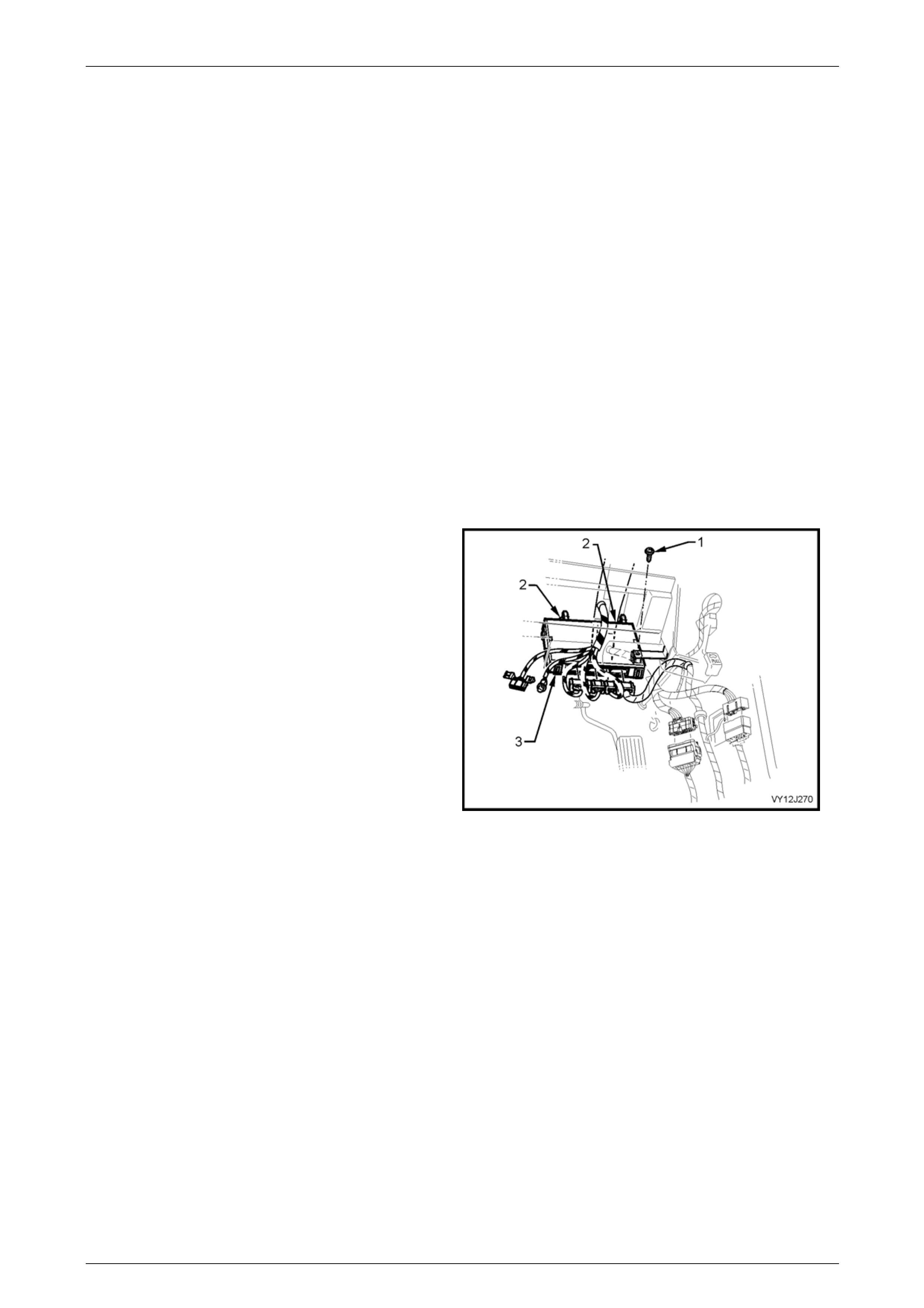
Body Control Module Page 12J–319
Page 12J–319
Remove
Access to BCM Without Disconnection
If accessing the BCM but not removing it (i.e. to carry out BCM diagnostic checks as outlined in some tests in this
Section), perform only Steps 6 and 7 of the removal procedure.
Removal
NOTE
If the BCM is being removed and being replaced
by a new BCM, start at Step 1. If the original BCM
is to be installed again, start at Step 4
1 Connect Tech 2 to the DLC.
2 Perform the Tech 2 Learn BCM Settings procedure. Refer to 4.8 Program – Learn BCM settings.
3 Before disconnecting the battery, refer to Section 00 Warnings, Cautions and Notes.
4 Disconnect the battery negative terminal.
5 From beneath the instrument panel remove the scrivets securing the bottom (foot well) cover, and remove the
cover.
6 Remove the screw (1) attaching the BCM (3) to the
instrument panel bracket outer brace.
7 Release the two rear retaining tangs (2) and gently
manoeuvre the BCM from the top mounting bracket.
(Remember the wiring harness is still connected.)
8 Disconnect the four wiring harness connectors by
pressing each connector tang and pulling the
connector away from the module.
Figure 12J – 100

Body Control Module Page 12J–320
Page 12J–320
Reinstall
1 Install the BCM in the reverse of the removal procedure ensuring the lugs adjacent to the retaining tangs are
correctly located.
2 Ensure the BCM is firmly installed in the mounting brackets.
Body control module
retaining screw torque specification..................1 – 3 Nm
3 Perform the appropriate following procedure, based on whether the BCM is the one previously fitted (original) or a
replacement (new).
Original BCM
Perform the Learnt BCM Settings procedure. Refer to 4.8 Program – Learn BCM settings.
Replacement BCM (New)
NOTE
The replacement BCM must be the same feature
level as the removed BCM. Tech 2 will identify an
incorrect BCM and display a mismatch.
1 Connect Tech 2.
2 Perform the Program Learnt BCM Settings procedure, refer to 4.8 Program.
3 Perform the BCM linking procedure, refer to 4.9 Security.
4 Perform the BCM Relearn Procedure. Refer to the BCM Relearn Procedure in this Section.
For additional information regarding Tech 2, refer to Section 0C Tech 2.
BCM Relearn Procedure
NOTE
The following procedure is not applicable to low
series vehicles.
The following procedure must be carried out if the battery has been disconnected, or upon the installation of a BCM.
1 Ensure that all rear lights are working.
2 Ensure the ignition is off, park lamps are off and the brake pedal at rest with the stop lights off.
3 Remove and install fuse F31 in the engine compartment fuse and relay panel assembly.
4 Start the engine and allow the engine to idle.
5 Press the brake pedal and hold for 5 seconds. Release the brake pedal.
6 Turn the park lamps on and leave on for 5 seconds.
7 With the park lamps still on, press the brake pedal and hold for 5 seconds. Release the brake pedal and turn the
park lamps off.
8 Turn the wipers to the intermittent position and turn the windscreen wiper dwell control fully clockwise and hold for
5 seconds, then turn it fully anticlockwise and hold for 5 seconds. Turn the wipers off.
9 Turn the ignition off.
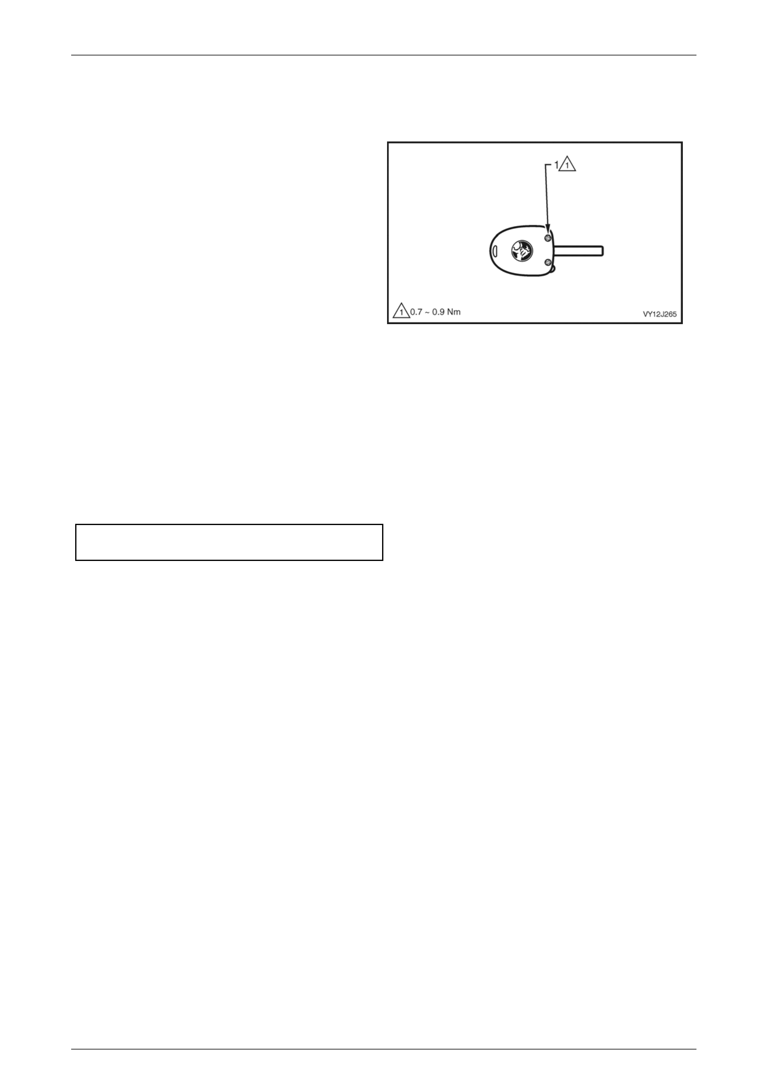
Body Control Module Page 12J–321
Page 12J–321
6.2 Remote Coded Key
Key Replacement
NOTE
The remote coded key holder is a sealed for life
unit with a non-removable battery, and the
housing cannot be separated. The battery life
expectancy is approximately five to ten years.
NOTE
Replacement of a Remote Coded Key will
necessitate programming the BCM to accept the
new key holder’s serial output data.
Programming of the remote coded key holder
can only be performed by an authorised Holden
service outlet, when provided with the correct
security information.
1 Loosen and remove the two (posi-drive) screws (1),
securing the key to the remote coded key holder.
2 Pull the key shaft from the key holder.
3 Assemble the key into the new remote key holder.
4 Insert the two (posi-drive) screws and start the threads
by hand. Tighten the screws to the correct torque
specification. Discard the unserviceable key holder.
Remote coded key holder
screw torque specification...................... 0.7 – 0.9 Nm
Figure 12J – 101
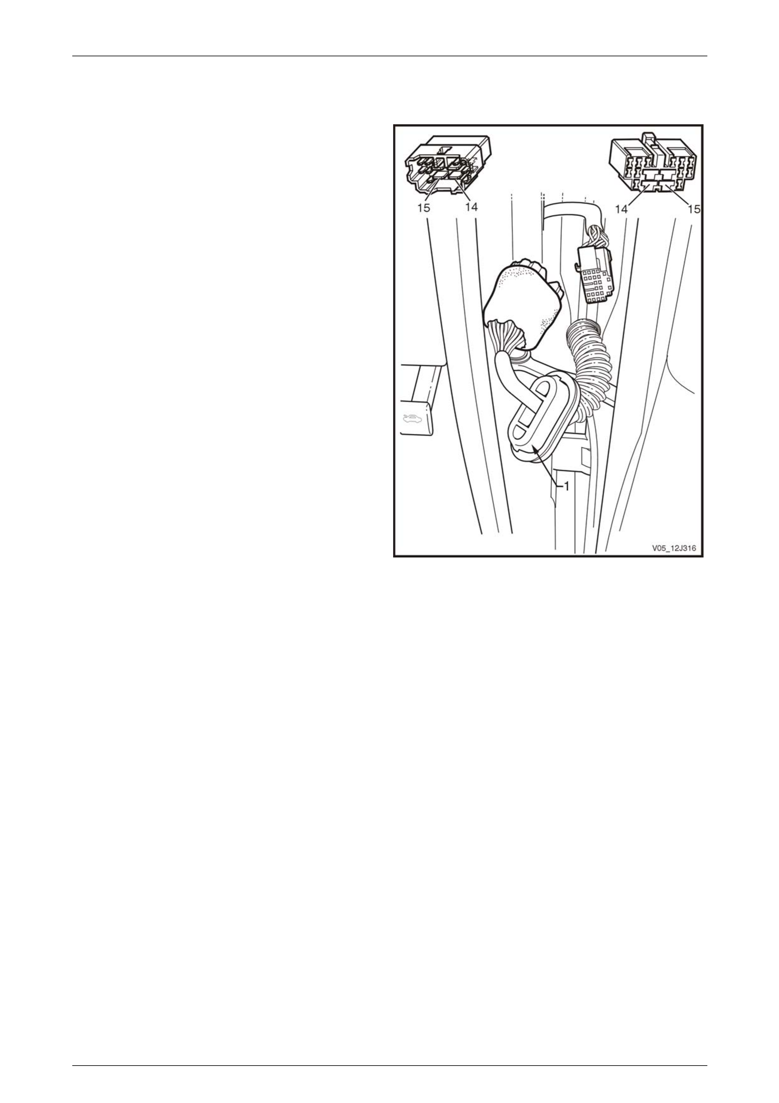
Body Control Module Page 12J–322
Page 12J–322
6.3 Power Window A and B Door Pillar
Wiring Loom Connectors
A Pillar X500 and X600 Connectors
Remove
1 Carefully prise the rubber door loom grommet (1) from
the front door - frame hinge area.
2 Using a screwdriver release the plastic retaining clip to
remove the wiring harness from the door frame.
3 Pull the wiring harness through the hole until the in
line connectors are located.
Reinstall
Reinstallation is the reverse of the removal procedure.
Figure 12J – 102
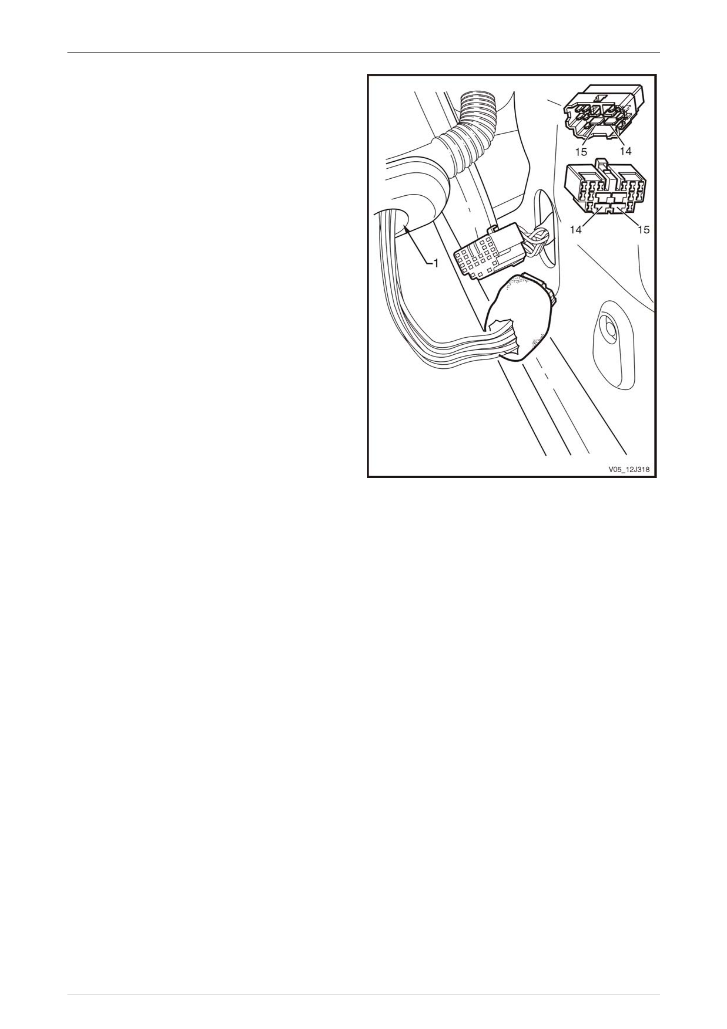
Body Control Module Page 12J–323
Page 12J–323
B Pillar X700 and X800 Connectors
Remove
1 Carefully prise the rubber door loom grommet (1) from
the rear door - frame hinge area.
2 Using a screwdriver release the plastic retaining clip to
remove the wiring harness from the door frame.
3 Pull the wiring harness through the hole until the in
line connectors are located.
Reinstall
Reinstallation is the reverse of the removal procedure.
Figure 12J – 103
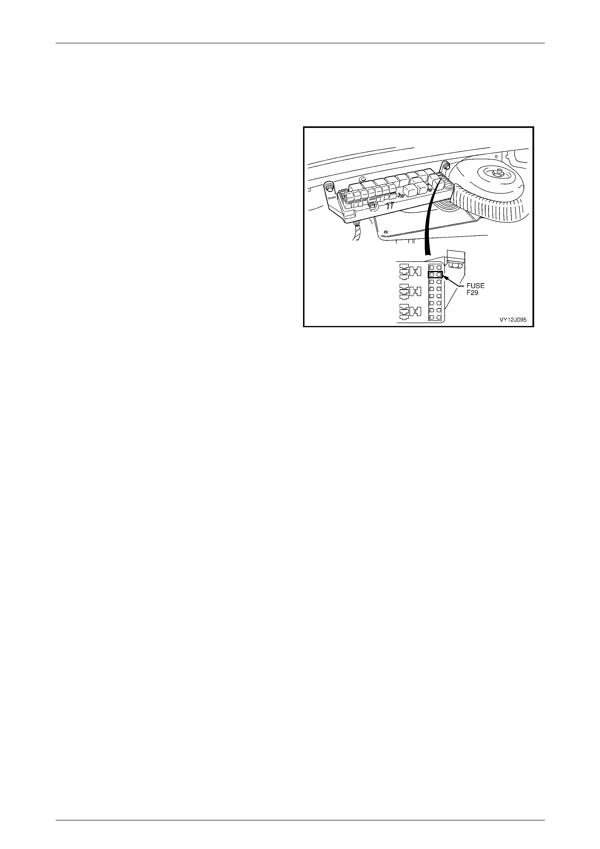
Body Control Module Page 12J–324
Page 12J–324
6.4 Bulb Re-learn Procedure Rear Lamp
Warning Failure System
Carry out this procedure if the battery has been disconnected.
1 Ensure the battery is fully charged and functional.
2 Ensure all rear light bulbs are working. Replace or
repair any faulty bulbs or wiring.
3 Turn the ignition OFF, park lamps OFF and brake
pedal is at rest (stop lamps off).
4 Remove and install fuse F29 from the engine
compartment relay housing, to reset the BCM.
5 Start the engine and allow it to idle.
6 Switch the park lamps ON.
7 Wait 5 seconds.
8 Press brake pedal and hold it down.
9 Wait 5 seconds.
10 Switch the park lamps OFF.
11 Wait 5 seconds.
12 Bulb re-learn is now complete. Turn the engine OFF
and release the brake pedal.
Figure 12J – 104

Body Control Module Page 12J–325
Page 12J–325
7 Torque Wrench Specifications
Body Control Module Retaining Screw........................................0.1 – 0.3 Nm
Remote Coded Key Housing Screw Torque Specification...........0.7 – 0.9 Nm
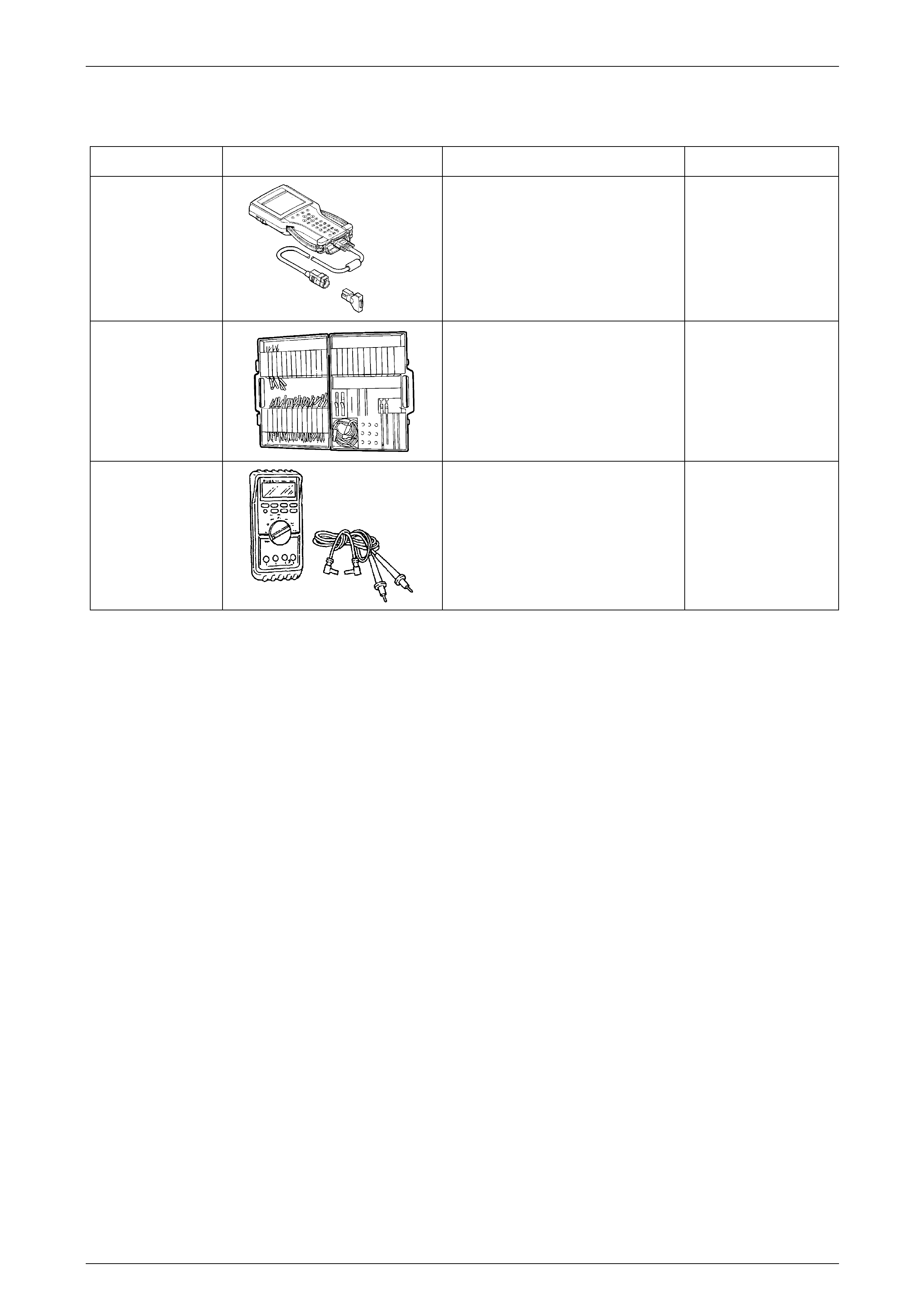
Body Control Module Page 12J–326
Page 12J–326
8 Special Tools
Tool Number Illustration Description Tool Classification
7000086I
Tech 2
DIAGNOSTIC SCAN TOOL
Used for diagnosis of vehicle electrical
system.
Previously released.
Mandatory
J35616-A
(KM609)
CONNECTOR TEST ADAPTOR KIT
Used when carrying out electrical
diagnostic circuit checks.
Previously released.
Desirable
3588
(J39200)
DIGITAL MULTIMETER
Must have at least 10 MΩ input
impedance and be capable of reading
frequencies.
Previously released.
Available