
HVAC Climate Control (Manual A/C) – Description and Operation Page 2A-1
Page 2A-1
Section 2A
HVAC Climate Control (Manual A/C) –
Description and Operation
ATTENTION
Before performing any service operation or other procedure described in this Section, refer to Section 00
Warnings, Cautions and Notes for correct workshop practices with regard to safety and / or property damage.
1 General Information ...............................................................................................................................4
1.1 Caution Label......................................................................................................................................................... 4
2 General Description ...............................................................................................................................5
2.1 Air Flow................................................................................................................................................................... 5
Sedan...................................................................................................................................................................... 5
Wagon..................................................................................................................................................................... 6
Coupe...................................................................................................................................................................... 7
Utility....................................................................................................................................................................... 8
Regular Cab............................................................................................................................................................ 9
Crew Cab .............................................................................................................................................................. 10
2.2 HVAC Inlet and Outlet Ducts............................................................................................................................... 11
Inlet ....................................................................................................................................................................... 11
Air Distribution Ducts.......................................................................................................................................... 12
Sedan, Wagon, Coupe and Crew Cab............................................................................................................. 12
Utility and Regular Cab .................................................................................................................................... 13
Cabin Ventilation Outlets .................................................................................................................................... 14
Sedan, Wagon, Coupe and Crew Cab............................................................................................................. 14
Utility and Regular Cab .................................................................................................................................... 15
Body Ventilation Outlets..................................................................................................................................... 16
Sedan............................................................................................................................................................... 16
Wagon.............................................................................................................................................................. 16
Coupe............................................................................................................................................................... 17
Utility ................................................................................................................................................................ 17
Regular Cab and Crew Cab ............................................................................................................................. 18
Outlet Assembly............................................................................................................................................... 19
2.3 HVAC Controller – Manual A/C........................................................................................................................... 20
Configuration ....................................................................................................................................................... 20
Functions.............................................................................................................................................................. 21
A/C Switch........................................................................................................................................................ 21
Heated Rear Window Switch............................................................................................................................ 21
Blower Fan Switch............................................................................................................................................ 22
Temperature Control........................................................................................................................................ 22
Manual Mode Control Symbols........................................................................................................................... 22
Components and Construction .......................................................................................................................... 23
Exploded View.................................................................................................................................................. 24
Electrical Connections ........................................................................................................................................ 25
Connector X1................................................................................................................................................... 25
Connector X2................................................................................................................................................... 25

HVAC Climate Control (Manual A/C) – Description and Operation Page 2A-2
Page 2A-2
2.4 Heater.................................................................................................................................................................... 26
Temperature Control Switch – Manual A/C........................................................................................................ 26
Air Mix Door Control Mechanism – Manual A/C................................................................................................ 26
Water Valve Assembly – V6 ................................................................................................................................ 27
Water Valve Assembly – GEN III V8.................................................................................................................... 27
Heater Operation – Manual A/C – V6.................................................................................................................. 28
Full Cold........................................................................................................................................................... 28
Warm................................................................................................................................................................ 29
Full Hot............................................................................................................................................................. 30
Heater Operation – Auto A/C – V6...................................................................................................................... 31
Full Cold........................................................................................................................................................... 31
Warm................................................................................................................................................................ 32
Full Hot............................................................................................................................................................. 33
Heater Operation – Manual A/C – GEN III V8 ..................................................................................................... 34
Full Cold........................................................................................................................................................... 34
Warm................................................................................................................................................................ 35
Full Hot............................................................................................................................................................. 36
Heater Operation – Auto A/C – GEN III V8 ......................................................................................................... 37
Full Cold........................................................................................................................................................... 37
Warm................................................................................................................................................................ 38
Full Hot............................................................................................................................................................. 39
Under-hood Heater Components – V6............................................................................................................... 40
Under-hood Heater Components – GEN III V8................................................................................................... 41
2.5 Air-conditioning Refrigerant Circuit................................................................................................................... 42
2.6 Vacuum Circuit..................................................................................................................................................... 43
Vacuum Mode Switch and Vacuum Lines – Manual A/C.................................................................................. 43
Solenoid Pack and Vacuum Lines – Auto A/C................................................................................................... 44
Vacuum Circuit Schematic – Manual A/C.......................................................................................................... 45
Vacuum Circuit Schematic – Auto A/C .............................................................................................................. 46
2.7 HVAC Unit Airflow Modes – Manual A/C............................................................................................................ 47
HVAC Flow Diagrams .......................................................................................................................................... 47
Recirculation Mode............................................................................................................. ................................. 48
Full Cold........................................................................................................................................................... 48
Full Heat........................................................................................................................................................... 48
Face Mode ............................................................................................................................................................ 49
Full Cold........................................................................................................................................................... 49
Full Heat........................................................................................................................................................... 49
Bi-level Mode........................................................................................................................................................ 50
Full Cold........................................................................................................................................................... 50
Full Heat........................................................................................................................................................... 50
Floor Mode............................................................................................................................................................ 51
Full Cold........................................................................................................................................................... 51
Full Heat........................................................................................................................................................... 51
Blend Mode........................................................................................................................................................... 52
Full Cold........................................................................................................................................................... 52
Full Heat........................................................................................................................................................... 52
Demist Mode......................................................................................................................................................... 53
Full Heat and A/C Activated ............................................................................................................................. 53
Default Mode ........................................................................................................................................................ 54
Loss of Vacuum Supply to HVAC Unit ............................................................................................................. 54

HVAC Climate Control (Manual A/C) – Description and Operation Page 2A-3
Page 2A-3
2.8 Heating, Ventilation and Air-conditioning (HVAC) Unit.................................................................................... 55
General Description – Manual A/C ..................................................................................................................... 55
Assembled Views – Manual A/C...................................................................................................................... 56
Exploded View – Manual A/C........................................................................................................................... 58
General Description – Auto A/C.......................................................................................................................... 59
Assembled Views – Auto A/C........................................................................................................................... 60
Exploded View – Auto A/C............................................................................................................................... 62
Evaporator............................................................................................................................................................ 63
Heater Core........................................................................................................................................................... 64
Blower Motor and Fan Assembly ....................................................................................................................... 64
Blower Motor Resistor Assembly – Manual A/C ............................................................................................... 65
Electronic Blower Motor Controller – Auto A/C ................................................................................................ 65
Air Mix Doors – Manual A/C................................................................................................................................ 66
Air Mix Doors and Motor – Auto A/C.................................................................................................................. 68
Air Mix Doors.................................................................................................................................................... 68
Air Mix Door Motor ........................................................................................................................................... 68
Motor and Door Configurations ........................................................................................................................ 68
Air Mix Door Motor/Door Calibration................................................................................................................. 69
Vacuum Actuators............................................................................................................................................... 70
Single-stage Actuator....................................................................................................................................... 70
Two-stage Actuators ........................................................................................................................................ 71
Vacuum Solenoid Pack – Auto A/C.................................................................................................................... 72
Vacuum Tank – Manual A/C................................................................................................................................ 72
Vacuum Tank – Auto A/C .................................................................................................................................... 73
Vacuum Tank Check Valve ................................................................................................................................. 73
2.9 Under-hood Components.................................................................................................................................... 74
Under-hood Air-conditioning Components – V6............................................................................................... 74
Under-hood Air-conditioning Components – V6 – AWD .................................................................................. 75
Under-hood Air-conditioning Components – GEN III V8.................................................................................. 76
Condenser, Radiator and Fan Module ............................................................................................................... 77
Condenser........................................................................................................................................................ 79
Filter Drier Receiver ......................................................................................................................................... 79
A/C Pressure Transducer.................................................................................................................................... 80
V6 Engine......................................................................................................................................................... 80
GEN III V8 Engine............................................................................................................................................ 81
Specification Table........................................................................................................................................... 81
Thermostatic Expansion Valve........................................................................................................................... 82
Opening............................................................................................................................................................ 82
Closing............................................................................................................................................................. 83
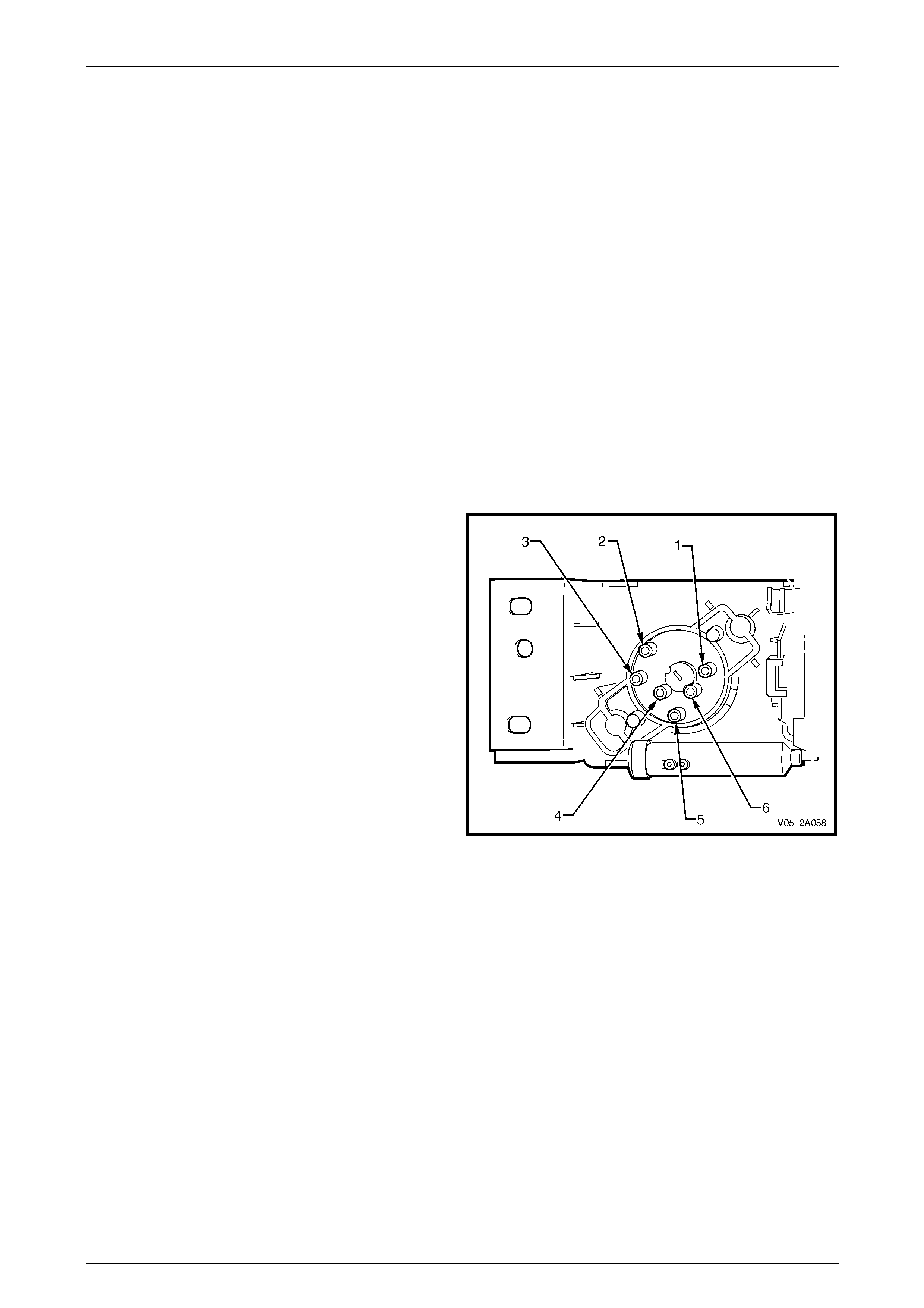
Air-conditioning Compressor Assembly – V6................................................................................................... 84
Compressor Control Valve............................................................................................................................... 85
Compressor Operation..................................................................................................................................... 86
Low A/C Demand............................................................................................................................................. 87
High A/C Demand ............................................................................................................................................ 88
Air-conditioning Compressor Assembly – GEN III V8...................................................................................... 89
Compressor Control Valve............................................................................................................................... 90
Compressor Operation..................................................................................................................................... 91
Low A/C Demand............................................................................................................................................. 92
High A/C Demand ............................................................................................................................................ 93
3 Specifications.......................................................................................................................................94
3.1 General ................................................................................................................................................................. 94
3.2 Water Valve........................................................................................................................................................... 95
3.3 HVAC Unit............................................................................................................................................................. 96
3.4 Compressor – V6 ................................................................................................................................................. 97
3.5 Compressor – GEN III V8..................................................................................................................................... 98
3.6 Refrigerant............................................................................................................................................................ 99
3.7 Condenser.......................................................................................................................................................... 100
3.8 Pressure Transducer......................................................................................................................................... 101
3.9 A/C System Lubricant........................................................................................................................................ 102
HVAC Climate Control (Manual A/C) – Description and Operation Page 2A-4
Page 2A-4
1 General Information
Two levels of air-conditioning can be fitted to the vehicles, the two heating, ventilation and air-conditio ning (HVAC)
systems are described as follows:
• HVAC climate control – manual air-cond ition ing (A/C) control, and
• HVAC occupant climate control – automatic air-conditioning (A/C) control.
The manual HVAC system uses a rotary dial type controller to select the desired operating modes and temperature. It
will be referred to as manual A/C in this Section.
The occupant climate control system features an electronic control module to control the desired operating mod es and
temperature. It is also referred to as auto A/C or OCC system.
The service information is divided into six sub-sections as follows:
Section 2A HVAC Climate Control (Manual A/C) – Description and Operation
• Provides a general description of the operation of the heater and air-conditioner s ystem, except the el ectronic
control system.
Section 2B HVAC Climate Control (Manual A/C) – Servicing and Diagnosis
• Provides the servicing procedures and diagnosis of the heater and air-conditioner system, except the elec tronic
control system.
Section 2C HVAC Climate Control (Man ual A/C) – Removal and Installation
• Provides the removal and installation procedures of the heater and air-conditioner system components, except the
electronic control system components.
Section 2D HVAC Occupant Climate Contro l (Auto A/C) – Description and Operation
• Provides a general description of the oper ation of the electronic control system.
Section 2E HVAC Occupant Climate Control (Auto A/C) – Diagnostics
• Provides the diagnostic proce dures of the electronic control system.
Section 2F HVAC Occupant Climate Control (Auto A/C) – Removal and Installation
• Provides the removal and installation procedures of the ele ctronic contro l system components.
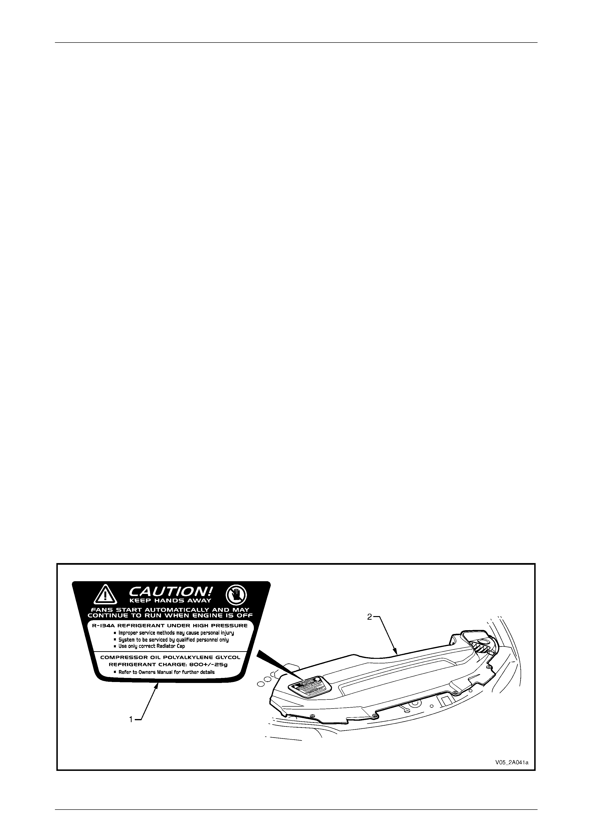
1.1 Caution Label
A fan operation caution and HVAC information label (1), is located on the right-hand side of the radiator shroud (2), refer
to Figure 2A – 1. This label provides information on the type and quantity of refrigerant required for the a ir-conditioning
system. It also specifies the type of lubricant required for the air-conditionin g compressor.
Figure 2A – 1
HVAC Climate Control (Manual A/C) – Description and Operation Page 2A-5
Page 2A-5
2 General Description
The integrated air-conditi oning system combines both the heating and cooling functions in a single unit. The vehicle’s
interior can be heated, cooled or vented (or a combination of these operations) depen ding on the modes and s witches
activated on the HVAC controller or the OCC control module. The controller or modu le is mounted in the instrument
panel centre fascia below centre ventilati on outlets.
2.1 Air Flow
Air enters the HVAC system from beneath the ple num chamber cover and passes through the blo wer motor/fan,
evaporator and heater assemblies within the HVAC unit to be cooled or heated as required. The air leaves the HVAC unit
and enters the vehicle interior through the centre, side, rear (where fitted), floor or demist outlets depending on the mode
selected.
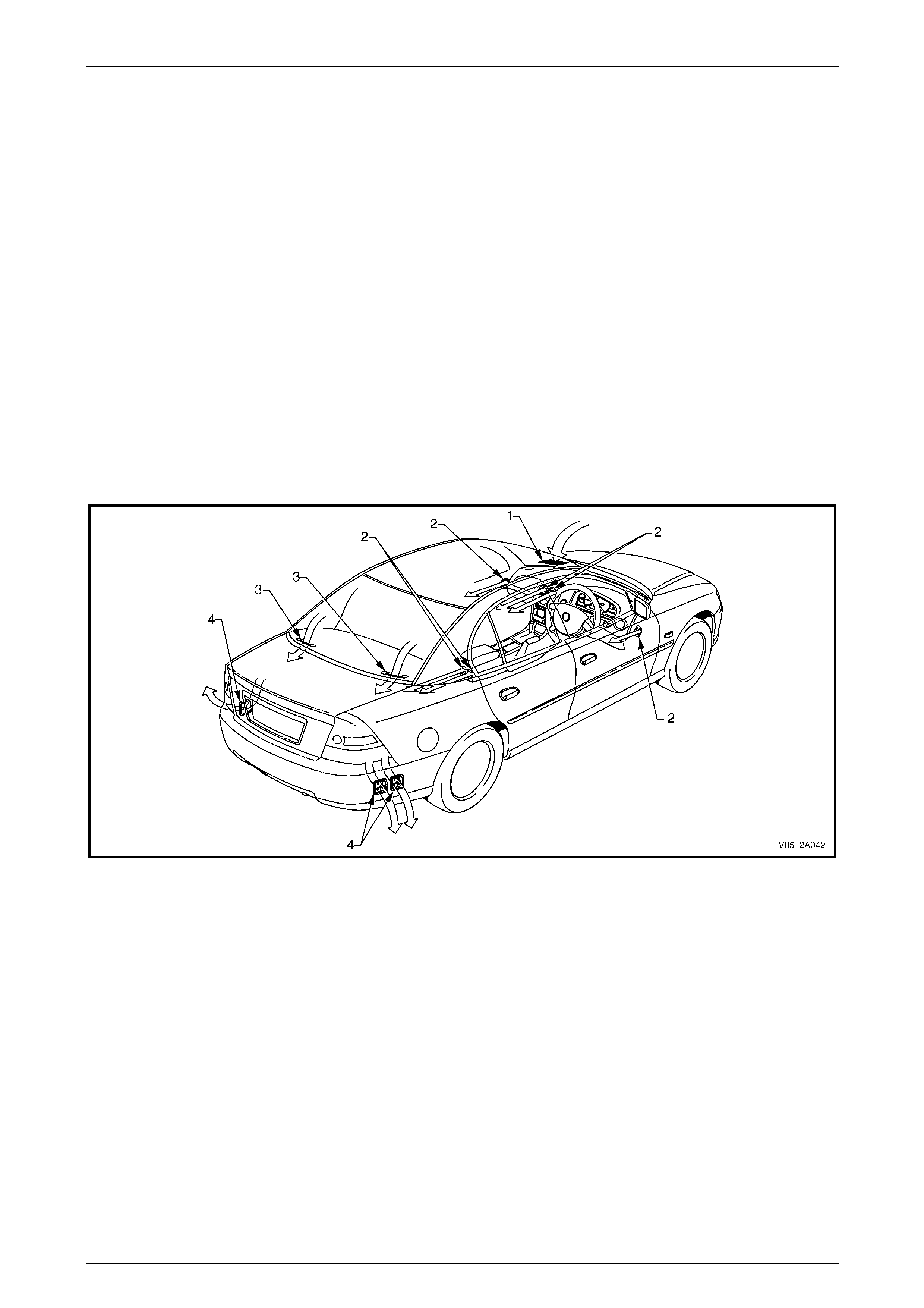
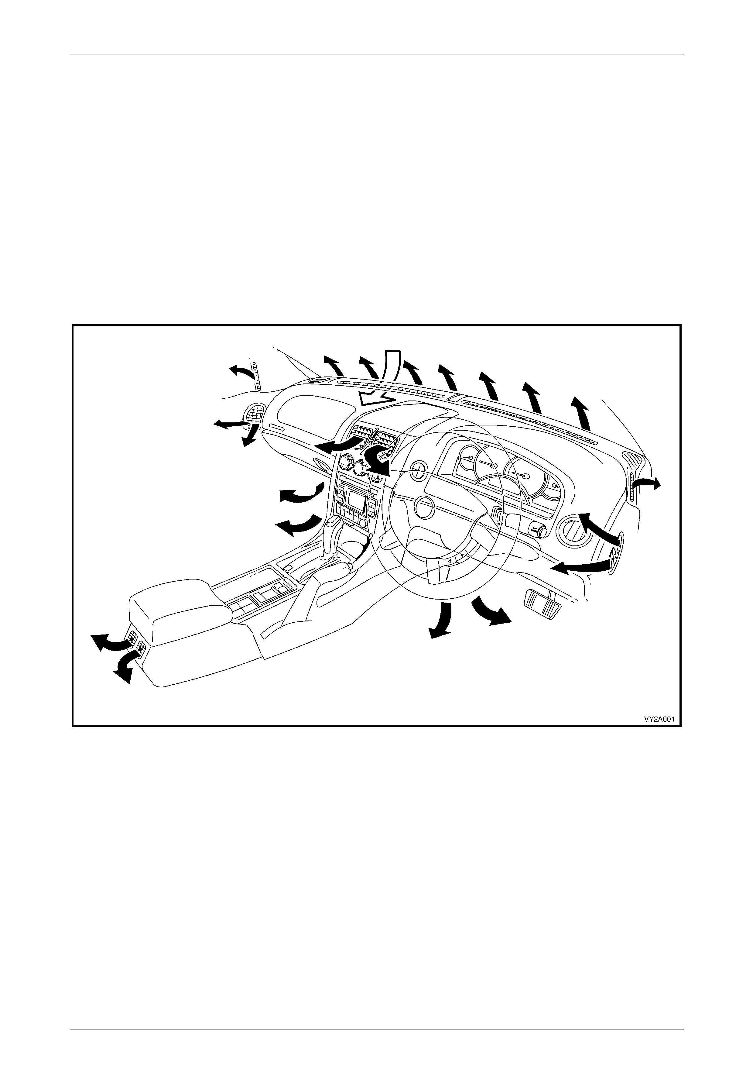
Sedan
When the doo rs and all movab le window s are cl osed , air passes through tw o grilles mounted in the rear window trim
panel (3) and exits the vehicle throu gh three body moun ted air outle ts (4) locate d behind the rea r bump er fascia , refer to
Figure 2A – 2.
The centre, side and rear ventilation outlets (2) can be turned on or off and are directionally adjustable. Turning off these
outlets will increase airflo w to the other open outlets.
Figure 2A – 2
Legend
1 Plenum Inlet
2 Cabin Air Outlets 3 Rear Window Trim Panel Grilles
4 Body Air Outlets
HVAC Climate Control (Manual A/C) – Description and Operation Page 2A-6
Page 2A-6
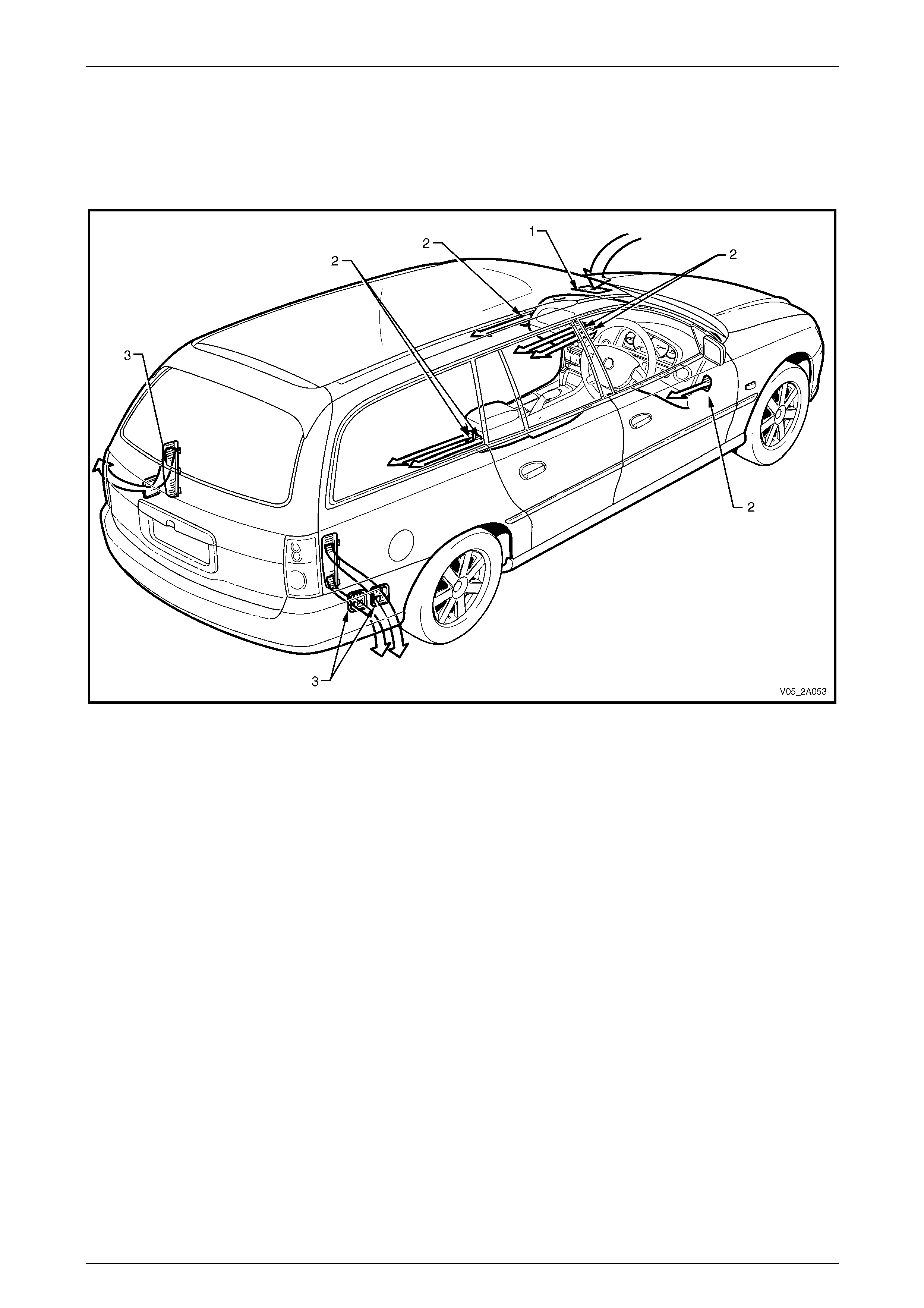
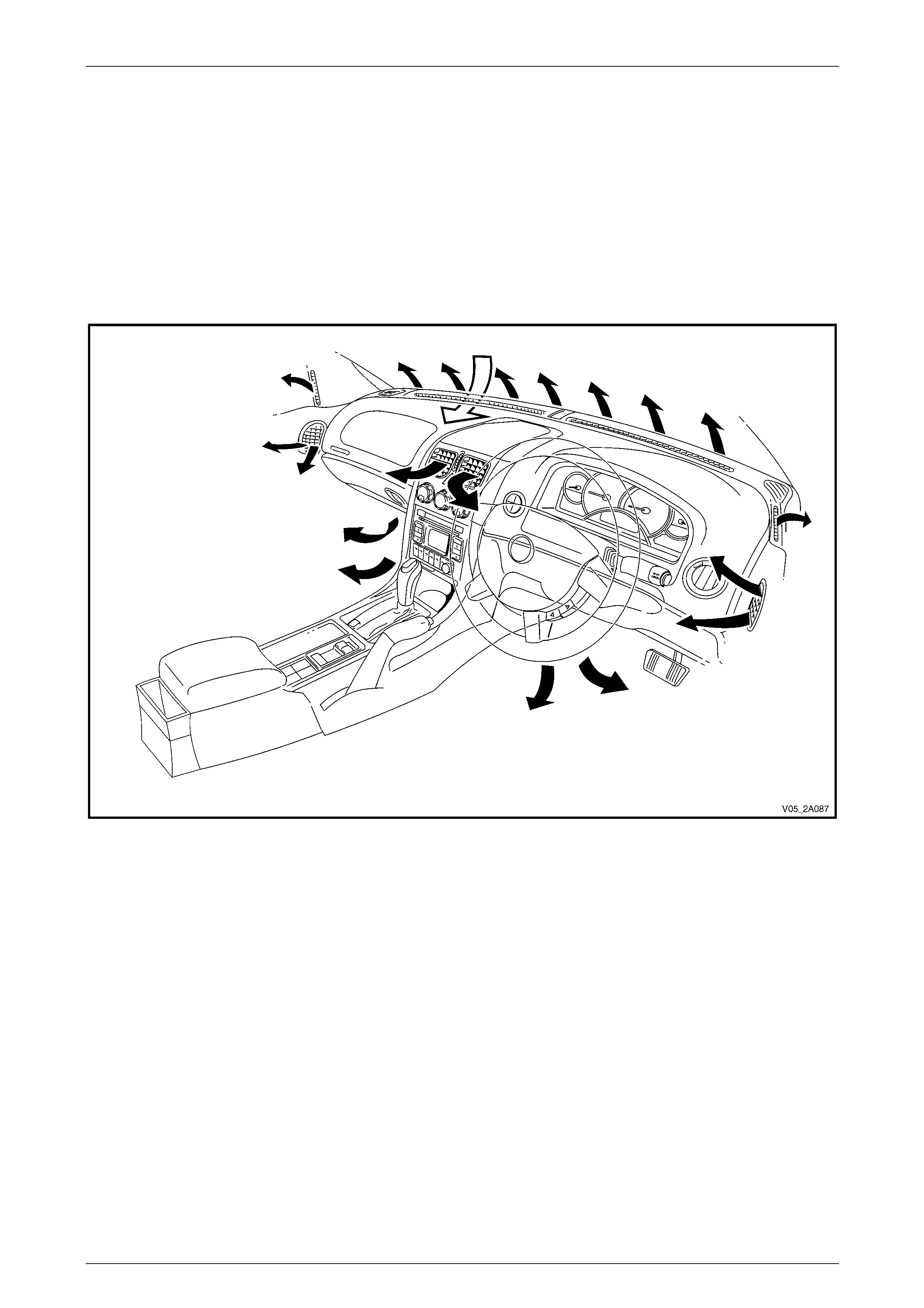
Wagon
When the doo rs and all movab le w indows are close d , air exits the vehicle through th ree body moun ted air outlets (3) loca ted
at the rear of the vehicle behind the rear bumper bar fascia, refer to Figure 2A – 3.
The centre, side and rear ventilation outlets (2) can be turned on or off and are directionally adjustable. Turning off these
outlets will increase airflo w to the other open outlets.
Figure 2A – 3
Legend
1 Plenum Inlet
2 Cabin Air Outlets 3 Body Air Outlets
HVAC Climate Control (Manual A/C) – Description and Operation Page 2A-7
Page 2A-7
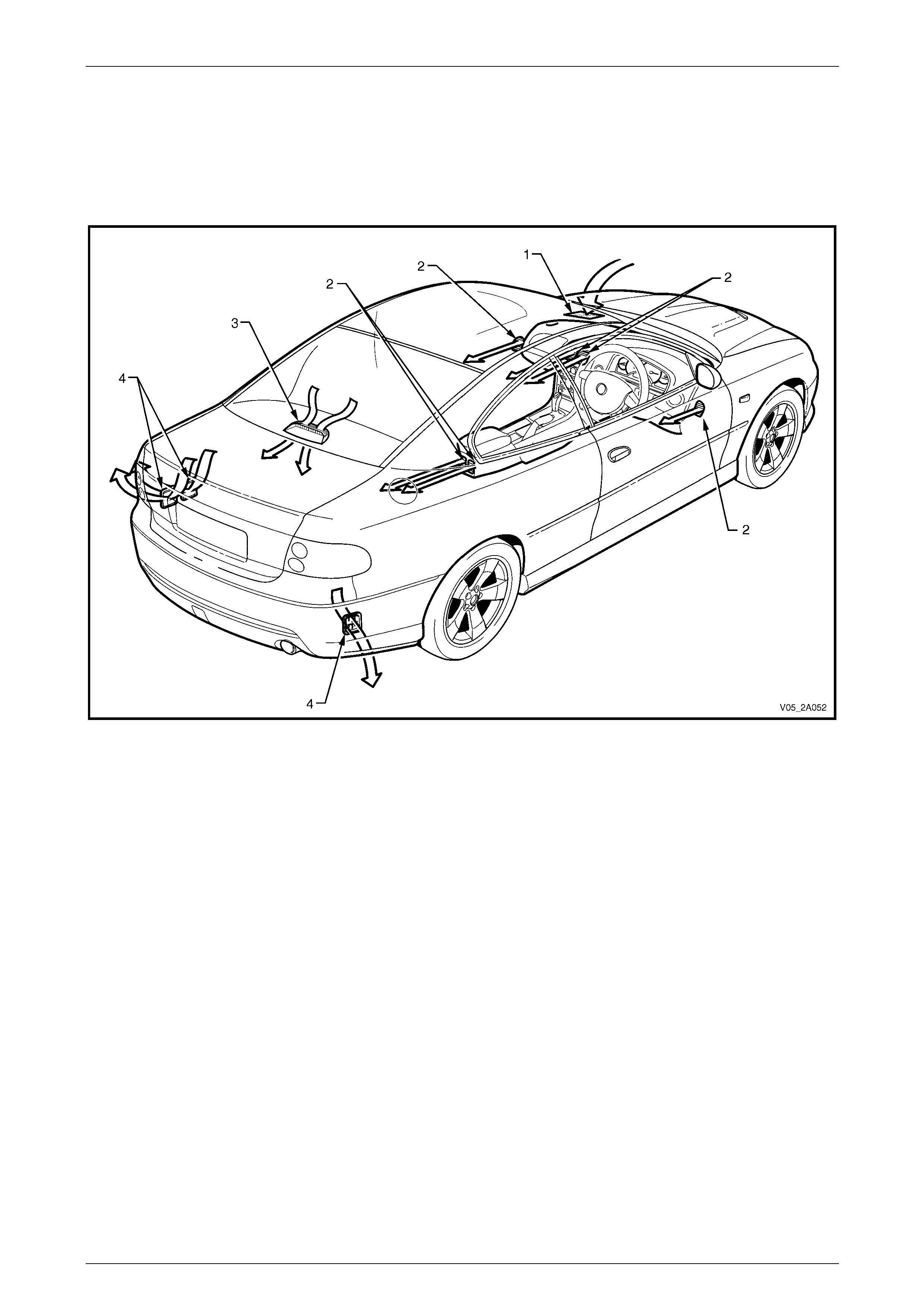
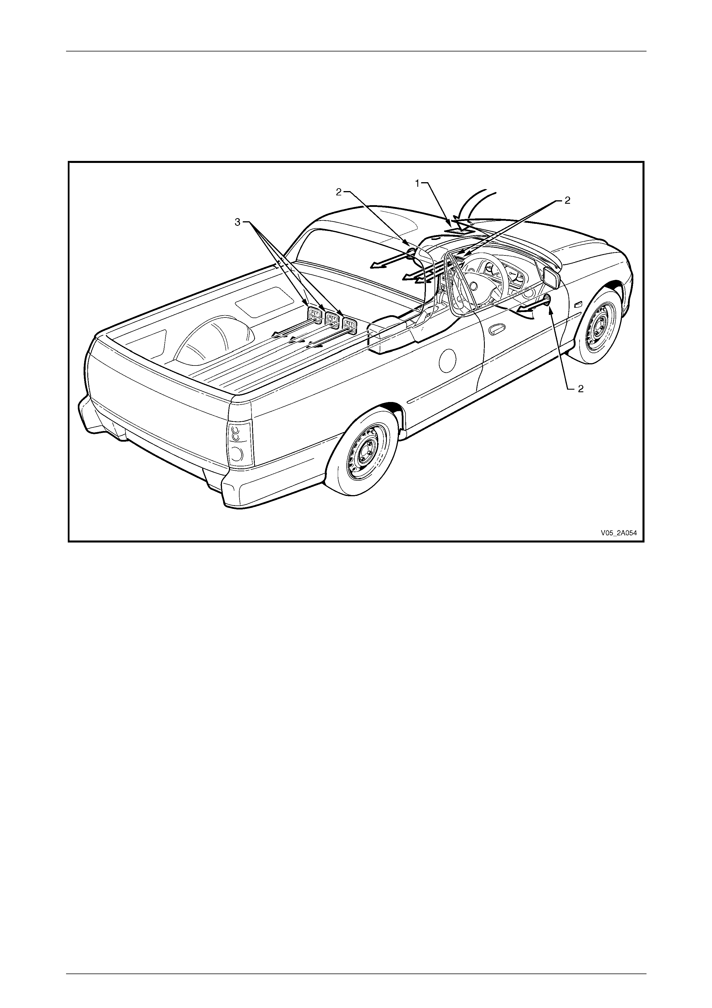
Coupe
Whe n the doors an d a l l mo va b l e w i nd ows are clo se d, ai r pa s s es t h ro ug h th e parcel shelf grille in centre stop light
housing (3) and ex its th e vehi cle throug h thre e body mou nted air outle ts (4) loca ted be h i nd th e rear bu mp e r fascia, refer to
Figure 2A – 4.
The centre, side and rear ventilation outlets (2) can be turned on or off and are directionally adjustable. Turning off these
outlets will increase airflo w to the other open outlets.
Figure 2A – 4
Legend
1 Plenum Inlet
2 Cabin Air Outlets 3 Parcel Shelf Grille in Centre Stop Light Housing
4 Body Air Outlets
HVAC Climate Control (Manual A/C) – Description and Operation Page 2A-8
Page 2A-8
Utility
When the doo rs and all movab le w indows are close d , air exits the vehicle through th ree body moun ted air outlets (3) loca ted
at the rear of the cabin, r efer to Figure 2A – 5.
The centre and side ventilation outlets (2) can be turned on or off and are directionall y adjustable. Turning off these
outlets will increase airflo w to the other open outlets.
Figure 2A – 5
Legend
1 Plenum Inlet
2 Cabin Air Outlets 3 Body Air Outlets
HVAC Climate Control (Manual A/C) – Description and Operation Page 2A-9
Page 2A-9
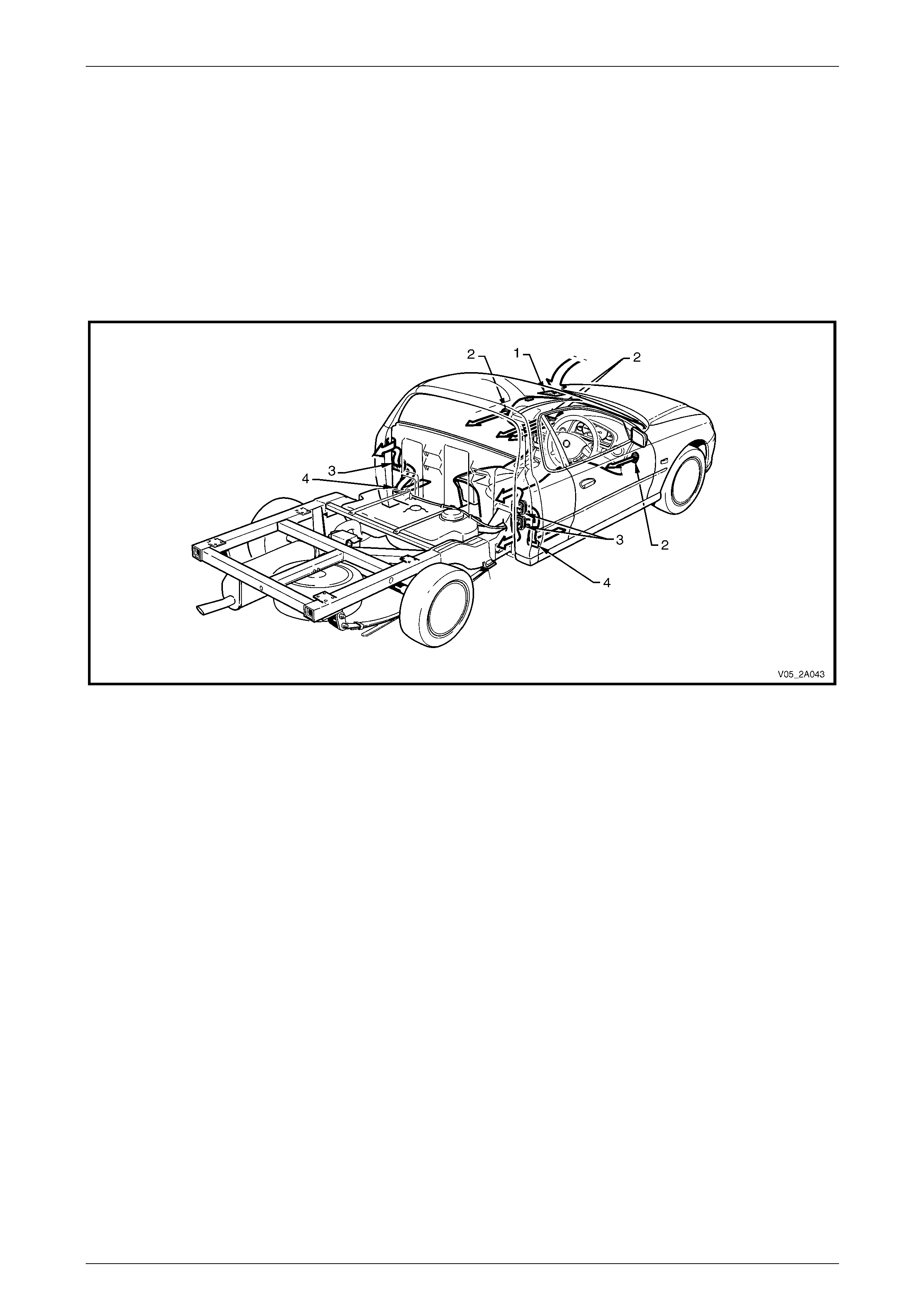
Regular Cab
When the doo rs and all movab le w indows are close d , air exits the vehicle through two rectangular apertures (4) located in
the seat back body panel trim assembly below the body ventilation outlets (3). These outlets are installed into the rear
inner panel. Two outlets are located on the right-hand side and one on the left-hand side of the cabin, refer to
Figure 2A – 6.
After passing through the body ventilation outlets, the air enters a cavity between the inner rear body panel and the rear
outer trim panel. It leaves the vehicle via a small air g ap located around the entire lower and side perimeters of the rear
outer trim panel.
The centre and side ventilation outlets (2) can be turned on or off and are directionall y adjustable. Turning off these
outlets will increase airflo w to the other open outlets.
Figure 2A – 6
Legend
1 Plenum Inlet
2 Cabin Air Outlets 3 Body Air Outlets
4 Airflow Apertures
HVAC Climate Control (Manual A/C) – Description and Operation Page 2A-10
Page 2A-10
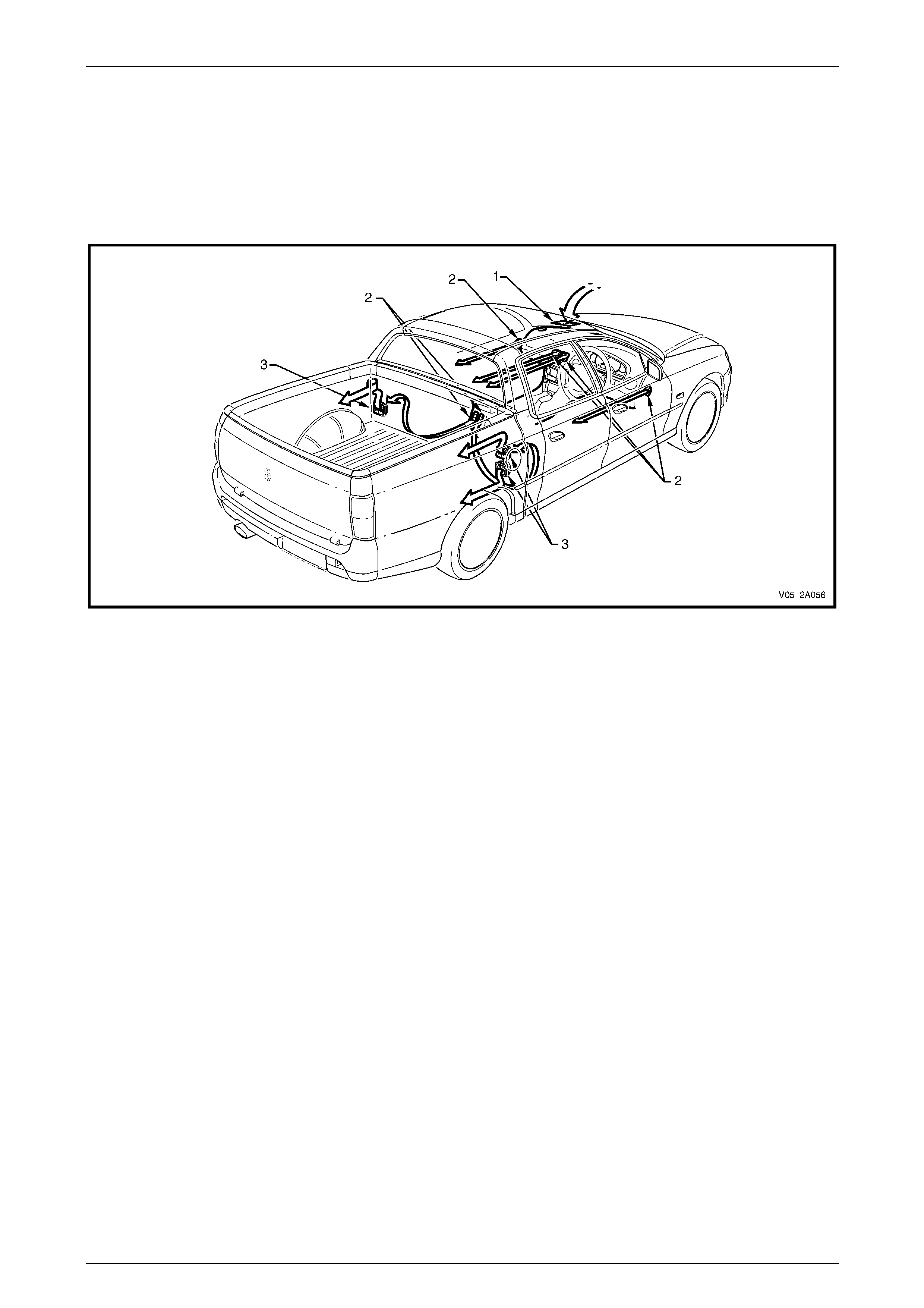
Crew Cab
When the doo rs and all movab le w indows are close d , air exits the vehicle via the underside of the rear seat cushion. Three
body ventilation outlets (3) are installed in the rear inner panel. Two outlets are located on the right-hand side and one on
the left-hand side of the cabin, refer to Figure 2A – 7.
The centre and side ventilation outlets (2) can be turned on or off and are directionall y adjustable. Turning off these
outlets will increase airflo w to the other open outlets.
Figure 2A – 7
Legend
1 Plenum Inlet
2 Cabin Air Outlets 3 Body Air Outlets

HVAC Climate Control (Manual A/C) – Description and Operation Page 2A-11
Page 2A-11
2.2 HVAC Inlet and Outlet Ducts
Inlet
Air enters the rectangular air inlet located on a raised area within the plenum chamber, refer to Figure 2A – 8. To prevent
foreign matter such as leaves or t wigs entering the HVAC unit, a stainless steel mesh screen is installed over the inlet.
Although not a regular maintenance item, this mesh screen can be removed to clear away any foreign matter that may
have accumulated at the HVAC inlet.
Figure 2A – 8
Legend
1 Plenum Cover
2 Plenum Chamber
3 Mesh Screen
4 Mesh Screen Retaining Clip
5 HVAC Inlet
HVAC Climate Control (Manual A/C) – Description and Operation Page 2A-12
Page 2A-12
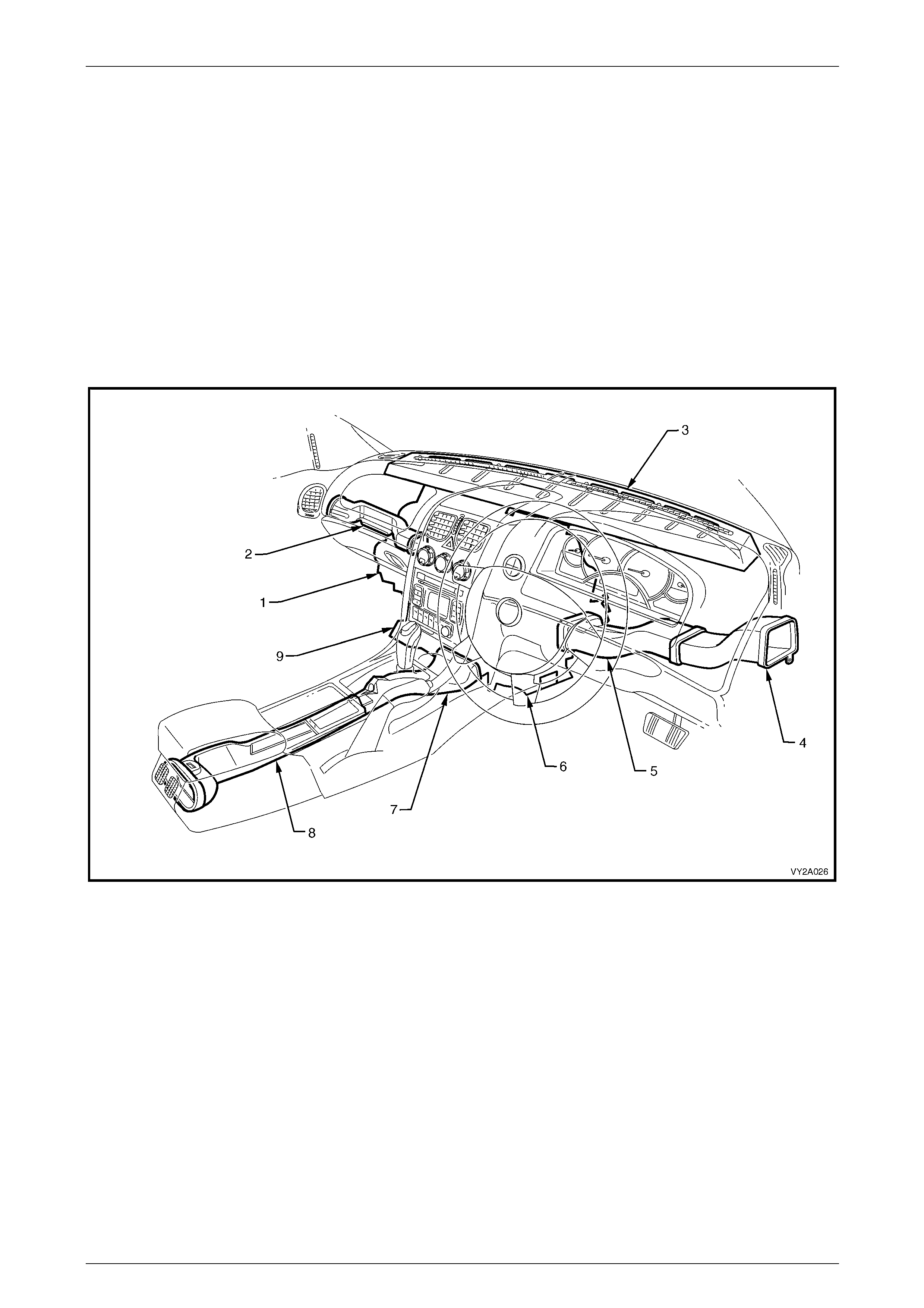
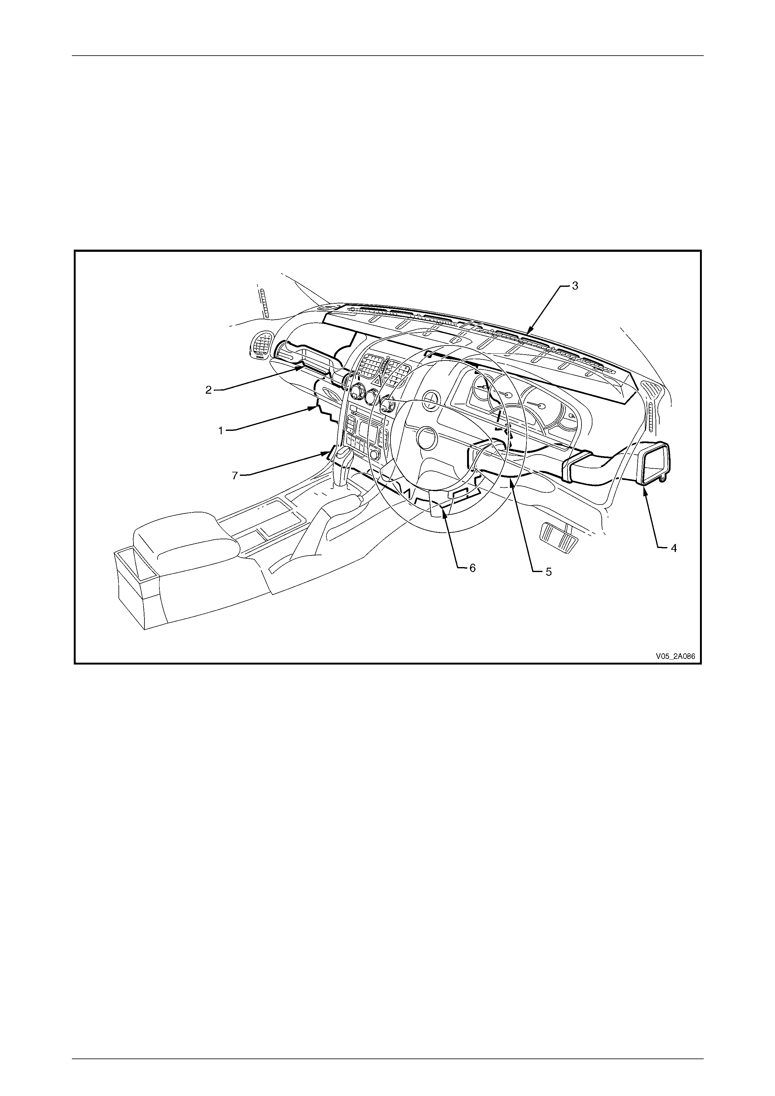
Air Distribution Ducts
Sedan, Wagon, Coupe and Crew Cab
Air that is directed to the sides and rear of the cabin is ch annelled throu gh plastic ducts attached to the HVAC case, refer
to Figure 2A – 9. Air leaving the side ducts is channelled through the left-hand and right-hand side instrument panel outer
covers and exits through air outlets installed into the door trims. A portion of this air is directed into sid e window
demisting outlets also installed as part of the door trims.
Air to the rear outlets is channelled through a two-piece rear duct installed under the floor conso le. Air leaving this duct is
divided into two paths by the rear ventilation outlet.
Air directed to the front floor is channelled thr ough foot ducts located on the underside of the HVAC un it.
Air for demisting the windscreen directly enters into a cavity formed by the dash panel assembly. This air is then directed
through eight openings located in the upper dash panel, and e xits through the demister grilles installed at the front of the
instrument panel pad.
Figure 2A – 9
Legend
1 HVAC Unit
2 Passenger Side Duct
3 Demister Cavity
4 Driver Side Outer Duct
5 Driver Side Inner Duct
6 Driver Foot Duct Outlet
7 Floor Console Front Duct
8 Floor Console Rear Duct
9 Passenger Foot Duct Outlet
HVAC Climate Control (Manual A/C) – Description and Operation Page 2A-13
Page 2A-13
Utility and Regular Cab
Air that is directed to the sides of the cabin is channelled through plastic ducts attached to the HVAC case, refer to
Figure 2A – 10. Air leaving the side ducts is channelled through the left-hand and right-h and side instrument panel outer
covers and exits through air outlets installed into the door trims. A portion of this air is dire cted into side window
demisting outlets also installed as part of the door trims.
Air directed to the front floor is channelled thr ough foot ducts located on the underside of the HVAC unit.
Air for demisting the windscreen directly enters into a cavity formed by the dash panel assembly. This air is then directed
through eight openings located in the upper dash panel, and e xits through the demister grilles installed at the front of the
instrument panel pad.
Figure 2A – 10
Legend
1 HVAC Unit
2 Passenger Side Duct
3 Demister Cavity
4 Driver Side Outer Duct
5 Driver Side Inner Duct
6 Driver Foot Duct Outlet
7 Passenger Foot Duct Outlet
HVAC Climate Control (Manual A/C) – Description and Operation Page 2A-14
Page 2A-14
Cabin Ventilation Outlets
Sedan, Wagon, Coupe and Crew Cab
Air entering the HVAC unit through the plenum chamber enters the cabin through ventilation outl ets at the following
points, refer to Figure 2A – 11:
• windscreen (fixed, part of upper instrument panel assembly),
• driver and front passenger side foot outlet (fixed, part of HVAC unit underside),
• driver and front passenger side outlet (adjustable, installed into door trims),
• driver and front passenger side window demist outlet (fixed, installed into door trims),
• driver and front passenger face level outlet (adjustable), and
• rear outlets (adjustable, installed to rear of floor console).
Figure 2A – 11
HVAC Climate Control (Manual A/C) – Description and Operation Page 2A-15
Page 2A-15
Utility and Regular Cab
Air entering the HVAC unit through the plenum chamber enters the cabin through ventilation outl ets at the following
points, refer to Figure 2A – 12:
• windscreen (fixed, part of upper instrument panel assembly),
• driver and front passenger side foot outlet (fixed, part of HVAC unit underside),
• driver and front passenger side outlet (adjustable, installed into door trims),
• driver and front passenger side window demist outlet (fixed, installed into door trims), and
• driver and front passenger face level outlet (adjustable).
Figure 2A – 12
HVAC Climate Control (Manual A/C) – Description and Operation Page 2A-16
Page 2A-16
Body Ventilation Outlets
To allow the HVAC system to operate efficiently, air must be allowed to leave the vehicle even when all wind ows and
doors are closed. This is achieved b y the installation of body ventilation outlets at the rear of the vehicle.
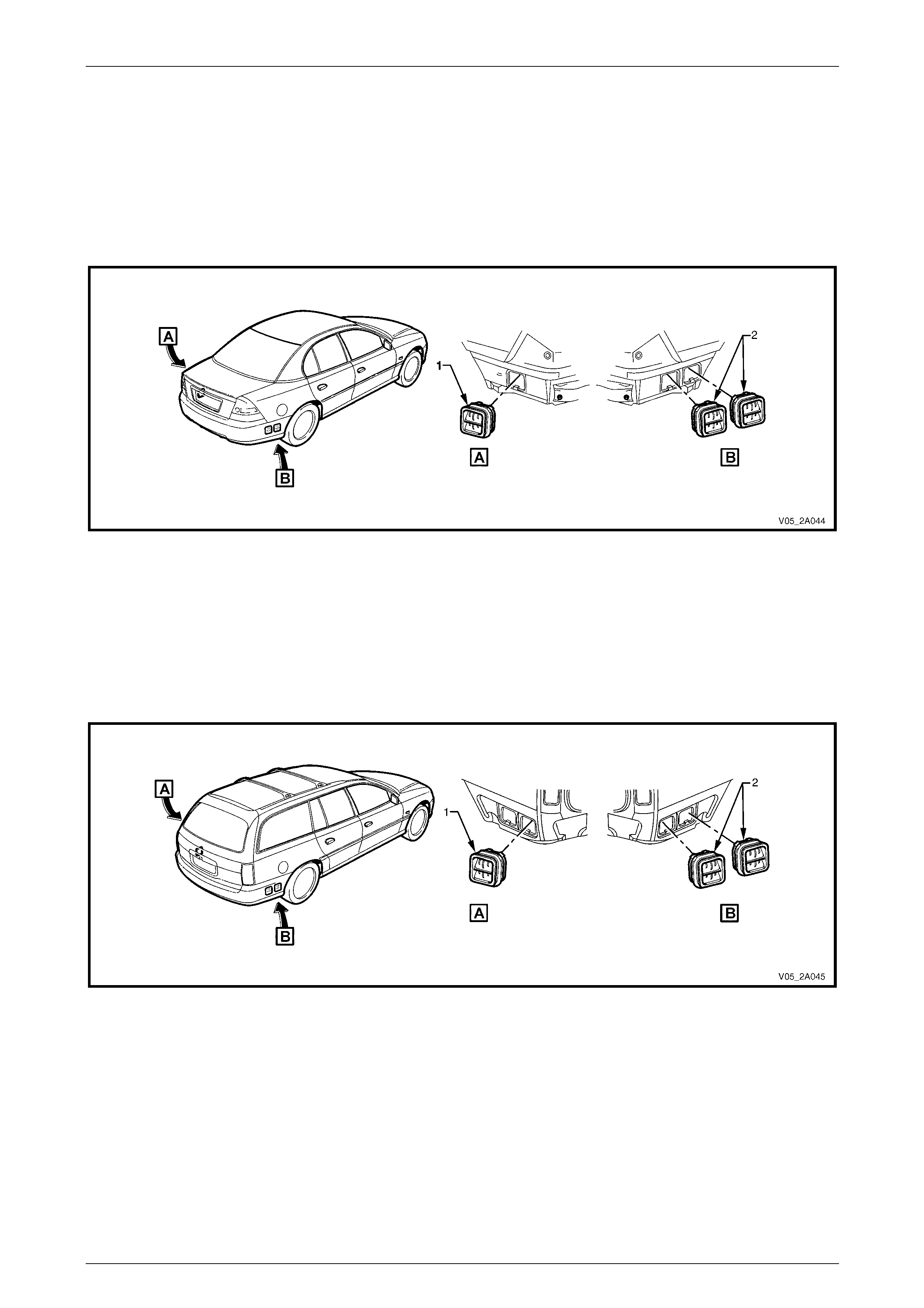
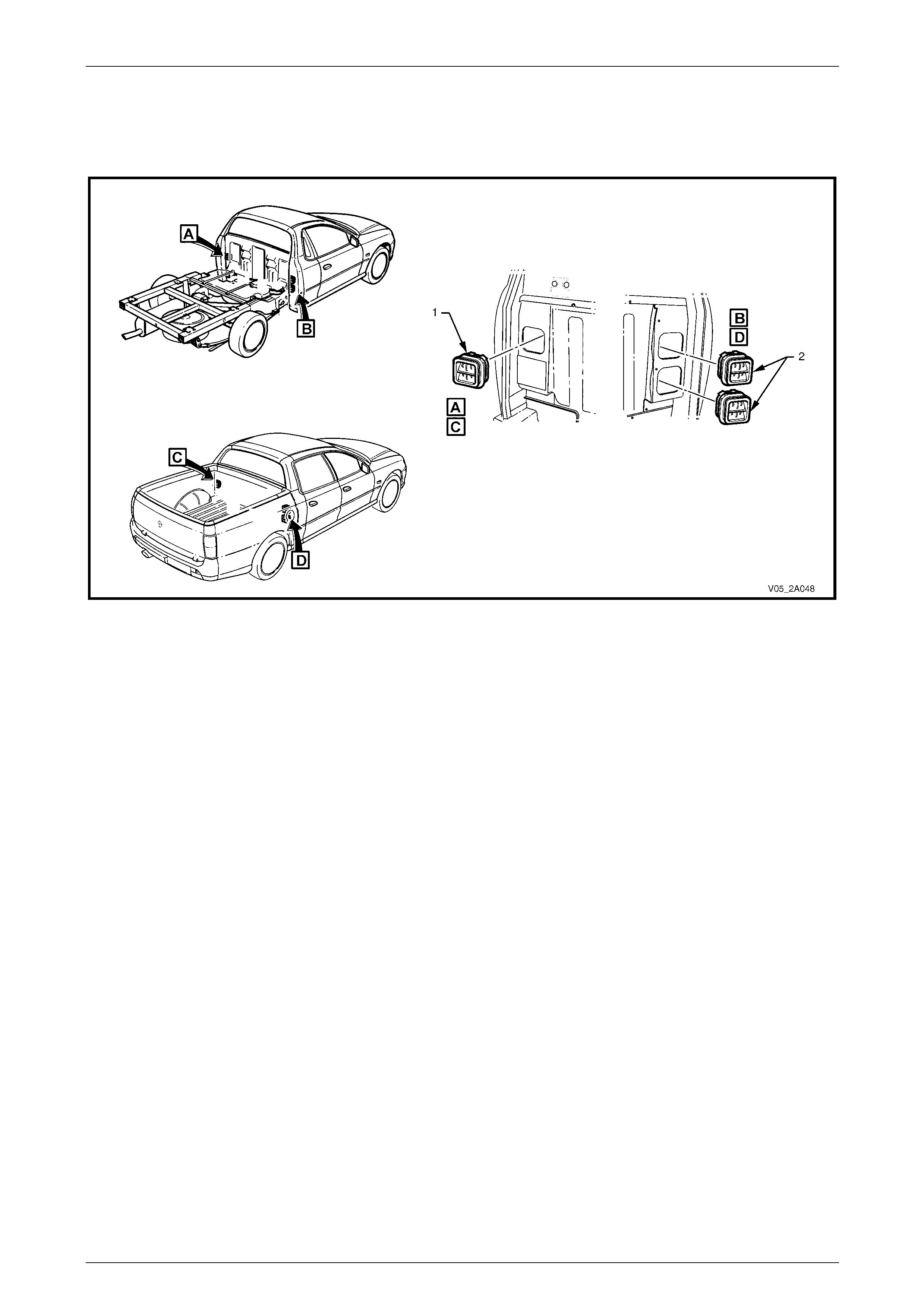
Sedan
Sedan vehicles have one venti latio n outlet (1) on the left-hand side and two outlets (2) on the right-hand side, refer to
Figure 2A – 13.
Figure 2A – 13
Legend
1 Body Ventilation Outlet – Left-hand Side 2 Body Ventilation Outlets – Right-hand Side
Wagon
Wagon vehicles have one ventilation outlet (1) on the left-hand side and two outlets (2) on the right-hand side, refer to
Figure 2A – 14.
Figure 2A – 14
Legend
1 Body Ventilation Outlet – Left-hand Side 2 Body Ventilation Outlets – Right-hand Side

HVAC Climate Control (Manual A/C) – Description and Operation Page 2A-17
Page 2A-17
Coupe
Coupe vehicles have two ventilation outlets (1) on the left-hand side and one outlet (2) on the right-hand side, refer to
Figure 2A – 15.
Figure 2A – 15
Legend
1 Body Ventilation Outlets – Left-hand Side 2 Body Ventilation Outlet – Right-hand Side
Utility
Utility vehicles have three ventilation outlets (1) on the floor panel extension located behind the seat on the left-hand
side, refer to Figure 2A – 16.
Figure 2A – 16
HVAC Climate Control (Manual A/C) – Description and Operation Page 2A-18
Page 2A-18
Regular Cab and Crew Cab
Regular Cab and Cre w Cab v ehicles have one ventilati on outlet (1) on the left-hand side and two outlets (2) on the
right-hand side of the cabin, refer to Figure 2A – 17.
Figure 2A – 17
Legend
1 Body Ventilation Outlet – Left-hand Side 2 Body Ventilation Outlets – Right-hand Side
HVAC Climate Control (Manual A/C) – Description and Operation Page 2A-19
Page 2A-19
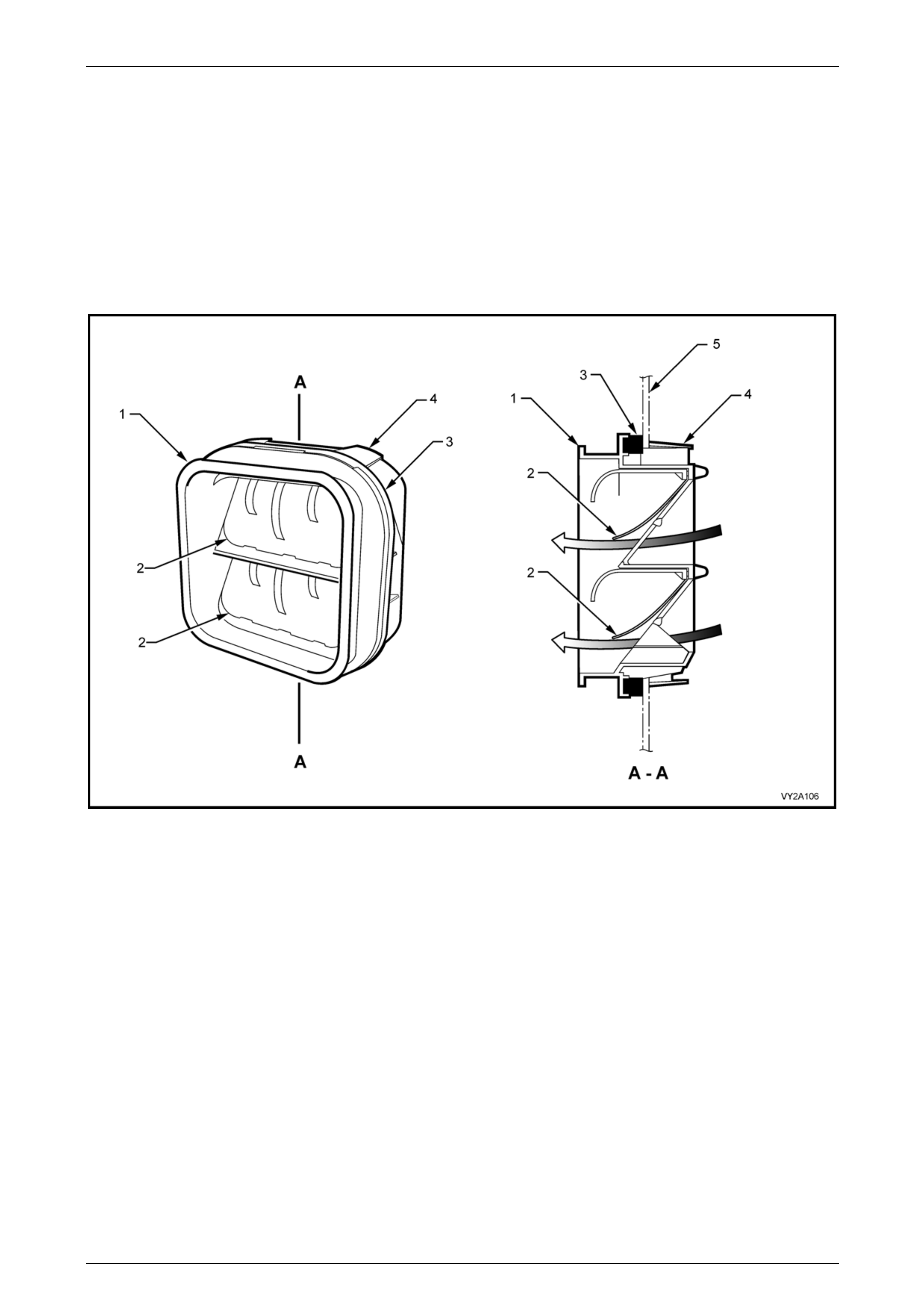
Outlet Assembly
Each ventilation outlet consist s of a fluted plastic housing (1) containing two flexible rubb er seals (2), refer to
Figure 2A – 18. When positiv e cabin air pressure acts upon the seals, they deflect outward to allow air to exit the vehicle.
Air may only exit and not enter the vehicle via the body ventilation outlets.
The ventilation outlet housing is retained to the body panel by a locking tab (4) located at each corner. Although not a
regular maintenance item, the bod y outlets can be removed to clear away any dust or foreign matter that may impede
them from operating efficiently. This is important for reasons of dust exclusion (outlets not sealing) or over-pressurisation
of the cabin (outlets obstructed) causing poor OCC system performance.
The body ventilation outlets fulf il an additional function in allowing the doors to be closed without exerting undue air
pressure upon the windows and dust seals of the vehicle.
Figure 2A – 18
Legend
1 Outlet Housing
2 Rubber Seal
3 Foam Seal
4 Locking Tab (four places)
5 Body Panel
HVAC Climate Control (Manual A/C) – Description and Operation Page 2A-20
Page 2A-20
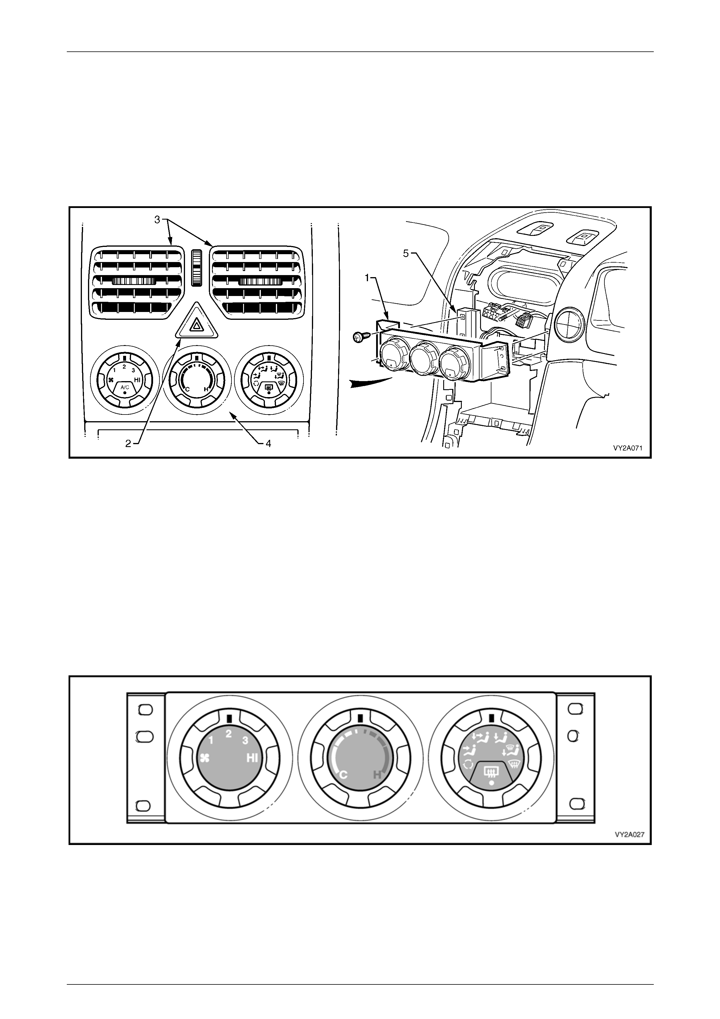
2.3 HVAC Controller – Manual A/C
The manual type HVAC controller (1) is located below the hazard switch (2) and face level centre vents (3), refer to
Figure 2A – 19. It is of modular construction and has contained within, or mounted to the rear of it, all switching hardware
required to control the HVAC system. Included in its functions are buttons for activating the air-conditioning and the
heated rear window.
The controller is installed b ehind the instrument panel centre fascia (4) and is attached to the instrument panel (5) at four
points.
Figure 2A – 19
Configuration
Three rotary switches are mounted on the front housing of the controller. They are, from left to right:
• blower fan switch (incorporating a push-button A/C switch where A/C is fitted),
• temperature control switch, and
• mode control switch (incorpor ating a push-button heated rear window switch).
There are two configurations of manual type HVAC controll ers:
1 Figure 2A – 20 shows the controller fitted to mode ls without air-conditioning. The air-conditioning switch is deleted
from the fan speed switch. The centre bezels of the switches are grey.
Figure 2A – 20

HVAC Climate Control (Manual A/C) – Description and Operation Page 2A-21
Page 2A-21
2 Figure 2A – 21 shows the controller fitted to all mo dels with air-conditioning. The air-conditioning switch is fitted to
the fan speed switch. The centre bezels of the switches are grey.
Figure 2A – 21
3 A design variation between equivalent co nfiguration controllers is a 3° facing angle, biase d towards the driver, of
the dials and front housing. The rear housing of the controller (1) is coloured bl ack. The letter R (2) (for RHD) is
moulded to the mounting flange of the rear housing for additional identification purposes, refer to Figure 2A – 22.
Figure 2A – 22
Functions
A/C Switch
The A/C switch is located at the bottom of the blower fan rotary switch, which is used to engage or disengage the
air-conditioner compressor. The in dicator lamp within the switch will illuminate when the A/C compressor is engaged.
Heated Rear Window Switch
The heated rear windo w switch is located at the bottom of the mode control switch, which is used to turn on or off the
heated rear window element. The indicator lamp within the switch will illuminate when the heated rear windo w elem ent is
on.
After switching the heated rear window on, it will automatically turn off after 15 minutes. To reactivate the heated rear
window, push the button again. This will turn on the heated rear window circuit for an ad ditional 15 minutes.
HVAC Climate Control (Manual A/C) – Description and Operation Page 2A-22
Page 2A-22
Blower Fan Switch
Four blower fan speeds are available – a fan speed has to be selected before the A/C system can be engaged. The fan
is in the off position when the position indicator is aligned with the fan symbol.
Temperature Control
On the temperature control switch, C is the full cold position and H is th e full hot position.
The controller is connected vi a a rod and levers to the air mix doors in the HVAC case. The air mix d oors control the
amount of incoming air flowing throug h the heater core, in accordance with the selected cabin temper ature. This
regulates the amount of heated air mixing with the unheated or air-conditioned air.
Refer to 2.8 Heating, Ventilation and Air-conditioning (HVAC) Unit for further information.
The heater water valve is held in the close d p ositio n by vacuum generated by the engine. When the third detent is
selected from the full cold position via the te mperature control, the water valve vacuum s witch located on the rear of the
HVAC controller is activated and the vacuu m line to the water valve is vented. This allows hot water flow into the heater
core and subsequent heatin g of the vehicle cabin. Refer to 2.4 Heater for further information.
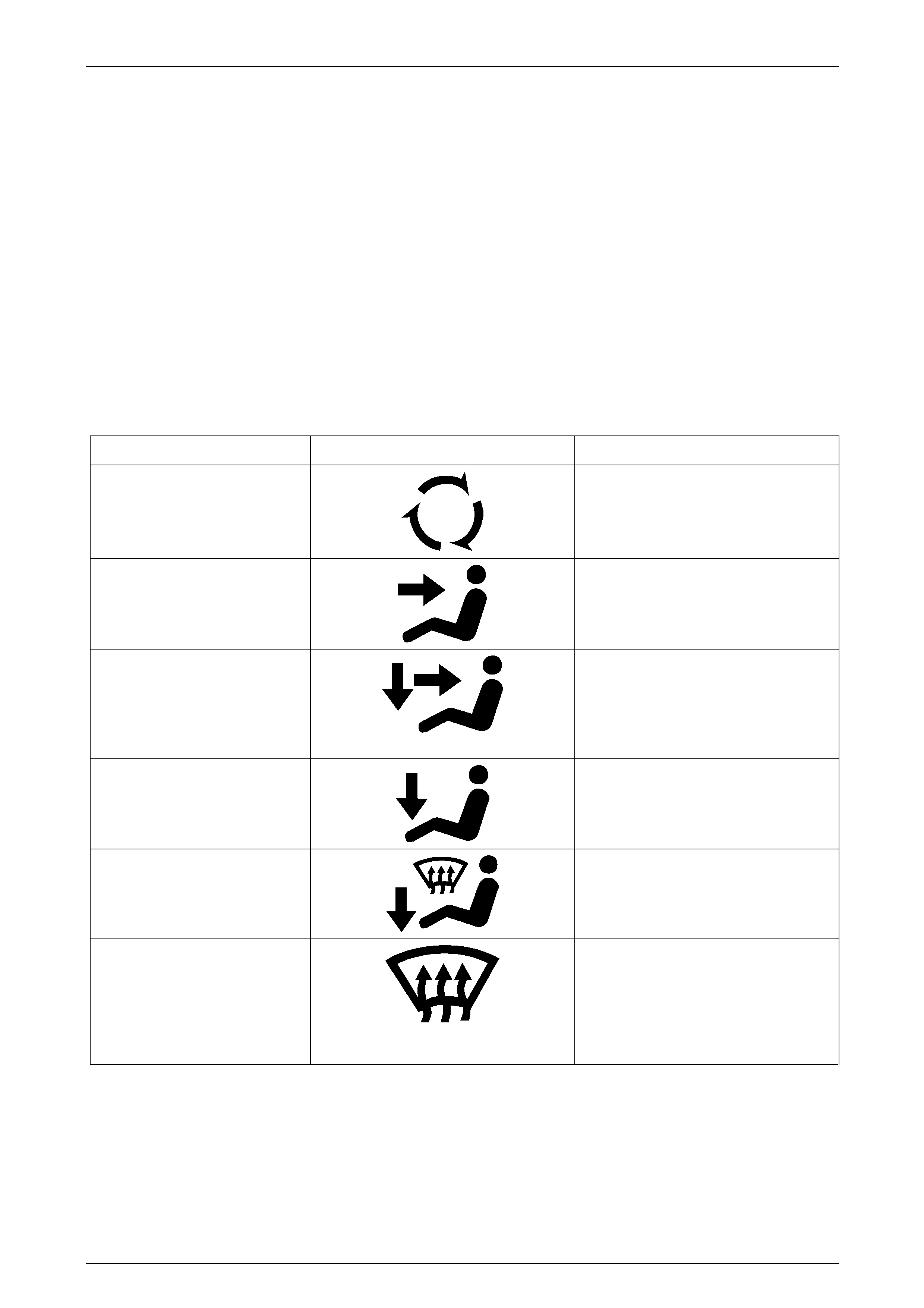
Manual Mode Control Symbols
Mode Symbol Description
100% Recirculated Air
With the manual mode control switched to
this position there is no fresh air entry into
the vehicle. Air is directed to the centre,
side and rear (where fitted) passenger
vents.
Face Mode
In this position air is directed to the
centre, side and rear (where fitted)
passenger vents.
Bi-Level
In this position the air is directed to the
floor, centre and side vents. When using
bi-level with the temperature control i n the
central position, warm air will be directed
to the feet and cooled air direct ed to the
face and side vents.
Floor
In this position the main airflow is directed
to the floor.
Blend
In this position air is directed to the floor
as well as to the demist ducts.
Demist
In this position air is directed to front
windscreen and front side windows only,
through the demist ducts. It is
recommended that the A/C button and
maximum heating be selected, as this will
provide accelerated dem isting
(dehumidification).

HVAC Climate Control (Manual A/C) – Description and Operation Page 2A-23
Page 2A-23
Components and Construction
The front and rear housings of the HVAC controller are cons tructed of plastic. The complete unit is assembled without
the use of fasteners; the front housing clips over the rear housi ng at six locations. Contained within this assemb ly is a
printed circuit board, which is retained within the rear housin g.
Attached to the back of the rear housing are the following components, refer to Figure 2A – 23:
• Water valve vacuum switch (14) – for water valve control (heater core flow).
• Mode switch vacuum valve (15) – for operation of the HVAC vacuum actuators.
• Pinion and crescent gear (11) – for mechanical actuation of the water valve vacuum switch and HVAC air mix
doors.
• Electrical switch / connector (9) – for blower fan operation.
• Electrical connector (10) – for illumination, A/C and heated rear window swit ching.
All these items are removable from the rear housing, except the illumination, A/C switch and heated rear window
electrical connector which is bonded to the printed circuit board.
There are no replaceabl e bulbs contained within the unit. Five LEDs provide the necessary illumination. If an LED fails to
function, the printed circuit board must be replaced.
Other components that may be individually serviced are the water valve vacuum switch, the mode switch vacuum valve
and the air mix door rod retainer (12). The three rotary switches and the front housing are service d as a u nit.
Figure 2A – 23
Legend
1 Blower Fan Switch
2 Blower Fan Speed Position Indicator
3 Temperature Control Switch
4 Temperature Control Position Indicator
5 Mode Position Switch
6 Mode Position Switch Position Indicator
7 Heated Rear Window Switch
8 Heated Rear Window Switch ON Indicator LED
9 Blower Fan Switch Connector
10 Illumination, A/C Switch and Heated Rear Window
Connector
11 Temperature Control Pinion
12 Air Mix Door Rod Retainer
13 Temperature Control Crescent Gear
14 Water Valve Vacuum Switch
15 Mode Switch Vacuum Valve
16 A/C Switch
17 A/C ON Indicator LED
HVAC Climate Control (Manual A/C) – Description and Operation Page 2A-24
Page 2A-24
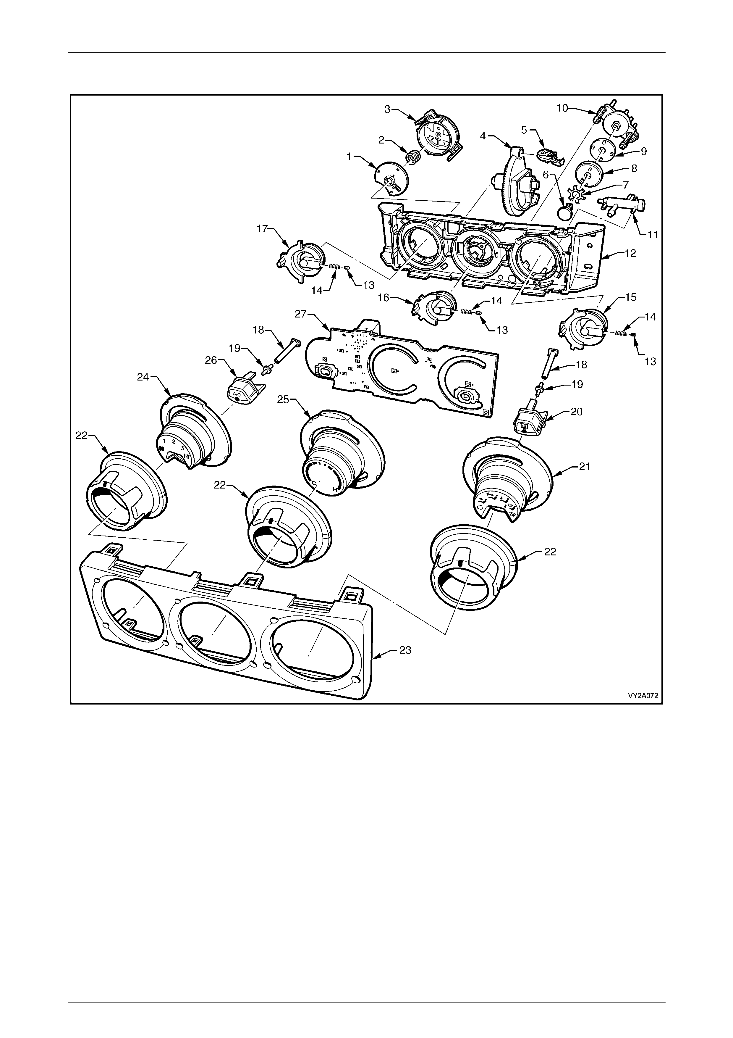
Exploded View
Figure 2A – 24
Legend
1 Disc – Blower Fan Switch
2 Spring – Blower Fan Switch
3 Housing – Blower Fan Switch
4 Crescent Gear
5 Air Mix Door Rod Retainer
6 Retaining Pin – Vacuum Valve
Mode Switch
7 Preload Spring – Vacuum Valve
Mode Switch
8 Disc – Vacuum Valve Mode
Switch
9 Gasket – Vacuum Valve Mode Switch
10 Housing – Vacuum Valve Mode Switch
11 Water Valve Vacuum Switch
12 Rear Housing
13 Detent Ball (3 places)
14 Detent Spring (3 places)
15 Shaft – Mode Switch
16 Shaft – Temperature Switch
17 Shaft – Blower Fan Switch
18 Diode Illumination Tube (2 places)
19 Diode Illumination Lens (2 places)
20 Heated Rear Window Switch Button
21 Bezel – Mode Switch
22 Dial (3 places)
23 Front Housing
24 Bezel – Blower Fan Switch
25 Bezel – Temperature Switch
26 A/C Switch Button
27 Printed Circuit Board
HVAC Climate Control (Manual A/C) – Description and Operation Page 2A-25
Page 2A-25
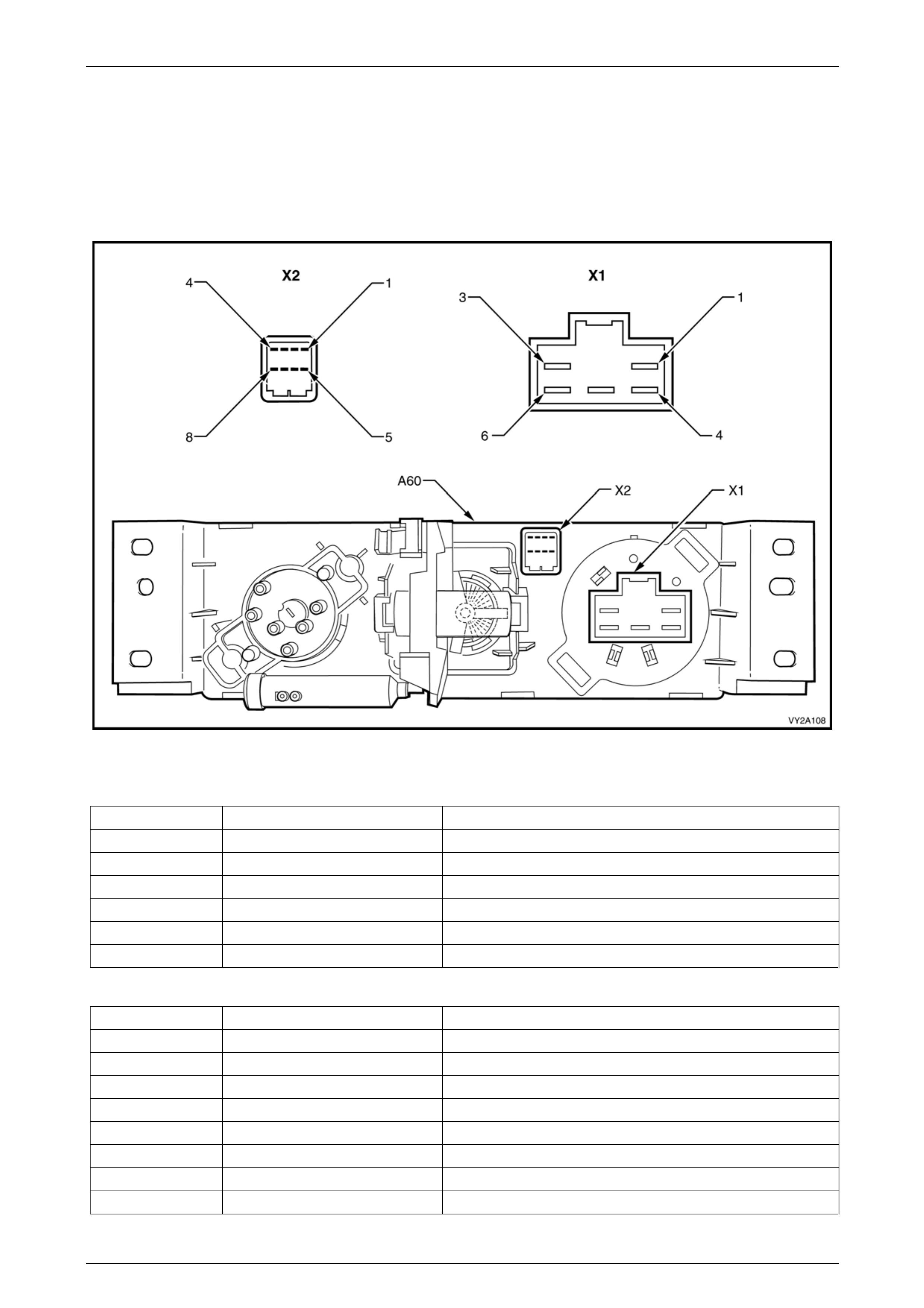
Electrical Connections
Two electrical connectors are located at the rear of the manual HVAC controller. In accordance with the Integrated
Vehicle Electrical Design (IV ED) standard, the controller is designated as A60 and the connectors ar e designated as X1
and X2.
Connector X1 is moulded to the rear of the b lower switch and connector X2 is bonded to the rear of the printed circuit
board. Figure 2A – 25 provides a view of the connector terminal assignments and the following tables provide information
on their function.
Figure 2A – 25
Connector X1
Pin Number Wire Colour Function
X1-1 Orange / Green Ground via Blower Inhibitor Relay
X1-2 – Not Connected
X1-3 Dark green / Yellow Fan Speed 1 – Blower Resistor Assembly
X1-4 Yellow / Black Fan Speed HI – Blower Relay
X1-5 Red / Yellow Fan Speed 3 – Blower Resistor Assembly
X1-6 Red / Green Fan Speed 2 – Blower Resistor Assembly
Connector X2
Pin Number Wire Colour Function
X2-1 Orange Rear Window Demister Select to BCM
X2-2 Red / White Air-conditioning Select to BCM
X2-3 Red / Black Air-conditioning ON LED Indication and Status to BCM
X2-4 Grey Instrument Dimming Control to BCM
X2-5 Pink / Blue Fuse F13 – Power for Switching and LED Indication
X2-6 – Not Connected
X2-7 Black / Red Demister ON LED Indication and Status to BCM
X2-8 Brown / White F use F 11 – Power for Instrument Illumination
HVAC Climate Control (Manual A/C) – Description and Operation Page 2A-26
Page 2A-26
2.4 Heater
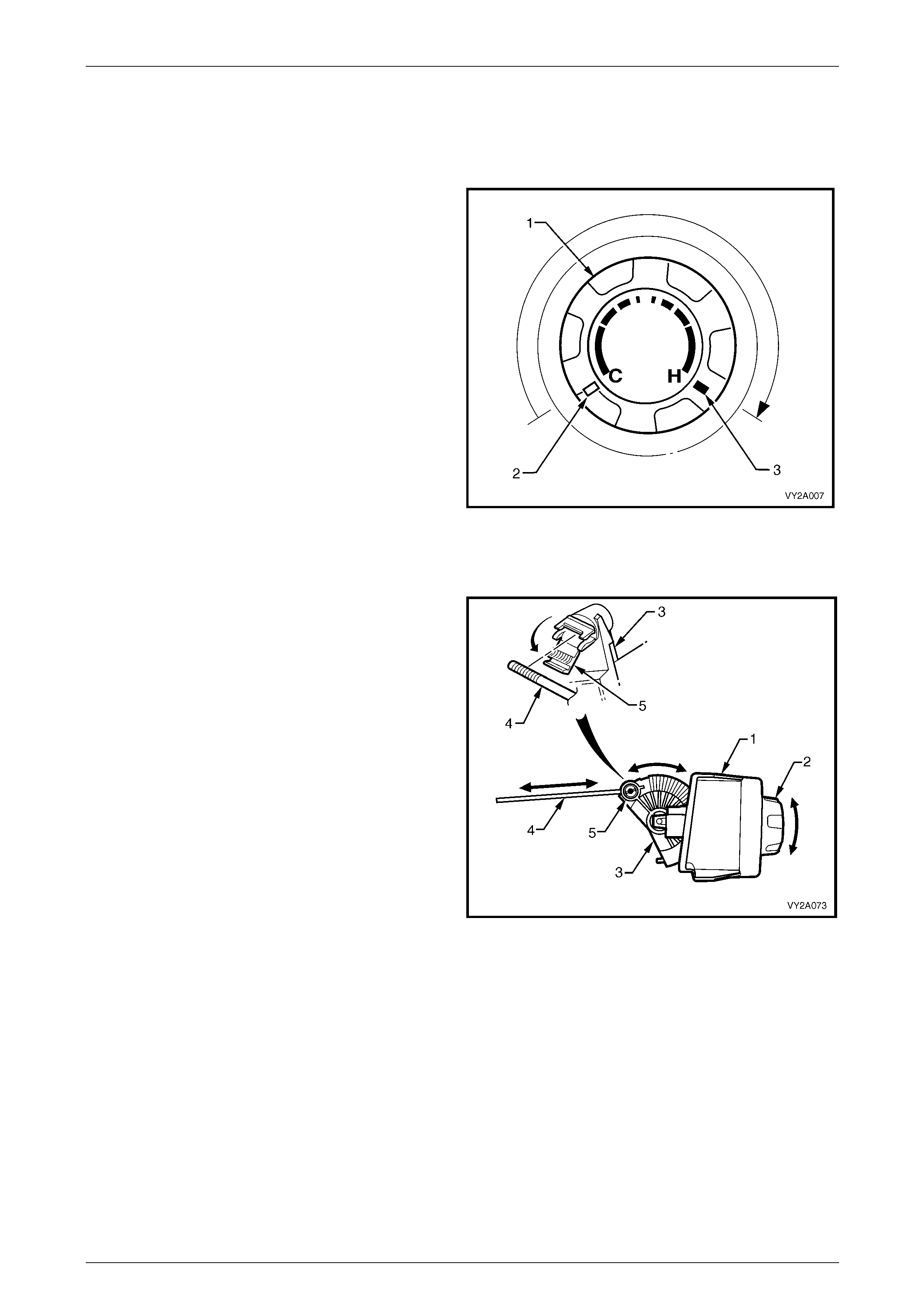
Temperature Control Switch – Manual A/C
When the temperature switch (1) is turned clockwise from
the full cold position (2) to the full hot position (3), the pinion
and crescent gear mounted to the rear of the controller are
rotated. This action simultaneously opens HVAC airflow
through the heater core and vents vacuum from the water
valve allowing heated coolant to flow through the heater
core.
Figure 2A – 26
Air Mix Door Control Mechanism – Manual A/C
On all manual air-conditioni ng systems the air mix door
function is the only HVAC airflow control not to use a
vacuum actuator.
An actuating rod provides a mechanical connection between
the HVAC controller (1) and the HVAC unit. The rod is
installed between the tempera t ure switch mechanism and
the air mix door levers.
The amount of airflow through the heater cor e is determined
by the degree of opening at the air mix door. When the
temperature switch (2) is rotated, the air mix door is opened
or closed by the crescent gear (3) pushing or pulling the
actuating rod (4). The rod is attached to the crescent gear
by a pivoting rod retainer (5).
The assembled position of the retainer on the actuating rod
is adjustable. The retainer must clamp the actuating rod at a
specific location if the correct relative positions of the air mix
door and temperature switch are to be maintained.
For correct installation of the actuating rod, refer to
Section 2C HVAC Climate Control (Manual A/C) – Removal
and Installation. Figure 2A – 27
HVAC Climate Control (Manual A/C) – Description and Operation Page 2A-27
Page 2A-27
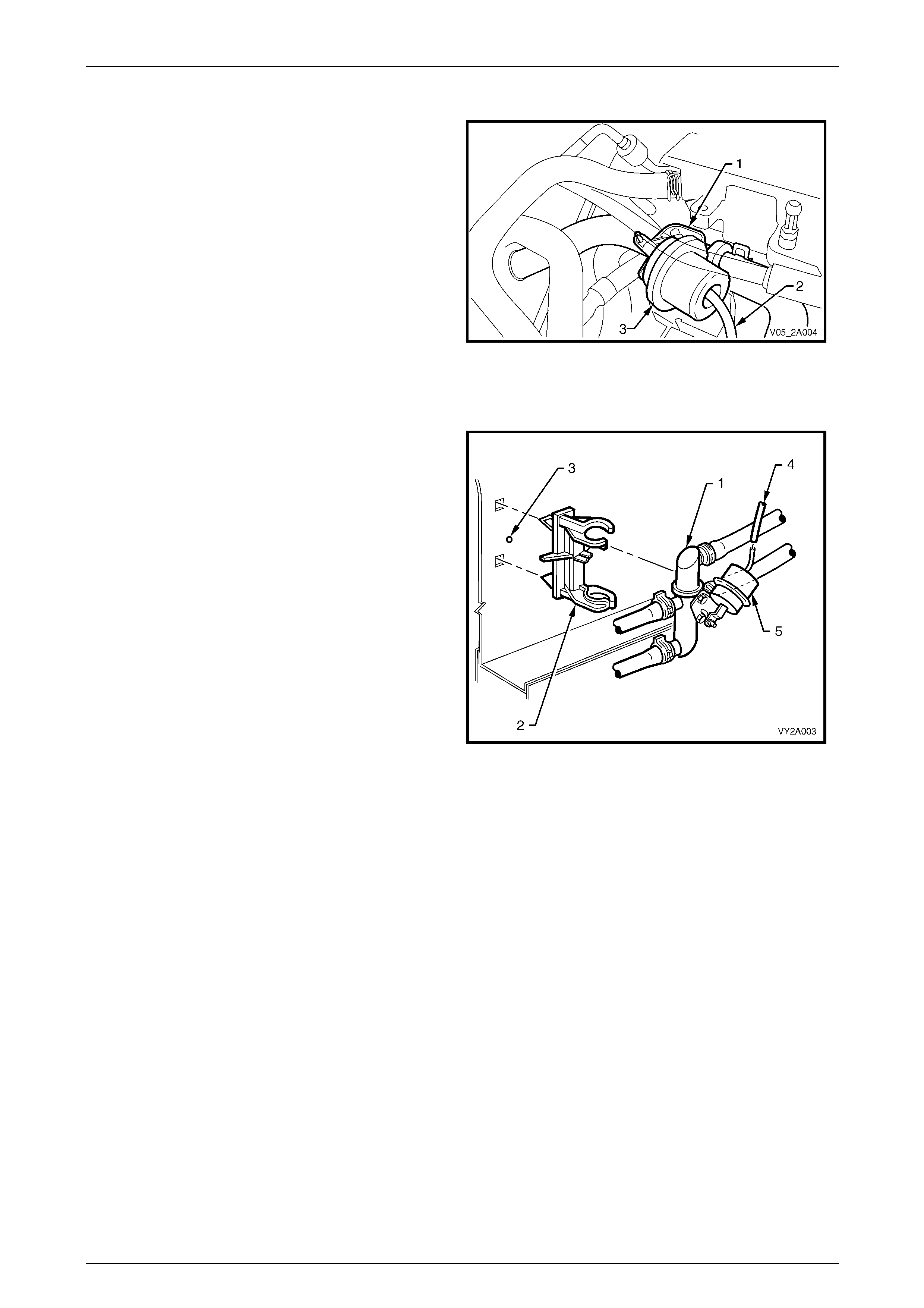
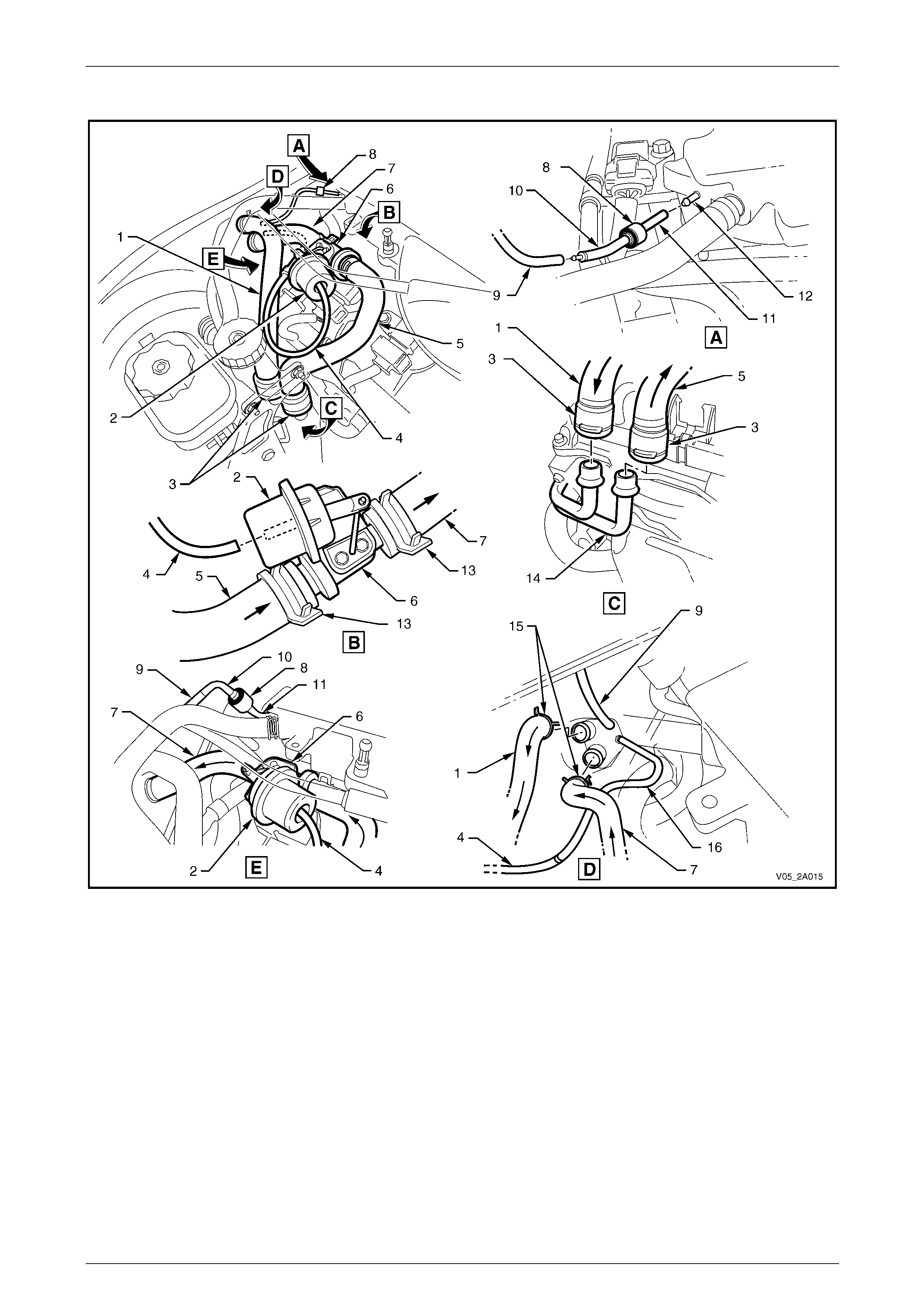
Water Valve Assembly – V6
The heater water valve is located in the engine bay and
rests above the right-hand side camshaft cover.
It is attached to a mounting bracket (1) and bolt on the
engine block.
The vacuum line (2) attached to the water valve vacuum
actuator (3) is connected to the water valve vacuum switch
mounted on the HVAC controller.
When full vacuum is applied to the water valve actuator, full
closure of the valve occurs and no coola nt will flow through
the heater core.
Figure 2A – 28
Water Valve Assembly – GEN III V8
The heater water valve assembly (1) is located in the engine
bay attached to a mounting clip (2), on the ri ght-hand side
wheelhouse panel (3).
The vacuum line (4) attached to the water valve vacuum
actuator (5) is connected to the water valve vacuum switch
mounted on the HVAC controller.
When full vacuum is applied to the water valve actuator, full
closure of the valve occurs and no coola nt will flow through
the heater core.
Figure 2A – 29
HVAC Climate Control (Manual A/C) – Description and Operation Page 2A-28
Page 2A-28
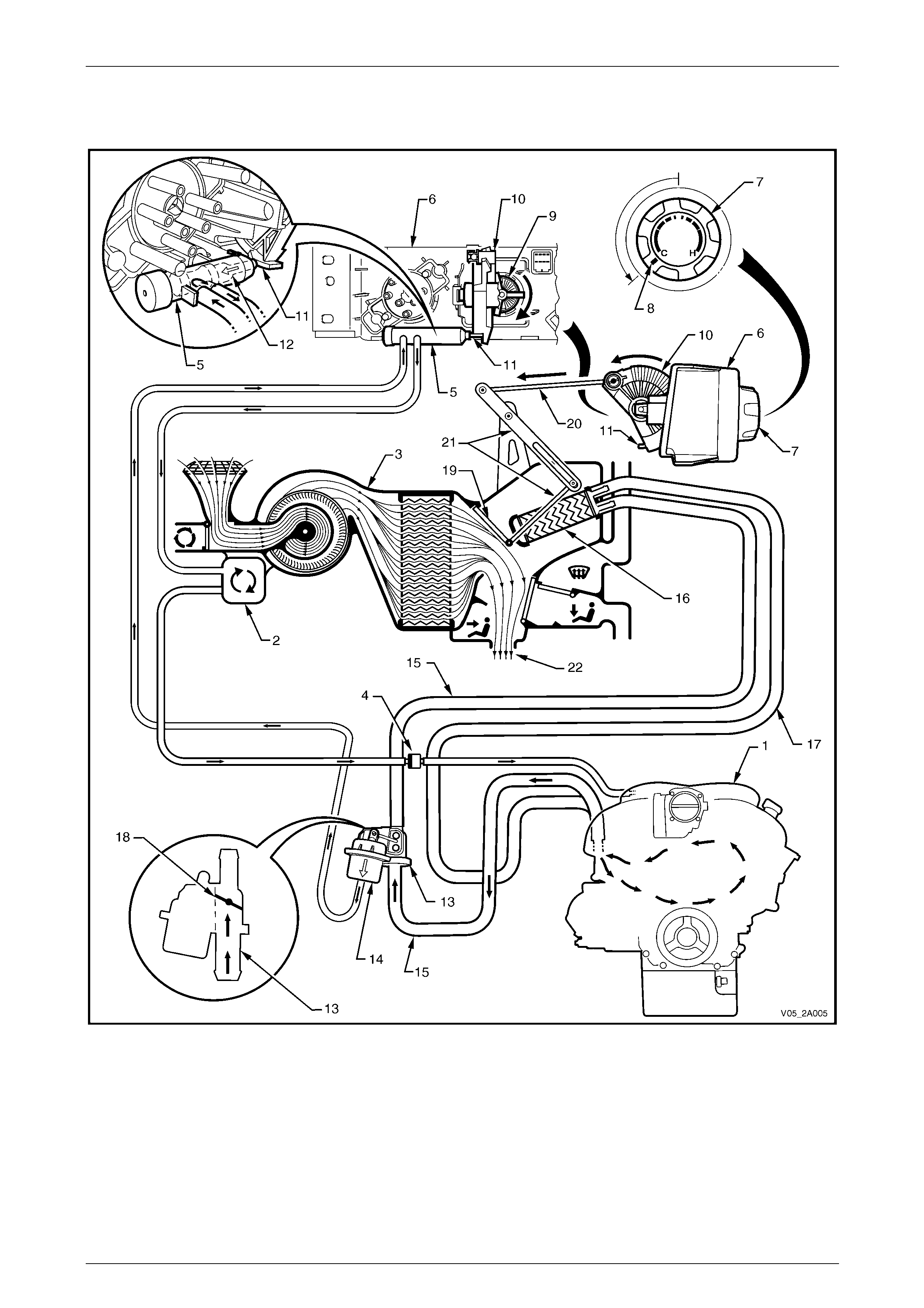
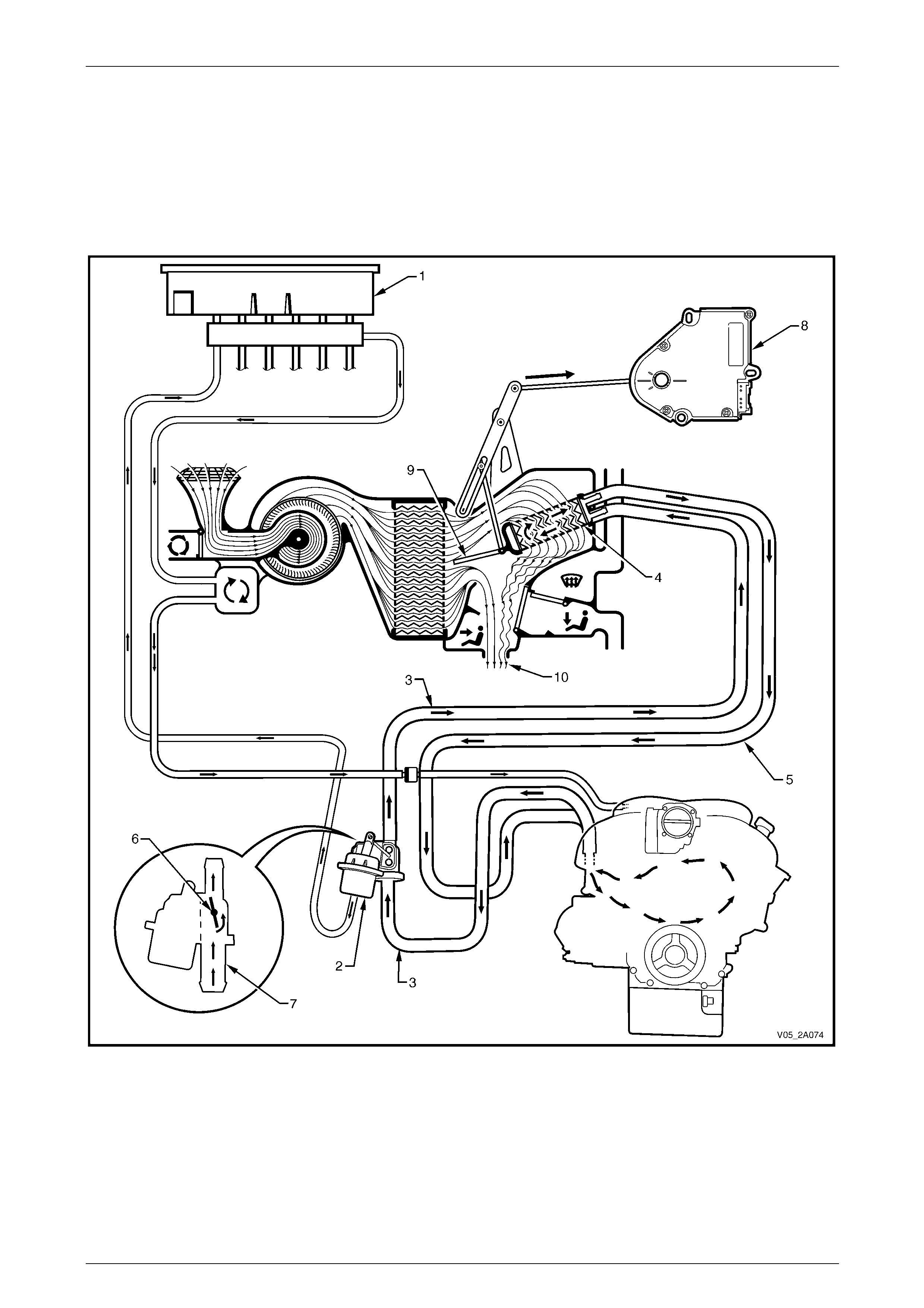
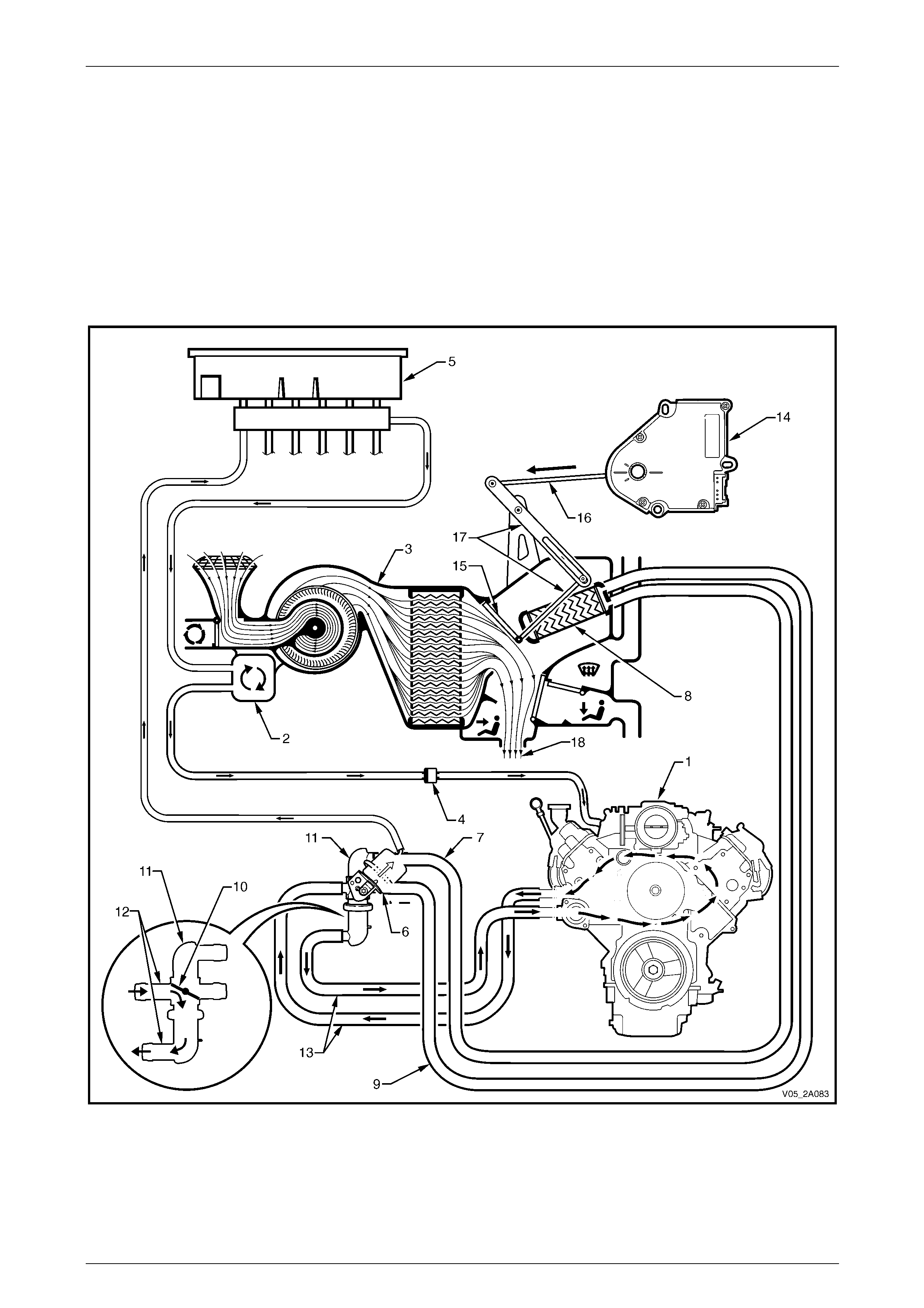
Heater Operation – Manual A/C – V6
Full Cold
Figure 2A – 30
Vacuum generated within the inle t manifold (1) o f the eng ine is stored within the vacu um tank (2) mo unted on the side the
HVAC unit (3), refer to Figure 2A – 30. Vacuum is retained within the HVAC system by the one way check valve (4) and is
directed to the water valve vacuum switch (5) mounted to the rear of the HVAC controller (6). When the temperature switch
(7) is turned to the full co ld positi on (8 ), the pinion gea r (9) rotate s the crescent ge ar (10) so the ramp (11) on th e cres cent
gear pushes the plun ger (12) insi de the w ater val ve va cuu m swit ch inward aga in st spring pre s sure . In th is posi tion , t he
water valve vacuum switch allows vacuum to be directed to the water valve (13). When vacuum is applied to the water valve
vacuum actuator (14), no coolant can flow through the inlet heater hose (15), the heater core (16) or the outlet heater hose
(17) because the disc (18) in the water valve is in the closed position.
The crescent gear is also mechan ically connected to the HVAC air mix door (19) via the actuating rod ( 20) and
levers (21). As well as operating the pl unger of the water valve vacuum switch, the crescent gear simulta neously locates
the air mix door in a position that does not allow any air to flow through the heater core i n the full cold mode. The result is
that all air (22) entering the vehicle cabin will be cold air.
HVAC Climate Control (Manual A/C) – Description and Operation Page 2A-29
Page 2A-29
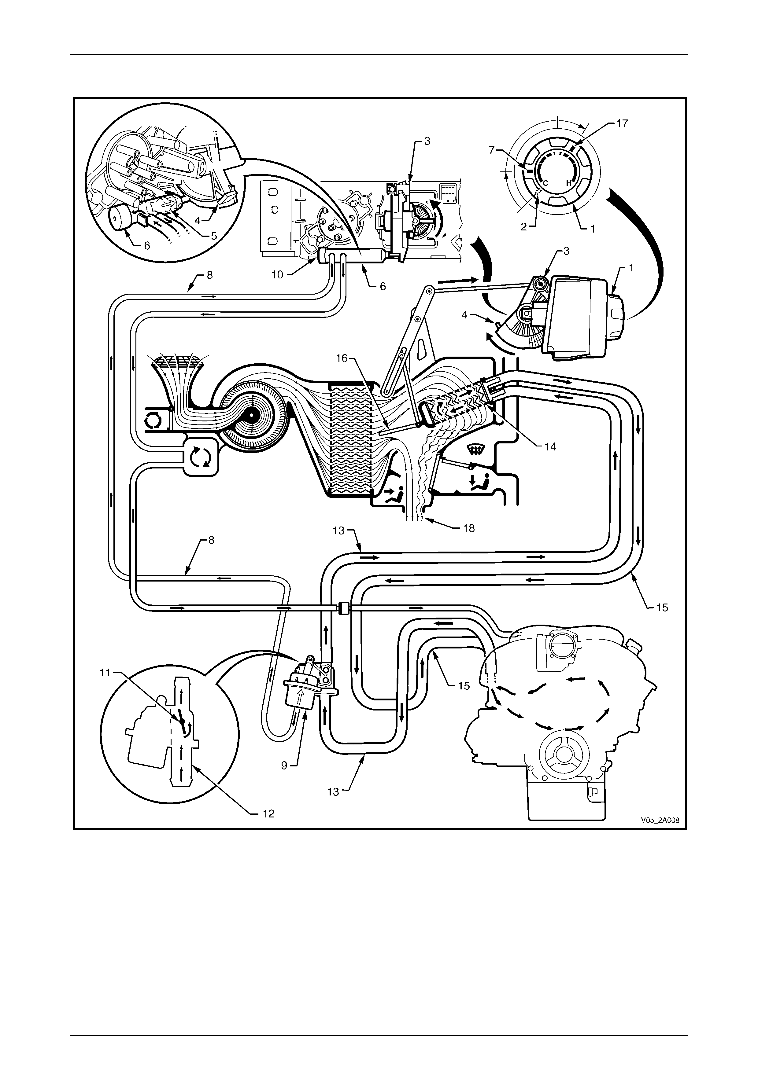
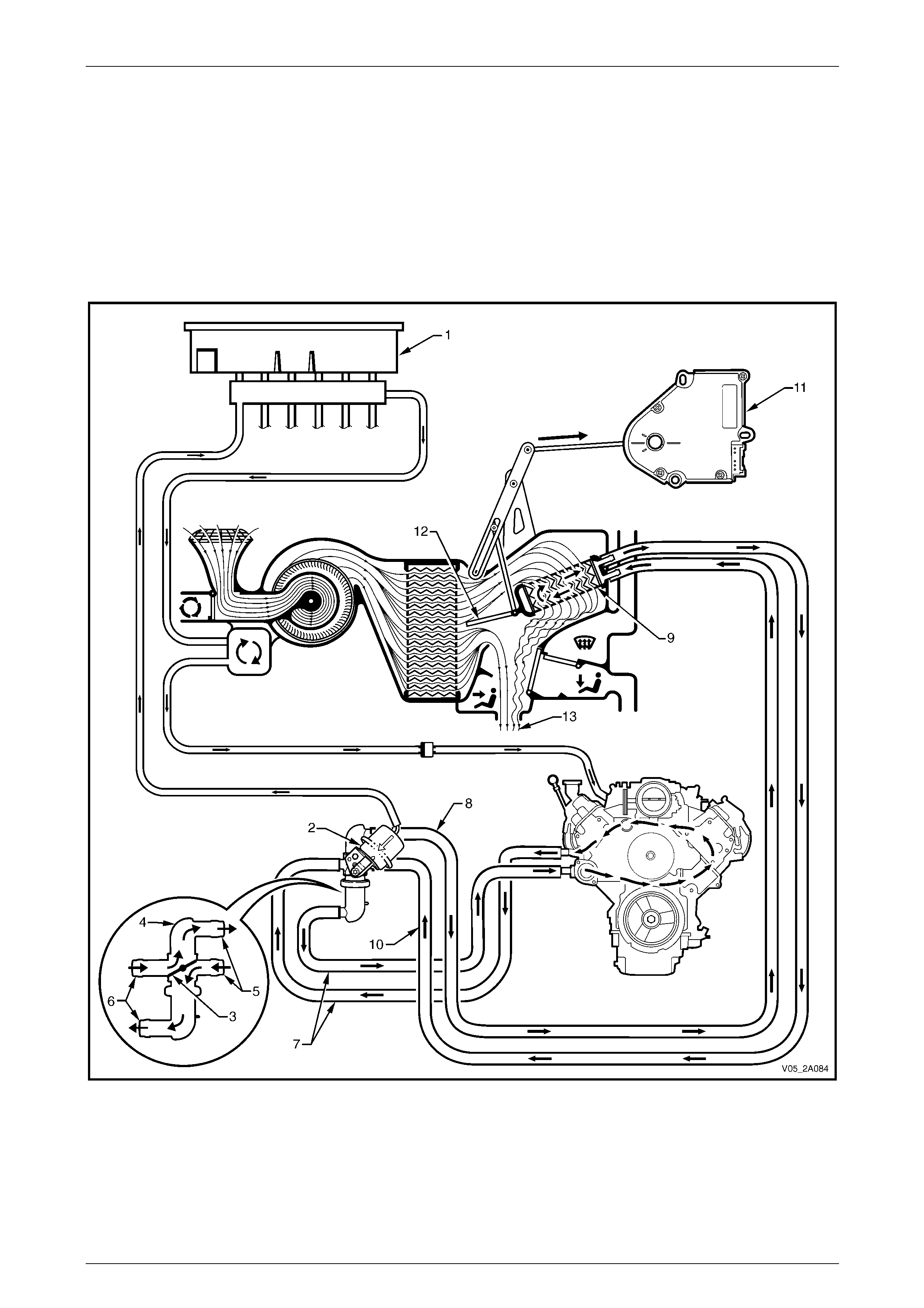
Warm
Figure 2A – 31
When the temperature switch (1) is turned from the full cold position (2), the crescent gear (3) rotates backwards moving
the ramp (4) away from the plunger (5) of the water valve vacuum switch (6), refer to Figure 2A – 31. Spring pressure
moves the plunger out ward and at the third detent positi on (7) of the temperature switch, the vacuum line (8) to the water
valve actuator (9) is vented through the exhaust port (10) of the water valve vacuum switch. When the actuator is
relieved of vacuum, the disc (11) in the water valve (12) will rotate and allow hot water to flow through inlet heater hose
(13) into the heater core (14) and through the outlet heater hose (15) back to the engine. As the crescent gear rotates
backward, it pulls the air mix door (16) ope n. W hen the temperature switch is turned to a warm position (17), the air mix
door will be partially open. This will cause some incoming air to pass through the heater core and some to air to bypass
the heater core. The mixture of heated and cool air (18) will result in warm air entering the vehicle cabin.
HVAC Climate Control (Manual A/C) – Description and Operation Page 2A-30
Page 2A-30
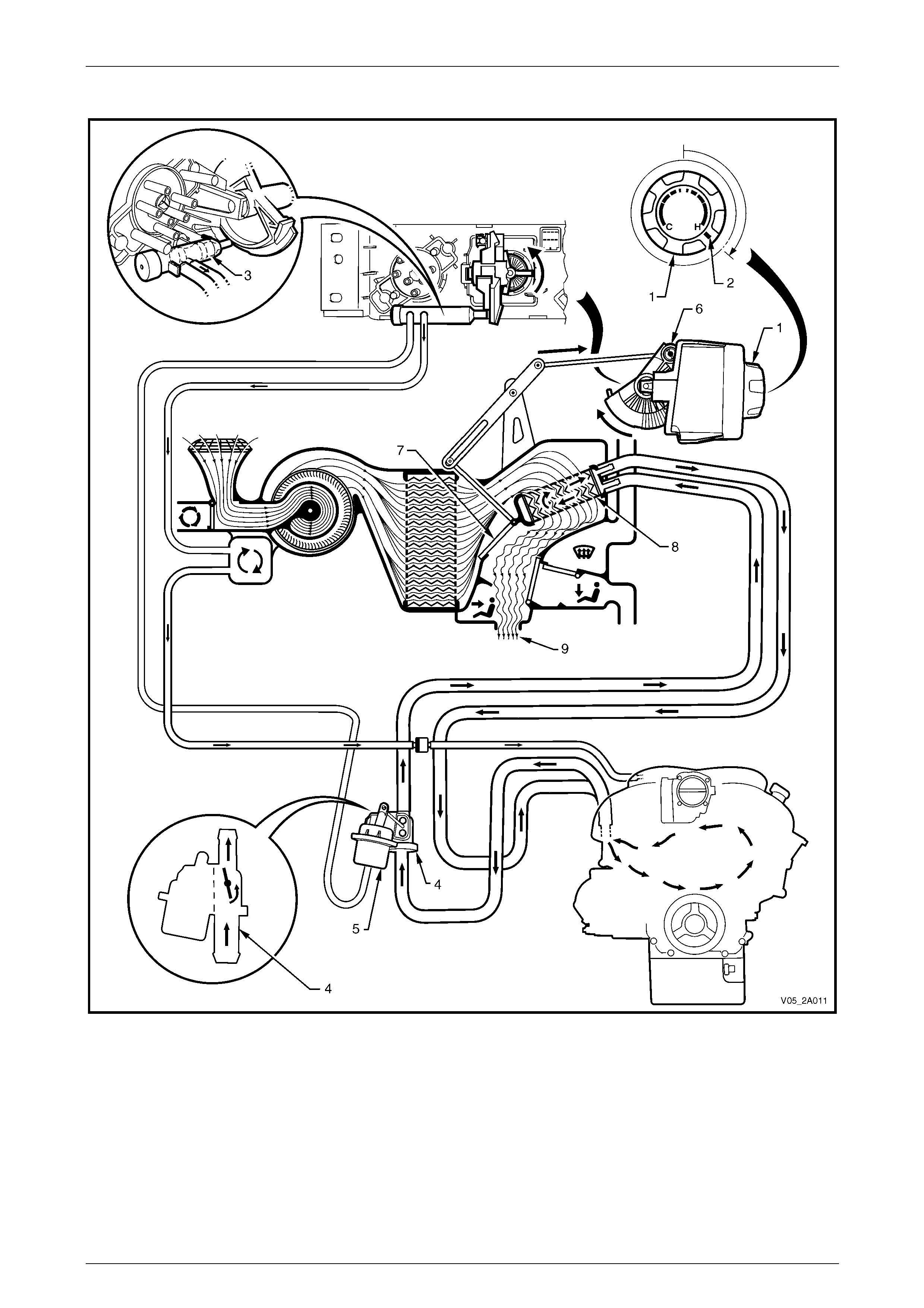
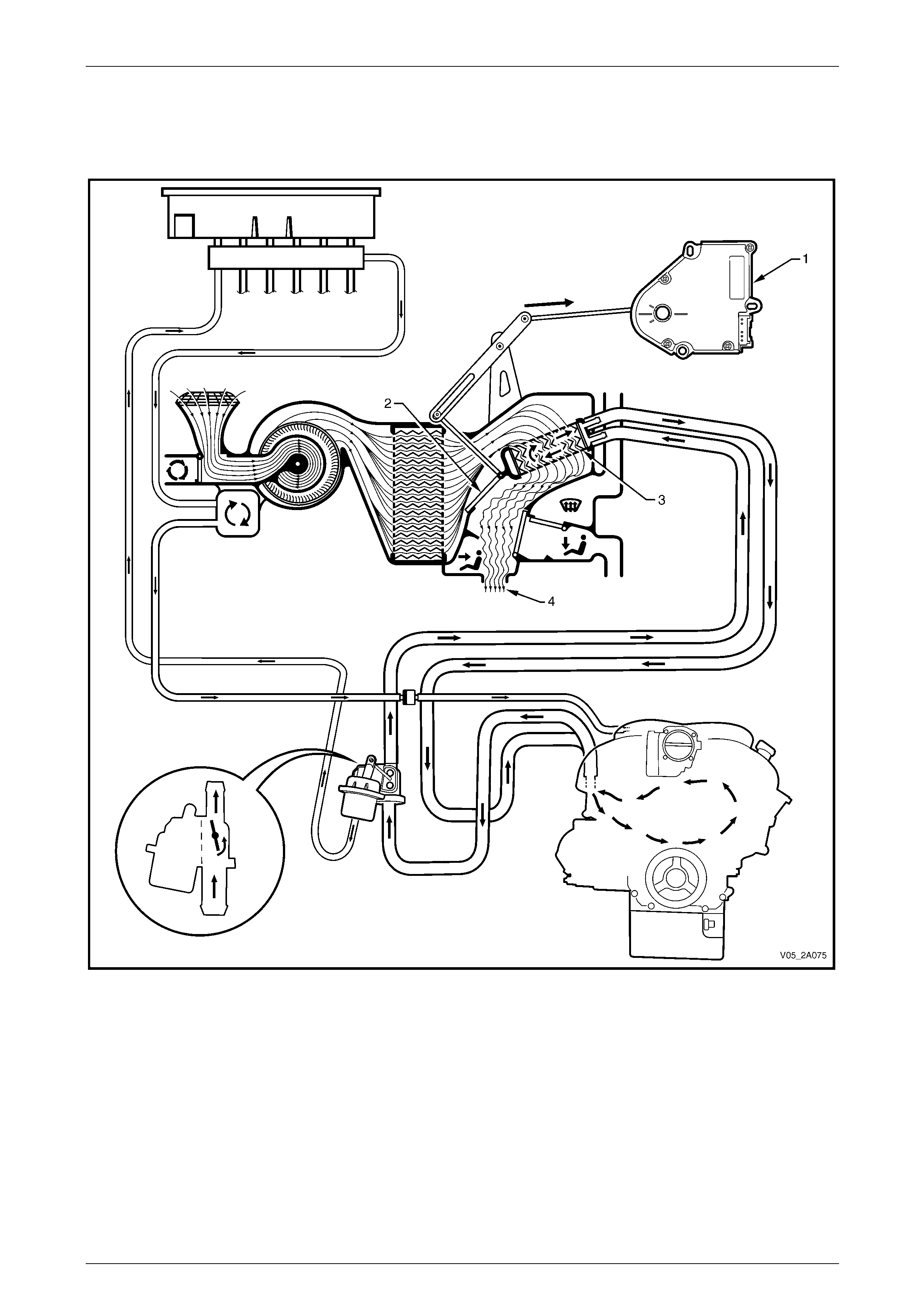
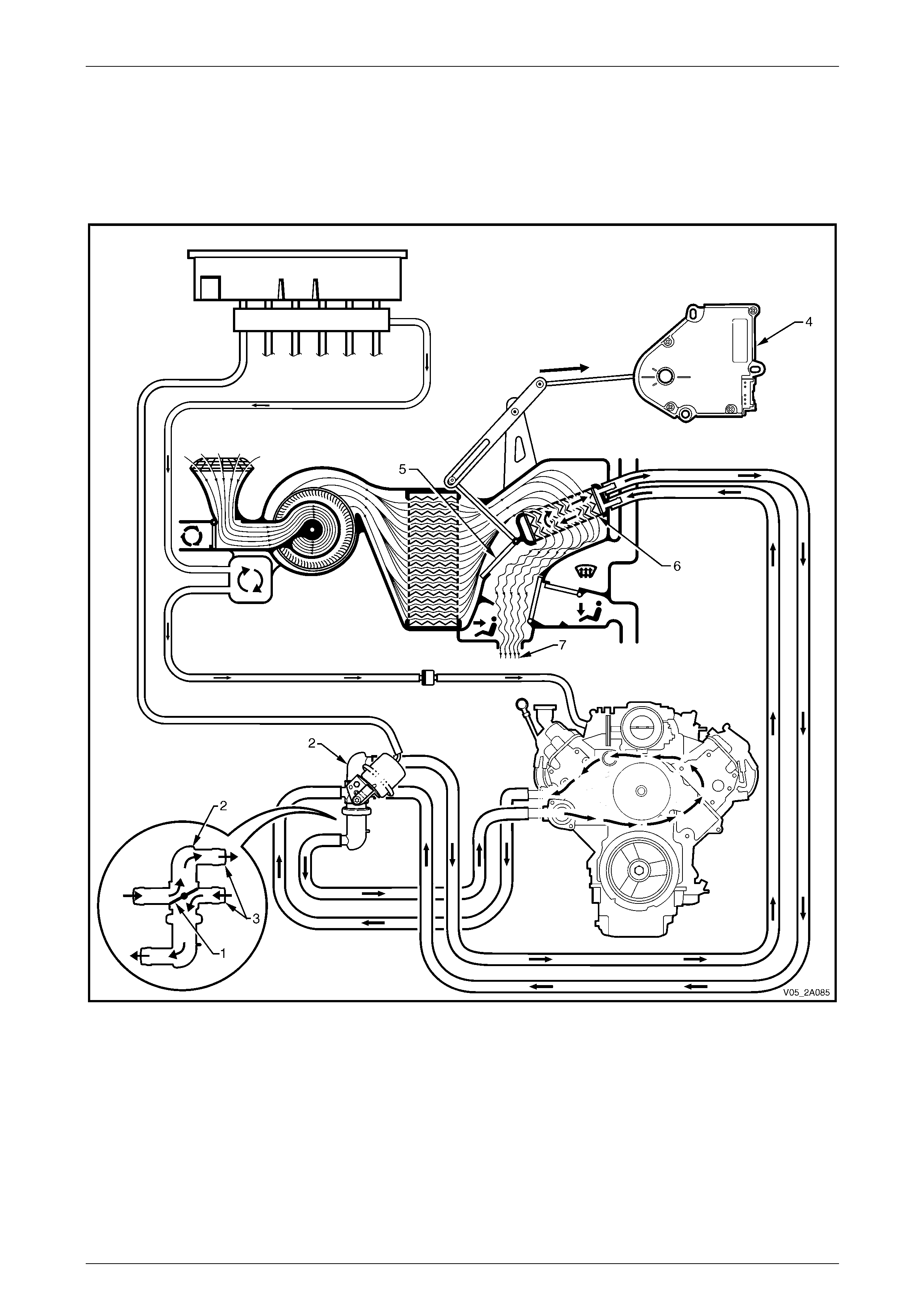
Full Hot
Figure 2A – 32
When the temperature switch (1) is turned to in the full hot positio n (2) the water valve vacuum switch plunger (3)
remains in the same position, refe r to Figure 2A – 32. Therefore, the water valve (4) remains in the fully o pen position
because the water valve actuator (5) is devoid of vacuum.
In the full hot position the crescent gear (6) will be rotated fully rearward. This action will move the air mix door (7) to a
position that directs all incoming air thro ugh the heater core (8). Therefore, all air (9) entering the vehicle cabin will be
heated air.
HVAC Climate Control (Manual A/C) – Description and Operation Page 2A-31
Page 2A-31
Heater Operation – Auto A/C – V6
Full Cold
Vacuum generated within the engine inlet manifold (1) is stored within the vacuum tank (2), which is mounted on the side
the HVAC unit (3), refer to Figure 2A – 33. Vacuum is retained within the system by the one-way check valve (4) and is
directed to the vacuum solenoid pack (5). When the temperature is set to a cold position, the solenoid pack allows vacuum
to be directed to the water valve vacuum actuator (6). No coolant can flow through the inlet heater hose (7), the heater
core (8) or the outlet heater hose (9) because the disc (10) in the water valve (11) is in the closed position.
An air mix door motor (12) is mechanically connected to the air mix door (13) via an actuating rod (14) a nd levers (15).
When the temperature is set to a cold position, the motor operates and mo ves the air mix door to a position that does not
allow any air to flow through the heater core. The result is that all air (16) entering the ve hicle cabin will be ambient
temperature or cooled if the air-conditioning is operating.
Figure 2A – 33
Legend
1 Inlet Manifold
2 Vacuum Tank
3 HVAC Unit
4 One-way Check Valve
5 Vacuum Solenoid Pack
6 Water Valve Vacuum Switching Valve
7 Water Valve Vacuum Actuator
8 Inlet Heater Hose
9 Heater Core
10 Outlet Heater Hose
11 Water Valve Disc
12 Water Valve
13 Air Mix Door Motor
14 Air Mix Doors
15 Actuating Rod
16 Actuating Levers
17 Cabin Air
HVAC Climate Control (Manual A/C) – Description and Operation Page 2A-32
Page 2A-32
Warm
When the temperatu re is set to a warm posi tion, th e vacuum sol enoid pack va lve (1) clo ses, and the vacuum a t the wate r
valve vacuum actuator (2) is vented, refer to Figure 2A – 34. Coolant can flow now flow through the inlet heater hose (3), the
heater core (4) and outlet heater hose (5) because the disc (6) in the water valve (7) is in the open position.
When the temperature is set to a warm position, the air mix door motor (8) also operates and moves the air mix door (9)
to a partially open position that allows some air to flow through the heater core. The position of the door is variable,
based on the temperature set. A position sensor within the motor provides feedback to the control module. The result is
that all air (10) entering the vehicle cabin will be warm.
Figure 2A – 34
Legend
1 Water Valve Vacuum Switching Valve
2 Water Valve Vacuum Actuator
3 Inlet Heater Hose
4 Heater Core
5 Outlet Heater Hose
6 Water Valve Disc
7 Water Valve
8 Air Mix Door Motor
9 Air Mix Doors
10 Cabin Air
HVAC Climate Control (Manual A/C) – Description and Operation Page 2A-33
Page 2A-33
Full Hot
When the temperature is set to the hot position, the air mix door motor (1) operates and moves the air mix door (2) to the
fully open position which directs all air through the heater core (3), refer to Figure 2A – 35. The result is that all air (4)
entering the vehicle cabin will be hot.
Figure 2A – 35
Legend
1 Air Mix Door Motor
2 Air Mix Doors 3 Heater Core
4 Cabin Air

HVAC Climate Control (Manual A/C) – Description and Operation Page 2A-34
Page 2A-34
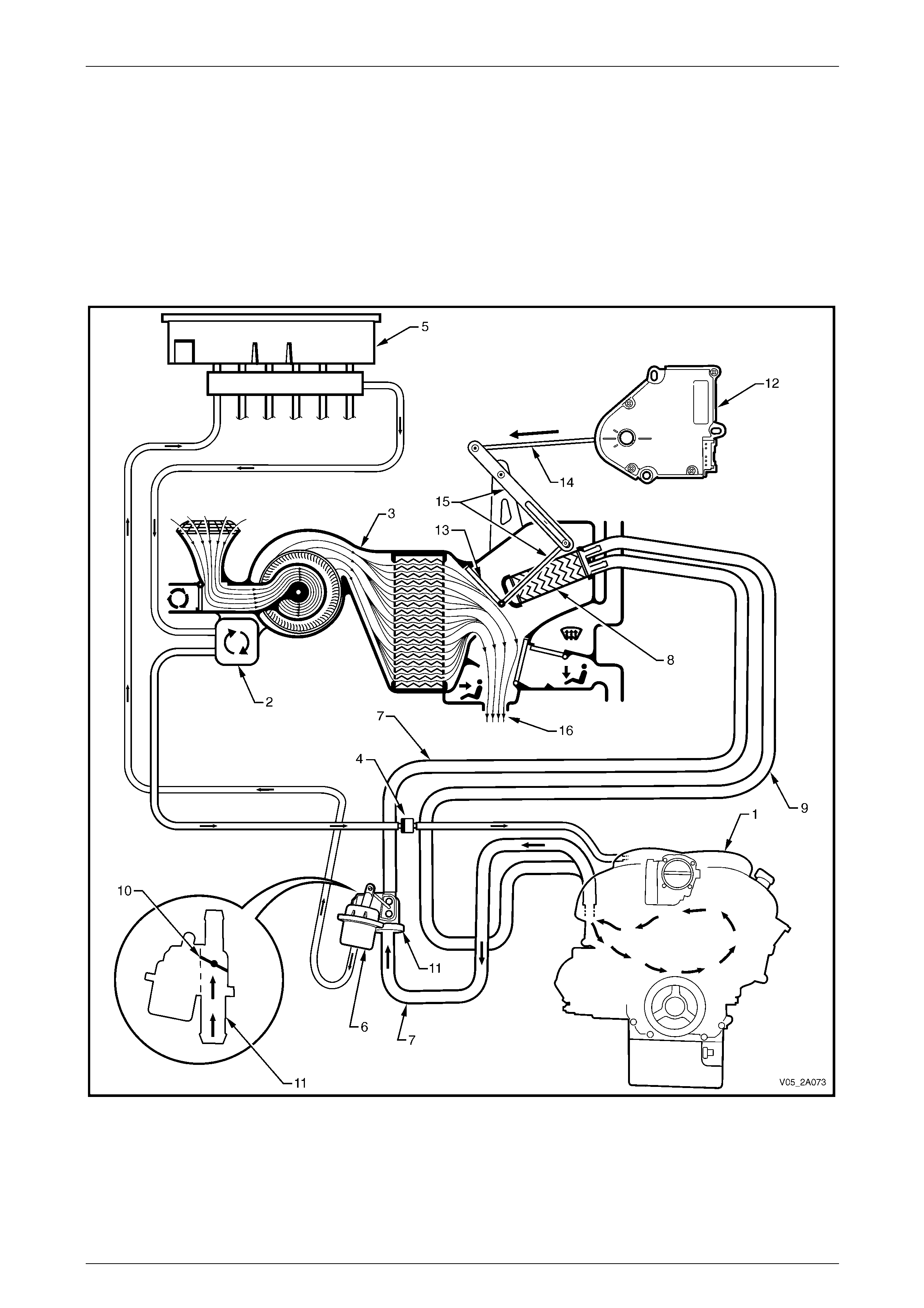
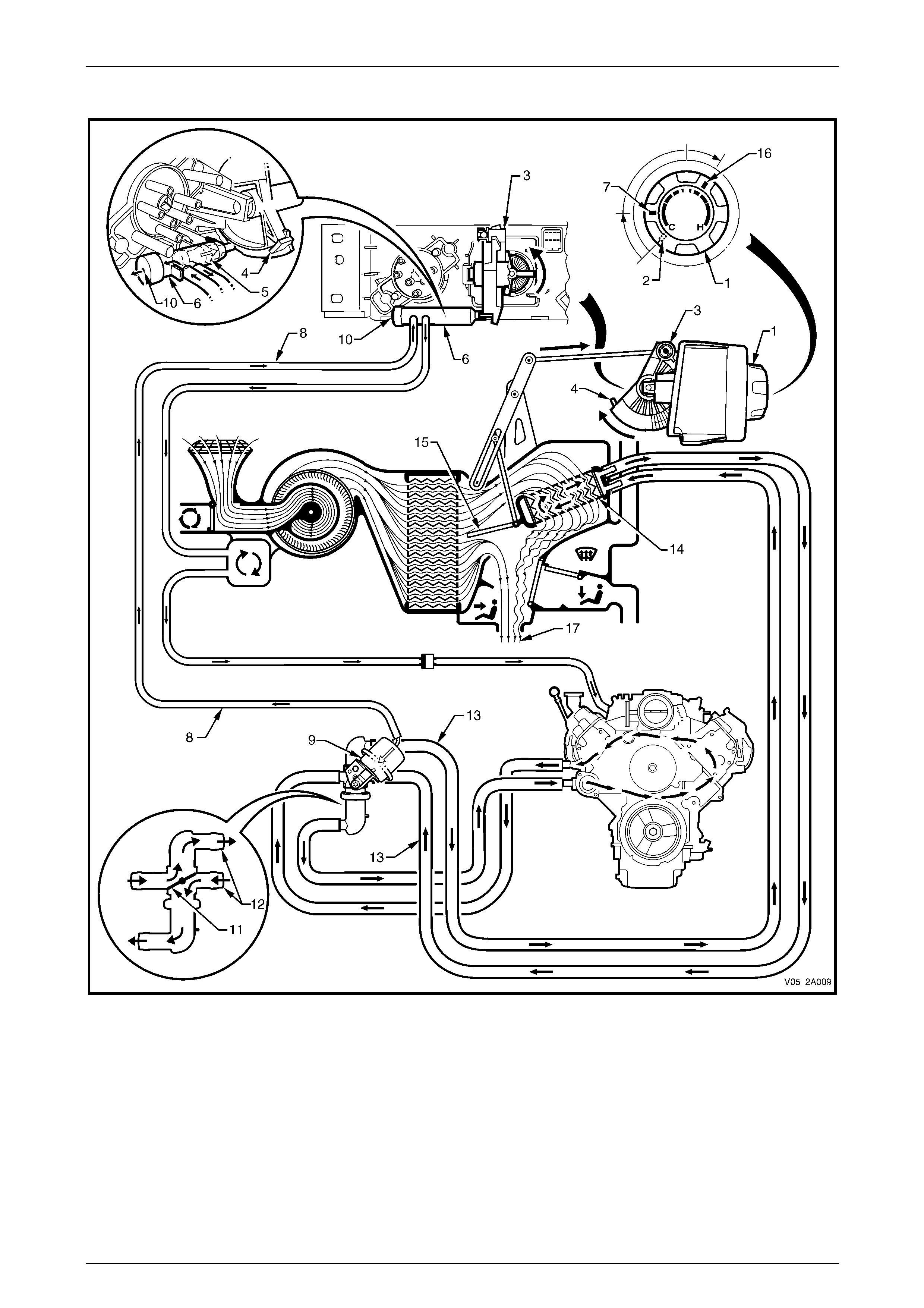
Heater Operation – Manual A/C – GEN III V8
Full Cold
Figure 2A – 36
Vacuum generated within the inlet manifold (1) of the engine is stored within the vacuum tank (2) mounted on the side
the HVAC unit (3), refer to Figure 2A – 36. Vacuum is retained within the HVAC system by the one way check valve (4)
and is directed to the water valve vacuum switch (5) mounted to the rear of the HVAC cont roller (6). W he n the
temperature switch (7) is turned to the full cold position (8), the pinion gear (9) rotates the crescent gear (10) so the ramp
(11) on the crescent gear pushes the plunger (12) inside the water valve vacuum switch inward against spring pressure.
In this position, the water valve vacuum switch allows vacuum to be directed to the water valve (13). When vacuum is
applied to the water valve vacuum actuator (14), no coolant can flow through the heater core (15). However, coolant is
still able to flow from the engine through the water valve via its engine side ports (16) and engine side heater hoses (17).
The crescent gear is also mechan ically connected to the HVAC air mix door (18) via the actuating rod (19) and
levers (20). As well as operating the pl unger of the water valve vacuum switch, the crescent gear simulta neously locates
the air mix door in a position that does not allow any air to flow through the heater core i n the full cold mode. The result is
that all air (21) entering the vehicle cabin will be cold air.
HVAC Climate Control (Manual A/C) – Description and Operation Page 2A-35
Page 2A-35
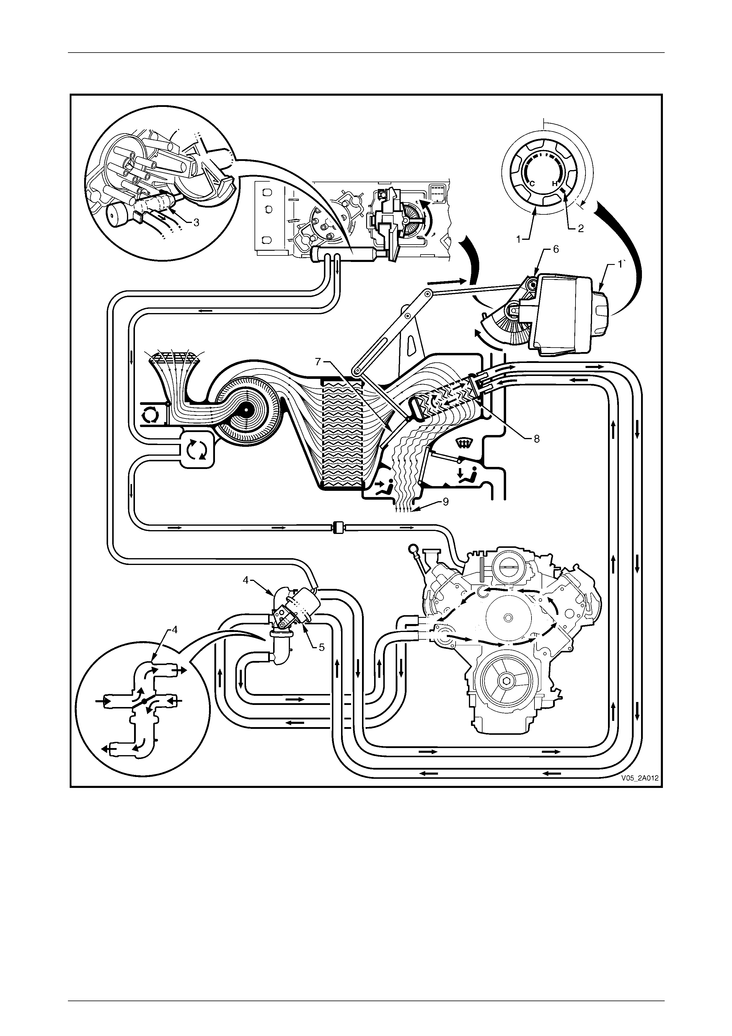
Warm
Figure 2A – 37
When the temperature switch (1) is turned from the full cold position (2), the crescent gear (3) rotates backwards moving
the ramp (4) away from the plunger (5) of the water valve vacuum switch (6), refer to Figure 2A – 37. Spring pressure
moves the plunger out ward and at the third detent positi on (7) of the temperature switch, the vacuum line (8) to the water
valve actuator (9) is vented through the exhaust port (10) of the water valve vacuum switch. When the actuator is
relieved of vacuum, the disc (11) in the water valve will rotate and allow hot water to flow through the cabin side water
valve ports (12) and the cabin side heater ho ses (13) into the heater core (14). As the crescent gear rotates backward, it
pulls the air mix door (15) open. When the temperature switch is turned to a warm positio n (16), the air mix door will be
partially open. This will cause some incoming air to pass through the heater core and some to air to b ypass the heater
core. The mixture of heated and cool air (17) will result in warm air entering the vehicle cabin.
HVAC Climate Control (Manual A/C) – Description and Operation Page 2A-36
Page 2A-36
Full Hot
Figure 2A – 38
When the temperature switch (1) is turned to in the full hot positio n (2) the water valve vacuum switch plunger (3)
remains in the same position, refe r to Figure 2A – 38. Therefore, the water valve (4) remains in the fully o pen position
because the water valve actuator (5) is devoid of vacuum.
In the full hot position the crescent gear (6) will be rotated fully rearward. This action will move the air mix door (7) to a
position that directs all incoming air thro ugh the heater core (8). Therefore, all air (9) entering the vehicle cabin will be
heated air.
HVAC Climate Control (Manual A/C) – Description and Operation Page 2A-37
Page 2A-37
Heater Operation – Auto A/C – GEN III V8
Full Cold
Vacuum generated within the engine inlet manifold (1) is stored within the vacuum tank (2), which is mounted on the side
the HVAC unit (3), refer to Figure 2A – 39. Vacuum is retained within the system by the one-way check valve (4) and is
directed to the vacuum solenoid pack (5). When the temperature is set to a cold position, the solenoid pack allows vacuum
to be directed to the water valve vacuum actuator (6). No coolant can flow through the inlet heater hose (7), the heater
core (8) or the outlet heater hose (9) because the disc (10) in the water valve (11) is in the closed position. However,
coolant is still able to flow from the engine thr ough the water valve via its engine side ports (12) and e ngine side heater
hoses (13).
An air mix door motor (14) is mechanically connected to the air mix door (15) via an actuating rod (16) a nd levers (17).
When the temperature is set to a cold position, the motor operates and mo ves the air mix door to a position that does not
allow any air to flow through the heater core. The result is that all air (18) entering the ve hicle cabin will be ambient
temperature or cooled if the air-conditioning is operating.
Figure 2A – 39
Legend
1 Inlet Manifold
2 Vacuum Tank
3 HVAC Unit
4 One-way Check Valve
5 Vacuum Solenoid Pack
6 Water Valve Vacuum Actuator
7 Inlet Heater Hose
8 Heater Core
9 Outlet Heater Hose
10 Water Valve Disc
11 Water Valve
12 Water Valve Engine Side Ports
13 Engine Side Heater Hoses
14 Air Mix Door Motor
15 Air Mix Door
16 Actuating Rod
17 Actuating Levers
18 Cabin Air
HVAC Climate Control (Manual A/C) – Description and Operation Page 2A-38
Page 2A-38
Warm
When the temperatu re is set to a warm posi tion, th e vacuum sol enoid pack va lve (1) clo ses, and the vacuum a t the wate r
valve vacuum actuator (2) is vented, refer to Figure 2A – 40. With the actuator relieved of vacuum, the disc (3) in the water
valve (4) rotates and allows hot water to flow through the cabin side water valve ports (5). Coolant flows from the engine
through the water valve via its engine si de ports (6) and engine side heater hoses (7) and is also flowing through the inlet
heater hose (8), the heater core (9) and the outlet heater hose (10) because of the disc position in the water valve.
When the temperature is set to a warm position, the air mix door motor (11) also operates and moves the air mix
door (12) to a partially open position allowing some air to flow through the heater core. The position of the door is
variable, based on the temperature set. A po sition sensor within the motor provides feedback to the control module. The
result is that all air (13) entering the vehicle cabin will be warm.
Figure 2A – 40
Legend
1 Vacuum Solenoid Pack
2 Water Valve Vacuum Actuator
3 Water Valve Disc
4 Water Valve
5 Water Valve Cabin Side Ports
6 Water Valve Engine Side Ports
7 Engine Side Heater Hoses
8 Inlet Heater Hose
9 Heater Core
10 Outlet Heater Hose
11 Air Mix Door Motor
12 Air Mix Door
13 Cabin Air
HVAC Climate Control (Manual A/C) – Description and Operation Page 2A-39
Page 2A-39
Full Hot
When the temperature is set to the hot position, the disc (1) in the water valve (2) allows hot water to flow through the
cabin side water valve ports (3), refer to Figure 2A – 41. The coolant flow pattern is the same as described for the warm
position.
The air mix door motor (4) operates and moves the air mix door (5) to the fully open position which direct s all air through
the heater core (6). The result is that all air (7) entering the vehicle cabin will be hot.
Figure 2A – 41
Legend
1 Water Valve Disc
2 Water Valve
3 Water Valve Cabin Side Ports
4 Air Mix Door Motor
5 Air Mix Door
6 Heater Core
7 Cabin Air
HVAC Climate Control (Manual A/C) – Description and Operation Page 2A-40
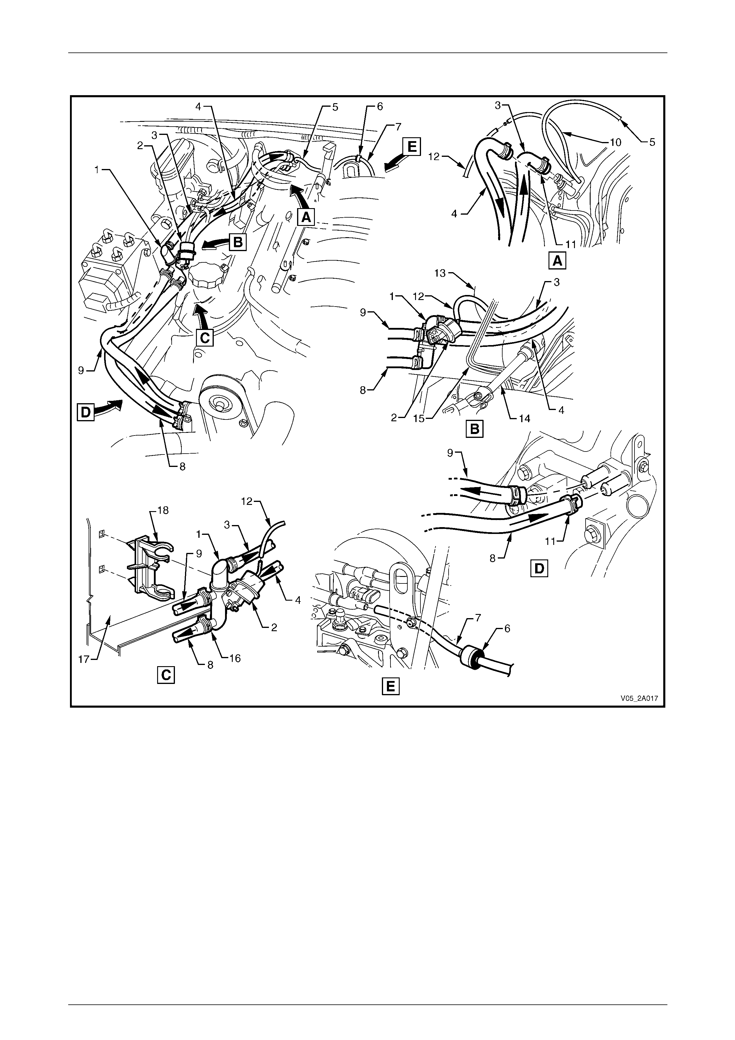
Page 2A-40
Under-hood Heater Components – V6
Figure 2A – 42
Legend
1 Heater Hose – from Cabin
2 Water Valve Actuator
3 Heater Hose Connectors (2 places)
4 Vacuum Hose – to Water Valve Actuator
5 Heater Hose – to Water Valve
6 Water Valve
7 Heater Hose – to Cabin
8 Vacuum Check Valve
9 Vacuum Hose – to HVAC Vacuum Tank
10 Vacuum Hose – to Check Valve
11 Vacuum Hose – to Inlet Manifold
12 Inlet Manifold Connection
13 Hose Clamps – Water Valve (2 places)
14 Heater Pipes
15 Hose Clamps – HVAC Unit (2 places)
16 Vacuum Hose – to Water Valve Vacuum Switch
HVAC Climate Control (Manual A/C) – Description and Operation Page 2A-41
Page 2A-41
Under-hood Heater Components – GEN III V8
Figure 2A – 43
Legend
1 Water Valve
2 Water Valve Actuator
3 Heater Hose – to Cabin
4 Heater Hose – from Cabin
5 Vacuum Hose (2 piece) – HVAC Supply
6 Check Valve
7 Vacuum Hose – to Inlet Manifold
8 Heater Hose – to Engine
9 Heater Hose – from Engine
10 Vacuum Hose – to Water Valve Vacuum Switch
11 Hose Clamps – Engine (2 places)
12 Vacuum Hose – to Water Valve Actuator
13 Brake Booster
14 Steering Column
15 Brake Lines
16 Hose Clamps – Water Valve (4 places)
17 Wheel House – Right-hand Side
18 Mounting Clip – Water Valve
HVAC Climate Control (Manual A/C) – Description and Operation Page 2A-42
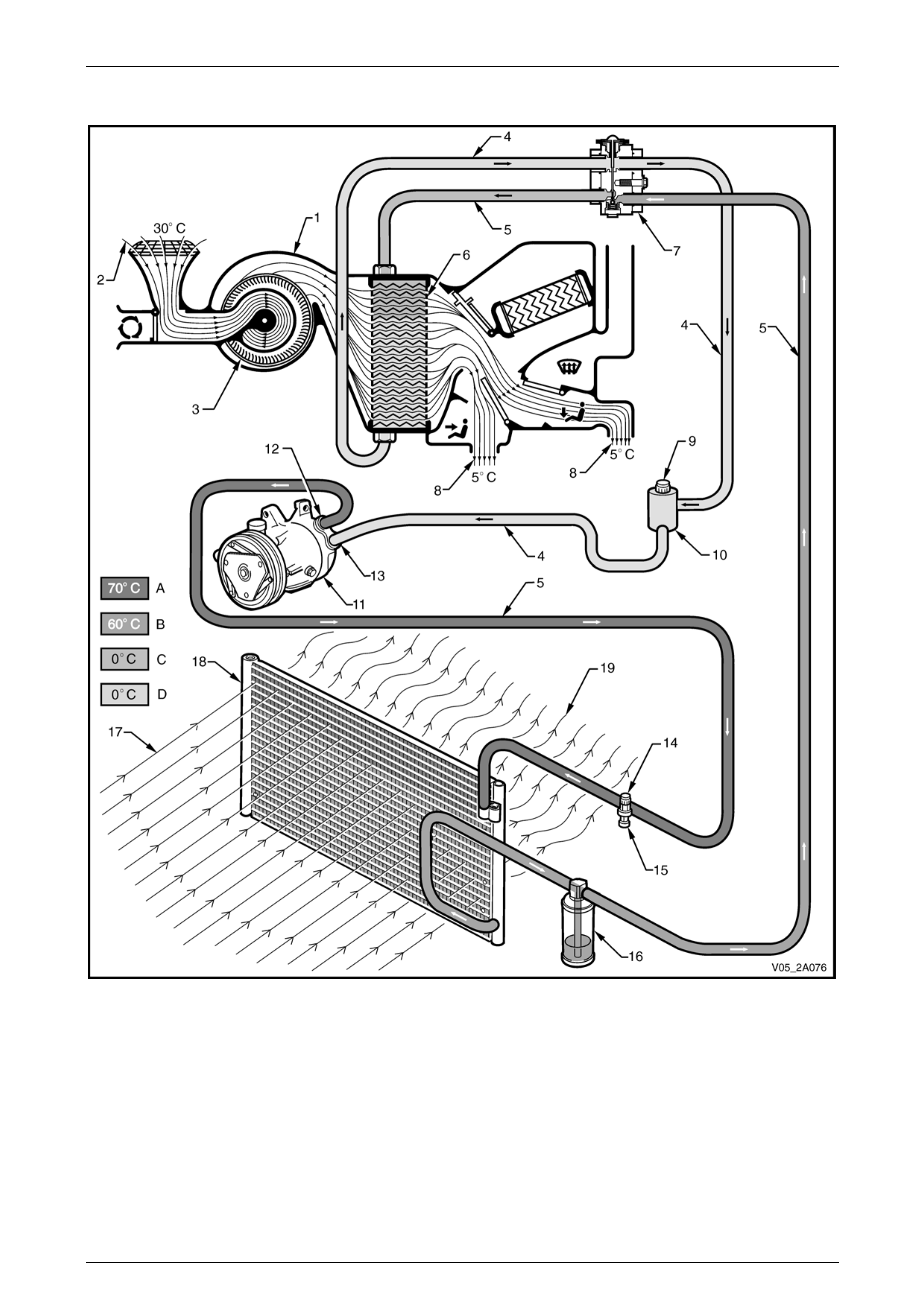
Page 2A-42
2.5 Air-conditioning Refrigerant Circuit
Figure 2A – 44
Legend
A High Pressure Vapour
D Low Pressure Vapour
B High Pressure Liquid
C Low Pressure Liquid
1 HVAC Unit
2 Inlet Air
3 Blower Fan
4 Low Pressure Line
5 High Pressure Line
6 Evaporator
7 Thermal Expansion Valve
8 Air-conditioned Air
9 Low Pressure Port
10 Muffler
11 Compressor
12 Compressor Pressure Port
13 Compressor Suction Port
14 High Pressure Port
15 Pressure Transducer
16 Filter Drier Receiver
17 Cool Ram (inlet) Air
18 Condenser
19 Warm (outlet) Air
HVAC Climate Control (Manual A/C) – Description and Operation Page 2A-43
Page 2A-43
2.6 Vacuum Circuit
The vacuum gene rated w ithin the engine inle t manifold is used to ope ra te the vacuu m ac tuato rs and the wate r val ve.
For further information on the water valve operation, refer to 2.4 Heater.
A vacuum tank located on the side of the HVAC unit is use d to store vacuum for times when engine vacuum is low such
as at full engine throttle. A check valve is fitted on the supply line between the inlet manifold and the vacuum tank to
ensure that vacuum is maintained within the system at all times.
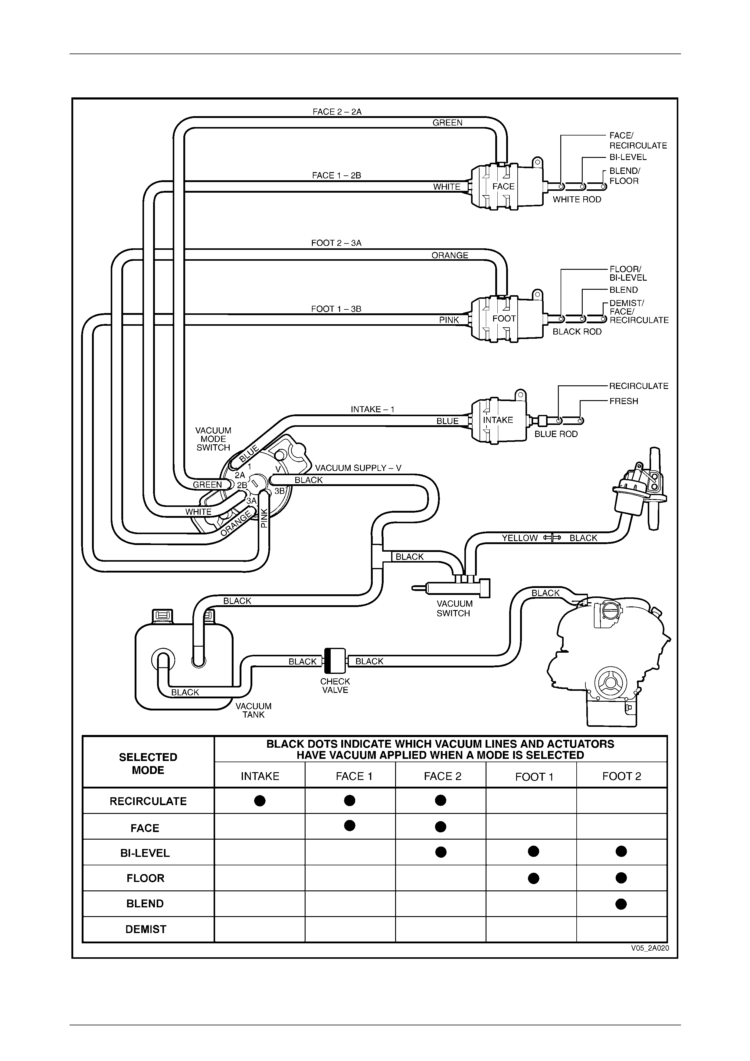
Vacuum Mode Switch and Vacuum Lines – Manual A/C
A black plastic vacuum supply line on the HVAC unit supplies vacuum to the vacuum tank. The check valve is used to
join the supply line to the hose connected to the inlet manifold.
Vacuum from the vacuum tank is then directed through a black supply hose to the vacuum mode switch, for HVAC door
operation, and from a tee joint to the water valve vacuum switch, for water valve operatio n.
From the water valve vacuum switch, vacuum moves into a yellow plastic tube a nd then connects to the black hose
(inside the cabin at the dash panel) which in turn is connected to the vacuum operated heater water valve. When vacuum
is applied to the water valve, the valve remains closed and water does not flow through the heater core.
As the vacuum mode switch is turned, vacuum is directed through the switch and onto th e desired vacuum actuators
through different coloured plas tic tubing. This vacuum will activate the actuator rod, which then moves a vent position
door.
Vacuum is vented from the vacuum actuator/plastic tube once the vacu um mode switch is turned to another position.
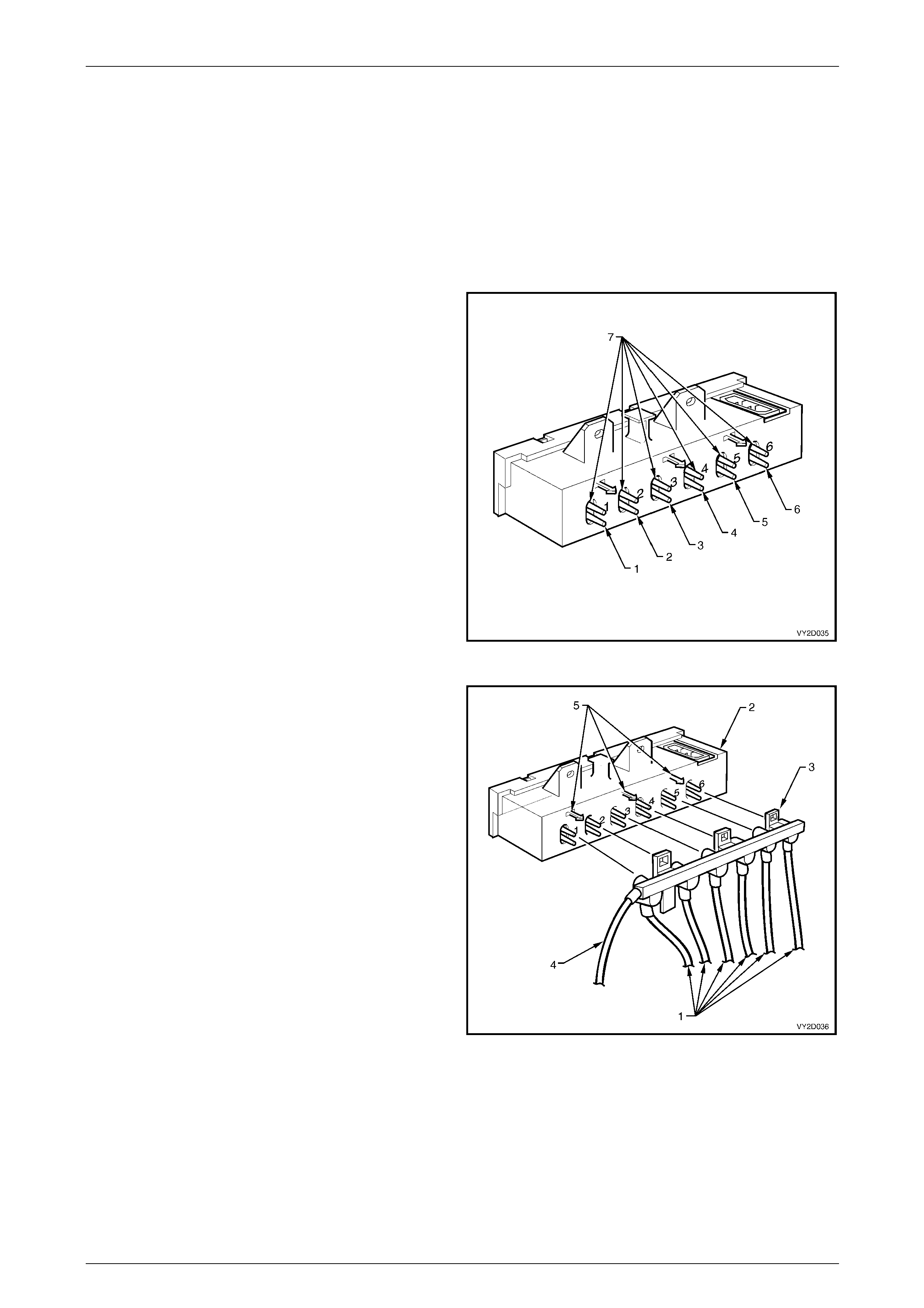
The six vacuum hoses between the vacuum mode switch
and the vacuum actuators are colour keyed. The function of
the switch connections and the colour of the attached
vacuum lines are listed belo w:
Legend
1 Vacuum supply (Black)
2 Fresh/Recirculation (Blue)
3 Face 2 (Green)
4 Face 1 (White)
5 Foot 2 (Orange)
6 Foot 1 (Pink)
Figure 2A – 45
HVAC Climate Control (Manual A/C) – Description and Operation Page 2A-44
Page 2A-44
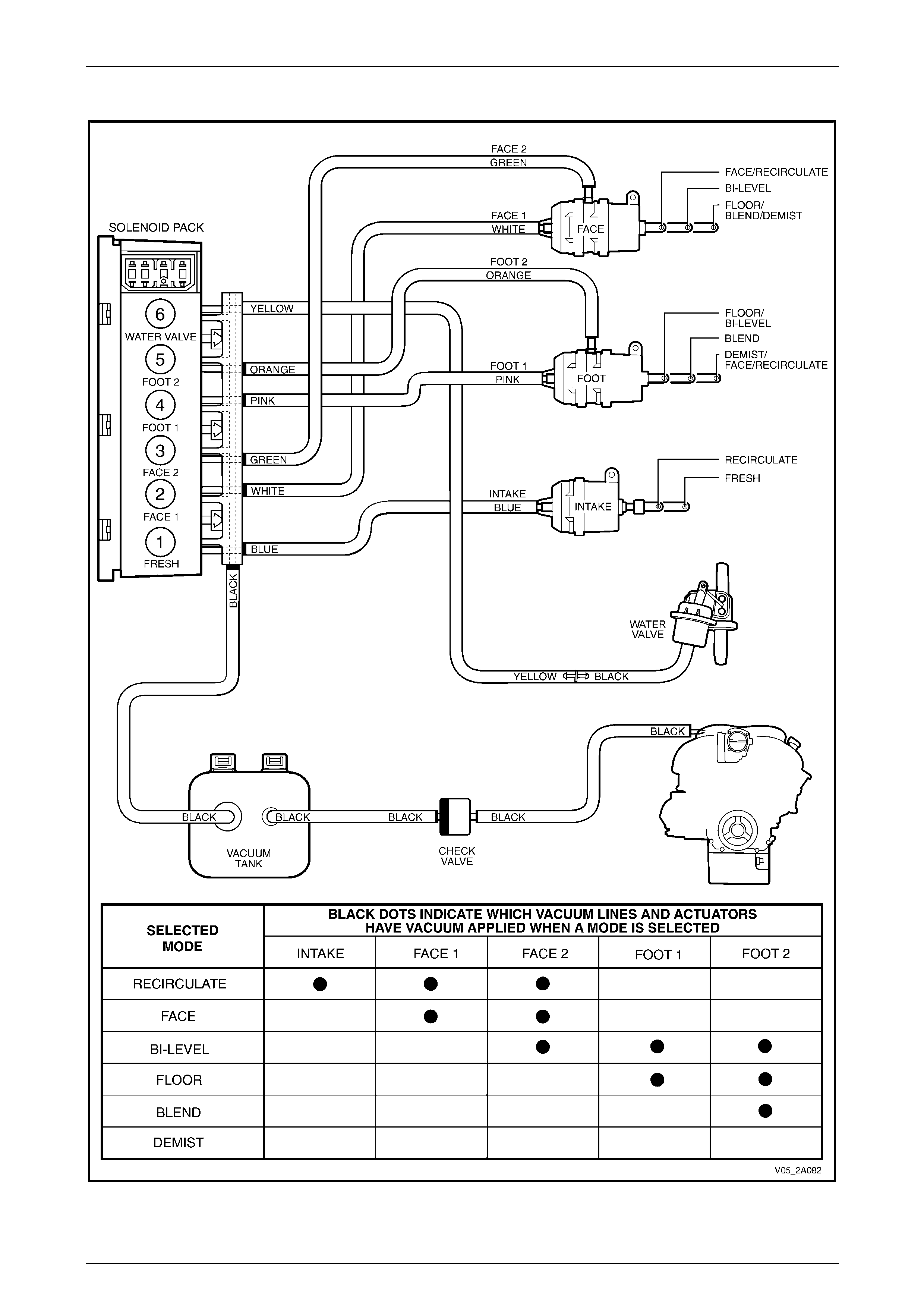
Solenoid Pack and Vacuum Lines – Auto A/C
A six solenoid vacuum solenoid pack is used to direct vacuum to the vacuum actuators an d the water valve The solenoid
pack is connected to the vacuum tank throug h a black p lastic vacuum hose. The OCC control module operates the
solenoids on and off to direct vacuum to the vacuum actuators and water valve when required. This alters the position of
the water valve and the various doors within the HVAC unit to bring about the desired heating, demisting or cooling
effect.
Vacuum is vented from the vacuum actuator / plastic hose once an OCC control module mode switch or temperature
switch is used to select a different setting. When vacuum is applied to the water valve, the valve rem ains closed and no
water will flow through the heater core.
The six vacuum hoses between the solenoid pack and the
vacuum actuators are colour keyed.
The function of the solenoid connections and the colour of
the attached vacuum lines are listed below:
Legend
1 Fresh/Recirculation (Blue)
2 Face 1 (White)
3 Face 2 (Green)
4 Foot 1 (Pink)
5 Foot 2 (Orange)
6 Water valve (Yellow)
7 Vacuum supply (Black)
Figure 2A – 46
All actuator vacuum hoses (1) at the solenoid pack (2) are
permanently connected to a common, soft plastic
manifold (3), which is installed to the front of the solenoid
pack.
The black hose (4) at the left-hand side of the manifold is
the vacuum supply line from the vacuum tank and is also
permanently connected.
The manifold is locked into its install ed position by three
retaining tangs (5) protruding from the solenoid pack
housing.
Figure 2A – 47
HVAC Climate Control (Manual A/C) – Description and Operation Page 2A-45
Page 2A-45
Vacuum Circuit Schematic – Manual A/C
Figure 2A – 48
HVAC Climate Control (Manual A/C) – Description and Operation Page 2A-46
Page 2A-46
Vacuum Circuit Schematic – Auto A/C
Figure 2A – 49
HVAC Climate Control (Manual A/C) – Description and Operation Page 2A-47
Page 2A-47
2.7 HVAC Unit Airflow Modes – Manual A/C
NOTE
For auto A/C airflow modes, refer to
Section 2D HVAC Occupant Climate Control
(Auto A/C) – Description and Operation
HVAC Flow Diagrams
The HVAC unit has seven different possible modes:
• recirculation
• face,
• bi-level,
• floor,
• blend,
• demist, and
• default.
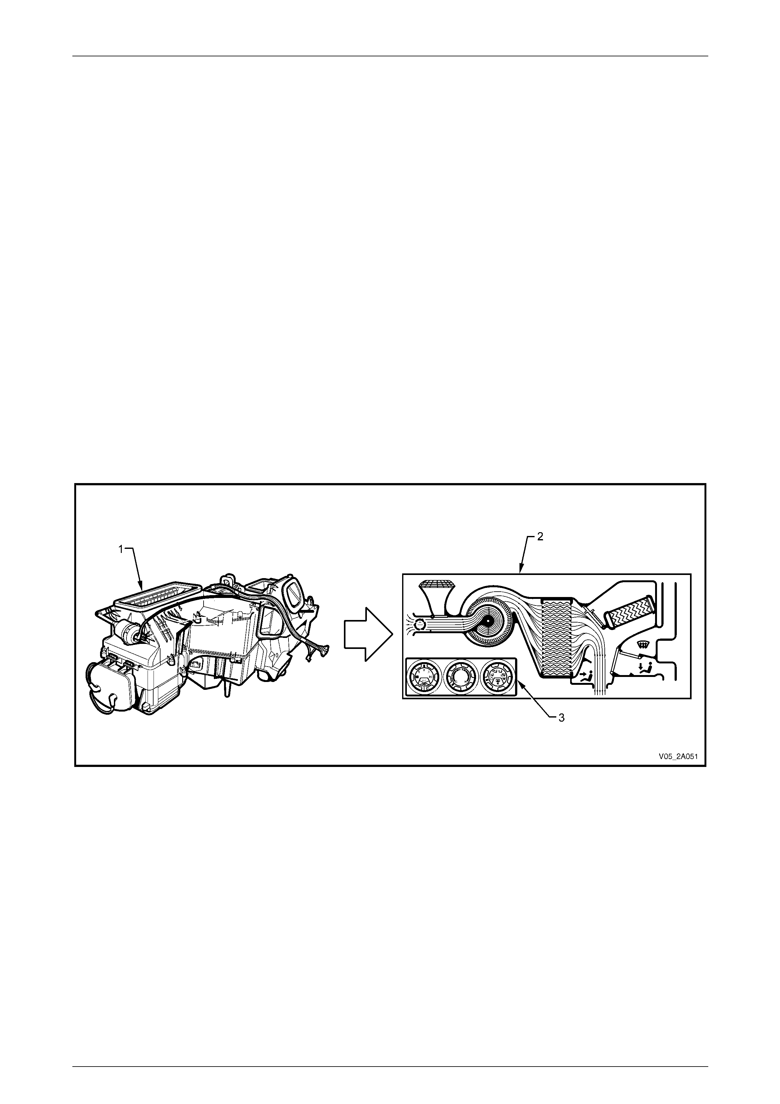
The following airflow mode diagrams provide a schematic representation of how cold and heated air flows through the
HVAC unit during the seven different possible modes.
Each schematic has a graphic representation of the HVAC controller with switch settings matching the given mode.
Figure 2A – 50
Legend
1 HVAC Unit
2 Airflow Schematic 3 HVAC Controller

HVAC Climate Control (Manual A/C) – Description and Operation Page 2A-48
Page 2A-48
Recirculation Mode
Full Cold
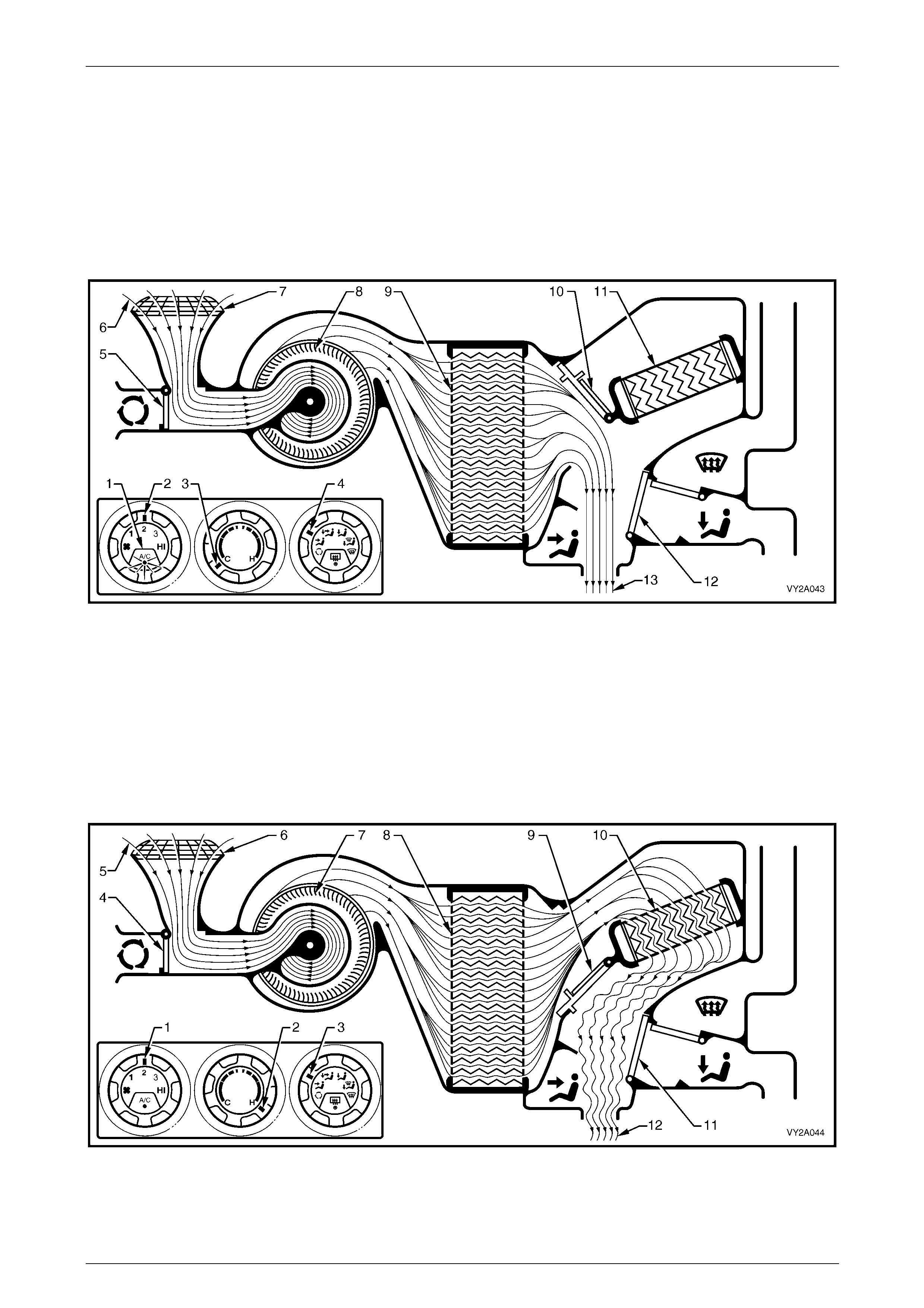
The A/C switch is on (1). The fan switch is set to an y one of four speeds (2), refer to Figure 2A – 51. The temperature
switch is set to the full cold position (3). The mode control switch is set to recirculation (4).
The plenum chamber (outside air) inlet (5) to the HVAC unit is closed off by the recirculation door (6). Interior air (7) is
drawn into the HVAC unit through the recircu lation inlet (8) by the blower motor fan (9), and is then forced through th e
cold evaporator fins (10). In full cold mode the air mix doors (11) are fully close d sealing off the passage through the
heater core (12). The air travels through the open face door (13). The cold air (14) is then d irected out through the centre
and side vents.
Figure 2A – 51
Full Heat
The fan switch is set to any one of four speeds (1), refer to Figure 2A – 52. The temperature switch is set to the full hot
position (2). The mode control switch is set to recirculation (3).
The plenum chamber (outside air) inlet (4) to the HVAC unit is closed off by the recirculation door (5). Interior air (6) is
drawn into the HVAC unit through the recircu lation inlet (7) by the blower motor fan (8), and is then forced through th e
evaporator fins (9). In full heat mode, the air mix doors (10) are fully o pen directing all incoming air through the heater
core (11). The air travels through the open face door (12). The heated air (13) is then directed out throu gh the centre and
side vents.
Figure 2A – 52
HVAC Climate Control (Manual A/C) – Description and Operation Page 2A-49
Page 2A-49
Face Mode
Full Cold
The A/C switch is on (1), refer to Figure 2A – 53. T he fan switch is set to any one of four speeds (2). The temperature
switch is set to the full cold position (3). The mode control switch is set to face mode (4).
The recirculation door (5) is closed allowing outside air (6) to enter and flow into the HVAC unit via the p lenum chamber
inlet (7). Air is drawn into the HVAC unit by the blower motor (8), and is then forced through the cold evaporator fins (9).
In full cold mode, the air mix doors (10) ar e fully closed sealing off the passage through the heater core (11). The air
travels through the open face door (12). T he cold air (13) is then directed through the cent re and side vents.
Figure 2A – 53
Full Heat
The fan switch is set to any one of four speeds (1), refer to Figure 2A – 54. The temperature switch is set to the full hot
position (2). The mode control switch is set to face mode (3).
The recirculation door (4) is closed allowing outside air (5) to enter and flow into the HVAC unit via the p lenum chamber
inlet (6). Air is drawn into the HVAC unit by the blower motor (7). This air is then forced through the evaporator core fins
(8). In full heat mode, the air mix doors (9) are fully open d irecting all incoming air through the he ater core (10). The air
travels through the open face door (11). T he heated air (12) is then directed out of the HVAC unit to the centre and side
vents.
Figure 2A – 54
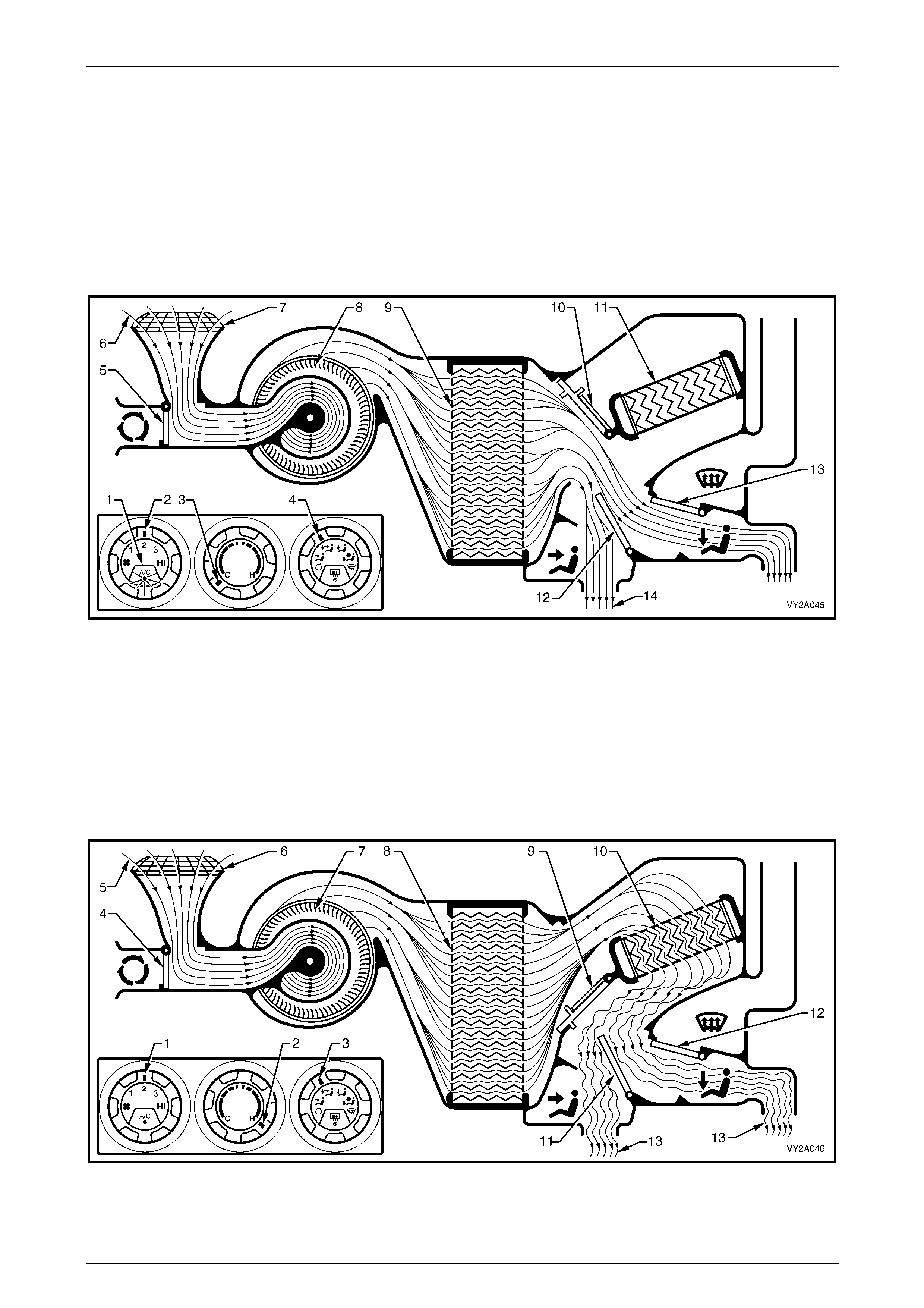
HVAC Climate Control (Manual A/C) – Description and Operation Page 2A-50
Page 2A-50
Bi-level Mode
Full Cold
The A/C switch is on (1), refer to Figure 2A – 55. T he fan switch is set to any one of four speeds (2). The temperature
switch is set to the full cold position (3). The mode control switch is set to bi-level mode (4).
The recirculation door (5) is closed allowing outside air (6) to enter and flow into the HVAC unit via the p lenum chamber
inlet (7). Air is drawn into the HVAC unit by the blower motor (8), and is then forced through the cold evaporator fins (9).
In full cold mode, the air mix doors (10) ar e fully closed sealing off the passage through the heater core (11). The air
travels through the half opened face door (12 ) and the through the demist / floor door (13) which is fully open in the floor
mode. The cold air (14) is then directed through the centre and side vents as well as the floor ducts.
Figure 2A – 55
Full Heat
The fan switch is set to any one of four speeds (1), refer to Figure 2A – 56. The temperature switch is set to the full hot
position (2). The mode control switch is set to bi-level mode (3).
The recirculation door (4) is closed allowing outside air (5) to enter and flow into the HVAC unit via the p lenum chamber
inlet (6). Air is drawn into the HVAC unit by the blower motor (7). This air is then forced through the evaporator core fins
(8). In full heat mode, the air mix doors (9) are fully open d irecting all incoming air through the he ater core (10). The air
travels through the half opened face door (11 ) and through the demist / floor door (12), which is fully open in the floor
mode. The heated air (13) is then directed through the centre and side vents as well as to the floor ducts.
Figure 2A – 56
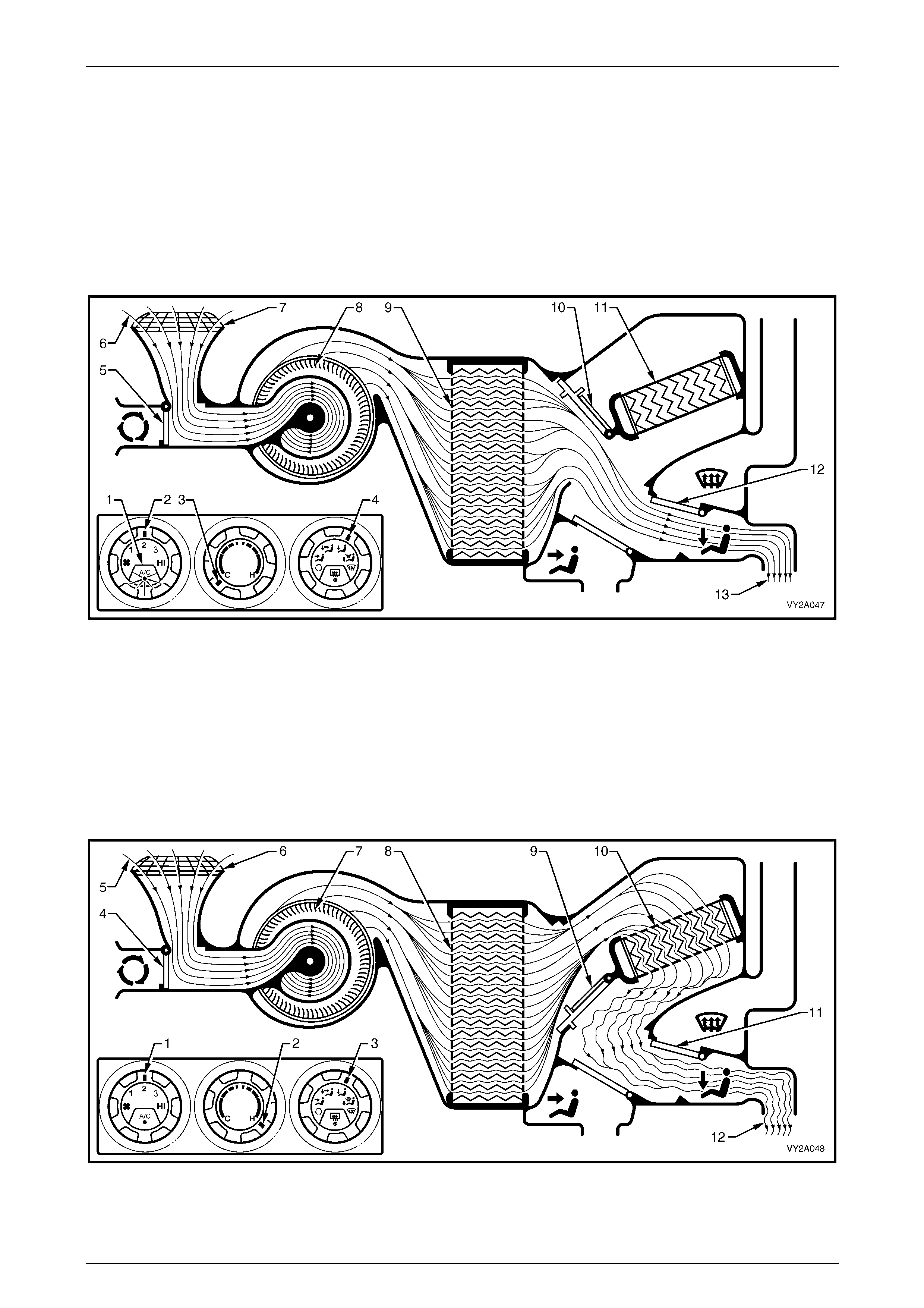
HVAC Climate Control (Manual A/C) – Description and Operation Page 2A-51
Page 2A-51
Floor Mode
Full Cold
The A/C switch is on (1), refer to Figure 2A – 57. T he fan switch is set to any one of four speeds (2). The temperature
switch is set to the full cold position (3). The mode control switch is set to floor mode (4).
The recirculation door (5) is closed allowing outside (6) air to enter and flow into the HVAC unit via the p lenum chamber
inlet (7). Air is drawn into the HVAC unit by the blower motor (8), and is then forced through the cold evaporator fins (9).
In full cold mode, the air mix doors (10) ar e fully closed sealing off the passage through the heater core (11). The air
travels through the demist / floor door (12), which is fully open in the floor mode. T he cold air (13) is the n directe d to floor
ducts.
Figure 2A – 57
Full Heat
The fan switch is set to any one of four speeds (1), refer to Figure 2A – 58. The temperature switch is set to the full hot
position (2). The mode control switch is set to floor mode (3).
The recirculation door (4) is closed allowing outside air (5) to enter and flow into the HVAC unit via the p lenum chamber
inlet (6). Air is drawn into the HVAC unit by the blower motor (7). This air is then forced through the evaporator core fins
(8). In full heat mode, the air mix doors (9) are fully open d irecting all incoming air through the he ater core (10). The air
travels through the demist / floor door (11), which is fully open in the floor mode. The heated air (12) is then directed to
the floor ducts.
Figure 2A – 58
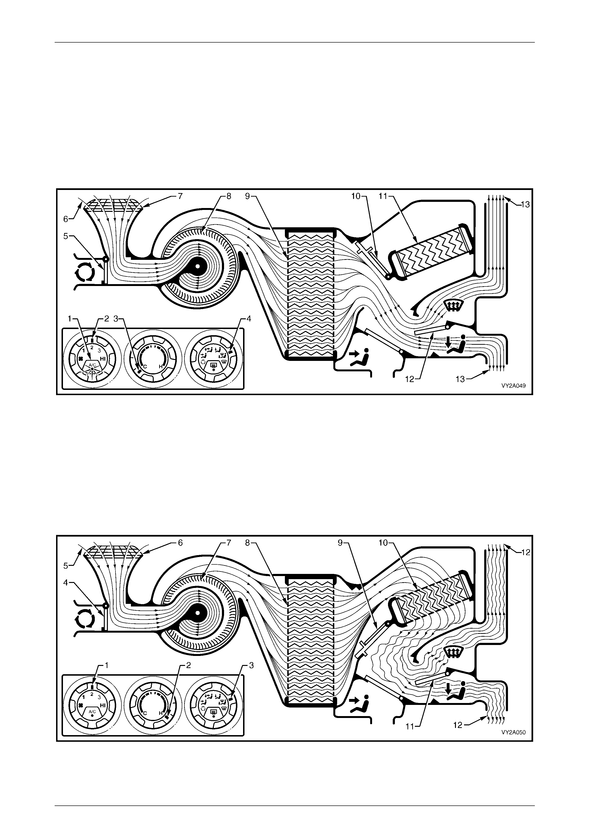
HVAC Climate Control (Manual A/C) – Description and Operation Page 2A-52
Page 2A-52
Blend Mode
Full Cold
The A/C switch is on (1), refer to Figure 2A – 59. T he fan switch is set to any one of four speeds (2). The temperature
switch is set to the full cold position (3). The mode control switch is set to blend mode (4).
The recirculation door (5) is closed allowing outside air (6) to enter and flow into the HVAC unit via the p lenum chamber
inlet (7). Air is drawn into the HVAC unit by the blower motor (8), and is then forced through the cold evaporator fins (9).
In full cold mode, the air mix doors (10) ar e fully closed sealing off the passage through the heater core (11). The air
travels through the demist / floor door (12), which is positioned ha lf way between, demist and floor modes. The cold air
(13) is then directed to both the front windscreen and the floor ducts.
Figure 2A – 59
Full Heat
The fan switch is set to any one of four speeds (1), refer to Figure 2A – 60. The temperature switch is set to the full hot
position (2). The mode control switch is set to blend mode (3).
The recirculation door (4) is closed allowing outside air (5) to enter and flow into the HVAC unit via the p lenum chamber
inlet (6). Air is drawn into the HVAC unit by the blower motor (7). This air is then forced through the evaporator core fins
(8). In full heat mode, the air mix doors (9) are fully open d irecting all incoming air through the he ater core (10). The air
travels through the demist / floor door (11), which is positioned half way between demist and floor mo des. The heated air
(12) is then directed to both the front windscreen and the floor ducts.
Figure 2A – 60
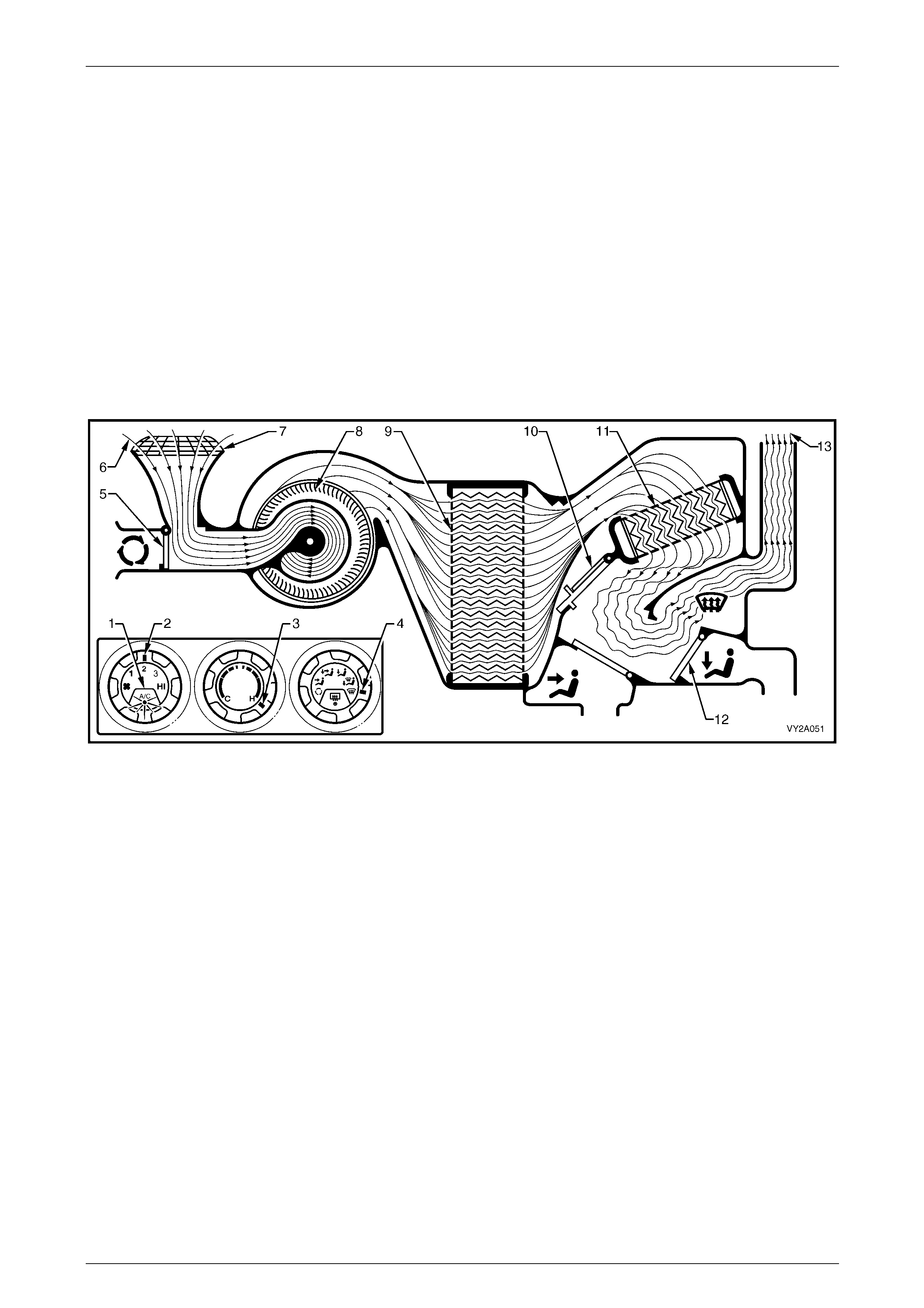
HVAC Climate Control (Manual A/C) – Description and Operation Page 2A-53
Page 2A-53
Demist Mode
Full Heat and A/C Activated
The A/C switch is on (1), refer to Figure 2A – 61. T he fan switch is set to any one of four speeds (2). The temperature
switch is set to the full hot position (3). The mode control switch is set to demist mode (4).
The recirculation door (5) is closed allowing outside air (6) to enter and flow into the HVAC unit via the p lenum chamber
inlet (7). Air is drawn into the HVAC unit by the blower motor (8). This air is then forced through the cold evaporator core
fins (9) removing moisture from the air. In full heat mode, the air mix doors (10) are fully open allowing dehumidified
incoming air through the heater core (11). The air travels through the demist / floor door (12) which is fully o pen in the
demist mode. The heated air (13) is then directed to the front windscreen via the demist outlets.
NOTE
By turning on the A/C system in this mode,
dehumidification of incoming air will take place,
demisting the front windscreen and side windows
in a shorter period.
Figure 2A – 61
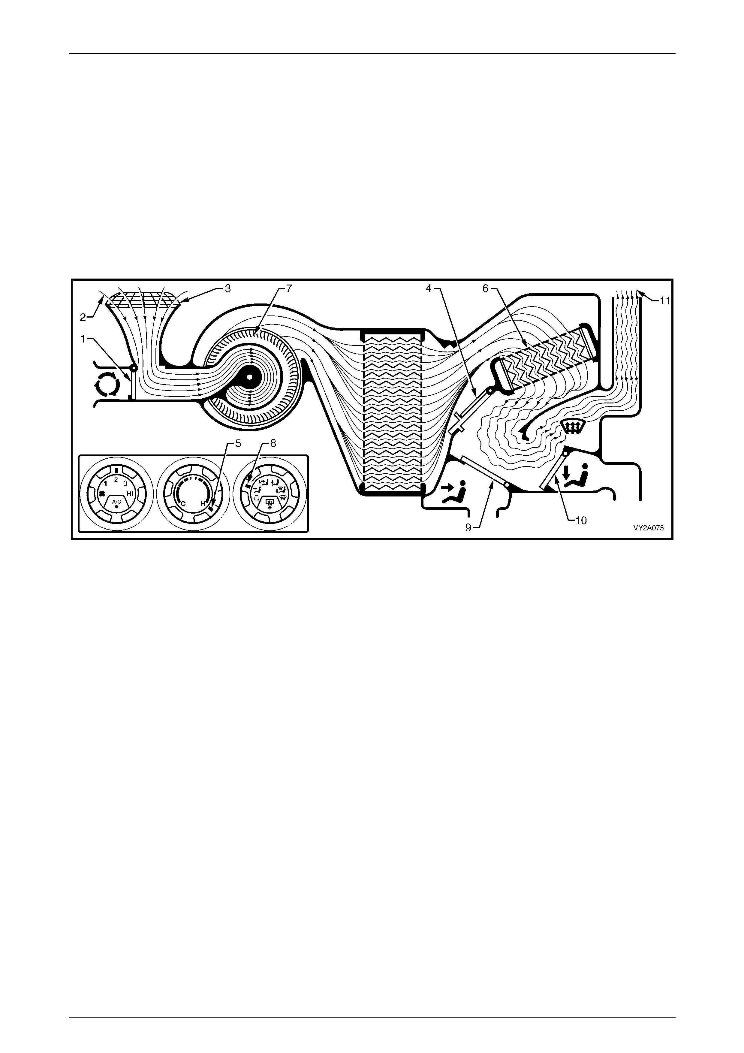
HVAC Climate Control (Manual A/C) – Description and Operation Page 2A-54
Page 2A-54
Default Mode
Loss of Vacuum Supply to HV AC Unit
If a total loss of vacuum occurs within the system, the HVAC unit will default to the following settings. These settings will
be the same in any position of the mode control switch.
The recirculation door (1) will remain closed allowing outside air (2) to enter and flow into the HVAC unit via the plenum
chamber inlet (3), refer to Figure 2A – 62. As the air mix doors (4) are controlled b y mechanical linkage, their position will
still be determined by the temperature switch setting (5). However, heated coolant will flow through the heater core (6)
regardless of the position of the temper ature switch as vacuum is required to maintain the water valve in the cold
(closed) position. The blower motor (7) will operate as normal. In any position of the mode switch (8), the face door (9)
will remain closed. T he demist / floor door (10) will be positioned so that all air (11) leavi ng the HVAC unit will be directed
to the demist outlets. Depending on the selected setting of temperature switch, this air may be cold, warm or hot air.
Figure 2A – 62
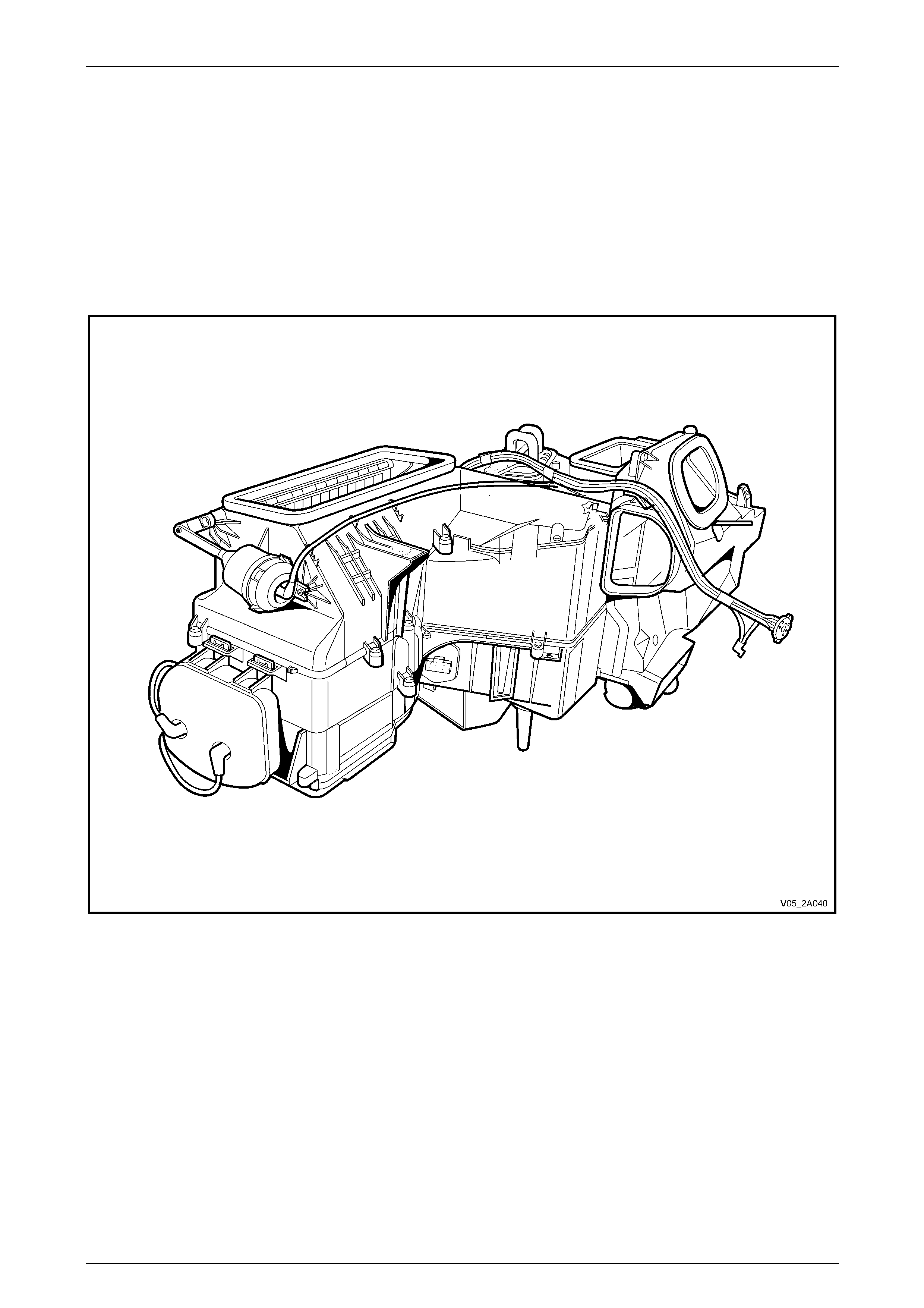
HVAC Climate Control (Manual A/C) – Description and Operation Page 2A-55
Page 2A-55
2.8 Heating, Ventilation and Air-conditioning
(HVAC) Unit
General Description – Manual A/C
The HVAC unit for manual A/C is a four piec e case construction and is fitted with three externally mounted vacuum
actuators to provide the selec ted ventilation modes.
A single recirculation door is used to control airflow into the HVAC unit. A single two-piece air mix door is used to control
the airflow through the heater core. W here air-conditioning is not fitted, the evaporator core is replaced by a perforated
baffle plate to maintain airflow speeds to levels comparable with A/C type units.
Figure 2A – 63
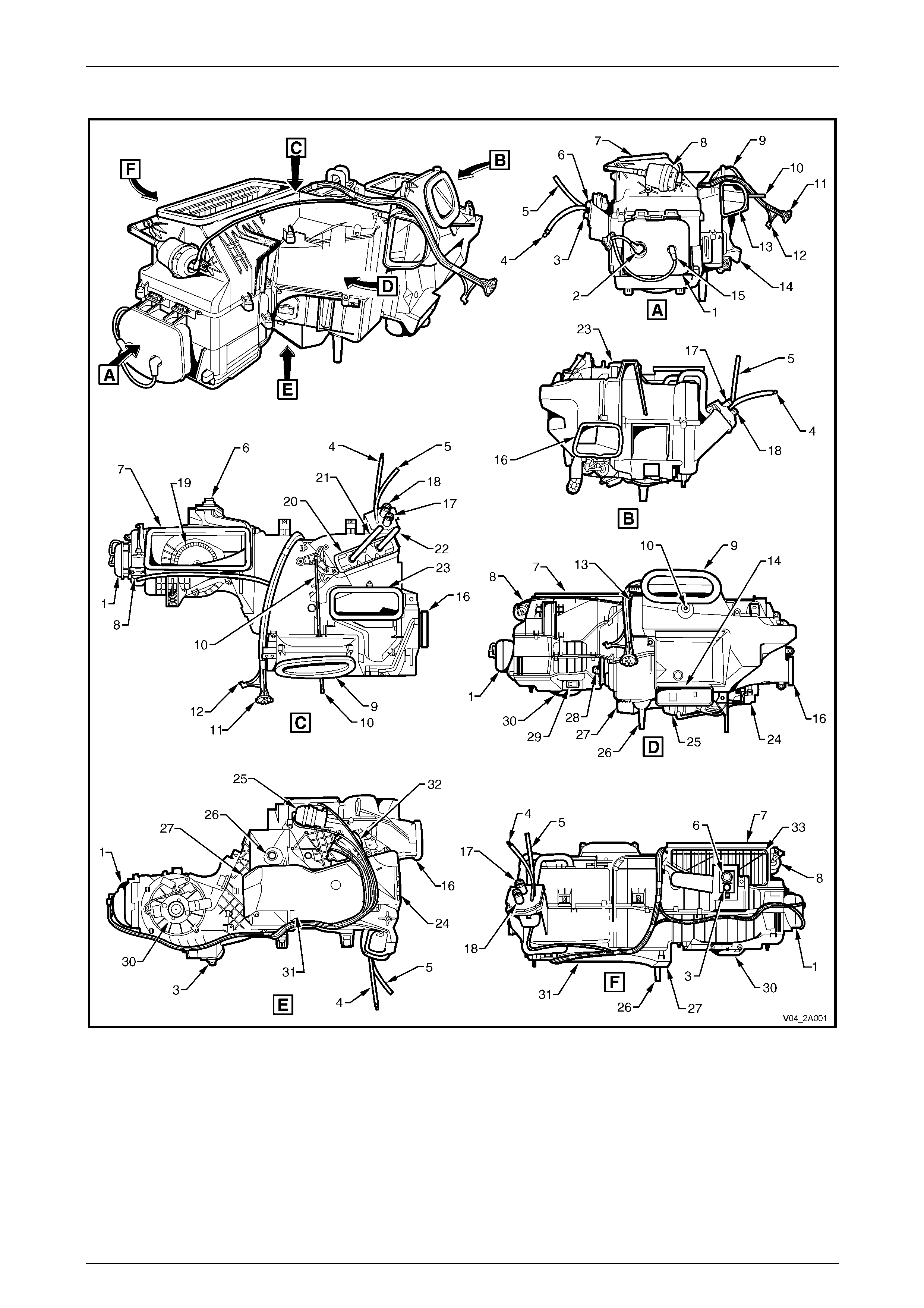
HVAC Climate Control (Manual A/C) – Description and Operation Page 2A-56
Page 2A-56
Assembled Views – Manual A/C
Figure 2A – 64

HVAC Climate Control (Manual A/C) – Description and Operation Page 2A-57
Page 2A-57
Legend
1 Vacuum Tank
2 Vacuum Connector from Inlet Manifold
3 A/C High Pressure Port
4 Vacuum Line to Water Valve
5 Vacuum Line to Inlet Manifold
6 A/C Low Pressure Port
7 HVAC Air Inlet
8 Intake Actuator
9 Face Vent Outlet
10 Air Mix Door Rod
11 Vacuum Manifold Connector to Mode Switch
12 Vacuum Connector to Water Valve Vacuum Switch
13 Side Duct Outlet – LHS
14 Rear Duct Outlet
15 Vacuum Connector from HVAC Controller
16 Side Duct Outlet – RHS
17 Heater Core Inlet
18 Heater Core Outlet
19 Blower Fan
20 Heater Core
21 Heater Core Outlet Pipe
22 Heater Core Inlet Pipe
23 Demist Outlet
24 Foot Vent Outlet – RHS
25 Face Actuator
26 Drain Tube
27 Foot Vent Outlet – LHS
28 Blower Motor Resistor Assembly
29 Blower Motor Connector
30 Blower Motor
31 Foot Duct
32 Demist / Foot Actuator
33 Recirculation Door
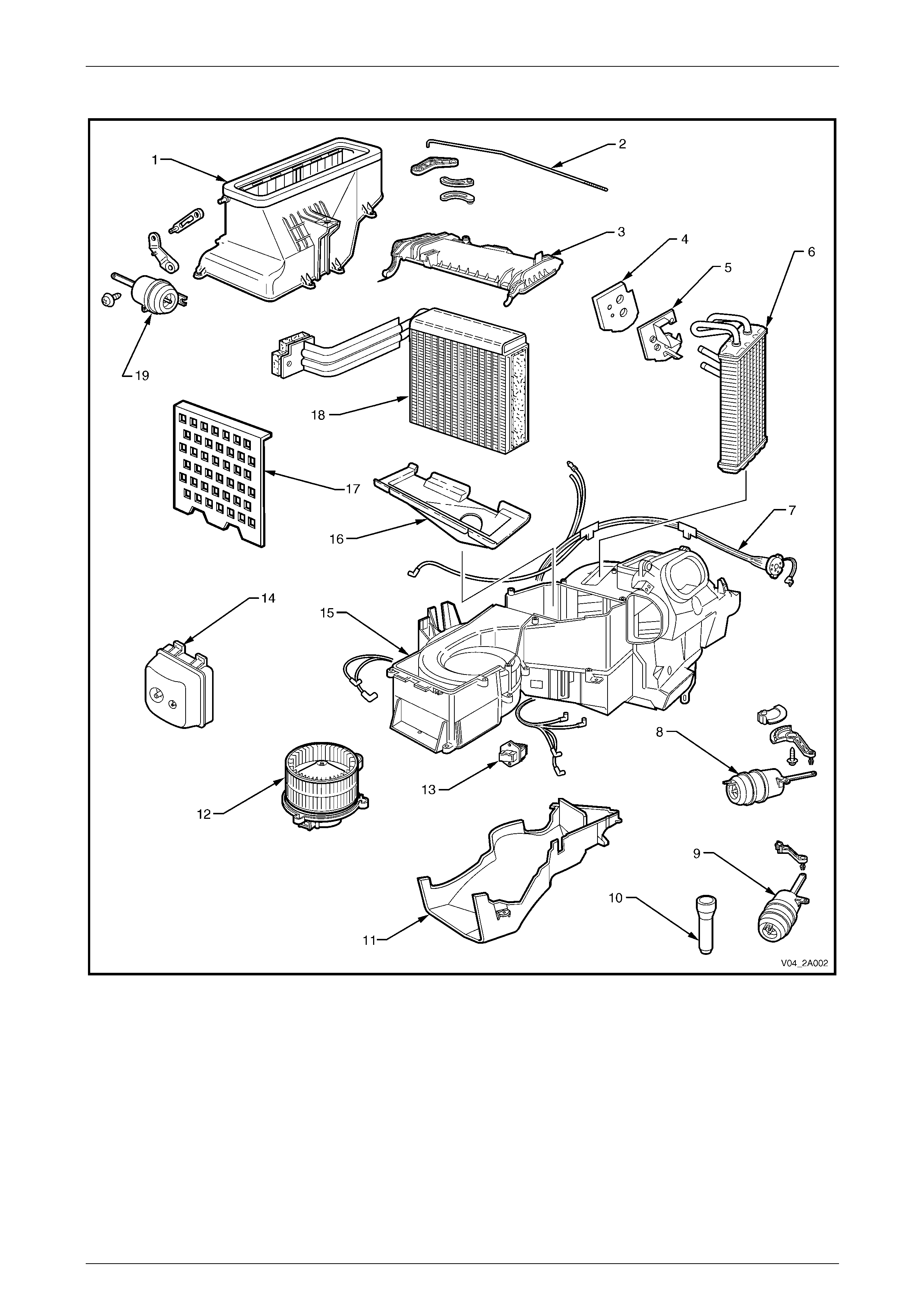
HVAC Climate Control (Manual A/C) – Description and Operation Page 2A-58
Page 2A-58
Exploded View – Manual A/C
Figure 2A – 65
Legend
1 Fresh / Recirculate housing
2 Air Mix Door Actuator Rod
3 Evaporator Core Cover
4 Heater Pipe Seal
5 Heater Pipe Retainer
6 Heater Core
7 Vacuum Tube Harness
8 Foot Actuator
9 Face Actuator
10 Drain Tube
11 Foot Duct
12 Blower Motor and Fan
13 Blower Motor Resistor Assembly
14 Vacuum Tank
15 HVAC unit case
16 Insulator
17 Baffle Plate (non A/C units)
18 Evaporator
19 Intake Actuator
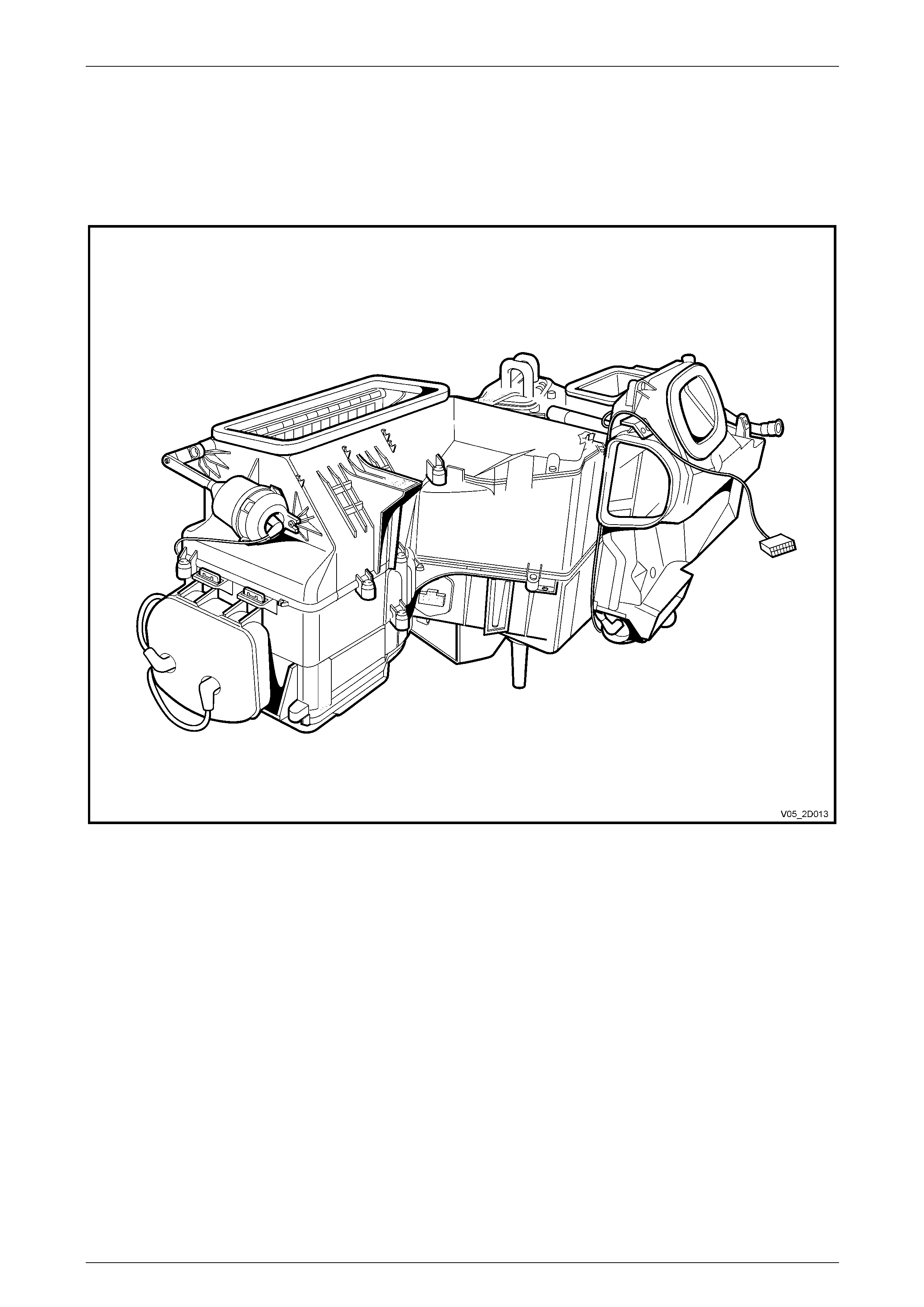
HVAC Climate Control (Manual A/C) – Description and Operation Page 2A-59
Page 2A-59
General Description – Auto A/C
The HVAC unit for auto A/C is a four piece case construction and is fitted with three externally mounte d vacuum
actuators to provide the selected operating modes. A six-solenoid vacuum solen oid p ack, controlling vacuum to the
actuators, is fitted under the HVAC unit to the rear of the blower motor cover.
A single recirculation door is used to control airflow into the HVAC unit. A single two piece air mix door is used to control
the airflow through the heater core. An air mix door motor is fitted below the HVAC unit to operate the air mix door.
Figure 2A – 66

HVAC Climate Control (Manual A/C) – Description and Operation Page 2A-60
Page 2A-60
Assembled Views – Auto A/C
Figure 2A – 67

HVAC Climate Control (Manual A/C) – Description and Operation Page 2A-61
Page 2A-61
Legend
1 Vacuum Tank
2 Vacuum Connector from Inlet Manifold
3 A/C High Pressure Port
4 Vacuum Line to Water Valve
5 Vacuum Line to Inlet Manifold
6 A/C Low Pressure Port
7 HVAC Air Inlet
8 Intake Actuator
9 Face Vent Outlet
10 Side Duct Outlet – Left-hand
11 Rear Duct Outlet
12 Vacuum Connector from Solenoid Pack
13 Drain Tube
14 Vacuum Solenoid Pack
15 Side Duct Outlet – Right-hand
16 Aspirator Tube
17 Heater Core Inlet
18 Heater Core Outlet
19 Blower Fan
20 Heater Core
21 Heater Core Outlet Pipe
22 Heater Core Inlet Pipe
23 Demist Outlet
24 Air Mix Door Rod
25 Foot Vent Outlet – Right-hand
26 Face Actuator
27 Foot Vent Outlet – Left-hand
28 Blower Motor Resistor
29 Blower Motor Connector
30 Blower Motor
31 Air Mix Door Motor
32 Foot Actuator
33 Foot Duct
34 Recirculation Door
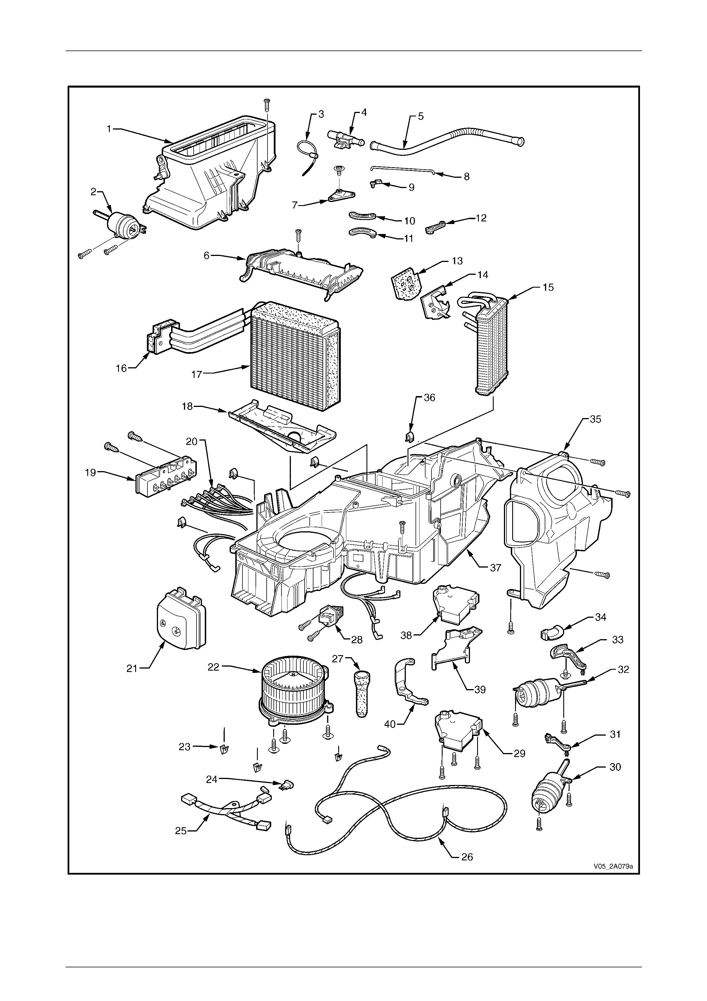
HVAC Climate Control (Manual A/C) – Description and Operation Page 2A-62
Page 2A-62
Exploded View – Auto A/C
Figure 2A – 68
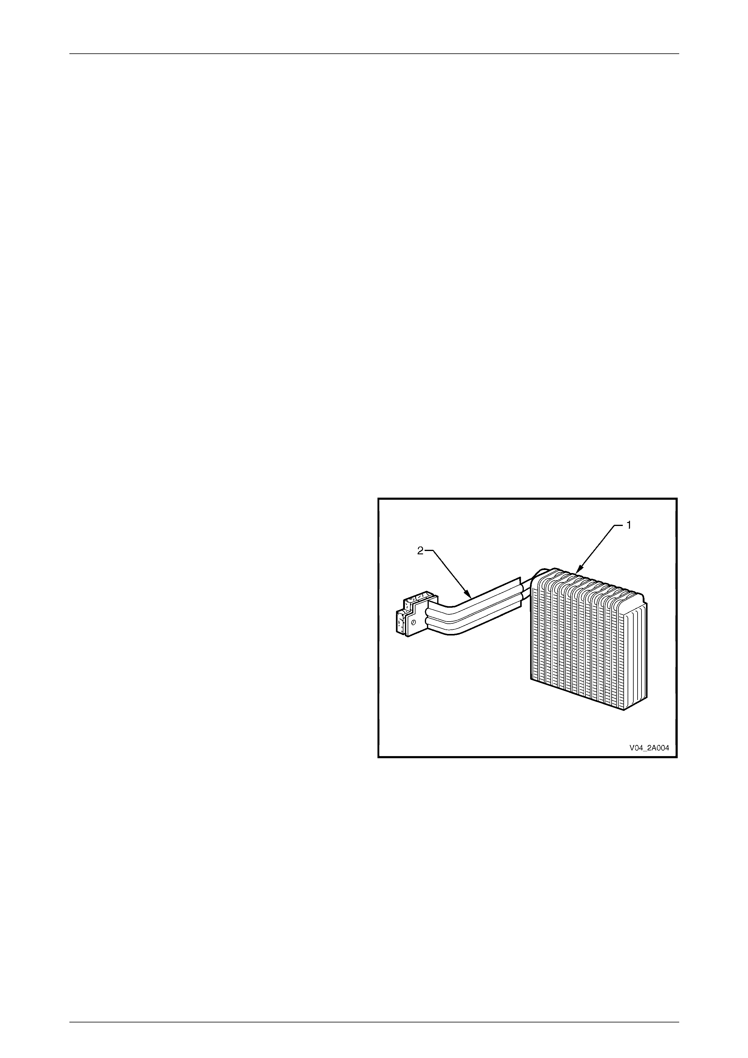
HVAC Climate Control (Manual A/C) – Description and Operation Page 2A-63
Page 2A-63
Legend
1 Intake Blower Duct
2 Vacuum Actuator – Fresh /
Recirculate
3 Evaporator Sensor
4 Aspirator Venturi
5 Aspirator Tube
6 Evaporator Cover
7 Air Mix Idler Lever
8 Air Mix Door Rod
9 Rod Retainer
10 Air Mix Balance Lever (1)
11 Air Mix Balance Lever (2)
12 Air Mix Shaft Lever
13 Seal – Heater Tube to Dash
14 Heater Tube Retainer
15 Heater Core
16 Seal – Evaporator Tube to Dash
17 Evaporator
18 Insulator
19 Vacuum Solenoid Pack
20 Vacuum Harness
21 Vacuum Tank
22 Blower Motor and Fan Assembly
23 Retaining Clip
24 Blower Motor Fuse
25 Blower Motor Switch Harness
26 Blower Motor and Control Harness
27 Evaporator Drain Hose
28 Electronic Blower Motor Controller
29 Air Mix Door Motor – (single zone)
(driver side door on dual zone)
30 Vacuum Actuator – Face
31 Mode Door Lever
32 Vacuum Actuator – Foot
33 Fresh / Recirculate Servo Link
34 Floor and Demist Door Lever
35 Vent distribution Housing
36 U-nut
37 HVAC Unit Case
38 Passenger Side Air Mix Door Motor –
(dual zone)
39 Intermediate Mounting Plate (dual zone)
40 Activating Lever (dual zone)
Evaporator
The evaporator is housed in the HVAC unit. It is constructed of aluminium and is a plate and fin design.
The evaporator is the cooling unit of the A/C system. As the low pressure, low temperature refrigerant enters the
evaporator, it begins to boil and evaporate. This evaporation process absor bs heat from the air passing the evaporator
fins by the blower fan.
Due to the evaporator being s o cold, con densation forms on the surface. This condensation is moisture taken from the
air (humidity). Also, any dust particles in the air passing through the evaporator become lodged in the condensate water
droplets, thus filtering contaminants from the air.
The evaporator (1) has an int egral inlet and outlet pipe
assembly (2).
Figure 2A – 69
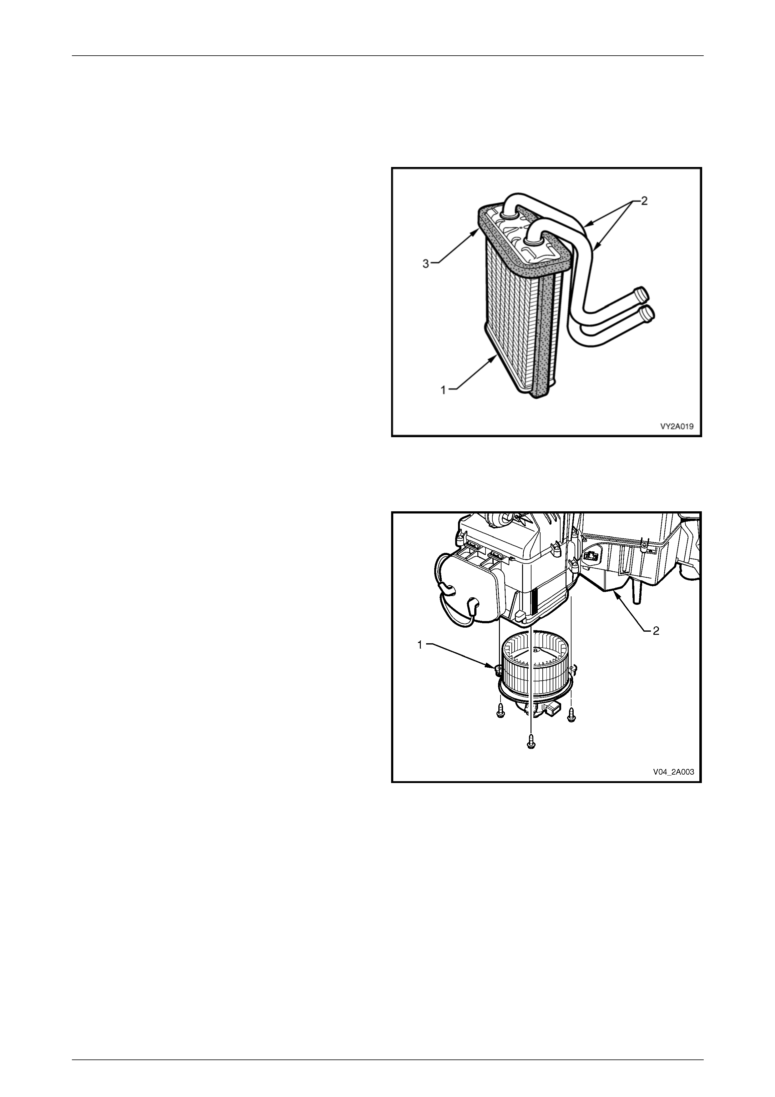
HVAC Climate Control (Manual A/C) – Description and Operation Page 2A-64
Page 2A-64
Heater Core
When the heater water valv e is in the open position, engine coolant flows through the heater core which is also housed in
the HVAC unit. Air passing the heater core fins provides heat to warm the vehicle inter ior and to provide windscreen
demisting.
The heater core (1) is an aluminium tu be and fin design. It
has integral inlet and outlet pipes (2).
Sealing foam (3) is bonded to the sides and around the top
of the heater core to prevent air leakage from the HVAC
case and to ensure air does not bypass the core’s h eat
exchanging sur faces.
Figure 2A – 70
Blower Motor and Fan Assembly
The blower motor and fan assembly (1) is located on the
underside of the HVAC unit (2), on the left-hand side.
For protection of the blower motor, a 35A blade-type fuse is
mounted on a bracket attached to the blower motor
mounting flange.
Figure 2A – 71

HVAC Climate Control (Manual A/C) – Description and Operation Page 2A-65
Page 2A-65
Blower Motor Resistor Assembly – Manual A/C
The blower motor and fan assembly dr aws air from the plenum chamber into the HVAC unit. This air is then expelled
from the HVAC unit at a speed and temperature as sel ected on the manual HVAC controller.
To provide the different fan speeds, a block of three resistors is wired into the blower motor circuit. The resistor block is
mounted to the HVAC unit and is exposed to the internal airflow.
The blower motor resistor assembly (1) is located to the
cabin side of the HVAC unit (2) beside the bl ower motor
housing.
The three resistors are located in a finned aluminium heat
sink (3).
Figure 2A – 72
Electronic Blower Motor Controller – Auto A/C
The blower motor and fan assembly dr aws air from the plenum chamber into the HVAC unit. This air is then expelled
from the HVAC unit at a speed and temperature as selected on the OCC control module.
To provide the various fan speeds, an el ectronic blower motor controller is wired into the blower motor circuit. The
controller is located on the underside of the HVAC unit and is exposed to the internal airflow between the blower fan and
the evaporator.
The electronic blo wer motor control ler (1) is located to the
cabin side of the HVAC unit (2) beside the bl ower motor
housing.
It uses a large scale power transistor to provide the fixed
and variable fan speeds. An aluminium heat sink (3) is used
to dissipate the heat from the power transistor.
Figure 2A – 73

HVAC Climate Control (Manual A/C) – Description and Operation Page 2A-66
Page 2A-66
Air Mix Doors – Manual A/C
The air mix doors control airflow through the heater core. On manual air-conditionin g HVAC units they are mechanically
connected to the temperature control dial at the HVAC controller via a rod, pinion and crescent gear assembly.
As the temperature control switch is rotated from cold to hot, the air mix doors are moved to direct all or some of the air,
depending on the position of the temperature control dial, within the HVAC unit through the heater core.
The air mix door assembly incorporates a main door and a small inner door. The two-stage door opening strateg y is used
to overcome blower fan pressure immediate ly downstream of the evaporator when all air is passing throu gh the heater
core (full hot position). This reduces door opening loads when a cooler or cold temperature is selected.
In the full hot position the main air mix door (1) and the sm all air mix door (2) are joined together and a ll air is directed
through the heater core (3), refer to Figure 2A – 74.
When the temperature switch (4) on the HVAC controller (5) is rotated to select a cooler temperature, the action of the
actuating rod (6) and intermediate lever (7) firstly moves the small air mix door lever (8), to depressurise the cavity
between the heater core and the evaporator (9), and then the large air mix door lever (10). As the doors travel towards
the full cold position, they move closer together. In the full cold position they are joined together again, completely
sealing off the heater core cavity.
The reverse sequence occurs when moving from the full col d to the full hot position.
In Figure 2A – 74 the cutaway drawing shows the air mix doors in a warm position. The air moving to the left (11) is
headed for the heater core and the air moving to the right (12) is bypassing the heater core. The air in the middle (13) i s
also bypassing the heater core via the holes in the large air mix door.
The airflow schematics A, B C and D represent air mix d oor movement from hot to cold and the resultant airflow.
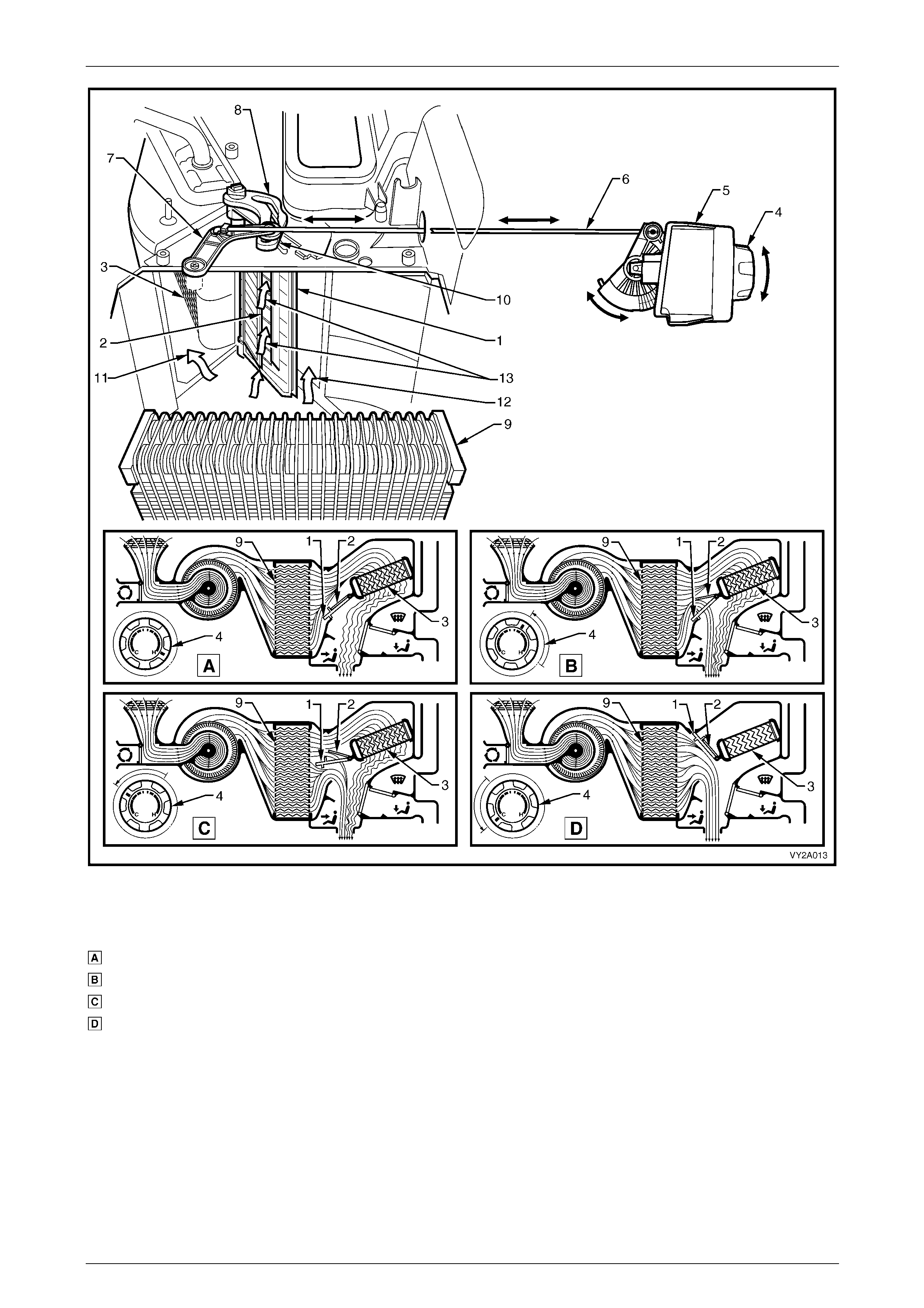
HVAC Climate Control (Manual A/C) – Description and Operation Page 2A-67
Page 2A-67
Figure 2A – 74
Legend
Full Hot
Warm
Warm
Full Cold
1 Main Air Mix Door
2 Small Air Mix Door
3 Heater Core
4 Temperature Switch
5 HVAC Controller
6 Actuating Rod
7 Intermediate Rod
8 Small Air Mix Door Lever
9 Evaporator
10 Large Air Mix Door Lever
11 Left-moving Air Flow
12 Right-moving Air Flow
13 Air Bypassing the Heater Core
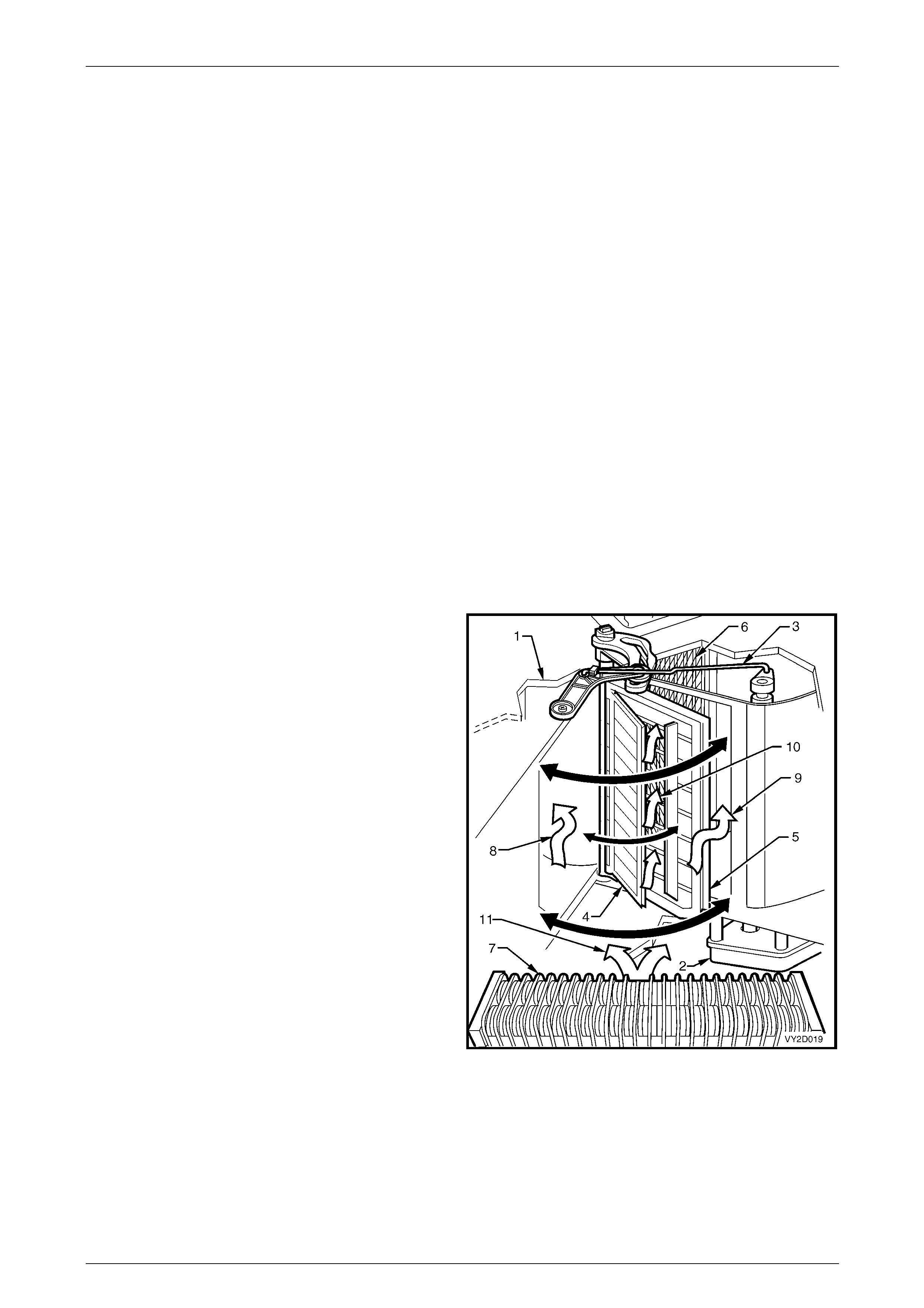
HVAC Climate Control (Manual A/C) – Description and Operation Page 2A-68
Page 2A-68
Air Mix Doors and Motor – Auto A/C
Air Mix Doors
Air mix doors control airflo w through the heater core thereby raising or lo wering the vehicl e’s cabin temperature. Two air
mix doors are fitted.
Air Mix Door Motor
The air mix door motor is a small electric stepp er motor used to operate the air mix doors.
Air mix door motor movement is achieved by applying a 12 V (nominal) signal from the OCC control module to the air mix
door motor, causing the motor to turn and open the air mix doors. The motor’s direction can be changed to close the
doors by the OCC control module reversing the polarity of the signal.
Motor and Door Configurations
Single Zone
The air mix door assembly incorporates a main door and a small (inner) door to control airflow through the he ater core.
The two-stage door opening strateg y is used to overcome b lower fan pressure immediately d ownstream of the
evaporator when all air is passing thro ugh the heater core (full hot position). T his reduces door opening loads when a
cooler or cold temperature is selected.
In the full hot position the large air mix door and the small air mix door are join ed together and all air is directed through
the heater core. When the temperature is red uced, the a ir mix door motor operates causing the action of actuatin g rod
and intermediate lever firstly moving the small air mix door lever, to depressurise the cav ity between the heater core and
evaporator, and then the large air mix door lever. As the doors travel towards the full cold positio n, they move closer
together. In the full cold position they are joined together a gain, completely sealing off the heater core cavity. The reverse
sequence occurs when movin g from the full cold to the full hot position.
Legend
1 HVAC Case
2 Air Mix Door Motor
3 Air Mix Door Motor Actuating Rod
4 Air Mix Door – Small
5 Air Mix Door – Large
6 Heater Core
7 Evaporator
8 Air to Heater Core
9 Air Bypassing Heater Core
10 Air Bypassing Heater Core through Large Air Mix Door
11 Air Leaving Evaporator
Figure 2A – 75
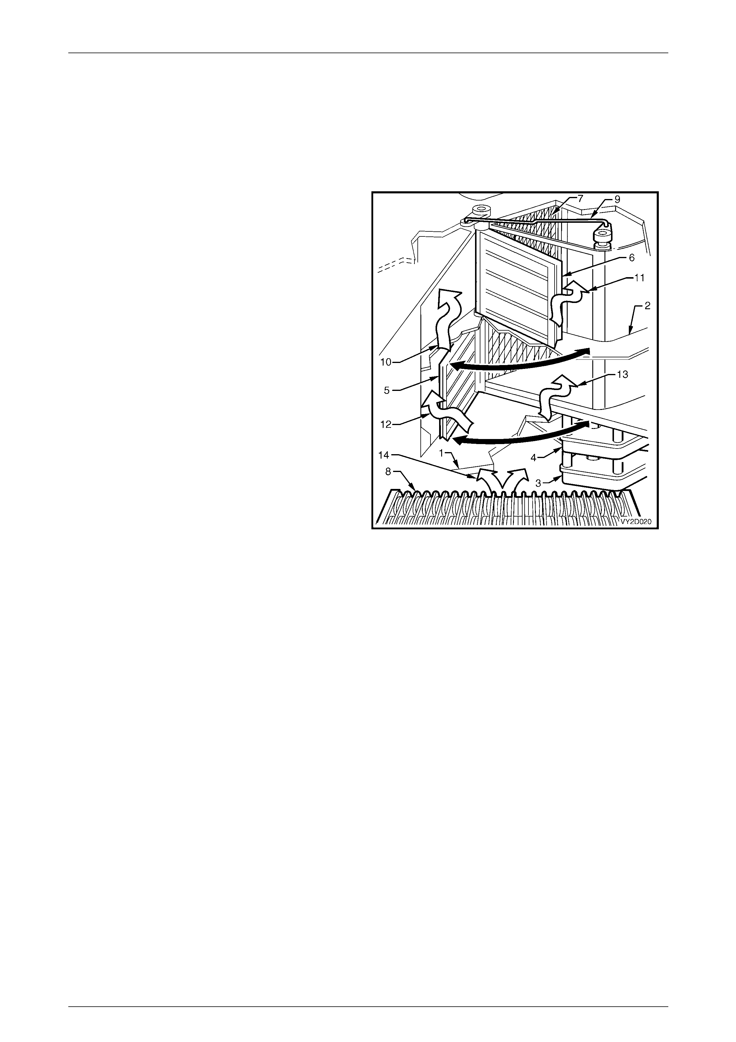
HVAC Climate Control (Manual A/C) – Description and Operation Page 2A-69
Page 2A-69
Dual Zone
Dual zone HVAC units use an equally sized upper and lo wer air mix door on one side of the heater core to provide th e
temperature differentiation between the driver’s side and front passenger’s side of the cabin.
Two air mix motors located under the HVAC unit are fitted to oper ate the two air mix doors in response to OCC module
output signals. The air mix motors function independently during dual zone oper ation. Their operating state is identical
during single zone operation.
Legend
1 HVAC Case
2 Dual Zone Partition
3 Air Mix Door Motor – Driver
4 Air Mix Door Motor – Passenger
5 Air Mix Door – Driver
6 Air Mix Door – Passenger
7 Heater Core
8 Evaporator
9 Air Mix Door Motor Actuating Rod – Passenger
10 Air to Heater Core – Passenger
11 Air Bypassing Heater Core – Passenger
12 Air to Heater Core – Driver
13 Air Bypassing Heater Core – Driver
14 Air Leaving Evaporator.
Figure 2A – 76
Air Mix Door Motor/Door Calibration
A potentiometer within the air mix door motor supplies a 3.6 ± 0.2 V feedback signal to the OCC control module to
indicate the position of the air mix doors in relation to air mix door motor drive position.
To maintain the correct working relationship with the OCC control module, the air mix door motor and door function must
be calibrated to the OCC control module. A variation of mo re than 5% from the base calibration value may cause
customer complaints such as cabin slow to heat, poor demist performance, etc.
Air mix door calibration can be performed with Tech 2. For further information,
refer to Section 2E HVAC Occupant Climate Control (Auto A/C) – Diagnos tics .
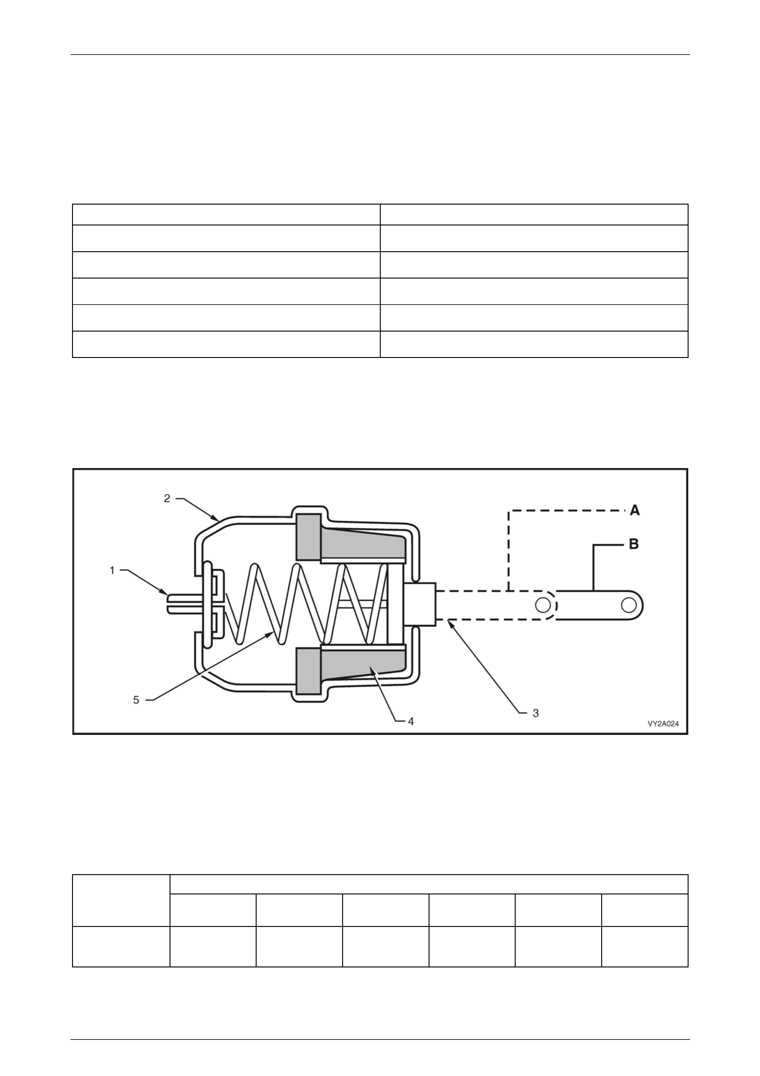
HVAC Climate Control (Manual A/C) – Description and Operation Page 2A-70
Page 2A-70
Vacuum Actuators
All doors on the HVAC unit, apart from the air mix doors, are opened and closed by three vacuum actuators. One is a
single-stage unit and two are two-stage units.
The HVAC actuator housings are made of plastic. The rods of the actuator s are also plastic and are colour-coded
according to their function. The intake (fresh / recirculate) actuator rod is blue, the demist / floor (foot) actuator rod is
black and the face door actuator rod is white.
The following table indicates which type of actuator is used to operate a particular ventilation door.
Ventilation Door Vacuum Actuator Type
Intake (Fresh / Recirculate) Single-stage (1 door)
Face Two-stage
Demist —
Demist / Floor (Foot) Two-stage
Foot —
Single-stage Actuator
The single-stage actuator consists of a vacuum housing (2) containing a spring (5), rubber diaphragm(4) and an
actuating rod (3), refer to Figure 2A – 77.
When vacuum is applied to the actuator, the rubber diaphragm is pulled back, compressing the sprin g and retracting the
actuating rod which is connected via o ne or more levers to an air distribution door. When vacuum is removed, the spring
pushes the diaphragm and actuating rod back to its original position.
Figure 2A – 77
Legend
A Actuator rod retracted
B Actuator rod extended 1 Vacuum port
2 Actuator housing
3 Actuator Rod
4 Diaphragm
5 Spring
The following table indicates what position (retracted or extended) the si ngle-stage actuator will be in when a partic ular
ventilation function is selected.
Selected Ventilation Function
Actuator Face Bi-level
(face / floor) Floor Blend
(demist / floor) Demist Recirculation
(face)
Intake
(fresh / recirc.) Extended Extended Extended Extended Extended Retracted

HVAC Climate Control (Manual A/C) – Description and Operation Page 2A-71
Page 2A-71
Two-stage Actuators
The HVAC unit contains doors that are required to open half way while another door closes fully. With single-stage
vacuum actuators this would require a complicated linkage set-up and additional actuators.
To overcome this situation, two-stage actuators are used. Through their design they can move the actuating rod fully
(2nd stage), half way (1st stage) and fully extended (no vacuum). This enables some door s housed within the HVAC unit
to be only half open when a blend mode is selected and other doors to be close d at the same time via another actuator.
When vacuum is directed to the 1st stage vacuum port (3), only the 1st stage rubber diaphragm (7) is pulled towards the
rear of the housing, moving the actuator rod (6) only h alf way. Once the 2nd (1) and 1st stage ports have vacuum
applied, both diaphragms (4 a nd 7) are pulled towards the rear of the housing, moving the actuator rod fully inwards to
the 2nd stage. Refer to Figure 2A – 78.
The extent of actuator rod travel in either 1st or 2nd stage is governed by compressing two springs (5 and 8), one on
each vacuum diaphragm. Both these springs are of differing tensions.
Figure 2A – 78
Legend
A Actuator Rod at Second Stage
B Actuator Rod at First Stage
C Actuator Rod Fully Extended
1 Vacuum port – Second Stage
2 Actuator housing
3 Vacuum Port – First Stage
4 Diaphragm – Second Stage
5 Spring – First Stage
6 Actuator Rod
7 Diaphragm – First Stage
8 Spring – Second Stage
The following table indicates what position (1st stage, 2nd stage or fully extended) a two-stage actuator will be in when a
particular ventilation function is selected.
Selected Ventilation Function
Actuator Face Bi-level
(face / floor) Floor Blend
(demist / floor) Demist Recirculation
(face)
Face
Actuator 2nd Stage 1st Stage Fully
Extended Fully
Extended Fully
Extended 2nd Stage
Demist /
Floor (foot)
Actuator
Fully
Extended 2nd Stage 2nd Stage 1st Stage Fully
Extended Fully
Extended

HVAC Climate Control (Manual A/C) – Description and Operation Page 2A-72
Page 2A-72
Vacuum Solenoid Pack – Auto A/C
The vacuum solenoid pack (1) is located on the lower rear
of the blower motor housing (2). It consists of a band of six
electronically activated vacuum solen oids. Five are used to
apply or remove vacuum to the vacuum actuators altering
the air distribution positions. The remaining solenoid is used
to actuate the heater water valve.
Power is supplied to these soleno ids through the OCC
control module. When a mode switch is selected on the
OCC control module, current flo ws through the appr opriate
solenoids and allows vacuum to flow to the actuators.
Removing this current flow de-energises the solenoids and
allows any vacuum contained in the actuator and line to vent
through the front section of the solenoid.
Figure 2A – 79
Vacuum Tank – Manual A/C
The vacuum tank (1) is located on the left-hand sid e of the
HVAC unit (2).
This tank is used to maintain a vacuum to the vacuum
actuators during driving situati ons where the vacuum source
is low, such as full engine throttle.
Two vacuum lines are attached to the vacuum tank:
• The vacuum line (3) located towards the front of the
vehicle is the vacuum supply line from the engine inlet
manifold.
• The vacuum line (4) located towards the rear of the
vehicle is the vacuum feed to the mode s witch vacuum
valve and the water valve vacuum switch mounted to
the rear of the HVAC controller.
Figure 2A – 80
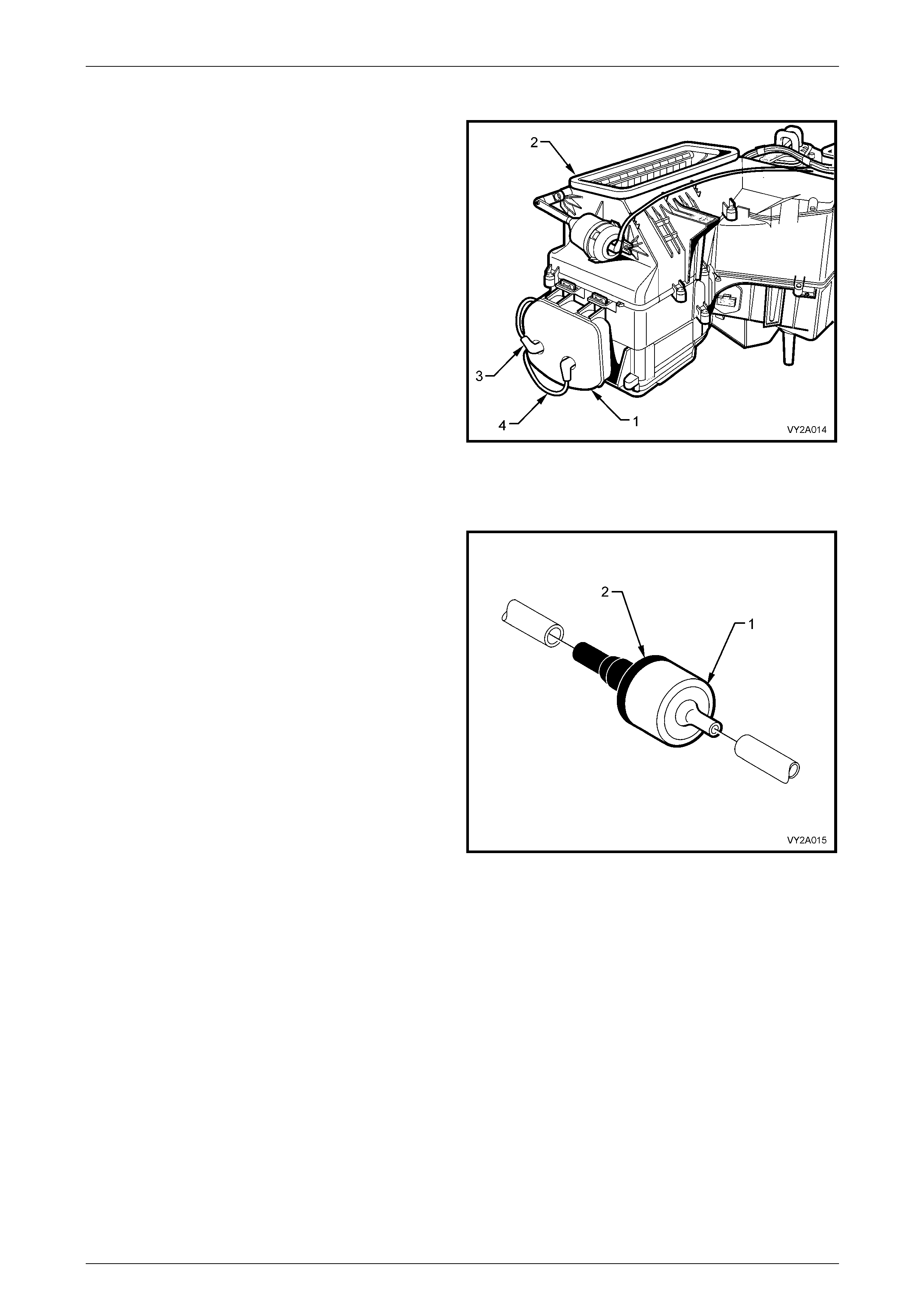
HVAC Climate Control (Manual A/C) – Description and Operation Page 2A-73
Page 2A-73
Vacuum Tank – Auto A/C
The vacuum tank (1) is located on the left-hand sid e of the
HVAC unit (2).
This tank is used to maintain a vacuum to the vacuum
actuators during driving situati ons where the vacuum source
is low, such as full engine throttle.
Two vacuum lines are attached to the vacuum tank:
• The vacuum line (3) located towards the front of the
vehicle is the vacuum supply line from the engine inlet
manifold.
• The vacuum line (4) located towards the rear of the
vehicle is the vacuum feed to the solenoid pack
located on the underside of the of the HVAC unit.
Figure 2A – 81
Vacuum Tank Check Valve
A check valve (1) is fitted in the vacuum source line from the
inlet manifold. It is located in the engine bay, to the rear of
the inlet manifold.
To maintain vacuum within the HVAC system, the valve
must be fitted correctly with the black section (2) of the valve
installed towards the HVAC unit side of the vacuum su pply
line.
Figure 2A – 82
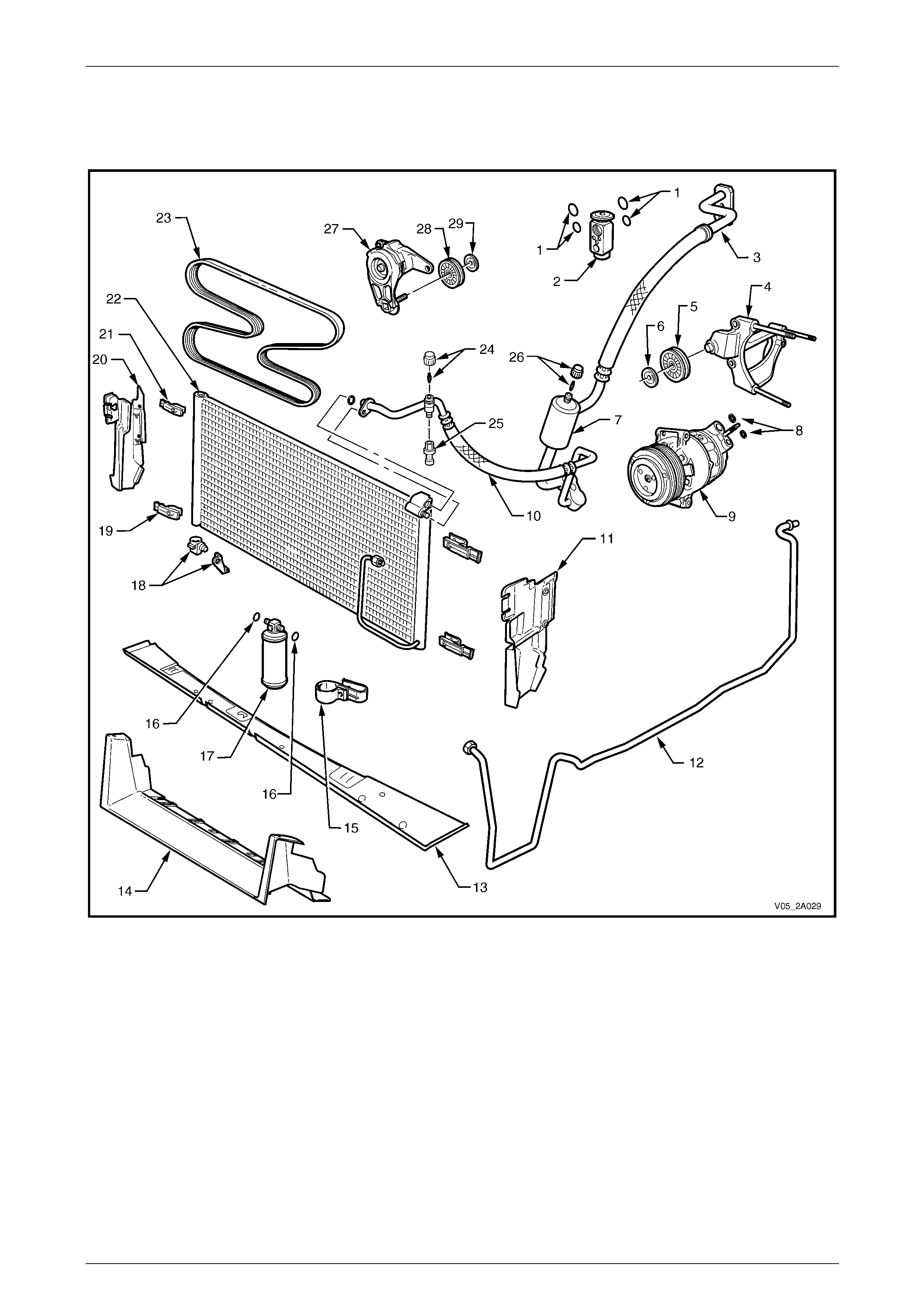
HVAC Climate Control (Manual A/C) – Description and Operation Page 2A-74
Page 2A-74
2.9 Under-hood Components
Under-hood Air-conditioning Components – V6
Figure 2A – 83
Legend
1 O-rings – Thermostatic
Expansion Valve
2 Thermostatic Expansion Valve
3 Suction Line
4 Compressor Mounting Bracket
5 Drive Belt Idler Pulley
6 Drive Belt Idler Pulley Washer
7 Muffler
8 Seals – Compressor
9 Compressor
10 Discharge Line
11 Air Chute – Left-hand Side
12 Liquid Line
13 Air Chute – Lower Baffle
14 Lower Air Chute Extension (where fitted)
15 Filter Drier Receiver Bracket
16 O-ring – Filter Drier Receiver
17 Filter Drier Receiver
18 Ambient Air Temperature Sensor and
Bracket
19 Condenser Lower Mounting Clip
(2 places)
20 Air Chute – Right-hand Side
21 Condenser Upper Mounting Clip
(2 places)
22 Condenser
23 Drive Belt
24 Schraeder Valve and Cap – High
Pressure Side
25 Pressure Transducer
26 Schraeder Valve and Cap – Low
Pressure Side
27 Drive Belt Tensioner Assembly
28 Drive Belt Tensioner Pulley
29 Drive Belt Tensioner Pulley Washer
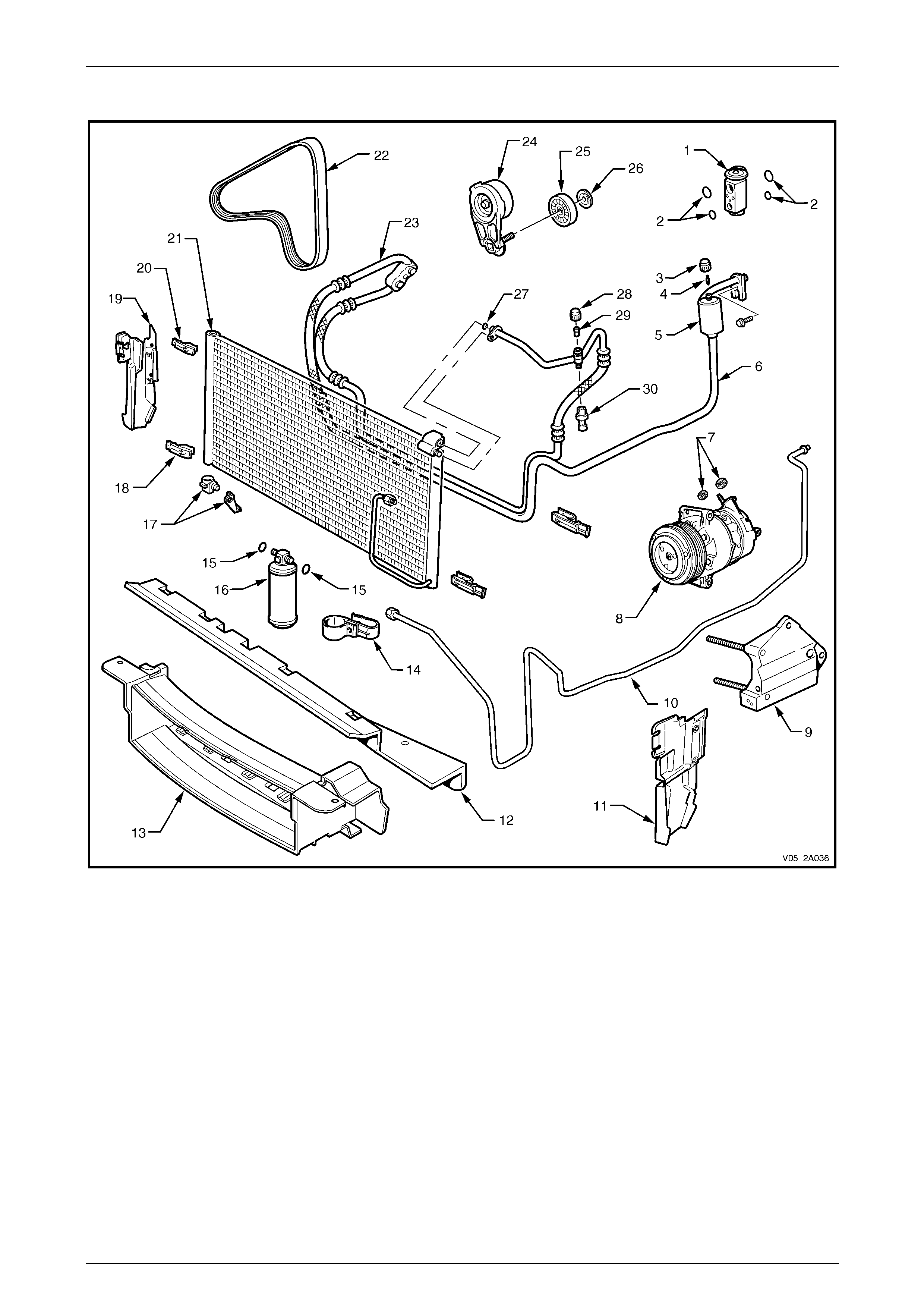
HVAC Climate Control (Manual A/C) – Description and Operation Page 2A-75
Page 2A-75
Under-hood Air-conditioning Components – V6 – AWD
Figure 2A – 84
Legend
1 Thermostatic Expansion Valve
2 O-rings – Thermostatic
Expansion Valve
3 Schraeder Cap – Low Pressure
Side
4 Schraeder Valve – Low
Pressure Side
5 Muffler
6 Discharge Line
7 Seals – Compressor
8 Compressor
9 Compressor Mounting Bracket
10 Liquid Line
11 Air Chute – Left-hand Side
12 Lower Air Chute
13 Lower Air Chute Extension
14 Filter Drier Receiver (FDR) Bracket
15 O-ring – Filter Drier Receiver
16 Filter Drier Receiver
17 Ambient Air Temp Sensor and Bracket
18 Condenser Lower Mounting Clip
19 Air Chute – Right-hand Side
20 Condenser Upper Mounting Clip
21 Condenser
22 Drive Belt
23 Discharge Hose / Tube
24 Drive Belt Tensioner Pulley Bracket
25 Drive Belt Tensioner Pulley
26 Drive Belt Tensioner Pulley Washer
27 O-ring – Discharge Tube
28 Schraeder Cap – High Pressure Side
29 Schraeder Valve – High Pressure Side
30 Pressure Transducer
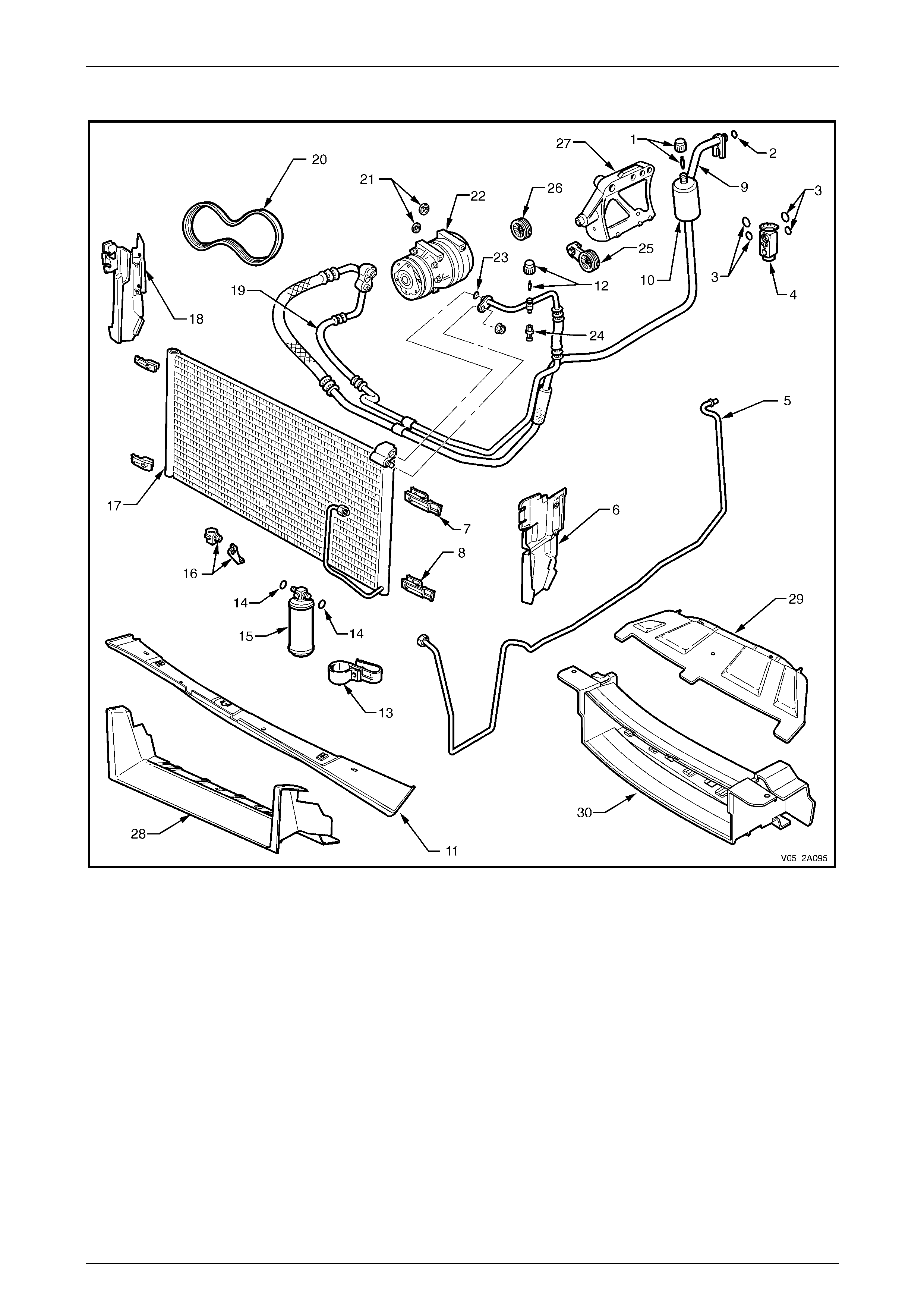
HVAC Climate Control (Manual A/C) – Description and Operation Page 2A-76
Page 2A-76
Under-hood Air-conditioning Components – GEN III V8
Figure 2A – 85
Legend
1 Schraeder Valve and Cap – Low
Pressure Side
2 O-ring
3 O-rings – Thermostatic
Expansion Valve
4 Thermostatic Expansion Valve
5 Liquid Line
6 Air Chute – Left-hand Side
7 Condenser Upper Mounting Clip
(2 places)
8 Condenser Lower Mounting Clip
(2 places)
9 Suction Line
10 Muffler
11 Air Chute – Lower Baffle
12 Schraeder Valve and Cap – High
Pressure Side
13 Filter Drier Receiver Bracket
14 O-ring – Filter Drier Receiver
15 Filter Drier Receiver (FDR)
16 Ambient Air Temperature Sensor and
Bracket
17 Condenser
18 Air Chute – Right-hand Side
19 Discharge Hose/Tube
20 Drive Belt
21 Seals – Compressor
22 Compressor
23 O-ring – Discharge Tube
24 Pressure Transducer
25 Drive Belt Tensioner
26 Drive Belt Idler Pulley
27 Compressor Mounting Bracket
28 Lower Air Chute Extension (SS models)
29 Lower Air Chute Extension (except SS
models)
30 Lower Air Chute Extension (AWD
models)

HVAC Climate Control (Manual A/C) – Description and Operation Page 2A-77
Page 2A-77
Condenser, Radiator and Fan Module
When the vehicle is built, the condenser (15), filter drier receiver (18), cooling fans (1 and 5), fan shroud (2) and
radiator (9) are installed into the engi ne compartment as an assembled unit, refer to Figure 2A – 86. This unit is
described as the condenser, radiator and fan module (CRFM).
NOTE
The illustration shows the CRFM for GEN III V8
engine, with the exception of the radiator cap
outlet, the CRFM is similar for V6 engine.
The condenser is mounted to the front of the radiator and is located and supported by four clips moulded into the front of
the plastic radiator tanks. The lower clips lock the condenser in place and can be released by hand to facilitate
condenser removal.
The cooling fan motors are each attached b y three screws to the one-piece plastic fan shroud. The fan shroud is
mounted to the rear of the radiator and is located and supported by four clips moulded into the rear of the plastic radiator
tanks. The upper clips lock the fan shroud in place and can be released by hand to facilitat e fan shroud removal. The
shroud must be removed to facilitate fan assembly removal.
Two wiring harness connectors are mounted to the upper section of the fan shroud allowing the fan assemblies to be
removed individually from the shroud. The fan motor and blade is balanced as an assembly and are serviced only as a
unit and must not be separated.
For further information relating to cooling fan operation refer to:
• Section 6B1 Engine Co oling – V6, or
• Section 6B3 Engine Cooling – GEN III V8.
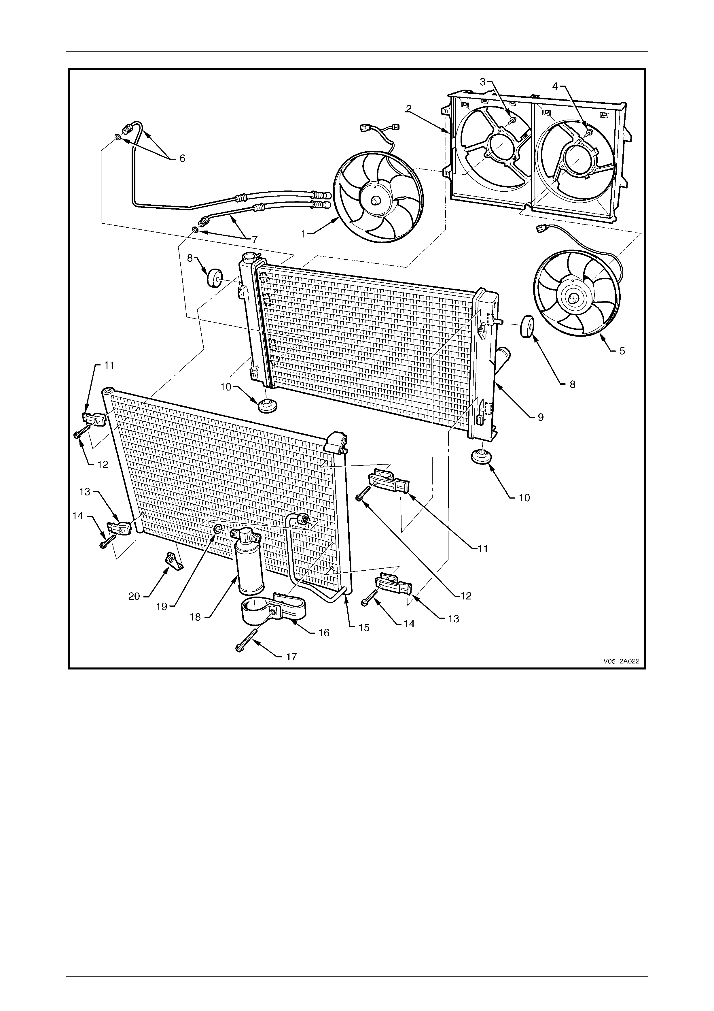
HVAC Climate Control (Manual A/C) – Description and Operation Page 2A-78
Page 2A-78
Figure 2A – 86
Legend
1 Right-hand Fan Assembly
2 Fan Shroud
3 Right-hand Fan Retaining Screw (3 places)
4 Left-hand Fan Retaining Screw (3 places)
5 Left-hand Fan Assembly
6 Inlet Transmission Cooling Line and Seal
7 Outlet Transmission Cooling Line and Seal
8 Upper Radiator Insulators (2 places)
9 Radiator
10 Lower Radiator Insulators (2 places)
11 Upper Condenser Mounting Clips (2 places)
12 Upper Condenser Mounting Clip Screws (2 places)
13 Lower Condenser Mounting Clips (2 places)
14 Lower Condenser Mounting Clip Screws (2 places)
15 Condenser
16 Filter Drier Receiver Mounting Bracket
17 Filter Drier Receiver Mounting Bracket Screw
18 Filter Drier Receiver
19 O-ring – Filter Drier Receiver
20 Ambient Air Temperature Sensor Mount
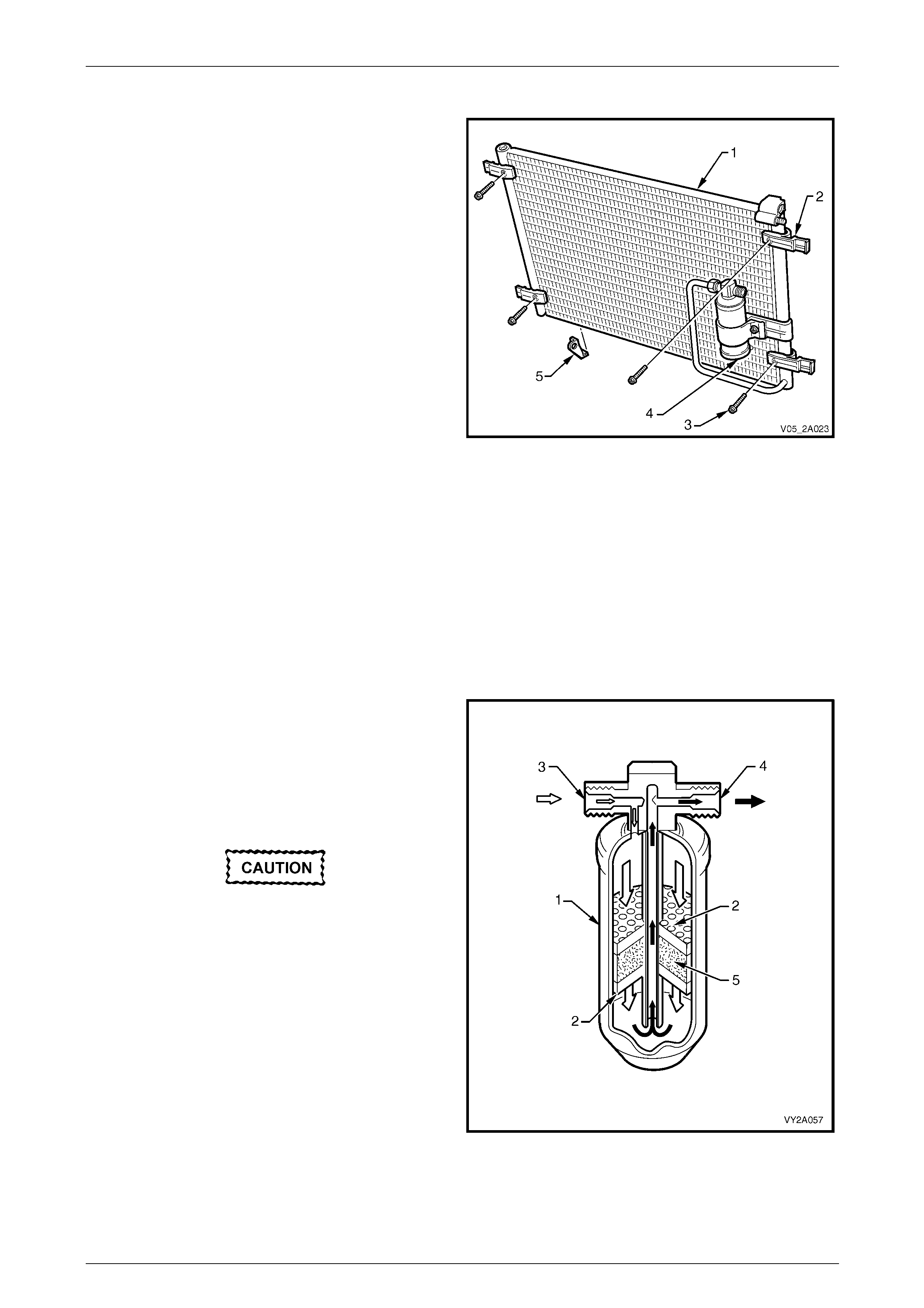
HVAC Climate Control (Manual A/C) – Description and Operation Page 2A-79
Page 2A-79
Condenser
The purpose of the cond enser (1) is the opposite of the
evaporator. The condenser receives high pressure, high
temperature refrigerant vapour from the compressor. It is
exposed to a flow of ram air from the movement of the
vehicle and, as the high pressure high temperature vapour
flows inside the condenser tubes, heat is given off to the
cooler ambient air flowing past the condenser core. The
vapour then condenses into a high pressure, high
temperature liquid.
Two cooling fans fitted to the rear of the radiator are
activated when required to assist in drawing cooling air
through the condenser.
The aluminium condenser is of a parallel flow design. It has
38 horizontal, flat section tube s with side mounted header
tubes.
It is mounted to the front of the radiator and is attached to
the radiator tanks by four identical mountin g clips (2)
attached with screws (3) to the condenser sides.
The filter drier receiver (FDR) (4) is attached to the front of
the condenser on the left-hand side.
A bracket (5) is fitted to the lower right-hand side of the
condenser to facilitate the installation of the ambient air
temperature sensor. This bracket should not be removed
from the condenser.
NOTE
The ambient air temperatur e sensor is fitted with
occupant climate control (auto A/C).
Figure 2A – 87
Filter Drier Receiver
The filter drier receiver acts as a particle filter, refrigerant
storage container and, most importantly, a moisture
absorber.
Moisture, temperature and R134a gen erates hydrofluoric
and hydrochloric acids. The silica gel beads (desicc ant)
located in the FDR absorb small q uantities of moisture thus
preventing acid generation.
Ensure the connection marked with the word
IN is connected to the co n den ser outlet.
Legend
1 FDR Housing
2 Strainer
3 From Condenser (High Pressure Unfiltered Liquid)
4 To Evaporator (High Pressure Filtered Liquid)
5 Desiccant
Figure 2A – 88
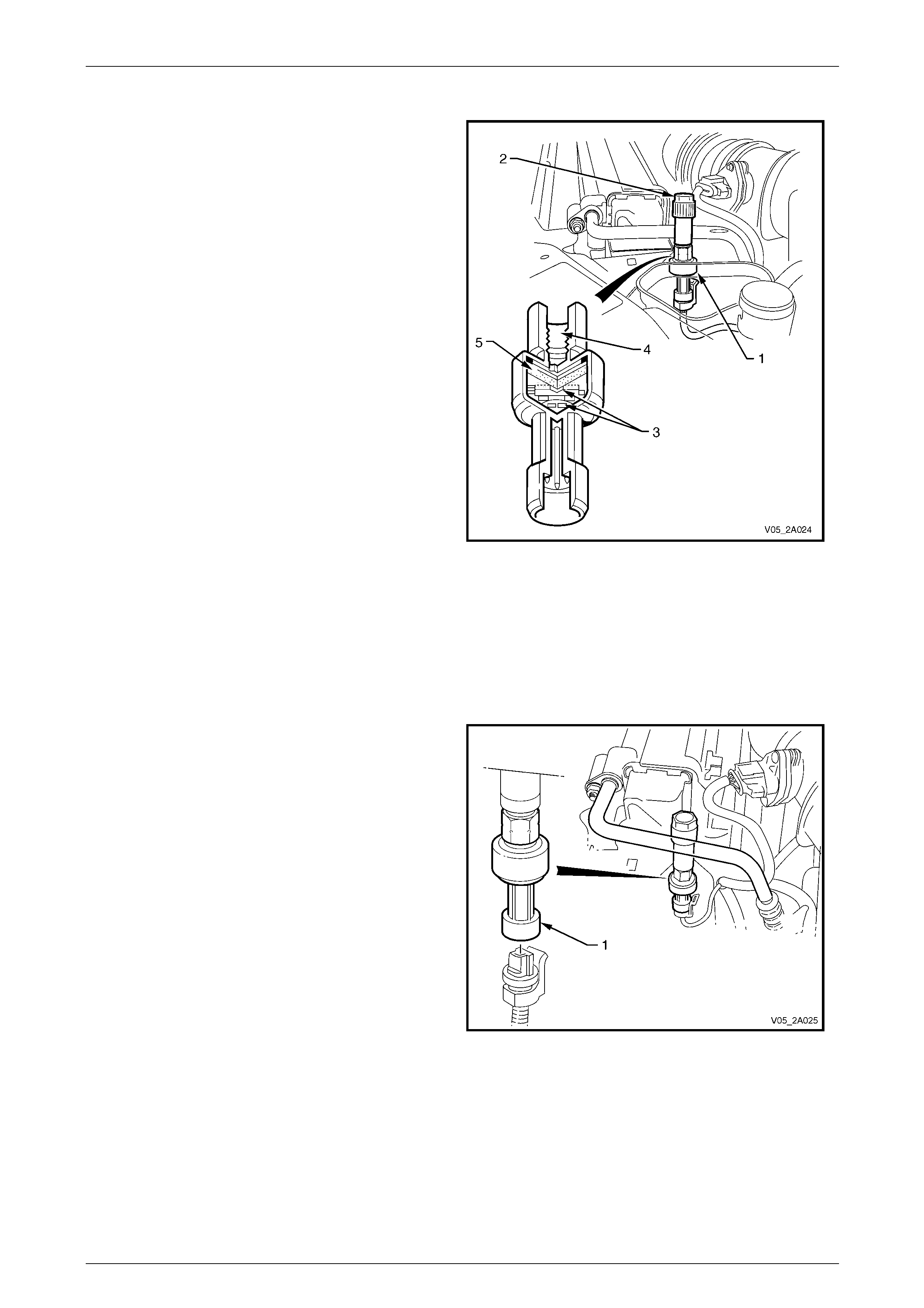
HVAC Climate Control (Manual A/C) – Description and Operation Page 2A-80
Page 2A-80
A/C Pressure Transducer
The pressure transducer is a seal ed gauge reference
capacitive pressure sensor with on-board signal
conditioning. It provides a 0 to 5 V output and requir es a 5 V
regulated power supply.
In operation, the transducer senses applied pressure via the
deflection of a two piece ceramic diaphragm with one half
being a parallel plate cap acitor. Changes in capac itance
influenced by the refrigerant pressure under the ceramic
diaphragm are converted to an ana logue output by the
transducer’s integral signal electronics.
The pressure transducer’s electronics are o n a flexible
circuit board contained in its upper section. T he y prov ide
linear calibration of the capac itance signal from the ceramic
sensing diaphragm.
Using the pressure transducer over a normal type pressure
switch is beneficial, as the transducer is constantly
monitoring pressures and sending signals to the engine
control module (ECM), whereas the normal type pressure
switch only has upper and lower cut-out points. With the
transducer, the ECM will still disengage the A/C compressor
at low or high refrigerant pressures but electronic diagnostic
equipment can be used to extract system pressure
information thereby making problem diagnosis easier.
Legend
1 Pressure Transducer
2 High Pressure Charge Port
3 Signal Electronics
4 Pressure Port
5 Ceramic Diaphragm
Figure 2A – 89
V6 Engine
The pressure transducer (1) not only acts as an input to the
ECM for A/C clutch operation, it also uses the information
provided by the pressure transducer to determine when to
turn on and off the 2nd Stage cooling fa n operation. For
further information on cooling fan operation, refer to
Section 6B1 Engine Co oling – V6.
Removal of the upper radiator shroud is required to gain
access to the pressure transducer.
Figure 2A – 90

HVAC Climate Control (Manual A/C) – Description and Operation Page 2A-81
Page 2A-81
GEN III V8 Engine
The pressure transducer (1) not only acts as an input to the
PCM for A/C clutch operation, it also uses the information
provided by the pressure transducer to determine when to
turn on and off the 2nd stage cooling fa n operation. For
further information on cooling fan operation, refer to
Section 6B3 Engine Cooling – GEN III V8.
Removal of the upper radiator shroud is required to gain
access to the pressure transducer.
Figure 2A – 91
Specification Table
Pressure Transducer Operation Specification – V6 Specification – GEN III V8
Low Pressure Cut-out @ 180 kPa 180 kPa
Low Pressure Cut-in @ 240 kPa 240 kPa
High Pressure Cut-out @ 2900 kPa 2900 kPa
High Pressure Cut-in @ 2000 kPa 200 0 kPa
2nd Stage Fan Operation On @ 2000 kPa 240 0 kPa
2nd Stage Fan Operation Off @ 1500 kPa 2000 kPa
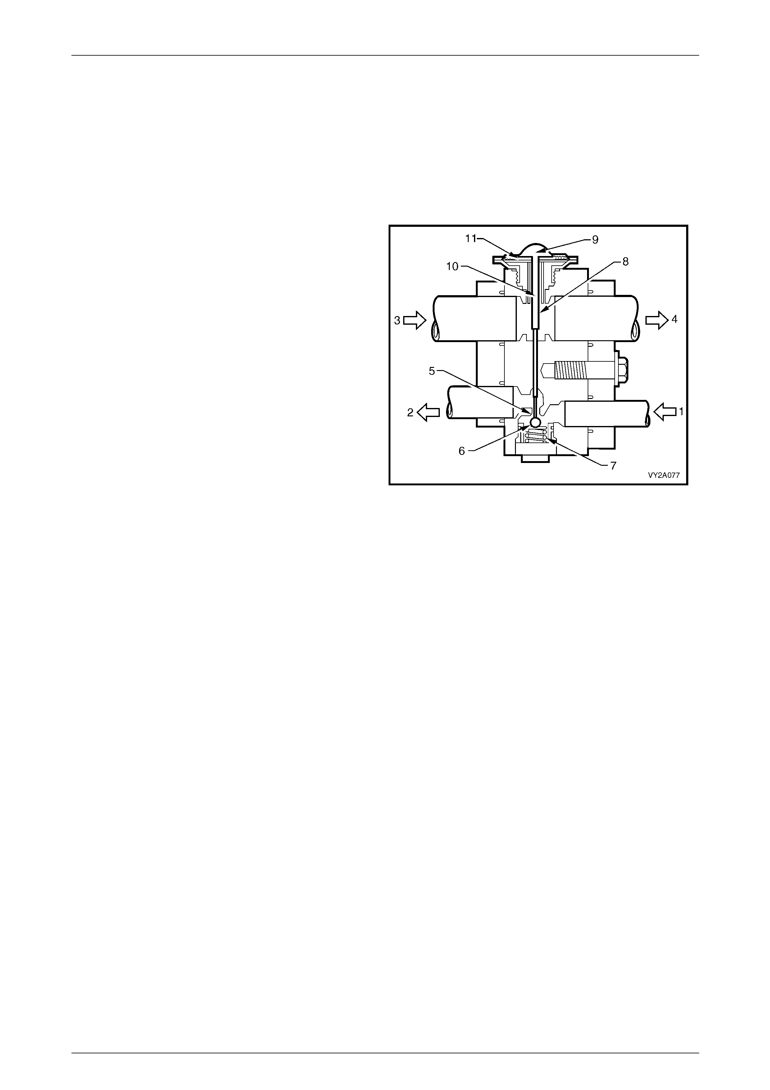
HVAC Climate Control (Manual A/C) – Description and Operation Page 2A-82
Page 2A-82
Thermostatic Expansion Valve
The thermostatic expansion valve (TXV) controls refrigerant gas flow to the evaporator and ensures that complete
evaporation takes place, it ha s two refrigerant passages.
One passage is in the refrigerant line from the condenser to the evaporator and contains a ball and spring valve.
The other passage is in the refrigerant line from the evaporator to the compressor and contains the temperature sensing
element.
Opening
As the non-cooled refrigerant from the evaporator coil flows
through the TXV outlet (suction), it makes contact with the
underside of the thin metallic diaphragm (11) and reacts on
the refrigerant contained above that diaphragm. This
refrigerant then expands forcing the pin (8) downwards
moving the ball (6) off its seat (5), compressing the
spring (7) and allowing more refriger ant to enter the
evaporator.
Legend
1 From Filter Drier Receiver
2 To Evaporator Coil
3 From Evaporator
4 To Compressor
5 Metering Orifice
6 Ball
7 Spring
8 Activating Pin (hollow)
9 Refrigerant
10 Pressure Compensation Under Diaphragm
11 Metallic Diaphragm
Figure 2A – 92
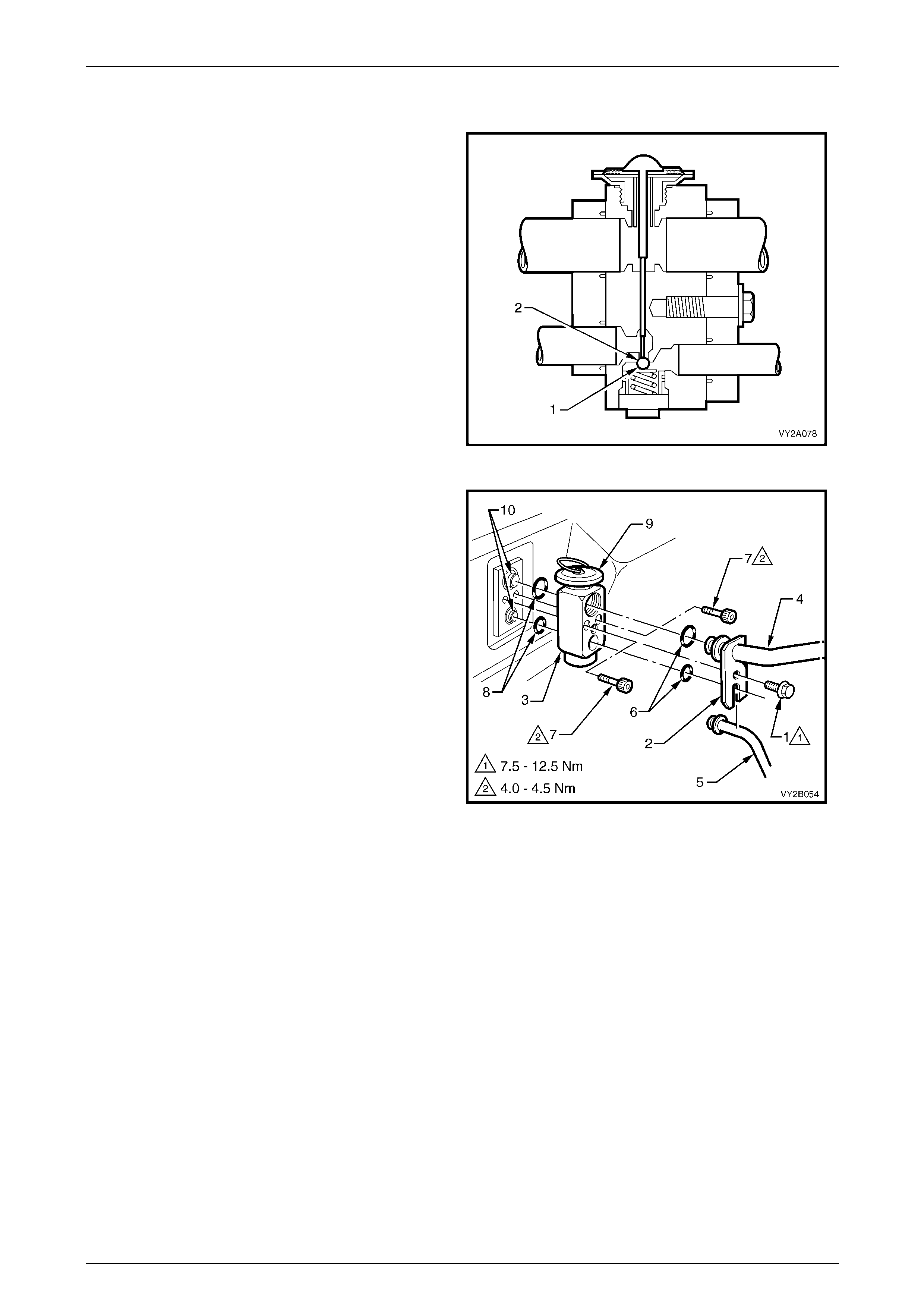
HVAC Climate Control (Manual A/C) – Description and Operation Page 2A-83
Page 2A-83
Closing
Operation is similar to opening but now the refrigerant from
the evaporator is cold. The refrigerant contai ned above the
diaphragm now contracts. The ball (1) moves towards the
seat (2) aided by the compressed spring, reducing
refrigerant flow.
NOTE
Low pressure liquid R134a passing through the
evaporator should be completely vaporised by
the time it reaches the TXV outlet side.
Figure 2A – 93
The TXV is installed in the engine compartment to the dash
panel assembly.
Legend
1 Retaining Screw – Tubes to TXV
2 Tube Retaining Plate
3 Thermostatic Expansion Valve (TXV)
4 Suction Tube
5 Liquid Tube
6 O-rings – TXV to Suction and Liquid Tubes
7 Retaining Screws – TXV to Evaporator Tubes
8 O-rings – TXV to Evaporator Tubes
9 TXV Diaphragm
10 Evaporator Tubes
Figure 2A – 94
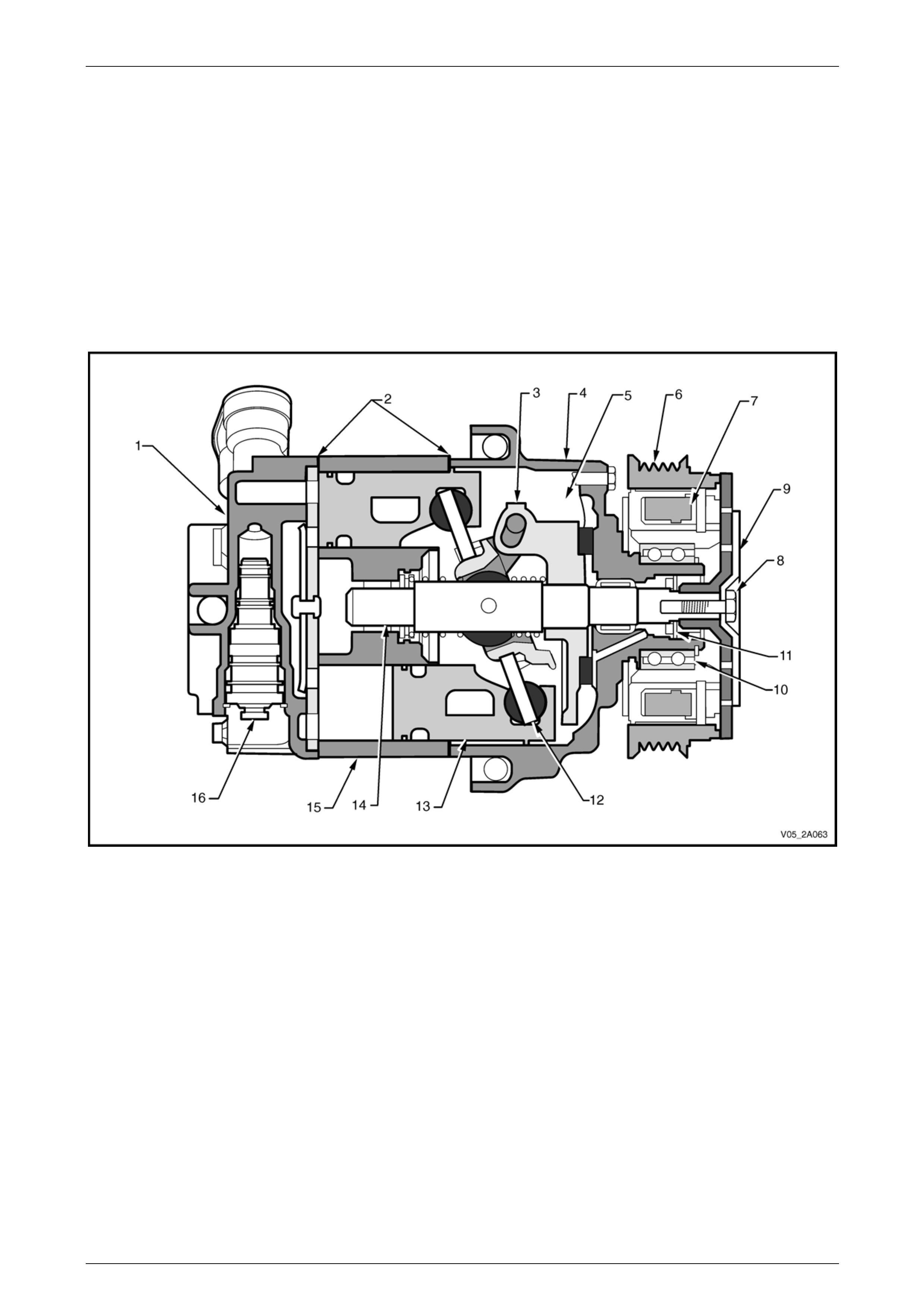
HVAC Climate Control (Manual A/C) – Description and Operation Page 2A-84
Page 2A-84
Air-conditioning Compressor Assembly – V6
The Delphi 7CVC air-conditioning compressor can match air-conditio ning system demand under all conditions without
cycling. The basic compressor mechanism is a variable angle swash-plate with axially oriented cylinders. The
compressor has a maximum displacement of 164 cc.
Operation of the compressor clutch is controlled by the engi ne control module (ECM). It is dependent on inputs from
various sensors such as the A/C pressure transducer, engine coolant temperature sensor, etc. and a request from the
OCC control module.
NOTE
The compressor is not serviceable and if found to
be malfunctioning it must be replaced as a unit.
Figure 2A – 95
Legend
1 Rear Head
2 Body Seals
3 Swash Plate Hinge
4 Front Head
5 Crankcase
6 Pulley
7 Magnetic Coil
8 Clutch and Pulley Retaining Bolt
9 Clutch Plate
10 Pulley Bearing
11 Shaft Lip Seal
12 Swash plate
13 Piston
14 Shaft
15 Cylinder
16 Control Valve

HVAC Climate Control (Manual A/C) – Description and Operation Page 2A-85
Page 2A-85
Compressor Control Valve
The control valve is installed in the compressor rear head. The angle of the swash-plate and the resultant compressor
displacement, is determined by the compress or crankcase to suction pressure differential, which is governed b y the
control valve, refer to Figure 2A – 96, shown typical.
Figure 2A – 96
Legend
1 Compressor Rear Head
2 Control Valve Retainer
3 Control Valve Bellows Housing
4 O-ring
5 Bellows
6 Bellows Spring
7 Shuttle Valve
8 Control Valve Discharge Pressure Valve Housing
9 Discharge Pressure Ball and Spring
10 Discharge Pressure Ball and Spring Retainer
11 Discharge Pressure Reed Valve
12 Discharge Pressure Port (to discharge pressure ball and
spring)
13 Discharge Pressure Reed Valve Rivet
14 Crankcase Pressure Port (from discharge pressure ball and
spring)
15 Crankcase Pressure Port (to bellows)
16 Suction Port (from bellows)
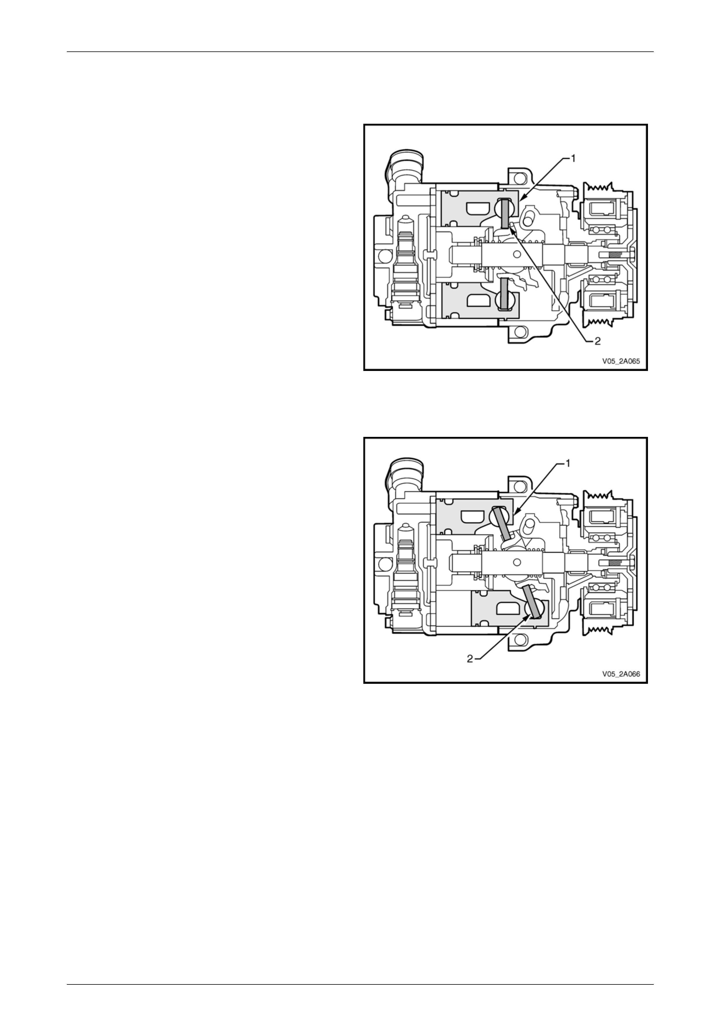
HVAC Climate Control (Manual A/C) – Description and Operation Page 2A-86
Page 2A-86
Compressor Operation
Compressor Minimu m Stroke
When the air-conditioning demand is low, the crankcase
pressure behind the pistons (1) is equal to the pressure in
front of the pistons. This forces the swash plate (2) to rotate
on its hinge, changing its angle to towards vertical, which
reduces the stroke of the pistons and the displacement of
the compressor to approximately 6 cc.
Figure 2A – 97
Compressor Maximum Stroke
When the air-conditioning demand is high, the crankcase
pressure behind the pistons (1) is less than the pressure in
front of the pistons. This forces the swash plate (2) to rotate
on its hinge, changing its angle away from vertical, which
increases the stroke of the pistons and the displacement by
approximately 140 cc.
Figure 2A – 98
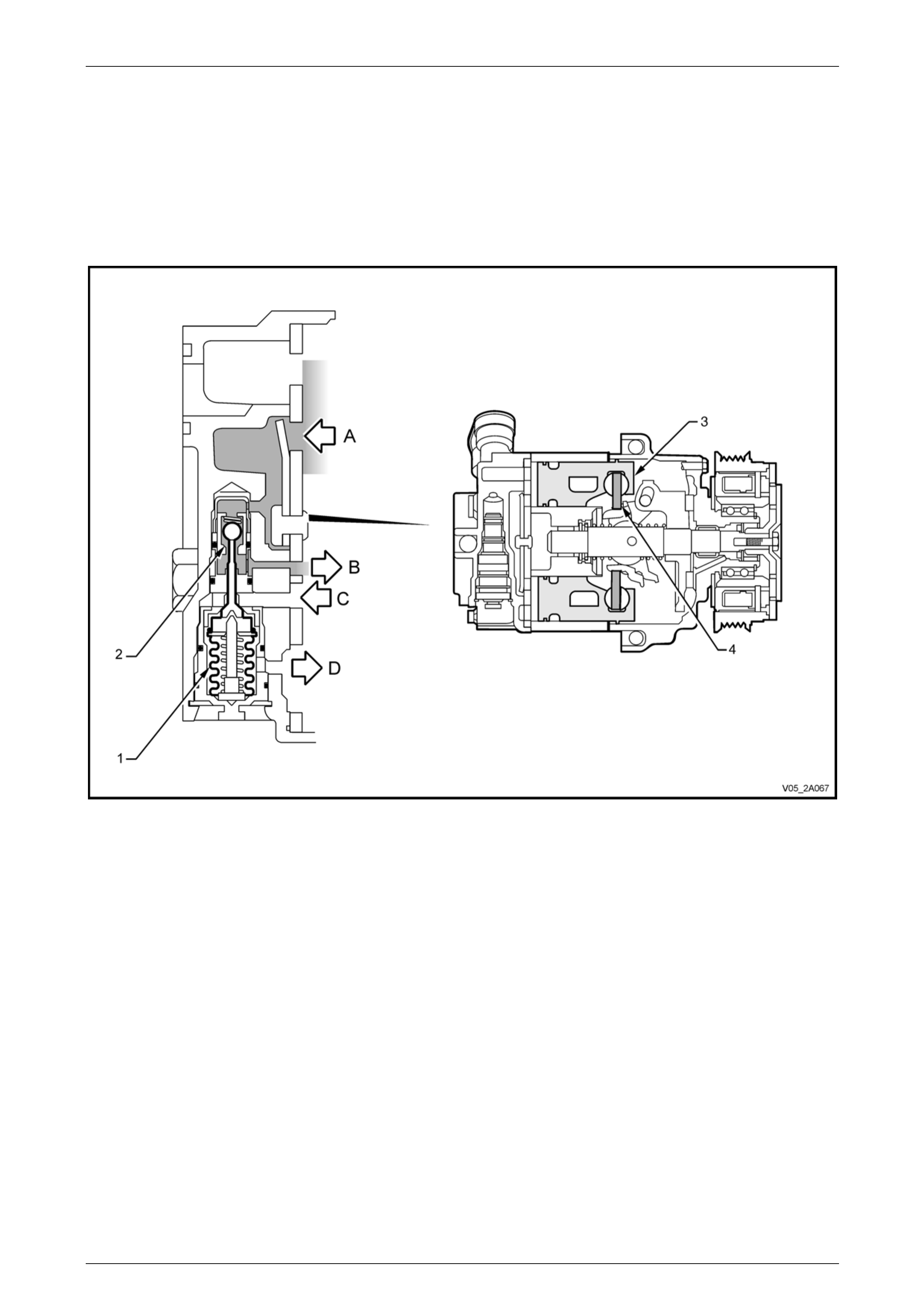
HVAC Climate Control (Manual A/C) – Description and Operation Page 2A-87
Page 2A-87
Low A/C Demand
When the evaporator cooling load is reduced (ambient temperat ure or blower fan speed is reduced) the s uction pressure
is reduced until it reaches the control p oint.
To reach the control point, the bellows (1) in the control valve assembly has expanded to allow discharge pressure (A) to
bleed past the control valve ball valve seat (2) and into the compressor crankcase, refer to Figure 2A – 99.
This crankcase pressure (B) acts as an oppo s ing force behind the compressor pistons (3) to cause the swash plate (4) to
change its angle to wards vertical and therefo r e, reduce piston stroke.
Figure 2A – 99
Legend
A Discharge Pressure
B Crankcase Pressure (from valve)
C Crankcase Pressure (to valve)
D Suction Pressure
1 Bellows
2 Control Ball Valve Seat
3 Piston
4 Swash Plate
NOTE
When the air-conditioner demand is low, A to B
open, C to D closed, (bleed to crankcase).
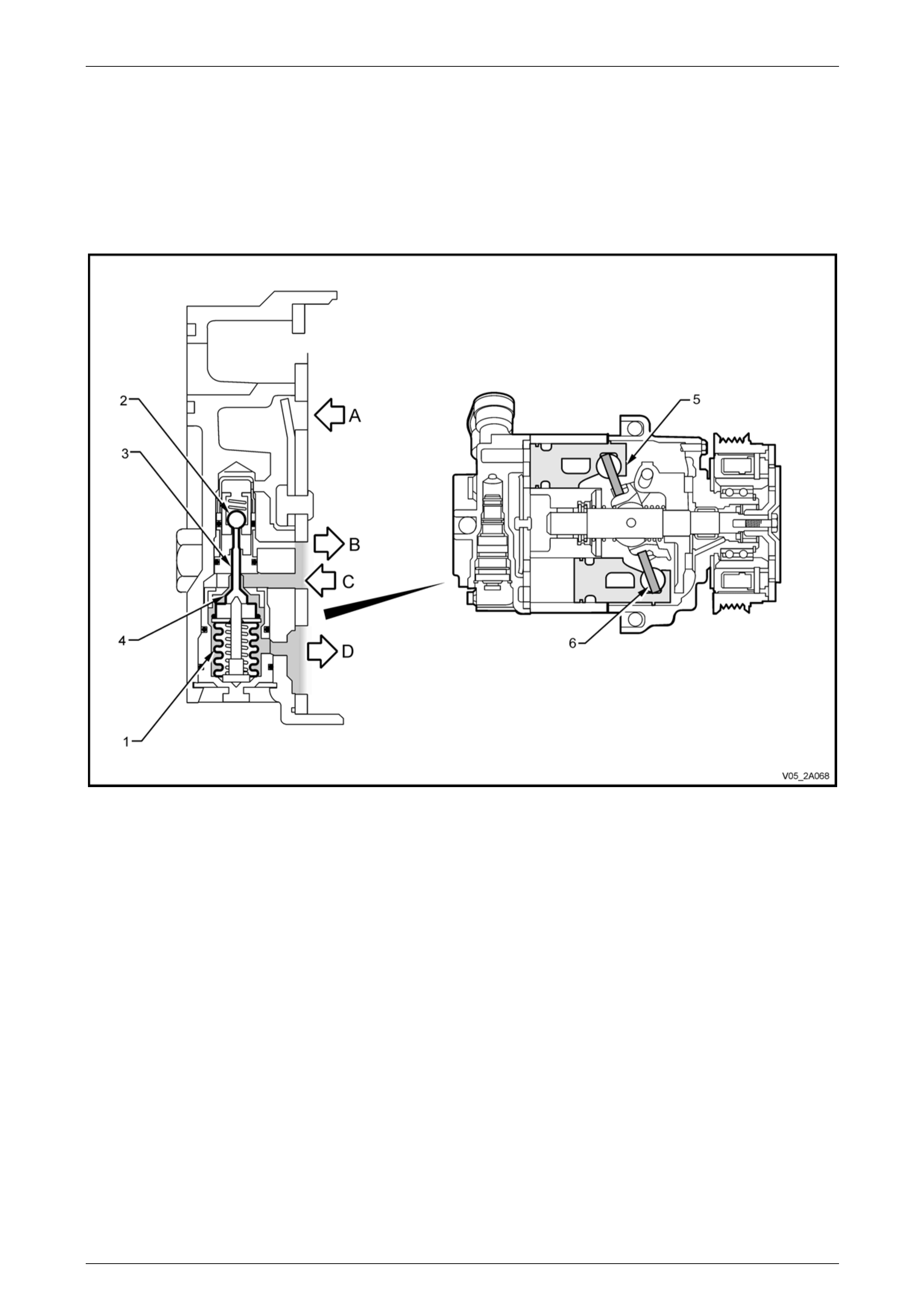
HVAC Climate Control (Manual A/C) – Description and Operation Page 2A-88
Page 2A-88
High A/C Demand
When suction pressure (D) is above the cont rol point, it will compress the control valve bellows (1), refer to
Figure 2A – 100. This will close the discharge valve, as the ball valve (2) is no w on its seat.
The shuttle valve (3) moves towards the suction port an d opens the suction valve (4). Crankcase press ure (C) will then
bleed from the compressor crankcas e past the suctio n valve to the suction port. As the crankcase pressure behind the
pistons (5) is reduced, the swash plate (6) will rotate from vertical causing the pistons to move towards maximum stroke.
The compressor will then have a corresp onding increase in its displ acement.
Figure 2A – 100
Legend
A Discharge Pressure
B Crankcase Pressure (from valve)
C Crankcase Pressure (to valve)
D Suction Pressure
1 Bellows
2 Control Ball Valve Seat
3 Shuttle Valve
4 Suction Valve
5 Piston
6 Swash Plate
NOTE
When the air-conditioner demand is high, A to B
closed, C to D open, (bleed from crankcase).
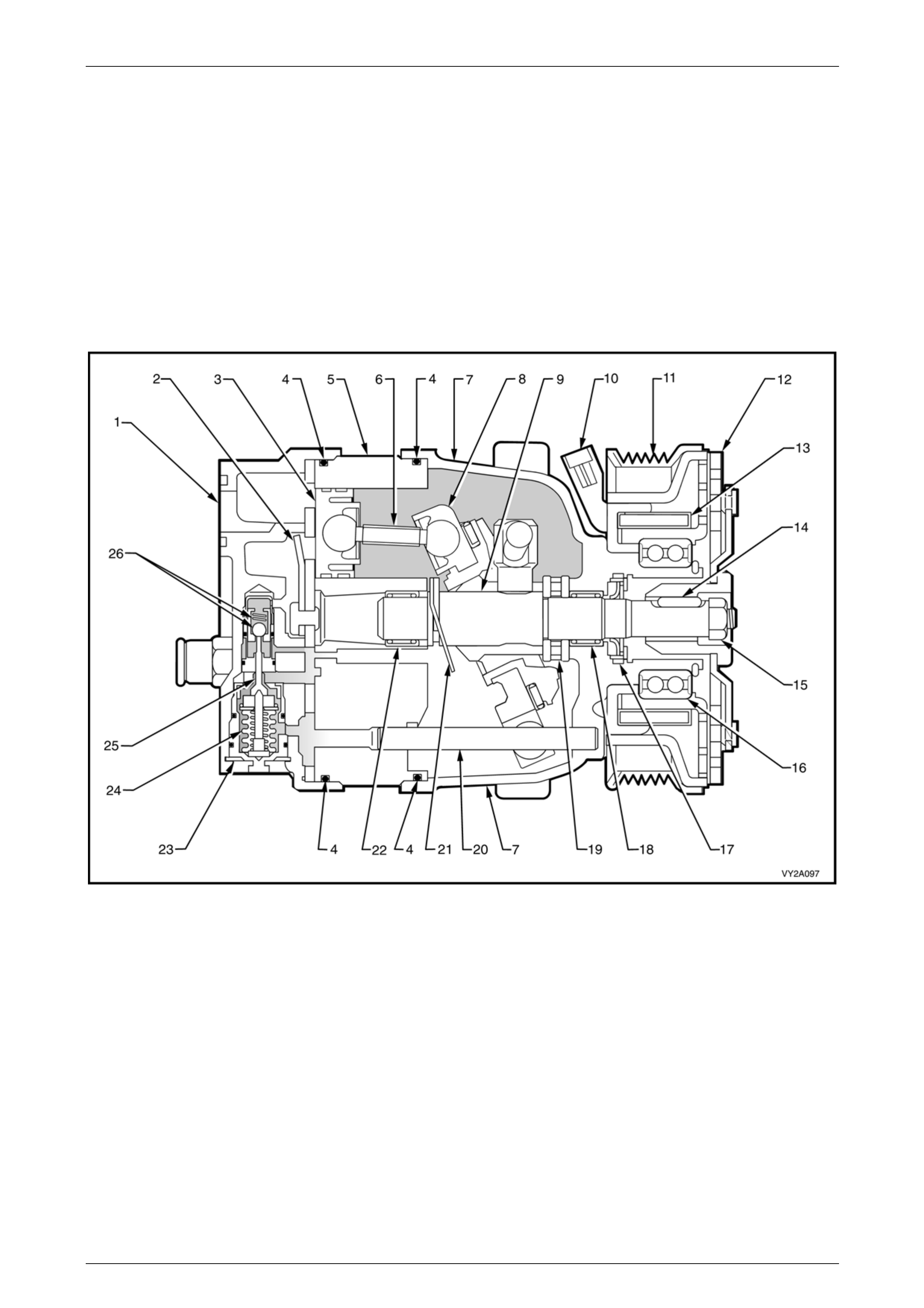
HVAC Climate Control (Manual A/C) – Description and Operation Page 2A-89
Page 2A-89
Air-conditioning Compressor Assembly – GEN III V8
The Delphi V7 air-conditi oning compressor can match air-conditioning system demand under all con ditions without
cycling. The basic compressor mechanism is a variable angle wobble plate with seven axiall y oriented cylinders. The
compressor has a maximum displacement of 185 cc.
Operation of the compressor clutch is controlled by the engi ne control module (ECM). It is dependent on inputs from
various sensors such as the A/C pressure transducer, engine coolant temperature sensor, etc. and a request from the
OCC control module.
NOTE
The compressor is not serviceable and if found to
be malfunctioning it must be replaced as a unit.
Figure 2A – 101
Legend
1 Rear Head
2 Discharge Pressure Reed Valve
3 Piston (7 places)
4 O-ring (2 places)
5 Cylinder
6 Piston Rod (7 places)
7 Front Head
8 Wobble Plate
9 Shaft
10 Clutch Coil Connector
11 Drive Pulley
12 Clutch Driver
13 Clutch Coil Assembly
14 Shaft to Clutch Driver Key
15 Clutch and Pulley Retaining Nut
16 Pulley Bearing
17 Shaft Seal
18 Shaft Bearing – Front
19 Thrust Bearing Assembly
20 Guide Pin
21 Return Spring
22 Shaft Bearing – Rear
23 Control Valve Retainer
24 Control Valve Bellows
25 Control Valve Shuttle Valve
26 Control Valve Discharge Pressure Ball
and Spring
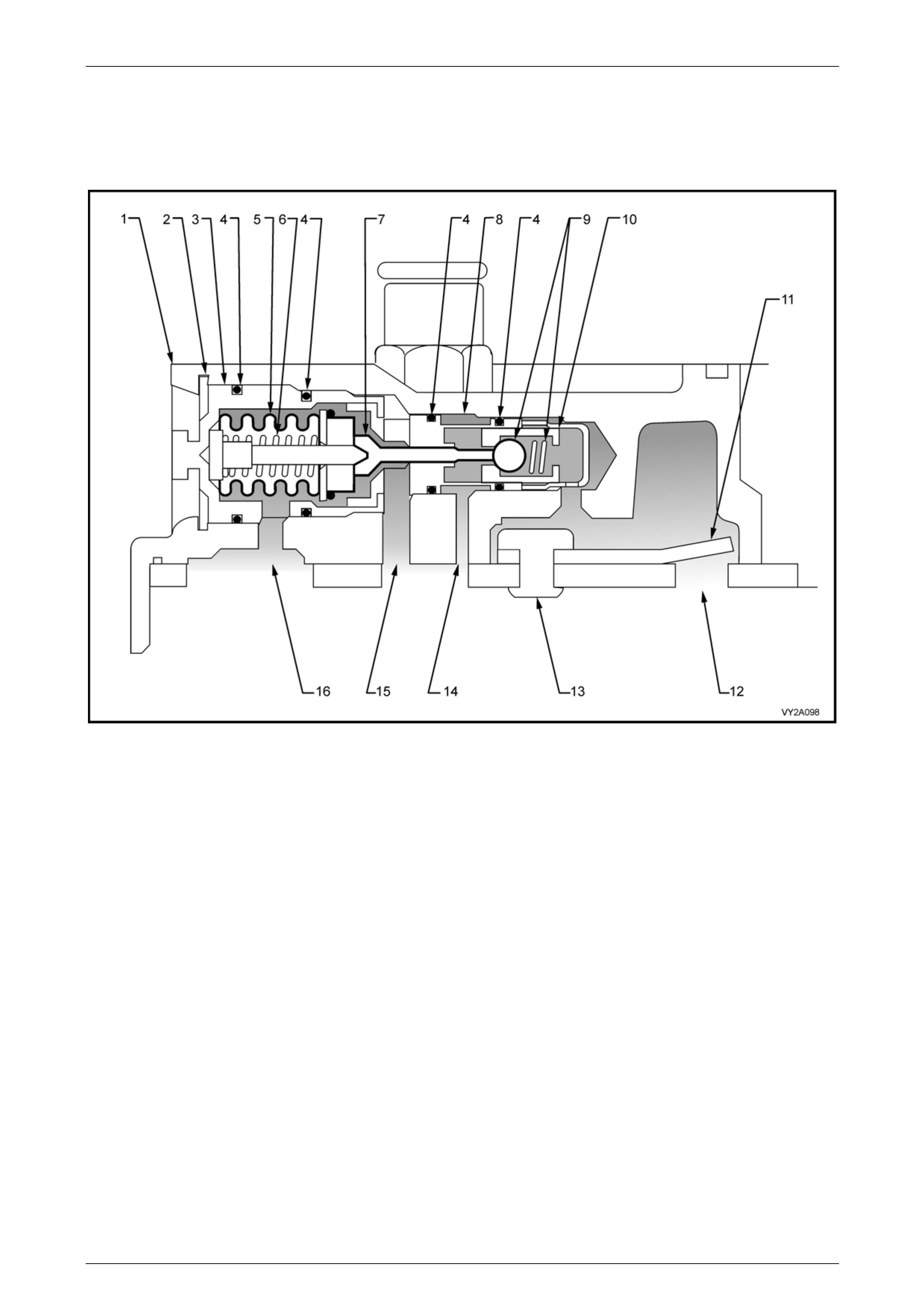
HVAC Climate Control (Manual A/C) – Description and Operation Page 2A-90
Page 2A-90
Compressor Control Valve
The control valve is installed in the compressor rear head. The angle of the wobble plate and the resultant compressor
displacement, is determined by the compress or crankcase to suction pressure differential, which is governed b y the
control valve, refer to Figure 2A – 102, shown typical.
Figure 2A – 102
Legend
1 Compressor Rear Head
2 Control Valve Retainer
3 Control Valve Bellows Housing
4 O-ring
5 Bellows
6 Bellows Spring
7 Shuttle Valve
8 Control Valve Discharge Pressure Valve Housing
9 Discharge Pressure Ball and Spring
10 Discharge Pressure Ball and Spring Retainer
11 Discharge Pressure Reed Valve
12 Discharge Pressure Port (to discharge pressure ball and
spring)
13 Discharge Pressure Reed Valve Rivet
14 Crankcase Pressure Port (from discharge pressure ball and
spring)
15 Crankcase Pressure Port (to bellows)
16 Suction Port (from bellows)
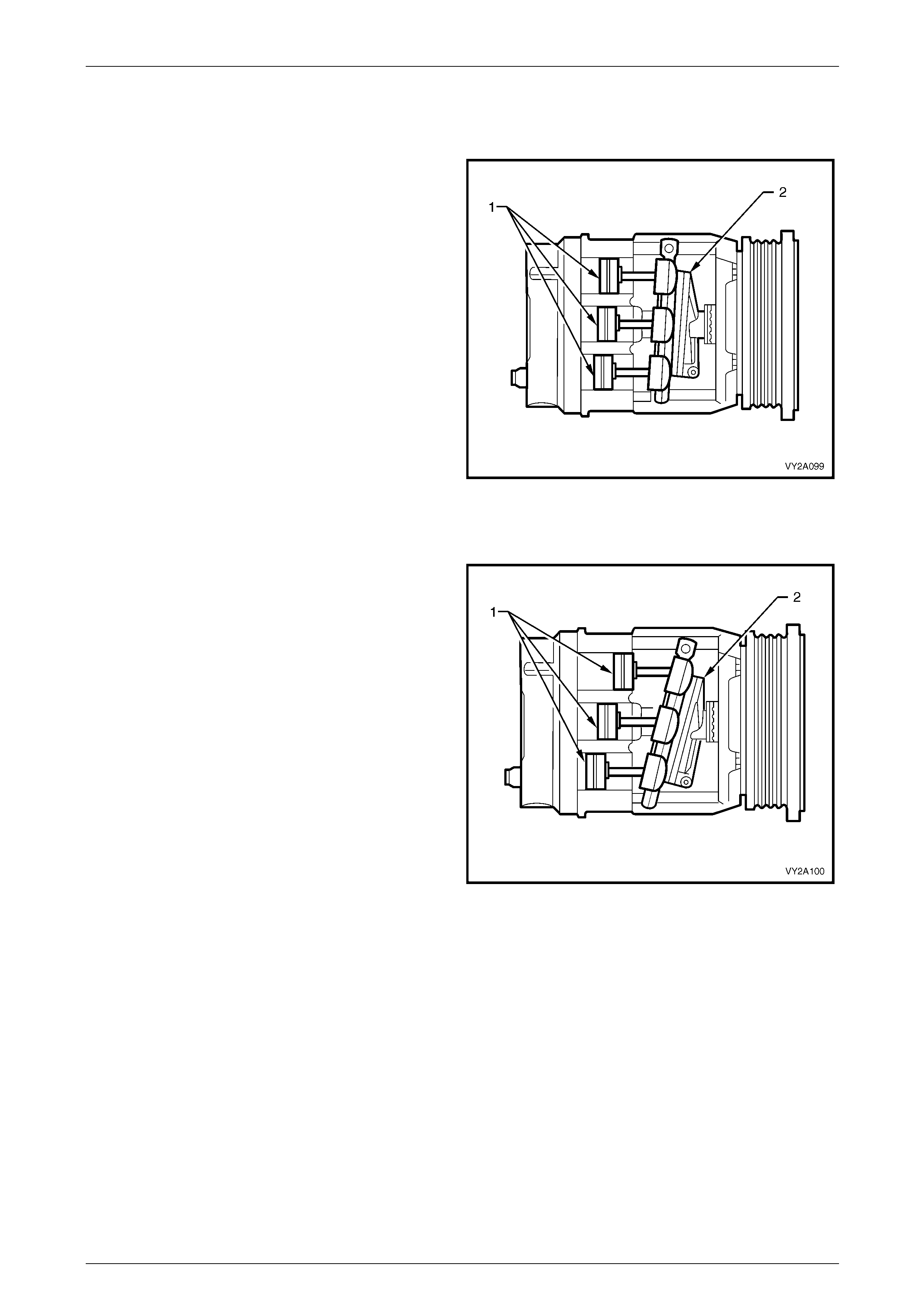
HVAC Climate Control (Manual A/C) – Description and Operation Page 2A-91
Page 2A-91
Compressor Operation
Compressor Minimu m Stroke
When the air-conditioning demand is low, the crankcase
pressure behind the pistons (1) is equal to the pressure in
front of the pistons. This forces the wobble plate (2) to rotate
on its hinge, changing its angle to towards vertical, which
reduces the stroke of the pistons and the displacement of
the compressor to approximately 7 cc.
Figure 2A – 103
Compressor Maximum Stroke
When the air-conditioning demand is high, the crankcase
pressure behind the pistons (1) is less than the pressure in
front of the pistons. This forces the wobble plate (2) to rotate
on its hinge, changing its angle away from vertical, which
increases the stroke of the pistons and the displacement by
approximately 170 cc.
Figure 2A – 104
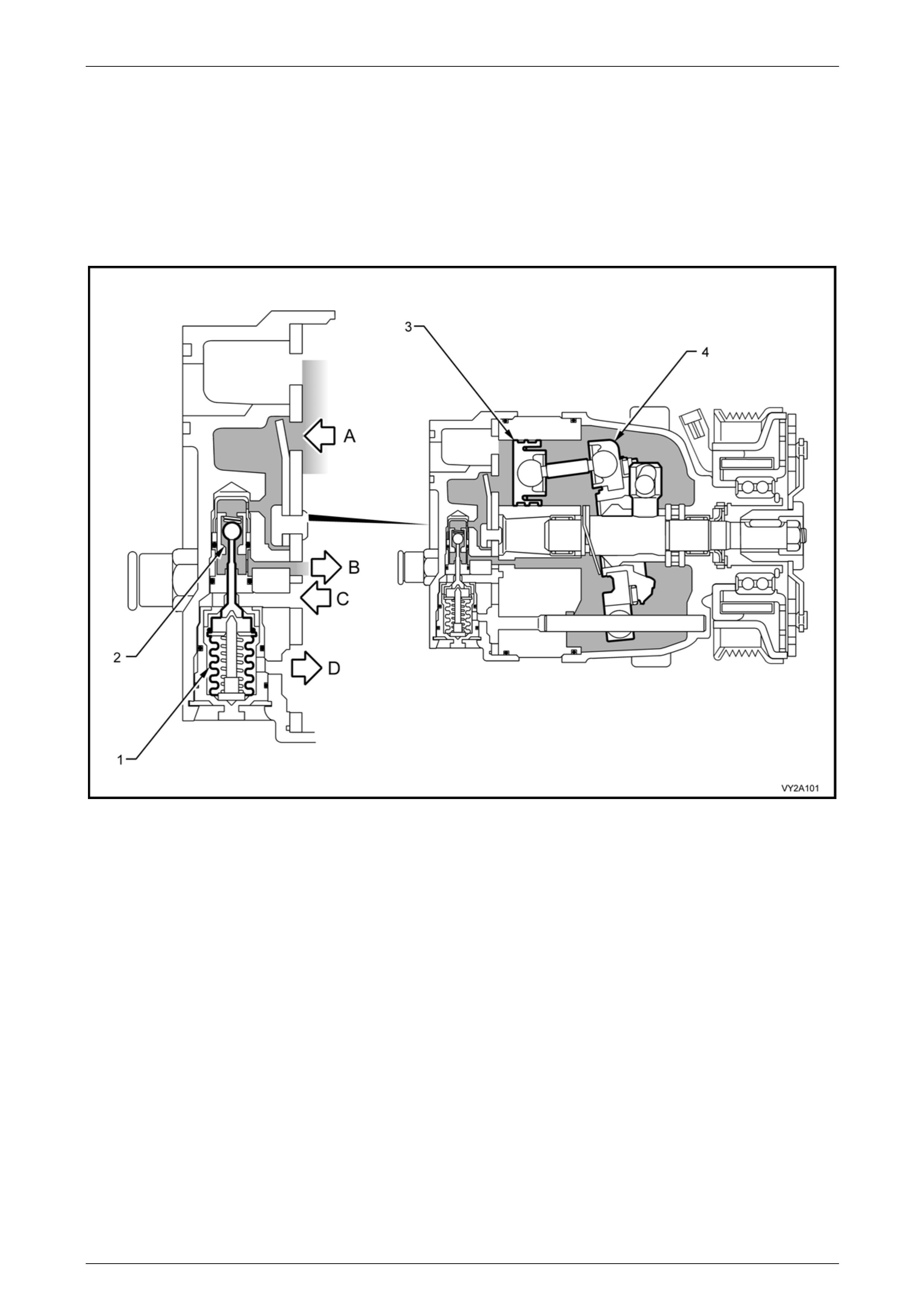
HVAC Climate Control (Manual A/C) – Description and Operation Page 2A-92
Page 2A-92
Low A/C Demand
When the evaporator cooling load is reduced (ambient temperat ure or blower fan speed is reduced) the s uction pressure
is reduced until it reaches the control p oint.
To reach the control point, the bellows (1) in the control valve assembly has expanded to allow discharge pressure (A) to
bleed past the control valve ball valve seat (2) and into the compressor crankcase, refer to Figure 2A – 105.
This crankcase pressure (B) acts as an oppo s ing force behind the compressor pistons (3) to cause the wobble plate (4)
to change its angle towards vertical and therefore, reduce piston stroke.
Figure 2A – 105
Legend
A Discharge Pressure
B Crankcase Pressure (from valve)
C Crankcase Pressure (to valve)
D Suction Pressure
1 Bellows
2 Control Ball Valve Seat
3 Piston
4 Wobble Plate
NOTE
When the air-conditioner demand is low, A to B
open, C to D closed, (bleed to crankcase).
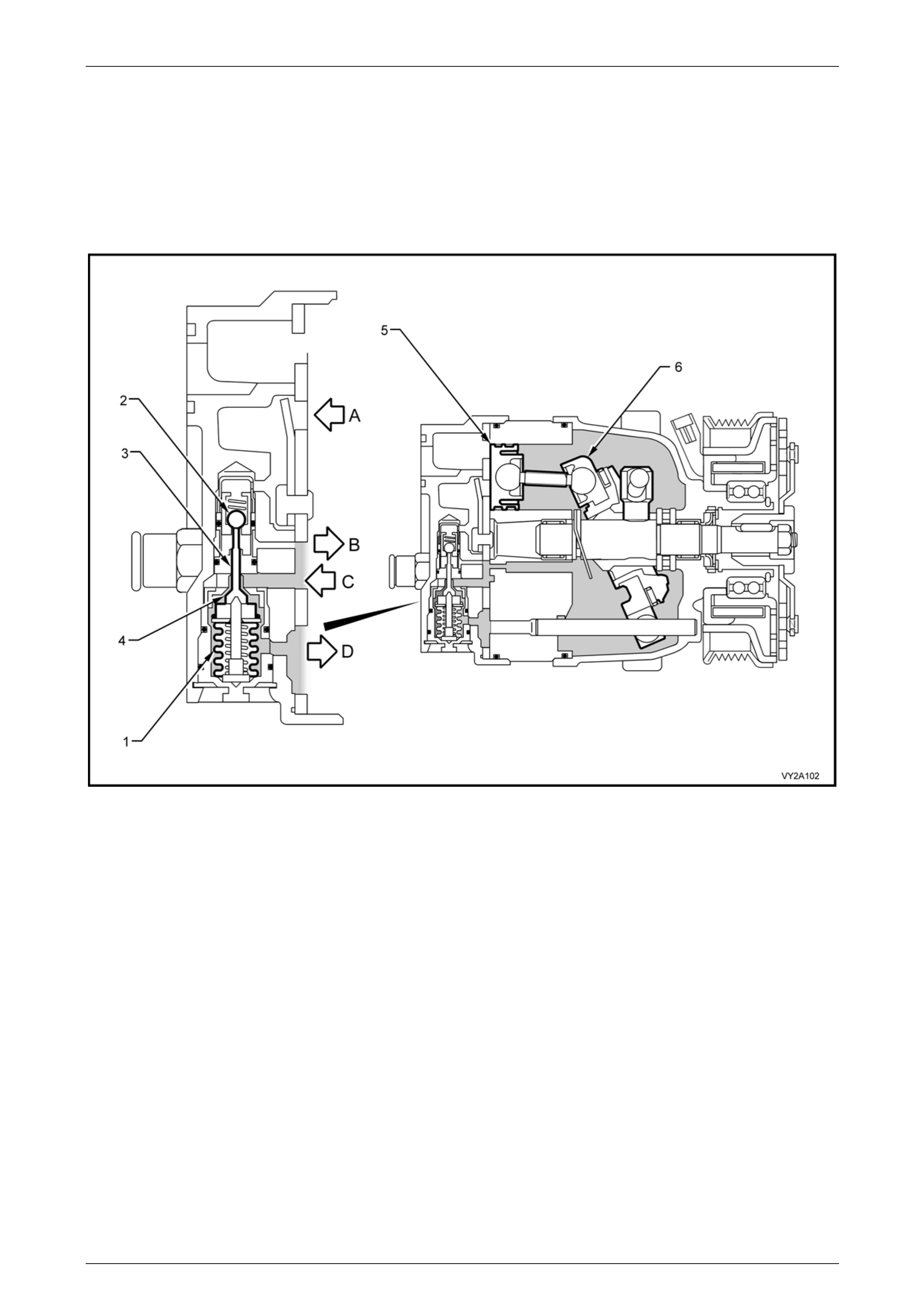
HVAC Climate Control (Manual A/C) – Description and Operation Page 2A-93
Page 2A-93
High A/C Demand
When suction pressure (D) is above the cont rol point, it will compress the control valve bellows (1), refer to
Figure 2A – 106. This will close the discharge valve, as the ball valve (2) is no w on its seat.
The shuttle valve (3) moves towards the suction port an d opens the suction valve (4). Crankcase press ure (C) will then
bleed from the compressor crankcas e past the suctio n valve to the suction port. As the crankcase pressure behind the
pistons (5) is reduced, the wobble plate (6) will rotate from vertical causing the pistons to move towards maximum stroke.
The compressor will then have a corresp onding increase in its displ acement.
Figure 2A – 106
Legend
A Discharge Pressure
B Crankcase Pressure (from valve)
C Crankcase Pressure (to valve)
D Suction Pressure
1 Bellows
2 Control Ball Valve Seat
3 Shuttle Valve
4 Suction Valve
5 Piston
6 Wobble Plate
NOTE
When the air-conditioner demand is high, A to B
closed, C to D open, (bleed from crankcase).

HVAC Climate Control (Manual A/C) – Description and Operation Page 2A-94
Page 2A-94
3 Specifications
3.1 General
Available modes .................................. Recirculation, Face, Bi-level, Floor, Blend and Demist
Blower fan speeds
Manual mode.....................................................................................................................Five
Automatic mode.........................................................................................................Step less
HVAC door actuation
Air mix doors........................................................................................Electronic / mechanical
Recirculation, Face, Foot, and Demist Doors............................................Electronic / vacuum
Air-conditioning system
Installation ................................................................................................................Integrated
Type............................................................Thermostatic expansion valve (TXV ) non-cycling

HVAC Climate Control (Manual A/C) – Description and Operation Page 2A-95
Page 2A-95
3.2 Water Valve
Type – V6.........................................................................................2 Port, non-constant flow
Type – GEN III V8...........................................4 Port, 2 non-c onstant flow and 2 constant flow
Actuation......................................................................................................................Vacuum
Construction
Porting...........................................................................................................................Plastic
Valve and vacuum actuator .............................................................................................Metal
Operation
Vacuum applied............................................................... No coolant flow through heater core
Vacuum not applied..............................................................Coolant flow through heater core

HVAC Climate Control (Manual A/C) – Description and Operation Page 2A-96
Page 2A-96
3.3 HVAC Unit
Vacuum actuators
Housing material............................................................................................................ Plastic
Rod material .................................................................................................................. Plastic
No. of single stage actuators ..................................................................................................1
No. of two stage actuators......................................................................................................2
Air mix function (heater core airflow)
No. of doors................................................................................................2 (unequally sized)
Actuation..............................................................Pinion and crescent gear, and actuating rod
Recirculation mode (inlet/fresh)
No. of doors............................................................................................................................1
Actuation...................................................................................Vacuum, single stage actuator
Rod colour .........................................................................................................................Blue
Face mode
No. of doors............................................................................................................................1
Actuation.......................................................................................Vacuum, two stage actuator
Rod colour .......................................................................................................................White
Demist/Floor mode
No. of doors............................................................................................................................1
Actuation.......................................................................................Vacuum, two stage actuator
Rod colour .......................................................................................................................Black
Blower fan assembly
Motor Power .................................................................................................................. 300 W
Motor Current .............................................................................................................25 Amps
Fan Drum Diameter.....................................................................................................157 mm
Fan Drum Height ...........................................................................................................90 mm
Number of Fan Blades..........................................................................................................45
Heater core
Design .............................................................................................Vertical flow, plate and fin
Construction ......................................................Aluminium core and tanks with integral pipes
No. of tubes ..........................................................................................................................18
Core width ...................................................................................................................160 mm
Core height..................................................................................................................195 mm
Core depth.....................................................................................................................35 mm
Evaporator
Design .............................................................................................Vertical flow, plate and fin
Construction ......................................................Aluminium core and tanks with integral pipes
No. of tubes ..........................................................................................................................24
Core width ...................................................................................................................270 mm
Core height..................................................................................................................215 mm
Core depth.....................................................................................................................70 mm
Vacuum solenoid pack Auto A/C
No. of solenoids......................................................................................................................6
Solenoid resistance ..............................................................................................109 – 111 Ω

HVAC Climate Control (Manual A/C) – Description and Operation Page 2A-97
Page 2A-97
3.4 Compressor – V6
Type...............................................................................................Non-cycling, variable stoke
Model..............................................................................................................................7CVC
Displacement.................................................................................................................164 cc
Clutch Coil Resistance.......................................................................3.42 ± 5% ohms at 25oC
Clutch Plate to Rotor Clearance ......................................................................0.30 – 0.76 mm
Number of Pistons..........................................................................................................Seven
Continuously Variable Displacement....................................................................... 6 – 165 cc
Diameter x Length .............................................................................................138 x 240 mm
Weight ............................................................................................................................6.0 kg
High Pressure Relief Valve..........................................................................................External
Thermal Fuse Burn-out Temperature ....................................................................184 ± 5.0°C
Control Valve Set-point.............................................................................................275.6 kPa

HVAC Climate Control (Manual A/C) – Description and Operation Page 2A-98
Page 2A-98
3.5 Compressor – GEN III V8
Type...............................................................................................Non-cycling, variable stoke
Model................................................................................................................................... V7
Displacement.................................................................................................................185 cc
Clutch Coil Resistance............................................................................... 3.2 ± 0.1 Ω at 25oC
Clutch Plate to Rotor Clearance ........................................................................0.38 – 1.0 mm
Number of Pistons..........................................................................................................Seven
Continuously Variable Displacement....................................................................... 7 – 185 cc
Diameter x Length .............................................................................................125 x 240 mm
Weight ............................................................................................................................6.3 kg
High Pressure Relief Valve...........................................................................................Integral
Thermal Fuse Burn-out Temperature ....................................................................184 ± 5.0°C
Control Valve Set-point.............................................................................................275.6 kPa

HVAC Climate Control (Manual A/C) – Description and Operation Page 2A-99
Page 2A-99
3.6 Refrigerant
Type...............................................................................................................................R134a
Charge Quantity.......................................................................................................800 ± 25 g

HVAC Climate Control (Manual A/C) – Description and Operation Page 2A-100
Page 2A-100
3.7 Condenser
Design ......................................................................................................Parallel flow, 4 pass
Construction ............................................................................................................Aluminium
No. of tubes ..........................................................................................................................38
Core height..................................................................................................................427 mm
Core width ...................................................................................................................615 mm
Core depth.....................................................................................................................19 mm

HVAC Climate Control (Manual A/C) – Description and Operation Page 2A-101
Page 2A-101
3.8 Pressure Transducer
Low Pressure Cut Out .................................................................................................180 kPa
Low Pressure Cut In....................................................................................................240 kPa
High Pressure Cut Out ...............................................................................................2900 kPa
High Pressure Cut In .................................................................................................2000 kPa

HVAC Climate Control (Manual A/C) – Description and Operation Page 2A-102
Page 2A-102
3.9 A/C System Lubricant
Type – V6...................................................................................................Daphne PS RL897
Type – GEN III V8.....................................Poly Alkaline Glycol (PAG) conforming to HN 2074
System Quantity – V6...................................................................................150 + 20 / -10 mL
System Quantity – GEN III V8.......................................................................220 +20 / -10 mL
Component Replacement Lubricant Compensation Quantities
Compressor...............................................Determine after oil balancing has been carried out
..............Refer to Section 2B HVAC Climate Control (Manual A/C) – Servicing and Diagnosis
Filter drier receiver..........................................................................................................15 mL
Condenser......................................................................................................................40 mL
Evaporator......................................................................................................................50 mL
Blown/ruptured pipe or hose...........................................................................................40 mL