
HVAC Climate Control (Manual A/C) – Servicing and Diagnosis Page 2B-1
Page 2B-1
Section 2B
HVAC Climate Control (Manual A/C) –
Servicing and Diagnosis
ATTENTION
Before performing any service operation or other procedure described in this Section, refer to Section 00
Warnings, Cautions and Notes for correct w orkshop practices wi th regard to safety and / or property damage.
1 Refrigerant Handling Precautions........................................................................................................2
2 Service Operations.................................................................................................................................4
2.1 Manifold Gauge Installation.................................................................................................................................. 4
2.2 System Charging and Evacuation........................................................................................................................ 5
Filling a Dial-A-Charge Cylinder ........................................................................................................................... 7
Evacuation and Leak Test..................................................................................................................................... 8
Charging System ................................................................................................................................................... 9
2.3 Checking System Oil Charge.............................................................................................................................. 10
2.4 Flushing the A/C System for Contamination or Lubricating Oil...................................................................... 11
Flushing Procedure.......................................................................................................................................... 11
2.5 Lubricating Oil Compensation............................................................................................................................ 13
Installing the Original Compressor.................................................................................................................... 13
Installing a New Compressor.............................................................................................................................. 13
Evaporator or Condenser.................................................................................................................................... 14
Filter Drier Receiver (FDR).................................................................................................................................. 14
Blown or Ruptured Pipe/Hose ............................................................................................................................ 14
3 System Functional Check....................................................................................................................15
4 Diagnostics...........................................................................................................................................17
4.1 Air-conditioner System Diagnosis...................................................................................................................... 17
Introduction.......................................................................................................................................................... 17
Preliminary Inspection...................................................................................................................................... 17
Air-conditioning System Tests.......................................................................................................................... 17
Preliminary Inspection ........................................................................................................................................ 17
Test 1: Checking Refrigerant Charge................................................................................................................. 18
Test 2: Checking Compressor Clutch Engagement.......................................................................................... 19
Compressor Electrical Connector..................................................................................................................... 20
Test 3: Checking Compressor System Performance........................................................................................ 21
Vehicle Set-up.................................................................................................................................................. 21
Air-conditioning System Performance Chart..................................................................................................... 22
Test 4: Checking Compressor for Less Than Full Stroke (Low Load) Simulation........................................ 23
Vehicle Set Up.................................................................................................................................................. 23
Test Procedure................................................................................................................................................. 23
Test 5: Checking Compressor for Full Stroke Operation (High Load) Simulation......................................... 24
Test 6: TXV Operational Check on Vehicle........................................................................................................ 25
Vehicle Set Up.................................................................................................................................................. 25
Test 7: Noise Diagnosis ...................................................................................................................................... 26
Preliminary Check............................................................................................................................................ 26
Compressor Noise Check................................................................................................................................. 27
5 Specifications.......................................................................................................................................28
6 Special Tools ........................................................................................................................................29
Techline
Techline
Techline
Techline

HVAC Climate Control (Manual A/C) – Servicing and Diagnosis Page 2B-2
Page 2B-2
1 Refrigerant Handling
Precautions
In any vocation or trade, there are established procedures and practices that have been developed after many years of
experience. In addition, occupational hazards may be present that require the observation of certain precautions, or use
of special tools and equipment. Observing the procedures, practices and precautions of servicing refrigeration equipment
will greatly reduce the possibility of damage to the vehicle, as well as virtually eliminating the element of hazard to the
service technician.
Care should be taken when discharging the air-conditioning system to ensure the refrigerant is not released to the
atmosphere but captured for recycling. Environmentally friendly refrigerant R134a is not an ozone depleting substance
but its release would add to the greenhouse warming effect.
Refrigerant R134a is transparent and colourless in both the gaseous and liquid states. At all normal temperatures and
pressures it will be a vapour. The vapour is heavier than air and is non-flammable, non-explosive, non-poisonous and
non-corrosive (except when in contact with moisture).
The following precautions in handling R134a should be observed at all times:
R134a and R12 are not compatible and must
never be mixed.
Always use safety glasses and gloves when
handling or servicing air-conditioning
systems. If R134a does enter the eye, freezing
can occur which could result in blindness.
The procedure outlined below is suggested if
R134a enters the eyes.
• Keep calm.
• Do not rub eyes.
• Splash large quantities of cool water into
the eyes to raise the temperature.
• Tape a sterile eye patch in place to prevent
dirt from entering the eye.
• Go immediately to a doctor or hospital for
professional treatment.

HVAC Climate Control (Manual A/C) – Servicing and Diagnosis Page 2B-3
Page 2B-3
If an accident occurs, do not attempt to treat
yourself.
• Always follow correct workshop practices.
• Always work in a well ventilated area.
• Avoid skin contact, as R134a will cause
frostbite on contact with bare skin.
• Do not abuse the refrigerant cylinder, or
any other tools you may need to use.
• Do not w eld or steam clean on or near any
air-conditioning components when
pressurised. This may cause a dangerous
pressure build up in the system.
• Do not discharge refrigerant into an
enclosed area.
• When purging a system, discharge the
refrigerant slowly.
• If it is necessary to transport or carry a
cylinder of refrigerant in a car, keep it in
the luggage compartment.
• Refrigerant cylinders should always be
protected from the radiant heat of the sun.
• When filling a refrigerant cylinder, never
completely fill it. Always leave space for
expansion. If the cylinder is completely
filled and the ambient temperature
increases, hydraulic pressure within the
cylinder will elevate to a dangerous level.
HVAC Climate Control (Manual A/C) – Servicing and Diagnosis Page 2B-4
Page 2B-4
2 Service Operations
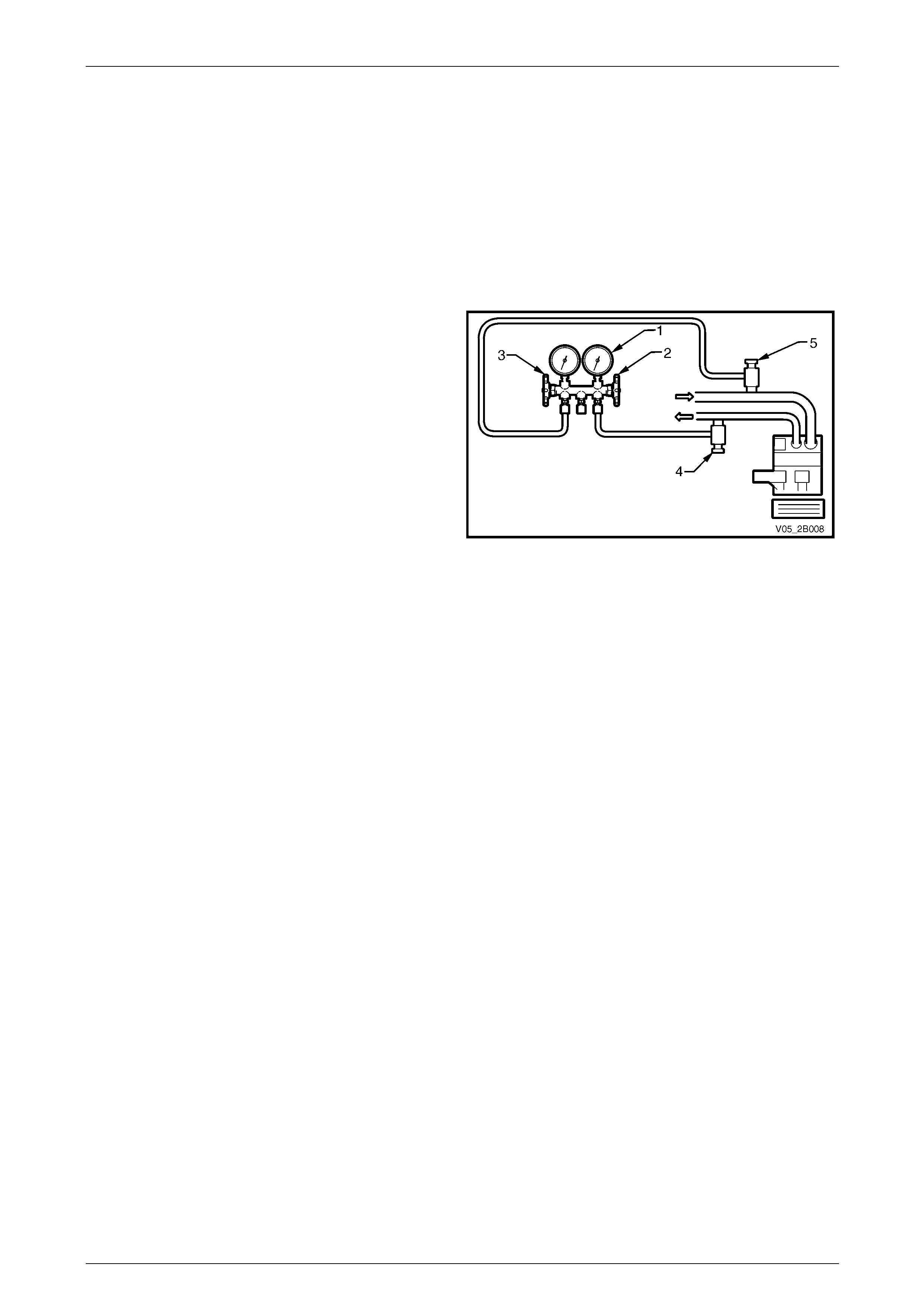
2.1 Manifold Gauge Installation
NOTE
Care should be taken to ensure that vehicle's
refrigerant is not released to the atmosphere
when connecting the manifold gauges.
1 Make sure the high pressure valve (2) and low
pressure valve (3) of the manifold gauge set (3) are
firmly closed.
2 Connect the high pressure charging hose to the high
pressure service valve (4) and the low pressure
charging hose to the low pressure service valve (5).
3 Bleed the air from the high and low pressure charging
hoses by slightly opening each pressure valve.
Figure 2B – 1

HVAC Climate Control (Manual A/C) – Servicing and Diagnosis Page 2B-5
Page 2B-5
2.2 System Charging and Evacuation
The wearing of safety goggles and gloves is
mandatory during system charging or
discharging.
Never run the compressor without refrigerant
in the system as the compressor lubricant
relies upon the flow of refrigerant to lubricate
the system components.
NOTE
• All hoses at point of connection to the system
must have isolation valves fitted.
• Care should be taken when discharging the
air-conditioning system to ensure the
refrigerant is not released to the atmosphere
but captured for recycling. R134a is not an
ozone depleting substance but its cost and
the fact that it does contribute to the
greenhouse effect, make it essential that it is
recovered.
A range of Refrigerant Recovery Units (RRU) is now available, which collect refrigerant from air-conditioning systems.
The following procedure describes the use of these units when recovering refrigerant from a vehicle’s air-conditioning
system.
1 Connect the RRU outlet to an R134a recovery cylinder with a refrigerant hose and open the valve on the cylinder.
Ensure the cylinder has sufficient capacity to hold the refrigerant in the system to be serviced. This can be
confirmed by weighing the cylinder or by referring to the volume gauge if fitted.
2 Connect a gauge manifold set to the vehicle air-conditioning system. Connect to both the low pressure and high
pressure sides of the system. Connect the centre hose of the gauge set to the inlet of the recovery unit. Connect
the RRU to an electrical supply.
3 Open the gauge set and quickly connect the stop taps to allow the refrigerant to enter the RRU via the centre hose.
At this point, depending on which unit is being used, the RRU will switch on. If the RRU is not an automated type,
switch the unit on.
4 The automatic recovery unit will operate until the air-conditioning system has been emptied of refrigerant down to
atmospheric pressure. The cylinder can now be closed.
5 Measure the amount of PAG oil removed from the A/C system. This oil is normally separated from the incoming
refrigerant into the RRU. New clean PAG oil must be added into the system before recharging it with refrigerant.
HVAC Climate Control (Manual A/C) – Servicing and Diagnosis Page 2B-6
Page 2B-6
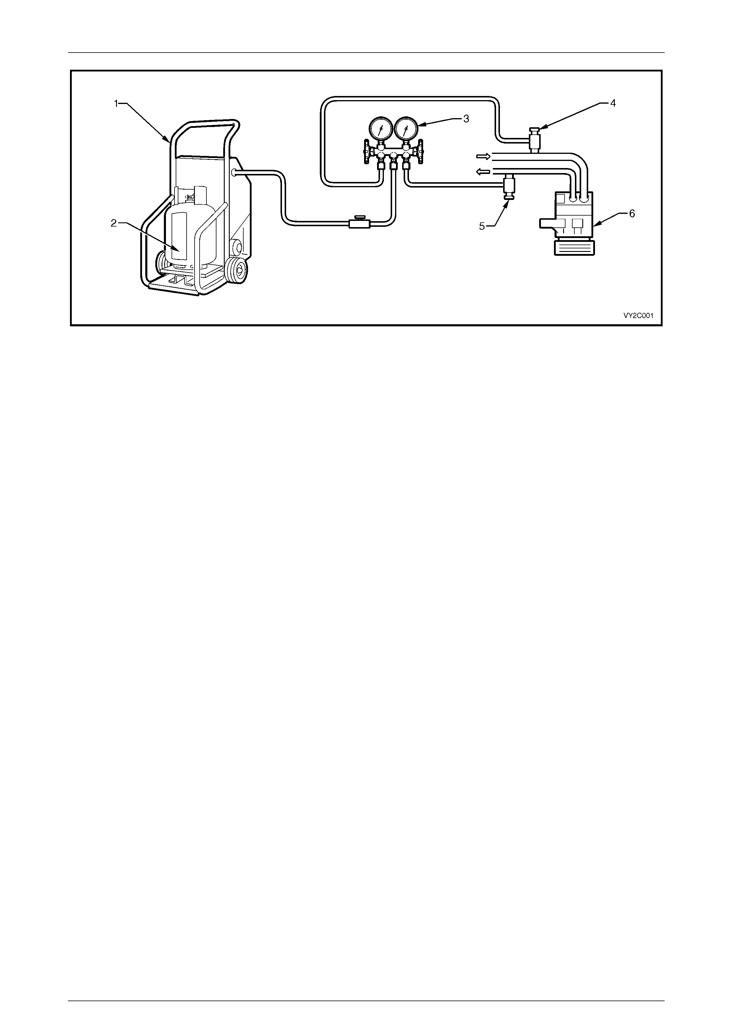
Figure 2B – 2
Legend
1 Refrigerant Recovery Unit (RRU)
2 Refrigerant Recovery Cylinder
3 Manifold/Gauge Set
4 Low Side Charging Adaptor
5 High Side Charging Adaptor
6 Compressor
HVAC Climate Control (Manual A/C) – Servicing and Diagnosis Page 2B-7
Page 2B-7
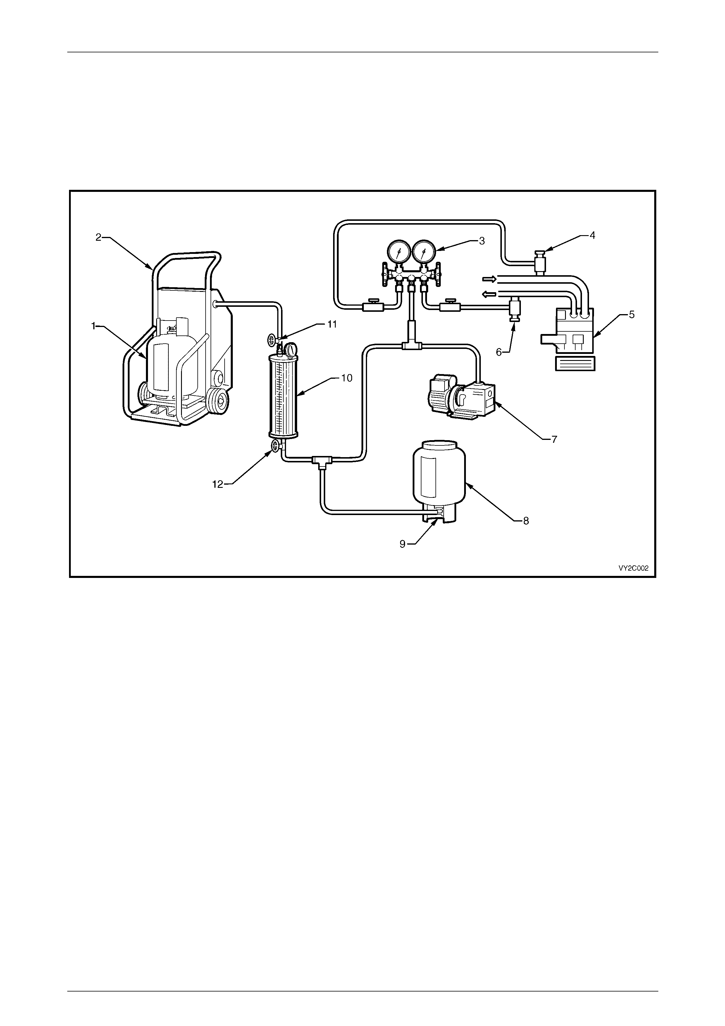
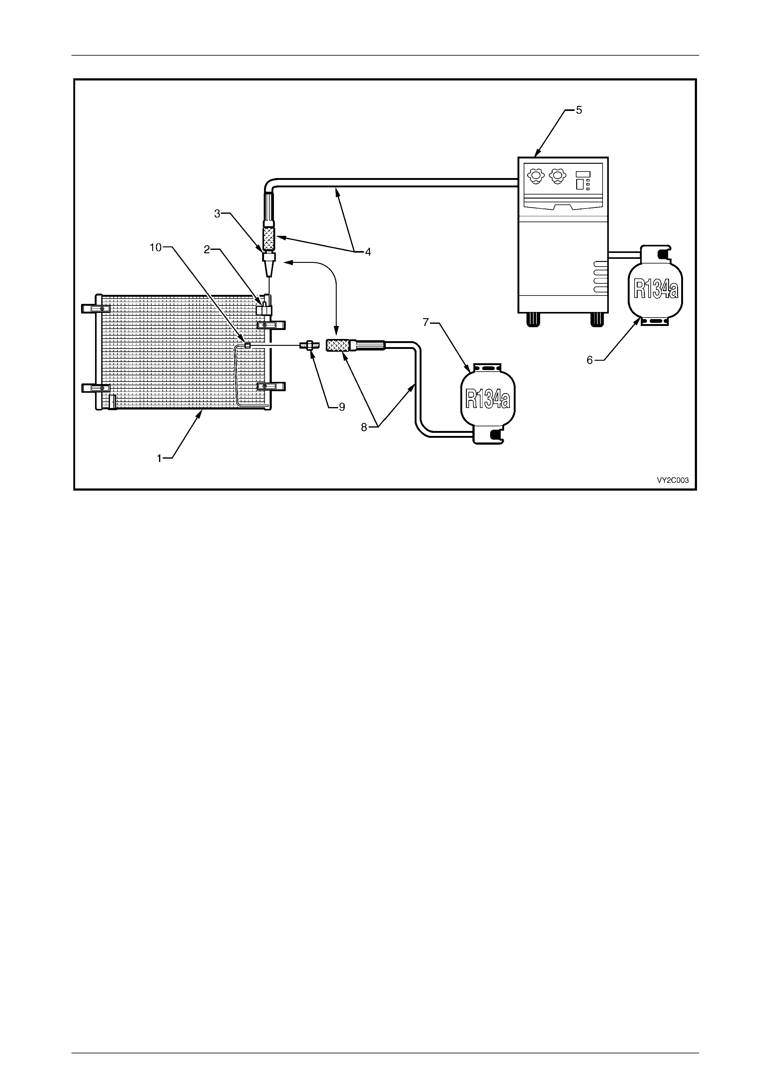
Filling a Dial-A-Charge Cylinder
1 Open the liquid valve on the R134a supply cylinder, allowing refrigerant to enter the dial-a-charge cylinder.
2 Bleed the dial-a-charge cylinder via the bleed valve on top (behind pressure gauge) as required to allow the
refrigerant to enter. This valve should be connected via a hose to a refrigerant recovery unit (RRU) and recovery
cylinder. When the refrigerant reaches the specified level (800g +/- 25g), close the supply valve at the bottom of the
‘dial-a-charge’ cylinder and be certain the bleed valve is also securely closed. Close the liquid valve on the R134a
supply cylinder.
Figure 2B – 3
Legend
1 Refrigerant Recovery Cylinder
2 Refrigerant Recovery Unit (RRU)
3 Manifold Gauge Set
4 Low Side Charging Adaptor
5 Compressor
6 High Side Charging Adaptor
7 Vacuum Pump
8 R134a Supply Cylinder
9 Liquid Valve
10 Dial-A-Charge Charging Cylinder
11 Bleed Valve
12 Supply Valve

HVAC Climate Control (Manual A/C) – Servicing and Diagnosis Page 2B-8
Page 2B-8
Evacuation and Leak Test
1 Check that both manifold hand valves of the gauge set are closed and turn the RRU off.
2 Connect the charging hoses onto the low and high service valves in the system.
Do Not Use Spanners.
3 Connect the centre manifold charging hose to the vacuum pump inlet.
4 Start the vacuum pump and slowly open the low side manifold valve. The low side gauge reading should decrease
to 98 – 102 kPa vacuum and the high side gauge should read slightly below the zero index of gauge. If high side
gauge reading does not register, check system for a blockage or leak.
NOTE
When the high side gauge is slightly below the
zero index of the gauge, open the high side
manifold valve.
5 After evacuating the system for 15 minutes to a vacuum of –100 kPa, close both the low and high side valves and
stop the vacuum pump. The system must hold a vacuum of –100 kPa for a minimum of 15 minutes. If the specified
vacuum is held then the system has no leaks and may continue to be evacuated for a further 15 minutes.
6 Wear safety goggles.
7 Connect the centre charging hose to the charging cylinder valve on the bottom of the cylinder. Open the bottom
charging cylinder valve. Do not open the low or high side valves on the manifold gauge at this time.
8 Loosen the centre charging hose nut connected to the centre fitting of the manifold gauge set until a hiss can be
heard. Allow the air to escape for a few seconds, then re-tighten the nut.
Under no circumstances should the engine be
started.
9 Partially charge the system with 200 g of R134a by slowly opening the high side manifold valve; the low side gauge
should register a pressure, if not, check for blockage. Close the high side manifold valve as soon as 200 g of
R134a has entered the system.
10 Check the system for leaks with an electronic detector. If a leak is detected, remove refrigerant from system using
the RRU and repair the faulty component or connection. Repeat Steps 4 to 10 after repair of leak.
NOTE
Various types and makes of leak detectors are
currently in use. Whichever leak detector is used,
it is important to follow the manufacturer’s
instructions in regard to adjustment and setting
the instrument prior to conducting the test.
Inspect for leaks by slowly moving the probe of
the detector around all hose connections and
points of possible leakage. Refrigerant R134a is
heavier than air and will be more apparent at the
bottom of a fitting.
HVAC Climate Control (Manual A/C) – Servicing and Diagnosis Page 2B-9
Page 2B-9
Charging System
After a leak check has proven the system to be leak free, charge the specified amount of refrigerant into the system as
follows:
1 Open the high side manifold valve slowly. Fill the system with as much of the specified charge as possible, then
close the high side manifold valve.
2 Rotate the compressor by hand for 12 revolutions to ensure no liquid refrigerant is trapped in the suction side of the
compressor.
Failure to comply with this Step may result in
damage to the compressor.
3 Start the engine and engage the compressor clutch and evaporator fan on high speed.
4 Set engine speed to 1500 – 1700 rpm.
5 If the system has been charged with the specified amount (800 ± 25 g), go to Step 7.
6 To complete the charging of the system, slowly open the low side manifold valve until the specified amount has
been charged into the system.
Do not allow more than 275 kPa to be
registered on the low p ressu re gauge.
7 Perform the system functional check, refer to 3 System Functional Check.
If the unit operates satisfactorily, stop the engine, shut the stop valves at the hose connections to the system and
disconnect the hoses taking extreme caution, as the discharge hose can have up to 2070 kPa stored in it. Install service
valve caps as required.
No sight glass is fitted to the system due to PAG oil’s foaming properties, which may be confused with a low gas charge.
Topping up of the system is not recommended.
Accurate system refrigerant charge may only be determined by charging the system with the correct amount of R134a.
Pressure gauge readings together with face air outlet temperatures are the only method of checking and diagnosing the
system cooling capacity (comparing results with the appropriate graph).
If in doubt as to the gas charge as a result of one the following conditions:
• suction pressure low,
• discharge pressure low, or
• air outlet temperature (face) above graph range.
1 Recover the refrigerant from the system using R134a specific equipment.
2 Evacuate the system. Charge with 800 ± 25 g of R134a.
3 Carry out cooling system pressure test and suction (low side) pressure readings comparisons.

HVAC Climate Control (Manual A/C) – Servicing and Diagnosis Page 2B-10
Page 2B-10
2.3 Checking System Oil Charge
A replacement compressor is charged at the factory with the total A/C system quantity of lubricating oil. This oil is then
circulated via the refrigerant throughout the entire A/C system. Only the type of oil specified (which is blue in colour) must
be used when adding or changing oil. This oil is not compatible with any other PAG oil.
• V6 – 150 mL of Daphne PS RL897 supplied with the compressor.
• GEN III V8 – 220 mL of Poly alkaline glycol (PAG) supplied with the compressor.
Although it is not necessary to regularly check the oil level within the system, all the A/C system components will hold a
quantity of the oil circulated. Therefore whenever an A/C system component is replaced, a replacement quantity of new
refrigerant (PAG) oil must be added to the system. Where a major loss of system oil has occurred, due to:
• a broken hose or severe leak,
• collision damage to the refrigerant system components, or
• if excess oil is suspected to be in the system.
Then:
1 Recover refrigerant from the system.
2 Remove the compressor, refer to Section 2C HVAC Climate Control (Manual A/C) – Removal and Installation.
3 Carefully drain the refrigerant oil from the compressor while calculating the system oil balancing requirements, refer
to 2.5 Lubricating Oil Compensation.
4 Flush the remaining oil from the rest of the system using R134a refrigerant.
NOTE
A refrigerant recovery unit (RRU) should be used
to flush the system to ensure the R134a is not
vented to the atmosphere. The R134a must be
reclaimed via the RRU into a separate bottle.
5 Add any additional amount of new refrigerant oil to the compressor as determined in (2) above.
6 Install the compressor, replacing the suction and discharge O-rings. Ensure the O-rings are not twisted and the
seals and O-rings are clean.
7 Evacuate then recharge the system.
Do not allow PAG oil to contact either bare
skin or vehicle paintwork. If contact occurs,
w ash PAG oil off immediately.

HVAC Climate Control (Manual A/C) – Servicing and Diagnosis Page 2B-11
Page 2B-11
2.4 Flushing the A/C System for
Contamination or Lubricating Oil
Some oil is lost whenever air-conditioning system components are replaced.
Where the system has been ruptured, contaminated, or a compressor has to be removed and reinstalled or replaced, the
system should be checked for contamination and, if so, the entire system must be flushed.
Currently the only method recommended when flushing is using the refrigerant R134a.
NOTE
A Refrigerant Recovery Unit (RRU) should be
used to capture the R134a used for flushing. The
R134a must be reclaimed via the RRU into a
separate bottle. Use only a dedicated R134a
RRU.
The complete air-conditioning system must
contain the correct quantity of PAG
refrigerant oil.
Flushing Procedure
1 Flush the individual components.
2 Self made flushing fittings will be required as A/C system component fittings all differ in size, shape and thread size.
3 Invert the decanting cylinder to use refrigerant in liquid form.
4 Reverse flush the components.
5 Do not flush through a compressor otherwise possible internal damage could occur.
6 Recover / recycle the flushing refrigerant, the recovery device will remove contaminants through its filtration system.
HVAC Climate Control (Manual A/C) – Servicing and Diagnosis Page 2B-12
Page 2B-12
Figure 2B – 4
Legend
1 Condenser
2 Condenser Inlet
3 Flush Gun
4 Recovery Hose and End Fitting
5 Refrigerant Recovery Unit (RRU)
6 Refrigerant Recovery Cylinder
7 R134a Supply Cylinder
8 Flushing Hose And End Fitting
9 Adaptor
10 Condenser Outlet
NOTE
To carry out the reverse flush procedure the
positions of items 3 and 4 will be swapped with
items 8 and 9.
HVAC Climate Control (Manual A/C) – Servicing and Diagnosis Page 2B-13
Page 2B-13
2.5 Lubricating Oil Compensation
The total amount of lubricating oil in the air-conditioning system must be maintained. If a compressor, evaporator,
condenser, filter drier receiver, hose or pipe is to be replaced, a specified amount of lubricating oil must be added to the
system to compensate for oil removed with the original component.
Installing the Original Compressor
1 Drain and measure the refrigerant oil contained in the compressor.
2 Charge the oil through the discharge port of the compressor with the same amount of new refrigerant oil.
NOTE
If the amount of oil in the original compressor was
not checked, then approximately 150 mL (V6) or
220 mL (V8) of new oil should be added to the
compressor being installed. (This is assuming the
compressor being installed has first been
drained).
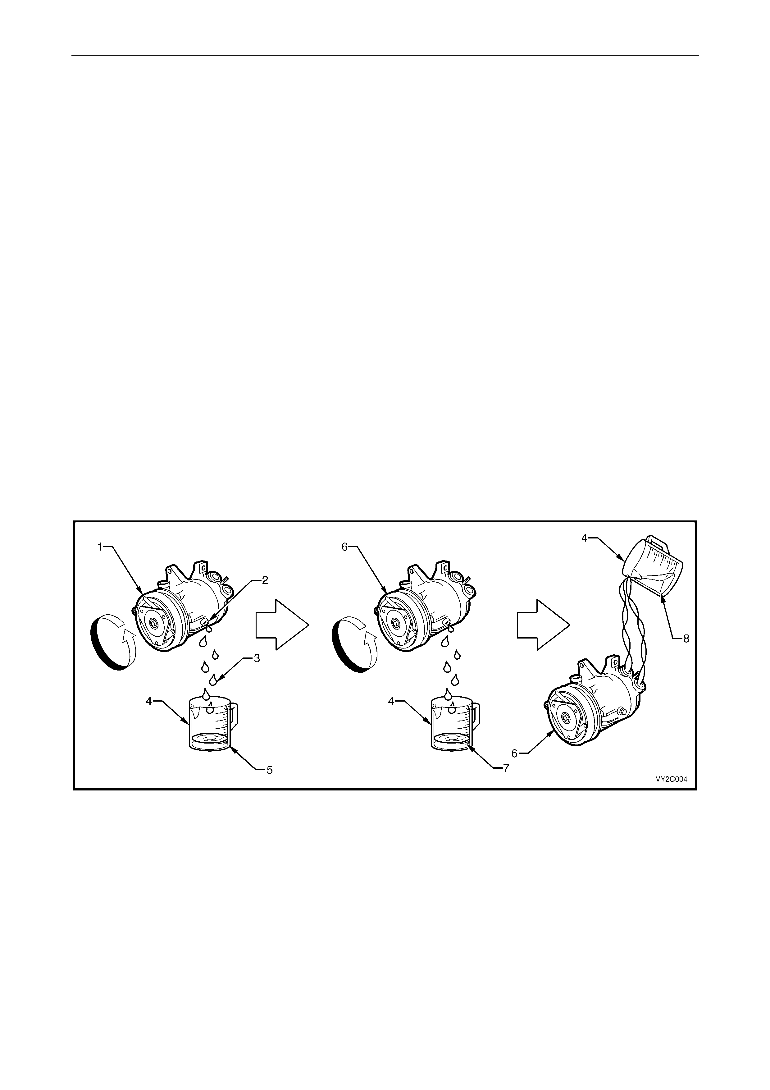
Installing a New Compressor
1 Drain and measure refrigerant oil from the original compressor drain plug.
2 Drain factory installed refrigerant oil from new compressor drain plug. The lubricant quantity will be approximately
150 mL (V6) or 220 mL (V8).
3 Measure the same amount of new refrigerant oil that was drained from the original compressor into a graduated
container. Install this amount of new oil into the new compressor through the suction / discharge port whilst turning
the compressor clutch pulley front face.
Figure 2B – 5
Legend
1 Original Compressor
2 Drain Plug Location
3 Drained Refrigerant Oil from Original Compressor
4 Graduated Container
5 Refrigerant Oil – Total Amount Removed: e.g. 100 mL
6 New Compressor
7 Drained Refrigerant Oil from New Compressor
8 Refrigerant Oil – Total Amount to be Installed: 100 mL

HVAC Climate Control (Manual A/C) – Servicing and Diagnosis Page 2B-14
Page 2B-14
Evaporator or Condenser
Drain as much of the original oil as possible from the evaporator or condenser. Add the same amount of new refrigerant
oil, either to the original or new evaporator or condenser.
• If replacing the condenser – add approximately 40 mL.
• If replacing the evaporator – add approximately 50 mL.
Filter Drier Receiver (FDR)
If replacing the FDR – add approximately 15 mL.
The FDR must be replaced whenever the system has been opened to the atmosphere for repair.
Blown or Ruptured Pipe/Hose
When replacement is required, add approximately 40 mL

HVAC Climate Control (Manual A/C) – Servicing and Diagnosis Page 2B-15
Page 2B-15
3 System Functional Check
Step Action Yes No
1 Is the fault specifically isolated to this system? Go to Step 2 Refer to Section 0D
Vehicle Diagnostics.
2 Does the OCC control module power-up?
Go to Step 3
Refer to Section 2E
HVAC Occupant
Climate Control
(Auto A/C) –
Diagnostics
3 Set the OCC control module to:
• fresh air position (recirculate off),
• Mode to Face,
• temperature set to T MIN, and
• blower speed set to High.
Were you able to adjust heating and ventilation controls as instructed? Go to Step 4
Refer to Section 2E
HVAC Occupant
Climate Control
(Auto A/C) –
Diagnostics
4 Perform the following:
• park the vehicle in a shaded area,
• open the hood and windows,
• open all ventilation outlets and adjust to the straight-ahead
position, and
• using a thermometer, note the ambient temperature. Go to Step 5 —
5 Connect the manifold gauges, refer to 2.1 Manifold Gauge
Installation. Go to Step 6 —
6 Start the engine and bring engine speed to 1700 rpm. Allow the
pressure gauge needles to stabilise. Go to Step 7 —
7 Does the A/C compressor clutch engage?
Go to Step 8
Refer to Test 2:
Checking
Compressor Clutch
Engagement
8 Are there any abnormal air-conditioning system noises?
NOTE
Rectify any abnormal noise conditions before continuing
with the System Functional Check. Refer to Test 7:
Noise Diagnosis Go to Step 9
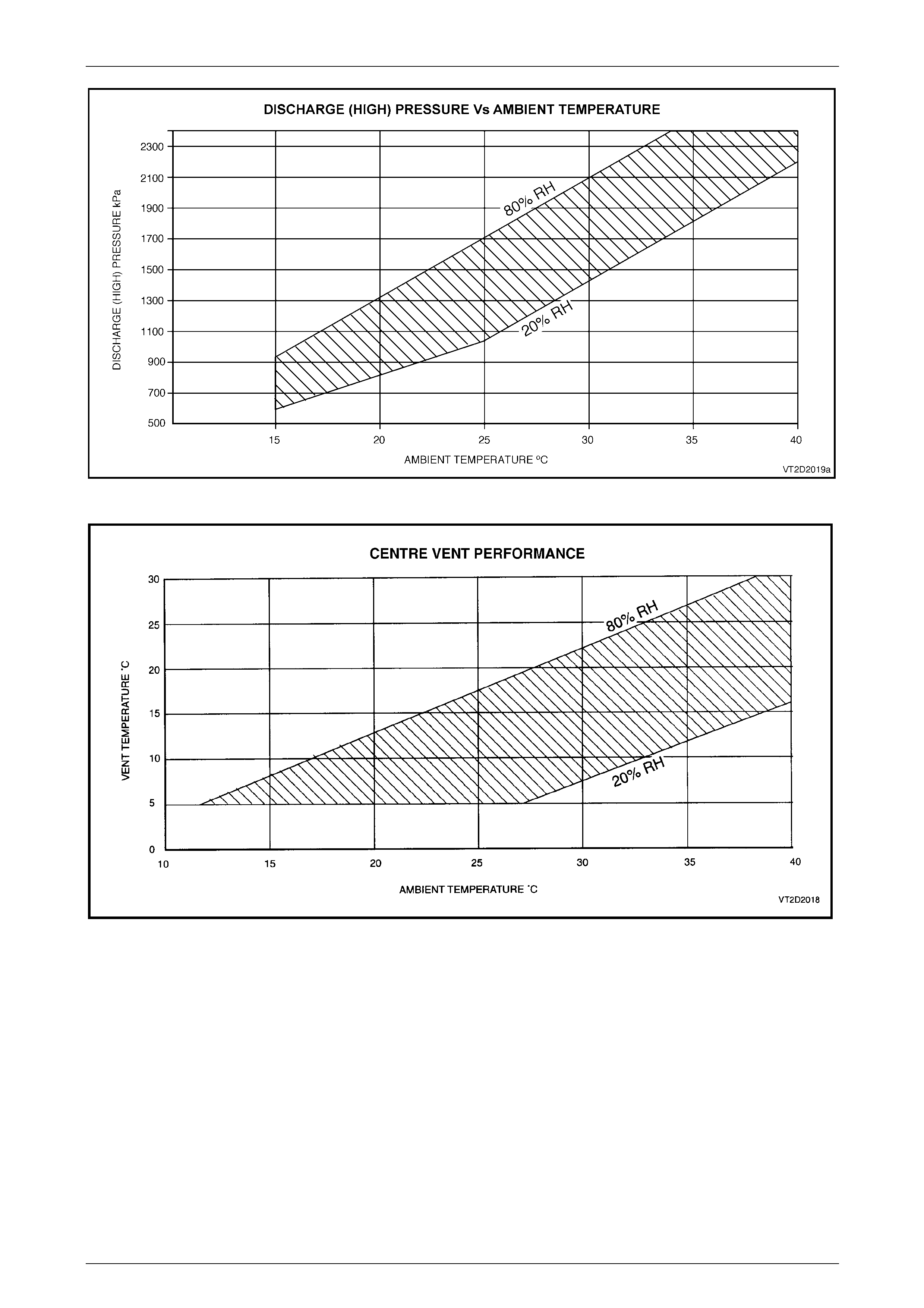
9 Check the manifold gauge pressures.
Are the pressures within the shaded area in Figure 2B – 6? Go to Step 10 Refer to 4
Diagnostics
10 Insert a thermometer probe approximately 50 mm into the centre vent
louvre.
Is the temperature within the shaded area in Figure 2B – 7? System OK Refer to 4
Diagnostics
HVAC Climate Control (Manual A/C) – Servicing and Diagnosis Page 2B-16
Page 2B-16
Figure 2B – 6
Figure 2B – 7

HVAC Climate Control (Manual A/C) – Servicing and Diagnosis Page 2B-17
Page 2B-17
4 Diagnostics
4.1 Air-conditioner System Diagnosis
Introduction
This diagnostic is the starting point for verifying and diagnosing all air-conditioning system related complaints. It
represents the correct path to follow from a customer complaint or condition through delivery of the vehicle back to the
customer.
Preliminary Inspection
The preliminary inspection covers all physical and visual inspections of interior and under-hood components. Many
problems can be detected by a thorough inspection of the air-conditioning system. Failure to perform this step could
result in wasted time proceeding through the remaining tests.
Air-conditioning System Tests
These tests were developed by producing known system problems and recording the air-conditioning system pressures
at various ambient temperatures.
To find the problem, compare the vehicle’s performance test readings to the readings on the charts for your ambient
temperature and humidity. When all pressure and temperature readings fall outside the limits of a given chart, use that
chart to repair the vehicle.
NOTE
There is some variance in readings between
systems of different vehicles, however the target
areas of the charts have been developed to
accommodate these changes.
Index to System Tests
Test 1: Checking Refrigerant Charge
Test 2: Checking Compressor Clutch Engagement
Test 3: Checking Compressor System Performance
Test 4: Checking Compressor for Less Than Full Stroke (Low Load) Simulation
Test 5: Checking Compressor for Full Stroke Operation (High Load) Simulation
Test 6: TXV Operational Check on Vehicle
Test 7: Noise Diagnosis
Preliminary Inspection
1 Perform the system functional check, refer to 3 System Functional Check.
2 Check the A/C fuse.
3 A/C blower fan operation.
4 Air mix door. Move the door rapidly from cold to hot.
5 Ensure the air mix door fully opens and closes. Re-calibrate the air mix motor / door movement,
refer to Section 2F HVAC Occupant Climate Control (Auto A/C) – Removal and Installation.
6 Air-conditioner clutch coil connection.
7 Air-conditioner pressure sensor connection.
8 Accessory drive belt. Replace if damaged or missing, refer to Section 6A1 Engine Mechanical – V6 or,
Section 6A3 Engine Mechanical – GEN III V8.
9 Engine cooling fan operation – at idle, the cooling fan must be on at any A/C mode and must be rotating in the
correct direction (drawing ambient air through the condenser towards the engine).
10 Condenser – Check for restricted air flow.
11 Dealer technical bulletins for updates on A/C system.

HVAC Climate Control (Manual A/C) – Servicing and Diagnosis Page 2B-18
Page 2B-18
Test 1: Checking Refrigerant Charge
This procedure is designed for use with gauges that have been calibrated correctly.
The ambient air temperature should be at least 15 °C, and the ignition key in the OFF position.
Step Action Yes No
1 Connect the high and low side pressure gauges to the system, refer to
2.1 Manifold Gauge Installation.
Is the high side pressure reading greater than 400 kPa?
Check compressor
clutch engagement.
Refer to Test 2:
Checking
Compressor Clutch
Engagement Go to Step 2
2 If the high pressure side is below 400 kPa, perform Evacuation and
Leak Test, refer to 2.2 System Charging and Evacuation.
Was the gas leak found?
Go to Step 3
Add refrigerant dye
to the A/C system.
Perform a pin point
inspection with a
black light after the
vehicle has driven
for a week with the
A/C operating
3 1 Recover the refrigerant.
2 Repair the system leak.
3 Evacuate and re-charge the system.
Is the high side pressure reading greater than 400 kPa? Check for correct
system operation Go to Step 2
HVAC Climate Control (Manual A/C) – Servicing and Diagnosis Page 2B-19
Page 2B-19
Test 2: Checking Compressor Clutch Engagement
Step Action Yes No
1 Run the engine at idle. Set the OCC control module to:
• normal A/C mode,
• high blower speed, and
• temperature to full cold.
Does the compressor clutch engage?
Check the
compressor system
performance. Refer
to Test 3: Checking
Compressor System
Performance Go to Step 2
2 Are there any engine management DTC's which may effect the
operation of the air-conditioning compressor clutch operation? Refer to Section
6C1-2 Engine
Management – V6 –
Diagnostics, or
Section 6C3-2
Powertrain
Management – GEN
III V8 – Diagnostics Go to Step 3
3 1 Turn off the ignition.
2 Using a multimeter check the compressor clutch coil windings
resistance.
Does the multimeter display 3.42 ± 0.2 Ohms? Go to Step 4
Replace the
compressor. Refer
to Section 2C HVAC
Climate Control
(Manual A/C –
Removal and
Installation
4 Check the compressor clutch air gap using a feeler gauge.
Is the air gap 0.3 to 0.76 mm?
Go to Step 5
Replace the
compressor. Refer
to Section 2C HVAC
Climate Control
(Manual A/C –
Removal and
Installation
5 1 Turn off the ignition switch.
2 Disconnect the compressor clutch wiring connector at the
compressor.
3 Connect a jumper lead from a good vehicle ground to the
compressor clutch terminal X1-A using a suitable electrical kit
adapter plug.
The coil windings have a diode connected across
them. Serious damage to the clutch could occur if the
battery polarity if not properly connected. Refer to
Compressor Electrical Connector for correct terminal
identification.
4 Temporarily connect a fused jumper wire from the positive
battery terminal to the compressor clutch terminal X1-B.
Does compressor clutch engage when contact with the lead is made? Go to step 6
Replace the
compressor. Refer
to Section 2C HVAC
Climate Control
(Manual A/C –
Removal and
Installation
6 Check the vehicle wiring harness and electrical connector to the
compressor clutch. Refer to the Section 12P Wiring Diagrams.
Is the wiring harness / connector circuit OK?
Go to Step 7
Repair the electrical
fault in the vehicle
harness. Refer to
Section 12P Wiring
Diagrams for
information on
electrical diagnosis
HVAC Climate Control (Manual A/C) – Servicing and Diagnosis Page 2B-20
Page 2B-20
Step Action Yes No
7 1 Using Tech 2, view the air-conditioning pressure sensor
pressure / voltage status parameter in the engine control module
data list. Refer to Section 6C1-2 Engine Management – V6 –
Diagnostics or, Section 6C3-2 Powertrain Management – GEN
III V8 – Diagnostics.
2 Compare the air-conditioning pressure sensor pressure / voltage
values correspond to the pressure gauge readings.
Are the actual gauge and pressure sensor values within 5 % of each
other? Go to step 8
Replace the air-
conditioning
pressure sensor.
Refer to Section 2C
HVAC Climate
Control (Manual A/C
– Removal and
Installation
8 Check the high pressure side pressure reading at idle.
NOTE
If the refrigerant pressure is above 2900 kPa the air-
conditioning pressure sensor will disengage the
compressor.
Is the high pressure side pressure above 2900 kPa?
Check the
compressor system
performance. Refer
to Test 3: Checking
Compressor System
Performance —
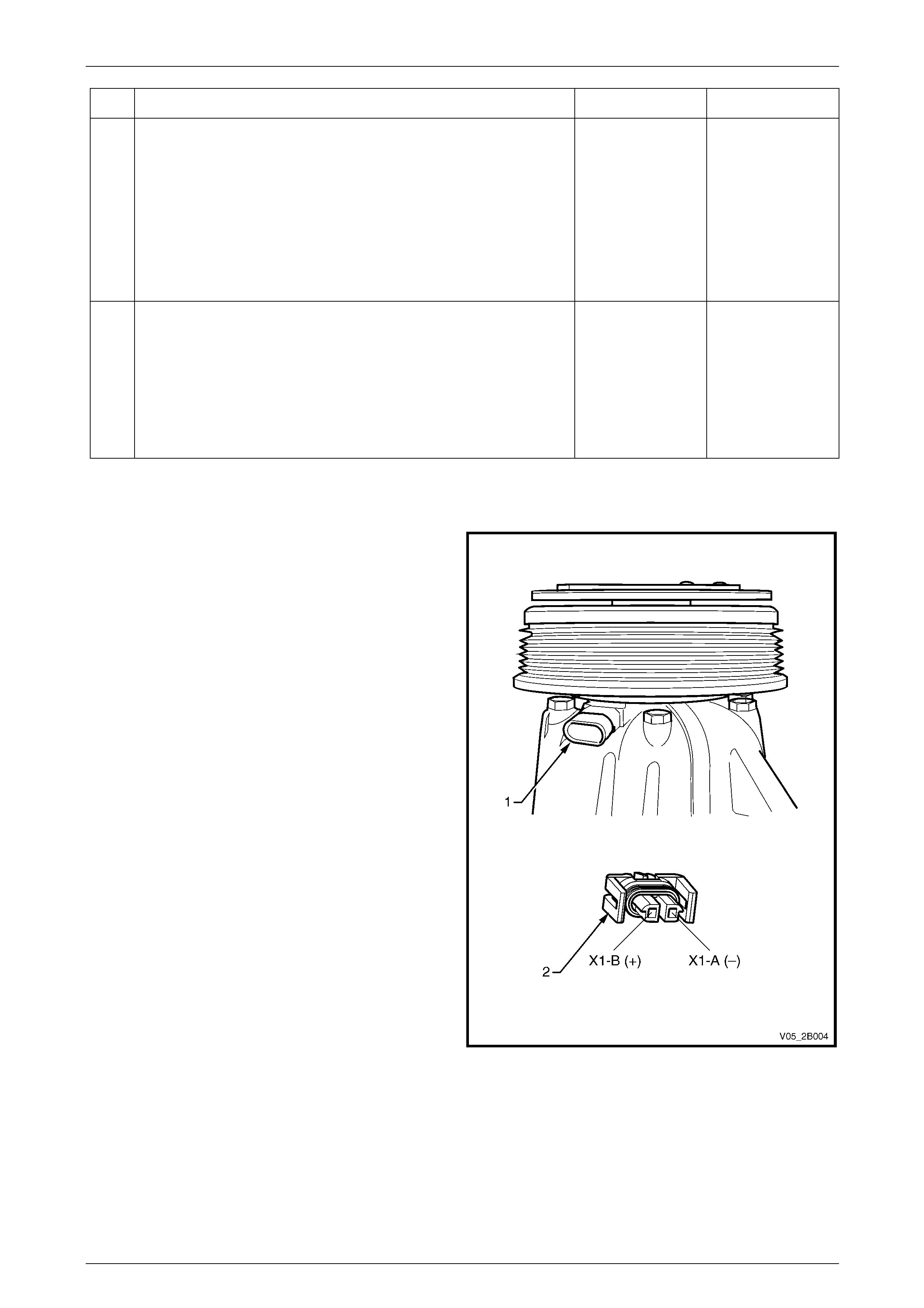
Compressor Electrical Connector
NOTE
The compressor clutch electrical connector (1) is
located near the accessory drive belt pulley.
The wiring harness connector (2) connections
must be observed when undertaking Step 5 of
the diagnostic table.
Figure 2B – 8
HVAC Climate Control (Manual A/C) – Servicing and Diagnosis Page 2B-21
Page 2B-21
Test 3: Checking Compressor System Performance
The following test is designed to increase the load on the air-conditioning system to ensure that during the test the
compressor is operating at maximum displacement.
Vehicle Set-up
1 Select the highest blower speed for the HVAC fan.
2 Open the hood and doors.
3 Select the vehicle’s temperature control setting to full cold and engage A/C.
4 Stabilise the vehicle’s interior temperature to match ambient temperature.
5 Insert a thermometer in vehicle’s centre vent position.
6 Set the engine at fast idle (1500 rpm).
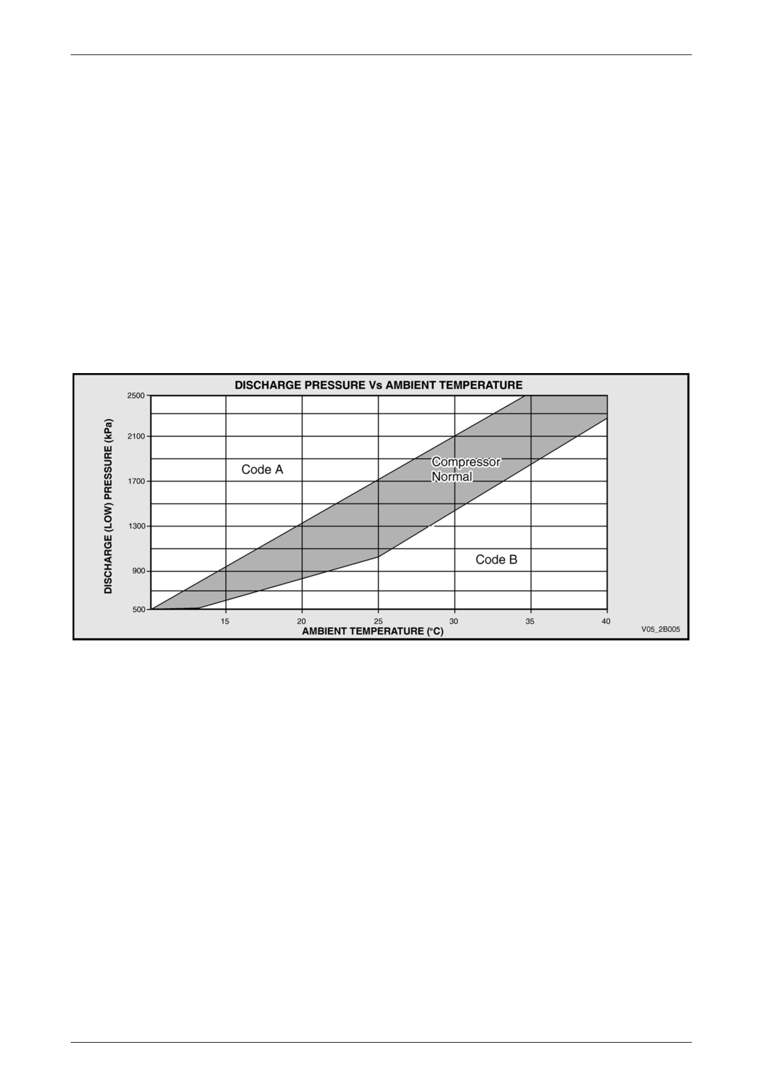
Using the information obtained from the test, plot the point where the ambient temperature intersects with the discharge
pressure. If the intersection point does not fall within the shaded area (compressor normal) in Figure 2B – 9, it will fall in
either Code A area or Code B area. Use the Air-conditioning System Performance Chart to assist in determining the true
system fault.
Figure 2B – 9
The chart on the following page lists what the possible causes are that fall into the Code A and Code B categories.

HVAC Climate Control (Manual A/C) – Servicing and Diagnosis Page 2B-22
Page 2B-22
Air-conditioning System Performance Chart
CODE A: (Possible causes) CODE B: (Possible causes)
1 Over charge of lubricating oil or refrigeran t –
symptoms:
• Low side pressure is to specification or higher.
• High side pressure is to high.
Action
a Refrigerant overcharge
Evacuate and recharge A/C system, refer to
2.2 System Charging and Evacuation.
b Oil overcharge
Recover refrigerant. Remove and drain compressor
of oil. If the measured amount of oil is greater than
100 cc, flush complete A/C system, refer to
2.2 System Charging and Evacuation.
1 Compressor not pumping – symp t oms:
• Low side pressure high.
• High side pressure lower than specification.
Action
a Check A/C system for leaks. (Note below)
b Repair leak. Evacuate and recharge the A/C
system, refer to 2.2 System Charging and
Evacuation.
c Carry out TXV testing, go to Test 6: TXV
Operational Check on Vehicle.
2 Refrigerant undercharge – symptoms:
• Low side pressure to specification.
• High side pressure to low.
Action
a Check A/C system for leaks. (Note below)
b Repair leak. Evacuate and recharge the A/C
system, refer to 2.2 System Charging and
Evacuation.
c Carry out TXV testing, go to Test 6: TXV
Operational Check on Vehicle.
2 Compressor control valve problem –
symptoms
• Low side pressure to high.
• High side pressure to specification.
Action
Go to Test 4: Checking Compressor for Less Than Full
Stroke (Low Load) Simulation.
3 TX Valve jammed open – symptoms:
• Low side pressure to specification or higher.
• High side pressure to high.
Action
Carry out TXV testing, go to Test 6: TXV Operational
Check on Vehicle.
3 TX Valve or Filter Drier restricted – symptoms:
• Low side pressure to specification.
• High side pressure to low.
Action
a Feel the inlet and outlet tubes of the Filter Drier,
both tube temperatures should be the same. If
temperatures are different, check the Filter Drier
orientation (flow direction).
b If orientation correct – replace the Filter Drier.
c Carry out TXV testing, go to Test 6: TXV
Operational Check on Vehicle.
4 Engine cooling fan problem – symptoms:
• Low side pressure to specification or higher.
• High side pressure to high.
Action
Check engine cooling fan operation. Refer to
Section 6B1 Engine Cooling – V6, or Section 6B3 Engine
Cooling – GEN III V8
HVAC Climate Control (Manual A/C) – Servicing and Diagnosis Page 2B-23
Page 2B-23
Test 4: Checking Compressor for Less Than Full Stroke (Low Load) Simulation
Vehicle Set Up
1 Select the lowest blower speed for the HVAC fan.
2 Close the doors and windows.
3 Select the vehicle’s temperature control setting to full cold and engage A/C.
4 Set the air to Recirculation mode.
5 Set the engine to a fast idle of 1500 rpm.
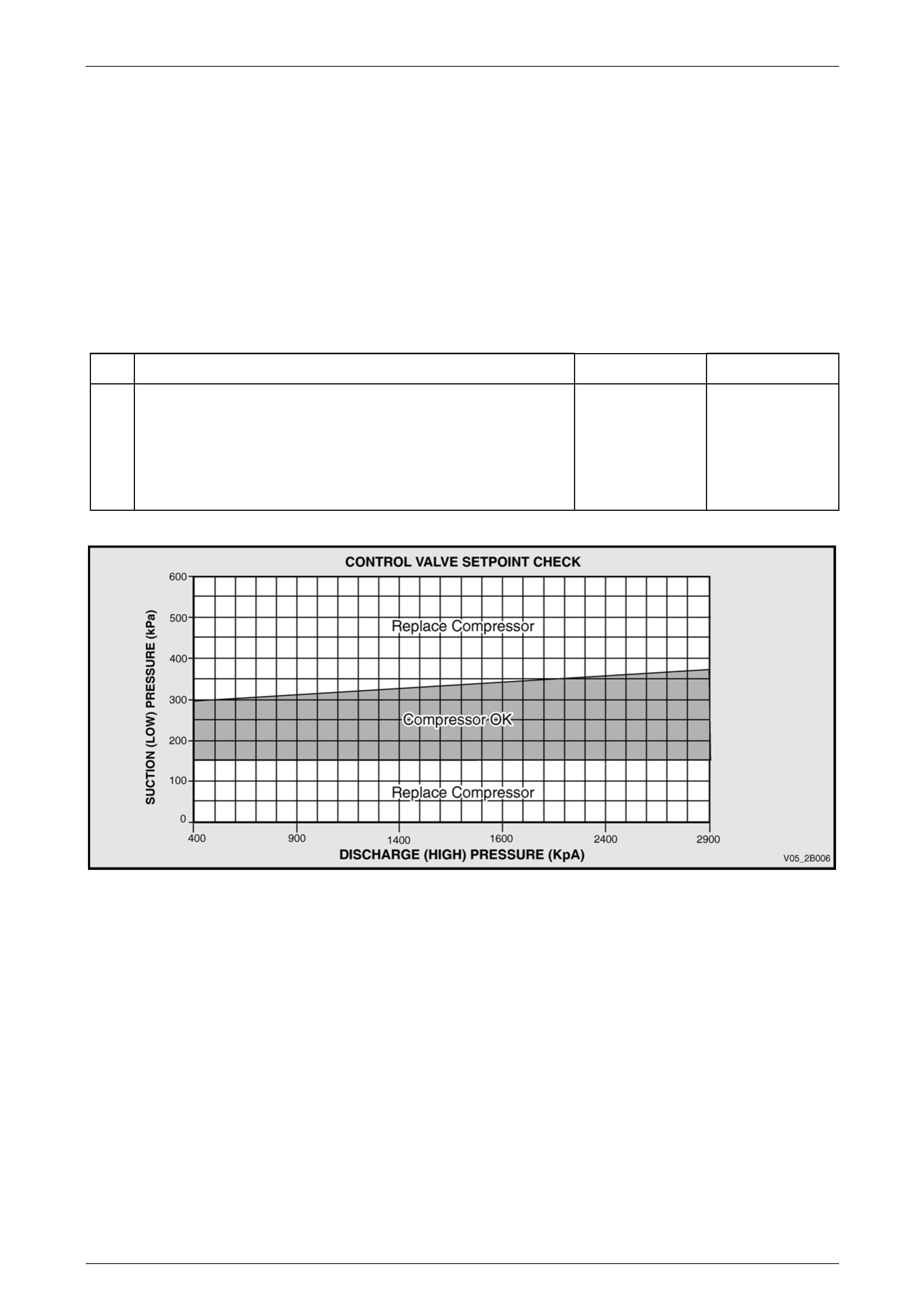
Test Procedure
Step Action Yes No
1 Check the system’s high and low gas pressures.
Do the high and low side pressure readings intersect in the shaded
area of the graph (below)?
Go to Test 5:
Checking
Compressor for Full
Stroke Operation
(High Load)
Simulation
Replace the
compressor. Refer
to Section 2C
HVAC Climate
Control (Manual A/C
– Removal and
Installation
Figure 2B – 10

HVAC Climate Control (Manual A/C) – Servicing and Diagnosis Page 2B-24
Page 2B-24
Test 5: Checking Compressor for Full Stroke Operation (High Load) Simulation
Vehicle Set Up:
1 Select the highest blower speed for the HVAC fan.
2 Open the hood and doors.
3 Select the vehicle’s temperature control setting to full cold and engage A/C.
4 Set the air to fresh air inlet mode.
5 Insert thermometer in vehicle’s centre vent position.
6 Set the engine at fast idle (3000 rpm).
Step Action Yes No
1 1 Using gauges, measure the system’s high and low pressures.
2 Subtract the low side reading from the high side reading and
compare the difference to the value shown in Figure 2B – 10.
Is the difference less than 210 kPa? Go to Step 2
Go to Test 3:
Checking
Compressor System
Performance
2 1 Turn the ignition off.
2 Rotate the compressor clutch front plate (not the pulley).
Does front plate turn freely by hand? Go to Test 3:
Checking
Compressor System
Performance
Replace the
compressor. Refer
to Section 2C
HVAC Climate
Control (Manual A/C
– Removal and
Installation
HVAC Climate Control (Manual A/C) – Servicing and Diagnosis Page 2B-25
Page 2B-25
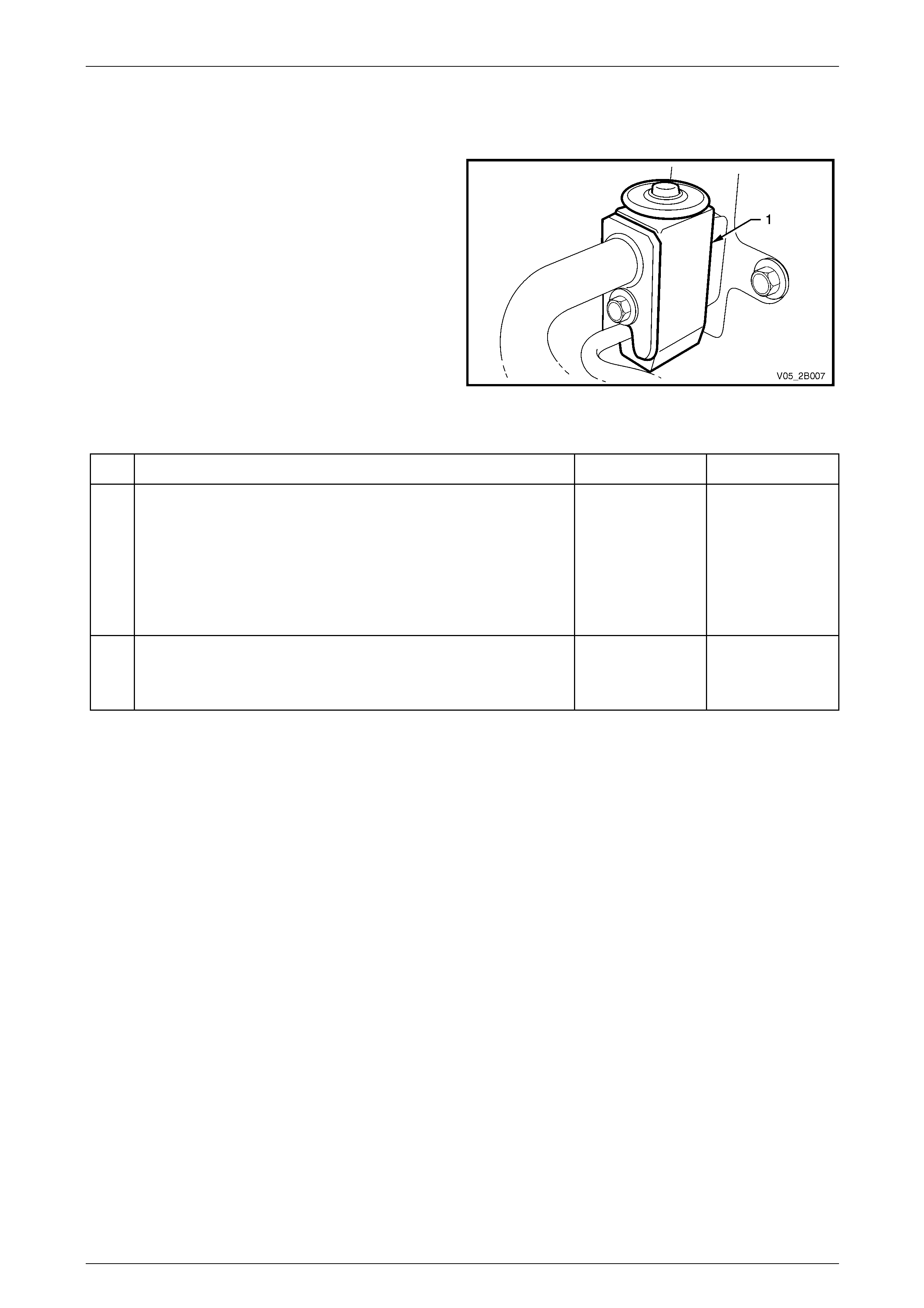
Test 6: TXV Operational Check on Vehicle
Vehicle Set Up
1 Start the engine. Leave the front doors open
2 Set the HVAC controls to:
• Maximum A/C,
• Highest blower speed,
• Face position, and
• Fresh air mode.
3 Take a note of the high and low side pressure gauge
readings once the gauge needles have stabilised.
4 Locate the TXV (1) at the rear of the engine
compartment.
5 Set the engine at fast idle.
Figure 2B – 11
Step Action Yes No
1 1 Apply freeze spray (or equivalent) over the TXV sensing disc
until it is frosted over.
2 View the high and low side pressure readings. The high side
reading should be reduced from what it was before the spray
was applied.
Did the high side pressure reading reduce once the temperature at the
TXV was reduced? Go to Step 2 Replace the TXV
2 Note the high and low pressures change as the TXV warms up.
Did the TXV react to the temperature change by noting the change in
pressures? TXV operation OK Replace the TXV

HVAC Climate Control (Manual A/C) – Servicing and Diagnosis Page 2B-26
Page 2B-26
Test 7: Noise Diagnosis
Preliminary Check
The purpose of this test is to observe for any loud knocking noises from the compressor, or any other noises that may
come from the accessory drive belt slipping.
Step Action Yes No
1 Inspect, and if necessary, rectify any faults with the accessory drive
belt and drive belt tensioner. Refer to Section 6A1 Engine Mechanical
– V6 or, Section 6A3 Engine Mechanical – GEN III V8. Go to Step 2 —
2 Run the engine and check for possible compressor noise.
Does the noise last longer than 30 seconds? Go to Step 4 Go to Step 3
3 1 Allow engine to run for a few minutes.
2 Stop engine and let it rest for a minute.
3 Restart engine.
Is any noise detected using this procedure?
Go to Step 5
It is normal to
observe a liquid
slugging condition.
This may occur after
extended system
shutdown at warmer
ambient
temperatures,
followed by an
overnight ambient
temperature drop
4 Check if the system has a low refrigerant charge. Refer to Test 1:
Checking Refrigerant Charge.
Is there enough system gas, etc.? Go to Step 6 Go to Step 7
5 Check if the TXV is stuck closed or open.
Is the TXV stuck open?
Carry out TXV
diagnosis. Refer to
Test 6: TXV
Operational Check
on Vehicle Go to Step 6
6 Check for any loose compressor bolts and / or A/C plumbing
contacting body work.
Are any mounting bolts loose? Tighten bolts and/or
relocate plumbing Go to Step 7
7 1 Recover refrigerant and replace compressor.
2 Recharge the system.
Are the gas pressures within specification, refer to Test 4: Checking
Compressor for Less Than Full Stroke (Low Load) Simulation? System checks
complete Go to Step 1

HVAC Climate Control (Manual A/C) – Servicing and Diagnosis Page 2B-27
Page 2B-27
Compressor Noise Check
Vehicle Set Up:
1 Prepare to build up high side pressure to 2000 kPa by preventing the engine cooling fans from operating by
temporarily disconnecting the cooling fan electrical connectors.
2 Select the lowest blower speed for the HVAC fan.
3 Open the hood.
4 Select the vehicle’s temperature control setting to full cold and engage A/C.
5 Set the air to fresh air inlet mode.
6 Set the engine idle speed to idle.
Step Action Yes No
1
After engine is started, d o not allow the h igh pressure
to exceed 2000 kPa as compressor overload noises
will become apparent, which is normal but not
desirable for any length of time.
1 Run engine for 5 minutes with the A/C on at 1700 rpm.
2 Allow the pressure gauge needles to stabilise.
3 Listen for abnormal compressor A/C system noises.
Is the low side pressure within normal range? Refer to
Figure 2B – 10.
Carry out Test 3:
Checking
Compressor System
Performance Go to Step 2
2 Check to see if the High side pressure is at or above 2000 kPa.
Was a clunk heard that lasted for 2 to 4 seconds duration? This noise is normal
for a load increase System OK
3 1 Turn off the engine and allow the gas pressures to stabilise.
2 Start engine and switch on A/C.
Was slugging or quick knocking observed at all?
Excess oil or liquid
is causing slugging,
refer to Test 3:
Checking
Compressor System
Performance or
jammed open TX
Valve, refer Test 6:
TXV Operational
Check on Vehicle
No excess oil or
liquid is apparent in
the system
4 1 Turn off the engine and allow the gas pressures to stabilise.
2 Start engine and switch on A/C.
3 Observe the gas pressures with cooling fans running / not
running.
Was ticking, a squeal or growling observed, especially at idle speed?
Inspect the
accessory drive belt
and tensioner for
damage and rectify
as necessary
Accessory drive belt
and tensioner are
operating OK
5 1 Observe the high side gas pressure.
2 Increase the engine revs above 2000 rpm.
Is the refrigerant pressure higher than normal and associated with a
rumble, growl, groan or A/C system pulsation through the hoses?
Refrigerant could be
overcharged, refer
to Test 1: Checking
Refrigerant Charge
The condenser may
have an air flow
restriction issue,
refer to Section 2C
HVAC Climate
Control (Manual
A/C) – Removal and
Installation
The refrigerant level
and the condenser
airflow are OK
6 1 Observe the high and low side gas pressures with the cooling
fans running / not running.
2 Reduce the engine revs to idle speed slightly above.
Is a continuous metallic knock or groan observed from the
compressor?
Check the
compressor
mounting bolts for
tightness, refer to
Section 2C HVAC
Climate Control
(Manual A/C) –
Removal and
Installation. The compressor is
mounted securely

HVAC Climate Control (Manual A/C) – Servicing and Diagnosis Page 2B-29
Page 2B-29
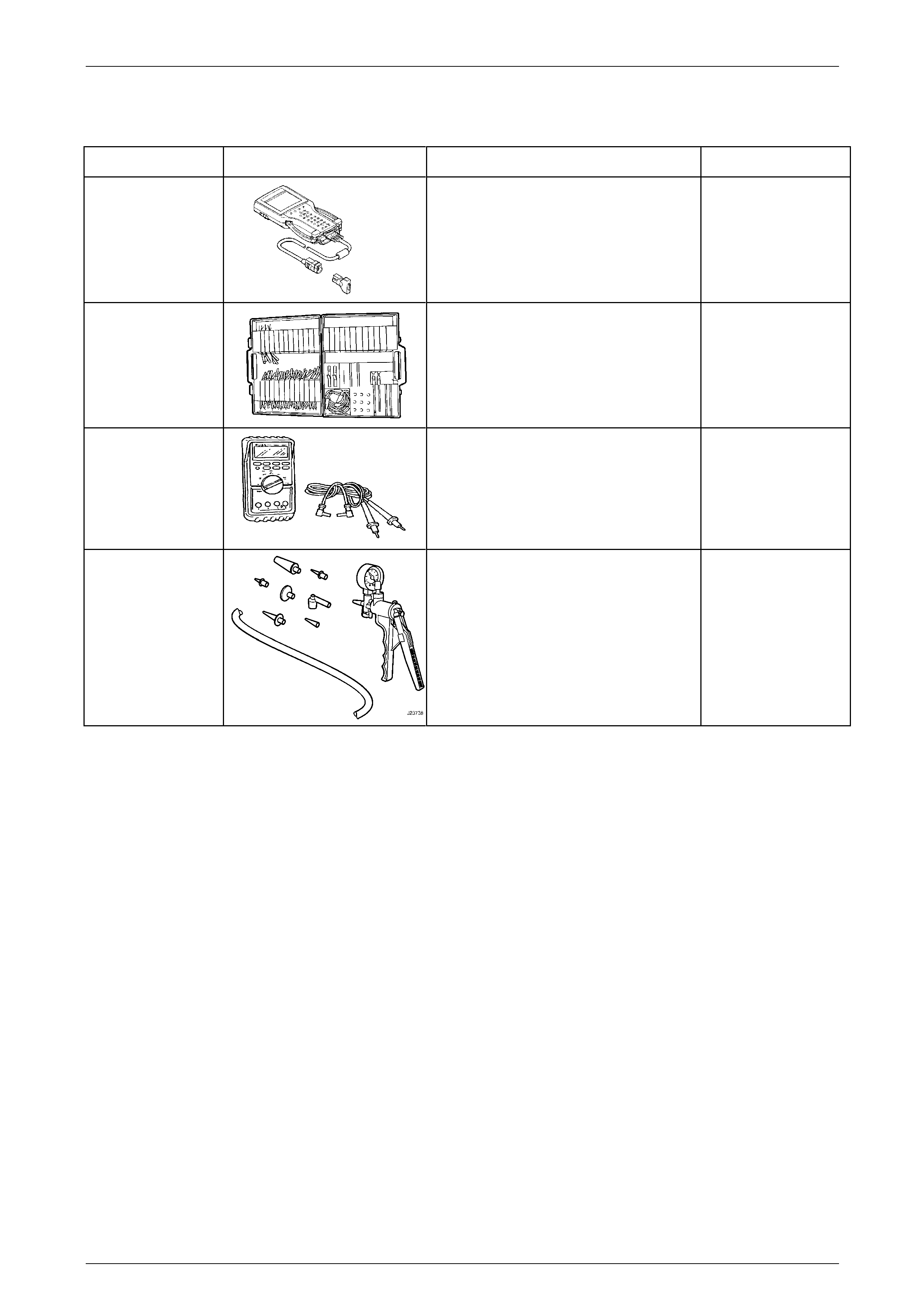
6 Special Tools
Tool Number Illustration Description Tool Classification
7000086I
TECH 2 DIAGNOSTIC SCAN TOOL
• Used for diagnosis of vehicle
electrical system.
• Previously released.
Mandatory
J35616-A
(KM609)
CONNECTOR TEST ADAPTOR KIT
• Used when carrying out electrical
diagnostic circuit checks.
• Previously released.
Desirable
3588
(J39200)
DIGITAL MULTIMETER
• Must have at least 10 MΩ input
impedance and be capable of
reading frequencies.
• Previously released.
Available
J23738 VACUUM PUMP
• Used for testing HVAC system
components, i.e. check valve,
HVAC controller, HVAC unit
vacuum tank, lines and actuators.
• Previously released.
Desirable