
HVAC Climate Control (Manual A/C) – Removal and Installation Page 2C-1
Page 2C-1
Section 2C
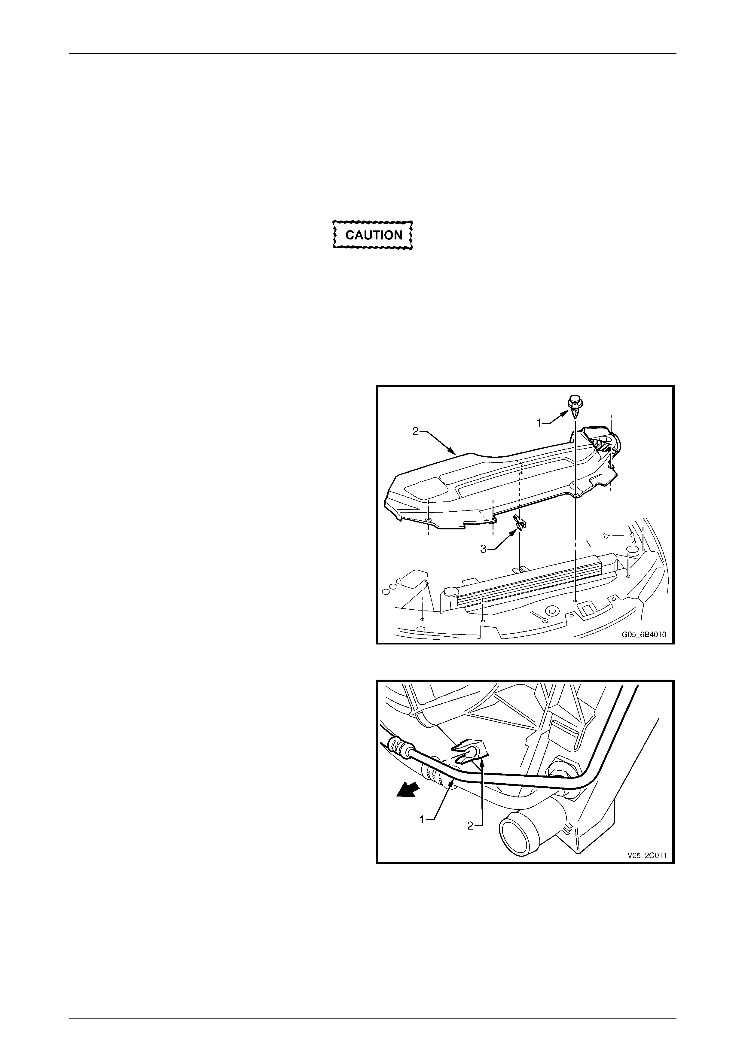
HVAC Climate Control (Manual A/C) –
Removal and Installation
ATTENTION
Before performing any service operation or other procedure described in this Section, refer to Section 00
Warnings, Cautions and Notes for correct workshop practices with regard to safety and / or property damage.
1 General Information ...............................................................................................................................5
2 HVAC Controller – Manual A/C .............................................................................................................6
2.1 Manual Controller Assembly................................................................................................................................. 6
Remove................................................................................................................................................................... 6
Reinstall.................................................................................................................................................................. 6
2.2 Water Valve Vacuum Switch................................................................................................................................. 7
Remove................................................................................................................................................................... 7
Reinstall.................................................................................................................................................................. 7
2.3 Air Mix Door Rod Retainer .................................................................................................................................... 8
Remove................................................................................................................................................................... 8
Reinstall.................................................................................................................................................................. 8
2.4 Front Housing/Switch Assembly and Printed Circuit Board.............................................................................. 9
Remove................................................................................................................................................................... 9
Reinstall................................................................................................................................................................ 11
2.5 Mode Switch Vacuum Valve................................................................................................................................ 13
Remove................................................................................................................................................................. 13
Reinstall................................................................................................................................................................ 13
3 Heating, Ventilation and Air-conditioning (HVAC) Unit....................................................................14
3.1 HVAC Unit............................................................................................................................................................. 14
Remove................................................................................................................................................................. 14
Reinstall................................................................................................................................................................ 17
3.2 Evaporator............................................................................................................................................................ 18
Remove................................................................................................................................................................. 18
Reinstall................................................................................................................................................................ 19
3.3 Heater Core........................................................................................................................................................... 20
Remove................................................................................................................................................................. 20
Reinstall................................................................................................................................................................ 21
3.4 Blower Motor and Fan Assembly ....................................................................................................................... 22
Remove................................................................................................................................................................. 22
Reinstall................................................................................................................................................................ 22
3.5 Electronic Blower Motor Controller.................................................................................................................... 23
Remove................................................................................................................................................................. 23
Test ....................................................................................................................................................................... 24
Test 1............................................................................................................................................................... 25
Test 2............................................................................................................................................................... 26
Reinstall................................................................................................................................................................ 26
3.6 Intake Blower Duct............................................................................................................................................... 27
Remove................................................................................................................................................................. 27
Reinstall................................................................................................................................................................ 27
3.7 Vent Distribution Housing................................................................................................................................... 28
Remove................................................................................................................................................................. 28
Reinstall................................................................................................................................................................ 28
Techline
Techline

HVAC Climate Control (Manual A/C) – Removal and Installation Page 2C-2
Page 2C-2
4 Vacuum System....................................................................................................................................29
4.1 Vacuum Retention Tests..................................................................................................................................... 29
Check Valve.......................................................................................................................................................... 30
Vacuum Tank........................................................................................................................................................ 32
Vacuum Mode Valve – Manual A/C..................................................................................................................... 33
Water Valve Vacuum Switch – Manual A/C........................................................................................................ 35
Vacuum Solenoid Pack – Auto A/C.................................................................................................................... 36
Vacuum Actuators............................................................................................................................................... 37
Water Valve Actuator........................................................................................................................................... 38
Vacuum Lines – Manual A/C............................................................................................................................... 39
Vacuum Lines – Auto A/C ................................................................................................................................... 41
Vacuum Actuator Lines.................................................................................................................................... 41
Vacuum Manifold Line...................................................................................................................................... 42
4.2 Vacuum Tank........................................................................................................................................................ 43
Remove................................................................................................................................................................. 43
Reinstall................................................................................................................................................................ 43
4.3 Vacuum Actuators............................................................................................................................................... 44
Intake Actuator (fresh / recirculation)................................................................................................................ 44
Remove............................................................................................................................................................ 44
Reinstall ........................................................................................................................................................... 44
Face Actuator....................................................................................................................................................... 45
Remove............................................................................................................................................................ 45
Reinstall ........................................................................................................................................................... 45
Foot Actuator ....................................................................................................................................................... 46
Remove............................................................................................................................................................ 46
Reinstall ........................................................................................................................................................... 46
5 Air-conditioning Lines and Retainers ................................................................................................47
5.1 Replace................................................................................................................................................................. 47
Lines and Retainers Views – V6 RWD................................................................................................................ 48
Lines and Retainers Views – V6 AWD................................................................................................................ 49
Lines and Retainers Views – GEN III V8............................................................................................................. 50
6 Air-conditioning Components.............................................................................................................51
6.1 Thermal Expansion Valve ................................................................................................................................... 51
Remove................................................................................................................................................................. 51
Reinstall................................................................................................................................................................ 51
6.2 A/C Pressure Transducer.................................................................................................................................... 52
Replace – V6......................................................................................................................................................... 52
Replace – GEN III V8............................................................................................................................................ 52
6.3 Condenser Assembly.......................................................................................................................................... 53
V6 Engine ............................................................................................................................................................. 53
Remove............................................................................................................................................................ 53
Reinstall ........................................................................................................................................................... 56
GEN III V8 Engine................................................................................................................................................. 57
Remove............................................................................................................................................................ 57
Reinstall ........................................................................................................................................................... 62

HVAC Climate Control (Manual A/C) – Removal and Installation Page 2C-3
Page 2C-3
6.4 Filter Drier Receiver............................................................................................................................................. 63
Remove................................................................................................................................................................. 63
Reinstall................................................................................................................................................................ 64
6.5 Air-conditioning Compressor Assembly ........................................................................................................... 65
V6 Engine – RWD................................................................................................................................................. 65
Remove............................................................................................................................................................ 65
Reinstall ........................................................................................................................................................... 66
V6 Engine – AWD................................................................................................................................................. 67
Remove............................................................................................................................................................ 67
Reinstall ........................................................................................................................................................... 68
GEN III V8 Engine................................................................................................................................................. 69
Remove............................................................................................................................................................ 69
Reinstall ........................................................................................................................................................... 70
7 Drive Belts and Pulleys........................................................................................................................71
8 Minor Compressor Repairs – GEN III V8............................................................................................72
8.1 Compressor Control Valve.................................................................................................................................. 73
Remove................................................................................................................................................................. 73
Reinstall................................................................................................................................................................ 73
8.2 Clutch Drive Plate and Hub Assembly............................................................................................................... 74
Remove................................................................................................................................................................. 74
Reinstall................................................................................................................................................................ 75
8.3 Clutch Pulley and Bearing Assembly................................................................................................................. 78
Remove................................................................................................................................................................. 78
Reinstall................................................................................................................................................................ 79
9 Under-hood Heater Components........................................................................................................81
9.1 Water Valve Assembly......................................................................................................................................... 81
V6 Engine ............................................................................................................................................................. 81
Remove............................................................................................................................................................ 81
Test.................................................................................................................................................................. 81
Reinstall ........................................................................................................................................................... 81
GEN III V8 Engine................................................................................................................................................. 82
Remove............................................................................................................................................................ 82
Test.................................................................................................................................................................. 82
Reinstall ........................................................................................................................................................... 82
9.2 Heater Hoses and Vacuum Lines ....................................................................................................................... 83
Replace – V6......................................................................................................................................................... 83
Replace – GEN III V8............................................................................................................................................ 85
10 HVAC Inlet, Ducts and Ventilation Outlets ........................................................................................86
10.1 HVAC Inlet Screen Assembly.............................................................................................................................. 86
Remove................................................................................................................................................................. 86
Reinstall................................................................................................................................................................ 87

HVAC Climate Control (Manual A/C) – Removal and Installation Page 2C-4
Page 2C-4
10.2 HVAC System Ducts............................................................................................................................................ 88
HVAC Ducts Views............................................................................................................................................... 88
Sedan, Wagon, Coupe and Crew Cab............................................................................................................. 88
Utility and Regular Cab .................................................................................................................................... 89
Driver Side Outer and Inner Ducts ..................................................................................................................... 90
Remove............................................................................................................................................................ 90
Reinstall ........................................................................................................................................................... 90
Passenger Side Duct ........................................................................................................................................... 91
Remove............................................................................................................................................................ 91
Reinstall ........................................................................................................................................................... 91
Floor Console Rear Duct (except Utility and Regular Cab).............................................................................. 91
Floor Console Front Duct (except Utility and Regular Cab)............................................................................. 91
Remove............................................................................................................................................................ 91
Reinstall ........................................................................................................................................................... 91
Foot Duct Outlet................................................................................................................................................... 92
Remove............................................................................................................................................................ 92
Reinstall ........................................................................................................................................................... 92
10.3 Cabin Ventilation Outlets .................................................................................................................................... 93
10.4 Body Ventilation Outlets..................................................................................................................................... 94
Remove................................................................................................................................................................. 94
Sedan and Coupe ............................................................................................................................................ 94
Wagon.............................................................................................................................................................. 94
Utility ................................................................................................................................................................ 95
Regular and Crew Cab..................................................................................................................................... 95
Reinstall................................................................................................................................................................ 95
11 Torque Wrench Specifications............................................................................................................96
12 Special Tools ........................................................................................................................................97

HVAC Climate Control (Manual A/C) – Removal and Installation Page 2C-5
Page 2C-5
1 General Information
This Section describes the removal and installation procedures of the he ater and air-conditioner components, except the
electronic control system components. For removal and installation proced ures of the he ater and air-conditioner
components not covered in this Section,
refer to Section 2F HVAC Occupant Climate Control (Auto A/C) – Removal and Installation.
HVAC Climate Control (Manual A/C) – Removal and Installation Page 2C-6
Page 2C-6
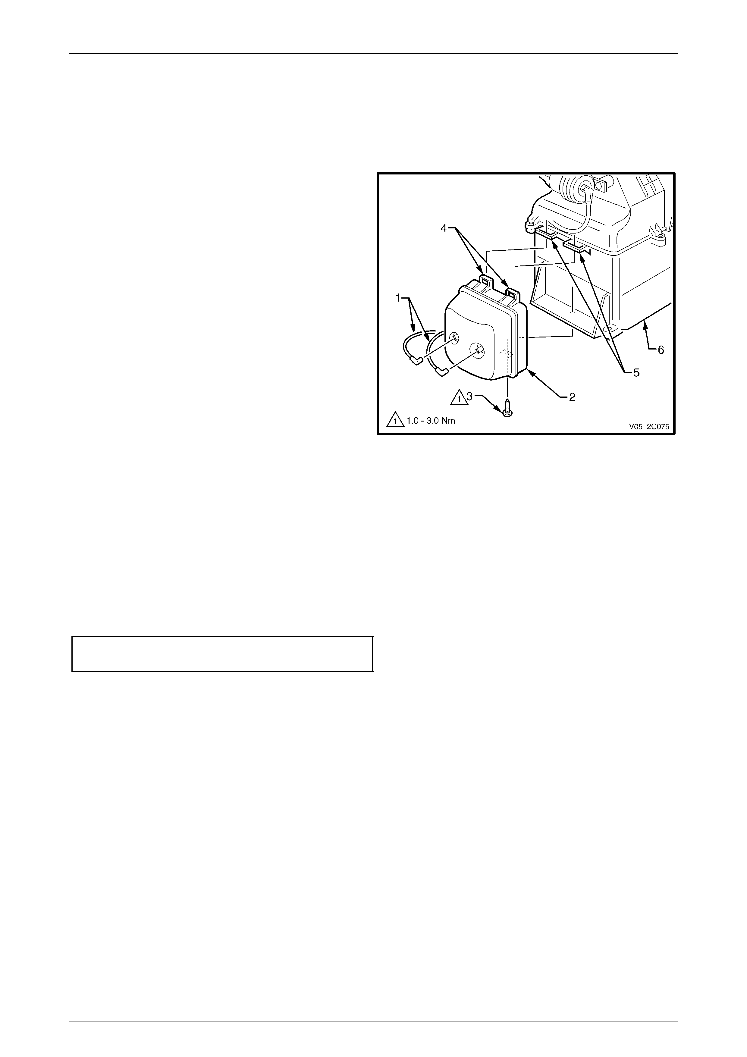
2 HVAC Controller – Manual A/C
2.1 Manual Controller Assembly
LT Section No. — 08–155A
Remove
1 Remove the instrument panel centre fascia, refer to Section 1A3 Instrument Panel and Console.
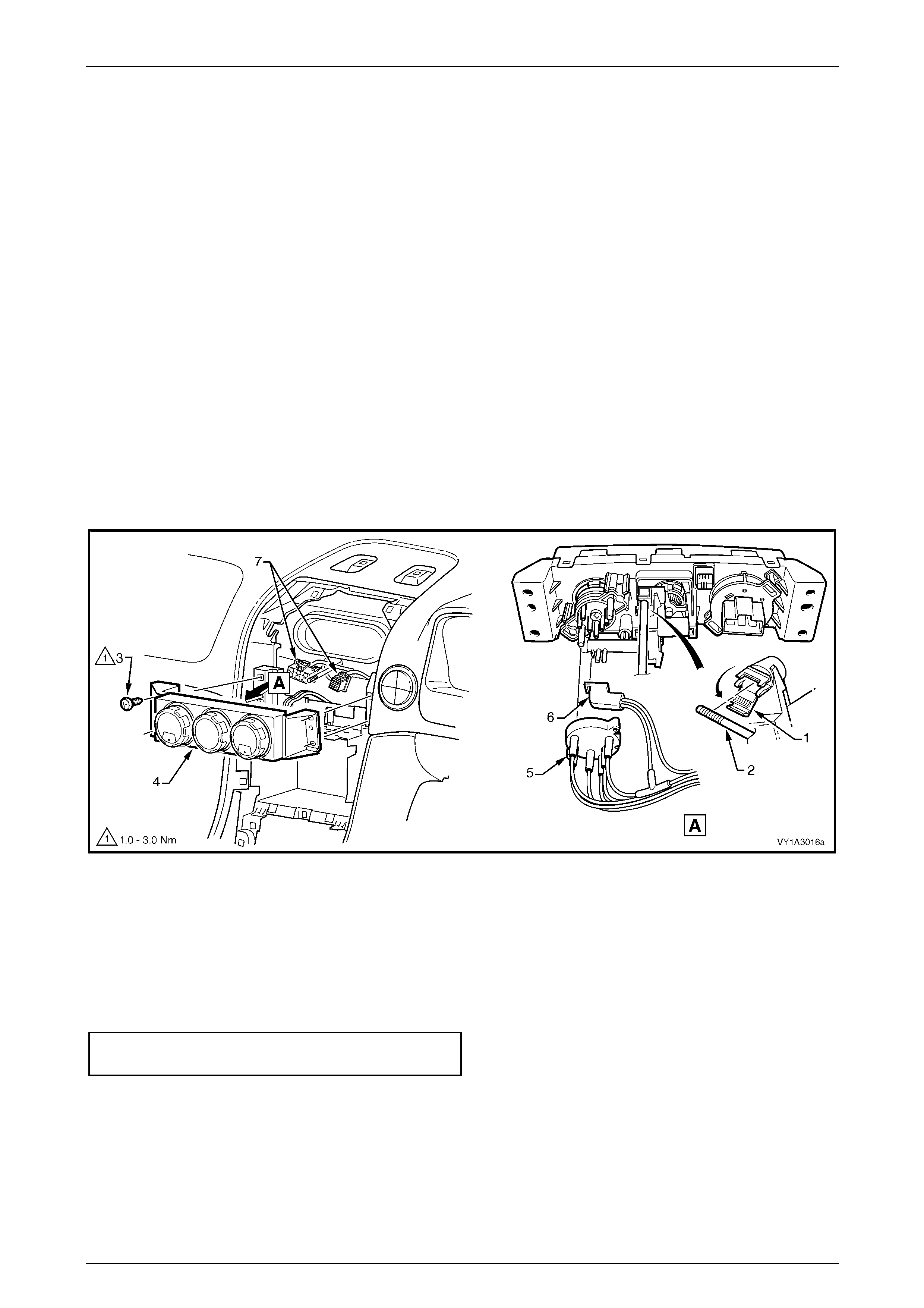
2 From the rear of the HVAC controller, open the air mix door rod retainer (1) and disconnect the rod (2), refer to
Figure 2C – 1.
3 Remove the screw (3), two places each side, attaching the HVAC controller (4) to the instrument panel.
4 Partially remove the HVAC controller assembly outwards from the instrument pan el to access the rear of the
controller.
5 Disconnect the two vacuum hose connections (5 and 6) and two wiring connectors (7).
6 Remove the HVAC controller assembly. NOTE
For service and diagnosis of the manual HVAC
controller, refer to Section 2B HVAC Climate
Control (Manual A/C) – Servicing and Di agnosis.
Figure 2C – 1
Reinstall
1 Install the two wiring connectors (7) and the lower then upper vacuum hose connections (5 and 6), refer to
Figure 2C – 1.
2 Push the control rod (2) toward the HVAC unit (front of vehicle) fully.
3 Seat the HVAC controller assembly (4) in position.
4 Install the attaching screws (3) and tighten to the correct torque specification.
Manual HVAC controller attachin g
screw torque specification...........................1.0 – 3.0 Nm
5 Rotate the temperature switch to the full cold position.
6 Position the air mix door rod retainer (1), so it will close upward.
7 Connect the control rod to the air mix do or rod retainer.
8 Close and lock the retainer over the rod.
9 Check for correct operation of the temperature switch.
10 Reinstall the floor console cover assembly and the instrument pan el centre fascia,
refer to Section 1A3 Instrument Panel and Consol e.
HVAC Climate Control (Manual A/C) – Removal and Installation Page 2C-7
Page 2C-7
2.2 Water Valve Vacuum Switch
LT Section No. — 08–155A
Remove
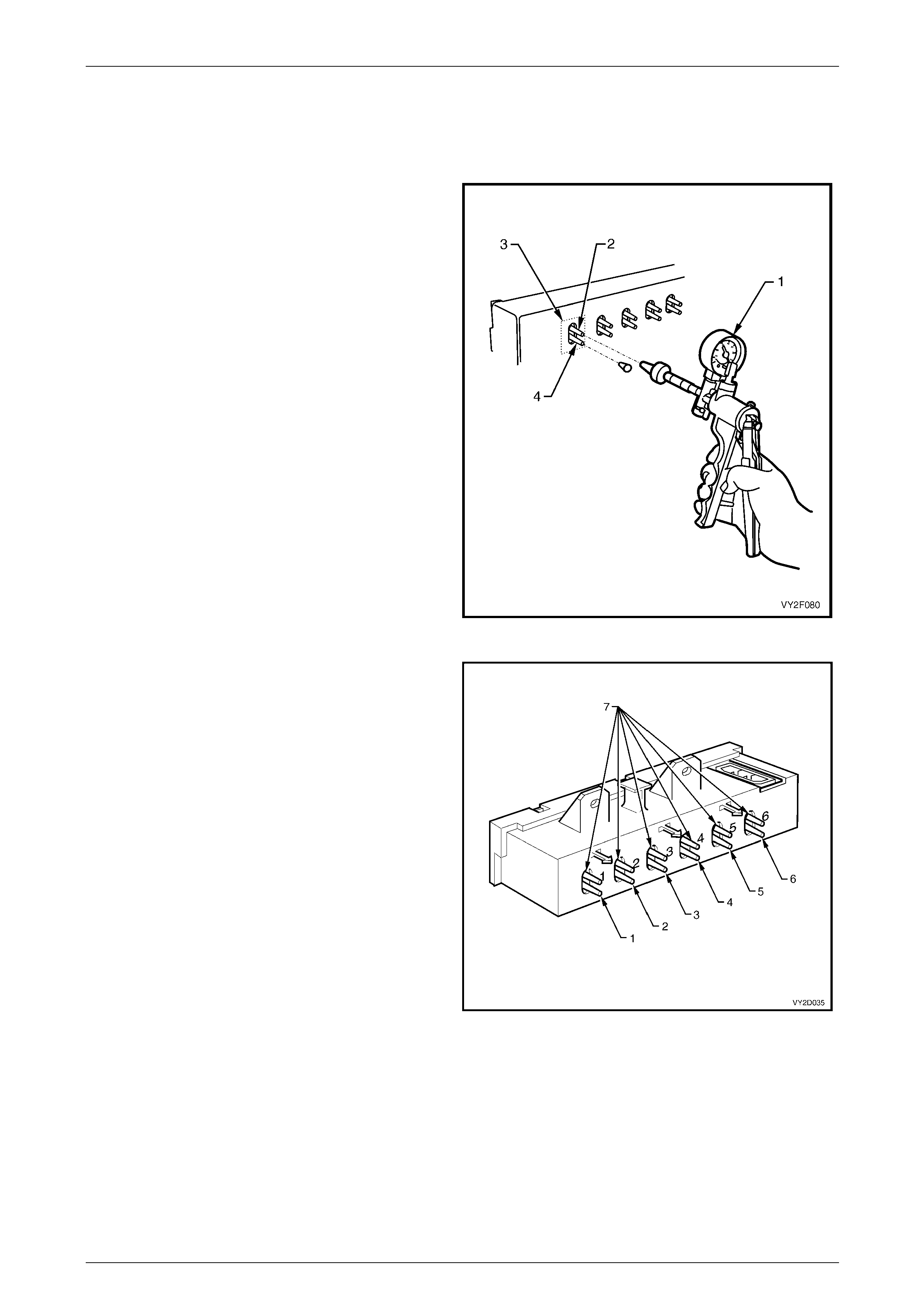
1 Remove the manual HVAC controller, refer to
2.1 Manual Controller Assembl y.
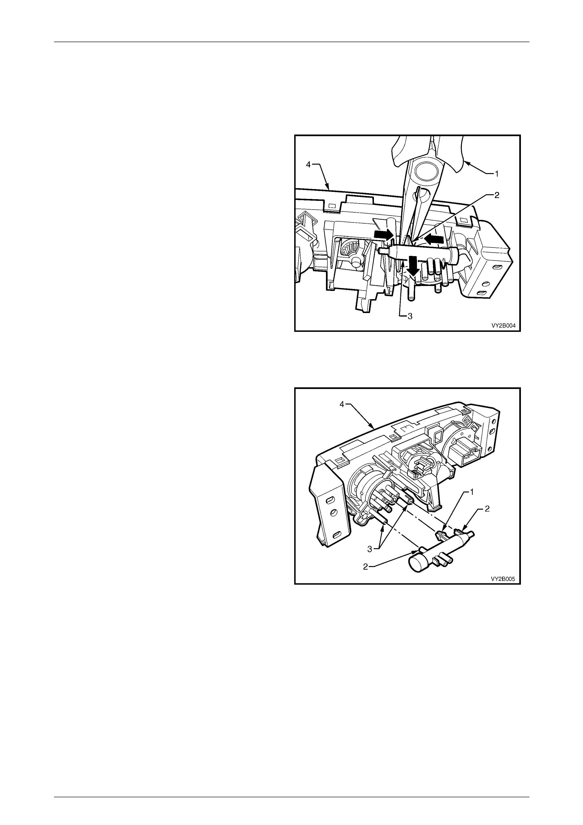
2 Turn the temperature switch to the full hot position.
Using needle nose pliers (1), carefully compress the
locking legs (2) of the vacuum switch (3) and withdraw
the switch from the controller rear housing (4) .
Figure 2C – 2
Reinstall
1 Insert the vacuum switch locking legs (1) through the
controller rear housing ensuring the locating
dowels (2) are installed into the two locators (3) of the
rear housing (4).
2 Push the vacuum switch into position ensuring the
locking legs lock into position and retain the switch in
the controller rear housing.
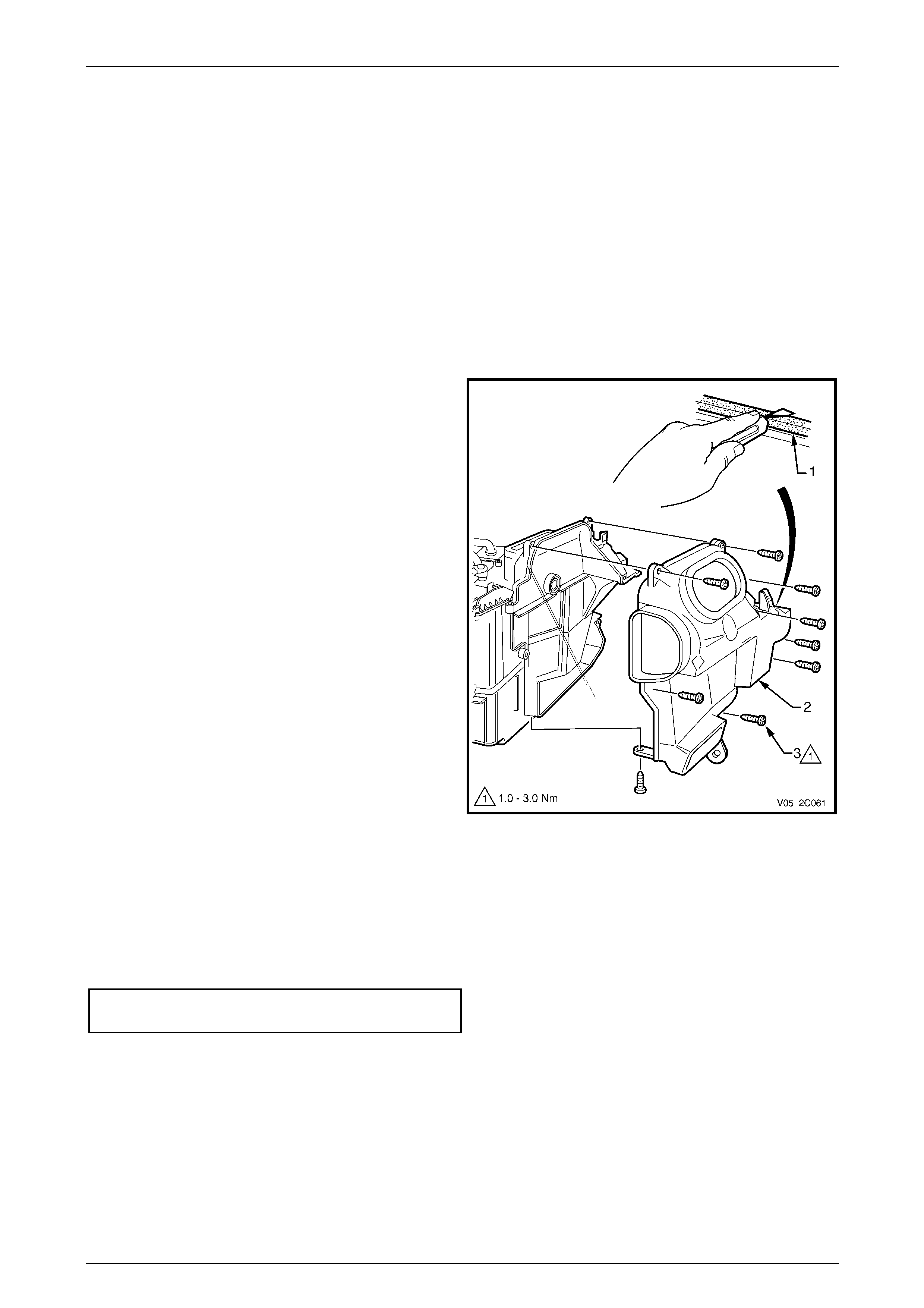
3 Install the controller to the instrument panel, refer to
2.1 Manual Controller Assembl y.
Figure 2C – 3
HVAC Climate Control (Manual A/C) – Removal and Installation Page 2C-8
Page 2C-8
2.3 Air Mix Door Rod Retainer
LT Section No. — 08–155A
Remove
1 Remove the manual HVAC controller, refer to
2.1 Manual Controller Assembl y.
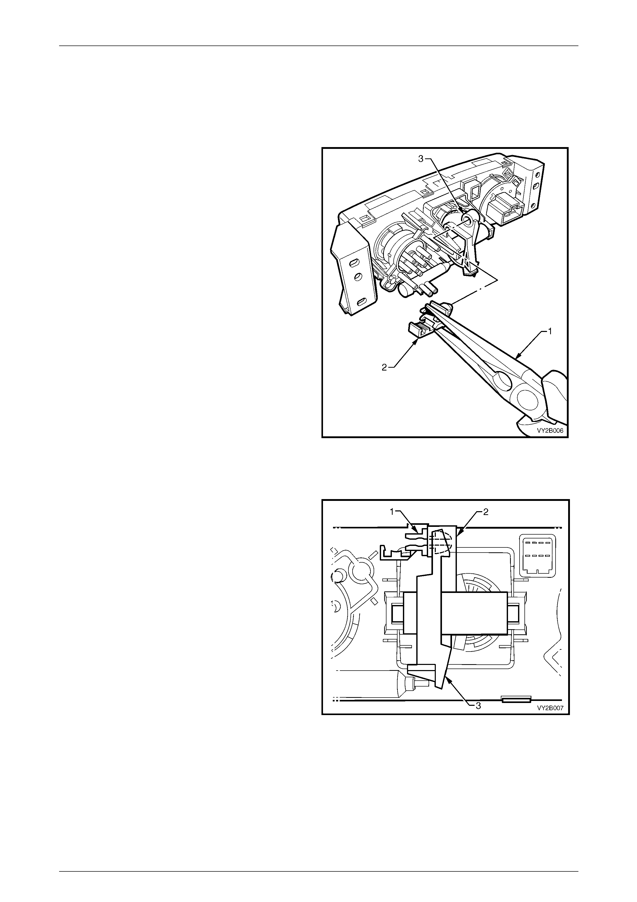
2 Using needle nose pliers (1), carefully compress the
rod retainer (2) together and withdraw the rod retainer
from the crescent gear (3) of the controller.
Figure 2C – 4
Reinstall
1 Insert the rod retainer (1) into the pivot hole (2) of the
crescent gear (3) ensuring it locks into position.
2 Install the controller to the instrument panel, refer to
2.1 Manual Controller Assembl y.
Figure 2C – 5
HVAC Climate Control (Manual A/C) – Removal and Installation Page 2C-9
Page 2C-9
2.4 Front Housing/Switch Assembly and
Printed Circuit Board
LT Section No. — 08–155A
Remove
1 Remove the manual HVAC controller, refer to 2.1 Manual Contro ller Assembly.
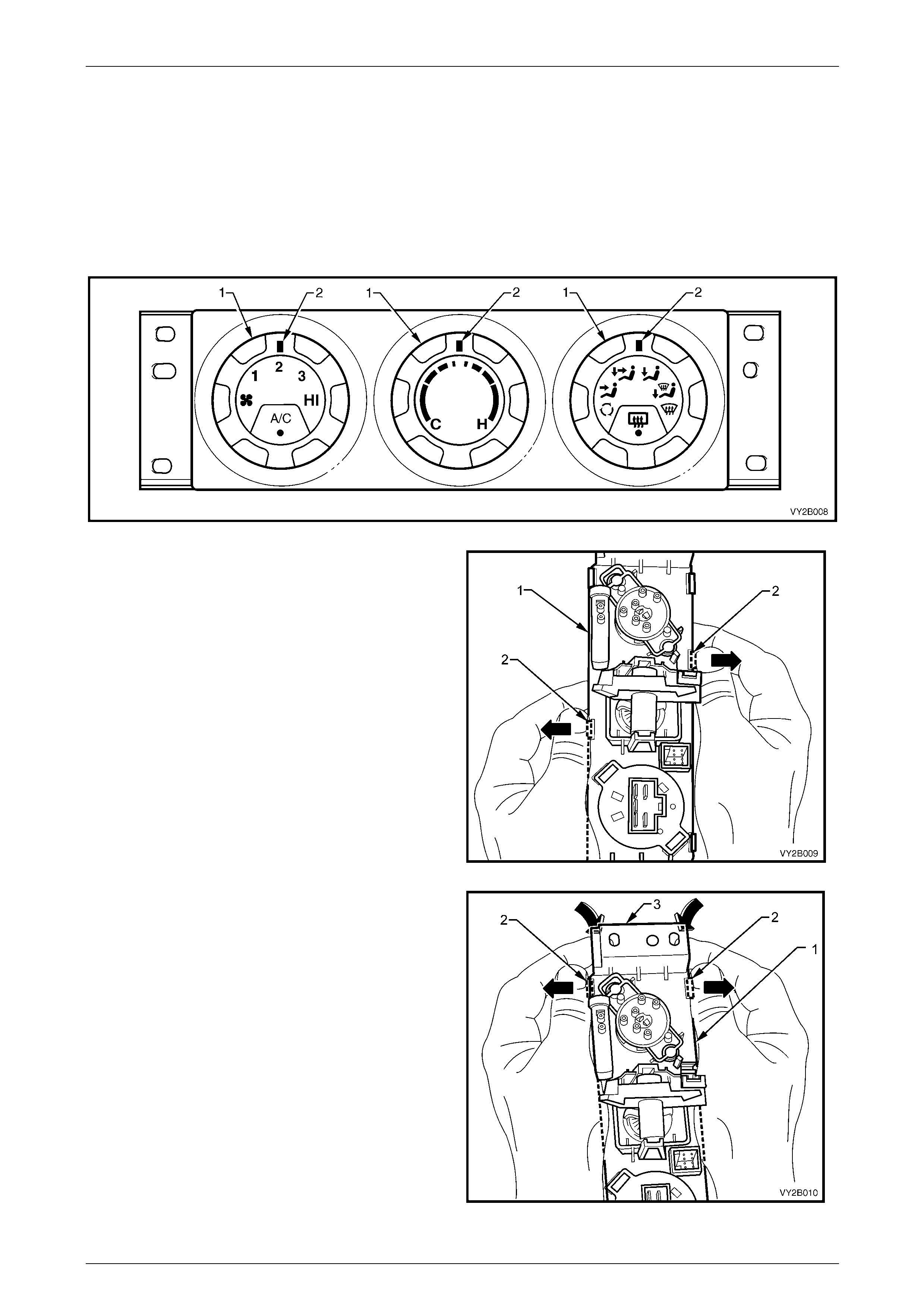
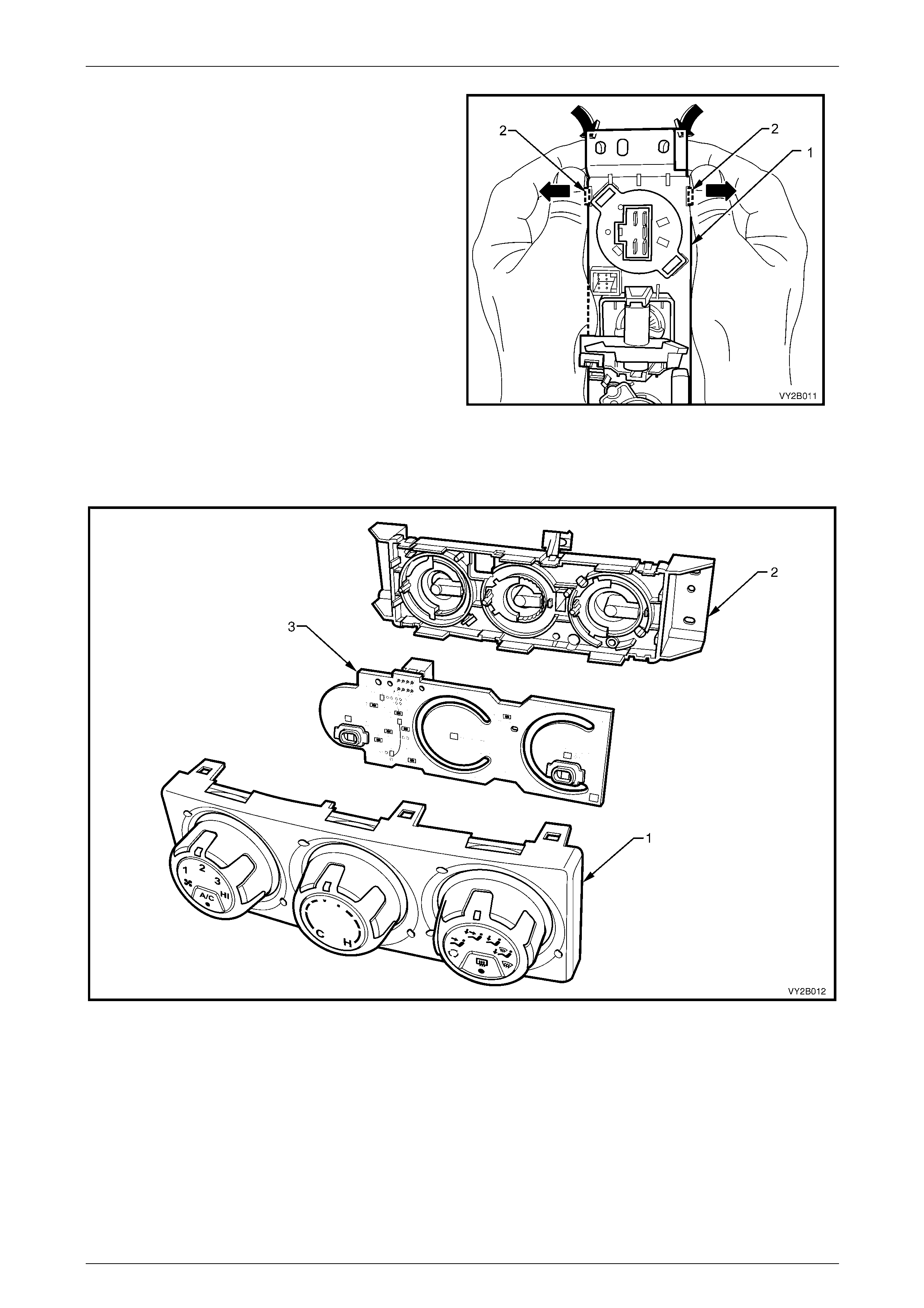
2 Rotate the switches (1) so all switch position indicators (2) are at the 12 o’clock position, refer to Figure 2C – 6.
Figure 2C – 6
3 Holding the controller (1), disengage the middle
retaining tangs of the front housing/switch assembly
from the controller rear housing by carefully moving the
retaining tangs (2) of the front housing o utwards with
thumb pressure.
Figure 2C – 7
4 Continue to disengag e the front housing/switch
assembly from the controller (1) rear housing by
moving the end retaining tangs (2) outwards with
thumb pressure while simulta neously separating the
rear housing from the front housing/switch assembly
using index finger pressure at the mounting flange (3)
of the controller.
Figure 2C – 8
HVAC Climate Control (Manual A/C) – Removal and Installation Page 2C-10
Page 2C-10
5 Rotate the controller (1) through 180° and disengage
the retaining tangs (2) at the other end of the controller
by using the same technique as described in previous
Step.
Figure 2C – 9
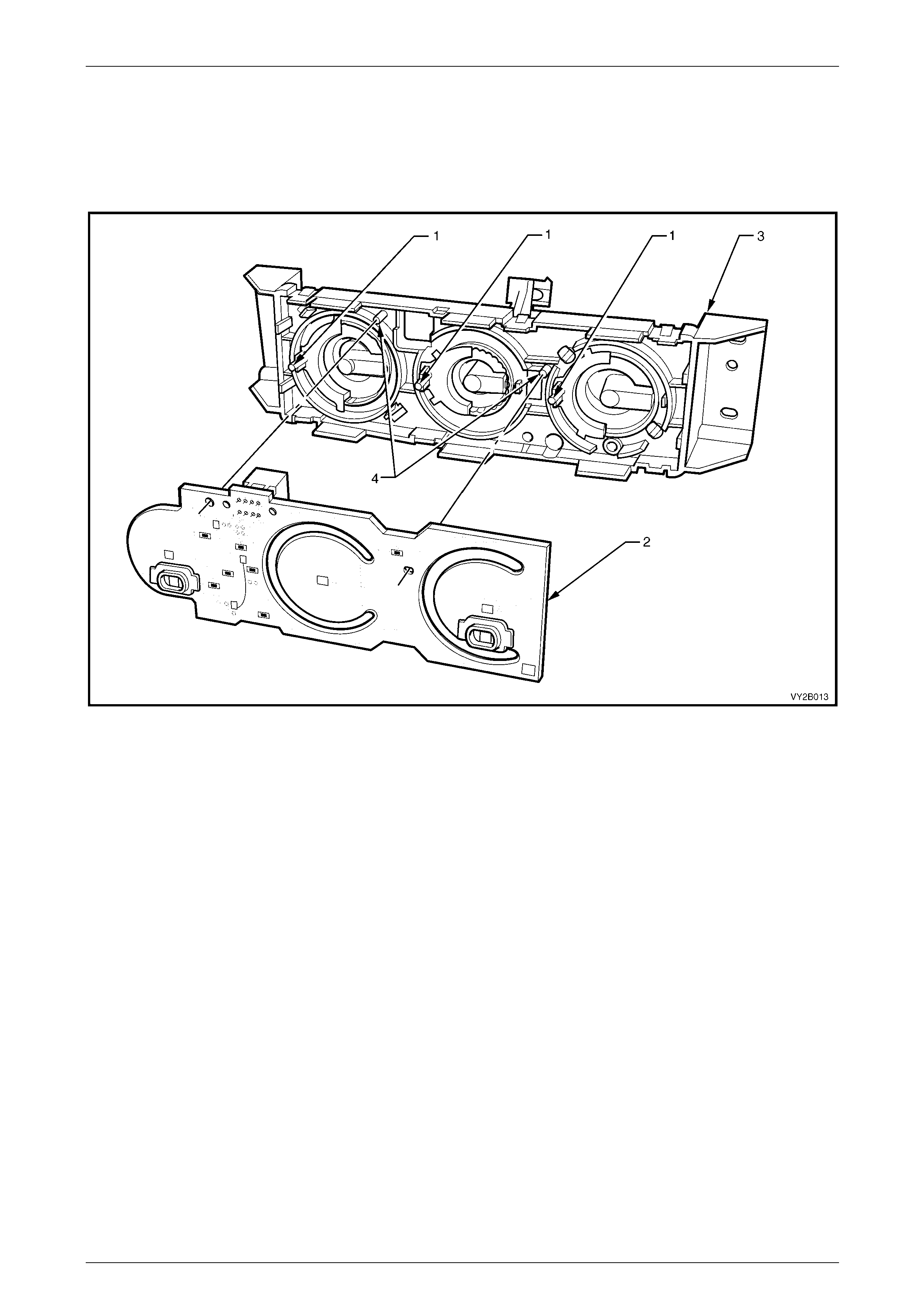
6 Remove the front housing/switch assembly (1) from the rear housing (2), refer to Figure 2C – 10.
7 Remove the printed circuit board (3) from the rear housing.
Figure 2C – 10
HVAC Climate Control (Manual A/C) – Removal and Installation Page 2C-11
Page 2C-11
Reinstall
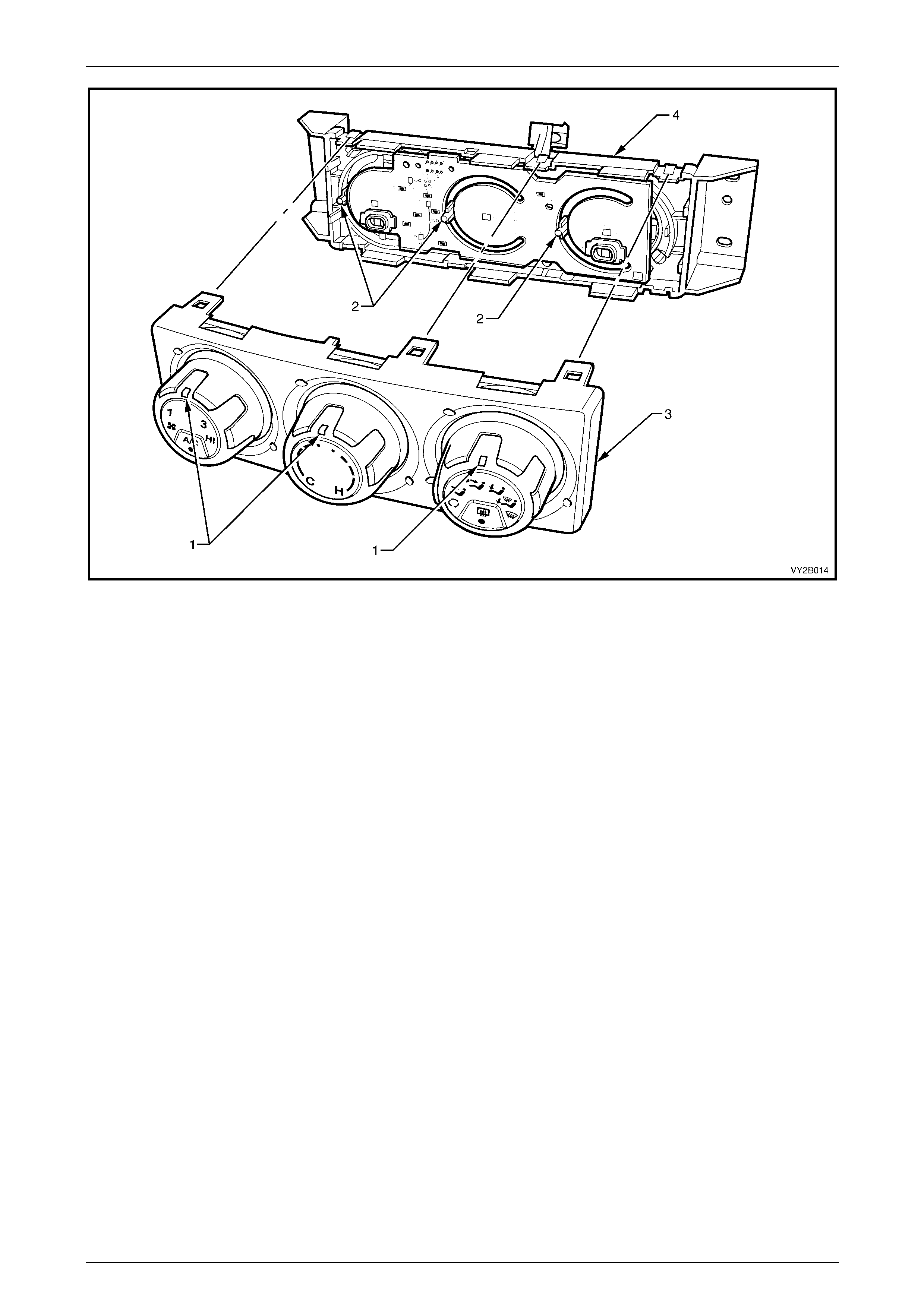
1 Ensure the switch shaft pins (1) are located at the 9 o’clock position, refer to Figure 2C – 11.
2 Ensure the locating pins (4) are ali gned with the corresponding holes of the circuit board and install the pr inted
circuit board (2) to the rear housing (3).
Figure 2C – 11
3 Rotate the switches so that all switch position indic ators (1) are at the 12 o’clock pos ition. Ensure all three shaft
pins (2) are still located at exactly the 9 o’clock position, refer to Figure 2C – 12.
4 Install the front housing/s witch assembl y (3) to the rear hou sing (4) ensuring its six retaining tan gs are fully
engaged over the rear housing tang protrusions.
5 Ensure all the switches rotate freely and the switch position indicators align correctly with all switch positions.
Ensure all switches do not rotate past intended rotation limits.
6 Install the controller to the instrument panel, refer to 2.1 Manual Controller Assembly.
HVAC Climate Control (Manual A/C) – Removal and Installation Page 2C-12
Page 2C-12
Figure 2C – 12
HVAC Climate Control (Manual A/C) – Removal and Installation Page 2C-13
Page 2C-13
2.5 Mode Switch Vacuum Valve
LT Section No. — 08–155A
Remove
1 Remove the manual HVAC controller, refer to 2.1 Manual Contro ller Assembly.
2 Remove the front housing/switch assembly and printed circuit board from the rear housing,
refer to 2.4 Front Housing/Switch Assembly and Printed Circuit Board.
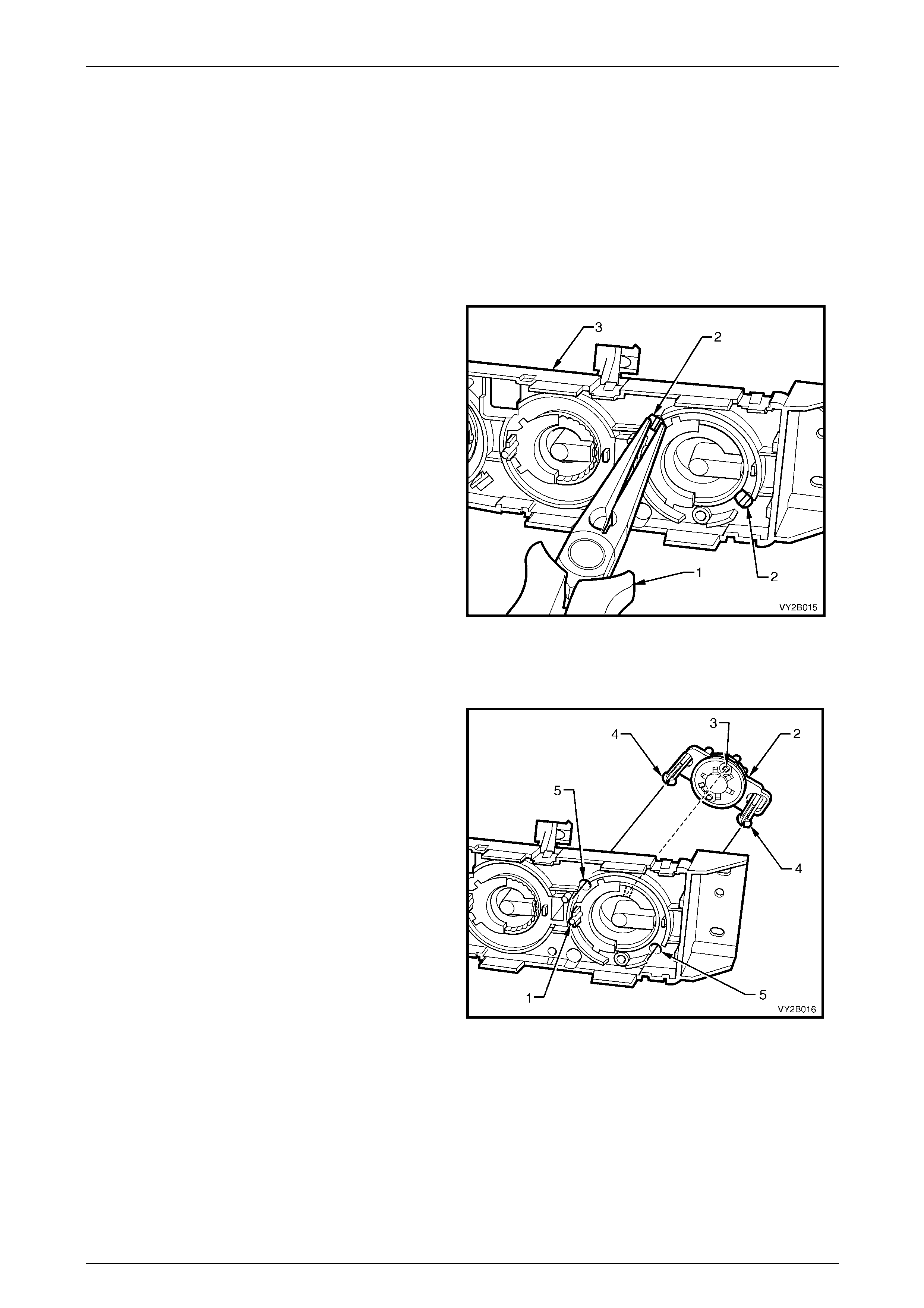
3 Using needle nose pliers (1), compress both pairs of
locking tangs (2) of the mounting dowels on the mode
switch vacuum valve and withdraw the switch
assembly from the controller rear housing (3).
Figure 2C – 13
Reinstall
1 Ensure the mode shaft pin (1) is located at the
9 o’clock position. On the mode switch valve
assembly (2) ensure the larger drive pin (3) is
positioned at the 12 o’clock po sition.
2 Align the mounting dowels (4) to the corresponding
holes (5) in the rear housing a nd install the switch
assembly ensuring the locking tangs of the mounting
dowels engage fully into the rear housing
3 Install the front housing/switch assembly and printed
circuit board to the rear housing, refer to
2.4 Front Housing/Switch Assembly and Printed
Circuit Board.
4 Ensure all switches rotate freely and all th e switch
position indicators align corre ctly with all switch
positions. Ensure all switches do not rotate p ast
intended rotation limits.
5 Install the controller to the instrument panel, refer to
2.1 Manual Controller Assembl y.
Figure 2C – 14

HVAC Climate Control (Manual A/C) – Removal and Installation Page 2C-14
Page 2C-14
3 Heating, Ve ntilation and Air-
conditioning (HVAC) Unit
3.1 HVAC Unit
LT Section No. — 08–150
Remove
NOTE
Disconnection of the battery affects certain
vehicle electronic systems. Refer to
Section 00 Warnings, Cautions and Notes prior to
disconnecting the batter y.
1 Disconnect the battery ground lead.
2 Disable the occupant protection system, refer to Section 12M Occupant Protection System.
3 Discharge the air-conditioning system,
refer to Section 2B HVAC Climate Control (Manual A/C) – Servicing and Diagnosis.
4 Drain engine coolant into a su itable, clean container, refer to:
• Section 6B1 Engine Co oling – V6, or
• Section 6B3 Engine Cooling – GEN III V8.
5 Remove instrument panel pad assemb ly and brackets & braces,
refer to Section 1A3 Instrument Panel and Consol e.
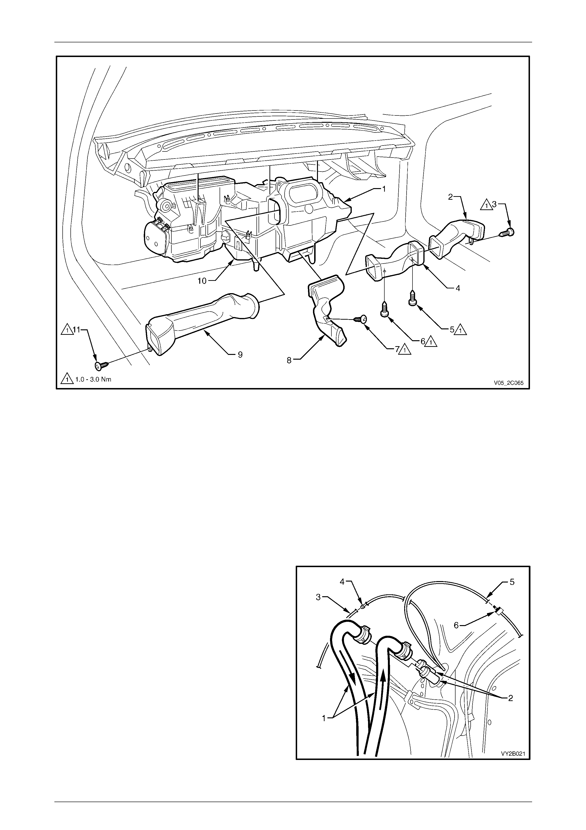
6 Remove the side and console air ducts from the HVAC unit as required, refer to Figure 2C – 15.
NOTE
• Some of the screws shown have been
removed with the instrument panel.
• The foot air duct remains attached when the
HVAC unit is removed
• The steering column (not shown) does not
require removal for HVAC unit removal.
HVAC Climate Control (Manual A/C) – Removal and Installation Page 2C-15
Page 2C-15
Figure 2C – 15
Legend
1 HVAC Unit
2 Driver Side Outer Duct
3 Screw
4 Driver Side Inner Duct
5 Screw
6 Screw
7 Screw
8 Floor Console Front Duct
9 Passenger Side Duct
10 Foot Duct
11 Screw
7 Remove the body control module (BCM), refer to Section 12J Body Control Modul e.
8 Remove the antenna lead from the retaining clips located at the HVAC unit case join.
9 Remove the instrument panel inflatable restraint module assembly,
refer to Section 12M Occupant Protection System.
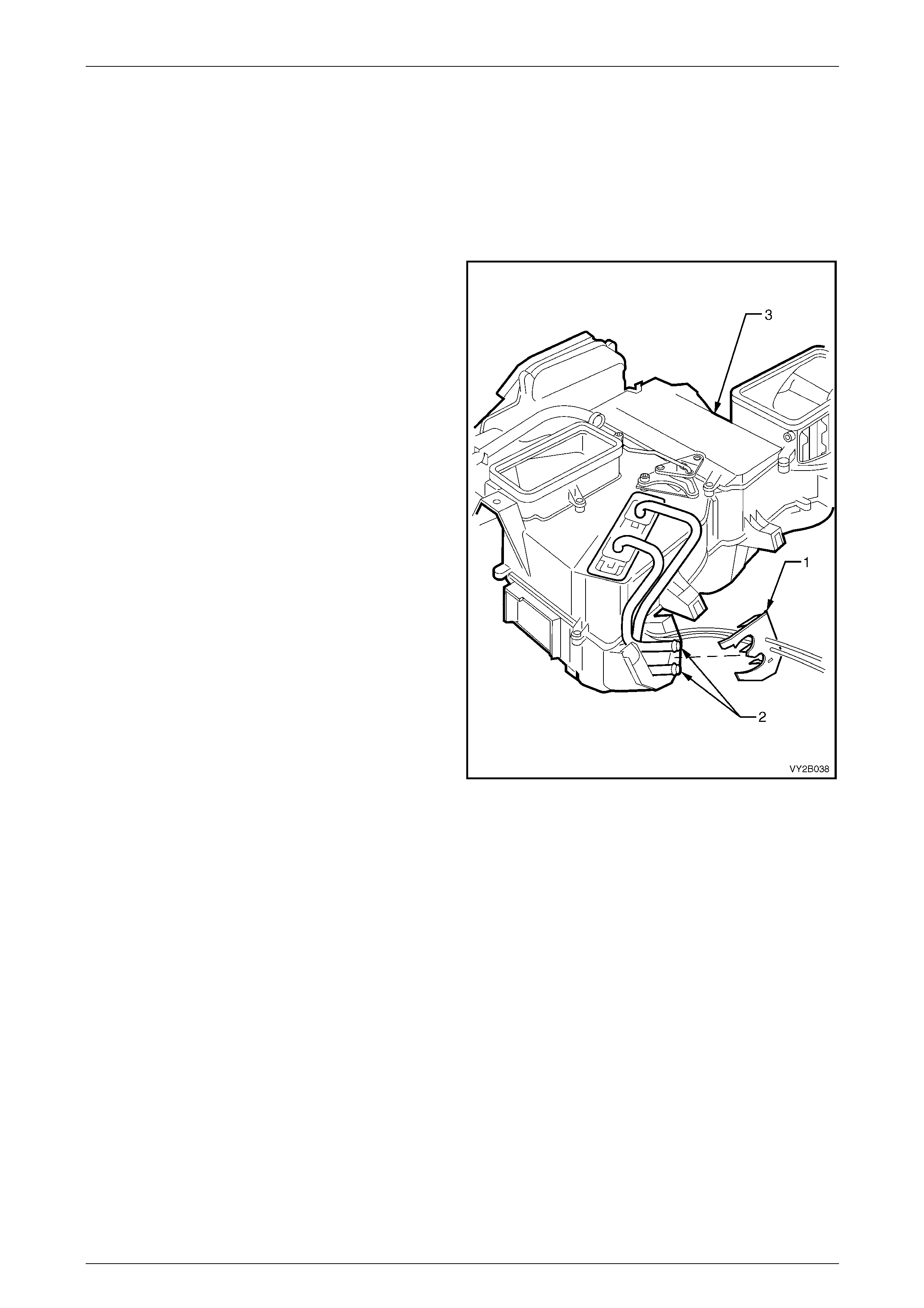
10 Mark the heater hoses (1) in relation to the heater core
pipes (2) to maintain correct coolant flow and
disconnect the heater hoses.
11 Disconnect the water valve vacuum hose (3) at the
joiner (4).
12 Disconnect the vacuum supply hose (5) at the check
valve (6).
13 Remove the thermal expansion valve, refer to
6.1 Thermal Expansion Valve.
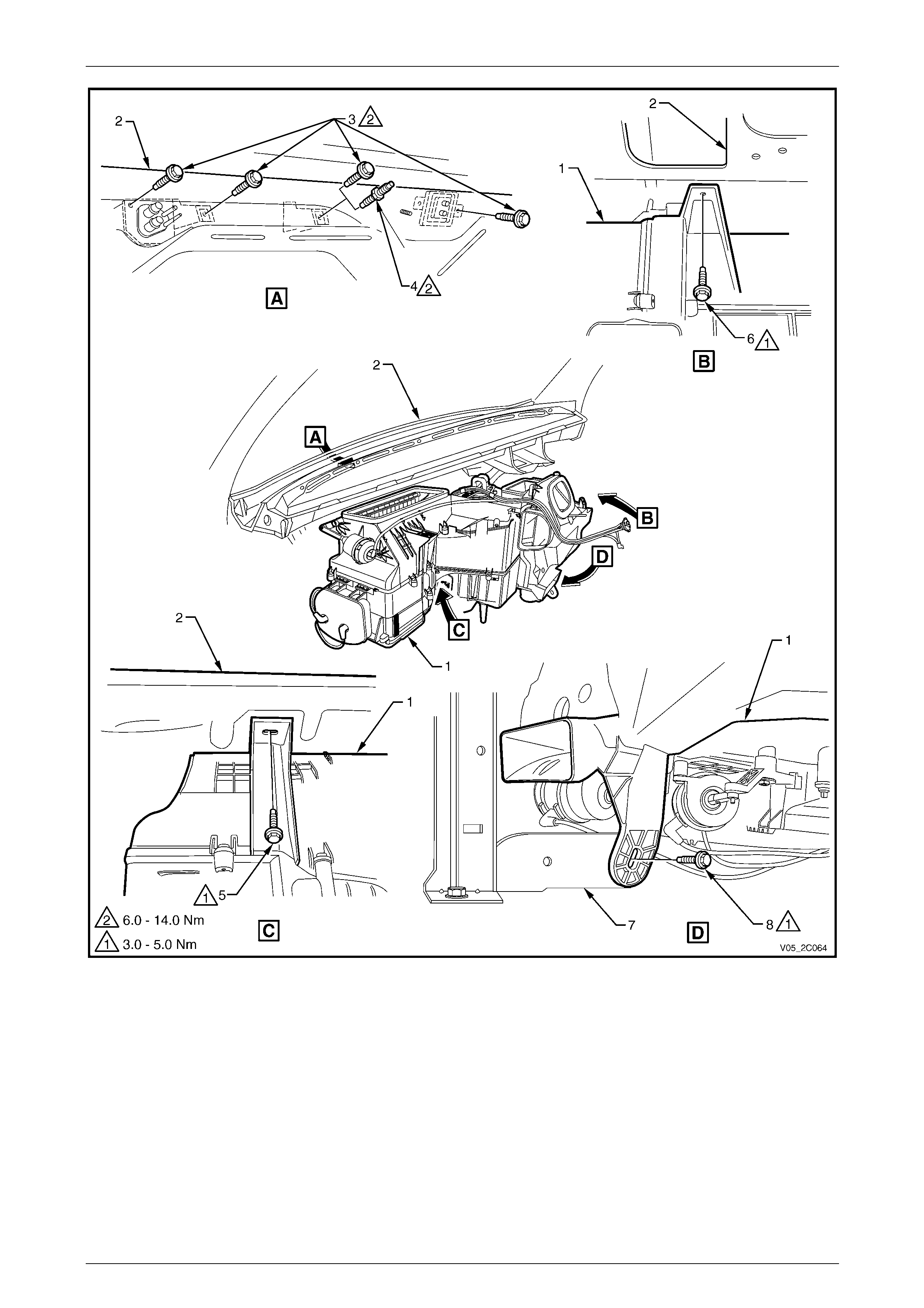
14 Remove the screws retaining the HVAC unit to the
dash panel, refer to Figure 2C – 17.
NOTE
The steering column (not shown) does not have
to be removed for HVAC unit removal
Figure 2C – 16
HVAC Climate Control (Manual A/C) – Removal and Installation Page 2C-16
Page 2C-16
Figure 2C – 17
Legend
1 HVAC Unit
2 Dash Panel
3 Screw – Dash Panel, Engine Compartment
(V6 – 4 places / GEN III V8 – 3 places)
4 Stud – Dash Panel, GEN III V8 Engine Compartment
5 Screw – Dash Panel, Passenger Compartment Left-hand
6 Screw – Dash Panel, Cabin Right-hand
7 Lower Radio Bracket Assembly
8 Screw – Lower Radio Bracket Assembly
HVAC Climate Control (Manual A/C) – Removal and Installation Page 2C-17
Page 2C-17
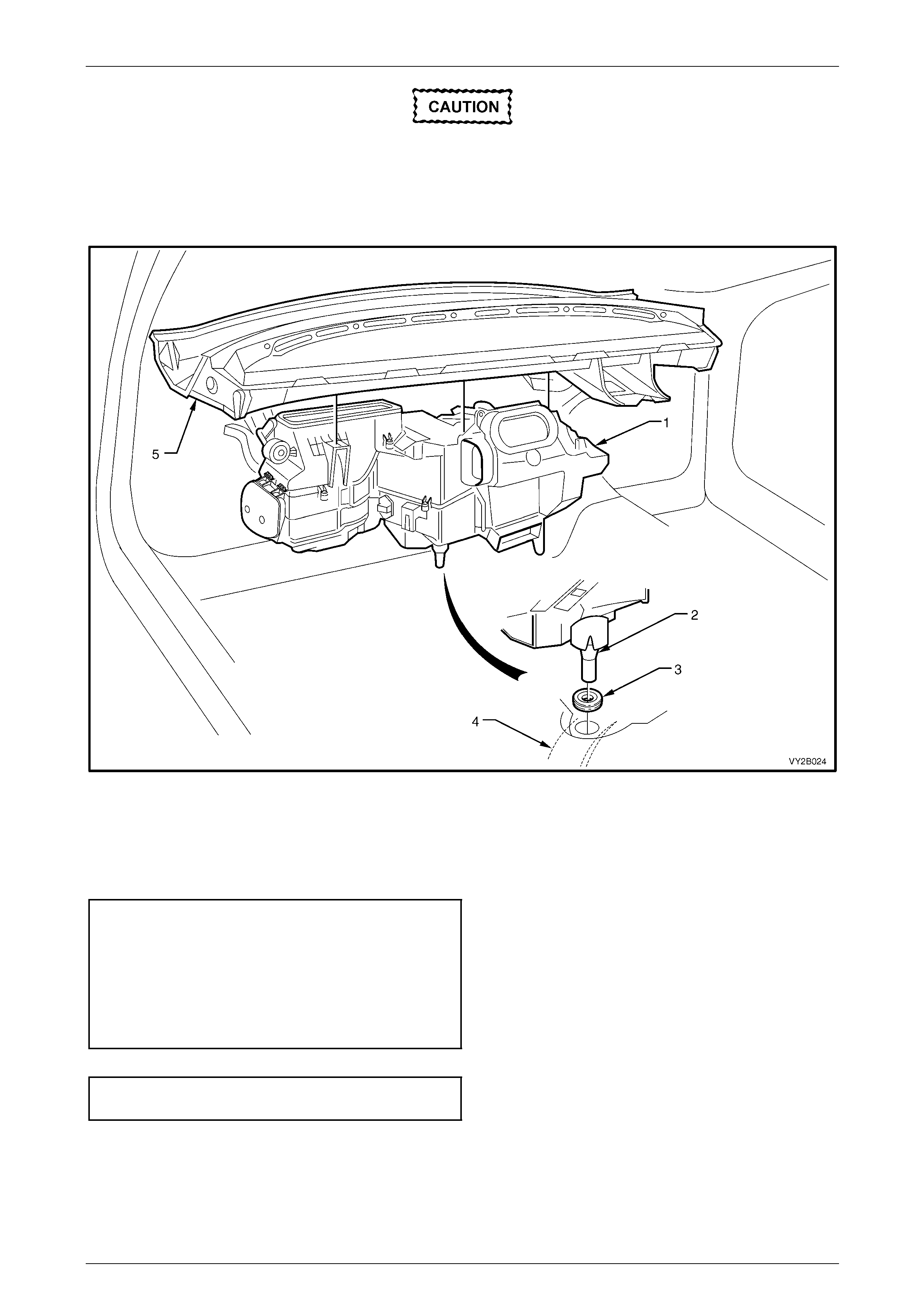
When removing the HVAC unit from the
vehicle take care not to strain the heater core
tubes and evaporator core tubes.
15 Remove the HVAC unit (1) from the vehicle by disengaging the drain tube (2) from the body grommet (3) installed
in the transmission tunnel (4), refer to Figure 2C – 18.
16 Carefully lift the HVAC unit away from the dash panel (5).
Figure 2C – 18
Reinstall
Reinstallation of the HVAC unit is the reverse of the removal procedure, noting the following:
1 Tighten the screws / stud attaching the HVAC unit to the correct torque specificati on, refer to Figure 2C – 17.
HVAC unit to lower radio bracket assembly
attaching screw torque specification...........3.0 – 8.0 Nm
HVAC unit to dash panel attaching
screw torque specification
(passenger compartment side) ...................3.0 – 8.0 Nm
HVAC unit to dash panel attaching
screw / stud torque specification
(engine compartment side) .......................6.0 – 14.0 Nm
2 Tighten the screws attaching the air d ucts to the correct torq ue specification, refer to Figure 2C – 15.
Side and console air duct attachi ng
screw torque specification...........................1.0 – 3.0 Nm
3 Fill the cooling system with the correct specification and quantity of coolant and pressure-test the system, refer to:
• Section 6B1 Engine Co oling – V6 Engine, or
• Section 6B3 Engine Cooling – GEN III V8.
4 Evacuate and charge the air-conditioning system with refrigerant,
refer to Section 2B HVAC Climate Control (Manual A/C) – Servicing and Diagnosis.

HVAC Climate Control (Manual A/C) – Removal and Installation Page 2C-18
Page 2C-18
3.2 Evaporator
LT Section No. — 08–150
Remove
1 Remove the HVAC unit, refer to 3.1 HVAC Unit.
2 On OCC (Auto A/C) units, disconnect the wiring
harness connector (1) from the evaporative
temperature sensor connector (2).
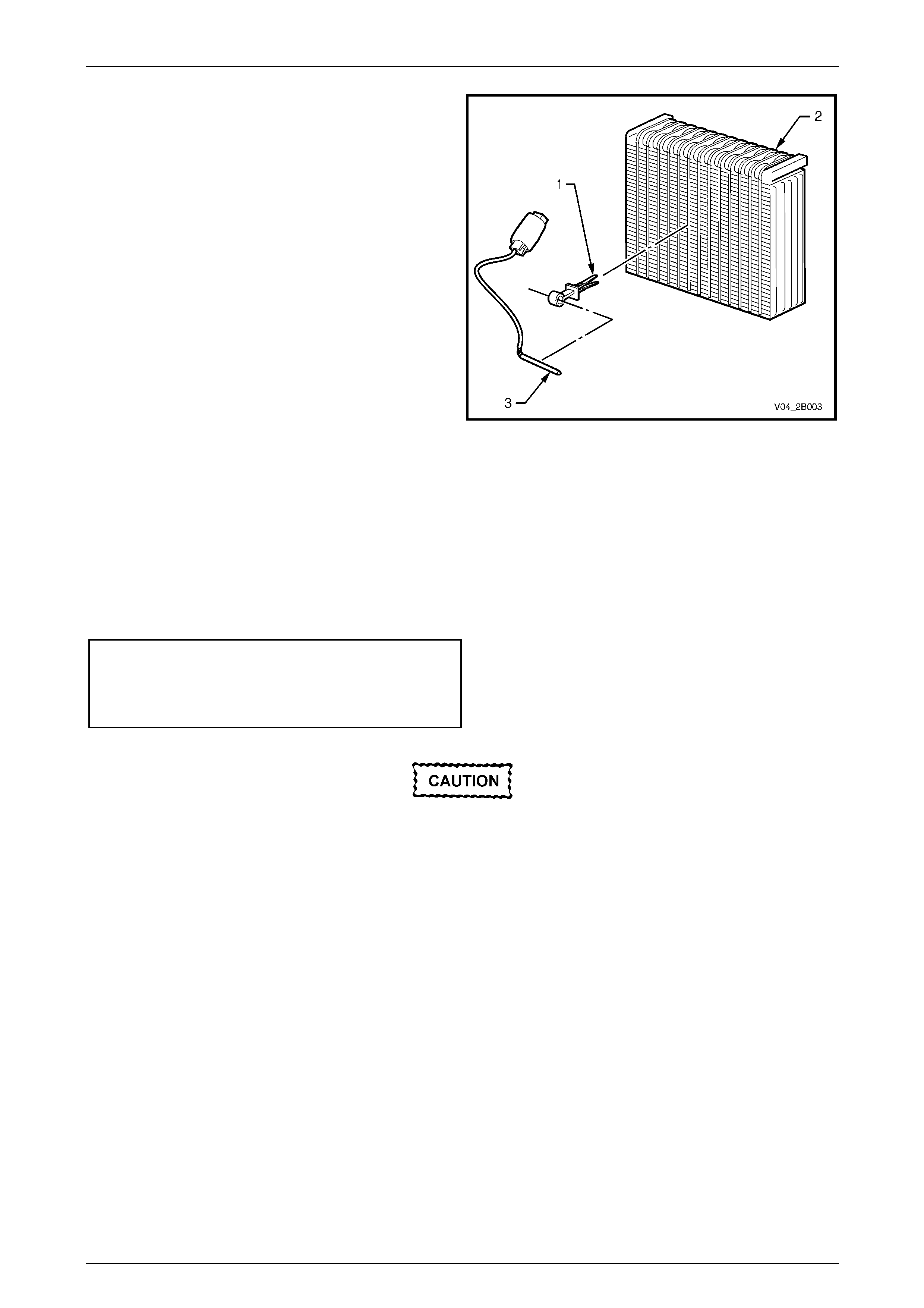
3 Remove the venturi pipe (3) from the evaporator
cover (4).
Figure 2C – 19
4 Remove the screw (1) and washer securing the air mix
door quadrant lever (2) to the evaporator cover (3) and
move the quadrant lever aside.
5 Remove the two screws (4) from the evaporator
cover (3), swing the cover open and remove it.
6 Carefully remove the evaporat or from its cavity in the
HVAC case.
NOTE
A foam insulator may also be removed with the
evaporator.
Figure 2C – 20
HVAC Climate Control (Manual A/C) – Removal and Installation Page 2C-19
Page 2C-19
7 If required, on OCC (Auto A/C) units, remove the
evaporator temperature sens or (3) by removing its
mounting clip (1) from the evaporator (2).
Figure 2C – 21
Reinstall
Reinstallation of the evaporator is the reverse of removal the procedur e, noting the following:
1 Ensure the foam insulator is correctly seated in the HVAC case.
2 If required, on OCC (Auto A/C) units, install the evaporator temperature sensor in the correct position on the
evaporator, refer to Section 2F HVAC Occupant Climate Control (Auto A/C) – Removal and Installation.
3 Tighten the attaching screws to the correct torque specification.
HVAC unit case attaching screw
torque specification.....................................1.0 – 3.0 Nm
Air mix door quadrant lever att achi ng
screw torque specification...........................1.0 – 3.0 Nm
The total quantity of lubricating oil in the air-
conditioning system must be maintained. If a
compressor, evaporator, condenser, filter
drier receiver, or air-conditioning line is
replaced, a specified quantity of lubricating
oil must be added to the system to
compensate for oil removed with the original
component. Refer to Section 2B HVAC
Climate Control (Manual A/C) – Servicing and
Diagnosis.
4 Evacuate and charge the system with refrige rant,
refer to Section 2B HVAC Climate Control (Manual A/C) – Servicing and Diagnosis.
HVAC Climate Control (Manual A/C) – Removal and Installation Page 2C-21
Page 2C-21
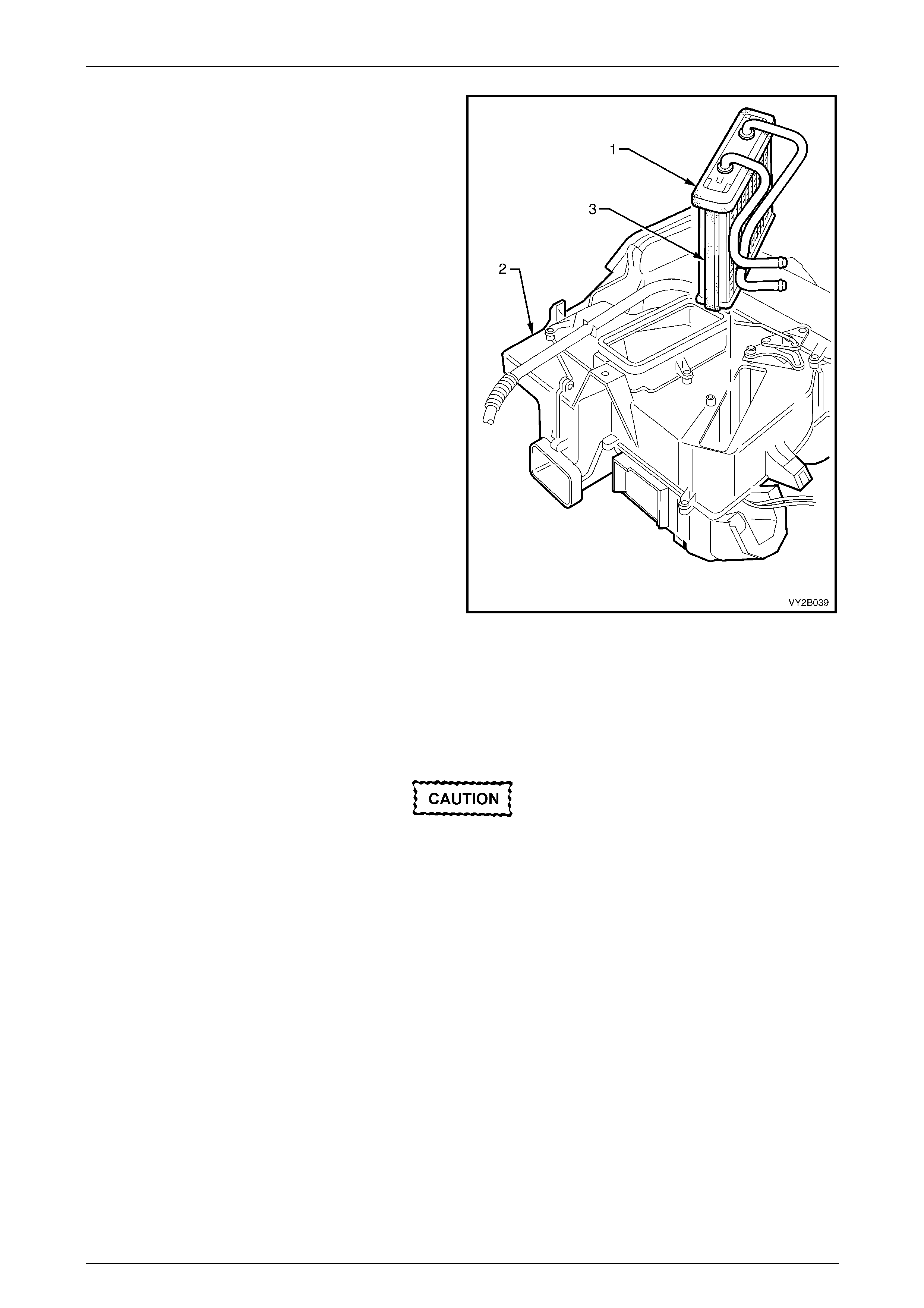
3 Remove the heater core (1) from the HVAC case (2)
without damaging the foam seal (3) located on top and
sides of the heater core.
Figure 2C – 23
Reinstall
Reinstallation of the heater c ore is the reverse of removal the procedure, noting the following:
1 Ensure the foam seals are not damaged when installing heater core to the HVAC unit case.
The total quantity of lubricating oil in the air-
conditioning system must be maintained. If a
compressor, evaporator, condenser, filter
drier receiver or air-conditioning line is to be
replaced, a specified quantity of lubricating
oil must be added to the system to
compensate for oil removed with the original
component. Refer to Section 2B HVAC
Climate Control (Manual A/C) – Servicing and
Diagnosis.
2 Evacuate and charge the system with refrige rant,
refer to Section 2B HVAC Climate Control (Manual A/C) – Servicing and Diagnosis.
HVAC Climate Control (Manual A/C) – Removal and Installation Page 2C-22
Page 2C-22
3.4 Blower Motor and Fan Assembly
LT Section No. — 08–150
Remove
1 Remove the left-hand instrument panel lower trim plate assembly,
refer to Section 1A3 Instrument Panel and Consol e.
2 If required, on OCC (Auto A/C) units, disconnect the wiring harness connector from the vacuum solenoid pack.
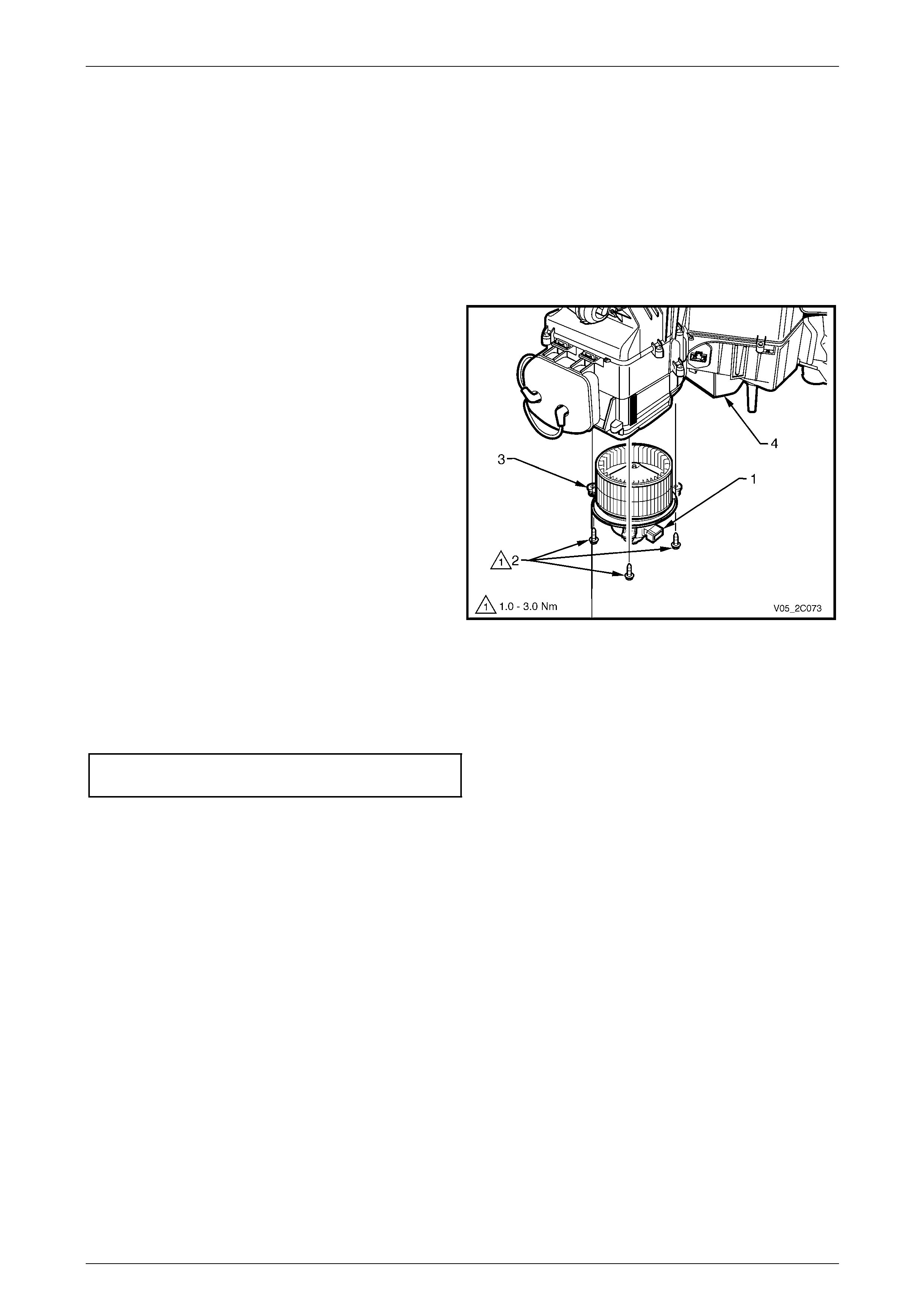
3 Disconnect the wiring harness connector from the
blower motor sub-harness connector (1)
4 Remove the three screws (2) attaching the blower
motor and fan assembly (3) to the HVAC unit (4) and
remove the assembly.
NOTE
The screw closer to the rear of the vehicle also
secures the fuse mounting bracket to the blower
motor and fan assembly mounting flange.
Figure 2C – 24
Reinstall
Reinstallation of the blower motor and fan assembly is the reverse of the removal procedure. Tighten the attaching
screws to the correct torque specification.
Blower motor and fan assembly
attaching screw torque specification...........1.0 – 3.0 Nm
HVAC Climate Control (Manual A/C) – Removal and Installation Page 2C-23
Page 2C-23
3.5 Electronic Blower Motor Controller
LT Section No. — 08–150
Remove
1 Remove the left-hand instrument panel lower trim plate assembly,
refer to Section 1A3 Instrument Panel and Consol e.
2 Remove the instrument panel compartment assembly, refer to Section 1A3 Instrument Panel and Console.
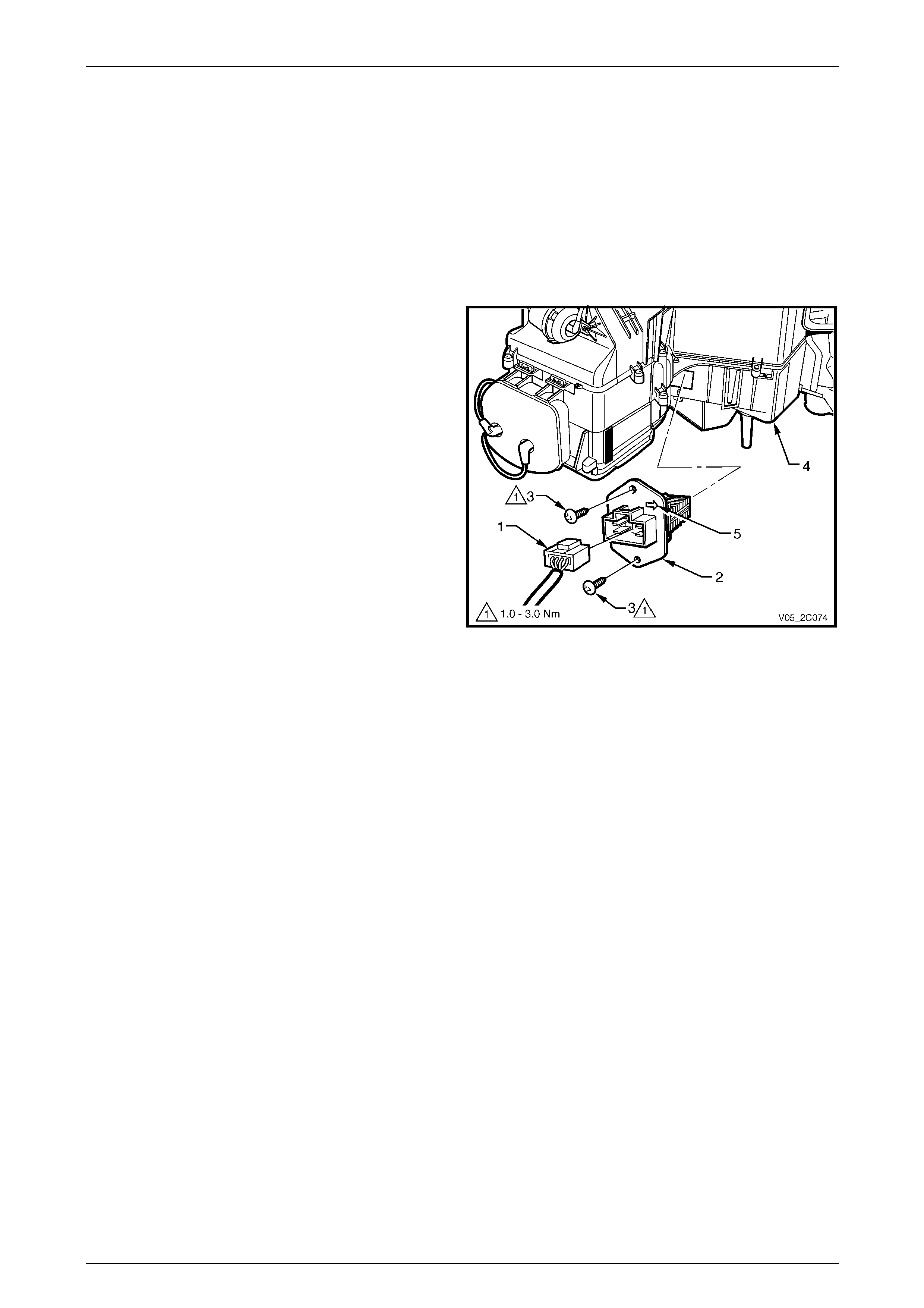
3 Remove the wiring harness connector (1) from the
electronic blower motor controller (2).
4 Remove the two screws (3) attaching the cont roller to
the side of the HVAC unit (4).
5 Remove the controller from the HVAC unit.
Figure 2C – 25
HVAC Climate Control (Manual A/C) – Removal and Installation Page 2C-24
Page 2C-24
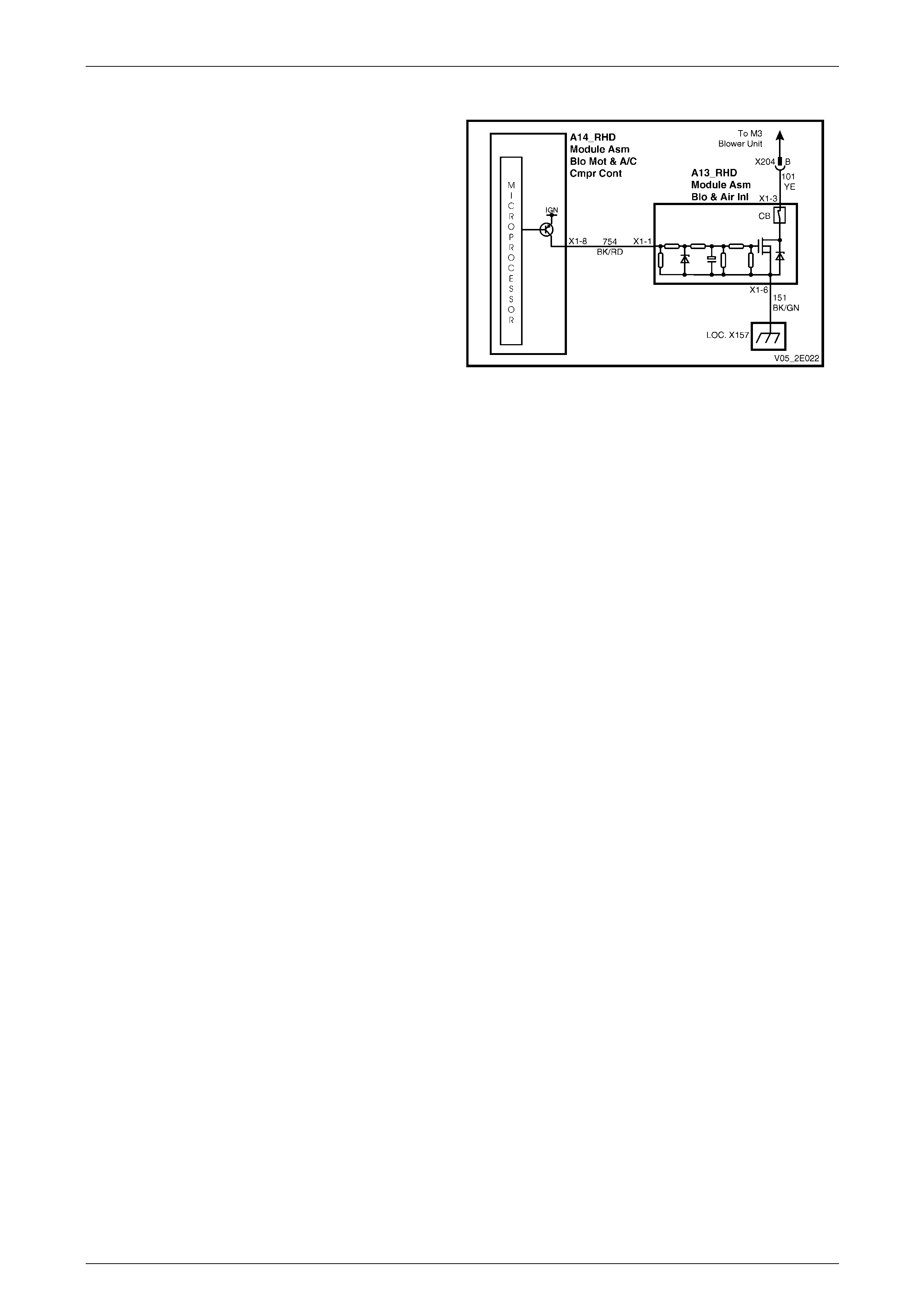
Test
The electronic blo wer motor controller (A13) provides a
ground circuit for the HVAC blower unit through its internal
power transistor circuitry.
Circuit 754 provides the control voltage to the module, which
determines the speed of the blower fan.
The blower speed controller incorporates an internal
resetable circuit breaker (CB). This circuit breaker is used to
prevent damage to the blower motor electrical circuit i n the
case of electrical current surges, blower motor lock up on
slower speeds or extreme temperature.
If any of the above situations occur in the blower motor
circuit, the controller’s internal resetable circuit breaker will
trip and render the blower motor ino perative. The internal
circuit breaker can then be reset by either of the two
following methods:
• After the ignition has been turned from the Off to the
On position.
• Manually moving the fan speed to position 4. All
blower functions will then return.
NOTE
If the blower motor switches off while driving and
resumes after the ignition has been turned back
on, do not replace the blower speed contro ller as
it has performed the function it was designed to
do. Check the blower motor and circuit for
voltage issues also ins pect the blower motor fan
for foreign material caught in the plastic impeller.
If the blower speed controller switches the
blower motor off at a frequ ency of (say) once per
month, inspect the blower motor fan’s plastic
impeller for foreign material (e.g. leaves, paper,
etc). If no foreign material is present, replace the
blower motor.
Figure 2C – 26

HVAC Climate Control (Manual A/C) – Removal and Installation Page 2C-25
Page 2C-25
The use of an ohmmeter can be very limit ed when testing
the blower motor module, except for a transistor short circui t
occurrence between terminals X1-3 and X1-6.
Connector Details
Pin Number Function
X1-1 Fan Speed Cont
X1-2 No Connection
X1-3 Blower Motor
X1-4 No Connection
X1-5 No Connection
X1-6 Ground
Two possible fault conditions associated with this controller
are provided in the following tables to assist the technician
in identifying faults.
Figure 2C – 27
Test 1
The blower fan runs continuously at maximum speed when the ignition switch is turned on.
Step Action Yes No
1 1 Turn ignition switch off.
2 Remove wiring connector from the OCC control module.
3 Turn ignition switch on.
Does the fan continue to run?
Replace the
electronic blower
motor controller
Repair circuit 754 or
test the OCC control
module

HVAC Climate Control (Manual A/C) – Removal and Installation Page 2C-26
Page 2C-26
Test 2
The blower fails to operate.
Step Action Yes No
1 Inspect the applicable OCC system fuses, refer to Section 12O Fuses,
Relays and Wiring Harnesses.
Are the fuses serviceable? Go to Step 2 Replace as required
2 1 Turn the ignition switch off.
2 Place a temporary test lead (capa ble of handling 30 amps)
between the electronic blower motor controller connector
A13 – X1 pin 3 and a known ground.
3 Turn on the ignition.
Does the fan speed operate at maximum sp eed? Go to Step 3 Repair circuit 101
3 Using a multimeter set to measure resistance, test for continuity
between the electronic blower motor controller connector A13 – X1
pin 6 and a known ground.
Does the multimeter indicate continuity? Go to Step 4 Repair circuit 151
4 1 Using a multimeter set to measure voltage, test for voltage at
electronic blower motor controller connector A13 – X1 pin 1.
2 Vary the blower fan speed using either the soft keys on Tech 2
or the fan speed button on the OCC control modu le.
Does the voltage increase as the fan speed indication increases? System OK
Repair circuit 754 or
test the OCC control
module
Reinstall
Reinstallation of the electronic blower motor controller is the reverse of the removal procedure, noting the following:
1 Install the controller with the arro w (5) pointing towards the rear of the vehicle, refer to Figure 2C – 25.
2 Tighten the attaching screws to the correct torque specification.
Electronic blower motor controller
attaching screw torque specification...........1.0 – 3.0 Nm

HVAC Climate Control (Manual A/C) – Removal and Installation Page 2C-27
Page 2C-27
3.6 Intake Blower Duct
LT Section No. — 08–150
Remove
1 Remove the HVAC unit, refer to 3.1 HVAC Unit.
2 Either disconnect the vacuum line (1) from the vacuum
actuator (2), or remove the vacuum actuator, refer to
4.3 Vacuum Actuators.
3 Remove the five screws (3) attaching the intake
blower duct (4) to the HVAC case and remove the
duct.
Figure 2C – 28
Reinstall
Reinstallation of the intake blower duct is the reverse of the removal procedure, noting the foll owing:
1 Ensure the duct is correctly seated on the HVAC case.
2 Tighten the screws to the correct torque specification.
Intake blower duct attaching
screw torque specification...........................1.0 – 3.0 Nm
HVAC Climate Control (Manual A/C) – Removal and Installation Page 2C-28
Page 2C-28
3.7 Vent Distribution Housing
LT Section No. — 08–150
Remove
1 Remove the HVAC unit, refer to 3.1 HVAC Unit.
2 On OCC (Auto A/C) units, remove the aspirator tube,
refer to Section 2F HVAC Occupant Climate Control (Auto A/C) – Removal and Installation.
3 As required, remove the wiring harness from the HVAC case.
4 Either disconnect the face actuator pushrod and vacuum lines, or remove the actuator,
refer to 4.3 Vacuum Actuators.
5 Carefully cut the driver side inner duct outl et foam
seal (1) on a 45° angle at the join of the vent
distribution housing (2) to the HVAC case, two places.
6 Remove the nine screws (1) attaching the v ent
distribution housing to the HVAC case and remove the
housing.
Figure 2C – 29
Reinstall
Reinstallation of the vent distribution housing is the revers e of the remov al procedure, noting the following:
1 Ensure the housing is correctly seated on the HVAC case.
2 Tighten the screws to the correct torque specification.
Vent distribution housing attaching
screw torque specification...........................1.0 – 3.0 Nm

HVAC Climate Control (Manual A/C) – Removal and Installation Page 2C-29
Page 2C-29
4 Vacuum System
4.1 Vacuum Retention Tests
LT Section No. — 08–150
To operate efficiently, the HVAC system requires a constant vacuum source and all vacuum components must have no
vacuum leaks. Vacuum is supplied by the en gin e induction system and is retained within t he HVAC system by the action
of the one-way check valve located in the engine compartment.
A vacuum reserve is stored within the vacuum tank located on the left-hand side of the HVAC unit. Any of the following
components may cause or contribute to a vacuum leak within the HVAC system:
• check valve,
• vacuum tank,
• vacuum mode valve – manual A/C,
• water valve vacuum switch – manual A/C,
• vacuum solenoid pack – auto A/C,
• vacuum actuators,
• water valve actuator, and
• vacuum lines.
Symptoms of a vacuum leak may be as follows:
• constant coolant flow through the heater core,
• air always directed to the windscreen,
• air directed to ventilation outlets that are not selected,
• dust and/or smog ingress into the cabin despite the selection of the recirculation mode, or
• constant hissing noise emanating from a leaking or disconnected vacuum hose or com ponent.
HVAC Climate Control (Manual A/C) – Removal and Installation Page 2C-30
Page 2C-30
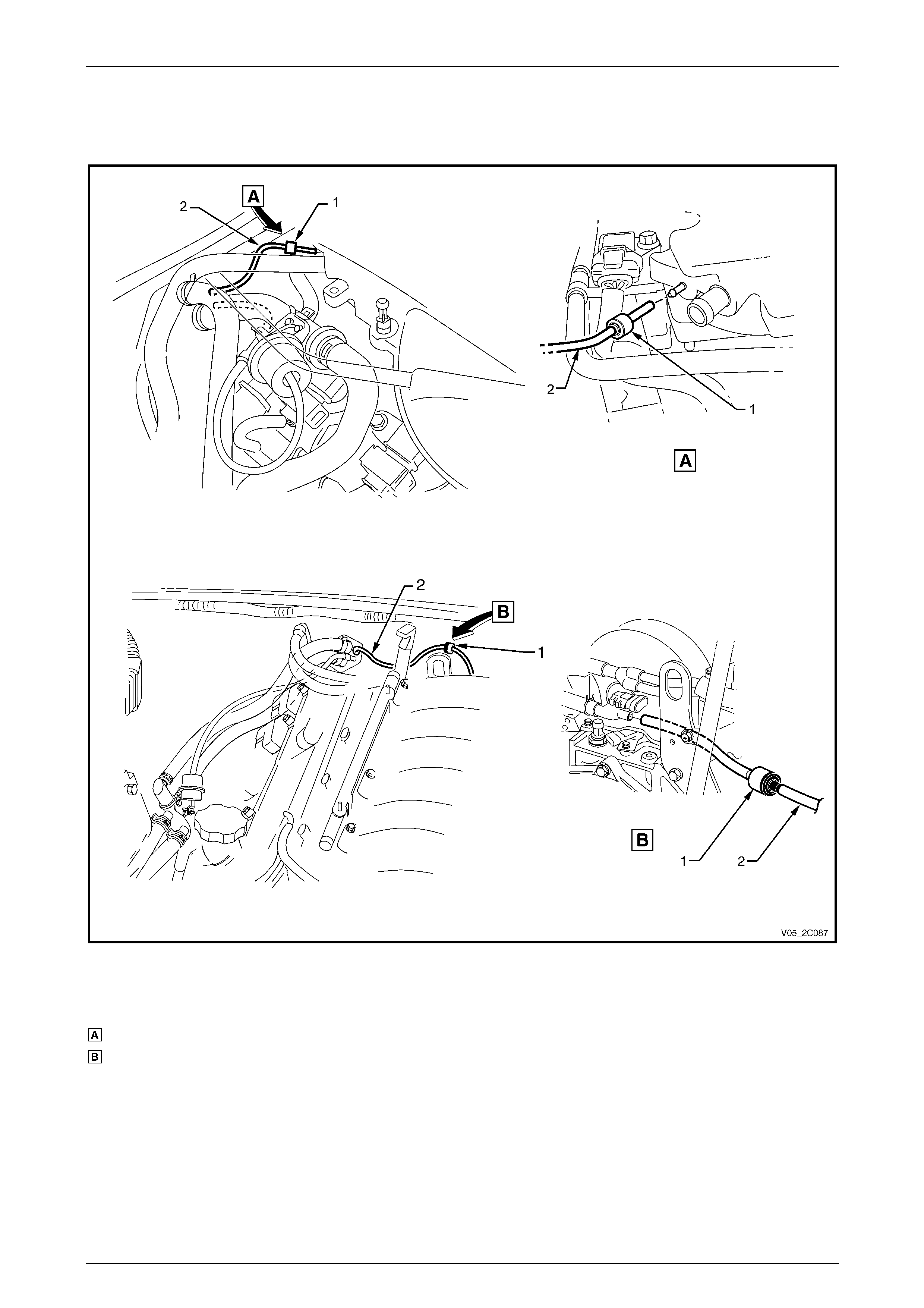
Check Valve
1 Locate the check valve (1) at the rear of the engine a nd disconnect the vacuum line sup pl y line (2) from the check
valve, refer to Figure 2C – 30.
Figure 2C – 30
Legend
V6 Engine
GEN III V8 Engine
1 Check Valve
2 Vacuum Line Supply Line
HVAC Climate Control (Manual A/C) – Removal and Installation Page 2C-31
Page 2C-31
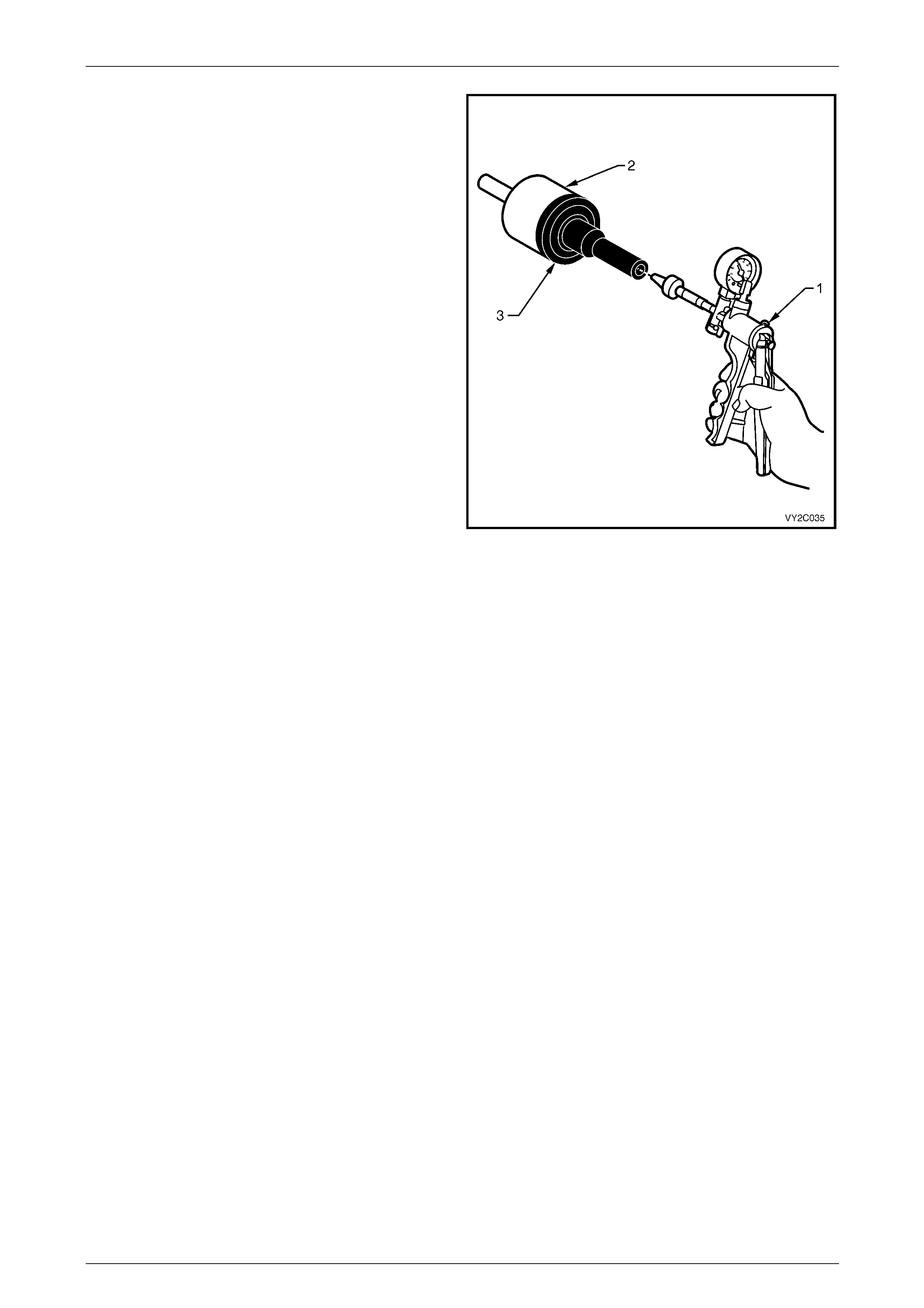
2 Connect a vacuum pump (1) to the check valve (2) at
the port of the valve black section (3).
3 Using the vacuum pump, create a vacuum and
observe the vacuum pump gauge needle:
• If the needle remains steady it indicates the
check valve is retaining vacuum.
• If the vacuum reading decreases, it indicate s a
leak in the check valve.
4 If a vacuum leak is indicated, replace the che ck valve.
5 Check the vacuum supply lines connected to the
check valve, replace if require d.
Figure 2C – 31
HVAC Climate Control (Manual A/C) – Removal and Installation Page 2C-32
Page 2C-32
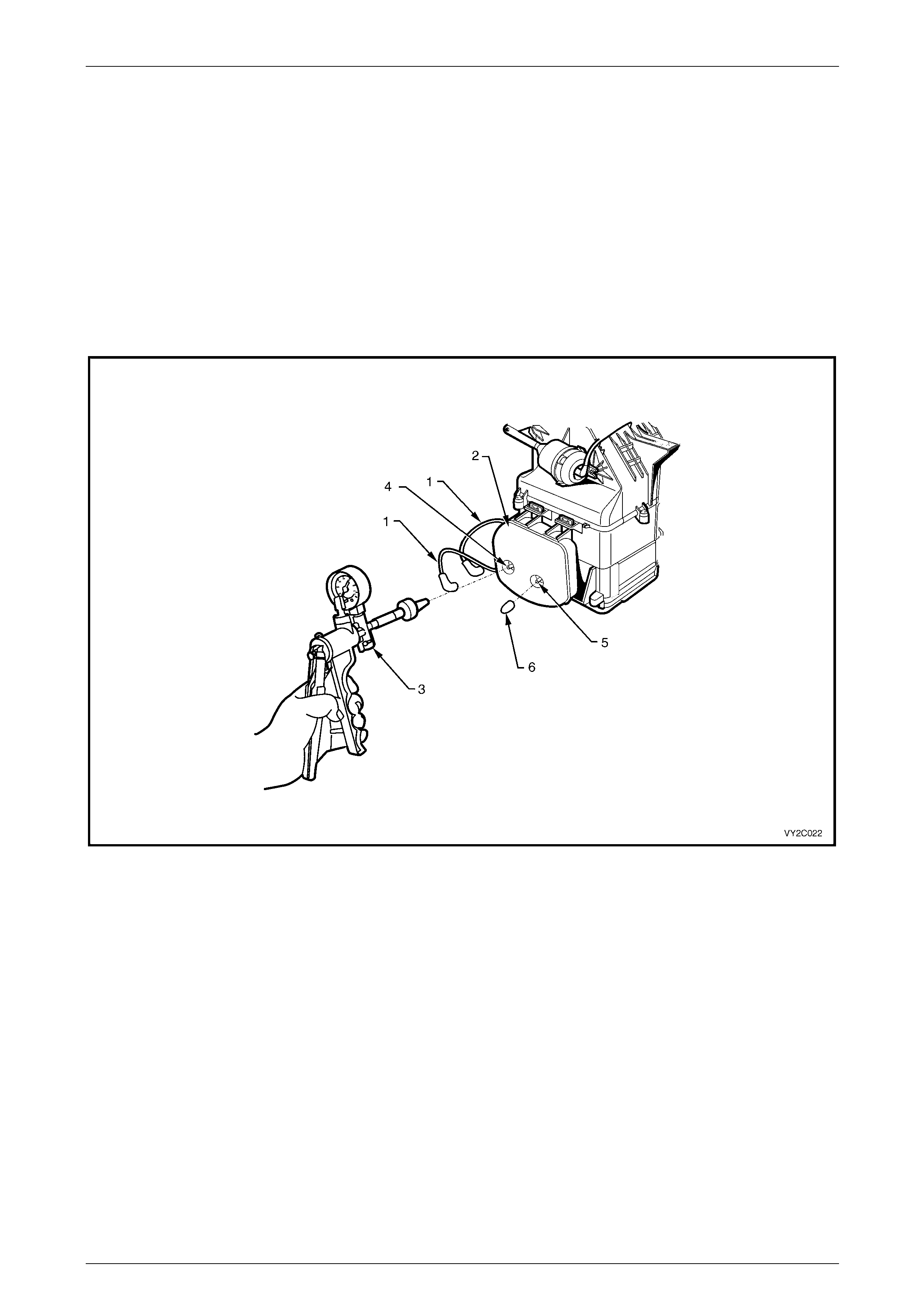
Vacuum Tank
1 Gain access to vacuum tank, refer to 4.2 Vacuum Tank.
2 Disconnect both vacuum lines (1) from the vacuum tank (2), refer to Figure 2C – 32.
3 Connect a vacuum pump (3) to the tank vacuum supply port (4) and cover the vacuum feed port (5) with a plug (6)
or finger.
4 Using the vacuum pump, create a vacuum and obs erve the vacuum pump gauge needle:
• If the needle remains steady it indicates the tank is retaining vacuum.
• If the vacuum reading decreases, it indicate s a leak in the tank.
5 If a vacuum leak is indicated, replace the vacuum tank, refer to 4.2 Vacuum Tank.
Figure 2C – 32
HVAC Climate Control (Manual A/C) – Removal and Installation Page 2C-33
Page 2C-33
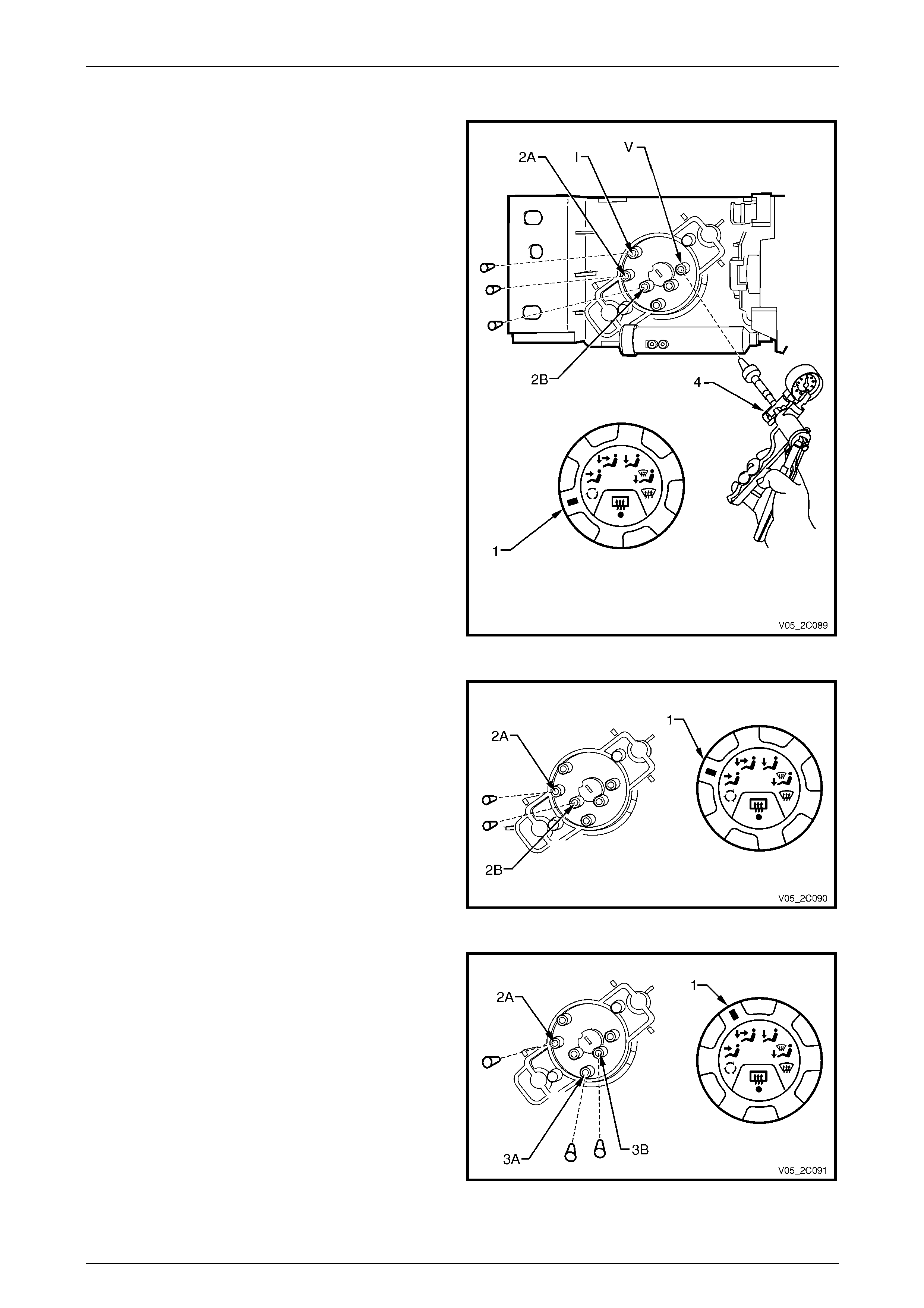
Vacuum Mode Valve – Manual A/C
1 Remove the HVAC manual controller, refer to
2.1 Manual Controller Assembl y.
2 Set the vacuum control switch (1) to recirculation
mode.
3 Plug the following ports on the vacuum mod e valve:
• intake (I)
• face 1 (2B)
• face 2 (2A)
4 Connect a vacuum pump (4) to the vacuum supply
port (V) of the vacuum mode valve. Create a vacuum
and observe the pump needle:
• If the needle remains steady, it indicates the
vacuum mode valve retains vacuum i n this
position.
• If the vacuum reading decreases quickly, it
indicates a leak in the vacuum mode valve.
5 Remove the plugs from the ports as required. If a
vacuum leak is indicated, replace the vacuum mode
valve, refer to 2.5 Mode Switch Vacuum Valve.
Figure 2C – 33
6 Set the vacuum control switch (1) to face mode.
7 Plug the following ports on the vacuum mode valve:
• face 1 (2B)
• face 2 (2A).
8 Perform the face mode vacuum test as described in
steps 4 and 5.
Figure 2C – 34
9 Set the vacuum control switch (1) to bi-level mode.
10 Plug the following ports on the vacuum mode valve:
• face 2 (2A)
• foot 1 (3B)
• foot 2 (3A).
11 Perform the bi-level mode vacuum test as de scribed in
steps 4 and 5.
Figure 2C – 35
HVAC Climate Control (Manual A/C) – Removal and Installation Page 2C-34
Page 2C-34
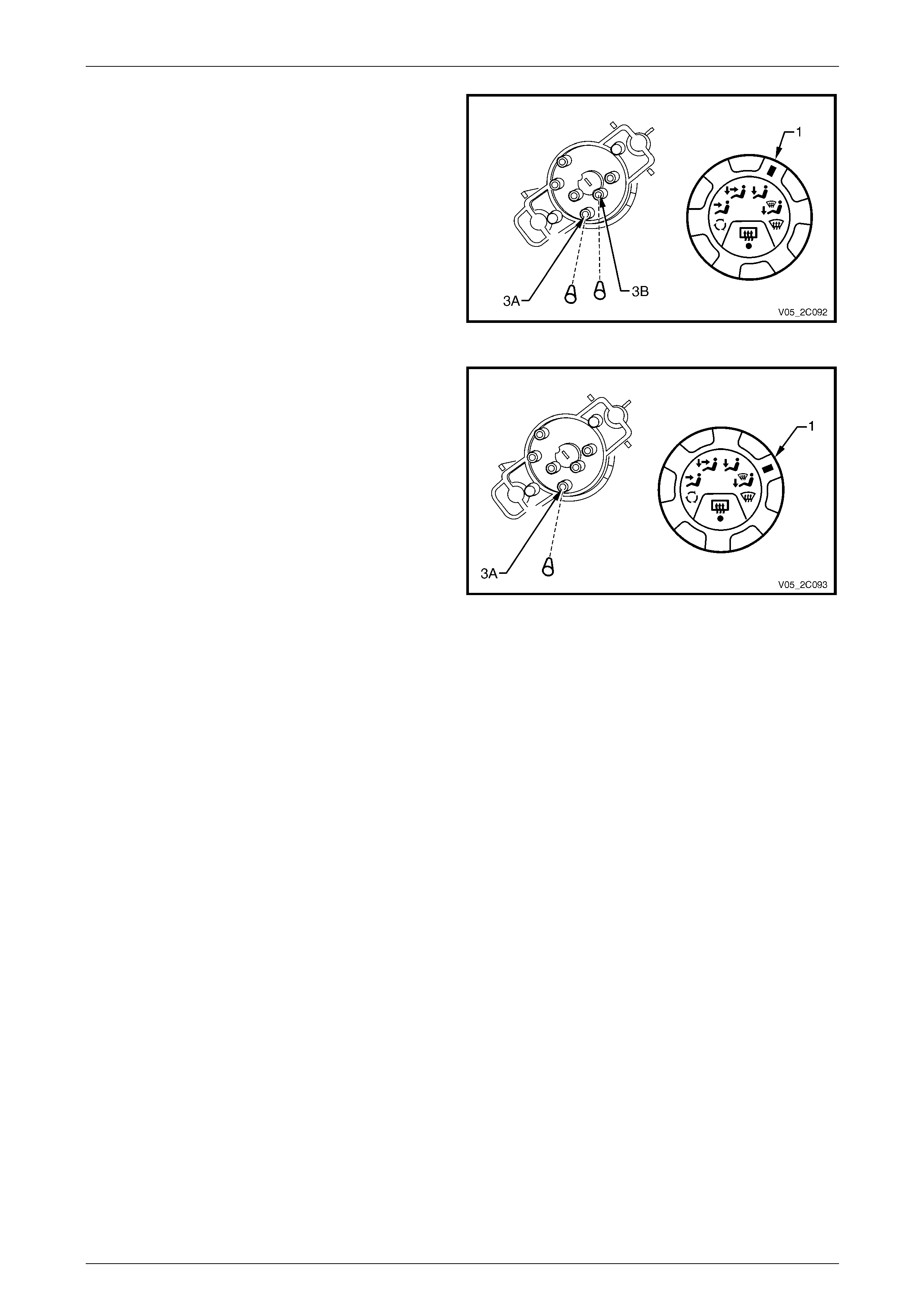
12 Set the vacuum control switch (1) to floor mode.
13 Plug the following ports on the vacuum mode valve:
• foot 1 (3B)
• foot 2 (3A).
14 Perform the floor mode vacuum test as described in
steps 4 and 5.
Figure 2C – 36
15 Set the vacuum control switch (1) to blend mode.
16 Plug the foot 2 (3A) port on the vacuum mode valve.
17 Perform the blend mode vacuum test as describe d in
steps 4 and 5.
18 Reinstall the HVAC manual c ontroller, refer to
2.1 Manual Controller Assembl y.
Figure 2C – 37
HVAC Climate Control (Manual A/C) – Removal and Installation Page 2C-35
Page 2C-35
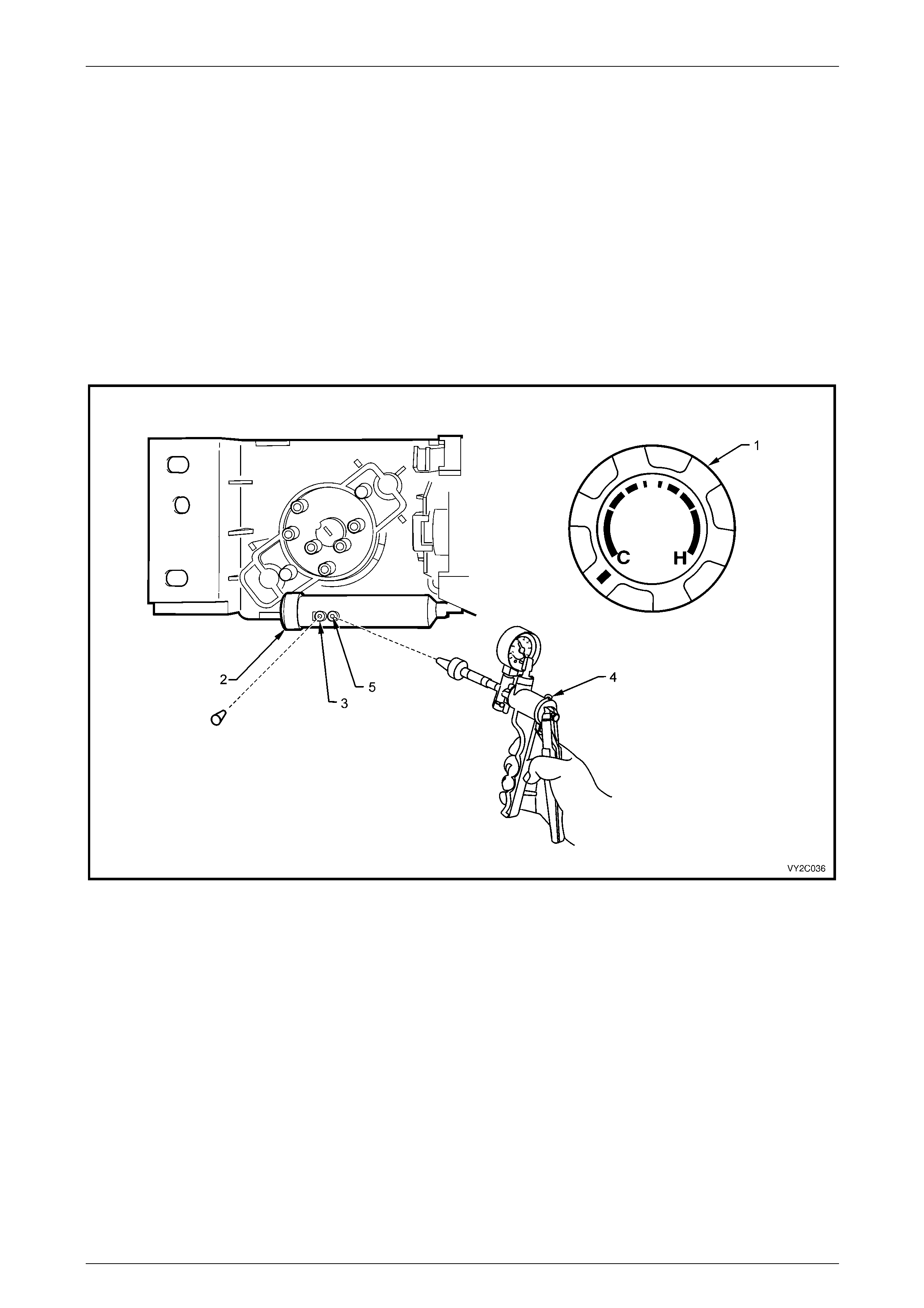
Water Valve Vacuum Switch – Manual A/C
1 Remove the HVAC manual control ler, refer to 2.1 Manual Controller Assembly.
2 Set the temperature control switch (1) to the full cold position, refer to Figure 2C – 38.
3 On the water valve vacuum switch (2), block the water valve port (3) with a suitable p lug.
4 Connect a vacuum pump (4) to the vacuum supply port (5) of the water valve vacuum switch. Create a vacuum and
observe the pump needle:
• If the needle remains steady, it indicates the water valve vacuum switch retains vacuum.
• If the vacuum reading decreases quickly, it indicates a leak in the water valve vacuum switch.
5 If a vacuum leak is indicated, replace the water valve vacuum switch, refer to 2.2 Water Valve Vacuum Switch.
6 Reinstall the HVAC manual c ontroller, refer to 2.1 Manual Controller Assembly.
Figure 2C – 38
HVAC Climate Control (Manual A/C) – Removal and Installation Page 2C-36
Page 2C-36
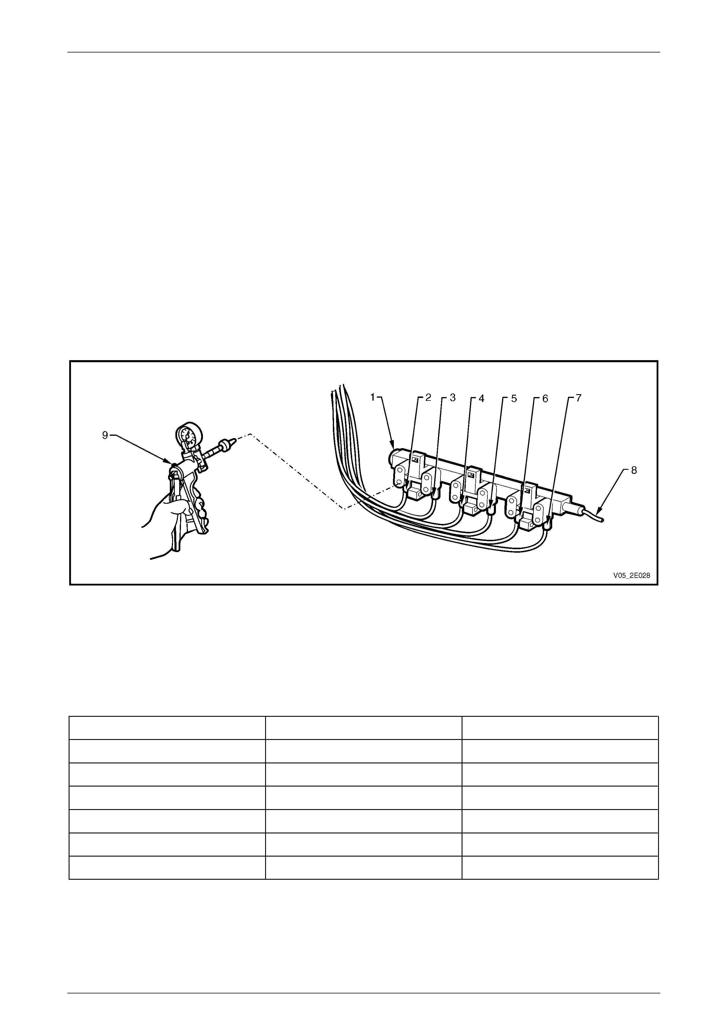
Vacuum Solenoid Pack – Auto A/C
1 Remove the vacuum solenoid pack,
refer to Section 2F HVAC Occupant Climate Control (Auto A/C) – Removal and Installation.
2 Connect a vacuum pump (1) to the vacuum supply
port (2) of solenoid (3) and plug the actuator port (4)
below it.
3 Using the vacuum pump, create a vacuum and
observe the vacuum pump gauge needle:
• If the needle remains steady it indicates the
solenoid is retaining vacuum.
• If the vacuum reading decreases, it indicate s a
leak in that solenoid.
4 Repeat steps 2 and 3 for each remaini ng solenoid.
5 If a vacuum leak is indicated, replace the vacuum
solenoid pack, refer to
Section 2F HVAC Occupant Climate Control (Auto
A/C) – Removal and Installation.
Figure 2C – 39
If the problem is isolated to one mode and the solenoid
does not show any signs of leakage, check the relevant
vacuum circuit in Vacuum Lines in this Section.
The function of the solenoid connections and the colour of
the attached vacuum lines are listed below:
Legend
1 Fresh/Recirculation (Blue)
2 Face 1 (White)
3 Face 2 (Green)
4 Foot 1 (Pink)
5 Foot 2 (Orange)
6 Water valve (Yellow)
7 Vacuum supply (Black)
Figure 2C – 40
HVAC Climate Control (Manual A/C) – Removal and Installation Page 2C-37
Page 2C-37
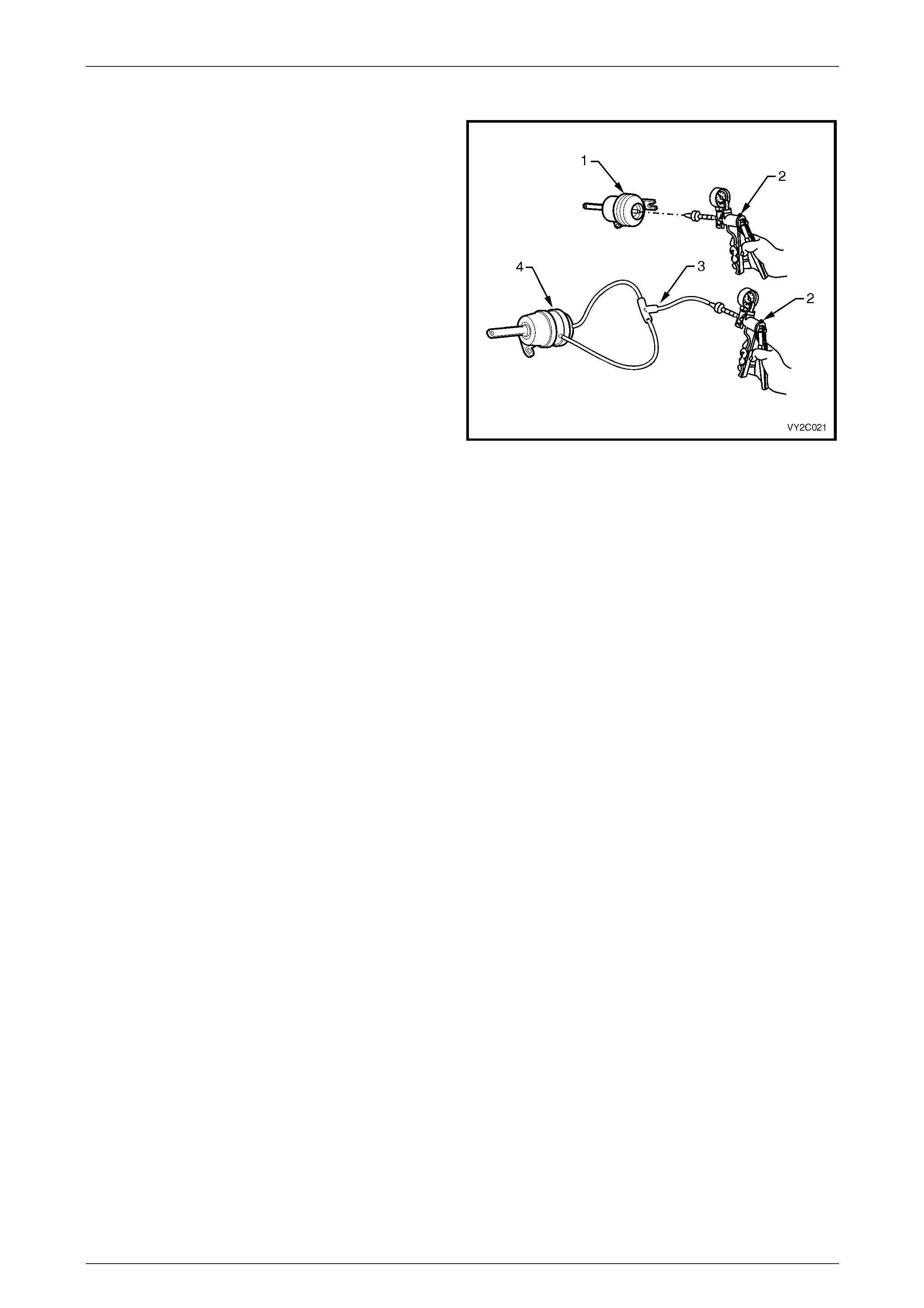
Vacuum Actuators
1 Remove the vacuum actuator, refer to
4.3 Vacuum Actuators.
2 For a single stage intake vacuum actuator (1), connect
the vacuum pump (2) to the rear port of the actuator.
For a two stage face or foot vacuum actuator (4),
connect the vacuum pump to the rear and si de ports
with a vacuum tee piece (3).
3 Using the vacuum pump, create a vacuum and
observe the vacuum pump gauge needle:
• If the needle remains steady it indicates the
actuator is retaining vacuum.
• If the vacuum reading decreases, it indicate s a
leak in the actuator.
4 If a vacuum leak is indicated, replace the vacuum
actuator, refer to 4.3 Vacuum Actuators.
Figure 2C – 41
HVAC Climate Control (Manual A/C) – Removal and Installation Page 2C-38
Page 2C-38
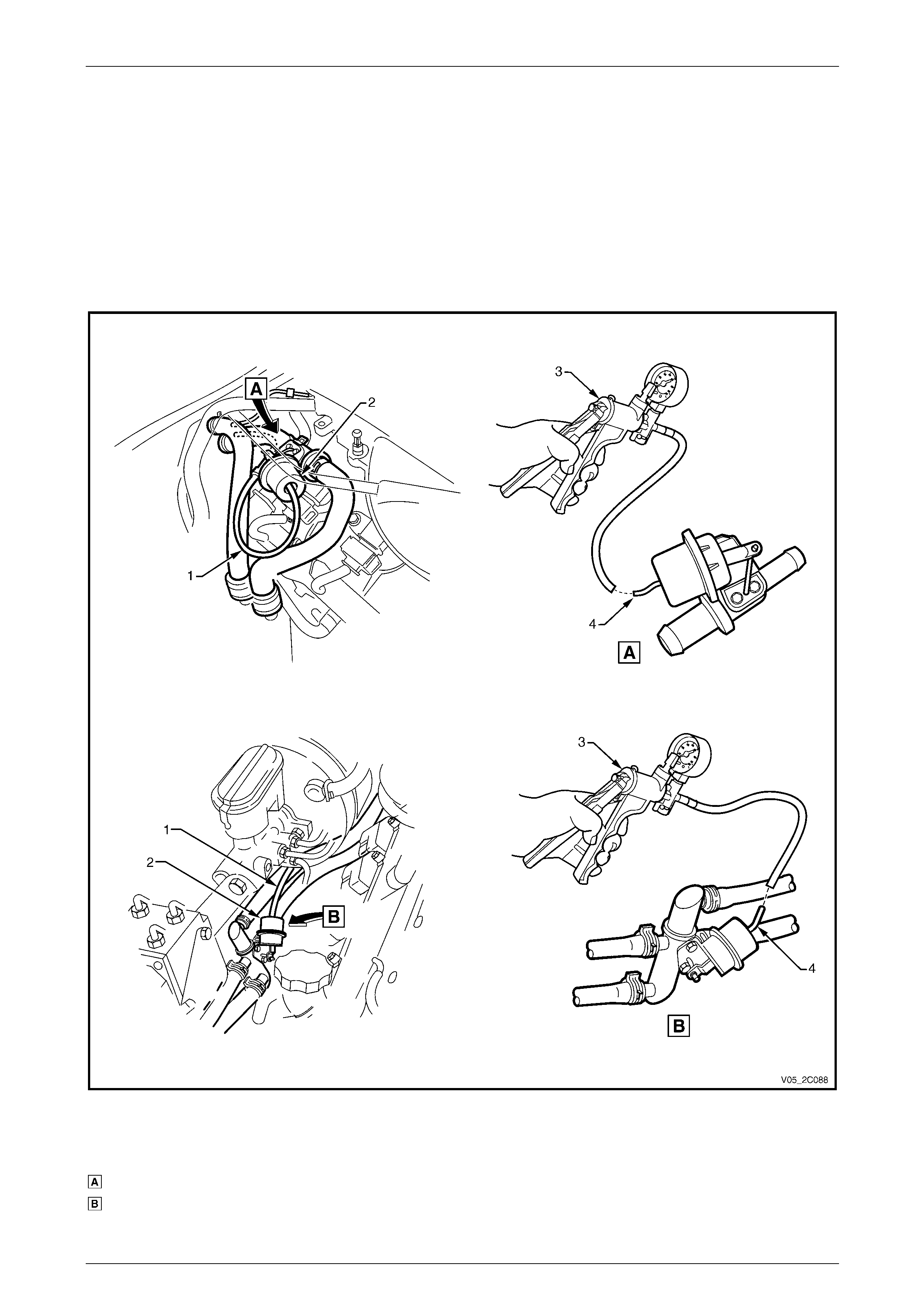
Water Valve Actuator
1 Disconnect the vacuum supply line (1) from the water valve actuator (2), refer to Figure 2C – 42.
2 Connect a vacuum pump (3) to the actuator vacuum port (4).
3 Using the vacuum pump, create a vacuum and obs erve the vacuum pump gauge needle:
• If the needle remains steady it indicates the actuator is retaining vacu um.
• If the vacuum reading decreases, it indicates a leak in the actuator.
4 If a vacuum leak is indicated, replace the water valve assembly, refer to 9.1 Water Valve Assembly.
Figure 2C – 42
Legend
V6 Engine
GEN III V8 Engine
1 Vacuum Supply Line
2 Water Valve Actuator 3 Vacuum Pump
4 Actuator Vacuum Port
HVAC Climate Control (Manual A/C) – Removal and Installation Page 2C-39
Page 2C-39
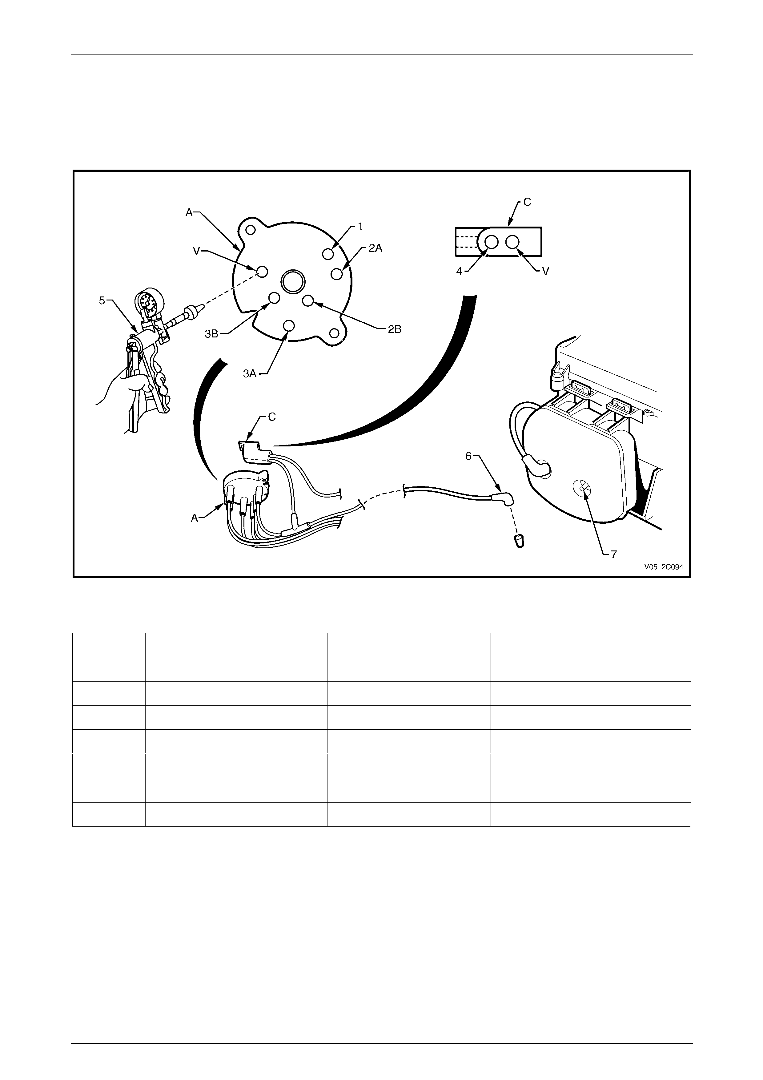
Vacuum Lines – Manual A/C
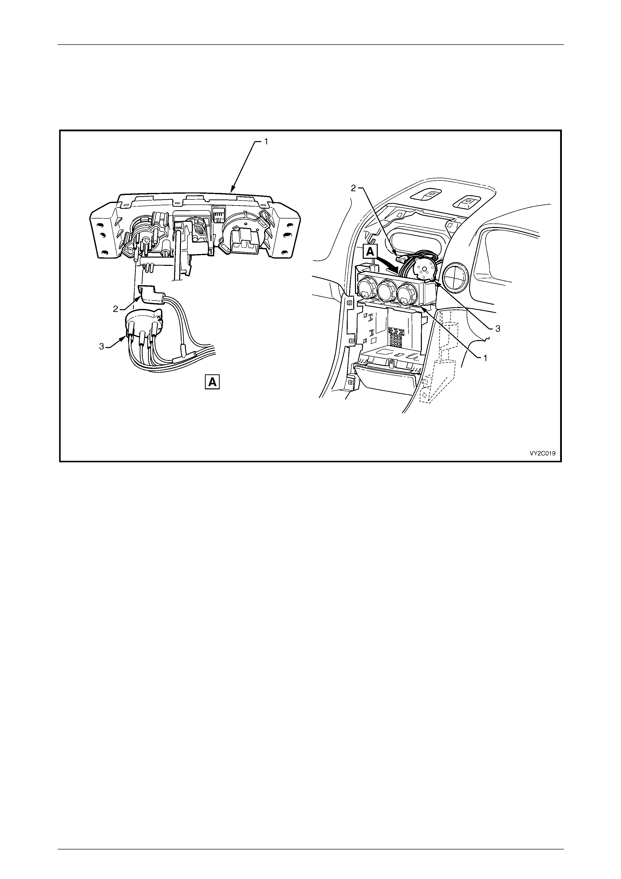
1 Remove the instrument panel centre fascia, refer to Section 1A3 Instrument Panel and Console.
2 From the back of the HVAC controller (1), remove the water valve vacuum switch valve connector (2) and the mode
valve plastic manifold (3), refer to Figure 2C – 43.
Figure 2C – 43
3 Connect a vacuum pump (5) to the appropriate port of the plastic vacuum manifold (A), refer to Figure 2C – 44 and
the associated table, for the follo wing:
• intake line – port (1),
• face 2 line – port (2A),
• face 1 line – port (2B),
• foot 2 line – port (3A), and
• foot 1 line – port (3B).
4 Using the vacuum pump, create a vacuum and obs erve the vacuum pump gauge needle:
• If the needle remains steady it indicates the vacuum circuit is retaining vacuum.
• If the vacuum reading decreases, it indicates a vacuum leak in that vacuum circuit.
5 If a vacuum leak is indicated check the vac uu m tubing for da mage or loose connection to the plastic vacuum
manifold and/or the associated vacuum actuator. If there is no damage or loose conn ection, perform a vacuum test
on the connecting vacuum actuator, refer to Vacuum Actuators in this Section.
6 Test the vacuum supply lines of the plastic vacuum manifold (A) as follo ws:
a Remove the connector (6) of the vacuum mode valv e supply line from the vacuum tank port (7) and plug the
connector.
b Plug the port (V) of the water valve vacuum switch connector (C).
c Connect the vacuum pump to the port (V) of the plastic vacuum manifold and repeat Step 4.
d If a vacuum leak is indicated check the vac uu m tubing for da mage or loose connection to the plastic vacuum
manifold.
HVAC Climate Control (Manual A/C) – Removal and Installation Page 2C-40
Page 2C-40
7 Test the water valve line and actuator as follows:
a Connect the vacuum pump to the port (4) of the vacuum s witch connector (C) and repeat Step 4.
b If a vacuum leak is indicated check the vac uu m tubing for damage or loose connection to the water valve
actuator. If there is no damage or loose connection, perform a vacuum test on the water valve actuator, refer
to Water Valve Actuator in this Section.
Figure 2C – 44
Port Actuator Vacuum line colour Function when vacuum applied
V — Black Vacuum Supply
1 Intake Blue Recirculation
2A Face 2 Green Bi-level
2B Face 1 White Face / Recirculation
3A Foot 2 Orange Blend
3B Foot 1 Pink Foot / Bi-level
4 Water valve Yellow Full cold
HVAC Climate Control (Manual A/C) – Removal and Installation Page 2C-41
Page 2C-41
Vacuum Lines – Auto A/C
Vacuum Actuator Lines
1 Remove the left-hand instrument panel lower trim plate assembly,
refer to Section 1A3 Instrument Panel and Consol e.
2 Remove the plastic manifold from the vacuum solenoid pac k. If required,
refer to Section 2F HVAC Occupant Climate Control (Auto A/C) – Removal and Installation.
3 Connect a vacuum pump (9) to the appropriate port of the vacuum manifold (1), refer to Figure 2C – 45 and the
associated table.
4 Using the vacuum pump, create a vacuum and obs erve the vacuum pump gauge needle:
• If the needle remains steady it indicates that vacuum circuit is retain ing vacuum.
• If the vacuum reading decreases, it indicate s a vacuum leak in that vacuum circuit.
5 If a vacuum leak is indicated check the vac uu m tubing for damage or loose connection to the man ifold and/or
vacuum actuator. If there is no damage or loose connection, perform a vacuum test on the connectin g vacuum
actuator.
Figure 2C – 45
Legend
1 Plastic Vacuum Manifold
2 Water Valve (Yellow)
3 Foot 2 (Orange)
4 Foot 1 (Pink)
5 Face 2 (Green)
6 Face 1 (White)
7 Fresh / Recirculation (Blue)
8 Vacuum Supply (Black)
9 Vacuum Pump
Actuator Vacuum line colour Function When Vacuum Applied
Intake Blue Recirculation
Face 1 White Bi-level
Face 2 Green Face
Foot 1 Pink Blend
Foot 2 Orange Foot / Bi-level
Water valve Yellow Full cold
HVAC Climate Control (Manual A/C) – Removal and Installation Page 2C-42
Page 2C-42
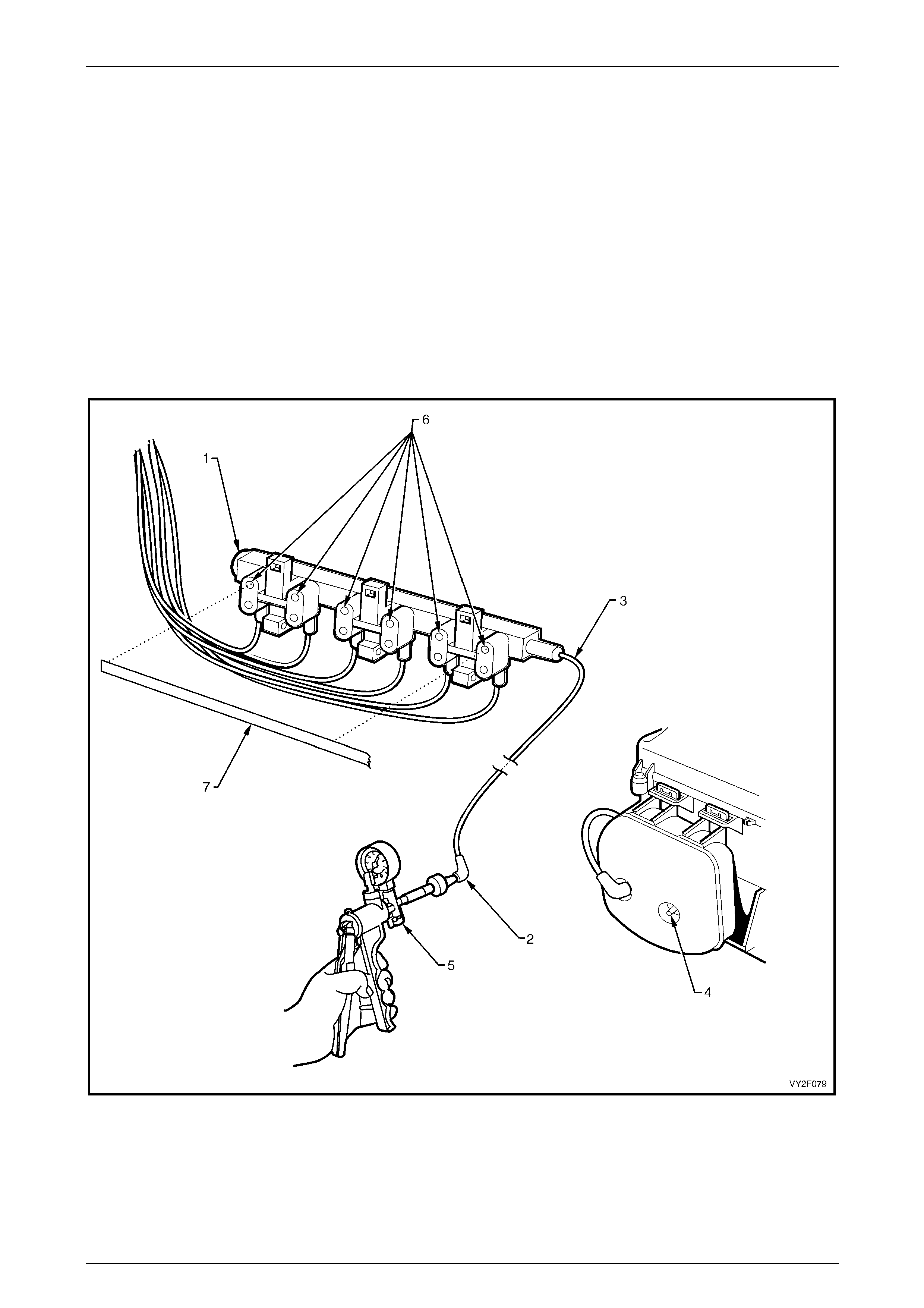
Vacuum Manifold Line
1 Remove the left-hand side instrument panel lower trim plate assembly,
refer to Section 1A3 Instrument Panel and Consol e.
2 Remove the plastic vacuum manifold (1) fro m the solen oi d pack, refer to Figure 2C – 46.
3 Remove the connector (2) of vacuum manifold line (3) from the vacuum tank manifold line port (4).
4 Connect a vacuum pump (5) to the vacuum manifold line connector. Seal the vacuum supply ports (6) on the
plastic vacuum manifold using a suitable strip of electrical tape (7).
5 Using the vacuum pump, create a vacuum and obs erve the vacuum pump gauge needle:
• If a vacuum leak is indicated, check the condition of the vacuum line for da mage or loose connection to the
plastic manifold and vacuum tank. Replace components as necessar y.
• If there is no fault or loose connection detected, perform a vacuum test on the vacuum tank and the ch eck
valve (if not already tested).
Figure 2C – 46
HVAC Climate Control (Manual A/C) – Removal and Installation Page 2C-43
Page 2C-43
4.2 Vacuum Tank
LT Section No. — 08–025
Remove
1 Remove the left-hand instrument panel lower trim
plate assembly, refer to
Section 1A3 Instrument Panel and Co nsole.
2 Remove the two vacuum lines (1) from the vacuum
tank (2).
3 Remove the screw (3) located under the vac uum tank.
4 Move the lower section of the vacuum tank out wards
and lower the tank to disengage the retai ni ng tangs (4)
from the locating slots (5) on the side of the HVAC unit
case (6).
Figure 2C – 47
Reinstall
Reinstallation of the vacuum tank is the reverse of the removal procedure, noting the following:
1 Ensure the vacuum lines are installed correctly:
• the line with the larger connecting el bow (vacuum source) is connected to the tank port closer to the engine
compartment, and
• the line with the smaller connecting elbow is connected to the tank port closer to the cabin.
2 Tighten the screw attaching the tank to the correct torque s pecification.
Vacuum tank attaching screw
torque specification.....................................1.0 – 3.0 Nm
HVAC Climate Control (Manual A/C) – Removal and Installation Page 2C-44
Page 2C-44
4.3 Vacuum Actuators
LT Section No. — 08–150
Intake Actuator (fresh / recirculation)
Remove
1 Remove the left-hand instrument panel lower trim plate assembly and left-hand instrument panel outer cover,
refer to Section 1A3 Instrument Panel and Consol e.
2 Remove the vacuum tank, refer to 4.2 Vacuum Tank
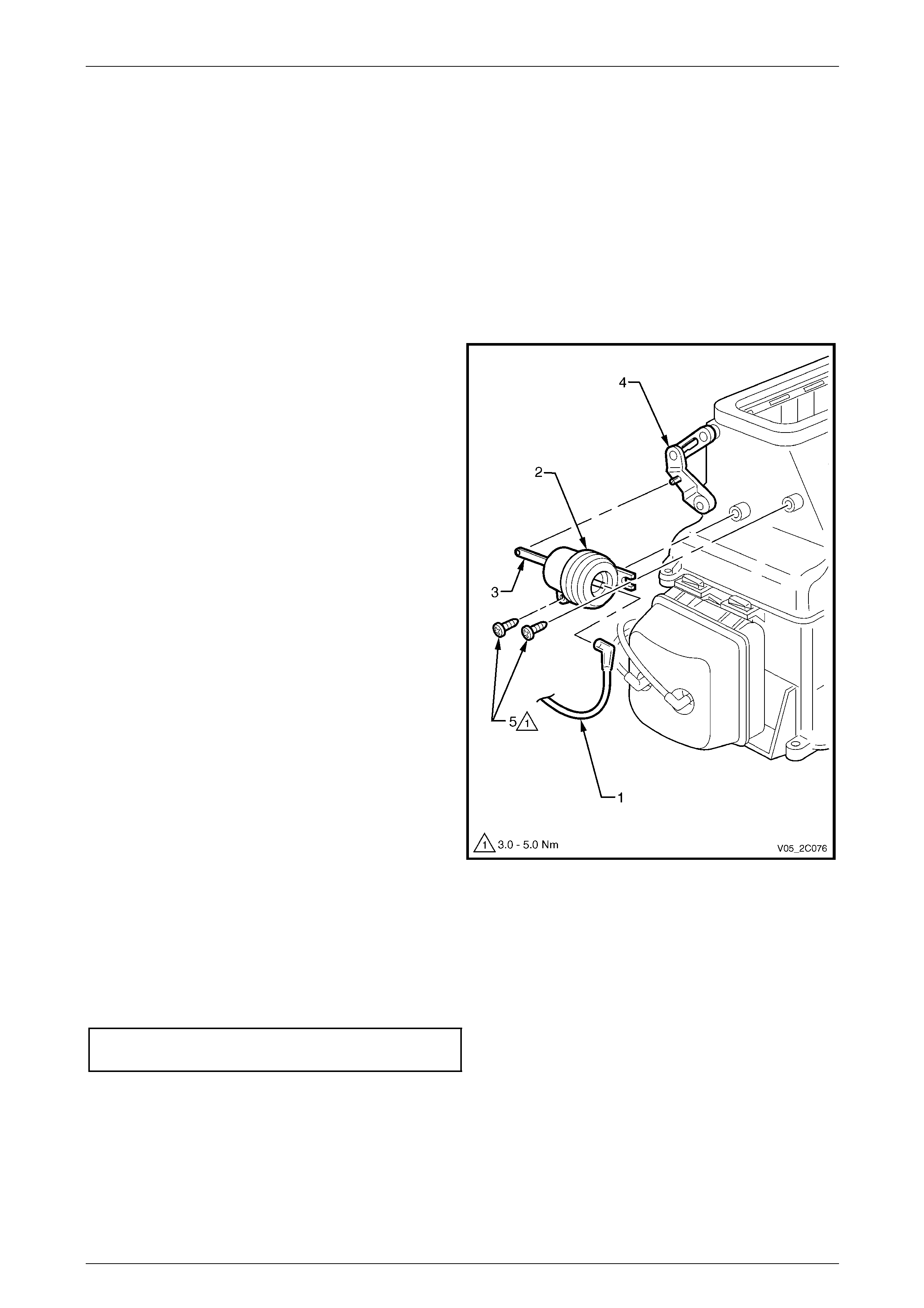
3 Remove the vacuum line (1) from the intake
actuator (2).
4 Remove the pushrod (3) from the actuator lever (4).
5 Remove the two screws (5) attaching the actuator to
the HVAC case and remove the actuator.
Figure 2C – 48
Reinstall
Reinstallation of the intake (fresh / recirculation) actuator is the reverse of the remov al procedure, noting the following:
1 Ensure the blue vacuum line is connected to the actuator.
2 Tighten the screws attaching the actuator to the correct torque specification.
Intake actuator attaching
screw torque specification...........................3.0 – 5.0 Nm
HVAC Climate Control (Manual A/C) – Removal and Installation Page 2C-45
Page 2C-45
Face Actuator
Remove
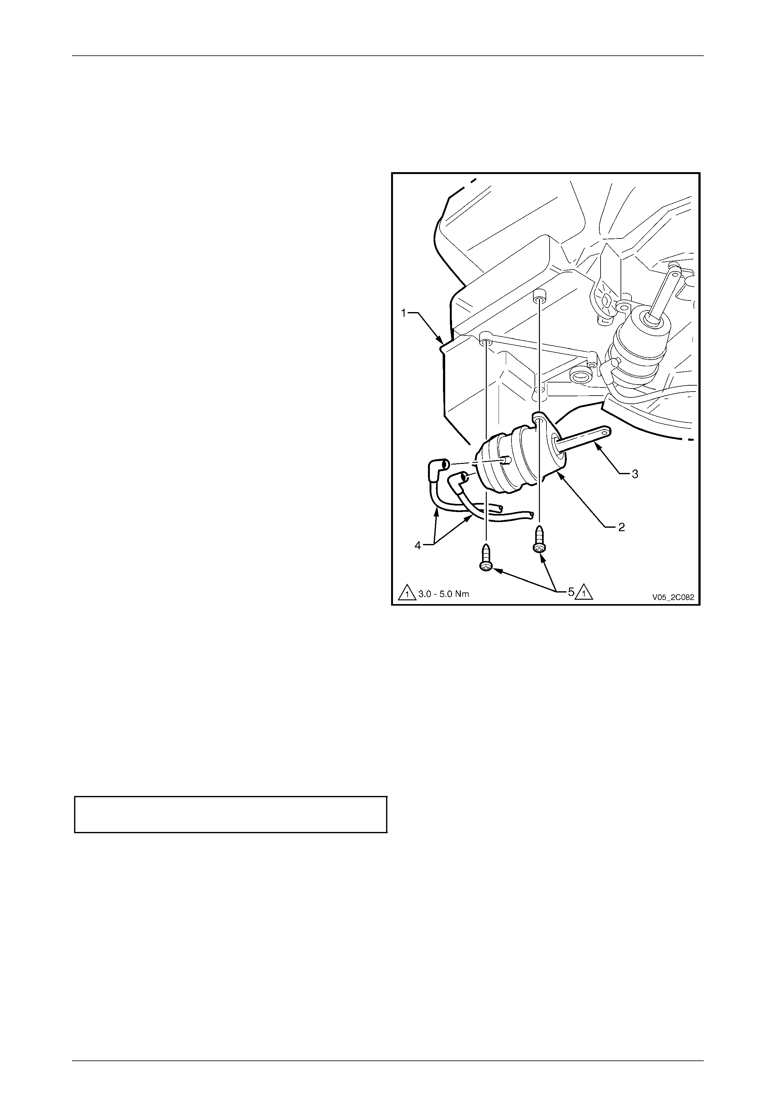
1 Remove the HVAC unit, refer to 3.1 HVAC Unit.
2 From the underside of the HVAC unit (1), locate the
face actuator (2).
3 Remove the pushrod (3) from the door lever.
4 Remove the vacuum lines (4) from the actuator.
5 Remove the two crews (5) attaching the actuator to
the HVAC case and remove the actuator.
Figure 2C – 49
Reinstall
Reinstallation of the face actuator is the rev erse of the removal pr ocedure, noting the following:
1 Ensure the vacuum lines are installed correctly:
• the green vacuum line is connected to the side of the actuator and
• the white vacuum line is connected to the rear of the actuator.
2 Tighten the screws attaching the actuator to the correct torque specification.
Face actuator attaching screw
torque specification.....................................3.0 – 5.0 Nm
HVAC Climate Control (Manual A/C) – Removal and Installation Page 2C-46
Page 2C-46
Foot Actuator
Remove
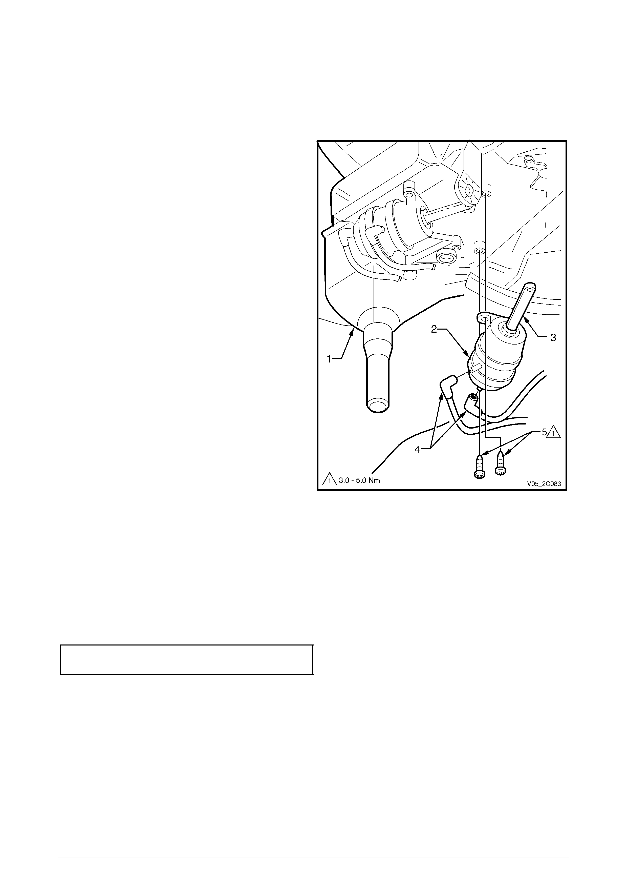
1 Remove the HVAC unit, refer to 3.1 HVAC Unit.
2 From the underside of the HVAC unit (1), locate the
foot actuator (2).
3 Remove the pushrod (3) from the door lever.
4 Remove the vacuum lines (4) from the vacuu m
actuator.
5 Remove the two screws (5) attaching the vacuum
actuator to the HVAC case and remove the actuator.
Figure 2C – 50
Reinstall
Reinstallation of the foot actuator is the reverse of the removal procedure, noting the follo wing:
1 Ensure the vacuum lines are installed correctly:
• the orange vacuum line is connected to the si de of the actuator and
• the pink vacuum line is connected to the rear of the actuator.
2 Tighten the two screws attaching the actuator to the correct torque specifi cation.
Foot actuator attaching screw
torque specification.....................................3.0 – 5.0 Nm

HVAC Climate Control (Manual A/C) – Removal and Installation Page 2C-47
Page 2C-47
5 Air-conditioning Lines and
Retainers
5.1 Replace
LT Section No. — 08–200
The total quantity of lubricating oil in the air-
conditioning system must be maintained. If a
compressor, evaporator, condenser, filter
drier receiver or air-conditioning line is
replaced, a specified quantity of lubricating
oil must be added to the system to
compensate for oil removed with the original
component. Refer to Section 2B HVAC
Climate Control (Manual A/C) – Servicing and
Diagnosis.
The following illustrations provide under hood views of the air-conditioning line connections and retainers:
• for RWD vehicle with V6 engine, refer to Figure 2C – 5 1
• for AWD vehicle with V6 engine, refer to Figure 2C – 5 2
• for RWD or AWD vehicle with GEN III V8 engine, refer to Figure 2C – 53 .
Replace the components as required ensuring the fasteners are tightened to the correct torque specification.
Liquid and suction li ne retaining plate
to TXV screw torque specification.............7.5 – 12.5 Nm
Liquid line to filter dryer receiver union
torque specification...................................7.5 – 12.5 Nm
Discharge line to condenser nut
torque specification...................................7.5 – 12.5 Nm
Suction line bracket attaching screw
torque specification...................................7.5 – 12.5 Nm
Compressor suction / discharge lin e
pad retaining nut torque specification .....25.0 – 35.0 Nm
HVAC Climate Control (Manual A/C) – Removal and Installation Page 2C-48
Page 2C-48
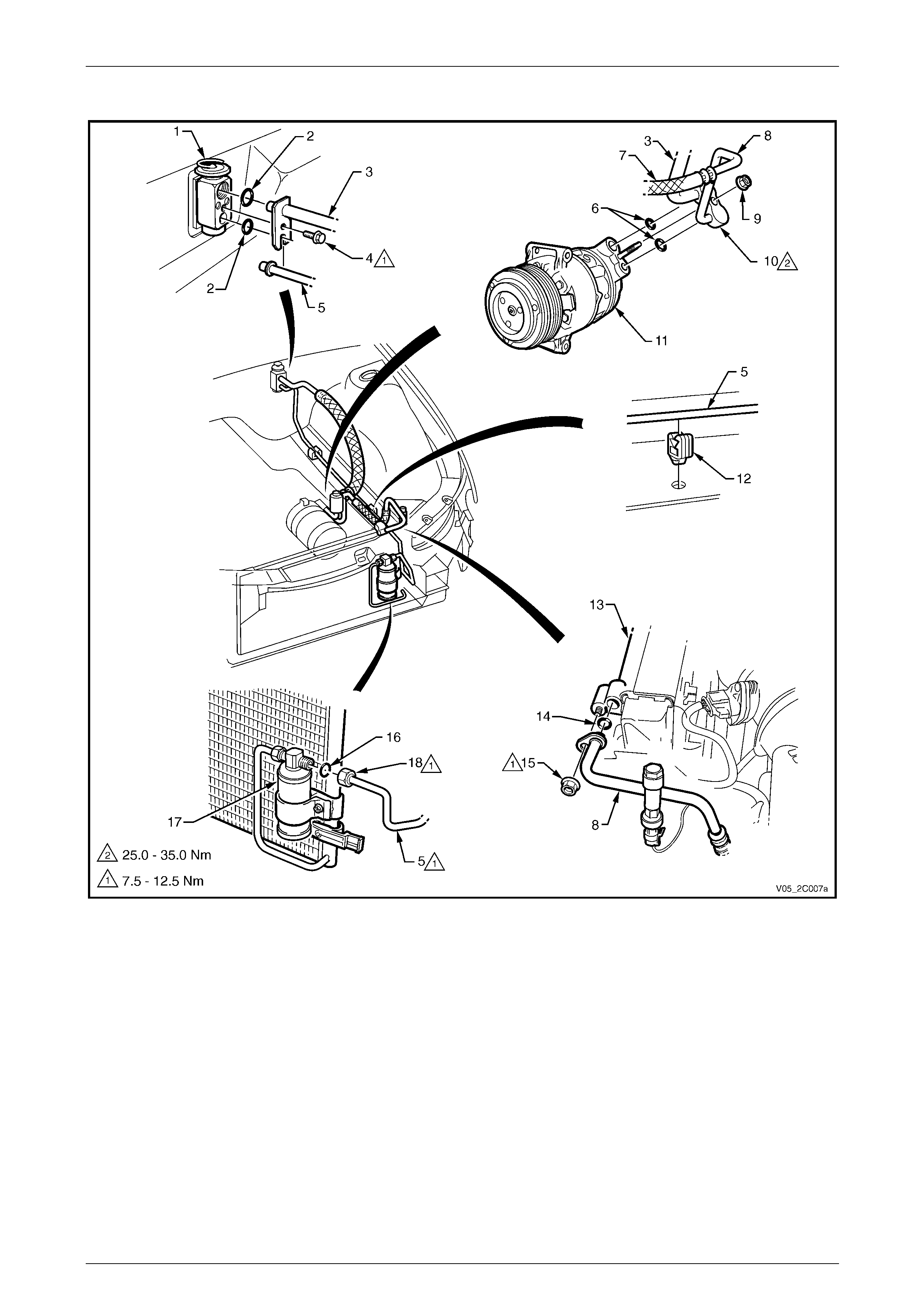
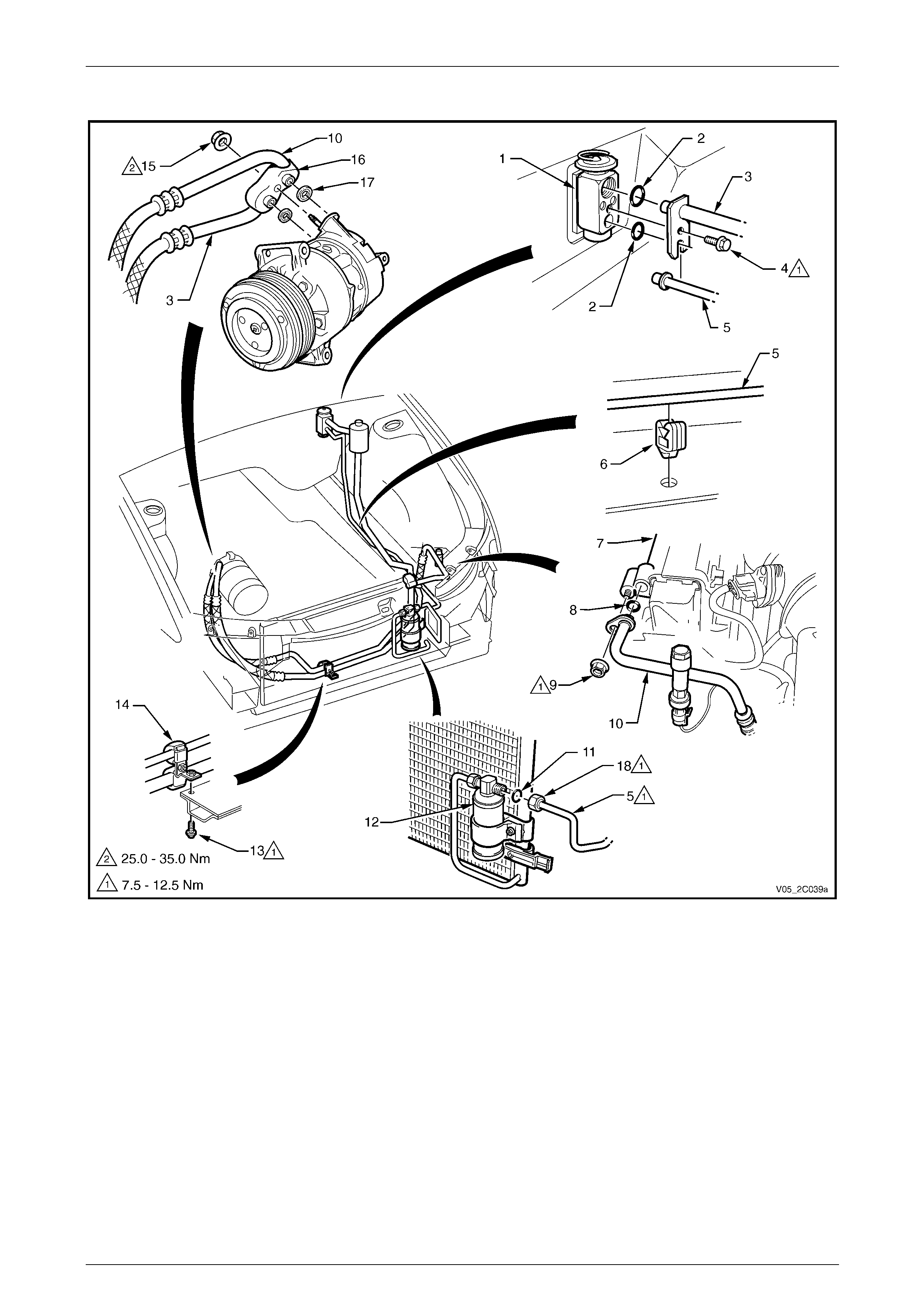
Lines and Retainers Views – V6 RWD
Figure 2C – 51
Legend
1 Thermal Expansion Valve (TXV)
2 O-ring – TXV
3 Suction Line
4 Screw
5 Liquid Line
6 Seals – Compressor
7 Discharge Line
8 Discharge Line
9 Nut
10 Compressor Pad
11 Compressor
12 Liquid Line Clip
13 Condenser
14 O-ring – Condenser
15 Nut
16 O-ring – FDR
17 Filter Drier Receiver (FDR)
18 Union
HVAC Climate Control (Manual A/C) – Removal and Installation Page 2C-49
Page 2C-49
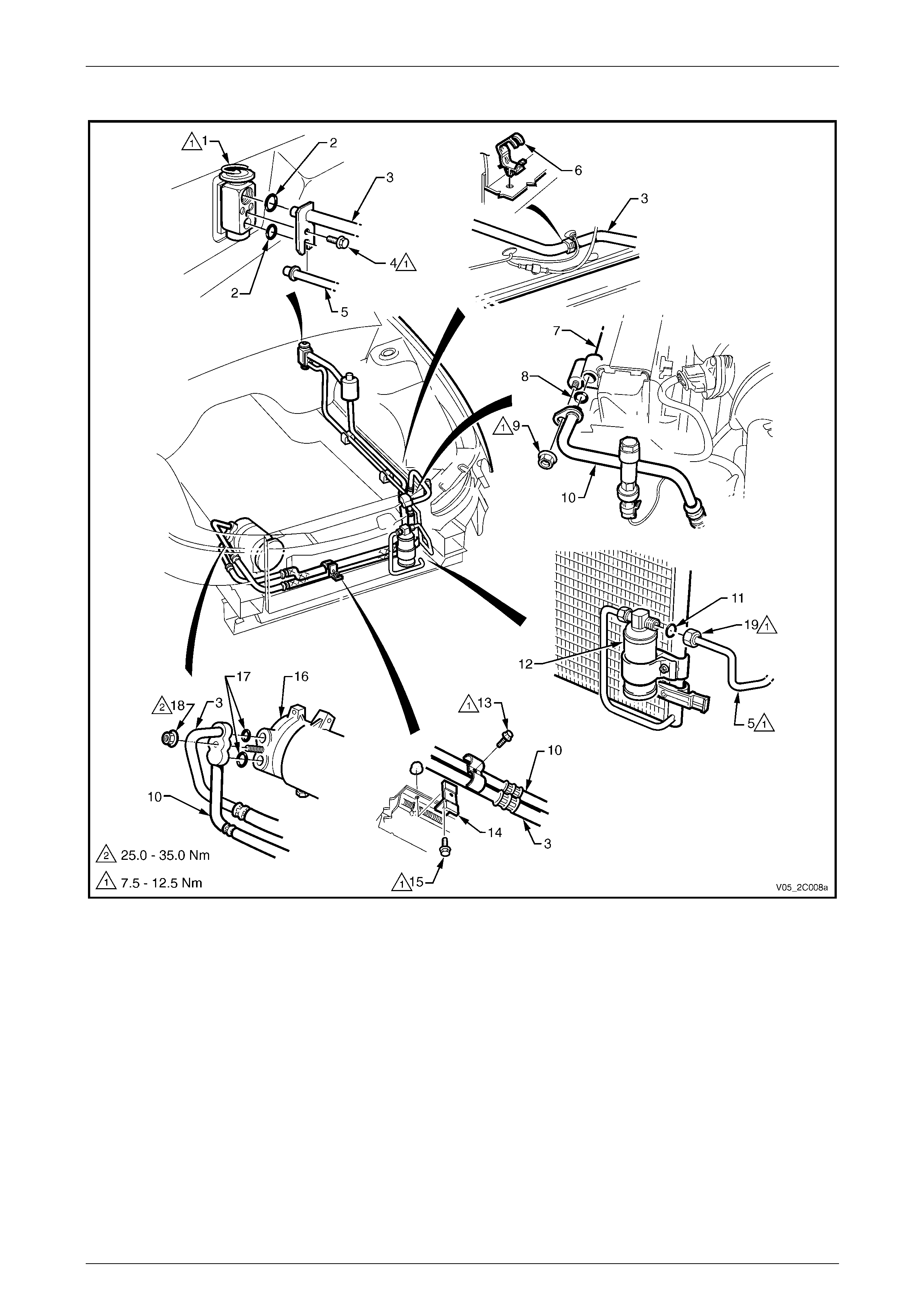
Lines and Retainers Views – V6 AWD
Figure 2C – 52
Legend
1 Thermal Expansion Valve (TXV)
2 O-ring – TXV
3 Suction Line
4 Screw
5 Liquid Line
6 Clip – Liquid Line
7 Condenser
8 O-ring – Condenser
9 Nut
10 Discharge Tube
11 O-ring – FDR
12 Filter Drier Receiver
13 Support Bracket screw
14 A/C Lines Support Bracket
15 Compressor Pad Nut
16 Compressor Pad
17 Compressor Seals
18 Union
HVAC Climate Control (Manual A/C) – Removal and Installation Page 2C-50
Page 2C-50
Lines and Retainers Views – GEN III V8
Figure 2C – 53
Legend
1 Thermal Expansion Valve (TXV)
2 O-ring – TXV
3 Suction Line
4 Screw
5 Liquid Line
6 Liquid Line Clip
7 Condenser
8 O-Ring – Condenser
9 Nut
10 Discharge Line
11 O-Ring – FDR
12 Filter Drier Receiver (FDR)
13 Bracket Screw
14 A/C Lines Bracket
15 Screw
16 Compressor
17 Seals – Compressor
18 Compressor Pad Nut
19 Union
HVAC Climate Control (Manual A/C) – Removal and Installation Page 2C-51
Page 2C-51
6 Air-conditioning Components
6.1 Thermal Expansion Valve
LT Section No. — 08–200
Remove
1 Recover the refrigerant from the air-conditioning system,
refer to Section 2B HVAC Climate Control (Manual A/C) – Servicing and Diagnosis.
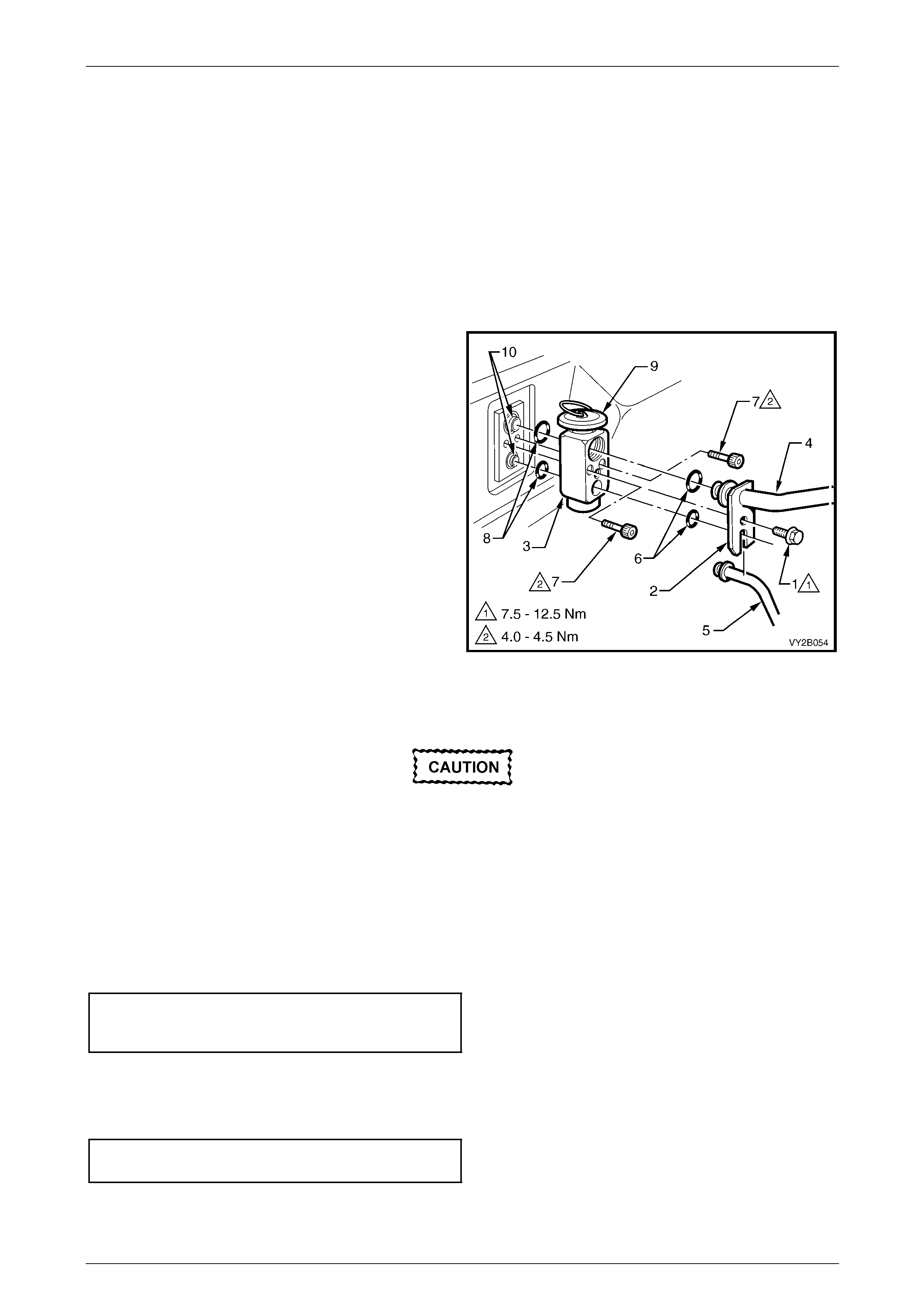
2 Remove the washer faced screw (1) retaining the
liquid and suction line plate (2) to the thermal
expansion valve (T XV) (3).
3 Remove the suction line (4) and the li quid line (5).
4 Remove and discard the liquid and suction line
O-rings (6).
5 Unscrew the two cap screws (7) and remove the TXV.
6 Remove and discard the evap orator tube O-ri ngs (8).
Figure 2C – 54
Reinstall
The total quantity of lubricating oil in the air-
conditioning system must be maintained. If
lubricating oil loss has occurred during TXV
replacement, oil must b e added to the system
to compensate.
1 Lubricate and fit two new O-rings to the evaporator tubes.
2 Install the thermal expansion valve (TXV) with the diaphrag m (9) facing upwards, onto the evaporator tubes (10),
refer to Figure 2C – 54.
3 Install the TXV to the evaporator tube plate and the two cap screws. Tighten the screws to the correct torque
specification.
Thermal expansion valve to
evaporator tubes securing
screw torque specification...........................4.0 – 4.5 Nm
4 Fit a new lubricated O-ring on to the suction line and the liquid line.
5 Install the liquid line and then the suction line plate onto the TXV.
6 Install the washer faced screw and tighten to the correct torque specification.
Liquid and suction li ne retaining plate
to TXV screw torque specification.............7.5 – 12.5 Nm
7 Evacuate and charge the A/C system with refrigerant,
refer to Section 2B HVAC Climate Control (Manual A/C) – Servicing and Diagnosis.
HVAC Climate Control (Manual A/C) – Removal and Installation Page 2C-52
Page 2C-52
6.2 A/C Pressure Transducer
LT Section No. — 08–200
Replace – V6
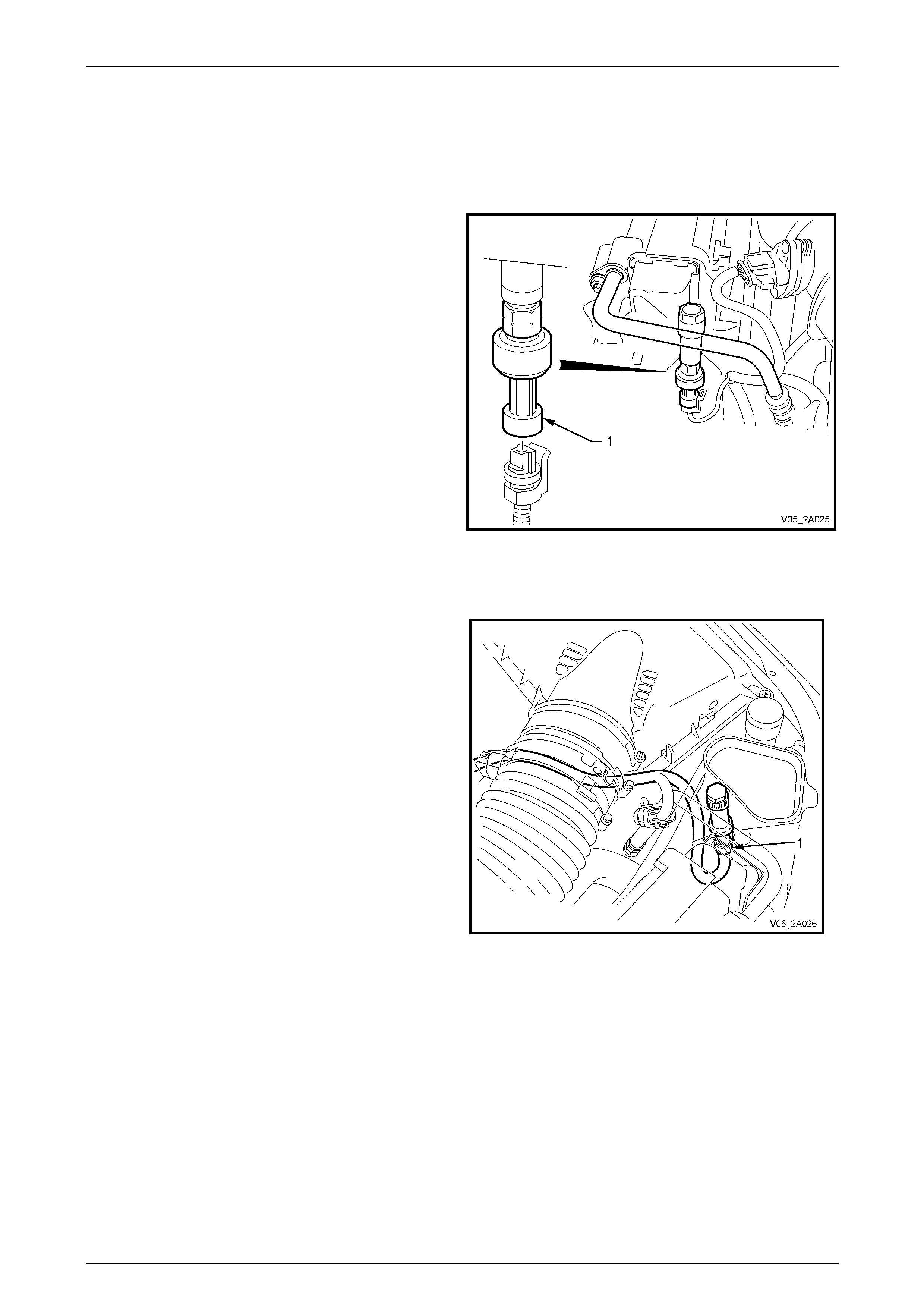
To replace the A/C pressure transducer (1), refer to
Section 6C1-3 Engine Management – V6 – Service
Operations.
Figure 2C – 55
Replace – GEN III V8
To replace the A/C pressure transducer (1), refer to
Section 6C3-3 Powertrain Management – GEN III V8 –
Service Operations.
Figure 2C – 56
HVAC Climate Control (Manual A/C) – Removal and Installation Page 2C-53
Page 2C-53
6.3 Condenser Assembly
LT Section No. — 08–200
V6 Engine
Remove
Disconnection of the battery affects certain
vehicle electronic systems. Refer to
Section 00 Warnings, Cautions and Notes
before disconnecting the battery.
1 Disconnect the battery ground lead.
2 Recover the refrigerant from the A/C system,
refer to Section 2B HVAC Climate Control (Manual A/C) – Servicing and Diagnosis.
3 Remove the upper radiator shroud (2) as fol lows:
• Using a fine, flat-blade scre wdriver to prise the
centre pin of the retainer (1) up ward and remove
the retainer, five places.
• Lift up the radiator shroud to disenga ge the
retaining clip (3) and remove the shroud.
Figure 2C – 57
4 Release the automatic transmission upp er co oling
pipe (1) from the integral clip (2) on the fan shroud.
Figure 2C – 58
HVAC Climate Control (Manual A/C) – Removal and Installation Page 2C-54
Page 2C-54
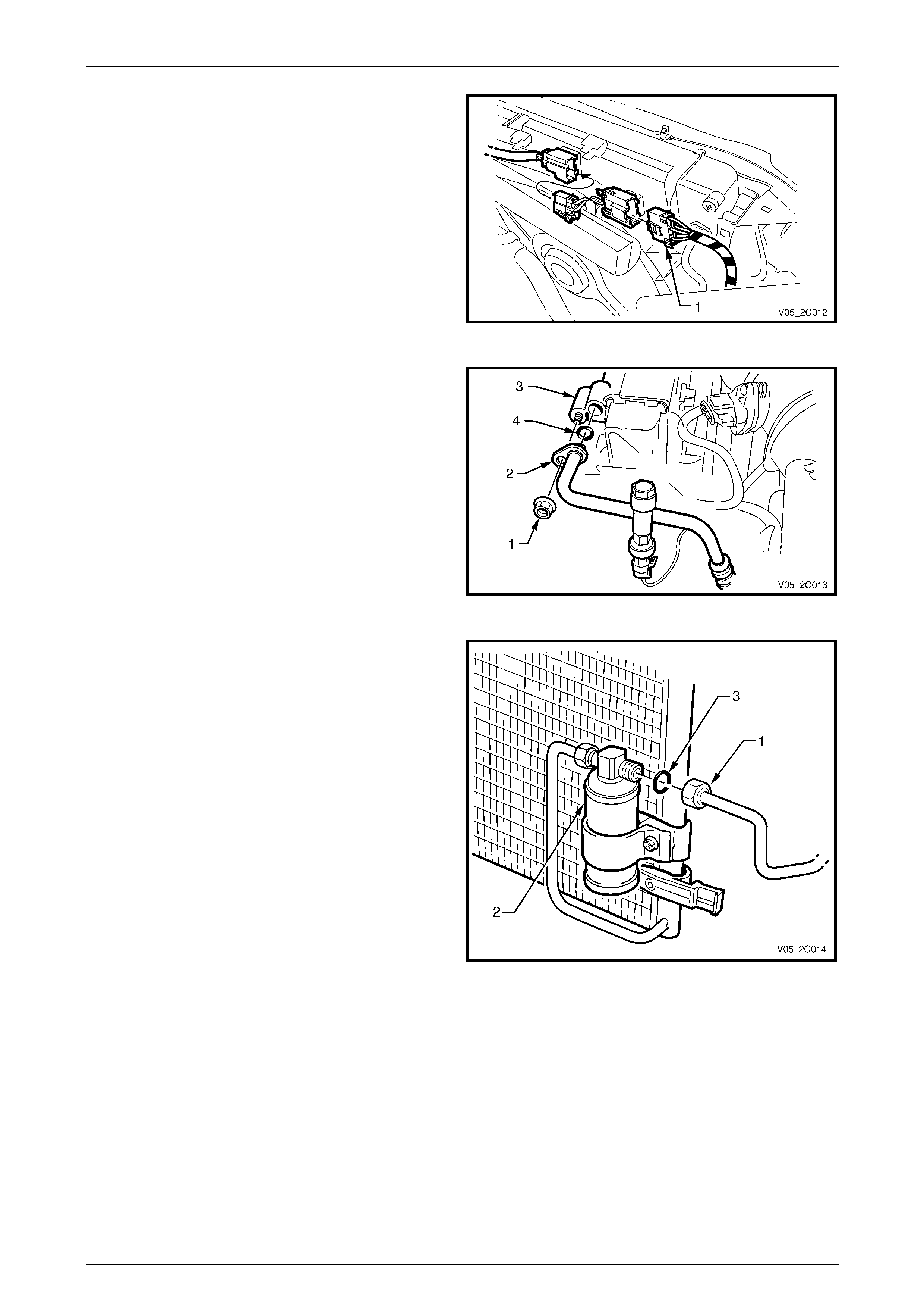
5 Depress tang on main wiring harness to cooling fan
motor wiring harness connector (1) and separate the
connector.
Figure 2C – 59
6 Remove the nut (1) retaining the discharge line pad
fitting (2) to the condenser (3).
7 Cap all open lines to avoi d moisture from entering the
system.
8 Discard the O-ring (4).
Figure 2C – 60
9 Remove the liquid line union (1) from the filter drier
receiver (FDR) (2) and discar d the O-ring (3).
Figure 2C – 61
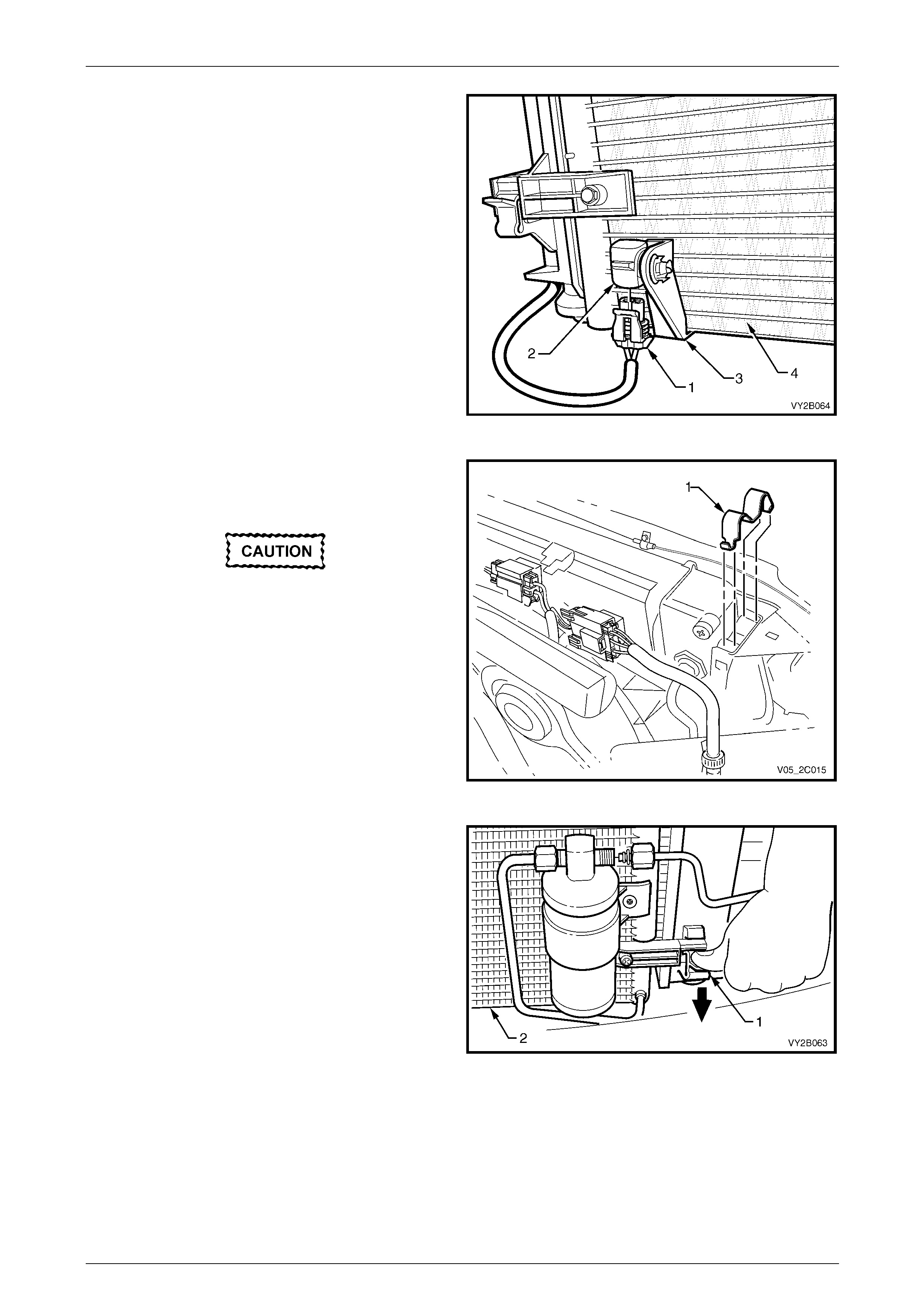
HVAC Climate Control (Manual A/C) – Removal and Installation Page 2C-55
Page 2C-55
10 On OCC (Auto A/C) units, disconnect the wiring
harness connector (1) from the ambient temperature
sensor (2). Do not attempt to remove the bracket (3)
from the condenser (4).
Figure 2C – 62
11 Using a screwdriver, compress and lever out the
radiator retaining clips (1) from radiator upper
mounting brackets.
Do not lift the radiator assembly by lifting on
the fan rings as this will bend the fan motor
shaft and create an un necessary vibration.
12 Lift the radiator assembly upwards out of the lower
insulators. Slant the upper section of the assembly
behind the radiator support as sembly and allow it to
remain there.
Figure 2C – 63
13 Release one of the clips secur ing the condenser to the
radiator. Do this by pressing down as indicated by the
arrow, on the locking retainer (1) with the fingers of
one hand, while lifting the condens er assembly (2)
with the other hand. Repeat for the other side.
Figure 2C – 64
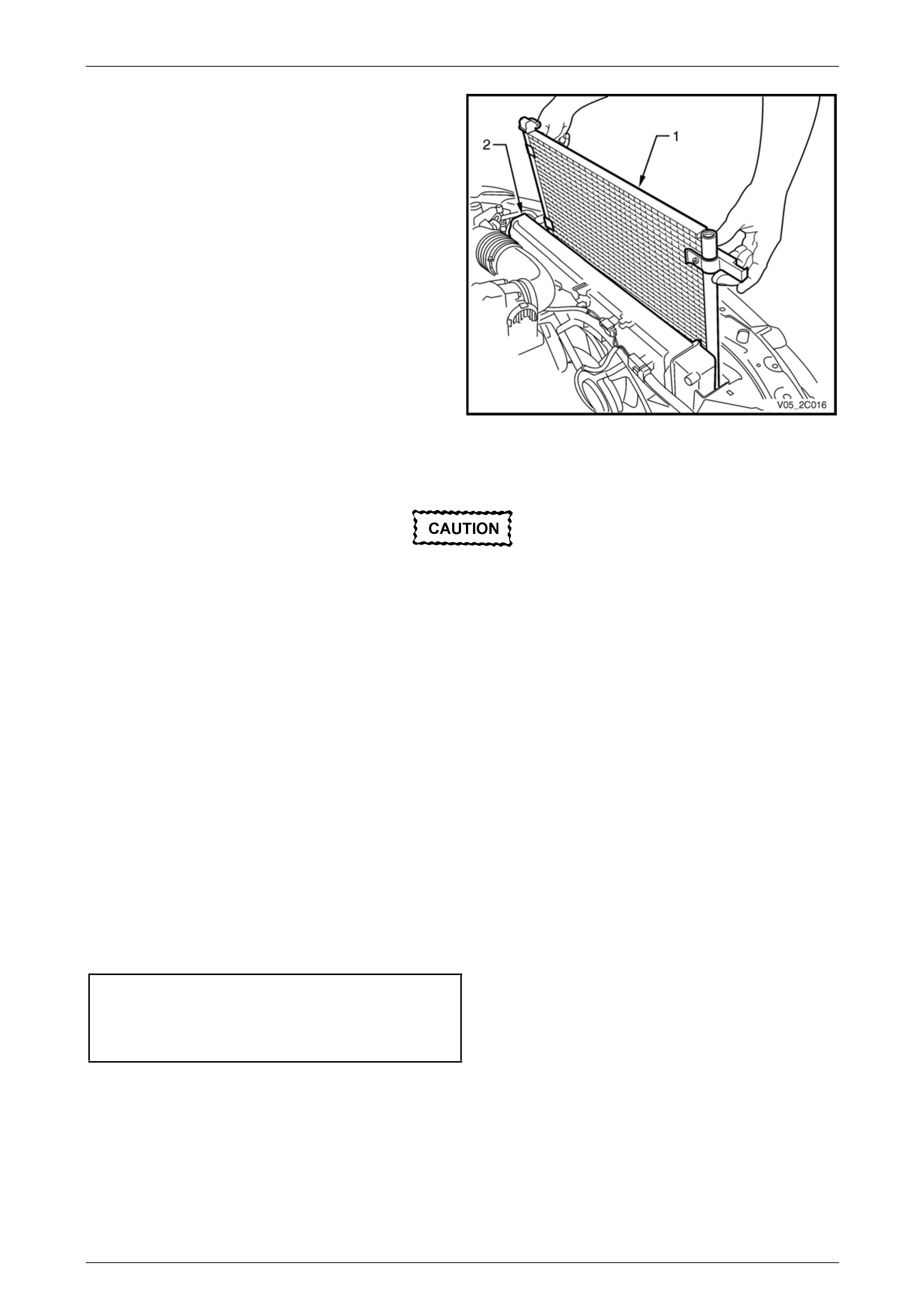
HVAC Climate Control (Manual A/C) – Removal and Installation Page 2C-56
Page 2C-56
14 Lift the condenser assembly (1) upwards suff iciently to
clear the mounts moulded to front of the radiator (2).
Remove the condenser with the FDR attached.
15 If required, remove the filter drier receiver, refer to
6.4 Filter Drier Receiver.
Figure 2C – 65
Reinstall
The total quantity of lubricating oil in the air-
conditioning system must be maintained. If a
compressor, evaporator, condenser, filter
drier receiver or air-conditioning line is to be
replaced, a specified quantity of lubricating
oil must be added to the system to
compensate for oil removed with the original
component. Refer to Section 2B HVAC
Climate Control (Manual A/C) – Servicing and
Diagnosis.
Reinstallation of the condenser is the reverse of the removal procedure, noting the following:
1 Before installing the radiator, inspect the cor e to ensure the r e is no foreign matter in the fins. Clean out between
the core fins with compressed air, blowing from rear to front.
2 Ensure the radiator lower mounting insulators are correctly located in the radiator sup port panel.
3 Ensure the upper insulators are installed on each of the upper mounting pins and the radiator retainers are
correctly installed on each side of the radiator b y checking the clips en gage on both sides of the channel support
bracket.
4 If removed, install the filter receiver drier (FDR), refer to 6.4 Filter Drier Receiver.
5 Install the liquid line and the discharge line using ne w l ubricated O-rings. T ighten the unions to the correct torque
specification.
Liquid line to filter dryer receiver
union torque specification .........................7.5 – 12.5 Nm
Discharge line pad to co ndenser
attaching nut torque specification..............7.5 – 12.5 Nm
6 Evacuate and charge the A/C system with refrigerant,
refer to Section 2B HVAC Climate Control (Manual A/C) – Servicing and Diagnosis.
7 Ensure the fan and shroud assembly to radiator attaching clips are all fully engaged and the two locking tangs on
the upper clips are securing the shroud corre ctly.
8 Check cooling fan operation, refer to Section 6B1 Engine Cooling – V6.
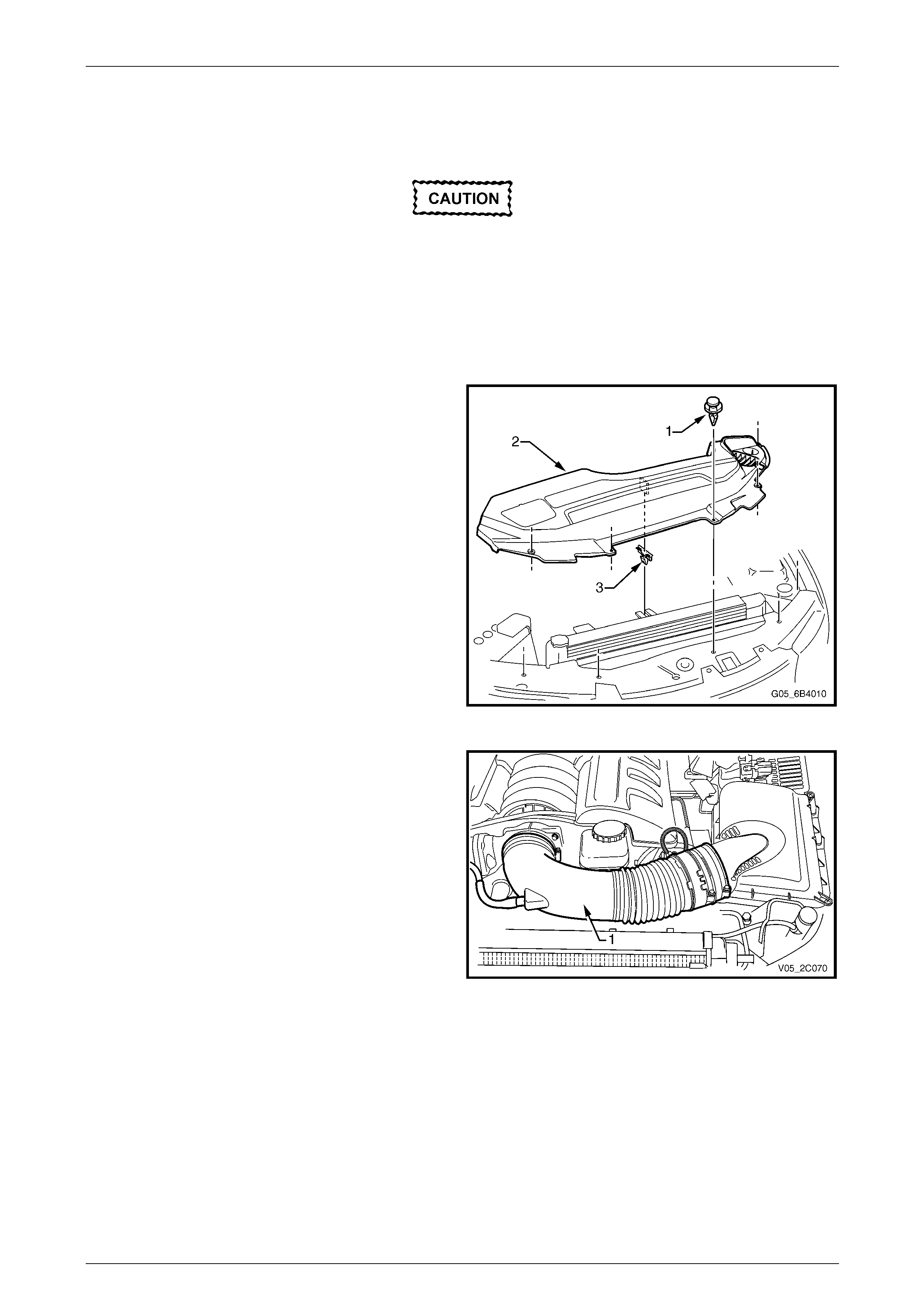
HVAC Climate Control (Manual A/C) – Removal and Installation Page 2C-57
Page 2C-57
GEN III V8 Engine
Remove
Disconnection of the battery affects certain
vehicle electronic systems. Refer to
Section 00 Warnings, Cautions and Notes
before disconnecting the battery.
1 Disconnect the battery ground lead.
2 Recover the refrigerant from the A/C system,
refer to Section 2B HVAC Climate Control (Manual A/C) – Servicing and Diagnosis.
3 Remove the upper radiator shroud (2) as fol lows:
a Use a fine, flat-blade screwdriver to prise the
centre pin of the retainer (1) up ward and remove
the retainer, five places.
b Lift up the radiator shroud to disengage the
retaining clip (3) and remove the shroud.
Figure 2C – 66
4 Remove the intake duct (1) and Mass Air Flow (MAF)
as an assembly, refer to Section 6A3 Engine
Mechanical – GEN III V8.
Figure 2C – 67
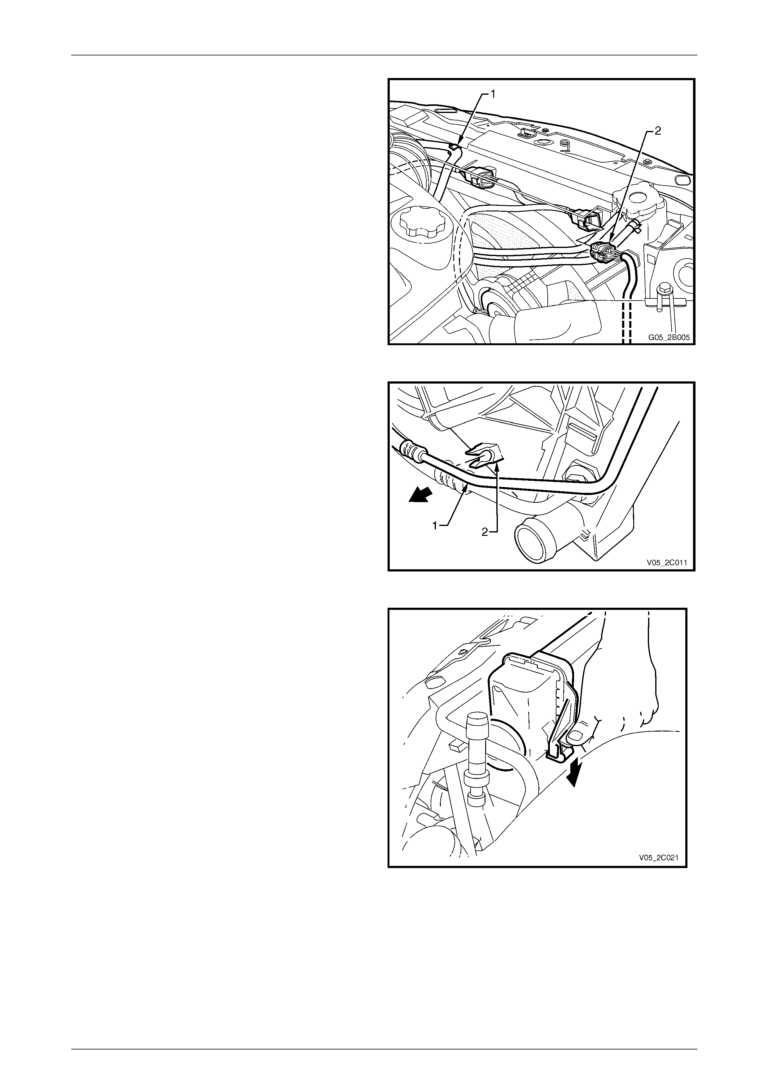
HVAC Climate Control (Manual A/C) – Removal and Installation Page 2C-58
Page 2C-58
5 Remove the coolant recovery hoses from the fan
shroud retaining clips (1).
6 Depress tang on main wiring harness to cooling fan
motor wiring harness connector and separ ate
connector (2).
Figure 2C – 68
7 Release the automatic transmission upp er co oling
pipe (1) from the integral clip (2) on the fan shroud.
Figure 2C – 69
8 While holding the shroud locking tang in the release
position, lift the shroud and fan assembly upwards.
Repeat for the opposite side.
NOTE
The automatic transmission fluid cooling pipe is
shown removed to more clearly show the shroud
release method. This is not a mandatory
requirement for shroud removal.
Figure 2C – 70

HVAC Climate Control (Manual A/C) – Removal and Installation Page 2C-59
Page 2C-59
When handling th e fan assembly:
• Do not grasp the assembly by the fan
rings (1) as this may bend the fan motor
shafts and cause fan vibrations.
• Hold the assembly at the fan sh roud (2) or
fan motor mounting struts (3).
Figure 2C – 71
9 Lift the shroud and fan assembly clear from the engine
bay, grasping the motor mounting brackets.
Figure 2C – 72
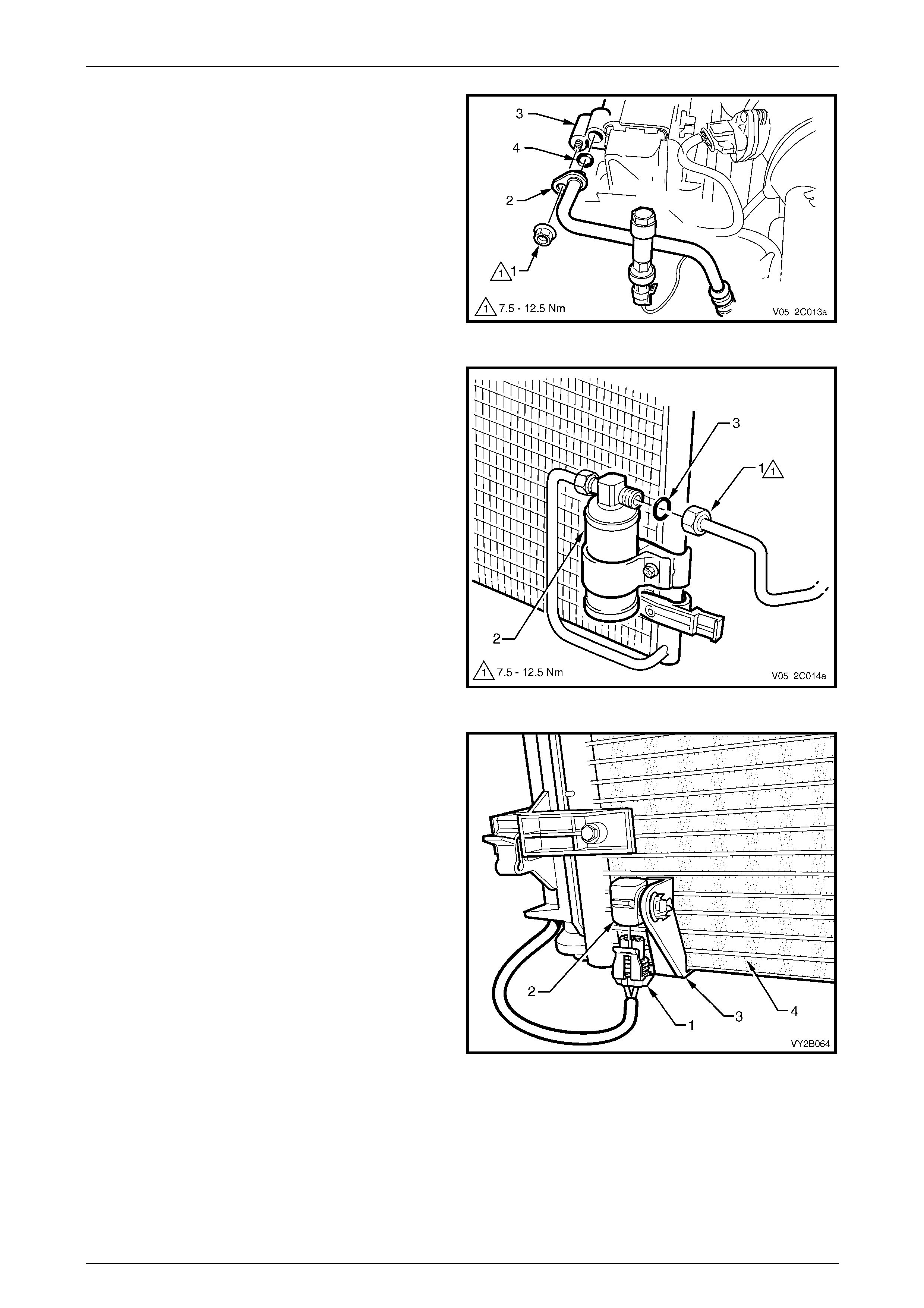
HVAC Climate Control (Manual A/C) – Removal and Installation Page 2C-60
Page 2C-60
10 Remove the nut (1) retaining the discharge line pad
fitting (2) to the condenser (3).
11 Cap all open lines to avoi d moisture from entering the
system.
12 Discard the O-ring (4).
Figure 2C – 73
13 Remove the liquid line union (1) from the filter drier
receiver (FDR) (2) and discar d the O-ring (3).
Figure 2C – 74
14 On OCC (Auto A/C) units, disconnect the wiring
harness connector (1) from the ambient temperature
sensor (2). Do not attempt to remove the bracket (3)
from the condenser (4).
Figure 2C – 75
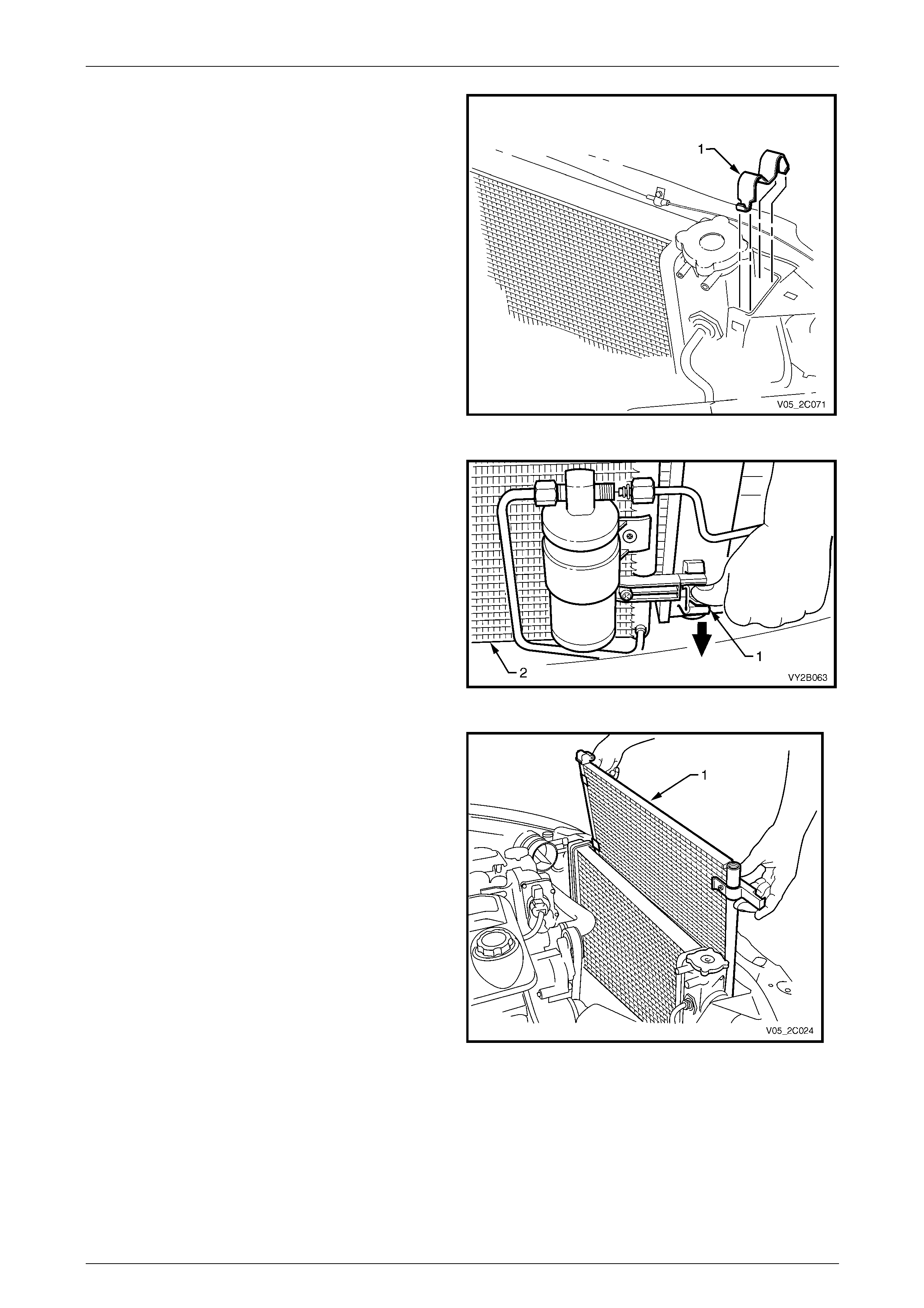
HVAC Climate Control (Manual A/C) – Removal and Installation Page 2C-61
Page 2C-61
15 Using a screwdriver, compress and lever out the
radiator retaining clips (1) from radiator upper
mounting brackets.
16 Lift the radiator assembly upwards out of the lower
insulators. Slant the upper section of the assembly
behind the radiator support as sembly and allow it to
remain there.
Figure 2C – 76
17 Release one of the clips secur ing the condenser to the
radiator. Do this by pressing down as indicated by the
arrow, on the locking retainer (1) with the fingers of
one hand, while lifting the condens er assembly (2)
with the other hand. Repeat for the other side.
Figure 2C – 77
18 Lift the condenser assembly (1) upwards suff iciently to
clear the mounts moulded to front of the radiator.
Remove the condenser with the FDR attached.
19 If required, remove the filter drier receiver, refer to
6.4 Filter Drier Receiver.
Figure 2C – 78
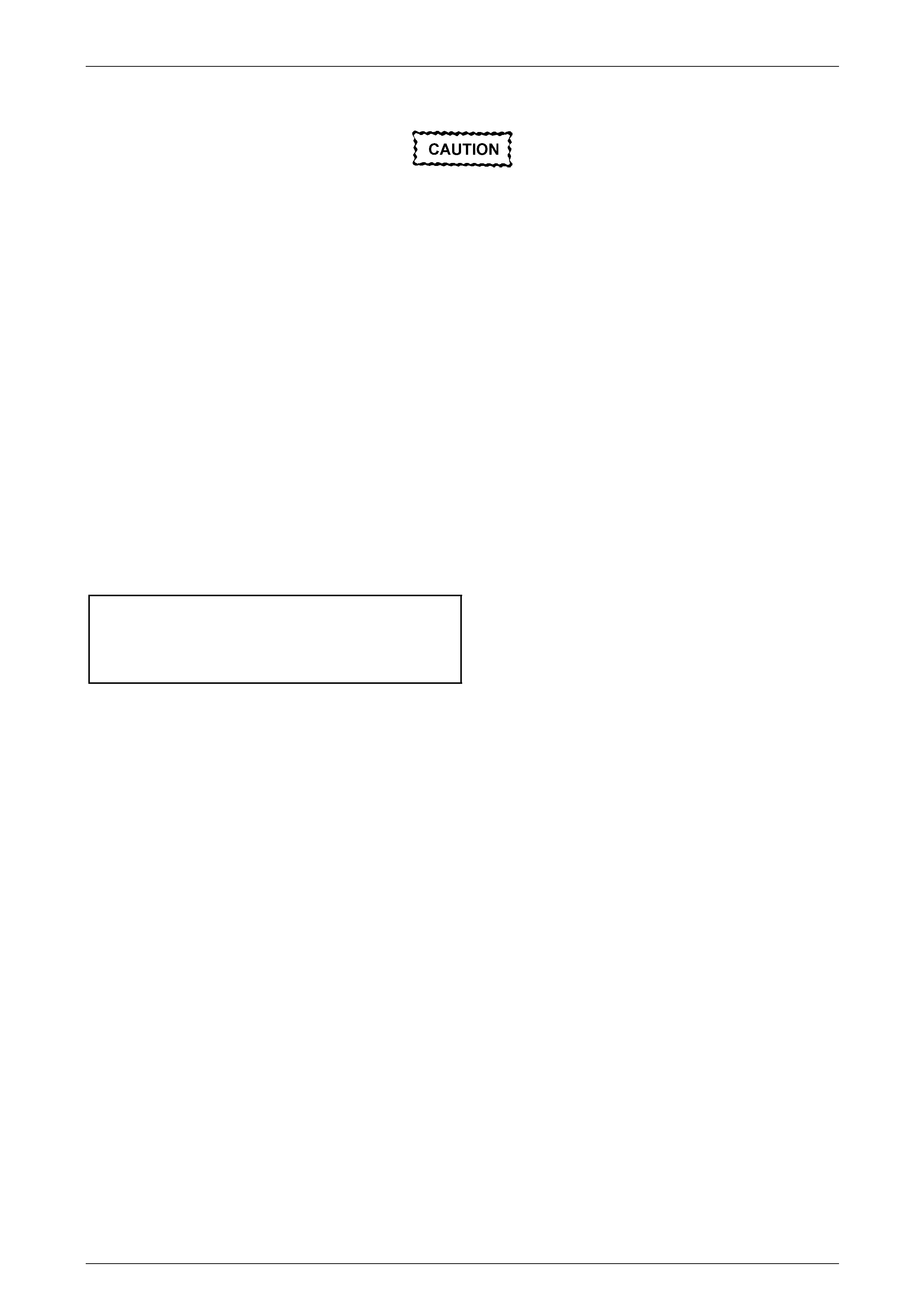
HVAC Climate Control (Manual A/C) – Removal and Installation Page 2C-62
Page 2C-62
Reinstall
The total quantity of lubricating oil in the air-
conditioning system must be maintained. If a
compressor, evaporator, condenser, filter
drier receiver or air-conditioning line is to be
replaced, a specified quantity of lubricating
oil must be added to the system to
compensate for oil removed with the original
component. Refer to Section 2B HVAC
Climate Control (Manual A/C) – Servicing and
Diagnosis.
Reinstallation of the condenser is the reverse of the removal procedure, noting the following:
1 Before installing the radiator, inspect the cor e to ensure the r e is no foreign matter in the fins. Clean out between
the core fins with compressed air, blowing from rear to front.
2 Ensure the radiator lower mounting insulators are correctly located in the radiator sup port panel.
3 Ensure the upper insulators are installed on each of the upper mounting pins and the radiator retainers are
correctly installed on each side of the radiator b y checking if the clips engage on both sides of the channel support
bracket.
4 If removed, install the filter receiver drier (FDR), refer to 6.4 Filter Drier Receiver.
5 Install the liquid line and the discharge line using ne w l ubricated O-rings. Tighten the union and attaching nut to the
correct torque specification.
Liquid line to filter dryer receiver
union torque specification .........................7.5 – 12.5 Nm
Discharge line pad to co ndenser
attaching nut torque specification..............7.5 – 12.5 Nm
6 Evacuate and charge the A/C system with refrigerant,
refer to Section 2B HVAC Climate Control (Manual A/C) – Servicing and Diagnosis.
7 Ensure the fan and shroud assembly to radiator attaching clips are all fully engaged and the two locking tangs on
the upper clips are securing the shroud corre ctly.
8 Check cooling fan operation, refer to Section 6C3-2 Powertrain Management – GEN III V8 – Diagnostics.
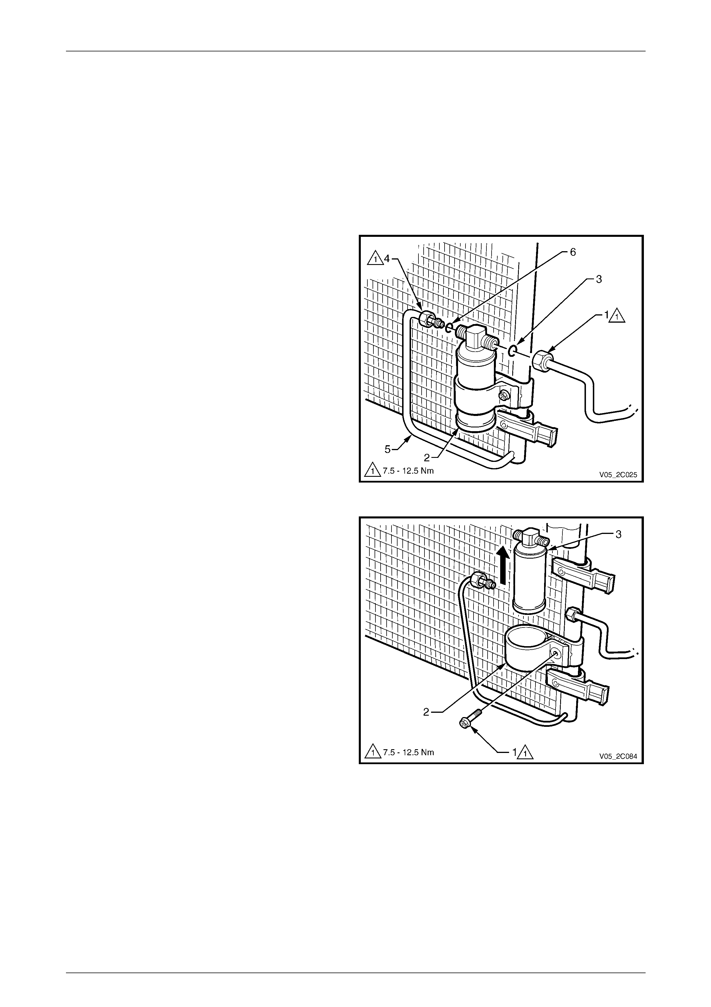
HVAC Climate Control (Manual A/C) – Removal and Installation Page 2C-63
Page 2C-63
6.4 Filter Drier Receiver
LT Section No. — 08–200
Remove
1 Recover the refrigerant from the A/C system,
refer to Section 2B HVAC Climate Control (Manual A/C) – Servicing and Diagnosis.
2 Remove the radiator grille, refer to Section 1C Radi ator Grille.
3 Remove the liquid line union (1) from the filter receiver
dryer (FDR) (2) and disc ard the O-ring (3).
4 Remove the discharge line union (4) from the FDR
and carefully flex the disch arge line (5) to the left clear
of the FDR. Discard the O-ring (6).
Figure 2C – 79
5 Remove the screw (1) on the FDR mounting
bracket (2).
6 Cap all open lines to avoi d moisture from entering the
system.
7 Expand the bracket and remove the FDR (3) by lifting
it upwards clear of the bracket and remove.
Figure 2C – 80
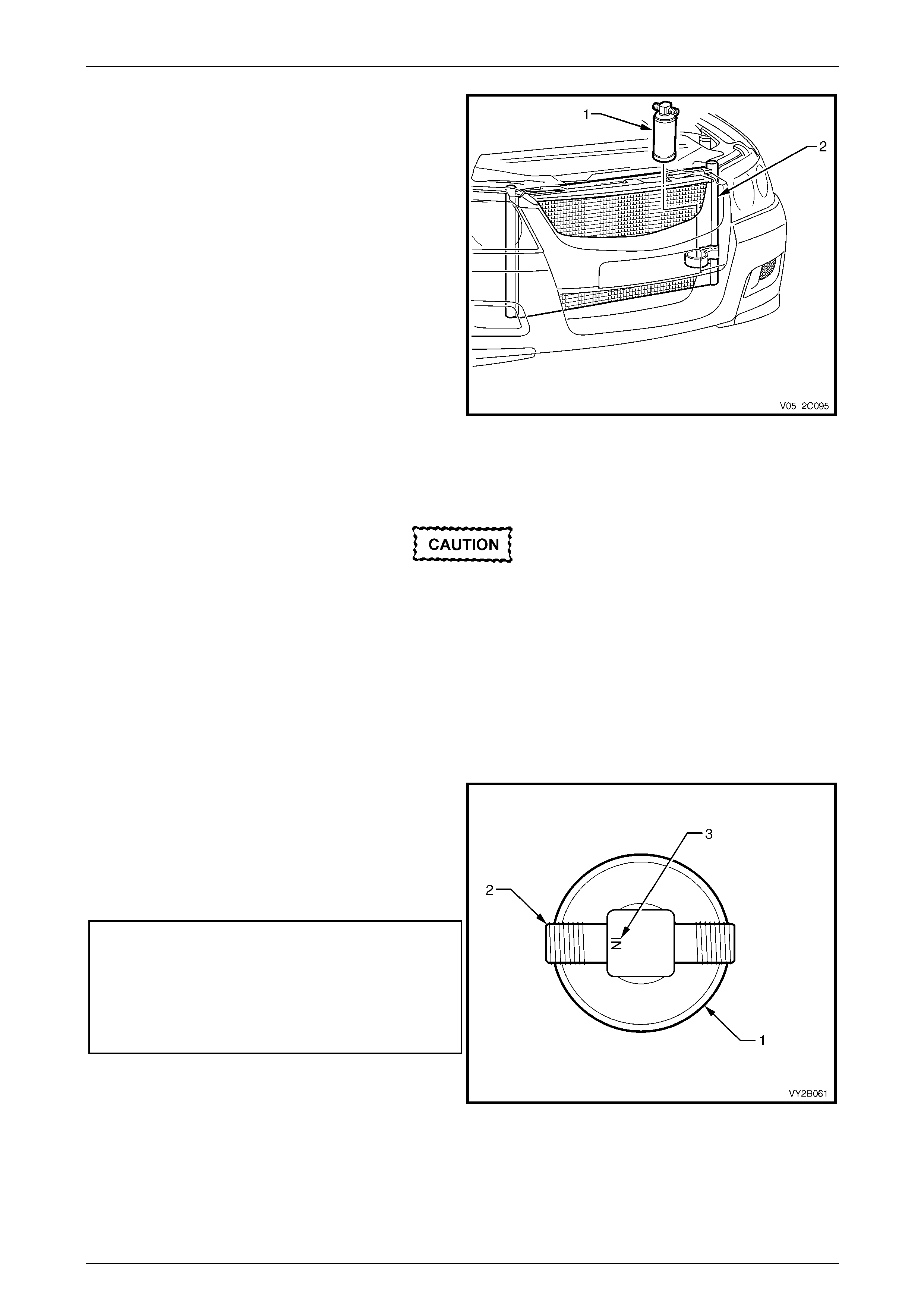
HVAC Climate Control (Manual A/C) – Removal and Installation Page 2C-64
Page 2C-64
8 Remove the FDR (1) through the grille ap erture (2).
Figure 2C – 81
Reinstall
The total quantity of lubricating oil in the air-
conditioning system must be maintained. If a
compressor, evaporator, condenser, filter
drier receiver or air-conditioning line is
replaced, a specified quantity of lubricating
oil must be added to the system to
compensate for oil removed with the original
component. Refer to Section 2B HVAC
Climate Control (Manual A/C) – Servicing and
Diagnosis.
Reinstallation of the filter drier receiver (F DR) is the reverse of the removal procedure, noting the following:
1 Install the FDR (1), ensuring the condenser union is
connected to the thread (2) adjacent to the word IN (3)
stamped on the head of the FDR.
2 Install the liquid line and the discharge line using ne w
lubricated O-rings to the condenser. Tighten the
mounting screw and unions to the correct torque
specification.
Filter drier receiver mounting
bracket screw torque specification........7.5 – 12.5 Nm
Liquid line to filter drier receiv er
union torque specification .....................7.5 – 12.5 Nm
Discharge line to filter drier receiver
union torque specification .....................7.5 – 12.5 Nm
3 Evacuate and charge the A/C system with refrigerant,
refer to Section 2B HVAC Climate Control (Manual
A/C) – Servicing and Diagnosi s. Figure 2C – 82
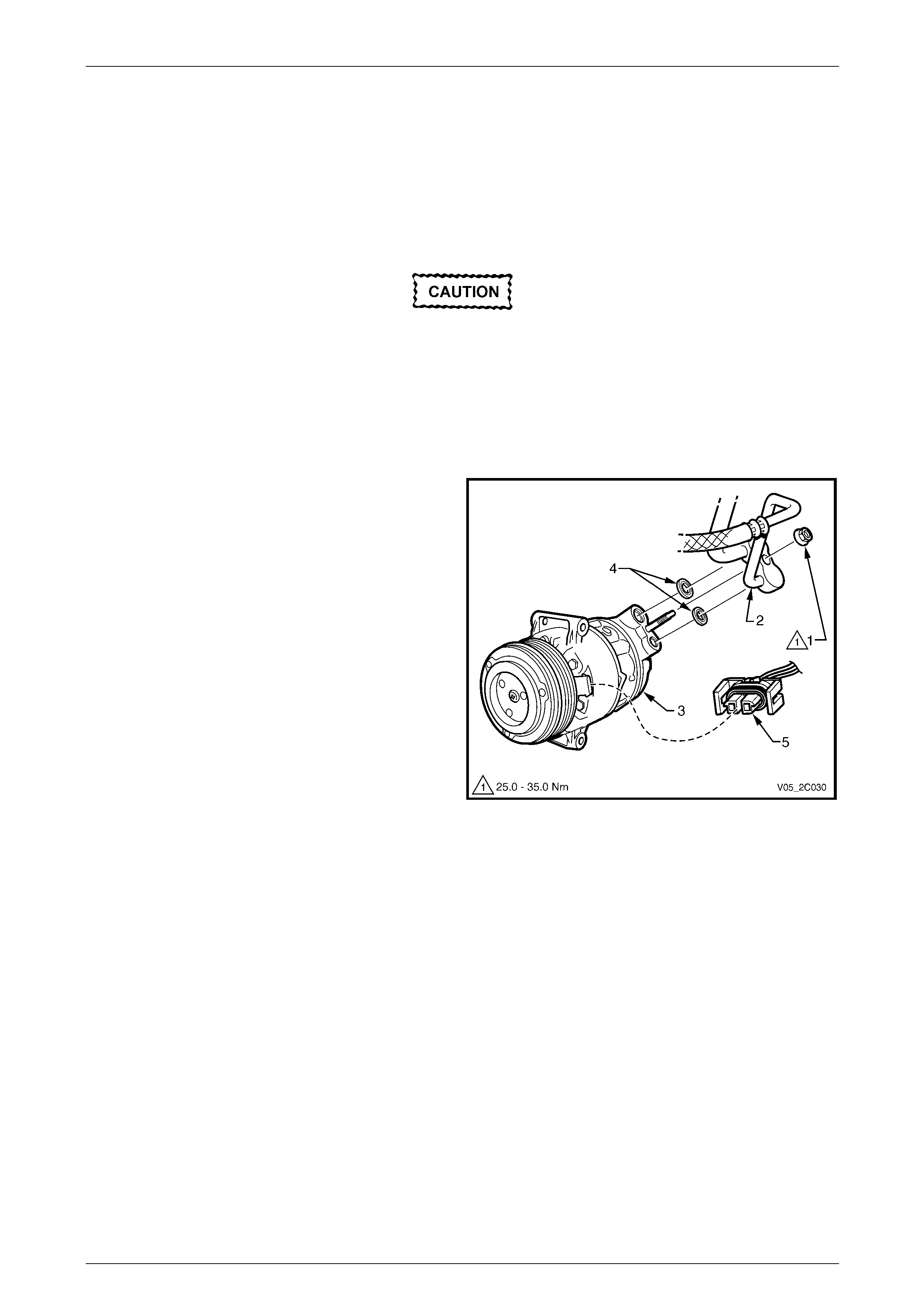
HVAC Climate Control (Manual A/C) – Removal and Installation Page 2C-65
Page 2C-65
6.5 Air-conditioning Compressor Assembly
LT Section No. — 08–200
V6 Engine – RWD
Remove
Disconnection of the battery affects certain
vehicle electronic systems. Refer to
Section 00 Warnings, Cautions and Notes
before disconnecting the battery.
1 Disconnect the battery ground lead.
2 Recover the refrigerant from the A/C system,
refer to Section 2B HVAC Climate Control (Manual A/C) – Servicing and Diagnosis.
3 Remove the nut (1) securing the suction / discharge
line pad (2) to the air-conditioning compressor
assembly (3).
4 Remove and discard the port seals (4).
5 Cap or plug the disconnected hoses an d ports
immediately to prevent absorption of moisture from the
atmosphere.
6 Remove the accessory drive belt, refer to
Section 6A1 Engine Mech anical – V6.
7 Disconnect the compressor clutch electrical
connector (5).
8 Raise the vehicle and place the vehicle on jack stands.
Refer to Section 0A General Information for the
location of jacking and support points.
Figure 2C – 83
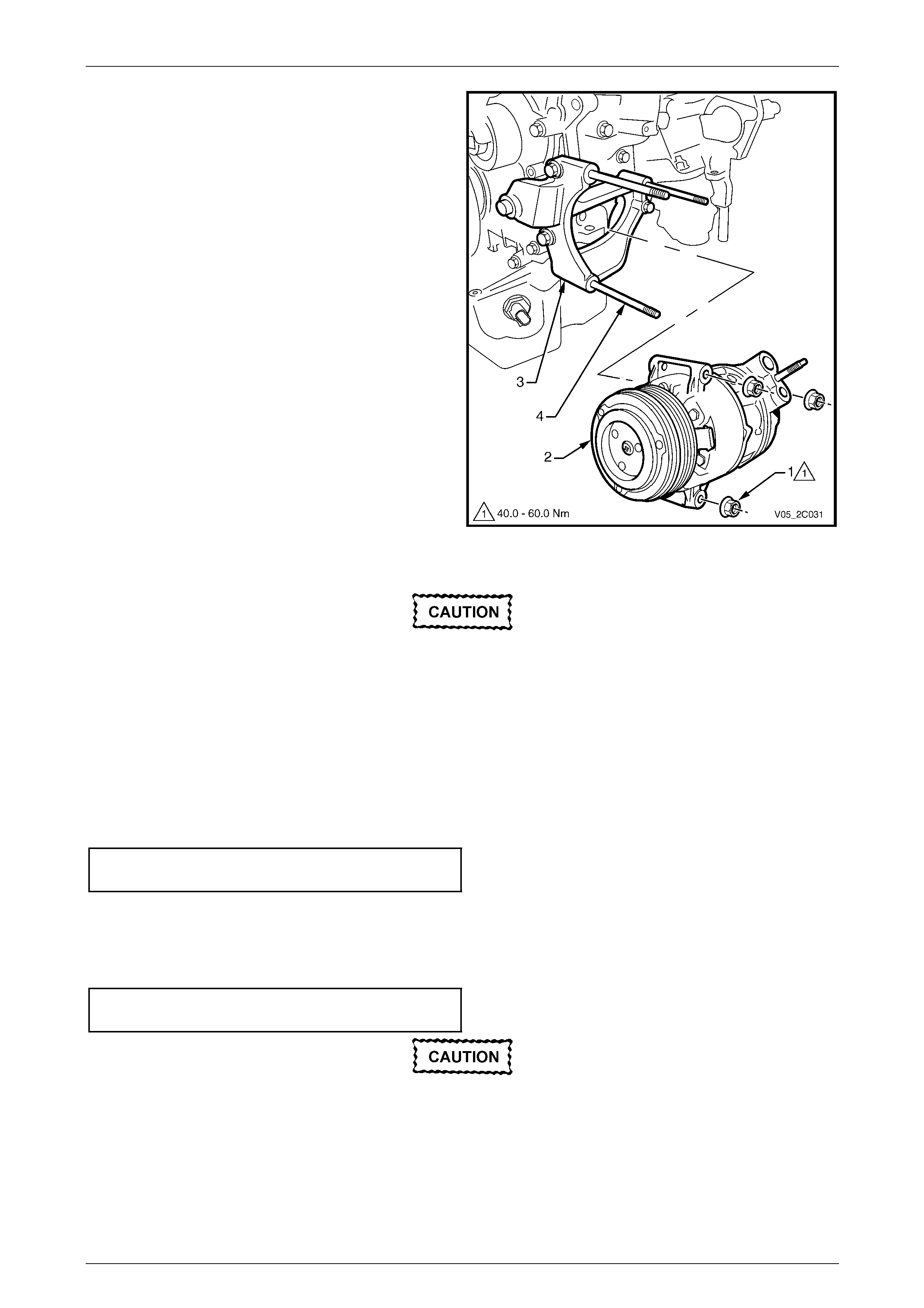
HVAC Climate Control (Manual A/C) – Removal and Installation Page 2C-66
Page 2C-66
9 Remove the three nuts (1) securing the compressor
assembly (2) to the compressor mounting bracket (3).
10 If required, remove the three compressor mountin g
studs (4). NOTE
The compressor mounting st uds have hexagon al
outer ends to enable their removal.
11 Remove the compressor assembly.
Figure 2C – 84
Reinstall
The total quantity of lubricating oil in the air-
conditioning system must be maintained. If a
compressor, evaporator, condenser, filter
drier receiver or air-conditioning line is
replaced, a specified quantity of lubricating
oil must be added to the system to
compensate for oil removed with the original
component. Refer to Section 2B HVAC
Climate Control (Manual A/C) – Servicing and
Diagnosis.
1 If required, reinstall the compressor mounting studs.
2 Install the air-conditioning compressor assembly and tighten the nuts to the correct torque specification.
Air-conditioning compressor assembly
retaining nut torque specification ............40.0 – 60.0 Nm
3 Install the accessory drive belt, refer to Section 6A1 Engine Mechanical – V6.
4 Remove the compressor port protection caps.
5 Install two new port sealing washers.
6 Fit the suction / discharge line pad to the compressor and tighten the nut to the correct torque specification.
Compressor suction / discharge lin e
pad retaining nut torque specification .....25.0 – 35.0 Nm
If fitting a new compressor, refer to
Section 2B HVAC Climate Control (Manual
A/C) – Servicing and Diagnosis for lubrication
requirements.
7 Evacuate and charge the A/C system with refrigerant,
refer to Section 2B HVAC Climate Control (Manual A/C) – Servicing and Diagnosis .
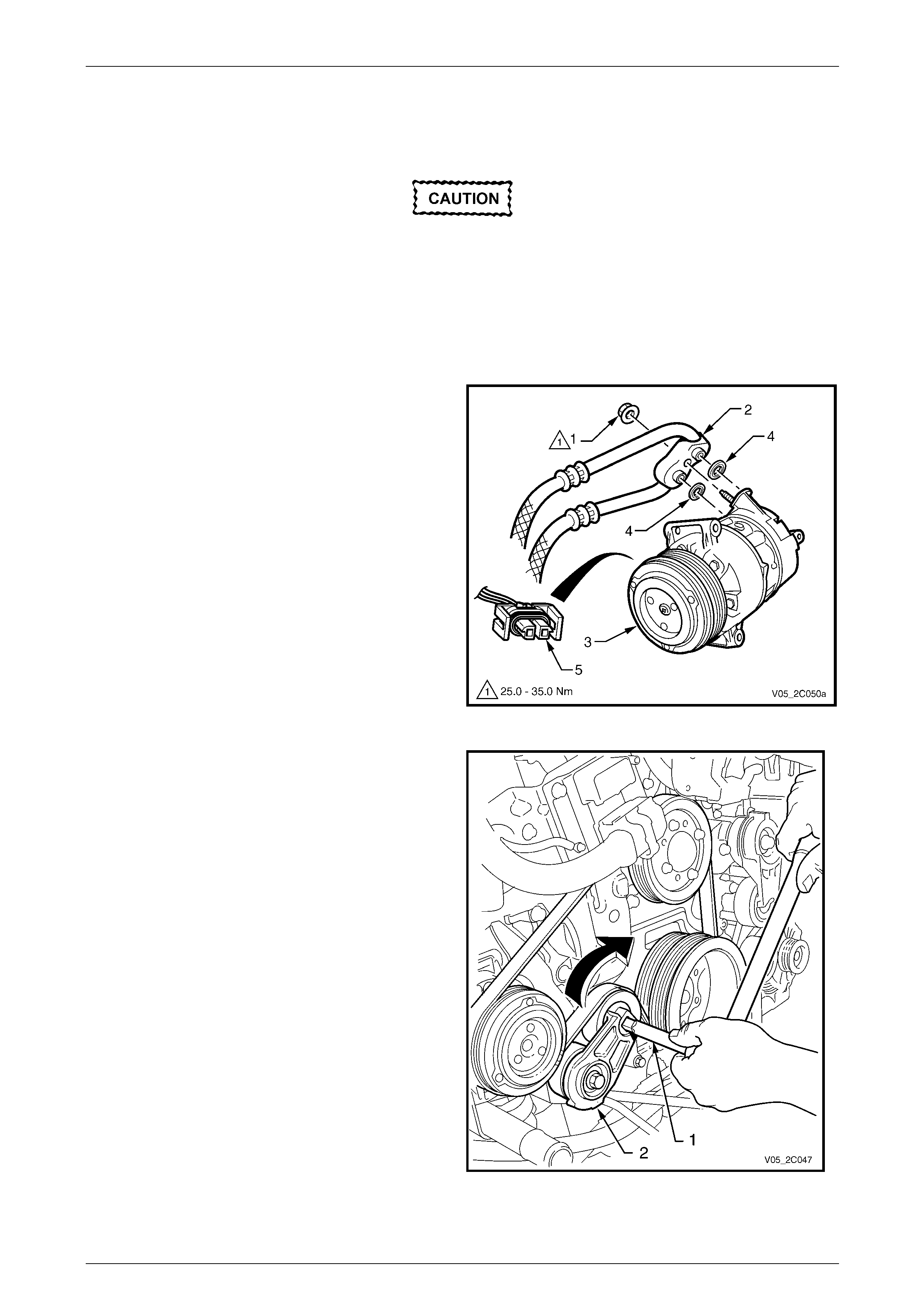
HVAC Climate Control (Manual A/C) – Removal and Installation Page 2C-67
Page 2C-67
V6 Engine – AWD
Remove
Disconnection of the battery affects certain
vehicle electronic systems. Refer to
Section 00 Warnings, Cautions and Notes
before disconnecting the battery.
1 Disconnect the battery ground lead.
2 Recover the refrigerant from the A/C system,
refer to Section 2B HVAC Climate Control (Manual A/C) – Servicing and Diagnosis.
3 Remove the nut (1) securing the suction / discharge
line pad (2) to the air-conditioning compressor
assembly (3).
4 Remove and discard the port seals (4).
5 Cap or plug the disconnected hoses an d ports
immediately to prevent absorption of moisture from the
atmosphere.
6 Disconnect the compressor clutch electrical
connector (5).
Figure 2C – 85
7 Using a ½ inch wrench socket extension shaft (1),
place it in the compressor drive belt tensioner
assembly (2) and release the belt tension to the
compressor belt.
8 Remove the compressor drive belt from the
compressor pulley.
NOTE
There is no requirement to completely remove
either of the drive belts when removing the
compressor. Allow the loosen ed A/C compressor
drive belt to rest on the crankshaft pulley until it
is required for installation.
Figure 2C – 86
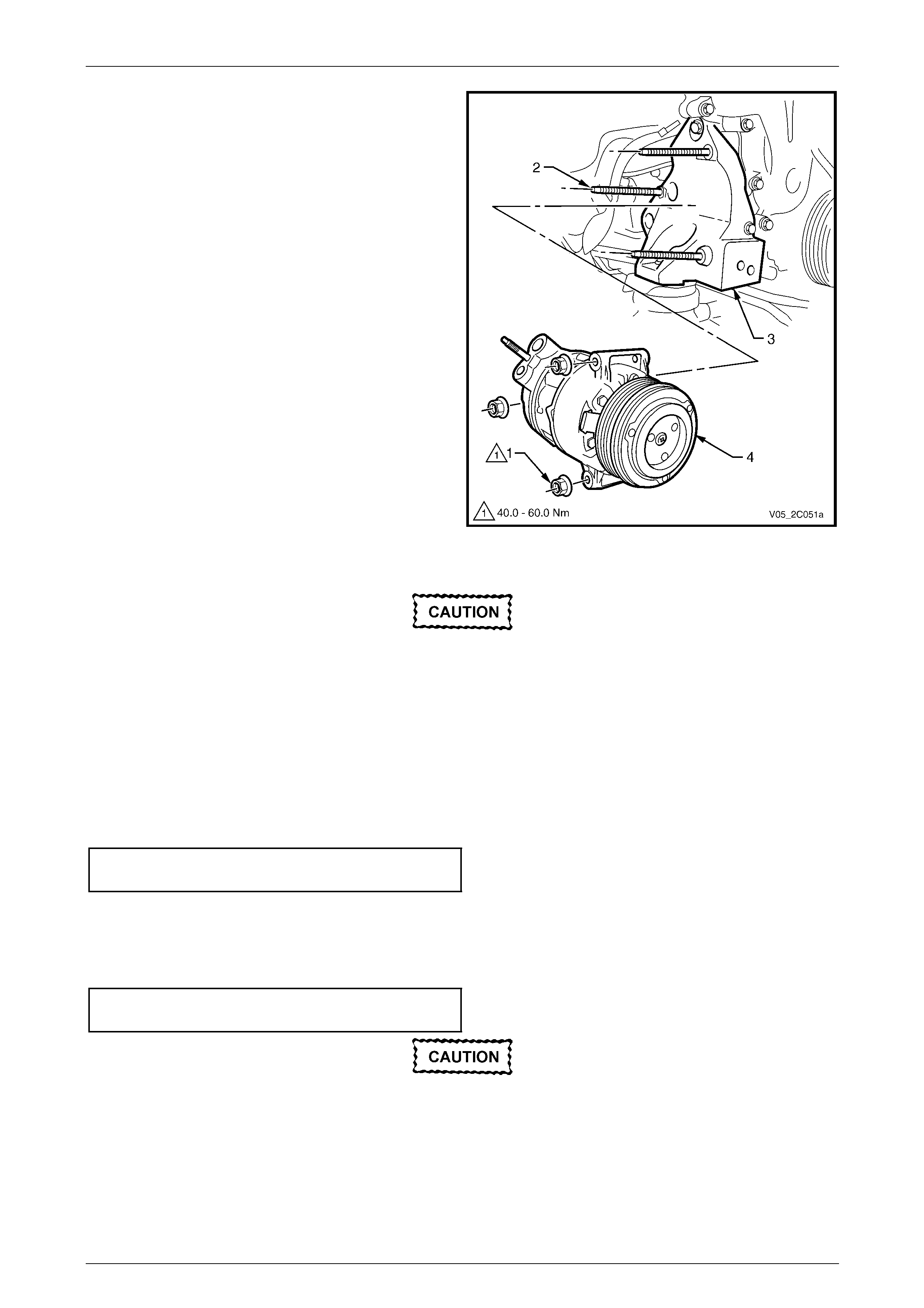
HVAC Climate Control (Manual A/C) – Removal and Installation Page 2C-68
Page 2C-68
9 Remove the three nuts (1) from the studs (2) attached
to the right-hand side engine mounting bracket (3)
retaining the compressor (4) to the engin e bl ock.
10 Supporting the compressor, remove the three
mounting studs. NOTE
The compressor mounting st uds have hexagon al
outer ends to enable their removal.
11 Remove the compressor from the vehicle.
Figure 2C – 87
Reinstall
The total quantity of lubricating oil in the air-
conditioning system must be maintained. If a
compressor, evaporator, condenser, filter
drier receiver or air-conditioning line is
replaced, a specified quantity of lubricating
oil must be added to the system to
compensate for oil removed with the original
component. Refer to Section 2B HVAC
Climate Control (Manual A/C) – Servicing and
Diagnosis.
1 Reinstall the mounting studs a nd the air-conditioning com pressor assembly.
2 Tighten the nuts retaining the compressor to the correct torque specification.
Air-conditioning compressor assembly
retaining nut torque specification ............40.0 – 60.0 Nm
3 Install the accessory drive belt, refer to Section 6A1 Engine Mechanical – V6.
4 Remove the compressor port protection caps.
5 Install two new port sealing washers.
6 Fit the suction / discharge line pad to the compressor and tighten the nut to the correct torque specification.
Compressor suction / discharge lin e
pad retaining nut torque specification .....25.0 – 35.0 Nm
If fitting a new compressor, refer to
Section 2B HVAC Climate Control (Manual
A/C) – Servicing and Diagnosis for lubrication
requirements.
7 Evacuate and charge the A/C system with refrigerant,
refer to Section 2B HVAC Climate Control (Manual A/C) – Servicing and Diagnosis .
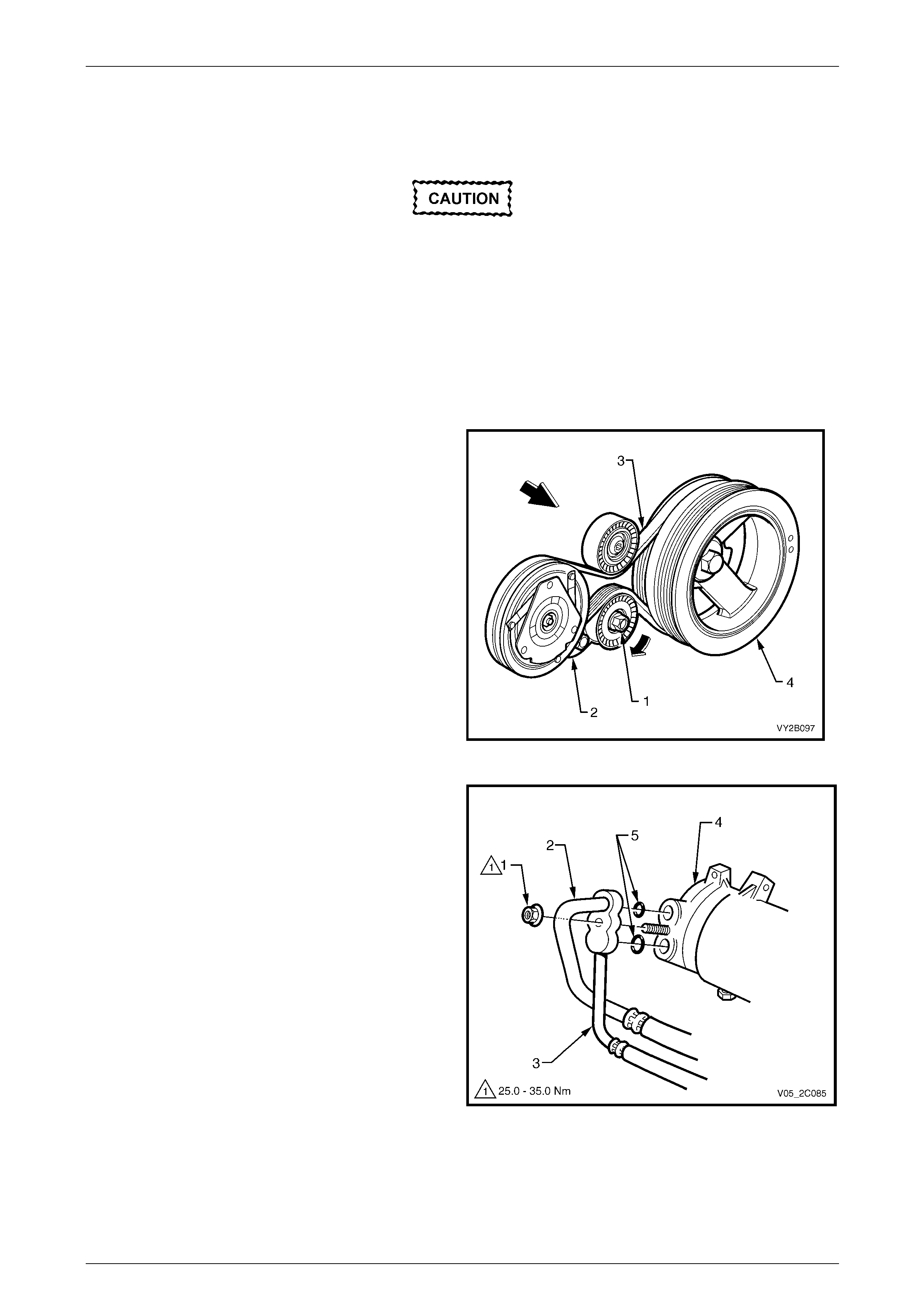
HVAC Climate Control (Manual A/C) – Removal and Installation Page 2C-69
Page 2C-69
GEN III V8 Engine
Remove
Disconnection of the battery affects certain
vehicle electronic systems. Refer to
Section 00 Warnings, Cautions and Notes
before disconnecting the battery.
1 Disconnect the battery ground lead.
2 Drain coo lant and remove th e heat er hos es and lo wer radi ator co olant hos e from the cylinde r block,
refer to Section 6B3 Engine Cooling – GEN III V8.
3 Recover the refrigerant from the A/C system,
refer to Section 2B HVAC Climate Control (Manual A/C) – Servicing and Diagnosis.
4 Using a 15 mm socket attached to the centre bolt (1)
of the air-conditioning drive belt tensioner (2), rotate
the tensioner in the direction shown to relieve the
tension on the belt (3).
5 Remove the air-conditioning drive belt from all pulleys
except the crankshaft pulley ( 4). Allow the belt to
remain on the crankshaft pulley.
Figure 2C – 88
6 Loosen and remove the nut (1) retaining the
suction (2) and discharge (3) hoses to the
compressor (4). Remove the hoses (2 and 3) from the
compressor.
7 Discard the seals (5).
8 Cap or plug the ports immediately to prevent entry of
moisture from the atmosphere.
9 Disconnect the compressor clutch electrical connector.
Figure 2C – 89
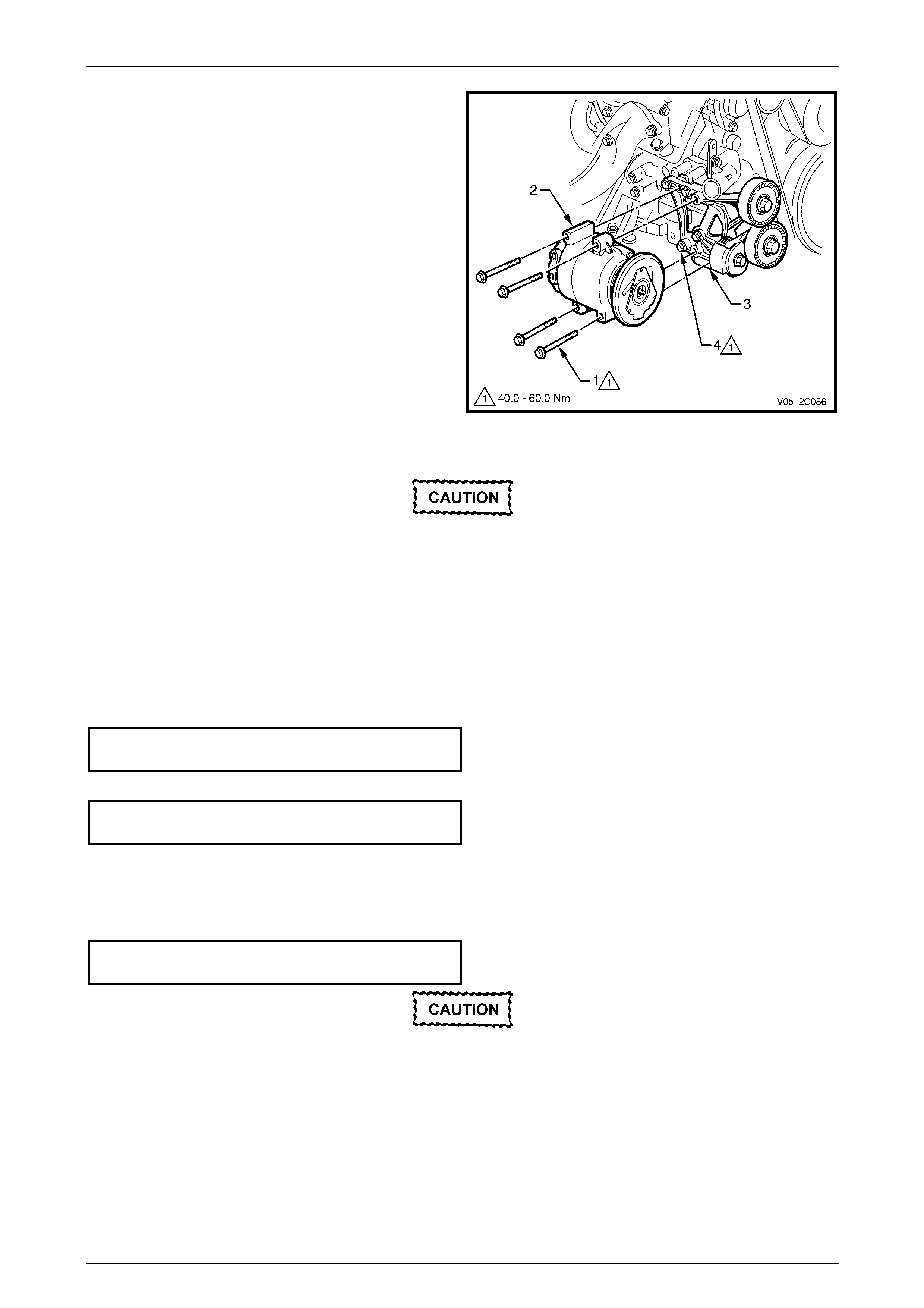
HVAC Climate Control (Manual A/C) – Removal and Installation Page 2C-70
Page 2C-70
10 Remove the four bolts (1) retaining the comp ressor (2)
to the mounting bracket (3).
11 Remove the compressor.
12 If required, remove the four bolts (4) attaching the
compressor mounting bracket to the cylinder block and
remove the bracket.
Figure 2C – 90
Reinstall
The total quantity of lubricating oil in the air-
conditioning system must be maintained. If a
compressor, evaporator, condenser, filter
drier receiver or air-conditioning line is
replaced, a specified quantity of lubricating
oil must be added to the system to
compensate for oil removed with the original
component. Refer to Section 2B HVAC
Climate Control (Manual A/C) – Servicing and
Diagnosis.
1 If removed, reinstall the compressor mounting bracket and tighten the four attaching bolts to the correct torque
specification.
Compressor mounting bracket
attaching bolt torque specification...........40.0 – 60.0 Nm
2 Install the air-conditioning compressor assembly and tighten the bolts to the correct torque specification.
Air-conditioning compressor assembly
attaching bolt torque specification...........40.0 – 60.0 Nm
3 Install the air-conditioning driv e belt, refer to Section 6A3 E ngine Mechanical – GEN III V8.
4 Remove the compressor port protection caps.
5 Install two new port seals.
6 Fit the suction / discharge line pad to the compressor and tighten the nut to the correct torque specification.
Compressor suction / discharge lin e
pad retaining nut torque specification .....25.0 – 35.0 Nm
If fitting a new compressor, refer to
Section 2B HVAC Climate Control (Manual
A/C) – Servicing and Diagnosis for lubrication
requirements.
7 Install the compressor clutch electrical conn ector.
8 Install the heater and lower radiator coolant hoses.
9 Refill the coolant system, refer to Section 6B3 Engine Cooling – GEN III V8.
10 Evacuate and charge the A/C system with refrigerant,
refer to Section 2B HVAC Climate Control (Manual A/C) – Servicing and Diagnosis .

HVAC Climate Control (Manual A/C) – Removal and Installation Page 2C-71
Page 2C-71
7 Drive Belts and Pulleys
With V6 engine, for replacement of the accessor y drive belt and the accessory drive belt idler and tensio ner
pulley assemblies, refer to Section 6A1 Engine Mech anical – V6.
With GEN III V8 engine, for replacement of the air-conditioning driv e belt and the air-conditionin g drive belt idler
and tensioner pulle y assemblies, refer to Section 6A3 Engine Mechanical – GEN III V8.

HVAC Climate Control (Manual A/C) – Removal and Installation Page 2C-72
Page 2C-72
8 Minor Compressor Repairs –
GEN III V8
Illustrations used in the follo wing procedures sho w the air-conditioning compressor removed from the vehicle for easier
viewing.
When servicing the compressor, remove only the parts in need of service, as determined by preliminary diagnosis.
Removal and installation of external parts of the compressor and disassembly / assembly of internal parts must be
performed on a clean workbench. T he work area, tools and parts must be clean at all tim es.
The total quantity of lubricating oil in the air-
conditioning system must be maintained. If a
compressor, evaporator, condenser, filter
drier receiver or air-conditioning line is
replaced, a specified quantity of lubricating
oil must be added to the system to
compensate for oil removed with the original
component. Refer to Section 2B HVAC
Climate Control (Manual A/C) – Servicing and
Diagnosis.
The only components that can be serviced are:
• rotor and bearing assembly,
• control valve,
• front armature plate,
• field coil,
• pad sealing washers,
• shaft nut and keyway,
• compressor pad sealing washers (‘O-rings’).
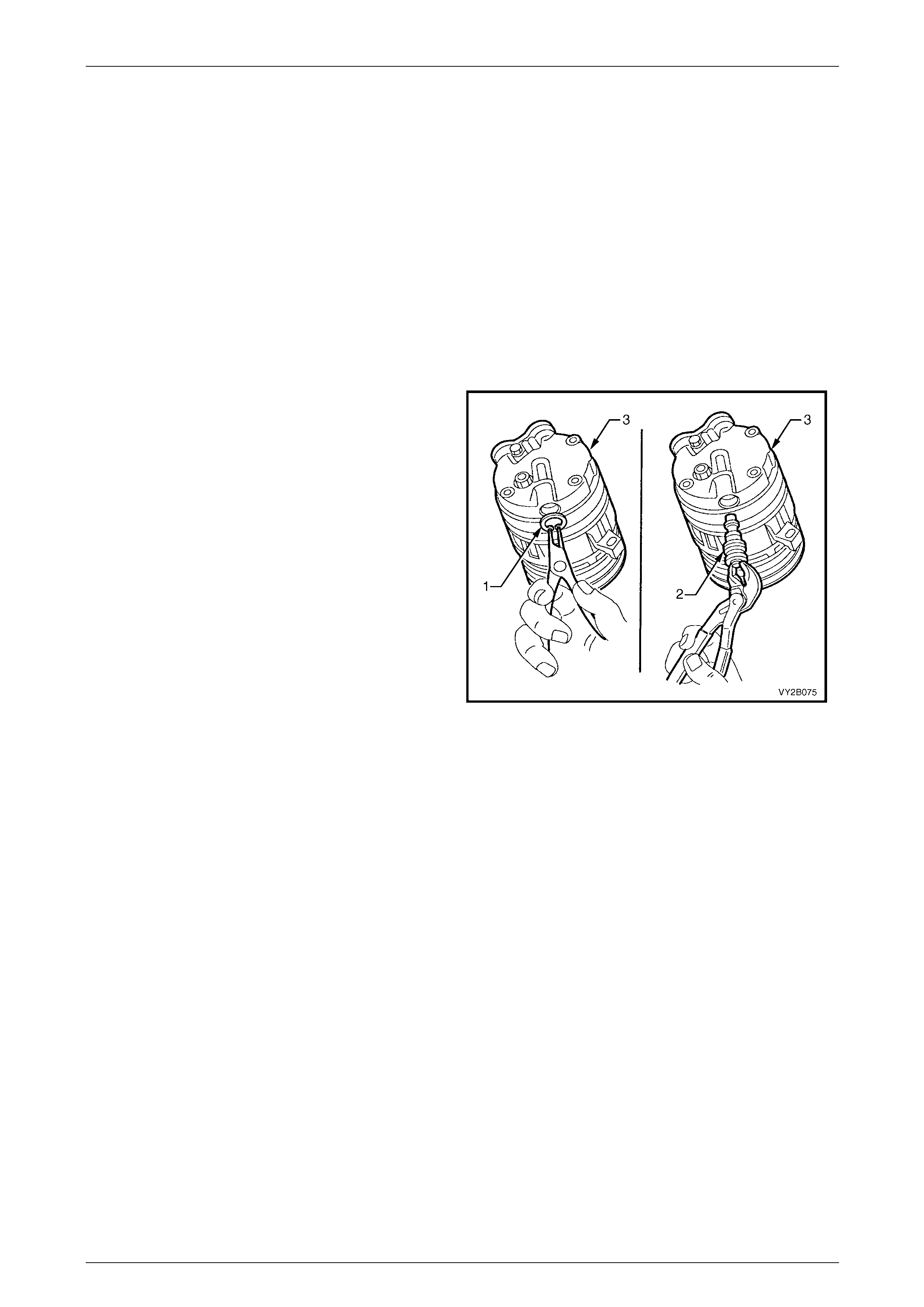
HVAC Climate Control (Manual A/C) – Removal and Installation Page 2C-73
Page 2C-73
8.1 Compressor Control Valve
LT Section No. — 08–200
Remove
1 Recover the refrigerant from the A/C system,
refer to Section 2B HVAC Climate Control (Manual A/C) – Servicing and Diagnosis.
2 Raise the front of the vehicle and support it on safety stands, refer to Section 0A General Information.
3 From beneath the vehicle remove the following, refer to Section 6B3 Engine Cooling – GEN III V8:
a under-tray, attached to the crossmember,
b lower air baffle /chute.
4 From beneath the vehicle remove the circl ip (1)
securing the control valve (2) to the compres sor (3).
5 Using a pair of suitable circlip pliers remove the control
valve from the compressor by pulling downwards.
Quickly insert the replacement control valve (this will
avoid any minor oil loss).
Figure 2C – 91
Reinstall
1 Lubricate the control valve O-rings and carefully push the c ontrol valve into the compressor.
2 Inspect the control valve retaining circlip, rep lace as required. Secure the control valve .with the circlip and ensure
the circlip is fully seated in its groove.
3 If lubricating oil has been lost duri ng the control valve removal procedure, add new lubricating oil as required,
through the suction port of the compressor.
Refer to Section 2B HVAC Climate Control (Manual A/C) – Servicin g and Diagnosis.
4 Install the lower air baffle / chute and under-tray, refer to Section 6B3 Engine Cooling – GEN III V8.
5 Evacuate and charge the A/C system with refrigerant,
refer to Section 2B HVAC Climate Control (Manual A/C) – Servicing and Diagnosis .
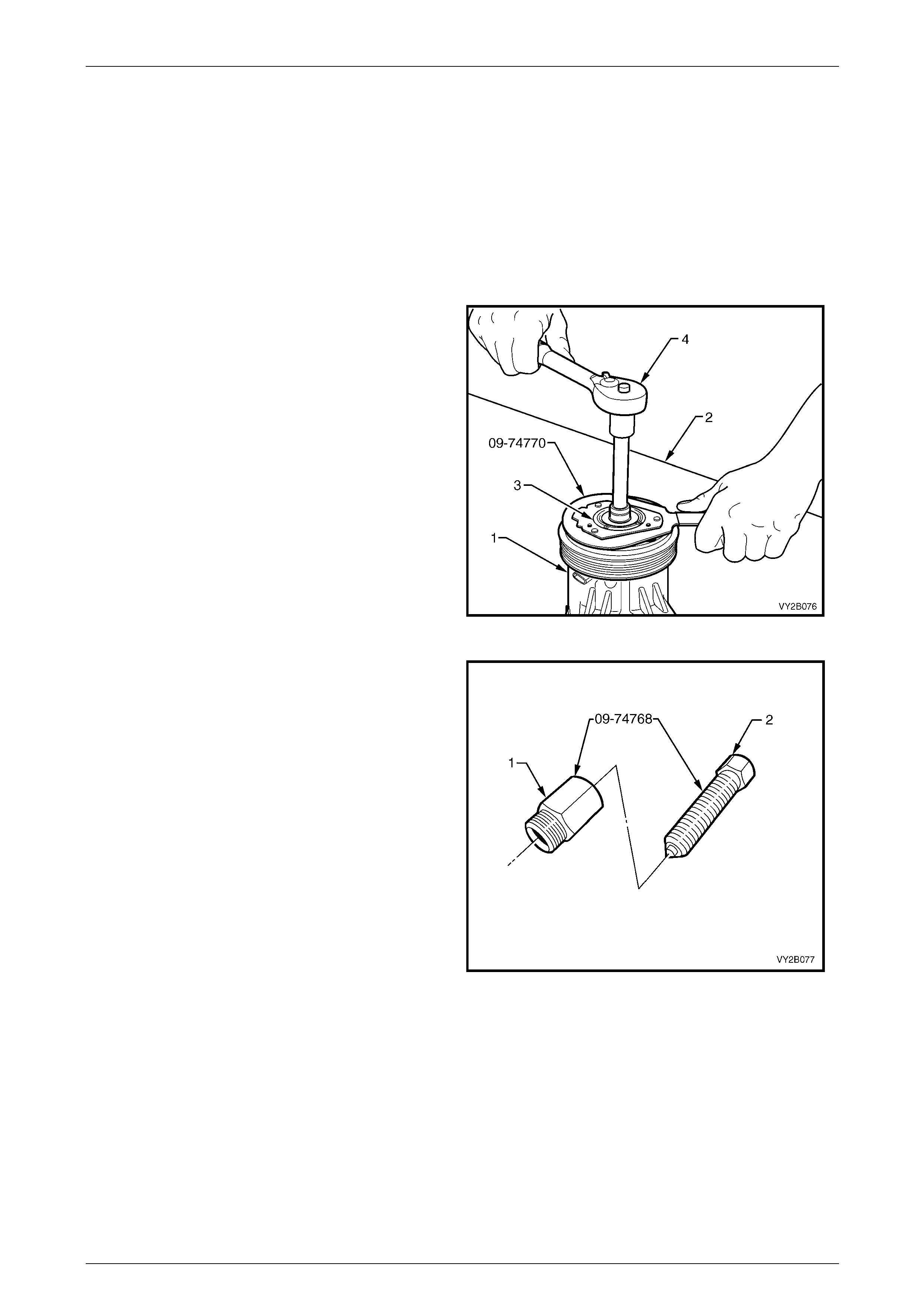
HVAC Climate Control (Manual A/C) – Removal and Installation Page 2C-74
Page 2C-74
8.2 Clutch Drive Plate and Hub Assembly
LT Section No. — 08–200
Remove
1 Recover the refrigerant from the A/C system,
refer to Section 2B HVAC Climate Control (Manual A/C) – Servicing and Diagnosis.
2 Remove the air-conditionin g compressor from the vehicle, refer to 6.5 Air-conditioning Compressor Assembly.
3 Place the compressor (1) on a clean work bench (2).
4 Use the clutch hub holdin g tool 09-74770 to keep the
hub assembly (3) from turning and remove the
compressor shaft nut using suitable ha nd tools (4).
Figure 2C – 92
5 Assemble the nut (1) and centre screw (2) of the
clutch hub and drive plate remover, Tool No. 09-74768
as shown. Install the centre screw no more than 2 cm
into the nut.
Figure 2C – 93
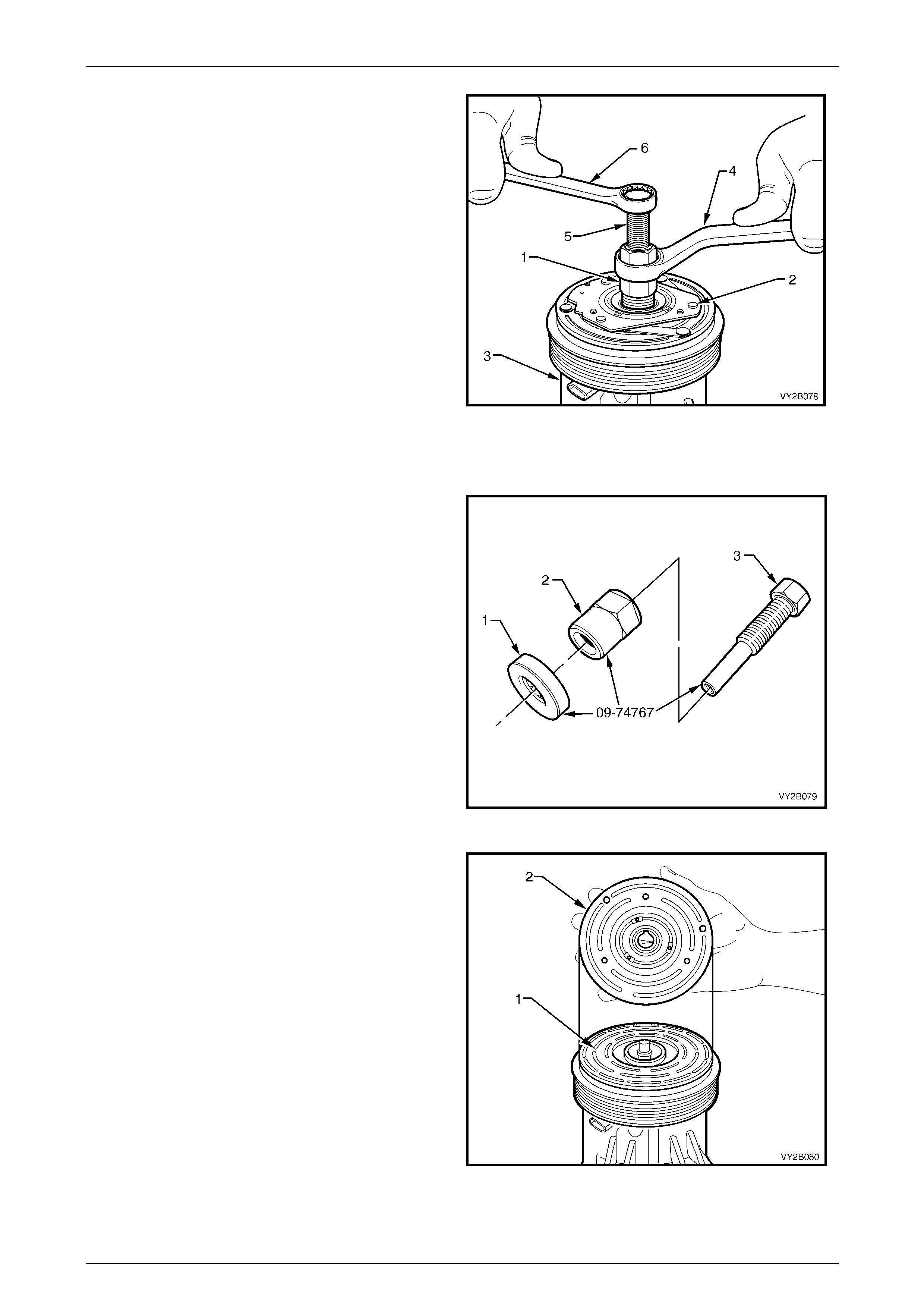
HVAC Climate Control (Manual A/C) – Removal and Installation Page 2C-75
Page 2C-75
6 Install the nut (1) of the Tool No. 09-74768, fully into
the clutch hub (2) of the compressor (3).
7 Hold the nut of Tool No. 09-74768 with a suitable hand
tool (4) and turn the centre screw (5) of the tool using
a second suitable hand tool (6) to remove the clutch
drive plate and hub assembly, as shown.
8 Remove the shaft key.
Figure 2C – 94
Reinstall
1 Assemble the bea ring (1) , nut (2 ) an d cen tre sc rew (3 )
of the clutch hub and drive plate installer Tool
No. 09-74767, as show n. In stal l the nu t up to the
hexagonal section of the centre screw .
Figure 2C – 95
2 Ensure the clutch contact surfaces of the clutch
pulley (1) and clutch plate (2) are clean before
installing the clutch plate and hub assembly to the
compressor. If necessary, remove any oil or grease
from the clutch surfaces with a clean, lint free cloth
dampened with methylated spirits and allow the
surfaces to dry.
Figure 2C – 96
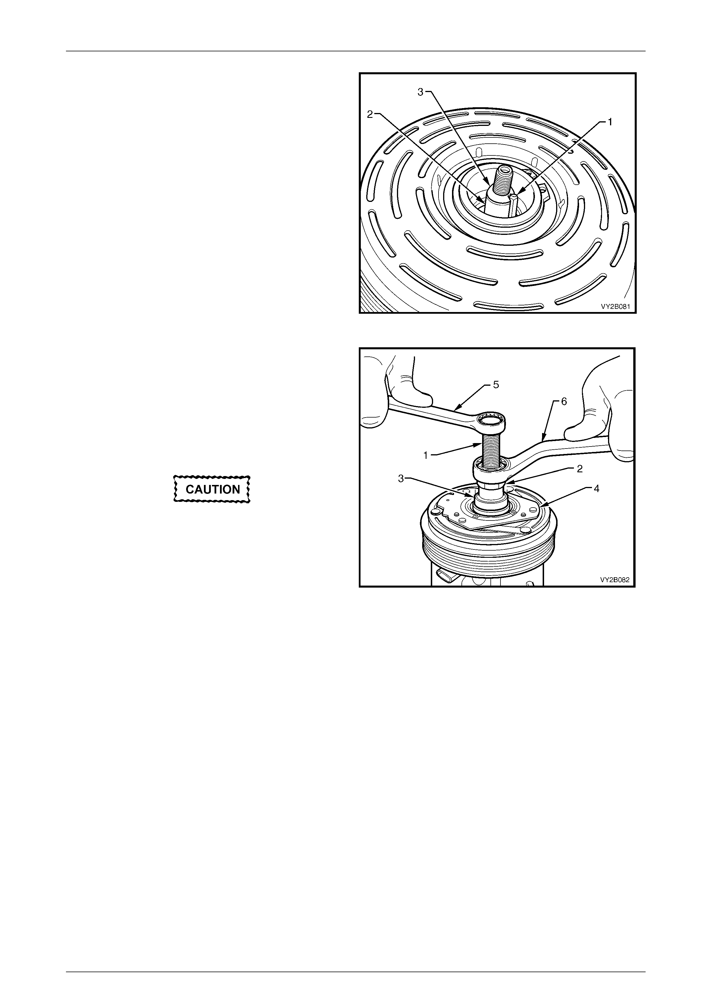
HVAC Climate Control (Manual A/C) – Removal and Installation Page 2C-76
Page 2C-76
3 Place a small amount of assembly grease on the
key (1) to locate it in the keyway of the compressor
shaft (2). Install the key level with the top of the
tapered section (3) of the compressor shaft, as shown.
4 Align the clutch hub keyway with the key and install
the clutch plate and hub assembly onto the
compressor shaft. Push as far as possible by hand,
the clutch plate and hub assembly onto the
compressor shaft ensuring the ke y has rem ain ed in
position.
Figure 2C – 97
5 Install the centre screw (1) fully onto the end of the
compressor shaft and turn the nut (2) do wn the centre
screw until the bearing (3) of installer T ool
No. 09-74767 contacts the clutch hub (4).
6 Hold the centre screw with a suitable hand tool (5) and
continue to turn the nut down using a sec on d a
suitable hand tool (6) to press the clutch hub and drive
plate onto the compressor shaft.
Excessive force is not required to install the
clutch hub and drive plate onto the
compressor shaft.
• If excessive force is required, remove the
special Tool No. 09-74767 and inspect
components.
• If the key has fallen down the keyway
causing it to protrude excessively from
the keyway, continuing the installation
procedure will damage components.
Figure 2C – 98
7 Turn the nut several turns and remove the installer
Tool No. 09-74767 from the compress or.
8 Check if the shaft key is located correctly in the
keyway before installing the clutch plate and hub
assembly to its final position.
9 Install Tool No. 09-74767 onto the compressor again
and press the clutch hub an d drive plate fully onto the
compressor shaft.
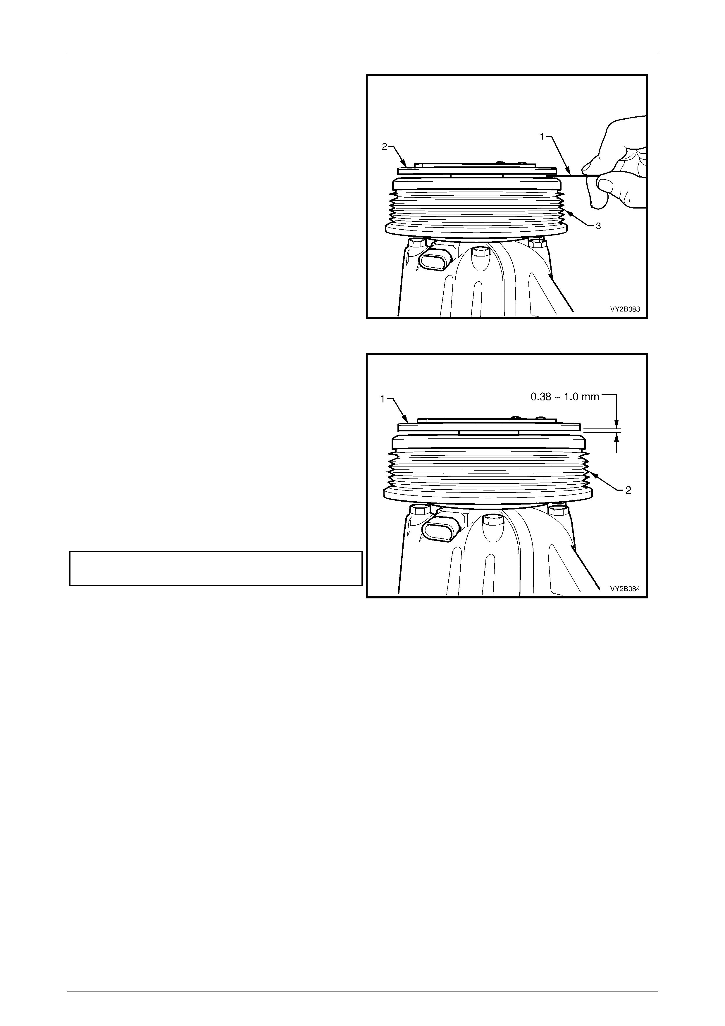
HVAC Climate Control (Manual A/C) – Removal and Installation Page 2C-77
Page 2C-77
10 Using a non-magnetic feeler strip (1) measure the air
gap between the frictional surfaces of the clutch
plate (2) and the clutch pulley (3).
Figure 2C – 99
NOTE
The air gap between the frictio nal surfaces of the
clutch plate (1) and the clutch pulley (2) must be
0.38 – 1.0 mm, and be checked with a
non-magnetic feeler strip.
11 Remove Tool No 09-74767 and check for proper
positioning of the shaft key. The key should be level
with, or slightly above the clutch hub.
12 Install the shaft nut, and holding the clutch pl ate and
hub assembly with the clutch hub h olding Tool
No 09-74770, tighten the nut to the correct torque
specification.
Clutch drive plate and hub assembly
retaining nut torque specification ............11.0 – 22.0 Nm
13 Re-check the air gap and spin the pull ey by hand,
checking if the pulley is not touching the drive plate.
14 Install the compressor to the vehicle, refer to
6.5 Air-conditioning Compressor Assembly.
15 Evacuate and charge the A/C system with refrigerant,
refer to Section 2B HVAC Climate Control (Manual
A/C) – Servicing and Diagnosi s .
Figure 2C – 100
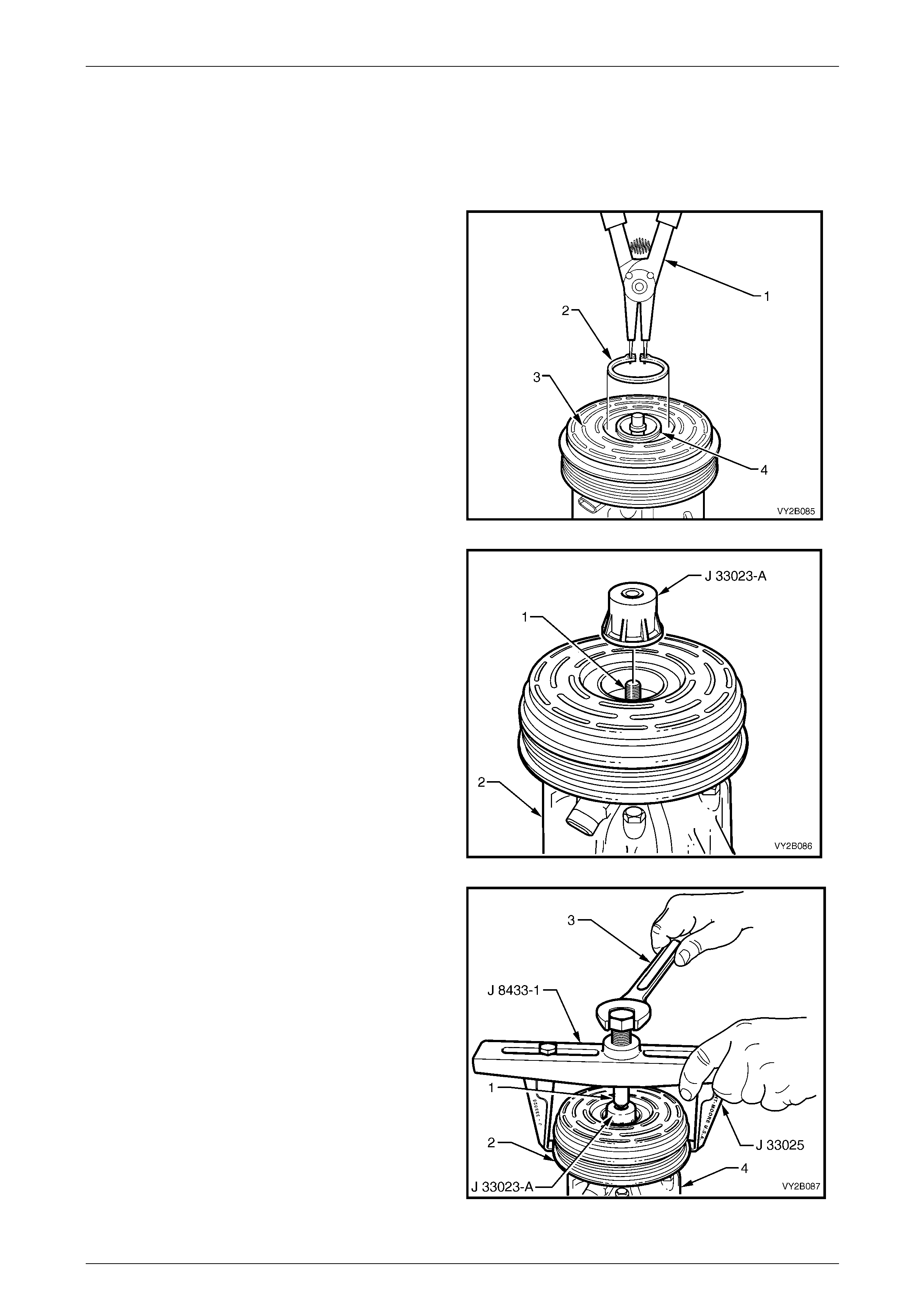
HVAC Climate Control (Manual A/C) – Removal and Installation Page 2C-78
Page 2C-78
8.3 Clutch Pulley and Bearing Assembly
LT Section No. — 08–200
Remove
1 Remove the air-conditioning compressor
from the vehicle, refer to
6.5 Air-conditioning Compressor Assembly.
2 Remove the clutch drive plate and hub assembly,
refer to 8.2 Clutch Drive Plate and Hub Assembly.
3 Using suitable ext ernal circlip pliers (1), remove the
circlip (2) the retaining the clutch pulley and bearing
assembly (3) to the compressor housing (4).
Figure 2C – 101
4 Install the puller pilot Tool No. J-33023-A onto the end
of the shaft (1) of the compressor (2).
Figure 2C – 102
5 Attach the puller legs, Tool No. J-33025, to the pu ller
bar Tool No. J-8433-1. Locate the centre screw (1) of
the puller bar in the countersink hole of the pull er pi lot
Tool No. J-33023-A. Engage the puller leg tangs under
the clutch pulley (2), as shown.
6 Turn the centre screw of the puller bar, Tool
No. J-8433-1, using a suitable hand tool (3) to remove
the clutch pulley and bearing assembly from the
compressor (4).
Figure 2C – 103
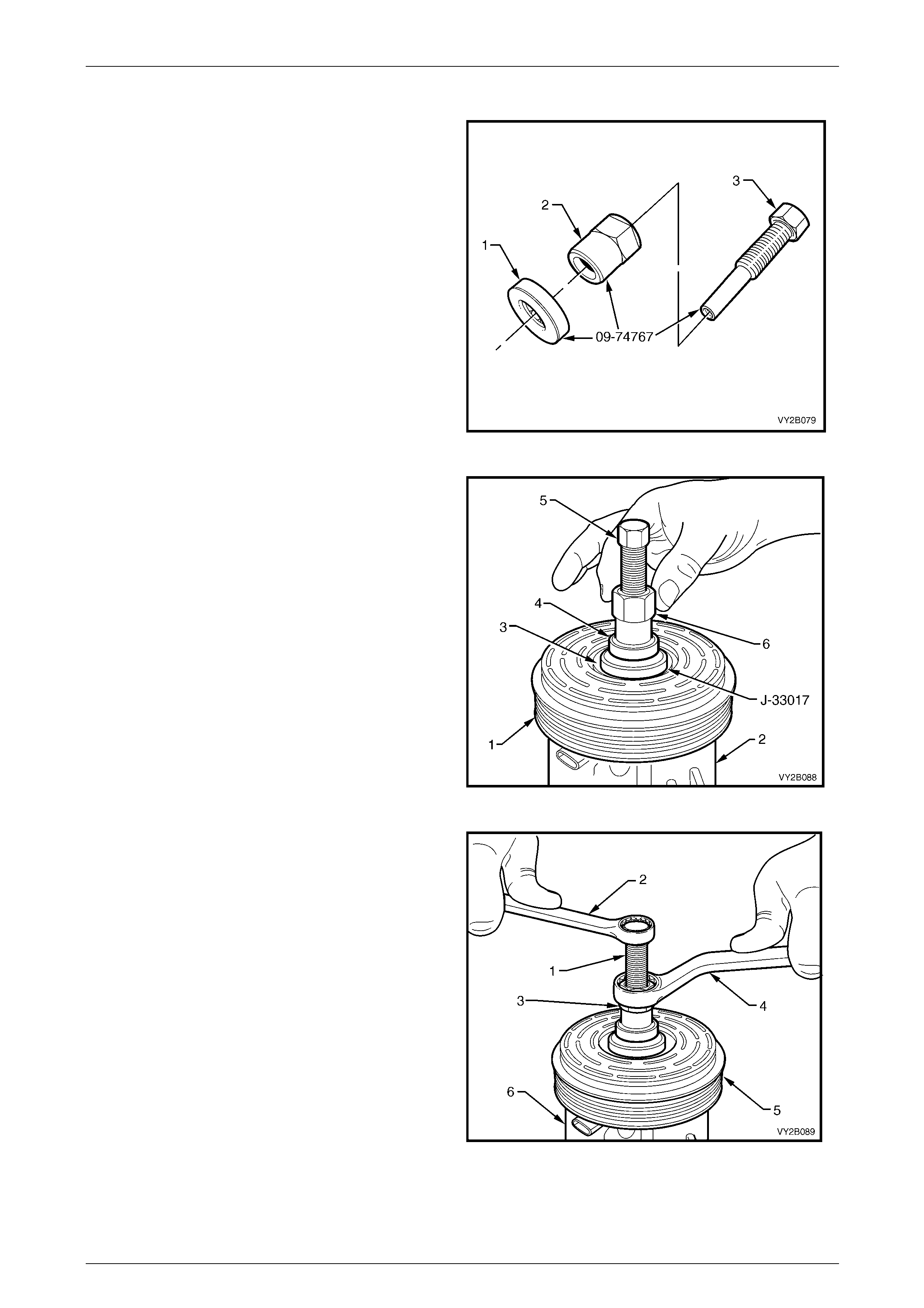
HVAC Climate Control (Manual A/C) – Removal and Installation Page 2C-79
Page 2C-79
Reinstall
1 Assemble the bea ring (1) , nut (2 ) an d cen tre sc rew (3 )
of the clutch hub and drive plate installer Tool
No. 09-74767. Install the nut up to the hexagonal of th e
centre sc rew.
Figure 2C – 104
2 Position the clutch pulley and bearing assembly (1) on
the compressor housing (2).
3 Position special Tool No. J-33017 with the larger
diameter facing down, between the pulley bearing (3)
and the bearing (4) of the installer, Tool No. 09-74767,
as shown.
4 Install the centre screw (5) of special Tool
No. 09-74767, fully onto the end of the compressor
shaft. Rotate the nut (6) down the screw until the
assembly is hand tensioned.
Figure 2C – 105
5 Hold the centre screw (1) with a suitable hand tool (2)
and turn the nut (3) with a second suitable hand
tool (4) to press the pulley and bearing assembly (5)
onto the compressor housing (6).
6 Install the circlip retaining the clutch pulley and be aring
assembly to the compressor housing.
7 Install the clutch drive plate and hub assem bly,
refer to 8.2 Clutch Drive Plate and Hub Assembly.
Figure 2C – 106
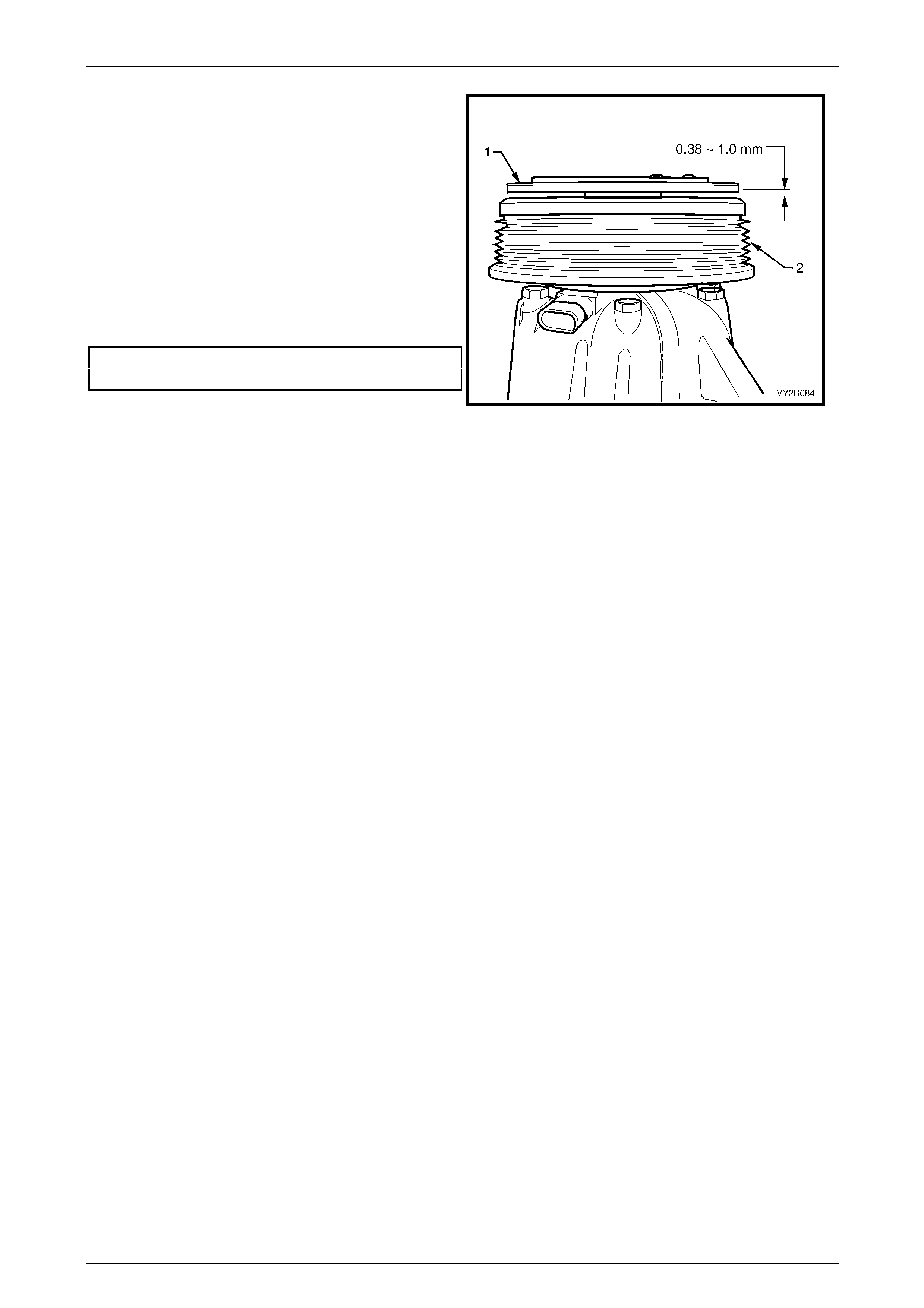
HVAC Climate Control (Manual A/C) – Removal and Installation Page 2C-80
Page 2C-80
NOTE
The air gap between the frictio nal surfaces of the
clutch plate (1) and the clutch pulley (2) must be
0.38 – 1.0 mm, and be checked with a
non-magnetic feeler strip.
8 Remove Tool No. 09-74767 and check for proper
positioning of the shaft key. The key should be level
with, or slightly above the clutch hub.
9 Install the shaft nut, and holding the clutch pl ate and
hub assembly with the clutch hub h olding, Tool
No. 09-74770, tighten the nut to the correct torque
specification.
Clutch drive plate and hub assembly
retaining nut torque specification ............11.0 – 22.0 Nm
10 Re-check the air gap and spin the pull ey by hand,
checking that the pulley is not touching the drive plate.
Figure 2C – 107
11 Install the compressor, refer to 6.5 Air-conditioning Compressor Assembly.
12 Evacuate and charge the A/C system with refrigerant,
refer to Section 2B HVAC Climate Control (Manual A/C) – Servicing and Diagnosis .
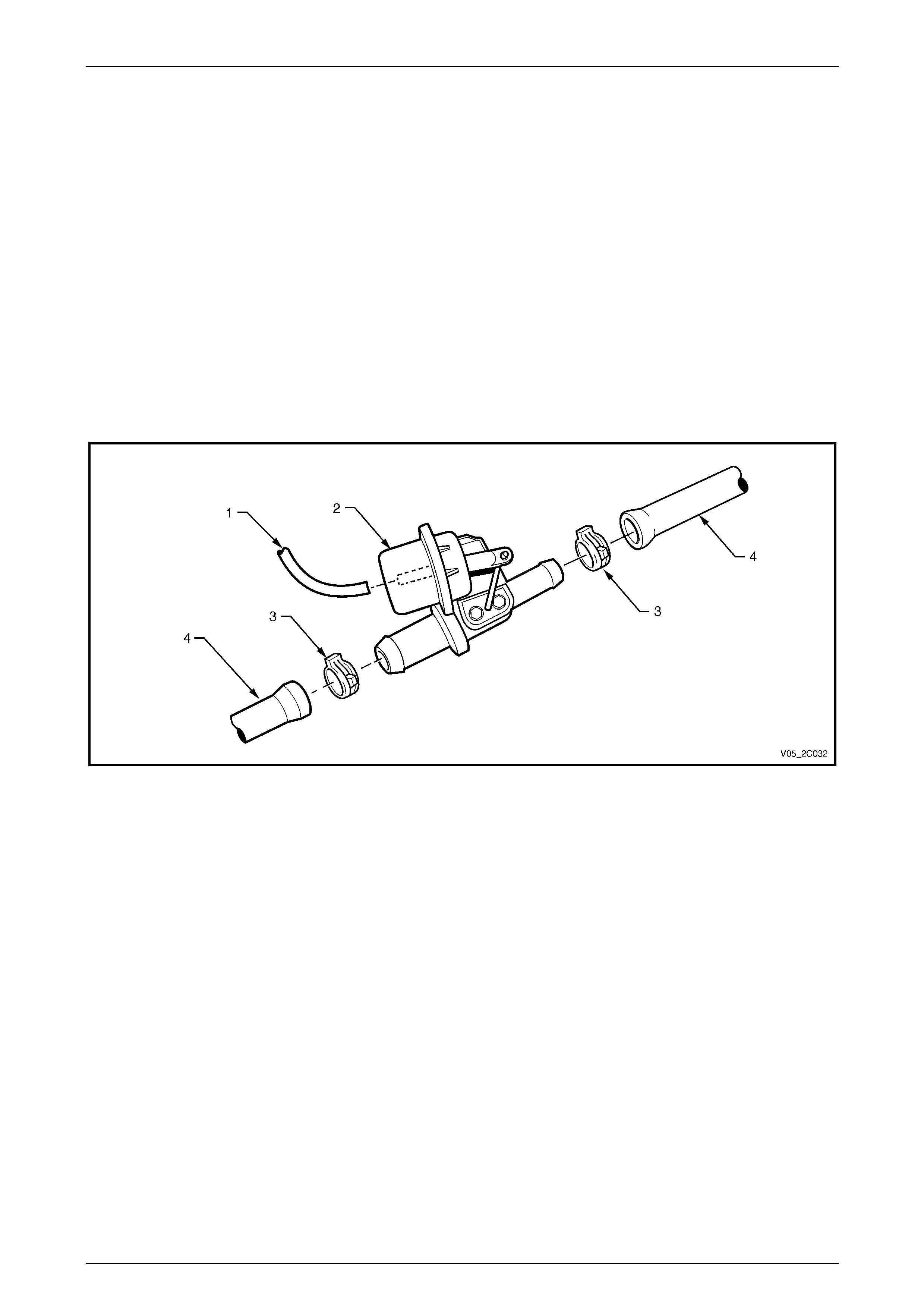
HVAC Climate Control (Manual A/C) – Removal and Installation Page 2C-81
Page 2C-81
9 Under-hood Heater Components
9.1 Water Valve Assembly
LT Section No. — 08–075
V6 Engine
Remove
1 Drain engine coolant into a suitable, clean container, refer to Section 6B1 Engine Cooling – V6.
2 Remove the vacuum hose (1) from the water valve actuator (2), refer to Figure 2C – 108.
3 Remove the two hose clips (3) from the water valve assembly ports.
4 Remove the two heater hoses (4) from the water valve asse mbly.
Figure 2C – 108
Test
To test the water valve actuator refer to 4.1 Vacuum Retention Tests. Also check for free movement of the actuator arm
and disc and ensure the ports are clear of a ny obstructions.
Reinstall
Reinstallation of the water valve assemb ly is the reverse of the removal procedure, noting the following:
1 Install the hoses to the correct ports of the water valve to maintain correct coolant flow.
2 Fill the cooling system with the correct specification and quantity of coolant and pressure-test the cooling system,
refer to Section 6B1 Engine Cooling – V6.
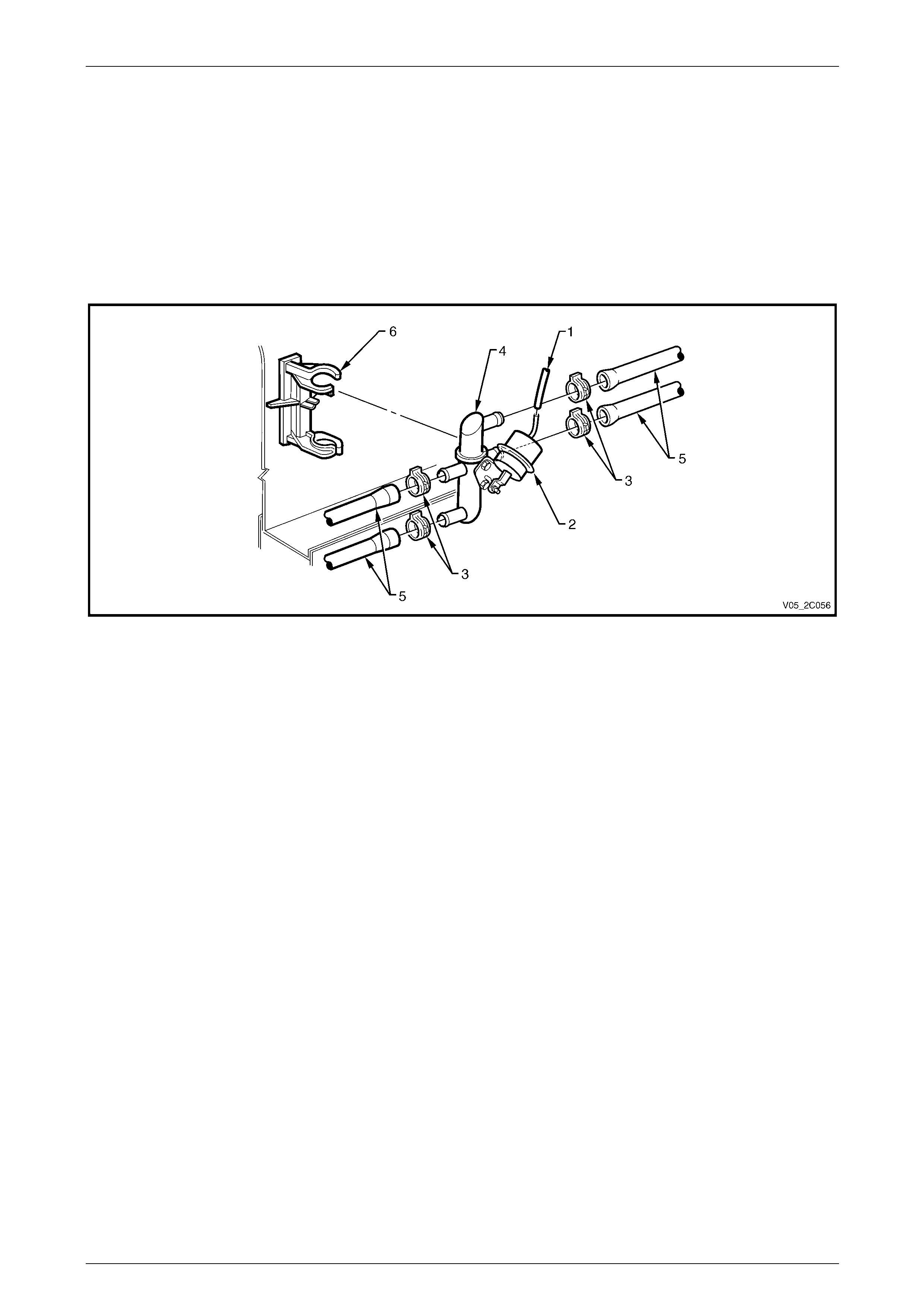
HVAC Climate Control (Manual A/C) – Removal and Installation Page 2C-82
Page 2C-82
GEN III V8 Engine
Remove
1 Drain engine coolant into a suitable, clean container, refer to Section 6B3 Engine Cooling – GEN III V8.
2 Remove the vacuum hose (1) from the water valve actuator (2), refer to Figure 2C – 109.
3 Remove the four hose clips (3) from the water valve (4) ports.
4 Remove the four heater hoses (5) from the water valve.
5 Remove the water valve assembly from the bracket (6).
Figure 2C – 109
Test
To test the water valve actuator refer to 4.1 Vacuum Retention Tests. Also check for free movement of the actuator arm
and disc and ensure the ports are clear of a ny obstructions.
Reinstall
Reinstallation of the water valve assemb ly is the reverse of the removal procedure, noting the following:
1 Install the hoses to the correct ports of the water valve to maintain correct coolant flow.
2 Fill the cooling system with the correct specification and quantity of coolant and pressure-test the cooling system,
refer to Section 6B3 Engine Cooling – GEN III V8.
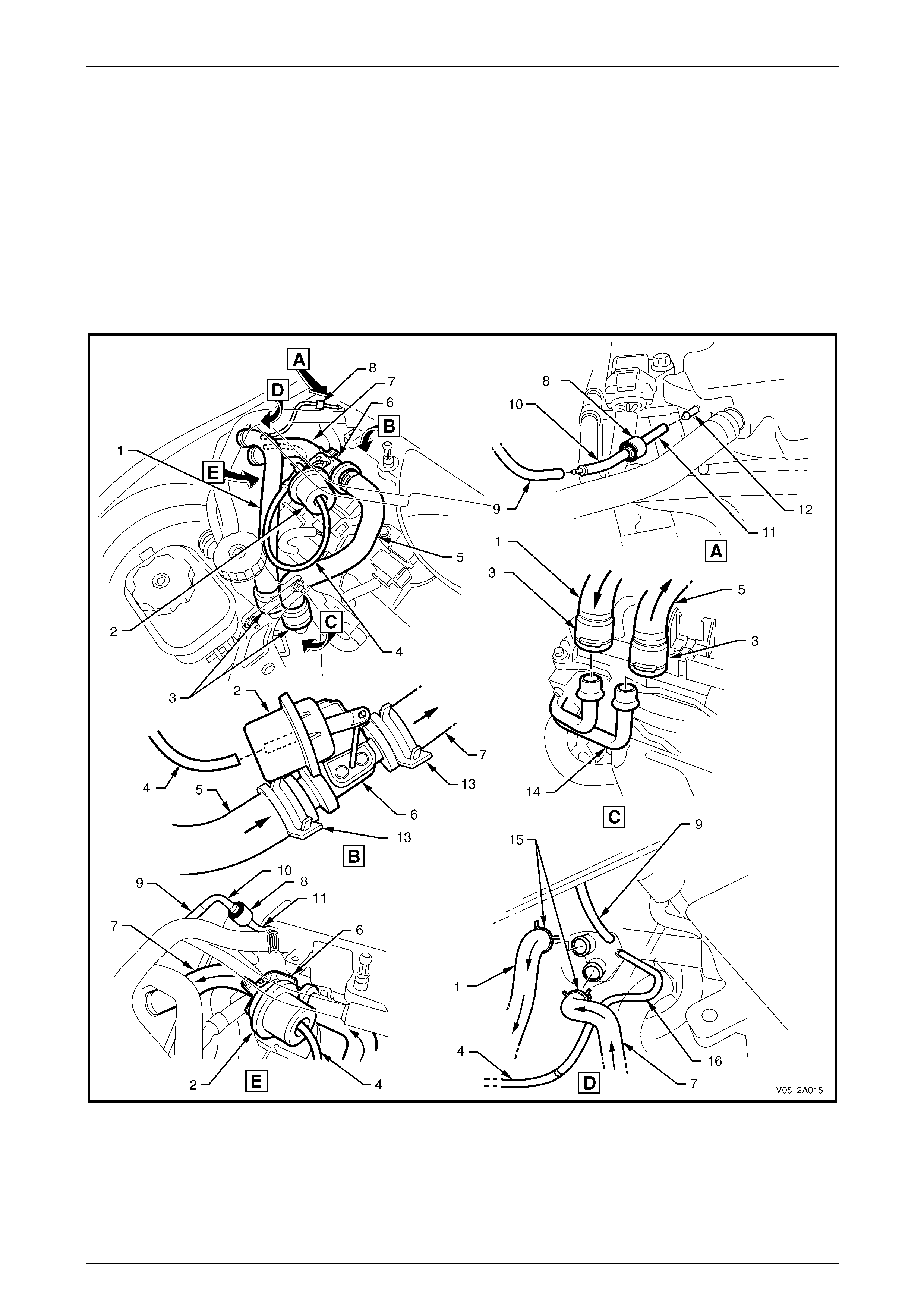
HVAC Climate Control (Manual A/C) – Removal and Installation Page 2C-83
Page 2C-83
9.2 Heater Hoses and Vacuum Lines
LT Section No. — 08–200
Replace – V6
Figure 2C – 110 provides under-hood views of heater hose and HVAC vac uum line installations.
Install all heater hoses to the ports indicated to maintain correct coola nt flow.
After the heater hoses are installed, fill the cooling system with the correct specification and quantity of coolant, and
pressure-test the cooling system, refer to Section 6B1 Engine Cooling – V6 Engi ne .
Figure 2C – 110

HVAC Climate Control (Manual A/C) – Removal and Installation Page 2C-84
Page 2C-84
Legend
1 Heater Hose from Cabin
2 Water Valve Actuator
3 Heater Hose Connectors (2 places)
4 Vacuum Hose to Water Valve Actuator
5 Heater Hose to Water Valve
6 Water Valve
7 Heater Hose to Cabin
8 Vacuum Check Valve
9 Vacuum Hose to HVAC Vacuum Tank
10 Vacuum Hose to Check Valve
11 Vacuum Hose to Inlet Manifold
12 Inlet Manifold Connection
13 Hose Clamps Water Valve (2 places)
14 Heater Pipes
15 Hose Clamps HVAC Unit (2 places)
16 Vacuum Hose to Vacuum Solenoid Pack (auto A/C) or
Vacuum Switch (manual A/C)
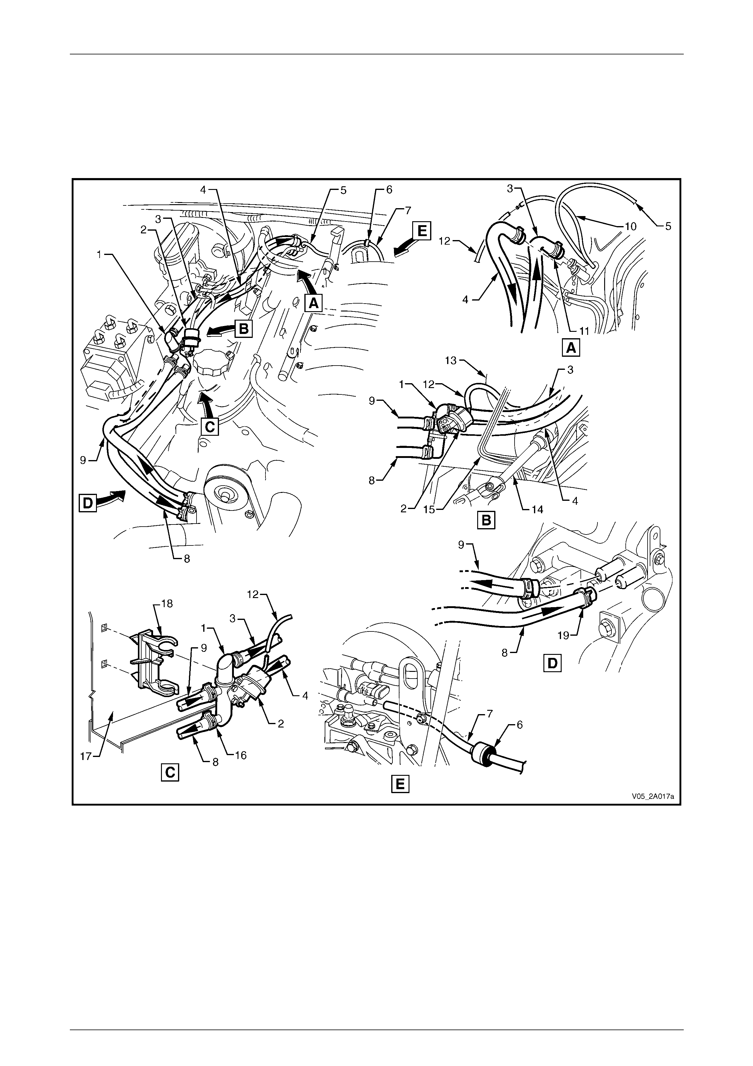
HVAC Climate Control (Manual A/C) – Removal and Installation Page 2C-85
Page 2C-85
Replace – GEN III V8
Figure 2C – 111 provides under-hood views of heater hose and HVAC vac uum line installations.
Install all heater hoses to the ports indicated to maintain correct coola nt flow.
After the heater hoses are installed, fill the cooling system with the correct specification and quantity of coolant, and
pressure-test the cooling system, refer to Section 6B3 Engine Cooling – GEN III V8.
Figure 2C – 111
Legend
1 Water Valve
2 Water Valve Actuator
3 Heater Hose – to Cabin
4 Heater Hose – from Cabin
5 Vacuum Hose (2 piece) – HVAC Supply
6 Check Valve
7 Vacuum Hose – to Inlet Manifold
8 Heater Hose – to Engine
9 Heater Hose – from Engine
10 Vacuum Hose to Vacuum Solenoid Pack (auto A/C) or
Vacuum Switch (manual A/C)
11 Hose Clamps – HVAC Unit (2 places)
12 Vacuum Hose – to Water Valve Actuator
13 Brake Booster
14 Steering Column
15 Brake Lines
16 Hose Clamps – Water Valve (4 places)
17 Wheel House – Right-hand Side
18 Mounting Clip – Water Valve
19 Hose Clamps – Engine (2 places)

HVAC Climate Control (Manual A/C) – Removal and Installation Page 2C-86
Page 2C-86
10 HVAC Inlet, Ducts and
Ventilation Outlets
10.1 HVAC Inlet Screen Assembly
LT Section No. — 10–510
Remove
1 Remove the plenum cover and water deflector assembl y, refer to Section 12N Wipers, Washers and Horn.
When removing the HVAC inlet screen
assembly, note the fo llowing:
• Prior to removal, clear away any foreign
matter such as leaves or twigs that may
have accumulated on or near the screen
assembly. Failure to do so may allow
foreign matter to fall into the HVAC inlet
causing noisy blow er fan operation.
• Exercise care as incorrect removal
technique will distort the screen and may
cause unsatisfactory screen fitting at
HVAC inlet.
2 Remove the screen assembly from the inlet by gras ping the retaining clip and liftin g the clip and screen assembly
upward clear of the HVAC inlet rim, refer to Figure 2C – 112.
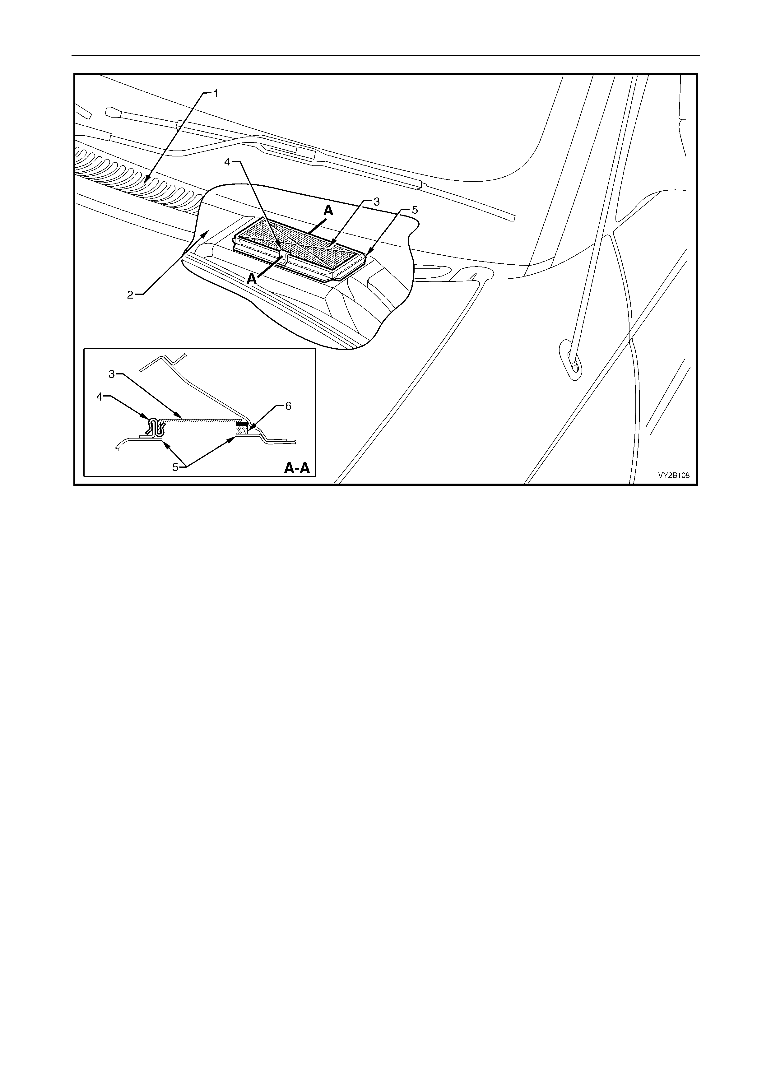
HVAC Climate Control (Manual A/C) – Removal and Installation Page 2C-87
Page 2C-87
Figure 2C – 112
Legend
1 Plenum Cover
2 Plenum Chamber
3 HVAC Inlet Screen
4 HVAC Inlet Screen Retaining Clip
5 HVAC Inlet
6 Foam Seal
Reinstall
Reinstallation of the HVAC inlet screen assembly is the reverse of the removal procedure, noting the following:
1 Install the mesh screen and clip assembl y in the correct orientation and apply light hand pressure to the outer
edges only of the upper face of the screen.
2 Ensure the front and sides of the screen are installed within the rim of the HVAC inlet.
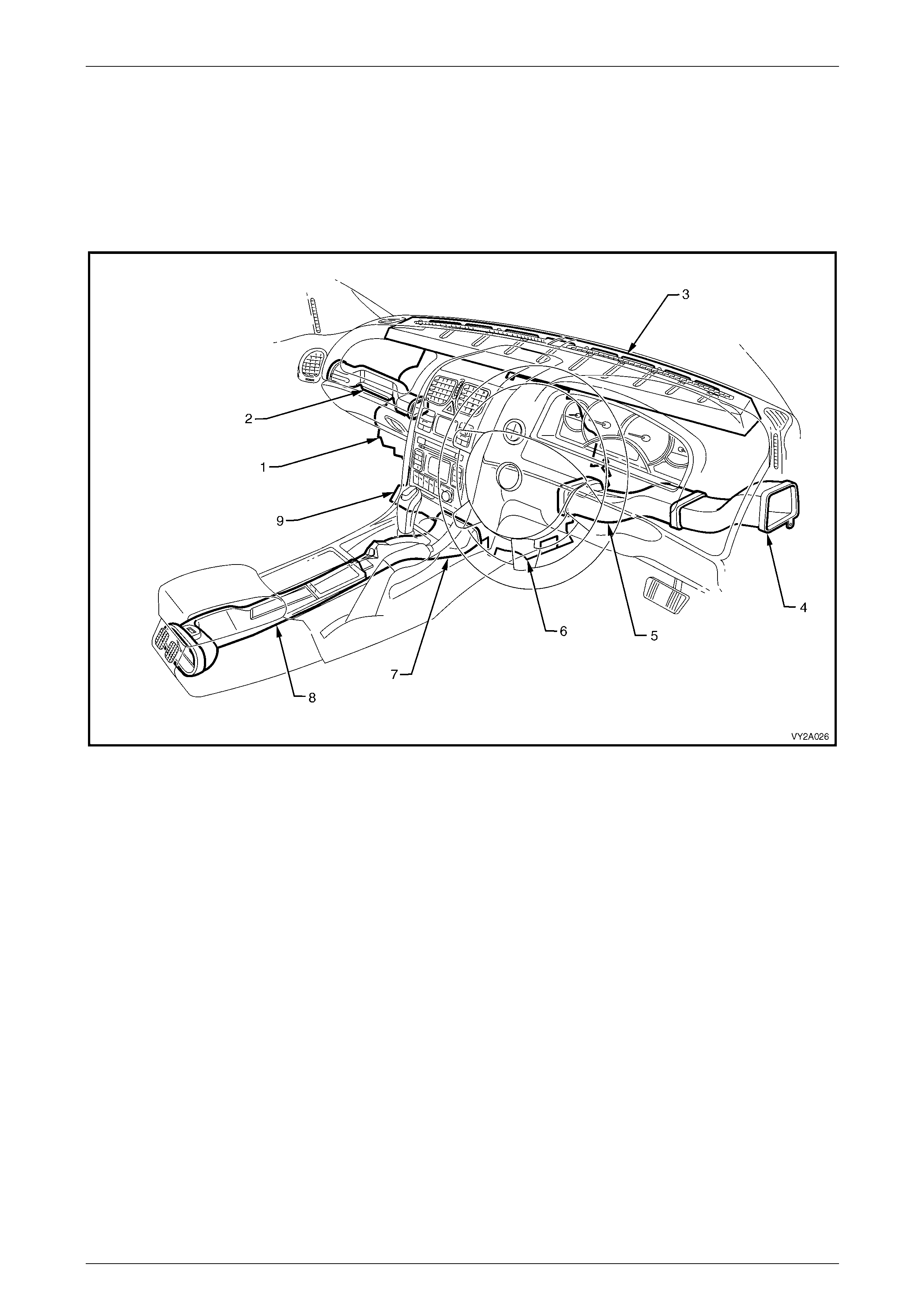
HVAC Climate Control (Manual A/C) – Removal and Installation Page 2C-88
Page 2C-88
10.2 HVAC System Ducts
LT Section No. — 08–175
HVAC Ducts Views
Sedan, Wagon, Coupe and Crew Cab
Figure 2C – 113
Legend
1 HVAC Unit
2 Passenger Side Duct
3 Demister Cavity
4 Driver Side Outer Duct
5 Driver Side Inner Duct
6 Driver Foot Duct Outlet
7 Floor Console Front Duct
8 Floor Console Rear Duct
9 Passenger Foot Duct Outlet

HVAC Climate Control (Manual A/C) – Removal and Installation Page 2C-89
Page 2C-89
Utility and Regular Cab
Figure 2A – 114
Legend
1 HVAC Unit
2 Passenger Side Duct
3 Demister Cavity
4 Driver Side Outer Duct
5 Driver Side Inner Duct
6 Driver Foot Duct Outlet
7 Passenger Foot Duct Outlet
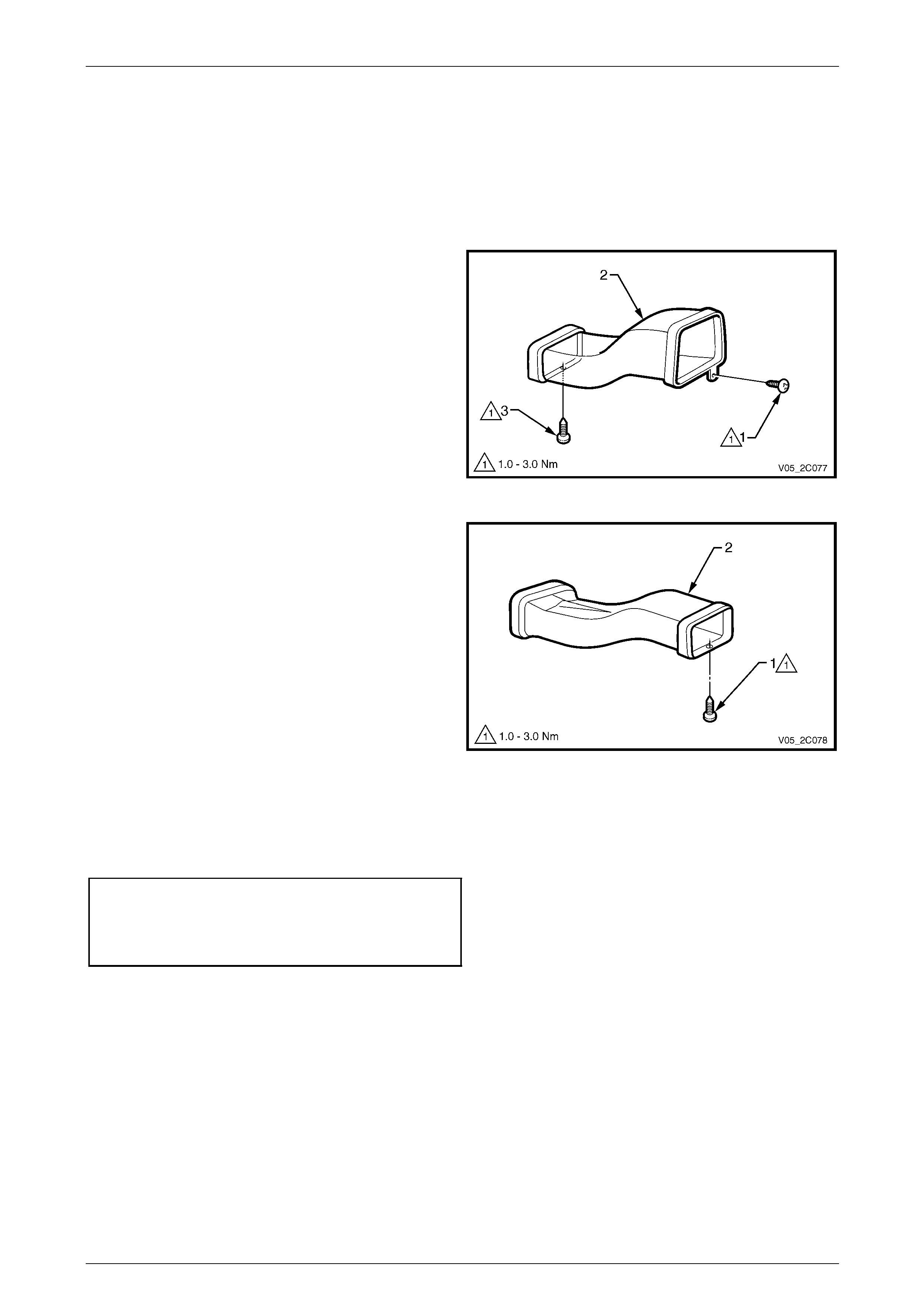
HVAC Climate Control (Manual A/C) – Removal and Installation Page 2C-90
Page 2C-90
Driver Side Outer and Inner Ducts
Remove
1 Remove the driver side instrument panel outer cover and instrument panel lower trim plate assembly,
refer to Section 1A3 Instrument Panel and Consol e.
2 Raise the steering column to it s highest adjustment level.
3 Remove the screw (1) attaching the driver side outer
duct (2) to the instrument panel.
NOTE
The retaining scre w (3) is removed from the duct
when the instrument panel lower trim panel
assembly is removed.
4 Separate the inner duct from the outer duct by partially
withdrawing the outer duct through the instrument
panel side cavity.
Figure 2C – 115
5 Remove the inner duct (2) from the HVAC unit outlet.
NOTE
The retaining scre w (1) is removed from the duct
when the instrument panel lower trim panel
assembly is removed.
6 Remove the inner duct through the instrument panel
lower trim panel cavity.
7 Remove the outer duct through the instrument panel
lower trim panel cavity.
Figure 2C – 116
Reinstall
Reinstallation of the driver side outer and inner ducts is the reverse of the removal procedure. Tighten the ducts
attaching screws to the correct torque specification.
Driver side outer duct attaching
screw torque specification...........................1.0 – 3.0 Nm
Driver side inner duct attaching
screw torque specification...........................1.0 – 3.0 Nm
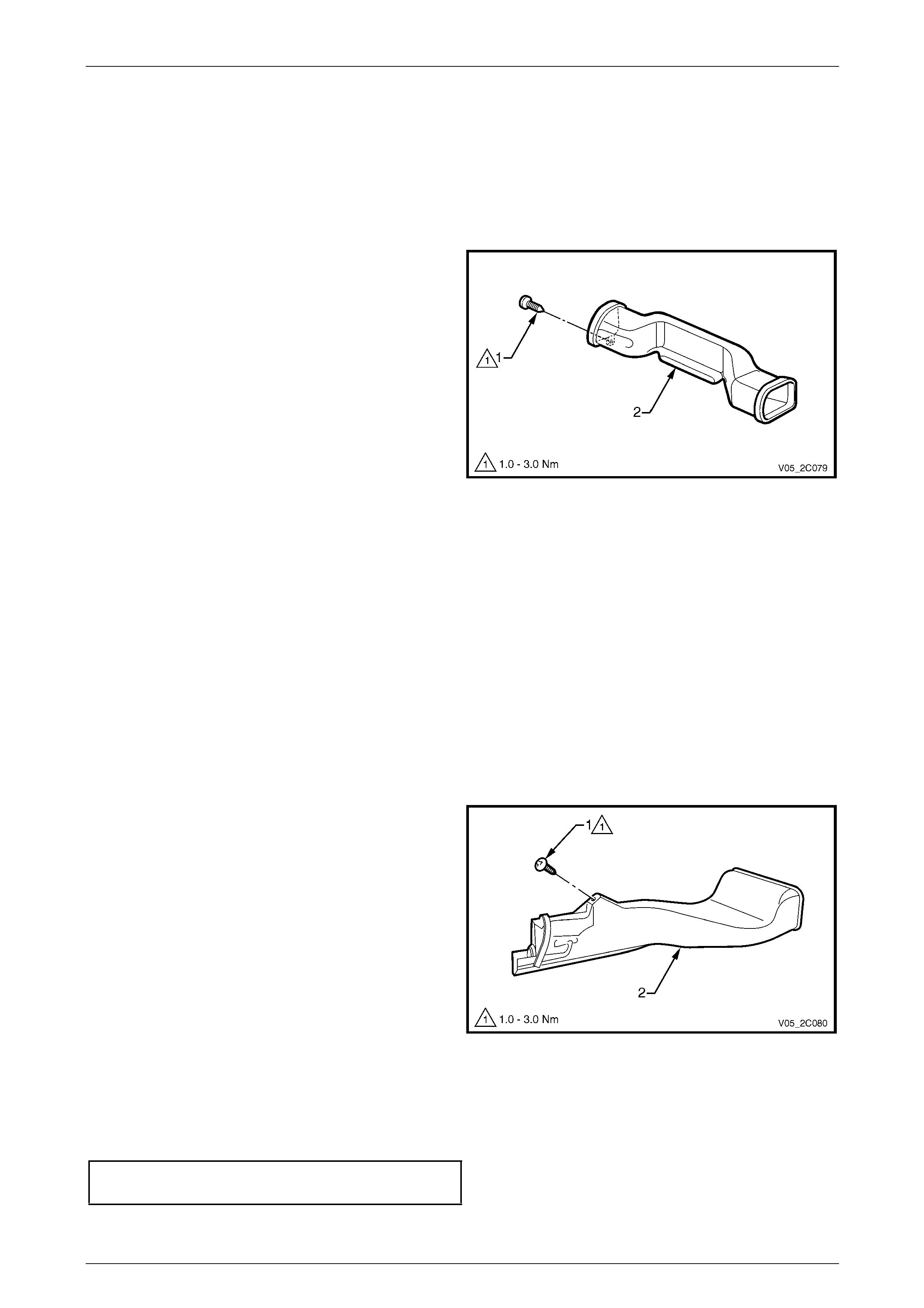
HVAC Climate Control (Manual A/C) – Removal and Installation Page 2C-91
Page 2C-91
Passenger Side Duct
Remove
1 Remove the instrument panel pad assembly, refer to Section 1A3 Instrument Panel and Console.
2 Remove the instrument panel inflatable restraint module assembly,
refer to Section 12M Occupant Protection System.
NOTE
The screw (1) attaching the passenger side
duct (2) to the instrument panel is removed as
part of the instrument panel pad assembly
removal procedure.
3 Remove the passenger side d uct from the HVAC unit
outlet.
Figure 2C – 117
Reinstall
Reinstallation of the passenger side duct is the reverse of the removal procedur e.
Floor Console Rear Duct (except Utility and Regular Cab)
The floor console rear duct is part of the floo r console assembly, for removal procedures
refer to Section 1A3 Instrument Panel and Consol e.
Floor Console Front Duct (except Utility and Regular Cab)
Remove
1 Remove the floor console assembly and left-hand instrument panel lower extension side trim,
refer to Section 1A3 Instrument Panel and Consol e.
2 Remove the screw (1) attaching the floor console front
duct (2) to the left-hand instrument panel lower
extension.
3 Remove the duct away from the HVAC unit, towards
the rear of the vehicle.
4 Remove the duct through the aperture between the
left-hand side instrument panel lower extension and
the transmission tunnel.
Figure 2C – 118
Reinstall
Reinstallation of the floor console front duct is the reverse of the removal procedure. Tighten the duct attaching screw to
the correct torque specification.
Floor console front duct attaching
screw torque specification...........................1.0 – 3.0 Nm
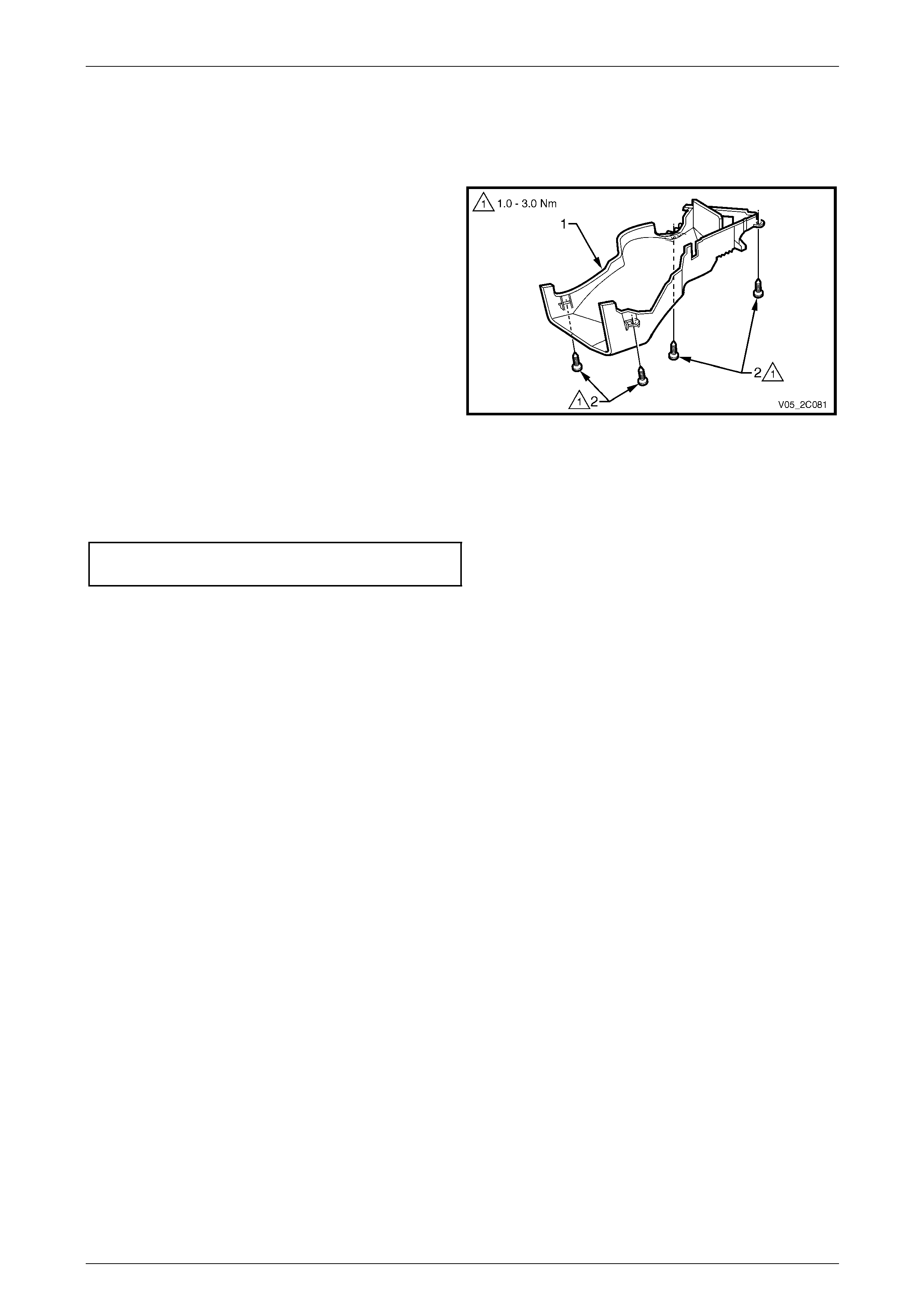
HVAC Climate Control (Manual A/C) – Removal and Installation Page 2C-92
Page 2C-92
Foot Duct Outlet
Remove
1 Remove the HVAC unit, refer to 3.1 HVAC Unit.
2 Remove the vacuum lines for the face and foot
actuators from the retaining clips on the underside of
the foot duct outlet (1).
3 Remove the harness for the air mix motor/s from the
outlet.
4 Remove the four screws (2) attaching the duct to the
underside of the HVAC unit and remove outlet.
Figure 2C – 119
Reinstall
Reinstallation of the foot duct outlet is the reverse of the removal procedure. Tighten the ducts attaching screws to the
correct torque specification.
Foot duct outlet attaching screw
torque specification.....................................1.0 – 3.0 Nm
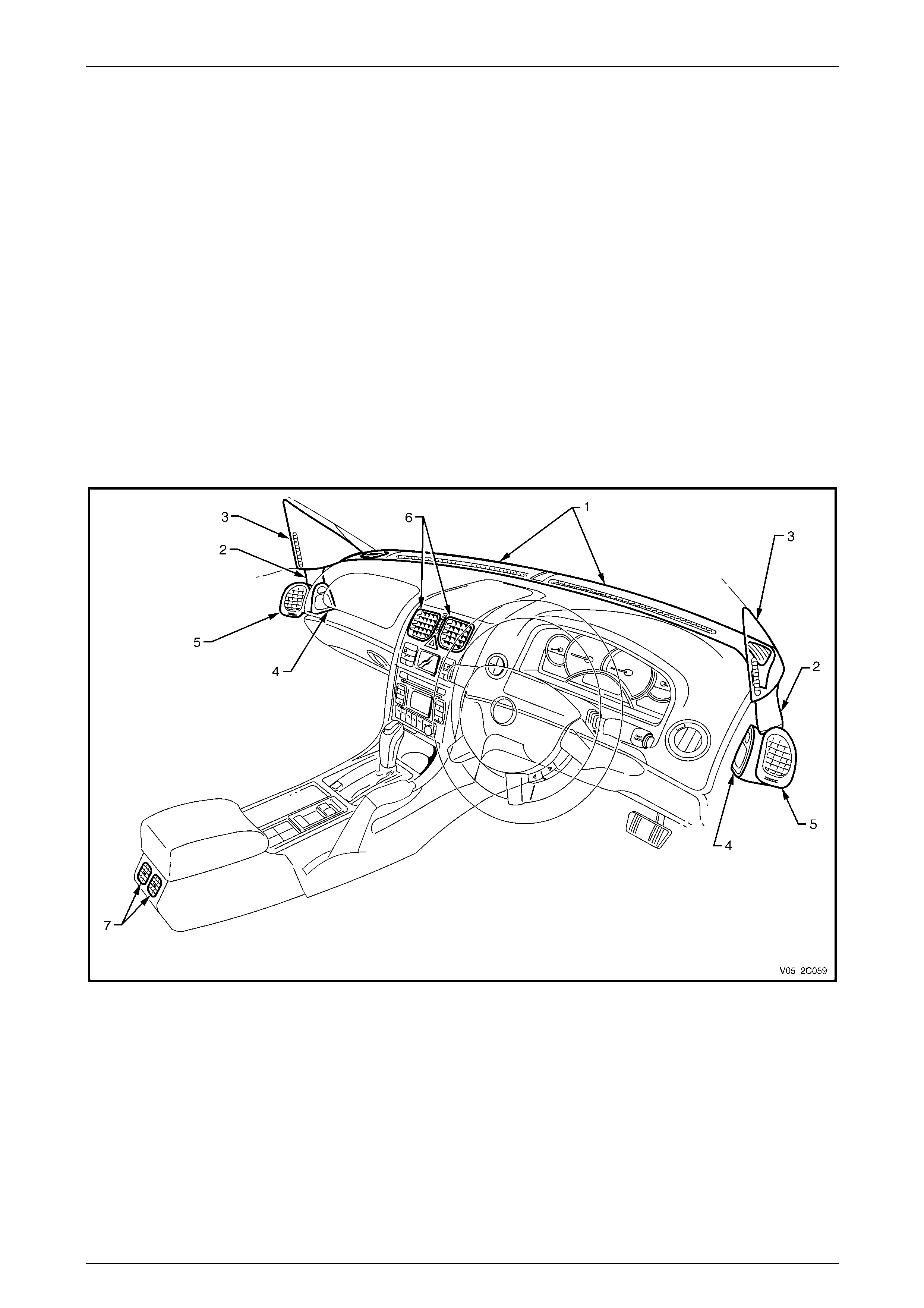
HVAC Climate Control (Manual A/C) – Removal and Installation Page 2C-93
Page 2C-93
10.3 Cabin Ventilation Outlets
LT Section No. — 08–175
Referring to Figure 2C – 120, to replace the following:
• Windshield defroster grill es (1), refer to Section 1A3 Instrument Panel and Cons ole .
• Side window defogger duct (2) and side windo w defogger outlet (3),
refer to Section 1A5 Front and Rear Door Assemblies.
• Front door air duct assembly (4) and front door air outlet assembl y (5),
refer to Section 1A5 Front and Rear Door Assemblies.
• Centre air outlet assembly (6), refer to Section 1A3 Instrument Panel and Console.
• Rear outlet housing assembly (7), refer to Section 1A3 Instrument Panel and Console.
NOTE
The rear outlet housing assembly is not fitted to
Utility and Regular Cab.
Figure 2C – 120
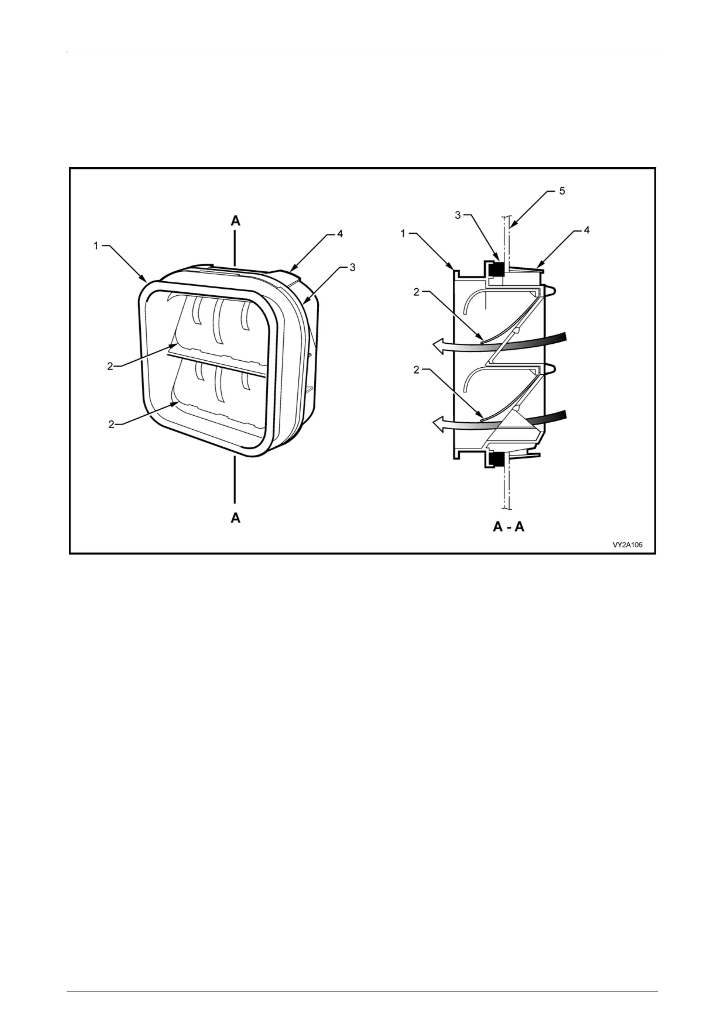
HVAC Climate Control (Manual A/C) – Removal and Installation Page 2C-94
Page 2C-94
10.4 Body Ventilation Outlets
LT Section No. — 08–700
Remove
Figure 2C – 121
Legend
1 Outlet Housing
2 Rubber Seal
3 Foam Seal
4 Locking Tab (4 places)
5 Body Panel
Sedan and Coupe
1 Remove the rear bumper fascia assembly, refer to Section 1D Bumper Bars.
2 As required, remove the left-hand or right-h and quarter inner rear side carp et,
refer to Section 1A8 Headlining and Interior Trim.
3 From inside the rear compartment, at each corner of the body ventilation outlet (1) press the locking tab (4) while
simultaneously moving it partiall y outward of the vehicle, refer to Figure 2C – 121.
4 From outside the vehicle, remove the ventilation outlet.
Wagon
1 Remove the rear bumper fascia assembly, refer to Section 1D Bumper Bars.
2 Carefully insert a flat bladed implement between the body panel and the foam seal at the corners on the bottom of
the ventilation outlet housing (1 ), refer to F igure 2C – 121.
3 Use the implement to press the t wo locking tabs (4) at the bottom of the ventilation outlet housing. While doing so,
allow the ventilation outlet housing to move upward within the body aperture.
4 Partially remove the ventilation outlet housing b y withdrawing the lower section from the body aperture.
5 Move the body ventilation outlet downward within the body aperture and remove it the from the quarter panel.

HVAC Climate Control (Manual A/C) – Removal and Installation Page 2C-95
Page 2C-95
Utility
1 Remove the load floor front panel assembly, refer to Section 1B Sheetmetal.
2 Remove the seat-back body panel trim, refer to Section 1A 8 Headlining and Interior Trim.
3 From inside the passenger compartment, at each corner of the body ventilation outlet (1) press the locking tab (4)
while simultaneously moving it partially outward of the passenger compartment, refer to F igure 2 C – 121.
4 From within the body cavit y below the load floor front panel assembly, remove the body v entilation outlet from the
front floor rear extension assembly.
Regular and Crew Cab
1 Remove the rear tray body assembly, refer to Section 1B Sheetmetal.
2 Remove the following:
• Seat-back body panel trim assembly, for Regular Cab, refer to Section 1A8 Headlining and Interior Trim.
• Rear seat-back assembly, for Crew Cab, refer to Section 1A7 Seat Assemblies.
3 Remove the rear outer trim panel, refer to Section 1A9 Exterior Ornamentation.
4 From inside the passenger compartment, at each corner of the body ventilation outlet (1) press the locking tab (4)
while simultaneously moving it partially outward of the passenger compartment, refer to F igure 2 C – 121.
5 Remove the body ventilation o utlet.
Reinstall
Reinstallation of the body ventilation outlet is the reverse of removal procedure, noting the following:
1 Install the body ventilation outlet in the correct vertical orientation.
2 Ensure all four locking tabs are fully engaged on the inner side of the body panel.

HVAC Climate Control (Manual A/C) – Removal and Installation Page 2C-96
Page 2C-96
11 Torque Wrench Specifications
Manual HVAC Controller Attaching Screw ...................................1.0 – 3.0 Nm
HVAC Unit to Lower Radio Bracket Assembly Screw....................3.0 – 8.0 Nm
HVAC Unit to Dash Panel Attaching Screw...................................3.0 – 8.0 Nm
HVAC Unit to Dash Panel Attaching Screw / Stud ......................6.0 – 14.0 Nm
Side and Console Air Duct Attaching Screw..................................1.0 – 3.0 Nm
HVAC Unit Case Attaching Screw.................................................1.0 – 3.0 Nm
Air Mix Door Quadrant Lever Attaching Screw..............................1.0 – 3.0 Nm
Blower Motor and Fan Assembly Attaching Screw........................1.0 – 3.0 Nm
Electronic Blower Motor Controller Attaching Screw.....................1.0 – 3.0 Nm
Intake Blower Duct Attaching Screw .............................................1.0 – 3.0 Nm
Vent Distribution Housing Attaching Screw...................................1.0 – 3.0 Nm
Vacuum Tank Attaching Screw .....................................................1.0 – 3.0 Nm
Intake Actuator Attaching Screw ...................................................3.0 – 5.0 Nm
Face Actuator Attaching Screw.....................................................3.0 – 5.0 Nm
Foot Actuator Attaching Screw......................................................3.0 – 5.0 Nm
Liquid and Suction Line Retaining Plate to TXV Screw...............7.5 – 12.5 Nm
Liquid Line to Filter Dryer Receiver Union...................................7.5 – 12.5 Nm
Discharge Line to Condenser Nut ...............................................7.5 – 12.5 Nm
Suction Line Bracket Attaching Screw.........................................7.5 – 12.5 Nm
Compressor Suction / Discharge Line
Pad Retaining Nut ....................................................................25.0 – 35.0 Nm
Thermal Expansion Valve to
Evaporator Tubes Securing Screw............................................... 4.0 – 4.5 Nm
Liquid and Suction Line Retaining Plate to TXV Screw ..............7.5 – 12.5 Nm
Liquid Line to Filter Dryer Receiver Union...................................7.5 – 12.5 Nm
Discharge Line Pad to Condenser Attaching Nut........................7.5 – 12.5 Nm
Filter Drier Receiver Mounting Bracket Screw.............................7.5 – 12.5 Nm
Discharge Line to Filter Drier Receiver Union .............................7.5 – 12.5 Nm
Air-conditioning Compressor Assembly
Retaining Nut – V6 ....................................................................40.0 – 60.0 Nm
Compressor Suction / Discharge Line
Pad Retaining Nut .....................................................................25.0 – 35.0 Nm
Compressor Mounting Bracket
Attaching Bolt – V8....................................................................40.0 – 60.0 Nm
Air-conditioning Compressor Assembly
Attaching Bolt – V8....................................................................40.0 – 60.0 Nm
Clutch Drive Plate and Hub A ssembly
Retaining Nut – V8 ....................................................................11.0 – 22.0 Nm
Clutch Drive Plate and Hub A ssembly
Retaining Nut – V8 ....................................................................11.0 – 22.0 Nm
Driver Side Outer Duct Attaching Screw........................................1.0 – 3.0 Nm
Driver Side Inner Duct Attaching Screw ........................................1.0 – 3.0 Nm
Floor Console Front Duct Attaching Screw....................................1.0 – 3.0 Nm
Foot Duct Outlet Attaching Screw .................................................1.0 – 3.0 Nm

HVAC Climate Control (Manual A/C) – Removal and Installation Page 2C-97
Page 2C-97
12 Special Tools
Tool Number Illustration Description Tool Classification
J-8433-1
Puller Bar
Used for removing clutch pulle y and
bearing assembly from A/C
compressor shaft.
Desirable
J-33025
Clutch Coil Puller Legs
Used for removing clutch pulle y and
bearing assembly from A/C
compressor shaft.
Desirable
J-33023-A Puller Pilot
Used for removing clutch pulle y and
bearing assembly from A/C
compressor shaft.
Desirable
J-33017
A/C Compressor Pulley and
Bearing Assembly Tool
Used in conjunction with installer tool
09-74767 for installing A/C clut ch
pulley and bearing assembly to A/C
compressor housing.
Desirable
09-74770
A/C Clutch Hub Holder
Used for holding A/C clutch hub/drive
plate during A/C clutch drive plate and
hub assembly removal and
installation.
Desirable
09-74767
A/C Clutch Hub and Drive Plate
Installer
Used for installing A/C clutch drive
plate and hub assembl y.
Desirable
09-74768
A/C Clutch Hub and Drive Plate
Remover
Used for removing A/C clutch drive
plate and hub assembl y.
Desirable
Special Tools No. 09-74770, 09-74767 and 09-74768 are available from:
The Aftermarket Department
Air International P/L
80 Turner Street
Port Melbourne 3207
Victoria