
Front Suspension 3A – 1
3A-1
Section 3A
Front Suspension
IMPORTANT
Before performing any Service Operation or other procedure described in this Section, refer to Section 00
Warnings, Cautions and Notes for correct workshop practices with regard to safety and/or property damage.
1 General Description ...............................................................................................................................4
2 Wheel Alignment ....................................................................................................................................8
2.1 Steering Geometry................................................................................................................................................. 8
Caster...................................................................................................................................................................... 8
Camber ................................................................................................................................................................... 9
Wheel Toe............................................................................................................................................................... 9
Steering Axis inclination..................................................................................................................................... 10
Scrub Radius........................................................................................................................................................ 10
Included Angle..................................................................................................................................................... 11
Toe-Out On Turns................................................................................................................................................ 11
2.2 Wheel Alignment Checking and Adjustment..................................................................................................... 12
Preliminary Inspection ........................................................................................................................................ 12
Caster Adjustment............................................................................................................................................... 12
Camber Adjustment............................................................................................................................................. 13
Toe Adjustment.................................................................................................................................................... 14
2.3 Jacking Precautions............................................................................................................................................ 15
2.4 Front Wheel Hub Assembly – End Float Checking Procedure ........................................................................ 16
3 Service Operations...............................................................................................................................17
3.1 Service Notes and Cautions................................................................................................................................ 17
3.2 Suspension and Trim Height, Check.................................................................................................................. 18
Preliminary Inspection ........................................................................................................................................ 18
Procedure............................................................................................................................................................. 19
Front and Rear Suspension Height Comparison.............................................................................................. 19
3.3 Front Wheel Hub Assembly, Brake Rotor and/or Brake Shield .......................................................................20
Remove................................................................................................................................................................. 20
All VZ Models................................................................................................................................................... 20
Inspect .................................................................................................................................................................. 21
Reinstall................................................................................................................................................................ 22
All VZ Except Coupe........................................................................................................................................ 22
All VZ Models................................................................................................................................................... 22
3.4 Front Wheel Hub Studs....................................................................................................................................... 24
Remove................................................................................................................................................................. 24
Reinstall................................................................................................................................................................ 26
All VZ Except Coupe........................................................................................................................................ 26
Coupe Only ...................................................................................................................................................... 26
All VZ Models................................................................................................................................................... 27
Techline
Techline
Techline
Techline

Front Suspension 3A – 2
3A-2
3.5 Front Strut Assembly .......................................................................................................................................... 28
Remove................................................................................................................................................................. 28
All VZ Models................................................................................................................................................... 28
All VZ Except Coupe........................................................................................................................................ 28
Coupe Only ...................................................................................................................................................... 29
All VZ Models................................................................................................................................................... 30
Reinstall................................................................................................................................................................ 30
All VZ Models................................................................................................................................................... 30
All VZ Except Coupe........................................................................................................................................ 31
Coupe Only ...................................................................................................................................................... 32
All VZ Models................................................................................................................................................... 33
3.6 Upper Strut Support Bearing and Mount........................................................................................................... 34
Remove................................................................................................................................................................. 34
Reinstall................................................................................................................................................................ 35
3.7 Front Spring ......................................................................................................................................................... 36
Remove................................................................................................................................................................. 36
Reinstall................................................................................................................................................................ 36
3.8 Front Strut Unit .................................................................................................................................................... 37
Replace................................................................................................................................................................. 37
3.9 Steering Knuckle.................................................................................................................................................. 38
Remove................................................................................................................................................................. 38
All VZ Models................................................................................................................................................... 38
All VZ Except Coupe........................................................................................................................................ 38
Coupe Only ...................................................................................................................................................... 39
All VZ Models................................................................................................................................................... 40
Reinstall................................................................................................................................................................ 40
All VZ Models................................................................................................................................................... 40
3.10 Front Control Arm................................................................................................................................................ 42
Remove................................................................................................................................................................. 42
Reinstall................................................................................................................................................................ 44
3.11 Front Control Arm Ball Joint............................................................................................................................... 46
Inspect .................................................................................................................................................................. 46
3.12 Front Control Arm Inner Bushing....................................................................................................................... 47
Replace................................................................................................................................................................. 47
3.13 Front Control Arm Rod Bushing......................................................................................................................... 48
Replace................................................................................................................................................................. 48
3.14 Front Control Arm Rod........................................................................................................................................ 49
Remove................................................................................................................................................................. 49
Reinstall................................................................................................................................................................ 49
3.15 Front Control Arm Rod Insulating Bushing....................................................................................................... 51
Replace................................................................................................................................................................. 51
3.16 Front Suspension Crossmember ....................................................................................................................... 52
Remove................................................................................................................................................................. 52
Reinstall................................................................................................................................................................ 55
3.17 Stabiliser Bar Link ............................................................................................................................................... 57
Remove................................................................................................................................................................. 57
All VZ Models................................................................................................................................................... 57
All VZ Except Coupe........................................................................................................................................ 57
Coupe Only ...................................................................................................................................................... 57
All VZ Models................................................................................................................................................... 58
Reinstall................................................................................................................................................................ 58
All VZ Except Coupe........................................................................................................................................ 58
Coupe Only ...................................................................................................................................................... 59
All VZ Models................................................................................................................................................... 59
3.18 Stabiliser Bar........................................................................................................................................................ 60
Remove................................................................................................................................................................. 60
Reinstall................................................................................................................................................................ 61

Front Suspension 3A – 3
3A-3
4 Diagnosis ..............................................................................................................................................62
General ................................................................................................................................................................. 62
Strut Diagnosis .................................................................................................................................................... 62
Acceptance Criteria............................................................................................................................................. 62
4.1 Diagnosis Guide................................................................................................................................................... 62
Hard or Heavy Steering ....................................................................................................................................... 62
Excessive Play or Looseness in Steering ......................................................................................................... 63
Erratic Steering on Brake Application ............................................................................................................... 63
Vehicle Pulls to One Side.................................................................................................................................... 63
Front or Rear Wheel Tramp................................................................................................................................. 63
Road Shocks........................................................................................................................................................ 64
Scuffed Tyres....................................................................................................................................................... 64
Cupped Tyres....................................................................................................................................................... 64
Front Wheel Shimmy........................................................................................................................................... 65
Vehicle Wanders.................................................................................................................................................. 65
5 Specifications.......................................................................................................................................66
Suspension Travel............................................................................................................................................... 66
Front Spring Details............................................................................................................................................. 66
Front Stabiliser Bar Details................................................................................................................................. 68
Front Strut Details................................................................................................................................................ 68
Front Control Arm Details................................................................................................................................... 68
Front Wheel Bearings.......................................................................................................................................... 68
Suspension and Trim Height Specifications..................................................................................................... 69
Front Wheel Alignment Specifications .............................................................................................................. 71
6 Torque Wrench Specifications............................................................................................................72
7 Special Tools ........................................................................................................................................73

Front Suspension 3A – 4
3A-4
1 General Description
The front suspension fitted to all MY 2005 V Z Series vehicles, is of the MacPherson strut design. The assembly consists
of the front crossmember, front control arms, front control arm rods, stabiliser bar and light weight strut assemblies (Refer
to Figures 3A – 1 and 3A – 2).
The crossmember is bolted to both longitu din al frame side members. The front crossmember to side member attaching
bolts incorporate a tapere d boss near the head of the bolt on the front bolts, to assist in front crossmember to bod y
alignment during assembly while the pivots of the front control arms are rubber bushed and are attached to the
crossmember by bolts and nuts. The outer end of each fron t control arm is connected to the knuckle on the strut
assembly through a front control arm ball joint assembly.
The strut assembly incorporates a hydraulic wet sleeve type damper inside the strut tube, a rubber front strut dust shield
assembly with air filter and compression rubber, a coil type suspension spring mounte d b etween the strut housing and
upper spring seat collar, a bearing assemb ly and an upper strut support.
The strut assembly is located at the upper end to the body structure by an upper strut support an d secured by a self-
locking nut and locating disc. The lo wer end of the strut tube is fastened to the steering knuckle by two bolts and nuts.
Positioning of the front control arm assembly is control led by a front control arm rod, which connects the front control arm
to the front suspension crossmember. The front control ar m rod is mounted in a rubber bushing at the front control ar m
end and a fluid filled insulator at the other.
A stabiliser bar is mounted to the side memb ers of the crossmember by two brackets and insulating rubbers. The link
connecting the stabiliser bar to each front sus pension strut tube has a ball joint socket stud and nut, at each end, except
for Coupe and AWD models, that retain the ball joint at the lower end only.
For the MY 2005 range of VZ models, there are three suspension options available; Standard (Producti on Option FE1),
Sports (Production Option FE2) and Cou ntry Pack (FR1).
There are also numerous configurations for each suspens ion option, depending on body type and powertrain
combination. For further information regarding the identification of which suspension option is fitted to a particular
vehicle, refer to 6.3 Body and Option Plate in Section 0A, General Information. F or all other information regarding the
suspension specification fitted to a particular vehicle, refer to 5 Specifications, in this Section.
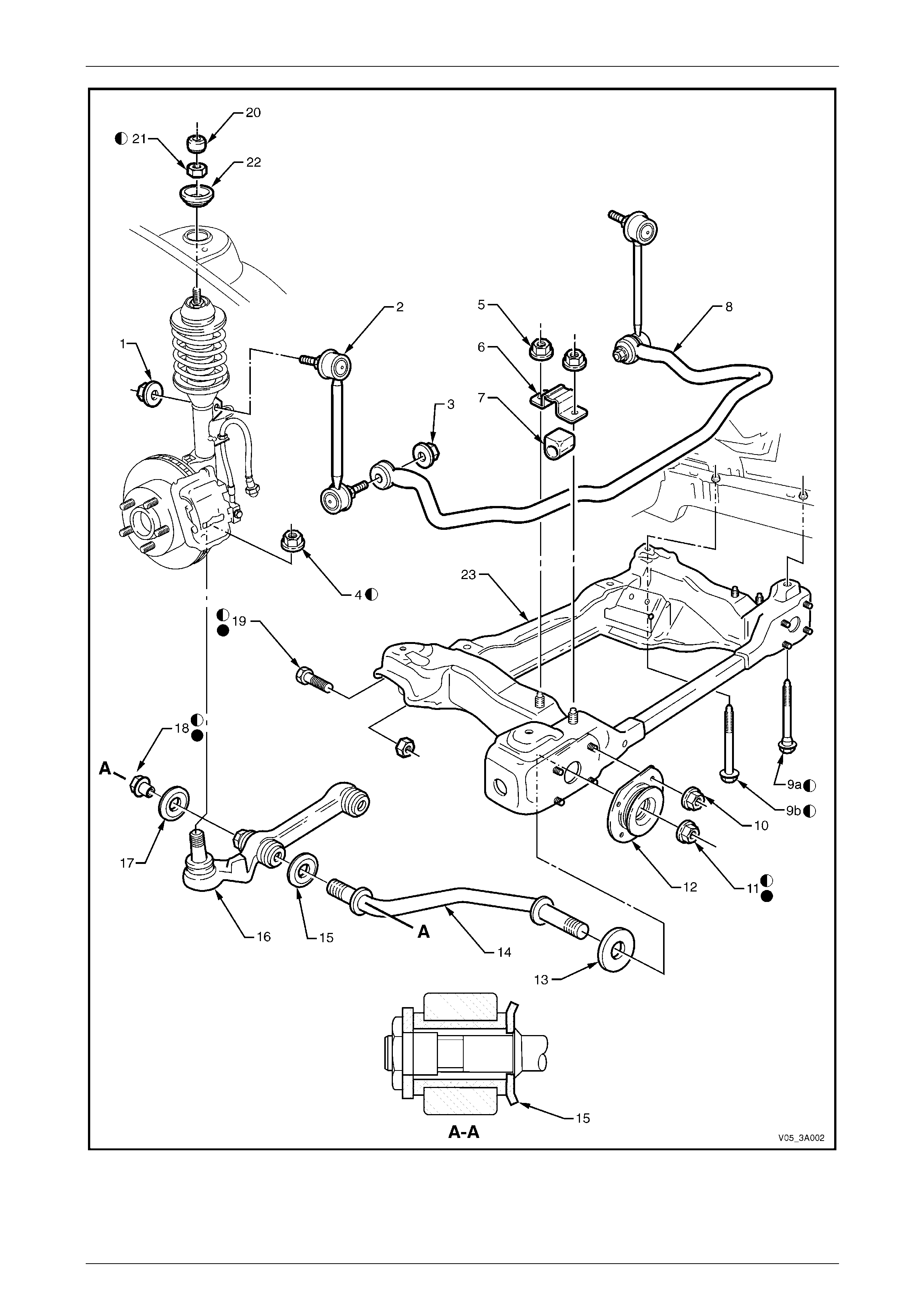
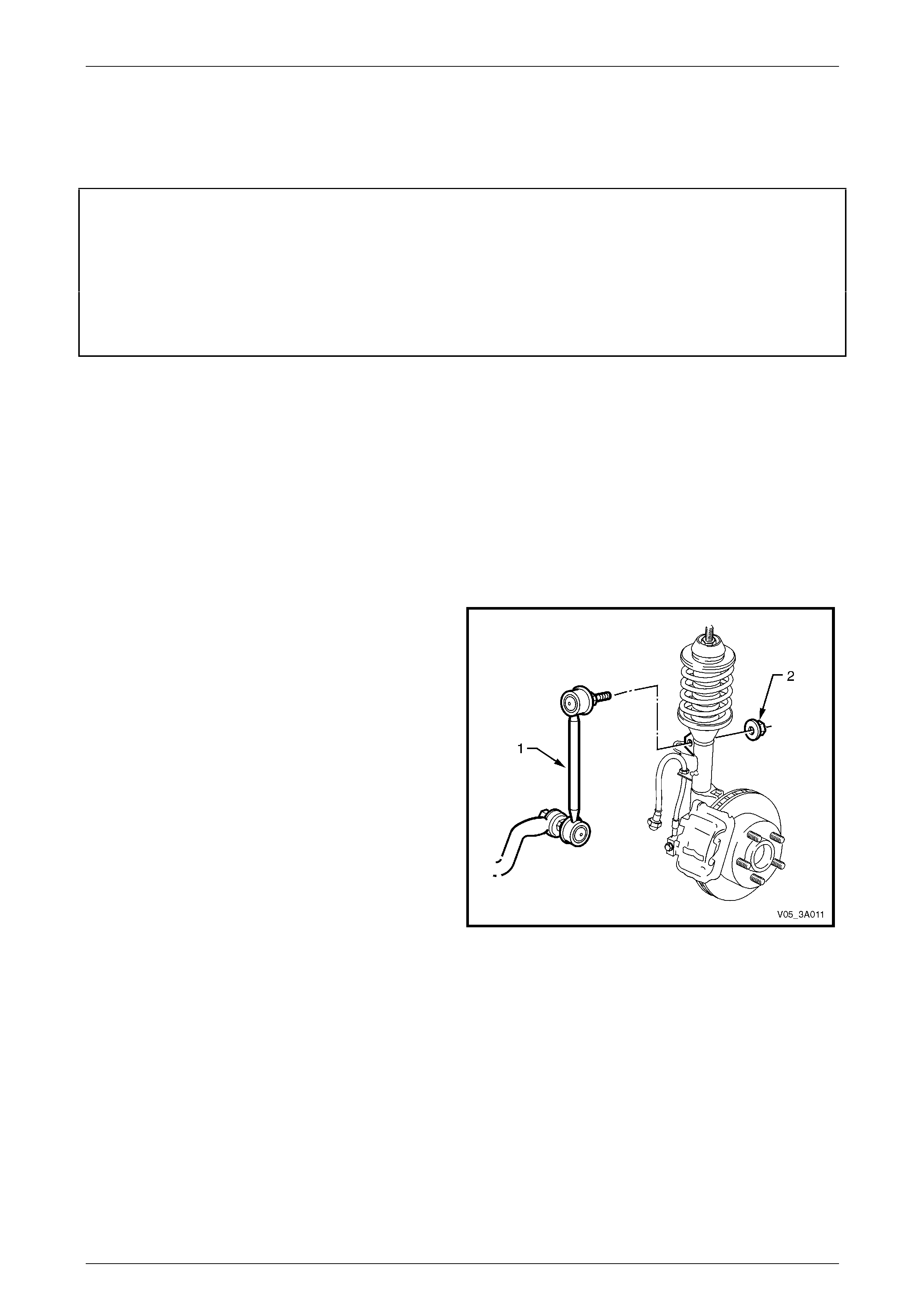
Legend for Figure 3A – 1
1 Nut (2 Places)
2 Link – Stabiliser Bar (2 Places)
3 Nut (2 Places)
4 Nut (2 Places)
5 Nut (4 Places)
6 Bracket (2 Places)
7 Insulator (2 Places)
8 Bar – Stabiliser
9a Bolt – Stepped (2 Places)
9b Bolt – Plain Shanked (2 Places)
10 Nut (8 Places)
11 Nut (2 Places)
12 Insulator Bushing – Front control
13 Washer (1 On Driver’s Side Only)
14 Rod – Front Control Arm (2 Places)
15 Washer – Cupped (2 Places)
16 Control Arm (2 Places)
17 Washer (2 Places)
18 Nut (2 Places)
19 Bolt and Nut (2 Places)
20 Cover – Dust (2 Places)
21 Nut (2 Places)
22 Locating Disc (2 Places)
23 Front Suspension Crossmember
‘A-A’ - Assemble washer ‘15’ as shown.
Fastener must be new and assembled dry.
Fastener must only be fully tightened with the vehicle at curb weight and on all four wheels.
Front Suspension 3A – 5
3A-5
Figure 3A – 1 – All VZ RWD Except Coupe
Front Suspension 3A – 6
3A-6
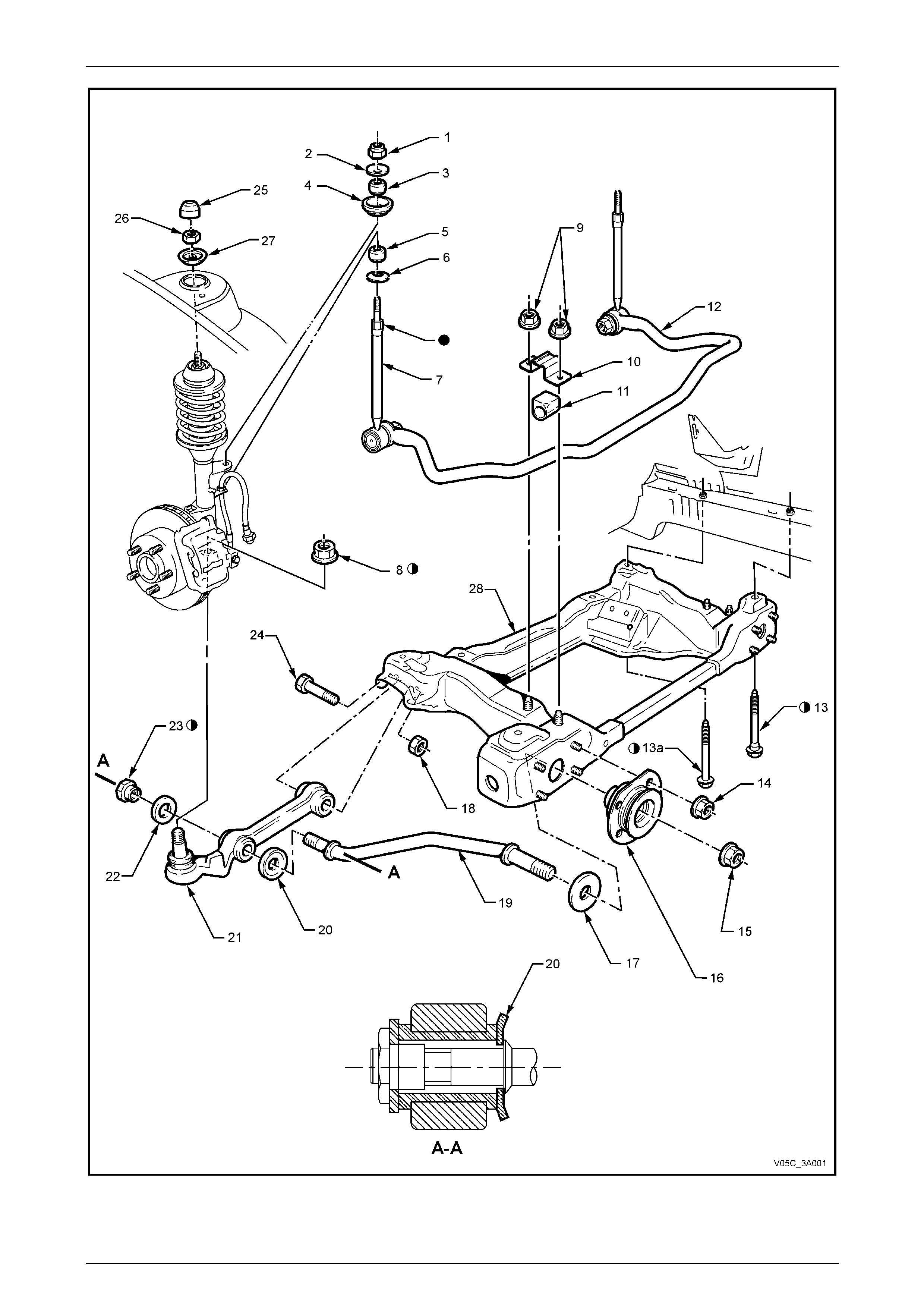
Figure 3A – 2 – All VZ Coupe
Front Suspension 3A – 7
3A-7
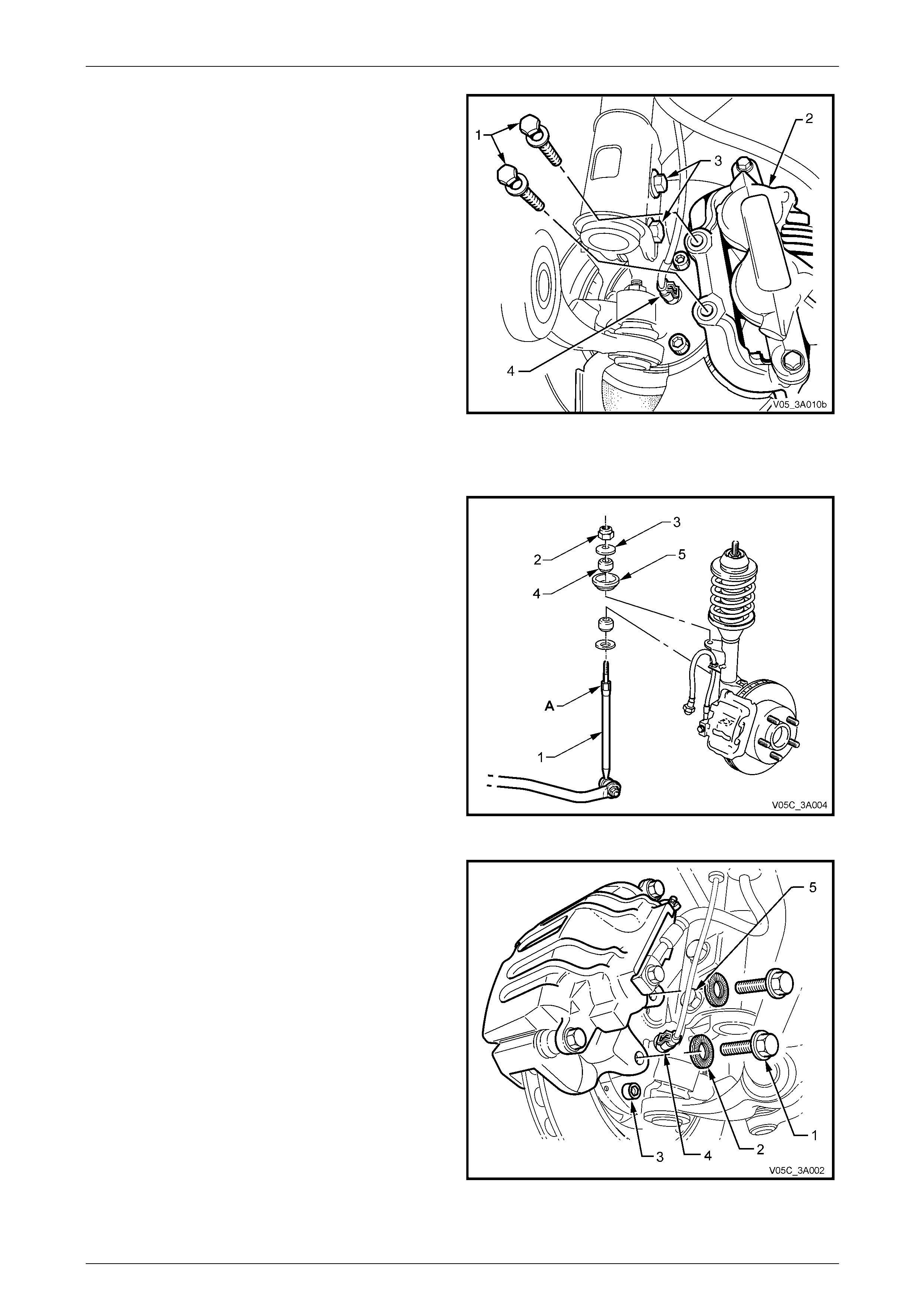
Legend for Figure 3A – 2
1 Nut (2 places)
2 Washer – Cupped (2 places)
3 Insulator (2 places)
4 Seat (2 places)
5 Insulator (2 places)
6 Washer – Cupped (2 places)
7 Link – Stabiliser Bar (2 places)
8 Nut (2 places)
9 Nut (4 Places)
10 Bracket (2 Places)
11 Insulator – Stabiliser Bar (2 places)
12 Bar – Stabiliser
13 Bolt – Stepped Shank (2 places)
13a Bolt – Plain Shanked (2 places)
14 Nut (8 places)
15 Nut (2 places)
16 Insulator Bushing – Front Control Arm
Rod (2 places)
17 Washer (1 On Driver’s Side Only)
18 Nut (2 Places)
19 Control Arm Rod (2 places)
20 Washer – Cupped (2 places)
21 Control Arm (2 places)
22 Washer (2 places)
23 Nut – Stepped (2 places)
24 Bolt (2 Places)
25 Cover – Dust (2 Places)
26 Nut (2 Places)
27 Locating Disc (2 Places)
28 Front Suspension Crossmember
‘A-A’ - Assemble washer ‘20’ as shown.
Fastener must be new and assembled dry.
Stud to be held while nuts are being tightened to specification
Front Suspension 3A – 8
3A-8
2 Wheel Alignment
ATTENTION
All front suspension fasteners are important attaching parts as they affect the performance of vital
components and/or could result in major repair expense. Where specified in this Section, fasteners MUST be
replaced with parts of the same part num ber or a GM appro ved equivalent. Do n ot use fasteners o f an inferior
quality or substitute design
Torque values must be used as specified during reassembly to ensure proper retention of all front
suspension components.
Throughout this Section, fastener torque wrench specifications may be accompanied with the following
identification marks:
Fasteners must be repl aced after loosening.
Vehicle must be at curb height before final tightening.
Fasteners either have micro encapsulated sealant applied or incorporate a mechanical thread lock
and should only be re-used once. If in doubt, replacement is recommended.
If one of these identification marks is present alongside a fastener torque wrench specification, the
recommendation regarding that fastener must be adhered to.
2.1 Steering Geometry
To achieve the desired handling characteristics of a vehicle under various operating conditions, modern steering
geometry relates to both front and rear suspension systems. It must also be realised that the various, measurable angles
that can be checked while the vehicle is sta tionary, are no real indication of the changes that occur in a dynamic
situation, when the vehicle is required to have directional stability, during normal manoeuvres, such as straight ahead
driving, cornering or braking.
Even though some of the following descriptions of front wheel alignment angles are not normally measurable and (in
some instances) not adjustable, each is an inherent part of the vehicle's dynamic sus pension tuning that has been
developed over an extended testing program.
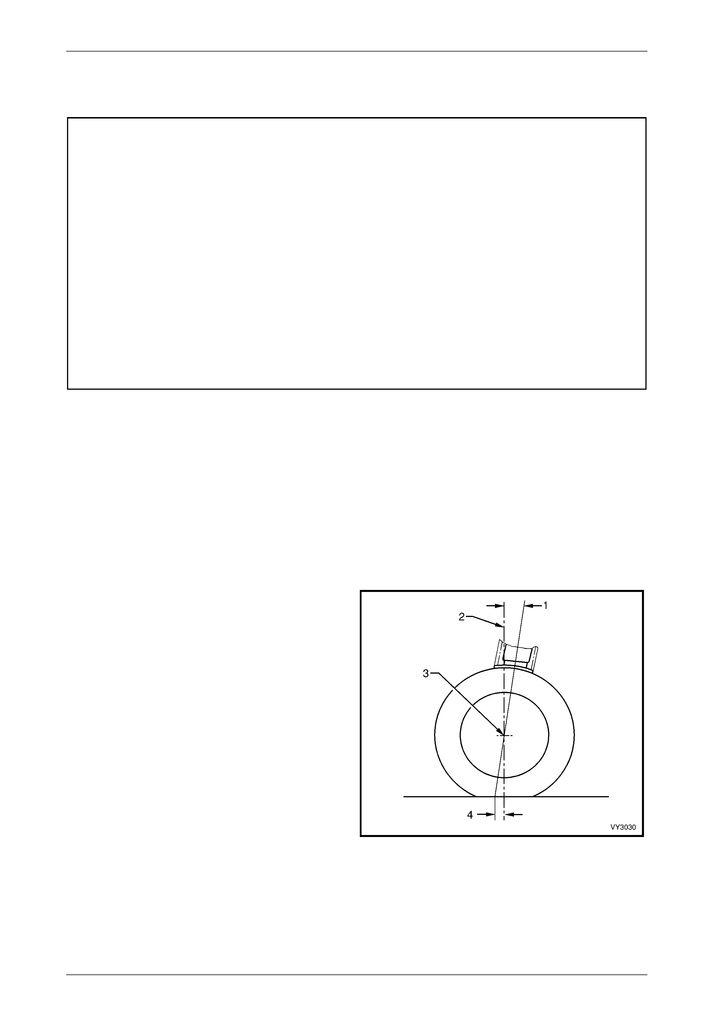
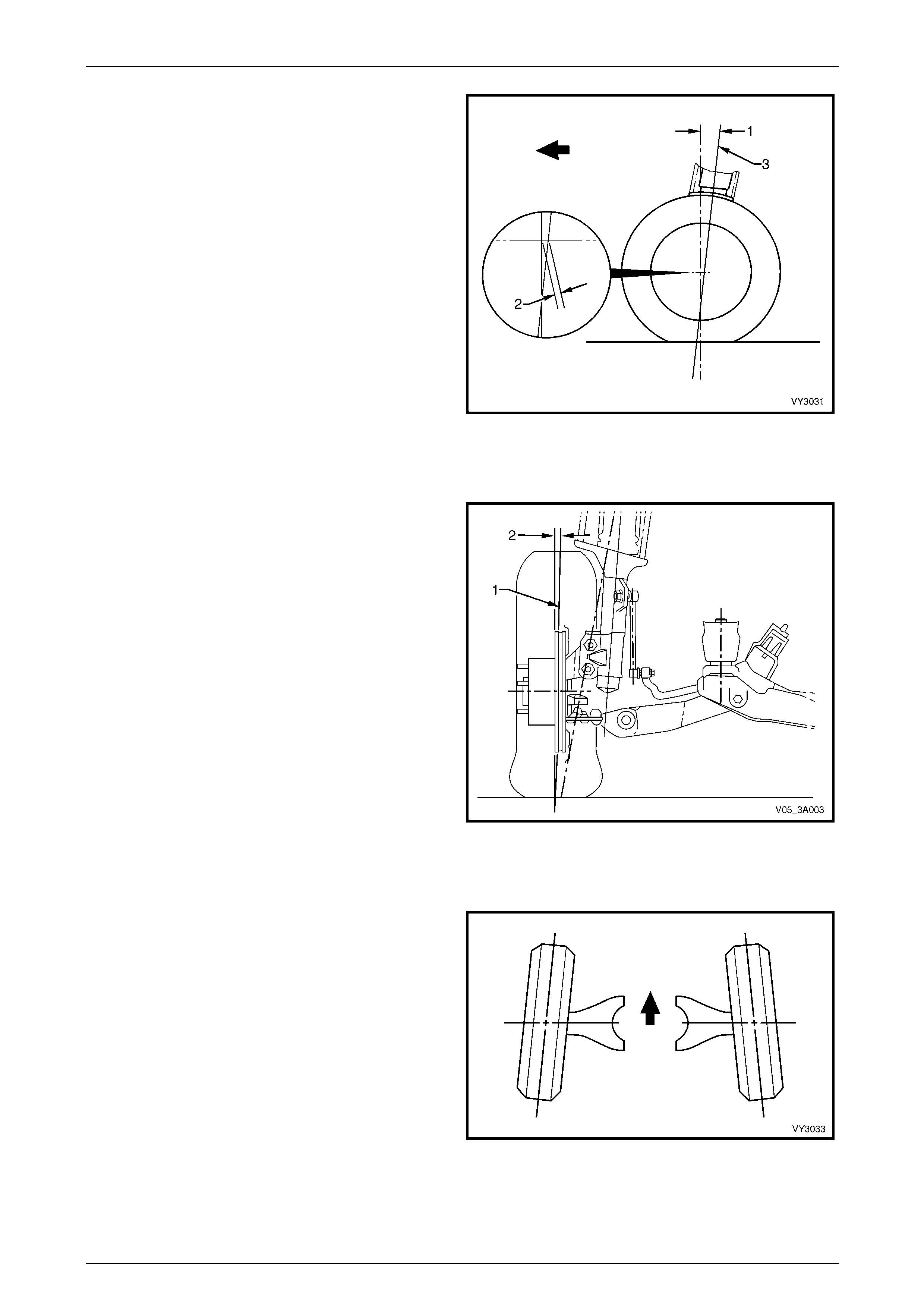
Caster
It is usual to describe this front wheel alignment angle as the
tilting of the steering axis either forward or backward (1)
from the vertical (2) when viewed from the side of the
vehicle. A backward tilt at the top steering axis point is said
be positive (+) and a forward tilt is said to be negative (-).
Measurement is usually expressed as an angle in degrees
and minutes. Figure 3A -3 shows the usual practice where
the vertical and steering axis centrelines both pass through
the wheel centre (3).
This results in a caster distance (4), which can be describe d
as being the distance in side view, between the point where
the steering axis contacts the ground and the centre of the
tyre’s footprint contact.
Figure 3A – 3
Front Suspension 3A – 9
3A-9
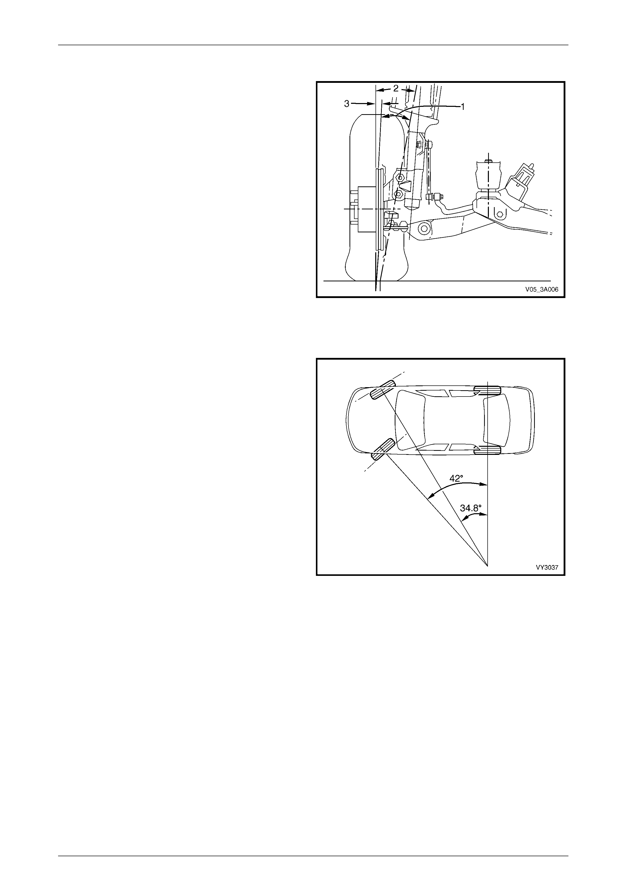
The amount of caster angle (1) will det ermine the ability of
the steering to return to the straight ahead position after a
cornering manoeuvre. Too high an angle though, can result
in an excessive steering effort with associated ‘wheel fight'
and ‘kickback'. To optimise vehicle handling and control
during cornering and to mai ntain the benefits of positive
caster, MY 2005 VZ Series vehicles have a 12 mm caster
offset (2) incorporated into the suspension design.
This is achieved by moving the wheel spindl e centreline (3)
forward (in this instance, by 12 mm), which will effectively
reduce the caster distance by that amount (Refer to
Figure 3A – 4). This action reduces the undesirable effects
of a high caster angle but maintains the directional stabilit y,
increased front axle lateral gri p and ste ering feel that a high
caster angle normally provi des.
Figure 3A – 4
Camber
This angle is the tilting of the wheels from the vertical (1)
when viewed from the front of the vehicle. When the wheels
tilt outward at the top, the camber (2) is said to be positive
(+). When the wheels tilt inward at the top, camber is said to
be negative (-). The amount of t ilt is measured in degrees
from vertical and this measurement is called the camber
angle.
While unequal camber may re sult in unstable steering or
wander, unequal and/or excessive camber can also cause
rapid tyre wear.
Figure 3A – 5
Wheel Toe
Wheel Toe (Refer to Figure 3A – 6), is the turning in (or out)
of the wheels when viewed from the overhead position. The
actual amount of toe is normally only a few minutes of a
degree. The purpose of a static toe specification is to ensure
parallel rolling of the wheels, once the vehicle is in a
dynamic state.
Excessive toe-in or toe-out may increase tyre wear. With
rear wheel drive vehicles, a slight amount of toe-in,
measured statically with the vehicle at rest, is requir ed to
off-set the small deflections due to rolling resistance and
brake applications which tend to turn the wheels outward.
Figure 3A – 6

Front Suspension 3A – 10
3A-10
Steering Axis inclination
When viewed from the vehicle front, Steering Axis
Inclination (1) can be described as being the angle formed
between the steering a xis (2) and the true vertical (3), where
the steering axis is the imaginar y centreline through the
upper strut support bearing an d the front control arm socket
assembly, both components being the pivot points of the
strut assembly.
The Steering Axis Inclination angle is an important factor in
determining steering effort and directional stability of the
vehicle, by assisting caster in keeping th e front wheels in a
central position. Steering Axis Inclin ation also provides a
self-centring effect after cornering.
Figure 3A – 7
Scrub Radius
This term refers to the distance that two imaginary points
are apart, at the road surface (1). These two imaginary
points are;
a The intersection of the steering axis (2) and the road
surface.
b The centreline of the t yre (3) at the road surface.
As road wheel offset will affect scrub radius (4), in the
interests of vehicle handling and safety, non-standard road
wheels are not to be fitted to any MY 2005 VZ Series
vehicle.
With rear wheel drive vehicles, it is usual practice to
maintain a positive scrub radius (as shown in Figure 3A – 8)
to make the steering more responsive and d irect, thereby
providing the driver with a more positive sense of the tyre
and road surface interaction.
Figure 3A – 8
Front Suspension 3A – 11
3A-11
Included Angle
When both the Steering Axis Inclination an gle (1) and
Camber angle (3) are combined, the resulting angle is
referred to as the Included Angle (2). This information can
be effectively used to determine if a component is damaged
or whether an adjustment is responsible for an out-of-
specification condition occurring.
While Figure 3A – 9 shows a positive camber angle, this has
only been used to clarify the term ‘Included Angle'.
Figure 3A – 9
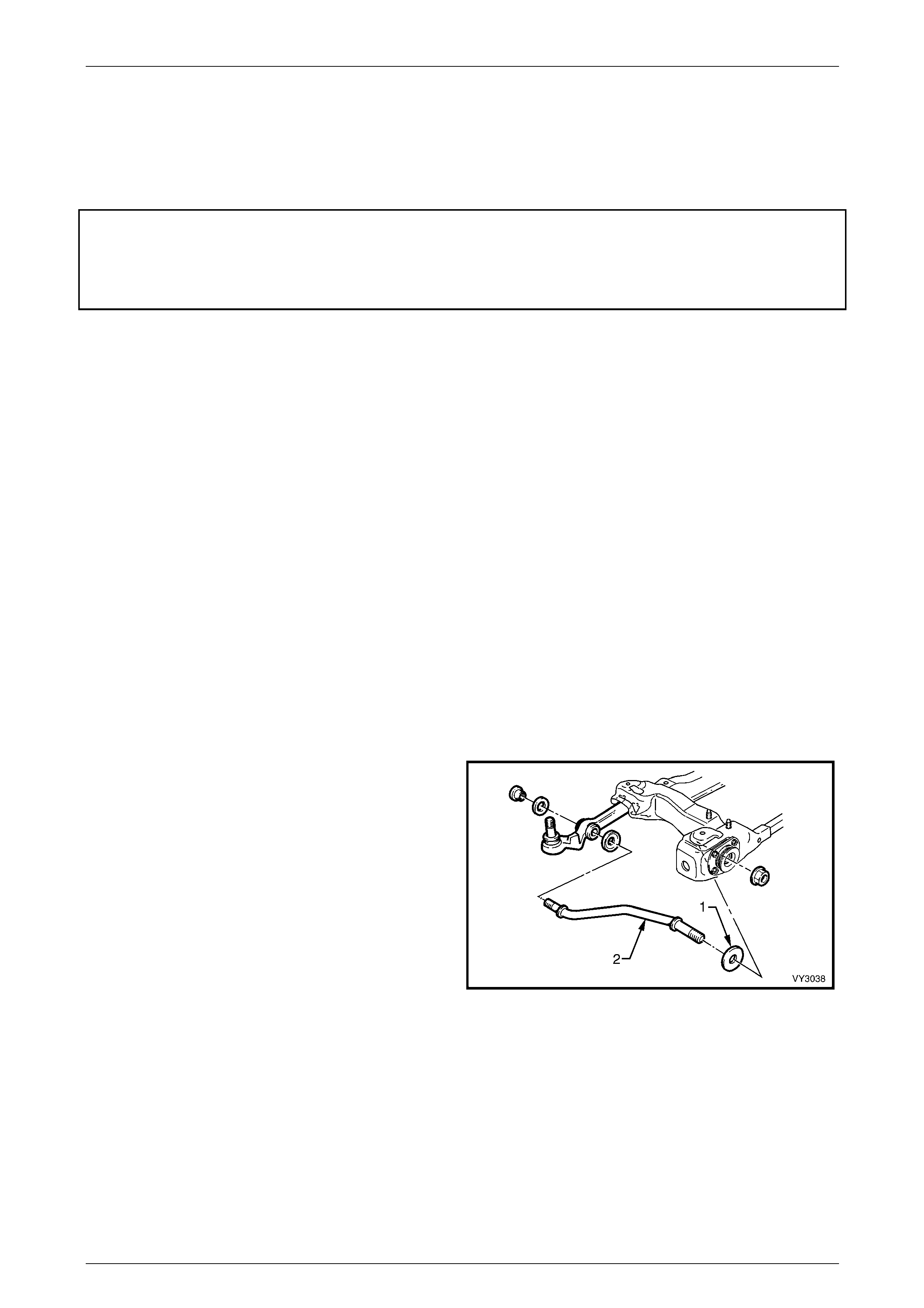
Toe-Out On Turns
During cornering operations, a vehicle's road wheels all turn
about a common turning point, causing the outer wheels to
try and turn through a greater radius than the inner. To
overcome the tendency for wheel slip under these
conditions, the outer wheel is commonl y caused to toe-out,
to compensate for this increased turning circle.
The amount of toe-out during cornering, is govern ed by the
angle of the steering arms, which are an inh erent part of th e
steering knuckle.
Figure 3A – 10
Front Suspension 3A – 12
3A-12
2.2 Wheel Alignment Checking and
Adjustment
LT Section No. – 06-212
ATTENTION
The following fasteners MU ST be replaced when performing these operations:
Steering knuckle to strut attach in g nuts and bolts.
Preliminary Inspection
Before any attempt is made to check camber, caster or toe-in, these preliminary checks should be carried out.
1 Check tyre and tyre mountings. Always check camber and toe-in at the mean run-out position on the tyre or rim.
2 Check and adjust tyre pressures to recommended va lues.
3 Front wheel bearing end float is to be checked to ensure it is within specification, as d etail ed in
2.4 Front Wheel Hub Assembly End Float Checking Procedure in this Section.
4 The front control arm ball joints should be checked for wear, refer to 3.11 F r ont control Arm Ball Joint in this
Section.
5 Check steering gear mounting bolts for tightness and steering tie rod ends for wear, refer to Section 9 Steering.
6 The vehicle should be at curb weight, fuel tank full, without driver, passengers or luggage etc.
7 Check for improperly operating front struts or rear shock absorbers.
8 Check for loose or missing stabiliser bar or front control ar m rod attachments.
9 Before checking the front wheel alignment, check the rear wheel alignment.
Refer to Section 4A1 Independent Coil Spri ng Rear Suspension or Section 4A2 Leaf Spring Rear Suspension for
rear wheel alignment details.
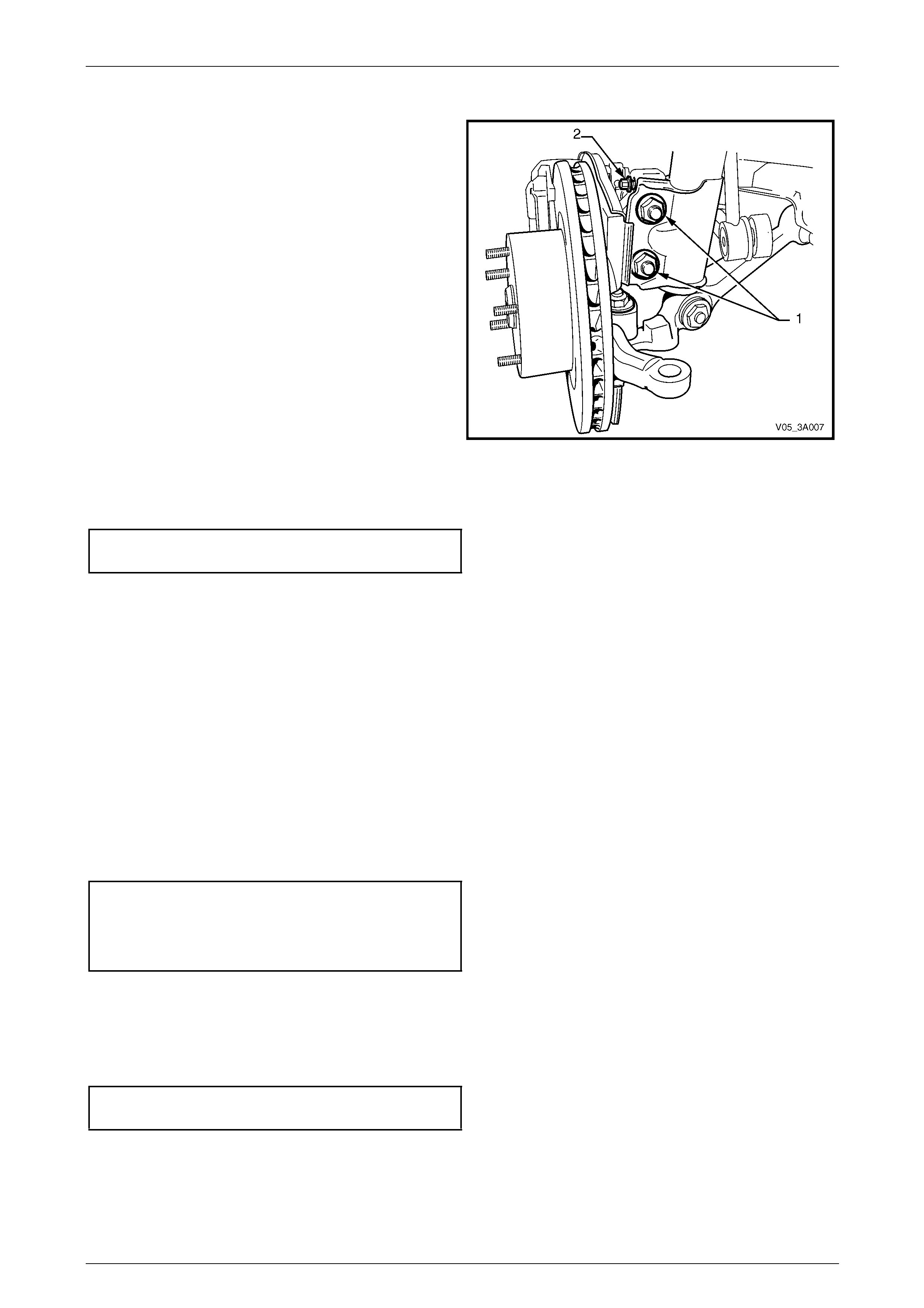
Caster Adjustment
While one bright finished spaced washer (1) will be fitted to
the driver’s side front control arm rod (2), the fitment of an
additional washer is permitted to correct minor caster
adjustments
NOTE
Only one additional spac er washer is to be fitted
and is to be added to the side with the higher
caster reading.
Figure 3A – 11
Front Suspension 3A – 13
3A-13
Camber Adjustment
1 Raise the front of the vehicle and support on safety
stands under the front side members.
Refer to 2.3 Jacking Precautions in this Section.
2 Remove the wheel cover (steel wheels) or centre cap
and decorative wheel nut caps (alloy wheels) and
mark the relationship of the wheel to the hub stud,
using a felt tipped pen or similar.
3 Remove the wheel attaching nuts and remove the
wheel.
4 Loosen, remove and discard the two lower strut
attaching bolts and nuts (1).
5 Install NEW lower strut attaching bolts and nuts but
do not tighten fully to specificat ion until after the
camber has been adjusted to the recommended
specification.
6 Install the road wheel, alignin g the previously made
marks.
7 Tighten road wheel attaching nuts to the correct torque
specification, working in a ‘star’ pattern, refer to
3.1 Service Notes and Cautions, in this Section.
Road wheel attaching
nut torque specification............................110 – 140 N.m
Figure 3A – 12
8 Lower the vehicle to the ground an d bounce several times to settle the suspension.
9 Check the camber angle.
10 If required, adjust the camber by turning the camber adjusting screw (2) in the requir ed direction; clockwise to
reduce negative camber, anti- clockwise to reduce positive camber.
NOTE
The camber adjusting screw has thread sealant
applied in the form of micro-encapsulation and
does not require a lock nut.
11 Raise vehicle once again, support on safety stands and remove the front road wheels.
12 Tighten both steering knuckle bolts and nuts to the correct torque specification.
Steering knuckle to strut bolts
and nuts torque specification .... Stage 1.............85 N.m
Stage 2 ...........100 N.m
Stage 3Turn through 90°
13 Install the road wheels, aligning the marks made prior to removal.
14 Remove the jack stands and lower the vehicle.
15 Tighten the road wheel attaching nuts to the correct torque specification, working in a ‘star’ pattern.
Refer to 3.1 Service Notes and Cautions, in t his Section.
Road wheel attaching
nut torque specification............................110 – 140 N.m
16 Reinstall the wheel cover or decorative wheel nut caps.
17 Check the camber angle again to ensure that it is still within specification.
Front Suspension 3A – 14
3A-14
Toe Adjustment
Toe of both front wheels, is checked with the wheels in the straight ahead position.
Adjustment is achieved by windi ng the steering linkage tie rods in or out of the steering linkage tie rod ends, increasing or
decreasing their length, changing the wheel toe setting.
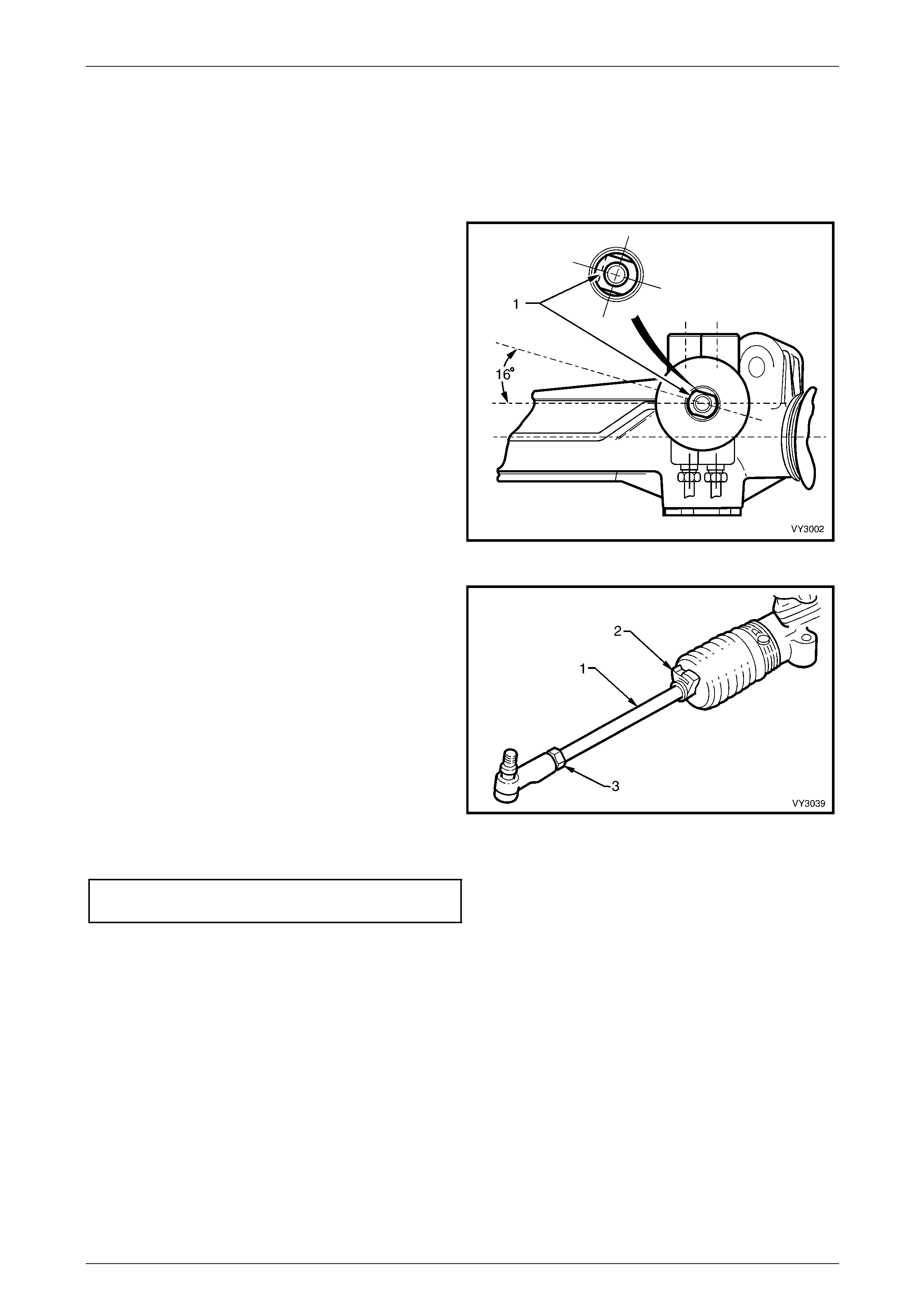
1 Set steering gear and wheels in straight ahead position.
2 To check if steering gear is in straight ahead position
(on-centre), the pinion (input) shaft (1) should be
aligned as shown.
Figure 3A – 13
3 Before adjusting the steering linkage tie rods (1),
disconnect the steering gear outer boot clips (2).
4 Loosen the lock nut (3) at the end of e ach steering
linkage tie rod end.
5 Turn each steering linkage tie rod (1) as required, until
the correct toe is obtained.
NOTE
During the toe adjustment, ensure that the
steering wheel is held in the straight ahead
position.
6 Tighten the lock nuts to the correct torque
specification, checking that the outer tie rod ends are
aligned with their ball studs.
Figure 3A – 14
Steering linkage tie rod to tie rod
end lock nut torque specification..........................50 N.m
7 Tighten the outer boot clips se curely, making sure that the convolutions of the boots are not distorted.
8 With the steering gear in the straight ahead position, ensure that the steering wheel is centralised. If not, remove
and reposition the steering wheel, refer to Section 9A Steering.
Front Suspension 3A – 15
3A-15
2.3 Jacking Precautions
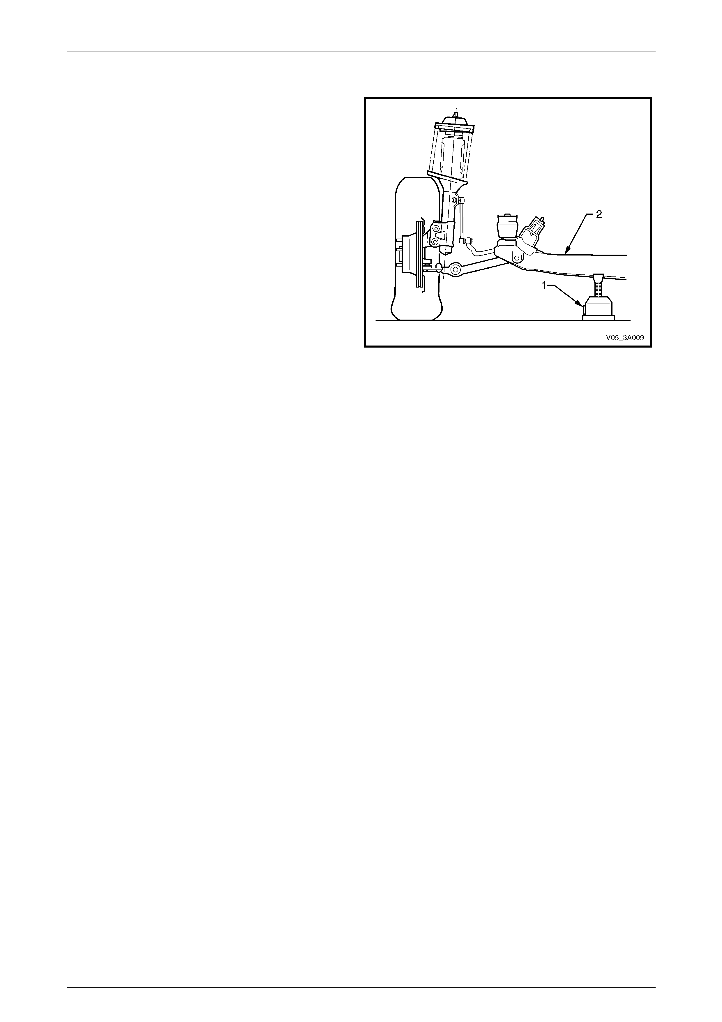
When raising the front of the vehicl e with a jack (1), the jack
should be placed under the c entre of the front crossmember
(2). The weight of the vehicle MUST NOT be lifted under the
control arms.
When the vehicle is raised on the jack, it must be firmly
supported on jack stands located under the frame side
members before any work is attempted. If a vehicle is not
correctly supported by jack stands, serious injury can result
if the vehicle should slip off the jack.
For further information relating to the location of jacking and
support points, refer to Section 0A General Information.
Figure 3A – 15
Front Suspension 3A – 16
3A-16
2.4 Front Wheel Hub Assembly – End Float
Checking Procedure
LT Section No. – 06-212
1 Raise the front of the vehicle and place on safety stands. Observe the jacking precautions as detailed in
2.3 Jacking Precautions in this Section.
2 Remove the wheel cover or decorative wheel nut caps (alloy wheels).
3 Mark the relationship of the wheel hub assembly to the brake rotor to preserve on-vehicle wheel balancing.
Remove the wheel attaching nuts and remove road wheel.
4 Reinstall three, reversed wheel nuts with a flat washer
under each nut, to prevent da mage to the nut thread.
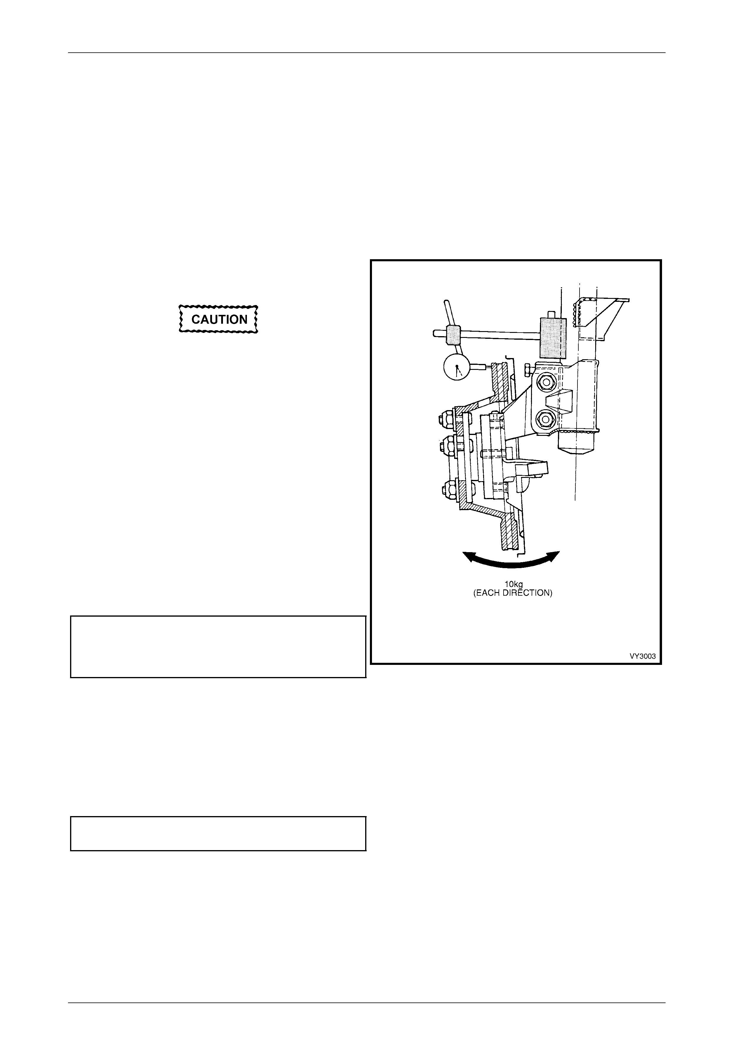
The dial indicator gauge MUST be mounted at
right-angles (90°) to the brake rotor friction
surface.
5 Mount a dial indicator to a suitable magnetic stand and
attach to the front strut tube. Position the dial indicator
pointer at the outer diameter of the rotor, as shown.
6 Apply an outward, 10 kg force to the outer b r ake rotor
diameter, in an opposite pos ition (180°) to the dial
indicator. To maintain consistency, a spring balance
capable of measuring this force, MUST be used. With
the force applied, zero the dial indicator.
7 Apply an inward, 10 kg force to the outer brake rotor
diameter and note the dial in dicator reading.
8 The reading obtained is the an gular movement (NOT
end float) and to determine the bearing’s serviceability,
compare the measured result with the following
specifications.
Wheel Bearing Angular 'Float' Specification
New bearing....................................0.106 mm maximum
Used bearing...................................0.213 mm maximum Figure 3A – 16
9 Should this inspection show that the wheel bearing assembly is outside the specified, angular ‘float’ dimension,
then the hub must be replaced. Refer to 3.3 F r ont Wheel Hub Assembly Brake Rotor or Shield, in this Section.
10 Remove the dial indicator and stand, and the three wheel nuts and flat washers.
11 Reinstall the road wheel, alig ning the marks made prior to removal and secure with attaching nuts.
12 Lower vehicle to the ground. Tighten road wheel attaching nuts to correct torque specification, working in a ‘star’
pattern. Refer to 3.1 Service Notes and Cautions , in this Section.
Road wheel attaching
nut torque specification ...........................110 – 140 N.m
13 Reinstall the cover or decorative wheel nut caps.

Front Suspension 3A – 17
3A-17
3 Service Operations
ATTENTION
All front suspension fasteners are important attaching parts as they affect the performance of vital
components and/or could result in major repair expense. Where specified in this Section, fasteners MUST be
replaced with parts of the same part num ber or a GM appro ved equivalent. Do n ot use fasteners o f an inferior
quality or substitute design
Torque values must be used as specified during reassembly to ensure proper retention of all front
suspension components.
Throughout this Section, fastener torque wrench specifications may be accompanied with the following
identification marks:
Fasteners must be repl aced after loosening.
Vehicle must be at curb height before final tightening.
Fasteners either have micro encapsulated sealant applied or incorporate a mechanical thread lock and
should only be re-used once. If in doubt, replacement is recommended.
If one of these identification marks is present alongside a fastener torque wrench specification, the
recommendation regarding that fastener must be adhered to.
3.1 Service Notes and Cautions
Road Wheels
• Whenever a road w heel is removed from or installed to an y MY 2005 VZ Series vehi cle, it MUST be
done in accordance with the procedure provided in Section 10, Wheels and Tyres.
• Whenever a road w heel is removed from the vehicle, the relationshi p of the road wheel to the hub
MUST be marked with a felt tipped pen or similar, to allow those parts to be reinstalled in their
original positions. This is critical to minimise the road wheel runout dimension.
• When reinstalling road wheels, do not use
an impact gun to tighten wheel nuts
unless the impact gun is fitted with a
torque limiter socket (Tool No. AU 534 or
a commercial equivalent). Failure to
correctly tighten w heel nuts to the correct
torque specification and in the correct
order (as shown), may result in a
distorted brake disc, leading to the
development of brake shudder.
Road wheel attaching nut
torque specification..................................110 – 140 N.m
Figure 3A – 17
ABS/TC Components
• Whenever any component that forms part of the ABS (if fitted) is disturbed
during Service Operations, it is vital that the complete ABS system be checked,
refer to Section 5B, ABS, ABS/TC, Electronic Brake Assist (EBA).

Front Suspension 3A – 18
3A-18
3.2 Suspension and Trim Height, Check
• Good judgement must be exercised before
replacing a spring or springs from a
vehicle whose height is within the limits
quoted.
• Even if a vehicle's dimensions should
prove to be slightly outside these
tolerances, the vehicle could well be in a
serviceable condition.
• Spring replacement under conditions of
excessive weight due to non-standard
fittings, undercoating, road dirt, etc; will
assist very little in restoring the vehicle to
its specified height.
The suspension and trim height dimensions for standard vehicles with base equipment only, are provided in
5 Specifications in this Section. The dimensions are for a new vehicle built to standard specification and are on ly
intended as a guide when checking susp ension and trim height dimensions at normal curb weight.
Preliminary Inspection
The following procedure sh ould be followed before checking any suspension or trim height.
1 Vehicle curb weight is defined as:
• Tyre pressures are to specification.
• Fuel tank is full – add additional weight in the rear compartment to compensate if necessary.
• All fluids are at the specified levels.
• Spare tyre is included.
• Tyre and wheel rim sizes are to specification.
• Vehicle contains no passe ngers.
2 Accumulated dirt, distance travelled, etc., must also be taken into consideration when checking vehicle heights.
3 Vehicle must be on a level surface.
4 It must be confirmed that the vehicle has not been subjected to accident d amage.
NOTE
It is normal for the vehicle to sit approximately 4
mm lower at the right hand side front, because of
the vehicle's battery weight.

Front Suspension 3A – 19
3A-19
Procedure
1 Push the vehicle up and do wn several times at the front bumper bar with a decreasing force and then gently
remove hands, allowing vehicle to settle on its own.
2 Carry out front suspension and trim height check, at ‘A’ and ‘C’ respectively; refer to Figure 3A–18.
Figure 3A – 18
Legend
A Front Suspension Height Location
B Rear Suspension Height Location C Front Trim Height Check Location
D Rear Trim Height Check Location
3 Push the vehicle up and do wn several times at the rear bumper bar with a decreasing force and th en gently
remove hands, allowing vehicle to settle on its own.
4 Carry out vehicle rear suspension and trim height check, at ‘B’ and ‘D’, respectively; refer to 3A–18.
Front and Rear Suspension Height Comparison
1 When checking a vehicle's suspension height, the following tolerances must also be taken into account, before any
spring is replaced. Compare the front and rear suspension height measurements between:
• Front to rear.
• Side to side
Ride Height Variations from Specification
Front to Rear..................................................... ± 20 mm
Side To Side ..................................................... ± 10 mm
Normal Spring Settling........................................± 5 mm
NOTE
Ride height variatio n may also be due to any one
or a combination of the following:
• Spring seat location on the suspens ion/body.
• Incorrect springs. Check spring identification
against the table shown in 5 Specifications in
this Section.
• Non-standard, additional vehicle weight, such
as a tow bar and/or after-market LPG fitment.
• Any combination of the above.

Front Suspension 3A – 20
3A-20
3.3 Front Wheel Hub Assembly, Brake Rotor
and/or Brake Shield
LT Section No. – 06-212
ATTENTION
The following fasteners MUST be replaced when performing these operations:
Front strut to steering knuckle attaching nuts and bolts.
Brake caliper to steering knuckle attaching bolts and Nord-Lock™ lock washers (Coupe only)
The following fasteners have either micro encapsulation or incorporate a mechanical thread lock and should
only be used once. If in doubt, replacement is recommended when performing this operation:
Front wheel hub assemb ly to steering knuckle attaching bolt.
NOTES
• Apart from wheel stud replacement, there are
no serviceable items in the front wheel hub
assembly. As the unit is a 'sealed for life'
assembly, neither bearing adjustment nor
lubrication maintenance is required. Should a
non-standard condition develop, then the hub
assembly must be replaced as a complete
unit.
• While the front wheel hub assembly is
designed to have zero axial free play or ‘end-
float’, some angular movement may be
evident when a rocking force is applied to the
mounted wheel and tyre assembly. Before a
hub is replaced, refer to checking procedure
as detailed in 2.4 Front Wheel Hub Assembly
– End Float Checking Procedure in this
Section.
• MY2005 Coupe models are not fitted with
front disc dust shields.
Remove
All VZ Models
1 Observing the jacking precautions as outlin ed in 2.3 Jackin g Precautions in this Section, raise the front of the
vehicle and support on safety stands.
2 Remove the wheel cover or decorative wheel nut caps.
3 Mark the relationship of the road wheel to hub or brake rotor. Loosen, then remove the road wheel attaching nuts.
Remove the road wheel.
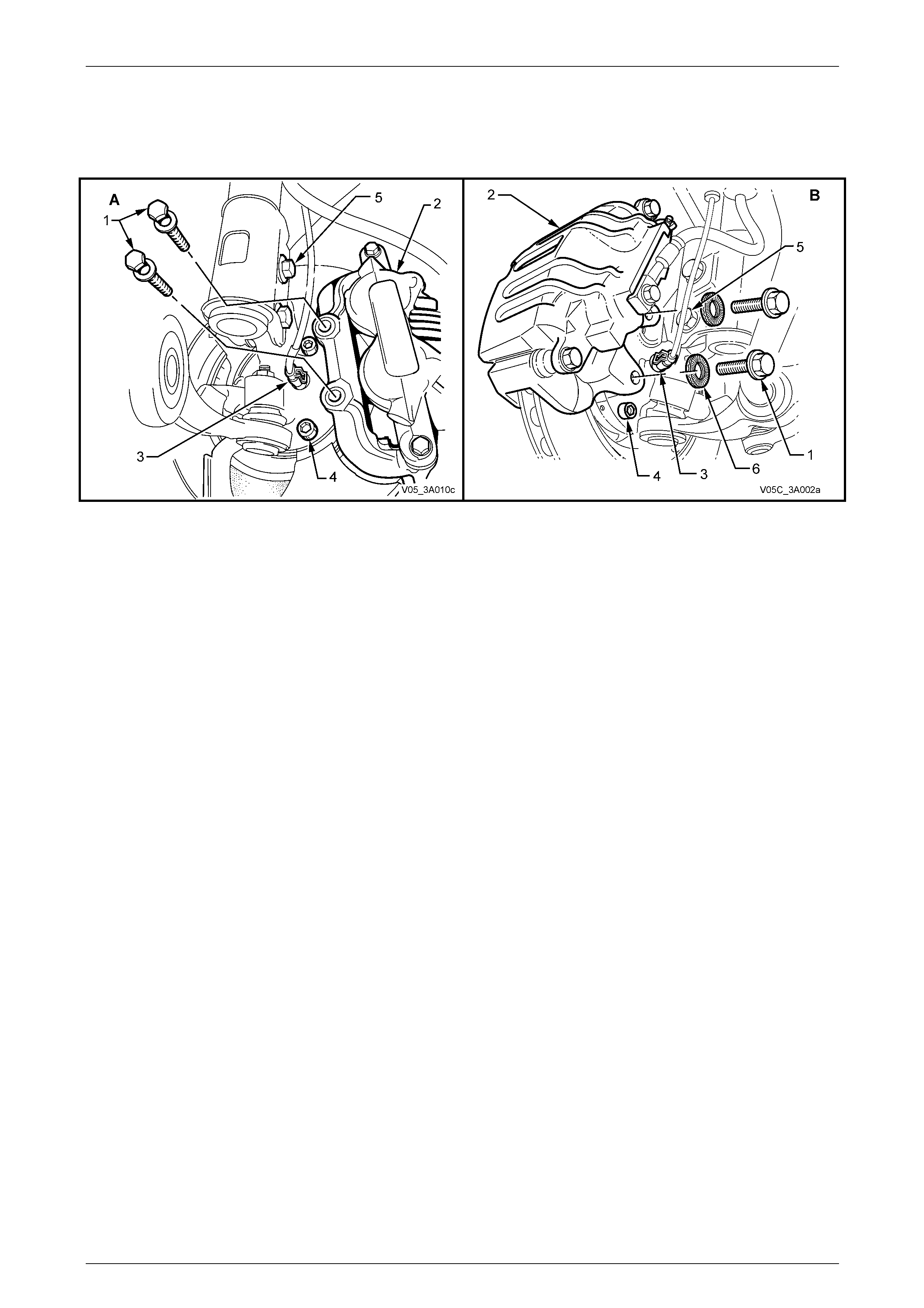
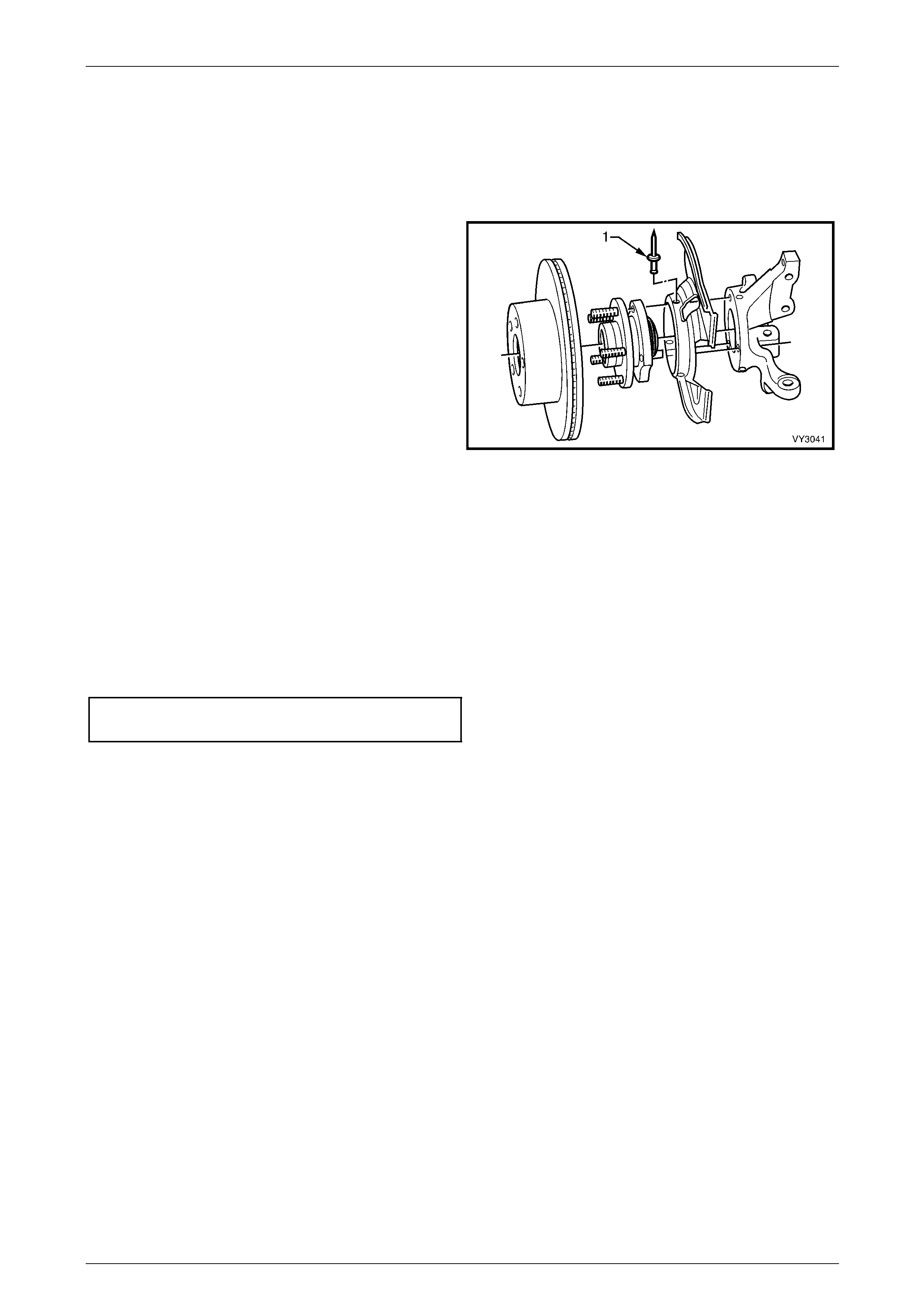
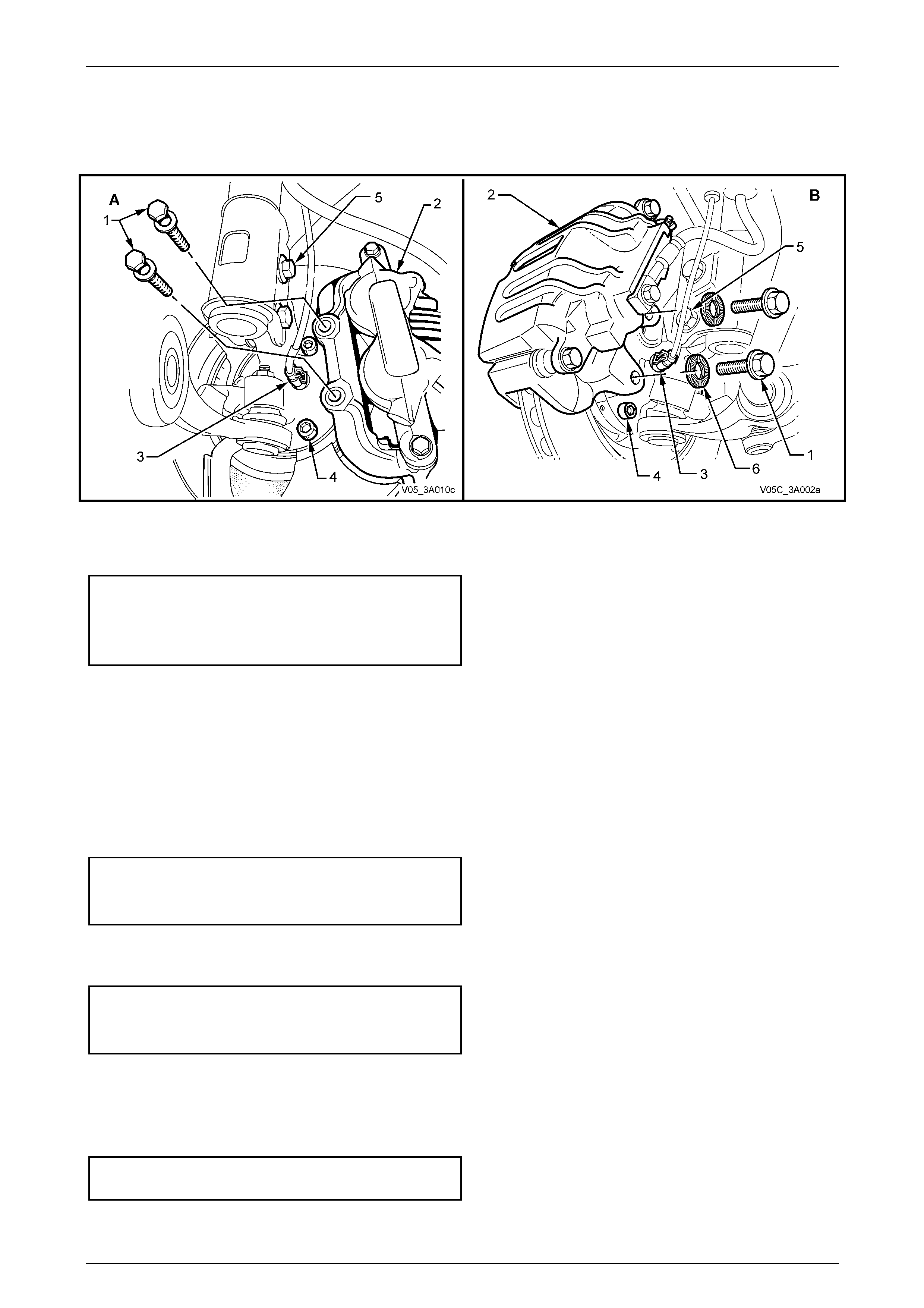
4 Remove the brake caliper retaining bolts and washers (1) or bolts (1) and Nordlock™ washers (6) (Coupe only) and
lift the caliper assembly (2) from the brake rotor. Position caliper in such a way that no strain is placed on the brak e
hose. If necessary, tie caliper to the suspension spring with a piece of wire. THE CALIPER IS NOT TO HANG BY
THE BRAKE HOSE.
5 The brake rotor to hub location is marked in prod uction. To maintain this relationship, ensure that the rotor to hub
position is carefully marked.
NOTE
This is necessary to overcome the possibility of
inducing a brake shudder condition after
reassembly.
6 If equipped with ABS, disconnect the wheel spee d sensor connector (3) from the hub sensor connector , by lifting
the connector locking tab and pulling on the connector to disconnect.
7 Remove the brake rotor from the wheel hub assembly.
Front Suspension 3A – 21
3A-21
NOTE
View ‘A’ in Figure 3A – 19 shows all VZ except
Coupe, while view ‘B’ shows the Coupe
arrangement.
Figure 3A – 19
8 Using a commerciall y available 10 mm Allen key socket and a suitable socket bar, loosen each of the three bolts
(4) holding the hub to the steering knuckle.
NOTE
• If the Allen key socket is too long to fit into the
front, upper hub bolt, then the lower strut to
steering knuckle nut (an d bolt) (5) will need t o
be loosened and removed. Discard the
removed bolt and nut, as they must be
replaced on reassembly.
• For the front lower hub bolt, turn wheel
outwards to provide sufficient clearance.
9 If the hub is a tight fit to the knuckle, it may be necessary to loosen the three bolts and tap on the he ads. DO NOT
STRIKE THE HUB.
10 Remove the three bolts and then the hub from steering knuckle.
11 Where removal of the brake disc dust shiel d is necessary (on all except Coupe), drill the heads from the three rivets
securing the shield to the steering knuckle support.
12 After removal of the dust shield, carefully drill out the remainder of the rivets, using a suitable sized dri ll.
Inspect
1 Check wheel studs are pressed firml y into the front wheel hu b assemb ly and ensure threads are not damage d. If
one or more of the wheel studs require replacement, refer to 3.4 Front W heel Hub Studs in this Section for details.
2 Examine the brake rotor for scores or dam age. If either of these conditions exist, the brake rotor shoul d be
machined. Refer to Section 5A Service and Park Braking Systems for details.
3 Check for damage to the shield that may cause fouling of any rotating parts and if suspect, the shield sho uld b e
replaced.
Front Suspension 3A – 22
3A-22
Reinstall
Installation of the front wheel hub assembly, brake rotor a nd br ake shield is the reverse of removal procedures, except
for the following points:
All VZ Except Coupe
1 If the brake shield has been removed, install three,
common pop rivets (1), using a commerciall y available
pop rivet gun.
NOTE
Install the first rivet in the brake shield hole with
the round hole. This will ensure that the
clearance to brake caliper is c orrect.
2 Before installing the hub, inspect both matin g surfaces
to make sure that they are clean and free from burrs
that could prevent correct alignment of both parts,
once installed.
Figure 3A – 20
All VZ Models
3 Install the hub assembly on to the steering knuckle.
NOTE
If equipped with ABS, carefully align the sensor
connection on the hub, with the hole in the
steering knuckle.
4 Reinstall the three attaching bolts (1) and tighten to the correct torque specification.
Front wheel hub to steering
knuckle bolt torque specification........................108 N.m
NOTE
The three hub attaching bolts are micro-
encapsulated with thread sealant and are not to
be re-used more than three ti mes. If in doubt, the
bolts should be replaced.
5 If equipped with ABS, fit the wheel speed sensor connector (3), checking that the locking tang is in place.
Front Suspension 3A – 23
3A-23
NOTE
View ‘A’ in Figure 3A – 19 shows all VZ except
Coupe, while view ‘B’ shows the Coupe
arrangement.
Figure 3A – 21
6 If removal of the lower strut to steering knuckle bolt and nut (5) was necessary, the bolt and nut, must be replaced
with new parts. Tighten the bolt and nut to the correct torque specification.
Steering knuckle to strut bolts
and nuts torque specification .... Stage 1.............85 N.m
Stage 2 ...........100 N.m
Stage 3Turn through 90°
7 Install brake rotor, aligning the marks made before removal.
NOTE
If the hub was replaced, then runout checks must
be carried out on the installed brake rotor. Refer
to Section 5A Service and Park Braking Systems
for important information regarding these checks
8 For all models except Coupe install brake caliper (2) and NEW attaching bolts (4) and washers.
9 Tighten the caliper attaching bolts to the correct torque sp ecification.
Brake caliper anchor plate bolt
torque specification (All except Coupe).......85 N.m, then
turn through 45°
10 For Coupe models only, install the caliper and NEW attaching bolts and NEW Nordlock™ washers.
11 Tighten the caliper attaching b olts to the correct torque specification.
Brake caliper anchor plate bolt
torque specification (Coupe only)................70 N.m, then
turn through 90°
12 Reinstall the road wheel, alig ning the marks made prior to removal and secure with the attaching nuts.
13 Lower the vehicle to the ground.
14 Tighten the road wheel attaching nuts to correct torque specification, working in a ‘star’ pattern,
refer to 3.1 Service Notes and Cautions, in this Section.
Road wheel attaching
nut torque specification............................110 – 140 N.m
15 Reinstall the wheel cover or decorative wheel nut caps.

Front Suspension 3A – 24
3A-24
3.4 Front Wheel Hub Studs
LT Section No. – 06-212
ATTENTION
The following fasteners MUST be replaced when performing these operations:
Brake caliper to steering knu ckle attaching bolts.
Remove
1 Observing the jacking precautions as outlin ed in 2.3 Jackin g Precautions in this Section, raise the front of the
vehicle and support on safety stands..
2 Remove the wheel cover or decorative wheel nut caps.
3 Mark the relationship of the wheel to the hub and rotor. Re move the wheel attaching nuts and remove th e wheel.
NOTE
To avoid the unnecessary removal of the micro-
encapsulated studs retaining the front wheel hub
assembly to the steering knuckle, it is
recommended that wheel stud/s replacement be
carried out with the hub left undisturbed.
4 Remove the brake caliper retaining bolts and washers, lift the caliper assembly from the brake rotor. Suspend the
caliper on a wire or hook to avoid strain on the hose. DO NOT ALLOW CALIPER TO HANG BY BRAKE HOSE.
5 Remove the brake rotor from the hub.
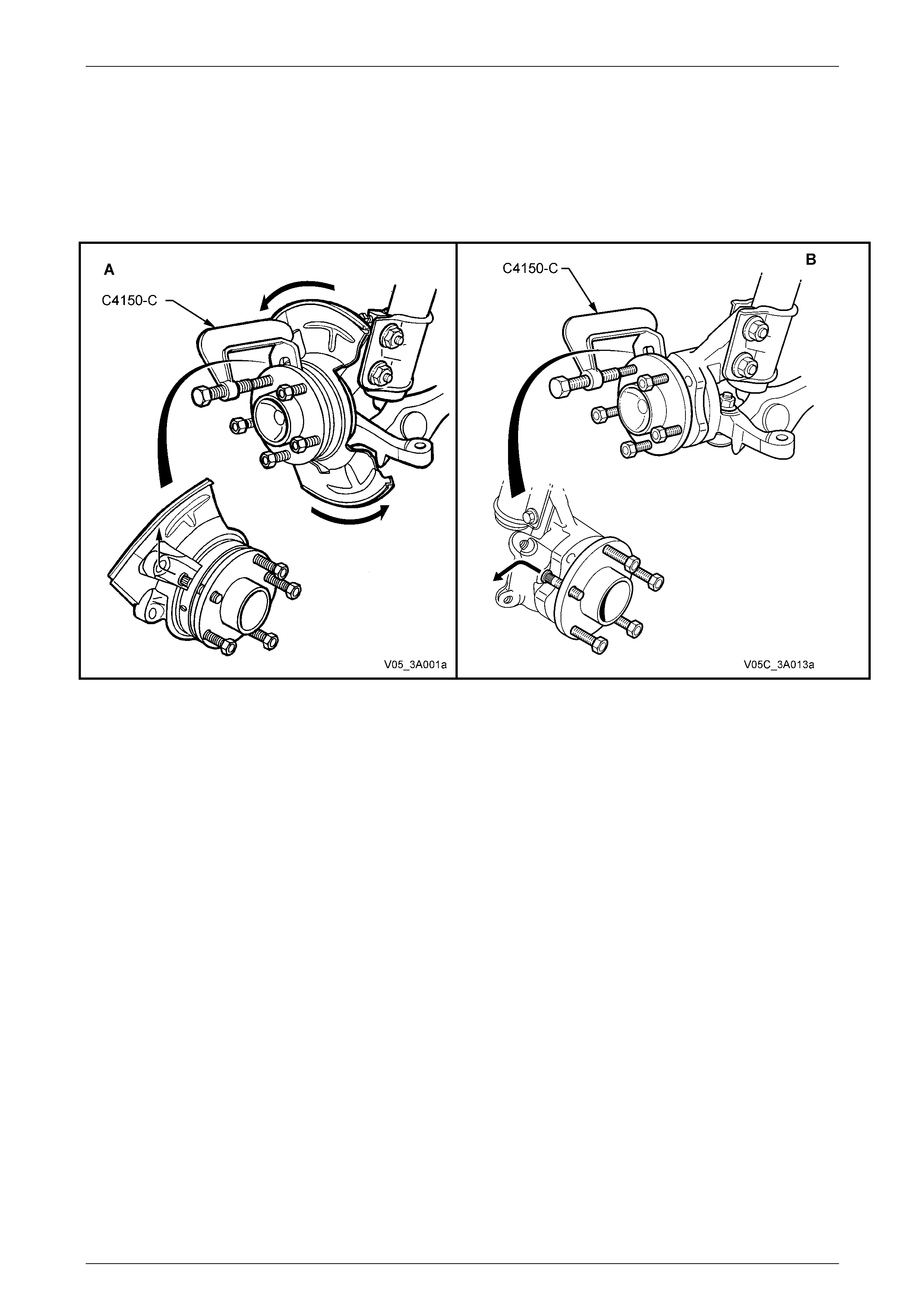
6 Install a wheel nut until the nut is flush with the end of the stud, then, using Tool No. C4150-C or equivalent, press
the stud/s from the front wheel hub assembly.
Front Suspension 3A – 25
3A-25
NOTE
To remove the stud/s on all but Coupe models
(view ‘A’), first drill out the three rivets securing
the brake shield to the steering knuckle. Then
rotate the shield and remove the wheel stud by
manipulating the head under the shield and into
the one recess in the steering knuckle, at
approximately the 11 o'clock position, as shown.
Figure 3A – 22
7 For Coupe models (view ‘B’), align the stud to be removed, with the cut-out in the hub bearing housing.
8 Using Tool No. C4150-C or equivalent, press the stud from the front wheel hub ass embly.
9 Repeat steps 7 and 8 for any additional; stud/s that require replacement.
Front Suspension 3A – 26
3A-26
Reinstall
All VZ Except Coupe
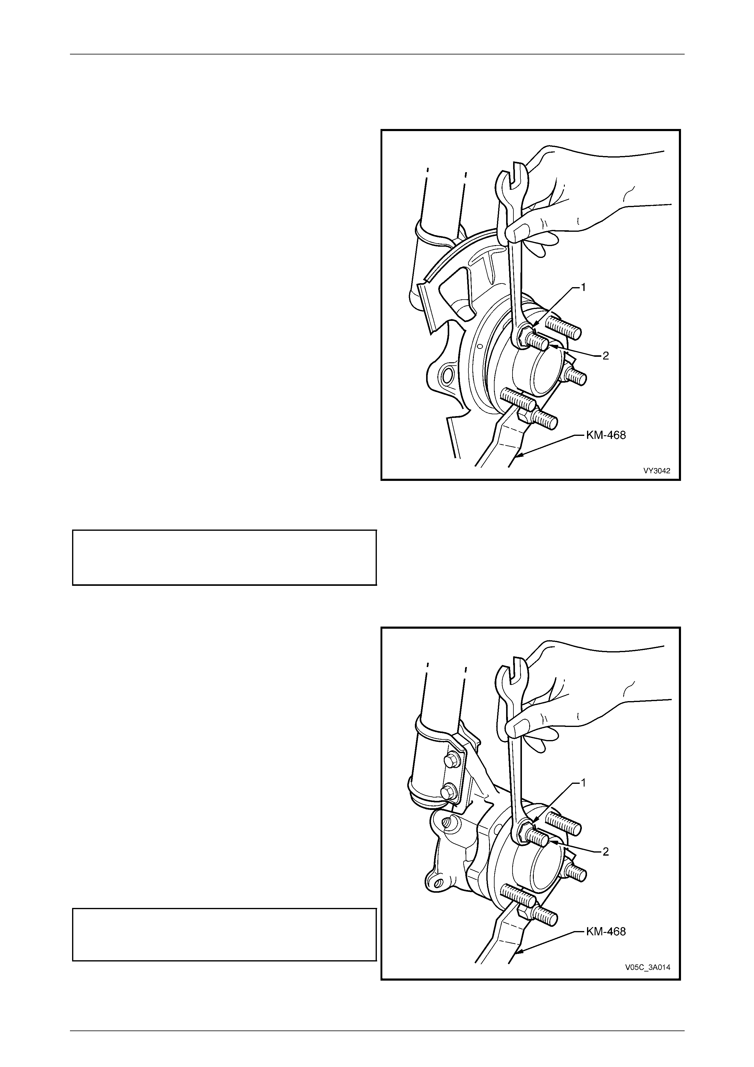
10 New studs can be installed as follows:
a Install Tool No. KM-468, using two reversed
wheel nuts.
b Install the replacement stud by first manipulati ng
the stud under the front brake shield and into the
wheel hub flange.
c Then, after assembling a suitable sized flat
washer and reversed wheel nut (1) onto the
replacement stud (2), hold Tool No. KM-468 and
tighten the wheel nut to draw the stud into place.
d Install any remaining studs in the same manner.
Remove Tool No. KM-468.
11 Using a suitable sized drill, remove the shanks of the
three brake shield retaining rivets. Then use common
pop rivets and a commercially available pop rivet gun
to reinstall the brake shield.
NOTE
Install the first rivet in the brake shield hole with
the round hole. This will ensure that the
clearance to brake caliper is c orrect.
12 Reinstall the brake rotor and caliper.
13 Install NEW caliper anchor plat e bolts and tighten to
the correct torque specification. Figure 3A – 23
Brake caliper anchor plate
bolt torque specification..............................85 N.m, then
Turn through 45°
Coupe Only
14 New studs can be installed as follows:
a Install Tool No. KM-468, using two reversed
wheel nuts.
b Install the replacement stud into the wheel hub
flange hole. Index the serrations wit those in the
stud hole.
c Then, after assembling a suitable sized flat
washer and reversed wheel nut (1) onto the
replacement stud (2), hold Tool No. KM-468 and
tighten the wheel nut to draw the stud into place.
d Install any remaining studs in the same manner.
Remove Tool No. KM-468.
15 Reinstall the brake rotor an d caliper, aligning the
marks made before removal.
16 Install NEW caliper anchor plat e bolts and tighten to
the correct torque specification.
Brake caliper anchor plate
bolt torque specification..............................70 N.m, then
Turn through 90°
Figure 3A – 24

Front Suspension 3A – 27
3A-27
All VZ Models
17 Reinstall the road wheel, alig ning the marks made prior to removal and secure with the attaching nuts.
18 Lower the vehicle to the ground.
19 Tighten the road wheel attaching nuts to correct the torque specification, working in a ‘star’ pattern.
Refer to 3.1 Service Notes and Cautions, in t his Section.
Road wheel attaching
nut torque specification............................110 – 140 N.m
20 Reinstall the cover or decorative wheel nut caps.
Front Suspension 3A – 28
3A-28
3.5 Front Strut Assembly
LT Section No. – 06-212
ATTENTION
The following fasteners MU ST be replaced when performing these operations:
Upper strut locating plate retaining nut
Steering knuckle to strut attach in g nuts and bolts.
Brake caliper to steering knuckle retaining bolts and Nord-Lock™ locking washers (Coupe only).
Remove
All VZ Models
1 Observing the jacking precautions as outlin ed in 2.3 Jackin g Precautions in this Section, raise the front of the
vehicle and support on safety stands.
2 Remove the wheel cover or decorative wheel nut caps, as required.
3 Mark the relationship of the road wheel to hub or brake rotor. Loosen, then remove the road wheel attaching nuts.
Remove the road wheel.
All VZ Except Coupe
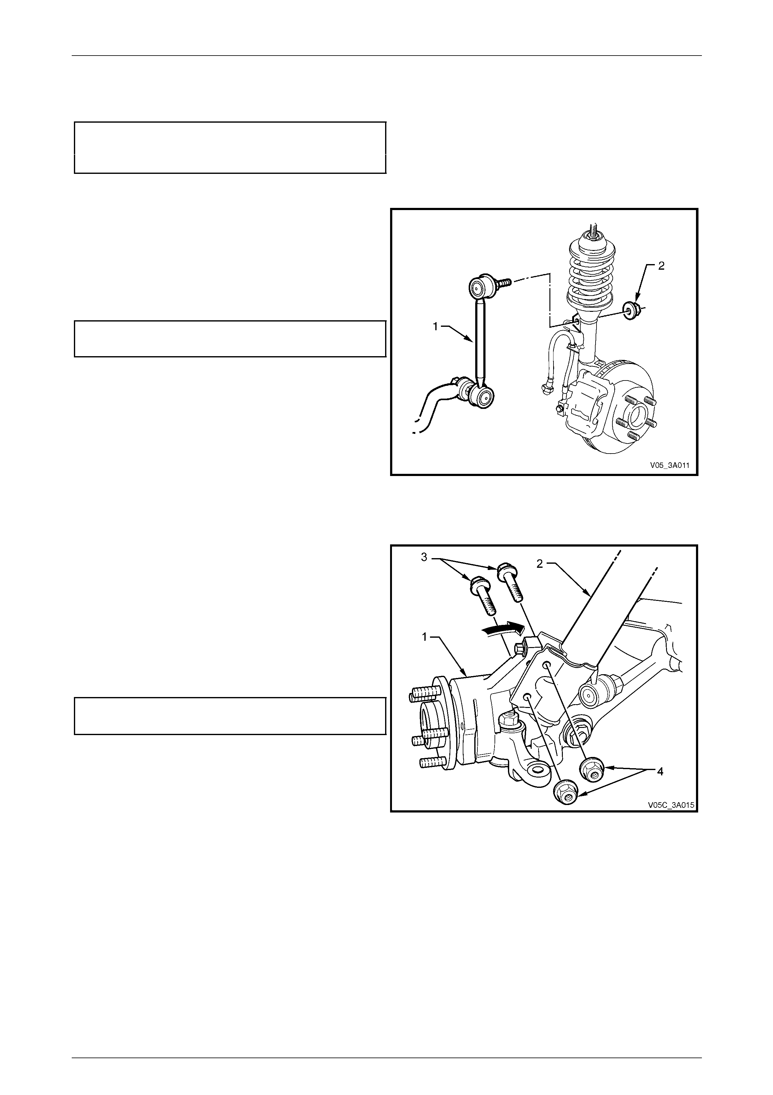
4 Position a suitable size open end spanner to hold the
stabiliser bar link upper ba ll joint stud, then use
another spanner to loosen and remove the u pper nut
(2).
5 Pull the link stud from the strut bracket.
6 Remove the brake hose retaining clip (all VZ except
Coupe) at the suspension tower bracket by first,
prising the end at the brake hose en d free, using a
screwdriver or similar. Remove the clip from the strut
bracket, then discard.
7 Where fitted, disconnect the ABS wheel speed sensor
cable and insulator from the strut bracket.
8 Rotate the brake hose grommet until the flats on the
grommet are aligned with the slot in the strut bracket,
then remove the hose and gro mmet.
Figure 3A – 25
Front Suspension 3A – 29
3A-29
9 Remove the brake caliper retaining bolts and washers
(1), lift the caliper assembly (2) from the brake rotor
and support in such a way that no strain is placed on
the brake hose. THE BRAKE CALIPER IS NOT TO
HANG BY THE BRAKE HOSE.
NOTE
This step is necessary to gain access to the
lower strut mounting bolts and nuts (3).
10 If required, remove the brake rotor from the wheel hu b
assembly. The brake rotor to hub relationship is
marked during production. To ensure this relationship
is maintained, ensure that the rotor to hub position is
carefully marked.
NOTE
This is necessary to overcome the possibility of
inducing a brake shudder condition after
reassembly. Figure 3A – 26
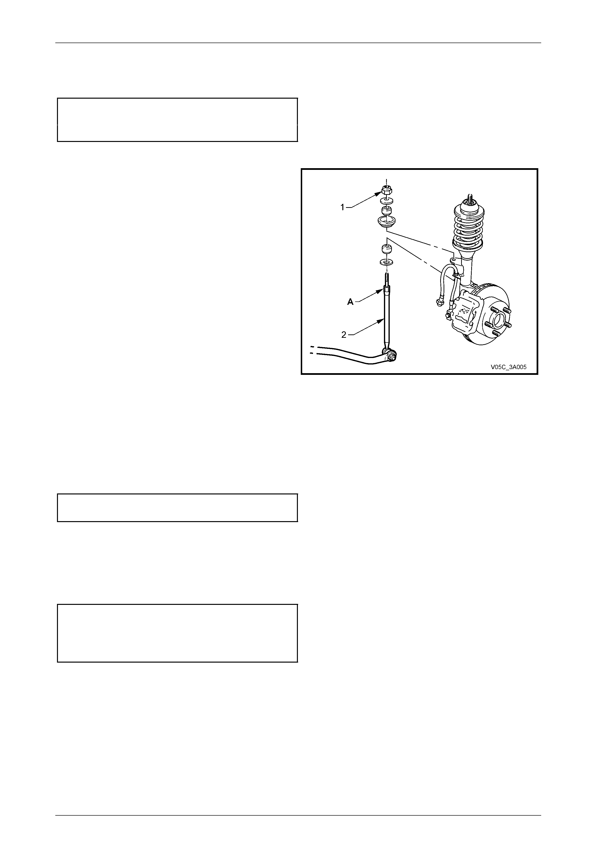
Coupe Only
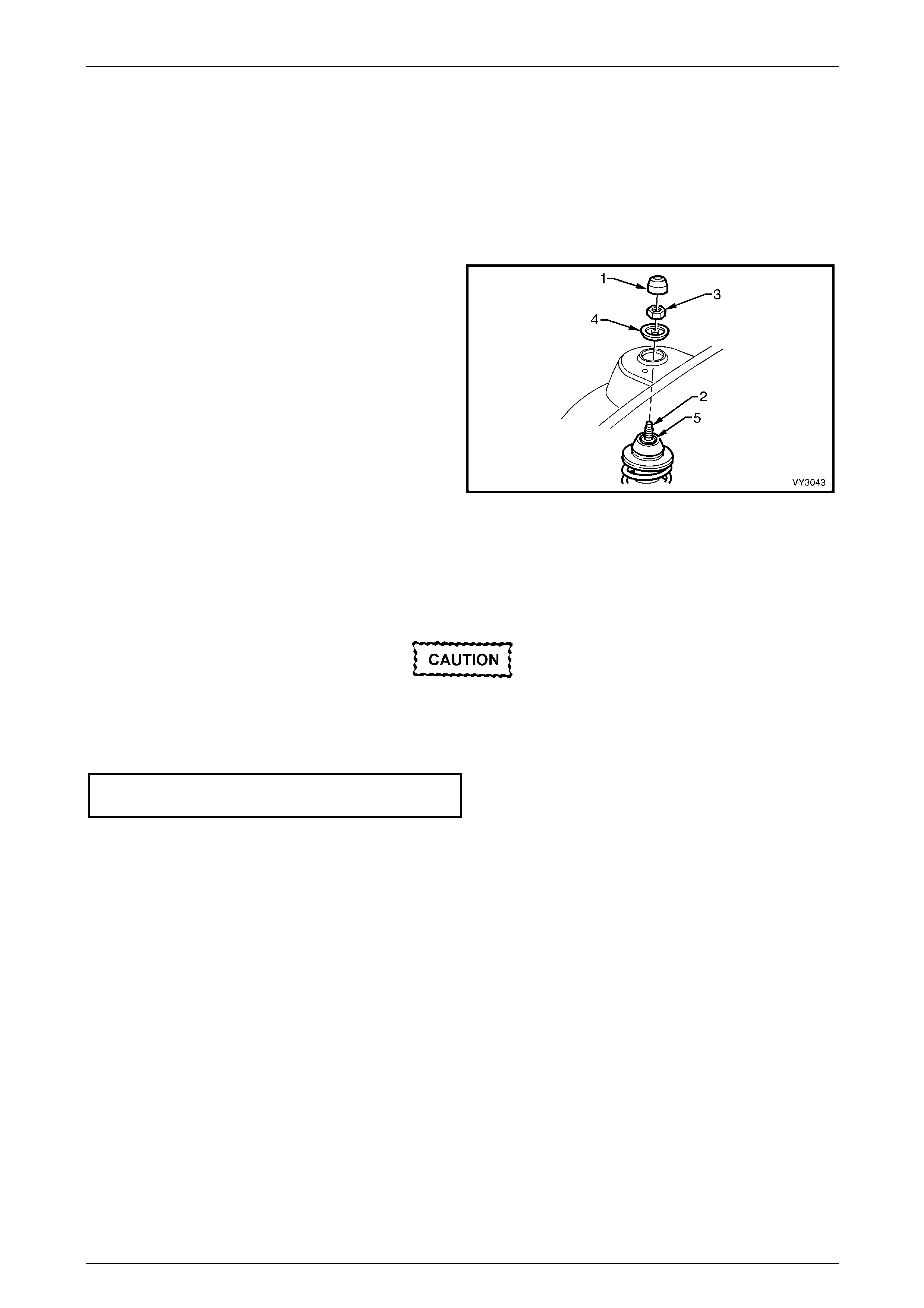
11 Position a suitable size open end spanner to hold the
stabiliser bar spacer stud (1) at ‘A’, then use another
spanner to loosen and remov e the up per nut (2),
washer (3), insulator (4) and seat (5).
12 Disconnect the wheel speed sensor cable and
insulator from the strut bracket.
13 Disconnect the wheel speed sensor cable and
insulator from the lower strut bracket.
Figure 3A – 27
14 Remove the brake caliper retaining bolts (1) and
washers (2). Discard both the bolts and the washers
as they must be replaced on reassem bl y.
15 Lift the caliper assembly from the brake rotor and
support in such a way that no strain is placed on the
brake hose. THE BRAKE CALIPER IS NOT TO HANG
BY THE BRAKE HOSE.
NOTE
This step is necessary to gain access to the
lower strut mounting bolts and nuts (5).
16 If required, remove the brake rotor from the wheel hu b
assembly. The brake rotor to hub relationship is
marked during production. To ensure this relationship
is maintained, ensure that the rotor to hub position is
carefully marked.
NOTE
This is necessary to overcome the possibility of
inducing a brake shudder condition after
reassembly.
Figure 3A – 28
Front Suspension 3A – 30
3A-30
All VZ Models
17 Position a suitable floor jack fitted with a block of wood on the lift pad under the control arm, and raise it sufficiently
to support the weight.
18 Loosen, remove and discard the two lower strut to knuckle attaching bolts and nuts (5).
19 To avoid placing strain on the ABS wheel speed sensor lead, release the c onnector locking tang and pull on the
sensor lead connector (4) to remove from the sensor.
20 Pull the steering knuckle clear of the strut.
21 Remove the dust cover (1) from the upper strut
support, in the engine compartment.
22 While holding the strut rod shaft (2) with a 10 mm
socket, remove the self-locking nut (3), using a 24 mm
ring spanner, then remove the locating disc (4).
Discard the removed strut rod nut.
23 Carefully lower the strut from the tower, manipulate
the strut to remove the stabiliser stud from the bracket
on the strut and remove the assembly from the
vehicle.
Figure 3A – 29
Reinstall
All VZ Models
The torque of the strut bearing retaining nut
(‘5’ in Figure 3A-29) MUST be checked for
correct tightness BEFORE installing the strut
into the vehicle.
Upper strut bearing retaining
nut torque specification........................................78 N.m
1 Lift the strut assembly into the spring strut tower.
2 Install the locating disc and partially install a NEW upper nut to the strut rod. Do not tighten at this time.
Front Suspension 3A – 31
3A-31
All VZ Except Coupe
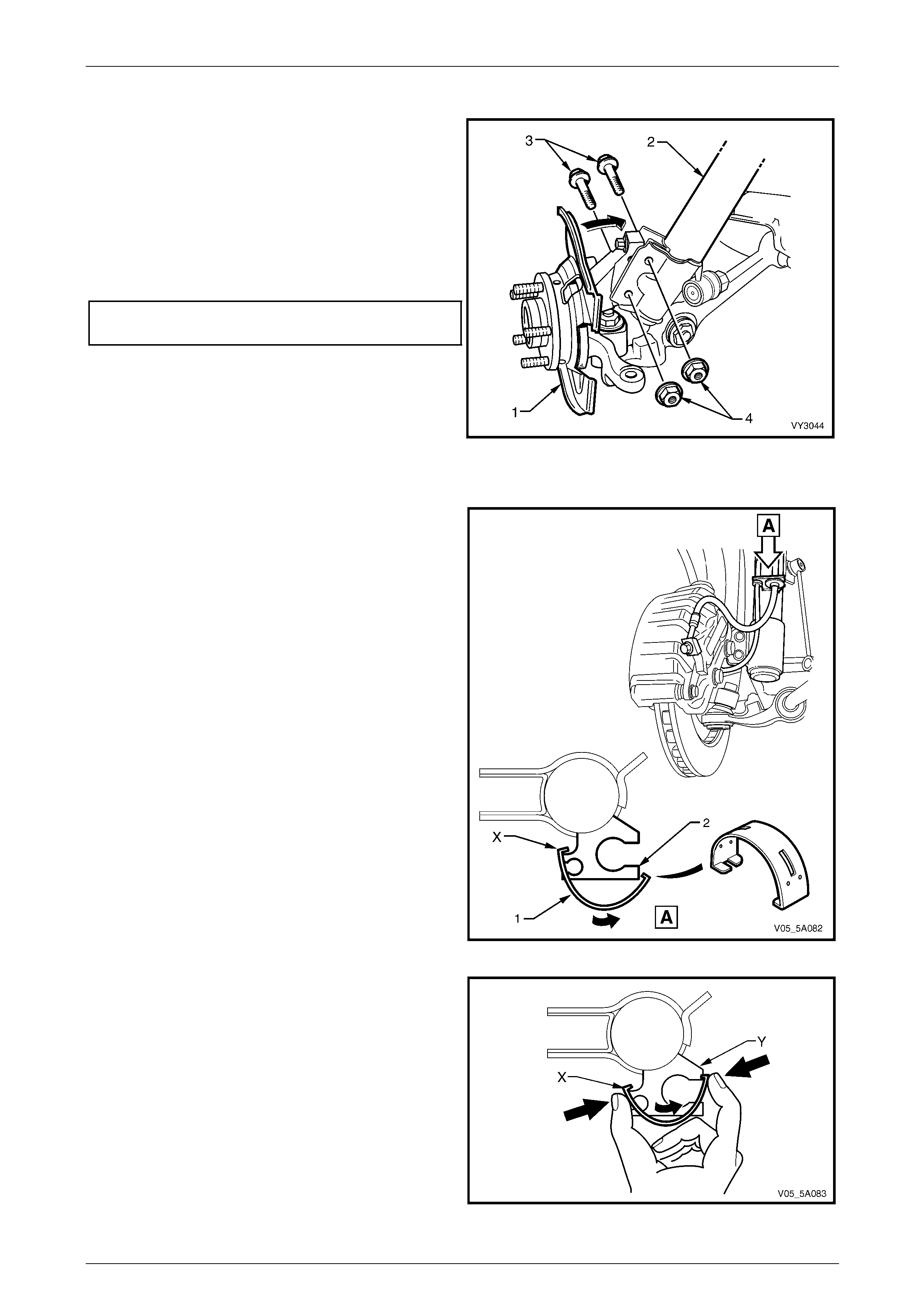
3 Pivot the hub and steering knuckle ass embly (1),
enough to line up the bolt hol es in the steering knuckle
and the lower end of the strut assembly (2).
4 Install NEW retaining bolts (3) and nuts (4), and
tighten to a preliminary torque of 85 Nm.
5 Use a 10 mm socket to hold the strut rod from turning,
then tighten the upper strut rod retaining nut (‘3’ in
Figure 3A-29) to the correct torque specification, using
a 24 mm ring spanner with a torque wrench attached.
Upper strut locating plate retaining
nut torque specification........................................55 N.m
6 Reinstall the wheel speed sensor connector, pushing
firmly onto the sensor until the retaining tang is secure.
7 Reinstall the sensor lead and grommet into the strut
mounting bracket.
8 Reinstall the brake hos e and grommet into the
suspension strut bracket and secure by turning the
grommet through 90°.
Figure 3A – 30
9 Install a NEW brake hose retaining clip, as follows:
a Slide one end of the retaining clip (1) over the
brake hose retaining bracket (2) at point ‘X’,
checking that the strut bracket is aligned with the
slot in the clip.
Figure 5A – 31
b While holding the installed end ‘X’ in place,
rotate the clip around the brak e hose retaining
bracket until the clip ‘clicks’ into position, at point
‘Y’.
c Squeeze the clip firmly with the thumb and
forefinger of one hand as indic ated, to ensure
that the clip ends are fully engage d.
Figure 5A – 32
Front Suspension 3A – 32
3A-32
10 If removed, reinstall the brake rotor, aligning the marks made prior to removal.
11 Reinstall the brake caliper, se cure with NEW attaching bolts and tighten to specification.
Brake caliper anchor plate
bolt torque specification..............................85 N.m, then
turn through 45°
12 Check that the wheel speed sensor lead and the brake hose are routed correctly and the hose is n ot twisted.
13 Reinstall the stabiliser bar link ball joint stud into the
strut bracket.
14 Reinstall the stud retaining nut (2).
15 While holding t he inner stud hexagon with a suitable
set spanner, tighten the nut to the correct torque
specification.
Upper stabiliser bar link stud
nut torque specification........................................50 N.m
Figure 3A – 33
Coupe Only
16 Pivot the hub and steering knuckle assembly (1) up, to
align the bolt holes in the steering knuckle a nd the
lower end of the strut assembly (2).
17 Install NEW retaining bolts (3) and nuts (4), and
tighten to a preliminary torque of 85 Nm.
18 Use a 10 mm socket to hold the strut rod from turning,
then tighten the upper strut rod retaining nut (‘3’ in
Figure 3A-29) to the correct torque specification, using
a 24 mm ring spanner with a torque wrench attached.
Upper strut locating plate retaining
nut torque specification........................................55 N.m
19 Reinstall the wheel speed sensor connector, pushing
firmly onto the sensor until the retaining tang is secure.
20 Reinstall the sensor lead and grommet into the strut
mounting bracket.
21 Reinstall the brake hose and grommet into the
suspension strut bracket and secure by turning the
grommet through 90°.
Figure 3A – 34
NOTE
The brake hose retaining clip is not required on
Coupe vehicles.
22 If removed, reinstall the brake rotor, aligning the marks made prior to removal.
Front Suspension 3A – 33
3A-33
23 Install the brake caliper and s ecure with NEW attaching bo lts and NEW ‘Nord-Lock’™ lock washers.
24 Tighten both bolts to the correct torque specification.
Brake caliper anchor plate
attaching bolt torque specification..............70 N.m, then,
turn through 90°
25 Check that the wheel speed sensor lead and the brake hose are routed correctly and the hose is n ot twisted.
26 Reinstall the stabiliser bar spacer stud nut (1) after
ensuring that all the compone nts are assembled as
shown.
27 While holding the spac er stud (2) with a suitable open
end spanner at ‘A’, use another spanner to tighten the
upper retaining nut until the end of the threa d on the
stud is contacted.
NOTE
Do not use power tools for this tightening
operation, otherwise thread damage will result.
Figure 3A – 35
All VZ Models
28 Reinstall the road wheel, alig ning the marks made prior to removal.
29 Lower the vehicle to the ground.
30 Tighten road wheel attaching nuts to the correct torque specification, working in a ‘star ’ pattern,
refer to 3.1 Service Notes and Cautions, in this Section.
Road wheel attaching
nut torque specification............................110 – 140 N.m
31 Reinstall the wheel cover or decorative road wheel retaining nut caps, as required.
32 Bounce the vehicle up and down several times to settle the suspension.
33 Check the wheel alignment, a s detailed in 2.2 Wheel Alignment Checking and Adjustment in this Section.
34 Tighten the steering knuckle to strut bolts and nuts to the specified torque values.
Steering knuckle to strut bolts
and nuts torque specification ..Stage 1................. 85 N.m
Stage 2............... 100 N.m
Stage 3..Turn through 90°
Front Suspension 3A – 34
3A-34
3.6 Upper Strut Support Bearing and Mount
LT Section No. – 06-210
Remove
1 Remove the front strut (1) as detailed in
3.5 Front Strut Assembly in this Section.
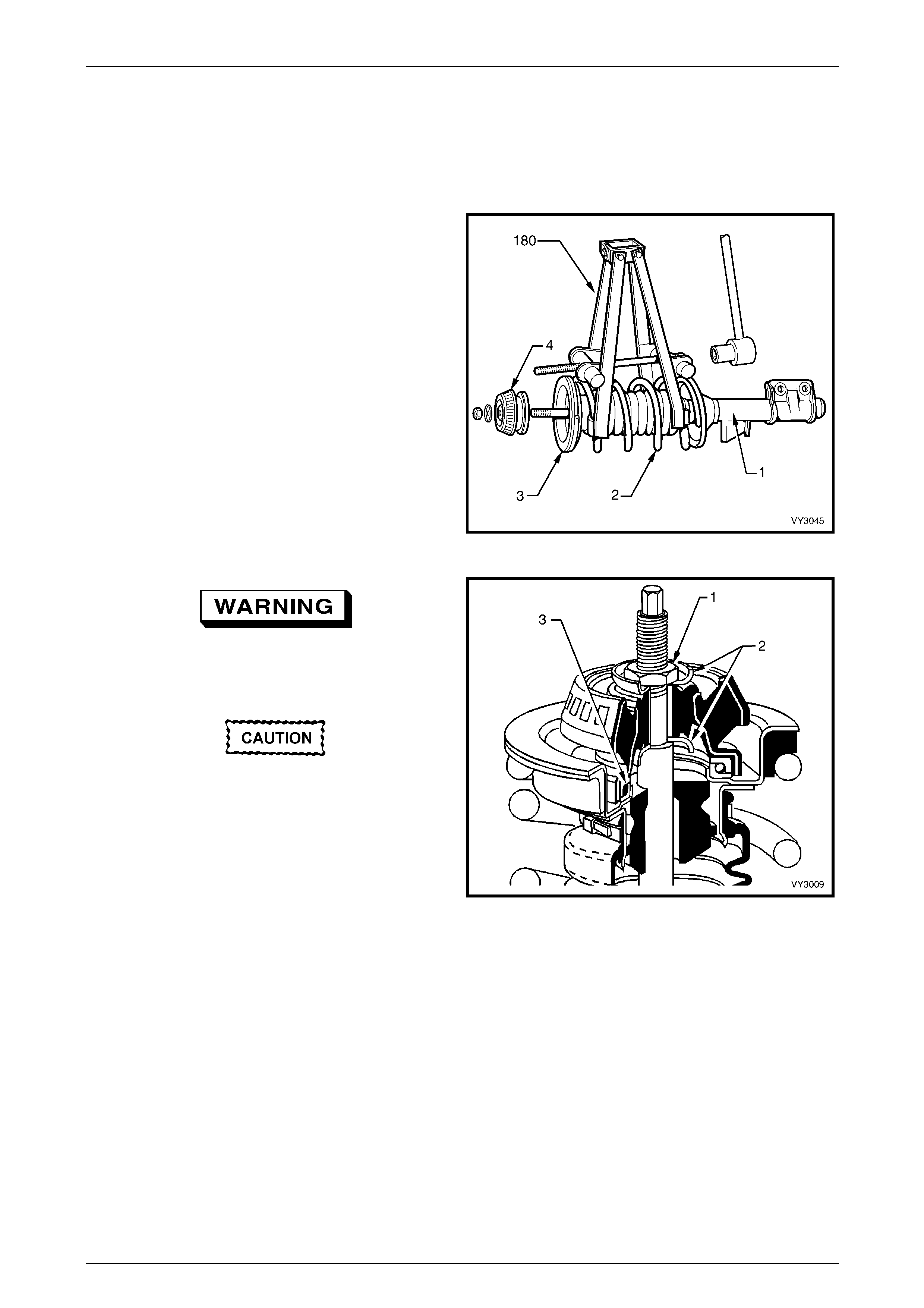
2 Fit Tool No. 180 (or a commercially available
equivalent) on to the front spring as shown. Compress
the spring (2) until the upper support bearing (3) has
clearance at the spring seat collar (4).
Figure 3A – 36
Do not attempt to remove the retaining nut (1)
from the strut rod shaft before compressing
the spring.
Under no circumstances is the machined
surface of the piston rod section to be
gripped directly on its outer surface.
3 While holding the strut rod shaft with a 10 mm socket,
remove the upper strut bearing to strut rod retaining
nut (1), using a 24 mm ring spanner.
4 Remove the front suspension strut mount assembly
and the two washers (2) either side.
NOTE
The lower washer may a dhere to the lower edge
of the mount.
Figure 3A – 37
5 Remove the strut bearing (3) from the upper spring seat collar, taking particular note of the bear ing's orientation.
NOTE
The upper support bearing is self-lubricated and
no servicing requirements are necessary. If
considered to be faulty, the bearing is to be
replaced as an assembly.

Front Suspension 3A – 35
3A-35
Reinstall
1 Pull the strut rod through the upper spring seat to its maximum length, then remove the strut rod nut.
2 Reinstall the upper bearing with the same orientation as noted on removal. Generally, the coloured or narrow, outer
section, faces towards the upper spring seat collar.
3 While holding the strut rod extended and, after installing the first mount washer with the dished shape facing
downward (refer to '2' in Figure 3A-37), install the upper front suspensi on strut mount assembly over the bearing
and washer.
4 Install the second washer with the dished shape facing upward (refer to '2' in Figure 3A-37 ), then install the
retaining nut.
5 Using a 10 mm socket and a 24 mm ring spanner with a torque wrench attached, tighten the nut to the correct
torque specification.
Upper strut bearing retaining
nut torque specification........................................78 N.m
6 Release the spring compress or and remove it from the spring.
7 Reinstall the front strut, refer to 3.5 Front Strut Assembly in this Section.
Front Suspension 3A – 36
3A-36
3.7 Front Spring
LT Section No. – 06-210
Remove
1 Remove the front strut, refer to 3.5 Front Strut Assembly in this Section.
2 Remove the front strut dust shield assembly, as detailed in 3.6 Upper Strut Support Bearing and Mount in this
Section.
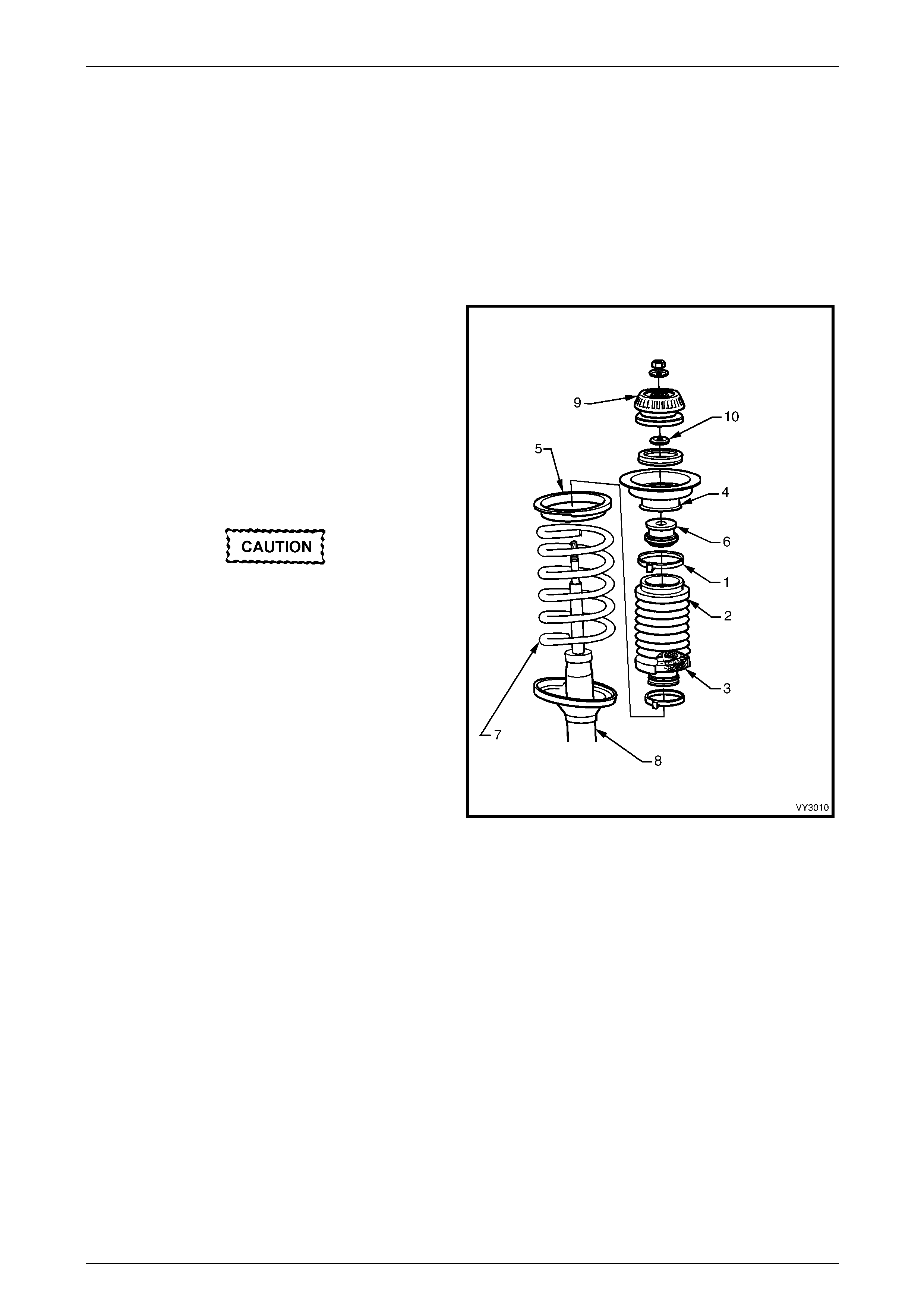
3 Remove the clamp (1) securing the front strut dust
shield assembly (2) and filter (3) to the upper sprin g
seat collar (4) and discard.
4 Remove the upper spring seat collar, spring insulator
(5) and compression bumper (6) from the top of the
spring (7).
5 Remove the spring from the strut (8) and release the
spring compressor.
Reinstall
If installing a replacement spring, check that
the spring is the correct type for the
suspension system fitted to the vehicle.
Refer to 5 Specifications in this Section for
details.
1 Position spring on strut with straight projectin g end of
spring correctly located in spring seat.
2 Install spring compressor Tool No. 180 (or a
commercial equivalent) to the spring (refer to
Figure 3A – 36) and compress it.
3 Install the upper spring insulator, spring seat collar and
compression bumper so that the double notch in the
upper flange of the spring seat collar is assembled,
facing inward. The spring ins ulator has a step which
locates on to the straight projecting end of the spring. Figure 3A – 38
4 Install the upper support plate (9), refer to 3.6 Upper Strut Support Bearing and Mount, in this Section.
NOTE
The lower washer (10) may have stuck to the
lower edge of the mount.
5 Fit the upper end of the front strut dust shield assembly over the lower flange of the spring seat collar and secure
with a retaining clamp. Tighten the clamp until the boot rubber is firmly secured.
6 Install front strut, refer to 3.5 Front Strut Assembly in this Section.
Front Suspension 3A – 37
3A-37
3.8 Front Strut Unit
LT Section No. – 06-212
Replace
When replacing the front strut, check that the
replacement is the correct type for the
suspension system fitted to the vehicle. Refer
to 5 Specifications in this Section for details.
NOTE
As the strut assembly is a sealed component, no
overhaul procedures are possible. If any strut
component is found to be unserviceable, the
complete strut must be replaced.
1 Remove the front strut assembly as detailed in 3.5 Front Strut Assembly in this Section.
2 Remove the upper support components as detailed in 3.6 Upper Strut Support Bearing a nd Mount in this Section.
3 Remove the spring as detailed in 3.7 Front Spring in this Section.
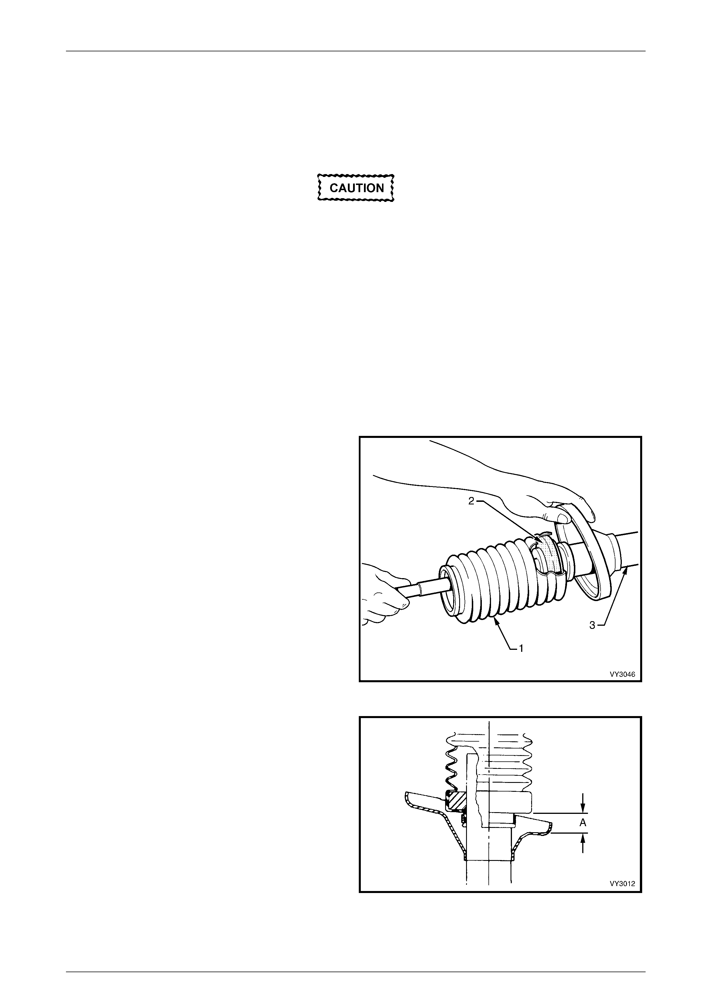
4 Remove the lower boot retaining clamp and discard.
Slide the front strut dust shield assembly (1) and filter
(2) from the strut assembly (3).
5 Pull the strut rod fully up and, while supporting the rod
to stop it from slipping back into the strut, install the
front strut dust shield assembly over the strut tube,
ensuring that the filter remains seated insid e the boot
assembly.
Figure 3A – 39
6 Ensure that the bottom of the front strut dust shield
assembly is positioned so that distance ‘A’ is between
30 – 35 mm.
7 Install the retaining clamp and tighten until th e rubber
on the front strut dust shield assembly is firmly
secured.
8 Install the front spring, refer to 3.7 Front Spring in this
Section.
9 Install the upper strut support assembly, refer to
3.6 Upper Strut Support Bearing and Mount in this
Section.
10 Install the front strut assembly,
refer to 3.5 Front Strut Assembly in this Section. Figure 3A – 40
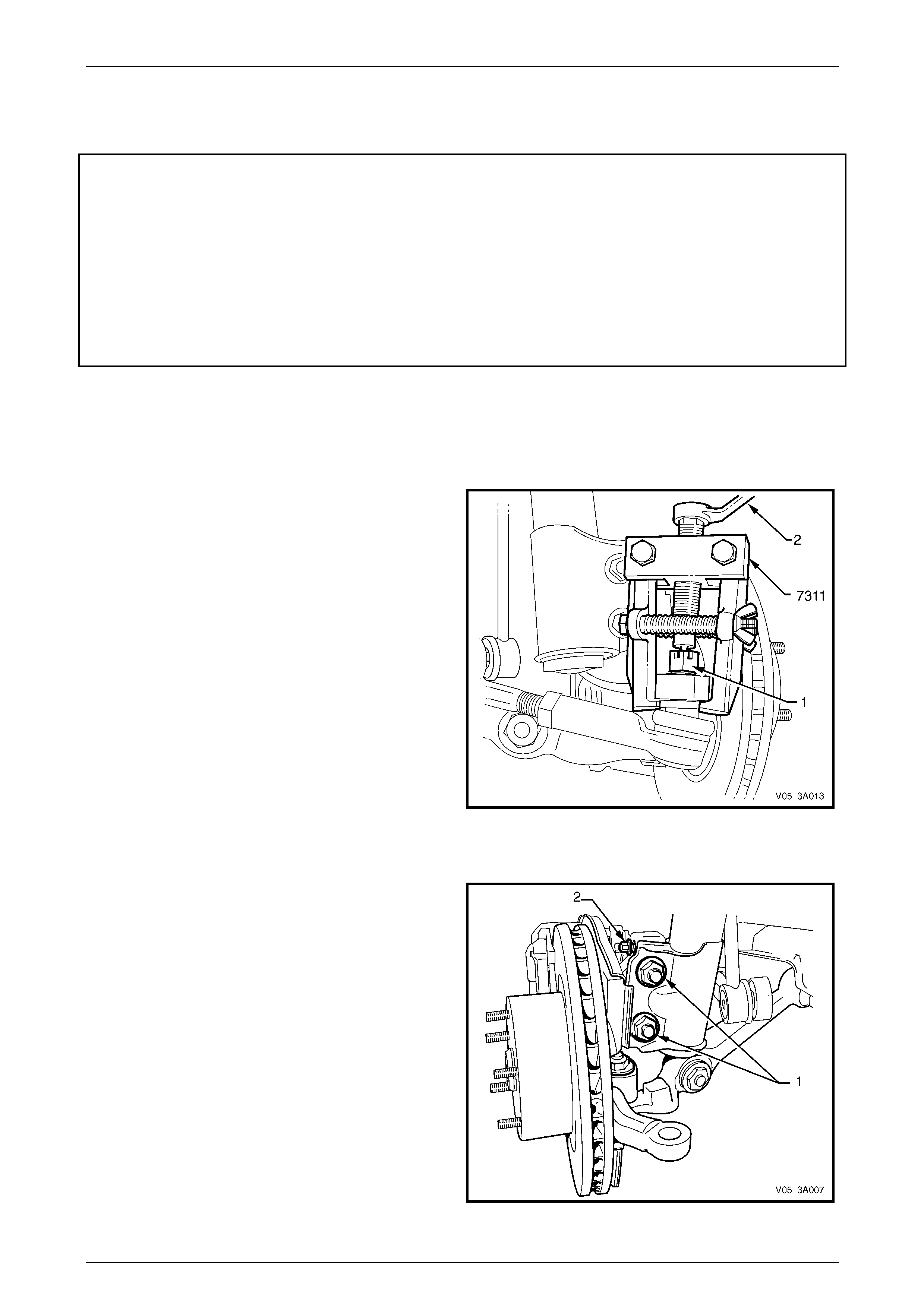
Front Suspension 3A – 38
3A-38
3.9 Steering Knuckle
LT Section No. – 06-212
ATTENTION
The following fasteners have either micro encapsulation or incorporate a mechanical th read lock and should
only be used once. If in doubt, replacement is recommended when performing these operations:
Front control arm ball joint stud nut.
The following fasteners MU ST be replaced when performing these operations:
Steering knuckle to fron t strut attaching nuts and bolts.
Brake caliper to steering knu ckle retaining bolts and Nord-Lock™ washers (Coupe only).
Remove
All VZ Models
1 Remove the front brake rotor, wheel hub assembly and brake shield,
refer to 3.3 Front Wheel Hub Assembly, Brake Rotor or Brake Shield in this Section.
2 Remove the split pin and loosen the castellated nut (1)
until the nut is flush with the end of the steering
linkage outer tie rod socket assembly stud.
3 Install Tool No. 7311 as shown and, using a ring
spanner (2), press the stud out from the steering
knuckle.
Figure 3A – 41
All VZ Except Coupe
4 Loosen, remove and discard the two lower strut
attaching bolts and nuts (1).
5 If the steering knuckle is to be replaced, remove the
camber adjusting bolt (2) from the arm.
Figure 3A – 42
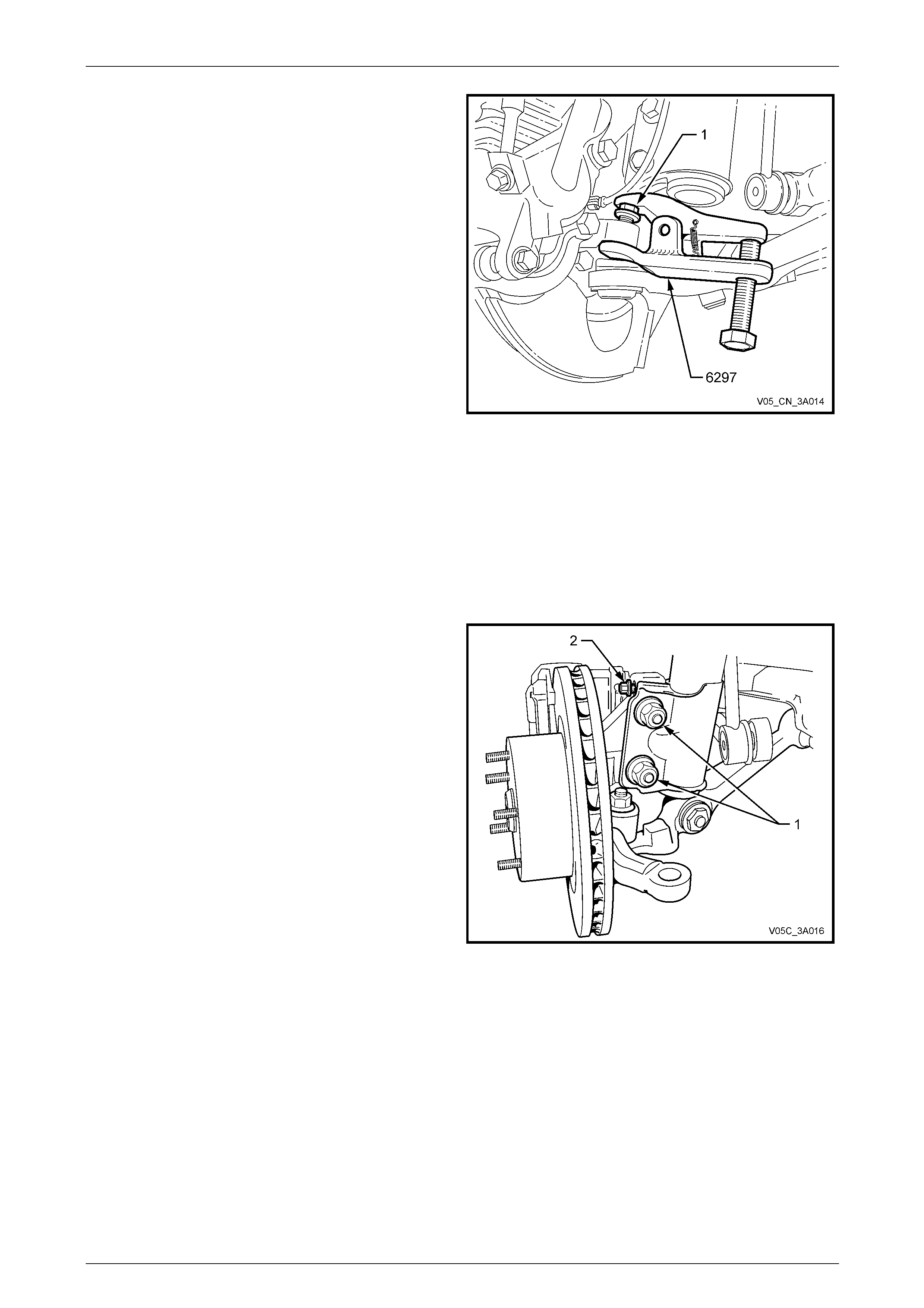
Front Suspension 3A – 39
3A-39
NOTE
While the view shows the brake caliper, rotor,
brake shield and wheel speed sensor lead still
installed, these would all have been removed in
Step 1 of this procedure.
6 Loosen the front control arm socket retainin g nut (1)
until the nut is flush with the end of the front control
arm socket stud thread.
NOTE
As the nut has micro-encapsulated thread
sealant applied, it must be replaced after
removal.
7 Install release Tool No. 6297 (or E 9332-A) as shown,
then apply force to the top of the front contro l arm
socket stud by tightening the forcing bolt on the tool,
separating the front control arm socket from the
knuckle.
NOTE
Once a load is applied by the release tool
loading bolt, a sharp tap on the nut end of the
tool will lessen the appl y force required.
8 Temporarily jam the front control arm socket stud
taper into the knuckle to hold the stud, before fully
removing the retaining nut. Discard the removed nut.
Figure 3A – 43
Coupe Only
9 Loosen, remove and discard the two lower strut
attaching bolts and nuts (1).
10 If the steering knuckle is to be replaced, remove the
camber adjusting bolt (2) from the arm.
Figure 3A – 44
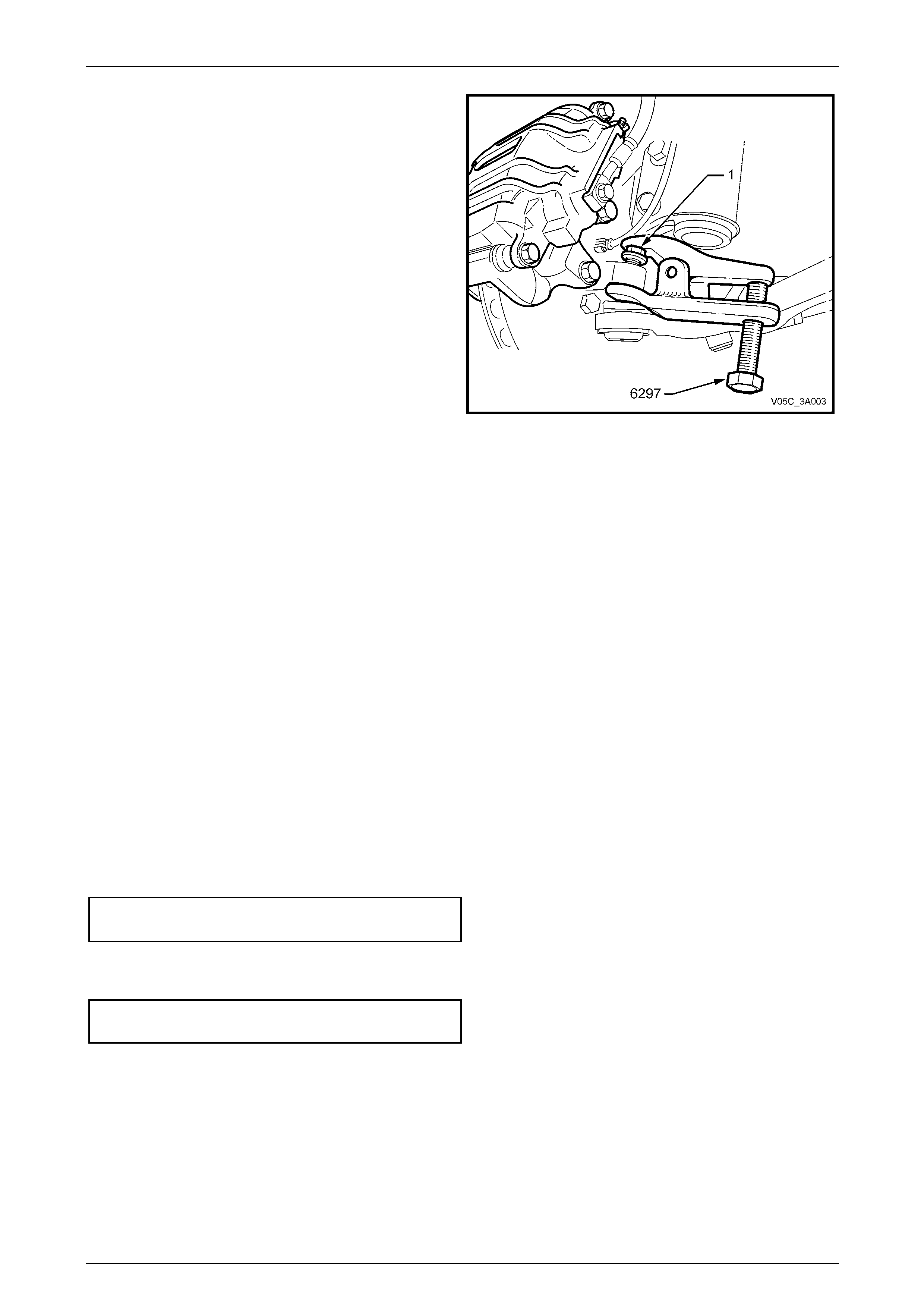
Front Suspension 3A – 40
3A-40
NOTE
While the view shows the brake caliper, rotor
and wheel speed sensor le ad still instal led, the s e
would all have been removed in Step 1 of this
procedure.
11 Loosen the front control arm socket retainin g nut (1)
until the nut is flush with the end of the front control
arm socket stud thread.
NOTE
As the nut has micro-encapsulated thread
sealant applied, it must be replaced after
removal.
12 Install release Tool No. 6297 (or E 9332-A) as shown,
then apply force to the top of the front contro l arm
socket stud by tightening the forcing bolt on the tool,
separating the front control arm socket from the
knuckle.
NOTE
Once a load is applied by the release tool
loading bolt, a sharp tap on the nut end of the
tool will lessen the appl y force required.
Figure 3A – 45
13 Temporarily jam the front control arm socket stud taper into the knuckle to hold the stud, before fully removin g the
retaining nut. Discard the removed nut.
All VZ Models
14 Separate the knuckle from the front control arm socket stud and remove from the vehicle.
Reinstall
Installation is the reverse of the removal procedures except for the following:
All VZ Models
1 Install the steering knuckle over the front con trol arm socket stud, then install NEW lower strut to steering knuckle,
bolts and nuts but do not tighten fully at this stage.
2 Position a suitable floor jack with a block of wood fitted to the lift pad under the front control arm, and raise
sufficiently to support the weight and jam the front control arm socket stud taper into the knuckle.
3 Install a NEW self-locking nut on to the front control arm ball joint stud and tighten the nut to the correct torque
specification.
Front control arm ball joint
nut torque specification........................................60 N.m
4 Reinstall the steering linkage outer tie rod end into the steering knuckle and tighten the castellated attaching nut to
the correct torque specification. Install new split pin.
Steering linkage outer tie rod end
castellated nut torque specification......................68 N.m
5 Reinstall the brake shield, wheel hub assembly and front br ake rotor,
refer to 3.3 Front Wheel Hub Assembly, Brake Rotor or Brake Shield in this Section.

Front Suspension 3A – 41
3A-41
NOTE
Check that the brake rotor is installed with the
marks made before removal, aligned.
6 Lower the vehicle to the ground.
7 Bounce the vehicle several times to settle the suspe nsion.
8 Check the wheel alignment, refer to 2.2 Wheel Alignment Checking and Adjustment in this Section.
9 Following the wheel alignm ent procedure, it will be necessary to raise the vehicle and tighten the NEW steering
knuckle to strut bolts and nuts to the correct torque specification.
Steering knuckle to strut bolts
and nuts torque specification ..Stage 1................85 N.m
Stage 2..............100 N.m
Stage 3 Turn through 90°
10 Lower the vehicle to the ground and tighten road wheel attaching nuts to the correct torque specification, working in
a ‘star’ pattern, refer to 3.1 Service Notes and Cautions, in this Section.
Road wheel attaching
nut torque specification............................110 – 140 N.m
11 Reinstall the wheel cover or decorative wheel nut caps.

Front Suspension 3A – 42
3A-42
3.10 Front Control Arm
LT Section No. – 06-200
ATTENTION
The following fasteners have either micro encapsulation or incorporate a mechanical th read lock and should
only be used once. If in doubt, replacement is recommended when performing these operations:
Front control arm ball joint stud nut.
The following fasteners MU ST be replaced when performing these operations:
Front control arm inner pivot bolt and nut.
Front control arm rod to front control arm attaching nut.
Front control arm rod to insulating bush attaching nut.
The following fasteners MUST be at curb height before final tightening:
• Front control arm inner pivot bolt and nut.
• Front control arm rod to front control arm attaching nut.
• Front control arm rod to insulating bush attaching nut.
Remove
1 Raise the vehicle and suppor t in a safe manner. Refer to 2.3 Jacking Precautions in this Section.
2 Remove the wheel cover or decorative wheel nut caps.
3 Mark the relationship of the wheel to hub. Loosen, then remove the roa d wheel attaching nuts and remo ve the
wheel.
4 Turn the steering out on full lock.
5 Loosen the front control arm socket retainin g nut (1) until the top of the nut is flush with the top of the front control
arm socket assembly stud thread.
NOTE
As the nut has micro-encapsulated thread se alant
applied, it must be replaced after removal.
6 Install the release Tool No. 6297 (or E9332-A) as shown, then apply force to the top of the front control arm socket
assembly stud by tightening the forcing bolt on the tool, separating the front control arm socket assembly from the
knuckle.
NOTE
Once a load is applie d by the release too l loadi ng
bolt, a sharp tap on the nut end of the tool will
lessen the apply force required.
7 Temporarily jam the front control arm socket assembl y stud taper into the knuckle to hold the stud, before fully
removing the retaining nut. Discard the removed nut.
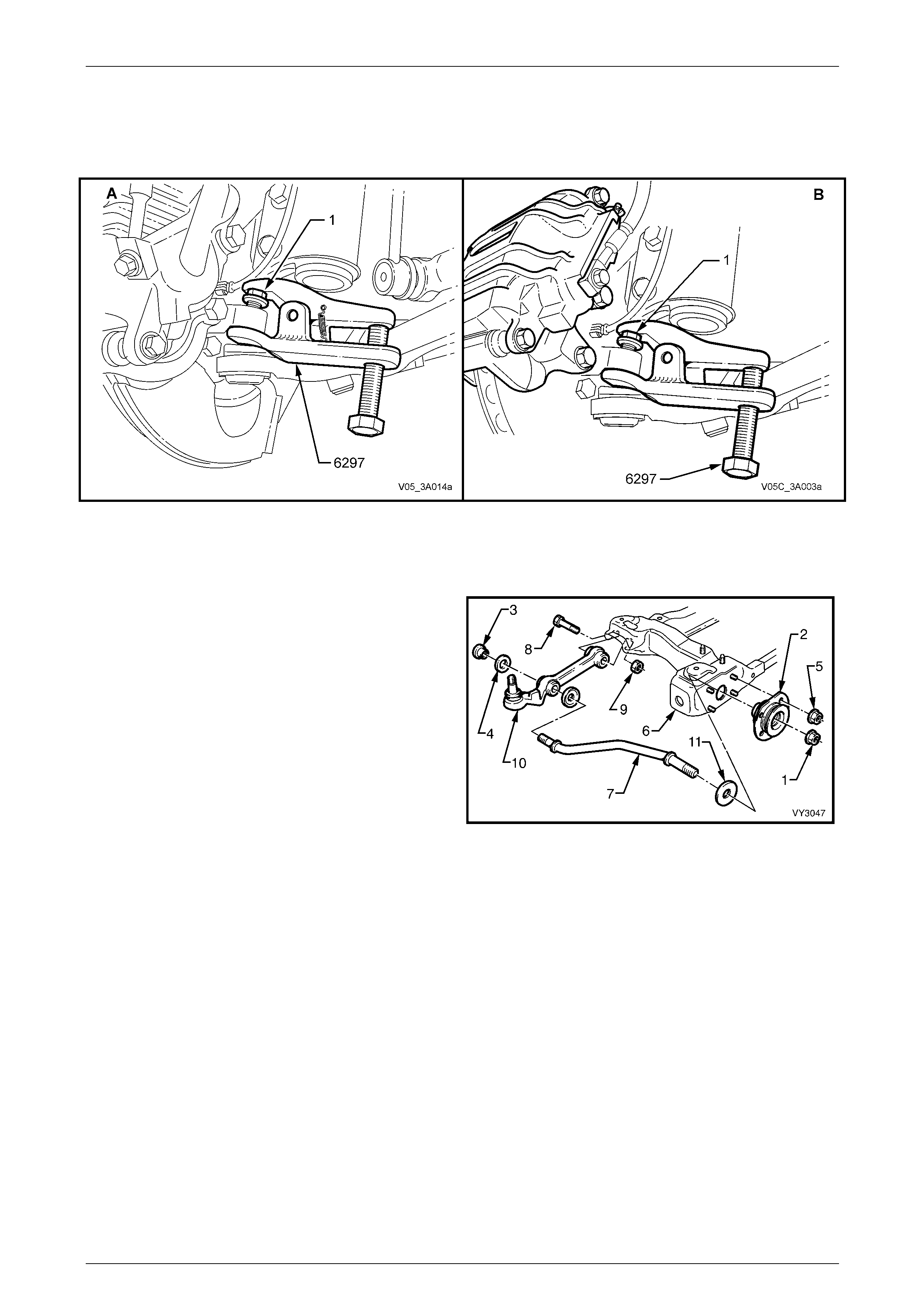
Front Suspension 3A – 43
3A-43
NOTE
View ‘A’ shows the arrangement for all VZ
models except Coupe, while view ‘B’; shows the
Coupe arrangement.
Figure 3A – 46
8 Separate the front control arm socket assembl y stud from the knuck le.
9 Hold the steering knuckle a way from the front control arm by using a suitable length prop.
10 Loosen the front control arm rod front nut (1) at the
front control arm rod insulating bushing asse mbly (2).
11 Remove the front control arm rod to front control arm
attaching nut (3) and washer (4). Discard the nut.
12 Remove the four nuts (5) securing the front control
arm rod insulating bushing to the crossmember (6),
then remove the front control arm rod (7) from the front
control arm rod bushing.
13 Remove the front control arm inner pivot bolt (8) and
nut (9). Discard the nut.
14 Remove the front control arm from the vehicle.
Figure 3A – 47
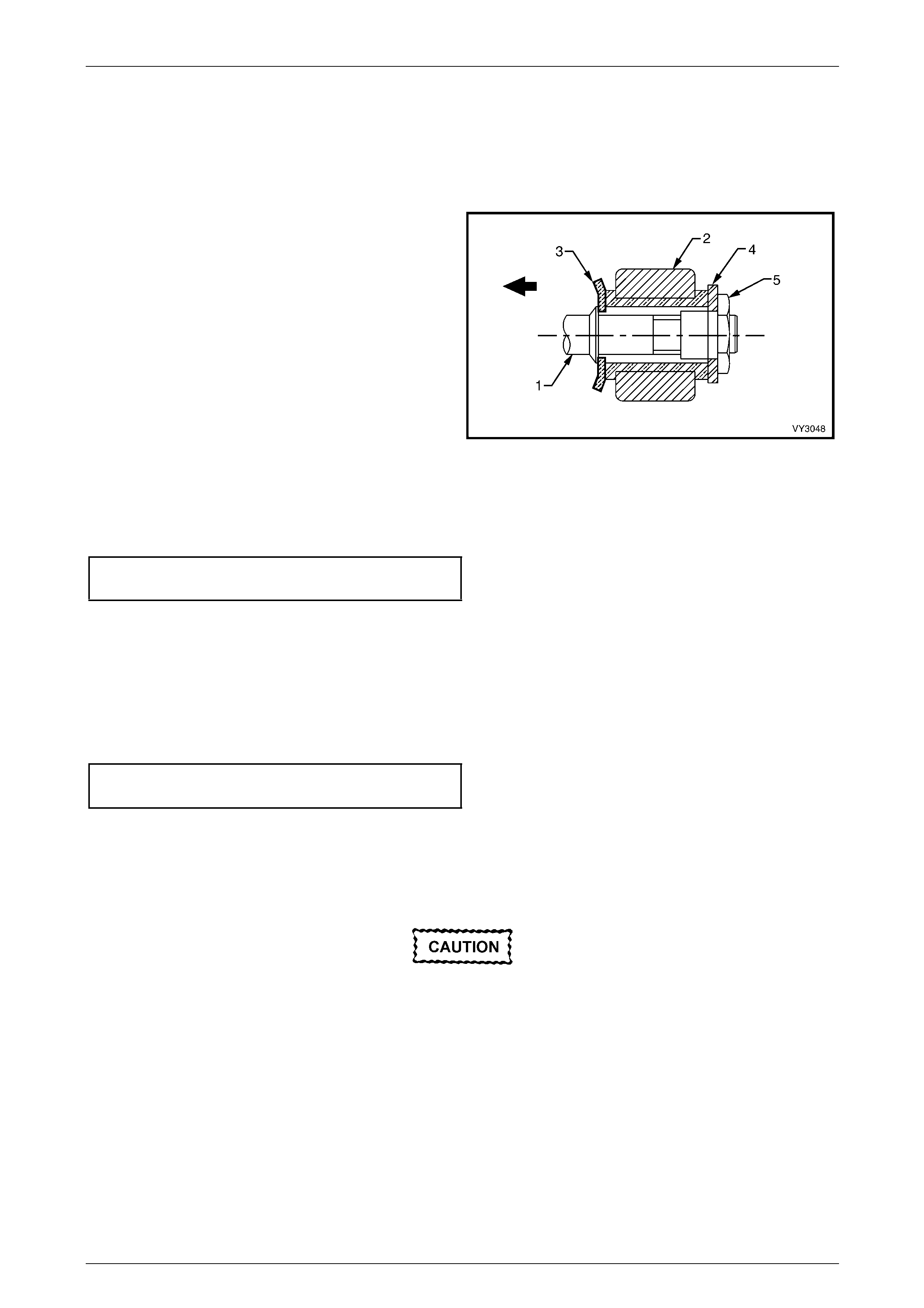
Front Suspension 3A – 44
3A-44
Reinstall
1 Referring to Figure 3A – 47, reinstall the front control arm to the crossmember, instal l the bolt (8), then install a
NEW nut (9), but do not fully tighten at this stage.
2 Reinstall front control arm rod (7) into the crossmember.
3 Install the front control arm rod (1) to the front control
arm (2) with the convex side of the cupped washer (3)
toward the front control arm bushing.
4 Reinstall the lower control arm rod to front control arm
washer (4) with a NEW attaching nut (5) but do not
fully tighten at this stage.
Figure 3A – 48
5 If the control arm is being installed on the dri v ers side, reinstall the bright finished flat washer to the front of the
control rod.
6 Reinstall the insulating bushing , install the four retaining nut s and tighten to the correct torque specification.
Front control arm insulating bu s hing
to crossmember nut torque specification .............23 N.m
7 Install a NEW front control arm rod nut ('1' in Figure 3A – 47) to the front of the front control arm rod but do not
tighten at this stage.
8 Using a suitable floor jack fitted with a block of wood positioned under the front control arm, raise the jack
sufficiently to support the weight of the strut assembly and jam the front control arm socket assembly stud taper
into the knuckle.
9 Install a NEW self-locking nut into the front control arm socket assembly stud and tighten the nut to the correct
torque specification.
Front control arm ball joint
nut torque specification........................................60 N.m
10 Reinstall the road wheel, alig ning marks made prior to removal.
11 Lower the vehicle to the ground.
12 Bounce the vehicle several times at the front, to settle the suspension.
The weight of the vehicle must be on all four
wheels before tightening the front control arm
rod nuts to specification. Failure to adhere to
this requirement will not only result in
reduced insulator bushing life but will
adversely affect the ride and handling
characteristics of the vehicle.

Front Suspension 3A – 45
3A-45
13 With the weight of the vehicle on the four roa d wheels, tighten the front control arm inner pivot bo lt and nut to the
correct torque specifications.
Front control arm inner pivot bolt
and nut torque specification...............................103 N.m
14 Tighten both front control arm rod nuts at the front of the front control arm (at the insulating bushin g) and at the
front control arm rod bushing, to the correct torque specific ations.
Front control arm rod to control
arm bushing torque specification .......................103 N.m
Front control arm rod
to front insulating bushing
nut torque specification......................................148 N.m
15 Tighten road wheel attaching nuts to the correct torque specification, working in a ‘star ’ pattern,
refer to 3.1 Service Notes and Cautions, in this Section.
Road wheel attaching
nut torque specification............................110 – 140 N.m
16 Reinstall the wheel cover or decorative wheel nut covers.
17 Check the wheel alignment, refer to 2.2 Wheel Alignment Checking and Adjustment in this Section.

Front Suspension 3A – 46
3A-46
3.11 Front Control Arm Ball Joint
LT Section No. – 06-200
NOTE
The front control arm ball joint is not serviced
separately and , if found t o be faulty, the complete
front control arm assembly must be replaced.
Refer to 3.10 Front Control Arm, in this Section
for the replacement procedur e.
Inspect
The following proced ure should be used when checking the front control arm ball joint for wear:
1 Jack the vehicle up with the jack lift pad located under the centre of the front crossmember.
Refer to 2.3 Jacking Precautions, in this Section.
2 Holding the road wheel at the top and bottom, check for play in the front control arm socket assembly by rocking
the wheel.
3 If any up or down movement of stud in front control arm socket assembly housing is dete cted, the front control arm
and ball joint assembly must be replaced.
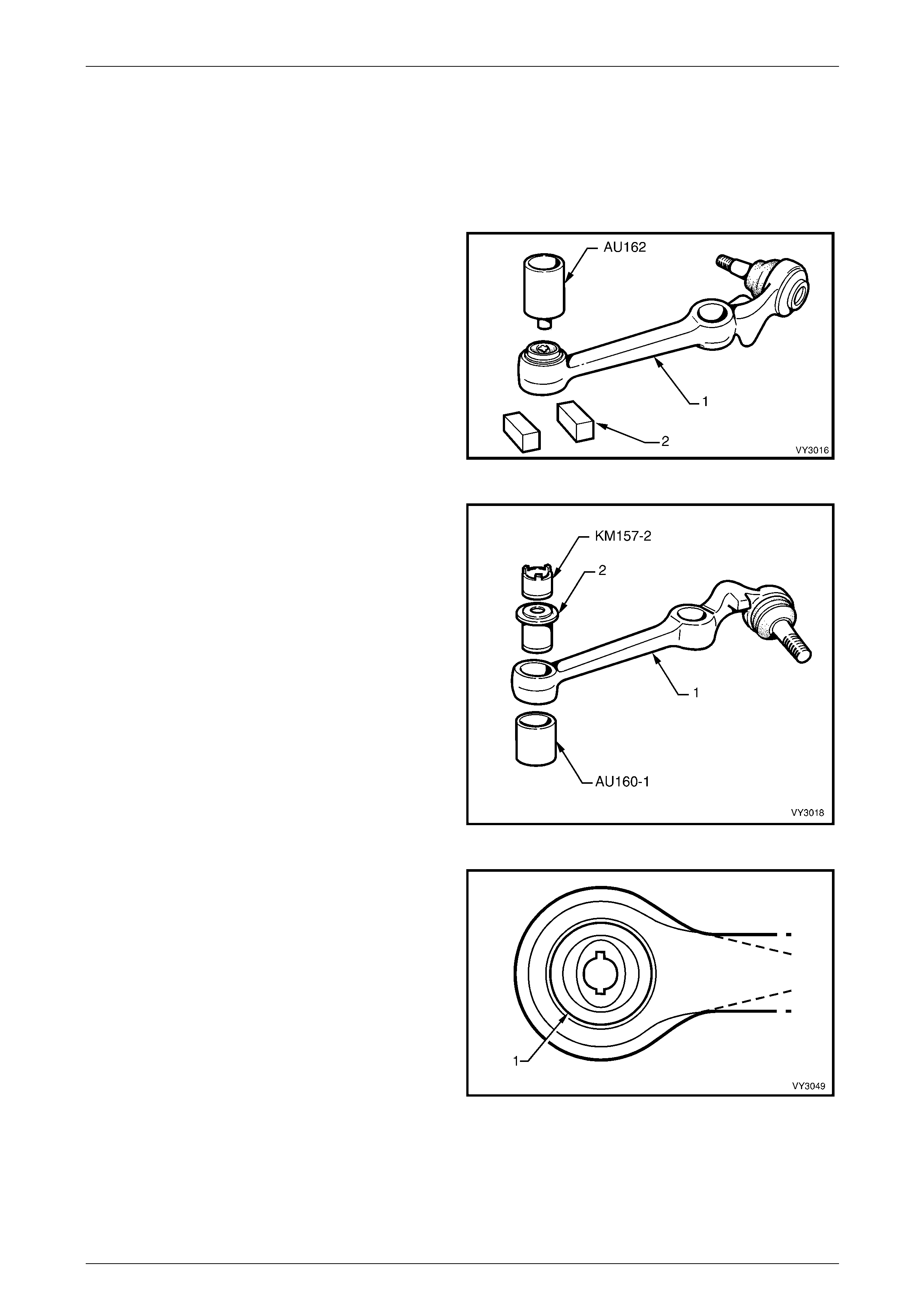
Front Suspension 3A – 47
3A-47
3.12 Front Control Arm Inner Bushing
LT Section No. – 06-200
Replace
1 Remove the front control arm (1),
refer to 3.10 Front Control Arm in this Section.
2 Support the front control arm with two pieces of square
scrap (2) and press the bushing from the arm, using
Tool No. AU162.
Figure 3A – 49
3 Using Tool Nos. AU160-1 and KM157-2, install the
new bushing from the front side of the front control
arm (1), until flange (2) on the outer sleeve is flush
with the front control arm.
NOTE
Installation tool KM157-2 should be used in the
orientation shown.
Figure 3A – 50
NOTES
• The front control arm inner bushing (1)
should be lubricated with a soapy water
solution to ease the installation process.
• The bushing MUST be aligne d, as shown.
4 Install the front control arm;
refer to 3.10 Front Control Arm in this Section.
Figure 3A – 51
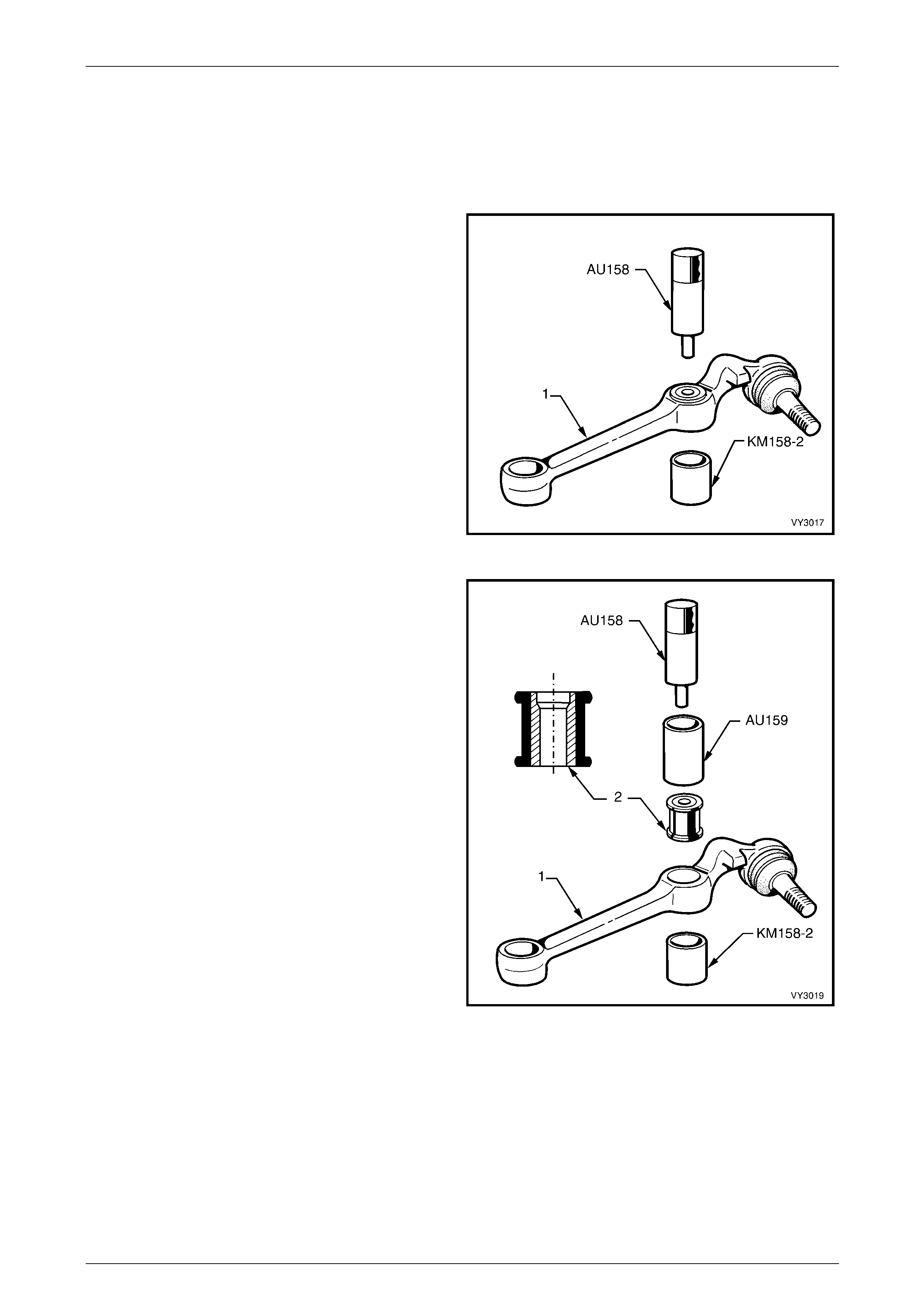
Front Suspension 3A – 48
3A-48
3.13 Front Control Arm Rod Bushing
LT Section No. – 06-200
Replace
1 Remove the front control arm;
refer to 3.10 Front Control Arm in this Section.
2 Press the front control arm rod bushing from the front
control arm (1) using Tool No AU15 8 and KM158-2 as
shown.
Figure 3A – 52
3 Press in a new front control arm rod bushing (2), using
Tool No's AU158, AU159 and KM158-2 as shown.
NOTES
• To assist installation, dip the bushing in a
soapy water solution.
• Install the bushing with the larger diameter of
the stepped front control arm rod mounting
hole toward the rear of the front control arm
(1).
4 Reinstall the front control arm,
refer to 3.10 Front Control Arm in this Section.
NOTE
Install the bushing until it is centrally located in
the front control arm.
5 Reinstall the front control arm.
Refer to 3.10 Front Control Arm in this Section.
Figure 3A – 53
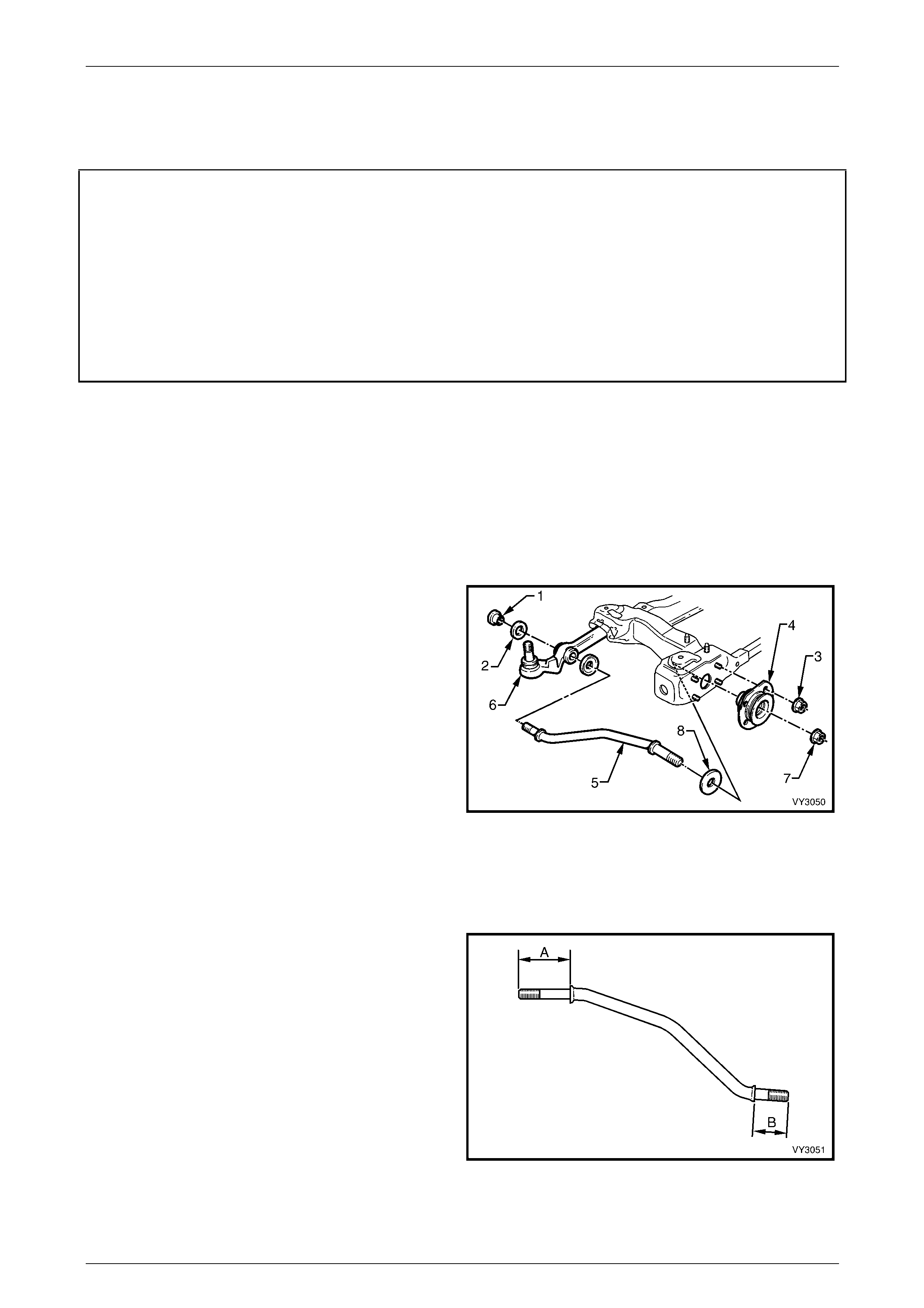
Front Suspension 3A – 49
3A-49
3.14 Front Control Arm Rod
LT Section No. – 06-200
ATTENTION
The following fasteners MU ST be replaced when performing these operations:
Front control arm rod to front control arm attaching nut.
Front control arm rod to insulating bushing attaching nut.
The following fasteners MUST be at curb height before final tightening:
• Front control arm rod to front control arm attaching nut.
• Front control arm rod to insulating bushing attaching nut.
Remove
1 Before raising the vehicle, l oo s en the front control arm rod nut; refer to '7' in Figure 3A – 54.
2 Raise the front of the vehicle and support in a safe manner. Refer to 2.3 Jacking Precautions, in this Section.
3 Remove the wheel cover or decorative wheel nut caps on the side where the front control arm rod is to be
removed.
4 Mark the relationship of the road wheel to the hub and brake rotor. Loosen, then remove road wheel attaching nuts
and remove the road wheel.
5 Remove the front control arm rod to front control arm
attaching nut (1) and washer (2). Discard the nut.
6 Remove the four nuts (3) attaching the front control
arm rod insulating bushing (4) to the crossmember
outrigger.
7 Remove the front control arm rod (5) and insulating
bushing assembly from the front control arm (6) and
remove the rod out through the crossmember
outrigger.
8 Secure the front control arm rod in protected vice jaws,
then remove the front control arm rod to front control
arm rod insulator bushing reta ining nut (7). Discard the
nut.
9 Remove the bright finished washer (8), from the
driver’s side front control arm rod.
Figure 3A – 54
Reinstall
1 Reinstall the bright finished inner washer onto the front
end of the front control arm rod (A), on the driver’s
side ONLY.
NOTE
The front end of the front control arm rod is
identified by the longer length of the shouldered
ends (‘A’ compared to ‘B’).
Figure 3A – 55
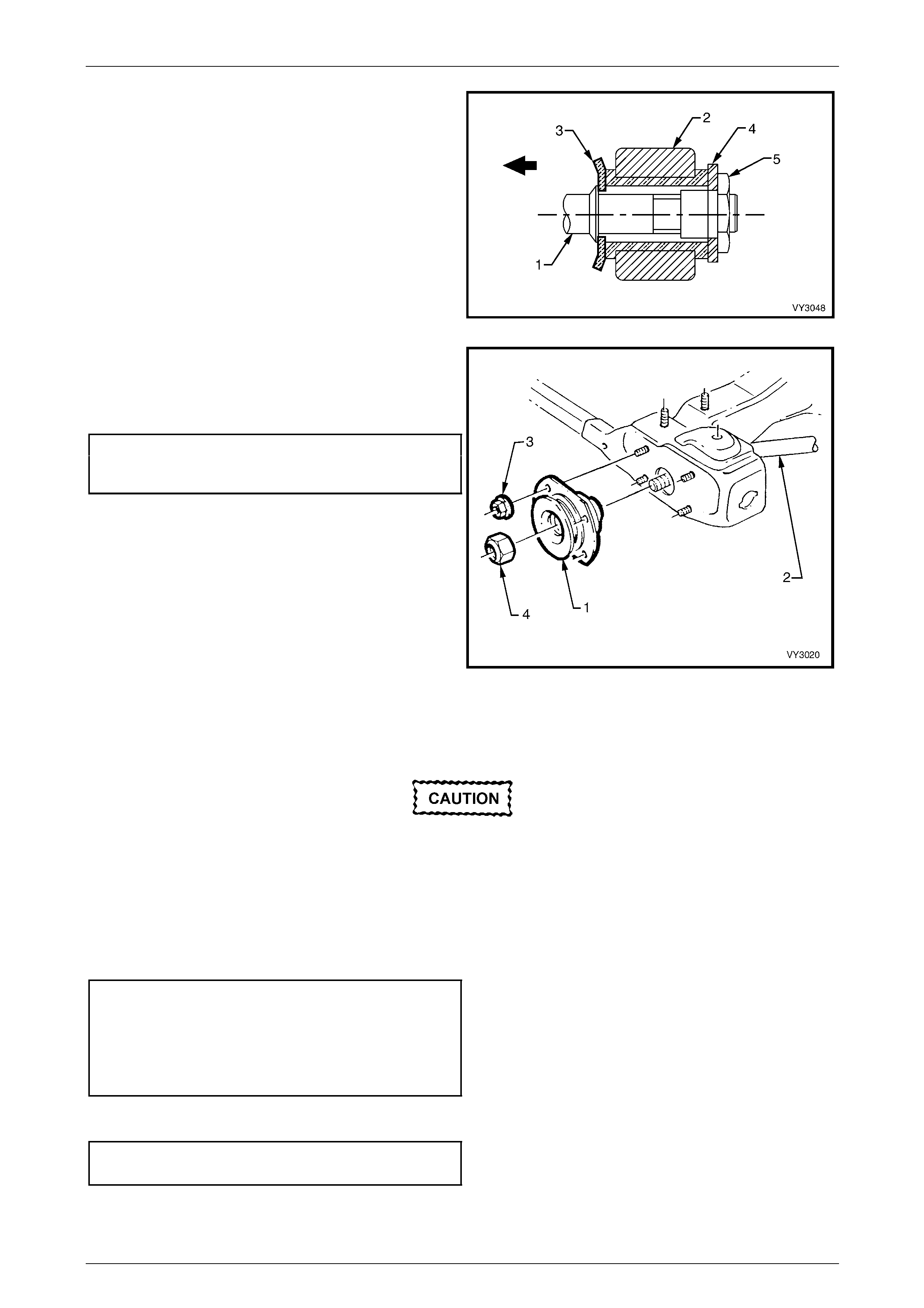
Front Suspension 3A – 50
3A-50
2 Reinstall the front control arm rod (1) into the hole in
the crossmember outrigger and then i nto th e front
control arm (2), with the cupped washer (3) installed
as shown.
3 Reinstall the front control arm rod to front control arm
washer (4) with a NEW attaching nut (5) but do not
fully tighten at this stage.
Figure 3A – 56
4 Install the front control arm rod insulating bu shing
assembly (1), over the front control arm rod (2) and
install the four retaining nuts (3) to the crossmember
outrigger studs. Tighten to the correct torque
specification.
Front control arm rod
insulator bushing attaching
nut torque specification........................................23 N.m
5 Install a NEW front control arm rod retaining nut (4)
but do not fully tighten at this stage.
NOTE
If fitted, ensure that the spacer washer is
installed over the front control arm rod and then
the flat washer, before fitting the front control
arm rod insulator bushing.
Figure 3A – 57
6 Install the road wheel, alignin g the marks made prior to removal and secure with the attaching nuts, tightening
progressively in a ‘star’ pattern. Refer to 3.1 Service Notes and Cautions, in this Section.
7 Lower the vehicle to the ground.
8 Bounce the vehicle several times to settle the suspe nsion.
The weight of the vehicle must be on all four
wheels before tightening the front control arm
rod nuts to specification. Failure to adhere to
this requirement will not only result in
reduced insulator bushing life but will
adversely affect the ride and handling
characteristics of the vehicle.
9 With the vehicle at curb position, tighten both the front control arm rod to insulating bushing an d the front control
arm rod to front control arm attaching nuts to the correct torque specificatio ns.
Front control arm rod to
insulator bushing attaching
nut torque specification......................................148 N.m
Front control arm rod to
control arm attaching nut
torque specification............................................103 N.m
10 Tighten road wheel attaching nuts to the correct torque specification, working in a ‘star’ pattern.
Refer to 3.1 Service Notes and Cautions, in t his Section.
Road wheel attaching
nut torque specification............................110 – 140 N.m
11 Reinstall the wheel cover or decorative wheel nut covers.
12 Check the wheel alignment, refer to 2.2 Wheel Alignment Checking and Adjustment in this Section.
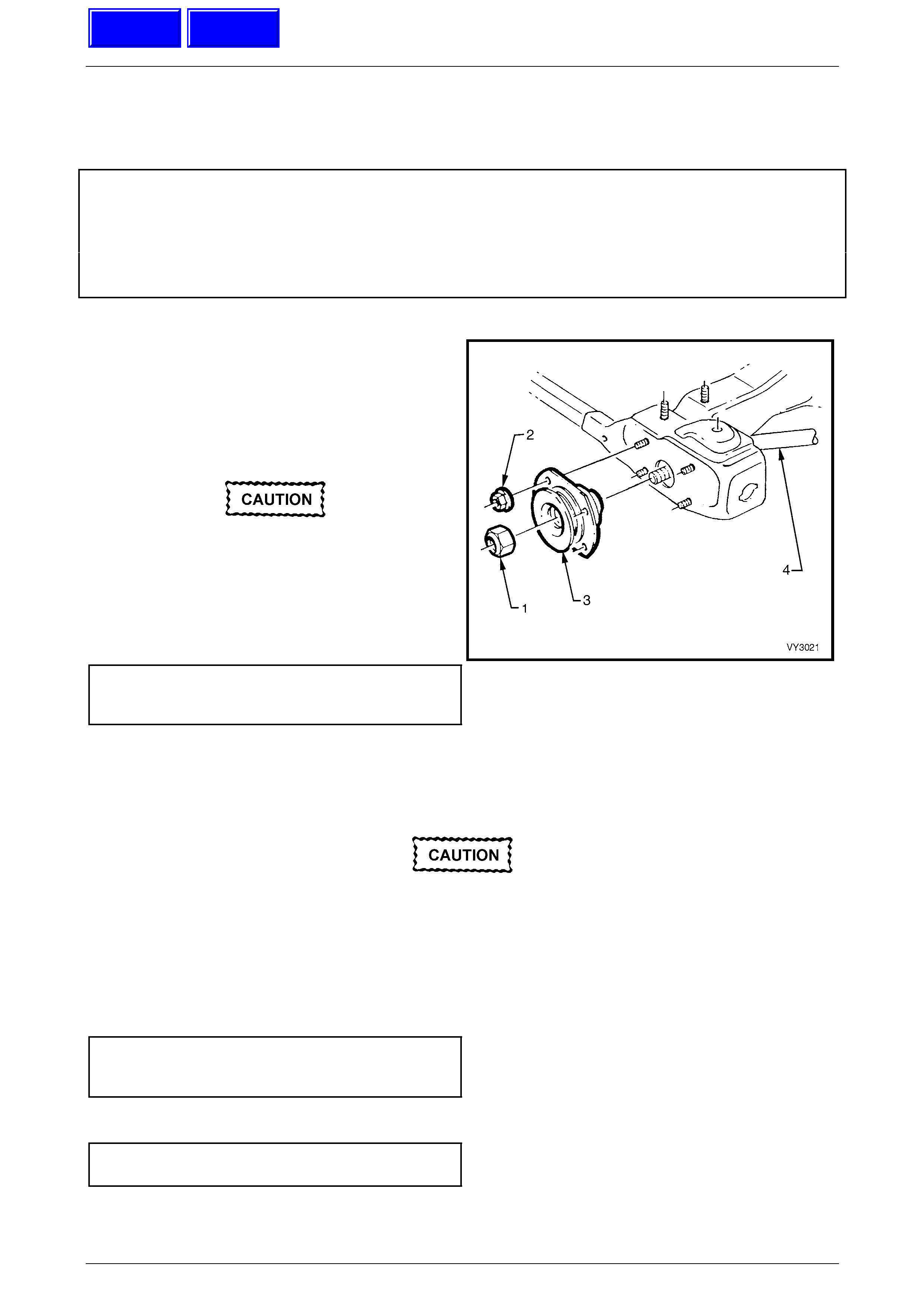
Front Suspension 3A – 51
3A-51
3.15 Front Control Arm Rod Insulating
Bushing
LT Section No. – 06-200 ATTENTION
The following fasteners MU ST be replaced when performing these operations:
Front control arm rod to insulating bushing attaching nut.
The following fasteners MUST be at curb height before final tightening:
• Front control arm rod to insulating bushing attaching nut.
Replace
1 Remove the lower front control arm rod, front retaining
nut (1) and discard.
Refer to 3.14 Front Control Arm Rod in this Section for
more details.
2 Remove the four nuts (2) securing the front control
arm rod insulating bushing assembly (3) to the
crossmember outrigger studs. Remove insulator
bushing from the vehicle.
If fitted, ensure that the spacer washer is
installed over the front control arm rod
before fitting the front control arm rod
insulator bushing.
3 Reinstall the front control arm rod insulating bushing
over the front control arm rod (4) and install the four
retaining nuts (2) onto the crossmember outrigger
studs and tighten to the correct torque specification.
Front control arm rod
insulating bushing attaching
nut torque specification........................................23 N.m
Figure 3A – 58
4 Install a NEW front control arm rod retaining nut but do not fully tighten at this stage.
5 Install the road wheel, alignin g the marks made prior to removal and secure with the attaching nuts. Do not
overtighten.
6 Lower the vehicle to the ground.
7 Bounce the vehicle several times to settle suspe nsio n.
The weight of the vehicle must be on all four
wheels before tightening the front control arm
rod nuts to specification. Failure to adhere to
this requirement will not only result in
reduced insulator bushing life but will
adversely affect the ride and handling
characteristics of the vehicle.
8 With the vehicle at curb weight and position, tighten the front control arm rod to insulating bushing attachi ng nut to
the correct torque specification.
Front control arm rod to
insulator bushing attaching
nut torque specification......................................148 N.m
9 Tighten road wheel attaching nuts to the correct torque specification working in a ‘star’ pattern.
Refer to 3.1 Service Notes and Cautions, in t his Section.
Road wheel attaching
nut torque specification............................110 – 140 N.m
10 Reinstall the wheel cover or decorative wheel nut caps.
11 Check the wheel alignment, a s detailed in 2.2 Wheel Alignment Checking and Adjustment in this Section.
Techline
Techline
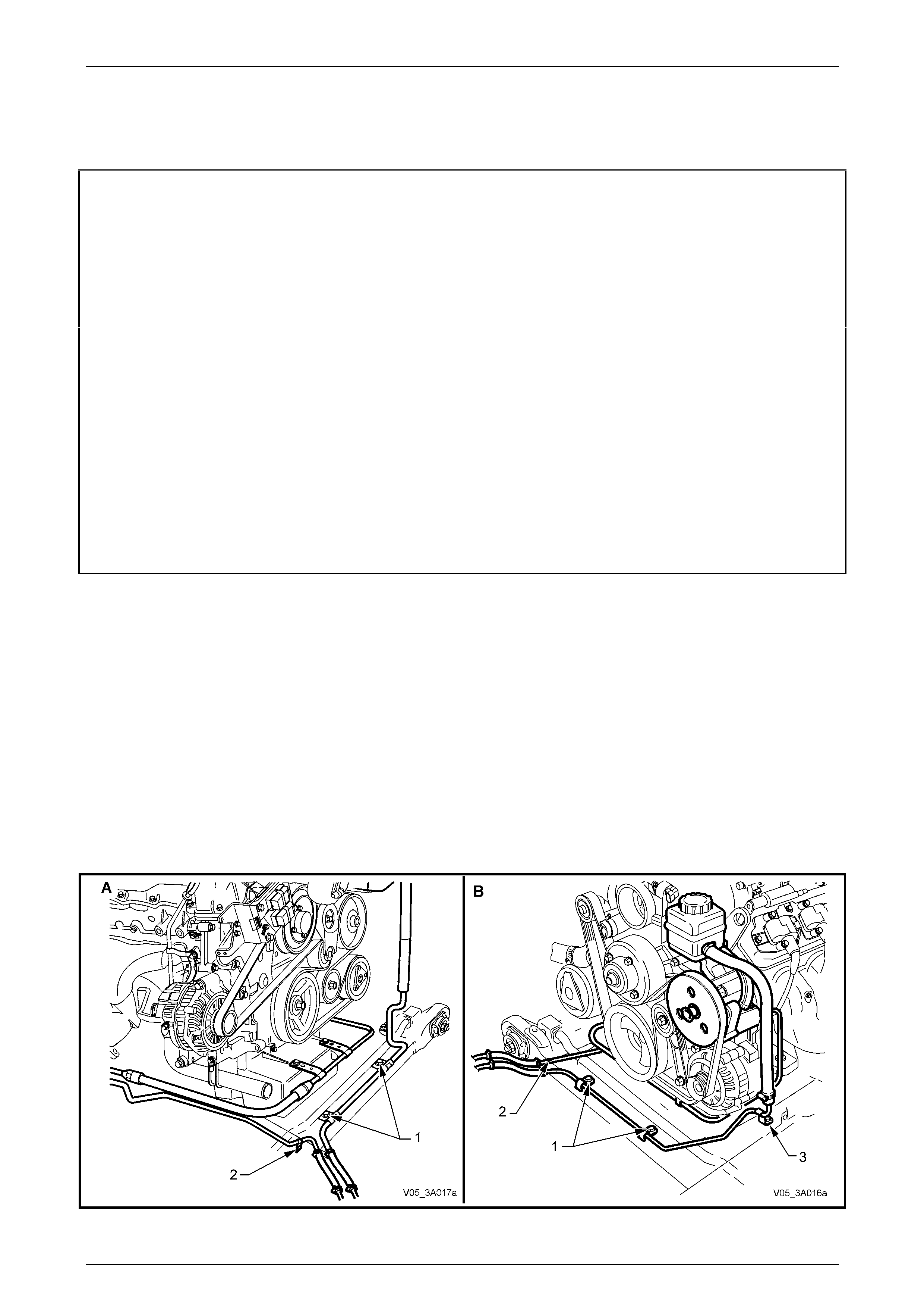
Front Suspension 3A – 52
3A-52
3.16 Front Suspension Crossmember
LT Section No. – 06-200
ATTENTION
The following fasteners MU ST be replaced when performing these operations:
Inner front control arm bushing retaining nut.
Crossmember to side frame attaching bolt.
Front control arm rod to insulating bushing attaching nut.
Front control arm rod to front control arm attaching nut.
Steering gear to crossmember mounting nut.
The following fasteners have either micro encapsulation or incorporate a mechanical th read lock and should
only be used once. If in doubt, replacement is recommended when performing these operations:
Front control arm ball joint stud nut.
The following fasteners MUST be at curb weight before final tightening:
• Inner front control arm bushing retaining nut.
• Front control arm rod to front control arm attaching nut.
• Front control arm rod to insulating bushing attaching nut.
Remove
1 Raise the front of the vehicle and support in a safe manner. Refer to 2.3 Jacking Precautions, in this Section.
2 Remove the wheel covers or decorative wheel nut caps.
3 Mark the relationship of the road wheel to hub or brake rotor. Loosen, then remove the road wheel attaching nuts,
working in a 'star' pattern. Refer to 3.1 Service Notes and Cautions, in this Section.
4 Remove the screws and brackets securing the po wer steering pipes to the front crossmember:
a In two places across the front rail (1).
b At the right (1) (All VZ) and left (2) (GEN III V8 only) side rails.
NOTE
View ‘A’ shows the V6 engine arrangement while
view ‘B’ shows the GEN III V8 layout.
Figure 3A – 59
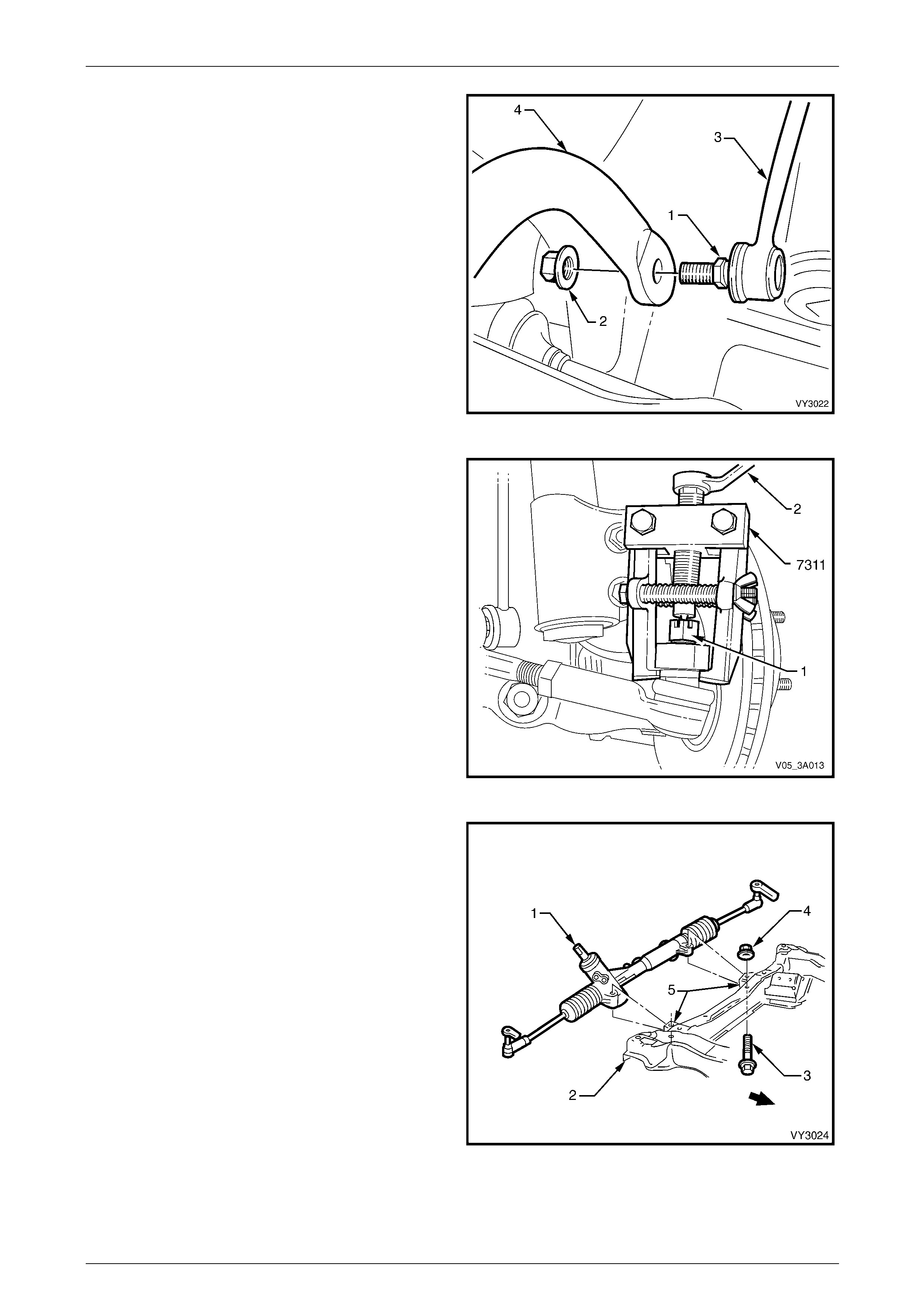
Front Suspension 3A – 53
3A-53
5 With a backing set spanner holding the stabiliser bar
link inner stud hexagon (1), use a second spanner to
loosen then remove the retaining nut (2).
6 Separate the stabiliser bar link (3) from the stabiliser
bar (4).
7 Repeat steps 5 and 6 for the other side.
Figure 3A – 60
8 Remove the split pin from the steering linkag e outer tie
rod socket assembly castellated nut (1), then loosen
the nut until the top of the nut is level with the top of
the steering linkage outer tie r od socket stud.
9 Install Tool No. 7311 and use a ring sp anner (2) to
separate the steering linkage outer tie rod socket
assembly stud from the steering knuckle.
Figure 3A – 61
10 Remove the steering gear housin g (1) to front
crossmember (2) mounting bolts (3) and nuts (4).
11 Discard the removed fasteners, as replacem ent is
required on reassembly.
12 Remove the steering gear housin g from the
crossmember mountings (5).
Figure 3A – 62
13 Turn each wheel out in turn.
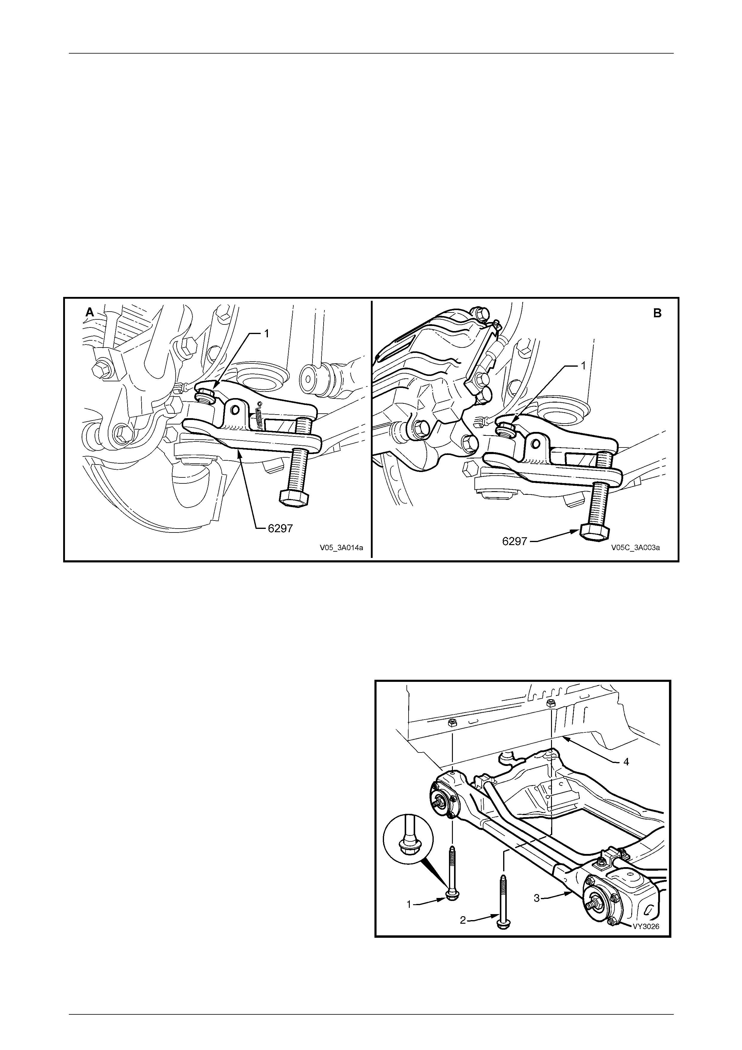
Front Suspension 3A – 54
3A-54
14 Loosen the front control arm socket assembl y retaining n ut (1) until the top of the nut is flush with the top of the
front control arm socket assembly stud thread.
15 Install release Tool No. 6297 (or E9332-A) as shown next, then apply force to the top of the front control arm socket
assembly stud by tightening the forcing bolt on the tool, separating the front control arm socket assembly from the
knuckle. NOTE
Once load is applied by the release tool loading
bolt, a sharp tap on the nut end of the tool will
lessen the apply force required.
16 Temporarily jam the front control arm socket assembl y stud taper into the knuckle to hold the stud, before removing
the retaining nut. NOTE
View ‘A’ shows the arrangement for all VZ
models except Coupe, while view ‘B’; shows the
Coupe arrangement.
Figure 3A – 63
17 Discard the removed nut as it has micro-encapsu lation seal ant applied and should be replaced on reassembly.
18 Separate the knuckle from the front control arm socket assembly stud.
19 Mark the engine hood hinge positions with a felt tipped pen and remove the hood.
20 Support the engine on a suitable lifti ng hook and remove the engine mount to crossmember nuts,
refer to Section 6A1, Engine Mechanical – V6 Engine or Section 6A3, Engine Mechanical – GEN III V8 Engine for
details.
21 Support the crossmember (3) on a jack and remove
the four bolts (1 and 2) securing the crossmember to
the side frame members (4).
22 Lower, then remove the crossmember asse mbly (3)
from vehicle.
23 As required, remove the front control arms, front
control arm rod insulating bus hings, front control arm
rods and stabiliser bar from the crossmember.
Figure 3A – 64

Front Suspension 3A – 55
3A-55
Reinstall
While the majority of the installation process is the reverse of the removal pr ocedures, note the follo wing points:
1 Reinstall the stabiliser bar insulating rubbers and brackets onto the crossmember, tightening the retaining nuts to
the correct torque specification.
Stabiliser bar support bracket
nut torque specification........................................27 N.m
2 When installing the crossmem ber, install two NEW front, black coloured and stepped bolts (‘1’ in Figure 3A-64) and
tighten to the correct torque specification. This will correctly align the crossmember to the side frames.
3 Install two NEW, rear, silver coloured, plain shanked bolts (‘2’ in Figure 3A-64) to the two rear positions and tighten
them to the correct torque specification
Crossmember to side frame
member bolt torque specification – All ...............122 N.m
4 Reinstall the two front control arms to the crossmember, installing the pivot bolts from the rear to the front. Install
the NEW nuts but do not fully tighten at this stage
5 If the front control arms were removed with the crossmember, install the front control arm ball joint stud into each
steering knuckle, reinstall the nut and tighten to the correct torque specification.
Front control arm ball joint
nut torque specification........................................60 N.m
6 If removed, reinstall both front control arm rods, loosely installing the washers and NEW retaining nuts;
refer to 3.14 Front Control Arm Rod in this Section. Do not tighten at this time. However, the front control arm rod
insulating bushing mountin g nuts can be tightened to the correct torque specification.
Front control arm rod insulating
bushing attaching
bolt torque specification.......................................23 N.m
7 Reinstall the steering gear housing to the crossmember and tighten the mounting nuts to the correct torque
specification.
Steering gear housing to
crossmember mounting
nut torque specification................................60 N.m then
turn through 45°
8 Reconnect the engine mounts to the crossmember, refer to Section 6A1, Engine Mechanical – V6 Engine or
Section 6A3, Engine Mechanical – GEN III V8 Engine for details.
9 Reinstall the road wheels ali gning the marks made before remova l.
10 Reinstall the engine hood.
11 Lower the vehicle to the ground.
12 Bounce the vehicle several times to settle the suspension.
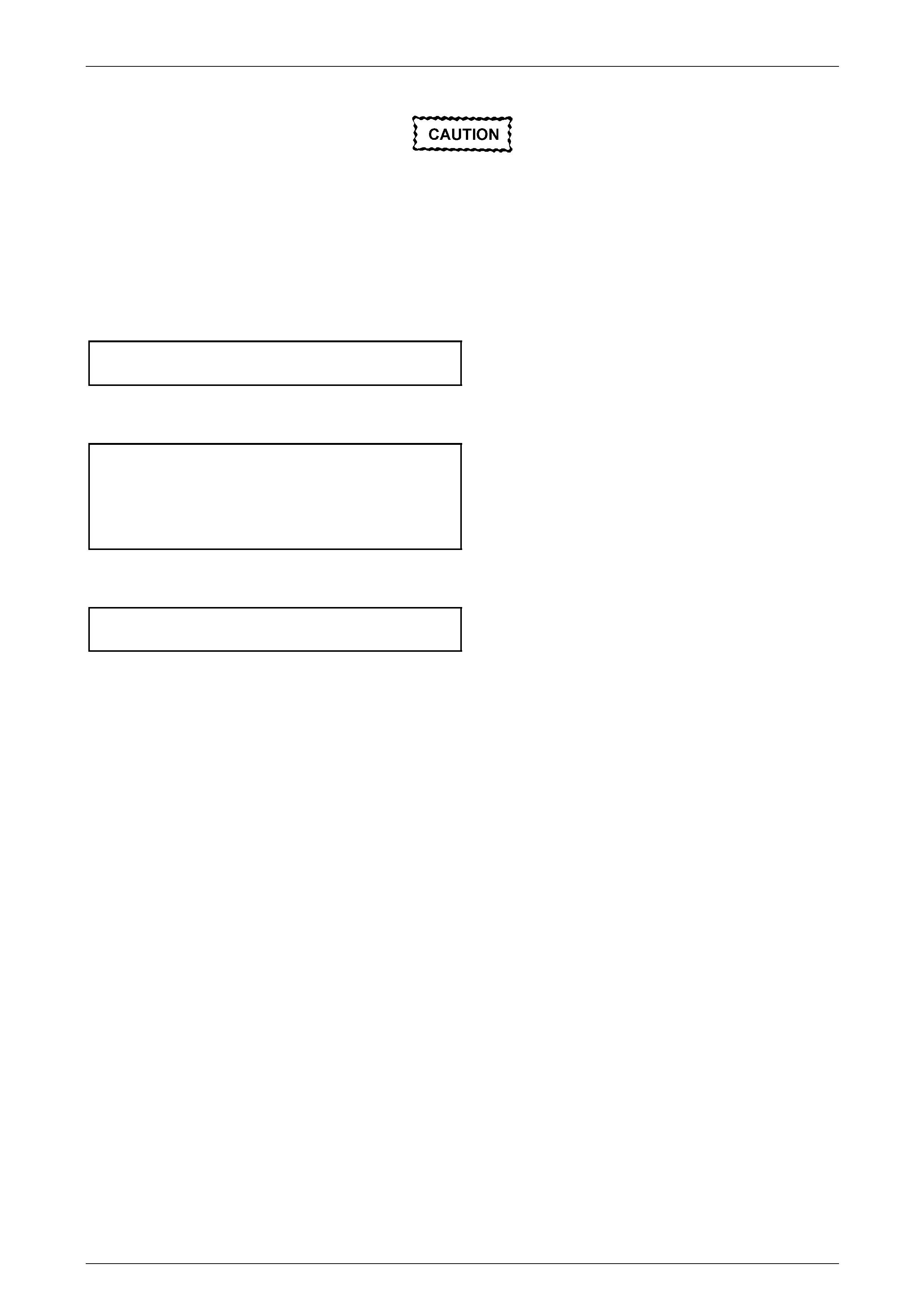
Front Suspension 3A – 56
3A-56
The weight of the vehicle must be on all four
wheels before tightening the front control arm
rod nuts to specification. Failure to adhere to
this requirement will not only result in
reduced insulator bushing life but will
adversely affect the ride and handling
characteristics of the vehicle.
13 With the weight of the vehicle on the four roa d wheels, tighten the front control arm inner pivot bo lt and nut to the
correct torque specifications.
Front control arm inner pivot bolt
and nut torque specification...............................103 N.m
14 Tighten both front control arm rod nuts at the front of the front control arm (at the insulating bushin g) and at the
front control arm rod bushing, to the correct torque specific ations.
Front control arm rod to control
arm bushing torque specification .......................103 N.m
Front control arm rod
to front insulating bushing
nut torque specification......................................148 N.m
15 Tighten road wheel attaching nuts to the correct torque specification, working in a ‘star ’ pattern,
refer to 3.1 Service Notes and Cautions, in this Section.
Road wheel attaching
nut torque specification............................110 – 140 N.m
16 Reinstall the wheel cover or decorative wheel nut caps.
17 Check the wheel alignment, refer to 2.2 Wheel Alignment Checking and Adjustment in this Section.
18 Road test the vehicle to check for correct operation.
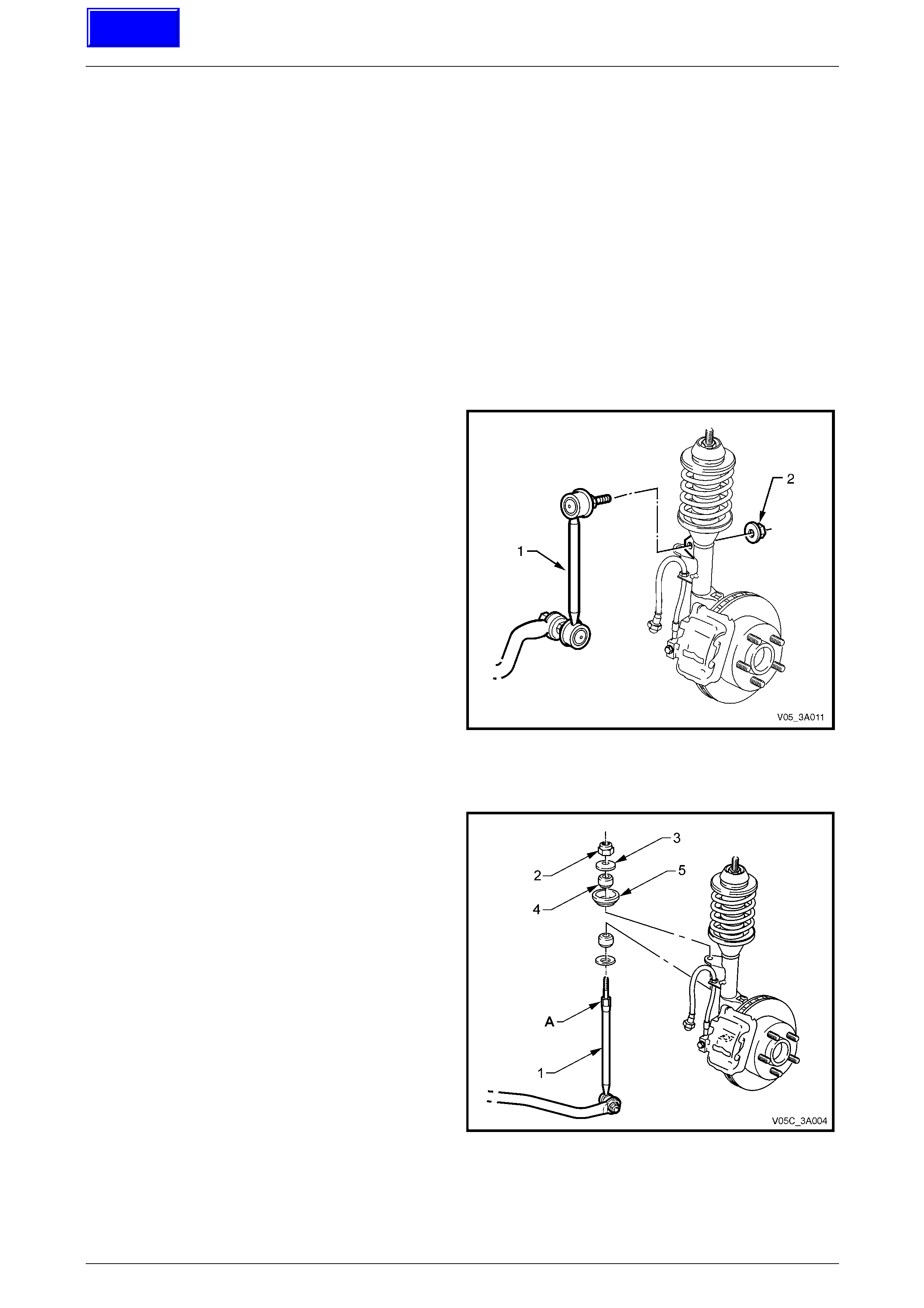
Front Suspension 3A – 57
3A-57
3.17 Stabiliser Bar Link
LT Section No. – 06-205
Remove
All VZ Models
1 Raise the front of the vehicle and support in a safe manner. Refer to 2.3 Jacking Precautions, in this Section.
2 Remove the wheel covers or decorative wheel nut caps.
3 Mark the relationship of the road wheel to hub or brake rotor. Loosen, then remove the road wheel attaching nuts,
working in a 'star' pattern. Refer to 3.1 Service Notes and Cautions, in this Section.
All VZ Except Coupe
4 Remove the upper ball joint:
a With a suitable size backing s et spann er hold the
stabiliser bar link inner stud hexagon.
b Use a second spanner to remove the retaining
nut (2).
c Separate the upper ball joint stud from the strut
bracket.
Figure 3A – 65
Coupe Only
5 Using a suitable size spanner, hold the stabiliser bar
spacer stud (1) at ‘A’, then use another spanner to
loosen and remove the stabiliser bar spacer stud nut
(2).
6 Remove the upper washer (3), upper insulator (4) and
centre washer (5).
Figure 3A – 66
Techline
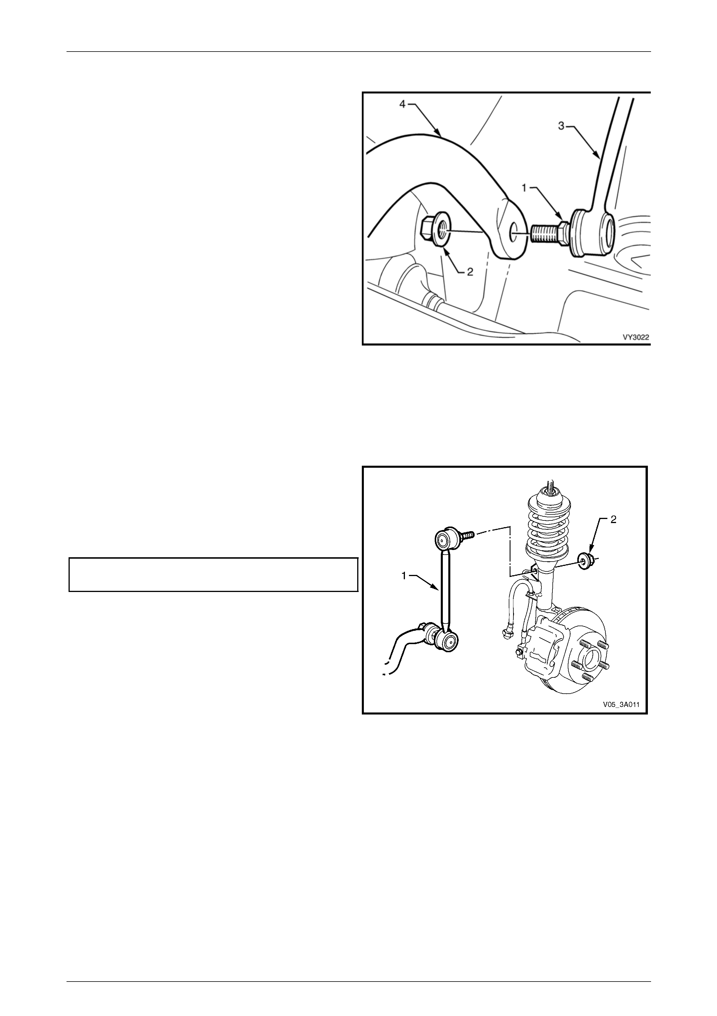
Front Suspension 3A – 58
3A-58
All VZ Models
7 With a backing set spanner holding the stabiliser bar
link inner stud hexagon (1), use a second spanner to
loosen then remove the retaining nut (2).
8 Separate the stabiliser bar link (3) from the stabiliser
bar (4).
9 Separate the stabiliser bar link (3) from the stabiliser
bar (4) and remove from the vehicle.
Figure 3A – 67
Reinstall
The installation procedure is the reverse to removal, except for the following points:
All VZ Except Coupe
1 Install the link upper ball joint stud to the strut bracket.
2 Reinstall the retaining nut.
3 While holding the inner stud hexagon with a backing
spanner, tighten the retaining nut (2) to the correct
torque specification.
Stabiliser bar link ball joint stud
nut torque specification........................................50 N.m
4 Install the link lower ball joint stud to the stabiliser bar
end.
5 Repeat Steps 2 and 3 for the lower stud.
Figure 3A – 68
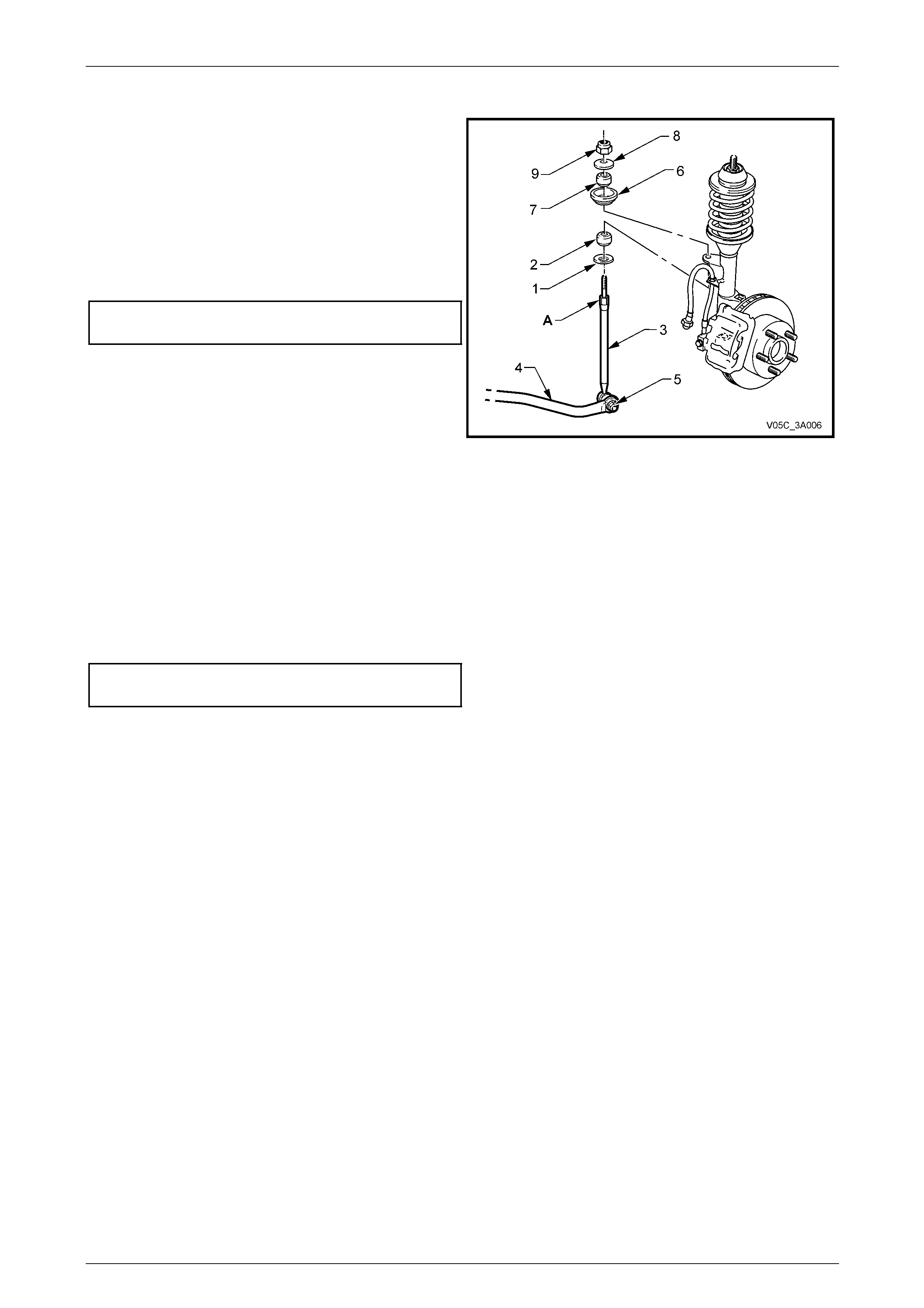
Front Suspension 3A – 59
3A-59
Coupe Only
6 As required, replace the lower link washer (1) and
insulator (2).
7 Before reinstallation of the stabiliser bar link ( 3) to the
stabiliser bar (4), insert the upper threaded end of the
link into the strut mounting bracket.
8 Reinstall the link ball sock et stud to the stabiliser bar
(4), tighten the retaining nut (5) to the correct torque
specification, while holding the inner stud hexagon ('1'
in Figure 3A – 67 with a spanner.
Stabiliser bar link ball socket retaining
nut torque specification........................................50 N.m
9 Reinstall the upper seat (6), upper insulator (7) and
washer (8).
10 Reinstall the upper link retaining nut (9).
11 While holding the spac er stud (3) with a suitable open
end spanner at ‘A’, use another spanner to tighten the
upper retaining nut (9) until the end of the thread on
the stud is contacted. Do not over-tighten.
Figure 3A – 69
All VZ Models
12 Install the road wheels, aligning the marks made prior to removal, and secure with the wheel attaching nuts, but do
not tighten to specification at this time.
13 Lower the vehicle to the ground.
14 Tighten the road wheel attaching nuts to the correct torque specification, working in a ‘star’ pattern.
Refer to 3.1 Service Notes and Cautions, in t his Section.
Road wheel attaching
nut torque specification............................110 – 140 N.m
15 Install the wheel cover or decorative wheel nut caps.
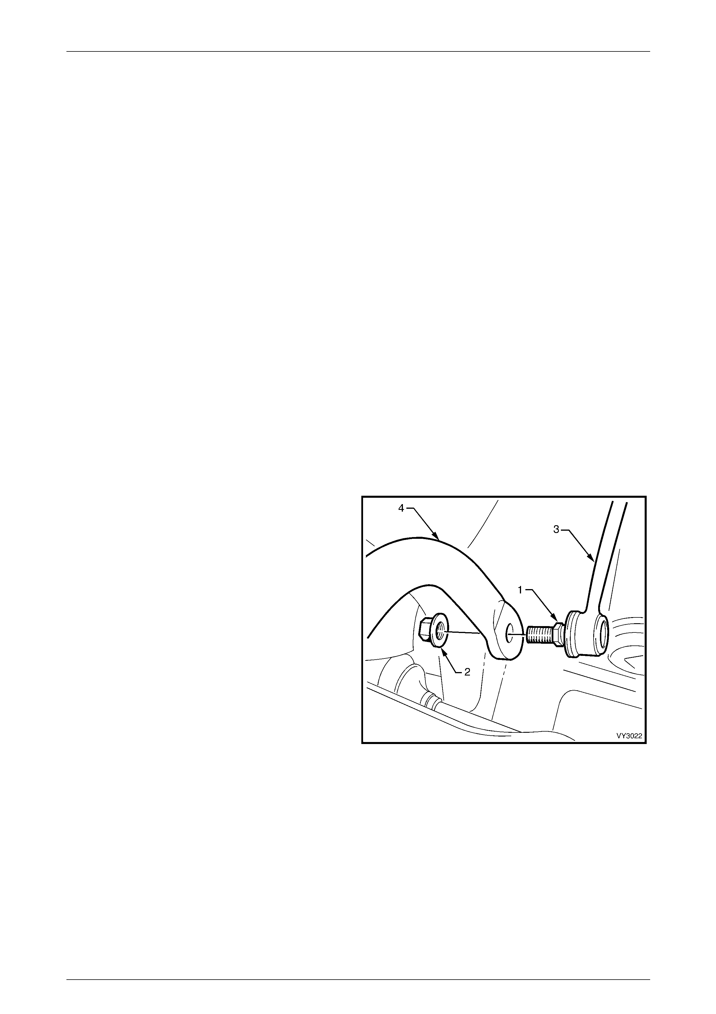
Front Suspension 3A – 60
3A-60
3.18 Stabiliser Bar
LT Section No. – 06-205
NOTE
To remove the stabiliser bar completely from the
vehicle, it will first be necessary to remove the
crossmember. Refer to 3.16 Front Suspension
Crossmember in this Section. Alternatively, the
stabiliser bar insulators and mounting brackets,
or the stabiliser bar link/s, can all be replaced
without removing the stabiliser bar from the
vehicle.
Remove
1 Raise the front of the vehicle and support in a safe manner. Refer to 2.3 Jacking Precautions, in this Section.
2 Remove the wheel covers or decorative wheel nut caps.
3 Mark the relationship of the road wheel to hub or brake rotor. Loosen, then remove the road wheel attaching nuts,
working in a 'star' pattern. Refer to 3.1 Service Notes and Cautions, in this Section.
4 After scribing crossmember alignment marks on the side frame members, remove the front suspension
crossmember mounting bolts, then lower enough to ena ble removal of the stabiliser bar from the vehic le.
5 Remove the nuts securing the stabiliser bar insulator retaining bracket to each side of the c rossmember, then
remove the stabiliser bar, support brackets and insulators from the crossmember.
6 Remove the insulators from the stabiliser bar.
7 With a backing set spanner holding the stabiliser bar
link, lower stud inner hexagon (1), use a second
spanner to loosen then remo ve the retaining nut (2).
8 Separate the stabiliser bar link (3) from the stabil iser
bar (4) and remove the stabiliser bar from the vehicle.
Figure 3A – 70

Front Suspension 3A – 61
3A-61
Reinstall
The installation procedure of the stabiliser bar is the reverse of the removal procedure, noting the following:
1 Install the stabiliser bar insulators onto the stabiliser bar
NOTE
The slit in each insulator should face forward, and
the rounded sections on the insulators should
seat in the mating recesses in the crossmember
side frame.
2 Reinstall the stabiliser bar into the vehicle.
3 Assemble the two support brackets onto the stabiliser bar insulators and over the studs on the crossmember
outrigger.
4 Reinstall and tighten the stabiliser bar support bracket bolts to the correct torque specification.
Stabiliser bar bracket retaining
nut torque specification........................................27 N.m
5 Install the lower stabiliser bar link socket stud to the stabiliser bar ends, then reinstall the nuts and tighten to the
correct torque specification. Refer to 3.17 Stabiliser Bar Link, in this Section.
Stabiliser bar link ball joint
stud nut torque specification ................................50 N.m
6 Reinstall the front suspension crossmember; refer to 3.16 Front Suspension Crossmember, in this Section.
7 Lower vehicle to the ground.
Front Suspension 3A – 62
3A-62
4 Diagnosis
General
When diagnosing suspected front suspension problems, it should be remembered that steering, wheels and tyres all
have an effect on front suspension performance. Refer to Section 9 Steering and Section 10 Wheels and Tyres.
Strut Diagnosis
1 Test by quickly pushing up an d down on the bumper bar at the front corner of the vehicle. Compare the resistance
to movement with a similar vehicle having acceptable ride quality.
2 Inspect the struts for excessive fluid leak age.
Acceptance Criteria
A strut DOES NOT require replacement, if any or a combination of the following are present:
a An oily build-up at the end of the piston rod, up to 1 cm wide.
b Oily ‘sludge’ accumulated from normal operating conditions to 4 cm from the top of the strut body.
c Road grease, oil, sand and dust discol ouration on the body, does not constitute a leaking strut. If this condition is
evident, the strut should be wiped cl ean and checked at a later service.
NOTE
Should one strut prove to be leaking and require
replacement, provided the remaining strut is
serviceable, it does not also need to be replaced.
4.1 Diagnosis Guide
Symptoms and Probable Cause Remedy
Hard or Heavy Steering
1 Low or uneven tyre pressures.
2 Steering gear or connections too tight or misaligned.
3 Insufficient fluid in steering gear.
4 Excessive caster.
5 Lower front control arm/s and/or front control arm rod/s
bent.
6 Steering knuckle bent.
7 Excessive toe-in.
1 Inflate tyres to specified pressure for specific load
conditions. Refer to tyre placard attached to the vehicle.
2 Adjust steering gear or replace components as necessary.
Refer to Section 9 Steering.
3 Check steering gear fluid level. Top up, using only
DEXRON III® fluid. Check system for leaks. Refer to
Section 9 Steering.
4 Check front wheel alignment. Adjust as necessary. Refer to
2.2 Wheel Alignment Checking and Adjustment in this
Section.
5 Check alignment of front control arms and front lower
control arm rods. Replace components as necessary. Refer
to 2.2 Wheel Alignment Checking and Adjustment in this
Section.
6 Replace steering knuckle. Refer to 3.9 Steering Knuckle in
this Section.
7 Check and adjust wheel toe. Refer to 2.2 Wheel Alignment
Checking and Adjustment in this Section.

Front Suspension 3A – 63
3A-63
Symptoms and Probable Cause Remedy
Excessive Play or Looseness in Steering
1 Steering gear or connections loose or worn.
2 Front control arm socket loose or worn.
3 Front wheel bearings worn.
4 Loose attachment of crossmember to frame.
1 Adjust steering gear or install new components as required.
Refer to Section 9 Steering.
2 Replace front control arm assembly. Refer to 3.10 Front
Control Arm in this Section.
3 Replace front wheel hub assembly. Refer to 3.3 Front
Wheel Hub, Brake Rotor or Brake Shield in this Section.
4 Check, align and tighten crossmember attaching nuts. Refer
to 3.16 Front Suspension Crossmember in this Section for
alignment procedures.
Erratic Steering on Brake Application
1 Low or uneven tyre pressures.
2 Excessive front brake rotor runout.
3 Front brake pads contaminated with lubricant.
4 Insufficient or uneven caster.
5 Steering knuckle bent.
6 Excessive play in steering gear.
1 Inflate tyres to specified pressure for specific load
conditions. Refer to the tyre placard attached to the vehicle.
2 Machine front rotors. Refer to Section 5A Service and Park
Braking System.
3 Replace brake pads. Correct cause of lubricant leakage.
Refer to Section 5A Service and Park Braking System.
4 Check front wheel alignment. Refer to 2.2 Wheel Alignment
Checking and Adjustment in this Section.
5 Replace steering knuckle. Refer to 3.9 Steering Knuckle in
this Section.
6 Adjust steering gear or replace worn components. Refer to
Section 9 Steering.
Vehicle Pulls to One Side
1 Low or uneven tyre pressures.
2 Rear wheels not tracking with front wheels.
3 Front brake pads contaminated.
4 Toe-in incorrect.
5 Incorrect or uneven caster or camber.
6 Final drive assembly shifted.
7 Steering knuckle bent.
1 Inflate tyres to specified pressure for specific load
conditions. Refer to tyre placard attached to the vehicle.
2 Check alignment of rear wheels with front wheels and
correct as necessary. Refer to Section 4A1 Independent
Coil Spring Rear Suspension or Section 4A2 Leaf Spring
Rear Suspension for details of rear wheel alignment.
3 Replace brake pads. Correct cause of contaminant. Refer
to Section 5A Service and Park Braking System.
4 Adjust toe-in to specification. Refer to 2.2 Wheel Alignment
Checking and Adjustment in this Section.
5 Check wheel alignment. Adjust as necessary. Refer to 2.2
Wheel Alignment Checking and Adjustment in this Section.
6 Check attaching bolts for looseness and rear suspension
trailing arm bushings for wear. Refer to Section 4A1
Independent Coil Spring Rear Suspension or Section 4A2
Leaf Spring Rear Suspension.
7 Replace steering knuckle. Refer to 3.9 Steering Knuckle in
this Section.
Front or Rear Wheel Tramp
1 Wheels and tyres out of balance.
2 Front struts or rear shock absorbers operating incorrectly,
leaking fluid or inoperative.
1 Balance wheels and tyres. Also check for eccentric or
bulged tyres. Replace as necessary. Refer to Section 10
Wheels and Tyres.
2 Check operation and replace components as necessary.
Refer to 3.8 Front Strut Unit in this Section or Section 4A1
Independent Coil Spring Rear Suspension or Section 4A2
Leaf Spring Rear Suspension, as necessary.

Front Suspension 3A – 64
3A-64
Symptoms and Probable Cause Remedy
Road Shocks
1 Incorrect tyre pressures.
2 Steering gear incorrectly adjusted.
3 Front struts or rear shock absorbers operating incorrectly or
unevenly, leaking fluid or inoperative.
4 Compression or rebound rubbers damaged or missing.
5 Unbalanced wheels.
6 Incorrect wheel alignment.
1 Inflate tyres to specified pressure for specific load
conditions. Refer to tyre placard attached to the vehicle.
2 Adjust steering gear. Refer to Section 9 Steering for details.
3 Check operation and replace components as necessary.
Refer to 3.8 Front Strut Unit in this Section or Section 4A1
Independent Coil Spring Rear Suspension or Section 4A2
Leaf Spring Rear Suspension, as necessary.
4 Replace missing or damaged parts. Refer to 3.8 Front Strut
Unit in this Section or Section 4A1 Independent Coil Spring
Rear Suspension or Section 4A2 Leaf Spring Rear
Suspension, as necessary.
5 Balance wheels. Refer to Section 10 Wheels and Tyres.
6 Check and adjust. Refer to 2.2 Wheel Alignment Checking
and Adjustment in this Section.
Scuffed Tyres
1 Toe-in incorrect
2 Tyres improperly inflated.
3 Wheels or tyres out-of-true.
4 Front control arm socket/s worn.
5 Uneven caster and camber.
6 Lower front control arm/s or front control arm rod/s bent.
7 Steering knuckle bent.
1 Adjust toe-in. Refer to 2.2 Wheel Alignment Checking and
Adjustment in this Section.
2 Inflate tyres to specified pressure for specific load
conditions. Refer to the tyre placard attached to the vehicle.
3 Check for wheel and tyre wobble. Check that the wheels
and tyres are correctly mounted. Balance wheels and tyres.
Refer to Section 10 Wheels and Tyres.
4 Replace worn components. Refer to 3.10 Front Control Arm
in this Section.
5 Check wheel alignment. Adjust as necessary. Refer to 2.2
Wheel Alignment Checking and Adjustment in this Section.
6 Check alignment of front control arm/s and front control arm
rod/s. Replace components as necessary. Refer to 3.10
Front Control Arm and 3.14 Front Control Arm Rod in this
Section.
7 Replace steering knuckle. Refer to 3.9 Steering Knuckle in
this Section.
Cupped Tyres
1 Tyres improperly inflated.
2 Wheels and tyres out-of-balance.
3 Dragging brakes.
4 Front control arm socket/s and/or wheel bearings worn.
5 Uneven caster.
6 Steering knuckle bent.
1 Inflate tyres to specified pressure for specific load
conditions. Refer to the tyre placard attached to the vehicle.
2 Balance wheels and tyres. Also check for eccentric or
bulged tyres. Replace as necessary. Refer to Section 10
Wheels and Tyres.
3 Check for seizing of the brake calipers and/or park brake
mechanism. Refer to Section 5A Service and Park Braking
System.
4 Replace worn components. Refer to 3.10 Control Arm or
3.3 Front Wheel Hub Assembly, Brake Rotor or Brake
Shield in this Section.
5 Check wheel alignment. Adjust as necessary. Refer to 2.2
Wheel Alignment Checking and Adjustment in this Section.
6 Replace steering knuckle. Refer to 3.9 Steering Knuckle in
this Section.

Front Suspension 3A – 65
3A-65
Symptoms and Probable Cause Remedy
Front Wheel Shimmy
1 Low or uneven tyre pressures.
2 Steering connections incorrectly adjusted or worn.
3 Front control arm socket/s and/or wheel bearings worn.
4 Wheels and tyres out-of-balance.
5 Wheels or tyres out-of-true.
6 Incorrect or uneven caster or incorrect toe-in setting.
7 Steering knuckle bent.
1 Inflate tyres to specified pressure for specific load
conditions. Refer to the tyre placard attached to the vehicle.
2 Adjust steering gear or install new components as needed.
Refer to Section 9 Steering.
3 Replace worn components. Refer to 3.10 Control Arm or
3.3 Front Wheel Hub Assembly, Brake Rotor or Brake
Shield in this Section.
4 Balance wheels and tyres. Also check for eccentric or
bulged tyres. Replace as necessary. Refer to Section 10
Wheels and Tyres.
5 Check for wheel and tyre wobble. Check that the wheels
and tyres are correctly mounted. Balance wheels and tyres.
Refer to Section 10 Wheels and Tyres.
6 Check and adjust. Refer to 2.2 Wheel Alignment Checking
and Adjustment in this Section.
7 Replace steering knuckle. Refer to 3.9 Steering Knuckle in
this Section.
Vehicle Wanders
1 Low or uneven tyre pressures.
2 Steering connections loose or worn.
3 Steering gear connections adjusted too tightly.
4 Front control arm socket/s worn.
5 Wheel toe settings outside specifications.
6 Incorrect or uneven caster.
7 Steering knuckle bent.
8 Rear axle shifted.
9 Loose attachment of front suspension crossmember to side
members.
1 Inflate tyres to specified pressure for specific load
conditions. Refer to the tyre placard attached to the vehicle.
2 Adjust steering gear or install new components as needed.
Refer to Section 9 Steering.
3 Test steering system for binding with front wheels off the
ground. Refer to Section 9 Steering.
4 Replace worn components. Refer to 3.10 Front Control Arm
in this Section.
5 Adjust toe-in. Refer to 2.2 Wheel Alignment Checking and
Adjustment in this Section.
6 Check wheel alignment. Adjust as necessary. Refer to 2.2
Wheel Alignment Checking and Adjustment in this Section.
7 Replace steering knuckle. Refer to 3.9 Steering Knuckle in
this Section.
8 Check all attachment fasteners for security, tightening to
specification, as required. Refer to Section 4A1
Independent Coil Spring Rear Suspension or Section 4A2
Leaf Spring Rear Suspension.
9 Check, align and tighten all fasteners to specification. Refer
to 3.16 Front Suspension Crossmember.
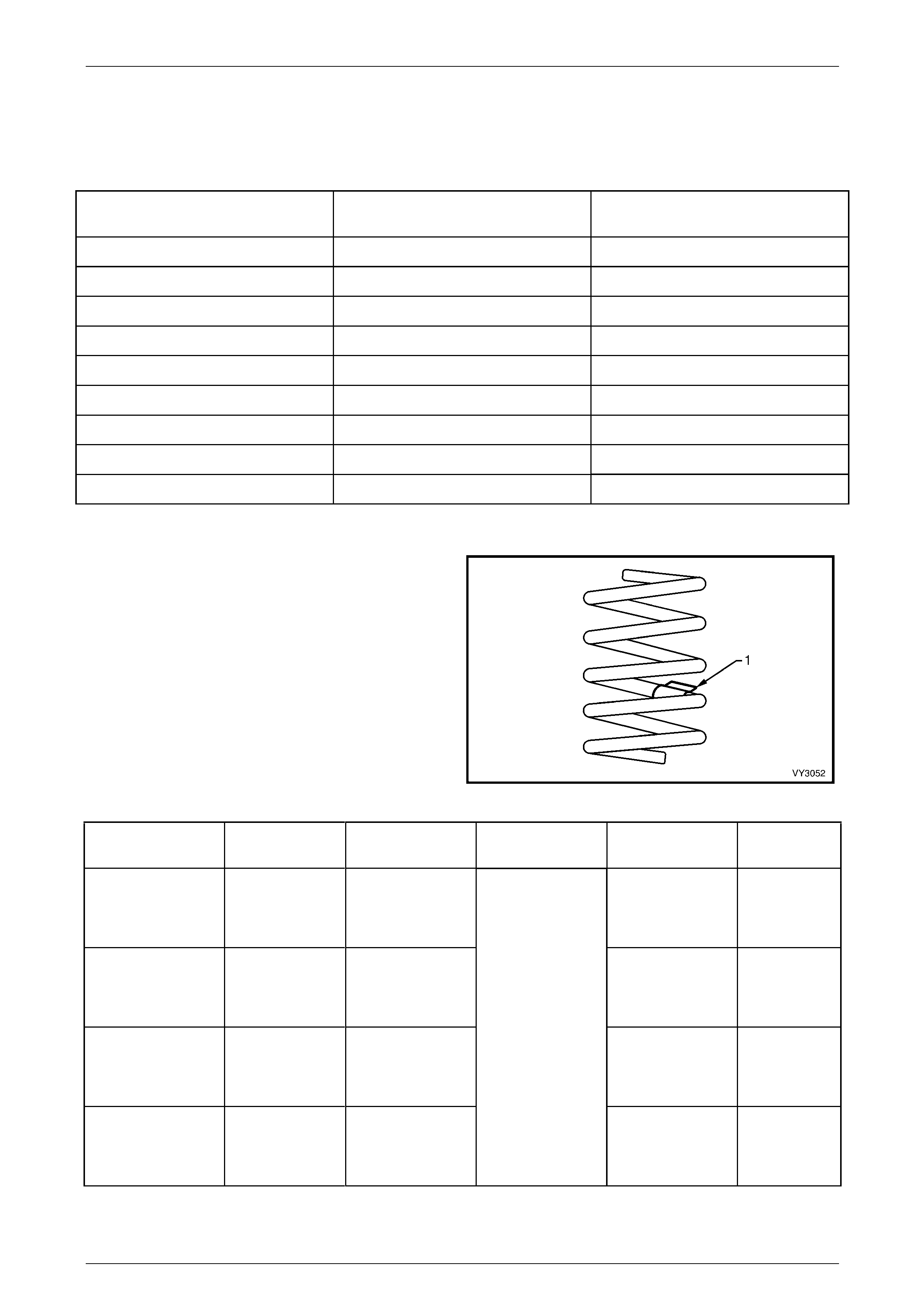
Front Suspension 3A – 66
3A-66
5 Specifications
Suspension Travel
Suspension Configuration Compression – 2/3 Compre ssio n of
Bumper (mm). Rebound (mm)
VZ Coupe – All 61 115
VZ – Sedan FE1 83 93
VZ – Sedan FE2 61 115
VZ – Sedan FR1 103 73
VZ – Wagon FE1 83 93
VZ – Wagon FE2 61 115
VZ – Wagon FR1 105 71
VZ – Utility FE1 105 71
VZ – Utility FE2 61 115
Front Spring Details
Identification of the front spring fitted to a par ticular vehicle
can be achieved by cross-referenci ng the two digit code
provided on the production id entificati on tag (1) with the
table below.
Figure 3A – 71
Suspension
Configuration Number of
Coils Free Length
(mm) Inside Diameter Spring Rate and
Type Production
I.D. Code
Coupe – All 5.25 355
Variable
24 – 31 N/mm
(3660 ± 110N
@ 200 mm)
HJ
Levels 1 and 2
Sedan, with
V6 Engine and FE1 6.05 390
Variable
19 – 23 N/mm
(3700 ± 110N
@ 200 mm)
AY
Level 3 Sedan 5.25 355
Variable
24 – 31 N/mm
(3660 ± 110N
@ 200 mm)
HJ
Levels 1 and 2
Sedan with
GEN III V8 Engine
and FE1
6.05 444
136 ± 1.5
Variable
19 – 23 N/mm
(3700 ± 110N
@ 210 mm)
HN

Front Suspension 3A – 67
3A-67
Suspension
Configuration Number of
Coils Free Length
(mm) Inside Diameter Spring Rate and
Type Production
I.D. Code
Levels 1 and 2
Sedan with
V6 Engine and FE2 5.25 355
Variable
24 – 31 N/mm
(3660 ± 110N
@ 200 mm)
HJ
Levels 1 and 2
Sedan with
GEN III V8 Engine
and FE2
5.25 355
Variable
24 – 31 N/mm
(3660 ± 110N
@ 200 mm)
HJ
Levels 1 and 2
Sedan with FR1 5.74 363
Variable
27 – 35 N/mm
(3600 ± 110N
@ 230 mm)
JM
Levels 1 and 2
Wagon with
V6 Engine and FE1 6.05 390
Variable
19 – 23 N/mm
(3700 ± 110N
@ 200 mm)
AY
Levels 1 and 2
Wagon with
GEN III V8 Engine
and FE1
6.05 444
Variable
19 – 23 N/mm
(3700 ± 110N
@ 210 mm)
HN
Levels 1 and 2
Wagon with
GEN III V8 and FE1 5.25 355
Variable
24 – 31 N/mm
(3660 ± 110N
@ 200 mm)
HJ
Levels 1 and 2
Wagon with
V6 and FE2 TBA TBA Variable
TBA AZ
Levels 1 and 2
Wagon with
GEN III V8 Engine
and FE2
6.05 444
Variable
19 – 23 N/mm
(3700 ± 110N
@ 210 mm)
HJ
Levels 1 and 2
Wagon with FR1 5.74 363
Variable
27 – 35 N/mm
(3600 ± 110N
@ 230 mm)
JM
Utility with FE1 5.74 363
Variable
27 – 35 N/mm
(3600 ± 110 N
@ 230 mm)
JM
Utility with FE2 5.74 351
Variable
27 – 35 N/mm
(3850 ± 110N
@ 209 mm)
HK
Regular Cab
with FE1 5.74 367
Variable
27 – 35 N/mm
(3600 ± 110 N
@ 230 mm)
JM
Crew Cab with FE1 5.74 367
136 ± 1.5
Variable
27 – 35 N/mm
(3600 ± 110 N
@ 230 mm)
JM
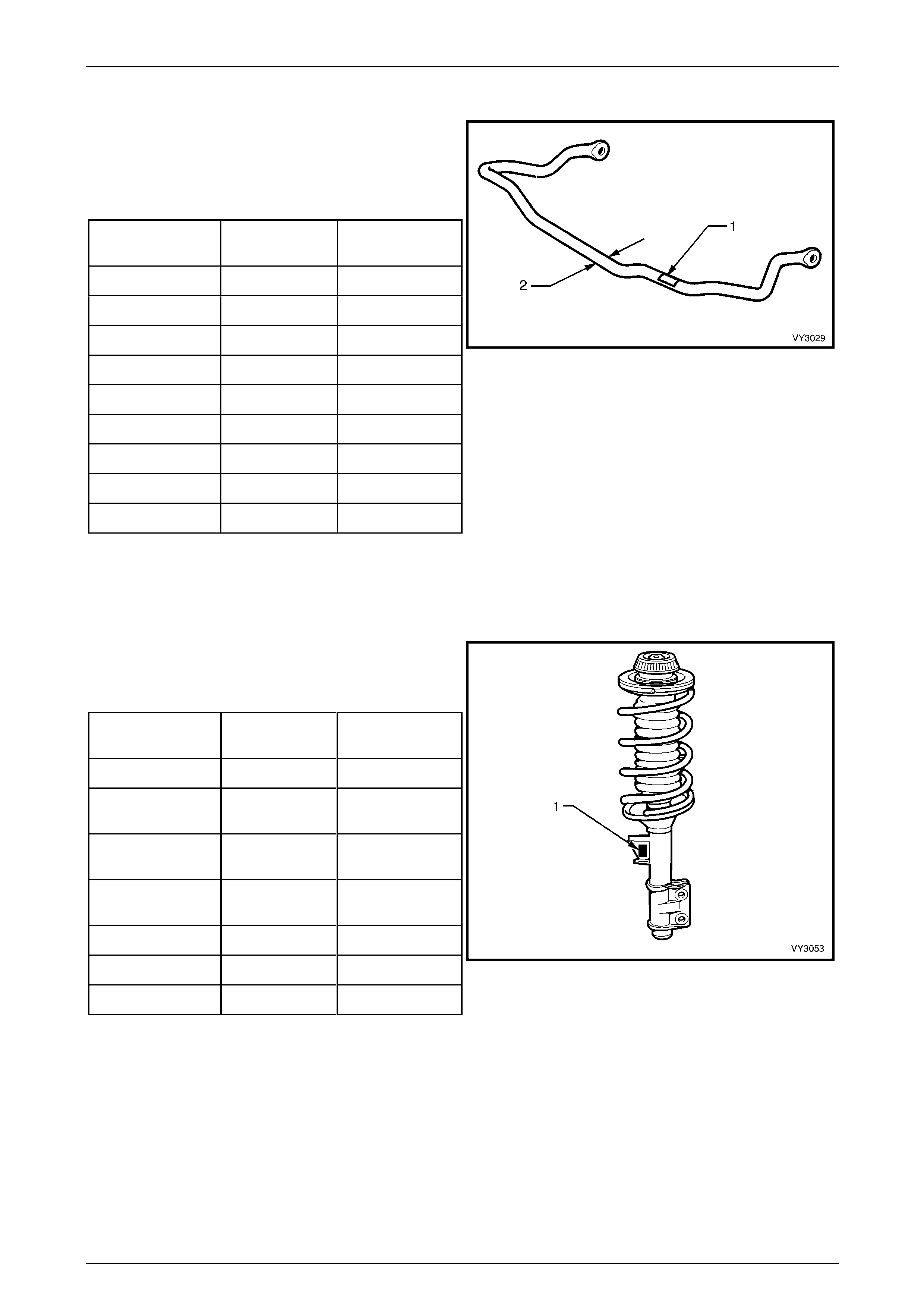
Front Suspension 3A – 68
3A-68
Front Stabiliser Bar Details
Identification of the front stabiliser bar fitted to a particular
vehicle can be achieved by cross-referencing the two digit
code provided on the pro duction identification tag (1) with
the table below.
The table also provides stabiliser bar diameters (2).
Suspension
Configuration Diameter Production I.D.
Code
Coupe 28 AA
Sedan FE1 25 WM
Sedan FE2 26 WL
Sedan FR1 25 WM
Wagon – All 25 WM
Utility FE1 26 WL
Utility FE2 25 WM
Regular Cab – All 27 XD
Crew Cab – All 28 YG
Figure 3A – 72
Front Strut Details
Type Wet strut – non-serviceable
Piston Diameter 30 mm
Identification of the front strut assemblies fitted to a
particular vehicle can be achie ved by cross-referencing the
two digit code provided on th e prod uction identification tag
(1) with the table below.
Suspension
Configuration Left Side
I.D. Code Right Side
I.D. Code
Coupe – All ZS ZZ
All Sedan and
Wagon with FE1 MB MA
All Sedan and
Wagon with FE2 LZ LY
All Sedan and
Wagon with FR1 NK NJ
Utility with FE1 NK NJ
Regular Cab – All NB NA
Crew Cab – All NB NA
Figure 3A – 73
Front Control Arm Details
Type Forged with rubber bushings for attachment to front crossmember and front control arm rod. F r ont control arm
bal joint assembly is a press fit into the front control arm and is not serviced separatel y.
Front Wheel Bearings
Type Double row ball bearing
Lubricant Sealed for life, non-adj ustable
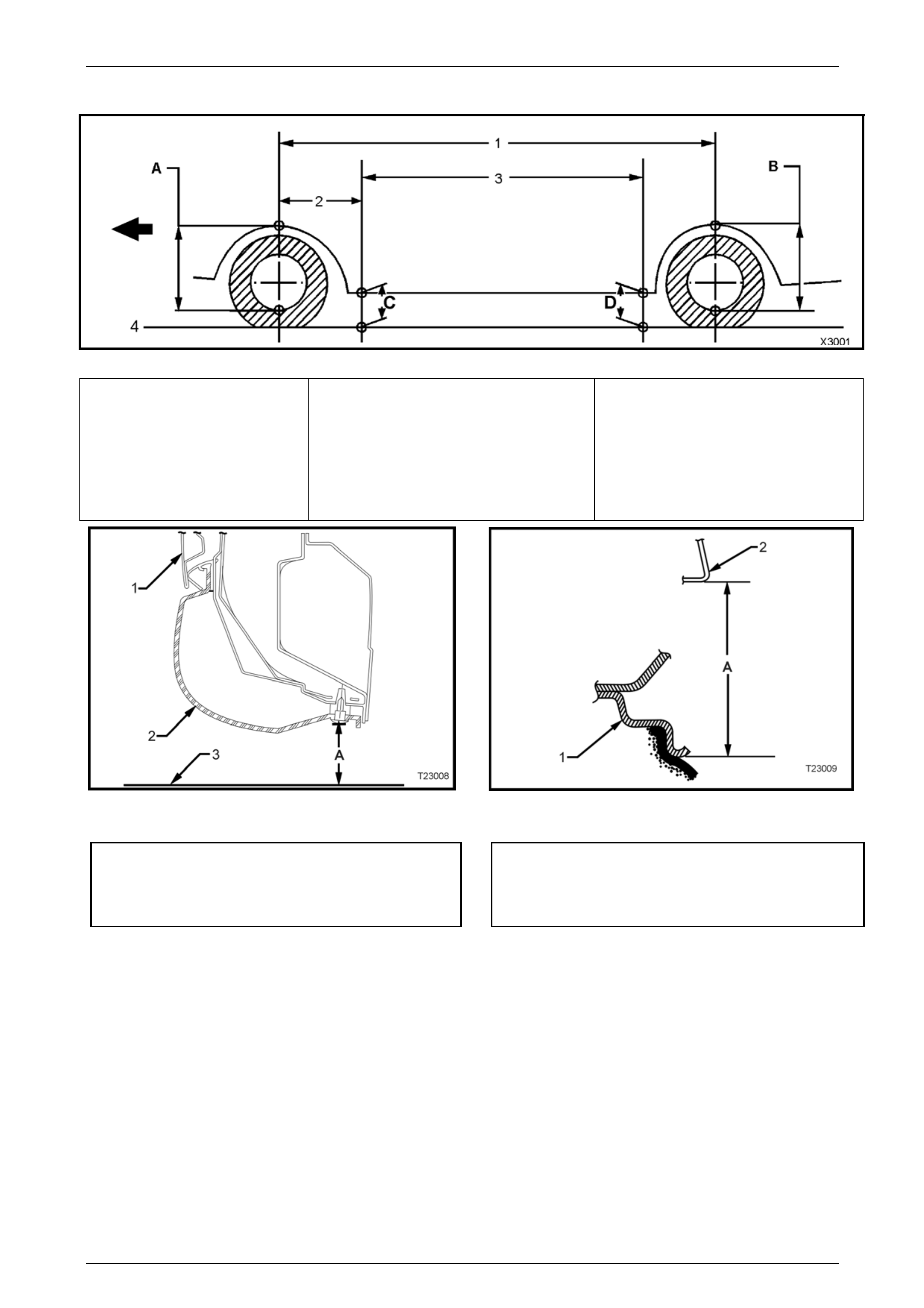
Front Suspension 3A – 69
3A-69
Suspension and Trim Height Specifications
Figure 3A – 74
A Front Suspension Height
Location
B Rear Suspension Height
Location
C Front Trim Height Check
Location
D Rear Trim Height Check
Location
1 Wheelbase:
Coupe – 2789 mm
Sedan – 2789 mm
Station Wagon – 2939 mm
Utility – 2939 mm
Regular Cab – 3197 mm
Crew Cab – TBA
2 Reference Point:
All Models – 584.5 mm
3 Trim Height Spacing:
Coupe – 1615 mm
Sedan – 1615 mm
Station Wagon – 1765 mm
Utility – 1765 mm
Regular Cab – 1500
Crew Cab – TBA
4. Ground Line
Figure 3A – 75 – Rear Trim Height Ch ecking Location
(Front Similar)
Figure 3A – 76 – Front and Rear Suspension Height
Checking Location
1 Door
2 Trim
3 Ground Line
‘A’ Trim Height
1 Wheel Rim
2 Fender Opening
'A’ Suspension Height
Front Suspension 3A – 70
3A-70
The following suspension/trim height
dimensions are for reference only and are
only intended to be a guide. Refer to
3.2 Suspension and Trim Height, Check for
ride height variations and additional
procedures.
Suspension Height
(mm) Trim Height (mm)
Vehicle Descript ion Transmission Suspension Front
(‘A’ in Fig.
3A – 60)
Rear
(‘B’ in Fig.
3A – 60)
Front
(‘C’ in Fig.
3A – 60)
Rear
(‘D in Fig.
3A – 60)
Coupe – All Manual FE2 618 609 165 175
Level 1 and 2 Sedan Manual/Automatic FE1/FR1 605 594 192 201
Level 1 and 2 Sedan
(except ‘S’ and ‘SS’) Manual/Automatic FE2 583 581 172 186
‘S’ Sedan Manual/Automatic FE2 605 603 172 186
‘SS’ Sedan Manual/Automatic FE2 611 609 172 186
Level 3 Sedan Automatic FE1/FR1 618 607 192 201
Level 3 Sedan Automatic FE2 596 608 172 186
Level 1 and 2 Wagon Manual/Automatic FE1/FR1 601 583 192 210
Level 1 and 2 Wagon Manual/Automatic FE2 586 568 177 195
Level 1 Utility Manual/Automatic FE1 616 641 210 235
‘S’ Utility Manual/Automatic FE1 629 654 210 235
‘S’ Utility Manual/Automatic FE2 619 654 202 233
‘SS’ Utility Manual/Automatic FE2 619 644 185 210
V6 FE2 588 517 212 256
Regular Cab V8 FE2 600 529 224 268
Crew Cab – Base FE2 592 670 210 240
Crew Cab – ‘S’ V6 FE2 600 680 216 256
Crew Cab – ‘SS’ V8 F E 2 616 692 210 256
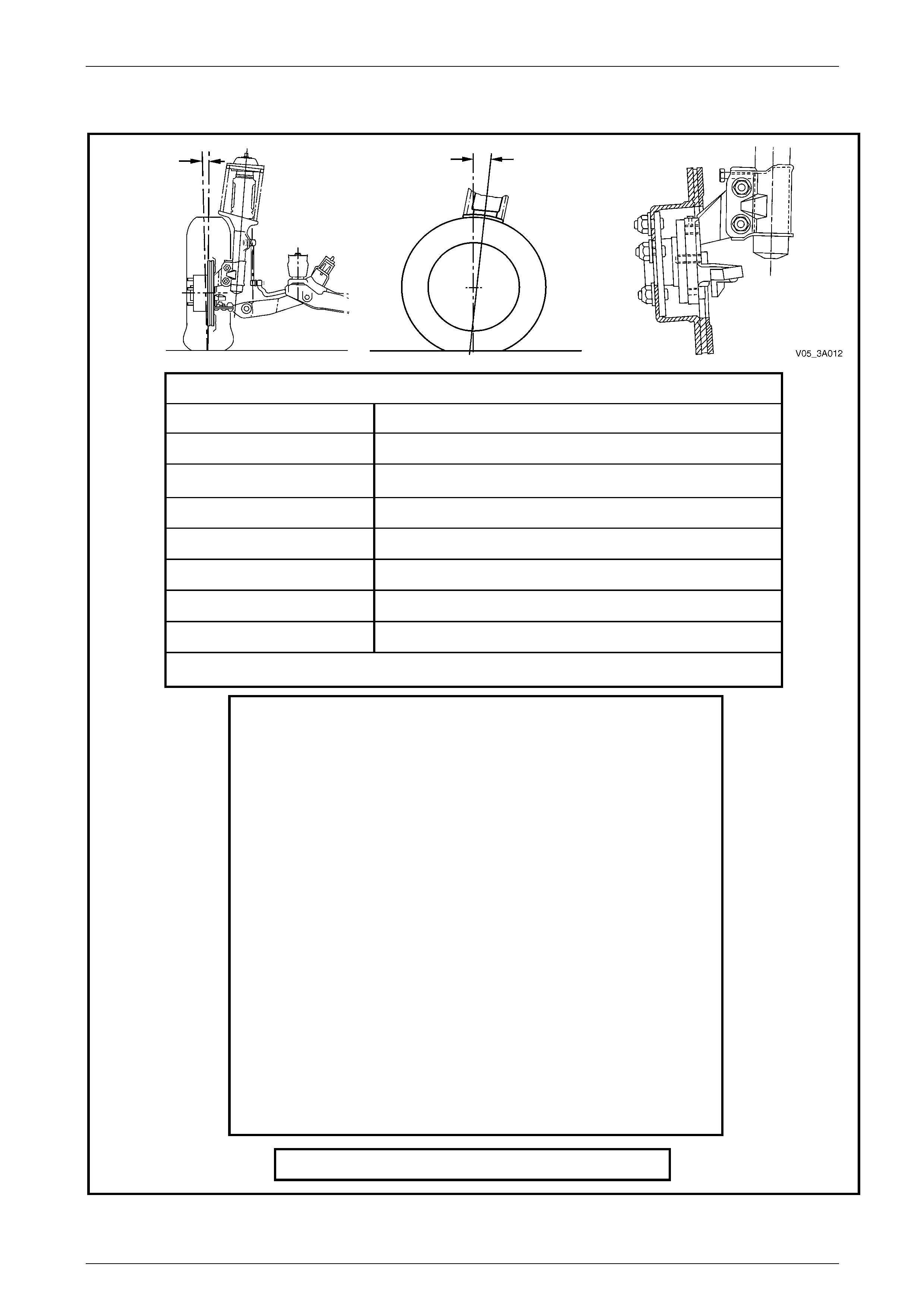
Front Suspension 3A – 71
3A-71
Front Wheel Alignment Specifications
Front Wheel Alignment at Curb Weight
Wheel Alignment Angle Specifications – All VZ
Camber –0° 12' ± 0° 18'
Caster • Driver Side – 7° 21' ± 1° 15' / Passenger Side 7° 45' ± 1° 15'
Toe-in Degrees Total 0° 10’ ± 0° 10'
Degrees per Wheel 0° 5’ ± 0° 5’
Toe-out on Turns 1° 42’ @ 20 ° turn angle ± 1° 30'
Steering Axis Inclination Angle 12° 52’ ± 1° 30'
Included Angle 12° 40’ ± 1° 30'
• The caster washer is fitted to the Driver’s side. Refer to Figure 3A – 11.
Service Information
• The adjusting values for camber, caster and toe-i n must remain within
the tolerances specified. The difference between left and right must not
exceed the follo wing:
Caster 0° 36'
Camber 0° 48'
Toe-In 0° 10'
• The specifications listed are the nom inal value, with acceptable
variance from this central point. Where possible, an attempt should
always be made to achieve the nominal settings when adjusting.
• Front wheel camber alters as a function of front suspension height.
• Camber adjusting bolt: After loosening both lower strut to steering
knuckle bolts and nuts, adjust camber by turning the adjusting bolt
clockwise to decrease negative camber and anti-clockwise to increase
negative camber. After adjustment, both bolts and nuts MU ST be
replaced with new parts and tightened to the recommended torque
setting.
• The rear wheel alignment sho uld be checked and corrected if
necessary (refer to Section 4A1 Independent Coil Spring Rear
Suspension) before checking front wheel alignment.
At curb weight with a full fuel tank – All Models
Figure 3A – 77

Front Suspension 3A – 72
3A-72
6 Torque Wrench Specifications
ATTENTION
Throughout this section, fastener torque wrench specifications may be accompanied with the following
identification marks:
Fasteners must be replaced after loosening.
Vehicle must be at curb height before final tightening.
Fasteners either have micro encapsulated sealant applied or incorporate a mechanic al th read lock and
should only be re-used once. If in doubt, replacement is recommended.
If one of these identification marks is present alongside a fastener torque wrench specification, the
recommendation regarding that fastener must be adhered to.
Brake Caliper Anchor Plate Bolts .......................Stage 1: ...................85 N.m
Stage 2:....Turn through 45°
Crossmember to Side Frame Bolt .....................................................122 N.m
Front Control Arm Ball Joint Nut..........................................................60 N.m
Front Control Arm Inner Pivot Bolt And Nut.......................................103 N.m
Front Control Arm Rod to Front Control Arm Attaching Nut...............103 N.m
Front Control Arm Rod to Insulating Bushing Retaining Nut..............148 N.m
Front Control Arm Rod Insulating Bushing to Crossmember Nut ........23 N.m
Front Wheel Hub Assembly To Steering Knuckle Attaching Bolt.......108 N.m
Road Wheel Attaching Nut ......................................................110 – 140 N.m
Stabiliser Bar Link Ball Joint Stud Retaining Nut (Both) ......................50 N.m
Stabiliser Bar Support Bracket Retaining Nut......................................27 N.m
Steering Gear Housing To Crossmember Mounting Nut ............60 N.m, then
Turn through 45°
Steering Knuckle To Strut Attaching Bolt............Stage 1: ...................85 N.m
Stage 2:.................100 N.m
Stage 3:....Turn through 90°
Steering Linkage Outer Tie Rod End Castellated Nut .........................68 N.m
Steering Linkage Tie Rod to Tie Rod End Lock Nut............................50 N.m
Upper Strut Bearing Retaining Nut......................................................78 N.m
Upper Strut Locating Plate Retaining Nut............................................55 N.m
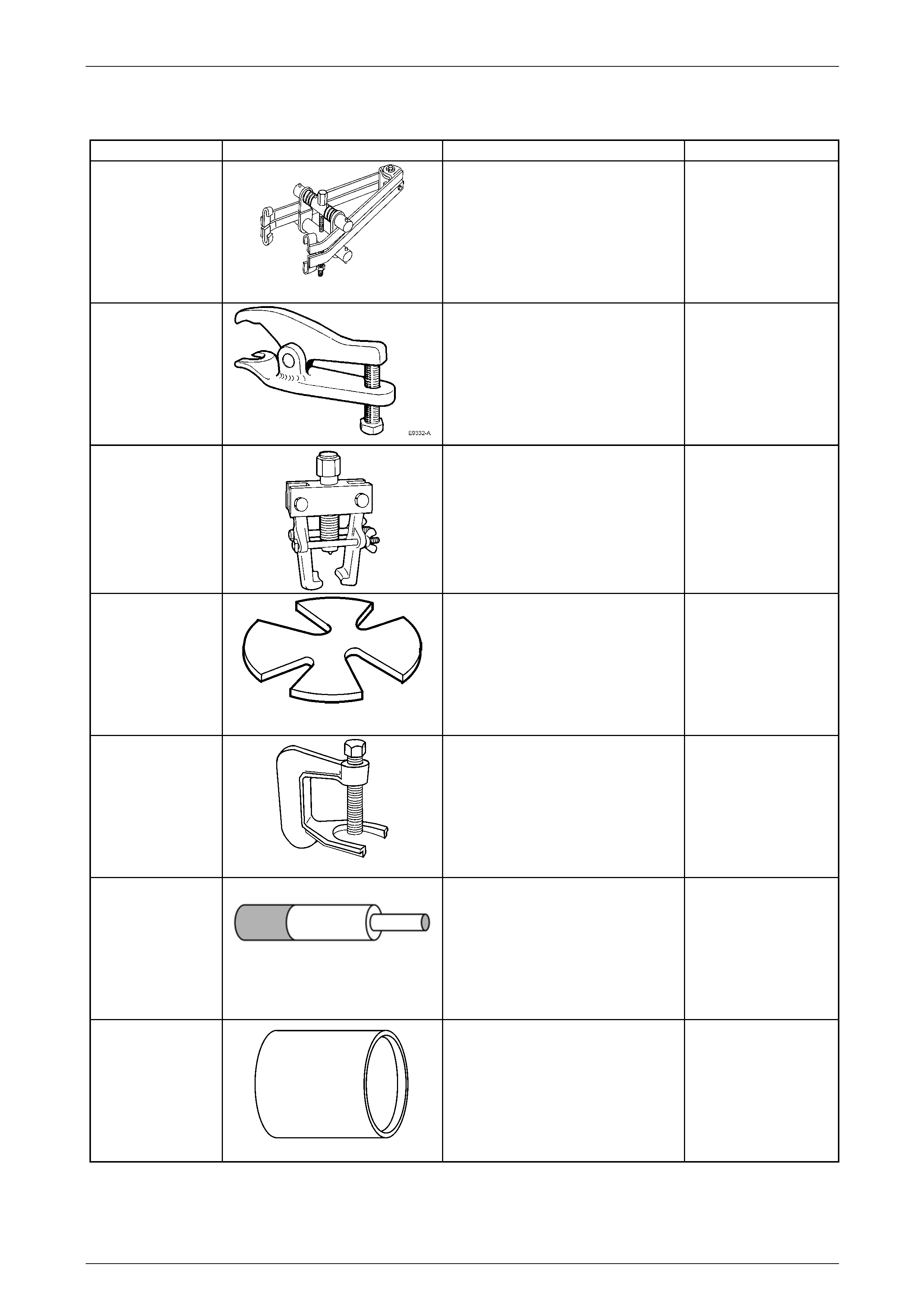
Front Suspension 3A – 73
3A-73
7 Special Tools
Tool Number Illustration Description Tool Classification
180
Spring Compressor
Used to compress the front
suspension coil spring.
Previously released.
Desirable
6297
Ball Joint Release Tool
Used to release the front control arm
ball joint from the steering knuckle.
Previously released as E 9332-A
Desirable
7311
Universal Puller
Used to remove the steering linkage
outer tie rod end from the steering
arm. Previously released.
Desirable
7A42
Press Plates
Used for various pressing operations.
Previously released.
Desirable
C4150-C
Press Tool
Used to remove the front wheel stud/s
from the front hub.
Previously released.
Unique
AU158
Front Control Arm Rod Bushing
Remover and Installer Mandrel
Used with KM 158-2 for removing the
bush, then with AU 159 and KM 157-2
for installing the new bush.
Previously released.
Desirable
AU158-2
Front Control Arm Rod Bushing
Installing Support Sleeve
Used with AU158 and AU1 59.
Previously released.
Desirable

Front Suspension 3A – 74
3A-74
AU159
Front Control Arm Rod Bushing
Replacer Sleeve
Used with AU158 and AU158-2.
Previously released.
Desirable
AU160-1
Support
Used to support front control arm
when installing a ne w inner in sulator.
Previously released.
Desirable
AU162
Front Control Arm Pivot Bushing
Removal Mandrel
Used with AU160-1 and KM157-2.
Previously released.
Desirable
AU534
Torque Limiting Socket
Used in conjunction with an impact
gun to tighten wheel nuts.
Previously released.
Mandatory
E7115
Angle Wrench
Used to tighten component fasteners
when angle torque is required.
Previously released.
Mandatory
KM157-2
Front Control Arm Pivot Bushing
Installer
Used with AU158 and AU1 59.
Previously released.
Desirable
KM158-2
Front Control Arm Pivot Bushing
Installing Support Sleeve
Used with AU158 and AU1 59.
Previously released.
Desirable
KM468
Holding Bar
Used to hold front wheel hub from
rotating. Previously released.
Unique