
Leaf Spring Rear Suspension Page 4A2–1
Page 4A2–1
Section 4A2
Leaf Spring Rear Suspension
ATTENTION
Before performing any Service Operation or other procedure described in this Section, refer to Section 00
Warnings, Cautions and Notes for correct workshop practices with regard to safety and/or property damage.
1 General Information ...............................................................................................................................2
2 Service Operations.................................................................................................................................3
2.1 Service Warnings, Cautions and Notes............................................................................................................... 3
2.2 Suspension and Trim Height, Check.................................................................................................................... 4
2.3 Rear Leaf Springs.................................................................................................................................................. 5
Remove................................................................................................................................................................... 5
Disassemble........................................................................................................................................................... 6
Inspect .................................................................................................................................................................... 7
Reassemble............................................................................................................................................................ 7
Reinstall.................................................................................................................................................................. 8
2.4 Rear Leaf Spring Eye and Shackle Bushes......................................................................................................... 9
Remove................................................................................................................................................................... 9
Inspect .................................................................................................................................................................... 9
Reassemble.......................................................................................................................................................... 10
2.5 Rear Leaf Spring Mass Damper.......................................................................................................................... 11
Remove................................................................................................................................................................. 11
Reinstall................................................................................................................................................................ 12
2.6 Rear Shock Absorbers ........................................................................................................................................ 13
Rear Shock Absorber Identification................................................................................................................... 13
Remove................................................................................................................................................................. 13
Inspect .................................................................................................................................................................. 13
Reinstall................................................................................................................................................................ 14
2.7 Rear Stabiliser Bar............................................................................................................................................... 15
Remove................................................................................................................................................................. 15
Inspect .................................................................................................................................................................. 15
Reinstall................................................................................................................................................................ 15
2.8 Rear Suspension Bump Stop.............................................................................................................................. 16
Remove................................................................................................................................................................. 16
Inspect .................................................................................................................................................................. 16
Reinstall................................................................................................................................................................ 16
3 Diagnosis ..............................................................................................................................................17
3.1 Checking and Testing Shock Absorbers........................................................................................................... 17
Preliminary Checks.............................................................................................................................................. 17
Testing Shock Absorber Action ......................................................................................................................... 17
4 Specifications.......................................................................................................................................18
5 Torque Wrench Specifications............................................................................................................19
6 Special Tools ........................................................................................................................................20
Techline
Leaf Spring Rear Suspension Page 4A2–2
Page 4A2–2
1 General Information
The rear suspension system for MY 2005 VZ Models with a live axle (except AWD), incorporate two multiple leaf spring
assemblies in conjunction with shock absorbers and a stabiliser bar as standard equipment. The rear suspension system
provides support and control of the movement of the rear axle assembly during vehicle motion and when stationary.
AWD Crew Cab models with a live rear axle and leaf springs do not have a stabiliser bar fitted.
The rear suspension system is mounted to the chassis at four locations via the leaf spring shackle mount brackets, the
spring eye bushing mount bra ckets and bolts. Two U-bolts on each side attach the rear axle assembly to each rear leaf
spring retainer bracket.
The natural resistance or tensi on of the leaf springs helps control wind-up or torque reaction of the rear axle assem bly.
The control of rear axle assembly wind-up or torque reaction is also assisted by double action shock absorbers whose
primary function is to provide spring damping. The shock absorbers are mounted between the chassis frame and the rear
leaf spring retainer brackets.
The rear axle assembly bump over-travel, is restricted b y rubber b ump stops mounted to the chassis just above the rear
axle housing tube on each side.
Where fitted, a decoupled stabiliser bar is attached to the re ar axle assembly by two mounting brackets and insulatin g
bushes, while at each end of the stabiliser bar, a link with two ball joints is attached. Each link is attached to the chassis,
using the second ball joint stud.
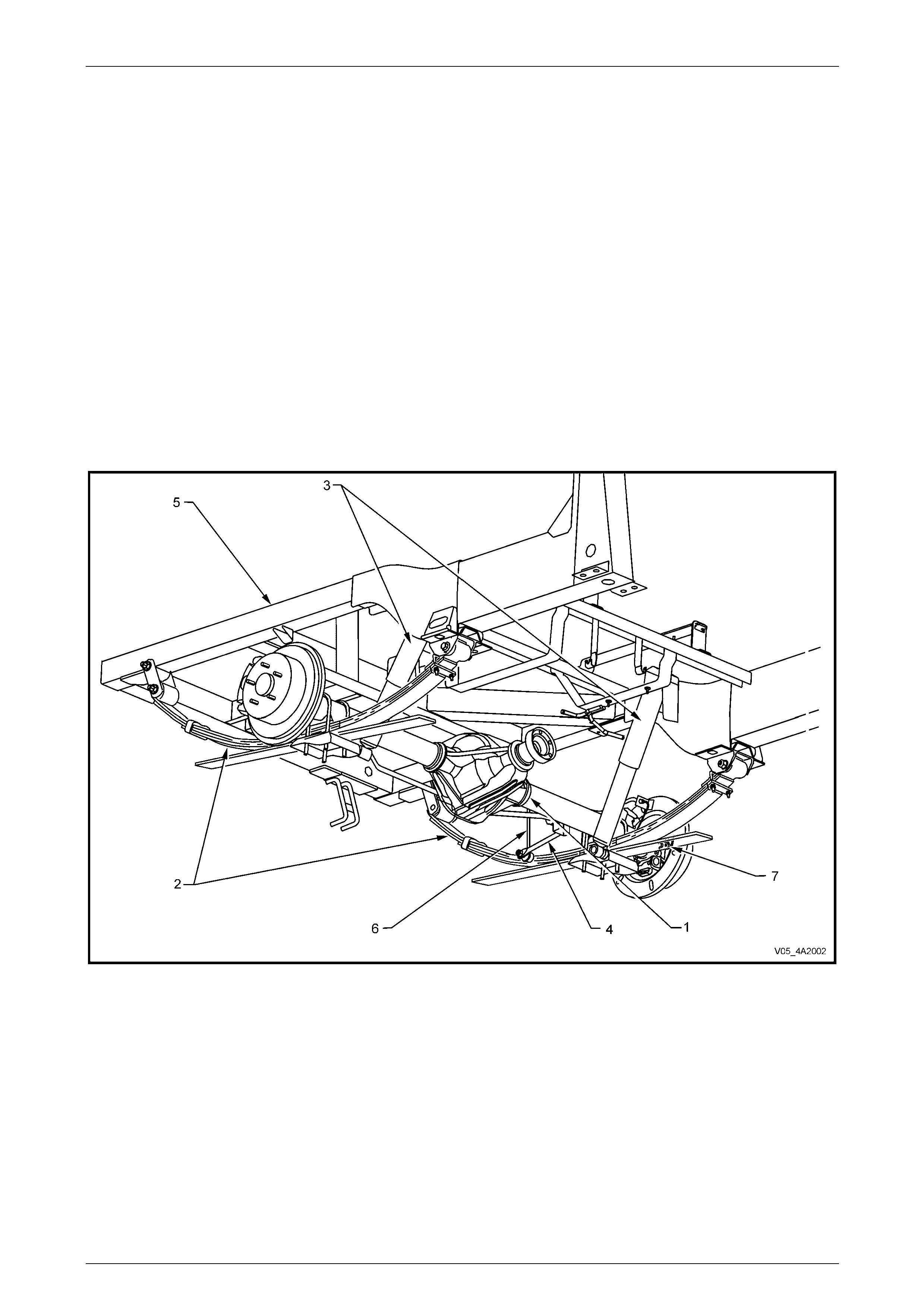
Figure 4A2 – 1
Legend
1 Rear Axle Assembly
2 Rear Leaf Spring Assembly
3 Rear Shock Absorber
4 Rear Suspension Stabiliser
5 Rear Chassis
6 Rear Stabiliser Bar to Chassis Link
7 Rear ABS Sensor
Leaf Spring Rear Suspension Page 4A2–3
Page 4A2–3
2 Service Operations
2.1 Service Warnings, Cautions and Notes
ATTENTION
All fasteners are important attaching parts as they affect the performance of vital components and/or could
result in major repair expense. W here specified in this section, fasteners MUST be replaced w ith parts of the
same part number or an approved equivalent. Do not use fasteners o f an inferior quality or substitute design.
Torque values must be used as specified during reassembly to ensure proper retention of all components.
Throughout this section, fastener torque wrench specifications may be accompanied with the following
identification marks:
Fasteners must be repl aced after loosening.
Vehicle must be at curb height before final tightening.
Fasteners either have micro encapsulated sealant applied or incorporate a mechanical thread lock and
should only be re-used once. If in doubt, replacement is recommended.
If one of these identification marks is present alongside a fastener torque wrench specification, the
recommendation regarding that fastener must be adhered to.
ABS/TC Components
• Whenever any component that forms part of the ABS (if fitted) is disturbed during
Service Operations, it is vital that the complete ABS system be checked, refer to
Section 5B ABS/TCS/ESP General Information.
Road Wheels
• Whenever a road w heel and/or brake di sc is removed from the vehicle, the relationship of the road
wheel and the disc to the hub MUST be marked with a felt tipped pen or similar, to allow those
parts to be reinstalled in their original positions. This is critical to minimise the brake disc and
road wheel runout dimension.
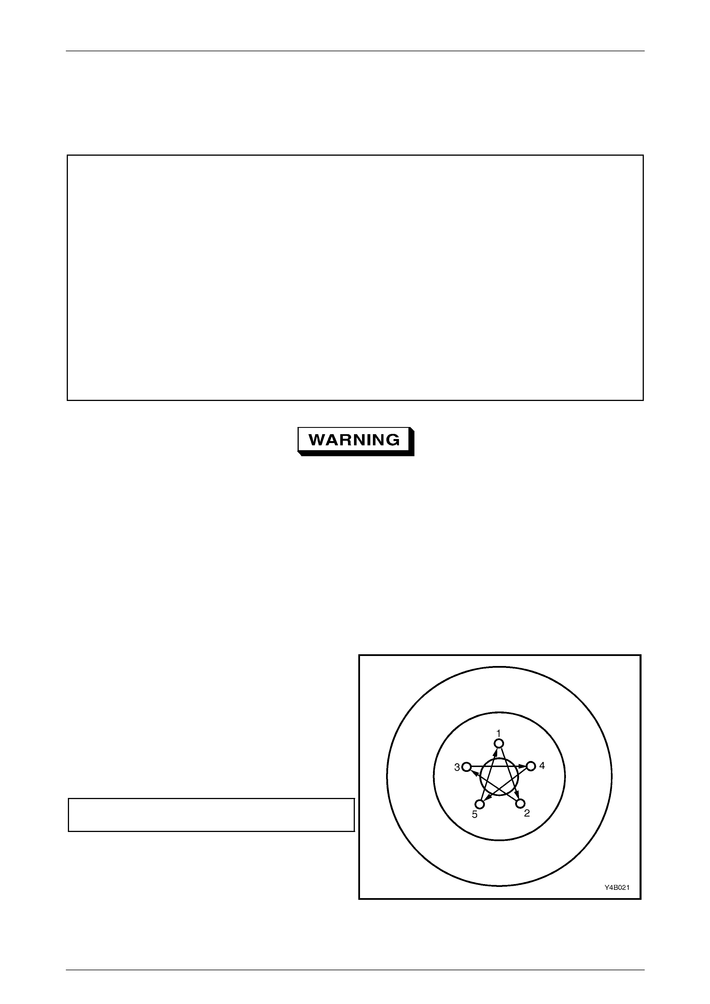
• When reinstalling road wheels, do not use
an impact gun to tighten wheel nuts
unless the impact gun is fitted with a
torque limiter socket (Tool No. AU 534 or
a commercial equivalent). Failure to
correctly tighten w heel nuts to the correct
torque specification and in the correct
order (as shown), may result in a
distorted brake disc, leading to the
development of brake shudder.
Road wheel attaching nut
torque specification................................... 110 – 140 N.m
Figure 4A2 – 2


Leaf Spring Rear Suspension Page 4A2–5
Page 4A2–5
2.3 Rear Leaf Springs
LT Section No: 07-150
ATTENTION
The following fasteners MUST be replaced when performin g these operations:
Rear leaf spring shackle attachin g nuts.
Rear leaf spring eye attaching bolt and nut.
Leaf spring centre bo l t attaching nut.
Rear shock absorber lower mounting attaching bolt.
Rear leaf spring and retainer plate ‘U’ b olt attachin g nuts.
The vehicle MUST be at curb weight and height before final tightening:
Rear leaf spring shackle attachin g nuts
Rear leaf spring eye attaching bolt and nut.
Rear shock absorber lower mounting attaching bolt.
Remove
1 Remove the rear wheel covers, then mark the relationship of the road wheel to one of the wheel studs.
2 Loosen, then remove the road wheel attaching nuts, working in a 'star' pattern. Refer to
2.1 Service Warnings, Cautions and Notes in this Section, for detailed information. Remove the road wheel.
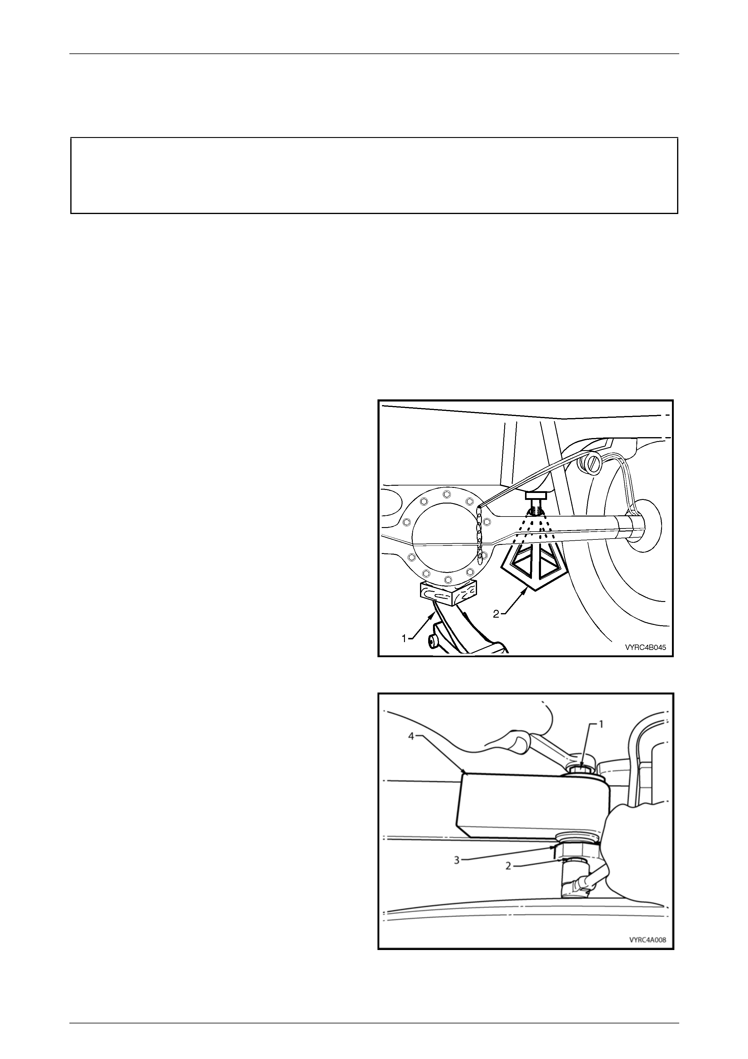
3 Using a floor jack under the centre of the rear axle
assembly (1).
4 Raise the rear of vehicle, then place safety stands
under the rear chassis (2) on both the left-hand an d
right-hand sides to support the weight of the vehicle.
5 With the floor jack still under the centre of the rear axle
assembly, take-up the weight of the rear axle housing,
while observing the leaf springs and sh ackles to gain
the desired height to relieve any spring tension.
6 Place two more safety stands at each side to support
the rear axle assembly weight.
7 Remove the floor jack.
Figure 4A2 – 3
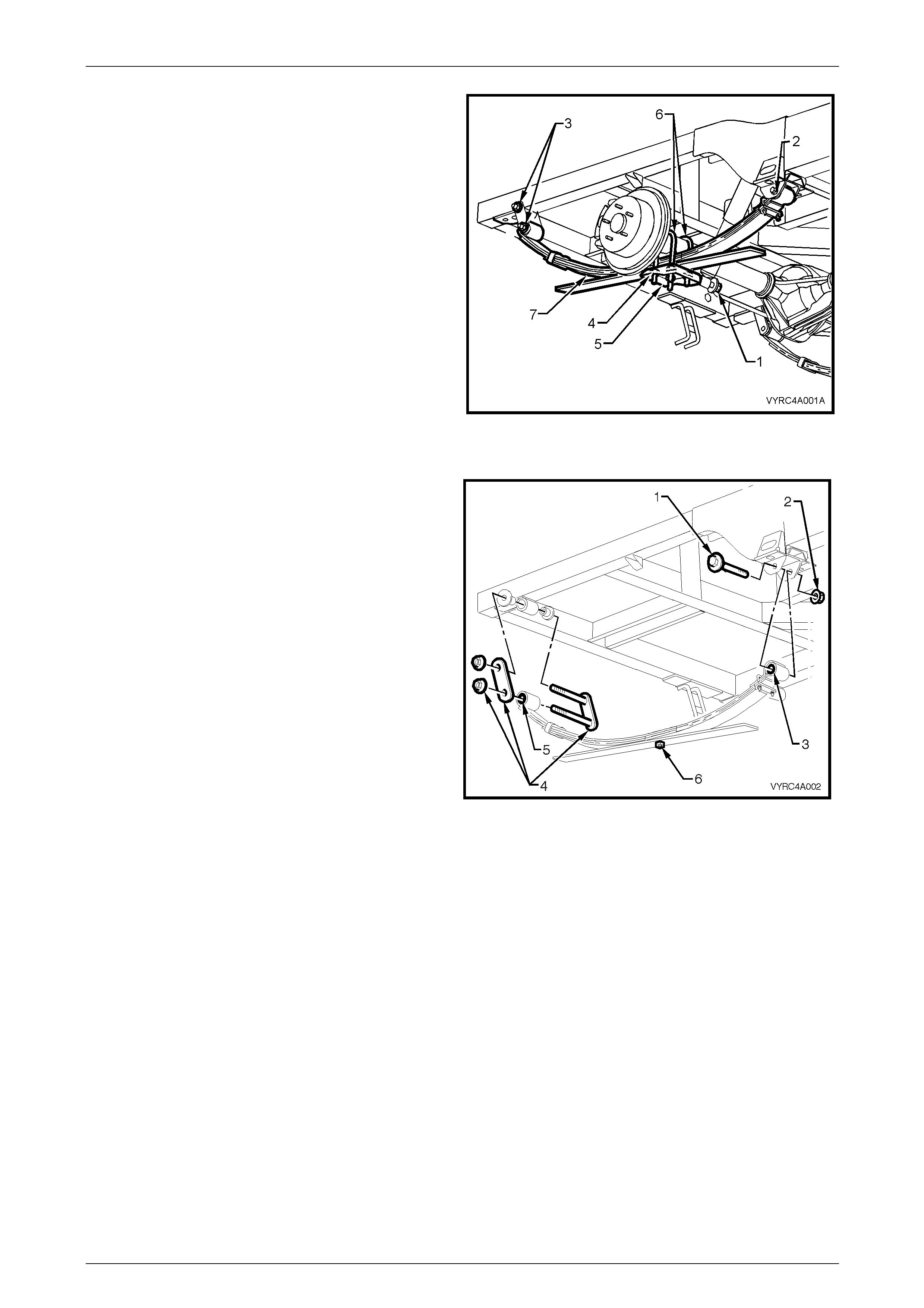
Leaf Spring Rear Suspension Page 4A2–6
Page 4A2–6
8 Using suitable socket equipment, loosen the following
fasteners:
a Lower shock absorber to leaf spring retainer
plate attaching bolt (1).
b Front leaf spring eye to mounting bracket bolt
(2).
c Rear leaf spring shackle attaching nuts (3).
d Rear axle housing to leaf sprin g retain er plate ‘U’
bolt attaching nuts (4).
9 Remove the lower shock absorber to leaf spring
retainer plate attaching bolt (1 ).
10 Remove the screw attaching the park brake cable
bracket to the lower spring leaf.
11 Remove rear axle housing to leaf spring retainer plate
‘U’ bolt attaching nuts (4), leaf spring retai ne r plate (5)
and ‘U’ bolt’s (6).
Figure 4A2 – 4
12 Remove the leaf spring swinging shackle attaching
nuts (4).
13 Remove the shackle plate then slide the sha ckle from
the upper bushings and the spring eye.
14 Remove the leaf spring eye to mounting bracket
attaching bolt (1) and nut (2).
15 Remove the leaf spring assembly (7) from the vehicle.
Figure 4A2-5
Disassemble
1 Using a felt tipped pen or similar, draw a line down the side of the spring, marking each leaf. This will assist in the
correct orientation of the leaves on reassembly.
2 Clamp the leaf spring assembly in a vice fitted with soft jaws, in an area close to the centre bolt. Alternatively a
G-clamp may be used.
3 Remove the leaf spring assembly centre bolt retaining nut (6).
4 Use a suitable pin punch and hammer to remove the centre bolt.
5 Loosen the clamping arrangement to separate the spring leaves.
Leaf Spring Rear Suspension Page 4A2–7
Page 4A2–7
Inspect
Clean all components using a suitab le solvent and inspect the following:
Worn or damaged components must be
replaced.
1 The leaf spring eye bush for excessive wear.
2 The leaf spring shackles and bushes for excessive wear.
3 The general condition of each spring leaf for signs of fatigue or cracking.
4 The interleaf spacers for excessive wear.
5 The centre bolt for straightnes s and excessive wear.
6 Check that the spring shackle hanger br acket fasteners are tightened to the correct torque specification.
Leaf spring shackle mounting plate
to chassis bolt torque specification ......................90 N.m
Reassemble
The procedure for reassembl y of the leaf spring is the reverse of the disassemble procedure noting the following points:
1 If replacing the leaf spring eye or shackle bus hes refer to 2.3 Rear Leaf Spr ing Eye and Shackle Bushes in this
Section.
2 Using the marks made before disassembly, arrange the individu al leaves, to align the centre bolt hole and the felt
tipped pen marks.
3 Before installation, the leaf spring ce ntre bolt should be lightly lubricated with an NLGI No. 2 lithium soap based EP
grease with molybdenum disulphide, such as Shell Retinax HDX2 grease or BP Energrease LMS-EP 23 (or
equivalent).
4 With centre bolt holes aligned in all spring leaves, install the centre bolt with the head upwards.
5 Clamp the spring leaves, then install the centre bolt attaching nut, tightening to the correct torque specification.
Leaf spring centre bolt attaching
nut torque specification........................................25 N.m
Leaf Spring Rear Suspension Page 4A2–8
Page 4A2–8
Reinstall
Take note of those fasteners that must be
replaced and those that are only to be fully
tightened when the vehicle is at curb weight.
1 Reinstall the spring to the vehicle, the n reinstall the front spring eye bolt with the bolt head facing outward.
2 Install a NEW nut but do not fully tighten at this stage. Preli m inary torque of the leaf spring eye, attaching bolt and
nut is for initial set-up only.
Leaf spring eye attaching bolt
and nut (preliminary) torque specification..............5 N.m
3 While supporting the spring, raise and install the rear shackle to the upper bushing and the spring eye bush. The
shackle pin threads are to face outward.
4 Reinstall the shackle plate, then install NEW shackle plate retaining nuts but do not fully tighten at this stage.
Preliminary torque of the shackle plate attaching nuts is for initial set-up o nly.
Leaf spring shackle attaching
nut (preliminary) torque specification.....................5 N.m
5 As required, use the floor jack to positio n and lower the axle housing to index with the spring centre bolt head.
6 Reinstall the two U-bolts and retainer plate.
7 Install NEW U-bolt nuts and tighten progressively and evenly to the correct torque specification.
Leaf spring and retainer plate U-bolt
attaching nut torque specification.........................90 N.m
8 Reinstall the lower shock abs orber b ushing to the leaf spring retailer plate, install the washer and a NEW bolt but
do not fully tighten at this stage. Preliminary torque of the shock absorber attaching bolt is for initial set-up onl y.
Rear shock absorber lower mounting
bolt (preliminary) torque specification ...................5 N.m
9 Reinstall the park brake cable bracket secu ring screw and tighten to the correct torque specification.
Park brake cable bracket retaining
screw torque specification...................................... 8 N.m
10 Lower the vehicle to the ground. Allow the vehicle to stand at curb weight and height. Bounce the rear of the
vehicle to settle the suspension and centre the bushings on their pins. With the vehicle remaini ng in this attitude,
tighten all fasteners to the correct torque specificatio n.
Leaf spring eye attaching
bolt and nut (final) torque specification ..............145 N.m
Leaf spring to shackle attaching
nut (final) torque specification............................110 N.m
Rear shock absorber lower mounting
attaching bolt (final) torque specification............110 N.m
11 Road test the vehicle to check for correct operation.
Leaf Spring Rear Suspension Page 4A2–9
Page 4A2–9
2.4 Rear Leaf Spring Eye and Shackle
Bushes
LT Section No: 07-150
Remove
1 Remove the rear leaf spring assembly; refer to
2.2 Rear Leaf Springs in this Section.
• When removing the bush from the leaf
spring eye, record the force exerted
during the pressing operatio n. If the force
exerted is less than 7.5 k N, the leaf spring
must be replaced.
• A removed eye bush must be replaced
with a new part on reassembly.
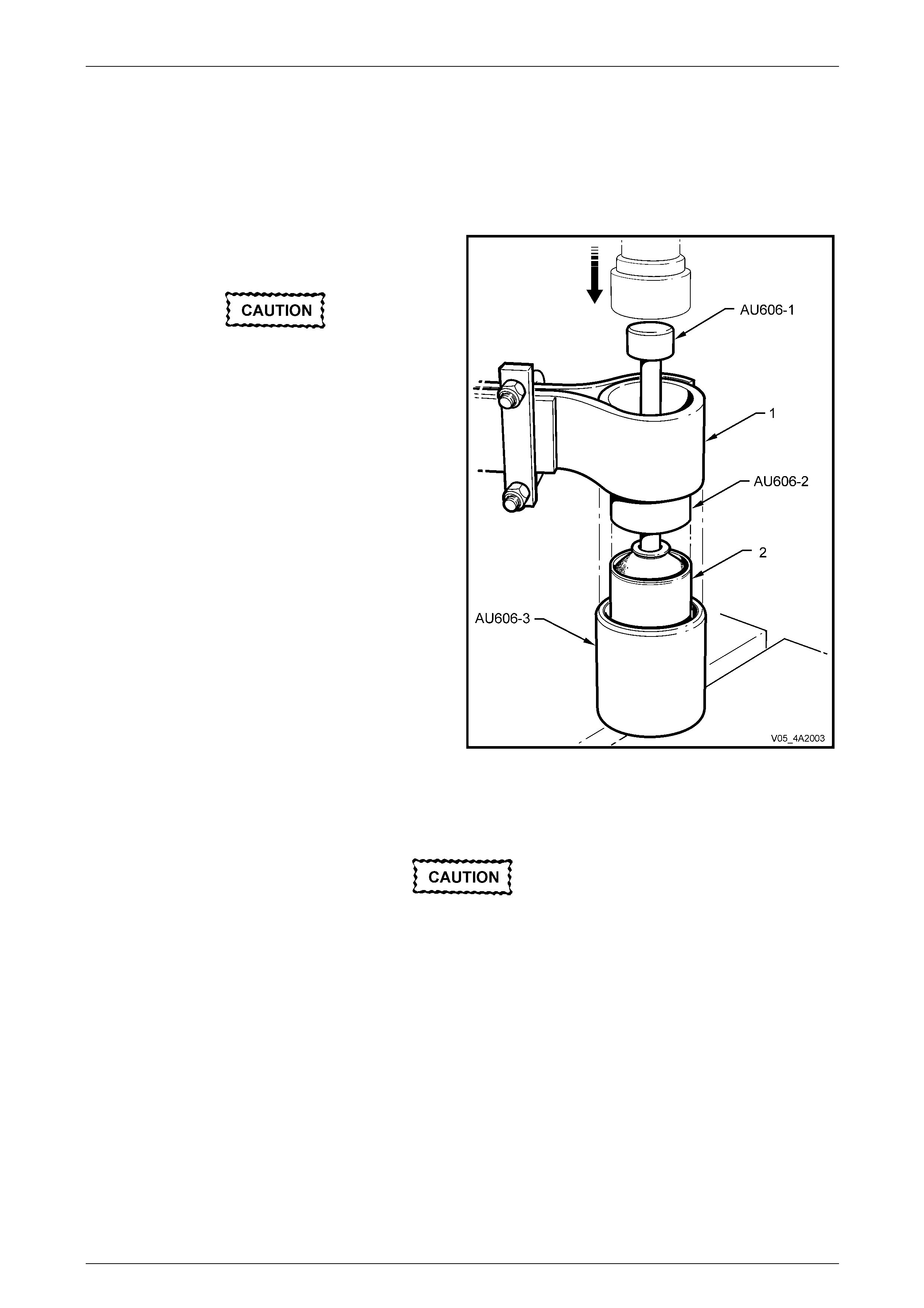
2 Using driver pin AU606-1, re mover AU606-2, receiver
AU606-3 and suitable press, place the leaf spring (1)
along with the tools on suitable press plates.
3 Remove the leaf spring eye bush b y press ing the bush
with AU606-1 and AU606-2, through the eye of the
leaf spring (1) and into the receiver, AU606-3.
4 Remove the shackle bushes from the rear spring eye
by carefully prising the bushes from the leaf sprin g
with a suitable lever.
Figure 4A2 – 6
Inspect
Worn or damaged components must be
replaced.
Clean all components using a suitab le solvent and inspect the following:
1 The leaf spring eye for damage or wear.
2 The leaf spring shackles and bushes for excessive wear.
3 The general condition of the s prin g leaf for si gns of fatigue, cracking or wear.
Leaf Spring Rear Suspension Page 4A2–10
Page 4A2–10
Reassemble
• When installing a new bush to the leaf
spring eye, the force required must
exceed 7.5 kN. If less than this force is
required, the leaf spring must be
replaced.
• A removed eye bush must be replaced
with a new part on reassembly.
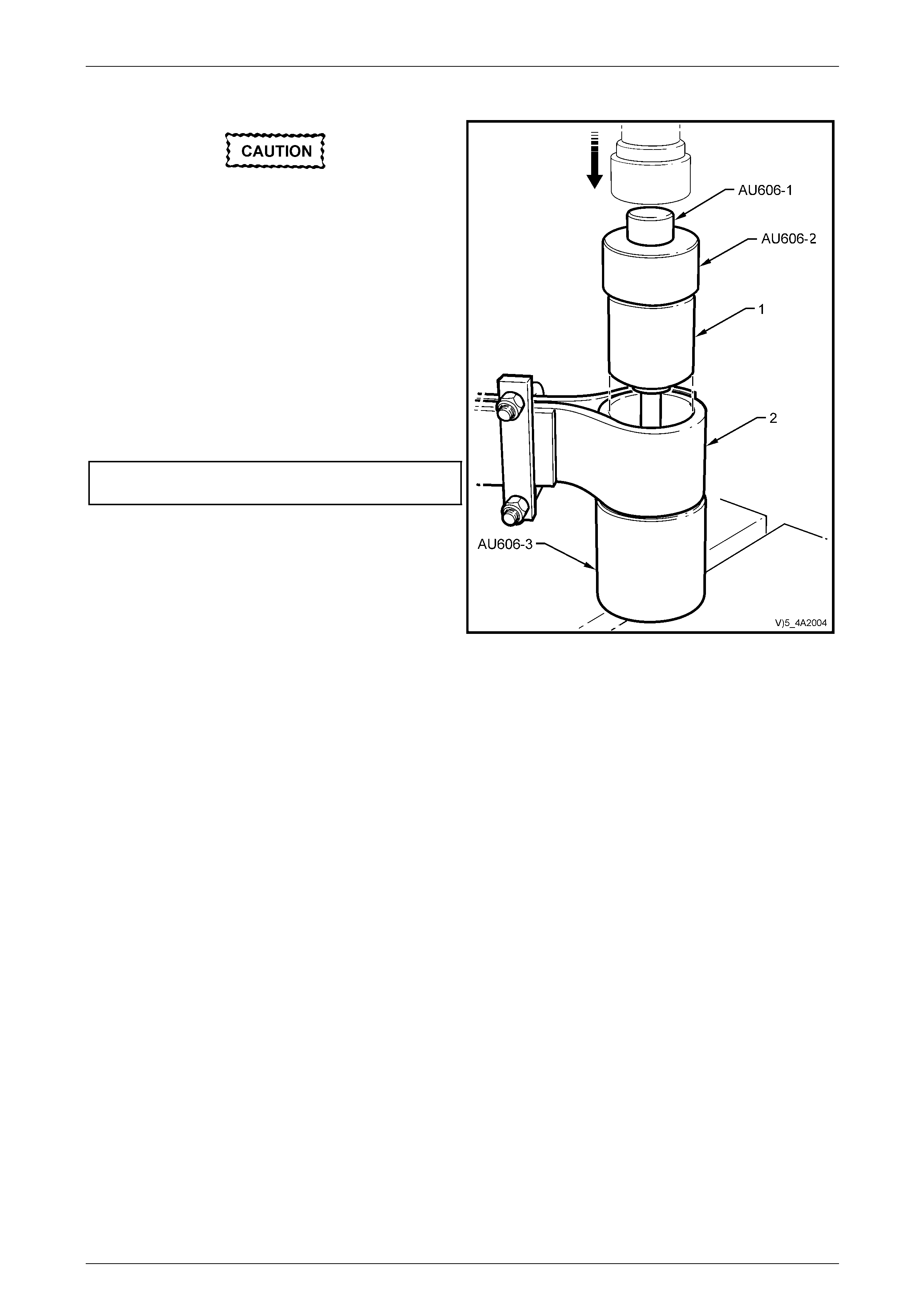
1 Using Tool No’s. AU606-1, AU606-4, AU606-3 and a
suitable press, place the leaf spring (2) along with the
leaf spring eye bush (1) on a suitable press plate.
2 Press the bush into the leaf spring eye (2) using
AU606-1, AU606-4 and AU606-3 to guide the new
bush (1) into the leaf spring eye (2).
Leaf spring eye bush
minimum press force.........................................7.5 kN
3 Install the rear shackle bushes by hand into the leaf
spring using soapy water or rubber grease to assist
installation.
4 Reinstall the leaf spring ass embly; refer to
2.2 Rear Leaf Springs in this Section.
5 Road test the vehicle yo check for correct vehicle
operation. Figure 4A2 – 7
Leaf Spring Rear Suspension Page 4A2–11
Page 4A2–11
2.5 Rear Leaf Spring Mass Damper
LT Section No: 07-150
ATTENTION
The following fasteners MUST be replaced when performin g this operation:
Rear leaf spring damper attaching bolt and nut.
NOTE
Rear spring mass dampers are fitted to vehicles
equipped with V6 automatic transmission and
GEN III V8 manual transmission configurations
only. The mass damper is attached to both rear
leaf spring assembly r etainer plates to reduc e the
amount of driveline noise transmitted to cabin of
the vehicle.
Remove
1 Using a floor jack under the centre of the rear axle
assembly (1), raise the rear of vehicle.
2 Place safety stands under the rear chassis (2) on both
sides of the vehicle.
3 Lower the jack to allow the rear axle to han g down
under its own weight.
Figure 4A2 – 8
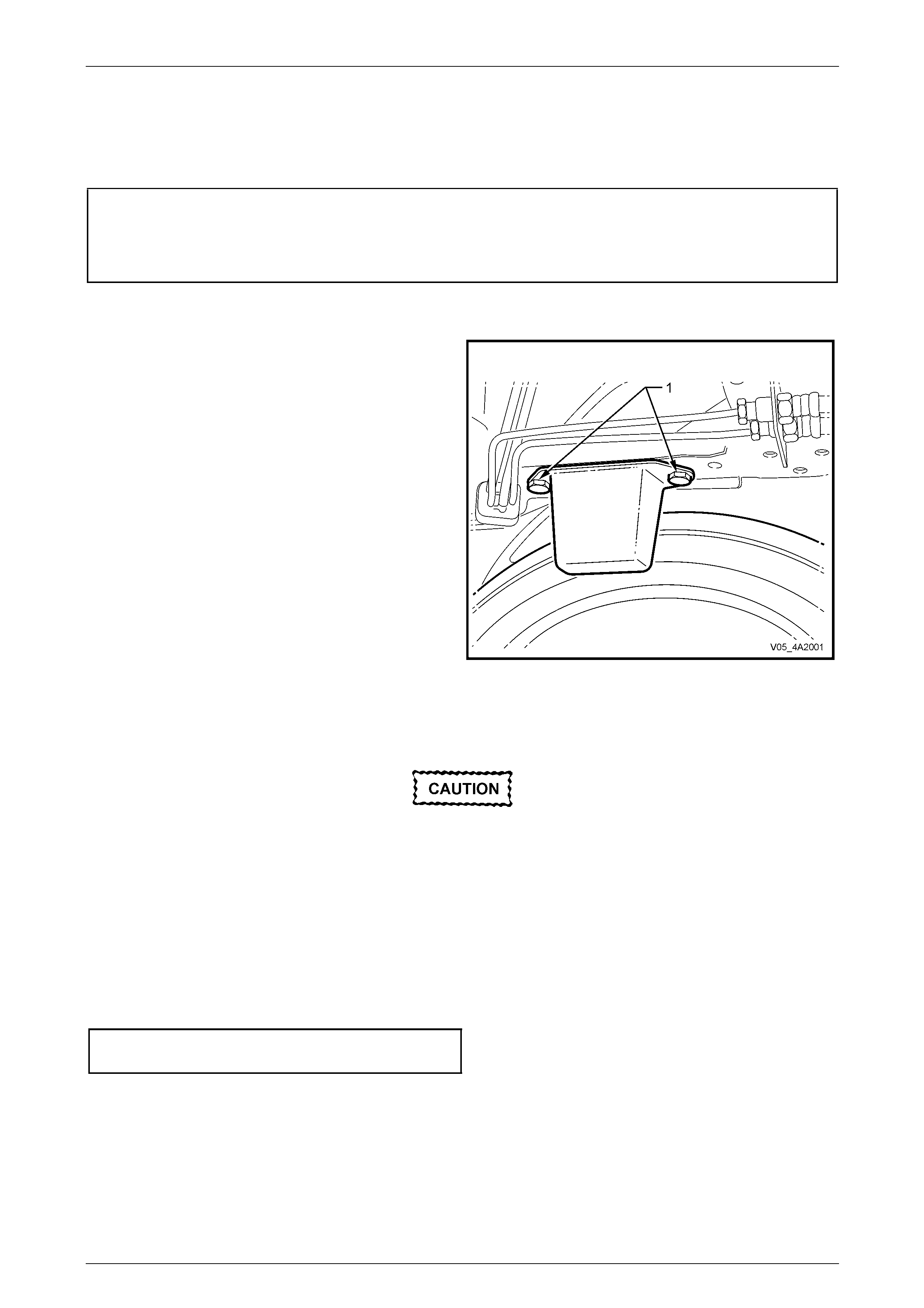
4 Using suitable spanners, remove the mass damper
retaining bolt (1) and nut (2) from the leaf spring
retainer plate (3).
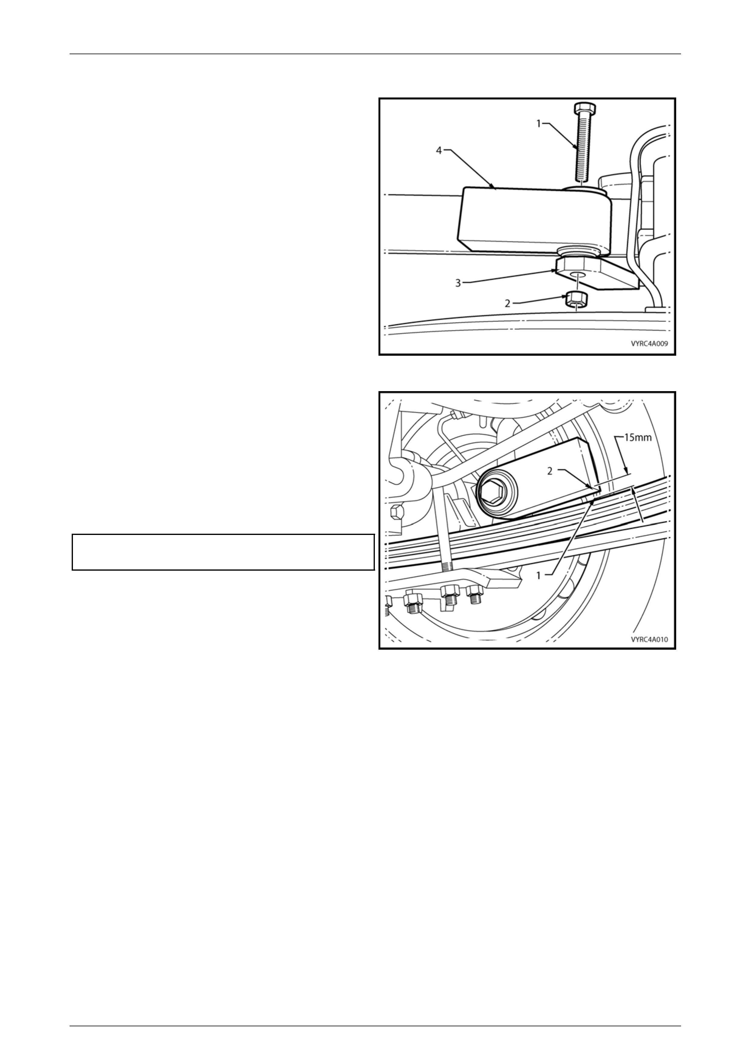
5 Remove the mass damper (4) from the vehicle.
Figure 4A2 – 9
Leaf Spring Rear Suspension Page 4A2–12
Page 4A2–12
Reinstall
1 Loosely install the mass damper (4), the retaining bolt
(1) and nut (2) to the leaf spring retainer plate (3).
Figure 4A2 – 10
NOTE
The mass damper must have a clearance of
15 mm minimum from the upper surface of the
main leaf with the leaf spring in the full hang
position.
2 While maintaining this minimum clearance, tighten the
mass damper retaining bolt and nut to the cor rect
torque specification.
Mass damper retaining bolt
and nut torque specification.................................90 N.m
3 Lower the vehicle to the ground an d road test for
correct operation.
Figure 4A2 – 11
Leaf Spring Rear Suspension Page 4A2–13
Page 4A2–13
2.6 Rear Shock Absorbers
LT Section No: 07-150
ATTENTION
The following fasteners MUST be replaced when performin g this operation:
Rear shock absorber upper mounting attaching nut.
Rear shock absorber lower mounting attaching bolt.
The following fasteners MU ST have the vehicle at curb weight before final tightening.
Rear shock absorber lower mounting attaching bolt.
Rear Shock Absorber Identification
Different specification shock absorbers are fitted to the rear suspension. Always check the current release of Partfinder™
for the correct shock absorber replacement.
Remove
1 Using a floor jack under the centre of the rear axle
assembly, raise the rear of the vehicle, then place
safety stands under the chassis to support the vehicle
weight.
2 Leave the floor jack under the centre of the rear axle
to assist in removing the shock absorber.
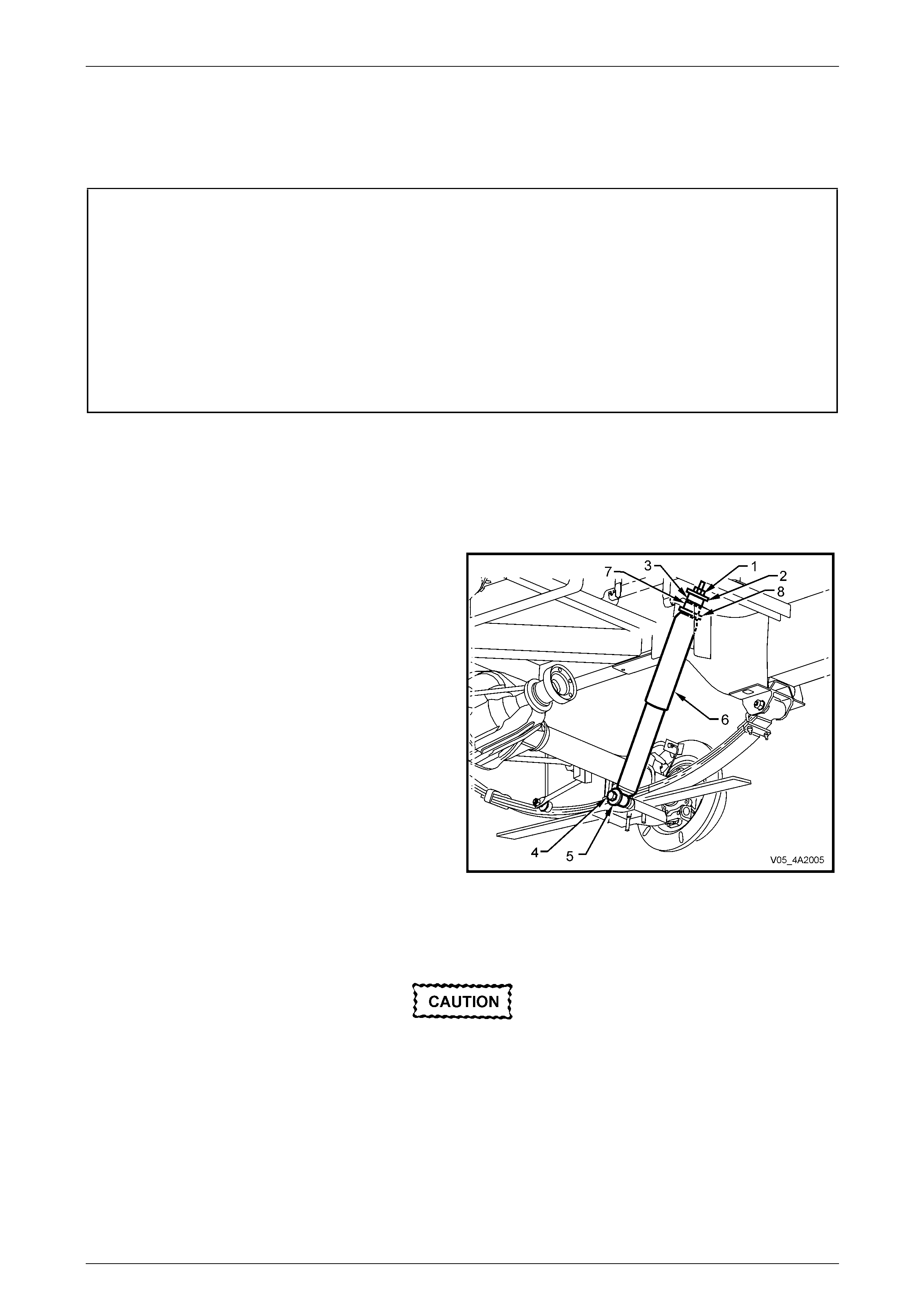
3 Using suitable spanners, remove the upper shock
absorber attaching nut (1), washer (2) and mounting
bush (3).
4 Lower the floor jack enough to remove any load on the
shock absorber.
5 Remove the lower shock absorber attaching bolt (4)
and flat washer (5).
6 Remove the shock absorber (6) from the vehicle.
7 Remove the remaining upper mounting bush (7) and
support washer (8) from the shock absorber. Figure 4A2 – 12
Inspect
Worn or damaged components must be
replaced.
Clean all components using a suitab le solvent and inspect the following:
1 The upper and lower shock absorber b ush es for excessive wear.
2 The shock absorber action.
3 The general condition of the shock absorber mounting points of the chassis and rear ax le.
Leaf Spring Rear Suspension Page 4A2–14
Page 4A2–14
Reinstall
Take note of those fasteners that must be
replaced and those that are only to be fully
tightened when the vehicle is at curb weight.
1 Reinstall the upper mounting lower plate and bushing to the shock absorber stem.
2 Reinstall the shock absorber to the upper mounting plate and install the upper b ush ing and plate to the stem,
securing with a NEW nut.
3 Tighten the upper shock absorber mou nting nut to the correct torque specification.
Rear shock absorber upper mount
attaching nut torque specification.........................48 N.m
4 Reinstall the lower shock abs orber mo unt to the lower mounting.
5 Install a NEW lower mounting bolt but onl y tighten to a preliminary torque at this stage.
Rear shock absorber lower mounting
bolt (preliminary) torque specification ....................5 N.m
6 Lower the vehicle to the ground.
7 With the vehicle at curb height and weight, bounce the rear of the vehicle several times to settle the suspension.
8 Tighten the lower shock absorber mounting bolt to the correct torque specification.
Rear shock absorber lower mounting
bolt (final) torque specification ...........................110 N.m
9 Road test the vehicle to check for correct operation.
Leaf Spring Rear Suspension Page 4A2–15
Page 4A2–15
2.7 Rear Stabiliser Bar
LT Section No: 07-125
ATTENTION
The following fasteners MUST be replaced when performin g this operation:
Rear stabiliser bar mounting to rear axle housing attaching bolt.
The following fasteners have either micro encapsulation or incorporate a mechanical thread lock and should
only be used once. If in doubt, replacement is recommended when performing this operation:
Rear stabiliser bar link upper and lower ball joint attaching nut.
Remove
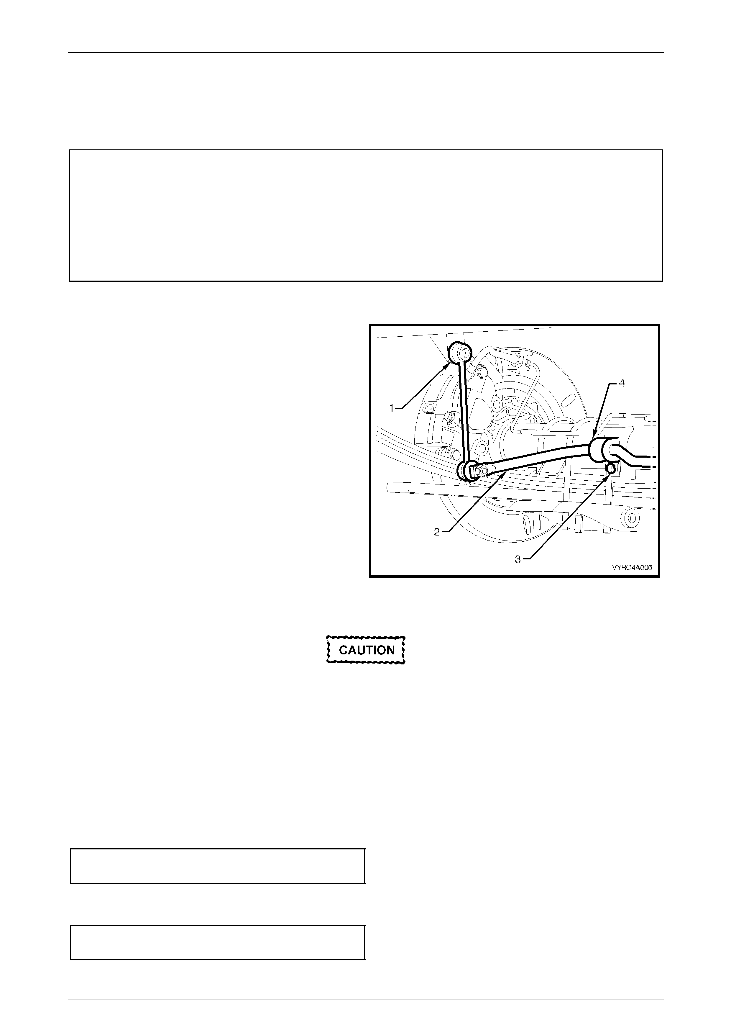
1 Using suitable spanners, remove the stabiliser bar (2),
upper drop link ball joint (1) from each side of the
chassis.
2 Remove each attaching bolt (3) securi ng the stabiliser
bar mounting brackets (4) to the rear axle housing.
Figure 4A2 – 13
Inspect
Worn or damaged components must be
replaced.
Clean all components using a suitable solvent and inspect for the following:
1 Excessive wear in either the upper or lower upper drop link ball joints.
2 The stabiliser bar mountings and the g eneral condition of the stabiliser mounting p oints of the chassis and rear
axle.
Reinstall
1 Reinstall the stabiliser rubber mounts and brackets to the stabiliser bar.
2 Reinstall the stabiliser bar and reinstall the mounting brackets, securing with NEW bolts tightened to the correct
torque specification.
Rear stabiliser bar mounting to rear
axle housing bolt torque specification..................25 N.m
3 Reinstall the rear stabiliser bar drop link upper and lower ball joints to the stabiliser bar and chass is brackets.
4 Reinstall securing nuts to each ball joint stud, tightening to the correct torque specification.
Rear stabiliser bar link upper and l ower
ball joint attaching nut torque specification ..........50 N.m
Leaf Spring Rear Suspension Page 4A2–16
Page 4A2–16
2.8 Rear Suspension Bump Stop
LT Section No: 07-150
ATTENTION
The following fasteners MUST be replaced when performin g this operation:
Rear suspensi o n bump stop, attaching bolt.
Remove
1 Using suitable spanners remo ve the bump stop
attaching bolts (1). Discard the removed bolts.
2 Remove the bump stop from the vehicle.
Figure 4A2 – 14
Inspect
Worn or damaged components must be
replaced.
1 Clean all components using a suitable solvent and inspect the following:
2 The general condition of the bump stop and mounting points to the chassis.
Reinstall
1 Reinstall the bump stop and secure with two NEW bolts.
2 Tighten both bump stop retaining bolts to the correct torque specification.
Rear suspension bump stop
attaching bolt torque specification........................25 N.m
Leaf Spring Rear Suspension Page 4A2–17
Page 4A2–17
3 Diagnosis
3.1 Checking and Testing Shock Absorbers
Preliminary Checks
1 Before proceeding with the removal of shock absorb er assemblies, it is go od practise to check and make sure the
noise is not coming from some other source.
2 Conduct a visual inspection of all shock absorber components and other rear suspension related components,
checking for anything that may appear unusual.
3 Check the torque of all attaching fasteners for tightness an d check all mounting bushes for alignment. If the bushes
are worn, loose fitting or misaligned, they must be replaced.
Testing Shock Absorber Action
:
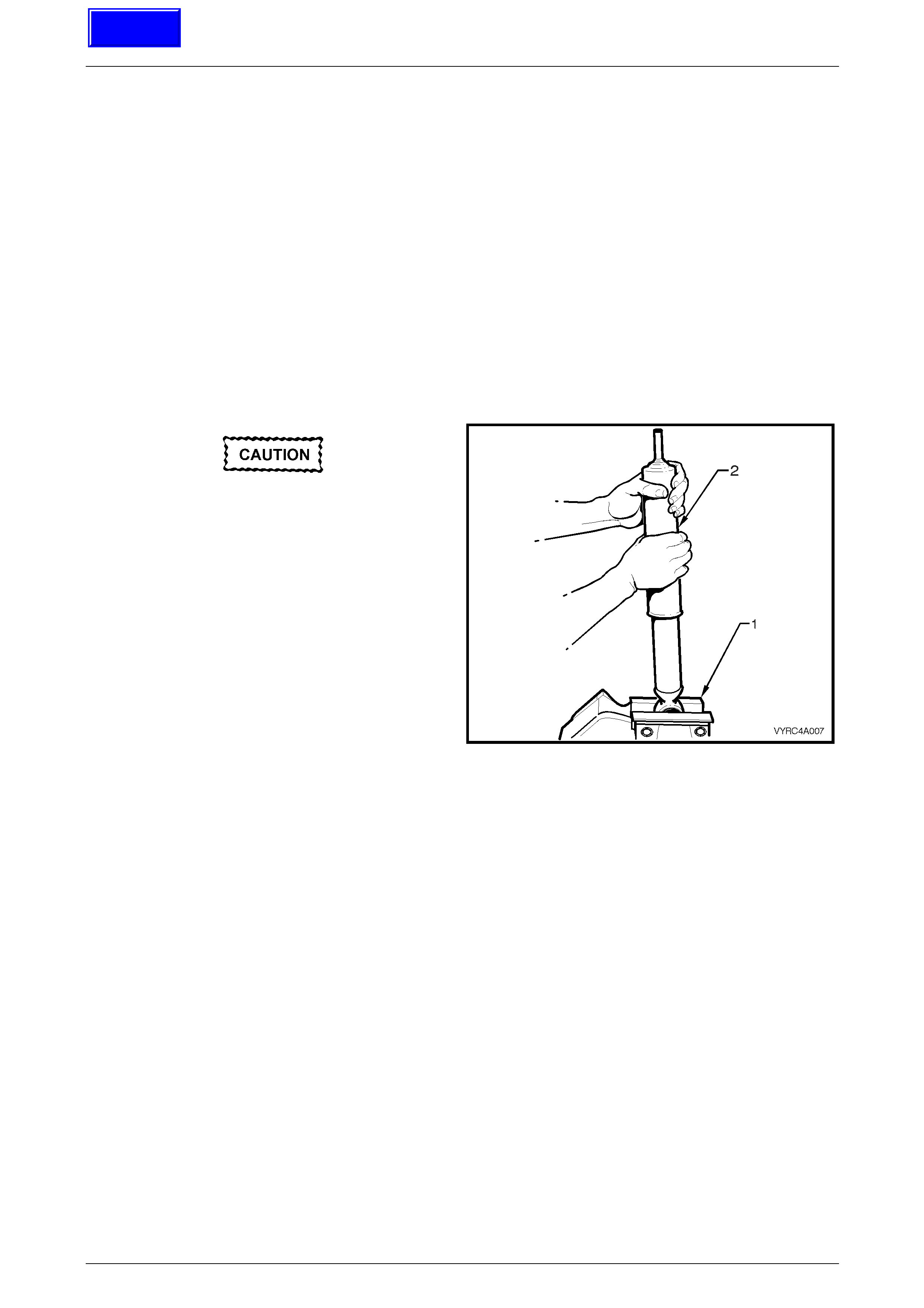
The following test is for non-gas pressurised
shock absorbers.
1 Using a suitable vice equipped with soft jaw’s (1),
support the shock absorber (2) by its lo wer mount.
2 Slowly pump the shock absorber up an d down its full
stroke at least six times to prime the internal valves of
the shock absorber.
3 Move the shock absorber up and down at various
rates of speed while monitoring the resistance. The
resistance should be consistent throughout both
stokes and there should be no slack spots. If slack
spots are detected this indicates either a lack of oil or
the internal valves are defective.
NOTE:
It is normal for a hissing (orifice swish) noise to
be detected during shock abs orber testing.
Figure 4A2 – 15
4 The following conditions are considered outside the normal functio n parameters and replacement is recommended:
a A skip or lag at reversal of the stroke mid way through.
b A seize (except at the extreme end of travel).
c A noise such as a grunt or squeal after the completing one full stroke in both directions.
d A clicking noise at fast reversal of the stroke.
e Fluid leakage.
Techline

Leaf Spring Rear Suspension Page 4A2–18
Page 4A2–18
4 Specifications
General
Rear Suspension Assembly.............................................................................................Dana
Type..............................................................Hotchkiss Drive with Semi-elliptical leaf springs)
Number of Primary Leaves.....................................................................................................3
Number of Secondary Leaves ................................................................................................1
Shock Absorber
Hydraulic (non-adjustable)..................................................................................Double acting
Application Code
Regular Cab – V6................................................................................................................BZ
Regular Cab – V8................................................................................................................BZ
Crew Cab – V6 ...................................................................................................................WA
Crew Cab – V8 ...................................................................................................................WA
Stabiliser Bar (Where Fitted)
Torsional Steel Bar with Drop Link Ball Joint Mounting .................................................14 mm
Thread Locking Compound
Rear Suspension Fasteners .......................................Loctite 242 or commercial equivalent to
GM Specification 9985283.

Leaf Spring Rear Suspension Page 4A2–19
Page 4A2–19
5 Torque Wrench Specifications
ATTENTION
Fasteners must be repl aced after loosening.
Vehicle must be at curb height and weight before final tightening.
Fasteners either have micro encapsulated sealant applied or incorporate a mechanical thread lock and
should only be re-used once. If in doubt, replacement is recommended.
Leaf Spring and Retainer Plate ‘U’ Bolt Attaching Nuts..........................90 N.m
Leaf Spring Centre Bolt Attaching Nut....................................................25 N.m
Leaf Spring Eye Mounting Plate to Chassis Attaching Bolts ...................90 N.m
Leaf Spring Eye Attaching Bolt And Nut (Preliminary)..............................5 N.m
Leaf Spring E ye Attaching Bolt And Nut (Final)....................................145 N.m
Leaf Spring Shackle Attaching Nuts (Preliminary)....................................5 N.m
Leaf Spring Shackle Attaching Nuts (Final)..........................................110 N.m
Leaf Spring Shackle Mounting Plate to Chassis Attaching Bolts............90 N.m
Mass Damper Attaching Bolt and Nut.....................................................90 N.m
Park Brake Cable Bracket Screw.............................................................8 N.m
Rear Shock Absorber Upper Mounting Attaching Nut ...........................48 N.m
Rear Shock Absorber Lower Mounting Attaching Bolt (Preliminary) ........5 N.m
Rear Shock Absorber Lower Mounting Attaching Bolt (Final)...............110 N.m
Rear Stabiliser Bar Mounting Attaching Bolt...........................................25 N.m
Rear Stabiliser Bar Link Upper and Lower Ball Joint Attaching Nut ......50 N.m
Rear Suspension Stop Bump To Chassis Frame Attaching Bolt............25 N.m
Road Wheel Attaching Nut.........................................................110 – 140 N.m
Leaf Spring Rear Suspension Page 4A2–20
Page 4A2–20
6 Special Tools
Tool Number Illustration Description Classification
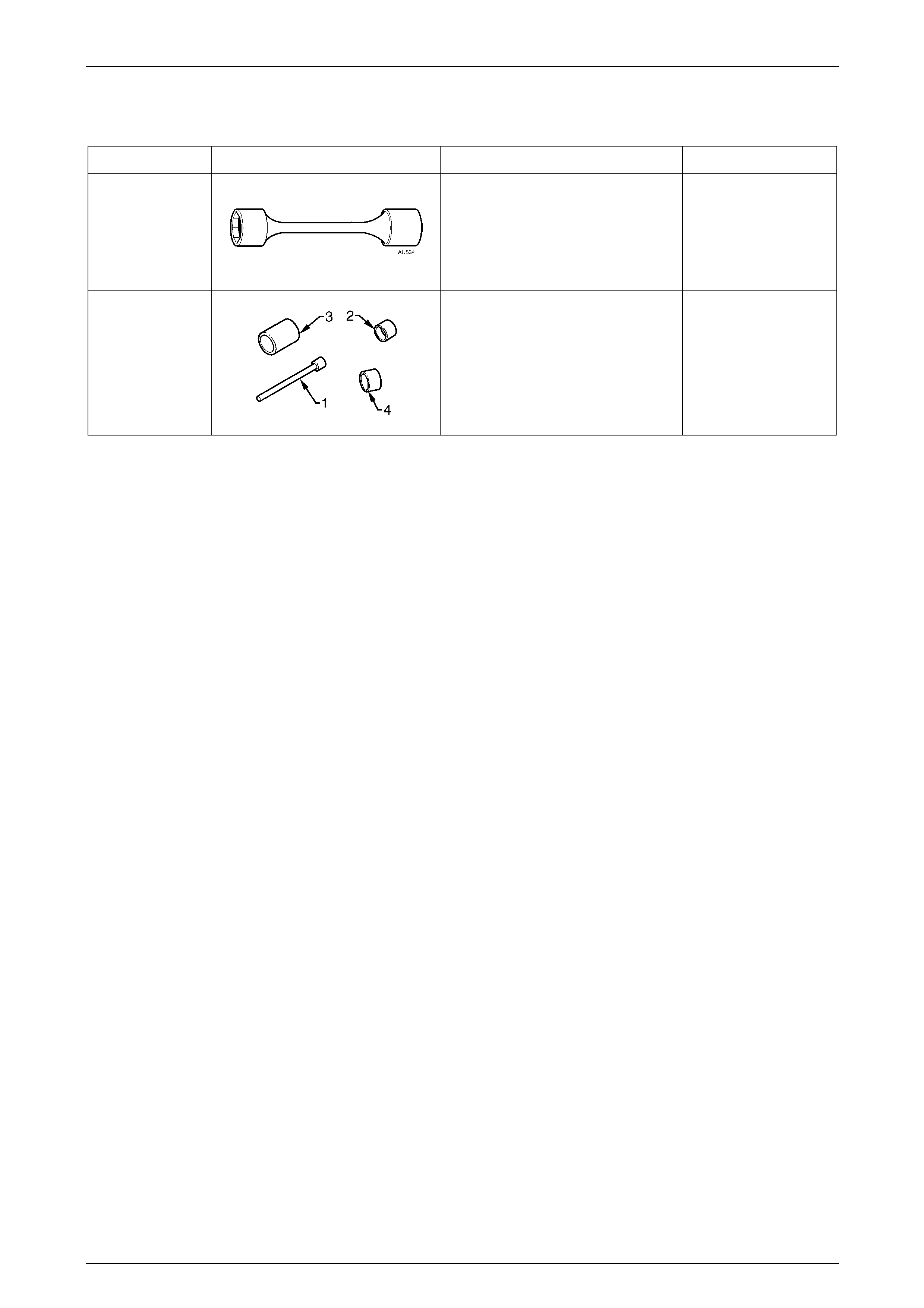
AU534
Torque Limiting Socket
Required when tightening ro ad
wheel nuts with an impact tool.
Also commercially available
Previously released.
Mandatory
AU606
Press Tool
Used to remove/install leaf spring
eye bush. Comprises:
1. AU606-1 – Centre Spigot
2. AU606-2 – Bush Remover
3. AU606-3 – Bush Catcher
4. AU606-4 – Bush Installer
Unique