
Rear Final Drive and Drive Shafts Page 4B1-1
Page 4B1-1
Section 4B1
Rear Final Drive and Drive Shafts
ATTENTION
Before performing any Service Operation or other procedure described in this Section, refer to Section 00
Warnings, Cautions and Notes for correct workshop practices with regard to safety and/or property damage.
1 General Description ...............................................................................................................................4
1.1 Final Drive Assembly Identification ..................................................................................................................... 7
Final Drive Applications........................................................................................................................................ 7
1.2 Final Drive Assembly Maintenance...................................................................................................................... 8
Maintenance........................................................................................................................................................... 8
Drive Shaft Bearings and Constant Velocity Joints ............................................................................................ 8
Differential Carrier Assembly.............................................................................................................................. 8
Final Drive Assembly Breather........................................................................................................................... 8
Limited Slip Differential Warnings........................................................................................................................ 8
Lubrication ............................................................................................................................................................. 9
2 Minor Service Operations....................................................................................................................10
2.1 General Information............................................................................................................................................. 10
Important Service Requirements........................................................................................................................ 10
2.2 Checking Differential Carrier Lubricant Level................................................................................................... 11
2.3 Changing/Flushing Rear Axle Lubricant............................................................................................................ 12
2.4 Trailing Arm Outer Rear Wheel Driveshaft Assembly Hub............................................................................... 13
Check for Run-Out............................................................................................................................................... 13
If Run-out is Within Specification....................................................................................................................... 15
If the Run-out Check, Exceeds Specification.................................................................................................... 15
2.5 Trailing Arm Outer Rear Wheel Driveshaft Assembly Hub Studs.................................................................... 16
Replace................................................................................................................................................................. 16
2.6 Limited Slip Differential....................................................................................................................................... 20
Torque Check....................................................................................................................................................... 20
2.7 Drive Shaft Assembly.......................................................................................................................................... 23
Remove................................................................................................................................................................. 23
Reinstall................................................................................................................................................................ 23
2.8 Drive Shaft and/or Constant Velocity Joints ..................................................................................................... 24
Disassemble......................................................................................................................................................... 24
Inspect .................................................................................................................................................................. 26
Drive Shaft and Boots ...................................................................................................................................... 26
Constant Velocity Joints................................................................................................................................... 26
Reassemble.......................................................................................................................................................... 27
Constant Velocity Joints................................................................................................................................... 27
Drive Shaft and Boots ...................................................................................................................................... 31
2.9 Inner Axle Shaft Seal ........................................................................................................................................... 33
Replace................................................................................................................................................................. 33
Techline
Techline
Techline
Techline
Techline
Techline
Techline
Techline

Rear Final Drive and Drive Shafts Page 4B1-2
Page 4B1-2
2.10 Pinion Oil Seal...................................................................................................................................................... 35
Replace (Vehicles With a Rear Rubber Coupling)............................................................................................. 35
Replace (Vehicles With a Rear Constant Velocity Joint).................................................................................. 38
2.11 Pinion Flange ....................................................................................................................................................... 41
Replace (Vehicles With a Rear Rubber Coupling)............................................................................................. 41
Using Old Oil Seal............................................................................................................................................ 41
Replace (Using New Oil Seal).......................................................................................................................... 43
Replace (Vehicles With a Rear Constant Velocity Joint).................................................................................. 47
Using Old Oil Seal............................................................................................................................................ 47
Using New Oil Seal .......................................................................................................................................... 49
3 Major Service Operations....................................................................................................................53
3.1 Outer Rear Wheel Driveshaft Flange Outer Rear Wheel Driveshaft Assembly and/or Wheel Bearing......... 53
Remove................................................................................................................................................................. 54
Reinstall................................................................................................................................................................ 60
To Install a New Bearing.................................................................................................................................. 60
To Reinstall Outer Rear Wheel Drive Shaft...................................................................................................... 61
3.2 Final Drive Assembly........................................................................................................................................... 65
Remove................................................................................................................................................................. 65
Reinstall................................................................................................................................................................ 70
3.3 Removed Final Drive Assembly.......................................................................................................................... 75
Disassemble......................................................................................................................................................... 76
For AWD Wagon Models.................................................................................................................................. 79
For RWD VZ Models........................................................................................................................................ 80
All VZ Models with IRS..................................................................................................................................... 81
Differential Case............................................................................................................................................... 83
Inspect .................................................................................................................................................................. 85
Differential Case............................................................................................................................................... 85
Differential Side Gears and Pinion Gears......................................................................................................... 85
Ring Gear and Pinion....................................................................................................................................... 86
Bearings........................................................................................................................................................... 86
Differential Carrier............................................................................................................................................ 86
Screw Adjusters and Inner Axle Shafts............................................................................................................ 87
Rear Cover....................................................................................................................................................... 87
Reassemble.......................................................................................................................................................... 88
Differential Case............................................................................................................................................... 88
Differential Case Side Bearing Pre-Load Setting ............................................................................................. 91
Hypoid Pinion Positioning Shim Selection ........................................................................................................ 92
MY 2005 VZ Series Vehicles with the 3.08:1 Ratio Axle Assembly..................................................................92
MY 2005 VZ Series Vehicles with Other Ratio Axle Assemblies...................................................................... 93
Pinion Installation................................................................................................................................................ 95
For VZ AWD Models ........................................................................................................................................ 96
For All RWD Models......................................................................................................................................... 97
For All Models .................................................................................................................................................. 98
For AWD Models.............................................................................................................................................. 98
For All RWD Models......................................................................................................................................... 99
For All Models .................................................................................................................................................. 99
Differential Backlash Setting .............................................................................................................................. 99
Ring Gear and Pinion Contact Pattern............................................................................................................. 100
Tooth Marking Nomenclature......................................................................................................................... 100
Ideal Contact.................................................................................................................................................. 102
Acceptable Heel Contacts.............................................................................................................................. 102
Acceptable Toe Contacts ............................................................................................................................... 103

Rear Final Drive and Drive Shafts Page 4B1-3
Page 4B1-3
3.4 Limited Slip Differential..................................................................................................................................... 104
Disassemble....................................................................................................................................................... 104
Inspect ................................................................................................................................................................ 107
Differential Case............................................................................................................................................. 107
Differential Side Gears and Pinion Gears....................................................................................................... 107
Ring Gear and Pinion..................................................................................................................................... 107
Bearings......................................................................................................................................................... 108
Reassemble........................................................................................................................................................ 108
3.5 Rear Axle ............................................................................................................................................................ 112
Reassemble........................................................................................................................................................ 112
4 Diagnosis ............................................................................................................................................113
4.1 General Information........................................................................................................................................... 113
Road Test ........................................................................................................................................................... 113
Tyre Noise .......................................................................................................................................................... 113
Front Wheel Bearings........................................................................................................................................ 113
Transmission Rear Bearing (Manual Transmission) ...................................................................................... 114
Backlash Clunk.................................................................................................................................................. 114
Drive-Line Snap.................................................................................................................................................. 114
Engine and Other Contributing Factors........................................................................................................... 114
4.2 Final Drive Assembly Noise.............................................................................................................................. 115
Gear Related Noise............................................................................................................................................ 115
Ring Gear and Pinion Noise........................................................................................................................... 115
Differential Side Gear and Pinion Noise......................................................................................................... 115
Common Causes of Gear Related Noises ..................................................................................................... 115
Bearing Related Noise....................................................................................................................................... 116
Differential Pinion Gear Bearings................................................................................................................... 116
Outer Rear Wheel Drive Shaft Wheel Bearings ............................................................................................. 116
Differential Side Bearings............................................................................................................................... 116
Common Causes of Bearing Related Noises................................................................................................. 116
4.3 LSD Noise........................................................................................................................................................... 117
4.4 Final Drive Bearing Diagnosis.......................................................................................................................... 118
5 Specifications.....................................................................................................................................121
6 Torque Wrench Specifications..........................................................................................................123
7 Special Tools ......................................................................................................................................124
Rear Final Drive and Drive Shafts Page 4B1-4
Page 4B1-4
1 General Description
Independent rear suspension (IRS) is fitted as standard equipment on all MY 2005 VZ Series vehicles except for those
fitted with rear leaf spring suspension. All are fitted with a rear final drive assembly with a four pinion type differential
assembly. The ring gear diam eter and ratio varies with different applications;
refer to 1.1 Final Drive Assembly Identification, in this Section.
Production option G80, Limited Slip Differential (LSD), (also referred to as Spin Resistant Differential – SRD) is avai lable
on selected models. While the majority of illustrations shown in this Section relate to vehicles fitted with the ABS braking
system, service procedures are the same for vehicles equipped with standard brakes, unless otherwise noted.
The final drive assembly is mounted directly to a crossmember which is rubber mounted to the vehicle u nderbody. The
differential case and drive pinion are mounted in opposed taper roller bearings in the carrier. Differential case side
bearing pre-load adj ustment is provided by scre w adjusters in the sides of the case, while pinion bearing pre-load is
provided by a collapsible spacer. Torque is transferred from the propeller shaft to the final drive assembl y via the pinion
flange which is splined to the hypoid pinion. T he torque is then transferred from the pinion through the ring gear,
differential case, differential pinion cross shafts, differential pinions, side gears and then via splines, to the inner axle
shafts and drive shafts.
The final drive assembl y shou ld be removed from the vehicle for all service operati ons other than for the removal of the
inner axle shafts, inner axle shaft oil seals, pinion oil seal or the rear cover. Two drive shaft assemblies are used, each
consisting of a shaft which is splined at each end into a ball type constant velocity joint. The inner constant velocity joint
is bolted to the inner axle shaft flange at the differential carrier, with the outer joint bolted to the outer rea r wheel
driveshaft flange at the rear trailing arm.
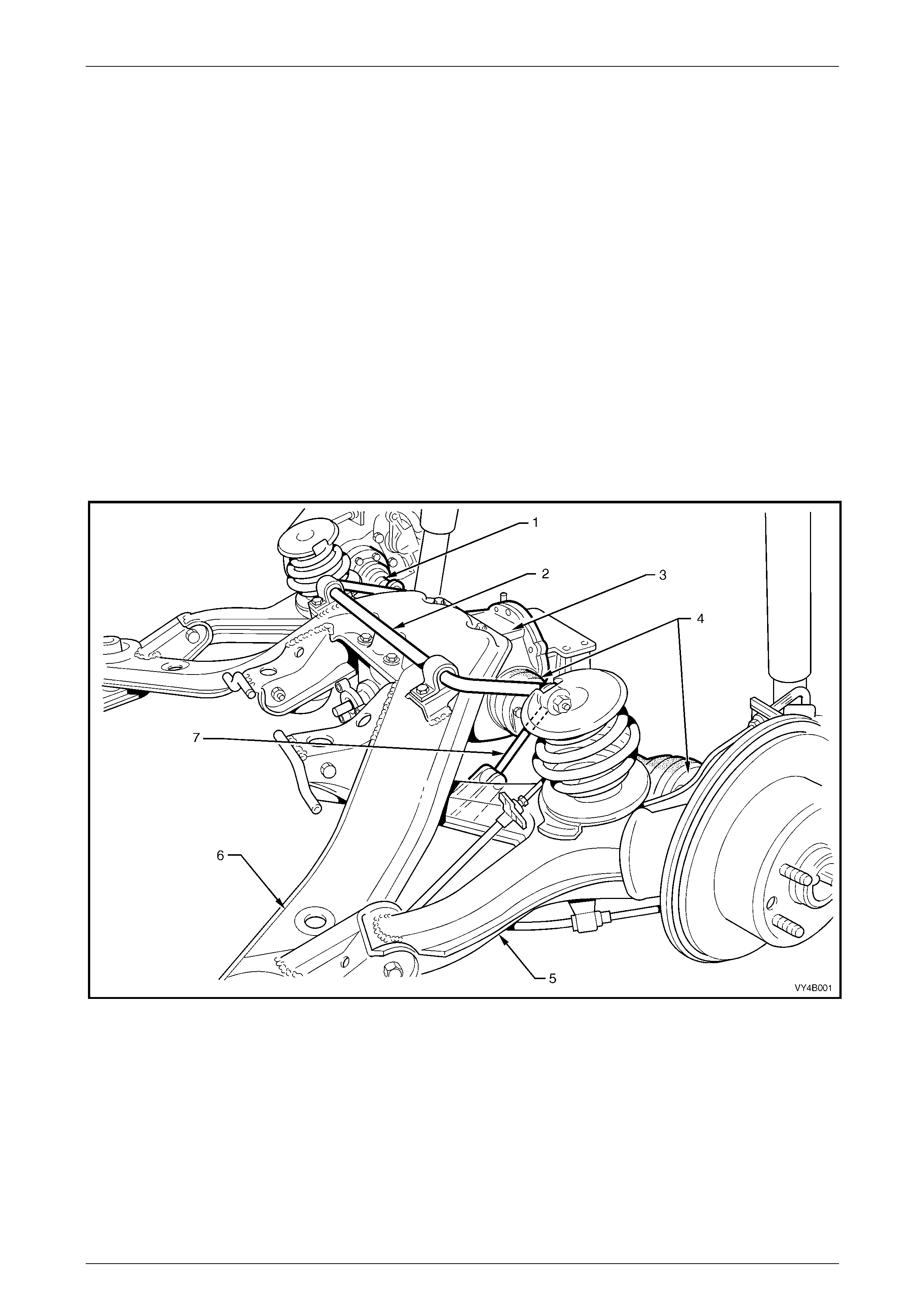
Figure 4B1 – 1
Legend
1 Drive Shaft
2 Rear Suspension Stabiliser Bar
3 Final Drive Assembly
4 Constant Velocity Joints
5 Trailing Arm
6 Rear Suspension Crossmember
7 Rear Stabiliser Bar to Trailing Arm Link
Rear Final Drive and Drive Shafts Page 4B1-5
Page 4B1-5
When fitted, the Limited Slip Differential (LSD) performs the same functions as the conventional type differential but in
addition, transfers driving force to the wheel with traction, should the opposite wheel begin to spin. The differential case
houses two cone type clutches behind the side gears, that are splined to the inner axle shafts. The tapered clutch face s
contact corresponding faces in the differenti al case. The cones form an integral part of the side gears.
The four pinion type Limited Slip Differential has three pre-load springs enclosed in the centre of the pinion cross shaft.
The Limited Slip Differential directs the major driving force to the wheel with the great er amount of traction, but will not
interfere with steering characteristics or differential action. The partial locking action, due to the spring load on the cones,
is automatically increased by the inherent separating forces between the side gears and pinions, which progressively
increases the resistance in the differenti al as applied torque is increased.
When the rear wheels are under extremely unbalanced conditions, such a s a wheel on a dry road and the other in mud
or ice, with the standard differential, wheel spin easily occurs if over-acceleration is attempted. However, with a Limited
Slip Differential, when the tendency for wheel spin occurs, the friction gen erated inside the case, transfers driving force to
the non-spinning wheel. In the event of continued spinning, a whirring sound from the over-running cones ma y be
produced but this condition/sound does not indicate failure of the unit.
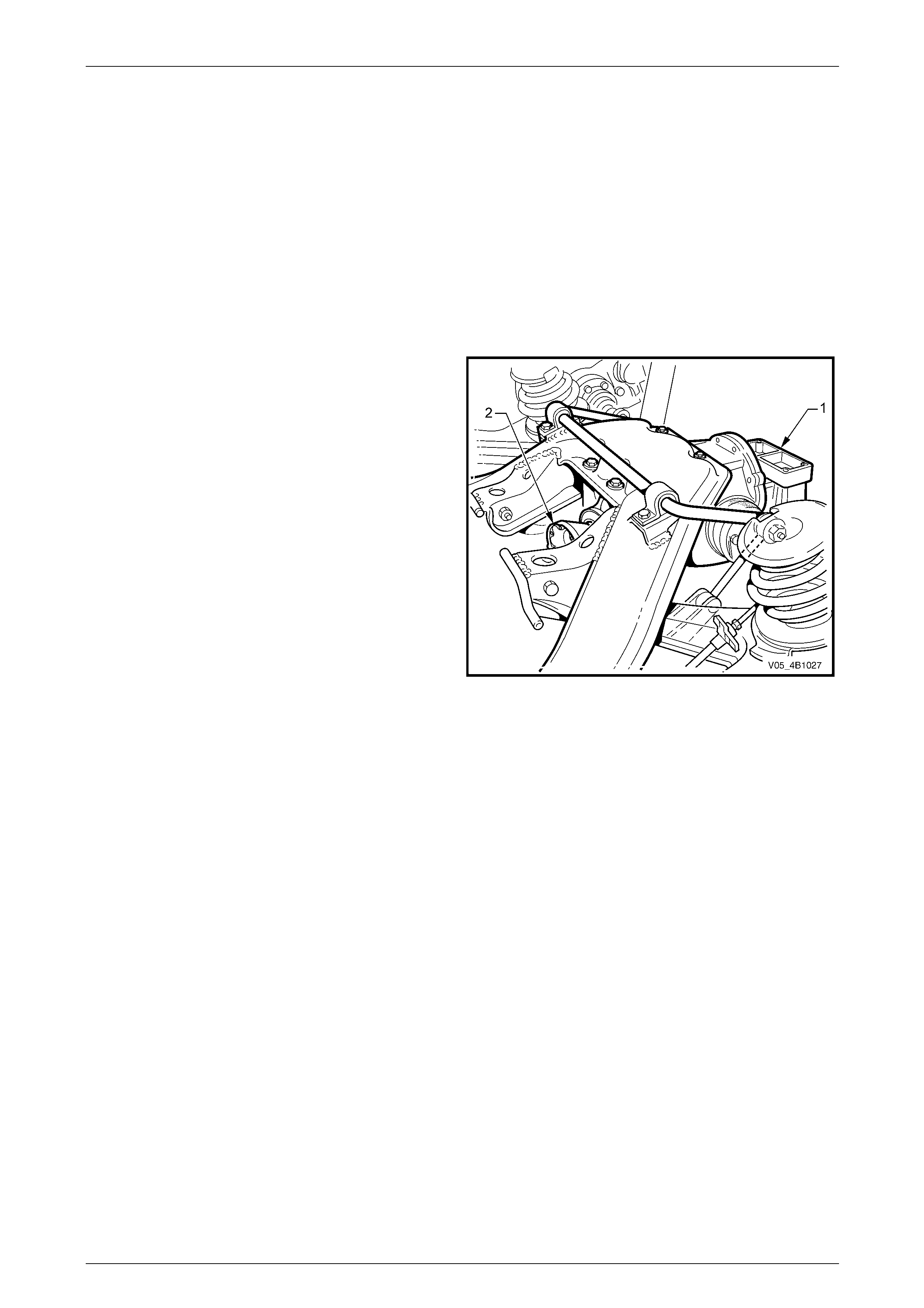
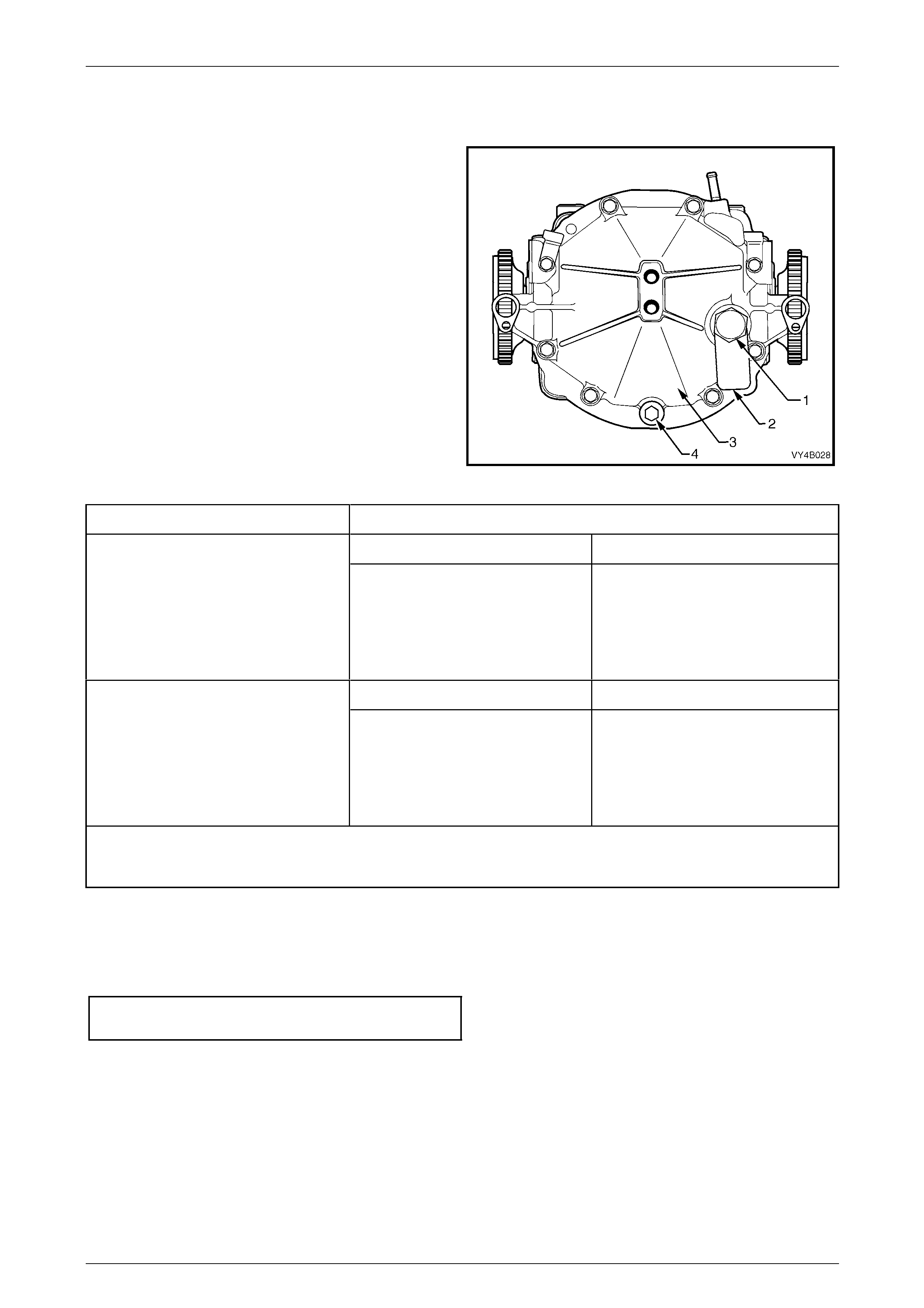
The final drive assembly fitted to the AWD Wago n, is the
same 3.46:1 ratio assembly (non LSD) fitted to other VZ
applications with this ratio, except for these changes:
1 The rear mount has a spacer (1) fitted.
2 The pinion flange (2) is redesigned to cater for the rear
propeller shaft constant velocity joint.
3 The front of the rear crossmember mounts have an
increased length centre boss. These are also fitted
with a snubber bush on each side.
4 The drive shafts have a plunge joint at both the inner
and outer ends, unlike other IRS assemblies, that
have a plunge joint at the inner end an d a fixed joint at
the outer.
NOTE
Coupe models also have drive shafts with
plunge joints at the inner and outer ends. Figure 4B1 – 2

Rear Final Drive and Drive Shafts Page 4B1-6
Page 4B1-6
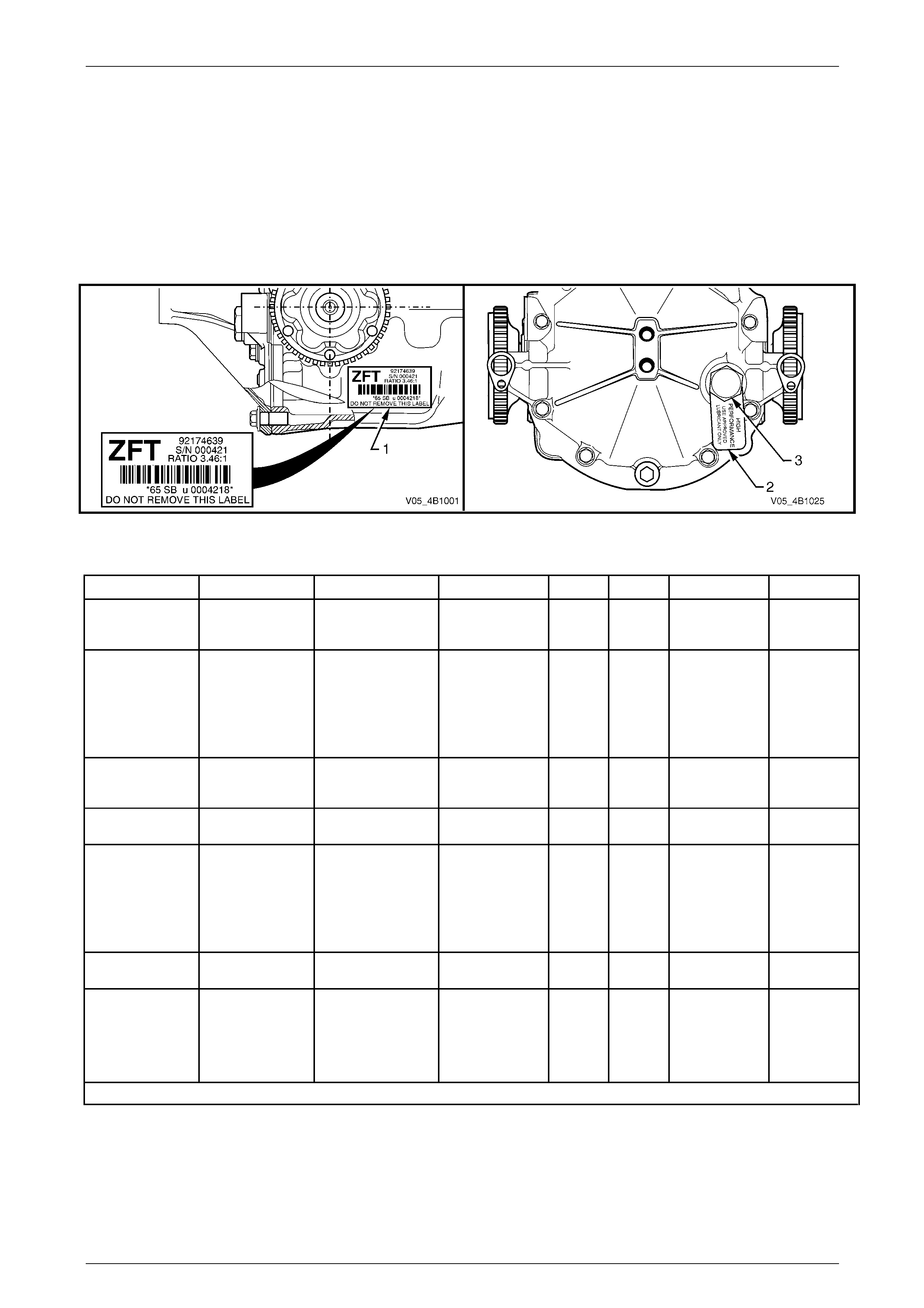
Figure 4B1 – 3
Legend
1 LH Inner Axle Shaft
2 Pinion Flange
3 RH Inner Axle Shaft
4 Identification Label
5 Drain Plug
6 Rear Cover
7 Breather
8 Filler Plug
9 Lubrication Tag
Rear Final Drive and Drive Shafts Page 4B1-7
Page 4B1-7
1.1 Final Drive Assembly Identification
The type of differential fitted to this final drive assembly can be identified by referring to the label (1) attached to the RHS
of the carrier housing and the lubric ation tag (2) under the filler plug (3) on the rear cover.
The locations of the identific ation label and lubrication tag are as shown in F igure 4B1-4.
The identification label (1) carries the final drive assembly pa rt number for the final drive ratio and the se rial number of
the assembly.
The code number and bar co de is used for production identification of the final drive as sembly.
Figure 4B1 – 4
Final Drive Applications
Body Type Engine Transmission Ratio ABS LSD Lubricant I.D. Code
VZ Wagon,
Sedan, Utility
HFV6
'Alloytec'
(P/O LE0 / LW2)
Automatic
'4L60-E'
(P/O M30) 3.08:1 N
Y
Y
N
N
Y
Mineral
Mineral
Synthetic +
ZFJ
ZFL
ZFM
VZ Sedan, Utility
HFV6
'Alloytec'
(P/O LE0)
OR
HFV6
'Alloytec 190'
(P/O LY7)
Manual 'D173'
(P/O MV5)
OR
Automatic
'5L40'
(P/O M82)
2.87:1 N
Y
Y
N
N
Y
Synthetic
Synthetic
Synthetic +
AZ
BB
BC
VZ Wagon,
Sedan, Utility GEN III V8
(P/O LS1)
Automatic
'4L60-E'
(P/O M30) 3.07:1 Y
Y N
Y Synthetic
Synthetic + ZFF
ZFH
VZ Wagon, Utility GEN III V8
(P/O LS1) Manual 'T56'
(P/O MM6) 3.46:1 Y
Y N
Y Synthetic
Synthetic + ZFT
ZFC
VZ AWD Wagon
HFV6
'Alloytec 190'
(P/O LY7)
OR
GEN III V8
(P/O LS1)
Automatic
'5L40'
(P/O M82)
OR
Automatic
'4L60-E'
(P/O M30)
3.46:1 Y N Synthetic AAA
VZ Sedan GEN III V8
(P/O LS1) Manual 'T56'
(P/O MM6) 3.73:1 Y
Y N
Y Synthetic
Synthetic + AX
ZFS
Coupe GEN III V8
(P/O LS1+)
Automatic
'4L60-E'
(P/O M30)
OR
Manual 'T56'
(P/O M12)
3.46:1 Y Y
Synthetic + ZFC
‘+’ indicates that an additive is added to the lubricant. Refer to Lubrication, in 1.2 Final Drive Assembly Maintenance.
Table 1
Where fitted, the information on the lubrication tag (2) under the filler plug (‘3’ in Figure 4B 1-4), will be:
With GEN III V8 or HFV6 'Alloytec 190' vehicles, fitted with the conventiona l differential;
“HIGH PERFORMANCE. USE APPROVED LUBRICANT ONLY”
With GEN III V8 or HFV6 'Alloytec 190' vehicles, fitted with LSD;
“LSD - HIGH PERFORMANCE. USE APPROVED LUBRICANT AND FRICTION MODIFIER”
Rear Final Drive and Drive Shafts Page 4B1-8
Page 4B1-8
1.2 Final Drive Assembly Maintenance
Maintenance
Drive Shaft Bearings and Cons tant Velocity Joints
The drive shaft constant velocity joints are lubricated for life and therefore require no periodic mainten ance.
The constant velocity joint boots are to be inspected at every maintenance service. If there is any evidence of damage to
boots, remove drive shaft and inspect constant velocity joints, refer to 2.7 Drive Shaft Assembly and to
2.8 Drive Shaft and/or Constant Velocity Joints, in this Section.
Differential Carrier Assembly
Check for lubricant leaks at every maintena nce service. If there is evidence of leakage, correct the leak and add l ubricant
as necessary. (Refer to 2 Minor Service Operations, in this Section).
At the time or distance interval specified in the appropriate Owner's Handbook, check to ensur e that the lubricant level is
to the bottom of the filler plug hole when the differential carrier assembly is COLD.
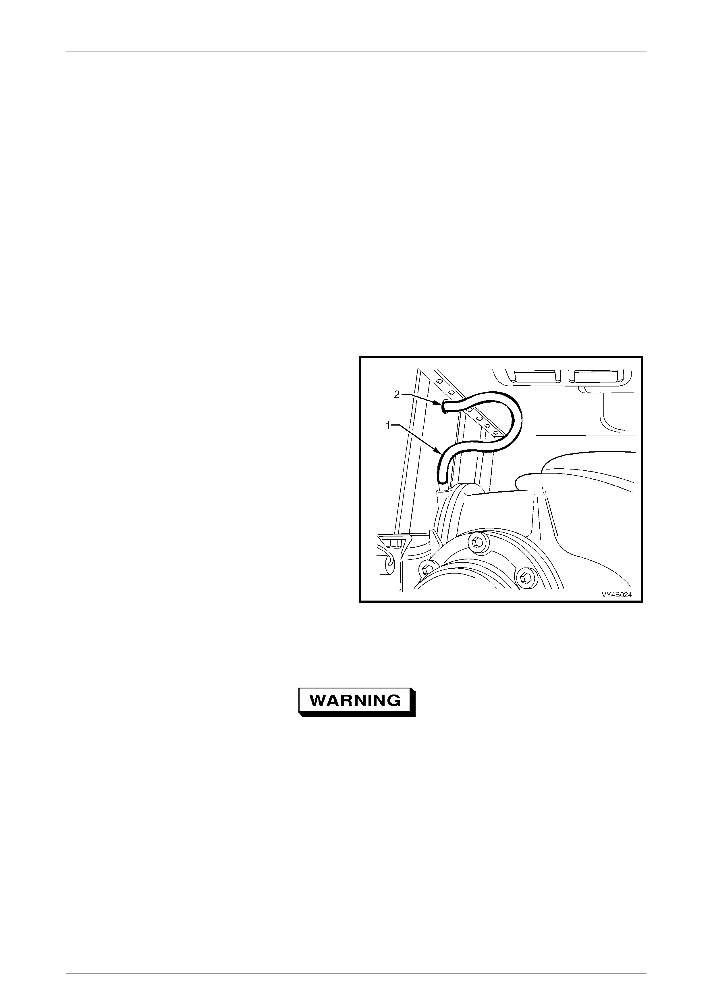
Final Drive Assembly Breathe r
The breather hose (1) should be checked regularly to
ensure that it is not blocked, is correctly routed and not
kinked.
The top end of the breather hose should b e in serted at least
25 mm into the vehicle underbody crossmember hole (2).
Figure 4B1 – 5
Limited Slip Differential Warnings
• When servicing a vehicle fitted with a
Limited Slip Differential, never run the
engine with the transmission in gear and
one wheel raised. The driving force to the
wheel on the ground may cause the
vehicle to move.
• 'On Car' type wheel balancers are not
recommended for use on the rear wheels
of cars equipped with a Limited Slip
Differential. One rear wheel will drive if in
contact with the ground when the opposite
wheel is raised and rotated.
• This type of balancer may be used by
removing the road wheel opposite to the
one being spun, the vehicle raised and
supported on safety stands. Refit wheel
nuts, reversed, to retain brake disc.
Rear Final Drive and Drive Shafts Page 4B1-9
Page 4B1-9
Lubrication
The lubricant level should be checked and topped up (if required), at the time or distance intervals
outlined in the appropri ate Owner's Handbook with the differential carrier COLD;
refer to 2.2 Checking Differential Carrier Lubricant Level in this Section. At this temperature, the lubricant should be level
with the bottom of the filler plug hole. This service operation also details the recommended lubricants for all final drives.
Never use any other than the stated and
recommended lubricant.
NOTES
• The lubricant for vehicles with the 3.08:1 ratio
assembly, with the standard, open or
conventional differential, is an approved
mineral oil. Using a straight run mineral oil in
an LSD final drive ass embly, will cause ‘stick-
slip’ chatter to occur when turning corners.
Alternatively, if a synthetic type lubricant is
used in any c onventional rear a xle of a 3.08:1
ratio assembly, oil seal deterioration with the
possibility of lubricant leakage may occur.
• The lubricant used in all other ratio rear axle
assemblies, is a synthetic product. The oil
seals in these assemblies have been speciall y
formulated to tolerate this lubricant. It must
also be noted that, using a mineral type
lubricant in any of these final drives, may
cause gear set and/or bearing damage under
high load driving conditio ns.
• When a Limited Slip Different ial (LSD) is fitted
to any rear axle, an approv ed additive such as
Sturaco 7098 MUST also be used, in
conjunction with a synthetic hypoid gear oil.
• If the incorrect lubricant is accide ntall y used i n
the rear axle of any MY 2005 VZ Series
vehicle, then the rear axle should be drained,
flushed (with the recomm ended lubricant) and
then refilled with the correct lubricant. The
procedure for this operation is detailed in
2.3 Changing/Flushi ng Rear Axle Lu bricant , in
this Section.
Rear Final Drive and Drive Shafts Page 4B1-10
Page 4B1-10
2 Minor Service Operations
2.1 General Information
Important Service Requirements
1 Whenever a road wheel and/or brake disc is removed from the vehicle, the relationsh ip of the road wheel and the
disc to the hub MUST be marked with a felt tipped pen or similar, in order for those parts to be reinstalled in their
original positions. This is critical to maintain the brake disc and road wheel runout dimension to a minimum.
2 When reinstalling road wheels, do not use an impact
gun to tighten wheel nuts unless the impact gun is
fitted with a torque limiter socket (Tool No. AU 534 or
a commercial equivalent). Failure to correctly tighten
wheel nuts to the correct torque specification and in
the correct order, may result in a distorted brake disc,
leading to the development of brake shudder.
Road wheel attaching nut
torque specification..............................110 – 140 N.m
For a complete description of the method used to measure
both brake disc and outer rear wheel driveshaft assembly
runout and correction, refer to
Section 5A Service and Park Braking Systems.
Figure 4B1 – 6
ATTENTION
All fasteners are important attaching parts as they affect the performance of vital components and/or could
result in major repair expense. W h ere specified in this section, fasteners MUST be rep laced with parts of the
same part number or an approved equivalent. Do not use fasten ers of an inferior quality or substitute desig n.
Torque values must be used as specified during reassembly to ensure proper retention of all components.
Throughout this section, fastener torque wrench specifications may be accompanied with the following
identification marks:
Fasteners must be repl aced after loosening.
Vehicle must be at curb height before final tightening.
Fasteners either have micro encapsulated sealant applied or incorporate a mechanic al thread lock and
should only be re-used once. If in doubt, replacement is recommended.
If one of these identification marks is present alongside a fastener torque wrench specification, the
recommendation regarding that fastener must be adhered to.
Rear Final Drive and Drive Shafts Page 4B1-11
Page 4B1-11
2.2 Checking Differential Carrier Lubricant
Level
1 Ensure vehicle is level.
2 Clean area around filler plug (1).
3 Remove filler plug (1) from rear cover (3) (do not lose
the lubrication tag (2) from the plug, if fitted).
4 The lubricant level is to be maintaine d at the bottom
edge of the filler plug hole, when COLD. Use only the
recommended lubricant, detail ed in the following table.
Figure 4B1 – 7
Application Recommended Lubricant
All With Non-LSD Differential All With LSD Differential
All with the V6 engine and
4L60-E automatic transmission.
1.6 litre Mineral Hypoid Gear Oil )
SAE 90 LSD such as;
AMPOL Gear Lube LSD 90,
CASTROL LSX90,
SHELL Helix Limited Slip Diff. Oil
VALVOLINE HP Gear Oil LS90
1.5 litre Synthetic Hypoid Gear Oil,
SAE 80W-140 such as;
MOBIL Mobilube SHC ID, or
CASTROL SAF-XA
PLUS;
0.1 litre of Sturaco 7098 Oil Additive
All With Non-LSD Differential All With LSD Differential
All with the V6 engine and
manual transmission or 5L40-E
automatic transmission
OR
All GEN III V8 engines and manual or
automatic transmission.
1.6 litre Synthetic Hypoid Gear Oil,
SAE 80W-140 such as;
MOBIL Mobilube SHC ID or
CASTROL SAF-XA
1.5 litre Synthetic Hypoid Gear Oil,
SAE 80W-140 such as;
MOBIL Mobilube SHC ID or
CASTROL SAF-XA,
PLUS;
0.1 litre of Sturaco 7098 Oil Additive
) If towing heavy loads for an extended time, it is recommended that Synthetic Hypoid Gear oil is used. If towing
between 1,600 kg and 2,100 kg at speeds over 80 km/h with a V6 naturally aspirated engine, it is strongly
recommended that synthetic gear oil be us ed.
Table – 2
5 Inspect filler plug (1) for damage, if OK, reinstall to the rear cover (3) (includi ng the lubrication tag (2). If damaged,
replace plug.
6 Tighten filler plug (1) to the correct torque specification.
Filler plug
torque specification..............................................30 N.m

Rear Final Drive and Drive Shafts Page 4B1-12
Page 4B1-12
2.3 Changing/Flushing Rear Axle Lubricant
1 To drain lubricant from differential carrier assembly, remove filler (1) and drain plugs (4) (refer Figure 4B1-7) and
allow (preferably warm) lubricant to drain into a suitable container.
2 If flushing is required, use an undiluted quantity of the recommended lubricant for the operatio n.
3 When the draining and flushing (if required), operation is co mpleted, apply thread sealing tape to rear cover drain
plug (4) thread. Install and tighten drain pl ug (4) to the correct torque specification.
Rear axle drain plug
torque specification..............................................30 N.m
4 Fill the final drive assembly with either 1.6 litres of the recommended lubric ant or 1.5 litres of the recommended
lubricant plus 0.1 litre of Sturaco 7098 oi l additive; refer to Table – 2. Install the filler pl ug (1) and lubrication tag (2)
(if fitted) and tighten to the correct torque specification.
Filler plug
torque specification..............................................30 N.m
Rear Final Drive and Drive Shafts Page 4B1-13
Page 4B1-13
2.4 Trailing Arm Outer Rear Wheel
Driveshaft Assembly Hub
LT Section No: 05-290
ATTENTION
Vehicle must be at curb weight before final tightening.
Lower shock absorber mounting bolt.
Check for Run-Out
1 Raise the rear of the vehicle and sup port in a safe manner. Refer to Section 0A General Information for the location
of recommended lifting and support poi nts.
2 Remove rear wheel cover (steel wheels) or wheel nut covers (alloy wheels) on that side of the vehic le where the
outer rear wheel driveshaft is to be checked.
3 Mark relationship of wheel to mounti ng flange. Remove road wheel attaching nuts and re move wheel.
Refer to 2.1 General Information in this Section for more information.
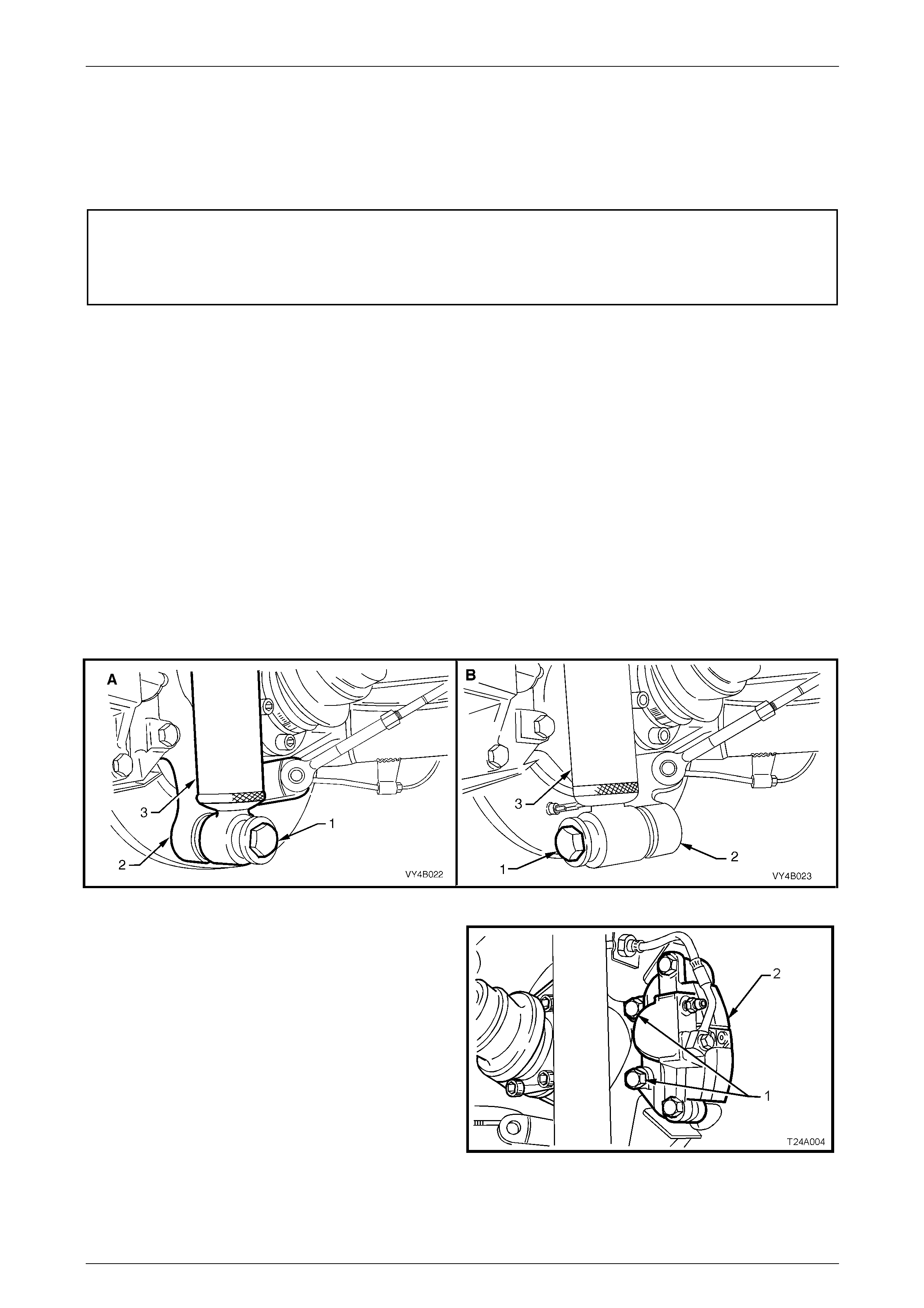
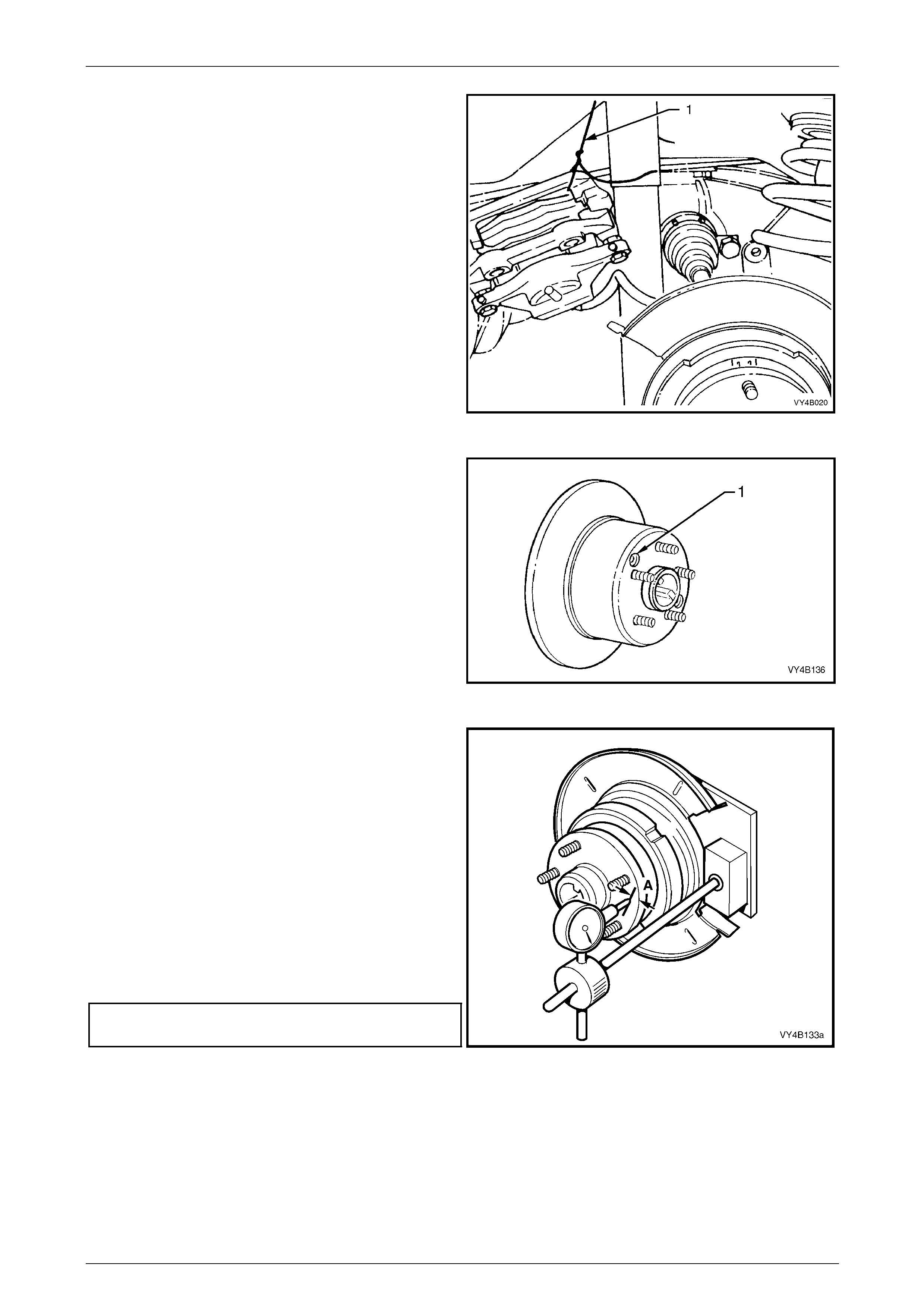
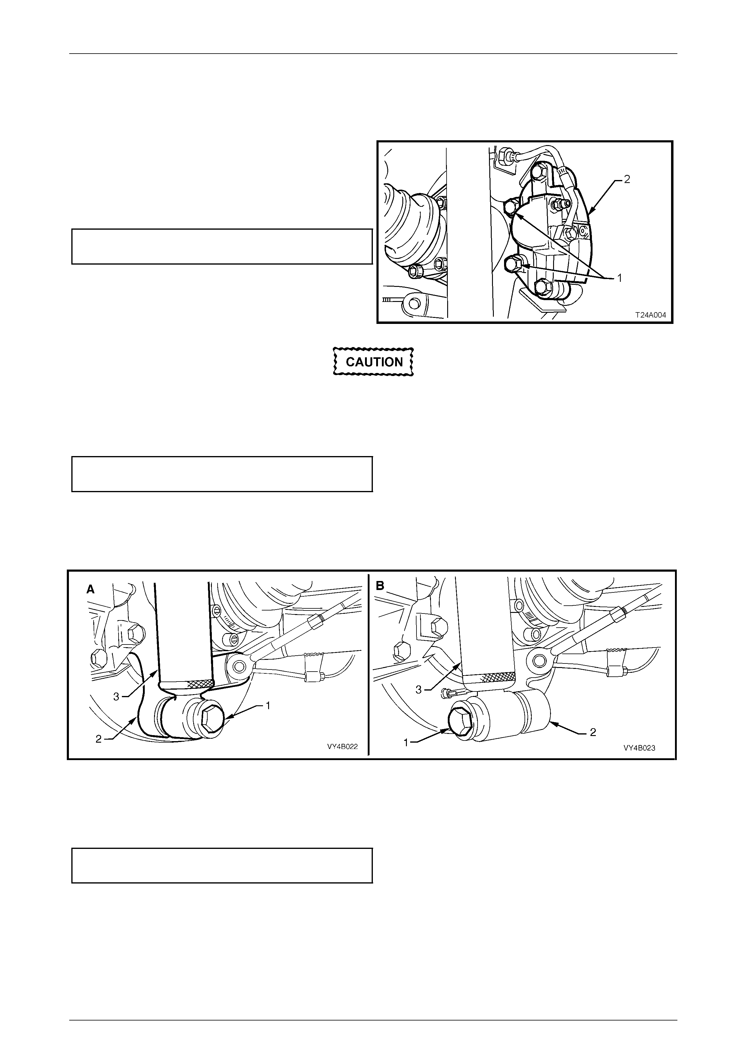
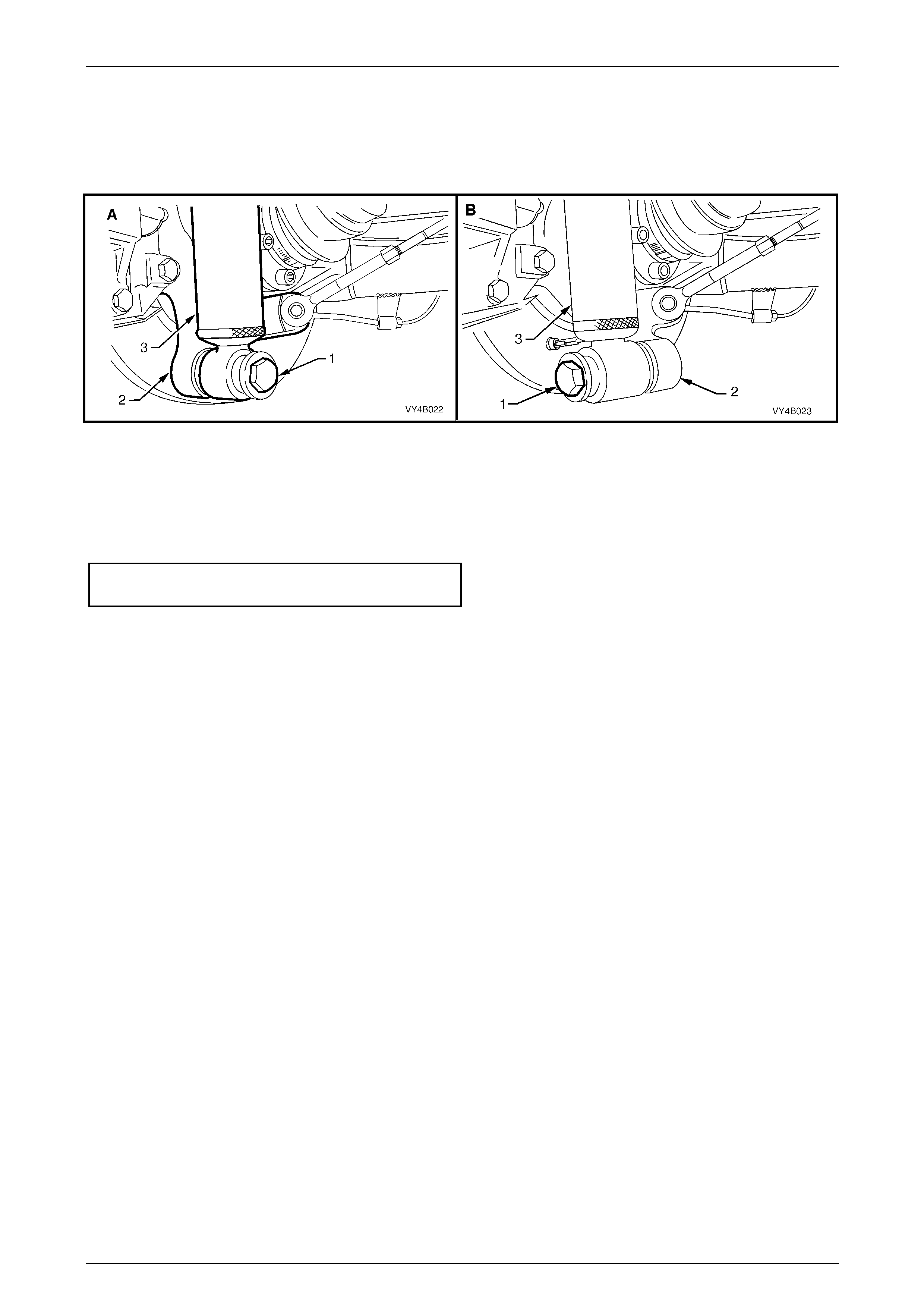
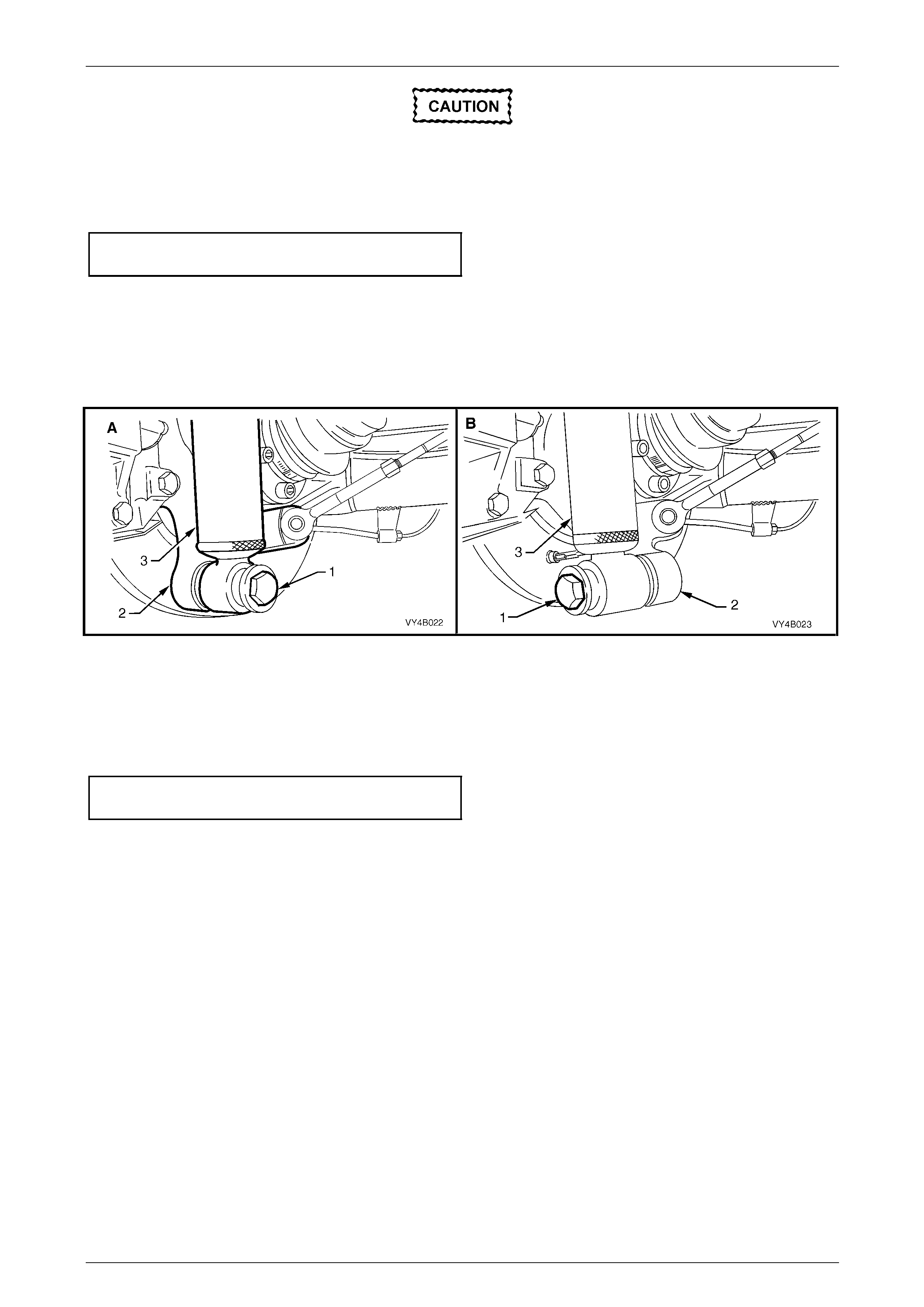
4 Disconnect rear shock absorber lower mounting bolt (1) from trailing arm (2), and pull lower end of shock absorber
(3) from trailing arm.
NOTE
View ‘A’ in Figure 4B1-8 shows the sedan and
coupe lower shock absorber mounting, while view
‘B’ shows the station wagon and utility
arrangement.
Figure 4B1 – 8
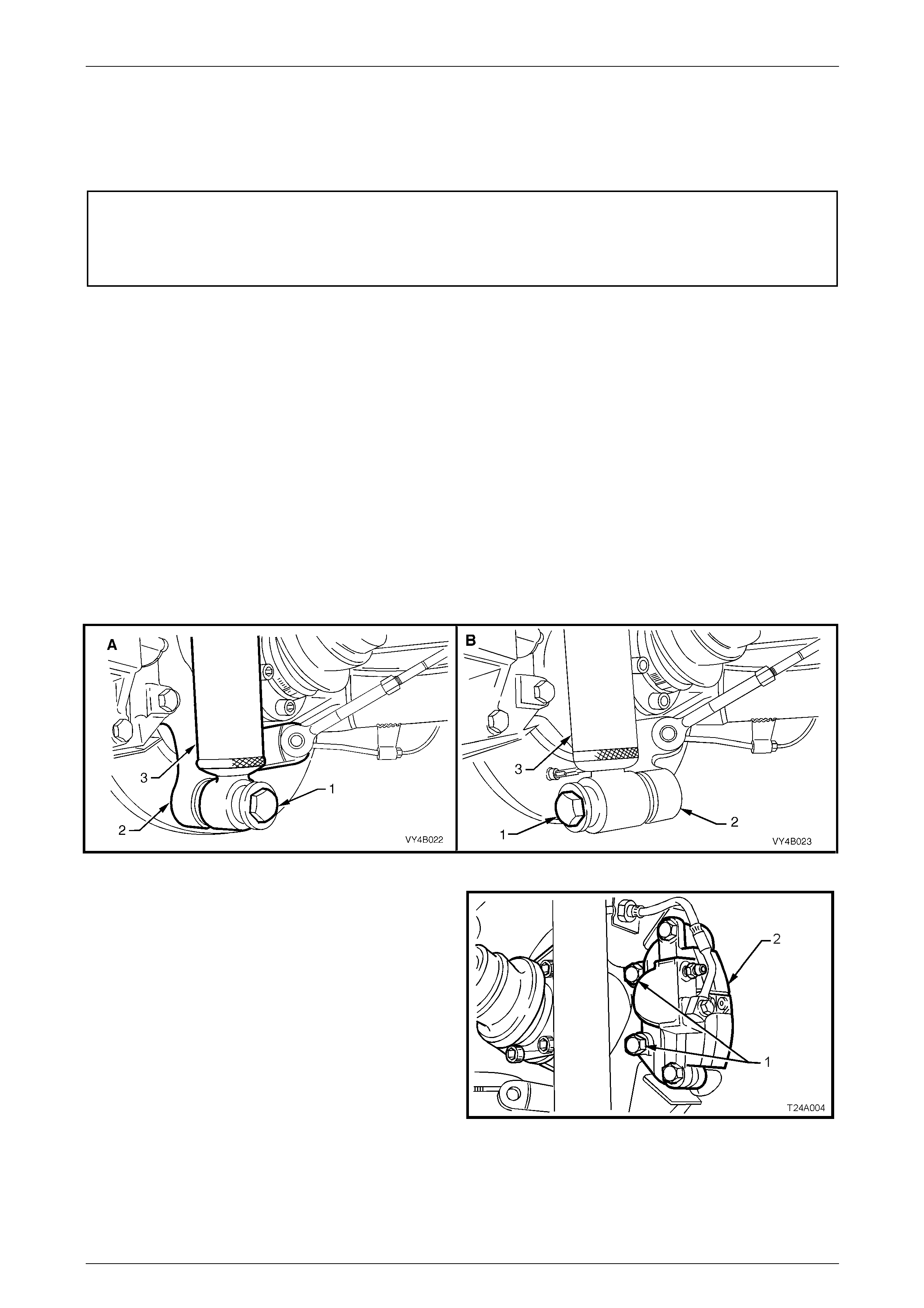
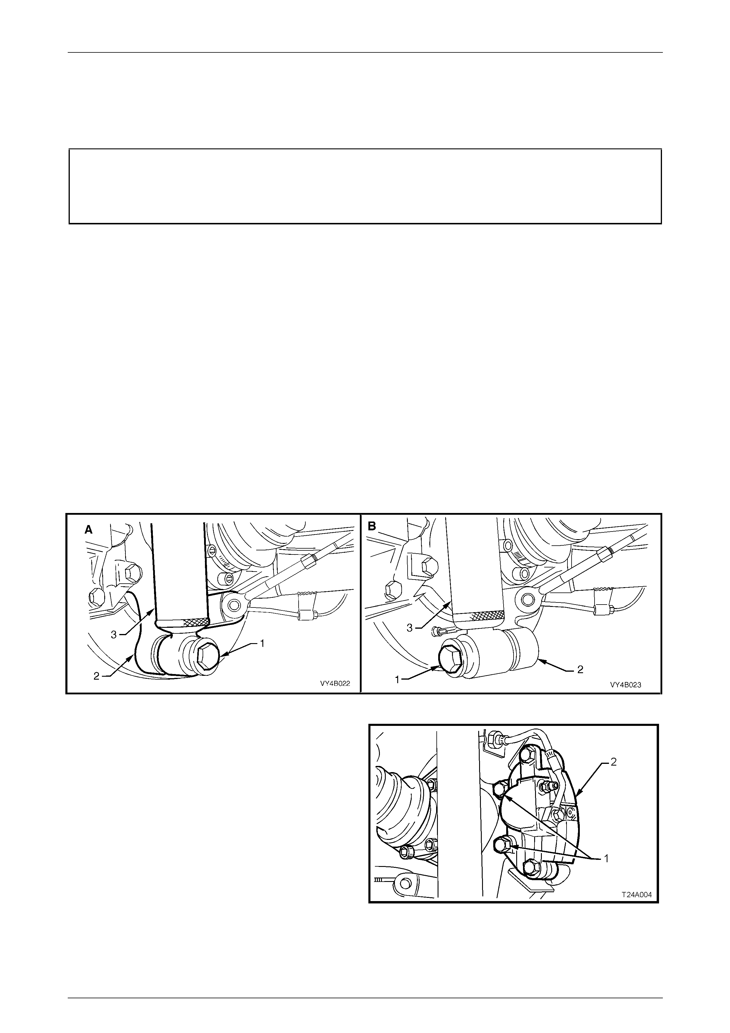
5 Remove brake caliper anchor plate to trailing arm
attaching bolts (1), remove caliper (2) from disc.
Figure 4B1 – 9
Rear Final Drive and Drive Shafts Page 4B1-14
Page 4B1-14
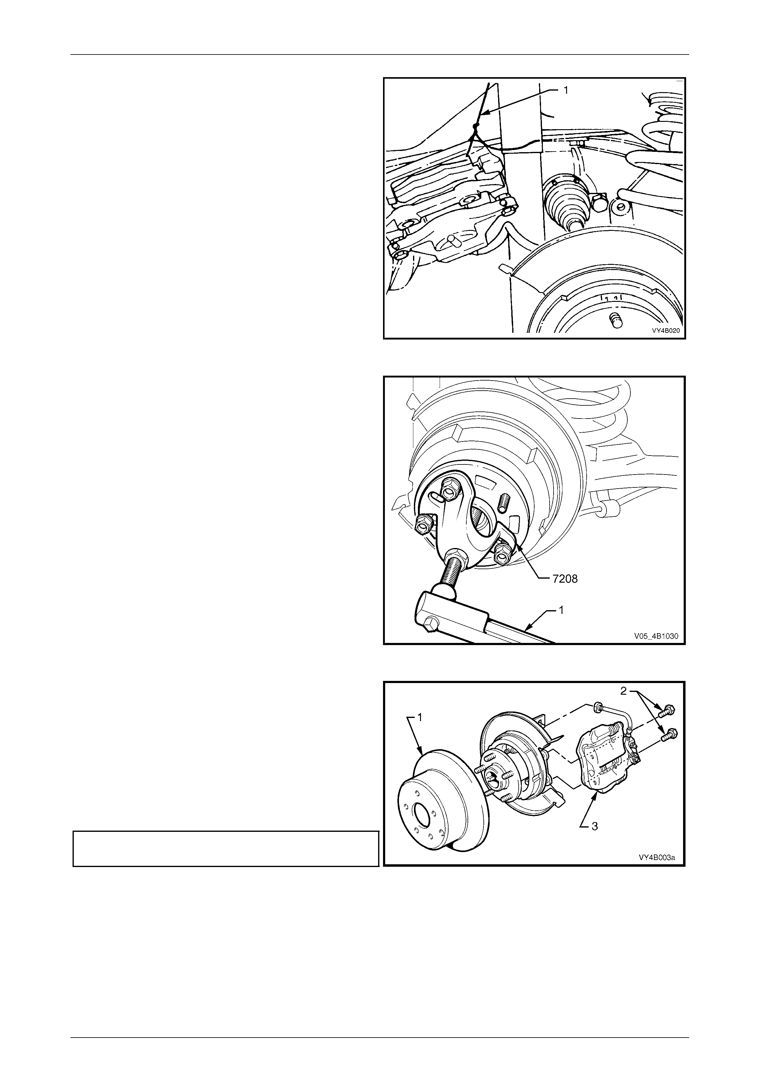
6 Using tie wire (1), secure caliper to lower end of shock
absorber upper mounting. DO NOT ALLOW CALIPER
TO HANG BY BRAKE HOSE.
7. Mark the brake disc position to outer rear wheel
driveshaft assembly, using a felt tipped pen or similar,
then remove the brake disc from the outer rear wheel
driveshaft assembly (Shown already removed in
Figure 4B1-10).
NOTE
If necessary, loosen the park brake shoe
adjustment. Refer to 3.9 Park Brake Shoe,
Adjust, in Section 5A Service and Park Braking
Systems.
Figure 4B1 – 10
8 If the park brake shoe adjustment needs to be
released to allow disc removal, adopt the following
method:
a Remove the access hole plug (1) from the hole
provided in the disc.
b Using a suitable lever such as a screwdriver,
loosen the park brake shoe screw adjuster, until
the disc is freed.
c After disc removal, reinstall the access hole plug
to prevent loss.
Figure 4B1 – 11
9 Clean the rear outer rear wheel driveshaft face by
rubbing lightly with fine emer y paper.
10 Mount the pre-fabricated mounting plate (refer
7 Special Tools in this Section for details) to the brake
caliper mounting points on the rear traili ng arm, using
the caliper mounting bolts.
11 Mount a magnetic based dial indicator stand, install a
dial indicator, positioning the pointer at a distance of 5
mm in from the outer edge (‘A’).
12 Using the wheel studs, carefully rotate outer rear
wheel driveshaft assembly hub, noting th e points of
maximum and minimum lateral run-out. The difference
between these two dimensio ns is the Total Indicated
Runout (TIR).
Maximum outer rear wheel driveshaft
assembly hub, total indicated runout............... 0.060 mm
Figure 4B1 – 12
Rear Final Drive and Drive Shafts Page 4B1-15
Page 4B1-15
If Run-out is Within Specification
1 Reinstall brake disc over the o uter rear wheel driveshaft wheel studs, ensuring that the alignment marks made prior
to disassembly, are aligned.
2 Clean the threads of the brake caliper attaching bolts
(1) and apply a thread sealant such as Loctite 243 (or
equivalent).
3 Reinstall the brake caliper a nchor plate (2) and secure
with the attaching bolts (1), tightened to the correct
torque specification.
Brake caliper anchor plate to trailing
arm bolt torque specification................................85 N.m
Figure 4B1 – 13
Vehicle must be at curb weight and on all four
wheels before the shock absorber mounting
bolt torque is applied.
4 Reinstall shock absorber to trailing arm, fit washer to the lower mounting bolt, install bolt and tighten to the correct
torque specification.
z Shock absorber lower mounting
bolt torque specification.....................................115 N.m
NOTE
View ‘A’ in Figure 4B1-14 shows the sedan and
coupe lower shock absorber mounting, while view
‘B’ shows the station wagon and utility
arrangement.
Figure 4B1 – 14
5 Reinstall road wheel, aligning marks made prior to removal, install and tig hten attaching nuts.
6 Remove safety stand and lo wer vehicle.
7 Tighten road wheel attaching nuts to the correct torque specification and in the correct sequence
(refer to Important Service Requirements in 2.1 General Information, in this Section).
Road wheel attaching nut
torque specification..................................110 – 140 N.m
8 Refit wheel cover/wheel nut caps.
If the Run-out Check, Exceeds Specification
1 The outer rear wheel drivesha ft assembly must be replaced,
refer to 3.1 Trailing Arm Outer Rear Wheel Drive Shaft Flange and/or Wheel Bearing, in this Section.
Rear Final Drive and Drive Shafts Page 4B1-16
Page 4B1-16
2.5 Trailing Arm Outer Rear Wheel
Driveshaft Assembly Hub Studs
LT Section No: 05-290
ATTENTION
Vehicle must be at curb weight before final tightening.
Lower shock absorber mounting bolt.
Replace
1 Raise the vehicle and suppor t in a safe manner. Refer to Section 0A General Information for the location of
recommended lifting and support points.
2 Remove rear wheel cover or wheel nut caps o n that side of the vehicle where the stud/s are to be replaced.
3 Mark relationship of wheel to mounti ng flange. Loosen then remove road wheel attaching nuts. Remove the road
wheel. Refer to 2.1 General Information in this Section for more information.
4 Loosen and disconnect rear shock absorber lower mounting bolt (1) from trailing arm (2) and pull lower end of
shock absorber (3) from trailing arm (2).
NOTE
View ‘A’ in Figure 4B1-15 shows the sedan and
coupe, lower shock absorber mounting, while
view ‘B’ shows the station wagon and utility
arrangement.
Figure 4B1 – 15
5 Loosen and remove brak e caliper anchor plate to
trailing arm attaching bolts (1) and remove calip er (2)
from disc.
Figure 4B1 – 16
Rear Final Drive and Drive Shafts Page 4B1-17
Page 4B1-17
6 Using tie wire (1), secure the brake caliper to lower
end of shock absorber upper mounting. DO NOT
ALLOW CALIPER TO HANG BY BRAKE HOSE.
7 Mark the brake disc position to outer rear wheel
driveshaft assembly, using a felt tipped pen or similar,
then remove the brake disc from the outer rear wheel
driveshaft assembly (Shown already removed in
Figure 4B1-16).
Figure 4B1 – 17
8 If the park brake shoe adjustment needs to be
released to allow disc removal, adopt the following
method:
a Remove the access hole plug (1) from the hole
provided in the disc.
b Using a suitable lever such as a screwdriver,
loosen the park brake shoe screw adjuster, until
the disc is freed.
c After disc removal, reinstall the access hole plug
to prevent loss.
Figure 4B1 – 18
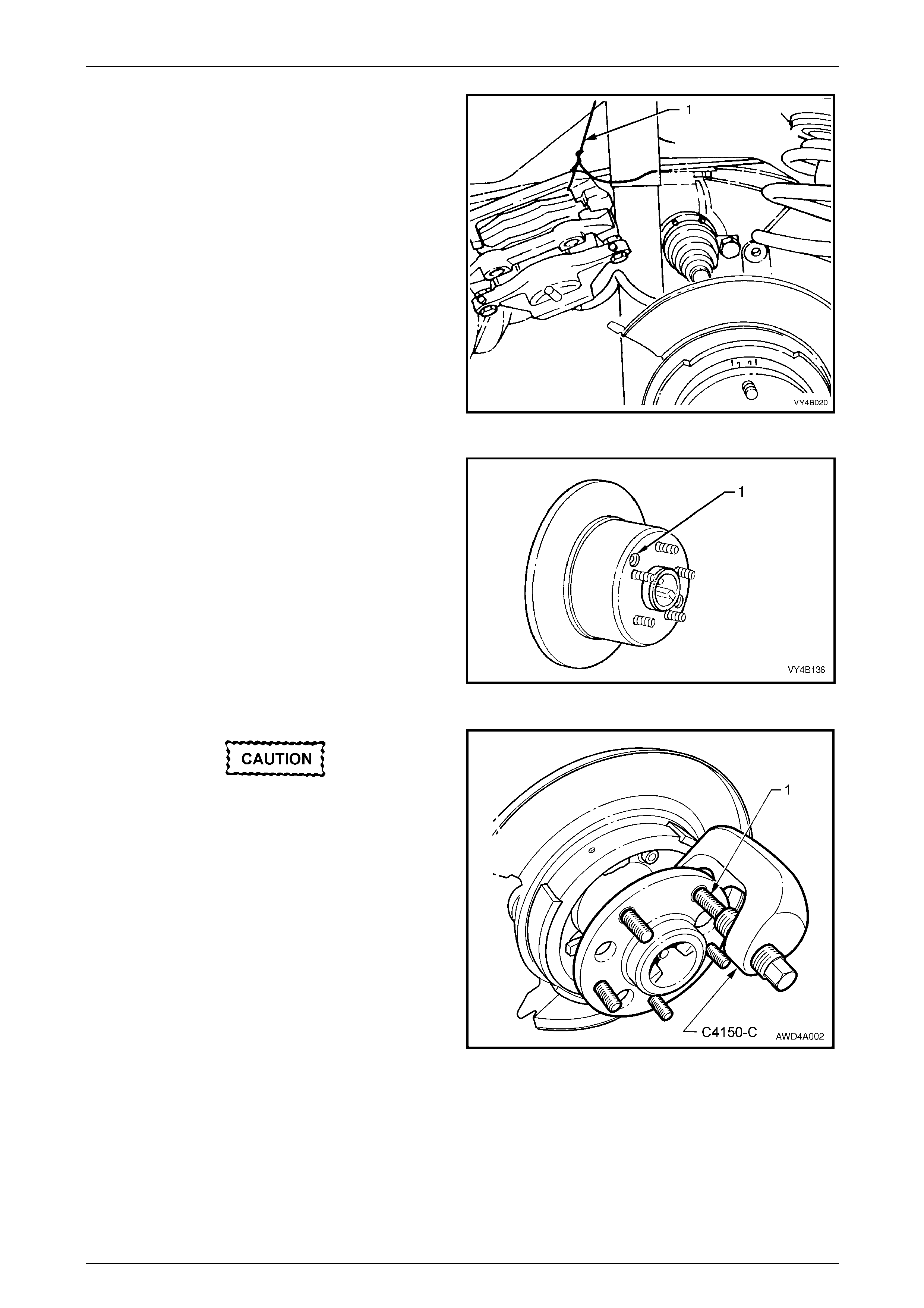
The use of a hammer and punch to remove a
wheel stud is not permitted, as distortion of
the outer rear wheel driveshaft assembly will
most likely occur. This would subsequently
result in brake shudder.
9 Use Tool No. C4150-C, remove the wheel stud (1) to
be replaced.
Figure 4B1 – 19
Rear Final Drive and Drive Shafts Page 4B1-18
Page 4B1-18
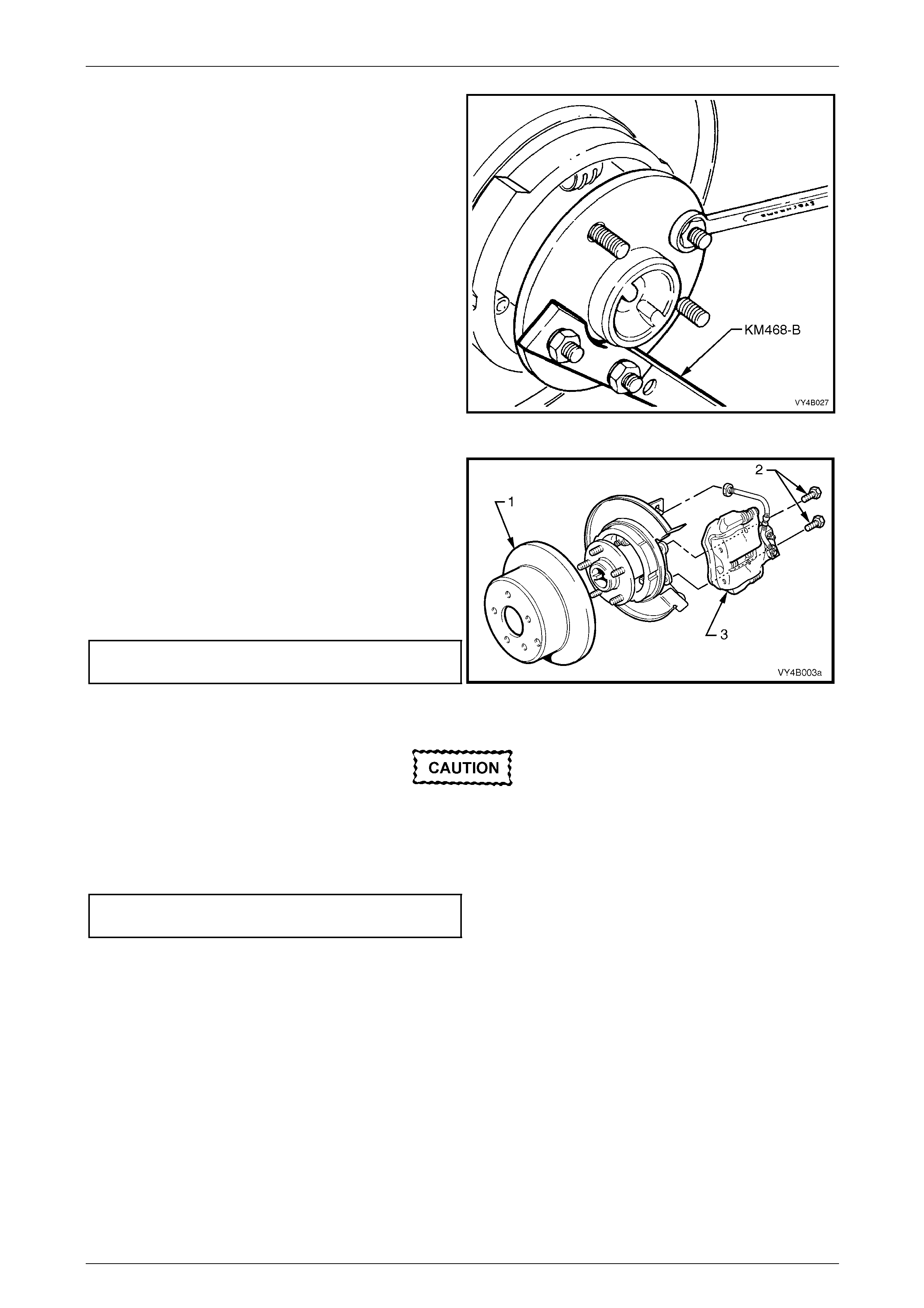
10 Install Tool No. KM468-B holding bar, with two wheel
nuts to the outer rear wheel driveshaft assembly hub
studs. Install a new stud into hub. Assemble some
suitable size washers and a reversed wheel nut, onto
stud. Tighten wheel nut to draw in stud. When stud is
fully installed, remove wheel nut and washers.
11 Install any remaining studs in the same manner.
12 Remove holding bar, T ool No. KM-468-B.
Figure 4B1 – 20
13 Reinstall brake disc (1) over the outer re ar wheel
driveshaft wheel studs, ensuring that the marks made
prior to disassembly, are aligned.
14 Clean the threads of the brake caliper attaching bolts
(1) and apply a thread sealant such as Loctite 243 (or
equivalent).
15 Reinstall brake calip er (3) anchor plate to trailing arm
attaching bolts (2) and tighten to the correct torque
specification.
Brake caliper anchor plate
torque specification..............................................85 N.m
Figure 4B1 – 21
Vehicle must be at curb weight and on all four
wheels before this torque is applied.
16 Reinstall shock absorber to trailing arm, fit washer to the lower mounting bolt, install bolt and tighten to the correct
torque specification.
z Shock absorber lower mounting
bolt torque specification.....................................115 N.m
Rear Final Drive and Drive Shafts Page 4B1-19
Page 4B1-19
NOTE
View ‘A’ in Figure 4B1-22 shows the sedan and
coupe lower shock absorber mounting, while view
‘B’ shows the station wagon and utility
arrangement.
Figure 4B1 – 22
17 Reinstall road wheel, aligning marks made prior to removal, install and tig hten attaching nuts.
18 Remove safety stand and lo wer vehicle.
19 Tighten road wheel attaching nuts to the correct torque specification and in the correct sequence
(refer Important Service Requirements in 2.1 Genera l Information, in this Section).
Road wheel attaching nut
torque specification..................................110 – 140 N.m
20 Refit wheel cover/wheel nut caps.
Rear Final Drive and Drive Shafts Page 4B1-20
Page 4B1-20
2.6 Limited Slip Differential
LT Section No. – 05-290
ATTENTION
Vehicle must be at curb weight before final tightening.
Lower shock absorber mounting bolt.
Torque Check
1 Place transmission in neutral with engine turned OFF .
2 Jack up one rear wheel and supp ort trailing arm on a safety stand. Release park brake lever to fully OFF position.
3 Remove rear wheel cover (steel wheels) or wheel nut caps (alloy wheels) on that side of the vehicle where the
stud/s are to be replaced.
4 Mark relationship of wheel to mounti ng flange. Loosen then remove road wheel attaching nuts. Remove the road
wheel.
5 Loosen and disconnect rear shock absorber lower mounting bolt from trailing arm an d pull lower end of shock
absorber from trailing arm.
NOTE
View ‘A’ in Figure 4B1-23 shows the sedan and
coupe lower shock absorber mounting, while view
‘B’ shows the station wagon and utility
arrangement.
Figure 4B1 – 23
6 Loosen, then remove brake caliper anchor plate to
trailing arm attaching bolts (1) and remove calip er (2)
from disc.
Figure 4B1 – 24
Rear Final Drive and Drive Shafts Page 4B1-21
Page 4B1-21
7 Using tie wire (1), secure the brake caliper to lower
end of shock absorber upper mounting. DO NOT
ALLOW CALIPER TO HANG BY BRAKE HOSE.
8 Mark the brake disc position to outer rear wheel
driveshaft assembly, using a felt tipped pen or similar,
then remove the brake disc from the outer rear wheel
driveshaft assembly (Shown already removed in
Figure 4B1-25).
Figure 4B1 – 25
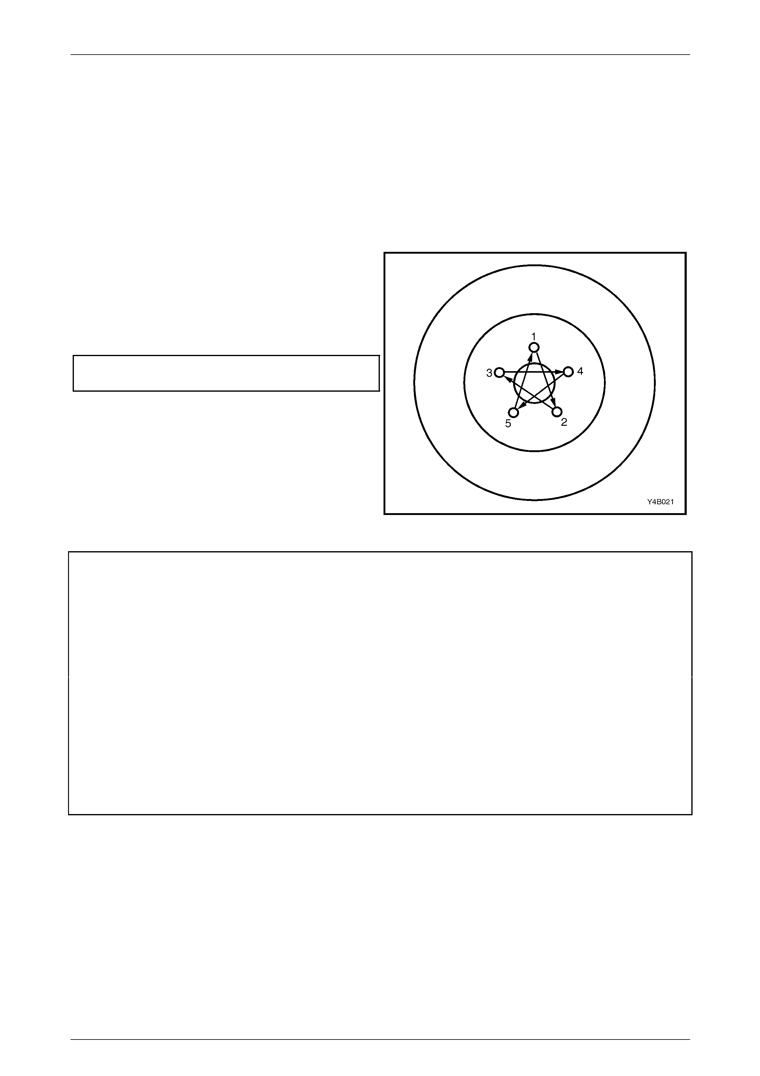
9 Install Tool No. 7208 to the outer rear wheel driveshaft
assembly, securing with three wheel nuts.
10 Lock the forcing screw with the lock nut provided.
11 Using a torque wrench (1) and a suitable size d socket,
rotate the outer rear wheel driveshaft in a forward
direction (clockwise).
NOTE
• If the LSD assembly is operating
satisfactorily, a torque reading of
approximately 70 N.m should be obtained
while turning the outer rear wheel driveshaft
assembly, with the opposite wheel remaining
stationary.
• If a torque reading of less than 45 Nm
is obtained, remove differential case
and inspect case internal components
and repair as necessary, refer to
3.4 Limited Slip Differential in this Section. Figure 4B1 – 26
12 Reinstall brake disc (1) over the outer re ar wheel
driveshaft wheel studs, ensuring that the marks made
prior to disassembly, are aligned.
13 Clean the threads of the brake caliper attaching bolts
(1) and apply a thread sealant such as Loctite 243 (or
equivalent).
14 Reinstall brake calip er (3) anchor plate to trailing arm
attaching bolts (2) and tighten to the correct torque
specification.
Brake caliper anchor plate to trailing
arm bolt torque specification................................85 N.m
Figure 4B1 – 27
Rear Final Drive and Drive Shafts Page 4B1-22
Page 4B1-22
Vehicle must be at curb weight and on all four
wheels before this torque is applied.
15 Reinstall shock absorber to trailing arm, fit washer to the lower mounting bolt, install bolt and tighten to the correct
torque specification.
z Shock absorber lower mounting
bolt torque specification.....................................115 N.m
NOTE
View ‘A’ in Figure 4B1-28 shows the sedan and
coupe lower shock absorber mounting, while view
‘B’ shows the station wagon and utility
arrangement.
Figure 4B1 – 28
16 Install road wheel, aligning marks made pr ior to removal, install and tighten attaching nuts.
17 Remove safety stand and lo wer vehicle.
18 Tighten road wheel attaching nuts to the correct torque specification and in the correct sequence
(refer ‘Important Service Requirements’ in 2.1 General Information, in this Section).
Road wheel attaching nut
torque specification..................................110 – 140 N.m
19 Refit wheel cover/wheel nut caps.
Rear Final Drive and Drive Shafts Page 4B1-23
Page 4B1-23
2.7 Drive Shaft Assembly
LT Section No: 05-290-1
ATTENTION
The following fasteners MUST be replaced when performing these operations:
All removed driveshaft constant velocity joint attaching bolts.
Remove
1 Raise the vehicle and suppor t in a safe manner. Refer to Section 0A General Information for the location of
recommended lifting and support points.
2 Use a felt tipped pen or similar, to identify the
driveshaft as being either right or left and also, which
constant velocity joint is the outer.
NOTE
It is important that the drive shaft orientation is
marked, to maintain the shaft ‘wind-up’ direction
when reinstalled.
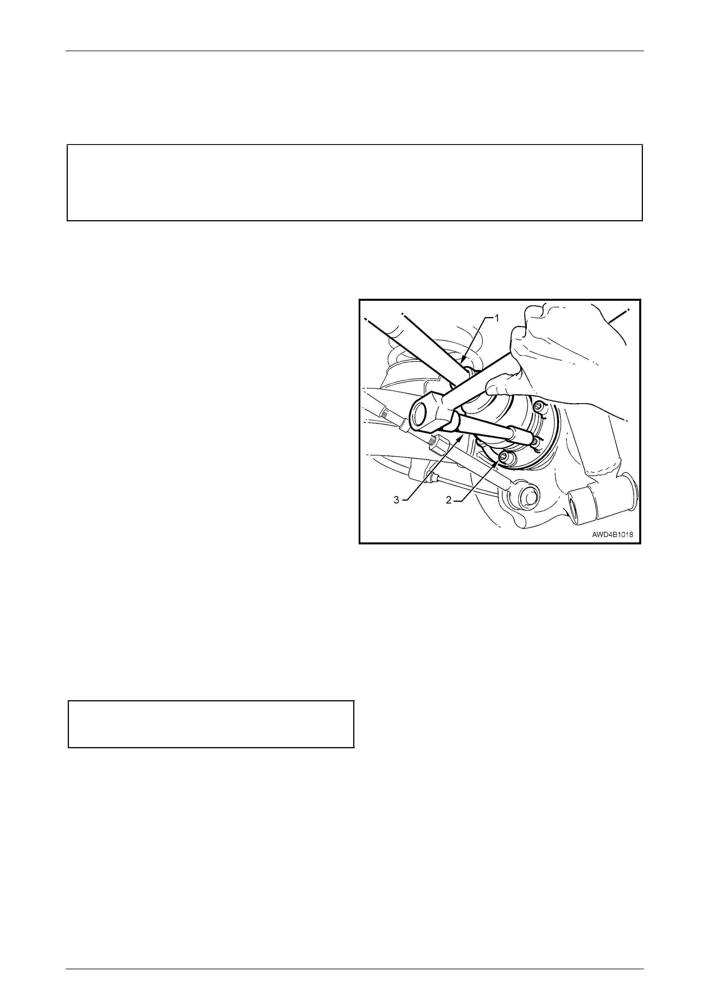
3 With the park brake firmly applied, use an 8 mm Allen
key socket and suitable socket equipm ent (3) remove
drive shaft inner constant velocity joint to inner axle
shaft and outer constant velocity joint to outer rear
wheel driveshaft flange attaching bo lts (2) (six places)
and plates, remove drive shaft (1).
NOTE
During drive shaft removal and reinstallati on, the
drive shaft must be supported to keep constant
velocity joint deflection to a minimum. Figure 4B1 – 29
Reinstall
Reinstallation of the drive shaft is reversal of the removal procedure, noting the following points.
1 When reinstalling the driveshaft, ensure that either constant velocity joint is not deflected excessively and that the
orientation is the same as before remov al, u sing the identification marks previously applied.
2 Reinstall the driveshaft, then six NEW bolts and three plates at each end, tightening to the correct torque
specification.
Drive shaft constant velocity joint
bolt torque specification.......................................50 N.m
plus 90° turn angle
Rear Final Drive and Drive Shafts Page 4B1-24
Page 4B1-24
2.8 Drive Shaft and/or Constant Velocity
Joints
LT Section No: 05-290-1
There are three repair kits available for drive shaft constant velocity joint repairs:
a A ‘Boot Kit’, which consists of a boot, boot clamps and retaining circlip, common for both the plunge and fixed
designs.
b A ‘Constant Velocity Joint Kit’, which contains the same items as the Boot Kit plus a 'fixe d' design constant velocit y
joint and lubricant of the correct type and quantity.
c A ‘Constant Velocity Joint Kit’, which contains the same items as the Boot Kit plus a 'plunge' design constant
velocity joint and lubricant of the correct type and quantity.
NOTE
• Sealant for the constant velocity joint covers
is not supplied in any kit. The correct sealant
however, is available in 75 gram tubes.
• Both the dust cap and the dust shield are
available as separate items and not included
in any of the available kits.
Disassemble
NOTE
Except where noted differences apply, the
following procedures apply to either the fixed or
plunge type of constant velocity joint.
1 Remove drive shaft assembly,
refer to 2.7 Drive Shaft Assembly in this Section.
2 Clean outside of assembly with a suitable solvent
before disassembling.
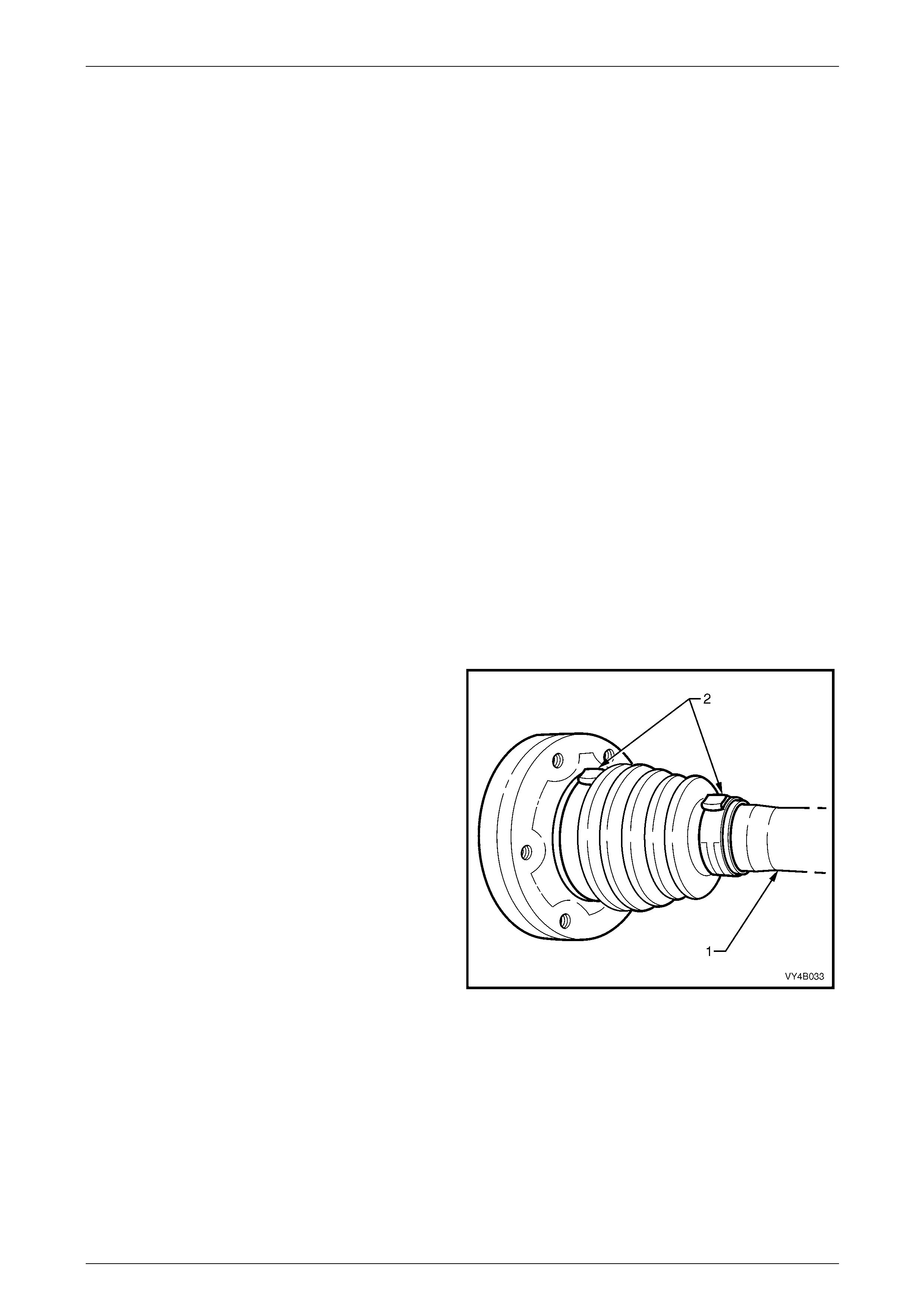
3 Clamp assembly, by drive shaft (1), in a vice fitted with
soft metal jaws.
4 Using tin snips or other suitable cutting tool, cut boot
clamps (2) in raised crimped area and remo ve clamps.
Figure 4B1 – 30
Rear Final Drive and Drive Shafts Page 4B1-25
Page 4B1-25
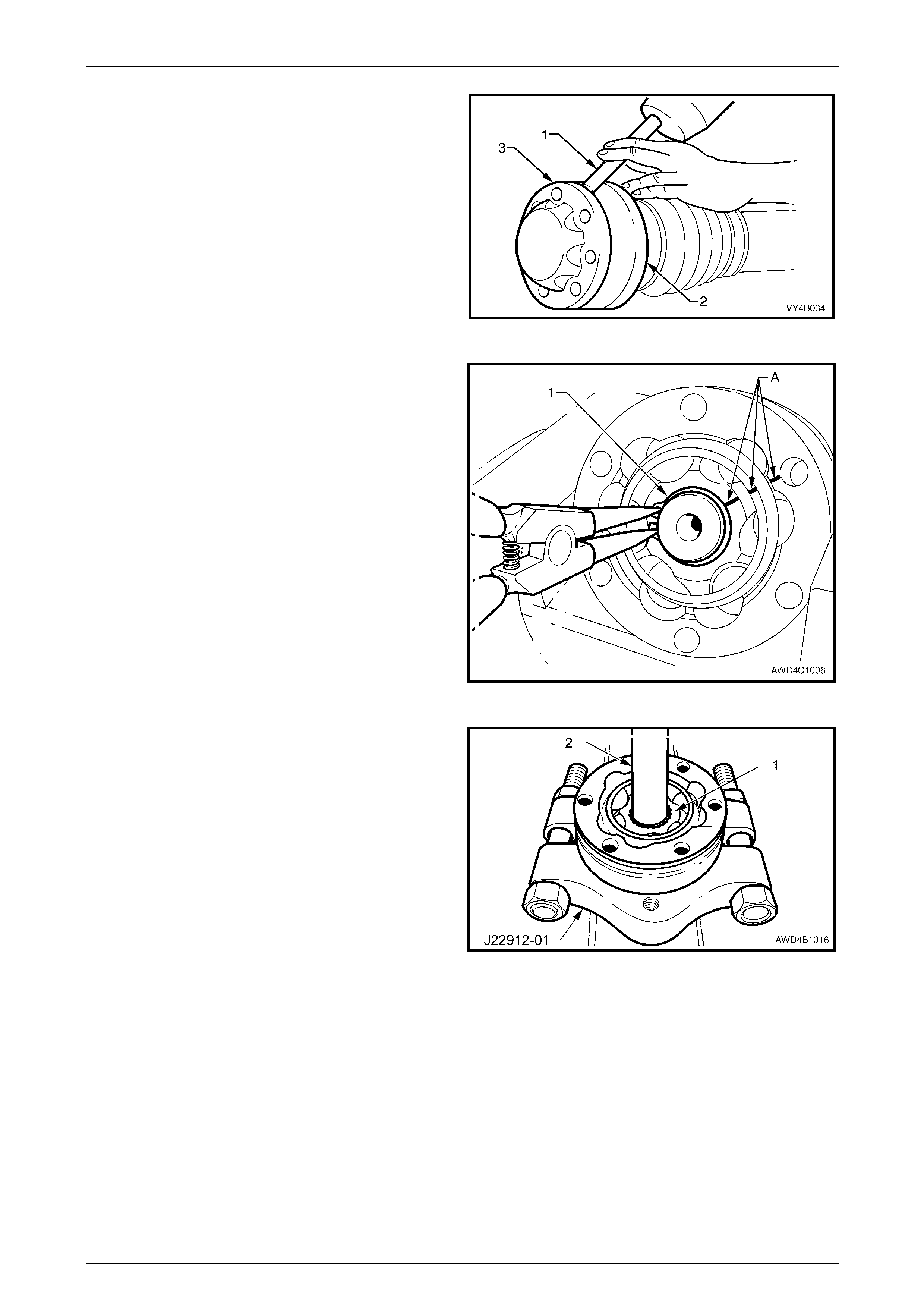
5 Using a suitable drift (1) and hammer, tap end dust
shield cap (3) from the outer end of the constant
velocity joint. being disassembled.
6 After changing the clamping, use a simil ar procedure
to dislodge the inner dust shield (2) from the constant
velocity joint.
Figure 4B1 – 31
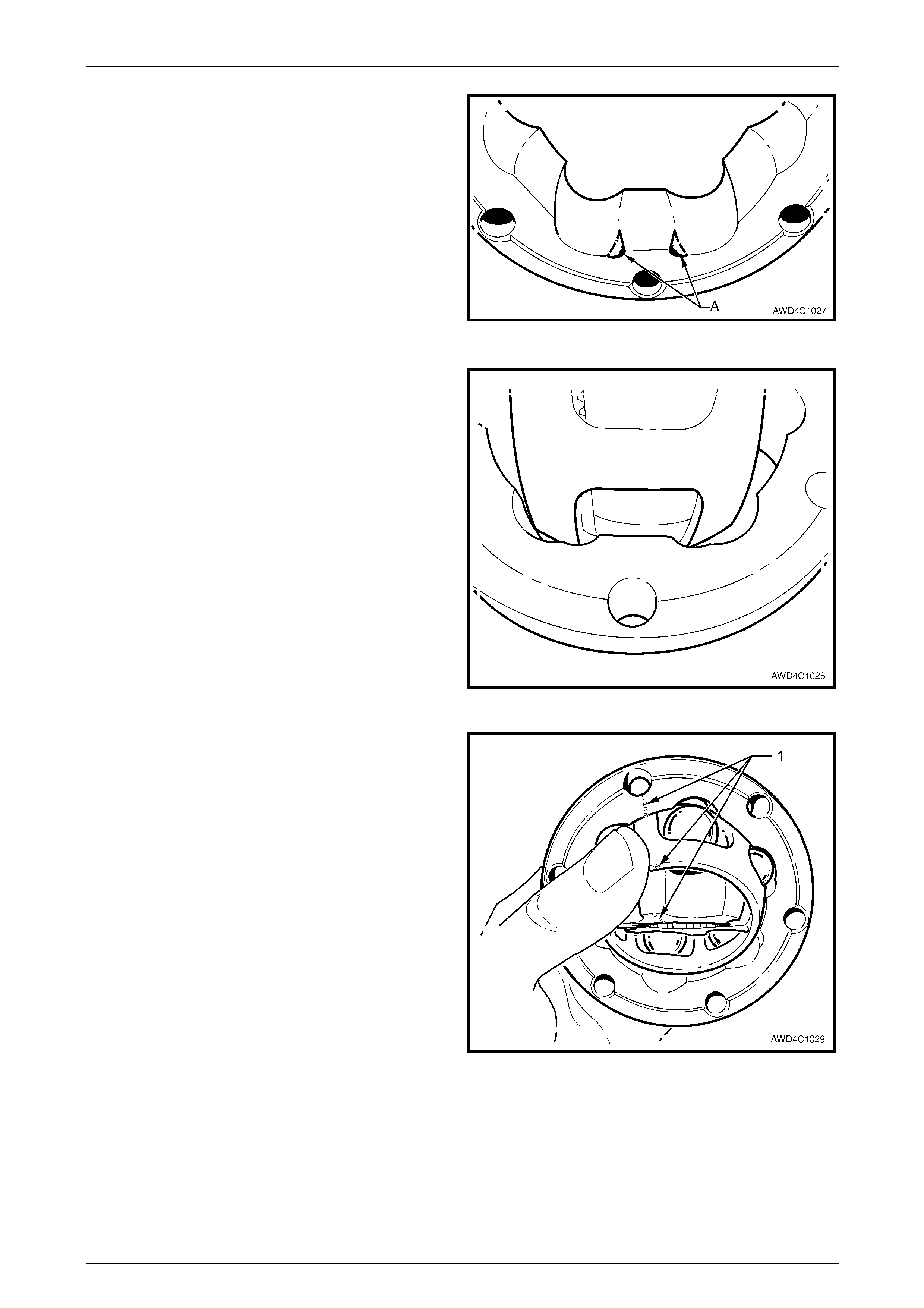
7 Using suitable circlip pliers, remove the circlip (1) from
the end of drive shaft where the constant velocity joint
is to be removed. Discard the removed circlip.
NOTE
Do not re-use circlips once they have been
removed. Always use new snap rings on
reassembly.
8 Wipe the excess lubricant from the outer joint surfaces
then apply correction fluid across the inner race, ball
carrier and outer race as indic ated b y 'A'.
NOTE
This step is necessary to maintain the original
relationship of these three components.
9 Remove assembly from vice. Slide inner dust shield
and boot towards the centre of the driveshaft. Figure 4B1 – 32
10 Using suitable press plates (such as Tool No. J22912-
01), supporting inner race (1), press drive sha ft from
constant velocity joint, using a suitable drift (2).
NOTE
While the press plates must support the inner
race, if clamped too tight to the drive shaft, then
the shaft splines will foul against the press
plates.
11 Repeat process to remove remaining constant velocity
joint, as required.
12 Remove boots and dust shields from drive shaft,
ensuring boots are not dam aged on edges of shaft
splines. Figure 4B1 – 33
Rear Final Drive and Drive Shafts Page 4B1-26
Page 4B1-26
Inspect
Drive Shaft and Boots
1 Clean shaft and boot/s in a suitable cleaning solvent.
2 Inspect drive shaft for twisting, cracking or excessive spline wear.
NOTE
As the drive shaft is not serviced separately, if
found to be defective, then the complete drive
shaft must be replaced.
3 Inspect boots and replace if split, fatigued, cracked or worn.
Constant Velocity Joints
Complete disassembly of the constant
velocity joints is not recommended. The
internal components are a precision fit and
develop their own characteristic wear
patterns. Intermixing components could
result in looseness, binding and/or premature
failure of the joint.
1 Inspect grease in joint and, if obviously contaminated
and/or has been subjected to dirt/water ingress, the
joint has probably suffered damage and should be
replaced.
2 If inspection reveals that the joint has not been
contaminated, clean joint by soaking in a suitable
cleaning solvent.
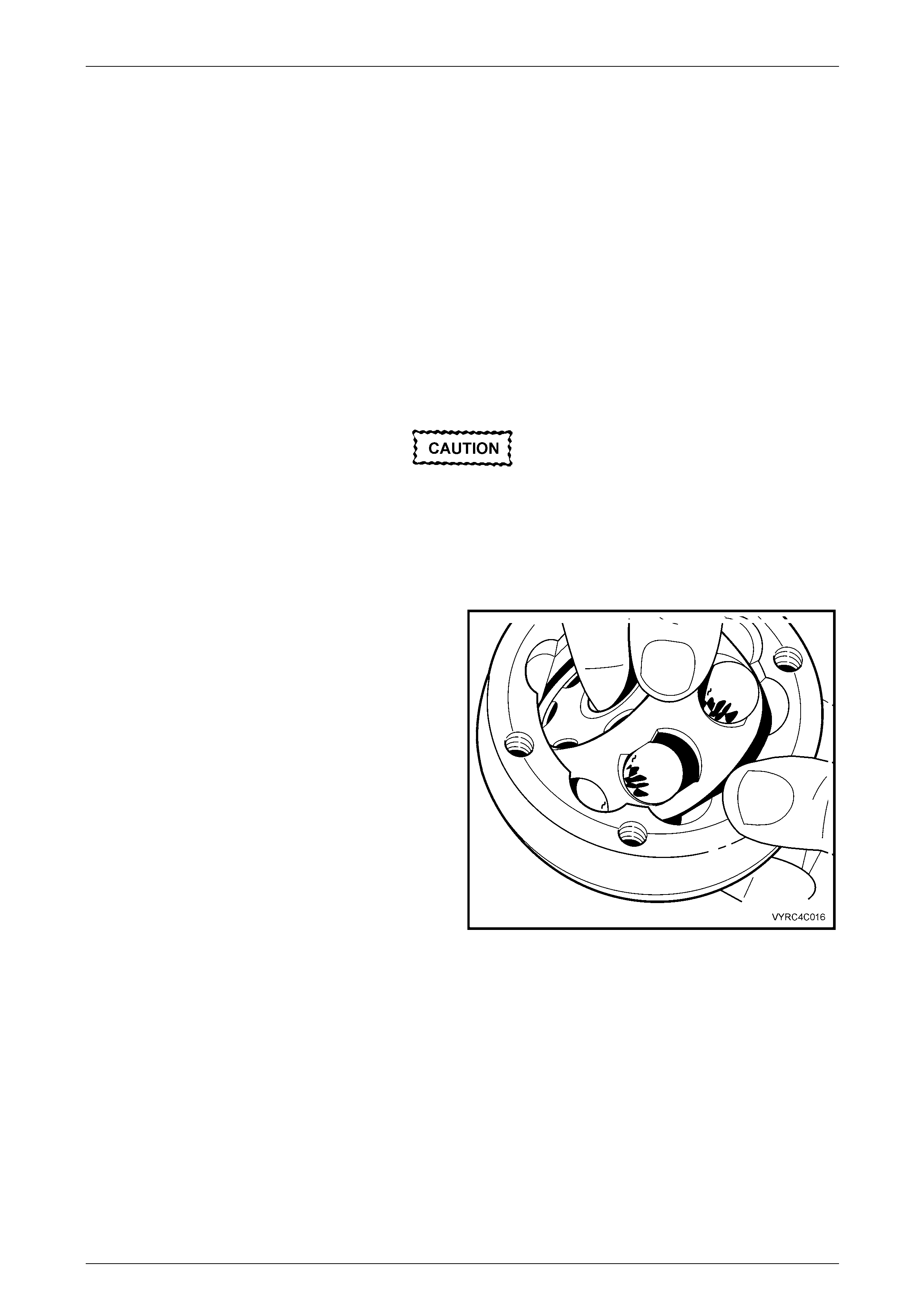
3 Once grease has been removed, insp ect internal
components by tilting inner race to one si de to expose
each ball.
NOTE
Take care not to pivot the inner race too sharply,
as the balls can become dislodged. If this does
occur and the origi nal location of the balls is lost,
then the constant velocity joint should be
replaced.
Figure 4B1 – 34
4 Replace the constant velocity joint assembly if there is severe pitting, galling, play between balls and the cage
windows, any cracking or damage to ca ge, outer race, pitting or galling or chips in raceways.
Rear Final Drive and Drive Shafts Page 4B1-27
Page 4B1-27
Reassemble
Constant Velocity Joints
NOTES
• During the removal, cleaning and inspection
of a constant velocity joint, it is possible for
the joint to become disassembled. Should the
disassembly of a constant velocity (CV) joint
be required and, notwithstanding the earlier
recommendation, it is possible to reassemble
the CV joint, provided the foll owing procedure
is followed EXACTLY.
• All components, including the individual balls,
MUST be maintained in their original
relationship to each other, to minimise the
creation of a noisy or binding joint.
• Under no circumstances are components
from one constant velocity joint to be mixed
with components from another CV joint.
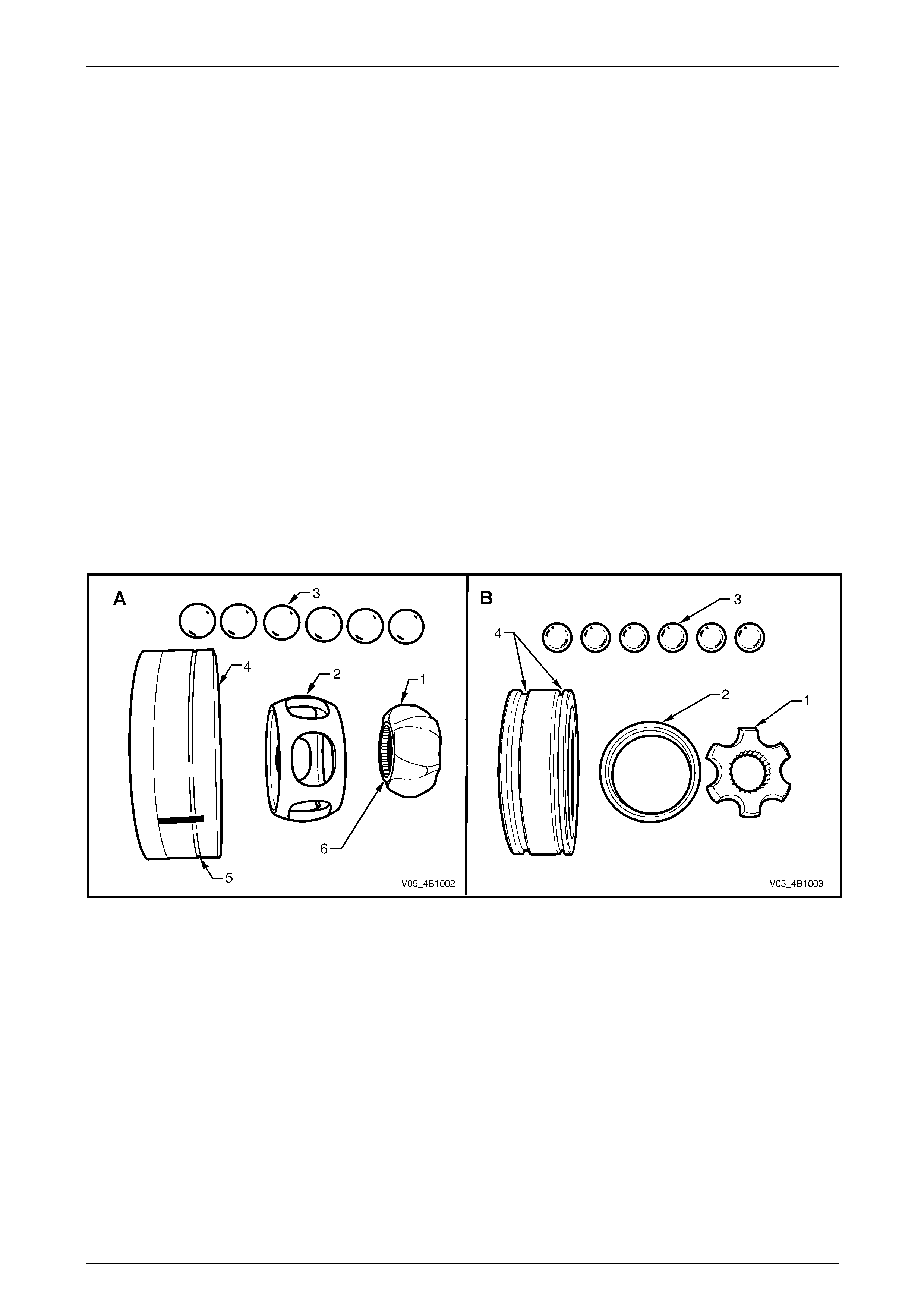
Shown in Figure 4B1 – 35, are exploded views of each constant velocity joint t ype; view 'A' is the plunge design, while
view 'B' shows the fixed design.
With the plunge joint ('A'), note the ide ntification groove (5) on the outer race and the ide ntificatio n step (6) on the inner
race (1). Conversely, the fixed joint ('B') has two grooves (4) on the outer race, a chamfer on the cage (2) and straight
ball raceways on the inner race (1).
Figure 4B1 – 35
Rear Final Drive and Drive Shafts Page 4B1-28
Page 4B1-28
Plunge Type
1 Place the inner race (1) into the cage (2) and position
centrally.
Figure 4B1 – 36
2 Place the inner race and cage assembly (2) into the
outer race (1). Make sure that the identification groove
(1) and step (2) are on opposite sides of the assembly,
as shown.
Figure 4B1 – 37
3 Align the thick sections (A) on the outer race (1) , with
the narrow ones (B) on the inner race (2), aligning the
three marks made before disassembly.
Figure 4B1 – 38
Rear Final Drive and Drive Shafts Page 4B1-29
Page 4B1-29
4 Tilt the cage and inner race, as shown and fit one ball
(1).
Repeat this process for the remaining five balls.
Figure 4B1 – 39
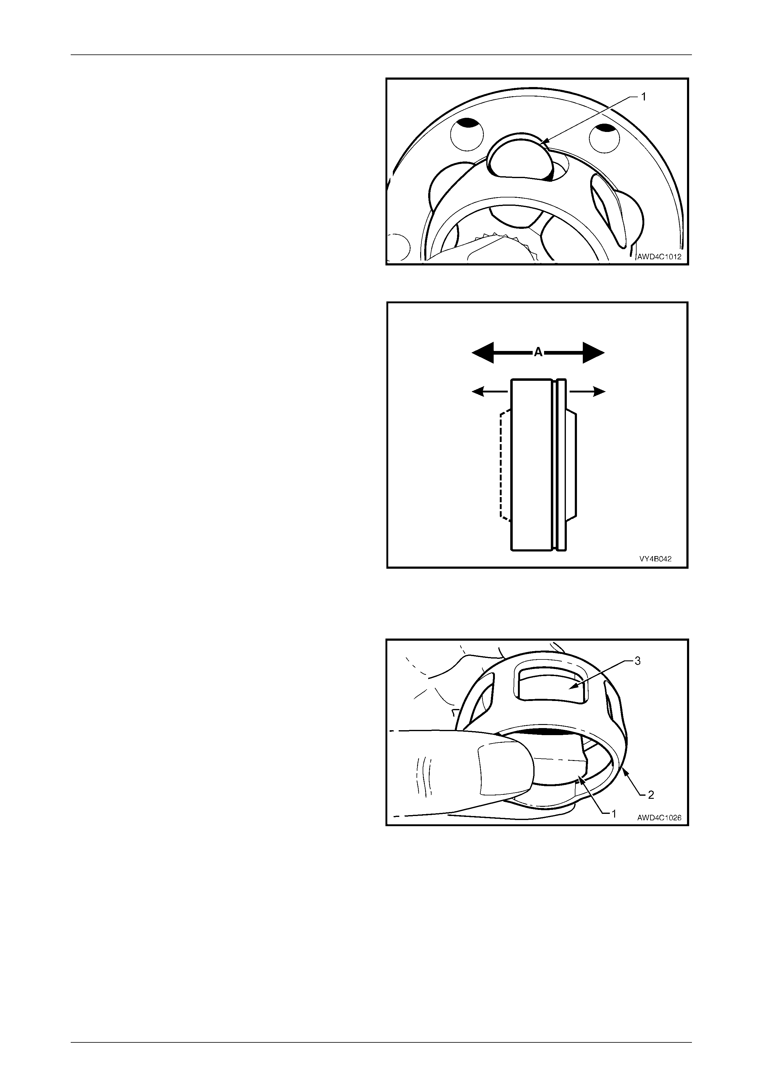
5 When assembly of the constant velocity joint is
complete, check for plunge movement of the inner
members, as indicated by ‘A’. If NO plunge movement
can be achieved, then the constant velocity joint has
NOT been correctly assembled.
If such a situation occurs, the constant velocity joint
must be disassembled and the assemb ly process
repeated until such time that the required plunge
movement is achieved.
Figure 4B1 – 40
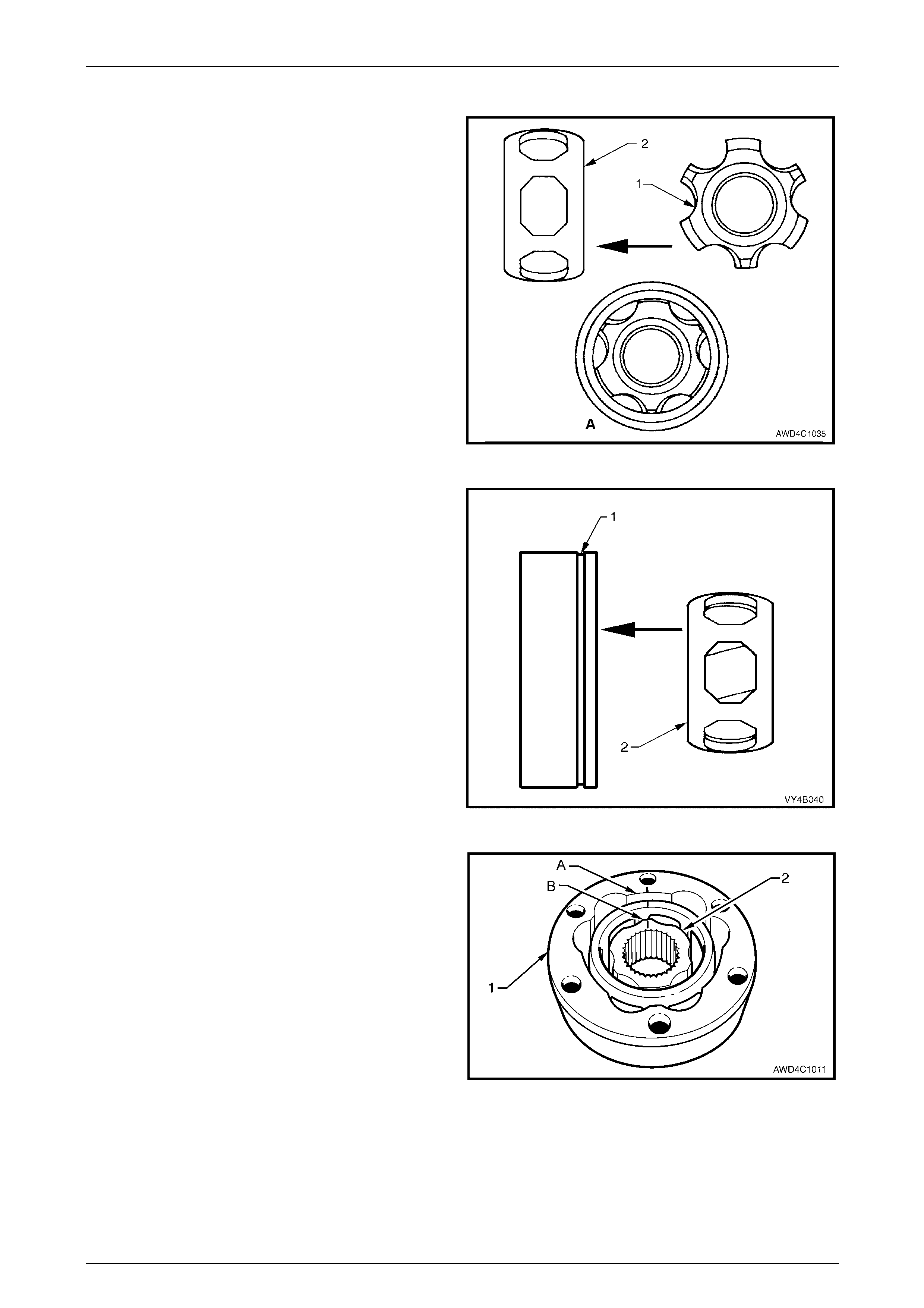
Fixed Type
1 With the inner race (1) at 90° to the ball cage (2),
insert one 'leg' (3) of the inner race into one of the ball
holes, then manipulate the inner race unti l installed
inside the ball cage. Check that the relatio nship marks
are both on the same side.
NOTE
The fine groove on the inner edge of the ball
cage and the chamfered spline edge, should
both be opposite the relationship marks.
Figure 4B1 – 41
Rear Final Drive and Drive Shafts Page 4B1-30
Page 4B1-30
2 Reinstall the ball cage and in ner race into the outer
race, following this next procedure:
a Locate the two reliefs in the ball grooves in the
outer race, indicated by 'A'. There will be similar
reliefs on the opposite side.
Figure 4B1 – 42
b With the ball cage and inner race at 90° to the
outer race, install at the relief points (as shown),
then manipulate the ball cage to fit inside the
outer race. Ensure that the relationship marks
are all on the same side and aligned.
Figure 4B1 – 43
3 Tilt the ball cage and inner race as shown, and fit the
balls, in their correct order, one at a time.
4 Check that the three relationship marks (1) are in
alignment.
5 Check that axial movement is minimal.
Figure 4B1 – 44
Rear Final Drive and Drive Shafts Page 4B1-31
Page 4B1-31
Drive Shaft and Boots
1 Remove old sealing bead of silicon from dust shields, dust caps and constant velocity joints.
2 Slide a NEW small boot clamp over the driveshaft, then ins tall both dust shield and boot assemblies onto
driveshafts, ensuring that boots are not damaged by sharp edges on each end by the shaft splines.
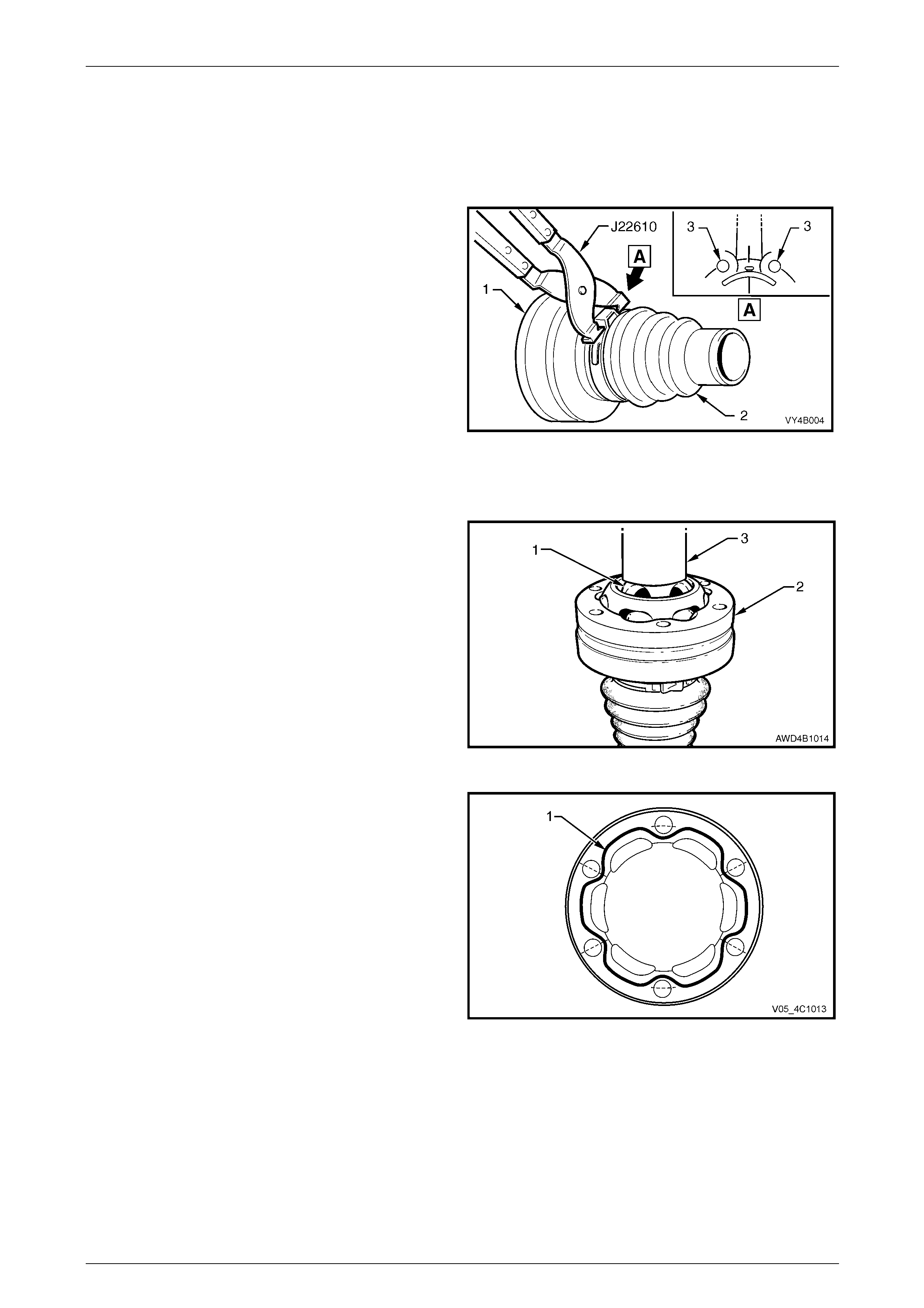
3 Position a NEW large boot clamp over boot (2) and
place boot over dust shield (1). Using Tool No.
J22610, securely crimp boot clamp, ensuring the crimp
is positioned mid-way between two bolt holes (3, in
view ‘A’).
Figure 4B1 – 45
4 Pack inside section of joint and boot with one tube of grease (40 grams) and pack half tube (20 grams) to outside
section of joint. Work the joint by hand to distribute grease onto all surfaces, inside the joint.
5 Using a suitable size tube (3) (or socket), press the
constant velocity joint (2) onto the drive shaft, ensuring
that the press load is taken by the inner race (1).
NOTE
While the plunge type constant velocity joint Is
shown, the procedure for either t ype is similar.
6 Install a NEW circlip to secure the constant velocity
joint, at each end.
Figure 4B1 – 46
7 Apply a 2 mm bead (1) of Loc tite 510 High
Temperature Gasket Eliminator sealant or equivalent,
to dust caps/shields. Take care not to contaminate the
constant velocity joint grease with sealant.
Figure 4B1 – 47
Rear Final Drive and Drive Shafts Page 4B1-32
Page 4B1-32
8 Position dust caps and dust shields ont o constant
velocity joints, ensuring that all bolt holes align.
NOTE
Temporarily install three of the retaining bolts to
assist with the alignment.
9 Using a suitable punch and hammer, tap caps and
shields into place.
Figure 4B1 – 48
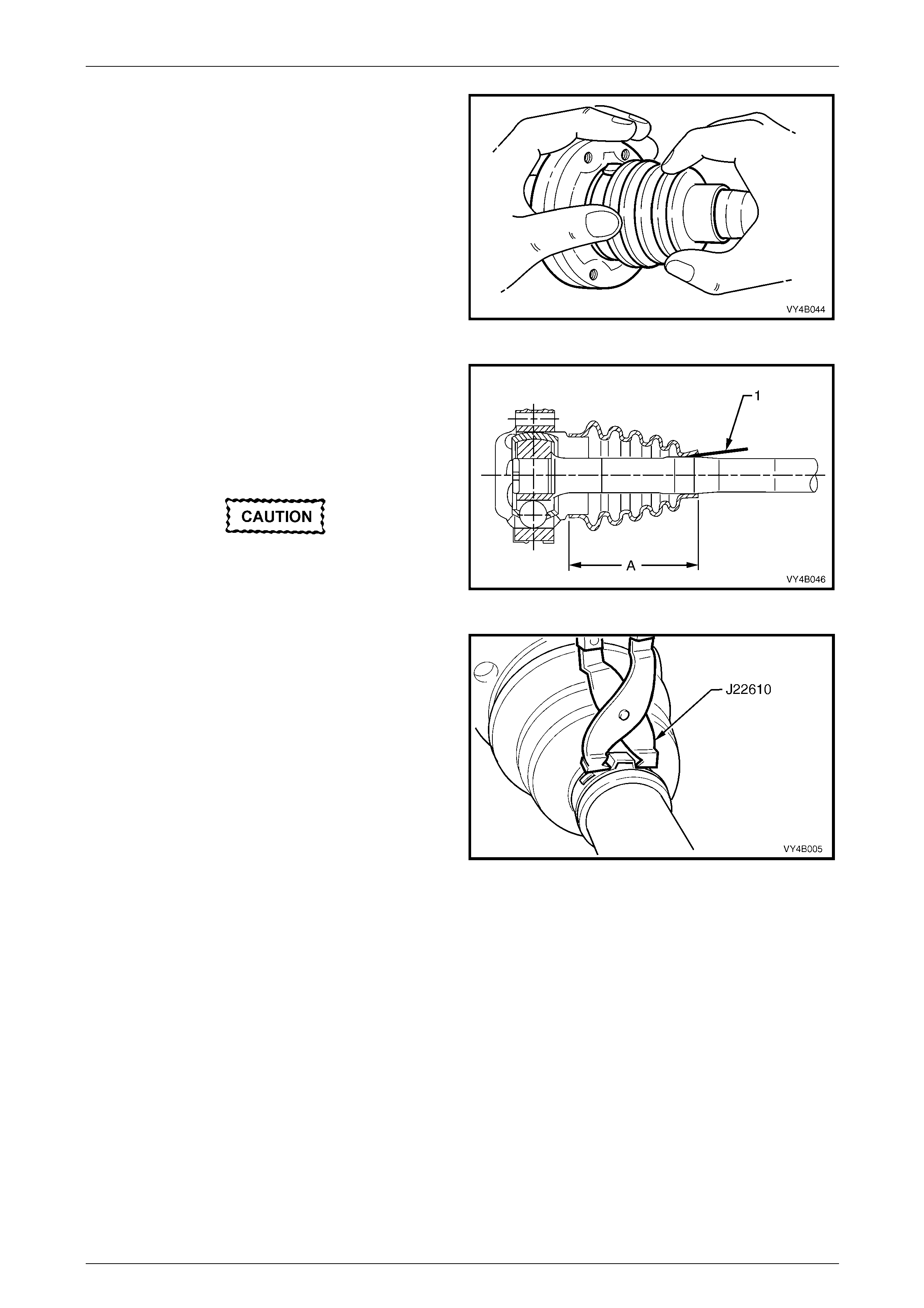
10 Locate small ends of boots into boot grooves on drive
shafts, ensuring that boots are not twisted.
With each joint, pr y up the small e nds of boots from
the shaft (1) to equalise air pressure inside and
outside of boots and work out any dim ples before
crimping the small clamp/s.
The location distance ’A’, only applies to the
plunge type constant velocity joint and
should be set at 81 mm before tightening the
small clamp. Figure 4B1 – 49
11 Position small clamps over ends of boots an d using
Tool No. J22610, crimp ends of clamps unti l a gap
between the clamp 'ears' of 1 to 2 mm is achieved.
12 Reinstall drive shaft, refer to
2.7 Drive Shaft Assembly – Reinstall in this Section.
Figure 4B1 – 50
Rear Final Drive and Drive Shafts Page 4B1-33
Page 4B1-33
2.9 Inner Axle Shaft Seal
LT Section No. – 05-290
Replace
1 Raise the vehicle and suppor t in a safe manner. Refer to Section 0A General Information for the location of
recommended lifting and support points.
2 Remove drive shaft from side of vehicle which seal is to be replaced, refer to 2.7 Drive Shaft Assembly – Remove
in this Section.
• During drive shaft removal, keep drive
shaft supported so that it does not hang
on one end.
• Drive shaft joint deflection should be kept
to a minimum.
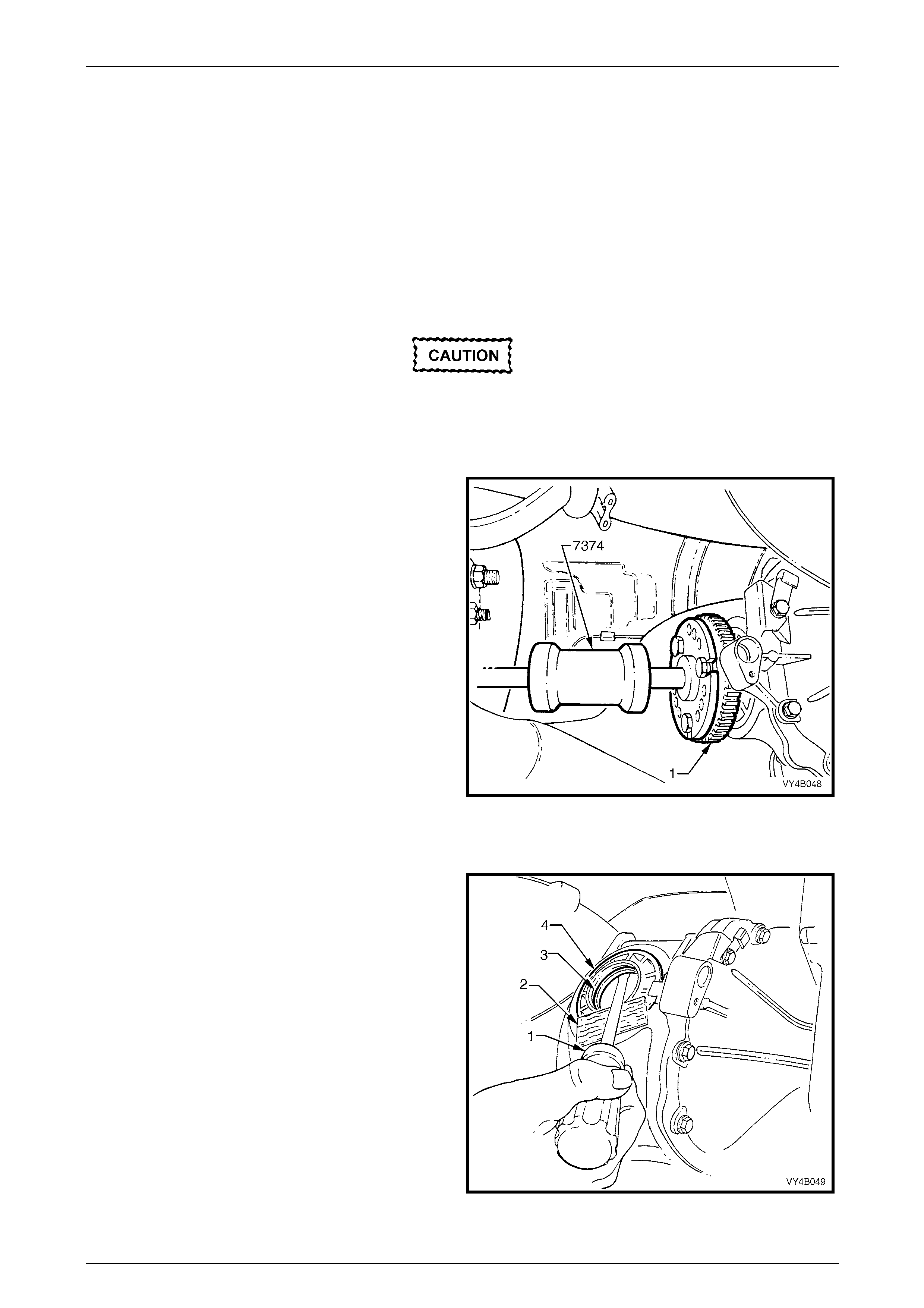
3 Remove inner axle shaft (1) by installing slide
hammer, Tool No. 7374 with three suitabl e size bolts
to axle flange. Use slide hammer to release axle shaft
spring clip.
NOTE
When the axle shaft is removed, a smal l amount
of lubricant may leak from differential carrier.
Figure 4B1 – 51
4 Clean around seal bore and housi ng area to make sure that no foreign matter enters axle shaft needle b earing in
the screw adjuster.
5 Using a suitable scre wdriver (1) and a block of wood
(2), lever seal (3) from screw adjuster bore (4).
NOTE
Take care not to damage the screw adjuster's
aluminium housing (4) with the scre wdriver blad e
(1), as this could cause oil leaks to occur, after a
new oil seal was fitted.
Figure 4B1 – 52
Rear Final Drive and Drive Shafts Page 4B1-34
Page 4B1-34
6 Before installation of a new seal, examine seal surface of inner axle shaft and remove any nicks or burrs. Should
this inspection show that the surface is marked, a new inner axle shaft should b e fitted.
NOTE
• The left hand inner axle shaft is shorter in
length than the right hand shaft.
• If the vehicle is equipped with ABS, the inner
axle shafts are unique for this applicati on.
• Check that the spring clip in end of axle shaft
is not damaged and moves freely in groove.
Replace spring clip if necessary, by
expanding ends of clip and removing from
shaft. Only expand the ends of a new clip
enough to allow installation into shaft groove.
7 Examine seal bore in screw adjuster and remove any nicks or burrs.
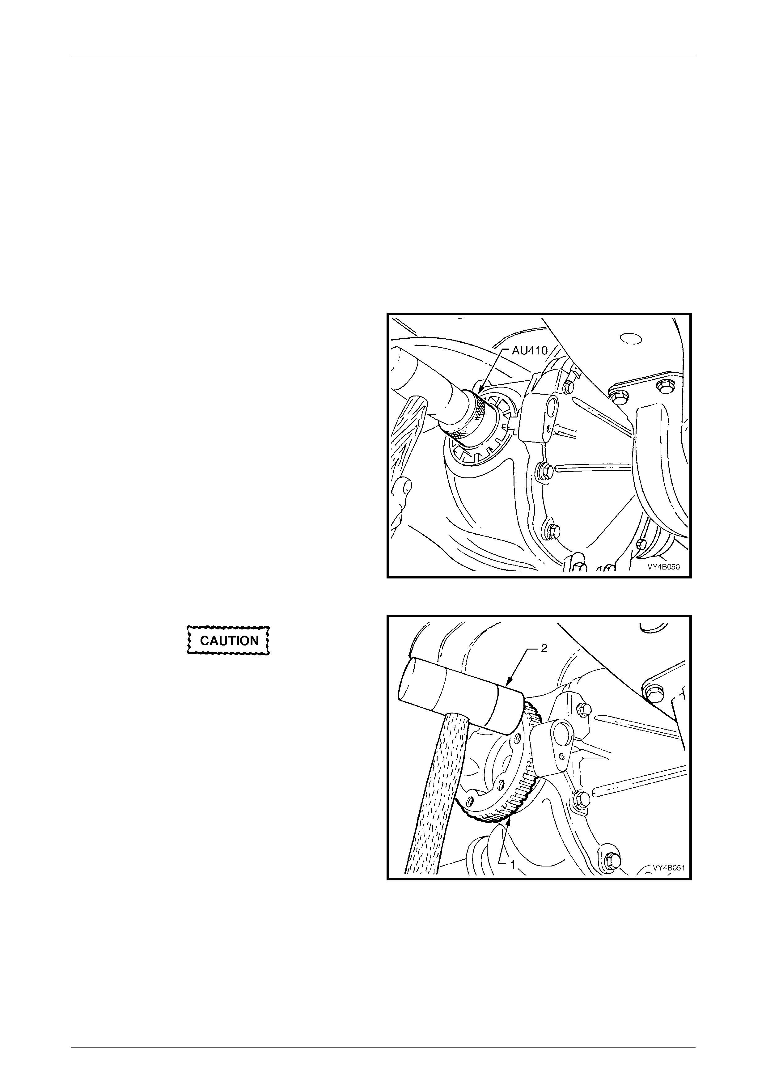
8 Lubricate seal lips and outsi de diameter with
Mobilgrease XHP 222 grease (or equivalent). Install
seal using Tool No. AU410, u ntil seal bottoms in bore.
Figure 4B1 – 53
Take care when installing the inner axle shaft
that the securing spring clip or the shaft
splines do not damage the seal lips.
9 Reinstall inner axle sh aft (1), aligni ng splines with
clutch cone (if fitted with a Limited Slip Differential)
and side gear.
10 Lightly hit on end of axle shaft flange (1) with a soft
faced hammer (2) to compress spring clip on shaft into
clutch cone and side gear splines. F ully engage shaft
(1) until clip snaps into side gear groove.
11 Reinstall drive shaft, refer to 2.7 Drive Shaft Assembly,
in this Section.
Figure 4B1 – 54
12 Remove safety stands and lower vehicle.
13 Check and fill differential carrier to correct le vel with specified lubricant.
Refer to 2.2 Checking Differential Carrier Lubricant Level, in this Section.
Rear Final Drive and Drive Shafts Page 4B1-35
Page 4B1-35
2.10 Pinion Oil Seal
LT Section No: 05-290 – 1
ATTENTION
Fasteners either have micro encapsulated sealant applied or incorporate a mechanical thread lock and
should only be re-used once. If in doubt, replacement is recommended.
Pinion flange retaining nut threads.
Replace (Vehicles With a Rear Rubber Coupling)
1 Raise the vehicle and suppor t in a safe manner. Refer to Section 0A General Information for the location of
recommended lifting and support points.
2 Mark the position of the propeller shaft rear coupling to pinion flange, using a felt tipped pen or similar.
3 Remove propeller shaft, refer to Section 4C1 Propeller Shaft and Universal Joints. This operation may also require
partial exhaust system removal.
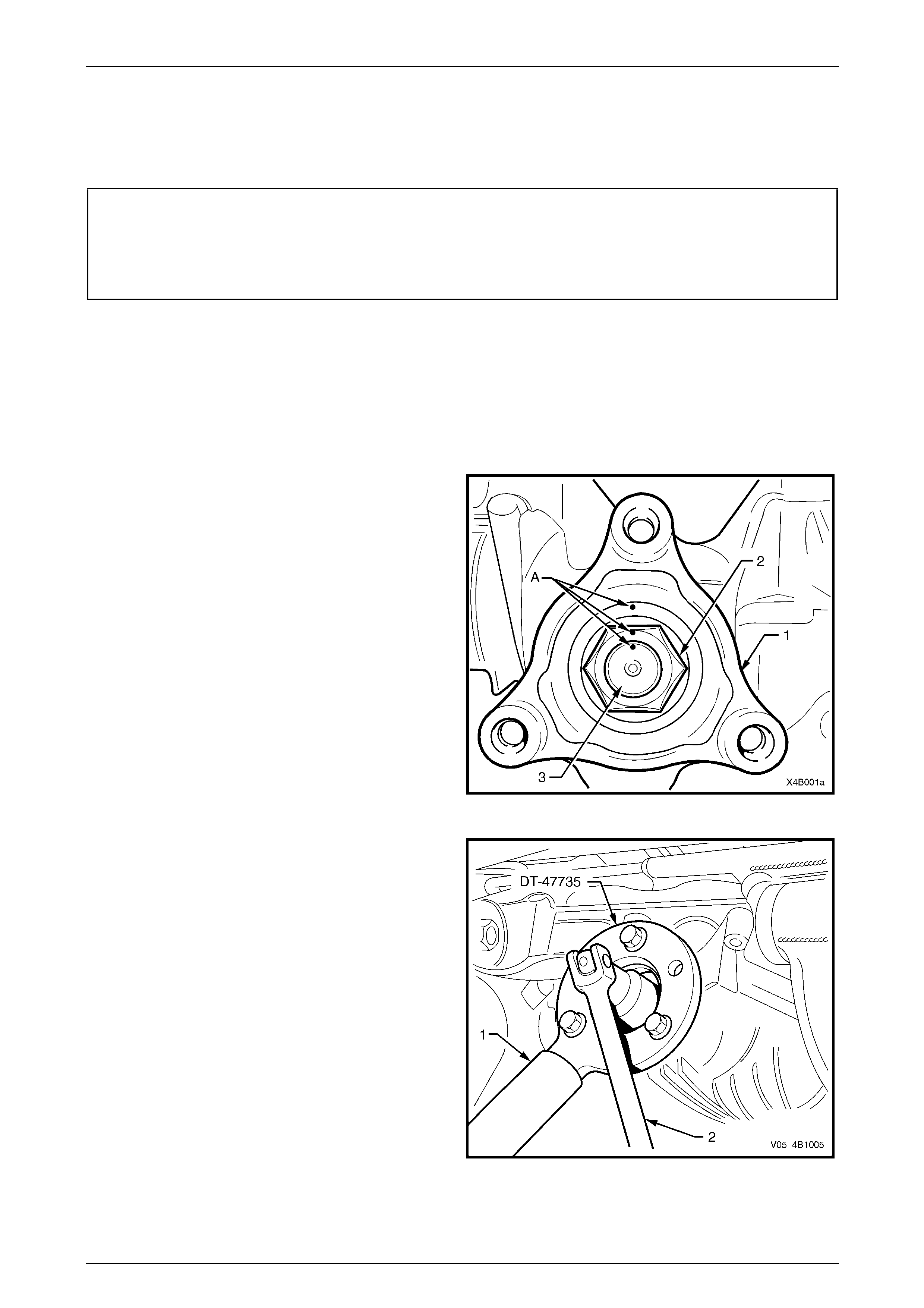
4 Lightly centre-punch ali gnment marks (A) on the pinion
flange (1), flange nut (2) and pini on end (3) as an aid
for reassembly.
NOTE
By reassembling to the original position, the
flange run-out will be minimised and the pinion
bearing preload will be maintained.
Figure 4B1 – 55
5 Attach Tool No. DT-47735 to the pinion flange, using
three suitable bolts to hold pinion flange.
NOTE
Use either the rear coupling to pinion flange
retaining bolts with a 25 mm spacer (e.g. flat
washers) installed first or use three bolts M12 x
1.5 x 40, with the thread extending to within 12
mm of the head.
6 Insert a suitable length of pipe (1) over the tang of the
installed tool for leverage, then remove the pinion
flange retaining nut, using a commercia lly available,
30 mm deep socket and socket bar (2).
7 Remove Tool No. DT -47735 from the pinion flange.
Figure 4B1 – 56
Rear Final Drive and Drive Shafts Page 4B1-36
Page 4B1-36
8 Place drain tray beneath differential carrier.
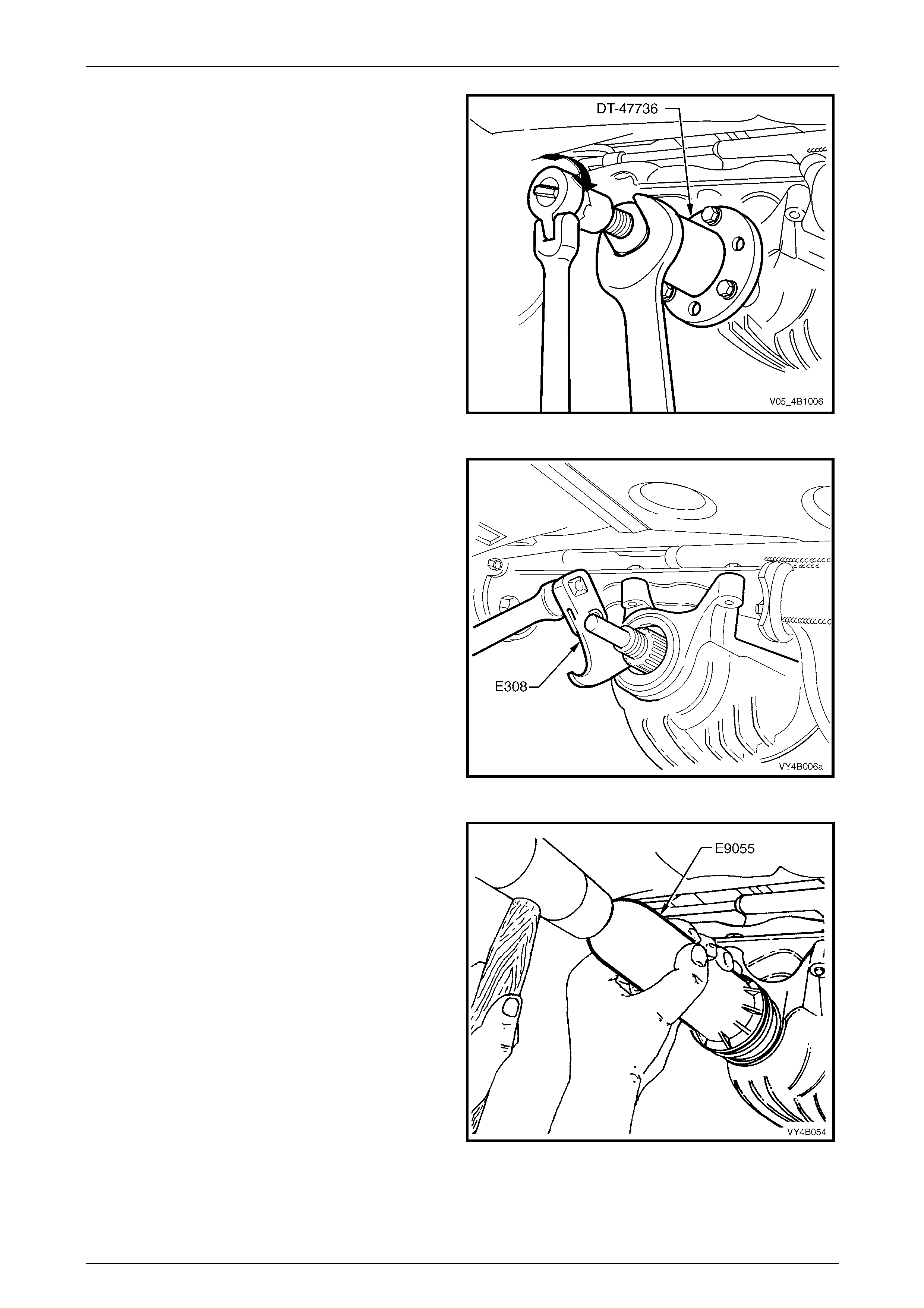
9 Install extractor, Tool No. DT-47736 to the pinion
flange using the same three b olts used to se cure the
flange holding tool, DT-47735 (refer Figure 4B1-57).
10 While holding the extractor tool with a suitable
spanner, withdraw pinion flange by tightening the
forcing screw in the direction indic ated.
Figure 4B1 – 57
11 Prise pinion oil seal from carrier bore using Tool No.
E308 or a universal seal removin g tool.
Figure 4B1 – 58
12 Lubricate the lips of a new pinion oil seal and the outer
diameter with Mobilgrease XHP 222 or equivalent
grease.
13 Start oil seal into differential carrier housing and drive
seal squarely into position us ing Tool No. E9055. Seal
fits flush to 0.25 mm below carrier housing surface.
14 Ensure that pinion shaft is free from burrs and that
flange oil seal surface is free from damage.
Figure 4B1 – 59

Rear Final Drive and Drive Shafts Page 4B1-37
Page 4B1-37
15 Clean the threads of the pinion shaft and the flange retaining nut, removing any oil, dirt or grease.
16 Coat splines and seal surface of pinion flange with differential gear lubricant, and install flange onto pinion shaft
splines. Ensure that centre-punch marks are aligned.
17 Reinstall holdin g tool DT-47735 to the pinion flange.
18 Apply a thread locking compound such as Loctite 243 or equival ent, to the threads of the pinion flange retaining
nut, then reinstall the nut.
19 Tighten the flange retaining nut until all centre-punch marks align. Then carefully tighten the nut to a pos ition not
more than 5° past the aligned setting.
• The pinion flange is an interference fit on
pinion shaft splines and should only be
pulled into place by tightening the
retaining nut. Do not used force or a
hammer the flange during the installation
process.
• Should the retaining nut be over-tightened
and pre-load exceeded, it will be
necessary to remove the pinion from the
carrier and install a new collapsible
spacer. Under no circumstances must the
retaining nut be backed off to decrease the
pre-load reading.
20 Reinstall prope ller shaft rear coupling to the pinion flange, refer Section 4C1 Propeller Shaft and Universal Joints.
21 If removed previously, reconnect exhaust system, in the reverse to the removal procedure.
Refer to Section 8B Exhaust System, for details.
22 Remove safety stands and lower vehicle.
23 Check lubricant level and top up as necessary. Refer 2.2 Checking Differential Carrier Lubricant Level, in this
Section.
24 Start vehicle and check for exhaust leaks.
Rear Final Drive and Drive Shafts Page 4B1-38
Page 4B1-38
Replace (Vehicles With a Rear Constant Velocity Joint)
1 Raise the vehicle and suppor t in a safe manner. Refer to Section 0A General Information for the location of
recommended lifting and support points.
2 Mark the position of the propeller shaft rear coupling to pinion flange, using a felt tipped pen or similar.
3 Remove propeller shaft, refer to Section 4C1 Propeller Shaft and Universal Joints. This operation may also require
partial exhaust system removal.
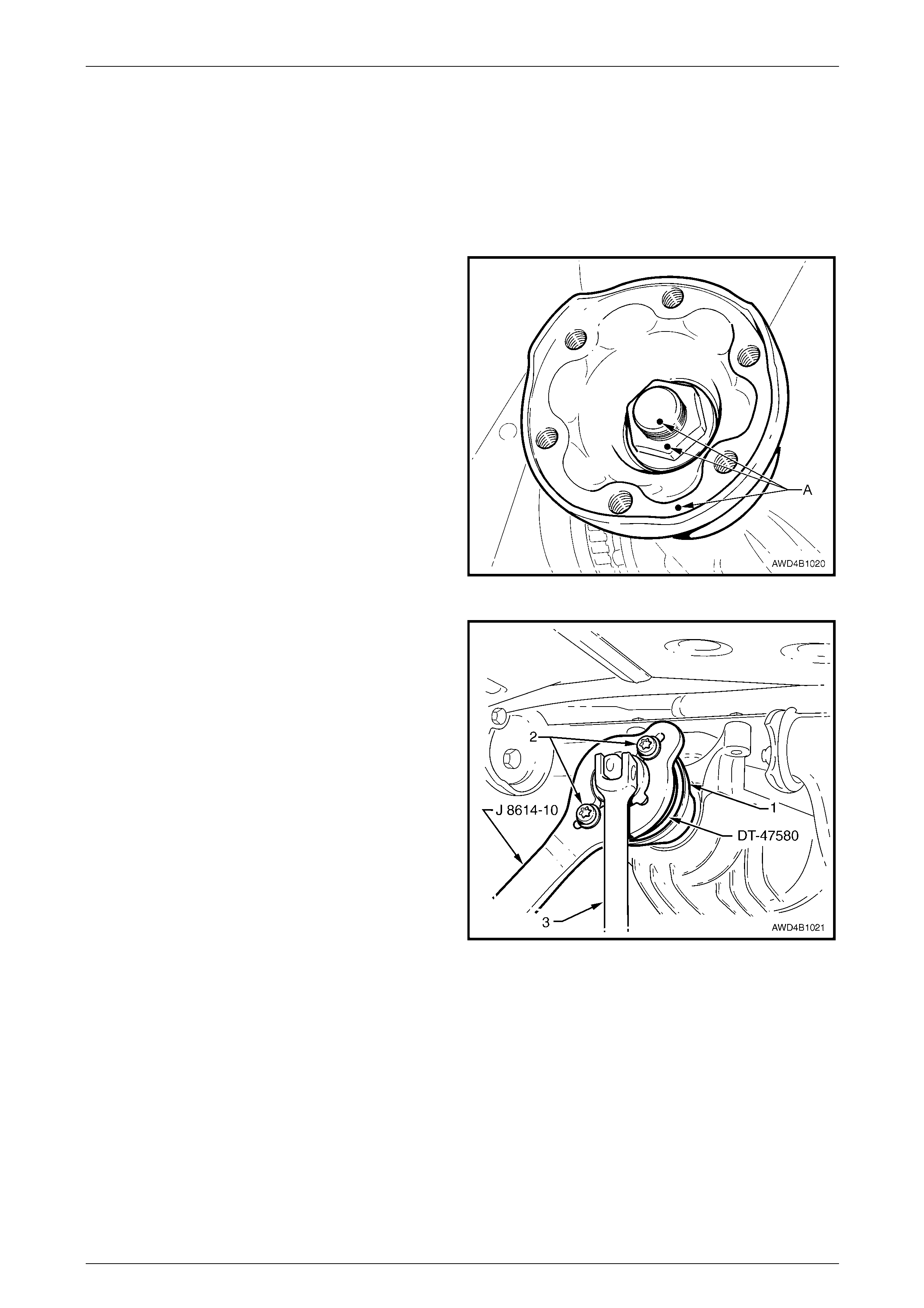
4 Lightly centre-punch ali gnment marks (A) on the pinion
flange, flange nut and pinion end as an aid for
reassembly.
NOTE
By reassembling to the original position, the
flange run-out will be minimised and the pinion
bearing preload will be maintained.
Figure 4B1 – 60
5 Install packing flange DT-47580 into the pinion flange
recess, aligning the holes with those in the pinion
flange.
6 Using two of the propeller shaft constant velocity joint
bolts (2) with flat washers, secure the holding bar, T ool
No. J8614-10 (part of Tool No. J 8614-O1) to the
pinion flange (1). The central recesses in the holding
tool should face inward.
7 While anchoring Tool No. J8614-10, loosen then
remove the pinion flange retaining nut, usin g a
commercially availabl e, 30 mm deep socket and
socket bar (3).
NOTE
A suitable length of pip e installed over the en d of
the socket bar will reduce the effort required to
loosen the pinion flange nut.
Figure 4B1 – 61
Rear Final Drive and Drive Shafts Page 4B1-39
Page 4B1-39
8 Place drain tray beneath differential carrier.
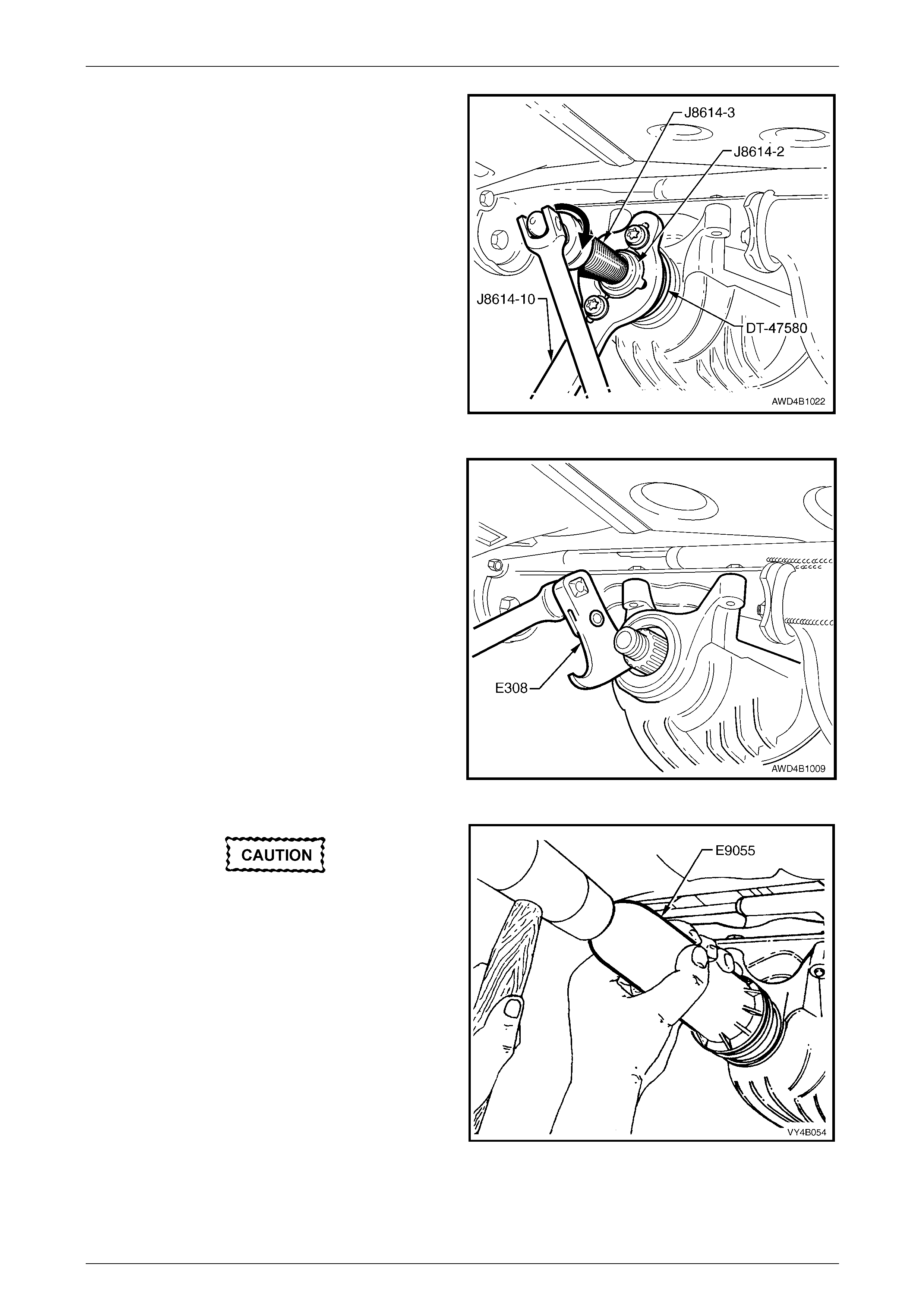
9 With Tool Nos J8614-10 and DT-47580 still installed,
thread the forcing screw, Tool No. J8614-3, in to the
adaptor, Tool No. J8614-2. Install this sub-assembly
into holder, Tool No. J8614-10, then rotate through 45°
to locate in the recesses in J8614-10.
10 While holding J8614-10, use a socket and bar to rotate
the forcing screw J8614-3 in the direction s hown, to
remove the pinion flange.
11 Remove the tools from the pinion flange, then carefull y
set the pinion flange to one side to avoi d damage to
the flanged seal surface.
Figure 4B1 – 62
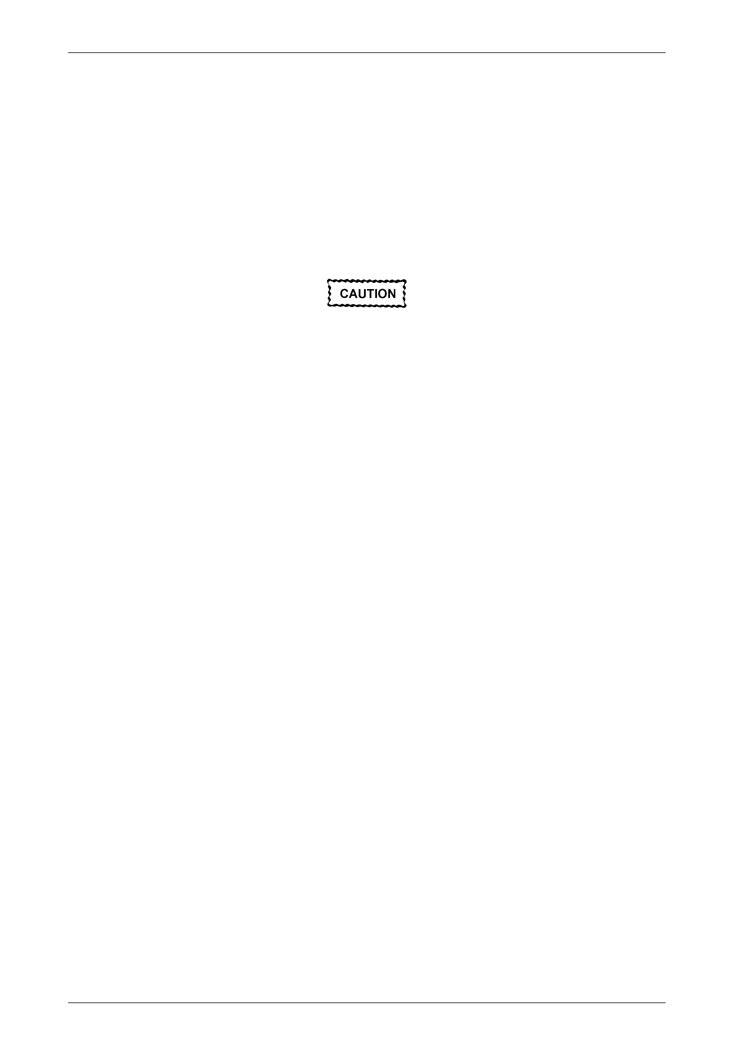
12 Prise pinion oil seal from carrier bore using Tool No.
E308 or a universal seal removin g tool.
Figure 4B1 – 63
When installing a new pinion oil seal, only
install the seal until it is square and flush
with the machined face of the final drive
housing. If installed too deeply then a
premature oil leak could o ccur.
13 Lubricate the lips and outside diameter of a new pinion
oil seal with Mobilgrease XHP 222 or equivalent
grease. The recess bet ween the lips should be
approximately 50% filled with grease.
NOTE
A light coating of grease is also to be applied to
the dirt lip that contacts the pinion flange slinger.
14 Start oil seal into differential carrier housing and drive
seal squarely into position us ing Tool No. E9055. Figure 4B1 – 64
Rear Final Drive and Drive Shafts Page 4B1-40
Page 4B1-40
15 Ensure that pinion shaft is free from burrs and that flange oil seal surface is free from damage.
16 Clean the threads of the pinion shaft and the flange retaining nut, removing any oil, dirt or grease.
17 Coat splines and seal surface of pinion flange with the recommended final drive lubricant, and install flange onto
pinion shaft splines. Ensure that centre-punch marks made at Step 4, are aligned.
18 Reinstall the packing flan ge T ool No. DT-47580 and holding tool J 8614-10 to the pinion flang e, as detailed in
Steps 5 and 6.
19 Apply a thread locking compound such as Loctite 262 or eq uivalent, to the cleaned threads of the pinion flange
retaining nut, then reinstall the nut.
20 Tighten the flange retaining nut until all centre-punch marks align. Then carefully tighten the nut to a pos ition not
more than 5° past the aligned setting.
• The pinion flange is an interference fit on
pinion shaft splines and should only be
pulled into place by tightening the
retaining nut. During installation, do not,
under any circumstances, use force or
hammer the flange onto the pinion splines.
• Should the retaining nut be over-tightened
and pre-load exceeded, it will be
necessary to remove the pinion from the
carrier and install a new collapsible
spacer. Under no circumstances must the
retaining nut be backed off to decrease the
pre-load setting.
21 Reinstall propeller shaft, refer to Section 4C1 Propeller Shaft and Universal Joints.
22 If removed previously, reconnect exhaust system, in the reverse to the removal procedure.
Refer to Section 8B Exhaust System, for details.
23 Remove safety stands and lower vehicle.
24 Check lubricant level and top up as necessary. Refer to 2.2 Checking Differential Carrier Lubricant Level, in this
Section.
25 Start vehicle and check for exhaust leaks.
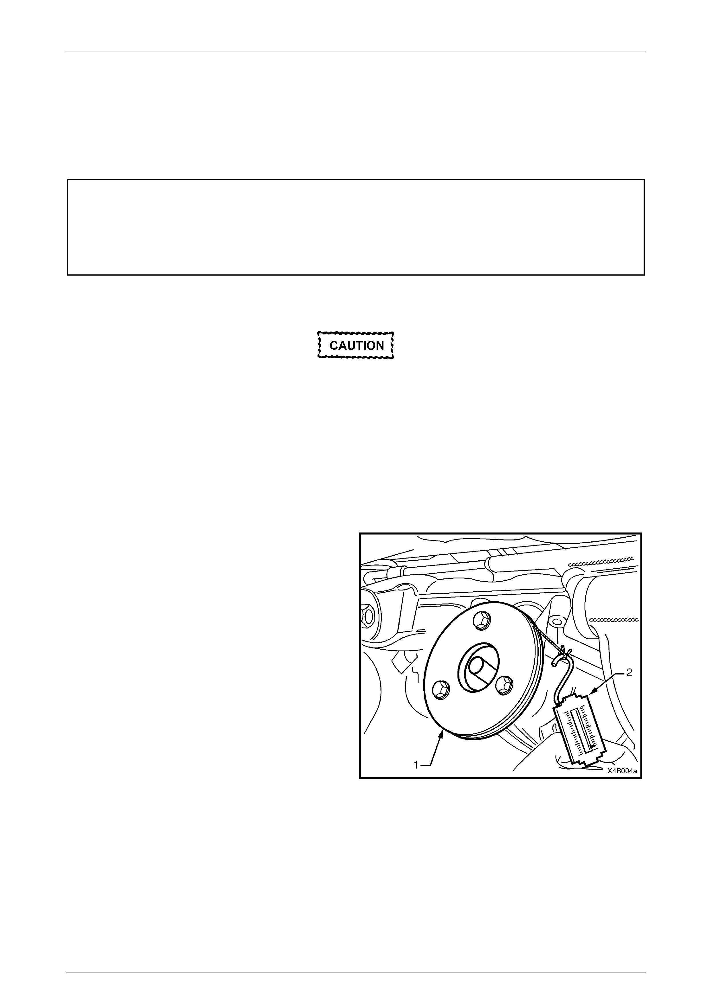
Rear Final Drive and Drive Shafts Page 4B1-41
Page 4B1-41
2.11 Pinion Flange
LT Section 05-290
Replace (Vehicles With a Rear Rubber Coupling)
ATTENTION
The following fasteners MU ST be replaced when performing these operations:
Drive shaft attaching bolts.
Pinion flange retaining nut.
Using Old Oil Seal
Resulting from production tolerances in the
length of the pinion flange, it is essential that
the following method be used when installing
a new pinion flange.
1 Raise the vehicle and suppor t in a safe manner. Refer to Section 0A General Information for the location of
recommended lifting and support points.
2 Remove propeller shaft, refer Section 4C1 Propeller Shaft and Universa l Joints .
3 Remove both drive shafts, refer 2.7 Drive Shafts, in this Section.
4 Check and record pre-load at pini on flange as follows:
a Fit a pulley (1) to pinion flange, using three
suitable bolts and attach a cord around p ulley
and to a spring scale (2).
NOTE
• Use either the rear coupling to pinion flange
retaining bolts with a 25 mm spacer (e.g. flat
washers) installed first or use three bolts M12
x 1.5 x 40, with the thread ext ending to within
12 mm of the head.
• For details of the fabricated pulley, refer to
7 Special Tools at end of this Section.
b Start rotation of pulley and whilst in motion
(approximately 50 – 60 rpm) note and record
reading of spring balance.
This pre-load reading includes pinion bearings,
side bearings, meshing effect of gear set and
pinion oil seal.
To determine pre-load, multipl y readi ng on
spring balance by radius of pulley.
Figure 4B1 – 65
Example: With a pulley diameter of 152 mm, the radius is 76 mm, which equals 0.076 m. With a spring balance reading
of 25 N, the pre-load equals 0.076 m x 25 N = 1.9 N.m.
5 Remove pulley from pinion flange.
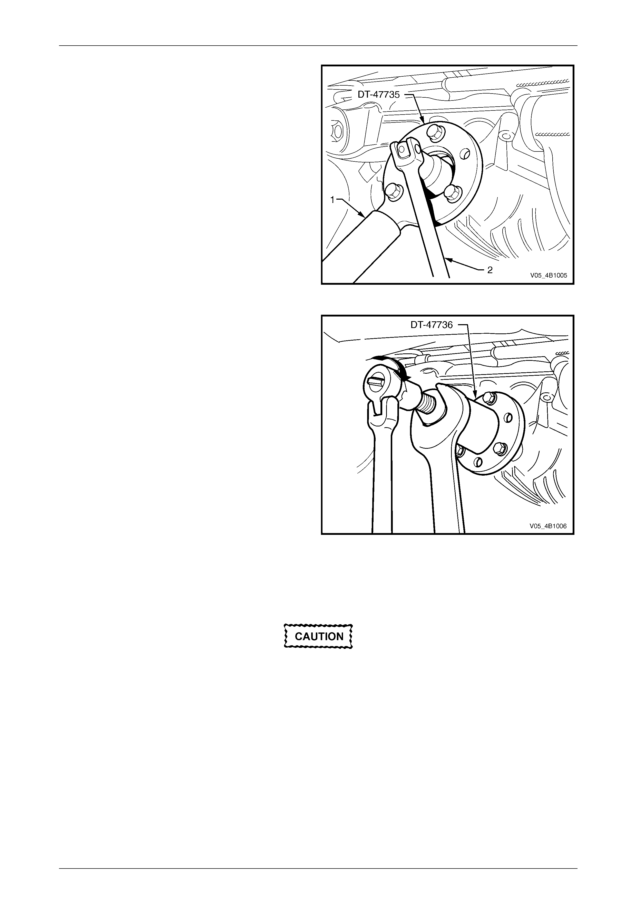
Rear Final Drive and Drive Shafts Page 4B1-42
Page 4B1-42
6 Attach Tool No. DT-47735 to the pinion flange, using
the same three bolts used in step 4a, to hold pinion
flange.
7 Insert a suitable length of pipe (1) over the tang of the
installed tool for leverage, then remove the pinion
flange retaining nut, using a commercia lly available,
30 mm deep socket and socket bar (2).
8 Remove Tool No. DT -47735 from the pinion flange.
Figure 4B1 – 66
9 Place drain tray beneath differential carrier.
10 Install extractor, Tool No. DT-47736 to the pinion
flange using the same three b olts used i n steps 4a and
6.
11 While holding the extractor tool with a suitable
spanner, withdraw pinion flange by tightening the
forcing screw in the direction shown.
Figure 4B1 – 67
12 Ensure that pinion shaft thread is free from burrs, oil, dirt or grease, then coat splines and seal surface of a new
pinion flange with the recommend ed rear axle lubricant.
13 Install the new pinion flange a nd a new retaining nut.
The pinion flange is an interference fit on
pinion shaft splines and should only be pulled
into place by tightening the retaining nut. Do
not used force or a hammer the flange during
the installation process.
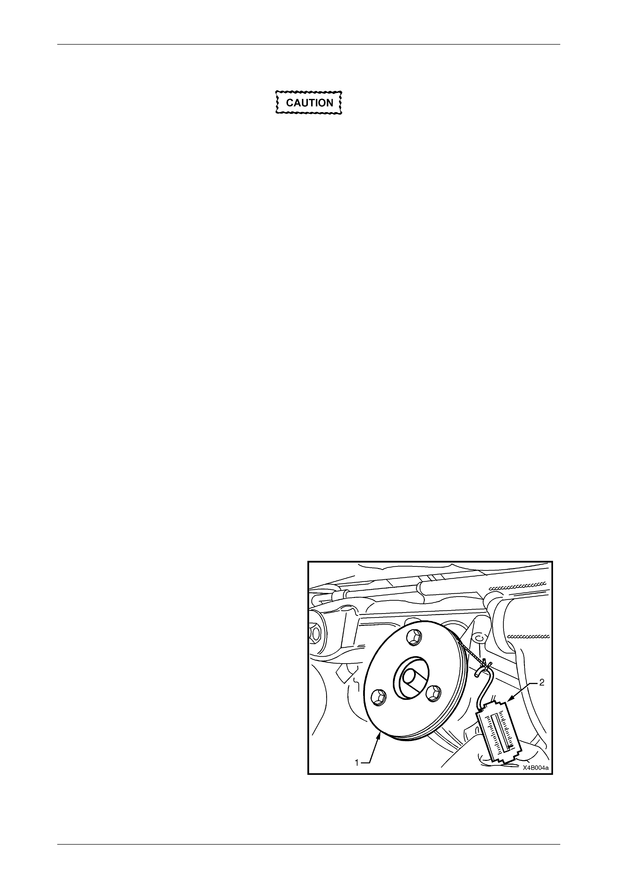
Rear Final Drive and Drive Shafts Page 4B1-43
Page 4B1-43
14 Tighten flange retaining nut gradually until pinio n shaft end play is reduced to approxim ately 0.50 mm.
Should the retaining nut be over-tightened
and the pre-load exceeded, it will be
necessary to remove the differential carrier
assembly and install a new collapsible
spacer. Under no circumstances must the
retaining nut be backed off to decrease the
pre-load setting.
15 Attach pulley to the new pinion flange and using a spring balance, check pre-load. Continue tightening nut while
alternatively turning pin io n to seat bearings, until the pre-load figure recorded previously (Step 4b) is rea c hed.
Further increase this original pre-load reading by 0.5 N.m.
NOTE
Rotate pinion an extra 30 – 4 0 turns a nd r e-c heck
the preload to ensure that no change has
occurred.
16 Reinstall drive shafts, refer to 2.7 Drive Shafts, in this Section.
17 Reinstall propeller shaft, refer to Section 4C1 Propeller Shaft and Universal Joints.
18 If removed previously, reconnect exhaust system, in reverse to the removal procedure.
Refer to Section 8B Exhaust System, for details.
19 Lower vehicle to the ground.
20 Check lubricant level and top up as necessary with the recommended lu bricant,
refer to 2.2 Checking Differential Carrier Lubricant Level, in this Section.
21 Start vehicle and check for exhaust leaks.
Replace (Using New Oil Seal)
1 Raise the vehicle and suppor t in a safe manner. Refer to Section 0A General Information for the location of
recommended lifting and support points.
2 Remove propeller shaft, refer to Section 4C1 Propeller Shaft and Universal Joints.
3 Remove both drive shafts, refer to 2.7 Drive Shafts, in this Section.
4 Check and record pre-load at pini on flange as follows:
a Fit a pulley (1) to pinion flange, using three
suitable bolts and attach a cord around p ulley
and to a spring scale (2).
NOTE
• Use either the rear coupling to pinion flange
retaining bolts with a 25 mm spacer (e.g. flat
washers) installed first or use three bolts M12
x 1.5 x 40, with the thread ext ending to within
12 mm of the head.
• For details of the fabricated pulley, refer
7 Special Tools at end of this Section.
b Start rotation of pulley and while in motion
(approximately 50 – 60 rpm), note and record
reading of spring balance.
This pre-load reading includes pinion bearings,
side bearings, meshing effect of gear set and
pinion oil seal.
To determine pre-load, multipl y readi ng on
spring balance by radius of pulley.
Figure 4B1 – 68
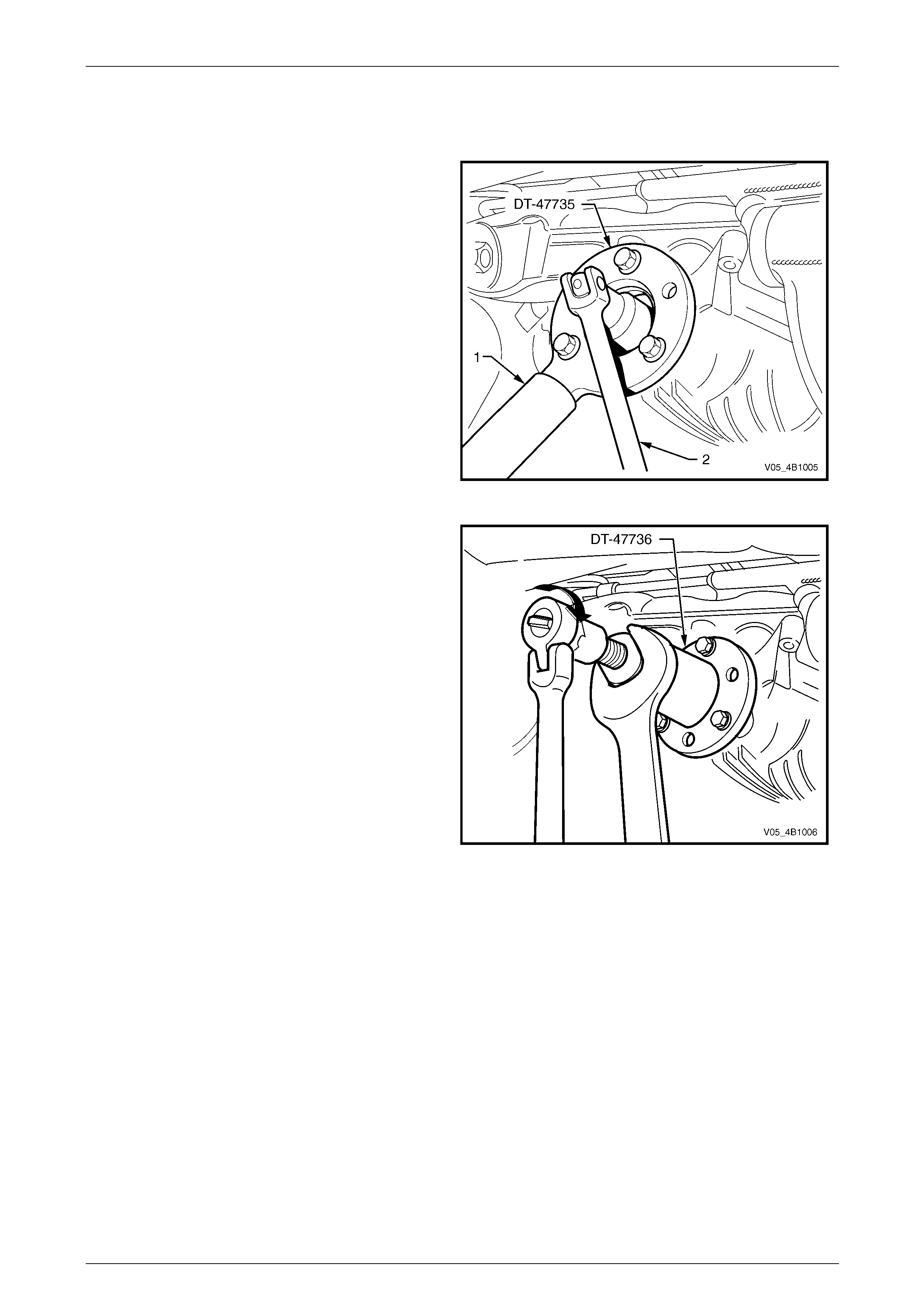
Rear Final Drive and Drive Shafts Page 4B1-44
Page 4B1-44
Example: With a pulley diameter of 152 mm, the radius is 76 mm, which equals 0.076 m. With a spring balance reading
of 25 N, the pre-load equals 0.076 m x 25 N = 1.9 N.m.
5 Remove pulley from pinion flange.
6 Attach Tool No. DT-47735 to the pinion flange, using
the same three bolts used in step 4a, to hold pinion
flange.
7 Insert a suitable length of pipe (1) over the tang of the
installed tool for leverage, then loosen the pinion
flange retaining nut, using a commercia lly available,
30 mm deep socket and socket bar (2) until end play
can be felt in the pinion shaft.
8 Check the oil seal and differential side bearing pre-
load using the spring scale and pulley, as detailed in
steps 4a and 4b. Record oil seal and side bearing pre-
load for later use.
9 Remove Tool No. DT -47735 from the pinion flange.
Figure 4B1 – 69
10 Place drain tray beneath differential carrier.
11 Install extractor, Tool No. DT-47736 to the pinion
flange using the same three b olts used insteps 4a and
6.
12 While holding the extractor tool with a suitable
spanner, withdraw pinion flange by tightening the
forcing screw in the direction shown.
Figure 4B1 – 70
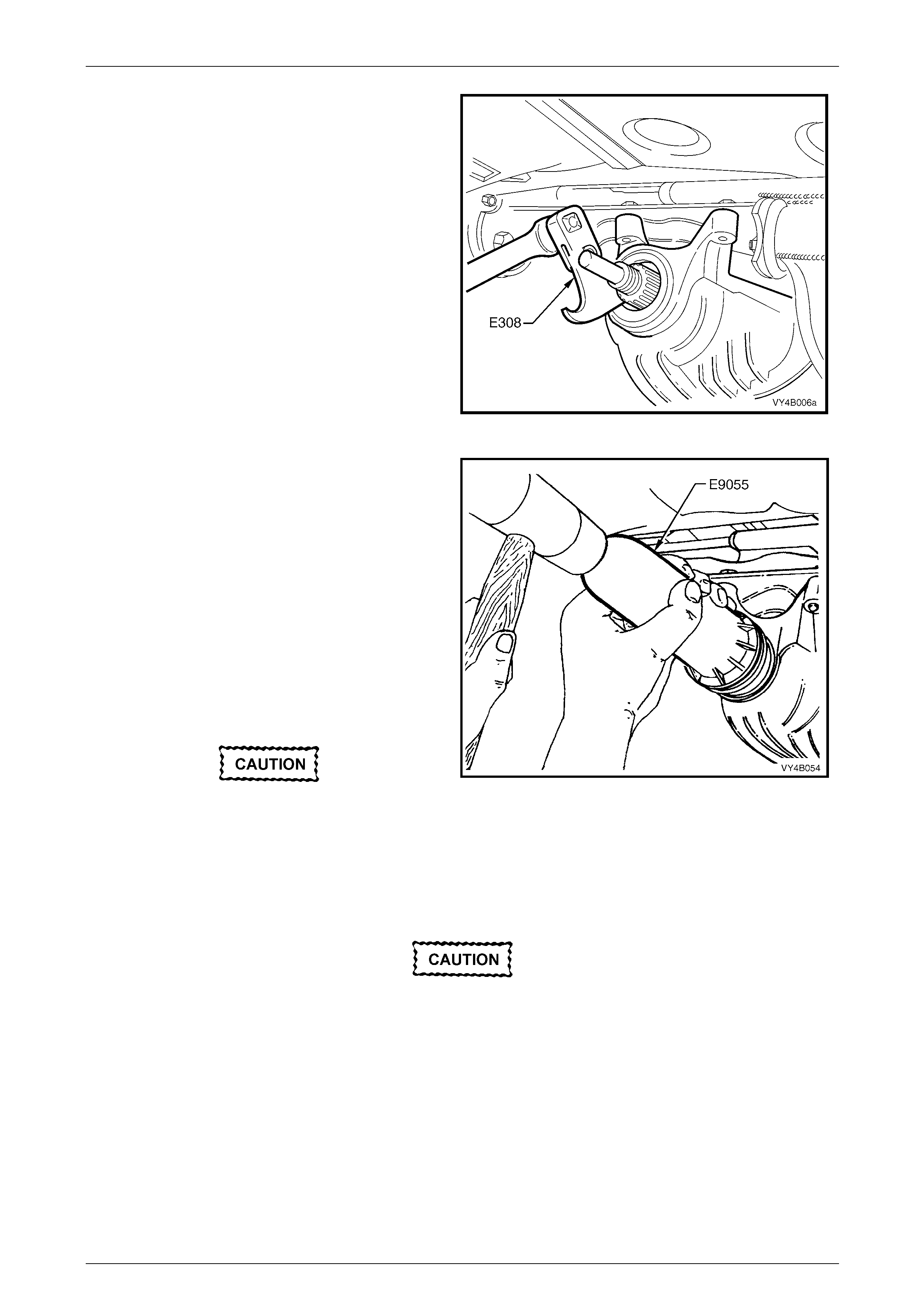
Rear Final Drive and Drive Shafts Page 4B1-45
Page 4B1-45
13 Prise pinion oil seal from carrier bore using Tool No.
E308 or a universal seal removin g tool.
Figure 4B1 – 71
14 Lubricate a new pinion oil seal lips and the outer
diameter with Mobilgrease XHP 222 grease or
equivalent.
15 Start oil seal into differential carrier housing and drive
seal squarely into position us ing Tool No. E9055. Seal
fits flush to 0.25 mm below carrier housing surface.
16 Ensure that pinion shaft is free from burrs, then clean
the threads of the pinion shaft, removing any oil, dirt or
grease.
17 Coat splines and seal surface of pinion flange with
differential gear lubricant, then reinstall flange to the
pinion shaft splines.
18 Install a new flange retaining nut, then tighten to draw
the pinion flange onto the pinion shaft spli nes.
The new pinion flange will be an interference
fit on pinion shaft splines and should only be
pulled into place by tightening the retaining
nut. Do not used force or a hammer the
flange during the installation process.
Figure 4B1 – 72
19 Continue to tighten the flange retaining nut gradually until pinion shaft end play is reduced to approximately 0.5
mm.
Should the retaining nut be over-tightened
and the pre-load exceeded, it will be
necessary to remove the differential carrier
assembly and install a new collapsible
spacer. Under no circumstances must the
retaining nut be backed off to decrease the
pre-load setting.
20 Check new oil seal and differential assemb ly pre-load using sprin g balance as previously outlin ed in steps 4a and
4b. Record pre-load for reassembly refer ence.
21. The pre-load reading for differential assembly obtained in step 8, is subtracted from pre-load reading obtained in
step 20. The difference bet ween these fi gures represents extra lip tension of new seal expressed as a N.m pre-
load figure. The difference be tween the pre-load readings obtained in steps 8 and 20 must be added to pre-load
reading obtained in step 4b to obtain a total pre-load reading.
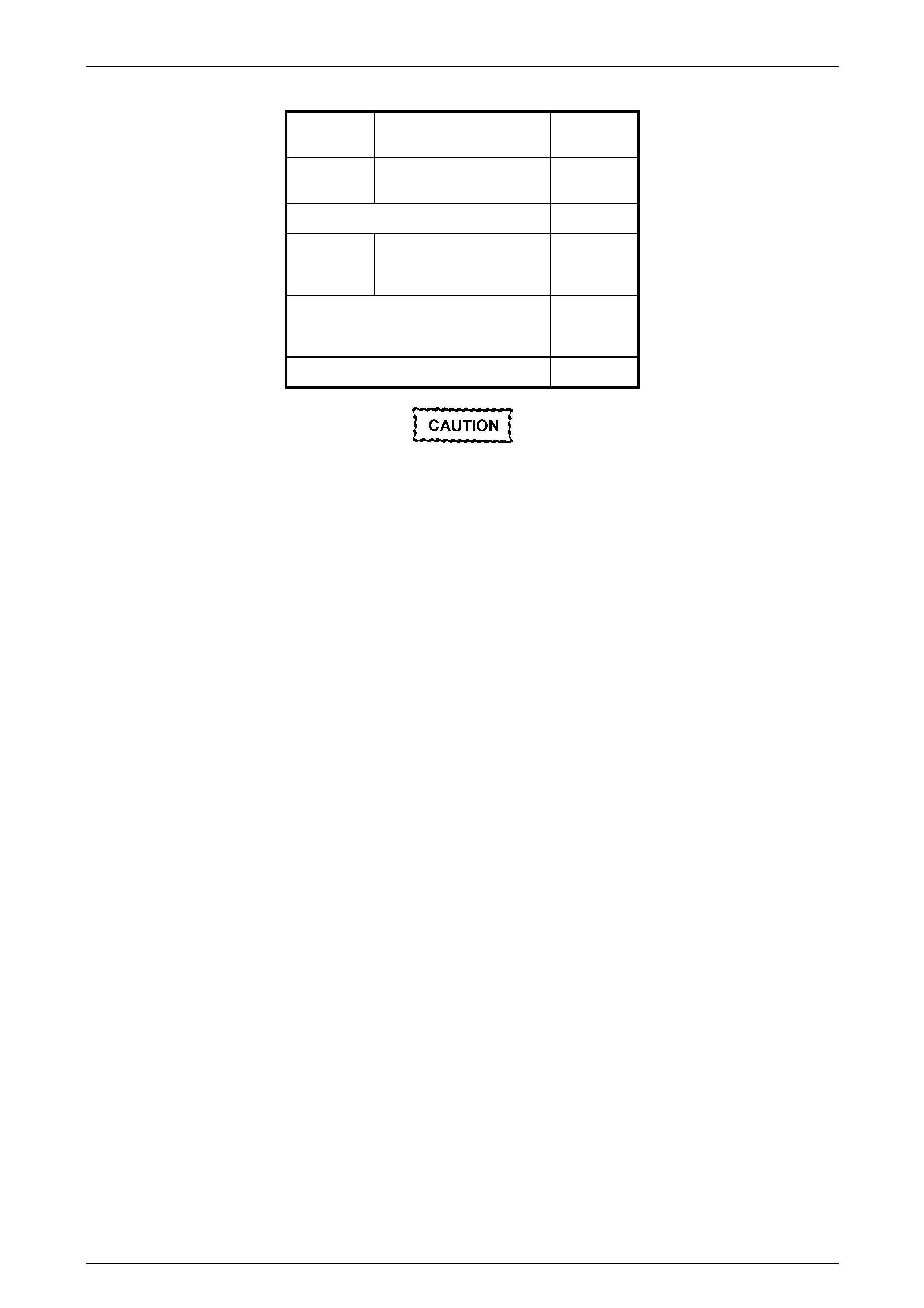
Rear Final Drive and Drive Shafts Page 4B1-46
Page 4B1-46
Theoretical Example
Step 20 New oil seal and side
bearing preload setting. 1.47 N.m
Step 8 Old oil seal and side
bearing preload reading. 1.02 N.m
Subtract Step 8 from Step 20 0.45 N.m
Step 4b Complete differential
assembly preload
reading. 1.47 N.m
The preload readi ng combination will be
the sum of:-
1.47 N.m
plus
0.45 N.m
Which gives a total preload reading of:- 1.92 N.m
Should the retaining nut be over-tightened
and the pre-load exceeded, it will be
necessary to remove the differential carrier
assembly and install a new collapsible
spacer. Under no circumstances must the
retaining nut be backed off to decrease the
pre-load setting.
22 Continue tightening retaining nut while alternately turning pinion to seat bearings until total pre-load figur e obtained
in step 21 is achieved, then i ncrease this pre-load reading by 0.11 to 0.34 N.m. Further rotate pinion an extra 30 –
40 turns and recheck pre-load to ensure that no change has occurred.
NOTE
It must be realised that the pre-load readings in
the example are only theoretical. In practice, the
figures could differ greatly, so the readings
obtained when performing the actual operations,
are the ones to use.
23 Reinstall drive shafts, refer to 2.7 Drive Shafts, in this Section.
24 Reinstall propeller shaft, refer to Section 4C1 Propeller Shaft and Universal Joints.
25 If removed previously, reconnect exhaust system, in the reverse to the removal procedure.
Refer to Section 8B Exhaust System, for details.
26 Lower vehicle to the ground.
27 Check lubricant level and top up as necessary, refer to 2.2 Checking Differential Carrier Lubricant Level.
28 Start vehicle and check for exhaust leaks.
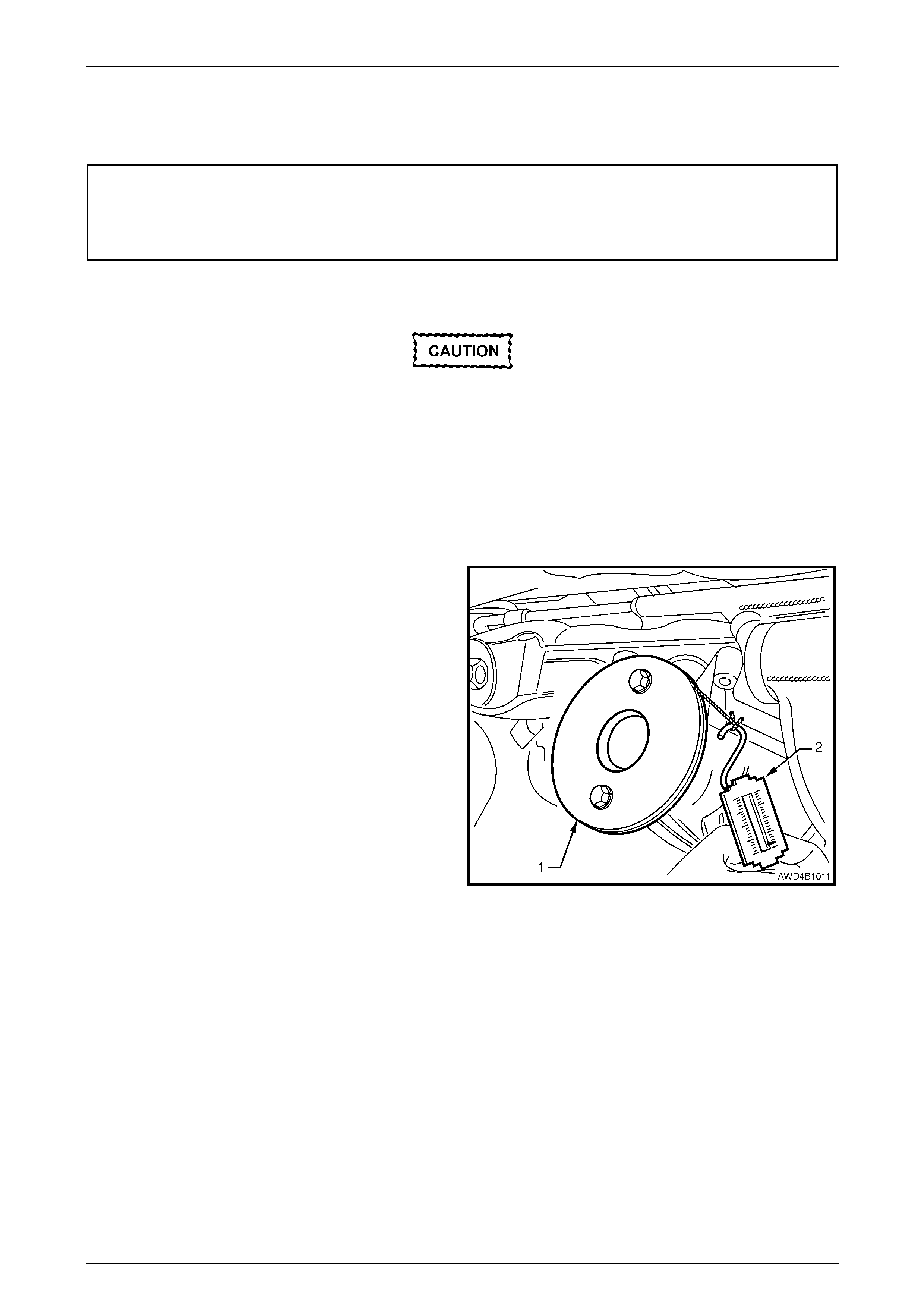
Rear Final Drive and Drive Shafts Page 4B1-47
Page 4B1-47
Replace (Vehicles With a Rear Constant Velocity Joint)
LT Section No. – 05-290
ATTENTION
The following fasteners MU ST be replaced when performing these operations:
Drive shaft attachin g bolts.
Using Old Oil Seal
Due to production tolerances in the length of
the pinion flange, it is essential that the
following method be used when installing a
new pinion flange.
1 Raise the vehicle and suppor t in a safe manner. Refer to Section 0A General Information for the location of
recommended lifting and support points.
2 Remove propeller shaft, refer 2.1 Propeller Shaft, in Section 4C1 Rear Propeller Shaft & Universal Joints.
3 Remove both driveshafts, refer 2.7 Driveshafts in this Section.
4 Check and record pre-load at pini on flange as follows:
a Fit a pulley (1) to pinion fla nge, using two
M8 x 1.25 bolts and attach a cord around pul ley
and to a spring scale (2).
NOTE
For details of the fabricated pulley, refer to
7 Special Tools at end of this Section.
b Start rotation of pulley and whilst in motion
(approximately 50 – 60 rpm) note and record
reading of spring balance.
NOTE
• This pre-load reading includes pinion
bearings, side bearings, meshing effect of
gear set and pinion oil seal.
• To determine pre-load, multiply reading on
spring balance by radius of pulley.
Example: With a pulley diameter of 152 mm, the radius is
76 mm, = 0.076 m. With a spring balance reading of 25 N,
the pre-load = 0.076 m x 25 N = 1.9 N.m.
5 Remove pulley from pinion flange.
Figure 4B1 – 73
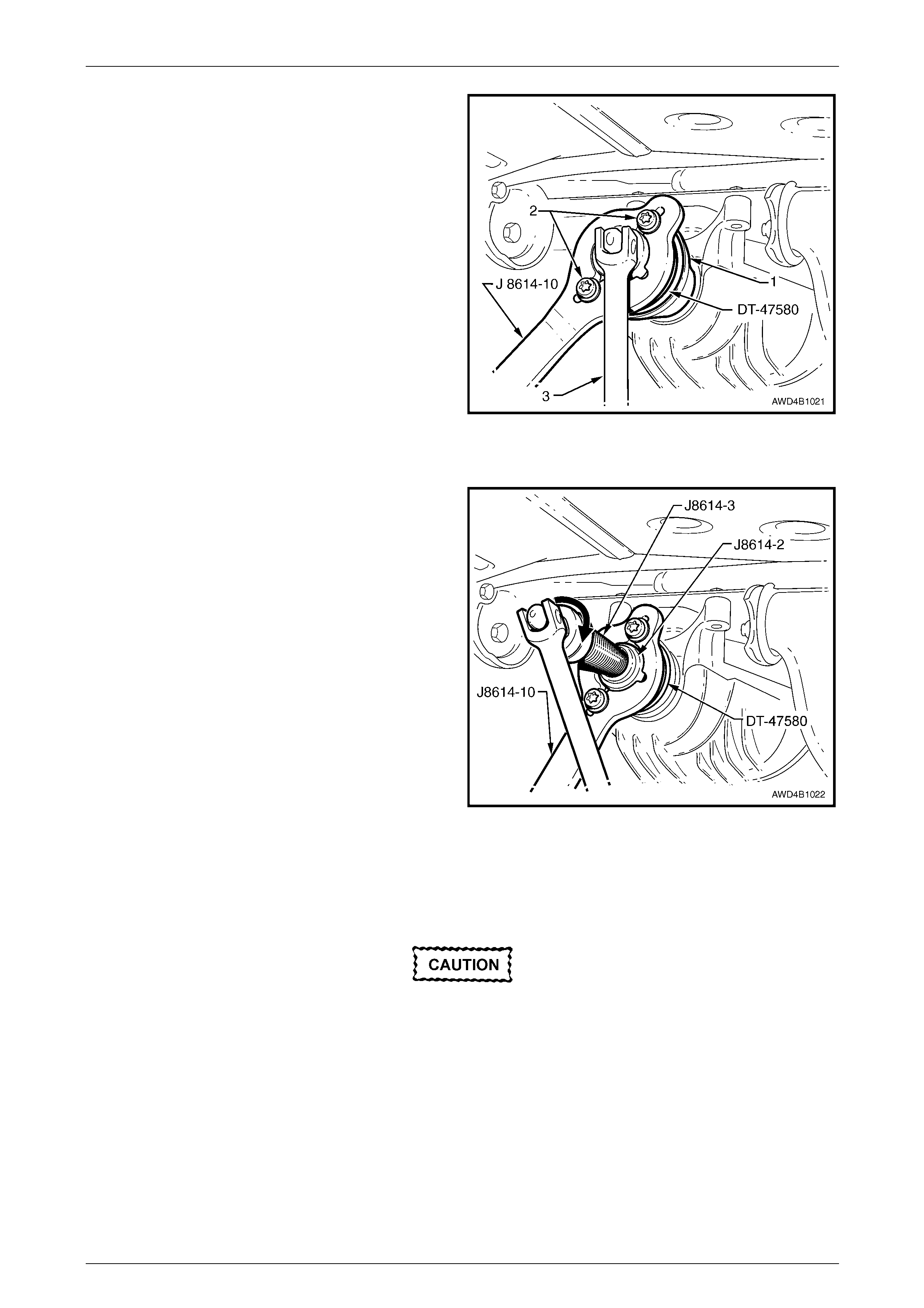
Rear Final Drive and Drive Shafts Page 4B1-48
Page 4B1-48
6 Install packing flange, T ool No. DT -47580 into the
pinion flange recess, aligning the holes with those in
the pinion flange.
7 Using two of the propeller shaft constant velocity joint
bolts (2), with flat washers, secure the holding bar,
Tool No. J8614-10 (part of Tool No. J 8614- O1) to the
pinion flange (1). The central recesses in the holding
tool should face inward.
8 While anchoring Tool No. J8614-10, loosen the pinion
flange retaining nut, using a commercia lly available,
30 mm deep socket and socket bar (3), until end play
can be felt in the pinion shaft.
NOTE
A suitable length of pip e installed over the en d of
the socket bar (3) will reduce the effort required
to loosen the pinion flange nut.
9 Check the oil seal and differential side bearing pre-
load using the spring scale and pulley, as detailed in
steps 4a and 4b. Record oil seal and side bearing pre-
load for later use.
Figure 4B1 – 74
10 Place drain tray beneath differential carrier.
11 With Tool Nos J8614-10 and DT-47580 still installed,
thread the forcing screw, Tool No. J8614-3, in to the
adaptor, Tool No. J8614-2. Install this sub-assembly
into holding bar, Tool No. J8614-10, then rotate
through 45° to locate in the recesses in J8614-10.
12 While holding J8614-10, use a socket and bar to rotate
the forcing screw J8614-3 in the direction s hown, to
remove the pinion flange.
13 Remove the tools from the pinion flange, then carefull y
set the pinion flange to one side to avoi d damage to
the flanged seal surface.
Figure 4B1 – 75
14 Ensure that pinion shaft thread is free from thread sealant, burrs, oil, dirt or grease, then coat splines and seal
surface of a new pinion flange with the recommend ed final drive lubricant.
15 Install the new pinion flange a nd a new retaining nut.
The new pinion flange will be an interference
fit on the pinion shaft splines and should only
be pulled into place by tightening the
retaining nut. During installation, do not,
under any circumstances use force or
hammer the flange onto the pinion splines.
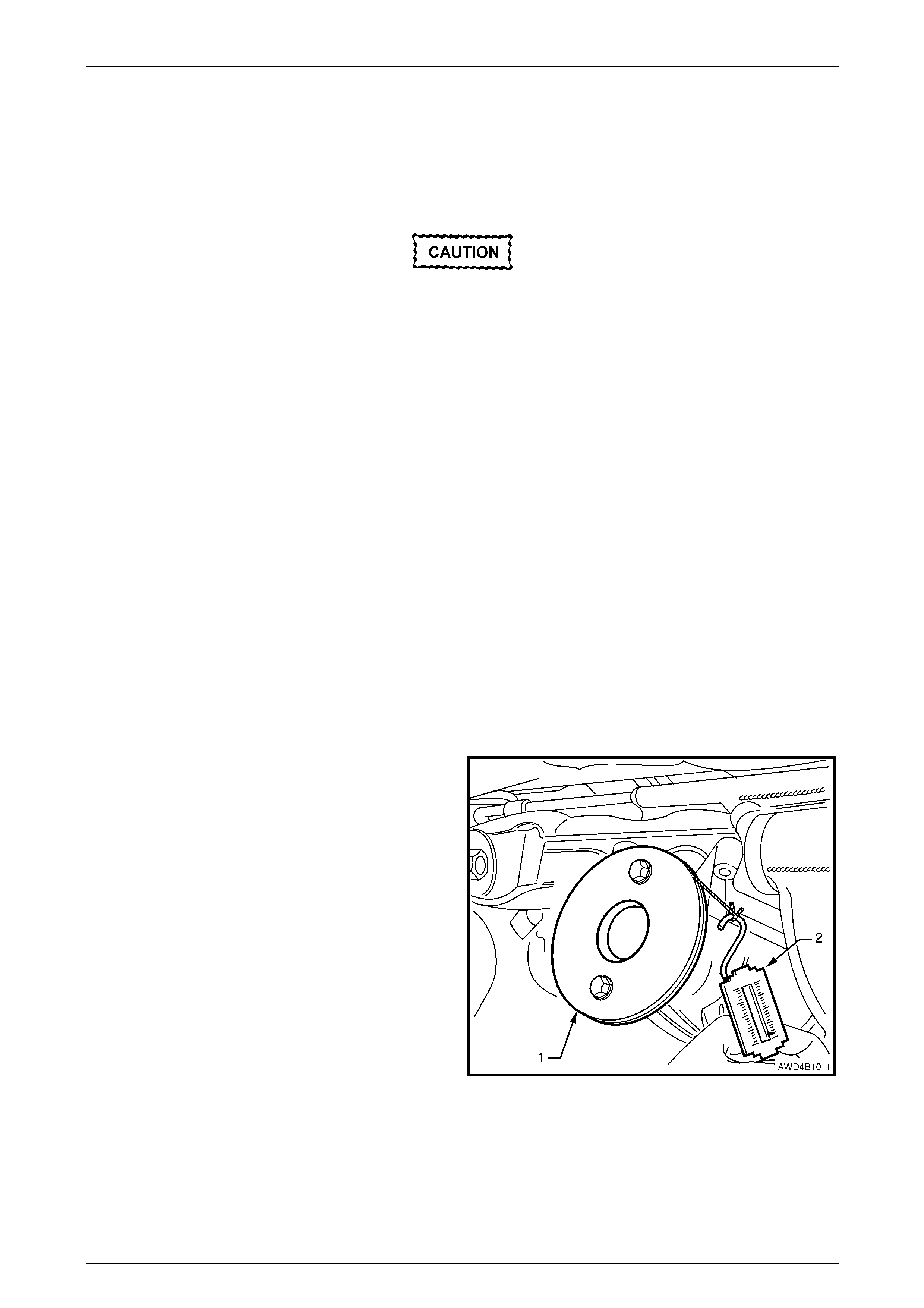
Rear Final Drive and Drive Shafts Page 4B1-49
Page 4B1-49
16 Tighten flange retaining nut gradually until pinio n shaft end play is reduced to approxim ately 0.50 mm.
17 Attach pulley to the new pinion flange and using spring balance, check pre-load. Continue tightening nut while
alternatively turning pin io n to seat bearings, until the pre-load figure recorded previously (Step 4b) is rea c hed.
Further increase this original pre-load reading by 0.5 N.m.
18 Rotate the pinion an extra 30 – 40 turns a nd re-check the preload to ensure that no change has occurred.
Should the retaining nut be over-tightened
and the pre-load exceeded, it will be
necessary to remove the differential carrier
assembly and install a new collapsible
spacer. Under no circumstances must the
retaining nut be backed off to decrease the
pre-load setting.
19 Reinstall driveshafts, refer to 2.7 Driveshaft Assembly in this Section.
20 Reinstall propeller shaft, refer to Section 4C1 Rear Propell er Shaft & Universal Joints.
21 If removed previously, reconnect exhaust system, in reverse to the removal procedure.
Refer to Section 8B Exhaust System, for details.
22 Lower vehicle to the ground.
23 Check lubricant level and top up as necessary with the recommended lu bricant,
refer to 2.2 Checking Differential Carrier Lubricant Level, in this Section.
24 Start vehicle and check for exhaust leaks.
Using New Oil Seal
1 Raise the vehicle and suppor t in a safe manner. Refer to Section 0A General Information for the location of
recommended lifting and support points.
2 Remove propeller shaft, refer to Section 4C1 Rear Propeller Shaft & Universal Joints.
3 Remove both driveshafts, refer to 2.7 Driveshaft Assembly in this Section.
4 Check and record pre-load at pini on flange as follows:
a Fit a pulley (1) to pinion fla nge, using two
M8 x 1.25 bolts and attach a cord around pul ley
and to a spring balance (2).
NOTE
For fabricated pulley details, refer to
7 Special Tools at end of this Section.
b Start rotation of pulley and whilst in motion
(approximately 50 – 60 rpm), note and record
the spring balance reading.
NOTES
• This pre-load reading includes pinion
bearings, side bearings, meshing effect of
gear set and pinion oil seal.
• To determine pre-load, multiply reading on
spring balance by radius of pulley. Figure 4B1 – 76
Example: With a pulley diameter of 152 mm, the radius is 76 mm which equals 0.076 m. With a spring bal ance reading
of 25 N, the pre-load equals 0.076 m x 26 N = 1.9 N.m.
5 Remove pulley from pinion flange.
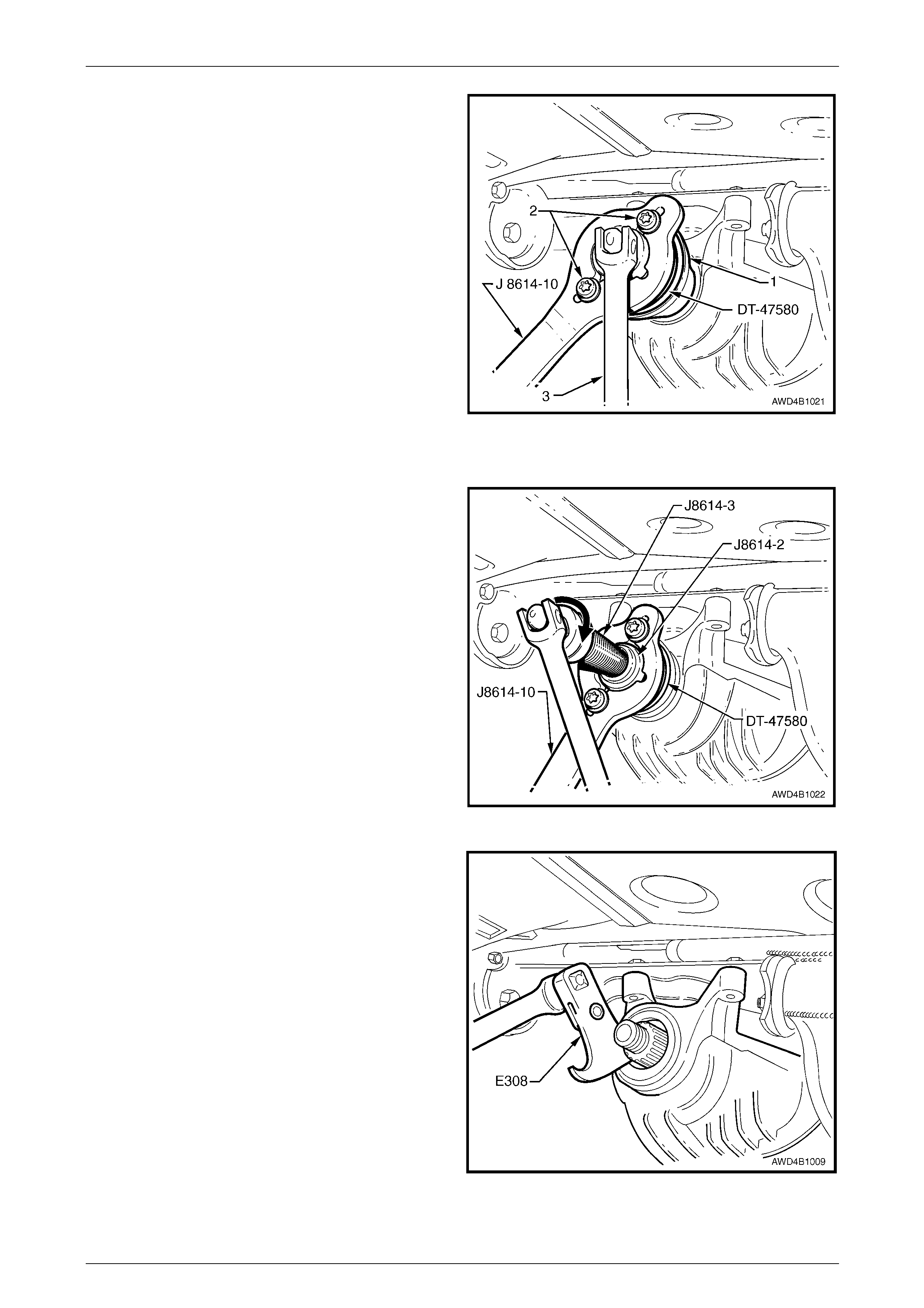
Rear Final Drive and Drive Shafts Page 4B1-50
Page 4B1-50
6 Install packing flange, T ool No. DT -47580 into the
pinion flange recess, aligning the holes with those in
the pinion flange.
7 Using two of the propeller shaft constant velocity joint
bolts (2), with flat washers, secure the holding bar,
Tool No. J8614-10 (part of Tool No. J 8614- O1) to the
pinion flange (1). The central recesses in the holding
tool should face inward.
8 While anchoring Tool No. J8614-10, loosen the pinion
flange retaining nut, using a commercia lly available,
30 mm deep socket and socket bar (3), until end play
can be felt in the pinion shaft.
NOTE
A suitable length of pip e installed over the en d of
the socket bar (3) will reduce the effort required
to loosen the pinion flange nut.
9 Check the oil seal and differential side bearing pre-
load using the spring scale and pulley, as detailed in
steps 4a and 4b. Record oil seal and side bearing pre-
load for later use.
Figure 4B1 – 77
10 Place drain tray beneath differential carrier.
11 With Tool Nos J8614-10 and DT-47580 still installed,
thread the forcing screw, Tool No. J8614-3, in to the
adaptor, Tool No. J8614-2. Install this sub-assembly
into holder, Tool No. J8614-10, then rotate through 45°
to locate in the recesses in J8614-10.
12 While holding J8614-10, use a socket and bar to rotate
the forcing screw J8614-3 in the direction s hown, to
remove the pinion flange.
13 Remove the tools from the pinion flange, then carefull y
set the pinion flange to one side.
Figure 4B1 – 78
14 Prise pinion oil seal from carrier bore using Tool No.
E308 or a commercially available, universal seal
removing tool.
Figure 4B1 – 79

Rear Final Drive and Drive Shafts Page 4B1-51
Page 4B1-51
When installing a new pinion oil seal, only
install the seal until it is flush with the
machined face of the final drive housing. If
installed too deeply then a premature oil leak
could occur.
15 Lubricate the lips and outside diameter of a new pinion
oil seal with Mobilgrease XHP 222 grease or
equivalent. The recess between the lips should be
approximately 50% filled with grease.
NOTE
A light coating of grease is also to be applied to
the dirt lip that contacts the pinion flange slinger.
16 Start oil seal into differential carrier housing and drive
seal squarely into position using Tool No. E9055. Figure 4B1 – 80
17 Ensure that pinion shaft is free from burrs, then clean the threads of the pinion shaft, removing any thread sealant,
oil, dirt or grease.
18 Coat splines and seal surface of pinion flange with the recommended final drive lubricant, then reinstall flange to
the pinion shaft splines.
19 Install a new flange retaining nut, then tighten to draw the pinion flange onto the pinion shaft splines.
The new pinion flange will be an interference
fit on the pinion shaft splines and should only
be pulled into place by tightening the
retaining nut. During installation Do not,
under any circumstances use force or
hammer the flange onto the pinion splines.
20 Continue to tighten the flange retaining nut gradually until pinion shaft end play is reduced to approximately
0.5 mm.
21 Check new oil seal and differential assemb ly pre-load using sprin g balance as previously outlin ed in steps 4a and
4b. Record pre-load for reassembly refer ence.

Rear Final Drive and Drive Shafts Page 4B1-52
Page 4B1-52
22 The pre-load reading for the final drive asse mbly obtained in step 9, is subtracted from the pre-load reading
obtained in step 21. The difference b etween these figures represents extra lip tens ion of new seal expressed as a
N.m pre-load figure. The difference between the pre-load readings obtained in steps 9 and 21 must be added to
pre-load reading obtained in step 4b to obtain a total pre-load reading.
Theoretical Example
Step 21 New oil seal and side
bearing pre-loa d setting 1.47 N.m
Step 9 Old seal and side bearing
pre-load reading 1.02 N.m
Subtract Step 9 from Step 21 0.45 N.m
Step 4b Complete differential
assembly pre-load
reading 1.47 N.m
The pre-load reading combination will
be the sum of:-
1.47 N.m
plus
0.45 N.m
Which gives a total pre-load reading of:- 1.92 N.m
23 Continue tightening retaining nut while alternately turning pinion to seat bearings until total pre-load figur e obtained
in step 22 is achieved, then i ncrease this pre-load readin g by 0.11 – 0.34 N.m. Further rotate pinion an extra
30 – 40 turns and recheck pre-load to ensure that no change has occurred .
Should the retaining nut be over-tightened
and the pre-load exceeded, it will be
necessary to remove the differential carrier
assembly and install a new collapsible
spacer. Under no circumstances must the
retaining nut be backed off to decrease the
pre-load setting.
NOTE
It must be realised that the pre-load readings in
the example are only theoretical. In practice, the
figures could differ greatly, so the readings
obtained when performing the actual operations,
are the ones to use.
24 Reinstall drive shafts, refer to 2.7 Driveshaft Assembly in this Section.
25 Reinstall propeller shaft, refer to Section 4C1 Rear Propell er Shaft & Universal Joints.
26 If removed previously, reconnect exhaust system, in the reverse to the removal procedure.
Refer to Section 8B Exhaust System, for details.
27 Remove safety stands and lower vehicle.
28 Check lubricant level and top up as necessary, refer to 2.2 Checking Differential Carrier Lubricant Level, in this
Section.
29 Start vehicle and check for exhaust leaks.
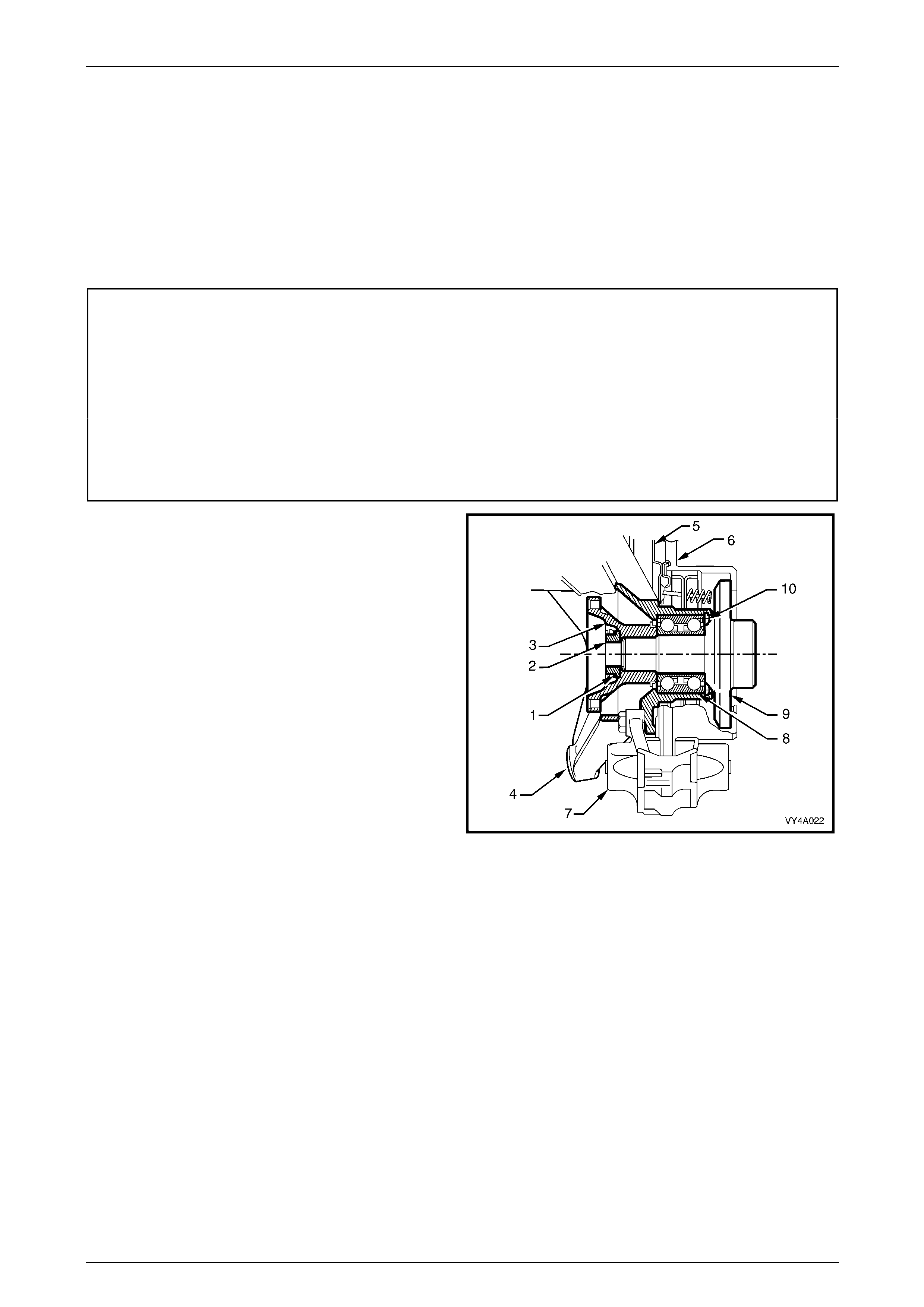
Rear Final Drive and Drive Shafts Page 4B1-53
Page 4B1-53
3 Major Service Operations
3.1 Outer Rear Wheel Driveshaft Flange
Outer Rear Wheel Driveshaft Assembly
and/or Wheel Bearing
LT Section No: 05-290
ATTENTION
The following fasteners MU ST be replaced when performing these operations:
Collar nut to outer rear wheel driveshaft assembly
Drive shaft constant velocity joint attaching bolts.
Lower rear disc brake shield to trailing arm bolts
Vehicle must be at curb weight before final tightening.
zLower shock absorber mounting bolt.
NOTE
• The following pr ocedure inv olv es the removal
of the outer rear wheel driveshaft flange,
outer rear wheel driveshaft and/or wheel
bearing with the trailing arm installed in the
vehicle. A similar procedure is included in
Section 4A1 Independent Coil Spring Rear
Suspension, when the trailing arm is
removed from the vehicle.
• This 'on-vehicle' procedure is not suitable for
the AWD Wagon, as the revised design of
the rear trailing arm on this vehicle prevents
the use of the stand-off supports required.
Refer to Section 4A1 Independent Coil
Spring Rear Suspension, for the necessary
procedure.
• The rear wheel bearing should only be
removed if it is faulty, or if the outer rear
wheel driveshaft assembly is to be removed. Figure 4B1 – 81
Legend
1 Collar Nut Lock Plate
2 Collar Nut
3 Outer Rear Wheel Driveshaft Flange
4 Trailing Arm
5 Brake Backing Plate
6 Brake Disc
7 Brake Caliper
8 Rear Wheel Bearing
9 Outer Rear Wheel Driveshaft Assembly
10 Rear Wheel Bearing Retaining Ring

Rear Final Drive and Drive Shafts Page 4B1-54
Page 4B1-54
Remove
1 Raise the vehicle and suppor t in a safe manner. Refer to Section 0A General Information for the location of
recommended lifting and support points.
2 On the side of the vehicle where the trailing arm is to be removed, remov e the wheel trim or wheel nut covers, mark
relationship of road wheel to hub (e.g. end of wheel stud), with a felt tipped pen or similar. Loosen then remove
road wheel attaching nuts. Remove the roa d wheel.
3 Remove brake hose retaining clip (1) from brake
backing plate bracket (2). Disconnect rear caliper
brake hose (3) from brake pipe (4) and disconnect
pipe from backing plate bracket (2).
4 Plug open ends of brake pipe (4) and hose (3) to
prevent fluid loss and foreign matter entry.
Figure 4B1 – 82
If the brake pipe to hose is not disconnected,
the brake caliper must be secured to the
vehicle underbody. The caliper is not to hang
by the brake hose.
5 Remove brake caliper anchor plate to trailing arm
attaching bolts (1) and remove caliper (2) from disc.
6 Remove brake disc from the wheel bearing hub.
NOTE
While the brake disc to hub location is m arked in
production, ensure that the disc to hub position
is carefully marked (e.g. disc to end of wheel
stud), with a felt tipped pen or similar. This is
necessary to overcome the possibility of
inducing a brake shudder condition after
reassembly.
Figure 4B1 – 83
7 If the park brake shoe adjustment needs to be
released to allow disc removal, adopt the following
method:
a Remove one of the access hole plugs (1) from
one of the access holes provided in the disc.
b Using a suitable lever such as a screwdriver,
loosen the park brake shoe screw adjuster, until
the disc is freed.
c After disc removal, reinstall the access hole plug
to prevent loss.
Figure 4B1 – 84
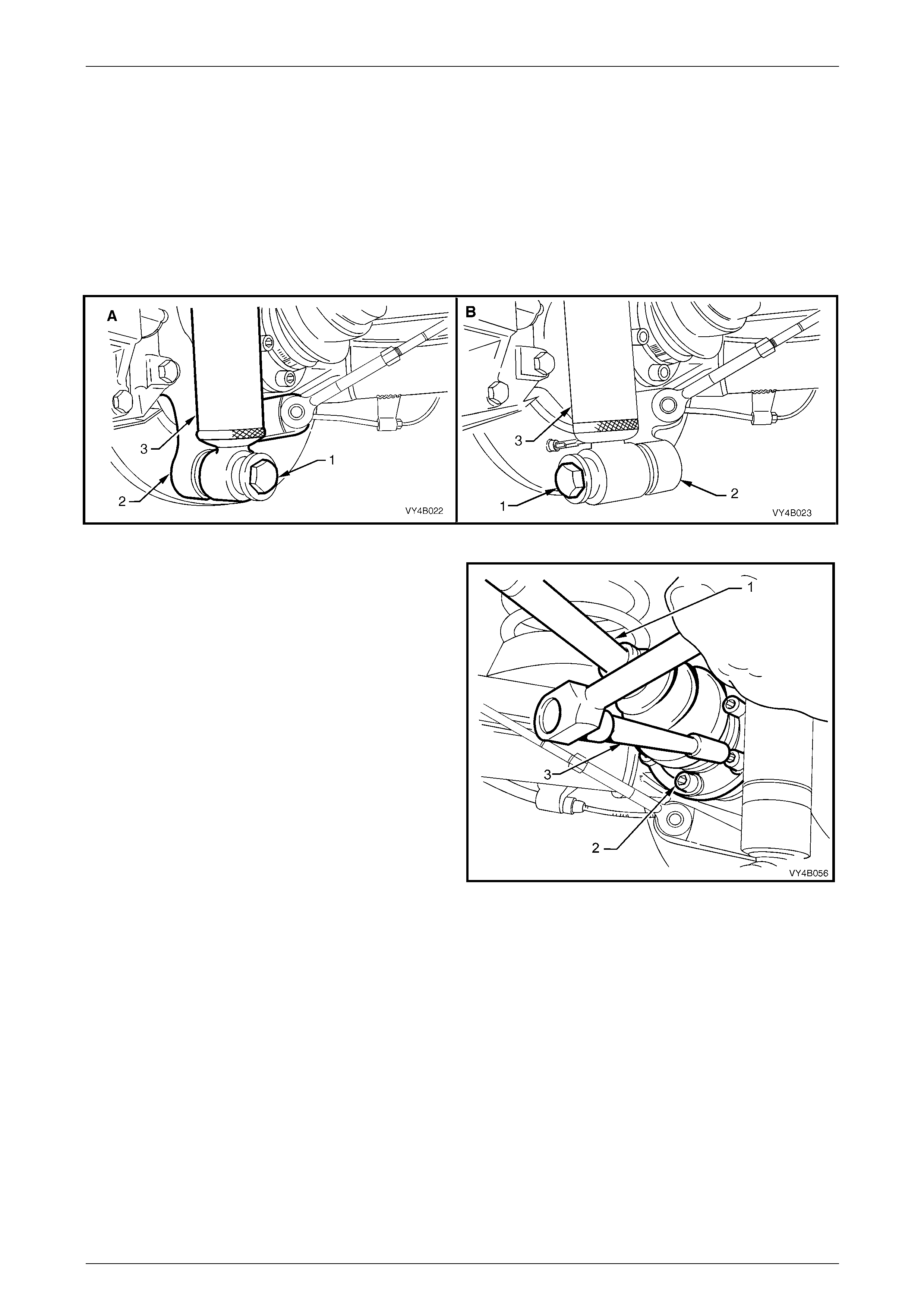
Rear Final Drive and Drive Shafts Page 4B1-55
Page 4B1-55
8 Position floor jack with a block of wood under the trailing arm (2). Raise jack slightly to take spring load off trailing
arm.
9 Disconnect rear shock absorber lower mounting bolt (1) from trailing arm (2), and pull lower end of shock absorber
(3) from trailing arm. Leave the supporting ja ck and wooden block in position.
NOTE
View ‘A’ in Figure 4B1-85 shows the sedan and
coupe lower shock absorber mounting, while view
‘B’ shows the station wagon and utility
arrangement.
Figure 4B1 – 85
10 Install holding bar, T ool No. KM 468 over the wheel
studs to hold outer rear wheel driveshaft assembly
from rotating.
11 Loosen then remove the six drive shaft (1) constant
velocity joint to outer rear wheel driveshaft flange
attaching bolts (2) and plates, using an 8 mm Allen
key socket and suitable socket equipment (3).
12 Discard the removed bolts as they must be repl aced
on reassembly.
Figure 4B1 – 86
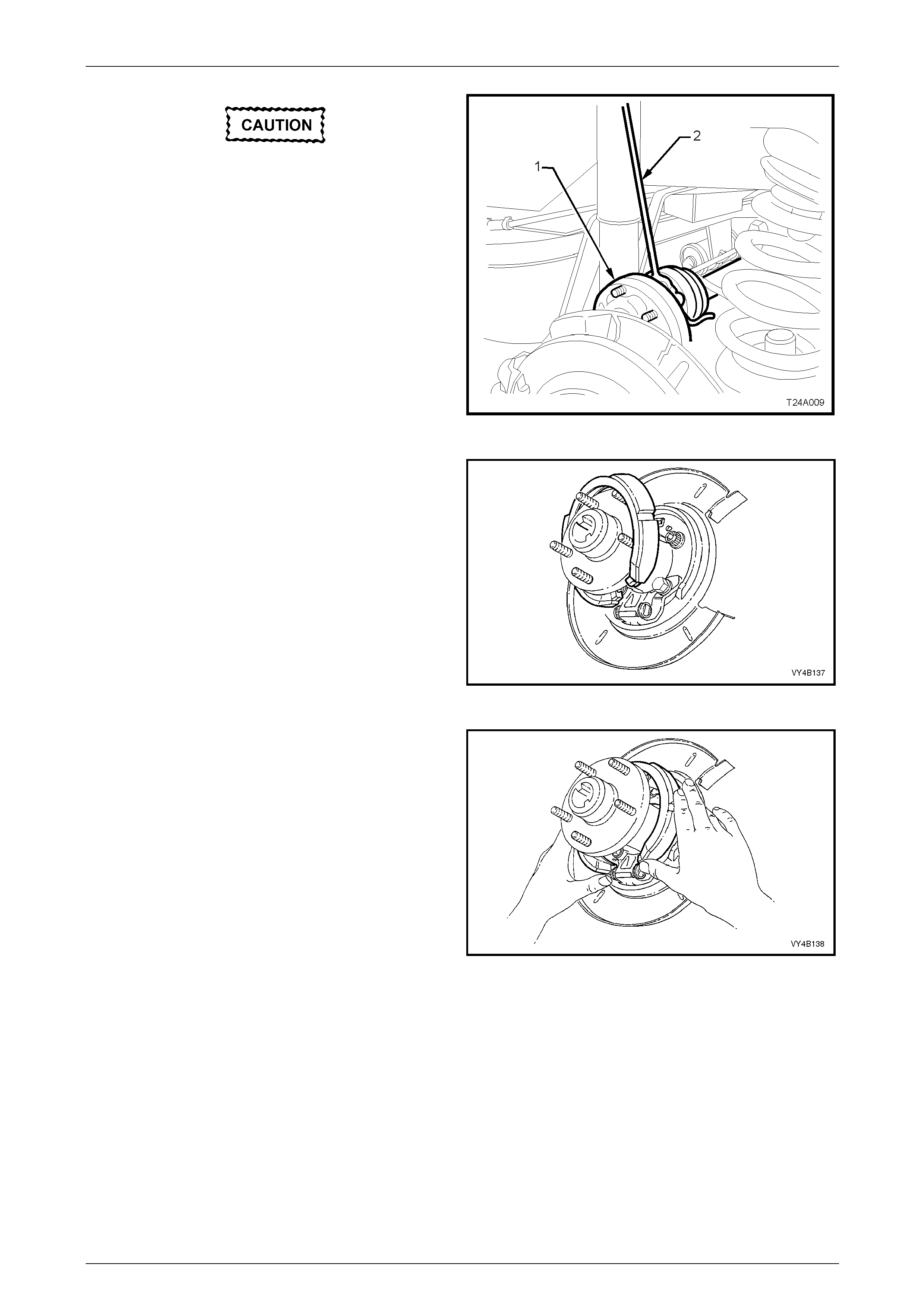
Rear Final Drive and Drive Shafts Page 4B1-56
Page 4B1-56
Bruising to the inside of the drive shaft
constant velocity joint boots will occur if the
trailing arm is lowered. This will lead to
premature failure of the boot and eventual
failure of the joint if left unchecked.
13 Separate drive shaft from flange and lift upward. While
keeping the outer constant velocit y joint (1) in the
same plane as the driveshaft, use a piece of wire (2)
and tie up the drive shaft assembly to lower end of
shock absorber upper mounting.
14. The supporting jack may no w be lowered and the
wooden block removed.
Figure 4B1 – 87
15 Remove park brake shoe b y g rasping each end as
shown. Push up on one end of the shoe, dislodging
the end from the actuator pin and the shoe from the
retaining clip.
Figure 4B1 – 88
16 Using a screwing motion, rotate the park brake shoe
around the outer rear wheel driveshaft flange to
remove it from the vehicle.
17 Remove the park brake shoe spring retainer by prisi ng
from the rear disc shield, with a screwdriver or similar
lever.
18 Using suitable socket equipment, loosen then remove
the two lower bolts securing the park brak e adjuster
and brake backing plate to th e trailing arm. Discard the
removed bolts.
19 Using Tool No. AU416 and suitable socket equipment,
loosen then remove the two upper brake backing plate
to the trailing arm, Torx bit headed bolts. Figure 4B1 – 89
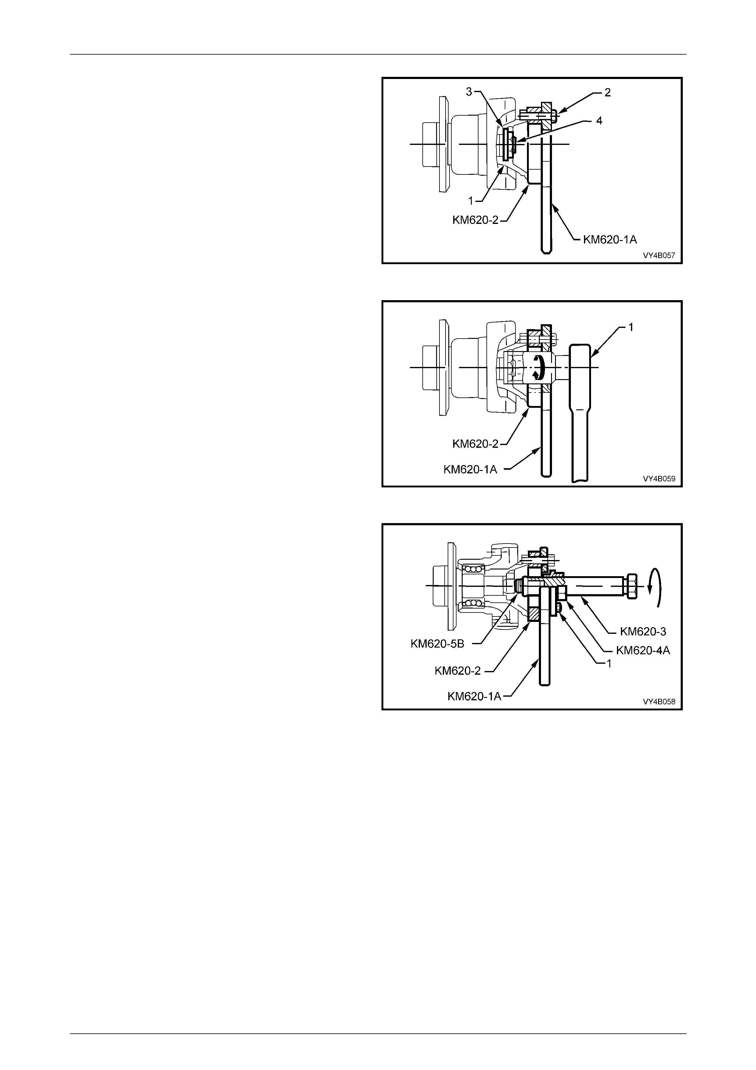
Rear Final Drive and Drive Shafts Page 4B1-57
Page 4B1-57
20 Secure flange holding tool, KM620-1A and outer rear
wheel driveshaft flange ring tool KM62 0-2 to outer rear
wheel driveshaft flange (1) with three of the removed
drive shaft constant velocity joint to outer rear wheel
driveshaft flange attaching bolts (2).
NOTE
Align holes marked ‘B' on the flange holding too l
KM620-1A and KM620-2 with holes in the outer
rear wheel driveshaft flange before installing and
tightening bolts.
Figure 4B1 – 90
21 Install a suitable length and diameter steel tube over
handle of KM620-1A to stop it from rotating, then use
suitable socket equipment (1) to loosen and remove
the collar nut and lock plate.
22 Discard the removed collar nut and lock plate, as
these parts must be replaced on reass embl y.
Figure 4B1 – 91
23 Lubricate the threads of forcing screw KM620-3, then
install to adaptor KM620-4-A. Apply grease to ball end
of plunger, Tool No. KM620-5 B, then install that, into
the end of forcing screw KM620-3.
24 Install the whole sub-assembly through the central
opening of flange holding too l KM620-1-A. Secure the
adaptor KM620-4A to the flange holding tool KM620-
1A, using three suitable bolts (1).
NOTE
Adjust the position of the forcing scre w KM620-3
in the adaptor KM620-4A, to allow adaptor to be
in full contact with the flange holding tool
KM620-1A. Figure 4B1 – 92
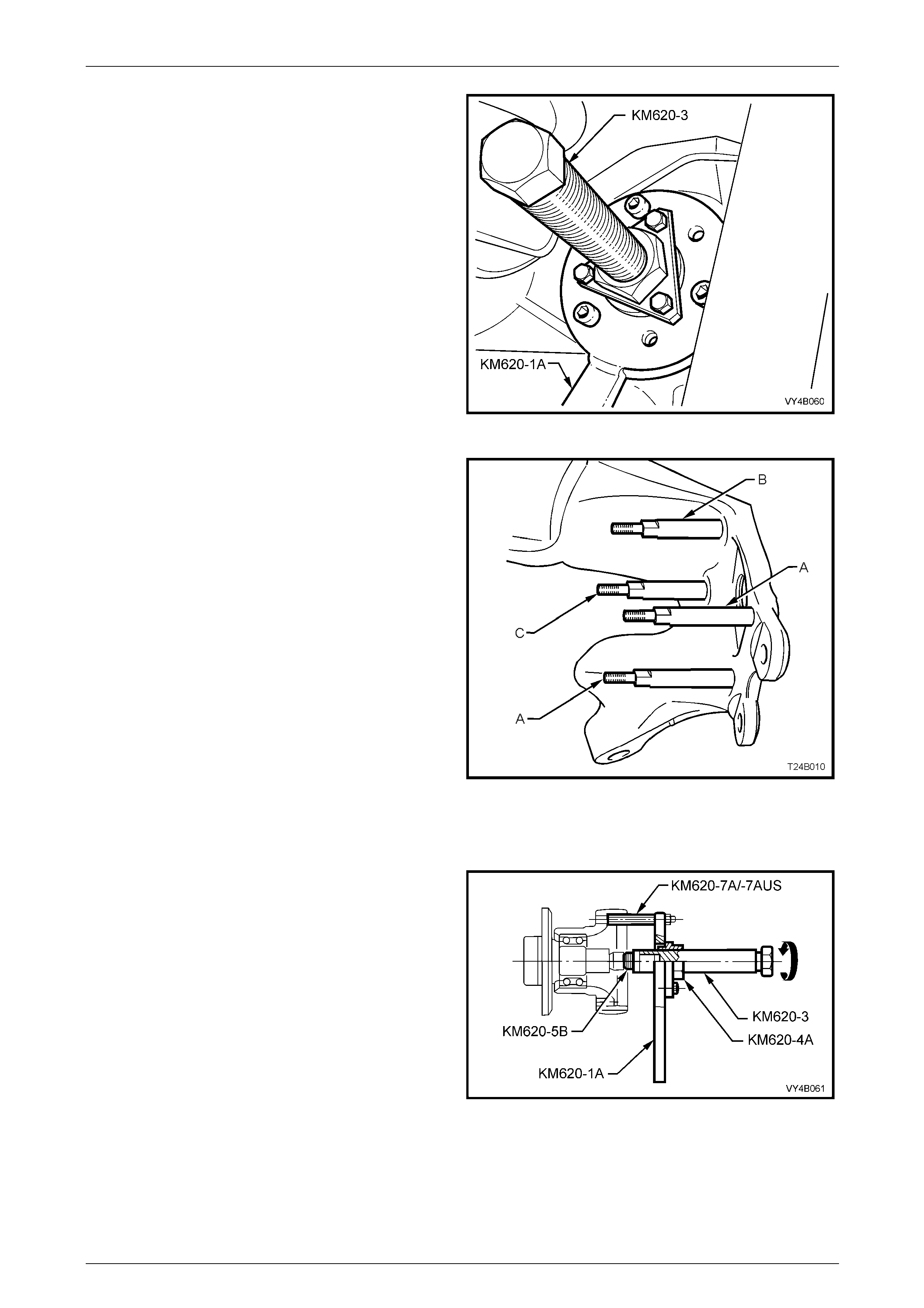
Rear Final Drive and Drive Shafts Page 4B1-58
Page 4B1-58
25 While holding KM620-1A from rotating, turn the screw
KM620-3, forcing the flange free from the outer rear
wheel driveshaft.
26 Separate tool components from flange once it has
been removed.
Figure 4B1 – 93
27 Before removing the outer rear wheel drives haft
assembly and rear wheel bearing from the trailing arm,
use a commercially available M10 x 1.25 b ottoming
tap and clean the four backing plate to trailing arm bolt
threads, using a suitable lubricant and working from
the outer rear wheel driveshaft assembly side.
This step is necessary to clear any dried mud,
dirt etc, from the exposed portion of the threads
on the inboard side of the trailing arm. Also, the
deepest thread (position ‘C’) may not be
completely formed through to the inbo ard side.
28 Install two supports KM620-7A in positions ‘A’ and two
KM620-7AUS to ‘B’ and ‘C’ in the trailing arm, as
indicated.
29 As a guide, the two longest supports (KM620 -7A) are
to be installed at the brake caliper mounting side
(position ‘A’). The longer of KM620-7AUS supports is
installed at position ‘B’ and th e shorter is installed at
position ‘C’.
30 After installing all four supports in the correct positions,
tighten with a set spanner.
Figure 4B1 – 94
31 Install flange holding tool KM620-1A over the four
supports, KM620-7A (2 places) and KM62 0-7AUS (2
places), install four suitable nuts (1) and tig hten to
secure.
32 Pre-assemble lubricated forcing screw KM620-3 to
adaptor KM620-4A. Apply grease to b all end of
plunger KM620-5B, then install that, into the end of
forcing screw KM620-3.
33 Install this sub-assembly through the central opening
of holding tool KM620-1A. Secure the adaptor KM620-
4A to the flange holding tool KM620-1A, using three
suitable bolts (2).
NOTE
Adjust the position of the forcing scre w KM620-3
into the adaptor KM620-4A, to allow full contact
of the adaptor to the flange holding tool KM620-
1A.
Figure 4B1 – 95
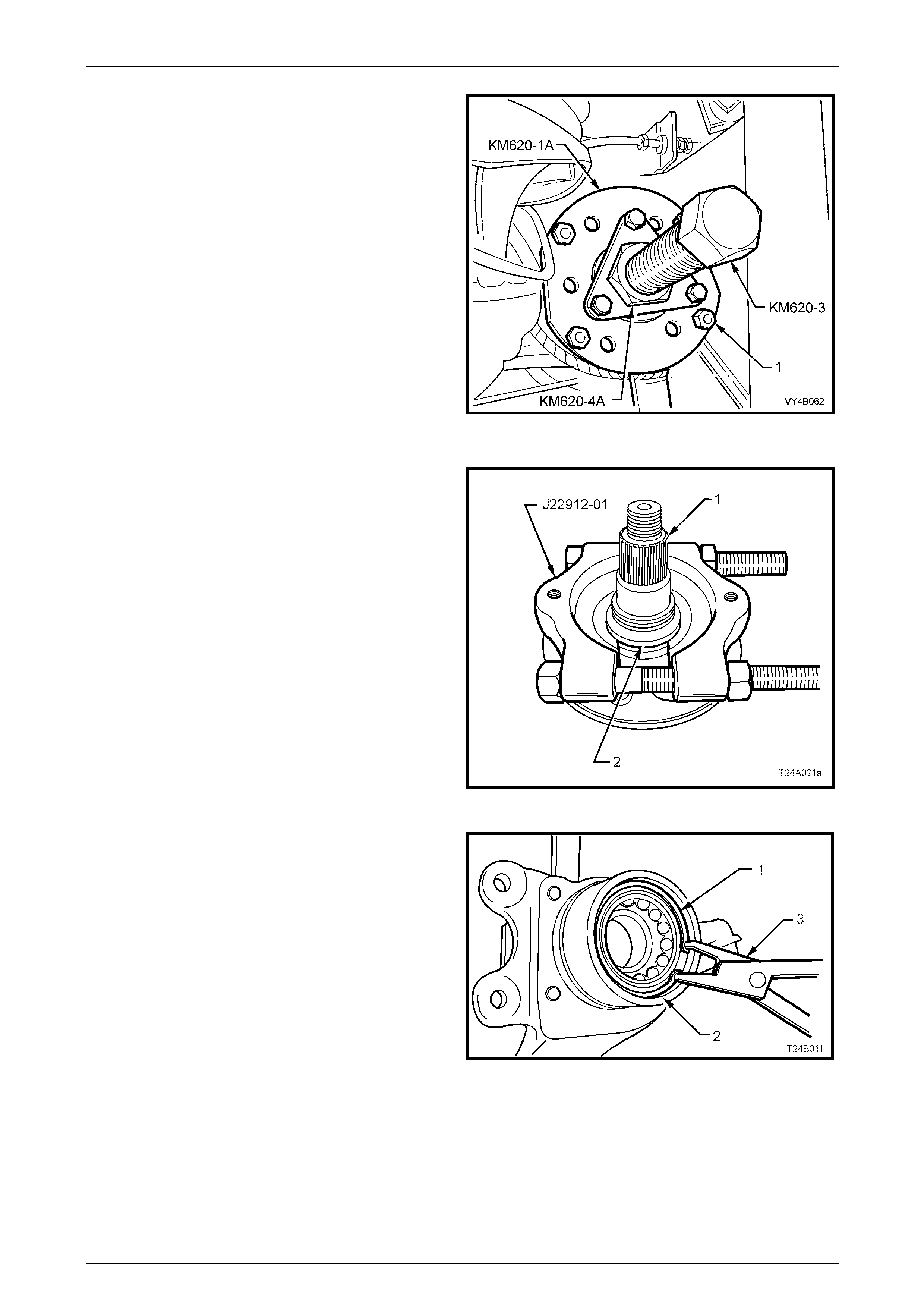
Rear Final Drive and Drive Shafts Page 4B1-59
Page 4B1-59
34 Insert a suitable length of tube over the handle of
holding tool KM620-1A to stop it from rotating and turn
the forcing screw KM620-3 to press outer rear wheel
driveshaft from rear wheel bearing.
35 When the outer rear wheel driveshaft has been
removed, remove nuts (1) holding KM620-1 A
assembly to the distance pieces, KM620-7A and
KM620-7-AUS. Remove KM620-1A, an d remove
KM620-5B from the end of KM620-3.
36 Unscrew the forcing screw (KM620-3), as this same
arrangement is used to press the rear wheel bearing
from the trailing arm.
NOTE
The rear wheel bearing inner cone will separate
from the bearing assembly and be retained on
the outer rear wheel driveshaft assembly.
37 Remove the brake backing plate and park brake
assembly from the trailing arm and set to one side. Figure 4B1 – 96
NOTE
The next step is not required if the outer rear
wheel driveshaft is to be replaced.
38 If the outer rear wheel driveshaft assembly (1) is to be
reinstalled, then the outer half of the inner rear wheel
bearing cone (2) will nee d to be removed from the
outer rear wheel driveshaft assembly (1).
a Install press plates J22912-0 1 over the bearing
cone (2) and tighten the press plate bo lts to grip
the bearing cone.
b Press the outer rear wheel driveshaft assembl y
(1) from the bearing cone (2) and discard
bearing cone.
NOTE
A new outer rear wheel driveshaft assembly is
supplied with wheel studs already installed. Figure 4B1 – 97
39 Remove wheel bearing retaini ng ring (1) from trailing
arm (2), using suitable circlip pliers (3).
Figure 4B1 – 98
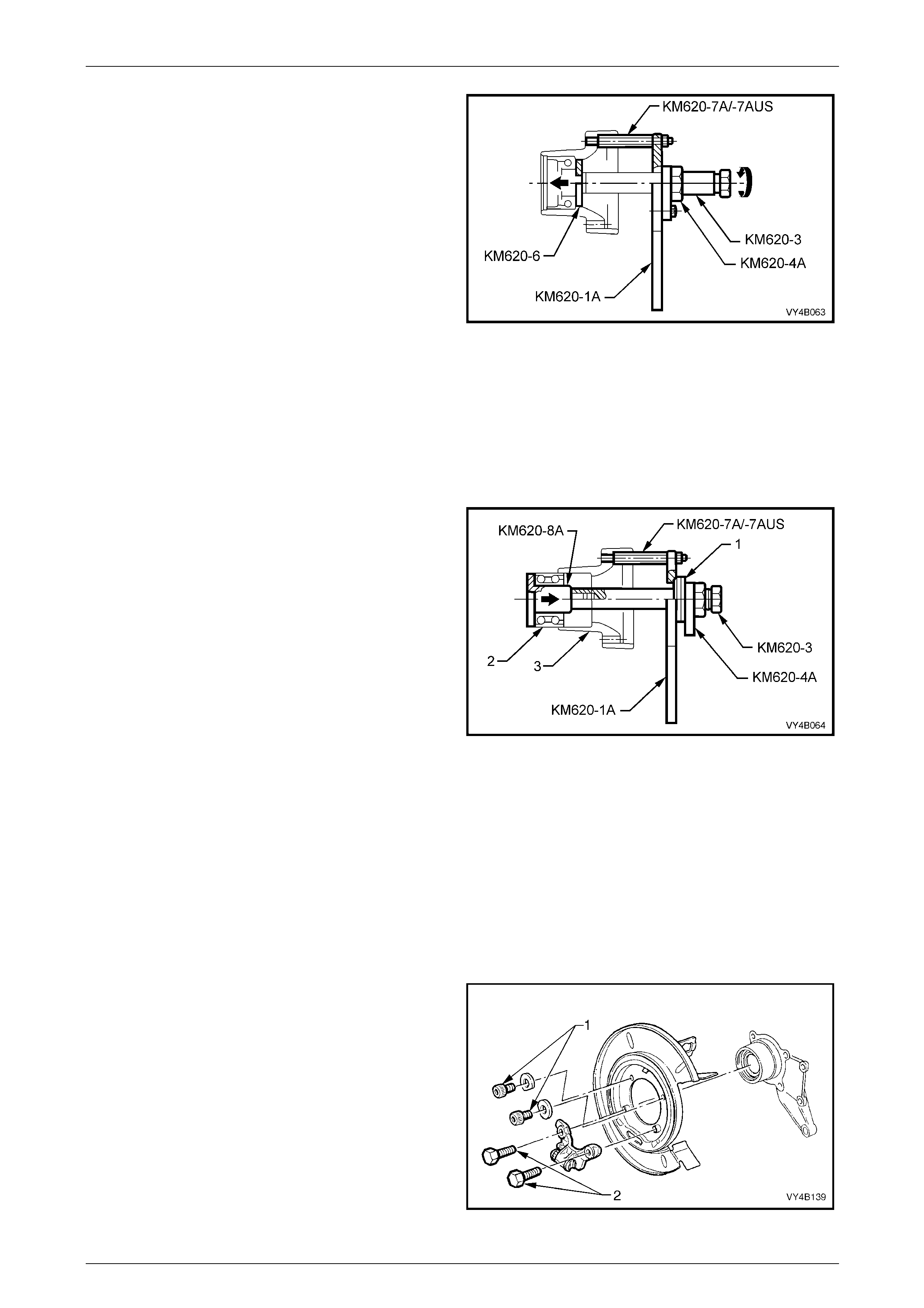
Rear Final Drive and Drive Shafts Page 4B1-60
Page 4B1-60
40 With the tool components set up as sho wn, install re ar
axle bearing removing plate KM 620-6 to rear of the
axle bearing. Reposition the forcing screw KM620-3 to
hold the removing plate KM620-6 in place.
41 Insert a suitable length of tube over the handle of
holding tool KM620-1A to stop it from rotating, then
turn the forcing screw KM620-3 to press the wheel
bearing from the trailing arm.
42 If installing a replacement trailing arm without bushes,
install new bushes. Refer to 2.6 T r ailing Arm Bushes
in Section 4A1 Rear Suspension.
Figure 4B1 – 99
Reinstall
To Install a New Bearing
1 Ensure that bearing bore of trailing arm is cl ean and free of any foreign matter.
2 Coat outside diameter of ne w wheel bearing and bore of trailing arm with an EP grease with molybdenum
disulphide, such as Shell Retinax HDX2 grease, BP Energrease LMS-EP 23, or equ ivalent.
3 Remove bolts securing adaptor KM620-4-A to the
holding tool KM620-1A, then remove the adaptor and
forcing screw KM620-3 from the holding tool KM620-
1A.
4 Lubricate the thrust ball bearing race (1) (part of
KM620-A) with an EP grease with molybde num
disulphide, such as Shell Retinax HDX2 grease, BP
Energrease LMS-EP 23, or equivalent., then assemble
the bearing onto the flanged end of adaptor KM620-
4A.
5 Reinstall the forcing screw and adaptor/bearing
assembly to the flange holding tool KM62 0-1A. Do not
reinstall the adaptor (KM620-4A) to hold ing tool
(KM620-1A) attaching bolts.
6 Install bearing installer KM620-8A into a new bearing
(2) and install both into the trailing arm (3).
Figure 4B1 – 100
7 Join the forcing screw (KM620-3), and bearing installer (KM620-8A) by engaging the screw thread of the forcing
screw (KM620-3) with installer (KM620-8A) and tightening the forcing screw to engage at least eight full threads.
8 While holding the forcing screw (KM620-3) from turning by using suitable socket equipment (4), rotate the adaptor
KM620-4A in a clockwise direction, usin g a suitable 40 mm wrench to draw the new bearing (2) fully into position.
9 When the bearing is fully installed, separate installer KM620-8A from the forcing screw KM620-3, then remove the
installer and forcing screw (KM620-3), adaptor (KM620-4A) and bearing, from the hol ding tool (KM620-1A). Leave
remaining tools installed.
10 Using suitable circlip pliers, install a new bearing retaining ring into trailing arm, ensuring that the ring is seated
correctly.
11 Install rear disc brake shield to trailing arm but do not
install fasteners (‘1’ and ‘2’) at this time, as the
supports, KM620-7A and KM620-7-AUS could not be
fully installed in the threaded holes on the opposite
side.
Figure 4B1 – 101
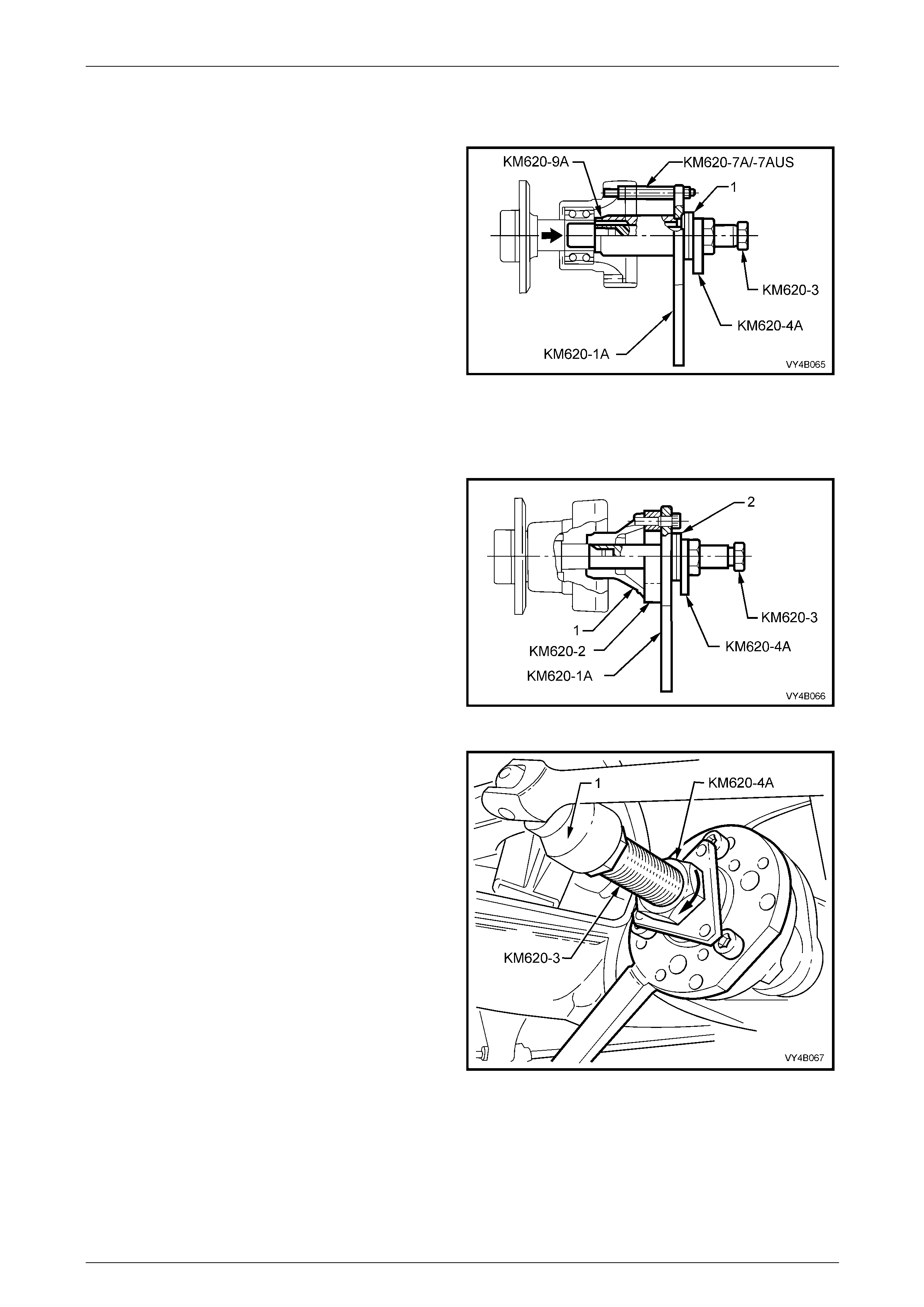
Rear Final Drive and Drive Shafts Page 4B1-61
Page 4B1-61
To Reinstall Outer Rear Wheel Drive Shaft
1 Remove KM620-1A from distance pieces, KM620-7A and KM620-7AUS.
2 Install sleeve KM620-9A over KM620-3, with the
stepped shoulder facing away from the outer rear
wheel driveshaft bearing.
3 Reinstall KM620-1A to KM620 -7A and KM620-7AUS,
tightening the attaching nuts.
4 Screw the threaded end of the outer rear wheel
driveshaft into KM620-3, engaging the full thread
depth.
5 While holding KM620-3 from turning, rotate KM620-4A
to draw outer rear wheel driveshaft into wheel bearing.
6 Unscrew forcing screw KM620-3 from outer rear wheel
driveshaft, then remove the nuts holding tool KM620-
1A to the distance pieces KM620-7A and KM620-
7AUS.
7 Remove the distance pieces KM620-7A and KM620-
7AUS from the trailing arm.
Figure 4B1 – 102
8 Assemble KM620-2 and KM620-1A to outer rear
wheel driveshaft flange using three drive shaft
constant velocity joint to flange bolts.
9 Lubricate outer rear wheel dri veshaft flange splines
and outer rear wheel drivesha ft threads with the
recommended differential carrier lubricant.
10 With KM620-4A, thrust ball bearing race (2) and
KM620-3 assembled to KM620-1A, screw the internal
thread of KM620-3 onto the outer rear wheel
driveshaft assembly.
Figure 4B1 – 103
11 While holding the forcing screw (KM620-3) from
turning with suitable socket equipment (1), use a
suitable 40 mm wrench to rotate the adaptor KM620-
4A in the direction shown, to install the outer rear
wheel driveshaft flange onto outer rear wheel
driveshaft.
12 Unscrew KM620-3 from the outer rear wheel
driveshaft, then remove it and adaptor KM620-4A from
the holding tool KM620-1A. Le ave the h olding tool
KM620-1A and outer rear wheel driveshaft flange ring
tool KM620-2 installed to the outer rear wheel
driveshaft flange.
Figure 4B1 – 104
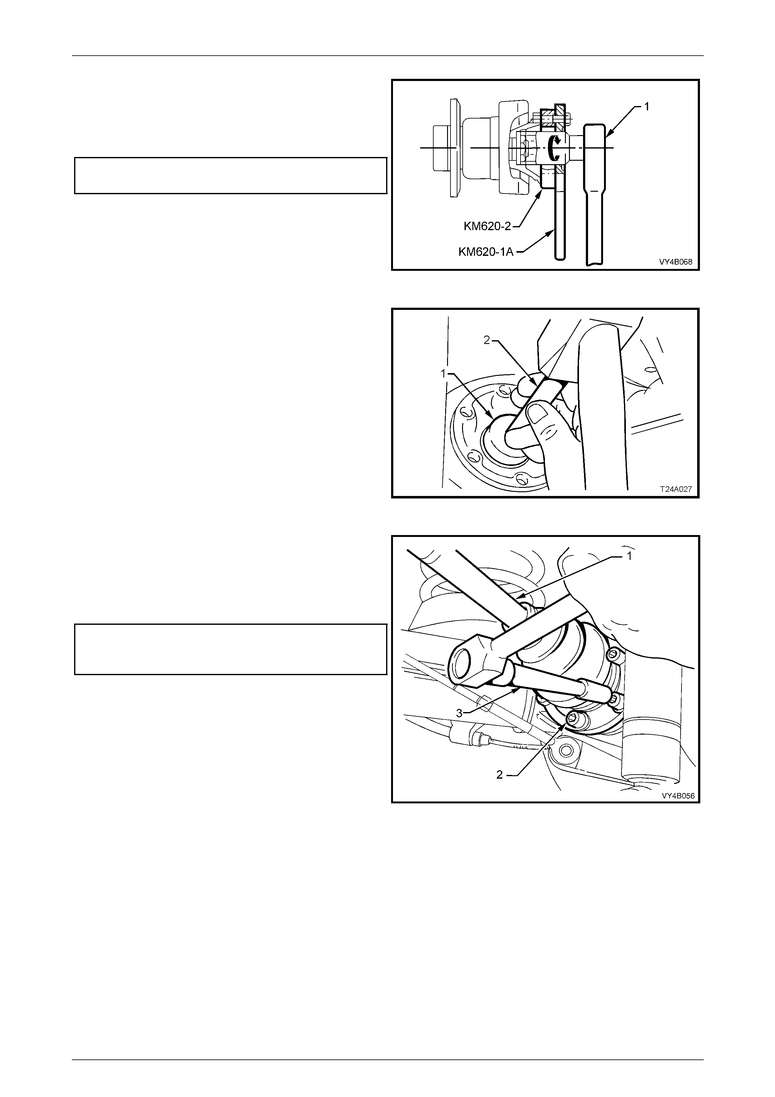
Rear Final Drive and Drive Shafts Page 4B1-62
Page 4B1-62
13 Install NEW collar nut to the outer rear wheel
driveshaft assembly and, using a suitab le length and
sized pipe over the handle of KM620-1A to hold outer
rear wheel driveshaft assembl y from turning, tighten
collar nut to the correct torque specification.
Collar nut to outer rear wheel drive
shaft assembly torque specification...................300 N.m
14 Remove the holding tool KM620-1A and outer rear
wheel driveshaft flange ring tool KM62 0-2 from the
outer rear wheel driveshaft flange.
Figure 4B1 – 105
15 Using a 1.25 inch socket (1), 150 mm socket bar (2)
and a soft faced hammer, install new lock plate over
collar nut.
Figure 4B1 – 106
16 Assemble driveshaft (1) outer constant velocity joint to
outer rear wheel driveshaft flange, alig ning bolt holes.
17 Reinstall six NEW attaching bolts (2) with plates and
tighten bolts to the correct torque specification, using
suitable socket equipment (3).
Drive shaft constant velocity
joint bolt torque specification.......................50 N.m, then
90° turn angle
Figure 4B1 – 107
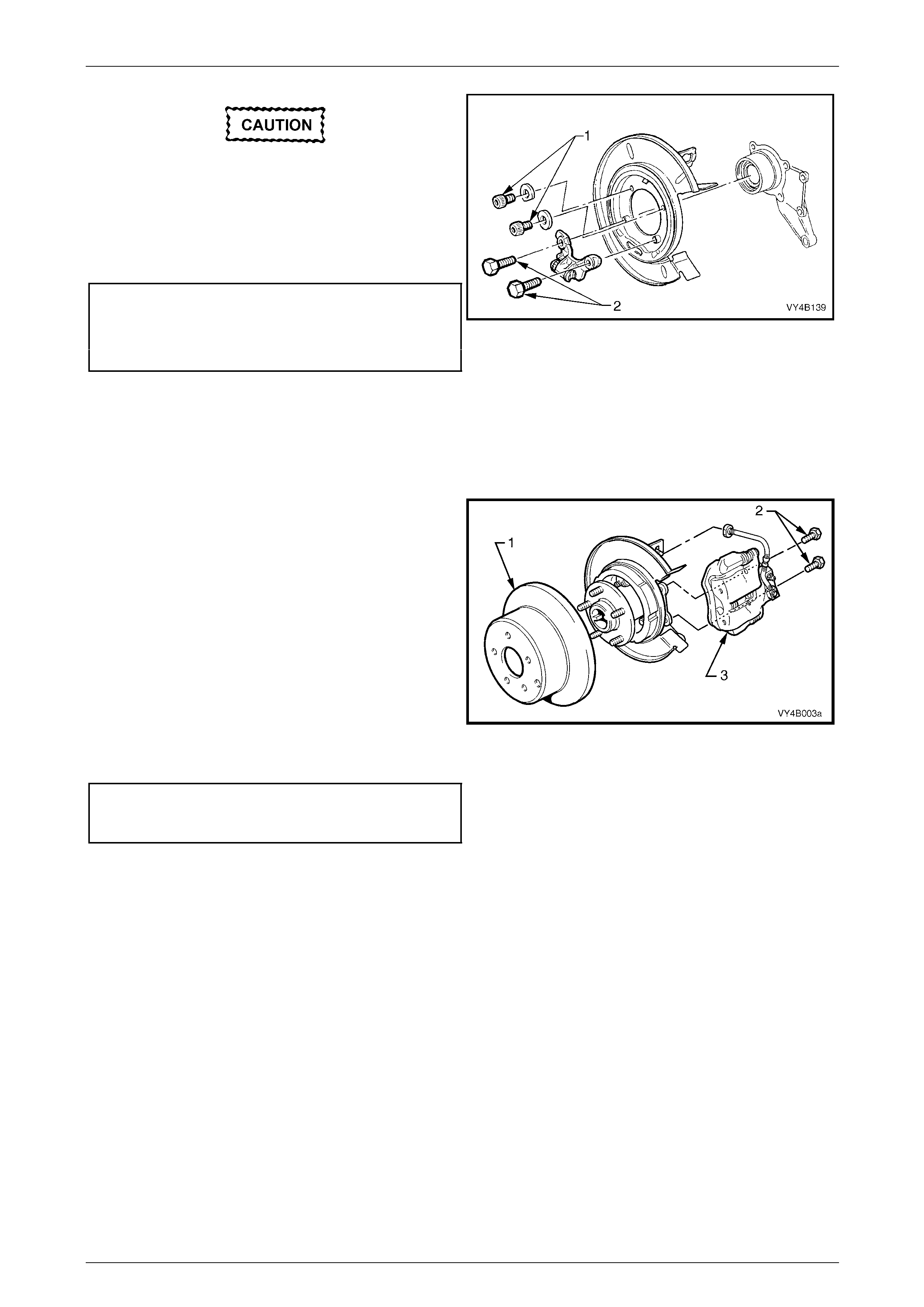
Rear Final Drive and Drive Shafts Page 4B1-63
Page 4B1-63
The lower, rear disc brake shield to trailing
arm attaching bolts must be replaced on
reassembly.
18 Reinstall the four brake backing plate to trailing arm
bolts (‘1’ and ‘2’) and tighten to the correct torque
specification.
Upper rear disc brake shield to
trailing arm bolt torque specification.....................75 N.m
Lower rear disc brake shield to
trailing arm bolt torque specification.....................85 N.m
NOTE
The upper Torx hea ded bolts have washers with
cut-outs that are to be installed with the cut-out
edge facing around the trailing arm hub, outer
surface.
Figure 4B1 – 108
19 Reinstall brake disc (1) to outer rear wheel driveshaft,
aligning the marks made before remova l.
NOTE
If the outer rear wheel driveshaft has been
replaced, then runout checks must be carried out
on the outer rear wheel driveshaft flang e and the
installed brake disc (1). Refer to 2.4 Trailing Arm
Outer Rear Wheel Drive Shaft Assembly, in this
Section for important information re gar ding thes e
checks.
20 Reinstall the brake caliper (3) to the trailing arm,
reinstall brake caliper anchor plate to trailing arm
attaching bolts (2 and tighten to the correct torque
specification.
Brake caliper anchor plate
to trailing arm attaching
bolt torque specification.......................................85 N.m
Figure 4B1 – 109
21 After reconnecting the brake li ne to the caliper hose and inst alling the brake hose retaining clip,
bleed the rear brakes and check for leaks. For the recommended procedure,
refer to Section 5A Service and Park Braking Systems.
22 Support the trailing arm with a floor jack and wooden block, sufficient to enable the shock absor ber to be
reinstalled.
23 Reinstall shock absorb er (3) to traili ng arm (2), install the lower mounting bolt (1) but do not torque to specification
at this stage.

Rear Final Drive and Drive Shafts Page 4B1-64
Page 4B1-64
NOTE
View ‘A’ in Figure 4B1-110 shows the sedan and
coupe lower shock absorber mounting, while view
‘B’ shows the station wagon and utility
arrangement.
Figure 4B1 – 110
24 Install road wheel, aligning marks made before removal and reinstall attaching nuts.
25 Lower vehicle to the ground and bounce the rear of the vehicle several times to settle the suspension components.
Vehicle must be at curb weight and on all four
wheels before this torque is applied.
26 Tighten the lower shock absorber bolt to the correct torque specification.
z Shock absorber lower mounting
bolt torque specification.....................................115 N.m
27 Tighten road wheel attaching nuts to the correct torque specification, working in a ‘star’ pattern.
Refer to Important Service Requirements in 2.1 General Informatio n, in this Section for more details.
Road wheel attaching nut
torque specification..................................110 – 140 N.m
28 Refit wheel cover/wheel nut decorative caps.

Rear Final Drive and Drive Shafts Page 4B1-65
Page 4B1-65
3.2 Final Drive Assembly
LT Section 05-290 – 1
ATTENTION
The following fasteners MUST be replaced when performing these operations:
Final drive assembly to crossmember attaching bolts.
Rear mount to differential carrier rear cover attaching bolts.
Rear mount to vehicle underbody attaching bolts.
Rear drive shaft constant velocity joint attaching bolts.
Rear crossmember front mounting bolt
Rear crossmember front mounting brace to underbody bolt.
The following fasteners MUST be at curb weight before final tightening:
Rear shock absorber to trailing arm bolt.
Whenever any component that forms
part of the ABS (if fitted) is disturbed during
Service Operations, it is vital that
the complete ABS system be checked; refer
ABS Function Check, in Section 5B ABS &
ABS/TC & Electronic Brake Assist (EBA).
Before disturbing the rear suspension
crossmember mounting bolts, an alignment
procedure is required on reinstallation and a
special tool is required for this purpose. If this
tool is not available, then the crossmember
cannot be correctly aligned and steering
and/or handling abnormalities will result.
NOTE
For this service operation, new intermediate
muffler support retainers must be used on
reassembly.
Remove
1 Raise the vehicle and suppor t in a safe manner. Refer to Section 0A General Information for the location of
recommended lifting and support points.
2 Remove wheel covers (steel wheels) or wheel nut caps (all oy wheels).
3 Mark relationship of road wheels to hubs (e.g. end of wheel stud), with a felt tipped pen or similar. Loosen, then
remove the road wheel attaching nuts, working in a 'star' pattern. Refer to Important Service Requirements, in
2.1 General Information, in this Section.
4 Remove the road wheel.
5 To provide access to the propeller shaft fasteners, it is recommended that the exhaust system is removed, from the
rear of the catalytic converters, rearward. Refer to Section 8B Exhaust System.
6 Remove propeller shaft, refer to Section 4C1 Propeller Shaft and Universal Joints.
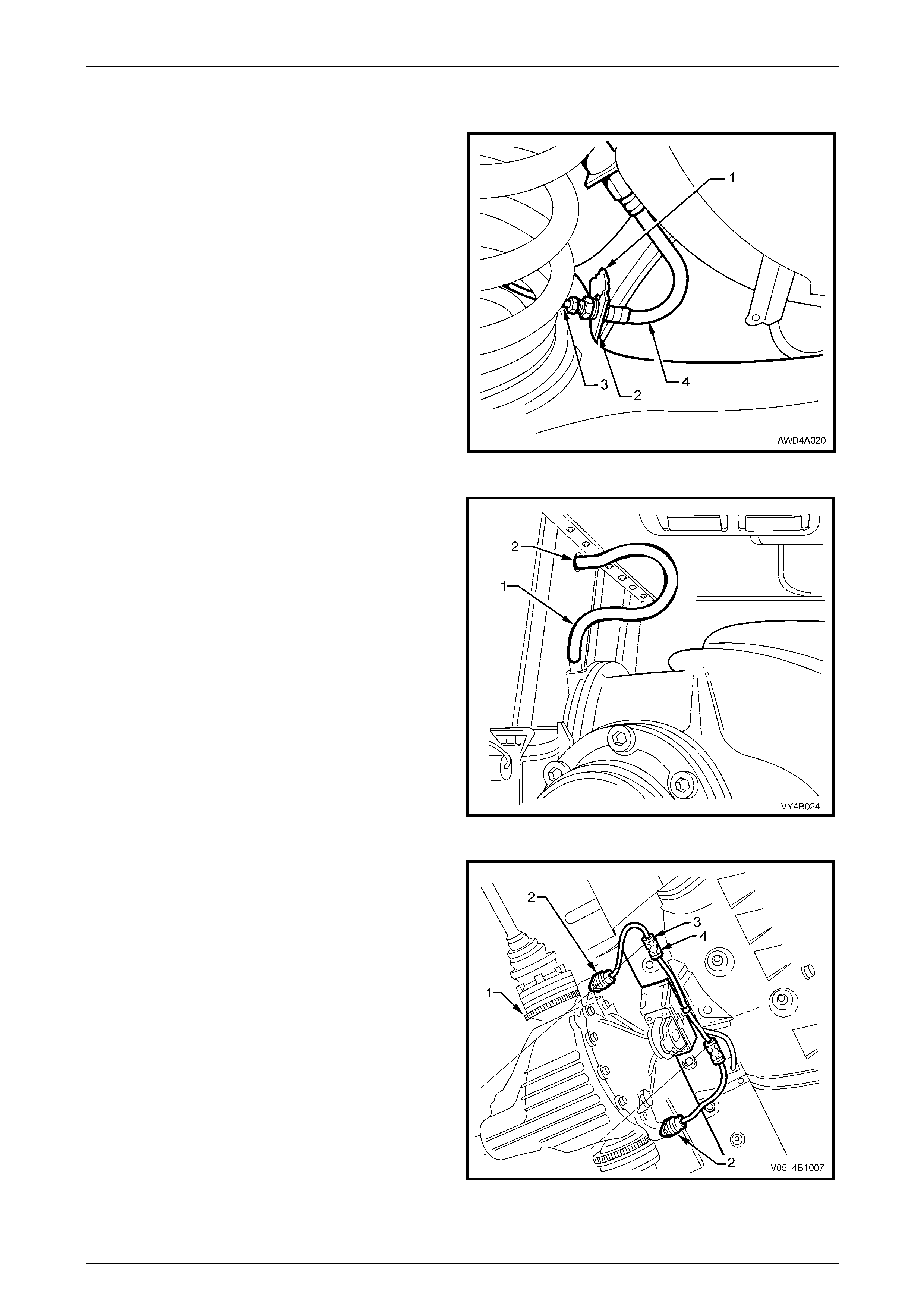
Rear Final Drive and Drive Shafts Page 4B1-66
Page 4B1-66
7 Disconnect both park brake cabl es from the equaliser bracket.
Refer to Section 5A Service and Park Braking System.
8 Disconnect brake pipe (3) from brake hose (4) at
trailing arm bracket (2) and remove the brake hose
retaining clip (1).
9 Plug the open ends of both pipes and hos es to prevent
unnecessary fluid loss and/or dirt entry.
10 Repeat for the other side.
Figure 4B1 – 111
11 Pull out differential carrier breather hose (1) from
vehicle underbody crossmember hole (2).
Figure 4B1 – 112
12 If vehicle is fitted with ABS, disengage both the sensor
lead connectors (3) from the underbody retaining clips
(4) then separate the sensor connectors from the body
harness connectors by levering with a screwdriver
Figure 4B1 – 113
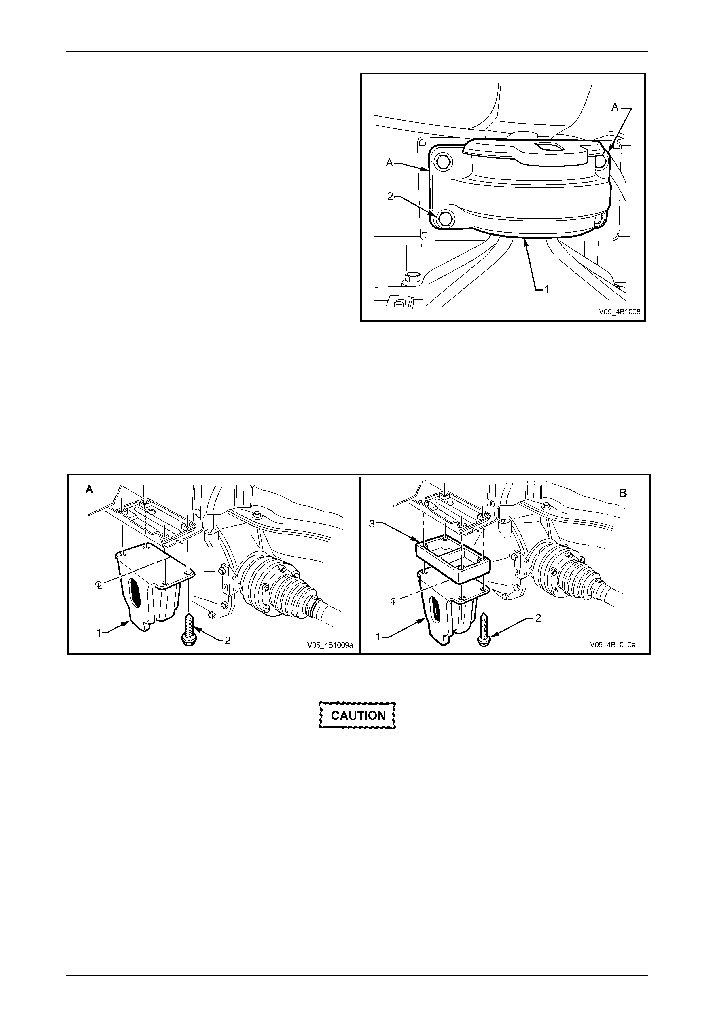
Rear Final Drive and Drive Shafts Page 4B1-67
Page 4B1-67
13 Using a scriber, mark rear mount (1) to vehicle under
body location (A). This will assist in rear crossmember
alignment on reinstallation.
14 Support weight of differential carrier with floor jack.
Figure 4B1 – 114
15 Remove rear mount (1) to vehicle underbody attaching bolts (2) and disca r d removed bolts. If an AWD Wagon, also
remove the spacer block (3).
NOTE
View 'A' in Figure 4B1-115 shows the
arrangement for all independent rear suspension
models, except for the AWD Wagon, which is
shown in 'B'.
Figure 4B1 – 115
Bruising to the inside of the drive shaft
constant velocity joint boots will occur if the
shock absorber is disconnected from the
trailing arm before the rear of the differential
carrier and crossmember assembly has been
lowered by at least 60 mm. Bruising of the
boot will lead to premature failure of the boot
and eventual failure of the joint, if left
unchecked.
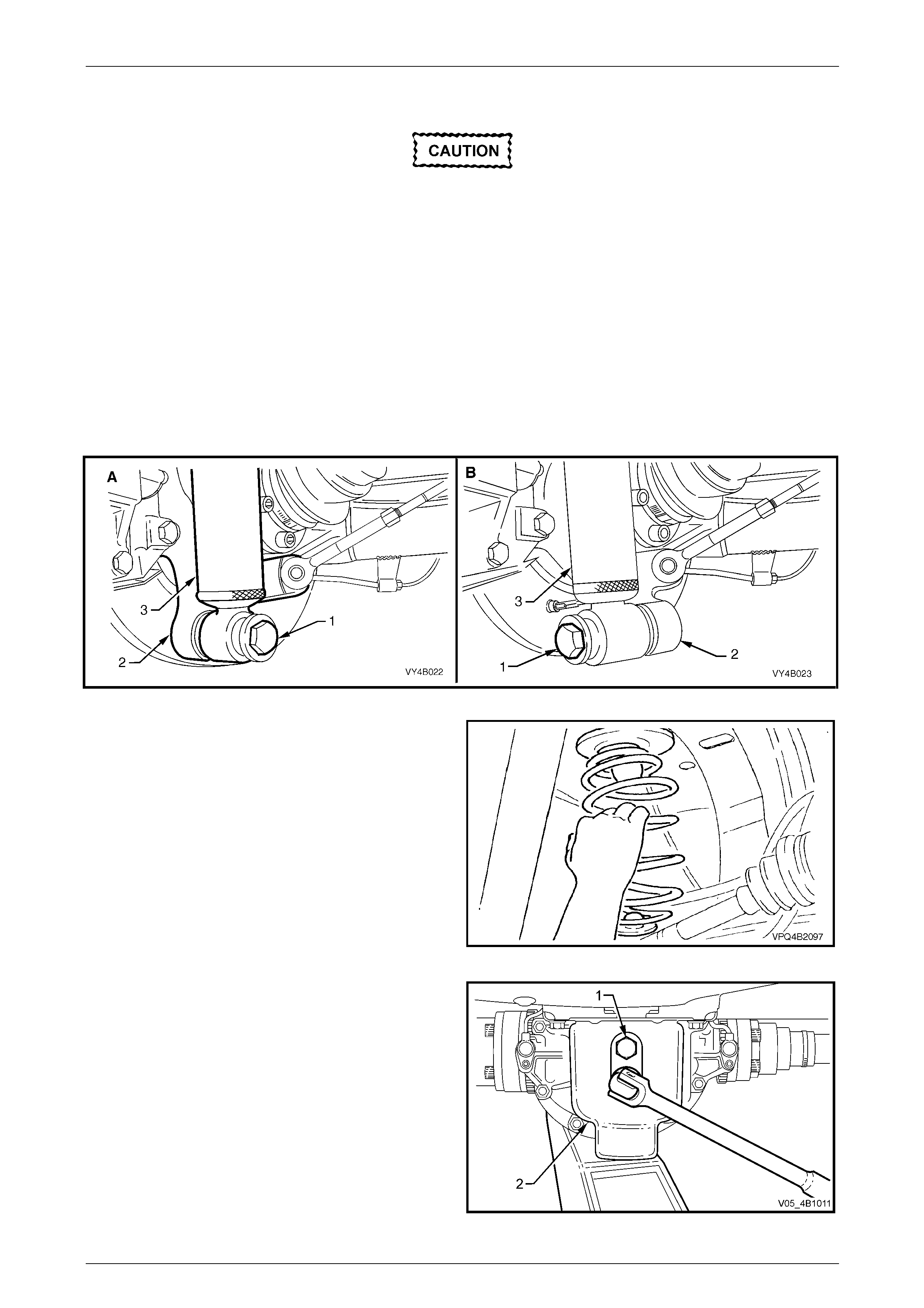
Rear Final Drive and Drive Shafts Page 4B1-68
Page 4B1-68
16 Lower differential carrier and rear crossmem ber assembly by at least 60 mm.
If automatic level ride suspension is fitted to
the vehicle, there are specific procedures
relating to the system pressure and the
removal of the rear shock absorbers. Refer to
Section 4A1 Independent Coil Spring Rear
Suspension.
17 Position floor jack with a block of wood under trailing arm. Raise jack slightly to take spring load off trailing arm.
18 Disconnect rear shock absorber lower mounting bolt (1) from trailing arm (2), and pull lower end of shock absorber
(3) from trailing arm.
NOTE
View ‘A’ in Figure 4B1-116 shows the sedan and
coupe lower shock absorber mounting, while view
‘B’ shows the station wagon and utility
arrangement.
Figure 4B1-116
19 Remove rear springs and insulators from veh icle
underbody and trailing arms.
20. Raise differential carrier and rear crossmember on
floor jack until rear mount contacts underbody.
Figure 4B1 – 117
21 If replacing differential carrier assembly, rear cover or
rear mount, loosen and remove rear mount to rear
cover attaching bolts (1), remove rear mount (2) and
discard attaching bolts (1). Discard the removed bolts.
Figure 4B1 – 118
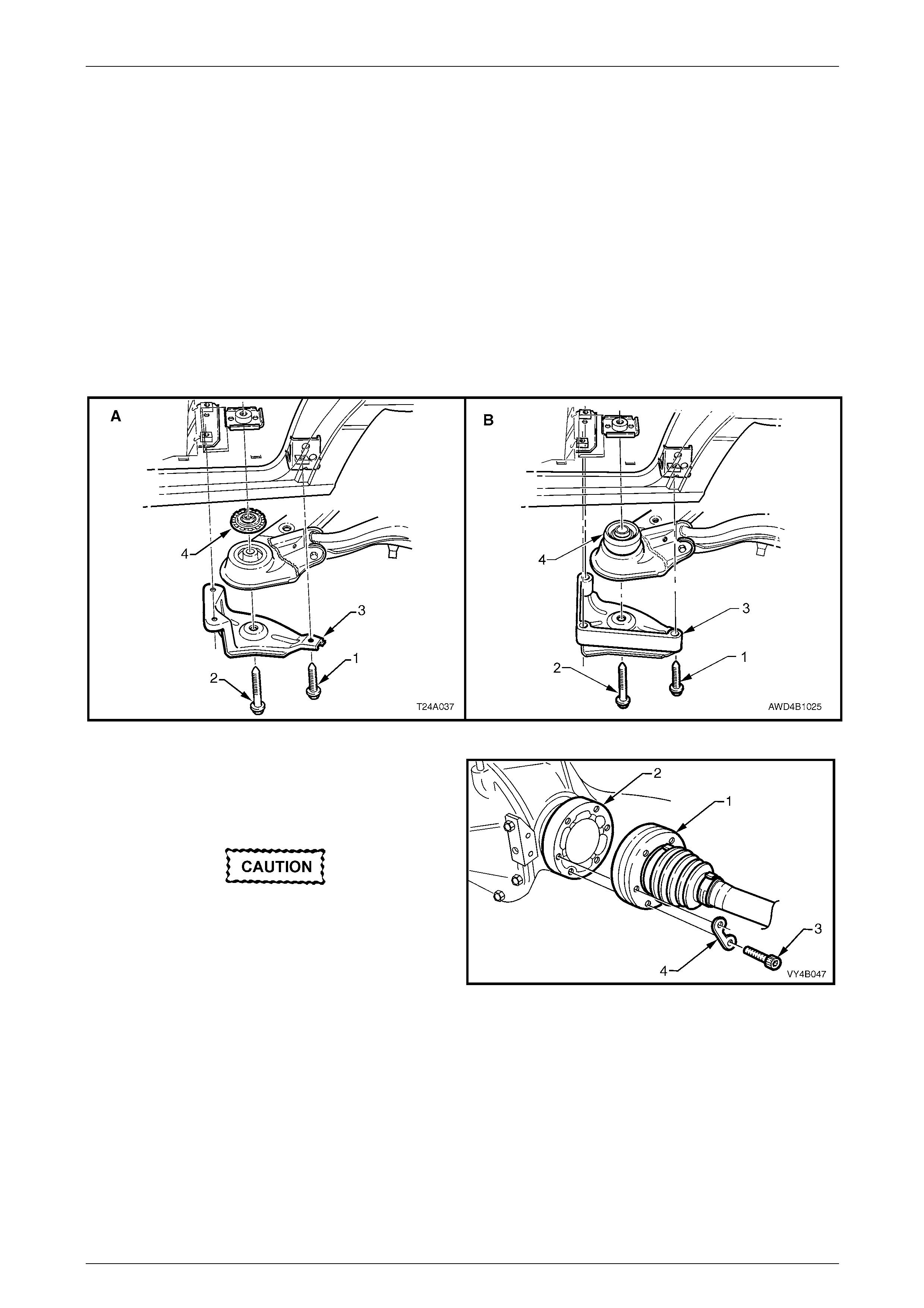
Rear Final Drive and Drive Shafts Page 4B1-69
Page 4B1-69
22 Use a floor jack and block of wood to suppor t differential carrier and crossmember assembly.
23 Remove brace to underbody bolts (1) (3 places) and crossmember to vehicle underbody attaching bolt (2) from
each side.
24 Remove the braces (3) from the vehicle.
25 With an assistant supporting front end of rear crossmember, lower assembly on jack an d remove from beneath
vehicle.
26 If the vehicle is fitted with isolating rubbers o r snubber bushes (4) located on top of each rear crossmember front
bush, remove and set to one side.
NOTE
View ‘A’ in Figure 4B1 – 119 shows the isolating
rubber fitted to GEN III V8 and manual
transmission, while view ‘B’ shows the AWD
Wagon arrangement.
Figure 4B1 – 119
27 Using an 8 mm Allen key sock et, remove drive shaft
inner constant velocity joint (1) to inner axle shaft (2)
attaching bolts (3) and plates (4). Discard all removed
bolts as they must be replaced on reassembly.
Support drive shafts with suitable tie wire so
they do not hang down on one end. Drive
shaft joint deflection should b e kept to within
the angular movement of an installed drive
shaft.
28 Disconnect joints from inner axle shafts. Figure 4B1 – 120
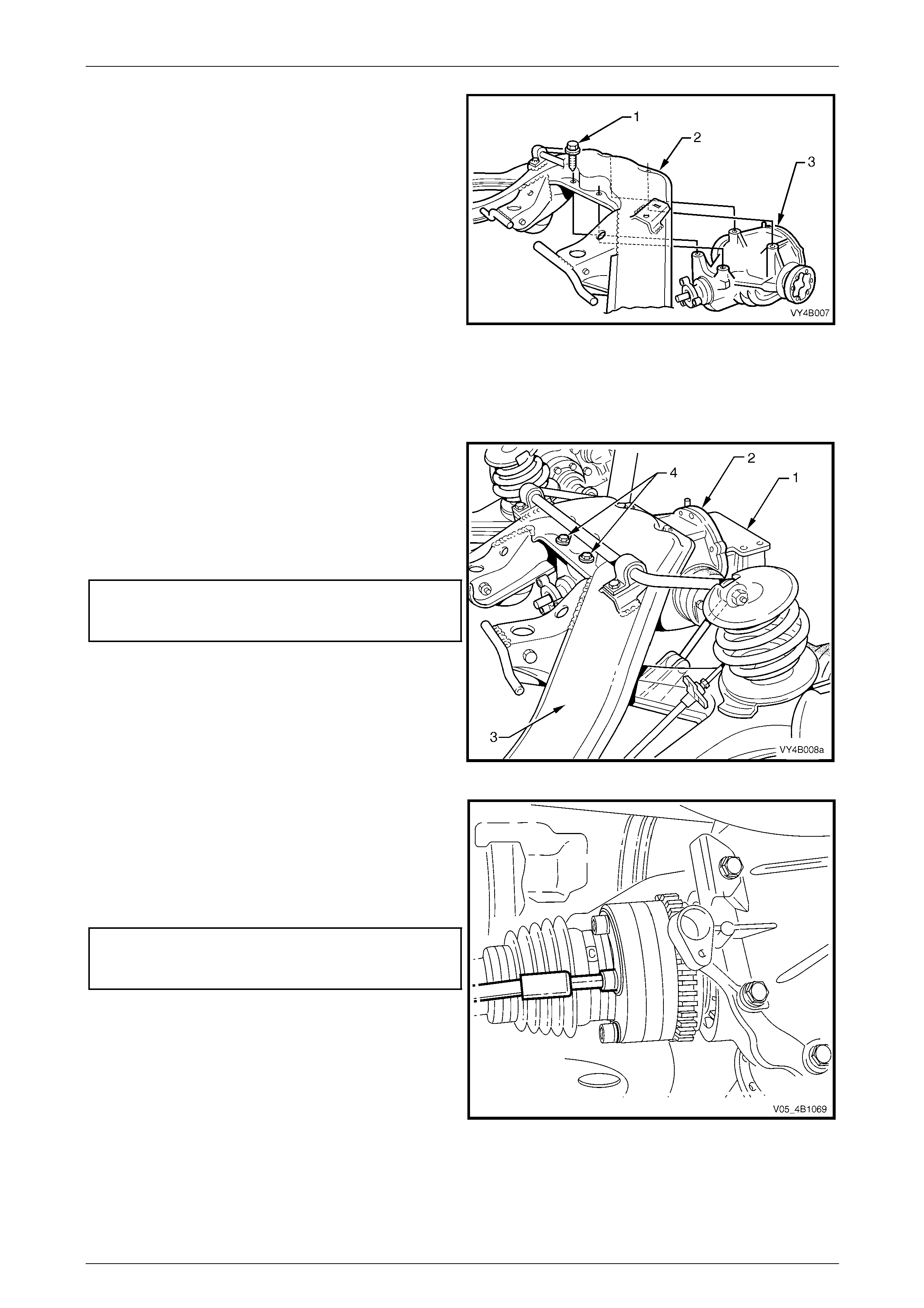
Rear Final Drive and Drive Shafts Page 4B1-70
Page 4B1-70
29 Remove differential carrier (3) to rear crossmember (2)
attaching bolts (1), remove rear crossmember
assembly from differential carrier and discar d
attaching bolts(1).
30 If not carried out in Step 21, remove rear mount to rear
cover attaching bolts, remove mount and disc ard
attaching bolts.
Figure 4B1 – 121
Reinstall
Installation is the reverse of removal procedure e xcept for the following items:
1 If necessary, reinstall rear mount (1) to rear cover
using NEW bolts but leave bolts finger tight at this
stage.
2 Line up mounting holes in final drive assembly (2) and
rear crossmember (3). Install NEW attaching bolts (4)
(four places) and tighten to the correct torque
specification.
Final drive assembly to crossmember
attaching bolt torque specification...............90 N.m, plus
40° turn angle
Figure 4B1 – 122
3 Inspect drive shaft constant velocity joint boots for
damage, replacing as necessary.
4 Install NEW drive shaft inner constant velocity joint
bolts and locking plates to secure the inner constant
velocity joint to the inner axle shaft and tighten to the
correct torque specification.
Drive shaft constant velocity joint
bolt torque specification..............................50 N.m, plus
90° turn angle
Figure 4B1 – 123
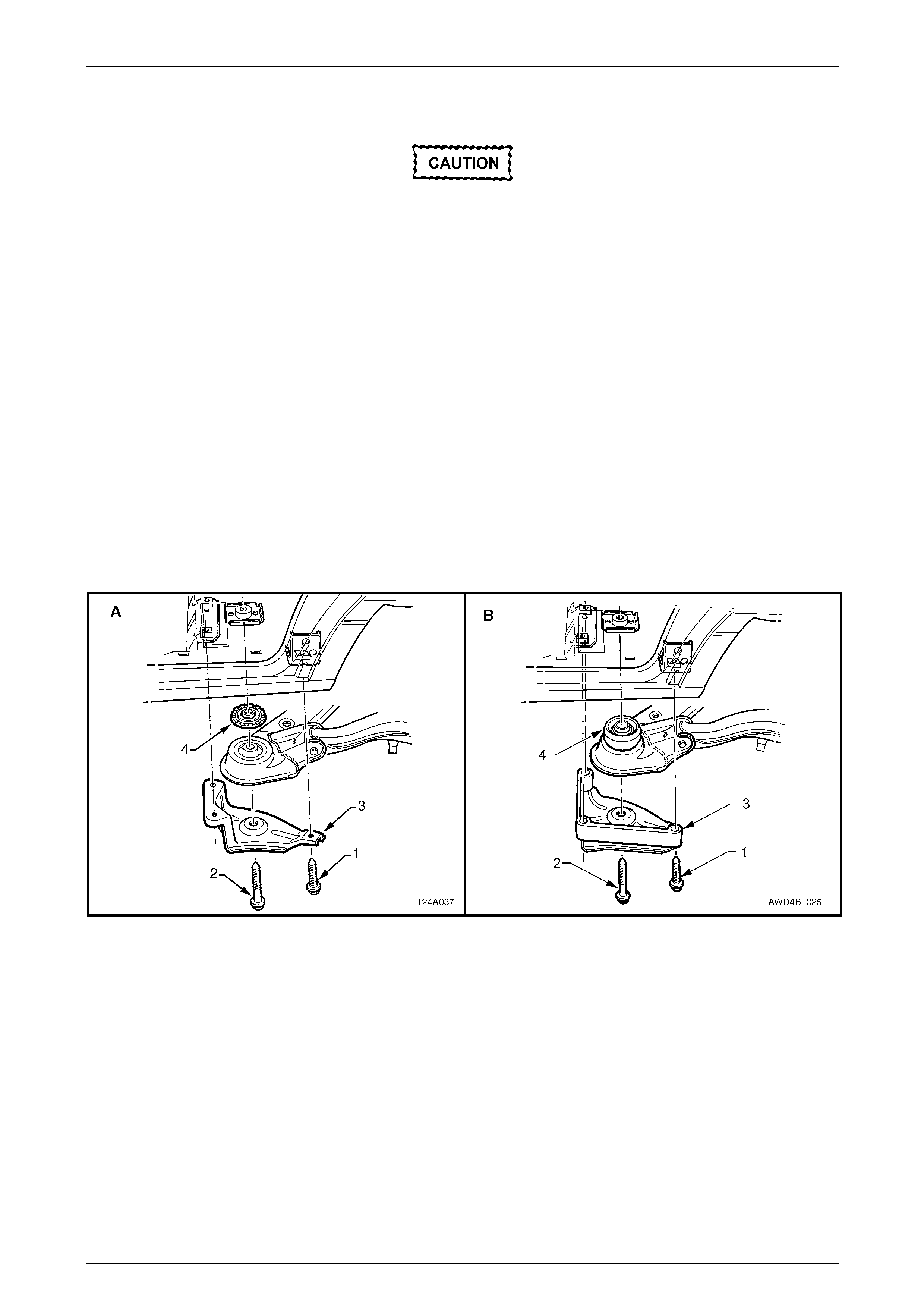
Rear Final Drive and Drive Shafts Page 4B1-71
Page 4B1-71
5 With the help of t wo assistants, place the differential carrier and rear crossmember assembly onto a floor jack.
• When raising the assembly, take care that
the rear mount does not foul on the fuel
tank or fuel hoses.
• During this operation, ensure that trailing
arms are also supported on safety stands,
to keep the drive shafts as near to
horizontal as possible. Otherwise, bruising
to the insides of the co nstant velocity joint
boots will result, leading to boots splitting
and eventually joint failure, if left
unchecked.
6 Position assembly under vehic le, raise with the jack and, with the aid of the assistants, guide the crossmember
front mounting points into position.
7 If the vehicle is fitted with an isolating rubber (' 4' in view A) or snubber bush ('4' in view B) on each side, they must
be fitted at the top of each crossmember front bush as shown, before raisin g the assembly into place.
NOTE
View 'A' in Figure 4B1-123 shows the
arrangement for the GEN III V8 engine and
manual transmission models, while view ‘B’
shows the snubber bushes fitted to AWD wagon
models.
Figure 4B1 – 124
8 Install crossmember front mounting braces (3), attaching bolts (‘1’ – three p laces each side) and rear
crossmember, front mounting bolt (2) but do not fully tighten any of these bolts at this stage.
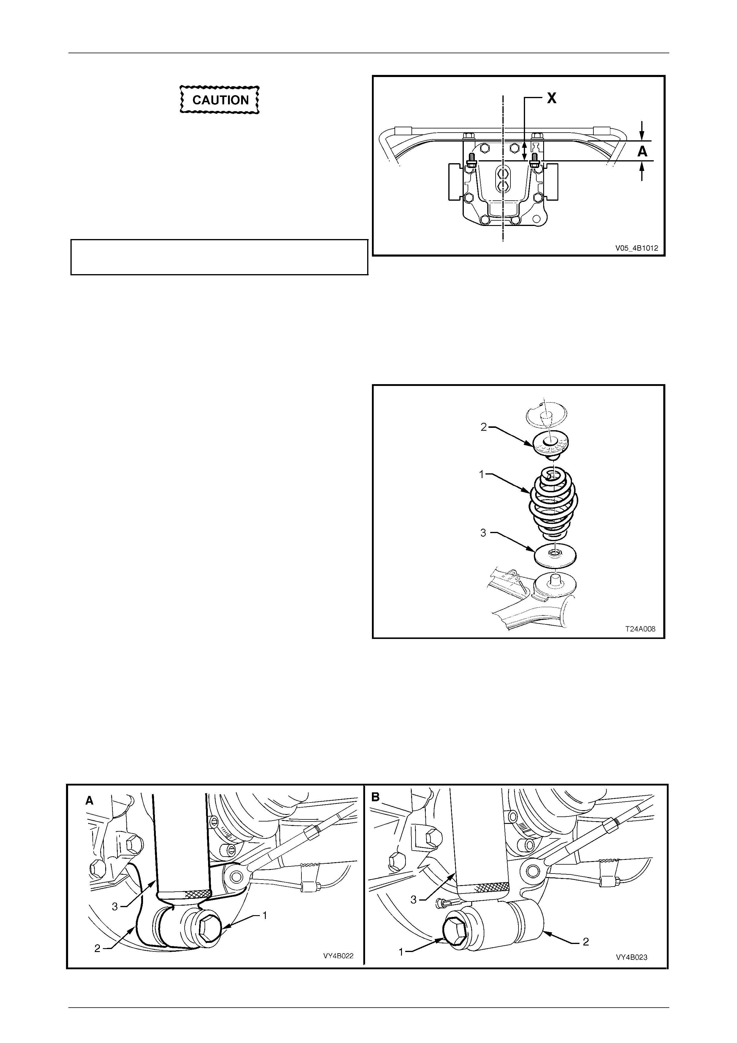
Rear Final Drive and Drive Shafts Page 4B1-72
Page 4B1-72
Ensure that mount does not twist during the
bolt tightening process, as the mount to
vehicle underbody mating surface should be
parallel to the rear crossmember, to within 1
mm (‘X’).
9 Lower rear of the final drive assembly to gain access
to the rear mount to cover attaching bolts. Tighten
attaching bolts to the correct torque specificat ion.
Rear mount to rear cover
bolt torque specification.......................................95 N.m
NOTE
Use a spirit level on rear mount to underbody
surface and top surface of crossmember to
ensure that both surfaces are parallel.
Dimension ‘A’ is to be 56.7 mm.
Figure 4B1 – 125
10 Lower differential carrier and rear crossmember
assembly on floor jack and safety stands. Install rear
springs (1) and the two insulators, (2 and 3).
NOTE
During this operation, the differential carrier and
rear crossmember assembly rear mount mus t be
lowered at least 60 mm from the vehicle
underbody. Otherwise damage to the drive shaft
constant velocity joint boots will occur.
Figure 4B1 – 126
11 Reinstall shock absorber to trailing arm, fit washer to the lower mounting bolt, install bolt but do not fully tighten at
this time, as the vehicle must be at curb weight before final tightening is undertaken.
NOTE
View ‘A’ in Figure 4B1-127 shows the sedan and
coupe lower shock absorber mounting, while view
‘B’ shows the station wagon and utility
arrangement.
Figure 4B1 – 127
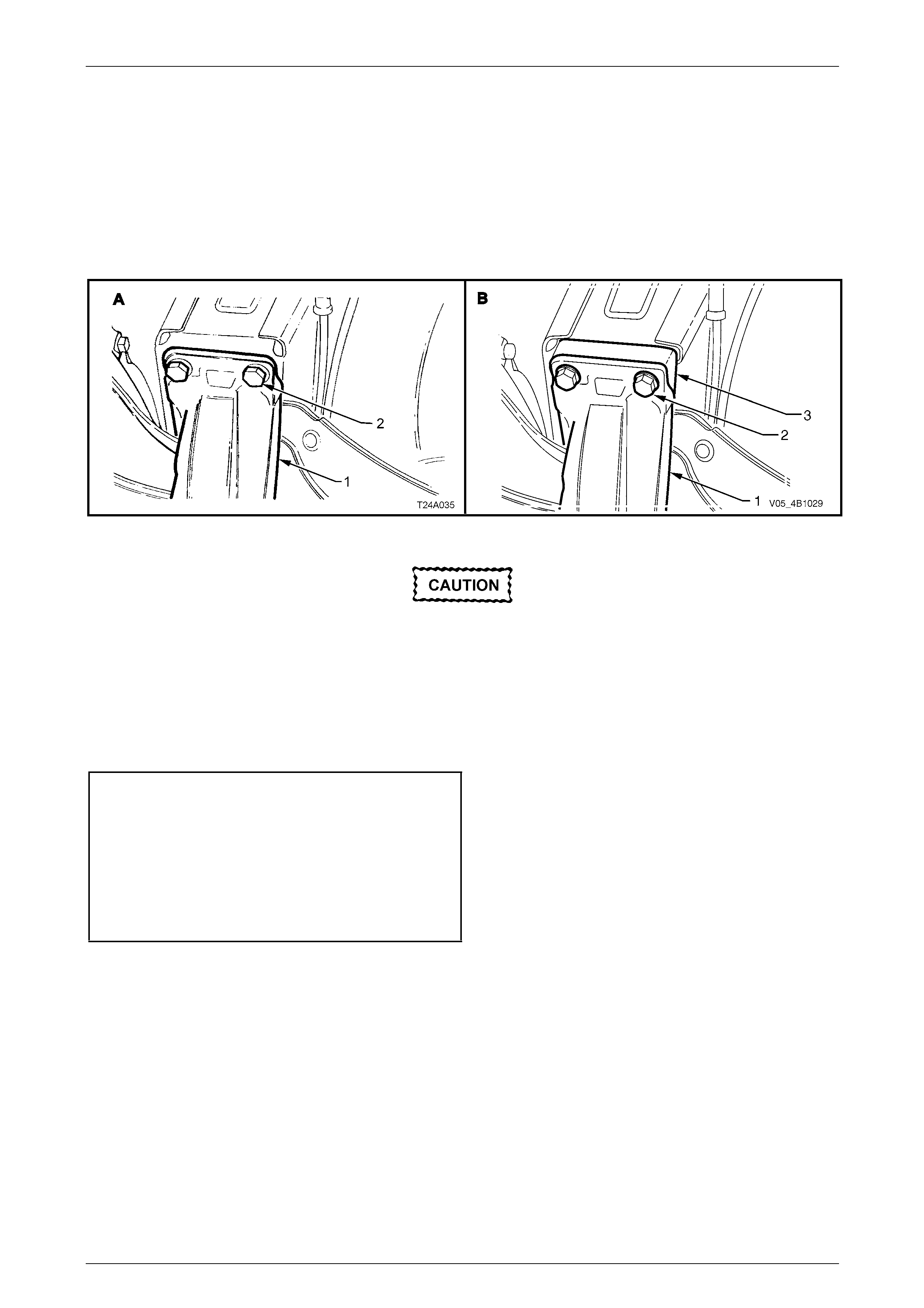
Rear Final Drive and Drive Shafts Page 4B1-73
Page 4B1-73
12 Raise assembly until rear mount contacts vehicle underbody.
13 Align rear mount (1) with marks on underbody, made on disassembly, then loosely install new attaching bolts (2)
but do not fully tighten at this stage.
NOTE
View 'A' in Figure 4B1-128 shows the
arrangement for all independent rear suspension
models, except for the AWD Wagon, which is
shown in 'B', with the spacer (3) included.
Figure 4B1 – 128
Failure to correctly align the rear
crossmember to the centreline of the vehicle
will result in steering abnormalities and
uneven tyre wear!
14 The rear crossmember MUST now be aligned to the vehicle centreline, using the special tool and procedure as
detailed in Sect ion 1A2 Body Dimensions.
15 Tighten all crossmember mou nting faste ners to the correct torque specifica t ion.
Rear mount to vehicle underbody
attaching bolt torque specification...............35 N.m, plus
60° turn angle
Crossmember front mounting
bolt torque specification............................125 N.m, plus
35 ° turn angle
Crossmember front mounting
brace bolt torque specification .............................75 N.m
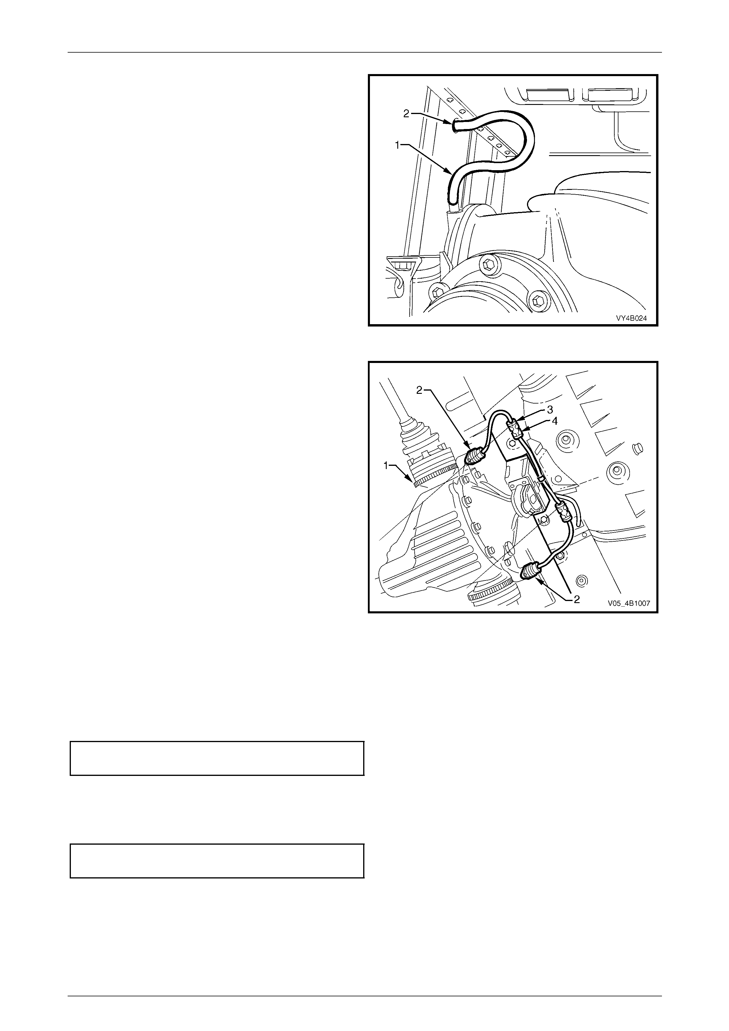
Rear Final Drive and Drive Shafts Page 4B1-74
Page 4B1-74
16 Install differential carrier breather hose into vehicle
underbody crossmember hole. Ensure that end of
hose is pushed into hole approximately 25 mm.
Figure 4B1 – 129
17 If equipped with ABS, reconnect wheel sensor wiring
harness connectors (3). Reinstall into the retaining
clips (4).
18 Reinstall park brake inner cables to the fron t retainer,
install and secure outer cable s in the underbody
retainers, then install the outer cable retaining bracket
bolt to the vehicle underbody.
19 Check and fill differential carrier to correct le vel with
specified lubricant, refer to 2.2 Checki ng Differential
Carrier Lubricant Level, in this Section.
20 Check park brake adjustment and bleed brake
hydraulic system, refer to Section 5A Service and Park
Braking System.
21 Reinstall propeller shaft. Refer to Section 4C1
Propeller Shaft and Universal Joints.
22 Reinstall exhaust s ystem,
refer to Section 8B Exhaust System. Figure 4B1 – 130
23 Reinstall road wheels, aligning the marks made prior to removal and secure with attaching nuts.
24 Lower vehicle to the ground.
25 Bounce the rear of the vehicle several times to settle suspension then, tighten road wheel attaching nuts to correct
torque specification, working in a ‘star’ pattern; refer to Important Service Requ irements, in 2.1 General Information,
in this Section.
Road wheel attaching
nut torque specification............................110 – 140 N.m
26 Refit wheel cover/wheel nut decorative caps.
27 Lower vehicle to the ground and, with the vehicle weight on a;; four wheels, tighten the lower shock absorber l ower
mounting bolts to the correct toque specificat ion.
z Shock absorber lower mounting
bolt torque specification.....................................115 N.m
28 Start vehicle and check for exhaust leaks. Repair as nec essary.
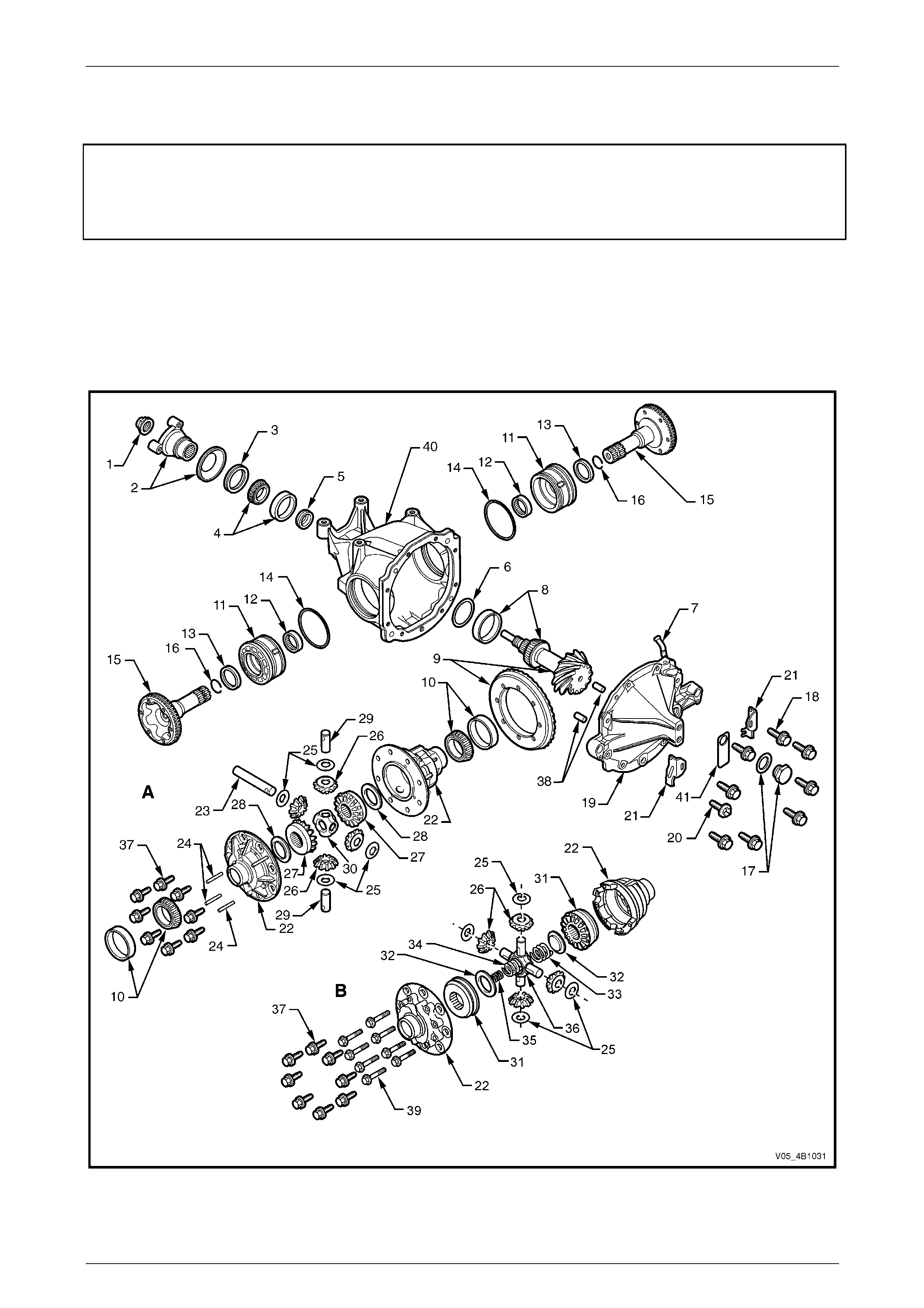
Rear Final Drive and Drive Shafts Page 4B1-75
Page 4B1-75
3.3 Removed Final Drive Assembly
ATTENTION
The following fasteners MU ST be replaced when performing these operations:
Final drive ring gear attaching bolts.
NOTE
Apart from the fact that the appearance of the
pinion flange and the drive pinion is different, the
unit repair for the removed final drive assem bly is
the same as described here, for the 3.46:1 ratio
assembly without LSD.
Figure 4B1-131
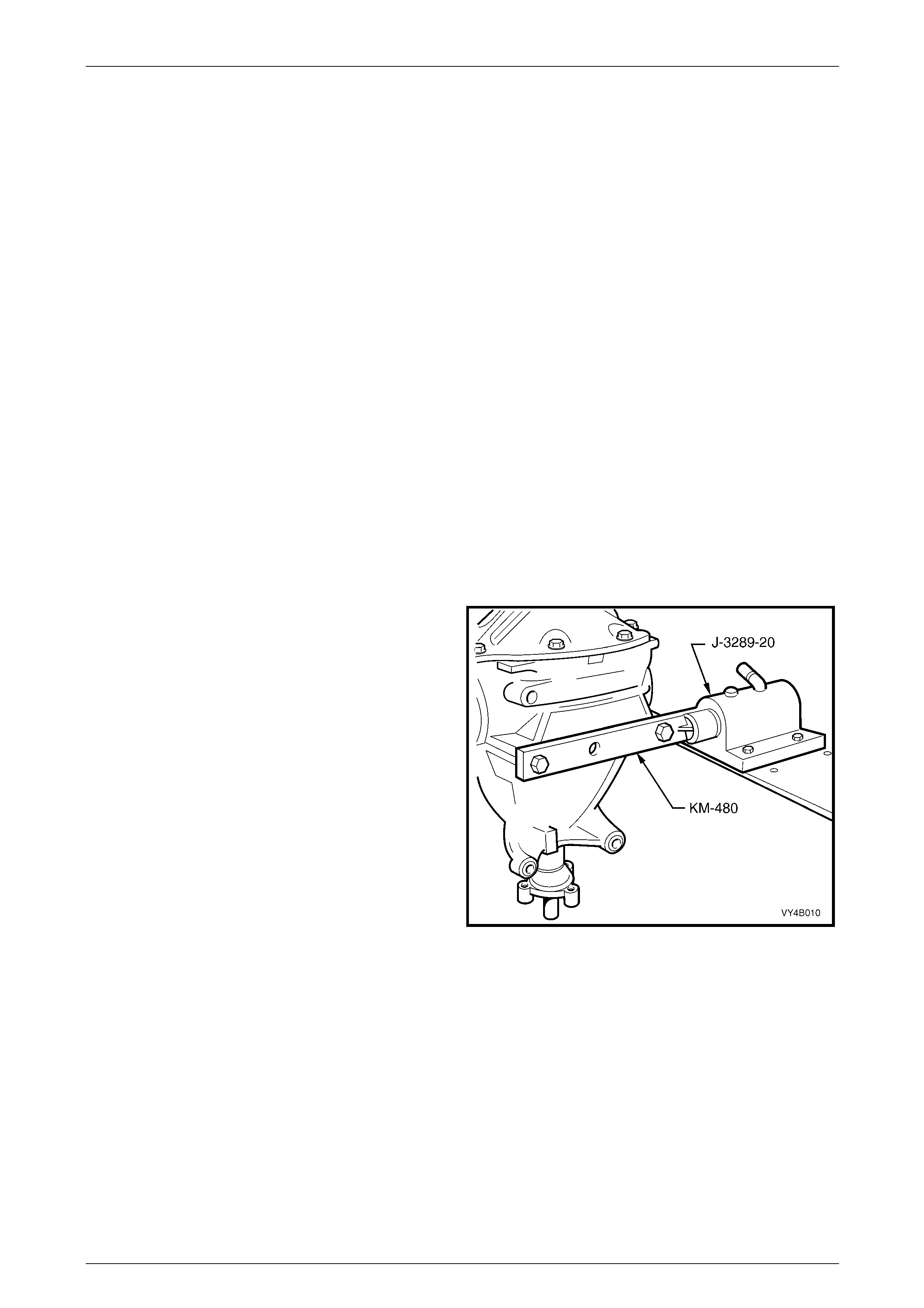
Rear Final Drive and Drive Shafts Page 4B1-76
Page 4B1-76
Legend
'A' Standard Differential
'B' Limited Slip Differential
1 Nut – Pinion flange retaining
2 Flange Asm – Differential pinion
3 Seal – Rear axle pinion oil
4 Bearing Asm – Pinion front
5 Collapsible Spacer – Pinion bearing
6 Shim – Pinion position adjusting
7 Breather Asm – Rear axle
8 Bearing Asm – Pinion Rear
9 Ring Gear and Pinion
10 Bearing Asm – Differential side
11 Screw – Differential side bearing
adjusting
12 Bearing Asm – Inner axle shaft
13 Seal – Inner axle shaft
14 O-ring – Screw adjuster
15 Shaft – Inner axle
16 Clip – Inner axle shaft
17 Screw Plug & Washer – Filler
18 Bolt – Rear cover attaching
19 Cover – Rear axle housing
20 Plug – Drain
21 Plate – Lock
22 Case – Differential
23 Shaft – Differential pinion gear - long
24 Lock Pin – Differential pinion shaft
25 Washer – Differential pinion gear
thrust
26 Gear – Differential pinion
27 Gear – Differential side
28 Washer – Differential side gear thrust
29 Shaft – Differential pinion gear - short
30 Block – Thrust
31 Gear and Cone Assembly – Differential
Side
32 Plate – Thrust spring (LSD only)
33 Spring – Differential pre-load - outer
34 Spring – Differential pre-load -middle
35 Spring – Differential pre-load -inner
36 Shaft – Cross (LSD)
37 Bolt – Ring gear to case
38 Pin – Dowel
39 Bolt – Case cap to cover
40 Housing – Carrier
41 Tag – Lubrication
Disassemble
NOTE
The disassembly operation is the same for all
assemblies, except where indi cated.
1 Remove differential carrier assembly. Refer to 3.2 Final Drive Assembly, in this Section.
2 Secure holding tool, Tool No. KM-480 or a fabricate d
copy (refer 7 Special Tools, in this Section for details) ,
to the differential carrier using two of the discarded
differential carrier to rear crossmember attachin g bolts.
3 Install holding tool into be nch mounted fixture base,
Tool No. J-3289-20.
Figure 4B1 – 132
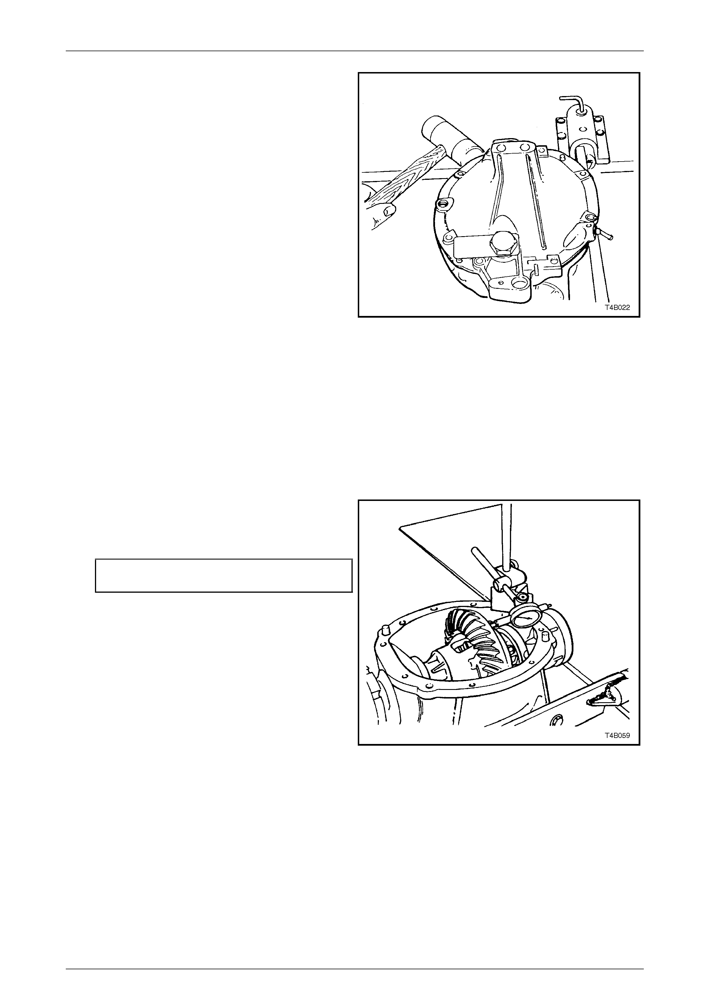
Rear Final Drive and Drive Shafts Page 4B1-77
Page 4B1-77
4 Remove rear cover to differential carrier attaching
bolts and screw adjuster lock plates.
5 Using a soft faced hammer, tap rear cover at rear
mount area to break rear cover to differential carrier
seal.
6 Remove rear cover, rotate the assembly and drain
residual differential lubricant into a suitable container.
Figure 4B1 – 133
7 Before removing differential case assembly and drive pinion from differential carrier, the follo wing inspection
procedures should be adopted. These inspections can help to isolate the cause of final drive assembly noise a nd
determine corrections needed.
a Visually inspect the moving parts for chipped or scuffed surfaces.
b Check the torque of the ring gear bolts and t he pinion flange nut.
NOTE
Ring gear bolts have a left hand threa d.
c Mount a dial indicator to read from the rear face
of the ring gear, then rotate the differential case
through several turns to measure ring gear run-
out.
Ring gear face
run-out specification................0.13 mm maximum
d Leave the dial indic ator set up and push the ring
gear hard one way, then hard the opp osite way
to measure side play. There should b e no sid e
play present.
e Check to ensure that there is no pinion end play.
If end play is evident, then special attention
should be made to the bearing insp ection
process, after disassembly.
Figure 4B1 – 134
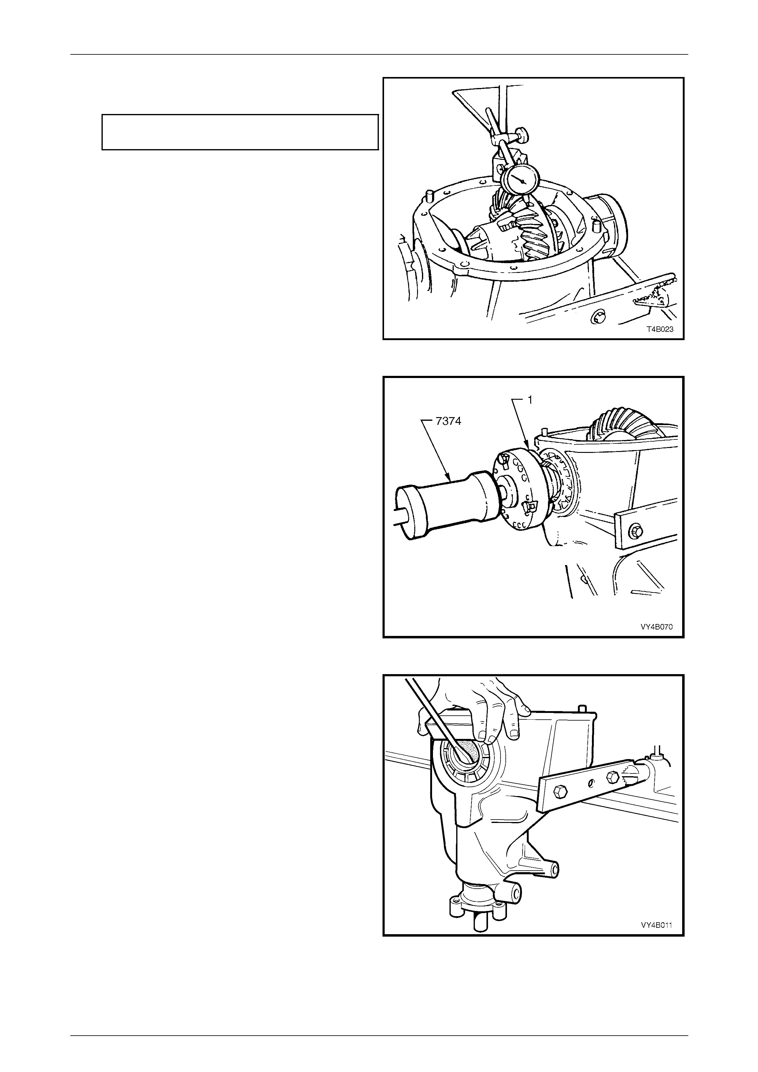
Rear Final Drive and Drive Shafts Page 4B1-78
Page 4B1-78
f Set up the dial indicator to measure ring gear
backlash at three equally spaced positions
Backlash specification
(At the tightest point)..................... 0.10 – 0.18 mm
g If no obvious faults are found, check the gear
tooth contact pattern. Refer to Ring Gear and
Pinion Contact Pattern in this Section, for
diagnostic assistance.
Figure 4B1 – 135
8 Remove inner axle shafts (1) by installing slide
hammer, Tool No. 7374 and three suitable size bolts
to each axle flange. Use the slide hammer to release
axle shaft spring clips.
NOTE
The left hand inner axle shaft is shorter in length
than the right hand shaft.
Figure 4B1 – 136
9 If new screw adjuster seals are to be installed, use a
suitable screwdriver and a block of wood to lever out
seals from screw adjusters.
NOTE
Take care not to damage the screw adjuster's
aluminium housing with the screwdriver blade,
as this could cause oil leaks to occur, after a
new oil seal is fitted.
Figure 4B1 – 137
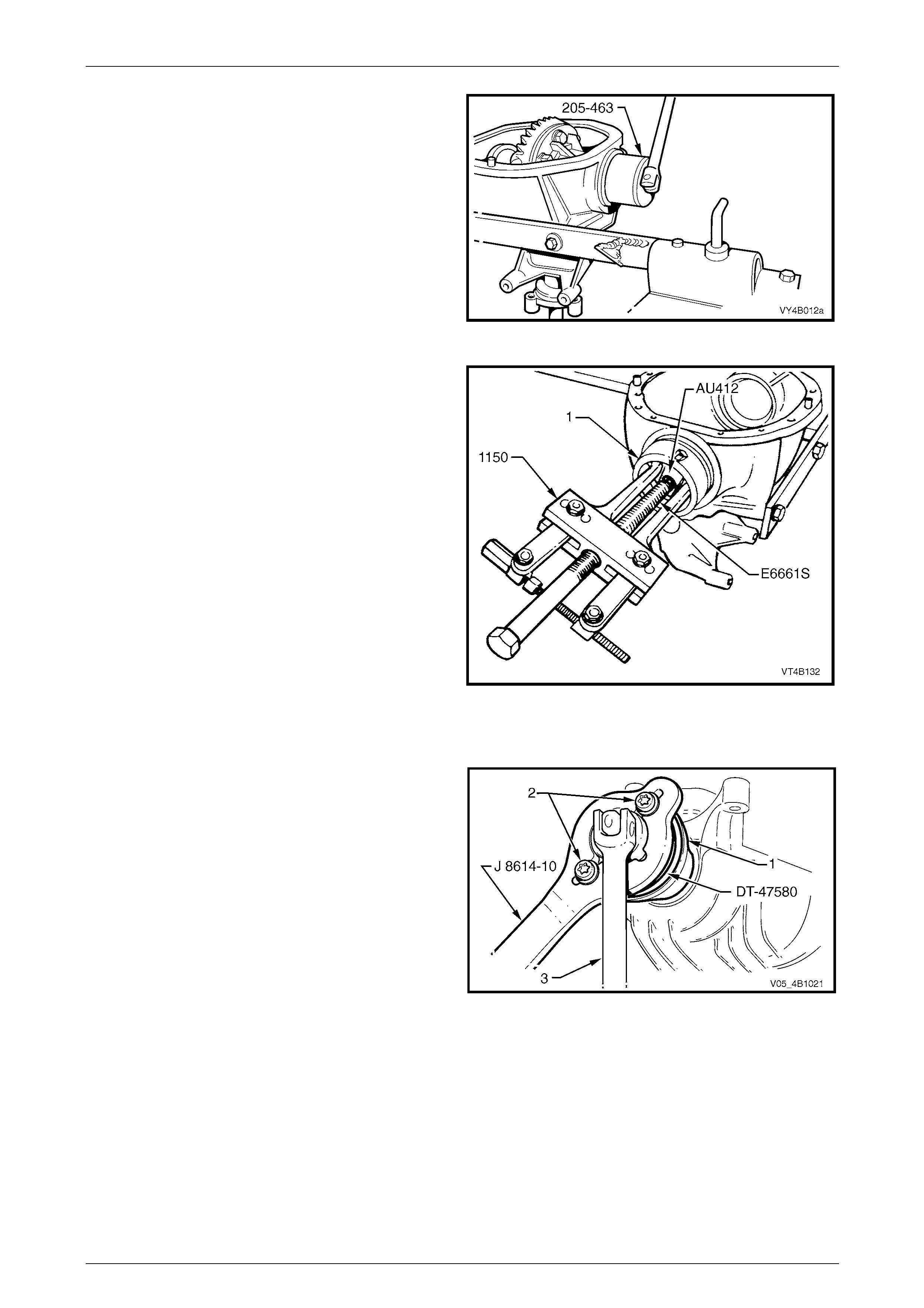
Rear Final Drive and Drive Shafts Page 4B1-79
Page 4B1-79
10 Remove screw adjusters from housing using Tool No.
205-463 (also released as AU407).
11 Remove differential case assembly from carrier
housing.
Figure 4B1 – 138
12 To remove side bearing cups from screw adjusters,
install screw adjusters, reversed, into differentia l
carrier.
13 Install adaptor, Tool No. AU412 onto screw adjuster.
Using puller, Tool No. 1150, and forcing screw Tool
No. E6661S, pull side bearing cups from screw
adjusters and discard.
NOTE
Side bearing cups ar e only to be removed if side
bearing assemblies are to be replaced.
Figure 4B1 – 139
For AWD Wagon Models
14 Install packing flange, T ool No. DT -47580 into the
pinion flange recess, aligning the holes with those in
the pinion flange.
15 Using two of the propeller shaft constant velocity joint
bolts (2), with flat washers, secure the holding bar,
Tool No. J8614-10 (part of Tool No. J 8614- O1) to the
pinion flange (1). The central recesses in the holding
tool should face inward.
16 While holding Tool No. J8614-10, loosen the remove
the pinion flange retaining nut, using a commercially
available, 30 mm deep socket and socket bar (3).
Figure 4B1 – 140
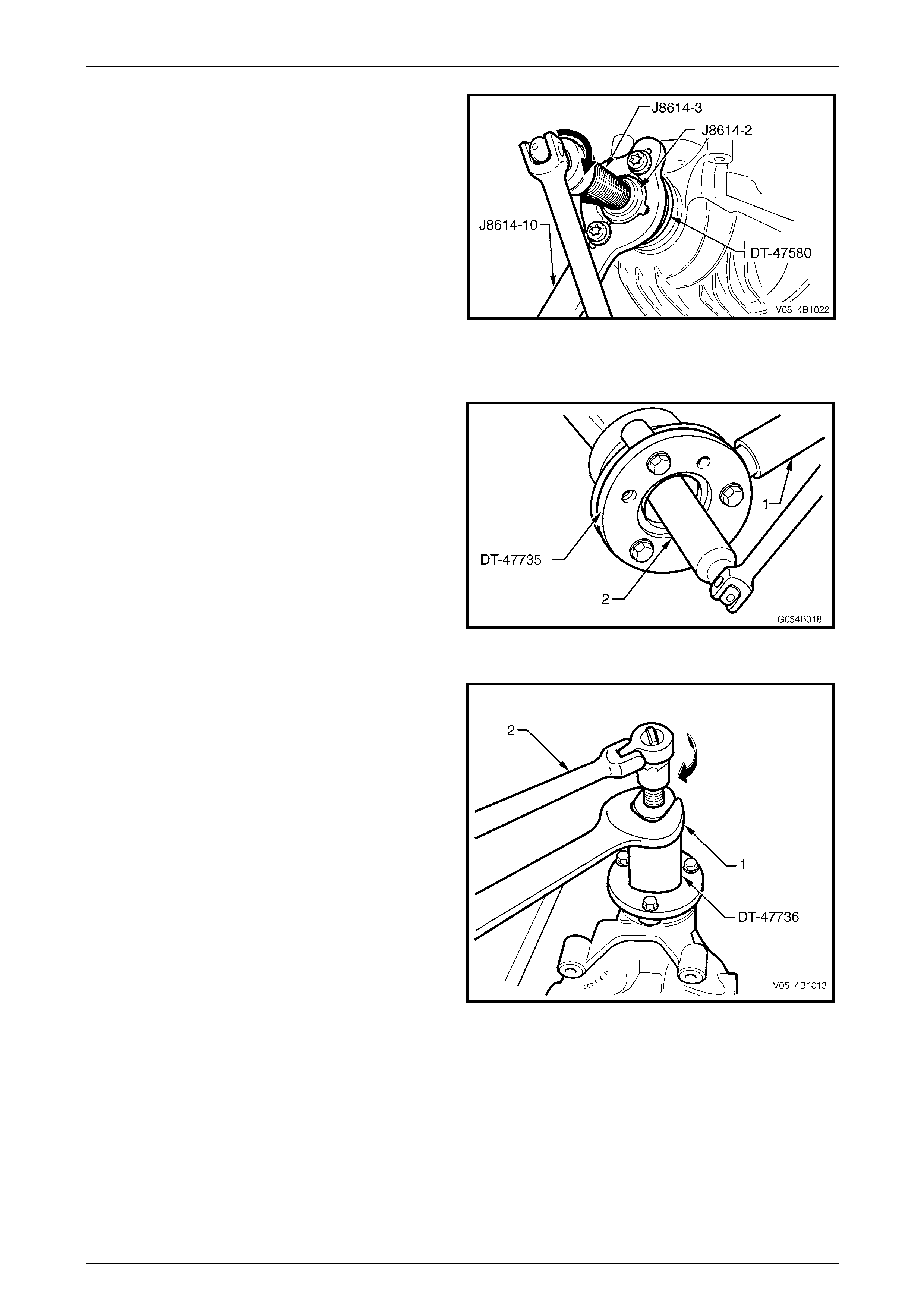
Rear Final Drive and Drive Shafts Page 4B1-80
Page 4B1-80
17 With Tool Nos J8614-10 and DT-47580 still installed,
thread the forcing screw, Tool No. J8614-3, in to the
adaptor, Tool No. J8614-2. Install this sub-assembly
into holding bar, Tool No. J8614-10, then rotate
through 45° to locate in the recesses in J8614-10.
18 While holding J8614-10, use a socket and bar to rotate
the forcing screw J8614-3 in the direction s hown, to
remove the pinion flange.
19 Remove the tools from the pinion flange, then carefull y
set the flange to one side to avoid damage to the
flanged seal surface.
Figure 4B1 – 141
For RWD VZ Models
20 Install Tool No. DT-47735 to the pi nion flange using
three suitable bolts.
NOTE
Use either the rear coupling to pinion flange
retaining bolts with a 25 mm spacer (e.g. flat
washers) installed first or use three bolts M12 x
1.5 x 40, with the thread extending to within 12
mm of the head.
21 While holding DT-47735 with a suitable length of pipe
(1) over the tang, loosen then remove the pinion
flange retaining nut, using a commercia lly available,
30 mm deep socket and bar (2).
22 Remove flange holding tool DT-47735 from pinion
flange. Figure 4B1 – 142
23 Install extractor, Tool No. KM 628-A to the pinio n
flange, using the same arrangement used in step 20.
24 While holding KM 628-A with a set spanner (1), use
suitable socket equipment (2) to withdraw the pinion
flange by tightening the forcing scre w in the direction
indicated.
25 Remove extractor. Tool No. KM628-A from pinion
flange, then carefully set the flange to one side to
avoid damage to the flanged seal surface.
Figure 4B1 – 143
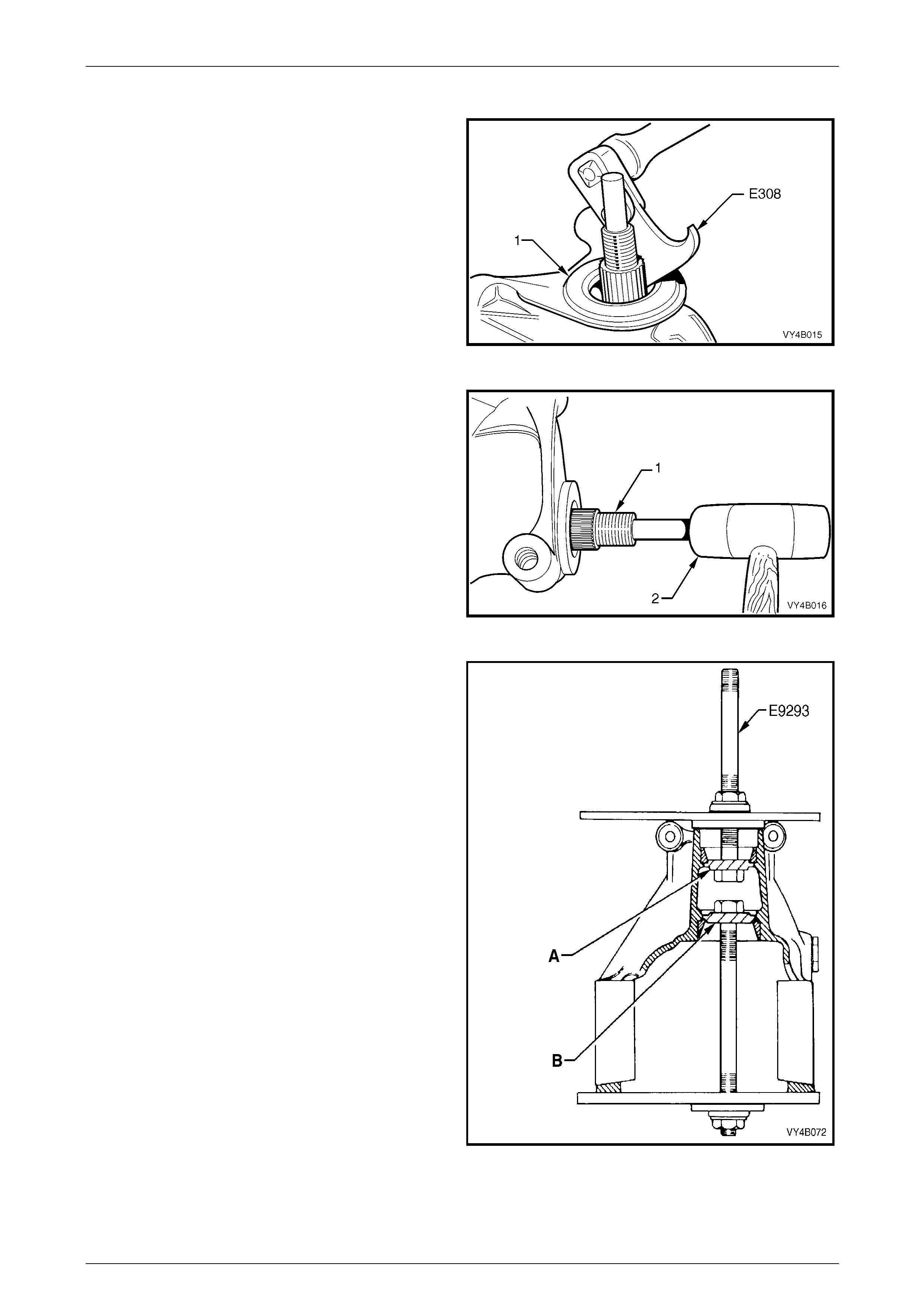
Rear Final Drive and Drive Shafts Page 4B1-81
Page 4B1-81
All VZ Models with IRS
26 Pry pinion oil seal out of carrier bore using Tool No.
E308 or a suitable seal extraction tool.
Figure 4B1 – 144
27 Remove pinion (1) by tapping on front end with a soft
faced hammer (2) to withdraw it through rear of carrier.
Remove pinion front bearing from carrier bore.
Remove and discard pinion bearing spacer.
Figure 4B1 – 145
28 If pinion bearings are to be replaced, remove bearing
cups using Tool No. E9293.
• View ‘A’ shows the tool arrangement to
remove the front (outer) pinion bearing cup,
while view ‘B’ shows the arrangement to
remove the rear (inner) bearing cup.
• When removing the rear (inner) pinion
bearing cup from all but 3.08:1 ratio
assemblies, the adaptor 'B' to be used with
E9293, is DT-47695.
• As the installation Tool No. E9271 (refer
Figure 4B1-147) relies on an installed
bearing cup for alignment, it is essential that
only one bearing cup is replaced at the one
time.
Figure 4B1 – 146
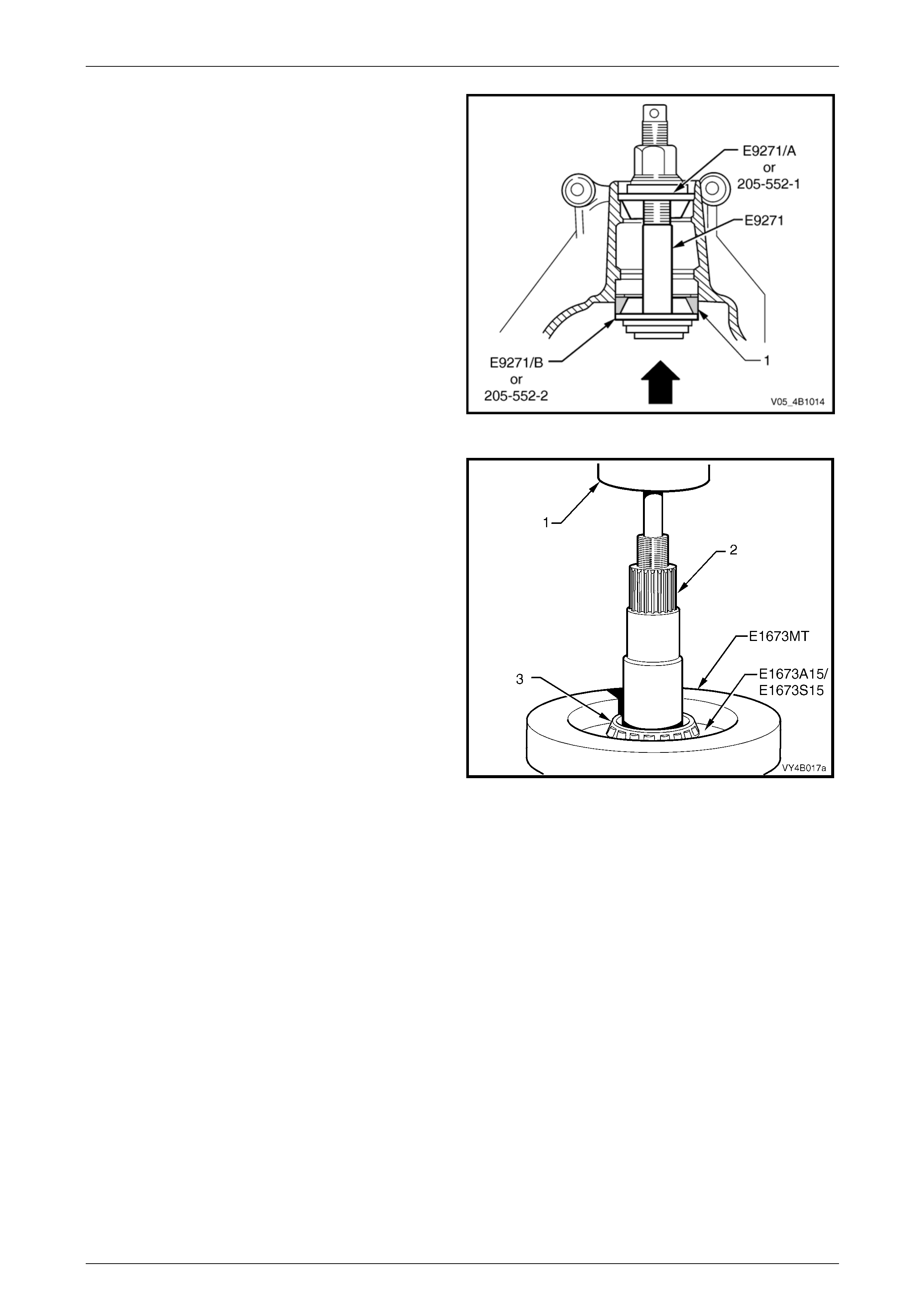
Rear Final Drive and Drive Shafts Page 4B1-82
Page 4B1-82
29 To install a new, rear (inner) pini on bearing cup (1),
use installer Tool No. E9271 with adaptor E9271/B, as
shown. The same arrangement is used to install a new
front (outer) pinion bearing cup, using ad aptor
E9271/A (or 205-552-1).
NOTE
When installing the rear (inner) pinion bearing
cup to all but 3.08:1 assemblies, the adaptor to
be used with E9271, is 205-552-2.
Figure 4B1 – 147
30 To remove rear (inner) bearing from the pinion,
remove legs from the ring of Tool No. E1673MT.
31 Place ring of Tool No. E1673MT on suitable press
plates. Install pinion and adap tors E1673A15 (3.08:1
assembly) or E1673S15 (all other assemblies) into the
ring.
32 Press pinion from bearing.
NOTE
With the larger pinion head size on all but the
3.08:1 assemblies, the ring must be placed over
the bearing first, then the adaptors manoeuvred
into place under the bearing cone.
33 Discard the removed bearing.
Figure 4B1 – 148
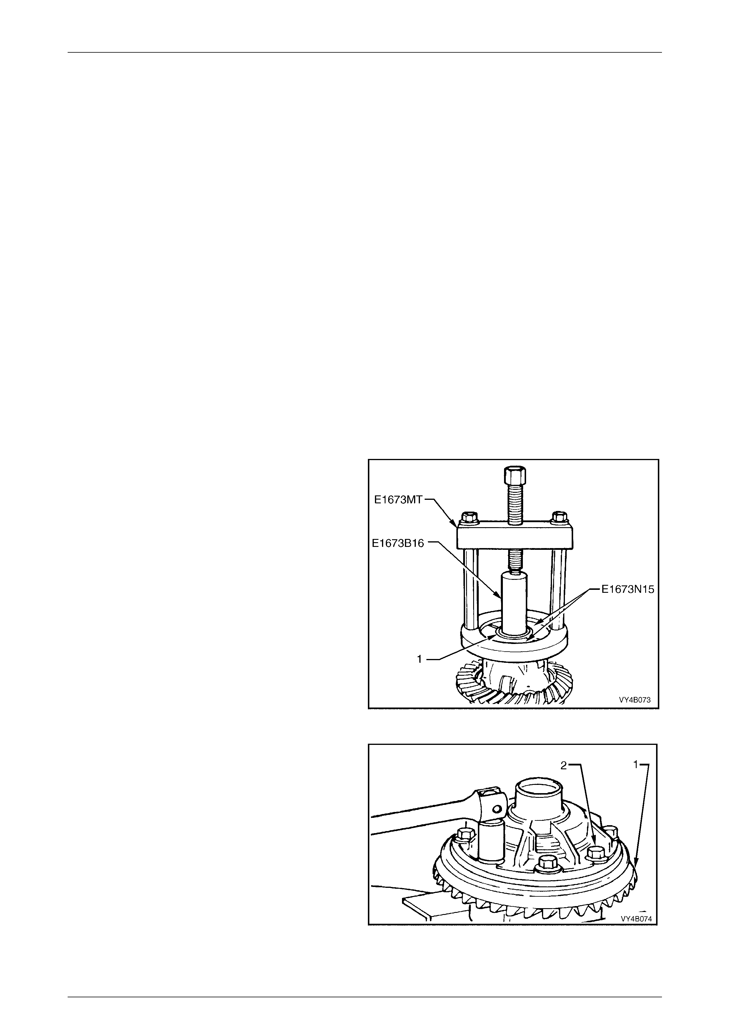
Rear Final Drive and Drive Shafts Page 4B1-83
Page 4B1-83
Differential Case
The following procedures describe the standard type differential case assembly. For Limited Slip Differential case
assembly, refer to 3.4 Limited Slip Differential, in this Section.
NOTE
The 3.08:1 differential is unique and is not
interchangeable with other ratio assemblies. The
general overhaul procedures however, remain
the same for all types.
The unique co mponents for the 3.08:1 differential
are; differential case, differential pinions, side
gears and thrust block.
1 Before disassembling the differential case, inspect differential side bearings for any signs of damage.
NOTE
The side beari ngs can be manufactured by either
one of two manufacturers; Timken or Koyo. When
replacing the differential side bearings, the two
bearings and cups must be of the same brand.
The pinion bearings may be of a different
manufacture but again, they must be a matched
pair. The reason for matched pairs of bearings is
that a different preload specification is required
for each brand.
2 If removing the side bearings from the differential
case, use Tool No. E1673MT, adaptors E1673N15
and stepped plug E1673B 16, as shown.
3 Discard the removed side bearin gs.
NOTE
To remove side bearing cups, refer to
Final Drive Assembly – Disassemble, Step 12.
Figure 4B1 – 149
4 Grip the differential case in a vice fitted with soft ja ws.
5 Remove ring gear (1) attaching bolts (2).
NOTE
Ring gear attaching bolts (2) use a left hand
thread and are identified by an 'L' on the bolt
head.
6 Remove differential case from vice.
Figure 4B1 – 150
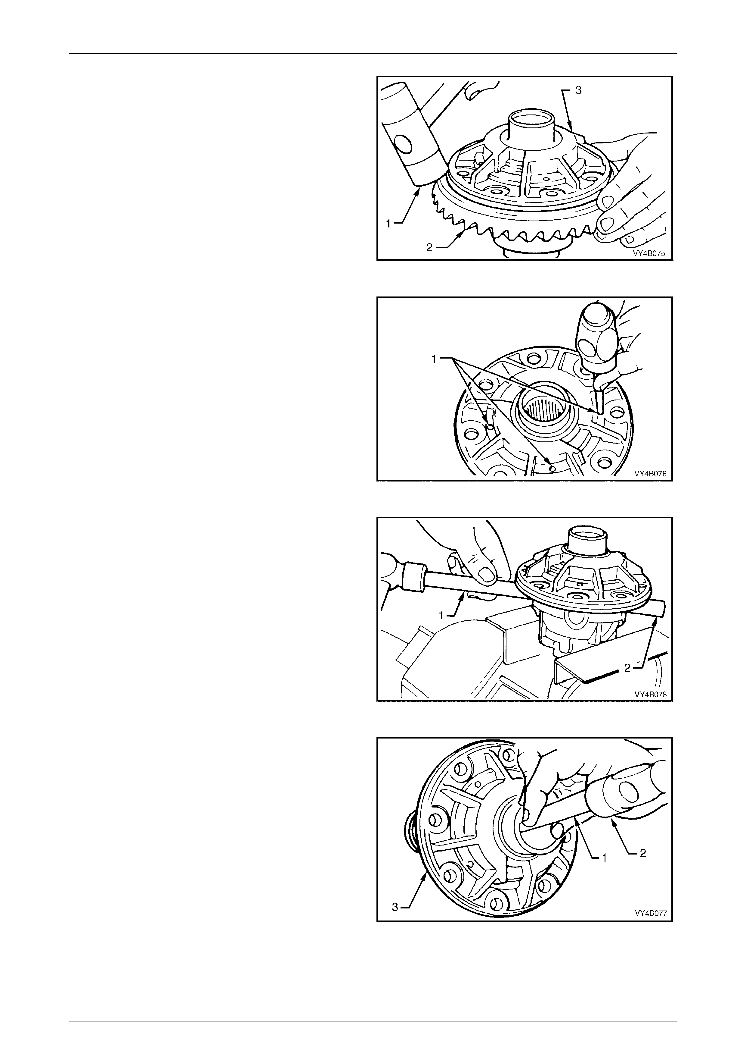
Rear Final Drive and Drive Shafts Page 4B1-84
Page 4B1-84
7 Using a soft faced hammer (1), remove ring gear (2)
from differential case (3) by hitting do wn on ring ge ar.
Support ring gear during this operation so that it does
not strike bench top as it comes free of case.
NOTE
Do not use a screwdriver to prise between ring
gear and case.
Figure 4B1 – 151
8 Drive out differential pinion gear long shaft a nd short
shafts retaining pins (1) from differential case, using a
suitable size pin punch an d hammer.
Figure 4B1 – 152
9 Re-mount the differential case in vice with soft jaws.
Using a brass drift (1) and hammer, drive out pinio n
long shaft (2) from differential case.
Figure 4B1 – 153
10 Remove differential case (3) from vice. Using a brass
drift (1) and hammer (2), separate two differential case
halves by driving against thrust block.
NOTE
Do not use a screwdriver to prise the differential
case halves apart.
Figure 4B1 – 154
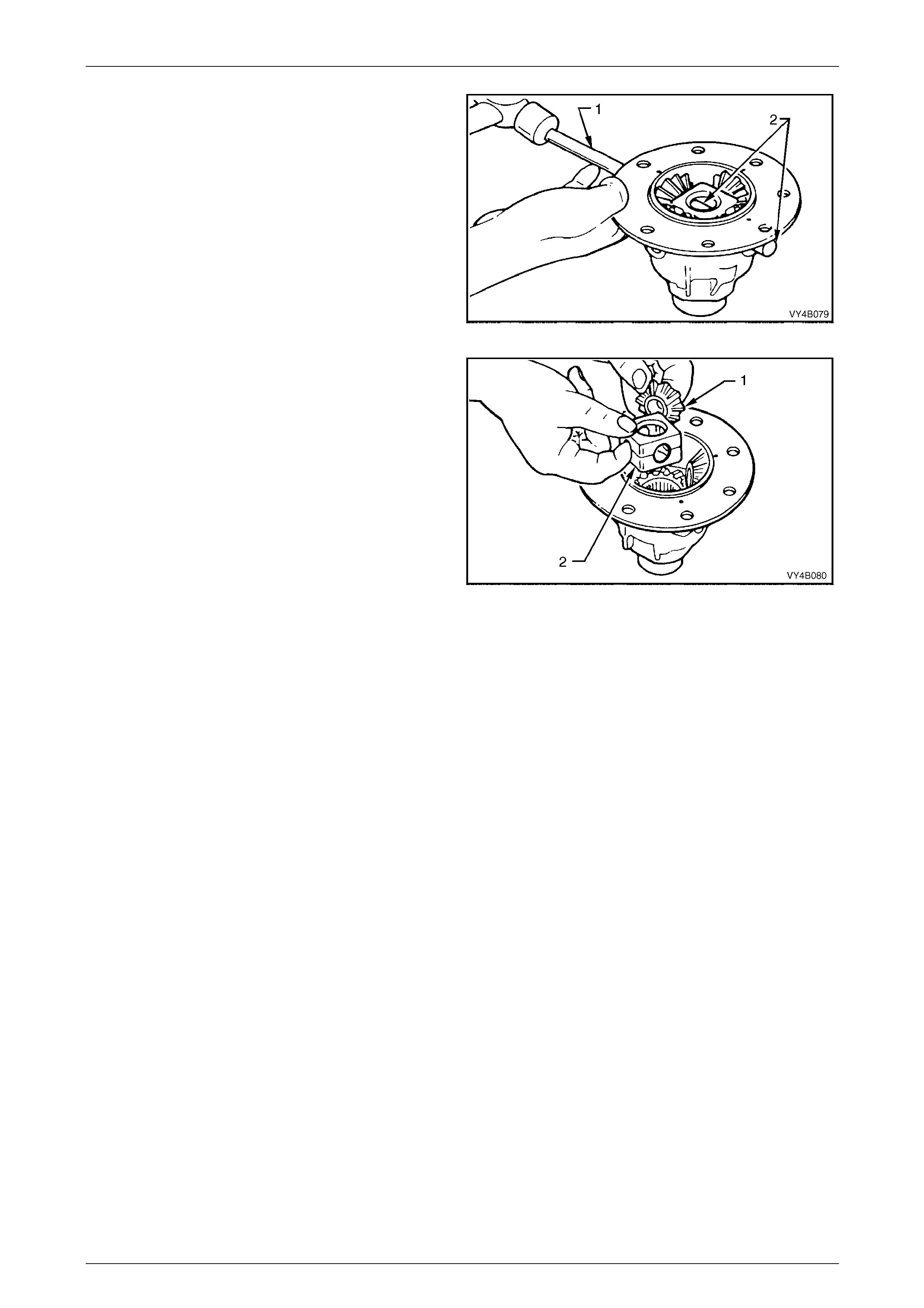
Rear Final Drive and Drive Shafts Page 4B1-85
Page 4B1-85
11 Using a brass drift (1) and hammer, drive out pinio n
gear short shafts (2) from differential case.
Figure 4B1 – 155
12 Lift out pinion gears (1), thrust washers and thrust
block (2) from differential case.
13 Remove differential side gears and thrust washers
from differential case halves.
NOTE
• When removing the thrust block from all but
the 3.08:1 ratio differential, note that the
pinion shafts are angled at 96° and not 90°
as is more usual.
• Keep the gears with their respective thrust
washers in pairs so they can be reinstalle d in
their original position. Figure 4B1 – 156
Inspect
All components should be thoroughly cleaned and dried, then inspected.
Differential Case
Check case for general soundness an d pay particular attention to the following points;
1 If differential case side bearings have been removed, check case journals for damage and that bearin g seating
surfaces are free from dirt and burrs.
2 The ring gear spigot and mounting face should be clean and free from dirt and burrs.
3 The mating surfaces for differential case halves should be clean and free from burrs.
4 The thrust surfaces for differential side gears and pinions should be examined for excessive wear.
5 The differential side gear journal bores should be clean and free from scoring.
6 The case bores for differential pinion gear shafts should be checked for ovality.
Differential Side Gears and Pinion Gears
1 Examine all gear teeth for cracks and hard contact marks.
2 The differential side gear spli nes should be checked for excessive wear. Wear on splines can contribute to
excessive driveline backlash.
3 Check differential side gear journals and back faces for scoring.
4 Check fit of differential side gears in differential case cap and cover. Wear on side gear hubs or in the case bores
can cause a "clunking" noise i n rear a xl e assembly when vehicle is driven at low speeds.
5 Inspect differential pinion bores and thrust surfaces for scoring. Also check differential pinion ge ar shafts are not
bent and that surfaces where pinions run are not worn or scored.
6 Check thrust washers. They should be free from cracks, nicks and burrs. Excessive wear of thrust washers or
pinion gear thrust surfaces can also contribute to excessive driveline backlash.
7 Check thrust block pinion gear shaft bores for ovality.
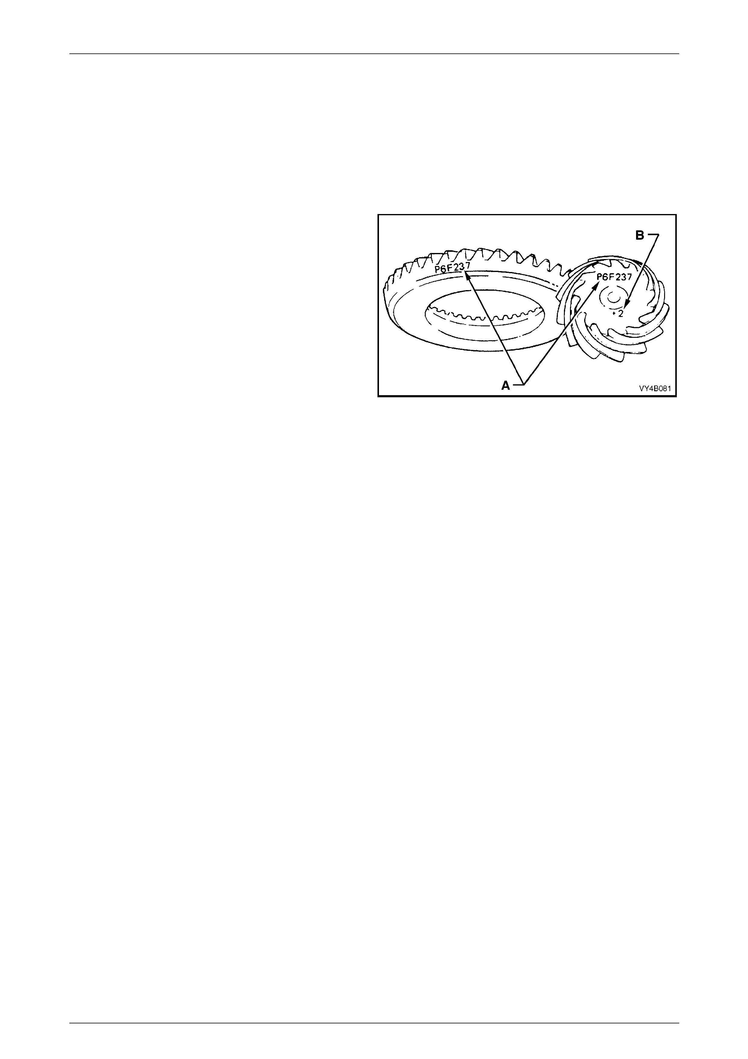
Rear Final Drive and Drive Shafts Page 4B1-86
Page 4B1-86
Ring Gear and Pinion
1 Inspect gear teeth for scoring or damage. Scoring of gear teeth is usua lly caused by excessive shock loading, use
of incorrect lubricant or insufficient "run in" before towing a heavy loa d. (Refer to the appropriate Owner's
Handbook). Scored gears must be replac ed.
2 The ring gear bore and back face should be clean and free from burrs.
3 The rear bearing seating surface on the pinion shoul d be clean and free from burrs.
4 Inspect pinion splines and flange splines for evidence of wear.
5 Inspect thread and bearing journals of pinion for
damage.
6 If on reassembly, a new gear set is to be installed,
ensure that the same matching number appe ars on
both the pinion and ring gear, as shown by ‘A’. The
pinion installation marking figure is indicated by ‘B’.
7 On ring gear bolts, clean the serrations under each
bolt flange.
Figure 4B1 – 157
Bearings
1 Bearing cups should have an even wear pattern and must be free from flaking or pitting. Ensure that seating
surfaces are clean and free from burrs or raised metal.
2 The bearing assembli es should feel smooth when turned in their cups.
3 The assembly should be free from loose particles.
4 No cracks should be present in roller cages, and bores should sho w no evidence of flaking or pitting.
NOTE
Refer to 4.4 Final Drive Bearing Diagn osis, in this
Section, for identification of bearing failures.
Differential Carrier
1 Check casting all over for general soundness.
2 Examine oil passages a nd ensure they are free from obstructions and loose particles.
3 The bore for the pinion oil seal should be free from burrs.
4 Inspect rear cover face and bolt holes for damage.
5 Check rear cover seating surface for scoring or other damage.
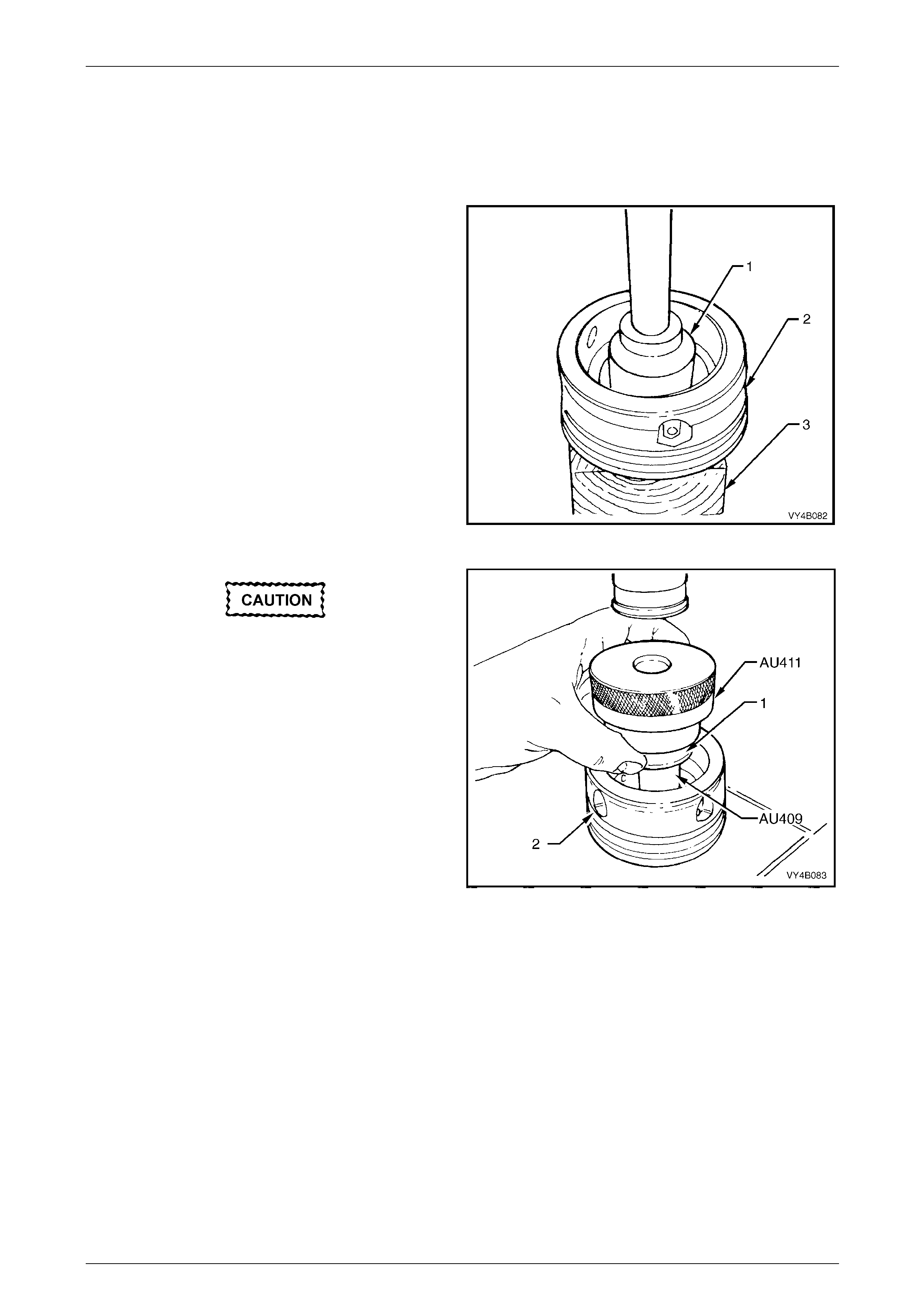
Rear Final Drive and Drive Shafts Page 4B1-87
Page 4B1-87
Screw Adjusters and Inner Axle Shafts
1 Inspect inner axle shaft needle bearings i nsi de screw adjusters for wear or damage.
2 If inner axle shaft needle bearings are to be replaced, reinstall screw adjusters into differential carrier and remove
inner axle shaft seals. Refer to Step 9 of Final Drive Assembly – Disassem ble.
3 Remove screw adjusters (2) from carrier and position
each onto a block of wood (3).
4 Using a 1.25 inch socket (1) and bar or a 73 mm
diameter tube, press the bearing from each of the
screw adjusters (2).
5 Remove and discard O-rings f rom screw adjusters.
6 Examine adjuster seal bores for burrs, nicks or other
damage. Examine oil pass ages and ensure t hey are
free from obstructions and loose particles.
7 Check that the adjuster thread and be aring bores are
clean and free from burrs or other damage.
Figure 4B1 – 158
Side bearing cups must be installed into
screw adjusters before installing needle
bearings. This is to ensure that needle
bearings are located correctly into screw
adjuster bores.
NOTE
To install side bearing cups, refer to Step 1,
Differential Case Side Bearin g Pre-Load Setting,
in this Section.
8 To install new screw adjuster needle bearings, place
screw adjuster (2) over fixture, Tool No. AU409 and
press needle bearing (1) into adjuster (2) using Tool
No. AU411. Repeat procedure for the remaining screw
adjuster. Figure 4B1 – 159
9 Examine seal surface of inner axle shafts and carefully remove any nicks or burrs. If this surface is irreparable on
either axle shaft, a new axle shaft must be fitted.
10 Check that the spring clip in end of each inner axle shaft is undamaged and moves freely in each groove. Replace
spring clips if necessary, by expanding ends of each clip and removing from inner axle shafts. Only expand the
ends of new clips sufficiently to allow installation into a xle shaft grooves.
Rear Cover
1 Clean sealant from rear cover sealing surface.
2 Inspect rear cover for cracks or damaged sealing surface.
3 Ensure breather passage is clea n and free of obstructions.
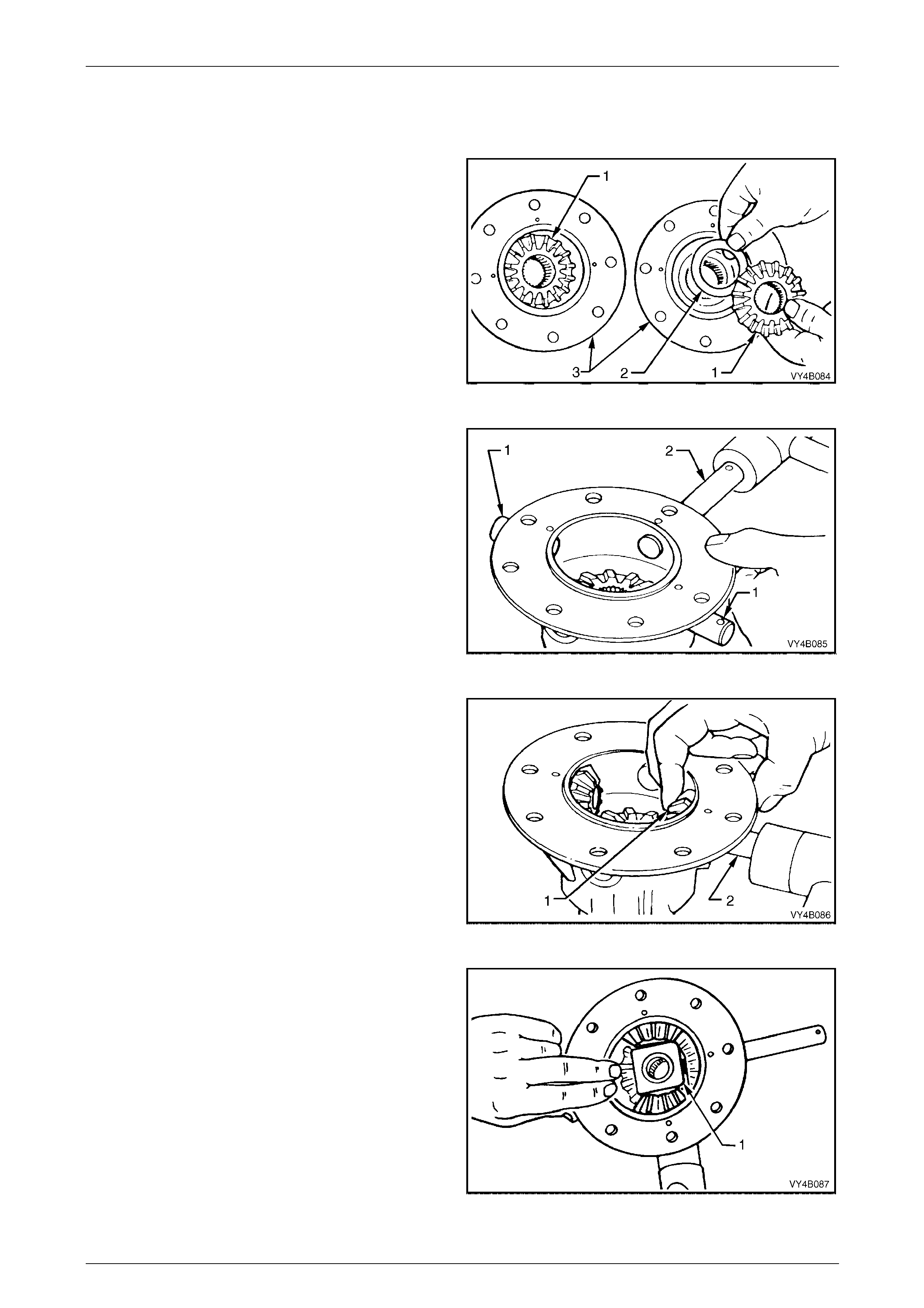
Rear Final Drive and Drive Shafts Page 4B1-88
Page 4B1-88
Reassemble
Differential Case
1 Lubricate all differential gears, bearings, thrust
washers and differential pinion gear shafts with the
recommended rear axle lubric ant before assembly.
2 Position differential side gears (1) with their thrust
washers (2) into differential case halves (3).
Figure 4B1 – 160
3 Using a soft faced hammer, reinstall pinio n gear short
shafts (1) and long shaft (2) into differential case, just
enough to allow a pinion gear thrust washer to sit on
the end of each shaft.
NOTE
Check that the retaining pin holes in the
differential case and pinion gear shafts are
aligned and that the chamfered edge of the
holes in each shaft facing up.
Figure 4B1 – 161
4 Install one of the pinion gear t hrust washers over
inside end of one of the short shafts.
5 Position appropriate pinion gear (1) next to thrust
washer and tap in short shaft (2) until it comes throug h
centre of the gear (1).
6 Carry out steps 4 and 5 for second pinion gear short
shaft.
Figure 4B1 – 162
7 Reinstall thrust block (1) between two installed pinion
gears. Knock the two pinion gear short shafts into
position, ensuring that retaining pin holes in the shafts
line up with holes in differentia l case.
Figure 4B1 – 163
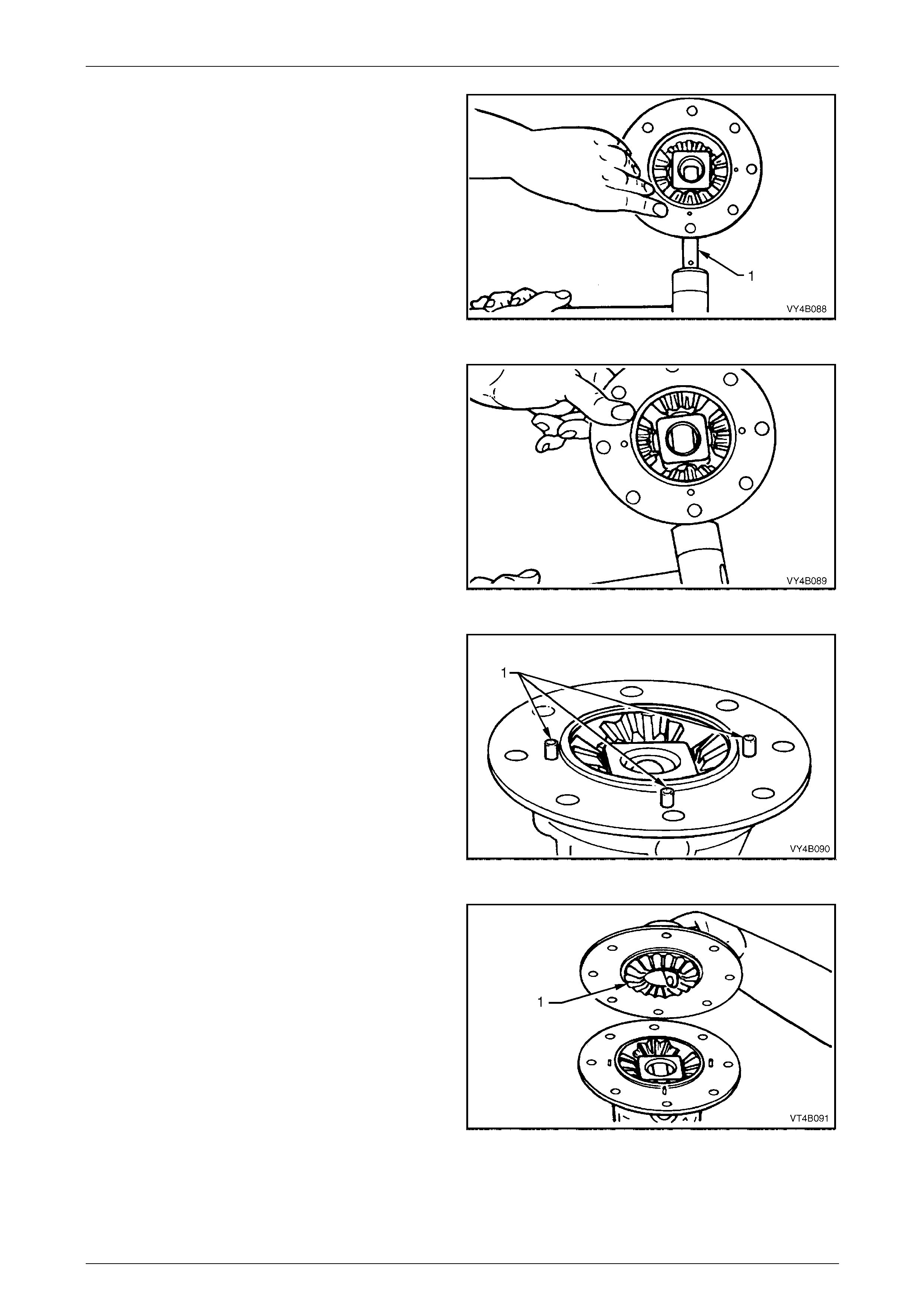
Rear Final Drive and Drive Shafts Page 4B1-89
Page 4B1-89
8 Install pinion gear thrust washer and gear to long shaft
(1). Tap long shaft (1) through gear and thrust block.
Figure 4B1 – 164
9 Reinstall remaining pinion gear and thrust washer. T ap
long shaft through pinion gear, ensuring that thrust
washer aligns with cross shaft and the retaining pin
hole in the shaft aligns with hole in differenti al case.
Figure 4B1 – 165
10 Install pinion gear long shaft and sh ort shaft retaining
pins. Ensure that ends of retaining pins (1) protrude 6
mm from differential case cap to cover mating surface.
This is needed to provide a positive location for the
differential case cover to case cap.
Figure 4B1 – 166
11 Holding differential side gear (1) in position with a
finger through differential case cover bor e as shown,
push the two differential case halves together, locating
on the three protruding retaining pins.
Figure 4B1 – 167
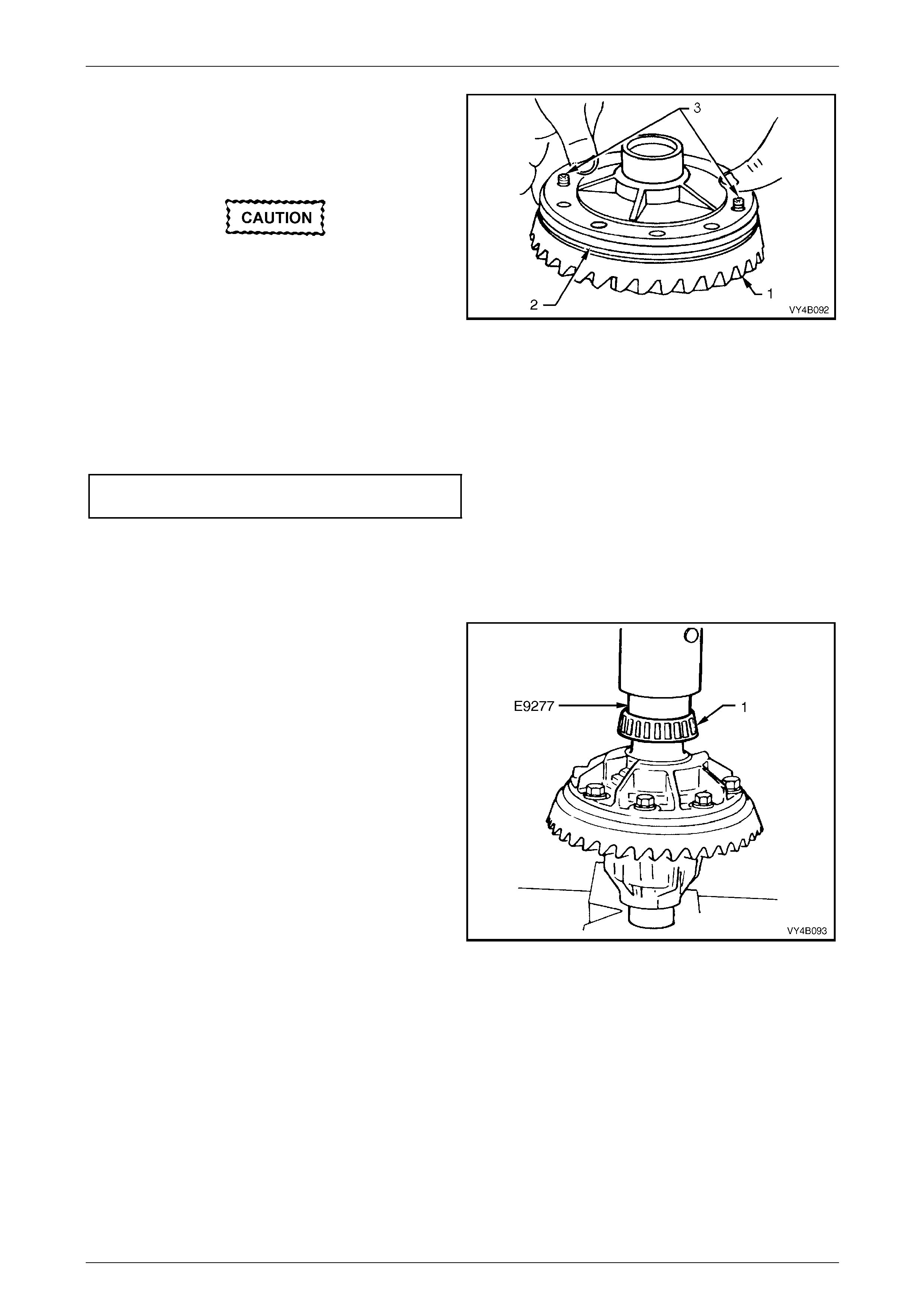
Rear Final Drive and Drive Shafts Page 4B1-90
Page 4B1-90
NOTE
For ease of assembly, it may be necessary to
heat the ring gear on a hot plate until it is hot to
the hand, prior to installing onto the differential
case cap.
A flame must never be used to heat the ring
gear.
NOTE
Use left hand threaded guide pins (3) to pilot the
ring gear over the differential case spi got.
12 Place ring gear (1) into position on differential case
cap (2) and install ring gear attaching bolts.
Figure 4B1 – 168
13 Install and gradually tighten NEW ring gear attaching bolts evenly, unti l gear face is flush with differential case
spigot. Tighten all bolts to the correct torque specific ation.
Final drive ring gear bolt
torque specification............................................140 N.m
NOTE
Ring gear attaching bolts use a left hand thread
and are identified by an 'L' on the bolt head.
14 If installing new side bearings (1), use Tool No. E9277
to press new side bearings onto differential case
journals.
NOTE
Check that both nearing assemblies are of the
same manufacture – Timken or Ko yo.
Figure 4B1 – 169
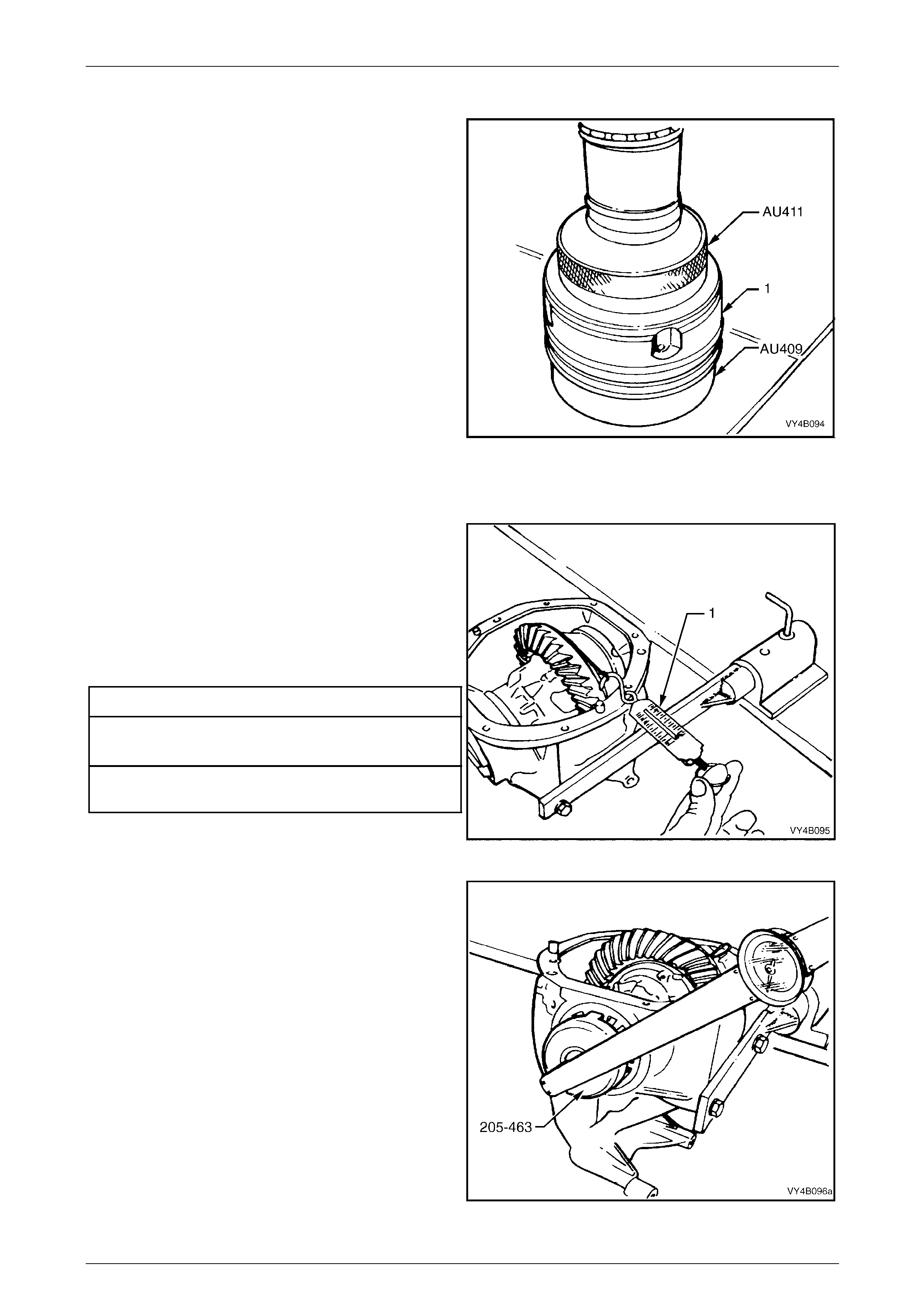
Rear Final Drive and Drive Shafts Page 4B1-91
Page 4B1-91
Differential Case Side Bearing Pre-Load Setting
1 If removed during disassembly, press new bearing
cups into screw adjusters firmly to the shoulder by
positioning screw adjuster onto Tool No. AU409 and
using Tool No. AU411 to pres s new cup into place.
Repeat procedure for remaini ng screw adjuster.
NOTE
• Ensure that bearing side and cup matching is
maintained and that the pair of bearing
assemblies are of the same manufacture –
either Timken or Koyo.
• The screw adjuster used on all but th e 3.08:1
unit is 1.9 mm deeper than the one used for
3.08:1 ratio unit. The deeper screw adjuster
can be identified by a groove on the inner
edge.
2 Install new O-rings to screw adjusters and apply a
lubricant such as rubber grease to each.
3 While supporting the differential case in the carrier, fit
screw adjusters to both sides of carrier. Continue
tightening adjusters until case assembly is supported
by side bearings.
Figure 4B1 – 170
4 Rotate differential case several times to ensure that
side bearings are correctly seated.
5 Wrap a piece of string aroun d differential case flange
and check side bearing pre-load by pulling on end of
string with a spring balance (1). Spring balance
reading must be within specification.
6 Tighten or loosen one of the scre w adjusters until the
correct pre-load is obtained.
Side Bearing Preload Specification
New Bearings Timken Koyo
15 – 35 N 8 – 24 N
Used Bearings Timken Koyo
8 – 18 N 5 - 13 N
Figure 4B1 – 171
7 Using Tool No. 205-4 63 (or AU407) and a torque
wrench, measure tightening torque of each screw
adjuster (usually within the range of 50 – 6 0 N.m) and
record.
NOTE
These torque readings will be used to set
bearing pre-loa d on fina l assembly.
8 Using Tool No. AU407, loosen and remove screw
adjusters, remove differential case assembly.
Figure 4B1 – 172
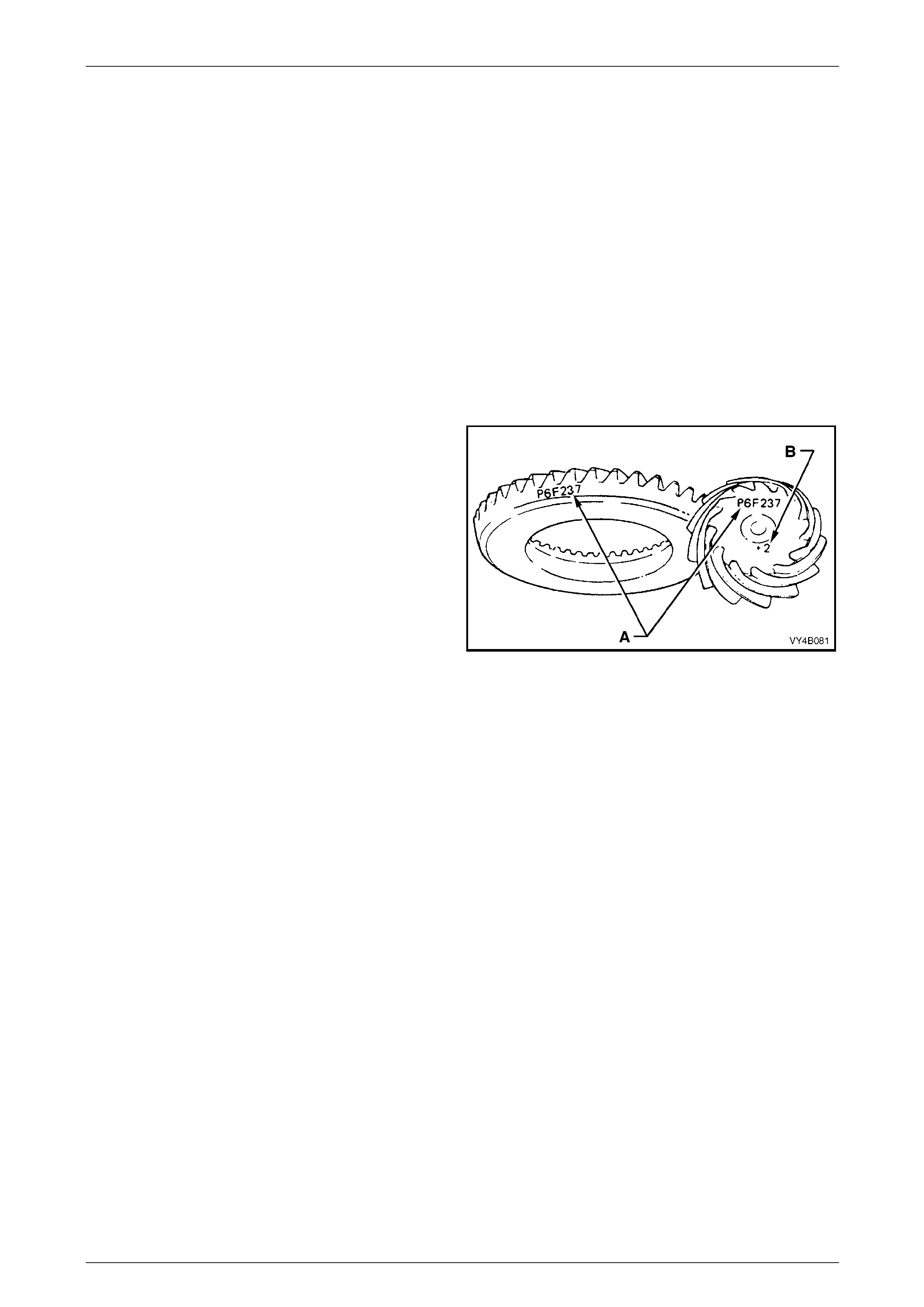
Rear Final Drive and Drive Shafts Page 4B1-92
Page 4B1-92
Hypoid Pinion Positioning Shim Selection
The pinion posit ioning shim is located between pinion rear (inner) bearing c up and carrier housing.
If the ring gear and pinion or the pinion rear bearing assembly are replace d, pinion depth must be rechecked with pinion
setting gauge, Tool No. DT-47737 (or previously released E9300A, plus dumm y pinion spacer, DT-47696 and arb our
AU408).
NOTE
The pinion setting gauge DT-47737 includes
these items:
Dummy pinion.......................................3C10E/11
Pad .......................................................3C10E/13
Sleeve...................................................3C10E/14
Dummy pinion spacer...........................DT-47696
Forcing nut.................................................6651/1
Arbour........................................................AU408
The gauge and arbour pr ovide a nominal or 'zero' pinion as a gauging reference.
NOTES
• If a new gear set is to be installed, check that
the same matching number (‘A’) appears on
both the pinion and the ring gear, with either
white or yellow marker.
• The pinion installation marking figure is
indicated by ‘B’, again with either white or
yellow marker.
• The final drive pinion fitted to the 3.08:1 ratio
assemblies, has a different mounting
distance to other ratios (94.49 mm and
102.50 mm respectively). Also, as 3.08:1
ratio, final drive assemblies have a different
rear (inner) pinion bearing, gear set sizes,
differential case assemblies and screw
adjusters, none of these parts are to be
mixed.
Figure 4B1 – 173
1 Inspect pinion bearing cups/c ones for nicks and burrs. Replace if damaged.
2 Lubricate pinion front and re ar bearings with the recommended differential carrier lubricant. Do not use eng ine or
other oils, as a misleading rotating torque can be obtained.
NOTE
Make sure that both pinion bearings used on the
dummy pinion to determine the pinion positio ning
shim thickness, are those t hat will be used on the
final reassembly.
MY 2005 VZ Series Vehicles with the 3.08:1 Ratio Axle Assembly
3 Install the rear bearing onto dumm y pinion, Tool No. DT-47737 (or E930 0A).
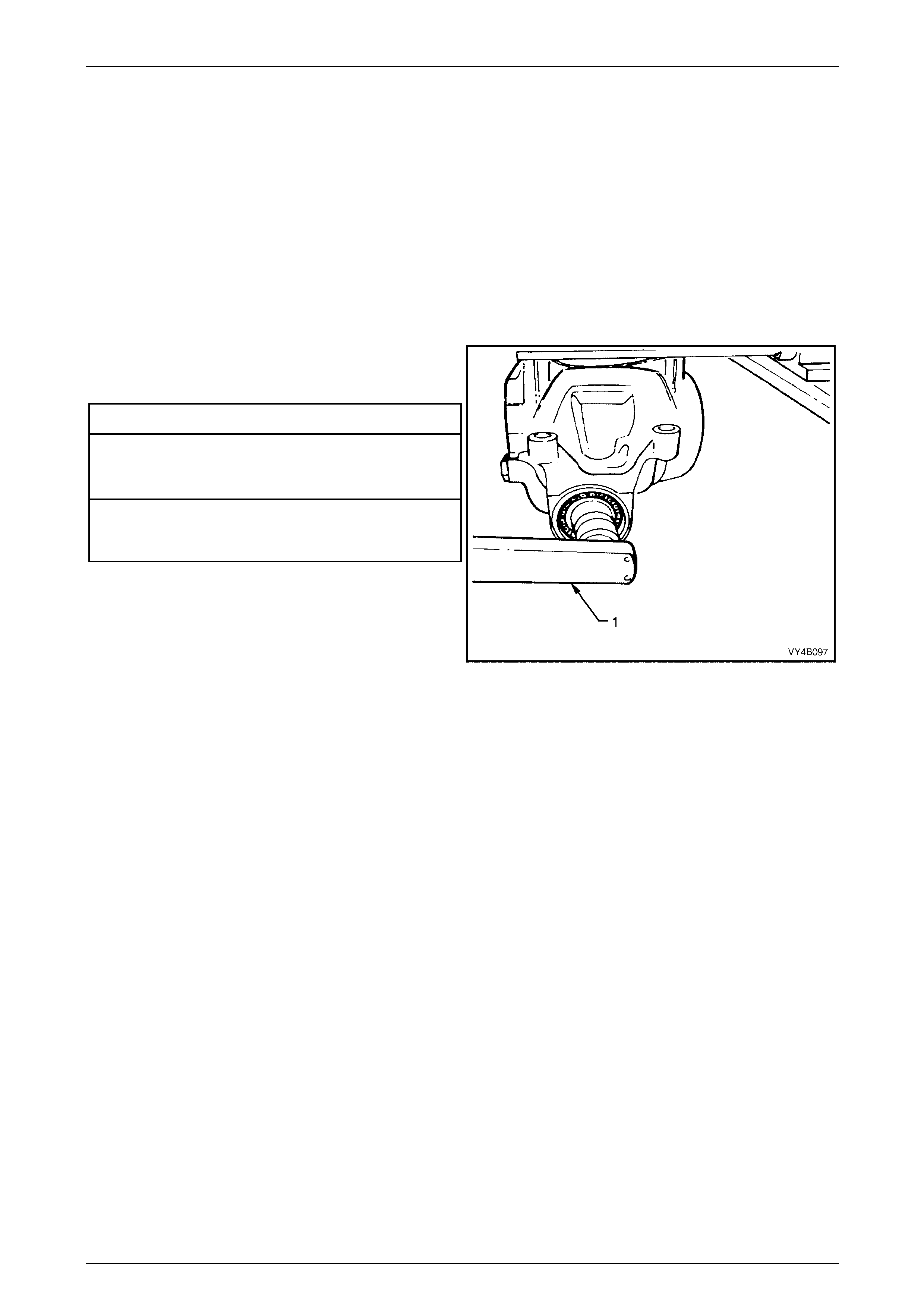
Rear Final Drive and Drive Shafts Page 4B1-93
Page 4B1-93
MY 2005 VZ Series Vehicles with Other Ratio Axle Assemblies
4 Install the spacer, Tool No. DT-47696, to the dummy pinion, supplied as part of DT-47737 (or E9300A), then install
the rear (inner) pinion bear ing onto the dummy pinion.
5 Install dummy pinion and rear (inner) bearing into carrier ho usin g. F it front (outer) bearing to dummy pinion, then
install the dummy pinion sleeve (3C10E/14) and nut (6651/1).
NOTE
Both bearings are to be thos e that will be used in
the final assembly and both must be lubricated
with the recommended lubricant for that
assembly.
6 Tighten nut on end of dummy pinion, using a
commercially availabl e, dial type torque wrench (1),
until the specified rotational torque is obtaine d.
Dummy Pinion Rotational Torq u e Sp ecification
New Bearings (No Pinion Oil Seal Installed)
Timken Koyo
1.4 – 2.0 N.m 1.5 – 1.9 N.m
Used Bearings (No Pinion Oil Seal Installed)
Timken Koyo
0.7 – 1.2 N.m 0.7 – 1.2 N.m
7 Rotate dummy pinion back and forth during tightening
to ensure that bearings settle in their cups.
Figure 4B1 – 174
NOTES
• Once the specified preload is reached,
remove the gauge pad (3C10E/13) from the
rear of the dummy pinion to allow continuous
rotation of the pinion during the preload
tightening process. Rotate the pinion
approximately 50 turns in each direction, the n
re-check the bearing preload, readjusting as
required, to achieve the specified figure.
When the required preload is reached,
reinstall the gauge pad and secure with the
screw provided.
• Pinion bearing pre-load is very important
because it retains the pinion in its correct
relationship to the ring gear.
• Bearings that are installed with insufficient or
no pre-load will, after a comparatively short
period of running, develop end play. This
causes noisy operation on overrun and could
be responsible for scuffing of ring gear and
pinion teeth.
• Bearings that have too much pre-load, may
become pitted or flaked and result in
premature failure. It is therefore essential to
ensure that bearings are pre-loaded to
specified torque specification.
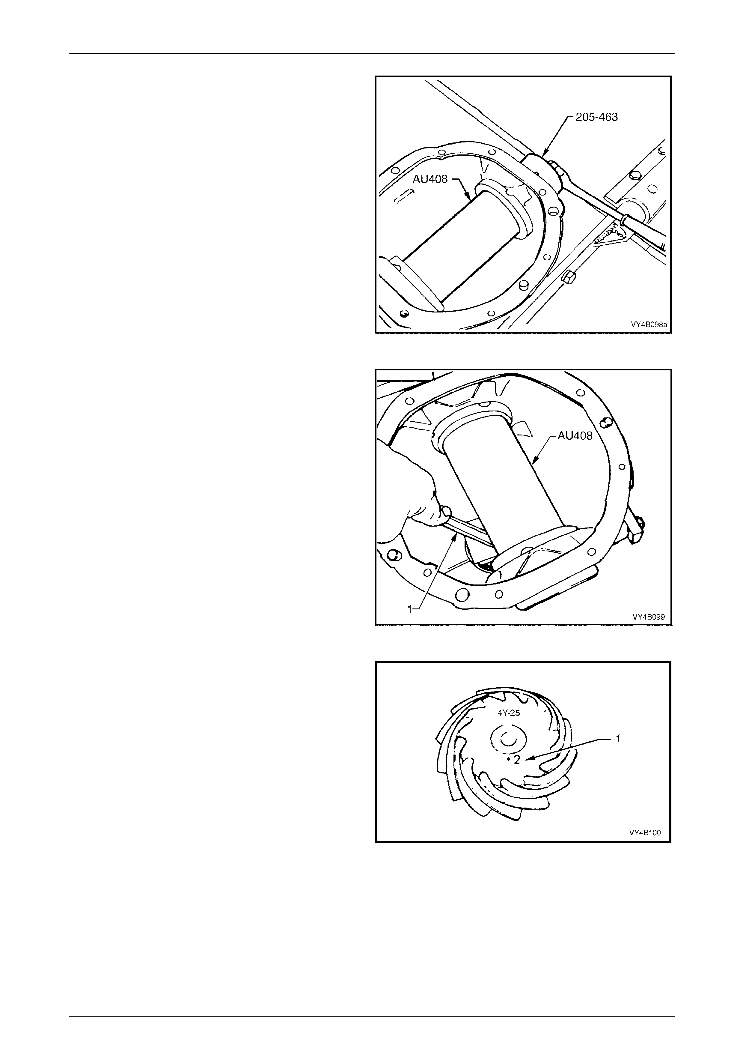
Rear Final Drive and Drive Shafts Page 4B1-94
Page 4B1-94
8 Position arbour Tool No. AU408 in carrier assembly
and install screw adjusters with side bearing cups.
Adjust screw adjusters to lightly clamp arbour, using
Tool No. 205-463 (or AU407).
NOTE
Ensure that arbour is free of any burrs that may
damage bearing cups.
Figure 4B1 – 175
9 Check clearance between arbour (Tool No. AU408)
and head of dummy pinion with a feeler gauge (1).
Record this dimension.
Figure 4B1 – 176
10 On the end of the pinion, a drive pinion installation
marking figure (1) is applied with either a white or
yellow marker. A zero marking ('0') indicates that shim
size equal to the dimension measur ed in Step 9 is the
correct size for this carrier/pinion combination.
A positive marking, e.g. +3, means that a thickness
measurement equivalent to this numerical marking
must be subtracted from shim size measured in Step
9. Refer to the following chart for specific details.
A negative marking, e.g. –3, means that a thickn ess
measurement equivalent to this numerical marking
must be added to the shim size measured in Step 9.
Refer to the following chart for specific details. Figure 4B1 – 177
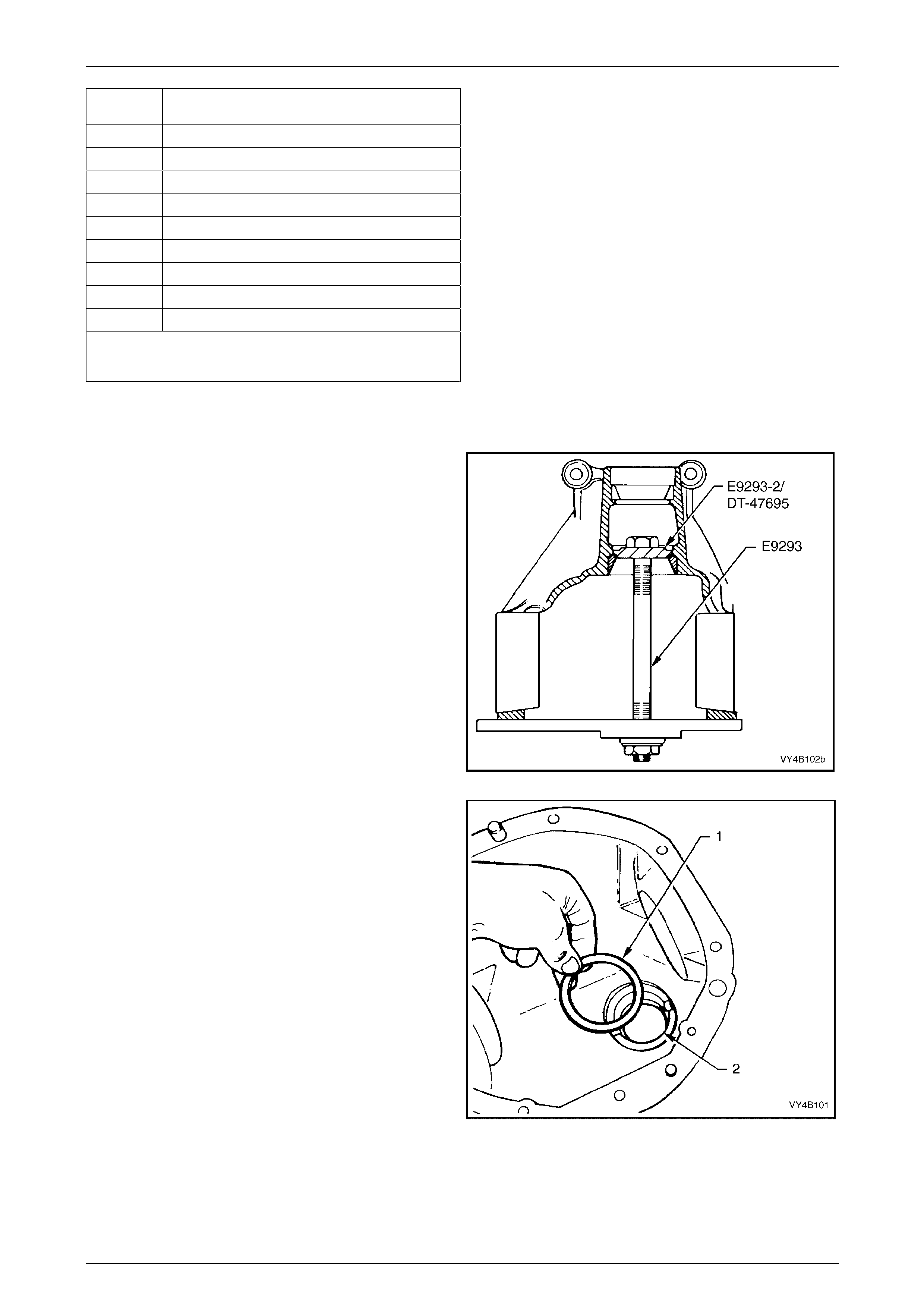
Rear Final Drive and Drive Shafts Page 4B1-95
Page 4B1-95
Pinion
Marking Shim Thickness
Required
– 4 Add 0.100 mm to the Step 9 measurement
– 3 Add 0.075 mm to the Step 9 measurement.
– 2 Add 0.050 mm to the Step 9 measurement.
– 1 Add 0.025 mm to the Step 9 measurement.
0 Size as measured in Step 9.
+ 1 Subtract 0.025 mm from the Step 9 measurement.
+ 2 Subtract 0.050 mm from the Step 9 measurement
+ 3 Subtract 0.075 mm from the Step 9 measurement.
+ 4 Subtract 0.100 mm from the Step 9 measurement
Pinion positioning shims are serviced in thicknesses of 0.2 mm
to 0.75 mm in 0.025 mm increments. They are also dimensioned
differently, depending on the pinion bearing used.
11 Remove dummy pinion and arbour from carrier assembly.
Pinion Installation
1 Select pinion positioning shim stack as determined in
the Hypoid Pinion Positioning Shim Selection
procedure, in this Section.
2 Remove pinion rear (inner) bearing cup, using Tool
No. E9293, using adaptor Tool No. E9293-2 (for the
3.08:1 unit) or DT-47695 (for all other ratio units).
Figure 4B1 – 178
3 Install pinion positioning shim /s (1) into pinion rear
bearing cup bore (2).
Figure 4B1 – 179
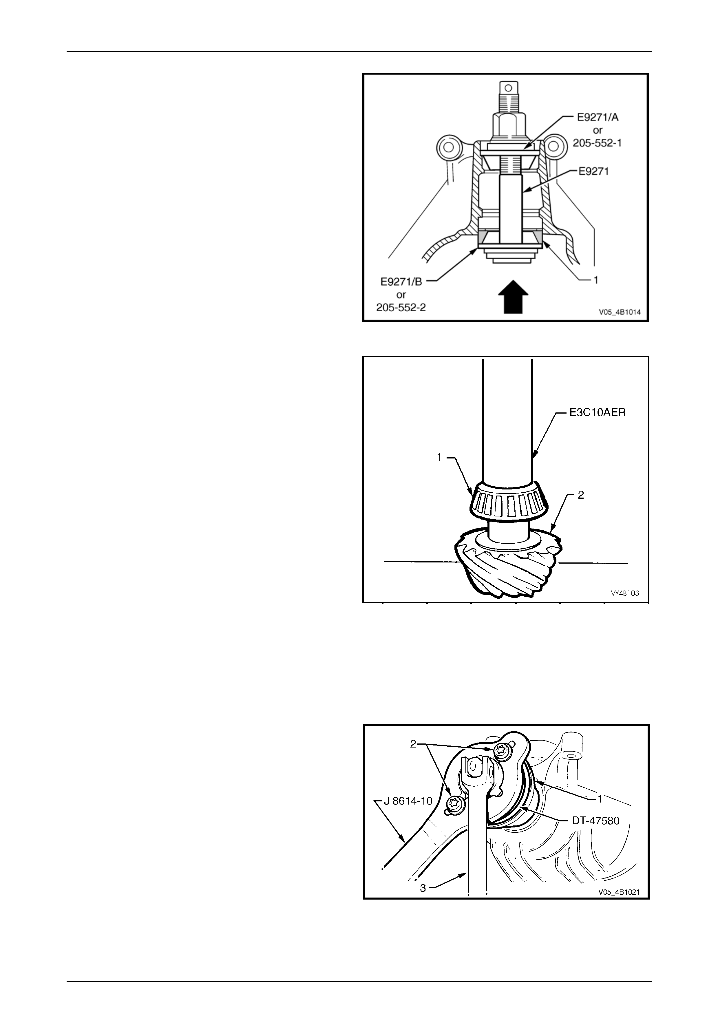
Rear Final Drive and Drive Shafts Page 4B1-96
Page 4B1-96
4 Reinstall pinion rear (inner) bearing cup (1) using Tool
No. E9271 and adaptor E9271/B or 205-552-2. Ensure
that cup is seated squarely in bore.
NOTE
When installing the inner pinion bearing cup to
all assemblies except the 3.08:1 ratio unit, the
adaptor to be used with E9271, is 205-552-2.
Figure 4B1 – 180
5 Press rear bearing inner race aga inst the shoulder of
the pinion, using Tool No. E3C10AE R.
NOTES
• To avoid possible damage to the pinion gear
teeth when pressing the bearing on, ensure
that the press plates are perfectly flat, free of
burrs and foreign matter prior to installing the
rear bearing.
• Locate bearing inner race squarely on the
pinion and press only on inner race surface.
• Only lubricate the bearing with the
recommended differential carrier lubricant.
Figure 4B1 – 181
6 Place the pinion in the carrier.
7 Lubricate pinion front bearing with the recommended differential carrier lubr icant and assemble the collapsible
pinion bearing spacer and front bearing onto pinion, while supporting pinio n head.
For VZ AWD Models
8 Install packing flange, T ool No. DT -47580 into the
pinion flange recess, aligning the holes with those in
the pinion flange.
9 Using two of the propeller shaft constant velocity joint
bolts (2), with flat washers, secure the holding bar,
Tool No. J8614-10 (part of Tool No. J 8614- O1) to the
pinion flange (1). The central recesses in the holding
tool should face inward.
10 While holding Tool No. J8614-10, tighten the original
pinion flange retaining nut, using a commercially
available, 30 mm deep socket and socket bar (3), until
pinion front bearing is squarely engaged on the pinion
shaft and not cocked. Figure 4B1 – 182
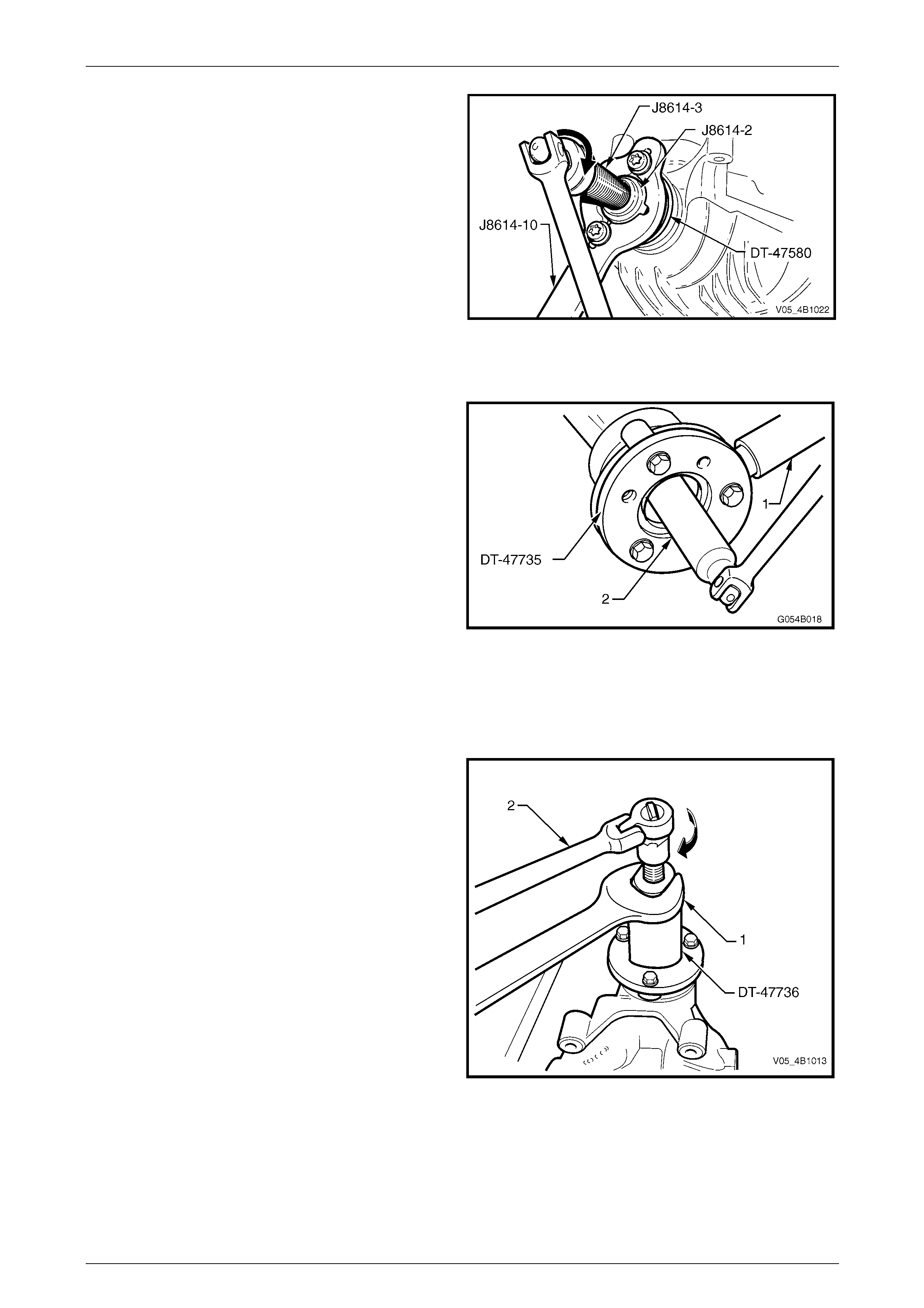
Rear Final Drive and Drive Shafts Page 4B1-97
Page 4B1-97
11 With Tool Nos J8614-10 and DT-47580 still installed,
thread the forcing screw, Tool No. J8614-3, in to the
adaptor, Tool No. J8614-2. Install this sub-assembly
into holding bar, Tool No. J8614-10, then rotate
through 45° to locate in the recesses in J8614-10.
12 While holding J8614-10, use a socket and bar to rotate
the forcing screw J8614-3 in the direction s hown, to
remove the pinion flange.
Figure 4B1 – 183
For All RWD Models
13 Install pinion flange and the original pinion flange
retaining nut.
14 Install Tool No. DT-47735 then, using a suitable length
of pipe (1) to over the holding tool tang, tighten
retaining nut until pinion front bear ing is squarely
engaged on the pinion shaft and not cocked.
NOTES
• If not done before, drill out holes stamped ‘B’
on Tool No. DT-47735 to 12.5 mm.
• Use either the rear coupling to pinion flange
retaining bolts with a 25 mm spacer (e.g. flat
washers) installed first or use three bolts M12
x 1.5 x 40, with the thread ext ending to within
12 mm of the head.
15. Insert a suitable length of pipe (1) over the tang of the
installed tool for leverage, then remove the pinion
flange retaining nut, using a commercia lly available
deep socket and socket bar (2).
Figure 4B1 – 184
16 Install extractor, Tool No. KM628-A to the pinion
flange using the same three b olts used to se cure the
flange holding tool, DT-47735 (refer step 9).
NOTE
• If not done before, drill out holes stamped ‘B’
on Tool No. DT-47735 to 12.5 mm.
• If using the original bolts, they must have 25
mm spacers fitted so the tool is clamped to
the pinion flange. If this is not done, the
screw thread on the extractor Tool No.
KM628-A will not be long enough to fully
remove the pinion flange.
17 While holding the extractor tool with a suitable
spanner, withdraw pinion flange by tightening the
forcing screw in the direction indic ated.
Figure 4B1 – 185
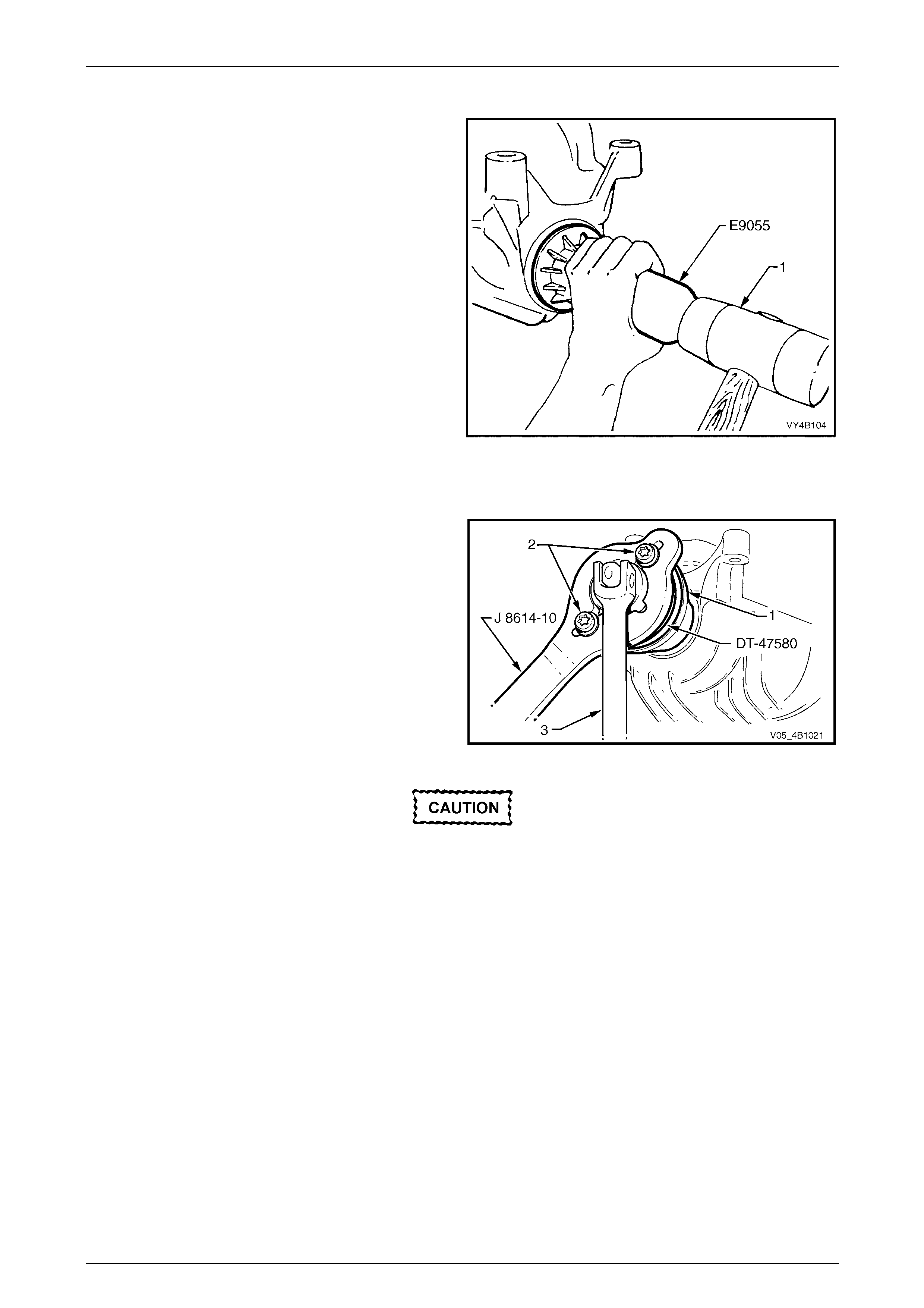
Rear Final Drive and Drive Shafts Page 4B1-98
Page 4B1-98
For All Models
18 Lubricate pinio n oil seal lips and the pinion oil seal
bore in the carrier housing with Mobilgrease XHP 222
or equivalent grease.
19 Install oil seal into carrier bore using T ool No. E9055
and a plastic faced hammer (1) until the seal fits flush
to 0.25 mm below carrier housing surface.
Figure 4B1 – 186
For AWD Models
20 Reinstall pinion flange and fit a NEW retaining nut.
21 Install packing flange, T ool No. DT -47580 into the
pinion flange recess, aligning the holes with those in
the pinion flange.
22 Using two of the propeller shaft constant velocity joint
bolts (2), with flat washers, secure the holding bar,
Tool No. J8614-10 (part of Tool No. J 8614- O1) to the
pinion flange (1). The central recesses in the holding
tool should face inward.
23 While holding Tool No. J8614-10, gradually tighten the
pinion flange retaining nut, while rotating pinion in both
directions to seat bearings.
Figure 4B1 – 187
If the retaining nut is over-tightened and pre-
load exceeded, it will be necessary to remove
the pinion from the carrier and a new
collapsible spacer installed. Under no
circumstances must the retaining nut be
backed off to decrease the pre-load reading.
24 Check bearing pre-load freq uently by removing flange hold ing tool (J 8614-10) and installing a pulley and string to
the pinion flange. Refer to 7 Special Tools at the end of this Section for pulley details.
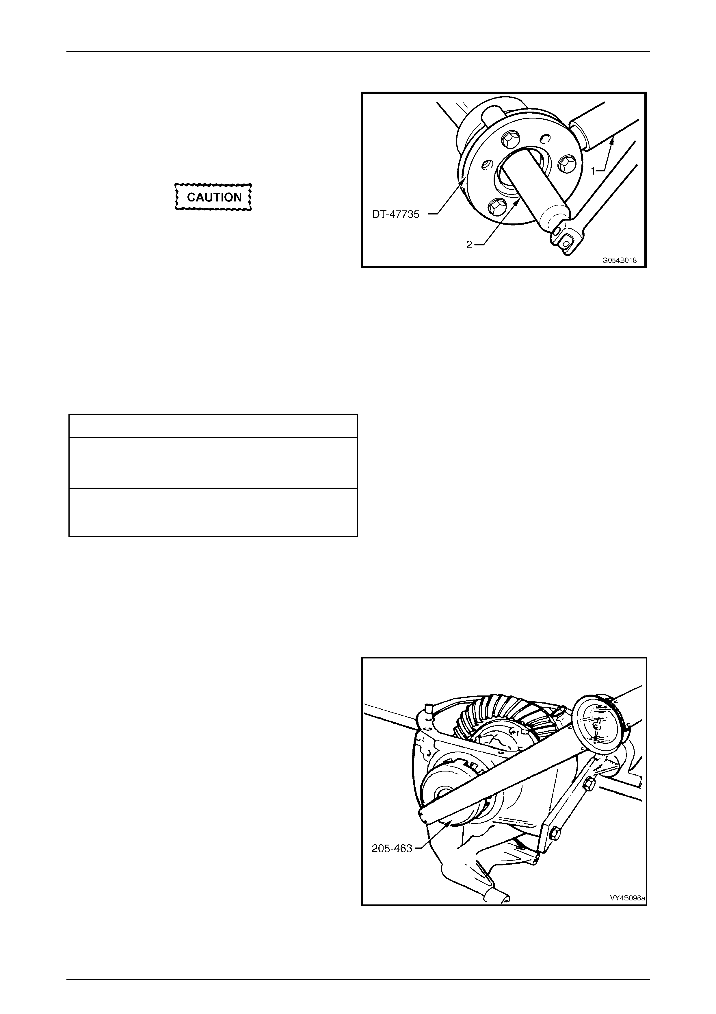
Rear Final Drive and Drive Shafts Page 4B1-99
Page 4B1-99
For All RWD Models
25 Reinstall pinion flange and fit a NEW retaining nut.
26 Hold pinion flange using Tool No. DT-47735 and a
suitable length of pipe (1).
27 Gradually tighten the retaining nut while rotating pinion
in both directions to seat bearings.
If the retaining nut is over-tightened and pre-
load exceeded, it will be necessar y to remo ve
the pinion from the carrier and a new
collapsible spacer installed. Under no
circumstances must the retaining nut be
backed off to decrease the pre-load reading. Figure 4B1 – 188
28 Check bearing pre-load freq uently by removing flange ho lding tool (DT-47735) and installing a pulle y and string to
the pinion flange. Refer to 7 Special Tools at the end of this Section for pulley details.
For All Models
29 Using a spring scale, measure rotationa l torque.
30 Continue to tighten the nut until specified torque is achieved.
Pinion Rotational To rqu e Specification
New Bearings (With Pinion Oil Seal Installed )
Timken Koyo
1.4 – 2.4 N.m 1.5 – 2.1 N.m
Used Bearings (With Pinion Oil Seal Installed)
Timken Koyo
0.7 – 1.2 N.m 0.7 – 1.2 N.m
31 The torque figure is calculated b y multiplying the radius of the pulley by the sprin g balance reading.
Example: If the pulley diameter is 152 mm, the radius is 76 mm which equals 0.076 m. The spring bala nce reading is
25 N. Therefore, the pre-load equals 0.076 m x 25 N = 1.9 Nm.
Differential Backlash Setting
1 Check threads of screw adjusters and ensure that they are free of damage.
2 Holding differential case in carrier, with ring gear in
mesh with pinion, fit screw adjusters and side bearing
cup assemblies to both sides of carrier. Usin g Tool No.
205-463 (or AU407), continue tightening adjusters until
case assembly is supported by side bearin gs.
3 Rotate differential case several times, to ensure that
side bearings are correctly seated.
4 Tighten screw adjusters to the torque setting recorded
previously. Refer to Step 6, ‘Differential Case Side
Bearing Pre-load Setting ’, in this Sectio n.
Figure 4B1 – 189
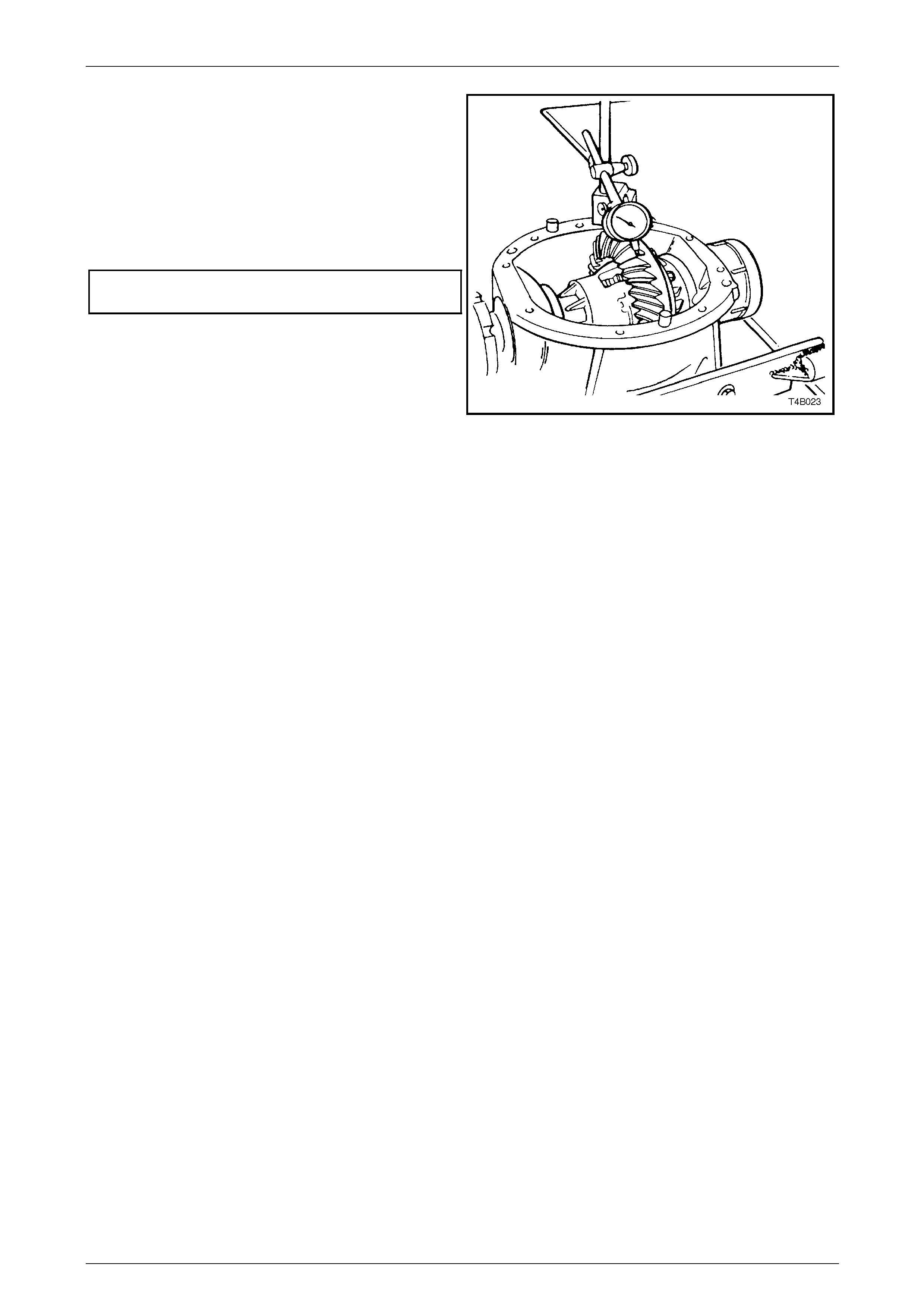
Rear Final Drive and Drive Shafts Page 4B1-100
Page 4B1-100
5 Mount a dial indicator on carrier and check gear
backlash between the ring ge ar and pinion at four
equally spaced positions around the ring gear.
NOTE
Position the dial indicator so that the indicator
stylus is perpendicular to th e ring gear tooth and
in line with gear rotation.
6 Backlash should be within the following specification.
Backlash specification.........................0.10 - 0.18 mm at
the tightest point.
7 If backlash is excessive or insufficient, adjust by
slackening off screw adjuster on the side that the ring
gear (differential case) needs to move towards. Re-
tighten opposite screw adjuster the same amount,
then tighten both as detailed in step 4.
8 With backlash correctly set, check gear contact pattern
as detailed in the follo wing in structions. Figure 4B1 – 190
Ring Gear and Pinion Contact Pattern
1 Thoroughly cle an ring gear and pinion teeth.
2 Paint ring gear teeth lightly and evenly with gear marking compound of a suitable consistency to produce a contact
pattern.
3 Rotate pinion through several revolutions in both directions whil e lightly loading gear set, using a suitable bar to
lever between ring gear o uter diameter and differential carrier.
NOTE
When rotating pinion, ensure that no metal swarf
from contact with rotating ring gear and bar is
allowed to enter gear teeth.
4 Inspect contact pattern produced b y above procedure.
5 After a satisfactory contact pattern is produced, clean the ring gear an d pinion gear teeth and pour a liberal quantity
of the correct rear axle lubricant onto the gears and beari ng s . T urn the gear set to work the lubricant into all
surfaces.
Tooth Marking Nomenclatur e
The large end of the tooth is called the 'HEEL' and the small end the 'TOE', also the top of the tooth which is above the
pitch line is called the 'FACE' while the area below the pitch line is called the 'FLANK'. The clearance between the pinion
and ring gear teeth is referred to as 'BACKLASH'.
Figure 4B1-191 illustrates correct and incorrect contact patterns.
Contact pattern 'A' provides the ideal marking for quietness and long life. If the pattern shows a toe contact as in 'B', it
indicates not enough backlash. T o correct, move the ring gear away from the pinion by screwing the side bearing
adjuster out on the ring gear side a djuster and screwing in the pi nion side adjuster by an equal amo unt.
If the pattern shows a heel contact 'C', it indicates too much backlash. To correct, move the ring gear towards the pinion
by screwing the side bearing adjuster out on the pinion side adjuster and screwing in the ring gear side adjuster by an
equal amount.
NOTE
Each time an adjustment is made, check gear
contact with gear marking compound and
continue adjustment until tooth contact appears
as in 'A'. Backlash must remain within specified
limits.
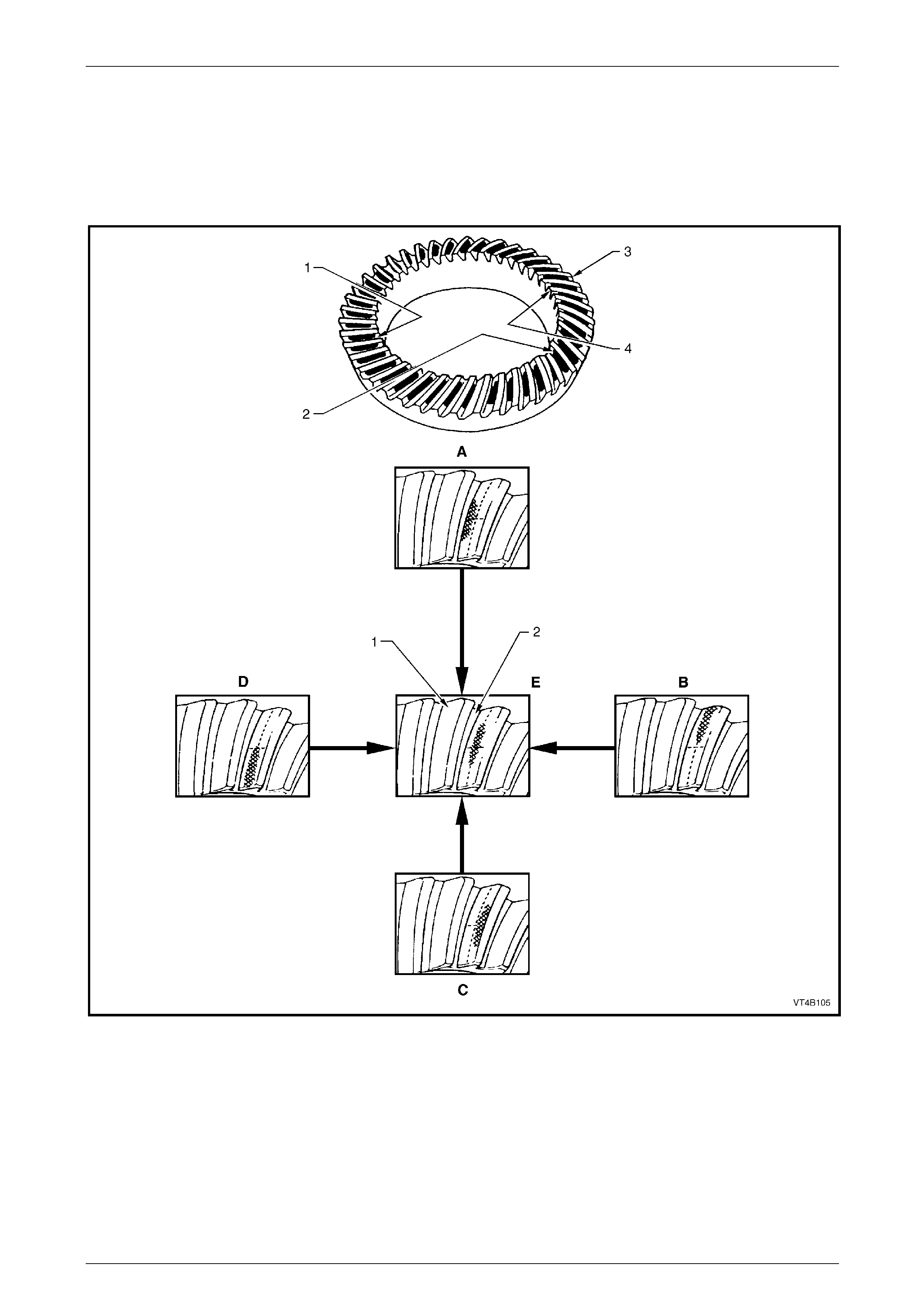
Rear Final Drive and Drive Shafts Page 4B1-101
Page 4B1-101
To correct a pattern shown in 'D', it will be necessary to install a thicker pin ion p ositioning shim; refer to
Hypoid Pinion Positioning Shim Selection, in this Section. A shim that is thicker by 0.025 mm is recommended as a
starting point. Continued changes may be necessary to obtain the correct setting. If the pattern shows a flank contact 'E',
it indicates that the pinion is in too far. To correct, replace the pinion shim with a 0.025 mm thinner shim and recheck
contact pattern.
In making pinion position adjustments, be sure backlash is correct before testing each contact pattern. Moving the pi nion
'IN' reduces backlash and moving pinion 'OUT' increases backlash.
Figure 4B1 – 191
Legend
1 Convex Side (Drive)
2 Concave Side (Coast)
3 Heel
4 Toe
A Low Flank Contact – Decrease Pinion Shim Thickness
B Heel Contact – Decrease Backlash
C High Face Contact – Increase Pinion Shim Thickness
D Toe Contact – Increase Backlash
E Ideal Contact
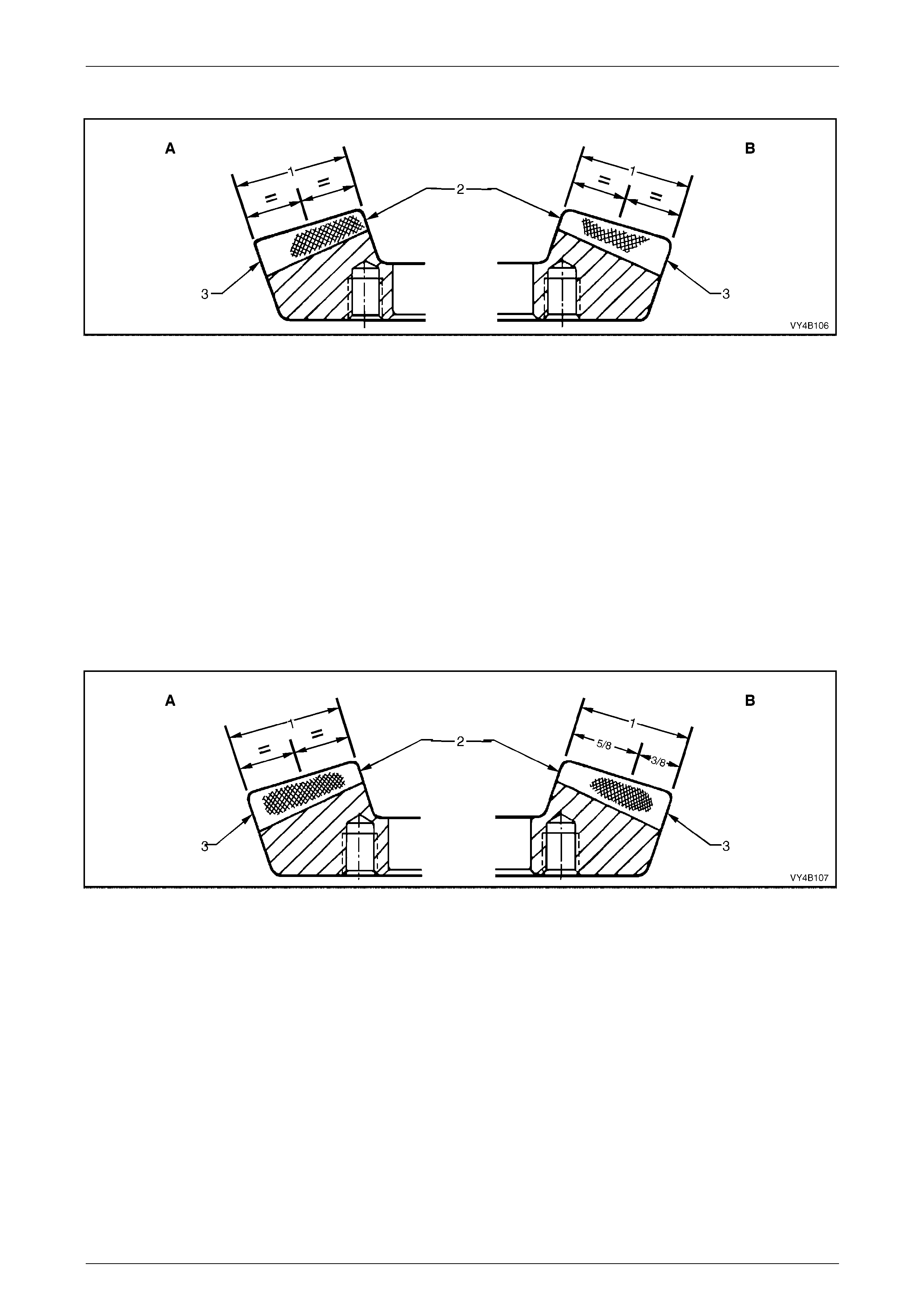
Rear Final Drive and Drive Shafts Page 4B1-102
Page 4B1-102
Ideal Contact
Figure 4B1 – 192
Legend
A Drive Side
B Coast Side 1 Face Width
2 Toe
3 Heel
Drive Side
A central toe contact marking, lengthwise in position and slightl y low contact in the profile position.
Total length approximat ely 5/8th of the gear face width.
There should be clearance of about 1 mm between the contact marking and the toe and alon g the top face angle line.
Coast Side
A centrally located marking, lengthwise in position and sli gh tly high in the profile position.
Total length approximat ely 5/8th of the gear face width.
There should be clearance between the contact and the face angle li ne of the gear.
Acceptable Heel Contacts
Figure 4B1 – 193
Legend
A Drive Side
B Coast Side 1 Face Width
2 Toe
3 Heel
Drive Side
A central face contact marking, lengthwise in position, is shown in Figure 4B1-193. This represents the limit of
acceptability of the contact marking towards the heel.
The marking should fade out at least 5 mm before the heel end.
A central profile marking position is sh own and is acceptable, although lo w contact marking is preferre d.
Coast Side
The centre of the contact marking is located at 5/8th of the face width from the toe and it does not approach the heel en d
by less than 5 mm.
A high contact marking, as shown in Figure 4B1-193, is pre ferred for coast side contacts which tend to be toward the
heel.
A central profile marking position is acceptable, providing the pinion face angle edge li nes do not appear lo w on the gear .
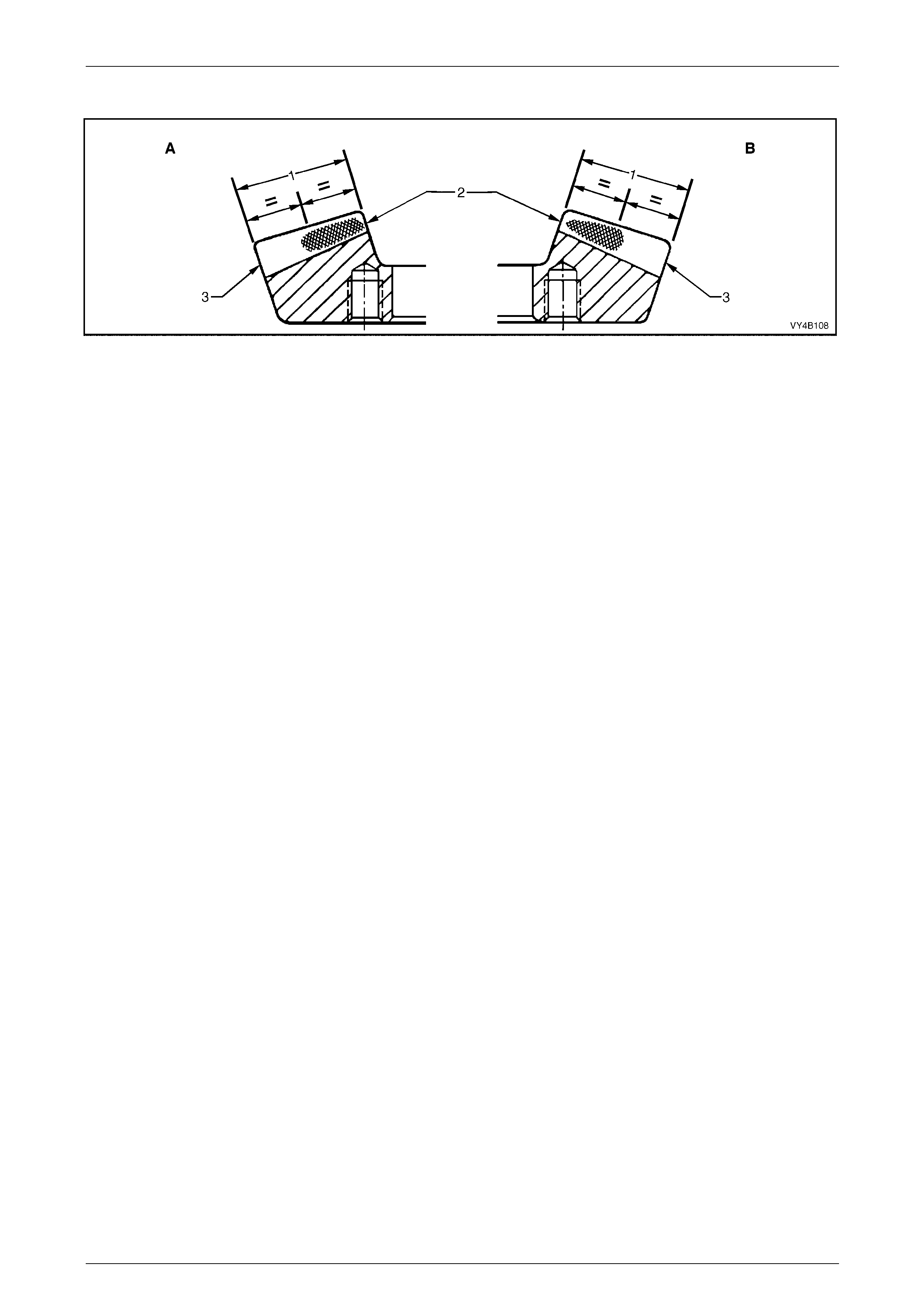
Rear Final Drive and Drive Shafts Page 4B1-103
Page 4B1-103
Acceptable Toe Contacts
Figure 4B1 – 194
Legend
A Drive Side
B Coast Side 1 Face Width
2 Toe
3 Heel
Drive Side
The contact markings begin almost at the toe end face and exte nd in length by approximately half the face width.
A slightly low contact marking is sho wn in Figure 4B1-1 94. This is preferable although a centrally located profile position
is acceptable.
Coast Side
The contact marking being almost at the toe end face and may appear pointed as sh own in Figure 4B1-194. A squ are
end is equally acceptable.
The total length of the contac t marking is approximately 1/2 of the face width.
A high profile marking positi on is desirable, although a cen tral profile is acceptable.
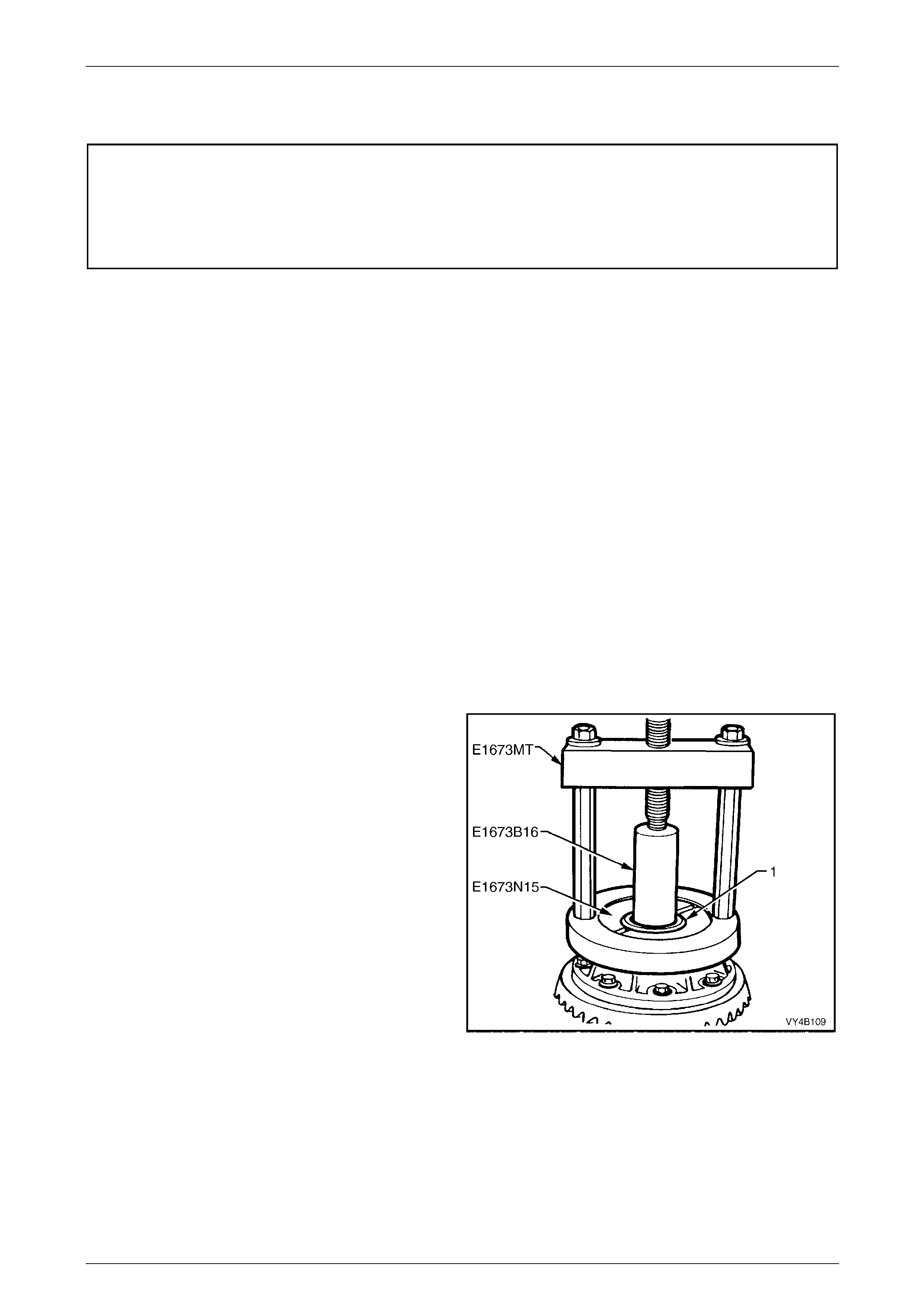
Rear Final Drive and Drive Shafts Page 4B1-104
Page 4B1-104
3.4 Limited Slip Differential
ATTENTION
The following fasteners MU ST be replaced when performing these operations:
Final drive ring gear attaching bo lts.
LSD case cap to cover attaching bolts.
NOTE
• The overhaul procedures, ring gear and
pinion positioning and tooth markings for the
limited slip differential are the same as
described for the standard type of rear axle
assembly, except for the servicing of the
internal components of the limited slip
differential assembly.
Disassemble
1 Before disassembling the differential case, inspect differential side bearings for any signs of damage.
NOTE
The side beari ngs can be manufactured by either
one of two manufacturers; Timken or Koyo. When
replacing the differential side bearings, the two
bearings and cups must be of the same brand.
The pinion bearings may be of a different
manufacture but again, they must be a matched
pair. The reason for matched pairs of bearings is
that a different preload specification is required
for each brand.
2 If replacing side bearings, use Tool No. E1673MT,
adaptors E1673N15 an d stepped plug E1673B16 to
remove side bearings from differential cas e.
3 Discard the removed side bearin gs.
4 To remove side bearing cups, refer to 3.3 Removed
Final Drive Assembly – Disassemble, Step 12 in this
Section.
Figure 4B1 – 195
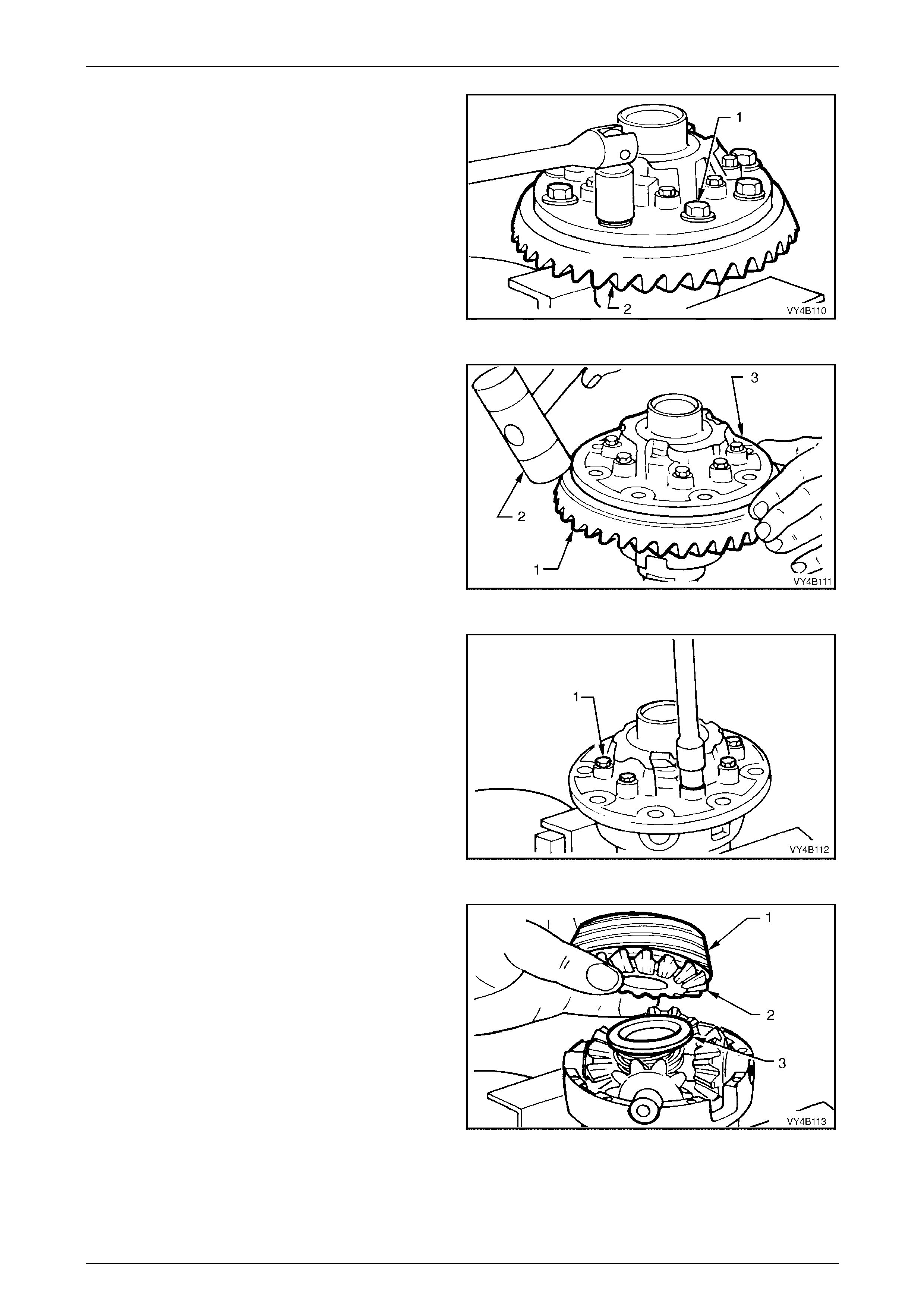
Rear Final Drive and Drive Shafts Page 4B1-105
Page 4B1-105
5 Grip differential case in a vice fitted with soft jaws.
6 Remove ring gear attaching bolts (1).
NOTE
Ring gear attaching bolts (2) use a left hand
thread and are identified by an 'L' on the bolt
head.
7 Remove differential case from vice.
Figure 4B1 – 196
8 Using a soft faced hammer (2), remove ring gear (1)
from differential case (3) by hitting do wn on ring ge ar.
Support ring gear during this operation so that it does
not strike bench top as it comes free of case.
Do not use a screwdriver to prise between ring
gear and case.
9 Place differential case in a vice equip ped with soft
jaws.
Figure 4B1 – 197
10 Loosen and remove differenti al case ca p to cover
attaching bolts (1) evenly. Lift off differential case
cover. If necessary, remove clutch cup from cover
(sometimes the cone will remain inside the c over).
Figure 4B1 – 198
11 Remove the integrated clutch cone (1)/side gear (2)
and thrust spring plate (3) from pinion cross shaft.
NOTE
The integral clutch cones and side gears must
stay assembled to each other.
Figure 4B1 – 199
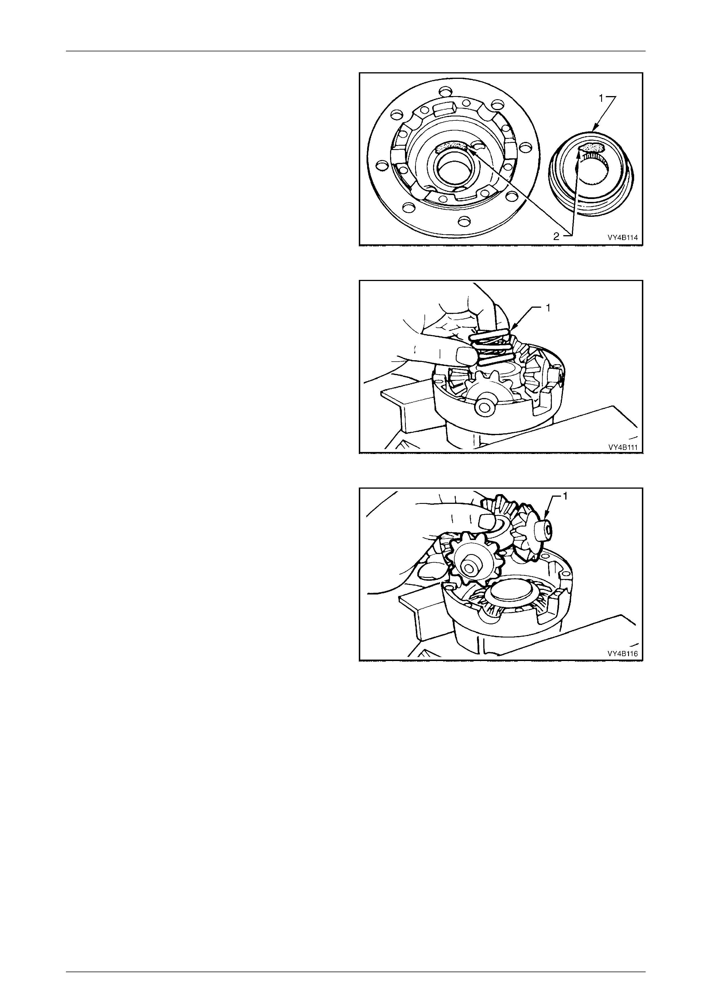
Rear Final Drive and Drive Shafts Page 4B1-106
Page 4B1-106
To ensure that the clutch cones (1) (are not
interchanged during reassembly, mark the cone
and corresponding side of the differential case
(2) with a felt tipped pen or similar.
Figure 4B1 – 200
12 Remove three concentric differential pre-load springs
(1) from centre of pinion cross shaft.
Figure 4B1 – 201
13 Lift pinion cross shaft (1), pinion gears and thrust
washers from case. Remove pinion gears and thrust
washers from cross shaft.
NOTE
Keep the pinion gears with their respective thrust
washers in sets so they can be reinstalled in
their original position.
14 Remove remaining thrust spring plate, side gear, shim
(if fitted) and clutch cone from differential case cap.
Figure 4B1 – 202
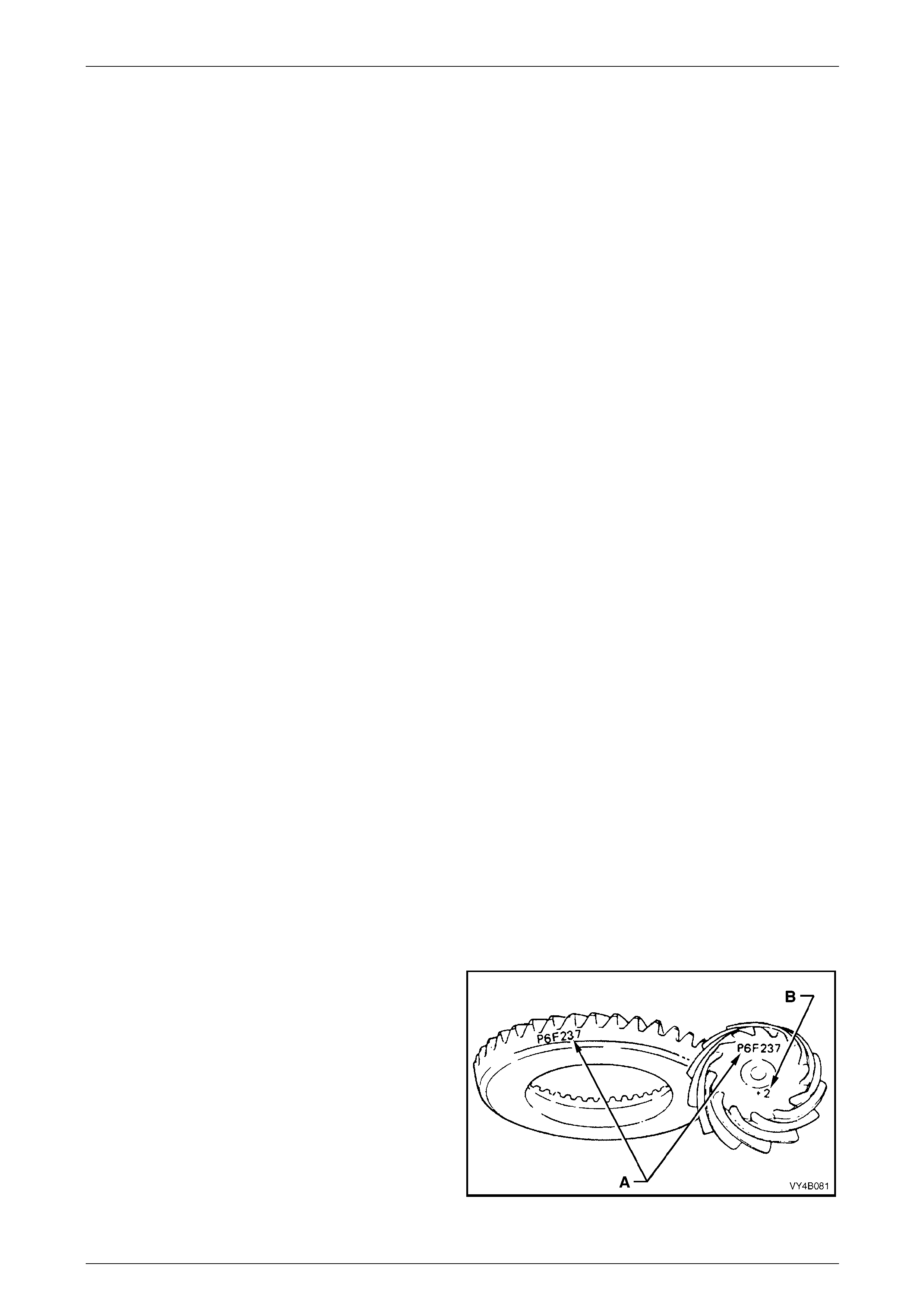
Rear Final Drive and Drive Shafts Page 4B1-107
Page 4B1-107
Inspect
All components should be thoroughly cleaned and dried, then inspected.
Differential Case
Check the case for general soun dness and pay particular attention to the following points:
1 If differential case side bearings have been removed, check case journals for damage and that seating surfaces
are free from dirt and burrs.
2 The ring gear spigot and mounting face should be clean and free from dirt and burrs.
3 The mating surfaces for differential case halves should be clean and free from burrs.
4 The thrust surfaces for the differentia l pinions should be examined for excessive wear.
5 The clutch cone seats in t wo hous ing halves should be smooth and free from any excessive scoring. Slight grooves
and scratches are permissible and norm al.
NOTES
• The land surface of the heavy spirals on
clutch cones will duplicate the housing
surface condition.
• Excessive wear or damage on the clutch cone
surface will require renewal of both clutch
cones (3.08:1 ratio only) or the clutch
cone/side gear assemblies (all other units)
and the housing.
6 Inspect axle splines of the clut ch cones for excessive wear.
7 Check thrust spring plates for excessive wear or damage.
8 Inspect pinion gear cross shaft bores for ovality.
Differential Side Gears and Pinion Gears
1 Examine all gear teeth for cracks or hard contact marks.
2 The differential side gear spli nes should be checked for excessive wear. Wear on splines can contribute to
excessive driveline backlash.
3 The differential pinion bores and thrust surfaces should be smooth and free from scores. Inspect all thrust washers
for cracks, nicks or burrs. Wear of thrust washers or thrust surfaces on gears can contribute to excessive driveline
backlash.
4 Check that pinion gear cross shaft is not bent and that surfaces on which pinions run, are not scored or worn.
Ring Gear and Pinion
1. Inspect gear teeth for scoring or damage. Scoring of the gear teeth is usually caused by excessiv e shock loading,
use of the incorrect lubricant or insufficient "run in" before towing a heavy load. (Refer to the appropriate Owner's
Handbook for more information). Scored g ears must be replaced.
2 If on reassembly, a new gear set is to be installed,
ensure that the same matching number 'A' appears on
both the pinion and ring gear. The pinion installation
marking figure is indicated by ‘B’.
3 On ring gear bolts, clean the serrations under each
bolt flange.
Figure 4B1 – 203
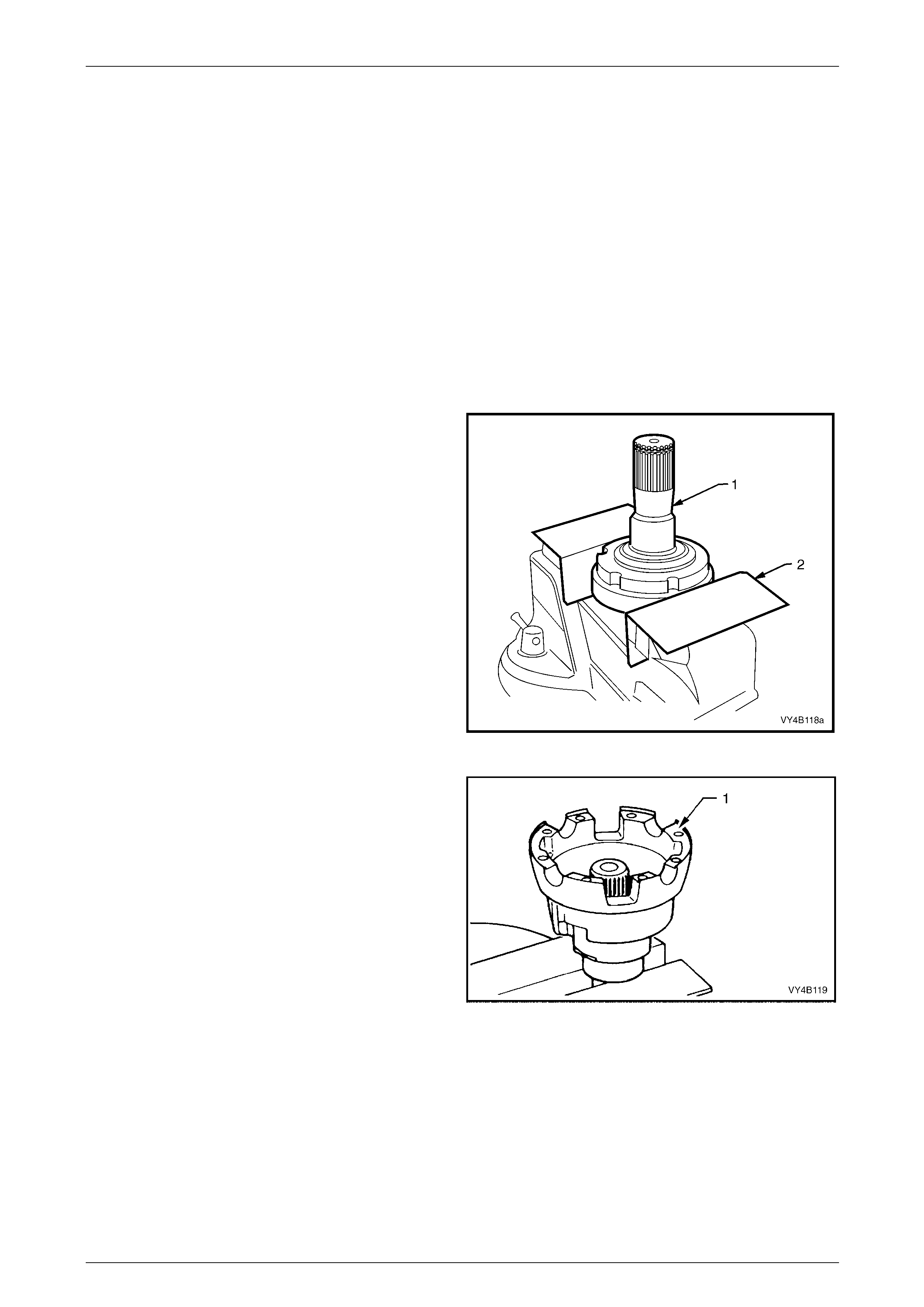
Rear Final Drive and Drive Shafts Page 4B1-108
Page 4B1-108
Bearings
1 Bearing cups should have an even wear pattern and be free from flaking or pitting. Ensure the seating surfaces are
clean and free from burrs or raised metal.
2 The bearing assembli es should feel smooth when turned in the cups.
3 The assembly should be free from loose particles.
4 There should be no cracks pr esent in the roller cages and the bores should show no evidence of flaking or pitting.
NOTE
Refer to 4.4 Final Drive Bearing Diagn osis, in this
Section, for identification of bearing failures.
Reassemble
1 Lubricate all gears, bearings, thrust washers and pinion gear cross shaft with rear axle lubricant befor e assembly.
2 Clamp the left hand inner axle shaft (1) in a vice
equipped with soft jaws (2), after removing the snap
ring from the end of the shaft.
Figure 4B1 – 204
3 Place differential case cap (1) over axle shaft mounted
in vice with interior of the housing faci ng upwards.
4 Paint a mixture of an EP grease with molybdenum
disulphide, such as Shell Retinax HDX2 grease, BP
Energrease LMS-EP 23, or equivalent, with the
recommended differential carrier lubricant onto faces
of side gears and clutch cone surfaces.
Figure 4B1 – 205
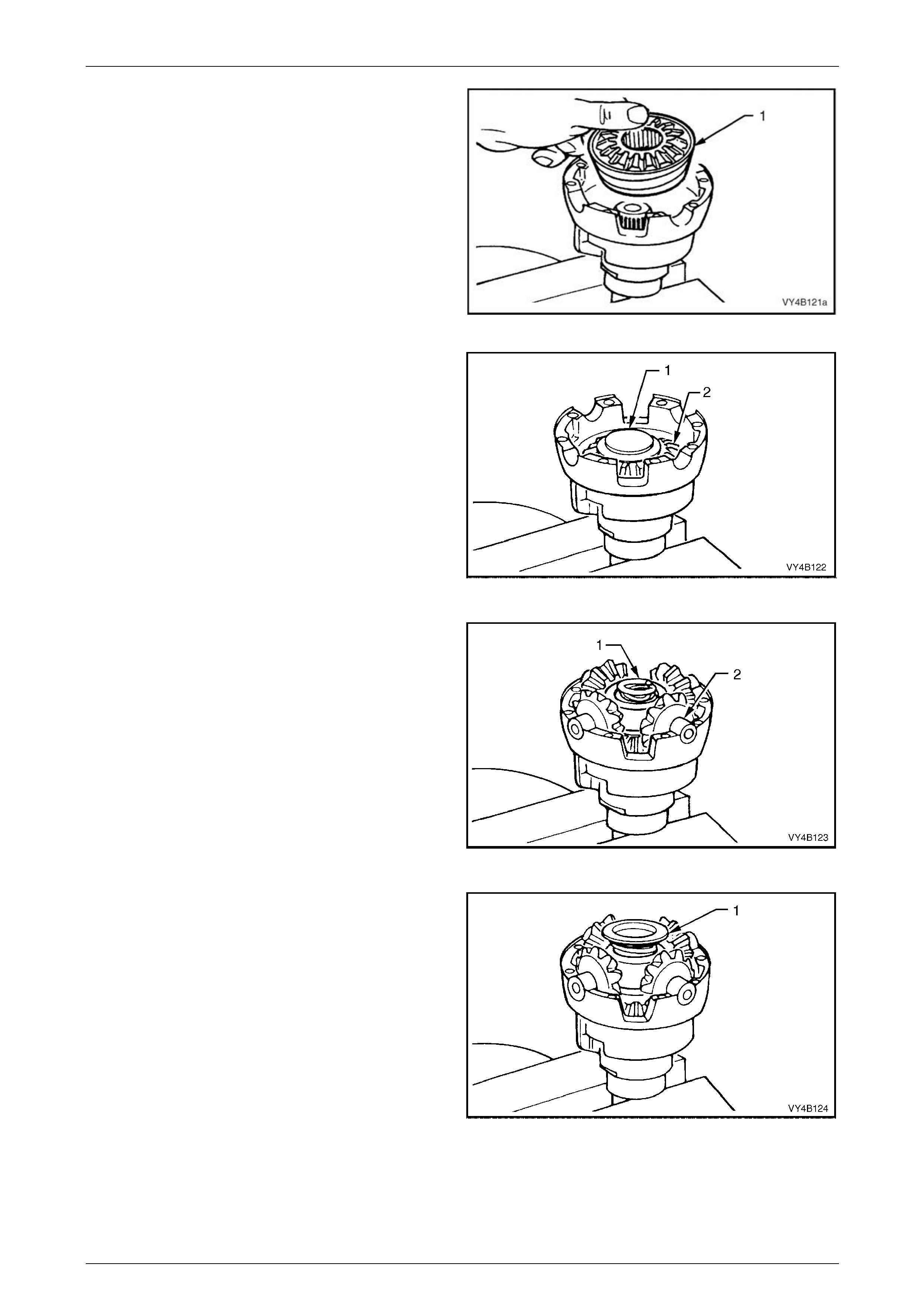
Rear Final Drive and Drive Shafts Page 4B1-109
Page 4B1-109
5 Install the clutch cone/side gear assembl y (1 ) into the
housing.
Figure 4B1 – 206
6 Place a thrust spring plate (1), stepped side up on side
gear (2).
7 Assemble the four pinions and thrust washers onto
pinion cross shaft.
8 Install pinions and cross shaft assembly to case cap,
ensuring that pinions mesh with side ge ar.
Figure 4B1 – 207
9 Install three new concentric differential pre-load
springs (1) into centre of the pinion cross shaft (2).
Only install NEW pre-load springs (1) on
reassembly: DO NOT RE-USE OLD SPRINGS.
Figure 4B1 – 208
10 Assemble second thrust spring plate (1), stepped side
down, onto pre-load springs.
Figure 4B1 – 209
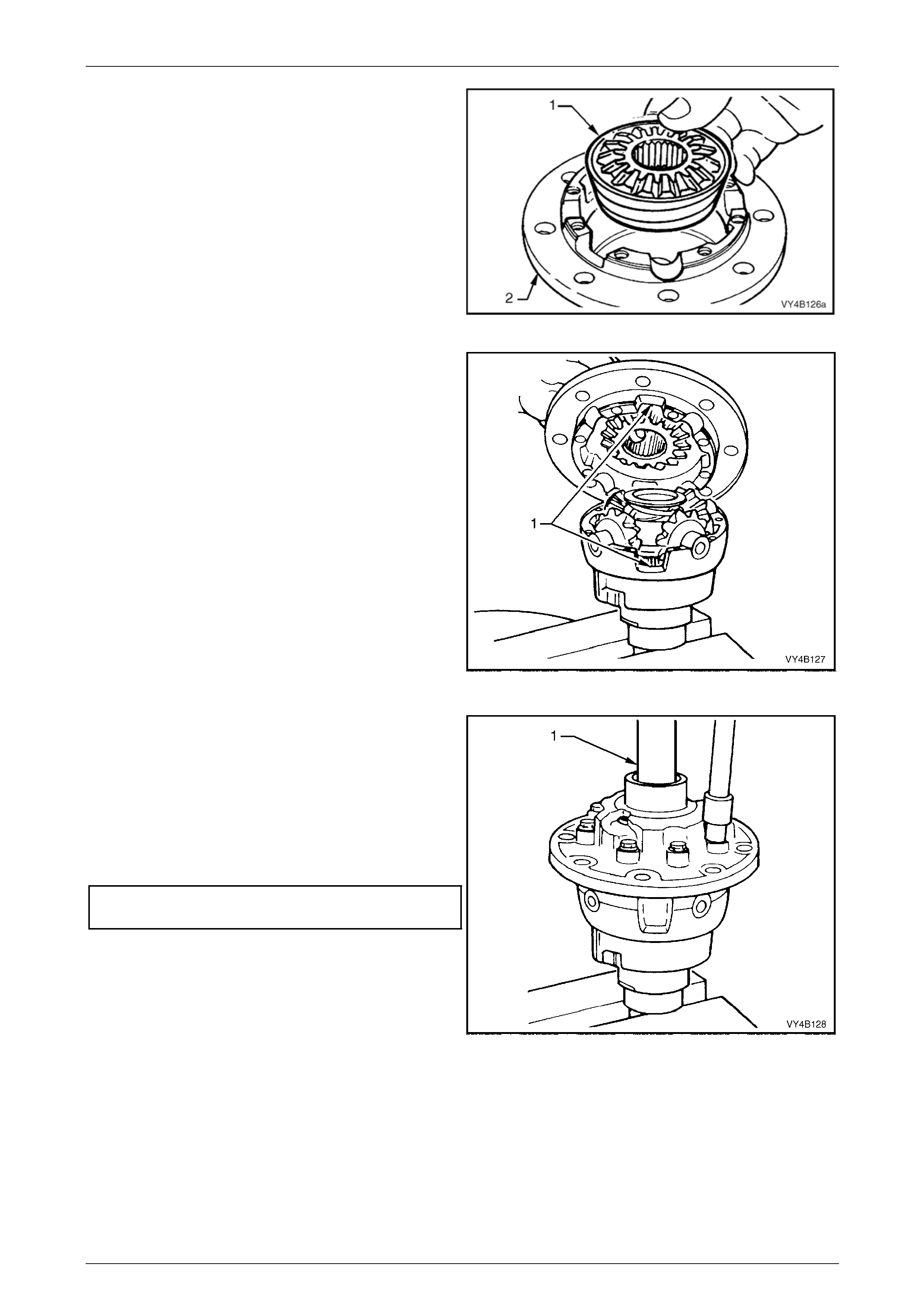
Rear Final Drive and Drive Shafts Page 4B1-110
Page 4B1-110
11 With other ratio differentials, install the clutch
cone/side gear assembly (4) into the case cover (2).
Figure 4B1 – 1
12 Install case cover onto case cap.
NOTE
Check that the cut outs (1) on each side of the
case cover and cap are aligned.
Figure 4B1 – 210
13 Install two NEW differential case cap-to-cover
attaching bolts in opposite bolt holes and finger
tighten.
14 Install other inner axle shaft (1) through case cover,
rotating axle shaft to engage clutch cone splines and
then side gear splines. Leave axle shaft in this
position. Install remaining, NEW, cap-to-cover
attaching bolts and tighten evenl y to the correct torque
specification.
Differential case cap to cover
attaching bolt torque specification........................40 N.m
Figure 4B1 – 211
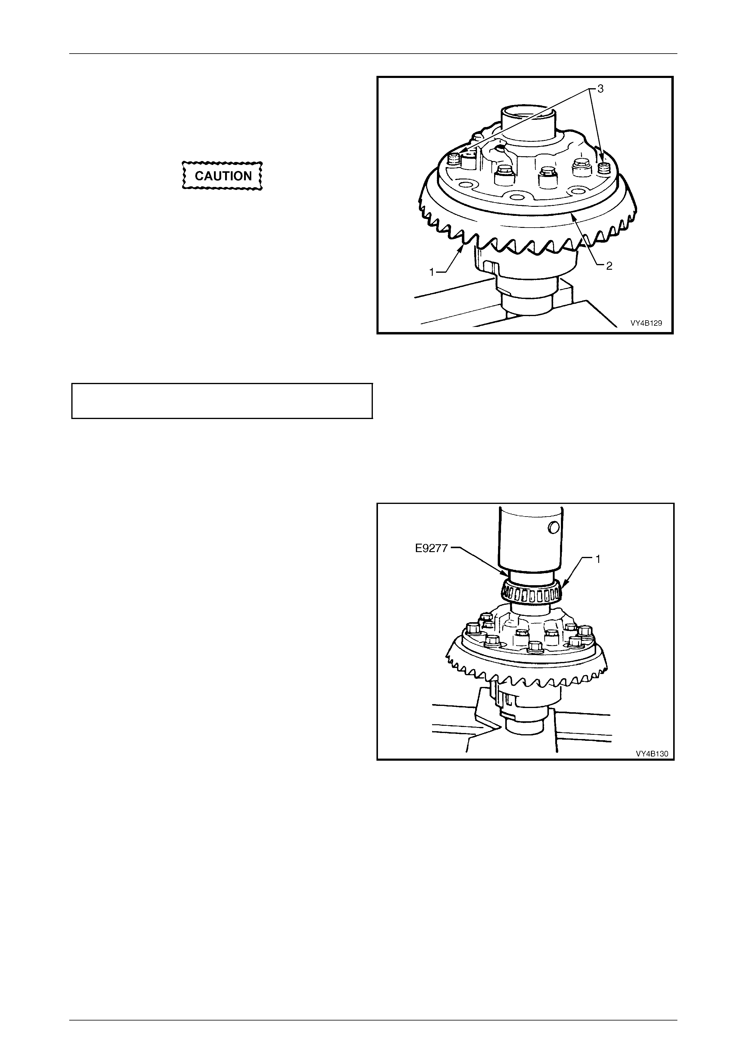
Rear Final Drive and Drive Shafts Page 4B1-111
Page 4B1-111
NOTE
For ease of assembly, it may be necessary to
heat the ring gear on a hot plate until it is hot to
the hand, prior to installing onto the differential
case cap.
A flame must never be used to heat the ring
gear.
NOTE
Use left hand threaded guide pins (3) to pilot the
ring gear over the differential case spi got.
15 Place ring gear (1) into position on differential case
cap (2) and install ring gear attaching bolts.
16 Install NEW ring gear attaching bolts evenly until gear
face is flush with differential case spigot.
17 Tighten bolts to the correct torque specification. Figure 4B1 – 212
Final drive ring gear
bolt torque specification.....................................140 N.m
NOTE
Ring gear attaching bolts use a left hand thread
and are identified by an 'L' on the bolt head.
18 If installing new side bearings (1), use Tool No. E9277
to press on side bearings (1) to differential case
journals.
19 Continue rear axle assembly, proceeding from
'Differential Case Side Bearing Pre-Load Setting', on
page 4B1-87, in this Section.
Figure 4B1 – 213
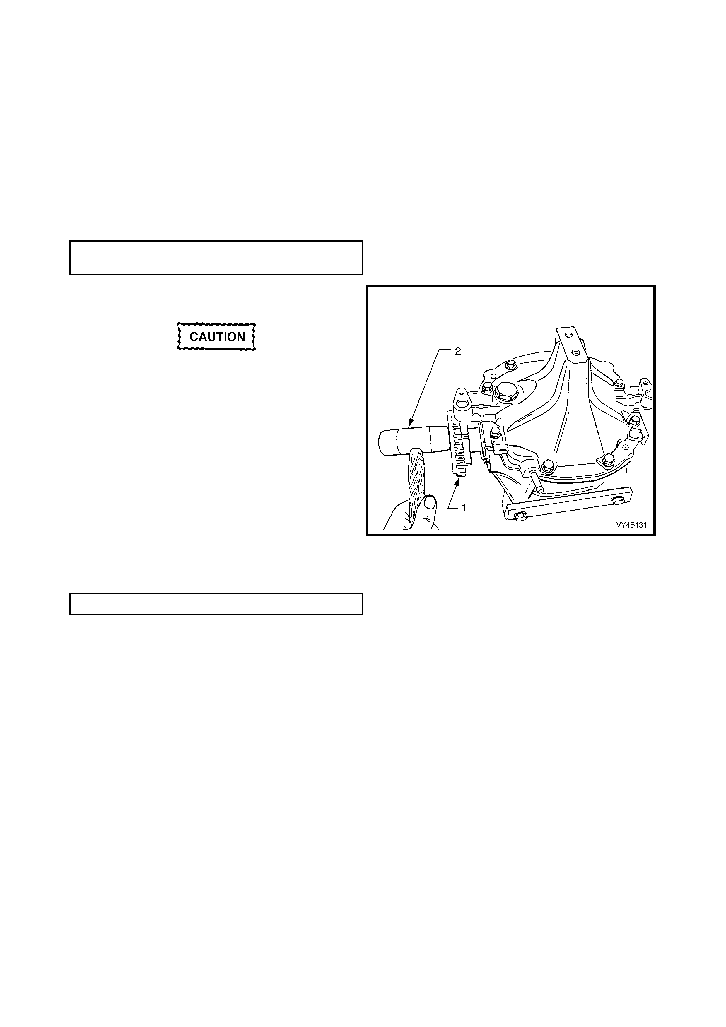
Rear Final Drive and Drive Shafts Page 4B1-112
Page 4B1-112
3.5 Rear Axle
Reassemble
1 Apply a 1.5 – 2.0 mm diameter continuous bead of sealant, such as Loctite 587 (‘Ultra Bl ue’) or equivalent to inside
edge of rear cover and bolt holes and completely around drain pl ug hole.
2 Install rear cover to differential carrier housing. Fit screw adjuster lock plates to rear cover, ensuring that lock plates
fit over ribs or between ribs on the screw adjusters.
3 Tighten rear cover attaching bolts to the correct torque spec ification.
Rear cover attaching bolt
torque specification..............................................27 N.m
4 If removed, reinstall a spring clip to the end of each
inner axle shaft (1), then reinstall.
To avoid premature seal failure, ensure axle
shaft splines or spring clip do not score or
damage the seal lips during installation.
5 Lightly tap on end of each shaft flange (1) with a soft
faced hammer (2) to compress spring clip on shaft into
clutch cup and side gear splines. Fully engage both
shafts until clips snap into side gear grooves.
Figure 4B1 – 214
6 If equipped with ABS, check that sensor to toothed inner axle shafts air gap is to specification.
ABS Sensor Air Gap..................................0.4 – 1.5 mm
7 Reinstall differential carrier assembly to the vehicle. Refer to 3.2 Final Drive Assembly, in this Section.
Rear Final Drive and Drive Shafts Page 4B1-113
Page 4B1-113
4 Diagnosis
4.1 General Information
Very often, final drive assemblies are consid ered as noisy, when in reality, the noise is emanating from some other
source, such as tyres, front wheel bearings, rear wheel bearings, manual tr ansmission rear bearings, engine noises,
muffler roar, automatic transmission or power steering pumps.
All final drive assemblies have some slight humming noise. This will vary with the t ype of body construction, load and tyre
pressure.
Noise which emanates from any one of these can quite ea sily be confused with a final drive assem bly noise and unless a
series of elimination tests are carried out to d efinite ly confirm the real source of the noise, differential assemblies may be,
and often are, dismantled unnecessarily.
Although not infallible, the following diagnosis guide will assist in locating and defining the different characteristics of the
components which could be responsible for a noise.
Road Test
Ensure that the final drive assembly lubricant is correct and at the correct level. Drive at low speed until thoroughly
familiar with vehicle noises b y which time the final drive assembly should have warmed up. Accelerate gradually from the
lowest practical speed in a direct ratio gear (1:1) to 100 km/h, noting any noises and the s peeds at which they occur.
Release the accelerator and without using the brakes, allo w the vehicle to lose speed. Next, allow the vehicle to coast to
rest from 100 km/h with the transmission in neutral position. Any noises common to earlier tests may be elimi nated as
final drive assembly gear noise, as the final drive assembly is not under load under these conditions. Engine noise is
gauged by gradually accelerating the engine with the vehicle at rest.
Only drive at high speeds when it is legal and
safe to do so.
Tyre Noise
Tyre noise can easily be mistaken for fina l drive assembly noise even though the noisy t yres may be operating on the
front wheels. Tyre noise changes with different road conditions, but final drive assembly noise does not. Final drive
assembly noise usually ceases when coasting with the transmission in neutral at speeds under 50 km/h. Tyre noise
continues, but with a lower tone as vehicle speed is reduced.
Tyre noise naturally should be first eliminated; driving on a grass surface is ideal to check against this condition. It should
be noted though, that dry grass can impose a fire hazard with the heat emanating from the catalytic converter and wet
grass can cause excessive wheel spin. Inflating tyres temporarily to high pressures will change the contact with the road
and assist in reducing t yre noise. Pressures up to 276 kPa may be used temporarily.
Tyres which have the surface of the non-skid divisions worn with one end higher than the other (saw-tooth wear) are
usually noisy. Interchanging tyres can prove effective in reducing noise.
Front Wheel Bearings
Worn, brinelled or chipped fro nt wheel bearings will cause a nois e, very similar to tyre noise. It is a constant noise, does
not vary on 'drive' or 'coast' and still persists when coasting with the transmission in neutral. T his noise does n ot
noticeably change on differing road surfaces to the same degree as does tyre noise.
Although not so pronounced, front wheel bearing noise can also be compared to a road surface noise, which is produced
when the vehicle is travelling over a surface such as penetrated bitumen type road.

Rear Final Drive and Drive Shafts Page 4B1-114
Page 4B1-114
Transmission Rear Bearing (Manual Transmission)
A rough or pitted rear transmission beari ng, usually produces a very definite bearing noise and sets up a distinct
'whirring' condition, which is most audible when accelerating from slow speed under a high throttle opening and tends to
diminish as vehicle speed increases.
This noise is also prominent under a co nstant throttle opening, but disappears on over-run when coasting with the
transmission in neutral.
When driven in second gear, noise can be amplified by lightly accelerating.
Backlash Clunk
Excessive clunk with accelera tion and deceleration may be caused by worn differential pinion shafts, excessive
clearance bet ween inn er axle shaft and side gear splines, drive shaft companion flange and wheel spindle flange splin es,
excessive clearance b etween side gear hub and counterbore in case, worn pini on and side gear teeth, worn thrust
washers and excessive drive pinion and ring gear backlash. Remove worn parts and repl ace as required, selecting close
fitting parts when possible. Adjust pinio n an d ring gear backlash.
Drive-Line Snap
A snap on sudden start, either forward or reverse, may be caused by a loose pinion flange. If loose, replace nut or flange
as outlined under 2.11 Pinion Flange, in this Section.
This condition may also be caused by incorrect lubricant in an LSD. Drain and refill with correct lubricant.
Engine and Other Contributing Factors
Noises which emanate from the eng ine, transmission or muffler are occasionally c onfused with final drive assemb ly
noises.
To isolate these noises, first carefully note the approximate vehicle speed and conditions where the supposed final drive
assembly noise is most pronounced, then with the vehicle stationary and in a quiet place to avoid interfering noises
(depress the clutch pedal on vehicl es with manual transmission), run the engine u p and down slowly through the engine
speeds that correspond to the vehicle speeds at which the noise was prominent and ob s erve whether there is any
similarity to a final drive assembl y noise.
For vehicles with manual transmission: With transmission still in neutra l, again run the engine at similar s peed while
slowly letting the clutch engage, and listen for noises from the transmission.
Muffler noises are usually readily identifi ed, possibly an exception being when a muffler emits a high-pitched periodic
whistling noise, which could be confuse d with a bearing noise.

Rear Final Drive and Drive Shafts Page 4B1-115
Page 4B1-115
4.2 Final Drive Assembly Noise
Final drive assembly noises fall into two categories:
a Gear related noises.
b Bearing related noises.
Before testing for final drive assembly noise, ensure that the lubricant is the correct type and at the correct level.
Gear Related Noise
Ring Gear and Pinion Noise
Noise produced by the ring gear and pinion set is of a cyclic nature and gener ally shows up as a 'drive noise' , 'coast
noise', or 'float noise'.
1 Drive noise is most pronounced on co nstant acceleration through the speed range of 50 to 90 km/h.
2 Coast noise is most pronounced when the vehicle is allowed to coast through the speed range from 90 to 50 km/h.
3 Float noise is most pronounced while the vehicle is kept at constant speed for periods between 50 to 90 km/h.
Final drive assembly noise will always change when comparing 'drive' and 'coast' and will usually cease when coasting
with transmission in neutral at speeds under 50 km/h.
Differential Side Gear and Pinion Noise
Noise produced by these gears occurs when there is excessive wear between the side gear hubs and the differential
case bores. This can cause a 'clunking' noise when the vehicle is driven at low speeds.
Noise produced due to excessive wear between the gear te eth will be most pronounced on turns.
Common Causes of Gear Related Noises
1 Low lubricant level or incorrect lubricant used.
2 Incorrect meshing of gear teeth (i.e. incorrect pinion positioning shim or backlash setting shims).
3 Scored gear teeth:- usually the result of incorrect lubricant type or level.
4 End play in bearings.
5 Bruised or chipped teeth.
6 Excessive runout of pinion head or ring gear backlash.
7 Ring gear creeping on differential case resulting from ring gear bolts loosening - noise from this source usuall y
appears as a sharp metallic sound when shifting from reverse to first gear.

Rear Final Drive and Drive Shafts Page 4B1-116
Page 4B1-116
Bearing Related Noise
Differential Pinion Gear Bearings
Worn, rough or loose bearings will tend to aggravate and magnify drive, float and coast noise, and result in heavy,
irregular drive nois e on co nstant acceleration and float, and also an irregular noise on deceleratio n.
Pinion bearings, if rough or brinelled, will produce a continuous whine, which will persist when coasting with transmission
in neutral even to a low speed.
End play in the pinion beari ng s, even from natural wear, which permits the pinion to feed back into the ring ge ar, will
cause a noise on over-run.
Outer Rear Wheel Drive Shaft Wheel Bearings
Outer rear wheel drive shaft bearings that are rough or pitte d can be responsible for a growling noise which on first
impression could be likened to a final drive noise.
The noise, however, does not vary on 'drive' or 'coast' and still persists when coasting with transmission in neutral.
Frequently this noise can be readily identified by the sound being conveyed in an eccentri c form. It can also be
intermittent as the noise may fade for a short period.
To confirm the diagnosis of a drive shaft bearing n oise:
1 Support the rear of the vehicle on safety stands and remove both rear wheels and brake discs.
2 Start the engine and, with top gear engaged, spee d engine up to a fast idle.
3 If a stethoscope is available, it is ideal to compare the noise of one wheel bearing against the other. To obtain the
best results with a stethoscope, keep the volume adjustment down low.
4 A difference in the noise of the outer rear wheel drive shaft bearings can also be discerned by placing a steel-
shafted screwdriver to the ear and in close pr oximity to each bearing in turn.
With practice, a noticeable difference i n no ise can, at most times, be observed between a good an d less than good
bearing.
Differential Side Bearings
Side bearings will produce a constant grinding noise of a slower nature than pinion be arings (side bearing noise ca nnot
be determined by the diagnosi s procedure for drive shaft bearing noise), but will be in the same frequency as drive shaft
bearings.
Common Causes of Bearing Related Noises
1 Low lubricant level or incorrect lubricant used.
2 Foreign matter in the lubricant.
3 Incorrect pre-load setting.
4 Bearings incorrectly mounted e.g. dirt trapped behind abut ment faces during assembly.

Rear Final Drive and Drive Shafts Page 4B1-117
Page 4B1-117
4.3 LSD Noise
If LSD stick-slip chatter is diagnosed, the differential carrier lubricant should be drain ed immediately after a run to warm
up the lubricant. This is to remove as much old lubricant and wear debris as possible. Refill carrier with the specified
lubricant and additive (if reco mmended), then re-evaluate LSD operation for a minimum of 20 km. Chatter will usually
disappear within this time.
Should chatter still occur, remove carrier and overhaul LSD. Refer to 3.4 Limited Slip Diffe rential, in this Section.
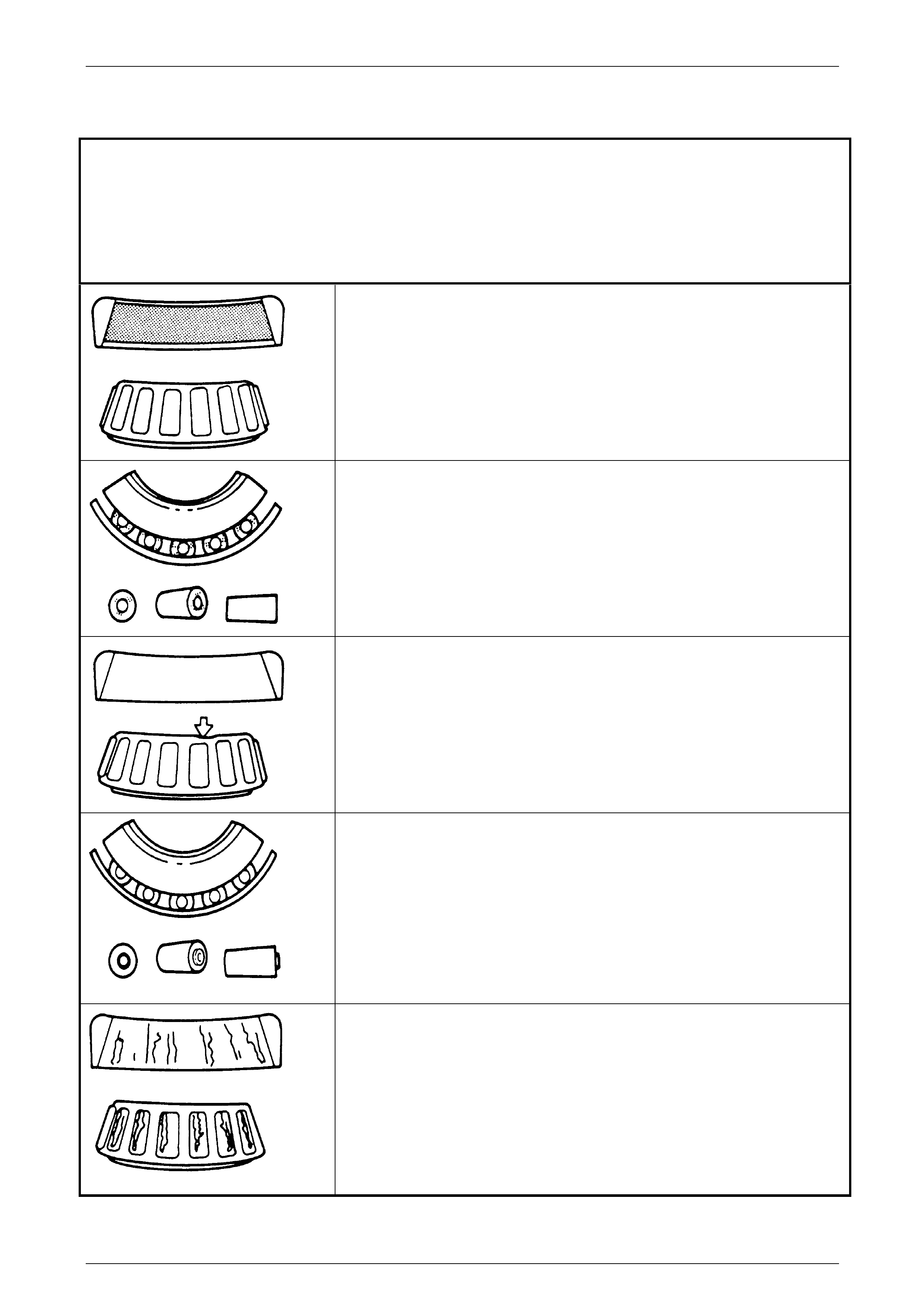
Rear Final Drive and Drive Shafts Page 4B1-118
Page 4B1-118
4.4 Final Drive Bearing Diagnosis
Consider the following factors when diagnosing bearing condition:
1 General condition of all parts during disassembly and inspection.
2 Classify the failure with the aid of the follo wing illustr ations.
3 Determine the cause.
4 Make all repairs, following recommended procedures.
Abrasive Roller Wear
Description:
Pattern on races and rollers caused by fine abrasives.
Correction:
Clean all parts and housings
Check seals and bearings, replacing if leaking, rough or nois y.
Galling
Description:
Metal smears on roller ends due to overheating, lubricant failure or overload.
Correction:
Replace bearing, check seals and check for proper lubrication.
Bent Cage
Description:
Cage damage due to improp er handling or tool use.
Correction:
Replace bearin g.
Abrasive Step Wear
Description:
Pattern on bearing ends caused by fine abrasives.
Correction:
Clean all parts and housing. C heck seals and bearings, replacing if leaking,
rough or noisy.
Etching
Description:
Bearing surfaces appear grey or greyish-black in colour with related etching
away or material, usually at the roller spacing.
Correction:
Replace bearings. Check sea ls and check for proper lubrication.
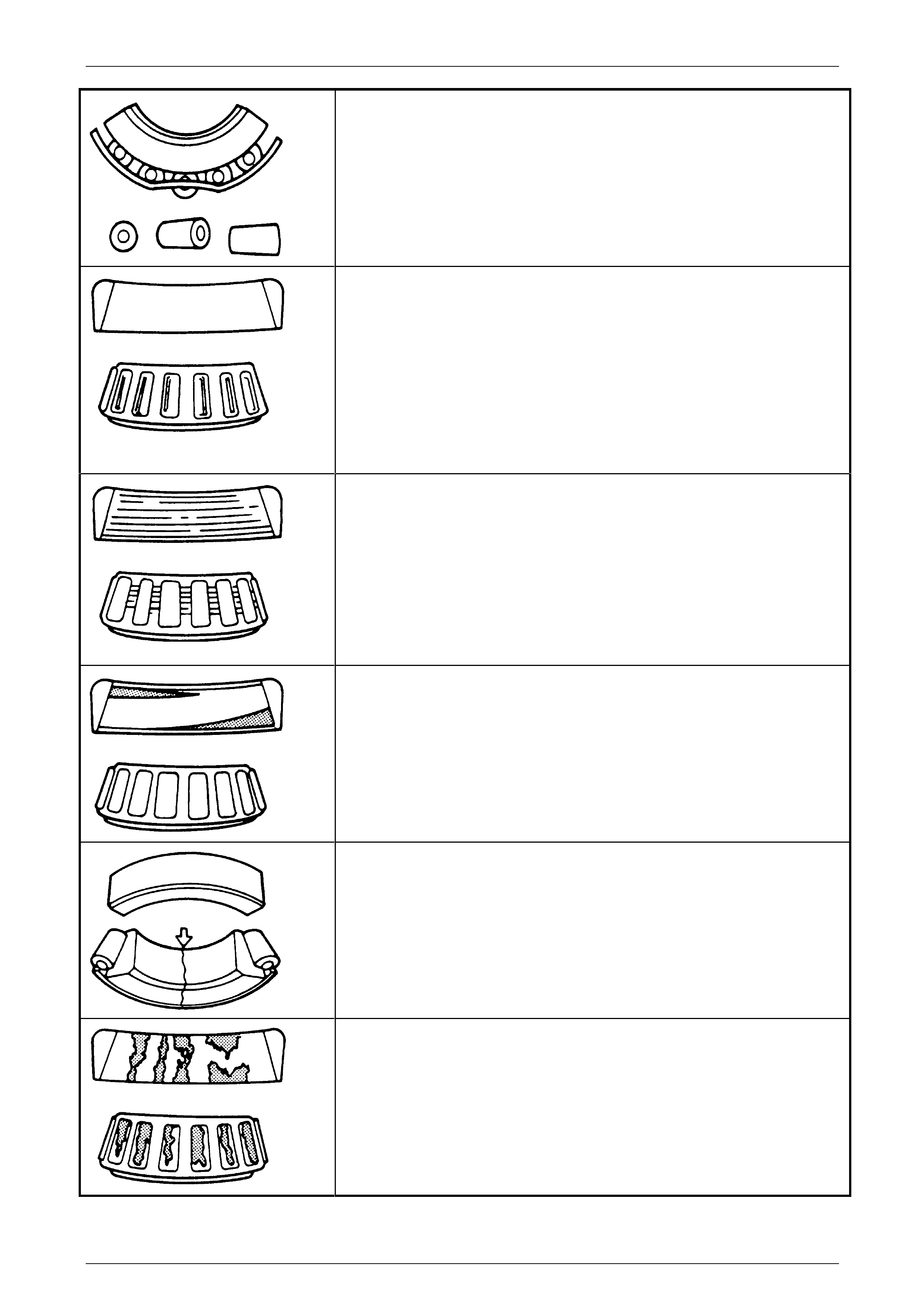
Rear Final Drive and Drive Shafts Page 4B1-119
Page 4B1-119
Bent Cage
Description:
Cage damage due to improp er handling or use of tools.
Correction:
Replace bearin g.
Indentations
Description:
Surface depressions on race and rol lers caused by hard particles of foreign
material.
Correction:
Clean all parts and housing. C heck seals and replace bearin gs if rough and
noisy.
Cage Wear
Description:
Wear around outside diameter of cage and roller pockets cause d by abrasive
materials and inefficient lubrication.
Correction:
Replace bearings. Check sea ls and check for proper lubrication.
Misalignment
Description:
Outer race misalignment due to foreign obje ct.
Correction:
Clean related parts and replace bearing. Make sure races are properl y seated.
Cracked Inner Race
Description:
Race cracked due to improp er fit, cocking or poor bearing seats.
Correction:
Replace bearings and correct bearing seats.
Fatigue Spalling
Description:
Flaking of surface metal resulting from fatigu e.
Correction:
Replace bearings and clean all related parts.
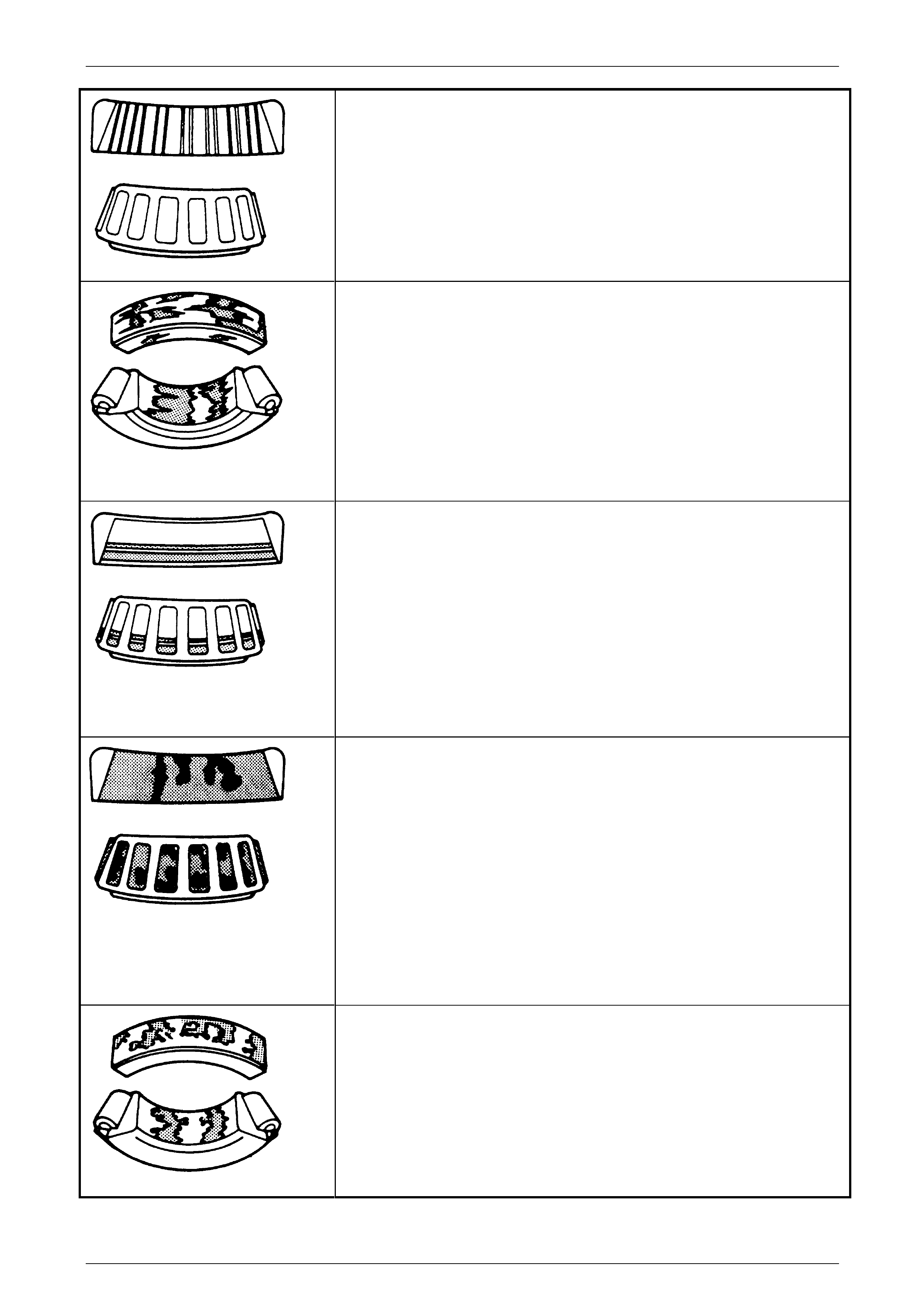
Rear Final Drive and Drive Shafts Page 4B1-120
Page 4B1-120
Brinelling
Description:
Surface indentations in raceway caused by rollers either u nder impact, loading
or vibration while the bearing is not rotating.
Correction:
Replace bearing if rough or noisy.
Frettage
Description:
Corrosion set up by relative movement of parts with no lubrication.
Correction:
Replace bearing. Clea n related parts. Check seals and check for proper
lubrication.
Stain Discoloration
Description:
Discolouration can range from light brown to black, caused by incorrect
lubrication or moisture.
Re-use bearing if stains can be removed by light polishing or if no evidence of
overheating is observed.
Correction:
Check seals and related parts for damage.
Heat Discoloration
Description:
Heat discolouration can range from faint yellow to dark blue, resulting from
overload or improper lubricant.
Excessive heat can cause softening of races or rollers.
To check for loss of temper on races or rollers, a simple file test may be made. A
file drawn over a tempered part will grab and cut metal, whereas a file drawn
over a hard part will glide readily with no metal cutting action.
Correction:
Replace bearings if overheating damage is indicated. Check seals and other
parts.
Smears
Description:
Smearing of metal due to slippage that can be caused by poor fits, lubrication,
overheating, overloads or handling damage.
Correction:
Replace bearings. Clea n related parts and check for proper fit and lubrication.

Rear Final Drive and Drive Shafts Page 4B1-121
Page 4B1-121
5 Specifications
General
Rear Axle Assembly Type ......................................................................................M80 Series
Axle Type................................................................................................Independent Housing
Standard and LSD Axles
Gear Type......................................................................................................................Hypoid
Gear Ratios (For application refer to Final Drive Applications)
2.87:1 3.07:1 3.08:1 3.46:1 3.73:1
No. of Teeth:
Ring Gear................................................ 43............ 43............ 37............45.........41
Drive Pinion Gear.................................... 15............ 14............12............13.........11
Lubricant
Capacity (Total) .......................................................................................................... 1.6 litres
Type...............................................Refer to 2.2 Checking Differential Carrier Lu brica nt Level
Differential Gears
Type....................................................................................................................Straight Bevel
No. of Teeth:
Pinion Gears – All ratios..................................................................................................10
Side Gears – All ratios ....................................................................................................15
Final Drive Pinion Gear Bearings
Bearing Type .................................................................................. Adjustable Tapered Roller
Bearing Adjustment ....................................................................................Collapsible Spacer
Bearing Pre-Load: Timken Koyo
Dummy pinion - New bearings............................................. 1.4 – 2.0.......... 1.5 – 1.9 N.m
Dummy pinion - Used bearings............................................ 0.7 – 1.2.......... 0.7 – 1.2 N.m
New with oil seal .................................................................. 1.4 – 2.4.......... 1.5 – 2.1 N.m
New without oil seal ............................................................. 1.4 – 2.0.......... 1.5 – 1.9 N.m
Used with oil seal................................................................. 0.7 – 1.2.......... 0.7 – 1.2 N.m
Used without oil seal............................................................ 0.7 – 1.2.......... 0. 7 – 1.2 N.m
Differential Carrier side Bearings
Type................................................................................................ Adjustable Tapered Roller
Adjustment...........................................................Screw adjusters on each side of the carrier.
Bearing Pre-Load (Refer to text for measuring procedure) Timken Koyo
New Bearings.......................................................................15 – 35 N................. 8 – 24 N
Used Bearings ......................................................................8 – 18 N.................. 5 – 13 N

Rear Final Drive and Drive Shafts Page 4B1-122
Page 4B1-122
Run-Out Specifications
Outer rear wheel driveshaft Assembly Hub ..........................0.06 mm Total Indicated Run-out
Case Assembly (without ring gear attached) ...........................................0.05 mm (maximum)
Ring Gear Rear Face (assembled to case flange)...................................0.13 mm (maximum)
Backlash Specifications
Ring Gear to Drive Pinion.............................................. 0.10 – 0.18 mm (at the tightest point)
LSD Torque Check
Torque Check Specificat ion......................................................................... 45 Nm (minimum)
ABS Sensor
Air Gap (non-adjustable)......................................................................................0.4 – 1.5 mm
Sealants
Drive Shaft Dust Caps/Shield ..............................RTV 732 Sealant, or commercial equivalent
Rear Cover to Carrier Housing ..................................... Loctite 587 (‘Ultra Blue’) or equivalent
As Required....................................................................Loctite 242 or commercial equivalent
Greases
Where Specified ......NLGI No. 2 lithium soap based EP grease with molybdenum disulphide,
such as Shell Retinax HDX2 grease,
BP Energrease LMS-EP 23, or equivalent.
Where Specified ................................... Commercially available Lithium Soap Based Grease.

Rear Final Drive and Drive Shafts Page 4B1-123
Page 4B1-123
6 Torque Wrench Specifications
ATTENTION
Fastener torque wrench specifications may be accompanied with the following identification marks:
Fasteners must be repl aced after loosening.
Vehicle must be at curb height before final tightening.
Fasteners either have micro encapsulated sealant applied or incorporate a mechanic al thread lock and
should only be re-used once. If in doubt, replacement is recommended
If one of these identification marks is present alongside a fastener torque wrench specification, the
recommendation regarding that fastener must be adhered to..
Brake caliper anchor plate to trailing arm bolts.......................................85 N.m
Collar nut to outer rear wheel driveshaft assembly...............................300 N.m
Crossmember front mounting bolt ........................ 125 N.m, plus 35° turn angle
Crossmember front mounting brace to underbody bolts.........................75 N.m
Differential case cap to cover bolt (LSD only).........................................40 N.m
Drain plug...............................................................................................30 N.m
Drive shaft constant velocity joint bolt.....................50 N.m, plus 90° turn angle
Filler plug................................................................................................30 N.m
Final drive to crossmember attaching bolts............ 90 N.m, plus 40° turn angle
Final drive ring gear bolts.....................................................................140 N.m
Rear cover attaching bolt........................................................................27 N.m
Rear disc brake shield to trailing arm. .......Upper bolts..........................75 N.m
Lower bolts..........................85 N.m
Rear mount to vehicle underbody attaching bolts.... 35 Nm, plus 60° turn angle
Rear mount to differential carrier rear cover attaching bolts...................95 N.m
Road wheel attaching nut...........................................................110 – 140 N.m
z Shock absorber lower mounting bolt ....................................................115 N.m
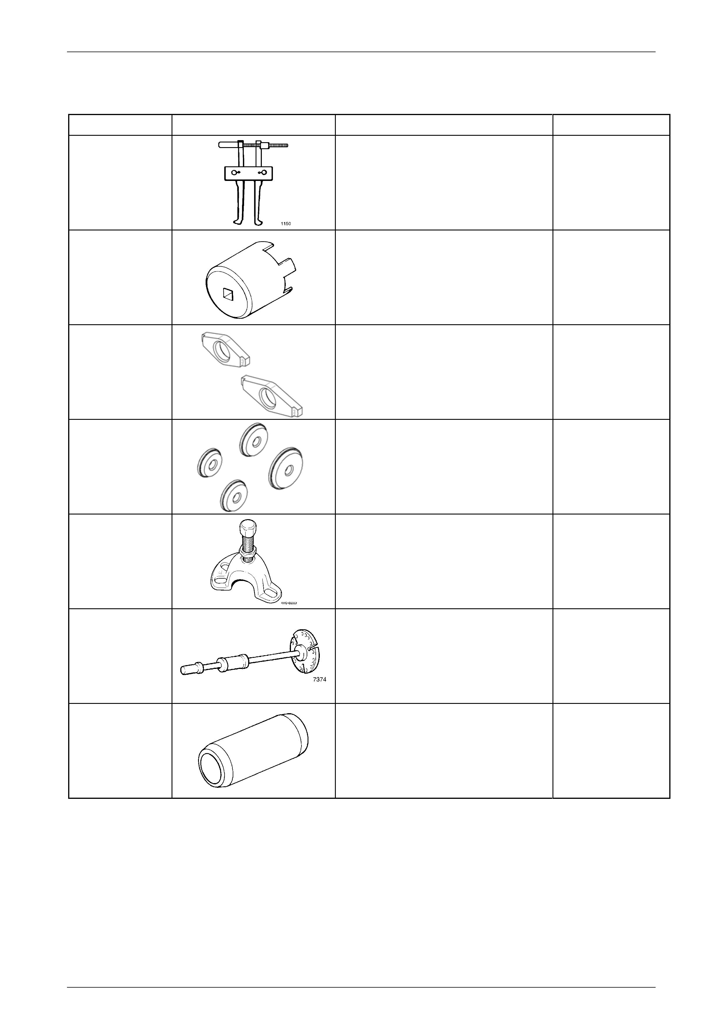
Rear Final Drive and Drive Shafts Page 4B1-124
Page 4B1-124
7 Special Tools
Tool Number Illustration Description Classification
1150
Puller
Used with forcing screw E6661S and
adaptor AU412 to remove side bearing
cups from the screw adjusters.
Previously released.
Unique
205-463
Screw Adjuster Socket
Used for checking and adjusting final
drive side bearings.
(Also released as AU407)
Previously released.
Unique
205-551 Adaptors
Used to remove the pinion bearing cups,
in conjunction with Remover/Installer
E9293. 205-551-1 is require d for all but
the 3.08:1 assembly.
Previously released.
Unique
205-552 Adaptors
Used to install the pinion bear ing cups, in
conjunction with Remover/Installer E 9271.
205-552-2 is requir ed for all but the 3.08:1
assembly. Previously released.
Unique
7208
Rear Axle Removal Adaptor
Previously released.
Unique
7374
Slide Hammer & Plate
Used to remove inner axle shafts from the
rear axle assembly.
Previously released.
Available
AU408
Dummy Arbour
Used with dummy pinion from E9300A.
Previously released.
Unique
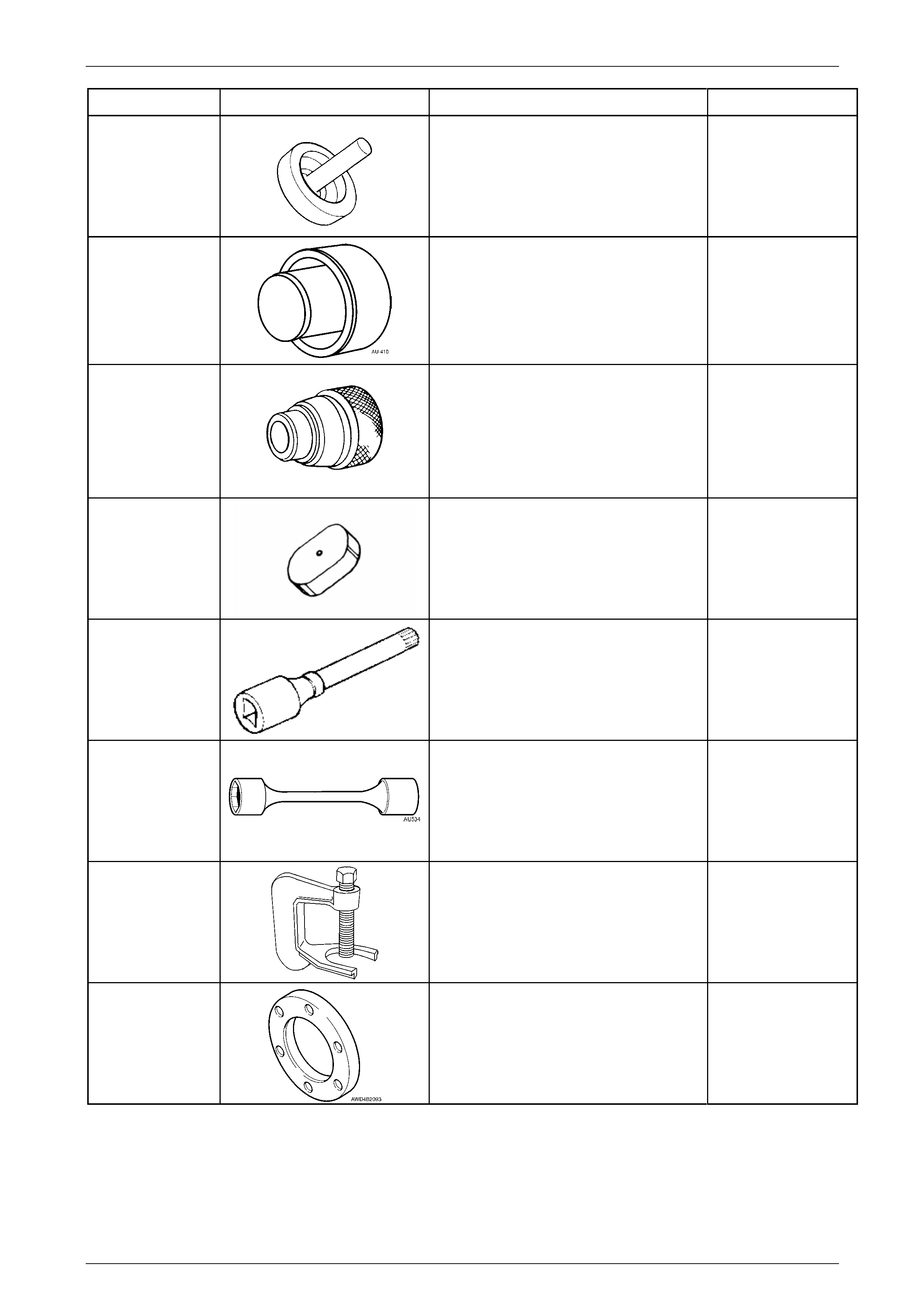
Rear Final Drive and Drive Shafts Page 4B1-125
Page 4B1-125
Tool Number Illustration Description Classification
AU409 Press Fixture Unique
AU410
Seal Installer
Used to install inner axle seals to screw
adjuster.
Previously released.
Unique
AU411
Bearing & Cup Remover
Used in conjunction with AU409.
Previously released.
Unique
AU412 Adaptor
Used with forcing screw E6661S and
puller 1150 to remove side bearing cups
from screw adjusters.
Previously released.
Unique
AU416 Torx Bit
Used to remove and reinstall upp er rear
brake backing plate to trailing arm bolts
Previously released.
Unique
AU 534
Torque Limiting Socket
Used in conjunction with an impact gun to
tighten wheel nuts.
Previously released.
Unique
C4150-C
Press Tool
Used to remove rear wheel studs from the
trunnion flange.
Previously released.
Unique
DT-47580
Packing Flange
Fits into the AWD Wagon pinion flang e to
act as a spacer for holding tool J8614-O1.
Previously released.
Available
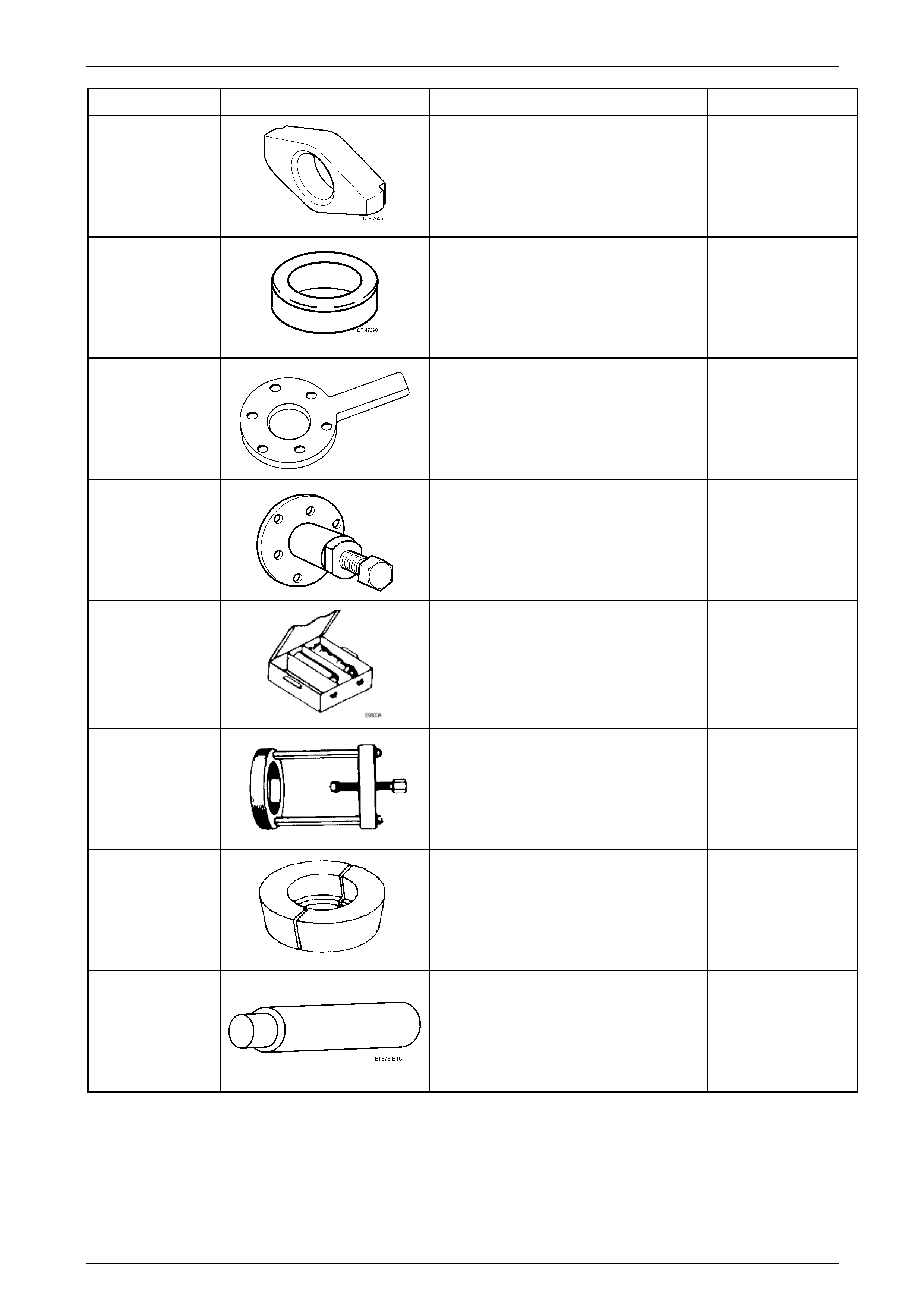
Rear Final Drive and Drive Shafts Page 4B1-126
Page 4B1-126
Tool Number Illustration Description Classification
DT-47695
Rear Pinion Bearing Cup Remover Unique
DT-47696
Spacer
Used in conjunction with the dumm y
pinion from E9300A when checkin g pin ion
depth on all but 3.08:1 assemblies.
Previously released.
Unique
DT-47735
Holding Tool
Used to hold the final drive pin ion flange
when loosening/tightening the pinion nut.
New release
Unique
DT-47736
Extractor Tool
Used to remove the final drive pinion
flange.
New release.
Unique
DT-47737
Pinion Height Setting Gauge
Includes dummy pinion, 3C10E/11, Pad,
3C10E/13, Sleeve, 3C10E/14, Dummy
Pinion Spacer DT -47696, F orcing Nut,
6651/13 and Arbour AU 408.
Previously released as E9300 A .
New release.
Unique
E1673A15 Basic Puller
Used with adaptors to remove bearings
from the final drive assembly.
Previously released.
Unique
E1673A15 Adaptor
Used with puller E1673MT and stepped
plug E1673B16 to remove the rear pinion
bearing on 3.08:1 assemblies.
Previously released.
Unique
E1673B16
Stepped Plug
Used with puller E1673MT and adaptor
E1673N15 to remove bearings from the
differential case.
Previously released.
Unique
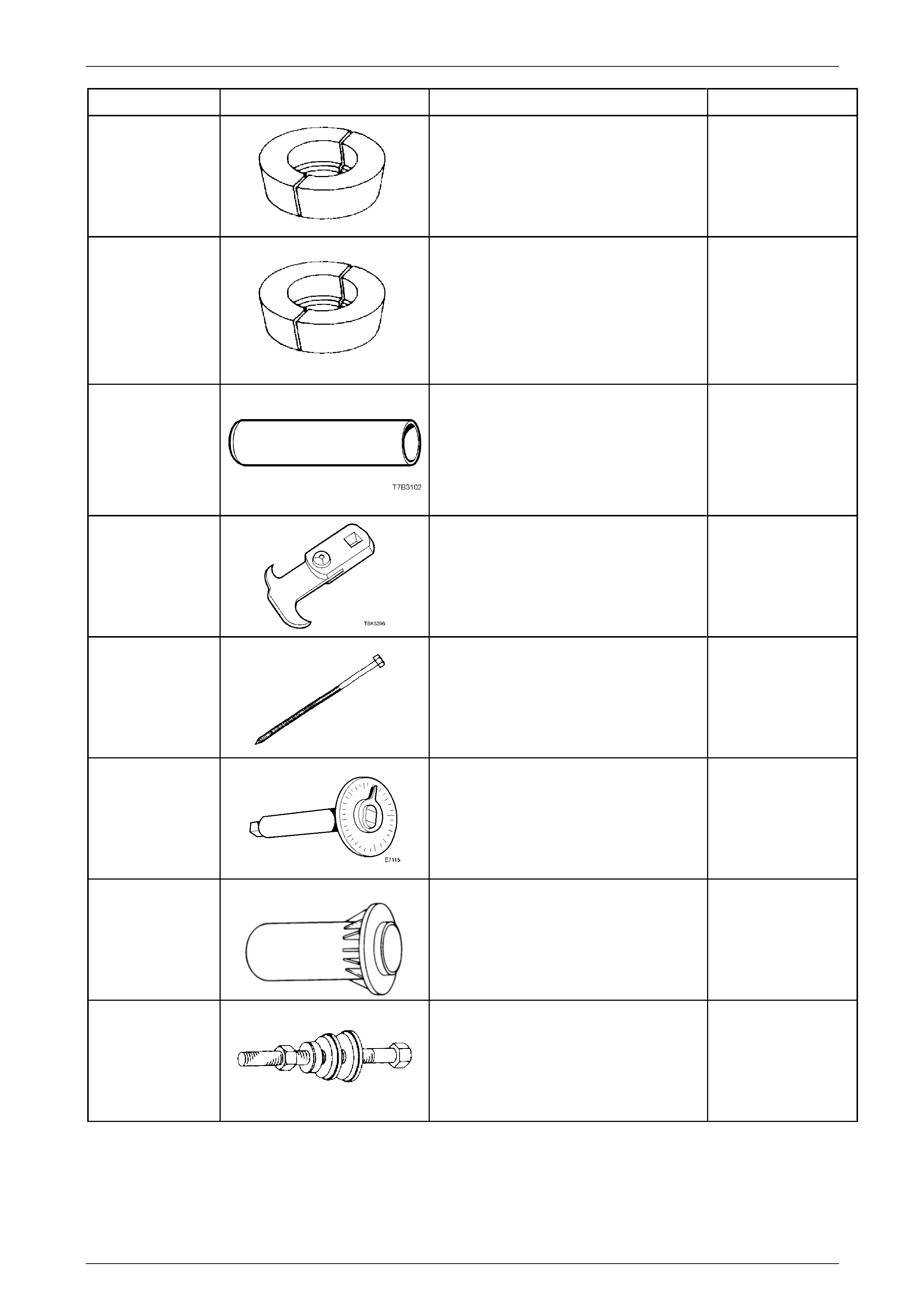
Rear Final Drive and Drive Shafts Page 4B1-127
Page 4B1-127
Tool Number Illustration Description Classification
E1673N15 Adaptor Unique
E1673S15 Adaptor
Used with puller E1673MT to remove the
rear pinion bearing on 3.07:1 and 3.46:1
assemblies.
Previously released.
Unique
E3C10AER
Pinion Rear Bearing Installer
Used to install the rear pinion bearing
during final drive overhaul.
Previously released.
Unique
E308
Seal Remover
Used as a universal seal remover. Also
released as 56750.
Previously released.
Available
E6661S
Forcing Screw
Used in conjunction with puller 1150 and
adaptor AU412.
Previously released.
Unique
E7115
Angle Wrench
Used to tighten fasteners when an angle
torque is specified.
Also released as BT 8653-A
Previously released.
Unique
E9055 Pinion Oil Seal Installer
Used to install the pinion oil seal.
Also released as 17-010A.
Previously released.
Unique
E9271
Pinion Bearing Cup Installer
Used to install the pinion bear ing cups on
3.08:1 assemblies and, with adaptor 205-
552-2, to install the inner pinion bearing
cup on all other ratios.
Previously released.
Unique
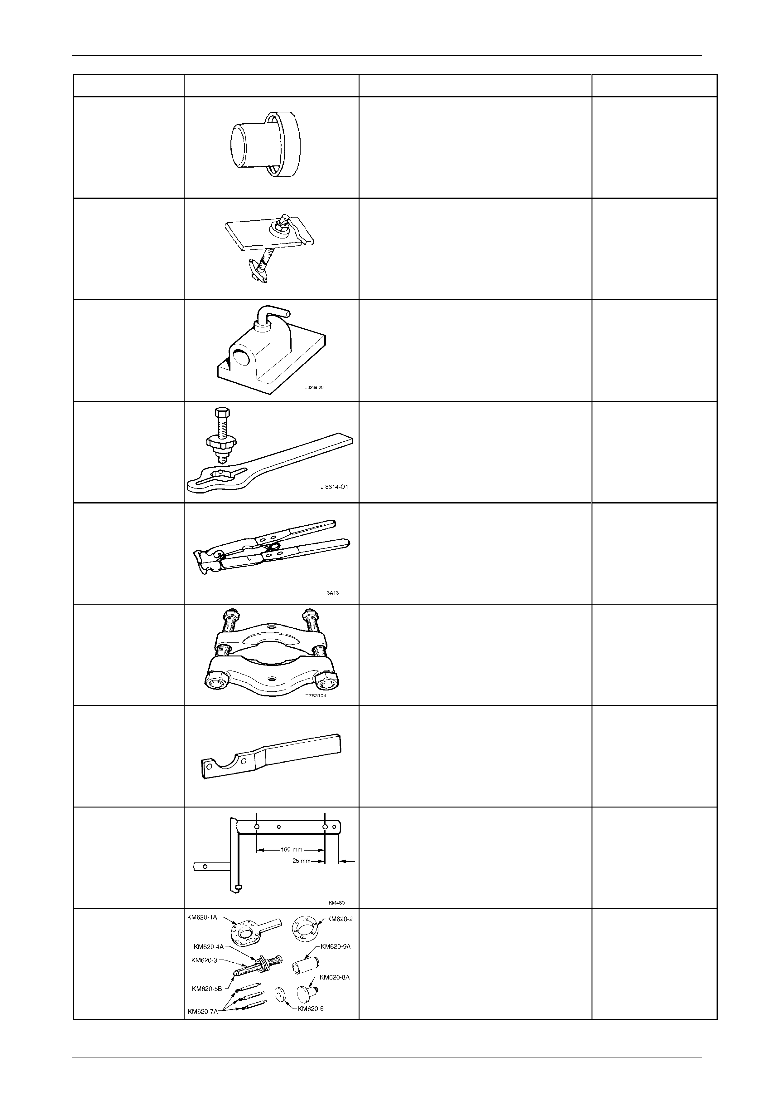
Rear Final Drive and Drive Shafts Page 4B1-128
Page 4B1-128
Tool Number Illustration Description Classification
E9277
Side Bearing Installer
Used to install bearings to the differential
case.
Previously released.
Unique
E9293
Pinion Bearing Cup Remover
Used to remove the pinion bearing cups
on 3.08:1 assemblies and, with adaptor
DT-47695, to remove the inner pinion
bearing cup on all other ratios.
Previously released.
Unique
J 3289-20
Holding Fixture Base
Used with either KM480 or fabricated
bracket to hold the final drive assembl y.
Previously released.
Unique
J 8614-O1 Flange/Pulley Holding Tool
Required for AWD Wagon, includes
J 8614-2, J 8614-3 and J 861 4-10.
Previously released.
Unique
J 22610
Clamp Pliers
Used to crimp the drive shaft boot clamps.
Also released as E1896.
Previously released.
Available
J 22912-01
Press Plates
Used in a number of different applicati ons
for separating components when pressing
operations are required.
Previously released.
Unique
KM468
Holding Bar
Used to stop the rear outer rear wheel
driveshaft from rotating.
Previously released.
Available
KM480 Holding Fixture
Modify by drilling two 14 mm holes as
shown. Fixture originall y relea s ed for
THM 125 automatic transaxle (’J’ car).
Previously released.
Unique
KM620-B Remover/Installer
Used for removing and installing outer
rear wheel driveshaft flange and rear
wheel bearing.
Previously released.
Unique
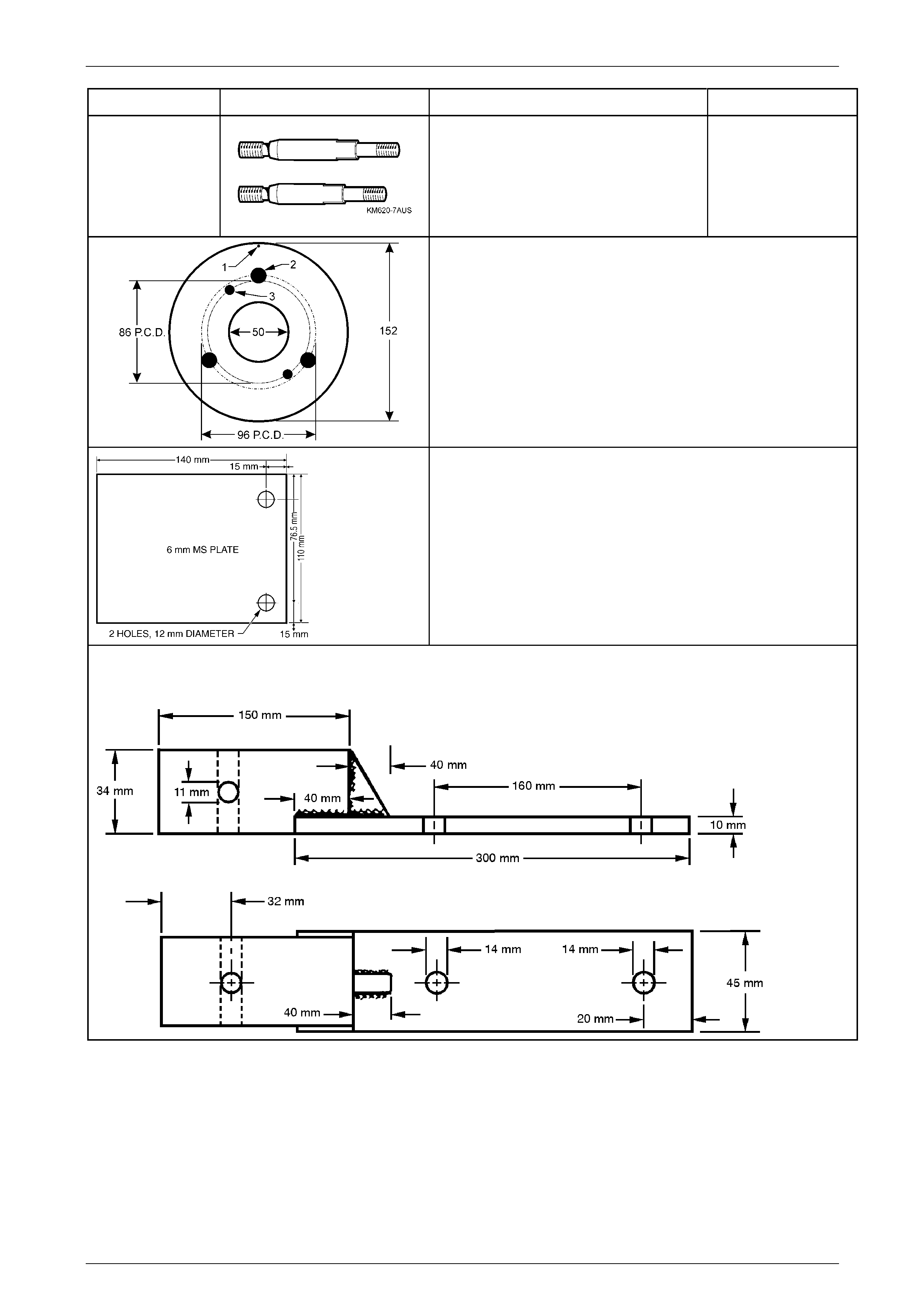
Rear Final Drive and Drive Shafts Page 4B1-129
Page 4B1-129
Tool Number Illustration Description Classification
KM620-7AUS
Supports
These two revised length sup ports are
required when using KM620-B on the rear
outer rear wheel driveshaft and/or
bearing, except for the AWD Wagon.
Previously released.
Unique
Pinion Flange Pulley
Fabricate this pulley to incl ude all VZ applications, inclu ding AWD
models.
1. Made from a 13 mm thick piece of wood.
2. Drill a small hole at '1' and attach a one metr e length of
string at this point, knotted at one end.
3. Drill two, 8.5 mm holes (3) opposite to each other on a pitch
circle diameter of 86 mm (AWD models, pinion flan ge).
4. Drill three, 13 mm holes (2) on a pitch circl e diameter of 96
mm, 120 mm apart (All other VZ models).
Dial Indicator Plate
Used to mount a magnetic based indicator stand when checking
the outer rear wheel driveshaft assembly hub for runout.
Fabricated from 6 mm, flat Mild Steel plate.
If using the brake caliper bolts to fasten to the trailing arm, then 17
mm spacers will need to be installed on each bolt, prior to
installing.
Fabricated Differential Carrier Holding Fixture
If KM480 is not available, fabricate as shown.