
Rear Final Drive and Live Axle Page 4B2 – 1
Page 4B2 – 1
Section 4B2
Rear Final Drive and Live Axle
ATTENTION
Before performing any Service Operation or other procedure described in this Section, refer to Section 00
Warnings, Cautions and Notes for correct workshop practices with regard to safety and/or property damage.
1 General Information ...............................................................................................................................3
1.1 General Description............................................................................................................................................... 3
Cone Type Limited Slip Differential – M78 Series............................................................................................... 4
Multi-Disc Type Limited Slip Differential – M86 Series....................................................................................... 5
1.2 Rear Axle Assembly Identification....................................................................................................................... 6
1.3 Rear Axle Assembly Maintenance........................................................................................................................ 7
Rear Axle Shaft and Bearings............................................................................................................................... 7
Rear Axle Assembly .............................................................................................................................................. 7
Rear Axle Assembly Breather............................................................................................................................... 8
Limited Slip Differential Precautions ................................................................................................................... 8
Lubrication ............................................................................................................................................................. 9
2 Minor Service Operations....................................................................................................................10
2.1 Service Warnings, Cautions and Notes............................................................................................................. 10
Road Wheel Replacement Caution..................................................................................................................... 10
2.2 Checking Rear Axle Lubricant Level.................................................................................................................. 11
2.3 Changing/Flushing Rear Axle Lubricant............................................................................................................ 12
2.4 Rear Axle Shaft Check For Run-Out and End Float.......................................................................................... 13
If Run-out and End Float is Within Specification.............................................................................................. 16
If the Run-out and End Float Check, Exceeds Specification............................................................................ 16
2.5 Rear Axle Shaft Wheel Studs.............................................................................................................................. 17
Replace................................................................................................................................................................. 17
2.6 Combined Rear Axle Backlash Check ............................................................................................................... 21
Procedure............................................................................................................................................................. 21
2.7 Limited Slip Differential Torque Check.............................................................................................................. 22
Procedure............................................................................................................................................................. 22
2.8 Rear Axle Shaft Assembly .................................................................................................................................. 25
Remove................................................................................................................................................................. 25
Reinstall................................................................................................................................................................ 28
2.9 Rear Axle Shaft, ABS Pulse Ring, Oil Seal, Bearing and Retainer Collar ....................................................... 29
Remove................................................................................................................................................................. 29
Inspect .................................................................................................................................................................. 31
Axle Shaft, Bearing and Cone.......................................................................................................................... 31
Reassemble.......................................................................................................................................................... 31
2.10 Pinion Oil Seal...................................................................................................................................................... 33
Remove................................................................................................................................................................. 33
Inspect .................................................................................................................................................................. 35
Reassemble.......................................................................................................................................................... 35
2.11 Pinion Flange ....................................................................................................................................................... 37
Replace (Using Old Oil Seal)............................................................................................................................... 37
Replace (Using New Oil Seal) ............................................................................................................................. 40
Theoretical Example......................................................................................................................................... 43
Techline
Techline
Techline

Rear Final Drive and Live Axle Page 4B2 – 2
Page 4B2 – 2
3 Major Service Operations....................................................................................................................44
3.1 Rear Axle Assembly ............................................................................................................................................ 44
Preliminary Check................................................................................................................................................ 44
Remove................................................................................................................................................................. 45
All Except AWD & Live Axle............................................................................................................................. 46
AWD & Live Axle Only...................................................................................................................................... 47
All With Live Axle.............................................................................................................................................. 47
All Except AWD & Live Axle............................................................................................................................. 48
All VZ and Live Axle......................................................................................................................................... 49
Reinstall................................................................................................................................................................ 50
3.2 Rear Axle and Differential Housing Assembly.................................................................................................. 51
Preliminary Check................................................................................................................................................ 52
Disassemble......................................................................................................................................................... 52
Inspect .................................................................................................................................................................. 56
Reassemble.......................................................................................................................................................... 57
3.3 Differential Assembly – M78 Series (Standard Non LSD)................................................................................. 58
Disassemble......................................................................................................................................................... 58
Inspect .................................................................................................................................................................. 61
Differential Case............................................................................................................................................... 61
Differential Side and Pinion Gears ................................................................................................................... 62
Ring Gear and Pinion Gear.............................................................................................................................. 63
Bearings........................................................................................................................................................... 64
Reassemble.......................................................................................................................................................... 64
3.4 Differential Assembly – M78 Series (Cone Type Limited Slip)......................................................................... 68
Disassemble......................................................................................................................................................... 69
Inspect .................................................................................................................................................................. 71
Differential Case............................................................................................................................................... 72
Differential Side Gears and Pinion Gears......................................................................................................... 72
Ring Gear and Pinion....................................................................................................................................... 72
Bearings........................................................................................................................................................... 72
Reassemble.......................................................................................................................................................... 73
3.5 Differential Assembly – M86 Series (Multi-Disc Type Limited Slip)................................................................. 78
Inspect .................................................................................................................................................................. 83
Differential Case............................................................................................................................................... 83
Differential Side Gears and Pinion Gears......................................................................................................... 83
Differential Concentric Grooved Disc’s, Clutch Plates, Retainers and Dished Spacers ................................... 83
Ring Gear and Pinion....................................................................................................................................... 83
Bearings........................................................................................................................................................... 83
Reassemble.......................................................................................................................................................... 84
3.6 Differential Assembly Adjustment and Installation Procedures – All Models................................................ 87
Differential Side Bearing Preload And Shim Selection..................................................................................... 87
Hypoid Pinion Bearing Preload Shim Selection................................................................................................ 90
Hypoid Pinion Shim Selection Table ................................................................................................................ 92
Pinion Installation................................................................................................................................................ 93
Differential Backlash Setting .............................................................................................................................. 96
Ring Gear and Pinion Contact Pattern............................................................................................................... 98
Tooth Marking Terminology................................................................................................................................ 98
4 Diagnosis ..............................................................................................................................................99
5 Specifications.....................................................................................................................................100
6 Torque Wrench Specifications..........................................................................................................102
7 Special Tools ......................................................................................................................................103
Rear Final Drive and Live Axle Page 4B2 – 3
Page 4B2 – 3
1 General Information
1.1 General Description
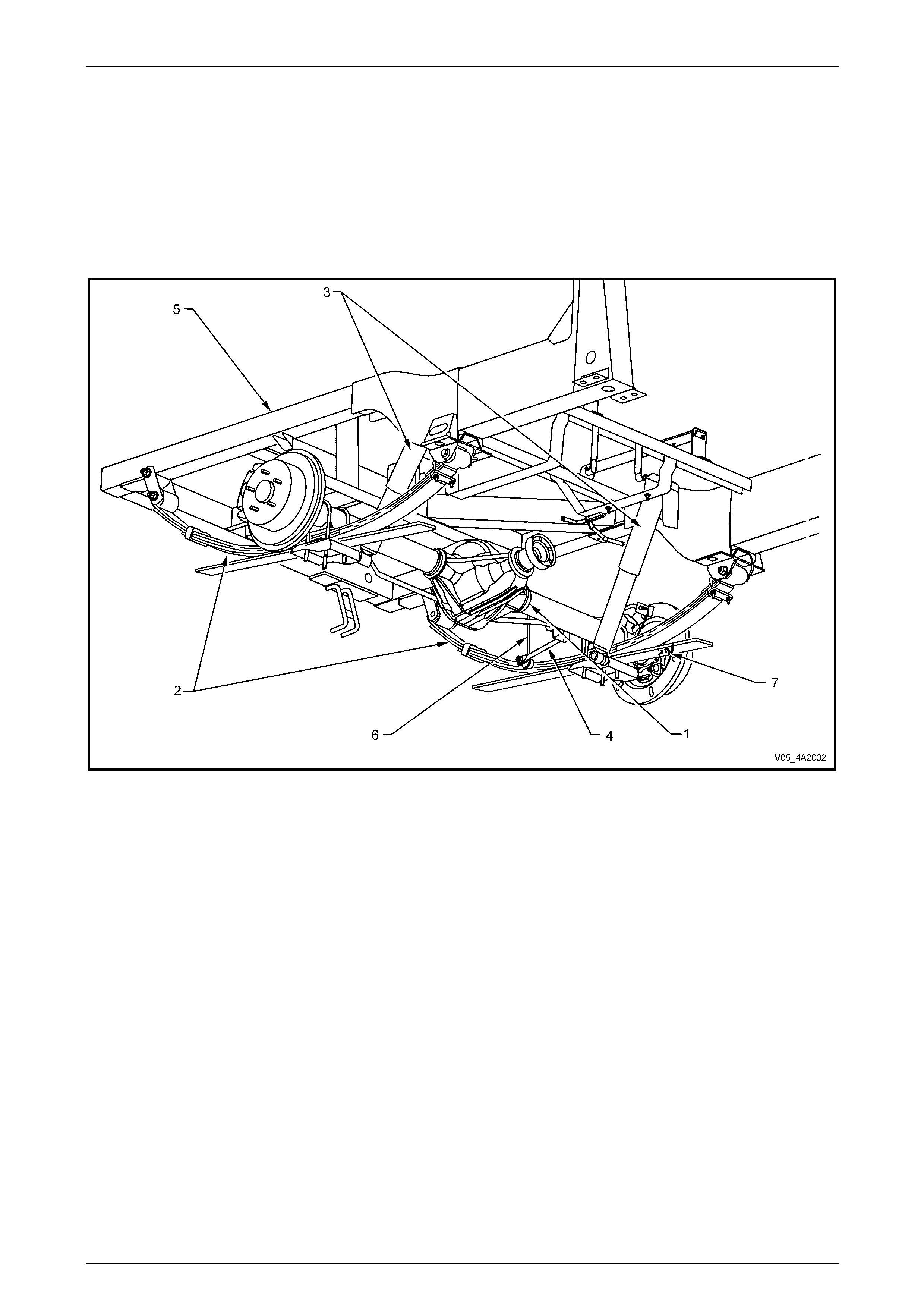
The rear final drive and live axle assembly fitted to those MY 2005 VZ Series vehicles with a live rear axle and leaf
springs (except AWD models) is a Salisbury (Unitised carrier) type rigid live axle, mounted to a leaf sprin g rear
suspension system in conjunction with shock absorbers and a stabiliser bar, as standard equipment. The Crew Cab
AWD model does not have a rear stabiliser bar fitted.
Figure 4B2 – 1
Legend
1 Rear Axle Assembly
2 Rear Leaf Spring Assembly
3 Rear Shock Absorber
4 Rear Suspension Stabiliser Bar
5 Chassis Frame
6 Rear Stabiliser bar to Chassis Link
7 Rear ABS Sensor
The ring gear diameter varies from 197 mm with a ratio of 3.08:1 (Production option GU4), to 220 mm with a ratio of
3.07:1 (Production option GU4) or 3.46:1 (Production option GS9). The rear axle ratio is dependent upon the engine and
transmission fitted to the vehicle. Production option G80, Li mited Slip Differential (LSD), (also referred to as Spin
Resistant Differential – ‘SRD’) is avail able on all V6 models and may be av ailable on GEN III V8 models.
The rear axle assembly is mounted to the chassis via leaf springs, ‘U’ bolts, spring shackles and spring eye bushings.
The differential case, hypoid ri ng gear and pinion are mounted with opposing tapered roll er bearings in the rear axle
housing. Differential side bearing preload adjustment is controlled by shims located between the tapered roller bearing
cups and the sides of the rear axle housing. A collapsible spacer and companion flange retaining nut pr ovide pinion
bearing preload.
Torque is transferred from the propeller shaft to the rear axl e assembly via the pinion flange, which is splined to the
hypoid pinion gear. The torque is then transferred from the hypoid pini on gear through the hypoid ring gear, differential
case, differential pinion cross shafts, differential pinion ge ars, side gears and then via splines on th e axle shafts to the
road wheels.
Rear Final Drive and Live Axle Page 4B2 – 4
Page 4B2 – 4
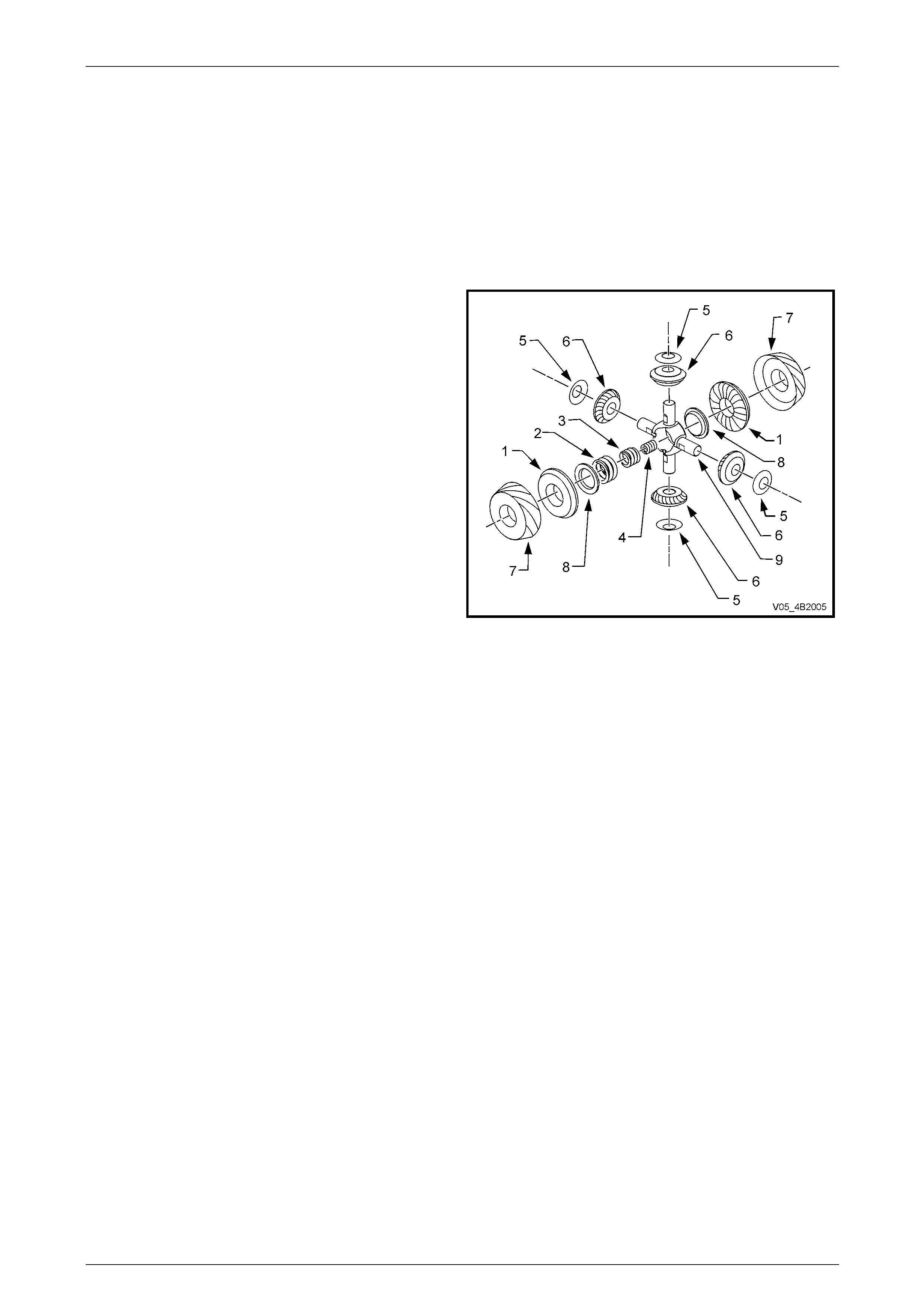
Cone Type Limited Slip Differential – M78 Series
The M78 Series Limited Slip Differential (LSD), used with V6 models, performs the same functions as the conventional
type differential but in addition, transfers driving force to the wheel with traction, should the opposite wheel begin to spin.
The differential case houses two cone type clutches behind the side gears that are splined to the inn er ends of the axle
shafts and their tapered faces contact corresponding faces in the differential case.
On this LSD, the cones form an integral part of the side gears. The four pinion type LSD has three preload springs
enclosed in the centre of the pinion cross shaft. The LSD directs the major driving force to the wheel with the greater
amount of traction, but will not interfere with steering characteristics or differential action. The inherent separating forces
between the side gears and pinions automaticall y increase the partial locking action, due to the spring load on the cones,
which progressively incr eases the resistance in the differential as applied torque is increased.
Legend
1 Gear – Differential Side
2 Spring – Outer, Differential Preload
3 Spring – Intermediate, Differential Preload
4 Spring – Inner, Differential Preload
5 Washer – Thrust, Differential Pinion Gear
6 Gear – Differential Pinion
7 Cone – Clutch
8 Plate – Thrust, Spring
9 Shaft – Differential Pinion Cross
Figure 4A2 – 2
When the rear wheels are under extremely unbalanc ed conditions, such as a wheel on a dry road and the other in mud
or ice, with the standard differential, wheel spin easily occurs if over-acceleration is attempted. However, with a LSD,
when the tendency for wheel spin occ urs, the friction generated inside the case, therefore transfers greater driving force
to the non-spinning wheel. In the event of continued spinning, a whirring sound from the over-running cones is produced
but this condition/sound does not indicate failure of the unit.
Rear Final Drive and Live Axle Page 4B2 – 5
Page 4B2 – 5
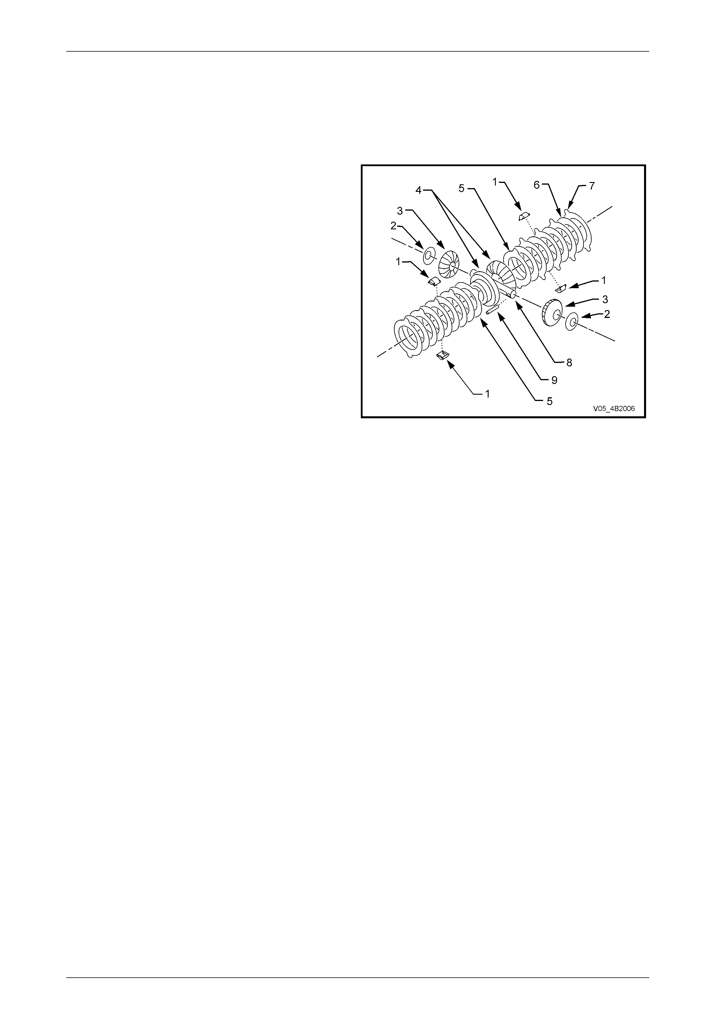
Multi-Disc Type Limited Slip Differential – M86 Series
The M86 Series Limited Slip Differential (LSD), used with all V8 models, performs the same functions as the M78 t ype
LSD. Like the M78 Series, the M86 Series differential trans fers driving force to the wheel with traction should the
opposite wheel begin to spin. The differential case houses four concentric grooved disc plates , four clutch plates, two
clutch plate retainers and a dished sp acer behind each side gear. The side gears are splined to match the inner axle
shafts.
Legend
1 Retainer – Clutch Plate
2 Washer – Thrust, Differential Pinion Gear
3 Gear – Differential Pinion
4 Gear – Differential Side
5 Spacer – Dished
6 Disc – Concentric Grooved
7 Clutch Plate
8 Shaft – Differential Pinion Gear, Long
9 Pin – Retaining, Differential Pinion Gear Shaft
Figure 4A2 – 3
On the M86 Series LSD the concentric, grooved disc plates are splined to the outer hub face of the side gears while the
clutch plates are supported by retainers that locate in the pockets of the differential housing.
As with the M78 Series, the M86 Series LSD directs the major driving force to the wheel with the greater amount of
traction, but will not interfere with steering characteristics or differential action. The partial locking action is due to the
force applied by the dished spacer to the concentric grooved disc plates, which in turn applies force to the clutch plates.
The inherent separating forces between the side gears and pinions automatically increase the force, which progressively
increases the resistance in the differenti al as applied torque is increased.
When the rear wheels are under extremely unbalanc ed conditions, such as a wheel on a dry road and the other in mud
or ice, with a standard differential, wheel spi n would easily occur if over-acceleration is attempted. However, with the
LSD, when the tendency for wheel spin occurs, the friction generated insid e the case, the r efore transfers greater force to
the non-spinning wheel
Rear Final Drive and Live Axle Page 4B2 – 6
Page 4B2 – 6
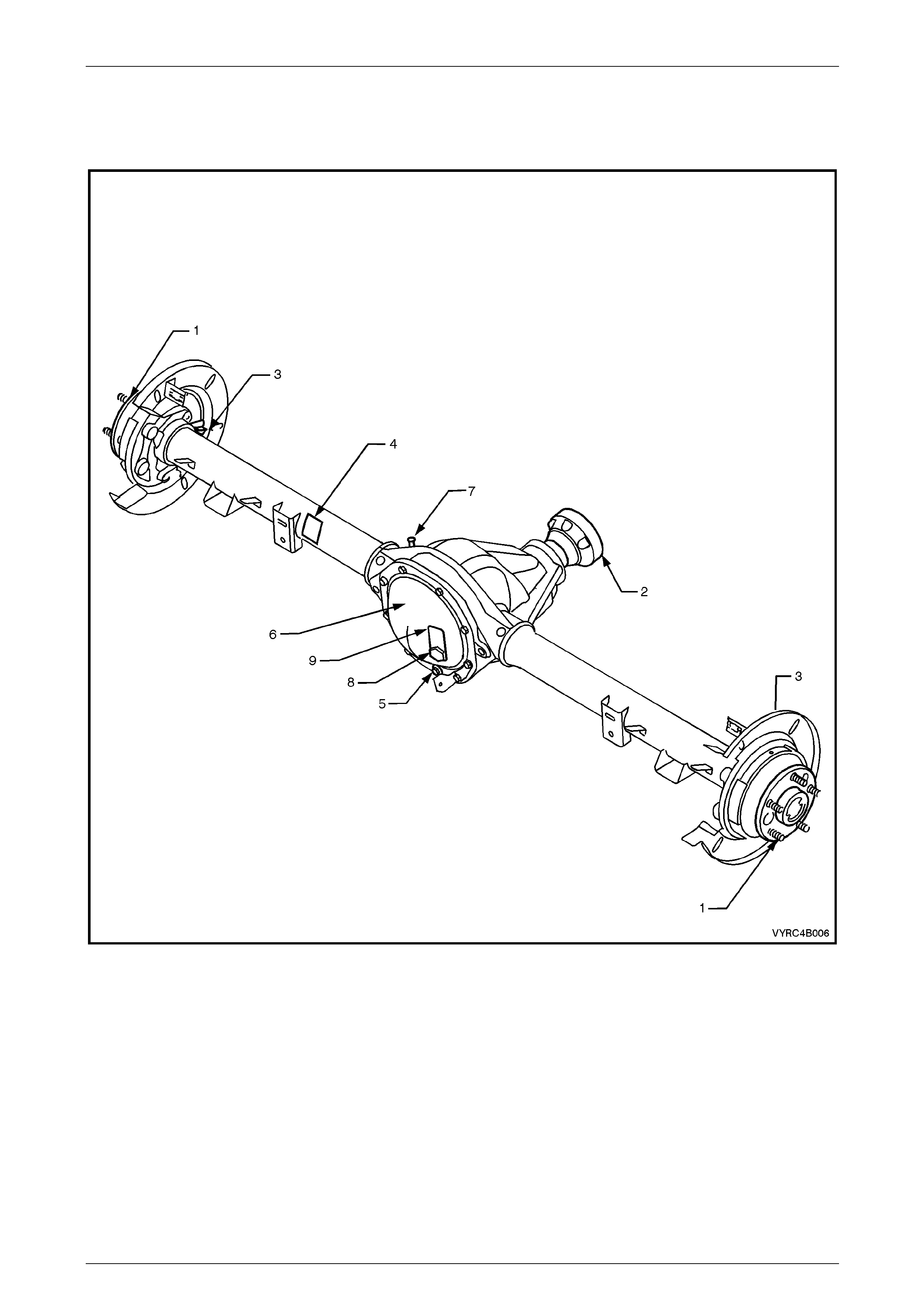
1.2 Rear Axle Assembly Identification
The type of differential fitted to the rear axle assembly can be identified by referring to either the identification lab el (4)
attached to the LHS of the axle housing and from the lubrication tag (9) under the filler plug (8) on the rear cover.
Figure 4B-4
Legend
1 Rear Axle Shaft
2 Pinion Flange
3 Rear ABS Sensor Mount
4 Identification Label
5 Drain Plug
6 Rear Cover
7 Breather
8 Filler Plug
9 Lubrication Tag
Rear Final Drive and Live Axle Page 4B2 – 7
Page 4B2 – 7
1.3 Rear Axle Assembly Maintenance
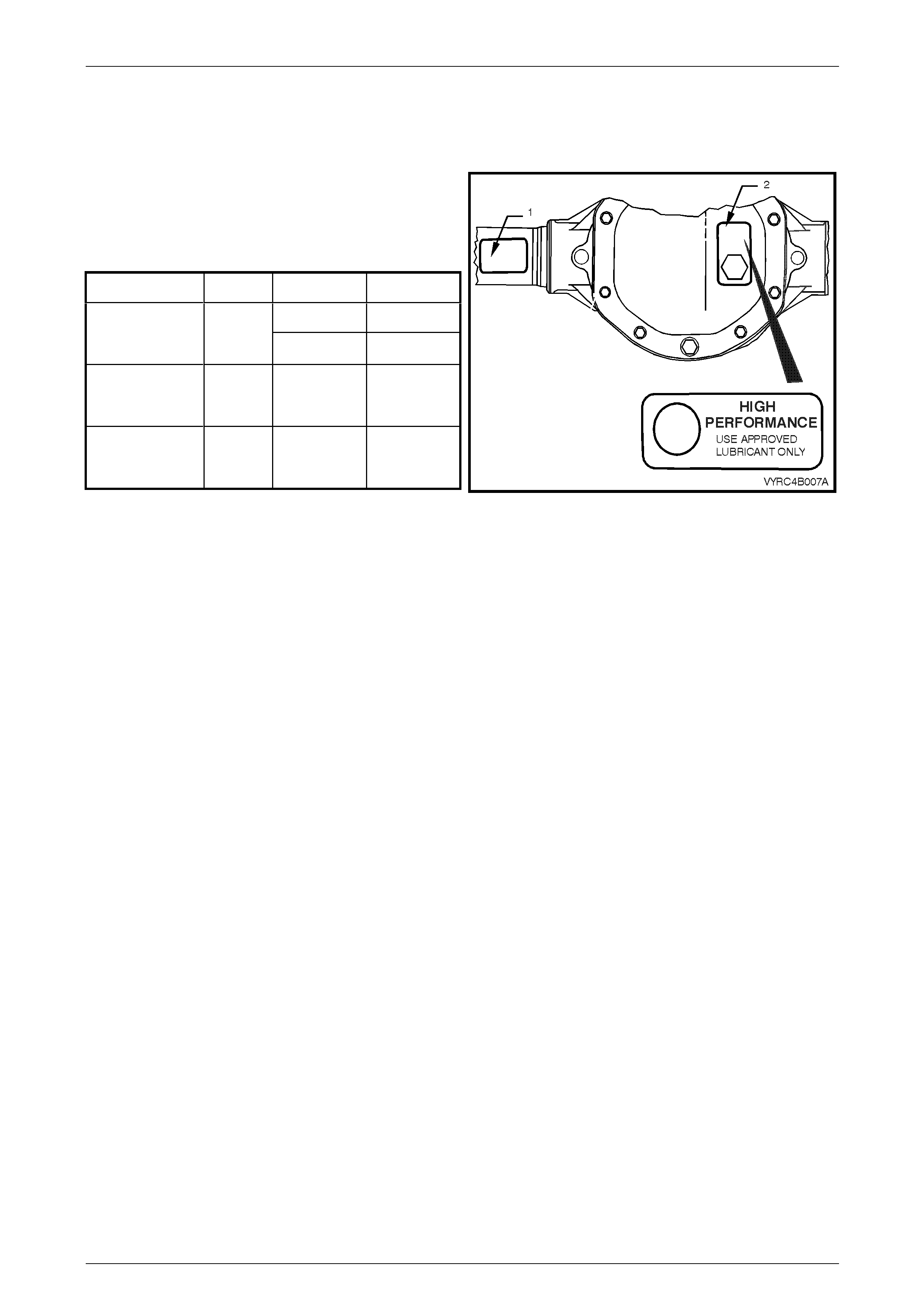
The locations of the identific ation label (1) and lubrication tag (2) are shown next.
The identification label (1) car r ies the rear axle assembly
part number, the rear axle ratio, the serial number and the
I.D. code of the assembly.
The code number and bar co de is used for production
identification of the rear axle assembly.
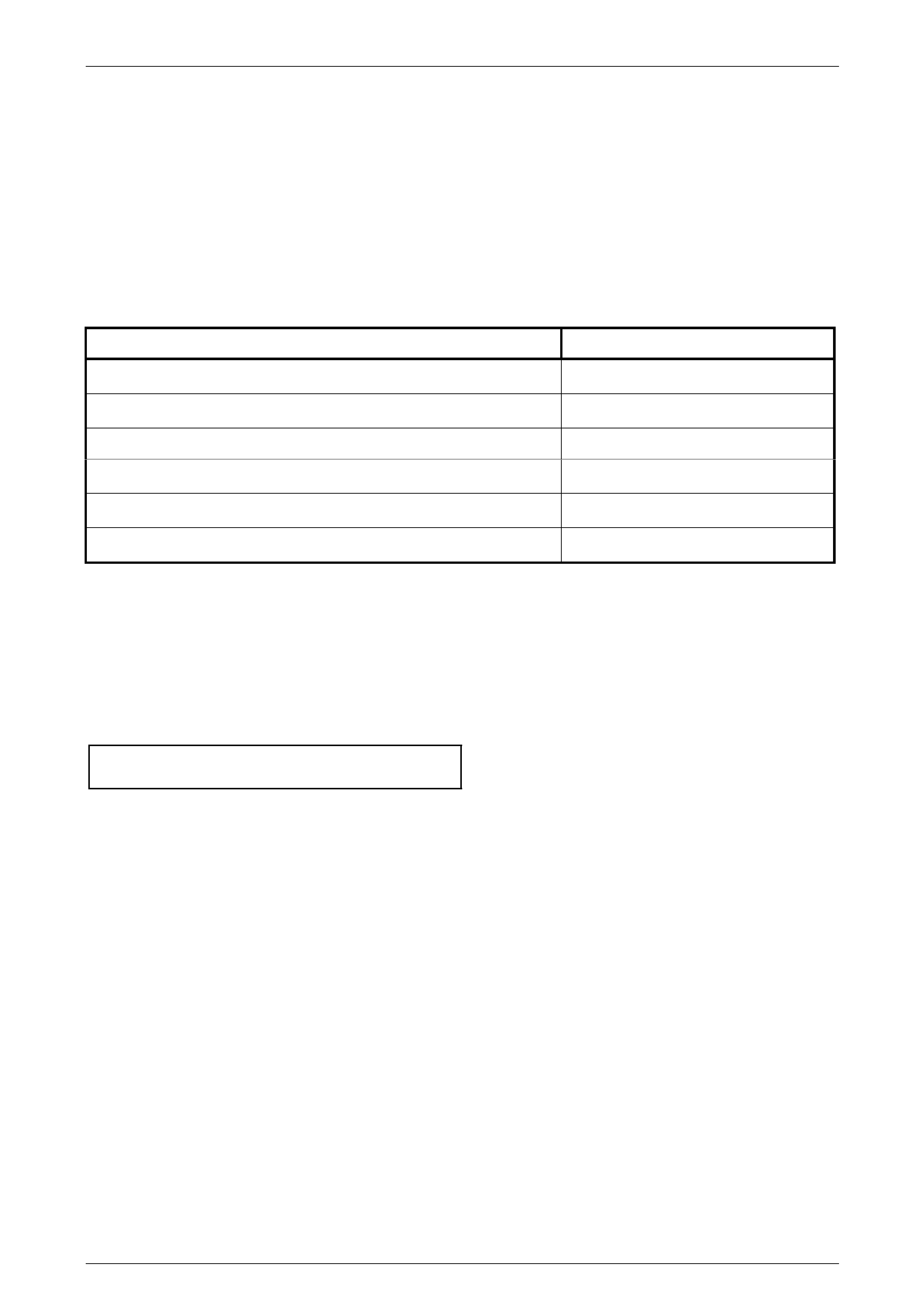
Usage Ratio Type I.D. Code
ABS (Std) TYV
V6 with Manual
or Automatic
Transmission 3.08:1 LSD & ABS TYU
GEN III V8 with
Automatic
Transmission 3.07:1 LSD & ABS TYX
GEN III V8 with
Manual
Transmission 3.46:1 LSD & ABS TYW
Figure 4A2 – 5
When fitted, the information on the lubrication tag (2) under the filler plug will be:
a With V6 conventional differential; “HIGH PERFORMANCE. USE APPROVED LUBRICANT ONLY”
b With V6 or GEN III V8 with LSD; “LSD - HIGH PERFORMANCE. USE APPROVED LUBRICANT AND FRICTION
MODIFIER”
Rear Axle Shaft and Bearings
The axle shaft outer bearings are lubricated for life and therefore require no periodic maintenance.
If there is any evidence of damage remove the suspect axle shaft. Inspect the axle shaft including the splines, axle shaft
outer bearing and outer axle retaining plate. Refer to 2.4 Rear Axle Shaft Check F or Run-Out and End Float,
2.8 Rear Axle Shaft Assembly and 2.9 Rear Axle Shaft, ABS Pulse Ring, Oil Seal, Bearing and Retainer Collar in this
Section.
Rear Axle Assembly
Check for lubricant leaks at every maintena nce service. If there is evidence of leakage, correct leak and add lubricant as
necessary, refer to 2.2 Checking Rear Axle Lubricant Level in this Section.
At the time or distance interval specified in the relevant MY 2005 VZ Series Owner's Handbook, check to ensure that the
lubricant level is to the bottom of the filler plug hole.
NOTE
The rear axle lubricant level MUST be checked
when the rear axle is cold, or overfilling and oil
leaks may occur
Rear Final Drive and Live Axle Page 4B2 – 8
Page 4B2 – 8
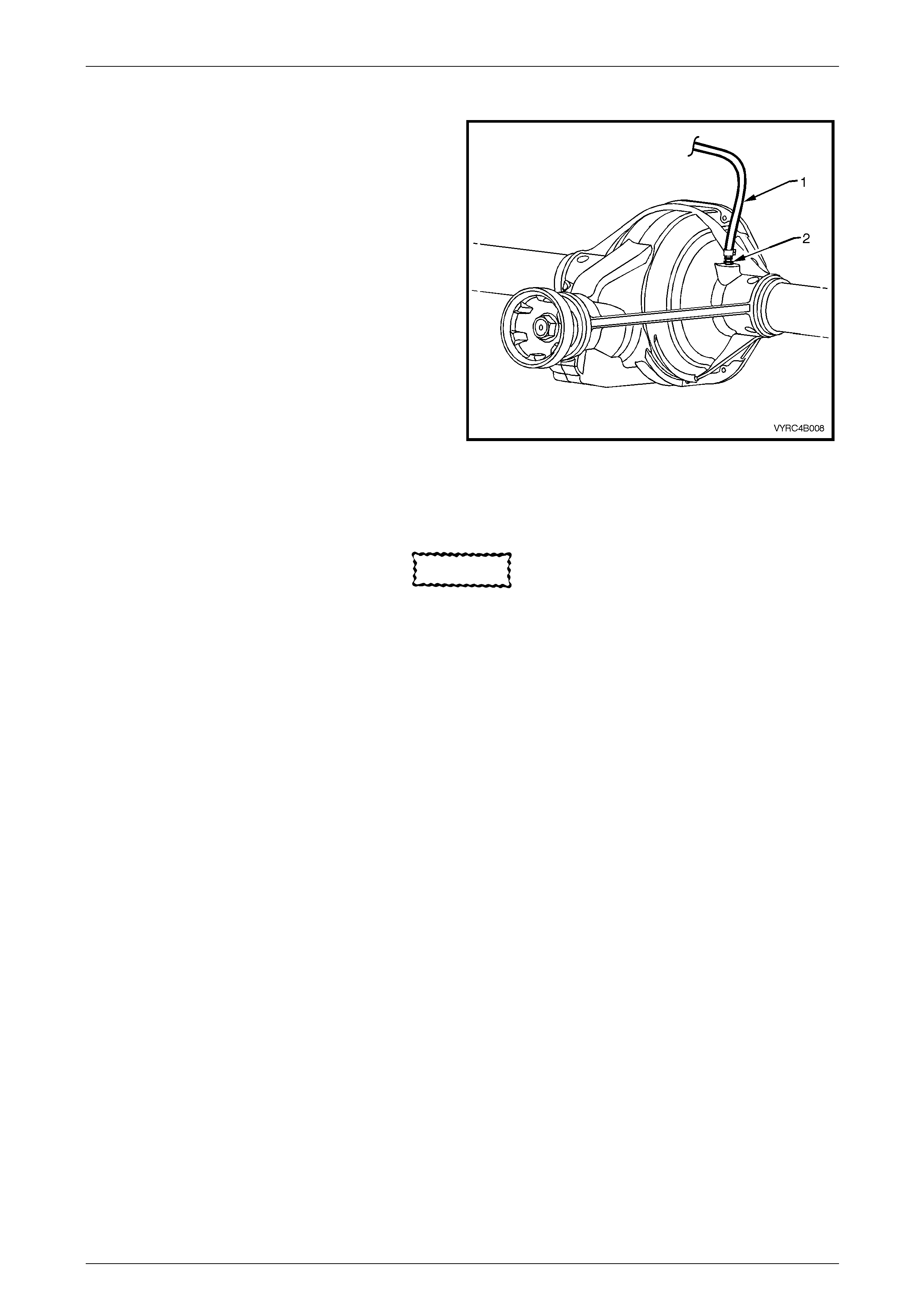
Rear Axle Assembly Breather
The breather hose (1) should be checked regularly to
ensure that it is correctly routed, not kinked nor blocked.
Figure 4A2 – 6
Limited Slip Differential Precautions
CAUTION
• When servicing a vehicle fitted with a
Limited Slip Differential, DO NOT run the
engine with the transmission in gear and
one wheel raised. The driving force to the
wheel on the ground may cause the
vehicle to move.
• 'On Car' type wheel balancers are not
recommended for use on the rear wheels
of vehicles equipped with a Limited Slip
Differential. One rear wheel will drive if in
contact with the ground when the opposite
wheel is raised and rotated. This type of
balancer may be used, by removing the
road wheel opposite to the one being
spun, the vehicle raised and supported on
safety stands. Refit wheel nuts, reversed,
to retain brake disc.
Rear Final Drive and Live Axle Page 4B2 – 9
Page 4B2 – 9
Lubrication
When servicing either a V6, M78 Series or V8,
M86 Series Rear Axle Assembly fitted with a
Limited Slip Differential, gloves and safety
glasses are recommended when handling the
lubrication additive to prevent any possible
irritation of the skin or eyes.
The lubricant level should be checked and topped up (if require d) with the recommended lubricant, at the time or
distance intervals outlined in the relevant MY2005 VZ Serie s Owner's Handbook with the rear axle assembly COLD;
refer to 2.2 Checking Rear Axle Lubricant Le vel in this Secti on. At this temperature, the lubrica nt should be level with the
bottom of the filler plug hole.
CAUTION
Never use any other than the stated and
recommended lubricant.
The lubricant for MY2005 VZ Series Models with a live axle, is a heavy-duty synthetic type. Using straight non-LSD type
oil in an LSD rear axle assem bly will cause ‘stick-slip’ chatter noise to occur when turning corners. It must also be noted
that, using a mineral type lubricant in any rear axle assembly fitted to a GEN III V8 or V6 powered vehicle may cause
gear set and/or bearing dama ge under high load driving conditio ns.
The oil seals of the rear axle assemblies have been specially formulated to tolerate this synthetic lubricant along with the
LSD lubricant additive. If the incorrect lubricant is accidentally used in the rear a xle ass embly of any MY2005 VZ Series
Model with a live axle, the rear axle assembly should be drained, flushed (with the recommended lubricant) and refilled
with the correct lubricant. For the procedure on this operation refer to 2.3 Changing/Flush ing Rear Axle Lubricant in this
Section.
Rear Final Drive and Live Axle Page 4B2 – 10
Page 4B2 – 10
2 Minor Service Operations
ATTENTION
All fasteners are important attaching parts as they affect the performance of vital components and/or could
result in major repair expense. W here specified in this Section, fasteners MUST be replaced w ith parts of the
same part number or an approved equivalent. Do not use fasteners of an inferior quality or substitute design.
Torque values must be used as specified during reassembly to ensure proper retention of all components.
Throughout this Section, fastener torque wrench specifications may be accompanied with the following
identification marks:
Fasteners must be repl aced after loosening.
Vehicle must be at curb height before final tightening.
Fasteners either have micro encapsulated sealant applied or incorporate a mechanical thread lock and
should only be re-used once. If in doubt, replacement is recommended.
If one or more of these identification marks is present alongside a fastener torque wrench specification, the
recommendation regarding that fastener must be adhered to.
2.1 Service Warnings, Cautions and Notes
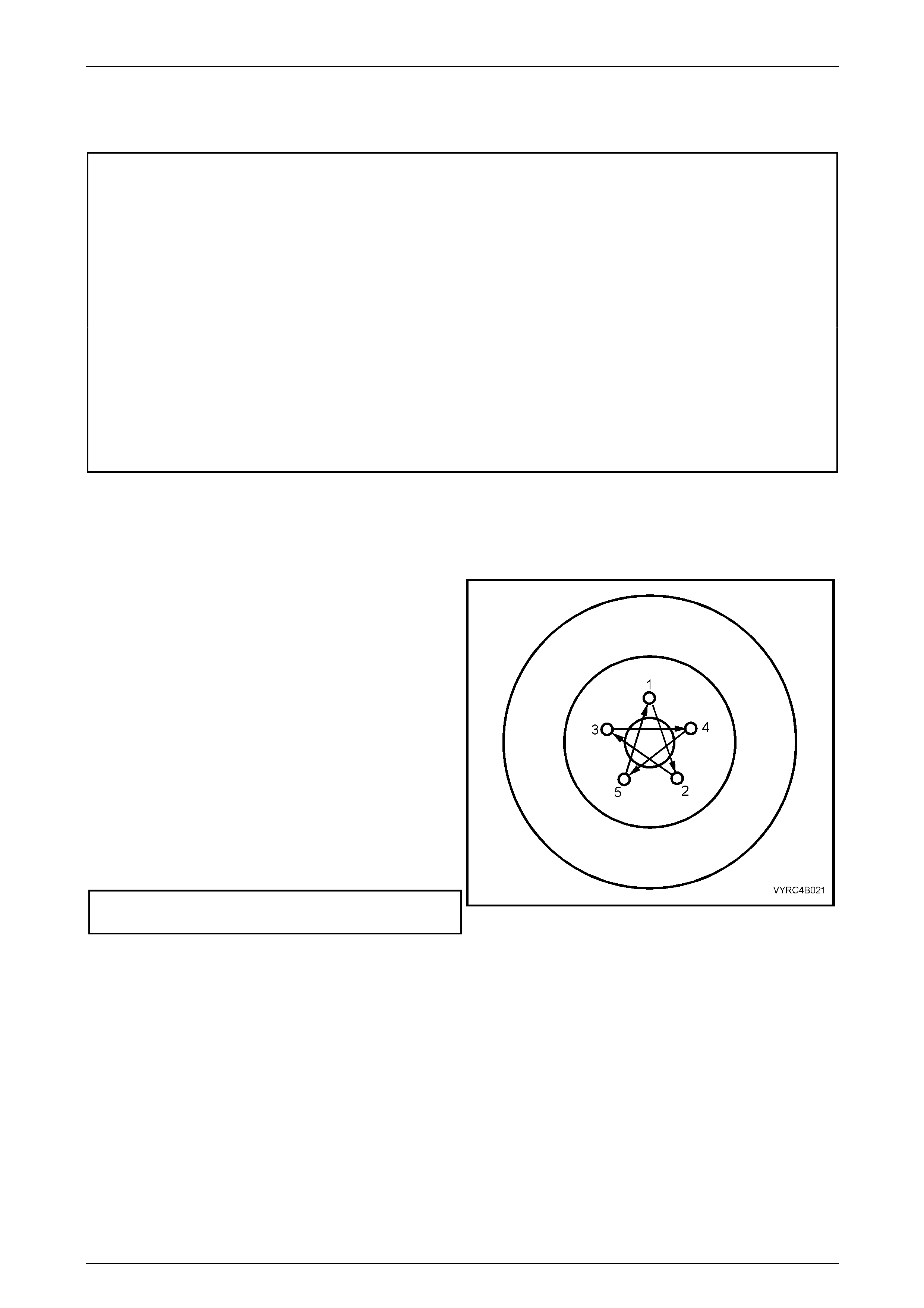
Road Wheel Replacement Caution
Whenever a road wheel and/or brake disc is removed from
the vehicle, the relationship of the road wheel and the disc
to the hub MUST be marked with a pen or similar, in order
for those parts to be reinstalled in their origi nal positions.
This is critical to maintain the brake disc an d road wheel
runout dimension to a minimu m.
When reinstalling road wheels, do not use an impact gun to
tighten wheel nuts unless the impact gun is fitted with a
torque limiter socket (Tool No. AU534 or a c ommercial
equivalent).
Failure to correctly tighten wheel nuts to the correct
torque specification and in the correct order may result in a
distorted brake disc, leading to the development of
brake shudder. For a complete description of the
method used to measur e both brake disc and
trunnion assembly runout an d correction,
refer to Section 5A Service and Park Braking Systems.
Road wheel attaching nut
torque specification..................................110 – 140 N.m Figure 4A2 – 7
Rear Final Drive and Live Axle Page 4B2 – 11
Page 4B2 – 11
2.2 Checking Rear Axle Lubricant Level
LT Section No: 05-400
CAUTION
When servicing any rear axle assembly fitted
with a Limited Slip Differential (LSD), gloves
and safety glasses are recommended when
handling the lubrication additive to prevent
any possible irritation of th e skin or eyes.
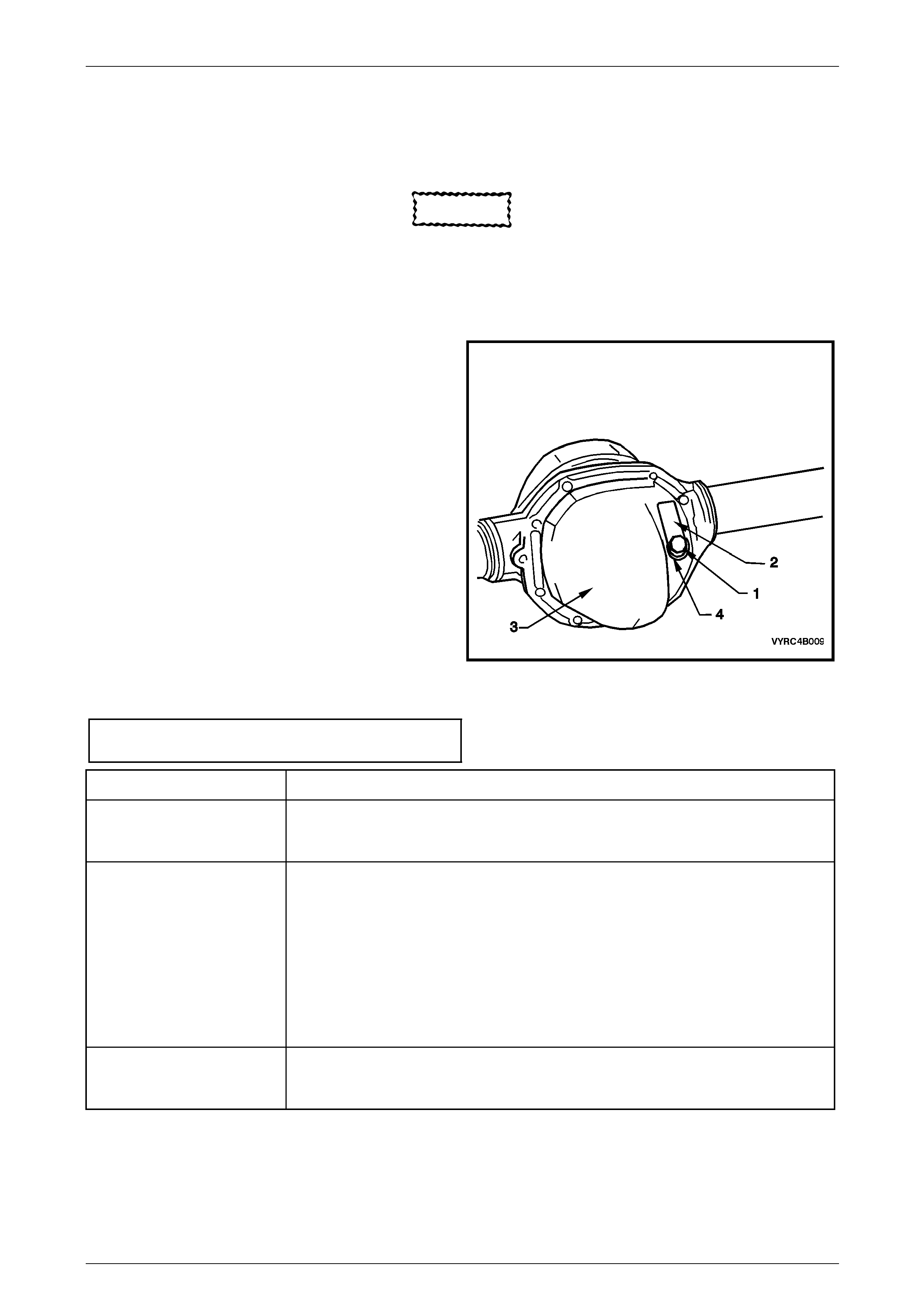
1 Check that the vehicle is level.
2 Clean area around filler plug (1).
3 Remove filler plug (1) from rear cover (3) (do not lose
the lubrication tag (2) from the plug, if fitted).
4 The lubricant level is to be maintaine d at the bottom
edge of the filler plug hole.
NOTE
• The rear axle lubricant level MUST be
checked when the rear axle is cold, or
overfilling and oil leaks may occur.
• Use only the recommended lubrica nt.
5 Inspect filler plug (1) and sealing washer (4) for
damage, if OK, reinstall to the rear cover (3) (includi ng
the lubrication tag (2). If damaged, replac e plug and
the sealing washer.
6 Tighten filler plug (1) to the correct torque
specification.
Rear axle filler plug
torque specification..............................................28 N.m
Figure 4A2 – 8
Engine & Axle Type Recommended Lubricant
V6
M78 Series
Non LSD
Synthetic Hypoid Gear Oil, such as; MOBIL Mobilube SHC ID, CASTROL SAF-XA or
equivalent lubricant to Holden's Specification HN2040.
V6
M78 Series LSD
(Cone Type)
Synthetic Hypoid Gear Oil, such as; MOBIL Mobilube SHC ID, CASTROL SAF-XA or
equivalent lubricant to Holden's Specification HN2040.
In addition to the synthetic, hypoid gear oil, additive kit (part number 92 145121) must
also be used.
The additive kit consists of:
• LSD Sturaco Additive – 100 ml special container
• Material Safety Data Sheet
• Lubrication ID Tag
GEN III V8
M86 Series LSD
(Multi Disc Type)
Synthetic Hypoid Gear Oil, such as; MOBIL Mobilube SHC ID, CASTROL SAF-XA or
equivalent lubricant to Holden's Specification HN2040.
Rear Final Drive and Live Axle Page 4B2 – 12
Page 4B2 – 12
2.3 Changing/Flushing Rear Axle Lubricant
LT Section No: 05-400
CAUTION
When servicing any rear axle assembly fitted
with a Limited Slip Differential (LSD), gloves
and safety glasses are recommended when
handling the lubrication additive to prevent
any possible irritation of th e skin or eyes.
1 Place a clean container under the rear axle with a 2
litre capacity.
NOTE
Draining warm oil takes less time and is more
complete than for cold oil.
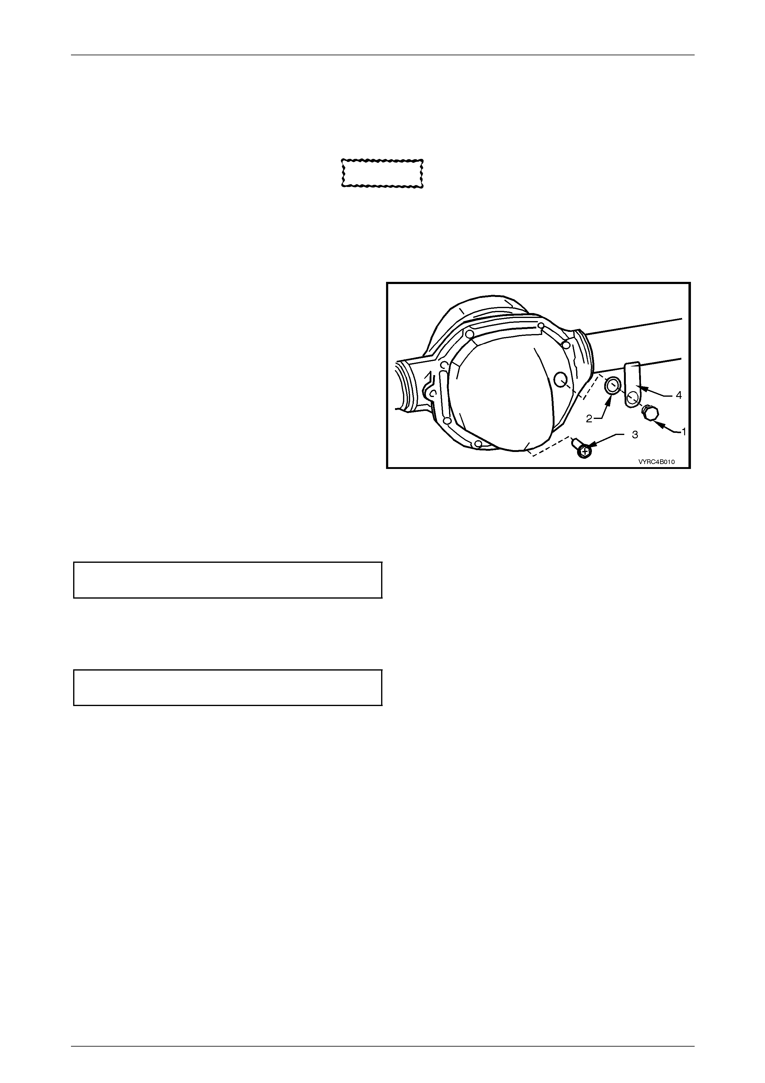
2 Remove both the filler plug (1), the sealing washer (2)
and the drain plug (3).
3 Allow the (preferably warm) lubricant to drain into the
container.
4 If flushing is required, use an undiluted quantity of the
recommended lubricant for the operation.
5 When the draining (and flushing if required) operation
is complete, apply thread-sealing tape to drain plug (3)
thread. Install and tighten drain pl ug (3) to the correct
torque specification.
Final drive drain plug
torque specification..............................................28 N.m
Figure 4B2 – 9
6 Fill the rear axle assembly with a total of 1.7 litres of the recommended lub r ic ant (or 1.6 litres of lubricant plus 100
ml of LSD additive, as appropriate), install the filler plug (1) wit h the sea ling washer (2) and lubrication tag (4).
7 Tighten the filler plug to the correct torque specificati on.
Final drive filler plug
torque specification..............................................28 N.m
Rear Final Drive and Live Axle Page 4B2 – 13
Page 4B2 – 13
2.4 Rear Axle Shaft Check For Run-Out and
End Float
LT Section No: 05-400
ATTENTION
The following fasteners have either micro encapsulation or incorporate a mechanical thread lock and should
only be used once. If in doubt , rep lacement is recommended w hen performing these operations:
Rear brake caliper to rear axle anch o r plate attaching bolts.
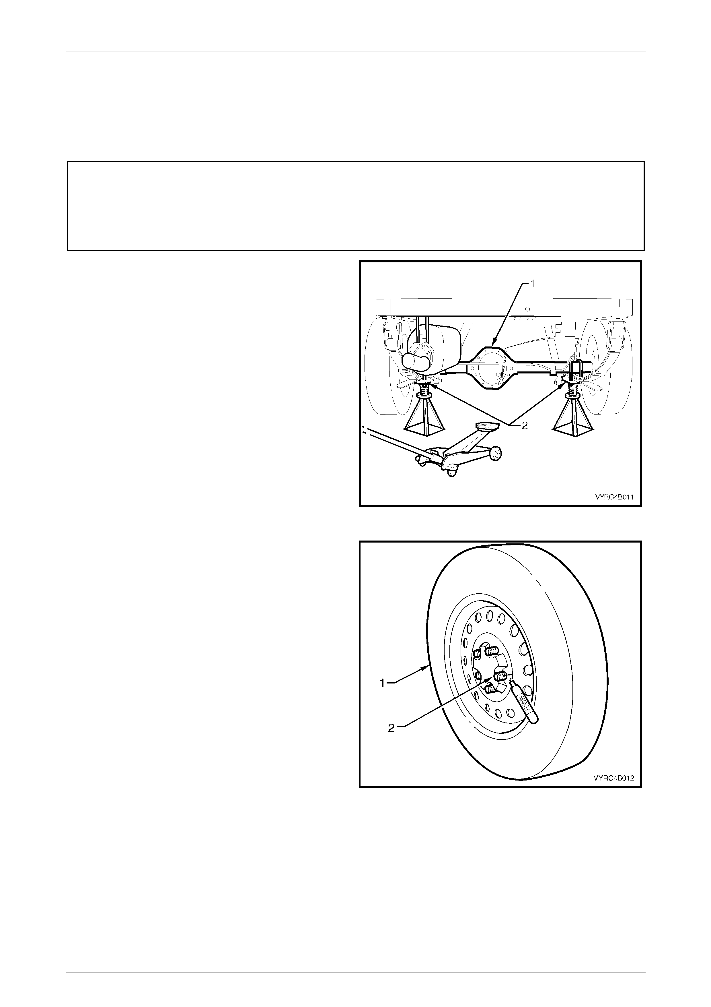
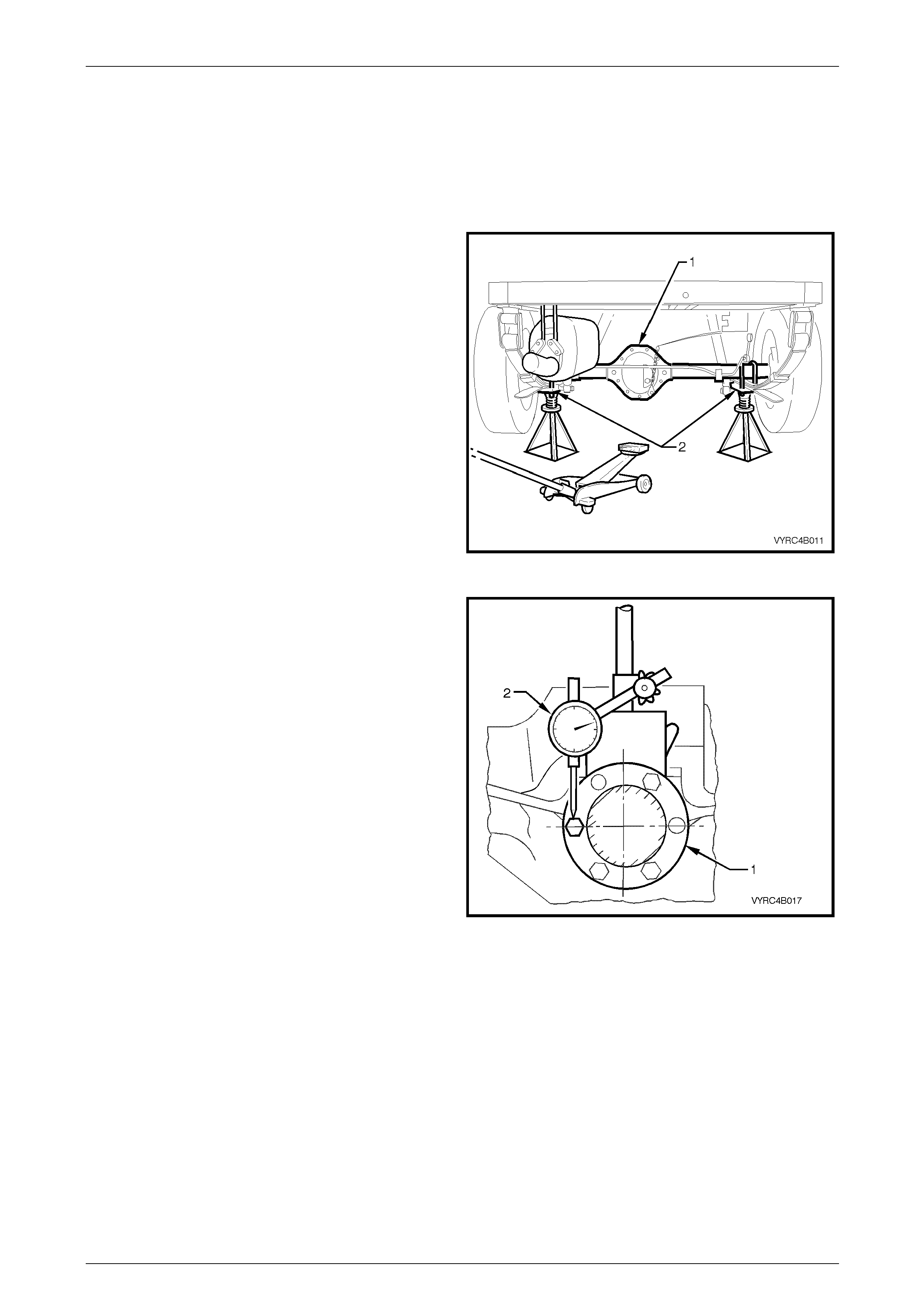
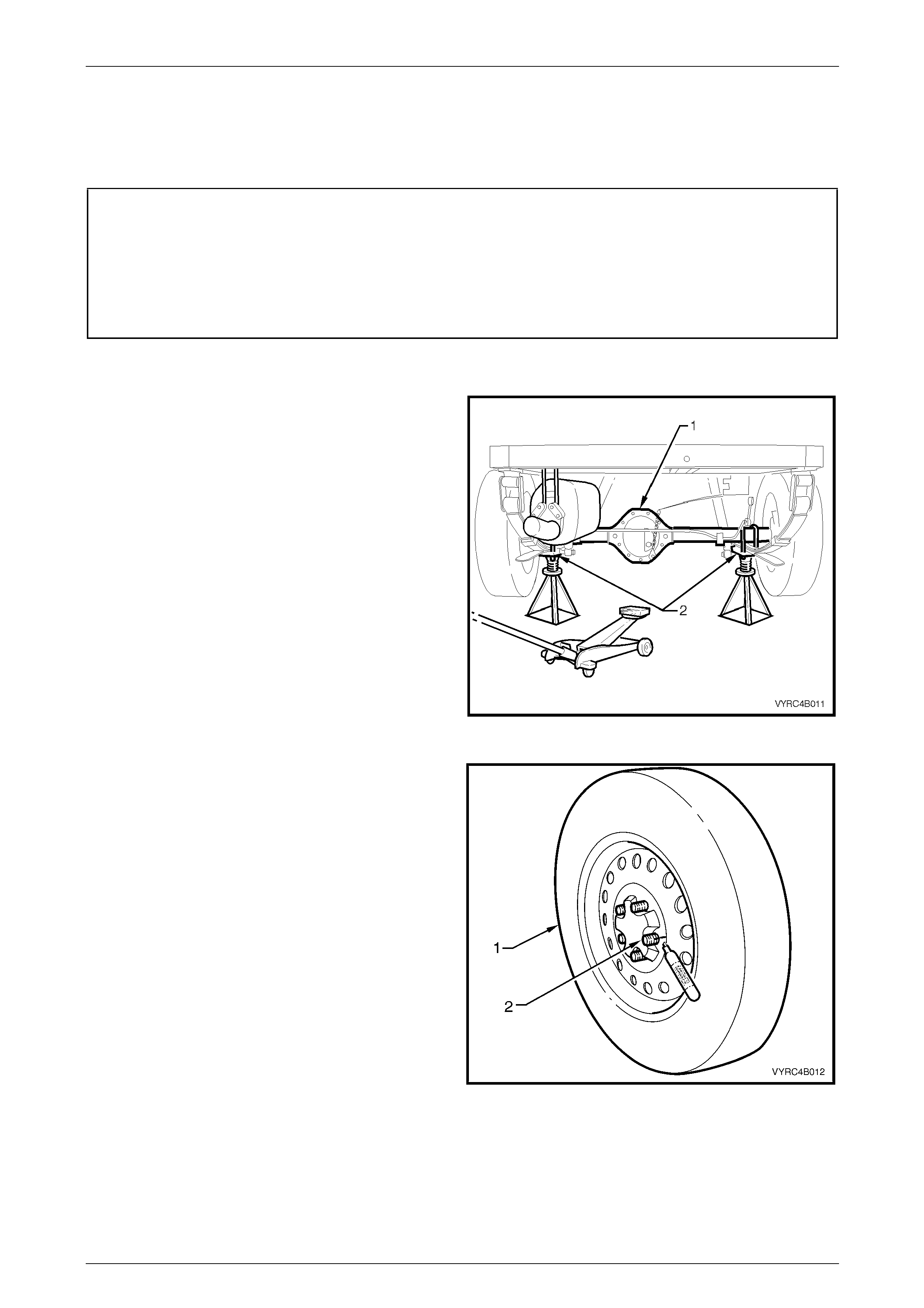
1 Place floor jack under the cent re of the rear axle
assembly (1) and raise the rear of the vehicle.
2 Place safety stands under the rear leaf spring retain er
plates (2) on both left-hand and right-hand sides to
support the weight of the vehicle.
Figure 4B2 – 10
3 Remove the wheel covers or decorative wheel nut
caps, then mark the relationship of the road wheel to
one of the wheel studs.
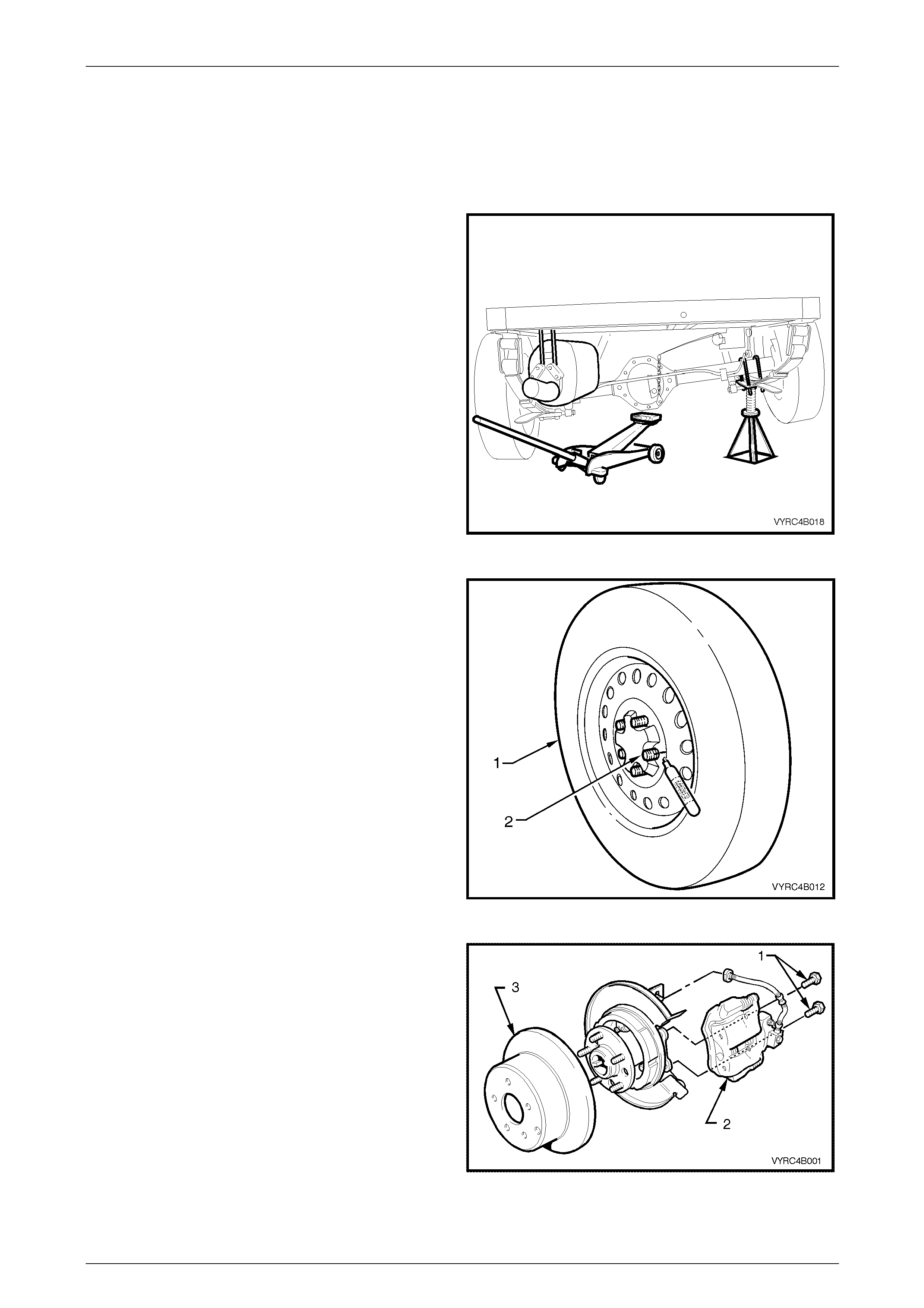
4 With a suitable marking pen, mark the relationship of
the wheel (1) to a rear axle wheel-retaining stud (2).
5 Loosen, then remove the road wheel attaching
nuts, working in a 'star' pattern. Refer to
2.1 Service Warnings, Cautions and Notes in this
Section, for detailed informatio n. Remove the road
wheel.
Figure 4B2 – 11
Rear Final Drive and Live Axle Page 4B2 – 14
Page 4B2 – 14
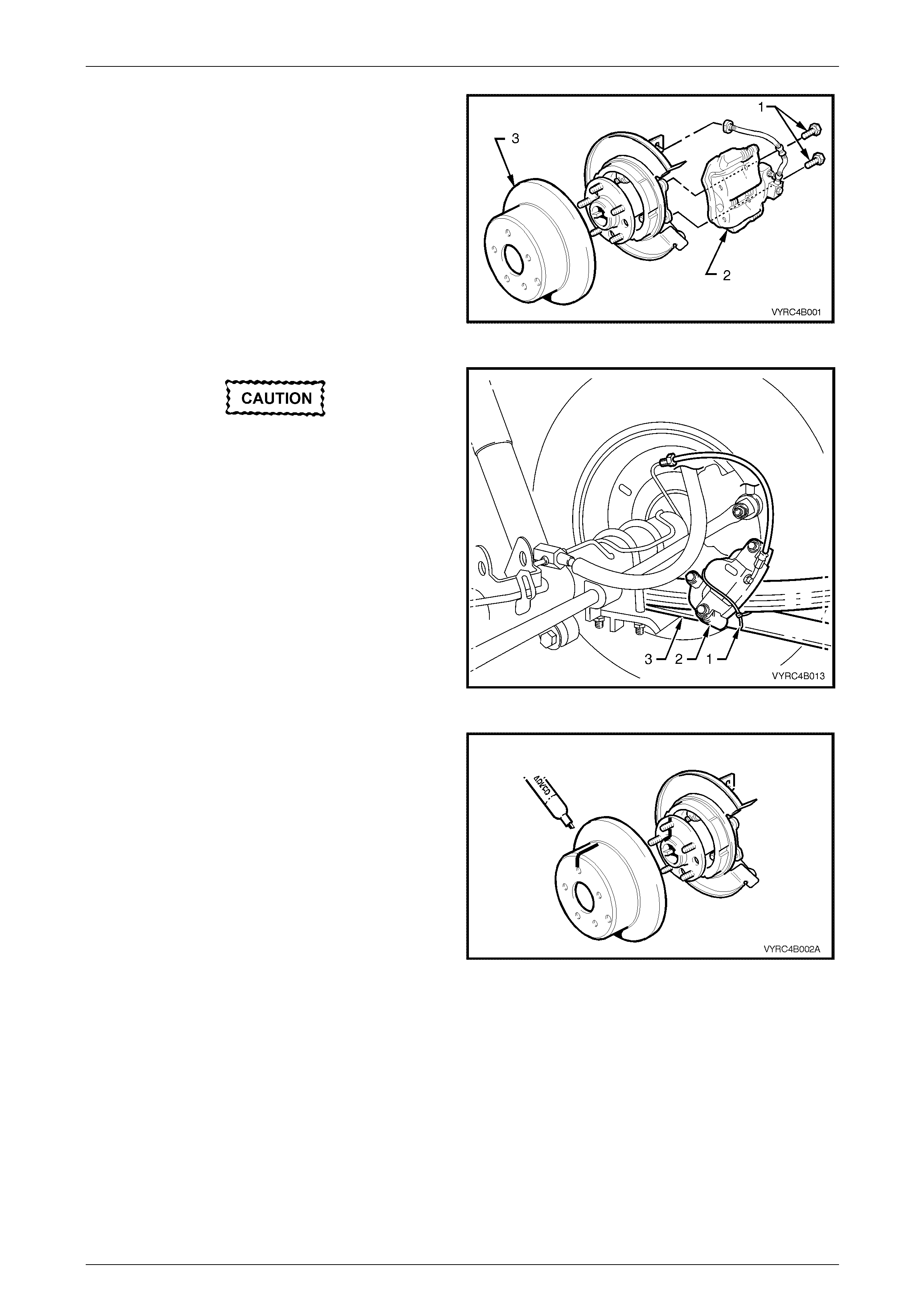
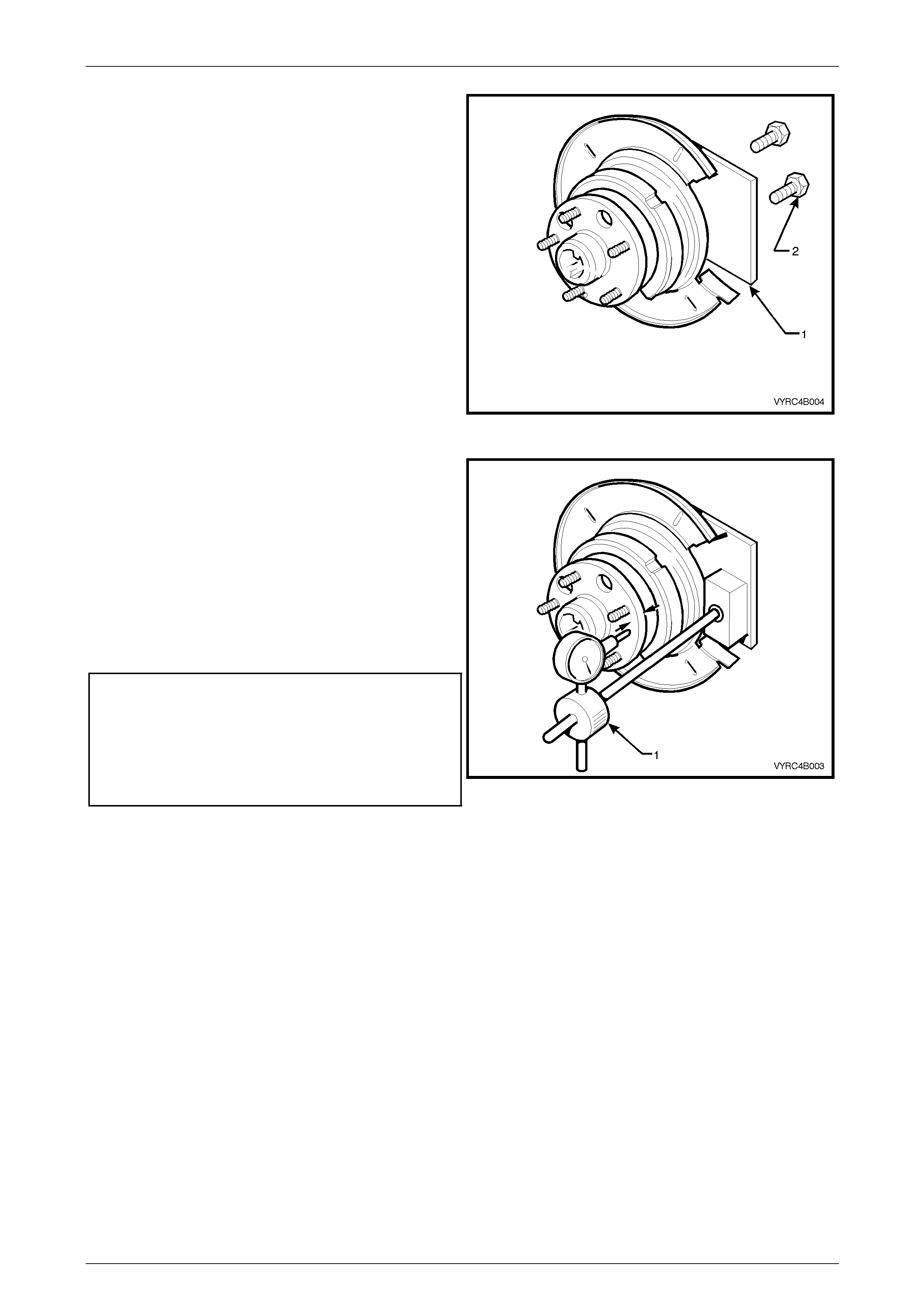
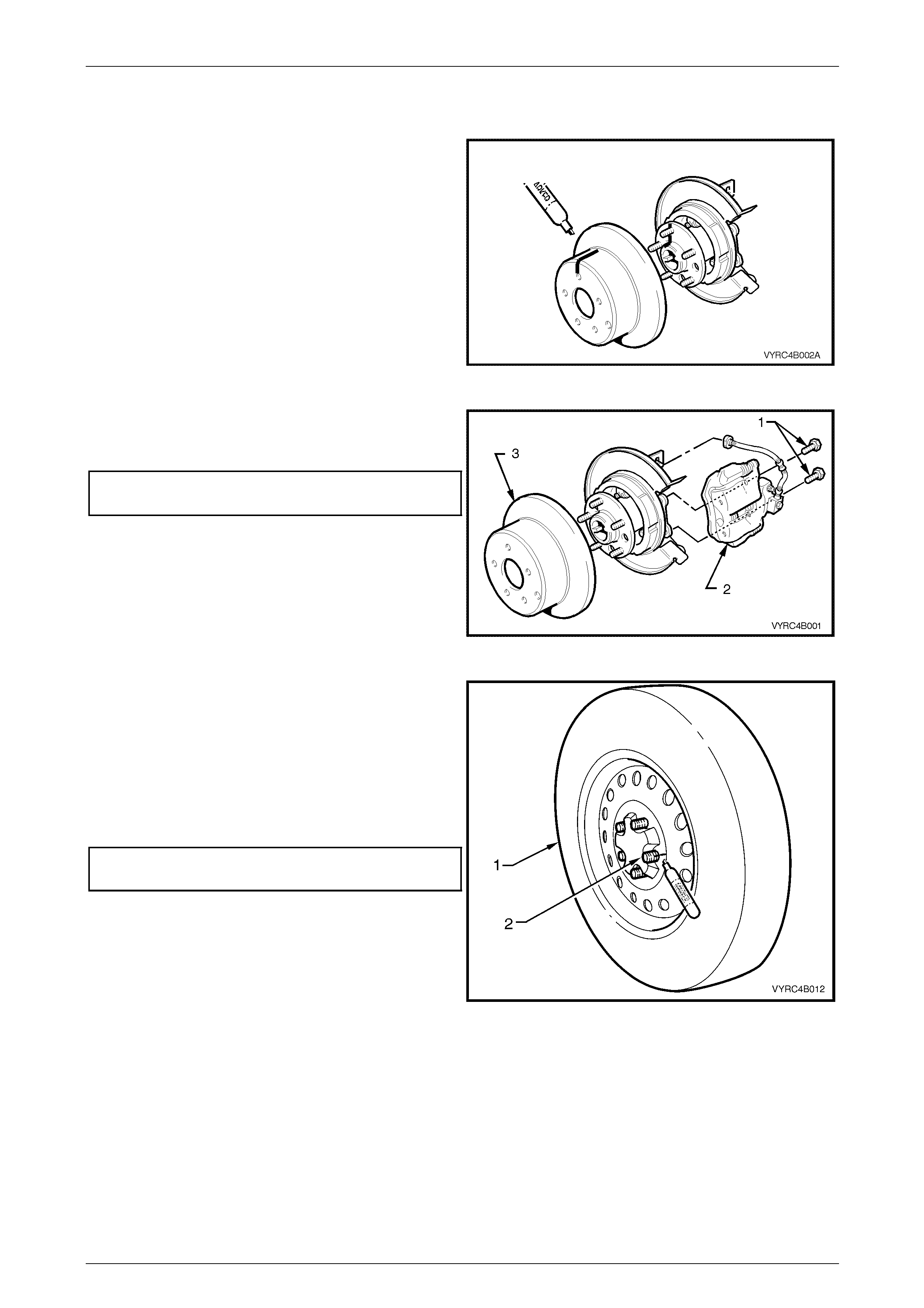
6 Remove the rear brake caliper to rear axle anchor
plate attaching bolts (1), and then rem ove th e brake
caliper (2) from the disc rotor (3).
Figure 4B2 – 12
Do not allow caliper to hang by brake hose,
as damage to the brake hose may occur.
7 Using tie wire (1), secure the caliper (2) to the top of
the rear leaf spring assembly (3).
Figure 4B2 – 13
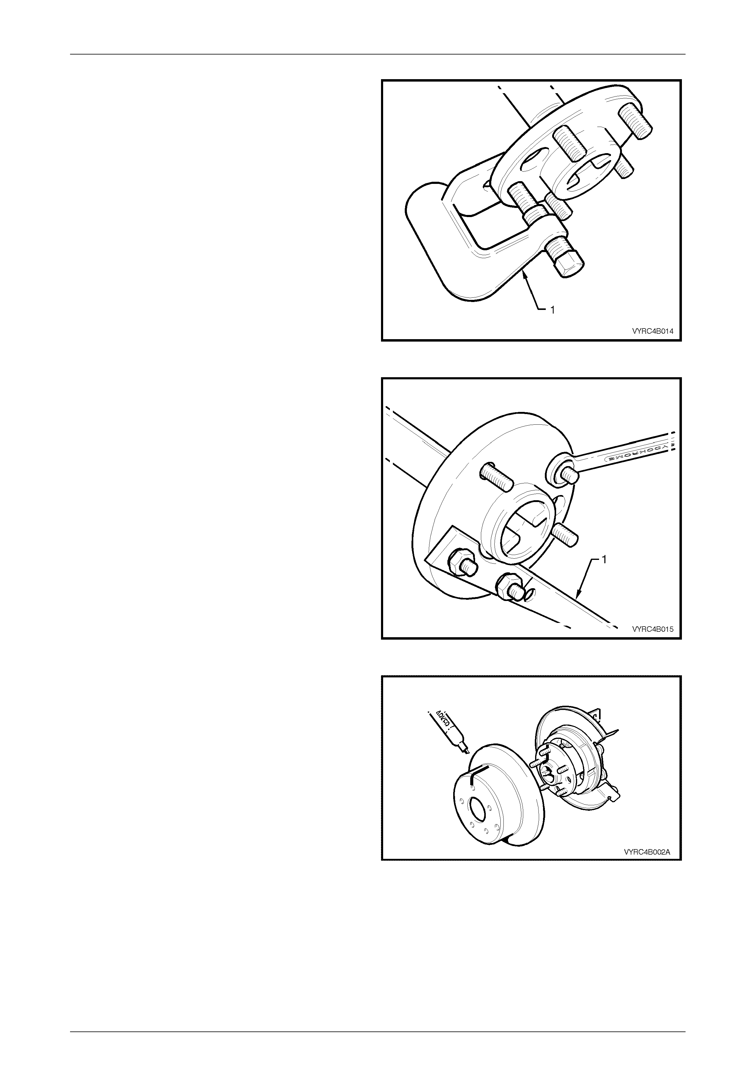
8 With a suitable marking pen, mark the relationship of
the brake disc rotor position to rear axle shaft
assembly, then remove the brake disc rotor from the
rear axle shaft assembly.
Figure 4B2 – 14
Rear Final Drive and Live Axle Page 4B2 – 15
Page 4B2 – 15
9 Clean the rear axle face by rubbing lightly with fine
emery paper.
10 Mount the pre-fabricated mounting p late (1) to the
brake caliper mounting points on the rear trailing arm,
using the caliper mounting bo lts (2).
NOTE
Refer to 7 Special Tools in this Section for
details on the pre-fabricated mounting plate.
Figure 4B2 – 15
11 Mount a magnetic based dial indicator stand, install a
dial indicator (1), positioning the pointer against the
axle flange face as shown.
12 Move the rear axle in and out by pushing and pulling,
noting the points of maximum and mi nimum end float.
The difference between these two dimensions is the
total indicated end float.
13 Using the wheel studs, carefully rotate the rear axle,
noting the points of maximum and mi nimum lateral
run-out. The difference bet ween these two dimensions
is the total indicated runout (TIR).
Maximum rear axle shaft end float
(Used Bearing).................................................. 0.75 mm
Rear axle shaft end float
(New Bearing)........................................ 0.02 – 0.30 mm
Maximum rear axle shaft
total indicated runout (TIR) ...............................0.12 mm Figure 4B2 – 16
Rear Final Drive and Live Axle Page 4B2 – 16
Page 4B2 – 16
If Run-out and End Float is Within Specification
1 Reinstall the disc brake rotor over the rear axle wheel
studs, ensuring that the relationship marks made prior
to disassembly are aligned.
Figure 4B2 – 17
2 Reinstall the brake caliper (2) to the rear axle anchor
plate, install the caliper attaching bolts an d tighten to
the correct torque specification
() Rear brake caliper to anchor plate
attaching bolt torque specification........................85 N.m
Figure 4B2 – 18
3 Reinstall the road wheel, aligning the relationship
marks made prior to removal.
4 Reinstall the wheel nuts but do not fully tighten at this
stage.
5 Lower the vehicle to the ground an d tighten the wheel
nuts to the specified torque, working in a 'star' pattern,
refer to 2.1 Service Notes and Cautions, in this
Section.
Road wheel attaching nut
torque specification..................................110 – 140 N.m
6 Reinstall the wheel cover or decorative wheel nut
caps.
Figure 4B2 – 19
If the Run-out and End Float Check, Exceeds Specification
The rear axle shaft and or bearing assembly must be replaced, refer to 2.8 Rear Axle Shaft Assembly also refer to
2.9 Rear Axle Shaft, Oil Seal, ABS Pulse Ring, Bearing and Retainer Collar in this Section.

Rear Final Drive and Live Axle Page 4B2 – 17
Page 4B2 – 17
2.5 Rear Axle Shaft Wheel Studs
LT Section No: E006600
ATTENTION
The following fasteners have either micro encapsulation or incorporate a mechanical thread lock and should
only be used once. If in doubt , rep lacement is recommended w hen performing these operations:
Rear brake caliper to rear axle anch o r plate attaching bolts.
Replace
1 Place floor jack under the cent re of the rear axle
assembly (1) and raise the rear of the vehicle.
2 Place safety stands under the rear leaf spring retain er
plates (2) on both left-hand and right-hand sides to
support the weight of the vehicle.
Figure 4B2 – 20
3 Remove the wheel covers or decorative wheel nut
caps, then mark the relationship of the road wheel to
one of the wheel studs.
4 With a suitable marking pen, mark the relationship of
the wheel (1) to a rear axle wheel-retaining stud (2).
5 Loosen, then remove the road wheel attaching
nuts, working in a 'star' pattern. Refer to
2.1 Service Warnings, Cautions and Notes in this
Section, for detailed informatio n.
6 Remove the road wheel.
Figure 4B2 – 21

Rear Final Drive and Live Axle Page 4B2 – 18
Page 4B2 – 18
7 Remove rear brake caliper to rear a xle anch or plate
attaching bolts (1), remove brake caliper (2) from the
disc rotor (3).
Figure 4B2 – 22
Do not allow caliper to hang by brake hose,
as damage to the brake hose may occur.
8 Using suitable tie wire (1), secure the caliper (2) to the
top of the rear leaf spring assembly (3).
Figure 4B2 – 23
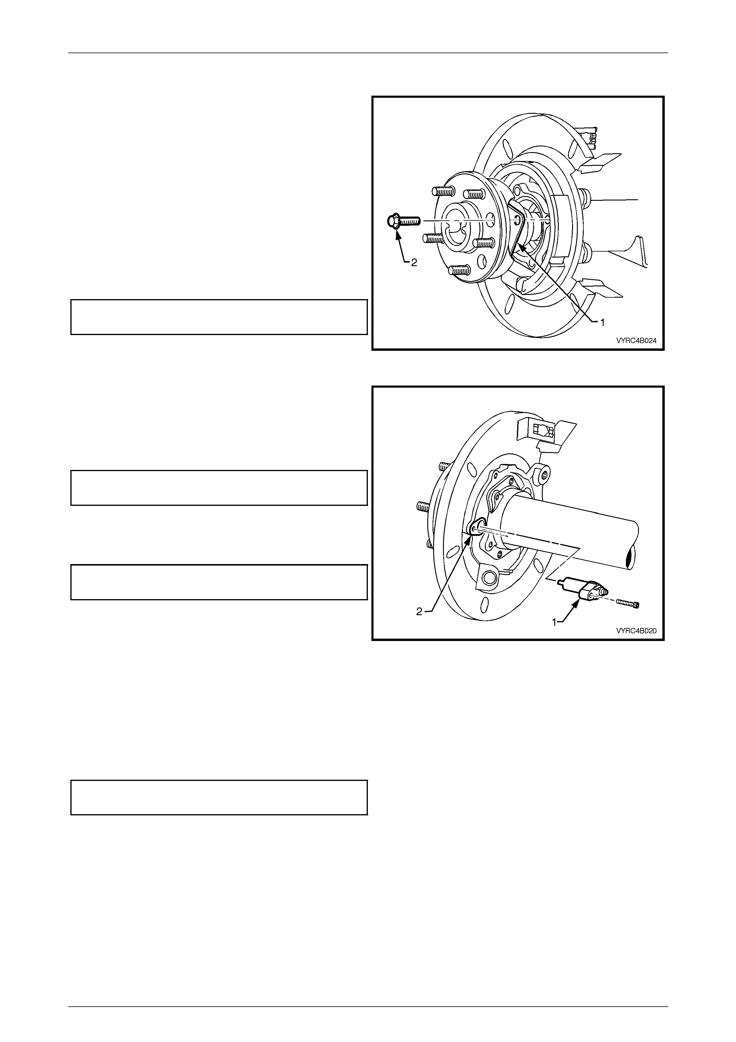
9 With a suitable marking pen, mark the relationship of
the brake disc rotor position to the rear axle shaft
assembly, then remove the brake disc rotor from the
rear axle shaft assembly.
Figure 4B2 – 24
Rear Final Drive and Live Axle Page 4B2 – 19
Page 4B2 – 19
10 Remove the rear axle shaft assembly; refer to
2.8 Rear Axle Shaft Assembly in this Section.
11 If replacing wheel-attaching studs, remove the rear
axle-bearing race, retaining collar and the ABS pulse
ring before replacing wheel studs. Refer to
2.9, Rear Axle Shaft, ABS Pulse Ring, Oil Seal,
Bearing And Retainer Collar in this Section.
12 Use Tool No. J24292-C (1) to remove the d amaged
stud from hub, as shown.
13 Remove any other studs that require replacement.
Figure 4B2 – 25
14 Install new studs into the rear axle shaft assembly
using the following method:
a Install Tool No. KM-468-B holding bar (1), with
two wheel nuts to the rear axle shaft assembly
studs.
b Insert a new wheel-attaching stud firmly into the
axle shaft flange and rotate the stud to align the
splines.
c Install a flat washer along with a wheel-attaching
nut to the stud with the tapered side facing
outward or flat face toward the washer.
d Tighten the wheel-attaching nut with a suitable
spanner to draw in the stud. When the stud is
fully installed, remove wheel nut and washers.
e Remove Tool No. KM468-B and the wheel
attaching nuts and washers.
Figure 4B2 – 26
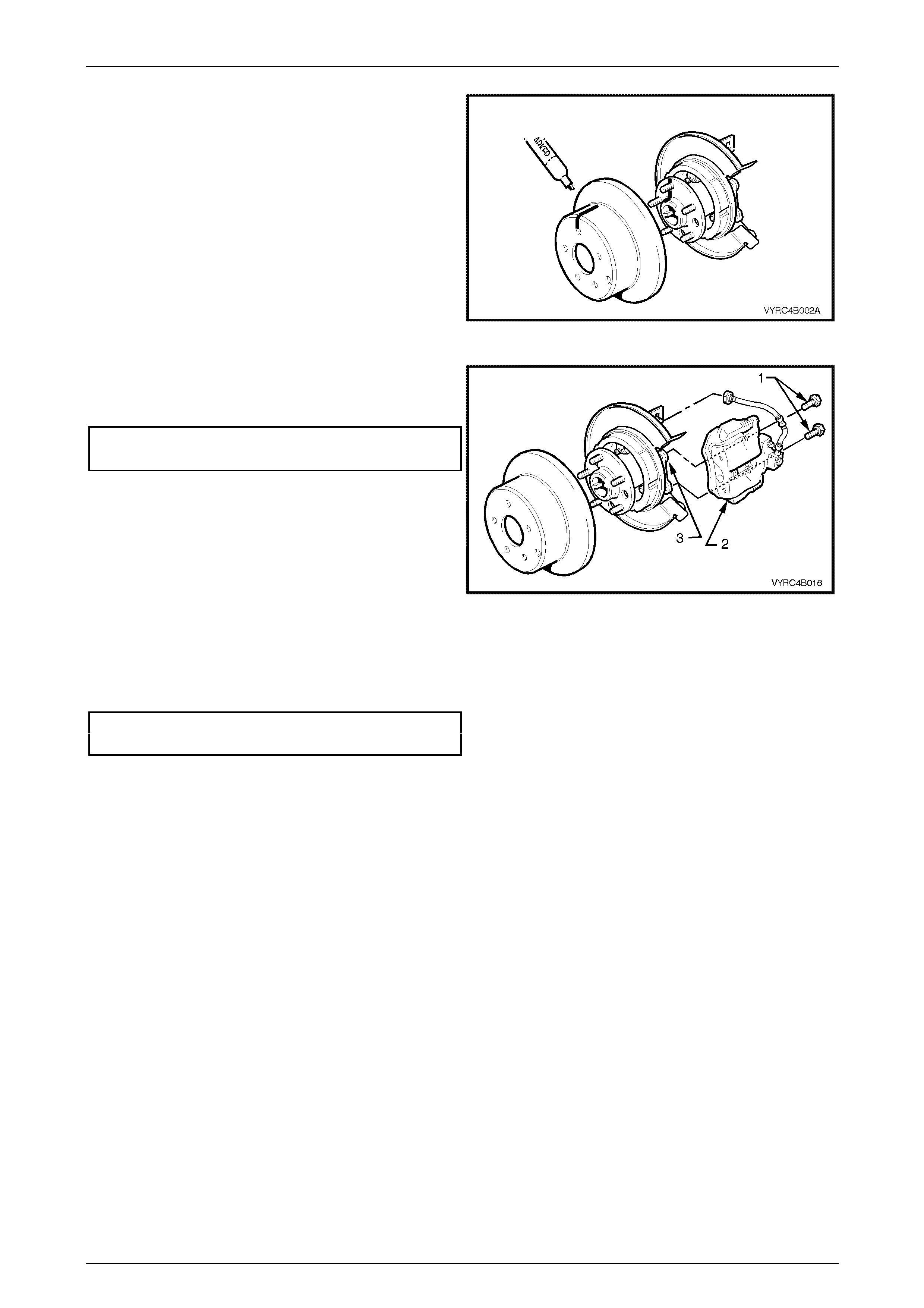
15 Reinstall the disc brake rotor over the rear axle wheel
studs, ensuring that the relationship alignment marks
made prior to disassembly are aligned.
Figure 4B2 – 27
Rear Final Drive and Live Axle Page 4B2 – 20
Page 4B2 – 20
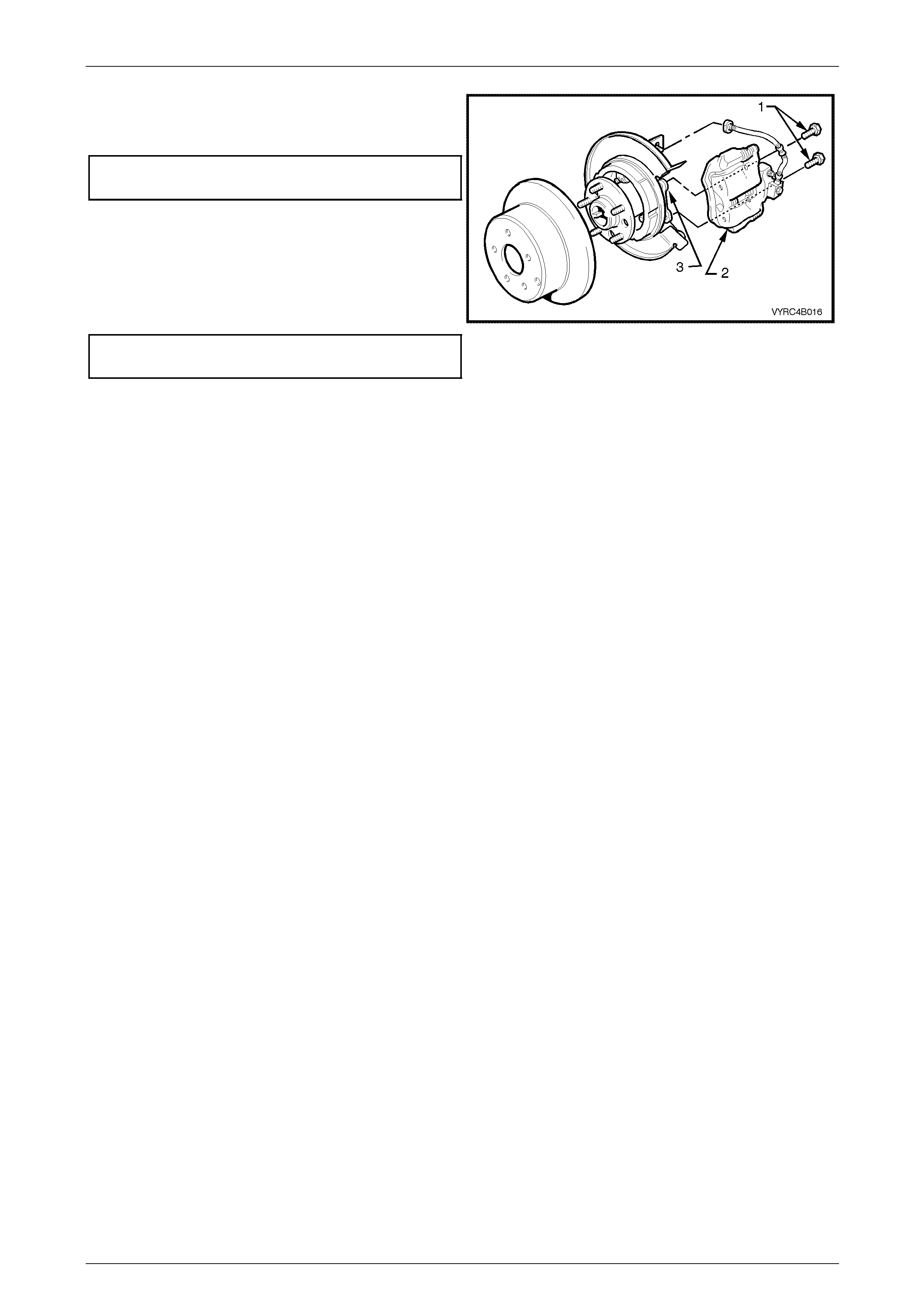
16 Reinstall brake calip er (2) to the rear axle anchor plate
(3) and tighten the caliper attaching bolts (1) to the
correct torque specification.
() Rear brake caliper to anchor plate
attaching bolt torque specification........................85 N.m
17 Reinstall road wheel in th e original position and secure
with the wheel nuts but do not fully tighten.
18 Lower the vehicle to the ground an d tighten the wheel
nuts to the specified torque, working in a 'star' pattern,
refer to 2.1 Service Notes and Cautions, in this
Section.
Road wheel attaching nut
torque specification..................................110 – 140 N.m Figu re 4B2 – 28
19 Reinstall the wheel cover/decorative wheel nut caps.
Rear Final Drive and Live Axle Page 4B2 – 21
Page 4B2 – 21
2.6 Combined Rear Axle Backlash Check
LT Section No: 05-400
Procedure
1 Place floor jack under the cent re of the rear axle
assembly (1) and raise the rear of the vehicle.
2 Place safety stands under the rear leaf spring retain er
plates (2) on both left-hand and right-hand sides to
support the weight of the vehicle.
3 Place the transmission in neutral with the engine
turned OFF.
Figure 4B2 – 29
4 Position a bolt on the pinion dr ive flange (1) in a
horizontal position to enable a dial indicator (2) to be
positioned for backlash measurement.
5 Firmly apply the park brake lever.
6 Install a dial indicator to a magnetic stand and position
on the axle carrier housing.
7 Rotate the propeller shaft by hand, in a clockwise
direction.
8 While holding the propeller shaft in this position, zero
the dial indicator.
9 Rotate the propeller shaft by hand, in the opposite
direction and observe the dial indicator needle and
record the reading.
NOTE
A torque of approximately 7 Nm will need to be
applied in each direction while obtaining the
backlash reading. If the backlash reading is less
than 7 mm at the bolt head, then the rear axle
assembly is within acceptable limits.
Figure 4B2 – 30
Rear Final Drive and Live Axle Page 4B2 – 22
Page 4B2 – 22
2.7 Limited Slip Differential Torque Check
LT Section No: 05-400
Procedure
1 Place the transmission in neutral with the engine
turned OFF.
2 Using a floor jack, raise one rear wheel, leaving the
remaining wheel on the floor and support the vehicle
under the rear axle assembly on raised side with a
safety stand.
Figure 4B2 – 31
3 Remove the wheel covers or decorative wheel nut
caps, then mark the relationship of the road wheel to
one of the wheel studs, using a felt tipped pen or
similar.
4 Loosen, then remove the road wheel attaching
nuts, working in a 'star' pattern. Refer to
2.1 Service Warnings, Cautions and Notes in this
Section, for detailed informatio n. Remove the road
wheel.
5 Release the park brake lever to the full y OF F position.
Figure 4B2 – 32
6 Remove the rear brake caliper to rear axle anchor
plate attaching bolts (1), remove the brake caliper (2)
from the disc rotor (3).
Figure 4B2 – 33
Rear Final Drive and Live Axle Page 4B2 – 23
Page 4B2 – 23
Do not allow caliper to hang by brake hose,
as damage to the brake hose may occur.
7 Using suitable tie wire (1), secure the caliper (2) to the
top of the rear leaf spring assembly (3).
Figure 4B2 – 34
8 With a suitable marking pen, mark the relationship of
the brake disc rotor position to the rear axle shaft
assembly, then remove the brake disc rotor from the
rear axle shaft assembly.
Figure 4B2 – 35
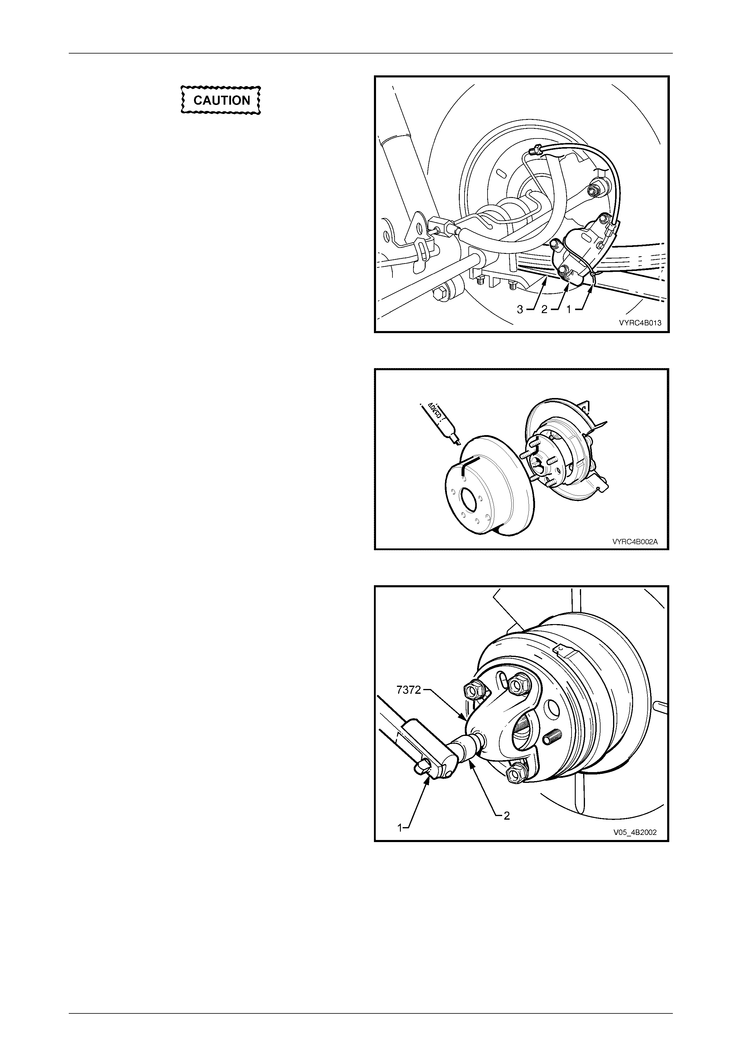
9 Install puller Tool No. 7372 to the rear axle and secure
with three wheel nuts.
10 Install the forcing screw of Tool No. 7372 an d lock in
position using the lock nut supplied.
11 Using a torque wrench (1) in conjunction with a
suitable sized socket (2), measure the torque required
to rotate the rear axle shaft assembly in a forward
direction.
12 A torque reading of approxim ately 70 Nm should be
obtained while turning the trunnion assembly, with the
opposite wheel remaini ng stationary.
13 If a torque reading of less than 35 Nm is obtained,
remove the differential case and ins pect case internal
components and repair as necessary, refer to
3.4 Cone Type Limited Slip Differential – M78 Series
or 3.5 Multi-Disc Type Limited Slip Differential – M86
Series in this Section.
Figure 4B2 – 36
Rear Final Drive and Live Axle Page 4B2 – 24
Page 4B2 – 24
14 Reinstall the disc brake rotor over the rear axle wheel
studs, ensuring that the relationship alignment marks
made prior to disassembly are aligned.
Figure 4B2 – 37
15 Reinstall the brake caliper (2) to the rear axle anchor
plate (3) and tighten the caliper attaching bolts (1) to
the correct torque specification.
() Rear brake caliper to anchor plate
attaching bolt torque specification........................85 N.m
Figure 4B2 – 38
16 Reinstall road wheel in th e original position and secur e with the wheel nuts but do not fully tighten.
17 Lower the vehicle to the ground an d tighten the wheel nuts to the specified torque, working in a 'star' pattern,
refer to 2.1 Service Notes and Cautions, in this Section.
Road wheel attaching nut
torque specification..................................110 – 140 N.m
18 Reinstall the wheel cover/decorative wheel nut caps.
Rear Final Drive and Live Axle Page 4B2 – 25
Page 4B2 – 25
2.8 Rear Axle Shaft Assembly
LT Section No: F504000
ATTENTION
The following fasteners have either micro encapsulation or incorporate a mechanical thread lock and should
only be used once. If in doubt , rep lacement is recommended w hen performing these operations:
Rear axle retainer th ru st plate attaching bolt.
ABS wheel speed sensor attaching bolt.
Remove
1 Place the transmission in neutral with the engine
turned OFF.
2 Using a floor jack, raise one rear wheel, leaving the
remaining wheel on the floor and support the vehicle
under the rear axle assembly on raised side with a
safety stand.
Figure 4B2 – 39
3 Remove the wheel covers or decorative wheel nut
caps, then mark the relationship of the road wheel to
one of the wheel studs, using a felt tipped pen or
similar.
4 Loosen, then remove the road wheel attaching nuts,
working in a 'star' pattern. Refer to
2.1 Service Warnings, Cautions and Notes in this
Section, for detailed informatio n. Remove the road
wheel.
5 Release the park brake lever to the full y OF F position.
Figure 4B2 – 40

Rear Final Drive and Live Axle Page 4B2 – 26
Page 4B2 – 26
6 Remove the rear brake caliper to rear axle anchor
plate attaching bolts (1), remove the brake caliper (2)
from the disc rotor (3).
Figure 4B2 – 41
Do not allow caliper to hang by brake hose,
as damage to the brake hose may occur.
7 Using suitable tie wire (1), secure the caliper (2) to the
top of the rear leaf spring assembly (3).
Figure 4B2 – 42
8 With a suitable marking pen, mark the relationship of
the brake disc rotor position to the rear axle shaft
assembly, then remove the brake disc rotor from the
rear axle shaft assembly.
Figure 4B2 – 43
Rear Final Drive and Live Axle Page 4B2 – 27
Page 4B2 – 27
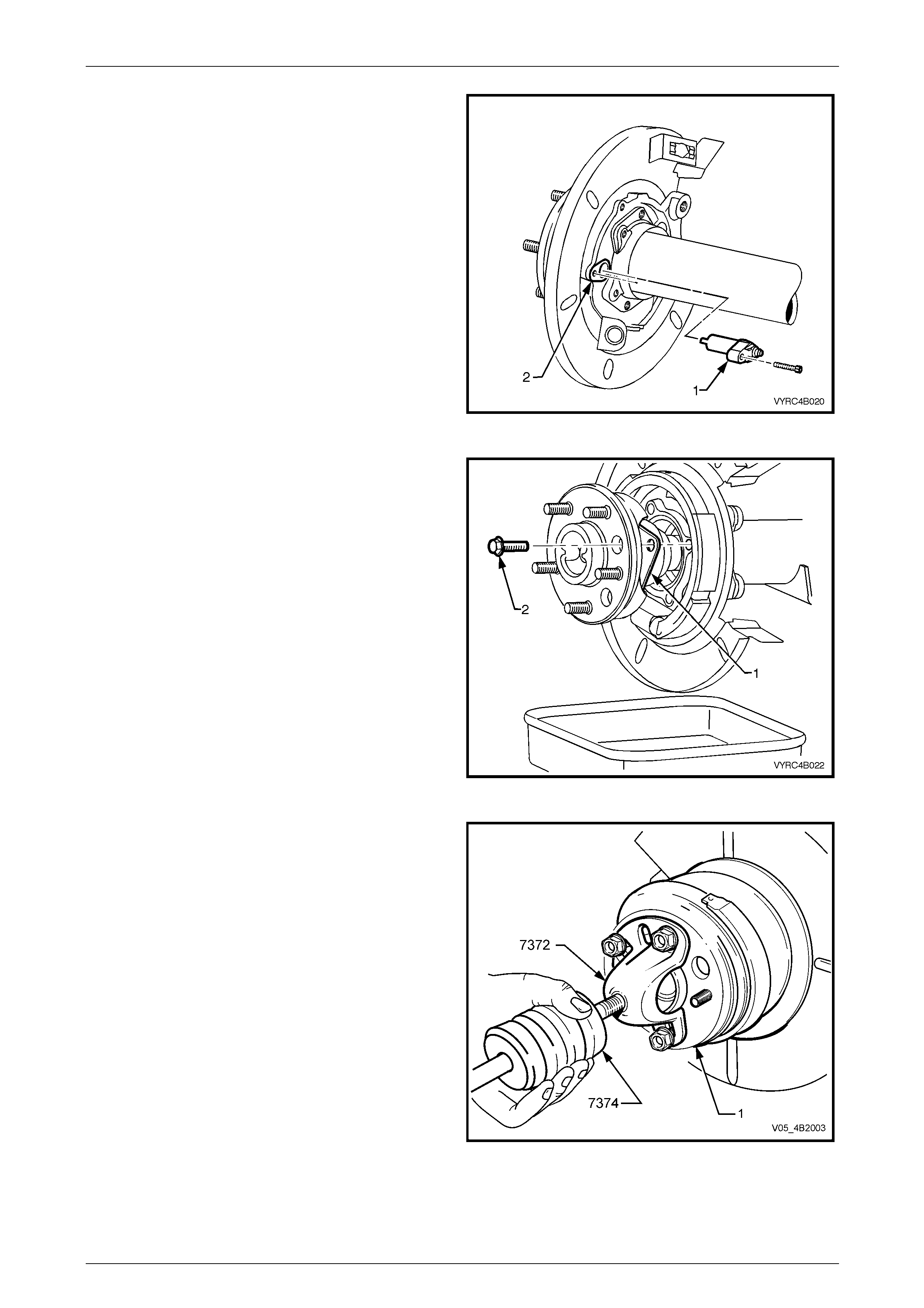
9 Disconnect and remove the ABS wheel speed sensor
(1) retaining screw.
10 Remove the wheel speed sensor (1) from the rear axle
housing (2)
Figure 4B2 – 44
11 Place a suitable container underneath the axle
housing to collect any oil that ma y leak out after axle
removal.
12 Remove the four bolts (2) securing the rear axle
retainer thrust plate (1).
Figure 4B2 – 45
13 Using three wheel attaching nuts, install Tool No. 7372
to the rear axle shaft flange (1).
14 Remove the forcing screw and lock nut from Tool No.
7372.
15 Install slide hammer, Tool No. 7374 to T ool No. 7372.
16 Using the slide hammer, Tool No. 7374, remove the
rear axle from the rear axle housing, taking care not to
damage the ABS pulse ring in the process.
17 Remove Tool No’s. 7372 and 7374 from the rear axle
shaft.
Figure 4B2 – 46
Rear Final Drive and Live Axle Page 4B2 – 28
Page 4B2 – 28
Reinstall
Reinstallation of the axle shaft is the reverse of the removal
procedure noting the following points:
1 Reinstall the rear axle shaft assembly.
2 Ensure the splines on the axle shaft align with the
matching splines located in the differential si de gears
and the axle shaft assembly is correctly positioned in
the rear axle housing to allow the retainer thrust plate
and attaching bolts to be installed without obstruction.
3 Install the retainer thrust plate (1) and attaching bolts
(2) to the rear axle housing.
4 Tighten the retainer thrust plate attaching bolts to the
correct torque specification.
() Retainer thrust plate attaching
bolt torque specification.......................................45 N.m
Figure 4B2 – 47
5 Reinstall the ABS wheel speed sensor (1) to the rear
axle housing, ABS sensor aperture (2) and re-connect
the sensor to the wiring harness.
6 Secure the wheel speed sens or with the retaining
screw tightened to the correct torque specification.
() ABS wheel speed sensor
screw torque specification....................................10 N.m
7 Install and tighten the rear brak e caliper anchor plate
to rear axle anchor plate attaching bolts to the correct
torque specification
() Rear brake caliper anchor plate
attaching bolt torque specification........................85 N.m
Figure 4B2 – 48
8 If required, flush the rear axle assembly, refer to 2.3 Changing/Flushing Rear Axle Lubricant in this Section.
9 Check the lubricant level, refer to 2.2 Checking Rear Axle Lubricant Level in this Section.
10 Reinstall road wheel in th e original position and secur e with the wheel nuts but do not fully tighten.
11 Lower the vehicle to the ground an d tighten the wheel nuts to the specified torque, working in a 'star' pattern,
refer to 2.1 Service Notes and Cautions, in this Section.
Road wheel attaching nut
torque specification..................................110 – 140 N.m
12 Reinstall the wheel cover/decorative wheel nut caps.
Rear Final Drive and Live Axle Page 4B2 – 29
Page 4B2 – 29
2.9 Rear Axle Shaft, ABS Pulse Ring, Oil
Seal, Bearing and Retainer Collar
LT Section No: F506000
Remove
1 Remove the rear axle shaft assembly; refer to 2.8 Rear Axle Shaft Assembly, Remove, in this Section.
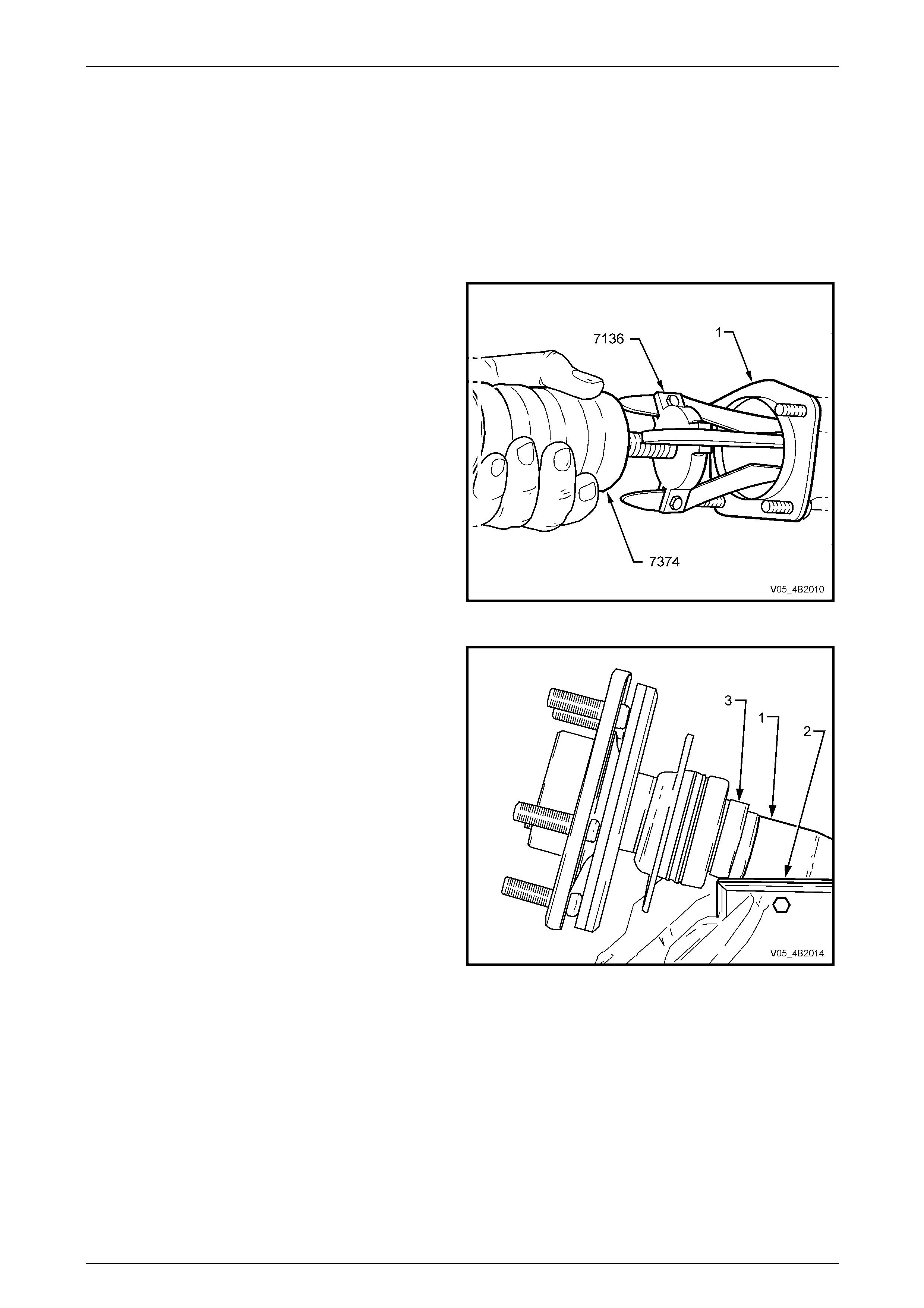
2 Install three legged puller, Tool No. 7136 behind the
wheel bearing cup and secure in this position.
3 Install slide hammer, Tool No. 7374 and remove the
rear axle bearing cup from the rear axle hou s ing (1).
4 Using a suitable solvent, clean the outsi de of the rear
axle shaft assembly before proceeding.
Figure 4B2 – 49
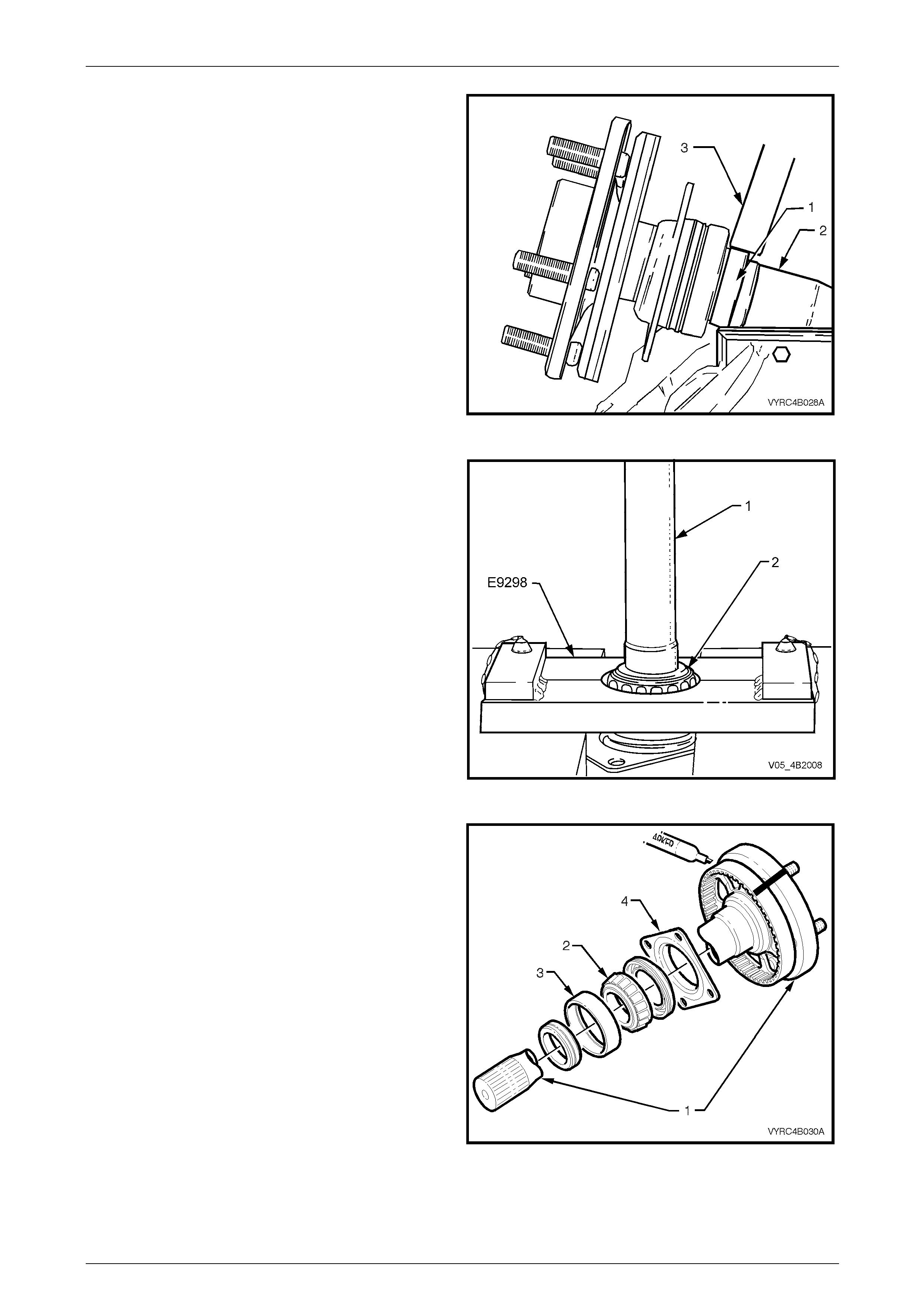
5 Clamp the bearing end of the rear axle shaft (1), in a
vice fitted with soft metal jaws (2).
NOTE
Check that the bearing retaining collar (3), is
resting on the vice jaws.
Figure 4B2 – 50
Rear Final Drive and Live Axle Page 4B2 – 30
Page 4B2 – 30
6 Centre punch the retainer collar (1).
7 Using 6 mm drill bit, drill a hole into the at right angles
to the axle shaft, taking care not to contact the axle
shaft (2).
8 Rotate the axle 90° and re-clamp in the vice j aws.
9 Taking care not to contact the axle shaft (2), use a
cold chisel (3) and hammer, split the bearing retainer
collar (1).
NOTE
It may be necessary to release the axle from the
vice, rotate the axle 90°, re-clamp and repeat the
splitting action.
10 Once removed, discard the removed retainer collar.
Figure 4B2 – 51
11 Install bearing remover T ool No. E9298 under the axle
bearing.
12 With the bearing remover supported b y pr ess plates,
press the rear axle shaft (1) from the inner-bearing
race (2).
13 Remove the oil seal and thrust retainer plate from the
axle shaft.
Figure 4B2 – 52
14 Clean the axle shaft (1), inner bearing race (2), and
bearing cup (3) along with the thrust retainer plate (4)
in a suitable cleaning solvent.
15 If the ABS pulse ring is to be removed, mark the
relationship to the rear axle flange, using a felt tipped
pen or similar.
NOTE
This relationship marking of the axle shaft fla nge
and ABS pulse ring is needed to align the large
hole in the axle shaft flange with an opening
between the webbing of the ABS pulse ring,
providing access for removal of the axle shaft
retainer plate attaching bolts.
Figure 4B2 – 53
Rear Final Drive and Live Axle Page 4B2 – 31
Page 4B2 – 31
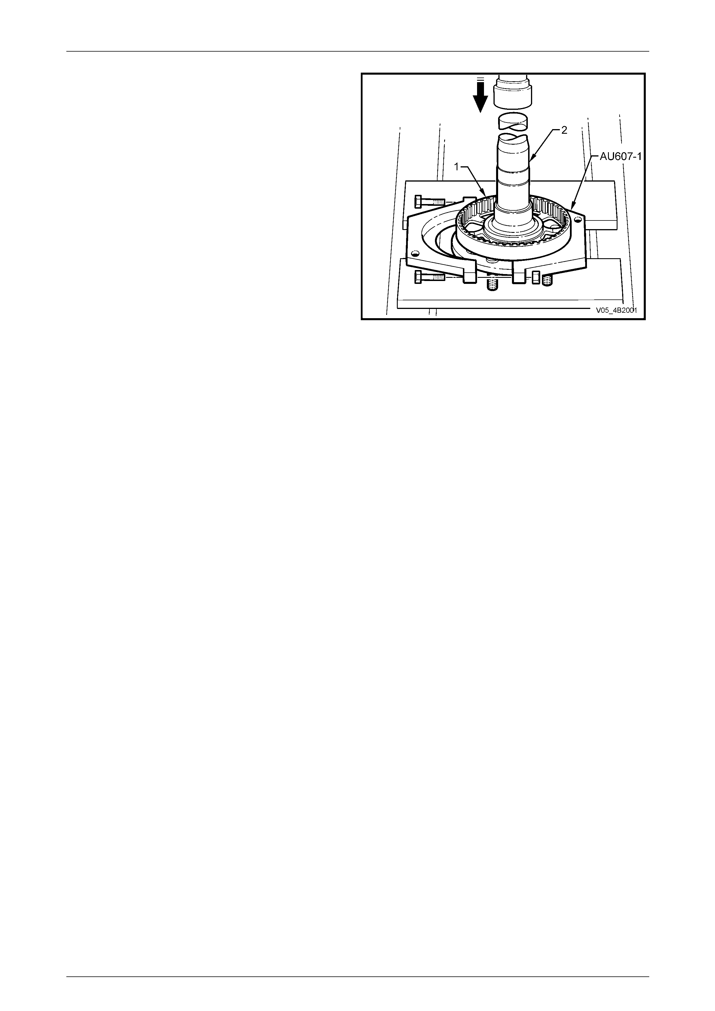
16 Using press plates, Tool No. AU607-1 to support the
ABS pulse ring (1), press rear axle shaft (2) from the
ABS pulse ring (1).
Figure 4B2 – 54
Inspect
Axle Shaft, Bearing and Cone
1 The axle shaft for twisting, cracking or excessive spline wear. Replace as requ ired.
2 The axle shaft-seating surface for the inner bearing. Replace as required.
3 The inner bearing and cone for pitting, scoring, cracks or uneven wear. Replace as required.
4 The thrust retainer plate for distortion, scoring, cracks or uneven wear. Replace as required.
5 The ABS pulse ring for distortion, scoring, cracks or other damage. Replace as required.
Reassemble
1 Reassembly of the ABS pulse ring, thrust retainer plate, oil seal, inner bearing race, and new retaining collar to the
axle shaft is the reversal of the removal procedure noting the following points:
NOTE
• Before installation, pre-lubricat e the inner se al
lips of the oil seal with Lithium No.2 Grease .
• Care must be taken to ensure the bearing
race and retaining collar is fitted squarely
during installation.
• Apply sufficient press force to ensure the
proper seating of all components.
Rear Final Drive and Live Axle Page 4B2 – 32
Page 4B2 – 32
1 If the ABS pulse ring (2) has been removed, align the
relationship marks on the side of both the rear axle
shaft flange and the ABS pulse ring.
2 If installing a new ABS pulse ring, check that a pulse
ring opening aligns with the large hole in the axle
flange. This is necessary to allow access to the
bearing retaining flange bolts.
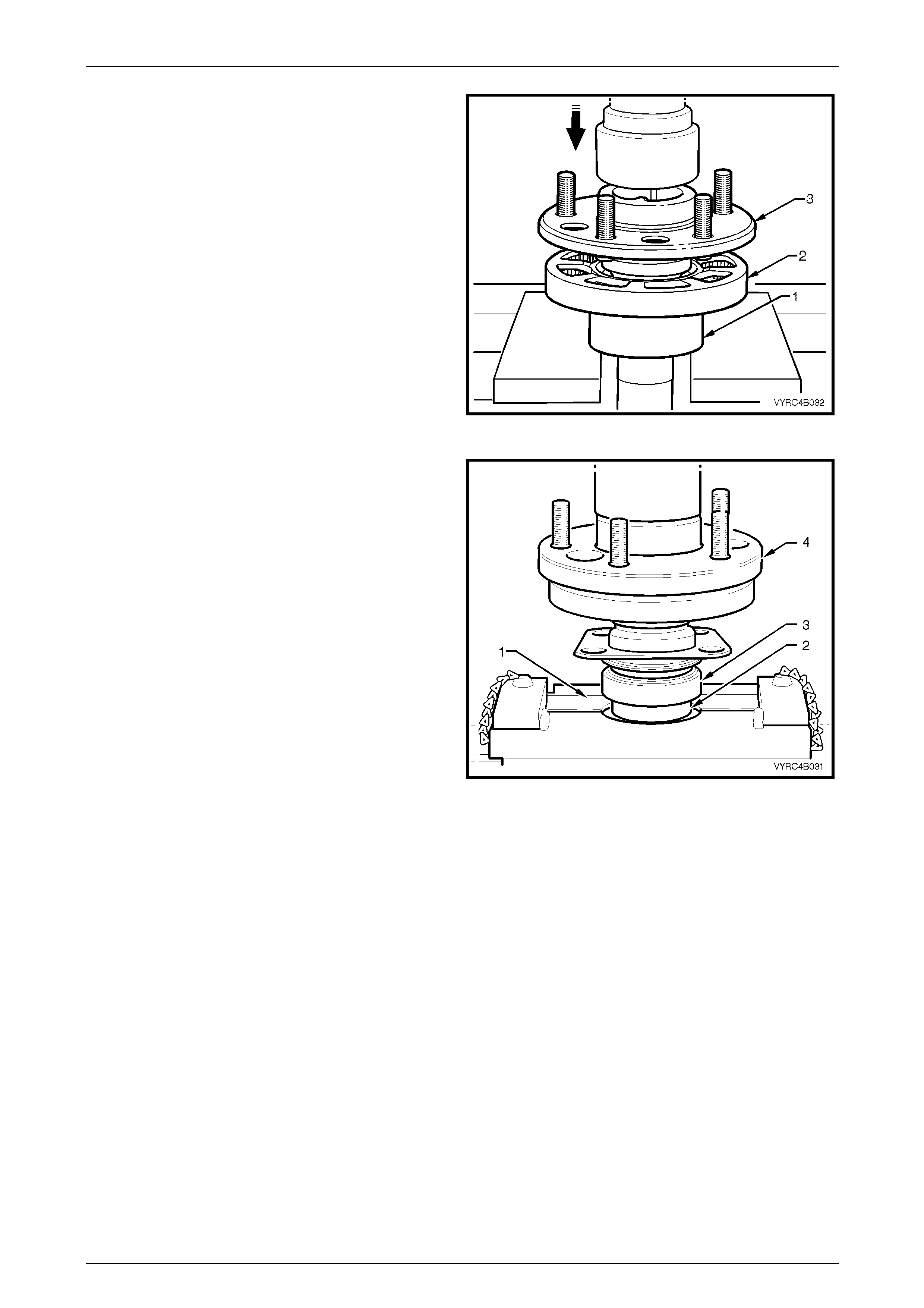
3 Install ring, Tool No. AU607-2 over the axle shaft.
4 Support the assembly with suitable press plates, then
press the ABS pulse ring (2) onto the machined axle
shaft seat.
5 After installation, check that the ABS pulse ring is
undamaged and square. If damage has occurred,
replace the pulse ring.
Figure 4B2 – 55
6 Install the thrust retainer plate, oil seal, inner bearing
race (3) and new retaining collar (2) to the axle shaft
(4).
7 Using Tool No. E9298 (1) to s upport the retaining
collar (2) and inner-bear ing race (3), press the collar
and inner-bearing race on to the axle shaft (4).
8 Check the inner bearing for bi nding or cage distortion.
If damage has occurred during the pressing operation
replace the retaining collar, bearing race and cone.
9 Reinstall the rear axle, refer to
2.8 Rear Axle Shaft Assembly in this Section.
Figure 4B2 – 56
Rear Final Drive and Live Axle Page 4B2 – 33
Page 4B2 – 33
2.10 Pinion Oil Seal
LT Section No: F502100
Remove
1 Raise the vehicle and suppor t in a safe manner. Refer to Section 0A General Information in this Service Information
for the location of recommended lifting and supp ort points.
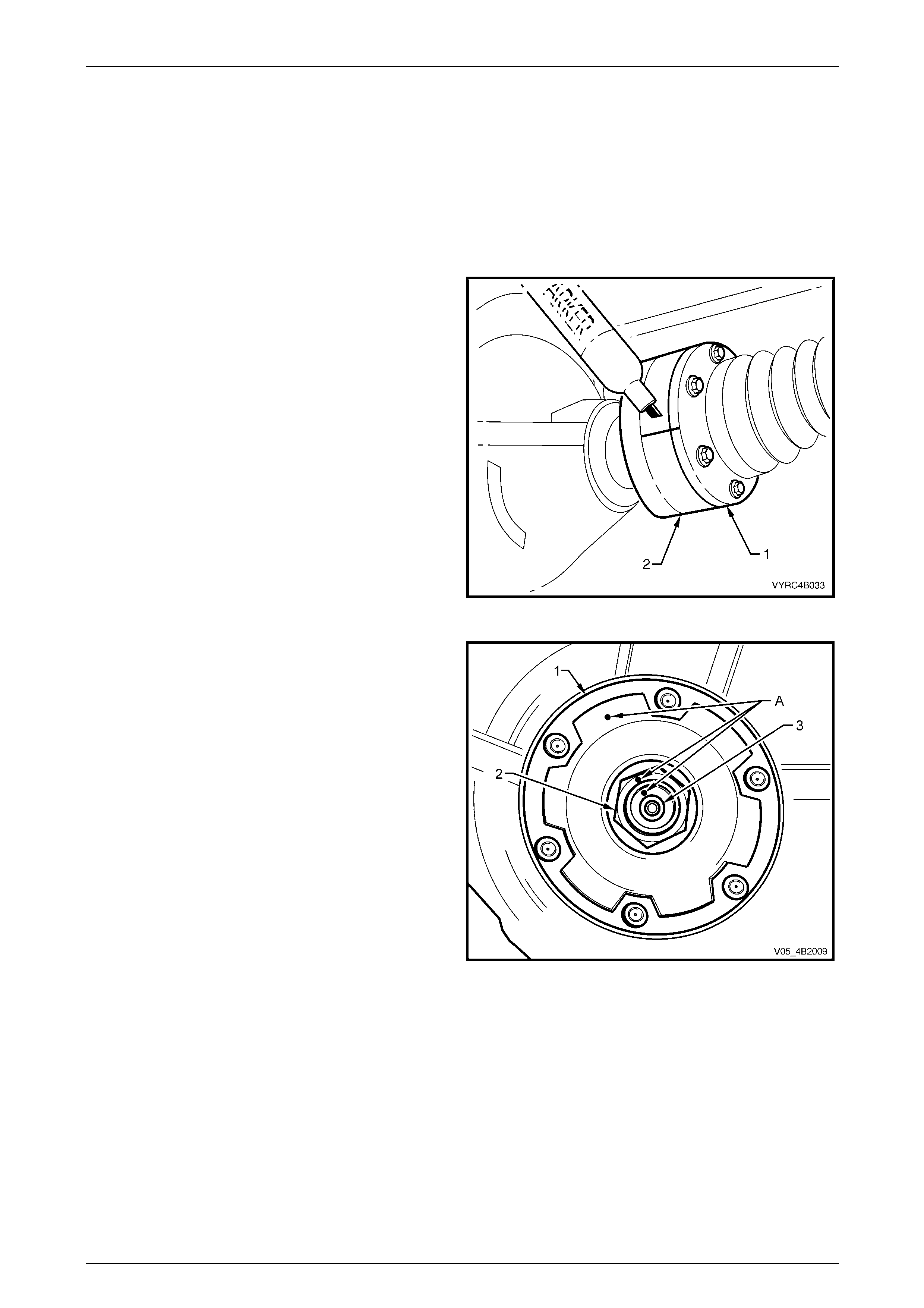
2 Using a felt tipped pen or similar, mark the relationship
position of the propeller shaft rear coupling (1) to the
pinion flange (2).
3 Remove the propeller shaft, refer to
Section 4C1 Propeller Shaft and Universal Joints. This
operation may also requir e pa rtial exhaust system
removal.
Figure 4B2 – 57
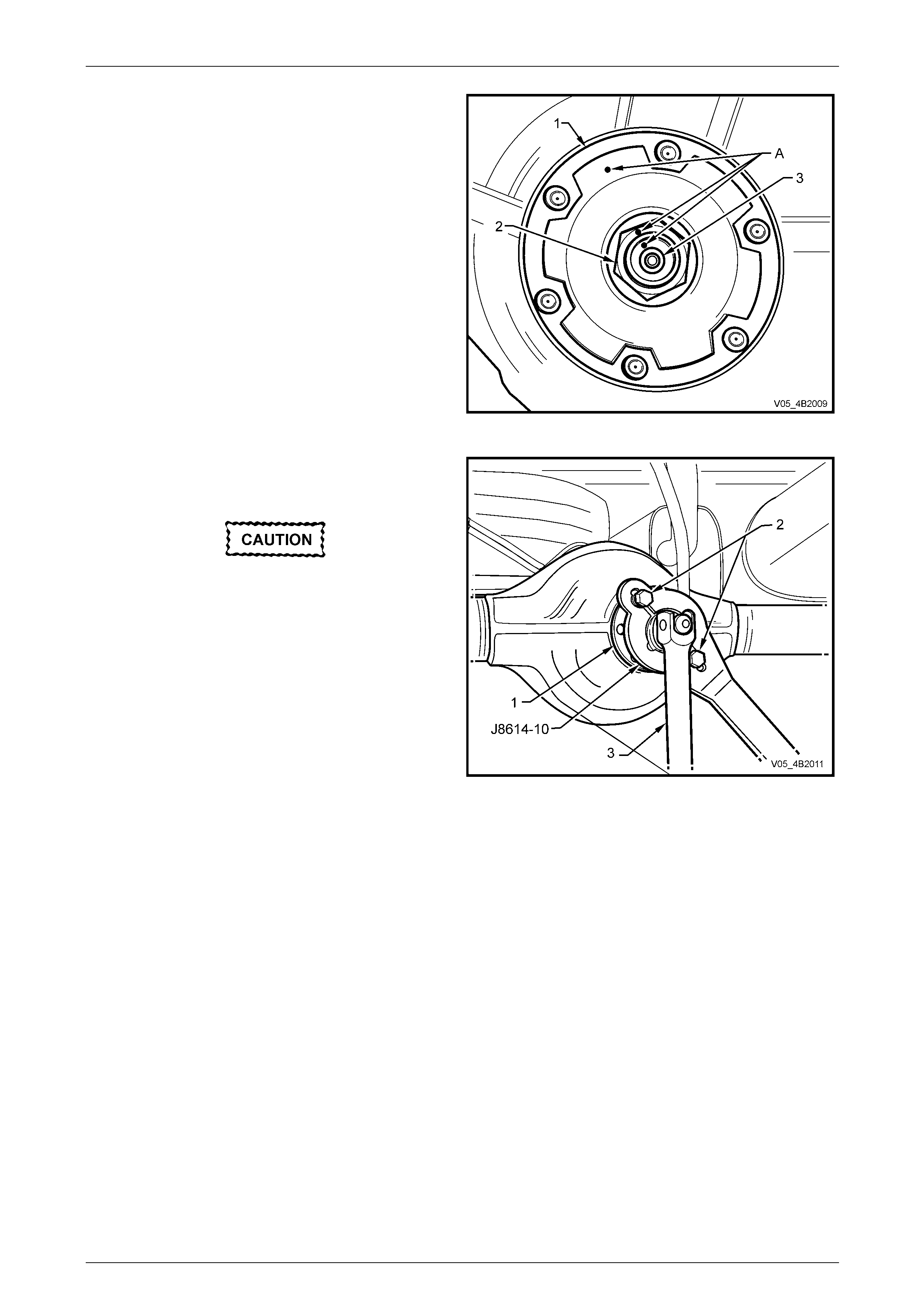
4 Lightly centre-punch ali gnment marks (A) on the pinion
flange (1), flange nut (2) and pini on end (3) to assist
the reassembly process.
NOTE
By reassembling to the original position, the
flange run-out will be minimised and the pinion
bearing preload will be maintained.
Figure 4B2 – 58
Rear Final Drive and Live Axle Page 4B2 – 34
Page 4B2 – 34
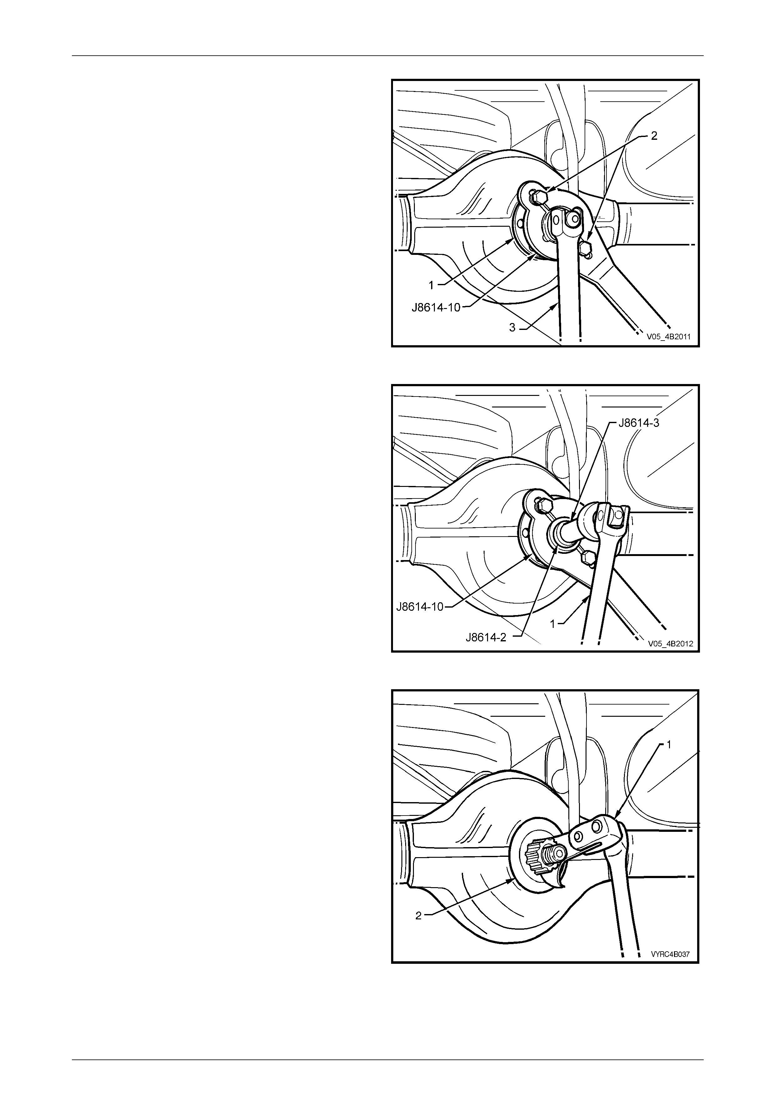
5 Using two of the propeller shaft constant velocity joint
bolts (2) with flat washers, secure the holding bar, T ool
No. J8614-10 (part of Tool No. J 8614-O1) to the
pinion flange (1).
6 Remove the pinion flange retaining nut, using a
commercially availabl e socket and socket bar (3).
7 Remove Tool No. J8614-10.
Figure 4B2 – 59
8 Place drain tray beneath the final drive housing.
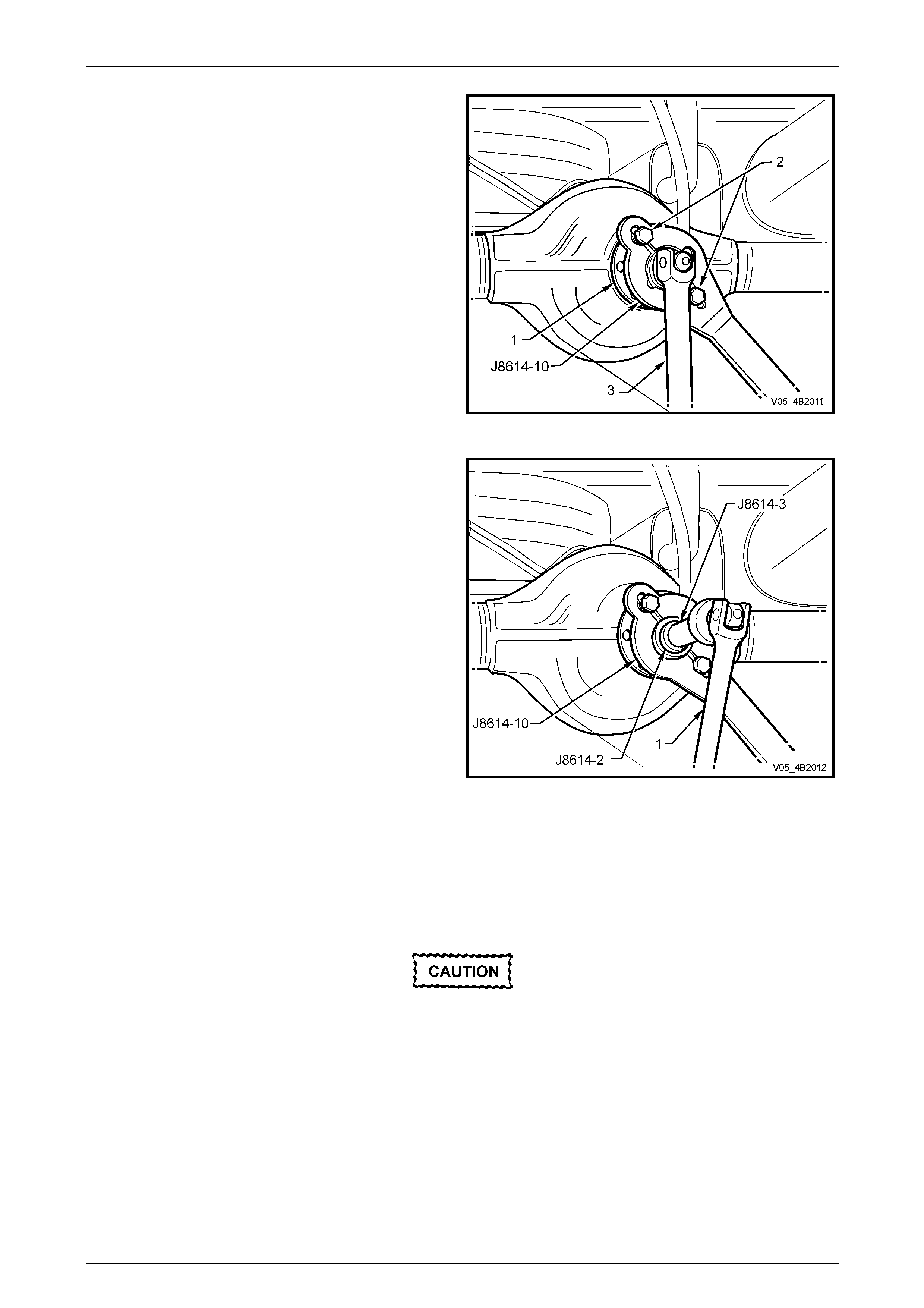
9 With Tool No J8614-10 still installed, thread the forcing
screw, Tool No. J8614-3, into the adaptor, Tool No.
J8614-2. Install this sub-assembly into holder , T ool
No. J8614-10, then rotate through 45° to locate in the
recesses in J8614-10.
10 While holding J8614-10, use a socket and bar (1) to
rotate the forcing screw J8614-3 in a clockwise
direction, to remove the pinion flange.
11 Remove the tools from the pinion flange, then carefully
set the pinion flange to one side to avoi d damage to
the flanged seal surface.
Figure 4B2 – 60
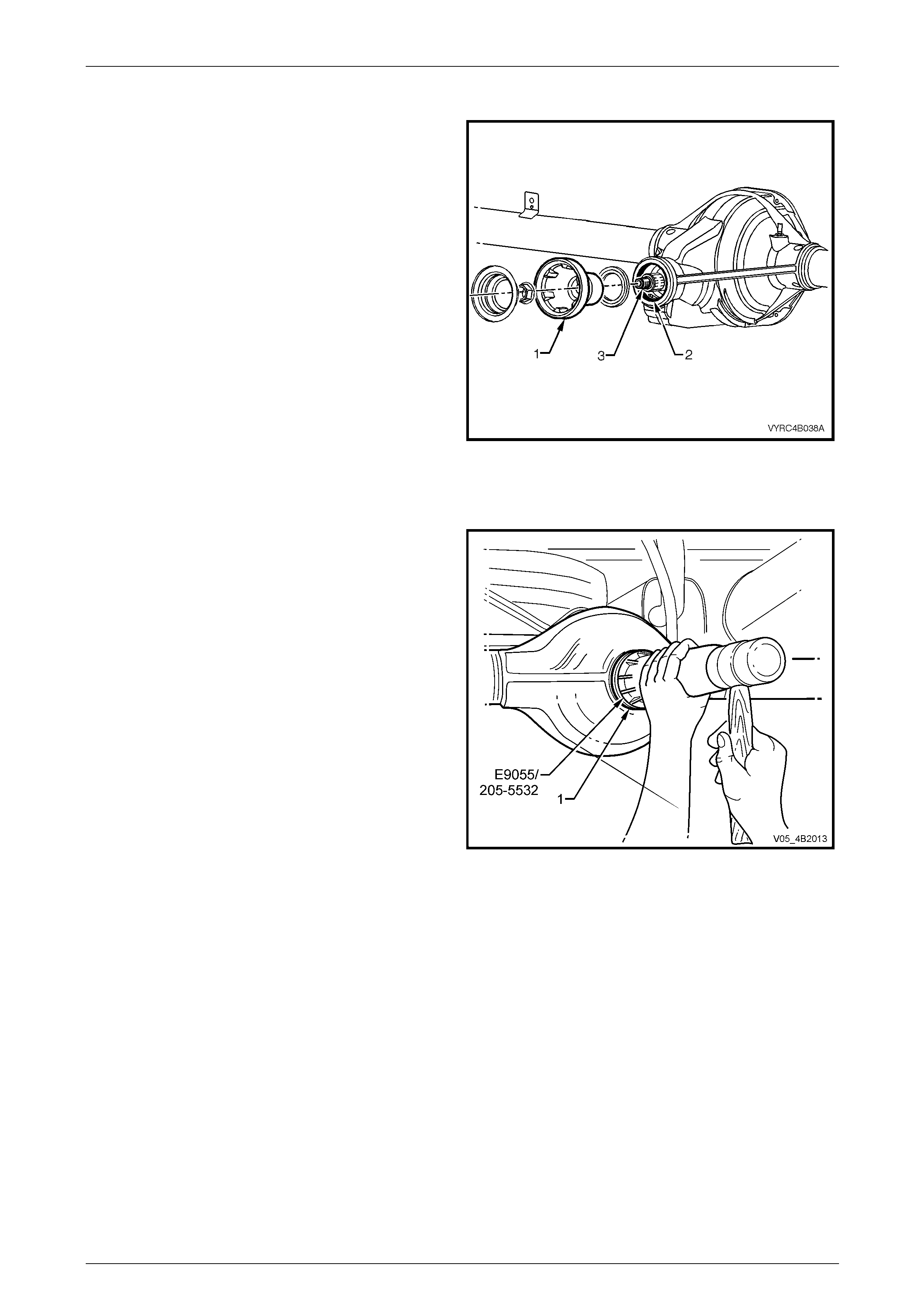
12 Using Tool No. E308 (1) or a universal seal removing
tool, prise the pinion oil seal (2) from the rear axle
housing, pinion carrier bore.
Figure 4B2 – 61
Rear Final Drive and Live Axle Page 4B2 – 35
Page 4B2 – 35
Inspect
1 Clean the pinion flange (1), the oil seal se at of the rear
axle housing, the pinion carrier bore (2) and the
threads of the pinion shaft (3) with a suitable cleaning
solvent.
2 Inspect the pinion flange for wear or damage,
particularly in the seal running surface..
NOTE
If the pinion flange is found to be unserviceable,
refer to 2.11 Pinion Flange, Replace (Using N ew
Oil Seal) in this Section from this point on
3 Discard the pinion oil seal.
Figure 4B2 – 62
Reassemble
1 Lubricate the lips and outside diameter of a new pinion
oil seal (1) with the Mobilgrease XHP 222. T he recess
between the lips shoul d be approximately 50% filled
with grease.
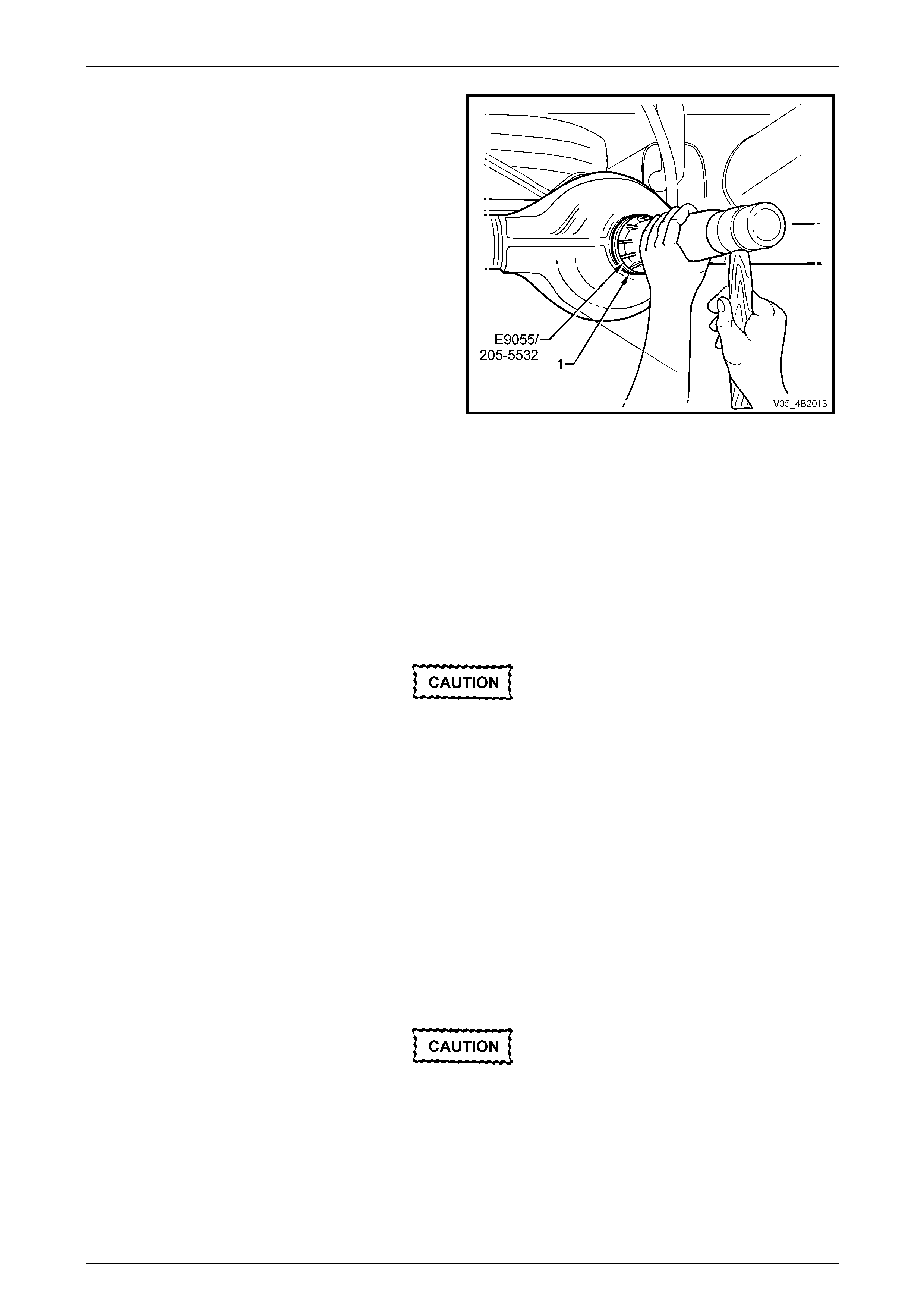
2 Start the oil seal into the rear axle housi ng pinion
carrier bore and drive the seal squarel y into positio n,
for M78 Series use Tool No. E9055 an d for M86
Series use Tool No. 205-553.
3 Check that the pinion shaft is free from burrs and that
oil seal flange surface is free from damag e.
Figure 4B2 – 63
Rear Final Drive and Live Axle Page 4B2 – 36
Page 4B2 – 36
4 Lubricate the splines an d seal surface of the pinion
flange with rear axle lubricant, refer to
2.2 Checking Rear Axle Lubricant Level in this Section
for the recommended lubricant.
5 Ensure that the centre-punch marks (A) are aligned in
relation to the pinion flang e (1) and the pinion end (3)
and install flange over the pinion shaft splines.
6 Apply a thread locking compound such as Loctite 262
or equivalent, to the cleaned threads of the p inion
flange retaining nut, then reinstall the nut.
Figure 4B2 – 64
7 Reinstall Tool No. J8614-10 (part of Tool No. J8614-
O1) to the pinion flange (1), using two of the constant
velocity joint retaining bolts (2), with flat washers.
The pinion flange is an interference fit on
pinion shaft splines and should only be
pulled into place by tightening the retaining
nut. During installation, do not, under any
circumstances, use force or hammer the
flange onto the pinion splines.
8 Tighten the flange retaining nut until all centre-punch
marks align, refer to Figure 4B2-64. T hen carefully
tighten the nut to a position not more than 5° past the
aligned setting.
Figure 4B2 – 65
9 Reinstall propeller shaft, refer to Section 4C1 Rear Propeller Shaft and Universal Joints.
10 If removed previously, reinstall the exhaust system, in the reverse to the removal procedure.
Refer to Section 8B Exhaust System, for details.
11 Lower vehicle to the ground.
12 Check lubricant level and top up as necessary. Refer to 2.2 Checking Rear Axle Lubricant Level, in this Section.
13 Start vehicle and check for exhaust leaks.
Rear Final Drive and Live Axle Page 4B2 – 37
Page 4B2 – 37
2.11 Pinion Flange
LT Section No. – F501100
ATTENTION
The following fasteners MUST be replaced w hen performing these operations:
Pinion flange nut.
Replace (Using Old Oil Seal)
• Due to production tolerances in the length
of the pinion flange, it is essential that the
following method be used when installing
a new pinion flange.
• A new retaining nut must always be used
when the pinion flange is rep l aced.
1 Raise the rear of the vehicle and sup port in a safe manner. Refer to Section 0A General Information in this Service
Information for the location of recommended lifting and support points.
2 Remove the wheel covers or decorative wheel nut caps, then mark the relationship of the road wheel to one of the
wheel studs.
3 Loosen, then remove the road wheel attachi ng nuts, working in a 'star' pattern.
Refer to 2.1 Service Warnings, Cautions and Notes in this Section, for detailed information. Remove the r oad
wheel.
4 Remove the propeller shaft; refer to Section 4C1 Propeller Shaft and Universal Joints. This operation may also
require partial exhaust s ystem removal, refer to Section 8B Exhaust System.
5 Remove both rear axle shafts; refer to 2.8 Rear Axle Shaft Assembly in this Section.
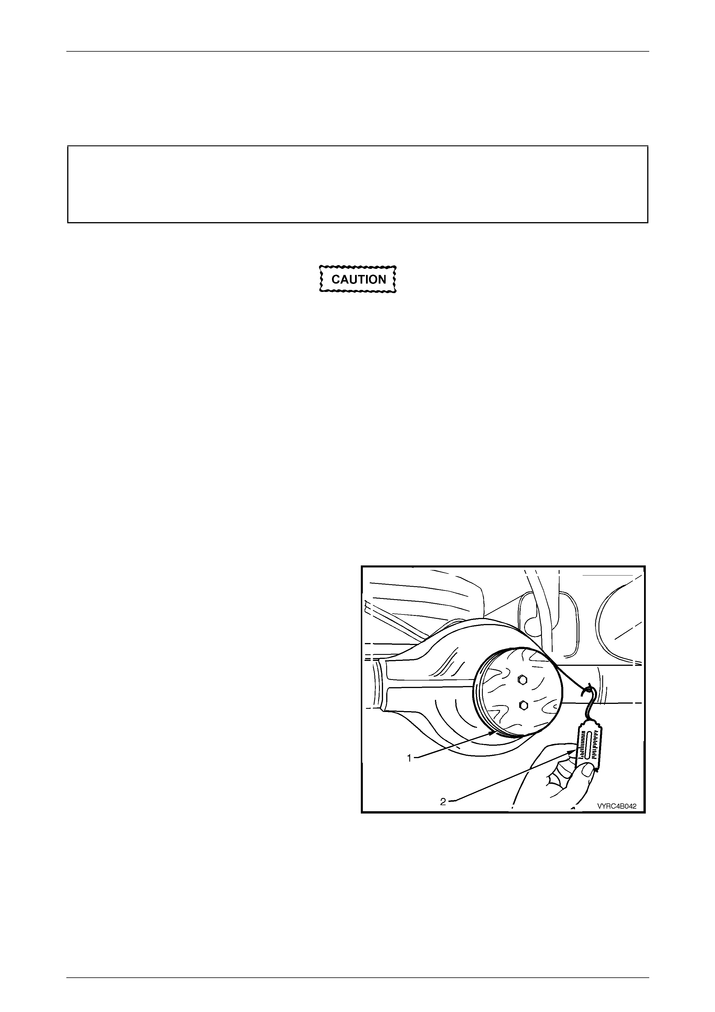
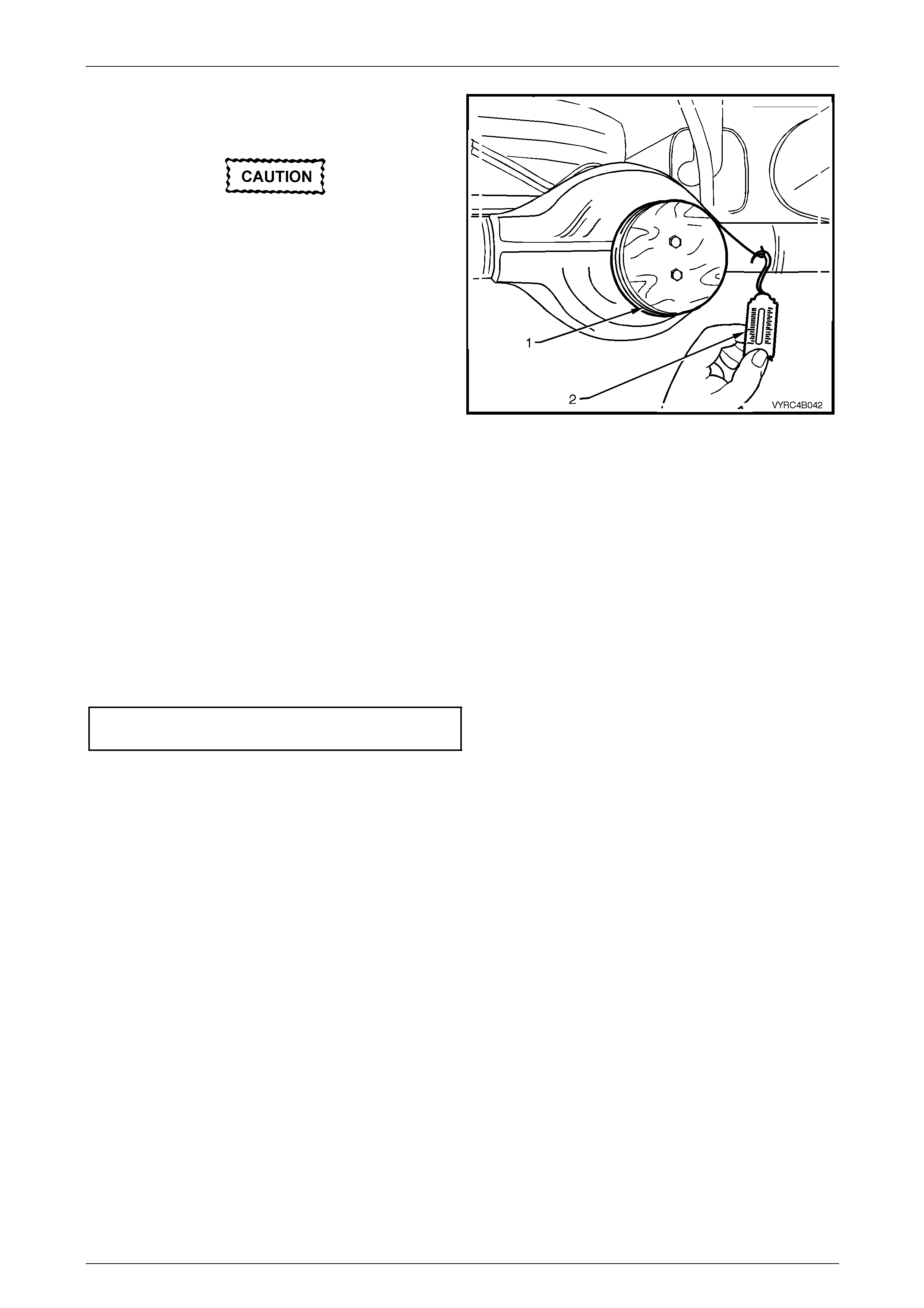
6 Check and record preload at pinion flange as follows:
a Fit the pre-fabricated pulley (1) to the pinion
flange, using two bolts and attach a cord around
the pulley and then to a spring balance (2).
NOTE
For details of the fabricated pulley, refer to
7 Special Tools in this Section.
b Start rotation of pulley and whilst in motion
(approximately 50-60 rpm) record rea din g on the
spring balance.
NOTE
This preload reading includes the pinion
bearings, the side bearings, the meshing effect
of gear set and the pinion oil s eal.
c To determine the preload, multipl y the reading
on spring balance by the radius of pulley.
i.e. With a pulley diameter of 152 mm, the radius
is 76 mm, which equals 0.076 m. With a spring
balance reading of 25 N, the preload equals
0.076 m x 25 N = 1.9 Nm.
7 Remove the pulley from the pinio n flan ge.
Figure 4B2 – 66
Rear Final Drive and Live Axle Page 4B2 – 38
Page 4B2 – 38
8 Using two of the propeller shaft constant velocity joint
bolts (2) with flat washers, secure the holding bar, T ool
No. J8614-10 (part of Tool No. J 8614-O1) to the
pinion flange (1).
9 Remove the pinion flange retaining nut, using a
commercially availabl e socket and socket bar (3).
10 Remove Tool No. J8614-10.
Figure 4B2 – 67
11 Place drain tray beneath the final drive housing.
12 With Tool No J8614-10 still installed, thread the forcing
screw, Tool No. J8614-3, into the adaptor, Tool No.
J8614-2. Install this sub-assembly into holder , T ool
No. J8614-10, then rotate through 45° to locate in the
recesses in J8614-10.
13 While holding J8614-10, use a socket and bar (1) to
rotate the forcing screw J8614-3 in a clockwise
direction, to remove the pinion flange.
14 Remove the tools from the pinion flange, then carefully
set the pinion flange to one side to avoi d damage to
the flanged seal surface.
15 Check that the pinion shaft thread is free from burrs,
oil, dirt or grease, and then coat the splines and the
seal surface of the new pinion flange with the
recommended rear axle lubric ant.
Figure 4B2 – 68
NOTE
Refer to 2.2 Checking Rear Axle Lubricant Level
or 5 Specifications in this Section for the
recommended lubricant.
16 Lubricate the splines and sea l surface of the pinion flange with rear axle lubricant,
refer to 2.2 Checking Rear Axle Lubricant Le vel in this Secti on for the recommended lubricant.
The pinion flange is an interference fit on
pinion shaft splines and should only be pulled
into place by tightening the retaining nut.
During installation, do not, under any
circumstances, use force or hammer the
flange onto the pinion splines.
17 Install the new pinion flange, using the original pinion nut with Loctite 243 applied to the cleaned threads.
Rear Final Drive and Live Axle Page 4B2 – 39
Page 4B2 – 39
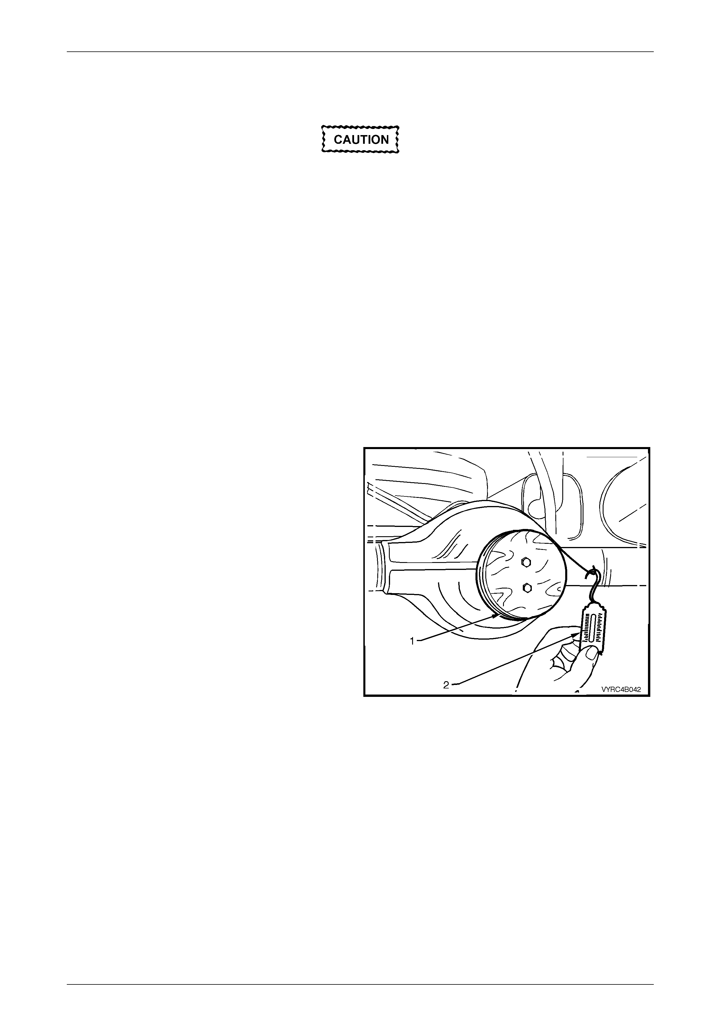
18 Attach the pre-fabricated pulley (1) to the new pinion
flange then using a suitabl e spring balance (2) check
the preload.
• Tighten the pinion nut gradually, checking
the preload figure constantly.
• Should the retaining nut be over-
tightened and pre-load exceeded , it w ill be
necessary to remove the pinion from the
carrier and install a new collapsible
spacer.
• Under no circumstances is the retaining
nut to be backed off to decrease the pre-
load setting.
19 Continue tightening the nut while alternatively turning
the pinion to seat the bearings, until the prelo ad figure
recorded previously in Step 4 b is reach ed. Then
further increase the original preload reading by
0.5 Nm.
Figure 4B2 – 69
20 Rotate the pinion an extra 30-40 turns and re-check the preload to ensure that no change has occurred.
21 Reinstall the propeller sh aft rear coupling to the pinion flange;
refer to Section 4C1 Rear Propeller Shaft and Universal Joints in this Section.
22 If removed, reinstall the exhaust system, refer to Section 8B Exhaust System.
23 Reinstall road wheel in th e original position and secur e with the wheel nuts but do not fully tighten.
24 Lower the vehicle to the ground an d tighten the wheel nuts to the correct torque specification, working in a 'star'
pattern, refer to 2.1 Service Notes and Cautions , in this Section.
Road wheel attaching nut
torque specification..................................110 – 140 N.m
25 Reinstall the wheel cover/decorative wheel nut caps.
26 Check the lubricant level and top up as necessary. Refer to 2.2 Checking Rear A xl e Lubricant Level in this Section.
27 Start the engine and check for exhaust le aks.
Rear Final Drive and Live Axle Page 4B2 – 40
Page 4B2 – 40
Replace (Using New Oil Seal)
• Due to production tolerances in the length
of the pinion flange, it is essential that the
following method be used when installing
a new pinion flange.
• A new retaining nut must always be used
when the pinion flange is rep l aced.
1 Raise the rear of the vehicle and sup port in a safe manner. Refer to Section 0A General Information in this Service
Information for the location of recommended lifting and support points.
2 Remove the wheel covers or decorative wheel nut caps, then mark the relationship of the road wheel to one of the
wheel studs.
3 Loosen, then remove the road wheel attachi ng nuts, working in a 'star' pattern.
Refer to 2.1 Service Warnings, Cautions and Notes in this Section, for detailed information. Remove the r oad
wheel.
4 Remove the propeller shaft; refer to Section 4C1 Propeller Shaft and Universal Joints. This operation may also
require partial exhaust s ystem removal, refer to Section 8B Exhaust System.
5 Remove both rear axle shafts; refer to 2.8 Rear Axle Shaft Assembly in this Section.
6 Check and record preload at pinion flange as follows:
a Fit a fabricated pulley (1) to the pinion flang e,
using two bolts and attach a cord around the
pulley and then to a spring balance (2).
NOTE
For details of the fabricated pulley, refer to
7 Special Tools in this Section.
b Start rotation of pulley and whilst in motion
(approximately 50-60 rpm) record rea din g on the
spring balance.
NOTE
This preload reading includes the pinion
bearings, the side bearings, the meshing effect
of gear set and the pinion oil s eal.
c To determine the preload, multipl y the reading
on spring balance by the radius of pulley.
i.e. With a pulley diameter of 152 mm, the radius
is 76 mm, which equals 0.076 m. With a spring
balance reading of 25 N, the preload equals
0.076 m x 25 N = 1.9 Nm.
7 Remove the pulley from the pinio n flan ge.
Figure 4B2 – 70

Rear Final Drive and Live Axle Page 4B2 – 41
Page 4B2 – 41
8 Using a suitable size socket and bar (3), loosen the
pinion flange retaining nut until a slight endplay can be
felt in the pinion shaft.
9 Remove holding Tool No. J8614-10 from the pinion
flange.
10 Reinstall the fabricated pulley to the pinion flange.
11 Re-measure the oil seal and d ifferentia l side bearing
preload using the spri ng balance and pulley, as
detailed in steps 6a and 6b.
12 Record the oil seal and side bearing preload for later
use.
13 Reinstall Tool No. J8614-10 to the pinion flange (1)
and completely remove the pi nion flange nut.
Figure 4B2 – 71
14 Place drain tray beneath the differential carrier.
15 With Tool No J8614-10 still installed, thread the forcing
screw, Tool No. J8614-3, into the adaptor, Tool No.
J8614-2. Install this sub-assembly into holder , T ool
No. J8614-10, then rotate through 45° to locate in the
recesses in J8614-10.
16 While holding J8614-10, use a socket and bar (1) to
rotate the forcing screw J8614-3 in a clockwise
direction, to remove the pinion flange.
17 Remove the tools from the pinion flange.
Figure 4B2 – 72
18 Prise the pinion oil seal (2) from the carrier bore using
Tool No. E308 (1) or a universal seal removing tool.
19 Lubricate the new pinion oil seal inner and outer lip
diameters with the recommended rear axle lubricant.
NOTE
Refer to 2.2. Checking Rear Axle Level or
5 Specifications in this Section in this Sectio n for
the recommended lubricant.
Figure 4B2 – 73
Rear Final Drive and Live Axle Page 4B2 – 42
Page 4B2 – 42
20 Lubricate the lips and outside diameter of a ne w pinion
oil seal with the Mobilgrease XHP 222. The recess
between the lips shoul d be approximately 50% filled
with grease.
21 Start the oil seal into the rear axle housi ng pinion
carrier bore and drive the seal squarel y into positio n,
for M78 Series use Tool No. E9055 an d for M86
Series use Tool No. 205-553.
NOTE
Once installed the seal fits flush to 0.25 mm
below the rear axle housing, pinion carrier bore
outer face.
Figure 4B2 – 74
22 Check that the pinion shaft thread is free from burrs, oil, dirt, thread sealant or grease.
23 Coat the splines and the seal surface of the new pinion flange with the recommended rear axle lubricant.
NOTE
Refer to 2.2. Checking Rear Axle Level or
5 Specifications in this Section in this Section for
the recommended lubricant.
24 Install the pinion flange, indexing with the final drive pinion splin es.
The new flange will be a interference fit on
pinion shaft splines and should only be pulled
into place by tightening the retaining nut. Do
not, under any circumstances, use force or
hammer flange during installation onto pinion
flange.
25 Install a NEW flange-retaining nut and tighten, drawing the pinion flange onto the pinio n shaft splines.
26 Continue to tighten the flange retaining nut gradually until pinion shaft endpla y is reduced to approximately 0.5 mm.
27 Check the new oil seal and final drive assembly preload usi ng a spring balance, refer to Steps 6a, 6b and 6c.
Record the preload for reassembly.
28 The preload reading for final drive assembly recorded in step 12, is subtracted from the preload re ading obtained in
step 27. The difference bet ween these fi gures represents extra lip tension of the new seal, expressed as a N.m
preload figure. T he difference between the preload readings obtained in steps 12 and 27 must be added to the
preload reading obtained in step 6b, to obtain a total preload reading.
Should the retaining nut be over tightened
and the preload exceed ed, it will b e necessar y
to remove then install a new collapsible
spacer and pinion retaining nut. Under no
circumstances must the retaining nut be
backed off to decrease the preload setting.
Rear Final Drive and Live Axle Page 4B2 – 43
Page 4B2 – 43
29 Continue tightening the pinion flange retaining nut while alternately turning the pinio n to seat the bearings until the
total preload figure obtained in step 27 is achieved. Then increase this preload reading by 0.11 to 0.34 N.m. Then
further rotate the pinion an extra 30-40 turns and rec heck the preload to ensure that no change has occurred.
NOTE
It must be realised that the preload readings in
the example are only theoretical. In practice, the
figures could differ greatly, so the readings
obtained when performing the actual operations,
are the ones to use.
Theoretical Example
Step, Section and Action Reading/Result
From Step 27 obtain the new oil seal an d side bearing preload setting. 1.67 Nm
From Step 12 obtain the old oil seal an d sid e bearing preload reading. 1.22 Nm
Subtract Step 9 from Step 22. 0.45 Nm
From Step 6b obtain the complete different ial assembly preload rea ding. 1.47 Nm
Add the preload readings together, the combination will be the sum of: 1.47 Nm plus 0.45 Nm
Which gives a total preload reading of: 1.92 Nm
30 Reinstall the propeller sh aft rear coupling to the pinion flange;
refer to Section 4C1 Rear Propeller Shaft and Universal Joints in this Section.
31 If removed, reinstall the exhaust system, refer to Section 8B Exhaust System.
32 Reinstall the axle shafts; refer to 2.8 Rear Axle Shaft Assembly in this Section.
33 Reinstall road wheel in th e original position and secur e with the wheel nuts but do not fully tighten.
34 Lower the vehicle to the ground an d tighten the wheel nuts to the correct torque specification, working in a 'star'
pattern, refer to 2.1 Service Notes and Cautions , in this Section.
Road wheel attaching nut
torque specification..................................110 – 140 N.m
35 Reinstall the wheel cover/decorative wheel nut caps.
36 Check the lubricant level and top up as necessary. Refer to 2.2 Checking Rear A xl e Lubricant Level in this Section.
37 Start the engine and check for exhaust le aks.

Rear Final Drive and Live Axle Page 4B2 – 44
Page 4B2 – 44
3 Major Service Operations
ATTENTION
All fasteners are important attaching parts as they affect the performance of vital components and/or could
result in major repair expense. W here specified in this Section, fasteners MUST be replaced w ith parts of the
same part number or an approved equivalent. Do not use fasteners of an inferior quality or substitute design.
Torque values must be used as specified during reassembly to ensure proper retention of all components.
Throughout this Section, fastener torque wrench specifications may be accompanied with the following
identification marks:
Fasteners must be repl aced after loosening.
Vehicle must be at curb height before final tightening.
Fasteners either have micro encapsulated sealant applied or incorporate a mechanical thread lock and
should only be re-used once. If in doubt, replacement is recommended.
If one or more of these identification marks is present alongside a fastener torque wrench specification, the
recommendation regarding that fastener must be adhered to.
3.1 Rear Axle Assembly
LT Section No: F650100
ATTENTION
The following fasteners have either micro encapsulation or incorporate a mechanical thread lock and should
only be used once. If in doubt , rep lacement is recommended w hen performing these operations:
Rear spring shackle mounting plate to chassis attaching bolt.
Rear stabiliser bar mounting to rear axle housing attaching bolt (where fitted).
Rear brake load sensing valve linkage to rear axle housing attaching bolt (where fitted).
The following fasteners MUST be replaced w hen performing these operations:
Rear spring U-bolt and retainer plate attaching nut.
Rear shock absorber upper mounting attaching nut.
Rear shock absorber lower mounting attaching bolt.
Rear stabiliser bar linkage attachin g nut (where fitted).
Vehicle must be at curb height before final tightening.
• Rear shock absorber lower mounting attaching bolt.
Preliminary Check
If an overhaul of the rear axle is anticipated, it is recommended that the rear axle shaft check for run-out and end float
procedure be undertaken and the results recorded for future use, following the removal of the rear a xle housing
assembly from the vehicle. Refer to 2.4 Rear Axle Shaft Check For Run-Out And End Float in this Section.
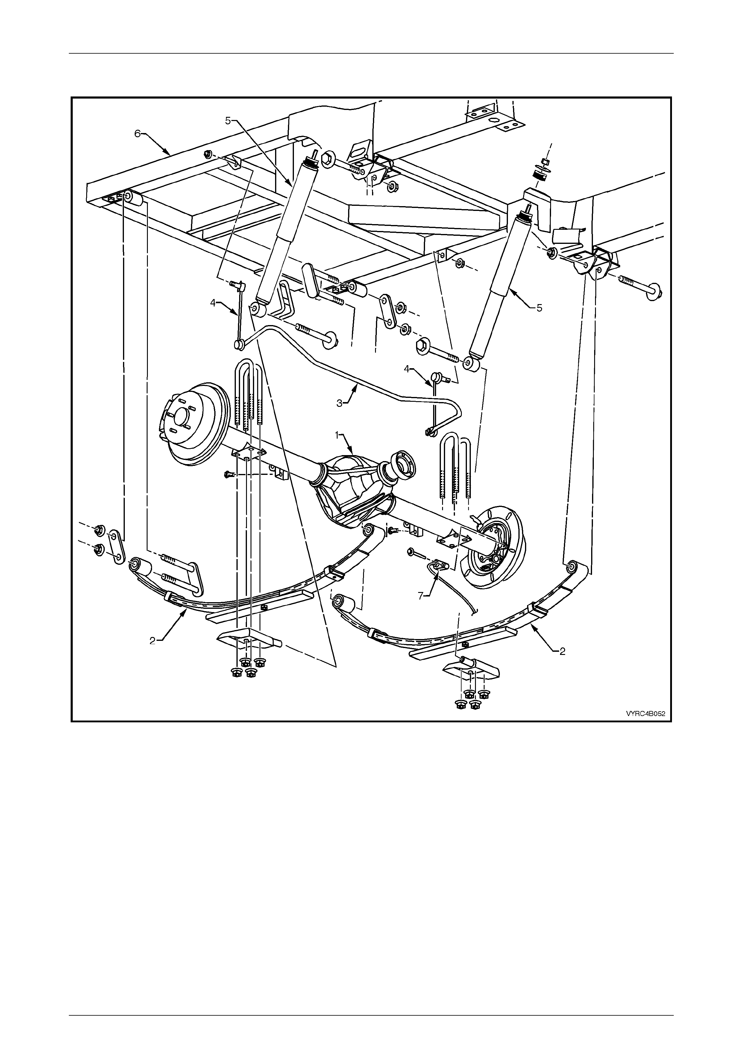
Rear Final Drive and Live Axle Page 4B2 – 45
Page 4B2 – 45
Remove
Figure 4B2 – 75
Legend
1 Rear Axle Assembly
2 Rear Leaf Spring Assembly
3 Rear Suspension Stabiliser bar
4 Rear Stabiliser bar to Chassis Link
5 Rear Shock Absorber
6 Rear Chassis
7 Rear ABS Wheel Speed Sensor
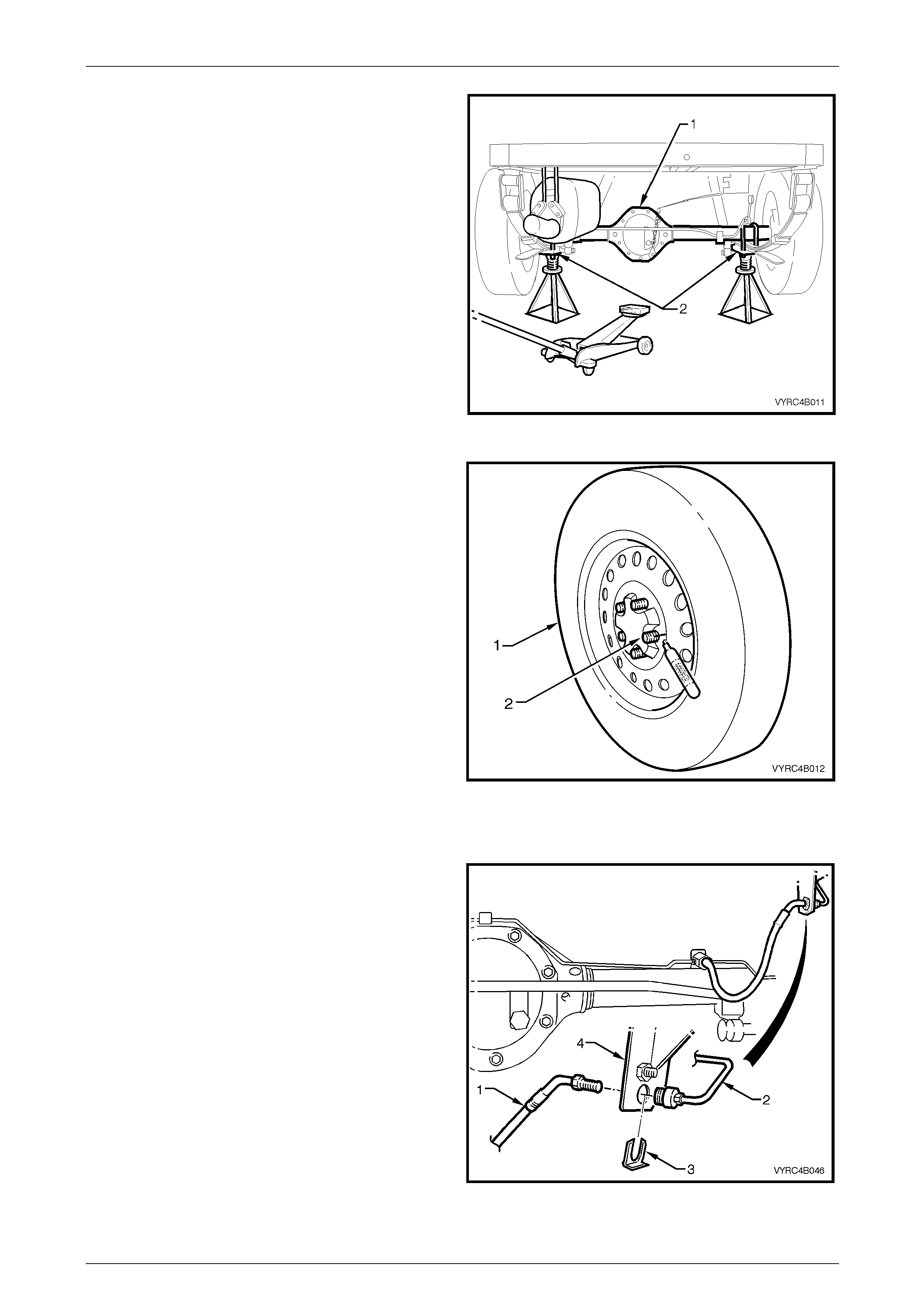
Rear Final Drive and Live Axle Page 4B2 – 46
Page 4B2 – 46
1 Place the transmission in Neu tral with the engine
turned OFF.
2 Using a floor jack, raise one rear wheel, leaving the
remaining wheel on the floor and support the vehicle
under the rear axle assembly on raised side with a
safety stand.
Figure 4B2 – 76
3 Remove the wheel covers or decorative wheel nut
caps, then mark the relationship of the road wheel to
one of the wheel studs, using a felt tipped pen or
similar.
4 Loosen, then remove the road wheel attaching nuts,
working in a 'star' pattern. Refer to
2.1 Service Warnings, Cautions and Notes in this
Section, for detailed informatio n. Remove the road
wheel.
5 Release the park brake lever to the full y OF F position.
6 Remove the propeller shaft, refer to Section 4C1 Rear
Propeller Shaft and Universal Joints.
Figure 4B2 – 77
All Except AWD & Live Axle
7 Place a clean drain container under the main rear
brake fluid supply pipe and hose connection.
8 Using a suitable commerciall y available flare nut
spanner, disconnect the main rear axle brake fluid
supply hose (1) from the rear brake fluid, sup ply pipe
(2).
9 Remove the brake hose retai ning clip (3) from the
hose support bracket (4) and remove the hose from
the bracket.
Figure 4B2 – 78
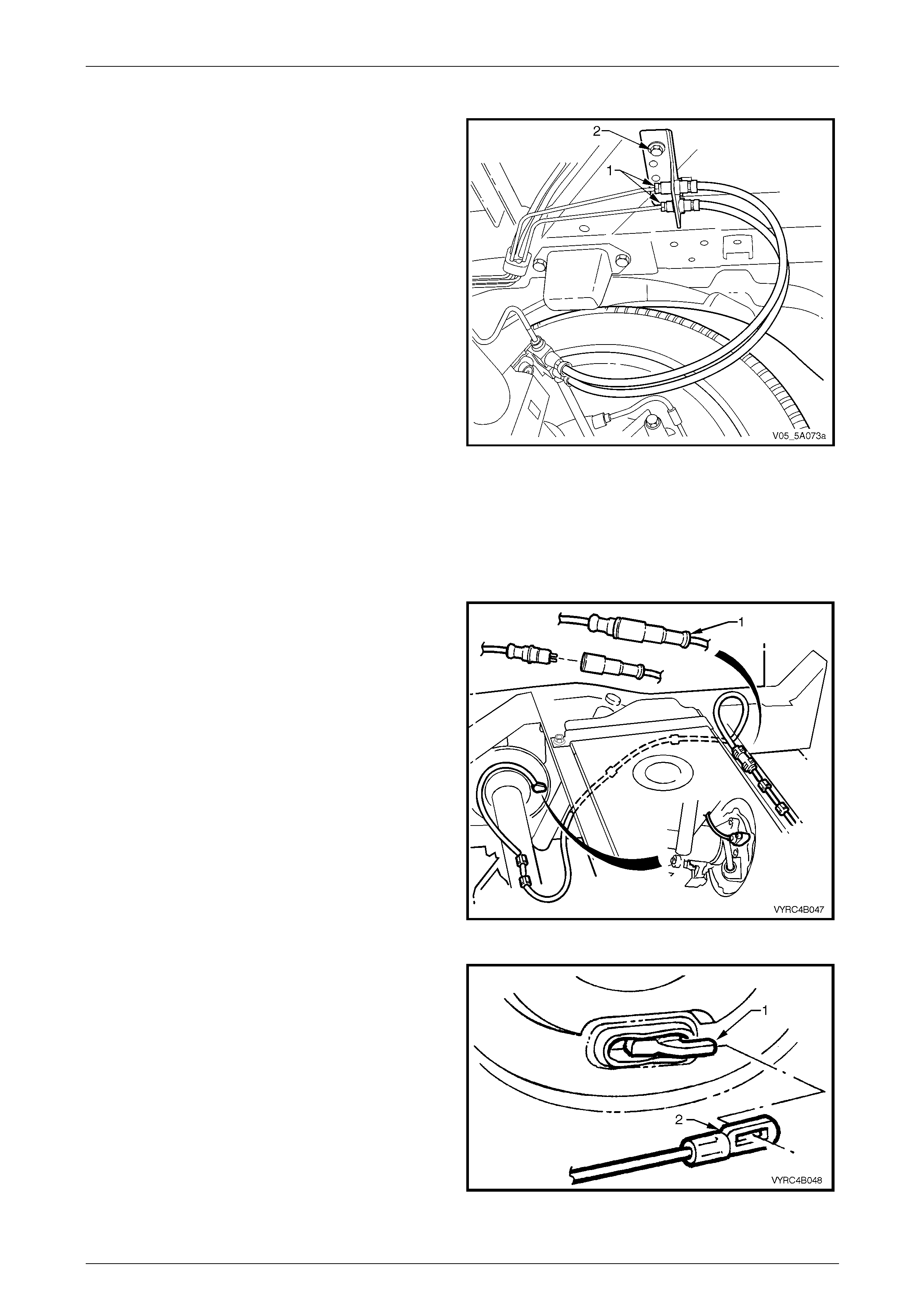
Rear Final Drive and Live Axle Page 4B2 – 47
Page 4B2 – 47
AWD & Live Axle Only
NOTE
Both hoses and mounting brackets at each end
are only serviced as a single assembl y.
1 Using a suitable commerciall y available flare nut
spanner, disconnect each of the rear brake fluid
supply pipes (1).
NOTE
Label at least one of the pipes to ensure correct
reinstallation.
2 Plug the open ends of the disconnected pipes and
hoses.
3 Remove the bolt (2) securing the brake hose bracket
to the vehicle frame.
Figure 5A – 79
All With Live Axle
4 Plug the open end/s of the brake pipe/s and the hose/s to prevent fluid loss and foreign matter entry.
5 Tape the hose/s to the rear axle housing to prevent accidental damage to t he hose/s during the rear axle housing
removal procedure.
6 Disconnect the ABS wheel speed sensor body
harness connector (1).
7 Tape the ABS wheel speed sensor body harness
connector to the chassis to prevent accidental damage
to the connector or harness during the rear axle
housing removal procedure.
8 Tape the ABS wheel speed sensor rear axle harness
connector to the rear axle housing to prevent
accidental damage to the connector or harness during
the rear axle housing removal procedure.
Figure 4B2 – 80
9 Adjust the park brake to allo w the park brak e cable to
be disconnected from the rear axle housing assembly,
refer to Section 5A Service and Park Braking System
for the necessary procedure.
10 Disconnect the park brake cable (2) from the rear axle,
park brake lever (1
11 Pull outer cable forward, out of leaf spring retainers.
12 Tape the cables to the chassis to prevent damage
during the rear axle housing removal procedure.
Figure 4B2 – 81
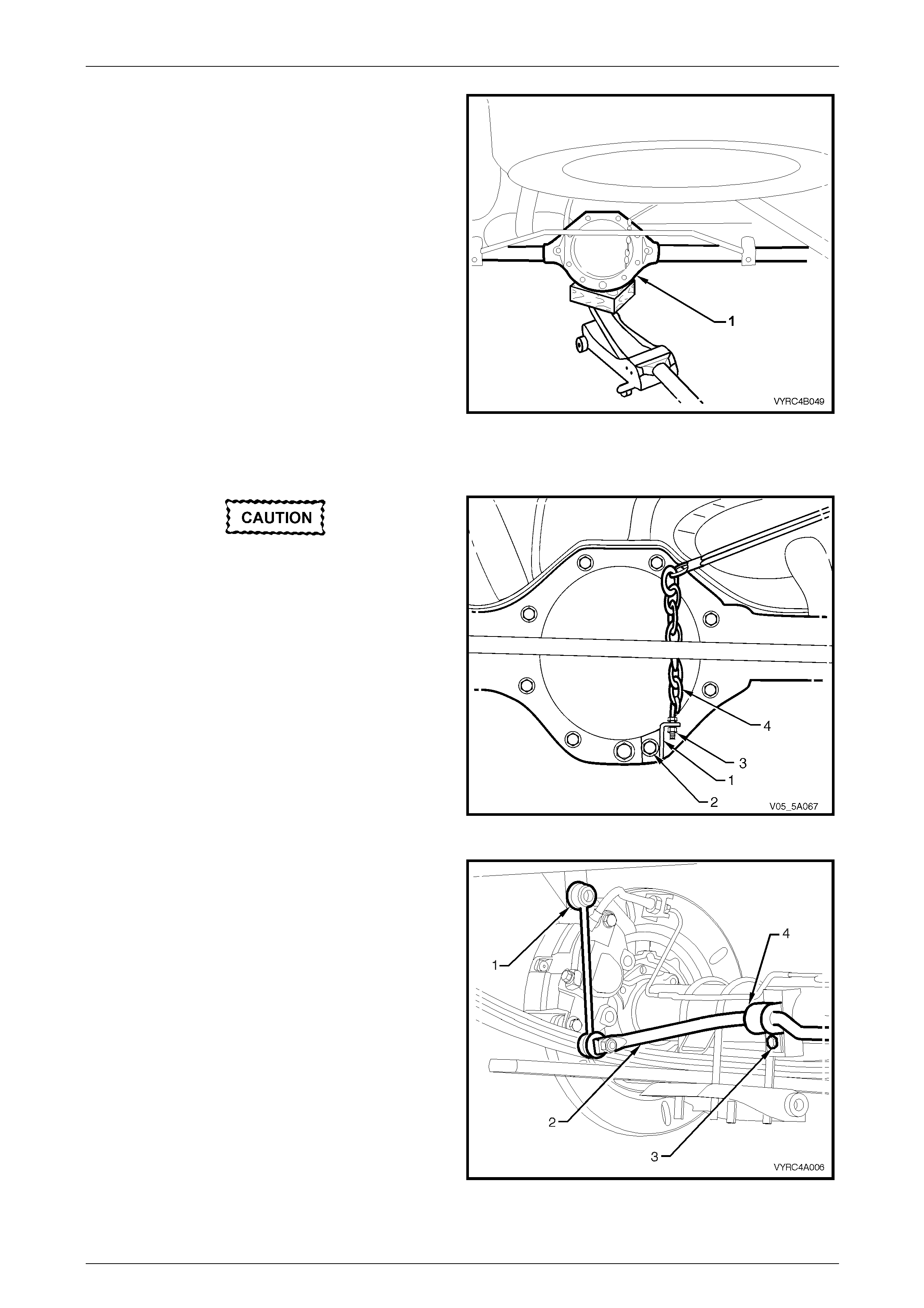
Rear Final Drive and Live Axle Page 4B2 – 48
Page 4B2 – 48
13 Position a floor jack with a block of wood, under the
centre of the rear axle housing assembly (1).
14 Raise the jack slightly and place safety stands under
rear axle housing tubes to support the weight of the
rear axle housing assembly.
Figure 4B2 – 82
All Except AWD & Live Axle
Do not remove the nut (3) or change the
length of the chain. This is preset and is not
to be disturbed.
15 Remove the load sensing proportioning valve chai n
bracket (1) and attaching bolt (2) as one u nit from the
rear axle cover.
NOTE
• When the bracket bolt (2) is removed, final
drive lubricant will leak out. Temporarily
reinstall the bolt quickly to reduce spillage.
• The static spring will have tension until the
chain and attaching bracket (6) is removed
from the rear axle cover and released slowly.
Figure 4B2 – 83
16 Remove the attaching bolt (3) from each rear stabiliser
bar to rear axle-mounting retainer (4) and re move the
retainers.
17 With the ball joints and linkage (1) still connected,
raise the stabiliser bar (2) by pushing it up an d away
from the rear axle assembly.
18 Using a suitable tie wire to secure the stabili ser bar to
the chassis.
Figure 4B2 – 84
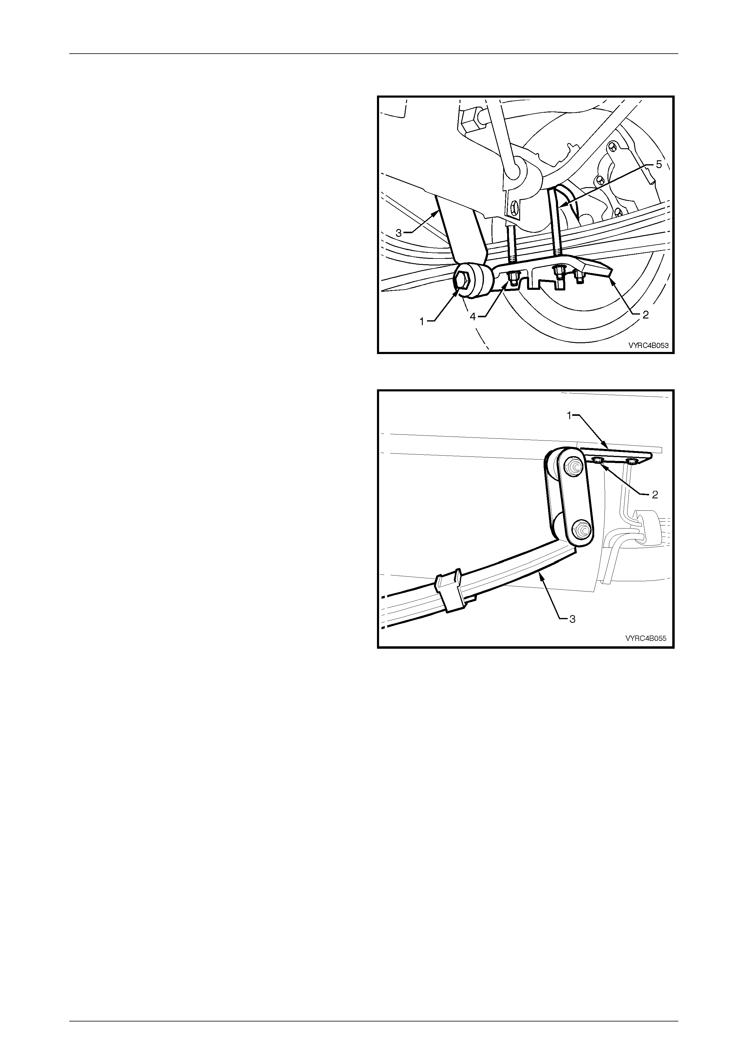
Rear Final Drive and Live Axle Page 4B2 – 49
Page 4B2 – 49
All VZ and Live Axle
19 Remove each rear shock absorber lower mounting
retaining bolt (1) from the leaf spring retainer plate (2),
and pull the lower end of shock absorber (3) from the
mounting point on the leaf spring retainer plate.
20 Disconnect all rear leaf spring U-bolt attaching nuts (4)
from the rear springs, then remove the retaining plates
(2) and U-bolts.
Figure 4B2 – 85
21 Loosen each front spring eye bolt to relieve tension on
the inner bush sleeve.
22 Remove the rear spring shackle mounting plate (1) to
chassis attaching bolts (2) located at the trail ing e nd of
each leaf spring assembly (3). Then carefully lower the
springs to floor level.
23 Using an assistant, remove the safety stands
supporting each side of the rear axle housing, then
gently lower the floor jack to floor level and manoeuvre
the rear axle assembly clear of the vehicle while
supporting its weight on the floor jack.
Figure 4B2 – 86
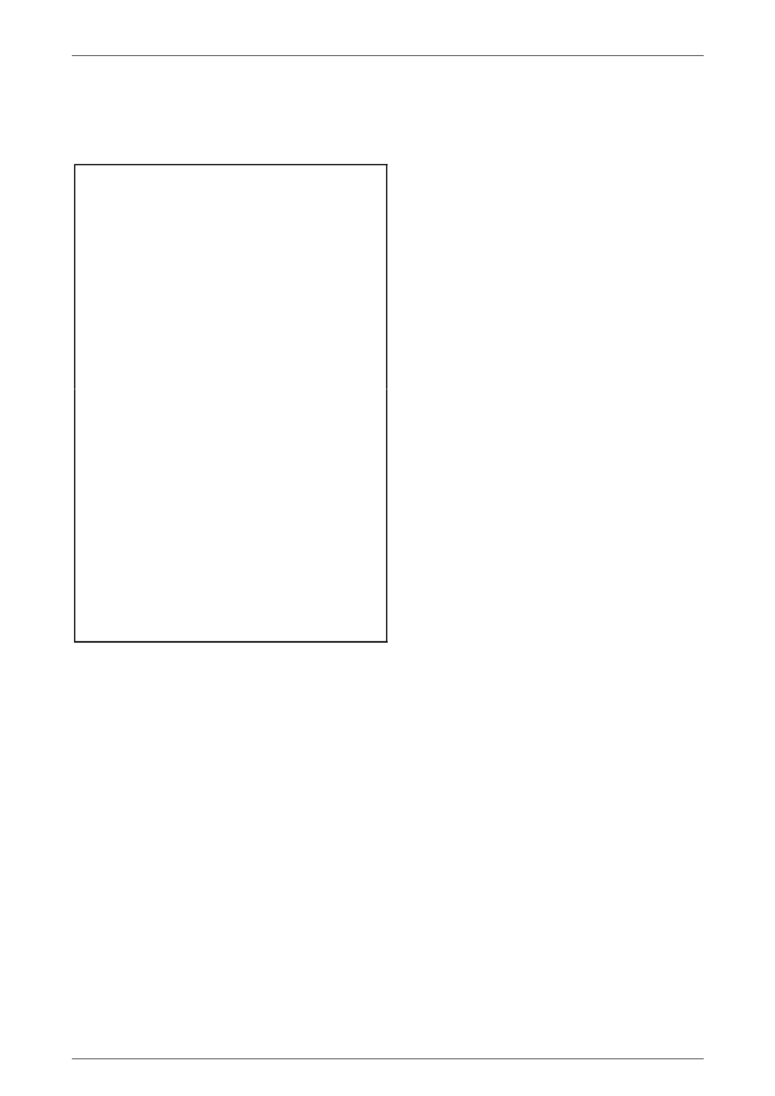
Rear Final Drive and Live Axle Page 4B2 – 50
Page 4B2 – 50
Reinstall
Reinstallation of the rear axle housing assembly is the reverse of the removal procedure noting the following points:
1 Tighten all attaching fasteners to the corre ct torque specification, detailed next.
Leaf spring and retainer plate
U-bolt nut torque specification..............................90 N.m
Leaf spring shackle mounting plate
to chassis bolt torque specification ......................90 N.m
Rear stabiliser bar mounting
bracket bolt torque specification...........................25 N.m
Rear shock absorber lower mounting
bolt (preliminary) torque specification ....................5 N.m
• Rear shock absorber lower mounting
bolt (final) torque specification ...........................110 N.m
Rear brake pipe flare nut to brake
hose torque specification .....................................15 N.m
Rear brake hose bracket to chassis bolt
(AWD model only) torque specification................15 N.m
Load sensing link to rear a xle cover bolt
(except AWD models) torque specification ..........28 N.m
• Leaf spring eye attaching bolt
and nut (final) torque specification.....................145 N.m
Road wheel attaching
nut torque specification............................110 – 140 N.m
Rear propeller shaft constant velocity
joint to rear axle pinion flange
attaching bolt (V6) torque specification................38 N.m
() Rear propeller shaft constant velocity
joint to rear axle pinion flange attaching
bolt (GEN III V8) torque specification...................68 N.m
2 Check the rear axle lubricant level and top up as necessary, refer to 2.2 Checking Rear Axle Lubrica nt Level, in this
Section.
3 Adjust the parking brake; refer to Section 5A Service and Park Braking System.
4 Road test the vehicle to check correct vehicle operation.
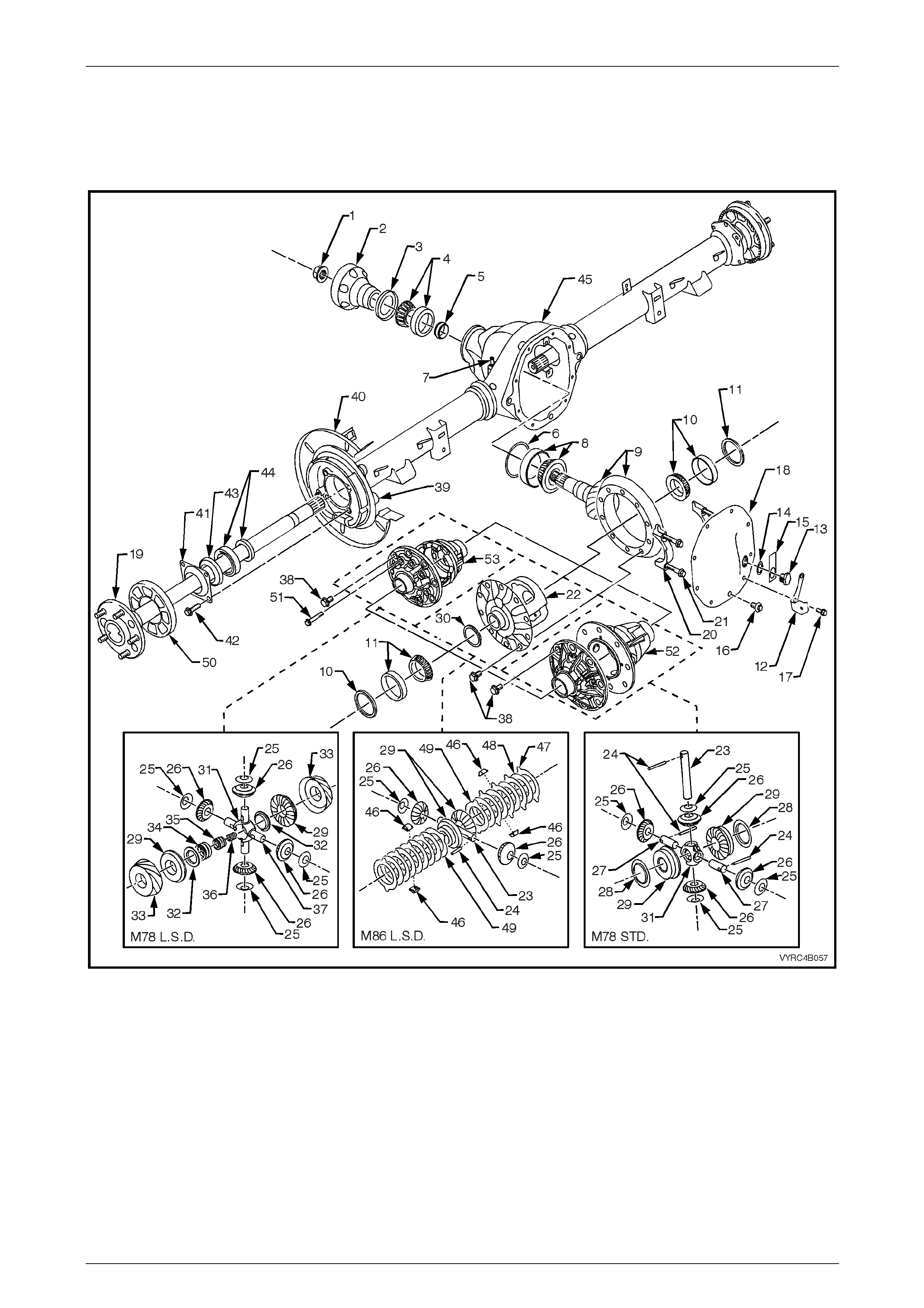
Rear Final Drive and Live Axle Page 4B2 – 51
Page 4B2 – 51
3.2 Rear Axle and Differential Housing
Assembly
LT Section No: F502600
Figure 4B-87
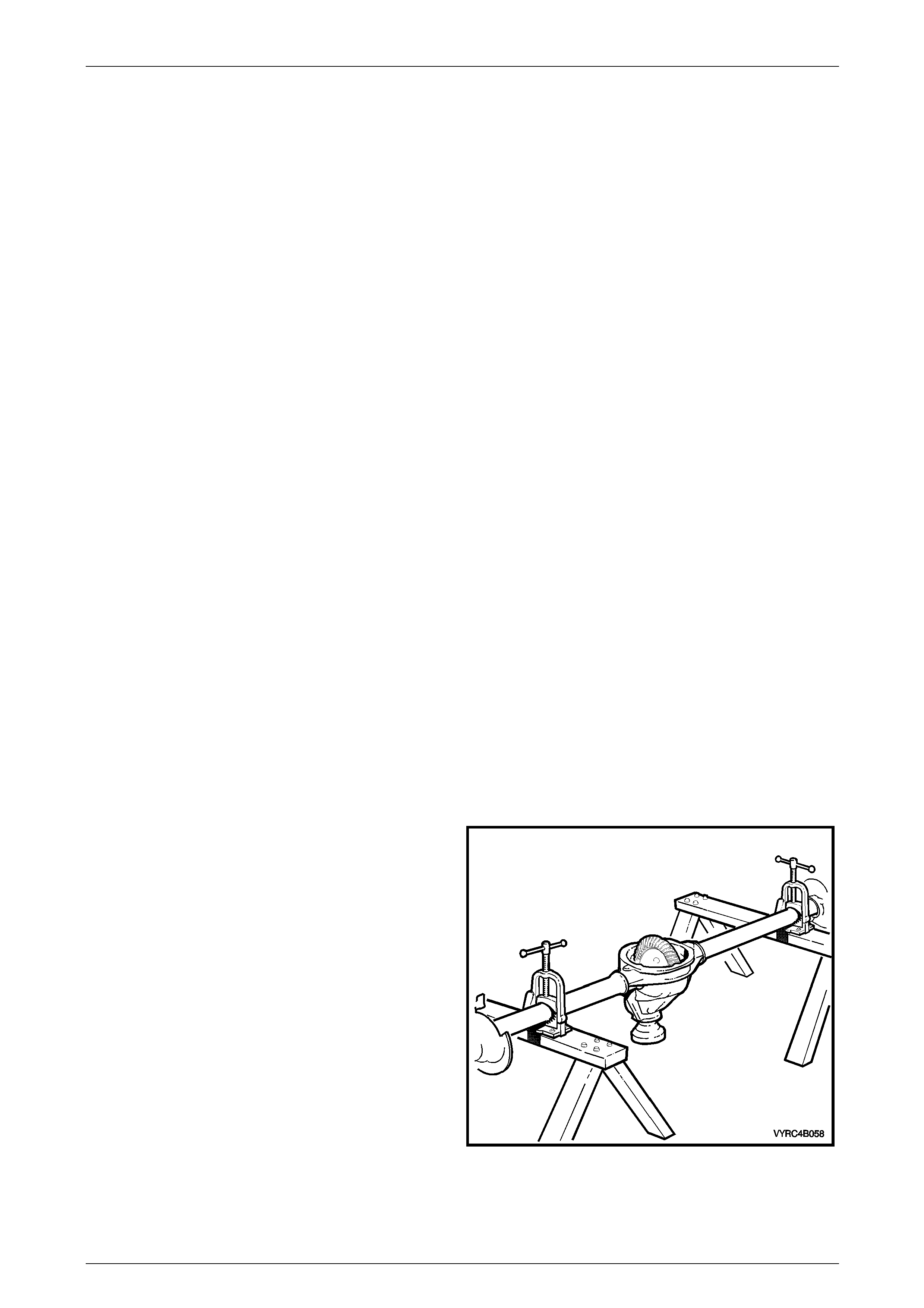
Rear Final Drive and Live Axle Page 4B2 – 52
Page 4B2 – 52
Legend
1 Nut – Pinion Flange Retaining
2 Flange – Pinion
3 Seal – Pinion Oil
4 Bearing Assembly – Pinion Front
5 Spacer – Collapsible, Pinion Bearing Pre-Load
6 Shim – Pinion Depth Adjusting
7 Fitting – Breather Tube
8 Bearing Assembly – Pinion Rear
9 Ring Gear and Pinion
10 Bearing Assembly – Side, Differential Case
11 Shim – Side Bearing Position And Preload Adjusting
12 Bracket – Load Sensing Valve Chain
13 Plug – Oil Filler, Rear Axle
14 Gasket – Oil Filler Plug
15 Tag – Lubrication Caution
16 Plug – Oil Drain, Rear Axle
17 Bolt and Washer – Differential Carrier Cover (8 Places)
18 Cover – Differential Carrier
19 Axle Shaft
20 Cap – Side Bearing and Differential Carrier
21 Bolt – Cap, Side Bearing and Differential Carrier
22 Case – Differential, M86 Series LSD
23 Shaft – Differential Pinion Gear, Long
24 Pin – Retaining, Differential Pinion Gear Shaft
25 Washer – Thrust, Differential Pinion Gear
26 Gear – Differential Pinion
27 Shaft – Differential Pinion Gear, Short (M78 Std)
28 Washer – Thrust, Differential Side Gear (M78 Std)
29 Gear – Differential Side
30 Spacer – Differential Case Side Bearing (M86)
31 Block – Thrust, Differential (M78)
32 Plate – Thrust, Spring (M78 LSD)
33 Cone – Clutch (M78 LSD)
34 Spring – Outer, Differential Preload (M78 LSD)
35 Spring – Intermediate, Differential Preload (M78 LSD)
36 Spring – Inner, Differential Preload (M78 LSD)
37 Shaft – Cross, Differential Pinion (M78 LSD)
38 Bolt – Ring To Differential Case Attaching (10 Places)
39 Bracket – ABS Sensor and Park Brake Cable Mounting
40 Plate – Brake Backing
41 Plate – Thrust and Retaining, Outer Axle Bearing and Shaft
42 Bolt – Thrust and Retaining Plate (4 Places per side)
43 Seal – Oil, Rear Axle Shaft
44 Bearing Kit – Rear Axle Shaft
45 Rear Axle Housing
46 Retainer – Clutch Plate, (M86 LSD)
47 Clutch Plate (M86 LSD)
48 Disc – Concentric Grooved (M86 LSD)
49 Spacer – Dished (M86 LSD)
50 Pulse Ring – ABS Sensor
51 Bolt – Differential Case (M78 LSD)
52 Case – Differential (M78 Std)
53 Case – Differential (M78 LSD)
Preliminary Check
If an overhaul of the rear axle is anticipated, it is recommended that a check for rear axle shaft run-out and end float is
undertaken and the results recorded for future reference, following the removal of the rear axl e housing assembly from
the vehicle. Refer to 2.4 Rear Axle Shaft Check For Run-Ou t and End F loat in this Section for the correct procedure.
Disassemble
1 Remove the rear axle assembly and rear road wheels;
refer to 3.1 Rear Axle Assembly in this Section.
2 Mount the rear axle housing assembly to a s uitab le
holding fixture to allow the rear axle to be drained of
lubricant.
3 Drain the lubricant from the rear axle ass emb ly into a
suitable, clean container of at least 2 litre capacity, by
removing the oil drain plug of the rear axle housing
assembly.
4 Rotate the rear axle housi ng assembly in the holding
fixture to allow access to the rear cover, as shown.
5 Remove the cover bolts and cover from the rear axle
housing.
NOTE
It maybe necessary to tap the cover with rubber
hammer to break the sealant seal. Figure 4B2 – 88
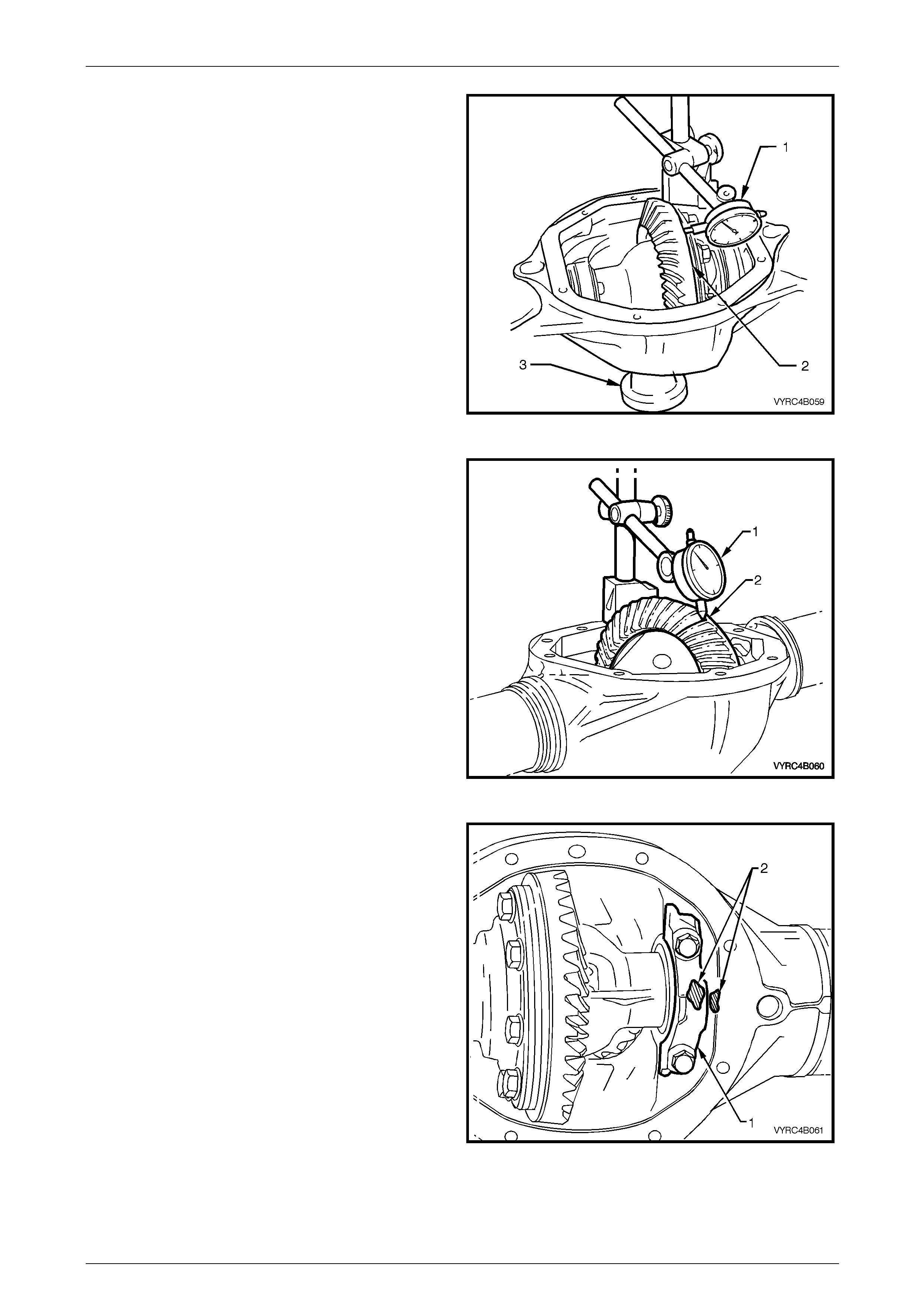
Rear Final Drive and Live Axle Page 4B2 – 53
Page 4B2 – 53
6 Before removing the differential case assembly
conduct an inspection of the following:
a Visually inspect all internal mo ving parts for
damaged, chipped or scuffed surfaces.
b Check the torque of the ring gear bolts, the
differential carrier bearing cap bolts and the
pinion flange nut.
c Using a dial indicator (1) against the back face of
the ring gear (2) measure the ring gear run-out
while rotating the pinion flange (3) throug h
several turns.
7 Leaving the dial indicator (1) set up as shown (Step 'c')
above, push the ring gear har d to one side, then push
it the opposite way to measure side play. There should
be no side play present.
Figure 4B2 – 89
8 Using a dial indicator on the face of the pinion flange,
check to ensure that there is no pinion endplay
present by pushing and pullin g on the pinion flange.
9 Using a dial indicator (1) against the back face of a
ring gear tooth (2), measure the ring gear backlash by
rocking the ring gear back and forth.
10 Repeat the backlash measurement at a further 2
equally spaced positions around the ring gear.
11 If no obvious faults are found, check the gear tooth
contact pattern of the ring gear and pinion ge ar. Refer
to 3.6 Rear Axle and Differential Housing Assembly,
Ring Gear and Pinion Contact Pattern in this Section.
12 Remove the rear axle shafts; refer to
2.8 Rear Axle Shaft Assembly in this Section.
Figure 4B2 – 90
13 To assist correct reassembly, mark one of the
differential side bearing caps (1) and the adjacent side
of the rear axle housing with a daub of p aint (2).
14 Remove the differentia l side-bearing cap reta ining
bolts and side bearing caps.
Figure 4B2 – 91
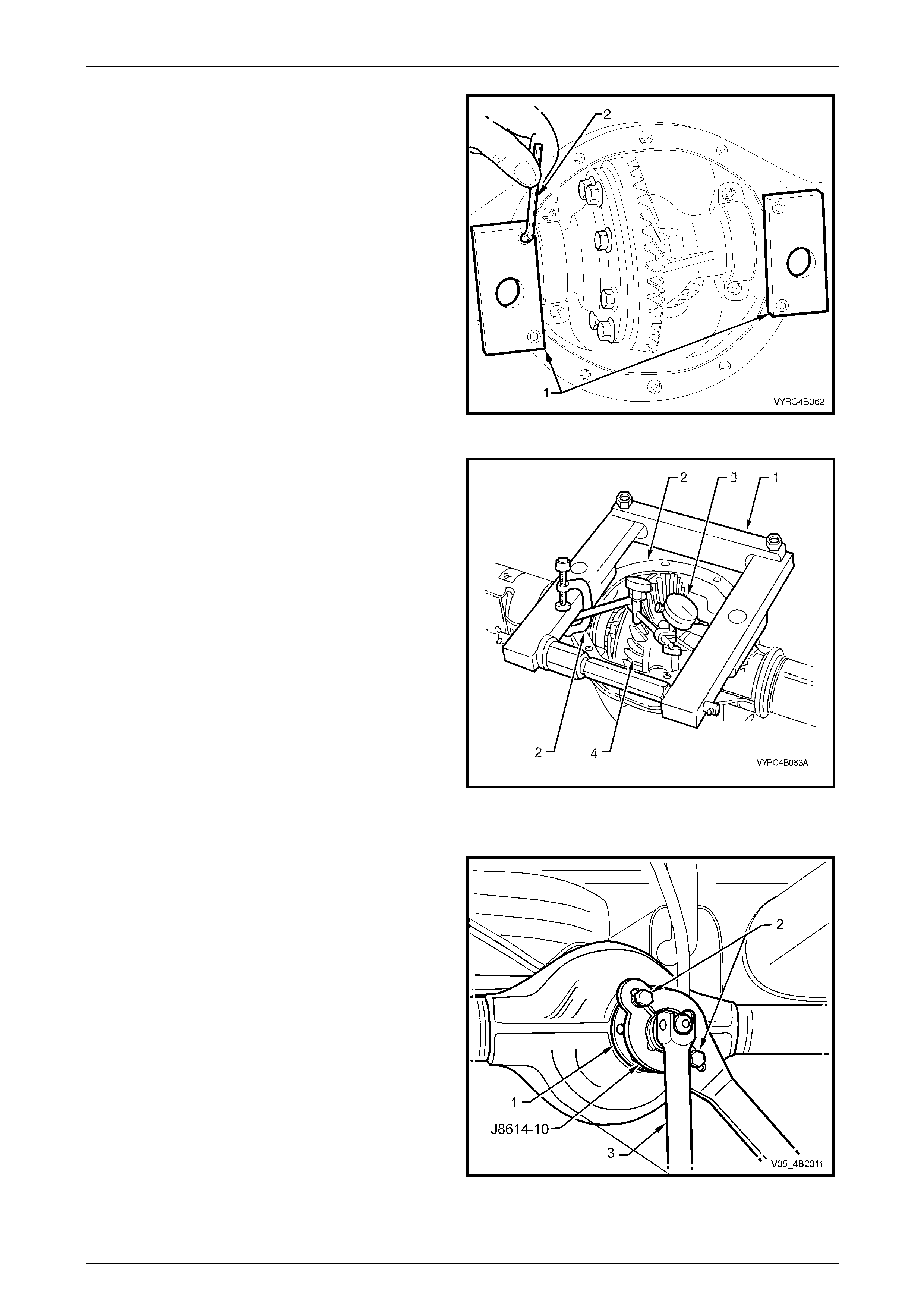
Rear Final Drive and Live Axle Page 4B2 – 54
Page 4B2 – 54
15 Install the adaptors (1) of the differential spreading
Tool No. E9255 to the differential carrier housing using
a 5mm Allen Key (2).
Figure 4B2 – 92
16 Install the differential spreadin g Tool No. E9255 and
adaptors (1) to the differential carrier housing (2).
17 Install a dial indicator (3) to the differential spreading
Tool No. E9255 and differential carrier housing.
18 Spread the differential carrier housing approximately
0.1 to 0.2 mm.
NOTE
Under no circumstances is the differential carrier
to be spread more than 0.5 mm.
19 Remove the differential case a ssembly (4) along with
the carrier side bearing cups and shims.
20 Keep each bearing cup, bearing cap and shim stack
with the matching bearing cone. Maintaining the
original relationship allows these parts to be reinstalled
in their original location.
21 Release the force exerted by the spreading Tool No.
E9255 and remove the tool along with the adaptors
from the differential carrier housing.
Figure 4B2 – 93
22 Attach the pinion flange holding bar, J8614-10 (part of
Tool No. J8614-O1), to the pinion flange (1), using two
of the rear propeller shaft constant velocity joint bolts
(2) to hold pinion flange.
23 Using a suitable socket and bar (3), while holding Tool
No. J8614-11, loosen the pinion flange, retain ing nut
and remove it from the pinion.
NOTE
Using a length of pipe over the socket bar will
reduce the effort required, to loosen the pinion
nut.
Figure 4B2 – 94
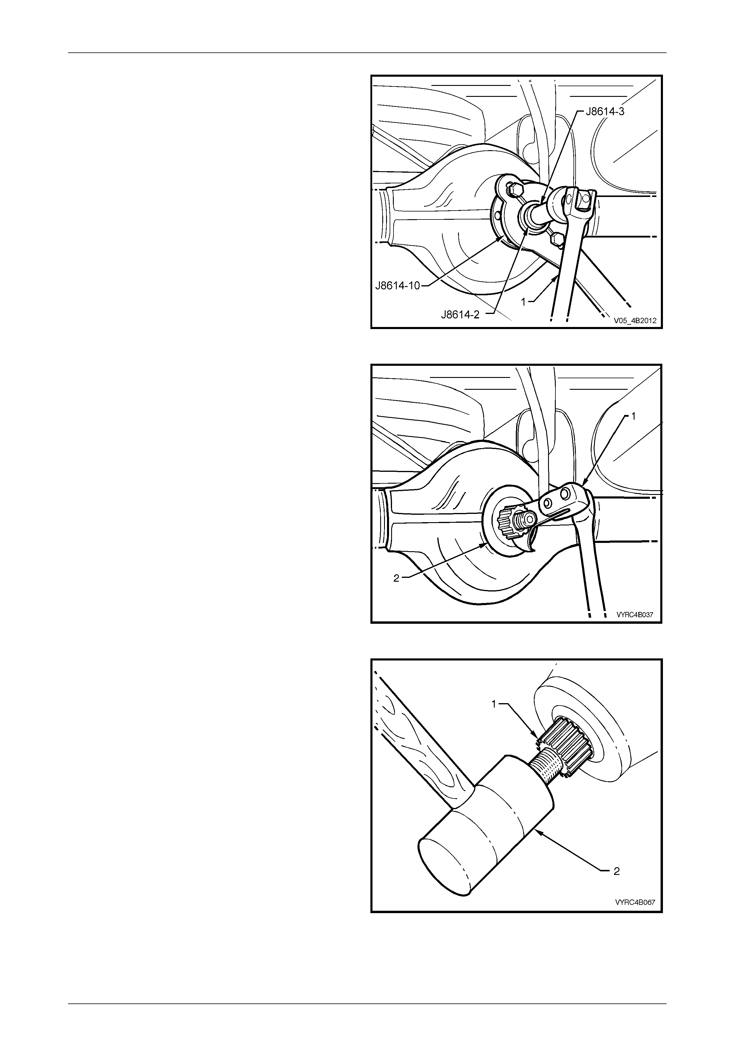
Rear Final Drive and Live Axle Page 4B2 – 55
Page 4B2 – 55
24 Install remover adaptor Tool No. J8614-2 and forcing
screw Tool No. J8614-3 to the pinion flange holding
fixture Tool No J8614-10, part of T ool No. J8614-O1.
25 While holding Tool No. J8614-10, part of Tool No.
J8614-O1, use a suitable socket and bar (1) to
withdraw pinion flange b y tur ning the forcing screw
(J8614-3) in a clockwise dir ection.
Figure 4B2 – 95
26 Prise the pinion oil seal (2) from carrier bore using
Tool No. E308 (1) or a universal seal removing tool.
Figure 4B2 – 96
27 Remove the pinion gear (1) by tapping on the front
end with a soft-faced hammer (2).
28 Remove the front pinion bearing from the carrier bore.
29 Remove and discard the pi nion bearing collapsible
spacer.
Figure 4B2 – 97
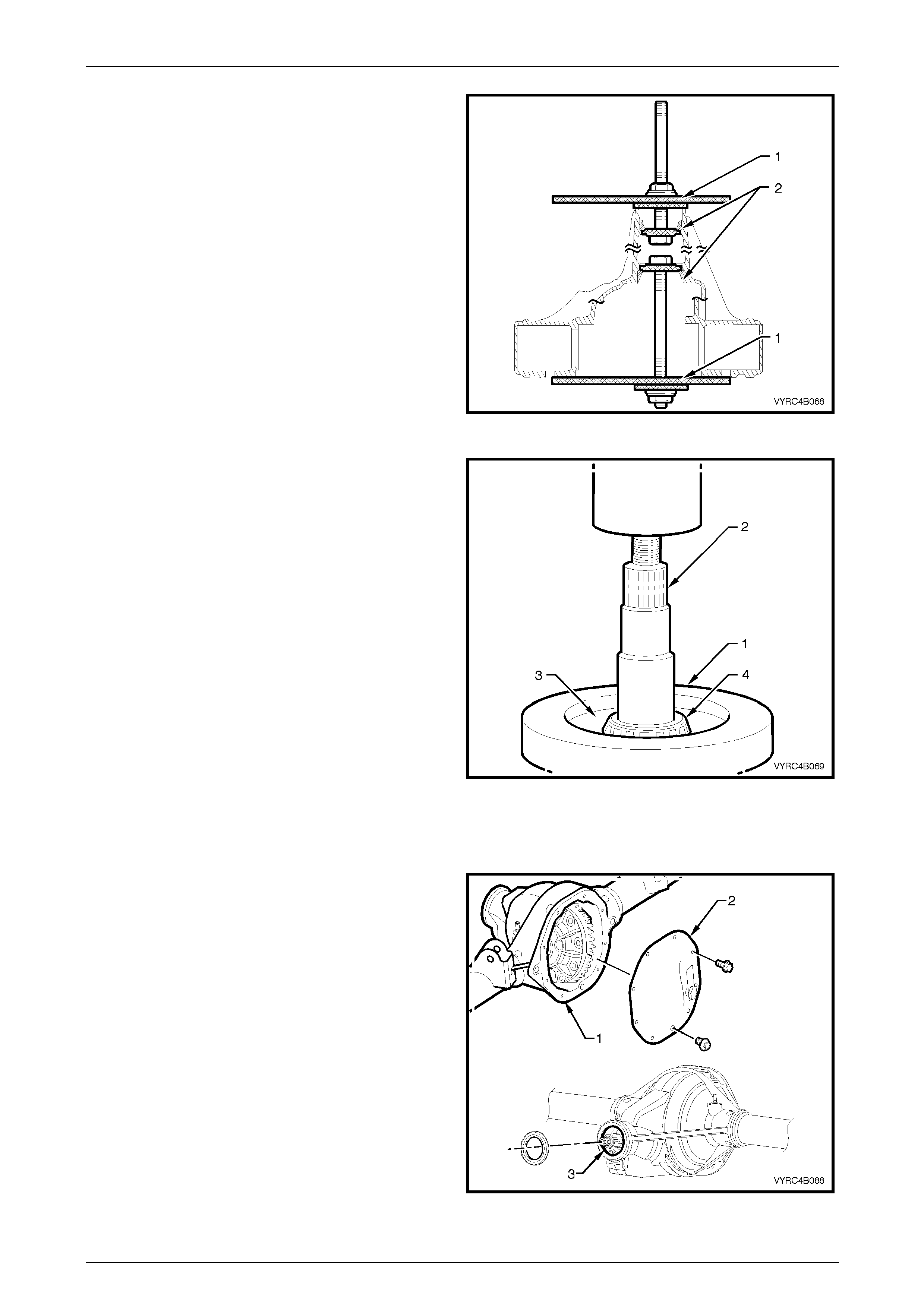
Rear Final Drive and Live Axle Page 4B2 – 56
Page 4B2 – 56
30 For M78 Series, if pinion-bear ing replacement is
required, use Tool No. E9293 (1) to remove the front
and rear pinion gear bearing cups (2) from the carrier
bore.
31 For M86 Series, if pinion-bear ing replacement is
required, use Tool No. E9293 (1), with the adaptor
Tool No. 205-551 to remove the front and rear pinion
gear bearing cups (2) from the carrier bore.
NOTE
When removing the rear p inion-bearing cup from
the carrier bore ensure that the pinion depth
shim is retrieved for future reference or possible
use. The shim is located between the rear
pinion-bearing cup and the bearing cup seat of
the carrier bore.
Figure 4B2 – 98
32 Remove the legs from the ring of the Tool No.
E1673MT.
33 Place the ring of Tool No. E1673MT (1) on suitable
press plates.
34 Remove and discard the rear pinion gear bearing;
For M78 Series, install the pinion gear (2) and
adaptors E1673A15 (3) into the ring (1) and
press the pinion gear (2) from the beari ng race
(4).
For M86 Series, install the pinion gear (2) and
adaptors 205-547 (3) into the ring (1) and press
the pinion gear (2) from the bearing race (4).
Figure 4B2 – 99
Inspect
1 Inspect the rear axle tubes and differential housing
casting for all-over general soundness and any signs
of damage.
2 Remove any gasket or sealant material from the
mating surfaces of the differential housing casting (1)
and the rear-cover plate (2). Clean and inspect the
surfaces for damage that may cause lubricant
leakage.
3 Inspect the rear cover bolt holes for damage.
4 Inspect all oil passages, bearing cup seating surfaces
and oil seal seating surfaces (3) for signs of wear,
damage or obstruction.
5 Check that the breather is clear of obstruction.
6 Ensure that all surfaces are free from burrs and
foreign matter.
Figure 4B2 – 100
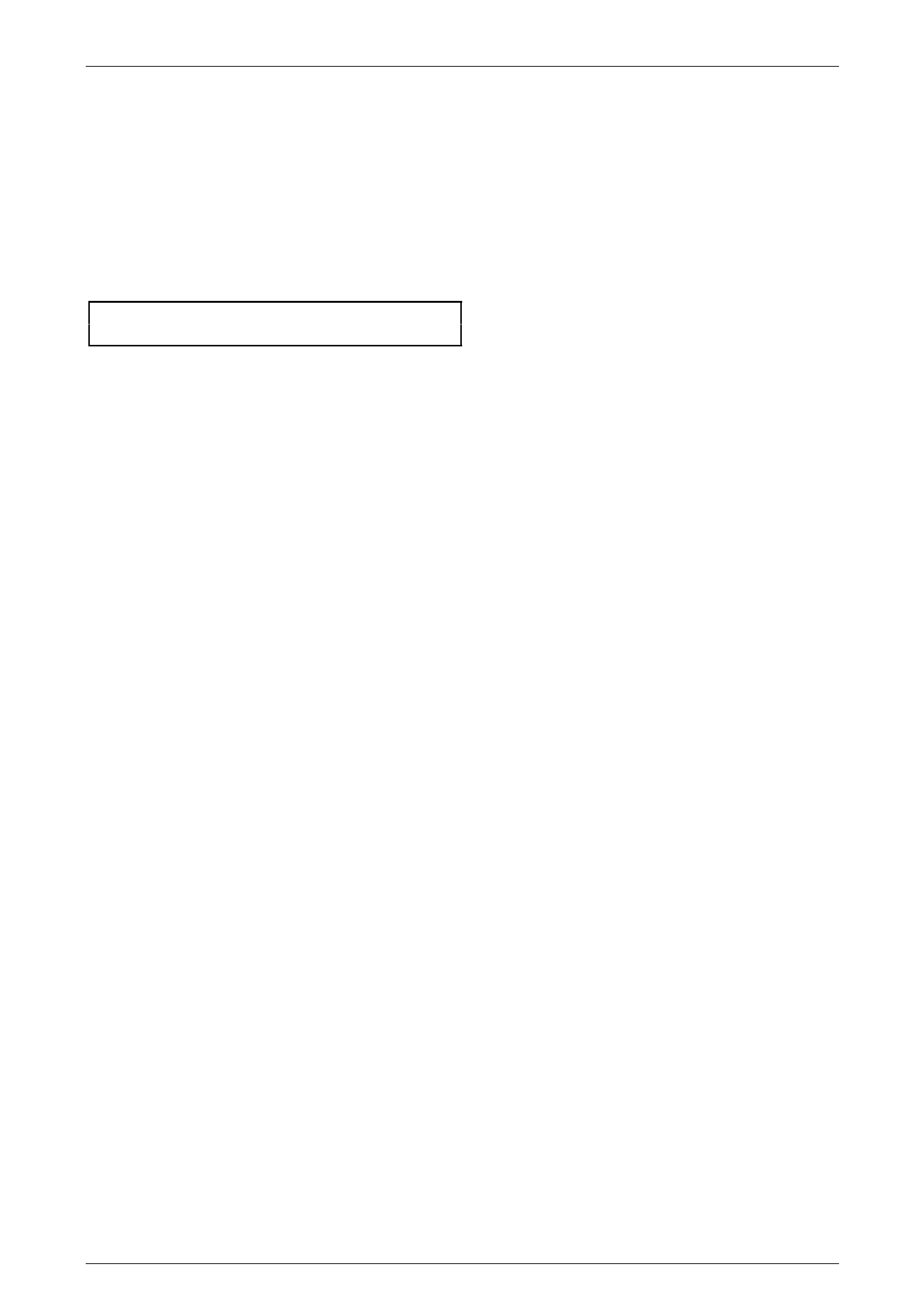
Rear Final Drive and Live Axle Page 4B2 – 57
Page 4B2 – 57
Reassemble
NOTE
For the differential assembly and pinion gear
reinstallation procedures refer to 3.6 Differential
Assembly Adjustment and Inst allation Pr oce dures
– All Models in this Section.
1 Install the rear cover and a new gasket to the carrier housin g.
2 Install and tighten the rear cover attaching bolts to the correct torque specification.
() Rear cover to carrier housing
bolt torque specification.......................................28 N.m
3 Reinstall the rear axle assemblies. Refer to 2.8 Rear Axle Shaft Assembly – Reinstall in this Section.
4 Reinstall the rear axle housing assembly. Refer to 3.1 Rear Axle Assembly – Reinstall in this Sectio n
5 Fill the rear axle housing asse mble with the recommended lubricant to the correct level.
Refer to 2.2 Checking Rear Axle Lubricant Le vel in this Section.
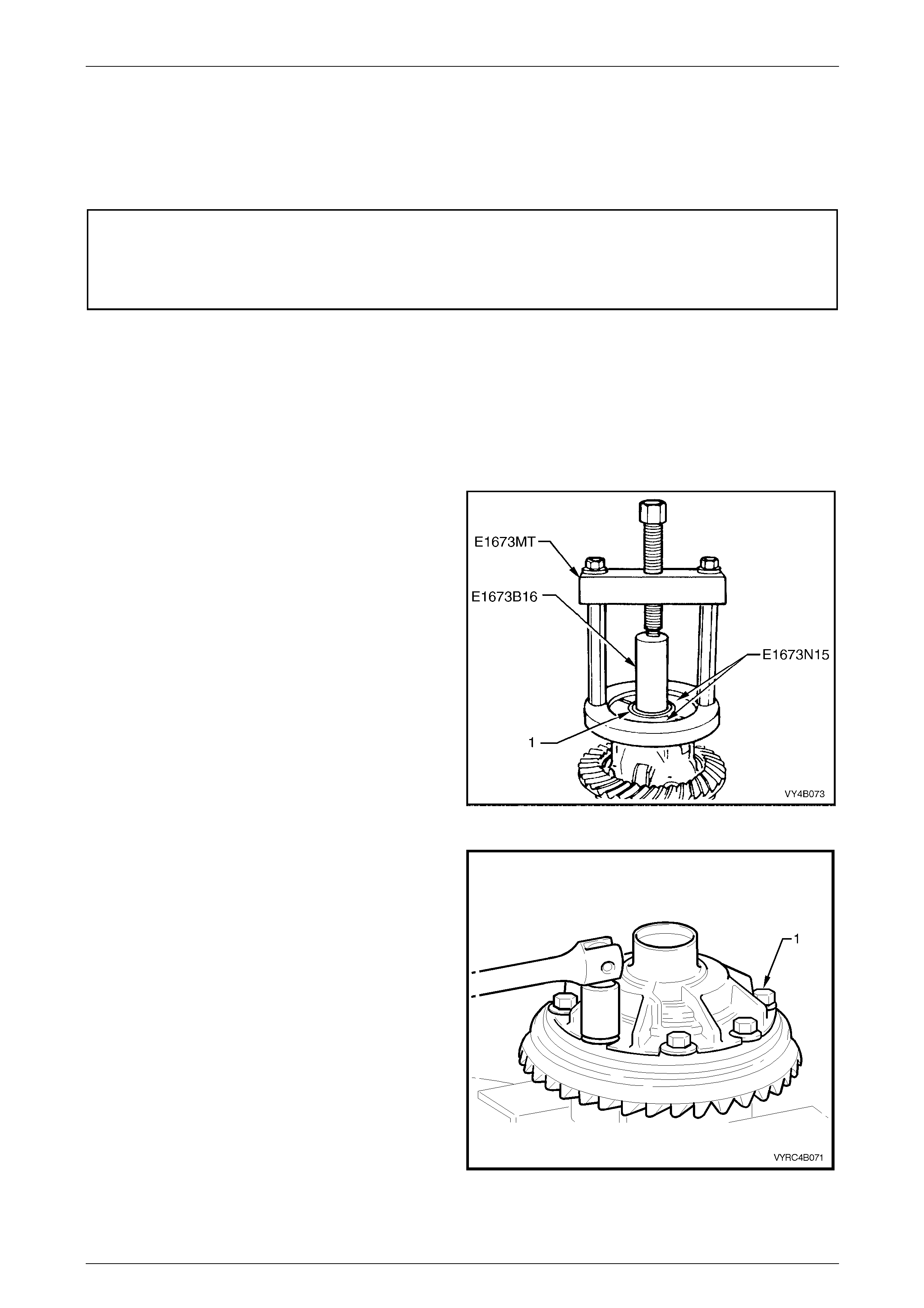
Rear Final Drive and Live Axle Page 4B2 – 58
Page 4B2 – 58
3.3 Differential Assembly – M78 Series
(Standard Non LSD)
LT Section No: F502600
ATTENTION
The following fasteners MUST be replaced w hen performing these operations:
Ring gear attaching bolts.
Disassemble
NOTE
For the differential assembly and pinion gear
removal procedure refer to 3.6 Rear Axle and
Differential Housing Assembly – Disassemble in
this Section.
6 Inspect the side-bearing race on each sid e of the
differential case for any signs of damage.
7 If necessary, use the assembled Tool No. E1 673MT,
adaptors E1673N15 an d stepped plug E1673B16 to
remove the side bearing race (1) from the differential
case and ring gear assembly.
8 Discard the side bearing races once removed.
Figure 4B2 – 101
9 Secure the differential case in a suitabl e vice fitted
with soft metal jaws.
10 Remove the ring gear attaching bolts (1). Dis card all
removed bolts.
NOTE
The ring gear attaching bolts have a left-hand
thread and are identified by an 'L' on the bolt
head.
11 Remove the differential case from the vice.
Figure 4B2 – 102
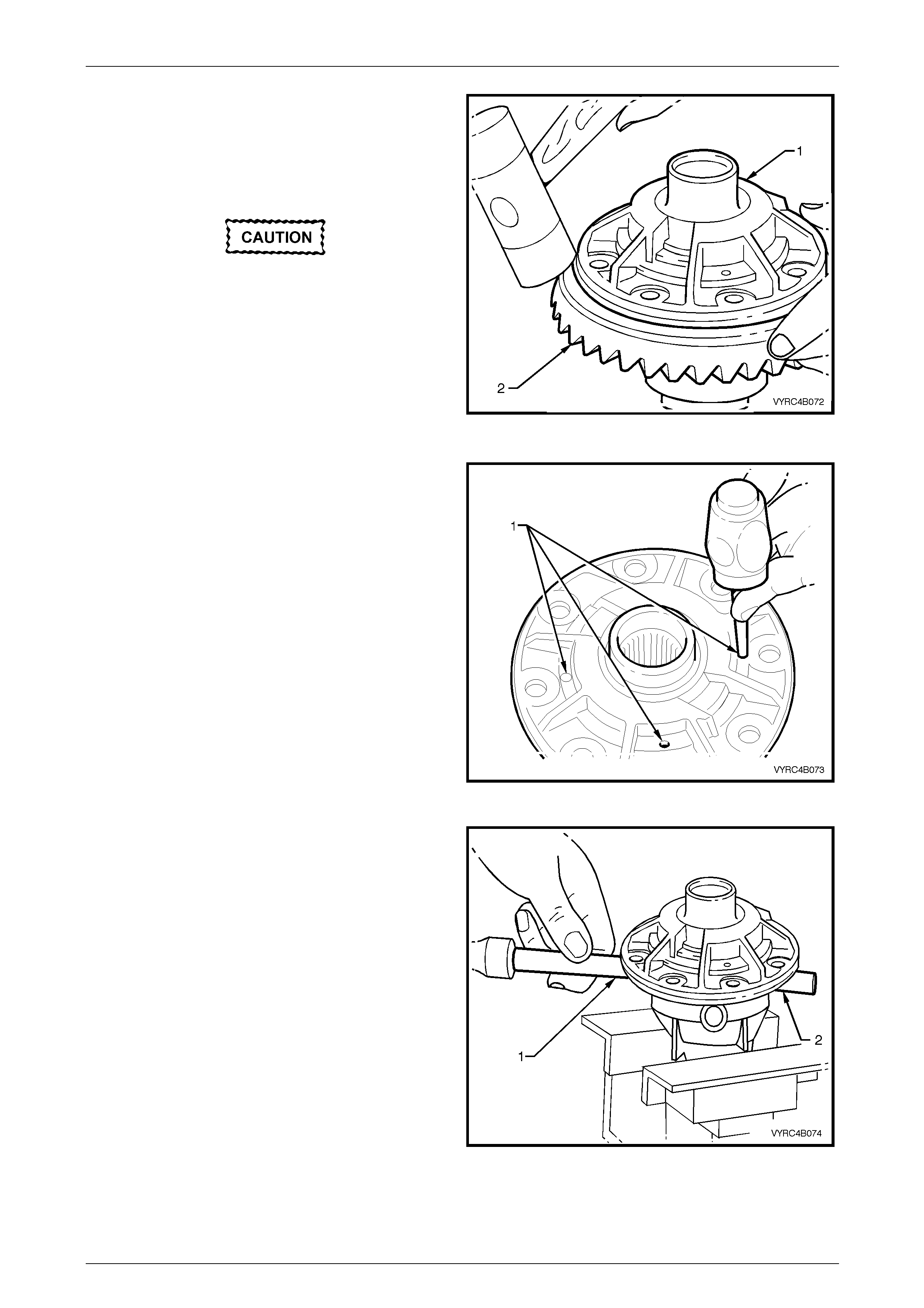
Rear Final Drive and Live Axle Page 4B2 – 59
Page 4B2 – 59
12 Place a piece of softwood large enou gh to cover the
overall diameter of the ring gear on top of a suitable
workbench.
13 Place the differential case (1) on top of the piece of
softwood with the ring gear facing do wnward, as
shown.
Do not use a screwdriver or other form of
leverage to pry between the ring gear and the
mating face of the differential case, as
damage will occur.
14 Using a soft faced hammer, tap down on the ring gear
while rotating the differential case to remove the ring
gear (2).
NOTE
The softwood will protect the ring gear from
damage during this next step. Figure 4B2 – 103
15 Re-secure the differential case in a suitable vice
equipped with soft metal ja ws
16 Using a hammer and pin p unch drive out the
differential cross shaft and short shaft retaining pins
(1).
Figure 4B2 – 104
17 Using suitable a hammer and brass drift (1) drive-out
the differential cross shaft (2).
18 Remove the differential case from the vice.
Figure 4B2 – 105
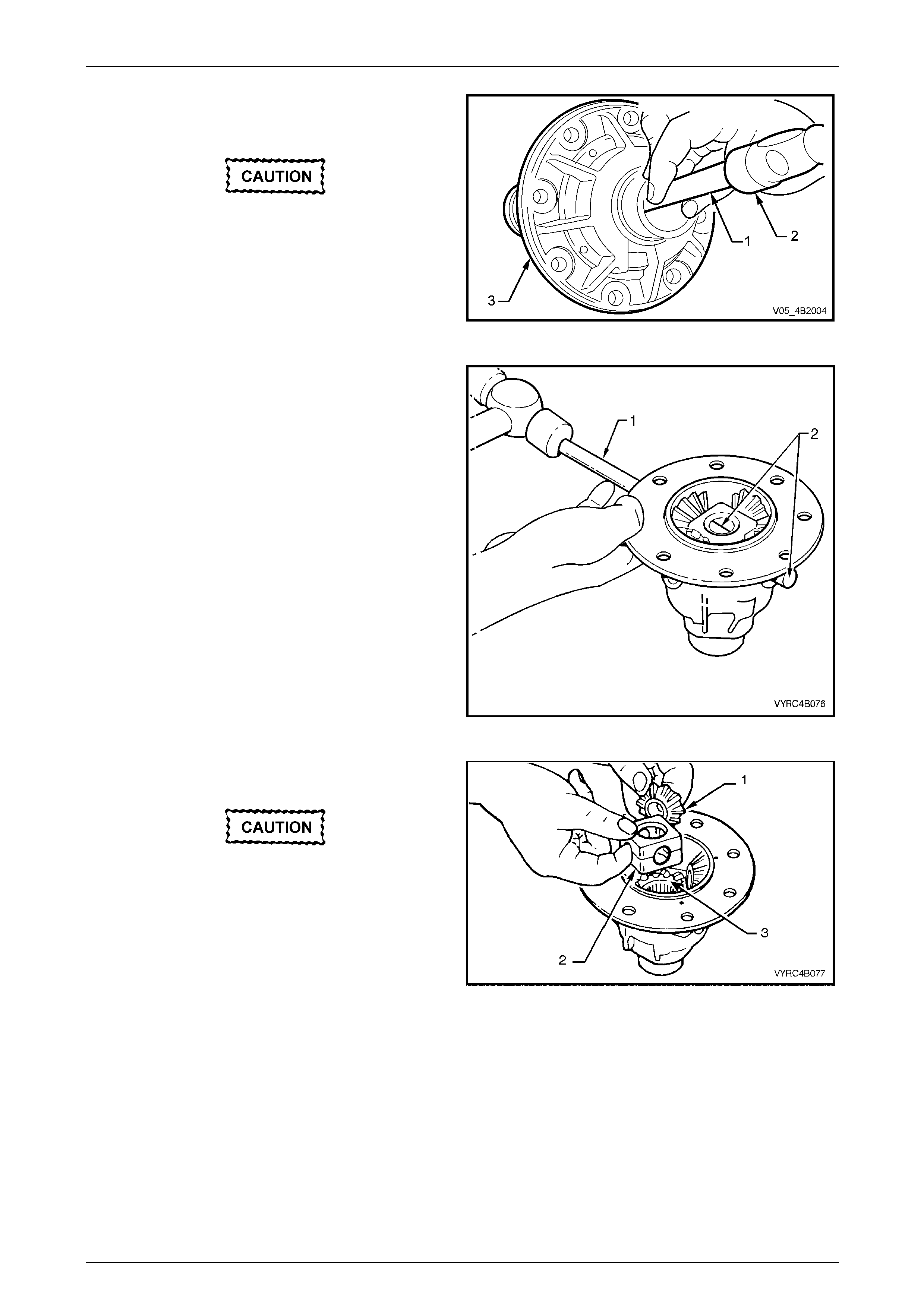
Rear Final Drive and Live Axle Page 4B2 – 60
Page 4B2 – 60
19 Place the differential case on top of a suitable
workbench with the ring gear attaching bolt holes
facing outward.
Do not use a screwdriver or other form of
leverage to pry the mating faces of the
differential case apart, as d amag e will occur.
20 Using a suitable hammer (2) with a brass dr ift (1),
drive against the thrust block to separate the
differential case halves (3).
Figure 4B2 – 106
21 Re-secure the differential cas e half containing the side
gears, pinion shaft and pinion gears in a suitable vice
equipped with soft metal jaws.
22 Using a suitable hammer and brass drift (1), drive out
the short pinion shafts (2) from the differential case.
Figure 4B2 – 107
23 Lift out the pinion gears (1), thrust washers and the
thrust block (2).
Keep each thrust washer with its respective
gear and both pinion and side gears relative
to their original positions. This is necessary
for reassembly.
24 Lift out the side gears (3) and respective thrust
washers.
Figure 4B2 – 108
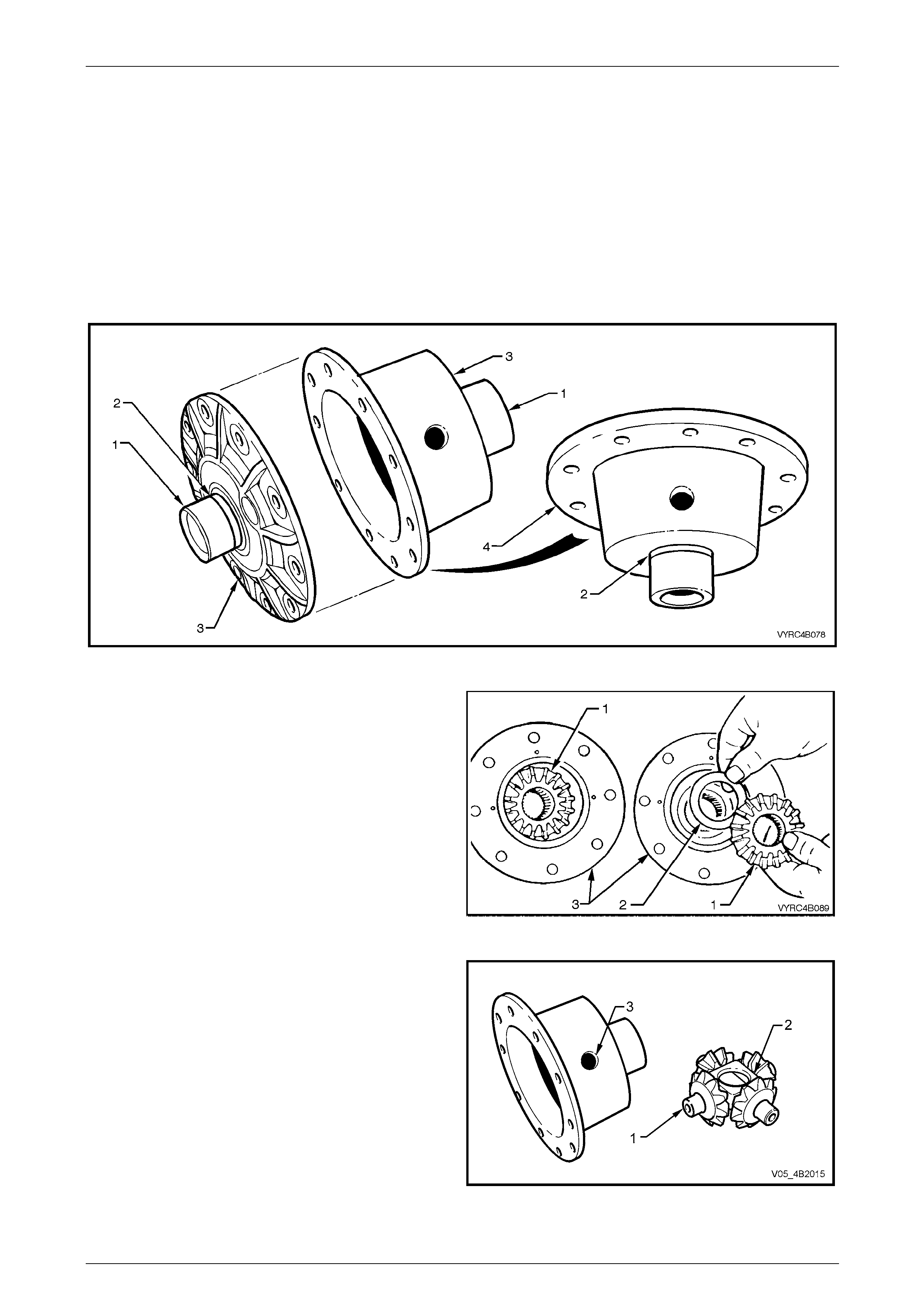
Rear Final Drive and Live Axle Page 4B2 – 61
Page 4B2 – 61
Inspect
Differential Case
All components of the differential should be cleaned and dried then ins pected. Check the differential case for general
condition payin g particu lar attention to the follow points:
1 If the side bearings have been removed from the differential case. Inspect the case side bearing journ al (1)
including the bearing seat (2) on each side of the differential case for any signs of damage.
2 Inspect the ring gear spigot and mounting face (4) of the differential case (3) for any signs of damage.
3 Ensure that all surfaces are free from burrs and foreign matter.
Figure 4B-109
4 Inspect the mating surface (3) of the differential case
halves for any signs of damage.
5 Inspect the thrust surfaces for the differential side and
pinion gears (1) of the differential case (3) for any
signs of damage or excessive wear.
6 Ensure that all machined surfaces are free from burrs
and foreign matter.
Figure 4B2 – 110
7 Inspect the differential pinion gear shafts (1) and
differential case bores (3) for ovality or any signs of
damage.
8 Inspect the thrust block and bores (2) for ovality or any
signs of damage.
9 Ensure that all machined surfaces are free from burrs
and foreign matter.
Figure 4B2 – 111
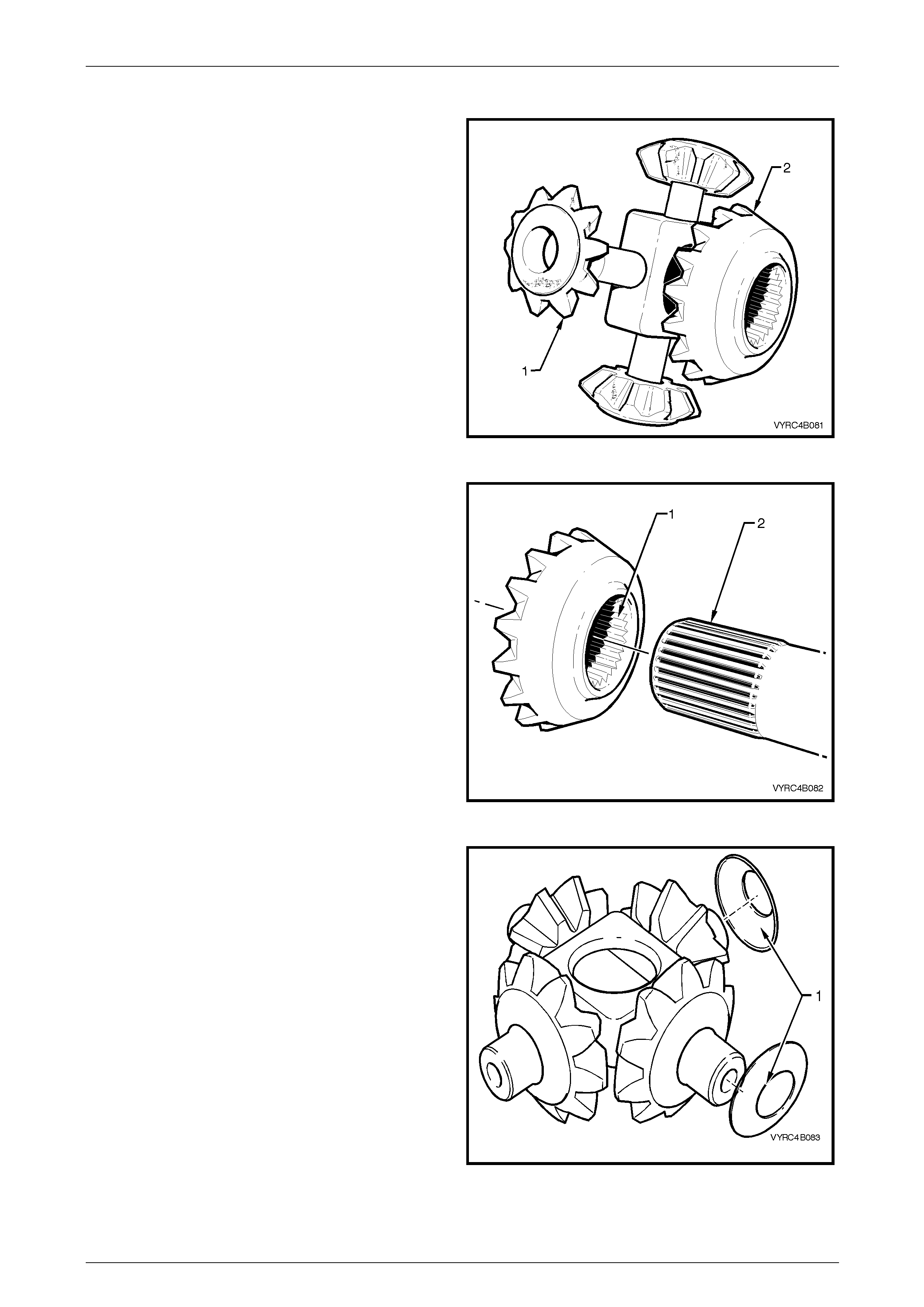
Rear Final Drive and Live Axle Page 4B2 – 62
Page 4B2 – 62
Differential Side and Pinion Gears
1 Inspect the teeth of the differential pinion g ea rs (1) and
side gears (2) for any signs of damage, cracks,
excessive wear or hard contact.
2 Inspect the thrust faces on the rear of the differential
side and pinion gears for any signs of damage or
scoring.
3 Ensure that all machined surfaces are free from burrs
and foreign matter.
Figure 4B2 – 112
4 Inspect the splines of the differential side gea rs (1) for
any signs of damage or exces s ive wear.
5 To check for excessive wear of the side gear spline,
slide the side gear (1) onto the splined section (2) of
the respective axle shaft. The gear should be a snug
fit with minimal side rotational movement on the axle
spline.
6 Ensure that all splined surface s are free from burrs
and foreign matter.
Figure 4B2 – 113
7 Inspect the thrust washer faces (1) for any signs of
damage or scoring.
8 Ensure that all thrust washer surfaces are free from
burrs and foreign matter.
Figure 4B2 – 114
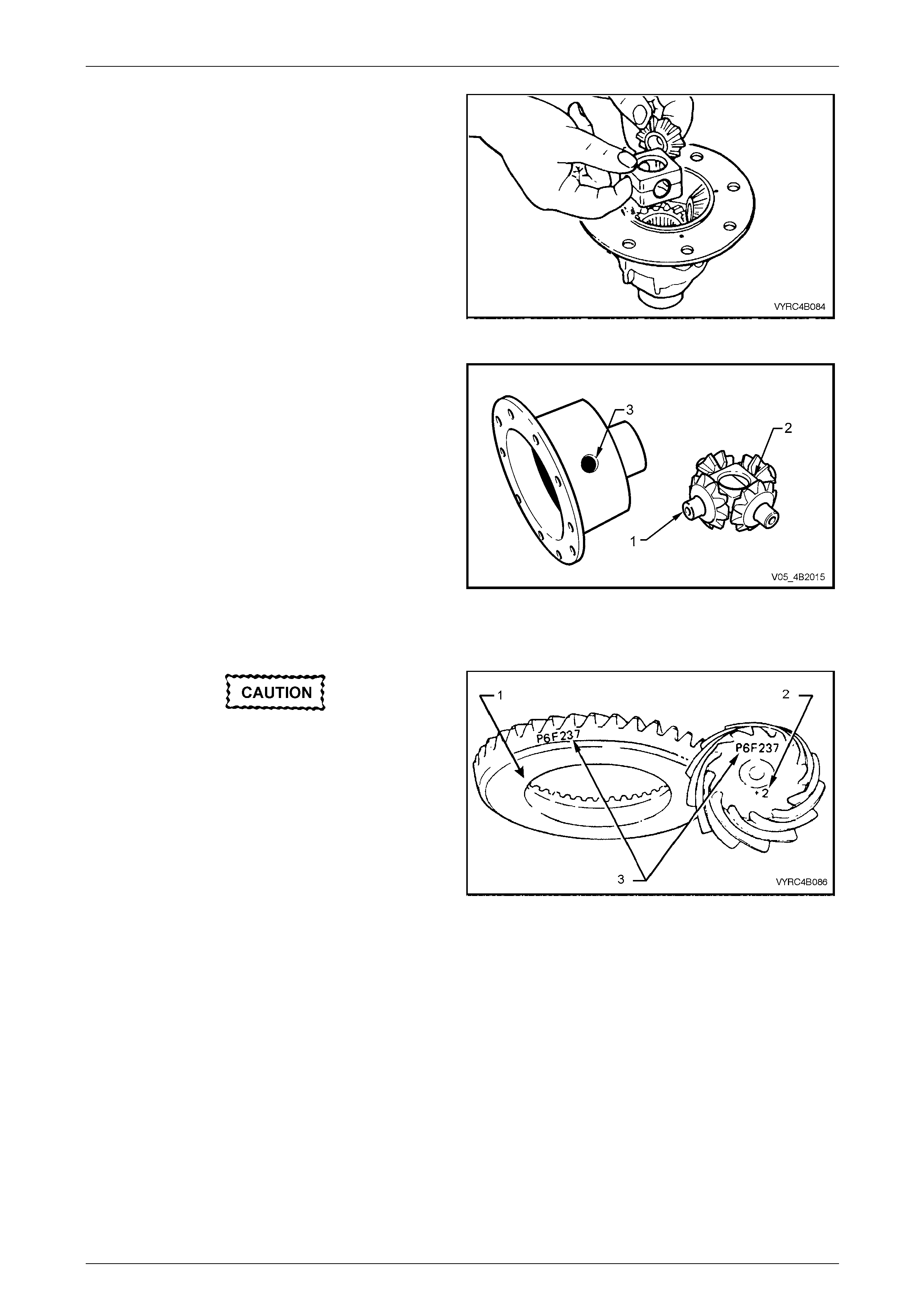
Rear Final Drive and Live Axle Page 4B2 – 63
Page 4B2 – 63
9 Check the fit of the differential gears in relation to the
differential case cap and cover. Wear of the side or
pinion gears; hub surfaces or case bores can cause a
'clunking' noise in the rear axle assembly when the
vehicle is driven at lo w speed.
10 Ensure that all surfaces are free of foreign matter.
Figure 4B2 – 115
11 Inspect all pinion gear shaft (1) surfaces for
straightness, scoring and wear.
12 Inspect the thrust block (2) and the differential case (3)
surfaces for scoring or wear.
13 Ensure that all surfaces are free from burrs and
foreign matter.
Figure 4B2 – 116
Ring Gear and Pinion Gear
Scored gears must be rep laced. If a new gear
set is to be installed, check that the same
matching numbers (3) appear on both the
pinion and ring gears.
1 Inspect the teeth of the ring gear (1) and pinion gear
(2) for any signs of damage, scoring, cracks, chips or
excessive wear.
NOTE
Excessive shock loading, use of incorrect
lubricant or insufficient ‘run in’ before towing a
heavy load, usually causes scoring of gear teeth.
2 Inspect the ring gear bore and back faces for any
signs of damage.
3 Inspect the pinion gear bearing seat, spline and thread
surfaces for any signs of damage or evidence of wear.
4 Check that all surfaces are free from burrs and foreign
matter.
Figure 4B2 – 117
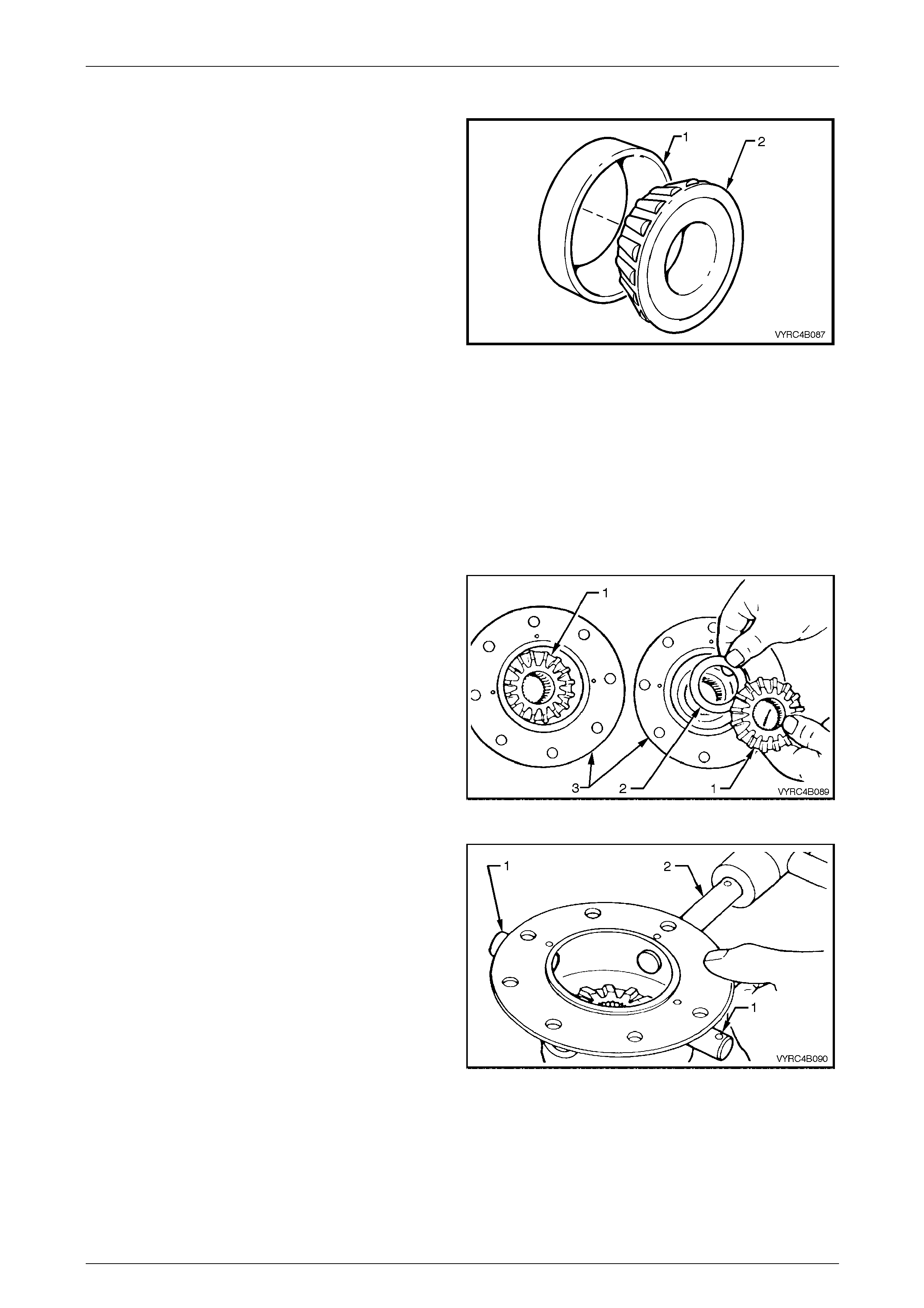
Rear Final Drive and Live Axle Page 4B2 – 64
Page 4B2 – 64
Bearings
NOTE
All bearings race assemblies and cu ps sho uld b e
kept in the same relationship as when removed.
All bearing race assemblies and cups should
remain as matching sets and should not be
mixed.
1 Inspect all bearing cups (1) for an even wear pattern.
The bearing cups should also be free from flaking or
pitting. Refer to 4.4 Differential and Rear Axle Bearing
Diagnosis in Section 4B1 Rear Final drive and
Driveshafts.
2 Inspect all bearing race assemblies (2) for signs of
wear or damage.
3 Inspect the roller cage and bores of the bearing race
assemblies for cracks, flaking, pitting or distortion. The
bearing race assemblies should feel smooth when
turned in their respective cups. Refer to 4.4 Differential
and Rear Axle Bearing Di agnosis in Section 4B1 Rear
Final drive and Driveshafts.
4 Check that all surfaces are free from burrs and foreign
matter.
Figure 4B2 – 118
Reassemble
1 Before reassembly, use the recommended rear axle
lubricant to lubricate the differentia l pinion gears, side
gears, and side bearings, thrust washers, pinion gear
shafts and thrust block.
2 Install the differential side gear s (1) and their related
thrust washer’s (2) into their respective differential
case halves (3).
Figure 4B2 – 119
3 Using a soft faced hammer, install the short pinion
gear shafts (1) and the long pinion gear shaft (2) into
the differential case, just enough to allow a thrust
washer to sit on the end of each shaft.
NOTE
Check that the retaining pin holes in the
differential case and pinion gear shafts are
aligned and that the chamfered edge of the
holes in each shaft is facing up.
Figure 4B2 – 120
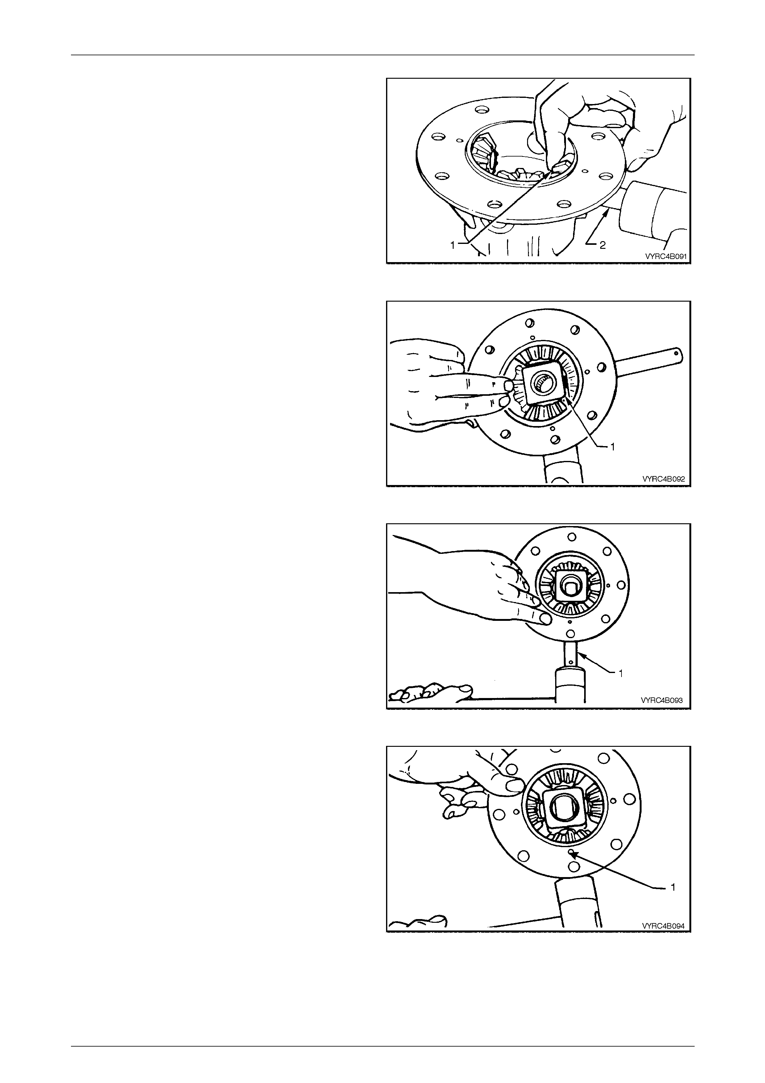
Rear Final Drive and Live Axle Page 4B2 – 65
Page 4B2 – 65
4 Install one of the pinion gear thrust washers over the
inside end of one of the short pinion shafts.
5 Holding the pinion gear and thrust washer (1) in place
while using a soft faced hammer, gently tap the short
pinion shaft (2) in until it comes through the centre of
the pinion gear.
6 Repeat steps 4 and 5 for the second pinion gear,
thrust washer and short pinion shaft.
Figure 4B2 – 121
7 Install the thrust block (1) bet ween the two-installed
pinion gears.
8 Hold the thrust block and differential case while using
a soft faced hammer to gently tap in each of the short
pinion shafts until the retaining pin holes of each shaft
line up with the related holes of the differential case.
Figure 4B2 – 122
9 Install the third pinion gear an d thrust washer over the
inside end of the long pinion shaft (1).
10 Hold the pinion gear and thrust washer in place. Use a
soft faced hammer to gently tap in the long pinion
shaft (1) until it comes through the centre of the pinion
gear and thrust block just enough to allow the
remaining pinion gear and thrust washer to be
installed.
Figure 4B2 – 123
11 Install the forth pinion gear and thrust washer over the
inside end of the long pinion shaft.
12 Use a soft faced hammer to gently tap the long pinio n
shaft through the centre of the pinion gear, thrust
washer and differential case until the retaining pin hole
of the shaft lines up with the related hole (1) of the
differential case.
Figure 4B2 – 124
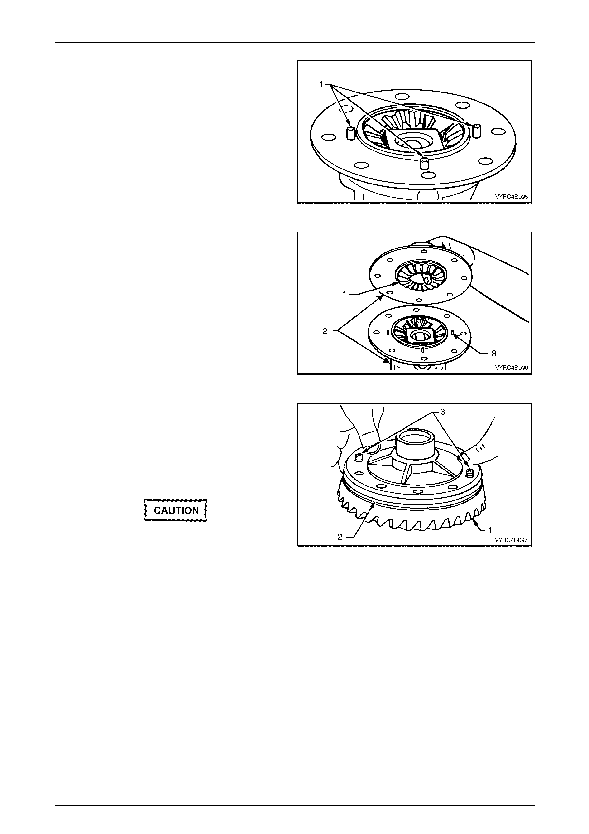
Rear Final Drive and Live Axle Page 4B2 – 66
Page 4B2 – 66
13 Install the three retaining pins (1) for each pinion shaft
ensuring each pin protrudes 6 mm from the mating
face of the differential case half.
Figure 4B2 – 125
14 Check that the mating surfaces of each differential
case half are free from burrs and foreign matter.
15 Holding the remaining side gear (1) in position with a
finger through the differential side gear bore, mate the
two halves of the differential case (2) toget her while
aligning the protruding pinion shaft retaining pins (3) of
the other case half
Figure 4B2 – 126
16 Check that all mating surfaces of the ring gear and
differential case are free from burrs and foreign matter.
NOTE
For ease of assembly, it may be necessary to
heat the ring gear on a hot plate until it is hot to
the hand, prior to installing onto the differential
case cap.
A flame must never be used to heat the ring
gear.
NOTE
Use left hand threaded guide pins (3) to pilot the
ring gear over the differential case spi got.
17 With the aid of two guide pins (3) place the ring gear
(1) into position on the differential case (2) and install
the NEW ring gear attaching bolts.
Figure 4B2 – 127
18 Remove the two guide pins and install the remaining ring gear attaching bolts.
19 Place ring gear (1) into positio n on differential case cap (2) and install ring gear attaching bolts.
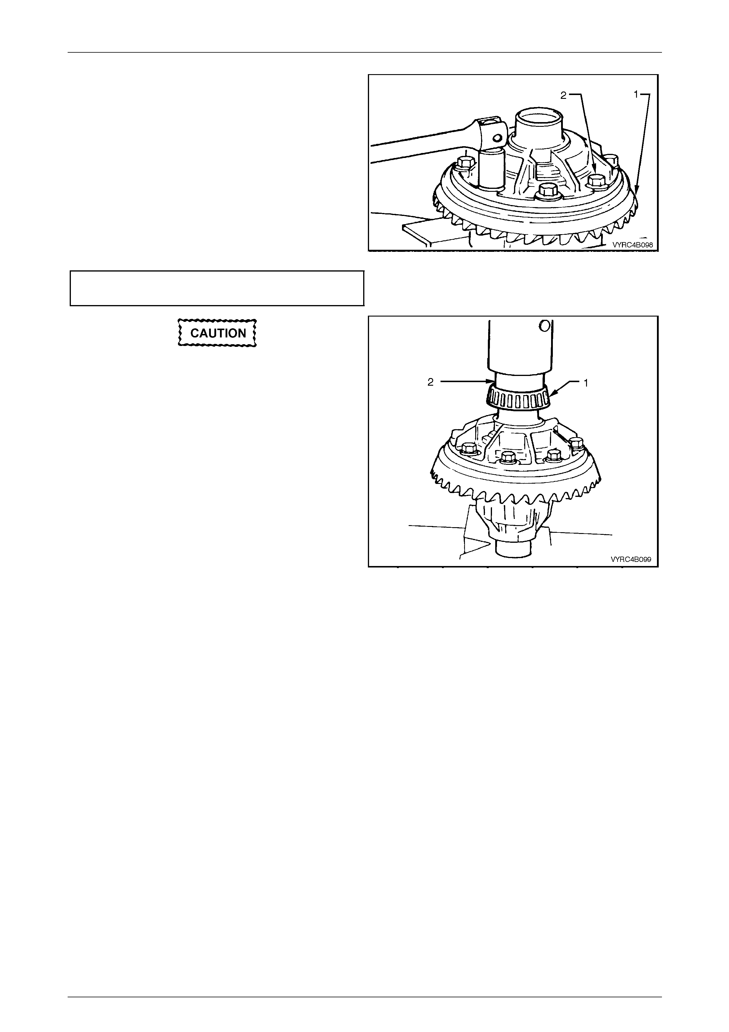
Rear Final Drive and Live Axle Page 4B2 – 67
Page 4B2 – 67
20 Secure the differential case in a suitabl e vice fitted
with soft metal jaws.
21 Using a cross pattern, tighten the ring gear attaching
bolts (2) to seat the ring gear (1) to the differential
case.
NOTE
The ring gear attaching bolts use a left-hand
thread and are identifi ed by an 'L' on the head of
the bolt.
22 Tighten the ring gear attaching bolts (2) to the correct
torque specification.
() Ring gear to differential case
attaching bolt torque specification......................140 N.m
Figure 4B2 – 128
23 To install new side bearing race assemblies (1) use
Tool No. 205-545 (2). Use suitable press plates to
support the opposite differential case journ al. With
Tool No. 205-545 in plac e, press the bearing race
assembly on to the differential case journal.
24 Repeat step 23 to install the remaining side bearing
race assembly on to the differential case journal,
taking care not to damage the previously installed
bearing race.
Figure 4B2 – 129
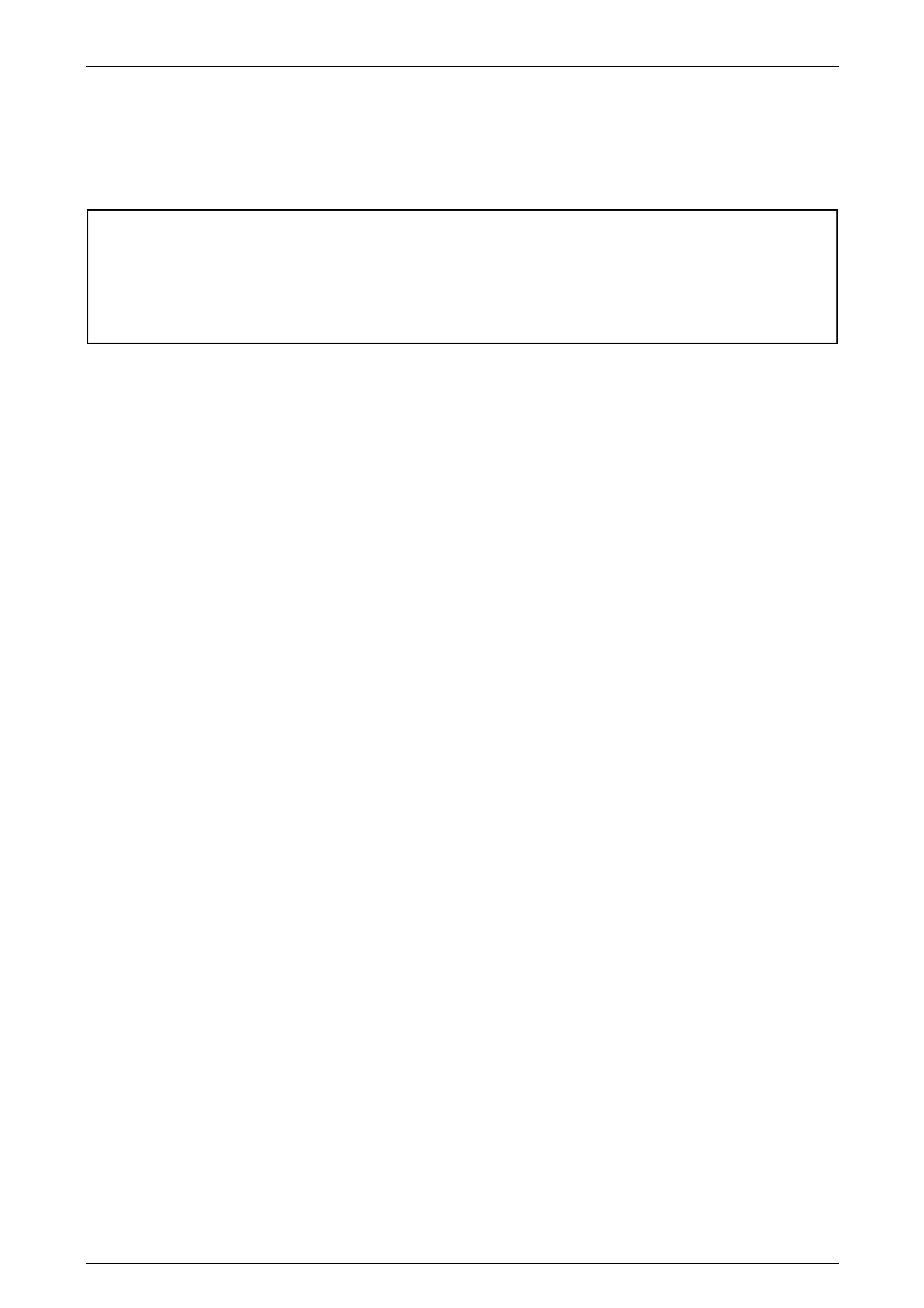
Rear Final Drive and Live Axle Page 4B2 – 68
Page 4B2 – 68
3.4 Differential Assembly – M78 Series
(Cone Type Limited Slip)
LT Section No: F502600
ATTENTION
The following fasteners MUST be replaced w hen performing these operations:
Ring gear bolts.
LSD case cap to cover attachin g bolts.
The overhaul proced ures, ring gear and pinion positioning a nd t ooth markings for the M78 Series limited slip differential
are the same as for the standard type of rear axle assembly. The only difference is the servicing of the in ternal
components of the limited slip differential assembly.
NOTE
• For the differential assembly and pinion gear
removal procedure refer to 3.6 Rear A xle and
Differential Housing Assembly, Disassemble
in this Section.
• The M78 Series differential has unique parts
and are not interchangeable with the M86
Series assembly. The general overhaul
procedure is also different for both types.
The unique components for the M 78 Series differentials are:
• Differential case.
• Differential pinions.
• Side gears.
• Differential pinion thrust washers.
• Pinion cross shaft.
• Clutch cones.
• Thrust spring plates.
• Differential preload springs.
• Differential case cap to cover attaching bolts.
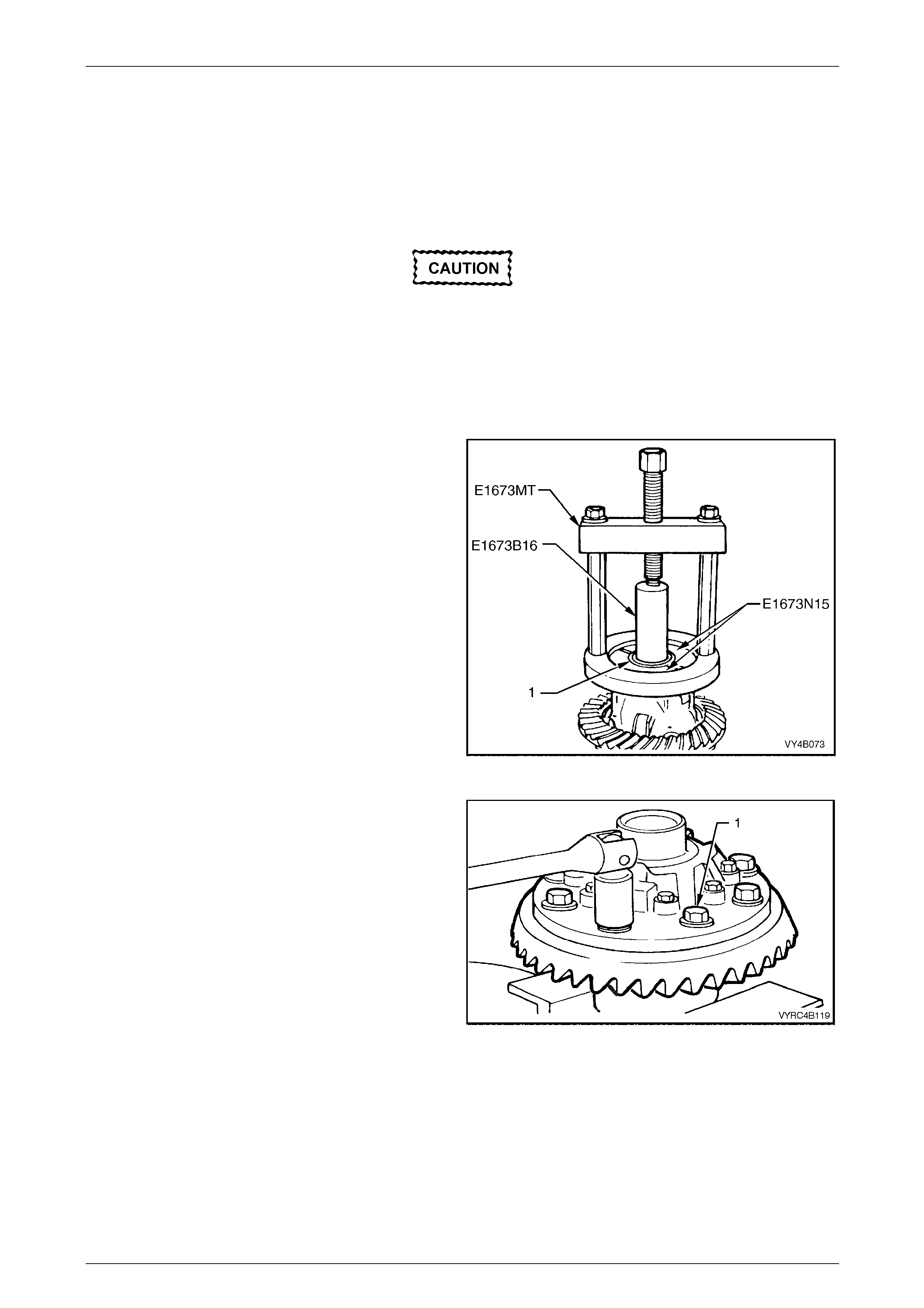
Rear Final Drive and Live Axle Page 4B2 – 69
Page 4B2 – 69
Disassemble
NOTE
Both side bearings and their cups are matched
parts. If either bearing is to be replaced, its
matching cup must also be replaced.
Either Timken or Koyo supply the side
bearings. When replacing the differential side
bearings, the two bearings and cups must be
of the same manufactu re.
The pinion bearings may be of a different
manufacture but again, they must be a
matched pair.
1 Before disassembling differential case, inspect
differential side bearings for an y signs of da mage.
2 If replacing the side bearings (1), use Tool No.
E1673MT, adaptors Tool No. E1673N15 and stepped
plug Tool No. E1673B16 to remove side b earings from
the differential case.
3 Discard removed side bearings.
NOTE
The side bearing cups should have been
removed during the disassembly process, refer
to 3.2 Rear Axle and Differential Housing
Assembly – Disassemble, in this Section.
Figure 4B2 – 130
4 Using in a suitable vice equipped with soft metal jaws,
secure the differential case, remove the ring gear
attaching bolts (1) and discard the bolts.
NOTE
The ring gear attaching bolts have a left-hand
thread and are identified by an 'L' on the bolt
head.
5 Remove the differential case from the vice.
Figure 4B2 – 131
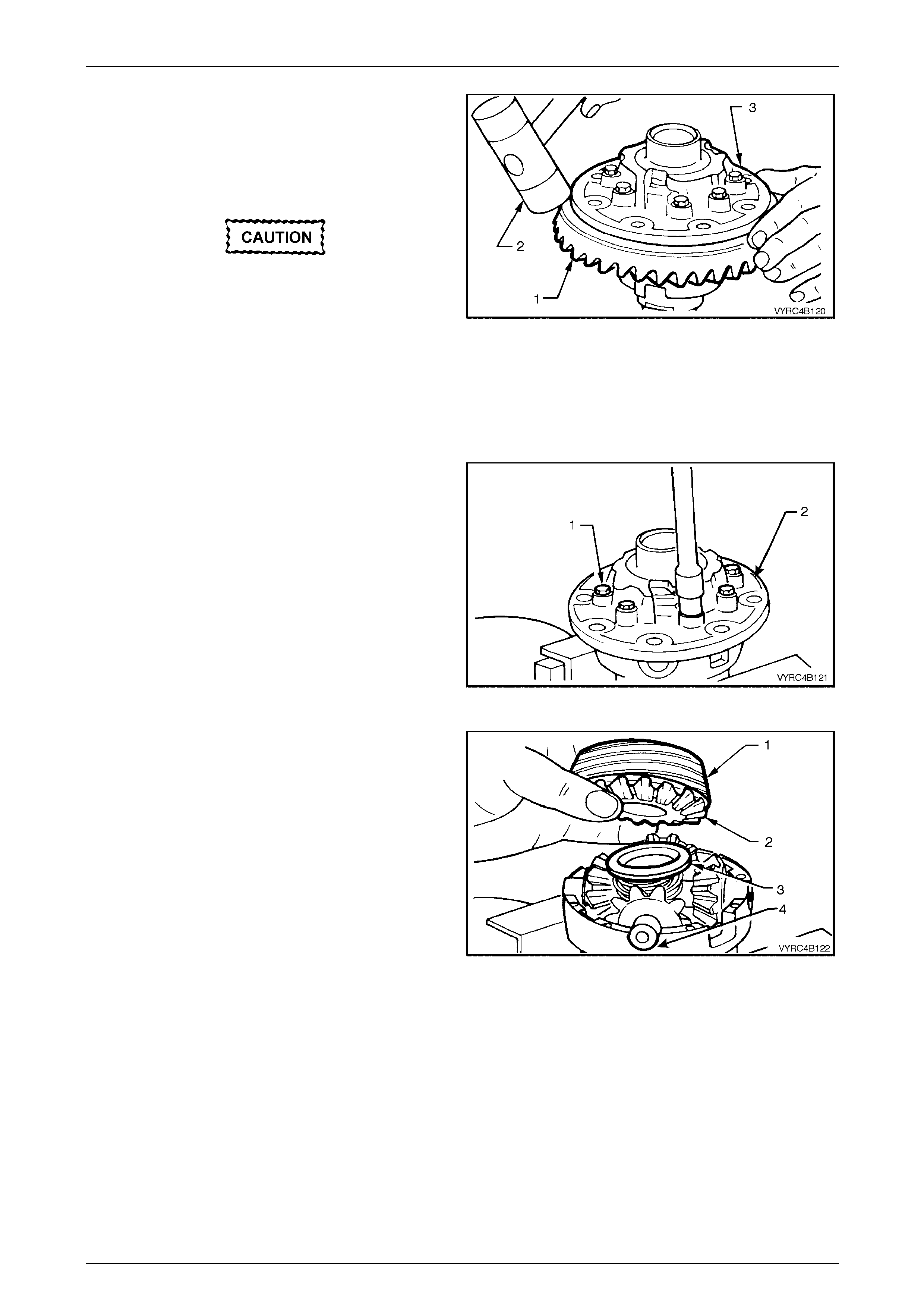
Rear Final Drive and Live Axle Page 4B2 – 70
Page 4B2 – 70
6 Place a piece of softwood large enou gh to cover the
overall diameter of the ring gear on top of a suitable
workbench.
7 Place the differential case (3) on top of the piece of
softwood with the ring gear facing do wnward, as
shown.
Do not use a screwdriver or other form of
leverage to pry between the ring gear and the
mating face of the differential case, as
damage will occur.
8 Using a soft faced hammer (2), tap down on the ring
gear while rotating the differe ntial case to remove the
ring gear (1).
NOTE
The softwood will protect the ring gear from
damage, when removed.
Figure 4B2 – 132
9 Return the differential case to a fitted with soft metal
jaws.
10 evenly loosen and rem ove the differential case cap to
cover attaching bolts (1) and discard the bolts.
11 Lift off the differential case cover (2) If necessary;
remove the clutch cone from the cover (the cone may
remain inside the cover).
Figure 4B2 – 133
12 Remove the clutch cone (1), shim (if fitted), side gear
(2) and thrust spring plate (3) from the pinion cross
shaft (4).
NOTE
The clutch cones and side gears are an integral
unit and must stay assembled to each other.
Figure 4B2 – 134
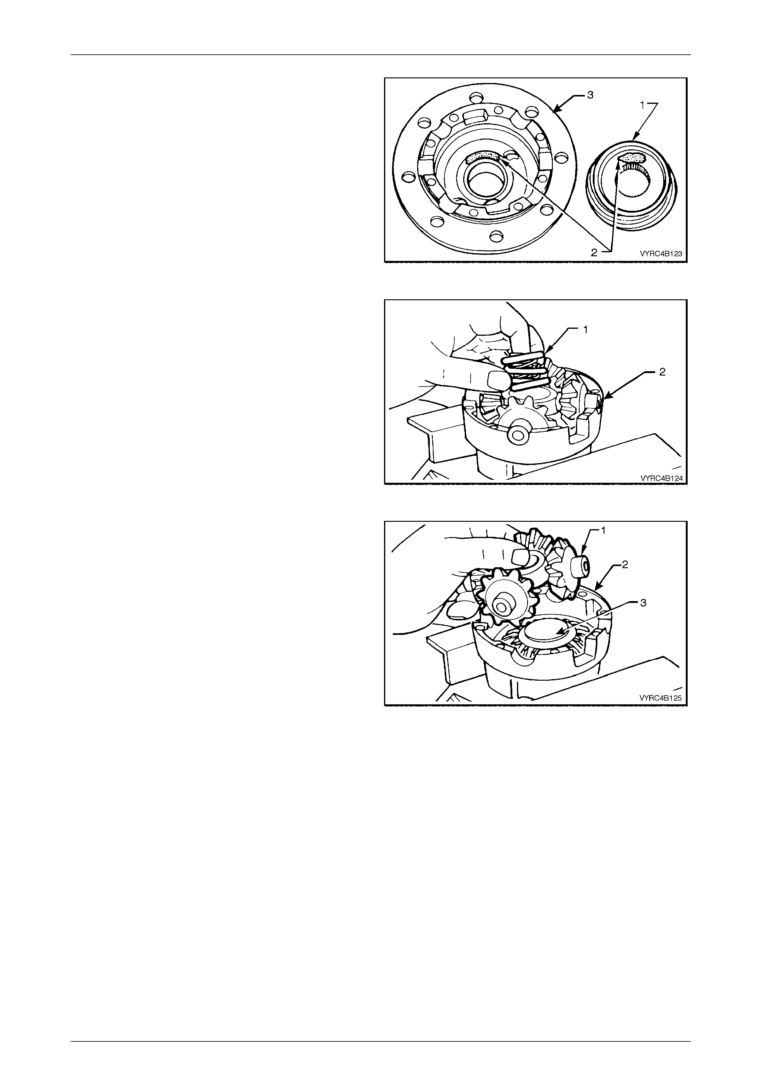
Rear Final Drive and Live Axle Page 4B2 – 71
Page 4B2 – 71
NOTE
To ensure that the clutch cones (1) are not
interchanged during reassembly, mark (2) the
cone and corresponding side of the differential
case (3) with a pen or similar. If shims are
present, they must also be marked so that they
can be reassembled into the correct case half.
Figure 4B2 – 135
13 Remove the three concentric differenti al pre load
springs (1) from centre of pinion cross shaft (2).
Figure 4B2 – 136
14 Lift the pinion cross shaft (1), pinion gears and thrust
washers from the differential case (2), as a single unit.
NOTE
Keep the pinion gears with their respective thrust
washers in sets so they can be reinstalled in
their original position.
15 Remove the pinion gears and thrust washers from
cross shaft.
16 Remove remaining thrust spring plate (3), side gear,
shim (if fitted) and clutch cone from differential case
(2). Figure 4B2 – 137
Inspect
All components should be thoroughly cleaned and dried, then inspected.
NOTE
Keep the marked components in their respective
sets so they can be reinstalled in their original
position.
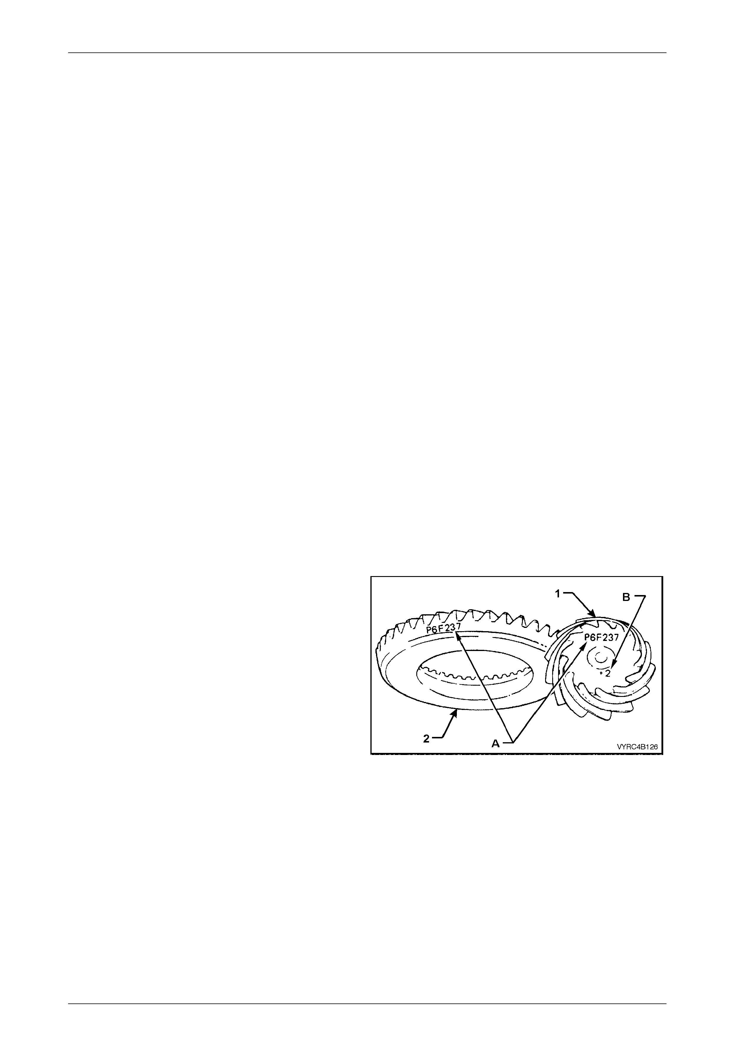
Rear Final Drive and Live Axle Page 4B2 – 72
Page 4B2 – 72
Differential Case
Check the following items:
1 The case for general soundness and pay particular attention to the following points:
a If differential case side bearings have been removed, check case journals for damage and that seating
surfaces are free from dirt and burrs.
b The ring gear spigot and mounting face should be clean and free from dirt and burrs.
c The mating surfaces for differential case halves shou ld be clean and free from burrs.
2 The thrust surfaces for the differentia l pinions should be examined for e xcessive wear.
3 The clutch cone seats in the two housing halves should be smooth and free from an y excessive scoring. Slight
grooves and scratches are permissible and normal.
4 The land surface of the heavy spirals on clutch cones will duplicate the housing surface condition. Exces sive wear
or damage on the clutch cone surface will require replacement of both clutch cones or the clutch cone/sid e gear
assemblies (as applicable) a nd the housing.
5 Inspect the axle splines of the clutch cones (where applicable) for excessive wear.
6 Check the thrust spring plates for excessive wear or damage.
7 If fitted, inspect side gear shims for damage.
8 Inspect the pinion gear cross shaft bores for ovality.
Differential Side Gears and Pinion Gears
Check the following items:
1 Examine all gear teeth for cracks or hard contact marks.
2 The differential side gear spli nes should be checked for excessive wear. Wear on splin es can contribute to
excessive driveline backlash.
3 The differential pinion bores and thrust surfaces should be smooth and free from scores. Inspect all thrust washers
for cracks, nicks or burrs. Wear of thrust washers or thrust surfaces on gears can contribute to excessive driveline
backlash.
4 Check that the pinion gear cross shaft is not bent and that surfaces on which pinions run, are not scored or worn.
Ring Gear and Pinion
Check the following items:
1 Inspect the gear teeth for scoring or damage.
Excessive shock loading, use of the incorrect lubricant
or insufficient “run in” before towing a heavy load,
usually causes scoring of the gear teeth. (Refer to the
MY2005 VZ Series, Cab Chassis Owner's Handbook).
Scored gears must be replaced,
2 If on reassembly, a new gear set is to be installed,
ensure that the same matching number (A) appears
on both the pinion (1) and ring gear (2).
3 The identification number (B) on the pinion end (1) is
used when setting the pinion depth on reassembly.
Figure 4B2 – 138
Bearings
Check the following items:
1 Bearing cups should have an even wear pattern and be free from flaking or pitting.
2 Ensure the seating surfaces are clean and free from burrs or raised metal.
3 The bearing assembli es should feel smooth when turned in the cups.
4 The assembly should be free from loose particles.
5 There should be no cracks pr esent in the roller cages and the bores should show no evidence of flaking or pitting.
Refer to 4.4 Differential and Rear Axle Bearing Diagnosis i n Section 4 B1 Rear Final Drive and Driveshafts, for
identification related to the diagnos is of bearing failures.
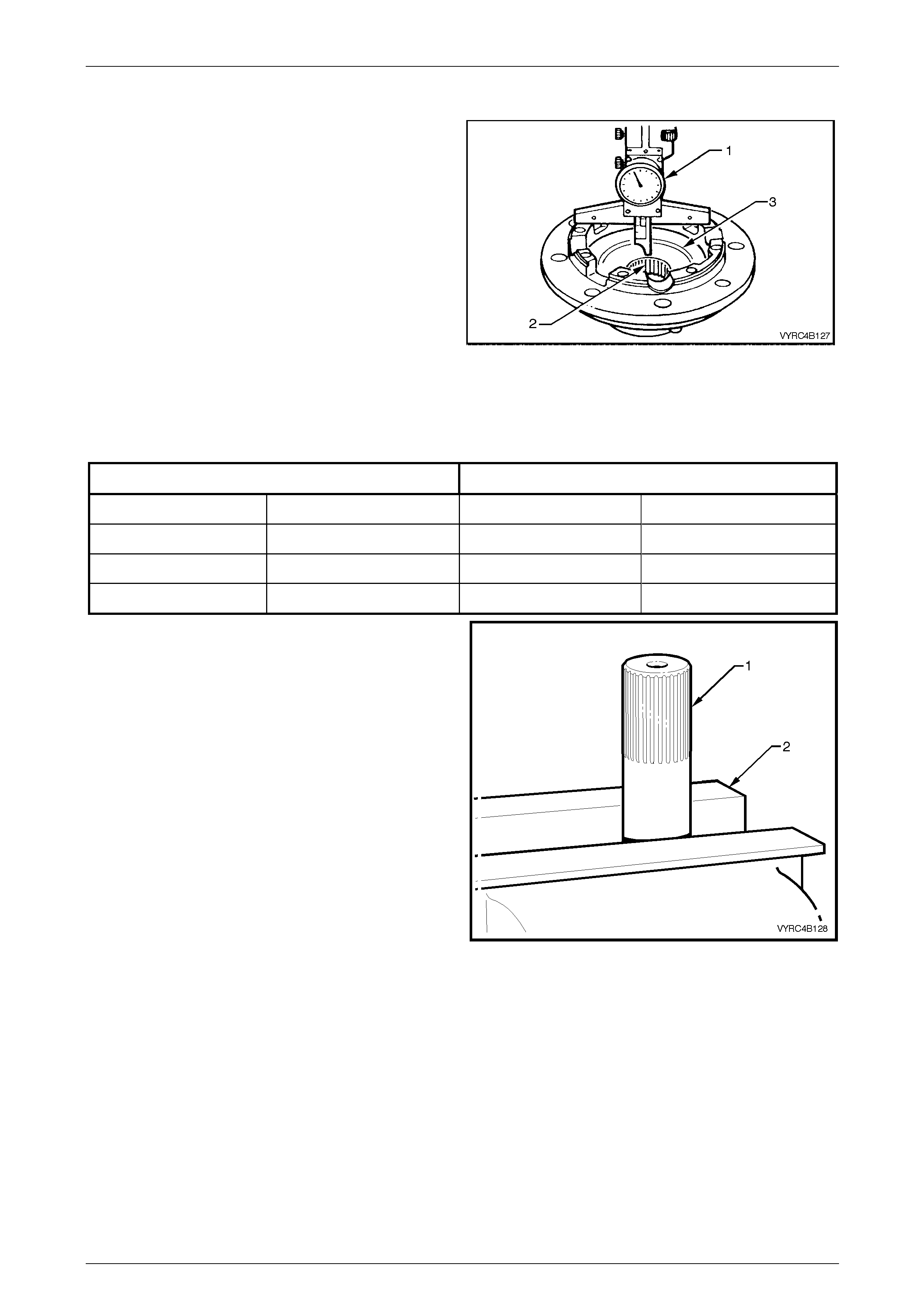
Rear Final Drive and Live Axle Page 4B2 – 73
Page 4B2 – 73
Reassemble
1 Lubricate all gears, bearings, thrust washers and
pinion gear cross shaft with rear axle lubrican t before
assembly. Refer to 2.2 Checking Rear Axle Lubricant
Level in this Section.
2 With the cone type unit separated, reinstall e ach
respective clutch cone and shim (if fitted) into
differential case halves.
3 To check if shims are required:
a Using a depth gauge (1), measure the distance
from the case-mating surface (2) to the flat
seating surface for the clutch cone (3). Record
this dimension.
b This measurement will indicate what size side
gear positioning shim is required. Each case half
and clutch cone must be measured for its own
respective shim.
Figure 4B2 – 139
4 With the measurement from "a", above, select the correct shim size as indicated b y the following chart.
Clutch Cone Without Groove Clutch Cone With Groove
Distance Measured Shim Size Required Distance Measured Shim Size Required
29.51 – 29.34 mm No shim required 32.0 – 31.84 mm No shim required
29.64 – 29.54 mm 0.13 mm shim required 32.14 – 32.04 mm 0.13 mm shim required
29.77 – 29.67 mm 0.25 mm shim required 32.27 – 32.17 mm 0.25 mm shim required
5 Remove clutch cones and shims from differential case
halves.
NOTE
There are two types of cone assemblies used in
the M78 Series LSD. For the later type shimmin g
is not required, as the side ge ar and cone ar e an
integrated, single assembly.
6 Clamp the left-hand axle shaft (1) in a vice fitted with
soft jaws (2), with at least 85 mm from the splined end
exposed.
NOTE
The axle shaft is used as a mounting tool with
the separate cone type, to ensure correct side
gear and clutch cone s pline alignm ent. Failure to
follow this procedure will prevent installation of
the axle shafts at final assembly.
Figure 4B2 – 140
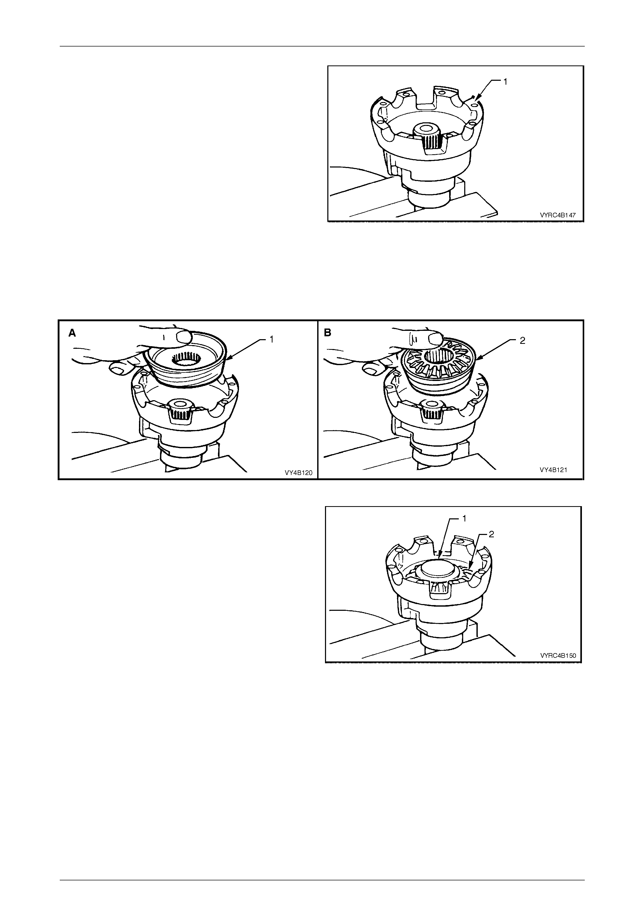
Rear Final Drive and Live Axle Page 4B2 – 74
Page 4B2 – 74
7 Place differential case cap (1) over axle shaft mounted
in vice (equipped with soft metal jaws) with interior of
the housing facing upwards
8 Paint a mixture of an EP grease with molybdenum
disulphide, such as Shell Retinax HDX2 grease, BP
Energrease LMS-EP 23, or equivalent, with the
recommended rear axle lubric ant onto faces of side
gears and clutch cone surfaces.
Figure 4B2 – 141
9 Install the clutch cone taking note of the following:
a For separate cone type differentials (view 'A'), install clutch cone over axle splines, seating it in position in
housing followed b y a shim (if required, refer Step 3) and side gear.
b With integral cone type differentials (view 'B'), install the clutch cone/side gear assembly (2) to the housing.
Figure 4B2 – 142
10 Place a thrust spring plate (1), stepped si de up onto
the side gear (2).
11 Assemble the four pinions and thrust washers onto
pinion cross shaft.
12 Install the pinions and the cross shaft assembl y to the
case cap, ensuring that the pinions mesh with the side
gear.
Figure 4B2 – 143
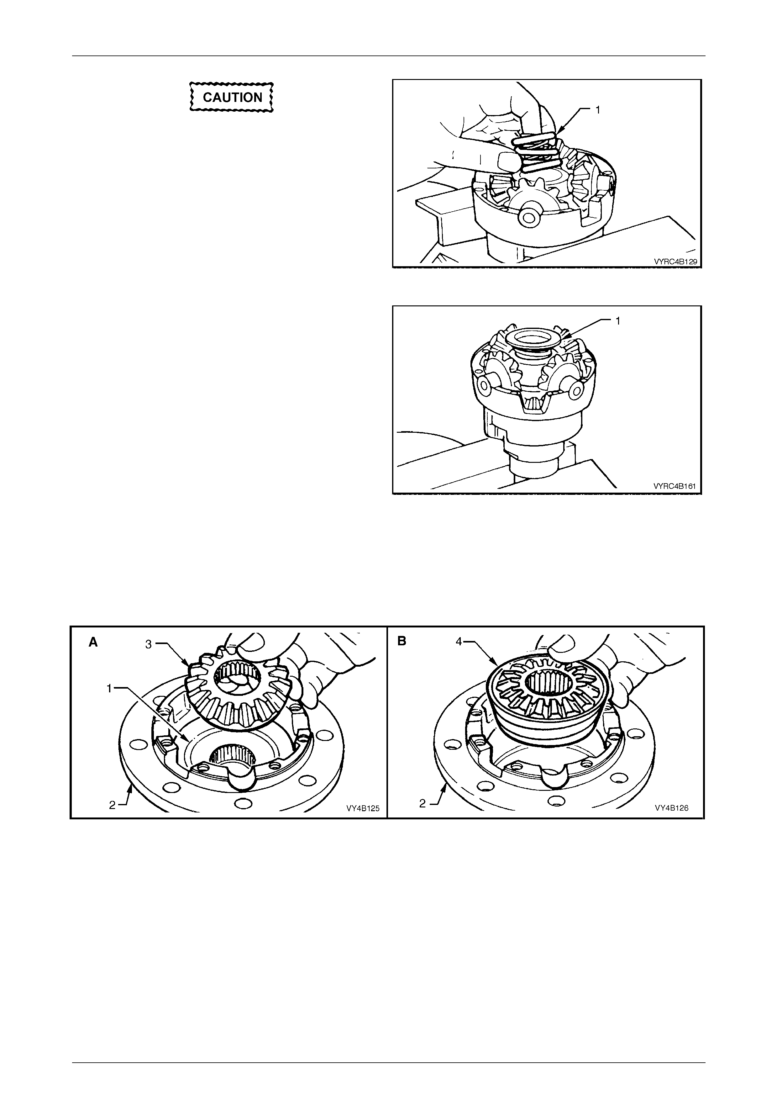
Rear Final Drive and Live Axle Page 4B2 – 75
Page 4B2 – 75
NEW preload springs must always be
installed on reassembly, DO NOT RE-USE
OLD SPRINGS.
13 Install three new concentric differential preload springs
(1) into the centre of the pinion cross shaft (2).
Figure 4B2 – 144
14 Assemble the second thrust spring plate (1), stepped
side down, onto the preload springs.
Figure 4B2 – 145
15 Install the clutch cone taking note of the following:
a For separate cone type differentials (view 'A'), install clutch cone, shim (if required) and side gear (3) to the
clutch cone seat (1) in the case cover (2).
b For integral cone type differentials (view 'B'), install the clutch cone/side gear assem bly (4) into the case
cover (2).
Figure 4B2 – 146
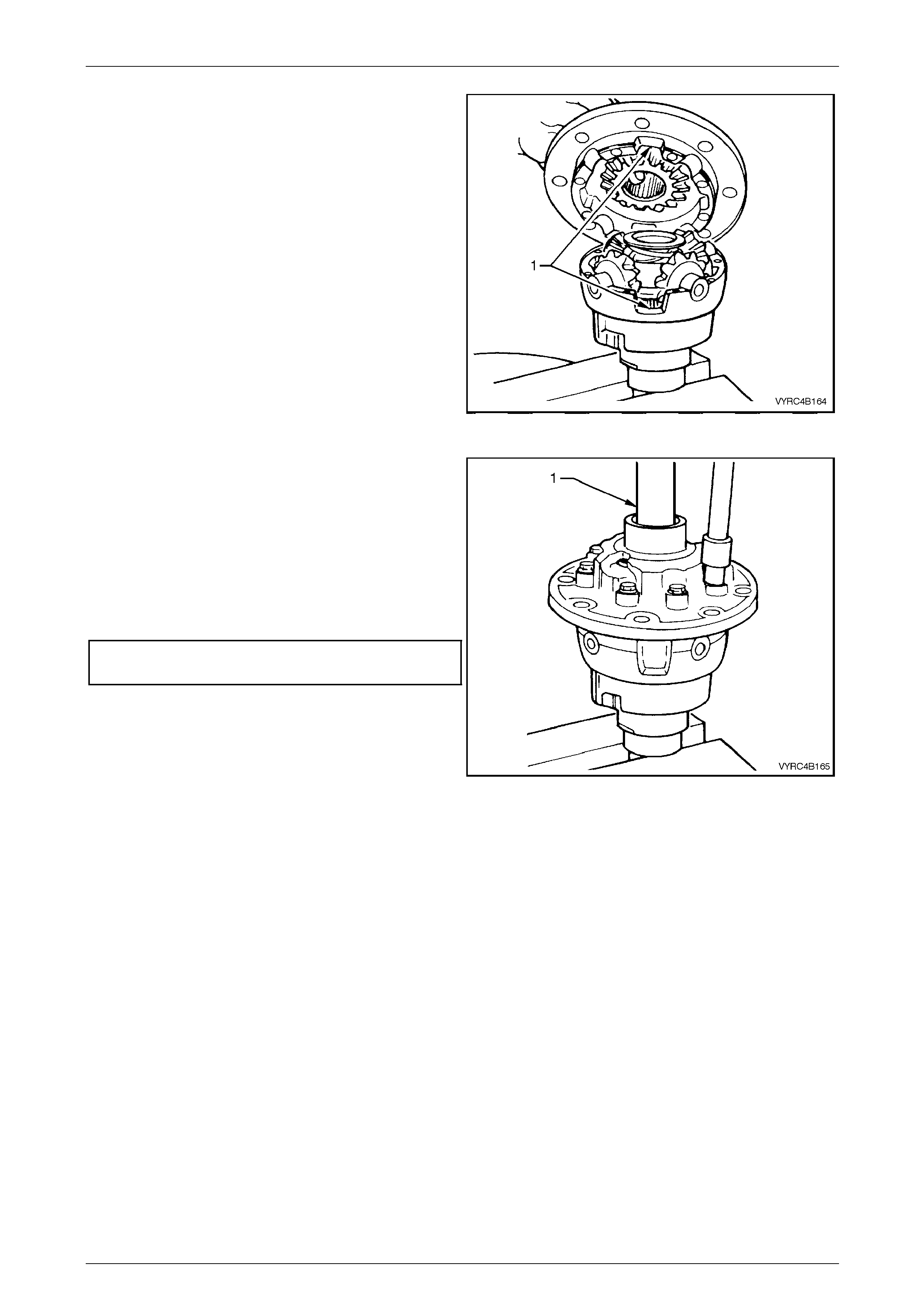
Rear Final Drive and Live Axle Page 4B2 – 76
Page 4B2 – 76
16 Install the case cover onto the case cap.
NOTE
Check that the cut out (1) on each side of the
case cover and cap are aligned.
Figure 4B2 – 147
17 Install two NEW differential case cap-to-cover
attaching bolts in opposite bolt holes and finger
tighten.
18 Install the other inner axle shaft (1) through the case
cover, rotating the axle shaft to engage the clutch
cone splines and then the side gear sp lines.
19 Leave the axle shaft in this position. Install the
remaining, (NEW) cap-to-cover attaching bolts and
tighten evenly to the correct torque specification.
() Differential case cap to cover
attaching bolt torque specification........................40 N.m
20 Remove the axle shafts from the differential case
assembly.
NOTE
• If the shafts bind on the clutch cone and sid e
gear splines, a light tap with a soft metal
hammer may be necessary to remove the
axle shafts.
• At no time must the side gears and clutch
cones be rotated until t he a xle shafts ar e full y
installed. Failure to observe th is condition will
result in side gear and clutch cone spline
misalignment, thus preventing inner axle
shaft installation.
Figure 4B2 – 148
Should the splines become misaligned, loosen the case cap to cover bolts and repeat step s 6, 7, 16, 17 and 18.
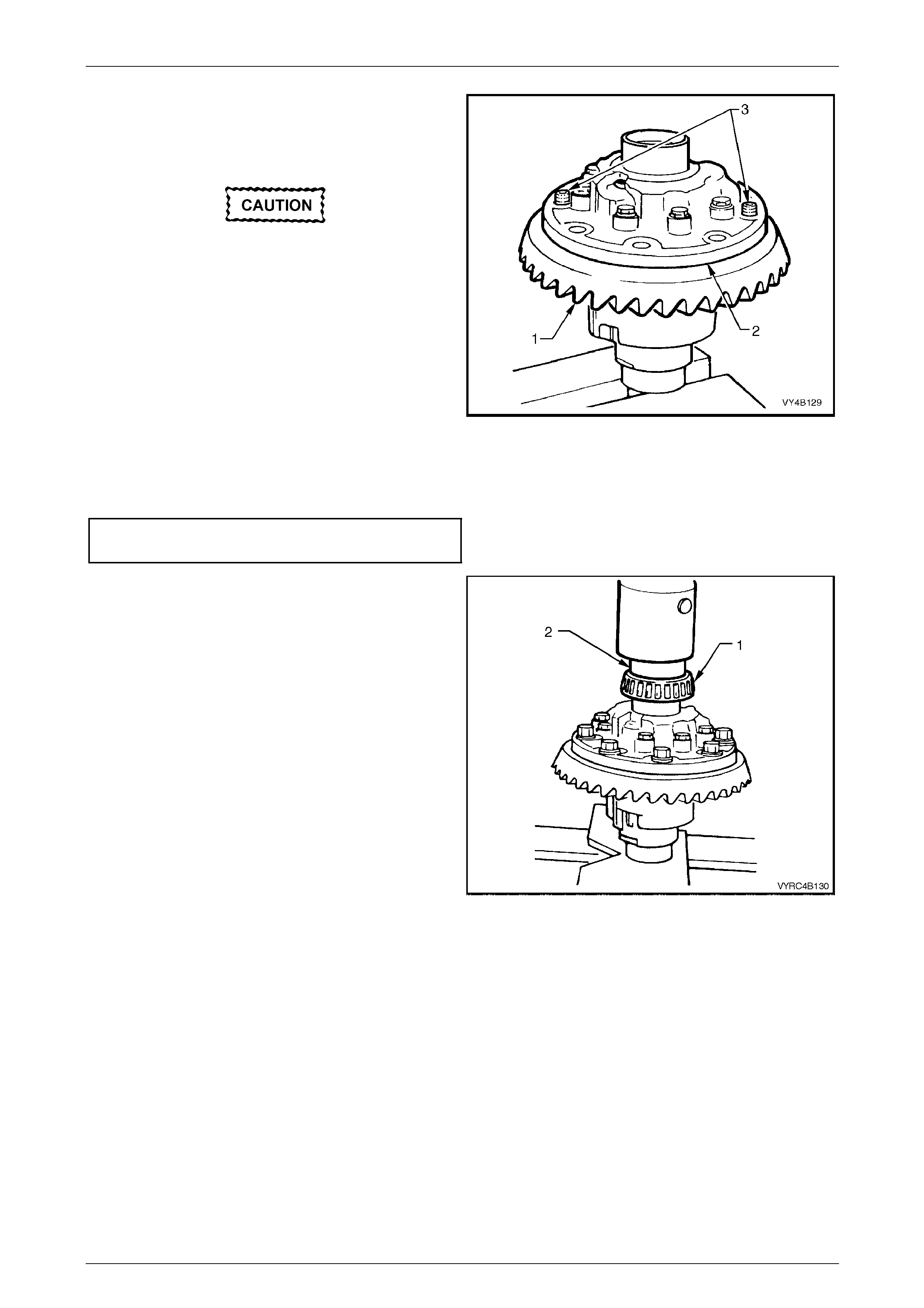
Rear Final Drive and Live Axle Page 4B2 – 77
Page 4B2 – 77
21 Check that all mating surfaces of the ring gear and
differential case are free from burrs and foreign matter.
22 Install two left-hand threaded guide pins (3) into two
opposing ring gear bolt holes .
A flame must never be used to heat the ring
gear.
NOTE
For ease of reassembly, it may be necessary to
heat the ring gear on a hot plate until it is hot to
the hand, prior to installing onto the differential
case cap
23 Place the ring gear (1) into position o n the differential
case cap (2) and install NEW ring gear attaching bolts.
Figure 4B2 – 149
24 Remove the left-hand threaded guide pins and install the remaining two NEW ring gear attaching bolts.
25 Tighten all ring gear attaching bolts to the correct torque specification
() Ring gear to differential case cover
attaching bolt torque specification......................140 N.m
26 If installing new side bearings (1), use Tool No. 205-
545 (2) to press on the new side bearings (1) to
differential case journals.
27 Continue rear axle reassembly, refer to 3.6 Differential
Assembly Adjustment and Installation Procedures – Al l
Models in this Section.
Figure 4B2 – 150
Rear Final Drive and Live Axle Page 4B2 – 78
Page 4B2 – 78
3.5 Differential Assembly – M86 Series
(Multi-Disc Type Limited Slip)
LT Section No: F502600
ATTENTION
The following fasteners MUST be replaced w hen performing these operations:
Ring gear bolts.
The overhaul procedures, ring gear and pinion positioning procedure are unique to the M86 Series rear axle assembly.
The tooth marking for the M86 Series limited slip differential are the same as for the standard type rear axle assembly
and the servicing of the internal compone nts of the limited slip differential assembly is also unique.
NOTE
For the differential assembly and pinion gear
removal procedure refer to 3.2 Rear Axle and
Differential Housing Assembly, Disassemble in
this Section.
The M86 Series differentials have un ique parts and are not interchangeabl e with the M78 Series unit. The general
overhaul procedures are also different for both types.
The unique components for the M 86 Series differentials are:
• Differential case.
• Differential pinion thrust washers.
• Differential pinion shaft.
• Side gears.
• Concentric grooved discs.
• Clutch plates.
• Clutch plate retainers.
• Dished spacers.
• Disassemble
1 Before disassembling the differential case, inspect differential side bearings for any signs of damag e.
NOTEB
Both side bearings and their cups are matched
parts. If either bearing is to be replaced, its
matching cup must also be replaced.
Either Timken or Koyo supply the side
bearings. When replacing the differential side
bearings, the two bearings and cups must be
of the same manufactu re.
The pinion bearings may be of a different
manufacture but again, they must be a
matched pair.
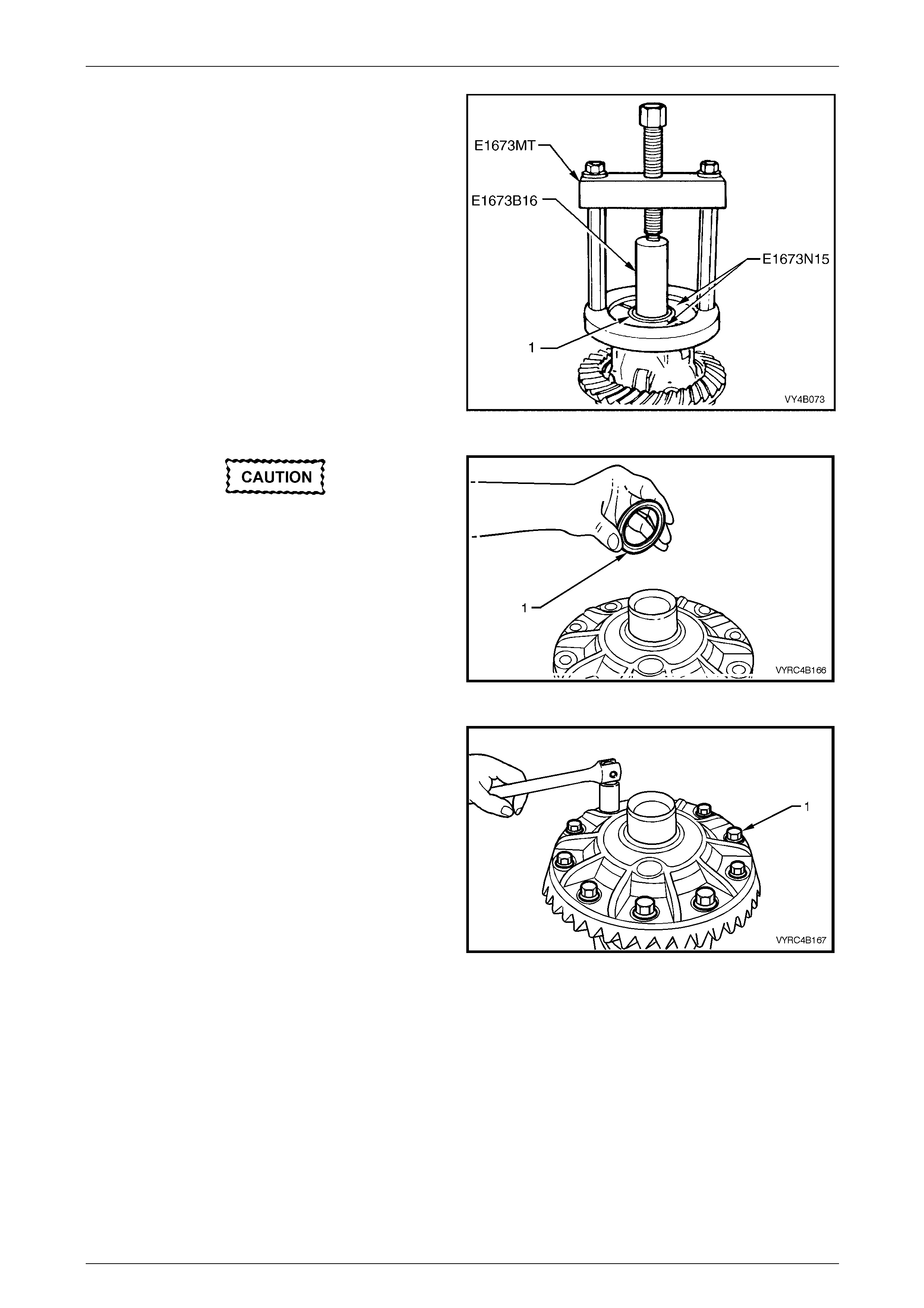
Rear Final Drive and Live Axle Page 4B2 – 79
Page 4B2 – 79
2 If replacing side bearings (1), use Tool No. E1673MT,
adaptors Tool No. E1673N 15 and stepped plug Tool
No. E1673B16 to remove side bearings from
differential case.
3 Discard side bearings once they are removed.
NOTE
The side bearing cups should have been
removed during the disassembly process, refer
to 3.2 Rear Axle and Differential Housing
Assembly – Disassemble, in this Section.
Figure 4B2 – 151
The M86 Series Differential requires a spacer
(1) to be installed on the ring gear sid e of the
differential case behind the side bearing.
This spacer must be installed to enable the
differential assembly to carrier set-up
procedure to be carried out co rrectly
4 If the spacer (1) has been removed, reinstall the
spacer onto the side-bearin g journal closest to the ring
gear before proceeding.
Figure 4B2 – 152
5 Secure the differential case in a vice fitted with soft
metal jaws.
6 Remove the ring gear attaching bolts (1) and discard
the bolts.
NOTE
The ring gear attaching bolts have a left-hand
thread and are identified by an 'L' on the bolt
head.
7 Remove the differential case from the vice.
Figure 4B2 – 153
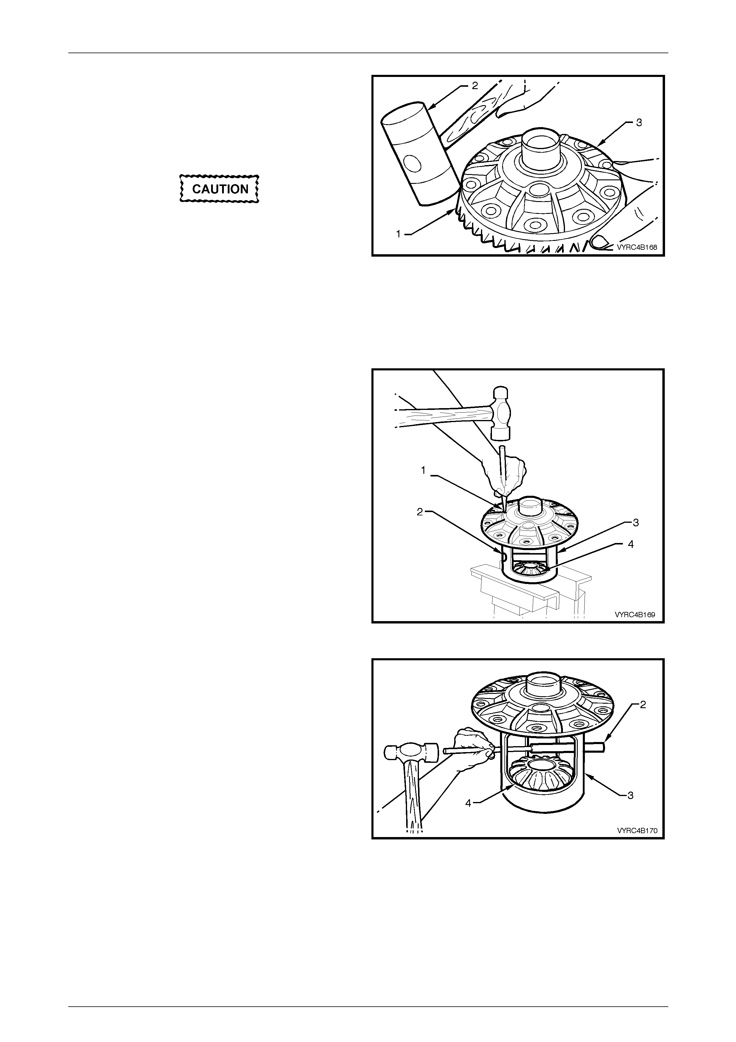
Rear Final Drive and Live Axle Page 4B2 – 80
Page 4B2 – 80
8 Place a piece of softwood large enou gh to cover the
overall diameter of the ring gear on top of a suitable
workbench.
9 Place the differential case (3) on top of the piece of
softwood with the ring gear facing do wnward, as
shown.
Do not use a screwdriver or other form of
leverage to pry between the ring gear and the
mating face of the differential case, as
damage will occur.
10 Using a soft faced hammer (2), tap down on the ring
gear while rotating the differe ntial case to remove the
ring gear (1).
NOTE
The softwood will protect the ring gear from
damage, when removed.
Figure 4B2 – 154
11 Secure the differential case in a vice fitted with soft
metal jaws with the ring gear-mating fla ng e nearest
the vice.
12 Using a suitable pin punch, remove the pinion gear
cross shaft retaining pin (1), from the pinion cross
shaft (2) and differential case (3).
Figure 4B2 – 155
13 Using a brass drift and hammer, remove the pinion
gear cross shaft (2), from the pinion gears (4) and
differential case (3).
NOTE
The concentric grooved disc’s, clutch plates,
dished spacers and side gears are an integral
unit and must stay assembled to eac h other and
must not be interchanged during disassembly.
Figure 4B2 – 156
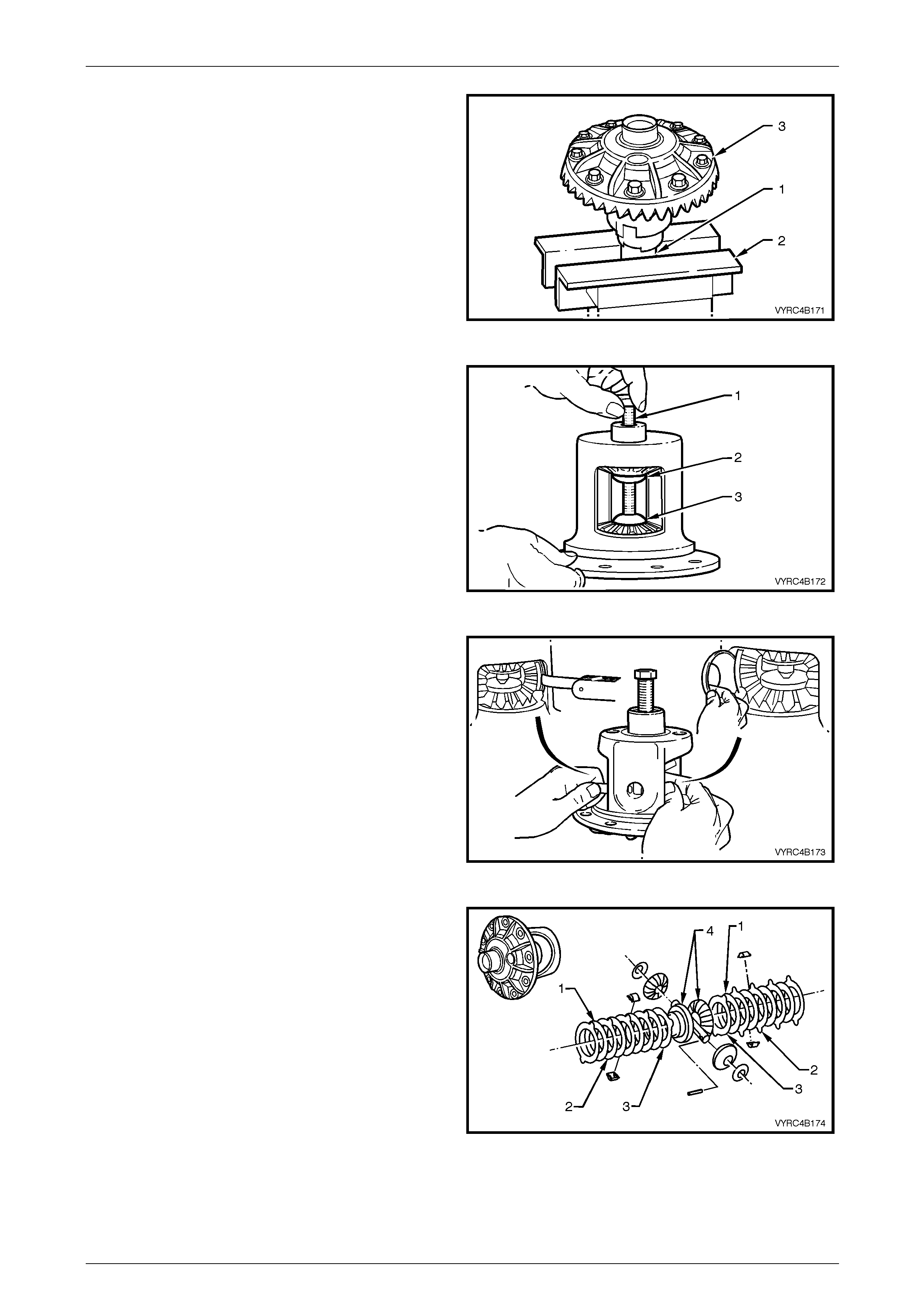
Rear Final Drive and Live Axle Page 4B2 – 81
Page 4B2 – 81
14 Clamp the left-hand axle shaft (1) in a vice fitted with
soft jaws (2), with at least 85 mm from the splined end
exposed then place the differ ential case (3) onto the
axle shaft spline, through the side gear splin e.
Figure 4B2 – 157
15 Install forcing screw (1) in conjunction with threaded
screw cap (2) and plain cap (3), which are parts of
Tool No. C-4487.
16 Turn the forcing screw until it becomes centred into
the plain cap.
17 Tighten the forcing screw until enough pressure is
applied to collapse the dis he d spacers of each side
gear, creating a small amount of clearance between
the teeth of the side gears and pinion gears.
Figure 4B2 – 158
18 Using a 0.51mm (0.020”) feeler strip or simil ar, push
the pinion gear thrust washers out from behind each of
the pinion gears and out of the differential ca se.
NOTE
Keep the pinion gears with their respective thrust
washers in sets. Mark each component with a
pen or similar, to ensure they are reinstalled in
their original position.
Figure 4B2 – 159
19 To ensure that the concentric grooved discs (1), clutch
plates (2), dished spacers (3) and side gears (4) are
not interchanged during disassembly or reassembly,
mark each component and corresponding side of the
differential case with a pen or similar.
Figure 4B2 – 160
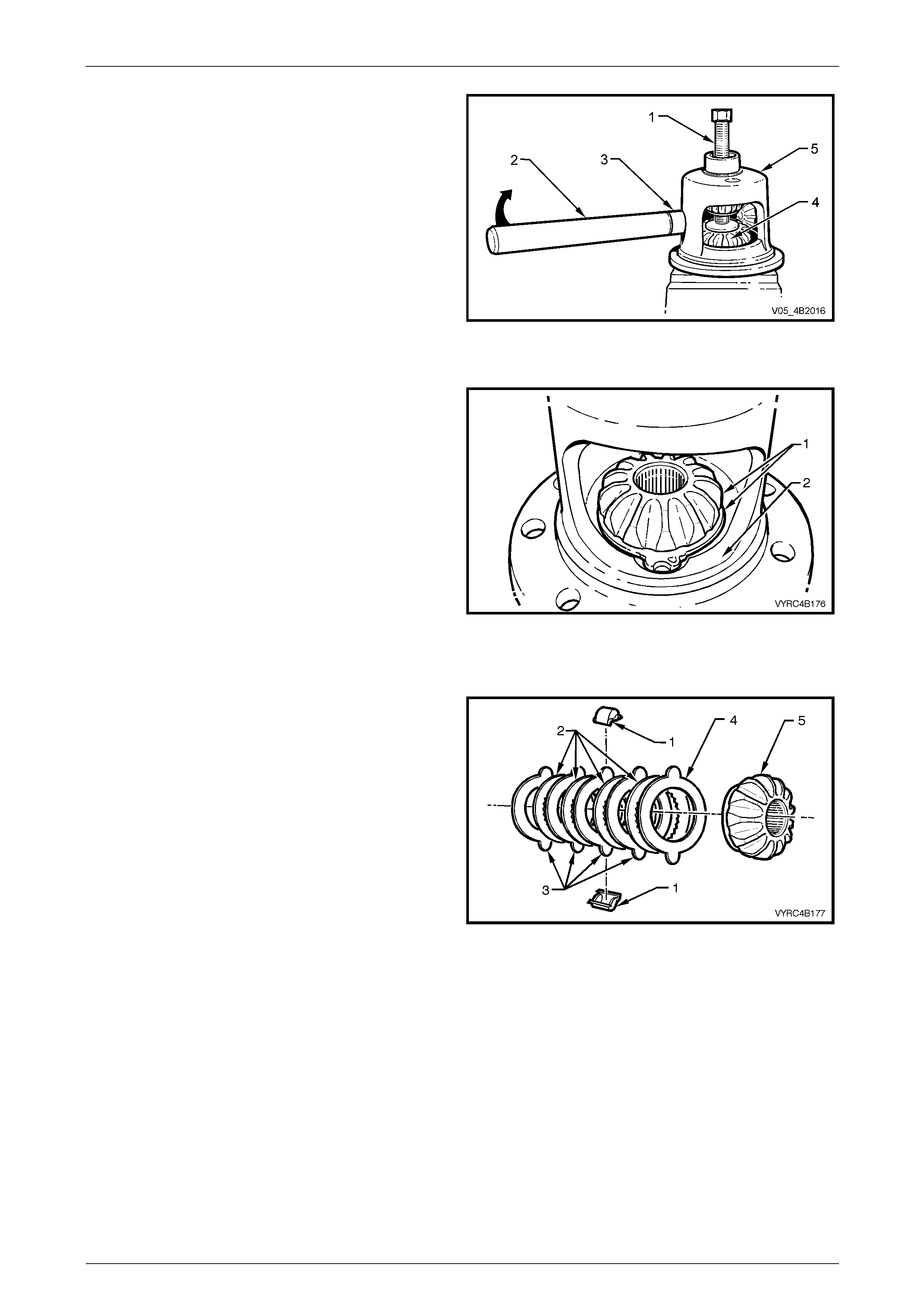
Rear Final Drive and Live Axle Page 4B2 – 82
Page 4B2 – 82
20 Relieve the force applied by the screw (1).
21 Using the assist handle (2) and the handle distance
piece (3) (part of Tool No. C-4487), insert the tool
combination into the differenti al case, sid e g ear shaft
aperture.
22 Rotate the differential case (5) in the direction
indicated, using the tool combination in step 21, until
the pinion gears can be accessed.
23 Remove the pinion gears from the differential case.
NOTE
Keep the pinion gears with their respective thrust
washers in sets. Mark each component with a
pen or similar, so they are reinstalled in their
original position.
Figure 4B2 – 161
24 While supporting the upper side ge ar and clutch pack
with one hand, remove the forcing screw along with
the threaded scre w cap and plain cap, which are parts
of Tool No. C-4487.
25 Remove the upper differential side g ear and clutch
pack from the differential case.
26 Remove the lower differential side gear and clutch
pack (1) from the differential case (2).
NOTE
Keep the side gears and their respective clutch
packs in sets. Mark each component with a pen
or similar, so they are reinstalled in their original
position.
27 Remove the differential case a nd axle from the vice.
Figure 4B2 – 162
28 Remove the clutch plate retainer’s (1) from e ach clutch
pack, then separate the concentric grooved discs (2),
clutch plates (3), dished spacer (4) and side g ear (5)
from each clutch pack.
NOTE
Keep the side gears and their respective clutch
packs in sets. Mark each component with a pen
or similar, so they are reinstalled in their original
position.
Figure 4B2 – 163
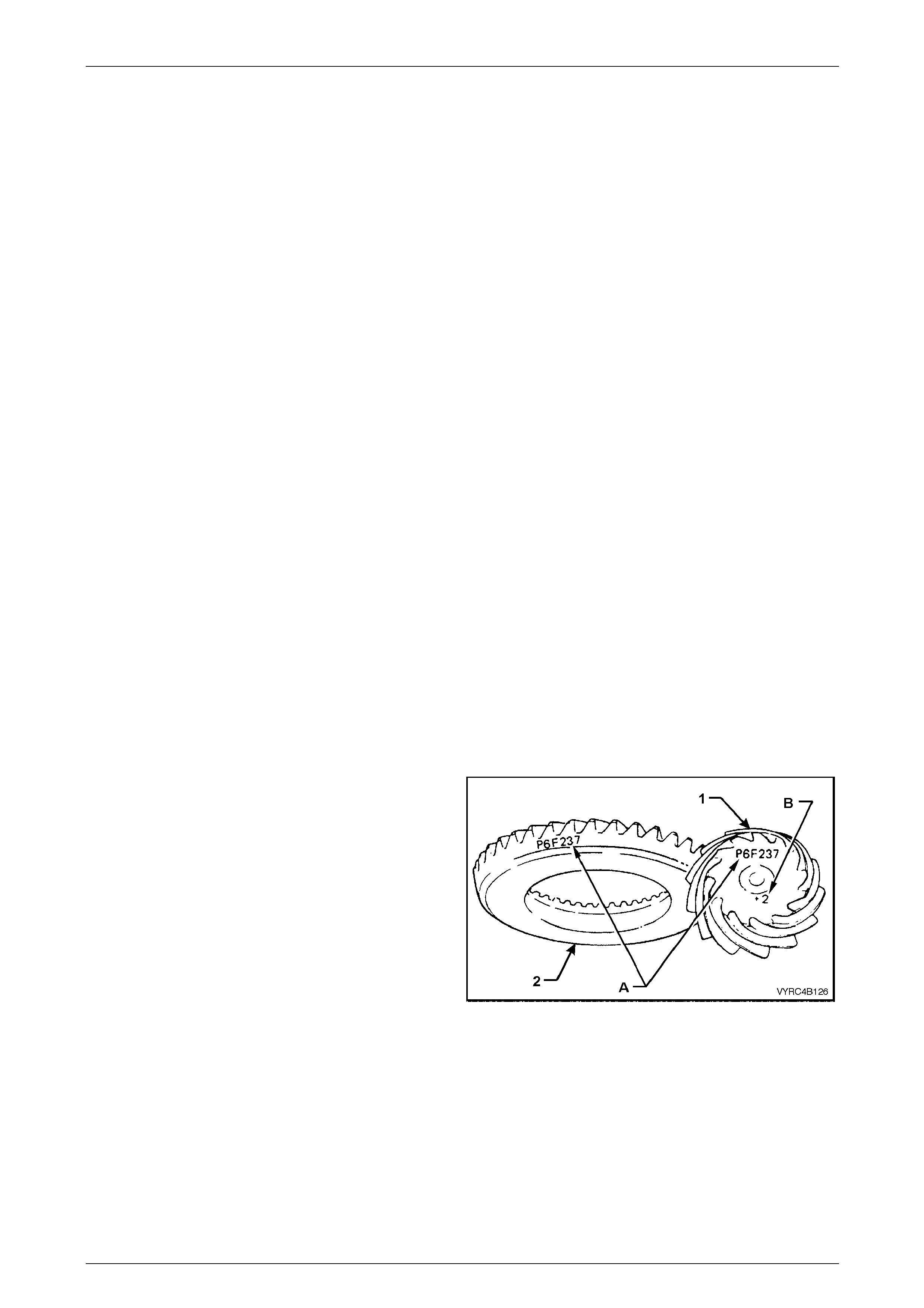
Rear Final Drive and Live Axle Page 4B2 – 83
Page 4B2 – 83
Inspect
All components should be thoroughly cleaned and dried, then inspected.
Differential Case
Check the case for general soun dness and pay particular attention to the following points:
1 If the differential case side bearings have be en removed, check the case journals for damage and that the seating
surfaces are free from dirt and burrs.
2 The ring gear spigot and mounting face should be clean and free from dirt and burrs.
3 The mating surfaces of the differential case should be clean and free from burrs.
4 The thrust surfaces for the differentia l pinions should be examined for e xcessive wear.
5 The clutch seats in the housing should be smooth and free from any excessive scoring.
6 The land surface condition for each dished spacer in the case. Excessive wear or d amag e on the surface will
require case renewal.
7 Inspect pinion gear cross shaft bores for ovality.
Differential Side Gears and Pinion Gears
1 Examine all gear teeth for cracks or hard contact marks. The differentia l side gear splines should be checked for
excessive wear, including the splines for the clutch plates. Wear on splines can contrib ute to excessive driveline
backlash. If damage or excessive wear is evident the complete set of side and pinion gears must be replaced.
2 The differential pinion bores a nd thrust surfaces should be smooth and free from scores. Inspect all thrust washers
for cracks, nicks or burrs. Wear of thrust washers or thrust surfaces on gears can contribute to excessive driveline
backlash.
3 Check the differential pinion gear cross shaft is not bent and that the surfaces on which the pinions run, are not
scored or worn.
Differential Concentric Grooved Disc’s, Clutch Plates, Retainers and Dished Spacers
1 Examine all surfaces of the concentric grooved disc’s, clutch plates, retainers and dished spacers for cracks,
excessive wear or hard contact marks. If damage is evident replace the complete set of concentric grooved discs,
clutch plates, retainers and dished spacers for both sides.
Ring Gear and Pinion
1 Inspect the gear teeth for scoring or damage. Excessiv e sh ock loading, use of the incorrect lubricant or insufficient
“run in” before towing a heavy load, usual ly causes scoring of the gear teeth. (Refer to the specific Owner's
Handbook). Scored gears must be replac ed.
2 If on reassembly, a new gear set is to be installed,
check that the same matching numbers (A) appear on
both the pinion (1) and ring gear (2).
3 The identification number (B) on the pinion end (1) is
used when setting the pinion depth, on reassembly.
Figure 4B2 – 164
Bearings
1 Bearing cups should have an even wear pattern and be free from flaking or pitting.
2 Ensure the seating surfaces are clean and free from burrs or raised metal.
3 The bearing assembli es should feel smooth when turned in the cups.
4 The assembly should be free from loose particles.
5 There should be no cracks pr esent in the roller cages and the bores should show no evidence of flaking or pitting.
Refer to 4.4 Differential and Rear Axle Bearing Diagnosis i n Section 4 B1 Final Drive and Driveshafts, for
identification of bearing failures.
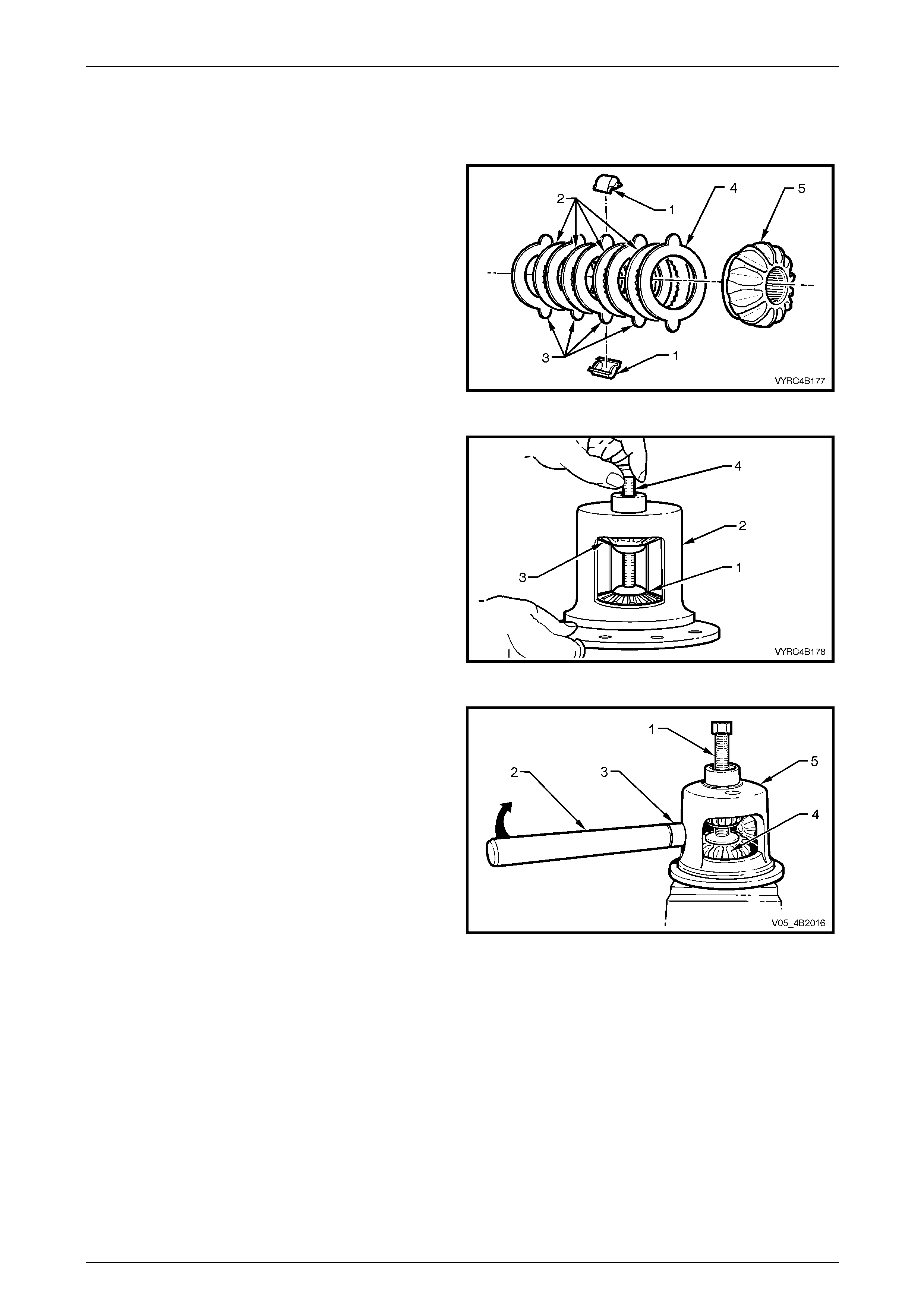
Rear Final Drive and Live Axle Page 4B2 – 84
Page 4B2 – 84
Reassemble
1 Lubricate all gears, bearings, thrust washers and pinion gear cross shaft with the recommend ed rear axle lubricant
before assembly. Refer to 2.2 Checking Rear Axle Lubricant Level or 5 Spec ifications in this Section.
2 Reassemble the concentric grooved discs (2), clutch
plates (3), dished spacer (4) the clutch plate retain er’s
(1) and side gear (5) from each clutch pack.
NOTE
If the used components are to be reinstalled,
keep the side gears with their respective clutch
pack components in sets, so they are reinstalled
in their original position.
Figure 4B2 – 165
3 Reinstall the differential cas e and axle into the vice
fitted with soft jaws.
4 Install the lower differential side gear and cl utch pack
(1) into the differential case (2).
5 Install the upper differential side gear and cl utch pack
(3) into the differential case (2) then support it with one
hand.
6 While supporting the upper side ge ar and clutch pack,
install the forcing screw along with the threaded screw
cap and plain cap (which are part of Tool No. C-4487).
7 Tighten the forcing screw (4) by hand until enough
pressure is applied to support each side gear in place. Figure 4B2 – 166
8 Install the pinion gears, 180° apart into the differential
case openings.
9 Using the assist handle (3) in conjunction with the
distance piece (4) (part of Tool No. C-44 87), insert the
tool combination into the differential pinion gear shaft,
aperture.
10 Rotate the differential case (in the direction i ndicated)
using the tool combination in step 9 until the bores of
the pinion gears in the differential housing and the
bores for the pinion shaft are aligned.
11 Tighten the forcing screw (6) until enough pressure is
applied to collapse the dis he d spacers of each side
gear, creating a small amount of clearance between
the teeth of the side gears and the pinion ge ars. Figure 4B2 – 167
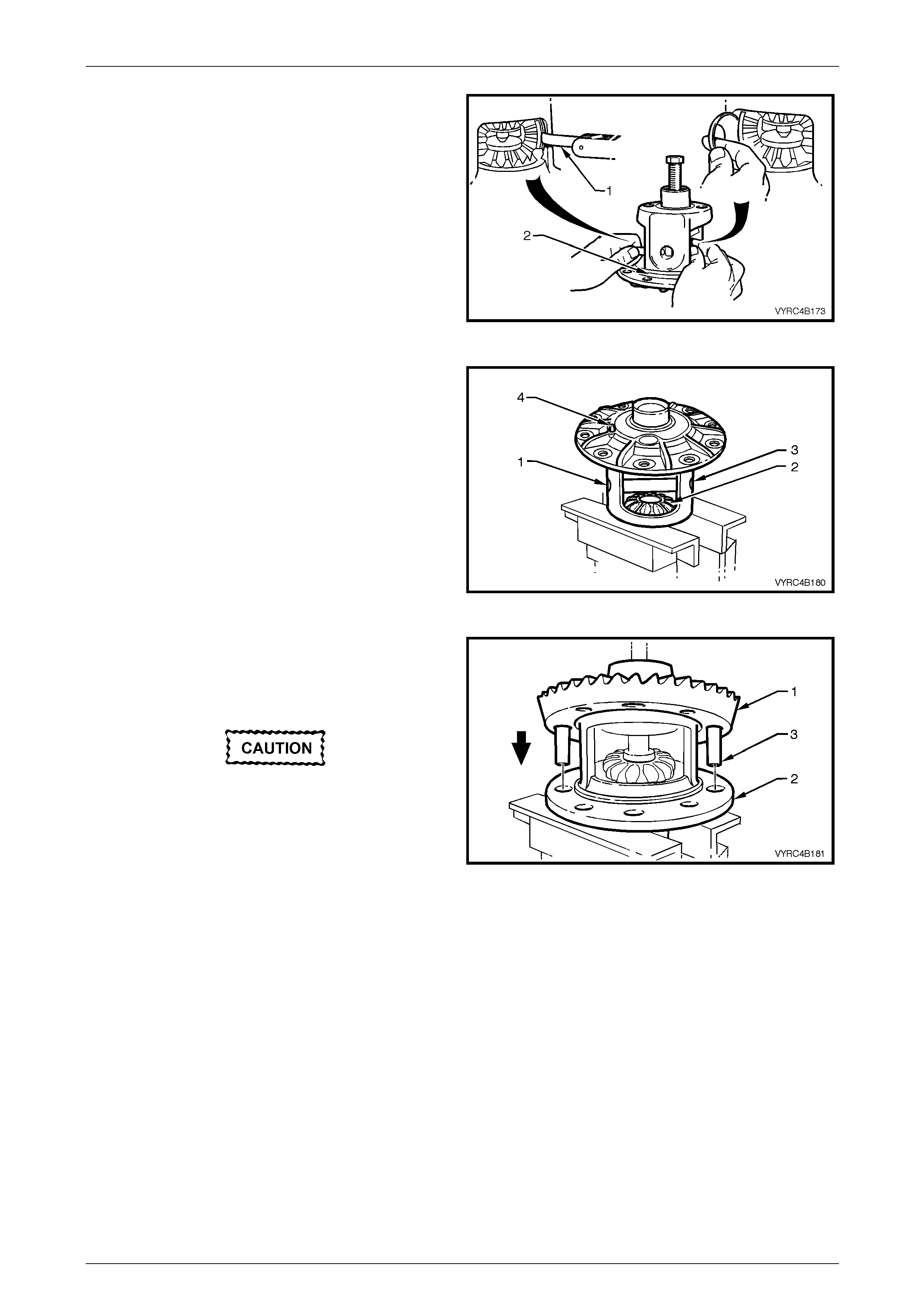
Rear Final Drive and Live Axle Page 4B2 – 85
Page 4B2 – 85
12 Using a 0.51 mm (0.020”) feeler strip (1) or similar,
install the pinion gear thrust washers between each of
the pinion gears and the differential case (2).
NOTE
If installing used components, keep the pinion
gears and their respective thrust washers in
sets, so they can be reinstalled in their original
position.
13 Relieve the pressure appli ed by the forcing screw.
Then remove the forcing screw along with the
threaded screw cap and plain cap (which are part of
Tool No. C-4487). Figure 4B2 – 168
14 Position the pinion gear cross shaft into the differential
case. Ensure the pinion gear, differentia l case and
retaining pin bores are aligne d.
15 Using a brass drift and soft faced hammer, drive the
pinion gear cross shaft (1), into the pinion gears (2)
and differential case (3).
16 Using a suitable pin punch, drive the pinion gear cross
shaft retaining pin (4) into the pinion cross shaft (1)
and differential case (3).
Figure 4B2 – 169
17 Check that all mating surfaces of the ring gear and
differential case are free from burrs and foreign matter.
18 Install two left-hand threaded guide pins (3) into two
opposing ring gear bolt holes .
A flame must never be used to heat the ring
gear.
19 To ease reassembly, heat the ring gear on a hot plate
until it is hot to the hand, prior to installing onto the
differential case cap.
20 Place the ring gear (1) into position o n the differential
case cap (2) and install NEW ring gear attaching bolts. Figure 4B2 – 170
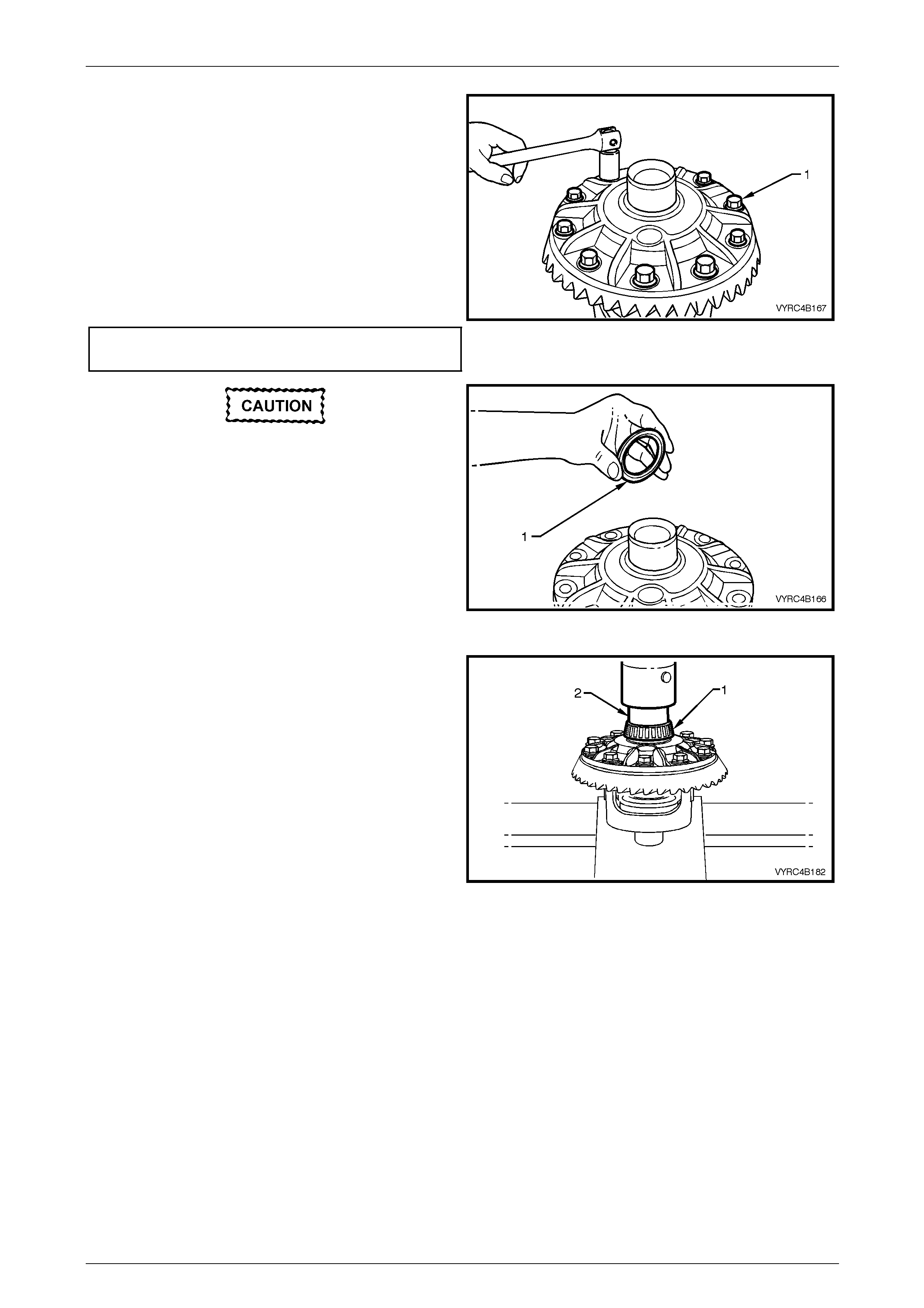
Rear Final Drive and Live Axle Page 4B2 – 86
Page 4B2 – 86
NOTE
Ring gear attaching bolts use a left-hand thread
and are identified by an 'L' on the bolt head.
21 Install the NEW ring gear attaching bolts (1) evenly
until the gear face is flush with the differenti al case
spigot.
22 Remove the left-hand threaded guide pins and install
the remaining two NEW ring gear attaching b olts.
23 Tighten all ring gear attaching bolts to the correct
torque specification.
() Ring gear to differential case
attaching bolt torque specification......................140 N.m Fig ure 4B2 – 171
The M86 Series Differential requires a spacer
(1) to be installed on the ring gear sid e of the
differential case behind the side bearing.
This spacer must be installed to enable the
differential assembly to carrier set-up
procedure to be carried out correctly.
24 If the spacer (1) has been removed, reinstall the
spacer onto the side bearing journal closest to the ring
gear before proceeding.
Figure 4B2 – 172
25 If installing new side bearings (1), use Tool No. 205-
545 (2) to press side bearings (1) onto the differential
case journals.
26 Continue rear axle assembly, refer to 3.6 Differential
Assembly Adjustment and Installation Procedures – Al l
Models, in this Section
Figure 4B2 – 173
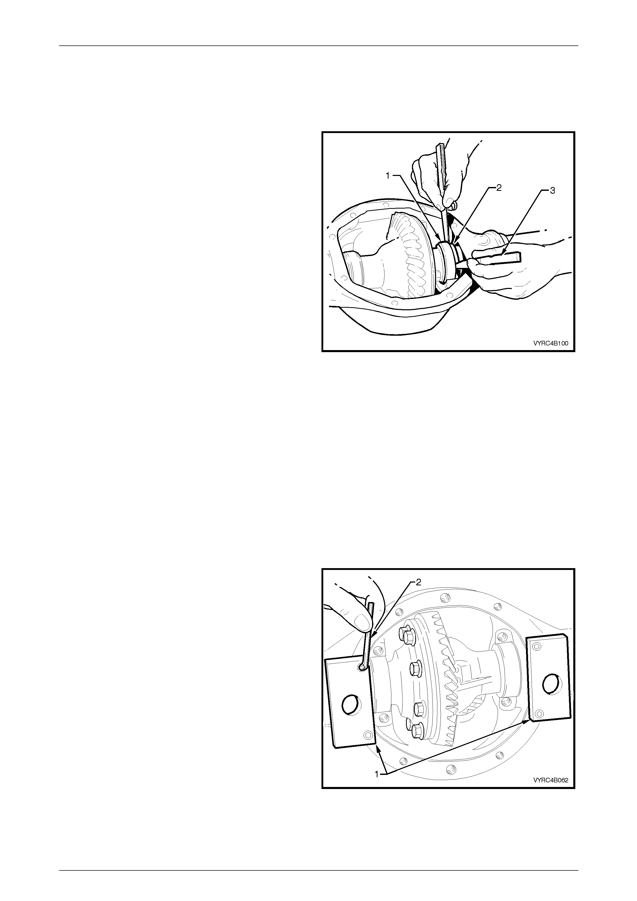
Rear Final Drive and Live Axle Page 4B2 – 87
Page 4B2 – 87
3.6 Differential Assembly Adjustment and
Installation Procedures – All Models
Differential Side Bearing Preload And Shim Selection
1 Select any two differential cas e side b earing shims,
placing one against each side bearing cup a nd install
the differential assembly in the differential ca rrier
housing without the aid of the spreading tool to spread
the carrier.
2 Push the differential case assembly hard to one si de.
On the opposing side, measure the distance between
the differential case side bearing cup (1) and the shim
(2) using two, feeler gauge sets (3).
3 With the feeler gauges still in place rotate th e
differential case to seat the side bearings. C heck that
the end float has not increased, if it has, remeasure
using the feeler gauges and record the measurement.
4 Remove the differential case assembly along with the
bearing cups and shims from the differential carrier
housing.
5 Measure the thickness of the two shims and record the
measurement.
Figure 4B2 – 174
6 To establish the thickness of shims and obta in the correct preload of the side bearings required the following
method is applied:
a Add the total thickness of the shims measured in step 5 together with clearance measured using the feel er
gauges in step 3.
b To preload the bearings and if installing new bearings add 0.15 mm to the total measurement. Used bearings
will require 0.10 mm to be added to the total measurem ent.
7 The thickness selection of the two shims required would be half the value of the total as calculated in step 6.
NOTE
A wide selection of shims are available. Check
the current release of Partfinder™ for details.
8 Install the adaptors (1) of the differential spreading
Tool No. E9255 (2) to the differential carrier housing
using a 5mm Allen Key (3).
Figure 4B2 – 175
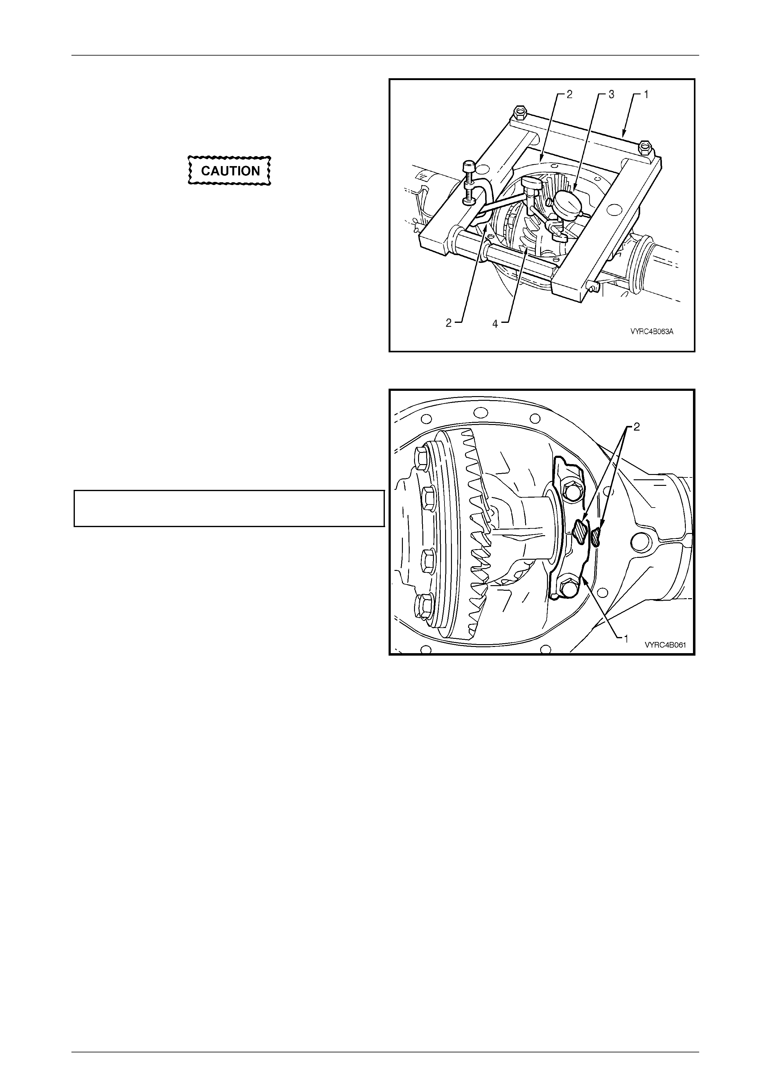
Rear Final Drive and Live Axle Page 4B2 – 88
Page 4B2 – 88
9 Install the differential spreading Tool No. (1) to the
differential carrier housing (2).
10 Install a dial indicator (3) to the differential spreading
Tool No. E9255 (1) and differential carrier h ousing (2).
Under no circumstances is the differential
carrier to be spread mo re th an 0.5 mm.
11 Spread the differential carrier housing approximately
0.1 to 0.2 mm.
12 Install the differential case assembly (4) alon g with the
carrier side bearing cups and shims.
13 Release the force exerted by the spreading Tool No.
E9255 (1) and remove the tool along with the adaptors
from the differential carrier housing.
Figure 4B2 – 176
14 Install the side bearing caps (1) and reta ining bolts.
Check that the original relationship marki ngs (2) of the
side bearing caps are maintained ensuring that they
are reinstalled in their original location.
15 Tighten the side bearing cap bolts to the correct torque
specification.
Side bearing cap to differenti al carrier
housing bolt torque specification...........................55 Nm
Figure 4B2 – 177
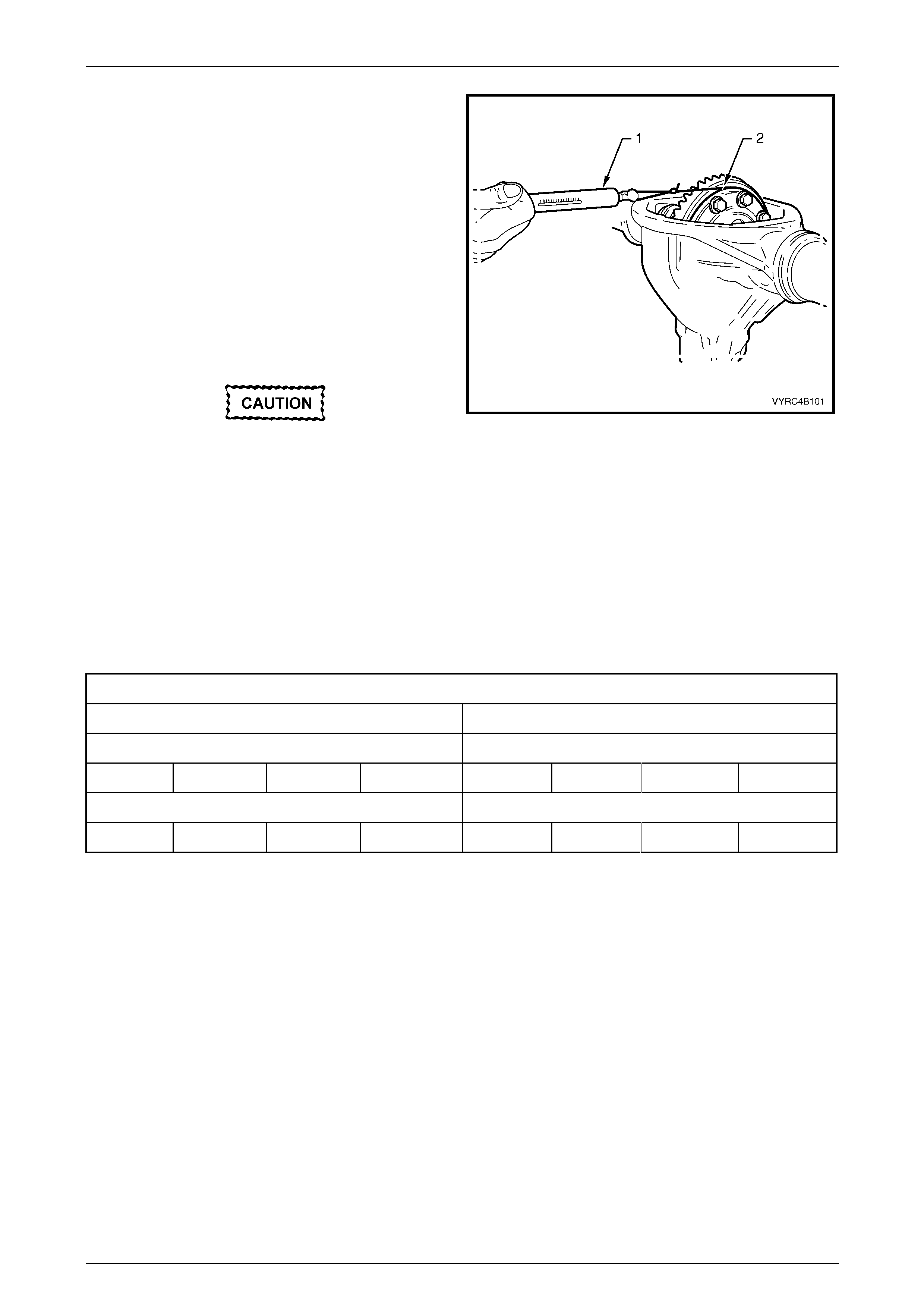
Rear Final Drive and Live Axle Page 4B2 – 89
Page 4B2 – 89
16 Rotate the differential case assembly several times to
ensure the side bearings are seated correctly.
17 Install a suitable piece of string to and around the
differential case flange near the ring ge ar.
18 Install a spring balance (1) to a piece of string
attached to the differential case flange (2). Check the
side bearing preload by pulling the spring balance at a
steady rate away from the differential case, while
observing the spring balance reading. The spring
balance reading must be within specification.
19 Re-install the differential spreadi ng Tool No. E9255 to
the differential carrier housing.
20 Re-install a dial indicator to the differential spreading
Tool No. E9255 and differential carrier housing.
Under no circumstances is the differential
carrier to be spread mo re th an 0.5 mm.
21 Spread the differential carrier housing approximately
0.1 to 0.2 mm.
Figure 4B2 – 178
22 If the side bearing preload is to specification, remove the differentia l case along with the side bearing caps, side
bearing cups, shims and retaining bolts. Ensure the original relationship of all components is maintained so the y
are reinstalled in their original location.
23 If the side bearing preload is not specification, repeat steps 6 to 22. Side bearing shims are available in 0.04mm
increments.
24 To facilitate the pinion gear bearing preload procedure, remove the differential case assembly maintainin g the
relationship of the side bearing cones, the preload shims and bearing c aps.
Refer to 3.2 Rear Axle and Differentia l Housing Assembly – Disassemble in this Section.
Side Bearing Preload Specification
M78 Series M86 Series
New Bearings New Bearings
Timken 15 – 35 N Koyo 8 – 24 N Timken 13 – 30 N Koyo 7 – 20 N
Used Bearings Used Bearings
Timken 8 – 18 N Koyo 5 – 13 N Timken 8 – 16 N Koyo 5 – 11 N
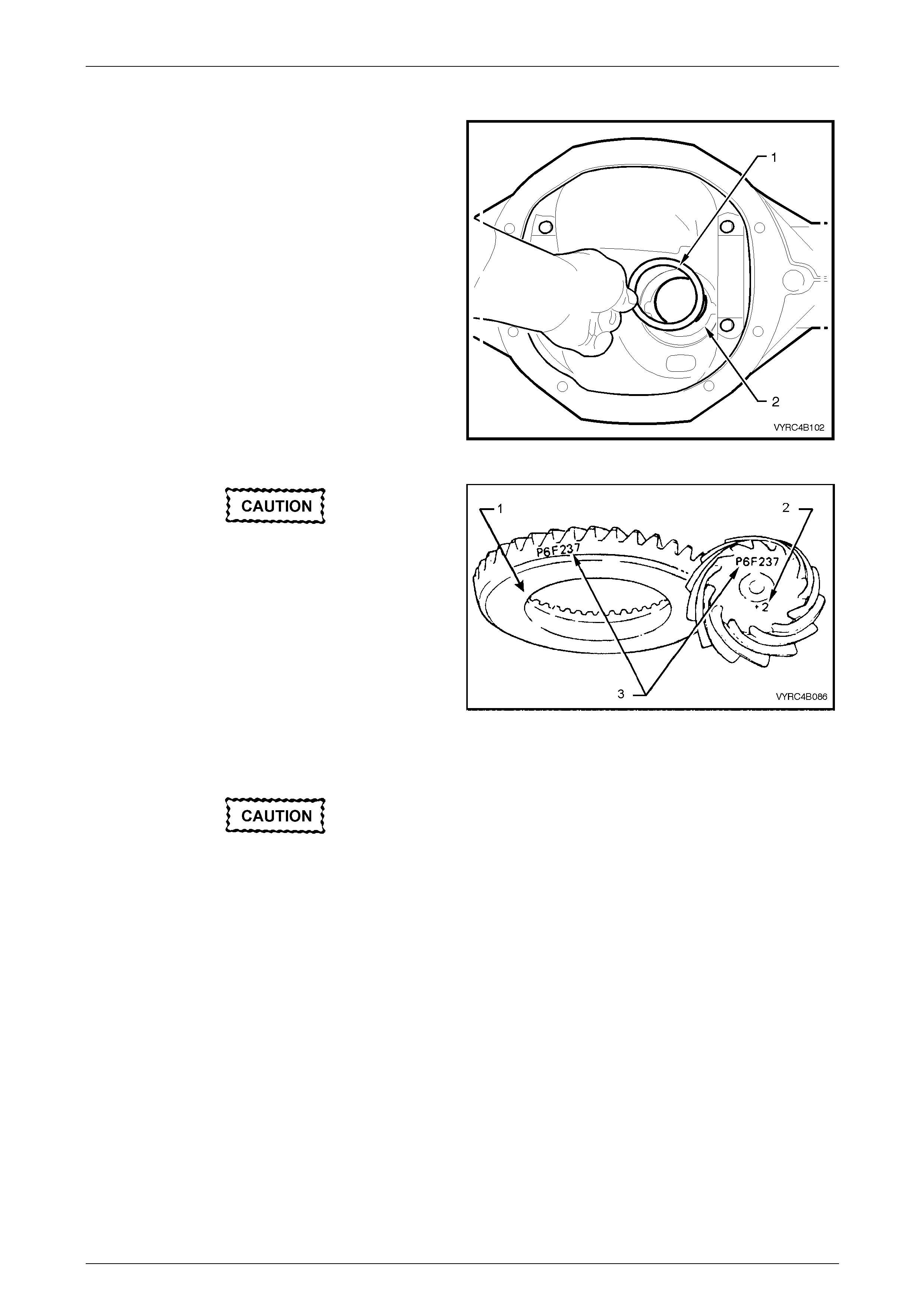
Rear Final Drive and Live Axle Page 4B2 – 90
Page 4B2 – 90
Hypoid Pinion Bearing Preload Shim Selection
1 The pinion posit ioning shim (1), is located between the
rear pinion bearing cup and the carrier-housing pi nion
bore (2).
NOTE
If the ring gear and pinion gear set or the rear
pinion bearing is replaced, the pi nion depth must
be rechecked.
Figure 4B2 – 179
If a new ring gear and pinion gear set is
replaced, ensure that the same matching
numbers (3) appear on the pinion gear and
the ring gear.
NOTE
• Only use the specified lubricant. Lubricants
other than that specified will affect the
rotational torque readings specified in the
steps that follow. Refer to 2.2 Checking Rear
Axle Lubricant Level in this Section.
• Ensure that the rear pinion bearing that will
be used on final reassembly of the pinion is
used on the dummy pinion for the pinion
position procedure.
Either Timken or Koyo supply the pinion
bearings. When replacing the pinion
bearings, the two bearings and cups must be
of the same manufactu re.
Figure 4B2 – 180
2 Inspect the pinion bearing cups for damage, nicks, burrs or excessive wear.
3 If required, install the front and rear pinio n b earing cup into the differential carrier-housing pinion bore.
Refer to 3.2 Rear Axle and Differentia l Housing Assembly – Disassemble in this Section.
4 For M78 Series, install the distance spacer Tool No. E9300-1 (part of Tool No. E9300A) onto the dummy pinion.
For M86 Series, install the preload adaptor Tool No. 205-548 onto the dummy pinion.
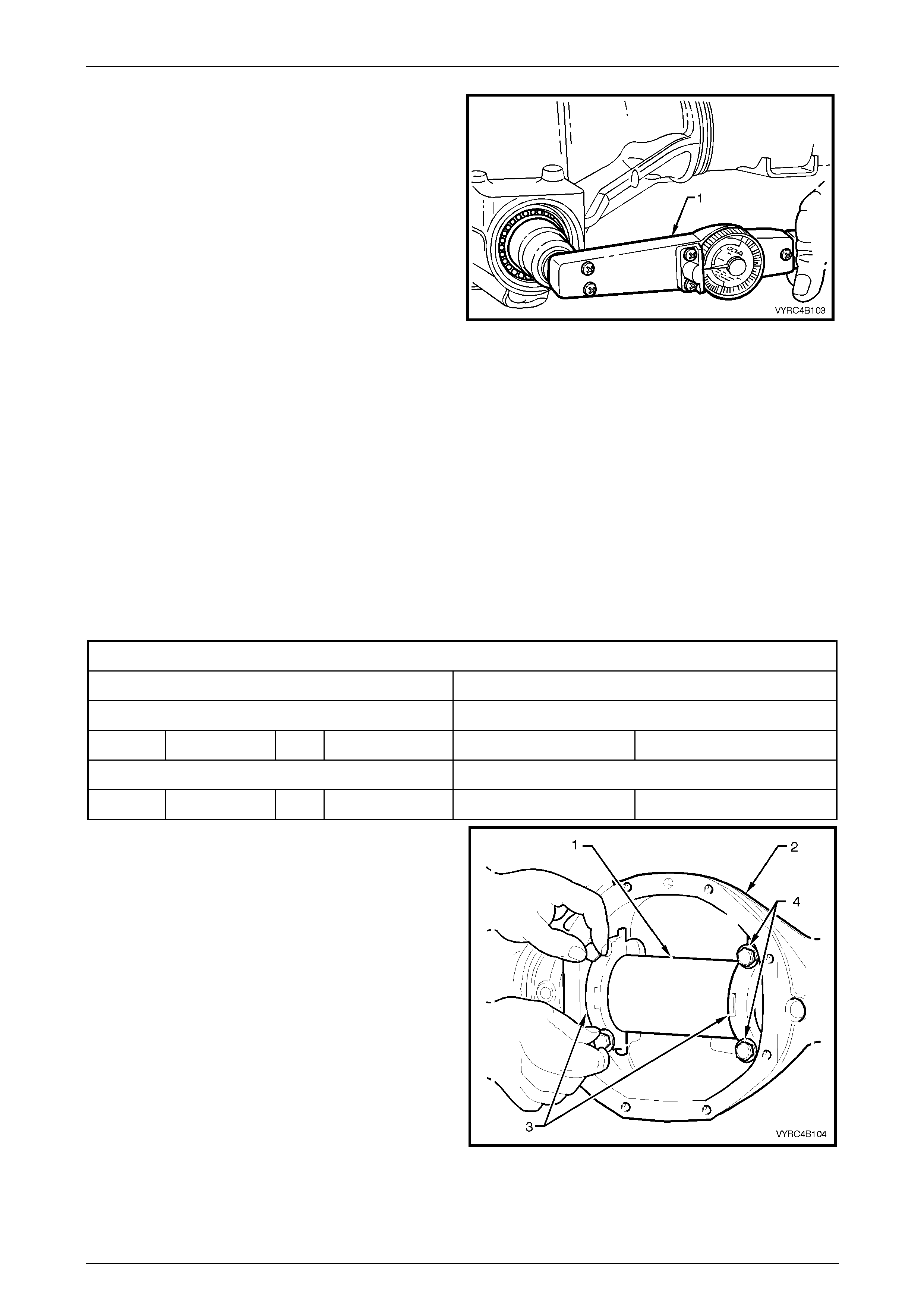
Rear Final Drive and Live Axle Page 4B2 – 91
Page 4B2 – 91
5 Install the rear pinion bearing onto the dummy pinion
of the Pinion Height Gauge Set Tool No. E9300A.
6 Install the dummy pinion, rear pinion bearing, the front
pinion bearing along with the dummy pinion thrust
collar and nut.
7 Using the information provided in the dummy pinion
rotational torque specification chart, tighten the
dummy pinion nut until the specified rotational torque
is obtained. While tightening the dummy pinion nut,
rotate the dummy pinion back and forth to en sure that
the bearings settle into their cups.
Figure 4B2 – 181
NOTE
• Pinion bearing preload is very important
because it retains the pinion in its correct
relationship to the ring gear.
• Bearings that are installed with insufficient or
no preload, will, after a comparatively short
period of running, develop end play, causing
noisy operation on overrun and could be
responsible for scuffing of ring gear and
pinion teeth.
• Bearings that have excessive preload may
become pitted or flaked, resulting in
premature failure. It is therefore essential to
ensure that the bearings are preloaded to
specified torque specification.
Dummy Pinion Rotational Torq u e Sp ecification
M78 Series M86 Series
New Bearings No Pinion Oil Seal Installed New Bearings No Pinion Oil Seal Installed
Timken 1.4 – 2.0 N.m Koyo 1.5 – 1.9 N.m Koyo 1.8 – 2.1 N.m
Used Bearings No Pinion Oil Seal Installed Used Bearings No Pinion Oil Seal Installed
Timken 0.7 – 1.2 N.m Koyo 0.7 – 1.2 N.m Koyo 0.8 – 1.3 N.m
NOTE
Ensure that arbour is free of burrs that may
damage bearing cups.
8 Position the arbour (1), part of Tool No. E9300A, into
the carrier assembly (2), install the side bearing caps
(3) and attaching bolts (4).
9 Tighten the side-bearing cap attaching bolts lightly.
Figure 4B2 – 182
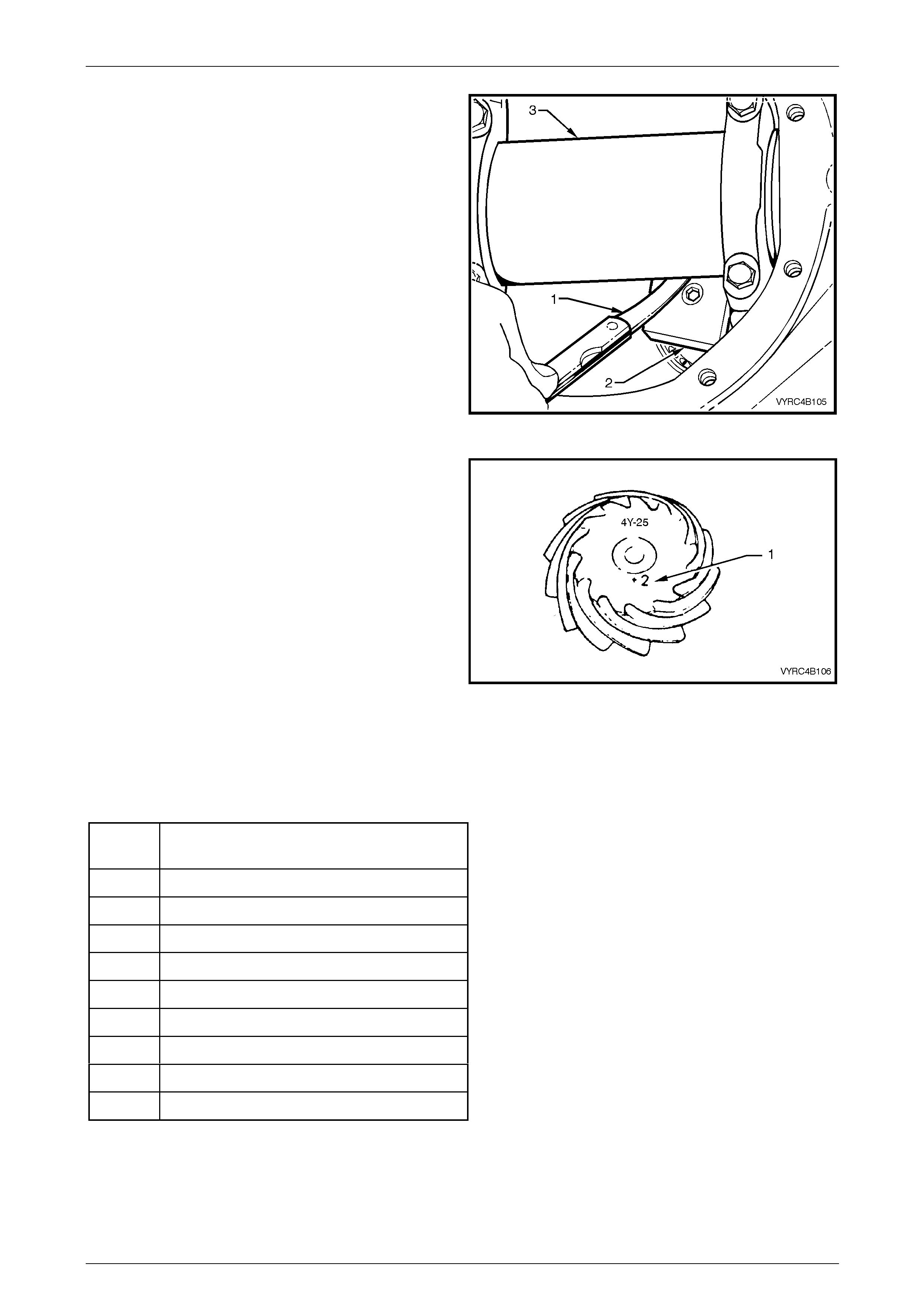
Rear Final Drive and Live Axle Page 4B2 – 92
Page 4B2 – 92
10 Measure with feeler gauges (1) and record the
clearance between the head of the dummy pinion (2)
and the arbour (3).
Figure 4B2 – 183
11 Look on the end of the pinion gear, for an etched drive
pinion installation-marking (1).
A zero marking, e.g. 0, indicates that the shim size for
this particular carrier/pinion combin ation is the correct
size as measured in step 10. Refer to the shi m
selection table below.
A positive marking, e.g. +2, means that this amount
must be subtracted from the recorded measurement
obtained in step 10. Refer to the shim selection table
below.
A negative marking, e.g. – 2, means that this amount
must be added to the recorded measurement obtained
in step 10. Refer to the shim selection table below.
12 Remove the dummy pinion and arbo ur from the
differential carrier housing.
Figure 4B2 – 184
Hypoid Pinion Shim Selection Table
Using the following table as a guide select the desired shim stack to achieve the required pinion position.
Pinion
Marking Shim Thickness Required
–4 Add 0.10 mm to the measurement of Step 9
–3 Add 0.075 mm to the measurement of Step 9
–2 Add 0.050 mm to the measurement of Step 9
–1 Add 0.025 mm to the measurement of Step 9
0 As per the measurement of Step 9
+1 Subtract 0.025 mm to the measurement of Step 9
+2 Subtract 0.050 mm to the measurement of Step 9
+3 Subtract 0.075 mm to the measurement of Step 9
+4 Subtract 0.10 mm to the measurement of Step 9
NOTE
A wide selection of shims are available, ranging
from 0.203 mm to 0.762 inclusive. Check the
current release of Partfinder™ for details.
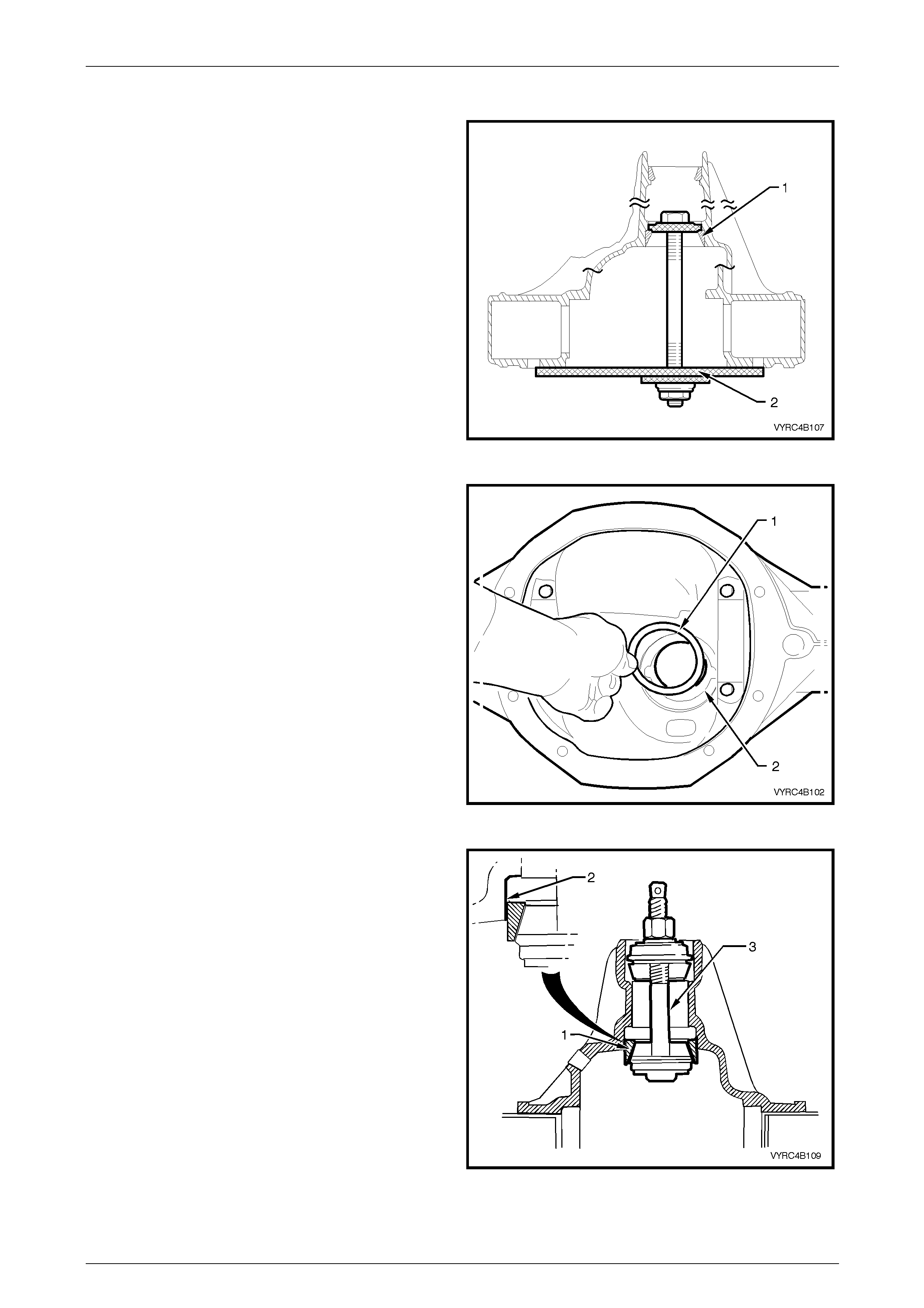
Rear Final Drive and Live Axle Page 4B2 – 93
Page 4B2 – 93
Pinion Installation
1 Remove the rear pinion bear ing cup (1) from the
differential carrier housing pi nion bore :
a For M78 Series, use Tool No. E9293 (2). Refer
to 3.2 Rear Axle and Differential Housing
Assembly – Disassemble in this Section.
b For M86 Series, use Tool No. E9293 (2) with
Tool No. 205-551. Refer to 3.2 Rear Axle and
Differential Housing Assembly – Disassemble in
this Section.
2 Select the required pinion positioning shims required,
refer to Hypoid Pinion Shim Selection, in 3.6 Rear Axle
and Differential Housing Assembly – Reassemble, in
this Section.
Figure 4B2 – 185
3 Install the pinion positioning shim/s (1) into the rear
pinion cup bore (2).
Figure 4B2 – 186
4 Reinstall the rear pinion- bearing cup (1) into the
differential carrier housing pinion bore:
a For M78 Series, reinstall the rear pinio n-b earing
cup (1) into the differential carrier housing pinion
bore (2) using Tool No. E9293, consisting of
Tool No. E9271 and E9293A (3), ensuring the
bearing cup is seated sq uarely in the bore.
b For M86 Series, reinstall the rear pinio n-b earing
cup (1) into the differential carrier housing pinion
bore (2) using Tool No. E9271 (3), part of Tool
No. E9293, along with adaptors Tool No. 205-
552 ensuring the be aring cup is seated squarely
in the bore.
Figure 4B2 – 187
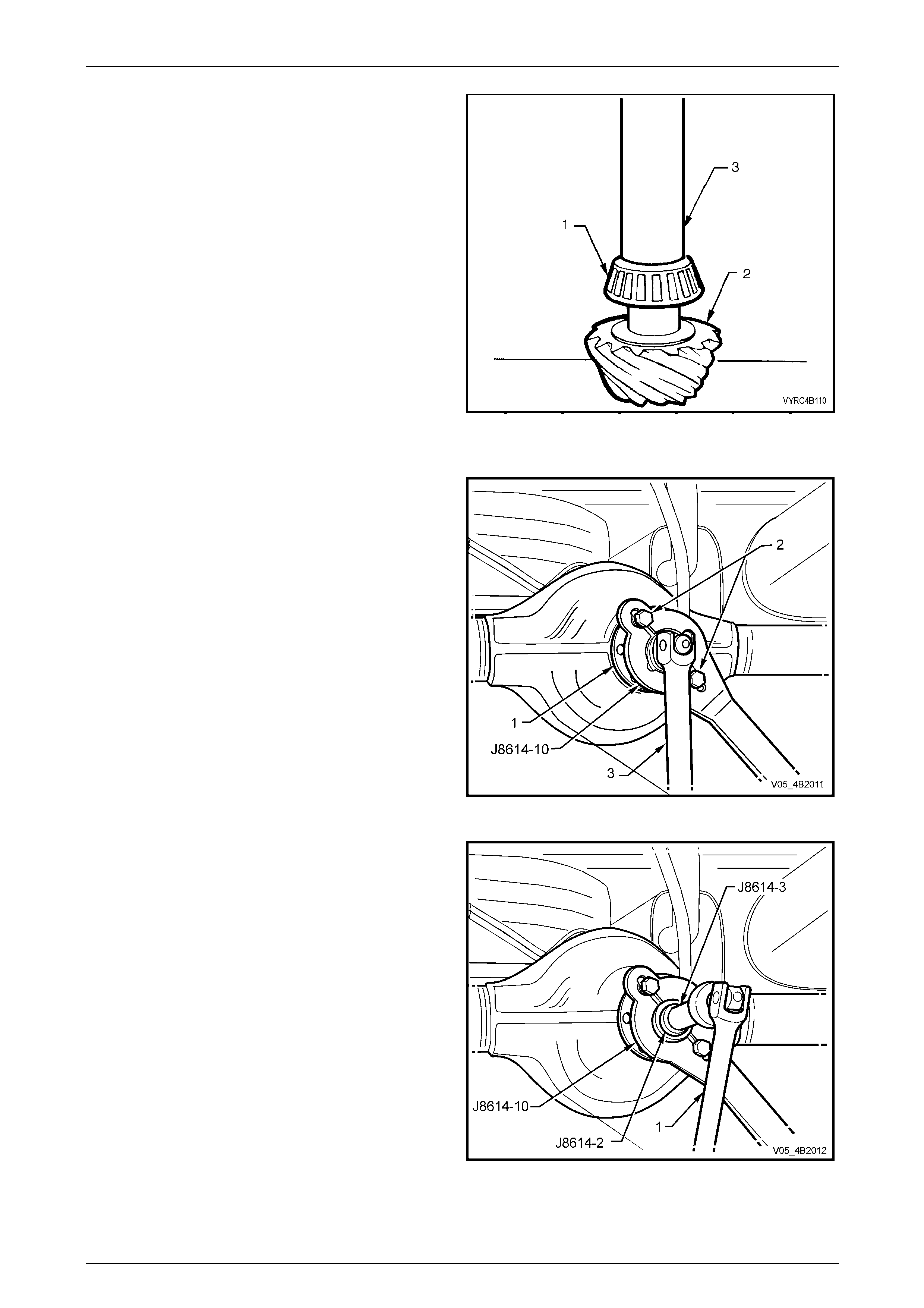
Rear Final Drive and Live Axle Page 4B2 – 94
Page 4B2 – 94
5 Install the rear pinion-bearing race to the pinion gear:
a For M78 Series, install the rear pinion-bearing
race (1) to the pinion gear (2), using Tool No.
E3C10AER (3).
b For M86 Series, install the rear pinion-bearing
race (1) to the pinion gear (2), using Tool No.
205-546 (3).
NOTE
• To avoid possible damage to the pinion gear
teeth when pressing the bearing race on to
the pinion gear, ensure the press plates are
perfectly flat, free of burrs and foreign matter.
• Ensure the rear pinion-bearing race is
squarely located on to the pinion gear and
only press on the inner rac e surface.
• Lubricate the rear pinion bearing race and
pinion gear with the recommended lubricant
only. Refer to 2.2 Checking Rear Axle
Lubricant Level in this Section.
Figure 4B2 – 188
6 Lubricate the rear pinio n-bearing race to the pinion
gear and install the pinion gear into the differential
carrier-housing pinion b ore.
7 Lubricate the new collapsible pinion bearing spacer,
the front pinion-bearing race a nd the pinion flange seal
surface.
8 While supporting the pinion gear in the differential
carrier housing, install a new collapsible pinion bearing
spacer, the front pinion bearing race, the pinion flange
and the original pinion flange nut.
9 Using Tool No. J8614- 10 (part of Tool No. J8614-O1)
with two rear propeller shaft constant velocity joint
bolts (2), hold the pinion flange (1).
10 Tighten the pinion flange nut using a suita ble socket
and bar (3) until the front pinion bearing starts on the
pinion gear shaft.
11 Remove the pinion flange nut. Figure 4B2 – 189
12 Using Tool No. J8614-10, Tool No. J8614-2 and Tool
No. J8614-3 (part of Tool No. J8614-O1) with two rear
propeller shaft constant velocity joint bolts, a suitable
socket and bar (1), remove the pinion flang e.
Figure 4B2 – 190
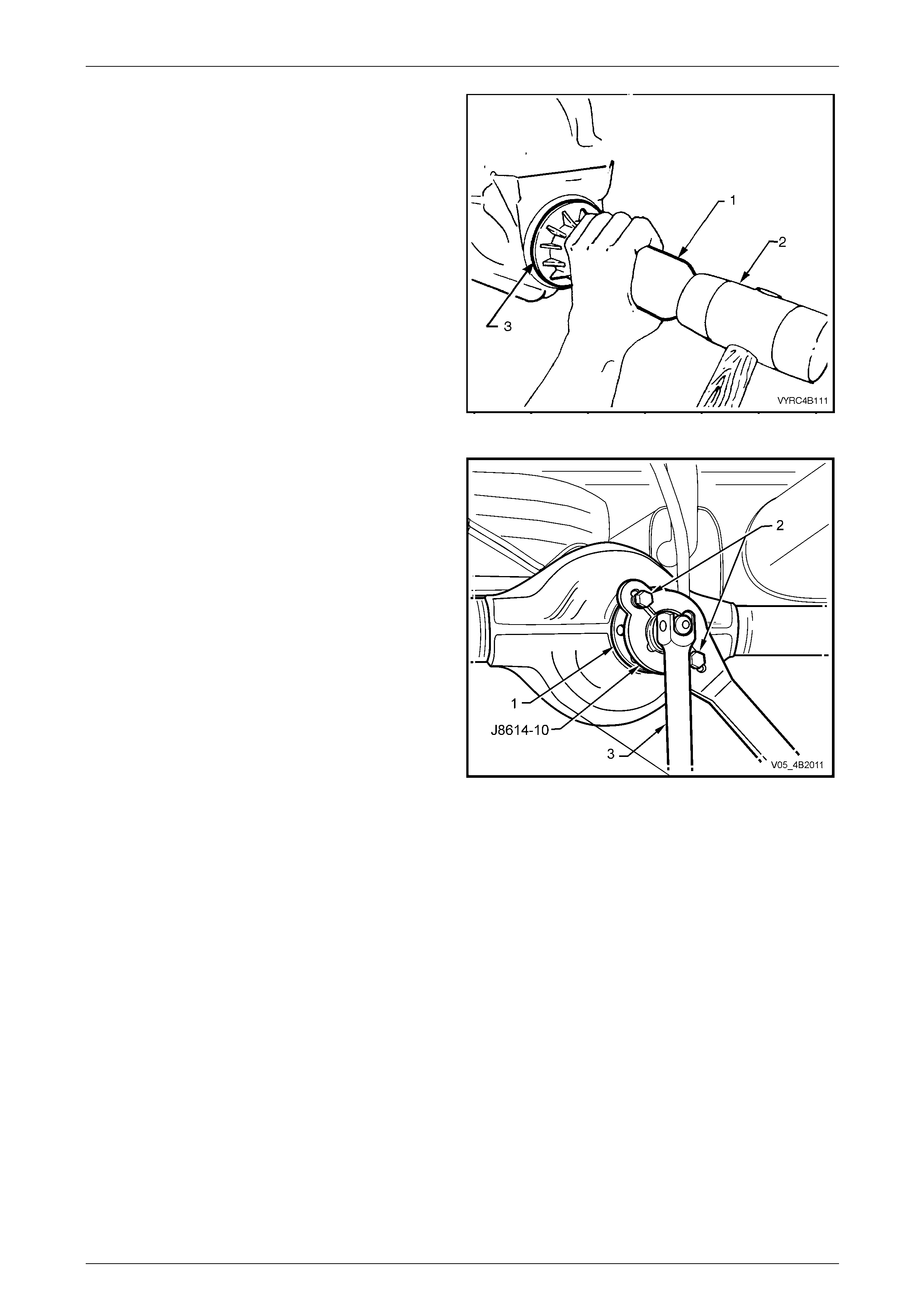
Rear Final Drive and Live Axle Page 4B2 – 95
Page 4B2 – 95
13 Lubricate the pinion oil seal l ip s with the
recommended lubricant onl y. Refer to
2.2 Checking Rear Axle Lubricant Level in this
Section.
14 Lightly coat the outside of the oil seal shell with non-
hardening gasket cement.
15 Install the oil seal (3) into the differential carr ier-
housing pinion bore:
a For M78 Series, use Tool No. E9055 (1) a nd a
soft-faced hammer (2).
b For M86 Series, use Tool No. 205-5 53 (1) and a
soft-faced hammer (2).
16 Check that the seal fits flush to 0.25 mm below the
front surface of the pinion bore.
Figure 4B2 – 191
17 Reinstall the pinion flange and a new pinion flange nut.
18 Using Tool No. J8614- 10 (1) (part of Tool No. J8614-
O1) with two rear propeller shaft constant velocity joint
bolts (2) to hold the pinion flange (1).
19 With a suitable socket and bar (3), gradually tighten
the pinion flange nut while rotating the pinion in both
directions to seat the bearings.
Figure 4B2 – 192
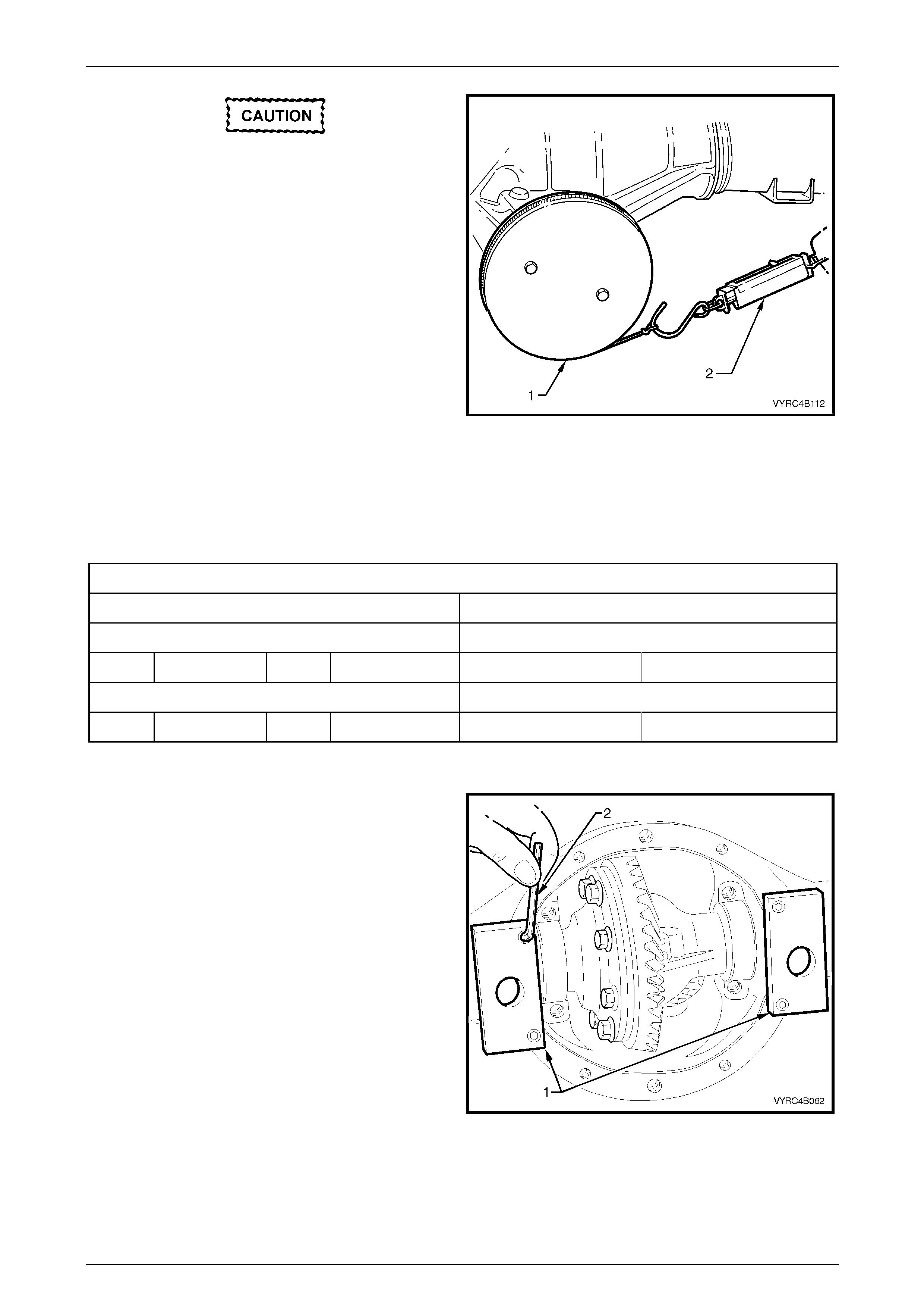
Rear Final Drive and Live Axle Page 4B2 – 96
Page 4B2 – 96
If the retaining nut is over-tightened and the
preload exceeded, the pinion will need to be
removed from the carrier and a new
collapsible spacer installed.
Under no circumstances must the retaining
nut be backed off to decrease the preload
reading.
20 The pinion bearing preload will need to be checked
frequently by removing the pinio n flan ge holding tool,
then installing a fabricated pulley (1) and string, with a
spring balance (2) to the pinio n flang e. Refer to
7 Special Tools in this Section for pulley details.
21 Using the spring balance, measure rotati onal torque.
22 Continue to tighten the nut until specified rotational
torque is achieved.
NOTE
The rotational torque figure is calculated by
multiplying the radius of the pulley by the spring
balance reading. i.e. If the pulle y diameter is 152
mm, the radius is 76 mm, which equals 0.076 m.
The spring balance reading is 25 N. Therefore,
the preload equals 0.076 m x 25 N = 1.9 Nm.
Figure 4B2 – 193
Pinion Rotational To rqu e Specification
M78 Series M86 Series
New Bearings Pinion Oil Seal Installed New Bearings Pinion Oil Seal Installed
Timken 1.4 – 2.0 N.m Koyo 1.5 – 1.9 N.m Koyo 1.9 – 2.3 N.m
Used Bearings Pinion Oil Seal Installed Used Bearings Pinion Oil Seal Installed
Timken 0.7 – 1.2 N.m Koyo 0.7 – 1.2 N.m Koyo 0.8 – 1.3 N.m
Differential Backlash Setting
1 Install the adaptors (1) of the differential spreading
Tool No. E9255 to the differential carrier housing using
a 5mm Allen Key (2).
Figure 4B2 – 194
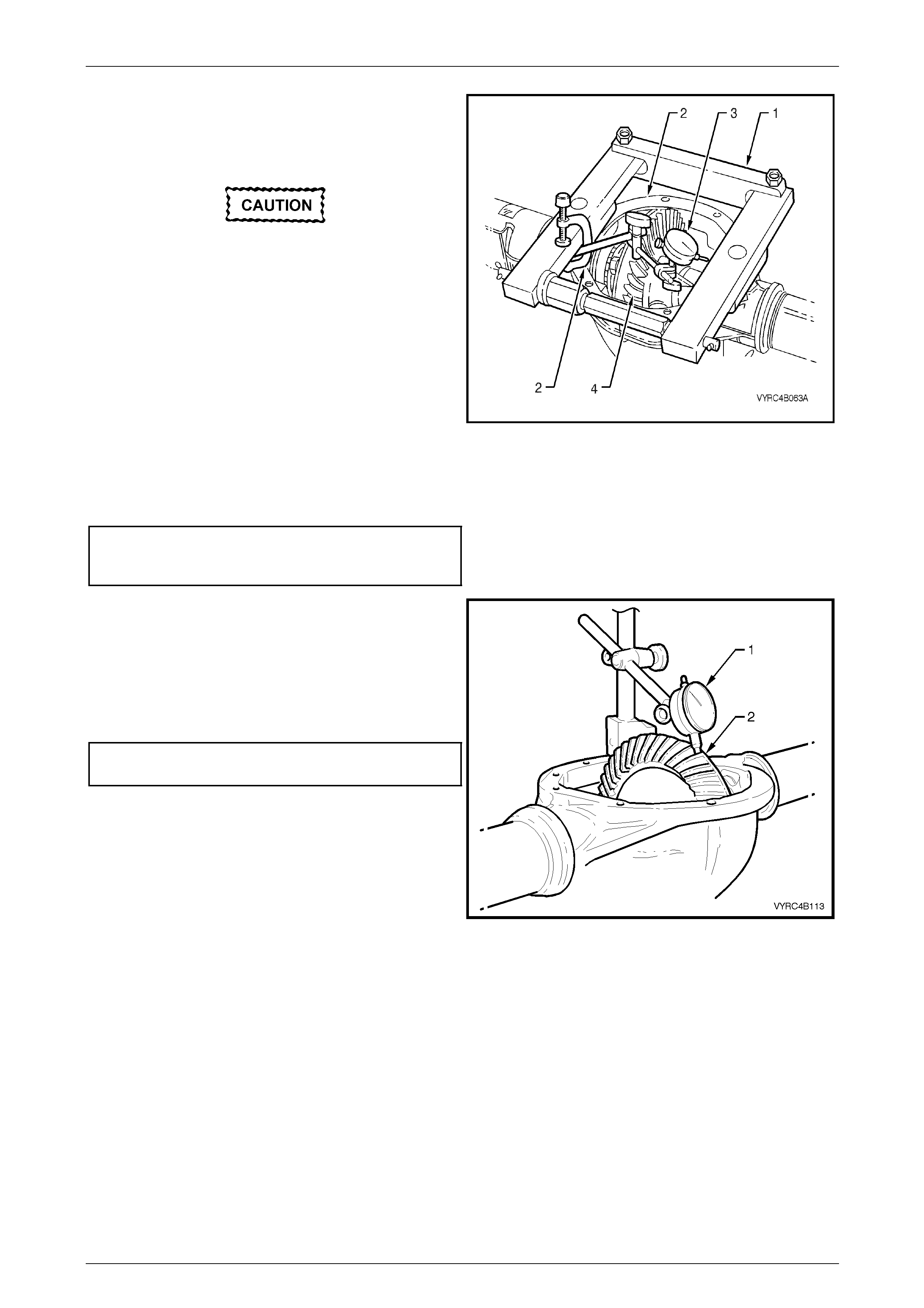
Rear Final Drive and Live Axle Page 4B2 – 97
Page 4B2 – 97
2 Install the differential spreadin g Tool No. E9255 and
the adaptor's (1) to the differential carrier housin g (2).
3 Install a dial indicator (3) to the differential spreading
Tool No. E9255 and differential carrier housing.
Under no circumstances is the differential
carrier to be spread mo re th an 0.5 mm.
4 Spread the differential carrier housing approximately
0.1 to 0.2 mm.
5 Install the differential case assembly (4), together with
the carrier side bearing cups and shims.
6 Release the force exerted by the spreading Tool No.
E9255 and remove tool alon g with the adaptors from
the differential carrier housing.
7 Install the side bearing caps a nd retaining bolts. Check
that the original relationship of the side bearing caps is
maintained so they are reinstalled in their or iginal
location.
Figure 4B2 – 195
8 Tighten the side bearing cap bolts to the correct torque specification.
Side bearing cap to differential
carrier housing attaching
bolt torque specification.......................................55 N.m
9 Using a dial indicator (1) against the back face of a
ring gear tooth (2), measure the ring gear backlash by
rocking the ring gear back and forth.
NOTE
The backlash measurement should be taken at
four equally spaced positions of the ring gear.
Ring gear to pinion
backlash specification..................... 0.10 mm – 0.18 mm
10 If backlash is insufficient, increase the size of the shim
on the pinion side of the ring gear and decrease the
size of the shim on the gear side by the same amou nt,
and repeat step 9.
11 If backlash is excessive, decrease the size of the shim
on the pinion side of the ring gear and increase the
size of the shim on the gear side by the same amou nt,
and repeat step 9. Figure 4B2 – 196

Rear Final Drive and Live Axle Page 4B2 – 98
Page 4B2 – 98
Ring Gear and Pinion Contact Pattern
1 With the backlash correctly set, check the gear contact pattern as detaile d in the following instructions.
2 Thoroughly clean the ring gear and the pinion teeth.
3 Paint the ring gear teeth lightly and evenly with the gear marking compound of a suitable consistency to produce a
contact pattern.
4 Rotate the pinion through several revolutions in both directions while li ghtly loading the gear set. To load the gear
set, use a suitable bar to lever between the ring gear outer diameter and the differential carrier housing.
NOTE
When rotating the pinion, ensure that no metal
swarf from contact with the rotating ring gear and
bar is allowed to enter the gear teeth.
5 Inspect the contact pattern produced by the above procedure.
6 After a satisfactory contact pattern is produced, clean the ring gear and the pinion gear teeth and pour a liberal
quantity of the correct rear axle lubricant onto the gears an d bearings. Turn the gear set to work the lubricant into
all surfaces.
Tooth Marking Terminology
For this description, refer to ‘Tooth Marking Terminology’, Ring Gear and Pinion Contact Pattern, in Section 4B1 Rear
Final Drive and Driveshafts.

Rear Final Drive and Live Axle Page 4B2 – 99
Page 4B2 – 99
4 Diagnosis
For all diagnosis, including bearing failure, relating to the rear final drive and live axle, refer to 4 Diagnosis, in
Section 4B1 Rear Final Drive and Driveshafts.

Rear Final Drive and Live Axle Page 4B2 – 100
Page 4B2 – 100
5 Specifications
General
Rear Axle Assembly .......................................GEN III V8 – Dana/Spicer – SAA – M86 Series
V6 – Dana/Spicer – SAA – M78 Series
Axle Type............................................................................................................Semi Float ing
Housing Type .............................................................................Unitised Carrier Construction
Standard and LSD Axles
Gear Type......................................................................................................................Hypoid
Gear Ratio (See I.D. label attached to the axle tube housing)...............V6 Automatic – 3.08:1
V6 Manual – 3.08:1
Gen III V8 Automatic – 3.07:1
Gen III V8 Manual – 3.46:1
3.08:1 3.07:1 3.46:1
No. of Teeth – Ring Gear................................................40........................43 .................45
No. of Teeth Drive Pinion Gear.......................................13........................14 .................13
Lubricants
Total Rear Axle Lubricant Capacity ...........................................................................1.7 Litres
NOTE
For rear axles with LSD the lubricant fill
comprises of 1.6 Litres of rear axle lubricant and
100 ml of Sturaco LSD additive.
Rear Axle Lubricant Type................................................................Synthetic Hypoid Gear Oil
Holden Specification HN20 40 or Mobilube SHC ID
LSD Additive........................................................................................................Sturaco 7098
Pre-lubricant as Specified in Text...................NLGI No. 2 lithium soap based EP grease with
molybdenum disulphide, such as Shell Retinax HDX2
grease or BP Energrease LMS-EP 23 (or eq uivalent).
Differential Gears
Type....................................................................................................................Straight Bevel
M78 Series M86 Series
4 Pinion 2 Pinion
No. of Teeth Pinion Gears....................................................................10..................... 9
M78 Series M86 Series
4 Pinion 2 Pinion
No. of Teeth Side Gears.......................................................................16.................... 13

Rear Final Drive and Live Axle Page 4B2 – 101
Page 4B2 – 101
Final Drive Pinion Gear Bearings
Bearing Type .................................................................................. Adjustable Tapered Roller
Bearing Adjustment ....................................................................................Collapsible Spacer
Pinion Bearing Preload (Refer to T ext for Method): Timken (N) Koyo (N)
Dummy pinion - New bearings – M78 Series 1.4 – 2.0 1.5 – 1.9
Dummy pinion - Used bearings – M78 Series 0.7 – 1.2 0.7 – 1.2
New with oil seal – M78 Series 1.4 – 2.4 1.5 – 2.1
New without oil seal – M78 Series 1.4 – 2.0 1.4 – 1.9
Used with oil seal – M78 Series 0.7 – 1.2 0.7 – 1.2
Used without oil seal – M78 Series 0.7 – 1.2 0.7 – 1.2
Dummy pinion - New bearings – M86 Series N/A 1.5 – 1.9
Dummy pinion - Used bearings – M86 Series N/A 0.7 – 1.2
New with oil seal – M86 Series N/A 1.9 – 2.3
New without oil seal – M86 Series N/A 1.8 – 2.1
Used with oil seal – M86 Series N/A 0.8 – 1.3
Used without oil seal – M86 S eries N/A 0.8 – 1.3
Differential Carrier Side Bearings
Type................................................................................................ Adjustable Tapered Roller
Adjustment............................................................................ Shim on each side of the carrier.
Side Bearing Prelo ad: Timken (N.m) Koyo (N.m)
(Refer to text for measurement conditions)
New Bearings – M78 Series 15 – 35 8.0 – 24
Used Bearings – M78 Series 8.0 – 18 5.0 – 13
New Bearings – M86 Series 13 – 30 7.0 – 20
Used Bearings – M86 Series 8 – 16 5.0 – 11
Run-Out and End Float Specifications
Rear Axle End Float:
New Bearing.........................................................0.02 – 0.30 mm (Total Indicated End Float)
Used Bearing.................................................. 0.75 mm (Maximum T otal Indicated End Float)
Rear Axle Shaft Run-out...................................0.12 mm (Maximum Total Indicated Run-Out)
Case Assembly (without ring gear attached) ...........................................0.05 mm (maximum)
Ring Gear Rear Face (assembled to case flange)...................................0.13 mm (maximum)
Backlash Specifications
Ring Gear to Drive Pinion.............................................. 0.10 – 0.18 mm (at the tightest point)
LSD Torque Check
Torque Check Specificat ion......................................................................... 35 Nm (minimum)
ABS Sensor
Air Gap (non-adjustable)......................................................................................0.4 – 2.4 mm
Sealants and Thread Locking Compound
Rear Cover to Carrier Housing ..................................... Loctite 587 ('Ultra Blue') or equivalent
Rear Axle Fasteners, Pinion Nut and Breather...............Loctite 262 or commercial equivalent
to GM Specification 9985283.

Rear Final Drive and Live Axle Page 4B2 – 102
Page 4B2 – 102
6 Torque Wrench Specifications
ATTENTION
Fasteners must be repl aced after loosening.
Vehicle must be at curb height before final tightening.
Fasteners either have micro encapsulated sealant applied or incorporate a mechanical thread lock and
should only be re-used once. If in doubt, replacement is recommended.
ABS Wheel Speed Sensor Bolt..........................................................................10 N.m
Axle Shaft Retainer Thrust Plate Bolts...............................................................45 N.m
Brake Caliper to Anchor Plate Bolts...................................................................85 N.m
Brake Hose Bracket to Chassis Bolt (AWD with Live Axle Only) .......................15 N.m
Brake Pipe Flare Nut to Brake Hose..................................................................15 N.m
Breather to Differential Carrier Housing.............................................................14 N.m
Differential Case Cap to Cover Bolts (LSD M78 Series)....................................40 N.m
• Leaf Spring Eye Attaching B olt and Nut (final).................................................145 N.m
Leaf Spring Eye Front Mounting Plate to Chassis Bolts.....................................90 N.m
Leaf Spring and Retainer Plate U-Bolt Nuts.......................................................90 N.m
Leaf Spring Shackle Mounting Plate to Chassis Bolts........................................90 N.m
Load Sensing Link to Rear Axle Cover Bolt (All Except AWD)...........................28 N.m
Propeller Shaft Constant Velocity Joint To Pinion Flange Bolts (V6).................38 N.m
Propeller Shaft Constant Velocity Joint To Pinion Flange Bolts (V8).................68 N.m
Rear Axle Drain Plug..........................................................................................28 N.m
Rear Axle Filler Plug ..........................................................................................28 N.m
Rear Cover to Carrier Housing Bolts..................................................................28 N.m
Ring Gear to Differential Case Bolts (STD, Non LSD M78 Series) ..................140 N.m
Ring Gear to Differential Case Bolts (LSD M78 Series)...................................140 N.m
Ring Gear to Differential Case Bolts (LSD M86 Series)...................................140 N.m
Road Wheel Attaching Nut.....................................................................110 – 140 N.m
Shock Absorber Lower Mounting Bolt (Preliminary) .............................................5 N.m
Shock Absorber Lower Mounting Bolt..............................................................110 N.m
Side Bearing Cap to Differential Carrier Housing Bolts (M78 Series) ................55 N.m
Side Bearing Cap to Differential Carrier Housing Bolts (M86 Series) ................55 N.m
Stabiliser Bar Mounting to Rear Axle Housing Bolt (All Except AWD) ...............25 N.m
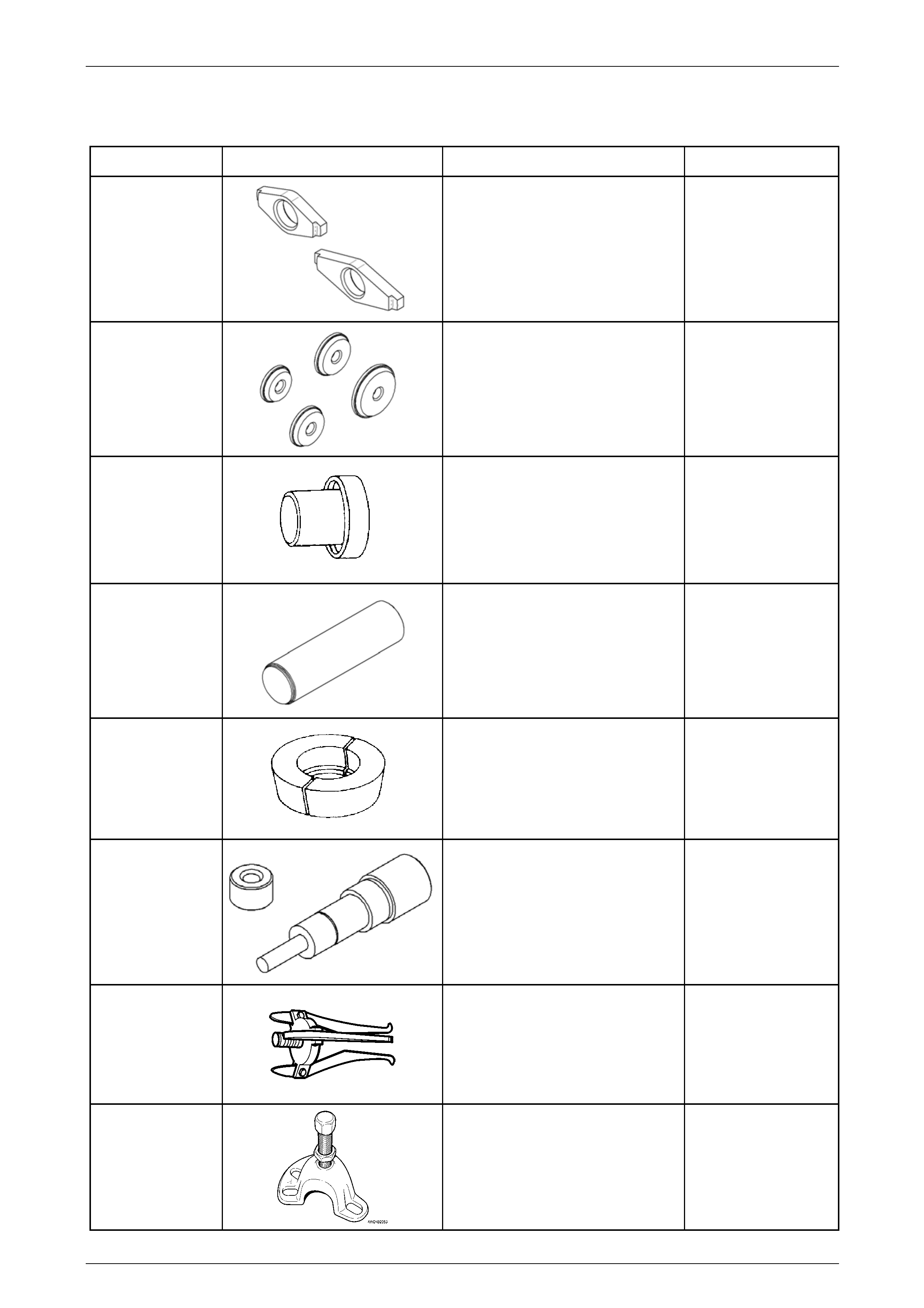
Rear Final Drive and Live Axle Page 4B2 – 103
Page 4B2 – 103
7 Special Tools
Tool Number Illustration Description Tool Classification
205-551
Adaptors – M86 Series Pinion
Bearing Cup Remover
Used with remover E9293 to remove
pinion-bearing cups from the
differential case.
Previously released
Unique
205-552
Adaptors – M86 Series Pinion
Bearing Cup Installer
Used with E9271 to install pin ion-
bearing cups to the differential case.
Previously released.
Unique
205-545
Side Bearing Cone Installer
Used to install bearings to the
differential case.
Previously released.
Unique
205-546
Pinion Rear Bearing Repl acer –
M86 Series
Used to install the rear pinion bearing
during rear axle overhaul.
Previously released.
Unique
205-547
Adaptor – M86 Series
Used with puller E1673MT to remove
the M86 Series rear pinion bearing.
Previously released.
Unique
205-548 Pinion Height Setting Gauge – M86
Series
Used with E9300A.
Previously released.
Unique
7136
Rear Axle Shaft Bearing Cup
Remover
Used to remove rear axle bearing cup
from the rear axle housing.
Used with 7374.
Available
7208
Rear Axle Removal Adaptor
Used with E6662B for LSD torque
check.
Previously released.
Unique
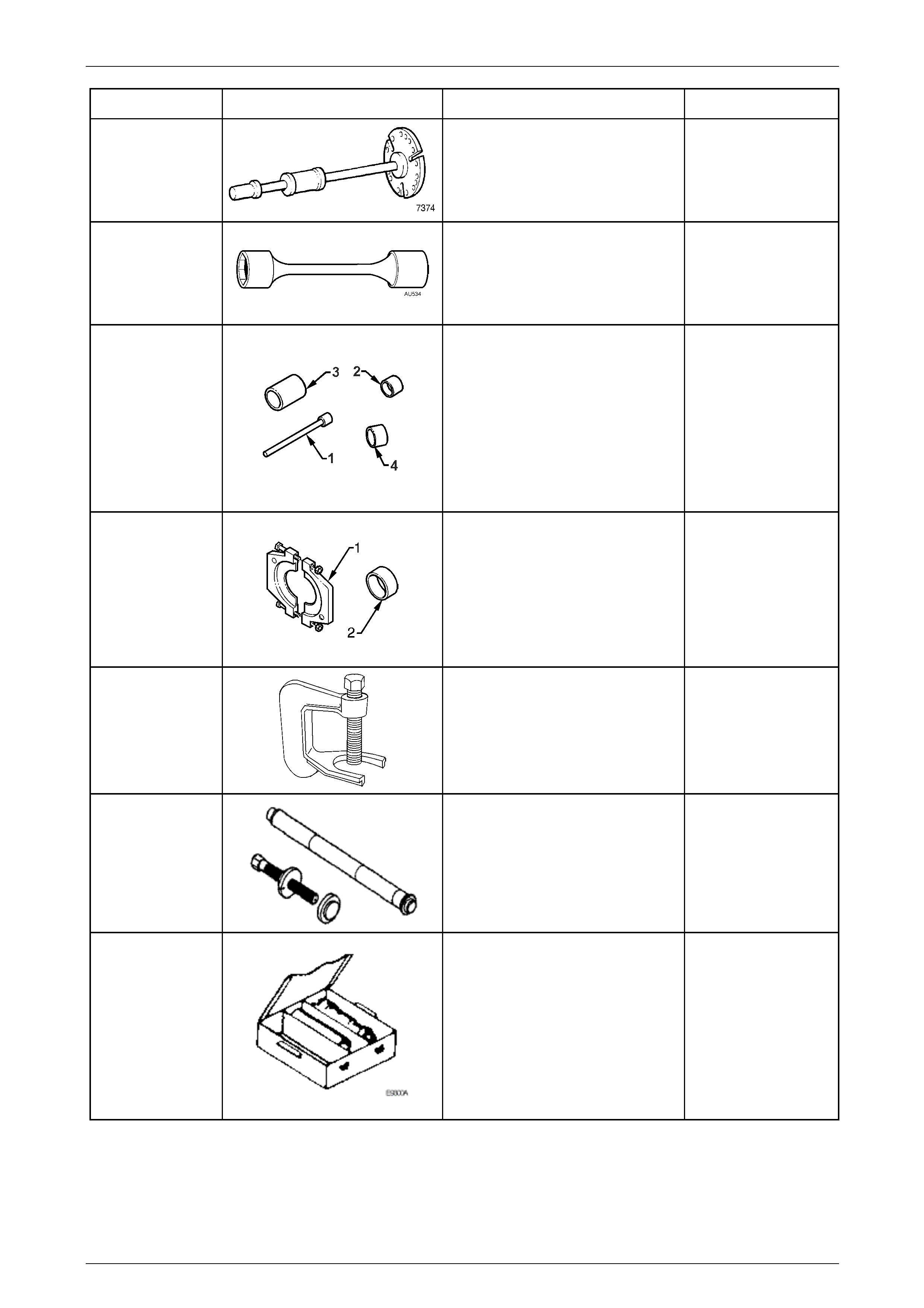
Rear Final Drive and Live Axle Page 4B2 – 104
Page 4B2 – 104
Tool Number Illustration Description Tool Classification
7374 Slide Hammer and Plate
Used to remove inner axle shafts from
the rear axle assembly.
Available
AU534
Torque Limiting Socket
Used in conjunction with an impact
gun to tighten wheel nuts.
Previously released.
Mandatory
AU606
Leaf Spring Eye Bush Remover and
Installer
Used to remove and install the front
eye bush of the rear leaf spring
assembly. Consists of:
AU606-1 Centre Spigot
AU606-2 Bush Remover
AU606-3 Bush Catcher
AU606-4 Bush Installer
Previously released
Unique
AU607
ABS Pulse Ring Remover and
Installer
Used to remove and install the ABS
pulse ring from the rear axle shaft.
Consists of:
AU607-1 ABS Pulse Ring Remover
AU607-2 ABS Pulse Ring Installer
Previously released
Unique
C-4150-C
Press Tool
Used to remove rear wheel studs from
the trunnion flange.
Previously released.
Unique
C-4487
Differential Side Gear and Clutch
Pack Remover and Installer –
M86 Series
Used to remove and install the
differential side gears and clutch
packs. Previously released.
Unique
DT-47737
Pinion Height Setting Gauge –
M78 Series
Consists of:
3C10E/11 – Dummy Pinion
3C10E/13 – Pad
3C10E/14 – Sleeve
DT-47696 – Dummy Pinion Spacer
6651/13 – Forcing Nut
AU408 – Arbour
Previously released as E9300A.
Unique
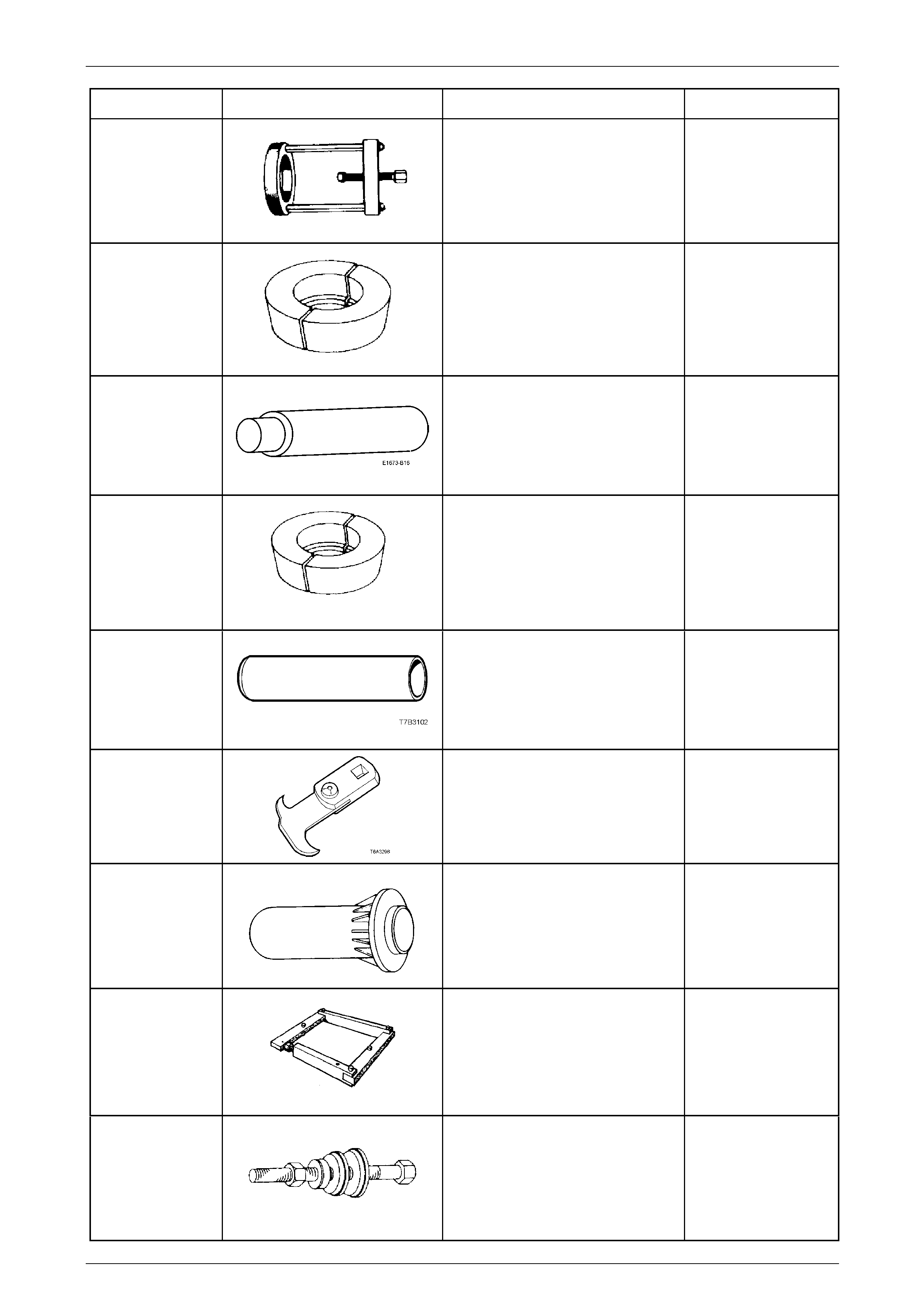
Rear Final Drive and Live Axle Page 4B2 – 105
Page 4B2 – 105
Tool Number Illustration Description Tool Classification
E1673MT
Basic Puller
Used to remove and install the
differential side bearings and remove
the rear drive pinion bearing.
Previously released.
Unique
E1673A15
Adaptor – M78 Series
Used with puller E1673MT to remove
the M78 Series rear pinion bearing.
Previously released.
Unique
E1673B16
Stepped Plug
Used with puller E1673MT and
adaptors E1673N15 to remove
bearings from the rear axle assembly.
Previously released.
Unique
E1673N15
Adaptor
Used with puller E1673MT and
stepped plug E1673B1 6 to remove
the side bearings from the differential
case.
Previously released.
Unique
E3C10AER
Pinion Rear Bearing Repl acer –
M78 Series
Used to install the rear pinion bearing
during rear axle overhaul.
Previously released.
Unique
E308
Seal Remover
Used as a universal seal remover.
Also released as 56750.
Previously released.
Available
E9055
M78 Series Pinion Oil Seal Installer
Used to install the pinion oil seal. Also
released as 17-010A.
Previously released
Unique
E9255
Differential Carrier Spreader and
Adaptor Plates
Used to remove and install the
differential assembly into the
differential carrier.
Previously released.
Unique
E9271
Pinion Bearing Cup Installer
Used to install pinion-bearing cups to
the differential case.
Previously released.
Unique
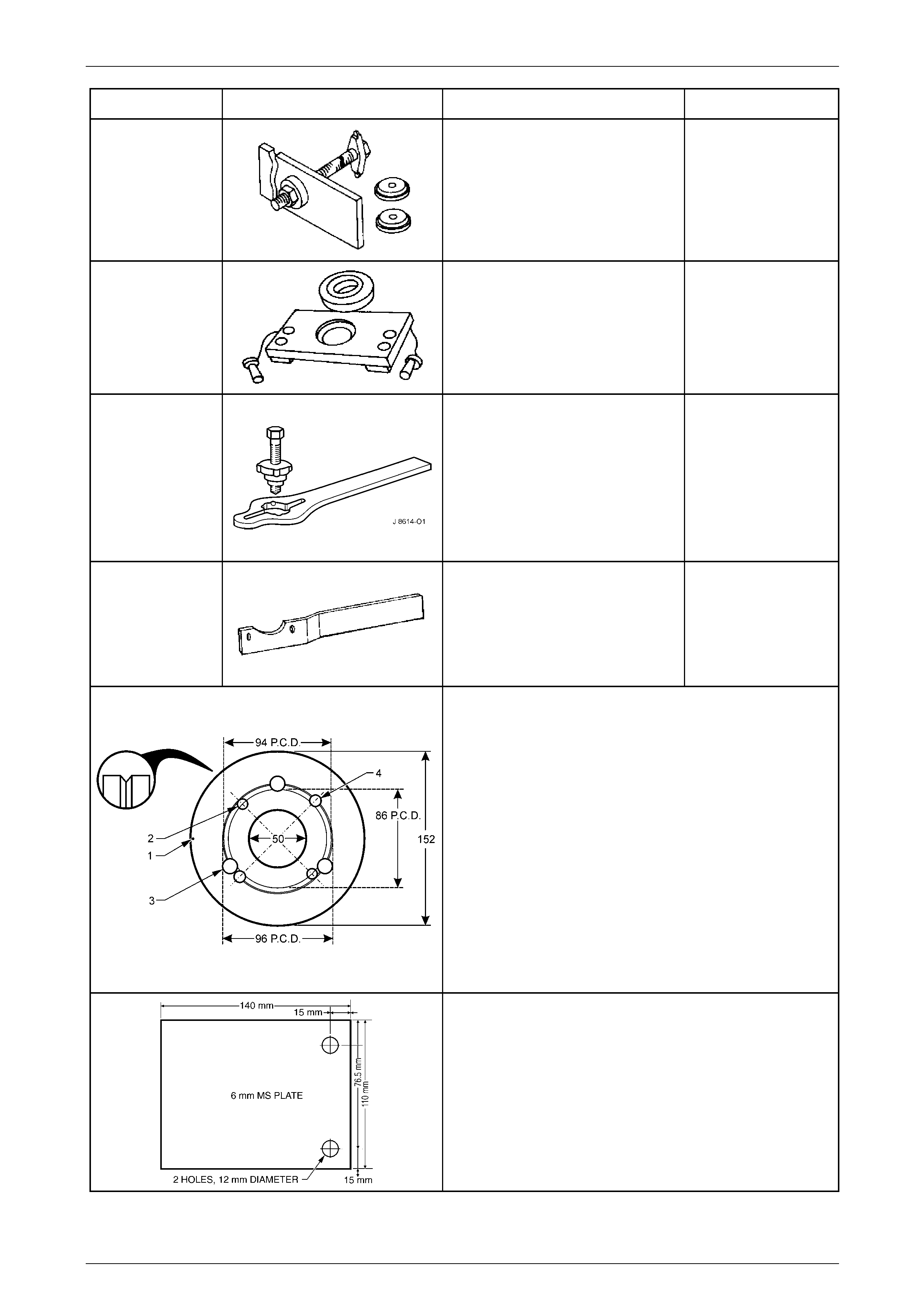
Rear Final Drive and Live Axle Page 4B2 – 106
Page 4B2 – 106
Tool Number Illustration Description Tool Classification
E9293
Pinion Bearing Cup Remover
Previously released.
Unique
E9298
Rear Axle Bearing Remover and
Installer
Used to remove and install the inner
bearing race from the rear axle
assembly.
Previously released
Available
J8614-O1
Pinion Flange Holder and Remover
Used to hold and remove the pinion
flange from the rear axle assembly.
Consists of:
J8614-10 Flange Holder
J8614-2 Adaptor
J8614-3 Forcing Screw
Previously released.
Unique
KM468-B
Holding Bar
Used to stop the rear trunnion from
rotating.
Previously released.
Available
Pinion Flange Pulley
Fabricate this pulley to incl ude all VZ applications.
1 152 mm diameter pulley made from a 13 mm thick piece
of wood with a 1 mm deep groove (inset) turned around
the circumference.
2 Drill a small hole at '1' and attach a one metre length of
string at this point, looped at one end, knotte d at the
other.
3 Drill two, 8.5 mm holes (2) opposite to each other on a
pitch circle diameter of 86 mm (AWD Wagon).
4 Drill three, 13 mm holes (3) on a pitch circle diameter of
96 mm, 120 mm apart (All VZ models with IRS).
5 Drill two, 10 mm holes (4) opposite to each other on a
pitch circle diameter of 94 mm (All VZ Live Axle models).
Dial Indicator Plate
Used to mount a magnetic based indicator stand when
checking the outer rear wheel driveshaft assembly hub for
runout.
Fabricated from 6 mm, flat Mild Steel plate.
If using the brake caliper bolts to fasten to the trailing arm, then
17 mm spacers will need to be installed on each bolt, prior to
installing.