
Front Final Drive, Bearing Housing & Driveshafts Page 4B3–1
Page 4B3-1
Section 4B3
Front Final Drive, Bearing Housing & Driveshafts
ATTENTION
Before performing any Service Operation or other procedure described in this Section, refer to Section 00
Warnings, Cautions and Notes for correct workshop practices with regard to safety and/or property damage.
1 General Description ...............................................................................................................................3
1.1 Final Drive Assembly Identification ..................................................................................................................... 4
1.2 Final Drive Maintenance........................................................................................................................................ 5
Maintenance........................................................................................................................................................... 5
Driveshaft Bearings and Constant Velocity Joints.............................................................................................. 5
Differential Carrier Assembly.............................................................................................................................. 5
Final Drive Assembly Breather........................................................................................................................... 5
Lubrication ............................................................................................................................................................. 6
2 Minor Service Operations......................................................................................................................7
2.1 Checking Final Drive Lubricant Level.................................................................................................................. 7
2.2 Changing/Flushing Final Drive Lubricant............................................................................................................ 8
2.3 Pinion Oil Seal........................................................................................................................................................ 9
Replace................................................................................................................................................................... 9
2.4 Driveshaft Assembly ........................................................................................................................................... 10
Remove................................................................................................................................................................. 10
Reinstall................................................................................................................................................................ 12
2.5 Driveshaft Outer Constant Velocity Joint.......................................................................................................... 15
Remove................................................................................................................................................................. 15
Reinstall................................................................................................................................................................ 17
2.6 Driveshaft Inner Tripot Joint............................................................................................................................... 18
Disassemble......................................................................................................................................................... 18
Inspect .................................................................................................................................................................. 20
Reassemble.......................................................................................................................................................... 20
2.7 Bearing Housing/Final Drive Carrier Outer Oil Seal.......................................................................................... 22
Replace................................................................................................................................................................. 22
2.8 Pinion Oil Seal...................................................................................................................................................... 24
Replace................................................................................................................................................................. 24
2.9 Pinion Flange ....................................................................................................................................................... 25
Replace................................................................................................................................................................. 25
3 Major Service Operations....................................................................................................................26
3.1 Bearing Housing Assembly ................................................................................................................................ 26
Remove................................................................................................................................................................. 26
GEN III V8 Engine............................................................................................................................................ 26
All AWD............................................................................................................................................................ 27
Disassemble......................................................................................................................................................... 27
Inspect .................................................................................................................................................................. 29
Reassemble.......................................................................................................................................................... 30
Reinstall................................................................................................................................................................ 32
Techline
Techline

Front Final Drive, Bearing Housing & Driveshafts Page 4B3–2
Page 4B3-2
3.2 Front Final Drive Assembly................................................................................................................................. 33
Remove................................................................................................................................................................. 33
GEN III V8 Engine............................................................................................................................................ 33
All AWD............................................................................................................................................................ 33
Reinstall................................................................................................................................................................ 36
3.3 Removed Final Drive Assembly.......................................................................................................................... 38
Disassemble......................................................................................................................................................... 39
Final Drive Cover.............................................................................................................................................. 39
Examining Gear Tooth Contact........................................................................................................................ 40
Drive Pinion...................................................................................................................................................... 40
Differential Assembly........................................................................................................................................ 44
Inspect .................................................................................................................................................................. 46
General Items................................................................................................................................................... 46
Gears ............................................................................................................................................................... 46
Bearing Cups ................................................................................................................................................... 46
Bearing Cone and Roller Assemblies............................................................................................................... 47
Pinion Flange ................................................................................................................................................... 47
Carrier and Cover Housings............................................................................................................................. 47
Differential Case............................................................................................................................................... 47
Reassemble.......................................................................................................................................................... 47
Differential........................................................................................................................................................ 47
Drive Pinion – Shim Selection.......................................................................................................................... 49
Differential Assembly – Bearing Preload and Backlash.................................................................................... 52
Final Drive Unit Assembly................................................................................................................................ 56
4 Diagnosis ..............................................................................................................................................59
5 Specifications.......................................................................................................................................60
6 Torque Wrench Specifications............................................................................................................61
7 Special Tools ........................................................................................................................................62
Front Final Drive, Bearing Housing & Driveshafts Page 4B3–3
Page 4B3-3
1 General Description
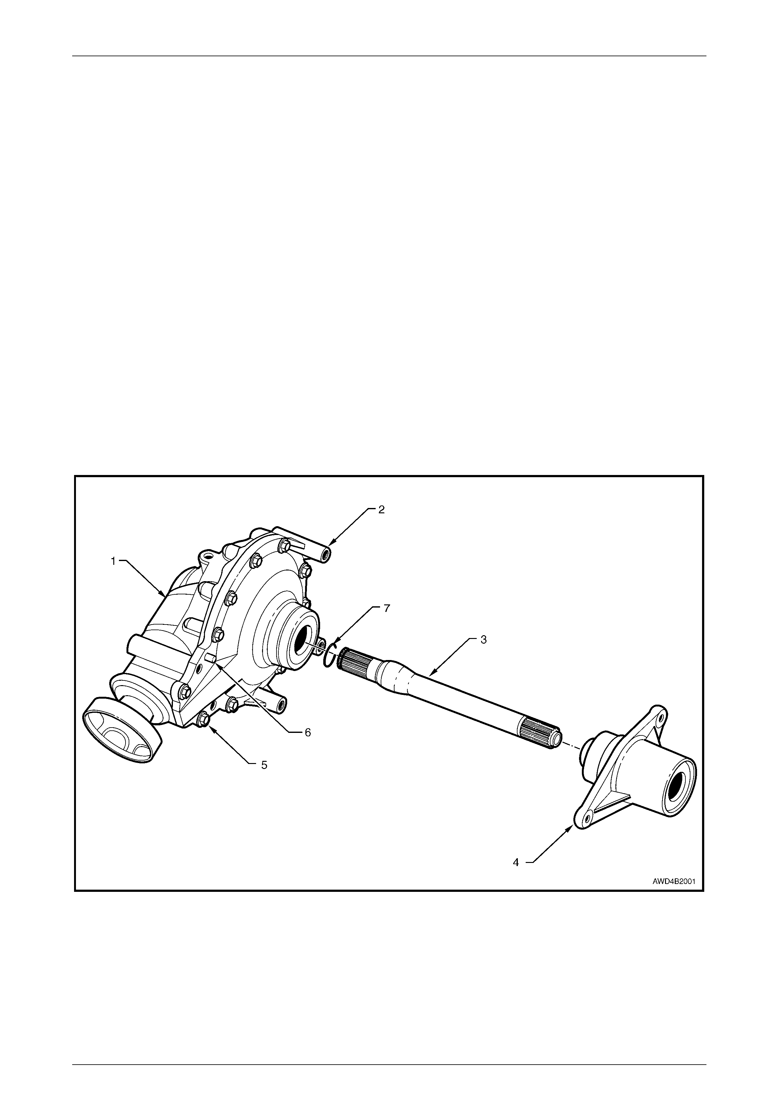
The front final drive assembly (1) is attached to the left side of the engine oil pan and a driveshaft support bearing
assembly (3) is located on the right side of the engine oil pan. An interconnecting shaft (2) passes through an integrally
cast tube in the engine oil pan, from the front drive assembly to the support bearing housing assembly. Refer to
Figure 4B3-1. The interconnecting shaft is retained in the right side differential axle gear by a snap ring.
The final drive assembly is a “Clam Shell” design, that is split vertically along its length and consists of two housings (1
and 2) made from ductile iron. The major housing (1) is the carrier that houses the hypoid pinion and supports the left
hand crown wheel carrier bearing. The minor half of the unit is called the cover (2), that supports the right hand crown
wheel carrier bearing. This cover is locate d on the carrier with a large diameter spigot and a hollow dowel to control
bearing to bearing alignment and is secured by ten bolts (5).
The hypoid drive pinion is supporte d in the carrier on two opposed, preloaded taper roll er bearings. A pinion positioning
shim is located under the pinion head bearing cup while the bearing preload is achieved with a collapsible spacer at the
outer (small) pinion bearing. The bearings and the companion flange are retained with the pinion nut.
The differential assembly and ring gear are supported on two opposed and preloaded taper roller bearings; one in the
carrier and the second in the cover. The backlash and the bearing pre lo ad are controlled with shims under the final drive
carrier bearing cups in the carrier an d the cover.
The final drive assembl y is indexed to the engine oil pa n by the cover seal housing, engagin g with a machined recess in
the engine oil pan, while a dowel (6) near the rear mounting bolt controls the pinion nos e angle. Four bolts are used to
attach the final drive assembly to the engine pan. The left front driveshaft is retained in the left differential axle gear b y a
snap ring on the inboard spline of the inner tripot joint.
The final drive ratio is 3.46:1 and the conventional differential assembly has two pinions, with a single, pin ned pinion
shaft and two axle side gears.
Figure 4B3-1
Legend
1 Final Drive Assembly, Major Housing
2 Final Drive Assembly, Cover
3 Interconnecting Shaft
4 Driveshaft Support Bearing Assembly
5 Carrier to Cover Attaching Bolts (10 places)
6 Pinion Nose Angle Locating Dowel
7 Interconnecting Shaft Snap Ring

Front Final Drive, Bearing Housing & Driveshafts Page 4B3–4
Page 4B3-4
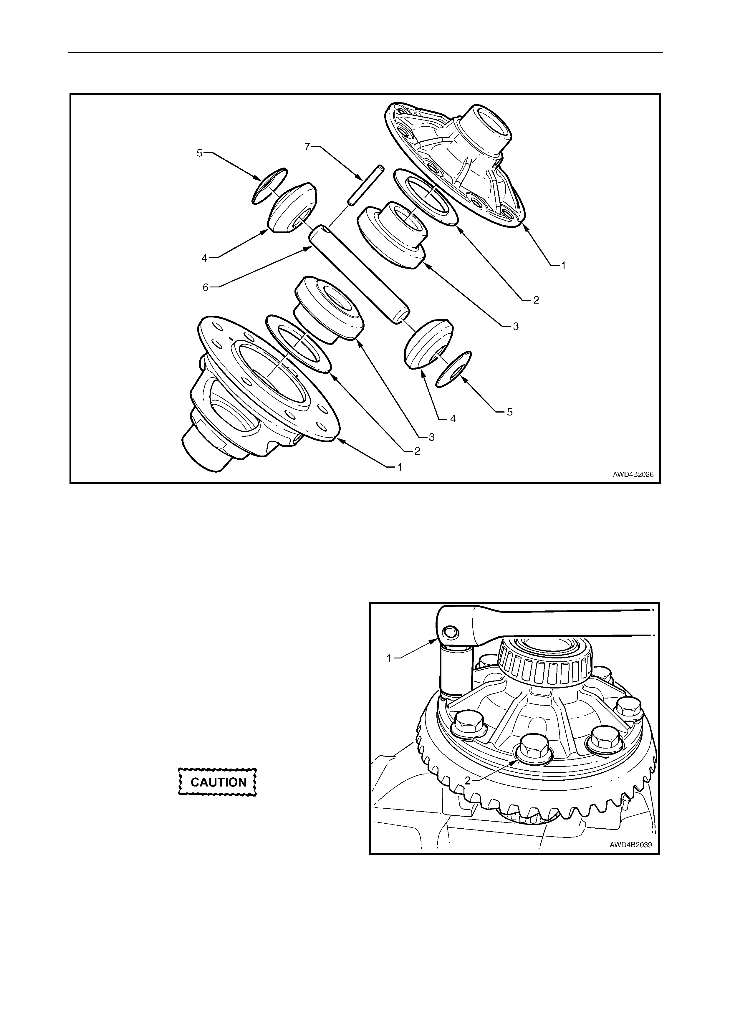
The bearing housin g assembly is a one piece aluminium casting attached to the right side of the engine oil pan with three
bolts. The bearing housing assembly is fitted with a needle roller bearing (2) and a ball bearing (6) to support and locate
the connecting sleeve (5). The sleeve supports one end of the interconnecting shaft and retains the rig ht side front
driveshaft, again by a retaining ring on the inner tripot joint spline. Both bearings are lubricated for life and require no
periodic maintenance. An oil seal (1 and 9) at each end of the bearing housing assembly, retain the lubricant.
Figure 4B3-2
Legend
1 Oil Seal – Inner
2 Needle Roller Bearing
3 Bearing Housing
4 O-Ring Seal
5 Connecting Sleeve
6 Single Row Ball Bearing
7 Circlip – Small
8 Circlip – Large
9 Oil Seal – Outer
1.1 Final Drive Assembly Identification
There is only one front final drive assembly available for fitment to all MY 2005 All Wheel Drive models, which has a final
drive ratio of 3.46:1 with a two pinion type, standard differential.
Front Final Drive, Bearing Housing & Driveshafts Page 4B3–5
Page 4B3-5
1.2 Final Drive Maintenance
Maintenance
Driveshaft Bearings and Constant Velocity Joints
The driveshaft outer constant velocity joint and the inner tripot joint are lubricated for life and therefore require no periodic
maintenance.
The constant velocity joint boots are to be inspected at every maintenance service. If there is any evidence of damage to
boots, remove driveshaft and inspect constant velocity joints, refer to 2.4 Driveshaft Assembly in this Section.
Differential Carrier Assembly
Check for lubricant leaks at every maintena nce service. If there is evidence of leakage, correct the leak and add l ubricant
as necessary. (Refer to 2 Minor Service Operations in this Section).
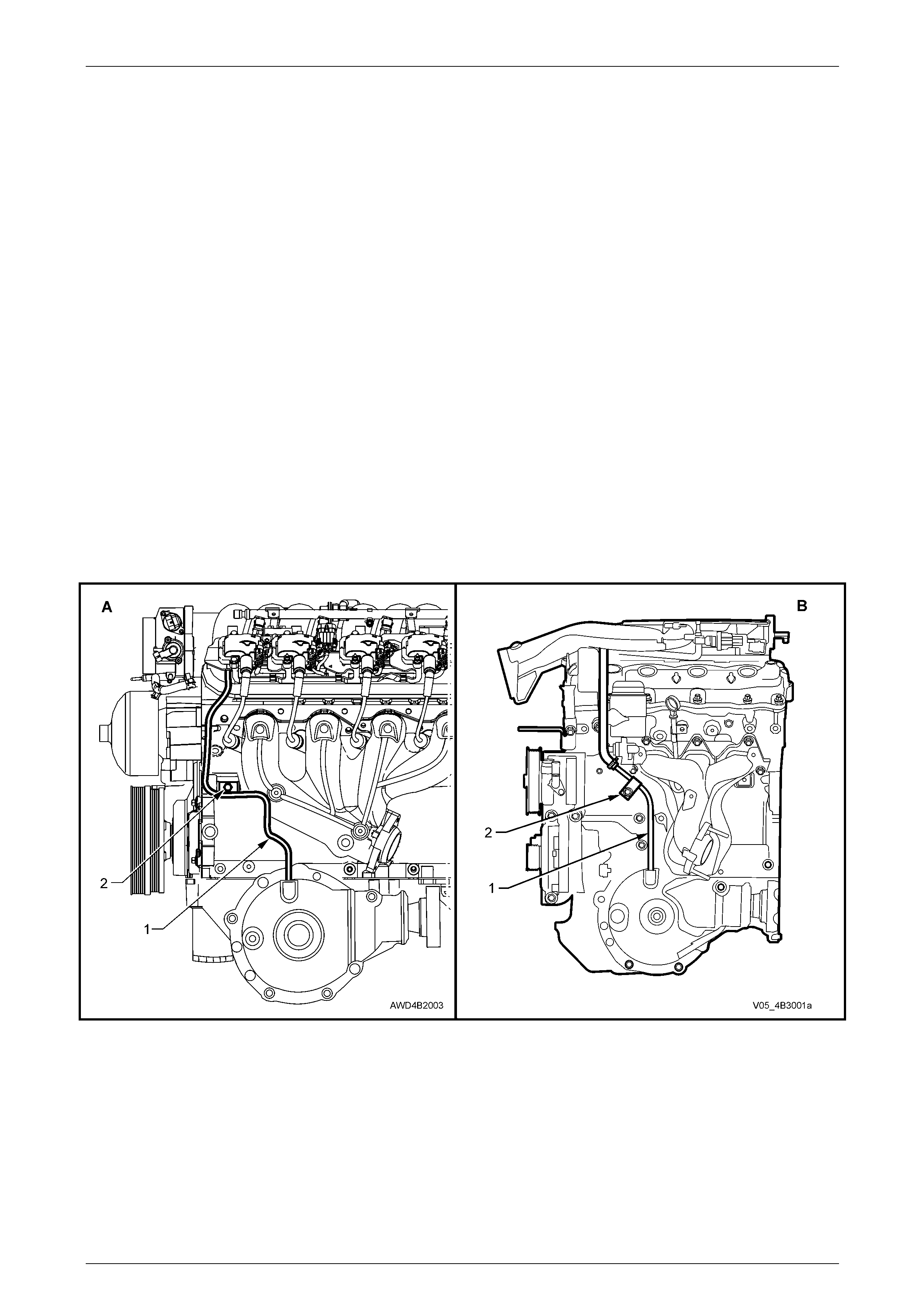
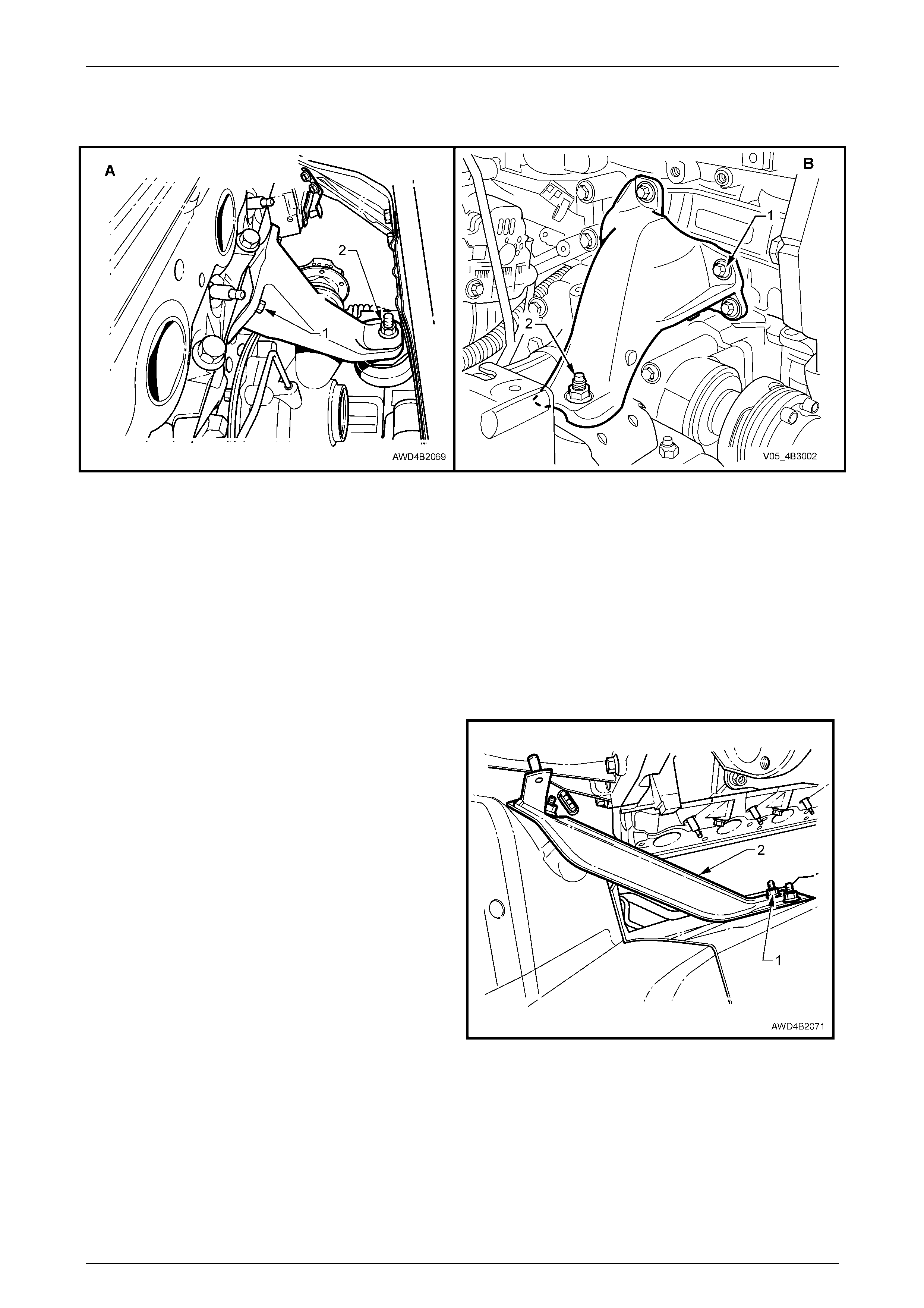
Final Drive Assembly Breathe r
The breather hose and pipe assembly (1) should be checked regu larly to ensure that it is correctly routed, the hose
condition is sound, the end is not blocke d and the pipe bracket fastener (2) is secure.
NOTE
View ‘A’ shows the GEN III V8 routing of the
breather tube, while view ‘B’ shows the V6
arrangement.
Figure 4B3 – 3

Front Final Drive, Bearing Housing & Driveshafts Page 4B3–6
Page 4B3-6
Lubrication
Never use any other than the stated and
recommended lubricant.
The lubricant level should be checked and topped up (if requir ed), at the time or distance intervals outlined in the
appropriate Owner's Handbook, with the differential carrier COLD and the vehicle on level ground; refer to
2.1 Checking Final Drive Lubricant Level in this Section. At this temperature, the lubricant should be within 5 mm of the
bottom of the filler plug hole. Operation 2.1 also d etails the recommended lubricant for this final drive.
NOTE
• The lubricant used in this final drive, is a
synthetic product and the oil s eals fitted, have
been specially formulated to tolerate this
lubricant. It must also be noted that, using a
mineral type lubricant in this final drive, may
cause gear set and/or bearing damage under
high load driving conditio ns.
• If the incorrect lubricant is accide ntall y used i n
the front final drive of any AWD vehicle, then
the front final drive must be drained, flushed
(with the recommended lubricant) and then
refilled with the correct lubricant. Refer to
2.2 Changing/Flushing Final Drive Lubricant,
in this Section.

Front Final Drive, Bearing Housing & Driveshafts Page 4B3–7
Page 4B3-7
2 Minor Service Operations
ATTENTION
All fasteners are important attaching parts as they affect the performance of vital components and/or could
result in major repair expense. W h ere specified in this section, fasteners MUST be rep laced with parts of the
same part number or an approved equivalent. Do not use fasten ers of an inferior quality or substitute desig n.
Torque values must be used as specified during reassembly to ensure proper retention of all components.
Throughout this section, fastener torque wrench specifications may be accompanied with the following
identification marks:
Fasteners must be replaced after loosening.
Vehicle must be at curb height before final tightening.
Fasteners either have micro encapsulated sealant applied or incorporate a mechanic al thread lock and
should only be re-used once. If in doubt, replacement is recommended.
If one of these identification marks is present alongside a fastener torque wrench specification, the
recommendation regarding that fastener must be adhered to.
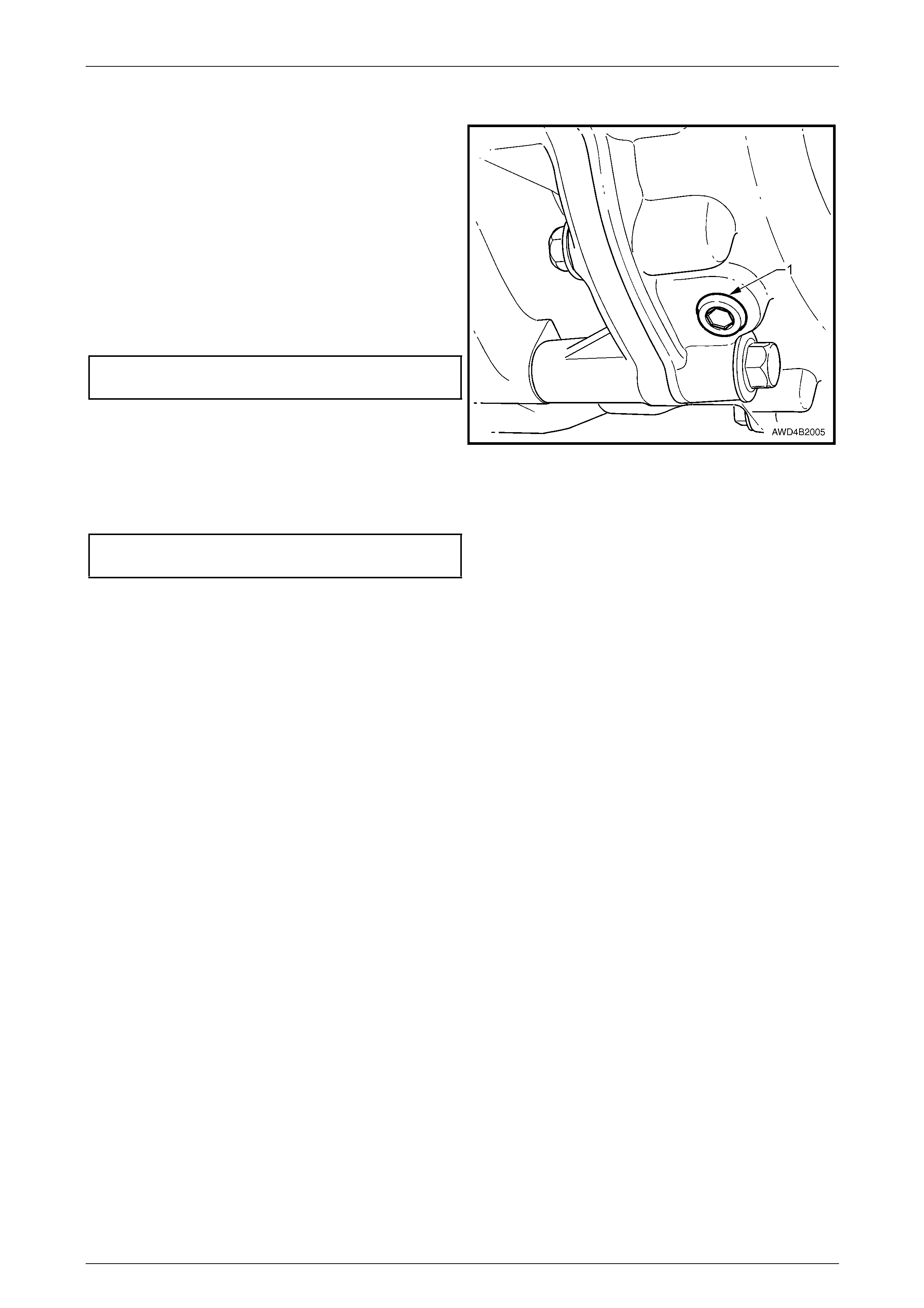
2.1 Checking Final Drive Lubricant Level
1 Ensure vehicle is on level ground.
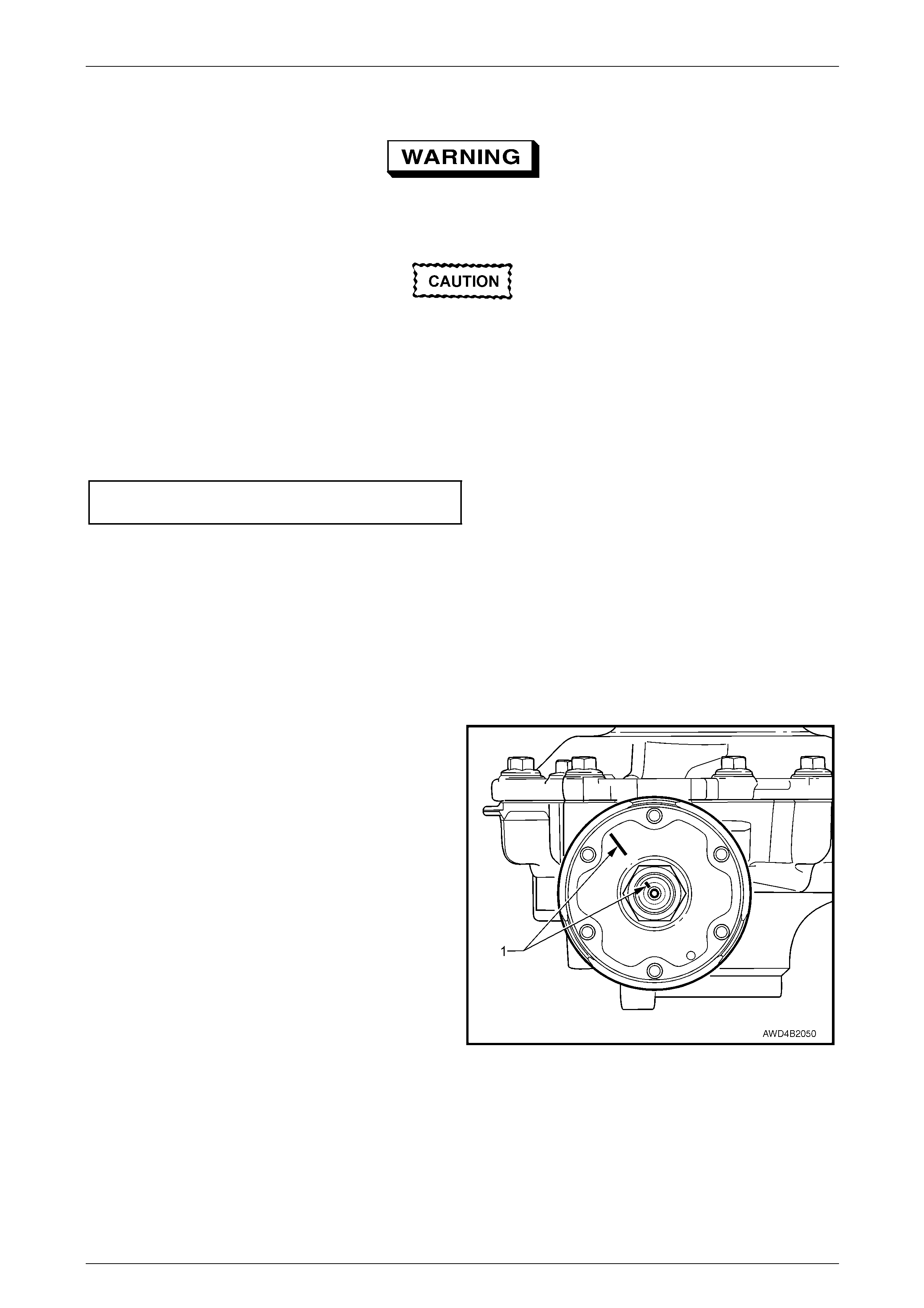
2 Clean area around filler plug (1).
3 Remove the hexagon headed filler plug (1) from the
carrier housing, using suitable socket equipment.
4 The lubricant l evel is to be maintained within 5 mm of
the bottom edge of the filler plug hole, when COLD
and the vehicle is on level ground. Use only the
recommended lubricant, detail ed as follows:
Front Final Drive Lubricant Specification
Synthetic Hypoid Gear Oil, SAE 80W-140
such as;
Castrol SAF-XA or Mobilube SHC ID
5 Inspect filler plug (1) for damage. If OK, reinstall to the
carrier housing. If damaged, repl ace plug.
Figure 4B3 – 4
6. Tighten filler plug (1) to the correct torque specificati on.
Final drive filler plug
torque specification..............................................28 N.m
Front Final Drive, Bearing Housing & Driveshafts Page 4B3–8
Page 4B3-8
2.2 Changing/Flushing Final Drive Lubricant
1 To drain lubric ant from differential carrier assembly,
remove the hexagon headed filler plug (refer
Figure 4B3-4), then the 8 mm Allen key headed drain
plug (1), allowing (preferably warm) lubricant to drain
into a suitable container of at least 1 litre capacity.
2 If flushing is required, use an undiluted quantit y of the
recommended lubricant for the operation.
3 When the draining and flushing (if required), operation
is completed, clean the final drive drai n plug (1)
threads. If required, Teflon tape may be applied to the
threads. Reinstall and tighten drain plug (1) to the
correct torque specification.
Final drive drain plug
torque specification..............................................45 N.m
Figure 4B3 – 5
4 Fill the final drive assembly with 0.8 litres of the recommended lubricant. Reinstall the filler plug ('1', in Figure 4B 3-
4) and tighten the filler plug to the correct torque spec ification.
Final drive filler plug
torque specification..............................................28 N.m

Front Final Drive, Bearing Housing & Driveshafts Page 4B3–9
Page 4B3-9
2.3 Pinion Oil Seal
Replace
Apart from the fact that it is the front propeller shaft that needs to be removed (rather than the rear), the procedure for the
front final drive pinion oil seal replacement is the same as that described for the rear final drive assembly.
Refer to Section 4C2 Front Propeller Shaft & Universal Joi nts and Section 4B1 Rear Final Drive & Driveshafts.
Front Final Drive, Bearing Housing & Driveshafts Page 4B3–10
Page 4B3-10
2.4 Driveshaft Assembly
LT Section No. – 05-290
Remove
1 Raise the vehicle and secure in a safe manner. Refer to Section 0A General Information for the location of jacking
and support points.
2 Remove the centre wheel nut cap, then mark the relationship of the road wheel to one of the wheel studs.
3 Loosen, then remove the road wheel attaching nuts, working in a 'star' pattern.
Refer to Section 10 Wheels and T yres for de tailed information. Remove the road wheel.
NOTE
Steps 2 and 3 are necessary to maintain
component relationships and to avoid brake rotor
distortion and the creation of brake shudder, after
the vehicle is placed back in service.
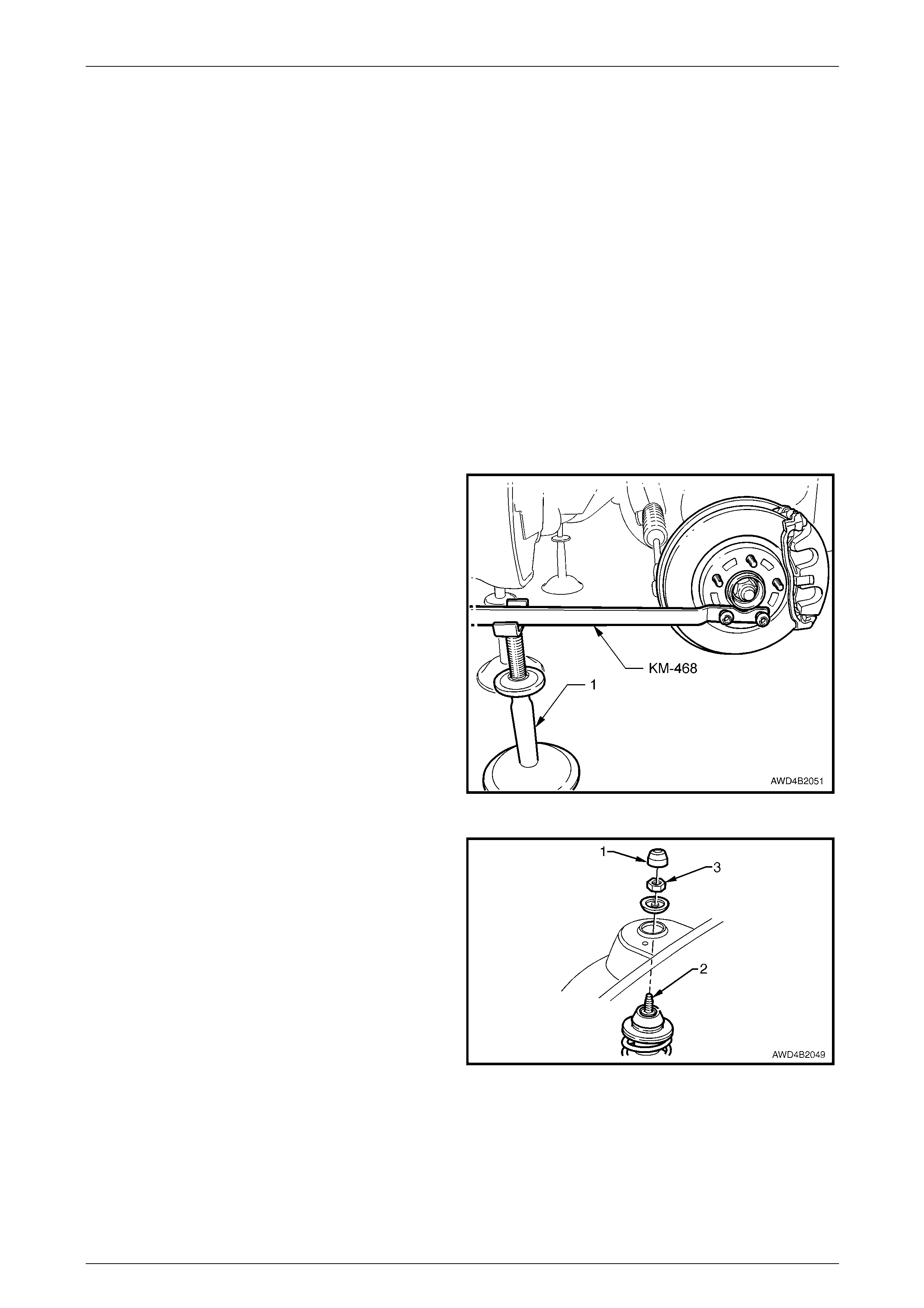
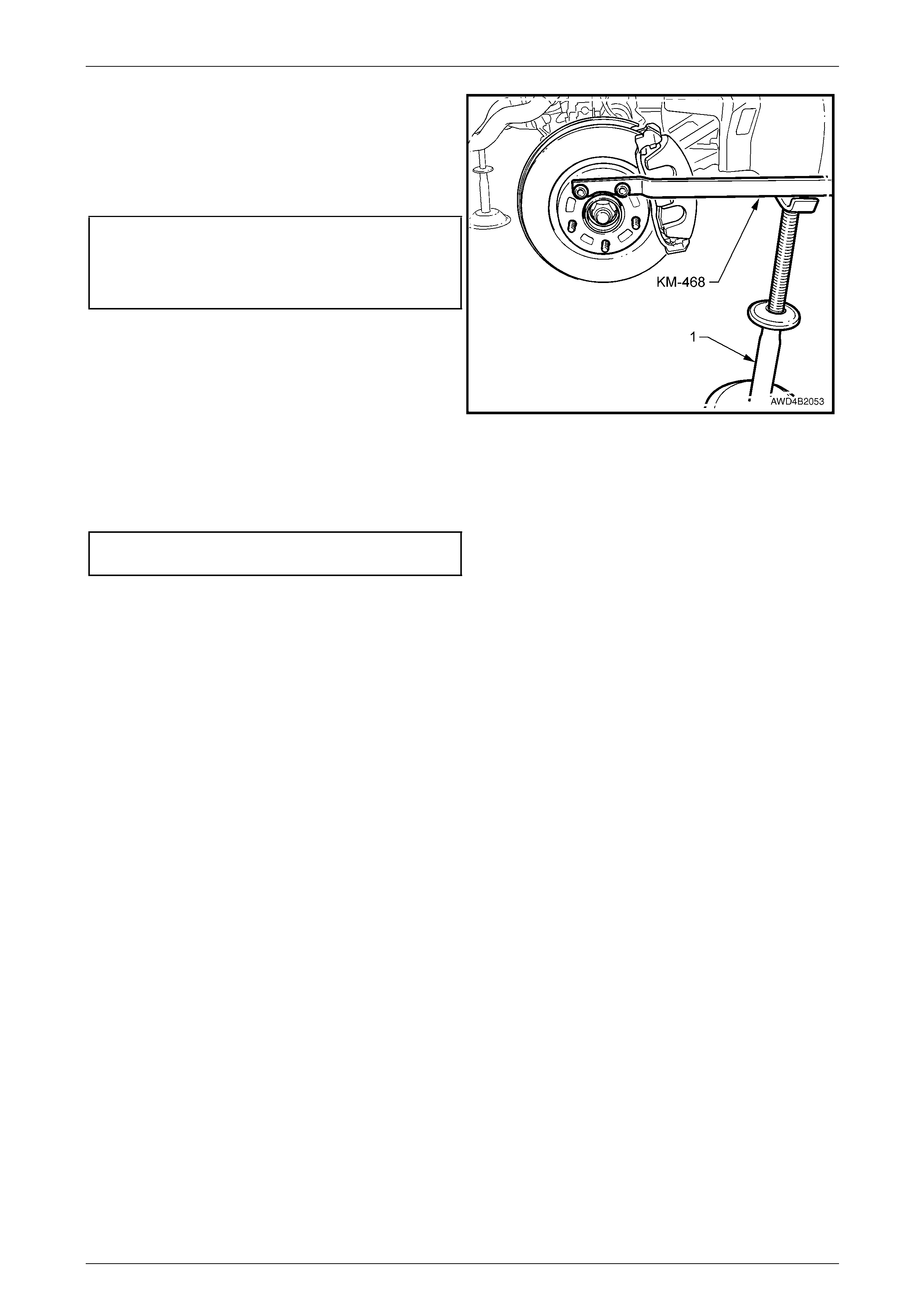
4 Attach holding tool KM-468 to the wheel hub with two
inverted wheel nuts. Support the tool outer end on a
safety stand.
5 Using suitable socket equipment, loosen then remove
the 36 mm driveshaft retaining nut and flat washer.
Discard the removed nut.
Figure 4B3 – 6
6 Remove the dust cover (1) from the upper strut
support, in the engine compartment.
7 While holding the strut rod shaft (2) with a 10 mm
socket, loosen the self-locking nut (3), using a 24 mm
ring spanner. Do not fully remove the nut.
NOTE
This step is necessary to allow the strut to be
moved outward, enabling driveshaft removal.
Figure 4B3 – 7
Front Final Drive, Bearing Housing & Driveshafts Page 4B3–11
Page 4B3-11
Under no circumstances is the end of the
driveshaft to be struck with a hammer to
dislodge the splines. To do so, will not only
damage the front hub bearing but the
driveshaft to outer constant velocity joint
snap ring can be also be dislodged.
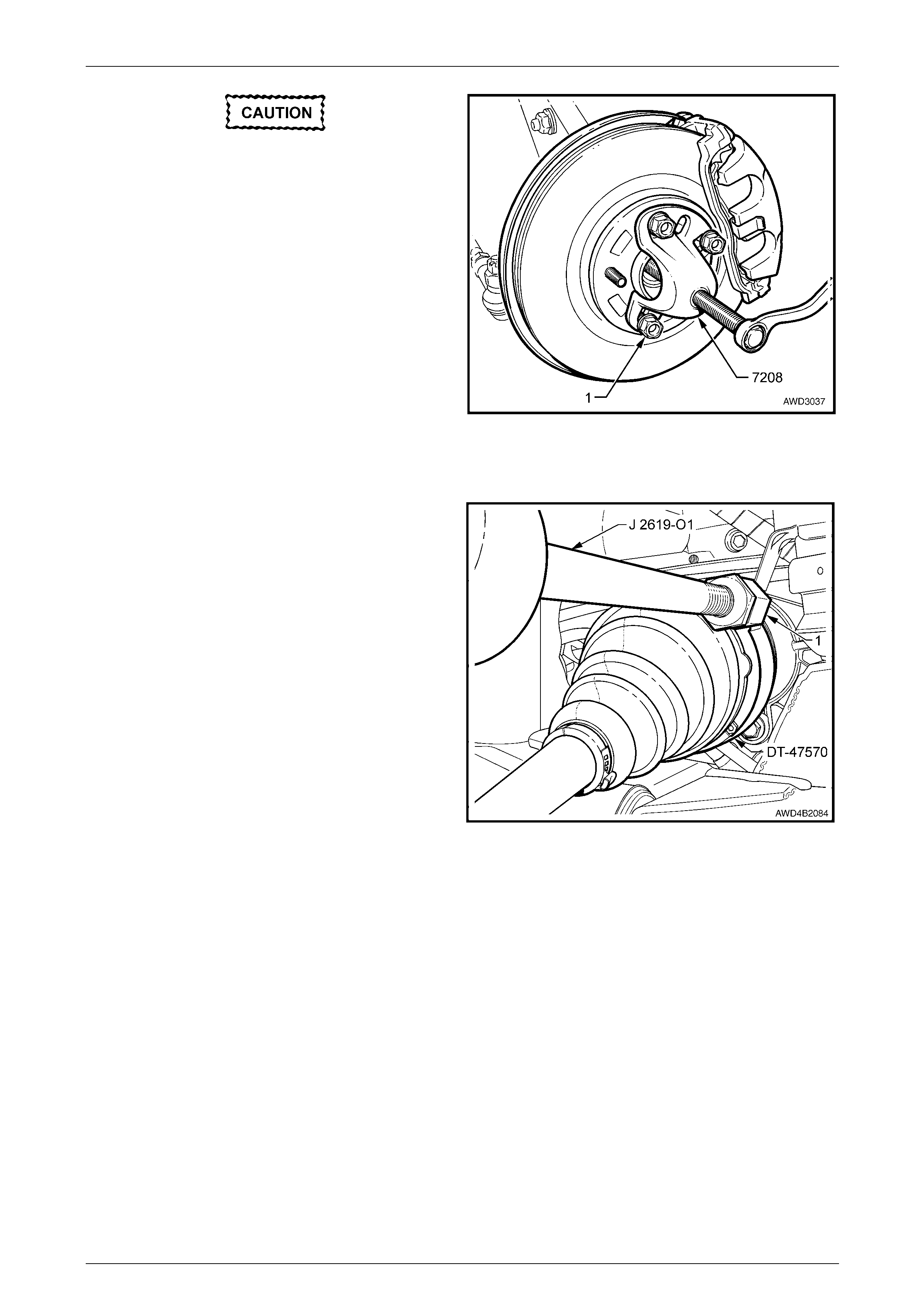
8 Install Tool No. 7208 to the fro nt hub studs a nd secure
with three of the wheel nuts (1).
9 Tighten the forcing screw to separate the front hub
and outer driveshaft splines. Remove Tool No. 7208.
Figure 4B3 – 8
10 Disconnect the front control arm ball joint stud from the front control arm.
Refer to Section 3B Front Suspension – AW D.
11 Install adaptor(1) from slide hammer J 2619-O1 to the
remover/installer, Tool No. DT-47570, then install DT-
47570 to the groove in the tripot joint housing,
tightening the thumb screw to secure.
12 Screw slide hammer J 2619-O1 into the adaptor unti l
secure.
13 Using the action of the slide hammer weight aga inst
the handle, dislodge the tripot joint snap ring from the
bearing housing (right side) or the front final drive side
gear (left side).
NOTE
While the right side view is sho wn, the procedur e
is the same for the either side.
14 Remove the driveshaft from the vehicle by first
pushing inward to free the outer shaft from the front
hub, then withdraw the driveshaft by pulling on the
tripot housing.
NOTE
If the driveshaft is removed from the final drive
(left) side, lubricant will flow from the oil seal.
Either plug the recess immediately with a
suitable plug or rag, or drain the lubricant into a
suitable, clean container. Refer to
2.2 Changing/Flushing Final Drive Lubricant, in
this Section.
Figure 4B3 – 9
Front Final Drive, Bearing Housing & Driveshafts Page 4B3–12
Page 4B3-12
• When removing the driveshaft do not
allow the tripot splines to drag on th e final
drive (or bearing housing) oil seal.
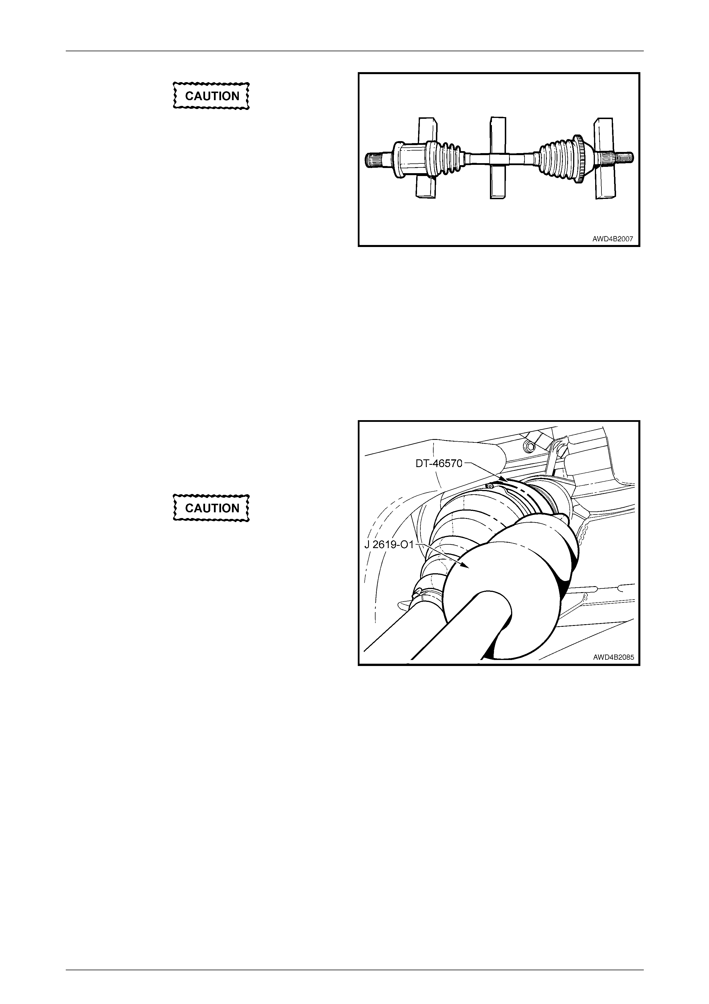
• The removed driveshaft must be handled
with care. Do not rest th e shaft or bellows
for any longer than necessary.
• The shaft is not to be allowed to hang free
on one end. Driveshaft joint deflection
should be kept to a minimum by
supporting the driveshaft with wooden
blocks, as shown.
NOTE
If both driveshafts are removed, the left side is
shorter than the right.
Figure 4B3 – 10
Reinstall
1 Install adaptor from slide hammer J 2619-O1 to the driveshaft remover installer, Tool No. DT-47570.
2 Install remover / installer Tool No. DT-47570 to the machined groove in the tripot housing and tighten the thumb
screw to secure.
3 Coat the tripot splines with the recommended final
drive lubricant, then reinstall the shorter driv eshaft
tripot joint into the front final drive (left side) or the
longer driveshaft tripot joint into the support bearing
(right side).
• When reinstalling the driveshaft, do not
allow the tripot splines to rub on the oil
seal, as the seal lip will be damaged.
• Under no circumstances is the driveshaft
to be used as a ram to install the tripot
joint. If this occurs, damage to the needle
rollers in the joint will most likely result.
4 Fully install the tripot joint by using the slide hammer
J 2619-O1, working against its adaptor.
5 Remove the slide hammer J-2619-O1, adaptor and the
remover/installer DT-47570.
6 Check that the retaining ring on the shaft is engaged,
by attempting to pull outwards on the tripot joint
housing. Disengagement should not be possible.
Figure 4B3 – 11
Front Final Drive, Bearing Housing & Driveshafts Page 4B3–13
Page 4B3-13
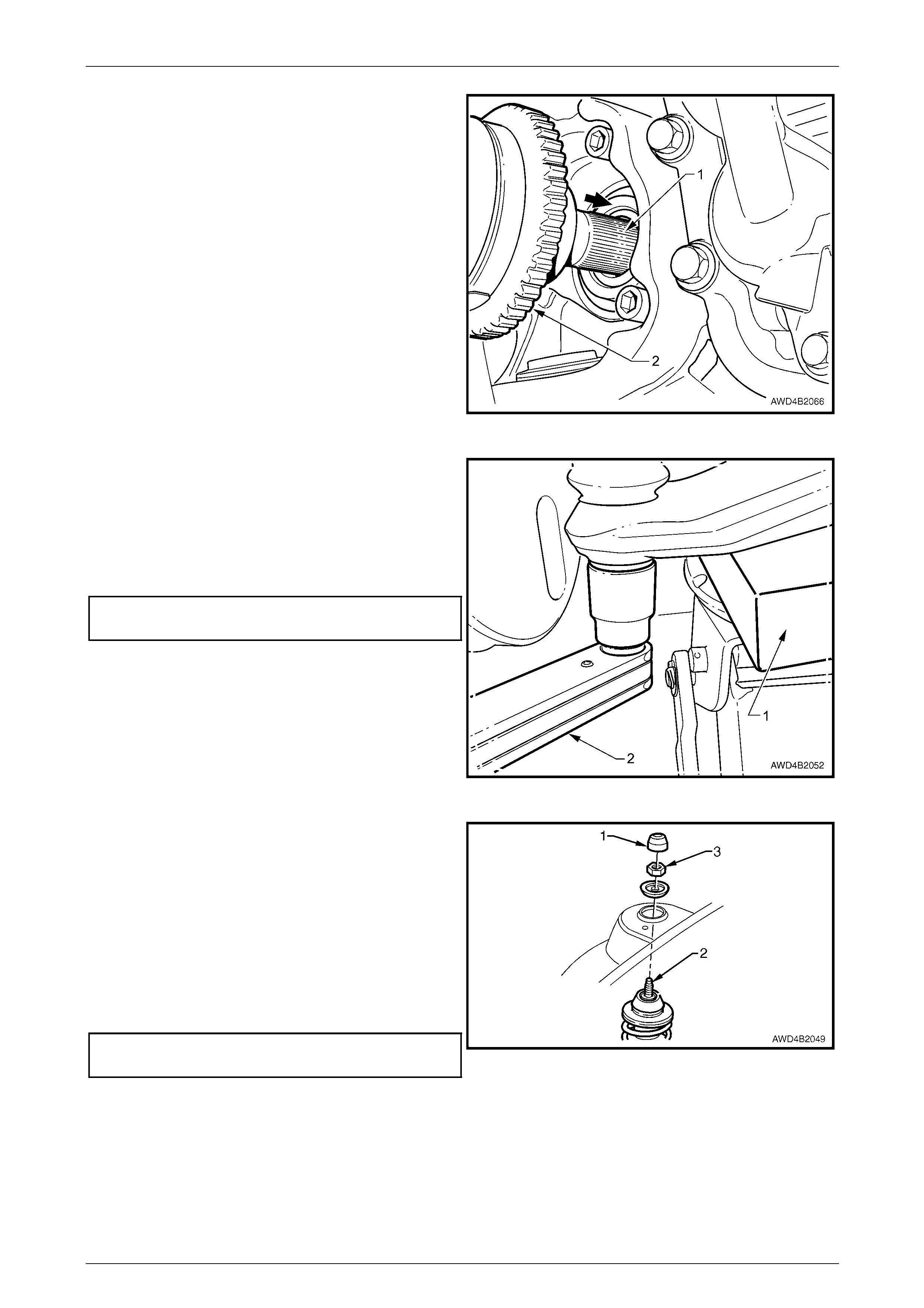
7 Lightly lubricate the outer driveshaft splines (1) with
the recommended final drive l ubricant, then pull
outward (arrow) by hand, on the wheel speed sensor
pulse ring (2) to allow the splined outer shaft to
engage with the front wheel hub. T ake care not to
damage the wheel speed sens or ring in the process.
NOTE
As the splined shaft is designed to be an
interference fit to the hub, use the old retaining
nut and washer to fully install the shaft through
the front wheel hub.
Figure 4B3 – 12
8 Support the front control arm with a floor jack fitted
with a block of wood (1) on the lifting pad. Raise the
jack until the front control arm is fully supported.
9 Reinstall the front control arm ball joint stud into the
front control arm, fit a new nut, then use a torque
wrench (2) to tighten to the correct torque
specification.
( ) Front control arm ball joint
stud nut torque specification ................................55 N.m
Figure 4B3 – 13
10 Raise the floor jack under the front control arm until
the strut is fully raised into the strut tower.
11 Hold the strut rod with a 10 mm socket and suitable
equipment, then fully remove the strut rod retaini ng nut
and discard.
12 Install a new strut rod retaining nut (3), then use a 10
mm socket to hold the strut rod (2) from turning.
13 Tighten the upper strut rod retaining n ut (3) to the
correct torque specification, using a 24 mm ring
spanner with a torque wrench attached.
( ) Upper strut locating plate
retaining nut torque specification .........................55 N.m
14 Reinstall the dust cover (1).
Figure 4B3 – 14
Front Final Drive, Bearing Housing & Driveshafts Page 4B3–14
Page 4B3-14
15 Install holding tool KM-468 to two of the wheel studs
and secure with two reversed wheel nuts. Support the
outer end of the holding tool on a safety stand (1).
16 Remove the old hub nut and washer. Reinstall the
washer with a new nut and tighten to the correct
torque specification.
( ) Front driveshaft outer
retaining nut torque
specification................ Stage 1 .........................130 N.m
Stage 2 ... Loos en nut until loose
Stage 3 .........................200 N.m
17 If it was the left driveshaft that was removed, check
the final drive lubricant level, topp ing up as required.
Refer to 2.1 Checking Final Drive Lubrica nt L evel, in
this Section.
18 Reinstall the road wheel, aligning the marks made
prior to removal and secure with attaching nuts. Figure 4B3 – 15
19 Remove the safety stands and lower vehicle.
20 Tighten road wheel attaching nuts to the correct torque specification, working in a ‘star’ pattern,
refer to Section 10 Wheels and T yres.
Road wheel attaching
nut torque specification............................110 – 140 N.m
21 Install the centre wheel nut cap.
22 Bounce the vehicle up and down several times to settle the suspension.
23 Check the wheel alignment, refer to 2.2 Wheel Alignment Checking and Adjustment in Section 3B Front
Suspension – AWD.
Front Final Drive, Bearing Housing & Driveshafts Page 4B3–15
Page 4B3-15
2.5 Driveshaft Outer Constant Velocity Joint
LT Section No. – 06-200
NOTE
Disassembly of the outer constant velocity joi nt is
not recommended. With normal handling, the
constant velocity joint balls will not be dislodged
but, should the joint become disassembled while
handling, then the assembl y must be repl aced.
NOTE
There are two service kits available for this outer
constant velocity joint:
• A Boot Kit comprising the boot, two boot
clamps and a retaining ring.
• A constant velocity Joint Kit, that includes the
Boot Kit, plus a new constant velocity joint
and lubricant of the correct type and quantity.
• For lubricant quantities, refer to
5 Specifications, in this Section.
Remove
1 Remove the driveshaft. Refer to 2.4 Driveshaft Assembly, in this Section.
2 Clean the outside of the assembly with suitable cleaning solvent before removing.
To reduce the possibility of boot damage
during the clamp removal process, it is
recommended that rag be placed over the
boot before using a screwdriver to release
clamp tension.
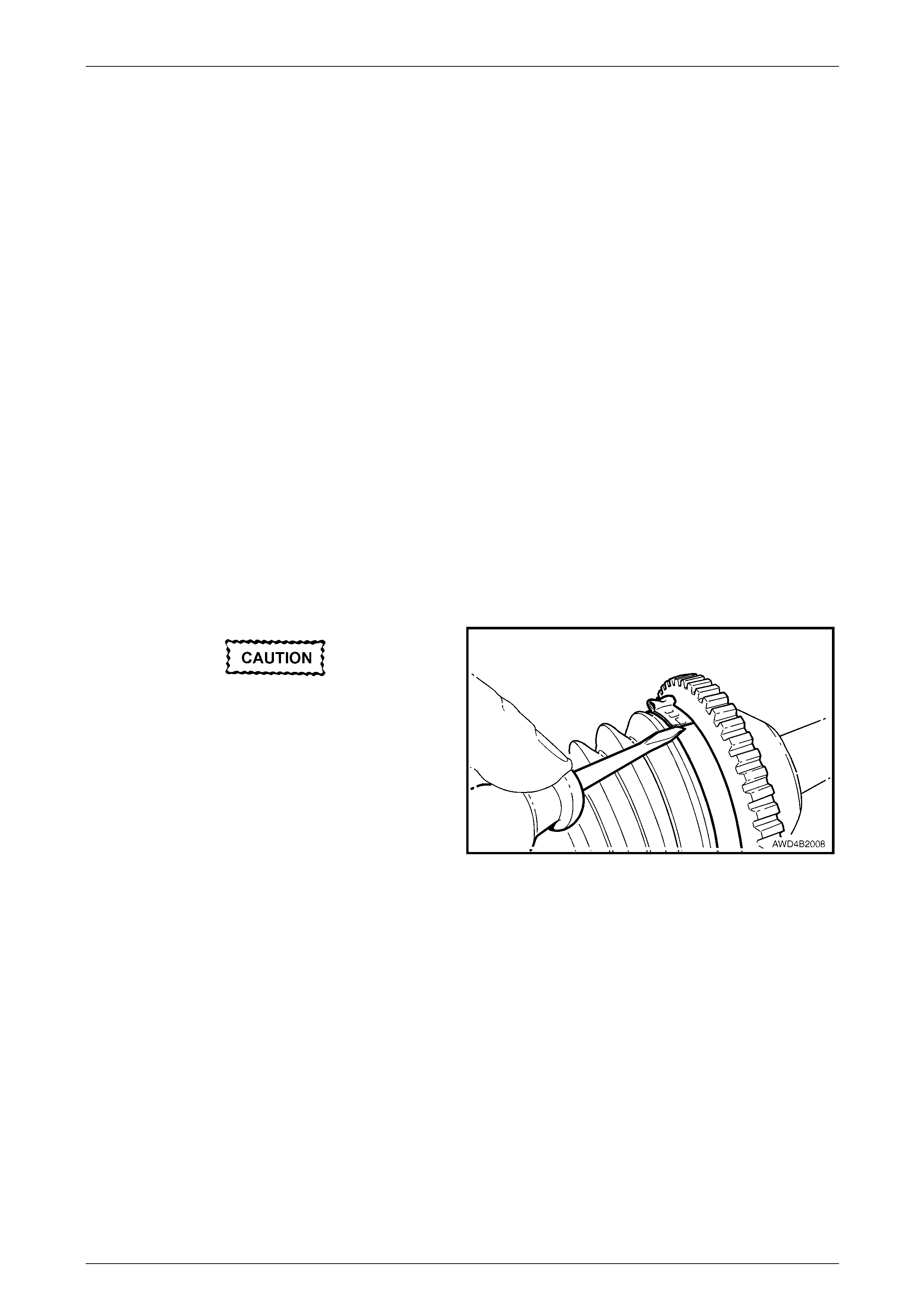
3 Using a small s c rewdriver or similar, lever the boot
clamp tang at the constant velocity joint (larger clamp)
sufficient to release the clamp tension. Disca rd the
removed clamp.
Figure 4B3 – 16
Front Final Drive, Bearing Housing & Driveshafts Page 4B3–16
Page 4B3-16
4 Push the boot back from the constant velocity joint and
back over the driveshaft.
5 Turn the constant velocity joint to maximum turn angle
and wipe excess grease from the inner race.
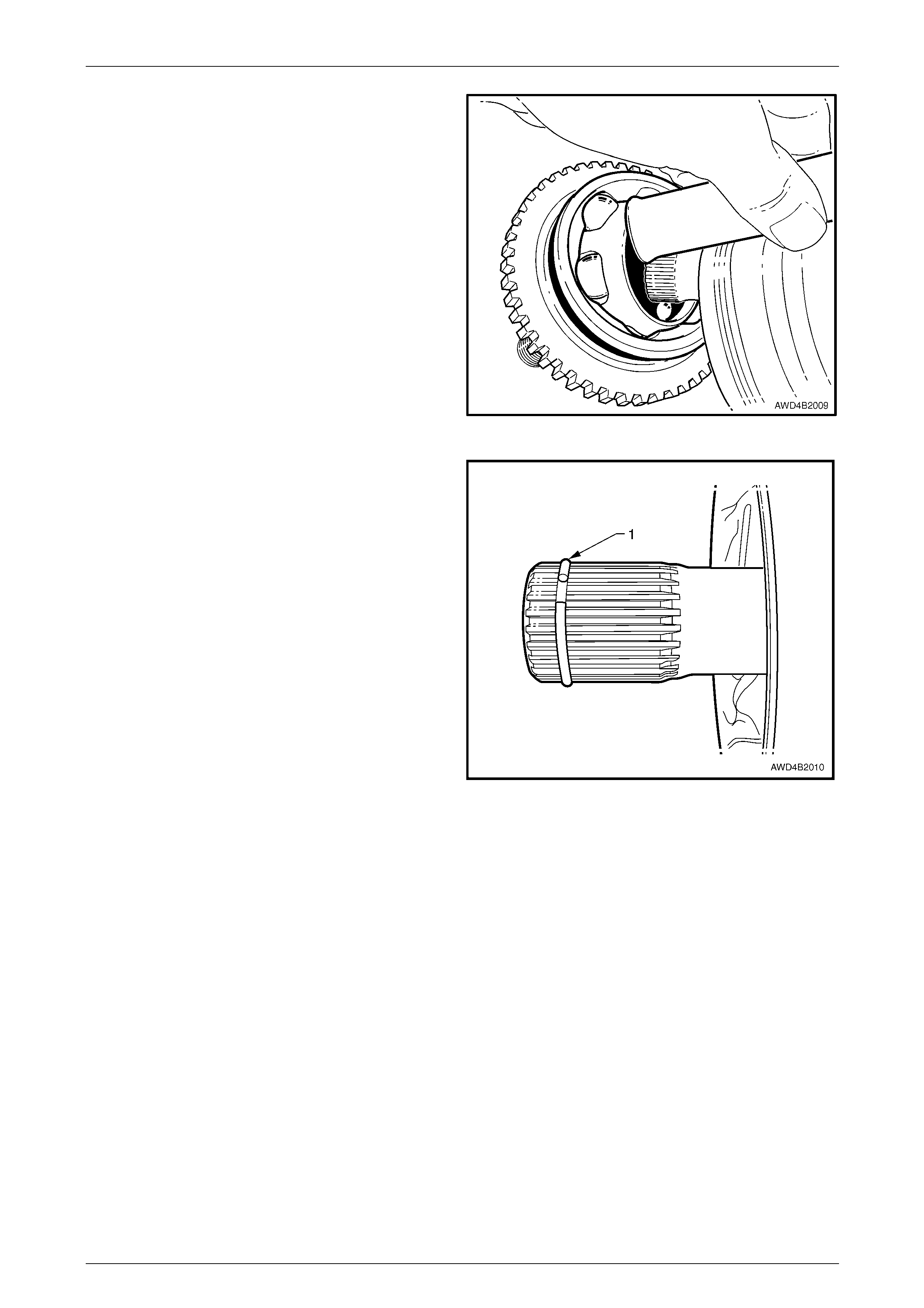
6 With the driveshaft held in a vice fitted with soft jaws,
use a brass drift on the inner race and hammer to
dislodge the snap ring on the end of the driveshaft and
remove the constant velocity joint.
Figure 4B3 – 17
7 Remove the snap ring (1) and discard, as it must be
replaced on reassembly of the outer const ant velocity
joint to the driveshaft.
8 Clean the driveshaft with suitable cleaning solvent an d
inspect the splines for damage.
Figure 4B3 – 18
9 Remove the small boot clamp from the driveshaft end of the boot and di scard.
10 Slide the boot from the driveshaft.
NOTE
If a constant velocity joint requires replacem ent, it
is strongly recommended that a new boot be
fitted.
Front Final Drive, Bearing Housing & Driveshafts Page 4B3–17
Page 4B3-17
Reinstall
1 Divide 155 gm of the specified grease into thirds. Apply one third into the new constant velocity joint, working into
the joint. Apply the remainder to the new boot.
2 Slide a new small clamp onto the driveshaft, then install the boot over the driveshaft, small end first. T ake care not
to damage the boot on the driveshaft splines during the installation pr ocess. Do not install any boot clamps at this
time.
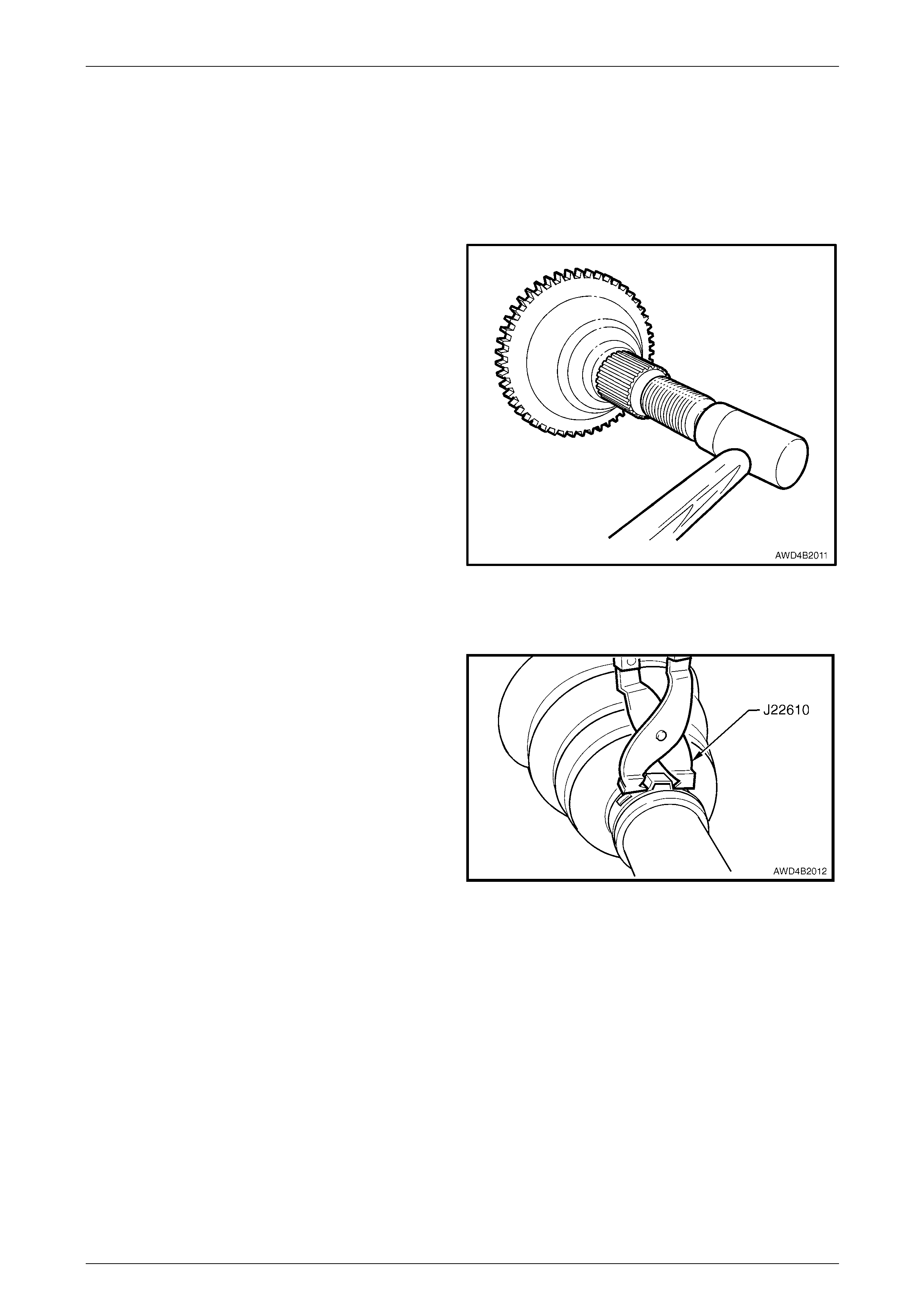
3 After checking that a NEW driveshaft snap ring is
installed and undamaged, install the ne w constant
velocity joint onto the driveshaft, using a plastic faced
hammer.
NOTE
To check for correct installation, tug on the
driveshaft in an attempt to dislodge it from the
constant velocity joint.
Figure 4B3 – 19
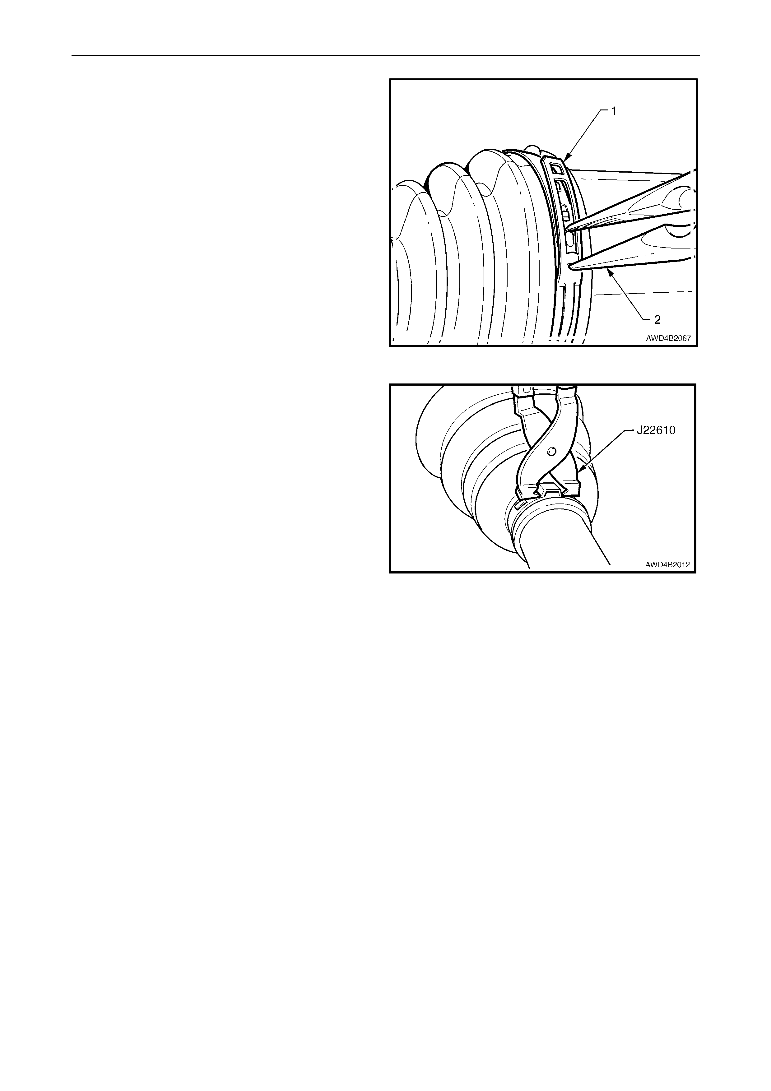
4 Install a new, large boot clam p to secure the boot to the constant velocity joint end, using T ool No. J22610. Load
clamp until the gap between the 'ears' is reduced to 1 – 2 mm.
5 Position the small end of the boot into the groove in
the driveshaft, then install the small clam p into position
in the boot groove.
6 Use Tool No. J226 10 to secure the boot, again until
the gap between the 'ears' is between 1 and 2 mm.
7 Reinstall the driveshaft to the vehicle. Refer to
2.4 Driveshaft Assembly in this Section.
Figure 4B3 – 20
Front Final Drive, Bearing Housing & Driveshafts Page 4B3–18
Page 4B3-18
2.6 Driveshaft Inner Tripot Joint
NOTE
There are two service kits available for the
driveshaft inner tripot joint:
• A Boot Kit comprising the boot, two boot
clamps, a slinger and a retaining ring.
• A constant velocity Joint Kit, that includes the
Boot Kit, plus a new constant velocity joint
and lubricant of the correct type and quantity.
• For lubricant quantities, refer to
5 Specifications, in this Section.
Disassemble
LT Section No. – 06-200
1 Remove the driveshaft. Refer to 2.4 Driveshaft Assembly, in this Section.
2 Clean the outside of the tripot assembly with suitable cleaning solvent before disassembly.
3 Clamp the driveshaft in a vice fitted with soft jaws.
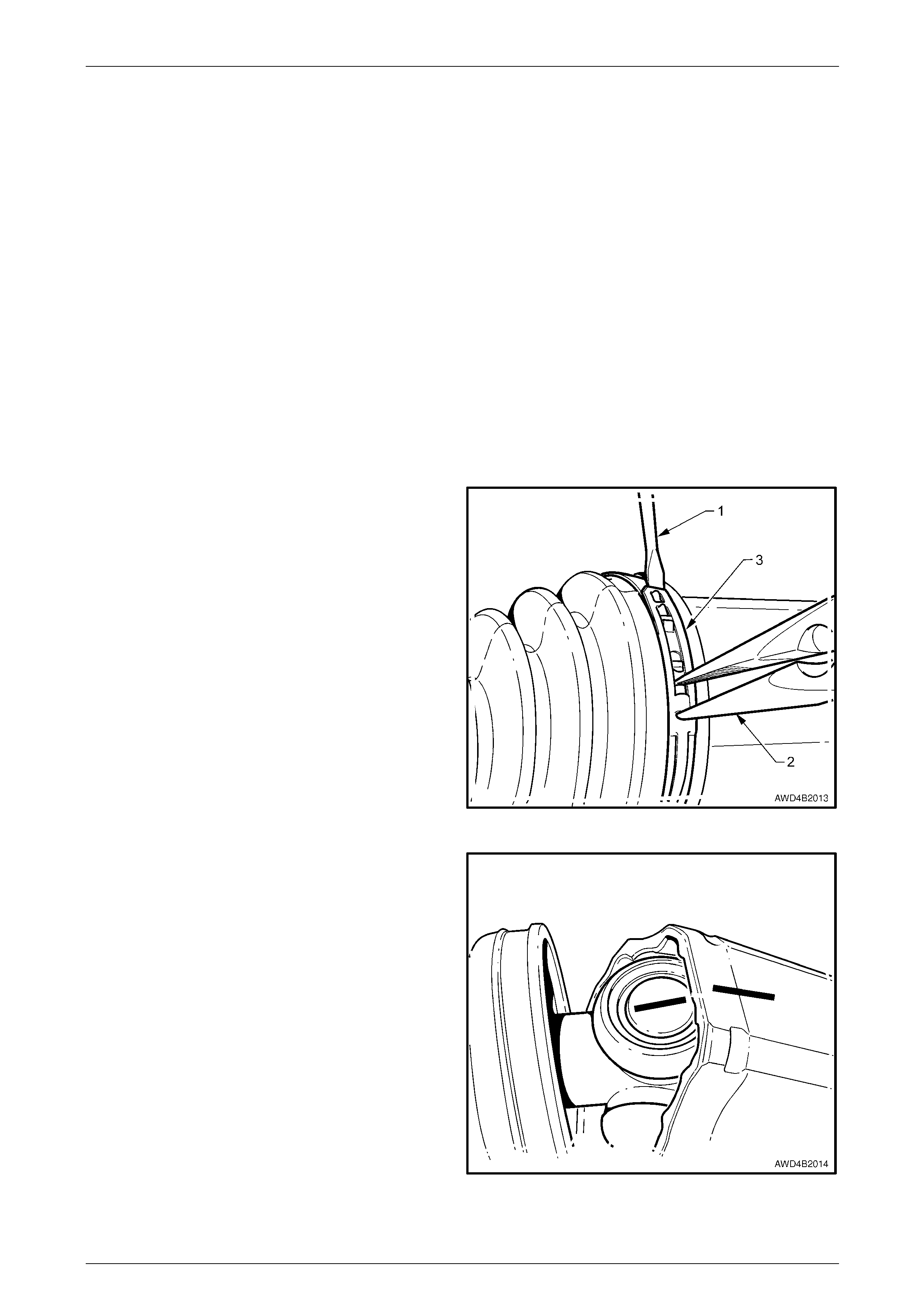
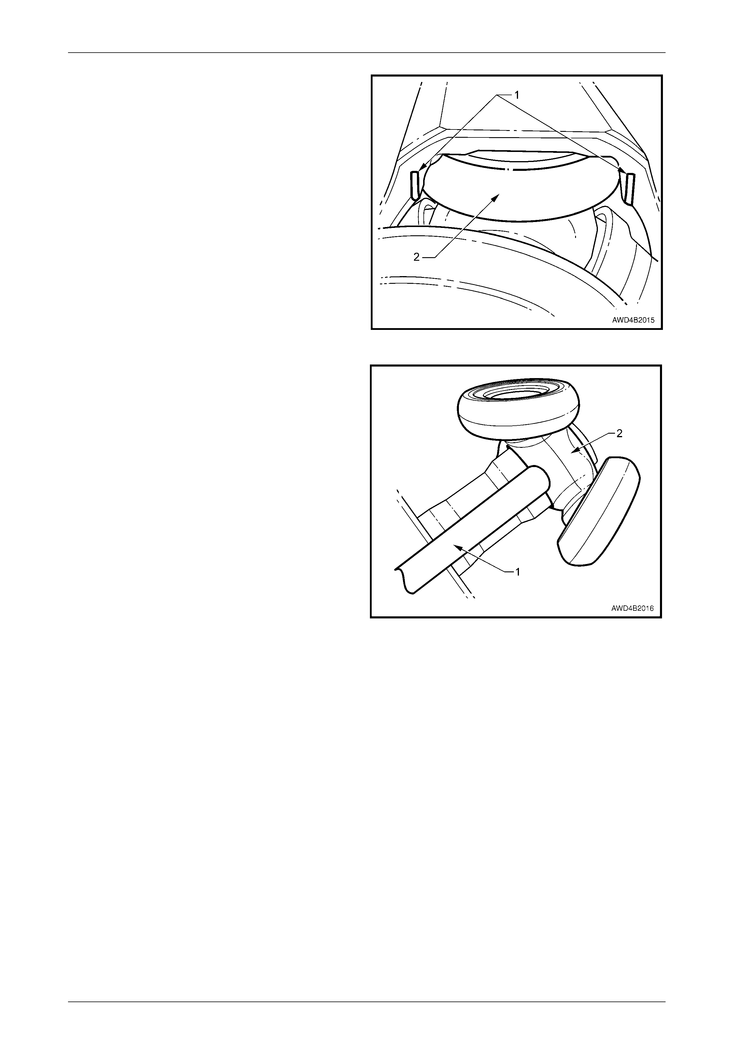
4 Using a small s c rewdriver (1) or similar, lever the boot
clamp tang at the constant velocity joint (larger clamp),
while using long nosed pl iers (2) to tension the clamp
(3). Once released, remove and discard the clamp (3).
5 Push the boot from the tripot joint ho using and back
over the driveshaft.
Figure 4B3 – 21
6 If the reason for disassembli ng the tripot joint is to
replace the boot only, wipe excess lubricant from the
tripot spider and use whiteout or similar, to mark the
relationship of the spider to the tripot housing.
NOTE
This is necessary to ensure that worn parts are
reassembled in their original positions.
Figure 4B3 – 22
Front Final Drive, Bearing Housing & Driveshafts Page 4B3–19
Page 4B3-19
NOTE
There may be some resistance to separating the
trunnions from the outer body because of
distortion (1) created for production purposes.
Removing one trunnion (2) at a time until the
three are released, will overc ome the pro blem.
Figure 4B3 – 23
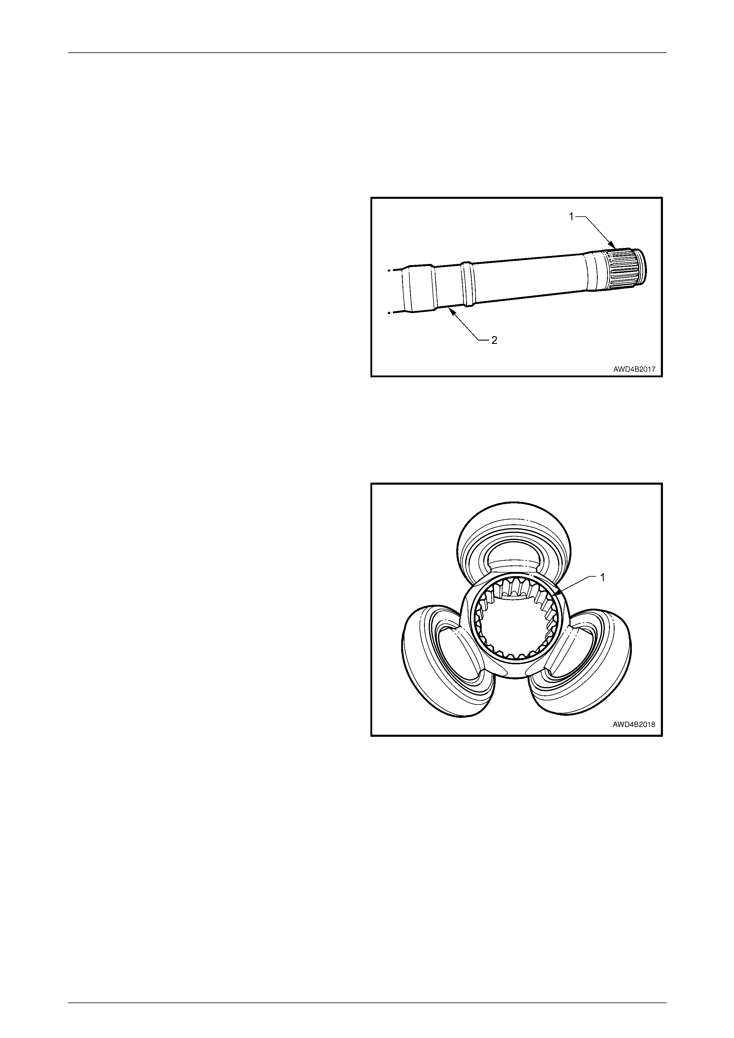
7 Using suitable circlip pliers, remove the circlip securing
the tripot spider to the driveshaft.
8 Remove the tripot spider and trunnion assembly (2)
from the driveshaft, using a brass drift (1) and hammer
on the spider as shown and not on one of the
trunnions.
NOTE
Provided excessive force is not used, the
trunnions will remain on the spider.
9 Remove the small boot clamp, then slide the boot from
the driveshaft. Discard the removed clamp.
Figure 4B3 – 24
Front Final Drive, Bearing Housing & Driveshafts Page 4B3–20
Page 4B3-20
Inspect
1 After cleaning components, check:
a. The tripot housing grooves for wear and/or scoring.
b Trunnions for excessive play or binding.
c Boot for cracks or other damage.
d The tripot and driveshaft splines (1) for wear or
damage.
NOTE
The groove (2) in the driveshaft is used to locate
the smaller end of the boot.
2 If any of the above conditions are found, then replace
the tripot assembly or the complete driveshaft.
Figure 4B3 – 25
Reassemble
1 Slide a NEW small clamp over the dr iveshaft, then slide the boot over the driveshaft splines, taking care not to
damage the boot on any sh arp edges. Do not apply any cl amps at this stage.
2 Reinstall the tripot spider and trunnions, noting the
following:
a The spider spline chamfer (1) faces inwards.
b Install the spider, using a tube or socket and a
plastic hammer.
c Retain the tripot spider usi ng a NEW circlip. Do
not over-stretch the circlip during installation.
Figure 4B3 – 26
3 Apply approximately 2/3 (140 g ± 5 grams) of the supplied lubricant to the inner half of the tripot hous ing and the
remainder (approximately 60 ± 5 grams) into the boot.
4 If reinstalling the orig inal tripot assembly (e.g. boot damage onl y), align the marks made before disassem bly and
carefully reinstall the trunnions into the tripot housing.
5 Gently stroke the driveshaft to the end of the housing to exude the grease aroun d the trunnions, then return the
spider to the mid-point position.
Front Final Drive, Bearing Housing & Driveshafts Page 4B3–21
Page 4B3-21
6 Slide the lar ger end of the boot over the end of the
tripot joint, then secure with a new clamp (1) ,
tightening with long nosed pliers (2) until the clamp
engages with the last of the retaining barbs.
Figure 4B3 – 27
7 Locate the small boot en d into driveshaft groove, then
install the new, small boot clamp.
8 After checking that the boot is not twisted, tighten the
small boot clamp, using clamp pliers, Tool No. J22612,
until the distance between the clamp 'ears' is between
1 to 2 mm.
9 Plunge the tripot joint in a nd out to check that there
are no leaks.
Figure 4B3 – 28
10 Reinstall the driveshaft. Refer to 2.4 Driveshaft Assembly, in this Section.
Front Final Drive, Bearing Housing & Driveshafts Page 4B3–22
Page 4B3-22
2.7 Bearing Housing/Final Drive Carrier
Outer Oil Seal
LT Section No. – 06-200
NOTE
If the bearing housing or front final drive
assembly, inner oil seal fails, then the respective
assembly will need to be removed from the
vehicle to effect repairs. Refer to
3.1 Bearing Housing Assembly, Remove or
3.2 Front Final Drive, Remove in this Section.
Replace
If the seal failure occurred at the outer final drive
location, drain the lubricant into a suitable
container, before proceeding. Refer to
2.2 Changing/Flushing Final Drive Lubricant, in
this Section.
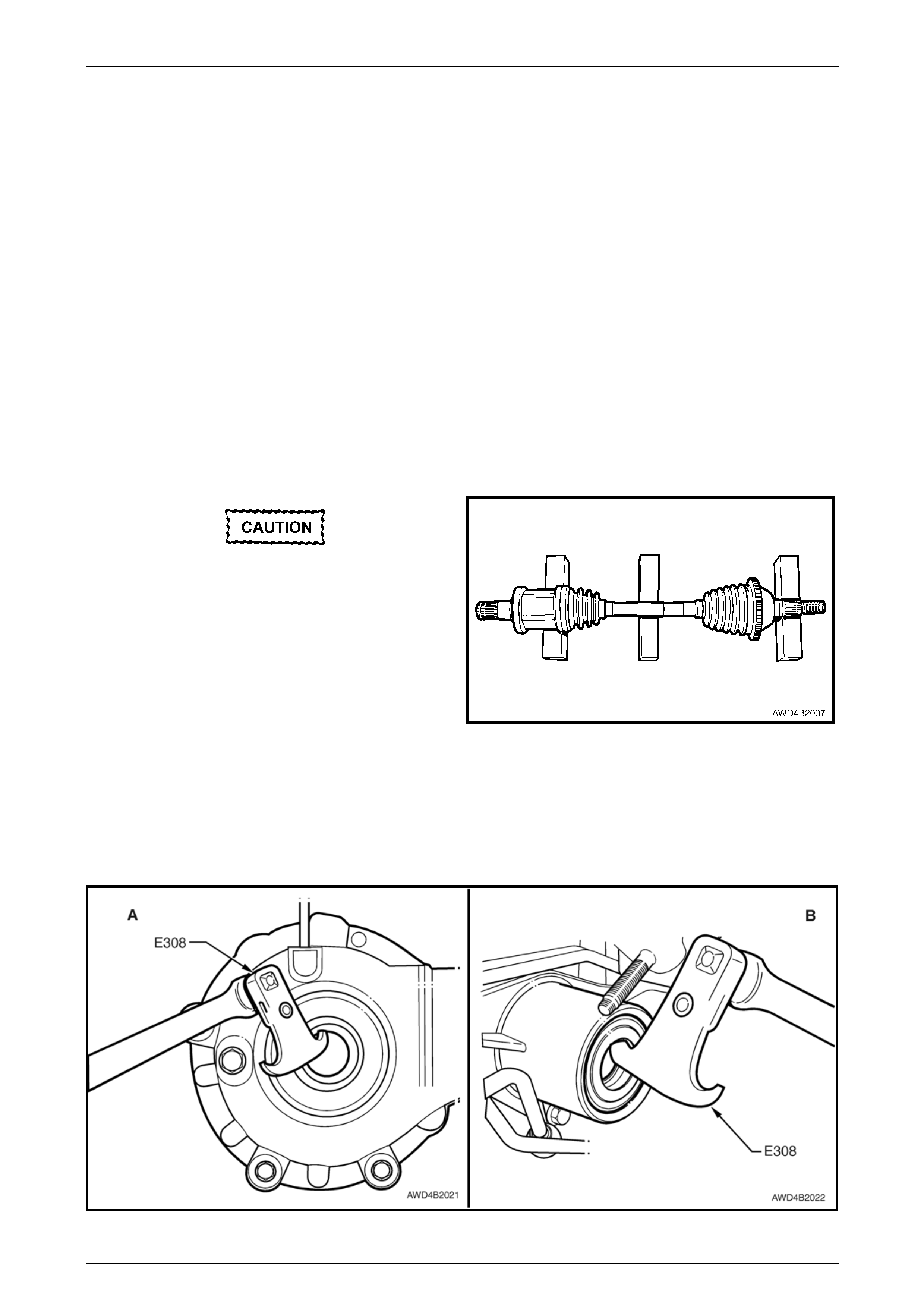
• The removed driveshaft must be handled
with care. Do not rest th e shaft or bellows
for any longer than necessary. Shaft is
not to be allowed to hang free on one end.
• Driveshaft joint deflection should be kept
to a minimum by resting the driveshaft on
three wooden blo cks, as sh own.
1 Remove the driv eshaft on the side where the seal
failure has occurred. Refer to 2.4 Driveshaft Assembly,
in this Section.
Figure 4B3 – 29
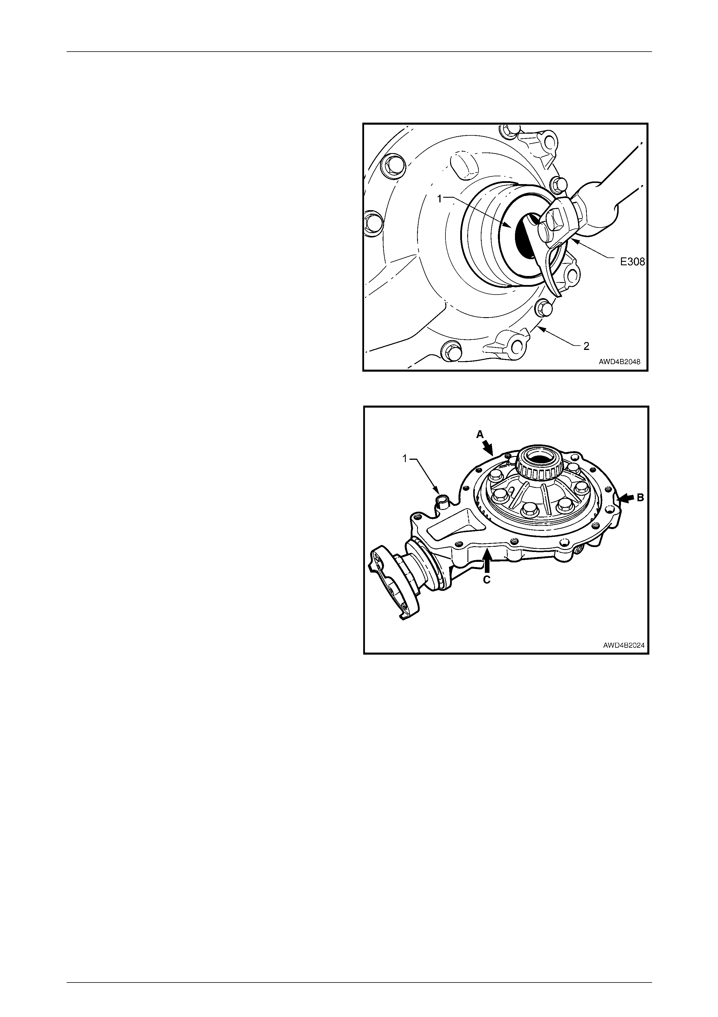
2 Using a seal removal tool such as E308 or commercial equivalent, remove the failed seal from either the front final
drive ('A') or the driveshaft bearing support housing ('B'), refer to Figure 4B 3-30.
NOTE
The engine exhaust pipe is sho wn removed in ' B',
to more clearly show the oil seal removal.
Figure 4B3 – 30
Front Final Drive, Bearing Housing & Driveshafts Page 4B3–23
Page 4B3-23
3 Carefully ins pe ct the seal running surface of the driveshaft for evidence of wear, nicks or scratches. If badly worn or
the damage is not repairable, then the particular tripot joint must be replaced.
Refer to 2.6 Driveshaft Inner Tripot Joint, in this Section.
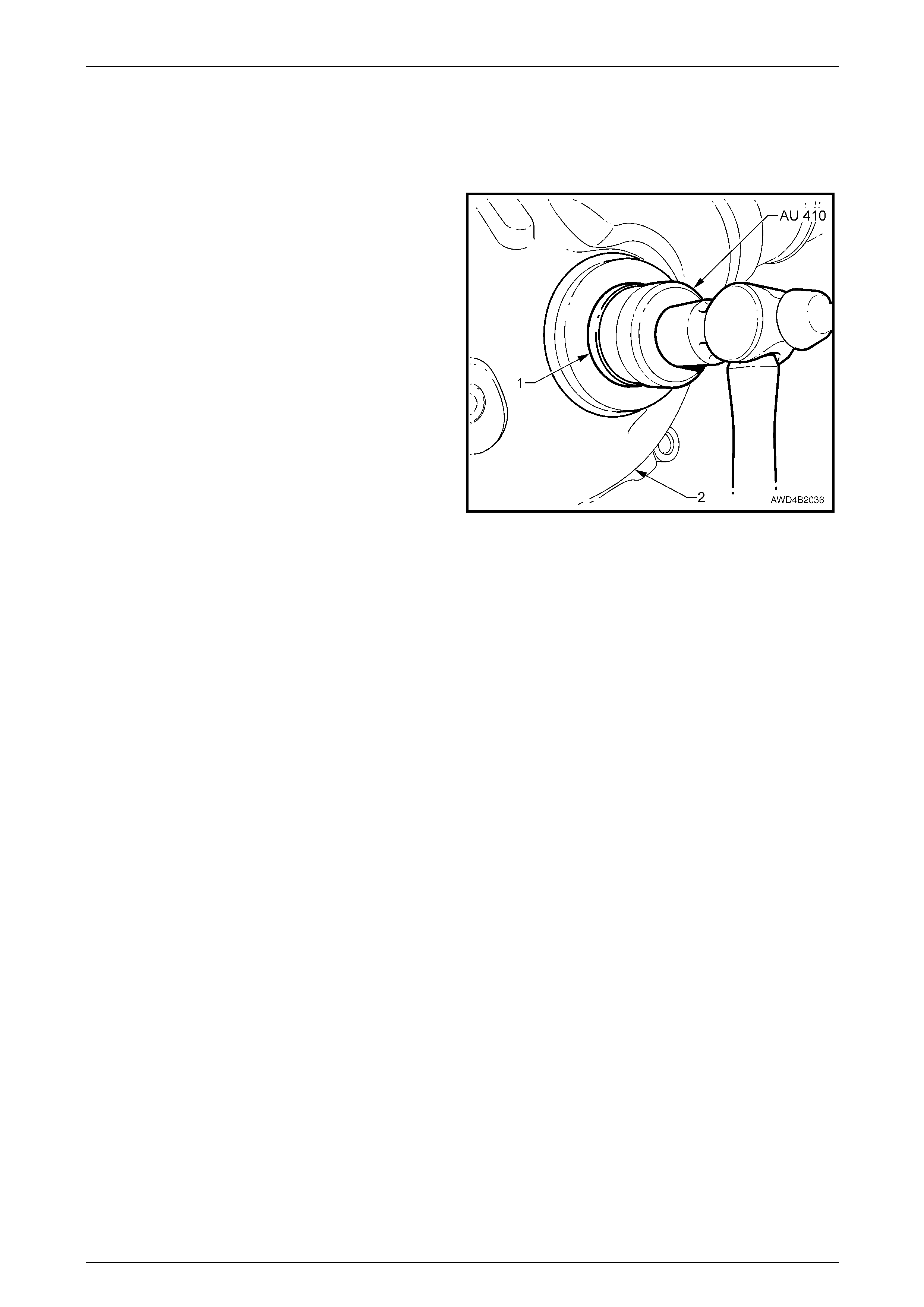
4 Before installing a new oil seal, lightly lubricate with Mobilgrease XHP 222, with the recesses between the seal lips
being filled to approximately 50%.
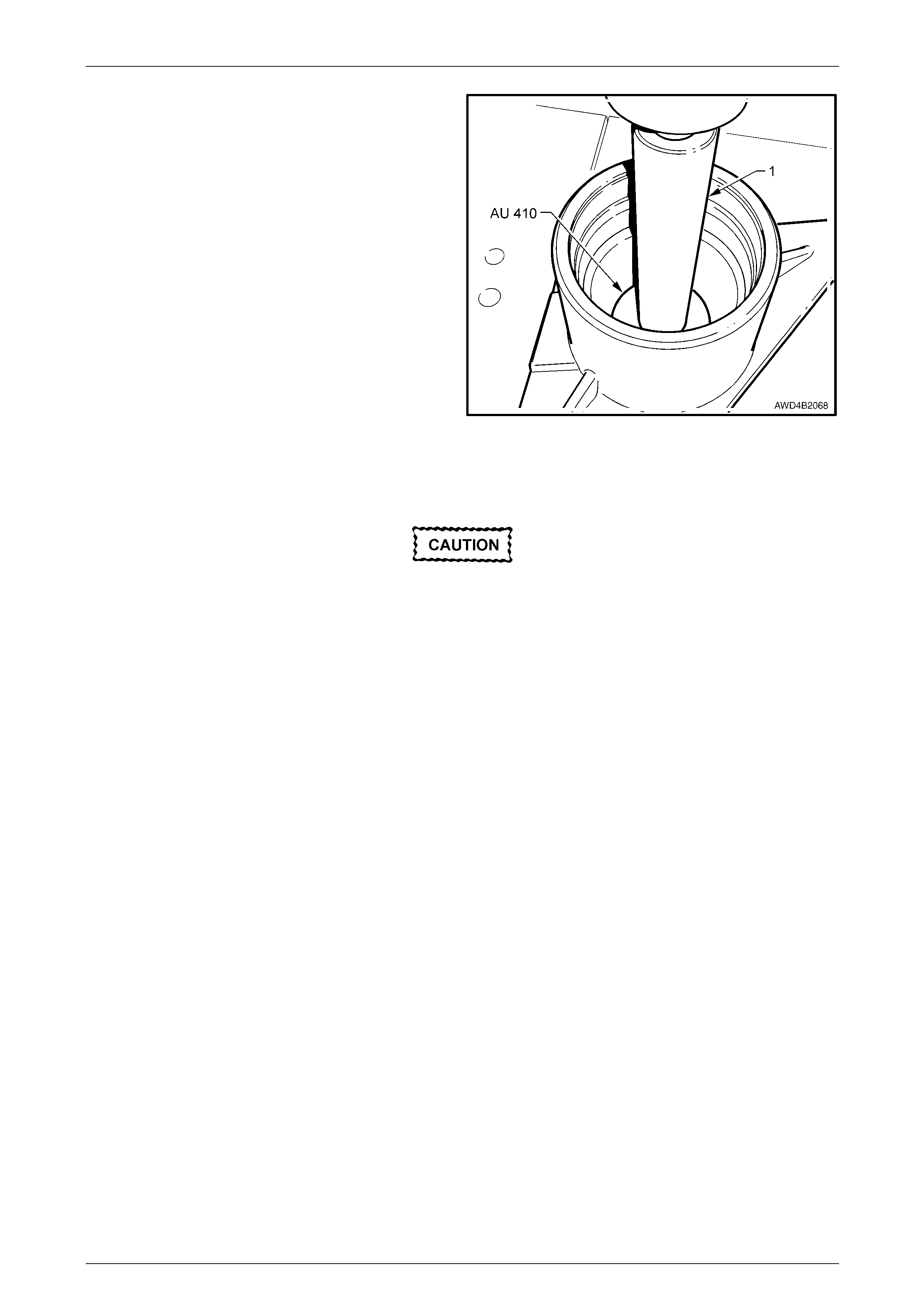
5 Using seal i nstaller AU 410, install the oil seal (1) to
the final drive carrier housing (2) until fully seated.
NOTE
While the final drive is shown, use Tool No.
J 21426 to install the new seal to the support
bearing housing.
6 Reinstall the driveshaft.
Refer to 2.4 Driveshaft Assembly, in this Section.
7 If required, with the vehic le on level ground, fill the
front final drive with the recommended lu bricant.
Refer to 2.2 Changing/Flushi ng Final Drive Lubricant,
in this Section.
Figure 4B3 – 31

Front Final Drive, Bearing Housing & Driveshafts Page 4B3–24
Page 4B3-24
2.8 Pinion Oil Seal
LT Section No. – 05-290
Replace
Apart from the fact that it is the front propeller shaft that needs to be removed (rather than the rear), the procedure for the
front final drive pinion oil seal replacement is the same as that described for the rear final drive assembly.
Refer to Section 4C2 Front Propeller Shaft & Universal Joints and Section 4B1 Rear Final Drive & Driveshafts.

Front Final Drive, Bearing Housing & Driveshafts Page 4B3–25
Page 4B3-25
2.9 Pinion Flange
LT Section No. – 05-290
Replace
Apart from the fact that it is the front propeller shaft that needs to be removed (rather than the rear), the procedure for the
front final drive pinion flange replacement is the same as that described for the rear final drive assembly.
Refer to Section 4C2 Front Propeller Shaft & Universal Joints and Section 4B1 Rear Final Drive & Driveshafts.
Front Final Drive, Bearing Housing & Driveshafts Page 4B3–26
Page 4B3-26
3 Major Service Operations
ATTENTION
All fasteners are important attaching parts as they affect the performance of vital components and/or could
result in major repair expense. W h ere specified in this section, fasteners MUST be rep laced with parts of the
same part number or an approved equivalent. Do not use fasten ers of an inferior quality or substitute desig n.
Torque values must be used as specified during reassembly to ensure proper retention of all components.
Throughout this section, fastener torque wrench specifications may be accompanied with the following
identification marks:
Fasteners must be replaced after loosening.
Vehicle must be at curb height before final tightening.
Fasteners either have micro encapsulated sealant applied or incorporate a mechanic al thread lock and
should only be re-used once. If in doubt, replacement is recommended.
If one of these identification marks is present alongside a fastener torque wrench specification, the
recommendation regarding that fastener must be adhered to.
3.1 Bearing Housing Assembly
LT Section No. – 06-200
Remove
1 Remove the right driveshaft. Refer to 2.4 Driveshaft Assembly, Remove, in this Section.
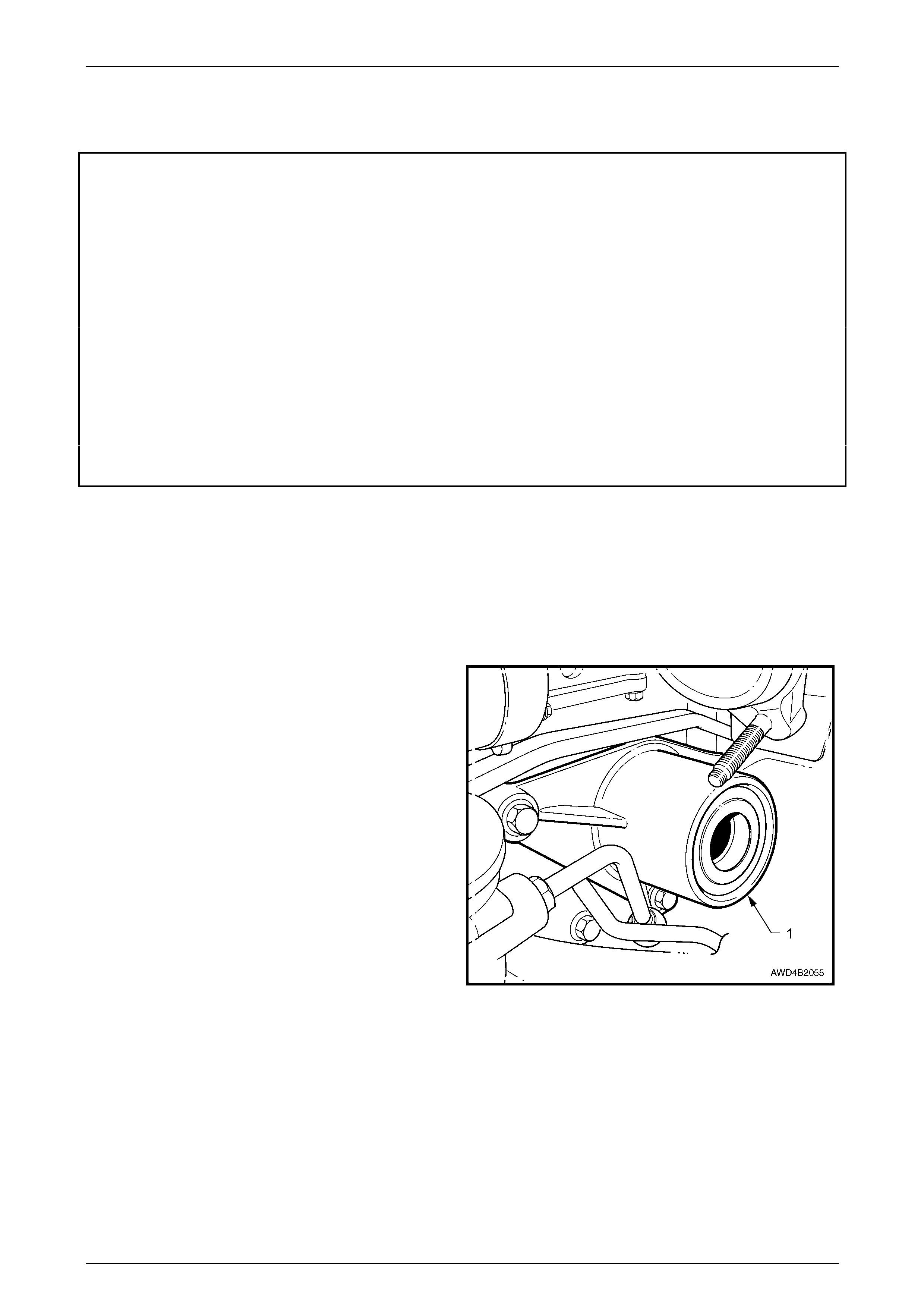
2 Loosen the three bolts securing the bearing housing
assembly (1) to the oil pan. Remove the lo wer and
rear bolts.
NOTE
The right side exhaust pipe is only shown
removed to more clearly show the support
bearing location and mo unting.
3 For the V6 engine, remov e all three bolts.
NOTE
While the front bolt cannot be removed at this
stage, it can be fully unscrewed.
GEN III V8 Engine
4 To fully remove the third bolt, it will be necessary to
raise the engine. Working from under the vehicle,
remove the 18 mm nuts securing both front engine
mounts to the crossmember cradle, using a deep
socket and suitable socket equipment.
5 Remove c ylind er No. 2 spark plug lead by first t wisting
the boot to break the seal, then pull on the boot, taking
care not to pull on the lead itself.
6 Using a deep 18 mm socket, universal joint and
suitable socket equipment, ins erted between the front
two exhaust manifold branches, engage with, then
remove the upper, right hand engine mount nut.
Figure 4B3 – 32
Front Final Drive, Bearing Housing & Driveshafts Page 4B3–27
Page 4B3-27
7 Raise the engine enough to allow the removal of the third b earing housing assembly retai nin g bolt. Once removed,
lower the engine back onto the mounts.
NOTE
Lowering the engine is necessary to achieve
optimum clearances for the bearing housing
assembly removal.
All AWD
8 Remove the bearing housing assembly from the engin e oil pan, rotating the assembly to provide sufficient
clearance.
Disassemble
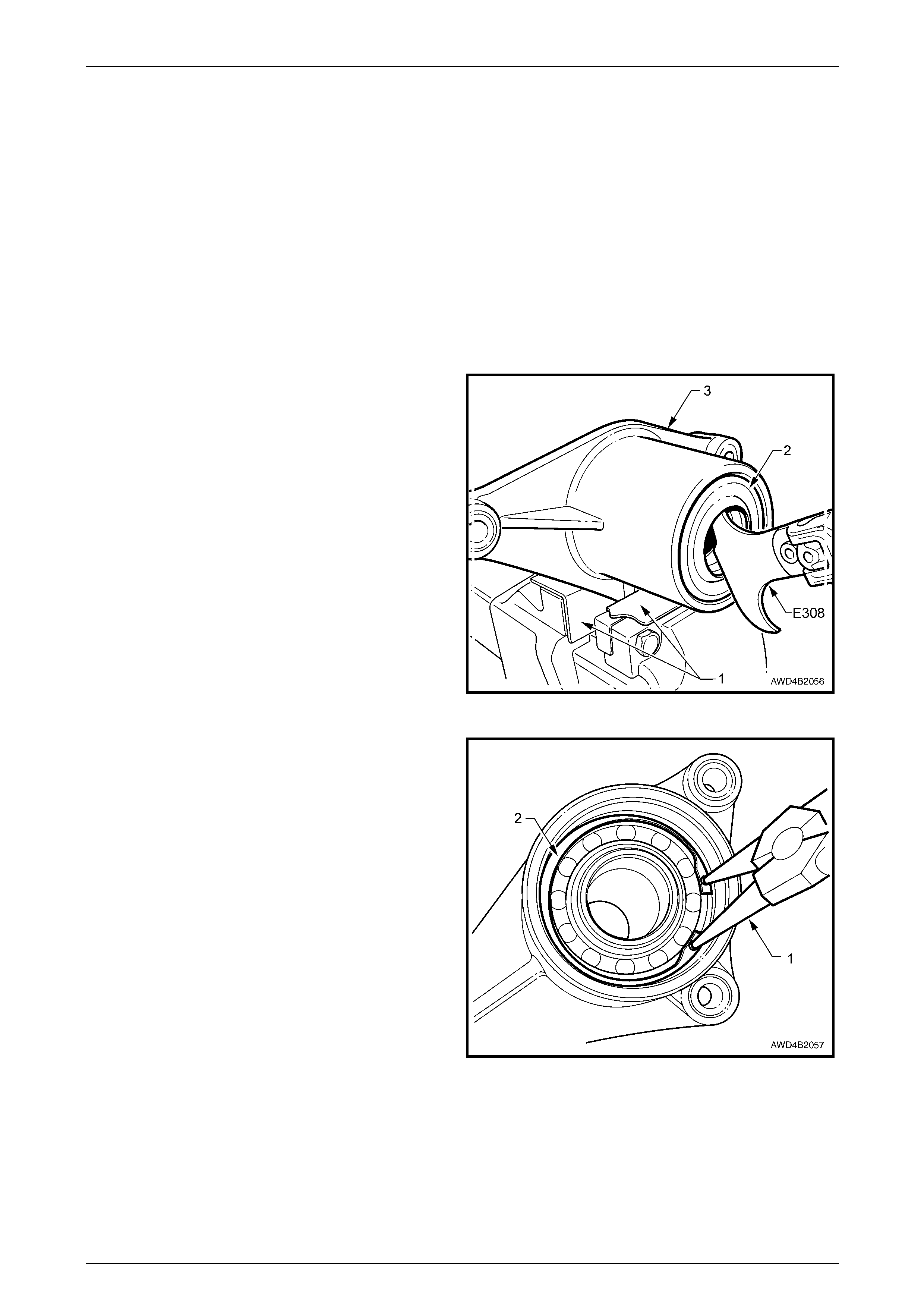
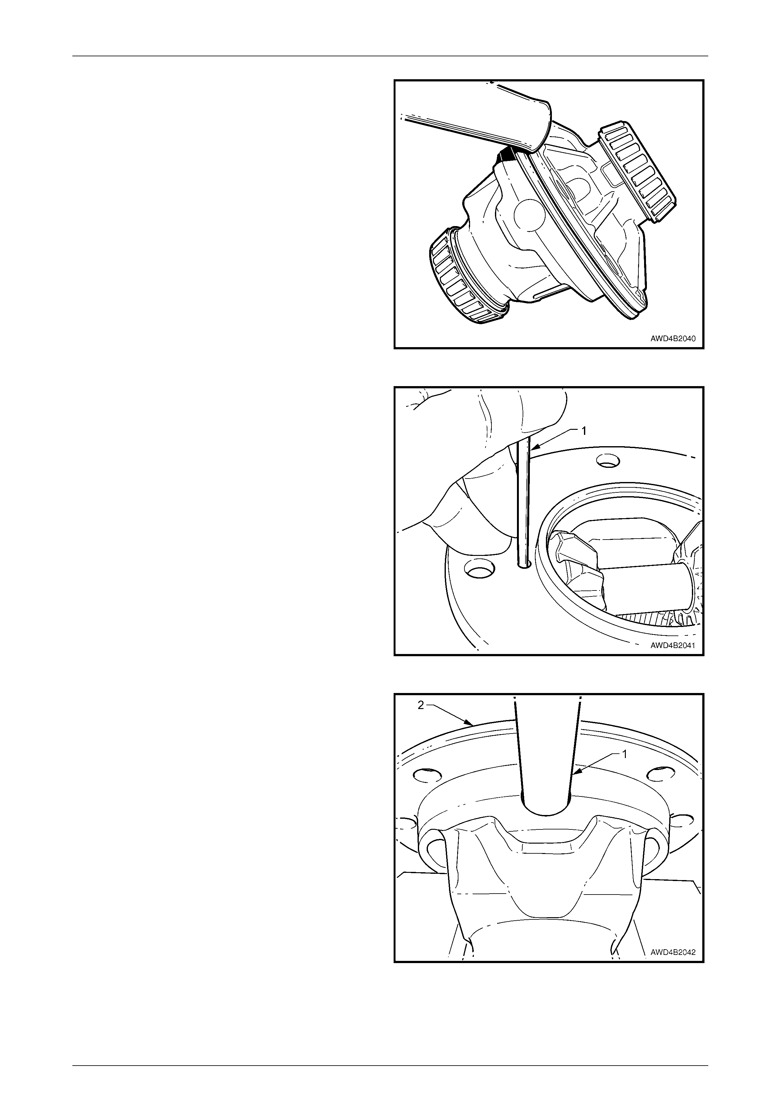
1 With the bearin g housing supported in a vice fitted with
soft jaws (1), use seal remover E308 or a commercial
equivalent, to remove the outer oil seal (2) from the
support bearing housing (3).
Figure 4B3 – 33
2 Using suitable circlip pliers (1), remove the outer
bearing retaining circlip (2).
Figure 4B3 – 34
Front Final Drive, Bearing Housing & Driveshafts Page 4B3–28
Page 4B3-28
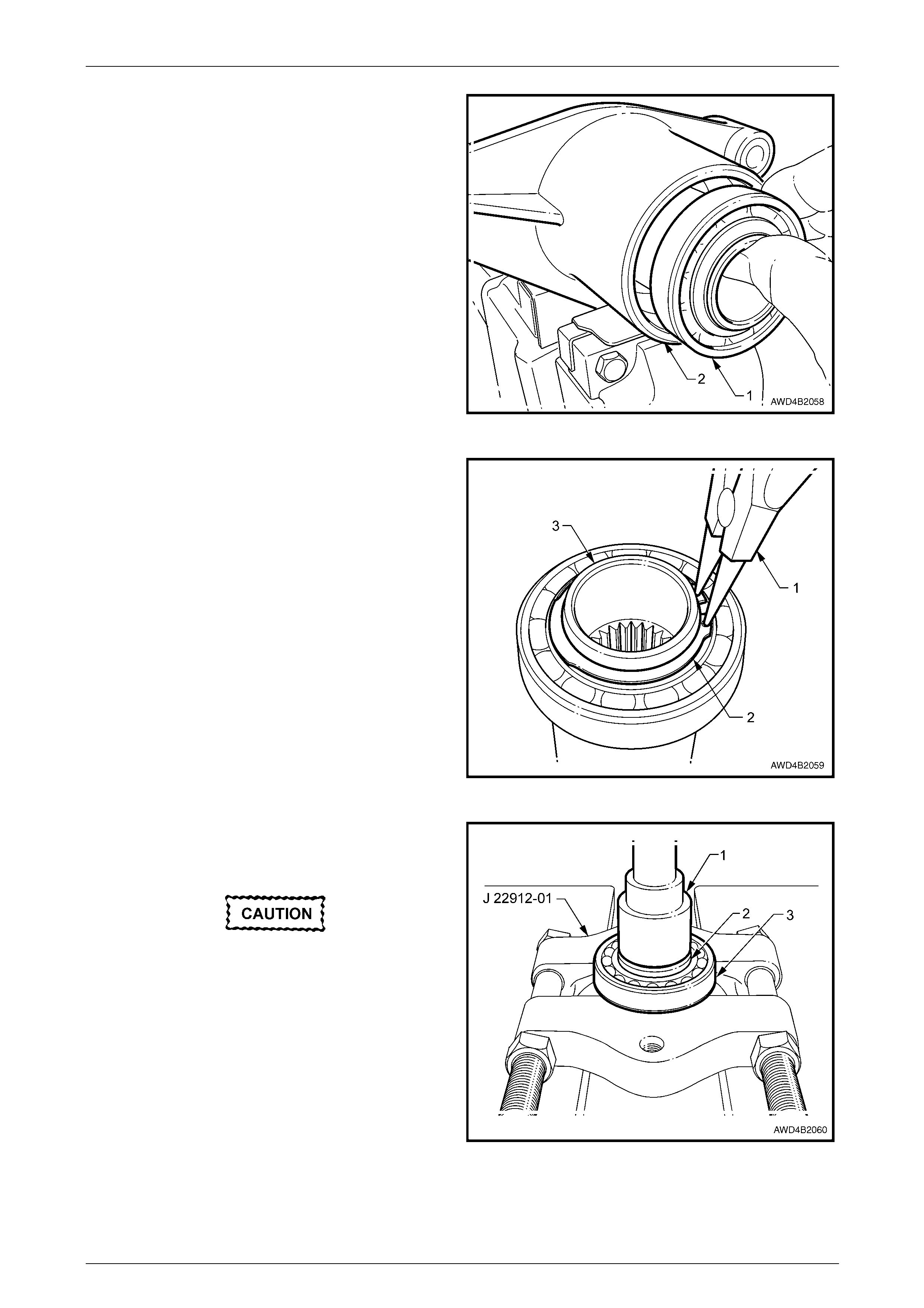
3 Slide the conn ecting sleeve and outer ball b earing
race (1) from the housing (2).
NOTE
It may be necessary to bump the housing on a
piece of wood to dislodge the bearing/sleeve
assembly.
4 Remove the O-ring seal from the inner end of the
connecting sleeve and discard.
Figure 4B3 – 35
5 Using suitable circlip pliers (1), remove the ball
bearing retaini ng circlip (2) from the connecting sleeve
(3).
Figure 4B3 – 36
6 Using a drift/tube/socket (1) with an OD of 38 mm and
press plates J22912-01 or equ ivalent, press the
connecting sleeve (2) from the outer ball bearing (3).
• Do not allow the connecting sleeve to
drop to the floor.
• Discard the bearing after removal as the
ball bearings may have been damaged in
the removal process.
Figure 4B3 – 37
Front Final Drive, Bearing Housing & Driveshafts Page 4B3–29
Page 4B3-29
7 Support the bearin g housing over press plates, then
use AU 410 and a drift (1) to press the needle roller
bearing and inner oil seal from the housing. Discard
the removed oil seal and needle roller bearing.
Figure 4B3 – 38
Inspect
Wear eye protection, to avoid personal injury.
1 Wash all components in a suitable solvent and blow dry.
2 Check for spline wear and/or damage in the connecting sleeve and for excess wear at both seal contact or roller
bearing areas. Repl ace the sleeve if damage/wear is detected.
3 Check the housing for cracks or other dam age. Also check that neither bearing is a loose f it in the housing. While
the outer ball bearing is a sliding fit, it should not be loose. If excess clearance or damage is determined, replace
the housing.
Front Final Drive, Bearing Housing & Driveshafts Page 4B3–30
Page 4B3-30
Reassemble
1 Pack a NEW needle rol ler bearing with Mobilgrease
XHP 222 and press into the housing (1) using Tool AU
410 and a suitable drift (2).
NOTE
There is no machined flange to limit the
installation depth of the needle roller bearing.
Therefore, the needle roller bearing should be
installed to a depth of 15 mm from the end face
of the housing (dimensio n ' A ').
Figure 4B3 – 39
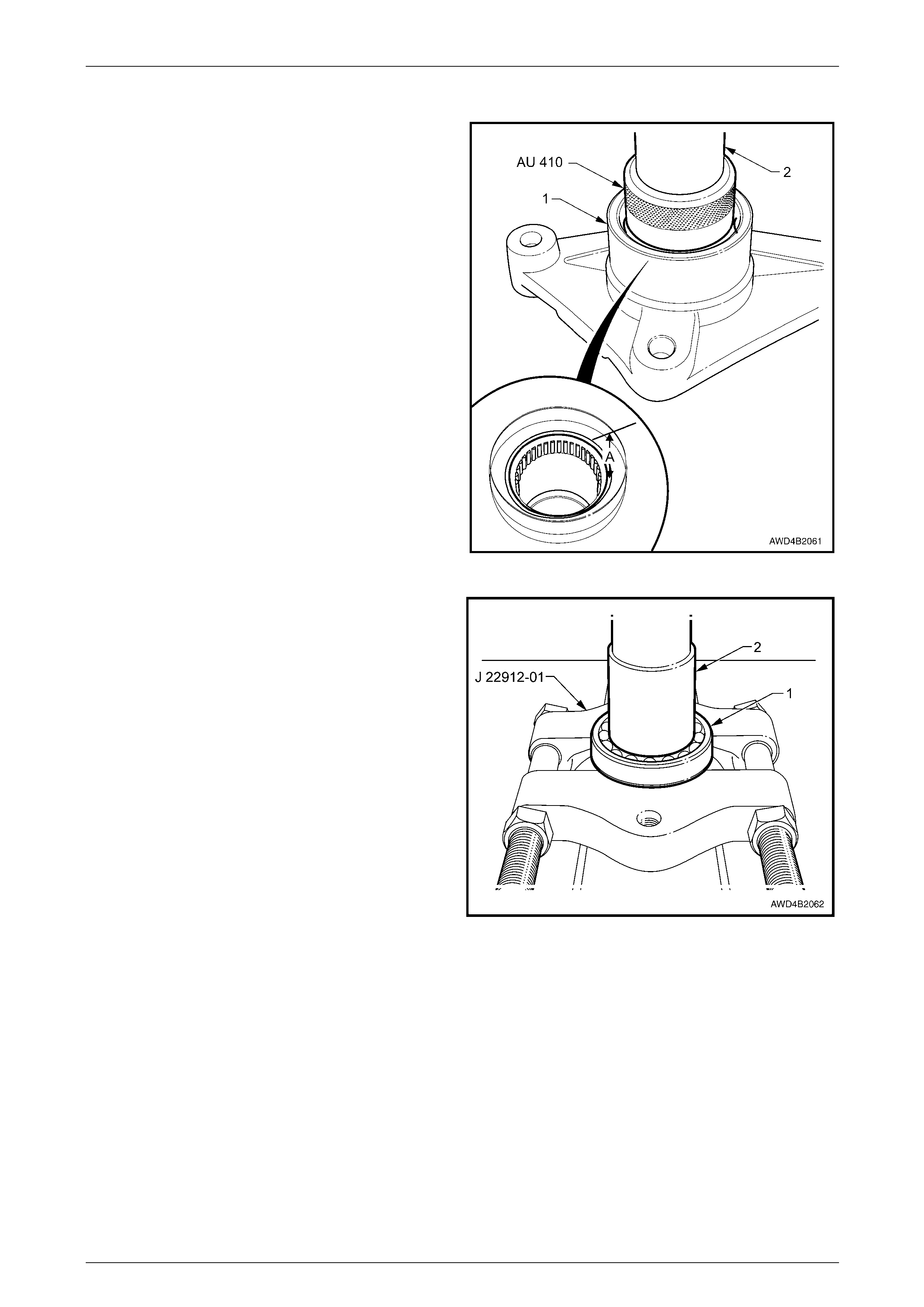
2 Pack the ball bearing (1) with Mobilgrease XHP 222
and press the connecting sle eve (2) into th e bearing,
using Tool J22912-01 that has previously been
adjusted to a loose fit over the connecting shaft. With
the flat side of the press plates against the bearing,
the press load will be taken on the inner race.
3 Install a new bearing retaining circlip, using suitable
circlip pliers.
4 Smear a new O-ring with Mobilgrease XHP 222 and
install into the needle roll er end of the connecting
sleeve.
5 Pack 30 – 50% of the bearing housing recess volume
with Mobilgrease XHP 222 (approximately 9 grams).
Figure 4B3 – 40
Front Final Drive, Bearing Housing & Driveshafts Page 4B3–31
Page 4B3-31
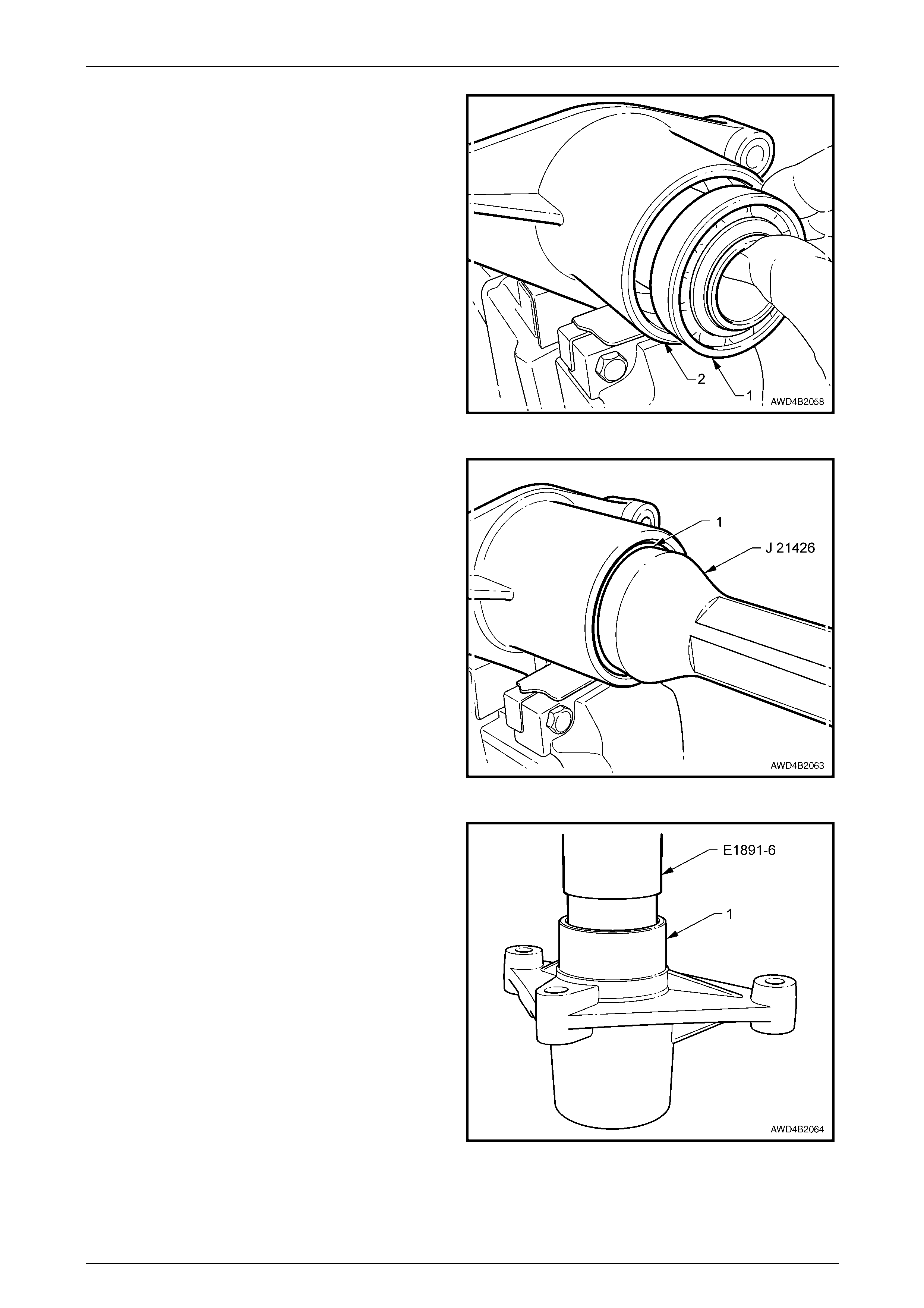
6 Slide the connecting sleeve and ball bearing (1) into
the bearing housing (2), seati ng with a plastic
hammer.
7 Install a new bearing to housing retaining cir c lip, using
suitable circlip pliers.
Figure 4B3 – 41
8 Before installing new oil seals, lubricate with
Mobilgrease XHP 222, with the recesses between the
seal lips being filled to approximately 50%.
9 Install the outer seal (1), using seal installer J 21426
until the seal is installed, flush with the end of the
housing.
Figure 4B3 – 42
10 Install the inner seal using sleeve E18 91-6 (also
released as 3A8-6), ensur ing that the seal is square to
the housing and installed until the outer seal surface is
flush with the housing (1).
Figure 4B3 – 43

Front Final Drive, Bearing Housing & Driveshafts Page 4B3–32
Page 4B3-32
Reinstall
Reinstallation is the reverse of the removal procedure except for the items detailed here.
1 Ensure that the splines of the intercon necting shaft are lubricated with Mobilgrease XHP 222, then engage the
shaft splines with those in the connecting sle eve.
2 Slide the housing assembly into the interconnecting shaft a nd rotate to install until the housing flan ges contact the
engine oil pan.
NOTE
Insert the front bolt into the housing before
installing the housing into the vehicle.
3 Reinstall the th ree housing retaining bolts, then tighten to the correct torque specification.
Bearing housing to engine oil pan
retaining bolt torque specification.........................45 N.m
NOTE
On GEN III V8 engined vehicles, the engine must
be raised to allow clearance between the right
side engine mount and the bearing housing,
before installing the front bolt.
4 Lower the engi ne, ensuring that the heat shields are each located correctly on their locating pins.
5 Ensure that the inner splin es of the right side driveshaft are lubricated with Mobilgre ase XHP 222, then reinstall the
driveshaft. Refer to 2.4 Driveshaft Assembly, Reinstall, in this Section.
6 Install NEW engin e mounti ng nuts to the engine mountings and tig hten to the correct torq ue specification.
Engine mount retaining nut (u pper
and lower) torque specification ............................80 N.m
7 On GEN III V8 engined vehicles, reinstall the spark plug lead to cylinder No. 2.
Front Final Drive, Bearing Housing & Driveshafts Page 4B3–33
Page 4B3-33
3.2 Front Final Drive Assembly
LT Section No. – 05-250
Remove
GEN III V8 Engine
1 Remove the air cleaner assembly. Refer to Section 6C3-3 Service Operations.
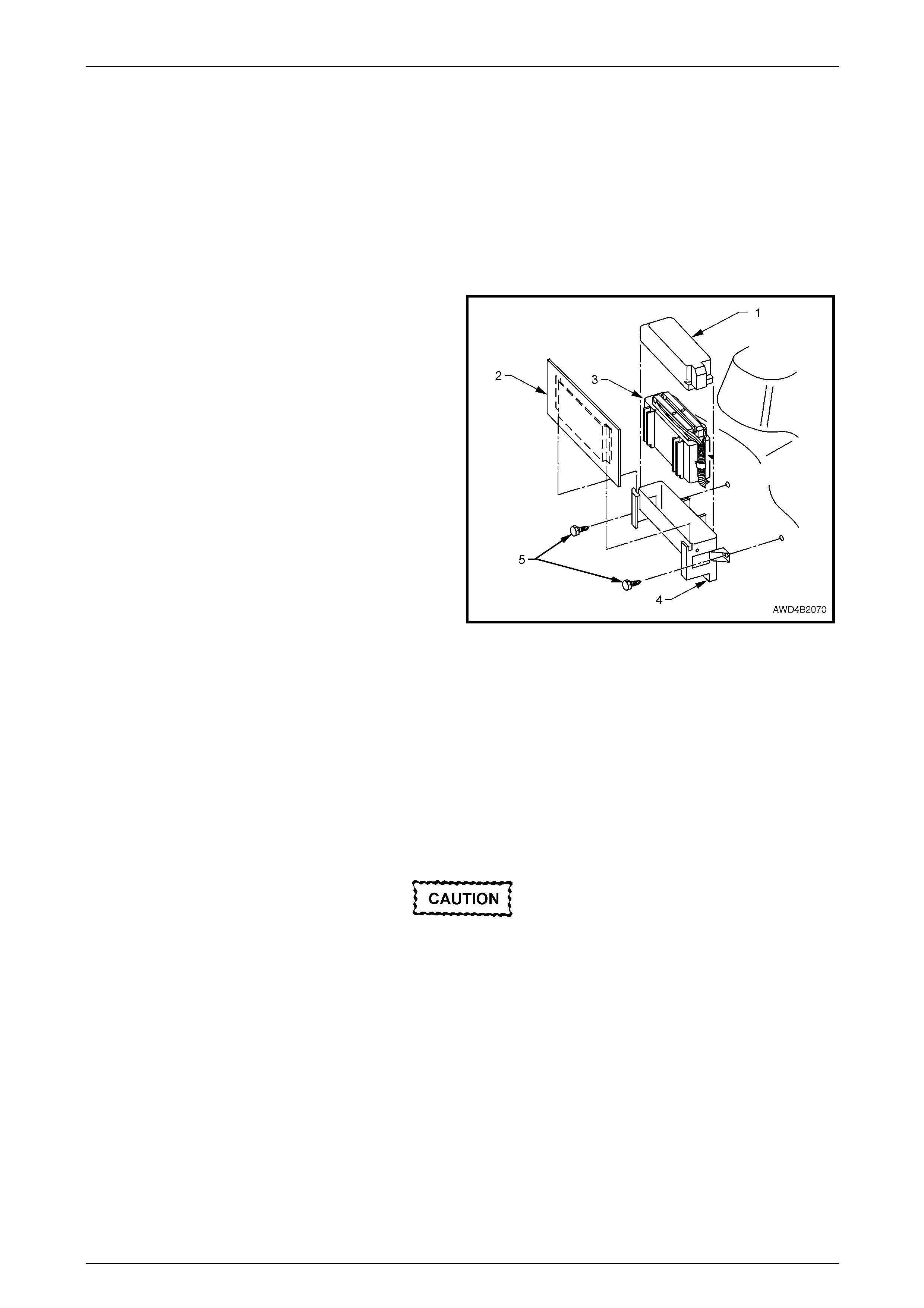
2 Remove the heat shield (2) protecting the Powertrain
Control Module (PCM) by pulling up evenly on each
end. Set to one side.
3 Remove the PCM cover (1) and set to one side.
4 Remove the PCM (3) from the engin e compartment.
Refer to Section 6C3-3 Service Operations.
5 Remove the two screws (5) securing the PCM cradle
(4) to the inner fender skirt, then remove the cradle
from the engine compartment.
Figure 4B3 – 44
All AWD
6 Raise the vehicle, and support in a safe manner. Refer to Section 0A General Information, for the location of
jacking and support points.
7 Mark the relationship of the rear transmission crossmember to the two side rails. Remove the rear transmission
crossmember. Refer to Section 7F Transfer Case and Adapter Housing.
NOTE
Support of the transfer case is not required
unless the rear mount bracket is also removed.
Take care not to damage the heated oxygen
sensor/s during the exhaust pipe removal
procedure.
8 Disconnect the left side e xhau st pipe from the exhaust manifold and the flange behind the catalytic converter.
Refer to Section 8B Exhaust System.
9 Remove the left side exhaust manifold. Refer to Section 6A1 Engine Mechanical (V6 engine) or
Section 6A3 Engine Mech anical (GEN III V8 engine).
NOTE
For the GEN III V8 engine, remove the exhaust
manifold from the engine bay, in the gap left by
the removed air cleaner assembly.
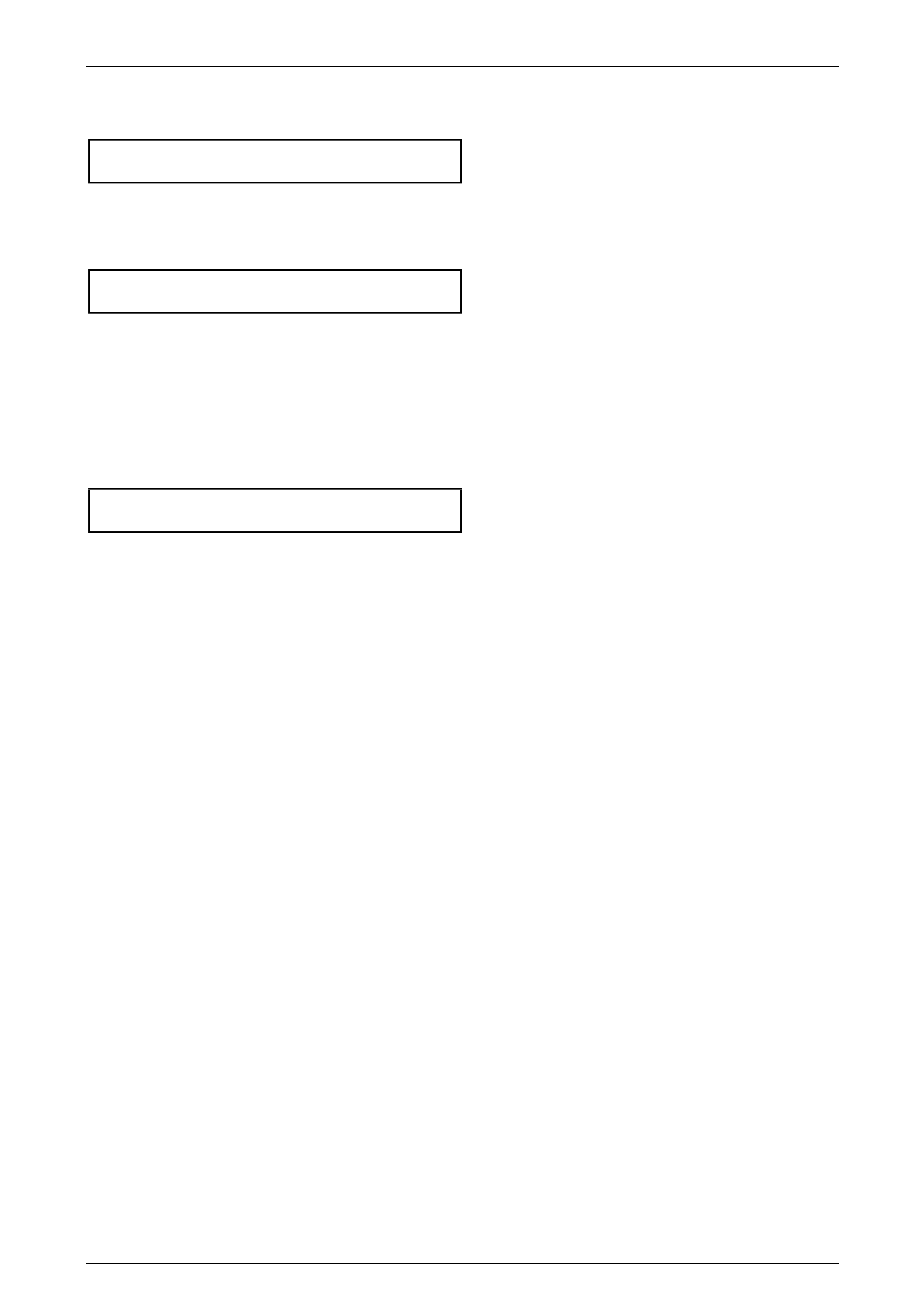
10 Loosen the four bolts (1) securing the left side engine mount bracket to the engine block, then rem ove the upper
engine mount to bracket nut (2), using a deep socket. Discard the removed nut.
Front Final Drive, Bearing Housing & Driveshafts Page 4B3–34
Page 4B3-34
NOTE
View ‘A’ shows the GEN III V8 arrangement,
while view ‘B’ shows the V6.
Figure 4B3 – 45
11 Drain the lubricant from the front final driv e assembly. Refer to 2.2 Changing/F lushing Final Drive Lubricant, in this
Section.
12 Completely remove the front propeller shaft from the vehicle.
Refer to Section 4C2 Front Propeller Shaft & Universal Joints.
13 Remove both front driveshafts. Refer to 2.4 Driveshaft Assembly, Remove, in this Section.
NOTE
This operation will have disconnected the front
control arm ball joints.
14 Remove the four flanged nuts (1) securing the left
side, upper underbody front side ra il brace (2).
Remove the brace (2) from the vehicle.
NOTE
The view is from under the vehicle looking
upward.
Figure 4B3 – 46
15 Remove the bearing housing from the right side of the engine oil pan.
Refer to 3.1 Bearing Housing Assembl y, Remove , in this Section.
Front Final Drive, Bearing Housing & Driveshafts Page 4B3–35
Page 4B3-35
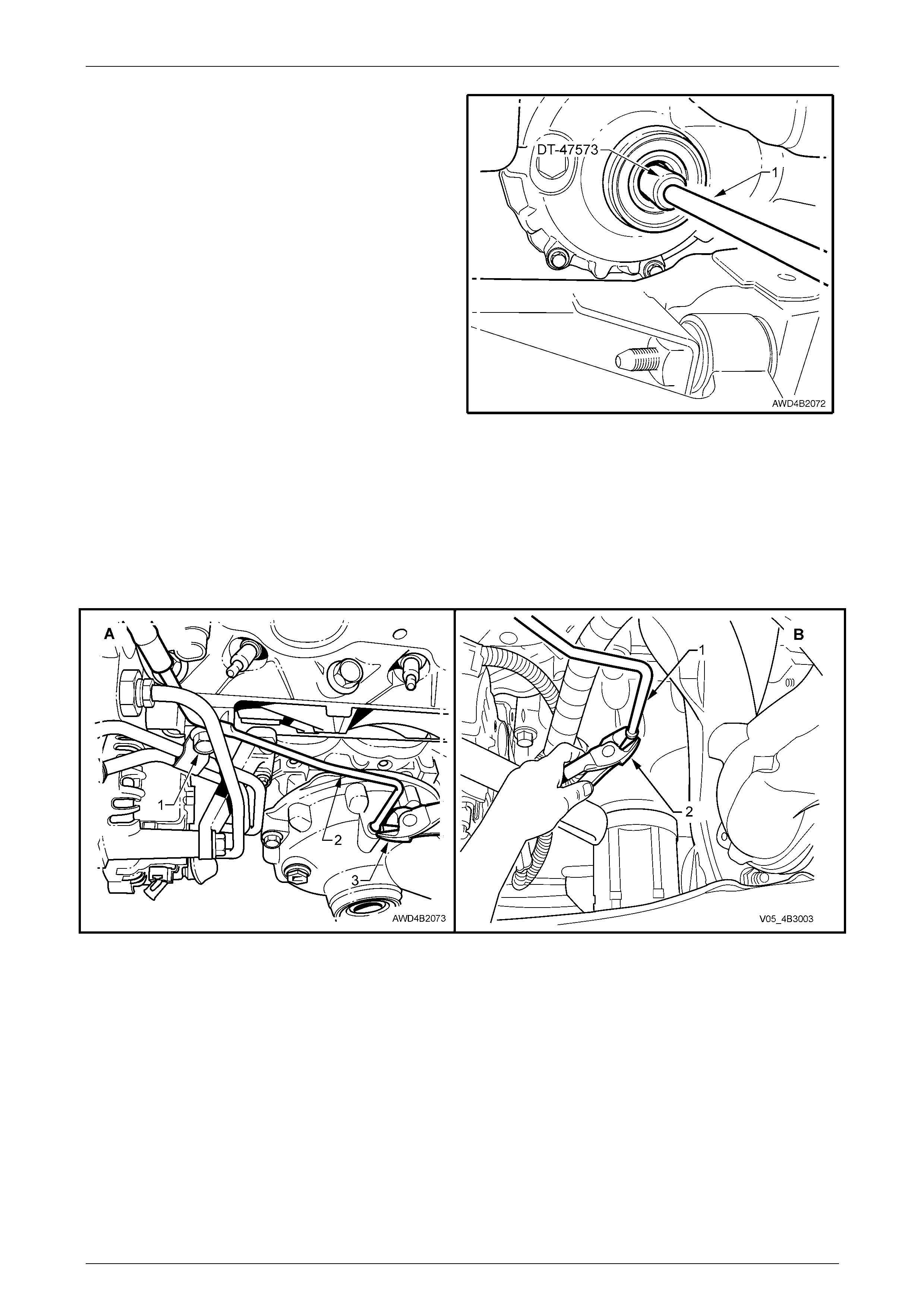
16 Insert final drive ring gear rotation T ool No. DT-47573
into the left side of the final drive and engage the
differential pinion pin.
17 Using a suitable length rod (1) and a plastic hammer,
tap the end of the rotation tool to disengag e the
intermediate shaft snap ring from the right side axle
gear in the differential. Remove the interconnecting
shaft from the engine oil pan, on the right side.
Figure 4B3 – 47
18 Support the engine, then remove the loose ned, left side engine mount bracket bolts (refer to Step 10 in this
procedure). Lift the bracket from the engine ba y and the heat shield from the mount.
19 Disconnect the final drive breather pipe bracket bolt (1), then remove the steel breather pipe (2) from the final drive
housing, using side cuttin g pli ers (3) to prise the pipe and O-ring free.
NOTE
While view ‘A’ shows the GEN III arrangement,
view ‘B’ shows the V6.
Figure 4B3 – 48
20 Remove the four final drive assembl y to engine oil pan securing bolts.
NOTE
At this stage, it will not be possible to remove an y
of the bolts completely from the final drive
housing.
21 Using a suitable lever, prise the fina l drive assembly from the engine oi l pan, releasing the locating do wel at the
pinion end and the final driv e cover boss from the engine oil pan.
22 Remove the final drive assembl y from under the vehic le by lowering, pinion end first and out through the space left
by the removed side rail brace.

Front Final Drive, Bearing Housing & Driveshafts Page 4B3–36
Page 4B3-36
Reinstall
Reinstallation of the front final drive assembly is the reverse of the removal procedure, except for the following:
1 Apply Loctite 2 43 or equivalent to the cleaned final drive attaching bolt threads, then insert the bolts into the final
drive mounting holes. The longest bolt should be in the pinion nose location.
2 Apply a smear of final drive lubricant to the locating boss on the final drive cover housing, before reinstalling into
place in the side of the engine oil pan. Levering the assembly into place may be required to fully install the pinion
locating dowel.
3 Reinstall the fo ur final drive assembly retainin g bolts and tighten to the correct torque specification.
Front final drive assembly to engine
oil pan retaining bolts torque specification ...........70 N.m
4 Ensure that the splines on the interconnecting shaft are lubricated with the recommended final drive lubricant
before reinstalling into the final drive assembly. Gently tap the shaft snap ring into place in the left side differential
axle gear, using a plastic hammer. Once installed, tug on the shaft to check that the retaining ring is engaged in the
side gear groove.
5 Replace the high temperature O-ring seal to the end of the breather pipe, smear with the recommended final dr ive
lubricant, then reinstall the pipe into the final drive housing.
6 Secure the pipe with the breather pipe bracket bolt and tighten to the correct torque specification.
Front final drive breather pipe bracket
bolt torque specification GEN III V8....................22 N.m
HFV6..............................9 N.m
7 Reinstall the e ngine mount heat shield, then manoeuvre the engine mount bracket into position. Reinstall the four
bracket to engine block retaining bolts and tighten to the correct torque specification.
Right side engine mount brac ket to
cylinder black bolt torque specification.................50 N.m
8 Reinstall the e xhaust manifold after cleaning the mating surfaces and fitting a new gasket.
Refer to Section 6A1 Engine Mechanical – V6 Engine or S ection 6A3 Engine Mechanical – GEN III V8 Engine.
Tighten the retaining bolts to the correct torque specification in two stages, working from the centre, outwards.
GEN III V8 exhaust manifold
bolt torque specification ...................... Stage 1 – 15 N.m
Stage 2 – 25 N.m
V6 exhaust manifold to cylinder
head bolt torque specification ..............................20 N.m
9 Reinstall the u pper underbody front side rail brace, then se cure with the four retaining nuts, tightening to the correct
torque specification.
Underbody front side rail brace
nut torque specification........................................25 N.m
10 Reinstall the front propeller shaft. Refer to Section 4C2 Front Propeller Shaft & Universal Joints.
11 Reinstall the exhaust pipe. This will require a new gasket being fitted to the cleaned rear mounting flange.
12 Install all exhaust related fasteners and ti ghten to the correct torque specifications.
Refer to Section 8B Exhaust System.
13 Reinstall the rear transmission crossmember, aligning marks made before removal. Install all fasteners and tighten
to the correct torque specification.
Transmission rear crossmember
attaching bolts torque specification – All..............55 N.m
14 Ensure that the outer splines of the interconn ecting shaft are lubricated with Mobilgrease XHP 222, then slide the
housing assembly onto the interconnecting s haft, engaging the splines, until the housing flanges contact the oil
pan. Refer to 3.1 Bearing Housing Assembly, Reinstall, in this Section.
Front Final Drive, Bearing Housing & Driveshafts Page 4B3–37
Page 4B3-37
15 Reinstall the three bearing housing assembly to engine oi l pan retaining bolts and tighten to the correct torque
specification.
Bearing housing to engine oil pan
retaining bolt torque specification.........................45 N.m
16 Reinstall both driveshafts. Refer to 2.4 Driveshaft Assembly, Reinstal l, in this Section.
17 After checking that the engine mount heat shield/s are in the correct position, lower the engine weight onto the
engine mounts, reinstall and tighten NEW engine mount to crossmember nuts to the correct torque specification.
Engine mount retaining nut
torque specification – All......................................80 N.m
18 Fill the front final drive with the recommended lubricant. Refer to 2.1 Checking Fin al Drive Lubricant Level and
2.2 Changing/Flushing Final Drive Lubric ant, in this Section.
19 Reinstall the road wheels, aligning marks made on removal but do not tighten at this stage.
20 Lower the vehicle to the ground, bou nce the front suspension several times, then push backwards and forwards to
settle the suspension.
21 Tighten the road wheel nuts working in a ‘star’ pattern to the correct torque specific ation.
Refer to Section 10 Wheels and Tyres.
Road wheel attaching
nut torque specification............................110 – 140 N.m
22 Check and correct (as required) the front wheel alignment.
Refer to 2.2 Wheel Alignment Checking a nd Adjustment, in Section 3 Front Suspension.
23 reinstall the centre wheel nut covers.
24 Road test the vehicle to check for correct vehicle operation.
Front Final Drive, Bearing Housing & Driveshafts Page 4B3–38
Page 4B3-38
3.3 Removed Final Drive Assembly
LT Section No. – 05-250
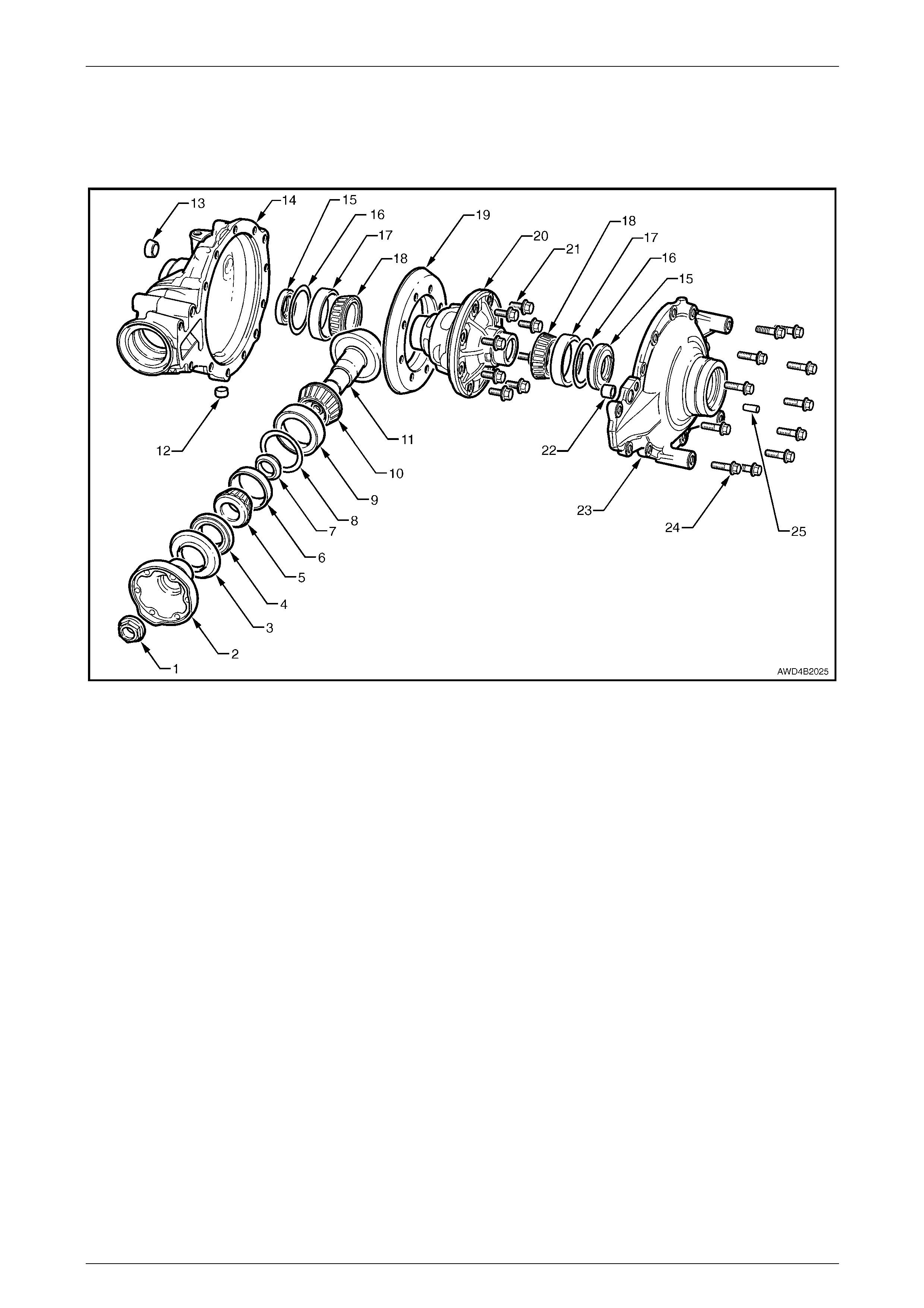
Figure 4B3-49
Legend
1 Pinion Nut
2 Pinion Flange
3 Slinger
4 Pinion Oil Seal
5 Pinion Outer (Tail) Bearing Cone
6 Pinion Outer (Tail) Bearing Cup
7 Collapsible Spacer
8 Pinion Position Shim
9 Pinion Inner (Head) Bearing Cup
10 Pinion Inner (Head) Bearing Cone
11 Hypoid Pinion Gear
12 Drain Plug
13 Filler Plug
14 Carrier Housing
15 Driveshaft Oil Seal
16 Differential Position Shim
17 Differential Bearing Cup
18 Differential Bearing Cone
19 Hypoid Ring Gear
20 Differential Case
21 Ring Gear Retaining Bolts (8 places)
22 Cover Aligning Hollow Dowel
23 Cover
24 Cover Retaining Bolts (10 places)
25 Pinion Nose Angle Locating Dowel
Front Final Drive, Bearing Housing & Driveshafts Page 4B3–39
Page 4B3-39
Disassemble
Final Drive Cover
1 Using Tool No. E308 or a commercial equival ent,
remove the oil seal (1) from the cover housi ng (2) and
discard.
Figure 4B3 – 50
2 Support the final drive assembly, with the cover bolts
facing upward.
3 Remove the 10 cover bolts.
4 Use a suitable lever at each of the points provided ('A',
'B' and 'C'), break the sealant seal, then lift the cover
from the carrier housing and the sleeve dowel (1). Set
the cover to one side.
5 Using a suitable scraper, remove the sealant remains
from the cover and carrier housings.
Figure 4B3 – 51
Before proceeding with the disassembly process, the gear tooth contact should be e xami ned and recorded as a
comparison when the reassembly takes place.
Front Final Drive, Bearing Housing & Driveshafts Page 4B3–40
Page 4B3-40
Examining Gear Tooth Contact
Wear eye protection when using compressed
air to dry washed components.
Do not allow bearings to spin when applying
compressed ai r in the drying-off process.
1 Lift the differential and ring gear assembly from the carrier housing, then wash all components in a suitable solvent
and blow dry, using compressed air.
2 Apply light oil to the roller bearings, then apply a thin coating of a gear marking compound to the ring gear teeth.
3 Reinstall the ring gear and differentia l to the carrier housing, then reinstall the cover and the 10 bolts, tightening
each to the correct torque specification.
Final drive cover bolt
torque specification..............................................45 N.m
4 Install ring gear rotation tool DT-47573 to engage with the differential pin and grasp the tool to apply a load to the
ring gear while rotating the pin ion a bout 10 times in each direction.
5 Remove the 10 bolts securing the cover to the carrier housing, then remove the cover an d the ring gear/differential
assembly.
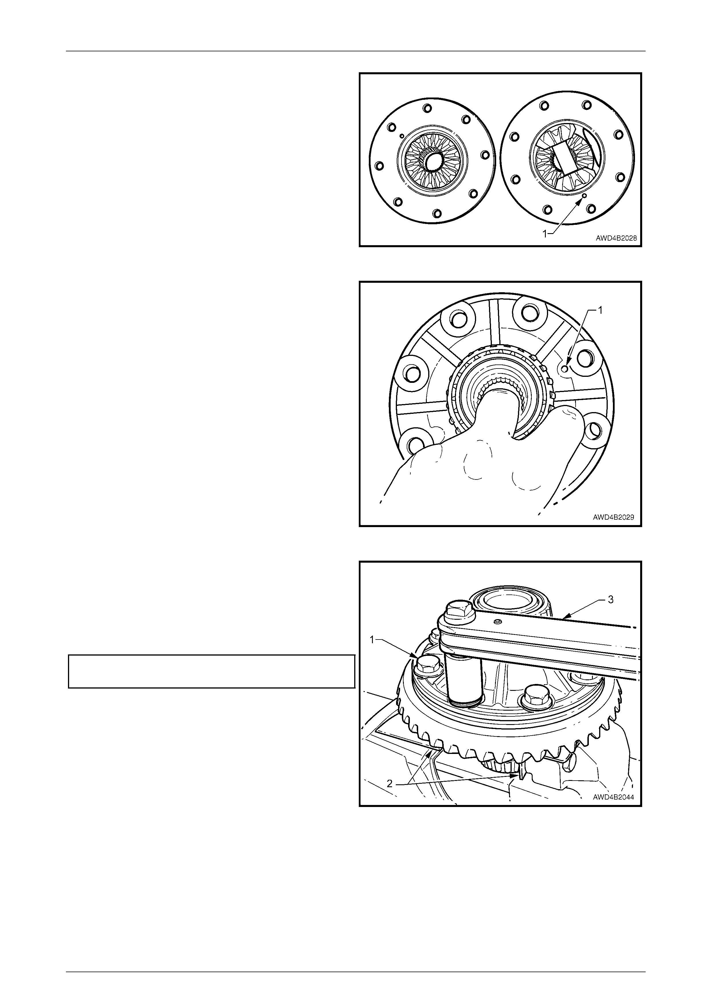
6 Examin e the ring gear tooth marking and record. The most convenient method would be to use a di gital camera.
Refer to 'Ring Gear and Pinion Contact Pattern', in 3.3 Removed F inal Drive Assembly, Reassemble,
Section 4B1 Rear Final Drive and Drive Shafts, for typical and acce ptable tooth contact patterns.
Drive Pinion
1 Mark the relationship of the pinion flange to the pinion
shaft (1), using correction fluid (e.g. 'whiteout'). This
step will minimise the chance of pinion flange runout,
should the pinion and flange not require replacement.
Figure 4B3 – 52

Front Final Drive, Bearing Housing & Driveshafts Page 4B3–41
Page 4B3-41
2 Install packing ring, Tool No. DT-47580 into the pin ion
flange recess, aligning the holes with those in the
pinion flange.
3 Using two of the propeller shaft constant velocity joint
bolts (1), with flat washers, secure the holding bar,
Tool No. J 8614-10 (part of Tool No. J 8614-O1) to the
pinion flange (2). The central recesses in the holding
tool should face inward.
4 Using a 30 mm deep socket and bar (3), loosen then
remove the pinion flange retaining nut.
NOTE
A suitable length of pipe installed over the end of
the socket bar will reduce the effort required to
loosen the pinion flange nut.
Figure 4B3 – 53
5 With Tool No. J 8614- 10 and packing ring, Tool N o.
DT-47580 still installed, thread the forcing screw, Tool
No. J 8614-3, into the adaptor, Tool No. J 8614-2.
Install this sub-assembly into holder, Tool No. J 8614-
10, then rotate through 45° to locate in the recesses in
J 8614-10.
6 While holding J 8614-10, use a socket and b ar (1) to
rotate the forcing screw J 8614-3 to remove the pinion
flange (2).
7 Remove the tools from the pinion flange.
Figure 4B3 – 54
8 Prise the pinion oil se al (1) from the carrier housing,
using Tool E308 or a commercial equivalent.
9 Use a soft faced hammer, drive the pinion from the
outer (tail) bearing cone.
NOTE
With the offset of the carrier housing, it will be
necessary to hold the pinion to one side, as it is
being driven from the outer bearing. If not, the
pinion head will strike the carrier housing before
being released from the bearing.
10 Remove the outer (tail) pinion bearing and collapsible
spacer from the final drive housing.
Figure 4B3 – 55
Front Final Drive, Bearing Housing & Driveshafts Page 4B3–42
Page 4B3-42
11 Again using Tool No. E308, re move the carrier bearing
oil seal from the carrier housing.
Figure 4B3 – 56
Wear eye protection when using compressed
air to dry washed components.
Do not allow bearings to spin when applying
compressed air in the drying off process.
12 Clean all components in a suitable cleaning solvent and blow dry, taking care not to spin an y of the roller bearings
with compressed air. Inspect the pinio n and the bearings for wear and/or damage.
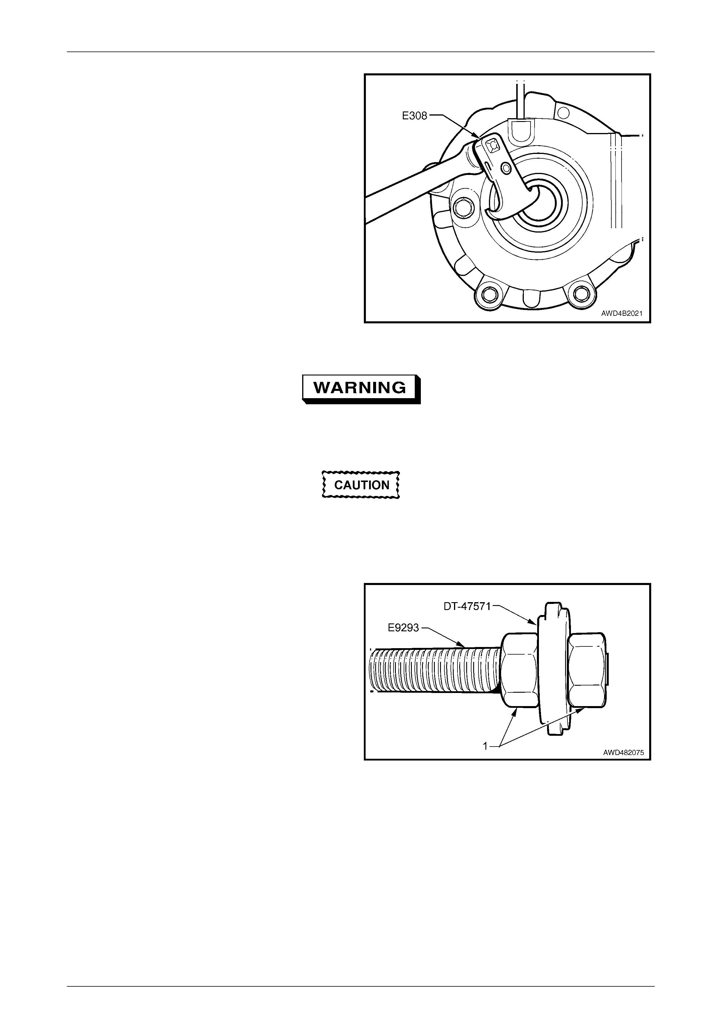
13 To remove the inner pinion bearin g cup, first assemble
the bearing cup remover DT -47571 onto the bolt of
Tool No. E9293 and secure with a nut (1) on each
side.
Figure 4B3 – 57
Front Final Drive, Bearing Housing & Driveshafts Page 4B3–43
Page 4B3-43
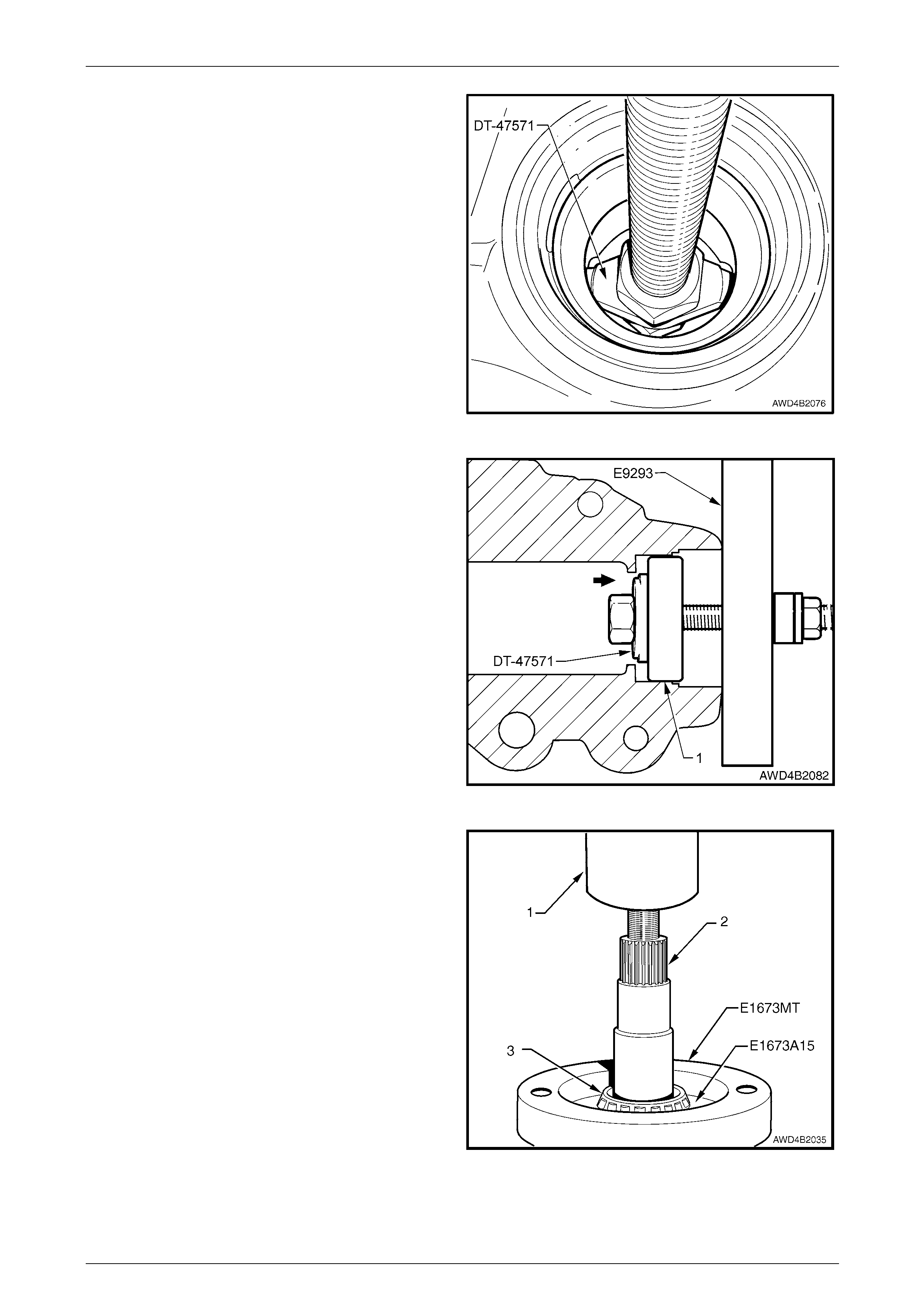
14 After clamping the carrier housing in a vice fitted with
soft jaws, insert the bolt and pinion bearing cup
removing tool DT-47571 into the pinion cavity, aligning
the tool with the two cut-outs in the housing.
15 Drive the inner pinion bearing cup from the housi ng
using a hammer.
Figure 4B3 – 58
16 If the pinion bearings are to be replaced, remove the
outer (tail) pinion bearing cup, as follows:
a Assemble pinion bearing cup remover, Tool No.
E9293 with the larger land of the remov er, Tool
No. DT-47571 into the outer (tail) cu p and the
plate (part of Tool No. E9293) over the pinio n
opening in the carrier housing .
b Install the bolt through the p inion bearing cup
remover, bearing cup and pla t e, then install the
thrust race, washer and nut.
c While holding the bolt head, tighten the nut to
remove the bearing cup from the carrier housing.
Figure 4B3 – 59
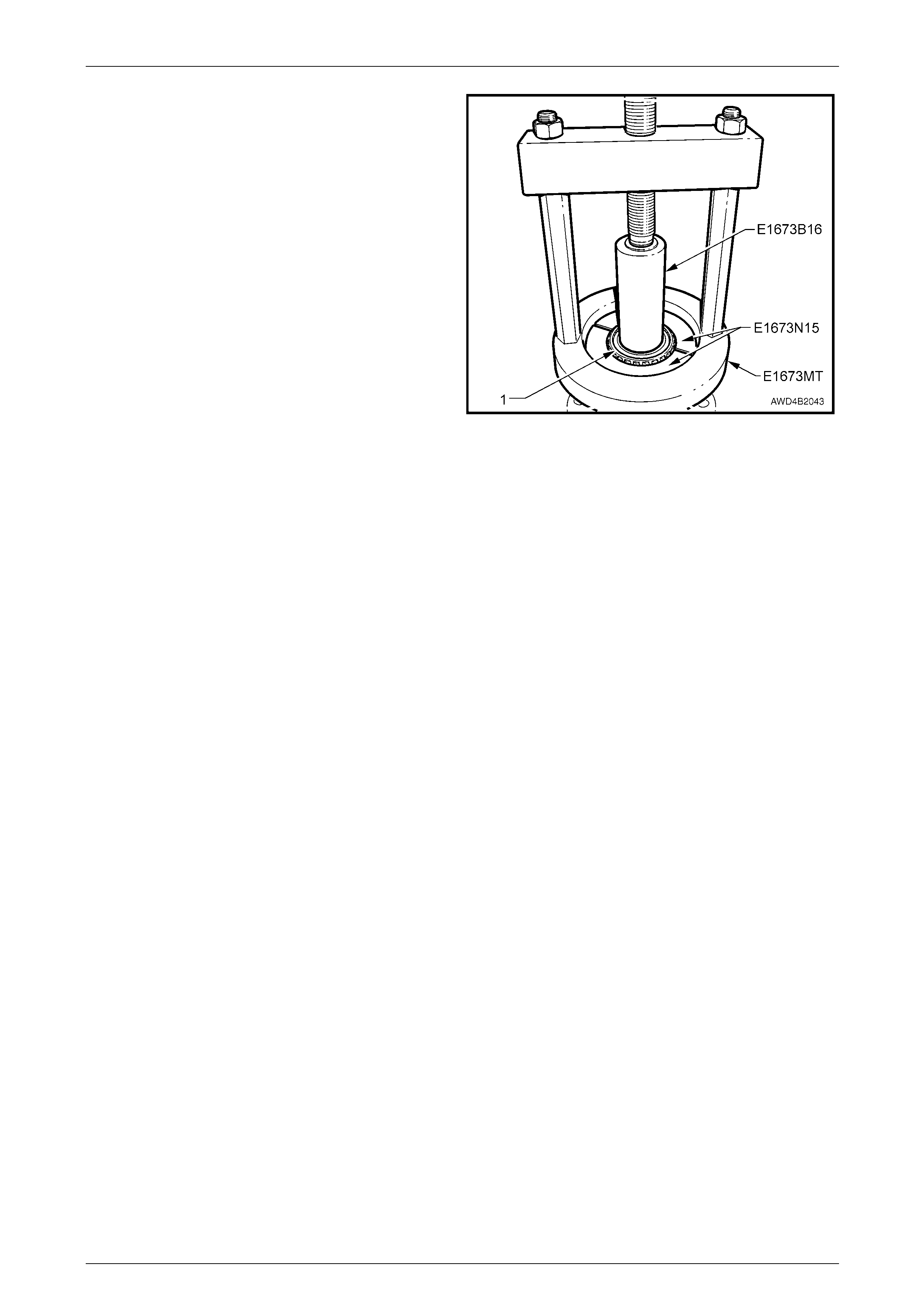
17 To remove inner bearing cone from the pinion, remove
legs from the ring of Tool No. E1673 MT.
18 Place ring on suitable press pl ates. Install pinion and
adaptors E 1673-A15 into the ring. Use a pr ess (1) to
remove the pinion (2) from the bearing (3). Discard the
removed bearing (3).
NOTE
Do not allow the pinion to drop and hit the floor.
Figure 4B3 – 60
Front Final Drive, Bearing Housing & Driveshafts Page 4B3–44
Page 4B3-44
Differential Assembly
Figure 4B3-61
Legend
1 Differential Case
2 Side Gear Thrust Washer
3 Differential Side Gear
4 Differential Pinion Gear
5 Differential Pinion Gear Thrust Washer
6 Differential Pinion Shaft
7 Locking Roll Pin
1 Secure the differential ho using in a vice fitted with soft
jaws.
2 Using suitable socket equipment (1), loosen the ring
gear retaining bolts (2), working from opposite sides
until all bolts are loosened. Re move and discard all
bolts, as they must be renewed on reassembly.
NOTE
The ring gear bolts have a right hand thread.
Do not use a screwdriver to prise between
ring gear and case.
3 Remove the ring gear from the differential case, either
by using a press or a soft faced hammer. Support the
differential case (or ring gear) durin g this operation to
prevent it from dropping and striking the floor or bench
top.
Figure 4B3 – 62
Front Final Drive, Bearing Housing & Driveshafts Page 4B3–45
Page 4B3-45
4 Using a suitable sized brass drift, separate the two
piece differential case.
Figure 4B3 – 63
5 Using a suitable sized pin punch (1) and ham m er,
remove the differential pinion cross shaft retainer roll
pin.
Figure 4B3 – 64
6 With the differential case (2) held in a vice fitted with
soft jaws, use a suitable sized brass drift (1) and
hammer to drive the differential pinion cross shaft out
from the differential case (2).
7 Lift the pinion gears and thrust washers from the case.
8 Remove the side gears and thrust washers from each
side of the case.
9 If inspection shows that the side bearing cones and
cups are undamaged, the bearing cones may be left
installed on each of the case halv es.
NOTE
If the bearing cones are removed, then the
cones and cups must be replaced with new parts
on reassembly.
Figure 4B3 – 65
Front Final Drive, Bearing Housing & Driveshafts Page 4B3–46
Page 4B3-46
10 If the side bearings are to be replaced, use Tool No.
E1673MT, with E1673N15 adaptors an d distance
piece, E1673B16, to remove the bearing cones (1).
Discard the removed bearings.
Figure 4B3 – 66
Inspect
General Items
• Thoroughly cle an all parts with a suitable, clean solve nt.
• Oil the bearings immediately after cleaning and drying to prevent rust developing.
• Inspect the parts for any major defects.
• Clean the inside of the case before rebuilding and installing the parts, inspect individu al parts as detailed next:
Gears
• The pattern taken during the d ismantling process should help in judging if the ring gear and pinion can be re-used.
Worn gears cannot be rebuilt to correct a noisy condition. Gear scoring is the result of excessive shock loading or
the use of an incorrect lubricant.
• Scored differential gears must be replaced. Examine the teeth and thrust surface of all differential gears.
• Check the fit of the side gear hubs in the case. Wear on the hub of the side gear can cause a “clunking” noise
when the vehicle is driven at low speeds.
• Check that none of the thrust washers shows signs of wear, cracks or burrs.
• Wear on splines, thrust surfaces, or thrust washers can contribute to excessive driv eline backlash.
• Inspect differential pinion gear bores an d shaft surfaces for scoring.
Bearing Cups
• Check bearing cups for rings, scores, gal ling or erratic wear patterns. For various roller bearing abnormal wear
conditions and their causes, refer to 4.4 Bearing Diagnosis, in Section 4B1 Final Drive & Driveshafts.
• Pinion bearings cups must be solidly seated. Check by attempting to insert a 0.05 mm feeler between these cups
and the bottom of their bores. Ensure that seating surfaces are clean and free from burrs or raised metal.
Front Final Drive, Bearing Housing & Driveshafts Page 4B3–47
Page 4B3-47
Bearing Cone and Roller Assemblies
• The bearings in the differential case a nd the rear (head) pinion should be checked before being removed from the
differential case or pinion. If these bearing cup and cone assemblies are removed, they must be discarded and
replaced with new parts.
• When lightly oiled and rotated in their respective cups, bearing cone rollers must turn without roughness. Examin e
the roller ends for wear. Step-wear on the roller ends indicat es the be aring preload was incorrect or the rollers were
slightly misaligned. Refer to 4.4 Bearing Diagnosis, in Section 4B1 Final Drive & Driveshafts, for examples of
abnormal bearing wear and their causes.
Pinion Flange
• Check the flange mating face run-out. Refer to 5 Specifications for the ma ximum Total Indicated Runout (TIR).
• The end of the flange that contacts the beari ng cone and the seal surface must be free from imperfections.
• Check that the constant velocity (constant velocity) joint bolt threads are in good condition. Clean out any residual
thread sealant by using an 8 mm tap.
Carrier and Cover Housings
• Check that the differential bearing bores are smooth and the differential carrier bearing preload spacer washer
abutment faces are not damaged.
Differential Case
• Carefully examine the cas e fo r damage and ensure that bearing seating surfaces are free from dirt and burrs. The
bearing assemblies will fail if they do not seat correctly against the shoulder on the housing.
• The ring gear spigot and mating surfaces for the differential case halves should be clean and free from burrs.
• Check that the differential pinion pin bores in the differential case are not oval.
• Check that the mating surfaces for the two case halves are clean and free from burrs.
• The differential side gear journal bores should be clean and free from scoring. The thrust surfaces for the
differential case halves should be clean and free from burrs.
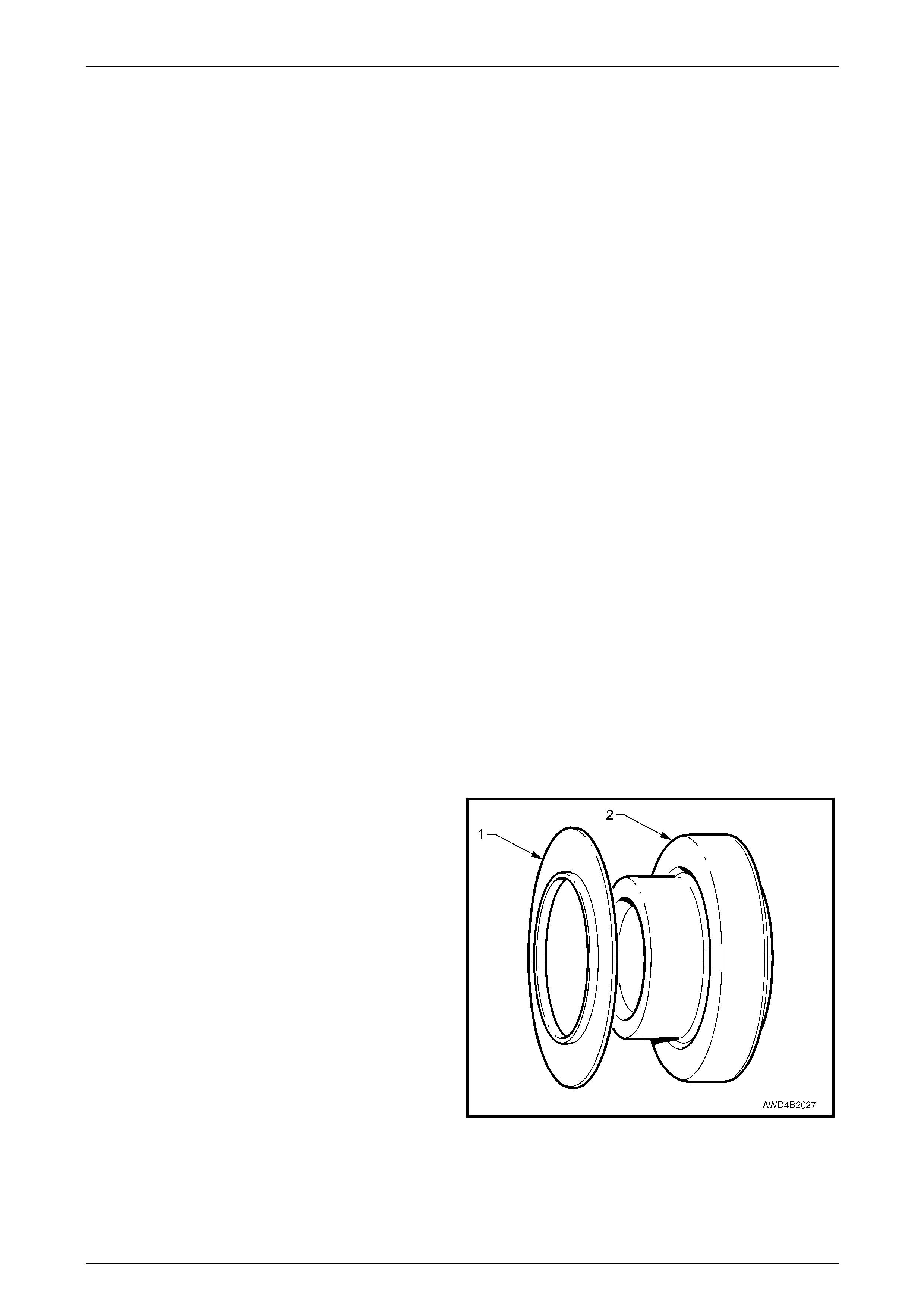
Reassemble
Differential
1 Before assembly, lubricate all differential parts with the
recommended front final drive lubricant.
2 Reinstall a si de gear thrust washer (1) over each side
gear (2), ensuring that the thrust washer is installed in
the orientation shown.
3 Reinstall o ne side gear and thrust washer into the
recess in the larger differential case half.
4 Mesh the two pinion gears with the installed side gear
and align with the pinio n shaft roll pin hole in the
differential case.
NOTE
To overcome the risk of damaging the thrust
washers through misalignment, using a
fabricated wooden dowel of 18.5 mm diameter
(100 mm long) can be us ed to align both pi nions
and their thrust washers before installation of the
pinion shaft. Figure 4B3 – 67
5 Align the roll pin hole by sight, in the differential case with the hole in the differential pinion pin, then use a brass
drift and hammer to drive the pinion pin i nto position, until the roll pin hole is in alignment.
Front Final Drive, Bearing Housing & Driveshafts Page 4B3–48
Page 4B3-48
6 Using a suitable pin punch and hammer i nstall a new
roll pin (1) through the differential case until the pin
protrudes through on the machined case half by about
6 mm. This will ensure a positive location for the case
cover.
7 Reinstall the re maining side gear and thrust washer
into the smaller case half.
Figure 4B3 – 68
8 While holding the side gear and thrust washer in
position with a finger, reinstall the case cover over the
differential case, meshing the differential gears and
aligning the roll pin with the accompanying hole in the
case cover (1).
9 Turn the differential assembly over, then Install the
ring gear into position on the differential case, aligning
the bolt holes.
NOTE
• For ease of assembly, heating the ring gear
on an electric hot plate until it is hot to the
hand, before installation.
• Under no circumstances is a flame to be
used to heat the ring gear.
• Making up two threaded guide pins to align
the ring gear would be an advantage. The
thread is 7/16" UNF 20 TPI right hand thread. Figure 4B3 – 69
10 Install and gradually tighten new ring gear at taching
bolts (1) evenly until the ring gear is fully installed to
the differential case.
11 With the differential case held in a vice fitted with soft
jaws (2), use a torque wrench (3) to tighten the ring
gear bolts (1) to the correct torque specification.
Ring gear bolt
torque specification............................................140 N.m
Figure 4B3 – 70
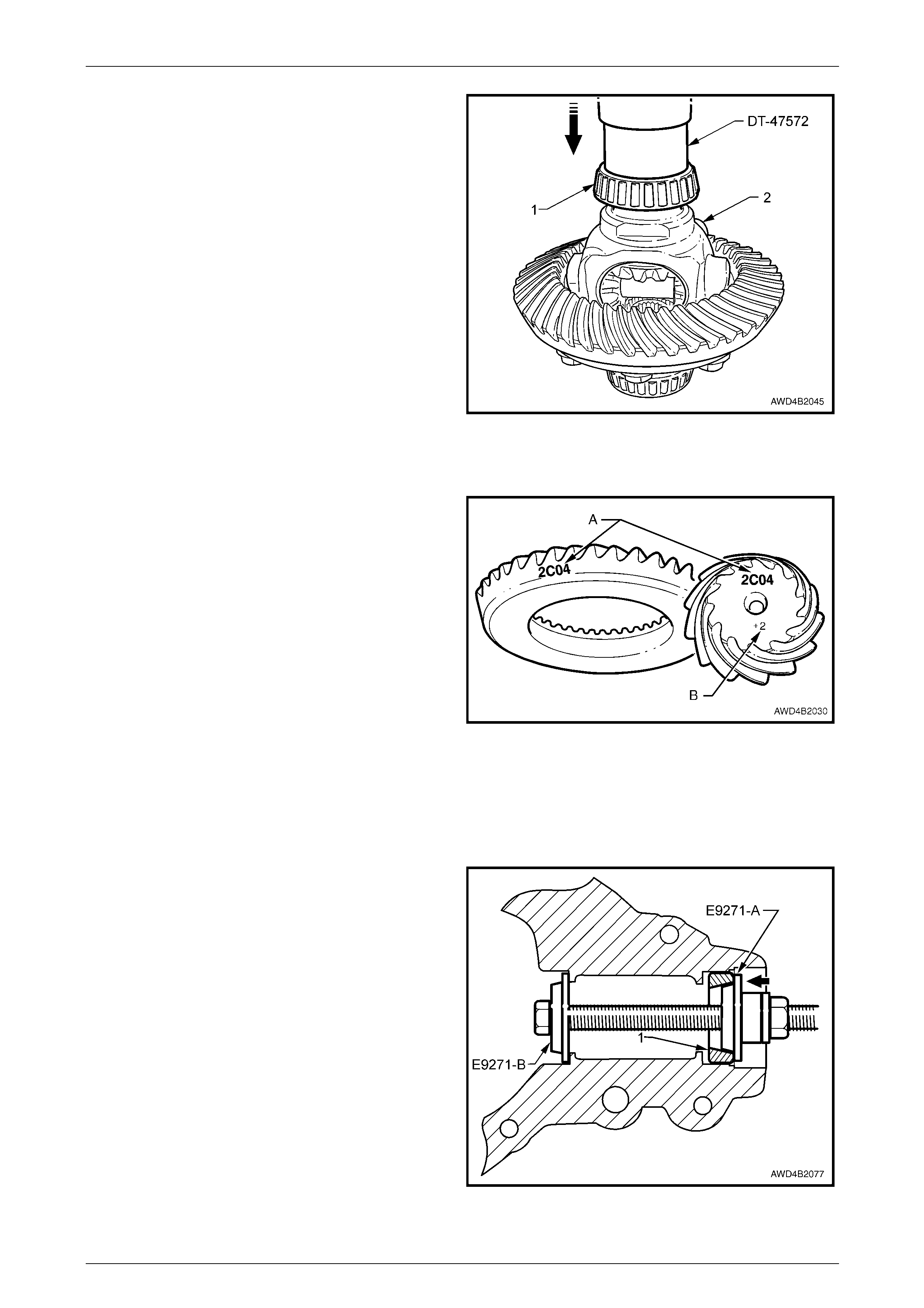
Front Final Drive, Bearing Housing & Driveshafts Page 4B3–49
Page 4B3-49
12 If removed, press new side bearing cones (1) to the
differential case (2), until fully installed, using installer,
Tool No. DT-47572.
Figure 4B3 – 71
Drive Pinion – Shim Selection
Gear Set Identification
The drive pinion and ring gear set identification marking ('A' )
('2C04' in this example) is the matching number that
appears on both the drive p inion and the ring gear. When a
new gear set is being installed in a final drive assembly, be
sure the same matching number appe ars on both the drive
pinion and the ring gear.
Gear Set Tolerance
The ring gear and pinio n are manufactured within a
tolerance of a specified distance. The head of each pinion is
marked ('B') with either: a positive (+) number, a negative (-)
number, or zero (0). This number indicates the best running
position for each particular gear set. This dimension is
controlled by the shimming behind the pinion head. When
the shim thickness is decreased the pini on gear is moved
away from the ring gear.
Figure 4B3 – 72
When the shim thickness is increased, the pinion is moved closer to the ring gear. A positive (+) number on the drive
pinion indicates that a thinner shim should be installed. A negative (–) number on the dri v e pinion indicates that a thicker
shim should be used. The marking o n the pi nion is in Imperial units.
Shim Selection Procedure
To select the correct shim thickness:
1 Install the outer (tail) pini on bearing cup (1) to the
carrier housing, as follows:
a Assemble T ool No. E9271 with installer E9271-A
to the outer cup and E9271-B (inverted) to the
inner cup, housing recess.
b Install the bolt through both installers, then the
thrust race, washer and nut.
c Tighten the nut, while holding the bolt head, to
install the bearing cup (1) until fully installed.
Figure 4B3 – 73
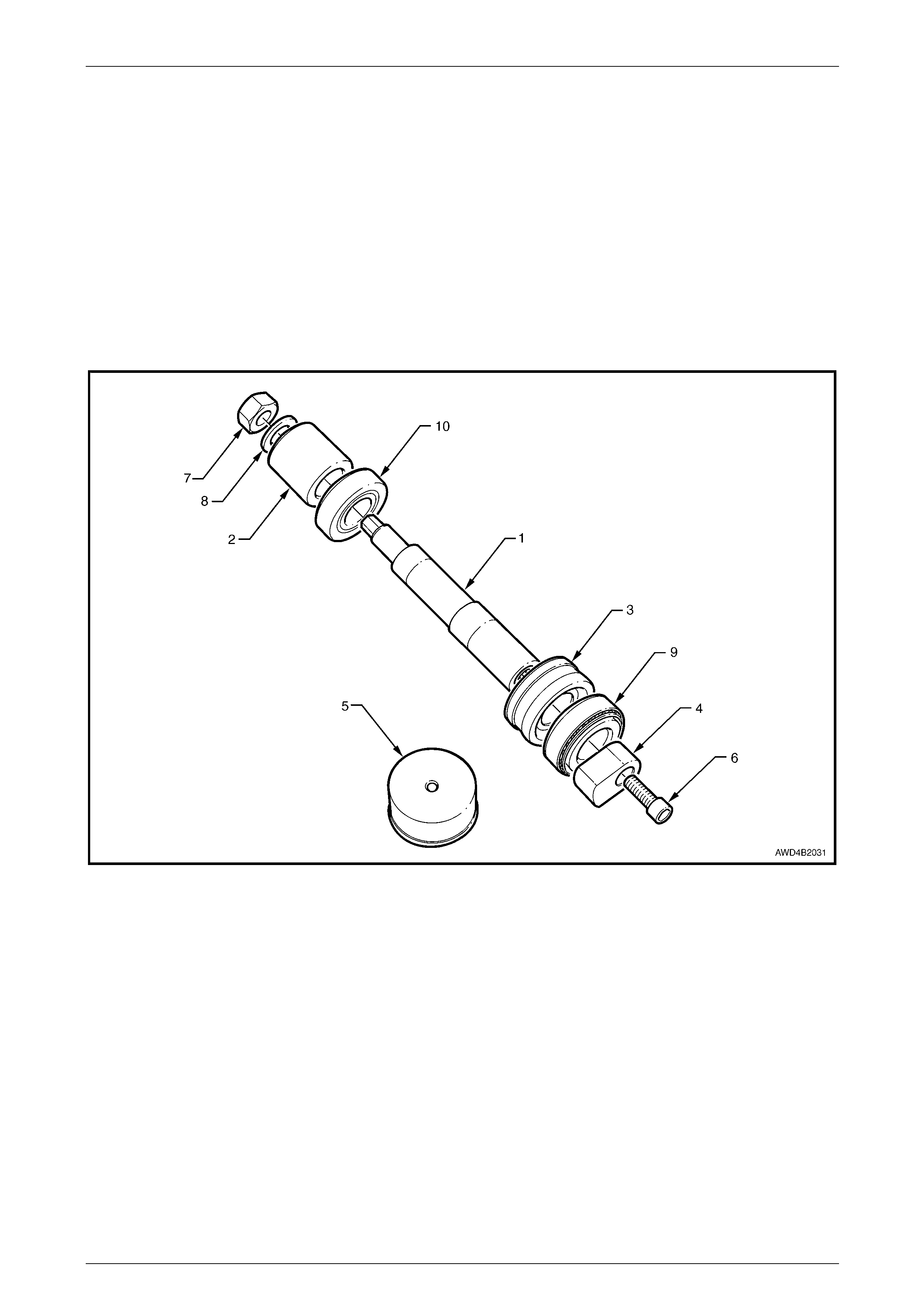
Front Final Drive, Bearing Housing & Driveshafts Page 4B3–50
Page 4B3-50
2 Assemble and install the dummy pinion, as follows:
NOTE
Ensure all surfaces of the dummy pinion
components are clean and free from dirt.
a Fit the gauge block (Tool No. DT-47583-3) in to the pinion inner (head) bear ing cup bore.
b Place the oiled outer (tail) bearing cone into the outer (tail) bearing cup, then slide the dumm y pinion stem
(Tool No. DT-47583-1) through the gauge block and the outer (tail) bearing.
c Slide the inner (head) pinion bearing cup and the oiled cone onto the head of the dummy pinion stem. Secure
the pinion plate (Tool No. DT-47583-4) to the dummy pinion stem (T ool No. DT-47583-1) with the supplied
screw (Tool No. DT-47583-6) and tighten securely.
d Slide the pinion spacer (Tool No. DT-47583-2) onto the tail of the dummy pinion stem.
Figure 4B3-74
Legend
1 Dummy Pinion Stem Nut and Washer
2 Spacer
3 Gauge Block
4 Pinion Plate
5 Selection Gauge
6 Pinion Plate Cap Head Screw
7 Dummy Pinion Stem Nut
8 Dummy Pinion Stem Flat Washer
9 Pinion Inner (Head) Bearing Cup and Cone
10 Pinion Outer (Tail) Bearing Cup and Cone

Front Final Drive, Bearing Housing & Driveshafts Page 4B3–51
Page 4B3-51
e Fit the pinion stem washer (1) (Tool No. DT -
47583-8), the nut (2) (Tool No. DT-47583-7) and
tighten until the specified pinion prel oad is
achieved.
NOTE
While tightening the pinion stem nut (2), use a
commercially available dial type torque wrench
to rotate the dummy pinion in both dir ections (as
far as the assembly will allow), a minimum of ten
times to ensure that the pinion be arings are fully
seated.
f Recheck and adjust preload if necessary.
NOTE
Both pinion bearings that are used with the
dummy pinion must be the bearings used for
reassembly.
Figure 4B3 – 75
3 The assembly should look the same as that shown next in a sectioned vi ew through the carrier housing.
4 Install the gauge block (Tool No. DT-47583-5) to the differential bearing bore in the carri er housing.
Figure 4B3-76
Legend
1 Dummy Pinion Stem Nut and Washer
2 Spacer
3 Gauge Block
4 Pinion Plate
5 Selection Gauge
6 Pinion Plate Cap Head Screw
7 Dummy Pinion Stem Nut
8 Dummy Pinion Stem Flat Washer
9 Pinion Inner (Head) Bearing Cup and Cone
10 Pinion Outer (Tail) Bearing Cup and Cone
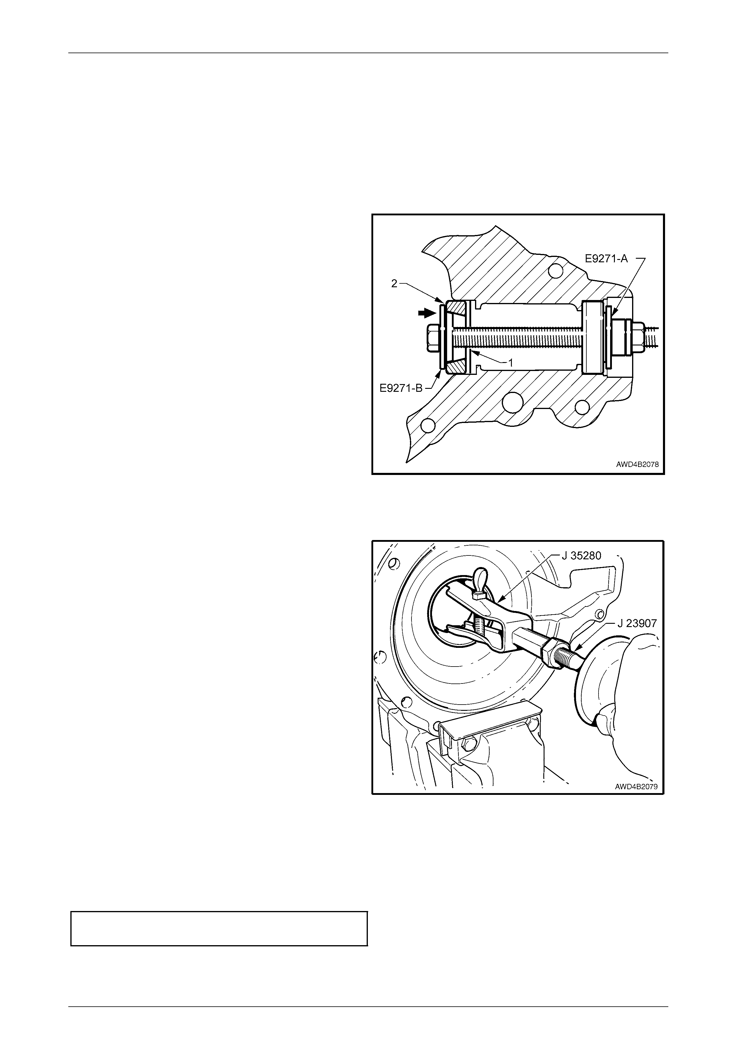
Front Final Drive, Bearing Housing & Driveshafts Page 4B3–52
Page 4B3-52
5 Using feeler ga uges measure the gap between the selection gauge and the plate of the dummy pinion. Note the
measurement taken. The correct shim thickness will be equal to this measurement plus/minus the marked pinion
adjustment.
• A positive (e.g. +0.002 in) marking indicates that this pinion must be set 2 thousandths of an inch further from
the drive gear, i.e. if the adjustment is +2, then 0.002 in. mu st be subtracted from the shim thickness.
• A negative (e.g. –0.002 in) marking indicates that this pinion must be set 2 thousandths of an inch closer to
the drive gear, i.e. if the adjustment is –2, then 0.002 in. mu st be added to the shim thickness.
6 Remove all tools from the carrier ho using.
7 Fit the selected shim (1) under the same inner (head)
pinion bearing cup (2) that was used to determine the
shim thickness and fully install the cup into the carrier
housing, using Tool No. E9271-B. Using Tool No.
E9271-A in the outer (tail) cup acts as a guide to
ensure that the inner (head) cup (2) is insta lled square
to its bore.
NOTE
If a 0.025 mm feeler gauge can be inserted
between a bearing cup and the bottom of its
bore at any point around the cup, the cup is not
fully seated.
Figure 4B3 – 77
Differential Assembly – Bearing Preload and Bac klash
1 Remove both differentia l bearing cups from the cover
and carrier housings, Using puller J 35280 and slide
hammer J 23907. As removal operations will distort
the shims under the cups they should be discarded,
along with the bearing cups.
NOTE
While the cover housing is shown, the operation
for either housing is similar.
Figure 4B3 – 78
2 Fit special bearing cups (Tool No. DT-47577) to the carrier and cover, without any shims. These bearing cups
have the outside diameters reduce d to all ow the cups to be a sliding fit in the housings.
3 Fit the differential assembl y with oiled bearing cones into the carrier housing.
4 Fit the cover and tighten the bolts to the correct torque sp ecification.
Final drive cover retaining
bolt torque specification.......................................45 N.m
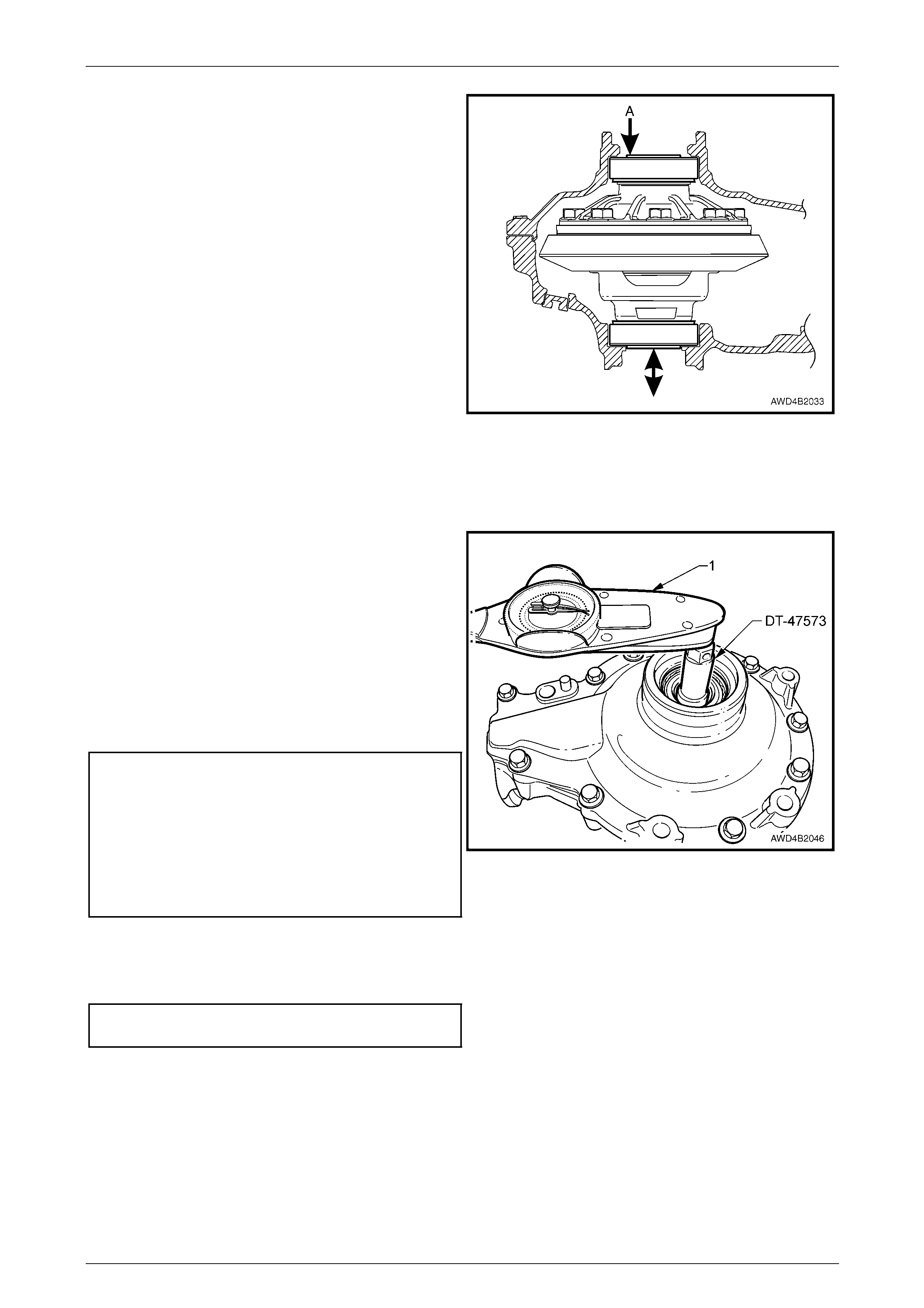
Front Final Drive, Bearing Housing & Driveshafts Page 4B3–53
Page 4B3-53
5 Position a dial indicator and magnetic base o n the
cover. The correct position is one where the dial
indicator stylus is in contact with bearing journal end of
the differential housing, such as position 'A'.
6 Zero the dial indicator.
7 Insert Tool No. DT-47573 into the lower side gear
opening and across the differ ential pinion pin.
8 Lift the differential up to measure the total end float,
note the reading, then lower and repeat at le ast
another two times, noting the end play in each
instance.
9 Take the avera ge reading as being the total differential
housing end float.
The total required shim thickness will be equal to the
measured end float value plus 0.1 mm. Select two
shims that equal the total thickness figure with one
shim being 0.15 mm thicker than the other.
10 Remove the cover, the differential case assembly and
the dummy bearing cups.
11 Position the thicker shim under the differential bearing
cup in the carrier housing.
Figure 4B3 – 79
12 Still using the dummy bearing cups, refit them in the
same positions. Refit the differential assembly and the
cover and progressively torqu e the bolts while
checking the bearing preload with a commercially
available dial type torque wrench (1).
NOTE
Rotate the differential, using Tool No. DT-47573
and a commercially available dial type torque
wrench (1), approximately 10 times in each
direction to ensure the preload is stabilised.
Readjust the differential if necessar y.
Side Bearing Preload Specification
(without pinion or axle shafts installed)
New Bearings
Koyo Bearings............................................0.6 – 1.9 N.m
Timken Bearings........................................1.1 – 2.8 N.m
Used Bearings
Koyo Bearings............................................0.3 – 1.0 N.m
Timken Bearings........................................0.6 – 1.4 N.m
Figure 4B3 – 80
13 If the bearing preload exceeds the specification by 0.1 N.m before the bolt s are fully torqued, then adjust the shim
thickness until the correct preload is set with the bolts fully torqued to specification.
Final drive cover retaining
bolt torque specification.......................................45 N.m
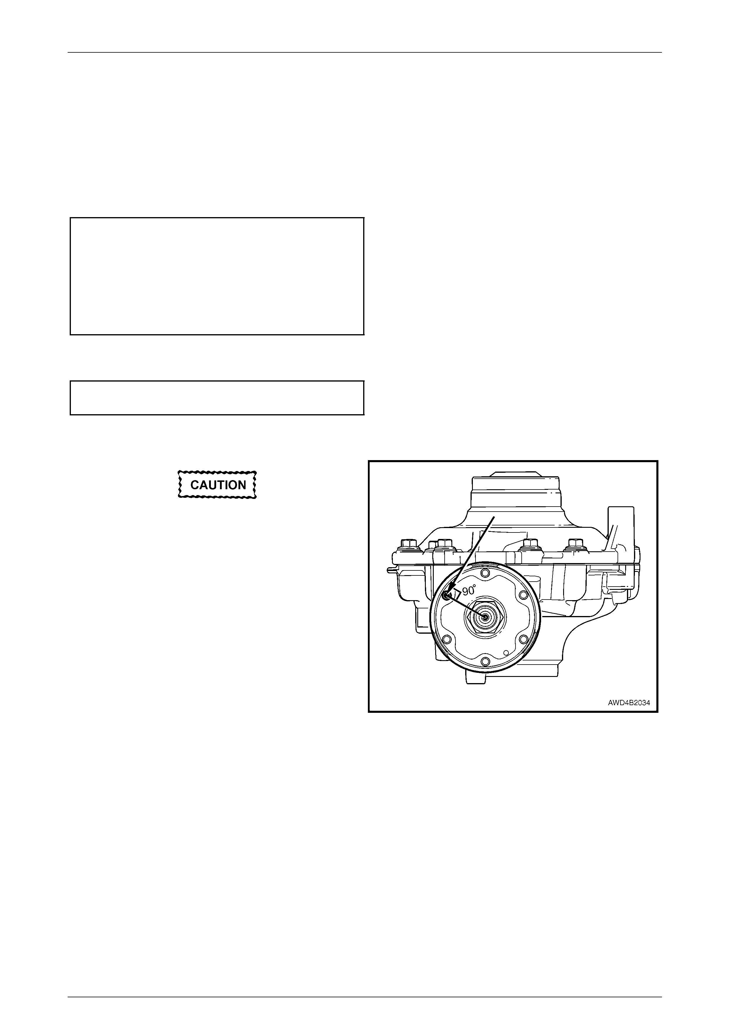
Front Final Drive, Bearing Housing & Driveshafts Page 4B3–54
Page 4B3-54
NOTE
Reduction of shim thickness must be equal for
each side.
14 Remove the cover and the differential assem bl y. Keep the differenti al case bearing and shims in the co rrect
relationship.
15 Install the hypoid pinion to the carrier but without the collapsible spacer and pinion oil seal. Torque the pinion nut
to produce the correct bearing preload.
Drive Pinion Bearing Preload Specification
Without Pinion Oil Seal and New Bearings
Koyo Bearings............................................1.4 – 1.8 N.m
Timken Bearings........................................1.4 – 2.4 N.m
Without Pinion Oil Seal and Used Bearings
Koyo Bearings............................................0.8 – 1.1 N.m
Timken Bearings........................................0.7 – 1.2 N.m
16 Fit the differential and ring gear assembly to the carrier housing, fit the cover to the case housing, install the
retaining bolts and tighten to the correct torque specification.
Final drive cover retaining
bolt torque specification.......................................45 N.m
17 Fit the companion flange to the pinion, alig ning marks made before disassembly, if appr opriate (i.e. the pinion
and/or the pinion flange h as not bee n replaced.).
The dial gauge must be positioned at 90° to
the radius of the companion flange to
produce an accurate m easurement.
18 Measure the backlash by ins erting a bolt into one of
the six threaded holes in the c ompanion flange. Place
a dial indicator and magnetic base on the carrier
housing, so the dial indicator stylus contacts the bolt at
90°. Zero the dial indicator.
19 After installing ring gear rotation tool DT-47573 use a
socket and bar to hold the differential in a sta tionary
state.
20 While holding the ring gear stationary, rotate the pinion
flange back and forth, noting the di al indicator reading.
The backlash specification measured at the bolt,
should be between 0.14 – 0.26 mm (this equates to
0.10 to 0.18 at the ring gear).
Figure 4B3 – 81
21 Adjust the differential bearing shim s to achieve the correct backlash.
NOTE:
Always maintain the same total thickness of the
shims. If one is reduced by 0.15 mm, then the
other shim must be increased by 0.15 mm.
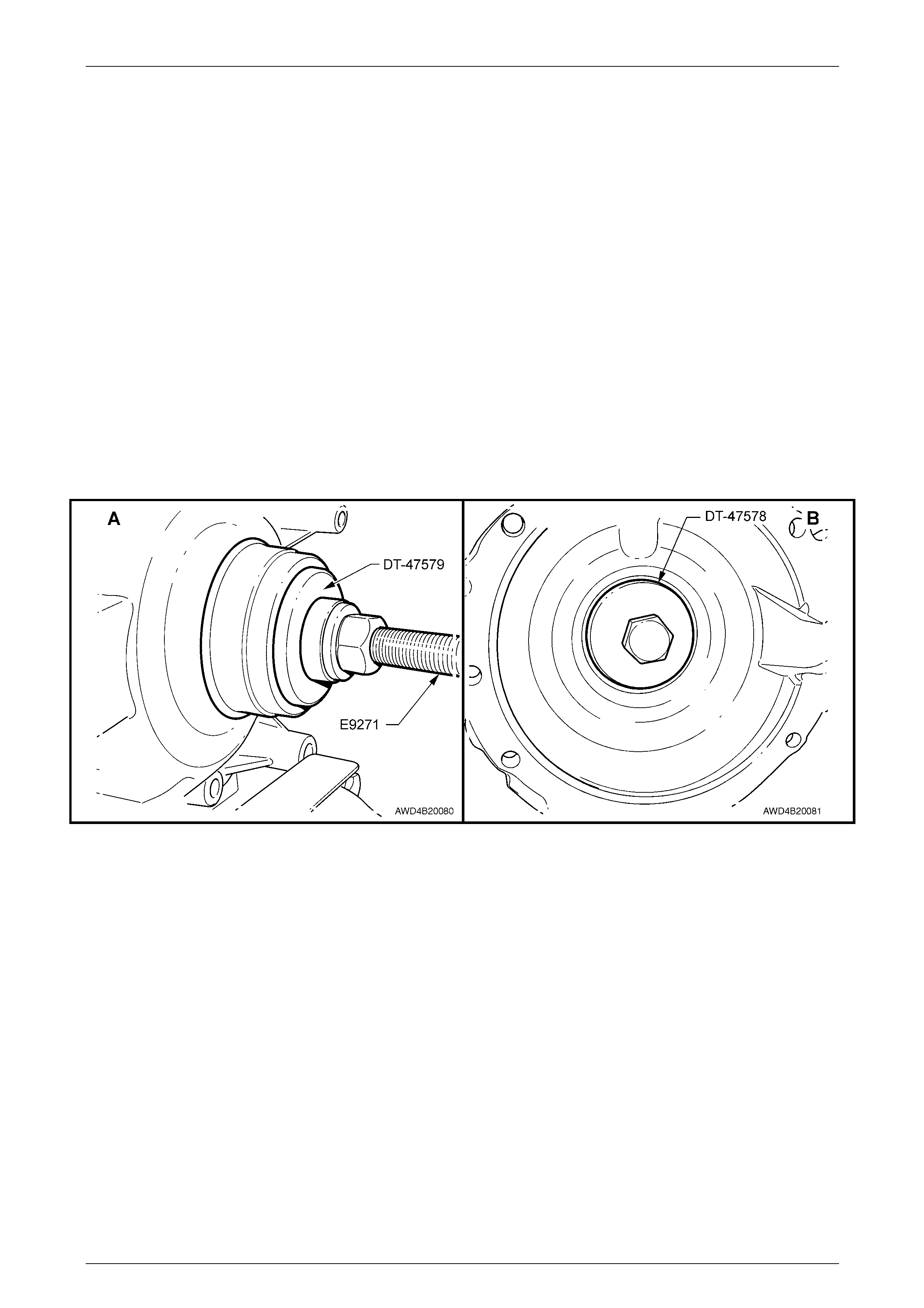
Front Final Drive, Bearing Housing & Driveshafts Page 4B3–55
Page 4B3-55
22 If backlash is excessive, decrease the shim thickness on the pinion side of the ring gear and increase shim
thickness on the ring gear side, by the same amount. If backlash is insufficient, increase the shim thickness on the
pinion side of the ring gear and decrease shim thickness on the ring gear s ide, b y the sam e amount.
23 With the backlash correct, rotate the pinion in both directio ns (approximately 10 times in each) sufficient to rotate
the ring gear 3 complete turns. Remove the cover & differential ass embl y to inspect the gear tooth markings. (The
markings should be the same as those for the rear drive unit. Refer to 'Ring Gear and Pinion Contact Pattern', in
3.3 Removed Final Drive Assembly, Reassemble, Section 4B1 Rear Final Drive and Drive Shafts). If the marking
is not acceptable, adjust the pinion position and/or backlash to achieve an acceptable tooth contact.
24 Once an acceptable marking has been achieved, remove the cover and the differential assembly. Remove the
dummy differential bearing cups (Tool No. DT-47577) from the carrier and the cover.
25 Install the established shim thicknesses and the correct bea ring cups to the cover and carrier housings, as follows:
a Assemble bear ing cup installer DT-47578 to the bearing cup and the bearing cup al igning plug, Tool No. DT-
47579 to the housing, then insert the bolt (p art of T ool No. E9271) through both.
b Install the thrust bearing, washer and nut (part of Tool No. E9271).
c Tighten the nut until the bearing cup is fully installed into the housing.
NOTE
While the cover housing is sho wn, the installation process for the carrier housi ng is e xactl y the same. Vie w 'A'
shows the tool arrangement outside the cove r, while View 'B' shows the inside view.
Figure 4B3 – 82
26 Reassemble the differential assembl y with the cover and recheck the backlash and the preload. Some change can
be expected due to slight variants in the bearing cups. Adjust the shim thickness if necessary, to correct the
backlash or preload.
27 Remove the cover, differential assembly, companion flange and pinion bearing for the final assembly of the drive
unit. Refer to "Final Drive Unit Assembly", in this Section.
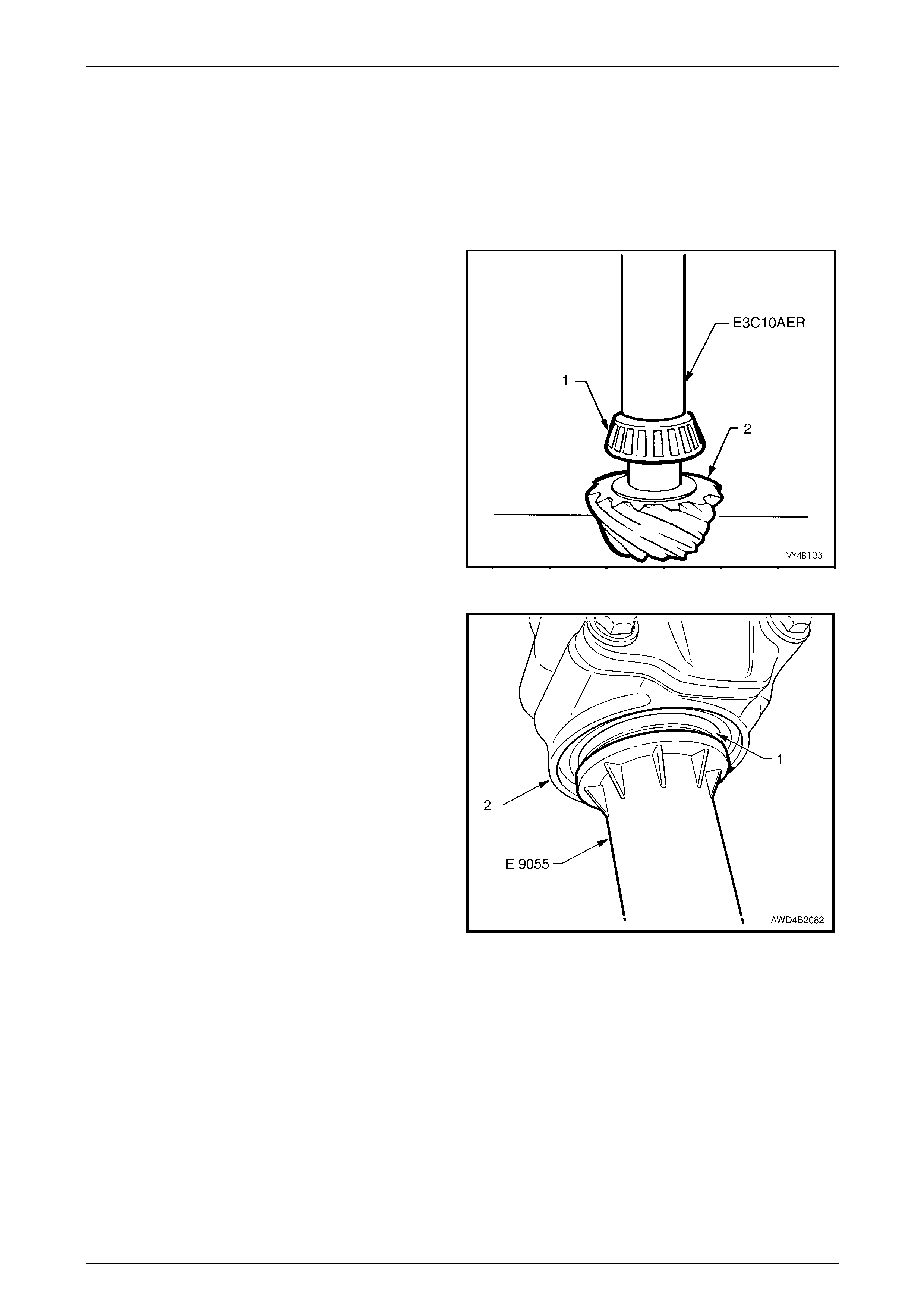
Front Final Drive, Bearing Housing & Driveshafts Page 4B3–56
Page 4B3-56
Final Drive Unit Assembly
1 If not already completed, reassemble the differential assembly. Refer to "Reassemble – Differential", in this
Section.
2 Establish and install the correct pinion shim required, refer to "Drive Pinion – Shim Selection", in this Section.
3 Determine and install the correct differential carrier bearing shims, preload and backlash required, refer to
"Differential Assembly - Bearing Preload and Backlash", in this Section.
4 If the pinion inner (head) bearing (1) is to be replaced,
place the new head bearing cone (1) onto the pinion
(2) and press the bearing aga inst the pin ion shaft
shoulder, using Tool No. E3C10AER.
5 Lubricate the pinion inner (head) bearing with the
recommended final drive lubri c ant, refer to
"Lubrication", in 1.2 Final Drive Maintenance, in this
Section.
6 Install the pinion in the carrier housing and install a
new collapsible pinion sp acer.
NOTE:
The new outer (tail) pinion bearing cup was
installed during the pinion depth procedure.
7 Lubricate the outer (tail) pinion bearing cone with the
recommended final drive lubri c ant, refer to
"Lubrication", in 1.2 Final Drive Maintenance, in this
Section, then install the bearing onto the pinion. Figure 4B3 – 83
8 Lubricate the l ips and outside diameter of a new pinion
oil seal (1), with Mobilgrease XHP 222. The recess
between the lips shoul d be approximatel y 50 % filled
with grease. A light coating of grease is also to be
applied to the dirt lip that contacts the companio n
flange guard.
9 Install the pinion oil seal (1) in the carrier housing (2),
using Tool No. E 9055.
Figure 4B3 – 84
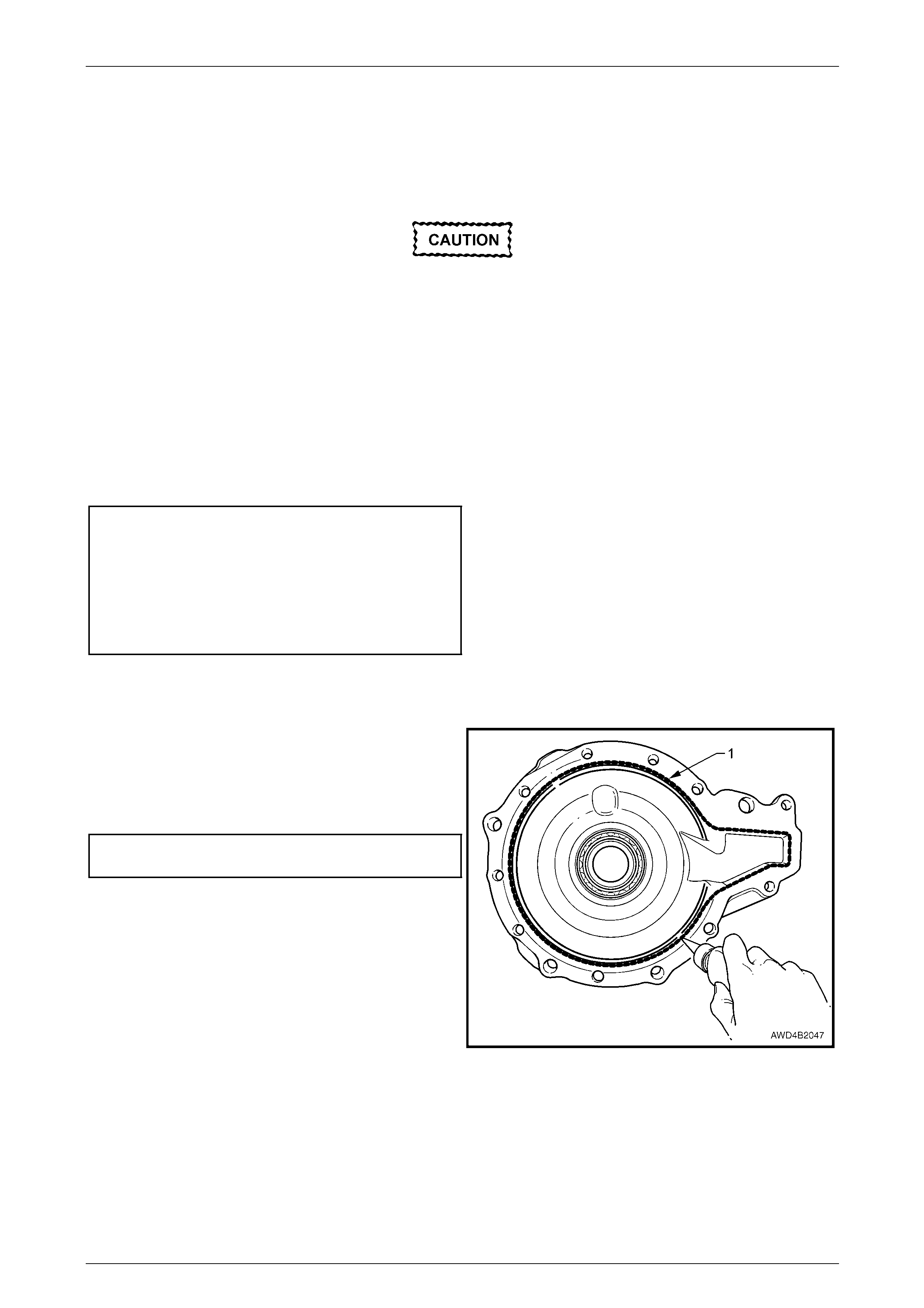
Front Final Drive, Bearing Housing & Driveshafts Page 4B3–57
Page 4B3-57
10 Reinstall the pinion flange onto the pinion shaft, then apply a thread sealant such as Loctite 262 or equivalent to
the pinion nut, before reinstalling the nut.
11 Fully install the pinion flange, by tightening the pinion nut but, during this process, rotate the pinion backwards and
forwards to seat the bearings. Fit [packing flange, Tool No. DT-47580 and holding bar, Tool N o. J 8614-10 to the
flange during the installation process.
If the preload is exceeded, the collapsible
spacer must be replaced and the preload
process repeated.
12 Frequently check the bearing preload while tightening the nut to achieve the specifi ed bearing preload.
Refer to 2.11 Pinion Flange Replace, in Section 4B1 Rear Final Drive & Driveshafts.
NOTE
Even though the procedure in Section 4B1
relates to the rear final drive assembly, the
procedure is exactly the same for the front final
drive assembly.
Drive Pinion Bearing Preload Specification
With Pinion Oil Seal and Ne w Bearings
Koyo Bearings............................................1.5 – 2.1 N.m
Timken Bearings........................................1.4 – 2.4 N.m
With Pinion Oil Seal and Used Bearings
Koyo Bearings............................................0.8 – 1.1 N.m
Timken Bearings........................................0.7 – 1.2 N.m
13 Refit the differential assembly in the carrier with the correct bearing cup shims previously installed behind the
differential carrier bearing cups (refer to Step 24, in Differential Assembly – Bearing Prel oad and Backlash, in this
Section.
14 Apply a continuous 1 – 1.5 mm bead of Loctite "Ultra
Blue" sealant #58791 (1) or e quivalent, to the cover
mating face in the location shown.
15 Reinstall the cover to the carrier ho using, reinstall the
10 bolts and tighten to the correct torque spec ification.
Final drive cover retaining
bolt torque specification.......................................45 N.m
Figure 4B3 – 85
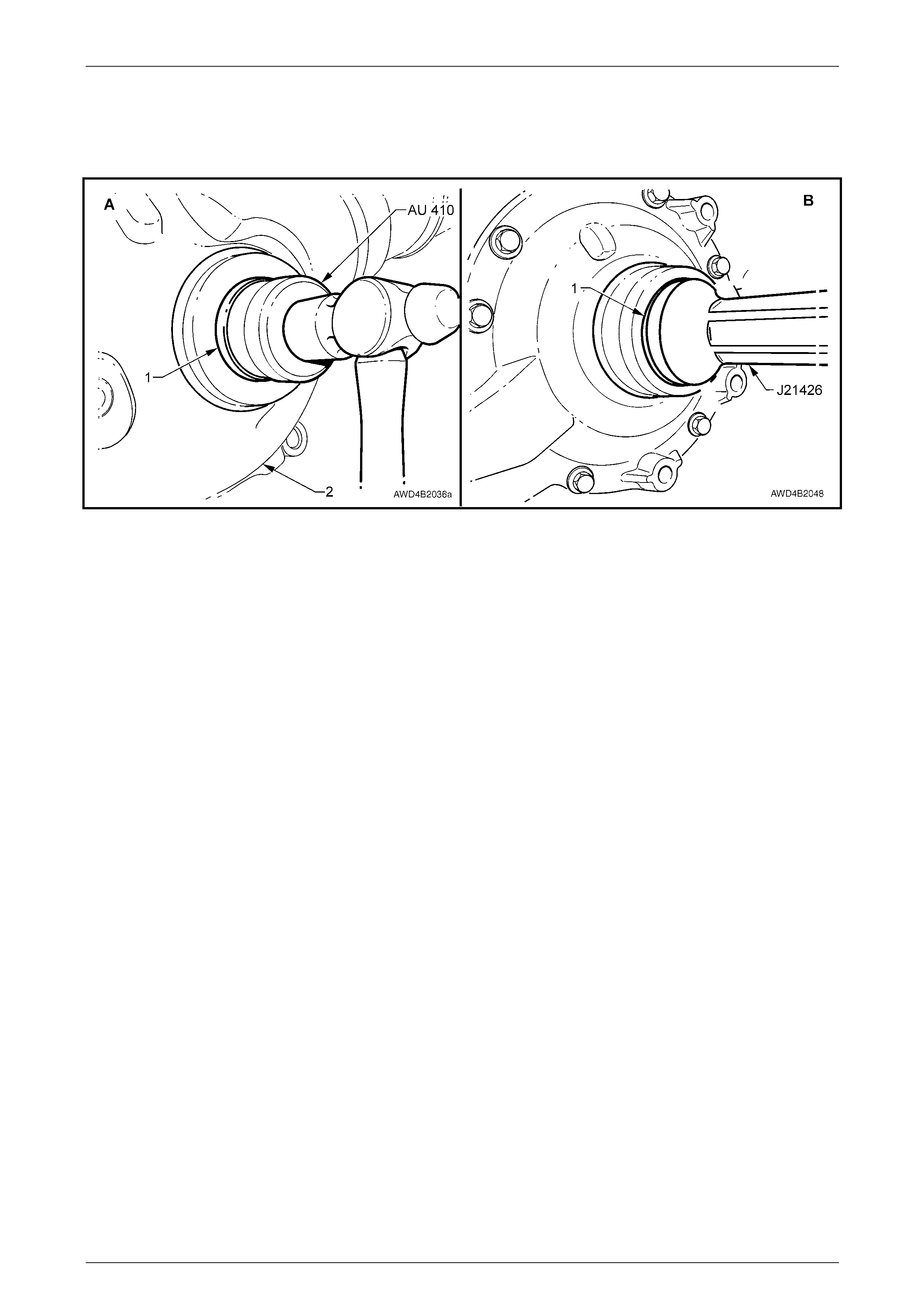
Front Final Drive, Bearing Housing & Driveshafts Page 4B3–58
Page 4B3-58
16 Lubricate new carrier and cover housing seal lips, with Mobilgrease XHP 222. The recess between the lips should
be approximately 50% filled with grease.
17 Use Tool No. Tool No. AU 410 to install the s eal (1) to the carrier housing ( v iew 'A') and Tool No. J 21426 to install
the oil seal (2) to the case housing (view 'B').
Figure 4B3 – 86
18 Reinstall the final drive asse mbly into the vehicle. Refer to 3.2 Front Final Drive, Reinstall, in this Section.

Front Final Drive, Bearing Housing & Driveshafts Page 4B3–59
Page 4B3-59
4 Diagnosis
Apart from the fact that a limited slip differential is not available for the front final drive assembly, for diagnostic
procedures relating to the front final drive an d driveshafts, refer to 4 Diagnosis, in Section 4B1 Rear Final Drive and
Driveshafts.

Front Final Drive, Bearing Housing & Driveshafts Page 4B3–60
Page 4B3-60
5 Specifications
General
Front Final Drive Assembly..................................................................................DANA – M70
Drive Type ..............................................................................................Independent Housing
Gear Type......................................................................................................................Hypoid
Gear Ratio (Refer ID label on Carrier Housing)..............................................................3.46:1
No. Teeth:
Ring Gear.....................................................................................................................45
Drive Pinion Gear.........................................................................................................13
Lubricant
Final Drive Assembly:
Capacity.............................................................................................................0.8 litres
Type – Synthetic Hypoid Gear Oil.............................................................SAE 80W-140
Final Drive Pinion Gear Bearings
Bearing Type ...................................................................................... Adjustable Taper Roller
Bearing Pre-Load Adjustment.....................................................................Collapsible Spacer
Pinion Depth of Mesh Adjustment.....................................................................Selective Shim
Bearing Pre-Load:...................................................................................Timken Koyo
New bearings without Oil Seal ......................................................1.4 – 2.4 1.4 – 1.8 N.m
Used bearings without Oil Seal.....................................................0.7 – 1.2 0.8 – 1.1 N.m
New Bearings With Oil Seal..........................................................1.4 – 2.4 1.5 – 2.1 N.m
Used Bearings With Oil Seal.........................................................0.7 – 1.2 0.8 – 1.1 N.m
Differential Carrier Bearings
Bearing Type ...................................................................................... Adjustable Taper Roller
Bearing Pre-Load Adjustment...........................................................................Selective Shim
Bearing Pre-Load, Measured without Axle Shafts or Pinion:..................Timken Koyo
New bearings ................................................................................1.1 – 2.8 0.6 – 1.9 N.m
Used bearings...............................................................................0.6 – 1.4 0.3 – 1.0 N.m
Backlash
Between Ring Gear and Pinion (at the tightest point)......................................0.10 – 0.18 mm
At the Pinion Flange Bolt Pitch Circle Diameter
(measured perpendicular to bolt).....................................................................0.14 – 0.26 mm
Run-Out Specifications
Maximum Ring Gear Run-Out (Assembled)
Measured on back face of ring gear ...........................................................................0.13 mm
Maximum Pinion Flange Run-Out........................................................................0.10 mm TIR
Sealants
Carrier to Cover Housing.............................................Loctite 58791 'Ultra Blue' or equivalent
Pinion Nut.........................................................................................Loctite 262 or equivalent.
Lubricants/Greases
Final Drive Oil Seal Lips, Bearing H ousing, Bearings,
Oil Seals and Shaft Splines ...................................................................Mobilgrease XHP 222
Driveshaft Lubricant Quantities
Outer, Fixed Constant Velocity Joint
Joint..................................................................55 ± 5 g
Boot................................................................100 ± 5 g
Inner Tripot Joint
Tripot ..............................................................140 ± 5 g
Boot..................................................................60 ± 5 g

Front Final Drive, Bearing Housing & Driveshafts Page 4B3–61
Page 4B3-61
6 Torque Wrench Specifications
ATTENTION
Fasteners must be repl aced after loosening.
Vehicle must be at curb height before final tightening.
Fasteners either ha ve micro encapsulated sealant a pplied or in corporate a mechani cal thread lock and
should only be re-used once. If in doubt, replacement is recommended.
Bearing housing to engine oil pan retaining bolt.....................................45 N.m
Exhaust manifold bolt – GEN III V8..............Stage 1.............................15 N.m
Stage 2.............................25 N.m
Exhaust manifold bolt – V6.....................................................................20 N.m
Engine mount bracket bolt .....................................................................50 N.m
Engine mount nut (Upper and lower)......................................................80 N.m
Final drive cover bolt ..............................................................................45 N.m
Final drive drain plug..............................................................................45 N.m
Final drive filler plug ...............................................................................28 N.m
Front control arm ball joint stud..............................................................55 N.m
Front driveshaft outer retaining nut...............Stage 1...........................130 N.m
Stage 2.. Loosen until nu t is loose
Stage 3...........................200 N.m
Front final drive breather pipe bracket bolt GEN III V8 Engine............22 N.m
HFV6 Engine......................9 N.m
Front final drive to engine oil pan retaining bolt......................................70 N.m
Ring gear bolt (right hand thread).........................................................140 N.m
Road wheel attaching nut...........................................................110 – 140 N.m
Transmission rear crossmem ber attaching bolt......................................55 N.m
Underbody front side rail brace attaching nut.........................................25 N.m
Upper strut locating plate retaining nut .................................................. 55 N.m
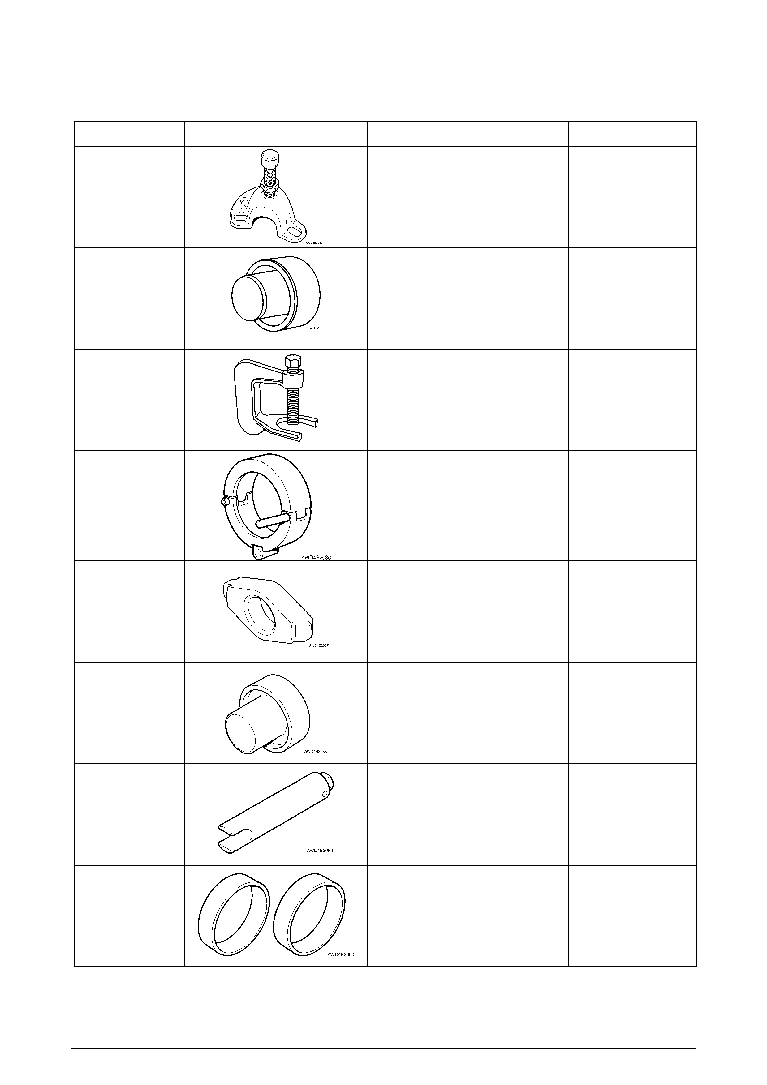
Front Final Drive, Bearing Housing & Driveshafts Page 4B3–62
Page 4B3-62
7 Special Tools
Tool Number Illustration Description Tool Classification
7208
Remover
Used to remove the front driveshaft
from front the hub.
Previously released.
Mandatory
AU 410
Seal Installer
Used to install the carrier cover oil
seal.
Previously released
Unique
C4150-C
Press Tool
Used to remove wheel studs from the
rear wheel trunnion.
Previously released as AJ24292-C.
Unique
DT-47570
Front Driveshaft Remover/Installer
Used in conjunction with slide
hammer J6125-1B to remove/install
the front driveshafts.
New release
Mandatory
DT-47571
Cup Removal Adaptor
Used in conjunction with E9293 to
remove both pinion bearing cups from
the carrier housing.
New release
Available
DT-47572
Side Bearing Installer
Used with a hydraulic press to install
the differential carrier bearing cones.
New release
Available
DT-47573
Ring Gear Rotation Tool
Used to rotate differential housing to
measure bearing preload.
New Release
Mandatory
DT-47577
Dummy Bearing Cups
Used when determining the
differential bearing preload and
position.
New release.
Available
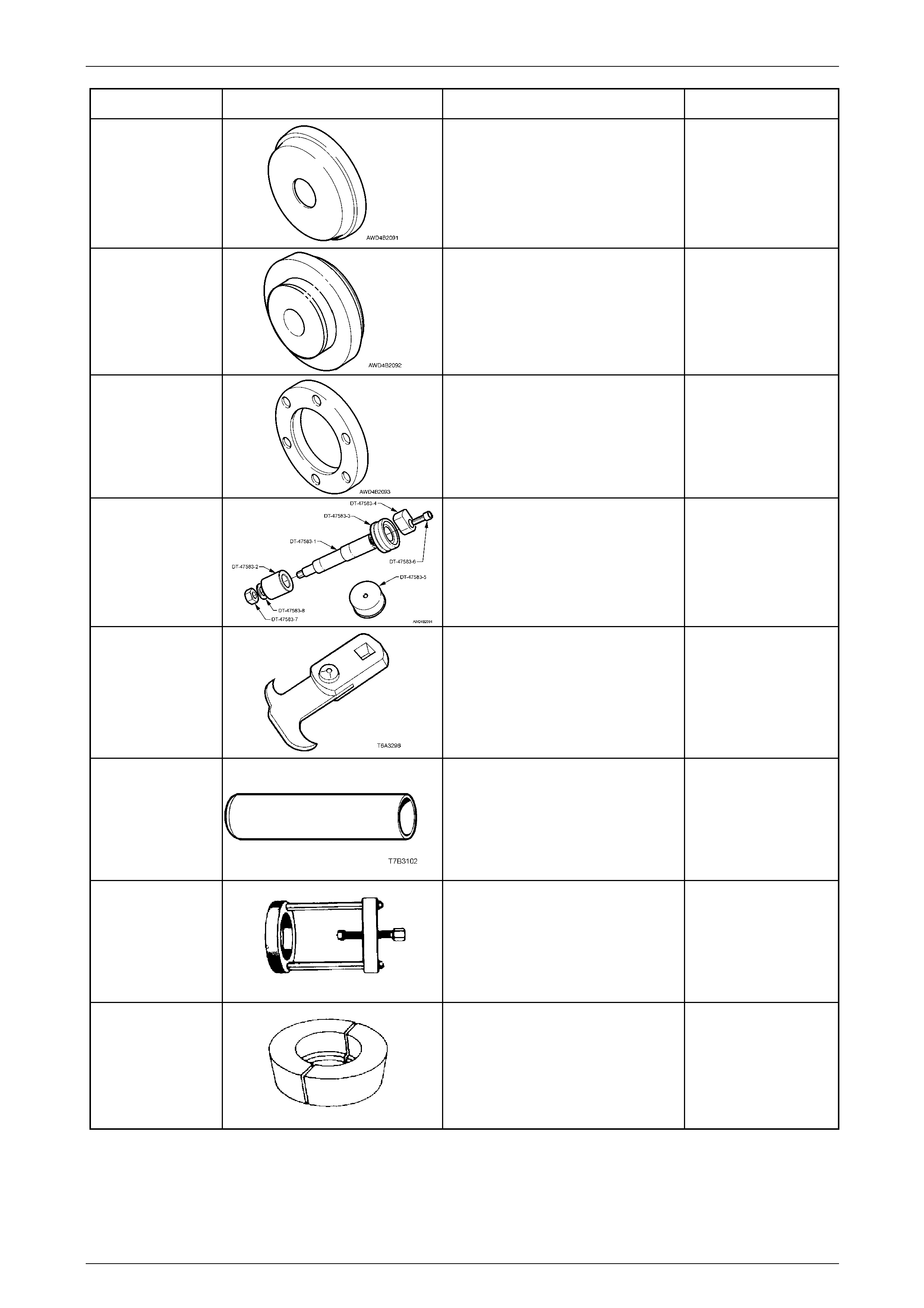
Front Final Drive, Bearing Housing & Driveshafts Page 4B3–63
Page 4B3-63
Tool Number Illustration Description Tool Classification
DT-47578
Bearing Cup Installer
Used in conjunction with bearing cup
alignment tool, DT-47579, to install
the ring gear carrier bearing cups to
the carrier and cover housings.
New release
Available
DT-47579
Bearing Cup Alignment Tool
Used in conjunction with bearing cup
installer, to ensure that bearing cups
are installed correctly.
New release.
Available
DT-47580
Spacer Ring
Fitted into the pinion flange to act as a
spacer for holding tool J8614-O1.
New Release
Available
DT-47583
Dummy Pinion
Used to determine the pinion bearing
preload and position.
New release
Available
E308
Seal Remover
Previously released
Available
E3C10AER
Pinion Bearing Cone Installer
Used to install the inner bearing cone
to the final drive pinion.
Previously released.
Unique
E1673MT
Basic Puller
Used with different adaptors to
remove tapered roller bearing cones,
Previously released
Unique
E 1673A15
Adaptor
Used in conjunction with E 1673-MT
to remove the inner pinion bearin g
cone.
Previously released
Unique
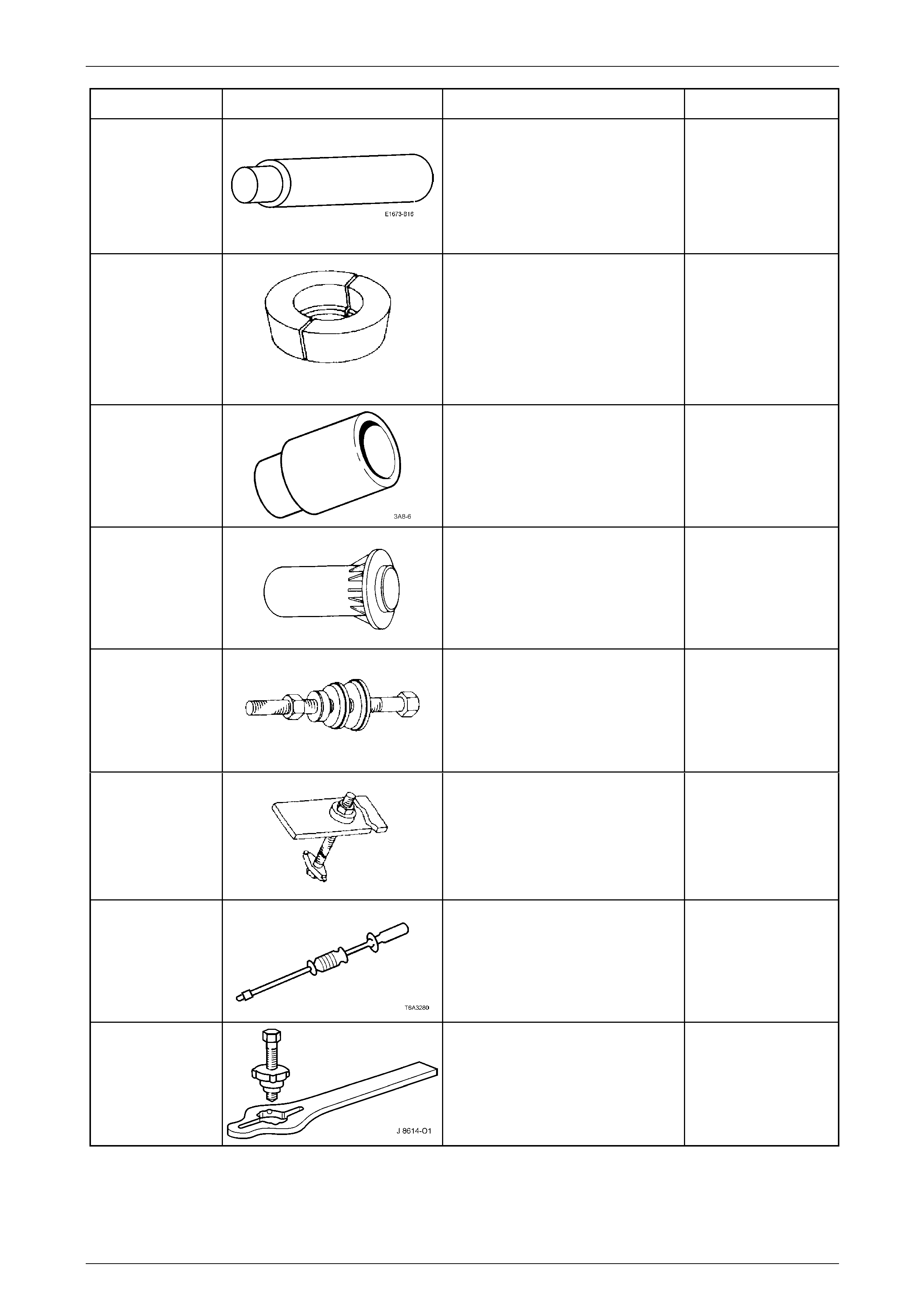
Front Final Drive, Bearing Housing & Driveshafts Page 4B3–64
Page 4B3-64
Tool Number Illustration Description Tool Classification
E 1673B16
Stepped Plug
Used in conjunction with puller
E 1673MT and adaptors E 1673A15/
E 1673N15 to remove bearings from
the final drive assembly.
Previously released
Unique
E 1673N15
Adaptor
Used in conjunction with puller
E 1673MT and stepped plug
E 1673B15, to remove the bearing
cones from the differential case
halves.
Previously released
Unique
E 1891-6
Sleeve
Also released as 3A8-6.
Previously released
Unique
E 9055
Seal Installer
Used to install the pinion oil seal.
Previously released
Unique
E 9271
Pinion Bearing Cup Installer
Comprises adaptors E 9271-A and
E 9271-B, together with bolt, nut, flat
washer and thrust bearing.
Previously released
Unique
E 9293
Pinion Bearing Cup Remover
Used to remove pinion bearing cups.
Previously released.
Unique
J 2619-O1
Slide Hammer and Adaptor
Used with driveshaft Tool, DT-47570
to remove/reinstall front driveshafts.
Previously released
Unique
J 8614-O1 Flange Pulley Holding Tool
Includes J 8614-2, J 8614-3 and J
8614-10. Used to remove the pinion
flange nut and flange.
Previously released
Unique
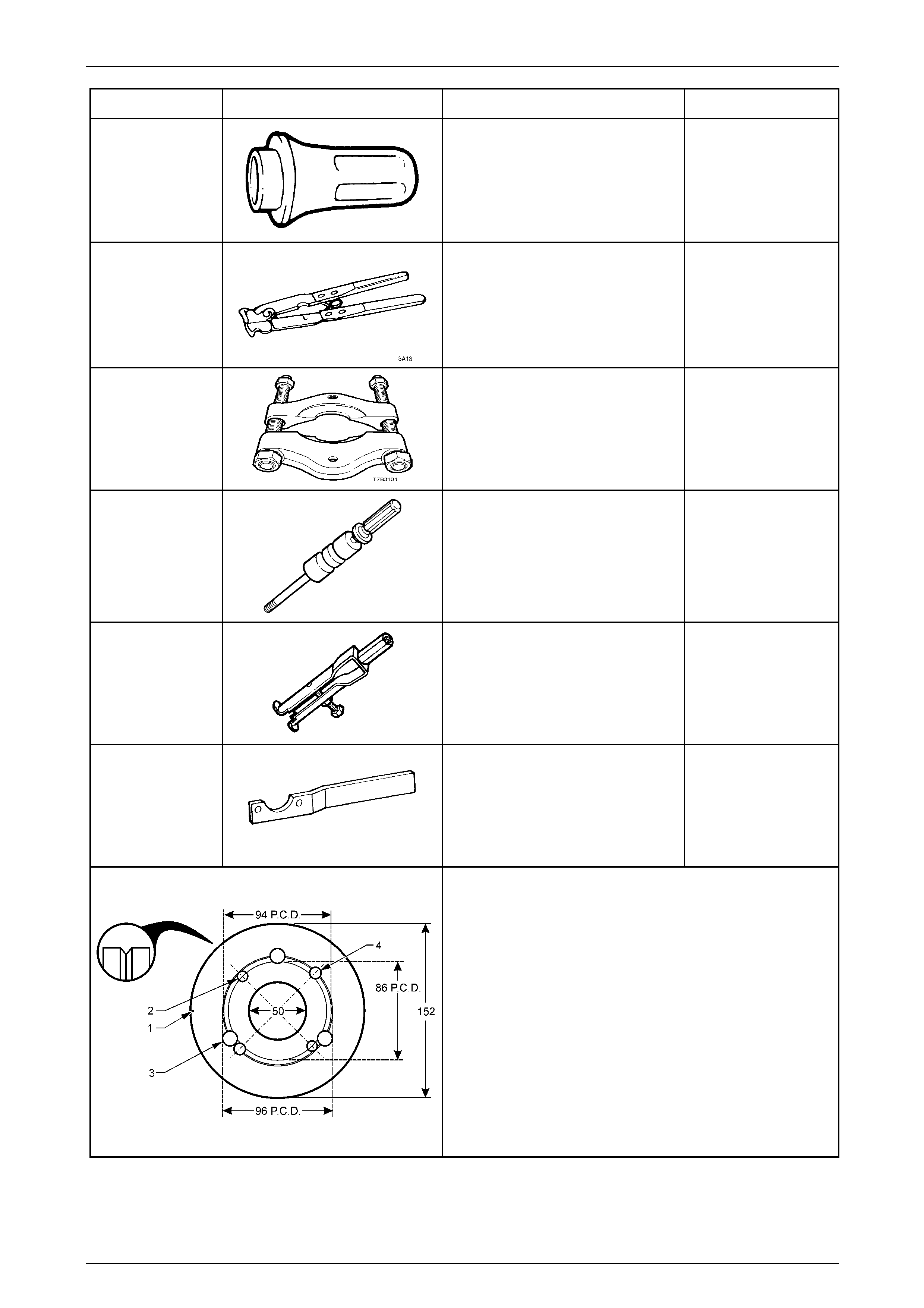
Front Final Drive, Bearing Housing & Driveshafts Page 4B3–65
Page 4B3-65
Tool Number Illustration Description Tool Classification
J 21426
Seal Installer
Used to install oil seals in various
locations.
Previously released
Unique
J 22610
Clamp Pliers
Used to secure boot clamps to some
of the constant velocity boot clamps.
Previously released
Available
J 22912-01
Press Plates
Used in a variety of pressing
operations as a support.
Previously released
Desirable
J 23907
Slide Hammer
Used in conjunction with bush
remover J 35280.
Previously released
Unique
J 35280
Universal Bush Remover
Used in conjunction with slide
hammer J23907.
Previously released.
Unique
KM-468
Holding Tool
Used to hold the wheel hub from
rotating.
Previously released
Unique
Pinion Flange Pulley
Fabricate this pulley to incl ude all VZ applications.
1 Made from a 13 mm thick piece of wood with a 1 mm
deep groove (inset) turned around the circu m ference.
2 Drill a small hol e at '1' and attach a one metre length of
fine string at this point, looped at one end, knotted at the
other.
3 Drill two, 8.5 mm holes (2) opposite to each other on a
pitch circle diameter of 86 mm (AWD Wagon).
4 Drill three, 13 mm holes (3) on a pitch circle diameter of
96 mm, 120 mm apart (All VZ models with IRS).
5 Drill two, 10 mm holes (4) opposite to each other on a
pitch circle diameter of 94 mm (All VZ Live Axle models).