
Diagnostics – All ABS 8.0 Variants Page 5B10 – 1
Page 5B10 – 1
Section 5B-10
Diagnostics – All ABS 8.0 Variants
1 General Information ...............................................................................................................................7
2 Wiring Diagrams and Connector Chart................................................................................................8
2.1 Wiring Diagrams .................................................................................................................................................... 8
HFV6 – ABS and ABS-TCS.................................................................................................................................... 8
HFV6 – ABS-TCS – Regular/Crew Cabs............................................................................................................... 9
HFV6 – ABS-TCS / ESP........................................................................................................................................ 10
GEN IV V8 – ABS and ABS-TCS.......................................................................................................................... 11
2.2 Connector Chart................................................................................................................................................... 12
HFV6 – ABS and ABS-TCS.................................................................................................................................. 12
HFV6 – ABS-TCS – Regular/Crew Cabs............................................................................................................. 13
HFV6 – ABS-TCS / ESP........................................................................................................................................ 14
GEN IV V8 – ABS AND ABS-TCS........................................................................................................................ 15
2.3 Connector Information ........................................................................................................................................ 16
Electronic Control Unit – A38 ............................................................................................................................. 16
Electronic Control Unit – A116 ........................................................................................................................... 17
Longitudinal Acceleration Sensor – B1 ............................................................................................................. 18
Front and Rear Wheel Speed Sensor – B52L, B52R, B76L and B76R............................................................. 19
Yaw-rate Sensor – B85 ........................................................................................................................................ 19
Steering Angle Sensor – B161............................................................................................................................ 20
3 Diagnostics...........................................................................................................................................21
3.1 Diagnostic General Descriptions........................................................................................................................ 21
Diagnostic Trouble Code Tables........................................................................................................................ 21
Diagnostic Trouble Codes................................................................................................................................... 22
Status of DTCs................................................................................................................................................. 22
Action Taken When a DTC Sets....................................................................................................................... 22
Conditions for Clearing DTCs........................................................................................................................... 22
4 Diagnostic Starting Point ....................................................................................................................23
4.1 Basic Requirements ............................................................................................................................................ 23
Basic Knowledge Required................................................................................................................................. 23
Basic Diagnostic Tools Required....................................................................................................................... 23
4.2 Diagnostic Precautions....................................................................................................................................... 24
4.3 Preliminary Checks.............................................................................................................................................. 25
4.4 Diagnostic System Check................................................................................................................................... 26
Description........................................................................................................................................................... 26
Test Description................................................................................................................................................... 26
5 Intermittent Faults................................................................................................................................27
5.1 Intermittent Fault Diagnostic Table.................................................................................................................... 27
Description........................................................................................................................................................... 27
6 Diagnostic Trouble Codes...................................................................................................................29
6.1 DTC List................................................................................................................................................................ 29
6.2 DTC C0035 or C0040 – Front Wheel Speed Sensor Circuit Fault.....................................................................31
DTC Descriptors................................................................................................................................................... 31
Diagnostic Fault Information .............................................................................................................................. 31
Circuit/System Description................................................................................................................................. 31
Techline

Diagnostics – All ABS 8.0 Variants Page 5B10 – 1
Page 5B10 – 2
Conditions for Running the DTC........................................................................................................................ 31
C0035 00 – C0040 00...................................................................................................................................... 31
C0035 05 – C0040 05...................................................................................................................................... 31
C0035 0F – C0040 0F...................................................................................................................................... 32
C0035 28 – C0040 28...................................................................................................................................... 32
C0035 64 – C0040 64...................................................................................................................................... 32
Conditions for Setting the DTC........................................................................................................................... 32
Action Taken When the DTC Sets ...................................................................................................................... 32
Conditions for Clearing the DTC ........................................................................................................................ 32
Additional Information......................................................................................................................................... 32
Test Description................................................................................................................................................... 33
DTC C0035 or C0040 Diagnostic Table.............................................................................................................. 33
6.3 DTC C0045 or C0050 – Rear Wheel Speed Sensor Circuit Fault......................................................................35
DTC Descriptors................................................................................................................................................... 35
Diagnostic Fault Information .............................................................................................................................. 35
Circuit/System Description................................................................................................................................. 35
Conditions for Running the DTC........................................................................................................................ 35
C0045 00 – C0050 00...................................................................................................................................... 35
C0045 05 – C0050 05...................................................................................................................................... 35
C0045 0F – C0050 0F...................................................................................................................................... 36
C0045 28 – C0050 28...................................................................................................................................... 36
C0045 64 – C0050 64...................................................................................................................................... 36
Conditions for Setting the DTC........................................................................................................................... 36
Action Taken When the DTC Sets ...................................................................................................................... 36
Conditions for Clearing the DTC ........................................................................................................................ 36
Additional Information......................................................................................................................................... 36
Test Description................................................................................................................................................... 37
DTC C0045 or C0050 Diagnostic Table.............................................................................................................. 37
6.4 DTC C0060, C0065, C0070, C0075 – Hydraulic Modulator Front Solenoid Fault............................................ 39
DTC Descriptors................................................................................................................................................... 39
Diagnostic Fault Information .............................................................................................................................. 39
Circuit Description............................................................................................................................................... 39
Conditions for Running the DTC........................................................................................................................ 39
Conditions for Setting the DTC........................................................................................................................... 39
Action Taken When the DTC Sets ...................................................................................................................... 40
Conditions for Clearing the DTC ........................................................................................................................ 40
Additional Information......................................................................................................................................... 40
Test Description................................................................................................................................................... 40
DTC C0060, C0065, C0070, C0075 Diagnostic Table......................................................................................... 41
6.5 DTC C0080, C0085, C0090, C0095 – Hydraulic Modulator Rear Solenoid Fault ............................................. 42
DTC Descriptors................................................................................................................................................... 42
4 Channel ABS 8.0........................................................................................................................................... 42
3 Channel ABS 8.0........................................................................................................................................... 42
Diagnostic Fault Information .............................................................................................................................. 42
Circuit Description............................................................................................................................................... 43
Conditions for Running the DTC........................................................................................................................ 43
Conditions for Setting the DTC........................................................................................................................... 43
Action Taken When the DTC Sets ...................................................................................................................... 43
Conditions for Clearing the DTC ........................................................................................................................ 43
Additional Information......................................................................................................................................... 43
Test Description................................................................................................................................................... 43
DTC C0080, C0085, C0090, C0095 Diagnostic Table......................................................................................... 44
6.6 DTC C0110 – Hydraulic Modulator Pump Motor Circuit Fault.......................................................................... 45
DTC Descriptors................................................................................................................................................... 45
Diagnostic Fault Information .............................................................................................................................. 45
Circuit Description............................................................................................................................................... 45
Conditions for Running the DTC........................................................................................................................ 45
Conditions for Setting the DTC........................................................................................................................... 45
Action Taken When the DTC Sets ...................................................................................................................... 45
Conditions for Clearing the DTC ........................................................................................................................ 45

Diagnostics – All ABS 8.0 Variants Page 5B10 – 1
Page 5B10 – 3
Additional Information......................................................................................................................................... 46
Test Description................................................................................................................................................... 46
DTC C0110 Diagnostic Table .............................................................................................................................. 46
6.7 DTC C0121 – Electronic Control Unit Internal Valve Relay Fault..................................................................... 47
DTC Descriptors................................................................................................................................................... 47
Diagnostic Fault Information .............................................................................................................................. 47
Circuit Description............................................................................................................................................... 47
Conditions for Running the DTC........................................................................................................................ 47
Conditions for Setting the DTC........................................................................................................................... 47
Action Taken When the DTC Sets ...................................................................................................................... 47
Conditions for Clearing the DTC ........................................................................................................................ 47
Additional Information......................................................................................................................................... 48
Test Description................................................................................................................................................... 48
DTC C0121 Diagnostic Table .............................................................................................................................. 48
6.8 DTC C0131 – Hydraulic Modulator Pressure Sensor Fault .............................................................................. 49
DTC Descriptors................................................................................................................................................... 49
Diagnostic Fault Information .............................................................................................................................. 49
Circuit Description............................................................................................................................................... 49
Conditions for Running the DTC........................................................................................................................ 49
Conditions for Setting the DTC........................................................................................................................... 49
Action Taken When the DTC Sets ...................................................................................................................... 49
Conditions for Clearing the DTC ........................................................................................................................ 49
Additional Information......................................................................................................................................... 49
Test Description................................................................................................................................................... 50
DTC C0131 Diagnostic Table .............................................................................................................................. 50
6.9 DTC C0141, C0146, C0151 or C0156 – Hydraulic Modulator Solenoid Valve Fault ........................................ 51
DTC Descriptors................................................................................................................................................... 51
Diagnostic Fault Information .............................................................................................................................. 51
Circuit Description............................................................................................................................................... 51
Conditions for Running the DTC........................................................................................................................ 51
Conditions for Setting the DTC........................................................................................................................... 51
Action Taken When the DTC Sets ...................................................................................................................... 52
Conditions for Clearing the DTC ........................................................................................................................ 52
Additional Information......................................................................................................................................... 52
Test Description................................................................................................................................................... 52
DTC C0141, C0146, C0151 or C0156 Diagnostic Table..................................................................................... 53
6.10 DTC C0161 – Brake Swit ch Circuit Fault............................................................................................................ 54
DTC Descriptors................................................................................................................................................... 54
Diagnostic Fault Information .............................................................................................................................. 54
Circuit Description............................................................................................................................................... 54
Conditions for Running the DTC........................................................................................................................ 54
Conditions for Setting the DTC........................................................................................................................... 54
Action Taken When the DTC Sets ...................................................................................................................... 54
Conditions for Clearing the DTC ........................................................................................................................ 54
Additional Information......................................................................................................................................... 54
Test Description................................................................................................................................................... 55
DTC C0161 Diagnostic Table .............................................................................................................................. 55
6.11 DTC C0186 – Lateral Acceleration Sensor Fault............................................................................................... 56
DTC Descriptors................................................................................................................................................... 56
Diagnostic Fault Information .............................................................................................................................. 56
Circuit Description............................................................................................................................................... 56
Conditions for Running the DTC........................................................................................................................ 56
Conditions for Setting the DTC........................................................................................................................... 56
Action Taken When the DTC Sets ...................................................................................................................... 56
Conditions for Clearing the DTC ........................................................................................................................ 56
Additional information......................................................................................................................................... 56
Test Description................................................................................................................................................... 57
DTC C0186 – Diagnostic Table ........................................................................................................................... 57

Diagnostics – All ABS 8.0 Variants Page 5B10 – 1
Page 5B10 – 4
6.12 DTC C0191 or C0192 Longitudinal Acceleration Sensor Signal Circuit.......................................................... 59
DTC Descriptors................................................................................................................................................... 59
Diagnostic Fault Information .............................................................................................................................. 59
Circuit Description............................................................................................................................................... 59
Conditions for Running the DTC........................................................................................................................ 59
Conditions for Setting the DTC........................................................................................................................... 59
DTC C0191 ...................................................................................................................................................... 59
DTC C0192 ...................................................................................................................................................... 59
Action Taken When the DTC Sets ...................................................................................................................... 59
Additional information......................................................................................................................................... 60
Test Description................................................................................................................................................... 60
DTC C0191 or C0192 Diagnostic Table.............................................................................................................. 60
6.13 DTC C0196 – Yaw-rate Sensor Output Signal Fault.......................................................................................... 62
DTC Descriptors................................................................................................................................................... 62
Diagnostic Fault Information .............................................................................................................................. 62
Circuit Description............................................................................................................................................... 62
Conditions for Running the DTC........................................................................................................................ 62
Conditions for Setting the DTC........................................................................................................................... 62
Action Taken When the DTC Sets ...................................................................................................................... 62
Conditions for Clearing the DTC ........................................................................................................................ 62
Additional information......................................................................................................................................... 62
Test Description................................................................................................................................................... 63
DTC C0196 – Diagnostic Table ........................................................................................................................... 63
6.14 DTC C0245, C0252 or C0253 – Wheel Speed Sensor Signal Output Fault...................................................... 65
DTC Descriptors................................................................................................................................................... 65
Diagnostic Fault Information .............................................................................................................................. 65
Circuit Description............................................................................................................................................... 65
Conditions for Running the DTC........................................................................................................................ 65
Conditions for Setting the DTC........................................................................................................................... 65
DTC C0245 ...................................................................................................................................................... 65
DTC C0252 ...................................................................................................................................................... 65
DTC C0253 ...................................................................................................................................................... 65
Action Taken When the DTC Sets ...................................................................................................................... 66
Conditions for Clearing the DTC ........................................................................................................................ 66
Additional Information......................................................................................................................................... 66
Test Description................................................................................................................................................... 66
DTC C0245, C0252 or C0253 Diagnostic Table.................................................................................................. 66
6.15 DTC C0460 – Steering Angle Sensor Circuit Fault............................................................................................ 68
DTC Descriptors................................................................................................................................................... 68
Diagnostic Fault Information .............................................................................................................................. 68
Circuit Description............................................................................................................................................... 68
Conditions for Running the DTC........................................................................................................................ 68
Conditions for Setting the DTC........................................................................................................................... 68
Action Taken When the DTC Sets ...................................................................................................................... 68
Conditions for Clearing the DTC ........................................................................................................................ 68
Additional Information......................................................................................................................................... 69
Test Description................................................................................................................................................... 69
DTC C0460 – Diagnostic Table ........................................................................................................................... 69
6.16 DTC C0550 and C0551 – Electronic Control Unit Internal Fault....................................................................... 71
DTC Descriptors................................................................................................................................................... 71
Diagnostic Fault Information .............................................................................................................................. 71
Circuit Description............................................................................................................................................... 71
Conditions for Running the DTC........................................................................................................................ 71
Conditions for Setting the DTC........................................................................................................................... 71
C0550............................................................................................................................................................... 71
C0551............................................................................................................................................................... 71
Action Taken When the DTC Sets ...................................................................................................................... 72
Conditions for Clearing the DTC ........................................................................................................................ 72
Additional Information......................................................................................................................................... 72
Test Description................................................................................................................................................... 72
DTC C0550 and C0551 Diagnostic Table ........................................................................................................... 73

Diagnostics – All ABS 8.0 Variants Page 5B10 – 1
Page 5B10 – 5
6.17 DTC C0569 – Electronic Control Unit Configuration Mismatch....................................................................... 74
DTC Descriptor..................................................................................................................................................... 74
Diagnostic Fault Information .............................................................................................................................. 74
Circuit Description............................................................................................................................................... 74
Conditions for Running the DTC........................................................................................................................ 74
Conditions for Setting the DTC........................................................................................................................... 74
Action Taken When the DTC Sets ...................................................................................................................... 74
Conditions for Clearing the DTC ........................................................................................................................ 74
Additional Information......................................................................................................................................... 74
Test Description................................................................................................................................................... 74
DTC C0569 Diagnostic Table .............................................................................................................................. 75
6.18 DTC C0800 – Battery Voltage Out of Range ...................................................................................................... 76
DTC Descriptors................................................................................................................................................... 76
Diagnostic Fault Information .............................................................................................................................. 76
Circuit Description............................................................................................................................................... 76
Conditions for Running the DTC........................................................................................................................ 76
Conditions for Setting the DTC........................................................................................................................... 76
Action Taken When the DTC Sets ...................................................................................................................... 76
Conditions for Clearing the DTC ........................................................................................................................ 76
Additional Information......................................................................................................................................... 77
Test Description................................................................................................................................................... 77
DTC C0800 Diagnostic Table .............................................................................................................................. 77
6.19 DTC C0895 – Yaw Rate Sensor Supply Voltage Out of Range.........................................................................79
DTC Descriptor..................................................................................................................................................... 79
Diagnostic Fault Information .............................................................................................................................. 79
Circuit Description............................................................................................................................................... 79
Conditions for Running the DTC........................................................................................................................ 79
Conditions for Setting the DTC........................................................................................................................... 79
Action Taken When the DTC Sets ...................................................................................................................... 79
Conditions for Clearing the DTC ........................................................................................................................ 79
Additional information......................................................................................................................................... 80
Test Description................................................................................................................................................... 80
DTC C0895 Diagnostic Table .............................................................................................................................. 80
6.20 DTC U2100 – No Communication With CAN Bus (High Speed)....................................................................... 82
DTC Descriptor..................................................................................................................................................... 82
Diagnostic Fault Information .............................................................................................................................. 82
Circuit Description............................................................................................................................................... 82
Conditions for Running the DTC........................................................................................................................ 82
Conditions for Setting the DTC........................................................................................................................... 82
Action Taken When the DTC Sets ...................................................................................................................... 82
Conditions for Clearing the DTC ........................................................................................................................ 83
Additional Information......................................................................................................................................... 83
Test Description................................................................................................................................................... 83
DTC U2100 Diagnostic Table .............................................................................................................................. 83
6.21 DTC U2105 Lost Communication With ECM...................................................................................................... 85
DTC Descriptors................................................................................................................................................... 85
Diagnostic Fault Information .............................................................................................................................. 85
Circuit Description............................................................................................................................................... 85
Conditions for Running the DTC........................................................................................................................ 85
Conditions for Setting the DTC........................................................................................................................... 85
Action Taken When the DTC Sets ...................................................................................................................... 85
Conditions for Clearing the DTC ........................................................................................................................ 85
DTC U2105 Diagnostic Table .............................................................................................................................. 86
6.22 DTC U2106 Lost Communication With TCM...................................................................................................... 88
DTC Descriptors................................................................................................................................................... 88
Diagnostic Fault Information .............................................................................................................................. 88
Circuit Description............................................................................................................................................... 88
Conditions for Running the DTC........................................................................................................................ 88
Conditions for Setting the DTC........................................................................................................................... 88
Action Taken When the DTC Sets ...................................................................................................................... 88

Diagnostics – All ABS 8.0 Variants Page 5B10 – 1
Page 5B10 – 6
Conditions for Clearing the DTC ........................................................................................................................ 88
Additional Information......................................................................................................................................... 88
DTC U2106 Diagnostic Table .............................................................................................................................. 89
6.23 DTC U2107 Lost Communication With BCM...................................................................................................... 91
DTC Descriptors................................................................................................................................................... 91
Diagnostic Fault Information .............................................................................................................................. 91
Circuit Description............................................................................................................................................... 91
Conditions for Running the DTC........................................................................................................................ 91
Conditions for Setting the DTC........................................................................................................................... 91
Action Taken When the DTC Sets ...................................................................................................................... 91
Conditions for Clearing the DTC ........................................................................................................................ 91
Additional Information......................................................................................................................................... 91
DTC U2107 Diagnostic Table .............................................................................................................................. 92
6.24 DTC U2143 Lost Communication With SAS ...................................................................................................... 94
DTC Descriptors................................................................................................................................................... 94
Diagnostic Fault Information .............................................................................................................................. 94
Circuit Description............................................................................................................................................... 94
Conditions for Running the DTC........................................................................................................................ 94
Conditions for Setting the DTC........................................................................................................................... 94
Action Taken When the DTC Sets ...................................................................................................................... 94
Conditions for Clearing the DTC ........................................................................................................................ 94
Additional Information......................................................................................................................................... 94
DTC U2143 Diagnostic Table .............................................................................................................................. 95

Diagnostics – All ABS 8.0 Variants Page 5B10 – 1
Page 5B10 – 7
1 General Information
This Section contains the diagnostics for al l variants of the Bosch 8.0 ABS braking systems. Except for ABS version 5.3,
each derivative contains a Diagnostic Trouble Code (DTC) list that has a hyperlink to this Section.
The stages for diagnosis remain as they have been; start at the Diagnostic System Check – Vehicle, in Section 0D
Vehicle Diagnostics, that will direct you to Section 5B – ABS-TCS-ESP General Information. From this point you will be
directed to the specific variation of the ABS that is fitted to the vehicle in question.
From the DTC list in each Sect ion, a hyperlink to this Section is provided.
To overcome unnecessary du plicati on of information, variations to the various circuit diagrams, general diagnostics
information and the diagnostic tables themselves are all included here in the one location.
Diagnostics – All ABS 8.0 Variants Page 5B10 – 1
Page 5B10 – 8
2 Wiring Diagrams and Connector
Chart
2.1 Wiring Diagrams
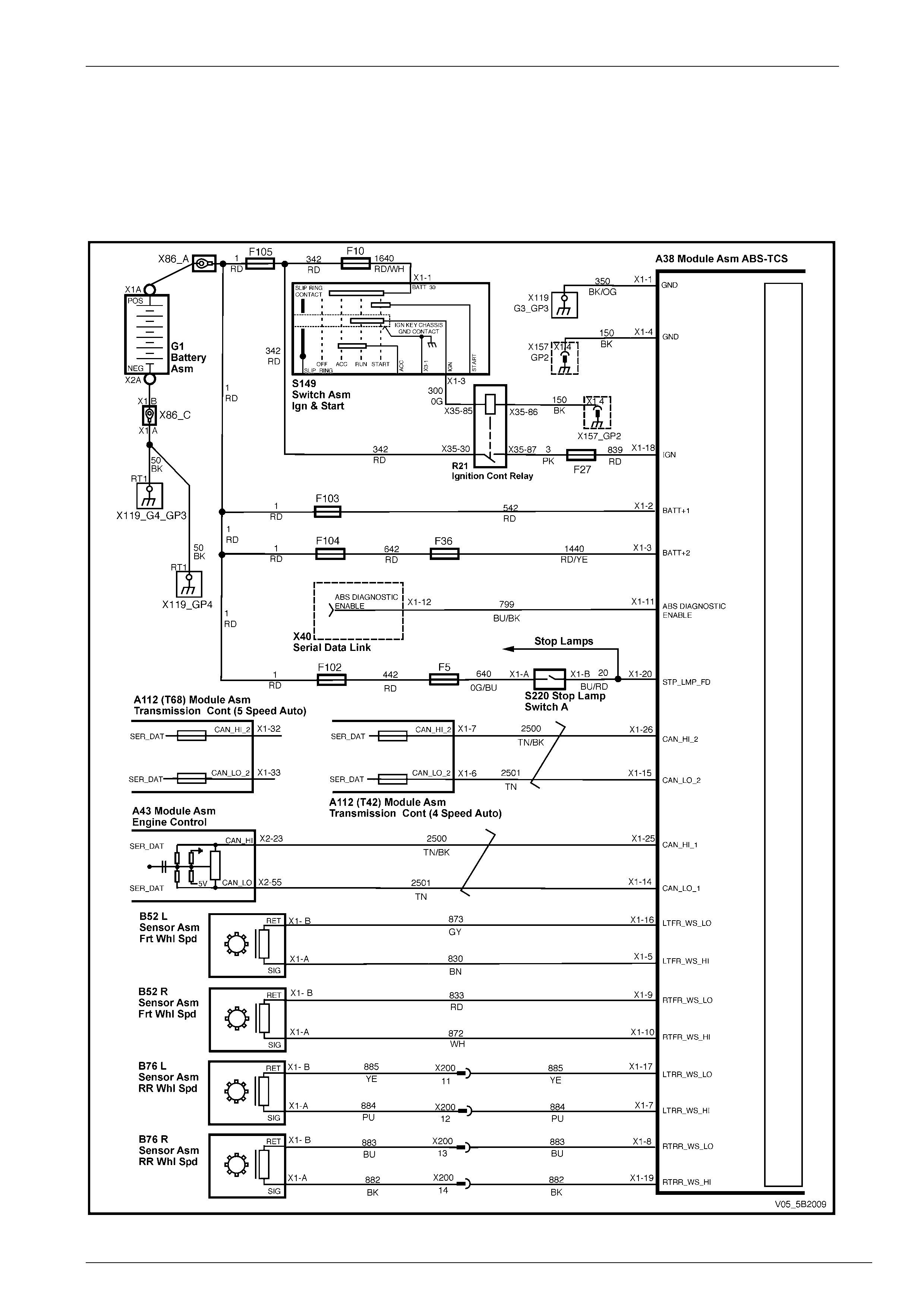
HFV6 – ABS and ABS-TCS
Figure 5B10-1
Diagnostics – All ABS 8.0 Variants Page 5B10 – 1
Page 5B10 – 9
HFV6 – ABS-TCS – Regular/Crew Cabs
Figure 5B10-2
Diagnostics – All ABS 8.0 Variants Page 5B10 – 1
Page 5B10 – 10
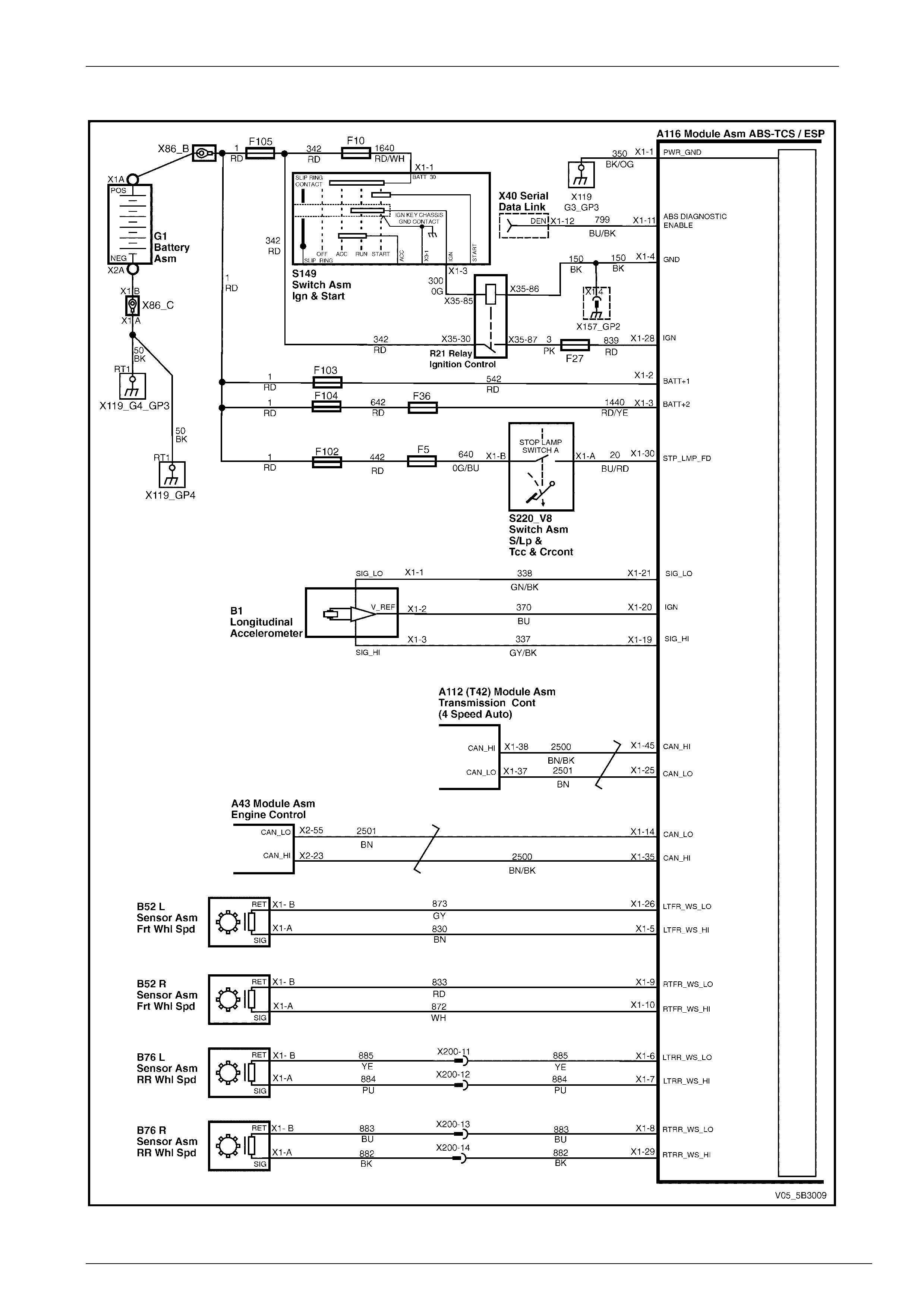
HFV6 – ABS-TCS / ESP
Figure 5B10-3
Diagnostics – All ABS 8.0 Variants Page 5B10 – 1
Page 5B10 – 11
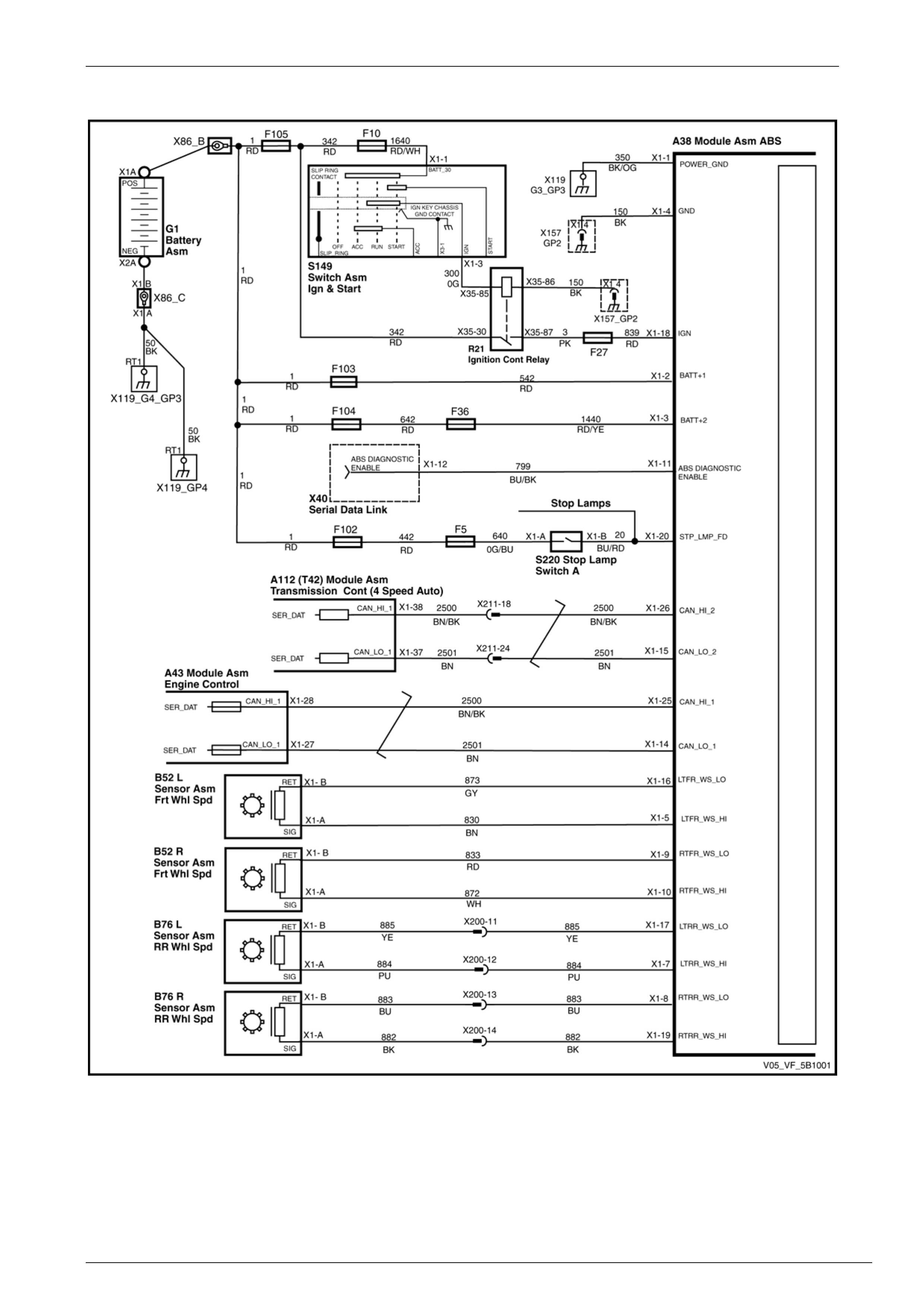
GEN IV V8 – ABS and ABS-TCS
Figure 5B10-4
Diagnostics – All ABS 8.0 Variants Page 5B10 – 1
Page 5B10 – 12
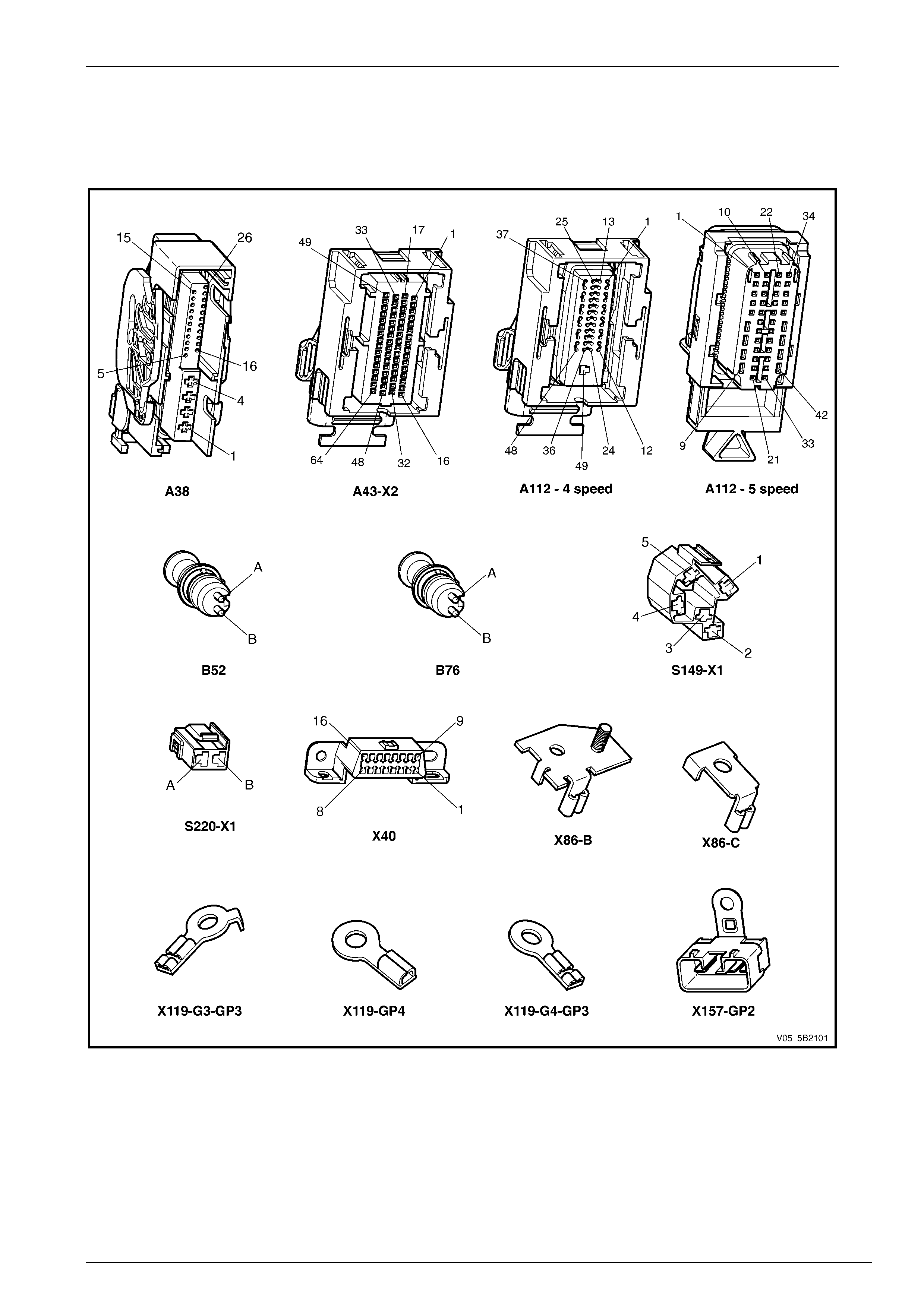
2.2 Connector Chart
HFV6 – ABS and ABS-TCS
Figure 5B10-5
Diagnostics – All ABS 8.0 Variants Page 5B10 – 1
Page 5B10 – 13
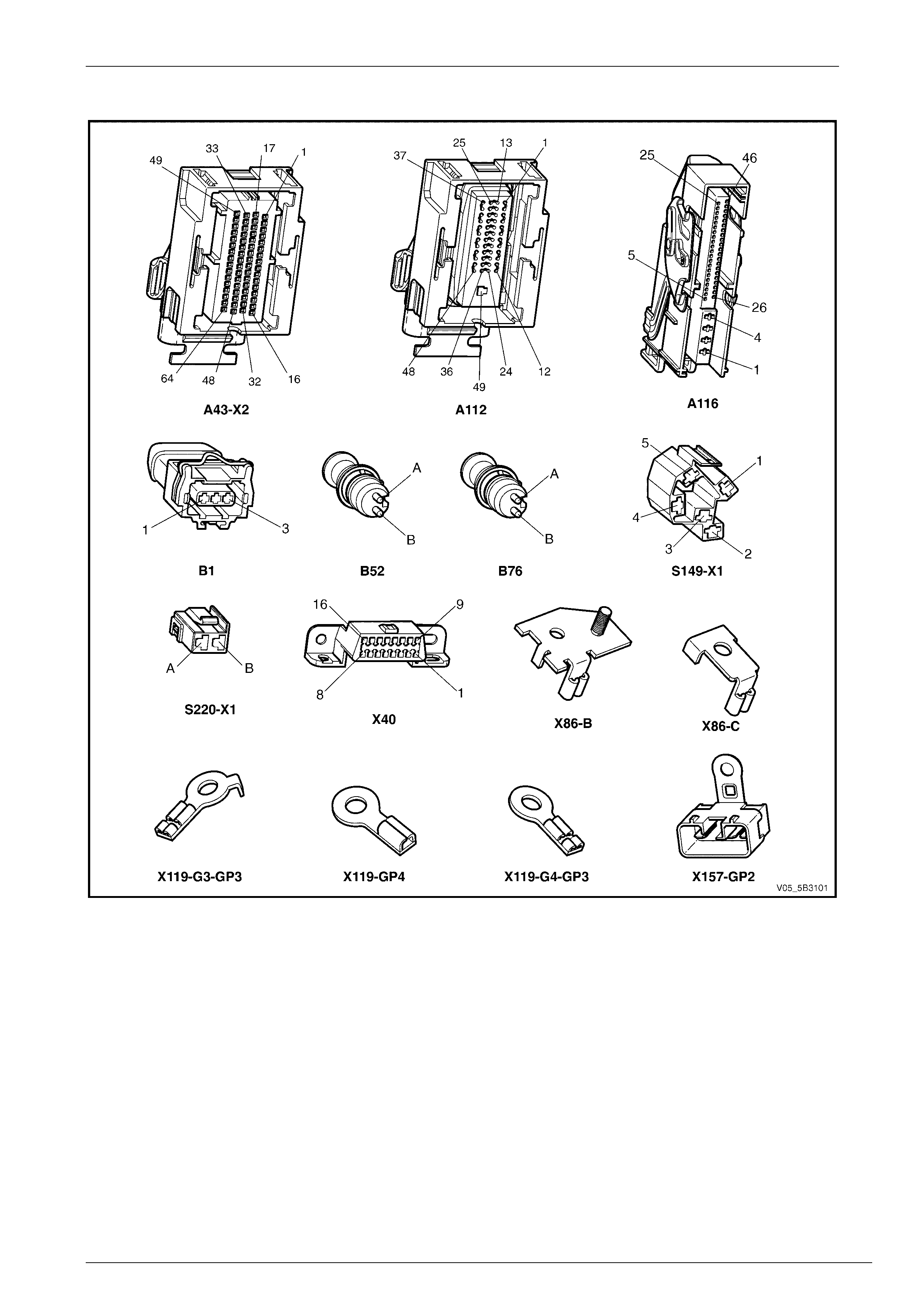
HFV6 – ABS-TCS – Regular/Crew Cabs
Figure 5B10-6
Diagnostics – All ABS 8.0 Variants Page 5B10 – 1
Page 5B10 – 14
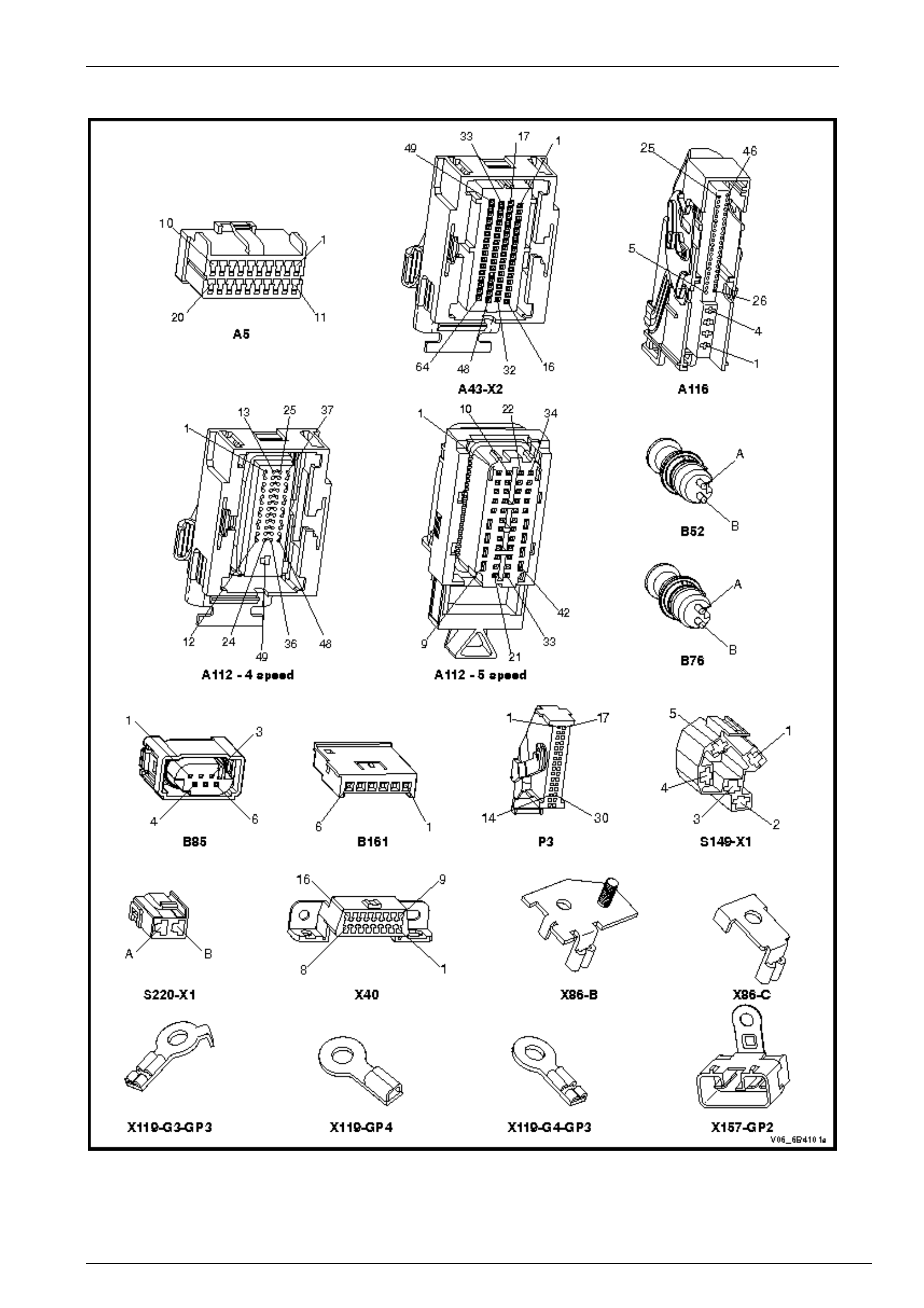
HFV6 – ABS-TCS / ESP
Figure 5B10-7
Diagnostics – All ABS 8.0 Variants Page 5B10 – 1
Page 5B10 – 15
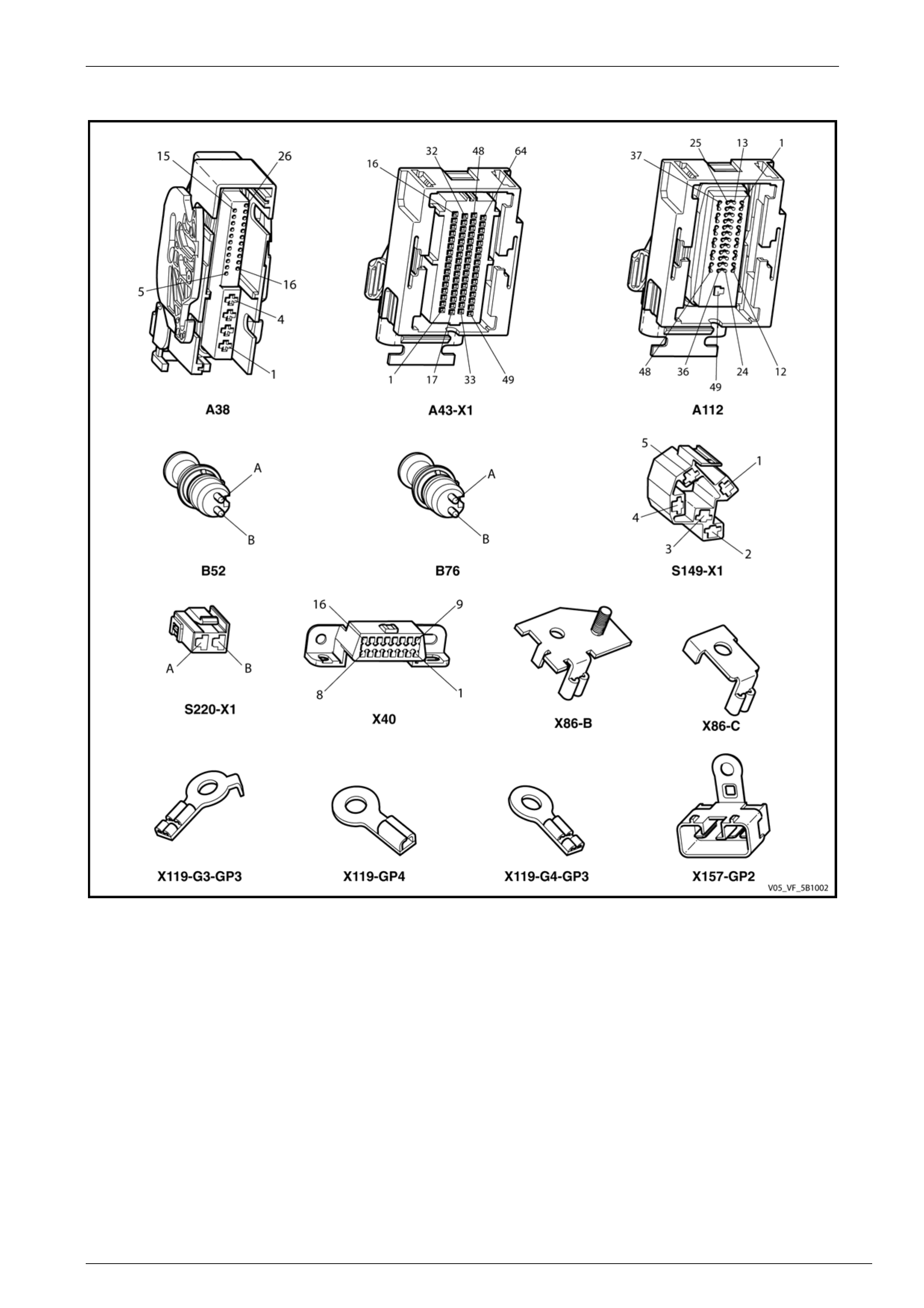
GEN IV V8 – ABS AND ABS-TCS
Figure 5B10-8
Diagnostics – All ABS 8.0 Variants Page 5B10 – 1
Page 5B10 – 16
2.3 Connector Information
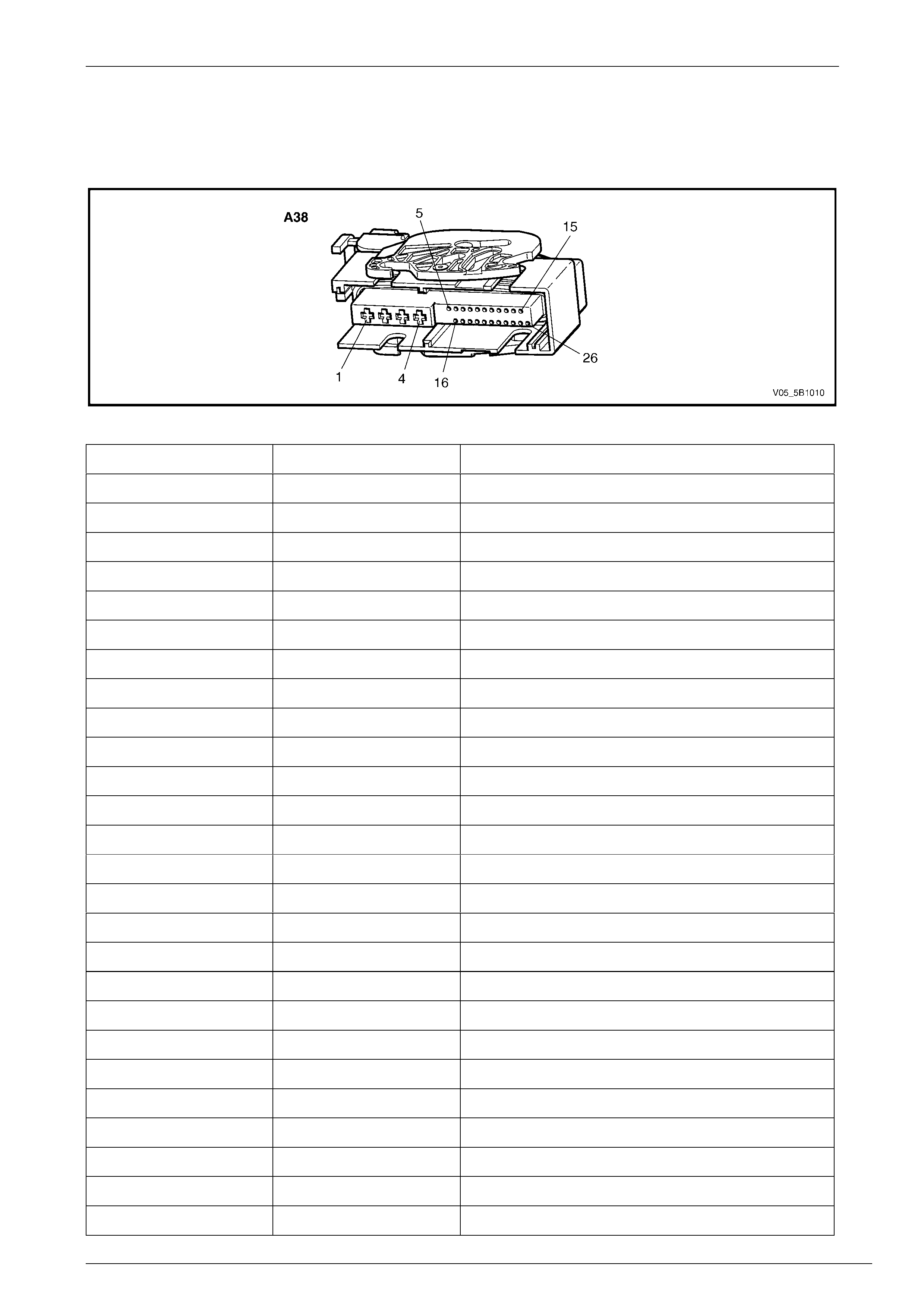
Electronic Control Unit – A38
Figure 5B10 – 1
Pin Circuit No. Function
1 350 Main Ground
2 542 12 V Uninterrupted Supply Voltage – Fuse 103
3 1440 12 V Uninterrupted Supply Voltage – Fuse 36
4 150 ECU Ground
5 830 Front Left Wheel Speed Sens or Signal
6 — Not Connected
7 884 Rear Left Wheel Speed Sensor Signal
8 883 Rear Right Wheel Speed Sensor Low Ref
9 833 Front Right Wheel Speed Sensor Low Ref
10 872 Front Right Wheel Speed Sensor Signal
11 799 ABS Diagnostic Enable
12 — Not Connected
13 — Not Connected
14 2501 CAN LO 1
15 2501 CAN LO 2
16 873 Front Left Wheel Speed Sensor Low Ref
17 885 Rear Left Wheel Speed Sensor Low Ref
18 839 12 V Ignition Supply Voltage – Fuse 27
19 882 Rear Right Wheel Speed Sensor Signal
20 20 Stop Lamp Switch 12 V Signal
21 — Not Connected
22 — Not Connected
23 — Not Connected
24 — Not Connected
25 2500 CAN HI 1
26 2500 CAN HI 2
Diagnostics – All ABS 8.0 Variants Page 5B10 – 1
Page 5B10 – 17
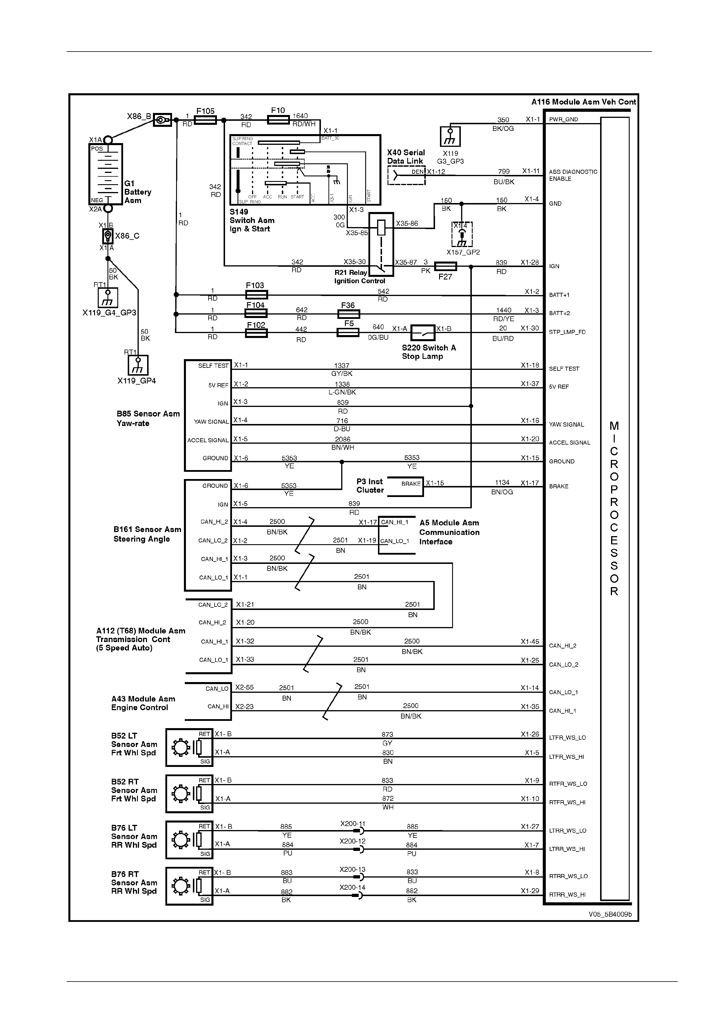
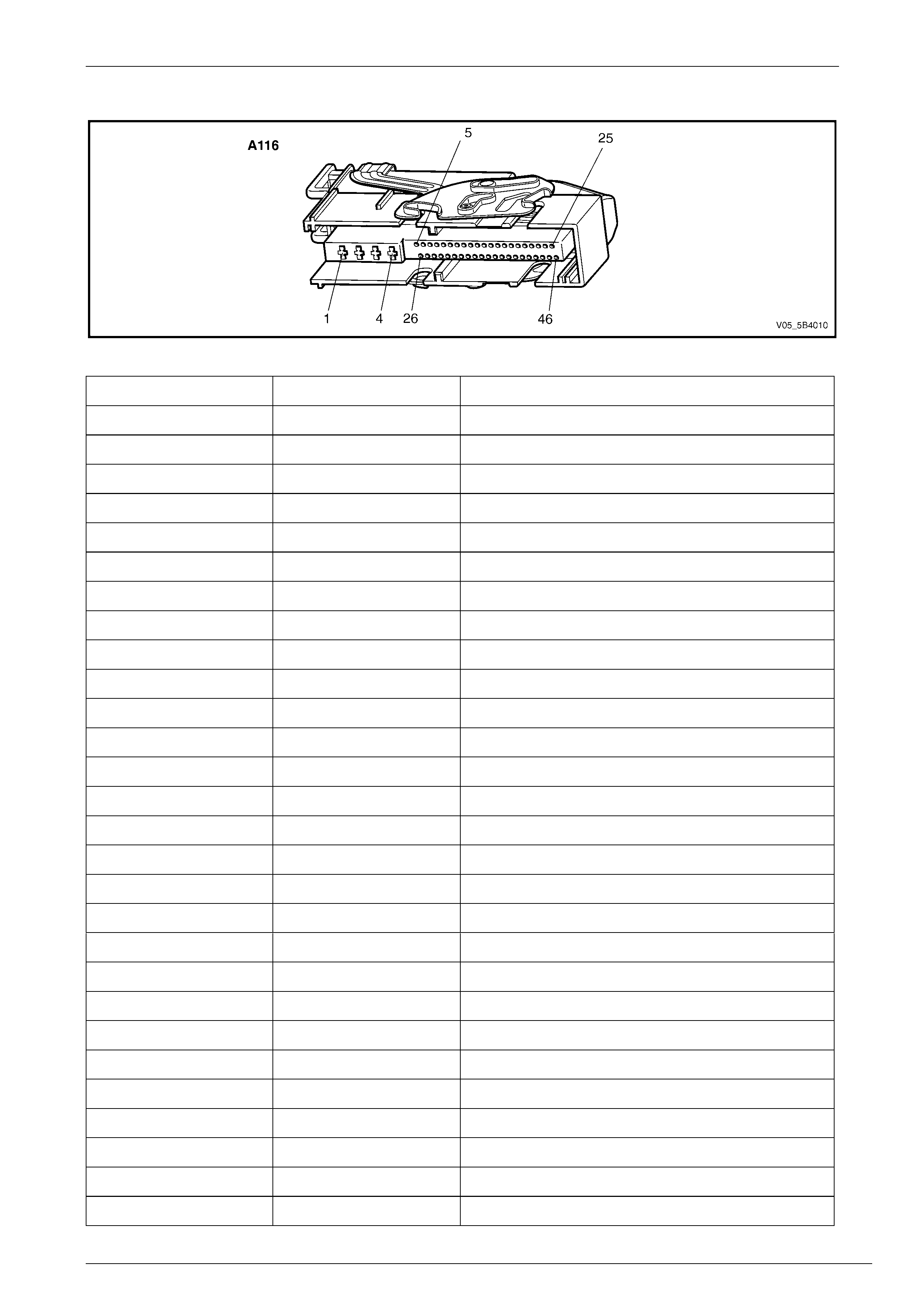
Electronic Control Unit – A116
Figure 5B10 – 2
Pin Circuit No. Function
1 350 Main Ground
2 542 12 V Uninterrupted Supply Voltage – Fuse 103
3 1440 12 V Uninterrupted Supply Voltage – Fuse 36
4 150 ECU Ground
5 830 Front Left Wheel Speed Sens or Signal
6 — Not Connected
7 884 Rear Left Wheel Speed Sensor Signal
8 883 Rear Right Wheel Speed Sensor Low Ref
9 833 Front Right Wheel Speed Sensor Low Ref
10 872 Front Right Wheel Speed Sensor Signal
11 799 ABS Diagnostic Enable
12 — Not Connected
13 — Not Connected
14 2501 CAN LO_1
15 5353 Yaw-rate Sensor – Low Reference
16 716 Yaw-rate Sensor Signal – Ya w Rate
17 1134 Instrument Cluster Brake Circuit
18 1337 Yaw-rate Sensor – Self Test
19 — Not Connected
20 2086 Yaw Rate Sensor Signal – Acceleration
21 — Not Connected
22 — Not Connected
23 — Not Connected
24 — Not Connected
25 2501 CAN LO_2
26 873 Front Left Wheel Speed Sensor – Low Reference
27 885 Rear Left Wheel Speed Sensor – Low Reference
28 839 12 V Ignition Supply Voltage Fuse 27
Diagnostics – All ABS 8.0 Variants Page 5B10 – 1
Page 5B10 – 18
Pin Circuit No. Function
29 882 Rear Right Wheel Speed Sensor Signal
30 20 Stop Light Switch 12 V Signal
31 — Not Connected
32 — Not Connected
33 — Not Connected
34 — Not Connected
35 2500 CAN HI_1
36 — Not Connected
37 1338 Yaw-rate Sensor 5 V Reference
38 — Not Connected
39 — Not Connected
40 — Not Connected
41 — Not Connected
42 — Not Connected
43 — Not Connected
44 — Not Connected
45 2500 CAN HI_2
46 — Not Connected
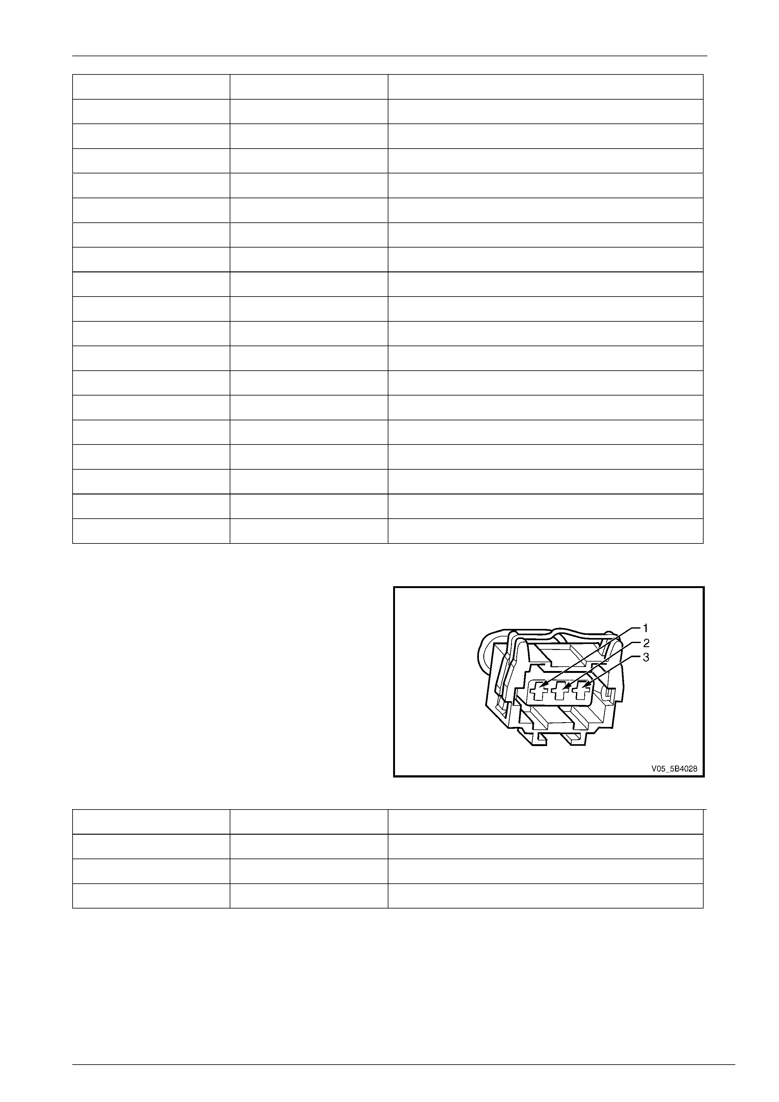
Longitudinal Acceleration Sensor – B1
Figure 5B10 – 3
Pin Circuit No. Function
1 338 Longitudinal Acceleration Sensor Signal Low
2 370 Longitudinal Acceleration Sensor Signal High
3 337 Longitudinal Acceleration Sensor 5V Reference
Diagnostics – All ABS 8.0 Variants Page 5B10 – 1
Page 5B10 – 19
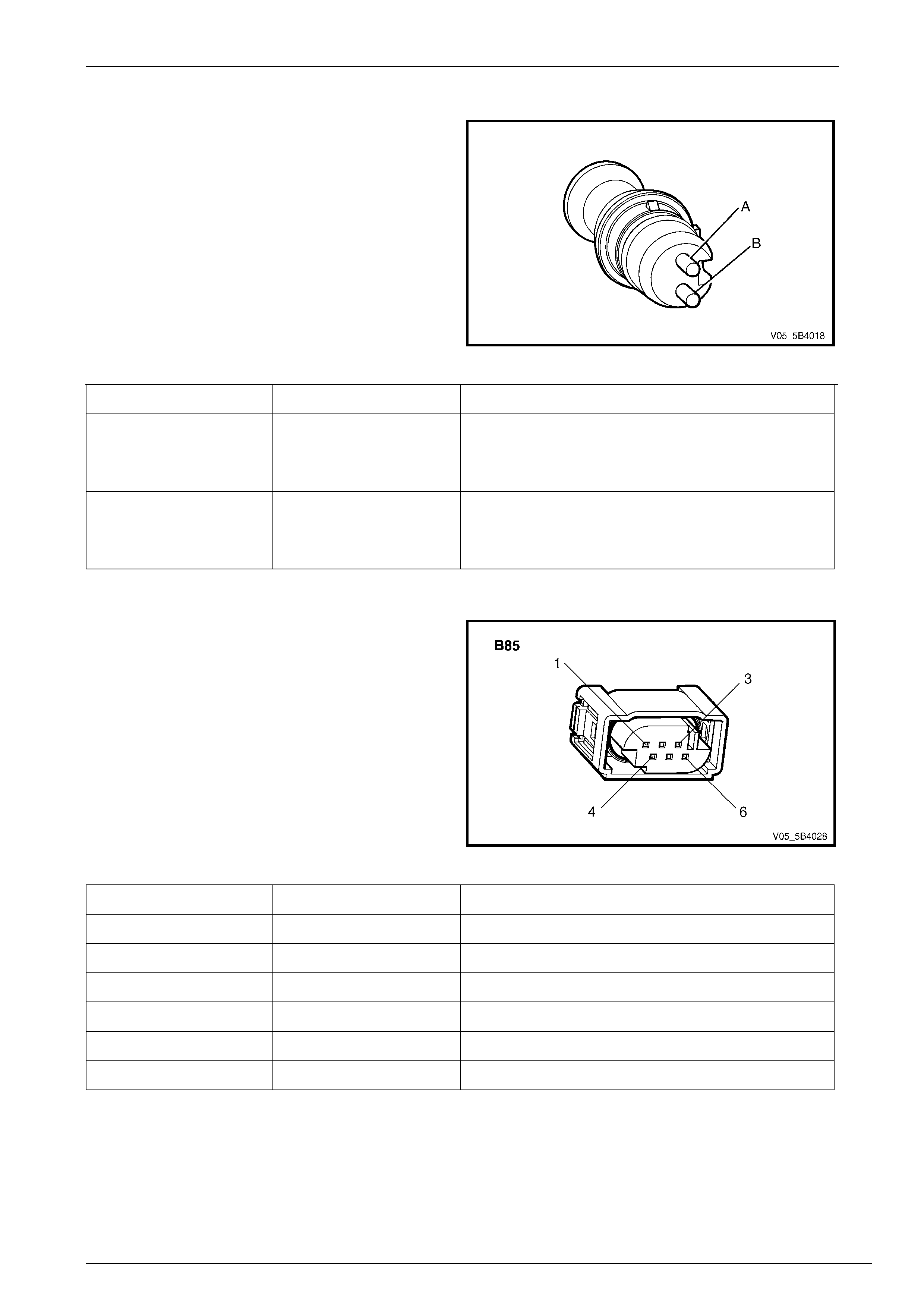
Front and Rear Wheel Speed Sensor – B52L, B52R, B76L and B76R
Figure 5B10 – 4
Pin Circuit No. Function
A B52_LT – 830
B52_RT – 872
B76_LT – 884
B76_RT – 882
Wheel Speed Sensor Signal
B B52_LT – 873
B52_RT – 833
B76_LT – 885
B76_RT – 883
Wheel Speed Sensor Low Reference
Yaw-rate Sensor – B85
Figure 5B10 – 5
Pin Circuit No. Function
1 1337 Yaw-rate Sensor Self-test
2 1338 Yaw-rate Sensor 5 V Reference
3 839 Yaw-rate Sensor 12 V Ignition Suppl y
4 716 Yaw-rate Sensor Signal (yaw-rate)
5 2086 Yaw-rate Sensor Signal (acceleration)
6 5353 Yaw-rate Sensor Low Reference
Diagnostics – All ABS 8.0 Variants Page 5B10 – 1
Page 5B10 – 20
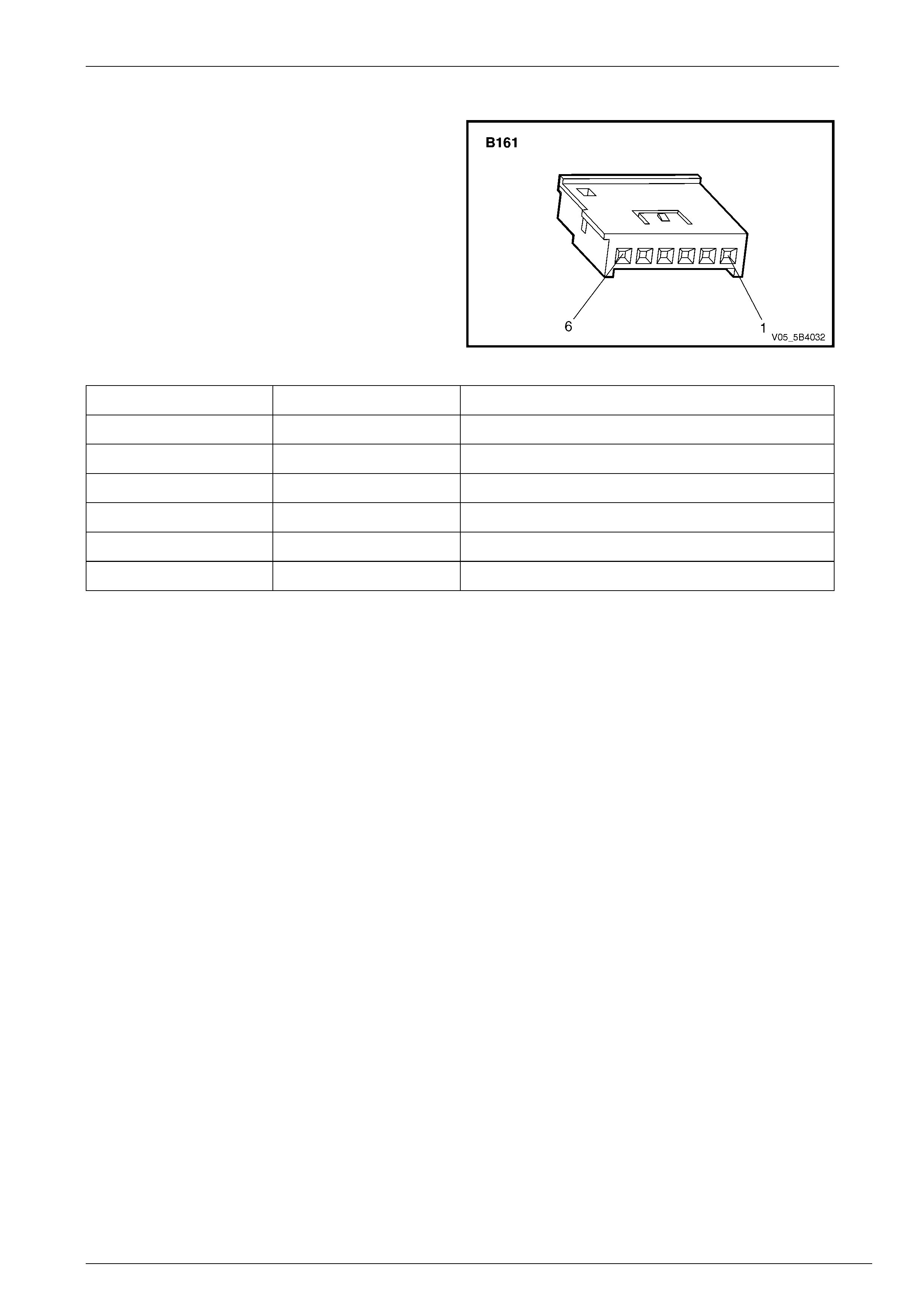
Steering Angle Sensor – B161
Figure 5B10 – 6
Pin Circuit No. Function
1 2501 Steering Angle Sensor CAN LO 1
2 2501 Steering Angle Sensor CAN LO 2
3 2500 Steering Angle Sensor CAN HI 1
4 2500 Steering Angle Sensor CAN HI 2
5 839 Steering Angle Sensor 12 V Ignition Supply
6 5353 Steering Angle Sensor Low Reference

Diagnostics – All ABS 8.0 Variants Page 5B10 – 1
Page 5B10 – 21
3 Diagnostics
3.1 Diagnostic General Descriptions
Any ABS diagnostic procedure is organised in a logical structure that begins with the Diagnostic System Check. The
Diagnostic System Check directs the diagnostic procedure to the logical steps or ap propriate diagnostic table required to
diagnose any ABS fault.
The diagnostic tables locate a faulty circuit or component through a logic based on the process of elimination.
Understanding and the correct use of the diagnostic tables is essential to reduce diagnostic time and to prevent
misdiagnosis.
However, the diagnostic information covered in this Section covers faults only in the ABS s ystem. If there are faults with
the conventional braking system such as the following, these faults must be corrected before attempting to rectify any
suspected ABS fault:
• Brake noise.
• Spongy brake pedal feel.
• Brake pedal or vehicle vibration during normal brake appl ication.
• Brake pulling to one side.
• Parking brake problem.
Refer to Section 5A Service and Park Braking System for the diagnosis and repa ir procedure of the conventional braking
system.
Diagnostic Trouble Code Tables
The diagnostic procedure is directed to the diagnostic trouble code (DTC) tables if there are DTCs currently stored in the
electronic control unit (ECU).
The diagnostic tables are designed to locate a faulty circuit or component through a logic based on the process of
elimination. These diagnostic tables are developed with the following assumptions:
• The vehicle functioned correctly at the time of assembly,
• There are no multiple faults, and
• the problem currently exists.
If there are multiple DTCs stored in the ECU, the diagn ostic process must b egin with the most likely DTC that may trigger
other DTCs. The following sit uation is an example of a DTC that may trigger other DTCs to set.
• If there is a battery supply voltage fault in the ECU, DTC C0800 Battery Voltage Out of Range may set.
• Insufficient battery supply voltage to an ABS component such as the h ydr aulic modulator pump motor may
cause incorrect hydraulic modulator operation. This condition will cause inc orrect ABS operation and may
trigger DTC C0110 to also set.
• A battery supply voltage to the ECU that is too high may cause damage to other ABS components. If this
charging system fault is not rectified and an ABS component is replaced, premature failure of the
replacement component may occur.
Therefore, knowledge of the various ABS variations and Tech 2 limitations are important to reduce diagn ostic time and to
prevent misdiagnosis. Refer to 4.1 Basic Requirements .
Techline

Diagnostics – All ABS 8.0 Variants Page 5B10 – 1
Page 5B10 – 22
Diagnostic Trouble Codes
The ECU performs a self-test that detects and isolates ABS faults. When a fault is detected, the ECU will log a diagnostic
trouble code (DTC) and symptom code that represe nts the fault detected. The DTCs stored in the ECU may be accessed
using Tech 2. Refer to Section 0D Vehicle Diagnostics for information ON Symptom Codes or Section 0C Tech 2 for
information on Tech 2.
Status of DTCs
The ECU designates the DTCs logged into a Current or History DTC.
Current DTCs
If the fault that triggers the DTC is present during the last ECU self-diagnostics, that DT C will be design ated as a current
DTC.
History DTCs
If the fault that triggers the DTC is not present during the last ECU self-test, that DTC will be designated as a History
DTC.
Action Taken When a DT C Sets
• The ECU disables the ABS for the duration of the ignition c ycle.
• One or all of the following warning indicators may activate:
• ABS-TCS warning indicator,
• ABS-TCS warning display,
• ESP warning display,
• HDC warning display,
• Brake failure indicator, and/or
• Trac-off warning display.
Conditions for Clearing DTCs
• The current DTC moves into a histor y DTC when there is no DTC logged during the current ECU self-test.
• Use Tech 2 to clear the DTC.

Diagnostics – All ABS 8.0 Variants Page 5B10 – 1
Page 5B10 – 23
4 Diagnostic Starting Point
4.1 Basic Requirements
Basic Knowledge Required
A lack of basic understanding regarding
electronics, electrical wiring circuits and use
of electrical circuit testing tools when
performing ABS diagnostic procedures, could
result in incorrect diagnostic results or
damage to components.
A general understanding of ba sic electronics, electrical wiring circuits and the correct use of the basic AB S electrical circuit
testing tools is required to perform the diagno stic procedures detailed in this Section. Refer to Section 12P Wiring Diagrams
for information on electrical circuits.
In addition, a general understanding of the ABS variants and each if the component’s ope ration is essential to prevent
misdiagnosis and component damage.
Basic Diagnostic Tools Required
Use of incorrect electrical circuit diagnostic
tools when performing the ABS diagnostic
procedures could result in incorrect
diagnostic results or damage to components.
The following electrical circuit testing tools are required to perform the diagnostic procedures detailed in this Section.
• Tech 2, refer to Section 0C Tech 2,
• Test lamp, refer to Section 12P Wiring Diagrams,
• Digital multimeter with 10 MΩ impedance, refer to Section 12P Wiring Diagrams.
• Connector test adapter kit Tool No. J35616-A.

Diagnostics – All ABS 8.0 Variants Page 5B10 – 1
Page 5B10 – 24
4.2 Diagnostic Precautions
In addition to the safety and precautionary
measures listed in the servicing section of
each ABS variant (9.1 Safety and
Precautionary Measures), the following
Diagnostic Precautions must be observed
when performing any ABS diagnostic
procedure.
• If there is a fault in the conventional braking system, rectify that fault before proceeding with any ABS variant
diagnostics.
• Use only the test equipment specified in the diagnostic tables: other test equipment may either give incorrect
results or may damage good components.
• The vehicle drive wheels mus t be chocked and the parking brake firmly applied while checking any system.
• Do not clear any DTCs unless instructed.
• The fault must be present when using the DTC Diagnostic Tables. Otherwise, misdiagnosis or replacement of good
parts may occur.
• Always use connector adaptors such as those contained in connector test adapter kit Tool No. J35616-A to prevent
connector terminal damage.
• Thorough inspection of the wiring circuits and connectors that are part of diagnostic proc edure must be performed,
otherwise misdiagnosis may occur.
• Inspect the electrical circuitry or connector terminals that are suspected to be causing the complaint for the
following:
• Backed-out connector terminals,
• Improper wiring connector mating,
• Broken wiring connector locks,
• Damaged connector terminals , and
• Physical damage to the wiring harness.
• Before replacing a component, inspect its connector terminal for corrosion or deformation that may cause the fault.
• If Tech 2 was used for diagnosis, disconnect it from the DLC and switch the ignition off for at least 10 seconds
before road testing. This is necessary to reset the ECU as it is disabled during most Tech 2 diagnostic procedures.
• After completing the required diagnostic and repair operations, road test the vehicle to ensure correct ABS
operation.

Diagnostics – All ABS 8.0 Variants Page 5B10 – 1
Page 5B10 – 25
4.3 Preliminary Checks
The Preliminary Checks are an examination of easily accessible components that could cause problems with the ABS
system. This visual and physical inspection procedure may quickly identify the fault and elimin ate the need for additional
diagnosis.
• Is the fault specifically isolated to this system? If unsure, refer to Section 0D Vehicle Diagnostics.
• Refer to Service Techlines for relevant information regarding the fau lt.
• Ensure that only the recommended t yres and wheel size are fitted to the vehicle.
• Check the hydraulic modulator for external leaks.
• Check the ABS fuses.
• Check the ABS warning indica tor fuse and stop lamp indicator fuse. Refer to Section 12O Fuses, Relays and
Wiring Harnesses.
• Ensure the battery is fully charged.
• Check the battery connections for corrosion or a loose terminal.
• Perform a visual and physical inspection of the following:
• ABS component wiring harness and terminals for proper connecti ons, pinches or cuts.
• Wiring harness routing which ma y be positioned very close to a high voltage or high current device such as
the following:
− Secondary ignition components,
− Motors and generators, and
− Aftermarket stereo amplifiers
NOTE
High voltage or high current devices may induce
electrical noise on a circuit, which can interfere
with normal circuit operation.
• ABS related components for poor mating of the connector halves or a terminal not fully seated in the
connector body.
• ABS components are sensitive to Electro-magnetic Interference (EMI). Che ck for incorrect aftermarket theft
deterrent devices, lights or mobile phone installations if an intermittent malfunction is suspected.

Diagnostics – All ABS 8.0 Variants Page 5B10 – 1
Page 5B10 – 26
4.4 Diagnostic System Check
Description
The diagnostic procedure is organised in a logical structure that begins with the Diagnostic System Check which directs
the technician to the logical steps necessary to diagnose any ABS fault.
Test Description
The following numbers refer to the step numbers in the diagnostic table:
4 Tests the operation of Tech 2.
6 Tests the integrity of the GM LAN serial dat a communication circuit. A PIM DTC sets if the PIM detects a fault in the
communication circuit. A fault on the serial data communication circuit may trigger multiple DTCs on other sensors
and components.
Step Action Yes No
1 Have you read the Basic Requirements?
Go to Step 2
Refer to
4.1 Basic
Requirements
2 Have you read the Diagnostic Precautions?
Go to Step 3
Refer to
4.2 Diagnostic
Precautions
3 Have you performed the Preliminary Checks?
Go to Step 4
Refer to
4.3 Preliminary
Checks
4 1 Switch off the ignition.
2 Connect Tech 2 to the Diagnostic Link Connector (DLC).
3 Switch on the ignition with the engine not running.
4 Press the Tech 2 power button on.
Does the Tech 2 screen illuminate and display Tech 2? Go to Step 5 Refer to 0C Tech 2
5 Using Tech 2, attempt to communicate with the PIM.
Does the PIM fail to communicate?
Refer to 6E1
Powertrain Interface
Module – V6
or 6E4 Powertrain
Interface Module
GEN IV V8 Go to Step 6
6 Using Tech 2, view and record DTCs set at the PIM.
Does DTC U1064, U2100, U2105, U2106, U2108, B1009, B1013,
B1014, B1000, B1019, B3057, B3924, P0633, P1611 or P1678 set in
the PIM?
Refer to 6E1
Powertrain Interface
Module – V6
or 6E4 Powertrain
Interface Module
GEN IV V8 Go to Step 7
7 Using Tech 2, view and record any ABS related DTCs.
Does Tech 2 display a ny DTCs? Go to Step 8
Refer to
5.1 Intermittent
Fault Diagnostic
Table
8 Does Tech 2 display multiple DTCs?
Go to Step 9
Go to the DTC
Table of the DTC
displayed. Refer to
6.1 DTC List
9 Refer to the DTC Table of the fault that is most likely to trigger multiple
DTCs. Refer to 3.1 Diagnostic General Descriptions for informatio n
on multiple DTCs fault. — —
When all diagno sis an d repairs are completed, check the system for correct operatio n.

Diagnostics – All ABS 8.0 Variants Page 5B10 – 1
Page 5B10 – 27
5 Intermittent Faults
5.1 Intermittent Fault Diagnostic Table
Description
A fault is intermittent if one of the following exists:
• The fault is not always present,
• The fault cannot be presently duplicated, and
• There is no Current DTC but a Histor y DTC is stored.
Checks Actions
Preliminary • Perform the Preliminary Checks. Refer to 4.3 Preliminary Checks.
• Gather information from the customer regarding the conditions that trigger the
intermittent fault such as:
− At what vehicle speed range d oes the fault occur?
− Does the fault occur when operating aftermarket electrica l e quipment inside
the vehicle?
− Does the fault occur on rough roads or in wet road conditions?
− If a wheel speed sensor fault is present only during wet road conditions,
inspect the wheel speed sensor electrical circuit for signs of water intrusion.
If the DTC is not current, simulate the effect of a wet road condition by
performing the following:
1 Mix two teaspoons of salt with 35 ml water.
2 Spray the saltwater solution to the suspected area.
3 Road test the vehicle at various road conditions.
4 Accelerate the vehicle at spee d greater th an 40 km/h for at least 30
seconds.
5 If the suspected wheel speed sensor sets a current DTC, refer to the
appropriate DTC diagnostic table.
Tech 2 Tests The following are lists of Tech 2 diagnostic tests that may be used to diagnose
intermittent faults:
• Wriggle test the suspected ABS compon ent wiring harness and connectors while
observing the Tech 2 operati ng parameters of the circuit being tested. If the Tech
2 read-out fluctuates during this procedure, check the wiring harness circuit for
loose connection.
• Road test the vehicle in the conditions that triggers the intermittent fault while an
assistant observes the suspec ted Tech 2 operating parameter data.
• Capture and store data in the Snapshot mode when the fault occurs. The stored
data may be played back at a slower rate to aid in diagnostics. Refer to the Tech 2
User Instructions for more information on the Snapshot fun ction.
• Operate suspected ABS components to test their operation using Tech 2 Output
Control Data.

Diagnostics – All ABS 8.0 Variants Page 5B10 – 1
Page 5B10 – 28
Checks Actions
Warning Indicator The following conditions may cause an intermittent Warning Indicator fault with no DTC
listed.
• Electromagnetic interference (EMI) caused by a faulty relay.
• Incorrect installation of aftermarket electrical equipment such as the following:
− Mobile phones
− Theft deterrent alarms
− Lights
− Radio equipment
− Stereo amplifier
• Warning indicator circuit is intermittently shorted to ground.
• Electronic control unit (ECU) ground connections are loose.
Wheel Speed Sensors • Visually inspect wheel spee d sensors and pulse rings for looseness, damage,
foreign material accumulation and prop er mounting. Replace damaged
components, remove any foreign material and/or properly attach loose
components.
• With the aid of an assistant, monitor the Tech 2 wheel speed sensor data display
while test driving the vehicle. Check for any whe el spe ed sensor that displays
erratic speed range.
Additional Tests • Incorrect installation of aftermarket electrical equipment such as the following:
− Mobile phones
− Theft deterrent alarms
− Lights
− Radio equipment
− Stereo amplifier
• Electromagnetic interference (EMI) caused by a faulty relay. The fault is triggered
when the relay or solenoid is activated.
• Test the A/C compressor clutch and some relays that contain a clamping diode or
resistor.
• Test the generator for a faulty rectifier bridge that ma y allow the A/C noise into the
ECU electrical circuit
When all diagno sis an d repairs are completed, check the system for correct operatio n.

Diagnostics – All ABS 8.0 Variants Page 5B10 – 1
Page 5B10 – 29
6 Diagnostic Trouble Codes
6.1 DTC List
NOTE
This DTC listing covers all ABS variants,
including three and four channel systems, plus
AWD. Therefore, when using this list to source a
diagnostic table, ensure that you read the DTC
description, before activating the hyperlink.
DTC Symptom
Code/s Description Diagnostic Table
C0035 00/05/0F/
28/64 Left Front Wheel Speed Sensor Signal or Low
Reference Circuit Fault 6.2 DTC C0035 or C0040 – F r ont Wheel
Speed Sensor Circuit Fault
C0040 00/05/0F/
28/64 Right Front Wheel Speed Sen s or Signal or Low
Reference Circuit Fault 6.2 DTC C0035 or C0040 – F r ont Wheel
Speed Sensor Circuit Fault
C0045 00/05/0F/
28/64 Left Rear Wheel Speed Sensor Sign al or Low
Reference Circuit Fault 6.3 DTC C0045 or C0050 – Rear W heel
Speed Sensor Circuit Fault
C0050 00/05/0F/
28/64 Right Rear Wheel Speed Sensor Signal or Low
Reference Circuit Fault 6.3 DTC C0045 or C0050 – Rear W heel
Speed Sensor Circuit Fault
C0060 00/08
Left Front Hydraulic Modulator Outlet Solenoid
Valve Circuit Fault 6.4 DTC C0060, C0065, C0070, C0075 –
Front Hydraulic Modulator Solenoid Fault
C0065 00/08/57
Left Front Hydraulic Modulator Inlet Solenoid Valve
Circuit Fault 6.4 DTC C0060, C0065, C0070, C0075 –
Front Hydraulic Modulator Solenoid Fault
C0070 00/08
Right Front Hydraulic Modulat or Outlet Sole noid
Valve Circuit Fault 6.4 DTC C0060, C0065, C0070, C0075 –
Front Hydraulic Modulator Solenoid Fault
C0075 00/08/57
Right Front Hydraulic Modulator Inlet Solenoid Valve
Circuit Fault 6.4 DTC C0060, C0065, C0070, C0075 –
Front Hydraulic Modulator Solenoid Fault
C0080 00/08
Left Rear Hydraulic Modulator Outlet Solenoid Valve
Circuit Fault 6.5 DTC C0080, C0085, C0090, C0095 –
Hydraulic Modulator Rear Soleno id F ault
C0085 00/08/57
Left Rear Hydraulic Modulator Inlet Solenoid Valve
Circuit Fault 6.5 DTC C0080, C0085, C0090, C0095 –
Hydraulic Modulator Rear Soleno id F ault
C0090 00/08
Right Rear Hydraulic Modulat or Outlet Sole noid
Valve Circuit Fault 6.5 DTC C0080, C0085, C0090, C0095 –
Hydraulic Modulator Rear Soleno id F ault
C0095 00/08/57
Right Rear Hydraulic Modulator Inlet Solenoid Valve
Circuit Fault 6.5 DTC C0080, C0085, C0090, C0095 –
Hydraulic Modulator Rear Soleno id F ault
C0090 00/08
Rear Hydraulic Modul ator Outlet Solenoid Valve
Circuit Fault (3 Channel System) 6.5 DTC C0080, C0085, C0090, C0095 –
Hydraulic Modulator Rear Soleno id F ault
C0095 00/08/57
Rear Hydraulic Modul ator Inlet Solenoid Valve
Circuit Fault (3 Channel System) 6.5 DTC C0080, C0085, C0090, C0095 –
Hydraulic Modulator Rear Soleno id F ault
C0110 03/07/16
Hydraulic Modulator Pump Motor Circuit Fault 6.6 DTC C0110 – Hydraulic Modu lator Pump
Motor Circuit Fault
C0121 01/02/03/
08/56/61 Electronic Control Unit Internal Valve Relay Fault 6.7 DTC C0121 – Electronic Control Unit
Internal Valve Relay Fault
C0131 00/08/11/57
Hydraulic Modulator Pressure Sensor Fault 6.8 DTC C0131 – Hydraulic Modulator
Pressure Sensor Fault
C0141 00/08
Hydraulic Modulator Front Isolating Solenoid Valve 1
Circuit Fault 6.9 DTC C0141, C0146, C0151 or C0 156 –
Hydraulic Modulator Solenoi d Valve
Fault

Diagnostics – All ABS 8.0 Variants Page 5B10 – 1
Page 5B10 – 30
DTC Symptom
Code/s Description Diagnostic Table
C0146 00/08/57
Hydraulic Modulator Front Priming So lenoid Valve 1
Circuit Fault 6.9 DTC C0141, C0146, C0151 or C0 156 –
Hydraulic Modulator Solenoi d Valve
Fault
C0151 00/08
Hydraulic Modulator Rear Isolating Solenoid Valve 2
Circuit Fault 6.9 DTC C0141, C0146, C0151 or C0 156 –
Hydraulic Modulator Solenoi d Valve
Fault
C0156 00/08/57
Hydraulic Modulator Rear Priming So lenoid Valve 2
Circuit Fault 6.9 DTC C0141, C0146, C0151 or C0 156 –
Hydraulic Modulator Solenoi d Valve
Fault
C0161 04/58 Brake Switch Circuit Malfunction 6.10 DTC C0161 – Brake Swit ch Circuit F ault
C0186 00/07/08/
11/12 Lateral Acceleration Sensor 6.11 DTC C0186 – Lateral Acceleration
Sensor Fault
C0191 00/2B
Longitudinal Acceleration Sensor 6.12 DTC C0191 or C0192 L ongitudinal
Acceleration Sensor Signal Circuit
C0192 00
Longitudinal Acceleration Sensor 6.12 DTC C0191 or C0192 L ongitudinal
Acceleration Sensor Signal Circuit
C0196 00/03/07/
08/11/12 Yaw-rate Sensor Output Signal Fault 6.12 DTC C0196 – Yaw-rate Sensor Output
Signal Fault
C0245 00
Wheel Speed Signal Output Fault 6.13 DTC C0245, C0252 or C025 3 – Wheel
Speed Sensor Signal Output F ault
C0252 00
Wheel Speed Signal Outside Operatin g Parameters 6.13 DTC C0245, C0252 or C025 3 – Wheel
Speed Sensor Signal Output F ault
C0253 00
Long Term Compensation Disabled 6.13 DTC C0245, C0252 or C025 3 – Wheel
Speed Sensor Signal Output F ault
C0460 00/11/12/42
Steering Angle Sensor Fault 6.14 DTC C0460 – Steering Angle Sensor
Circuit Fault
C0550 00/31/32/33/
34/35/36/37/
38/55/57
Electronic Control Unit Internal F ault 6.15 DTC C0550 and C0551 – Electronic
Control Unit Internal Fault
C0551 45
ECU Not Programmed 6.15 DTC C0550 and C0551 – Electronic
Control Unit Internal Fault
C0569 00
Electronic Control Unit Configuration Mismatch 6.16 DTC C0569 – Electronic Control U nit
Configuration Mismatch
C0800 03/07/0F
Battery Voltage Out of Range 6.17 DTC C0800 – Battery Voltage Out of
Range
C0895 08
Steering Angle Sensor Supply Voltage Out of Range 6.18 DTC C0895 – Yaw Rate Sensor Supply
Voltage Out of Range
U2100 00
CAN Bus Off – Cannot Transmit Generic Failure 6.19 DTC U2100 – No Communication With
CAN Bus (High Speed)
U2105 00/71
CAN Bus No Communication With ECM (Engine
Control Module) 6.20 DTC U2105 Lost Communication With
ECM
U2106 00/71
CAN Bus No Communication With TCM
(Transmission Control Module) 6.21 DTC U2106 Lost Communication With
TCM
U2107 00/71
CAN Bus No Communication With BCM (Body
Control Module) 6.22 DTC U2107 Lost Communication With
BCM
U2143 00/71/74
CAN Bus No Communication With SAS (Steering
Angle Sensor) 6.23 DTC U2143 Lost Communication With
SAS

Diagnostics – All ABS 8.0 Variants Page 5B10 – 1
Page 5B10 – 31
6.2 DTC C0035 or C0040 – Front Wheel
Speed Sensor Circuit Fault
DTC Descriptors
This diagnostic procedure supports the following DTCs:
DTC C0035 00: Left Front Wheel Speed Sensor Circuit Malfunction
DTC C0035 05: Left Front Wheel Speed Sen s or Circuit Short to Battery or Open
DTC C0035 0F: Left Front W heel Spee d Sensor Signal Erratic
DTC C0035 28: Left Front Wheel Speed Sensor Signal Dropout
DTC C0035 64: Left Front Wheel Speed Sensor Actuator Slipping
DTC C0040 00: Right Front Whee l Speed Sensor Circuit Malfunction
DTC C0040 05: Right Front Whee l Speed Sensor Circuit Short to Battery or Open
DTC C0040 0F: Right Front Wheel Speed Sensor Signal Erratic
DTC C0040 28: Right Front Wheel Speed Sensor Signal Dropout
DTC C0040 64: Right Front Wheel Speed Sensor Actuator Slipping
Diagnostic Fault Information
Perform the Diagnostic System Check - Vehicle prior to using this diagnostic procedure.
Circuit Generic
Failure
Signal Short
to Battery or
Open
Signal
Erratic
Signal
Dropout Actuator
Slipping
Left Front Sensor Signal Circuit C0035 00 C0035 05 C0035 0F C0035 28 C0035 64
Right Front Sensor Signal Circuit C0040 00 C0040 05 C0040 0F C0040 28 C0040 64
Circuit/System Description
The electronic control unit (ECU) suppli es ground to the wheel speed sensor low reference circuit. The wheel speed
sensor in conjunction with a pulse ri ng generates an AC signal voltage. The amplitude and frequency of the signal
generated is proportional to the wheel speed.
The ECU monitors each wheel speed sensor signal circuit to determine the rotational spee d of each wheel and calculate
wheel slip.
Refer to 2 Wiring Diagram and Connector Chart to assist with diagnosis.
Conditions for Running the DTC
C0035 00 – C0040 00
• The ignition is ON.
• Ignition voltage is greater than 8 volts.
C0035 05 – C0040 05
• The ignition is ON.
• Ignition voltage is greater than 8 volts.
• The brake pedal is not presse d.
• A DTC is not set for the other wheel speed circuit on the same axle.

Diagnostics – All ABS 8.0 Variants Page 5B10 – 1
Page 5B10 – 32
C0035 0F – C0040 0F
• The ignition is ON.
• Ignition voltage is greater than 8 volts.
C0035 28 – C0040 28
• The ignition is ON.
• Vehicle is accelerated from rest to 60 km/h or;
• Vehicle is driven at a speed of at least 30 km/h for about 7 s econ ds.
C0035 64 – C0040 64
• The ignition is ON.
• Vehicle is accelerated from rest to 60 km/h or;
• Vehicle is driven at a speed of at least 30 km/h for about 7 s econ ds.
Conditions for Setting the DTC
• A missing wheel speed sensor signal.
• Wheel speed sensor power supply is less than 7.6 volts.
• A short to voltage, open or ground is detected on the wheel spee d sensor signal circuit.
• A open or short to ground in the wheel speed sensor circuit supply voltage.
• An erratic signal output of the wheel speed sensor is detected.
• The wheel speed sensor pl ausibility fault (Missing/damaged tooth on pulse wheel).
Action Taken When the DTC Sets
• The ABS ECU disables the Antilock Brake System (ABS)/Traction Control System (TCS)/Electronic Stability
Program (ESP) for the duration of the ignition cycle.
• The dynamic rear brake proportioning does not function optimally.
• The ABS indicator turns ON.
• The Traction Control indicator turns ON (If TCS is fitted).
• The Instrument displays an Electronic Stab ility Program message (if fitted).
Conditions for Clearing the DTC
• The condition for setting the DT C is no longer present.
• The ABS ECU automatically clears the history DTC when a current DTC is not detected in 100 consecutive drive
cycles.
Additional Information
• For intermittent faults, refer to 5.1 Intermittent Fault Diagnostic Table.
• High voltage or high current devices such as spark plugs and spark plug wires may induce electrical noise on the
front left wheel speed sensor circuit. This electrical noise can interfere with normal wheel speed sensor operation.
Ensure the wheel speed sens or wiring harness is routed away from these high voltage or high current devices.
• Refer to 2.3 Wheel Speed Sensors for the following information:
• wheel speed sensor description and operation, and
• wheel speed sensor test procedure using an oscilloscope.

Diagnostics – All ABS 8.0 Variants Page 5B10 – 1
Page 5B10 – 33
Test Description
The following numbers refer to the step numbers in the diagnostic table:
2 Verifies the fault that triggers the DTC, currently exists.
3 Tests the front wheel speed sensor internal circuitry.
4 Tests the front wheel speed sensor output voltage capacity.
DTC C0035 or C0040 Diagnostic Table
Step Action Value(s) Yes No
1 Has the Diagnostic System Check been completed? — Go to Step 2
Refer to
4.4 Diagnostic
System Check
2
1 Switch off the ignition for 10 seconds.
2 Road test the vehicle at speed greater than 40
km/h for at least 7 seconds.
3 Using Tech 2, view DTCs.
Does DTC C0035 or C0040, fail this ignition cycle?
—
Go to Step 3
Refer to Additional
Information in this
Section
3
1 Ignition OFF.
2 Raise the front of the vehicle and support on
safety stands. Refer to 0A General Information
for location of the jacking and support points.
3 Disconnect the wheel speed sensor connector at
the front hub.
4 Using a digital multimeter, measure the
resistance across the pins of the wheel speed
sensor connector.
Does the resistance measure within the specified
range?
1.3 – 1.8 kΩ
@ 20°C?
Go to Step 4 Go to Step 7
4
1 Raise the front of the vehicle and support on
safety stands. Refer to 0A General Information
for location of the jacking and support points.
2 Connect an oscilloscope to the wheel speed
sensor terminals if a RWD vehicle or the wheel
speed sensor lead inside the engine
compartment, if an AWD vehicle.
3 Observe the wheel speed sensor output signal
pattern while spinning the appropri ate wheel.
Refer to 2.4 Wheel Speed Sensors for
information on testing a wheel speed sensor
using an oscilloscope.
NOTE
If an oscilloscope is not available, use a
DMM set to AC volts to check for an AC
voltage at the sensor, while the wheel is
being spun by hand.
Was the output pattern satisfactory or the voltage
output greater than the specified value?
100 mV
Go to Step 12 Go to Step 5
5
1 Inspect for poor connections at the wheel speed
sensor harness connector. Refer to Detecting
Intermittent Electrical Faults in 12 P Wiring
Diagrams.
Was a fault found and rectified?
—
Go to Step 12 Go to Step 8

Diagnostics – All ABS 8.0 Variants Page 5B10 – 1
Page 5B10 – 34
Step Action Value(s) Yes No
6
1 RWD Vehicle: Replace the front hub. Refer to 3
Front Suspension.
AWD Vehicle: If inspection shows that the pulse
ring is undamaged, replace the wheel speed
sensor and lead assembly.
Was the replacement carried out successful ly?
—
Go to Step 12 —
7 1 Replace the wheel speed sensor, refer to 9.4
Front Wheel Speed Sensor – RWD or 9.5 Front
Wheel Speed Sensor – AWD. — Go to Step 12 —
8
1 Disconnect the wiring harness connector from the
ABS Electronic Control Unit (ECU).
2 Test the wheel speed sensor circuits for the
following:
• open circuit
• short to ground
• short to voltage
• wiring shorted together
Refer to 12P Wiring Diagra m s for information on
electrical fault diagnos is.
Was any fault found and rectified?
—
Go to Step 4 Go to Step 9
9
1 Inspect for poor connections at the ABS ECU
harness connector. Refer to Detecting
Intermittent Electrical Faults in 12 P Wiring
Diagrams.
Was any fault found and rectified?
—
Go to Step 12 Go to Step 11
10
1 Replace the faulty wheel speed sensor lead
(RWD) or lead and sensor (AWD), refer to 9.6
Front Wheel Speed Sensor Lead – RWD
Vehicles or 9.7 Front Wheel Speed Sensor Lead
– AWD Vehicles.
Was the repair completed
—
Go to Step 12 —
11 1 Replace the ECU. Refer to 9.3 Electron ic Control
Unit / Hydraulic Modulator Assembly.
Was the repair completed? — Go to Step 12 —
12
1 Using Tech 2, clear the DTCs.
2 Switch off the ignition for 10 seconds.
3 Operate the vehicle within the conditions for
running DTCs C0035 a nd C0040.
Does any wheel speed sensor circuit DTC fail this
ignition cycle?
Go to Step 2 Go to Step 12
13 1 Using Tech 2, select the DT C display function.
Does Tech 2 display a ny DTCs? Go to the
appropriate DTC
Table System OK
When all diagno sis an d repairs are completed, check the system for correct operatio n.

Diagnostics – All ABS 8.0 Variants Page 5B10 – 1
Page 5B10 – 35
6.3 DTC C0045 or C0050 – Rear Wheel
Speed Sensor Circuit Fault
DTC Descriptors
This diagnostic procedure supports the following DTCs:
DTC C0045 00: Left Rear Wheel Spee d Sensor Circuit Malfunction
DTC C0045 05: Left Rear Wheel Spee d Sensor Circuit Short to Battery or Open
DTC C0045 0F: Left Rear Wheel Sp eed Sensor Signal Erratic
DTC C0045 28: Left Rear Wheel Speed Sensor Signal Dropout
DTC C0045 64: Left Rear Wheel Spee d Sensor Actuator Slipping
DTC C0050 00: Right Rear Wheel Speed Sensor Circuit Malfunction
DTC C0050 05: Right Rear Wheel Speed Sensor Circuit Short to Battery or Open
DTC C0050 0F: Right Rear Wheel Speed Sensor Signal Erratic
DTC C0050 28: Right Rear Wheel Speed Sensor Signal Dropout
DTC C0050 64: Right Rear Wheel Speed Sensor Actuator Slipping
Diagnostic Fault Information
Perform the Diagnostic System Check - Vehicle prior to using this diagnostic procedure.
Circuit Generic
Failure
Signal Short
to Battery or
Open
Signal
Erratic
Signal
Dropout Actuator
Slipping
Left Rear Sensor Signal Circ uit C0045 00 C0045 05 C0045 0F C0045 28 C0045 64
Right Rear Sensor Signal Circuit C0050 00 C0050 05 C0050 0F C0050 28 C0050 64
Circuit/System Description
The electronic control unit (ECU) suppli es ground to the wheel speed sensor low reference circuit. The wheel speed
sensor in conjunction with a pulse ri ng generates an AC signal voltage. The amplitude and frequency of the signal
generated is proportional to the wheel speed.
The ECU monitors each wheel speed sensor signal circuit to determine the rotational spee d of each wheel and calculate
wheel slip.
Refer to 2 Wiring Diagram and Connector C hart to assist with diagnosis.
Conditions for Running the DTC
C0045 00 – C0050 00
• The ignition is ON.
• Ignition voltage is greater than 8 volts.
C0045 05 – C0050 05
• The ignition is ON.
• Ignition voltage is greater than 8 volts.
• The brake pedal is not presse d.
• A DTC is not set for the other wheel speed circuit on the same axle.

Diagnostics – All ABS 8.0 Variants Page 5B10 – 1
Page 5B10 – 36
C0045 0F – C0050 0F
• The ignition is ON.
• Ignition voltage is greater than 8 volts.
C0045 28 – C0050 28
• The ignition is ON.
• Vehicle is accelerated from rest to 60 km/h or;
• Vehicle is driven at a speed of at least 30 km/h for about 7 s econ ds.
C0045 64 – C0050 64
• The ignition is ON.
• Vehicle is accelerated from rest to 60 km/h or;
• Vehicle is driven at a speed of at least 30 km/h for about 7 s econ ds.
Conditions for Setting the DTC
• A missing wheel speed sensor signal.
• Wheel speed sensor power supply is less than 7.6 volts.
• A short to voltage, open or ground is detected on the wheel spee d sensor signal circuit.
• A open or short to ground in the wheel speed sensor circuit supply voltage.
• An erratic signal output of the wheel speed sensor is detected.
• The wheel speed sensor pl ausibility fault (Missing/damaged tooth on pulse wheel).
Action Taken When the DTC Sets
• The ABS ECU disables the Antilock Brake System (ABS)/Traction Control System (TCS)/Electronic Stability
Program (ESP) for the duration of the ignition cycle.
• The dynamic rear brake prop ortion ing does not function.
• The ABS indicator turns ON.
• The Traction Control indicator turns ON (If TCS is fitted).
• The Instrument displays an Electronic Stab ility Program message (if fitted).
Conditions for Clearing the DTC
• The condition for setting the DT C is no longer present.
• The ABS ECU automatically clears the history DTC when a current DTC is not detected in 100 consecutive drive
cycles.
Additional Information
• For intermittent faults, refer to 5.1 Intermittent Fault Diagnostic Table.
• High voltage or high current devices such as spark plugs and spark plug wires may induce electrical noise on the
front left wheel speed sensor circuit. This electrical noise can interfere with normal wheel speed sensor operation.
Ensure the wheel speed sens or wiring harness is routed away from these high voltage or high current devices.
• Refer to 2.4 Wheel Speed Sensors for the following information:
• wheel speed sensor description and operation, and
• wheel speed sensor test procedure using an oscilloscope.

Diagnostics – All ABS 8.0 Variants Page 5B10 – 1
Page 5B10 – 37
Test Description
The following numbers refer to the step numbers in the diagnostic table:
2 Verifies the fault that triggers the DTC currentl y exists.
3 Tests the wheel speed sensor internal circuitry.
4 Tests for a fault in the wheel speed sensor pulse ring.
5 Tests the front left wheel speed sensor output voltage ca pacity.
DTC C0045 or C0050 Diagnostic Table
Step Action Value(s) Yes No
1
Has the Diagnostic System Check been complete d?
—
Go to Step 2
Refer to
4.4 Diagnostic
System Check
in this Section.
2
1 Switch off the ignition for 10 seconds.
2 Road test the vehicle at speed greater than
40 km/h for at least 7 seconds.
3 Using Tech 2, view DTCs.
Does DTC C0035 or C0040, fail this ignition cycle?
—
Go to Step 3
Refer to Additional
Information in this
Section
3
1 Ignition OFF.
2 Raise the rear of the vehicle and sup port on
safety stands. Refer to 0A General Information
for location of the jacking and support points.
3 Disconnect the appropriate wheel speed sensor
connector.
4 Using a digital multimeter, measure the
resistance across the pins of the wheel speed
sensor connector.
Does the resistance measure within the specified
range?
1.3 – 1.8 kΩ
@ 20°C
Go to Step 4 Go to Step 7
4
1 With the vehicle still raised and supported b y
safety stands, connect an oscilloscop e to the
wheel speed sensor connector termina ls.
3 Observe the wheel speed sensor output signal
pattern while spinning the appropri ate wheel.
Refer to 2.4 Wheel Speed Sensors for
information on testing a wheel speed sensor
using an oscilloscope.
NOTE
If an oscilloscope is not available, use a
DMM set to AC volts to check for an AC
voltage at the sensor connector terminals,
while the wheel is being sp un by hand.
Was the output pattern satisfactory or the voltage
output greater than the specified value?
100 mV
Go to Step 11 Go to Step 5
5
1 Check that the rear tyres are the same brand,
size and that the tyre pressures are to
specification.
2 Check the pulse wheel for missing or d amaged
teeth, runout or a loose fit to the inner axle shaft.
Was a problem found and rectified?
—
Go to Step 11 Go to Step 6

Diagnostics – All ABS 8.0 Variants Page 5B10 – 1
Page 5B10 – 38
Step Action Value(s) Yes No
6
1 Replace the wheel speed sensor and lead
assembly. Refer to 9.8 Rear Wheel Speed
Sensor
Was the replacement carried out successful ly?
Go to Step 11 —
7
1 Inspect for poor connections at the wheel speed
sensor harness connector. Refer to Detecting
Intermittent Electrical Faults in 12 P Wiring
Diagrams.
Was a fault found and rectified?
—
Go to Step 11 Go to Step 8
8
1 Disconnect the wiring harness connector from the
ABS Electronic Control Unit (ECU).
2 Test the wheel speed sensor circuits for the
following:
• open circuit
• short to ground
• short to voltage
• wiring shorted together
Refer to 12P Wiring Diagra m s for information on
electrical fault diagnos is.
Was any fault found and rectified?
—
Go to Step 11 Go to Step 9
9
1 Inspect for poor connections at the ABS ECU
harness connector. Refer to Detecting
Intermittent Electrical Faults in 12 P Wiring
Diagrams.
Was any fault found and rectified?
—
Go to Step 11 Go to Step 10
10 1 Replace the ECU. Refer to 9.3 Electron ic Control
Unit / Hydraulic Modulator Assembly.
Was the repair completed? — Go to Step 11 —
11
1 Using Tech 2, clear the DTCs.
2 Switch off the ignition for 10 seconds.
3 Operate the vehicle within the conditions for
running DTCs C0035 a nd C0040.
Does any wheel speed sensor circuit DTC fail this
ignition cycle?
—
Go to Step 2 Go to Step 12
12 1 Using Tech 2, select the DT C display function.
Does Tech 2 display a ny DTCs? Go to the
appropriate System OK
When all diagno sis an d repairs are completed, check the system for correct operatio n

Diagnostics – All ABS 8.0 Variants Page 5B10 – 1
Page 5B10 – 39
6.4 DTC C0060, C0065, C0070, C0075 –
Hydraulic Modulator Front Solenoid
Fault
DTC Descriptors
This diagnostic procedure supports the following DTCs:
• DTC C0060 00: Left Front Hydraulic Modulator Outlet Solenoid Valve Circuit Malfunction.
• DTC C0060 08: Left Front Hydraulic Modulator Outlet Solenoid Valve Invalid Signal.
• DTC C0065 00: Left Front Hydraulic Modulator Inlet Solenoid Valve Circuit Malfunction.
• DTC C0065 08: Left Front Hydraulic Modulator Inlet Solenoid Valve Invalid Signal.
• DTC C0065 57: Left Front Hydraulic Modulator Inlet Solenoid Valve Reaction Did Not Occur.
• DTC C0070 00: Right Front Hydraulic Modulator Outlet Solenoid Valve Circuit Malfuncti on.
• DTC C0070 08: Right Front Hydr aulic Modulator Outlet Solenoid Valve Circuit Invali d Signal.
• DTC C0075 00: Right Front Hydraulic Modulator Inlet Solenoid Valve Circuit Malfunction.
• DTC C0075 08: Right Front Hydr aulic Modulator Inlet Solenoid Valve Circuit Invalid Sign al.
• DTC C0075 57: Right Front Hydr aulic Modulator Inlet Solenoid Valve Circuit Reaction Did Not Occur.
Diagnostic Fault Information
Perform the Diagnostic System Check – Vehicle prior to using this diagnostic procedure.
Circuit Generic
Failure Invalid Signal Expected Reaction Did Not
Occur
Left Front Hydraulic Modulator Outlet Solenoid
Valve C0060 00 C0060 08 —
Left Front Hydraulic Modulator Inlet Solenoid
Valve C0065 00 C0065 0 8 C0065 57
Right Front Hydraulic Modulat or Outlet Sole noid
Valve C0070 00 C0070 08 —
Right Front Hydraulic Modulator Inlet Solenoid
Valve C0075 00 C0075 0 8 C0075 57
Circuit Description
The electronic control unit (ECU) energises the solenoid valve relay when the ignition is switched on. W hen energised,
the solenoid valve relay applies battery voltage to the hydraulic modulator solenoid valve coils. The solenoid valve relay
remains energised until the ig nition is switched off or the ABS-TCS / ESP is disabled.
The ECU controls the operation of each solenoid valve by applying ground to the solenoid valve coil control circuit to
modulate the brake fluid pressure of each brake circuit.
The ECU monitors the solenoid valve relay and the solenoid valves circuit for correct operation.
Refer to 2 Wiring Diagram and Connector C hart to assist with diagnosis,
Conditions for Running the DTC
Runs in conjunction with the ECU Self-test initialisation sequence.
Conditions for Setting the DTC
If the ECU detects a short to voltage, open circuit or invalid signal fault in an y of the front inlet and outlet solenoid valves.

Diagnostics – All ABS 8.0 Variants Page 5B10 – 1
Page 5B10 – 40
Action Taken When the DTC Sets
• The ABS ECU disables the Antilock Brake System (ABS)/Traction Control System (TCS)/Electronic Stability
Program (ESP) for the duration of the ignition cycle.
• The dynamic rear brake prop ortion ing does not function.
• The ABS indicator turns ON.
• The Traction Control indicator turns ON (If TCS is fitted).
• The Instrument displays an Electronic Stab ility Program message (if fitted).
Conditions for Clearing the DTC
• The condition for the DTC is no lon ger present.
• The ABS ECU automatically clears the history DTC when a current DTC is not detected in 100 consecutive drive
cycles.
Additional Information
• For intermittent faults, refer to 5.1 Intermittent Fault Diagnostic Table.
• Refer to 2.3 Hydraulic Modulator Assembl y for the hydraulic modulator description and operatio n.
Test Description
The following numbers refer to the step numbers in the diagnostic table:
2 Verifies the fault that triggers the DTC, currently exists.
3 Verify the integrity of the ECU internal circuitry. Internal fault within the ECU may trigger this fault code.

Diagnostics – All ABS 8.0 Variants Page 5B10 – 1
Page 5B10 – 41
DTC C0060, C0065, C0070, C0075 Diagnostic Table
Step Action Yes No
1
1 Has the Diagnostic System Check been performed? Go to Step 2
Refer to
4.4 Diagnostic
System Check in
this Section.
2 1 Switch off the ignition for 10 seconds.
2 Operate the vehicle within the conditions for running these DTCs
or road test the vehicle at speed greater than 15 km/h.
3 Using Tech 2, view DTCs.
Do DTCs C0060, C0065, C0070 or C0075 fail this ignition cycle? Go to Step 3
Refer to Additional
Information in this
Section
3
1 Is DTC C0550 or C0551 also set?
Refer to
1.12 DTC C0550
and C0051 –
Electronic Control
Module Unit Internal
Fault Go to Step 4
4 1 Test all ground circuits of the ECU for a high resistance or an
open circuit fault. Refer to 12P Wiring Diagrams for information
on electrical fault diagnosis.
2 Test the ABS-TCS / ESP fuses and replace as required. Refer to
12O Fuses, Relays and Wiring Harnesses.
3 Test the ECU battery supply voltage circuit for a hig h resistance,
open circuit or short to ground fault. Refer to 12P Wiring
Diagrams for information on electrical fault diagnosis.
Was any fault found and rectified? Go to Step 7 Go to Step 5
5 1 Inspect for poor connections at the ECU wiring connector. Refer
to 12P Wiring Diagrams for information o n el ectrical fault
diagnosis.
Was any fault found and rectified? Go to Step 7 Go to Step 6
6 1 Replace the hydraulic modulator. Refer to 9.3 Electronic Control
Unit / Hydraulic Modulator Assembly.
Was the repair completed? Go to Step 7 —
7 1 Using Tech 2, clear the DTCs.
2 Switch off the ignition for 10 seconds.
3 Operate the vehicle within the conditions for running DTCs.
Does any hydraulic modulator solenoid valve circuit DTC fail this
ignition cycle? Go to Step 2 Go to Step 8
8 1 Using Tech 2, select the DTC displa y function.
Does Tech 2 display a ny DTCs?
Go to the
appropriate DTC
Table System OK
When all diagno sis an d repairs are completed, check the system for correct operatio n.

Diagnostics – All ABS 8.0 Variants Page 5B10 – 1
Page 5B10 – 42
6.5 DTC C0080, C0085, C0090, C0095 –
Hydraulic Modulator Rear Solenoid Fault
DTC Descriptors
This diagnostic procedure supports the following DTCs:
4 Channel ABS 8.0
• DTC C0080 00: Left Rear Hydraulic Modulator Outlet Solenoid Valve Circuit Malfunction.
• DTC C0080 08: Left Rear Hydraulic Modulator Outlet Solenoid Valve Invalid Signal.
• DTC C0085 00: Left Rear Hydraulic Modulator Inlet Solenoid Valve Circuit Malfunction.
• DTC C0085 08: Left Rear Hydraulic Modulator Inlet Solenoid Valve Invalid Signal.
• DTC C0085 57: Left Rear Hydraulic Modulator Inlet Solenoid Valve Reaction Did Not Occur.
• DTC C0090 00 Right Rear Hydraulic Modulator Outlet Solenoid Valve Circuit Malfunction.
• DTC C0090 08: Right Rear Hydrau lic Modulator Outlet Solenoid Valve Invalid S ignal.
• DTC C0095 00: Right Rear Hydraulic Modulator Inlet Solenoid Valve Circuit Malfunction.
• DTC C0095 08: Right Rear Hydrau lic Modulator Inlet Solenoid Valve Invalid Signal.
• DTC C0095 57: Right Rear Hydrau lic Modulator Inlet Solenoid Valve Reaction Di d Not Occur.
3 Channel ABS 8.0
• DTC C0090 00: Rear Hydraulic Modulator Outlet Solenoid Valve Circuit Malfunction.
• DTC C0090 08: Rear Hydraulic Modulator Outlet Solenoid Valve Invalid Sign al.
• DTC C0095 00: Rear Hydraulic Modulator Inlet Solenoid Valve Circuit Malfunction.
• DTC C0095 08: Rear Hydraulic Modulator Inlet Solenoid Valve Invalid Sign al.
• DTC C0095 57: Rear Hydraulic Modulator Inlet Solenoid Valve Reaction Did Not Occur.
Diagnostic Fault Information
Perform the Diagnostic System Check – Vehicle prior to using this diagnostic procedure.
Circuit Generic
Failure Invalid Signal Expected Reaction Did Not
Occur
4 Channel ABS 8.0
Left Rear Hydraulic Modulator Outlet Solenoid
Valve C0080 00 C00860 08 —
Left Rear Hydraulic Modulator Inlet Solenoid
Valve C0085 00 C0085 0 8 C0085 57
Right Rear Hydraulic Modulat or Outlet Sole noid
Valve C0090 00 C0090 08 —
Right Rear Hydraulic Modulator Inlet Solenoid
Valve C0095 00 C0095 0 8 C0095 57
3 Channel ABS 8.0
Rear Hydraulic Modul ator Outlet Solenoid Valve C0090 00 C0090 08 —
Rear Hydraulic Modul ator Inlet Solenoid Valve C0095 00 C0095 08 C0095 57

Diagnostics – All ABS 8.0 Variants Page 5B10 – 1
Page 5B10 – 43
Circuit Description
The electronic control unit (ECU) energises the solenoid valve relay when the ignition is switched on. W hen energised,
the solenoid valve relay applies battery voltage to the hydraulic modulator solenoid valve coils. The solenoid valve relay
remains energised until the ig nition is switched off or the ABS-TCS / ESP is disabled.
The ECU controls the operation of each solenoid valve by applying ground to the solenoid valve coil control circuit to
modulate the brake fluid pressure of each brake circuit.
The ECU monitors the solenoid valve relay and the solenoid valves circuit for correct operation.
Refer to 2 Wiring Diagram and Connector C hart to assist with diagnosis,
Conditions for Running the DTC
Runs in conjunction with the ECU Self-test initialisation sequence.
Conditions for Setting the DTC
If the ECU detects a short to voltage, open circuit or invalid signal fault in an y of the rear inlet and outlet solenoid valves.
Action Taken When the DTC Sets
• The ABS ECU disables the Antilock Brake System (ABS)/Traction Control System (TCS)/Electronic Stability
Program (ESP), as applicable, for the duration of the ignition cycle.
• Dynamic rear brake proportioning d oes not function.
• The ABS indicator turns ON.
• The Traction Control indic ator turns ON (If fitted).
• The Instrument displays an Electronic Stab ility Program message (if fitted).
Conditions for Clearing the DTC
• The condition for the DTC is no lon ger present.
• The ABS ECU automatically clears the history DTC when a current DTC is not detected in 100 consecutive drive
cycles.
Additional Information
• For intermittent faults, refer to 5.1 Intermittent Fault Diagnostic Table.
• Refer to 2.3 Hydraulic Modulator Assembl y for the hydraulic modulator description and operatio n.
Test Description
The following numbers refer to the step numbers in the diagnostic table:
2 Verifies the fault that triggers the DTC, currently exists.
3 Verify the integrity of the ECU internal circuitry. Internal fault within the ECU may trigger this fault code.

Diagnostics – All ABS 8.0 Variants Page 5B10 – 1
Page 5B10 – 44
DTC C0080, C0085, C0090, C0095 Diagnostic Table
Step Action Yes No
1
1 Has the Diagnostic System Check been performed? Go to Step 2
Refer to
4.4 Diagnostic
System Check
in this Section.
2
1 Switch off the ignition for 10 seconds.
2 Operate the vehicle within the conditions for running these DTCs
or road test the vehicle at speed greater than 15 km/h.
3 Using Tech 2, view DTCs.
Does DTC C0080, C0085, C0090 or C0095 fail this ignition cycle? Go to Step 3
Refer to Additional
Information in this
Section
3
1 Is DTC C0550 or C0551 also set?
Refer to
1.12 DTC C0550
and C0551 –
Electronic Control
Unit Internal Fault Go to Step 4
4
1 Test all ground circuits of the ECU for a high resistance or an
open circuit fault. Refer to 12P Wiring Diagrams for information
on electrical fault diagnosis.
2 Test the ABS-TCS / ESP fuses and replace as required. Refer to
12O Fuses, Relays and Wiring Harnesses.
3 Test the ECU battery supply voltage circuit for a hig h resistance,
open circuit or short to ground fault. Refer to 12P Wiring
Diagrams for information on electrical fault diagnosis.
Was any fault found and rectified? Go to Step 7 Go to Step 5
5
1 Inspect for poor connections at the ECU wiring connector. Refer
to 12P Wiring Diagrams for information o n el ectrical fault
diagnosis.
Was any fault found and rectified? Go to Step 7 Go to Step 6
6 1 Replace the hydraulic modulator. Refer to 9.3 Electronic Control
Unit / Hydraulic Modulator Assembly.
Was the repair completed? Go to Step 7 —
7
1 Using Tech 2, clear the DTCs.
2 Switch off the ignition for 10 seconds.
3 Operate the vehicle within the conditions for running DTCs.
Does any hydraulic modulator solenoid valve circuit DTC fail this
ignition cycle? Go to Step 2 Go to Step 8
8 1 Using Tech 2, select the DTC displa y function.
Does Tech 2 display a ny DTCs?
Go to the
appropriate DTC
Table System OK
When all diagno sis an d repairs are completed, check the system for correct operatio n.

Diagnostics – All ABS 8.0 Variants Page 5B10 – 1
Page 5B10 – 45
6.6 DTC C0110 – Hydraulic Modulator Pump
Motor Circuit Fault
DTC Descriptors
This diagnostic procedure supports the following DTCs:
• DTC C0110 03: Hydraulic Modulator Pump Motor Circuit Malfunction.
• DTC C0110 07: Hydraulic Modul ator Pump Motor Circuit High Voltage.
• DTC C0110 16: Hydraulic Modul ator Pump Motor Circuit – ECU Failure.
Diagnostic Fault Information
Perform the Diagnostic System Check – Vehicle prior to using this diagnostic procedure.
Circuit Generic Failure High Voltage ECU Failure
Hydraulic Modulator Pump Motor Circuit C0110 03 C00110 07 C00110 16
Circuit Description
The electronic control unit (ECU) operates the hydraulic modulator pump motor by grounding the pump motor relay
control circuit to achieve the following:
• ABS Reducing Pressure Phase – the hydraulic modulator pump builds-up the brake fluid pressure to allow the
released brake fluid pressure from the slipping wheel to be returned to the brake master cylinder reservoir against
brake pedal pressure.
• TCS Brake Intervention Mode – the hydr aulic modulator pump builds-up the brake fluid pressure, which is directed
to the spinning wheel to prevent wheel-spin.
The ECU monitors the pump motor rela y and the pump motor circuit for correct operation.
Refer to 2 Wiring Diagram and Connector Chart to assist with diagnosis,
Conditions for Running the DTC
Runs in conjunction with the ECU Self-test Initialisati on Sequence.
Conditions for Setting the DTC
• If the pump motor relay is activated and there is no pump motor system voltage present after 60 milliseconds.
• If the pump motor system voltage is present for greater than 2.5 seconds and the pump motor relay did not
activate.
• If there is no pump motor run down voltage after the pump motor relay is deactivated.
Action Taken When the DTC Sets
• The ABS ECU disables the Antilock Brake System (ABS)/Traction Control System (TCS)/Electronic Stability
Program (ESP) for the duration of the ignition cycle.
• The dynamic rear brake prop ortion ing does not function.
• The ABS indicator turns ON.
• The Traction Control indic ator turns ON (If fitted).
• The Instrument displays an Electronic Stab ility Program message (if fitted).
Conditions for Clearing the DTC
• The condition for the DTC is no lon ger present.
• The ABS ECU automatically clears the history DTC when a current DTC is not detected in 100 consecutive drive
cycles.

Diagnostics – All ABS 8.0 Variants Page 5B10 – 1
Page 5B10 – 46
Additional Information
• For intermittent faults, refer to 5.1 Intermittent Fault Diagnostic Table.
• Refer to 2.3 Hydraulic Modulator Assembl y for the hydraulic modulator description and operatio n.
Test Description
The following numbers refer to the step numbers in the diagnostic table:
2 Verifies the fault that triggers the DTC currentl y exists.
3 Verify the integrity of the ECU internal circuitry. Internal fault within the ECU may trigger this fault code.
DTC C0110 Diagnostic Table
Step Action Yes No
1 Has the Diagnostic System Check been performed?
Go to Step 2
Refer to
4.4 Diagnostic
System Check
in this Section.
2 1 Switch off the ignition for 10 seconds.
2 Operate the vehicle within the conditions for running these DTCs
or road test the vehicle at speed greater than 15 km/h.
3 Using Tech 2, view DTCs.
Does DTC C0110 fail this ignition cycle? Go to Step 3
Refer to Additional
Information in this
Section
3 Is DTC C0550 0r C0551 also set? Refer to
1.12 DTC C0550
and C0551 –
Electronic Control
Unit Internal Fault Go to Step 4
4 1 Test all ground circuits of the ECU for a high resistance or an
open circuit fault. Refer to 12P Wiring Diagrams for information
on electrical fault diagnosis.
2 Test the ABS-TCS / ESP fuses and replace as required. Refer to
12O Fuses, Relays and Wiring Harnesses.
3 Test the ECU battery supply voltage circuit for a hig h resistance,
open circuit or short to ground fault. Refer to 12P Wiring
Diagrams for information on electrical fault diagnosis.
Was any fault found and rectified? Go to Step 7 Go to Step 5
5 Inspect for poor connections at the ECU wiring connector. Refer to
12P Wiring Diagrams for information on el ectrical fault diagnosis.
Was any fault found and rectified? Go to Step 7 Go to Step 6
6 Replace the hydraulic modulator. Refer to 9.3 Electronic Control Unit /
Hydraulic Modulator Assembly.
Was the repair completed? Go to Step 7 —
7 1 Using Tech 2, clear the DTCs.
2 Switch off the ignition for 10 seconds.
3 Operate the vehicle within the conditions for running DTC
C0110.
Does DTC C0110 fail this ignition cycle? Go to Step 2 Go to Step 8
8 Using Tech 2, select the DTC displa y function.
Does Tech 2 display a ny DTCs?
Go to the
appropriate DTC
Table System OK
When all diagno sis an d repairs are completed, check the system for correct operatio n.

Diagnostics – All ABS 8.0 Variants Page 5B10 – 1
Page 5B10 – 47
6.7 DTC C0121 – Electronic Control Unit
Internal Valve Relay Fault
DTC Descriptors
This diagnostic procedure supports the following DTCs:
• DTC C0121 01: Electronic Control Unit Internal Valve Relay Short to Battery.
• DTC C0121 02: Electronic Control Unit Internal Valve Relay Short to Ground.
• DTC C0121 03: Electronic Control Unit Internal Valve Relay Low Voltage.
• DTC C0121 08: Electronic Control Unit Internal Valve Relay Invalid Signal.
• DTC C0121 56: Electronic Control Unit Internal Valve Relay Maximum Number of Activations Exceeded.
• DTC C0121 61: Electronic Control Unit Internal Valve Relay Stuck.
Diagnostic Fault Information
Perform the Diagnostic System Check - Vehicle prior to using this diagnostic procedure.
Circuit Short to
Battery Short to
Ground Low
Voltage
Invalid
Signal Maximum
Number of
Activations
Exceeded
Relay
Stuck
Electronic Control Unit Internal
Valve Relay C0121 01 C0121 02 C0121 03 C0121 08 C0121 56 C0121 64
Circuit Description
The electronic control unit (ECU) energises the solenoid valve relay when the ignition is switched on. W hen energised,
the solenoid valve relay applies battery voltage to the hydraulic modulator solenoid valve coils. The solenoid valve relay
remains energised until the ig nition is switched off or the ABS-TCS / ESP is disabled.
The ECU controls the operation of each solenoid valve by applying ground to the solenoid valve coil control circuit to
modulate the brake fluid pressure of each brake circuit.
The ECU monitors the solenoid valve relay and the solenoid valves circuit for correct operation.
Refer to 2 Wiring Diagram and Connector C hart to assist with diagnosis,
Conditions for Running the DTC
The ignition is switched on.
Conditions for Setting the DTC
If the ECU detects a short to voltage, short to ground, low voltage, invalid signal or incorrect valve relay operation.
Action Taken When the DTC Sets
• The ABS ECU disables the Antilock Brake System (ABS)/Traction Control System (TCS)/Electronic Stability
Program (ESP) for the duration of the ignition cycle.
• The dynamic rear brake prop ortion ing does not function.
• The ABS indicator turns ON.
• The Traction Control indicator turns ON (If TCS is fitted).
• The Instrument displays an Electronic Stab ility Program message (if fitted).
Conditions for Clearing the DTC
• The condition for setting the DT C is no longer present.
• The ABS ECU automatically clears the history DTC when a current DTC is not detected in 100 consecutive drive
cycles.

Diagnostics – All ABS 8.0 Variants Page 5B10 – 1
Page 5B10 – 48
Additional Information
• For intermittent faults, refer to 5.1 Intermittent Fault Diagnostic Table.
• Refer to 2.3 Hydraulic Modulator Assembl y for the hydraulic modulator description and operatio n.
Test Description
The following numbers refer to the step numbers in the diagnostic table:
2 Verifies the fault that triggers the DTC currentl y exists.
3 Verifies the condition of the battery supply v oltag e. Incorrect battery voltage may trigger this DTC
DTC C0121 Diagnostic Table
Step Action Yes No
1 Has the Diagnostic System Check been performed?
Go to Step 2
Refer to
4.4 Diagnostic
System Check
in this Section.
2 1 Switch off the ignition for 10 seconds.
2 Road test the vehicle at speed greater than 15 km/h.
3 Using Tech 2, view DTCs.
Does DTC C0121 fail this ignition cycle? Go to Step 3
Refer to Additional
Information in this
Section
3 Is DTC C0800 also set? Refer to
1.17 DTC C0800 –
Battery Voltage Out
of Range Go to Step 4
4 1 Test all ground circuits of the ECU for a high resistance or an
open circuit fault. Refer to 12P Wiring Diagrams for information
on electrical fault diagnosis.
2 Test the ABS-TCS / ESP fuses and replace as required. Refer to
12O Fuses, Relays and Wiring Harnesses.
3 Test the ECU battery supply voltage circuit for a hig h resistance,
open circuit or short to ground fault. Refer to 12P Wiring
Diagrams for information on electrical fault diagnosis.
Was any fault found and rectified? Go to Step 6 Go to Step 5
5 1 Replace the ECU and hydraulic modulator assembly. Refer to
9.3 Electronic Control Unit / Hydraulic Modulator Assembl y.
Was the repair completed? Go to Step 6 —
6 1 Using Tech 2, clear the DTCs.
2 Switch off the ignition for 10 seconds.
3 Operate the vehicle within the conditions for setting DTC C0121.
Does DTC C0121 fail this ignition cycle? Go to Step 2 Go to Step 7
7 Using Tech 2, select the DTC displa y function.
Does Tech 2 display a ny DTCs?
Go to the
appropriate DTC
Table System OK
When all diagno sis an d repairs are completed, check the system for correct operatio n.

Diagnostics – All ABS 8.0 Variants Page 5B10 – 1
Page 5B10 – 49
6.8 DTC C0131 – Hydraulic Modulator
Pressure Sensor Fault
DTC Descriptors
This diagnostic procedure supports the following DTCs:
• C0131 00: Hydraulic Modulator Pressure Sensor Malfunction.
• C0131 08: Hydraulic Modulato r Pressure Sensor Invalid Signal.
• C0131 11: Hydraulic Modulator Pressure Sensor Offset Range/Performance.
• C0131 57: Hydraulic Modulato r Pressure Sensor Reaction Did Not Occur.
Diagnostic Fault Information
Perform the Diagnostic System Check - Vehicle prior to using this diagnostic procedure.
Circuit Generic
Failure Invalid Signal Offset Range/
Performance Reaction Did
Not Occur
Hydraulic Modulator Pressure
Sensor C0131 00 C0131 0 8 C0131 11 C0131 57
Circuit Description
The ECU monitors and evaluates the sig nal output signal from the hydraulic modulator pressure sensor to determine the
brake fluid pressure applied to each wheel. This enables the ECU to detect the speed at which brake pedal force is
applied.
Refer to 2 Wiring Diagram and Connector Chart to assist with diagnosis.
Conditions for Running the DTC
Runs in conjunction with the ECU Self-test initialisation sequence.
Brake is to be released.
Conditions for Setting the DTC
If the ECU detects a fault in the hydraulic modulator pressure sensor signal voltage output.
Action Taken When the DTC Sets
• The ABS ECU disables the Antilock Brake System (ABS)/Traction Control System (TCS)/Electronic Stability
Program (ESP) for the duration of the ignition cycle.
• The dynamic rear brake prop ortion ing does not function.
• The ABS indicator turns ON.
• The Traction Control indicator turns ON (If TCS is fitted).
• The Instrument displays an Electronic Stab ility Program message (if fitted).
Conditions for Clearing the DTC
• The condition for setting the DT C is no longer present.
• The ABS ECU automatically clears the history DTC when a current DTC is not detected in 100 consecutive drive
cycles.
Additional Information
• For intermittent faults, refer to 5.1 Intermittent Fault Diagnostic Table.
• Refer to 2.3 Hydraulic Modulator Assembl y for the hydraulic modulator description and operatio n.

Diagnostics – All ABS 8.0 Variants Page 5B10 – 1
Page 5B10 – 50
Test Description
The following numbers refer to the step numbers in the diagnostic table:
2 Verifies the fault that triggers this DTC currentl y exists.
3 Verify the integrity of the ECU internal circuitry. Internal fault within the ECU may trigger this fault code.
DTC C0131 Diagnostic Table
Step Action Yes No
1 Has the Diagnostic System Check been performed?
Go to Step 2
Refer to
4.4 Diagnostic
System Check
in this Section.
2 1 Switch off the ignition for 10 seconds.
2 Operate the vehicle within the conditions for setting this DTC or
road test the vehicle at speed greater than 15 km/h.
3 Using Tech 2, view DTCs.
Does DTC C0131 fail this ignition cycle? Go to Step 3
Refer to Additional
Information in this
Section
3 Is DTC C0550 or C0551 also set? Refer to
1.15 DTC C0550
and C0551 –
Electronic Control
Unit Internal Fault Go to Step 4
4 1 Test all ground circuits of the ECU for a high resistance or an
open circuit fault. Refer to 12P Wiring Diagrams for information
on electrical fault diagnosis.
2 Test the ABS-TCS / ESP fuses and replace as required. Refer to
12O Fuses, Relays and Wiring Harnesses.
3 Test the ECU battery supply voltage circuit for a hig h resistance,
open circuit or short to ground fault. Refer to 12P Wiring
Diagrams for information on electrical fault diagnosis.
Was any fault found and rectified? Go to Step 7 Go to Step 5
5 Inspect for poor connections at the ECU wiring connector. Refer to
12P Wiring Diagrams for information on el ectrical fault diagnosis.
Was any fault found and rectified? Go to Step 7 Go to Step 6
6 1 Replace the hydraulic modulator. Refer to 9.3 Electronic Control
Unit / Hydraulic Modulator Assembly.
Was the repair completed? Go to Step 7 —
7 1 Using Tech 2, clear the DTCs.
2 Switch off the ignition for 10 seconds.
3 Operate the vehicle within the conditions for setting DTC C0131.
Does DTC C0131 fail this ignition cycle? Go to Step 2 Go to Step 8
8 Using Tech 2, select the DTC displa y function.
Does Tech 2 display a ny DTCs?
Go to the
appropriate DTC
Table System OK
When all diagno sis an d repairs are completed, check the system for correct operatio n.

Diagnostics – All ABS 8.0 Variants Page 5B10 – 1
Page 5B10 – 51
6.9 DTC C0141, C0146, C0151 or C0156 –
Hydraulic Modulator Solenoid Valve
Fault
DTC Descriptors
This diagnostic procedure supports the following DTCs:
• DTC C0141 00: Hydraulic Modulator F ront Isolating Solenoid Valve 1 Circuit Malfunction.
• DTC C0141 08: Hydraulic Modul ator F r ont Isolating Solenoid Valve 1 Invalid Signal.
• DTC C0146 00: Hydraulic Modul ator F r ont Priming Solenoid Valve 1 Circuit Malfunction.
• DTC C0146 08: Hydraulic Modulator Front Priming Solenoid Valve 1 Invalid Signal.
• DTC C0146 57: Hydraulic Modul ator F r ont Priming Solenoid Valve 1 Reaction Did Not Occur.
• DTC C0151 00: Hydraulic Modulator Rear Isolating Solenoid Valve 2 Circuit Malfunction.
• DTC C0151 08: Hydraulic Modul ator Rear Isolating Solenoid Valve 2 Invalid Signal.
• DTC C0156 00: Hydraulic Modul ator Rear Priming Solenoid Valve 2 Circ uit Malfunction.
• DTC C0156 08: Hydraulic Modulator Rear Priming Solenoid Valve 2 Invalid Signal.
• DTC C0156 57: Hydraulic Modul ator Rear Priming Solenoid Valve 2 Reaction Did Not Occur.
Diagnostic Fault Information
Perform the Diagnostic System Check - Vehicle prior to using this diagnostic procedure.
Circuit Generic
Failure Invalid Signal Reaction Did
Not Occur
Hydraulic Modulator Front Isolatin g Solenoid Valve 1 C0141 00 C0141 08 —
Hydraulic Modulator Front Prim ing Solenoid Valve 1 C0146 00 C0146 08 C0146 57
Hydraulic Modulator Rear Isolating Solenoid Valve 2 C0151 00 C0151 08 —
Hydraulic Modulator Rear Prim ing Solenoid Valve 2 C0156 00 C0156 08 C0156 57
Circuit Description
The electronic control unit (ECU) energises the solenoid valve relay when the ignition is switched on. W hen energised,
the solenoid valve relay applies battery voltage to the hydraulic modulator solenoid valve coils. The solenoid valve relay
remains energised until the ig nition is switched off or the ABS-TCS / ESP is disabled.
The ECU controls the operation of each solenoid valve by applying ground to the solenoid valve coil control circuit to
modulate the brake fluid pressure of each brake circuit.
The ECU monitors the solenoid valve relay and the solenoid valves circuit for correct operation.
Refer to 2 Wiring Diagram and Connector C hart to assist with diagnosis.
Conditions for Running the DTC
Runs in conjunction with the ECU Self-test initialisation sequence.
Conditions for Setting the DTC
If the ECU detects a short to voltage, open circuit or invalid signal fault in any of the following hydraulic modu lator
components:
• Isolating solenoid valve, or
• Priming solenoid valve.

Diagnostics – All ABS 8.0 Variants Page 5B10 – 1
Page 5B10 – 52
Action Taken When the DTC Sets
• The ABS ECU disables the Antilock Brake System (ABS)/Traction Control System (TCS)/Electronic Stability
Program (ESP) for the duration of the ignition cycle.
• The dynamic rear brake prop ortion ing does not function.
• The ABS indicator turns ON.
• The Traction Control indicator turns ON (If TCS is fitted).
• The Instrument displays an Electronic Stab ility Program message (if fitted).
Conditions for Clearing the DTC
• The condition for the DTC is no lon ger present.
• The ABS ECU automatically clears the history DTC when a current DTC is not detected in 100 consecutive drive
cycles.
Additional Information
• For intermittent faults, refer to 5.1 Intermittent Fault Diagnostic Table.
• Refer to 2.3 Hydraulic Modulator Assembl y for the hydraulic modulator description and operatio n.
Test Description
The following numbers refer to the step numbers in the diagnostic table:
2 Verifies the fault that triggers the DTC currentl y exists.
3 Verify the integrity of the ECU internal circuitry. Internal fault within the ECU may trigger this fault code.

Diagnostics – All ABS 8.0 Variants Page 5B10 – 1
Page 5B10 – 53
DTC C0141, C0146, C0151 or C0156 Diagnostic Table
Step Action Yes No
1
1 Has the Diagnostic System Check been performed? Go to Step 2
Refer to
4.4 Diagnostic
System Check
in this Section.
2
1 Switch off the ignition for 10 seconds.
2 Operate the vehicle within the conditions for running these DTCs
or road test the vehicle at speed greater than 15 km/h.
3 Using Tech 2, view DTCs.
Does DTC C0141, C0146, C0151 or C0156 fail this ignition cycle? Go to Step 3
Refer to Additional
Information in this
Section.
3
1 Is DTC C0550 or C0551 also set?
Refer to
1.12 DTC C0550
and C0551 –
Electronic Control
Unit Internal Fault Go to Step 4
4
1 Test all ground circuits of the ECU for a high resistance or an
open circuit fault. Refer to 12P Wiring Diagrams for information
on electrical fault diagnosis.
2 Test the ABS-TCS / ESP fuses and replace as required. Refer to
12O Fuses, Relays and Wiring Harnesses.
3 Test the ECU battery supply voltage circuit for a hig h resistance,
open circuit or short to ground fault. Refer to 12P Wiring
Diagrams for information on electrical fault diagnosis.
Was any fault found and rectified? Go to Step 7 Go to Step 5
5
1 Inspect for poor connections at the ECU wiring connector. Refer
to 12P Wiring Diagrams for information o n el ectrical fault
diagnosis.
Was any fault found and rectified? Go to Step 7 Go to Step 6
6 1 Replace the hydraulic modulator. Refer to 9.3 Electronic Control
Unit / Hydraulic Modulator Assembly.
Was the repair completed? Go to Step 7 —
7
1 Using Tech 2, clear the DTCs.
2 Switch off the ignition for 10 seconds.
3 Operate the vehicle within the conditions for running DTCs.
Does any hydraulic modulator solenoid valve circuit DTC fail this
ignition cycle? Go to Step 2 Go to Step 8
8 1 Using Tech 2, select the DTC displa y function.
Does Tech 2 display a ny DTCs?
Go to the
appropriate DTC
Table System OK
When all diagno sis an d repairs are completed, check the system for correct operatio n.

Diagnostics – All ABS 8.0 Variants Page 5B10 – 1
Page 5B10 – 54
6.10 DTC C0161 – Brake Switch Circuit Fault
DTC Descriptors
This diagnostic procedure supports the following DTCs:
• DTC C0161 04: Brake Switch Circuit Fault – Open Circuit
• DTC C0161 58: Brake Switch Circuit Fault – Incorrect Re action After Event
Diagnostic Fault Information
Perform the Diagnostic System Check - Vehicle prior to using this diagnostic procedure.
Circuit Op en Circuit Incorrect Reaction After Event
Brake Switch Circuit Fault C0161 04 C0161 58
Circuit Description
The stop lamp switch is a normally open switch that closes when the brake pedal is depressed. When the brake pedal is
depressed, the stop lamp switch supp lies signal voltage to the stop lamp signa l circuit.
The electronic control unit (ECU) monitors the brake switch signal voltage to determin e when the brake is applied and to
check stop lamp circuit.
Refer to 2 Wiring Diagram and Connector Chart to assist with diagnosis.
Conditions for Running the DTC
The ignition is switched on.
Brake pedal released.
Conditions for Setting the DTC
An open or high resistance in the following:
• Stop lamp switch signal circuit,
• Stop lamp ground circuit, or
• Stop lamp.
Action Taken When the DTC Sets
• The ABS ECU disables the Antilock Brake System (ABS)/Traction Control System (TCS)/Electronic Stability
Program (ESP) for the duration of the ignition cycle.
• The dynamic rear brake prop ortion ing does not function.
• The ABS indicator turns ON.
• The Traction Control indicator turns ON (If TCS is fitted).
• The Instrument displays an Electronic Stab ility Program message (if fitted).
Conditions for Clearing the DTC
• The condition for setting the DT C is no longer present.
• The ABS ECU automatically clears the history DTC when a current DTC is not detected in 100 consecutive drive
cycles.
Additional Information
• For intermittent faults, refer to 5.1 Intermittent Fault Diagnostic Table.
• Refer to Section 12E Cruise Control for service information and testing of the stop lamp switch.

Diagnostics – All ABS 8.0 Variants Page 5B10 – 1
Page 5B10 – 55
Test Description
The following number refers to the step number in the diagnostic table:
2 Tests the stop lamp circuit.
DTC C0161 Diagnostic Table
Step Action Yes No
1 1 Has the Diagnostic System Check been performed?
Go to Step 2
Refer to
4.4 Diagnostic
System Check
in this Section.
2 1 Check the stop lamps for correct operation.
2 If required, test the stop lamp circuit and the stop lamp switch for
correct adjustment. Refer to 12E Cruise Control for further
information on the stop lamp switch adjustme nt.
Was any fault found and rectified? Go to Step 8 Go to Step 3
3 1 Using Tech 2, view the brake switch status parameter in the
ABS-TCS / ESP data list.
2 While observing the brake switch status parameter, depress the
brake pedal.
Does the brake switch status parameter display Applied? Go to Step 4 Go to Step 5
4 1 Switch off the ignition for 10 seconds.
2 Operate the vehicle within the conditions for setting DTC C0161.
3 Using Tech 2, select the DTC displa y function.
Does DTC C0161 fail this ignition cycle? Go to Step 5
Refer to Additional
Information in this
Section
5 1 Test the stop lamp switch signal circuit for a high resistance,
open circuit or short to ground condition. Refer to 12P Wiring
Diagrams for information on electrical fault diagnosis.
Was any fault found and rectified? Go to Step 8 Go to Step 6
6 1 Inspect for poor connections at the ECU wiring connector. Refer
to 12P Wiring Diagrams for information o n el ectrical fault
diagnosis.
Was any fault found and rectified? Go to Step 8 Go to Step 7
7 1 Replace the hydraulic modulator. Refer to 9.3 Electronic Control
Unit / Hydraulic Modulator Assembly.
Was the repair completed? Go to Step 8 —
8 1 Using Tech 2, clear the DTCs.
2 Switch off the ignition for 10 seconds.
3 Operate the vehicle within the conditions for running DTC
C0161.
Does DTC C0161 fail this ignition cycle? Go to Step 2 Go to Step 9
9 Using Tech 2, select the DTC displa y function.
Does Tech 2 display a ny DTCs?
Go to the
appropriate DTC
Table System OK
When all diagno sis an d repairs are completed, check the system for correct operatio n.

Diagnostics – All ABS 8.0 Variants Page 5B10 – 1
Page 5B10 – 56
6.11 DTC C0186 – Lateral Acceleration
Sensor Fault
DTC Descriptors
This diagnostic procedure supports the following DTCs:
DTC C0186 00: Lateral Acceleration Sensor Malfunction
DTC C0186 07: Lateral Acceleration Sensor Erratic Signal
DTC C0186 08: Lateral Acceleration Sensor Invalid Signal
DTC C0186 11: Lateral Acceleration Sensor Offset Range/Performance
DTC C0186 12: Lateral Acceleration Sensor Circuit Range/Performance
DTC C0186 57: Lateral Acceleration Sens or Expected Reaction Did Not Occur
Diagnostic Fault Information
Perform the Diagnostic System Check – Vehicle prior to using this diagnostic procedure.
Circuit Generic
Failure Erratic
Signal Invalid
Signal
Offset
Range/
Performance
Circuit
Range/
Performance
Expected
Reaction Did
Not Occur
Lateral Acceleration Sensor C0186 00 C0186 07 C0186 08 C0186 11 C0186 12 C0186 57
Circuit Description
The ECU supplies 5 V to the yaw-rate sensor reference circuit and a ground through the yaw-rate sensor low reference
circuit, which is shared with the steering angle sensor. The ECU, yaw-rate sensor ass emb ly and steering angle sensor
share a common12 V supply voltage circuit.
The lateral acceleration sensor produces signal output voltage that corresp onds to the vehicle lateral acceleration.
Refer to 2 Wiring Diagram and Connector C hart to assist with diagnosis.
Conditions for Running the DTC
The ignition is switched on.
Conditions for Setting the DTC
If the ECU detects a fault in the lateral acceleration signal voltag e output.
Action Taken When the DTC Sets
• The ECU disables ESP for the duration of the ignition cycle.
• The ABS warning lamp, the ABS warning icon and the Trac-off icon activates.
Conditions for Clearing the DTC
• The condition for setting the DT C is no longer present.
• The ABS ECU automatically clears the history DTC when a current DTC is not detected in 100 consecutive drive
cycles.
Additional information
• For intermittent faults, refer to 5.1 Intermittent Fault Diagnostic Table.
• Refer to 2.3 Yaw Rate Sensor for the follo wing information:
− Lateral Acceleration Sensor c omponent description and operation, and
− Yaw-rate Sensor Assembly connector illustration and terminal assignment.

Diagnostics – All ABS 8.0 Variants Page 5B10 – 1
Page 5B10 – 57
Test Description
The following number refers to the step number in the diagnostic table:
2 Verifies the fault that triggers this DTC currentl y exists.
DTC C0186 – Diagnostic Table
Step Action Yes No
1 Has the Diagnostic System Check been performed?
Go to Step 2
Refer to
4.4 Diagnostic
System Check
in this Section.
2 1 Switch off the ignition for 10 seconds.
2 Road test the vehicle at speed greater than 15 km/h.
3 Using Tech 2, view the DTCs.
Does DTC C0186 fail this ignition cycle? Go to Step 3
Refer to Additional
Information in this
Section
3 Test the shared 12 V ignition circuit of the yaw-rate sensor assembly
for a high resistance, open circuit or short to ground fault. Refer to 12P
Wiring Diagrams for information on el ectrical fault diagnosis.
NOTE
The yaw-rate sensor assembly shares the 12 V ignition
circuit with the ECU and the s teering angle sensor. A fault
in the 12 V ignition circuit may trigger DTCs on
components that share this circuit.
Was any fault found and rectified? Go to Step 13 Go to Step 4
4 Test the shared reference ground circuit of the yaw-rate sensor
assembly for a high resistance or an open circuit fault. Refer to 12P
Wiring Diagrams for information on el ectrical fault diagnosis.
NOTE
The yaw-rate sensor assembly shares the reference
ground circuit with steering angle sensor. A fault in the
reference ground circuit may also trigger DTCs on the
steering angle sensor.
Was any fault found and rectified? Go to Step 13 Go to Step 5
5
1 Disconnect the yaw-rate sensor assembly wiring co nnector.
2 Ignition ON, engine OFF.
3 Using a digital multimeter, measure the voltage between the
yaw-rate sensor 5 V reference circuit and a g ood ground.
Does the multimeter display 4 . 8 – 5.2 V? Go to Step 7 Go to Step 6
6
1 Test the yaw-rate sensor 5 V reference circuit for a short to
voltage, high resistance or an open circ uit fault. Refer to 12P
Wiring Diagrams for information on electrical fault diagnosis.
Was any fault found and rectified? Go to Step 13 Go to Step 11
7 1 Test the lateral acceleration s ensor signal circuit for a short to
ground, short to voltage, high resistance or an ope n circuit fault.
Refer to 12P Wiring Diagra ms for information on electrical fault
diagnosis.
Was any fault found and rectified? Go to Step 13 Go to Step 8

Diagnostics – All ABS 8.0 Variants Page 5B10 – 1
Page 5B10 – 58
Step Action Yes No
8 1 Test the yaw-rate sensor assembly self-test circuit for a short to
ground, short to voltage, high resistance or an ope n circuit fault.
Refer to 12P Wiring Diagra ms for information on electrical fault
diagnosis
Was any fault found and rectified? Go to Step 13 Go to Step 9
9 1 Inspect for poor connections at the yaw-rate sensor wiring
connector. Refer to 12P Wiring Diagrams for information on
testing wiring circuits.
Was any fault found and rectified? Go to Step 13 Go to Step 10
10 1 Replace the yaw-rate sensor, refer to 9.14 Yaw-rate Sensor
Was the repair completed? Go to Step 13 —
11 1 Inspect for poor connections at the ECU wiring connector. Refer
to 12P Wiring Diagrams for information o n el ectrical fault
diagnosis.
Was any fault found and rectified? Go to Step 13 Go to Step 12
12 1 Replace the hydraulic modulator. Refer to 9.3 Electronic Control
Unit / Hydraulic Modulator Assembly.
Was the repair completed? Go to Step 13 —
13 1 Using Tech 2, clear the DTCs.
2 Switch Off the ignition for 10 seconds.
3 Operate the vehicle within the conditions for runn ing DTC 186.
Does DTC C0186 fail this ignition cycle? Go to Step 2 Go to Step 14
14 1 Using Tech 2, select the DTC displa y function.
Does Tech 2 display a ny DTCs?
Go to the
appropriate DTC
Table System OK
When all diagno sis an d repairs are completed, check the system for correct operatio n.

Diagnostics – All ABS 8.0 Variants Page 5B10 – 1
Page 5B10 – 59
6.12 DTC C0191 or C0192 Longitudinal
Acceleration Sensor Signal Circuit
DTC Descriptors
This diagnostic procedure supports the following DTCs:
• DTC C0191 00: Longitudinal Acceleration Sensor Line Fault
• DTC C0191 2B: Longitudinal Acceleration Sensor Supply Fault
• DTC C0192 00: Longitudinal Acceleration Sensor Plausibility Fault
Diagnostic Fault Information
Perform the Diagnostic System Check - Vehicle prior to using this diagnostic procedure.
Circuit Generic Failure Supply Fault Plausibility Fault
C0191 00 C0191 2B —
Longitudinal Acceleration Sensor — — C0192 00
Circuit Description
The ECU supplies 5 volts to the longitudinal acceleration sensor reference circuit and ground through the low reference
circuit.
The longitudinal acceleration sensor uses two differential capacitors in conjunction with a mass plate to produce a signal
voltage. This signal voltage is proportional to the level of vehicle acc eleration.
The ECU monitors the longitudin al acceleration sensor signal volta ge circuit to determine the level of vehicle acceleration
or deceleration.
• When the vehicle is stationary, the longitudinal acceleration sensor sign al voltage ranges from 2.4 to 2.6 V.
• As the vehicle accelerates, the signal voltage increases proportional to the vehicle acce leration with a maximum of
4.7 V.
• As the vehicle decelerates, the signal voltage decreases in proportion to the vehicle deceleratio n with a minimum of
0.4 V.
Refer to 2 Wiring Diagram and Connector C hart to aid in diagnosis.
Conditions for Running the DTC
The ignition is switched on.
Conditions for Setting the DTC
DTC C0191
When the ECU detects the longitudinal acceleration sensor signal voltage is outside 0. 4 – 4.7 V range for more than 100
milliseconds.
DTC C0192
If the ECU detects the longitudinal acceleration sensor signal voltage is changing ra pidly under normal d r iving conditions
or if the ECU determines the signal voltage is false, the ECU will disregard the signal voltage to prevent a false TCS
brake intervention and will set DTC C0192.
Action Taken When the DTC Sets
• The ECU disables TCS for the duration of the ignition cycle.
• The ABS warning lamp, the ABS warning icon and the Trac-off icon activates.

Diagnostics – All ABS 8.0 Variants Page 5B10 – 1
Page 5B10 – 60
Additional information
• For intermittent faults, refer to 5.1 Intermittent Fault Diagnostic Table.
• Refer to 2.3 Longitudinal Acceleration Se nsor for the following information:
• longitudinal acceler ation se nsor component description and operation, an d
• longitudinal acceleration sensor connector illustration and terminal assignment.
Test Description
The following number refers to the step number in the diagnostic table:
2 Verifies the fault that triggers this DTC currentl y exists.
DTC C0191 or C0192 Diagnostic Table
Step Action Yes No
1 Has the Diagnostic System Check been performed?
Go to Step 2
Refer to
4.4 Diagnostic
System Check
in this Section.
2 1 Switch off the ignition for 10 seconds.
2 Road test the vehicle at speed greater than 15 km/h.
3 Using Tech 2, view the DTCs.
Does DTC C0191 or C0192 fail this ignition? Go to Step 3
Refer to Additional
Information in this
Section
3 1 Switch off the ignition.
2 Disconnect the longitudinal acceleration sensor wiring
connector. Refer to 9.8 Longitudinal Acceleration Sensor.
3 Switch on the ignition with the engine not running.
4 Using a digital multimeter, measure the voltage between
longitudinal acceleration sensor low reference circuit and 5 V
reference circuit.
Does the multimeter display n ear 5 V? Go to Step 5 Go to Step 4
4 Test the longitudinal acceleration sensor 5 V reference circuit and low
reference circuit for a short to voltage, short to ground or an open
circuit condition. Refer to 12P Wiring Diagrams for information on
electrical fault diagnos is.
Was any fault found and rectified? Go to Step 10 Go to Step 7
5 Test the longitudinal acceleration sensor signal circuit for a short to
ground, short to voltage, high resistance or an ope n circuit fault
condition. Refer to 12P Wiring Diagr ams for information on electrical
fault diagnosis.
Was any fault found and rectified? Go to Step 10 Go to Step 6
6 Inspect for poor connections at the longit udinal acceleration sensor
wiring connector. Refer to 12P Wiring Diagrams for information on
testing wiring circuits.
Was any fault found and rectified? Go to Step 10 Go to Step 8
7 Inspect for poor connections at the ECU wiring connector. Refer to
12P for information on testing wiring circuits.
Was any fault found and rectified? Go to Step 10 Go to Step 9
8 Replace the longitudinal acceleration sensor. Refer to 9.8 Long itudinal
Acceleration Sensor.
Was the repair completed? Go to Step 10 —

Diagnostics – All ABS 8.0 Variants Page 5B10 – 1
Page 5B10 – 61
Step Action Yes No
9 Replace the ECU. Refer to 9.3 Electronic Control Unit / Hydraulic
Modulator Assembly.
9.3 Electronic Control Unit / Hydraulic Modulator Assembly
Was the repair completed? Go to Step 10 —
10 1 Using Tech 2, clear the DTCs.
2 Switch off the ignition for 10 seconds.
3 Operate the vehicle within the conditi ons for running DTC C0191
and C0192.
Does DTC C0191 or C0192 fail this ignition? Go to Step 2 Go to Step 11
11 Using Tech 2, select the DTC displa y function.
Does Tech 2 display a ny DTCs?
Go to the
appropriate DTC
Table. System OK
When all diagno sis an d repairs are completed, check the system for correct operatio n.

Diagnostics – All ABS 8.0 Variants Page 5B10 – 1
Page 5B10 – 62
6.13 DTC C0196 – Yaw-rate Sensor Output
Signal Fault
DTC Descriptors
This diagnostic procedure supports the following DTCs:
DTC C0196 00: Yaw Rate Sensor Signal Malfunctio n.
DTC C0196 03: Yaw Rate Sensor Signal Low Voltage.
DTC C0196 07: Yaw Rate Sensor Signal High Voltage.
DTC C0196 08: Yaw Rate Sensor Signal Inv alid Value.
DTC C0196 11: Yaw Rate Sensor Signal Offset Range/Performance.
DTC C0196 12: Yaw Rate Sensor Circuit Range/Performance.
Diagnostic Fault Information
Perform the Diagnostic System Check - Vehicle prior to using this diagnostic procedure.
Circuit Generic
Failure Low
Voltage High
Voltage Invalid
Value
Offset
Range/
Performance
Circuit
Range/
Performance
Yaw Rate Sensor C0196 00 C0196 07 C0196 08 C0196 11 C0196 12 C0196 57
Circuit Description
The ECU supplies 5 V to the yaw-rate sensor assembly reference circuit and a ground through the yaw-rate sensor low
reference circuit, which is shared with the steering angle sensor. The ECU, yaw-rate sensor assembly and steering angle
sensor share a common 12 V supply voltage circuit.
The yaw-rate sensor prod uces signal output voltage that corresponds to the vehicle rotation around its vertical axis.
Refer to 2 Wiring Diagram and Connector Chart to assist with diagnosis.
Conditions for Running the DTC
The ignition is switched on.
Conditions for Setting the DTC
If the ECU detects a fault in the yaw-rate signal voltage output.
Action Taken When the DTC Sets
• The ECU disables ESP for the duration of the ignition cycle.
• The ABS warning lamp, the ABS warning icon and the Trac-off icon activates.
Conditions for Clearing the DTC
• The condition for setting the DT C is no longer present.
• The ABS ECU automatically clears the history DTC when a current DTC is not detected in 100 consecutive drive
cycles.
Additional information
• For intermittent faults, refer to 5.1 Intermittent Fault Diagnostic Table.
• Refer to 2.3 Yaw Rate Sensor the follo wing information:
• Yaw-rate Sensor component description and operation, and
• Yaw-rate Sensor connector illustration and terminal assignment.

Diagnostics – All ABS 8.0 Variants Page 5B10 – 1
Page 5B10 – 63
Test Description
The following number refers to the step number in the diagnostic table:
2 Verifies the fault that triggers this DTC currentl y exists.
DTC C0196 – Diagnostic Table
Step Action Yes No
1
1 Has the Diagnostic System Check been performed? Go to Step 2
Refer to
4.4 Diagnostic
System Check
in this Section.
2 1 Switch off the ignition for 10 seconds.
2 Road test the vehicle at speed greater than 15 km/h.
3 Using Tech 2, view the DTCs.
Does DTC C0196 fail this ignition cycle? Go to Step 3
Refer to Additional
Information in this
Section
3 1 Test the shared 12 V ignition circuit of the yaw-rate sensor
assembly for a high resistance, open circuit or short to ground
fault. Refer to 12P Wiring Diagrams for information on el ectrical
fault diagnosis.
NOTE
The yaw-rate sensor assembly shares the 12 V ignition
circuit with the ECU and the s teering angle sensor. A fault
in the 12 V ignition circuit may trigger DTCs on
components that share this circuit.
Was any fault found and rectified? Go to Step 13 Go to Step 4
4 1 Test the shared reference ground circuit of the yaw-rate sensor
assembly for a high resistance or an open circuit fault. Refer to
12P Wiring Diagrams for information on el ectrical fault
diagnosis.
NOTE
The yaw-rate sensor assembly shares the reference
ground circuit with the steering angle se nsor. A fault in the
reference ground circuit may also trigger DTCs on the
steering angle sensor.
Was any fault found and rectified? Go to Step 13 Go to Step 5
5
1 Disconnect the yaw-rate sensor assembly wiring co nnector.
2 Switch on the ignition with the engine not running.
3 Using a digital multimeter, measure the voltage between the
yaw-rate sensor 5 V reference circuit and a g ood ground.
Does the multimeter display 4 . 8 – 5.2 V? Go to Step 7 Go to Step 6
6
1 Test the yaw-rate sensor 5 V reference circuit for a short to
voltage, high resistance or an open circ uit fault. Refer to 12P
Wiring Diagrams for information on electrical fault diagnosis.
Was any fault found and rectified? Go to Step 13 Go to Step 11
7 1 Test the yaw-rate sensor signal circuit for a short to ground,
short to voltage, high resistance or an open circuit fault. Refer to
12P Wiring Diagrams for information on el ectrical fault
diagnosis.
Was any fault found and rectified? Go to Step 13 Go to Step 8

Diagnostics – All ABS 8.0 Variants Page 5B10 – 1
Page 5B10 – 64
Step Action Yes No
8 1 Test the yaw-rate sensor assembly self-test circuit for a short to
ground, short to voltage, high resistance or an ope n circuit fault.
Refer to 12P Wiring Diagra ms for information on electrical fault
diagnosis
Was any fault found and rectified? Go to Step 13 Go to Step 9
9 1 Inspect for poor connections at the yaw-rate sensor wiring
connector. Refer to 12P Wiring Diagrams for information on
testing wiring circuits.
Was any fault found and rectified? Go to Step 13 Go to Step 10
10 1 Replace the yaw-rate sensor assembly, refer to 9.14 Yaw Rate
Sensor.
Was the repair completed? Go to Step 13 —
11 1 Inspect for poor connections at the ECU wiring connector. Refer
to 12P Wiring Diagrams for information o n el ectrical fault
diagnosis.
Was any fault found and rectified? Go to Step 13 Go to Step 12
12 1 Replace the ECU. Refer to 9.3 Electronic Control Unit /
Hydraulic Modulator Assembly.
Was the repair completed? Go to Step 13 —
13 1 Using Tech 2, clear the DTCs.
2 Switch off the ignition for 10 seconds.
3 Operate the vehicle within the conditions for running DTC
C0196.
Does DTC C0196 fail this ignition cycle? Go to Step 2 Go to Step 14
14 Using Tech 2, select the DTC displa y function.
Does Tech 2 display a ny DTCs?
Go to the
appropriate DTC
Table System OK
When all diagno sis an d repairs are completed, check the system for correct operatio n.

Diagnostics – All ABS 8.0 Variants Page 5B10 – 1
Page 5B10 – 65
6.14 DTC C0245, C0252 or C0253 – Wheel
Speed Sensor Signal Output Fault
DTC Descriptors
This diagnostic procedure supports the following DTCs:
• DTC C0245 00: Wheel Speed Signal Output Fault.
• DTC C0252 00: Wheel Speed Signal Outside Operating Parameters.
• DTC C0253 00: Long Term Compensation Disabled.
Diagnostic Fault Information
Perform the Diagnostic System Check - Vehicle prior to using this diagnostic procedure.
Circuit Generic Failure
Wheel Speed Sensor Signal Output C0245 00
Wheel Speed Signal Outside Operatin g Parameters C0252 00
Long Term Compensation Disabled C0253 00
Circuit Description
The electronic control unit (ECU) suppli es ground to the wheel speed sensor low reference circuit. The wheel speed
sensor in conjunction with a pulse ri ng generates an AC signal voltage. The amplitude and frequency of the signal
generated is proportiona l to the wheel speed. The ECU monitors the wheel speed sensor signal voltage to determine the
rotational speed of each wheel and to calc ulate the vehicle reference speed.
The ECU compensates for normal lo ng-term rotational wheel speed devi ation if the d ifference does not exceed the
predetermined parameters. These deviations may be caused by difference in tyre wear or difference in tyre pressure
between the wheels.
Refer to 2 Wiring Diagram and Connector C hart to assist with diagnosis.
Conditions for Running the DTC
• Ignition On.
• The ECU receives a wheel speed sensor output signal.
Conditions for Setting the DTC
DTC C0245
If the ECU detects there is a deviation of greater than 6 km/h between a wheel speed and the vehicle speed and the
ECU cannot specifically identify which wheel speed sensor is causing the fault.
Once the ECU identifies the wheel speed sensor that triggers DTC C0245, it will take the following action s:
• The ECU will set the DTC that represents the faulty wheel speed sensor.
• The ECU will designate DTC C0245 as a histor y DTC.
DTC C0252
If the wheel speed deviation between the wheels is outside the ECU’s programming parameters.
DTC C0253
If the long term wheel speed deviation exceeds the programmed parameters.

Diagnostics – All ABS 8.0 Variants Page 5B10 – 1
Page 5B10 – 66
Action Taken When the DTC Sets
• The ABS ECU disables the Antilock Brake System (ABS)/Traction Control System (TCS)/Electronic Stability
Program (ESP) for the duration of the ignition cycle.
• The dynamic rear brake prop ortion ing does not function.
• The ABS indicator turns ON.
• The Traction Control indic ator turns ON (If fitted).
• The Instrument displays an Electronic Stab ility Program message (if fitted).
Conditions for Clearing the DTC
• The condition for the DTC is no lon ger present.
• The ABS ECU automatically clears the history DTC when a current DTC is not detected in 100 consecutive drive
cycles.
Additional Information
• For intermittent faults, refer to 5.1 Intermittent Fault Diagnostic Table.
• Refer to 2.3 Hydraulic Modulator Assembl y for the hydraulic modulator description and operatio n.
Test Description
The following numbers refer to the step numbers in the diagnostic table:
2 Verifies the fault that triggers this DTC currentl y exists.
3 Tests for specific wheel speed sensor fault.
6 Tests for a fault in the wheel speed sensor pulse ring.
DTC C0245, C0252 or C0253 Diagnostic Table
Step Action Yes No
1
1 Has the Diagnostic System Check been performed? Go to Step 2
Refer to
4.4 Diagnostic
System Check
in this Section.
2 1 Switch off the ignition for 10 seconds.
2 Road test the vehicle at speed greater than 40 km/h.
3 Using Tech 2, view the DTCs.
Does DTC C0245, C0252 or C0253 fail this ignition cycle? Go to Step 3
Refer to Additional
Information in this
Section
3 1 Does DTC C0035, C0040, C0045 or C0050 also fail this ignition
cycle? Go to Step 4 Go to Step 5
4 1 For DTCs C0035 or C0040, refer to DTC C0035 or C0040 Front
Wheel Speed Sensor or:
For DTCs C0045 or C0050, refer to DTC C0045 or C0050 Rear
Wheel Speed Sensor.
Was a problem found and rectified? Go to Step 10 Go to Step 5
5 1 Inspect for incorrect tyre size, incorrect tyre pressure or other
fault that may cause false wheel speed reading.
Was any fault found and rectified? Go to Step 10 Go to Step 6

Diagnostics – All ABS 8.0 Variants Page 5B10 – 1
Page 5B10 – 67
Step Action Yes No
6 1 Raise the front and rear of the vehicle and support on safety
stands. Refer to 0A General Information for location of the
jacking points.
2 Inspect all wheel speed sensors, their pulse ring and wiring
harness for signs of physical damage or conditio ns that may
trigger an intermittent fault. Refer to 5.1 Intermittent Fault
Diagnostic Table.
Was a fault found and rectified? Go to Step 10 Go to Step 7
7 1 With the vehicle still raised and supported by safety stands,
connect an oscilloscope to the wheel speed sensor connector
terminals.
2 Observe the wheel speed sensor output signal pattern while
spinning the appropriate wheel. Refer to 2.4 Wheel Speed
Sensors for information on testing a wheel spee d sensor, using
an oscilloscope.
NOTE
If an oscilloscope is not available, use a DMM set to AC
volts to check for an AC voltage at the sensor connector
terminals, while the wheel is being spun by hand.
3 Perform the testing procedure to the remaining wheel speed
sensors.
Was the output pattern satisfactory or the voltage output greater than
100 mV? Go to Step 10 Go to Step 8
8 1 Inspect for poor connections at the ECU wiring connector. Refer
to 12P Wiring Diagrams for information o n el ectrical fault
diagnosis.
Was a fault found and rectified? Go to Step 10 Go to Step 8
9 1 Replace the ECU. Refer to 9.3 Electronic Control Unit /
Hydraulic Modulator Assembly.
Was the repair completed? Go to Step 10 —
10 1 Using Tech 2, clear the DTCs.
2 Switch off the ignition for 10 seconds.
3 Operate the vehicle within the conditions for running DTCs
C0245, C0252 and C0253.
Does any wheel speed sensor signal output DTC fail this ignition
cycle? Go to Step 2 Go to Step 11
11 Using Tech 2, select the DTC displa y function.
Does Tech 2 display a ny DTCs?
Go to the
appropriate DTC
Table System OK
When all diagno sis an d repairs are completed, check the system for correct operatio n.

Diagnostics – All ABS 8.0 Variants Page 5B10 – 1
Page 5B10 – 68
6.15 DTC C0460 – Steering Angle Sensor
Circuit Fault
DTC Descriptors
This diagnostic procedure supports the following DTCs:
DTC C0460 00: Steering Angle Sensor Circuit Malfunction
DTC C0460 11: Steering Angle Sensor Circuit, Offset Compensation Out of Range.
DTC C0460 12: Steering Angl e Sensor Circuit Range/Performance.
DTC C0460 42: Steering Angle Sensor Not Programmed.
Diagnostic Fault Information
Perform the Diagnostic System Check - Vehicle prior to using this diagnostic procedure.
Circuit Generic
Failure Offset Compensation
Out of Range Circuit
Range/Performance Not Programmed
Steering Angle Sensor
Circuit C0460 00 C0460 11 C0460 12 C0460 42
Circuit Description
The steering angle sensor shares a 12 V ignition supply voltage with the ECU and the yaw-rate sensor. The ECU applies
a ground to the steering angle sensor low reference circuit, which is shared with the ya w-rate sensor.
The steering angle sensor provides a serial data signal output to the ECU that represents the steering wheel degree of
rotation. The ECU utilises this signal to calculate the driver intended dr iving direction.
Refer to 2 Wiring Diagram and Connector C hart to assist with diagnosis.
Conditions for Running the DTC
The ignition is switched on.
Conditions for Setting the DTC
If the ECU detects the following steering angle sensor fault,
• Steering angle sensor internal failure,
• Steering angle sensor output signal out of range or
• Steering angle sensor not calibrated.
Action Taken When the DTC Sets
• The ABS ECU disables the Antilock Brake System (ABS)/Traction Control System (TCS)/Electronic Stability
Program (ESP) for the duration of the ignition cycle.
• The dynamic rear brake prop ortion ing does not function.
• The ABS indicator turns ON.
• The Traction Control indicator turns ON (If TCS is fitted).
• The Instrument displays an Electronic Stab ility Program message (if fitted).
Conditions for Clearing the DTC
• The condition for setting the DT C is no longer present.
• The ABS ECU automatically clears the history DTC when a current DTC is not detected in 100 consecutive drive
cycles.

Diagnostics – All ABS 8.0 Variants Page 5B10 – 1
Page 5B10 – 69
Additional Information
• For intermittent faults, refer to 5.1 Intermittent Fault Diagnostic Table.
• Refer to 2.3 Steering Angle Sensor for the following information:
• Steering angle sensor com ponent description and operation, and
• Steering angle sensor connector illustration and terminal assignment.
• An electrical fault in the shared electrical circuits may trigger DTCs on the components or sensors that shares in
the faulty shared circuit. Test the electrical circuit of the appropriate sensors or components to isolate the fault.
Test Description
The following numbers refer to the step numbers in the diagnostic table:
2 Verifies the fault that triggers this DTC currentl y exists.
4 Tests the shared 12 V ignition circuit.
5 Tests the shared reference groun d circuit.
DTC C0460 – Diagnostic Table
Step Action Yes No
1
1 Has the Diagnostic System Check been performed? Go to Step 2
Refer to
4.4 Diagnostic
System Check
in this Section.
2
1 Using Tech 2, calibrate the steering angle sensor, refer to
9.15 Steering Angle Sensor.
2 Switch off the ignition for 10 seconds.
3 Road test the vehicle in a straight ahead dire ction for 15
minutes.
3 Using Tech 2, select the DTC displa y function.
Does DTC C0460 fail this ignition cycle? Go to Step 3
Refer to Additional
Information in this
Section
4
1 Test the shared 12 V ignition circuit of the steering angl e sensor
for a high resistance, open circuit or short to ground fault. Refer
to 12P Wiring Diagrams for information o n el ectrical fault
diagnosis.
NOTE
The steering angle sensor shares the 12 V ignition circuit
with the ECU and the yaw-rate sensor. A fault in the 12 V
ignition circuit may trigger DT Cs on comp onents that share
this circuit.
Was any fault found and rectified? Go to Step 8 Go to Step 5
5
1 Test the shared reference ground circuit of the steering angle
sensor for a high resistance or an open circuit fault. Refer to 12P
Wiring Diagrams for information on electrical fault diagnosis.
NOTE
The steering angle sensor shares the ground reference
circuit with the yaw-rate sensor. A fault in the reference
ground circuit may also trigger DTCs on the yaw-rate
sensor.
Was any fault found and rectified? Go to Step 8 Go to Step 6

Diagnostics – All ABS 8.0 Variants Page 5B10 – 1
Page 5B10 – 70
Step Action Yes No
6
1 Inspect for poor connections at the steering angle sensor wiring
connector. Refer to 12P Wiring Diagrams for information on
electrical fault diagnos is.
Was any fault found and rectified? Go to Step 8 Go to Step 7
7 1 Replace and calibrate the ste erin g ang le sensor, refer to
9.15 Steering Angle Sensor.
Was the repair completed? Go to Step 8 —
8
1 Using Tech 2, clear the DTCs.
2 Switch off the ignition for 10 seconds.
3 Operate the vehicle within the conditions for running DTC
C0460.
Does DTC C0460 fail this ignition cycle? Go to Step 2 Go to Step 9
9 Using Tech 2, select the DTC displa y function.
Does Tech 2 display a ny DTCs?
Go to the
appropriate DTC
Table System OK

Diagnostics – All ABS 8.0 Variants Page 5B10 – 1
Page 5B10 – 71
6.16 DTC C0550 and C0551 – Electronic
Control Unit Internal Fault
DTC Descriptors
This diagnostic procedure supports the following DTCs:
• DTC C0550 00: Electronic Control Unit Malfunction.
• DTC C0550 31: Electronic Control Unit Failure / Replace ECU
• DTC C0550 32: Electronic Control Unit Failure / Replace ECU
• DTC C0550 33: Electronic Control Unit Failure / Replace ECU
• DTC C0550 34: Electronic Control Unit Failure / Replace ECU
• DTC C0550 35: Electronic Control Unit Failure / Replace ECU
• DTC C0550 36: Electronic Control Unit Failure / Replace ECU
• DTC C0550 37: Electronic Control Unit Failure / Replace ECU
• DTC C0550 38: Electronic Control Unit Failure / Replace ECU
• DTC C0550 55: Electronic Control Unit Failure / Replace ECU
• DTC C0551 45: Electronic Control Unit (ECU) Not Programmed.
Diagnostic Fault Information
Perform the Diagnostic System Check - Vehicle prior to using this diagnostic procedure.
Circuit Generic
Failure
General
Checksum
Error
General Memory
Error Special
Memory Failure RAM Error
C0550 00 C0550 31 C0550 32 C0550 33 C0550 34
ROM Error EEPROM
Error Watchdog/Safety
Micro Error Supervision
Software Error Expected Number of
Events Nor Reached
Electronic Control Unit
C0550 35 C0550 36 C0550 37 C0550 38 C0550 55
ECU Not
Programmed
Electronic Control Unit C0551 45
Circuit Description
The electronic control unit (ECU) is the control centre is the ABS-TCS / ESP. The programming and calibration needed
by the ECU to control the operation of the ABS-TCS / ESP are stored in the ECU read only memory (ROM). The ECU
constantly performs a self-test that detects and isolates ABS-TCS / ESP faults.
Refer to 2 Wiring Diagram and Connector C hart to assist with diagnosis.
Conditions for Running the DTC
The ignition is switched on.
Conditions for Setting the DTC
C0550
If an internal ECU system fault exists.
C0551
If an the ECU is not programmed or if the ECU programming is lost.

Diagnostics – All ABS 8.0 Variants Page 5B10 – 1
Page 5B10 – 72
Action Taken When the DTC Sets
• The ABS ECU disables the Antilock Brake System (ABS)/Traction Control System (TCS)/Electronic Stability
Program (ESP) for the duration of the ignition cycle.
• The dynamic rear brake prop ortion ing does not function.
• The ABS indicator turns ON.
• The Traction Control indicator turns ON (If TCS is fitted).
• The Instrument displays an Electronic Stab ility Program message (if fitted).
Conditions for Clearing the DTC
• The condition for setting the DT C is no longer present.
• The ABS ECU automatically clears the history DTC when a current DTC is not detected in 100 consecutive drive
cycles.
Additional Information
• For intermittent faults, refer to 5.1 Intermittent Fault Diagnostic Table.
Test Description
The following numbers refer to the step numbers in the diagnostic table:
2 Verifies the fault that triggers this DTC currentl y exists.
3 Verifies the condition of the battery supply v oltag e. Incorrect battery voltage may trigger this DTC.
4 Ensures there is no fault in the ABS-T CS / ESP fuses. A blown fuse may trigger this DTC.

Diagnostics – All ABS 8.0 Variants Page 5B10 – 1
Page 5B10 – 73
DTC C0550 and C0551 Diagnostic Table
Step Action Yes No
1
1 Has the Diagnostic System Check been performed? Go to Step 2
Refer to
4.4 Diagnostic
System Check
in this Section.
2
1 Switch off the ignition for 10 seconds.
2 Road test the vehicle at speed greater than 15 km/h.
3 Using Tech 2, view the DTCs.
Does DTC C0550 or C0551 fail this ignition cycle? Go to Step 3
Refer to Additional
Information in this
Section
3
1 Is DTC C0800 also set?
Refer to
1.17 DTC 800 –
Battery Out of
Range Go to Step 4
4
1 Test all ground circuits of the ECU for a high resistance or an
open circuit fault. Refer to 12P Wiring Diagrams for information
on electrical fault diagnosis.
2 Test the ABS-TCS fuses and replace as required. Refer to 12O
Fuses, Relays and Wiring Harnesses.
3 Test the ECU battery supply voltage circuit for a hig h resistance,
open circuit or short to ground fault. Refer to 12P Wiring
Diagrams for information on electrical fault diagnosis.
Was any fault found and rectified? Go to Step 6 Go to Step 5
5 1 Replace the hydraulic modulator. Refer to 9.3 Electronic Control
Unit / Hydraulic Modulator Assembly.
Was the repair completed? Go to Step 6 —
6
1 Using Tech 2, clear the DTCs.
2 Switch off the ignition for 10 seconds.
3 Operate the vehicle within the conditi ons for running DTC C0550
and C0551.
Does DTC C0550 or C0551 fail this ignition cycle? Go to Step 2 Go to Step 7
7 Using Tech 2, select the DTC displa y function.
Does Tech 2 display a ny DTCs?
Go to the
appropriate DTC
Table System OK
When all diagno sis an d repairs are completed, check the system for correct operatio n.

Diagnostics – All ABS 8.0 Variants Page 5B10 – 1
Page 5B10 – 74
6.17 DTC C0569 – Electronic Control Unit
Configuration Mismatch
DTC Descriptor
This diagnostic procedure su pports DTC C0569 00: Electronic Control Unit Configuration Mismatch.
Diagnostic Fault Information
Perform the Diagnostic System Check - Vehicle prior to using this diagnostic procedure.
Circuit Configuration Mismatch
Electronic Control Unit C0569 00
Circuit Description
The electronic control unit (ECU) is the control centre is the ABS-TCS / ESP. The programming and calibration needed
by the ECU to control the operation of the ABS-TCS / ESP are stored in the ECU’s read only memory (ROM). The ECU
constantly performs a self-test that detects and isolates ABS-TCS / ESP faults.
Refer to 2 Wiring Diagram and Connector C hart to assist with diagnosis.
Conditions for Running the DTC
The ignition is switched on.
Conditions for Setting the DTC
If the ECU system configuration doesn't match the vehicle system configuration.
Action Taken When the DTC Sets
• The ABS ECU disables the Antilock Brake System (ABS)/Traction Control System (TCS)/Electronic Stability
Program (ESP) for the duration of the ignition cycle.
• The dynamic rear brake prop ortion ing does not function.
• The ABS indicator turns ON.
• The Traction Control indicator turns ON (If TCS is fitted).
• The Instrument displays an Electronic Stab ility Program message (if fitted).
Conditions for Clearing the DTC
• The condition for setting the DT C is no longer present.
• The ABS ECU automatically clears the history DTC when a current DTC is not detected in 100 consecutive drive
cycles.
Additional Information
• For intermittent faults, refer to 5.1 Intermittent Fault Diagnostic Table.
• Refer to 6E1 Powertrain Interface Module – V6 for configuration programming of the vehicle systems.
2.3 Hydraulic Modulator Assembl y for the hydraulic modulator description and operation.
Test Description
The following number refers to the step number in the diagnostic table:
3 Incorrect vehicle system configuration may trigger this DTC.

Diagnostics – All ABS 8.0 Variants Page 5B10 – 1
Page 5B10 – 75
DTC C0569 Diagnostic Table
Step Action Yes No
1
1 Has the Diagnostic System Check been performed? Go to Step 2
Refer to
4.4 Diagnostic
System Check
in this Section.
2
1 Switch off the ignition for 10 seconds.
2 Using Tech 2, view the DTCs.
Does DTC C0569 fail this ignition cycle? Go to Step 3
Refer to Additional
Information in this
Section
3
1 Using Tech 2, observe the vehicle system configuratio n. Refer to
6E1 Powertrain Interface Module – V6 for information o n vehicl e
system configuration.
2 Ensure the vehicle systems are correctly configured in the PIM.
Was any fault found and rectified? Go to Step 5 Go to Step 4
4 1 Replace the hydraulic modulator. Refer to 9.3 Electronic Control
Unit / Hydraulic Modulator Assembly.
Was the repair completed? Go to Step 5 —
5
1 Using Tech 2, clear the DTCs.
2 Switch off the ignition for 10 seconds.
3 Operate the vehicle within the conditions for running DTC
C0569.
Does DTC C0569 fail this ignition cycle? Go to Step 2 Go to Step 6
6 Using Tech 2, select the DTC displa y function.
Does Tech 2 display a ny DTCs?
Go to the
appropriate DTC
Table System OK
When all diagno sis an d repairs are completed, check the system for correct operatio n.

Diagnostics – All ABS 8.0 Variants Page 5B10 – 1
Page 5B10 – 76
6.18 DTC C0800 – Battery Voltage Out of
Range
DTC Descriptors
This diagnostic procedure supports the following DTCs:
• DTC C0800 03: Battery Voltage T oo Low.
• DTC C0800 07: Battery Voltage T oo High.
• DTC C0800 0F: Batter y Voltage Spikes.
Diagnostic Fault Information
Perform the Diagnostic System Check - Vehicle prior to using this diagnostic procedure.
Circuit Voltage Too Low Voltage Too High Voltage Spikes
Battery Voltage C0800 30 C0800 07 C0800 0F
Circuit Description
The electronic control unit (ECU) monitors the battery supply voltage available to the ECU. If the voltage availab le to the
ECU is not within the specified range, the following fault may occur:
• A low battery supply voltage to the ECU may cause incorrect ABS-TCS / ESP operation.
• A battery supply voltage to the ECU that is too high may cause damage to the ABS-TCS / ESP components.
Refer to 2 Wiring Diagram and Connector C hart to assist with diagnosis.
Conditions for Running the DTC
The ignition is switched on.
Conditions for Setting the DTC
DTC C0800 sets if ECU battery supply voltage meets one of the following conditions while the vehicle speed is greater
than 6 km/h:
• If the ECU battery supply voltage is less than 9.3 V and the ABS-T CS / ESP is not active,
• If the ECU battery supply voltage is less than 9.6 V and the ABS-T CS / ESP is active, or
• If the ECU battery supply voltage is greater than 16.8 V regardless of the ABS-TCS / ESP mode.
Action Taken When the DTC Sets
• The ABS ECU disables the Antilock Brake System (ABS)/Traction Control System (TCS)/Electronic Stability
Program (ESP) for the duration of the ignition cycle.
• The dynamic rear brake prop ortion ing does not function.
• The ABS indicator turns ON.
• The Traction Control indicator turns ON (If TCS is fitted).
• The Instrument displays an Electronic Stab ility Program message (if fitted).
Conditions for Clearing the DTC
• The condition for setting the DT C is no longer present.
• The ABS ECU automatically clears the history DTC when a current DTC is not detected in 100 consecutive drive
cycles.

Diagnostics – All ABS 8.0 Variants Page 5B10 – 1
Page 5B10 – 77
Additional Information
• For intermittent faults, refer to 5.1 Intermittent Fault Diagnostic Table.
• Thorough inspection of the battery and the charging system must be performed. Refer to Section 6D1-1 Charging
System – V6 or Section 6D3-1 Charging System – GEN IV V8 and Section 12A Battery.
• An electrical fault in the shared electrical circuits may trigger DTCs on the components or sensors that shares in
the faulty shared circuit. Test the electrical circuit of the appropriate sensors or components to isolate the fault.
Test Description
The following numbers refer to the step numbers in the diagnostic table:
2 Verifies if a fault exists in the battery or charging system.
3 Verifies the fault that triggers this DTC currentl y exists.
DTC C0800 Diagnostic Table
Step Action Yes No
1
1 Has the Diagnostic System Check been performed? Go to Step 2
Refer to
4.4 Diagnostic
System Check
in this Section.
2 1 Test the charging system and the battery. Refer to 6D1-1
Charging System – V6 and 12A Battery.
Was any fault found and rectified? Go to Step 10 Go to Step 3
3
1 Switch off the ignition for 10 seconds.
2 Road test the vehicle at speed greater than 15 km/h.
3 Using Tech 2, view the DTCs.
Does DTC C0800 fail this ignition cycle? Go to Step 4
Refer to Additional
Information in this
Section
4 Test the ABS-TCS / ESP fuses and replace as required. Refer to 12O
Fuses, Relays and Wiring Harnesses.
Was any fault found and rectified? Go to Step 10 Go to Step 5
5
1 Test the ECU 12 V ignition circuit for a high resistance, open
circuit or short to ground fault. Refer to 12P Wiring Diagrams for
information on electrical fault diagnosis.
NOTE
The ECU shares the 12 V ignition circuit with the steering
angle sensor and the yaw-rate sensor. A fault in the 12 V
ignition circuit may trigger DT Cs on comp onents that share
this circuit.
Was any fault found and rectified? Go to Step 10 Go to Step 6
6
1 Test the ECU Battery 1 and Battery 2 suppl y volt age circuit for a
high resistance, open circuit or short to ground fault. Refer to
12P Wiring Diagrams for information on el ectrical fault
diagnosis.
Was any fault found and rectified? Go to Step 10 Go to Step 7
7
1 Test all ground circuits of the ECU for a high resistance or an
open circuit fault. Refer to 12P Wiring Diagrams for information
on electrical fault diagnosis.
Was any fault found and rectified? Go to Step 10 Go to Step 8

Diagnostics – All ABS 8.0 Variants Page 5B10 – 1
Page 5B10 – 78
Step Action Yes No
8
1 Inspect for shorted terminals or poor connec tions at the ECU
wiring connector. Refer to 12P Wiring Diagrams for information
on electrical fault diagnosis.
Was any fault found and rectified? Go to Step 10 Go to Step 9
9 1 Replace the ECU. Refer to 9.3 Electronic Control Unit /
Hydraulic Modulator Assembly.
Was the repair completed? Go to Step 10 —
10
1 Using Tech 2, clear the DTCs.
2 Switch off the ignition for 10 seconds.
3 Operate the vehicle within the conditions for running DTC
C0800.
Does DTC C0800 fail this ignition cycle? Go to Step 2 Go to Step 11
11 Using Tech 2, select the DTC displa y function.
Does Tech 2 display a ny DTCs?
Go to the
appropriate DTC
Table System OK
When all diagno sis an d repairs are completed, check the system for correct operatio n.

Diagnostics – All ABS 8.0 Variants Page 5B10 – 1
Page 5B10 – 79
6.19 DTC C0895 – Yaw Rate Sensor Supply
Voltage Out of Range
DTC Descriptor
This diagnostic procedure supports DTC C0895 08: Yaw Rate Sensor Power Supply Voltage Range / Performance
Diagnostic Fault Information
Perform the Diagnostic System Check - Vehicle prior to using this diagnostic procedure.
Circuit Out of Range
Yaw Rate Sensor Supply Voltage C0895 08
Circuit Description
The yaw-rate sensor shares a 12 V ignition supply voltage with the ECU and the steeri ng angle sensor. The ECU appli es
a ground to the yaw-rate sensor low reference circuit, which is shared with the steering angle se nsor.
The yaw-rate sensor assembl y (1) compr ise s of a yaw-rate sensor and a lateral acceleration sensor.
• The yaw-rate sensor prod uces a signal output voltage that corresponds to a vehicle rotation aro un d its vertical a xis.
• The lateral acceleration sensor produces a signal output voltage that corresponds to a vehicle lateral wheel skid.
The ECU uses the output signal voltage of th e yaw-rate sensor and the acceleration sensor in conjunction with the wheel
speed sensor signal out put voltage and serial data output signal of the steering angle sensor, to support the calculation
of actual vehicle behaviour as compared to the driver intended driving direction.
Refer to 2 Wiring Diagram and Connector C hart to assist with diagnosis.
Conditions for Running the DTC
The ignition is switched on.
Conditions for Setting the DTC
If the yaw-rate sensor ignition circuit meets one of the following conditions while the vehicle speed is greater than 6 km/h:
• the yaw-rate sensor ignition circuit drops below 9.3 V and the ABS-TCS / ESP is not active,
• the yaw-rate sensor ignition circuit drops below 9.6 V and the ABS-TCS / ESP is active, or
• the yaw-rate angle sensor ignition circuit exceeds 16.8 V regardless of the ABS-TCS / ESP mode.
Action Taken When the DTC Sets
• The ABS ECU disables the Antilock Brake System (ABS)/Traction Control System (TCS)/Electronic Stability
Program (ESP) for the duration of the ignition cycle.
• The dynamic rear brake prop ortion ing does not function.
• The ABS indicator turns ON.
• The Traction Control indicator turns ON (If TCS is fitted).
• The Instrument displays an Electronic Stab ility Program message (if fitted).
Conditions for Clearing the DTC
• The condition for setting the DT C is no longer present.
• The ABS ECU automatically clears the history DTC when a current DTC is not detected in 100 consecutive drive
cycles.

Diagnostics – All ABS 8.0 Variants Page 5B10 – 1
Page 5B10 – 80
Additional information
• For intermittent faults, refer to 5.1 Intermittent Fault Diagnostic Table.
• Thorough inspection of the battery and the charging system must be performed. Refer to Section 6D1-1 Charging
System – V6, Section 6D3-1 Charging System – GEN IV V8 or Section 12A Battery.
• An electrical fault in the shared electrical circuits may trigger DT Cs on the components or sensors that share the
faulty shared circuit. Test the electrical circuit of the appropriate sensors or components to isolate the fault.
Test Description
The following numbers refer to the step numbers in the diagnostic table:
2 Verifies the fault that triggers this DTC currentl y exists.
3 Verifies the condition of the shared ignitio n circuit.
5 Tests the integrity of the ECU low reference circuit.
DTC C0895 Diagnostic Table
Step Action Yes No
1
1 Has the Diagnostic System Check been performed? Go to Step 2
Refer to
4.4 Diagnostic
System Check
in this Section.
2
1 Switch off the ignition for 10 seconds.
2 Road test the vehicle at speed greater than 15 km/h.
3 Using Tech 2, view the DTCs.
Does DTC C0895 fail this ignition cycle? Go to Step 3
Refer to Additional
Information in this
Section
3
1 Is DTC C0800 also set?
Refer to
1.17 DTC C0800 –
Battery Voltage Out
of Range Go to Step 4
4
1 Test the yaw rate sensor 12 V ignition circu it for a high
resistance, open circuit or short to ground fault. Refer to 12P
Wiring Diagrams for information on electrical fault diagnosis.
NOTE
The yaw-rate steering angle sensor shares the 12 V
ignition circuit with the ECU and the steer ing angle sensor .
A fault in the 12 V ignition circuit may trigger DTCs on
components that share this circuit.
Was any fault found and rectified? Go to Step 10 Go to Step 5
5
1 Disconnect the yaw rate sensor connector.
2 Using a digital multimeter, measure the resistance between the
yaw rate sensor low reference terminal and a good ground.
Does the multimeter display 5 Ω? Go to Step 8 Go to Step 6

Diagnostics – All ABS 8.0 Variants Page 5B10 – 1
Page 5B10 – 81
Step Action Yes No
6
1 Test the low reference circuit of the yaw rate sensor for a high
resistance or an open circuit fault. Refer to 12P Wiring Diagrams
for information on electrical fault diagnosis.
NOTE
The yaw-rate sensor shares the reference ground circuit
with the steering angle sensor. A fault in the reference
ground circuit may also trigger DTCs on the steerin g angle
sensor.
Was any fault found and rectified? Go to Step 10 Go to Step 9
7
1 Inspect for poor connections at the yaw rate sensor wiring
connector. Refer to 12P Wiring Diagrams for information on
electrical fault diagnos is.
Was any fault found and rectified? Go to Step 10 Go to Step 8
8 1 Replace the yaw rate sensor, refer to 9.14 Yaw Rate Sensor.
Was the repair completed? Go to Step 10 —
9 1 Replace the ECU. Refer to 9.3 Electronic Control Unit /
Hydraulic Modulator Assembly.
Was the repair completed? Go to Step 10 —
10
1 Using Tech 2, clear the DTCs.
2 Switch off the ignition for 10 seconds.
3 Operate the vehicle within the conditions for running DTC
C0895.
Does DTC C0895 fail this ignition cycle? Go to Step 2 Go to Step 11
11 Using Tech 2, select the DTC displa y function.
Does Tech 2 display a ny DTCs?
Go to the
appropriate DTC
Table System OK

Diagnostics – All ABS 8.0 Variants Page 5B10 – 1
Page 5B10 – 82
6.20 DTC U2100 – No Communication With
CAN Bus (High Speed)
DTC Descriptor
This diagnostic procedure su pports DTC U2100 00: CAN Bus Off – Cannot Transmit
Diagnostic Fault Information
Perform the Diagnostic System Check - Vehicle prior to using this diagnostic procedure.
Circuit Generic Failure
CAN Bus Off – Cannot Transmit U2100 00
Circuit Description
The engine control module (E CM), ABS-TCS electronic control unit (ECU), transmission control mo dule (TCM), and the
steering angle sensor (V6 engines o nly), all transmit and receive data using the GM LAN serial data protocol, while the
body control module (BCM) a nd other vehicle control modules use the U niversal Asynchronous Receive and Transmit
(UART) serial data protocol.
As the GM LAN and UART protocols are not compatibl e, a powertrain interface module (PIM) is integrated into the serial
data system to enable communication b etween the two different protocols.
The PIM will detect if a short to ground or a short to voltage conditio n occurs on the GM LAN circuits 2501 (CAN LO line)
and 2500 (CAN HI line). If either of these conditions occur, DTC U2100 sets.
Conditions for Running the DTC
Conditions for running the DTC are:
• The ignition is switched on.
• The ignition volt age is 10.0 – 16.0 V.
Conditions for Setting the DTC
The PIM detects a short to ground or short to voltage on the GM LAN circuits 2501 or 250 0 when the ignition is switched
on and the short condition exists for greater than five seconds.
NOTE
This DTC will only set when the ignition has
initially been turned to the On position, and will
not set when the vehicle is being driven.
Action Taken When the DTC Sets
NOTE
Depending on the severity of the fault, the
number of messages displayed ma y vary.
• When the DTC sets, the following messages may be displayed on the instrument cluster multi-function display:
• Service Vehicle Soon,
• Fuel Gauge Error – Contact Retailer, and
• TCS Fail.
• The instrument cluster will also display an ABS Off warning indicator.

Diagnostics – All ABS 8.0 Variants Page 5B10 – 1
Page 5B10 – 83
Conditions for Clearing the DTC
• If there is no DTC logged in the current PIM self test, the current DTC will be cleared.
• The ABS ECU automatically clears the history DTC when a current DTC is not detected in 100 consecutive drive
cycles.
Additional Information
• Refer to Section 6E1 Powertrain Interface Module – V6 or Section 6E4 Powertrain Interface Module – GEN IV V8,
for the following information:
• PIM connector illustration and terminal assignment, and
• PIM wiring diagram.
• For intermittent faults, refer to 5.1 Intermittent Fault Diagnostic Table.
• Always test the connectors related to this diagnostic procedure for shorted terminals or poor wiring connection
before replacing any component. Refer to Section 12P Wiring Diagrams for information on electric al fault diagnosis.
Test Description
The following numbers refer to the step numbers in the diagnostic table:
2 This establishes whether the GM LAN circuit between the DLC and the PIM is valid or not.
4 Establishes if the previously set DTC/s is/are current.
5 This step isolates whether the fault is between the PIM and the vehicle D LC.
6 This step tests GM LAN serial data circuits 2500 and 2501 b etween the ABS-TCS ECU and the ECM.
8 This step isolates whether the fault is bet ween the ABS-TCS ECU and the TCM or with the TCM.
9 This step tests GM LAN serial data circuits 2500 and 2501 between the ABS-TCS ECU and the TCM.
11 This step tests GM LAN serial data circuits 2500 and 2501 between the TCM and the PIM.
12 This step tests GM LAN serial data circuits 2500 and 2501 b etween the PIM and the data link connector.
13 This step tests PIM harness connector for serviceability.
DTC U2100 Diagnostic Table
Step Action Yes No
1
1 Has the Diagnostic System Check been performed? Go to Step 2
Refer to
4.4 Diagnostic
System Check
in this Section.
2 1 Install TECH 2 to the vehicle DLC.
Does Tech 2 power up? Go to Step 3 Go to Step 5
3
1 Use TECH 2 to establish what DTC/s is/are set and note them
down.
2 Use TECH 2 to clear all stored DTC/s.
Have the DTC/s been cleared ? Go to Step 4 —
4
1 Switch off the ignition for 10 seconds.
2 Operate the vehicle within the conditions for setting DTC U2100.
3 Ignition ON, engine OFF.
4 Using TECH 2, select the DTC display function.
Does DTC U2100 fail this ignition cycle? Go to Step 5
Refer to Additional
Information in this
Section

Diagnostics – All ABS 8.0 Variants Page 5B10 – 1
Page 5B10 – 84
Step Action Yes No
5
1 Test the serial data circuits 2500 and 2501 between the PIM and
the DLC for a short to voltage, short to ground or a short
together condition.
Has a problem been found and rectified? Go to Step 10 Go to Step 6
6
1 From the TECH 2 Main Menu select:
Diagnostics / 2006 / VZ and WL Series / Vehicle / Module /
ECU Presence, then follow the on-screen instructions.
Does TECH 2 display any ECU as No Communication? Go to Step 7 Go to Step 10
7
1 Test the serial data circuits 2500 and 2501 between the affected
module/sensor and the next module/sensor for a short to
voltage, short to ground or short together condition.
Test in the following order:
• PIM and Steering Angle Sensor (SAS), if fitted.
If no SAS, test between the PIM and the TCM.
• SAS and TCM
• TCM and ABS ECU
• ABS ECU and ECM
Refer to Section 12P Wiring Diagrams for informatio n on wiring
circuit testing and repair.
Has any fault been found and rectified? Go to Step 10 Go to Step 8
8
1 Inspect for poor connections at each affected modul e/sensor
wiring harness connector. Refer to 12P Wirin g Dia grams for
information on electrical fault diagnosis.
Has any fault been found and rectified? Go to Step 10 Go to Step 9
9
1 Replace the affected module/sensor.
2 Program the module/sensor, as required.
Has the repair and progr amming been completed? Go to Step 10 —
10
1 Using TECH 2, clear the DTCs.
2 Switch off the ignition for 30 seconds.
3 Start the engine.
4 Operate the vehicle within the conditions for running the DTC.
Does DTC U2100 fail this ignition cycle? Go to Step 2 Go to Step 11
11 Using TECH 2, select the DTC display function.
Does TECH 2 display any DTCs?
Go to the
appropriate DTC
Table System OK
When all diagno sis an d repairs are completed, clear all DTCs and check the system for correct operation.

Diagnostics – All ABS 8.0 Variants Page 5B10 – 1
Page 5B10 – 85
6.21 DTC U2105 Lost Communication With
ECM
DTC Descriptors
This diagnostic procedure supports the following DTCs:
• DTC U2105 00: Lost Communication with ECM.
• DTC U2105 71: Invalid signal from ECM
Diagnostic Fault Information
Perform the Diagnostic System Check - Vehicle prior to using this diagnostic procedure.
Circuit Generic Failure Invalid Signal from ECM
ECM Communication U2105 00 U2105 71
Circuit Description
The transmission control module (T CM), ABS-TCS electronic control unit (ECU) and engine control module (ECM)
transmit and receive data using the GM LAN serial data protocol, while the body control module (BCM) and other vehicl e
control modules use the Universal Asynchronous Receive and T r ansmit (UART) serial data protocol.
As the GM LAN and UART protocols are not compatibl e, a powertrain interface module (PIM) is integrated into the serial
data system to enable communication b etween the two different protocols.
The PIM continuousl y receiv es messages from the ECM. If the PIM does not receive a message within a predetermined
time or, if the signal received is considered to be invalid, DTC U2105 sets.
Conditions for Running the DTC
Conditions for running the DTC are:
• The ignition is switched on.
• The ignition volt age is 10.0 – 16.0 V.
Conditions for Setting the DTC
The periodic polling message that is expected from the Transmitter Module (i.e. ECM), has not been received by other
modules on the GM LAN serial data circuits.
Action Taken When the DTC Sets
• As the ECM is never signalled, the ECM will not function and the engine will not start.
Conditions for Clearing the DTC
• A current DTC clears when the malfunction is no longer present.
• A history DTC clears when the ECM ignition cycle counter reaches the reset threshold of 50, without a repeat of the
malfunction.
• Additional Information
• Refer to Section 6C1-2 Engine Diagnostics – V6 or Section 6C4-2 Engine Diagnostics – GEN IV V8 , for the
following information:
• ECM connector illustration and terminal assi gnment, and
• ECM wiring diagram.
• For intermittent faults, refer to 5.1 Intermittent Fault Diagnostic Table.
• If there are multiple non-communicating modules, choose the one closest to the Data Link Connector (DLC) to
begin the diagnosis.
• Always test the connectors related to this diagnostic procedure for shorted terminals or poor wiring connection
before replacing any component. Refer to Section 12P Wiring Diagrams for information on electric al fault diagnosis.

Diagnostics – All ABS 8.0 Variants Page 5B10 – 1
Page 5B10 – 86
DTC U2105 Diagnostic Table
Step Action Yes No
1
1 Has the Diagnostic System Check been performed? Go to Step 2
Refer to
4.4 Diagnostic
System Check
in this Section.
2 1 Install TECH 2 to the vehicle DLC.
Does Tech 2 power up? Go to Step 3 Go to Step 5
3
1 Use TECH 2 to establish what DTC/s is/are set and note them
down.
2 Use TECH 2 to clear all stored DTC/s.
Have the DTC/s been cleared ? Go to Step 4 —
4
1 Switch off the ignition for 10 seconds.
2 Operate the vehicle within the conditions for setting DTC U2105.
3 Ignition ON, engine OFF.
4 Using TECH 2, select the DTC display function.
Does DTC U2105 fail this ignition cycle? Go to Step 5
Refer to Additional
Information in this
Section
5
1 Test the serial data circuits 2500 and 2501 between the PIM and
the DLC for a short to voltage, short to ground or a short
together condition.
Has a problem been found and rectified? Go to Step 10 Go to Step 6
6
1 From the TECH 2 Main Menu select:
Diagnostics / 2006 / VZ and WL Series / Vehicle / Module /
ECU Presence, then follow the on-screen instructions.
Does TECH 2 display the ECM as No Communication? Go to Step 7 Go to Step 10
7
1 Test the serial data circuits 2500 and 2501 between the affected
module/sensor and the next module/sensor for a short to
voltage, short to ground or short together condition.
Test in the following order:
• ECM and ABS ECU
• ABS and TCM
• TCM and SAS (if fitted)
• SAS and PIM or;
TCM and PIM
Refer to Section 12P Wiring Diagrams for informatio n on wiring
circuit testing and repair.
Has any fault been found and rectified? Go to Step 10 Go to Step 8
8
1 Inspect for poor connections at the ECM wiring harness
connector. Refer to 12P Wiring Diagrams for information on
electrical fault diagnos is.
Has any fault been found and rectified? Go to Step 10 Go to Step 9
9
1 Replace the ECM.
2 Perform an ECM reset, using TECH 2, Refer to 6C1-3 – En gine
Management – V6 – Service Operations.
Has the repair and progr amming been completed? Go to Step 10 —

Diagnostics – All ABS 8.0 Variants Page 5B10 – 1
Page 5B10 – 87
Step Action Yes No
10
1 Using TECH 2, clear the DTCs.
2 Switch off the ignition for 30 seconds.
3 Start the engine.
4 Operate the vehicle within the conditions for running the DTC.
Does DTC U2105 fail this ignition cycle? Go to Step 2 Go to Step 11
11 Using TECH 2, select the DTC display function.
Does TECH 2 display any DTCs?
Go to the
appropriate DTC
Table System OK
When all diagno sis an d repairs are completed, clear all DTCs and check the system for correct operation.

Diagnostics – All ABS 8.0 Variants Page 5B10 – 1
Page 5B10 – 88
6.22 DTC U2106 Lost Communication With
TCM
DTC Descriptors
This diagnostic procedure supports the following DTCs:
• DTC U2106 00: Lost Communication with TCM.
• DTC U2106 71: Invalid signal from T CM.
Diagnostic Fault Information
Perform the Diagnostic System Check - Vehicle prior to using this diagnostic procedure.
Circuit Generic Failure Invalid Signal from ECM
TCM Communication U2106 00 U2106 71
Circuit Description
The transmission control module (T CM), ABS-TCS electronic control unit (ECU) and engine control module (ECM)
transmit and receive data using the GM LAN serial data protocol, while the body control module (BCM) and other vehicl e
control modules use the Universal Asynchronous Receive and T r ansmit (UART) serial data protocol.
As the GM LAN and UART protocols are not compatibl e, a powertrain interface module (PIM) is integrated into the serial
data system to enable communication b etween the two different protocols.
The PIM continuousl y receiv es messages from the TCM. If the PIM does not receive a message within a predetermine d
time or, if the signal received is considered to be invalid, DTC U2106 sets.
Conditions for Running the DTC
Conditions for running the DTC are:
• The ignition is switched on.
• The ignition volt age is 10.0 – 16.0 V.
Conditions for Setting the DTC
The periodic polling message that is expected from the transmitter module (i.e. TCM), has not been received by other
modules on the GM LAN serial data circuits.
Action Taken When the DTC Sets
• As the TCM is never signalled, the TCM will not function and the automatic transmission will not perform as
expected.
Conditions for Clearing the DTC
• A current DTC clears when the malfunction is no longer present.
• A history DTC clears when the TCM ignition cycle counter reaches the reset threshold of 50, without a repeat of the
malfunction.
Additional Information
• Refer to Section 7C2 Automatic Transmission – 4L60-E, Section 7D2 Automatic Transmission – 4L65-E or
Section 7E2 Automatic Tr ansmission – 5L40-E, for the following information:
• TCM connector illustration and terminal assi gnment, and
• TCM wiring diagram.
• For intermittent faults, refer to 5.1 Intermittent Fault Diagnostic Table.

Diagnostics – All ABS 8.0 Variants Page 5B10 – 1
Page 5B10 – 89
• If there are multiple non-communicating modules, choose the one closest to the Data Link Connector (DLC) to
begin the diagnosis.
• Always test the connectors related to this diagnostic procedure for shorted terminals or poor wiring connection
before replacing any component. Refer to Section 12P Wiring Diagrams for information on electric al fault diagnosis.
DTC U2106 Diagnostic Table
Step Action Yes No
1
1 Has the Diagnostic System Check been performed? Go to Step 2
Refer to
4.4 Diagnostic
System Check
in this Section.
2 1 Install TECH 2 to the vehicle DLC.
Does Tech 2 power up? Go to Step 3 Go to Step 5
3
1 Use TECH 2 to establish what DTC/s is/are set and note them
down.
2 Use TECH 2 to clear all stored DTC/s.
Have the DTC/s been cleared? Go to Step 4 —
4
1 Switch off the ignition for 10 seconds.
2 Operate the vehicle within the conditions for setting DTC U2106.
3 Ignition ON, engine OFF.
4 Using TECH 2, select the DTC display function.
Does DTC U2106 fail this ignition cycle? Go to Step 5
Refer to Additional
Information in this
Section
5
1 Test the serial data circuits 2500 and 2501 between the PIM and
the DLC for a short to voltage, short to ground or a short
together condition.
Has a problem been found and rectified? Go to Step 10 Go to Step 6
6
1 From the TECH 2 Main Menu select:
Diagnostics / 2006 / VZ and WL Series / Vehicle / Module /
ECU Presence, then follow the on-screen instructions.
Does TECH 2 display the TCM as No Communication? Go to Step 7 Go to Step 10
7
1 Test the serial data circuits 2500 and 2501 between the affected
module/sensor and the next module/sensor for a short to
voltage, short to ground or short together condition.
Test in the following order:
• PIM and Steering Angle Sensor (SAS), if fitted.
If no SAS, test between the PIM and the TCM.
• SAS and TCM
• TCM and ABS ECU
• ABS ECU and ECM
Refer to Section 12P Wiring Diagrams for informatio n on wiring
circuit testing and repair.
Has any fault been found and rectified? Go to Step 10 Go to Step 8
8
1 Inspect for poor connections at the TCM wiring harness
connector. Refer to 12P Wiring Diagrams for information on
electrical fault diagnos is.
Has any fault been found and rectified? Go to Step 10 Go to Step 9

Diagnostics – All ABS 8.0 Variants Page 5B10 – 1
Page 5B10 – 90
Step Action Yes No
9
1 Replace the TCM.
2 Program the TCM, using TECH 2.
Has the repair and progr amming been completed? Go to Step 10 —
10
1 Using TECH 2, clear the DTCs.
2 Switch off the ignition for 30 seconds.
3 Start the engine.
4 Operate the vehicle within the conditions for running the DTC.
Does DTC U2106 fail this ignition cycle? Go to Step 2 Go to Step 11
11 Using TECH 2, select the DTC display function.
Does TECH 2 display any DTCs?
Go to the
appropriate DTC
Table System OK
When all diagno sis an d repairs are completed, clear all DTCs and check the system for correct operation.

Diagnostics – All ABS 8.0 Variants Page 5B10 – 1
Page 5B10 – 91
6.23 DTC U2107 Lost Communication With
BCM
DTC Descriptors
This diagnostic procedure supports the following DTCs:
• DTC U2107 00: Lost Communication with BCM.
• DTC U2107 71: Invalid signal from BCM.
Diagnostic Fault Information
Perform the Diagnostic System Check - Vehicle prior to using this diagnostic procedure.
Circuit Generic Failure Invalid Signal from ECM
BCM Communication U2107 00 U2107 71
Circuit Description
The transmission control module (T CM), ABS-TCS electronic control unit (ECU) and engine control module (ECM)
transmit and receive data using the GM LAN serial data protocol, while the body control module (BCM) and other vehicl e
control modules use the Universal Asynchronous Receive and T r ansmit (UART) serial data protocol.
As the GM LAN and UART protocols are not compatibl e, a powertrain interface module (PIM) is integrated into the serial
data system to enable communication b etween the two different protocols.
The PIM continuousl y receiv es messages from the BCM. If the PIM does not receive a message within a predetermined
time or, if the signal received is considered to be invalid, DTC U2107 sets.
Conditions for Running the DTC
Conditions for running the DTC are:
• The ignition is switched on.
• The ignition volt age is 10.0 – 16.0 V.
Conditions for Setting the DTC
The periodic polling mess age that is expected from the transmitter module (i.e. BCM), has not been received by the PIM
or other modules on the GM LAN serial data circuits.
Action Taken When the DTC Sets
• As the BCM is never signalled, the BCM will not function and no UART serial data mod ule s/sensors will perform as
expected.
Conditions for Clearing the DTC
• A current DTC clears when the malfunction is no longer present.
• A history DTC clears when the BCM ignition cycle counter reaches the reset threshold of 50, without a repeat of the
malfunction.
Additional Information
• Refer to Section 12J Body Control Module, for the following information:
• BCM wiring diagram, and:
• BCM connector illustration and terminal assi gnment
• For intermittent faults, refer to 5.1 Intermittent Fault Diagnostic Table.

Diagnostics – All ABS 8.0 Variants Page 5B10 – 1
Page 5B10 – 92
• If there are multiple non-communicating modules, choose the one closest to the Data Link Connector (DLC) to
begin the diagnosis.
• Always test the connectors related to this diagnostic procedure for shorted terminals or poor wiring connection
before replacing any component. Refer to Section 12P Wiring Diagrams for information on electric al fault diagnosis.
DTC U2107 Diagnostic Table
Step Action Yes No
1
1 Has the Diagnostic System Check been performed? Go to Step 2
Refer to
4.4 Diagnostic
System Check
in this Section.
2 1 Install TECH 2 to the vehicle DLC.
Does Tech 2 power up? Go to Step 3 Go to Step 5
3
1 Use TECH 2 to establish what DTC/s is/are set and note them
down.
2 Use TECH 2 to clear all stored DTC/s.
Have the DTC/s been cleared? Go to Step 4 —
4
1 Switch off the ignition for 10 seconds.
2 Operate the vehicle within the conditions for setting DTC U2107.
3 Ignition ON, engine OFF.
4 Using TECH 2, select the DTC display function.
Does DTC U2107 fail this ignition cycle? Go to Step 5
Refer to Additional
Information in this
Section
5
1 Test the serial data circuits 2500 and 2501 between the PIM and
the DLC for a short to voltage, short to ground or a short
together condition.
Has a problem been found and rectified? Go to Step 11 Go to Step 6
6
1 Test the serial data circuits 2500 and 2501 between the PIM and
the BCM for a short to voltage, short to ground or a short
together condition.
Has a problem been found and rectified? Go to Step 11 Go to Step 7
7
1 From the TECH 2 Main Menu select:
Diagnostics / 2006 / VZ and WL Series / Vehicle / Module /
ECU Presence, then follow the on-screen instructions.
Does TECH 2 display the BCM as No Communication? Go to Step 8 Go to Step 11
8
1 Test the serial data circuits 2500 and 2501 between the affected
module/sensor and the next module/sensor for a short to
voltage, short to ground or short together condition.
Test in the following order:
• PIM and Steering Angle Sensor (SAS), if fitted.
If no SAS, test between the PIM and the TCM.
• SAS and TCM
• TCM and ABS ECU
• ABS ECU and ECM
Refer to Section 12P Wiring Diagrams for informatio n on wiring
circuit testing and repair.
Has any fault been found and rectified? Go to Step 11 Go to Step 9

Diagnostics – All ABS 8.0 Variants Page 5B10 – 1
Page 5B10 – 93
Step Action Yes No
9
1 Inspect for poor connections at the BCM wiring harness
connectors. Refer to 12P Wiring Diagrams for information on
electrical fault diagnos is.
Has any fault been found and rectified? Go to Step 11 Go to Step 10
10
1 Replace the BCM.
2 Program the BCM, using TECH 2.
Has the repair and progr amming been completed? Go to Step 11 —
11
1 Using TECH 2, clear the DTCs.
2 Switch off the ignition for 30 seconds.
3 Start the engine.
4 Operate the vehicle within the conditions for running the DTC.
Does DTC U2107 fail this ignition cycle? Go to Step 2 Go to Step 12
12 Using TECH 2, select the DTC display function.
Does TECH 2 display any DTCs?
Go to the
appropriate DTC
Table System OK
When all diagno sis an d repairs are completed, clear all DTCs and check the system for correct operation.

Diagnostics – All ABS 8.0 Variants Page 5B10 – 1
Page 5B10 – 94
6.24 DTC U2143 Lost Communication With
SAS
DTC Descriptors
This diagnostic procedure supports the following DTCs:
• DTC U2143 00: Lost Communication With Steering Angle Sensor (SAS).
• DTC U2143 71: Invalid signal from SAS.
• DTC U2143 74: SAS Checksum Error.
Diagnostic Fault Information
Perform the Diagnostic System Check - Vehicle prior to using this diagnostic procedure.
Circuit Generic Failure
Invalid Signal from
ECM Checksum Erro r
SAS Communication U2143 00 U2143 71 U2143 74
Circuit Description
The engine control module (E CM), transmission control module (TCM), ABS-TCS electronic control unit (ECU) and
steering angle sensor (SAS) (where fitted), each transmit and receive data using the GM LAN serial data protocol, while
the body control module (BCM) and other vehicle control modules use the Universal Asynchronous Re ceive and
Transmit (UART) serial data protocol.
As the GM LAN and UART protocols are not compatibl e, a powertrain interface module (PIM) is integrated into the serial
data system to enable communication b etween the two different protocols.
The PIM continuousl y receiv es messages from the SAS module. If the PIM does not receive a message within a
predetermined time, the signal received is considered to be invalid or the SAS identifier is incorrect, DTC U2143 sets.
Conditions for Running the DTC
Conditions for running the DTC are:
• The ignition is switched on.
• The ignition volt age is 10.0 – 16.0 V.
Conditions for Setting the DTC
The periodic polling message that is expected from the transmitter module (i.e. SAS), has not been received by other
modules on the GM LAN serial data circuits, is invalid or the SAS identifier is incorrect.
Action Taken When the DTC Sets
• When DTC U2143 sets, the SAS sensor is never sig nalled, so the sensor will not function and the SRS function will
be disabled will not perform as expected.
Conditions for Clearing the DTC
• A current DTC clears when the malfunction is no longer present.
• A history DTC clears when the SAS ignition cycle counter reaches the reset threshold of 50, without a repeat of the
malfunction.
Additional Information
• Refer 2 Wiring Diagram and C onnector Chart, for the following information:
• SAS wiring diagram;
• SAS connector illustration and terminal assignment.

Diagnostics – All ABS 8.0 Variants Page 5B10 – 1
Page 5B10 – 95
• For intermittent faults, refer to 5.1 Intermittent Fault Diagnostic Table.
• If there are multiple non-communicating modules, choose the one closest to the Data Link Connector (DLC) to
begin the diagnosis.
• Always test the connectors related to this diagnostic procedure for shorted terminals or poor wiring connection
before replacing any component. Refer to Section 12P Wiring Diagrams for information on electric al fault diagnosis.
DTC U2143 Diagnostic Table
Step Action Yes No
1
1 Has the Diagnostic System Check been performed? Go to Step 2
Refer to
4.4 Diagnostic
System Check
in this Section.
2 1 Install TECH 2 to the vehicle DLC.
Does Tech 2 power up? Go to Step 3 Go to Step 5
3
1 Use TECH 2 to establish what DTC/s is/are set and note them
down.
2 Use TECH 2 to clear all stored DTC/s.
Have the DTC/s been cleared ? Go to Step 4 —
4
1 Switch off the ignition for 10 seconds.
2 Operate the vehicle within the conditions for setting DTC U2143.
3 Ignition ON, engine OFF.
4 Using TECH 2, select the DTC display function.
Does DTC U2143 fail this ignition cycle? Go to Step 5
Refer to Additional
Information in this
Section
5
1 Test the serial data circuits 2500 and 2501 between the PIM and
the DLC for a short to voltage, short to ground or a short
together condition.
Has a problem been found and rectified? Go to Step 10 Go to Step 6
6
1 From the TECH 2 Main Menu select:
Diagnostics / 2006 / VZ and WL Series / Vehicle / Module /
ECU Presence, then follow the on-screen instructions.
Does TECH 2 display the SAS as No Communication? Go to Step 7 Go to Step 10
7
1 Test the serial data circuits 2500 and 2501 between the affected
module/sensor and the next module/sensor for a short to
voltage, short to ground or short together condition.
Test in the following order:
• PIM and Steering Angle Sensor (SAS).
• SAS and TCM
• TCM and ABS ECU
• ABS ECU and ECM
Refer to Section 12P Wiring Diagrams for informatio n on wiring
circuit testing and repair.
Has any fault been found and rectified? Go to Step 10 Go to Step 8
8
1 Inspect for poor connections at the SAS wiring harness
connector. Refer to Section 12P Wiring Diagrams for information
on electrical fault diagnosis.
Has any fault been found and rectified? Go to Step 10 Go to Step 9

Diagnostics – All ABS 8.0 Variants Page 5B10 – 1
Page 5B10 – 96
Step Action Yes No
9
1 Replace the SAS.
2 Recalibrate the SAS, using TECH 2.
Has the repair and progr amming been completed? Go to Step 10 —
10
1 Using TECH 2, clear the DTCs.
2 Switch off the ignition for 30 seconds.
3 Start the engine.
4 Operate the vehicle within the conditions for running the DTC.
Does DTC U2143 fail this ignition cycle? Go to Step 2 Go to Step 11
11 Using TECH 2, select the DTC display function.
Does TECH 2 display any DTCs?
Go to the
appropriate DTC
Table System OK
When all diagno sis an d repairs are completed, clear all DTCs and check the system for correct operation.