
Clutch- V6 Engine 7A1 – 1
Section 7A1
Clutch – V6 Engine
ATTENTION
Before performing any Service Operation or other procedure described in this Section, refer to Section 00
Warnings, Cautions and Notes for correct workshop practices with regard to safety and/or property damage.
1 General Information ...............................................................................................................................3
2 General Description...............................................................................................................................4
2.1 Dual Mass Flyw heel............................................................................................................................................... 4
Service Implications.............................................................................................................................................. 4
2.2 Clutch Control........................................................................................................................................................ 5
Arrangement........................................................................................................................................................... 5
2.3 Clutch Master Cylinder/Actuating Cylinder Operation ....................................................................................... 7
Master Cylinder...................................................................................................................................................... 7
Clutch Released................................................................................................................................................. 7
Clutch Applied.................................................................................................................................................... 7
Clutch Actuating Cylinder Operation................................................................................................................... 8
3 Service Operations.................................................................................................................................9
3.1 Service Warnings, Cautions and Notes............................................................................................................... 9
3.2 Fluid Level Check ................................................................................................................................................ 10
3.3 Clutch Hydraulic System, Bleed......................................................................................................................... 11
3.4 Clutch Fluid – Change......................................................................................................................................... 12
3.5 Clutch Master Cylinder........................................................................................................................................ 13
Remove................................................................................................................................................................. 13
Disassemble......................................................................................................................................................... 14
Clean and Inspect ................................................................................................................................................ 16
Reassemble.......................................................................................................................................................... 16
Reinstall................................................................................................................................................................ 17
3.6 Clutch Actuating Cylinder................................................................................................................................... 18
Remove................................................................................................................................................................. 18
Disassemble......................................................................................................................................................... 19
Clean and Inspect ................................................................................................................................................ 19
Reinstall................................................................................................................................................................ 20
3.7 Clutch Throwout Bearing.................................................................................................................................... 21
Remove................................................................................................................................................................. 21
Clean and Inspect ................................................................................................................................................ 22
Reinstall................................................................................................................................................................ 22
3.8 Clutch Pedal Assembly....................................................................................................................................... 23
Remove................................................................................................................................................................. 23
Disassemble......................................................................................................................................................... 25
Reassemble.......................................................................................................................................................... 25
Reinstall................................................................................................................................................................ 26
7A1 – 1

Clutch- V6 Engine 7A1 – 2
3.9..................................................................................................................Clutch Pedal Switches 27
Clutch Cruise Cancel Switch .............................................................................................................................. 27
Replace............................................................................................................................................................ 27
Clutch Pedal Calibration Switch......................................................................................................................... 28
Replace............................................................................................................................................................ 28
3.10 Clutch Driven Plate and Pressure Plate............................................................................................................. 29
Remove................................................................................................................................................................. 29
Inspect .................................................................................................................................................................. 29
Reinstall................................................................................................................................................................ 30
3.11 Dual Mass Flywheel............................................................................................................................................. 31
Replace................................................................................................................................................................. 31
4 Diagnosis ..............................................................................................................................................32
5 Specifications.......................................................................................................................................34
6 Torque Wrench Specifications............................................................................................................34
7 Special Tools ........................................................................................................................................36
7A1 – 2
Clutch- V6 Engine 7A1 – 3
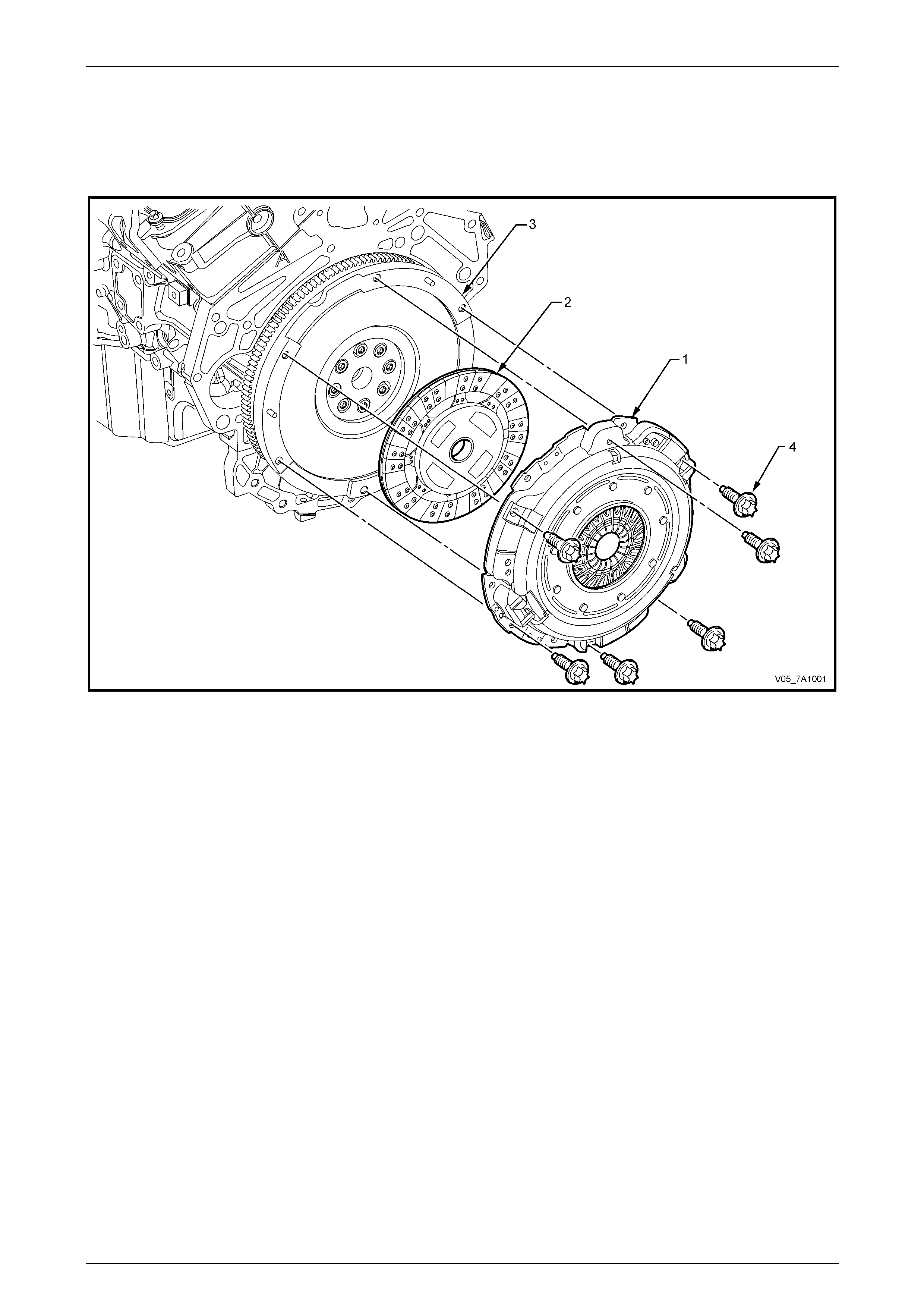
1 General Information
The clutch system used with the 6 speed Manua l Transmission, production option MV5 (AY6) is an hydraulically
controlled, diaphragm spring clutch pressure plate (1), clutch driven plate (2) and a dual mass engine flywheel (3).
7A1 – 3
Clutch- V6 Engine 7A1 – 4
2 General Description
2.1 Dual Mass Flywheel
Most engine vibrations cause d b y the igniting fuel air mixture are absorbed by the engine fl ywheel and clutch assembly.
However, vibrations that are not absorbed, can travel via the transmission bearings, as far as the propeller shaft and the
vehicle body. Using a dual mass flywheel m akes it possible for even these secondary vibrations to be absorbed at that
point.
The flywheel is divided int o two parts that are joined radially by springs. T he first half is bolted directly to the engine
crankshaft. A torsion damper consisting of springs and dampening friction systems forms the intermediary components,
while the clutch is bolted to the second half of the flywheel. The single, dry clutch driven plate is no longer fitted with
torque reaction springs.
The effectiveness of the dual mass flywheel is due to the div ision of the moments of inertia. The moment of inertia of the
flywheel half on the engine side is reduce d and correspondingly increased on the transmission si de flywheel half.
As a result of this system, critical vibrations are only discernible at engine speeds below idle speed. This prevents bo dy
noises and allows smooth gear changing, especially at low temperatures.
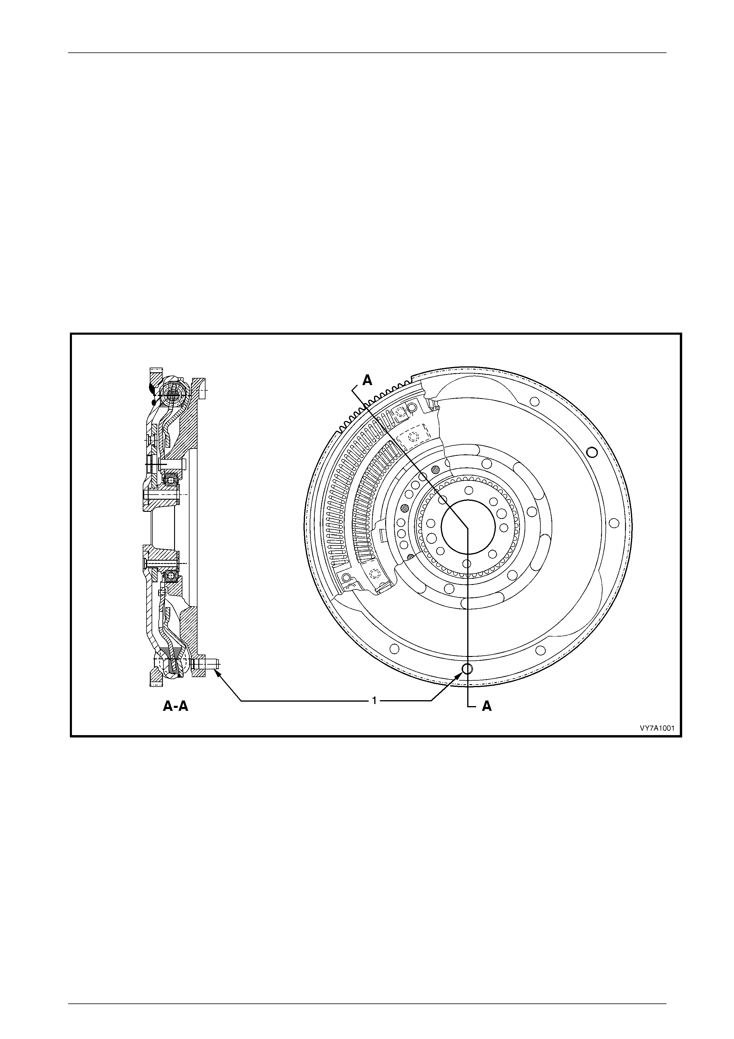
Figure 7A1 – 1 – Dual Mass Fl ywheel Assembly
Legend
1 Locating Pin
Service Implications
1 Re-surfacing of the flywheel clutch side surface, is not possible for the following reasons:
• As both flywheel masses are able to move independently to each other, it is not possible to effectively clamp
the assembly without the possibility of misalignme nt.
• A special balancing proced ure is followed at manufacture that involves rotating the flywheel to 6,000 rpm for a
minimum amount of time prior to undertakin g balancing at normal speeds.
2 Because the ring gear is welded to the crankshaft side of the flywheel, ring gear replacement is not possible, as re-
welding could cause distortion and possible burning of the grease used to lubricate the springs.
7A1 – 4
Clutch- V6 Engine 7A1 – 5
2.2 Clutch Control
Hydraulic actuation for the clutch has been adopted for a number of be neficial reasons:
• Noise reduction.
• Automatic adjustment.
• Constant pedal position.
• Constant efficiency factor.
• Constant pedal path.
Arrangement
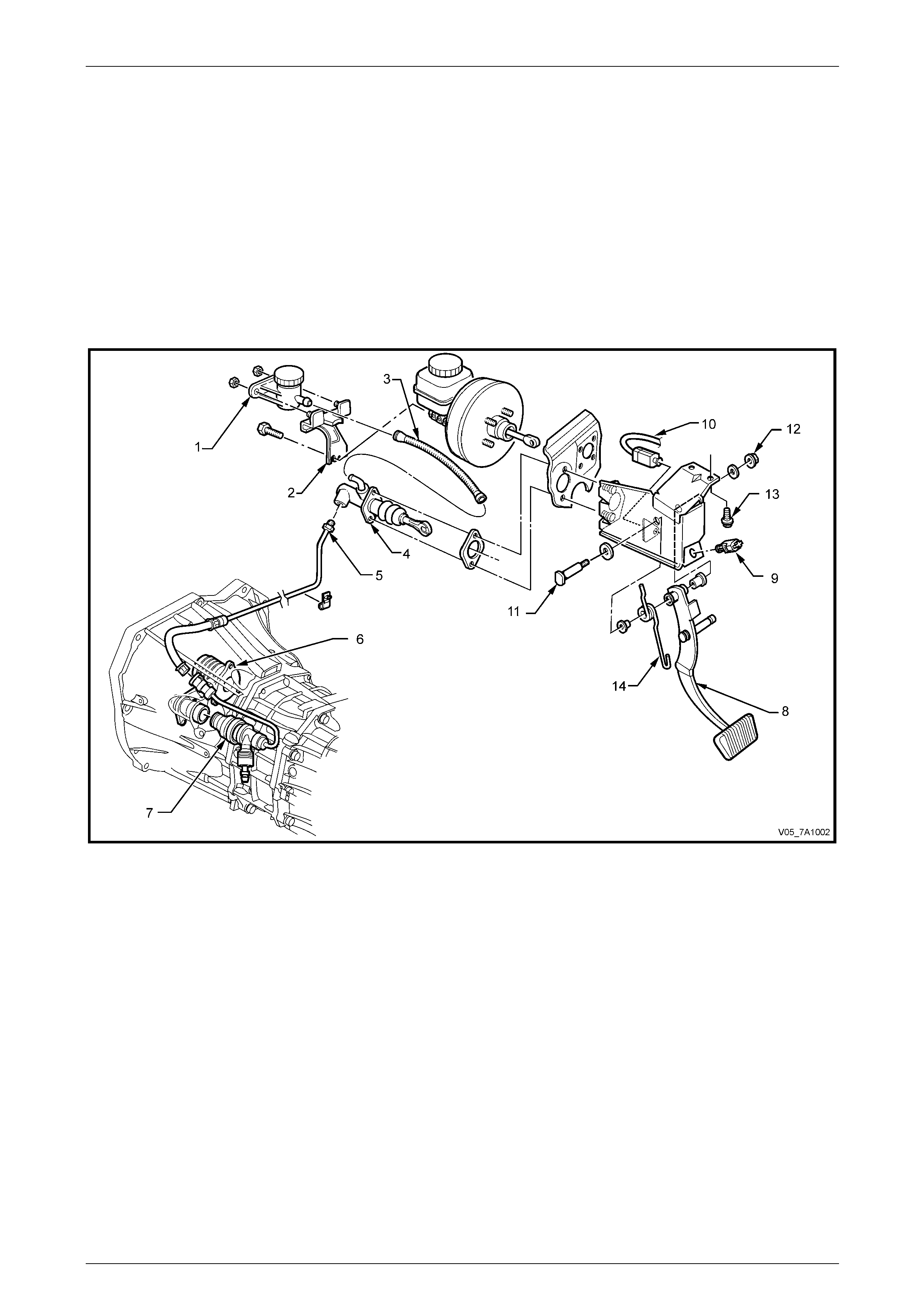
Figure 7A1 – 2 – Clutch Control Layout
Legend
1 Reservoir – Clutch Fluid
2 Bracket – Clutch Fluid Reservoir
3 Hose – Reservoir to Master Cylinder
4 Clutch Master Cylinder
5 Pipe and Hose – Master Cylinder to Adaptor
6 Centralised Slave Cylinder Assembly
7 Slave Cylinder Assembly Adaptor and Pipe
8 Pedal – Clutch
9 Switch – Cruise Control Cancel
10 Switch – Clutch Pedal Calibration
11 Pin – Clutch Pedal Pivot
12 Nut – Clutch Pedal Pivot Pin
13 Bolt – Clutch Pedal Bracket Retaining
14 Spring – Clutch Pedal Return
7A1 – 5
Clutch- V6 Engine 7A1 – 6
Brake fluid is fed to the clutch master cylinder from a remote reservoir mounted to a bracket, bolted to the end of the
brake master cylinder. A flexible line (fitted with push/pull quick connect fittings at each end) connects the two
components.
The master cylinder is attached to the firewall in the engine compartme nt.
The clutch pedal is mounted in the support bracket, bolted to the brake pedal support bracket and the dash panel.
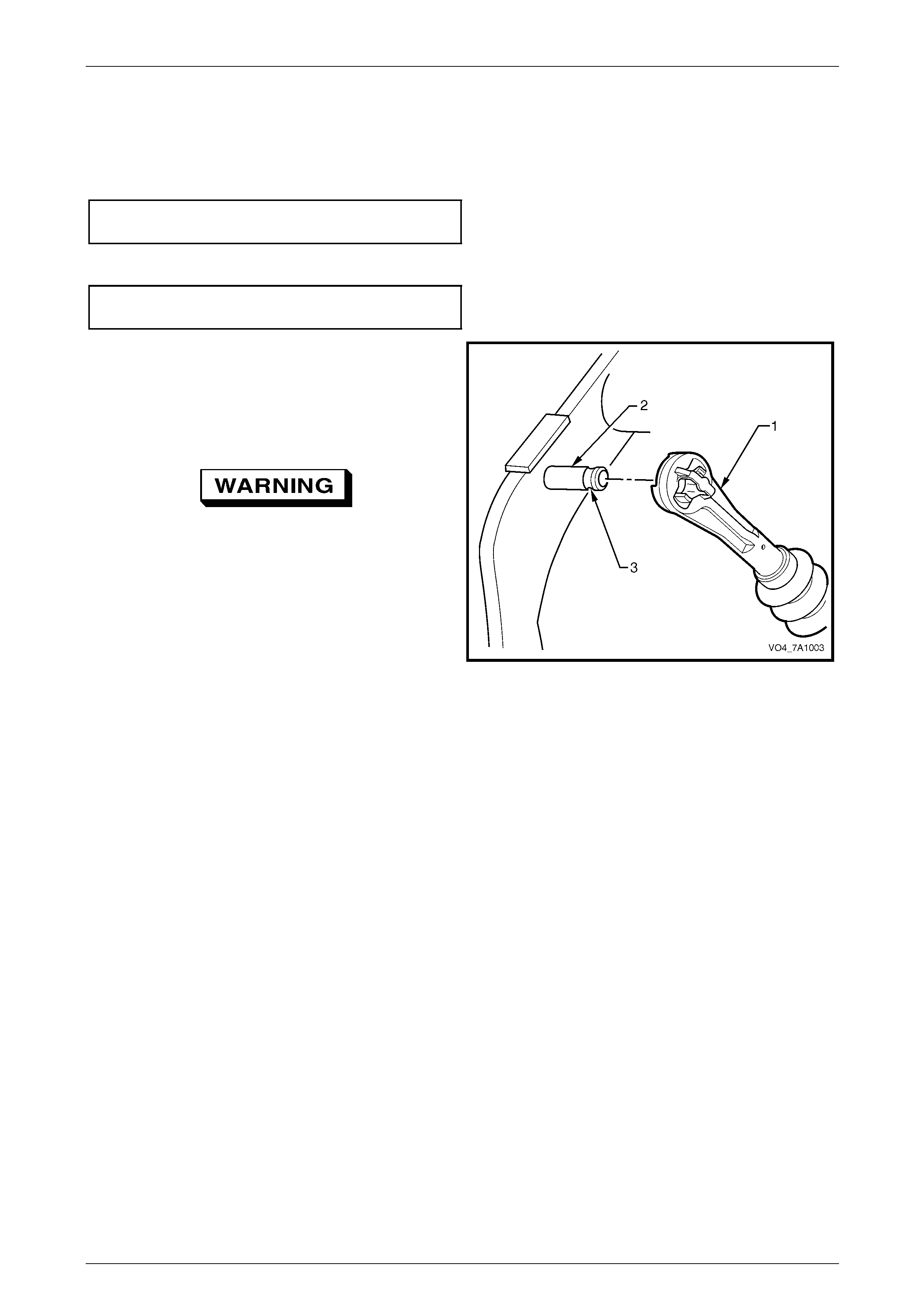
The clutch master cylinder piston is con nected to the clutch pedal by a push rod, with a quick connect fitting that is
retained on the clutch pedal pin by a groove. No clutch adjustments are required.
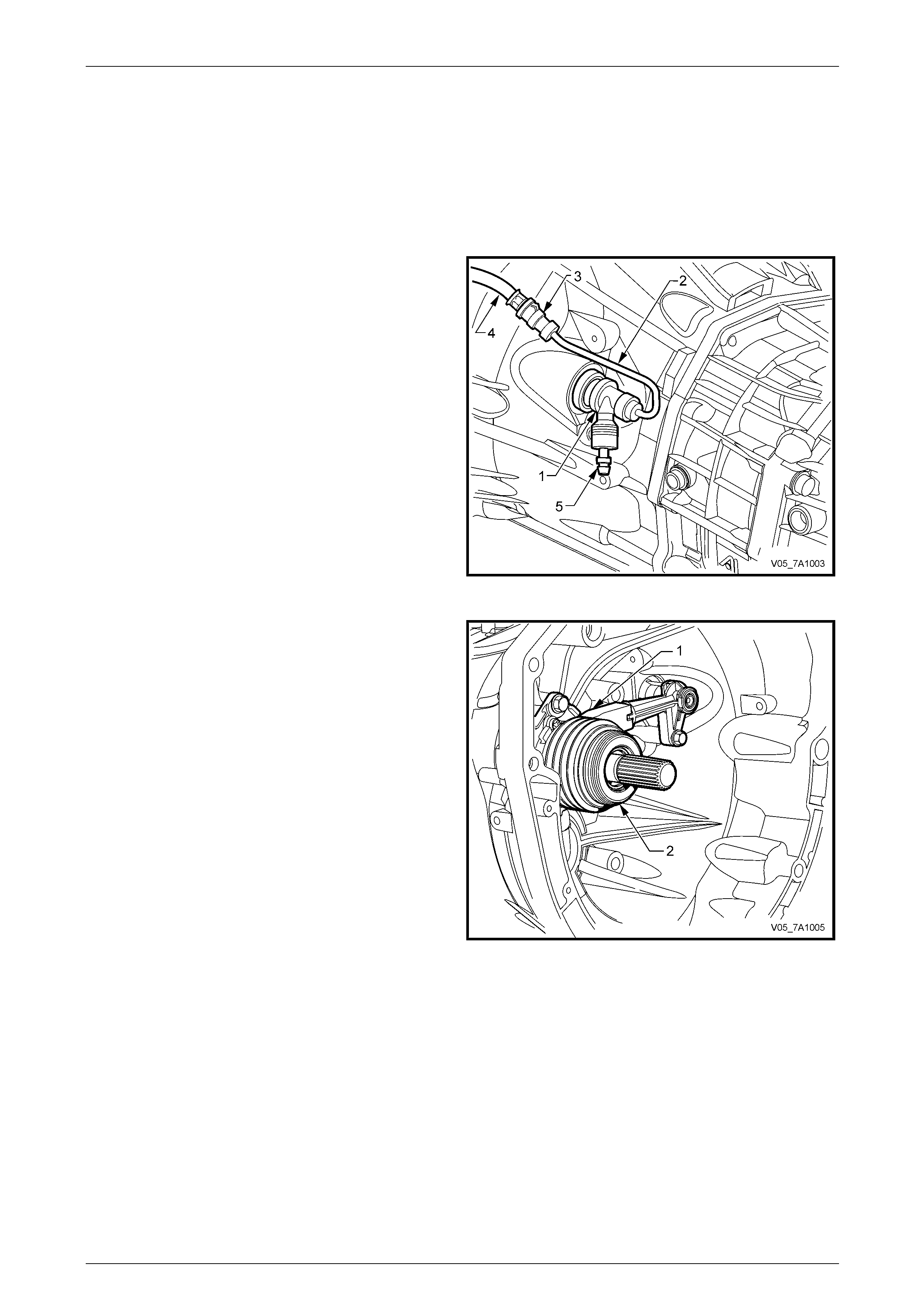
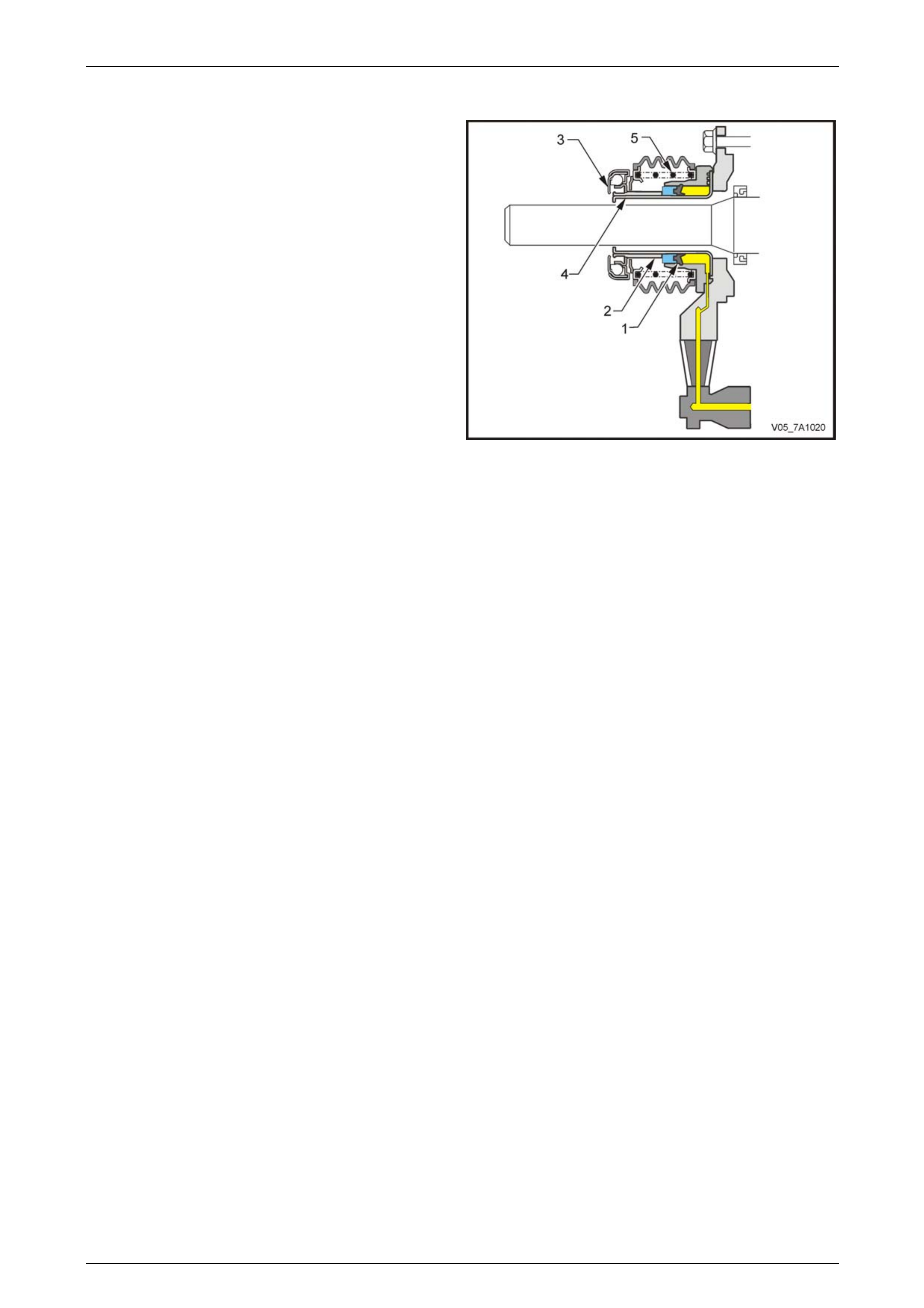
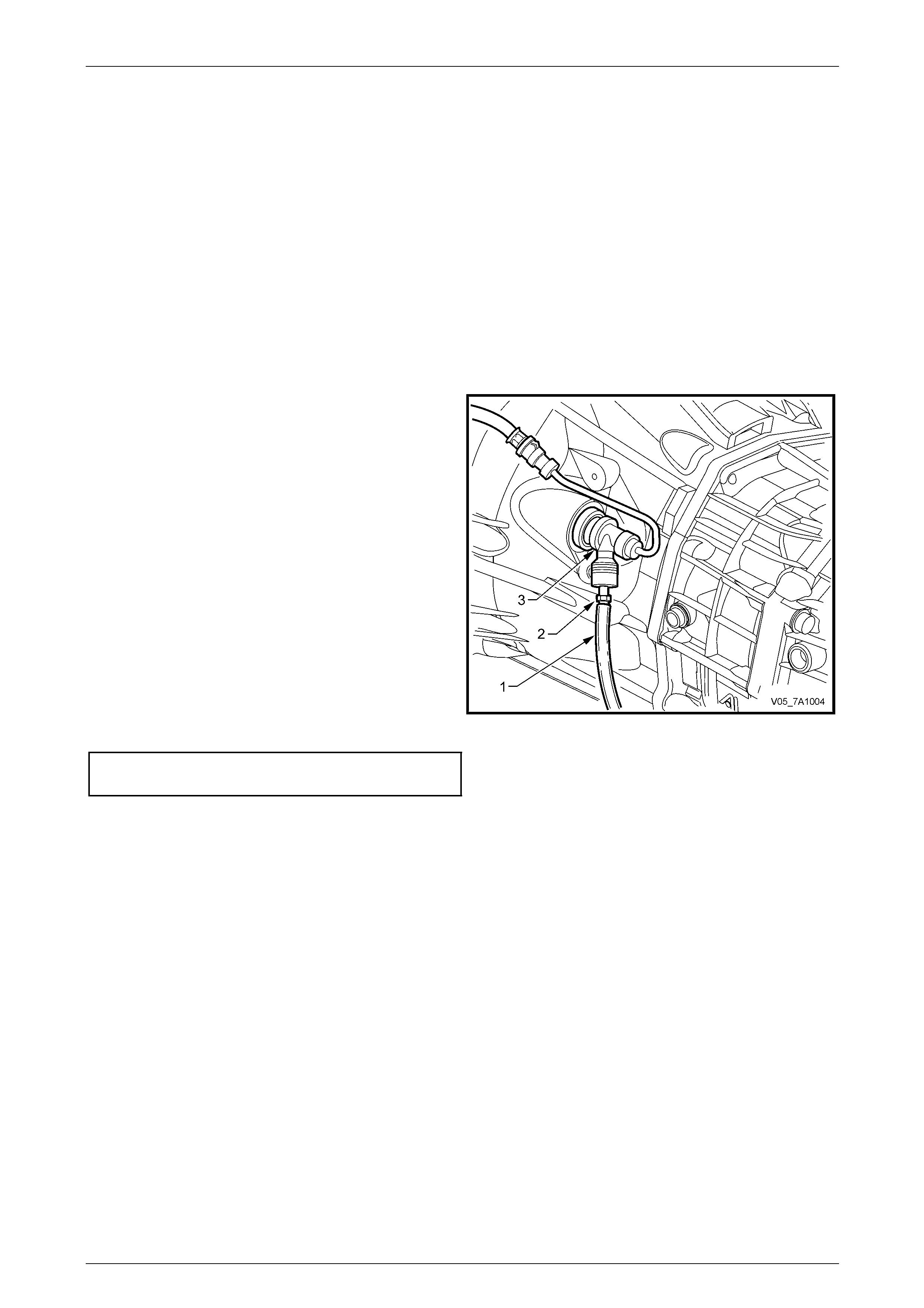
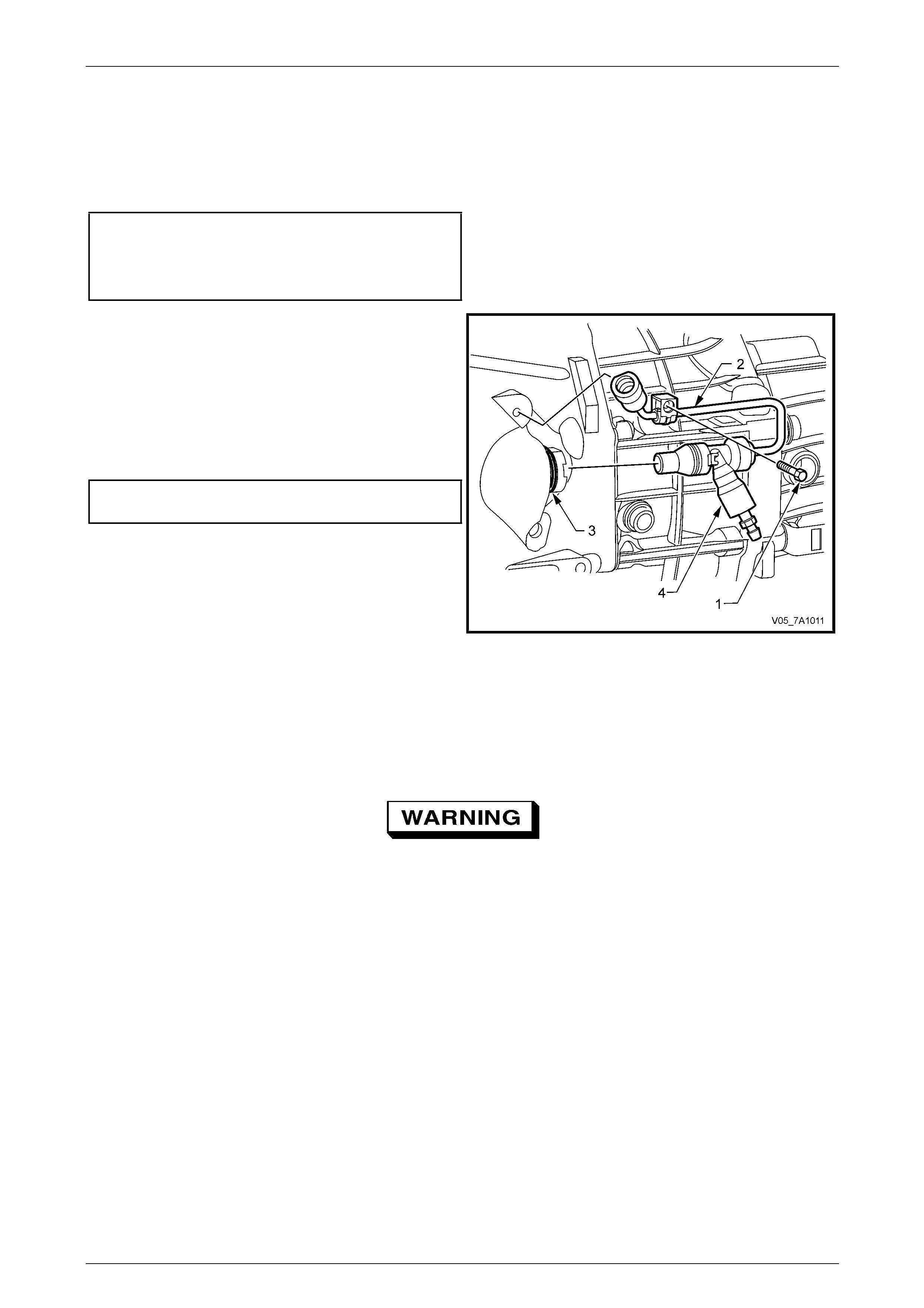
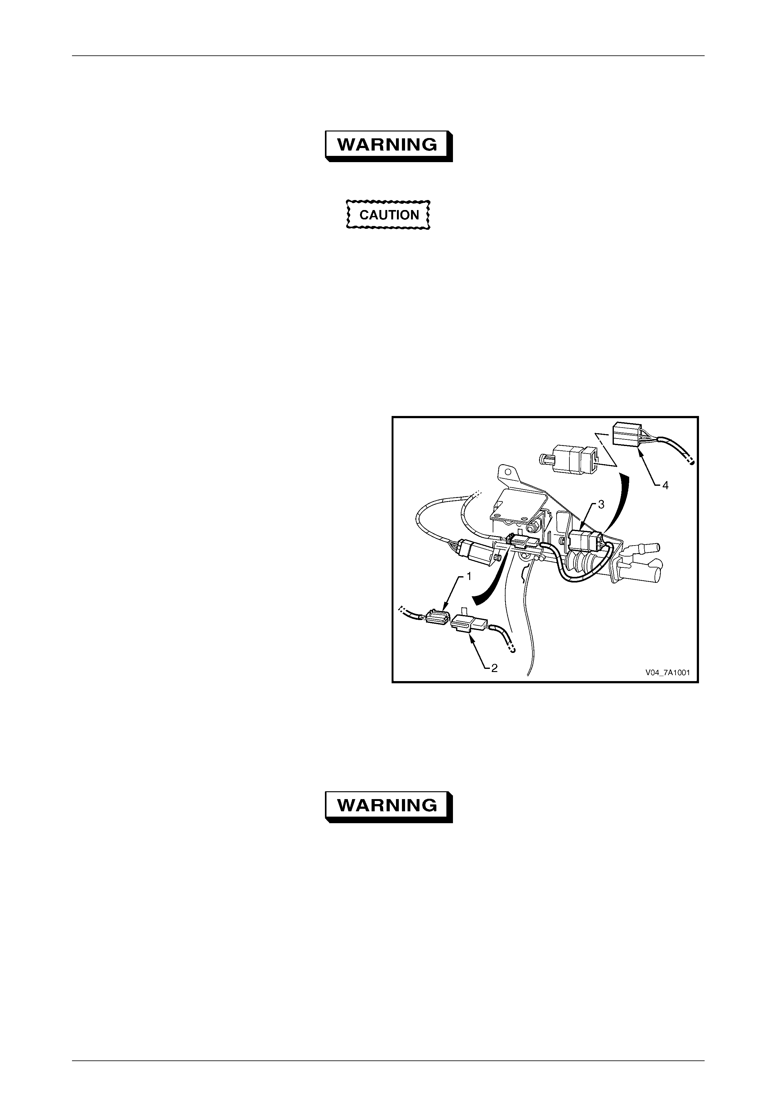
Connection of the concentric clutch hydraulic slave cylinder
to the clutch master cylinder is by an adaptor (1) steel piping
(2) and a quick connect fitting (3) to a flexible hose (4).
A bleed valve (5) is provided t o allow the removal of air from
the hydraulic system.
Figure 7A1 – 3
Stroking of the clutch pressure plate diaphragm spring is
achieved by using a concentric hydraulic clutch slave
cylinder (1) mounted to the front of the transmission
The clutch throwout bearing (2) is a sealed-for-life ball race,
requiring no periodic servicing.
Apart from the throwout bearing and the dust boot, there are
no other serviceable items in the clutch slave cylinder
assembly. If any other component is found to be faulty, then
the complete assembly must be replaced.
There is no spigot on the end of the transmission input
shaft, as the shaft support is rigid enough to allow its
deletion. This results in no bearin g being required in the end
of the engine crankshaft; often a source of a squeal
resulting from a lack of lubrication.
Figure 7A1 – 4
7A1 – 6
Clutch- V6 Engine 7A1 – 7
2.3 Clutch Master Cylinder/Actuating
Cylinder Operation
Master Cylinder
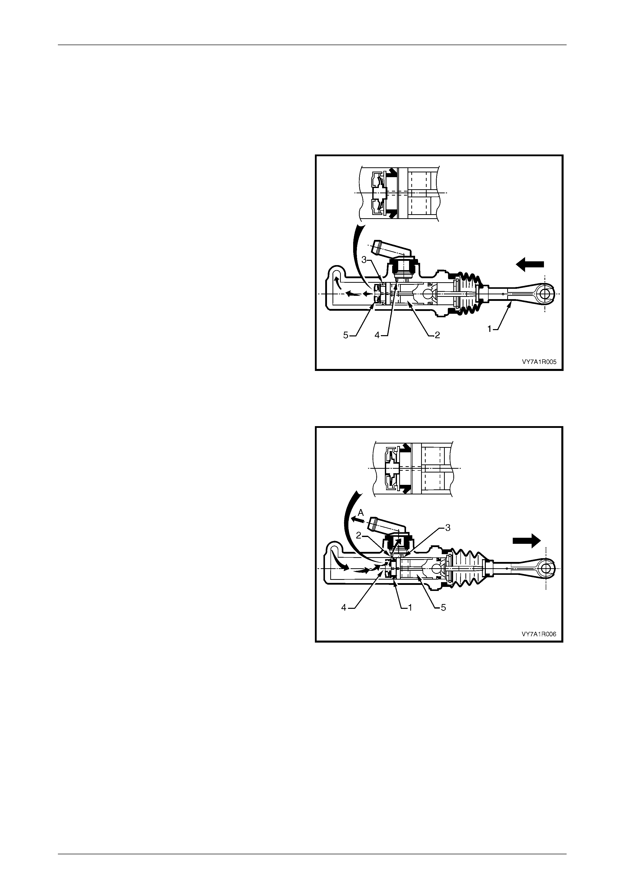
Clutch Released
As the clutch pedal is depressed, force is transmitted via the
clutch pedal push rod (1), to the clutch master cylinder
piston (2), moving it down the cylinder bore. When the
piston starts to move, the primary seal (3) covers the
compensating port (4) and the resultant build-up in
pressure, seats the relief valve (5) in the end of the piston.
As hydraulic pressure develops, the fluid is displaced and
moves the piston in the clutch actuating cylinder against the
return spring and clutch pressure plate diaphragm spring
forces, to stroke the actuating cylinder push rod. In turn, this
action moves the clutch throwout lever and bearing,
releasing the clutch pressure plate.
Figure 7A1 – 5
Clutch Applied
As the depressed clutch pedal is raised, the clutch pressure
plate diaphragm spring force, moves the fluid back through
hydraulic system, to the master cylinder. As the clutch pedal
is lifted to the point where the pedal is fully released, the
master cylinder, primary piston seal (1) uncovers the
compensating port (2). Once this occurs, excess,
pressurised fluid (arrows) returns to the fluid reservoir, via
‘A’.
If the clutch pedal is released very quickly, the combined
forces of the clutch pressure plate diaphragm spring, the
return spring in the actuating cylinder and the clutch pedal
return spring, return both pistons quicker than the fluid can
return to the reservoir through the relatively small
compensating port (2).
This creates a partial vacuum condition that causes
atmospheric pressure acting on the reservoir fluid, to force
fluid through the recuperating port (3), unseating the relief
valve (4) in the end of the master cylinder piston and
equalising fluid pressure. Should any excess fluid build up in
front of the master cylinder piston (5), it can then return to
the reservoir via the compensating port (2). Figure 7A1 – 6
7A1 – 7
Clutch- V6 Engine 7A1 – 8
Clutch Actuating Cylinder Operation
When pressurised fluid from the clutch mast er cylinder acts
upon the seal (1), the seal moves, stroking the sleeve (2)
before it. As the throwout bearing assembly (3) is attached
to the sleeve (2), the throwout bearing also moves with the
sleeve, to force the diaphragm fingers of the pressure plate
to move against its in-built spring force.
As the actuating cylinder sleeve (2) continues to be moved
along the guide of the cylinder body (4), the force applied to
the pressure plate diaphragm spring causes the pressure
plate diaphragm spring to piv ot, thus releasing the applied
force on the clutch driven plate, allowing it to spin. When
this situation occurs, the frictional link between the engine
flywheel and the transmission input shaft is broken a nd gear
changing can then take place, without undue stress being
placed upon the transmission synchromesh assemblies.
When the clutch pedal is released, the pressure plate
diaphragm spring force, moves the throwout bearing (3) and
actuating cylinder sleeve (2), back along the actuatin g
cylinder body guide (4), returning displaced fluid back to the
master cylinder reservoir. Figure 7A1 – 7
Coil spring (5) acts to maintain constant contact of the throwout bearing with the pressure plate diaphragm spring fingers,
thereby reducing pedal travel to begin initial movement b y compensatin g for an y slight finger height variation in the
diaphragm spring.
7A1 – 8
Clutch- V6 Engine 7A1 – 9
3 Service Operations
3.1 Service Warnings, Cautions and Notes
ATTENTION
All fasteners are important attaching parts as they affect the performance of vital components and/or could
result in major repair expense. W here specified in this Section, fasteners MUST be replaced w ith parts of the
same part number or an app roved equivalent. Do not use fasteners of an inferior quality or substitute design.
Torque values must be used as specified during reassembly to ensure proper retention of all components.
Throughout this Section, fastener torque wrench specifications may be accompanied with the following
identification marks:
Fasteners must be repl aced after loosening .
Vehicle must be at curb height before final tightening.
Fasteners either have micro encapsulated sealant applied or incorporate a mechanical thread lock and
should only be re-used once. If in doubt, replacement is recommended.
If one or more of these identification marks is present alongside a fastener torque wrench specification, the
recommendation regarding that fastener must be adhered to.
Asbestos
• While Holden clutch parts are not asbestos based in their material composition, a danger exists
that replacement non-genuine parts may contain asbestos.
• Not only is it in the interests of personal safety but also the safe and reliable operation of the
clutch system, that only genuine parts are used for replacemen t purposes.
• Even so, when servicing clutch parts, do not create dust by grinding or sanding the clutch plate,
or clean clutch parts w ith a dry brush or w ith compressed air. Breathing in dust th at may contain
asbestos fibres can cause serio us bodily harm over a protracted period of time.
• A water dampened cloth or water based solution should be used to remove any dust on clutch
parts. Equipment is commercially available to perform this washing function. These wet methods
prevent clutch component fibres from becoming airborne.
Brake Fluid
Brake fluid is extremely damaging to paint. If
fluid should accidentally come into contact
with a painted surface, immediately wash the
fluid from the paint and clean the painted
surface.
• The polyglycol brake fluid used in the MY 2005 VZ Series vehicles is hygroscopic and absorbs
moisture from the air through the flexible clutch hose etc. Therefore, for maximum clutch
effectiveness, a tw o yearly change of brake flui d is mandatory, refer to 3.4 Clutch Fluid – Change,
in this Section.
• To prevent the absorption of moisture from the air or other contamination, it is recommended that
the brake fluid be stored in small (500 ml) containers and that any surplus fluid remaining in a
container after use be discarded.
• The only approved brake fluid is DOT 4 or Super DOT 4 and is available in 250 and 500 ml
containers. If pressure bleeding equipment is used, it must be of an approved type with a
diaphragm separating the brake fluid from the air.
7A1 – 9
Clutch- V6 Engine 7A1 – 10
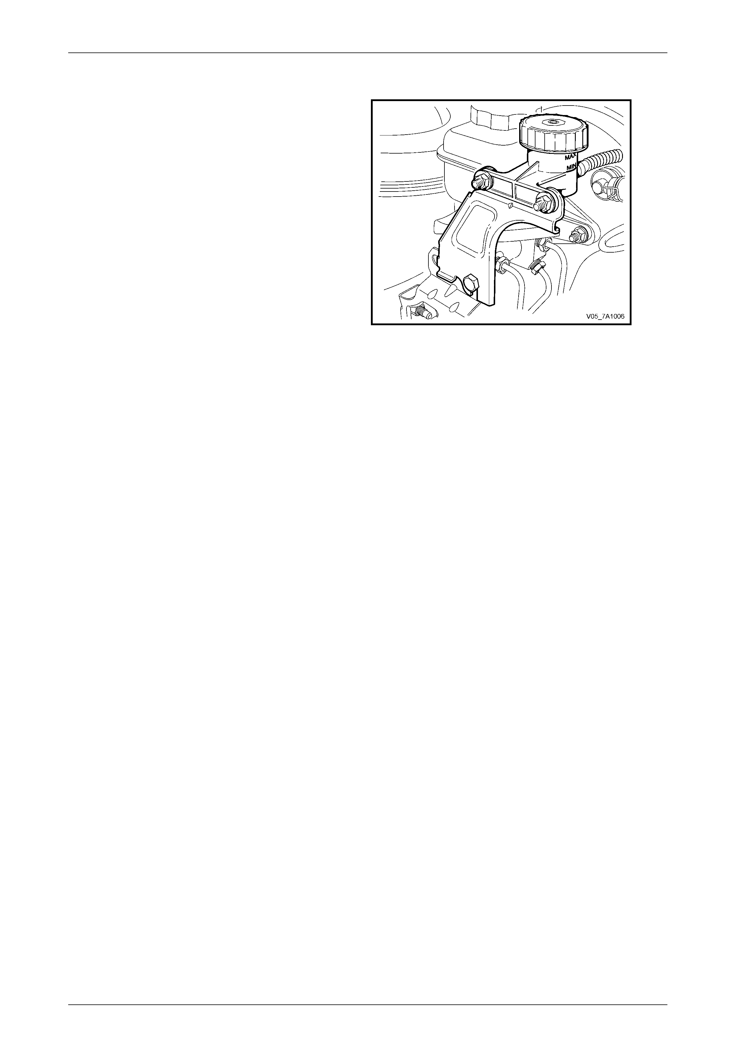
3.2 Fluid Level Check
Check that the fluid level is between the ‘MAX’ and ‘MIN’
guidelines on the transluce nt reservoir housing. Should the
addition of fluid be required, remove the reservoir cap and
top up with heavy duty brake fluid (DOT 4 or Super DOT 4).
Figure 7A1 – 8
7A1 – 10
Clutch- V6 Engine 7A1 – 11
3.3 Clutch Hydraulic System, Bleed
NOTE
• The clutch hydraulic system must be bled
whenever the hydraulic line has been
disconnected, or when a leak has allowed air
to enter the system. Air trapped in the s ystem
can prevent full disengagement of the clutch.
• During bleeding operations, the master
cylinder reservoir must be kept at least half
full with hydraulic brake fluid.
1 Carefully clean any dirt from around the reservoir cap.
2 Remove the filler cap and top up reservoir as required, with heavy duty hydraulic brake fluid (DOT 4 or Super DOT
4).
3 Slip the end of a length of plastic tube (1) ove r the
bleeder screw (2) on the actuating cylinder adaptor (3)
and insert the other end into a clea n glass container,
that has been partially filled with new brake fluid.
NOTE
Ensure that the end of the hose always remains
submerged in the brake fluid during bleeding
operations.
4 Loosen the bleeder scre w 1/2 to 3/4 turn.
5 Fully depress the clutch pedal by hand, then allo w it to
return slowly. Continue this slow pumping motion,
forcing fluid and air through the hydraulic system until
all bubbles cease to app ear at the end of the bleeder
hose.
6 While depressing the pedal, tighten the bleeder scre w,
then remove the bleeder hose from the actuating
cylinder bleeder screw.
Clutch actuator bleed
screw torque specification......................................8 N.m
Figure 7A1 – 9
7 Once all bleeding operations have been completed, ensure that the fluid level in the reservoir is correct.
NOTE
An alternative bleeding method is to use a
commercially availa bl e pr essu re blee din g s yst em,
using a universal reservoir sealing cap
arrangement. Follow the manufacturer’s
instructions for the system used.
7A1 – 11

Clutch- V6 Engine 7A1 – 12
3.4 Clutch Fluid – Change
At the interval specified in the Owners Handbook, the clutch fluid must be changed. Discolouration of the fluid is n o
reason for fluid replacement. The recommended method is to use a commercially ava ilable pressure bleeder, together
with an appropriate fluid reservoir cap. Follow the manufacturer’s instructions in the use of the pressure b lee ding
equipment and continue allowing fluid to flow through the system until the fluid runs clear in the bleeder hose attached to
the clutch actuating cylinder bleeder screw.
Following the fluid change operation, ensure that the fluid level in the reservoir is correct, the cap is installed correctly
and that the actuating cylinder bleeder screw is tightened to the correct torque specificatio n.
Clutch actuator bleed
screw torque specification......................................8 N.m
7A1 – 12
Clutch- V6 Engine 7A1 – 13
3.5 Clutch Master Cylinder
LT Section No. – 00-430
Remove
Disable the SRS (Air Bag). Refer to
Section 12M, Occupant Protection System.
Disconnection of the battery affects certain
vehicle electronic systems. Refer to
Section 00 Warnings, Cautions and Notes,
before removing the ground lead.
1 Disconnect the battery ground cable.
2 If fitted, remove front suspension strut tower brace, refer to Section 1A1 Body.
3 Remove ignition keys from ignition switch.
4 Remove the following components:
a Instrument panel lower trim panel assembly, refer to Section 1A3 Instrument Panel and Consol e.
b Driver side instrument panel lower trim plate assembly, refer to Section 1A3 Instrument Panel and Console.
c Instrument panel lower trim panel retainer, refer to Section 1A3 Instrument Pane l and Console.
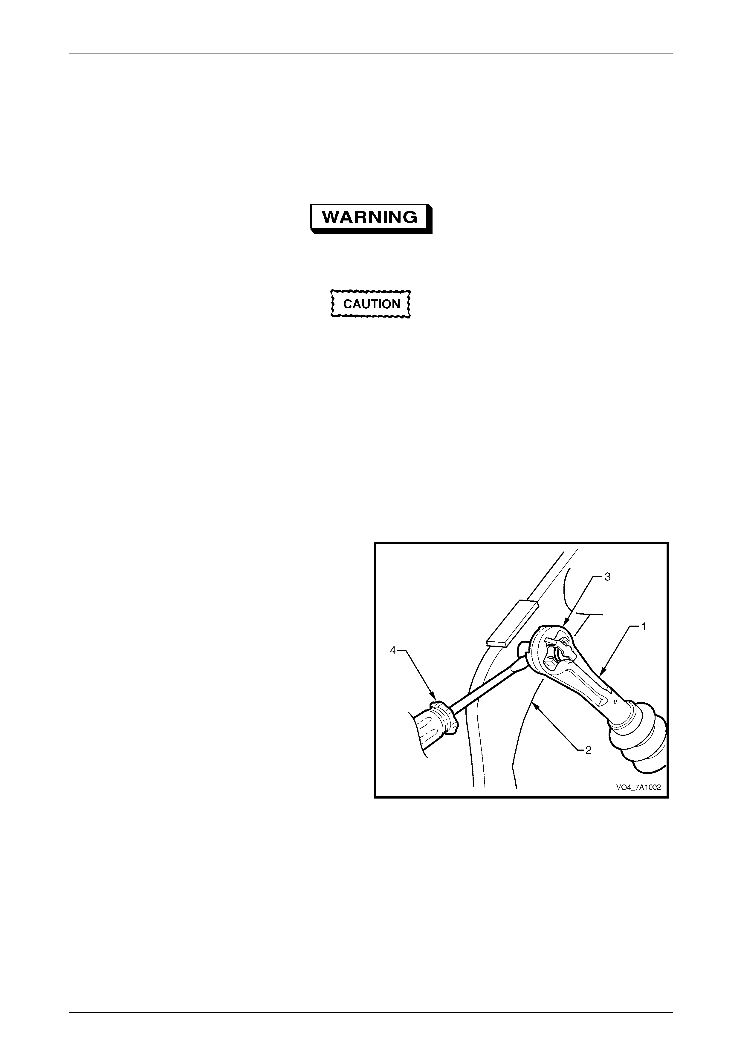
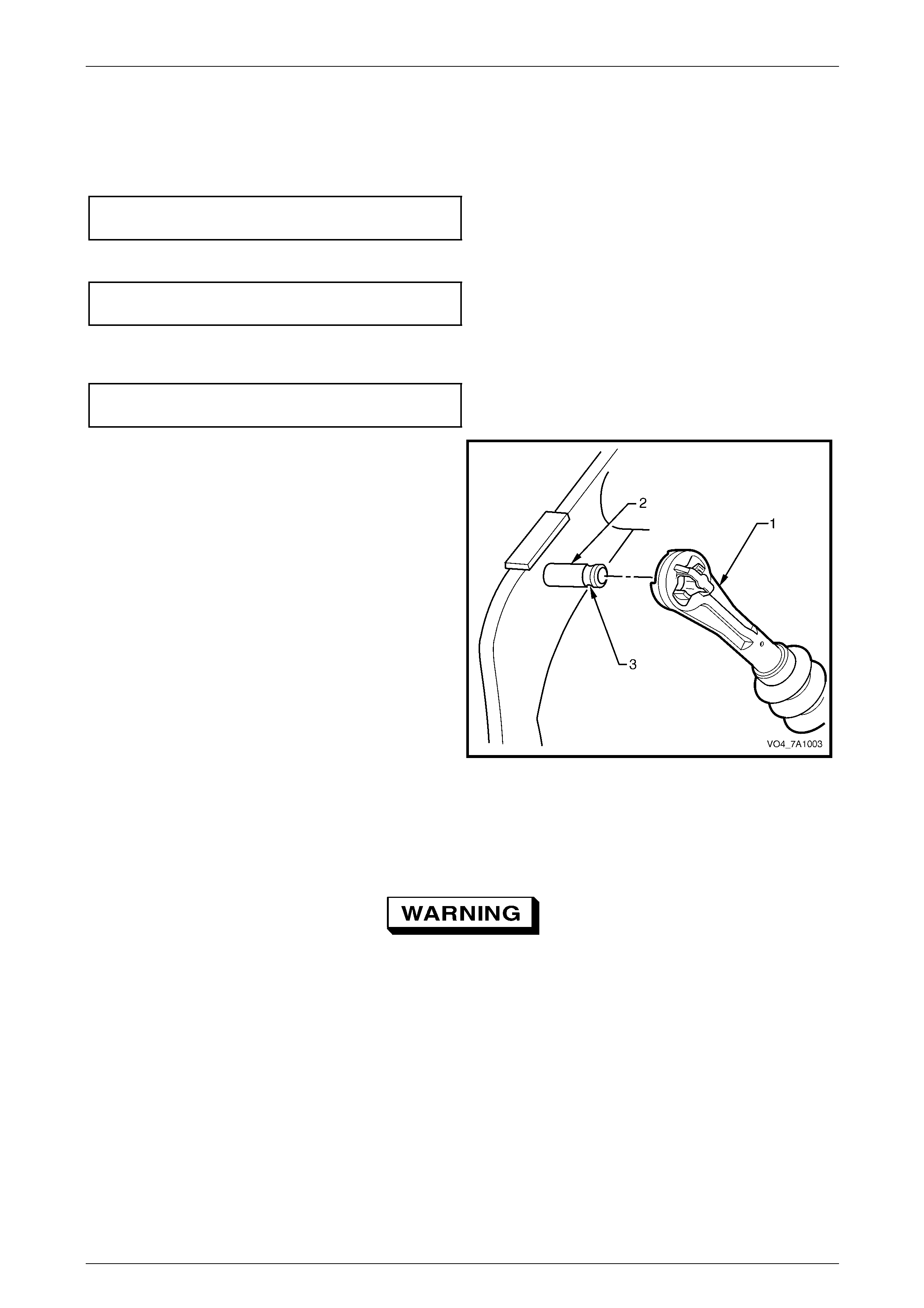
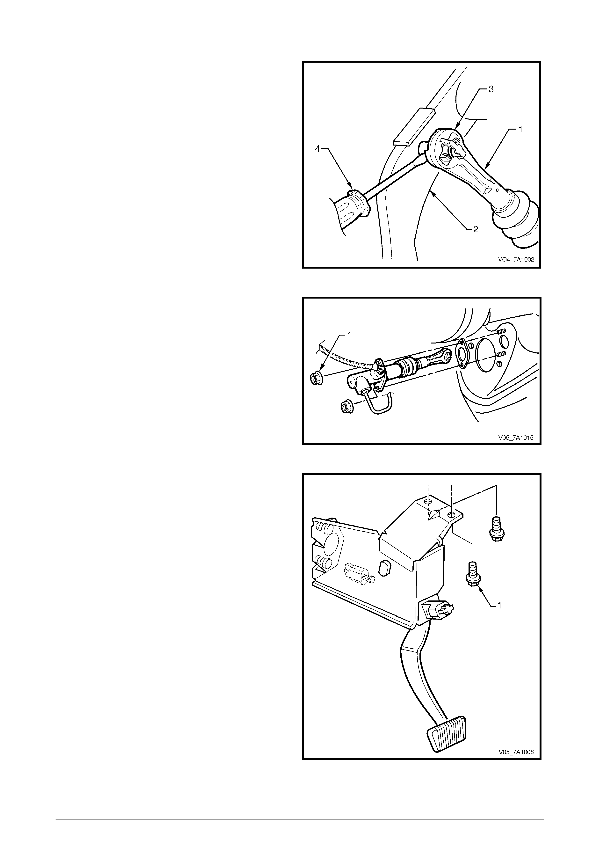
5 Disconnect the clutch master cylinder push rod (1)
from the pin attached to the clutch pedal (2) by prising
the pushrod quick connect fitting (3) with a
screwdriver (4).
Figure 7A1 – 10
7A1 – 13
Clutch- V6 Engine 7A1 – 14
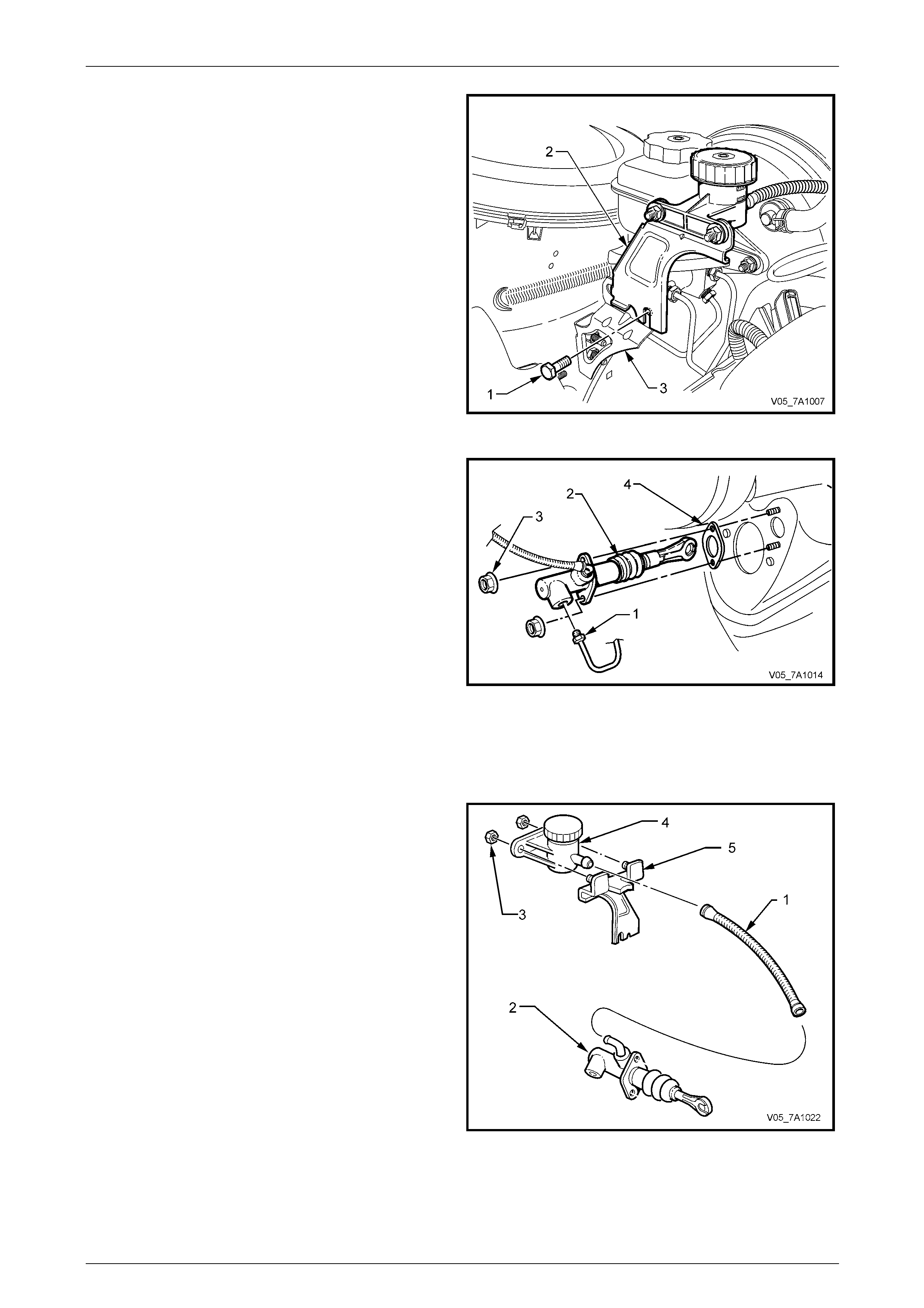
6 Remove the clutch master cylinder fluid reservoir and
bracket (2) as an assembly by removing the bolt (1)
from the end of the brake master c ylinder end brace
(3). Support the clutch reservoir to prevent fluid
spillage.
Figure 7A1 – 11
7 Remove the hydraulic steel pipe (1) from the clutch
master cylinder (2)
8 Plug both the open pipe end and the master cylinder
opening to prevent dirt entry and fluid loss.
9 Remove the two clutch master cylinder retain ing nuts
(3) from the engine bay side of the cockpit module and
remove the master cylinder and reservoir assembly
from the vehicle. Also remove the gasket (4).
Figure 7A1 – 12
Disassemble
1 Drain the brake fluid from the reservoir into a suitable container. Discard the collected flu id.
2 Disconnect the flexible hose (1) from the master
cylinder (2) by pulling on the end of the hose at the
master cylinder.
3 If required, remove the nuts (3) attaching the reservoir
(4) to the clutch reservoir mounting bracket (5).
NOTE
When the hose is disconnected, a rubber seal
normally located in each e nd of the flexible hose
may become dislodged. If this occurs, push the
seal back into the flexible hose.
Figure 7A1 – 13
7A1 – 14
Clutch- V6 Engine 7A1 – 15
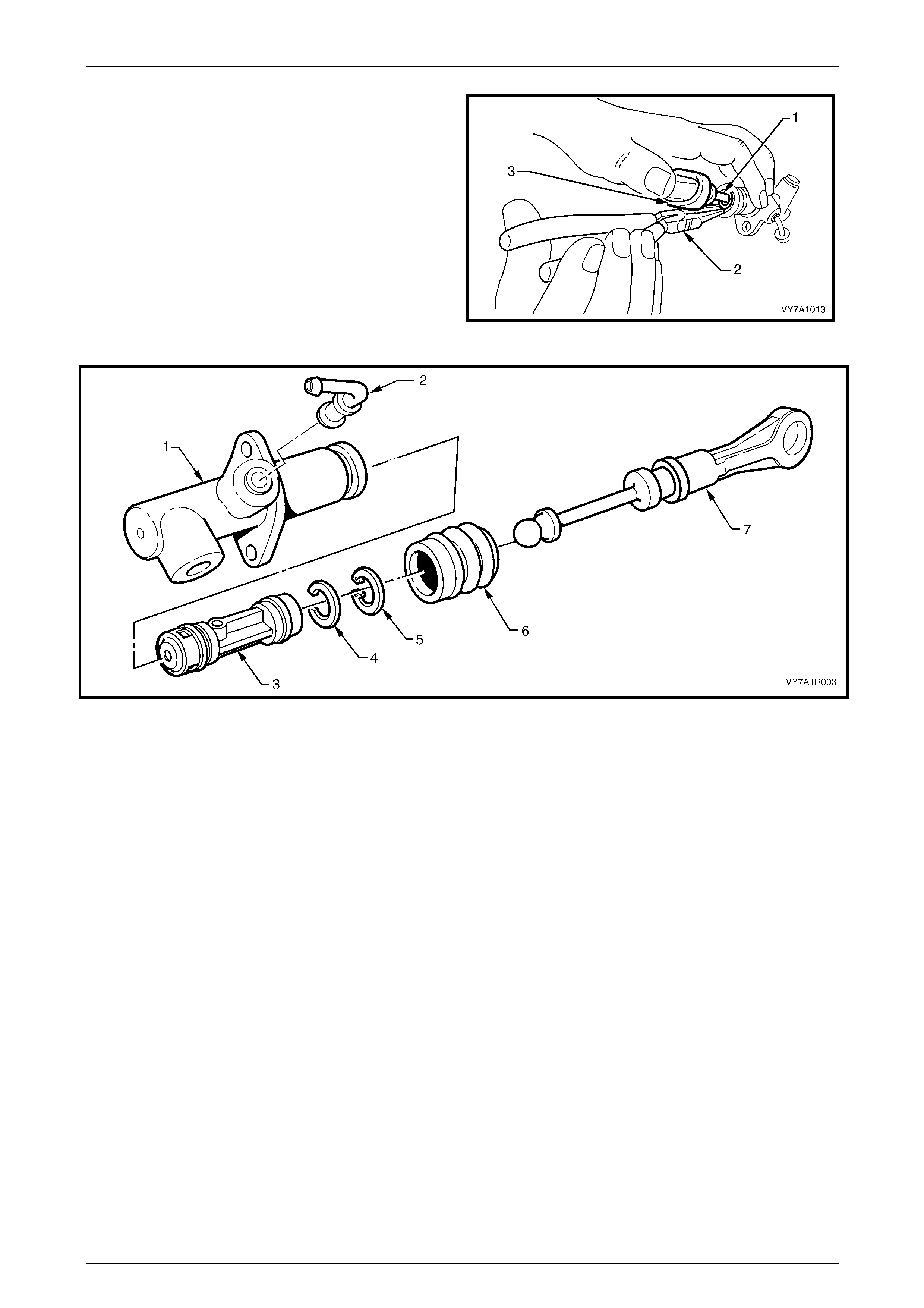
4 Dislodge the boot from the cylinder gro ove and pull
back over the end of the push rod.
5 Using the master cylinder push rod (3), depress the
master cylinder piston sufficient to relieve pressure on
the circlip (1).
6 Then, using suitable circlip pliers (2), remove the
circlip from the master cylinder body.
7 As the push rod is secured to the piston, gently pulling
on the push rod will remove the pisto n assembly and
retaining washer from the master cylinder bore.
8 As the repair kit supplies all of the removed
components as a complete assembly, no further
dismantling is required. Figure 7A1 – 14
Figure 7A1 – 15
Legend
1 Clutch Master Cylinder
2 Clutch Master Cylinder Elbow
3 Piston, Valve and Seals Assembly
4 Retaining Washer
5 Circlip
6 Boot
7 Push Rod Assembly
7A1 – 15
Clutch- V6 Engine 7A1 – 16
Clean and Inspect
• Do not wash hands in petrol or oil before
cleaning or handling master cylinder
parts; always use a soap and water based
hand cleaning product.
• Hands must be clean before hydraulic
components are handled and washed, as
the slightest trace of mineral based grease
or oil in the cylinder or on components,
can cause excessive swelling and/or
destroy rubber based parts.
1 Wash all parts in clean alcoho l or methylated spirits and blow dry with compressed air.
2 Inspect the master cylinder bore for scores, deep scratches or corrosion. If considered to be unservice able, the
complete master cylinder assembly must be replaced.
NOTE
The master cylinder bore must not be honed.
3 Carefully inspect the piston to ensure that it is free from burrs and/or sharp edges, which may cause da m age to the
master cylinder wall.
4 Check that the breather cap ventilation system on the reservoir is intact and functional.
5 Replace all internal compo nents supplied in the clutch master cylinder overhaul kit.
Reassemble
1 Dip piston seals and the piston in clean brake fluid.
2 After lubricating the master cylinder bor e with clean brake fluid, install the piston, push rod and boot ass embly into
the cylinder.
NOTE
Ensure that neither of the piston seals get caught
or damaged during the installation process.
3 Reinstall the washer (4) and r etaining circlip (5). Refer to Figure 7A1 – 14.
4 Reinstall the flange of the boot (6) over the end of the master cylinder (1), ensuring that the boot fits completely into
the groove provided.
5 Reinstall master cylinder reservoir hose to the master cylinder fitting, by pushing it onto the master cylinder fitting.
6 Plug the master cylinder outlet fitting to prevent the entry of foreign matter into the cylinder, during reinstallation
operations.
7 If previously removed, refit the master cylinder reservoir to the clutch master cylinder bracket. Tighten to the correct
torque specification.
Master cylinder fluid reservoir to
mounting bracket nut torque specification.............. 3 N.m
7A1 – 16
Clutch- V6 Engine 7A1 – 17
Reinstall
Installation is the reverse of removal operations except for the following points:
1 Reinstall master cylinder ove r studs, fit retaining nuts and washers and tighten to the correct torque specification.
Clutch master cylinder mounting
nut torque specification........................................25 N.m
2 Reinstall and tighten hydr aulic pipe flare nut to master cylinder to the correct torque specification.
Hydraulic pipe flare
nut torque specification........................................12 N.m
3 Reinstall the clutch master cylind er fluid reservoir bracket to the brake master cylinder end brace. Tighten the
retaining bolt to the correct torque specification.
Clutch reservoir bracket to brake master
cylinder bracket bolt torque specification .............10 N.m
4 Reinstall the clutch master cylind er push rod (1) to the
clutch pedal pivot pin (2), ensurin g that the quick
connect retaining clips are full y engaged in the
groove (3).
5 Reinstall the instrument panel lower trim panel
retainer, lower trim panel and driver side lower trim
plate, refer to Section 1A3 Instrument Panel &
Console.
Figure 7A1 – 16
6 Bleed the clutch hydraulic syst em, as detailed in 3.3 Clutch Hydraulic System Bleed, in this Section.
7 Following bleeding operations, check that the hydraulic fluid level is correct, as detailed in 3.2 Fluid Level – Ch eck,
in this Section.
Enable the SRS (Air Bag). Refer to
Section 12M Occupant Protection System.
8 Road test the vehicle to check for correct clutch operation.
7A1 – 17
Clutch- V6 Engine 7A1 – 18
3.6 Clutch Actuating Cylinder
LT Section No. – 00-430
Disable the SRS (Air Bag). Refer to
Section 12M, Occupant Protection System.
Disconnection of the battery affects certain
vehicle electronic systems. Refer to
Section 00 Warnings, Cautions and Notes,
before removing the ground lead.
Remove
1 Raise the vehicle and suppor t in a safe manner. Refer to Section 0A General Information in this Service Information
for the location of recommended lifting and support points.
2 Remove the transmission from the vehicle a nd place on a work bench.
Refer to Section 7B1 Manual Transmission – V6 .
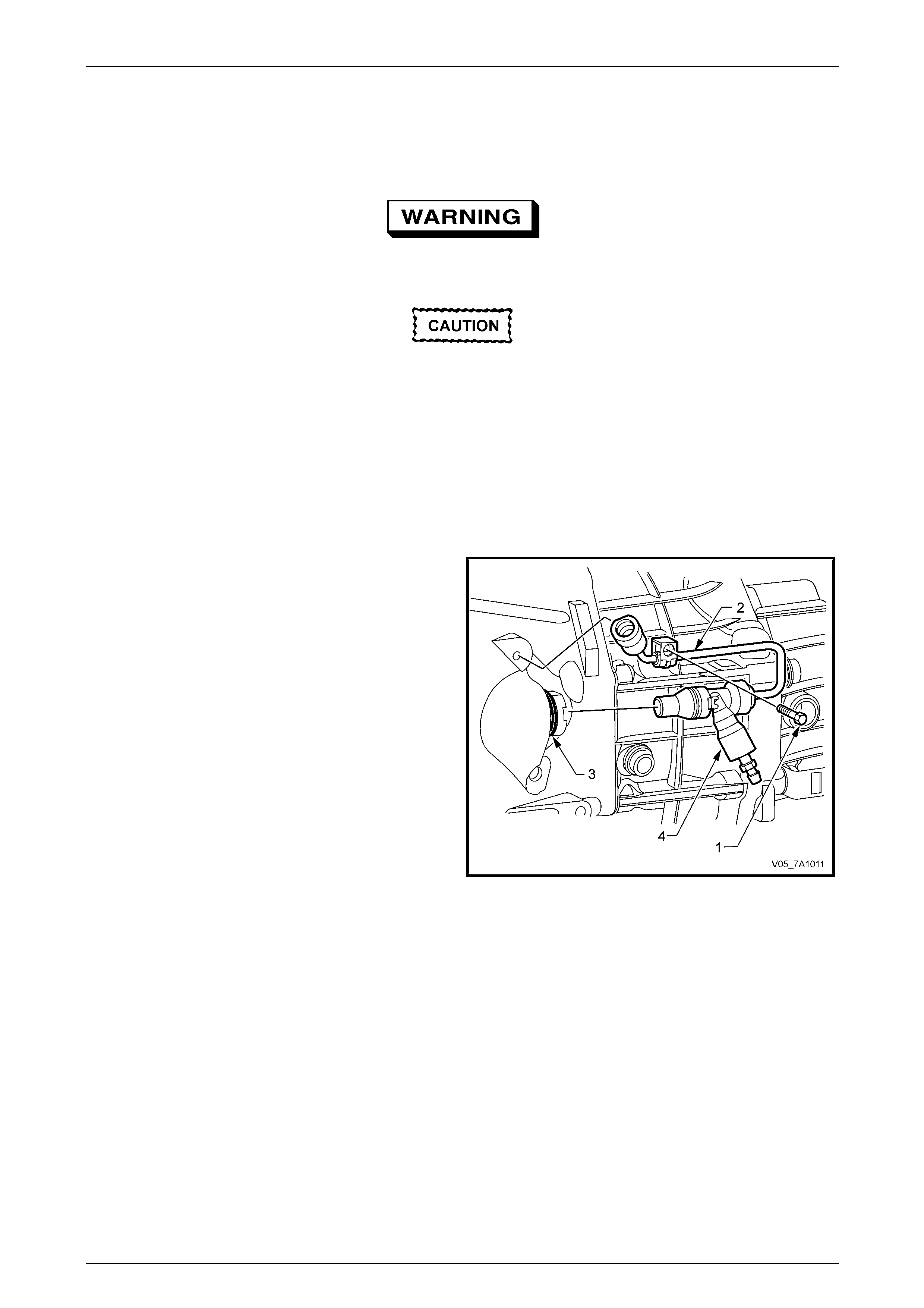
3 Remove the screw (1) retaining the actuating c ylinder
adaptor fluid feed pipe (2) to the transmission housing.
4 Using a small bladed screwdriver, lift the retaining wire
clip (3) securing the actuating cylinder ada ptor (4).
5 Remove the actuating cylin der adaptor and set to one
side.
Figure 7A1 – 17
7A1 – 18
Clutch- V6 Engine 7A1 – 19
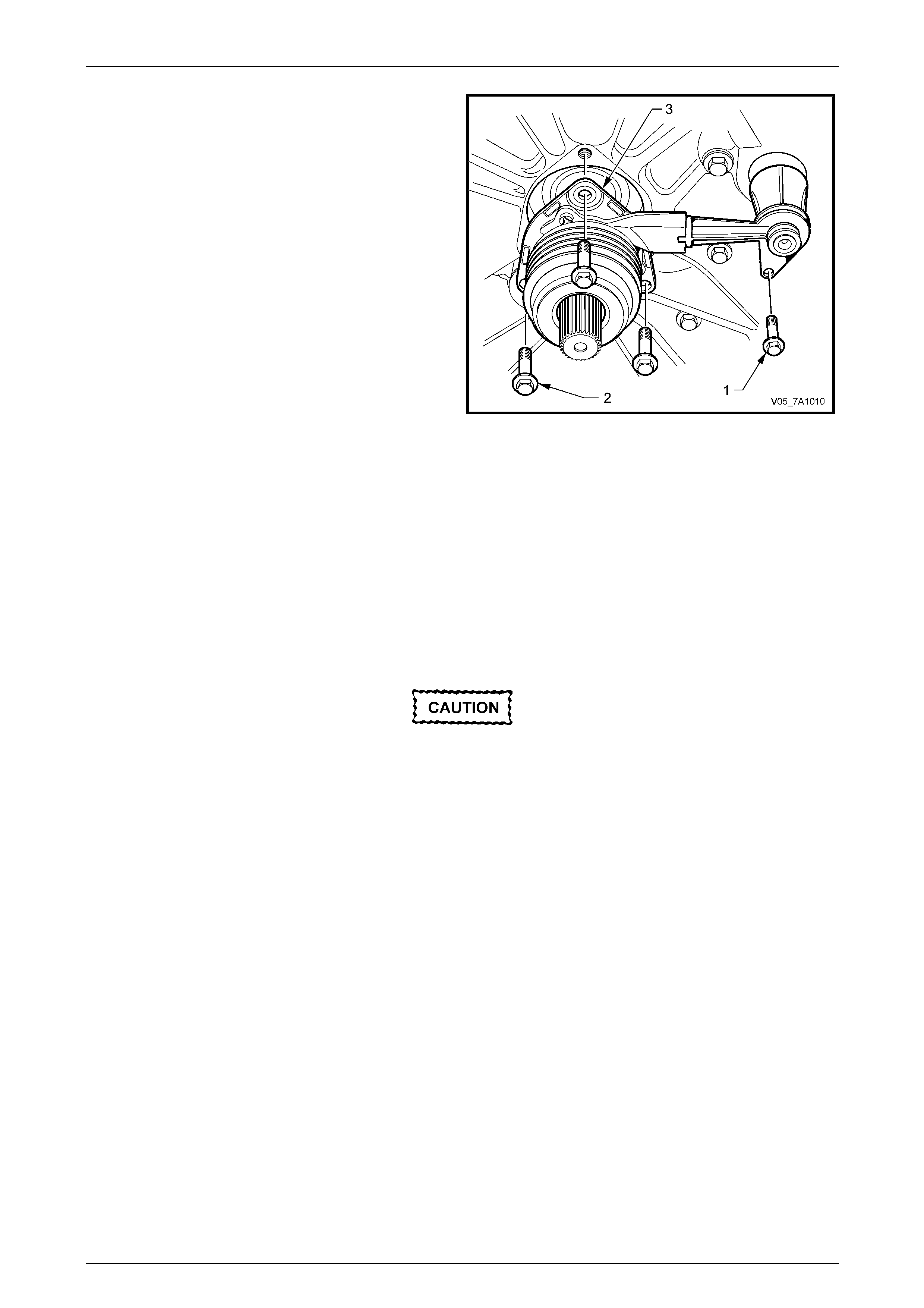
6 Remove the clutch actuating cylinder piping bolt (1)
and the three bolts (2) securing the c ylinder to the
front transmission housing.
7 Remove the actuating cylin der (3) from the front
transmission case.
Figure 7A1 – 18
Disassemble
1 If required, remove the throwout bearing and dust boot. Refer to 3.7 Clutch Throwout Bearing, in this Section.
NOTE
Apart from the bearing and boot, there are no
other serviceable items in this assembly.
Clean and Inspect
Do not wash hands in petrol or oil before
cleaning or handling actuating cylinder parts;
always use a soap and water based hand
cleaning product.
1 Inspect the actuating cylinder for any evidence of fluid leakage. If leakage is found, replace the assembly.
2 Wash all parts in clean alcoho l or methylated spirits and blow dry with compressed air.
3 Inspect the actuating cylinder adaptor sealing O-ring for damage, replacing as required.
4 Inspect the actuating cylinder adaptor for obvious damage, replacing the assembly as required.
5 Remove the bleeder screw from the actuating cylinder adaptor, check that no thread damage ex ists, replacing the
assembly as required.
6 Check that the bleeder screw threads are und amaged and that the drilled passage is clear and free of debris.
7 Check the throwout bearing. Refer to 3.7 Clutch Throwout Bearing – Replace, in this Section.
7A1 – 19
Clutch- V6 Engine 7A1 – 20
Reinstall
Installation is the reverse to removal operat ions, except for those items listed here.
1 Reinstall the clutch release c ylinder. Install the three screws securing the cylinder, then the fluid pipe adaptor
screw. Tighten all fasteners to the correct torque specification.
Clutch actuating cylinder
screw torque specification....................................17 N.m
Clutch actuating cylinder fluid pipe
retaining screw torque specification.......................3 N.m
2 Install the sealing O-ring to the fluid pipe adaptor, after
coating with clean brake fluid .
3 Push the fluid pipe adaptor (4) into the clutch release
cylinder until the quick connect wire clip (3) engages.
Tug of the adaptor to check for correct installation.
4 Reinstall the scre w (1) securing the fluid pipe retainer
to the transmission case and tighten to the correct
torque specification.
Adaptor fluid pipe bracket
screw torque specification......................................3 N.m
Figure 7A1 – 19
5 Reinstall the transmission i nto the vehicle. Refer to Section 7B1 Manual Transmission – V6.
6 Bleed the clutch hydraulic syst em, as detailed in 3.3 Clutch Hydraulic System, Bleed, in this Section.
7 Following bleeding operations, check that the hydraulic fluid level is correct, as detailed in 3.2 Fluid Level Ch eck, in
this Section.
Enable the SRS (Air Bag). Refer to
Section 12M Occupant Protection System.
8 Lower vehicle and road test vehicle, to check for correct clutch operation.
7A1 – 20
Clutch- V6 Engine 7A1 – 21
3.7 Clutch Throwout Bearing
LT Section No. – 00-400
Disable the SRS (Air Bag). Refer to
Section 12M, Occupant Protection System.
Remove
1 Raise the vehicle and suppor t in a safe manner. Refer to Section 0A General Information in this Service Information
for the location of recommended lifting and support points.
2 Remove the transmission from the vehicle a nd place on a work bench.
Refer to Section 7B1 Manual Transmission – V6 .
3 Remove the actuator cylinder assembly from the front of the transmission. Refer to 3.6 Clutch Actuating Cylinder, in
this Section.
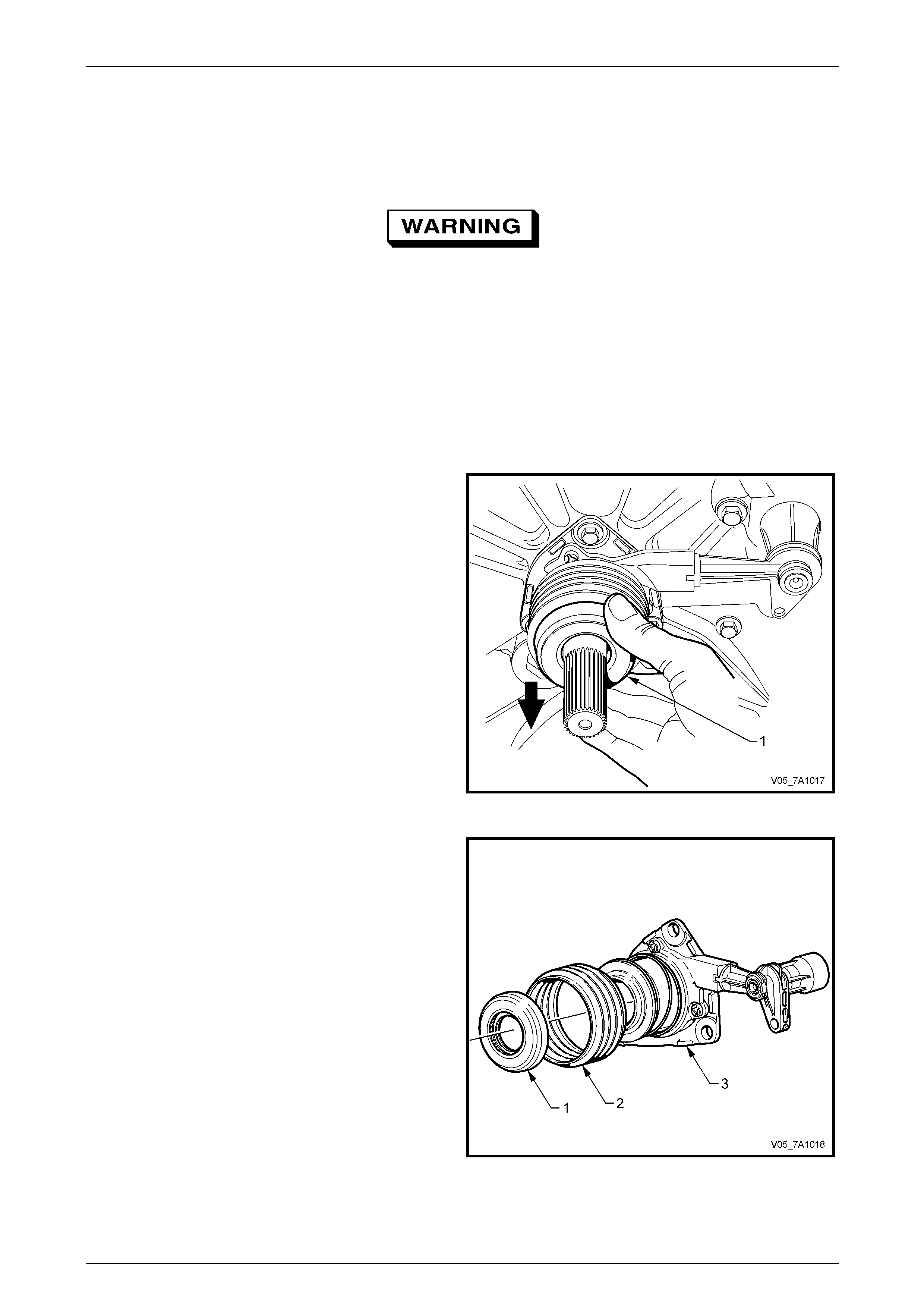
4 While grasping the throwout bearing (1), pull on the
bearing to release it from the clutch actuating cylinder
sleeve.
5 Remove the throwout bearing and dust boot (if
required) from the throwout bearing guide sleeve.
Figure 7A1 – 20
6 If required, dislodge the boot (2) from the two grooved
retaining grooves and remove from the actuating
cylinder assembly (3).
NOTE
Apart from the throwout bearing (1) a nd the dust
boot, there are no other serviced items in the
actuating cylinder assembly.
Figure 7A2 – 21
7A1 – 21
Clutch- V6 Engine 7A1 – 22
Clean and Inspect
Do not use cleaners or chemicals on the
bearing guide sleeve.
1 Check the throwout bearing for any signs of roughness or dryness by rotating the beari ng back and forth while
applying a light axial load to the bearing. If either of these conditions are evident, replace the throwout bearing.
2 Inspect the bearing guide sleeve for signs of damage, abrasion or scuffing. Replac e the clutch release assembly,
including the boot and throwout bearing, id any of these conditions exist.
3 Inspect the boot for cracking or heat damage. Replace if a ny doubt exists relating to the serviceabilit y of the boot.
4 Inspect the clutch release assembly and the fluid pipe adaptor. Refer to 3.6 Clutch Actuating Cylinder, in this
Section.
5 Use a water dampened rag or water based cleaning solution to wipe the actuating cylinder clean.
Reinstall
1 Using a clean dry Shop rag, wipe the exposed portion of the throwout bearing guide sleeve.
2 Sparingly apply a coating of an NLGI No. 2 lithium soap based EP grease with molybden um disulphide, such as
Shell Retinax HDX2 grease or BP Energrease LMS-EP 23 (or equivalent) to the actuating cylinder guide sleeve.
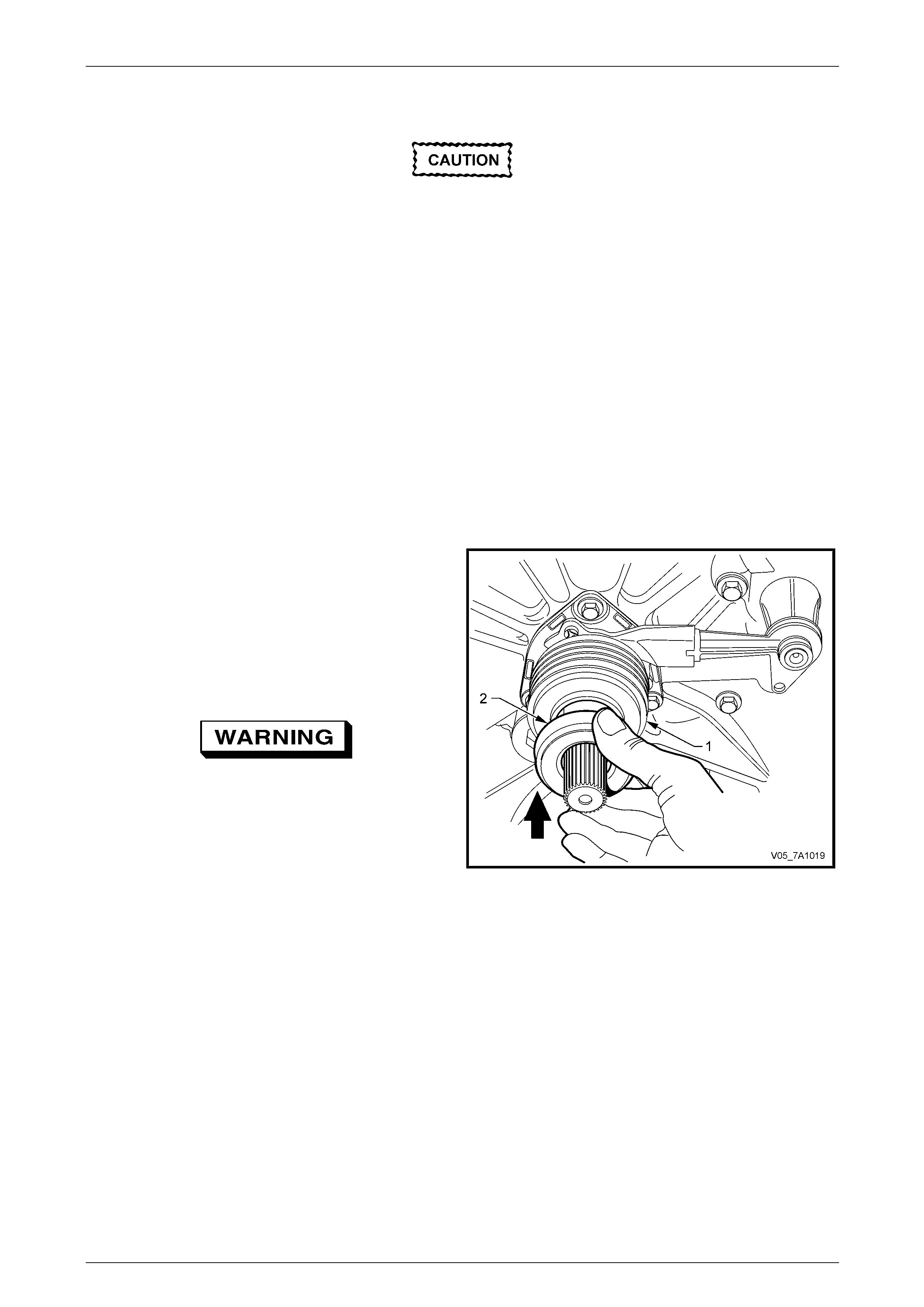
3 If removed, install the boot (1) over the guide sleeve
and engage with the actuating cylinder grooves.
4 Install the clutch throwout bearing (2) to the guide
sleeve and push the new bearing onto the sleeve until
it is fully installed.
5 Reinstall the transmission.
Refer to Section 7B1 Manual Transmission – V6 .
Enable the SRS (Air Bag). Refer to
Section 12M Occupant Protection System.
6 Road test the vehicle to check for correct clutch and
transmission operation.
Figure 7A1 – 22
7A1 – 22
Clutch- V6 Engine 7A1 – 23
3.8 Clutch Pedal Assembly
LT Section No. – 04-600
Remove
Disable the SRS (Air Bag). Refer to
Section 12M, Occupant Protection System.
Disconnection of the battery affects certain
vehicle electronic systems. Refer to
Section 00 Warnings, Cautions and Notes,
before removing the ground lead.
1 Disconnect the battery ground cable.
2 If fitted, remove front suspension strut tower brace, refer to Section 1A1 Body.
3 Remove ignition keys from ignition switch.
4 Remove the following components:
a Instrument panel lower trim panel assembly, refer to Section 1A3 Instrument Panel and Consol e.
b Driver side instrument panel lower trim plate assembly, refer to Section 1A3 Instrument Panel and Console.
c Instrument panel lower trim panel retainer, refer to Section 1A3 Instrument Pane l and Console.
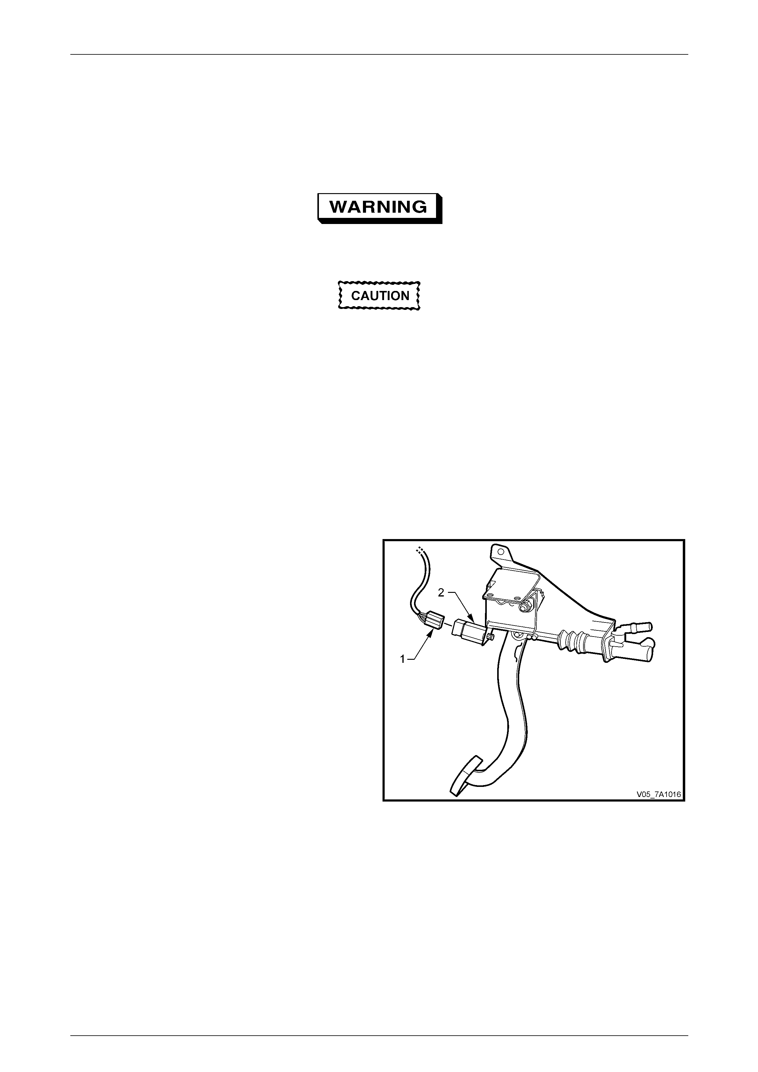
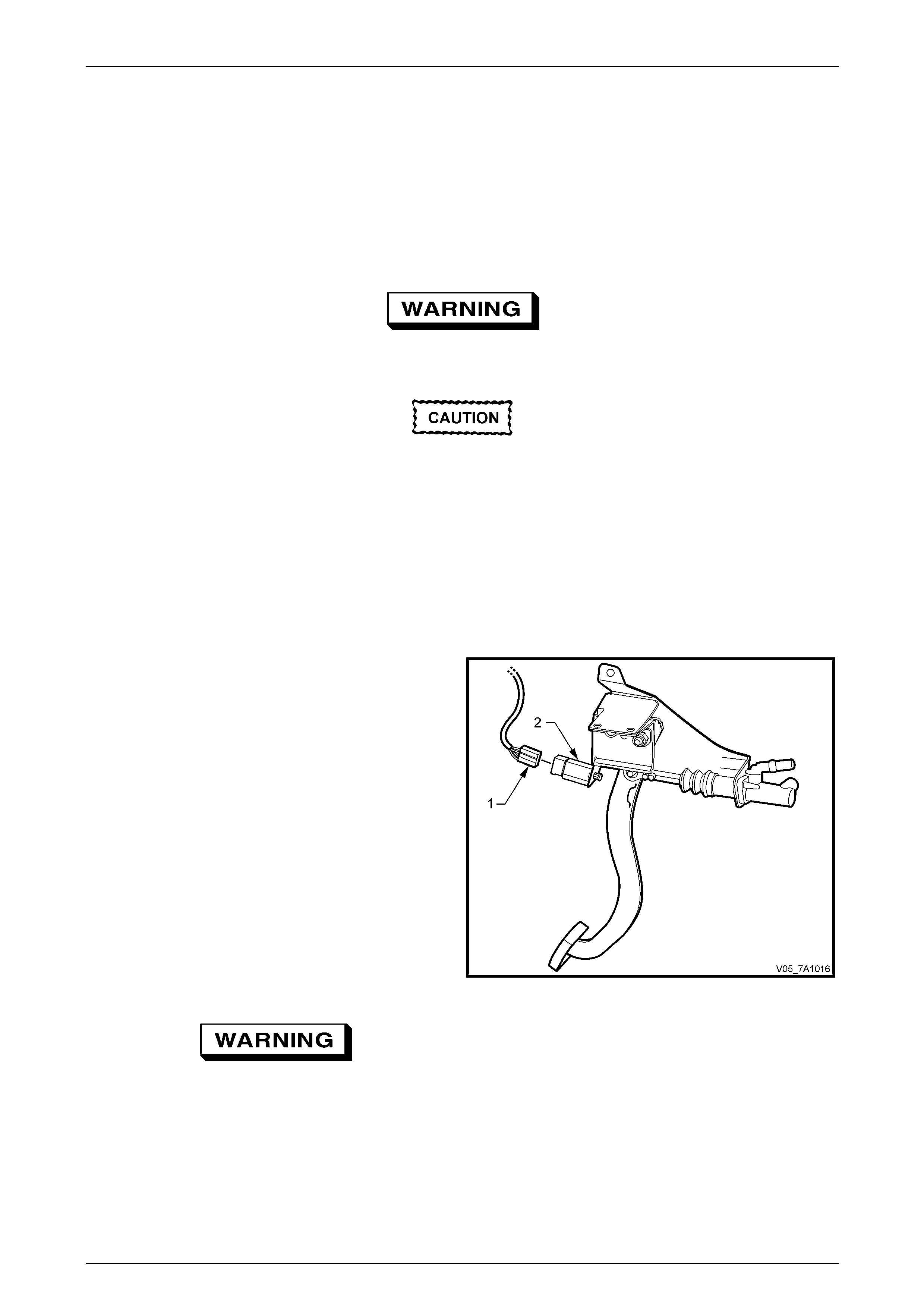
5 Disconnect the wiring harness connector (1) from the
clutch cruise cancel switch (2).
Figure 7A1 – 23
7A1 – 23
Clutch- V6 Engine 7A1 – 24
6 Disconnect the clutch master cylinder push rod (1)
from the pin attached to the clutch pedal (2) by prising
the pushrod quick connect fitting (3) with a
screwdriver (4).
Figure 7A1 – 24
7 Remove the two clutch master cylinder retain ing nuts
(1),from the engine bay side of the cockpit module.
Allow the master cylinder to remain in place.
Figure 7A1 – 25
8 Remove the bolts (1) (two places), securing the clutch
pedal bracket to the brake pedal support bracket.
9 Lower the clutch pedal bracket assembly from under
the instrument panel.
Figure 7A1 – 26
7A1 – 24
Clutch- V6 Engine 7A1 – 25
Disassemble
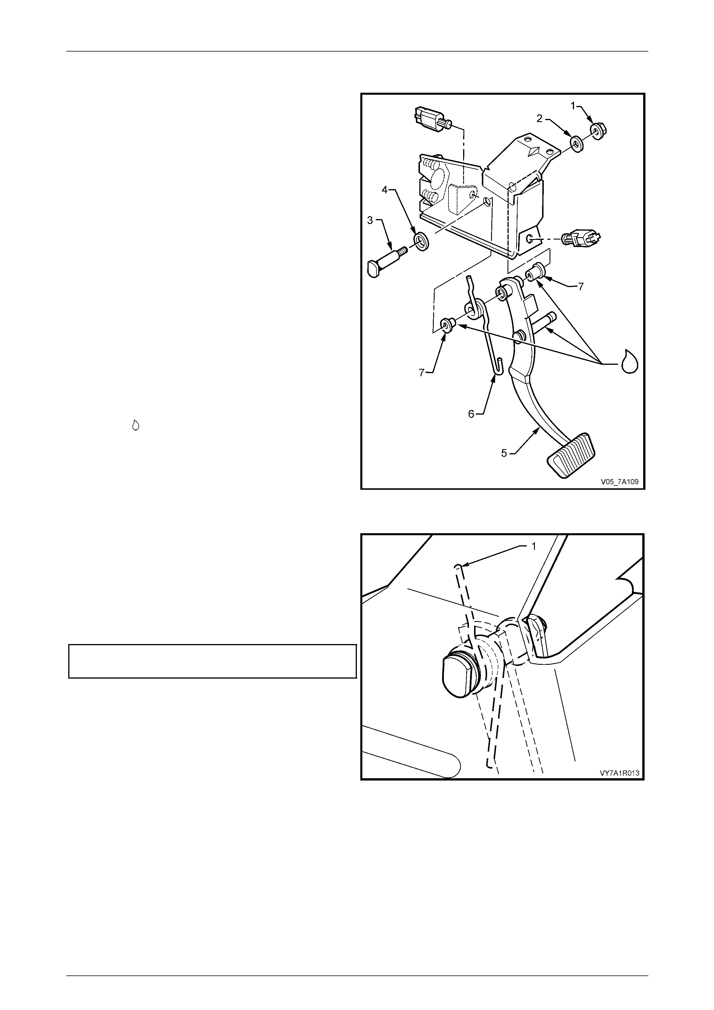
1 Remove the nut (1) and washer (2) securing the clutch
pedal pivot bolt (3) to the pedal support bracket.
2 Carefully withdraw the clutch pedal pivot bolt and
washer (4) from the pedal support assembly.
3 Withdraw the clutch pedal (5) and return spri ng (6) as
an assembly.
4 Release the end of the return spring (6) from the
clutch pedal.
5 Remove the return spring and the two bushes (7) from
the pedal.
6 If required, remove the two clutch switches by turning
counter-clockwise 1/4 turn, then pull to remove.
Reassemble
Installation is the reverse of the removal procedure except
for the following points:
1 Lubricate all bush surfaces with an NLGI No. 2 lithium
soap based EP grease with molybdenum disulphide,
such as Shell Retinax HDX2 grease or BP Energrease
LMS-EP 23 (or equivalent), as indicated by the
symbol .
2 Reinstall the two pedal bushes into the pedal pivot
bore.
3 Assemble the clutch pedal return spring (6) to the
clutch pedal (5) and then inst all the pedal to the clutch
pedal support bracket. Reinstall the clutch pedal pivot
bolt (3) and washers (2 and 4). Figure 7A1 – 27
NOTE
When the return spring is installed to the clutch
pedal pivot pin, position the upper end of the
spring (1) as shown.
4 Install and tighten the nut (1) to the correct torque
specification.
Clutch pedal pivot bolt
torque specification..............................................15 N.m
Figure 7A1 – 28
7A1 – 25
Clutch- V6 Engine 7A1 – 26
Reinstall
1 Reinstall the clutch pedal br acket assembly, taking care to align the clutch master cylinder mounting studs with the
master cylinder. Install the two bracket bolts and tighten to the correct torque specification.
Refer to Figure 7A1 – 23.
Clutch pedal bracket to brake ped al
support bolt torque specification ..........................25 N.m
2 Reinstall the master cylinder retaining nuts, two places, and tighten to their correct torque specification.
Clutch master cylinder mounting
nut torque specification........................................25 N.m
3 Reinstall the clutch master cylind er push rod (1) to the
pedal pin (2), ensuring that the quick connect fitting (3)
fully engages the groove (4) in the pedal p in.
4 Reinstall all removed instrument panel components in
the reverse to removal operations.
Enable the SRS (Air Bag). Refer to
Section 12M Occupant Protection System.
5 Road test vehicle to check clutch operation.
Figure 7A1 – 29
7A1 – 26
Clutch- V6 Engine 7A1 – 27
3.9 Clutch Pedal Switches
LT Section No. – 04-600
Clutch Cruise Cancel Switch
Replace
Disable the SRS (Air Bag). Refer to
Section 12M, Occupant Protection System.
Disconnection of the battery affects certain
vehicle electronic systems. Refer to
Section 00 Warnings, Cautions and Notes,
before removing the ground lead.
1 Disconnect the battery ground lead.
2 As required, first remove the following components:
a Driver side instrument panel lower trim plate assembly, refer to Section 1A3, Instrument Panel and Console.
b Instrument panel lower trim panel assembly, refer to Section 1A3, Instrument Panel and Console.
c Instrument panel lower trim panel retainer, refer to Section 1A3, Instrument Pane l and Console.
3 Disconnect the clutch cruise cancel switch electrical
connector (1).
4 Remove the clutch cruise cancel switch (2) by rotating
the switch counter-clockwise a 1/4 of a turn, then pull
to free the switch bayonet lugs.
5 To reinstall the clutch cruise cancel switch (2):
a Insert the switch into the clutch pedal bracket,
aligning the bayonet lugs with the bracket slots.
b Rotate the switch 1/4 of a turn clock wise to lock
the switch bayonet lugs.
NOTE
No switch adjustment is required.
6 Reinstall the electrical connector (1) to the switch (2).
7 Reinstall all removed instrument panel components in
the reverse order to the removal procedure.
Enable the SRS (Air Bag). Refer to
Section 12M Occupant Protection System.
Figure 7A1 – 30
8 Road test the vehicle to ensure correct cruise cancel operation.
7A1 – 27
Clutch- V6 Engine 7A1 – 28
Clutch Pedal Calibration Switch
Replace
Disable the SRS (Air Bag). Refer to
Section 12M, Occupant Protection System.
Disconnection of the battery affects certain
vehicle electronic systems. Refer to
Section 00 Warnings, Cautions and Notes,
before removing the ground lead.
1 Disconnect the battery ground lead.
2 As required, first remove the following components:
a Driver side instrument panel lower trim plate assembly, refer to Section 1A3, Instrument Panel and Console.
b Instrument panel lower trim panel assembly, refer to Section 1A3, Instrument Panel and Console.
c Instrument panel lower trim panel retainer, refer to Section 1A3, Instrument Pane l and Console.
3 Disconnect the main wiring harness connector (1) from
the clutch pedal calibration switch patch harness
connector (2).
4 Remove the clutch pedal cali bration switch patch
harness connector from the clutch pedal support
bracket by prising the two retaining tabs with a
screwdriver to release the tabs.
5 Remove the clutch pedal position switch (3) by rotating
the switch counter-clockwise a 1/4 of a turn, then pull
to free the switch bayonet lugs.
6 Disconnect the clutch pedal calibration switch patch
harness connector (4) from the cruise cancel switch.
7 Reinstall the clutch pedal calibration switch patch
harness connector (4) to the clutch pedal cali bration
switch.
8 Install the clutch pedal calibration switch by rotating it
a 1/4 of a turn clockwise to lock the switch bayonet
lugs. Figure 7A1 – 31
9 Clip the clutch pedal calibration switch patch harness connector (2) to the clutch pedal support bracket.
10 Reinstall the main wiring harness connector to the clutch pedal calibration switch patch harness.
11 Reinstall all removed instrument panel components in the reverse or der to that off the removal operations.
Enable the SRS (Air Bag). Refer to
Section 12M Occupant Protection System.
12 Road test the vehicle to check the clutch pedal calibration switch operation.
NOTE
For clutch pedal calibration switch information,
refer to Section 6C1-2A Diagnosis – V6 Engi ne.
7A1 – 28
Clutch- V6 Engine 7A1 – 29
3.10 Clutch Driven Plate and Pressure Plate
LT Section No. – 00-400
Remove
Disable the SRS (Air Bag). Refer to
Section 12M, Occupant Protection System.
1 Remove transmission assem bl y. Refer to Section 7B1 Manual Transmission – V6 E ngine.
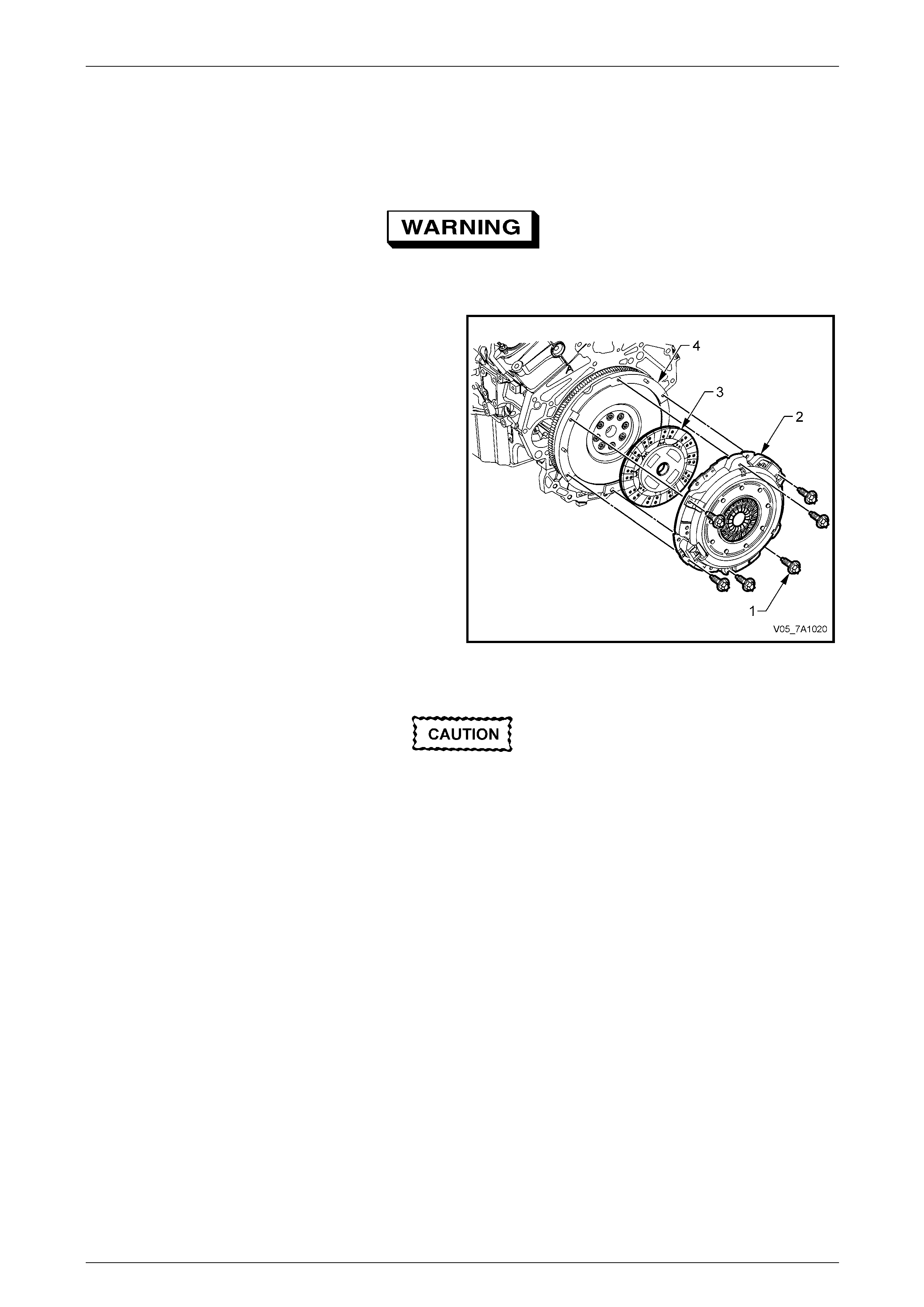
2 Mark the relationship of the clutch pressure plate (2) to
the flywheel (4), to maintain the correct balance
condition on reassembly.
3 Initially loosen all pressure plate retaining bolts (1),
working from opposite sides, to avoid distorti on of the
pressure plate cover (2).
4 Continue loosening the six bolts from opposite sides,
until all are removed.
5 Dislodge the pressure plate cover (2) from the flywheel
dowels and remove both the pressure plate and the
clutch driven plate (3) from the flywheel (4).
6 To remove either the clutch actuating cylinder or the
clutch throwout bearing, refer to
3.6 Clutch Actuating Cylinder or
3.7 Clutch Throwout Bearing, in this Section.
Figure 7A1 – 32
Inspect
• Do not wash the pressure plate with liquid
petroleum based products or use
compressed air.
• If removed, do not soak the throw out
bearing in cleaning solvent as this will
destroy the bearing lubrican t.
1 Use a water dampened cloth or water based solution to wipe the pressure plate and flywheel surfaces.
2 Check throwout bearing for roughness of operatio n or signs of wear. Replace as required, refer to
3.7 Clutch Throwout Bearing, in this Section.
3 Check the clutch actuating cylinder boot for cracks of heat related damage. Replace as required, refer to
3.7 Clutch Throwout Bearing, in this Section.
4 Check the clutch actuating cylinder for signs of fluid leakage. Replace as requir ed, refer to
3.6 Clutch Actuating Cylinder, in this Section.
5 Inspect flywheel and clutch pressure plate friction surfaces for burn marks, scoring or roughness. Slight roug hness
may be smoothed with fine emery cloth. Scoring of flywheel or pressure plate surfaces however will require
replacement of damaged/ worn component/s.
6 Inspect clutch driven plate for lining wear or other damage, such as tearing, scoring, oil or fluid co ntamination.
NOTE
If oil or fluid is found on the clutch linings, locate
and correct the cause of the leak before
proceeding with the clutch repairs.
7 If installing a new clutch driven plate, check clutch hub for a free sliding fit on transmission input shaft splines.
7A1 – 29
Clutch- V6 Engine 7A1 – 30
Reinstall
1 Offer the clutch driven and pressure plate assemblies up to the flywheel, aligning the pressure plate cover and
flywheel and the reference marks made before removal (only if original pressure plate assembly is being
reinstalled).
NOTE
The clutch driven plate is installed with the short
boss facing the flywheel. The driven plate hub is
also stamped “FW Side” (Fl ywheel Side).
2 Insert a suitable clutch centring tool (either fabricated or commercially available) into crankshaft end hole, through
the driven plate.
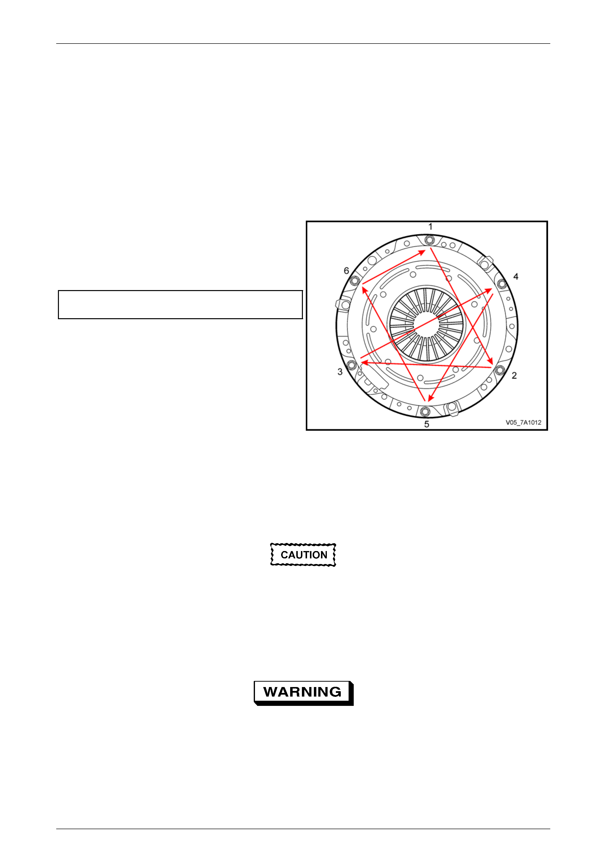
3 Loosely install pressure plate to flywheel, Torx headed bolts.
4 Progressively tighten each of the six, Torx headed
bolts, in the sequence shown, using a su itable Torx
socket and socket equipment.
5 Finally, tighten each bolt, again in seque nce, to the
correct torque specification.
Clutch pressure plate cover to
flywheel bolt torque specification .........................25 N.m
6 Remove the clutch plate centring tool.
Figure 7A1 – 33
7 Sparingly lubricate the cleaned, transmission input shaft splines (maximum of 0.5 gm), using an NLGI No. 2 lithium
soap based EP grease with molybdenum disulphide, such as Shell Retinax HDX2 grease or BP Energrease LMS-
EP 23 (or equivalent).
8 If removed, reinstall the clutch throwout bearing to the clutch actuating cylinder, refer to
3.7 Clutch Throwout Bearing, in this Section.
When installing the transmission, do not
allow it to ‘hang’ on the inpu t shaft splines, as
the clutch driven plate will be damaged.
9 Reinstall the transmission assembly. Refer to Section 7B1 Manu al Transmission – V6.
10 Check transmission lubricant level, topping up as required. Refer to Section 7B1 Manual Transmission – V6 for the
recommended procedure.
Enable the SRS (Air Bag). Refer to
Section 12M Occupant Protection System.
11 Check for exhaust leaks before road testing the vehicle for satisfactory clutch operation.
7A1 – 30

Clutch- V6 Engine 7A1 – 31
3.11 Dual Mass Flywheel
Replace
1 As this operation is included with other e ng ine mechanical items, refer to Section 6A1 Engine Mechanic al – V6, for
details regarding this servic e operation.
NOTE
The ring gear is welded to the flywheel and, as
such is not replaceable. If ring gear damage is
evident, then the complete flywheel assembly
must be replaced.
7A1 – 31

Clutch- V6 Engine 7A1 – 32
4 Diagnosis
Condition Probable Cause Corrective Action
Slipping Worn or oil-soaked lining.
Grease on linings from excess ive
application to the input shaft splines
Driven plate sticking on main drive
gear splines.
Weak or broken diaphragm spring
Master or actuating cylinder defective
Replace clutch driven plate, correct oil
leak.
Replace clutch driven plate, remove
excess lubrication.
Clean splines and check clutch hub
for a free sliding fit.
Replace pressure pl ate and
diaphragm assembly. Refer 3.10
Clutch Driven Plate and Pres sure
Plate, in this Section.
Overhaul defective cylinder as
detailed in 3.5 Master Cylinder or 3.6
Clutch Actuating Cylinder, in this
Section.
Drag or Failure to Release Air trapped in hydraulic system.
Leak In hydraulic system.
Clutch master or actuating cylinder
defective.
Cracked or oil-soaked linings.
Excessive driven plate run-out or
distorted.
Driven plate sticking on splines.
Bleed system as outlined under 3.3
Clutch Hydraulic System Bleed, in this
Section.
Correct leak and bleed hydrau lic
system.
Overhaul defective cylinder as
outlined under 3.5 Master Cylinder or
3.6 Clutch Actuating Cylinder, in this
Section.
Replace clutch driven plate. Refer
3.10 Clutch Driven Plate and Pressure
Plate, in this Section.
Replace driven plate. Refer Operation
3.10 Clutch Driven Plate and Pressure
Plate, in this Section.
Clean splines and check clutch hub
for a free sliding fit.
Grab or Chatter Oil on linings.
Worn transmission input shaft splines.
Rough, or grooved, flywheel or
pressure plate.
Loose engine mountings.
Loose or worn propeller shaft
coupling/s or damaged pinion flange.
Defective clutch driven plate.
Defective dual mass flywheel.
Replace driven plate, correct oil le ak.
Replace transmission input shaft.
Replace flywheel or replace both
flywheel and pressure plate.
Tighten or replace mountings.
Tighten or replace propeller shaft
coupling/s and/or pinion fla nge.
Replace clutch driven plate. Refer
3.10 Clutch Driven Plate and Pressure
Plate, in this Section.
Replace dual mass flywheel. Refer
6A1 Engine Mechanical – V6 Engine,
in this Section
7A1 – 32

Clutch- V6 Engine 7A1 – 33
Condition Probable Cause Corrective Action
Harsh or Stiff Clutch Operation Clutch pedal bush seized or tight on
pedal shaft.
Blockage in fluid hydraulic pipe.
Replace bushes as detail ed in 3.8
Clutch Pedal Assembly in this
Section.
Clean lines and bleed hydraulic
system. Refer 3.3 Clutch Hydraulic
System, Bleed in this Section.
Clutch Engagement Too Slow Blockage in fluid hydraulic pipe.
Clutch master or actuating cylinder
defective.
Incorrect hydraulic fluid used.
Incorrect brake fluid used. Clean lines
and bleed hydraulic system. Refer 3.3
Clutch Hydraulic System, Bleed in this
Section.
Overhaul defective cylinder as
outlined under 3.5 Master Cylinder or
3.6 Clutch Actuating Cylinder, in this
Section.
Flush and bleed hydraulic system.
Refer 3.4 Clutch Fluid Change in this
Section.
7A1 – 33

Clutch- V6 Engine 7A1 – 34
5 Specifications
Master Cylinder
Type...........................................................................................................Compensating por t.
Bore Size..................................................................................................................19.05 mm
Nominal Stroke..............................................................................................................30 mm
Clutch Actuating Cylinder
Type...................................................Concentric cylinder with adaptor including bleed scre w.
Brake Fluid
Type.....................................................................................................DOT 4 or Super DOT 4
Clutch Driven Plate
Type.........................................................................................................Single plate dry disc.
Disc Facing:
Outside Diameter..................................................................................................240 ± .0 mm
Inside Diameter...................................................................................................155 + 1.5 mm
Thickness of disc assembly with 7,000 N load ....................................................8.4 ± 0.2 mm
Clutch Pressure Plate
Type............................................................Recessed, with a pressed steel cover plate and a
Belleville diaph ragm spring.
Clutch Throwout Bearing
Type...........................................................................................................................Ball race.
Lubrication......................................................................................Sealed with grease for life.
Dual Mass Flywheel:
Type....................................................... Spring dampened internally; the transmission side is
recessed to accommodate the clutch assembly.
Rotational free play maximum, including length tolerances and heat setting losses:
Degrees.............................................................................................................................. 11°
Distance...................................................... 27 mm at the outside diameter (281.3 mm) of the
secondary side of the flywheel assembly.
Serviceability ......................................... None. Starter motor ring gear is not replaceable and
machining of the clutch facing surface is not permitted.
Lubricants
Transmission input shaft splines.....................NLGI No. 2 lithium soap based EP grease with
molybdenum disulphide, such as Shell Retinax HDX2
grease or BP Energrease LMS-EP 23 (or equivalent).
Clutch pedal bushes.......................................NLGI No. 2 lithium soap based EP grease with
molybdenum disulphide, such as Shell Retinax HDX2
grease or BP Energrease LMS-EP 23 (or equivalent).
7A1 – 34

Clutch- V6 Engine 7A1 – 35
6 Torque Wrench Specifications
Adaptor fluid pipe bracket screw ..............................................................3 N.m
Clutch actuating cylinder bleeder screw...................................................8 N.m
Clutch actuating cylinder fluid pipe bracket retaining screw .....................3 N.m
Clutch actuating cylinder fluid pipe retaining screw..................................3 N.m
Clutch actuating cylinder to transmission screw.....................................17 N.m
Clutch master cylinder mounting nut ......................................................25 N.m
Clutch reservoir bracket to brake master cylinder end brace bolt...........10 N.m
Clutch pedal bracket to brake pedal support bolt ...................................25 N.m
Clutch pedal pivot bolt............................................................................15 N.m
Clutch pressure plate to flywheel bolt.....................................................25 N.m
Fluid reservoir to clutch master cylinder bracket nut ................................3 N.m
Hydraulic pipe flare nut to master cylinder..............................................12 N.m
Hydraulic pipe flare nut to flexible hose..................................................10 N.m
7A1 – 35
Clutch- V6 Engine 7A1 – 36
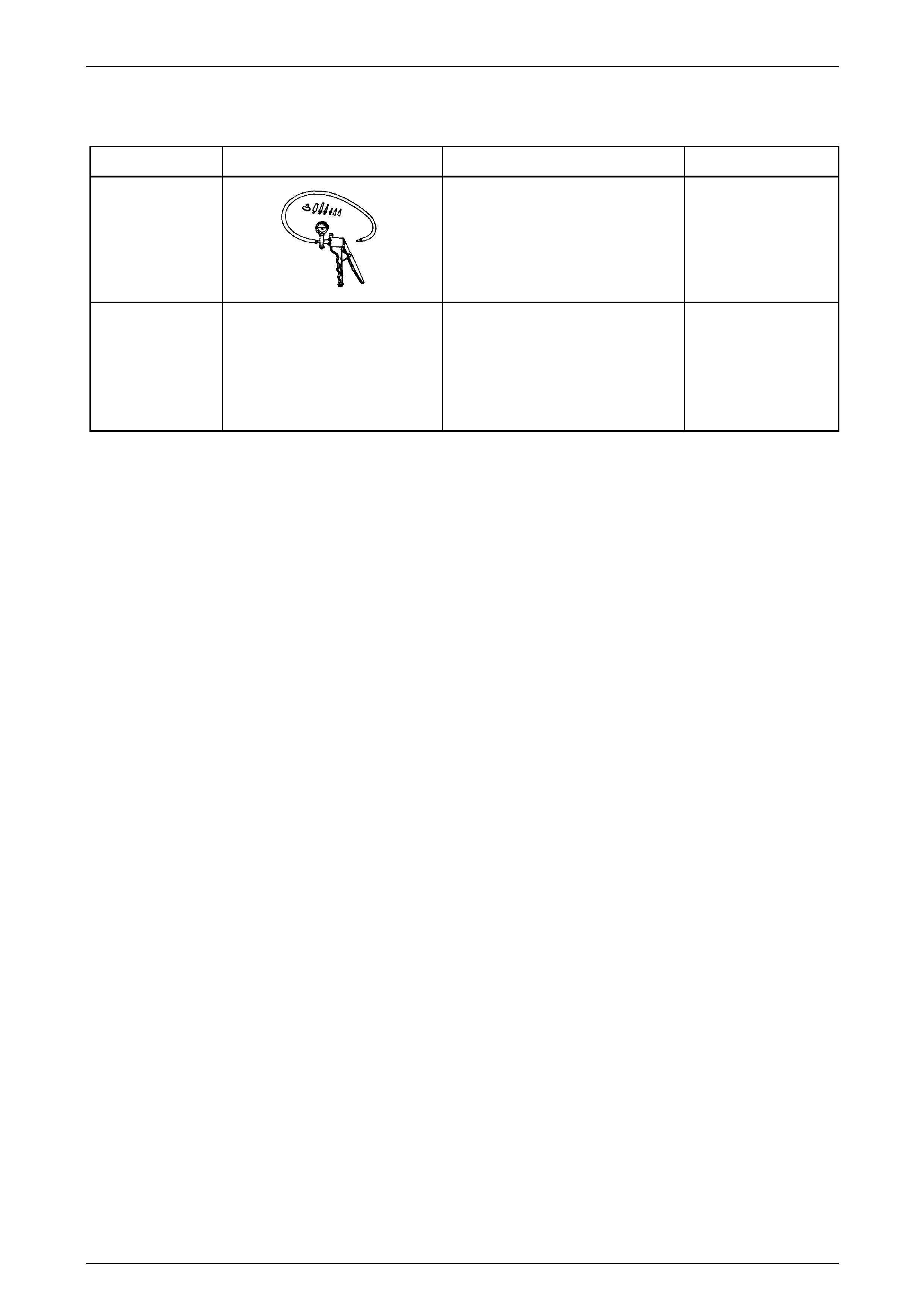
7 Special Tools
Tool Number Illustration Description Tool Classification
J 23738
Hand Vacuum Pump
Used where an applied vacuum is
required such as brake/clutch system
bleeding and/or fluid cha nging etc.
Previously released and commercially
available
Mandatory
N/A
Clutch Centring Tool
Commercially available
Available
7A1 – 36