
Manual Transmission – GEN III V8 Page 7B2-1
Section 7B2
Manual Transmission – GEN III V8
ATTENTION
Before performing any Service Operation or other procedure described in this Section, refer to Section 00
Warnings, Cautions and Notes for correct workshop practices with regard to safety and/or property damage.
1 General Information ...............................................................................................................................4
MY2006 VZ Update................................................................................................................................................. 4
1.1 General Description............................................................................................................................................... 4
Synchroniser Assemblies.....................................................................................................................................4
Synchroniser Action ........................................................................................................................................... 4
Reverse Gear.......................................................................................................................................................... 4
Bearing Support..................................................................................................................................................... 5
Lubrication ............................................................................................................................................................. 5
Selector Mechanism .............................................................................................................................................. 5
Reverse Lockout Mechanism................................................................................................................................ 5
Shift Pattern............................................................................................................................................................ 5
Transmission Exploded View ............................................................................................................................... 7
Transmission Power Flows................................................................................................................................... 9
Neutral................................................................................................................................................................ 9
First Gear........................................................................................................................................................... 9
Second Gear...................................................................................................................................................... 9
Third Gear.......................................................................................................................................................... 9
Fourth Gear........................................................................................................................................................ 9
Fifth Gear........................................................................................................................................................... 9
Sixth Gear .......................................................................................................................................................... 9
Reverse Gear..................................................................................................................................................... 9
Manual Transmission Power Flows.................................................................................................................. 10
1.2 Transmission Serial Number .............................................................................................................................. 11
2 Servicing Information ..........................................................................................................................12
2.1 Recommended Lubricant.................................................................................................................................... 12
2.2 Checking Transmission Lubricant Level........................................................................................................... 13
2.3 Draining and Refilling Transmission.................................................................................................................. 14
3 Minor Service Operations....................................................................................................................15
3.1 Back-Up Lamp Switch ......................................................................................................................................... 15
Replace................................................................................................................................................................. 15
3.2 Speed Sensor....................................................................................................................................................... 16
Replace................................................................................................................................................................. 16
3.3 Transmission Support Mount............................................................................................................................. 18
Replace................................................................................................................................................................. 18
3.4 Reverse Lock-Out Solenoid Assembly .............................................................................................................. 19
Remove................................................................................................................................................................. 19
Disassemble......................................................................................................................................................... 20
Reassemble.......................................................................................................................................................... 21
Reinstall................................................................................................................................................................ 21
Page 7B2- 1
Techline
Techline
Techline
Techline
Techline

Manual Transmission – GEN III V8 Page 7B2-2
3.5 Control Lever Knob, Boot & Control Lever Assembly...................................................................................... 22
Remove................................................................................................................................................................. 22
Reinstall................................................................................................................................................................ 23
3.6 Control Lever Boot .............................................................................................................................................. 24
Replace................................................................................................................................................................. 24
3.7 Remote Shift Lever Boot..................................................................................................................................... 26
Remove................................................................................................................................................................. 26
Reinstall................................................................................................................................................................ 27
4 Major Service Operations....................................................................................................................28
4.1 Transmission Output Shaft Seal and Boot........................................................................................................ 28
Remove................................................................................................................................................................. 28
Reinstall................................................................................................................................................................ 30
4.2 Transmission Assembly...................................................................................................................................... 32
Remove................................................................................................................................................................. 32
Reinstall................................................................................................................................................................ 36
4.3 Transmission Disassemble................................................................................................................................. 39
Clutch Housing and Slave Cylinder ................................................................................................................... 39
Extension Housing .............................................................................................................................................. 40
Speedometer Pulse Ring..................................................................................................................................... 43
Reverse and 5th/6th Driven Gear........................................................................................................................ 44
Countershaft Extension Assembly..................................................................................................................... 45
Transmission Case.............................................................................................................................................. 46
Gear Trains and Shift Rails................................................................................................................................. 47
4.4 Remote Control Shift Mechanism....................................................................................................................... 48
Disassemble......................................................................................................................................................... 48
Clean and Inspect................................................................................................................................................ 49
Clean................................................................................................................................................................ 49
Inspect.............................................................................................................................................................. 49
Reassemble.......................................................................................................................................................... 50
4.5 Transmission Sub-Assemblies........................................................................................................................... 52
Disassemble......................................................................................................................................................... 52
Mainshaft.......................................................................................................................................................... 52
Input Shaft........................................................................................................................................................ 54
Countershaft Gear............................................................................................................................................ 55
Countershaft Extension.................................................................................................................................... 55
Synchromesh Assemblies................................................................................................................................ 56
Reverse Idler Gear........................................................................................................................................... 57
Reverse Lockout Solenoid Assembly............................................................................................................... 58
Shift Rail and Fork Assemblies......................................................................................................................... 58
Transmission Adaptor Plate ............................................................................................................................. 59
Transmission Case........................................................................................................................................... 60
Extension Housing ........................................................................................................................................... 61
Clean And Inspect Components......................................................................................................................... 62
Clean................................................................................................................................................................ 62
Inspect.............................................................................................................................................................. 62
Reassemble.......................................................................................................................................................... 63
Synchromesh Assemblies – All........................................................................................................................ 63
Reverse Synchromesh Assembly Only............................................................................................................ 64
Mainshaft.......................................................................................................................................................... 65
Input Shaft........................................................................................................................................................ 67
Countershaft Gear............................................................................................................................................ 67
Countershaft Extension Gear........................................................................................................................... 68
Reverse Idler Gear........................................................................................................................................... 69
Reverse Lockout Assembly.............................................................................................................................. 70
Shift Rail and Fork Assemblies......................................................................................................................... 70
Transmission Adaptor Plate ............................................................................................................................. 71
Transmission Case........................................................................................................................................... 71
Extension Housing ........................................................................................................................................... 72
Page 7B2- 2

Manual Transmission – GEN III V8 Page 7B2-3
4.6 Bearing Shimming Procedures........................................................................................................................... 73
Input Shaft, Mainshaft & Countershaft............................................................................................................... 73
Countershaft Extension ...................................................................................................................................... 74
4.7 Transmission Reassemble.................................................................................................................................. 77
Gear Trains and Shift Rails................................................................................................................................. 77
Transmission Case.............................................................................................................................................. 78
Countershaft Extension Assembly..................................................................................................................... 80
5th/6th Driven Gear.............................................................................................................................................. 80
Reverse Synchromesh Assembly ...................................................................................................................... 81
Reverse Speed Gear............................................................................................................................................ 81
Speedometer Pulse Ring..................................................................................................................................... 82
Extension Housing .............................................................................................................................................. 83
Clutch Housing and Slave Cylinder ................................................................................................................... 85
5 Diagnosis ..............................................................................................................................................88
5.1 Transmission Shifts Hard ................................................................................................................................... 88
5.2 Transmission Hard To Shift Into Reve rse.......................................................................................................... 89
5.3 Gear Clash When Shifting Gears........................................................................................................................ 90
5.4 Transmission Noisy............................................................................................................................................. 91
5.5 Transmission Jumps Out Of Gear...................................................................................................................... 92
5.6 Transmission Does Not Shift Into One Gear ..................................................................................................... 93
5.7 Transmission Locked In One Gear..................................................................................................................... 94
6 Specifications.......................................................................................................................................95
7 Torque Wrench Specifications............................................................................................................97
8 Special Tools ........................................................................................................................................98
Page 7B2- 3

Manual Transmission – GEN III V8 Page 7B2-4
1 General Information
Dependent on vehicle specifications for specific markets, this manual transmission is available for fitment to the GEN III
V8 engine and is a six spee d, Type T56. There are two variants to this transmission, the primary difference be ing gear
ratios, refer to 6 Specifications for details. Applic ation for these two variants are:
a Production option MM6 may be avai lable for VZ models, except Coupe.
b Production option M12 is avail able for Coupe models.
The transmission primarily co nsists of a four piece aluminium alloy co nstruction, comprising a clutch housing bolted to a
front adaptor plate, transmission case and ex tension housing.
The ‘T56’ manual transmission is a fully synchronised unit, including reverse gear, with blocking ring type synchronisers.
A triple piece synchroniser assembl y is fitted to first and second gears and two piece assemblies are fitted to third, fourth,
fifth and sixth gears. Reverse gear is fitted with a single piece blocking ring.
The input shaft, mainshaft and countershaft gears are all supported by taper roller bearings. A parallel roller supports the
rear of the mainshaft, while all constant mesh gears have caged needle roller bearings.
During disassembly, the major number of gear train components and shift mechanism remain on the transmission front
adaptor plate.
MY2006 VZ Update
This six speed manual transmission (P/O MM6) is also available for fitment to selected models in the MY2006 VZ Update
vehicle range.
The transmission is essentially the same as that fitted to MY2005 VZ models except that, with a change in crankshaft
spigot bearing from a roller to a sealed-for-life ball bearing, the transmission input shaft is shorter. Apart from this one
change, the transmission service procedures carry over from earlier models.
For further information on the changed crankshaft spigot bearing, refer to 4.4 Crankshaft Spigot Bearing in
Section 6A4 GEN IV V8 Engine Mechanical of the MY 2006 VZ Update Service Information.
1.1 General Description
Synchroniser Assemblies
Each of the four synchroniser hubs are splined to their respective shafts and secured by a snap ring. All synchromesh
blocking rings have a carbon fibre frictional material and are brass, except for 1st and 2nd gears.
The blocking rings used on 1s t and 2nd gears are of a double cone construction, with carbon fibre friction al material on
each side of the inner member. The purpose of the synchroniser assemblies is to permit clutching to the required gear.
Synchroniser Action
During synchroniser operation , the synchroniser ring is moved into engagement by the appropriate fork, carrying with it,
three spring loaded synchr oniser inserts, located in slots in the synchroniser hub.
The synchroniser ring, together with the inserts, is moved along the hub, placing a load on the three lugs of the blocking
ring.
This initial force is sufficient to seat the bloc king ring and start pre-synchronisation because of the friction between the
cone on the constant mesh gear and the blocking ri ng.
At this stage, gear engagement is prevented as long as there is a difference in speed between the mating surfaces of the
blocking ring and cone of the constant mesh gear. As the speeds between the blocking ring and the gear cone become
synchronised, the teeth on the blocking rin g and gear cone line up with the internal splines of the ring, allowing the ring to
engage the teeth on the gear being engaged, completing gear selecti on.
Reverse Gear
The reverse idler gear is in constant mesh with the counter gear extension and the rev erse gear, splined to the
mainshaft. When reverse gear is engaged, the reverse s ynchromesh ring engages the reverse constant mesh gear,
completing the selection.
Page 7B2- 4
Manual Transmission – GEN III V8 Page 7B2-5
Bearing Support
All shafts in the transmission are supported by taper roller bearings, except for a parallel roller bearing at the rear of the
mainshaft.
The input shaft gear, front countershaft gear and rear countershaft gear extension bearing cups are a sliding fit in their
respective housings. Selectiv e shims are located under each of the bearing cups to control bearing pre-load or end float
(for the countershaft extension).
Each of the constant mesh gears is supported b y caged needle roller bearings, except for the reverse idler gear that has
a twin, caged needle roller bearing running on the reverse idler gear shaft.
Lubrication
Lubrication of all internal components is by splash feed, provided by the rotating countershaft gear asse mbly.
Selector Mechanism
The floor mounted, gearshift control lever op erates through a remote lever arrangement onto a single rail mechanism
which extends into the transmission rear cas e. T he 1st/2nd, 3rd/4th, 5th/6th and reverse shift shaft rails are all supported
at each end, in the adaptor plate, transmission case or extension housing.
A shift interlock system, prevents engagement of more than one gear at a time. The system consists of a selector pin
and interlock plate mounted on the 1st/2nd and 3rd/4th selector shaft rail.
When any gear is selected, th e selector pin is aligned with the particular shift fork link or shift lever, with 5th/6th and
reverse gears. As this selector pin slides within the interlock plate, only the gear selecte d can be engaged.
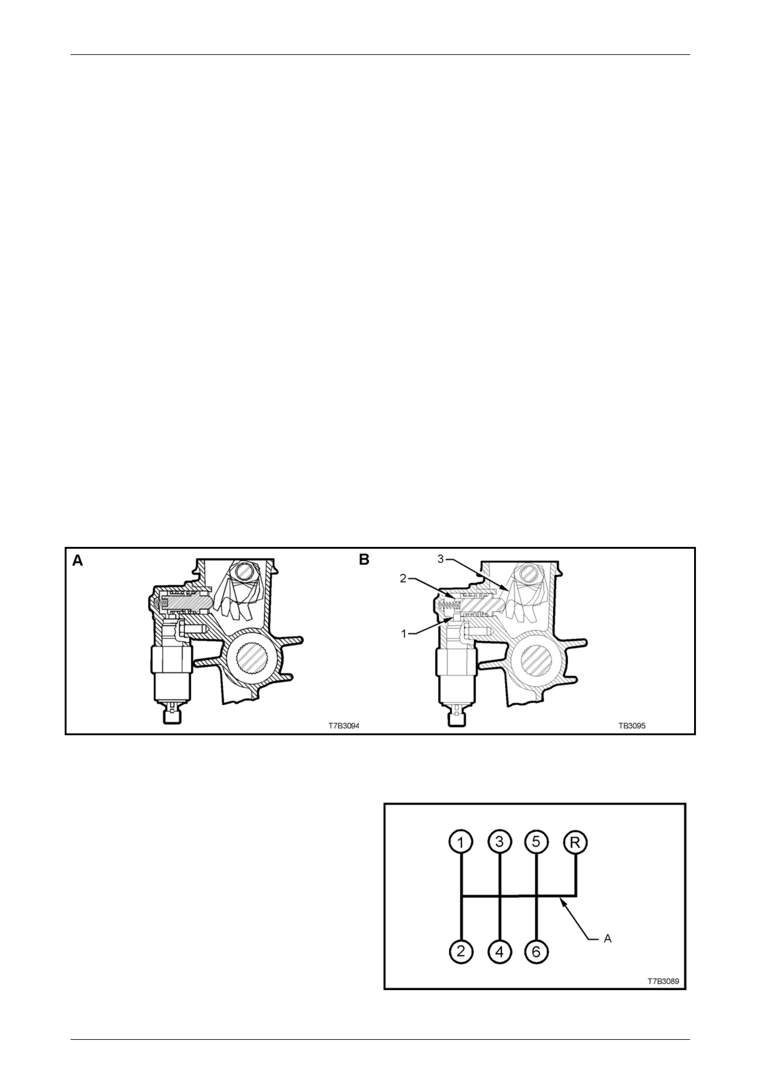
Reverse Lockout Mechanism
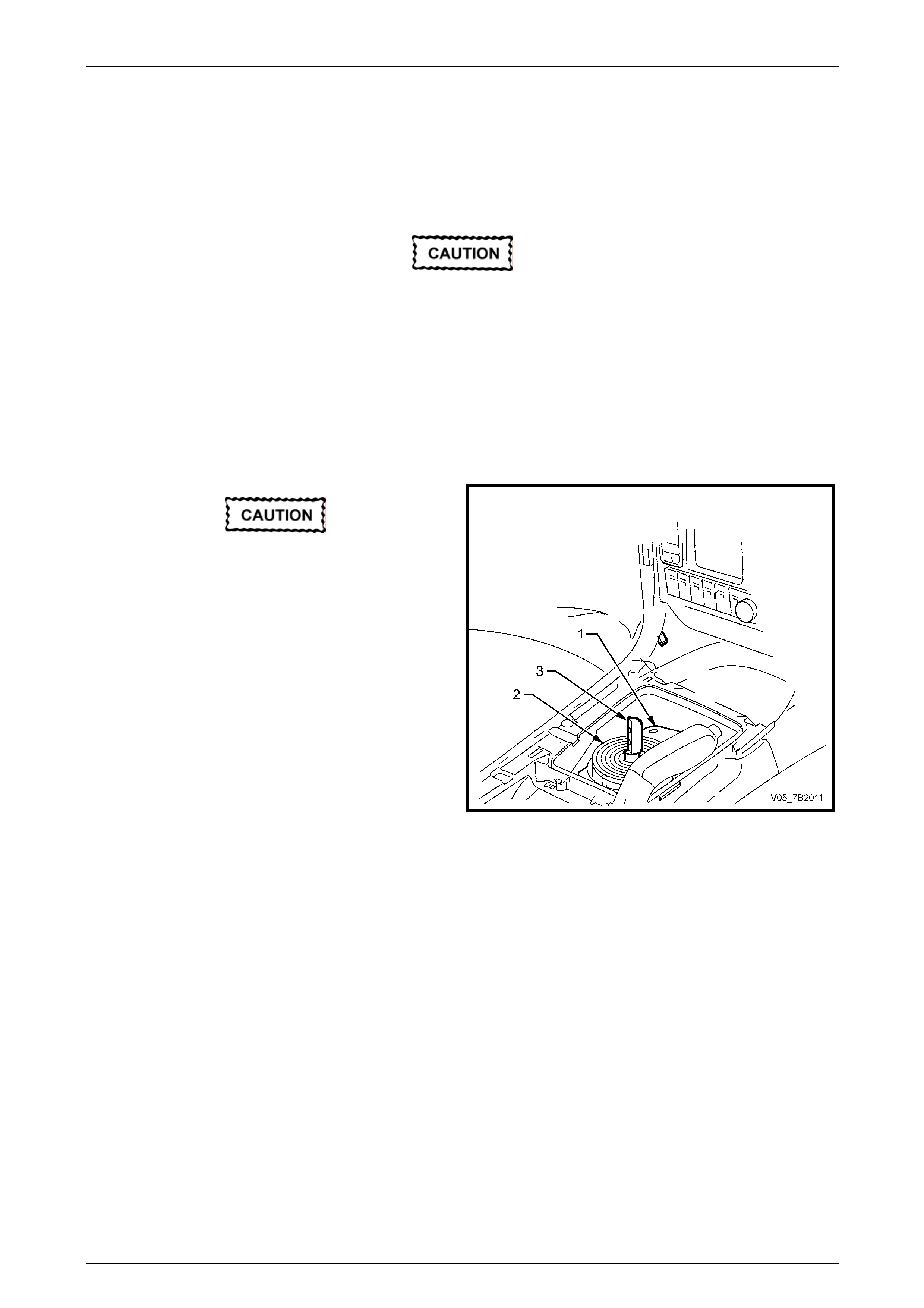
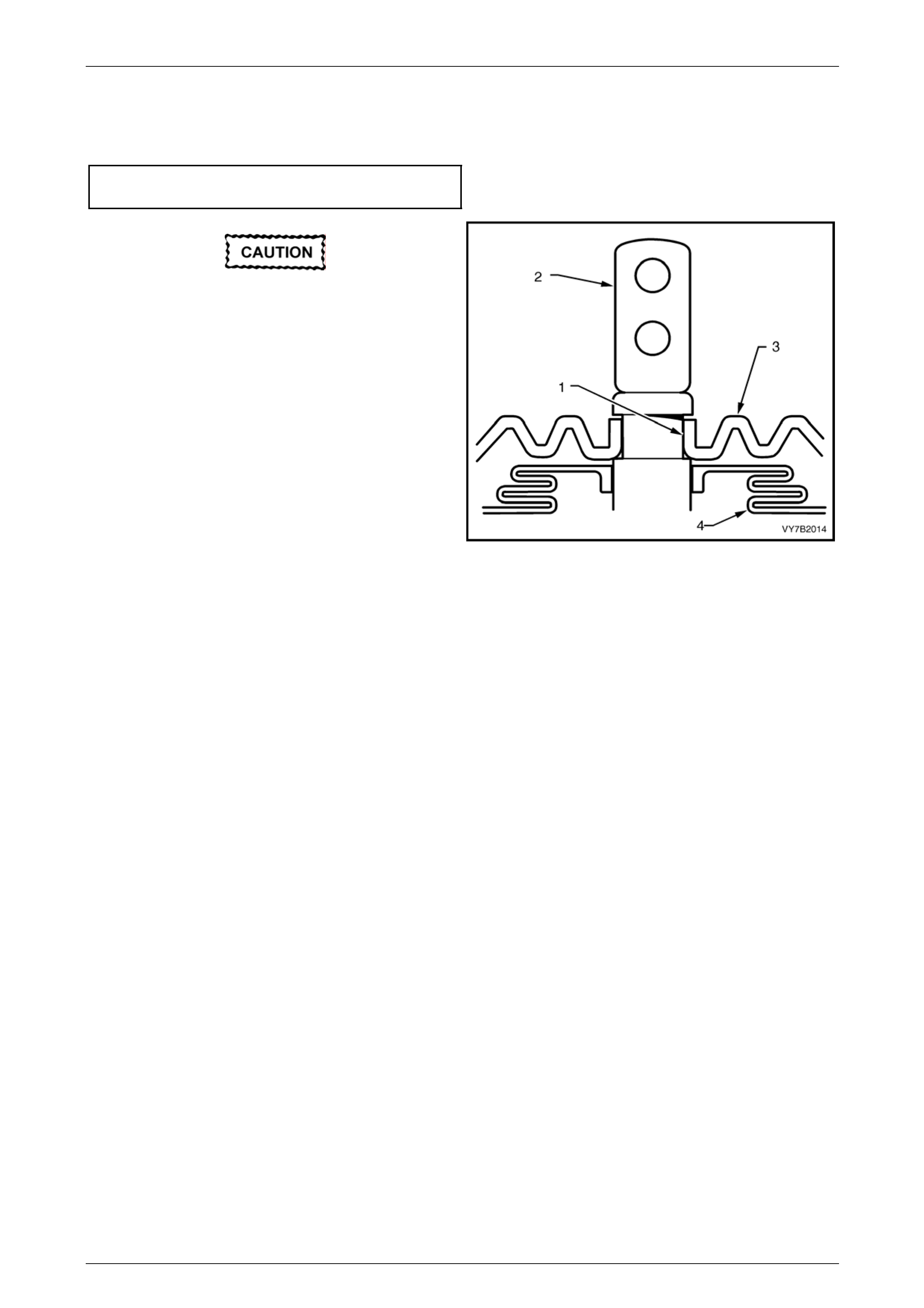
The transmission is also fitted with a reverse locko ut solenoid assembly that prevents the selection of reverse gear,
above road speeds of 8 km/h. Above this speed, the Powertrain Control Module (PCM), causes the solenoid plunger (1)
to block the movement of the spring loaded, reverse lockout plunger (2) (See view ‘B, next).
When activated, the rear offset lever (3) is blocked from rotating to the reverse selection position.
Figure 7B2 – 1 – Reverse Lockout Mechanism
Shift Pattern
The shift pattern is as shown in Figure 7B 2-2. Point ‘A’
indicates that reverse gear can be inhibited by the reverse
lockout solenoid assembly, just described.
Figure 7B2 – 2
Page 7B2- 5
Manual Transmission – GEN III V8 Page 7B2-6
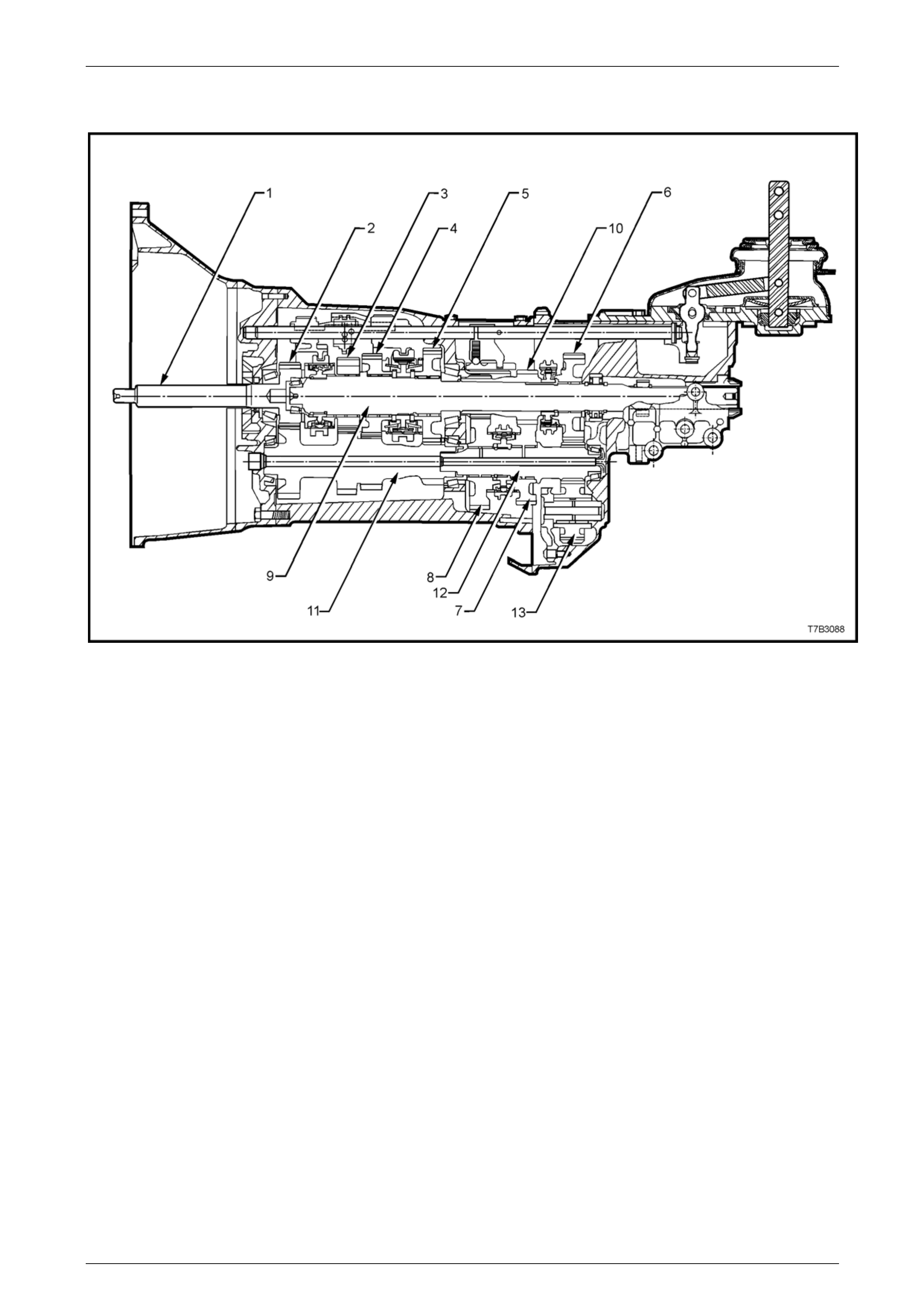
Refer Figure 7B2-3 for a sectione d view of the type T56 transmission (production option MM6) and Figure 7B2-4 for an
exploded view of the transmission components.
Figure 7B2-3 - Type ‘T56’ Transmission, Section ed View
1 Input Shaft
2 Input Shaft Drive Gear
3 Third Speed Driven Gear
4 Second Speed Driven Gear
5 First Speed Driven Gear
6 Reverse Driven Gear
7 Fifth Speed Drive Gear
8 Sixth Speed Drive Gear
9 Mainshaft
10 5th/6th Speed Compound Gear
11 Countershaft Gear
12 Countershaft Gear Extension
13 Reverse Idler Gear
Page 7B2- 6
Manual Transmission – GEN III V8 Page 7B2-7
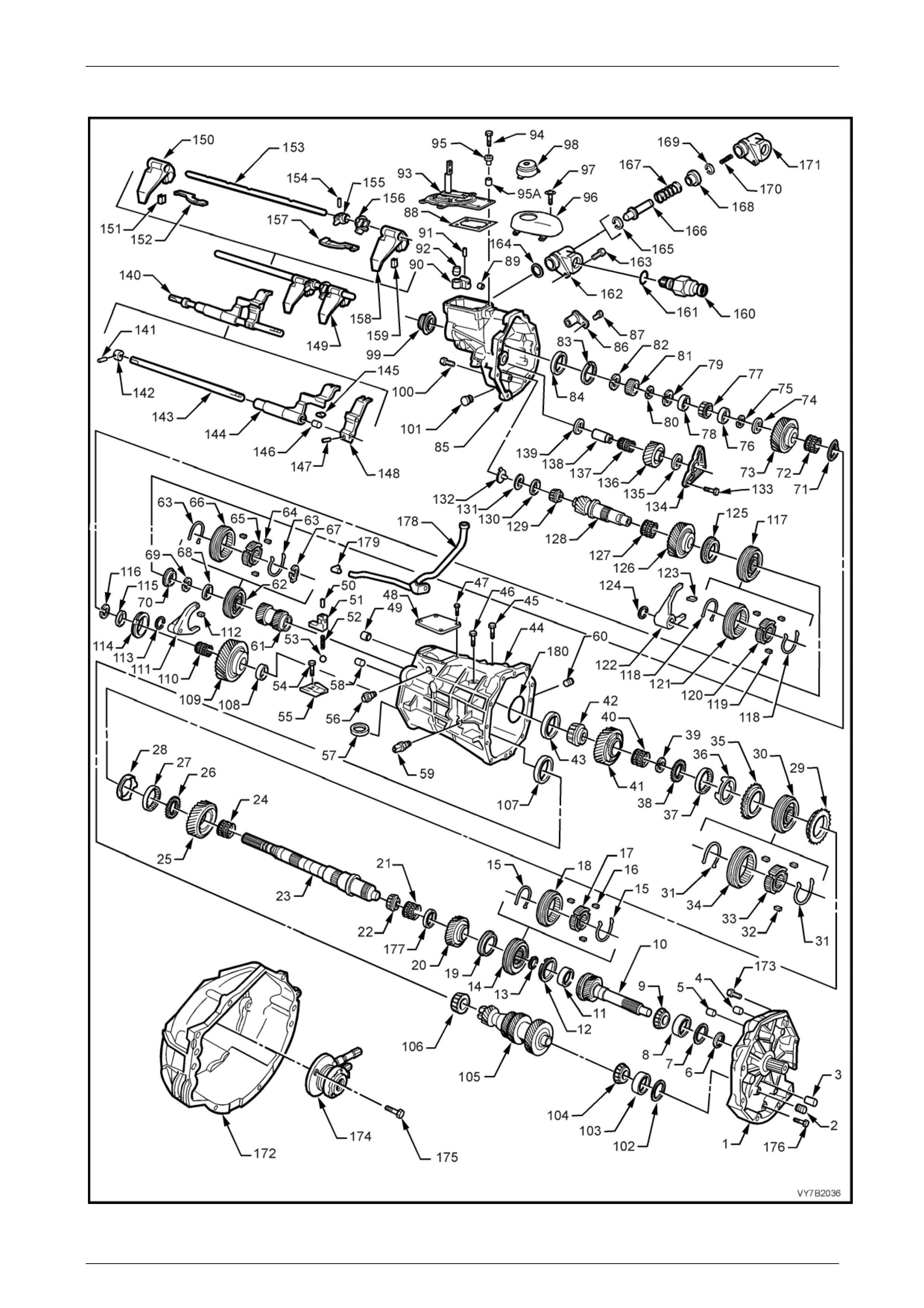
Transmission Exploded View
Figure 7B2 – 4 – Tran smission Components
Page 7B2- 7

Manual Transmission – GEN III V8 Page 7B2-8
Legend – Transmission Components
1 Plate, Transmission Adaptor
2 Plug
3 Pin, Dowel (2 places)
4 Pin, Dowel (2 places)
5 Bushing, Shift Rail
6 Seal, Input Shaft
7 Shim, Input Shaft
8 Cup, Input Shaft Bearing
9 Bearing, Input Shaft Tapered
10 Shaft, Input
11 Cup, Input Shaft Bearing
12 Blocker Ring, 4th Gear
13 Ring, Snap
14 Synchroniser Assembly, 3rd/4th
15 Spring, 3rd/4th Synchroniser
16 Key, 3rd/4th Synchroniser
17 Hub, 3rd/4th Synchroniser
18 Ring, 3rd/4th Synchroniser
19 Blocker Ring, 3rd Gear
20 Gear, 3rd Speed
21 Bearing, 3rd Gear Needle
22 Bearing, Mainshaft Small Tapered
23 Mainshaft
24 Bearing, 2nd Gear Needle
25 Gear, 2nd Speed
26 Washer, Thrust
27 Cone, Inner
28 Cone, Friction
29 Blocker Ring, 2nd Gear
30 Synchroniser Assembly, 1st/2nd
31 Spring, 1st/2nd Synchroniser
32 Key, 1st/2nd Synchroniser
33 Hub, 1st/2nd Synchroniser
34 Ring, 1st/2nd Synchroniser
35 Blocker Ring, 1st Gear
36 Cone, Friction
37 Cone, Inner
38 Washer, Thrust
39 Ring, Snap
40 Bearing, 1st Gear Needle
41 Gear, 1st Speed
42 Bearing, Mainshaft Large Tapered
43 Cup, Mainshaft Bearing
44 Case, Transmission
45 Bolt, Shift Lever Guide
46 Bolt, Shift Lever Guide
47 Bolt, Shift Detent Cover
48 Cover, Shift Detent
49 Bushing, Shift Rail
50 Pin, Front Offset Lever Roll
51 Lever, Front Offset
52 Spring, Shift Detent
53 Ball, Shift Detent
54 Bolt, Shift Guide Plate
55 Plate, Shift Guide
56 Enhancer, Shift
57 Magnet (2 places)
58 Pin, Dowel (2 places)
59 Switch, Back-Up Lamp
60 Plug, Fill
61 Gear, 5th/6th Driven
62 Synchroniser Assembly, Reverse
63 Spring, Reverse Synchroniser
64 Key, Reverse Synchroniser
65 Hub, Reverse Synchroniser
66 Ring, Reverse Synchroniser
67 Retainer, Reverse Synchroniser Key
68 Washer, Thrust
69 Ring, Snap
70 Blocker Ring, Reverse Gear
71 Washer, Wave
72 Bearing, Reverse Gear Needle
73 Gear, Reverse
74 Washer, Thrust
75 Ring, Snap
76 Spacer
77 Bearing, Rear Mainshaft Tapered
78 Spacer
79 Ring, Snap
80 Ring, Snap
81 Ring, Speedometer Pulse
82 Ring, Snap
83 Ring, Snap
84 Cup, Mainshaft Bearing Rear
85 Housing, Transmission Extension
86 Sensor, Electronic Speed
87 Bolt, Speed Sensor
88 Gasket, Shifter Assembly Cover
89 Bushing, Shift Rail
90 Lever, Rear Offset Shift
91 Pin, Rear Offset Shift Lever Roll
92 Cup, Isolator
93 Shifter Assembly
94 Bolt, Shifter Assembly
95 Sleeve, Insulating
95a Distance Piece, Shift Cover Bolt
96 Cover, Shifter Assembly
97 Screw, Shifter Assembly Cover
98 Boot, Shifter
99 Seal and Boot, Rear Output
100 Bolt, Transmission Extension Housing
101 Plug, Drain
102 Shim, Countershaft
103 Cup, Countershaft Bearing
104 Bearing, Countershaft Tapered
105 Countershaft
106 Bearing, Countershaft Tapered
107 Cup, Countershaft Bearing
108 Washer, Thrust
109 Gear, 6th Drive
110 Bearing, 6th Gear Needle
111 Fork, Reverse Shift
112 Pad, Reverse Shift Fork
113 Circlip
114 Blocker Ring, 6th Gear
115 Spacer
116 Ring, Snap
117 Synchroniser Assembly, 5th/6th
118 Spring, 5th/6th Synchroniser
119 Key, 5th/6th Synchroniser
120 Hub, 5th/6th Synchroniser
121 Ring, 5th/6th Synchroniser
122 Fork, 5th/6th Shift
123 Pad, 5th/6th Shift Fork
124 Circlip
125 Blocker Ring, 5th Gear
126 Gear, 5th Drive
127 Bearing, 5th Gear Needle
128 Extension, Countershaft
129 Bearing, Countershaft Extension
Tapered
130 Cup, Countershaft Extension Bearing
131 Shim, Countershaft Extension
132 Funnel, Oil
133 Bolt, Reverse Idler Shaft Bracket
134 Bracket, Reverse Idler Shaft
135 Washer, Reverse Idler Gear Thrust
136 Gear, Reverse Idler
137 Bearing, Reverse Idler Gear Roller
138 Shaft, Reverse Idler Gear
139 Washer, Reverse Idler Gear Thrust
140 Rail Assembly, 5th/6th, Reverse Shift
141 Pin, Roll
142 Collar
143 Rail, Shift
144 Lever, 5th/6th Shift Rail
145 Pad, 5th/6th Shift Rail Lever
146 Bushing, 5th/6th Shift Rail Lever
147 Pin, Roll
148 Lever, Reverse Shift Rail
149 Rail Assembly, 1st/2nd, 3rd/4th Shift
150 Fork, 1st/2nd Shift
151 Pad, 1st/2nd Shift Fork
152 Link, Shift
153 Rail, 1st/2nd 3rd/4th Shift
154 Pin, Roll
155 Pin, Selector
156 Plate, Interlock
157 Link, Shift
158 Fork, 3rd/4th Shift
159 Pad, 3rd/4th Shift Fork
160 Solenoid, Reverse Lockout
161 O-Ring, Reverse Lockout Solenoid
162 Body Assembly, Reverse Lockout
163 Bolt, Reverse Lockout Assembly
164 O-Ring, Reverse Lockout Asm
165 Circlip
166 Plunger, Reverse Lockout
167 Spring, Reverse Lockout Outer
168 Collar, Reverse Lockout
169 ‘C’ Clip
170 Spring, Reverse Lockout Inner
171 Body, Reverse Lockout
172 Housing, Clutch
173 Bolt, Clutch Housing to Adaptor
174 Assembly, Clutch Slave Cylinder
175 Bolt, Clutch Slave Cylinder
176 Bolt, Transmission Adaptor Plate
177 Spacer
178 Tube, Vent
179 Fitting, Vent Tube
180 O-Ring, Mainshaft
Page 7B2- 8

Manual Transmission – GEN III V8 Page 7B2-9
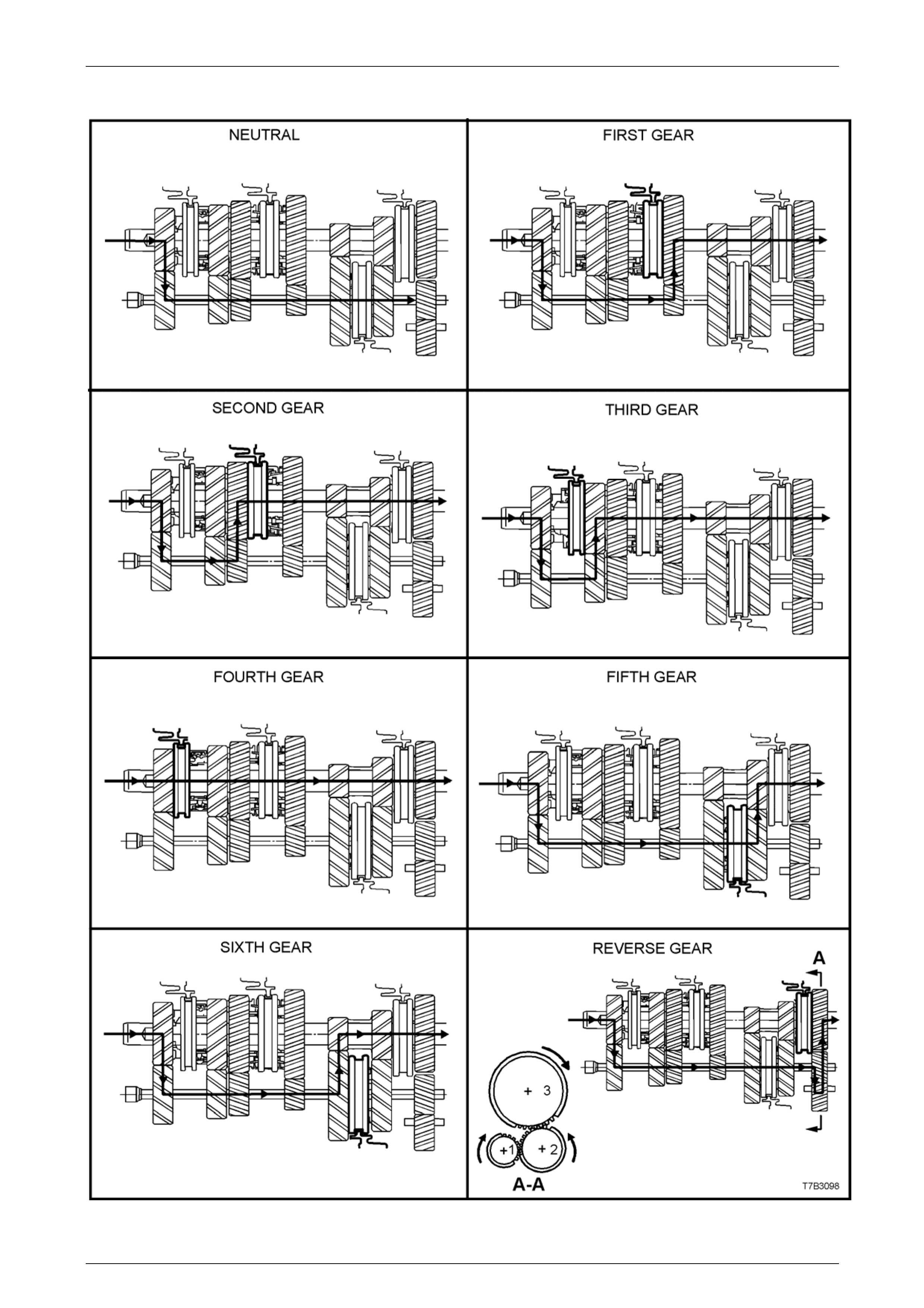
Transmission Power Flows
The input shaft drive gear, third, second and first speed gears are in constant mesh with the countershaft gear. As the
countershaft gear extension is splined to the end of the countershaft gear, reverse drive gear at the end of this extensi on,
rotates with the countershaft gear.
Therefore, when the engine is running with the clutch engaged, engine torque is transferred to the input shaft drive gear
and through the countershaft gear to the third, second, first spee d and reverse gears at all times.
The schematics in Figure 7B2 – 5 relate to the following descriptions:
Neutral
In neutral, with the clutch engaged, the input shaft drive gea r turns the countershaft gear and countershaft extension.
The countershaft gear turns the constant mesh gears of 3rd, 2nd, 1st and reverse ge ars because no synchroniser
assemblies are engage d. As these constant mesh gears are supported on roller beari ngs, they will also rotate with the
countershaft gear.
As the 5th/6th compound gear is splined to the mainshaft, these constant mesh gears, mounted on the counters haft
extension, will remain stationery while the vehicle is stopped.
First Gear
In first gear, the first/second speed synchroni ser ring is moved rearward to engage the first speed gear, which is bei ng
turned by the countershaft gear. Because the first/second speed synchroniser hub is splined to the mainshaft, torque is
transferred to the mainshaft from the first speed gear through the synchroniser ring and hub, at a speed reduction of
2.66:1 (MM6) or 2.97:1 (M12).
Second Gear
In second gear, the first/second speed s ynchr oniser ring is moved forward to engage the second speed g ear, which is
being turned by the countershaft gear. Because the first/second speed synchroniser hub is splined to the mainshaft,
torque is transferred to the mainshaft from the second speed gear through the synchroniser ring and hub, at a speed
reduction of 1.78:1 (MM6) or 2.07:1 (M12).
Third Gear
In selecting third gear, the first/second speed synchroniser ring moves to the neutral position and the third/fourth speed
synchroniser ring is moved rearward to engage the third speed gear. As this gear is being turned b y the countershaft
gear, the engagement of the ring with the thir d speed gear, torque is transferred to the mainshaft because the third/fourth
speed synchroniser hub is splined to the mainshaft. The mainshaft the turns at a speed reduction of 1.30:1 (MM6) or
1.43:1 (M12).
Fourth Gear
In fourth gear, the third/fourth speed synchroniser rin g is moved forward to engage the input shaft drive gear. This
engagement of the input shaft drive ge ar with the third/fourth synchroniser ring and hub assembly, transfers torque
directly to the mainshaft.
While the countershaft gear and countershaft extension is still rotating, no torque transfer takes place but the spinning
gear continues to lubricate the internal transmission components by the ‘splash’ method. As the mainshaft is effectively
joined to the input shaft, the drive is direct with a ratio of 1.00:1 (MM6 and M12).
Fifth Gear
In fifth gear, which is the first of the overdrive ratios , the first/second and third/fourth speed synchroniser rings must be in
the neutral position. The fifth/sixth speed synchroniser ring is moved rearward to engage the fifth speed drive gear,
supported on the countershaft extension by a caged needle roller bearin g. This engagement of the ring with the fifth
speed constant mesh gear, allows torque to be transferred from the countershaft gear extension to the mainshaft, via the
splined synchromesh hub and the splined fifth/sixth speed compo und driven gear. This speed generates an overdrive
ratio of 0.74:1 (MM6) or 0.84:1 (M12).
Sixth Gear
In sixth gear, the fifth/sixth speed synchroniser ring is moved forward to engage the sixth speed drive gear, supported on
the countershaft extension b y a caged needle roller bearing. This engagement of the ring with the sixth speed constan t
mesh gear, allows torque to be transferred from the countershaft gear extension to the mainshaft, via the splined
synchromesh hub and the splined fifth/sixth speed compound driven gear. This speed generates an overdrive ratio of
0.50:1 (MM6) or 0.57:1 (M12).
Reverse Gear
In reverse gear, the reverse synchroniser ri ng is moved rearward to engage the mainshaft mounted, rev erse driven gear.
This allows torque to be transferred from the countershaft extension gear through the reverse idler gear (reversing
direction of rotation) to the mainshaft reverse driven gear. As the reverse synchromesh hub is splined to the mainshaft,
this causes the mainshaft to rotate in the opposite direction to the input shaft drive gear, at a speed reduction of 2.90:1
(MM6) or 3.28:1 (M12).
Page 7B2- 9
Manual Transmission – GEN III V8 Page 7B2-10
Manual Transmission Power Flows
Figure 7B2-5 – Power Flow Schematics
Page 7B2- 10

Manual Transmission – GEN III V8 Page 7B2-11
1.2 Transmission Serial Number
The transmission serial numb er is located on a self-
adhesive decal attached to the top of the transmission case.
This number provides cod ed information which could be
significant to parts interpretation and should be referred to
when ordering replacement parts.
In addition, an identification tag is attache d to the
transmission under an extension housi ng bolt, on the right
hand side. Refer to Figure 7B2 – 8.
Figure 7B – 6
Page 7B2- 11

Manual Transmission – GEN III V8 Page 7B2-12
2 Servicing Information
ATTENTION
All fasteners are important attaching parts as they affect the performance of vital components and/or could
result in major repair expense. W here specified in this Section, fasteners MUST be replaced w ith parts of the
same part number or an app roved equivalent. Do not use fasteners of an inferior quality or substitute design.
Torque values must be used as specified during reassembly to ensure proper retention of all components.
Throughout this Section, fastener torque wrench specifications may be accompanied with the following
identification marks:
Fasteners must be repl aced after loosening.
Vehicle must be at curb height before final tightening.
Fasteners either have micro encapsulated sealant applied or incorporate a mechanical thread lock and
should only be re-used once. If in doubt, replacement is recommended.
If one or more of these identification marks is present alongside a fastener torque wrench specification, the
recommendation regarding that fastener must be adhered to.
2.1 Recommended Lubricant
The recommended lubricant for the ‘T56’ manual transmission is Dexron III® automatic transmission fluid.
The transmission lubricant capacity is approximately 4.4 litres.
Page 7B2- 12
Manual Transmission – GEN III V8 Page 7B2-13
2.2 Checking Transmission Lubricant Level
NOTE
This transmission is classified as being a “Fill for
Life” transmission and checking the lubricant
level is not recommended.
The only time that fluid level checking would be
appropriate, would be after correction of a fluid
leak that did not require the transmission to be
fully drained and/or removed from the vehic le.
1 Raise the vehicle and suppor t in a safe manner. Refer to Section 0A General Information for the location of
recommended lifting and support points.
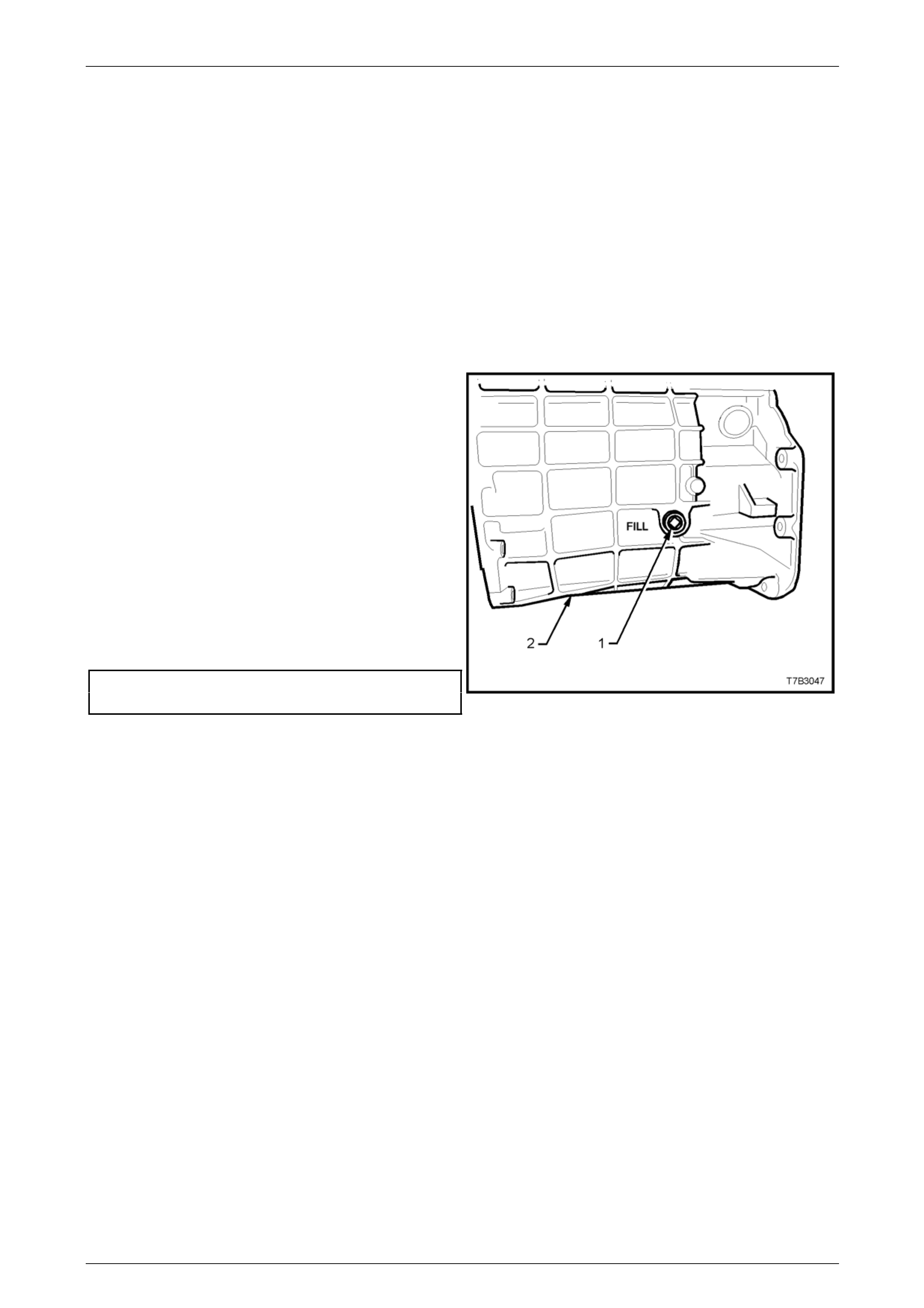
2 Place a drain tray beneath transmissio n and remove
transmission filler plug (1) from left hand side of
transmission case (2), using a 3/8” drive socket bar.
NOTE
Depending on the severity of the loss, fluid will
probably flow from the filler plug hole, following
removal.
3 Allow excess fluid to drain until flow stops. If required,
top up fluid level until it does flow out.
4 Clean the threads of the filler plug, apply thread
sealant such as Loctite 565 or equiv ale nt (GM P/N
12346004), then reinstall filler plu g, tighten ing to the
correct torque specification. Do not apply Teflon
thread tape to the plug threads.
Transmission filler plug
torque specification...............................................28 Nm Figure 7B – 7
5 Remove the back-up lamp switch. Refer to 3.1 Back-Up Lamp Switch, Replace in this Section.
6 Using commercially available fluid dispensing equipment, add a measured, 0.5 litres of the recommended lubricant
to the transmission, via the back-up lam p switch threaded hole in the transmission case.
7 Reinstall the back-up lamp switch. Refer to 3.1 Back-Up Lamp Switch, Replace in this Section, then lower the
vehicle to the ground.
Page 7B2- 13

Manual Transmission – GEN III V8 Page 7B2-14
2.3 Draining and Refilling Transmission
Should a lubricant change b e required, then the following procedure should be adopted.
1 To drain transmission, jack up vehicle front and rear
and support on safety stands. Refer to
Section 0A General Information, for the location of
jacking and support points.
2 Place a drain tray beneath transmissio n and remove
filler plug (‘1’ in Figure 7B2-7) and then the drain plug
from the transmission extension housing (‘1’ in Figure
7B2-8), using a 3/8” drive socket bar.
3 After draining, clean the threads of the drain plug,
apply thread sealant such as Loctite 565 or equivalent
(GM P/N 12346004) then reinstall
NOTE
Do not apply Teflon thread tape to the plug
threads. Figure 7B2– 8
4 Tighten the drain plug to the correct torque specification.
Transmission drain plug
torque specification...............................................28 Nm
5 Refill transmission to correct level, refer to 2.2 Checking T r ansmission Lubricant Level in this Section.
Page 7B2- 14
Manual Transmission – GEN III V8 Page 7B2-15
3 Minor Service Operations
ATTENTION
All fasteners are important attaching parts as they affect the performance of vital components and/or could
result in major repair expense. W here specified in this Section, fasteners MUST be replaced w ith parts of the
same part number or an app roved equivalent. Do not use fasteners of an inferior quality or substitute design.
Torque values must be used as specified during reassembly to ensure proper retention of all components.
Throughout this Section, fastener torque wrench specifications may be accompanied with the following
identification marks:
Fasteners must be repl aced after loosening.
Vehicle must be at curb height before final tightening.
Fasteners either have micro encapsulated sealant applied or incorporate a mechanical thread lock and
should only be re-used once. If in doubt, replacement is recommended.
If one or more of these identification marks is present alongside a fastener torque wrench specification, the
recommendation regarding that fastener must be adhered to.
3.1 Back-Up Lamp Switch
LT Reference No. – 04-075
Replace
1 Raise the vehicle and suppor t in a safe manner. Refer to Section 0A General Information in this Service Information
for the location of recommended lifting and support points.
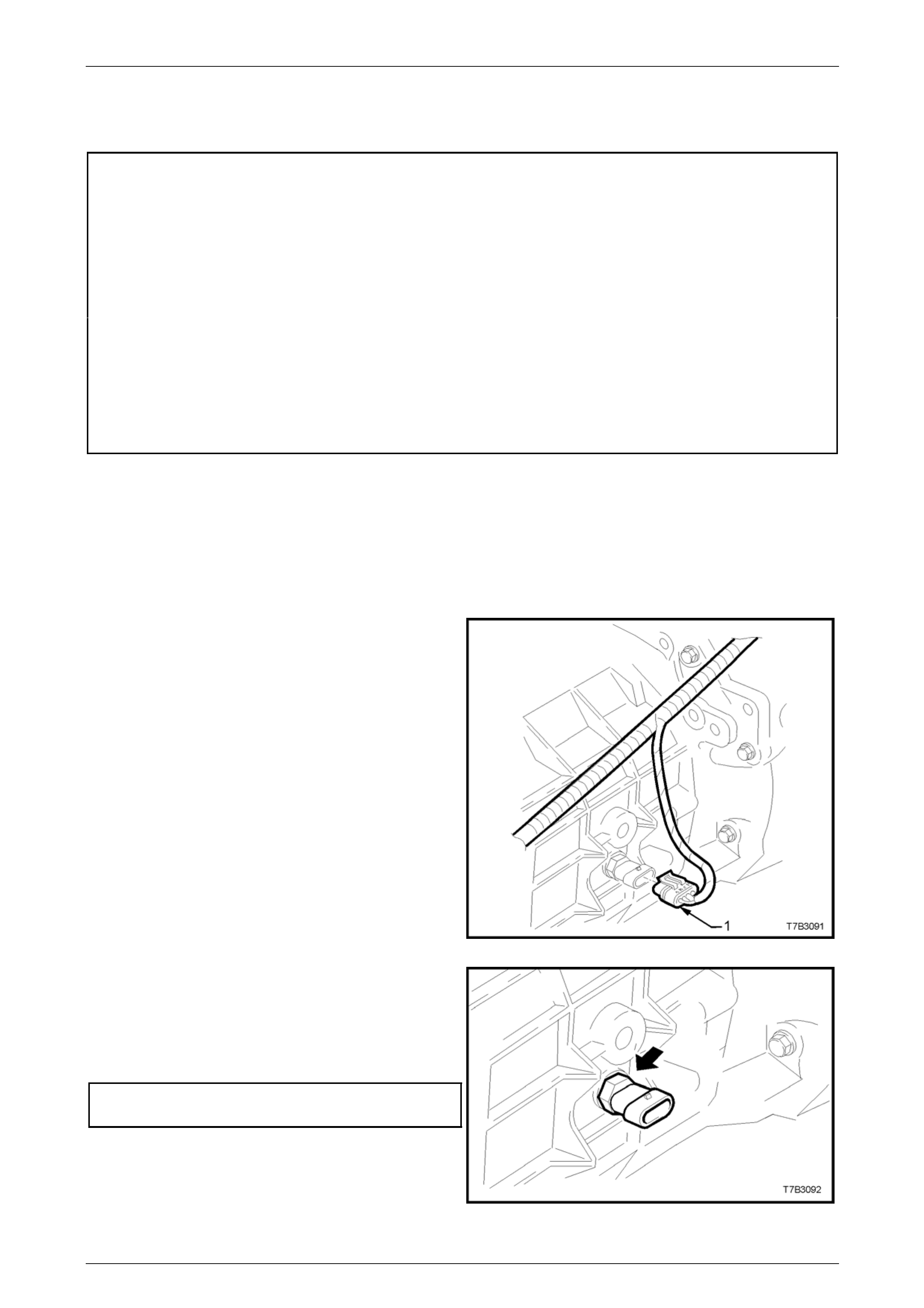
2 Remove wiring harness connector (1) from switch,
located on the right hand side of the transmission
case.
Figure 7B2 – 9
3 Loosen, then remove switch (arro w) from the
transmission case.
4 Apply Loctite 565 or eq uivalent (GM P/N 12346004),
to the cleaned threads of the back-up lamp s witch.
5 Install switch to transmission case and tighten to the
correct torque specification.
Back-up lamp switch
torque specification...............................................28 Nm
6 Install wiring harness connector to switch.
7 Remove safety stands and lower vehicle to ground.
8 Check back-up lamp operation.
Figure 7B2 – 10
Page 7B2- 15
Manual Transmission – GEN III V8 Page 7B2-16
3.2 Speed Sensor
LT Section No. – 04-075
Replace
1 Raise the vehicle and suppor t in a safe manner. Refer to Section 0A General Information in this Service Information
for the location of recommended lifting and support points.
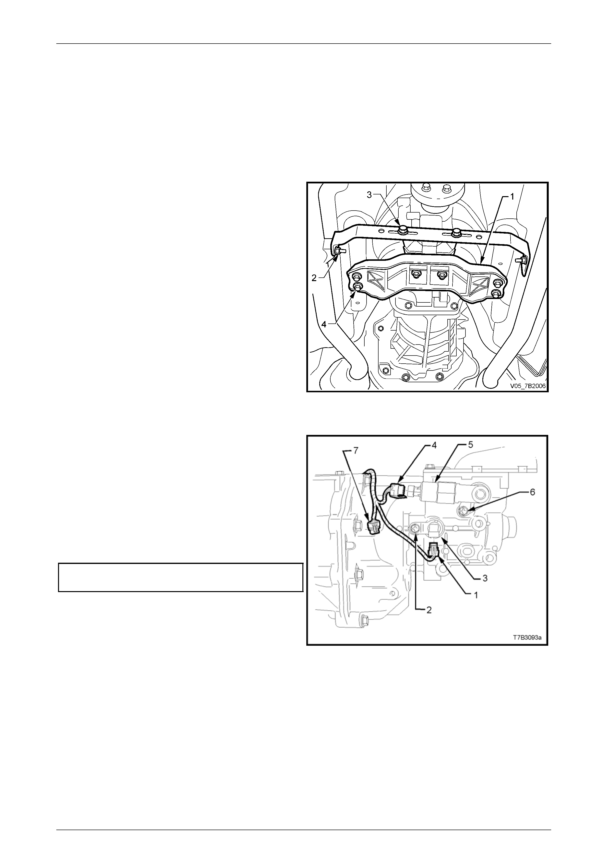
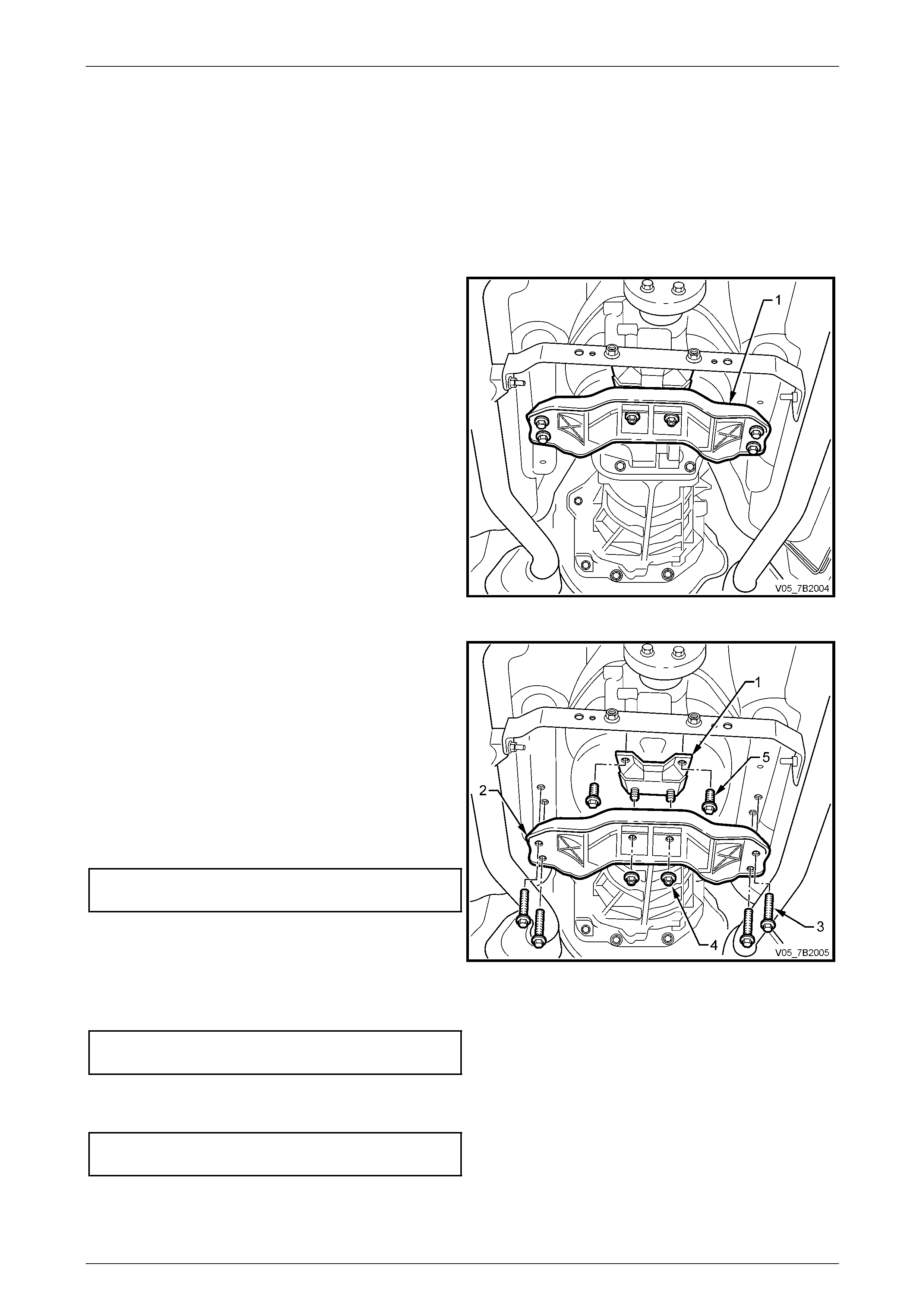
2 Scribe around each of the transmissio n sup port
crossmember (1) mounting points to the vehicle
underbody, to provide an alignment reference for
reassembly.
NOTE
This step is critical to the correct powertrain
alignment on reassembly. If not carried out, then
vehicle vibration and/or handling problems may
result.
3 Remove the two nuts (2) securing the exhaust pipe
bracket to each of the exhaust pipes.
4 Loosen the two bracket bolts (3) and d isengage the
bracket from the exhaust pipes.
5 Support the transmission with a suitable lifting devic e,
then remove the four crossmember to side rail
bolts (4).
6 Lower the rear of the transmission eno ugh to gain
clear access to the sensor.
Figure 7B2 – 11
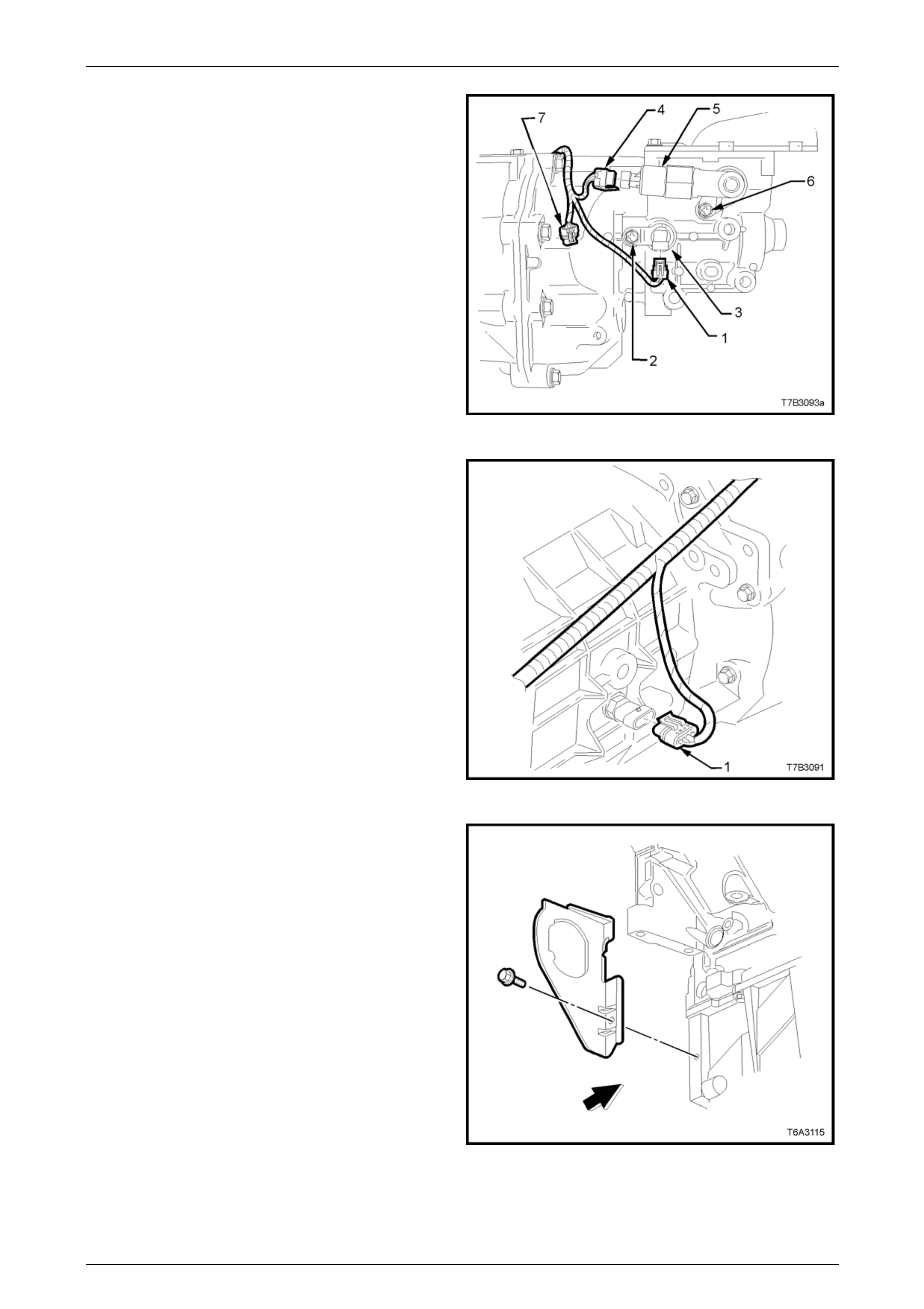
7 Remove the speed sensor wiring harness connector
(1) from the sensor (3).
8 Remove speed sensor mounting brack et screw (2)
from the transmission extension housing, th en remove
the sensor (3).
9 Installation is the reverse of removal except for the
following points;
10 Tighten the speed sensor to mounting bracket
retaining screw (2) to the correct torque specificatio n.
Speed sensor bracket
screw torque specification.....................................12 Nm
11 Connect the speed sensor lead connector (1) to the
sensor.
Figure 7B2 – 12
Page 7B2- 16
Manual Transmission – GEN III V8 Page 7B2-17
12 Raise the transmission, then install the four
crossmember to side frame bolts (4), aligning the
crossmember (1) with the scribed lines made prior to
disassembly. Tighten the bolts (4) to the correct torque
specification.
Rear crossmember to side frame
member bolt torque specification..........................58 Nm
13 Engage the exhaust pipe bracket with each of the
exhaust pipe studs, reinstall the two nuts (2) and
tighten to the correct torque specification.
Exhaust pipe bracket to exhaust
pipe nut torque specification ................................. 25 Nm
14 Tighten the two bracket bolts (3) to the correct torque
specification.
Exhaust pipe bracket to transmission
bracket bolt torque specification............................25 Nm
15 Lower the vehicle and road test to check for correct
vehicle operation.
Figure 7B2 – 13
Page 7B2- 17
Manual Transmission – GEN III V8 Page 7B2-18
3.3 Transmission Support Mount
LT Section No. – 04-020
Replace
1 Raise front of vehicle and support on safet y stands. Refer to Section 0A General Information, for the location of
jacking and support points.
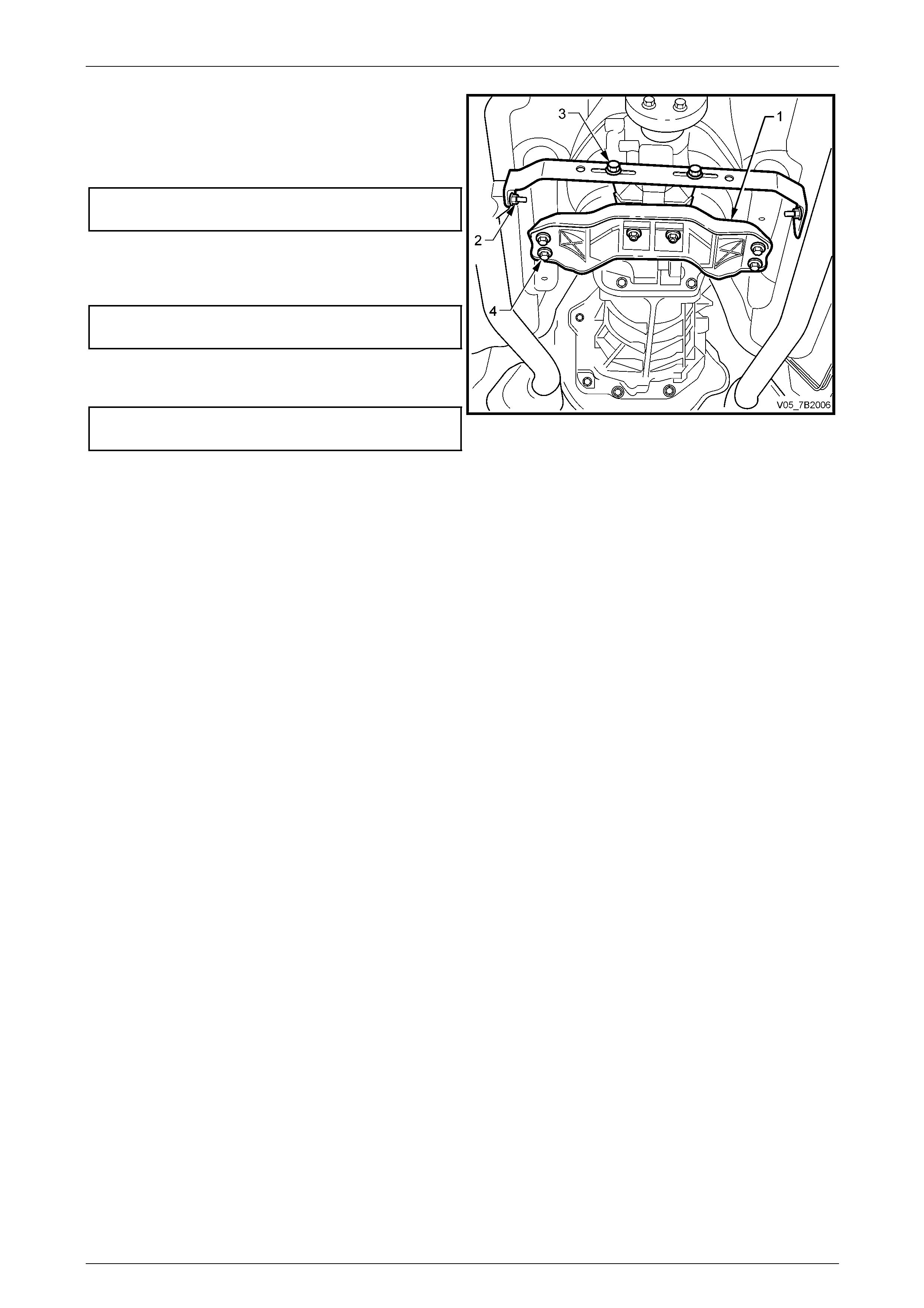
2 Scribe around each of the transmissio n sup port
crossmember (1) mounting points to the vehicle
underbody, to provide an alignment reference for
reassembly.
NOTE
This step is critical to the correct powertrain
alignment on reassembly. If not carried out, then
vehicle vibration and/or handling problems may
result.
Figure 7B2 – 14
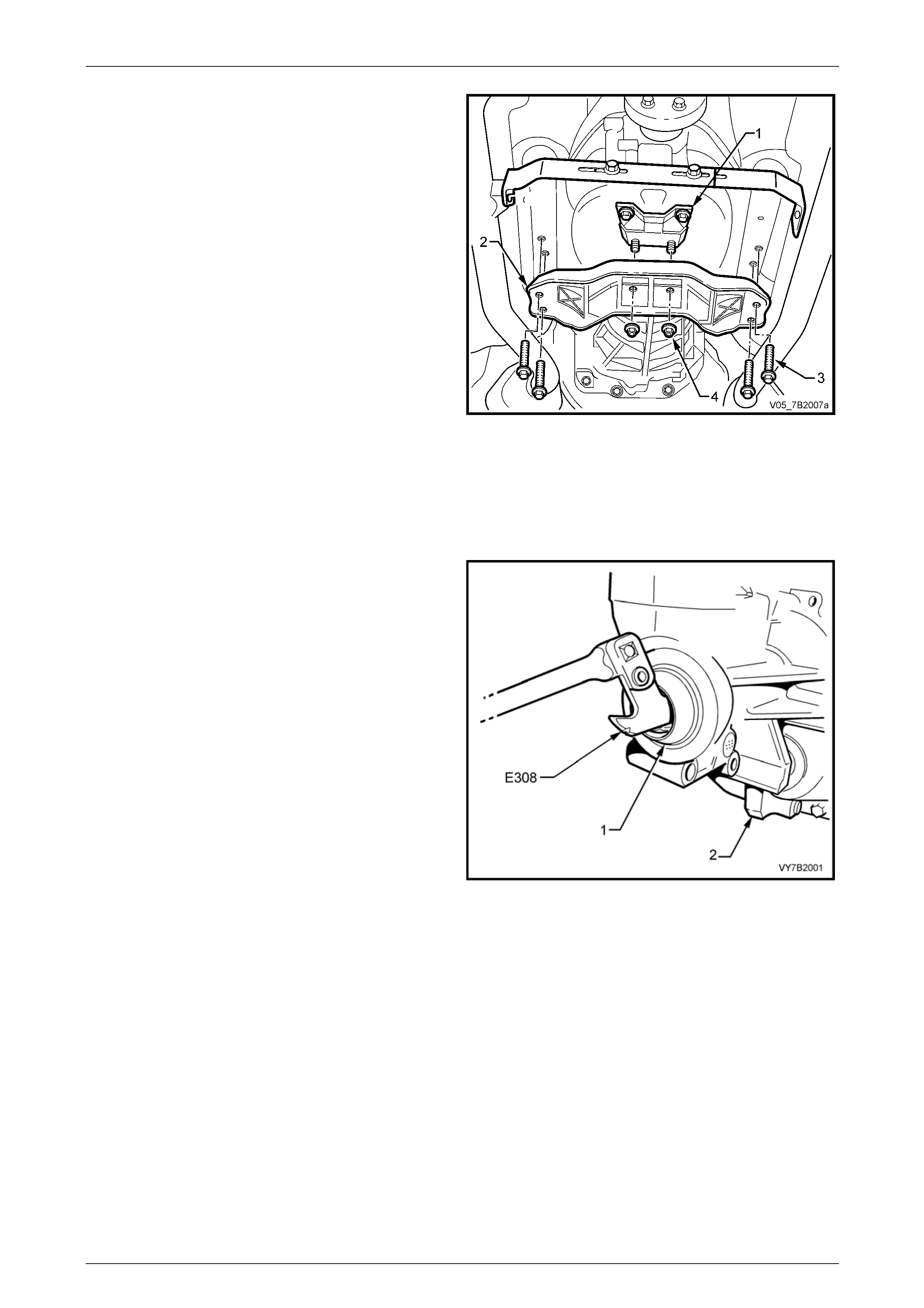
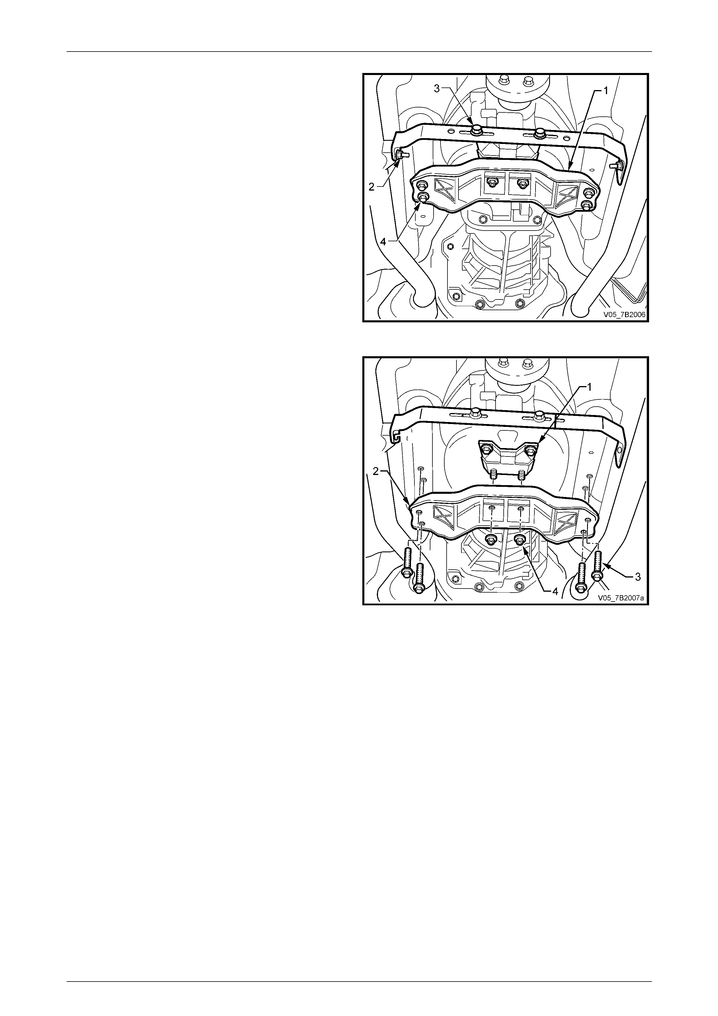
3 Support the transmission with a suitable lifting devic e,
then remove the four bolts (3).
4 Lower the transmission slightly, then remove the two
rear mount to crossmember nuts (4)). Set the
crossmember to one side.
5 Remove the two bolts (5) securing the mount (1) to the
transmission extension housing, then remove the
mount from the vehicle.
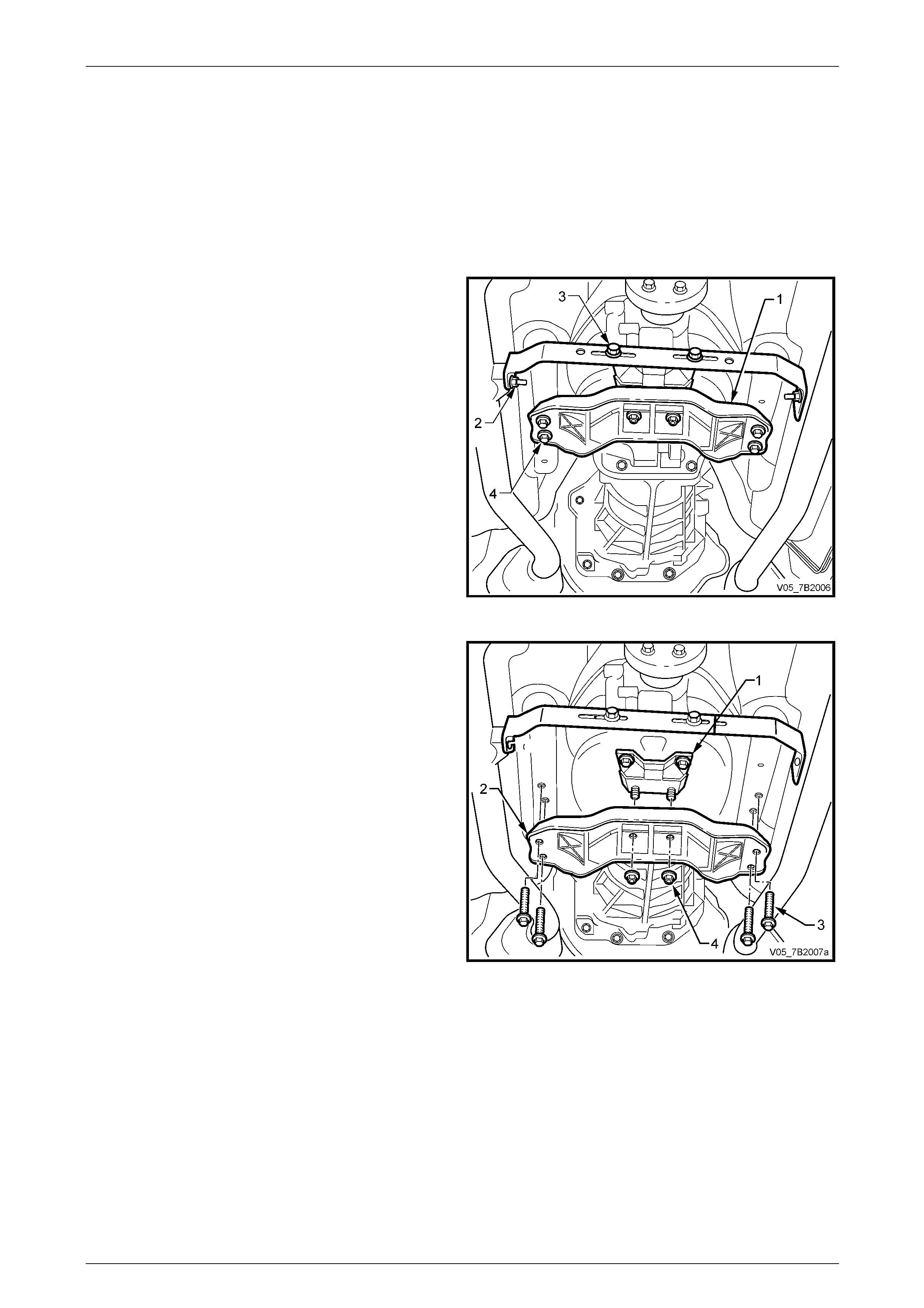
6 Reinstall the mount (1) to the transmission e x tension
housing, install the t wo bolts (5) and tighten to the
correct torque specification.
Transmission support mount
bolt torque specification........................................25 Nm
7 Raise the transmission slightl y , then reinstall the
transmission support crossmember, aligning the
scribed lines made prior to disassembly.
8 Reinstall the four crossmember to side frame bolts (3)
and tighten to the correct torque specification.
Figure 7B2 – 15
Rear crossmember to side frame
member bolt torque specification..........................58 Nm
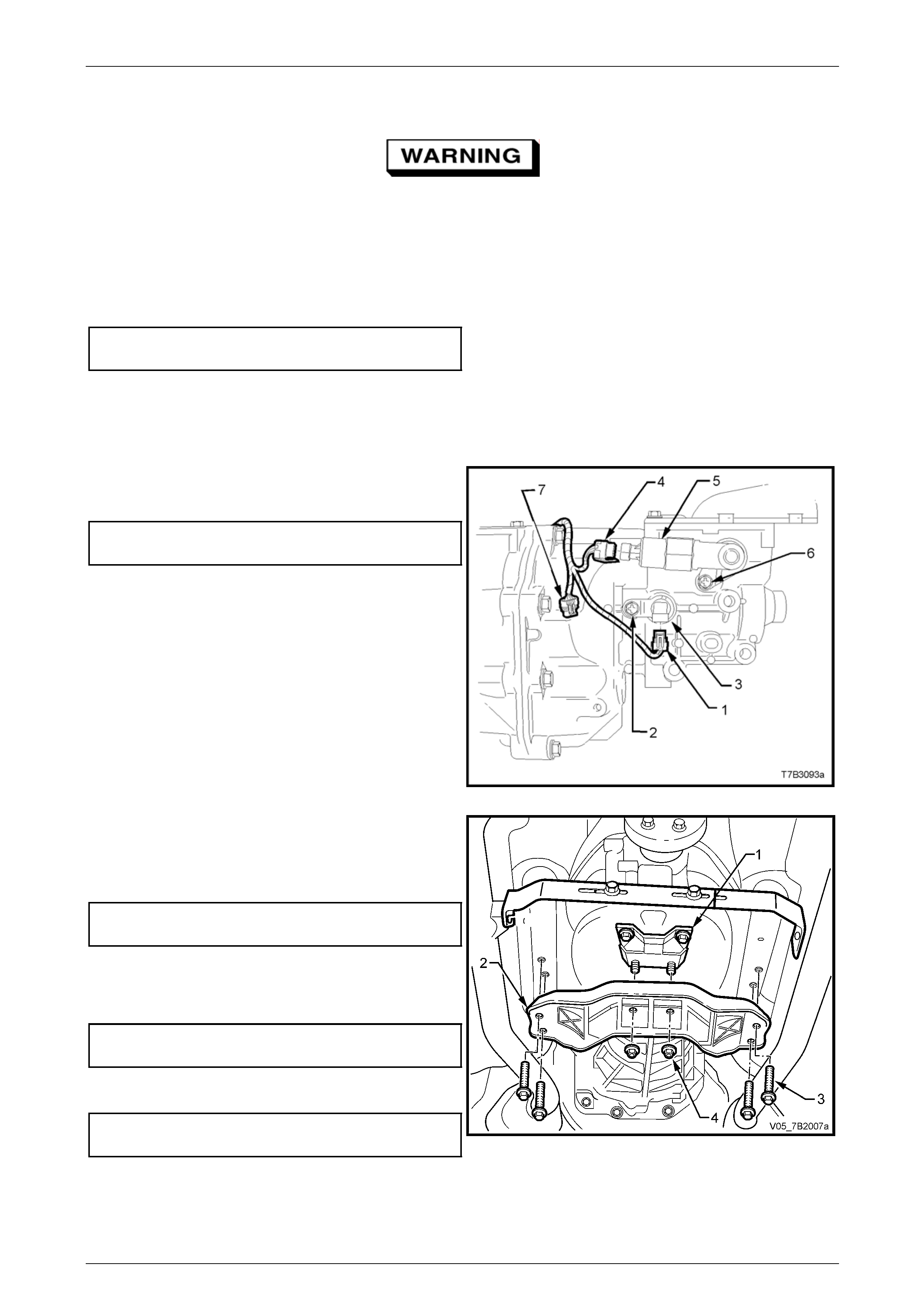
9 Remove the lifting device from the transmission, centralise the rear mount studs in the crossmember holes, then
reinstall the nuts (4), tightening to the correct torque specification.
Rear crossmember to transmission
mount nut torque specification..............................25 Nm
10 Lower the vehicle and road test to check correct vehicle operation.
Page 7B2- 18
Manual Transmission – GEN III V8 Page 7B2-19
3.4 Reverse Lock-Out Solenoid Assembly
LT Section No. – 04-090
Remove
1 Raise the vehicle and suppor t in a safe manner. Refer to Section 0A General Information for the location of
recommended lifting and support points.
2 Scribe around each of the transmissio n sup port
crossmember (1) mounting points to the vehicle
underbody, to provide an alignment reference for
reassembly.
NOTE
This step is critical to the correct powertrain
alignment on reassembly. If not carried out, then
vehicle vibration and/or handling problems may
result.
3 Remove the two nuts (2) securing the exhaust pipe
bracket to each of the exhaust pipes.
4 Loosen the two bracket bolts (3) and d isengage the
bracket from the exhaust pipes.
Figure 7B2 – 16
5 Support the transmission with a suitable lifting devic e,
then remove the four crossmember to side rail
bolts (3).
6 Remove the two transmission mount to cross member
nuts (4).
7 Remove the crossmember and set to one side.
Figure 7A1 – 17
Page 7B2- 19

Manual Transmission – GEN III V8 Page 7B2-20
8 Lower the transmission sufficient to gain access to the
reverse lockout solenoid assembly (5).
9 Remove wiring harness connector (4) from the reverse
lockout solenoid (5), after depressing the locking tab.
10 Remove the reverse lockout solenoid assembl y
mounting screw (6), then remove the assembly from
the transmission extension housing by rotating back
and forth while pulling on the assembly.
Figure 7B2 – 18
Disassemble
1 While holding the lock out body (2) in a vice fitted with
soft jaws, unscrew the reverse lockout solenoid (1)
from the body (2), then remove the O-ring seal (3). If
the O-ring seal (3) is undamaged, it can be re-used.
2 Remove the O-ring (4) from the body (2). If the O-ring
seal is undamaged it can also be re-used.
3 Remove circlip (5), using suit able pliers, from the body
(2).
4 Remove lockout plunger assembl y (6) from the body
(2), then remove the inner spring (7).
The reverse lockout assembly is under a
strong spring force. Exercise care when
removing ‘C’ clip (9), as injury could result.
5 Compress the reverse lockout plunger (6) a nd collar
(8) in a bench vice, then remove the ‘C’ clip (9).
6 Release the vice and disasse m ble the collar (8) and
spring (10) from the plunger (6).
Figure 7B2 – 19
7 Clean all parts in a suitable solvent and blow dry with compressed air.
Wear eye protection to prevent potential
injury.
8 Inspect all parts for damage or wear and springs for broken or damaged coils.
9 For solenoid testing procedure, refer to Section 6C3 Powertrain Management – GEN III V8 Engine.
Page 7B2- 20
Manual Transmission – GEN III V8 Page 7B2-21
Reassemble
Refer Figure 7B2 – 21 for compon ent identification.
Wear eye protection to prevent potential
injury.
1 Compress the reverse lockout plunger (6), sp ring (10) and collar (8) in a bench vice, then install the ‘C’ clip (9).
2 Reinstall the inner spring (7) into the end of the lockout plunger assembly (6), then install the assembly into the
reverse lockout body (2).
3 Reinstall circlip (5), using suitable pliers, to retain the lockout plunger assembly (6).
4 Reinstall the reverse lockout sole noid (1) with a new O-ring, tightening to the correct torque specification.
Reverse Lock-out solenoid
torque specification...............................................40 Nm
5 If damaged, install a new O-ring (4) to the body (2), otherwise the original can be re-used.
Reinstall
The reinstallation process is the reverse of removal operations except for the following:
1 After reinstalling the reverse lockout assembly (5),
install the retaining screw (6) and tighten to the correct
torque specification.
Reverse lock-out assembly
retaining screw torque specification......................18 Nm
2 Reinstall the wiring harness connector (4) to the
reverse lockout solenoid.
Figure 7B2 – 20
3 Raise the transmission slightly, then reinstall the four
crossmember to side frame bolts (3), aligning the
crossmember (2) with the scribed lines made prior to
disassembly. Tighten the bolts (3) to the correct torque
specification.
Rear crossmember to side frame
member bolt torque specification..........................58 Nm
4 Remove the lifting device from the transmission,
centralise the rear mount studs (1) in the
crossmember holes, then reinstall the nuts (4),
tightening to the correct torque specification.
Rear crossmember to transmission
mount nut torque specification..............................25 Nm
5 Reinstall the exhaust pipe br acket to exhaust pipe
nuts, tightening to the correct torque specification.
Exhaust pipe bracket to exhaust
pipe nut torque specification ................................. 25 Nm
6 Lower vehicle to the ground and road test to check for
correct vehicle operation.
Figure 7B2 – 21
Page 7B2- 21
Manual Transmission – GEN III V8 Page 7B2-22
3.5 Control Lever Knob, Boot & Control
Lever Assembly
LT Section No. – 04-060
ATTENTION
The following fasteners either have micro encapsulated sealant applied or incorporate a mechanical thread
lock and should only be re-u sed once. If in doubt, replacement is recommen ded.:
Control lever to remote shifter shaft retaining bolts.
NOTE
The gearshift lever knob and gearshift lever are
permanently bonded togeth er during ma nufacture
and are not serviced separately. Therefore, do
not attempt to separate these two components.
Remove
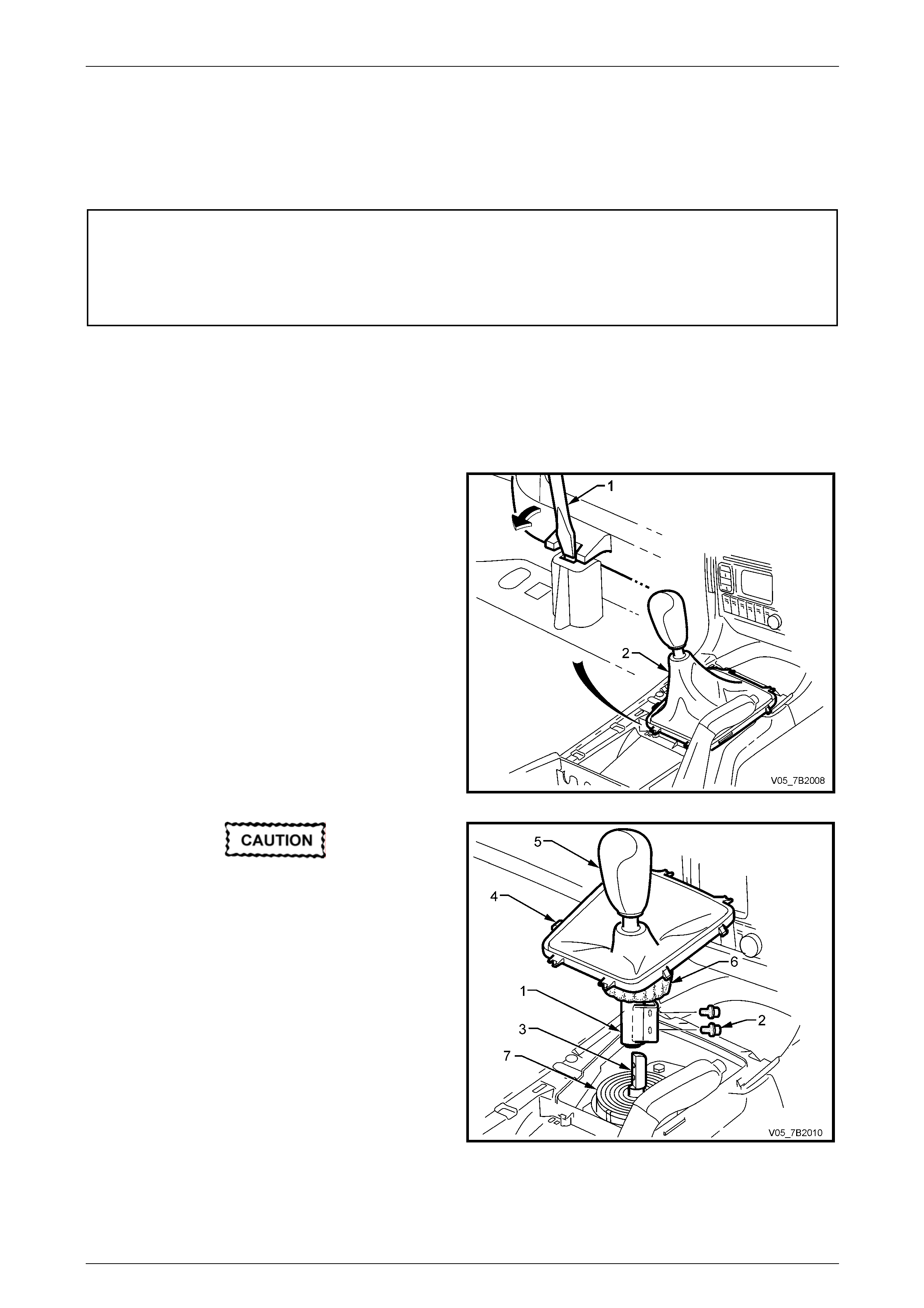
1 Remove the floor console cover assembly. Refer to
Section 1A3 Instrument Panel and Co nsole.
2 Using a fine bladed screwdriver (1), release each
locking tab, while exerting an upward force on the boot
carrier. Lift the gearshift boot retainer free from the
floor console.
Figure 7B2 – 22
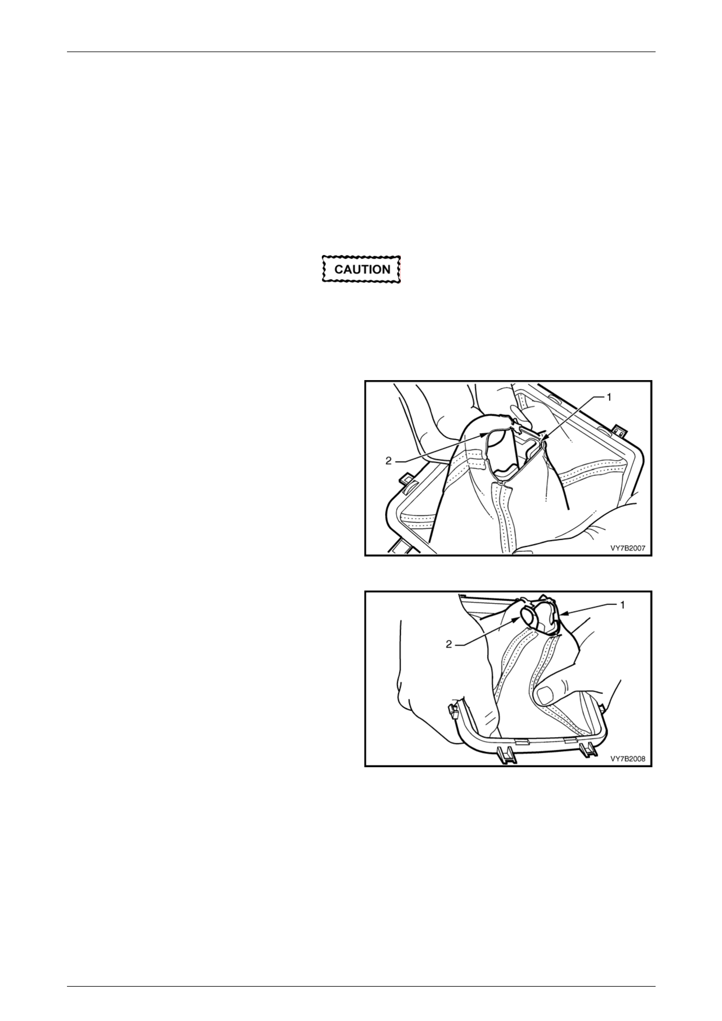
The gearshift knob (5) and gearshift lever (1)
are permanently glued together and are not
to be separated. The boot (4) however, is
replaceable. Refer to 3.6 Control Lever Boot,
Replace, in this Section.
3 Lift the gearshift lever boot (4) up and over the
gearshift knob (5), then turn the insulat or (6) back on
itself, enough to gain access t o the ge arshift remote
shift lever shaft screws (2).
4 Using a 10 mm socket, remove the two bolts (2)
securing the control lever (1) to the gearshift remote
shift lever shaft (3), then lift the control lever (1),
gearshift knob (5) and boot (4), free.
5 Clean old thread sealant from the bolt threads.
Figure 7B2 – 23
Page 7B2- 22
Manual Transmission – GEN III V8 Page 7B2-23
Reinstall
Before reinstalling the control lever assembly,
check that the gearshift remote lever boot (7)
is located correctly in the groove provided in
the remote gearshift lever (3), refer to
Figure 7B2 – 31. If the boot is not located
correctly, the durability of the boot will be
severely diminished, once the vehicle is put
back into service.
1 Apply thread sealant such as Loctite 242 or equivalent, to the cleaned threads of the co ntrol lever retaining bolts
(2).
2 With the control lever boot still pulled up over the gearshift knob and the insulator installed over the control lever,
(and also folded back on itself), reinstall the assembly to the gearshift remote shift lever shaft, reinstall the two bolts
and tighten to the correct torque specification.
Gearshift lever to remote shift lever
shaft bolt torque specification................................25 Nm
3 Unfold the insulator sock, ensurin g that it is pulled down over the lower part of the control lever assembly, covering
the mounting bracket and attaching screws, then pull the boot (4) down.
NOTE
The correct position of the insulating sock is for
the lower edge to just contact the remote shift
lever, rubber boot (6).
4 Align the boot carrier locking tabs with the locations in the floor console, then carefully seat the boot retainers until
each tab engages correctly.
5 Reinstall the floor console cover assembly. Refer to Section 1A3 Instrument Panel and Console in the MY 2005 VZ
and WL Series Service Information.
Page 7B2- 23
Manual Transmission – GEN III V8 Page 7B2-24
3.6 Control Lever Boot
LT Section No. 04-060
Replace
1 Remove the control lever knob, boot and co ntrol lever assembly.
Refer to 3.5 Control Lever Knob, Boot & Control Lever, in this Section.
2 Carefully remove the insulator sock and inspect for tears or rub marks. Replace as required.
To install a new boot, a specific procedure is
required, to ensure that damage to the new
boot does not occur.
3 Turn the boot inside out and pull up over the control lever knob. Cut the tie strap and remove the boot from the
knob and control lever assembl y. Discard bo th the boot and the tie strap.
4 With the new boot (2) turned inside out, begin
installation by locating the lever attaching lug (1),
inside and against one of the long sides of the boot
assembly, as shown.
NOTE
During the installation process, apply a firm but
constant force and ease the boot over the lever
attaching lug to minimise the chance of the boot
stitching being ruptured.
Figure 7B2 – 24
5 Gradually ease the boot opening (1) over the rounded
section of the lever assembly(2), taking care not to
rupture the boot stitching in the process.
Figure 7B2 – 25
Page 7B2- 24
Manual Transmission – GEN III V8 Page 7B2-25
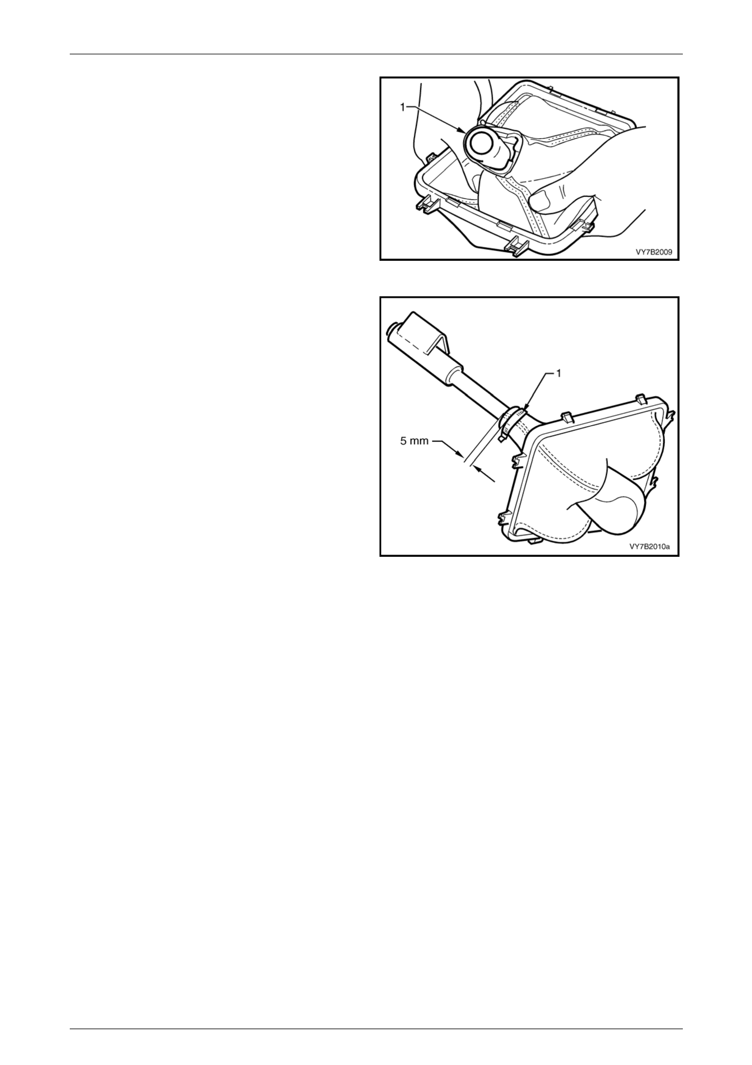
6 Continue to apply a constant force to the boot (1),
easing the boot over the lever end. When fully
stretched over the lever end, pull the bo ot down, to
install past the mounting flange.
Figure 7B2 – 26
7 Slide the boot into place over the groove in the
gearshift knob.
8 Install a new retaining tie strap aroun d the boot,
ensuring that:
a 5 mm of the boot extends beyond the tie strap.
b The tie strap is located in the knob groove, with
the catch located at the rear of the shift lever.
This will be in a position on the opp osite side to
the lever mounting flange.
c Fully tighten the tie strap to secure the boot in
place. Cut the excess strap and discard.
9 If the insulator sock is in a serviceable condition,
reinstall it over the mounting flang e, then roll the sock
back, to expose the mounting flange bolt holes.
10 After installing the insulator to the control lever and
with the boot still inside out, reinstall the control lever
knob, boot and control lever assembly. Refer to
3.5 Control Lever Knob, Boot & Control Lever, in this
Section.
Figure 7B2 – 27
Page 7B2- 25
Manual Transmission – GEN III V8 Page 7B2-26
3.7 Remote Shift Lever Boot
LT Section No. – 04-060
Remove
Disconnection of the battery affects certain
vehicle electronic systems. Refer to
Section 00 Warnings, Cautions and Notes,
before removing the ground lead.
1 Disconnect the battery ground lead.
2 Remove the gearshift control lever knob, boot and control lever assembly from the gearshift remote shift lever.
Refer to 3.5 Control Lever Knob and Boot Assembly in this Section, for the necess ary procedure.
3 Raise the vehicle and suppor t in a safe manner. Refer to Section 0A General Information for the location of
recommended lifting and support points.
Do not tear the boot (2) when removing it
from the groove in the gearshift remote shift
lever shaft (3).
4 From under the vehicle, remove the four nuts securing
the shift lever boot retaining plate (1) to the floor pan,
then remove the boot (2) and retain ing plate (1)
assembly.
5 Inspect the gearshift remote shift lever boot (3) for
tears or other damage, replacing as requir ed.
Figure 7B2 – 28
Page 7B2- 26
Manual Transmission – GEN III V8 Page 7B2-27
Reinstall
1 Reinstall the gearshift remote lever boot (2) and plate (1) and secure to the floor pan, with the four nuts, tightening
to the correct torque specification.
Remote shift lever boot
plate nut torque specification ................................10 Nm
Ensure that the boot (3) engages fully with
the groove (1) in the gearshift remote shift
lever shaft (2). If full engagement does not
occur, then the boot will rip prematurely,
resulting in an increase in transmission and
road noise level.
2 Fit the neck of the boot (3) into the recess (1) in the
remote shift lever (3).
3 Reinstall the gearshift control lever knob, boot and
control lever assembly. Refer to 3.5 Control Lever
Knob and Boot Assembly in this Section, for the
necessary procedure.
4 Reinstall the floor console cover assembly. Refer to
Section 1A3 Instrument Panel & Consol e. Figure 7B2 – 29
5 Reconnect battery ground lead.
6 Road test vehicle and check for correct gearshift operation.
Page 7B2- 27

Manual Transmission – GEN III V8 Page 7B2-28
4 Major Service Operations
ATTENTION
All fasteners are important attaching parts as they affect the performance of vital components and/or could
result in major repair expense. W here specified in this Section, fasteners MUST be replaced w ith parts of the
same part number or an app roved equivalent. Do not use fasteners of an inferior quality or substitute design.
Torque values must be used as specified during reassembly to ensure proper retention of all components.
Throughout this Section, fastener torque wrench specifications may be accompanied with the following
identification marks:
Fasteners must be repl aced after loosening.
Vehicle must be at curb height before final tightening.
Fasteners either have micro encapsulated sealant applied or incorporate a mechanical thread lock and
should only be re-used once. If in doubt, replacement is recommended.
If one or more of these identification marks is present alongside a fastener torque wrench specification, the
recommendation regarding that fastener must be adhered to.
4.1 Transmission Output Shaft Seal and
Boot
LT Section No. – 04-090
Remove
Disconnection of the battery affects certain
vehicle electronic systems. Refer to
Section 00 Warnings, Cautions and Notes,
before disconnecting the battery.
1 Disconnect battery ground lead.
2 Raise the vehicle and suppor t in a safe manner. Refer to Section 0A General Information in this Service Information
for the location of recommended lifting and support points.
3 Scribe around each of the transmissio n sup port
crossmember (1) mounting points to the vehicle
underbody, to provide an alignment reference for
reassembly.
NOTE
This step is critical to the correct powertrain
alignment on reassembly. If not carried out, then
vehicle vibration and/or handling problems may
result.
4 Remove the two nuts (2) securing the exhaust pipe
bracket to each of the exhaust pipes.
5 Loosen the two bracket bolts (3) and d isengage the
bracket from the exhaust pipes.
Figure 7B2 – 30
Page 7B2- 28
Techline
Manual Transmission – GEN III V8 Page 7B2-29
6 Support the transmission with a suitable lifting devic e,
then remove the four engine rear crossmem ber to side
frame attaching bolts (3).
7 Lower the transmission slightly, then remove the two
transmission mount to crossmember nuts (4). Set the
crossmember (2) to one side.
NOTE
Illustration does not show transmission jack in
position, for clarity of the crossmember
orientation.
Figure 7B2 – 31
8 Lower the transmission enough to provi de clearance for the propeller shaft rubber coupling when the propeller
shaft is removed.
9 Remove the intermediate and rear section of the exhaust system. Refer to Section 8B Exhaust System.
10 Remove the propeller shaft. Refer to Section 4C1 Rear Propeller Shaft and Universal Jo ints.
11 Using a seal remover such as Tool No. E308 (or
equivalent), remove the seal (1) from the transmission
extension housing (2).
NOTE
If E308 or commercial equival ent seal remov er is
not available and a lever such as a screwdriver
is used to prise the seal from the extension
housing, take care not to scratch the bore of the
extension housing during the removal process.
Figure 7B2 – 32
Page 7B2- 29
Manual Transmission – GEN III V8 Page 7B2-30
Reinstall
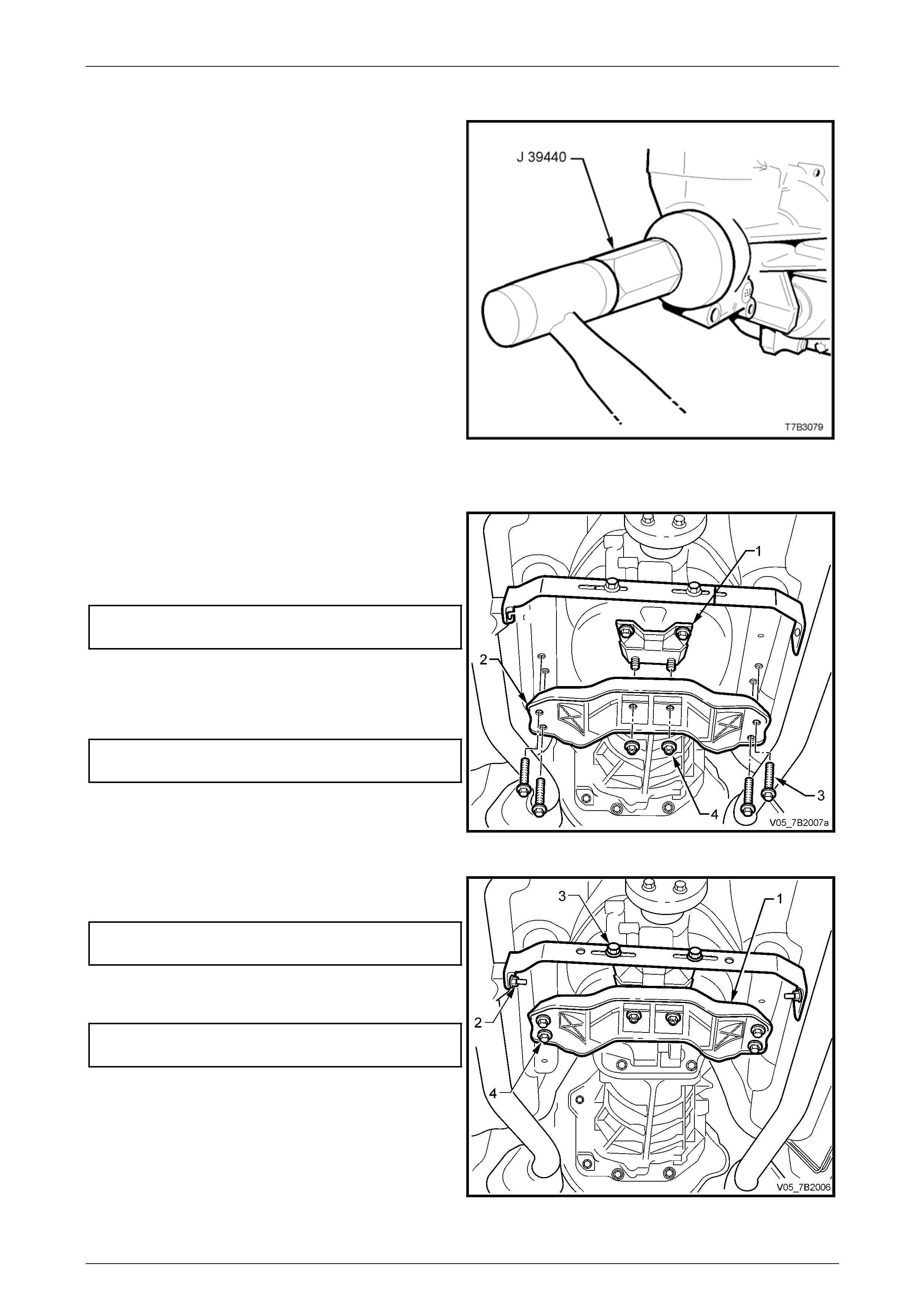
1 After lubricating the seal lip with transmission
lubricant, use seal installer J 39440 and install the new
seal into the rear of the extension h ousing.
Figure 7B2 – 33
2 Reinstall the propeller shaft, refer to Section 4C1 Rear Propeller S haft and Universal Joints.
3 Raise the transmission slightly, then reinstall the four
crossmember to side frame bolts (3), aligning the
crossmember (2) with the scribed lines made prior to
disassembly. Tighten the bolts (3) to the correct torque
specification.
Rear crossmember to side frame
member bolt torque specification..........................58 Nm
4 Remove the lifting device from the transmission,
centralise the rear mount studs in the crossmember
holes, then reinstall the nuts (4), tightening to the
correct torque specification.
Rear crossmember to transmission
mount nut torque specification..............................25 Nm
Figure 7B2 – 34
5 Reinstall the exhaust pipe br acket to exhaust pipe nuts
(2), tightening to the correct torque specification.
Exhaust pipe bracket to exhaust
pipe nut torque specification ................................. 25 Nm
6 Tighten the two bracket bolts (3) to the correct torque
specification.
Exhaust pipe bracket to transmission
bracket bolt torque specification............................25 Nm
Figure 7A1 – 35
Page 7B2- 30

Manual Transmission – GEN III V8 Page 7B2-31
7 Reinstall the exhaust system and check all clearances, refer to Section 8B Exhaust System.
8 If transmission lubricant leaked from the rear of the transmission when the propeller shaft was removed, check
transmission lubricant level and top up as necessary. Refer to 2.2 Checking Transmission Lubricant Level, in this
Section.
9 Lower the vehicle to the ground.
10 Reconnect battery ground lead.
11 Road test to check for correct vehicle operation.
Page 7B2- 31
Manual Transmission – GEN III V8 Page 7B2-32
4.2 Transmission Assembly
Remove
Disconnection of the battery affects certain
vehicle electronic systems. Refer to
Section 00 Warnings, Cautions and Notes,
before removing the ground lead.
1 Disconnect the battery ground lead.
2 Remove the floor console cover assembly. Refer to Section 1A3 Instrument Panel and Console.
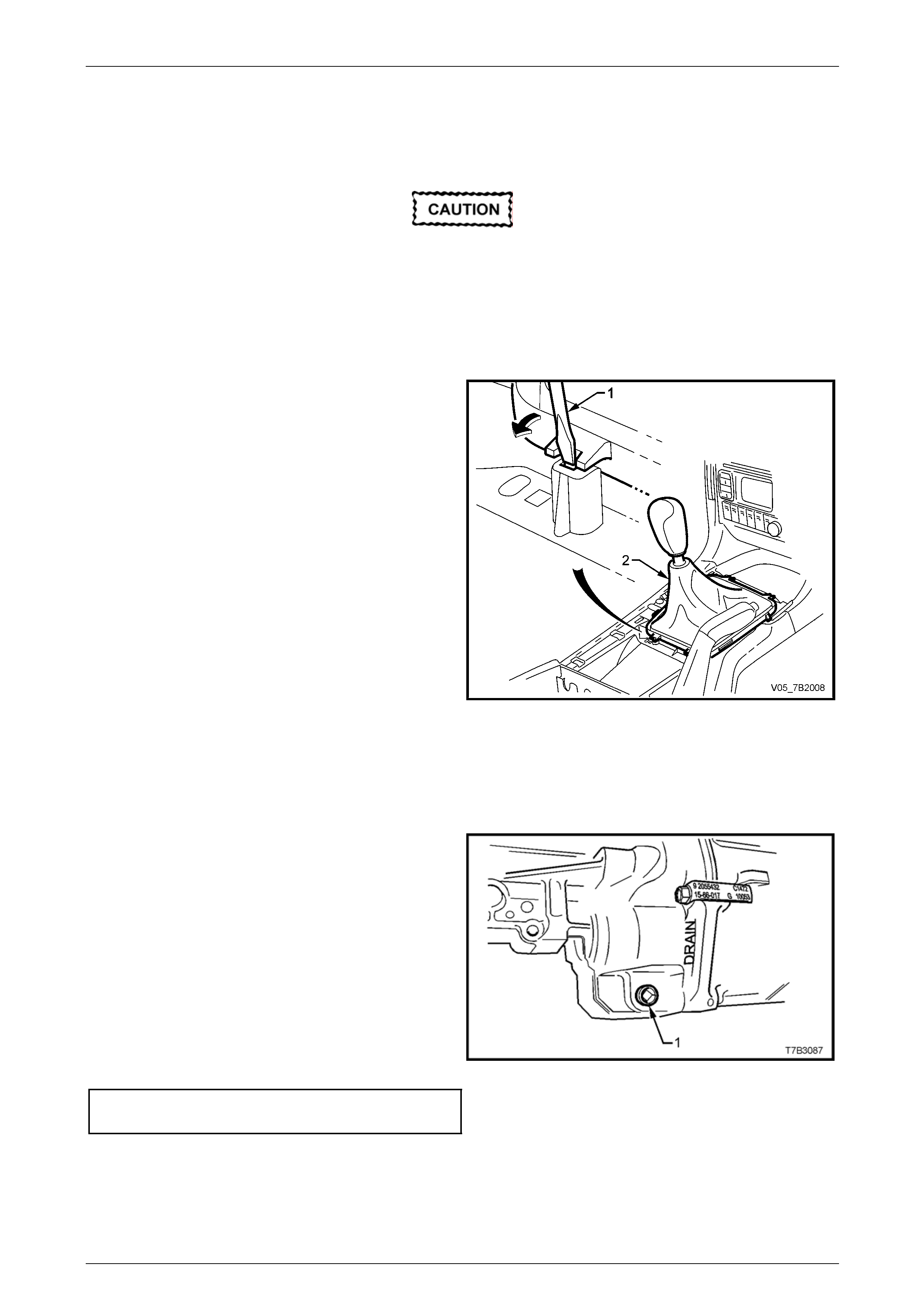
3 Using a fine bladed screwdriver (1), release each
locking tab, while exerting an upward force on the boot
carrier. Lift the gearshift boot retainer free from the
floor console.
4 Remove the gearshift knob, boot and gears hift lever
(2). Refer 3.5 Control Lever Knob, Boot & Control
Lever Assembly, in this Section.
5 Remove the gearshift remote shift lever boot. Refer
3.6 Gearshift Remote Shift Lever Boot, in this Section.
6 Select third gear to allow the remote shifter lever to
clear the opening in the floor pan, when the
transmission is lowered for removal.
Figure 7B2 – 36
7 Raise vehicle, preferably on a ‘drive-on’ hoist or a four post hoist. This preference is based on the fact that the
transmission is very heavy and the use of a transmission jack will be required for effective transmission removal
and installation.
8 Disconnect wiring harness co nnectors from each of the two oxygen sensors.
NOTE
Depending on the reason for remova l, it might be
appropriate to drain the transmission lubricant
into a clean container.
9 Place a drain tray beneath transmissio n and remove
the drain plug (1) using a 3/8” drive socket bar.
10 When transmission has fully drained, clean the
threads of the drain plug, apply thread seal ant such as
Loctite 565 or equivalent (GM P/N 12346004).
11 Reinstall the drain plug and tighten to the corr ect
torque specification, using a 3/8” drive adaptor and a
torque wrench.
Drain plug
torque specification...............................................28 Nm
NOTE
Do not apply Teflon thread tape to the plug
threads.
Figure 7B2 – 37
Page 7B2- 32
Manual Transmission – GEN III V8 Page 7B2-33
12 Scribe around each of the transmission support
crossmember (1) mounting points to the vehicle
underbody, to provide an alignment reference for
reassembly.
NOTE
This step is critical to the correct powertrain
alignment on reassembly. If not carried out, then
vehicle vibration and/or handling problems may
result.
13 Remove the two nuts (2) securing the exhaust pipe
bracket to each of the exhaust pipes.
14 Loosen the two bracket bolts (3) and disengage the
bracket from the exhaust pipes.
Figure 7B2 – 38
15 Support the transmission with a suitable lifting device,
then remove the four engine rear crossmem ber to side
frame attaching bolts (3).
16 Lower the transmission slightly, then remove the two
transmission mount to crossmember nuts (4). Set the
crossmember (2) to one side.
NOTE
Illustration does not show transmission jack in
position, for clarity of the crossmember
orientation.
Figure 7B2 – 39
17 Lower the transmission enough to provide clearance for the propeller shaft rubber coupling when the propeller
shaft is removed.
18 Remove the intermediate and rear section of the exhaust system. Refer to Section 8B Exhaust System.
19 Remove the propeller shaft. Refer to Section 4C1 Rear Propeller Shaft and Universal Jo ints.
Page 7B2- 33
Manual Transmission – GEN III V8 Page 7B2-34
20 Remove the speed sensor wiring harness co nnector
(1) and the connector (4) from the reverse lockout
solenoid. (5).
21 If post exhaust oxygen sensors are fitted, disconnect
each sensor wiring harness connector.
Figure 7B2 – 40
22 Remove the wiring harness connector from the back-
up lamp switch, located on the right hand side of the
transmission.
23 Cut the tie strap securing the powertrain harness to
the breather pipe (not shown), remove the harness
from the clip under the right hand top extension
housing bolt and secure to on e side.
Figure 7B2 – 41
24 Remove the starter motor. Refer to Section 6D3-2,
Starting System - GEN III V8, for the necessary
procedure.
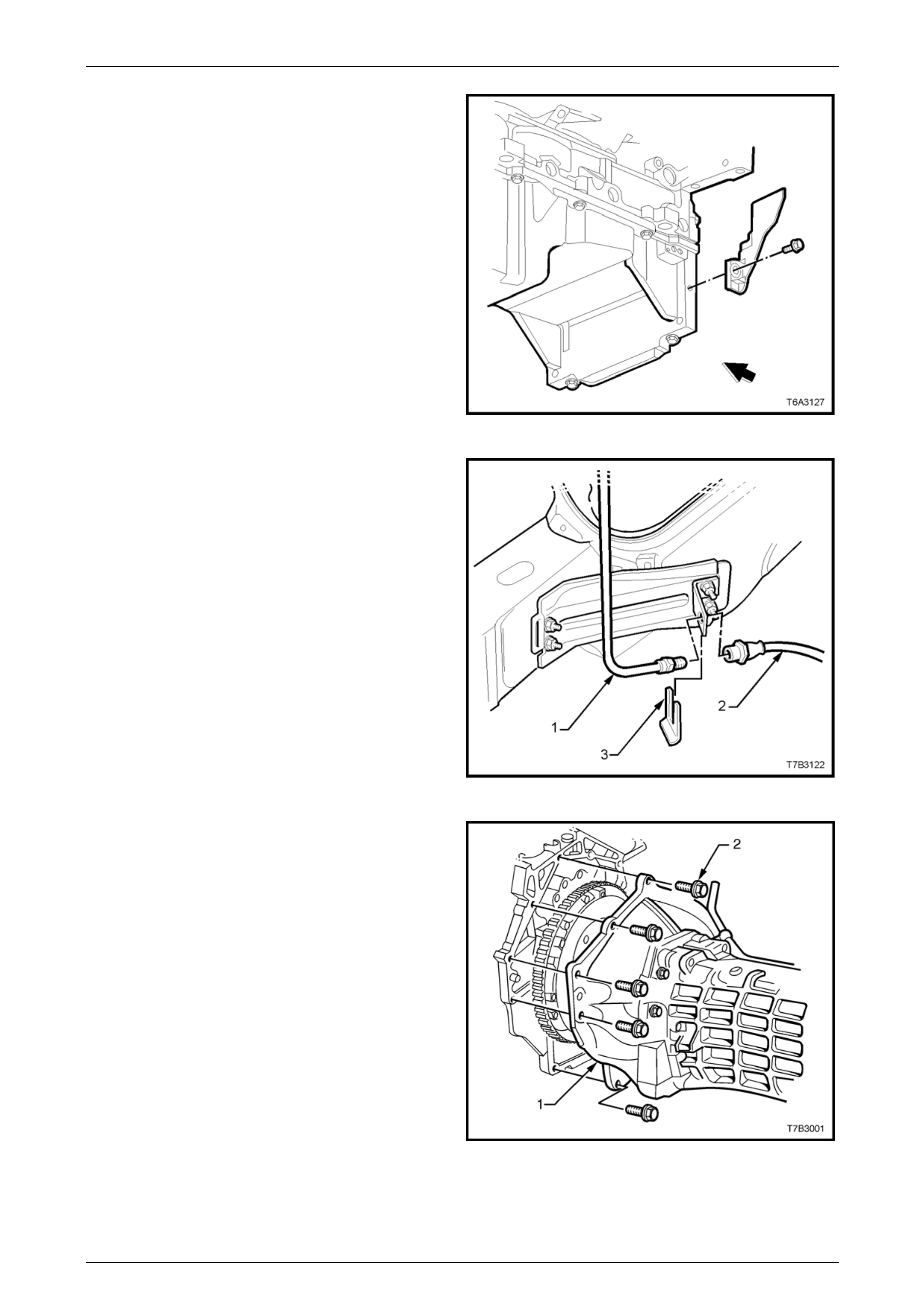
25 Remove the right close-out cover and screw.
Figure 7B2 – 42
Page 7B2- 34
Manual Transmission – GEN III V8 Page 7B2-35
26 Remove the left close-out cover and screw.
Figure 7B2 – 43
27 Place a suitable container under the clutch hydraulic
hose area.
28 Use a back-up spanner on the hydraulic hos e (2) at
the bracket attached to the vehicle sub-frame, then
loosen and disconn ect the hydraulic pipe (1) from the
hydraulic hose (2).
29 Remove the hose retaining clip (3) using combin ation
pliers, then remove the hose from the bracket.
NOTE
Plug the hydraulic hose (2) and master cylinder
pipe (1) open ends to reduce fluid loss and dirt
entry.
Figure 7B2 – 44
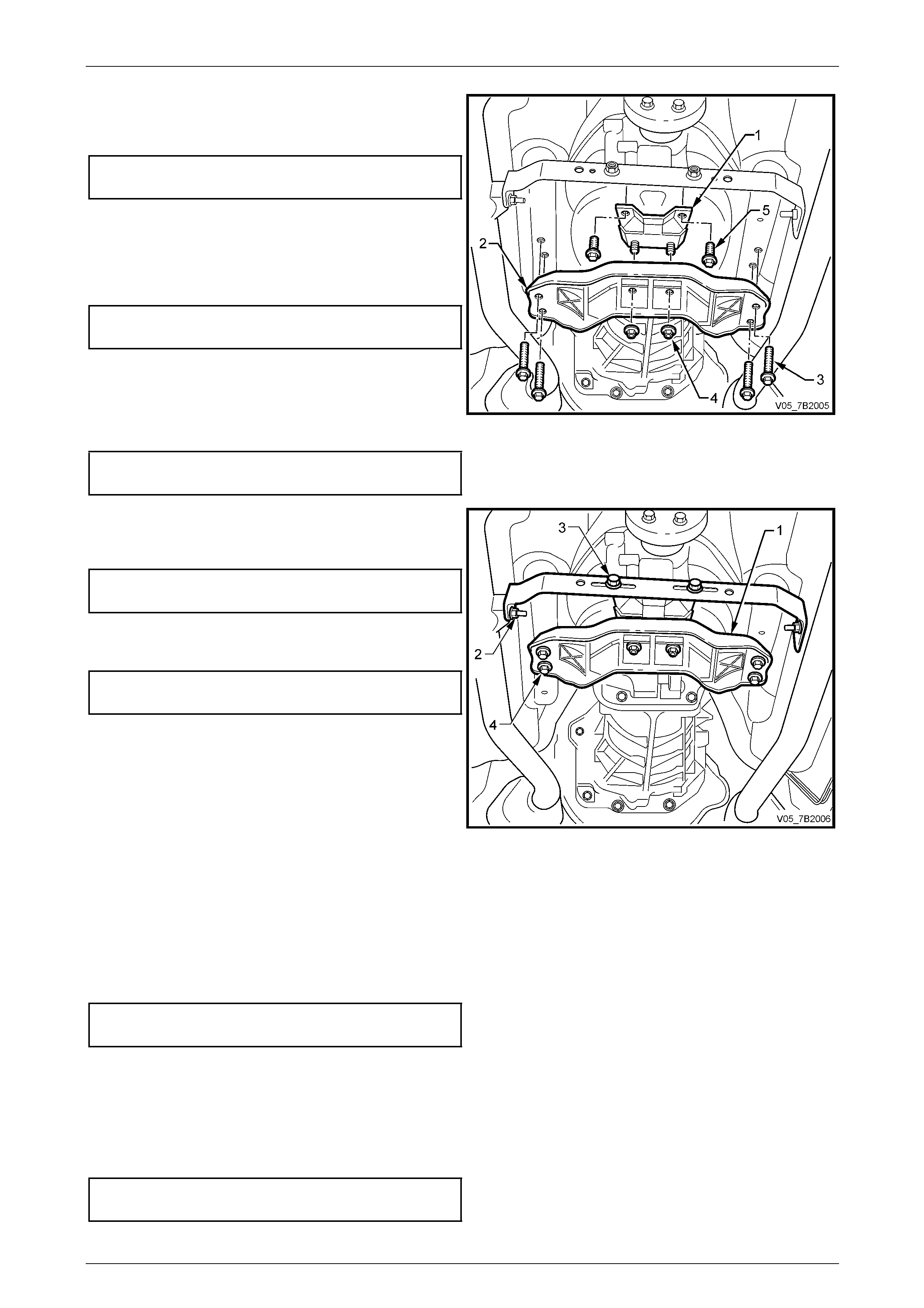
30 Lower the transmission enough to gain access to the
bolts (2) fastening the clutch housing (1) to the rear of
the engine.
31 Progressively loosen then remove the eight clutch
housing to engine bolts (2).
32 Pull the transmission rearward, just enough to clear
the locating dowels, then rotate the transmission
through 90° to the right to gain clearance at the floor
pan.
33 With the transmission supported by a transmission
jack, continue to withdraw the transmission, taking
care not to place any load ing on the clutch driven plate
centre splines that could caus e driven plate distortion.
NOTE
It is most important that distortion of the driven
plate is prevented, because replacement would
then be required.
34 When the transmission input shaft is clear of the clutch
pressure plate, the transmission can b e lowered and
removed from the vehicle.
Figure 7B2 – 45
Page 7B2- 35

Manual Transmission – GEN III V8 Page 7B2-36
Reinstall
1 Select 3rd gear.
2 If removed, reinstall the clutch slave cylinder pipe (1)
to the slave cylinder (2), and tighten to the correct
torque specification.
Clutch hydraulic pipe flar e nut to
slave cylinder torque specification ........................13 Nm
3 Sparingly appl y NLGI No. 2 lithium soap based EP
grease with molybdenum disulphide, such as Shell
Retinax HDX2 grease or BP Energrease LMS-EP 23
(or equivalent) to the bearing face of the clutch
throwout bearing, mounted to the slave cylinder (2),
the splines and spigot of the input shaft.
Figure 7B2 – 46
4 With the transmission on its side, with the top surface facing the right hand side of the vehicle, use a transmission
jack to raise the transmission and install inp ut shaft into the splines of clutch driven plate.
5 Push transmission in toward engine block. It ma y be necessary to rotate the mainshaft after temporarily installing
the propeller shaft, to assist in spline alignment.
6 When installed up to the locating dowel pins, rotate the transmission counter-clockwise 90°, then push fully home.
7 Reinstall the clutch housing to engine block/oil pan
bolts and tighten all bolts in the sequenc e shown, to
the specified torque.
Clutch housing to engine block
bolt torque specification........................................50 Nm
Figure 7B2 – 47
8 Reinstall wiring harness co nnectors to the back up lamp switch, reverse lockout solenoid, speed sensor and post
oxygen sensors, if fitted.
9 Secure the powertrain wiring harness to the transmission vent pipe, using a cable tie.
10 Reinstall the propeller shaft, refer to Section 4C1 Rear Propeller Shat and Universal Joints.
Page 7B2- 36
Manual Transmission – GEN III V8 Page 7B2-37
11 Reinstall the transmission mount (1) to the
transmission extension, install the two bolts (5) and
tighten to the correct torque specification.
Transmission mount to extension
housing bolt torque specification...........................25 Nm
12 Raise the transmission slightly, then reinstall the four
crossmember to side frame bolts (3), aligning the
crossmember (2) with the scribed lines made prior to
disassembly. Tighten the bolts (3) to the correct torque
specification.
Rear crossmember to side frame
member bolt torque specification..........................58 Nm
13 Remove the lifting device from the transmission.
14 Centralise the rear mount studs in the crossmember
holes, then reinstall the nuts (4), tightening to the
correct torque specification.
Rear crossmember to transmission
mount nut torque specification..............................25 Nm
Figure 7B2 – 48
15 Engage the exhaust pipe bracket with each of the
exhaust pipe studs, reinstall the two nuts (2) and
tighten to the correct torque specification.
Exhaust pipe bracket to exhaust
pipe nut torque specification ................................. 25 Nm
16 Tighten the two bracket bolts (3) to the correct torque
specification.
Exhaust pipe bracket to transmission
bracket bolt torque specification............................25 Nm
Figure 7A1 – 49
17 Reinstall the exhaust system and check all exhaust clearanc es, refer to Section 8B E xhau st System.
18 Remove the plugs from the ends of the disconnected clutch hydraulic hose and pipe.
19 Reinstall the hose to the sub-frame bracket and secure with the horseshoe clip.
20 Reinstall the pipe flare fitting, tightening to the correct specification. Use a back-up spanner on the hydraulic hose
fitting during the tightening pr ocess.
Clutch hydraulic pipe flare nut
to hose torque specification ..................................13 Nm
21 Bleed the clutch hydraulic system, refer to Section 7A3 Clutch – GEN III V8.
22 If transmission fluid was drained during the removal operation, then refill, as described in
2.3 Draining and Refillin g Transmission, in this Section.
23 Reinstall the right and left close-out covers, secure with a screw in each and tighten to the correct torque
specification.
Engine to transmission close- out
cover (each side) torque specification...................12 Nm
Page 7B2- 37

Manual Transmission – GEN III V8 Page 7B2-38
24 Reinstall the starter motor. Refer to Section 6D3-2, Starting System - GEN III V8, for the necessary procedure.
25 If not refilled, check and adjust the transmission fluid level, as required.
Refer to 2.2 Checking Transmission Lubricant Level, in this Section.
26 Lower vehicle to the ground.
27 Reinstall the remote shift lever boot and retainer, checking that the boot engages with the groove in the remote
shift lever shaft. Refer to 3.7 Remote Shift Lever Boot, in this Section.
28 Reinstall the gearshift control lever to the remote shift shaft, refer to
3.5 Control Lever Knob, Boot and Control Lever Assembly, in this Section.
29 Reconnect battery ground lead.
30 Road test vehicle and check transmission, clutch and gearshift operations.
Page 7B2- 38
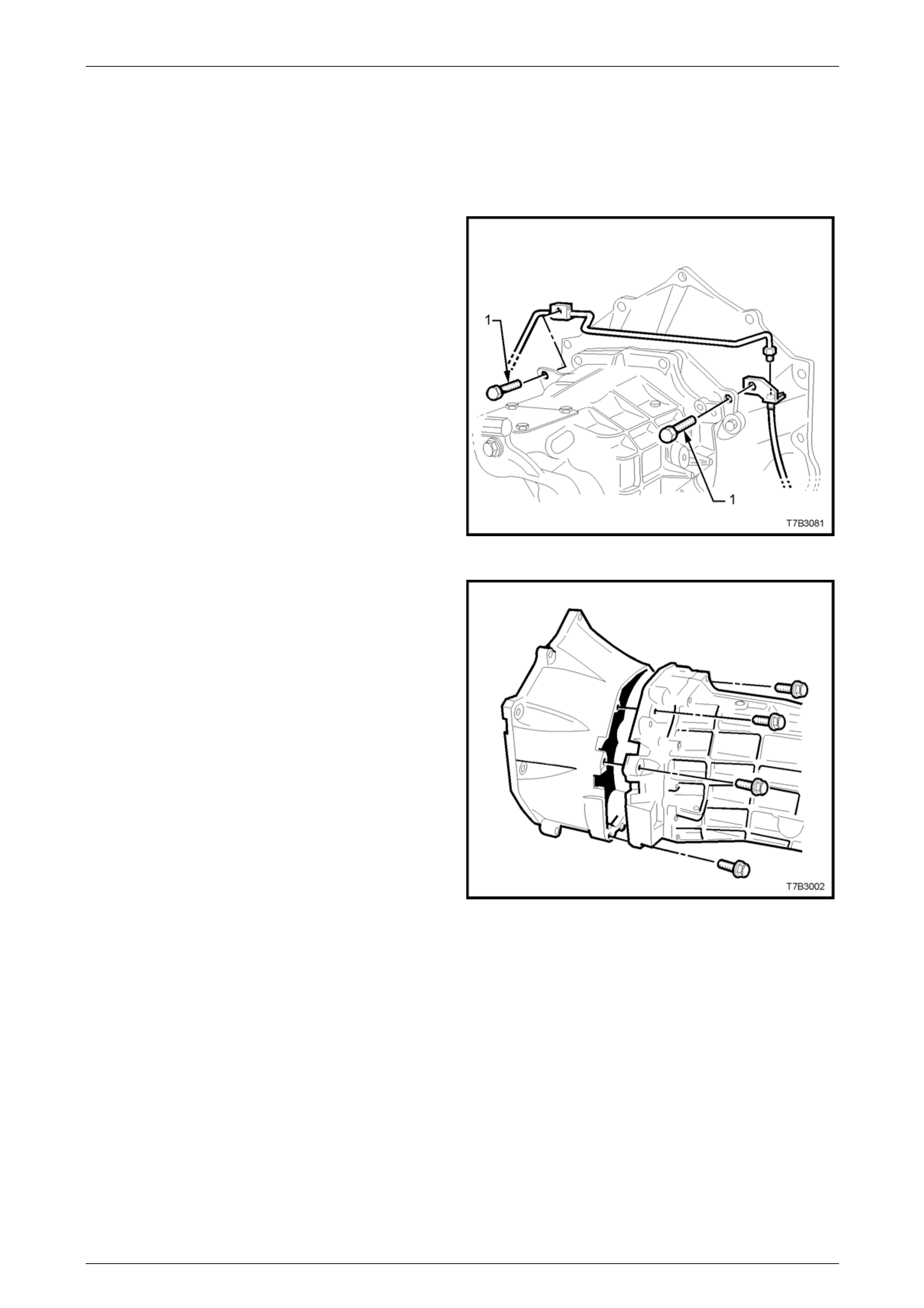
Manual Transmission – GEN III V8 Page 7B2-39
4.3 Transmission Disassemble
1 Remove transmission assem bl y from vehicle. Refer 4.2 Transmission Assembly – Remove, in this Section.
Clutch Housing and Slave Cylinder
2 Remove the two bolts (1) securing the clutch slave
cylinder pipe to the transmission, unscre w the fitting
from the slave cylinder and remove the pipe and
brackets from the transmission.
Figure 7B2 – 50
3 Remove the 8 bolts holding the clutch ho using to the
transmission, then remove the housing.
Figure 7B2 – 51
Page 7B2- 39
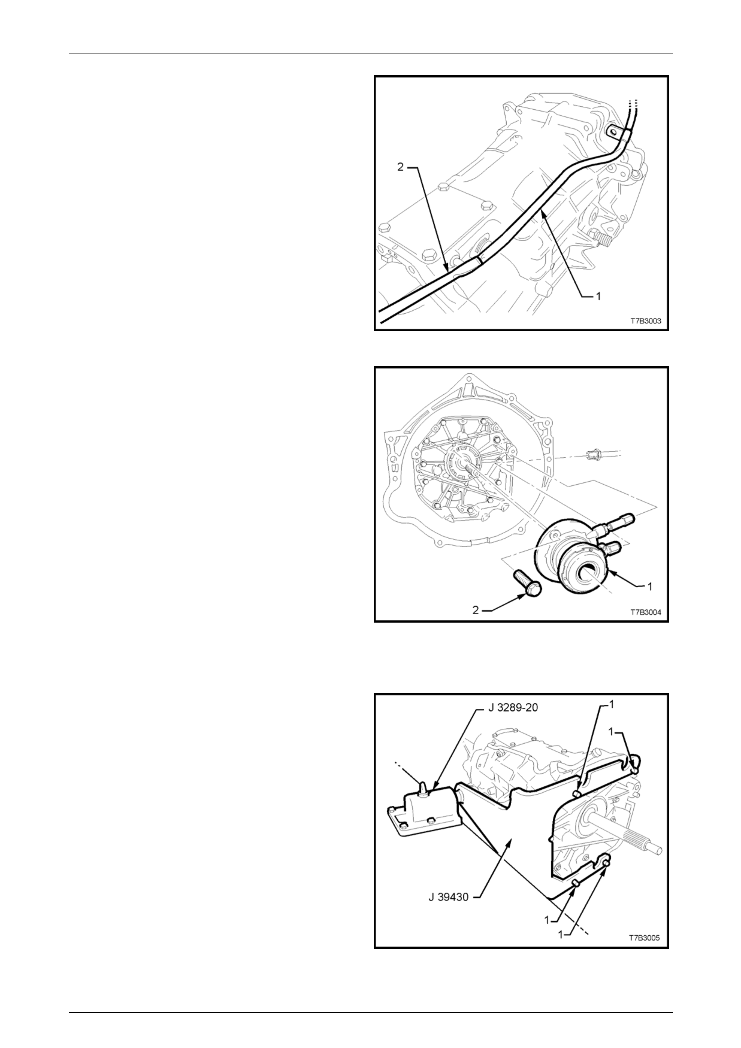
Manual Transmission – GEN III V8 Page 7B2-40
4 Remove the plastic vent tube (1), by pushing on the
end of the tube with the flat blade of a screwdriver (2),
to slide the tube from the vent tube fitting, then set the
pipe to one side.
Figure 7B2 – 52
5 Remove the 2 bolts (2) securing the clutc h slave
cylinder (1) to the transmission adaptor plate, then set
the slave cylinder assembly (1) to one side.
Figure 7B2 – 53
Extension Housing
1 Install holding tool J 39430 to the front of the
transmission, using 4 of the clutch housing bolts (1).
2 Install holding tool J 39 430 into the bench holding
fixture J 3289-20.
Figure 7B2 – 54
Page 7B2- 40
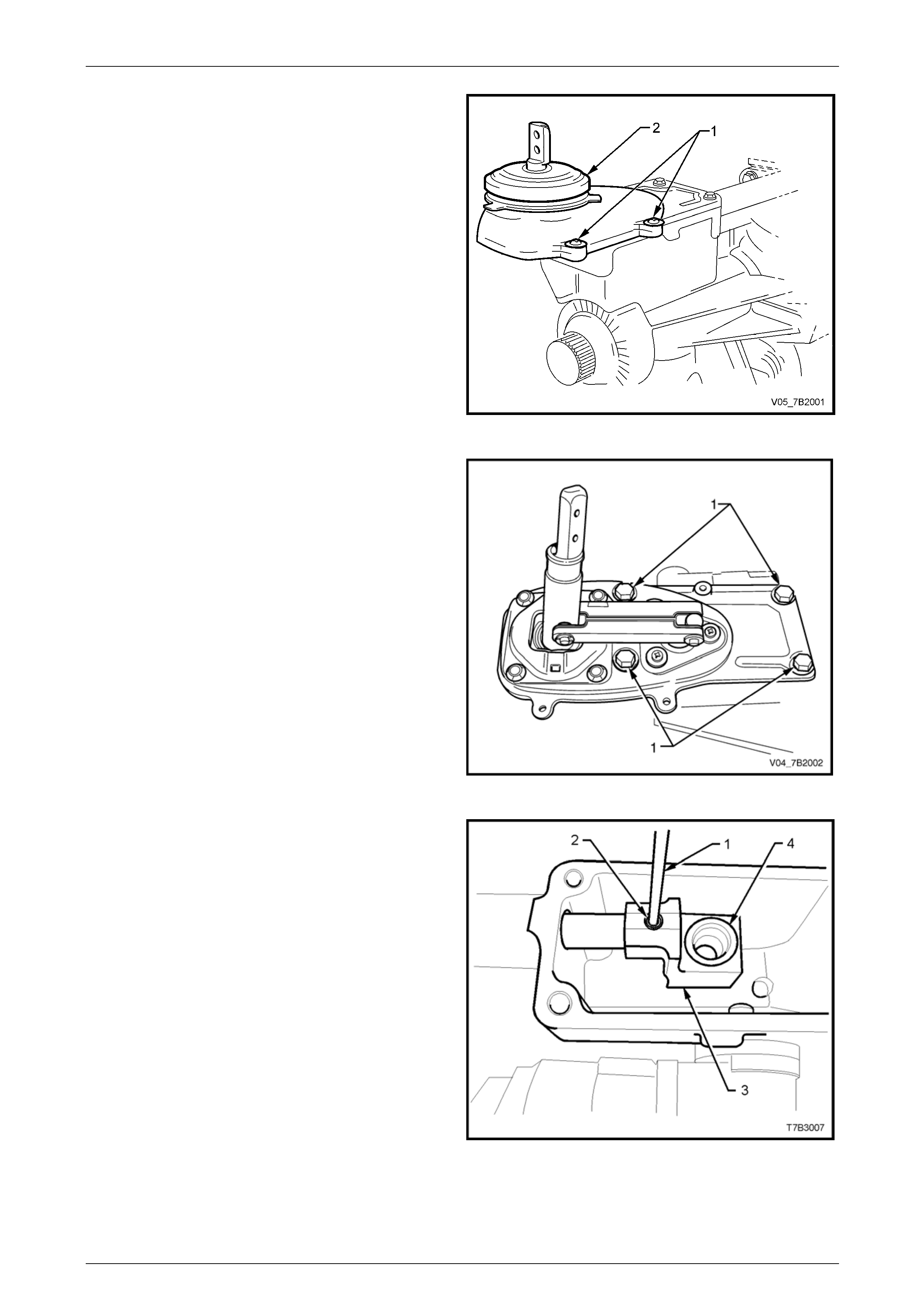
Manual Transmission – GEN III V8 Page 7B2-41
3 With the transmission in a horizontal position with the
shift lever up, drain the transmission fluid (if not carried
out previously).
4 Remove the four screws (1) securing the shift lever
cover, prise the cover loose.
5 Remove the cover and shift lever boot (2) from the
extension housing.
Figure 7B2 – 55
6 Select either 2nd or 4th gear.
7 Remove the 4 bolts (1) holding the shifter assembly to
the extension housing.
8 Tap the remote shift housing assembly with a rubber
or plastic hammer to break the seal.
9 Remove the remote shift assembly and rubber seal
from the extension housing.
Figure 7B2 – 56
10 Select either 2nd or 4th gear.
NOTE
Selecting either gear, shortens the shift rail
overhang, providing more support during the roll
pin removal.
11 Using a suitable pin punch (1), remove the rear offset
lever roll pin (2).
12 Remove the rear offset lever (3) and check that the
isolator cup (4) is secure in the lever. If loose, discard
both the isolator cup and the rear offset lever .
Figure 7B2 – 57
Page 7B2- 41
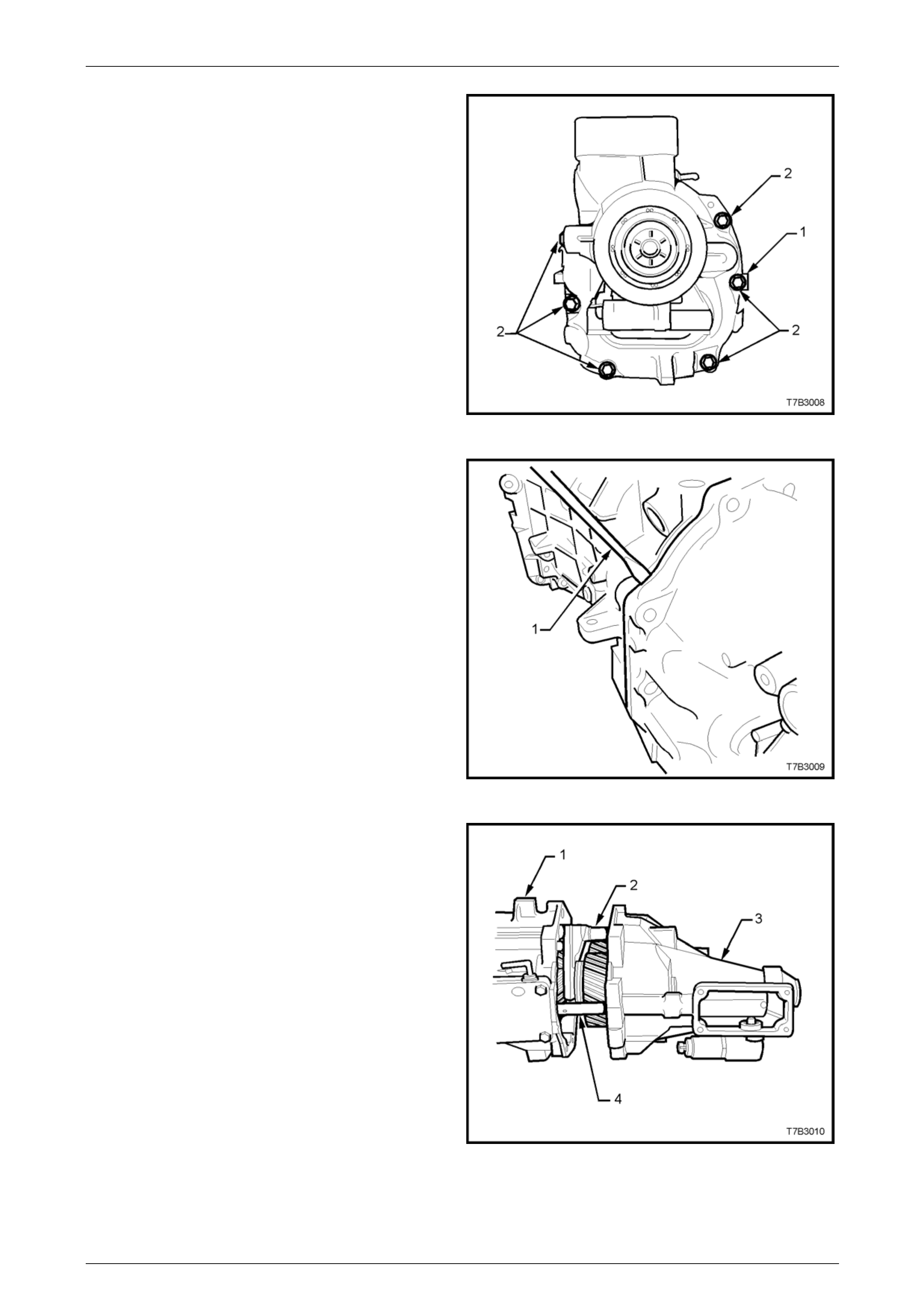
Manual Transmission – GEN III V8 Page 7B2-42
13 Remove the 8 bolts (2) holding the extension housi ng,
noting the position of the identi fication tag (1).
NOTE
The two top bolts (not shown) have sealant
applied to the threads.
Figure 7B2 – 58
14 With the transmission in a horizontal position, break
the sealant seal by levering in the point provided,
using a flat bladed screwdriver (1).
15 Tap the extension housing rearward, using a plastic or
rubber hammer to remove the housing from the 2
locating dowel pins.
Figure 7B2 – 59
16 Slide the housing (3) from the shift rails (2 and 4) and
remove from the transmission case (1).
Figure 7B2 – 60
Page 7B2- 42
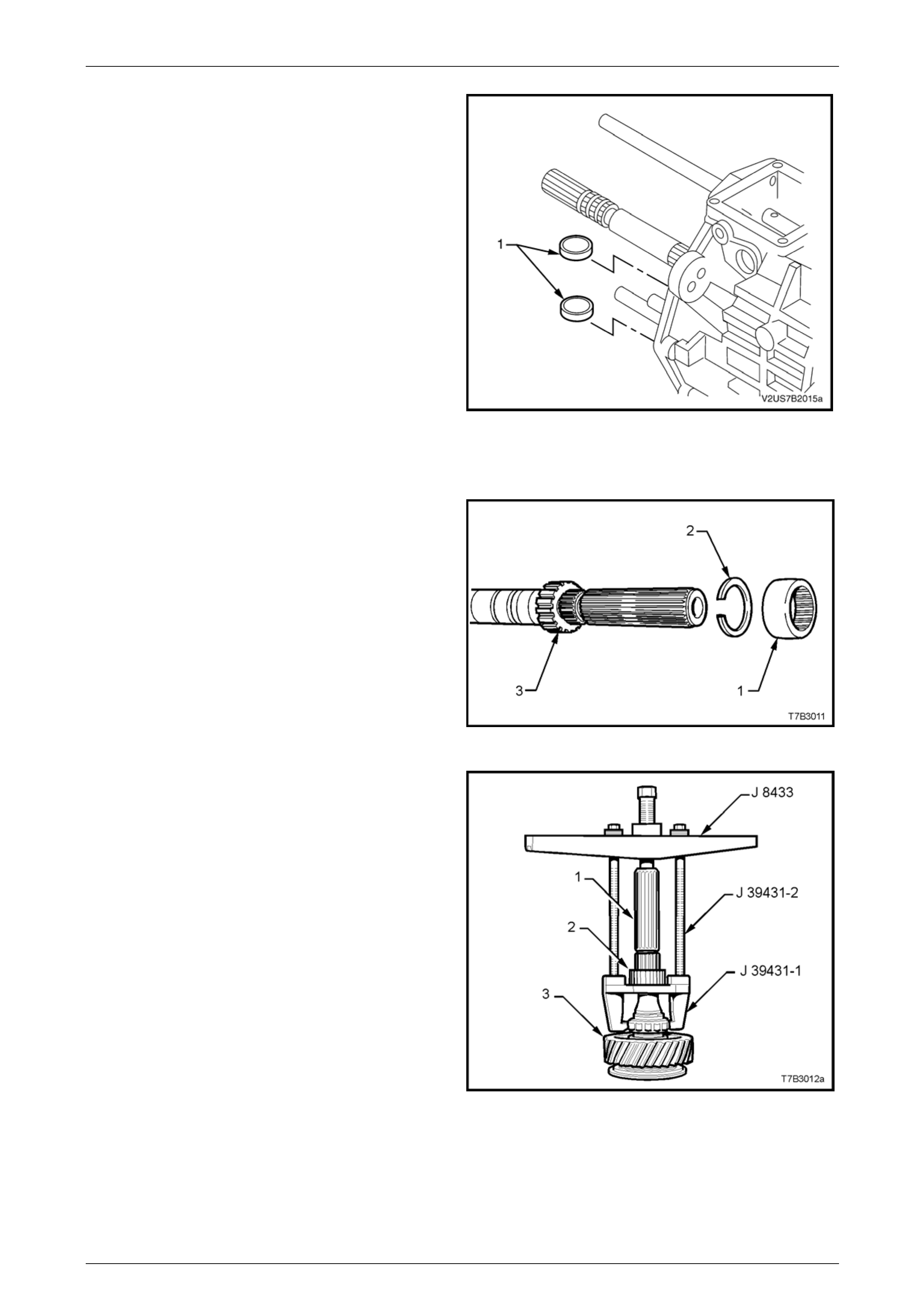
Manual Transmission – GEN III V8 Page 7B2-43
17 Remove both circular magnets located in the recess in
the rear of the transmission case and set to one side.
Figure 7B2 – 61
Speedometer Pulse Ring
1 Slide the rubber shipping ring (1) from the mainshaft
and discard.
NOTE
This rubber ring (1) splined to the mainshaft, is
only required f or shipping from the manufac turer.
It serves no functional purpo se and reinstallation
on transmission assembly, is not required. This
part is not serviced.
2 Using suitable snap ring pliers, remove the snap ring
(2) from the speedometer pulse ring (3).
Figure 7B2 – 62
3 Assemble universal bridge puller J 84 33 and puller
J 39431-1 using bolts J 39431 -2, as shown.
4 Remove the speedometer pulse ring (2) from the
mainshaft (1), then disassemble the tools.
5 Remove the second speedometer pulse ring snap
ring, using suitable snap ring pliers.
Figure 7B2 – 63
Page 7B2- 43
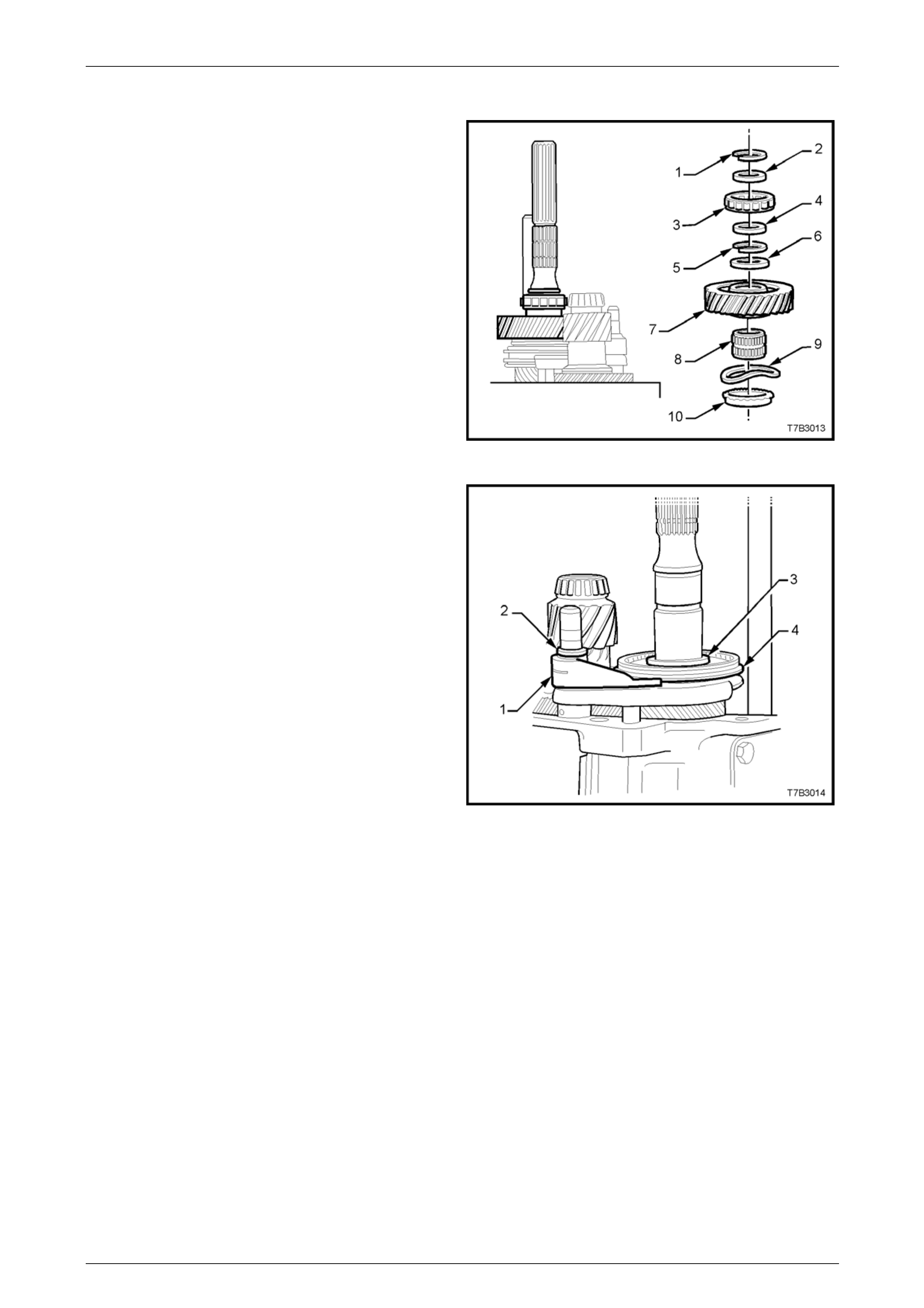
Manual Transmission – GEN III V8 Page 7B2-44
Reverse and 5th/6th Driven Gear
1 Remove the following compon ents from the mainshaft:
1 Snap ring.
2 Spacer.
3 Rear mainshaft roller race.
4 Spacer.
5 Snap ring.
6 Thrust washer.
7 Reverse gear.
8 Reverse gear, caged roller bearing.
9 Wave washer.
10 Reverse gear blocker ring.
Figure 7B2 – 64
2 Using suitable snap ring pliers, remove reverse
synchromesh assembly snap ring (3).
3 Using fine nosed circlip pliers , remove circlip (2) from
the reverse shift rail and discard.
4 Remove the reverse synchrom esh assembly (4),
thrust washer (not shown) and reverse shift fork (1), as
an assembly.
NOTE
The synchromesh hub (4) is a sliding fit to the
mainshaft splines.
Figure 7B2 – 65
Page 7B2- 44
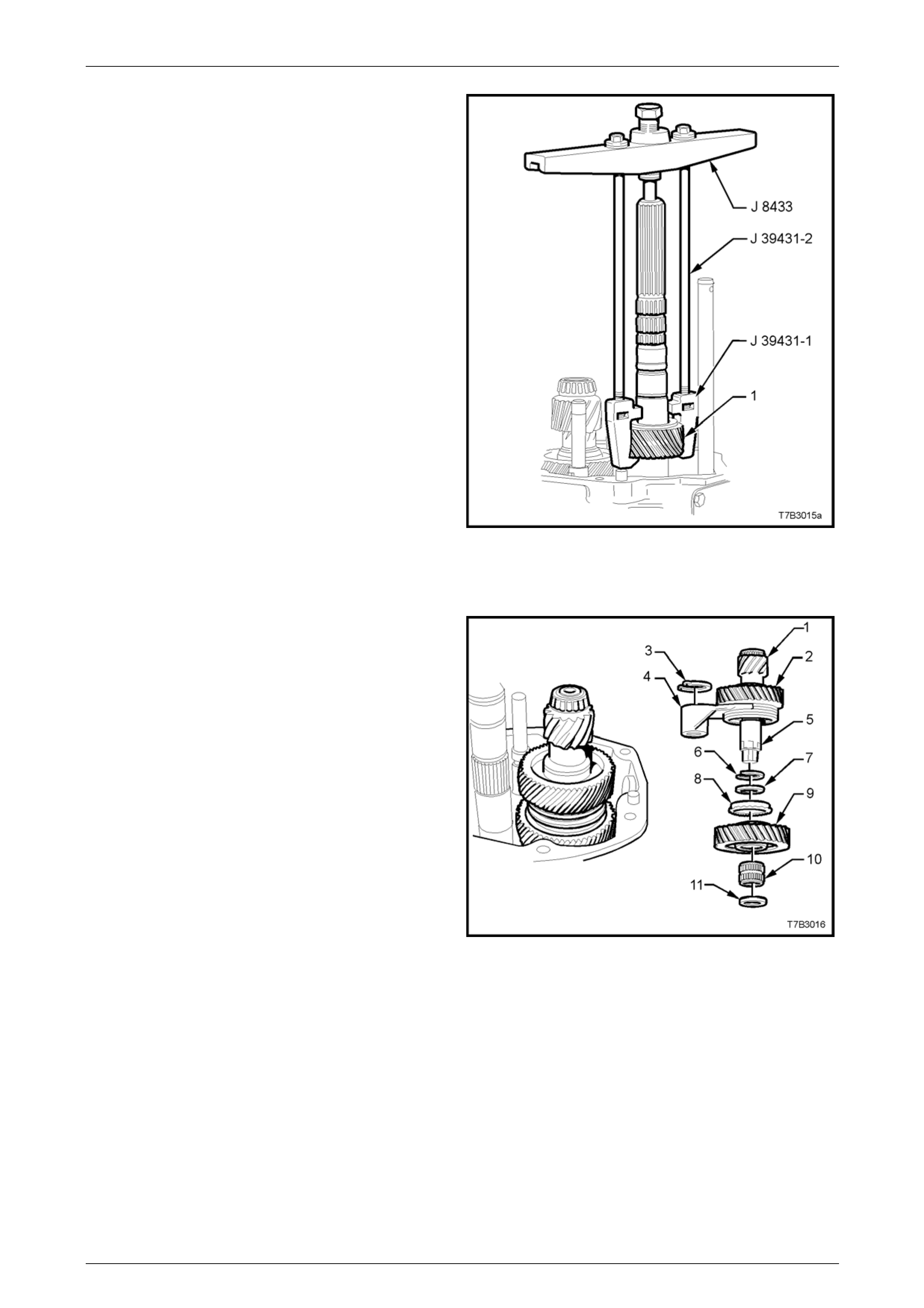
Manual Transmission – GEN III V8 Page 7B2-45
5 Assemble universal bridge puller J 84 33 and puller
adaptor J 39431-1 using bolts J 39431-2, as shown.
6 Remove 5th/6th driven gear (1), then dismantle tools.
Figure 7B2 – 66
Countershaft Extension Assembly
1 Remove the circlip (3) from the 5th/6th shift rail, then
remove the following components as an assembl y;
countershaft extension (1) with the 5th drive gear (2),
selector fork (4) and synchromesh assem bl y (2), all
secured by the snap ring (6).
2 Remove the following components;
7 Spacer.
8 6th gear, blocker ring.
9 6th drive gear.
10 6th drive gear, caged needle roller bearing.
11 Thrust washer.
Figure 7B2 – 67
Page 7B2- 45
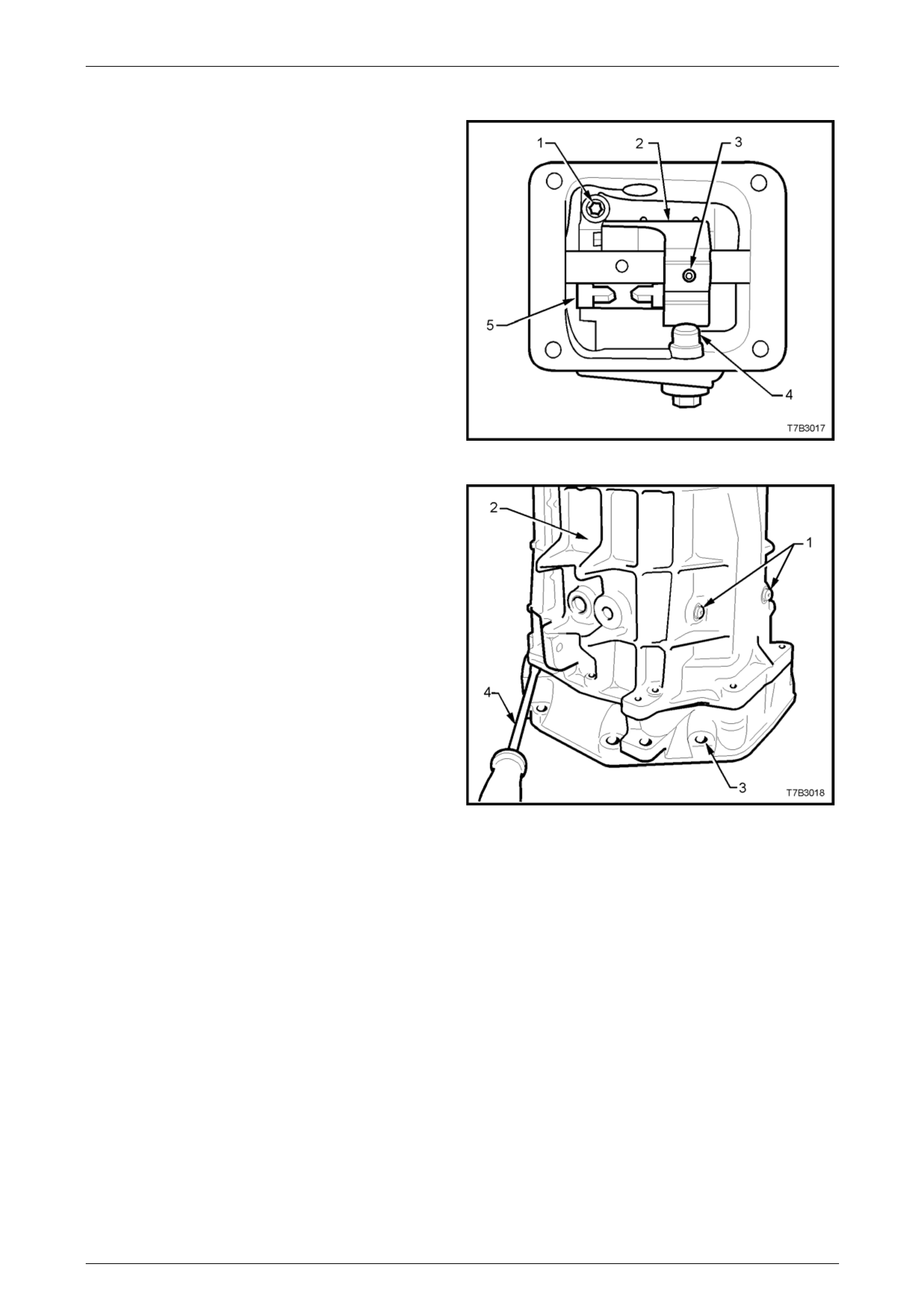
Manual Transmission – GEN III V8 Page 7B2-46
Transmission Case
1 Remove the 4 bolts securing the guide plate cover to
the transmission case. Use a flat bladed screwdriver
and plastic hammer to dislodge the cover sealant, then
remove the cover.
NOTE
Be careful not to bend the cover when breaking
the sealant grip.
2 Remove the shift enhancer (4) from the transmission
case, using a suitable sized socket.
3 Using a suitable sized pin punch, remove the roll pin
(3), from the front offset lever (2).
Figure 7B2 – 68
4 Remove the two T40 Torx bit screws securing the shift
lever guides (1).
NOTE
Both of these screws have thread sealant
applied and will be extremely difficult to remove
unless a hot air gun is used to soften the thread
sealant prior to loosening and during removal.
5 Remove the reverse lamp switch from the side of the
transmission case.
6 Remove the 10 adaptor plate to transmissi on case
bolts from the front of the transmission (not shown).
7 Carefully rotate the transmission into a v ertical
position, then lever the transmission case (2) from the
adaptor plate (3), using a flat bladed screwdriver (4) in
the spaces provided, to break the seala nt se al and
clear the two dowel pins.
8 Lift the transmission case upward from the gear train
and shift rail components, while supporting the front
offset lever during the process.
NOTE
Holding the front offset lever against the guide
plate during case removal, will reduce the
possibility of the detent ball and spring from
being dislodge d.
9 Referring to Figure 7B2-71, use a T40 Torx bit, to
remove the 2 screws (1) from the guide plate (5).
NOTE
In Figure 7B2-71, the front offset lever (2) covers
the second guide plate screw.
10 Remove the guide plate (5) from the transmission
case.
Figure 7B2 – 69
Page 7B2- 46
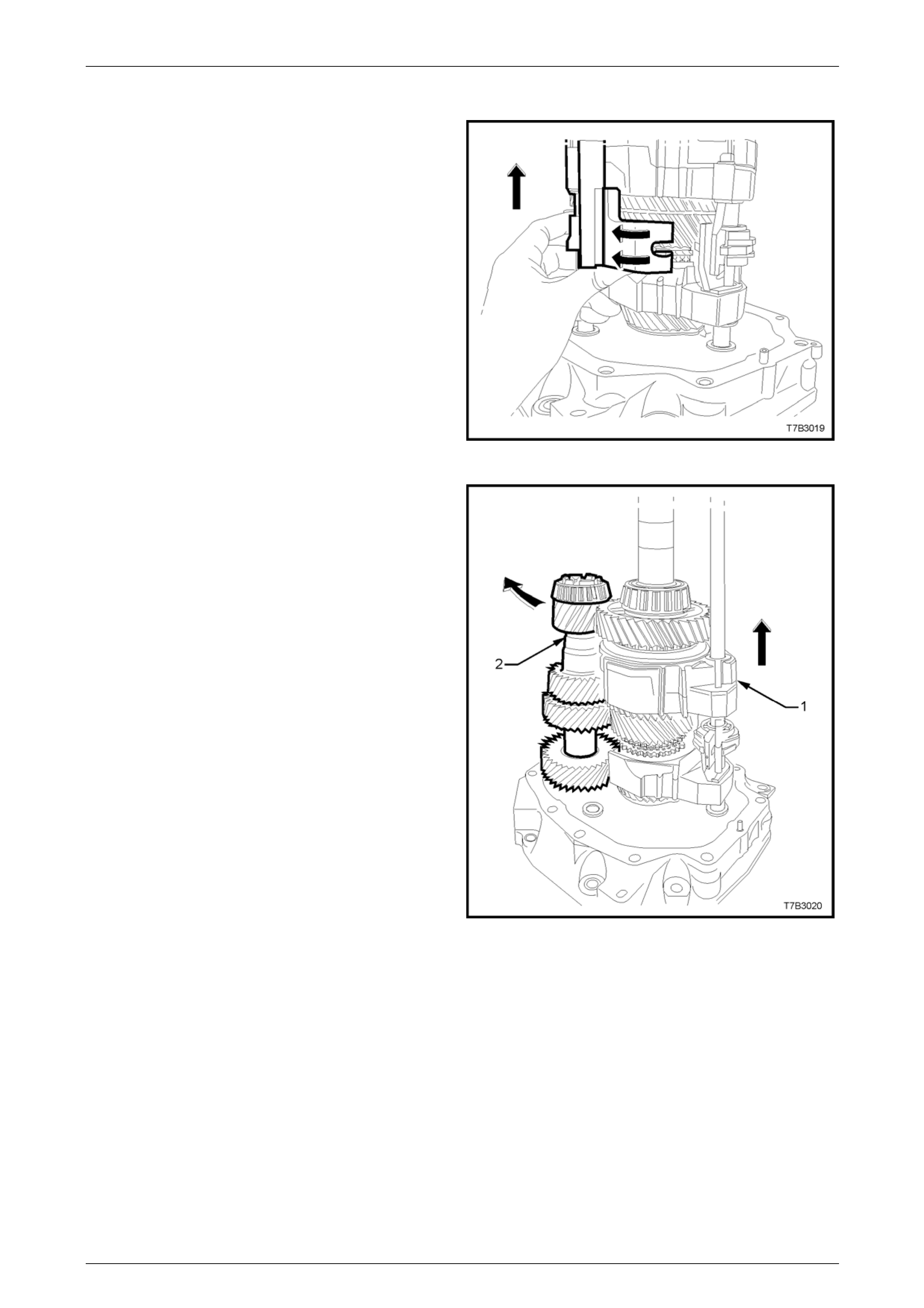
Manual Transmission – GEN III V8 Page 7B2-47
Gear Trains and Shift Rails
1 Rotate the 5th/6th and Reverse shift levers from the
interlock plate (curved arrows), then lift both shift rail
assemblies from the adaptor plate.
Figure 7B2 – 70
2 Lift the mainshaft and shift forks (1) to allow counter
gear (2) removal.
3 Carefully lift the mainshaft assembly with the shift
forks in place, from the input shaft and set to one side.
4 Lift the input shaft from the adaptor plate and set to
one side.
Figure 7B2 – 71
Page 7B2- 47
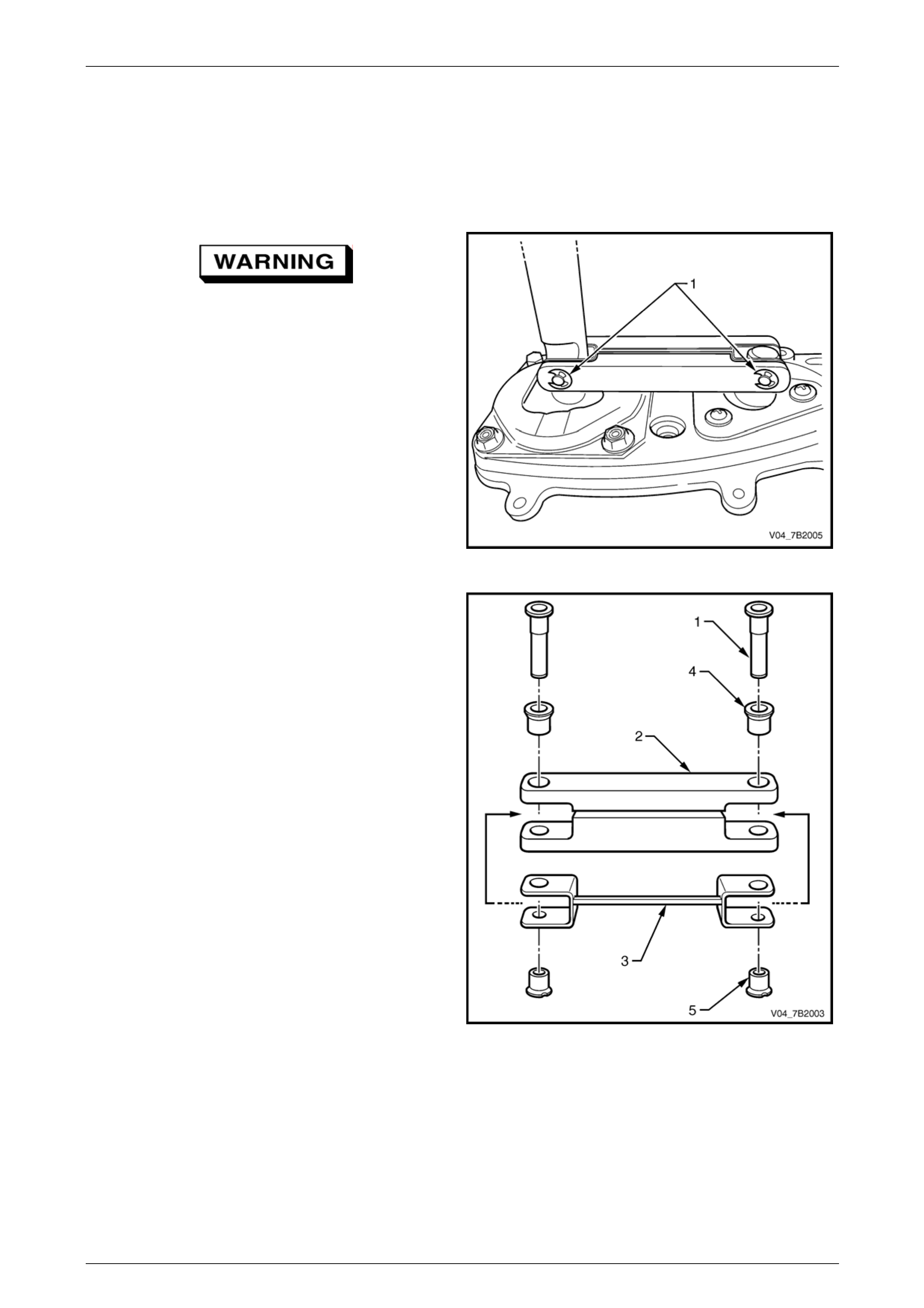
Manual Transmission – GEN III V8 Page 7B2-48
4.4 Remote Control Shift Mechanism
LT Section No. – 04-100
Disassemble
Wear safety glasses to avoid possible eye
injury.
1 Using a small screwdriver, remove both E-clips (1)
from the shifter lever pins.
Figure 7B2 – 72
2 Tap the two pivot pins (1) free from the bridging piece
(2).
NOTE
• The pivot pins are designed to be an
interference fit to the remote shifter shaft and
the selector pivot. Therefore, the pivot pins
must be replaced after removal.
• The remote shifter shaft and the selector
pivot are not shown for clarity of illustration.
3 Remove the bridged washer (3) located on the
bridging piece (2).
4 Remove both the large (4) and small (5) b ushes from
the bridging piece (2).
Figure 7B2 – 73
Page 7B2- 48
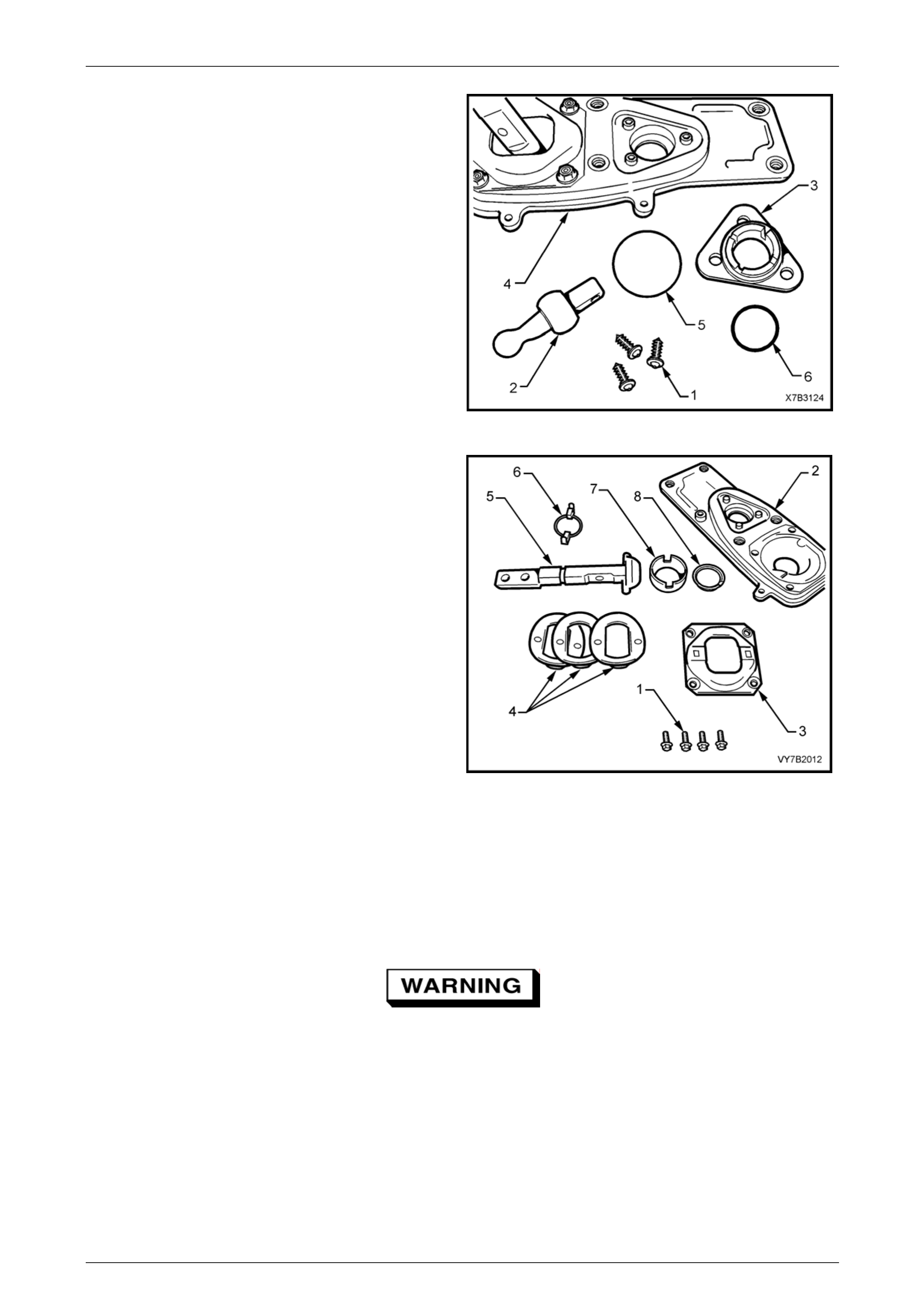
Manual Transmission – GEN III V8 Page 7B2-49
5 Remove the selector pivot seat (3) self-tapping
screws (1).
6 Remove the remote selector pivot (2) and the pivot
seat from the baseplate (4).
7 Remove the O-ring seals (5 and 6) from the pivot seat.
8 Support the pivot seat assembly in a soft jaw bench
vice.
9 Using a rubber or plastic ham mer, tap the ball end of
the selector pivot (2) until it separates from of the pivot
seat.
Figure 7B2 – 74
10 Remove the screw retaining the remote shift shaft
plate (3) to the base plate (2).
11 Remove the remote shift shaft plate (3) from the base
plate.
12 Remove the wave springs (4), remote shifter shaft (5)
and guide (6) from the base plate.
13 Remove the ball seat (7) and seat support ring (8)
from the base plate.
Figure 7B2 – 75
Clean and Inspect
Clean
1 Remove the rubber insulating bushes and seal from the extension housing.
2 Thoroughly wash all compon ents in a suitable cleaning solvent.
Wear safety glasses to avoid eye injury.
3 Blow-dry all components usin g compressed air.
Inspect
1 Inspect pins, bushes, ball seats and other components for wear or damag e. Replace as required.
2 Inspect the O-ring seals at the front pivot assembly, the cover plate insulating rubber bush es and seal to the
extension housing for deterioration or damage. Replace as required.
Page 7B2- 49
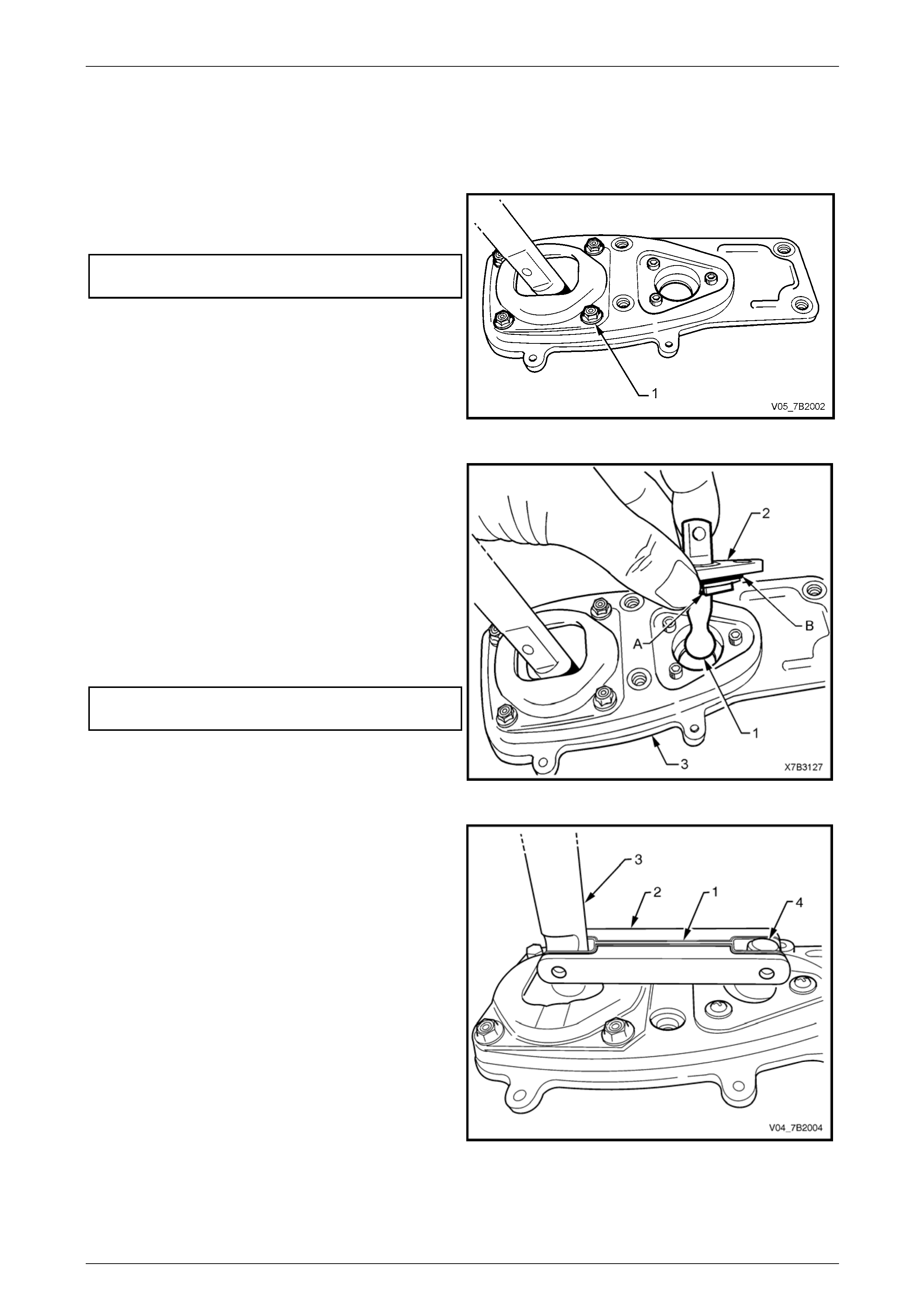
Manual Transmission – GEN III V8 Page 7B2-50
Reassemble
Reassembly is the reverse of the disassembly proc edure except for the following:
1 Apply an NLGI No. 2 lithium soap based EP grease with molybdenum disulphide, such as Shell Retinax HDX2
grease or BP Energrease LMS-EP 23 (or eq uivalent) to all moving parts in the rear remote shifter assembly.
2 Reinstall the scre ws (1) retaining the remote shift lever
plate to the baseplate and tighten to the correct torque
specification.
Rear remote shift lever plate
bolt torque specification........................................12 Nm
Figure 7B2 – 76
3 Apply NLGI No. 4 EP grease to the ball socket of the
front selector pivot (1).
4 Using a rubber or plastic ham mer, tap the front
selector pivot until fully seated in the pivot seat (2).
5 Install the O-ring seals (A) and (B) to the selector pivot
seat.
6 Reinstall the front selector piv ot assembl y to the
baseplate (3).
7 Install the selector pivot assembly retaining screws
and tighten to the correct torque specification.
Front selector pivot seat
screw torque specification....................................4.0 Nm
Figure 7B2 – 77
8 Insert the bridged washer (1) into the bridgi ng
piece (2).
9 Position the bridging piece into the remote shifter shaft
(3) and the selector pivot (4).
Figure 7B2 – 1
Page 7B2- 50
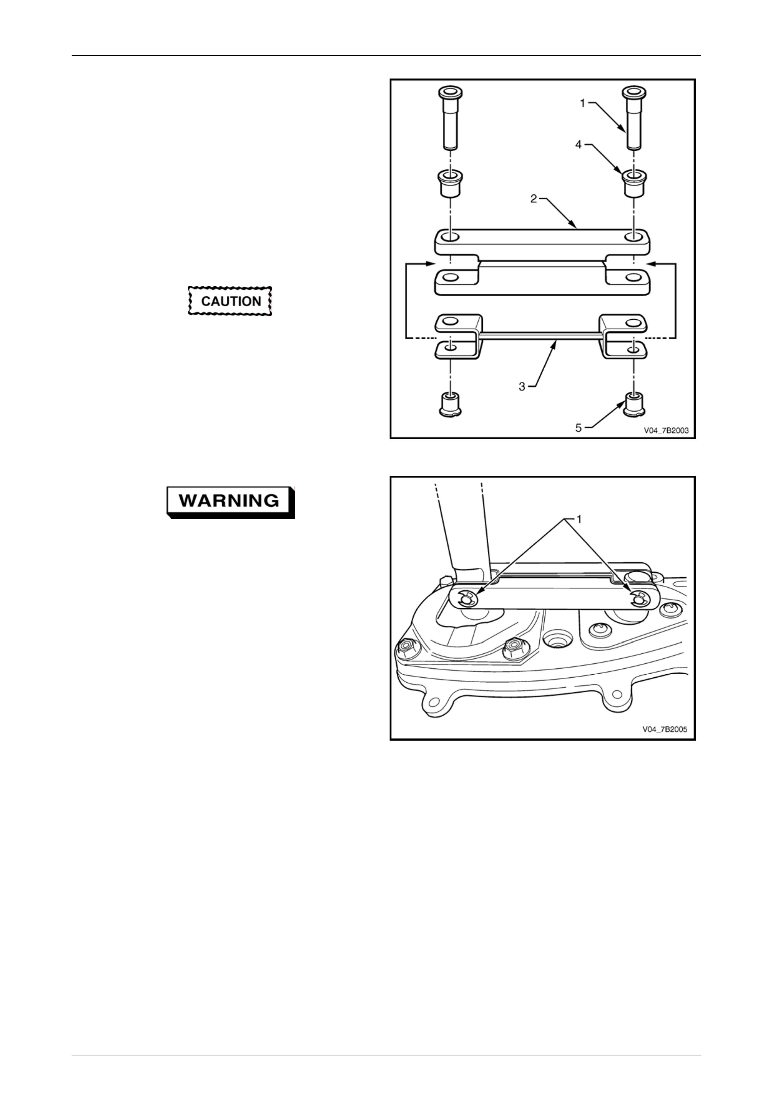
Manual Transmission – GEN III V8 Page 7B2-51
10 Lubricate both the new large (4) and small (5) bushes
with NLGI No. 4 EP grease or equivalent.
11 Install the new bushes into the bridging piece (2).
NOTE
The remote shifter shaft and the selector pivot
are not shown for clarity of illustration.
12 Insert the new pivot pins (1) into their correct locations
in the bridging piec e.
13 Tap the new pivot pins into the bridging piec e until fully
seated.
The pivot pins are designed to be
interference fit to the remote shifter sh aft an d
the selector pivot. Therefore, the pivot pin
should not free float in the remote shifter
shaft and the selector pivot.
Figure 7B2 – 2
Wear safety glasses to avoid possible eye
injury.
14 Install new E-clips (1) to secure the pivot pin.
Figure 7B2 – 3
Page 7B2- 51
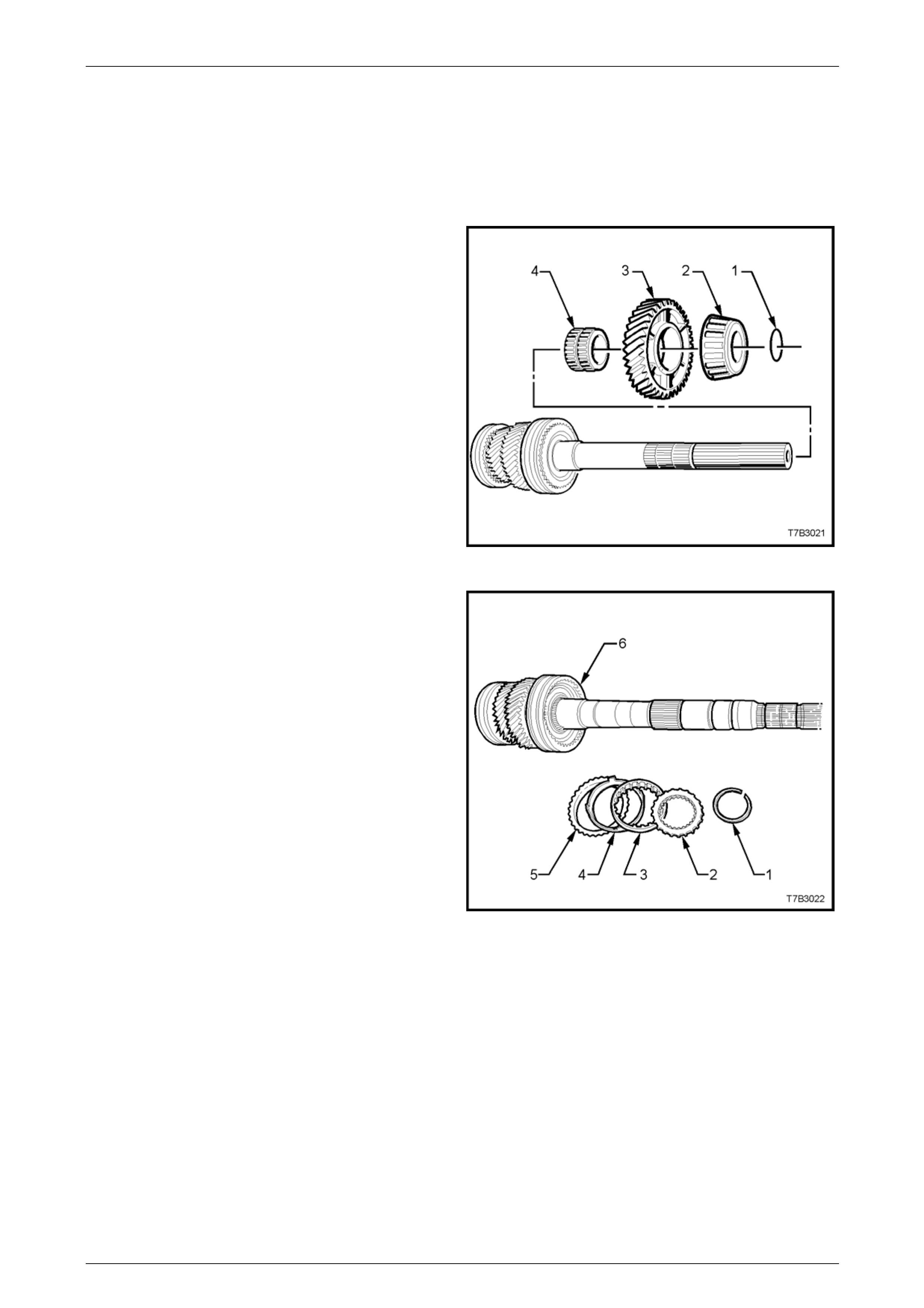
Manual Transmission – GEN III V8 Page 7B2-52
4.5 Transmission Sub-Assemblies
Disassemble
Mainshaft
NOTE
Do not mix any synchromesh blocker rings, or
any synchromesh components.
1 Remove the O-ring (1) behind the rear mai nshaft
bearing (2).
NOTE
The O-ring (1) is only used by the manufacturer
to assist in the assembly process. It serves no
other purpose and can be discarded after
removal. This O-ring is not serviced.
2 Grasp the 1st speed gear (3) and slide from the
mainshaft, removing the rear tapered roller bearing (2)
in the process. This rear bearing is a sli din g fit on the
mainshaft.
3 Remove the 1st speed gear, caged needle roller
bearing (4) from the mainshaft. Figure 7B2 – 78
4 Remove the snap ring (1) securing the 1st/2nd
synchromesh assembly (6).
5 Remove the thrust washer (2), inner cone (3), friction
cone (4), and blocker ring (5) from the 1st/2nd
synchromesh assembly (6).
Figure 7B2 – 79
Page 7B2- 52

Manual Transmission – GEN III V8 Page 7B2-53
6 Install split press plates J 36513, with the flat side
(side A) against the 2nd speed constant mes h gear
(3).
7 Press the mainshaft (1) from the 2nd speed constant
mesh gear (3) and synchromesh assembly (2). The
components of the 2nd speed synchromesh unit (2nd
speed blocker ring, friction cone, 2nd speed inner
cone and thrust washer), will also be removed in this
operation.
8 Remove the 2nd speed gear caged needle roller
bearing from the mainshaft.
Figure 7B2 – 80
9 Remove the snap ring securing the 3rd/4th
synchromesh assembly.
10 Install split press plates J 22912-01 with the flat side
against the 3rd speed constant mesh gear (3).
11 Tighten the press plate wing nuts to securely locate
the plates under the gear.
Do not allow the mainshaft to d rop free to the
floor, after pressing operations.
12 Press the mainshaft (1) from the 3rd/4th synchromesh
assembly (2).
NOTE
The 3rd speed constant mesh gear (3), 3rd
speed blocker ring, friction cone, inner cone and
thrust washer will also be removed, during this
pressing operation.
13 Remove the 3rd speed gear caged needle roller
bearing from the mainshaft.
Figure 7B2 – 81
Page 7B2- 53
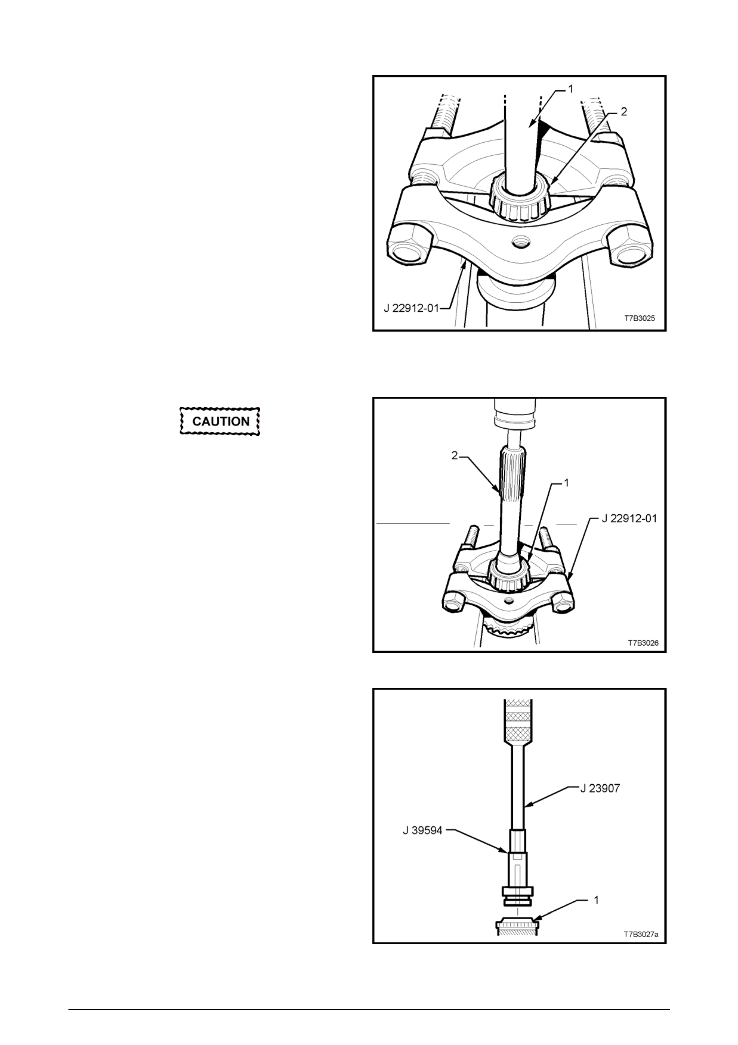
Manual Transmission – GEN III V8 Page 7B2-54
14 Install split press plates J 22912-01 under the pilot
bearing (2) installed on the nose of the mainshaft.
15 Tighten the press plate bolts to secure.
16 Press the bearing (2) from the mainshaft, using a
suitable sized drift (1) (or socket extension). Discard
the bearing.
NOTE
Only remove this bearing if it is to be replaced,
as damage to the bearing during the removal
process, will most likely occur.
Figure 7B2 – 82
Input Shaft
Only remove the input shaft bearing or the
pilot bearing cup, if these components are to
be replaced.
1 Install split press plates J 22912-01 under th e input
shaft bearing (1), tightening the bolts to secure.
2 Press the bearing (1) from the input shaft (2).
3 Discard the removed bearing (1).
Figure 7B2 – 83
4 After assembling bearing remover J 395 94 to slide
hammer J 23907, remove the front mainshaf t bearing
cup from the input shaft (1). Discard the removed
bearing cup.
Figure 7B2 – 84
Page 7B2- 54

Manual Transmission – GEN III V8 Page 7B2-55
Countershaft Gear
Only remove either or both of the
countershaft bearing/s if replacement is
required, as damage will result from the
removal procedure.
1 For the rear taper roller bearing (1);
a Install press plates J 22912-01 under the tap er
roller bearing (1), tightening the bolts to secure.
b Press the bearing (1) from the countershaft gear,
using a suitable size drift (2) (or socket).
c Discard the removed bearing.
Figure 7B2 – 85
2 For the front taper roller bearing;
a Install split press plates J 39511 under the front
countershaft gear bearing (1), tightening the
bolts to secure.
b Press the bearing (1) from the countershaft gear
(3), using a suitable size drift (2) (or socket).
c Discard the removed bearing.
Figure 7B2 – 86
Countershaft Extension
1 Remove the following compon ents from the
countershaft gear extension (7):
1 5th/6th gear shift fork.
2 Thrust washer (may be retained on countershaft
gear).
3 6th speed drive gear.
4 Synchromesh blocking ring.
5 Caged needle roller bearing.
6 Spacer.
Figure 7B2 – 87
Page 7B2- 55
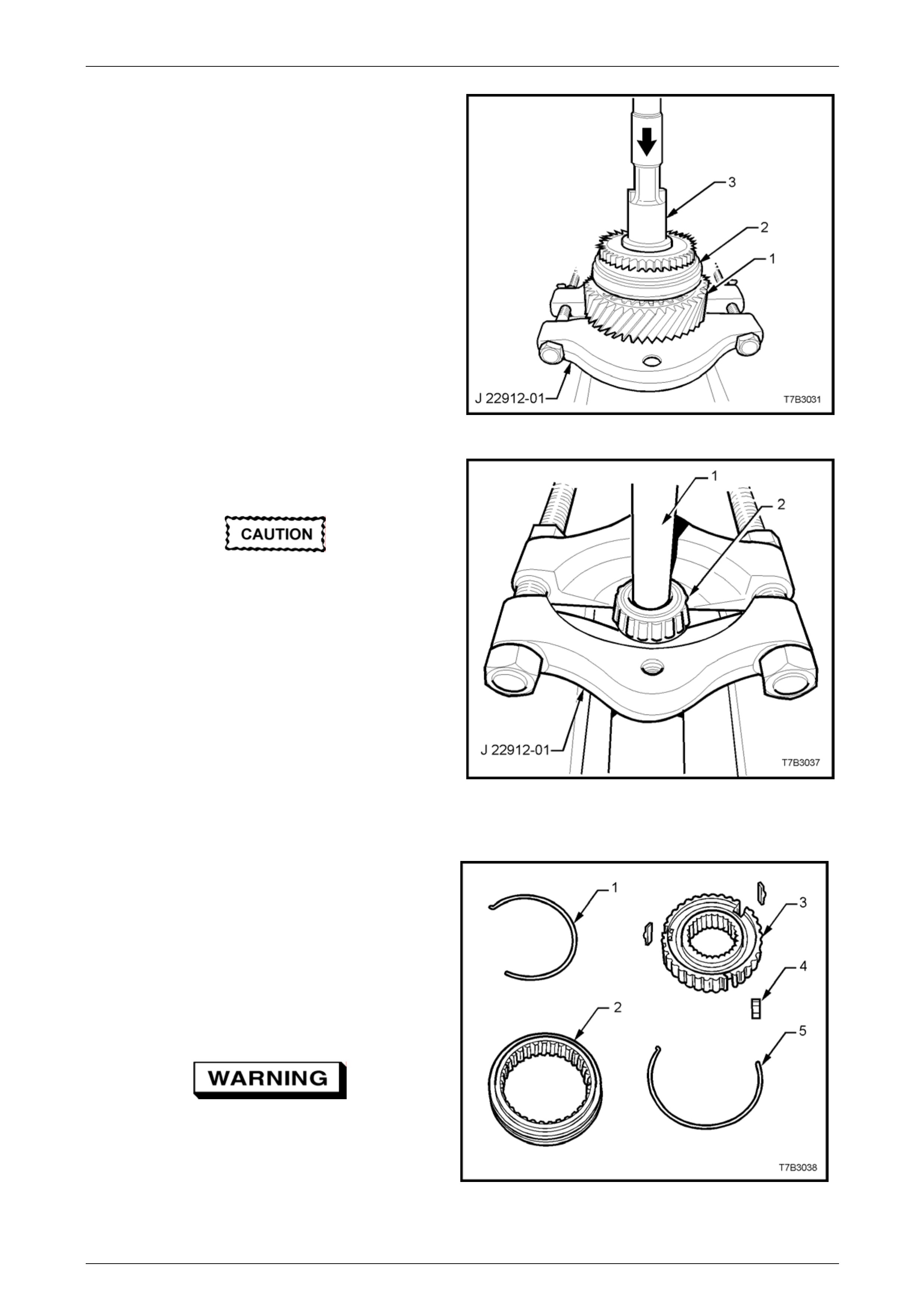
Manual Transmission – GEN III V8 Page 7B2-56
2 Remove 5th/6th gear synchromesh assembly snap
ring.
3 With the flat sides of press plates J 22912-01 under
the 5th speed drive gear (1), press the gear and
synchromesh assembly (2) from the counters haft
extension shaft (3), using a suitable size drift.
Figure 7B2 – 88
4 Install split press plates J 22912-01 under the tapered
roller bearing (2), tightening the bolts to secure.
Only remove this bearing if replacement is
required, as damage will result from the
removal procedure.
5 Press the bearing (2) from the countershaft extensio n,
using a suitable sized drift (1) (or socket ext ension).
Discard the removed bearing.
Figure 7B2 – 89
Synchromesh Assemblies
All Assemblies Except Reverse Gear
NOTE
This operation is not recommended, unless
considered to be absolutely necessary. If
disassembly is requir ed, then extreme care must
be taken to identify each component and it’s
exact location, using liquid paper or a felt tipped
pen for the purpose.
Wear eye protection to prevent potential
injury.
1 Using a small scre wdriver, remove the synchroniser
springs (1 and 5).
Figure 7B2 – 90
Page 7B2- 56

Manual Transmission – GEN III V8 Page 7B2-57
2 Note the location of the synchromesh ass embly ring
‘V’ mark (1) to the key location in the hub (2), then
slide the ring from the hub.
NOTE
If a 'V' mark cannot be found, then mark the
relationship (3) between the ring and the hub,
using correction fluid (e.g. Whiteout™).
Figure 7B2 – 91
Reverse Gear Synchromesh Assembly.
Wear eye protection to prevent potential
injury.
1 Using a small scre wdriver, remove the synchroniser
spring from the reverse gear side.
2 Note the location of the synchromesh ass embly ring
mark (‘V’) to the key location in the hub, then slide the
ring from the hub.
3 Remove the three keys.
4 Remove the synchromesh key retainer (1), using a pin
punch through the hub key slots. Discard the retainer.
5 Remove the second synchro niser spring, using a
small bladed screwdriver. Figure 7B2 – 92
Reverse Idler Gear
1 Using Torx bit T40, remove the three screws (1)
securing the reverse idler gear shaft support plate (2).
2 Remove the support plate (2), reverse idler gear thrust
washer (3), reverse idler gear (4), caged needle roller
bearing (5), the second reverse idler gear thrust
washer (6), and idler gear shaft (7) from the extension
housing (8).
Figure 7B2 – 93
Page 7B2- 57

Manual Transmission – GEN III V8 Page 7B2-58
Reverse Lockout Solenoi d Assembly
Refer to 3.4 Reverse Lockout Solenoid Asse mbly, Disassemble, in this Section, for this procedure.
Shift Rail and Fork Assemblies
1st/2nd and 3rd/4th Shift Rail Assembly
1 Rotate the selector pin (1) until the interlock plate (7)
clears both shift plate links (2 and 3).
2 Slide the 3rd/4th shift fork (4) and link (2) from the shift
rail (5).
3 Slide the 1st/2nd shift fork (6) and link (3) from the
shift rail (5).
4 Slide the interlock plate (7) from the shift rail (5).
5 Using a suitable size pin pu nch and hammer, remove
the roll pin (8) from the selector pin (1).
NOTE
While both shift fork links are the same, it is
good practice to keep each link with its
respective fork.
Figure 7B2 – 94
5th/6th and Reverse Shift Rail Assemb ly
6 Remove the roll pin (1) from the collar (2) and shift rail
(3), using a suitable size pi n punch and hammer.
7 Slide the 5th/6th shift rail lever (5) from the shift rail
(3).
NOTE
• Only remove the bushes from the 5th/6th
shift rail if they are worn or damaged and
require replacement.
• While the sleeve can be pressed from the
5th/6th shift rail lever (after removing the
retaining circlip), this operation is not
recommended unless parts are to be
replaced.
8 Using a suitable size pin pu nch and hammer, remove
the roll pin (4) holding the rev erse shift rail lever (6) to
the shift rail (3). Slide the reverse shift rail lever (6)
from the shift rail (3). Figure 7B2 – 95
Page 7B2- 58
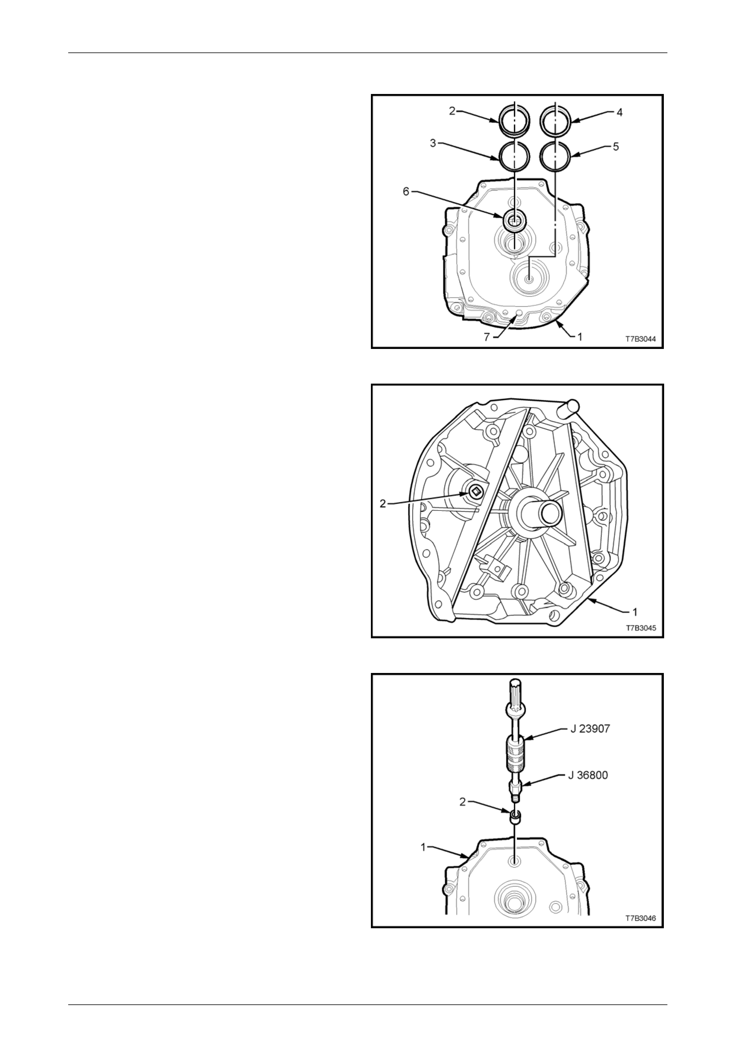
Manual Transmission – GEN III V8 Page 7B2-59
Transmission Adaptor Plate
1 Slide the input shaft bearing cup (2) an d shim/s (3) by
pulling with the finger tips of each hand.
NOTE
Rotating the cup back and forth while pulling, will
reduce the problem of the bearing cup cocking
and jamming in the adaptor plate bore.
2 Repeat this process with the counter shaft front
bearing cup (4) and shim/s (5).
3 Prise the input shaft oil seal (6) from the adaptor plate
(1).
4 Only remove the dowel pins (7), if replacement is
required.
Figure 7B2 – 96
5 Using a 3/8” drive socket bar, remove the adaptor
plate plug (2) from the front of the adaptor plate (1).
Figure 7B2 – 97
6 If worn or damaged, remove the 1st/2nd and 3rd/4th
shift rail bushing (2), using the following procedure:
a Screw bushing remover J 36800 into the shift rail
bushing (2).
b Screw slide hammer J 23907 into the bushing
remover J 36800 and remove the bushing (2)
from the adaptor plate (1).
Figure 7B2 – 98
Page 7B2- 59
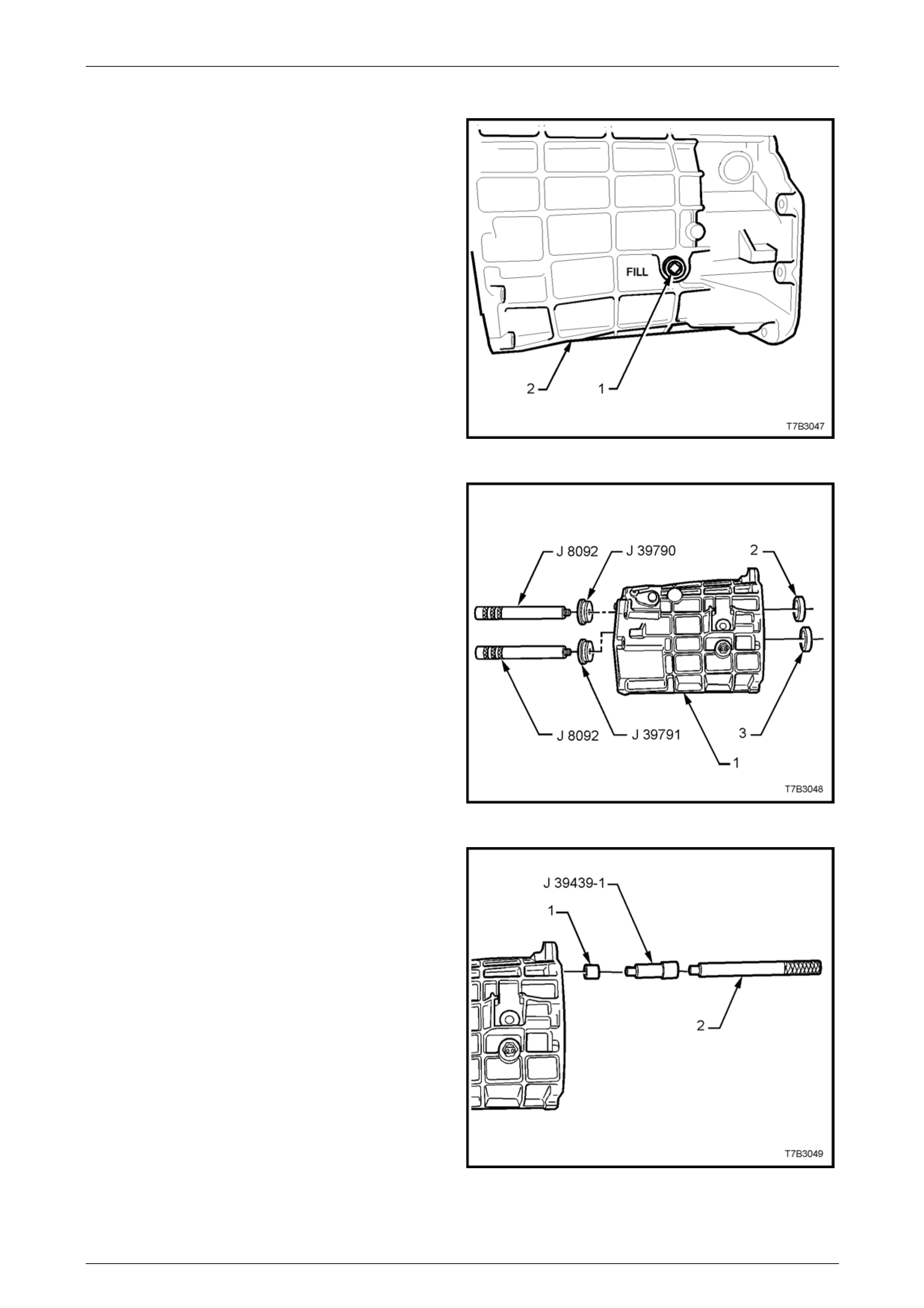
Manual Transmission – GEN III V8 Page 7B2-60
Transmission Case
1 Using a 3/8” drive socket bar, remove the filler plug (1)
from the transmission case (2).
Figure 7B2 – 99
NOTE
Only remove the rear mainshaft bearing cup (2)
and/or rear countershaft gear bearing cup (3) if
these components are to be replaced.
2 Press the mainshaft bearing rear cup (2) from the
transmission case (1), using remover J 39790 and
driver handle J 8092.
3 Press the countershaft gear rear bearing cup (3) from
the transmission case (1), using remover J 39791 and
driver handle J 8092.
4 Discard removed bearing cup/s.
Figure 7B2 – 100
5 If worn or damaged, remove the shift rail bushes (1),
using bushing remover J 3943 9-1 and a suitable driver
handle (2). Discard the removed bus hes (1).
Figure 7B2 – 101
Page 7B2- 60
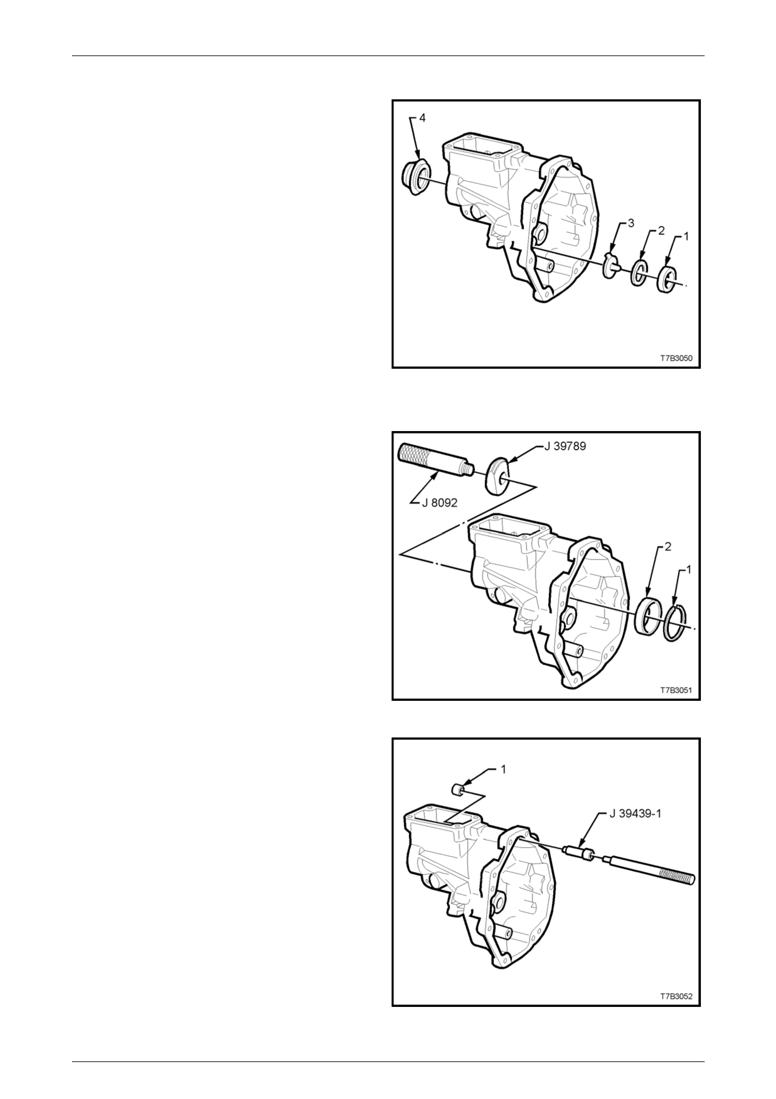
Manual Transmission – GEN III V8 Page 7B2-61
Extension Housing
NOTE
If not removed during the transmission
disassembly process, remove the following
components:
a Drain Plug.
b Reverse lockout solenoid and body assembly.
c Vehicle speed sensor.
d Reverse idler gear assembl y.
6 Slide out the countershaft gear extension, rear bearing
cup (1), shim/s (2) and oil funnel (3) by pulling with the
finger tips of each hand.
NOTE
Rotating the rear bearing cup (1) back and forth
while pulling with the finger tips, will reduce the
problem of the bearing c up cocking and jamm ing
in the extension housing bore.
7 Prise the rear seal (4) from the extension ho using,
using a suitable lever. Discard the remove d seal.
Figure 7B2 – 102
NOTE
Only remove the mainshaft rear roller bearing
cup if the bearing assembly is to be replaced.
8 Remove the mainshaft rear roller bearing cup retaining
snap ring (1) using suitable pliers.
9 Press the mainshaft rear bearing cup (2) from the
extension housing, using remover J 39789 and driver
handle J 8092.
Figure 7B2 – 103
10 If worn or damaged, remove the shift rail bushing (1),
using bushing remover J 3943 9-1 and a suitable driver
handle. Discard the removed bushing.
NOTE
The propeller shaft slip yoke bush is not servi ce d
separately. If excessive wear is detected, then
the extension housing assembly must be
replaced.
Figure 7B2 – 104
Page 7B2- 61

Manual Transmission – GEN III V8 Page 7B2-62
Clean And Inspect Components
Clean
Wear eye protection to prevent potential
injury.
1 Thoroughly wash all components in a suitable cleaning solvent. Dry all parts with clean, dry compressed air.
2 Use a wire brush or thread taps to clean thread sealant from all fasteners that are to be re-used.
Inspect
1 Inspect transmission case, rear extension, adaptor plate and clutch housings for any cracks or defects that may
cause lubricant leakage.
2 Ensure that there is no damage to or sealant on, the front face of transmission adaptor plate that could cause
misalignment between case and clutch housing.
3 Check all machined faces for burrs and traces of sealant. If scraping of theses surfaces is required, only use a
plastic scraper to avoid damaging finely machined alloy surfaces. If burrs are found, dress them off with a fine mill
file.
4 All roller and needle b earing assemblies should be inspect ed closely and replaced if there is any sign of wear.
Inspect mainshaft and internal surfaces of all gears where needle bearings come in contact.
For diagnosis of tapered roller bearing failures, refer to Section 4B1 Final Drive and Drive Shafts.
NOTE
• If the countershaft gear bearings are worn or
damaged, refer to 4.5 Transmission Sub-
Assemblies, Disassemble, Countershaft Gear,
in this Section. If either bearing is removed, it
must be replaced with a new part as damage
will occur during the removal operation.
• If the input shaft bearing is worn or damaged,
refer to 4.5 Transmission Sub-Assemblies,
Disassemble, Input Shaft, in this Section.
• As needle roller wear can be difficult to see, it
is good practice to replace all needle roller
bearings where the vehicle has travelled a
substantial distance.
5 Inspect all gears, sleeves, hubs, rings and shafts for wear, scoring, pitting, chips, nicks or burrs. Slight scores or
burrs may be honed off with a fine stone but, if a gear is chipped or unduly worn, it must be replaced.
6 Check synchroniser teeth on blocking rings and gears. Replace any component that is worn or damaged.
7 Inspect synchroniser hubs, outer rings, inserts and springs for damage or wear. Check that the synchroniser rings
slide freely on their hubs. Replace any worn component.
NOTE
Even though the synchromesh blocking rings are
the same, it is sound practice to keep each ring
with its respective gear, to preserve wear
patterns.
8 Inspect reverse idler gear shaft, replacing if worn.
9 Check all thrust washers, replace any that are worn.
10 Inspect all shift control component, both contact and sliding surfaces for wear, scratches, projections or other
damage.
11 Inspect breather tube to ensure that it is not blocked.
Page 7B2- 62
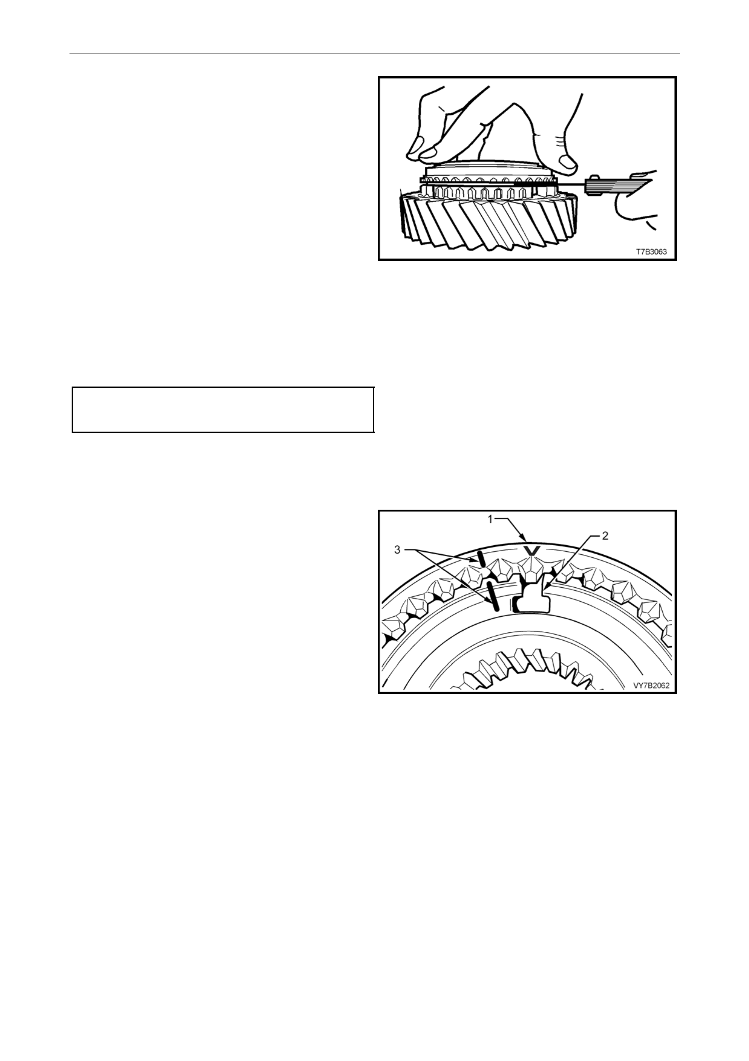
Manual Transmission – GEN III V8 Page 7B2-63
NOTE
If any constant mesh gear end float is
considered to be excessive, then careful
attention must be paid to measuring bl ocker ring
wear. If within the specifications provided,
replace parts as required to reduce end float, as
no shim adjustment is provided.
12 Measure the wear of all blocker rings as follows:
a Place the three blocking ring components onto
the appropriate gear cone i.e. fifth gear blocking
ring assembly onto fifth speed drive gear.
b Hold rings square on the gear ’s cone surface
and hold firmly in the seated position.
c Measure clearances in the location shown.
d Discard any blocker ring that measur es less than
the minimum prescribed clearance.
Blocker Ring Assembly To Gear Clearance
1st to 6th Gears Inclusive ..................0.38 mm Minimum
Reverse .............................................0.75 mm Minimum
Figure 7B2 – 105
Reassemble
Synchromesh Assemblies – All
1 Install the synchromesh ring over the hub, aligning the
‘V’ on the edge of the ring (1) with one of the
previously marked, hub ke y openings (2) or, align the
marks (3) made before disassembly.
NOTE
While none of the hubs has an offset, the
orientation of the outer synchroniser ring is
specific, depending on the ap plication.
Figure 7B2 – 106
Page 7B2- 63
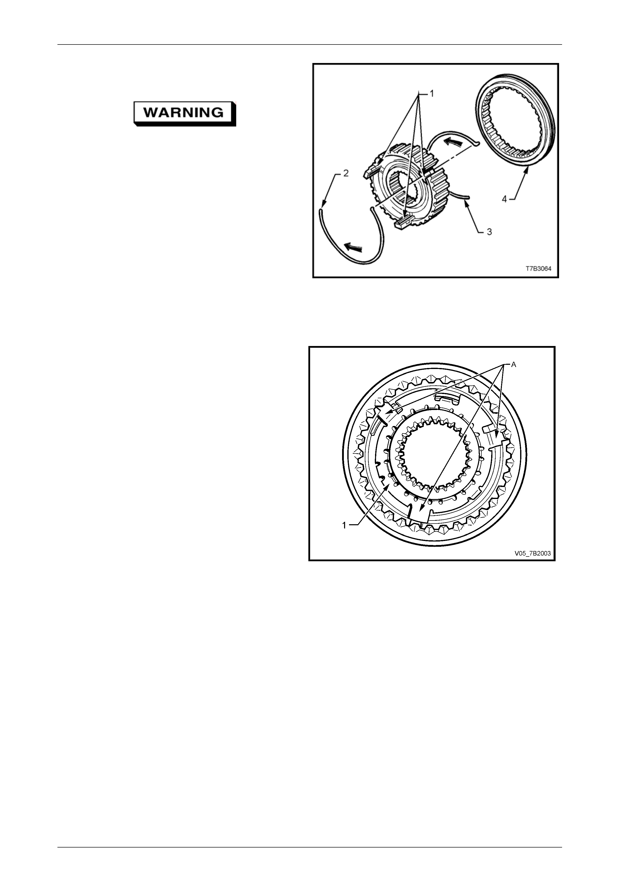
Manual Transmission – GEN III V8 Page 7B2-64
2 Install the three keys (1) with the protrusions facing
outward.
Wear eye protection to prevent potential
injury.
3 Install one synchroniser sprin g (2), locatin g the spring
tang in one of the synchronise r keys, using a small
screwdriver to assist.
4 Turn the assembly over, then install the second
synchroniser spring (3), locating the tang in the same
key as before but in the opposite direction to the first.
Again use a small screwdriver to assist.
NOTE
The synchromesh assembly is shown in an
exploded state to more clearly show the
synchroniser spring arrangement. Figure 7B2 – 107
Reverse Synchromesh Assembly Only
1 Following the assembly of the s ynchromesh assembly,
as detailed in steps 1 to 4 abo ve, install a new
synchromesh key retainer (1), locating the tangs 'A'
over the synchromesh keys.
2 Using a suitable size sleeve such as Tool No. E1891-6
(or tube I.D. 50 mm, wall thickness 5 mm maximum), a
block of wood and a hammer, install the key retainer,
securing it to the synchromesh hub centre.
Figure 7B2 – 108
Page 7B2- 64
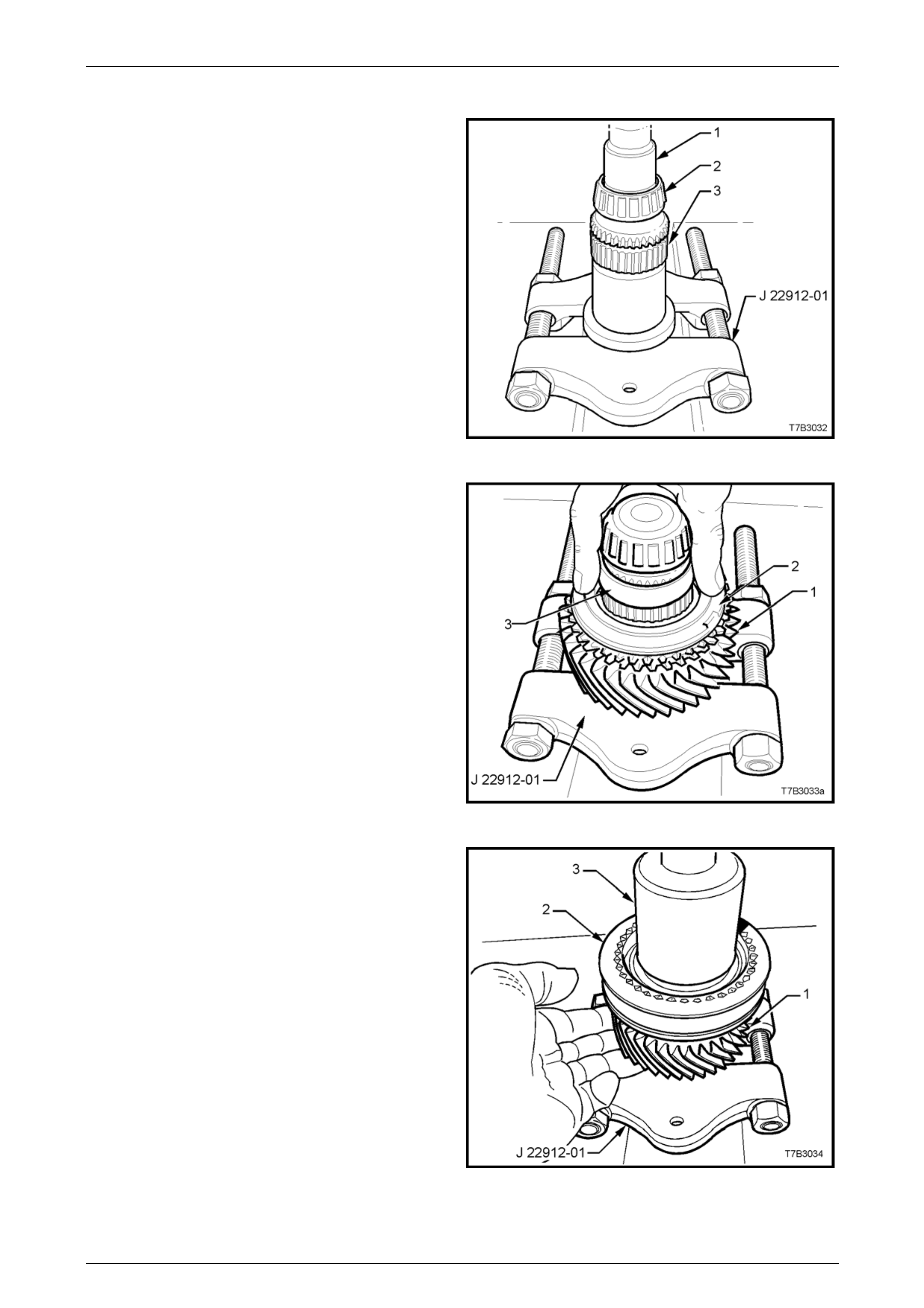
Manual Transmission – GEN III V8 Page 7B2-65
Mainshaft
1 With press plates J 22919-01 install ed under the
mainshaft flange as shown, press a NEW spigot taper
roller bearing (2) onto the mainshaft (3), using a
suitable sleeve (1) (e.g. 21 mm socket).
Figure 7B2 – 109
2 With press plates J 22912-01, still installed under the
mainshaft flange, install the 3rd gear caged needle
roller race, 3rd gear (1) and the blocker ring (2).
3 Install plastic sleeve (3) over the mainshaft.
Figure 7B2 – 110
4 Install 3rd/4th synchromesh assembly (2) to the
mainshaft splines, noting that the groove in the outer
ring faces forward (to 4th gear).
5 Press 3rd/4th synchromesh assembly to the
mainshaft, using a suitable size sleeve (3) (47 mm ID,
minimum length 25 mm and wall thickness 5 mm).
6 During the pressing process, hold the 3rd g ear (1) and
blocker ring into place against the synchromesh
assembly (2) to ensure correct location of the locating
dogs on the blocker ring, with the synchrom esh keys.
Figure 7B2 – 111
Page 7B2- 65
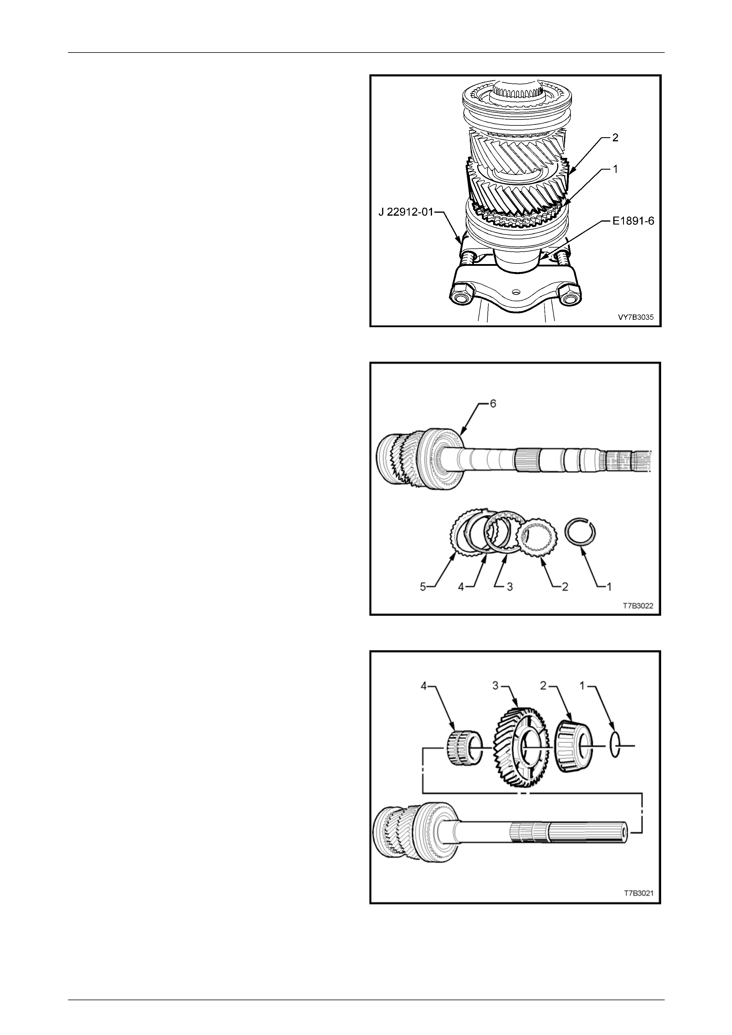
Manual Transmission – GEN III V8 Page 7B2-66
7 Install 2nd speed gear (3) and cage d needle roller
bearing, the blocking ring a nd 1st/2nd speed
synchromesh assembly (2) to the mainshaft, noting
that the groove in the outer ring of the s ynchromesh
assembly faces rearward (to 1st gear).
8 Using a suitable sleeve such as Tool E1891-6 (or I.D.
50 mm, wall thickness 5 mm), supported by press
plates J 22912-01 as shown, press the mainshaft into
the 1st/2nd speed synchromesh assembly (2).
NOTE
The locating dogs of the 2nd spee d blocking ring
should be aligned with the synchromesh keys
during the pressing process, allowing the 2nd
speed gear (3) weight to keep the assembly in
place.
Figure 7B2 – 112
9 Reinstall the blocker ring (5), friction co ne (4), inner
cone (3) and the thrust washer (2) to engage with the
mainshaft splines and the 1st/2nd spee d synchromesh
assembly teeth.
10 Using suitable snap ring pliers, install a new snap ring,
securing these components.
Figure 7B2 – 113
11 After lubricating the 1st speed constant mesh gear
needle roller bearing with new transmission fluid,
install the bearing and the 1st speed constant mesh
gear, engaging the lugs on the friction ring with the
cut-outs in the gear.
12 Slide the taper roller bearing cone along the
mainshaft. If present and serviceable the bearing can
be retained by reinstalling the O-ring (1).
NOTE
As noted in the disassembly process, this O-ring
(1) is only used to assist in the assembly
process and can be discarded. If not fitted
however, care must be taken to ensure that the
roller bearing does not slide from the mainshaft
and suffer cage damage from dropping onto a
hard surface.
Figure 7B2 – 114
Page 7B2- 66
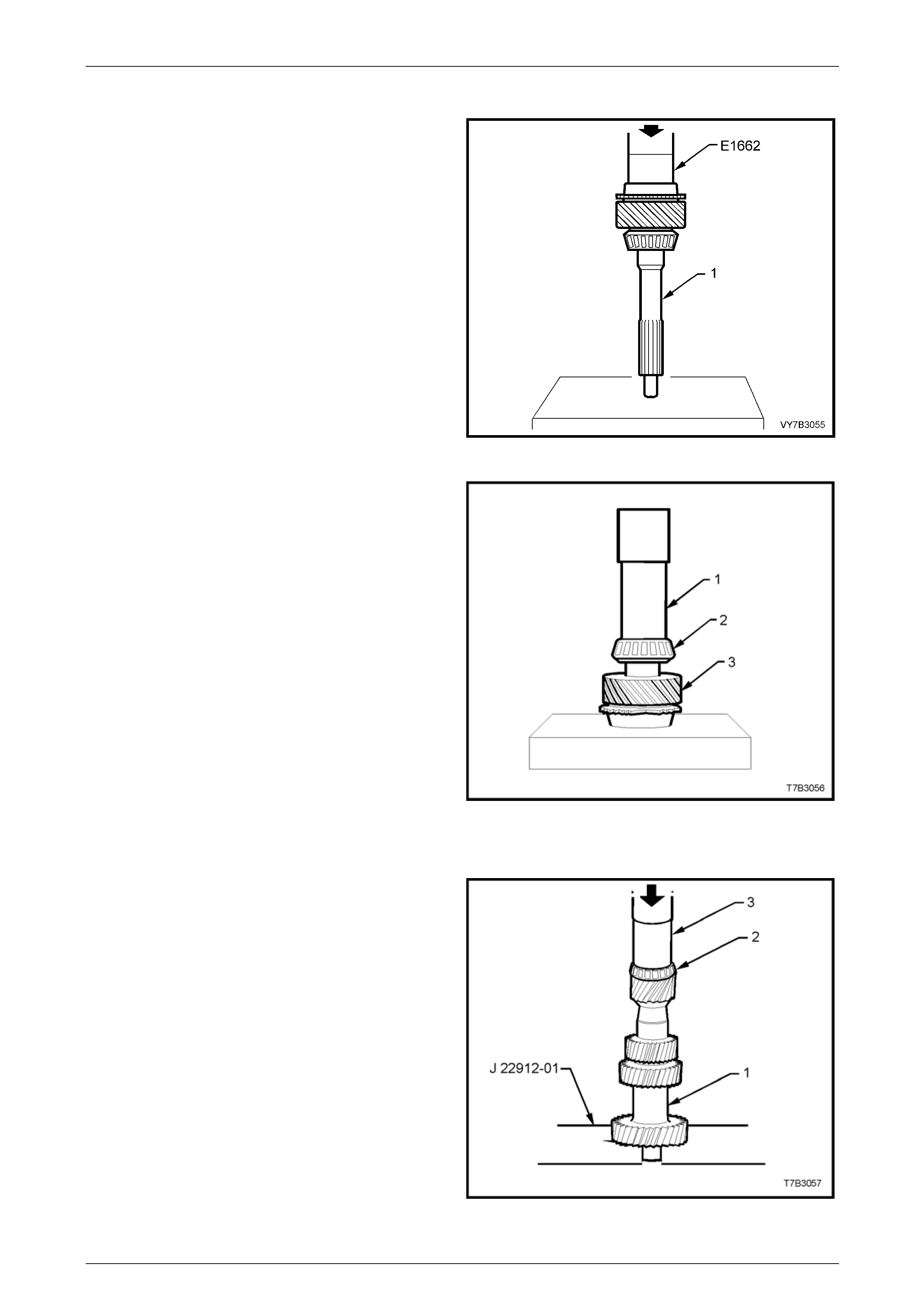
Manual Transmission – GEN III V8 Page 7B2-67
Input Shaft
1 Using tube E1662 or equivalent size (O.D. 47 mm,
length approximately 40 mm) and an hydraulic press,
install a new input shaft beari ng cup into the counter
bore of the input shaft (1).
Figure 7B2 – 115
2 Using a suitable size tube (1) (I.D. 32 mm, wall
thickness 5 mm maximum and length 200 mm), and
an hydraulic press, install a new tapered roller bearing
(2) to the input shaft (3).
Figure 7B2 – 116
Countershaft Gear
1 Using press plates J 22912-01, support the input gear
of the countershaft gear (1).
2 Install a new bearing (2) to the small end of the
countershaft gear (1), using a suitable size sleeve (3)
(I.D. 40 mm, wall thickness 4 mm maximum) and an
hydraulic press.
Figure 7B2 – 117
Page 7B2- 67
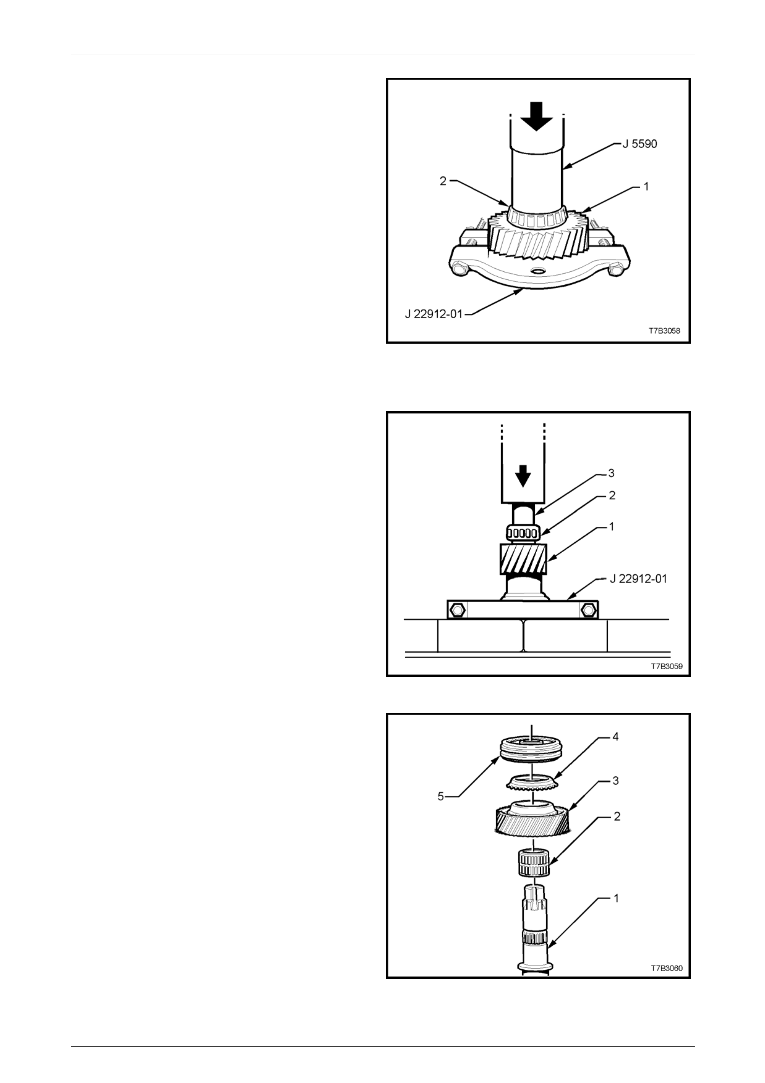
Manual Transmission – GEN III V8 Page 7B2-68
3 Using press plates J 22912-01, support the input gear
of the countershaft gear (1) as shown.
4 Install a new bearing (2) to the large end of the
countershaft gear (1), using installer J 559 0 or a
suitable sleeve (I.D. 36 mm, wall thickness 4 mm
maximum) and an hydraulic press.
Figure 7B2 – 118
Countershaft Extension Gear
1 With press plates J 22912-01 install ed under the
countershaft extension flange (1) as shown, press a
new taper roller bearing (2) onto the extens ion (1),
using a suitable sleeve (3) (e.g. 21 mm socket).
Figure 7B2 – 119
2 Install the following components to the countershaft
extension (1):
2 5th gear caged needle roller bearing.
3 5th speed drive gear.
4 5th speed synchromesh blocking ring.
5 5th/6th speed synchromesh assembly.
Figure 7B2 – 120
Page 7B2- 68

Manual Transmission – GEN III V8 Page 7B2-69
3 With the assembly arranged as shown, press the
countershaft extension into the s ynchrom esh
assembly hub, using tube J 5590.
NOTE
Index the blocking ring assembly with the
synchromesh keys before pressing operations.
4 Fit a new snap ring to the countershaft extension to
secure the synchromesh assembly.
Legend
1 Countershaft gear extension.
2 5th speed drive gear.
3 5th/6th speed synchromesh assembly.
Figure 7B2 – 121
5 Install the spacer washer (6), caged needle roller
bearing (5), 6th speed blocking ring (4), 6th speed
drive gear (3), and thrust washer (2) with the recessed
side facing the countershaft gear.
6 Install the 5th/6th shift fork (1) to the synchromesh
ring, in preparation for instal lation.
Figure 7B2 – 122
Reverse Idler Gear
1 Install the reverse idler gear shaft (7) and thrust
washer (6) to the transmission extension housin g (8).
2 Lubricate the reverse idler gear (4) and caged needle
roller bearing (5) with clean transmission fluid, then
install both over the idler gear shaft (7).
3 Install the outer thrust washer (3) and reverse idler
shaft retaining bracket (2).
4 Clean any thread sealant residue from the threads of
the three, Torx headed bracket scre ws (1), using a
wire brush.
5 Apply thread sealant such as Loctite 242 or
equivalent, to the screw threads.
6 Reinstall the three Torx headed screws and tighten to
the correct torque specification.
Reverse idler gear shaft bracket
screw torque specification.....................................25 Nm Figure 7B2 – 123
Page 7B2- 69
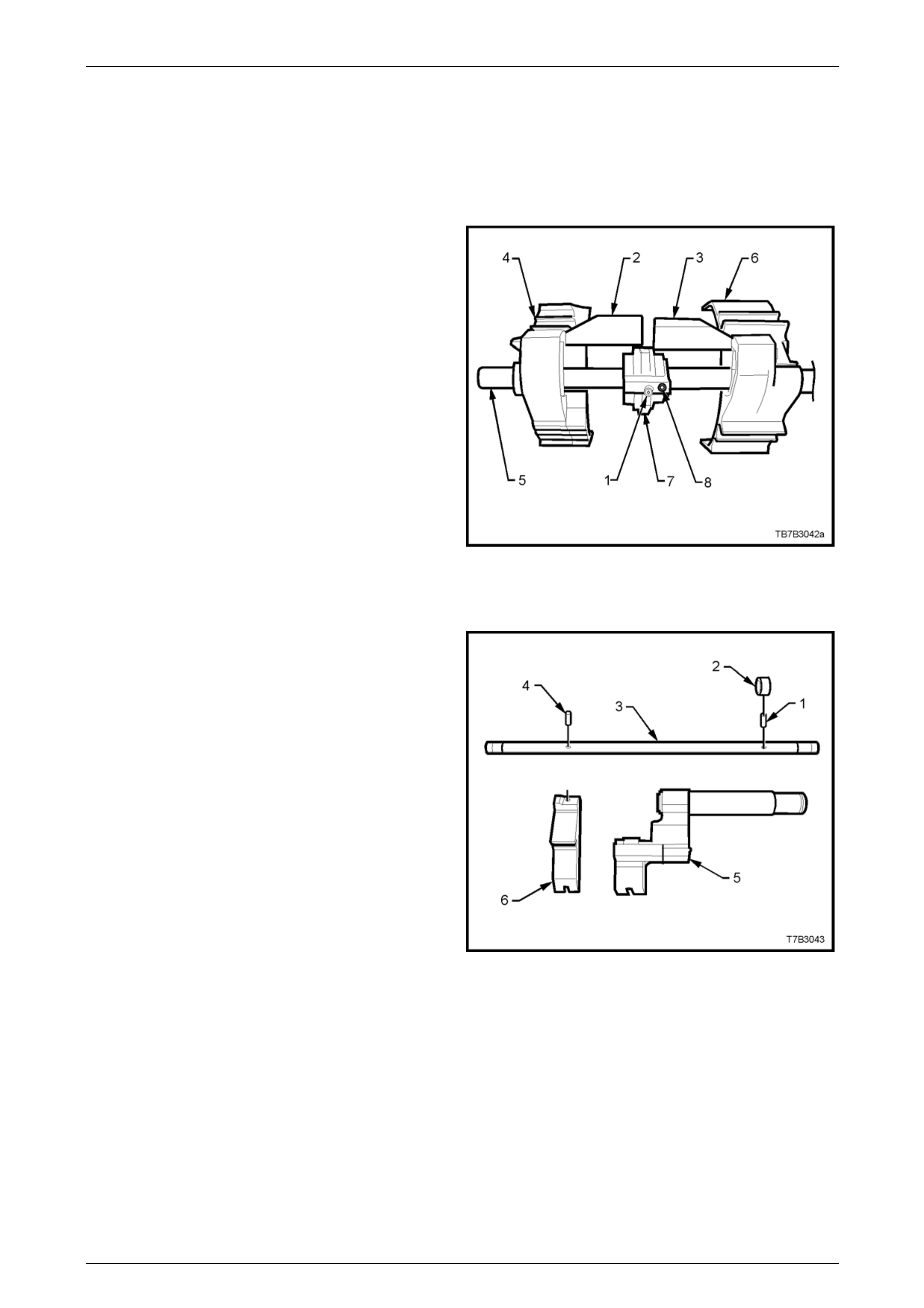
Manual Transmission – GEN III V8 Page 7B2-70
Reverse Lockout Assembly
Refer to 3.4 Reverse Lockout Solenoid Asse mbly, in this Section, for the reassembly description.
Shift Rail and Fork Assemblies
1st/2nd and 3rd/4th Shift Rail Assembly
1 If removed, slide the selector pin (1) over the shift rail
(5) and secure with a new roll pin (8).
2 Install the interlock plate (7) over the selector pin (1),
then slide the 1st/2nd shift fork (6) and link (3) over
shift rail (5), rotating the interlock plate to allow
installation of the link (3).
3 Repeat step 2 for the 3rd/4th shift fork and link (2).
4 Rotate the interlock plate (7) to engage both shift fork
links (2 and 3).
Figure 7B2 – 124
5th/6th and Reverse Shift Rail Assemb ly
1 Using a suitable size pin pu nch and hammer, install a
NEW roll pin (4) to secure the reverse shift rail lever
(6) to the shift rail (3).
2 Slide the 5th/6th shift rail lever assembly (5) onto the
shift rail (3).
3 Using a suitable size pin pu nch and hammer, install a
new roll pin (1) to secure the collar (2).
Figure 7B2 – 125
Page 7B2- 70
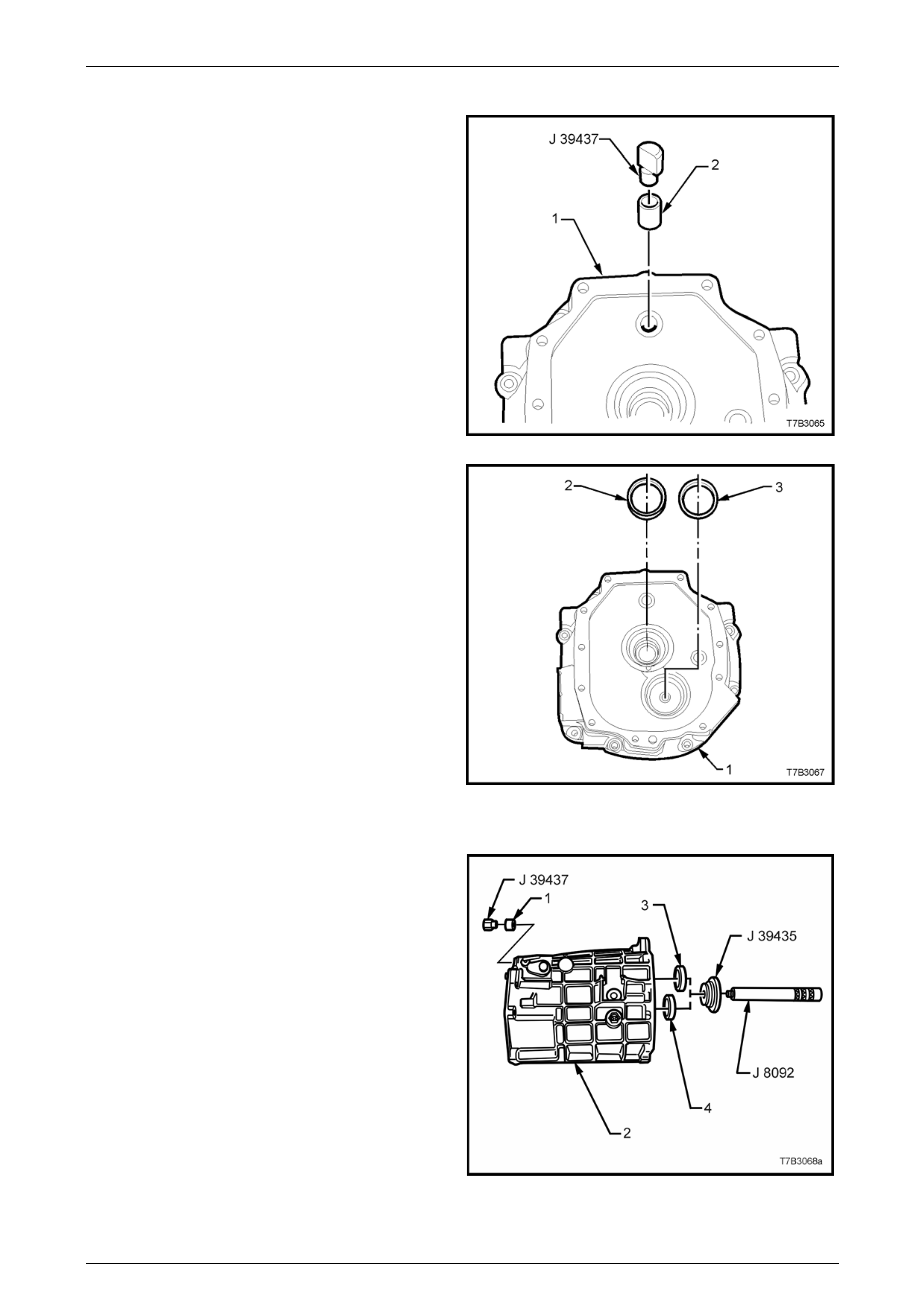
Manual Transmission – GEN III V8 Page 7B2-71
Transmission Adaptor Plate
1 If removed, install a new shift rail bush (2) to the
adaptor plate (1), using installer J 3943 7 or equivalent
stepped driver.
Figure 7B2 – 126
2 Install both the input shaft and front countershaft
bearing cups (2 and 3 respectively) to the adaptor
plate (1), WITHOUT any shims. The correct shim
thickness will be fitted during the assembly operati ons,
when shaft end floats are determined.
Figure 7B2 – 127
Transmission Case
1 If removed, install new shift rail bushes (1) to the
transmission case (2), using installer J 39437 or
equivalent stepped driver.
2 Install mainshaft bearing cup (3) and countershaft
bearing cup (4), using installer J39435 and driver
handle J 8092.
3 If removed, install new dowel pins.
4 Loosely install filler plug.
Figure 7B2 – 128
Page 7B2- 71
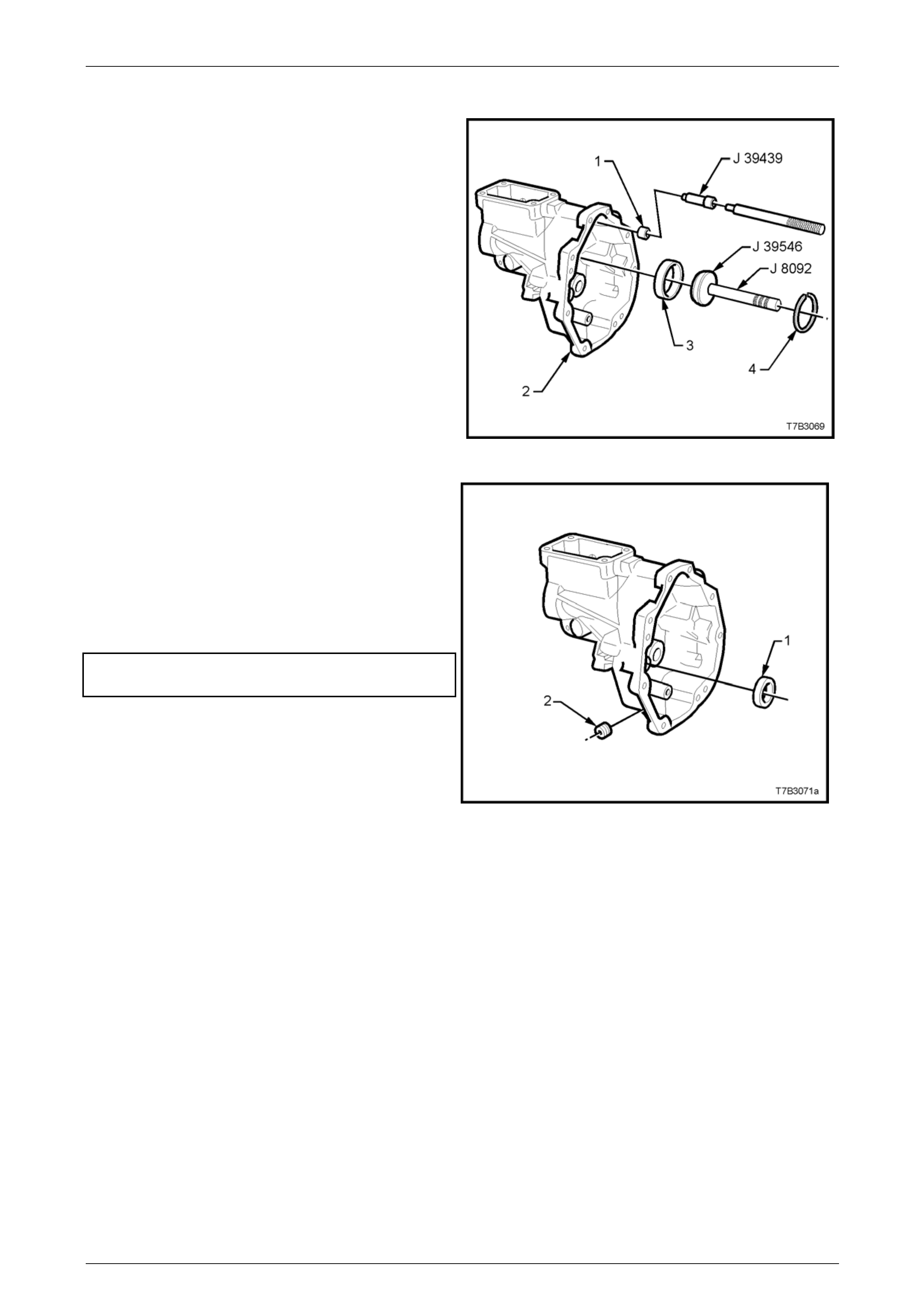
Manual Transmission – GEN III V8 Page 7B2-72
Extension Housing
1 If removed, install new shift rail bushing (1) to the
extension housing (2), using tool J 39439 or equivalent
stepped driver.
2 Install mainshaft roller bearing cup (3), using installer
J39546 and driver handle J 8092.
3 Install roller bearing cup circlip (4), using suitable
pliers.
Figure 7B2 – 129
4 Temporarily install the countershaft exte nsion bearing
cup (1) WITHOUT any shims. Shim selection will b e
determined during the end float measuring procedure
detailed in 4.6 Beari ng Shimming Procedures, in this
Section.
5 Apply sealant such as Loctite 565 or equivalent (GM
P/N 12346004), to the cleaned threads of th e
transmission drain plug (2) an d install, tightening to the
correct torque specification.
Drain plug
torque specification...............................................28 Nm
Figure 7B2 – 130
Page 7B2- 72
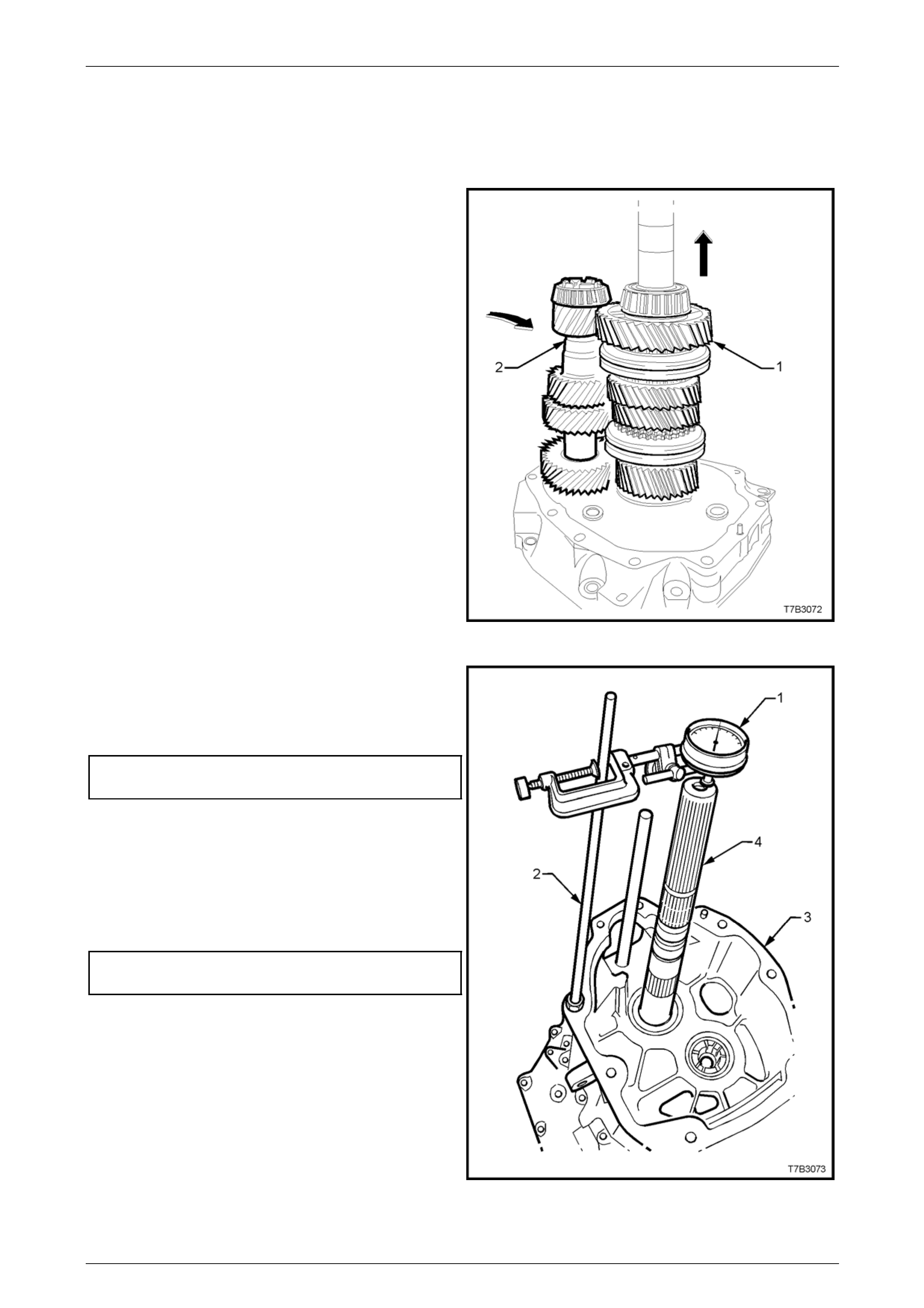
Manual Transmission – GEN III V8 Page 7B2-73
4.6 Bearing Shimming Procedures
Input Shaft, Mainshaft & Countershaft
1 With the adaptor plate mounted to the transmission
holding fixture J 39430 that in turn, is installed into
bench fixture J 3289-20, rotate to the vertical with the
rear of the adaptor plate facing up.
2 Install the input shaft, 4th speed blocking ring and
mainshaft into the front bearing cup. Check that the
blocker ring is correctly aligne d with the synchromesh
assembly keys.
3 While slightly lifting the mainshaft, install the
countershaft to its front bearing.
Figure 7B2 – 131
4 Install the transmission case to the adaptor p late and
reinstall the ten adaptor plate to case bolts.
5 Tighten the ten bolts to the correct torque
specification.
Adaptor plate to transmission
case bolt torque specification................................35 Nm
6 Rotate the assembly through 180° and moun t a
commercially availabl e dial indicator (1) and stand (2)
to the end of the transmission case (3), as shown.
Zero the dial indicator, then lift the mainshaft (4) up
and down to obtain the end play.
7 Select a shim pack to achieve the correct bearing pre-
load specification.
Input shaft/Mainshaft
Pre-load Specification............................ 0.00 – 0.05 mm
NOTE
There are 37 shim selections available, ranging
from 0.559 – 1.372 mm.
8 Remove the dial indicator assembl y.
Figure 7B2 – 132
Page 7B2- 73
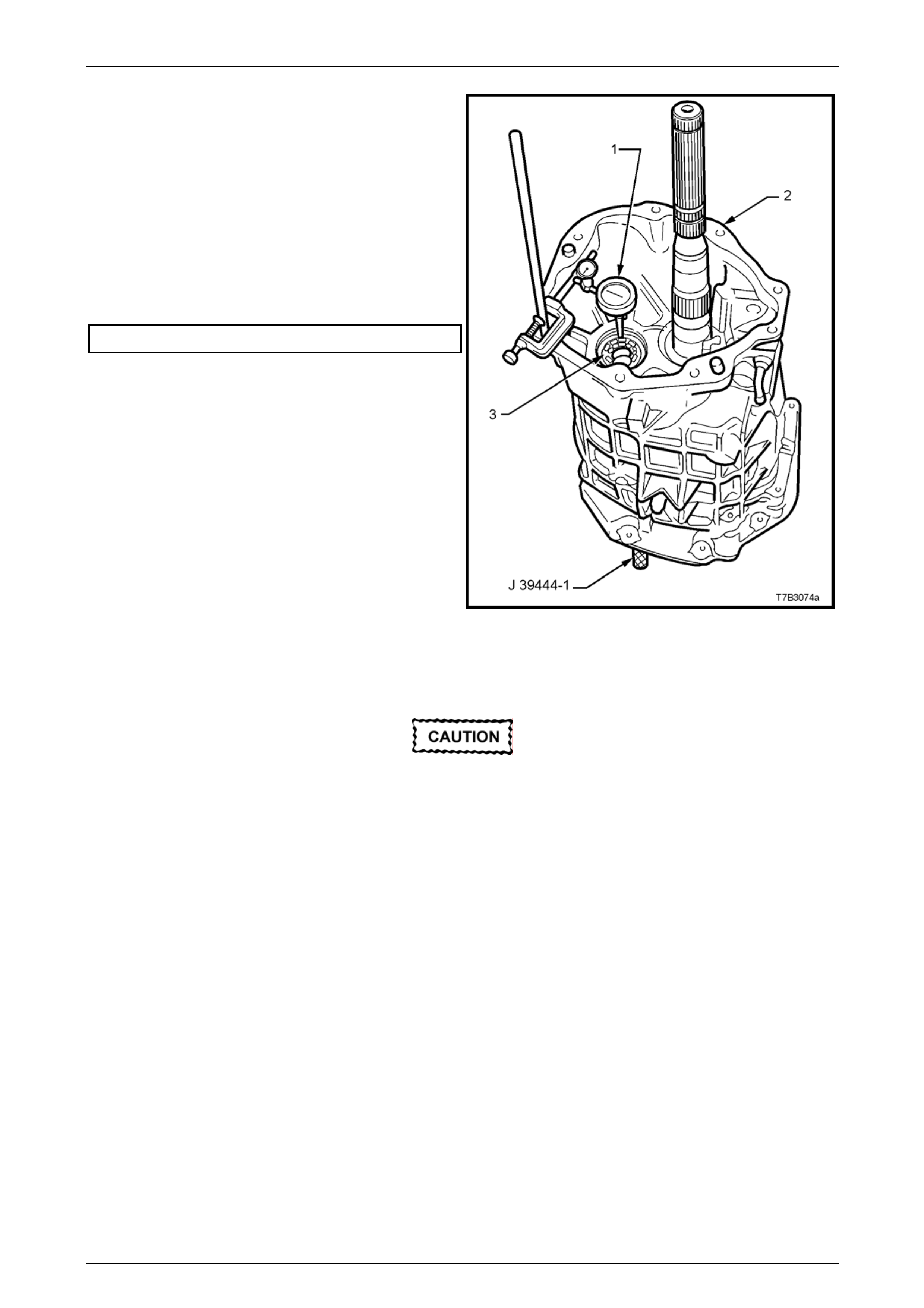
Manual Transmission – GEN III V8 Page 7B2-74
9 With the transmission assembly remaining in the
vertical position, mount a commercially available d ial
indicator (1) to the transmission case (2), with the
probe sensing the end of the countershaft (3). Zero the
dial indicator.
10 Insert countershaft end play rod J 39444-1 (not
shown) into the adaptor plate plug hole (at the front of
the plate), then use the rod to move the count ershaft
up and down, enabling an end play measurement to
be taken.
11 Select a shim pack to achieve the correct bearing pre-
load specification.
Countershaft Pre-load Specification ....... 0.00 – 0.05 mm
NOTE
There are 33 shim selections available, ranging
from 0.356 - 1.372 mm.
12 Remove the dial indicator assembly.
Figure 7B2 – 133
Countershaft Extension
This procedure is not to be undertaken until
the correct shim stack has been installed
under the countershaft front bearing cup.
1 Loosen then remove the adaptor plate to transmission case bolts.
2 Lift the transmission case clear of the mainshaft and countershaft.
3 Lift the mainshaft slightly to allow countershaft removal.
4 Remove the mainshaft assembly, then lift the input shaft and blocking rings from the adaptor plate.
5 Remove the input shaft bearing cup, b y pulli ng with the finger tips of each hand.
NOTE
Rotating the bearing cup back and forth while
pulling, will reduce th e problem of the bearing cup
cocking and jamming in the adaptor p late bore.
6 Repeat this process with the counter shaft front bearing cu p.
7 Install the calculated shim stack for the input shaft/mainshaf t and counters haft, previously determined.
8 Reinstall the input shaft and c ountershaft bearing cups.
9 Reinstall the input shaft, 4th speed blocking rings and mainshaft, to the adaptor plate, ensuring that the blocking
rings engage correctly with the synchromesh assembly keys.
10 Reinstall the countershaft to the adaptor plate, using the same procedure detailed previo usly.
Page 7B2- 74
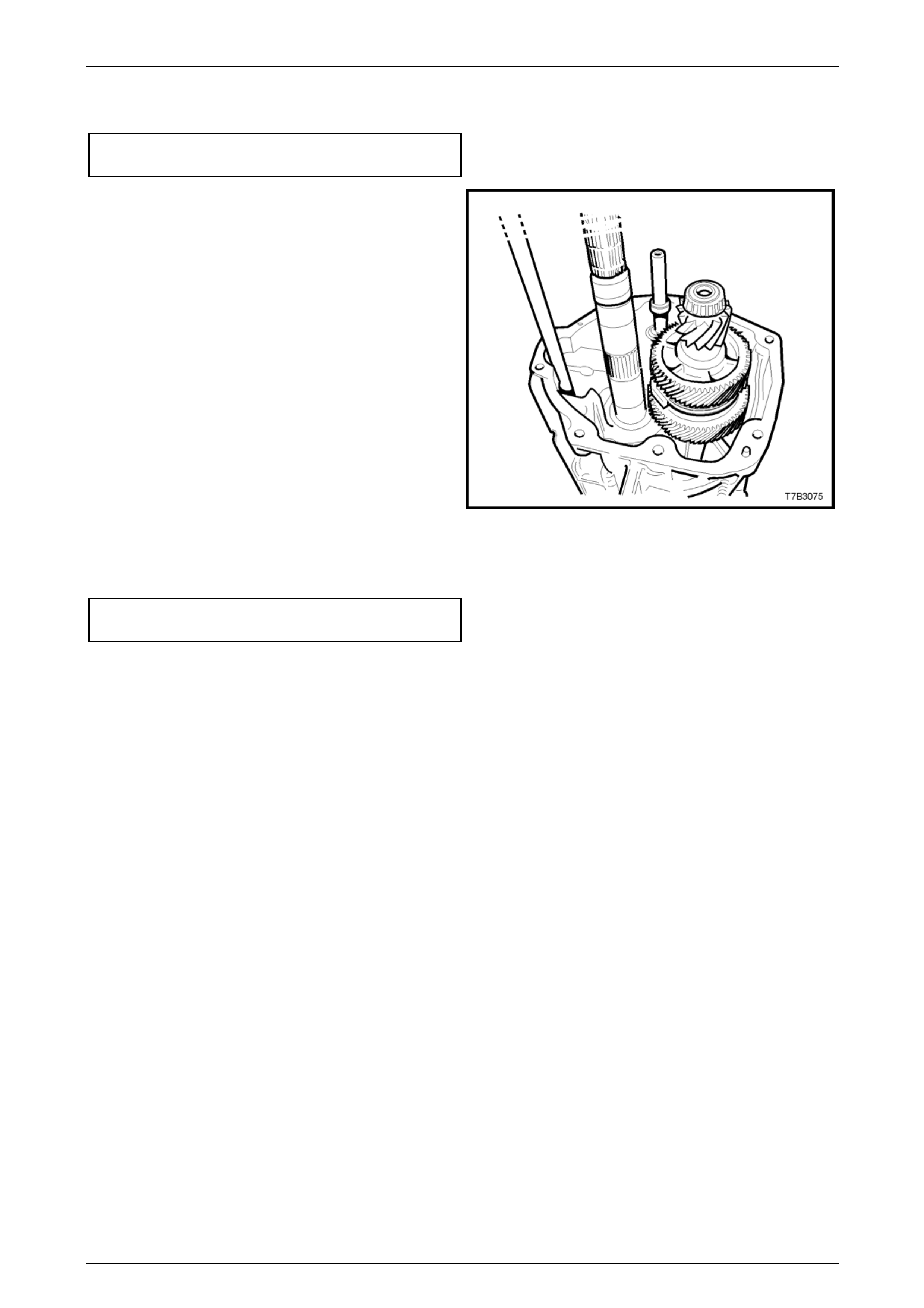
Manual Transmission – GEN III V8 Page 7B2-75
11 Reinstall the transmission case over the mainshaft, reinstall the ten adaptor to transmission case bolts and tighten
to the correct torque specification.
Adaptor plate to transmission
case bolt torque specification................................35 Nm
12 With the transmission in a vertical position, install the
countershaft extension, ensuring that the recessed
side of the thrust washer faces toward the
countershaft and that the dogs on the e xtension fully
engage with those on the countershaft.
Figure 7B2 – 134
13 Install the extension housing over the countershaft extensi on, install the eight bolts and tighten to the correct torque
specification.
Extension housing to transmission
case bolt torque specification................................35 Nm
Page 7B2- 75
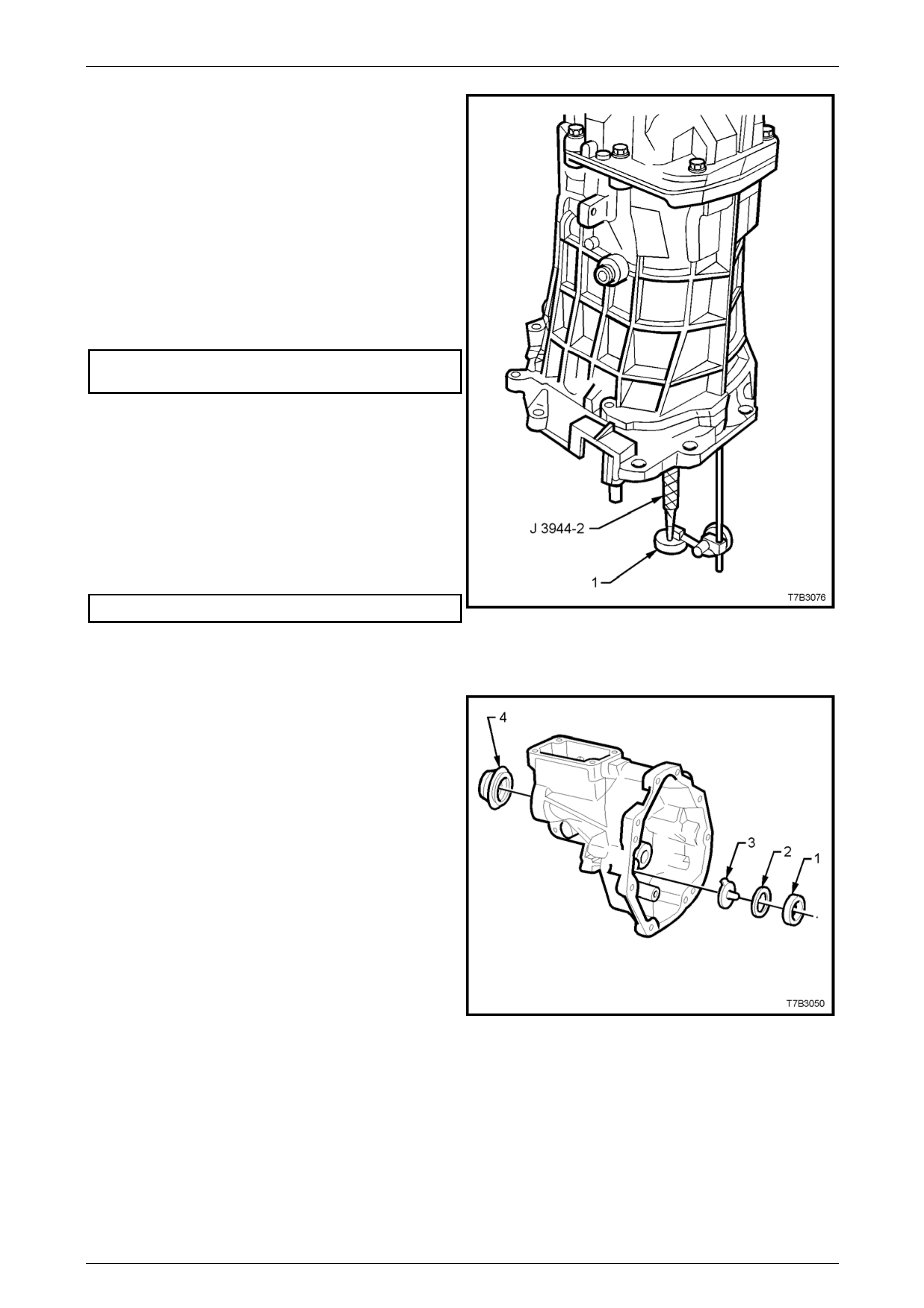
Manual Transmission – GEN III V8 Page 7B2-76
14 Insert countershaft extension, end play rod J 39444-2
through the adaptor plate plug hole and hollow
countershaft, then screw the rod into the threaded end
of the countershaft extension.
15 Mount a commercially available dial indicator to the
adaptor plate, with the probe sensing the end of the
end play rod.
16 Zero the dial indicator.
17 Lift the end play rod J 39444-2 up and do wn to
determine the countershaft extensio n end play.
18 Select a shim pack to achieve the correct end play
specification.
Countershaft Extension
End Play Specification ........................... 0.05 – 0.13 mm
NOTE
There are 33 shim selections available, ranging
from 0.559 - 1.372 mm.
19 Remove the dial indicator and end play rod.
20 Apply sealant such as Loctite 565 or equivalent (GM
P/N 12346004), to the cleaned threads of th e adaptor
plug, install the plug and tighten to the correct torque
specification.
Adaptor plate plug torque specification.................28 Nm
21 Loosen then remove the eight extension housing to
transmission case bolts, then remove the extensi on
housing.
Figure 7B2 – 135
22 Slide the countershaft gear extension, rear bearing
cup (1) from the extension housing.
NOTE
Rotating the cup back and forth while pulli ng with
the finger tips, will reduce the problem of the
bearing cup cocking and jamming in the
extension housing bore.
23 Install the oil funnel (3), the shim pack (2) determined
from the end play check, then reinstall the
countershaft extension rear bearing cup (1).
Figure 7B2 – 136
24 Loosen then remove the ten adaptor plate to transmission case bolts, then remove the tra nsmissio n case.
25 Lift the mainshaft assembly slightly to allow countershaft removal, then remove the mainshaft assembly and in put
shaft and blocker rings.
Page 7B2- 76
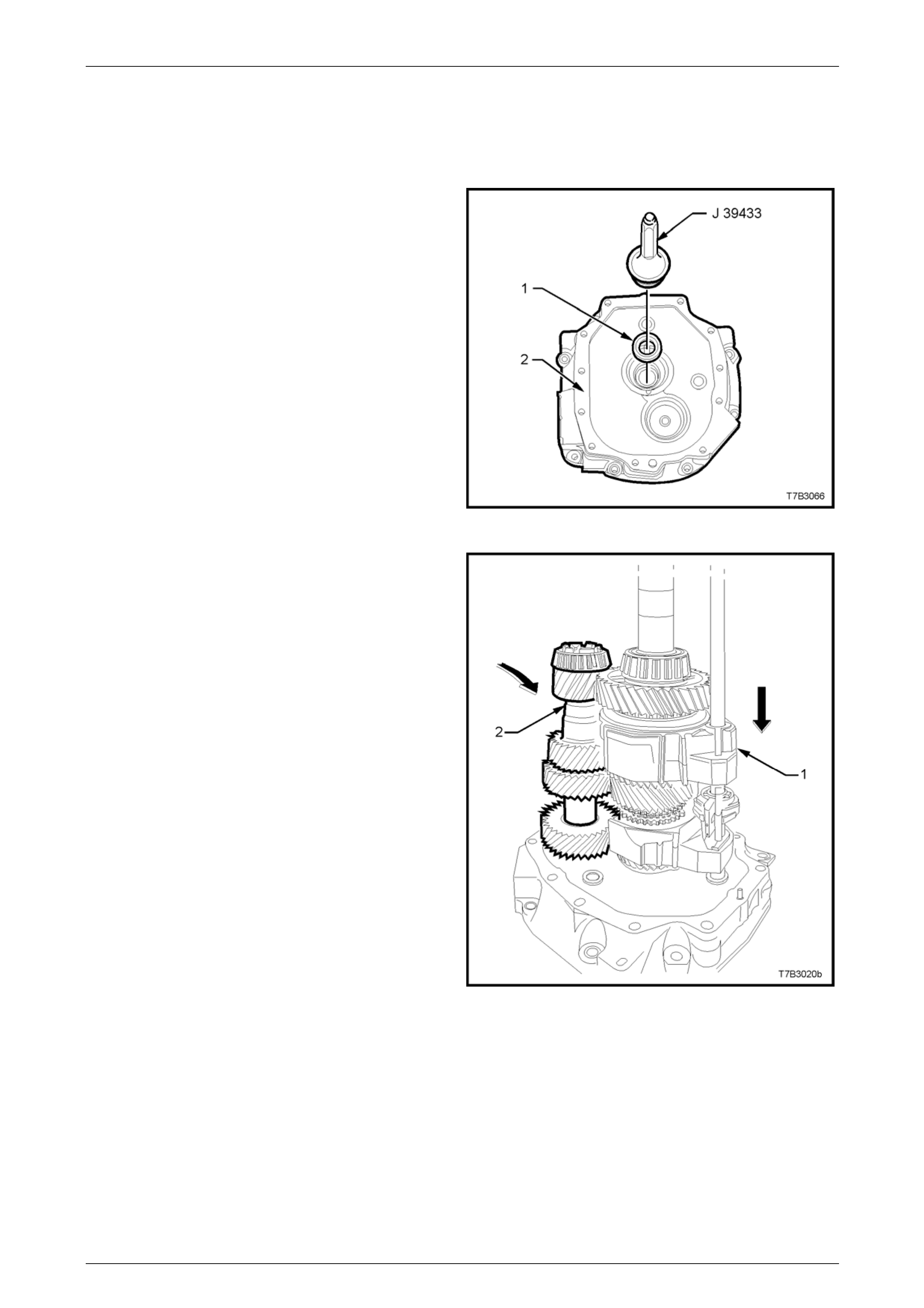
Manual Transmission – GEN III V8 Page 7B2-77
4.7 Transmission Reassemble
Gear Trains and Shift Rails
1 Using seal installer J 39433, i nstall a n ew oil seal (1)
to the adaptor plate (2).
2 Lubricate the input shaft, taper roller bearing and seal
contact area of the input shaft with clean transmission
fluid, then reinstall the input shaft to the adaptor plate.
3 Install the blocker rings to the input shaft gear.
Figure 7B2 – 137
4 Reinstall the mainshaft, together with the 1st/2nd,
3rd/4th shift shaft and forks (1) after lubricating the
spigot taper roller bearing and shift shaft bush with
clean transmission fluid. T ake care that the 4 th speed
blocker rings are correctly engaged with the
synchromesh assembly keys.
5 Lubricate the countershaft, front and rear taper roller
bearings with clean transmission fluid, then reinstall
the countershaft (2) to the adaptor plate, after lifting
the mainshaft assembly (1) slightly, to allow
installation access.
Figure 7B2 – 138
Page 7B2- 77
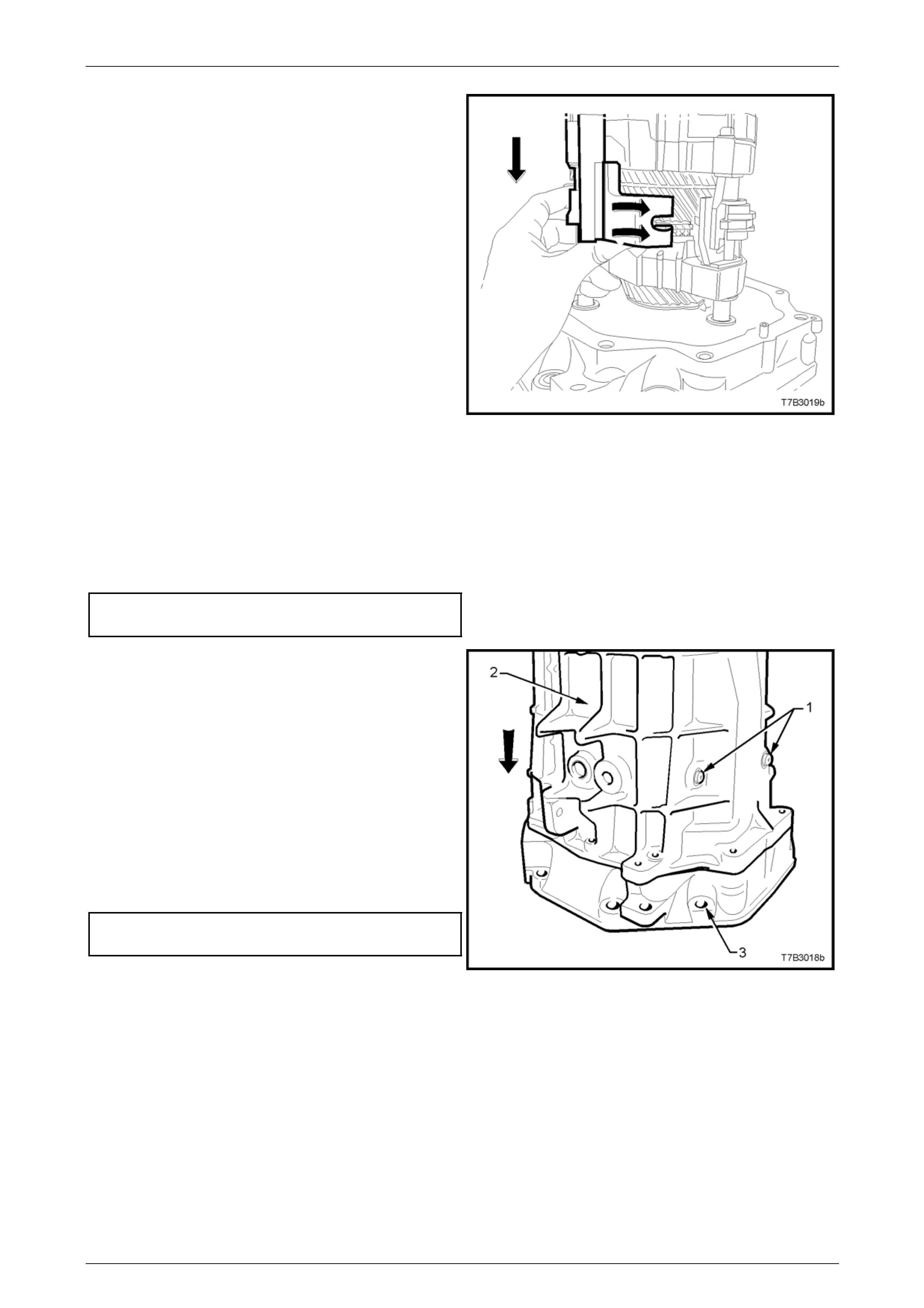
Manual Transmission – GEN III V8 Page 7B2-78
6 Install the 5th/6th and Reverse shift shaft assembly,
then align the slots in the shift rail levers with the
interlock plate and selector pin.
Figure 7B2 – 139
Transmission Case
1 Install the front offset lever guide plat e to the transmission case, with the ‘H+’ pattern in the guide plate facing the
rear of the transmission.
2 Reinstall the two Torx headed screws and tighten to the correct torque specificatio n, using a T40 Torx bit and
adaptor.
Shift guide plate screw
torque specification...............................................22 Nm
3 Apply a single bead of sealant such as Loctite
“Ultrablack” 598 or equivalent (GM P/N 12345739), to
the cleaned, transmission case to adaptor p late mating
surface.
4 Reinstall the transmission ca se (2) over the mainshaft
and shift shaft. As the case is installed, push the front
offset lever against the detent ball and spring, holding
the detent ball against the gui de plate, in the neutral
plane position, to align the front offset lever with the
shift shaft.
5 When the case is fully installe d over the two adaptor
plate dowel pins, install the ten ada ptor to
transmission case bolts and tighten to the correct
torque specification.
Adaptor plate to transmission
case bolt torque specification................................35 Nm
6 Apply thread sealant such as Loctite 242 or
equivalent, to the cleaned threads of the shift lever
guide bolts (1). Figure 7B2 – 140
Page 7B2- 78
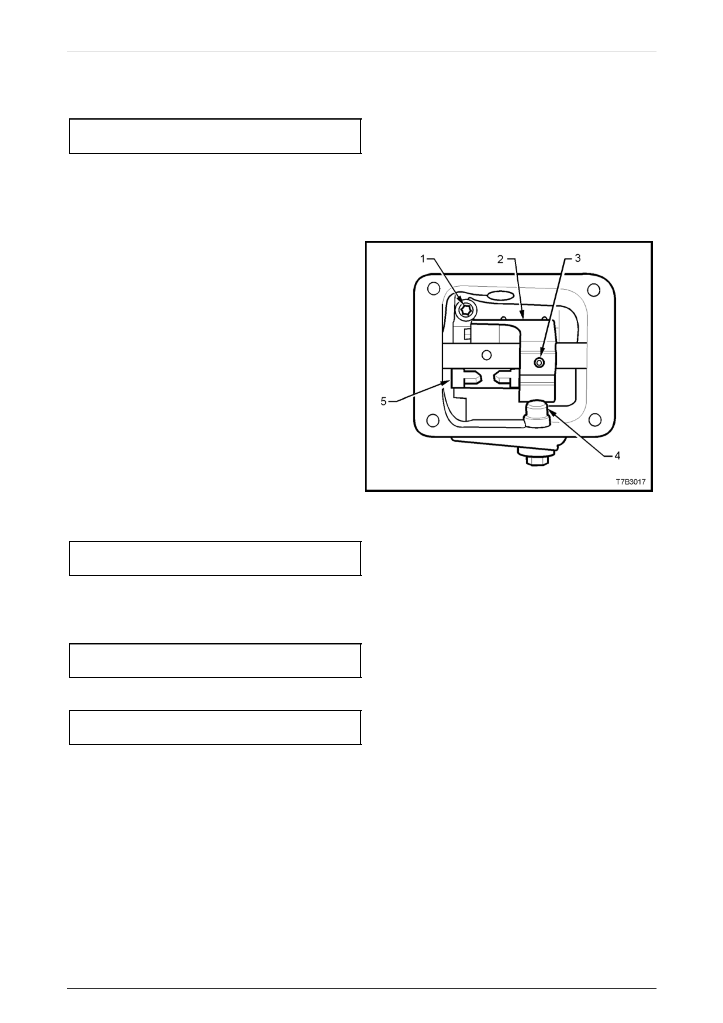
Manual Transmission – GEN III V8 Page 7B2-79
7 Pull up on the 5th/6th and Reverse shift shaft to align the slot of the interlock plate with the guide bolt hole.
8 Reinstall and tighten to the correct torque sp ecification.
Shift lever guide bolt
torque specification...............................................28 Nm
NOTE
To maintain the shift rails in the correct position
during the remainder of the assembly process, it
is vital that these two guide bolts are installed at
this time.
9 Align the front offset lever (2) with the hole in the shift
shaft, then install a new roll pin (3) to secure, using a
suitable size pin punch and hammer.
NOTE
Insert a pin punch of suitable size into the rear
offset lever roll pin hole in the shift shaft and
check that the shift shaft is able to be rotated
freely through each of the detent ball positions.
This will ensure that the shift selector forks,
interlock plate and associated parts are all
aligned correctly. If difficulty is experienced in
rotating the shift shaft, then the transmission
case must be removed and the problem recti fied
before proceeding.
10 Apply thread sealant such as Loctite 242 or
equivalent, to the cleaned threads of the shift
enhancer (4).
11 Using a 24 mm socket, install and tighten the shift
enhancer to the correct torque specification.
Shift enhancer
torque specification...............................................40 Nm
Figure 7B2 – 141
12 Apply a continuous bead of sealant such as Loctite “Ultrablack” 598 or equivalent (GM P/N 12345739), to the
mating surface of the cover plate, then install the plate to the transmission case.
13 Install the four cover bolts and tighten to the correct torque specification.
Front offset lever cover
bolt torque specification........................................25 Nm
14 Install the back-up lamp switch and tighten to the correct torque specification.
Back-up lamp switch
torque specification...............................................28 Nm
Page 7B2- 79
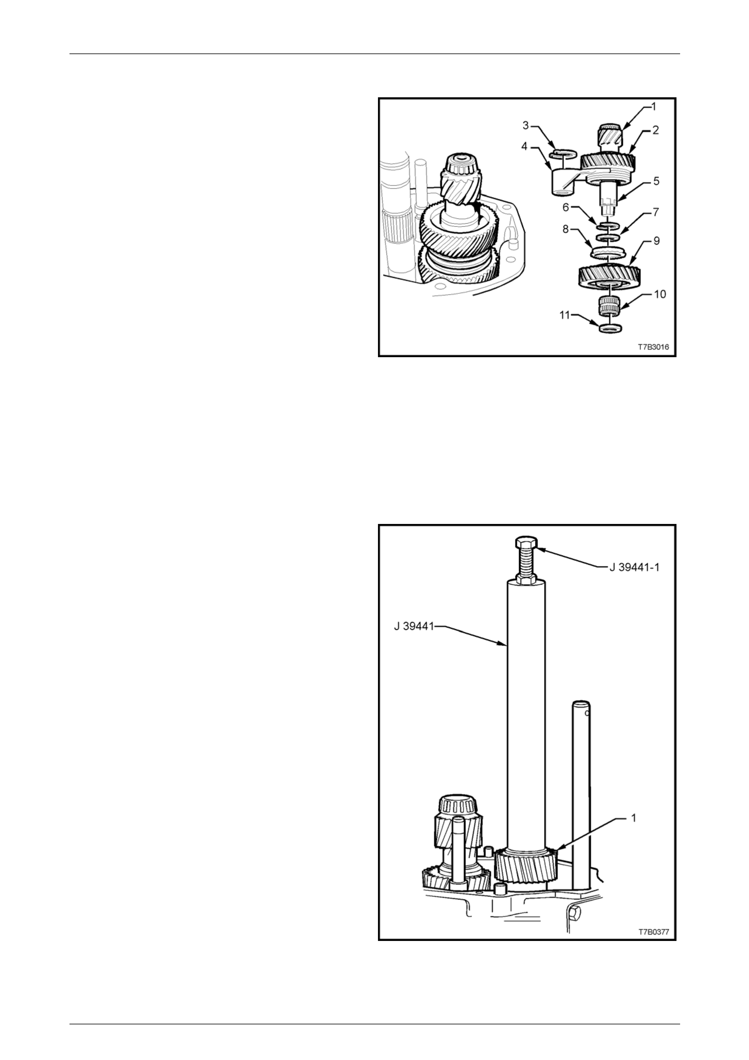
Manual Transmission – GEN III V8 Page 7B2-80
Countershaft Extension Assembly
1 Install the following components to the countershaft
extension (5):
7 Spacer.
8 6th gear, blocker ring.
9 6th drive gear.
10 6th drive gear, caged needle roller bearing.
11 Thrust washer.
NOTE
• The recessed side of the thrust washer (11)
faces the countershaft.
• Snap ring (6) was installed when the 5th/6th
synchromesh assembly (2) was installed to
the countershaft extension (1). Refer to
Step 4, page 7B2-68.
Figure 7B2 – 142
2 With the 5th/6th shift fork (4) positioned as sho wn, install the countershaft extension assembly onto the rear of the
countershaft, guiding the 5th/6th shift fork (4) over the 5th/6th shift rail lever sleeve.
3 Rotate the countershaft extension back and forth to ensure that the dog teeth on the countershaft extension mate
with the corresponding dogs on the end of the countershaft.
4 Install a new circlip (3) to the groove in the 5th/6th shift rail lever sleeve to secure the shift fork.
5th/6th Driven Gear
1 Install the 5th/6th speed driven gear (1) over the
mainshaft with the smaller gear facing in ward.
2 Engage the inner gear splines with those on the
mainshaft and install, using installer J 39 441 and
bolt/nut J 39441-1.
NOTE
It may be necessary to rotate the 5th and 6th
drive gears on the countershaft extension to
assist in gear meshing with the driven gear (1),
prior to the gear installation process.
Figure 7B2 – 143
Page 7B2- 80
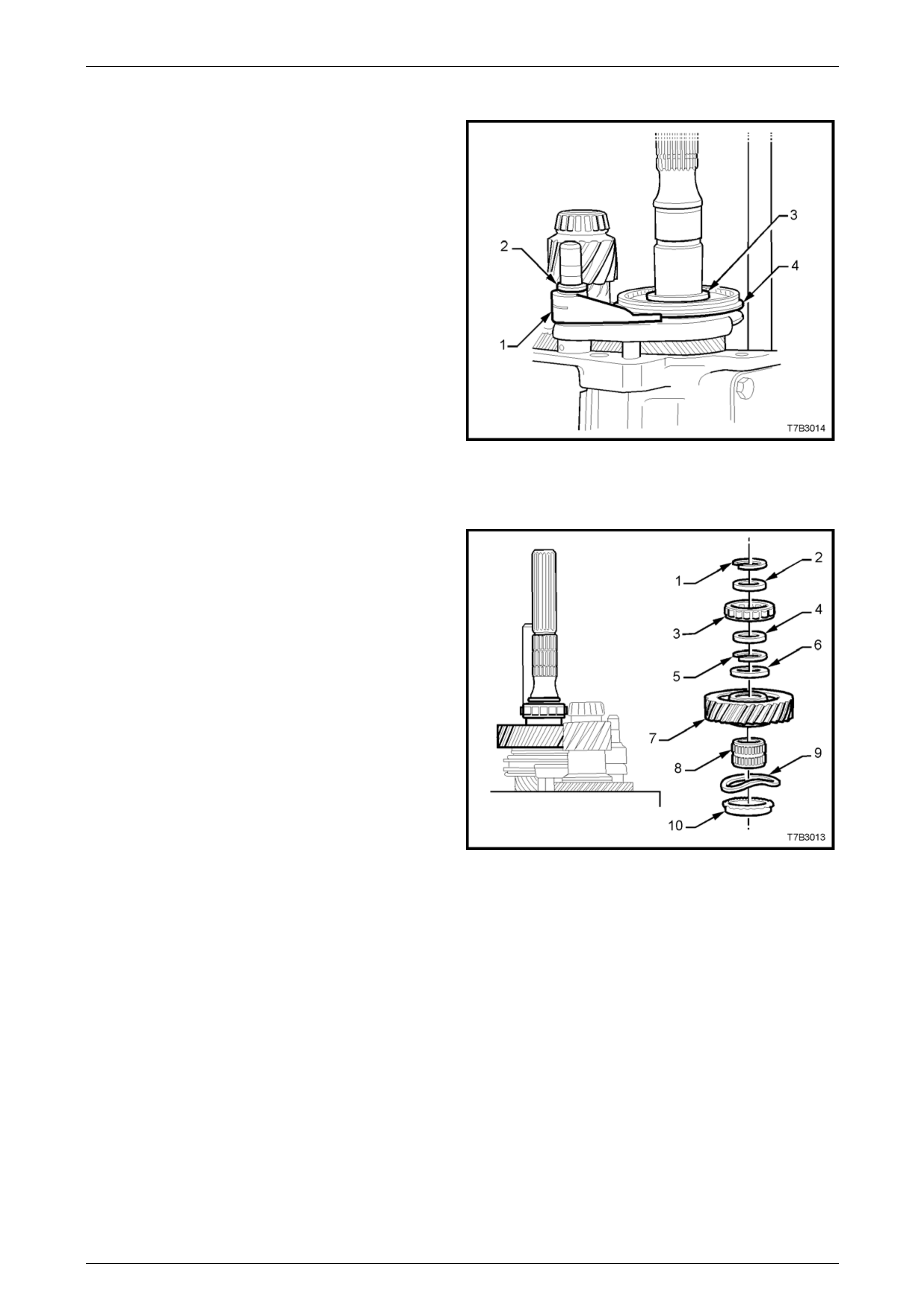
Manual Transmission – GEN III V8 Page 7B2-81
Reverse Synchromesh Assembly
1 With the reverse shift lever (1) positione d as shown,
reinstall the reverse synchromesh assembly (4) and
shift lever (1) to the mainshaft and shift shaft, ensuring
that the reverse synchromesh key retainer faces the
end of the 6th speed driven gear.
2 Fit a new circlip (2) to retain the shift fork (1) and a
new snap ring (3) to secure the reverse sync hromesh
assembly (4).
Figure 7B2 – 144
Reverse Speed Gear
1 Install the following components onto the mainshaft,
aligning the blocker rings with the synchromesh keys,
in the process:
10 Reverse gear blocker ring.
9 Wave washer.
8 Reverse gear, caged roller bearing.
7 Reverse gear.
6 Thrust washer.
2 Fit a new snap ring (5) to secure the reverse driven
gear (7).
3 Continue to install the components of the rear
mainshaft roller bearing, as follows
4 Spacer.
3 Rear mainshaft roller race.
2 Spacer.
4 Secure these components with a new snap ring (1).
Figure 7B2 – 145
Page 7B2- 81
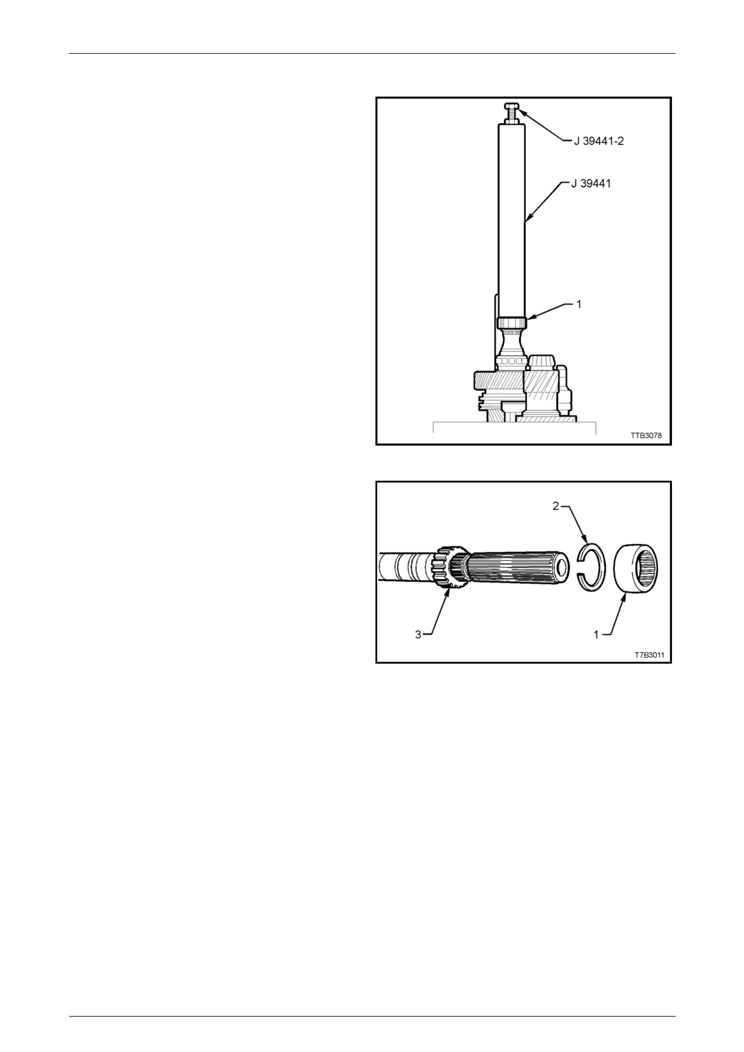
Manual Transmission – GEN III V8 Page 7B2-82
Speedometer Pulse Ring
1 Install a new, inner snap ring to the spee dometer
pulse ring groove in the mainshaft.
2 Install the speedometer pulse ring to the mainshaft,
using Installer J 39441 and bolt/nut J 39441-2.
3 Tighten the nut of J 39441-2 until the pulse ring
bottoms against the snap ring.
4 Remove the tools.
Figure 7B2 – 146
5 Install a new snap ring (2) to the outer speedometer
pulse ring (3) groove in the mainshaft.
6 If in a serviceable condition, the rubber, splined
packing ring (1) may be reinstalled. Otherwise discard,
as it serves no functional purpose.
Figure 7B2 – 147
Page 7B2- 82
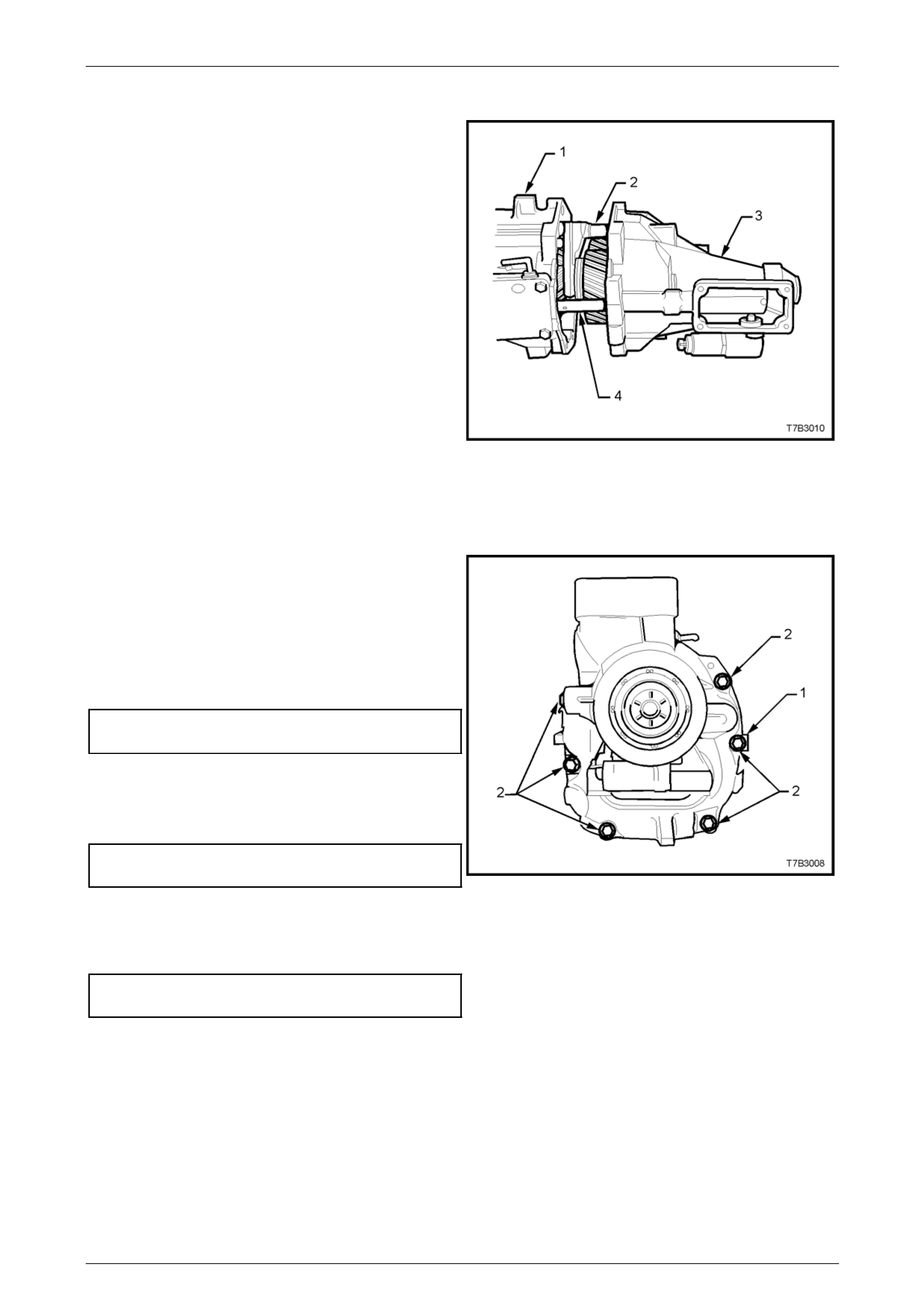
Manual Transmission – GEN III V8 Page 7B2-83
Extension Housing
1 Rotate the transmission through 90° into the horizontal
position, then move the shift rail (4) into the 2nd or 4th
gear position to shorten the shift rail length.
2 Lubricate the countershaft e xtension taper roller
bearing with clean transmission fluid.
3 Install the two circular magnet s into the grooved space
in the transmission case.
4 Apply a continuous bead of seal ant such as Loctite
“Ultrablack” 598 or equivalent (GM P/N 12345739), to
the extension housing to transmission case mating
surface.
5 Install the extension housing (3) over the mainshaft,
aligning the shift rails (4 and 2) with the extension
housing bushes.
NOTE
Because the 5th/6th and Reverse shift shaft (2)
is unsupported at this point, it will need to be
manipulated to ali gn the end of the shaft with the
corresponding bore in the extension hous ing. Do
not try and force the extension housing over the
dowel pins.
Figure 7B2 – 148
6 Install all but the two upper extension housing bolts.
(not shown). Apply thread sealant such as Loctite 565
or equivalent (GM P/N 12346004), to the cleaned
threads of the two upper bolts. Note that a wiring
harness clip is under the right hand up per bolt and
also, the position of the identification tag (1).
7 Tighten all 8 bolts (2) to the correct torque
specification.
Extension housing bolt
torque specification...............................................35 Nm
8 Install the O-ring to the reverse lockout solenoid
assembly, then install the assembly and retainin g bolt
to the extension housin g, tightening to the correct
torque specification.
Reverse lock-out solenoid assembly
retaining screw torque specification......................18 Nm
Figure 7B2 – 149
9 Install the O-ring seal to the vehicle speed sensor, then install the sensor to the extension housing, retaining with a
screw, tightened to the correct torque specification.
Speed sensor retaining
screw torque specification.....................................12 Nm
Page 7B2- 83
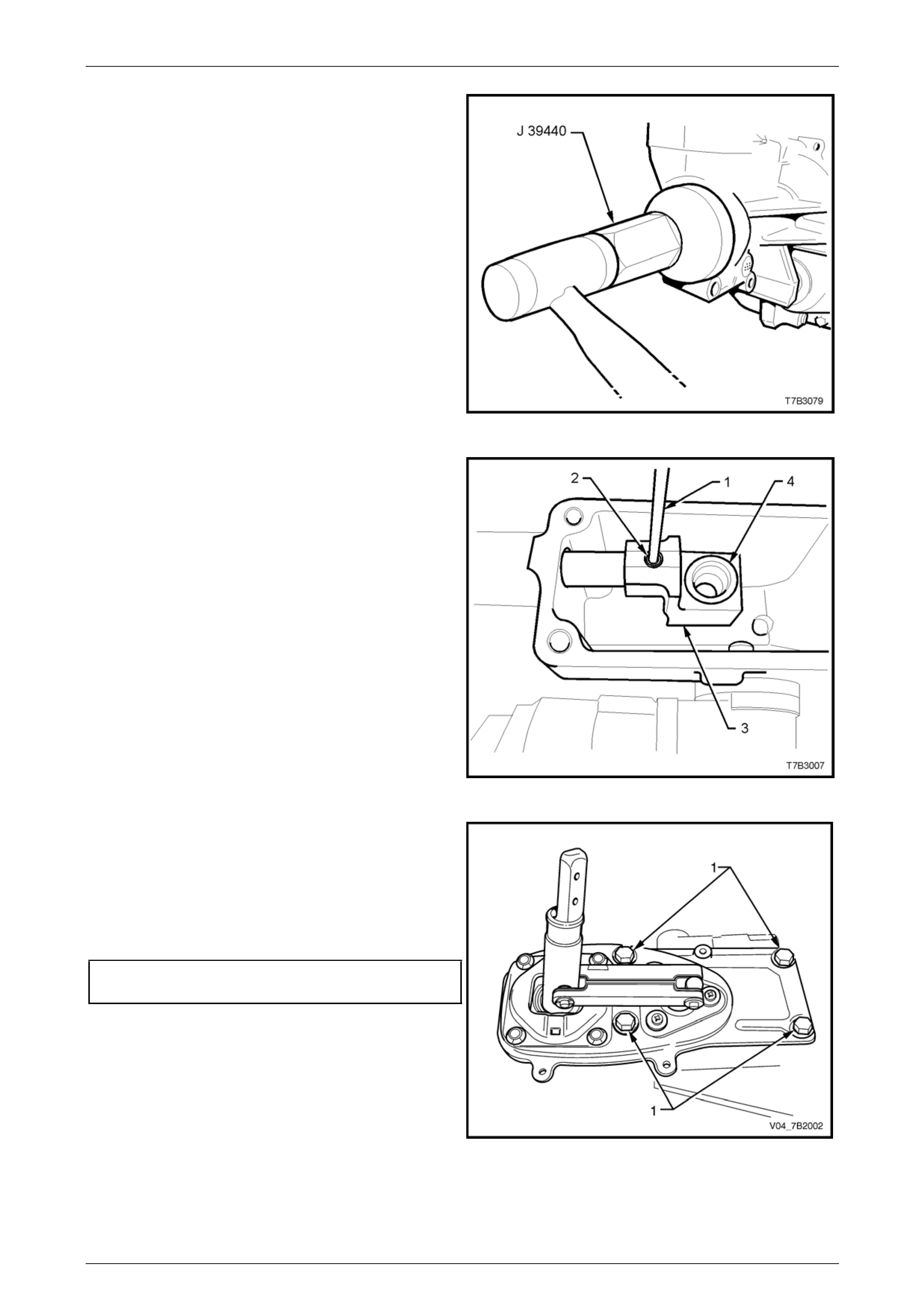
Manual Transmission – GEN III V8 Page 7B2-84
10 Using seal installer J 39440, install a NEW rear seal to
the extension housing.
Figure 7B2 – 150
11 Slide the rear offset lever (3) over the shift rail and
secure with a new roll pin (2), installed with a suitable
pin pinch (1) and hammer.
12 Apply Lithium grease NLGI No. 4 EP to the isolator
cup (4) in the rear offset shift lever (3).
Figure 7B2 – 151
13 If the remote shifter assembly, rubber seal is
undamaged, then it may be re-used. Otherwise, fit a
new seal to the extension hous ing.
14 Reinstall the remote shifter assembly to the extension
housing, install the insulating grommets an d four
retaining bolts (1), then tighten to the correct torque
specification.
Remote shift lever retaining
bolt torque specification........................................20 Nm
Figure 7B2 – 152
Page 7B2- 84
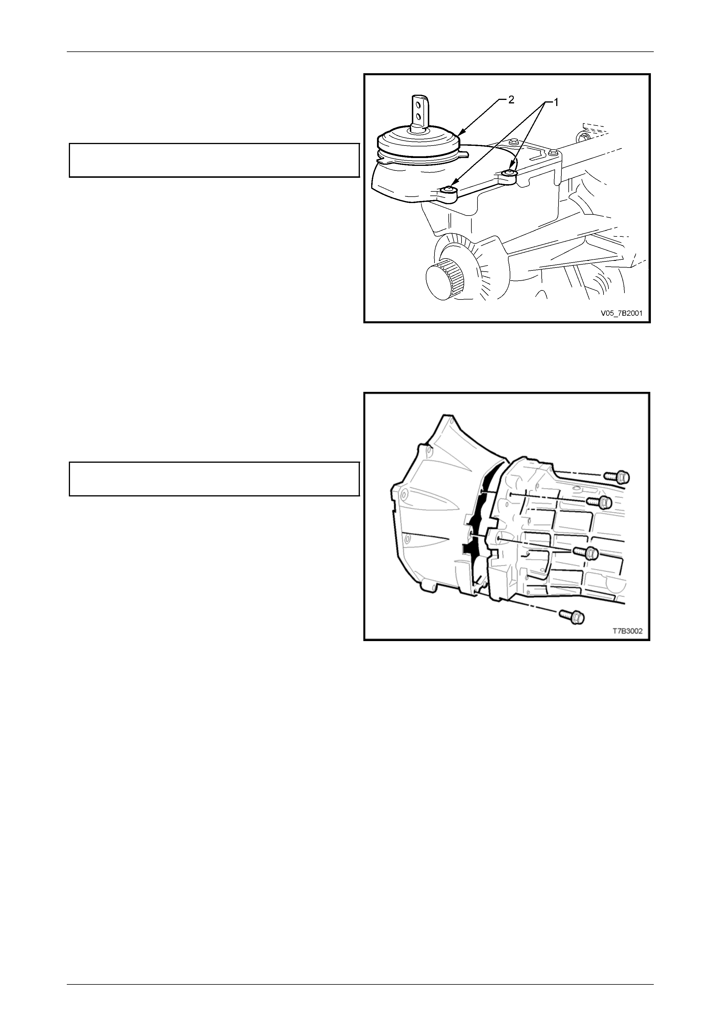
Manual Transmission – GEN III V8 Page 7B2-85
15 Reinstall the shift cover and boot (2) over the shifter
assembly.
16 Reinstall the shift cover screws (1) and tighten to the
correct torque specification.
Shift cover retaining
screw torque specification....................................4.0 Nm
Figure 7B2 – 153
Clutch Housing and Slave Cylinder
1 Remove the transmission from the transmission
holding fixture J 39430.
2 Reinstall the clutch housing and eight bolts, tightening
to the correct torque specification.
Clutch housing to adaptor plat e
bolt torque specification........................................35 Nm
Figure 7B2 – 154
Page 7B2- 85
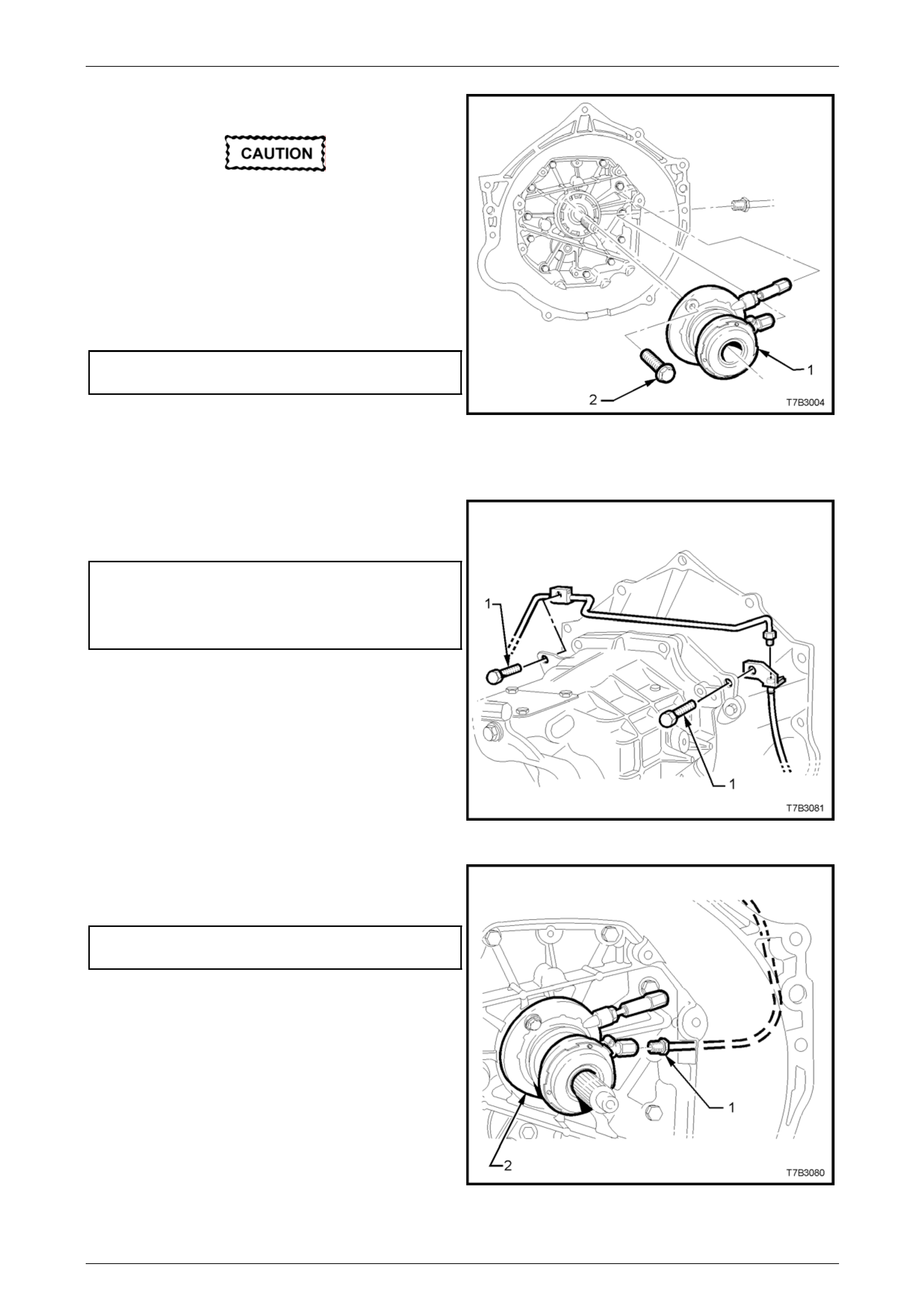
Manual Transmission – GEN III V8 Page 7B2-86
3 Install the clutch slave cylinder (1) over the input shaft.
Before tightening the two retaining bolts,
centralise the slave cylinder bleed er screw in
the transmission adaptor plate/clutch
housing aperture. This is necessary to
ensure access to the bleeder, after the
transmission has been installed.
4 Apply thread sealant such as Loctite 242 or
equivalent, to the two slave cylinder retaining bolts (2),
install and tighten to the correct torque specification.
Clutch slave cylinder
bolt torque specification........................................10 Nm
5 Sparingly appl y an NLGI No. 2 lithium soap based EP
grease with molybdenum disulphide, such as Shell
Retinax HDX2 grease or BP Energrease LMS-EP 23
(or equivalent) to the clutch throwout bearing contact
face, the splines and spigot of the input shaft.
Figure 7B2 – 155
6 Route the clutch fluid pipe around the transmission
housing, install the bracket fasteners (1) and tighten to
the correct torque specification.
Clutch pipe bracket screw
(Left Side) torque specification................................5 Nm
Clutch pipe bracket screw
(Right Side) torque specification...........................10 Nm
Figure 7B2 – 156
7 Install the clutch fluid pipe fitting (1) to the slave
cylinder (2) and tighten to the correct torque
specification.
Clutch hydraulic pipe fitting to
slave cylinder torque specification ........................13 Nm
Figure 7B2 – 157
Page 7B2- 86
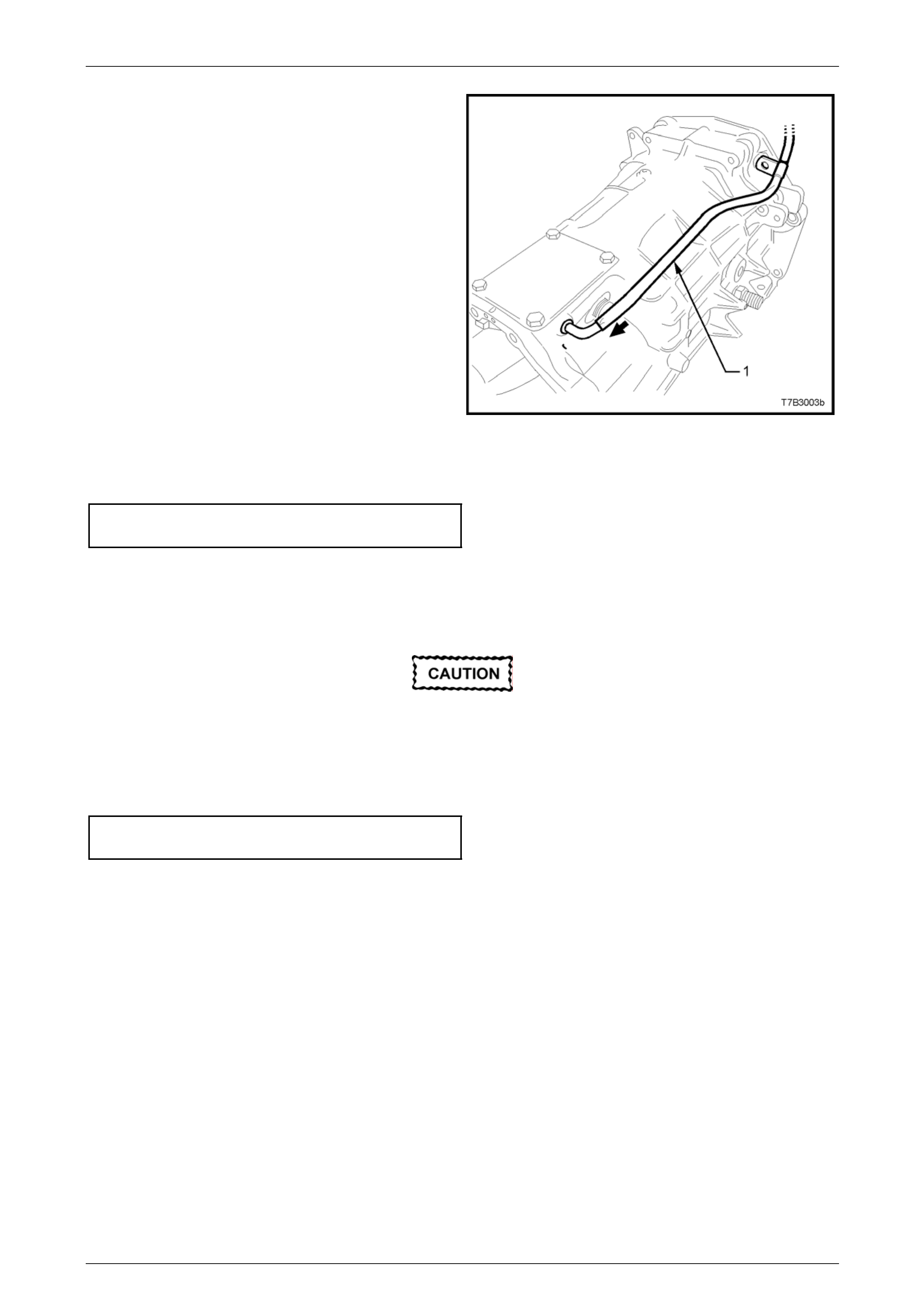
Manual Transmission – GEN III V8 Page 7B2-87
8 Install the transmission vent tube (1), sliding it over the
pipe located at the front offset lever.
Figure 7B2 – 158
9 If removed, reinstall the rear engine mount to transmission extension bolts, tightening to the correct torque
specification.
Transmission mount to extension
housing bolt torque specification...........................25 Nm
10 Fit a suitable plug to the rear oil seal to prevent dirt/dust entry.
11 Fill transmission with 4.4 litres of Dexron III® fluid. Refer to 2.2 Checking Transmissio n Lubricant Level, in this
Section.
Under no circumstances is Teflon thread tape
to be used on the filler, drain or adaptor plate
plugs.
12 Apply sealant such as Loctite 565 or equivalent (GM P/N 12346004), to the cleaned threads of the filler plug and
tighten to the correct torque specification.
Filler plug
torque specification...............................................28 Nm
13 Reinstall transmission into the vehicle. Refer to 4.2 Transmission Assembly, in this Section.
Page 7B2- 87

Manual Transmission – GEN III V8 Page 7B2-88
5 Diagnosis
5.1 Transmission Shifts Hard
Definition: The transmission does not shift smoothly or without difficulty into another gear.
Step Action Yes No
1 1 Check the transmission for improper lubricant.
Refer to 2.1 Recommended Lubricant.
Is the recommended lubricant being used? Go to Step 2 Go to Step 3
2 1 Check the transmission for loose shift lever housing bolts.
Are the bolts loose? Go to Step 4 Go to Step 5
3 1 Drain and refill the transmission with the recommended lubricant.
Refer to 2.3 Draining and Refilling Transmission.
Does the transmission shift smoothly? System OK Go to Step 5
4 1 Align the component parts and tighten the fasteners.
Refer to 7 Torque Specifications.
Does the transmission shift smoothly? System OK Go to Step 5
5 1 Check for proper clutch operation.
Was the clutch the cause of hard shifting? System OK Go to Step 6
6 1 Remove the transmission. Refer to 4.2 Transmission Assembly,
Remove, in this Section.
2 Disassemble the transmission. Refer to 4.3 Transmission
Disassemble.
3 Look for the following list of causes:
• Binding shift rail.
• Mispositioned shift selector arm roll pin.
• Worn shift rail bores.
• Distorted oil seal.
4 Replace all worn or damaged parts. – –
Page 7B2- 88

Manual Transmission – GEN III V8 Page 7B2-89
5.2 Transmission Hard To Shift Into Reverse
Definition: The transmission does not shift smoothly into reverse ge ar or will n ot shift into reverse g ear.
Step Action Value(s) Yes No
1
1 Turn ignition switch to the ON position.
2 Check for voltage at the reverse lockout solenoid
electrical connector.
Is the specified voltage at the connector?
12 volts
Go to Step 2 Go to Step 5
2
1 Remove the reverse lockout solenoid assembly from
the reverse lockout assembly. Refer to
3.4 Reverse Lockout Solenoid , Remove.
2 Apply 12 volts to the solenoid electrical connector.
Is the solenoid plunger extended?
–
Go to Step 3 Go to Step 6
3
1 Remove the reverse lockout assembl y from the
transmission. Refer to 3.4 Reverse Lockout
Solenoid Assembly, Remove.
Can you easily depress the reverse lockout plunger with
your thumb?
–
Go to Step 4 Go to Step 7
4
1 Remove the transmission. Refer to
4.2 Transmission Assembly, Remove.
2 Disassemble the transmission. Refer to
4.3 Transmission Disassembl e, in this Section.
3 Look for the following list of causes:
• Worn or broken shift linkage parts.
• A worn or damaged synchroniser ring or hub.
4 Replace all worn or damaged parts.
–
– –
5 1 Repair the reverse lockout solenoid electrical circuit.
Is the circuit OK? – Go to Step 1 –
6 1 Replace the solen oid.
Does the transmission shift OK now? – System OK –
7
1 Repair or replace the reverse lockout assembly.
Refer to 3.4 Reverse Lockout Solenoid Asse mbly,
Reinstall.
Does the transmission shift OK now?
–
System OK –
Page 7B2- 89

Manual Transmission – GEN III V8 Page 7B2-90
5.3 Gear Clash When Shifting Gears
Definition: The transmission gears clash when shifting from one gear into another.
Step Action Yes No
1 1 Check for low oil level in the transmission. Refer to
2.2 Checking Transmission Lu bricant Level.
Is the oil level OK? Go to Step 2 Go to Step 3
2 1 Check the transmission for improper lubricant.
Refer to 2.1 Recommended Lubricant.
Is the recommended lubricant being used? Go to Step 5 Go to Step 4
3 Replenish the oil to the level of the oil fill plug. – –
4 Drain and refill the transmissio n with the recommended lubricant. Refer
to 2.3 Draining and Refilling T r ansmission. – –
5 1 Check for proper clutch operation.
Is the clutch operating properly? Go to Step 6 –
6 1 Remove the transmission. Refer to 4.2 Transmission Assembly,
Remove.
2 Disassemble the transmission.
Refer to 4.3 Transmission Disassemble.
3 Look for the following list of causes:
• Gearshift components are worn or damaged.
• Synchroniser assemblies worn or damaged.
4 Replace all worn or damaged parts. – –
Page 7B2- 90

Manual Transmission – GEN III V8 Page 7B2-91
5.4 Transmission Noisy
Definition: Transmission gear noise is evident in the pass enger compartment.
Step Action Yes No
1 1 Check for low oil level in the transmission.
Refer to 2.2 Checking Transmission Lubricant Level.
Is the oil level OK? Go to Step 2 Go to Step 3
2 1 Check the transmission for improper lubricant.
Refer to 2.1 Recommended Lubricant.
Is the recommended lubricant being used? Go to Step 5 Go to Step 4
3 Replenish the oil to the level of the oil fill plug. – –
4 Drain and refill the transmissio n with the recommended lubricant.
Refer to 2.3 Draining and Refilling Transmission. – –
5 1 Check for loose clutch housin g bolts. Refer to 7 Torque Wrench
Specifications.
Are the bolts tightened to specifications? Go to Step 6 Go to Step 7
6 1 Remove the transmission.
Refer to 4.2 Transmission Assembly, Remo ve.
2 Disassemble the transmission.
Refer to 4.3 Transmission Disassemble.
3 Look for the following list of causes:
• Gearshift components are worn or damaged.
• Transmission gears are worn or damaged.
• Bearing components are worn or damag ed.
4 Replace all worn or damaged parts. – –
7 Tighten the clutch housing b olts to the specified torque. – –
Page 7B2- 91

Manual Transmission – GEN III V8 Page 7B2-92
5.5 Transmission Jumps Out Of Gear
Definition: Transmission selects Neutral without any driver action.
Step Action Yes No
1 1 Check for loose clutch housin g bolts.
Refer to 7. Torque Wrench Specifications.
Are the bolts tightened to specifications? Go to Step 2 Go to Step 3
2 Tighten the clutch housing b olts to the specified torque. – –
3 1 Remove the transmission.
Refer to 4.2 Transmission Assembly, Remo ve.
2 Disassemble the transmission.
Refer to 4.3 Transmission Disassemble.
3 Look for the following list of causes:
• Gearshift components worn or damaged.
• Gear teeth worn or tapered.
• Synchroniser assemblies worn or damaged.
• Excessive end play in compo nents.
• Bearing components are worn or damag ed.
4 Replace all worn or damaged parts. – –
Page 7B2- 92

Manual Transmission – GEN III V8 Page 7B2-93
5.6 Transmission Does Not Shift Into One
Gear
Definition: The transmission does not shift into one gear.
Step Action Yes No
1 1 Remove the transmission. Refer to 4.2 Transmission Assembly,
Remove.
2 Check for worn or damaged gearshift compo nents.
Are the gearshift components OK? Go to Step 2 Go to Step 3
2 1 Disassemble the transmission.
Refer to 4.3 Transmission Disassemble.
2 Look for worn or damaged synchroniser assemblies.
Replace all worn or damaged parts.
3 1 Replace the worn or damaged gearshift components. Refer to
Transmission Disassemble.
Will the transmission shift gears? System OK Go to Step 2
Page 7B2- 93

Manual Transmission – GEN III V8 Page 7B2-94
5.7 Transmission Locked In One Gear
Definition: The transmission cannot be shifted out of ge ar.
Step Action Yes No
1 1 Remove the transmission. Refer to 4.2 Transmission Assembly,
Remove.
Are the gearshift components properl y assembled? Go to Step 2 Go to Step 3
2 Are the gearshift components worn, bent or broken ? Go to Step 4 Go to Step 5
3 1 Disassemble the gearshift components. Properl y ass embl e the
gearshift components. Refer to 4.3 Transmission Disassemble.
Will the transmission shift gears? System OK Go to Step 5
4 1 Replace the worn or damaged parts. Refer to 4.3 Transmission
Disassemble.
Will the transmission shift gears? System OK Go to Step 5
5 1 Disassemble the transmission geartrain.
Refer to 4.3 Transmission Disassemble.
2 Look for worn, broken, or damaged compone nts.
Replace all worn, broken, or damaged comp onents. – –
Page 7B2- 94

Manual Transmission – GEN III V8 Page 7B2-95
6 Specifications
Transmission:
GEN III, V8 Powered Vehicles...............................................T ype T56 Manual Transmission.
Overdrive 5th and 6th Speed
Production Option (All Except Coupe)..............................................................................MM6
Coupe................................................................................................................................M12
Transmission Ratios: MM6 M12
1st...........................................................................................2.66:1 .............................2.97:1
2nd..........................................................................................1.78:1 .............................2.07:1
3rd ..........................................................................................1.30:1 .............................1.43:1
4th...........................................................................................1.00:1 .............................1.00:1
5th...........................................................................................0.74:1 .............................0.84:1
6th...........................................................................................0.50:1 .............................0.57:1
Reverse..................................................................................2.90:1 .............................3.28:1
Number Of Teeth: MM6 M12
Input Gear..................................................................................31 ......................................29
Mainshaft Gear
1st........................................................................................39 ......................................43
2nd.......................................................................................43 ......................................41
3rd........................................................................................37 ......................................37
5th........................................................................................37 ......................................37
6th........................................................................................29 ......................................29
Reverse................................................................................35 ......................................35
Reverse Idler Gear...............................................................23 ......................................23
Countershaft Gear Input............................................................36......................................38
Countershaft Gear
1st........................................................................................17 ......................................19
2nd.......................................................................................28 ......................................26
3rd........................................................................................33 ......................................34
Countershaft Gear Extension
5th........................................................................................58 ......................................58
6th........................................................................................67 ......................................67
Reverse................................................................................14 ......................................14
Page 7B2- 95

Manual Transmission – GEN III V8 Page 7B2-96
Synchromesh Assemblies:
Synchromesh Ring Wear
Replacement Clearance – All for ward gears..........................................less than 0. 38 mm
Reverse Gear.........................................................................................less than 0.75 mm
Bearing Pre-Load/End Float:
Input Shaft/Mainshaft.........................................................................0.00 – 0.05 mm pre-load
Countershaft Gear.............................................................................0.00 – 0.05 mm pre-load
Countershaft Gear Extension ...........................................................0.05 – 0.13 mm end float
Selective Shim Washer Thicknesses:
Input Shaft Bearing......................................................................................0.559 – 1.372 mm
Countershaft Gear.......................................................................................0.356 – 1.372 mm
Countershaft Gear Extension ......................................................................0.559 – 1.372 mm
Lubricants:
Transmission .................................................................................................Dexron III® fluid.
Capacity (Nominal).....................................................................................................4.4 litres
Rear Offset Lever Isolating Cup ........................................................... NLGI No. 4 EP grease
Clutch Throwout Bearing Contact Face.......................... 10% molybdenum disulphide grease
Sealants:
Thread Sealant in nominated locations.............Loctite 242 or equivalent (GM P/N 12345382)
Sealing Plugs....................................................Loctite 565 or equivalent (GM P/N 12346004)
Adaptor Plate and Extension Housing to Case..........Loctite 598HB “Ultrabl ack” or equivalent
(GM P/N 12345739)
Page 7B2- 96

Manual Transmission – GEN III V8 Page 7B2-97
7 Torque Wrench Specifications
ATTENTION
Fasteners must be repl aced after loosening.
Vehicle must be at curb height before final tightening.
Fasteners either have micro encapsulated sealant applied or incorporate a mechanical thread lock and
should only be re-used once. If in doubt, replacement is recommended.
Adaptor Plate Plug ..................................................................................28 Nm
Adaptor Plate to Transmission Case Bolts..............................................35 Nm
Backup Lamp Switch...............................................................................28 Nm
Cross Brace Bracket Bolt to Catalytic Converter.....................................25 Nm
Cross Brace Bracket Bolt to Transmission Extension .............................50 Nm
Clutch Housing to Adaptor Plate Bolt ......................................................35 Nm
Clutch Housing to Engine Block Bolt.......................................................50 Nm
Clutch Hydraulic Pipe Bracket Screw (LHS)..............................................5 Nm
Clutch Hydraulic Pipe Bracket Screw (RHS)...........................................10 Nm
Clutch Hydraulic Pipe Fitting to Slave Cylinder .......................................13 Nm
Clutch Hydraulic Pipe Fitting to Flexible Hose.........................................13 Nm
Clutch Slave Cylinder Bolt.......................................................................10 Nm
Drain Plug................................................................................................28 Nm
Engine to Transmission Close-out Cover Screws (Each Side)................12 Nm
Exhaust Pipe Bracket to Exhaust Pipe Nut..............................................25 Nm
Exhaust Pipe Bracket to Transmission Bracket Nut................................25 Nm
Extension Housing to Transmission Case Bolts......................................35 Nm
Filler Plug ................................................................................................28 Nm
Front Offset Lever Cover Bolts................................................................25 Nm
Front Selector Pivot Seat Screw................................................................4 Nm
Gearshift Control Lever to Remote Shift Lever Bolt.................................25 Nm
Rear Crossmember to Transmission Support Mount Nut .......................25 Nm
Rear Crossmember to Side Frame Member Bolt ....................................58 Nm
Rear Remote Shift Lever to Extension Housing Screw ...........................12 Nm
Remote Shift Lever Retaining Bolt ..........................................................20 Nm
Remote Shift Lever Boot Plate Nut..........................................................10 Nm
Reverse Idler Shaft Bracket Screw..........................................................25 Nm
Reverse Lockout Assembly Retaining Screw..........................................18 Nm
Reverse Lockout Solenoid.......................................................................40 Nm
Shift Cover Retaining Scre w......................................................................4 Nm
Shift Enhancer Assembly ........................................................................40 Nm
Shift Lever Guide Bolts............................................................................28 Nm
Shift Guide Plate Torx Bit Headed Screw................................................22 Nm
Speed Sensor Bracket to Extension Housing Screw...............................12 Nm
Transmission Support Mount to Extension Housing Bolt.........................25 Nm
Page 7B2- 97
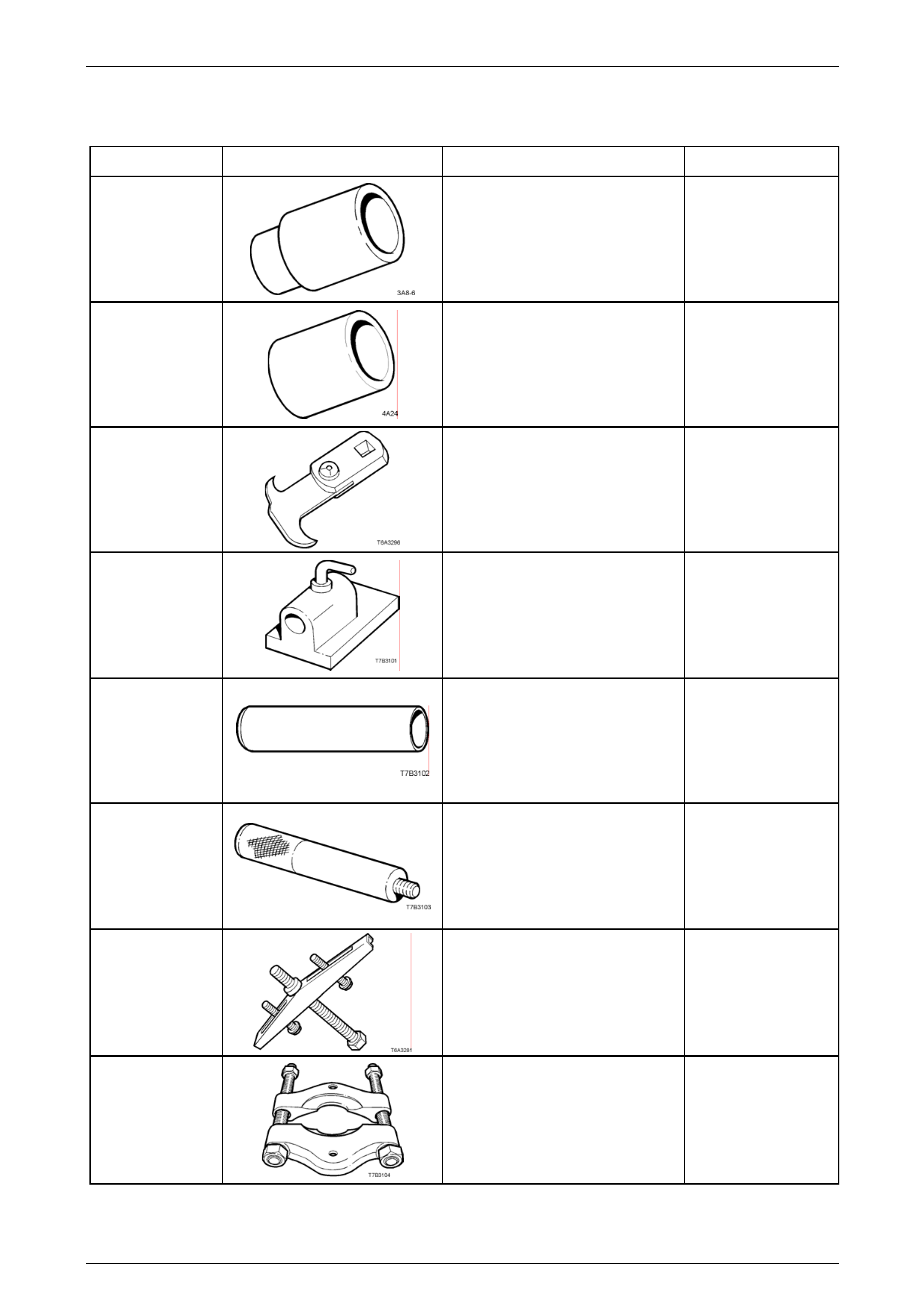
Manual Transmission – GEN III V8 Page 7B2-98
8 Special Tools
Tool Number Illustration Description Tool Classification
E1891-6
Sleeve
Used to install the 1st/2nd gear
synchromesh hub to the mainshaft.
Previously released as 3A8-6
Unique
E1662
Sleeve
Used to install the bearing cup into the
input shaft gear.
Previously released as 4A24.
Unique
E308
Seal Remover
Used to remove the rear oil seal from
the extension housing.
Previously released as E308 and
49V012001
Desirable
J 3289-20
Bench Holding Fixture
Used as a bench fixture to support a
transmission. Used in conjunction with
Transmission Holding Fixtur e ,
J 39430.
Previously released.
Unique
J 5590
Press Tube
Used to install various components,
using an hydraulic press.
Previously released for 4L60- E
automatic transmission.
Unique
J 8092
Universal Driver Handle
Used in conjunction with various other
tools for removal and installation of
various bearing cups in the
transmission.
Previously released
Unique
J 8433
Universal Bridge Puller
Used in conjunction with j 39431-1 & 2
to remove the speedometer pulse ring
and the 5th/6th speed, compound
driven gear.
Previously released
Unique
J 22912-01
Press Plates
Used in a number of different
applications in removing beari ngs and
other transmission componen ts when
pressing operations are required.
Previously released.
Desirable
Page 7B2- 98
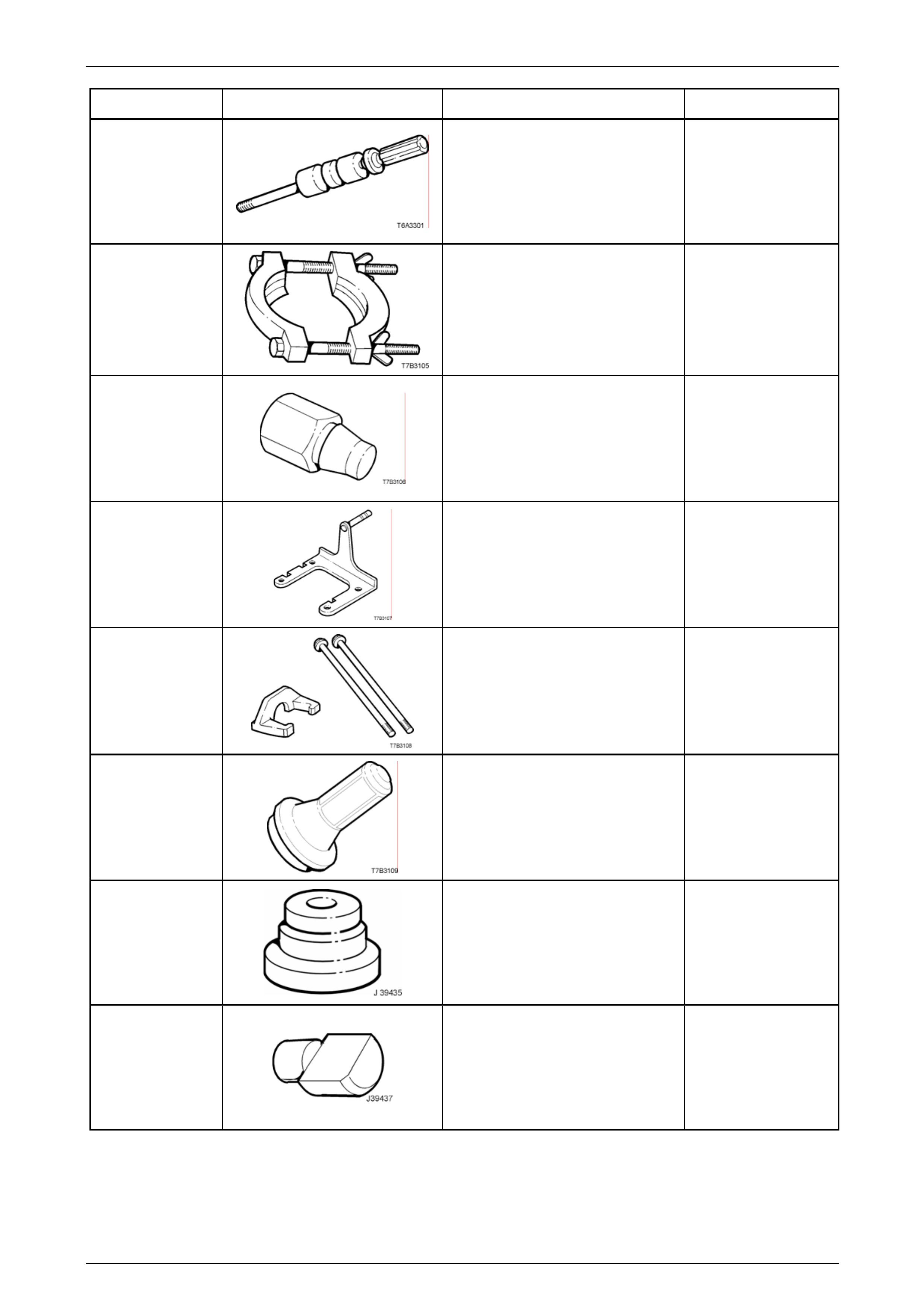
Manual Transmission – GEN III V8 Page 7B2-99
Tool Number Illustration Description Tool Classification
J 23907
Slide Hammer
Used in conjunction with a number of
different pullers to remove bushes and
bearing cups in the transmission.
Unique
J 36513
Press Plates
Used to press 1st/2nd speed
synchromesh assembly and 2nd gear
from the mainshaft.
Previously released.
Unique
J 36800
Bushing Remover
Used to remove the shift rail bushes in
the adaptor plate and extension
housing, in conjunction with slide
hammer J 23907.
Previously released.
Unique
J 39430
Transmission Holding Fixture
Used in conjunction with Bench
Fixture J 3289-20 to mount the
transmission to the bench for unit
repair operations.
Previously released.
Unique
J 39431-1 & 2
Remover and Bolts
Used to remove the speedometer
pulse ring and the 5th/6th speed,
compound driven gear, in conjunction
with universal bridge pull er J 8433.
Previously released.
Unique
J 39433
Seal Installer
Used to install the input shaft oil seal.
Previously released.
Desirable
J 39435
Bearing Cup Installer
Used to install the rear mainshaft and
rear countershaft bearing cup, in
conjunction with driver handle J 8092.
Previously released
Unique
J 39437
Bushing Installer
Used to install the selector shaft
bushes in the adaptor plate, and
transmission case.
Previously released
Unique
Page 7B2- 99
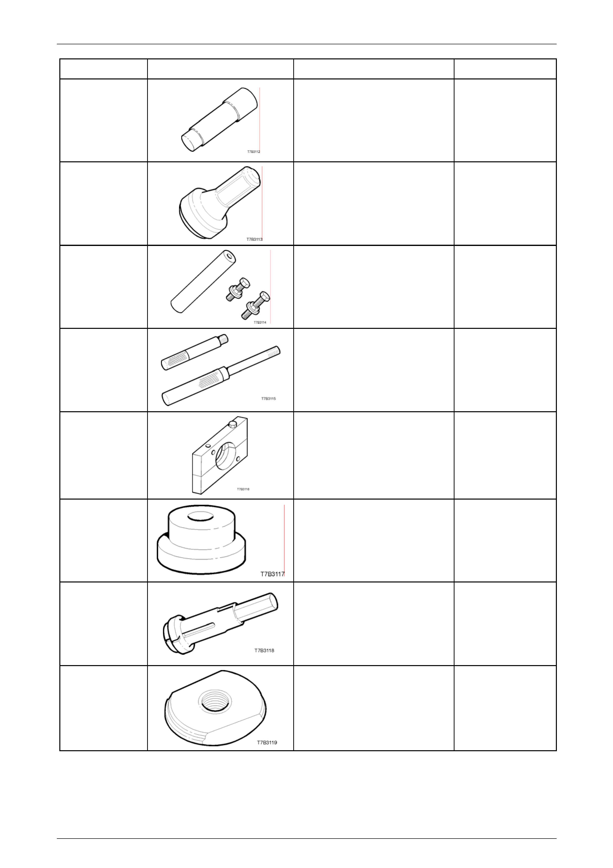
Manual Transmission – GEN III V8 Page 7B2-100
Tool Number Illustration Description Tool Classification
J 39439-1
Bushing Remover/Installer
Used to remove shift shaft bushes
from the transmission case and
extension housing.
Unique
J 39440
Rear Seal and Boot Installer
Used to install the rear extension se al.
Previously released
Desirable
J 39441
Gear Installer
Used to install the 5th/6th compound
driven gear and the speedometer
pulse ring.
Previously released
Unique
J 39444-1 & 2
End Play Rods
Used to check the end float of the
countershaft gear (J 39444-1) and
countershaft gear extension (J 39444-
2).
Previously released
Unique
J 39511
Split Plate
Used to remove the front countershaft
gear bearing.
Previously released
Unique
J 39546
Bearing Cup Installer
Used to install the rear mainshaft
roller bearing cup, in conjunction with
driver handle J 8092.
Previously released
Unique
J 39594
Bearing Cup Remover
Used in conjunction with slide
hammer J 23907 to remove the
mainshaft pilot bearing cu p in the
input shaft gear.
Previously released
Unique
J 39789
Bearing Cup Remover
Used to press out the rear mainshaft
roller bearing cup from the extensi on
housing, in conjunction with driver
handle J 8092.
Unique
Page 7B2- 100

Manual Transmission – GEN III V8 Page 7B2-101
Tool Number Illustration Description Tool Classification
J 39790
Bearing Cup Remover
Used to press out the rear mainshaft
bearing cup from the transmis s ion
case, in conjunction with driver handle
J 8092.
Previously released
Unique
J 39791
Bearing Cup Remover
Used to press out the rear
countershaft bearing cup from the
transmission case, in conjunction with
driver handle J 8092.
Previously released
Unique
Page 7B2- 101