
Automatic Transmission – 4L60E – Electrical Diagnosis Page 7C2–1
Page 7C2–1
Section 7C2
Automatic Transmission – 4L60E – Electrical
Diagnosis
ATTENTION
Before performing any service operation or other procedure described in this Section, refer to Section 00
Warnings, Cautions and Notes for correct workshop practices with regard to safety and/or property damage.
1 General Information ...............................................................................................................................8
1.1 Introduction............................................................................................................................................................ 8
1.2 General Description............................................................................................................................................... 9
Transmission Adaptive Functions ..................................................................................................................... 11
Limp Home Mode Description ............................................................................................................................ 11
1.3 Transmission Indicators and Messages............................................................................................................ 12
MFD Displays ....................................................................................................................................................... 12
Power Mode..................................................................................................................................................... 12
Normal Mode.................................................................................................................................................... 12
Shift Range Selected........................................................................................................................................ 12
1.4 Electronic Component Description.................................................................................................................... 13
Transmission Control Module (TCM)................................................................................................................. 13
2 Wiring Diagrams and Connector Chart..............................................................................................15
2.1 Wiring Diagrams .................................................................................................................................................. 15
2.2 Connector Chart................................................................................................................................................... 18
2.3 Connector Information ........................................................................................................................................ 19
In-line 20-Way Connector End View................................................................................................................... 19
Transmission Side – X121–X1......................................................................................................................... 19
Harness Side – X121–X1................................................................................................................................. 20
Internal Connector End Views............................................................................................................................ 21
Vehicle Speed Sensor...................................................................................................................................... 21
1-2 Shift Solenoid Valve Connector.................................................................................................................. 21
2-3 Shift Solenoid Valve Connector.................................................................................................................. 21
Pressure Control (PC) Solenoid Valve Connector............................................................................................ 21
Transmission Manual Shift Shaft Switch Assembly.......................................................................................... 22
3-2 Shift Solenoid Valve Assembly Connector................................................................................................. 22
Torque Converter Clutch (TCC) Pulse-Width M odulated (PWM) Solenoid Valve Connector........................... 22
Torque Converter Clutch (T CC) Solenoid Valve Connec tor............................................................................. 22
Transmission Control Module Connector End View – A112–X1...................................................................... 23
3 Tech 2 Information ...............................................................................................................................25
3.1 Tech 2 Diagnostics.............................................................................................................................................. 25
Test Modes........................................................................................................................................................... 25
Diagnostic Trouble Codes................................................................................................................................ 25
Data Display..................................................................................................................................................... 26
Snapshot.......................................................................................................................................................... 26
Additional Functions......................................................................................................................................... 26
Miscellaneous Tests......................................................................................................................................... 27
Programming.................................................................................................................................................... 27
Techline
Techline

Automatic Transmission – 4L60E – Electrical Diagnosis Page 7C2–2
Page 7C2–2
3.2 Data Display ......................................................................................................................................................... 28
Transmission Data............................................................................................................................................... 28
Transmission Data Parameters........................................................................................................................ 28
TCC Data............................................................................................................................................................... 29
TCC Data Parameters...................................................................................................................................... 29
1-2 Shift Data........................................................................................................................................................ 30
1-2 Shift Data Parameters................................................................................................................................ 30
2-3 Shift Data........................................................................................................................................................ 31
2-3 Shift Data Parameters................................................................................................................................ 31
3-4 Shift Data........................................................................................................................................................ 31
3-4 Shift Data Parameters................................................................................................................................ 31
Pressure Control Solenoid Data......................................................................................................................... 32
Pressure Control Solenoid Data Parameters ................................................................................................... 32
Transmission Adapts .......................................................................................................................................... 32
1-2 Adapt Data................................................................................................................................................. 32
2-3 Adapt Data................................................................................................................................................. 32
3-4 Adapt Data................................................................................................................................................. 33
Steady State Adapt Data.................................................................................................................................. 33
3.3 Tech 2 Data Definitions ....................................................................................................................................... 34
3.4 Miscellaneous Tests............................................................................................................................................ 36
4 Diagnostics...........................................................................................................................................40
4.1 Introduction.......................................................................................................................................................... 40
4.2 Precautions .......................................................................................................................................................... 41
4.3 Diagnostic Trouble Code Tables........................................................................................................................ 42
Multiple DTCs Fault Condition............................................................................................................................ 42
4.4 Diagnostic Trouble Code Definitions................................................................................................................. 43
Type A – Emission Related DTCs....................................................................................................................... 43
Type B – Emission Related DTCs....................................................................................................................... 43
Conditions for Clearing Type A or Type B DTCs.............................................................................................. 43
Type C – Non-emission Related DTCs............................................................................................................... 44
Conditions for Clearing Type C DTCs.............................................................................................................. 44
Current DTCs........................................................................................................................................................ 44
History DTCs........................................................................................................................................................ 44
4.5 Diagnostic System Check................................................................................................................................... 45
Description........................................................................................................................................................... 45
Test Description................................................................................................................................................... 45
4.6 Diagnostic Trouble Code List............................................................................................................................. 46
4.7 DTC P0218 – Transmission Fluid Overtemperature.......................................................................................... 48
DTC Description................................................................................................................................................... 48
Circuit Description............................................................................................................................................... 48
Conditions for Running the DTC........................................................................................................................ 48
Conditions for Setting the DTC........................................................................................................................... 48
Action Taken When the DTC Sets ...................................................................................................................... 48
Conditions for Clearing the DTC ........................................................................................................................ 48
Diagnostic Aids.................................................................................................................................................... 48
Test Description................................................................................................................................................... 49
DTC P0218 Diagnostic Table............................................................................................................................... 49
4.8 DTC P0562 – System Voltage Low ..................................................................................................................... 51
DTC Description................................................................................................................................................... 51
Circuit Description............................................................................................................................................... 51
Conditions for Running the DTC........................................................................................................................ 51
Conditions for Setting the DTC........................................................................................................................... 51
Action Taken When the DTC Sets ...................................................................................................................... 51
Conditions for Clearing the DTC ........................................................................................................................ 51
Diagnostic Aids.................................................................................................................................................... 51
Test Description................................................................................................................................................... 51
DTC P0562 Diagnostic Table............................................................................................................................... 52

Automatic Transmission – 4L60E – Electrical Diagnosis Page 7C2–3
Page 7C2–3
4.9 DTC P0563 – System Voltage High..................................................................................................................... 54
DTC Description................................................................................................................................................... 54
Circuit Description............................................................................................................................................... 54
Conditions for Running the DTC........................................................................................................................ 54
Conditions for Setting the DTC........................................................................................................................... 54
Action Taken When the DTC Sets ...................................................................................................................... 54
Conditions for Clearing the DTC ........................................................................................................................ 54
Diagnostic Aids.................................................................................................................................................... 54
Test Description................................................................................................................................................... 54
DTC P0563 Diagnostic Table............................................................................................................................... 55
4.10 DTC P0601 to P0604 or P1621 – TCM Malfunction............................................................................................ 57
DTC Description................................................................................................................................................... 57
Circuit Description............................................................................................................................................... 57
Conditions for Running the DTC........................................................................................................................ 57
Conditions for Setting the DTC........................................................................................................................... 57
Action Taken When the DTC Sets ...................................................................................................................... 57
Conditions for Clearing the DTC ........................................................................................................................ 57
Test Description................................................................................................................................................... 57
DTC P0601 to P0604 or P1621 Diagnostic Table............................................................................................... 58
4.11 DTC P0711 to P0713 – Transmission Fluid Temperature Sensor.................................................................... 59
DTC Description................................................................................................................................................... 59
Circuit Description............................................................................................................................................... 59
Conditions for Running the DTC........................................................................................................................ 59
DTC P0711 ...................................................................................................................................................... 59
DTC P0712 ...................................................................................................................................................... 59
DTC P0713 ...................................................................................................................................................... 59
Conditions for Setting the DTC........................................................................................................................... 60
DTC P0711 ...................................................................................................................................................... 60
DTC P0712 ...................................................................................................................................................... 60
DTC P0713 ...................................................................................................................................................... 60
Action Taken When the DTC Sets ...................................................................................................................... 60
Conditions for Clearing the DTC ........................................................................................................................ 60
Diagnostic Aids.................................................................................................................................................... 60
Test Description................................................................................................................................................... 61
DTC P0711 to P0713 Diagnostic Table............................................................................................................... 61
4.12 DTC P0719 – Brake Switch Circuit High Input (Stuck On)................................................................................ 63
DTC Description................................................................................................................................................... 63
Circuit Description............................................................................................................................................... 63
Conditions for Running the DTC........................................................................................................................ 63
Conditions for Setting the DTC........................................................................................................................... 63
Action Taken When the DTC Sets ...................................................................................................................... 63
Conditions for Clearing the DTC ........................................................................................................................ 63
Diagnostic Aids.................................................................................................................................................... 63
Test Description................................................................................................................................................... 63
DTC P0719 Diagnostic Table............................................................................................................................... 64
4.13 DTC P0722 – Vehicle Speed Sensor Circuit Low Voltage ................................................................................ 65
DTC Description................................................................................................................................................... 65
Circuit Description............................................................................................................................................... 65
Conditions for Running the DTC........................................................................................................................ 65
Conditions for Setting the DTC........................................................................................................................... 65
Action Taken When the DTC Sets ...................................................................................................................... 65
Conditions for Clearing the DTC ........................................................................................................................ 65
Diagnostic Aids.................................................................................................................................................... 66
Test Description................................................................................................................................................... 66
DTC P0722 Diagnostic Table............................................................................................................................... 66

Automatic Transmission – 4L60E – Electrical Diagnosis Page 7C2–4
Page 7C2–4
4.14 DTC P0723 – Vehicle Speed Sensor Circuit Intermittent.................................................................................. 68
DTC Description................................................................................................................................................... 68
Circuit Description............................................................................................................................................... 68
Conditions for Running the DTC........................................................................................................................ 68
Conditions for Setting the DTC........................................................................................................................... 68
Action Taken When the DTC Sets ...................................................................................................................... 68
Conditions for Clearing the DTC ........................................................................................................................ 68
Diagnostic Aids.................................................................................................................................................... 69
Test Description................................................................................................................................................... 69
DTC P0723 Diagnostic Table............................................................................................................................... 69
4.15 DTC P0724 – Brake Switch Circuit Low Input (Stuck Off) ................................................................................ 71
DTC Description................................................................................................................................................... 71
Circuit Description............................................................................................................................................... 71
Conditions for Running the DTC........................................................................................................................ 71
Conditions for Setting the DTC........................................................................................................................... 71
Action Taken When the DTC Sets ...................................................................................................................... 71
Conditions for Clearing the DTC ........................................................................................................................ 71
Diagnostic Aids.................................................................................................................................................... 71
Test Description................................................................................................................................................... 71
DTC P0724 Diagnostic Table............................................................................................................................... 72
4.16 DTC P0741 – Torque Converter Clutch System – Stuck Off............................................................................. 73
DTC Description................................................................................................................................................... 73
Circuit Description............................................................................................................................................... 73
Conditions for Running the DTC........................................................................................................................ 73
Conditions for Setting the DTC........................................................................................................................... 73
Action Taken When the DTC Sets ...................................................................................................................... 73
Conditions for Clearing the DTC ........................................................................................................................ 74
Diagnostic Aids.................................................................................................................................................... 74
Test Description................................................................................................................................................... 74
DTC P0741 Diagnostic Table............................................................................................................................... 74
4.17 DTC P0742 – Torque Converter Clutch System – Stuck On............................................................................. 76
DTC Description................................................................................................................................................... 76
Circuit Description............................................................................................................................................... 76
Conditions for Running the DTC........................................................................................................................ 76
Conditions for Setting the DTC........................................................................................................................... 76
Action Taken When the DTC Sets ...................................................................................................................... 77
Conditions for Clearing the DTC ........................................................................................................................ 77
Diagnostic Aids.................................................................................................................................................... 77
Test Description................................................................................................................................................... 77
DTC P0742 Diagnostic Table............................................................................................................................... 78
4.18 DTC P0751 – 1-2 Shift Solenoid Valve Performance – No First or Fourth Gear ............................................. 80
DTC Description................................................................................................................................................... 80
Circuit Description............................................................................................................................................... 80
Conditions for Running the DTC........................................................................................................................ 80
Conditions for Setting the DTC........................................................................................................................... 80
Action Taken When the DTC Sets ...................................................................................................................... 80
Conditions for Clearing the DTC ........................................................................................................................ 80
Diagnostic Aids.................................................................................................................................................... 81
Test Description................................................................................................................................................... 81
DTC P0751 Diagnostic Table............................................................................................................................... 81
4.19 DTC P0752 – 1-2 Shift Solenoid Valve Performance – No Second or Third Gear........................................... 83
DTC Description................................................................................................................................................... 83
Circuit Description............................................................................................................................................... 83
Conditions for Running the DTC........................................................................................................................ 83
Conditions for Setting the DTC........................................................................................................................... 83
Action Taken When the DTC Sets ...................................................................................................................... 83
Conditions for Clearing the DTC ........................................................................................................................ 83
Diagnostic Aids.................................................................................................................................................... 84
Test Description................................................................................................................................................... 84
DTC P0752 Diagnostic Table............................................................................................................................... 84

Automatic Transmission – 4L60E – Electrical Diagnosis Page 7C2–5
Page 7C2–5
4.20 DTC P0756 – 2-3 Shift Solenoid Valve Performance – No First or Second Gear............................................ 86
DTC Description................................................................................................................................................... 86
Circuit Description............................................................................................................................................... 86
Conditions for Running the DTC........................................................................................................................ 86
Conditions for Setting the DTC........................................................................................................................... 86
Action Taken When the DTC Sets ...................................................................................................................... 87
Conditions for Clearing the DTC ........................................................................................................................ 87
Diagnostic Aids.................................................................................................................................................... 87
Test Description................................................................................................................................................... 87
DTC P0756 Diagnostic Table............................................................................................................................... 88
4.21 DTC P0757 – 2-3 Shift Solenoid Valve Performance – No Third or Fourth Gear............................................ 90
DTC Description................................................................................................................................................... 90
Circuit Description............................................................................................................................................... 90
Conditions for Running the DTC........................................................................................................................ 90
Conditions for Setting the DTC........................................................................................................................... 90
Action Taken When the DTC Sets ...................................................................................................................... 90
Conditions for Clearing the DTC ........................................................................................................................ 90
Diagnostic Aids.................................................................................................................................................... 91
Test Description................................................................................................................................................... 91
DTC P0757 Diagnostic Table............................................................................................................................... 91
4.22 DTC P0787 – 3-2 Shift Solenoid Control Circuit Low Voltage.......................................................................... 93
DTC Description................................................................................................................................................... 93
Circuit Description............................................................................................................................................... 93
Conditions for Running the DTC........................................................................................................................ 93
Conditions for Setting the DTC........................................................................................................................... 93
Action Taken When the DTC Sets ...................................................................................................................... 93
Conditions for Clearing the DTC ........................................................................................................................ 93
Test Description................................................................................................................................................... 94
DTC P0787 Diagnostic Table............................................................................................................................... 94
4.23 DTC P0788 – 3-2 Shift Solenoid Control Circuit High Voltage......................................................................... 97
DTC Description................................................................................................................................................... 97
Circuit Description............................................................................................................................................... 97
Conditions for Running the DTC........................................................................................................................ 97
Conditions for Setting the DTC........................................................................................................................... 97
Action Taken When the DTC Sets ...................................................................................................................... 97
Conditions for Clearing the DTC ........................................................................................................................ 97
Test Description................................................................................................................................................... 98
DTC P0788 Diagnostic Table............................................................................................................................... 98
4.24 DTC P0894 – Transmission Component Slipping........................................................................................... 100
DTC Description................................................................................................................................................. 100
Circuit Description............................................................................................................................................. 100
Conditions for Running the DTC...................................................................................................................... 100
Conditions for Setting the DTC......................................................................................................................... 101
Action Taken When the DTC Sets .................................................................................................................... 101
Conditions for Clearing the DTC ...................................................................................................................... 102
Diagnostic Aids.................................................................................................................................................. 102
Test Description................................................................................................................................................. 102
DTC P0894 Diagnostic Table............................................................................................................................. 103
4.25 DTC P0961 – Line Pressure Control Solenoid System Performance ............................................................ 109
DTC Description................................................................................................................................................. 109
Circuit Description............................................................................................................................................. 109
Conditions for Running the DTC...................................................................................................................... 109
Conditions for Setting the DTC......................................................................................................................... 109
Action Taken When the DTC Sets .................................................................................................................... 109
Conditions for Clearing the DTC ...................................................................................................................... 109
Diagnostic Aids.................................................................................................................................................. 109
Test Description................................................................................................................................................. 109
DTC P0961 Diagnostic Table............................................................................................................................. 110

Automatic Transmission – 4L60E – Electrical Diagnosis Page 7C2–6
Page 7C2–6
4.26 DTC P0973 – 1-2 Shift Solenoid Control Circuit Low Voltage........................................................................ 112
DTC Description................................................................................................................................................. 112
Circuit Description............................................................................................................................................. 112
Conditions for Running the DTC...................................................................................................................... 112
Conditions for Setting the DTC......................................................................................................................... 112
Action Taken When the DTC Sets .................................................................................................................... 112
Conditions for Clearing the DTC ...................................................................................................................... 112
Test Description................................................................................................................................................. 113
DTC P0973 Diagnostic Table............................................................................................................................. 113
4.27 DTC P0974 – 1-2 Shift Solenoid Control Circuit High Voltage....................................................................... 116
DTC Description................................................................................................................................................. 116
Circuit Description............................................................................................................................................. 116
Conditions for Running the DTC...................................................................................................................... 116
Conditions for Setting the DTC......................................................................................................................... 116
Action Taken When the DTC Sets .................................................................................................................... 116
Conditions for Clearing the DTC ...................................................................................................................... 116
Test Description................................................................................................................................................. 116
DTC P0974 Diagnostic Table............................................................................................................................. 117
4.28 DTC P0976 – 2-3 Shift Solenoid Control Circuit Low Voltage........................................................................ 119
DTC Description................................................................................................................................................. 119
Circuit Description............................................................................................................................................. 119
Conditions for Running the DTC...................................................................................................................... 119
Conditions for Setting the DTC......................................................................................................................... 119
Action Taken When the DTC Sets .................................................................................................................... 119
Conditions for Clearing the DTC ...................................................................................................................... 119
Test Description................................................................................................................................................. 120
DTC P0976 Diagnostic Table............................................................................................................................. 120
4.29 DTC P0977 – 2-3 Shift Solenoid Control Circuit High Voltage....................................................................... 123
DTC Description................................................................................................................................................. 123
Circuit Description............................................................................................................................................. 123
Conditions for Running the DTC...................................................................................................................... 123
Conditions for Setting the DTC......................................................................................................................... 123
Action Taken When the DTC Sets .................................................................................................................... 123
Conditions for Clearing the DTC ...................................................................................................................... 123
Test Description................................................................................................................................................. 123
DTC P0977 Diagnostic Table............................................................................................................................. 124
4.30 DTC P1810, P1815 and P1816 – Transmission Fluid Pressure Position Switch........................................... 126
DTC Description................................................................................................................................................. 126
Circuit Description............................................................................................................................................. 126
Conditions for Running the DTC...................................................................................................................... 126
DTC P1810 .................................................................................................................................................... 126
DTC P1815 .................................................................................................................................................... 126
DTC P1816 .................................................................................................................................................... 126
Conditions for Setting the DTC......................................................................................................................... 127
DTC P1810 .................................................................................................................................................... 127
DTC P1815 .................................................................................................................................................... 127
DTC P1816 .................................................................................................................................................... 127
Action Taken When the DTC Sets .................................................................................................................... 127
Conditions for Clearing the DTC ...................................................................................................................... 127
Diagnostic Aids.................................................................................................................................................. 127
Test Description................................................................................................................................................. 127
DTC P1810, P1815 and P1816 Diagnostic Table.............................................................................................. 128

Automatic Transmission – 4L60E – Electrical Diagnosis Page 7C2–7
Page 7C2–7
4.31 DTC P2763 – Torque Converter Clutch Pressure Control Solenoid Control Circuit High Voltage............. 130
DTC Description................................................................................................................................................. 130
Circuit Description............................................................................................................................................. 130
Conditions for Running the DTC...................................................................................................................... 130
Conditions for Setting the DTC......................................................................................................................... 130
Action Taken When the DTC Sets .................................................................................................................... 130
Conditions for Clearing the DTC ...................................................................................................................... 130
Test Description................................................................................................................................................. 130
DTC P2763 Diagnostic Table............................................................................................................................. 131
4.32 DTC P2764 – Torque Converter Clutch Pressure Control Solenoid Control Circuit Low Voltage.............. 133
DTC Description................................................................................................................................................. 133
Circuit Description............................................................................................................................................. 133
Conditions for Running the DTC...................................................................................................................... 133
Conditions for Setting the DTC......................................................................................................................... 133
Action Taken When the DTC Sets .................................................................................................................... 133
Conditions for Clearing the DTC ...................................................................................................................... 134
Test Description................................................................................................................................................. 134
DTC P2764 Diagnostic Table............................................................................................................................. 134
4.33 DTC P2769 – Torque Converter Clutch Enable Solenoid Control Circuit Low Voltage............................... 137
DTC Description................................................................................................................................................. 137
Circuit Description............................................................................................................................................. 137
Conditions for Running the DTC...................................................................................................................... 137
Conditions for Setting the DTC......................................................................................................................... 137
Action Taken When the DTC Sets .................................................................................................................... 137
Conditions for Clearing the DTC ...................................................................................................................... 138
Diagnostic Aids.................................................................................................................................................. 138
Test Description................................................................................................................................................. 138
DTC P2769 Diagnostic Table............................................................................................................................. 138
4.34 DTC P2770 – Torque Converter Clutch Enable Solenoid Control Circuit High Voltage .............................. 141
DTC Description................................................................................................................................................. 141
Circuit Description............................................................................................................................................. 141
Conditions for Running the DTC...................................................................................................................... 141
Conditions for Setting the DTC......................................................................................................................... 141
Action Taken When the DTC Sets .................................................................................................................... 141
Conditions for Clearing the DTC ...................................................................................................................... 142
Test Description................................................................................................................................................. 142
DTC P2770 Diagnostic Table............................................................................................................................. 142
4.35 DTC U2107– Lost Communication with Body Control Module...................................................................... 143
DTC Description................................................................................................................................................. 143
Circuit Description............................................................................................................................................. 143
Conditions for Running the DTC...................................................................................................................... 143
Conditions for Setting the DTC......................................................................................................................... 143
Action Taken When the DTC Sets .................................................................................................................... 143
Conditions for Clearing the DTC ...................................................................................................................... 143
Diagnostic Aids.................................................................................................................................................. 143
Test Description................................................................................................................................................. 143
DTC U2107 Diagnostic Table ............................................................................................................................ 144
5 Electrical Specifications....................................................................................................................145
5.1 Transmission Fluid Temperature (TFT) Sensor Specifications..................................................................... 145
5.2 Range Reference................................................................................................................................................ 146
5.3 Transmission Fluid Pressure Manual Valve Position Switch Logic.............................................................. 147
5.4 Transmission Range Switch Logic................................................................................................................... 148
5.5 Component Resistance..................................................................................................................................... 149
5.6 Shift Solenoid Valve State and Gear Ratio ...................................................................................................... 150
5.7 Line Pressure..................................................................................................................................................... 151
6 Special Tools ......................................................................................................................................152

Automatic Transmission – 4L60E – Electrical Diagnosis Page 7C2–8
Page 7C2–8
1 General Information
1.1 Introduction
This Section covers the electrical diagnostic for the 4L60E automatic transmission when mated to a V6 engine.
For diagnosis of the 4L60E automatic transmission when mated to a GEN III V8 engine, refer to
Section 6C3-2 Powertrain Management – GEN III V8 – Diagnostics.

Automatic Transmission – 4L60E – Electrical Diagnosis Page 7C2–9
Page 7C2–9
1.2 General Description
The 4L60E automatic transmission incorporates electronic controls that utilise a transmissi on control module (TCM) to
control shift points through:
• the 1-2 and 2-3 shift solenoid valves,
• the 3-2 downshift solenoid valve,
• a torque converter clutch (TCC) solenoid val v e,
• apply and release through the TCC pulse width modulated (PWM) solenoi d valve, and
• line pressure through the pressure control (PC) solenoid valve.
Electrical signals from various sensors pr ovide information to the TCM about the following:
• vehicle speed,
• throttle position,
• engine coolant temperatur e,
• transmission fluid temperature,
• gear range selector position,
• engine speed,
• converter turbine speed, and
• engine load braking and operating mode.
The TCM uses this information to determine the precise moment to upshift or downshift, apply or release the TCC and
what fluid pressure is needed to apply the clutches. This type of control provides consistent and precise shift points and
shift quality based on the operating conditions of the vehicle.
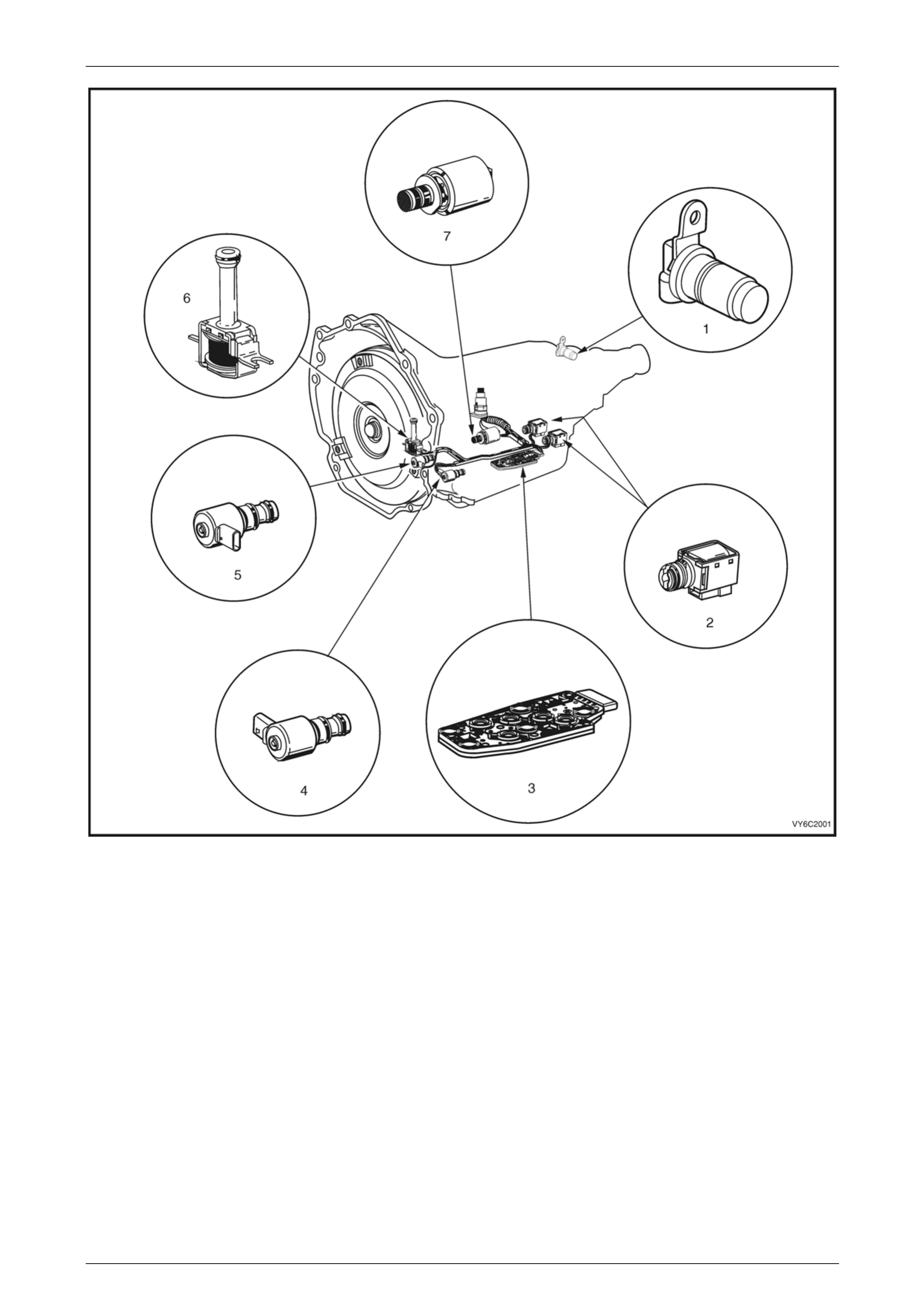
Figure 7C2 – 1 shows the location of the internal electro nic components in the transmission.
Automatic Transmission – 4L60E – Electrical Diagnosis Page 7C2–10
Page 7C2–10
Figure 7C2 – 1
Legend
1 Vehicle Speed Sensor 5 Torque Converter Clutch Pulse Width Modulation (TCC
PWM) Solenoid Valve
2 1-2 Shift Solenoid (Solenoid A) and 2-3 Shift Solenoid
(Solenoid B) 6 Torque Converter Clutch (TCC) Solenoid Valve
3 Automatic Transmission Fluid Pressure (TFP) Manual Valve
Position 7 Pressure Control (PC) Solenoid Valve
4 3-2 Downshift Solenoid

Automatic Transmission – 4L60E – Electrical Diagnosis Page 7C2–11
Page 7C2–11
Transmission Adaptive Functions
The 4L60E automatic transmission uses a line pressure control system, which has the ability to adapt the system line
pressure to compensate for normal wear within the transmission, such as the clutch pack fibre plates, seals, springs, etc.
The adapt feature is similar in function to the long term/short term fuel trim feature of the engi ne management system.
The 4L60E automatic transmission uses the adapt function for garage shifts, upshifts and torque converter clutch (TCC)
application. The TCM monitors the engine torque to determine if the shift is occurring too fast or too slow and adjusts the
pressure control solenoid to maintain the correct shift feel.
Limp Home Mode Description
If a major electrical system failure occurs which could affect vehicle safety or damage the transmission during norma l
operation, the TCM enters a limp home mo de. In the limp home mode, the transmission operates in the following
manner:
• The pressure control solenoid is off and the li ne pressure is at maximum to minimise clutch slippage.
• The TCC solenoid is off, therefore the torque converter clutch is disabled.
• The two shift solenoids are turned off. The transmission will operate in fourth gear if the vehicle has successfully
completed a 1-2 upshift in the current ignition cycle. If the vehicle has not completed a 1-2 upshift in the current
ignition cycle, the transmission will operate in third gear. If the transmiss ion is operating in fourth gear, third gear
may be obtained if the engine is stopped briefly and re-star t ed.
In limp home mode, the gear selector lev er is ineffective at selecting forward gear ranges. In third or fourth gear, heat
builds up in the transmission quickly, particularly in stop and go traffic. Excessive heat build-up may cause transmission
failure if the vehicle is driven for extended distances in limp home mode.
Automatic Transmission – 4L60E – Electrical Diagnosis Page 7C2–12
Page 7C2–12
1.3 Transmission Indicators and Messages
The instrument clusters multi-function display (MFD) component of the Instrument ma y display messages relating to this
transmission.
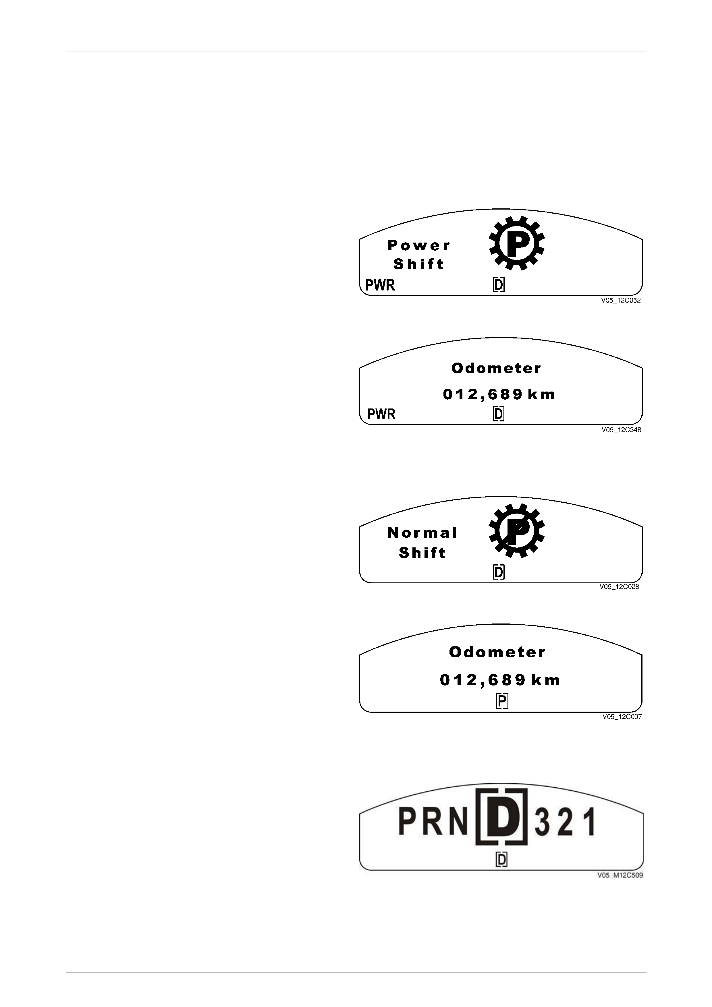
MFD Displays
Power Mode
When the transmission is placed in Power Mode, the PWR
icon illuminates and the Power Shift animation is displayed
for 2 seconds.
Figure 7C2 – 2
After 2 seconds, the animated display extinguishes and the
PWR icon remains. The display reverts to the previously
displayed trip computer screen.
Figure 7C2 – 3
Normal Mode
When the transmission is change d from Power Mode to
Normal Mode, the PWR icon extinguishes immediately and
the Normal Shift animation is displa yed for 2 seconds.
Figure 7C2 – 4
After 2 seconds, the animated display extinguishes and the
display reverts to the previous ly displayed trip computer
screen.
Figure 7C2 – 5
Shift Range Selected
The gear icon remains for 2 seconds after it is selected.
While the transmission selector is moving, the constant
icons reflect the selector movement through the gears.
NOTE
If any warning is active, the large dis play symbol
is not shown and only the bracketed constant
icon at the bottom changes when the automatic
transmission selector is moved. Figure 7C2 – 6
Automatic Transmission – 4L60E – Electrical Diagnosis Page 7C2–13
Page 7C2–13
1.4 Electronic Component Description
For all other electrical components not cov ered in this section, refer to General Motors Powertrain Group Electronically
Controlled Automatic Transmission Technician's Guide.
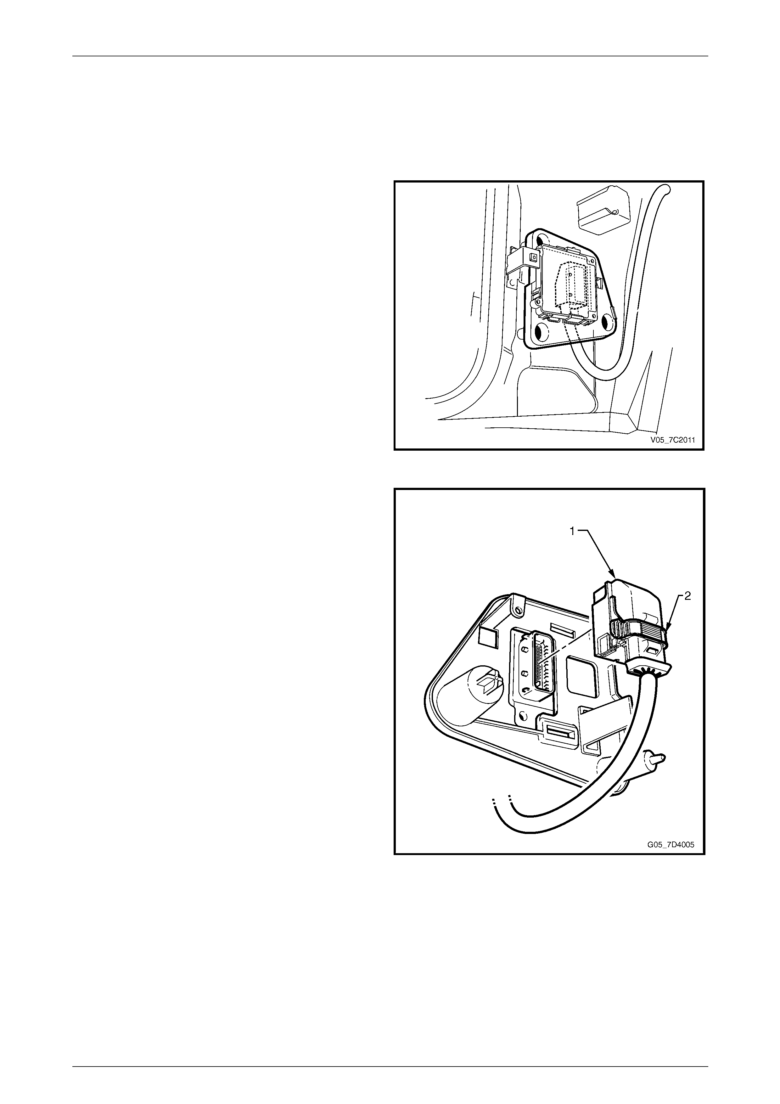
Transmission Control Module (TCM)
The Transmission Control Mo dule (TCM) is located behind
the left-hand body hinge pillar trim assembly and connects
directly to the transmission wiring harness. A single 49-way
connector is used to make the connection b etween the
vehicle wiring harness and the TCM.
Figure 7C2 – 7
The TCM is an electronic cont rol module receiving input or
providing output to control the operation of the 4L60E
automatic transmission.
The TCM receives the following inputs from the engine
control module (ECM):
• engine speed and torque values,
• engine intake air temperature (IAT), accelerator pedal
position (APP) information,
• engine coolant temperature (ECT),
• driver selected shift mode, and
• air-conditioning (A/C) status.
The ECM provides this data to the TCM through the
databus.
Other TCM inputs are:
• battery and ignition voltage,
• brake switch status,
• transmission fluid temperature (TFT), and
• vehicle speed sensor (VSS). Figure 7C2 – 8

Automatic Transmission – 4L60E – Electrical Diagnosis Page 7C2–14
Page 7C2–14
The TCM provides the following outputs to control the automatic transmission:
• shift solenoids to control transmission shifting,
• torque converter clutch (TCC) pulse width modulated (PWM) solenoid operatio n to control the apply and release of
the torque converter clutch assembly, and
• pressure control (PC) solenoid to regulate the transmission line pressur e.
Other TCM outputs provided to the ECM / PIM are:
• check powertrain icon illumination request,
• vehicle speed,
• transmission fluid temperature,
• commanded gear status,
• TCC status, and
• torque reduction requests.
Automatic Transmission – 4L60E – Electrical Diagnosis Page 7C2–15
Page 7C2–15
2 Wiring Diagrams and Connector
Chart
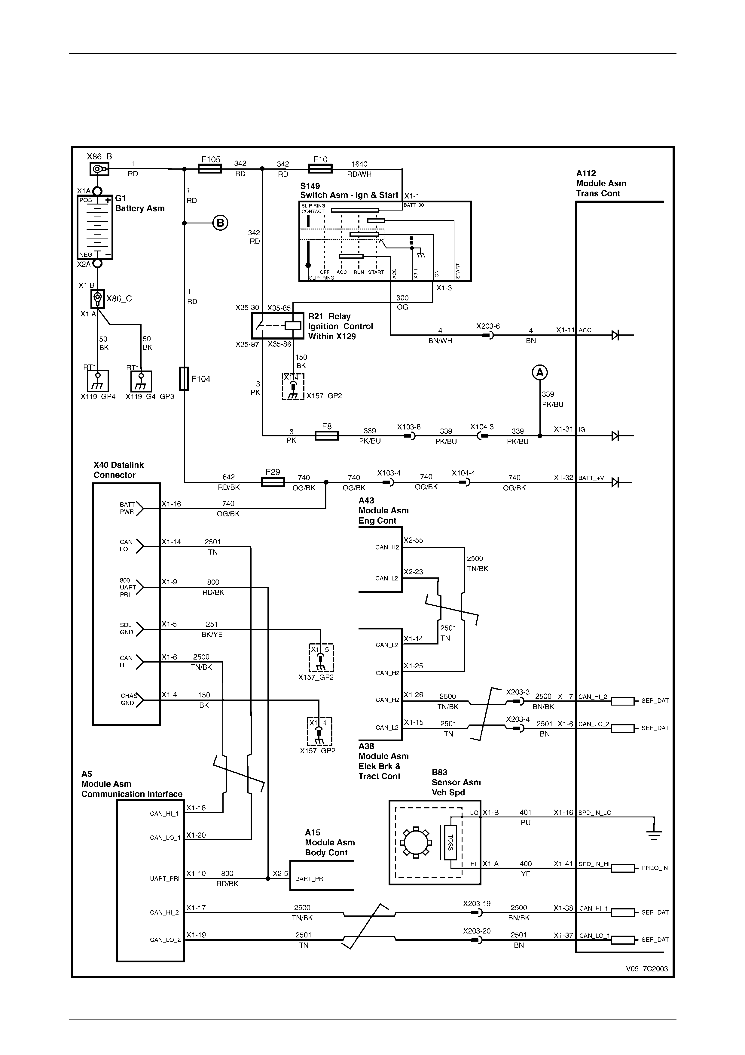
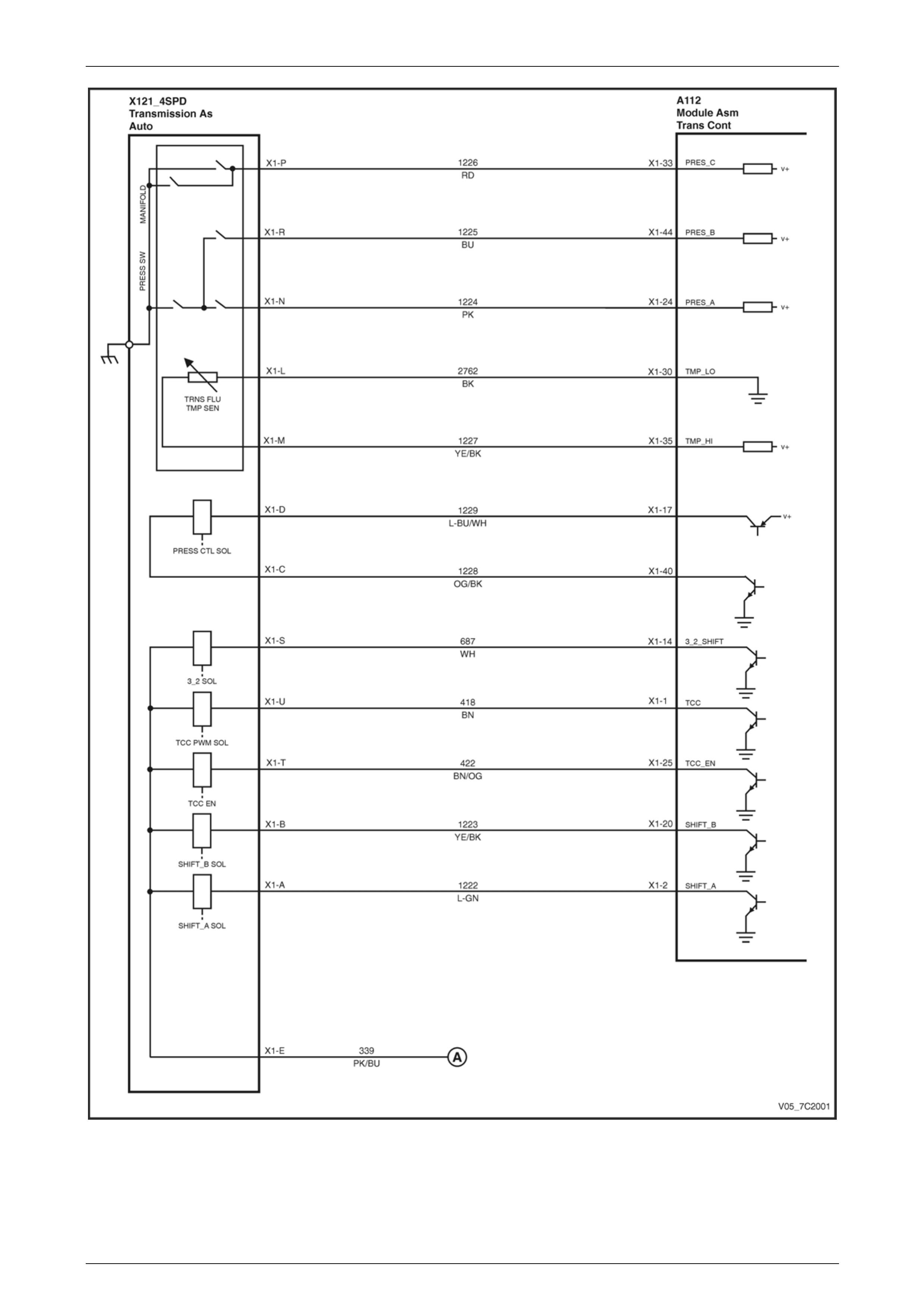
2.1 Wiring Diagrams
Figure 7C2 – 9
Automatic Transmission – 4L60E – Electrical Diagnosis Page 7C2–16
Page 7C2–16
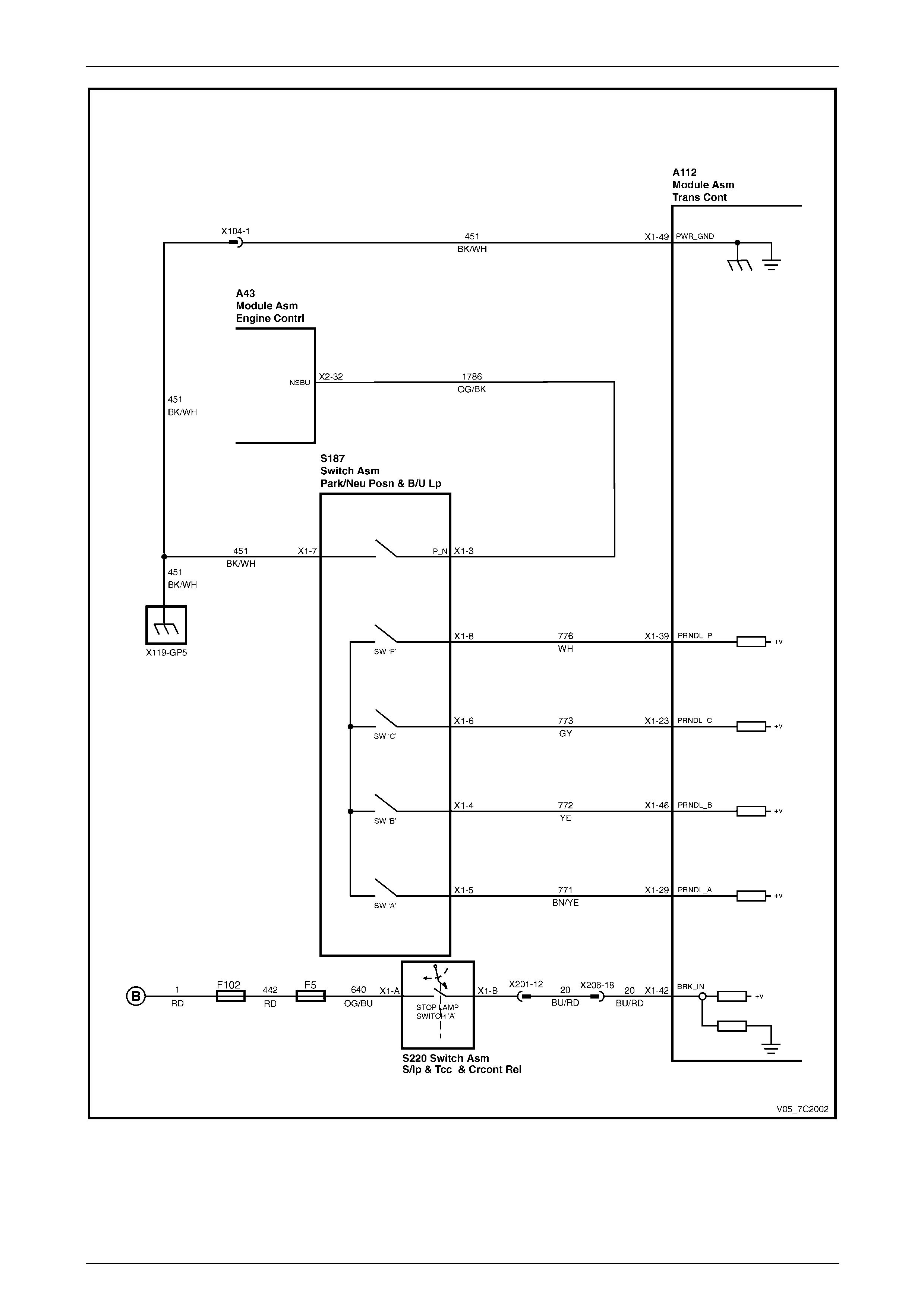
Figure 7C2 – 10
Automatic Transmission – 4L60E – Electrical Diagnosis Page 7C2–17
Page 7C2–17
Figure 7C2 – 11
Automatic Transmission – 4L60E – Electrical Diagnosis Page 7C2–18
Page 7C2–18
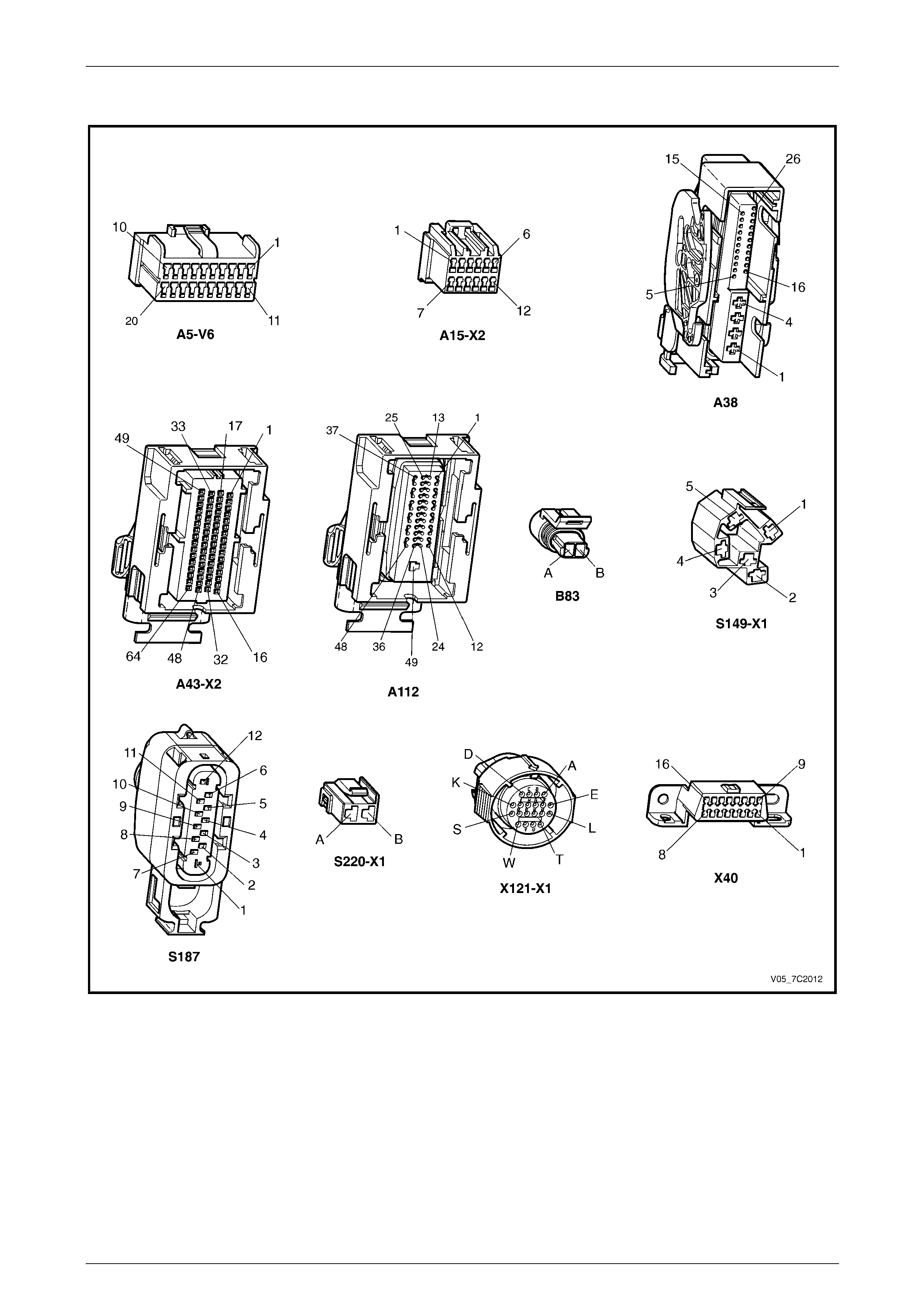
2.2 Connector Chart
Figure 7C2 – 12
Automatic Transmission – 4L60E – Electrical Diagnosis Page 7C2–19
Page 7C2–19
2.3 Connector Information
In-line 20-Way Connector End View
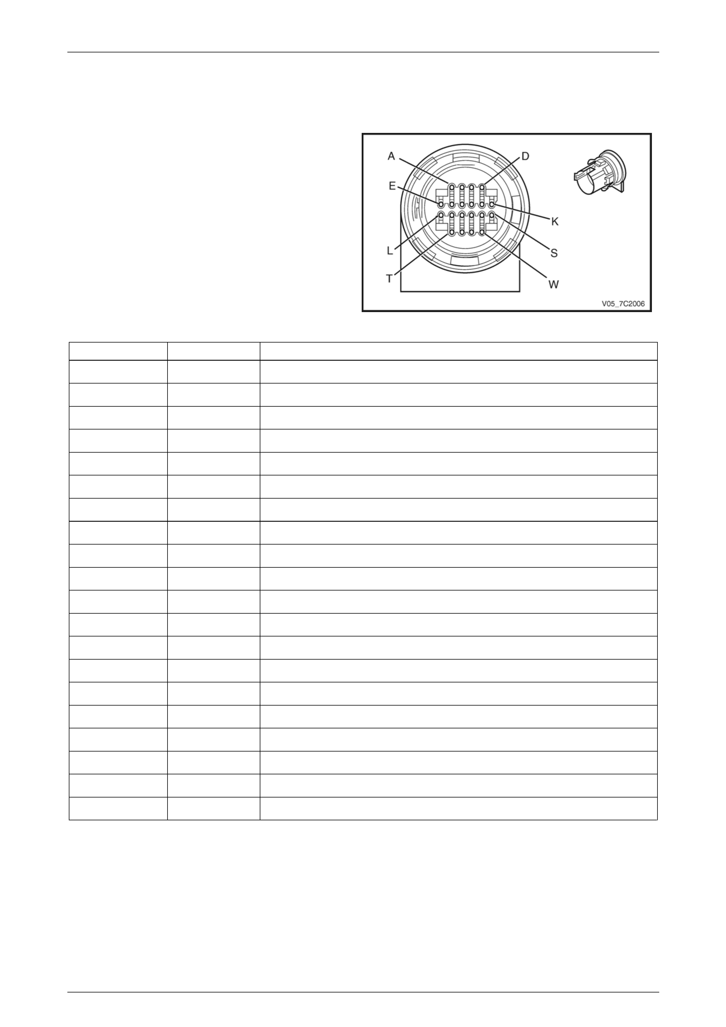
Transmission Side – X121–X1
Figure 7C2 – 13
Terminal / Pin Wire Colour Function
X1–A L-GN 1-2 Shift Solenoid Valve Cont rol
X1–B YE 2-3 Shift Solenoid Valve Cont rol
X1–C PU Pressure Control (PC) Solenoid Valve Low Control
X1–D L-BU Pressure Control (PC) Solenoid Valve High Control
X1–E RD Ignition Voltage
X1–F — Not Used
X1–G — Not Used
X1–H — Not Used
X1–J — Not Used
X1–K — Not Used
X1–L BN Transmission Fluid Temperature (TFT) Sensor Low Reference
X1–M GY Transmission Fluid Temperature (TFT) Sensor Signal
X1–N PK Transmission Fluid Pressure Switch A Sensor Signal
X1–P OG Transmission Fluid Pressure Switch C Sensor Signal
X1–R BU Transmission Fluid Pressure Switch B Sensor Signal
X1–S WH 3-2 Shift Solenoid Valve Cont rol
X1–T BK Torque Converter Clutch (TCC) Solenoid Valve Control
X1–U BN Torque Converter Clutch (T CC) PWM Solen oid Valve Control
X1–V — Not Used
X1–W — Not Used
Automatic Transmission – 4L60E – Electrical Diagnosis Page 7C2–20
Page 7C2–20
Harness Side – X121–X1
Figure 7C2 – 14
Terminal / Pin Wire Colour Circuit No. Function
X1–A L-GN 1222 1-2 Shift Solenoid Valve Cont rol
X1–B YE / BK 1223 2-3 Shift Solenoid Valve Cont rol
X1–C OG / BK 1228 Pressure Control (PC) Solenoid Valve Low Control
X1–D L-BU / WH 1229 Pressure Control (PC) Solenoid Valve High Control
X1–E PK / BU 339 Ignition Voltage
X1–F — — Not Used
X1–G — — Not Used
X1–H — — Not Used
X1–J — — Not Used
X1–K — — Not Used
X1–L BK 2762 Transmission Fluid Temperature (TFT) Sensor Low Reference
X1–M YE / BK 1227 Transmission Fluid Temperature (TFT) Sensor Signal
X1–N PK 1224 Transmission Fluid Pressure Switch A Sensor Signal
X1–P RD 1226 Transmission Fluid Pressure Switch C Sensor Signal
X1–R BU 1225 Transmission Fluid Pressure Switch B Sensor Signal
X1–S WH 687 3-2 Shift Solenoid Valve Control
X1–T BN / OG 422 Torque Converter Clutch (T CC) Solenoi d Valve Control
X1–U BN 418 Torque Converter Clutch (T CC) PWM Solen oid Va lve Control
X1–V — — Not Used
X1–W — — Not Used
Automatic Transmission – 4L60E – Electrical Diagnosis Page 7C2–21
Page 7C2–21
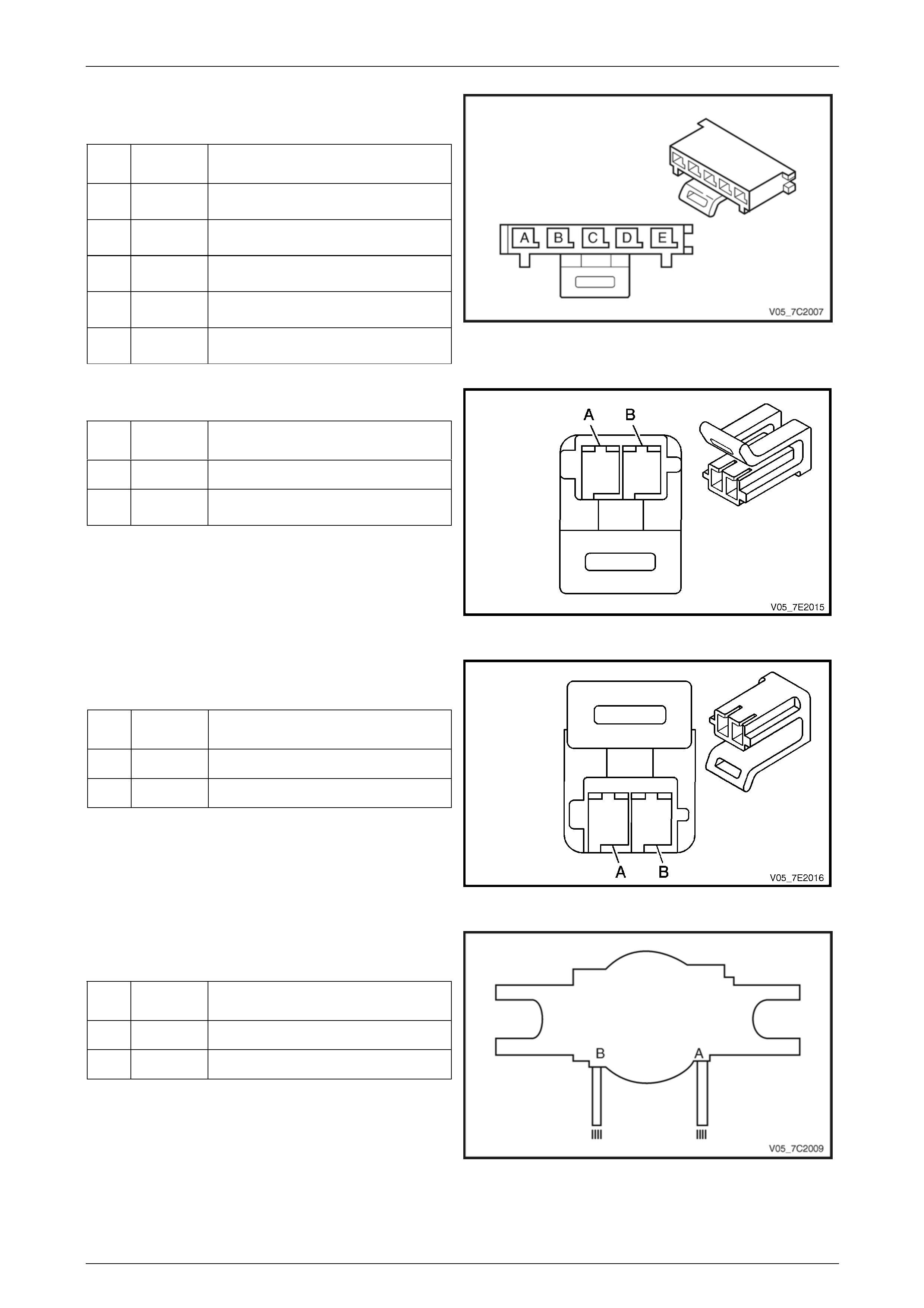
Internal Connector End Views
Vehicle Speed Sensor
Pin
Wire
Colour Circuit
No. Function
A YE 400 VSS High Signal
B PU 401 VSS Low Signal
Figure 7C2 – 15
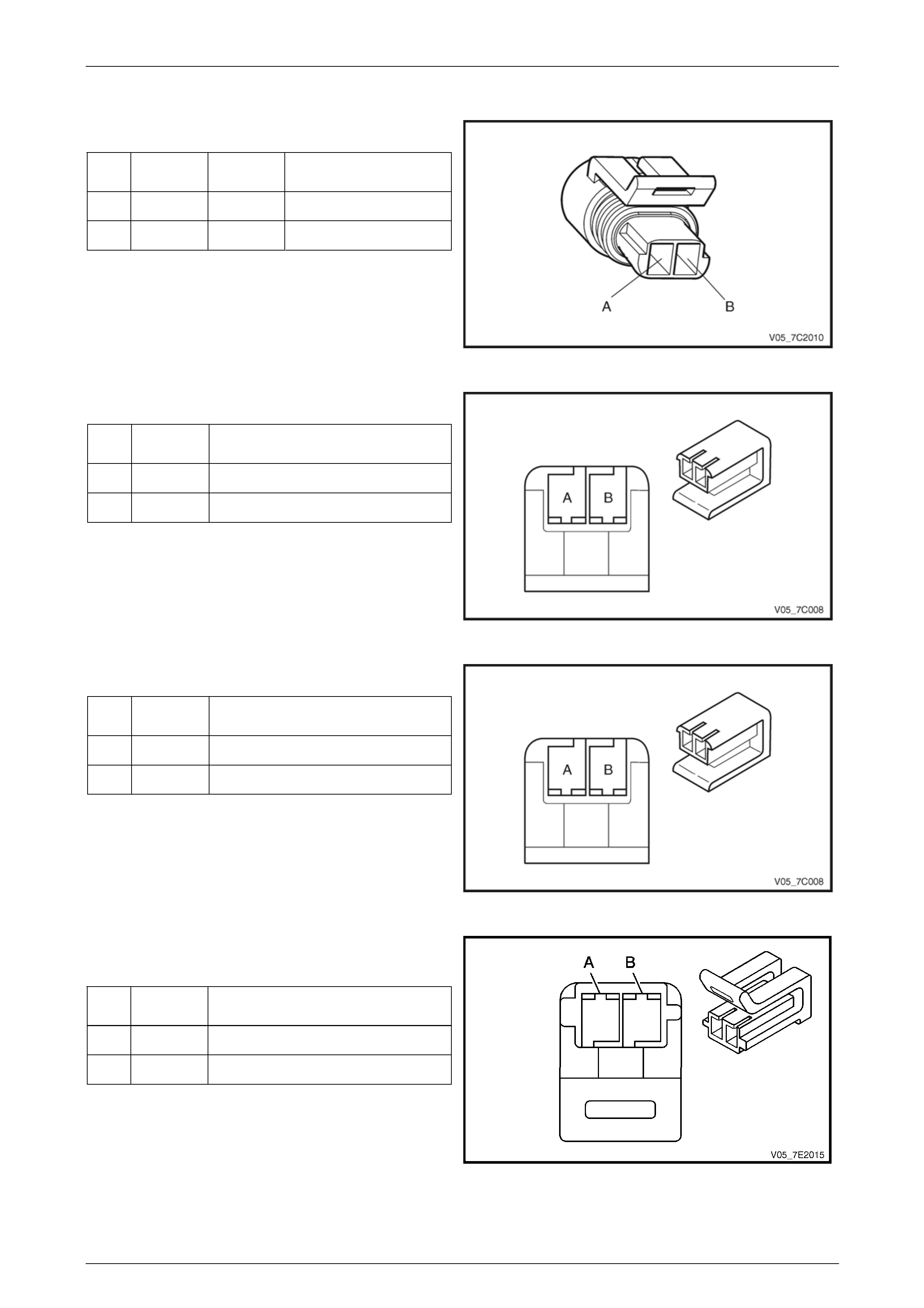
1-2 Shift Solenoid Valve Connector
Pin
Wire
Colour Function
A L-GN 1-2 Shift Solenoid Valve Cont rol
B RD Ignition Voltage
Figure 7C2 – 16
2-3 Shift Solenoid Valve Connector
Pin
Wire
Colour Function
A YE 2-3 Shift Solenoid Valve Control
B RD Ignition Voltage
Figure 7C2 – 17
Pressure Control (PC) Solenoid Valve
Connector
Pin
Wire
Colour Function
A PU PC Solenoid Valve High Control
B L-BU PC Solenoid Valve Control
Figure 7C2 – 18
Automatic Transmission – 4L60E – Electrical Diagnosis Page 7C2–22
Page 7C2–22
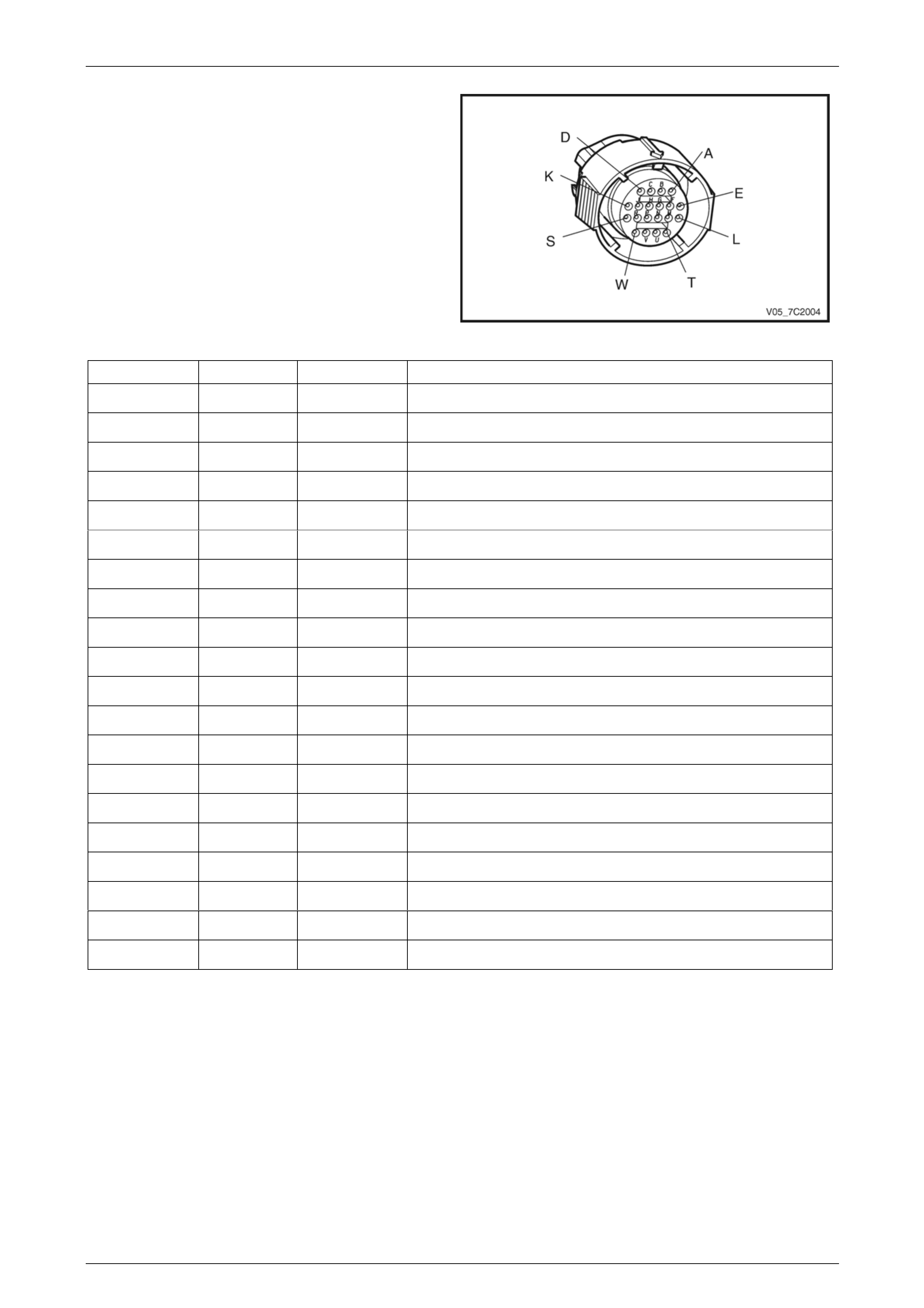
Transmission Manual Shift Shaft S witch
Assembly
Pin Wire
Colour Function
A BN Transmission Fluid Temperat ure
(TFT) Sensor Low Reference
B GY Transmission Fluid Temperat ure
(TFT) Sensor Signal
C PK Transmission Fluid Pressure Switch
Signal A
D OG Transmission Fluid Pressure S witch
Signal C
E BU Transmission Fluid Pressure Switch
Signal B
Figure 7C2 – 19
3-2 Shift Solenoid Valve Assembly Connector
Pin
Wire
Colour Function
A RD Ignition Voltage
B WH 3-2 Downshift Solenoid Valve
Control
Figure 7C2 – 20
Torque Converter Clutch (TCC) Pulse-Width
Modulated (PWM) Solenoid Valve Connector
Pin
Wire
Colour Function
A RD Ignition Voltage
B TN TCC PWN Solenoid Valve Control
Figure 7C2 – 21
Torque Converter Clutch (TCC) Solenoid Valve
Connector
Pin
Wire
Colour Function
A RD / BK Ignition Voltage
B BK TCC Solenoid Valve Control
Figure 7C2 – 22
Automatic Transmission – 4L60E – Electrical Diagnosis Page 7C2–23
Page 7C2–23
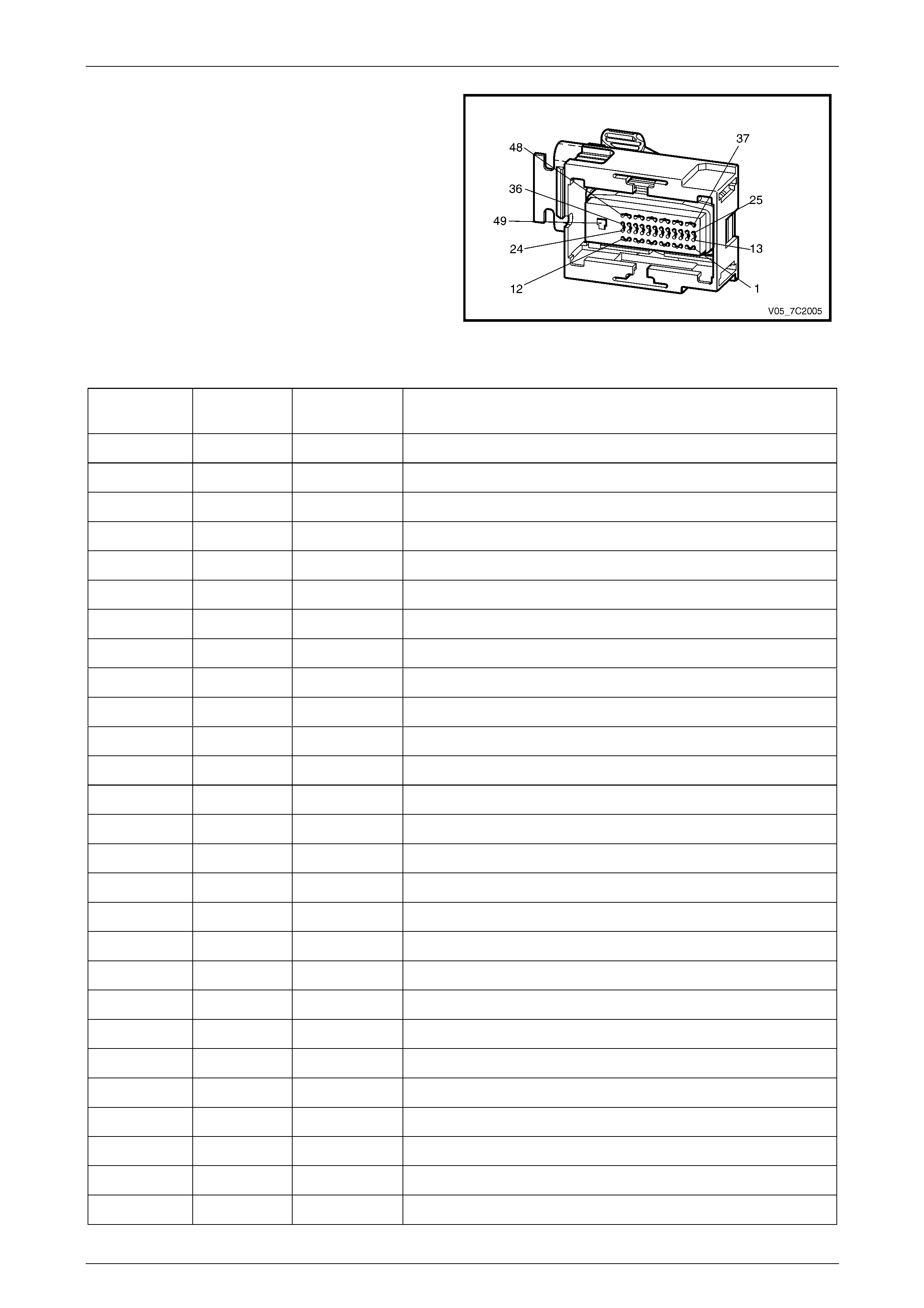
Transmission Control Module Connector End
View – A112–X1
Figure 7C2 – 23
Terminal/
Pin Wire Colour Circuit No. Function
X1–1 BN 418 Torque Converter Clutch (TCC) PWM Solenoid Va lve Control
X1–2 L-GN 1222 1-2 Shift Solenoid Va lve Control (Solenoid A)
X1–3 — — Not Used
X1–4 — — Not Used
X1–5 — — Not Used
X1–6 BN 2501 High Speed GMLAN Serial Data Bus – (CAN 2 Low)
X1–7 BN / BK 2500 High Speed GMLAN Serial Data Bus – (CAN 2 High)
X1–8 — — Not Used
X1–9 — — Not Used
X1–10 — — Not Used
X1–11 BN 4 Accessory Voltage
X1–12 — — Not Used
X1–13 — — Not Used
X1–14 WH 687 3-2 Downshift Solenoid Valve Control
X1–15 — — Not Used
X1–16 PU 401 Output Speed (OSS) Sensor – Lo w Signal
X1–17 L-BU / WH 1229 Pressure Control (PC) Solenoid Valve High Control
X1–18 — — Not Used
X1–19 — — Not Used
X1–20 YE / BK 1223 2-3 Shift Solenoid Valve Control (Solenoid B)
X1–21 — — Not Used
X1–22 — — Not Used
X1–23 GY 773 Park/Neutral Position and Back-up Lam p Switch C Signal
X1–24 PK 1224 Transmission F luid Pressure Switch A Signal
X1–25 BN / OG 422 Torque Converter Clutch (TCC) Solenoid Va lve Control
X1–26 — — Not Used
X1–27 — — Not Used

Automatic Transmission – 4L60E – Electrical Diagnosis Page 7C2–24
Page 7C2–24
X1–28 — — Not Used
X1–29 BN / YE 771 Park/Neutral Position and Back-up Lamp Switch A Signal
X1–30 BK 2762 Transmission F luid Temperature (TFT ) Sensor Low Reference
X1–31 PK / BU 339 Ignition Voltage
X1–32 OG / BK 740 Battery Voltage
X1–33 RD 1226 Transmission F luid Pressure Switch C Signal
X1–34 — — Not Used
X1–35 YE / BK 1227 Transmission Fluid Temperature (TFT) Sensor High Signal
X1–36 — — Not Used
X1–37 BN 2501 High Spee d GMLAN Serial Data Bus (CAN 1 Low)
X1–38 BN / BK 2500 High Speed GMLAN Serial D ata Bus (CAN 1 High)
X1–39 WH 776 Park/Neutral Position and Back-up Lamp Switch P Sign al
X1–40 OG / BK 1228 Pressure Control (PC) Solenoid Valve Low Control
X1–41 YE 400 Output Speed (OSS) Sensor – High Signal
X1–42 BU / RD 20 Stop Lamp Switch Signal
X1–43 — — Not Used
X1–44 BU 1225 Transmission Fluid Pressure S witch B Signal
X1–45 — — Not Used
X1–46 YE 772 Park/Neutral Position and Back-up Lamp Switch B Signal
X1–47 — — Not Used
X1–48 — — Not Used
X1–49 BK / WH 451 Power Ground
Automatic Transmission – 4L60E – Electrical Diagnosis Page 7C2–25
Page 7C2–25
3 Tech 2 Information
3.1 Tech 2 Diagnostics
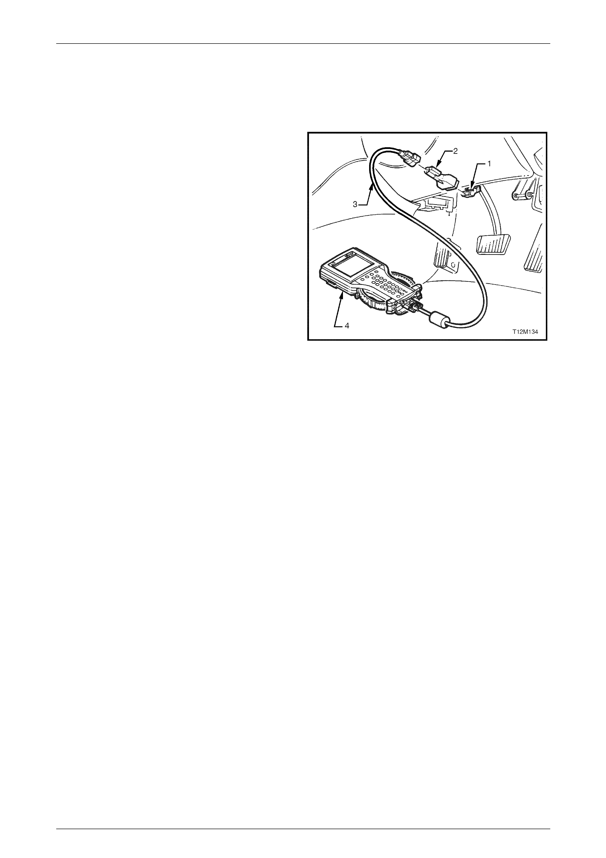
Tech 2, with the appropriate software, cables and adapters,
when connected to the serial data link con ne ctor (DLC) can
read seat and exterior rear-view mirror serial data. The DLC
is attached to the instrument panel trim retai ner beneath the
steering wheel.
1 DLC
2 DLC Adapter
3 DLC Cable
4 Tech 2
For additional general information on connecting and
operating Tech 2, refer to Section 0C Tech 2.
Figure 1A7 – 24
Test Modes
Tech 2 has six test modes for diagnos ing the transmission. To get to these various test modes, on Tech 2 select:
Diagnostics / Model Year / Model / Transmission / Automatic Transmission
and follow Tech 2’s prompts. This will then display the following menu operations.
Diagnostic Trouble Codes
If Diagnostic Trouble Codes is selected, a selection list is displayed which contains:
• Read DTC Information – Once selected, both current and history diagnostic trouble co des (DTCs) stored in the
transmission control module will be displayed.
• Clear Engine & Transmission DTC(s) – Once selected, DTCs stored in the transmission control module (TCM)
and engine control module (ECM) memory may be cleared.
• Freeze Frame / Failure Records – Shows Freeze Frame / Failure Records information. Freeze Frame / Failure
Records are types of snapshots stored in the memory of the TCM and contain data parameters from the TCM at
the time the DTC set.
NOTE
For a complete list of TCM DTCs, refer to
4.6 Diagnostic Trouble Code List. For further
information on Tech 2 and it functions, refer to
Section 0C Tech 2.

Automatic Transmission – 4L60E – Electrical Diagnosis Page 7C2–26
Page 7C2–26
Data Display
If Data Display is selected, a selection list is displayed which contains:
• Transmission Data – Once is selected, a list of transmission components and the TCM inputs are displayed along
with their status.
• TCC Data – Once selected, displays specific parameter info rmation about the torque converter clutch controlling
devices and their circuits.
• 1-2 Shift Data – Once selected, displays specific parameter information about the 1-2 shift solenoid valve (shift
solenoid A) and its circuits.
• 2-3 Shift Data – Once this mode is selected, displays spec ific parameter information about the 2-3 shift solenoid
valve (shift solenoid B) and its circuits.
• 3-4 Shift Data – Once selected, displays information on 3-4 shift timing.
• Pressure Control Solenoid Data – Once selected, displays specific parameter information about the PC solenoid
and its circuits.
• Transmission Adapts – Once selected, it has further sub menus:
• 1-2 Adapt Data – In this mode Tech 2 continuously monitors and displays 1-2 TAP cell data param eters.
• 2-3 Adapt Data –In this mode Tech 2 continuously monitors and displays 2-3 TAP cell data parameters.
• 3-4 Adapt Data –In this mode Tech 2 continuously monitors and displays 3-4 TAP cell data parameters.
• Steady State Adapt Data – In this mode Tech 2 continuously monitors and displays Stead y State TAP data
parameters.
• System Identification: In this mode, Tech 2 will display the transmission identification screen. The following items
will be displayed; Identifier, Pa rtnumber, Hardware Partnumber, Alpha Code, Software Version Number, Software
Partnumber, VIN Digit 1-10, VIN Digit 11-17.
NOTE
Further information about the Data Display mode
and the data parameter is contained in
3.2 Data Display.
Snapshot
In this test mode, Tech 2 captures TCM data before and after a forced manual trigger.
Additional Functions
If Additional Functions is selected, a selections list is displayed which contains:
• System Identification– In this mode, Tech 2 will display the transmission identification screen. The following items
will be displayed; Identifier, Pa rtnumber, Hardware Partnumber, Alpha Code, Software Version Number, Software
Partnumber, VIN Digit 1-10, VIN Digit 11-17.

Automatic Transmission – 4L60E – Electrical Diagnosis Page 7C2–27
Page 7C2–27
Miscellaneous Tests
If Miscellaneous Functions is selected, a selections list is displayed which contains:
• TCC Solenoid –Tech 2 can command the TCC solenoid on and off. Tech 2 will display whether the TCC solenoid
is active or inactive.
• TCC PWN Solenoid – Tech 2 can command the TCC PWM solenoid on and off. Tech 2 will display whether the
TCC PWM solenoid is active or inactive and torque percentage.
• TCC Apply – Tech 2 can command the TCC on when the vehicle is above 50 km/h.
• Shift Solenoid A – Tech 2 can command the shift solenoid A (1-2 shift solenoid) on and off.
• Shift Solenoid B – Tech 2 can command the shift solenoid B (2-3 shift solenoid) on and off.
• 3/2 Downshift Solenoid – Tech 2 can command the 3/2 downshift solenoid (3-2 shift solenoid) on and off.
• Gear Control – Tech 2 can incrementally command shift solenoid states to correspond to relative gear states. The
TCM will only allow single shift increments or decrements and does not allow a shift if it causes the engin e RPM to
exceed a calibrated limit.
• High Side Driver 1 – This test is not applicable.
• High Side Driver 2 – This test is not applicable.
• Pressure Control Solenoid – This function allows the user to control state of the pressure control solenoid in
increments of 100 mA.
NOTE
For operating parameters of the Miscellaneous
Test, refer to 3.4 Miscellaneous Tests.
Programming
If Programming is selected, a selection list is displayed which contains:
• Reset TAP Cells – This test allows the user to reset the Transmission Adapt (TAP) cells by pressing the Reset soft
key.
NOTE
Upon resetting the TAP cells the TCM loses all
learnt adaptive functions. When the vehicl e is first
driven after this, the shifts may be harsh. This
harshness will ease as the T CM rel earns the T AP
cells.

Automatic Transmission – 4L60E – Electrical Diagnosis Page 7C2–28
Page 7C2–28
3.2 Data Display
If Data Display is selected, a selection list is displayed which contains the following:
Transmission Data
Once this mode, a list of transmission components and the TCM inputs are disp layed along with their status.
Transmission Data Parameters
For definitions of the parameters in this table, refer to 3.3 Tech 2 Data Def initions.
Tech 2 Parameter Units Displayed Typical Data Value
Engine Torque Nm Varies
Throttle Position Percent Varies
Engine Speed RPM Varies
AT Input Speed N/A N/A
AT Output Speed RPM Varies
Vehicle Speed km/h 0
Commanded Gear 1,2,3,4 1
Shift Solenoid A On / Off Varies
Shift Solenoid B On / Off Varies
3-2 Downshift Solenoid On/Off On
Estimated Gear Ratio Ratio 8.00:1
Speed Ratio Ratio 8.00:1
Torque Converter Efficiency Ratio .00:1
TFP Gear Park/Neutral, Reverse, Drive4,
Drive3, Drive2, Drive1 or Inval id Park/Neutral
TFP Switch A Open 12 V / Closed 0 V Varies
TFP Switch B Open 12 V / Closed 0 V Varies
TFP Switch C Open 12 V / Closed 0 V Varies
Engine Coolant Temperature °C Varies
Transmission Fluid Temp °C Varies
Transmission Hot Mode On/Off Off
PCS Actual Current Amps Varies (0.1 – 1.1 A)
PCS Desired Current Amps Varies (0.1 – 1.1 A)
PCS Duty Cycle Percent Varies
High Side Driver 1 N/A N/A
TCC Solenoid On / Off Varies
TCC PWM Solenoid Percent 0%
TCC Slip Speed RPM +/-50 RPM from Engine Speed
High Side Driver 2 N/A N/A
TR Switch A Open 12 V / Closed 0 V Varies
TR Switch B Open 12 V / Closed 0 V Varies

Automatic Transmission – 4L60E – Electrical Diagnosis Page 7C2–29
Page 7C2–29
Tech 2 Parameter Units Displayed Typical Data Value
TR Switch C Open 12 V / Closed 0 V Varies
TR Switch P Open 12 V / Closed 0 V Varies
Latest Shift Seconds Varies
1-2 Shift Time Seconds Varies
2-3 Shift Time Seconds Varies
3-4 Shift Time Seconds Varies
Cruise Control Active / Inactive Varies
A/C Clutch On / Off Varies
Ignition Voltage Volts 12-14 V
Shift Pattern Normal/ Power / Cruise Varies
TCC Data
Once this mode is selected, displays specific parameter information about the torque conv erter clutch controlling devices
and their circuits.
TCC Data Parameters
For definitions of the parameters in this table, refer to 3.3 Tech 2 Data Def initions.
Tech 2 Parameter Units Displayed Typical Data Value
TCC Solenoid On / Off Varies
TCC PWM Solenoid Percent 0%
TCC Slip Speed RPM +/-50 RPM from Engine Speed
TCC Duty Cycle Circuit Open or Shorted / Short to Battery /
Okay Okay
High Side Driver 2 N/A N/A
High Side Driver 2 Circuit N/A N/A
Throttle Position Percent Varies
Engine Speed RPM Varies
AT Input Speed N/A N/A
AT Output Speed RPM Varies
Engine Torque Nm Varies
Vehicle Speed km/h 0
Commanded Gear 1,2,3,4 1
Engine Coolant Temperature °C Varies
Transmission Fluid Temp °C Varies
Estimated Gear Ratio Ratio 8.00:1
Transmission Hot Mode On / Off Off

Automatic Transmission – 4L60E – Electrical Diagnosis Page 7C2–30
Page 7C2–30
1-2 Shift Data
Once this mode is selected, displays specific parameter information about the 1-2 shift soleno id valve and its circuits.
1-2 Shift Data Parameters
For definitions of the parameters in this table, refer to 3.3 Tech 2 Data Def initions.
Tech 2 Parameter Units Displayed Typical Data Value
Shift Solenoid A On / Off Varies
Shift Solenoid B On / Off Varies
Commanded Gear 1,2,3,4 1
1-2 Shift Time Seconds Varies
1-2 Shift Error Seconds Varies
Shift Solenoid A Circuit Open or Shorted / Short to Battery /
Okay Okay
High Side Driver 2 N/A N/A
High Side Driver 2 Circuit N/A N/A
Throttle Position Percent Varies
Engine Speed RPM Varies
AT Input Speed N/A N/A
AT Output Speed RPM Varies
Vehicle Speed km/h 0
Estimated Gear Ratio Ratio 8.00:1

Automatic Transmission – 4L60E – Electrical Diagnosis Page 7C2–31
Page 7C2–31
2-3 Shift Data
Once this mode is selected, displays specific parameter information about the 2-3 shift soleno id valve and its circuits.
2-3 Shift Data Parameters
For definitions of the parameters in this table, refer to 3.3 Tech 2 Data Def initions.
Tech 2 Parameter Units Displayed Typical Data Value
Shift Solenoid A On / Off Varies
Shift Solenoid B On / Off Varies
Commanded Gear 1,2,3,4 1
2-3 Shift Time Seconds Varies
2-3 Shift Error Seconds Varies
Shift Solenoid B Circuit Open or Shorted / Short to Battery /
Okay Okay
High Side Driver 2 N/A N/A
High Side Driver 2 Circuit N/A N/A
Throttle Position Percent Varies
Engine Speed RPM Varies
AT Input Speed N/A N/A
AT Output Speed RPM Varies
Vehicle Speed km/h 0
Estimated Gear Ratio Ratio 8.00:1
3-4 Shift Data
Once this mode is selected, displays information on 3-4 shif t timing.
3-4 Shift Data Parameters
For definitions of the parameters in this table, refer to 3.3 Tech 2 Data Def initions.
Tech 2 Parameter Units Displayed Typical Data Value
Shift Solenoid A On / Off Varies
Shift Solenoid B On / Off Varies
Commanded Gear 1,2,3,4 1
3-4 Shift Time Seconds Varies
3-4 Shift Error Seconds Varies
High Side Driver 2 N/A N/A
High Side Driver 2 Circuit N/A N/A
Throttle Position Percent Varies
Engine Speed RPM Varies
AT Input Speed N/A N/A
AT Output Speed RPM Varies
Vehicle Speed km/h 0
Estimated Gear Ratio Ratio 8.00:1

Automatic Transmission – 4L60E – Electrical Diagnosis Page 7C2–32
Page 7C2–32
Pressure Control Solenoid Data
Displays specific parameter information about the PC solenoid and its circuits.
Pressure Control Solenoid Data Parameters
For definitions of the parameters in this table, refer to 3.3 Tech 2 Data Def initions.
Tech 2 Parameter Units Displayed Typical Data Value
PCS Actual Current Amps Varies (0.1 – 1.1 A)
PCS Desired Current Amps Varies (0.1 – 1.1 A)
PCS Duty Cycle Percent Varies
High Side Driver 1 N/A N/A
High Side Driver 1 Circuit N/A N/A
Engine Speed RPM Varies
Transmission Fluid Temp °C Varies
Throttle Position Percent Varies
Vehicle Speed km/h 0
Commanded Gear 1,2,3,4 1
Transmission Adapts
Once this is selected, it has further sub menus.
1-2 Adapt Data
In this mode Tech 2 continuously monitors and displays 1-2 TAP cell data parameters.
1-2 Adapt Data Parameter
For definitions of the parameters in this table, refer to 3.3 Tech 2 Data Def initions.
Tech 2 Parameter Units Displayed Typical Data Value
1-2 Shift Time Seconds Varies
1-2 Shift Error Seconds Varies
Current TAP Cell 4-16 Varies
Throttle Position Percent Varies
1-2 Tap Cell (1 – 17) kPa Varies
2-3 Adapt Data
In this mode Tech 2 continuously monitors and displays 2-3 TAP cell data parameters.
2-3 Adapt Data Parameters
For definitions of the parameters in this table, refer to 3.3 Tech 2 Data Def initions.
Tech 2 Parameter Units Displayed Typical Data Value
2-3 Shift Time Seconds Varies
2-3 Shift Error Seconds Varies
Current TAP Cell 4-16 Varies
Throttle Position Percent Varies
2-3 Tap Cell (1 – 17) kPa Varies

Automatic Transmission – 4L60E – Electrical Diagnosis Page 7C2–33
Page 7C2–33
3-4 Adapt Data
In this mode Tech 2 continuously monitors and displays 3-4 TAP cell data parameters.
3-4 Adapt Data Parameters
For definitions of the parameters in this table, refer to 3.3 Tech 2 Data Def initions.
Tech 2 Parameter Units Displayed Typical Data Value
3-4 Shift Time Seconds Varies
3-4 Shift Error Seconds Varies
Current TAP Cell 4-16 Varies
Throttle Position Percent Varies
3-4 Tap Cell (1 – 17) kPa Varies
Steady State Adap t Data
In this mode TECH 2 continuously monitors and displays Steady State T AP data par ameters.
Steady State Adapt Data Parameters
For definitions of the parameters in this table, refer to 3.3 Tech 2 Data Def initions.
Tech 2 Parameter Units Displayed Typical Data Value
Current TAP Cell 4-16 Varies
Throttle Position Percent Varies
Gear (1-4) TAP Cell kPa Varies
TCC (1-4) TAP Cell kPa Varies
Reverse Gear TAP Cell kPA Varies

Automatic Transmission – 4L60E – Electrical Diagnosis Page 7C2–34
Page 7C2–34
3.3 Tech 2 Data Definitions
1-2 Shift Error: This parameter displays the difference between the desir ed 1-2 shift time and the actual 1-2 shift time. A
positive number indicates a firm or fast shift and the actual shift time was shorter than the desired shift time. A negative
number indicates a soft or slow shift and the actual shift time was longer than the desired shift time. This value is only
accurate if the shift was adaptable.
1-2 Shift Time: This parameter displays the actual time of the last 1-2 shift. The shift time is based on the engine r.p.m.
drop after the commanded 1-2 shift. This value is only accurate if the shift was adaptable.
1-2 TAP Cell (1-17): This parameter displays the amount of transmission adaptive pressure (TAP), based on 17 Nm of
engine torque increment per cell, added to or subtracted from shift pressure during a 1-2 upshift. A positive number
indicates that long shifts have been detected and PC solenoid pressure has been added to decrease shift time. A
negative number indicates that short shifts have been detected and PC solenoid pressure has been subtracted to
increase shift time.
2-3 Shift Error: This parameter displays the difference between the desir ed 2-3 shift time and the actual 2-3 shift time. A
positive number indicates a firm or fast shift, the actual shift time was shorter than the desired shift time. A negative
number indicates a soft or slow shift, the actual shift time was longer than the desired shift time. This value is only
accurate if the shift was adaptable.
2-3 Shift Time: This parameter displays the actual time of the last 2-3 shift. The shift time is based on the engine r.p.m
drop after the commanded 2-3 shift. This value is only accurate if the shift was adaptable.
2-3 TAP Cell (1-17): This parameter displays the amount of transmission adaptive pressure (TAP), based on 17 Nm of
engine torque increment per cell, added to or subtracted from shift pressure during a 2-3 upshift. A positive number
indicates that long shifts have been detected and PC solenoid pressure has been added to decrease shift time. A
negative number indicates that short shifts have been detected and PC solenoid pressure has been subtracted to
increase shift time.
3-4 Shift Error: This parameter displays the difference between the desir ed 3-4 shift time and the actual 3-4 shift time. A
positive number indicates a firm or fast shift, the actual shift time was shorter than the desired shift time. A negative
number indicates a soft or slow shift, the actual shift time was longer than the desired shift time. This value is only
accurate if the shift was adaptable.
3-4 Shift Time: This parameter displays the actual time of the last 3-4 shift. The shift time is based on the engine r.p.m.
drop after the commanded 3-4 shift. This value is only accurate if the shift was adaptable.
3-4 TAP Cell (1-17): This parameter displays the amount of transmission adaptive pressure (TAP), based on 17 Nm of
engine torque increment per cell, added to or subtracted from shift pressure during a 3-4 upshift. A positive number
indicates that long shifts have been detected and PC solenoid pressure has been added to decrease shift time. A
negative number indicates that short shifts have been detected and PC solenoid pressure has been subtracted to
increase shift time.
A/C Clutch: This parameter displays the condition of the sirconditioning compressor as either On or Off.
AT Output Speed: This parameter displays the rotational speed of the transmission output shaft. Tech 2 displays output
shaft speed as revolutions per minute (RPM).
Commanded Gear: This parameter displays the current commanded state of the shift solenoid valves. Tech 2 displays
1, 2, 3 or 4.
Current TAP Cell: This parameter displays the current transmission adaptive pressure (TAP) cell in use for transmission
line pressure adaptation. The cells are based on 17 Nm of engi ne torque. The higher the engine torque, the higher the
current TAP cell. The last cell used will remai n displa yed until the next adaptable u psh ift occurs.
Engine Coolant Temperature: This parameter displays the input signal from the engine coolant temperate (ECT )
sensor. ECT is high at 151°C when the signal voltage is low, 0 V. ECT is low at -40°C when the signal voltage is hi gh,
5 V.
Engine Speed: This parameter displays the rotational speed of the eng ine expressed as revolutions per minute.
Engine Torque: This parameter displays the calcul ated value based on engine load, thr ottle position, mass air flow, and
other engine inputs. This parameter is accur ate to within 20 Nm of actual measured engine torque.
Estimated Gear Ratio: This parameter displays the estimated turbine speed divided by the transmission output sp eed.
Estimated turbine speed is calculate d from engine speed and engine torque.
Ignition Voltage: This parameter displays the system voltage measured at the ignition feed.
Latest Shift: This parameter displays the actual time of the last upshift. This value is only accurate if the shift was
adaptable.
PCS Actual Current: This parameter displays the current flow through the pressure con trol solenoid circuit, which is
measured by the control module. High current flow results in low line pressure. Low current flow results in high line
pressure.

Automatic Transmission – 4L60E – Electrical Diagnosis Page 7C2–35
Page 7C2–35
PCS Duty Cycle: This parameter displays the commanded state of the pressure control solenoid, expressed as a
percentage of energised on ti me. A reading of low percent indicates zero on time, non-energised, or no current flow. A
high percent at idle indicates maximum on time, energised, or high curr ent flow.
PCS Desired Current: This parameter displays the commanded current of the pressure control solenoi d circuit. High
current results in low line pressure. Low current results in high line pressure.
Shift Pattern: This parameter displays Normal, Power or Cruise depending on what mode the transmission is i n.
Shift Solenoid A: This parameter displays the comman ded state of the 1-2 shift solenoid valve. When the transmission
is in 1st and 4th gear, the display should indic ate On; current is flowing through the solenoid. When the transmission is in
2nd and 3rd gear, the display should indicate Off; current is not flowing through the solenoi d.
Shift Solenoid A Circuit: This parameter displays whether an open or a short to ground, short to battery or the circuit is
okay in the 1-2 shift solenoid valve fee db ack signal. The 1-2 shift solenoid valve must be commanded off and on.
Shift Solenoid B: This parameter displays the commanded state of the 2-3 shift solenoid valve. When the transmission
is in 1st and 4th gear, the display should indic ate On; current is flowing through the solenoid. When the transmission is in
2nd and 3rd gear, the display should indicate Off; current is not flowing through the solenoi d.
Shift Solenoid B Circuit: This parameter displays whether an open or a short to ground, short to battery or the circuit is
okay in the 2-3 shift solenoid valve fee db ack signal. The 2-3 shift solenoid valve must be commanded off and on.
Speed Ratio: This parameter displays the calculated speed ratio of the transmission.
TCC Duty Cycle Circuit: This parameter displays whether an open or a short to ground, short to battery or the circuit is
okay in the TCC PWM solenoid valv e feedback signal. The TCC PWM solenoid valve must be commanded off and on.
TCC Solenoid: This parameter displays the commanded sate of the T CC solenoid. On indicates a commanded
energised state; current is flowing throug h the solenoid. Off indicates a commanded non-energised state; current is not
flowing through the solenoid. T his command ed state occurs at various vehicle speeds between applications.
TCC Slip Speed: This parameter displays the differenc e between transmission output speed and engine speed. A
negative value indicates the e ngine speed is less than the output speed, deceleration. A positive value indicates the
engine speed is greater than the output speed, acceleration. A value of zero indicates the eng ine speed is equal to the
output speed, TCC applie d.
TCC PWM Solenoid: This parameter displays the commanded percentage of on time for the TCC PWM solenoid. A high
percentage represents an on, energised, commanded state.0 percent represents an off, non-energised, commanded
state.
TFP Gear: This parameter displays Park/Neutral, Reverse, Drive4, Drive3, Drive2, Drive1 or Invalid. This parameter
is the decoded status of the three A/B/C inputs from the automatic transmission fluid pressure manual valve position
switch. If a valid combination of inputs is not detected, invalid will be dis played.
TFP Swi A/B/C: This parameter displays Open 12 V / Closed 0 V for each s witch. This parameter indicates the statues
of the three inputs from the automatic transmission fluid pressure man ual valve position switch assembly.
Throttle Position: This parameter displays a calculated value, which is determined by the accelerator pedal position and
the actual throttle position, used to optimis e transmission controls. It represents the driver’s intended requested for
torque or acceleration. The range is 0-100%, 0% represents an idle or coast request and 100% represents a request for
wide open throttle (WOT).
Torque Converter Efficiency: This parameter displays a ratio of 0.00:1 to 2:1. The ratio is calculates by multiplying the
speed ratio by a value related to the ‘K factor’ of the torque converter. The ‘K factor’ is the looseness or tightness of the
torque converter for a given torqu e. The nearer the torque converter is to full coupling, i.e. 1:1, the closer the torque
converter efficiency number will be to 1.
TR Switch A/B/C/P: This parameter displays the status of the four inputs from the transmission range switch. Tech 2
displays Open 12V / Closed 0 V. Open 12 V indicates an ignitio n volta ge input to the control module. Closed 0 V
indicates a zero voltage input to the control module.
Transmission Fluid Temperature: This parameter displays the input signal of the transmission fluid temperatur e
sensor. Transmission fluid temperature is high, 151°C, when signal volta ge is low, 0 V. Transmission fluid temperature is
low, -40°C, when signal voltage is high, 5 V.
Transmission Hot Mode: This parameter displays the automatic transmission fluid temperature (TFT ) and displays On
or Off. Off indicates the TFT has not exceeded 130°C. On indicates the TFT has exceeded 130°C and has not cooled to
120°C for greater than 5 seconds. These numbers are appr oximate and differ with transmissions.
Vehicle Speed: This paramet er displays the speed at which the vehicle is travelling. Tech 2 displays vehicle speed as
kilometres per hour (km/h). The vehicle speed is calculates based on the input signal from the automati c transmission
output shaft speed sensor.

Automatic Transmission – 4L60E – Electrical Diagnosis Page 7C2–36
Page 7C2–36
3.4 Miscellaneous Tests
Tech 2
Miscellaneous Tests Description
1-2 Solenoid
• The TCM commands the 1-2 shift solenoid valve on and off. Tech 2’s Shift Solenoid A
Parameter should match the commanded state. Tech 2’s Commanded Gear
parameter should correspond with the shift solenoid combination. Refer to
5.6 Shift Solenoid Valve State and Gear Ratio.
• When the ignition is on, and the engine is off, there no limits to this control. The
solenoid remains on until commanded off, and vice versa. When the test is exited, the
solenoid state is determined b y the T CM.
• When the engine is running, the following control limits apply:
• Only sequential gear chan ges are allowed. For example, 1st to 3rd is not allowed.
If a non-sequential gear change is attempted, the message Non-sequential
gear changes not allowed. Gear changes must be made in order appears
on Tech 2.
• The vehicle speed must be below a calibrated value. If the vehicle speed is too
high, the message Vehicle speed to o high appears on Tech 2.
• The engine speed must be below a calibrated value. If the engine speed is too
high, the message Engine speed too high appears on Tech 2.
• Downshifts are allowed only when the vehicle speed is below a calibrated value.
If the vehicle speed is too high, the message Eng. is on and veh. speed to hi
for 3-2 or 2-1 downshift appears on T ech 2.
• The gear requested may not be greater than the current selected transmission
range (PRNDL). For example, 3rd gear is not allowed if the transmissi on range is
D2. If the gear requested is greater than the current selected transmission
range, the message Eng. running and gear request is greater than the
current TR appears on Tech 2.
• The solenoid remains on until commanded off, and vice versa. When the test is
exited, the solenoid state is determine d by the TCM.
2-3 Solenoid
• The TCM commands the 2-3 shift solenoid valve on and off. Tech 2’s Shift Solenoid B
parameter should match the commanded state. Tech 2’s Commanded Gear
parameter should correspond with the shift solenoid combination. Refer to
5.6 Shift Solenoid Valve State and Gear Ratio.
• When the ignition is on, and the engine is off, there no limits to this control. The
solenoid remains on until commanded off, and vice versa. When the test is exited, the
solenoid state is determined b y the T CM.
• When the engine is running, the following control limits apply:
• Only sequential gear chan ges are allowed. For example, 1st to 3rd is not allowed.
If a non-sequential gear change is attempted, the message Non-sequential
gear changes not allowed. Gear changes must be made in order appears
on Tech 2.
• The vehicle speed must be below a calibrated value. If the vehicle speed is too
high, the message Vehicle speed to o high appears on Tech 2.
• The engine speed must be below a calibrated value. If the engine speed is too
high, the message Engine speed too high appears on Tech 2.
• Downshifts are allowed only when the vehicle speed is below a calibrated value.
If the vehicle speed is too high, the message Eng. is on and veh. speed to hi
for 3-2 or 2-1 downshift appears on Tech 2.
• The gear requested may not be greater than the current selected transmission
range (PRNDL). For example, third gear is not allowed if the transmission range
is D2. If the gear requested is greater than the current selected transmission
range, the message Eng. running and gear request is greater than the
current TR appears on Tech 2.
• The solenoid remains on until commanded off, and vice versa. When the test is
exited, the solenoid state is determine d by the TCM.

Automatic Transmission – 4L60E – Electrical Diagnosis Page 7C2–37
Page 7C2–37
Tech 2
Miscellaneous Tests Description
3-2 Downshift Solenoid
• The TCM commands the 3-2 shift solenoid valve on and off. Tech 2’s 3-2 Downshift
Sol. parameter should match the commande d state.
• When the ignition is on, and the engine is off, there are no limits to this control. The
solenoid remains on until commanded off, and vice versa. When the test is exited, the
solenoid state is determined b y the T CM.
• When the engine is running, the following control limits apply:
• The transmission range (PRNDL) must be Park or Neutral. If the transmission
range is not in Park or Neutral, the message :Engine running and
transmission range is not Park/Neutral appears on Tech 2.
• The solenoid remains on until commanded off, and vice versa. When the test is
exited, the solenoid state is determine d by the TCM.
Clear TAPS
(Transmission Adaptive
Pressures)
• The TCM clears (or resets) the TAP cells to the ori gin al base value.
• There are no limits to using this test. It may be performed with the engine running or
when the ignition is on, and the engine is off.
PC Solenoid
• The TCM commands the current to the pressure contro l solenoid to control
transmission line pressure. As the current increases, the line pressur e decreases. As
the current decreases, the line pressure increases. The current range is 0.00 – 1.10 A
and may be commanded in one-tenth of a n amp increments.
• When the ignition is on, and the engine is off, the reference (commanded) amperage
may be controlled within calibrated lim its. T ech 2’s parameter PCS Desired Current
changes by the parameter PCS Actual Current does not change. The reference
current remains until commanded otherwise.
• When the engine is running, the following control limits apply:
• When the transmission range i s Park or Neutral, the reference (commanded)
current may be controlled within calibrated limits. The engine speed must be
less than 1,500 r.p.m. If the engine speed is great than 1,500 r.p.m, the
message TR in park/neutral and engine speed over 1,500 RPM appears on
Tech 2. Both Tech 2 parameters PCS Desir ed Current and PCS Actual Current
parameters change. Both current read ings remain until commanded otherwise.
• When the transmission range i s not in Park or Neutral, the reference current can
only be controlled less than th e current determined by the TCM. The TCM does
not allow a value to be selected that may cause damage to the transmission. If
the requested amperage is more than allowed by the TCM, the message
Requested current for the PC Solenoid is too high appears on Tech 2.
• Transmission range DTCs must not be active. If a transmission range DTC is
active, the message Engine running with transmission DTC present appears
on Tech 2.

Automatic Transmission – 4L60E – Electrical Diagnosis Page 7C2–38
Page 7C2–38
Tech 2
Miscellaneous Tests Description
Shift Transmission
• The TCM commands upshifts and downshifts. Tech 2’s Commanded Gear parameter
should correspond with the shift solenoid combination. Refer to 5.6 Shift Solenoid
Valve State and Gear Ratio.
• When the ignition is on, and the engine is off, there are no limits to this control. The
Tech 2 shift solenoid states changes to match the Commanded Gear selected.
• When the engine is running, the following control limits apply:
• The TCM does not allow a shift if it causes the engine r.p.m. to exceed a
calibrated limit. If a gear is requested and the engine speed is too high, the
message Engine speed too high appears on Tech 2.
• The TCM does not allow a 3-2 or 2-1 downshift if the vehicle speed exceeds a
calibrated limit. If either downshift is requested and the vehic le spe ed is too high,
the message Eng. is on and veh. Speed too hi for 3-2 or 2-1 downshift
appears on Tech 2.
• The TCM does not allow a 4-3 downshift if this vehicle speed exceeds a
calibrated limit. If a 4-3 downshift is requested and the vehicle speed is too high,
the message Vehicle speed to h ig h appears on Tech 2.
• The TCM does not allow an upshift if the veh icle sp eed exceeds a calibrated
limit. If an upshift is requested and the vehicle speed is too high, the message
Vehicle speed to high appears on Tech 2.
• The TCM does not allow an upshift that is greater than the current selected
transmission range (PRNDL). For exampl e 3rd gear is not all owed if the
transmission range is D2. If an upshift is requested that is greater than the
current selected transmission range, the message Eng. running and gear
request is greater than the current TR appears on Tech 2.
TCC Control Solenoid
• The TCM commands the dut y c ycle of the TCC PWM solenoid. The duty cycle is
represented by a percentage of on (energised) time. Approximately 90-100 percent
duty cycle represents an on (energised) commanded state. Zero percent represents
an off (non-energised) commanded state. Tech 2 TCC PWM Solenoid parameter
should match the commanded state.
• When the ignition is on, and the engine is off, there are no limits to this control. The
solenoid remains on (90-100 percent duty cycle) until commanded off (zero percent
duty cycle), and vice versa. When the test is exit ed, the solenoid duty cycle is
determined by the TCM.
• When the engine is running, the following control limits apply:
• If the transmission range is Park, and the transmission is in hot mode, the T CC
control solenoid may not be commanded off. If the solenoid is requested off, the
message TCC OFF command disabled in Hot Mode appears on Tech 2.
• The TCC control solenoid may not be commanded off for more than a cali brated
amount of time. If the solenoid is commanded off for a certain amount of time,
the message TCC OFF time has been exceed ed appears on T ech 2.

Automatic Transmission – 4L60E – Electrical Diagnosis Page 7C2–39
Page 7C2–39
Tech 2
Miscellaneous Tests Description
TCC Enable
• The TCM commands the TCC enable solenoid valve on and off. Tech 2’s TCC
Solenoid param eter should match the commended state.
• When the ignition is on, and the engine is off, there are no limits to this control. The
solenoid remains on until commanded off, and vice versa. When the test is exited, the
solenoid state is determined b y the T CM.
• When the engine is running, the following control limits apply:
• If the transmission range is Park or Neutral, the TCC enable solenoid may not
be commanded off for more than a calibrated amou nt of time. If the solenoi d is
commanded off for a certain amount of time, the message TCC OFF time has
been exceeded appears on Tech 2.
• If the transmission range is Park or Neutral and the TCC control solenoid duty
cycle is less than maximum capac ity, the TCC solenoid may not be commanded
on. If the solenoid is requested on during these conditions, the message TCC
Control Solenoid is not set to maximum Pressure appears on Tech 2.
• If the TCC control solenoid duty cycle is less than ma ximum capacity, the TCC
solenoid may not be commanded on. If the sole noid is commanded on dur ing
these conditions the message TCC Control Solenoid is not set to maximum
Pressure appears on Tech 2.
• If the transmission is in hot mode, the TCC solenoid may not be commanded off.
If the solenoid is requested off the message TCC OFF command disabled in
Hot Mode appears on the scan tool display.

Automatic Transmission – 4L60E – Electrical Diagnosis Page 7C2–40
Page 7C2–40
4 Diagnostics
4.1 Introduction
The transmission diagnostic pr ocedure is organised in a logi cal structure that begins with the diag nostic system check
and as such must always be used as the starting point. The diagnostic system check directs the technician to the logical
steps necessary to diagnose a transmissio n d r iveability fault condition.

Automatic Transmission – 4L60E – Electrical Diagnosis Page 7C2–41
Page 7C2–41
4.2 Precautions
When tests are required on connector
terminals, use the adapters in connector
adaptor kit J35616-C to prevent damage to
terminals.

Automatic Transmission – 4L60E – Electrical Diagnosis Page 7C2–42
Page 7C2–42
4.3 Diagnostic Trouble Code Tables
The diagnostic system check and the DTC list, directs the technician to the appropriate diagnostic trouble code (DTC)
tables if there is a DTC currently stored in the TCM.
The diagnostic tables locate a faulty circuit or component through a logic based on the process of elimination. These
diagnostic tables are developed with the following assumptions:
• the vehicle functioned correctly at the time of assembly,
• there are no multiple faults, and
• the problem currently exists.
Understanding and the correct use of the diagnostic tables are essential to reduce diagnostic time and to prevent
misdiagnosis.
Multiple DTCs Fault Condition
Some fault conditions trigger multiple comp onent DTCs even if the fault condition exists only on a single compo nent. If
there are multiple DTCs stored in the TCM, the service technician must view and record all DTCs logged.
Relationship between the logged DTCs can then be analysed to determine the source of the fault condition. Always
begin the diagnostic process with the DTC table of the fault condition that may trigger other DTCs to set.
The following fault conditions ma y trigger multiple DTCs:
• a fault in the serial data communication circ uit,
• a system voltage that is too low may cause incorrect transmission tem operation or transmission component
malfunction,
• a system voltage that is too high may damage the TCM and/or other components,
• fault condition in the TCM Read Only Memory (ROM) or Random Access Memory (RAM),
• fault condition in the TCM internal circuitry or programming, or
• improperly connected sensor or component wiring connector.
If there are no obvious faults to begin a multiple DTC fault condition diagnostic procedure, refer to the Conditions for
Running the DTC in each diagnostic.

Automatic Transmission – 4L60E – Electrical Diagnosis Page 7C2–43
Page 7C2–43
4.4 Diagnostic Trouble Code Definitions
The TCM constantly performs self-diagnostic tests on the transmission and it components. When the TCM detects a fault
condition in the transmission operati ng parameters, the TCM sets a DTC to represents that fault condition. The following
are the types of DTCs programmed in the T CM. In addition, DTCs are classified as either Current or History DTC.
• Type A – Emission Related DTCs,
• Type B – Emission Related DTCs, and
• Type C – Non-emission Related DTCs.
NOTE
Depending on the t ype of DTC set, the TCM may
command the check powertrain icon display to
display on the instrument clusters multi-function
display (MFD) and warn the driver there is a fault
in the transmission. Refer to
Section 12C Instruments for further information
on the check powertrain icon.
Type A – Emission Related DTCs
The TCM takes the following action when a Type A DTC runs and fails:
• sets a current Type A DTC that represents the fault condition,
• illuminates the MFD check powertrain icon, and
• records the operating condition at the time the diagnost ic fails and stores this information in the Freeze Frame/
Failure Record.
Type B – Emission Related DTCs
The TCM takes the following actions when a Type B DTC runs and fails.
• On the first time a Type B DTC fails:
• sets a current Type B DTC that represents the fault condition, and
• records the operating conditions at the time the fault sets and stores this information in the Failure Records.
• On the second consecutive ignition cycle that a Type B DTC fails:
• illuminates the MFD check powertrain icon, and
• records the operating condition at the time the diagnostic fai ls and stores th is information in the Freeze
Frame/ Failure Record.
Conditions for Clearing Type A or Type B DTCs
• The current DTC clears when there is no fa ult condition in the current TCM self-diagnostics.
• If there are no DTCs logged after six consecutive ignition cycl es, the TCM deactivates the MFD check powertrain
icon.
• Type A or Type B History DTC clears when there is no fault condition after 40 consecutive warm-up cycles.
• Use of Tech 2 to clear DTCs.

Automatic Transmission – 4L60E – Electrical Diagnosis Page 7C2–44
Page 7C2–44
Type C – Non-emission Related DTCs
The TCM takes the following action when a Type C DTC runs and fails:
• sets a current Type C DTC that represents the fault condition,
• records the operating conditions at the time the DT C is logged and stores this information in the Failure R ecord,
and
• the MFD may display a message.
NOTE
The MFD check powertrain icon does not
illuminate when a Type C DTC sets.
Conditions for Clearing Type C DTCs
• The current DTC clears when there is no fa ult condition in the current TCM self-diagnostics.
• Type C History DTC clears when there is no fault condition after 40 consecutive warm-up cycles.
• Use of Tech 2 to clear DTCs.
Current DTCs
A DTC is a Current DTC if the fault condition that triggers the DTC is present during the last TCM self-diagnostics.
History DTCs
A DTC is a History DTC if the fault condition that triggers the DTC is not present during the last TCM self-diagnostics.

Automatic Transmission – 4L60E – Electrical Diagnosis Page 7C2–45
Page 7C2–45
4.5 Diagnostic System Check
Description
This section procedure is organis ed in a logical structure that begins with the diagnostic system check. The diagnostic
system check directs you in a logical direction to the appropriate Section or diagnostic procedure.
Test Description
The following numbers refer to the step numbers in the diagnostic table:
1 If you are unsure whether the problem is isolated to the TCM or the issue is affecting a number of vehicle functions,
proceed to Section 0D Vehicle Diagnostics.
2 Within Section 0D Vehicle Diagnostics there are a number of requirements that must be met before you can start
diagnosis.
3 Checks if there is data communication between Tech 2 and the TCM.
4 Checks if the TCM has set any DTCs. If no DT Cs have set, the functional test must be performed, which diagnoses
the hydro-mechanical functio ns of the transmission.
Step Action Yes No
1 Is the fault specifically isol ated to this system / module? Go to Step 2 Refer to Section 0D
Vehicle Diagnostics
2 Have you read the Basic Diagnostic Requirements, Diagnostic
Precautions and Preliminar y Checks? Go to Step 3 Refer to Section 0D
Vehicle Diagnostics
3 1 Connect Tech 2 to the DLC.
2 On Tech 2 select:
Transmission / Automatic Transmission
and follow the instruction on Tech 2.
Does Tech 2 display the TCM specifications? Go to Step 4
Refer to Section
6E1 Powertrain
Interface Module
4 On Tech 2 select:
Diagnostic Trouble Codes / Read DTC Information
Does Tech 2 display a ny DTCs?
Go to
4.6 Diagnostic
Trouble Code List
Perform the
Functional Test,
refer to Section 7C3
Automatic
Transmission –
4L60E – Hydraulic
and Mechanical
Diagnosis

Automatic Transmission – 4L60E – Electrical Diagnosis Page 7C2–46
Page 7C2–46
4.6 Diagnostic Trouble Code List
NOTE
If the DTC listed on Tech 2 is not contained in
this list, refer to Section 0D Vehicle Diagnostics.
DTC Type Description Diagnostic Table
P0218 C
Transmission Fluid Overtemperature 4.7 DTC P0218 – Transmission F luid
Overtemperature
P0562 C
System Voltage Low 4.8 DTC P0562 – System Voltage
Low
P0563 C
System Voltage High 4.9 DTC P0563 – System Voltage
High
P0601 A
Transmission Control Module (TCM) Read Only Memory
(ROM) 4.10 DTC P0601 to P0604 or P1621
– TCM Malfunction
P0602 A
Transmission Control Module (TCM) Not Programmed 4.10 DTC P0601 to P0604 or P1621
– TCM Malfunction
P0603 A
Transmission Control Module (TCM) Random Access
Memory (RAM) 4.10 DTC P0601 to P0604 or P1621
– TCM Malfunction
P0604 A
Transmission Control Module (TCM) Long Term Memory
Performance 4.10 DTC P0601 to P0604 or P1621
– TCM Malfunction
P0711 C
Transmission Fluid Temperature (TFT) Sensor
Performance 4.11 DTC P0711 to P0713 –
Transmission Fluid Temperat ure
Sensor
P0712 C
Transmission Fluid Temperature (TFT) Sensor Circuit Low
Voltage 4.11 DTC P0711 to P0713 –
Transmission Fluid Temperat ure
Sensor
P0713 C
Transmission Fluid Temperature (TFT) Sensor Circuit High
Voltage 4.11 DTC P0711 to P0713 –
Transmission Fluid Temperat ure
Sensor
P0719 C
Brake Switch Circuit High Input (Stuck On) 4.12 DTC P0719 – Brake Swit ch
Circuit High Input (Stuck On)
P0722 B
Vehicle Speed Sensor Circuit Low Voltage 4.13 DTC P0722 – Vehicle Spee d
Sensor Circuit Low Voltage
P0723 B
Vehicle Speed Sensor Circuit Intermittent 4.14 DTC P0723 – Vehicle Spee d
Sensor Circuit Intermittent
P0724 C
Brake Switch Circuit Low Input (Stuck Off) 4.15 DTC P0724 – Brake Swit ch
Circuit Low Input (Stuck Off)
P0741 B
Torque Converter Clutch (TCC) System – Stuck Off 4.16 DTC P0741 – Torque Converter
Clutch System – Stuck Off
P0742 B
Torque Converter Clutch (TCC) System – Stuck On 4.15 DTC P0724 – Brake Switch
Circuit Low Input (Stuck Off)
P0751 B
1-2 Shift Solenoid (SS) Valve Performance – No F irst or
Fourth Gear 4.18 DTC P0751 – 1-2 Shift Solenoi d
Valve Performance – No First or
Fourth Gear
P0752 B
1-2 Shift Solenoid (SS) Valve Performance – No Second or
Third Gear 4.19 DTC P0752 – 1-2 Shift Solenoi d
Valve Performance – No Second or
Third Gear
P0756 A
2-3 Shift Solenoid (SS) Valve Performance – No F irst or
Second Gear 4.20 DTC P0756 – 2-3 Shift Solenoi d
Valve Performance – No First or
Second Gear
P0757 A
2-3 Shift Solenoid (SS) Valve Performance - No Third or
Fourth Gear 4.21 DTC P0757 – 2-3 Shift Solenoi d
Valve Performance – No Third or
Fourth Gear
P0787 A
3-2 Shift Solenoid (SS) Control Circuit Lo w Voltage 4.22 DTC P0787 – 3-2 S hift Solenoid
Control Circuit Low Voltage
P0788 A
3-2 Shift Solenoid (SS) Control Circuit High Voltag e 4.23 DTC P0788 – 3-2 Shift Solenoid
Control Circuit High Voltage

Automatic Transmission – 4L60E – Electrical Diagnosis Page 7C2–47
Page 7C2–47
DTC Type Description Diagnostic Table
P0894 B
Transmission Component Slippi ng 4.24 DTC P0894 – Transmission
Component Slipping
P0961 C
Line Pressure Control (PC) Solenoid System Performance 4.25 DTC P0961 – Line Pressure
Control Solenoid System Performanc e
P0973 B
1-2 Shift Solenoid (SS) Control Circuit Lo w Voltage 4.26 DTC P0973 – 1-2 S hift Solenoid
Control Circuit Low Voltage
P0974 B
1-2 Shift Solenoid (SS) Control Circuit High Voltag e 4.27 DTC P0974 – 1-2 Shift Solenoid
Control Circuit High Voltage
P0976 A
2-3 Shift Solenoid (SS) Control Circuit Lo w Voltage 4.28 DTC P0976 – 2-3 S hift Solenoid
Control Circuit Low Voltage
P0977 A
2-3 Shift Solenoid (SS) Control Circuit High Voltag e 4.29 DTC P0977 – 2-3 Shift Solenoid
Control Circuit High Voltage
P1621 A
Transmission Control Module (TCM) Long Term Memory
Performance 4.10 DTC P0601 to P0604 or P1621
– TCM Malfunction
P1810 B
Transmission Fluid Press ure (TFP) Position Switch Circuit 4.30 DTC P1810, P1815 and P1816 –
Transmission Fluid Pressure Position
Switch
P1815 B
Transmission Fluid Press ure (TFP) Valve Position Switch -
Start in Wrong Range 4.30 DTC P1810, P1815 and P1816 –
Transmission Fluid Pressure Position
Switch
P1816 B
Transmission Fluid Press ure (TFP) Valve Position Switch
Indicates Park/Neutral (P/N) with Drive Ratio 4.30 DTC P1810, P1815 and P1816 –
Transmission Fluid Pressure Position
Switch
P2763 B
Torque Converter Clutch (TCC) Pressure Control (PC)
Solenoid Control Circuit High Voltage 4.31 DTC P2763 – Torque Converter
Clutch Pressure Control Solenoid
Control Circuit High Voltage
P2764 B
Torque Converter Clutch (TCC) Pressure Control (PC)
Solenoid Control Circuit Low Voltage 4.32 DTC P2764 – Torque Converter
Clutch Pressure Control Solenoid
Control Circuit Low Voltage
P2769 B
Torque Converter Clutch (T CC) Enable Sol enoid Control
Circuit Low Voltage 4.33 DTC P2769 – Torque Converter
Clutch Enable Solenoi d Control Circuit
Low Voltage
P2770 B
Torque Converter Clutch (T CC) Enable Sol enoid Control
Circuit High Voltage 4.34 DTC P2770 – Torque Converter
Clutch Enable Solenoi d Control Circuit
High Voltage
U1304 B
Lost Communications with UART System Refer to Section 6E1 Powertrain
Interface Module – V6.
U2100 B
No Communication with CAN bus (Hig h Speed) Refer to Section 6E1 Powertrain
Interface Module – V6.
U2105 B
CAN Bus No Communication with Engine Control Module Refer to Section 6E1 Powertrain
Interface Module – V6.
U2107 C
Lost Communication with Body Control Module Refer to 4.35 DTC U2107– Lost
Communication with Body Control
Module
U2108 C
CAN Bus No Communication with ABS-TCS Electronic
Control Unit Refer to Section 6E1 Powertrain
Interface Module – V6.

Automatic Transmission – 4L60E – Electrical Diagnosis Page 7C2–48
Page 7C2–48
4.7 DTC P0218 – Transmission Fluid
Overtemperature
DTC Description
This diagnostic procedure supports DTC P0218 Transmission Fluid Overtemperature.
Circuit Description
The flow of transmission fluid starts in the bottom pan and is drawn through the filter, co ntrol valve body assembly,
transmission case and into the oil pump assembly. The oil pump assembly pressurises the fluid an d directs it to the
pressure regulator valve where it becomes the main supply of fluid to the vario us components and hydraulic circuits in
the transmission. Hot fluid exiting the torque converter flows through the converter clutch app ly valve and into the
transmission cooler lines, to the oi l cooler located in the vehicle radiator, and auxiliary cooler if equipped. From the
cooler, fluid returns to cool and lubr icate the front of the transmission. In forward drive ranges, D4 fluid from the manual
valve is routed through an orificed cup plug in the rear of the transmission c ase to feed the rear lube fluid circuit.
When the transmission control module (TCM) detects a high transmission fluid temperature (TFT) for a long period of
time, DTC P0218 sets. DTC P0218 is a type C DTC.
Refer to 2 Wiring Diagrams and Connector Chart to aid in diagnosis.
Conditions for Running the DTC
• No DTCs P0711, P0712 or P0713.
• The ignition switch is on for 5 seconds.
Conditions for Setting the DTC
The TFT is greater than 130°C for 600 seconds (10 mi nutes).
Action Taken When the DTC Sets
• The TCM does not request the ECM to illuminate the check powertrain icon.
• The TCM freezes transmission adapt functions.
• The TCM records the operating cond itions when the conditions for setting the DTC are met. The TCM stores this
information as Failure Record s.
• The TCM stores DTC P0218 in TCM history.
Conditions for Clearing the DTC
• Tech 2 can clear the DTC.
• The TCM clears the DTC from TCM history if the vehicle completes 40 warm-up cycles without a non-em ission
related diagnostic fault occurring.
• The TCM cancels the DTC default actions when the fault no longer exists and the DTC passes.
Diagnostic Aids
• Tech 2’s Transmission Fluid Temp. should rise steadily to a normal operating temperature, then stabilise.
• Ask about the customer's driving habits, trailer towing, etc. Trailer towing should occur in D3.
• Refer to Symptoms - Automatic Transmission in
Section 7C3 Automatic Transmission – 4L60E – Hydraulic and Mechanical Diagnosis.

Automatic Transmission – 4L60E – Electrical Diagnosis Page 7C2–49
Page 7C2–49
Test Description
The following numbers refer to the step numbers in the diagnostic table:
2 Low transmission fluid can cause the transmission to overheat.
3 This step inspects for airflow restrictions or damage, which may result in the transmission overheating.
4-5 Decreased line pressure will cause the transmission to overheat. The torque converter stator is the pump for the
transmission fluid. If the torque converter is damaged, it may not be producing the req uired pressure.
DTC P0218 Diagnostic Table
Step Action Yes No
1 Has the Diagnostic System Check been performed?
Go to Step 2
Refer to
4.5 Diagnostic
System Check
2 1 Connect Tech 2 to the DLC.
2 Turn on the ignition, with the engine off.
NOTE
Before clearing the DTC, use the Tech 2 Freeze
Frame/Failure Record to record the transmission
parameters at the time the DTC set. Using Tech 2 to clear
the DTC(s) erases the Freeze Frame/Failure Record
records from the TCM.
3 On Tech 2 select:
Transmission / Automatic Transmission / Diagnostic
Trouble Codes / Freeze Frame.
4 Select the relevant DTC and note the parameters at the time of
the DTC setting.
5 On Tech 2 select:
Diagnostic Trouble Codes / Clear Engine & Transmission
DTCs.
6 Follo w the instructions o n Tech 2 and clear the DTCs.
7 Inspect for correct transmission fluid level, refer to
Section 7C4 Automatic Transmission – 4L60E – On-vehicle
Servicing.
Did you perform the fluid checking procedure? Go to Step 3
Perform the
transmission fluid
checking procedure,
refer to
Section 7C4
Automatic
Transmission –
4L60E – On-vehicle
Servicing
3 1 Inspect the engine cooling system and transmission cooling
system for the following conditions:
• Air flow restrictions
• Air flow blockage
• Debris
2 Inspect the transmission cooling system for damaged cooler
lines.
3 Check the flow rate of the transmission fluid, refer to
Section 7C4 Automatic Transmission – 4L60E – On-vehicle
Servicing.
Did you find and correct the condition? Go to Step 6 Go to Step 4
4 Test for correct line pr essure, refer to Section 7C3 Automatic
Transmission – 4L60E – Hydraulic and Mechanical Diagnosis.
Did you find and correct the condition? Go to Step 6 Go to Step 5

Automatic Transmission – 4L60E – Electrical Diagnosis Page 7C2–50
Page 7C2–50
Step Action Yes No
5 Diagnose the torque converter stator, refer to Section 7C3 Automatic
Transmission – 4L60E – Hydraulic and Mechanical Diagnosis.
Did you find and correct the condition? Go to Step 6
Check for an
intermittent fault in
the circuit, refer to
Section 12P Wiring
Diagrams
6 Perform the following procedure to verify the repair:
1 On Tech 2 select:
Diagnostic Trouble Codes / Clear Engine & Transmission
DTCs.
2 Follow the instructions on Tech 2 and clear any DTCs.
3 Start and idle the engine until it reaches normal operating
temperature.
4 On Tech 2 select:
Data Display / Transmission Data.
5 Drive the vehicle for 10 minutes.
6 On Tech 2, monitor the Transmission Fluid Temp. and ensure
it has stabilised and is less than 129°C.
7 On Tech 2 select:
Diagnostic Trouble Codes / Read DTC Information.
Has DTC P0218 set? Go to Step 2 Go to Step 7
7 On Tech 2 select:
Diagnostic Trouble Codes / Read DTC Information.
Does Tech 2 display a ny DTCs you have not diagnosed?
Refer to
4.6 Diagnostic
Trouble Code List System OK
When all diagno sis an d repairs are completed, check the system for correct operation.

Automatic Transmission – 4L60E – Electrical Diagnosis Page 7C2–51
Page 7C2–51
4.8 DTC P0562 – System Voltage Low
DTC Description
This diagnostic procedure su pports DTC P0562 System Voltage Low.
Circuit Description
The transmission control module (T CM) continuously monitors the system voltage on the batter y (circuit 740) and ignition
(circuit 339) circuits. Lower than normal voltage may be inadequate to operate the transmission control solenoids
properly. Improper solenoid operation may cause erratic transmission op eration and tie-up conditions, which may result
in internal damage.
When the TCM detects low voltage, DTC P0562 sets. DTC P0562 is a type C DTC.
Refer to 2 Wiring Diagrams and Connector Chart to aid in diagnosis.
Conditions for Running the DTC
The engine speed is gr eater than 1,200 r.p.m.
Conditions for Setting the DTC
The TCM detects system voltage less than 11 V for 10 seconds.
Action Taken When the DTC Sets
• The TCM does not request the engine control module (ECM) to illuminate the check powertrain icon.
• The TCM records the operating cond itions when the conditions for setting the DTC are met. The TCM records this
information as a Failure Record.
• The TCM stores DTC P0562 in TCM history.
Conditions for Clearing the DTC
• The TCM clears the DTC from TCM history if the vehicle completes 40 warm-up cycles without a non-em ission
related diagnostic fault occurring.
• Tech 2 can clear the DTC.
Diagnostic Aids
• Observe the instrument cluster’s multi-function displa y mess aging that would indicate the electrical system requires
service.
• Inspect for the following conditions:
• Loose or damaged terminals at the generator, and
• Loose or worn generator drive belt.
Test Description
The following numbers refer to the step numbers in the diagnostic table:
3 The alternator warni ng indicator will illum inate if there is a problem with the charging system of the vehicl e.
4 Checks the charging system voltage with a nominal load.
5 Checks if the ignition voltage measurement reported by the TCM is within acceptable parameters.
7 Checks if there is battery voltage supplied to the TCM.
8 Checks if there is battery voltage supplied through the ignition circuit to the TCM.
9 Checks the ground circuits of the TCM.

Automatic Transmission – 4L60E – Electrical Diagnosis Page 7C2–52
Page 7C2–52
DTC P0562 Diagnostic Table
Step Action Yes No
1 Has the Diagnostic System Check been performed?
Go to Step 2
Refer to
4.5 Diagnostic
System Check
2 1 Connect Tech 2 to the DLC.
2 Turn on the ignition, with the engine off.
NOTE
Before clearing the DTC, use the Tech 2 Freeze
Frame/Failure Record to record the transmission
parameters at the time the DTC set. Using Tech 2 to clear
the DTC(s) erases the Freeze Frame/Failure Record
records from the TCM.
3 On Tech 2 select:
Transmission / Automatic Transmission / Diagnostic
Trouble Codes / Freeze Frame.
4 Select the relevant DTC and note the parameters at the time of
the DTC setting.
5 On Tech 2 select:
Diagnostic Trouble Codes / Clear Engine & Transmission
DTCs.
6 Follo w the instructions o n Tech 2 and clear the DTCs.
7 Using a multim eter set to measure volta ge, probe across the
battery terminals.
Does the multimeter display greater than 11 V ? Go to Step 3
Check the
serviceability of the
battery, refer to
Section 12A Battery
3 1 Start the engine.
2 Allow the engine to warm up to normal operating temperature.
Is the alternator fail warning indicator i lluminated?
Refer to
Section 6D1-1
Charging system –
V6 Go to Step 4
4 1 Turn on the high beam headlamps.
2 Turn the HVAC fan control to the hi ghest speed setting.
3 Turn on the rear window demister.
4 Increase the engine speed to 1,500 r.p.m.
5 Using a multim eter set to measure volta ge, probe across the
battery terminals.
Does the multimeter display 12.5 – 14.5 V? Go to Step 5
Refer to
Section 6D1-1
Charging system –
V6
5 1 Increase the engine speed to 1,500 r.p.m.
2 On Tech 2 select:
Data Display / Transmission Data
Does Tech 2 display the Ignition Voltage parameter within 12.5 –
14.5 V?
Check for an
intermittent fault in
the circuit, refer to
Section 12P Wiring
Diagrams Go to Step 6
6 Check the fuses F8 and F29 for serviceability.
Are the fuses serviceable?
Go to Step 7
Replace the
affected fuse(s). If
the fuse(s) blow
again, check for a
short to ground in
the fuses circuit
Go to Step 13

Automatic Transmission – 4L60E – Electrical Diagnosis Page 7C2–53
Page 7C2–53
Step Action Yes No
7 1 Turn off the ignition.
2 Disconnect the TCM connector A112 – X1.
3 Using a multim eter set to measure volta ge, probe between
connector A112 – X1 pin 32 and a known ground.
Does the multimeter display battery voltage? Go to Step 8
Check circuits 740
and 642 for an
open, high
resistance or short
to ground
Repair or replace
the affected circuit
8 1 Using a multimeter set to measure voltage, probe between
connector A112 – X1 pin 31 and a known ground.
2 Turn on the ignition, with the engine off.
Does the multimeter display battery voltage? Go to Step 9
Check circuits 3 and
339 for an open,
high resistance or
short to ground
Repair or replace
the affected circuit
9 Using a multim eter set to measure resistance, probe between
connector A112 – X1 pin 49 and a known ground.
Does the multimeter display continuity?
Got to Step 10
Check circuit 451 for
an open or high
resistance
Repair or replace
circuit 451
10 Replace the TCM, refer to Section 7C4 Automatic Transmission –
4L60E – On-vehicle Servicing
Is the action complete? Go to Step 11 —
11 Perform the following procedure to verify the repair:
1 On Tech 2 select:
Diagnostic Trouble Codes / Clear Engine & Transmission
DTCs.
2 Follow the instructions on Tech 2 and clear any DTCs.
3 Operate the vehicle under the following conditions:
a Start the engine.
b Allow the engine to warm up to normal operating
temperature.
c Raise the engine speed to at least 1,200 r.p.m.
d TCM voltage must be greater than 11 V for 12 seconds.
4 On Tech 2 select:
Diagnostic Trouble Codes / Read DTC Information.
Has DTC P0562 set? Go to Step 2 Go to Step 12
12 On Tech 2 select:
Diagnostic Trouble Codes / Read DTC Information.
Does Tech 2 display a ny DTCs you have not diagnosed?
Refer to
4.6 Diagnostic
Trouble Code List System OK
When all diagno sis an d repairs are completed, check the system for correct operation.

Automatic Transmission – 4L60E – Electrical Diagnosis Page 7C2–54
Page 7C2–54
4.9 DTC P0563 – System Voltage High
DTC Description
This diagnostic procedure supports DTC P0563 System Voltage H igh.
Circuit Description
The transmission control module (T CM) continuously monitors the system voltage on the batter y (circuit 740) and ignition
(circuit 339) circuits. Higher than normal voltage ma y cause the solenoids inside the transmission to operate improperly
or damage solid-state components inside the TCM.
When the TCM detects high voltage, DTC P0563 sets. DTC P0563 is a type C DT C.
Refer to 2 Wiring Diagrams and Connector Chart to aid in diagnosis.
Conditions for Running the DTC
The ignition is on.
Conditions for Setting the DTC
The TCM detects system voltage greater than 18 V for 10 seconds.
Action Taken When the DTC Sets
• The TCM does not request the engine control module (ECM) to illuminate the check powertrain ic on.
• The TCM records the operating cond itions when the conditions for setting the DTC are met. The TCM records this
information as a Failure Record.
• The TCM stores DTC P0563 in TCM history.
Conditions for Clearing the DTC
• The TCM clears the DTC from TCM history if the vehicle completes 40 warm-up cycles without a non-em ission
related diagnostic fault occurring.
• Tech 2 can clear the DTC.
Diagnostic Aids
• Observe the instrument cluster’s multi-function display for messaging that would indicate the electrical system
requires service.
• Use Tech 2 to inspect all other modul es for voltage related DTCs.
• Running the engine with a battery charger attached may cause DTC P0563 to set.
• Inspect the charging circuit for high resistance.
• Inspect the vehicle battery for open or sulphated cells.
Test Description
The following numbers refer to the step numbers in the diagnostic table:
3 The alternator warni ng indicator will illum inate if there is a problem with the charging system of the vehicl e.
4 Checks the charging system voltage with a minimal load.
5 Checks if there is a difference between the Tech 2 reading and the voltage measure in an earl ier step.

Automatic Transmission – 4L60E – Electrical Diagnosis Page 7C2–55
Page 7C2–55
DTC P0563 Diagnostic Table
Step Action Yes No
1 Has the Diagnostic System Check been performed?
Go to Step 2
Refer to
4.5 Diagnostic
System Check
2 1 Connect Tech 2 to the DLC.
2 Turn on the ignition, with the engine off.
NOTE
Before clearing the DTC, use the Tech 2 Freeze
Frame/Failure Record to record the transmission
parameters at the time the DTC set. Using Tech 2 to clear
the DTC(s) erases the Freeze Frame/Failure Record
records from the TCM.
3 On Tech 2 select:
Transmission / Automatic Transmission / Diagnostic
Trouble Codes / Freeze Frame.
4 Select the relevant DTC and note the parameters at the time of
the DTC setting.
5 On Tech 2 select:
Diagnostic Trouble Codes / Clear Engine & Transmission
DTCs.
6 Follo w the instructions o n Tech 2 and clear the DTCs.
7 On Tech 2 select:
Diagnostic Trouble Codes / Read DTC Information.
Has DTC P0562 set?
Refer to
4.8 DTC P0562 –
System Voltage Low Go to Step 3
3 1 Start the engine.
2 Allow the engine to warm up to normal operating temperature.
Is the alternator fail warning indicator i lluminated?
Refer to
Section 6D1-1
Charging system –
V6 Go to Step 4
4 1 Turn off all electrical accessories.
2 Increase the engine speed to 2,000 r.p.m.
3 Using the multimeter set to measure voltage, probe across the
battery terminals. Record the measurement for referenc e.
Does the multimeter display 12.5 – 14.5 V? Go to Step 5
Refer to
Section 6D1-1
Charging system –
V6
5 1 Leave the engine running.
2 On Tech 2 select:
Data Display / Transmission Data
and observe the Ignition Voltage on Tech 2.
3 Increase the engine speed to 2,000 r.p.m.
Is the difference between the voltage displayed on T ech 2 and the
voltage measurement in Step 4 gr eater than the specified value? Go to Step 7 Go to Step 6
6 Did DTC P056 3 reset?
Go to Step 7
Check for an
intermittent fault in
the circuit, refer to
Section 12P Wiring
Diagrams
7 Replace the T CM, refer to Section 7C4 Automatic Transmission –
4L60E – On-vehicle Servicing.
Is the action complete? Go to Step 8 —

Automatic Transmission – 4L60E – Electrical Diagnosis Page 7C2–56
Page 7C2–56
Step Action Yes No
8 Perform the following procedure to verify the repair:
1 On Tech 2 select:
Diagnostic Trouble Codes / Clear Engine & Transmission
DTCs
2 Follow the instructions on Tech 2 and clear any DTCs.
3 On Tech 2 select:
Data Display / Transmission Data
4 Operate the vehicle under the following conditions:
a Start the engine.
b Allow the engine to warm up to normal operating
temperature.
c Observe the Ignition Voltage on Tech 2.
d Ignition Voltage must remain below 18 V for 12 seconds.
5 On Tech 2 select:
Diagnostic Trouble Codes / Read DTC Information.
Has DTC P0563 set? Go to Step 2 Go to Step 9
9 On Tech 2 select:
Diagnostic Trouble Codes / Read DTC Information.
Does Tech 2 display a ny DTCs you have not diagnosed?
Refer to
4.6 Diagnostic
Trouble Code List System OK
When all diagno sis an d repairs are completed, check the system for correct operation.

Automatic Transmission – 4L60E – Electrical Diagnosis Page 7C2–57
Page 7C2–57
4.10 DTC P0601 to P0604 or P1621 – TCM
Malfunction
DTC Description
This diagnostic procedure supports the following DTCs:
• DTC P0601 Transmission Control Module (TCM) Read Only Memory (RO M),
• DTC P0602 Transmission Control Module (TCM) Not Programmed,
• DTC P0603 Transmission Control Module (TCM) Long Term Memory Reset,
• DTC P0604 Transmission Control Module (TCM) Random Access Memory (RAM), and
• DTC P1621 Transmission C ontrol Module (TCM) Long T erm Memory Performance.
Circuit Description
The internal fault detection is handled inside the transmission control module (TCM). No external circuits are involved.
These DTCs are type A DT Cs.
Refer to 2 Wiring Diagrams and Connector Chart to aid in diagnosis.
Conditions for Running the DTC
The TCM runs the program to detect an internal fau lt when the engine is running. The only requirements are voltage and
ground. This program runs even if the voltage is out of the valid operating range.
Conditions for Setting the DTC
The TCM has detected an internal malfunction.
Action Taken When the DTC Sets
• The TCM requests the ECM to illuminate the check powertrain icon.
• The TCM allows the vehicle to operate in transmission protection mode.
• The TCM records the operating cond itions when the conditions for setting the DTC are met. The TCM stores this
information as a Failure Record.
• The ECM records the operating conditions when the conditions for setting the DTC are met. The ECM stores this
information as a Freeze Frame.
Conditions for Clearing the DTC
• The ECM turns off the check powertrain icon after the third consecutive drive trip in which the TCM does not send a
check powertrain icon illumination request.
• Tech 2 can clear the DTC.
• The TCM clears the DTC from TCM history if the vehicle completes 40 warm-up cycles without an emissi on-related
diagnostic fault occurring.
• The TCM cancels the DTC default actions when the ignition is off long enough to power down the TCM.
Test Description
The following numbers refer to the step numbers in the diagnostic table:
2 DTC P0602 in dicates the TCM is not programmed.

Automatic Transmission – 4L60E – Electrical Diagnosis Page 7C2–58
Page 7C2–58
DTC P0601 to P0604 or P1621 Diagnostic Table
Step Action Yes No
1 Has the Diagnostic System Check been performed?
Go to Step 2
Refer to
4.5 Diagnostic
System Check
2 1 Connect Tech 2 to the DLC.
2 Turn on the ignition, with the engine off.
3 On Tech 2 select:
Transmission / Automatic Transmission / Diagnostic
Trouble Codes / Read DTC Information.
Has DTC P0602 set? Go to Step 3 Go to Step 4
3 1 On Tech 2 select:
Diagnostic Trouble Codes / Clear Engine & Transmission
DTCs
2 Follow the instructions on Tech 2 and clear any DTCs.
3 Program the TCM, refer to Section 7C 4 Automatic Transmission
– 4L60E – On-vehicle Servic ing.
4 On Tech 2 select:
Diagnostic Trouble Codes / Read DTC Information.
Has DTC P0602 set? Go to Step 4 Go to Step 5
4 Replace the T CM, refer to Section 7C4 Automatic Transmission –
4L60E – On-vehicle Servicing.
Did you complete the replacement? Go to Step 5 —
5 Perform the following procedure to verify the repair:
1 On Tech 2 select:
Diagnostic Trouble Codes / Clear Engine & Transmission
DTCs.
2 Follow the instructions on Tech 2 and clear any DTCs.
3 Start the engine.
4 On Tech 2 select:
Diagnostic Trouble Codes / Read DTC Information.
Have any of the DTCs in this procedure set? Go to Step 2 Go to Step 6
6 On Tech 2 select:
Diagnostic Trouble Codes / Read DTC Information.
Does Tech 2 display a ny DTCs you have not diagnosed?
Refer to
4.6 Diagnostic
Trouble Code List System OK
When all diagno sis an d repairs are completed, check the system for correct operation.

Automatic Transmission – 4L60E – Electrical Diagnosis Page 7C2–59
Page 7C2–59
4.11 DTC P0711 to P0713 – Transmission
Fluid Temperature Sensor
DTC Description
This diagnostic procedure supports the following DTCs:
• DTC P0711 – Transmission Fluid Temperature (TFT) Sensor Performance,
• DTC P0712 – Transmission Fluid Temperature (TFT) Sensor Circuit Low Voltage, and
• DTC P0713 – Transmission Fluid Temperature (TFT) Sensor Circuit High Voltage.
Circuit Description
The automatic transmission fluid temperature (TFT) sensor is part of the automatic transmission fluid pr essure (TFP)
manual valve position switch. The automatic TFT sensor is a negative coefficient thermistor. The transmission control
module (TCM) supplies a 5 volt reference signal to the sensor and measures the voltage drop in the circuit. When the
transmission fluid is cold, the sensor resistance is high and the TCM detects high signal voltage. As the fluid temperature
increases, the resistance of the sensor decreases, which lowers the signal voltage. This diagnostic monitors the TFT
circuit. The circuit may be functional, but not i n the norma l operating ra nge. This diagnostic indicates stuck, erratic,
intermittent, skewed, or inaccurate values, indicating poor system performance. The TFT range is -40 – 151°C.
Refer to 2 Wiring Diagrams and Connector Chart to aid in diagnosis.
Conditions for Running the DTC
DTC P0711
• No DTC P0117, P0118, P0722 or P072 3.
• DTC P0711 has not passed in the current ignition cycle.
• The engine run time is greater than 5 seconds.
• The transmission fluid temperature is -39 – 149°C.
• For conditions 1 and 2 in Con ditions for Setting the DTC, the engine coolant temperature is greater than 70°C and
has changed by at least 50°C since start-up.
• For conditions 1 and 2 in Con ditions for Setting the DTC, the TCC slip speed is 120 r.p.m. or greater for
600 seconds (10 minutes) cumulativel y.
DTC P0712
The engine run time is greater than 5 seconds.
DTC P0713
• No DTCs P0722, P0723.
• The output shaft speed is greater than 200 r.p.m. for 200 seconds (3 minut es and 20 seconds) cumulative.
• The TCC slip speed is greater than 120 r.p.m. for 200 seconds (3 minutes and 20 seconds) cumulative.
• The engine run time is greater than 5 seconds.

Automatic Transmission – 4L60E – Electrical Diagnosis Page 7C2–60
Page 7C2–60
Conditions for Setting the DTC
DTC P0711
One of the following conditions occurs:
Condition 1
• The transmission fluid temperature at start-up is -40 – 21°C.
• The vehicle speed is greater than 8 km/h for 900 seconds (15 minutes) cumulativel y.
• The transmission fluid temperature has not changed by more than 2°C sinc e start-up for 100 seconds (1 minute
and 40 seconds).
Condition 2
• The transmission fluid temperature at start-up is 129 – 150°C.
• The vehicle speed is greater than 8 km/h for 600 seconds (10 minutes) cumulativel y.
• The transmission fluid temperature has not changed by more than 2°C sinc e start-up for 100 seconds (1 minute
and 40 seconds).
Condition 3
The transmission fluid temperature has changed by 20°C or greater within 250 mi lliseconds and it has done this 14 times
within 7 seconds.
DTC P0712
The TCM detects a transmission fluid temperature of 150°C or more for 2 seconds.
DTC P0713
The TCM detects a transmission fluid temper ature of -39°C or less for 25 seconds.
Action Taken When the DTC Sets
• The TCM does not request the engine control module (ECM) to illuminate the check powertrain ic on.
• The TCM freezes transmission adaptive functions.
• The TCM calculates a default transmission fluid temperature base d on e ngine coolant temperature, intake air
temperature and engine run ti me.
• The TCM records the operating cond itions when the conditions for setting the DTC are met. The TCM stores this
information as a Failure Record.
• The TCM stores the DTC in TCM histor y.
Conditions for Clearing the DTC
• Tech 2 can clear the DTC.
• The TCM clears the DTC from TCM history if the vehicle completes 40 warm-up cycles without a non-em ission-
related diagnostic fault occurring.
• The TCM cancels the DTC default actions when the fault no longer exists and the DTC passes.
Diagnostic Aids
• Tech 2 displays the transmission fluid temperature in degrees. After the transmission is operating, the fluid
temperature should rise steadily to a normal operating temperature, then stabilise.
• Verify the customer's driving habits, trailer towing, etc. Trailer towing should occur i n D3.

Automatic Transmission – 4L60E – Electrical Diagnosis Page 7C2–61
Page 7C2–61
Test Description
The following numbers refer to the step numbers in the diagnostic table:
3 Checks the hardware components that affect the transmission fluid temperature.
4 Checks there is power supplied to the TFT sensor.
5 Checks the TFT sensor high referenc e circuit for serviceability.
6 Check the TFT sensor for serviceability.
7 Checks the TFT sensor low reference circuit for serviceability.
DTC P0711 to P0713 Diagnostic Table
Step Action Yes No
1 Has the Diagnostic System Check been performed?
Go to Step 2
Refer to
4.5 Diagnostic
System Check
2 1 Connect Tech 2 to the DLC.
2 Turn on the ignition, with the engine off.
NOTE
Before clearing the DTC, use the Tech 2 Freeze
Frame/Failure Record to record the transmission
parameters at the time the DTC set. Using Tech 2 to clear
the DTC(s) erases the Freeze Frame/Failure Record
records from the TCM.
3 On Tech 2 select:
Transmission / Automatic Transmission / Diagnostic
Trouble Codes / Freeze Frame.
4 Select the relevant DTC and note the parameters at the time of
the DTC setting.
5 On Tech 2 select:
Diagnostic Trouble Codes / Clear Engine & Transmission
DTCs.
6 Follo w the instructions o n Tech 2 and clear the DTCs.
7 On Tech 2 select:
Data Display / Transmission Data
8 Drive the vehic le and observe Tech 2 for either of the following
conditions:
• The Trans. Fluid Temp. does not change more than
2.25°C in 409 seconds since start-up
• The Trans. Fluid Temp. changes more than 20°C in
200 milliseconds 14 times within 7 seconds
• The Trans. Fluid Temp. less than -39°C?
Does Tech 2 display a ny of the above conditions? Go to Step 4 Go to Step 3
3 Inspect the transmission and related components for the following:
• transmission fluid level,
• transmission fluid cooling syst em restrictions / blockages,
• debris in the transmission fluid,
• incorrect line pressure,
• torque converter stator operation, an d
• transmission overload.
Was a fault found and rectified? Go to Step 10
Check for an
intermittent fault in
the circuit, refer to
Section 12P Wiring
Diagrams
4 1 Switch off the ignition.
2 Disconnect connector X121 – X1 from the transmission.
3 Using a multim eter set to measure volta ge, probe between
harness connector X121 – X1 pin M and a known ground.
Does the multimeter display 4 . 8 – 5.2 V? Go to Step 6 Go to Step 5

Automatic Transmission – 4L60E – Electrical Diagnosis Page 7C2–62
Page 7C2–62
Step Action Yes No
5 Test the TFT sensor signal circuit (circuit 1227) for a high resistance,
open circuit, short to ground or short to voltage fault condition.
Did you find and correct the condition? Go to Step 10 Go to Step 9
6 1 Switch off the ignition.
2 Remove the TCM fuses F29 and F 8, refer to Section 1 2O
Fuses, Relays and Wiring Harnesses.
3 Using a multim eter set to measure resistance, probe between
connector X121 – X1 pin L and a known ground.
Does the multimeter display l ess than 5 ? Go to Step 8 Go to Step 7
7 Test the TFT sensor low reference circuit (circuit 2762) for high
resistance, open circuit, short to ground or short to voltage fault
condition.
Was any fault found and rectified? Go to Step 10 —
8 Replace the T FT sensor, refer to Section 7C4 Automatic Transmission
– 4L60E – On-vehicle Servicing.
NOTE
Check for damaged wiring (short to ground, short to
voltage, high resistance or open circuit) or poor
connections inside the transmission assembly before
replacing the TFT sensor.
Was the repair complete? Go to Step 10 —
9 Replace the T CM, refer to Section 7C4 Automatic Transmission –
4L60E – On-vehicle Servicing
Was the repair completed? Go to Step 10 —
10 Perform the following procedure to verify the repair:
1 On Tech 2 select:
Diagnostic Trouble Codes / Clear Engine & Transmission
DTCs.
2 Follow the instructions on Tech 2 and clear any DTCs.
3 Start the engine.
4 Operate the vehicle within the conditions for running the DTC or
within the conditions in the Failure Records.
5 On Tech 2 select:
Diagnostic Trouble Codes / Read DTC Information.
Have any of the DTCs in this procedure set? Go to Step 2 Go to Step 11
11 On Tech 2 select:
Diagnostic Trouble Codes / Read DTC Information.
Does Tech 2 display a ny DTCs you have not diagnosed?
Refer to
4.6 Diagnostic
Trouble Code List System OK
When all diagno sis an d repairs are completed, check the system for correct operation.

Automatic Transmission – 4L60E – Electrical Diagnosis Page 7C2–63
Page 7C2–63
4.12 DTC P0719 – Brake Sw itch Circuit High
Input (Stuck On)
DTC Description
This diagnostic procedure supports DTC P0719 Brake Switch Circuit High Voltage.
Circuit Description
The transmission control module (T CM) has a direct input from the stop lamp switch assembly. When the brake pedal is
pressed, 12 V is supplied to the TCM through connector A112 – X1 pin 42.
When the TCM detects a voltage on the stop lamp switch signal circuit during acceleratio n, then DTC P0719 sets.
DTC P0719 is a type C DTC.
Refer to 2 Wiring Diagrams and Connector Chart to aid in diagnosis.
Conditions for Running the DTC
• No DTCs P0722, P0723 or P0724.
• The vehicle speed is 8 – 40 km/h for 6 seconds, then greater than 40 km/ h for 7 secon ds.
Conditions for Setting the DTC
The TCM detects voltage on the stop lamp switch signal cir cuit during acceleration.
Action Taken When the DTC Sets
• The TCM does not request the engine control module (ECM) to illuminate the check powertrain ic on.
• The TCM records the operating cond itions when the conditions for setting the DTC are met. The TCM records this
information as a Failure Record.
• The TCM stores DTC P0719 in TCM history.
Conditions for Clearing the DTC
• The TCM clears the DTC from TCM history if the vehicle completes 40 warm-up cycles without a non-em ission
related diagnostic fault occurring.
• Tech 2 can clear the DTC.
Diagnostic Aids
• Verify if the brake pedal position
sensor is adjusted properly, refer to
Section 12E Cruise Control.
• Test drive the vehicle if a switch or circuit
condition cannot be located. An
intermittent condition may be duplicated
during a test drive.
• Application of the brake pedal while
accelerating may cause this DTC to set.
Test Description
The following numbers refer to the step numbers in the diagnostic table:
2 Checks the stop lamp s witch is serviceable.
4 Checks if there is a stop lamp switch signal to the TCM.

Automatic Transmission – 4L60E – Electrical Diagnosis Page 7C2–64
Page 7C2–64
DTC P0719 Diagnostic Table
Step Action Yes No
1 Has the Diagnostic System Check been performed?
Go to Step 2
Refer to
4.5 Diagnostic
System Check
2 1 Connect Tech 2 to the DLC.
2 On Tech 2 select:
Engine / V6 Engine / Data Display / Cruise / Traction Data.
3 Turn on the ignition, with the engine off.
NOTE
Ensure the brake pedal is in the rest position .
Does the Stop Lamp Pedal Switch parameter indicate Inactive?
Check for an
intermittent fault in
the circuit, refer to
Section 12P Wiring
Diagrams Go to Step 3
3 Test the stop lamp switch assembly, refer to Section 12E Cruise
Control.
Is the stop lamp switch assembly serviceable? Go to Step 4
Replace the stop
lamp switch
assembly.
4 1 Disconnect connector A112 – X1 from the TCM.
2 Using a multim eter set to measure volta ge, probe between
harness connector A112 – X1 pin 42 and a known ground.
NOTE
Ensure the brake pedal is in the rest position .
Does the multimeter display battery voltage?
Repair or replace
circuit 20
Go to Step 6 Go to Step 5
5 Replace the T CM, refer to Section 7C4 Automatic Transmission –
4L60E – On-vehicle Service.
Did you complete the replacement? Go to Step 6 —
6 Perform the following procedure to verify the repair:
1 On Tech 2 select:
Diagnostic Trouble Codes / Clear Engine & Transmission
DTCs
2 Follow the instructions on Tech 2 and clear any DTCs.
3 Operate the vehicle under the following conditions:
• Turn on the ignition, with the engine off for at least
2 seconds.
• Start the vehicle and idle for 5 seconds.
• Drive in D4 from 0 – 60 km/h 8 times in 1 ignition cycle.
4 On Tech 2 select:
Diagnostic Trouble Codes / Read DTC Information.
Has DTC P0719 set? Go to Step 2 Go to Step 7
7 On Tech 2 select:
Diagnostic Trouble Codes / Read DTC Information.
Does Tech 2 display a ny DTCs you have not diagnosed?
Refer to
4.6 Diagnostic
Trouble Code List System OK
When all diagno sis an d repairs are completed, check the system for correct operation.

Automatic Transmission – 4L60E – Electrical Diagnosis Page 7C2–65
Page 7C2–65
4.13 DTC P0722 – Vehicle Speed Sensor
Circuit Low Voltage
DTC Description
This diagnostic procedure su pports DTC P0722 Vehicle Speed Sensor Circuit Low Voltage.
Circuit Description
The vehicle speed sensor (V SS) provides vehicle speed information to the transmissi on control module (TCM). T he VSS
is a permanent magnet gener ator. T he sensor is mounted in the extension housing facing the rear internal gear which is
splined to the output shaft assembly. As the output shaft and internal gear rotate, the toothed rotor of the internal gear
produces AC voltage as the rotor teeth pass through the magnetic field of the sensor. The AC voltage level and the
number of pulses increase as the speed of the vehic le increases. The TCM converts the voltage to vehicle speed. The
TCM uses the output shaft speed signal to determine shift timing and torque converter clutch (TCC) scheduling.
If the TCM detects no vehicle speed when there is engine speed in a drive gear range, then DTC P0722 sets.
DTC P0722 is a type B DTC.
Refer to 2 Wiring Diagrams and Connector Chart to aid in diagnosis.
Conditions for Running the DTC
• No DTCs P0723, P1810, P1815 or P1816.
• Ignition voltage is 8 – 18 V.
• TFT is -40°C – 150°C.
• The engine run time is greater than 5 seconds.
• The throttle position is greater than 12 percent.
• The engine torque is 108 – 882 Nm.
Conditions for Setting the DTC
The transmission output shaft speed is less than 50 r.p.m. for 3 seconds.
Action Taken When the DTC Sets
• The TCM illuminates the check powertrain icon during the second consecutive trip in which the Conditions for
Setting the DTC are met.
• The TCM commands maximum line pressure.
• The TCM freezes transmission adaptive functions.
• The TCM calculates vehicle speed from the automatic transmission engine r.p.m. and commanded gear.
• At the time of the first failure, the TCM records the operating conditions when the conditions for setting the DTC are
met. The TCM stores this information as a Failure Record.
• At the time of the second failure, the ECM records the operating co nditions when the conditions for setting the DTC
are met. The ECM stores this information as a Freeze Frame.
• The TCM stores DTC P0722 in TCM history.
Conditions for Clearing the DTC
• The ECM turns off the check powertrain icon after the sixth consecutive drive trip in which the TCM does not send
a check powertrain icon illumination request.
• Tech 2 can clear the DTC.
• The TCM clears the DTC from TCM history if the vehicle completes 40 warm-up cycles without an emissi on related
diagnostic fault occurring.
• The TCM cancels the default actions when the ignition is off long enou gh to power down the TCM.

Automatic Transmission – 4L60E – Electrical Diagnosis Page 7C2–66
Page 7C2–66
Diagnostic Aids
• Inspect the rear internal gear teeth for damag e.
• Visually inspect the VSS for cracks or damage.
• Ensure the VSS is properly torqued to the extension housing.
Test Description
The following numbers refer to the step numbers in the diagnostic table:
2 Disable the traction control system when performing this step. When the ignition key is cycled off and then cycled
back on, the traction control system defaults to on.
3 Checks the VSS for correct resistance.
4 Checks if the VSS and ass ociated circuits are shorted to ground.
5 Checks the VSS produces an AC voltage when the output shaft is rotated.
6 Checks the integrit y of the circ uits between the TCM and the VSS.
DTC P0722 Diagnostic Table
Step Action Yes No
1 Has the Diagnostic System Check been performed?
Go to Step 2
Refer to
4.5 Diagnostic
System Check
2 1 Connect Tech 2 to the DLC.
2 Turn on the ignition, with the engine off.
NOTE
Before clearing the DTC, use the Tech 2 Freeze
Frame/Failure Record to record the transmission
parameters at the time the DTC set. Using Tech 2 to clear
the DTC(s) erases the Freeze Frame/Failure Record
records from the TCM.
3 On Tech 2 select:
Transmission / Automatic Transmission / Diagnostic
Trouble Codes / Freeze Frame.
4 Select the relevant DTC and note the parameters at the time of
the DTC setting.
5 On Tech 2 select:
Diagnostic Trouble Codes / Clear Engine & Transmission
DTCs.
6 Follo w the instructions o n Tech 2 and clear the DTCs.
7 Raise and s upport the rear axle assembly, refer to Section 0A
General Information.
8 Start the engine.
9 Disable the traction control system.
10 Place the tra nsmission in any drive range.
11 On Tech 2 select:
Data Display / Transmission Data.
With the drive wheels rotating, does the Tech 2 AT Output Speed
parameter increase with the dr ive wheel speed?
Check for an
intermittent fault in
the circuit, refer to
Section 12P Wiring
Diagrams Go to Step 3

Automatic Transmission – 4L60E – Electrical Diagnosis Page 7C2–67
Page 7C2–67
Step Action Yes No
3 1 Turn off the ignition.
2 Disconnect connector B8 3 – X1 from the sensor.
3 Using a multim eter set to measure resista nce, probe across the
speed sensor pins A and B.
Does the multimeter display 9 76 – 2354 ? Go to Step 4 Go to Step 6
4 1 Using a multimeter set to measure resistance, probe between
connector B83 – X1 pin A and a known ground.
2 Using a multim eter set to measure resistance, probe between
connector B83 – X1 pin B and a known ground.
Does the multimeter display greater than 50 k in both instances? Go to Step 5 Go to Step 6
5 1 Place the transmission in neutral.
2 Using a multim eter set to measure AC volta ge, probe across the
speed sensor pins A and B.
3 Rotate a rear wheel b y hand.
Does the multimeter display 0.3 V AC? Go to Step 6 Go to Step 7
6 1 Disconnect connector A112 – X1 from the TCM.
2 Test circuits 400 and 401 for the following conditions:
• Short to ground
• Open circuit
• Short together
Did you find and correct the condition? Go to Step 9 Go to Step 8
7 Replace the ve hicle speed sensor, refer to Section 7C4 Automatic
Transmission – 4L60E – On-vehicle Service.
Did you complete the replacement? Go to Step 9 —
8 Replace the T CM, refer to Section 7C4 Automatic Transmission –
4L60E – On-vehicle Service.
Did you complete the replacement? Go to Step 9 —
9 Perform the following procedure to verify the repair:
1 On Tech 2 select:
Diagnostic Trouble Codes / Clear Engine & Transmission
DTCs.
2 Follow the instructions on Tech 2 and clear any DTCs.
3 Operate the vehicle so the tr ansmission output speed is greater
than 500 r.p.m. for 3 seconds.
4 On Tech 2 select:
Diagnostic Trouble Codes / Read DTC Information.
Has DTC P0722 set? Go to Step 2 Go to Step 9
10 On Tech 2 select:
Diagnostic Trouble Codes / Read DTC Information.
Does Tech 2 display a ny DTCs you have not diagnosed?
Refer to
4.6 Diagnostic
Trouble Code List System OK
When all diagno sis an d repairs are completed, check the system for correct operation.

Automatic Transmission – 4L60E – Electrical Diagnosis Page 7C2–68
Page 7C2–68
4.14 DTC P0723 – Vehicle Speed Sensor
Circuit Intermittent
DTC Description
This diagnostic procedure su pports DTC P0723 Vehicle Speed Sens or Circuit Intermittent.
Circuit Description
The vehicle speed sensor (V SS) provides vehicle speed information to the transmissi on control module (TCM). T he VSS
is a permanent magnet gener ator. T he sensor is mounted in the extension housing facing the rear internal gear which is
splined to the output shaft assembly. As the output shaft and internal gear rotate, the toothed rotor of the internal gear
produces AC voltage as the rotor teeth pass through the magnetic field of the sensor. The AC voltage level and the
number of pulses increase as the speed of the vehic le increases. The TCM converts the voltage to vehicle speed. The
TCM uses the output shaft speed signal to determine shift timing and torque converter clutch (TCC) scheduling.
If the TCM detects an unrealistic drop in output shaft speed, DTC P0723 sets. DTC P0723 is a type B DTC.
Refer to 2 Wiring Diagrams and Connector Chart to aid in diagnosis.
Conditions for Running the DTC
• No DTCs P0722, P1810, P1815 or P1816.
• Ignition voltage is 8 – 18 V.
• TFT is -40°C and 150°C.
• The engine run time is greater than 5 seconds.
• The throttle position is greater than 12 percent.
• The engine torque is 108 – 882 Nm.
Conditions for Setting the DTC
The transmission output shaft speed drops greater than 1,000 r.p.m. for at least 3.4 seconds.
Action Taken When the DTC Sets
• The TCM illuminates the check powertrain icon during the second consecutive trip in which the conditions for
setting the DTC are met.
• The TCM commands maximum line pressure.
• The TCM freezes transmission adaptive functions.
• The TCM calculates vehicle speed from the automatic transmission input shaft speed sensor an d commanded
gear.
• At the time of the first failure, the TCM records the operating conditions when the conditions for setting the DTC are
met. The TCM stores this information as a Failure Record.
• At the time of the second failure, the ECM records the operating co nditions when the conditions for setting the DTC
are met. The ECM stores this information as a Freeze Frame.
• The TCM stores DTC P0723 in TCM history.
Conditions for Clearing the DTC
• The ECM turns off the check powertrain icon after the sixth consecutive drive trip in which the TCM does not send
a check powertrain icon illumination request.
• Tech 2 can clear the DTC.
• The TCM clears the DTC from TCM history if the vehicle completes 40 warm-up cycles without an emissi on related
diagnostic fault occurring.
• The TCM cancels the default actions when the ignition is off long enou gh to power down the TCM.

Automatic Transmission – 4L60E – Electrical Diagnosis Page 7C2–69
Page 7C2–69
Diagnostic Aids
• Inspect the rear internal gear teeth for damag e.
• Visually inspect the VSS for cracks or damage.
• Ensure the VSS is properly torqued to the transmission housing.
Test Description
The following numbers refer to the step numbers in the diagnostic table:
2 Disable the traction control system when performing this step. When the ignition key is cycled off and then cycled
back on, the traction control system defaults to on.
3 Checks the VSS for correct resistance.
4 Checks if the VSS and ass ociated circuits are shorted to ground.
5 Checks the VSS produces an AC voltage when the output shaft is rotated.
6 Checks the integrit y of the circ uits between the TCM and the VSS.
DTC P0723 Diagnostic Table
Step Action Yes No
1 Has the Diagnostic System Check been performed?
Go to Step 2
Refer to
4.5 Diagnostic
System Check
2 1 Connect Tech 2 to the DLC.
2 Turn on the ignition, with the engine off.
NOTE
Before clearing the DTC, use the Tech 2 Freeze
Frame/Failure Record to record the transmission
parameters at the time the DTC set. Using Tech 2 to clear
the DTC(s) erases the Freeze Frame/Failure Record
records from the TCM.
3 On Tech 2 select:
Transmission / Automatic Transmission / Diagnostic
Trouble Codes / Freeze Frame.
4 Select the relevant DTC and note the parameters at the time of
the DTC setting.
5 On Tech 2 select:
Diagnostic Trouble Codes / Clear Engine & Transmission
DTCs.
6 Follo w the instructions o n Tech 2 and clear the DTCs.
7 Raise and s upport the rear axle assembly, refer to Section 0A
General Information.
8 Start the engine.
9 Disable the traction control system.
10 Place the tra nsmission in D3 range.
11 With the drive wheels rotating, slowly accelerate to 2,000 r.p.m.
and hold. Road test the vehicle if necessary.
12 On Tech 2 select:
Data Display / Transmission Data.
With the drive wheels rotating, does the Tech 2 AT Output Speed
parameter drop or fluctuate more than 1,300 r.p.m.? Go to Step 3
Check for an
intermittent fault in
the circuit, refer to
Section 12P Wiring
Diagrams

Automatic Transmission – 4L60E – Electrical Diagnosis Page 7C2–70
Page 7C2–70
Step Action Yes No
3 1 Turn off the ignition.
2 Disconnect connector B8 3 – X1 from the sensor.
3 Using a multim eter set to measure resista nce, probe across the
speed sensor pins A and B.
Does the multimeter display 9 76 – 2354 ? Go to Step 4 Go to Step 7
4 1 Using a multimeter set to measure resistance, probe between
connector B83 – X1 pin A and a known ground.
2 Using a multim eter set to measure resistance, probe between
connector B83 – X1 pin B and a known ground.
Does the multimeter display greater than 50 k in both instances? Go to Step 5 Go to Step 7
5 1 Place the transmission in neutral.
2 Using a multim eter set to measure AC volta ge, probe across the
speed sensor pins A and B.
3 Rotate a rear wheel b y hand.
Does the multimeter display 0.3 V AC? Go to Step 6 Go to Step 7
6 1 Disconnect connector A112 – X1 from the TCM.
2 Test circuits 400 and 401 for the following conditions:
• Short to ground,
• Short to battery,
• Open circuit, and
• Short together.
Did you find and correct the condition? Go to Step 9 Go to Step 8
7 Replace the ve hicle speed sensor, refer to Section 7C4 Automatic
Transmission – 4L60E – On-vehicle Service.
Did you complete the replace m ent? Go to Step 9 —
8 Replace the T CM, refer to Section 7C4 Automatic Transmission –
4L60E – On-vehicle Service.
Did you complete the replace m ent? Go to Step 9 —
9 Perform the following procedure to verify the repair:
1 On Tech 2 select:
Diagnostic Trouble Codes / Clear Engine & Transmission
DTCs.
2 Follow the instructions on Tech 2 and clear any DTCs.
3 On Tech 2 select:
Data Display / Transmission Data.
4 Operate the vehicle ensuring the transmission output speed
drop is less than 500 r.p.m. for 2 seconds and output speed is
greater than 500 r.p.m.
5 On Tech 2 select:
Diagnostic Trouble Codes / Read DTC Information.
Has DTC P0723 set? Go to Step 2 Go to Step 10
10 On Tech 2 select:
Diagnostic Trouble Codes / Read DTC Information.
Does Tech 2 display a ny DTCs you have not diagnosed?
Refer to
4.6 Diagnostic
Trouble Code List System OK
When all diagno sis an d repairs are completed, check the system for correct operation.

Automatic Transmission – 4L60E – Electrical Diagnosis Page 7C2–71
Page 7C2–71
4.15 DTC P0724 – Brake Switch Circuit Low
Input (Stuck Off)
DTC Description
This diagnostic procedure supports DTC P0724 Brake Switch Circuit Low Voltage.
Circuit Description
The transmission control module receives a direct input from the stop lamp switch assembly. When the brake pedal is
pressed, 12 V is supplied to the TCM through connector A112 – X1 pin 42.
When the TCM detects an open or short to ground on the stop lamp signal circuit duri ng stopping then DTC P0724 sets.
DTC P0724 is a type C DTC.
Refer to 2 Wiring Diagrams and Connector Chart to aid in diagnosis.
Conditions for Running the DTC
• No DTCs P0719, P0722 or P0723.
• The vehicle speed is greater than 40 km/h for 7 seconds, then 8 – 40 km/h for 5 seconds, then less than 8 km/h.
• Continuously eight times once the previous criteria have been met.
Conditions for Setting the DTC
The TCM detects an open or short to ground on the stop lamp switch signal circuit when the circuit should be h igh,
battery voltage.
Action Taken When the DTC Sets
• The TCM does not request the engine control module (ECM) to illuminate the check powertrain ic on.
• The TCM records the operating cond itions when the conditions for setting the DTC are met. The TCM records this
information as a Failure Record.
• The TCM stores DTC P0724 in TCM history.
Conditions for Clearing the DTC
• The TCM clears the DTC from TCM history if the vehicle completes 40 warm-up cycles without a non-em ission
related diagnostic fault occurring.
• Tech 2 can clear the DTC.
Diagnostic Aids
• Verify the brake pedal position
sensor is adjusted properly, refer to
Section 12E Cruise Contro l.
• Test drive the vehicle if a switch or circuit
condition cannot be located. An
intermittent condition may be duplicated
during a test drive.
Test Description
The following numbers refer to the step numbers in the diagnostic table:
3 Checks if the stop lamp switch is serviceable.
4 Checks if there is a stop lamp switch signal to the TCM.

Automatic Transmission – 4L60E – Electrical Diagnosis Page 7C2–72
Page 7C2–72
DTC P0724 Diagnostic Table
Step Action Yes No
1 Has the Diagnostic System Check been performed?
Go to Step 2
Refer to
4.5 Diagnostic
System Check
2 1 Connect Tech 2 to the DLC.
2 On Tech 2 select:
Engine / V6 Engine / Data Display / Cruise / Traction Data.
3 Turn on the ignition, with the engine off.
4 Press the brake pedal.
Does the Stop Lamp Pedal Switch parameter indicate Activ e ?
Check for an
intermittent fault in
the circuit, refer to
Section 12P Wiring
Diagrams Go to Step 3
3 Test the stop lamp switch assembly, refer to Section 12E Cruise
Control.
Is the stop lamp switch assembly serviceable? Go to Step 4
Replace the stop
lamp switch
assembly
4 1 Disconnect connector A112 – X1 from the TCM.
2 Using a multim eter set to measure volta ge, probe between
harness connector A112 – X1 pin 42 and a known ground.
3 Press the brake pedal.
Does the multimeter display battery voltage? Go to Step 5
Repair or replace
circuit 20
Go to Step 6
5 Replace the T CM, refer to Section 7C4 Automatic Transmission –
4L60E – On-vehicle Servicing.
Did you complete the replace m ent? Go to Step 6 —
6 Perform the following procedure to verify the repair:
1 On Tech 2 select:
Diagnostic Trouble Codes / Clear Engine & Transmission
DTCs.
2 Follow the instructions on Tech 2 and clear any DTCs.
3 Operate the vehicle under the following conditions:
• Turn on the ignition, with the engine off for at least
2 seconds.
• Start the vehicle and idle for 5 seconds.
• Drive in D4 from 0 – 60 km/h then brake, eight times in one
ignition cycle.
4 On Tech 2 select:
Diagnostic Trouble Codes / Read DTC Information.
Has DTC P0724 set? Go to Step 2 Go to Step 7
7 On Tech 2 select:
Diagnostic Trouble Codes / Read DTC Information.
Does Tech 2 display a ny DTCs you have not diagnosed?
Refer to
4.6 Diagnostic
Trouble Code List System OK
When all diagno sis an d repairs are completed, check the system for correct operation.

Automatic Transmission – 4L60E – Electrical Diagnosis Page 7C2–73
Page 7C2–73
4.16 DTC P0741 – Torque Converter Clutch
System – Stuck Off
DTC Description
This diagnostic procedure su pports DTC P0741 Torque Conv erter Clutch (TCC) System - Stuck Off.
Circuit Description
The torque converter clutch (TCC) solenoid valve is a normally-open exhaust valve that is used with the torque converter
clutch pulse width modulation (TCC PWM) solenoid valve to c ontrol fluid acting on the converter clutch apply valve. The
TCC solenoid valve attaches to the transmission case assembly extending into the pump cover. When grounded by the
transmission control module (TCM), the TCC solenoid valve stops converter signal oil from exhausting. This causes
converter signal oil pressure to incre ase a nd move the converter clutch apply valve against spring force and into the
apply position. In this position, release fluid is open to an exhaust port and converter feed fluid fills the apply fluid circuit.
The converter feed fluid applies the TCC. When the TCM no longer provide s a ground path, the TCC soleno id valve de-
energizes and apply fluid exhausts, releasing the T CC.
When the TCM detects high torque converter slip when the TCC is commanded off, then DTC P0741 sets. DT C P0741 is
a type B DTC.
Refer to 2 Wiring Diagrams and Connector Chart to aid in diagnosis.
Conditions for Running the DTC
• No DTCs P0722, P0723, P0742, P2763 or P2764.
• The IMS range is D2, D3 or D4.
• Ignition voltage is 8 – 18 V.
• The transmission fluid temperature is greater than 20°C.
• The engine torque is 108 – 881 Nm.
• The throttle position is greater than 10 percent.
• The gear ratio is within the following ranges:
• 1.41:1 – 1.56:1 — 2nd gear,
• 0.95:1 – 1.05:1 — 3rd gear.
• The TCC is commanded on 0.1 seconds.
• The TCC duty cycle is greater than 60 p erce nt for more than 3 seconds.
Conditions for Setting the DTC
The TCM commands the TCC on, and the TCC slip is greater than 250 r.p.m. for 3 seconds.
Action Taken When the DTC Sets
• The TCM requests the ECM to illuminate the check powertrain icon during the second consecutive drive trip in
which the conditions for setting the DTC are met.
• The TCM inhibits TCC.
• The TCM inhibits 4th gear if the transmission is in Hot Mode.
• The TCM commands elevat ed line pressure.
• The TCM freezes transmission adaptive functions.
• At the time of the first failure, the TCM records the operating conditions when the conditions for setting the DTC are
met. The TCM stores this information as a Failure Record.
• At the time of the second failure, the ECM records the operating co nditions when the conditions for setting the DTC
are met. The ECM stores this information as a Freeze Frame.
• The TCM stores DTC P0741 in TCM history.

Automatic Transmission – 4L60E – Electrical Diagnosis Page 7C2–74
Page 7C2–74
Conditions for Clearing the DTC
• The ECM turns off the check powertrain icon after the sixth consecutive drive trip in which the TCM does not send
a check powertrain icon illumination request.
• Tech 2 can clear the DTC.
• The TCM clears the DTC from TCM history if the vehicle completes 40 warm-up cycles without a non-em ission
related diagnostic fault occurring.
• The TCM cancels the default actions when the ignition is off long enou gh to power down the TCM.
Diagnostic Aids
• Inspect the transmission fluid lines to the radiator. The lines may be pinched, blocked or twisted.
• Contamination ma y cause the TCC apply valve to stick in the valve bod y.
• Internal damage to the torque converter may prevent TCC application.
Test Description
The following numbers refer to the step numbers in the diagnostic table:
2 This step tests the hydraulic state of the TCC. When the TCM commands the TCC solenoid valve off, the slip
speed should increase.
3 Checks the mechanical components that cause the DTC and their state.
DTC P0741 Diagnostic Table
Step Action Yes No
1 Has the Diagnostic System Check been performed?
Go to Step 2
Refer to
4.5 Diagnostic
System Check
2 1 Connect Tech 2 to the DLC.
2 Turn on the ignition, with the engine off.
NOTE
Before clearing the DTC, use the Tech 2 Freeze
Frame/Failure Record to record the transmission
parameters at the time the DTC set. Using Tech 2 to clear
the DTC(s) erases the Freeze Frame/Failure Record
records from the TCM.
3 On Tech 2 select:
Transmission / Automatic Transmission / Diagnostic
Trouble Codes / Freeze Frame.
4 Select the relevant DTC and note the parameters at the time of
the DTC setting.
5 On Tech 2 select:
Diagnostic Trouble Codes / Clear Engine & Transmission
DTCs.
6 Follo w the instructions o n Tech 2 and clear the DTCs.
7 On Tech 2 select:
Automatic Transmission / Data Display / Transmission Data.
8 Drive the vehicle in the D4 drive range in second, third, or fourth
gear under steady acceleration, with a TP angle at 20%.
On Tech 2, while TCC Solenoid status is On, is the TCC Slip Speed
within -20 to +20 RPM?
Refer to Diagnostic
Aids within this
Section Go to Step 3

Automatic Transmission – 4L60E – Electrical Diagnosis Page 7C2–75
Page 7C2–75
Step Action Yes No
3 The TCC system is hydraulically stuck off. Inspect for the following
conditions:
• TCC PWM solenoid valv e mechanically stuck in the off position
or leaking.
• TCC regulator apply valve stuck in the off position.
• TCC solenoid valve stuck in the off position or leaking.
• TCC enable valve stuck in the off position.
• Incorrectly aligned, damaged or leaking valve body gasket.
• Inspect the forward clutch input housing assembly for the input
shaft fluid seal ring leaking or worn.
Did you find and correct any of the above conditions? Go to Step 4 —
4 Perform the following procedure to verify the repair:
1 On Tech 2 select:
Diagnostic Trouble Codes / Clear Engine & Transmission
DTCs.
2 Follow the instructions on Tech 2 and clear any DTCs.
3 On Tech 2 select:
Automatic Transmission / Data Display / Transmission Data.
4 Drive the vehicle in D4 with the TCC on and the throttle above
10%. Ensure Tech 2 displays TCC Slip Speed between -25 to
+25 RPM for 3 seconds.
5 On Tech 2 select:
Diagnostic Trouble Codes / Read DTC Information.
Has DTC P0741 set? Go to Step 2 Go to Step 5
5 On Tech 2 select:
Diagnostic Trouble Codes / Read DTC Information.
Does Tech 2 display a ny DTCs you have not diagnosed?
Refer to
4.6 Diagnostic
Trouble Code List System OK
When all diagno sis an d repairs are completed, check the system for correct operation.

Automatic Transmission – 4L60E – Electrical Diagnosis Page 7C2–76
Page 7C2–76
4.17 DTC P0742 – Torque Converter Clutch
System – Stuck On
DTC Description
This diagnostic procedure su pports DTC P0742 Torque Con v erter Clutch (TCC) System – Stuck On.
Circuit Description
The torque converter clutch (TCC) solenoid valve is a normally-open exhaust valve that is used with the torque converter
clutch pulse width modulation (TCC PWM) solenoid valve to c ontrol fluid acting on the converter clutch apply valve. The
TCC solenoid valve attaches to the transmission case assembly extending into the pump cover. When grounded by the
transmission control module (TCM), the TCC solenoid valve stops converter signal oil from exhausting. This causes
converter signal oil pressure to incre ase a nd move the converter clutch apply valve against spring force and into the
apply position. In this position, release fluid is open to an exhaust port and converter feed fluid fills the apply fluid circuit.
The converter feed fluid applies the TCC. When the TCM no longer provide s a ground path, the TCC soleno id valve de-
energizes and apply fluid exhausts, releasing the T CC.
When the TCM detects low torque converter slip when the TCC is commanded off, then DTC P0742 sets. DTC P0742 is
a type B DTC.
Refer to 2 Wiring Diagrams and Connector Chart to aid in diagnosis.
Conditions for Running the DTC
• No DTCs P0722, P0723, P0741 P02763, P02764, P02769 or P02770.
• Ignition voltage is 8 – 18 V.
• The engine run time is greater than 5 seconds.
• The IMS range is D4.
• The transmission fluid temperature is 10 – 130°C.
• The engine speed is 500 – 6,500 r.p.m. for 5 seconds, then 800 – 4,400 r.p.m.
• The engine torque is 156 – 881 Nm.
• The throttle position is greater than 10 percent.
• The transmission is not in 1st gear and the gear ratio is 0.95:1 – 1.56:1.
• The vehicle speed is greater than 15 km/h.
• TCC is commanded off.
Conditions for Setting the DTC
The following conditions occur four times in one ignition cycle:
• The TCM commands the TCC off.
• The TCC slip is -15 – +15 r.p.m. for greater than 3 secon ds.

Automatic Transmission – 4L60E – Electrical Diagnosis Page 7C2–77
Page 7C2–77
Action Taken When the DTC Sets
• The TCM requests the ECM to illuminate the check powertrain icon during the second consecutive drive trip in
which the conditions for setting the DTC are met.
• The TCM commands maximum line pressure.
• The TCM freezes transmission adaptive functions.
• At the time of the first failure, the TCM records the operating conditions when the conditions for setting the DTC are
met. The TCM stores this information as a Failure Record.
• At the time of the second failure, the ECM records the operating co nditions when the conditions for setting the DTC
are met. The ECM stores this information as a Freeze Frame.
• The TCM stores DTC P0742 in TCM history.
Conditions for Clearing the DTC
• The ECM turns off the check powertrain icon after the sixth consecutive drive trip in which the TCM does not send
a check powertrain icon illumination request.
• Tech 2 can clear the DTC.
• The TCM clears the DTC from TCM history if the vehicle completes 40 warm-up cycles without a non-em ission
related diagnostic fault occurring.
• The TCM cancels the default actions when the ignition is off long enou gh to power down the TCM.
Diagnostic Aids
The TCC fluid hydraulic ally applies the TCC, possibly causing an engine stall, under the following conditions:
• The TCC is hydraulically stuck in the on position
• The parking brake is applied.
• Any gear range is selected.
• Contamination may cause the TCC apply valve to intermittently stick in the valve body.
• Internal damage in the torque converter ma y cause no TCC apply.
Test Description
The following numbers refer to the step numbers in the diagnostic table:
2 This step tests the hydraulic state of the TCC. When the TCM commands the TCC solenoid valve off, the slip
speed should increase.
3 Checks the mechanical components that cause the DTC and their state.

Automatic Transmission – 4L60E – Electrical Diagnosis Page 7C2–78
Page 7C2–78
DTC P0742 Diagnostic Table
Step Action Yes No
1 Has the Diagnostic System Check been performed?
Go to Step 2
Refer to
4.5 Diagnostic
System Check
2 1 Connect Tech 2 to the DLC.
2 Turn on the ignition, with the engine off.
NOTE
Before clearing the DTC, use the Tech 2 Freeze
Frame/Failure Record to record the transmission
parameters at the time the DTC set. Using Tech 2 to clear
the DTC(s) erases the Freeze Frame/Failure Record
records from the TCM.
3 On Tech 2 select:
Transmission / Automatic Transmission / Diagnostic
Trouble Codes / Freeze Frame.
4 Select the relevant DTC and note the parameters at the time of
the DTC setting.
5 On Tech 2 select:
Diagnostic Trouble Codes / Clear Engine & Transmission
DTCs.
6 Follo w the instructions o n Tech 2 and clear the DTCs.
7 On Tech 2 select:
Automatic Transmission / Data Display / Transmission Data.
8 Drive the vehicle in the D4 drive range in second, third, or fourth
gear under steady acceleration, with a TP angle at 10%.
On Tech 2, while TCC Solenoid status is On, is the TCC Slip Speed
within -20 to +20 RPM? Go to Step 3
Refer to Diagnostic
Aids within this
Section
3 The TCC is hydraulically stuck ON. Inspect for the following:
• Blocked exhaust orifice in the TCC solenoid valve.
• Converter clutch apply valve stuck in the apply position.
• Incorrectly aligned or damaged valve b od y gasket.
• Restricted release passage.
• Restricted transmission cooler line.
Did you find and correct the condition? Go to Step 4 —

Automatic Transmission – 4L60E – Electrical Diagnosis Page 7C2–79
Page 7C2–79
Step Action Yes No
4 Perform the following procedure to verify the repair:
1 On Tech 2 select:
Diagnostic Trouble Codes / Clear Engine & Transmission
DTCs.
2 Follow the instructions on Tech 2 and clear any DTCs.
3 On Tech 2 select:
Automatic Transmission / Data Display / Transmission Data.
4 Drive the vehicle in D4 with the TCC ON and the throttle above
10%. Ensure Tech 2 displays TCC Slip Speed between 100 –
2,500 RPM for 3 seconds.
5 On Tech 2 select:
Diagnostic Trouble Codes / Read DTC Information.
Has DTC P0742 set? Go to Step 2 Go to Step 5
5 On Tech 2 select:
Diagnostic Trouble Codes / Read DTC Information.
Does Tech 2 display a ny DTCs you have not diagnosed?
Refer to
4.6 Diagnostic
Trouble Code List System OK
When all diagno sis an d repairs are completed, check the system for correct operation.

Automatic Transmission – 4L60E – Electrical Diagnosis Page 7C2–80
Page 7C2–80
4.18 DTC P0751 – 1-2 Shift Solenoid Valve
Performance – No First or Fourth Gear
DTC Description
This diagnostic procedure su pports DTC P0751 1-2 Shift Solenoid (SS) Valve Performance – No First or Fourth Gear.
Circuit Description
The 1-2 shift solenoid (SS) valve controls the fluid flow acting on the 1-2 and 3-4 shift valves. The 1-2 SS valve is a
normally-open exhaust valve that is used with the 2-3 SS valve, to allow four different shifting combinations.
If the transmission control module (TCM) detects a 2-2-3-3 shift pattern, then DTC P0751 sets. DTC P0751 is a type B
DTC.
Refer to 2 Wiring Diagrams and Connector Chart to aid in diagnosis.
Conditions for Running the DTC
• No DTCs P0722, P0723, P0742, P0894, P0973, P0974, P0976, P0977 or P1815.
• Ignition voltage is 8 – 18 V.
• The engine r.p.m. is 500 – 6,500 r.p.m. for greater than 5 seconds.
• The transmission fluid temperature is 20 – 130°C.
• The throttle position is greater than 10 percent.
• The input shaft speed is 200 – 6,800 r.p.m.
• The output shaft speed is greater than 100 r.p.m.
Conditions for Setting the DTC
Both of the following conditions must occur twice during the same trip:
• Fail Case 1: The TCM commands 1st gear and the resulting gear ratio is 1.44:1 – 1.50:1 for 2 seconds.
• Fail Case 2: The TCM commands 4th gear and the resulting gear rati o is 0.98:1 – 1.03:1 for 4 seconds.
Action Taken When the DTC Sets
• The TCM requests the ECM to illuminate the check powertrain icon during the second consecutive trip in which the
Conditions for Setting the DTC are met.
• The TCM commands maximum line pressure.
• The TCM freezes transmission adaptive functions.
• At the time of the first failure, the TCM records the operating conditions when the conditions for setting the DTC are
met. The TCM stores this information as a Failure Record.
• At the time of the second failure, the ECM records the operating co nditions when the conditions for setting the DTC
are met. The ECM stores this information as a Freeze Frame.
• The TCM stores DTC P0751 in TCM history during the second consecutive trip in which the conditions for setting
the DTC are met.
Conditions for Clearing the DTC
• The ECM turns off the check powertrain icon after the fourth consecutive drive trip in which the TCM does not send
a check powertrain icon illumination request.
• Tech 2 can clear the DTC.
• The TCM clears the DTC from TCM history if the vehicle completes 40 warm-up cycles without a non-em ission
related diagnostic fault occurring.
• The TCM cancels the DTC default actions when the ignition is off long enough to power down the TCM.

Automatic Transmission – 4L60E – Electrical Diagnosis Page 7C2–81
Page 7C2–81
Diagnostic Aids
• If you clear DTC P0751, and then cannot reset DTC P0751, the following conditions may exist:
• Fluid contamination,
• Blocked fluid circuits, or
• Restricted fluid circuits.
• Refer to 5.6 Shift Solenoid Valve State and Gear Ratio.
Test Description
The following numbers refer to the step numbers in the diagnostic table:
2 This step tests the TCM command ed all shifts, all shift solenoid valves responded correctly, and if all the shifts did
not occur.
3 Checks the mechanical components that cause the DTC and their state.
DTC P0751 Diagnostic Table
Step Action Yes No
1 Has the Diagnostic System Check been performed?
Go to Step 2
Refer to
4.5 Diagnostic
System Check
2 1 Connect Tech 2 to the DLC.
2 Turn on the ignition, with the engine off.
NOTE
Before clearing the DTC, use the Tech 2 Freeze
Frame/Failure Record to record the transmission
parameters at the time the DTC set. Using Tech 2 to clear
the DTC(s) erases the Freeze Frame/Failure Record
records from the TCM.
3 On Tech 2 select:
Transmission / Automatic Transmission / Diagnostic
Trouble Codes / Freeze Frame.
4 Select the relevant DTC and note the parameters at the time of
the DTC setting.
5 On Tech 2 select:
Diagnostic Trouble Codes / Clear Engine & Transmission
DTCs.
6 Follo w the instructions o n Tech 2 and clear the DTCs.
7 Drive the vehicle in D4 range under the following conditions:
• Accelerate the vehicle
• Ensure the TCM commands 1st, 2nd, 3rd and 4th gears.
Did you detect a 2-2-3-3 shift pattern? Go to Step 3
Refer to Diagnostic
Aids within this
Section
3 Inspect the shift soleno id/hydraulic circuit for the following conditions:
• An internal malfunction.
• Damaged seals on the shift solenoid valve. Perform the shift
solenoid leak test, refer to Section 7C3 Automatic Transmission
– 4L60E – Hydraulic and Mechanical Diagnosis.
Did you find and correct the condition? Go to Step 4 —

Automatic Transmission – 4L60E – Electrical Diagnosis Page 7C2–82
Page 7C2–82
Step Action Yes No
4 Perform the following procedure to verify the repair:
1 On Tech 2 select:
Diagnostic Trouble Codes / Clear Engine & Transmission
DTCs
2 Follow the instructions on Tech 2 and clear any DTCs.
3 Drive the vehicle in D4 range under the following conditions,
only if traffic and road conditions permit:
• Hold the throttle at 20%, and
• Accelerate to 88 km/h.
4 On Tech 2 select:
Diagnostic Trouble Codes / Read DTC Information.
Has DTC P0751 set? Go to Step 2 Go to Step 5
5 On Tech 2 select:
Diagnostic Trouble Codes / Read DTC Information.
Does Tech 2 display a ny DTCs you have not diagnosed?
Refer to
4.6 Diagnostic
Trouble Code List System OK
When all diagno sis an d repairs are completed, check the system for correct operation.

Automatic Transmission – 4L60E – Electrical Diagnosis Page 7C2–83
Page 7C2–83
4.19 DTC P0752 – 1-2 Shift Solenoid Valve
Performance – No Second or Third Gear
DTC Description
This diagnostic procedure su pports DTC P0752 1-2 Shift Solenoid (SS) Valve Performance – No Second or Third Gear.
Circuit Description
The 1-2 shift solenoid (SS) valve controls the fluid flow acting on the 1-2 and 3-4 shift valves. The 1-2 SS valve is a
normally-open exhaust valve that is used with the 2-3 SS valve, to allow four different shifting combinations.
When the transmission control module (TCM) detects a 1-1- 4-4 shift pattern, then DTC P0752 sets. DTC P0752 is a
type B DTC.
Refer to 2 Wiring Diagrams and Connector Chart to aid in diagnosis.
Conditions for Running the DTC
• No DTCs P0722, P0723, P0742, P0894, P0973, P0974, P0976, or P0977.
• Ignition voltage is 8 – 18 V.
• The engine run time is greater than 5 seconds.
• The transmission fluid temperature is 20 – 130°C.
• The throttle position is greater than 10 percent.
• The output shaft speed is greater than 150 r.p.m.
• The engine torque is 108 – 882 Nm.
Conditions for Setting the DTC
The TCM commands 2nd ge ar and the resulting gear ratio is 2.42:1 – 2.52:1, 1st gear ratio for 2 seconds twice during
the same trip.
Action Taken When the DTC Sets
• The TCM requests the ECM to illuminate the check powertrain icon during the second consecutive trip in which the
Conditions for Setting the DTC are met.
• The TCM commands maximum line pressure.
• The TCM freezes transmission adaptive functions.
• The TCM inhibits 3-2 do wnshifts if the vehicle speed is greater than 40 km/h.
• At the time of the first failure, the TCM records the operating conditions when the conditions for setting the DTC are
met. The TCM stores this information as a Failure Record.
• At the time of the second failure, the ECM records the operating co nditions when the conditions for setting the DTC
are met. The ECM stores this information as a Freeze Frame.
• The TCM stores DTC P0752 in TCM history during the second consecutive trip in which the conditions for setting
the DTC are met.
Conditions for Clearing the DTC
• The ECM turns off the check powertrain icon after the fourth consecutive drive trip in which the TCM does not send
a check powertrain icon illumination request.
• Tech 2 can clear the DTC.
• The TCM clears the DTC from TCM history if the vehicle completes 40 warm-up cycles without a non-em ission
related diagnostic fault occurring.
• The TCM cancels the DTC default actions when the ignition is off long enough to power down the TCM.

Automatic Transmission – 4L60E – Electrical Diagnosis Page 7C2–84
Page 7C2–84
Diagnostic Aids
• If you clear DTC P0752, and then cannot reset DTC P0752, the following conditions may exist:
• Fluid contamination,
• Blocked fluid circuits, or
• Restricted fluid circuits.
• Refer to 5.6 Shift Solenoid Valve State and Gear Ratio.
Test Description
The following numbers refer to the step numbers in the diagnostic table:
2 This step tests the TCM command ed all shifts, all shift solenoid valves responded correctly, and if all the shifts did
not occur.
3 Checks the mechanical components that cause the DTC and their state.
DTC P0752 Diagnostic Table
Step Action Yes No
1 Has the Diagnostic System Check been performed?
Go to Step 2
Refer to
4.5 Diagnostic
System Check
2 1 Connect Tech 2 to the DLC.
2 Turn on the ignition, with the engine off.
NOTE
Before clearing the DTC, use the Tech 2 Freeze
Frame/Failure Record to record the transmission
parameters at the time the DTC set. Using Tech 2 to clear
the DTC(s) erases the Freeze Frame/Failure Record
records from the TCM.
3 On Tech 2 select:
Transmission / Automatic Transmission / Diagnostic
Trouble Codes / Freeze Frame.
4 Select the relevant DTC and note the parameters at the time of
the DTC setting.
5 On Tech 2 select:
Diagnostic Trouble Codes / Clear Engine & Transmission
DTCs.
6 Follo w the instructions o n Tech 2 and clear the DTCs.
7 Drive the vehicle in D4 range under the following conditions:
• Accelerate the vehicle, and
• Ensure the TCM commands 1st, 2nd, 3rd and 4th gears.
Did you detect a 1-1-4-4 shift pattern? Go to Step 3
Refer to Diagnostic
Aids within this
Section
3 Inspect the shift soleno id/hydraulic circuit for the following conditions:
• An internal malfunction.
• Damaged seals on the shift solenoid valve. Perform the shift
solenoid leak test, refer to Section 7C3 Automatic Transmission
– 4L60E – Hydraulic and Mechanical Diagnosis.
Did you find and correct the condition? Go to Step 4 —

Automatic Transmission – 4L60E – Electrical Diagnosis Page 7C2–85
Page 7C2–85
Step Action Yes No
4 Perform the following procedure to verify the repair:
1 On Tech 2 select:
Diagnostic Trouble Codes / Clear Engine & Transmission
DTCs
2 Follow the instructions on Tech 2 and clear any DTCs.
3 Drive the vehicle in D4 range under the following conditions,
only if traffic and road conditions permit:
• Hold the throttle at 20%, and
• Accelerate to 88 km/h.
4 On Tech 2 select:
Diagnostic Trouble Codes / Read DTC Information.
Has DTC P0752 set? Go to Step 2 Go to Step 5
5 On Tech 2 select:
Diagnostic Trouble Codes / Read DTC Information.
Does Tech 2 display a ny DTCs you have not diagnosed?
Refer to
4.6 Diagnostic
Trouble Code List System OK
When all diagno sis an d repairs are completed, check the system for correct operation.

Automatic Transmission – 4L60E – Electrical Diagnosis Page 7C2–86
Page 7C2–86
4.20 DTC P0756 – 2-3 Shift Solenoid Valve
Performance – No First or Second Gear
DTC Description
This diagnostic procedure su pports DTC P0756 2-3 Shift Solenoid (SS) Valve Performance – No First or Second Gear.
Circuit Description
The 2-3 shift solenoid (SS) valve controls the fluid flow acting on the 2-3 shift valves. The 2-3 SS valve is a normally-
open exhaust valve that is used with the 1-2 SS valve, to allow four different shifting combinations.
When the transmission control module (TCM) detects a 4-3- 3-4 shift pattern, then DTC P0756 sets. DTC P0756 is a
type A DTC.
Refer to 2 Wiring Diagrams and Connector Chart to aid in diagnosis.
Conditions for Running the DTC
• No DTCs P0120, P0722, P0723, P0742, P0973, P0974, P0976, P0977 or P1815.
• The engine torque is 108 – 882 Nm.
• The engine run time is greater than 5 seconds.
• The transmission fluid temperature is 20 – 130°C.
• The throttle position is greater than 10 percent.
• The output shaft speed is greater than 150 r.p.m.
Conditions for Setting the DTC
Both of the following conditions must occur twice during the same trip:
• Fail Case 1: The TCM commands 1st gear when the output shaft speed is 200 r.p.m. or greater, the engi ne torque
is 40 – 350 Nm, and the resulting gear rati o is 0.73:1 – 0.77:1 for 2.8 seconds.
• Fail Case 2: The TCM commands 2nd gear when the engine torque is 36 – 350 Nm and the resulting gear ratio is
1.56:1 – 1.64:1 for 1 second.

Automatic Transmission – 4L60E – Electrical Diagnosis Page 7C2–87
Page 7C2–87
Action Taken When the DTC Sets
• The TCM requests the ECM to illuminate the check powertrain icon during the second consecutive trip in which the
conditions for setting the DTC are met.
• The TCM inhibits 1st gear.
• The TCM commands maximum line pressure.
• The TCM freezes transmission adaptive functions.
• At the time of the first failure, the TCM records the operating conditions when the conditions for setting the DTC are
met. The TCM stores this information as a Failure Record.
• At the time of the second failure, the ECM records the operating co nditions when the conditions for setting the DTC
are met. The ECM stores this information as a Freeze Frame.
• The TCM stores DTC P0756 in TCM history.
Conditions for Clearing the DTC
• The ECM turns off the check powertrain icon after the fourth consecutive drive trip in which the TCM does not send
a check powertrain icon illumination request.
• Tech 2 can clear the DTC.
• The TCM clears the DTC from TCM history if the vehicle completes 40 warm-up cycles without a non-em ission
related diagnostic fault occurring.
• The TCM cancels the DTC default actions when the ignition is off long enough to power down the TCM.
Diagnostic Aids
• If you clear DTC P0756, and then cannot reset DTC P0756, the following conditions may exist:
• Fluid contamination,
• Blocked fluid circuits, or
• Restricted fluid circuits.
• Refer to 5.6 Shift Solenoid Valve State and Gear Ratio.
Test Description
The following numbers refer to the step numbers in the diagnostic table:
2 This step tests the TCM command ed all shifts, all shift solenoid valves responded correctly, and if all the shifts did
not occur.
3 Checks the mechanical components that cause the DTC and their state.

Automatic Transmission – 4L60E – Electrical Diagnosis Page 7C2–88
Page 7C2–88
DTC P0756 Diagnostic Table
Step Action Yes No
1 Has the Diagnostic System Check been performed?
Go to Step 2
Refer to
4.5 Diagnostic
System Check
2 1 Connect Tech 2 to the DLC.
2 Turn on the ignition, with the engine off.
NOTE
Before clearing the DTC, use the Tech 2 Freeze
Frame/Failure Record to record the transmission
parameters at the time the DTC set. Using Tech 2 to clear
the DTC(s) erases the Freeze Frame/Failure Record
records from the TCM.
3 On Tech 2 select:
Transmission / Automatic Transmission / Diagnostic
Trouble Codes / Freeze Frame.
4 Select the relevant DTC and note the parameters at the time of
the DTC setting.
5 On Tech 2 select:
Diagnostic Trouble Codes / Clear Engine & Transmission
DTCs.
6 Follo w the instructions o n Tech 2 and clear the DTCs.
7 Drive the vehicle in D4 range under the following conditions:
• Accelerate the vehicle, and
• Ensure the TCM commands 1st, 2nd, 3rd and 4th gears.
Did you detect a 4-3-3-4 shift pattern? Go to Step 3
Refer to Diagnostic
Aids within this
Section
3 1 Inspect the shift solenoid/hydraulic circuit for the following
conditions:
• Debris or chips in the AFL oil passage.
• Debris or chips restricting oil flow in passage #29 of the
case or through the spacer plate gasket into the valve
body.
• A cracked 2-3 shift solenoid.
• A 2-3 shift valve which is stuck or hung up in the valve
body bore.
• A 2-3 shuttle valve which is stuck or hung up in its bore.
• Damaged seals on the shift solenoid valves. Perform the
shift solenoid leak test, refer to Section 7C3 Automatic
Transmission – 4L60E – Hydraulic and Mechanical
Diagnosis.
2 Clean and inspect the related valves, bores and the valv e body
for debris or contamination.
Did you find and correct the condition? Go to Step 4 —

Automatic Transmission – 4L60E – Electrical Diagnosis Page 7C2–89
Page 7C2–89
Step Action Yes No
4 Perform the following procedure to verify the repair:
1 On Tech 2 select:
Diagnostic Trouble Codes / Clear Engine & Transmission
DTCs
2 Follow the instructions on Tech 2 and clear any DTCs.
3 Drive the vehicle in D4 range under the following conditions,
only if traffic and road conditions permit:
• Hold the throttle at 40%, and
• Accelerate to 64 km/h.
4 On Tech 2 select:
Diagnostic Trouble Codes / Read DTC Information.
Has DTC P0756 set? Go to Step 2 Go to Step 5
5 On Tech 2 select:
Diagnostic Trouble Codes / Read DTC Information.
Does Tech 2 display a ny DTCs you have not diagnosed?
Refer to
4.6 Diagnostic
Trouble Code List System OK
When all diagno sis an d repairs are completed, check the system for correct operation.

Automatic Transmission – 4L60E – Electrical Diagnosis Page 7C2–90
Page 7C2–90
4.21 DTC P0757 – 2-3 Shift Solenoid Valve
Performance – No Third or Fourth Gear
DTC Description
This diagnostic procedure su pports DTC P0757 2-3 Shift Solenoid (SS) Valve Performance – No Third or Fourth Gear.
Circuit Description
The 2-3 shift solenoid (SS) valve controls the fluid flow acting on the 2-3 shift valves. The 2-3 SS valve is a normally-
open exhaust valve that is used with the 1-2 SS valve to allow four different shifting combinations.
When the transmission control module (TCM) detects a 1-2- 2-1 shift pattern, then DTC P0757 sets. DTC P0757 is a
type A DTC.
Refer to 2 Wiring Diagrams and Connector Chart to aid in diagnosis.
Conditions for Running the DTC
• No DTCs P0120, P0722, P0723, P0742, P0973, P0974, P0976, P0977 or P1815.
• The engine torque is 108 – 882 Nm.
• The engine run time is greater than 5 seconds.
• The transmission fluid temperature is 20 – 130°C.
• The throttle position is greater than 10 percent.
• The output shaft speed is greater than 150 r.p.m.
Conditions for Setting the DTC
The TCM commands 3rd ge ar and the resulting gear ratio is a 1.44:1 – 1.52:1, 1st gear, for 2.25 seconds.
Action Taken When the DTC Sets
• The TCM requests the ECM to illuminate the check powertrain icon during the second consecutive trip in which the
conditions for setting the DTC are met.
• The TCM commands maximum line pressure.
• The TCM freezes transmission adaptive functions.
• The TCM inhibits 4th gear.
• At the time of the first failure, the TCM records the operating conditions when the conditions for setting the DTC are
met. The TCM stores this information as a Failure Record.
• At the time of the second failure, the ECM records the operating co nditions when the conditions for setting the DTC
are met. The ECM stores this information as a Freeze Frame.
• The TCM stores DTC P0757 in TCM history during the second consecutive trip in which the conditions for setting
the DTC are met.
Conditions for Clearing the DTC
• The ECM turns off the check powertrain icon after the fourth consecutive drive trip in which the TCM does not send
a check powertrain icon illumination request.
• Tech 2 can clear the DTC.
• The TCM clears the DTC from TCM history if the vehicle completes 40 warm-up cycles without a non-em ission
related diagnostic fault occurring.
• The TCM cancels the DTC default actions when the ignition is off long enough to power down the TCM.

Automatic Transmission – 4L60E – Electrical Diagnosis Page 7C2–91
Page 7C2–91
Diagnostic Aids
• If you clear DTC P0757, and then cannot reset DTC P0757, the following conditions may exist:
• Fluid contamination,
• Blocked fluid circuits, or
• Restricted fluid circuits.
• Refer to 5.6 Shift Solenoid Valve State and Gear Ratio.
Test Description
The following numbers refer to the step numbers in the diagnostic table:
2 This step tests the TCM command ed all shifts, all shift solenoid valves responded correctly, and if all the shifts did
not occur.
3 Checks the mechanical components that cause the DTC and their state.
DTC P0757 Diagnostic Table
Step Action Yes No
1 Has the Diagnostic System Check been performed?
Go to Step 2
Refer to
4.5 Diagnostic
System Check
2 1 Connect Tech 2 to the DLC.
2 Turn on the ignition, with the engine off.
NOTE
Before clearing the DTC, use the Tech 2 Freeze
Frame/Failure Record to record the transmission
parameters at the time the DTC set. Using Tech 2 to clear
the DTC(s) erases the Freeze Frame/Failure Record
records from the TCM.
3 On Tech 2 select:
Transmission / Automatic Transmission / Diagnostic
Trouble Codes / Freeze Frame.
4 Select the relevant DTC and note the parameters at the time of
the DTC setting.
5 On Tech 2 select:
Diagnostic Trouble Codes / Clear Engine & Transmission
DTCs.
6 Follo w the instructions o n Tech 2 and clear the DTCs.
7 Drive the vehicle in D4 range under the following conditions:
• Accelerate the vehicle, and
• Ensure the TCM commands 1st, 2nd, 3rd and 4th gears.
Did you detect a 1-2-2-1 shift pattern? Go to Step 3
Refer to Diagnostic
Aids within this
Section
3 Inspect the shift soleno id/hydraulic circuit for the following conditions:
• An internal malfunction
• Damaged seals on the shift solenoid valve. Perform the shift
solenoid leak test, refer to Section 7C3 Automatic Transmission
– 4L60E – Hydraulic and Mechanical Diagnosis.
Did you find and correct the condition? Go to Step 4 —

Automatic Transmission – 4L60E – Electrical Diagnosis Page 7C2–92
Page 7C2–92
Step Action Yes No
4 Perform the following procedure to verify the repair:
1 On Tech 2 select:
Diagnostic Trouble Codes / Clear Engine & Transmission
DTCs.
2 Follow the instructions on Tech 2 and clear any DTCs.
3 Drive the vehicle in D4 range under the following conditions,
only if traffic and road conditions permit:
• Hold the throttle at 15%, and
• Accelerate to 80 km/h.
4 On Tech 2 select:
Diagnostic Trouble Codes / Read DTC Information.
Has DTC P0757 set? Go to Step 2 Go to Step 5
5 On Tech 2 select:
Diagnostic Trouble Codes / Read DTC Information.
Does Tech 2 display a ny DTCs you have not diagnosed?
Refer to
4.6 Diagnostic
Trouble Code List System OK
When all diagno sis an d repairs are completed, check the system for correct operation.

Automatic Transmission – 4L60E – Electrical Diagnosis Page 7C2–93
Page 7C2–93
4.22 DTC P0787 – 3-2 Shift Solenoid Control
Circuit Low Voltage
DTC Description
This diagnostic procedure su pports the following DTC:
DTC P0787 3-2 Shift Solenoid (SS) Control Circuit Low Voltage.
Circuit Description
The 3-2 shift solenoid (SS) valve is a normally-closed, 3-port, on/off device that controls the 3-2 downshift. The solenoid
attaches to the control valve body within the transmission. The solenoid receives ignition v oltage through the ignition 1
circuit (circuit 339). The transmission control module (TCM) controls the solenoid b y providing a ground path on the 3-2
shift solenoid valve control circuit (circuit 687). During a 3-2 downshift, the 2-4 band applies as the 3-4 clutch releases.
The TCM varies the timing between the 3-4 cl utch release and the 2-4 band apply depending on the vehicle speed and
the throttle position.
When the TCM detects a continuous op en or short to ground in the 3-2 SS valve circuit, then DTC P0787 sets.
DTC P0787 is a type A DTC.
Refer to 2 Wiring Diagrams and Connector Chart to aid in diagnosis.
Conditions for Running the DTC
• The system voltage is 10 – 18 V.
• The engine speed is greater than 450 r.p.m. for 5 seconds.
• Vehicle speed is less than 200 km/h.
Conditions for Setting the DTC
The TCM commands the solenoid off and the voltage feedback remains low, 0 V.
Action Taken When the DTC Sets
• The TCM requests the ECM to illuminate the check powertrain icon during the second consecutive trip in which the
conditions for setting the DTC are met.
• The TCM commands maximum line pressure.
• The TCM freezes transmission adaptive functions.
• The TCM commands 3rd gear.
• The TCM inhibits TCC engag ement.
• At the time of the first failure, the TCM records the operating conditions when the conditions for setting the DTC are
met. The TCM stores this information as a Failure Record.
• At the time of the second failure, the ECM records the operating co nditions when the conditions for setting the DTC
are met. The ECM stores this information as a Freeze Frame.
• The TCM stores DTC P0787 in TCM history during the second consecutive trip in which the conditions for setting
the DTC are met.
Conditions for Clearing the DTC
• The ECM turns off the check powertrain icon after the fourth consecutive drive trip in which the TCM does not send
a check powertrain icon illumination request.
• Tech 2 can clear the DTC.
• The TCM clears the DTC from TCM history if the vehicle completes 40 warm-up cycles without a non-em ission
related diagnostic fault occurring.
• The TCM cancels the DTC default actions when the ignition is off long enough to power down the TCM.

Automatic Transmission – 4L60E – Electrical Diagnosis Page 7C2–94
Page 7C2–94
Test Description
The following numbers refer to the step numbers in the diagnostic table:
4 Checks the ability of the TCM to control the solenoid.
5 Checks for supply voltage to the 3-2 SS valve.
6 Checks the ability of the TCM and wiring to control the ground circuit.
8 Checks the resistance of the c ontrol valve body wiring harness and the 3-2 SS valve.
9 Checks if the 3-2 SS or control valve body wiring harness is shorted to the transmission housing.
13 Checks if the control valve body wiring harness is shorted to ground.
14 Checks if an y of the other solenoids in the transmission are shorted to ground.
DTC P0787 Diagnostic Table
Step Action Yes No
1 Has the Diagnostic System Check been performed?
Go to Step 2
Refer to
4.5 Diagnostic
System Check
2 1 Connect Tech 2 to the DLC.
2 Turn on the ignition, with the engine off.
NOTE
Before clearing the DTC, use the Tech 2 Freeze
Frame/Failure Record to record the transmission
parameters at the time the DTC set. Using Tech 2 to clear
the DTC(s) erases the Freeze Frame/Failure Record
records from the TCM.
3 On Tech 2 select:
Transmission / Automatic Transmission / Diagnostic
Trouble Codes / Freeze Frame.
4 Select the relevant DTC and note the parameters at the time of
the DTC setting.
5 On Tech 2 select:
Diagnostic Trouble Codes / Clear Engine & Transmission
DTCs.
6 Follo w the instructions o n Tech 2 and clear the DTCs.
Are any of the following DTCs also set?
• P0961
• P0973
• P0976
• P2764
• P2769. Go to Step 3 Go to Step 4
3 Inspect fuse F8 and check if it is blown, refer to Section 12O Fuses,
Relays and Wiring Harnesses.
Is the fuse blown?
Replace the fuse
Go to Step 12 Go to Step 5
4 1 On Tech 2 select:
Automatic Transmission / Miscellaneous Tests / 3-2
Downshift Solenoid.
2 With Tech 2 command the 3- 2 shift solenoid ON and OFF.
Does Tech 2 display the 3-2 Downshift Solenoi d as Active and
Inactive respectively?
Check for an
intermittent fault in
the circuit, refer to
Section 12P Wiring
Diagrams Go to Step 5

Automatic Transmission – 4L60E – Electrical Diagnosis Page 7C2–95
Page 7C2–95
Step Action Yes No
5 1 Turn off the ignition.
2 Disconnect connector X121 – X1 from the transmission.
NOTE
Additional DTCs may set
3 Install Tool No. J 44152 Jumper Harness (20 pins) on to the
harness connector X121 – X1.
4 Turn on the ignition, with the engine off.
5 Using a test lamp, probe between connector X121 – X1 pin E
and a known ground.
Does the test lamp illuminate? Go to Step 6
Check circuit 339 for
an open circuit
Repair or replace
circuit 339
Go to Step 18
6 1 Using a test lamp, probe connector X121 – X1 pin E with the
ground lead to connector X121 – X1 pin S.
2 On Tech 2 select:
Automatic Transmission / Miscellaneous Tests / 3-2
Downshift Solenoid.
3 With Tech 2 command the 3- 2 shift solenoid ON and OFF three
times.
Does the test lamp turn on and off with each command? Go to Step 8 Go to Step 7
7 Is the test lamp always illuminates? Go to Step 15 Go to Step 16
8 1 Remove Tool No. J44152 from the harness connector X121 –
X1 and install on to the transmission connector X1 21 – X1.
2 Using a multim eter set to measure resistance, probe across
transmission connector X121 – X1 pins E and S.
Does the multimeter display 2 0 – 32 ? Go to Step 9 Go to Step 10
9 1 Using a multimeter set to measure resistance, probe between:
• Transmission connector X121 – X1 pin E and a known
ground.
• Transmission connector X121 – X1 pin S and a known
ground.
Does the multimeter display greater than 250 k in both instances?
Check for an
intermittent fault in
the circuit, refer to
Section 12P Wiring
Diagrams Go to Step 11
10 1 Remove Tool No. J44152 from the transmission.
2 Gain access to the 3-2 SS and the control valve body wiring
harness, refer to Section 7C4 Automatic Transmission – 4L60E
– On-vehicle Servicing.
3 Disconnect the interna l connector from the 3-2 SS.
4 Using a multim eter set to measure resista nce, probe across the
3-2 SS pins.
Does the multimeter display 2 0 – 32 ?
Replace the control
valve body wiring
harness, refer to
Section 7C4
Automatic
Transmission –
4L60E – On-vehicle
Servicing.
Go to Step 18
Replace the 3-2 SS,
refer to
Section 7C4
Automatic
Transmission –
4L60E – On-vehicle
Servicing.
Go to Step 18
11 1 Remove Tool No. J44152 from the transmission.
2 Gain access to the 3-2 SS and the control valve body wiring
harness, refer to Section 7C4 Automatic Transmission – 4L60E
– On-vehicle Servicing.
3 Disconnect the interna l connector from the 3-2 SS.
4 Using a multim eter set to measure resistance, probe between
each of the 3-2 SS pins and the transmission case.
Does the multimeter display 2 50 k in b oth instances?
Replace the control
valve body wiring
harness, refer to
Section 7C4
Automatic
Transmission –
4L60E – On-vehicle
Servicing.
Go to Step 18
Replace the 3-2
shift solenoid, refer
to Section 7C4
Automatic
Transmission –
4L60E – On-vehicle
Servicing.
Go to Step 18
12 Test circuit 339 for a short to ground between connector
X121 – X1 pin E and the splice.
Did you find and correct the condition? Go to Step 18 Go to Step 13

Automatic Transmission – 4L60E – Electrical Diagnosis Page 7C2–96
Page 7C2–96
Step Action Yes No
13 1 Gain access to the control valve body wiring harness, refer to
Section 7C4 Automatic Transmission – 4L60E – On-vehicle
Servicing.
2 Test for a short to ground i n th e control valve body wiring
harness.
Did you find a short to ground condition?
Replace the control
valve body wiring
harness, refer to
Section 7C4
Automatic
Transmission –
4L60E – On-vehicle
Servicing.
Go to Step 18 Go to Step 14
14 1 Test each solenoid in the transmission for a short to ground,
refer to Section 12P Wiring Diagrams.
2 Replace the faulty solenoid as necessary.
Did you complete the replacement? Go to Step 18 —
15 Using a multimeter, test circuit 687 for a short to ground.
Did you find and correct the condition? Go to Step 18 Go to Step 17
16 Using a multimeter, test circuit 687 for an open circuit.
Did you find and correct the condition? Go to Step 18 Go to Step 17
17 Replace the TCM, refer to Section 7C4 Automatic Transmission –
4L60E – On-vehicle Servicing.
Did you complete the replace m ent? Go to Step 18 —
18 Perform the following procedure to verify the repair:
1 On Tech 2 select:
Diagnostic Trouble Codes / Clear Engine & Transmission
DTCs.
2 Follow the instructions on Tech 2 and clear any DTCs.
3 On Tech 2 select:
Automatic Transmission / Data Display / Transmission Data.
4 Drive the vehicle in D3 or D4 and perform a 3-2 downshift.
Ensure the 3-2 Downsh ift Solen oid parameter displays On
when the shift occurs.
5 On Tech 2 select:
Diagnostic Trouble Codes / Read DTC Information.
Has DTC P0787 set? Go to Step 2 Go to Step 19
19 On Tech 2 select:
Diagnostic Trouble Codes / Read DTC Information.
Does Tech 2 display a ny DTCs you have not diagnosed?
Refer to
4.6 Diagnostic
Trouble Code List System OK
When all diagno sis an d repairs are completed, check the system for correct operation.

Automatic Transmission – 4L60E – Electrical Diagnosis Page 7C2–97
Page 7C2–97
4.23 DTC P0788 – 3-2 Shift Solenoid Control
Circuit High Voltage
DTC Description
This diagnostic procedure su pports DTC P0788 3-2 Shift Solenoid (SS) Control Circuit High Voltage.
Circuit Description
The 3-2 shift solenoid (SS) valve is a normally-closed, 3-port, on/off device that controls the 3-2 downshift. The solenoid
attaches to the control valve body within the transmission. The solenoid receives ignition v oltage through the ignition 1
circuit (circuit 339). The transmission control module (TCM) controls the solenoid b y providing a ground path on the 3-2
shift solenoid valve control circuit (circuit 687). During a 3-2 downshift, the 2-4 band applies as the 3-4 clutch releases.
The TCM varies the timing between the 3-4 cl utch release and the 2-4 band apply depending on the vehicle speed and
the throttle position.
When the TCM detects a continuous short to voltage in the 3-2 shift solenoid valve control circuit, then DTC P078 8 sets.
DTC P0788 is a type A DTC.
Refer to 2 Wiring Diagrams and Connector Chart to aid in diagnosis.
Conditions for Running the DTC
• The system voltage is 10 – 18 V.
• The engine speed is 450 r.p.m. for 5 seconds.
• The engine is not in fuel cut off.
Conditions for Setting the DTC
DTC P0788 sets if the TCM commands the sole noid on and the voltage feedback remains hig h, battery voltage.
Action Taken When the DTC Sets
• The TCM requests the ECM to illuminate the check powertrain icon during the second consecutive trip in which the
Conditions for Setting the DTC are met.
• The TCM commands maximum line pressure.
• The TCM freezes transmission adaptive functions.
• The TCM commands 3rd gear.
• The TCM inhibits TCC engag ement.
• At the time of the first failure, the TCM records the operating conditions when the conditions for setting the DTC are
met. The TCM stores this information as a Failure Record.
• At the time of the second failure, the ECM records the operating co nditions when the conditions for setting the DTC
are met. The ECM stores this information as a Freeze Frame.
• The TCM stores DTC P0788 in TCM history during the second consecutive trip in which the conditions for setting
the DTC are met.
Conditions for Clearing the DTC
• The ECM turns off the check powertrain icon after the fourth consecutive drive trip in which the TCM does not send
a check powertrain icon illumination request.
• Tech 2 can clear the DTC.
• The TCM clears the DTC from TCM history if the vehicle completes 40 warm-up cycles without a non-em ission
related diagnostic fault occurring.
• The TCM cancels the DTC default actions when the ignition is off long enough to power down the TCM.

Automatic Transmission – 4L60E – Electrical Diagnosis Page 7C2–98
Page 7C2–98
Test Description
The following numbers refer to the step numbers in the diagnostic table:
2 Checks for a short to voltage in the 3-2 SS signal circuit.
3 Checks for the serviceability of the 3-2 SS.
DTC P0788 Diagnostic Table
Step Action Yes No
1 Has the Diagnostic System Check been performed?
Go to Step 2
Refer to
4.5 Diagnostic
System Check
2 1 Connect Tech 2 to the DLC.
2 Turn on the ignition, with the engine off.
NOTE
Before clearing the DTC, use the Tech 2 Freeze
Frame/Failure Record to record the transmission
parameters at the time the DTC set. Using Tech 2 to clear
the DTC(s) erases the Freeze Frame/Failure Record
records from the TCM.
3 On Tech 2 select:
Transmission / Automatic Transmission / Diagnostic
Trouble Codes / Freeze Frame.
4 Select the relevant DTC and note the parameters at the time of
the DTC setting.
5 On Tech 2 select:
Diagnostic Trouble Codes / Clear Engine & Transmission
DTCs.
6 Follo w the instructions o n Tech 2 and clear the DTCs.
7 Turn off the ignition.
8 Disconnect connector X121 – X1 from the transmission.
NOTE
Additional DTCs may set
9 Install Tool No. J 44152 Jumper Harness (20 pins) on to the
harness connector X121 – X1.
10 T urn on the ignition, with the engine off.
11 Using a test lamp and Tool No. J 35616-C, probe between
connector X121 – X1 pin S and a known ground.
Does the test lamp illuminate? Go to Step 5 Go to Step 3
3 1 Install Tool No. J 44152 to the transmission connector X121 –
X1.
2 Using a multim eter set to measure resistance, probe across
transmission connector X121 – X1 pins E and S.
Does the multimeter display l ess than 2 0 ? Go to Step 4 Go to Step 6

Automatic Transmission – 4L60E – Electrical Diagnosis Page 7C2–99
Page 7C2–99
Step Action Yes No
4 1 Remove Tool No. J44152 from the transmis s ion.
2 Gain access to the 3-2 SS and the control valve body wiring
harness, refer to Section 7C4 Automatic Transmission – 4L60E
– On-vehicle Servicing.
3 Disconnect the interna l connector from the 3-2 SS.
4 Using a multim eter set to measure resista nce, probe across the
3-2 SS pins.
Does the multimeter display l ess than 2 0 ?
Replace the 3-2 SS,
refer to
Section 7C4
Automatic
Transmission –
4L60E – On-vehicle
Servicing
Go to Step 7
Replace the control
valve body wiring
harness, refer to
Section 7C4
Automatic
Transmission –
4L60E – On-vehicle
Servicing.
Go to Step 7
5 Test circuit 687 for a short to voltage.
Did you find and correct the condition? Go to Step 7 Go to Step 6
6 Replace the T CM, refer to Section 7C4 Automatic Transmission –
4L60E – On-vehicle Servicing.
Did you complete the replacement? Go to Step 7 —
7 Perform the following procedure to verify the repair:
1 On Tech 2 select:
Diagnostic Trouble Codes / Clear Engine & Transmission
DTCs.
2 Follow the instructions on Tech 2 and clear any DTCs.
3 On Tech 2 select:
Automatic Transmission / Data Display / Transmission Data.
4 Drive the vehicle in D3 or D4 and perform a 3-2 downshift.
Ensure the 3-2 Downsh ift Solen oid parameter displays On
when the shift occurs and Off in all other instances
5 On Tech 2 select:
Diagnostic Trouble Codes / Read DTC Information.
Has DTC P0787 set? Go to Step 2 Go to Step 8
8 On Tech 2 select:
Diagnostic Trouble Codes / Read DTC Information.
Does Tech 2 display a ny DTCs you have not diagnosed?
Refer to
4.6 Diagnostic
Trouble Code List System OK
When all diagno sis an d repairs are completed, check the system for correct operation.

Automatic Transmission – 4L60E – Electrical Diagnosis Page 7C2–100
Page 7C2–100
4.24 DTC P0894 – Transmission Component
Slipping
DTC Description
This diagnostic procedure supports DTC P0894 Transmission Comp onent Slipping.
Circuit Description
The transmission control module (T CM) monitors the difference between engine speed and transmission output speed.
In D3 drive range with the TCC engag ed, the engine speed should closel y match the transmission output speed. In D4
drive range, with the TCC engage d, the TCC slip speed should be -20 to +50 r.p.m.
When the TCM detects exces s ive TCC slip when the TCC should be engaged, then DTC P0894 sets. DTC P0894 is a
type B DTC.
Refer to 2 Wiring Diagrams and Connector Chart to aid in diagnosis.
Conditions for Running the DTC
• No DTCs P0122, P0123, P0722, P0723, P0741, P0742, P0751, P0752, P0756, P0757, P0973, P0974, P1810,
P1815, P1816, P2763 or P2764.
• The engine speed is greater than 450 r.p.m. for 5 seconds.
• The engine is not in fuel cut-off.
• The engine torque is 108 Nm – 882 Nm.
• The vehicle speed is 48 – 177 km/h.
• The engine speed is 1,200 – 3,750 r.p.m.
• The speed ratio is 0.70 – 2.25, speed ratio is engine speed divided by the transmission o utput speed.
• The gear range is D4.
• The commanded gear is not 1st gear.
• The TFT is 20 – 130°C.
• The shift solenoid performance diagn ostic co unters are zero.
Techline

Automatic Transmission – 4L60E – Electrical Diagnosis Page 7C2–101
Page 7C2–101
Conditions for Setting the DTC
DTC P0894 sets if the following conditions o ccur for three T CC cycles.
• The TCC is commanded on for 5 seconds.
• The throttle position is greater than 10 percent.
• The TCC slip speed is 100 – 550 r.p.m. for 10 secon ds.
NOTE
The following actions may occur before the DTC
sets, if the:
• TCC is commanded on for 10 seconds, and
• the TCC is at 75 percent duty cycle for
5 seconds, and
• the TP angle is 10 – 99 percent, and
• the transmissi on slip counter has increment ed
to either 1 or 2, out of 3 to increment the fail
counter for the current ignition c ycle,
then the following slip conditi ons and actions ma y
increment the fail counter for the current ignition
cycle. These conditions must occur sequenti ally.
Condition 1
If the TCC slip speed is 100 – 550 r.p.m. for 10 seconds, then the T CM will command maximum line pressure and freeze
shift adapts from being updated.
Condition 2
If Condition 1 is met and the TCC slip speed is 100 – 550 r.p.m. for 10 seconds, then the TCM will command the TCC off
for 1.5 seconds.
Condition 3
If Condition 2 is met and the TCC slip speed is 100 – 550 r.p.m. for 10 seconds, then the fail counter on the current
ignition cycle is incremented.
The above slip conditions and actions may be disregarded if the TCC is commanded off at any time, because of a drivin g
manoeuvre, sudden acceleration or deceleration.
Action Taken When the DTC Sets
• The TCM requests the ECM to illuminate the check powertrain icon during the second consecutive trip in which the
conditions for setting the DTC are met.
• The TCM commands maximum line pressure.
• The TCM freezes transmission adaptive functions.
• The TCM inhibits TCC.
• The TCM inhibits 4th gear if in hot mode.
• At the time of the first failure, the TCM records the operating conditions when the conditions for setting the DTC are
met. The TCM stores this information as a Failure Record.
• At the time of the second failure, the ECM records the operating co nditions when the conditions for setting the DTC
are met. The ECM stores this information as a Freeze Frame.
• The TCM stores DTC P0894 in TCM history during the second consecutive trip in which the conditions for setting
the DTC are met.

Automatic Transmission – 4L60E – Electrical Diagnosis Page 7C2–102
Page 7C2–102
Conditions for Clearing the DTC
• The ECM turns off the check powertrain icon after the fourth consecutive drive trip in which the TCM does not send
a check powertrain icon illumination request.
• Tech 2 can clear the DTC.
• The TCM clears the DTC from TCM history if the vehicle completes 40 warm-up cycles without a non-em ission
related diagnostic fault occurring.
• The TCM cancels the DTC default actions when the ignition is off long enough to power down the TCM.
Diagnostic Aids
• Bronze material found in the transmission o il pan may indicate stator shaft bushing wear. If bushing wear is
suspected, inspect the stator shaft and the input, turbine, shaft for damage.
• Perform the Torque Converter Diagnosis Procedure,
refer to Section 7C3 Automatic Transmission – 4L60E – Hydraulic and Mechanical Diagnosis.
Test Description
The following numbers refer to the step numbers in the diagnostic table:
3 Checks the torque converter for slippage while in a commanded lock-up state.
4-12 Checks the mechanical components that cause the DT C and their state.
13 W hen the TAP cells are cleared the T CM needs to relear n the TAP cells for the transmission. As such, when the
vehicle is first driven, the shifts may be harsh. The transmission shifts should become smoother the more the
vehicle is driven until the TCM has relearned all TAP cells.

Automatic Transmission – 4L60E – Electrical Diagnosis Page 7C2–103
Page 7C2–103
DTC P0894 Diagnostic Table
Step Action Yes No
1 Has the Diagnostic System Check been performed?
Go to Step 2
Refer to
4.5 Diagnostic
System Check
2 Inspect for correct transmission fluid level, refer to Section 7C4
Automatic Transmission – 4L60E – On-vehicle Servicing.
Did you perform the fluid checking procedure?
Go to Step 3
Check the
transmission fluid
level, refer to
Section 7C4
Automatic
Transmission –
4L60E – On-vehicle
Servicing
3 1 Connect Tech 2 to the DLC.
2 Turn on the ignition, with the engine off.
NOTE
Before clearing the DTC, use the Tech 2 Freeze
Frame/Failure Record to record the transmission
parameters at the time the DTC set. Using Tech 2 to clear
the DTC(s) erases the Freeze Frame/Failure Record
records from the TCM.
3 On Tech 2 select:
Transmission / Automatic Transmission / Diagnostic
Trouble Codes / Freeze Frame.
4 Select the relevant DTC and note the parameters at the time of
the DTC setting.
5 On Tech 2 select:
Diagnostic Trouble Codes / Clear Engine & Transmission
DTCs.
6 Follo w the instructions o n Tech 2 and clear the DTCs.
NOTE
It may be necessary to allow multiple TCC cycles to occur
to verify a slipping condition. It may also be necessary to
ensure the transmission is warm before performing this
step.
7 On Tech 2 select:
Automatic Transmission / Data Display / Transmission Data.
8 Drive the vehicle in 4th gear with the TCC commanded on.
On Tech 2, while TCC Solenoid status is On, is the TCC Slip Speed
within 130 – 800 RPM for 7 seconds? Go to Step 4
Refer to Diagnostic
Aids within this
Section

Automatic Transmission – 4L60E – Electrical Diagnosis Page 7C2–104
Page 7C2–104
Step Action Yes No
4 1 Inspect the torque converter clutch (TCC) solenoid valve for the
following conditions:
• internal malfunction, such as sediment or damage, and
• damaged seals, refer to Section 7C4 Automatic
Transmission – 4L60E – On-vehicle Servicing.
2 Inspect the torque converter clutch pulse width modulation
(TCC PWM) solenoid valve for the follo wing conditions:
• internal malfunction, such as sediment or damage, and
• damaged seals, refer to Section 7C4 Automatic
Transmission – 4L60E – On-vehicle Servicing.
Did you find and correct the condition? Go to Step 14 Go to Step 5
5 1 Inspect the 1-2 shift solenoid (SS) valve for the following
conditions:
• internal malfunction, such as sediment or damage, and
• damaged seals, refer to Section 7C4 Automatic
Transmission – 4L60E – On-vehicle Servicing.
2 Inspect the 2-3 shift solenoid (SS) valve for the following
conditions:
• internal malfunction, such as sediment or damage, and
• damaged seals, refer to Section 7C4 Automatic
Transmission – 4L60E – On-vehicle Servicing.
3 Inspect the 3-2 shift solenoid valve assembly for the following
conditions:
• internal malfunction, such as sediment or damage, and
• damaged seals, Section 7C4 Automatic Transmission –
4L60E – On-vehicle Servicing.
Did you find and correct the condition? Go to Step 14 Go to Step 6
6 Inspect the valve body assembly for the following conditions:
• stuck regulator apply valve, and
• scored regulator apply valve bod y, refer to Section 7C5
Automatic Transmission – 4L60E – Unit Re pair.
Did you find and correct the condition? Go to Step 13 Go to Step 7
7 Inspect the torque converter assemb ly for the following conditions:
• front stator shaft bushing for wear,
• stator roller clutch not holding, and
• external damage/leaks, refer to Section 7C5 Automatic
Transmission – 4L60E – Unit Repair.
Did you find and correct the condition? Go to Step 13 Go to Step 8

Automatic Transmission – 4L60E – Electrical Diagnosis Page 7C2–105
Page 7C2–105
Step Action Yes No
8 Inspect the oil pump assembly for the following conditions:
• a stuck converter clutch valve,
• the converter clutch valve is assembled backwards,
• a incorrectly position converter clutch valve retaining ring,
• a cocked converter clutch outer valve spring,
• a incorrectly positioned pump to case gask et,
• restricted orifice cup plugs,
• damaged orifice cup plugs, and
• over-tightened, or unevenl y tightene d pump body to cover bolts,
refer to Section 7C5 Automatic Transmission – 4L60E – Unit
Repair.
Did you find and correct the condition? Go to Step 13 Go to Step 9
9 Inspect the input housing and shaft assembly for the following
conditions:
• cut turbine shaft O-ring seal,
• damaged turbine shaft O-ring seal,
• restricted turbine shaft retainer and ball assembly, and
• damaged turbine shaft retain er and ball assembly, refer to
Section 7C5 Automatic Transmission – 4L60E – Unit Repair.
Did you find and correct the condition? Go to Step 13 Go to Step 10

Automatic Transmission – 4L60E – Electrical Diagnosis Page 7C2–106
Page 7C2–106
Step Action Yes No
10 1 Inspect the 2-4 band assembly for the following conditions:
• worn 2-4 band,
• damaged 2-4 band,
• incorrectly positioned 2-4 b an d,
• incorrectly assembled 2-4 band, and
• the band anchor pin is not engag ed, refer to Section 7C5
Automatic Transmission – 4L60E – Unit Re pair.
2 Inspect the 2-4 servo assembl y for the following conditions:
• restricted apply passages in the 2-4 servo assembly,
• blocked apply passages in the 2-4 servo assembly,
• nicks or burrs on the 2nd apply piston pin,
• damaged 2nd apply piston pin,
• incorrect 2nd apply piston pin,
• nicks or burrs on the pin bore in the case,
• damaged fourth servo piston,
• incorrectly assembled fourth servo piston,
• damaged servo bore in the case,
• missing piston seals,
• cut piston seals,
• damaged piston seals,
• porosity in the pistons,
• porosity in the cover,
• porosity in the case,
• damaged piston seal grooves,
• plugged orifice cup plug, and
• missing orifice cup plug, refer to Section 7C5 Automatic
Transmission – 4L60E – Unit Repair.
Did you find and correct the condition? Go to Step 13 Go to Step 11

Automatic Transmission – 4L60E – Electrical Diagnosis Page 7C2–107
Page 7C2–107
Step Action Yes No
11 Inspect the forward clutch assembly for the following conditions:
• worn clutch plates,
• porosity in the forward clutch piston,
• damaged forward clutch piston,
• missing forward clutch piston inn er and outer seals,
• cut forward clutch piston inner and outer seals,
• damaged forward clutch piston inner and outer seals,
• missing input housing to for ward clutch housi ng O-ring seal,
• cut input housing to forward clutch housing O-ring seal,
• damaged input housing to forward clutch housing O-ring seal,
• damaged forward clutch housing,
• damaged forward clutch housing retainer and ball assembly, and
• forward clutch housing retain er and ball assembly is not sealing,
refer to Section 7C5 Automatic Transmission – 4L60E – Unit
Repair.
Did you find and correct the condition? Go to Step 13 Go to Step 12
12 Inspect the 3-4 clutch assembly for the following conditions:
• worn clutch plates,
• porosity in the 3-4 clutch piston,
• damaged 3-4 clutch piston,
• missing 3-4 clutch inner and outer seals,
• cut 3-4 clutch inner and outer seals,
• damaged 3-4 clutch inner a nd outer seals,
• damaged 3-4 clutch spring assembly,
• damaged 3-4 clutch ap ply ring,
• damaged piston seal grooves,
• blocked orifice cup plug, and
• missing orifice cup plug, refer to Section 7C5 Automatic
Transmission – 4L60E – Unit Repair.
Did you find and correct the condition? Go to Step 13
Check for an
intermittent fault in
the circuit, refer to
Section 12P Wiring
Diagrams

Automatic Transmission – 4L60E – Electrical Diagnosis Page 7C2–108
Page 7C2–108
Step Action Yes No
13 1 Change the transmission fluid and filter.
2 Inspect for correct transmission fluid level, refer to
Section 7C4 Automatic Transmission – 4L60E – On-vehicle
Servicing.
3 Add new fluid as necessary.
NOTE
The Clear TAPS function will clear all adapt cells. This may
affect transmission performance. The TCM will update the
transmission adapt cell values as the vehicle is driven.
4 On Tech 2 select:
Transmission / Programming / Reset TAP Cells
and follow Tech 2 instructions.
Did you complete the above procedure? Go to Step 14 —
14 Perform the following procedure to verify the repair:
1 On Tech 2 select:
Diagnostic Trouble Codes / Clear Engine & Transmission
DTCs.
2 Follow the instructions on Tech 2 and clear any DTCs.
3 On Tech 2 select:
Automatic Transmission / Data Display / Transmission Data.
4 Operate the vehicle under the following conditions:
• Drive the vehicle in D4, with the TCC on, and a throttle
position at 20%.
• On Tech 2 ensure the TCC Slip Speed is -20 to +50 RPM
for at least 7 seconds.
5 On Tech 2 select:
Diagnostic Trouble Codes / Read DTC Information.
Has DTC P0894 set? Go to Step 2 Go to Step 15
15 On Tech 2 select:
Diagnostic Trouble Codes / Read DTC Information.
Does Tech 2 display a ny DTCs you have not diagnosed?
Refer to
4.6 Diagnostic
Trouble Code List System OK
When all diagno sis an d repairs are completed, check the system for correct operation.

Automatic Transmission – 4L60E – Electrical Diagnosis Page 7C2–109
Page 7C2–109
4.25 DTC P0961 – Line Pressure Control
Solenoid System Performance
DTC Description
This diagnostic procedure su pports DTC P0961 Line Pressure Control (PC) Solenoid System Performance.
Circuit Description
The pressure control (PC) solenoid valve is an electronic device that regulates transmission li ne pressure based on the
current flow through its coil winding. The magnetic field produced by the coil moves the solenoid's internal valve, which
varies pressure to the pressure regulator valve. The transmission control module (T CM) controls the P C solenoid valve
by applying a varying amount of current to the solenoid. T he applie d current can vary from 0.1 – 1.1 A. Low current,
0.1 A, indicates high line pressure. High current, 1.1 A, indicates lo w line pressure. The duty cycle of the PC solenoid
valve is expressed as a percentage of energised on time. Zero percent ind icates zero on time, non-energised, or no
current flow. Approximately 60 percent at idle indicates maximum on time, energised, or high current flow. The TCM
determines the appropriate line pressure for a given load by comparing the throttle position, the engine speed and other
inputs.
When the TCM detects a continuous open or short to ground in the PC solenoid valve circuit, then DTC P0961 sets.
DTC P0961 is a type C DTC.
Refer to 2 Wiring Diagrams and Connector Chart to aid in diagnosis.
Conditions for Running the DTC
• The system voltage is 8 – 18 V.
• The engine is running.
Conditions for Setting the DTC
The PC solenoid valve duty cycle reaches its high limit, appro ximately 95 percent, or lo w limit, approximately 2 percent.
Action Taken When the DTC Sets
• The TCM does not request the engine control module (ECM) to illuminate the check powertrain ic on.
• The TCM records the operating cond itions when the conditions for setting the DTC are met. The TCM records this
information as a Failure Record.
• The TCM freezes transmission adaptive functions.
• The TCM commands maximum line pressure.
• The TCM stores DTC P0961 in TCM history.
Conditions for Clearing the DTC
• The TCM clears the DTC from TCM history if the vehicle completes 40 warm-up cycles without a non-em ission
related diagnostic fault occurring.
• Tech 2 can clear the DTC.
Diagnostic Aids
DTC P0961 may set under low voltage conditions caused by high electrical system demands.
Test Description
The following numbers refer to the step numbers in the diagnostic table:
2 Checks the ability of the TCM to control the solenoid.
3 Checks the resistance of the c ontrol valve body wiring harness and the PC solenoid.
5 Checks the serviceability of the PC solenoid circuits contained in the control valve body wiring harness.
6-8 Checks the serviceabilit y the power and signal circuits between the T CM and the transmission.

Automatic Transmission – 4L60E – Electrical Diagnosis Page 7C2–110
Page 7C2–110
DTC P0961 Diagnostic Table
Step Action Yes No
1 Has the Diagnostic System Check been performed?
Go to Step 2
Refer to
4.5 Diagnostic
System Check
2 1 Connect Tech 2 to the DLC.
2 Turn on the ignition, with the engine off.
NOTE
Before clearing the DTC, use the Tech 2 Freeze
Frame/Failure Record to record the transmission
parameters at the time the DTC set. Using Tech 2 to clear
the DTC(s) erases the Freeze Frame/Failure Record
records from the TCM.
3 On Tech 2 select:
Transmission / Automatic Transmission / Diagnostic
Trouble Codes / Freeze Frame.
4 Select the relevant DTC and note the parameters at the time of
the DTC setting.
5 On Tech 2 select:
Diagnostic Trouble Codes / Clear Engine & Transmission
DTCs.
6 Follo w the instructions o n Tech 2 and clear the DTCs.
7 On Tech 2 select:
Miscellaneous Tests / Pressure Control Solenoid.
8 Using Tech 2, turn the pressure control solenoid on and off three
times.
Does Tech 2 display the PCS as On and Off when comman ded by
Tech 2?
Check for an
intermittent fault in
the circuit, refer to
Section 12P Wiring
Diagrams Go to Step 3
3 1 Turn off the ignition.
2 Disconnect connector X121 – X1 from the transmission.
3 Install Tool No. J 44152 Jumper Harness (20 pins) on to the
transmission connector X121 – X1.
4 Using the multimeter set to measure resistance, probe across
transmission connector X121 – X1 pins C an d D.
Does the multimeter display 3 – 7 ? Go to Step 4 Go to Step 5
4 Using the multimeter set to measure resistance, probe between
connector X121 – X1 pin C and the transmission case.
Does the multimeter display greater than 250 k? Go to Step 6 Go to Step 5
5 Test circuits 12 28 and 1229 between connector X121 – X1 and the
solenoid for the following:
• open circuit,
• short together, and
• short to ground.
Did you find any of the conditions tested?
Replace the control
valve body wiring
harness, refer to
Section 7C4
Automatic
Transmission –
4L60E – On-vehicle
Servicing.
Go to Step 11
Replace the PC
solenoid valve, refer
to Section 7C4
Automatic
Transmission –
4L60E – On-vehicle
Servicing
Go to Step 11

Automatic Transmission – 4L60E – Electrical Diagnosis Page 7C2–111
Page 7C2–111
Step Action Yes No
6 1 Disconnect Tool No. J 44152 from connector X121 – X1.
2 Connect X121 – X1 to the transmission.
3 Disconnect connector A1 12 – X1 from the TCM.
4 Using a multim eter set to measure resistance, probe between
connector A112 – X1 pins 17 and 40.
Does the multimeter display 3 – 7 ? Go to Step 7 Go to Step 8
7 Using a multim eter set to measure resistance, probe between
connector A112 – X1 pin 40 and a known ground.
Does the multimeter display greater than 250 k? Go to Step 9 Go to Step 8
8 Test circuits 12 28 and 1229 between connectors X121 – X1 and
A112 – X1 for the following:
• open circuit,
• short together, and
• short to ground.
Did you find any of the conditions tested?
Repair or replace
the affected circuit
Go to Step 11 —
9 Test circuits 1228 and 1229 for short to voltage between connector
X121 – X1 and the solenoid.
Did you find and correct the condition? Go to Step 11 Go to Step 10
10 Replace the TCM, refer to Section 7C4 Automatic Transmission –
4L60E – On-vehicle Servicing.
Did you complete the replace m ent? Go to Step 11 —
11 Perform the following procedure to verify the repair:
1 On Tech 2 select:
Diagnostic Trouble Codes / Clear Engine & Transmission
DTCs.
2 Follow the instructions on Tech 2 and clear any DTCs.
3 On Tech 2 select:
Data Display / Pressure Control Solenoid Data.
4 Start the engine and e nsure the difference on Tech 2 between
the PCS Actual Current and the PCS Desired Current is less
than 16 mA.
5 On Tech 2 select:
Diagnostic Trouble Codes / Read DTC Information.
Has DTC P0961 set? Go to Step 2 Go to Step 20
12 On Tech 2 select:
Diagnostic Trouble Codes / Read DTC Information.
Does Tech 2 display a ny DTCs you have not diagnosed?
Refer to
4.6 Diagnostic
Trouble Code List System OK
When all diagno sis an d repairs are completed, check the system for correct operation.

Automatic Transmission – 4L60E – Electrical Diagnosis Page 7C2–112
Page 7C2–112
4.26 DTC P0973 – 1-2 Shift Solenoid Control
Circuit Low Voltage
DTC Description
This diagnostic procedure su pports DTC P0973 1-2 Shift Solenoid (SS) Control Circuit Low Voltag e.
Circuit Description
The 1-2 shift solenoid (SS) valve controls the fluid flow acting on the 1-2 and 3-4 shift valves. The solenoid is a normally-
open exhaust valve. With the 2-3 SS valve, the 1-2 SS valve allows four different shifting combinations. The solenoid
attaches to the control valve body within the transmission. The 1-2 SS valve receives ignition voltage through the
ignition 1 voltage circuit (circuit 339). The transmission control module (TCM) controls the solenoid b y pr oviding the
ground path on the 1-2 SS valve control circ uit (circuit 1222).
When the TCM detects a continuous op en or short to ground in the 1-2 SS valve circuit, then DTC P0973 sets.
DTC P0973 is a type B DTC.
Refer to 2 Wiring Diagrams and Connector Chart to aid in diagnosis.
Conditions for Running the DTC
• The engine run time is greater than 5 seconds.
• The 1-2 SS is commanded on.
Conditions for Setting the DTC
DTC P0973 sets when either of the follo wing conditions occurs for 4.3 seconds:
• The TCM detects an open in the 1-2 shift solenoid valve circuit when the 1-2 SS is commanded o n.
• The TCM detects a short to ground in the 1-2 shift solenoid valve circuit when the 1-2 SS is commanded on.
Action Taken When the DTC Sets
• The TCM requests the ECM to illuminate the check powertrain icon during the second consecutive drive trip in
which the conditions for setting the DTC are met.
• The TCC commands maximum line pressure.
• The TCM inhibits 3-2 shift if vehicle speed is less than 40 km/h.
• The TCM freezes transmission adaptive functions.
• At the time of the first failure, the TCM records the operating conditions when the conditions for setting the DTC are
met. The TCM stores this information as a Failure Record.
• At the time of the second failure, the ECM records the operating co nditions when the conditions for setting the DTC
are met. The ECM stores this information as a Freeze Frame.
• The TCM stores DTC P0973 in TCM history.
Conditions for Clearing the DTC
• The ECM turns off the check powertrain icon after the fourth consecutive drive trip in which the TCM does not send
a check powertrain icon illumination request.
• Tech 2 can clear the DTC.
• The TCM clears the DTC from TCM history if the vehicle completes 40 warm-up cycles without an emissi on related
diagnostic fault occurring.
• The TCM cancels the default actions when the ignition is off long enou gh to power down the TCM.

Automatic Transmission – 4L60E – Electrical Diagnosis Page 7C2–113
Page 7C2–113
Test Description
The following numbers refer to the step numbers in the diagnostic table:
4 Checks the ability of the TCM to control the solenoid.
5 Checks for supply voltage to the 1-2 SS valve.
6 Checks the ability of the TCM and wiring to control the ground circuit.
8 Checks the resistance of the c ontrol valve body wiring harness and the 1-2 SS valve.
9 Checks if the 1-2 SS or control valve body wiring harness is shorted to the transmission housing.
13 Checks if the control valve body wiring harness is shorted to ground.
14 Checks if an y of the other solenoids in the transmission are shorted to ground.
DTC P0973 Diagnostic Table
Step Action Yes No
1 Has the Diagnostic System Check been performed?
Go to Step 2
Refer to
4.5 Diagnostic
System Check
2 1 Connect Tech 2 to the DLC.
2 Turn on the ignition, with the engine off.
NOTE
Before clearing the DTC, use the Tech 2 Freeze
Frame/Failure Record to record the transmission
parameters at the time the DTC set. Using Tech 2 to clear
the DTC(s) erases the Freeze Frame/Failure Record
records from the TCM.
3 On Tech 2 select:
Transmission / Automatic Transmission / Diagnostic
Trouble Codes / Freeze Frame.
4 Select the relevant DTC and note the parameters at the time of
the DTC setting.
5 On Tech 2 select:
Diagnostic Trouble Codes / Clear Engine & Transmission
DTCs.
6 Follo w the instructions o n Tech 2 and clear the DTCs.
Are any of the following DTCs also set?
• P0787
• P0976
• P2764
• P2769. Go to Step 3 Go to Step 4
3 Inspect fuse F8 and check if it is blown, refer to Section 12O Fuses,
Relays and Wiring Harnesses.
Is the fuse blown? Replace the fuse
Go to Step 12 Go to Step 5
4 1 On Tech 2 select:
Transmission / Automatic Transmission / Miscellaneous
Tests / Shift Solenoid A.
2 With Tech 2 command the shift solenoid A ON and OFF.
3 On Tech 2 select:
Data Display / 1-2 Shift Data.
Does Tech 2 display the Shift Solenoid A Circuit as Okay?
Check for an
intermittent fault in
the circuit, refer to
Section 12P Wiring
Diagrams Go to Step 5

Automatic Transmission – 4L60E – Electrical Diagnosis Page 7C2–114
Page 7C2–114
Step Action Yes No
5 1 Turn off the ignition.
2 Disconnect connector X121 – X1 from the transmission.
NOTE
Additional DTCs may set.
3 Install Tool No. J 44152 Jumper Harness (20 pins) on to the
harness connector X121 – X1.
4 Turn on the ignition, with the engine off.
5 Using a test lamp, probe between connector X121 – X1 pin E
and a known ground.
Does the test lamp illuminate? Go to Step 6 Go to Step 15
6 1 Using a test lamp, probe connector X121 – X1 pin E with the
ground lead to connector X121 – X1 pin A.
2 On Tech 2 select:
Automatic Transmission / Miscellaneous Tests / Shift
Solenoid A.
3 With Tech 2 command the shift solenoid A On and Off three
times.
Does the test lamp turn on and off with each command? Go to Step 8 Go to Step 7
7 Is the test lamp always illuminated? Go to Step 16 Go to Step 17
8 1 Remove Tool No. J44152 from the harness connector
X121 – X1 and install on to the transmission connector
X121 – X1.
2 Using a multim eter set to measure resistance, probe across
transmission connector X121 – X1 pins E and A.
Does the multimeter display 1 9 – 31 ? Go to Step 9 Go to Step 10
9 Using a multim eter set to measure resistance, probe between:
• Transmission connector X121 – X1 pin E and a known ground.
• Transmission connector X121 – X1 pin A and a known ground.
Does the multimeter display greater than 250 k in both instances?
Check for an
intermittent fault in
the circuit, refer to
Section 12P Wiring
Diagrams Go to Step 11
10 1 Remove Tool No. J44152 from the transmission.
2 Gain access to the 1-2 SS and the control valve body wiring
harness, refer to Section 7C4 Automatic Transmission – 4L60E
– On-vehicle Servicing.
3 Disconnect the interna l connector from the 1-2 SS.
4 Using a multim eter set to measure resista nce, probe across the
1-2 SS pins.
Does the multimeter display 1 9 – 31 ?
Replace the control
valve body wiring
harness, refer to
Section 7C4
Automatic
Transmission –
4L60E – On-vehicle
Servicing
Go to Step 19
Replace the 1-2 SS,
refer to
Section 7C4
Automatic
Transmission –
4L60E – On-vehicle
Servicing.
Go to Step 19
11 1 Remove Tool No. J44152 from the transmission.
2 Gain access to the 1-2 SS and the control valve body wiring
harness, refer to Section 7C4 Automatic Transmission – 4L60E
– On-vehicle Servicing.
3 Using a multim eter set to measure resistance, probe between
each of the 1-2 SS pins and a known ground.
Does the multimeter display 2 50 k in b oth instances?
Replace the control
valve body wiring
harness, refer to
Section 7C4
Automatic
Transmission –
4L60E – On-vehicle
Servicing
Go to Step 19
Replace the 1-2 SS,
refer to
Section 7C4
Automatic
Transmission –
4L60E – On-vehicle
Servicing.
Go to Step 19
12 Test circuit 339 for a short to ground between connector
X121 – X1 pin E and the splice.
Did you find and correct the condition? Go to Step 19 Go to Step 13

Automatic Transmission – 4L60E – Electrical Diagnosis Page 7C2–115
Page 7C2–115
Step Action Yes No
13 1 Gain access to the control valve body wiring harness, refer to
Section 7C4 Automatic Transmission – 4L60E – On-vehicle
Servicing.
2 Test for a short to ground i n th e control valve body wiring
harness.
Did you find a short to ground condition?
Replace the control
valve body wiring
harness, refer to
Section 7C4
Automatic
Transmission –
4L60E – On-vehicle
Servicing
Go to Step 19 Go to Step 14
14 1 Test each solenoid for a short to ground.
2 Replace the faulty solenoid as necessary.
Did you complete the replacement? Go to Step 19 —
15 Test circuit 339 for an open circuit between connector
X121 – X1 pin E and the splice.
Did you find and correct the condition? Go to Step 19 —
16 Using a multimeter, test circuit 1222 for a short to ground.
Did you find and correct the condition? Go to Step 19 Go to Step 18
17 Using a multimeter, test circuit 1222 for an open circuit.
Did you find and correct the condition? Go to Step 19 Go to Step 18
18 Replace the TCM, refer to Section 7C4 Automatic Transmission –
4L60E – On-vehicle Servicing.
Did you complete the replacement? Go to Step 19 —
19 Perform the following procedure to verify the repair:
1 On Tech 2 select:
Diagnostic Trouble Codes / Clear Engine & Transmission
DTCs.
2 Follow the instructions on Tech 2 and clear any DTCs.
3 On Tech 2 select:
Data Display / 1-2 Shift Data.
4 Drive the vehicle in D4 and ensure the following conditi ons are
met::
• The TCM commands the Shift Solenoid A On and the
Shift Solenoid A Circuit status parameter displays Okay.
• The TCM commands the Shift Solenoid A Off and the
Shift Solenoid A Circuit status parameter displays Okay.
• All conditions are met for 5 seconds.
5 On Tech 2 select:
Diagnostic Trouble Codes / Read DTC Information.
Has DTC P0973 set? Go to Step 2 Go to Step 20
20 On Tech 2 select:
Diagnostic Trouble Codes / Read DTC Information.
Does Tech 2 display a ny DTCs you have not diagnosed?
Refer to
4.6 Diagnostic
Trouble Code List System OK
When all diagno sis an d repairs are completed, check the system for correct operation.

Automatic Transmission – 4L60E – Electrical Diagnosis Page 7C2–116
Page 7C2–116
4.27 DTC P0974 – 1-2 Shift Solenoid Control
Circuit High Voltage
DTC Description
This diagnostic procedure su pports DTC P0974 1-2 Shift Solenoid (SS) Control Circuit High Voltage.
Circuit Description
The 1-2 shift solenoid (SS) valve controls the fluid flow acting on the 1-2 and 3-4 shift valves. The solenoid is a normally-
open exhaust valve. With the 2-3 SS valve, the 1-2 SS valve allows four different shifting combinations. The solenoid
attaches to the control valve body within the transmission. The 1-2 SS valve receives ignition voltage through the
ignition 1 voltage circuit (circuit 339). The transmission control module (TCM) controls the solenoid b y pr oviding the
ground path on the 1-2 SS valve control circ uit (circuit 1222).
When the TCM detects a continuous short to voltage in the 1-2 shift solenoid valve control circuit, then DTC P097 4 sets.
DTC P0974 is a type A DTC.
Refer to 2 Wiring Diagrams and Connector Chart to aid in diagnosis.
Conditions for Running the DTC
• The system voltage is 8 – 18 V.
• The engine speed is 500 r.p.m. for 5 seconds.
Conditions for Setting the DTC
DTC P0974 sets if the TCM commands the sole noid on and the voltage feedback remains hig h, battery voltage.
Action Taken When the DTC Sets
• The TCM requests the ECM to illuminate the check powertrain icon during the second consecutive trip in which the
Conditions for Setting the DTC are met.
• The TCM commands maximum line pressure.
• The TCM freezes transmission adaptive functions.
• The TCM inhibits TCC engag ement.
• At the time of the first failure, the TCM records the operating conditions when the conditions for setting the DTC are
met. The TCM stores this information as a Failure Record.
• At the time of the second failure, the ECM records the operating co nditions when the conditions for setting the DTC
are met. The ECM stores this information as a Freeze Frame.
• The TCM stores DTC P0974 in TCM history during the second consecutive trip in which the conditions for setting
the DTC are met.
Conditions for Clearing the DTC
• The ECM turns off the check powertrain icon after the fourth consecutive drive trip in which the TCM does not send
a check powertrain icon illumination request.
• Tech 2 can clear the DTC.
• The TCM clears the DTC from TCM history if the vehicle completes 40 warm-up cycles without a non-em ission
related diagnostic fault occurring.
• The TCM cancels the DTC default actions when the ignition is off long enough to power down the TCM.
Test Description
The following numbers refer to the step numbers in the diagnostic table:
2 Checks the ability of the TCM to command the 1-2 SS valve.
3 Checks for a short to voltage in the 1-2 SS signal circuit.
4 Checks the serviceability of the 1-2 SS and the control valve body wiring harness.

Automatic Transmission – 4L60E – Electrical Diagnosis Page 7C2–117
Page 7C2–117
DTC P0974 Diagnostic Table
Step Action Yes No
1 Has the Diagnostic System Check been performed?
Go to Step 2
Refer to
4.5 Diagnostic
System Check
2 1 Connect Tech 2 to the DLC.
2 Turn on the ignition, with the engine off.
NOTE
Before clearing the DTC, use the Tech 2 Freeze
Frame/Failure Record to record the transmission
parameters at the time the DTC set. Using Tech 2 to clear
the DTC(s) erases the Freeze Frame/Failure Record
records from the TCM.
3 On Tech 2 select:
Transmission / Automatic Transmission / Diagnostic
Trouble Codes / Freeze Frame.
4 Select the relevant DTC and note the parameters at the time of
the DTC setting.
5 On Tech 2 select:
Diagnostic Trouble Codes / Clear Engine & Transmission
DTCs.
6 Follo w the instructions o n Tech 2 and clear the DTCs.
7 On Tech 2 select:
Transmission / Automatic Transmission / Miscellaneous
Tests / Shift Solenoid A.
8 With Tech 2 command the shift solenoid A ON and OFF.
9 On Tech 2 select:
Data Display / 1-2 Shift Data.
Does Tech 2 display the Shift Solenoid A Circuit as Okay?
Check for an
intermittent fault in
the circuit, refer to
Section 12P Wiring
Diagrams Go to Step 3
3 1 Turn off the ignition.
2 Disconnect connector X121 – X1 from the transmission.
NOTE
Additional DTCs may set
3 Install Tool No. J 44152 Jumper Harness (20 pins) on to the
harness connector X121 – X1.
4 Turn on the ignition, with the engine off.
5 Using a test lamp, probe between connector X121 – X1 pin A
and a known ground.
Does the test lamp illuminate?. Go to Step 6 Go to Step 4
4 1 Install Tool No. J44152 on to the transmission connector
X121 – X1.
2 Using a multim eter set to measure resistance, probe across
transmission connector X121 – X1 pins E and A.
Does the multimeter display l ess than 2 0 ? Go to Step 5 Go to Step 7

Automatic Transmission – 4L60E – Electrical Diagnosis Page 7C2–118
Page 7C2–118
Step Action Yes No
5 1 Remove Tool No. J44152 from the transmis s ion.
2 Gain access to the 1-2 SS and the control valve body wiring
harness, refer to Section 7C4 Automatic Transmission – 4L60E
– On-vehicle Servicing.
3 Disconnect the interna l connector from the 1-2 SS.
4 Using a multim eter set to measure resista nce, probe across the
1-2 SS pins.
Does the multimeter display l ess than 2 0 ?
Replace the 1-2 SS,
refer to
Section 7C4
Automatic
Transmission –
4L60E – On-vehicle
Servicing.
Go to Step 8
Replace the control
valve body wiring
harness, refer to
Section 7C4
Automatic
Transmission –
4L60E – On-vehicle
Servicing
Go to Step 8
6 Using a multim eter, test circuit 1222 for a short to voltage.
Did you find and correct the condition? Go to Step 8 Go to Step 7
7 Replace the T CM, refer to Section 7C4 Automatic Transmission –
4L60E – On-vehicle Servicing
Did you complete the replacement? Go to Step 8 —
8 Perform the following procedure to verify the repair:
1 On Tech 2 select:
Diagnostic Trouble Codes / Clear Engine & Transmission
DTCs.
2 Follow the instructions on Tech 2 and clear any DTCs.
3 On Tech 2 select:
Data Display / 1-2 Shift Data.
4 Drive the vehicle in D4 and ensure the following conditi ons are
met::
• The TCM commands the Shift Solenoid A On and the
Shift Solenoid A Circuit status parameter displays Okay.
• The TCM commands the Shift Solenoid A Off and the
Shift Solenoid A Circuit status parameter displays Okay.
• All conditions are met for 5 seconds.
5 On Tech 2 select:
Diagnostic Trouble Codes / Read DTC Information.
Has DTC P0974 set? Go to Step 2 Go to Step 9
9 On Tech 2 select:
Diagnostic Trouble Codes / Read DTC Information.
Does Tech 2 display a ny DTCs you have not diagnosed?
Refer to
4.6 Diagnostic
Trouble Code List System OK
When all diagno sis an d repairs are completed, check the system for correct operation.

Automatic Transmission – 4L60E – Electrical Diagnosis Page 7C2–119
Page 7C2–119
4.28 DTC P0976 – 2-3 Shift Solenoid Control
Circuit Low Voltage
DTC Description
This diagnostic procedure su pports DTC P0976 2-3 Shift Solenoid (SS) Control Circuit Low Voltag e.
Circuit Description
The 2-3 shift solenoid (SS) valve controls the fluid flow acting on the 2-3 shift valves. The solenoid is a normally- open
exhaust valve. With the 1-2 SS valve, the 2-3 SS valve allo ws four different shifting combinations. The solenoid attaches
to the control valve body within the transmission. The 2-3 SS valve receives voltage through the igniti on 1 voltage circuit
(circuit 339). The transmission control module (TCM) controls the solenoid by providing the groun d path on the 2-3 SS
valve control circuit (circuit 1223).
When the TCM detects a continuous open or short to ground in the 2-3 SS valve control circuit, then DTC P0976 sets.
DTC P0976 is a type A DTC.
Refer to 2 Wiring Diagrams and Connector Chart to aid in diagnosis.
Conditions for Running the DTC
• The engine run time is greater than 5 seconds.
• The 2-3 SS is commanded on.
Conditions for Setting the DTC
DTC P0976 sets when either of the follo wing conditions occurs for 4.3 seconds:
• The TCM detects an open in the 2-3 shift solenoid valve circuit when the 2-3 SS is commanded o n.
• The TCM detects a short to ground in the 2-3 shift solenoid valve circuit when the 2-3 SS is commanded on.
Action Taken When the DTC Sets
• The TCM requests the ECM to illuminate the check powertrain icon.
• The TCC commands maximum line pressure.
• The TCM inhibits 3-2 shift if vehicle speed is less than 40 km/h.
• The TCM freezes transmission adaptive functions.
• At the time of the first failure, the TCM records the operating conditions when the conditions for setting the DTC are
met. The TCM stores this information as a Failure Record.
• At the time of the second failure, the ECM records the operating co nditions when the conditions for setting the DTC
are met. The ECM stores this information as a Freeze Frame.
• The TCM stores DTC P0976 in TCM history.
Conditions for Clearing the DTC
• The ECM turns off the check powertrain icon after the fourth consecutive drive trip in which the TCM does not send
a check powertrain icon illumination request.
• Tech 2 can clear the DTC.
• The TCM clears the DTC from TCM history if the vehicle completes 40 warm-up cycles without an emissi on related
diagnostic fault occurring.
• The TCM cancels the default actions when the ignition is off long enou gh to power down the TCM.

Automatic Transmission – 4L60E – Electrical Diagnosis Page 7C2–120
Page 7C2–120
Test Description
The following numbers refer to the step numbers in the diagnostic table:
4 Checks the ability of the TCM to control the solenoid.
5 Checks for supply voltage to the 2-3 SS valve.
6 Checks the ability of the TCM and wiring to control the ground circuit.
8 Checks the resistance of the c ontrol valve body wiring harness and the 2-3 SS valve.
9 Checks if the 2-3 SS or control valve body wiring harness is shorted to the transmission housing.
13 Checks if the control valve body wiring harness is shorted to ground.
14 Checks whether any of the other solenoids in the transmission are shorted to ground.
DTC P0976 Diagnostic Table
Step Action Yes No
1 Has the Diagnostic System Check been performed?
Go to Step 2
Refer to
4.5 Diagnostic
System Check
2 1 Connect Tech 2 to the DLC.
2 Turn on the ignition, with the engine off.
NOTE
Before clearing the DTC, use the Tech 2 Freeze
Frame/Failure Record to record the transmission
parameters at the time the DTC set. Using Tech 2 to clear
the DTC(s) erases the Freeze Frame/Failure Record
records from the TCM.
3 On Tech 2 select:
Transmission / Automatic Transmission / Diagnostic
Trouble Codes / Freeze Frame.
4 Select the relevant DTC and note the parameters at the time of
the DTC setting.
5 On Tech 2 select:
Diagnostic Trouble Codes / Clear Engine & Transmission
DTCs.
6 Follo w the instructions o n Tech 2 and clear the DTCs.
Are any of the following DTCs also set?
• P0787
• P0973
• P2764
• P2769. Go to Step 3 Go to Step 4
3 Inspect fuse F8 and check if it is blown, refer to Section 12O Fuses,
Relays and Wiring Harnesses.
Is the fuse blown? Replace the fuse
Go to Step 12 Go to Step 5
4 1 On Tech 2 select:
Transmission / Automatic Transmission / Miscellaneous
Tests / Shift Solenoid B.
2 With Tech 2 command the shift solenoid B ON and OFF three
times.
3 On Tech 2 select:
Data Display / 2-3 Shift Data.
Does Tech 2 display the Shift Solenoid B Circuit as Okay?
Check for an
intermittent fault in
the circuit, refer to
Section 12P Wiring
Diagrams Go to Step 5

Automatic Transmission – 4L60E – Electrical Diagnosis Page 7C2–121
Page 7C2–121
Step Action Yes No
5 1 Turn off the ignition.
2 Disconnect connector X121 – X1 from the transmission.
NOTE
Additional DTCs may set.
3 Install Tool No. J 44152 Jumper Harness (20 pins) on to the
harness connector X121 – X1.
4 Turn on the ignition, with the engine off.
5 Using a test lamp, probe between connector X121 – X1 pin E
and a known ground.
Does the test lamp illuminate? Go to Step 6 Go to Step 15
6 1 Using a test lamp, probe between connector X121 – X1 pin E
with the ground lead to connector X121 – X1 pin B.
2 On Tech 2 select:
Automatic Transmission / Miscellaneous Tests / Shift
Solenoid B.
3 With Tech 2 command the shift solenoid B On and Off three
times.
Does the test lamp turn on and off with each command? Go to Step 8 Go to Step 7
7 Is the test lamp always illuminated? Go to Step 16 Go to Step 17
8 1 Remove Tool No. J44152 from the harness connector
X121 – X1 and install on to the transmission connector
X121 – X1.
2 Using a multim eter set to measure resistance, probe across
transmission connector X121 – X1 pins E and B.
Does the multimeter display 1 9 – 31 ? Go to Step 9 Go to Step 10
9 Using a multim eter set to measure resistance, probe between:
• Transmission connector X121 – X1 pin E and a known ground.
• Transmission connector X121 – X1 pin B and a known ground.
Does the multimeter display greater than 250 k in both instances?
Check for an
intermittent fault in
the circuit, refer to
Section 12P Wiring
Diagrams Go to Step 11
10 1 Remove Tool No. J44152 from the transmission.
2 Gain access to the 2-3 SS and the control valve body wiring
harness, refer to Section 7C4 Automatic Transmission – 4L60E
– On-vehicle Servicing.
3 Disconnect the interna l connector from the 2-3 SS.
4 Using a multim eter set to measure resista nce, probe across the
2-3 SS pins.
Does the multimeter display 1 9 – 31 ?
Replace the control
valve body wiring
harness, refer to
Section 7C4
Automatic
Transmission –
4L60E – On-vehicle
Servicing
Go to Step 19
Replace the 2-3 SS,
refer to
Section 7C4
Automatic
Transmission –
4L60E – On-vehicle
Servicing
Go to Step 19
11 1 Remove Tool No. J44152 from the transmission.
2 Gain access to the 2-3 SS and the control valve body wiring
harness, refer to Section 7C4 Automatic Transmission – 4L60E
– On-vehicle Servicing.
3 Using a multim eter set to measure resistance, probe between
each of the 2-3 SS pins and a known ground.
Does the multimeter display 2 50 k in b oth instances?
Replace the control
valve body wiring
harness, refer to
Section 7C4
Automatic
Transmission –
4L60E – On-vehicle
Servicing
Go to Step 19
Replace the 2-3 SS,
refer to
Section 7C4
Automatic
Transmission –
4L60E – On-vehicle
Servicing
Go to Step 19
12 Test circuit 339 for a short to ground between connector
X121 – X1 pin E and the splice.
Did you find and correct the condition? Go to Step 19 Go to Step 13

Automatic Transmission – 4L60E – Electrical Diagnosis Page 7C2–122
Page 7C2–122
Step Action Yes No
13 1 Gain access to the control valve body wiring harness, refer to
Section 7C4 Automatic Transmission – 4L60E – On-vehicle
Servicing.
2 Test for a short to ground i n th e control valve body wiring
harness.
Did you find a short to ground condition?
Replace the control
valve body wiring
harness, refer to
Section 7C4
Automatic
Transmission –
4L60E – On-vehicle
Servicing
Go to Step 19 Go to Step 14
14 1 Test each solenoid for a short to ground.
2 Replace the faulty solenoid as necessary.
Did you complete the replacement? Go to Step 19 —
15 Test circuit 339 for an open circuit between connector
X121 – X1 pin E and the splice.
Did you find and correct the condition? Go to Step 19 —
16 Using a multimeter, test circuit 1223 for a short to ground.
Did you find and correct the condition? Go to Step 19 Go to Step 20
17 Using a multimeter, test circuit 1223 for an open circuit.
Did you find and correct the condition? Go to Step 19 Go to Step 20
18 Replace the TCM, refer to Section 7C4 Automatic Transmission –
4L60E – On-vehicle Servicing.
Did you complete the replacement? Go to Step 19 —
19 Perform the following procedure to verify the repair:
1 On Tech 2 select:
Diagnostic Trouble Codes / Clear Engine & Transmission
DTCs.
2 Follow the instructions on Tech 2 and clear any DTCs.
3 On Tech 2 select:
Data Display / 2-3 Shift Data.
4 Drive the vehicle in D4 and ensure the following conditi ons are
met::
• The TCM commands the Shift Solenoid B On and the
Shift Solenoid A Circuit status parameter displays Okay.
• The TCM commands the Shift Solenoid B Off and the
Shift Solenoid A Circuit status parameter displays Okay.
• All conditions are met for 5 seconds.
5 On Tech 2 select:
Diagnostic Trouble Codes / Read DTC Information.
Has DTC P0976 set? Go to Step 2 Go to Step 20
20 On Tech 2 select:
Diagnostic Trouble Codes / Read DTC Information.
Does Tech 2 display a ny DTCs you have not diagnosed?
Refer to
4.6 Diagnostic
Trouble Code List System OK
When all diagno sis an d repairs are completed, check the system for correct operation.

Automatic Transmission – 4L60E – Electrical Diagnosis Page 7C2–123
Page 7C2–123
4.29 DTC P0977 – 2-3 Shift Solenoid Control
Circuit High Voltage
DTC Description
This diagnostic procedure su pports DTC P0977 2-3 Shift Solenoid (SS) Control Circuit High Voltage.
Circuit Description
The 2-3 shift solenoid (SS) valve controls the fluid flow acting on the 2-3 shift valves. The solenoid is a normally- open
exhaust valve. With the 1-2 SS valve, the 2-3 SS valve allo ws four different shifting combinations. The solenoid attaches
to the control valve body within the transmission. The 2-3 SS valve receives voltage through the igniti on 1 voltage circuit
(circuit 339). The transmission control module (TCM) controls the solenoid by providing the groun d path on the 2-3 SS
valve control circuit (circuit 1223).
When the TCM detects a continuous short to voltage in the 2-3 shift solenoid valve control circuit, then DTC P097 7 sets.
DTC P0977 is a type A DTC.
Refer to 2 Wiring Diagrams and Connector Chart to aid in diagnosis.
Conditions for Running the DTC
• The system voltage is 8 – 18 V.
• The engine speed is 500 r.p.m. for 5 seconds.
Conditions for Setting the DTC
DTC P0977 sets if the TCM commands the sole noid on and the voltage feedback remains hig h, battery voltage.
Action Taken When the DTC Sets
• The TCM requests the ECM to illuminate the check powertrain icon during the second consecutive trip in which the
conditions for setting the DTC are met.
• The TCM commands maximum line pressure.
• The TCM freezes transmission adaptive functions.
• The TCM inhibits TCC engag ement.
• At the time of the first failure, the TCM records the operating conditions when the conditions for setting the DTC are
met. The TCM stores this information as a Failure Record.
• At the time of the second failure, the ECM records the operating co nditions when the conditions for setting the DTC
are met. The ECM stores this information as a Freeze Frame.
• The TCM stores DTC P0977 in TCM history during the second consecutive trip in which the conditions for setting
the DTC are met.
Conditions for Clearing the DTC
• The ECM turns off the check powertrain icon after the fourth consecutive drive trip in which the TCM does not send
a check powertrain icon illumination request.
• Tech 2 can clear the DTC.
• The TCM clears the DTC from TCM history if the vehicle completes 40 warm-up cycles without a non-em ission
related diagnostic fault occurring.
• The TCM cancels the DTC default actions when the ignition is off long enough to power down the TCM.
Test Description
The following numbers refer to the step numbers in the diagnostic table:
3 Checks for a short to voltage in the 2-3 SS signal circuit.
4 Checks the serviceability of the 2-3 SS.

Automatic Transmission – 4L60E – Electrical Diagnosis Page 7C2–124
Page 7C2–124
DTC P0977 Diagnostic Table
Step Action Yes No
1 Has the Diagnostic System Check been performed?
Go to Step 2
Refer to
4.5 Diagnostic
System Check
2 1 Connect Tech 2 to the DLC.
2 Turn on the ignition, with the engine off.
NOTE
Before clearing the DTC, use the Tech 2 Freeze
Frame/Failure Record to record the transmission
parameters at the time the DTC set. Using Tech 2 to clear
the DTC(s) erases the Freeze Frame/Failure Record
records from the TCM.
3 On Tech 2 select:
Transmission / Automatic Transmission / Diagnostic
Trouble Codes / Freeze Frame.
4 Select the relevant DTC and note the parameters at the time of
the DTC setting.
5 On Tech 2 select:
Diagnostic Trouble Codes / Clear Engine & Transmission
DTCs.
6 Follo w the instructions o n Tech 2 and clear the DTCs.
7 On Tech 2 select:
Transmission / Automatic Transmission / Miscellaneous
Tests / Shift Solenoid B.
8 With Tech 2 command the shift solenoid B ON and OFF three
times.
9 On Tech 2 select:
Data Display / 2-3 Shift Data.
Does Tech 2 display the Shift Solenoid B Circuit as Okay?
Check for an
intermittent fault in
the circuit, refer to
Section 12P Wiring
Diagrams Go to Step 3
3 1 Turn off the ignition.
2 Disconnect connector X121 – X1 from the transmission.
NOTE
Additional DTCs may set.
3 Install Tool No. J 44152 Jumper Harness (20 pins) on to the
harness connector X121 – X1.
4 Turn on the ignition, with the engine off.
5 Using a test lamp, probe between connector X121 – X1 pin B
and a known ground.
Does the test lamp illuminate? Go to Step 6 Go to Step 4
4 1 Install Tool No. J44152 on to the transmission connector
X121 – X1.
2 Using a multim eter set to measure resistance, probe across
transmission connector X121 – X1 pins E and B.
Does the multimeter display l ess than 2 0 ? Go to Step 5 Go to Step 7

Automatic Transmission – 4L60E – Electrical Diagnosis Page 7C2–125
Page 7C2–125
Step Action Yes No
5 1 Remove Tool No. J44152 from the transmis s ion.
2 Gain access to the 2-3 SS and the control valve body wiring
harness, refer to Section 7C4 Automatic Transmission – 4L60E
– On-vehicle Servicing.
3 Disconnect the interna l connector from the 2-3 SS.
4 Using a multim eter set to measure resista nce, probe across the
2-3 SS pins.
Does the multimeter display l ess than 2 0 ?
Replace the 2-3 SS,
refer to
Section 7C4
Automatic
Transmission –
4L60E – On-vehicle
Servicing.
Go to Step 8
Replace the control
valve body wiring
harness, refer to
Section 7C4
Automatic
Transmission –
4L60E – On-vehicle
Servicing
Go to Step 8
6 Using a multim eter, test circuit 1223 for a short to voltage.
Did you find and correct the condition? Go to Step 8 Go to Step 7
7 Replace the T CM, refer to Section 7C4 Automatic Transmission –
4L60E – On-vehicle Servicing
Did you complete the replacement? Go to Step 8 —
8 Perform the following procedure to verify the repair:
1 On Tech 2 select:
Diagnostic Trouble Codes / Clear Engine & Transmission
DTCs.
2 Follow the instructions on Tech 2 and clear any DTCs.
3 On Tech 2 select:
Data Display / 2-3 Shift Data.
4 Drive the vehicle in D4 and ensure the following conditi ons are
met::
• The TCM commands the Shift Solenoid B On and the
Shift Solenoid B Circuit status parameter displays Okay.
• The TCM commands the Shift Solenoid B Off and the
Shift Solenoid B Circuit status parameter displays Okay.
• All conditions are met for 5 seconds.
4 On Tech 2 select:
Diagnostic Trouble Codes / Read DTC Information.
Has DTC P0977 set? Go to Step 2 Go to Step 9
9 On Tech 2 select:
Diagnostic Trouble Codes / Read DTC Information.
Does Tech 2 display a ny DTCs you have not diagnosed?
Refer to
4.6 Diagnostic
Trouble Code List System OK
When all diagno sis an d repairs are completed, check the system for correct operation.

Automatic Transmission – 4L60E – Electrical Diagnosis Page 7C2–126
Page 7C2–126
4.30 DTC P1810, P1815 and P1816 –
Transmission Fluid Pressure Position
Switch
DTC Description
This diagnostic procedure supports the following DTCs:
• DTC P1810 Transmission Flu id Pressure (TFP) Position Switch Circuit.
• DTC P1815 Transmission Fluid Pressure (TFP) Valve Position Switch – Start in Wrong Range.
• DTC P1816 Transmission Flu id Pressure (TFP) Valve Position S witch Indicates Park/Neutral (P/N) with Drive
Ratio.
Circuit Description
The automatic transmission fluid pressure (TFP) manual valve position switch consists of five press ure switches
(two normally-closed and three normally-open) and a trans m ission fluid temperature (TFT) sensor combined into
one unit. The combined unit mounts on the valve body. The transmission control mo dule (TCM) supplies ignition voltage
for each range signal. By grounding one or more of these circuits through vario us combi nations of the pressure switches,
the TCM detects which manual valve position you select. The TCM compares the actual voltage combination of the
switches to a TFP manual valve position switch combination chart stored in memor y.
The TFP manual valve position switch cannot distinguish between park and neutral because the monitored valve body
pressures are identical. With the en gine off and the ignition switch on, the T FP manual valve position switch indicates
park/neutral. Disconnecting connector X121 – X1 from the transmission removes the ground p otential for the three range
signals to the TCM. In this case, with the engine off, and the ignition switch on, D2 will be indicated.
When the TCM detects an invalid state of the T FP manual valve position switch circuit by deciphering the TFP manual
valve position switch inputs, then either DTC P1810, P1815 or P1816 sets. All theses DTCs are a type B DTC.
Refer to 2 Wiring Diagrams and Connector Chart to aid in diagnosis.
Conditions for Running the DTC
DTC P1810
• The system voltage is 8 – 18 V.
• The engine speed is greater than 500 r.p.m. for 5 seconds.
DTC P1815
• No DTCs P0722 or P0723.
• The system voltage is 8 – 18 V.
• The engine speed is less than 50 r.p.m., then 50 – 650 r.p.m. for 0.75 seconds, then greater than 650 r.p.m. for
5 seconds.
• Output shaft speed less than 250 r.p.m.
DTC P1816
• No DTCs P0722 or P0723.
• The system voltage is 8 – 18 V.
• The engine speed is less than 50 r.p.m., then 50 – 650 r.p.m. for 0.75 seconds, then greater than 650 r.p.m. for
5 seconds.
• Output shaft speed less than 250 r.p.m.

Automatic Transmission – 4L60E – Electrical Diagnosis Page 7C2–127
Page 7C2–127
Conditions for Setting the DTC
DTC P1810
DTC P1810 sets when the TCM detects an invalid TFP manual valve position switch state for 60 seconds.
DTC P1815
DTC P1815 sets when the TCM detects D2 only, TFP manual valve position switch state after engine start for 7 secon ds.
DTC P1816
DTC P1816 sets when the TCM detects one of the following conditions for 13 seconds:
• park/neutral indicated with a 1st gear ratio,
• park/neutral indicated with a 2nd gear ratio,
• park/neutral indicated with a 3rd gear ratio, or
• park/neutral indicated with a 4th gear ratio.
Action Taken When the DTC Sets
• The TCM requests the ECM to illuminate the check powertrain icon during the second consecutive trip in which the
conditions for setting the DTC are met.
• The TCM commands maximum line pressure.
• The TCM freezes transmission adaptive functions.
• The TCM inhibits TCC engag ement.
• The TCM commands 4th gear.
• At the time of the first failure, the TCM records the operating conditions when the conditions for setting the DTC are
met. The TCM stores this information as a Failure Record.
• At the time of the second failure, the ECM records the operating co nditions when the conditions for setting the DTC
are met. The ECM stores this information as a Freeze Frame.
• The TCM stores the DTC in TCM history during the second c onsecutive trip in which the conditions for setting the
DTC are met.
Conditions for Clearing the DTC
• The ECM turns off the check powertrain icon after the fourth consecutive drive trip in which the TCM does not send
a check powertrain icon illumination request.
• Tech 2 can clear the DTC.
• The TCM clears the DTC from TCM history if the vehicle completes 40 warm-up cycles without a non-em ission
related diagnostic fault occurring.
• The TCM cancels the DTC default actions when the ignition is off long enough to power down the TCM.
Diagnostic Aids
• Refer to the 5.3 Transmission Fluid Pressure Manual Valve Position Switch Logic for the normal range signals and
the invalid combinations. On the table, LOW is 0 V, HI is ignition voltage.
• Sediment in the valve body ma y cause improper operation of the TFP manual va lve position switch. If the presence
of sediment is suspected, clean the valve bo dy and replace the TFP manual valve position switch.
Test Description
The following numbers refer to the step numbers in the diagnostic table:
3 Checks the indicated range signal to the selected manual valve position.
4-5 Checks for correct voltage from the TCM to the transmissio n inline 20-way connector.
6 Checks if there is a short between any of the signal circuits.

Automatic Transmission – 4L60E – Electrical Diagnosis Page 7C2–128
Page 7C2–128
DTC P1810, P1815 and P1816 Diagnostic Table
Step Action Yes No
1 Has the Diagnostic System Check been performed?
Go to Step 2
Refer to
4.5 Diagnostic
System Check
2 Inspect for correct transmission fluid level, refer to Section 7C4
Automatic Transmission – 4L60E – On-vehicle Servicing.
Did you perform the fluid checking procedure?
Go to Step 3
Refer to
Section 7C4
Automatic
Transmission –
4L60E – On-vehicle
Servicing
3 1 Connect Tech 2 to the DLC.
2 Turn on the ignition, with the engine off.
NOTE
Before clearing the DTC, use the Tech 2 Freeze
Frame/Failure Record to record the transmission
parameters at the time the DTC set. Using Tech 2 to clear
the DTC(s) erases the Freeze Frame/Failure Record
records from the TCM.
3 On Tech 2 select:
Transmission / Automatic Transmission / Diagnostic
Trouble Codes / Freeze Frame.
4 Select the relevant DTC and note the parameters at the time of
the DTC setting.
5 On Tech 2 select:
Diagnostic Trouble Codes / Clear Engine & Transmission
DTCs.
6 Follo w the instructions o n Tech 2 and clear the DTCs.
7 Start the engine and i dle at normal operating temperature.
8 Apply the brake pedal.
9 On Tech 2 select:
Data Display / Transmission Data.
10 Select each transmission range: P, R, N, D4, D3, D2 and D1.
Does each selected transmission range match the TFP Gear
displayed on Tech 2?
Check for an
intermittent fault in
the circuit, refer to
Section 12P Wiring
Diagrams Go to Step 4
4 1 Turn off the ignition.
2 Disconnect connector X121 – X1 from the transmission.
NOTE
Additional DTCs may set.
3 Turn on the ignition, with the engine off.
Does Tech 2 display Open 12V for any of the TFP Switch. A/B/C
parameters? Go to Step 5 Go to Step 7
5 1 Turn off the ignition.
2 Install Tool No. J 44152 Jumper Harness (20 pins) on to the
harness connector X121 – X1.
3 Turn on the ignition, with the engine off.
4 Using a multim eter set to measure volta ge, probe between the
following pins and ground:
• connector X121 – X1 pin P,
• connector X121 – X1 pin R, and
• connector X121 – X1 pin N.
Did the multimeter display 1 0 – 12 V for all th e tests? Go to Step 6 Go to Step 8

Automatic Transmission – 4L60E – Electrical Diagnosis Page 7C2–129
Page 7C2–129
Step Action Yes No
6 1 Disconnect connector A112 – X1 from the TCM.
2 Using a multim eter set to measure resista nce, probe across the
following pins:
• connector X121 – X1 pins P and R,
• connector X121 – X1 pins P and N, and
• connector X121 – X1 pins R and N.
Does the multimeter display continuity in any of the tests? Go to Step 9 Go to Step 10
7 Test the circuit (A/B/C) that displayed Closed on Tech 2, for a short to
ground between connector X121 – X1 and A112 – X1.
Did you find and correct the condition? Go to Step 12 Go to Step 11
8 Test the signal circuits of the T F P manual va lve position switch that
did not indicate battery voltage for an open circuit between connectors
X121 – X1 and A112 – X1.
Did you find and correct the condition? Go to Step 12 Go to Step 11
9 Test the affected sig nal circuits of the TFP manual valve position
switch for a shorted together cond ition between connectors X121 – X1
and A112 – X1.
Did you find and correct the condition? Go to Step 12 Go to Step 11
10 Test the TFP circuits for an open circuit or shorted condition bet ween
connector X121 – X1 and the TFP manual valve position switch.
Did you find a condition?
Replace the control
valve body wiring
harness, refer to
Section 7C4
Automatic
Transmission –
4L60E – On-vehicle
Servicing.
Go to Step 12
Replace the TFP
manual valve
position switch, refer
to Section 7C4
Automatic
Transmission –
4L60E – On-vehicle
Servicing.
Go to Step 12
11 Replace the TCM refer to Section 7C4 Automatic Transmission –
4L60E – On-vehicle Servicing.
Did you complete the replace m ent? Go to Step 12 —
12 Perform the following procedure to verify the repair:
1 On Tech 2 select:
Diagnostic Trouble Codes / Clear Engine & Transmission
DTCs.
2 Follow the instructions on Tech 2 and clear any DTCs.
3 Operate the vehicle under the following conditions:
• Turn on the ignition, with the engine off for at least
2 seconds.
• Start the vehicle and idle for 5 seconds.
• Drive in D4 until the TCC locks for 10 seconds.
• Continue to run the engine for at least 60 seconds from
start-up.
4 On Tech 2 select:
Diagnostic Trouble Codes / Read DTC Information.
Has DTC P1810 set? Go to Step 2 Go to Step 13
13 On Tech 2 select:
Diagnostic Trouble Codes / Read DTC Information.
Does Tech 2 display a ny DTCs you have not diagnosed?
Refer to
4.6 Diagnostic
Trouble Code List System OK
When all diagno sis an d repairs are completed, check the system for correct operation.

Automatic Transmission – 4L60E – Electrical Diagnosis Page 7C2–130
Page 7C2–130
4.31 DTC P2763 – Torque Converter Clutch
Pressure Control Solenoid Control
Circuit High Voltage
DTC Description
This diagnostic procedure su pports DTC P2763 Torque Con verter Clutch (TCC) Pressure Control (PC) Solenoid Co ntrol
Circuit High Voltage.
Circuit Description
The torque converter clutch pulse width modulation (TCC PWM) solenoid valve controls the fluid acting on the converter
clutch valve. The converter clutch valve controls the TCC application and release. The solenoid attaches to the control
valve body within the transmission. The solenoid receives voltage through ignition voltage 1 circuit (circuit 339). The
transmission control module (TCM) controls the solenoid by providing a ground path on the TCC PWM solenoid valve
control circuit (circuit 418). Current flo ws through the sole noi d coil according to the duty cycle, percentage of on and off
time. The TCC PWM solenoid valve provides a smooth engagement of the TCC by operating during a duty cycle percent
of on time.
When the TCM detects a continuous short to voltag e in the TCC PWM solenoid valve control circuit, then DTC P2763
sets. DTC P2763 is a type A DTC.
Refer to 2 Wiring Diagrams and Connector Chart to aid in diagnosis.
Conditions for Running the DTC
• The system voltage is 8 – 18 V.
• The engine speed is 500 r.p.m. for 5 seconds.
Conditions for Setting the DTC
DTC P2763 sets if the TCM commands the sole noid on and the voltage feedback remains hig h, battery voltage.
Action Taken When the DTC Sets
• The TCM requests the ECM to illuminate the check powertrain icon during the second consecutive trip in which the
conditions for setting the DTC are met.
• The TCM commands maximum line pressure.
• The TCM freezes transmission adaptive functions.
• The TCM inhibits TCC engag ement.
• The TCM inhibits 4th gear if in hot mode.
• At the time of the first failure, the TCM records the operating conditions when the conditions for setting the DTC are
met. The TCM stores this information as a Failure Record.
• At the time of the second failure, the ECM records the operating co nditions when the conditions for setting the DTC
are met. The ECM stores this information as a Freeze Frame.
• The TCM stores DTC P2763 in TCM history during the second consecutive trip in which the conditions for setting
the DTC are met.
Conditions for Clearing the DTC
• The ECM turns off the check powertrain icon after the fourth consecutive drive trip in which the TCM does not send
a check powertrain icon illumination request.
• Tech 2 can clear the DTC.
• The TCM clears the DTC from TCM history if the vehicle completes 40 warm-up cycles without a non-em ission
related diagnostic fault occurring.
• The TCM cancels the DTC default actions when the ignition is off long enough to power down the TCM.
Test Description
The following numbers refer to the step numbers in the diagnostic table:
2 Checks for a short to voltage in the TCC PWM solenoid valve signal circuit.
3 Checks the serviceability of the TCC PWM solenoid valve.

Automatic Transmission – 4L60E – Electrical Diagnosis Page 7C2–131
Page 7C2–131
DTC P2763 Diagnostic Table
Step Action Yes No
1 Has the Diagnostic System Check been performed?
Go to Step 2
Refer to
4.5 Diagnostic
System Check
2 1 Connect Tech 2 to the DLC.
2 Turn on the ignition, with the engine off.
NOTE
Before clearing the DTC, use the Tech 2 Freeze
Frame/Failure Record to record the transmission
parameters at the time the DTC set. Using Tech 2 to clear
the DTC(s) erases the Freeze Frame/Failure Record
records from the TCM.
3 On Tech 2 select:
Transmission / Automatic Transmission / Diagnostic
Trouble Codes / Freeze Frame.
4 Select the relevant DTC and note the parameters at the time of
the DTC setting.
5 On Tech 2 select:
Diagnostic Trouble Codes / Clear Engine & Transmission
DTCs.
6 Follo w the instructions o n Tech 2 and clear the DTCs.
7 On Tech 2 select:
Transmission / Automatic Transmission / Miscellaneous
Tests / TCC PWM Solenoid.
8 With Tech 2 command the TCC PWM solenoid ON and OFF
three times.
9 On Tech 2 select:
Data Display / TCC Data.
Does Tech 2 display the TCC Duty Cycle Circuit as Okay?
Check for an
intermittent fault in
the circuit, refer to
Section 12P Wiring
Diagrams Go to Step 3
3 1 Turn off the ignition.
2 Disconnect connector X121 – X1 from the transmission.
NOTE
Additional DTCs may set
3 Install Tool No. J 44152 Jumper Harness (20 pins) on to the
harness connector X121 – X1.
4 Turn on the ignition, with the engine off.
5 Using a test lamp, probe between connector X121 – X1 pin U
and a known ground.
Does the test lamp illuminate? Go to Step 6 Go to Step 4
4 1 Install Tool No. J44152 on to the transmission connector
X121 – X1.
2 Using a multim eter set to measure resistance, probe across
transmission connector X121 – X1 pins E and U.
Does the multimeter display l ess than 2 0 ? Go to Step 5 Go to Step 7

Automatic Transmission – 4L60E – Electrical Diagnosis Page 7C2–132
Page 7C2–132
Step Action Yes No
5 1 Remove Tool No. J44152 from the transmis s ion.
2 Gain access to the TCC PWM solenoid and the control valv e
body wiring harness, refer to Section 7C4 Automatic
Transmission – 4L60E – On-vehicle Servicing.
3 Disconnect the interna l connector from the TCC PWM solenoid.
4 Using a multim eter set to measure resista nce, probe across the
TCC PWM solenoid pi ns.
Does the multimeter display l ess than 2 0 ?
Replace the TCC
PWM solenoid, refer
to Section 7C4
Automatic
Transmission –
4L60E – On-vehicle
Servicing.
Go to Step 8
Replace the control
valve body wiring
harness, refer to
Section 7C4
Automatic
Transmission –
4L60E – On-vehicle
Servicing
Go to Step 8
6 Using a multim eter, test circuit 418 for a short to voltage.
Did you find and correct the condition? Go to Step 8 Go to Step 7
7 Replace the T CM, refer to Section 7C4 Automatic Transmission –
4L60E – On-vehicle Servicing.
Did you complete the replacement? Go to Step 8 —
8 Perform the following procedure to verify the repair:
1 On Tech 2 select:
Diagnostic Trouble Codes / Clear Engine & Transmission
DTCs.
2 Follow the instructions on Tech 2 and clear any DTCs.
3 On Tech 2 select:
Data Display / TCC Data.
4 Drive the vehicle in D4 and ensure the TCC Duty Cycle Circuit
parameter displays Okay for 5 seconds.
5 On Tech 2 select:
Diagnostic Trouble Codes / Read DTC Information.
Has DTC P2763 set? Go to Step 2 Go to Step 9
9 On Tech 2 select:
Diagnostic Trouble Codes / Read DTC Information.
Does Tech 2 display a ny DTCs you have not diagnosed?
Refer to
4.6 Diagnostic
Trouble Code List System OK
When all diagno sis an d repairs are completed, check the system for correct operation.

Automatic Transmission – 4L60E – Electrical Diagnosis Page 7C2–133
Page 7C2–133
4.32 DTC P2764 – Torque Converter Clutch
Pressure Control Solenoid Control
Circuit Low Voltage
DTC Description
This diagnostic procedure su pports DTC P2764 Torque Con verter Clutch (TCC) Pressure Control (PC) Solenoid Co ntrol
Circuit Low Voltage.
Circuit Description
The torque converter clutch pulse width modulation (TCC PWM) solenoid valve controls the fluid acting on the converter
clutch valve. The converter clutch valve controls the TCC application and release. The solenoid attaches to the control
valve body within the transmission. The solenoid receives voltage through ignition 1 voltage circu it (circu it 339). The
transmission control module (TCM) controls the solenoid by providing a ground path on the TCC PWM solenoid valve
control circuit (circuit 422). Current flo ws through the sole noi d coil according to the duty cycle, percentage of on and off
time. The TCC PWM solenoid valve provides a smooth engagement of the TCC by operating during a duty cycle percent
of on time.
When the TCM detects a continuous open or short to ground in the TCC PWM solenoid valve control circuit, then
DTC P2764 sets. DTC P2764 is a type A DTC.
Refer to 2 Wiring Diagrams and Connector Chart to aid in diagnosis.
Conditions for Running the DTC
• The system voltage is 8 – 18 V.
• The engine speed is 500 r.p.m. for 5 seconds.
Conditions for Setting the DTC
DTC P2764 sets when either of the follo wing conditions occurs for 5 seconds:
• The TCM detects an open in the TCC PWM shift solenoid valve circuit when the TCC PWM is commande d on.
• The TCM detects a short to ground in the TCC PWM shift solenoid valve circuit when the T CC PWM is
commanded on.
Action Taken When the DTC Sets
• The TCM requests the ECM to illuminate the check powertrain icon during the second consecutive trip in which the
Conditions for Setting the DTC are met.
• The TCM commands maximum line pressure.
• The TCM freezes transmission adaptive functions.
• The TCM inhibits TCC engag ement.
• The TCM inhibits 4th gear if in hot mode.
• At the time of the first failure, the TCM records the operating conditions when the conditions for setting the DTC are
met. The TCM stores this information as a Failure Record.
• At the time of the second failure, the ECM records the operating co nditions when the conditions for setting the DTC
are met. The ECM stores this information as a Freeze Frame.
• The TCM stores DTC P2764 in TCM history during the second consecutive trip in which the conditions for setting
the DTC are met.

Automatic Transmission – 4L60E – Electrical Diagnosis Page 7C2–134
Page 7C2–134
Conditions for Clearing the DTC
• The ECM turns off the check powertrain icon after the fourth consecutive drive trip in which the TCM does not send
a check powertrain icon illumination request.
• Tech 2 can clear the DTC.
• The TCM clears the DTC from TCM history if the vehicle completes 40 warm-up cycles without a non-em ission
related diagnostic fault occurring.
Test Description
The following numbers refer to the step numbers in the diagnostic table:
4 Checks the ability of the TCM to control the solenoid.
5 Checks for supply voltage to the TCC PWM solenoid valve.
6 Checks the ability of the TCM and wiring to control the ground circuit.
8 Checks the resistance of the control valve body wiring harness and the TCC PWM solenoid valve.
9 Checks if the TCC PWM solenoid valve or control valve body wiring harness is shorted to the transmission housing.
13 Checks if the control valve body wiring harness is shorted to ground.
14 Checks if an y of the other solenoids in the transmission are shorted to ground.
DTC P2764 Diagnostic Table
Step Action Yes No
1 Has the Diagnostic System Check been performed?
Go to Step 2
Refer to
4.5 Diagnostic
System Check
2 1 Connect Tech 2 to the DLC.
2 Turn on the ignition, with the engine off.
NOTE
Before clearing the DTC, use the Tech 2 Freeze
Frame/Failure Record to record the transmission
parameters at the time the DTC set. Using Tech 2 to clear
the DTC(s) erases the Freeze Frame/Failure Record
records from the TCM.
3 On Tech 2 select:
Transmission / Automatic Transmission / Diagnostic
Trouble Codes / Freeze Frame.
4 Select the relevant DTC and note the parameters at the time of
the DTC setting.
5 On Tech 2 select:
Diagnostic Trouble Codes / Clear Engine & Transmission
DTCs.
6 Follo w the instructions o n Tech 2 and clear the DTCs.
Are any of the following DTCs also set?
• P0787
• P0973
• P0976
• P2769. Go to Step 3 Go to Step 4
3 Inspect fuse F8 and check if it is blown, refer to Section 12O Fuses,
Relays and Wiring Harnesses.
Is the fuse blown? Replace the fuse
Go to Step 12 Go to Step 5

Automatic Transmission – 4L60E – Electrical Diagnosis Page 7C2–135
Page 7C2–135
Step Action Yes No
4 1 On Tech 2 select:
Transmission / Automatic Transmission / Miscellaneous
Tests / TCC PWM solenoid.
2 With Tech 2 command the TCC PWM solenoid ON and OFF
three times.
3 On Tech 2 select:
Data Display / TCC Data.
Does Tech 2 display the TCC Duty Cycle Circuit as Okay?
Check for an
intermittent fault in
the circuit, refer to
Section 12P Wiring
Diagrams Go to Step 5
5 1 Turn off the ignition.
2 Disconnect connector X121 – X1 from the transmission.
NOTE
Additional DTCs may set.
3 Install Tool No. J 44152 Jumper Harness (20 pins) on to the
harness connector X121 – X1.
4 Turn on the ignition, with the engine off.
5 Using a test lamp, probe between connector X121 – X1 pin E
and a known ground.
Does the test lamp illuminate? Go to Step 6 Go to Step 15
6 1 Using a test lamp, probe connector X121 – X1 pin E with the
ground lead to connector X121 – X1 pin B.
2 On Tech 2 select:
Automatic Transmission / Miscellaneous Tests / TCC PW M
Solenoid.
3 With Tech 2 command the TCC PWM Solenoid On and Off
three times.
Does the test lamp turn on and off with each command? Go to Step 8 Go to Step 7
7 Is the test lamp always illuminated? Go to Step 16 Go to Step 17
8 1 Remove Tool No. J44152 from the harness connector
X121 – X1 and install on to the transmission connector
X121 – X1.
2 Using a multim eter set to measure resistance, probe across
transmission connector X121 – X1 pins E and U.
Does the multimeter display 1 0 – 15 ? Go to Step 9 Go to Step 10
9 Using a multim eter set to measure resistance, probe between:
• Transmission connector X121 – X1 pin E and a known ground.
• Transmission connector X121 – X1 pin U and a known ground.
Does the multimeter display greater than 250 k in both instances?
Check for an
intermittent fault in
the circuit, refer to
Section 12P Wiring
Diagrams Go to Step 11
10 1 Remove Tool No. J44152 from the transmission.
2 Gain access to the TCC PWM solenoid and the control valv e
body wiring harness, refer to Section 7C4 Automatic
Transmission – 4L60E – On-vehicle Servicing.
3 Disconnect the interna l connector from the TCC PWM solenoid.
4 Using a multim eter set to measure resista nce, probe across the
TCC PWM solenoid pi ns.
Does the multimeter display 1 0 – 15 ?
Replace the control
valve body wiring
harness, refer to
Section 7C4
Automatic
Transmission –
4L60E – On-vehicle
Servicing
Go to Step 19
Replace the TCC
PWM solenoid, refer
to Section 7C4
Automatic
Transmission –
4L60E – On-vehicle
Servicing.
Go to Step 19
11 1 Remove Tool No. J44152 from the transmission.
2 Gain access to the TCC PWM solenoid and the control valv e
body wiring harness, refer to Section 7C4 Automatic
Transmission – 4L60E – On-vehicle Servicing.
3 Using a multim eter set to measure resistance, probe between
each of the TCC PWM solenoid pins and a known ground.
Does the multimeter display 2 50 k in both instances?
Replace the control
valve body wiring
harness, refer to
Section 7C4
Automatic
Transmission –
4L60E – On-vehicle
Servicing
Go to Step 19
Replace the TCC
PWM solenoid, refer
to Section 7C4
Automatic
Transmission –
4L60E – On-vehicle
Servicing.
Go to Step 19

Automatic Transmission – 4L60E – Electrical Diagnosis Page 7C2–136
Page 7C2–136
Step Action Yes No
12 Test circuit 339 for a short to ground between connector
X121 – X1 pin E and the splice.
Did you find and correct the condition? Go to Step 19 Go to Step 13
13 1 Gain access to the control valve body wiring harness, refer to
Section 7C4 Automatic Transmission – 4L60E – On-vehicle
Servicing.
2 Test for a short to ground i n th e control valve body wiring
harness.
Did you find a short to ground condition?
Replace the control
valve body wiring
harness, refer to
Section 7C4
Automatic
Transmission –
4L60E – On-vehicle
Servicing
Go to Step 19 Go to Step 14
14 1 Test each solenoid for a short to ground.
2 Replace the faulty solenoid as necessary.
Did you complete the replacement? Go to Step 19 —
15 Test circuit 339 for an open circuit between connector
X121 – X1 pin E and the splice.
Did you find and correct the condition? Go to Step 19 —
16 Using a multimeter, test circuit 418 for a short to ground.
Did you find and correct the condition? Go to Step 19 Go to Step 20
17 Using a multimeter, test circuit 418 for an open circuit.
Did you find and correct the condition? Go to Step 19 Go to Step 20
18 Replace the TCM, refer to Section 7C4 Automatic Transmission –
4L60E – On-vehicle Servicing.
Did you complete the replacement? Go to Step 19 —
19 Perform the following procedure to verify the repair:
1 On Tech 2 select:
Diagnostic Trouble Codes / Clear Engine & Transmission
DTCs.
2 Follow the instructions on Tech 2 and clear any DTCs.
3 On Tech 2 select:
Data Display / TCC Data.
4 Drive the vehicle in D4 and ensure the TCC Duty Cycle Circuit
parameter displays Okay for 5 seconds.
5 On Tech 2 select:
Diagnostic Trouble Codes / Read DTC Information.
Has DTC P2764 set? Go to Step 2 Go to Step 20
20 On Tech 2 select:
Diagnostic Trouble Codes / Read DTC Information.
Does Tech 2 display a ny DTCs you have not diagnosed?
Refer to
4.6 Diagnostic
Trouble Code List System OK
When all diagno sis an d repairs are completed, check the system for correct operation.

Automatic Transmission – 4L60E – Electrical Diagnosis Page 7C2–137
Page 7C2–137
4.33 DTC P2769 – Torque Converter Clutch
Enable Solenoid Control Circuit Low
Voltage
DTC Description
This diagnostic procedure su pports DTC P2769 Torque Con verter Clutch (TCC) Enable Sole noid Control Circuit Low
Voltage.
Circuit Description
The torque converter clutch (TCC) soleno id valve is an electrical device that is used with the torque converter clutch
pulse width modulation (TCC PW M) solenoid valve to control TCC apply and release. The TCC solenoi d valve attaches
to the transmission case assembly extendin g into the pump cover. The TCC solenoid valv e receives voltage through
ignition voltage 1 circuit (circuit 339). The transmission control module (TCM) controls the solenoid by providing the
ground path on the TCC solenoid valve co ntrol circuit (circu it 422). The TCM monitors the throttle position (TP) voltage,
the vehicle speed and other i nputs to determine when to energize the TCC solenoid valve.
NOTE
The TCC solenoid valve is part of the control
valve body wiring harness. To replace the
solenoid valve, the control valve body harness
must be replaced.
When the TCM detects a continuous open or short to ground in the TCC solenoid valve control circuit, then DTC P2769
sets. DTC P2769 is a type B DTC.
Refer to 2 Wiring Diagrams and Connector Chart to aid in diagnosis.
Conditions for Running the DTC
• The system voltage is 8 – 18 V.
• The engine speed is 500 r.p.m. for 5 seconds.
Conditions for Setting the DTC
DTC P2769 sets when either of the follo wing conditions occurs for 5 seconds:
• The TCM detects an open in the TCC solenoid valve circuit when the TCC is commanded on.
• The TCM detects a short to ground in the TCC shift solenoid valve circuit when the TCC is commanded on.
Action Taken When the DTC Sets
• The TCM requests the ECM to illuminate the check powertrain icon during the second consecutive trip in which the
conditions for setting the DTC are met.
• The TCM freezes transmission adaptive functions.
• The TCM inhibits TCC engag ement.
• The TCM inhibits 4th gear if in hot mode.
• At the time of the first failure, the TCM records the operating conditions when the conditions for setting the DTC are
met. The TCM stores this information as a Failure Record.
• At the time of the second failure, the ECM records the operating co nditions when the conditions for setting the DTC
are met. The ECM stores this information as a Freeze Frame.
• The TCM stores DTC P2769 in TCM history during the second consecutive trip in which the conditions for setting
the DTC are met.

Automatic Transmission – 4L60E – Electrical Diagnosis Page 7C2–138
Page 7C2–138
Conditions for Clearing the DTC
• The ECM turns off the check powertrain icon after the fourth consecutive drive trip in which the TCM does not send
a check powertrain icon illumination request.
• Tech 2 can clear the DTC.
• The TCM clears the DTC from TCM history if the vehicle completes 40 warm-up cycles without a non-em ission
related diagnostic fault occurring.
Diagnostic Aids
With the TCC engaged, the TCC slip spee d should be -20 – +40 r.p.m.
Test Description
The following numbers refer to the step numbers in the diagnostic table:
4 Checks for supply voltage to the 3-2 SS valve.
5 Checks the ability of the TCM and wiring to control the ground circuit.
7 Checks the resistance of the c ontrol valve body wiring harness and the TCC solenoid valve.
8 Checks if the TCC solenoid valve or control valve body wiring harness is shorted to the transmission housing.
10 Checks if the control valve body wiring harness is shorted to ground.
11 Checks whether any of the other solenoids in the transmission are shorted to ground.
DTC P2769 Diagnostic Table
Step Action Yes No
1 Has the Diagnostic System Check been performed?
Go to Step 2
Refer to
4.5 Diagnostic
System Check
2 1 Connect Tech 2 to the DLC.
2 Turn on the ignition, with the engine off.
NOTE
Before clearing the DTC, use the Tech 2 Freeze
Frame/Failure Record to record the transmission
parameters at the time the DTC set. Using Tech 2 to clear
the DTC(s) erases the Freeze Frame/Failure Record
records from the TCM.
3 On Tech 2 select:
Transmission / Automatic Transmission / Diagnostic
Trouble Codes / Freeze Frame.
4 Select the relevant DTC and note the parameters at the time of
the DTC setting.
5 On Tech 2 select:
Diagnostic Trouble Codes / Clear Engine & Transmission
DTCs.
6 Follo w the instructions o n Tech 2 and clear the DTCs.
Are any of the following DTCs also set?
• P0787
• P0973
• P0976
• P2764. Go to Step 3 Go to Step 4
3 Inspect fuse F8 and check if it is blown, refer to Section 12O Fuses,
Relays and Wiring Harnesses.
Is the fuse blown? Replace the fuse
Go to Step 9 Go to Step 5

Automatic Transmission – 4L60E – Electrical Diagnosis Page 7C2–139
Page 7C2–139
Step Action Yes No
4 1 Turn off the ignition.
2 Disconnect connector X121 – X1 from the transmission.
NOTE
Additional DTCs may set.
3 Install Tool No. J 44152 Jumper Harness (20 pins) on to the
harness connector X121 – X1.
4 Turn on the ignition, with the engine off.
5 Using a test lamp, probe between connector X121 – X1 pin E
and a known ground.
Does the test lamp illuminate? Go to Step 7 Go to Step 12
5 1 Using a test lamp, probe connector X121 – X1 pin E with the
ground lead to connector X121 – X1 pin T.
2 On Tech 2 select:
Automatic Transmission / Miscellaneous Tests / TCC
Solenoid.
3 With Tech 2 command the TCC Solenoid On and Off three
times.
Does the test lamp turn on and off with each command? Go to Step 7 Go to Step 6
6 Is the test lamp always illuminated? Go to Step 13 Go to Step 14
7 1 Remove Tool No. J44152 from the harness connector
X121 – X1 and install on to the transmission connector
X121 – X1.
2 Using a multim eter set to measure resistance, probe across
transmission connector X121 – X1 pins E an d T.
Does the multimeter display 2 1 – 33 ?
Go to Step 8
Replace the control
valve body wiring
harness and TCC
solenoid, refer to
Section 7C4
Automatic
Transmission –
4L60E – On-vehicle
Servicing
Go to Step 16
8 Using a multim eter set to measure resistance, probe between:
• Transmission connector X121 – X1 pin E and a known ground.
• Transmission connector X121 – X1 pin T and a known ground.
Does the multimeter display greater than 250 k in both instances? Check for an
intermittent fault in
the circuit, refer to
Section 12P Wiring
Diagrams
Replace the control
valve body wiring
harness and TCC
solenoid, refer to
Section 7C4
Automatic
Transmission –
4L60E – On-vehicle
Servicing
Go to Step 16
9 Test circuit 339 for a short to ground between connector
X121 – X1 pin E and the splice.
Did you find and correct the condition? Go to Step 16 Go to Step 10
10 1 Gain access to the control valve body wiring harness, refer to
Section 7C4 Automatic Transmission – 4L60E – On-vehicle
Servicing.
2 Test for a short to ground i n th e control valve body wiring
harness.
Did you find a short to ground condition?
Replace the control
valve body wiring
harness and TCC
solenoid, refer to
Section 7C4
Automatic
Transmission –
4L60E – On-vehicle
Servicing
Go to Step 16 Go to Step 11
11 1 Test each solenoid for a short to ground.
2 Replace the faulty solenoid as necessary.
Did you complete the replacement? Go to Step 16 —
12 Test circuit 339 for an open circuit between connector
X121 – X1 pin E and the splice.
Did you find and correct the condition? Go to Step 16 —

Automatic Transmission – 4L60E – Electrical Diagnosis Page 7C2–140
Page 7C2–140
Step Action Yes No
13 Using a multimeter, test circuit 422 for a short to ground.
Did you find and correct the condition? Go to Step 16 Go to Step 15
14 Using a multimeter, test circuit 422 for an open circuit.
Did you find and correct the condition? Go to Step 16 Go to Step 15
15 Replace the TCM, refer to Section 7C4 Automatic Transmission –
4L60E – On-vehicle Servicing.
Did you complete the replacement? Go to Step 16 —
16 Perform the following procedure to verify the repair:
1 On Tech 2 select:
Diagnostic Trouble Codes / Clear Engine & Transmission
DTCs
2 Follow the instructions on Tech 2 and clear any DTCs.
3 On Tech 2 select:
Miscellaneous Tests / TCC Solenoid.
4 Drive the vehicle in D4. With Tech 2 command the TCC solenoid
valve On for 5 seconds and Off for 5 seconds
5 On Tech 2 select:
Diagnostic Trouble Codes / Read DTC Information.
Has DTC P2769 set? Go to Step 2 Go to Step 17
17 On Tech 2 select:
Diagnostic Trouble Codes / Read DTC Information.
Does Tech 2 display a ny DTCs you have not diagnosed?
Refer to
4.6 Diagnostic
Trouble Code List System OK
When all diagno sis an d repairs are completed, check the system for correct operation.

Automatic Transmission – 4L60E – Electrical Diagnosis Page 7C2–141
Page 7C2–141
4.34 DTC P2770 – Torque Converter Clutch
Enable Solenoid Control Circuit High
Voltage
DTC Description
This diagnostic procedure su pports DTC P2770 Torque Con verter Clutch (TCC) Enable Sole noid Control Circuit High
Voltage.
Circuit Description
The torque converter clutch (TCC) soleno id valve is an electrical device that is used with the torque converter clutch
pulse width modulation (TCC PW M) solenoid valve to control TCC apply and release. The TCC solenoi d valve attaches
to the transmission case assembly extendin g into the pump cover. The TCC solenoid valv e receives voltage through
ignition voltage 1 circuit (circuit 339). The transmission control module (TCM) controls the solenoid by providing the
ground path on the TCC solenoid valve co ntrol circuit (circu it 422). The TCM monitors the throttle position (TP) voltage,
the vehicle speed and other i nputs to determine when to energize the TCC solenoid valve.
NOTE
The TCC solenoid valve is part of the control
valve body wiring harness. To replace the
solenoid valve, the control valve body harness
must be replaced.
When the TCM detects a continuous shor t to voltage in the TCC solenoid valve control circuit, then DTC P2770 sets.
DTC P2770 is a type B DTC.
Refer to 2 Wiring Diagrams and Connector Chart to aid in diagnosis.
Conditions for Running the DTC
• The system voltage is 8 – 18 V.
• The engine speed is 500 r.p.m. for 5 seconds.
Conditions for Setting the DTC
DTC P2770 sets if the TCM commands the sole noid on and the voltage feedback remains hig h, battery voltage.
Action Taken When the DTC Sets
• The TCM requests the ECM to illuminate the check powertrain icon during the second consecutive trip in which the
conditions for setting the DTC are met.
• The TCM commands maximum line pressure.
• The TCM freezes transmission adaptive functions.
• The TCM inhibits TCC engag ement.
• The TCM inhibits 4th gear if in hot mode.
• At the time of the first failure, the TCM records the operating conditions when the conditions for setting the DTC are
met. The TCM stores this information as a Failure Record.
• At the time of the second failure, the ECM records the operating co nditions when the conditions for setting the DTC
are met. The ECM stores this information as a Freeze Frame.
• The TCM stores DTC P2770 in TCM history during the second consecutive trip in which the conditions for setting
the DTC are met.

Automatic Transmission – 4L60E – Electrical Diagnosis Page 7C2–142
Page 7C2–142
Conditions for Clearing the DTC
• The ECM turns off the check powertrain icon after the fourth consecutive drive trip in which the TCM does not send
a check powertrain icon illumination request.
• Tech 2 can clear the DTC.
• The TCM clears the DTC from TCM history if the vehicle completes 40 warm-up cycles without a non-em ission
related diagnostic fault occurring.
• The TCM cancels the DTC default actions when the ignition is off long enough to power down the TCM.
Test Description
The following numbers refer to the step numbers in the diagnostic table:
2 Checks for a short to voltage in the TCC solenoid valve signal circuit. Isolates whether the TCM or the TCC
solenoid valve and control va lve body wiring harness are at fault.
DTC P2770 Diagnostic Table
Step Action Yes No
1 Has the Diagnostic System Check been performed?
Go to Step 2
Refer to
4.5 Diagnostic
System Check
2 1 Turn off the ignition.
2 Disconnect connector X121 – X1 from the transmission.
NOTE
Additional DTCs may set.
3 Install Tool No. J 44152 Jumper Harness (20 pins) on to the
harness connector X121 – X1.
4 Turn on the ignition, with the engine off.
5 Using a test lamp, probe connector X121 – X1 pin T to ground.
Does the test lamp illuminate? Go to Step 3
Replace the internal
wiring harness and
TCC solenoid valve,
refer to
Section 7C4
Automatic
Transmission –
4L60E – On-vehicle
Servicing.
Go to Step 5
3 Using a multim eter, test circuit 422 for a short to voltage.
Did you find and correct the condition? Go to Step 5 Go to Step 4
4 Replace the T CM, refer to Section 7C4 Automatic Transmission –
4L60E – On-vehicle Service
Did you complete the replacement? Go to Step 5 —
5 Perform the following procedure to verify the repair:
1 On Tech 2 select:
Diagnostic Trouble Codes / Clear Engine & Transmission
DTCs
2 Follow the instructions on Tech 2 and clear any DTCs.
3 Drive the vehicle in D4.
4 On Tech 2 select:
Diagnostic Trouble Codes / Read DTC Information.
Has DTC P2770 set? Go to Step 2 Go to Step 6
6 On Tech 2 select:
Diagnostic Trouble Codes / Read DTC Information.
Does Tech 2 display a ny DTCs you have not diagnosed?
Refer to
4.6 Diagnostic
Trouble Code List System OK
When all diagno sis an d repairs are completed, check the system for correct operation.

Automatic Transmission – 4L60E – Electrical Diagnosis Page 7C2–143
Page 7C2–143
4.35 DTC U2107– Lost Communication with
Body Control Module
DTC Description
This diagnostic procedure su pports DTC U2107 – Lost Communication with Body Control Module (BCM).
Circuit Description
The body control module (BCM) is the vehicl e’s bus master. The BCM relies on UART protocol to communicate and due
to the TCM being on a GMLAN protocol data bus, the powertrain interface module (PIM) is required to translate the
information between each mo dule, in both directions.
Operating information and co mmands are exchanged between the modules. The modules have pre-recorded information
about what messages are needed to be exchanged on the serial data circuits, for each virtual network. The messages
are supervised and also, some periodic messages are used by the receiver module as an availabilit y indication of the
transmitter module. The supervision time-out period is 250 ms. Each message contains the identification number of the
transmitter module.
Refer to 2 Wiring Diagrams and Connector Chart to aid in diagnosis.
Conditions for Running the DTC
• No DTCs U1304, U2100 or U2105.
• Voltage supplied to the BCM is in the normal operati ng voltage range.
• The vehicle power mode requires serial data communication to occur.
• The DTC U2100 does not hav e a current status.
Conditions for Setting the DTC
A supervised periodic message that includes the transmitter module availability has not been received.
Action Taken When the DTC Sets
The module uses a default value for the missing parameter.
Conditions for Clearing the DTC
• A current DTC clears when the malfunction is no longer present.
• A history DTC clears when the module ignition cycle counter reaches the reset threshold , without a repeat of the
malfunction.
Diagnostic Aids
• A poor connection at the BCM may cause this code to set.
• An improperly powered module may cause this code to set.
Test Description
The following numbers refer to the step numbers in the diagnostic table:
2 Checks if Tech 2 can communicate with the BCM. If Tech 2 cannot communicate with the BCM, the fault is isolated
to the BCM and its circuitry.
3 Checks if Tech 2 can communicate with the PIM. If Tech 2 cannot communicate with the PIM, the fault is isolated to
the PIM and its circuitry.

Automatic Transmission – 4L60E – Electrical Diagnosis Page 7C2–144
Page 7C2–144
DTC U2107 Diagnostic Table
Step Action Yes No
1 Did you perform the Diagnostic System Check?
NOTE
Most communication DTCs are set by the powertrain
interface module (PIM). Ensure the PIM has not set any
DTCs. Go to Step 2
Refer to
4.5 Diagnostic
System Check
2 1 Connect Tech 2 to the DLC.
2 Turn on the ignition, with the engine off.
NOTE
Before clearing the DTC, use the Tech 2 Freeze
Frame/Failure Record to record the transmission
parameters at the time the DTC set. Using Tech 2 to clear
the DTC(s) erases the Freeze Frame/Failure Record
records from the TCM.
3 On Tech 2 select:
Transmission / Automatic Transmission / Diagnostic
Trouble Codes / Freeze Frame.
4 Select the relevant DTC and note the parameters at the time of
the DTC setting.
5 On Tech 2 select:
Diagnostic Trouble Codes / Clear Engine & Transmission
DTCs.
6 Follo w the instructions o n Tech 2 and clear the DTCs.
7 On Tech 2 select:
Body / Body Control Module
Are the BCM specifications displaye d on Tech 2? Go to Step 2
Refer to
Section 12J Body
Control Module
3 On Tech 2 select:
Body / Powertrain Interface Module.
Are the PIM specifications displayed on Tech 2? Go to Step 3
Refer to
Section 6E1
Powertrain Interface
Module – V6
4 Perform the following procedure to verify the repair:
1 On Tech 2 select:
Diagnostic Trouble Codes / Clear Engine & Transmission
DTCs
2 Follow the instructions on Tech 2 and clear any DTCs.
3 Turn the ignition on.
4 On Tech 2 select:
Diagnostic Trouble Codes / Read DTC Information.
Has DTC U2107 set? Go to Step 2 Go to Step 5
5 On Tech 2 select:
Diagnostic Trouble Codes / Read DTC Information.
Does Tech 2 display any DTCs you have not diagnosed?
Refer to
4.6 Diagnostic
Trouble Code List System OK
When all diagno sis an d repairs are completed, check the system for correct operation.

Automatic Transmission – 4L60E – Electrical Diagnosis Page 7C2–145
Page 7C2–145
5 Electrical Specifications
5.1 Transmission Fluid Temperature (TFT)
Sensor Specifications
Temperature Minimum Resistance Normal Resistance Maximum Resistance Signal
°C Volts
-40 90636 100707 110778 5.00
-30 47416 52684 57952 4.78
-20 25809 28677 31545 4.34
-10 14558 16176 17794 3.89
0 8481 9423 10365 3.45
10 5104 5671 6238 3.01
20 3164 3515 3867 2.56
30 2013 2237 2461 1.80
40 1313 1459 1605 1.10
50 876 973 1070 3.25
60 600 667 734 2.88
70 420 467 514 2.56
80 299 332 365 2.24
90 217 241 265 1.70
100 159 177 195 1.42
110 119 132 145 1.15
120 89.9 99.9 109.9 0.87
130 69.1 76.8 84.5 0.60
140 53.8 59.8 65.8 0.32
150 42.5 47.2 51.9 0.00

Automatic Transmission – 4L60E – Electrical Diagnosis Page 7C2–146
Page 7C2–146
5.2 Range Reference
Range Park Reverse Neutral 4 3 2 1
Gear 1st 2
nd 3
rd 4
th 1
st 2
nd 3
rd 1
st ** 2nd 1
st 2
nd ***
Shift
Solenoid A
(1-2 Shift
Solenoid)
ON* ON* ON* ON OFF OFF ON ON OFF OFF ON OFF ON OFF
Shift
Solenoid B
(2-3 Shift
Solenoid)
ON* ON* ON* ON ON OFF OFF ON ON OFF ON ON ON ON
2-4 Band - - - - A - A - A - - A - A
Reverse
Input Clutch - A - - - - - - - - - - - -
Overrun
Clutch - - - - A A - - A A A A A A
Forward
Clutch - - - A A A A A A A A A A A
Forward
Sprag Clutch
Assembly
- - - H H H - H H H H H H H
3-4 Clutch - - - - - A A - - A - - - -
Lo/Roller
Clutch - - - H - - - H - - H - H -
Lo/Rev
Clutch A A - - - - - - - - - - A -
A = Applied
H = Holding
ON = Solenoid is energised
OFF = Solenoid is de-energised
* Shift solenoid state is a function of the vehicles speed and may change if the vehicle speed increases sufficiently
** Manual shift from second to first gear is electronically prevented under normal operating conditions
*** Manual shift from first to second gear is only available above approximately 48 – 56 km/h

Automatic Transmission – 4L60E – Electrical Diagnosis Page 7C2–147
Page 7C2–147
5.3 Transmission Fluid Pressure Manual
Valve Position Switch Logic
Gear Selector Position Signal A Signal B Signal C
Park/Neutral Open 12 V Closed 0 V Open 12 V
Reverse Closed 0 V Closed 0 V Open 12 V
Drive 4 Open 12 V Closed 0 V Closed 0 V
Drive 3 Open 12 V Open 12 V Closed 0 V
Drive 2 Open 12 V Open 12 V Open 12 V
Drive 1 Closed 0 V Open 12 V Open 12 V
Closed 0 V Open 12 V Closed 0 V
Invalid
Closed 0 V Closed 0 V Closed 0 V

Automatic Transmission – 4L60E – Electrical Diagnosis Page 7C2–148
Page 7C2–148
5.4 Transmission Range Switch Logic
Gear Selector Position Signal A Signal B Signal C Signal P
Park (P) Closed 0 V Open 12 V Open 12 V Closed 0 V
Reverse (R) Closed 0 V Closed 0 V Open 12 V Open 12 V
Neutral (N) Open 12 V Closed 0 V Open 12 V Closed 0 V
Drive 4 (OD) Open 12 V Closed 0 V Closed 0 V Open 12 V
Drive 3 (3) Closed 0 V Closed 0 V Closed 0 V Closed 0 V
Drive 2 (2) Closed 0 V Open 12 V Closed 0 V Open 12 V
Drive 1 (1) Open 12 V Open 12 V Closed 0 V Closed 0 V

Automatic Transmission – 4L60E – Electrical Diagnosis Page 7C2–149
Page 7C2–149
5.5 Component Resistance
Component Pass/Thru Pins Resistance at 20°C Resistance at 100°C Resistance to Ground
(Case)
Shift Solenoid A (1-2
Shift Solenoid Valve)
A, E 19 – 24 24 – 31 Greater than 250 k
Shift Solenoid B (2-3
Shift Solenoid Valve)
B, E 19 – 24 24 – 31 Greater than 250 k
TCC Solenoid Valve T, E 21 – 26 26 – 33 Greater than 250 k
TCC PWM Solenoid
Valve
U, E 10 – 11 13 – 15 Greater than 250 k
3-2 Shift Solenoid
Valve
S, E 20 – 24 29 – 32 Greater than 250 k
Pressure Control
Solenoid Valve
C, D 3 – 5 4 – 7 Greater than 250 k
*Transmission Fluid
Temperature (TFT)
Sensor
M, L 3088 – 3942 159.3 – 198.0 Greater than 10 M
Vehicle Speed Sensor A, B 1420 @ 25°C 2140 @ 150°C Greater than 10 M
*: The resistance of this device is necessarily temperature dependent and will therefore vary far more than any other
device. Refer to 5.1 Transmission Fluid Temperature (TFT) Sensor Specifications.

Automatic Transmission – 4L60E – Electrical Diagnosis Page 7C2–150
Page 7C2–150
5.6 Shift Solenoid Valve State and Gear
Ratio
Gear 1-2 Shift Solenoid 2-3 Shift Solenoid Gear Ratio
1 ON ON 3.059:1
2 OFF ON 1.625:1
3 OFF OFF 1.000:1
4 ON OFF 0.696:1

Automatic Transmission – 4L60E – Electrical Diagnosis Page 7C2–151
Page 7C2–151
5.7 Line Pressure
Pressure Control Solenoid Current (Amp) Approximate Line Pressure (PSI)
0.00 198 – 227
0.10 197 – 226
0.20 189 – 221
0.30 181 – 216
0.40 168 – 205
0.50 154 – 193
0.60 137 – 175
0.70 114 – 156
0.80 90 – 132
0.90 64 – 105
1.00 53 – 85
1.10 53 – 68
