
Automatic Transmission – 4L65E – On-vehicle Servicing Page 7D4–1
Page 7D4–1
Section 7D4
Automatic Transmission – 4L65E –
On-vehicle Servicing
ATTENTION
Before performing any service operation or other procedure described in this Section, refer to Section 00
Warnings, Cautions and Notes for correct workshop practices with regard to safety and/or property damage.
1 General Information ...............................................................................................................................4
1.1 General Service Information................................................................................................................................. 4
Description............................................................................................................................................................. 4
Service Information ............................................................................................................................................... 4
2 Maintenance Operations........................................................................................................................5
2.1 Transmission Fluid................................................................................................................................................5
Transmission Fluid Level......................................................................................................................................5
Transmission Fluid Colour....................................................................................................................................6
2.2 Reverse Flush and Flo w Rate Test....................................................................................................................... 7
Reverse Flush ........................................................................................................................................................ 7
Flow Rate Test........................................................................................................................................................ 8
3 Service Operations.................................................................................................................................9
3.1 Fluid Change and Filter Replacement.................................................................................................................. 9
Remove................................................................................................................................................................... 9
Reinstall................................................................................................................................................................ 11
3.2 Selector Linkage and Rod, Except AWD............................................................................................................ 12
Remove................................................................................................................................................................. 12
Inspect .................................................................................................................................................................. 12
Reinstall................................................................................................................................................................ 12
3.3 Selector Cable Assembly, AWD.......................................................................................................................... 13
Remove................................................................................................................................................................. 13
Reinstall................................................................................................................................................................ 14
3.4 Shift Selector Assembly, Except Coupe and AWD........................................................................................... 16
Remove................................................................................................................................................................. 16
Disassemble......................................................................................................................................................... 17
Lower Housing Assembly................................................................................................................................. 17
Patch Harness and Switch............................................................................................................................... 20
Upper Cover, Boot and Selector Knob............................................................................................................. 22
Selector Lever Assembly.................................................................................................................................. 24
Reinstall................................................................................................................................................................ 26
3.5 Shift Selector Assembly, Coupe......................................................................................................................... 27
Remove................................................................................................................................................................. 27
Disassemble......................................................................................................................................................... 28
Lower Housing Assembly................................................................................................................................. 28
Patch Harness and Switch............................................................................................................................... 31
Upper Cover, Boot and Selector Knob............................................................................................................. 33
Selector Lever Assembly.................................................................................................................................. 35
Reinstall................................................................................................................................................................ 37
Techline
Techline

Automatic Transmission – 4L65E – On-vehicle Servicing Page 7D4–2
Page 7D4–2
3.6 Shift Selector Assembly, AWD ........................................................................................................................... 38
Remove................................................................................................................................................................. 38
Disassemble......................................................................................................................................................... 39
Lower Housing Assembly................................................................................................................................. 39
Patch Harness and Switch............................................................................................................................... 42
Upper Cover, Boot and Selector Knob............................................................................................................. 42
Reinstall................................................................................................................................................................ 42
3.7 Neutral Start and Back-up Lamp Switch, Except AWD ..................................................................................... 43
Remove................................................................................................................................................................. 43
Reinstall................................................................................................................................................................ 43
Adjust.................................................................................................................................................................... 44
3.8 Neutral Start and Back-up Lamp Switch, AWD ................................................................................................. 45
Remove................................................................................................................................................................. 45
Reinstall................................................................................................................................................................ 46
Adjust.................................................................................................................................................................... 46
3.9 Vehicle Speed Sensor, Except AWD.................................................................................................................. 47
Remove................................................................................................................................................................. 47
Reinstall................................................................................................................................................................ 47
3.10 Vehicle Speed Sensor, AWD............................................................................................................................... 48
Remove................................................................................................................................................................. 48
Reinstall................................................................................................................................................................ 48
3.11 Manual Shaft Oil Seal .......................................................................................................................................... 49
Replace................................................................................................................................................................. 49
3.12 Transmission Support and Mount, Except Coupe and AWD........................................................................... 51
Remove................................................................................................................................................................. 51
Reinstall................................................................................................................................................................ 51
3.13 Transmission Support and Mount, Coupe ......................................................................................................... 53
Remove................................................................................................................................................................. 53
Reinstall................................................................................................................................................................ 53
3.14 Extension Housing and Rear Bush, Except AWD............................................................................................. 55
Remove................................................................................................................................................................. 55
Reinstall................................................................................................................................................................ 56
3.15 Extension Housing Oil Seal, Except AWD......................................................................................................... 57
Replace................................................................................................................................................................. 57
3.16 Transmission Support and Adaptor Housing, AWD......................................................................................... 58
Remove and Reinstall.......................................................................................................................................... 58
3.17 Shift Solenoid Locations..................................................................................................................................... 59
Location and Identification ................................................................................................................................. 59
3.18 1 – 2 Accumulator Assembly.............................................................................................................................. 60
Remove................................................................................................................................................................. 60
Clean and Inspect................................................................................................................................................ 60
Reinstall................................................................................................................................................................ 60
3.19 Control Valve Body Harness............................................................................................................................... 61
Remove................................................................................................................................................................. 61
Reinstall................................................................................................................................................................ 63
3.20 Control Valve Body.............................................................................................................................................. 65
Remove................................................................................................................................................................. 65
Disassemble, Clean, Inspect and Reassemble.................................................................................................. 66
Reinstall................................................................................................................................................................ 66
3.21 Spacer Plate, Check Balls, Filter Screens and 3 – 4 Accumulator .................................................................. 70
Remove................................................................................................................................................................. 70
Clean and Inspect................................................................................................................................................ 71
Reinstall................................................................................................................................................................ 72
3.22 Filler Tube and Breather Hose............................................................................................................................ 75
Remove................................................................................................................................................................. 75
Reinstall................................................................................................................................................................ 76

Automatic Transmission – 4L65E – On-vehicle Servicing Page 7D4–3
Page 7D4–3
3.23 Transmission Cooler Lines and Hoses.............................................................................................................. 77
Arrangement......................................................................................................................................................... 77
Radiator............................................................................................................................................................ 77
Fluid Cooler Lines ............................................................................................................................................ 78
Radiator Cooler Hoses / Lines............................................................................................................................ 78
Remove............................................................................................................................................................ 78
Reinstall ........................................................................................................................................................... 80
Transmission Fluid Lines.................................................................................................................................... 81
Remove............................................................................................................................................................ 81
Reinstall ........................................................................................................................................................... 82
3.24 Transmission Assembly – Except AWD ............................................................................................................ 83
Remove................................................................................................................................................................. 83
Reinstall................................................................................................................................................................ 86
3.25 Transmission Assembly – AWD......................................................................................................................... 88
Remove................................................................................................................................................................. 88
Reinstall................................................................................................................................................................ 91
4 Specifications.......................................................................................................................................93
5 Torque Wrench Specifications............................................................................................................94
6 Special Tools ........................................................................................................................................95

Automatic Transmission – 4L65E – On-vehicle Servicing Page 7D4–4
Page 7D4–4
1 General Information
This Section describes the removal and rei nstallation procedures of the four speed 4L65E h ydra-matic automatic
transmission as well as the service operatio ns which can be performed with the transmission still fitted to the vehicle.
1.1 General Service Information
Description
For rear wheel drive (RWD) vehicles the shift selector mechanism is linked to the transmission manual shaft with a
selector rod. An extension housing is fitted to the rear of the transmission case with the transmission mount and support.
For all wheel drive (AWD) vehicles the shift selector mechanism is linked to the transmission manual shaft with a selector
cable. An adaptor housing a nd transfer case are fitted to the rear of the transmission case with the support mount
attached to the rear mounting bracket, for description and service o peration refer to
Section 7F Transfer Case and Adaptor Ho using.
The four speed 4L65E hydra- matic automatic transmission is fitted with a filler tube, a breather hose and a vent pipe for
hot fluid overflow.
The transmission fluid is driven through a cooler within the radiator via the fluid lines and cooler hoses / lines to maintain
normal operating temperature.
Service Information
Throughout the service operations within this
Section, when handling retaining clips, using
compressed air o r cleaning flu ids, w ear safety
equipment to avoid personal injury.
Refer to Section 7D1 Automatic transmission – 4L65E – General Information for the following:
• information relating to mechanical and electrical operations,
• abbreviations, transmission specificati ons, special tools and torque wrench specifications,
• servicing, cleaning and inspe c tion procedure recommendations.
It is essential to read and understand the General Information, Warnings, Cautions and Service Notes contained in that
same Section, before any service operation is performed on the four speed 4L65E hydra-matic automatic transmission or
any associated components.
Failure to comply with the procedur es and service notes can affect the reliable and efficient operation of this automatic
transmission.

Automatic Transmission – 4L65E – On-vehicle Servicing Page 7D4–5
Page 7D4–5
2 Maintenance Operations
2.1 Transmission Fluid
When adding or changing the transmission fluid, use only the recommended automatic transmission fluid , refer to
Section 0B Lubrication and Se rvice .
For the automatic transmission fluid diagnos is, refer to
Section 7D3 Automatic Transmission – 4L65E – Hydraulic and Mechanical Diagnosis.
Transmission Fluid Level
NOTE
Carry out this operation with the transmission at
normal operating temperature (82 – 94°C), a s the
temperature greatly affects the fluid level.
1 Drive the vehicle for a distance of at least 25 km to bring the transmissi on up to normal operating temperature.
If the transmission is not at normal operating
temperature and the correct procedure is not
followed, the result could b e a false reading of
the fluid level on the transmission fluid
indicator.
2 If the vehicle has been operated un der any of the following conditions, switch the engine off and allow the
transmission to cool for approximatel y thirty minutes:
• in high ambient temperatures abov e 32° C,
• at sustained high speeds,
• in heavy stop / start city traffic during hot weather, or
• towing.
3 Park the vehicle on level ground.
4 Move the gear selector to the Park position and apply the park brake.
5 Allow the engine to idle for 3 minutes with the accessories turned off.
Techline
Automatic Transmission – 4L65E – On-vehicle Servicing Page 7D4–6
Page 7D4–6
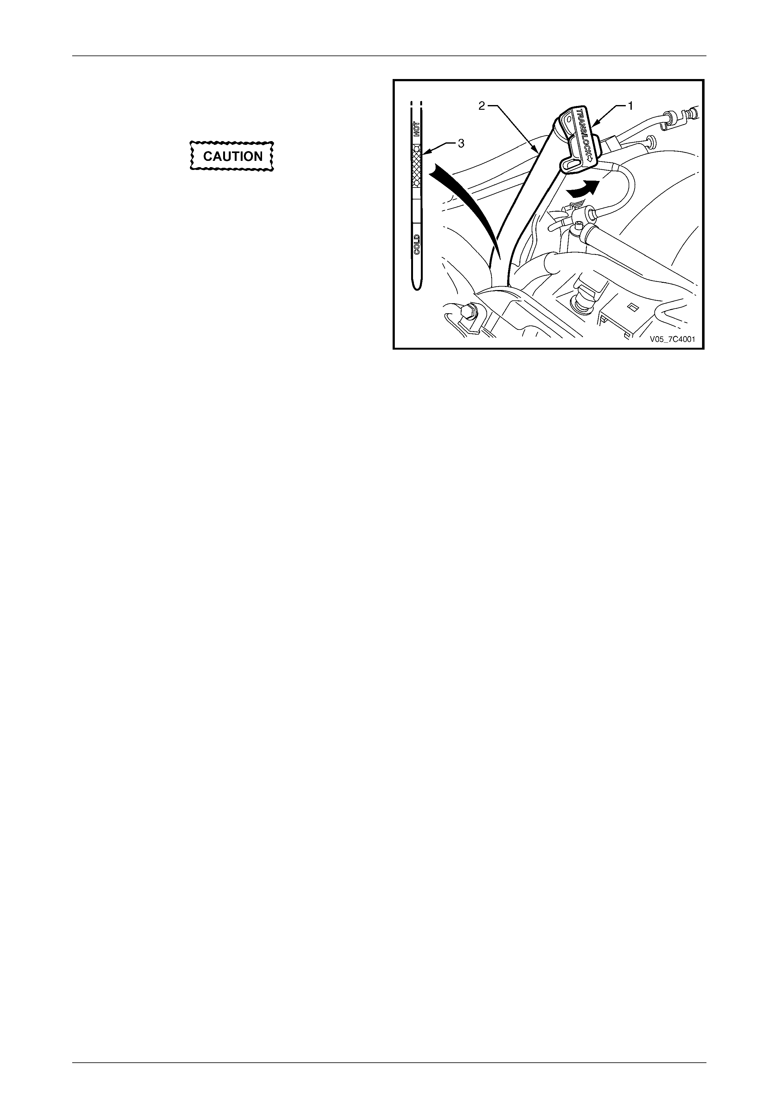
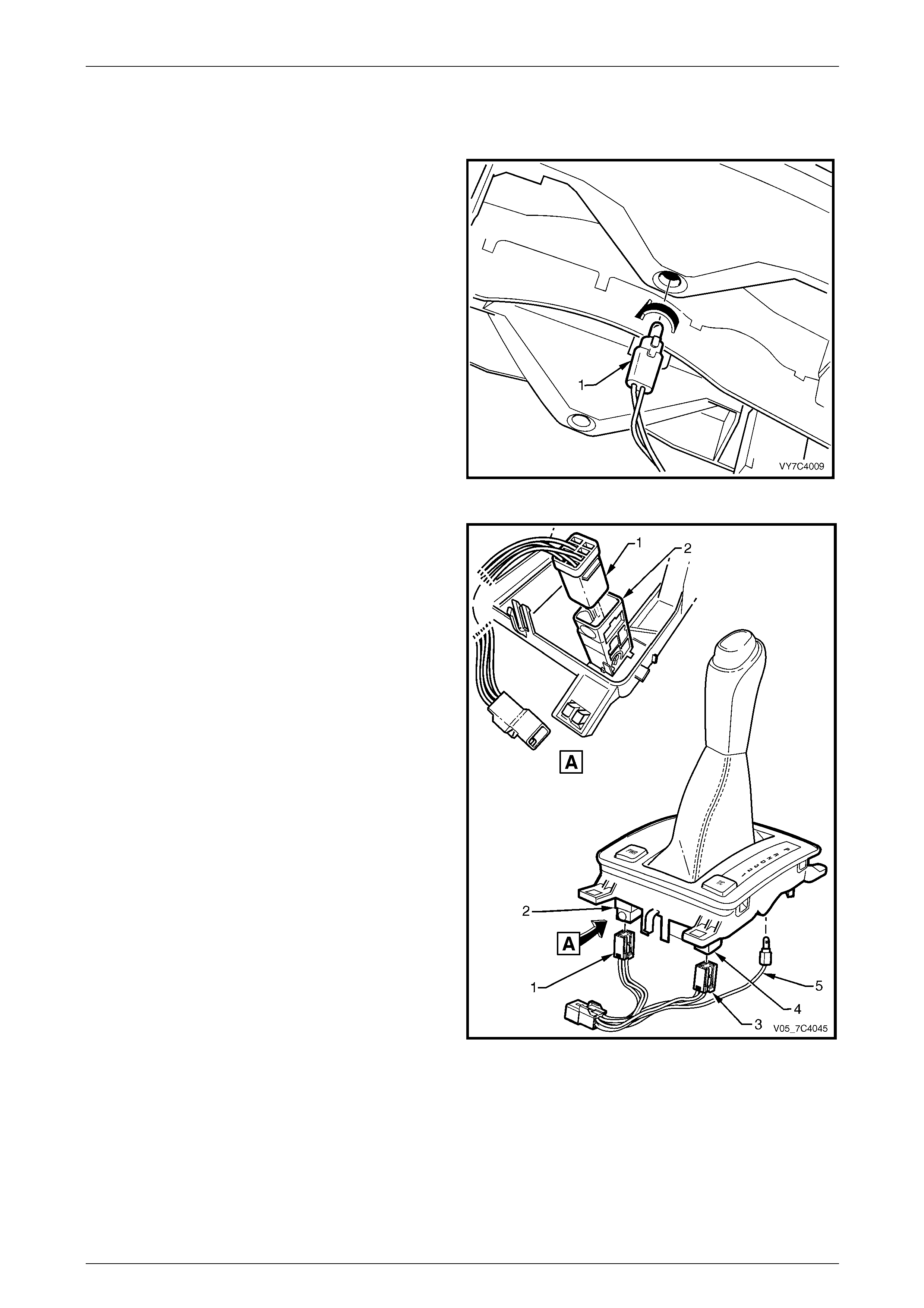
6 Lift the locking lever (1) on the transmission fluid
indicator, then remove the indicator from the filler
tube (2) and check the fluid colour, con ditio n and level.
Do not overfill the transmission. Overfilling
can cause aeration resulting in fluid loss,
shift complaints and possible damage to the
transmission.
7 If the transmission fluid level is low, add only enough
of the recommended fluid until its level shows onto the
crosshatch hot area (3) of the fluid indicator.
Figure 7D4 – 1
Transmission Fluid Colour
New transmission fluid is red in colour due to a dye that is added to the fluid so it can be distinguished from other oils and
lubricants. The red dye is not perma nent and as such, is not an indicator of the quality of the fluid.
As the vehicle is driven the transmission fluid will quickly look darker in colour and appear to be a light brown. A dark
brown colour with a distinctively burnt odour may indicate fluid deterioration and th e need for fluid replacement.
NOTE
A dark brown fluid colour observed, coupled with
a reported delayed shift patter n may only indicate
that fluid replacement is required. This is not a
definite indication of a potential transmission
failure.

Automatic Transmission – 4L65E – On-vehicle Servicing Page 7D4–7
Page 7D4–7
2.2 Reverse Flush and Flow Rate Test
It is essential to perform a reverse flush and oil cooler flow rate test after any of the following:
• the transmission is repaired or replaced,
• fluid contamination is suspected, or
• whenever the oil pump and/or torque converter is replaced.
NOTE
The reverse flush must be completed prior to
conducting a flow rate test.
Reverse Flush
1 Disconnect both fluid lines at the transmission and cooler hoses / lines at the radiator cooler, refer to
3.23 Transmission Cooler Lines and Hoses.
2 Check the cooler hoses / lines to radiator cooler fittings sealing washers for damag e, replace as required.
To avoid personal injury, wear safety glasses
when using compressed air.
3 Carefully check the radiator cooler lower fitting to see if any foreign material is evident at this point. If foreign
material is found, remove it with a suitable tool and/or compressed air at a reduc ed pressure of approximately
345 kPa blown in the reverse direction through the cooler.
4 Using compressed air at a reduce pressure of approximately 345 kPa blown in a revers e direction, clean the fluid
lines, cooler hoses / lines and if required any external cooler (where fitted).
5 Reconnect the fluid outlet line to the transmission and both cooler hoses / lines to the radiator cooler fittings,
refer to 3.23 Transmission Cooler Lin es an d Hoses .
NOTE
Do not reconnect the fluid inlet line at the
transmission end. This line needs to be left
disconnected to perform the flo w rate test.
6 Perform the flow rate test, refer to Flow Rate Test in this Section.
NOTE
This will also flush the fluid lines, cooler hoses /
lines and cooler with transmission fluid.
7 If the flow rate is satisfactory, reconnect the fluid inlet line to the transmission,
refer to 3.23 Transmission Cooler Lin es an d Hoses .
8 Lower the vehicle, check and top up the transmission fluid to the correct level as required,
refer to 2.1 Transmission Fluid.
Automatic Transmission – 4L65E – On-vehicle Servicing Page 7D4–8
Page 7D4–8
Flow Rate Test
Do not run the engine any longer than
absolutely necessary, as a fluid level too low
can cause aeration an d foaming.
1 Ensure the transmission fluid is at the recommended level or slightl y abo v e, refer to 2.1 Tr ansmission Fluid.
2 Disconnect the fluid inlet line at the transmis sion quick-connect fitting,
refer to 3.23 Transmission Cooler Lin es an d Hoses .
3 Place a suitable size containe r underneath the disconnected fluid inlet line.
4 With the selector lever in the P position, start the engine and observe the fluid flow into the container after all the air
bubbles have ceased and a steady flow is evident. Measure the flow rate over 20 seconds and ensure it is within
the specification.
Transmission fluid flow rate specificati on per 20 Seconds:
Temperature:
Ambient............................................................ 0.7 Litres
86° – 93° C ...................................................... 1.2 Litres
5 If the flow rate is less than the specification, the cause of the low flow rate must be located and rectified.
Possible cause could include:
• restricted cooler within the radiator tank,
• damaged or restricted external cooler, where fitted,
• kinked or damaged transmission flu id lines and/or cooler hoses / lines, or
• internal transmission fault such as a faulty pump.
6 Reinstall the fluid inlet line to the transmission quick-connect fitting,
refer to 3.23 Transmission Cooler Lin es an d Hoses .
Automatic Transmission – 4L65E – On-vehicle Servicing Page 7D4–9
Page 7D4–9
3 Service Operations
3.1 Fluid Change and Filter Replacement
LT Section No. — 04–220
To avoid personal injury take note of the
following:
• Avoid accidental hot oil spillage by
performing fluid change only when the
transmission fluid is cold.
• Wear safety glasses and gloves when
using compressed air and cleaning fluids.
Remove
1 Raise the vehicle and suppor t in a safe manner, refer to Section 0A General Information.
2 Clean all dirt from around the oil pan and the transmission case.
3 Place a suitable sized drain tray under the
transmission.
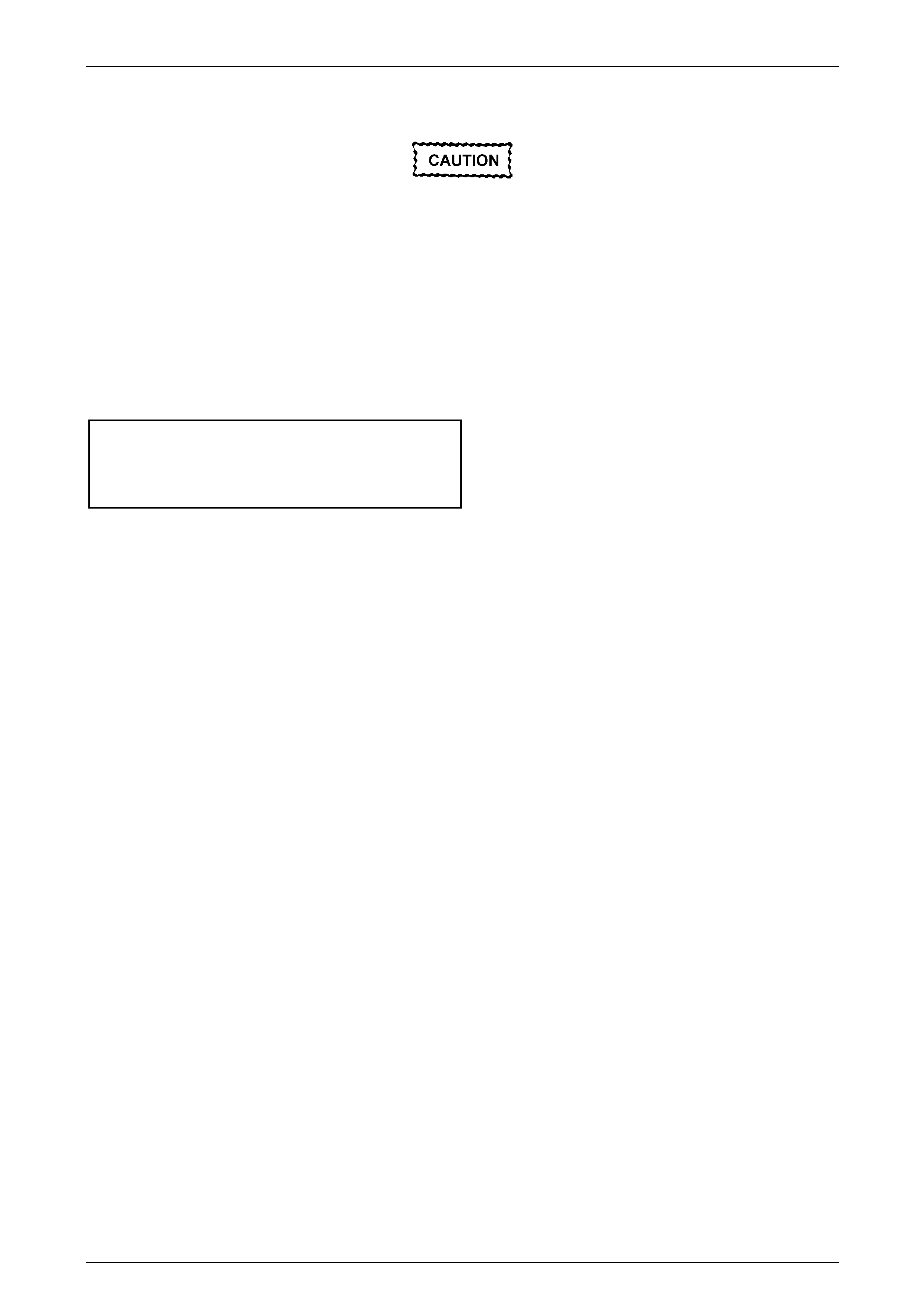
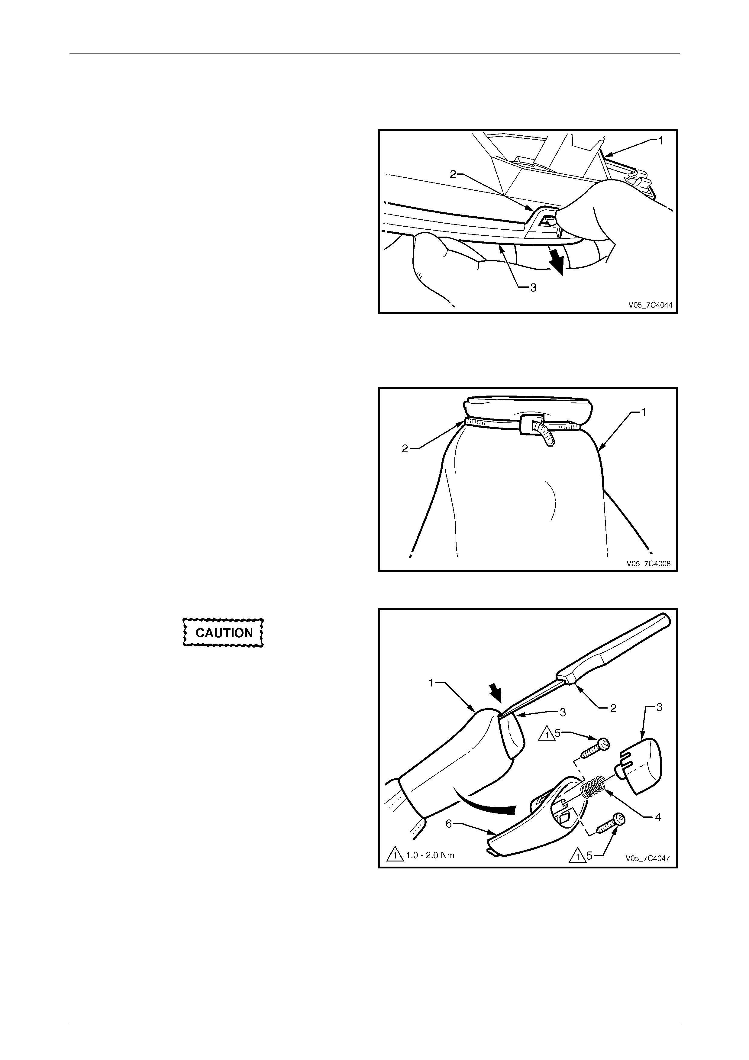
4 Hold the oil pan (1) in place a nd remove the oil pan
bolts (2) from the front and both sides.
NOTE
Leave the three rear oil pan b olts in place.
5 Loosen the three rear oil pan bolts by about 4 turns
each. While still supporting the oil pan, lightly tap the
sides with a rubber hammer to break the gasket (3)
seal.
6 Lower the front of the oil pan and drain the fluid into a
suitable container.
7 Remove the three remaining r ear bolts and the oil pan
from the transmission.
8 Remove the oil pan gasket and discard. Figure 7D4 – 2
Techline
Automatic Transmission – 4L65E – On-vehicle Servicing Page 7D4–10
Page 7D4–10
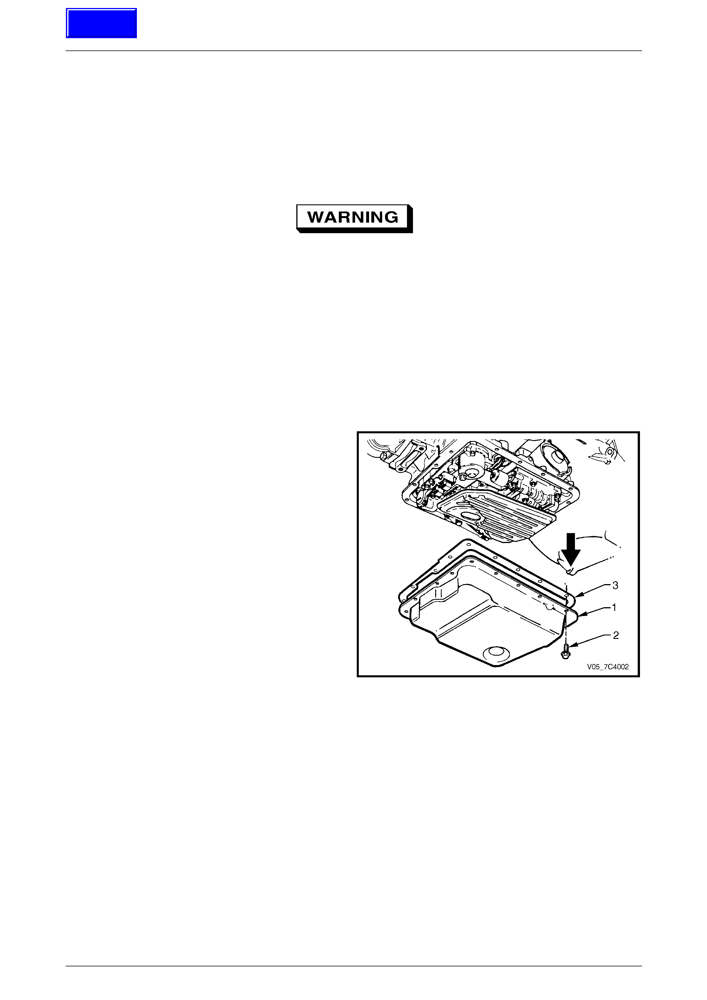
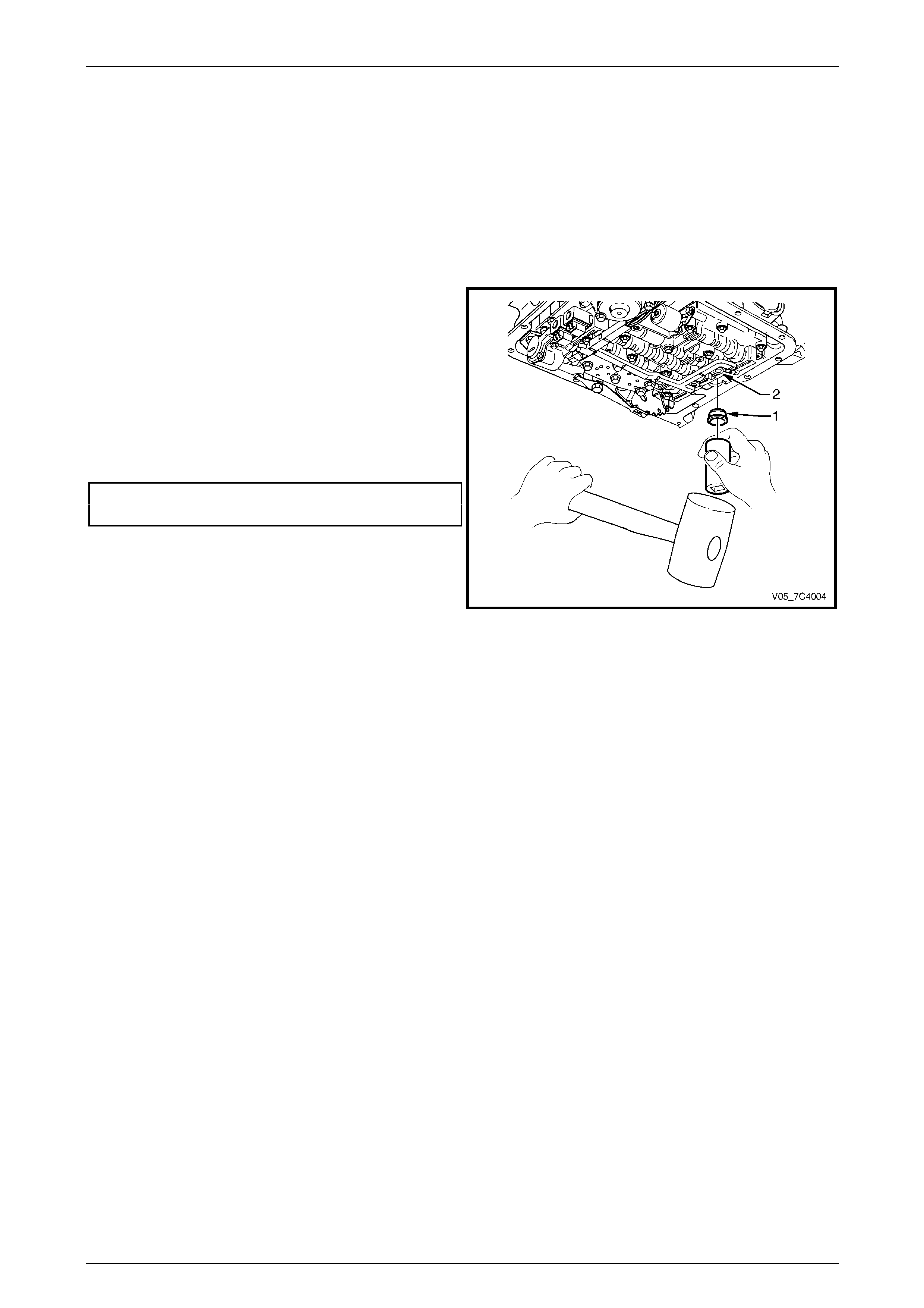
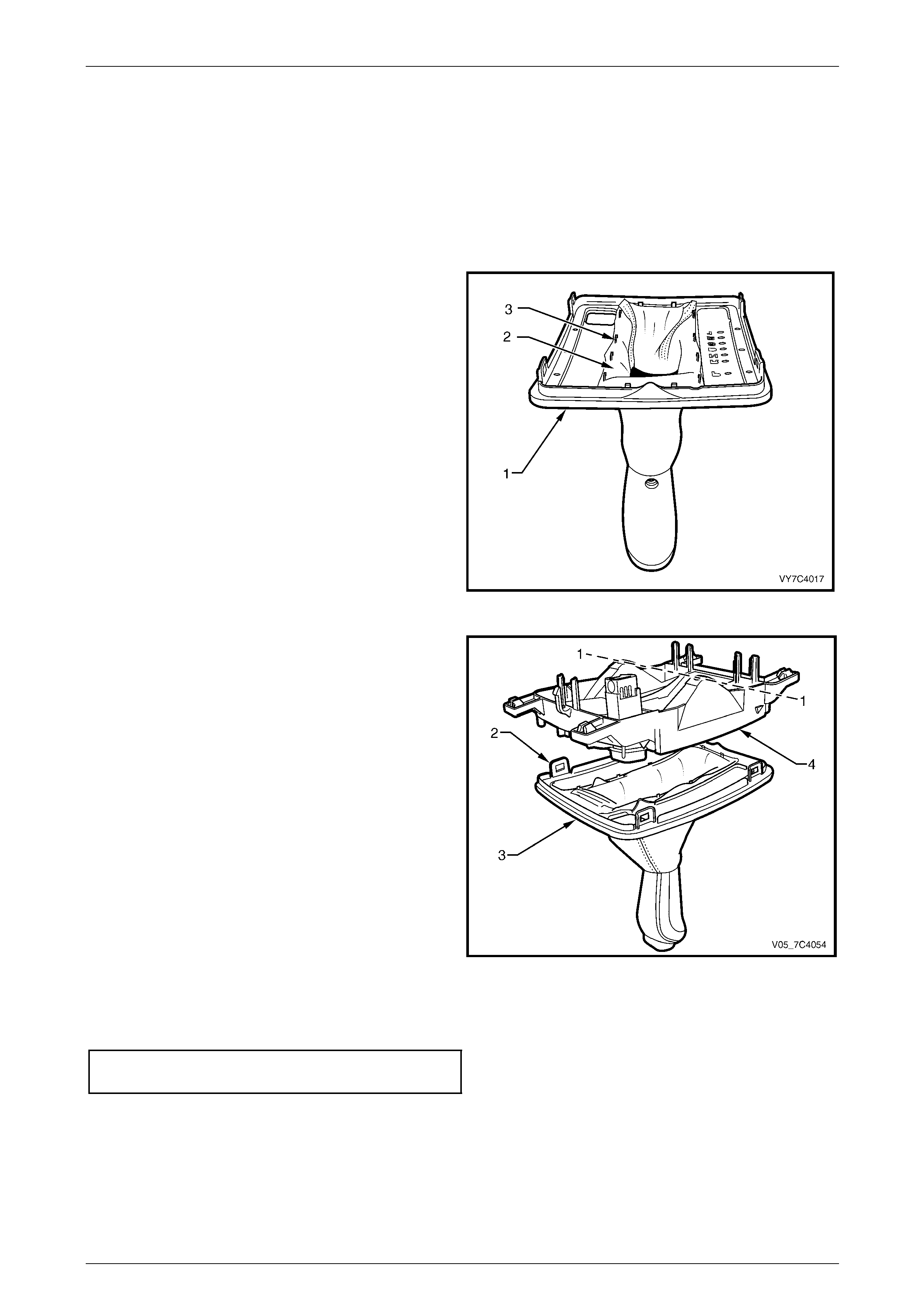
9 Remove the oil filter (1) by pulling down while twisting
the filter and remove it from the transmission.
10 Open the filter by prising the metal crimping a way from
the top of the filter and pull it apart.
11 Inspect the filter material for particles that may indicate
evidence of a potential transmission problem.
Examples of the type of material are:
• clutch friction material,
• bronze slivers, indicating bush wear and
• steel particles.
Figure 7D4 – 3
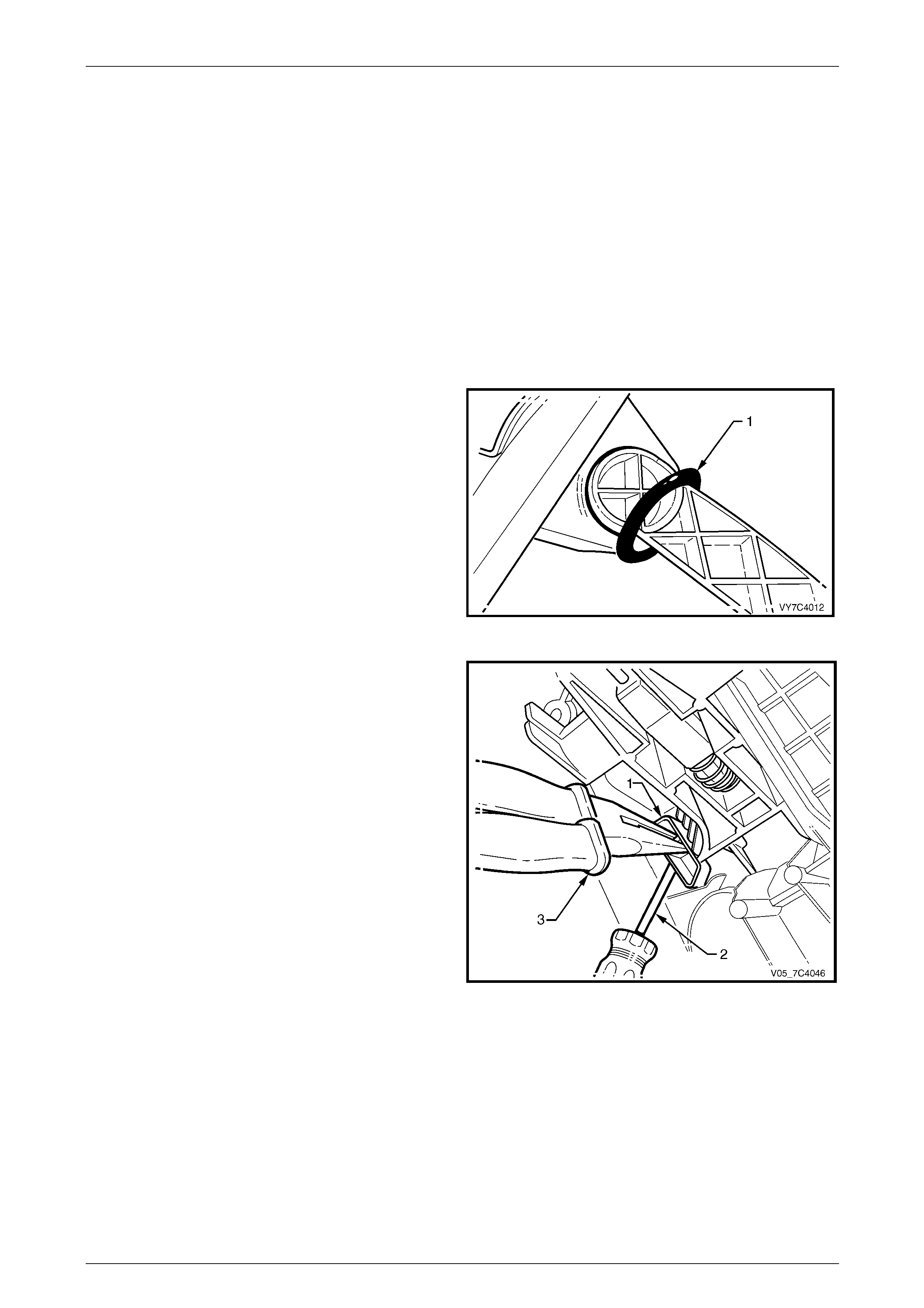
Take care not to scratch the oil pump bore,
as fluid leakage could occur from this point
or the pump may suck in air, causing the
fluid to aerate.
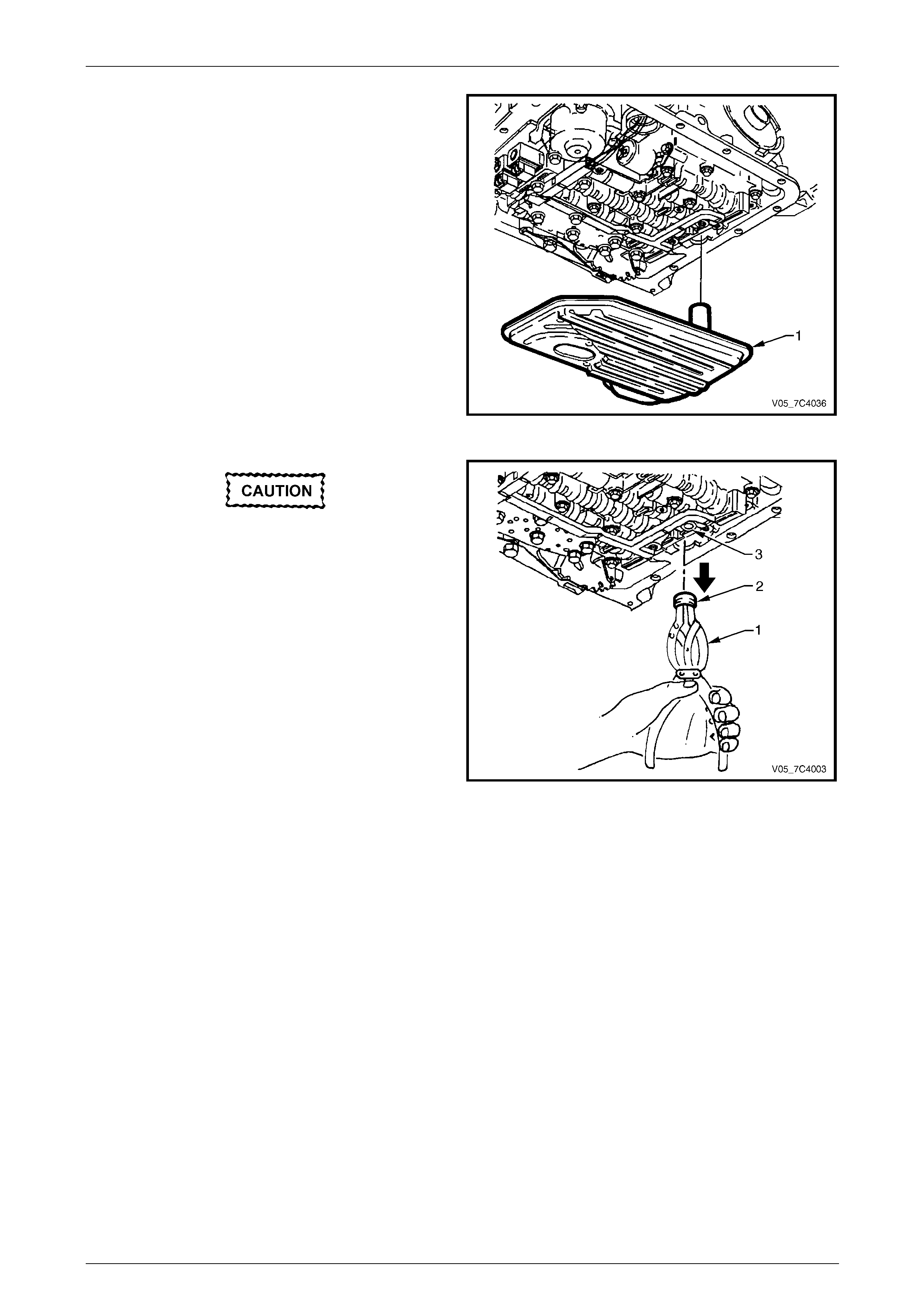
12 Using suitable circlip pliers (1) or a two legged puller
and slide hammer, remove the oil filter seal (2) taking
care not to scratch the oil pump bore (3) during the
process. Discard the seal.
Figure 7D4 – 4
Automatic Transmission – 4L65E – On-vehicle Servicing Page 7D4–11
Page 7D4–11
Reinstall
1 Clean the oil pan in a commercially available cleaning fl uid and blow dry using compressed air.
NOTE
Ensure all traces of the old gasket are removed
from the transmission and oil pan.
2 Wipe the transmission case gasket mating s urface with a clean lint free cloth.
3 Lubricate a new oil filter seal (1) with clean
transmission fluid and install into the oil pump bore (2)
using a suitable sized socket or piec e of tubing.
4 Install a new filter into the transmission case.
5 Check if the magnet is functional and l ocated in the
designated position in the oil pan. Install a new gasket
and reinstall the oil pan.
6 Tighten the bolts attaching the oil pan to the correct
torque specification.
Oil pan attaching bolt
torque specification............................................12.0 Nm
Figure 7D4 – 5
7 Lower vehicle and add the recommended automatic transmission fluid, approx imately 5.0 litres for the GEN III V8
engine.
8 Operate the vehicle for about 24 km or until normal transmission operating temperature is reached,
refer to 2.1 Transmission Fluid.
9 Ensure there are no fluid leaks from the oil pan area, rectify as required.
10 Check and top up the transmission fluid to the correct level as required, refer 2.1 Transmission Fluid.
Automatic Transmission – 4L65E – On-vehicle Servicing Page 7D4–12
Page 7D4–12
3.2 Selector Linkage and Rod, Except AWD
LT Section No. — 04–170
Remove
1 Position the transmission selector lever to the Park position.
2 Raise the vehicle and suppor t in a safe manner, refer to Section 0A General Information.
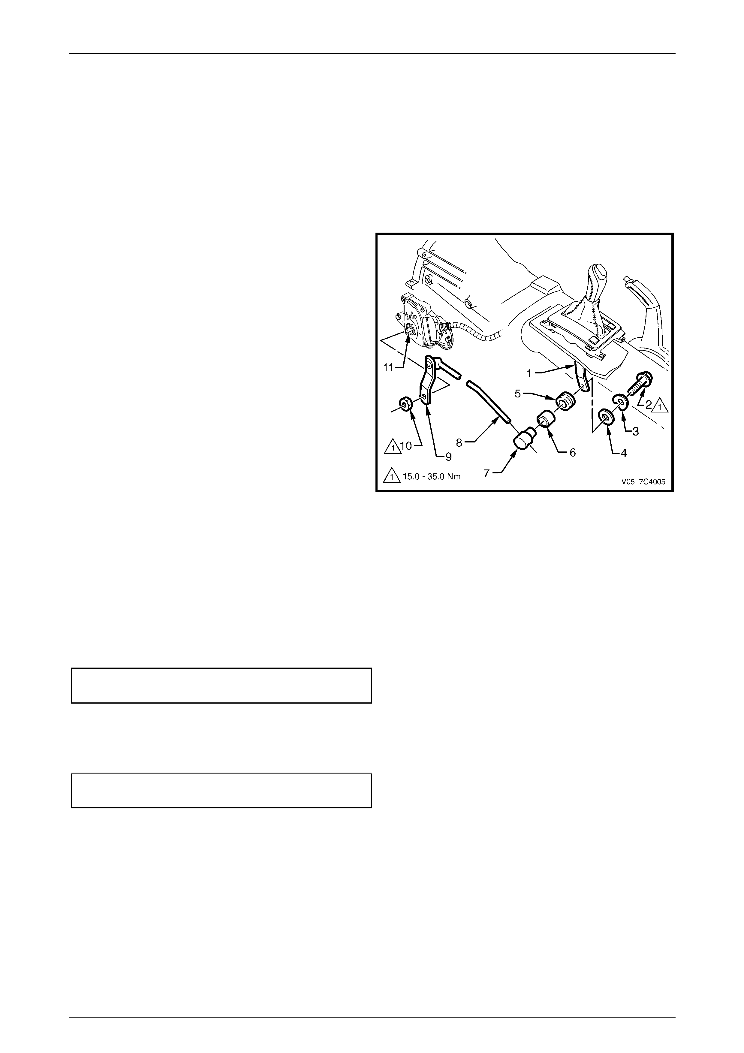
3 Remove the following parts from the lower end of the
selector linkage (1):
a locking bolt (2),
b dished washer (3),
c flat washer (4),
d insulator (5) and
e sleeve (6).
4 Slide the trunnion (7) out of the selector rod (8).
5 Hold the transmission manua l shaft linka ge (9) with an
adjustable wrench and remov e the attachi ng nut (10).
6 Remove the linkage and selector rod assembly from
the transmission manual shaft (11).
Figure 7D4 – 6
Inspect
Inspect all components for wear and/or damage, repl ace as required.
Reinstall
Reinstallation of the selector linkage and rod is the reverse of the removal procedure, noting the following:
1 Tighten the manual shaft linkage (9) attaching nut (10) to the correct torque specification, refer to Figure 7D4 – 6.
Manual shaft linkage attaching nut
torque specification.................................15.0 – 35.0 Nm
2 Ensure the transmission selector lever is in the Park position.
3 Position the manual shaft linkage in the Park position and then tighten the selector rod locking bolt (2) to the correct
torque specification.
Selector rod locking bolt
torque specification.................................15.0 – 35.0 Nm
4 Ensure the engine can onl y be started with the transmission selector lever in Park or Neutral position and the back-
up lamps work correctly. If required, adjust the neutral start and back-up lamp switch, refer to
3.7 Neutral Start and Back-up Lamp Switch, Except AW D.
5 Lower the vehicle and check if t he gear selection operates correctly.
Automatic Transmission – 4L65E – On-vehicle Servicing Page 7D4–13
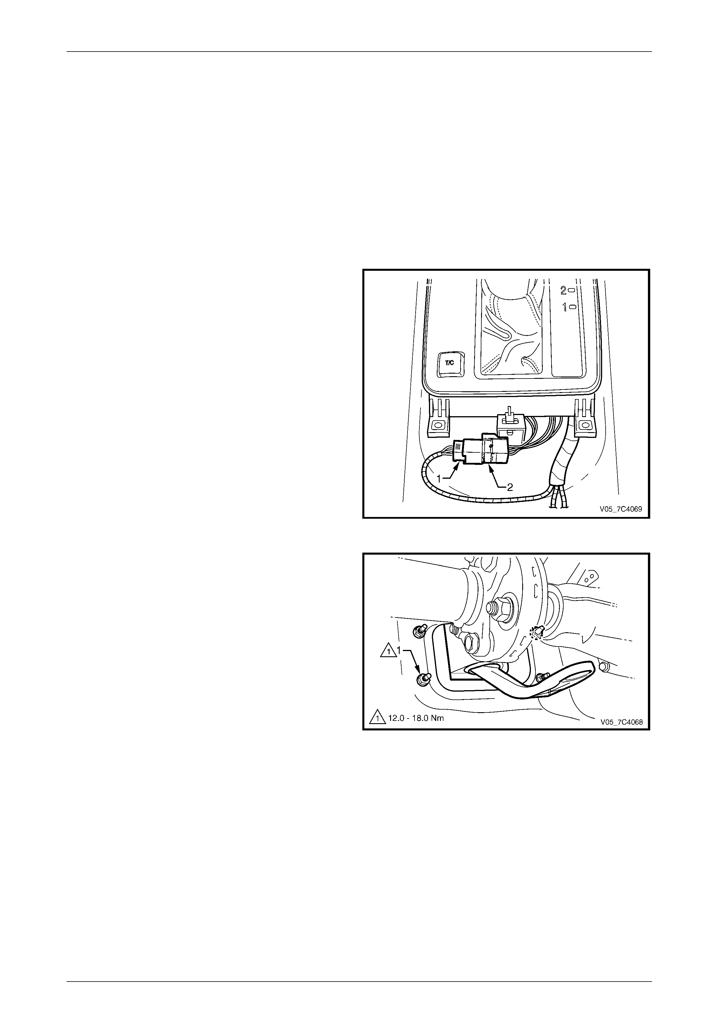
Page 7D4–13
3.3 Selector Cable Assembly, AWD
LT Section No. — 04–170
Remove
1 Remove the following components, refer to Section 1A3 Instrument Panel and Console:
a floor console cover,
b lower extension side trim panels and
c floor console assembly.
2 Position the transmission selector lever to the Park
position.
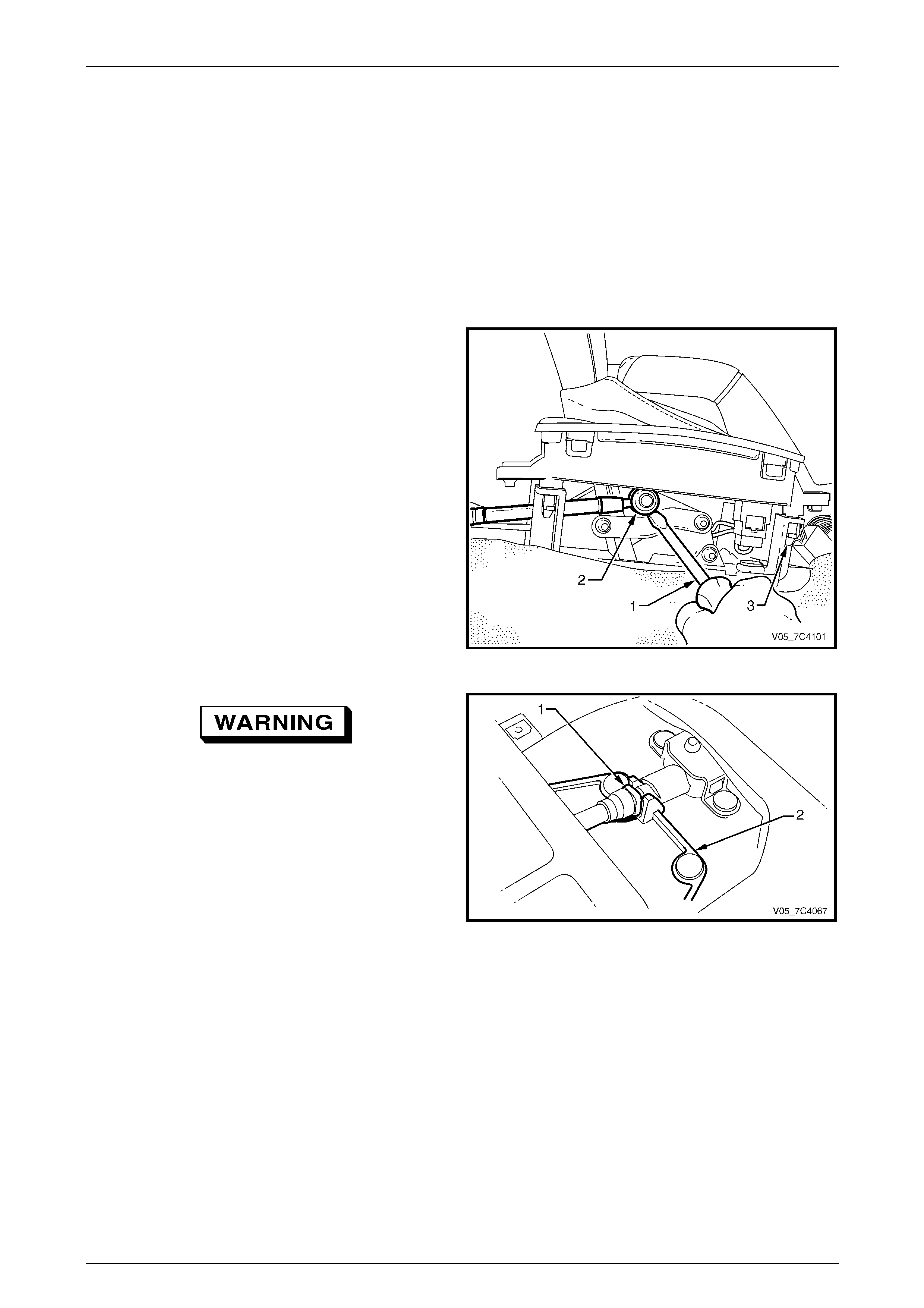
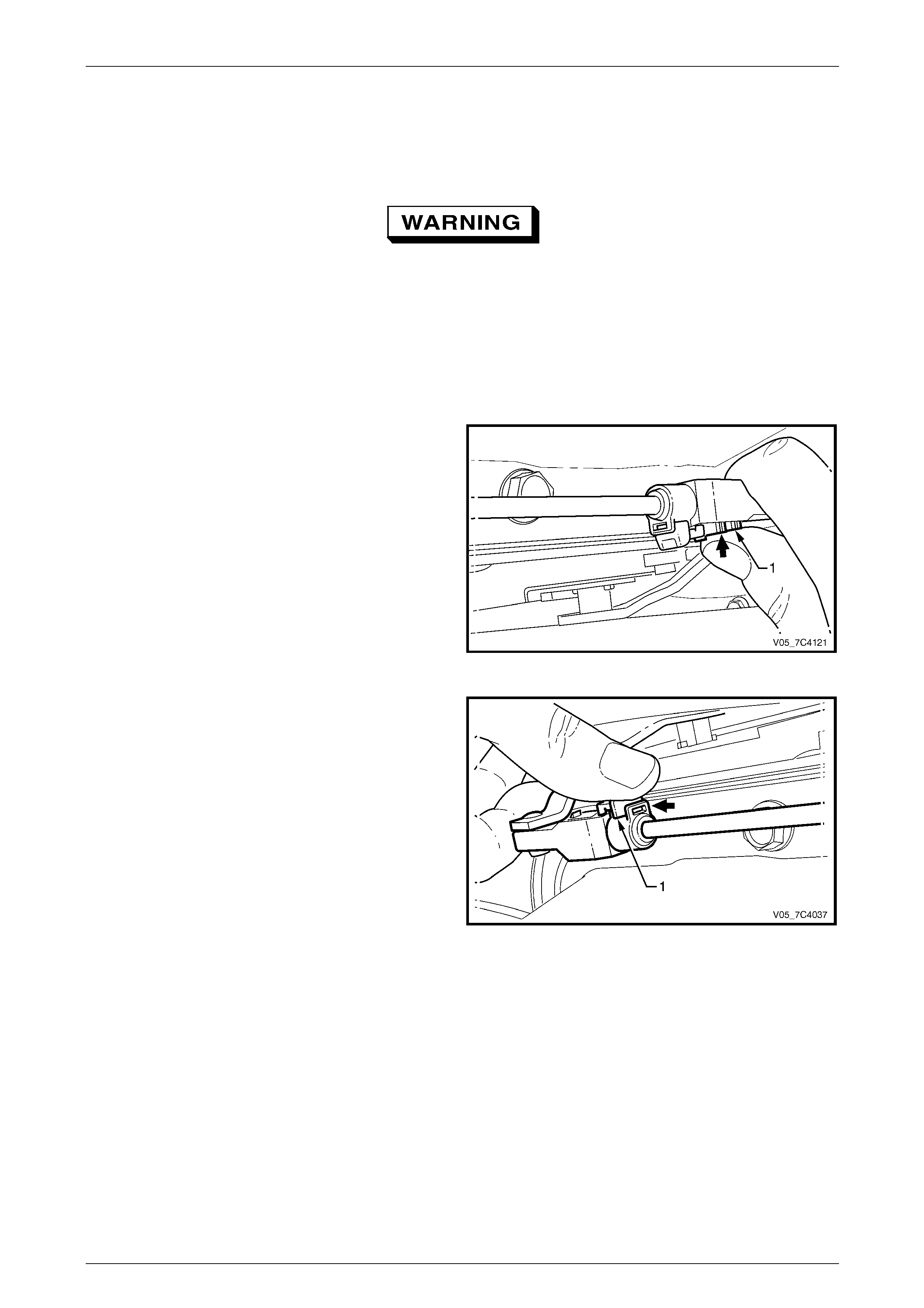
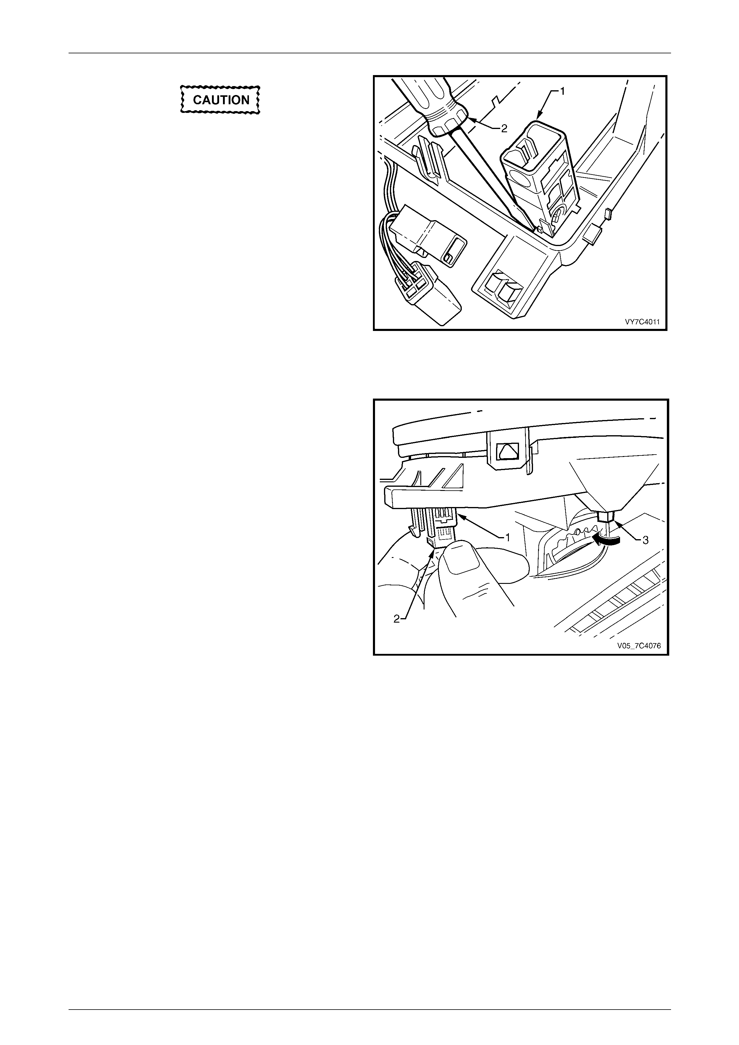
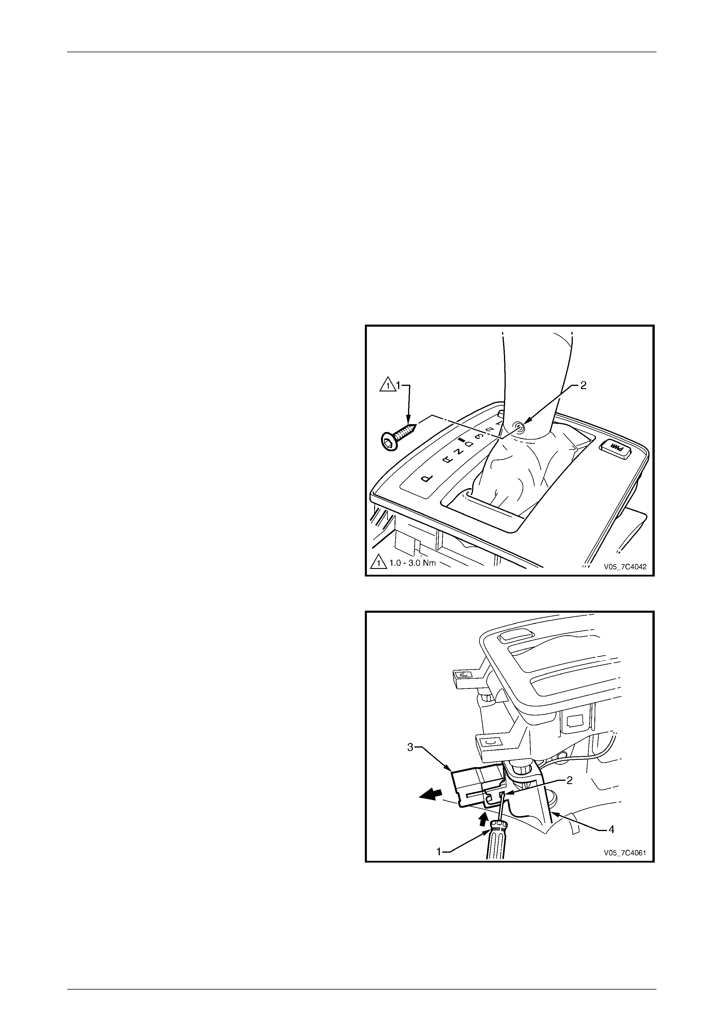
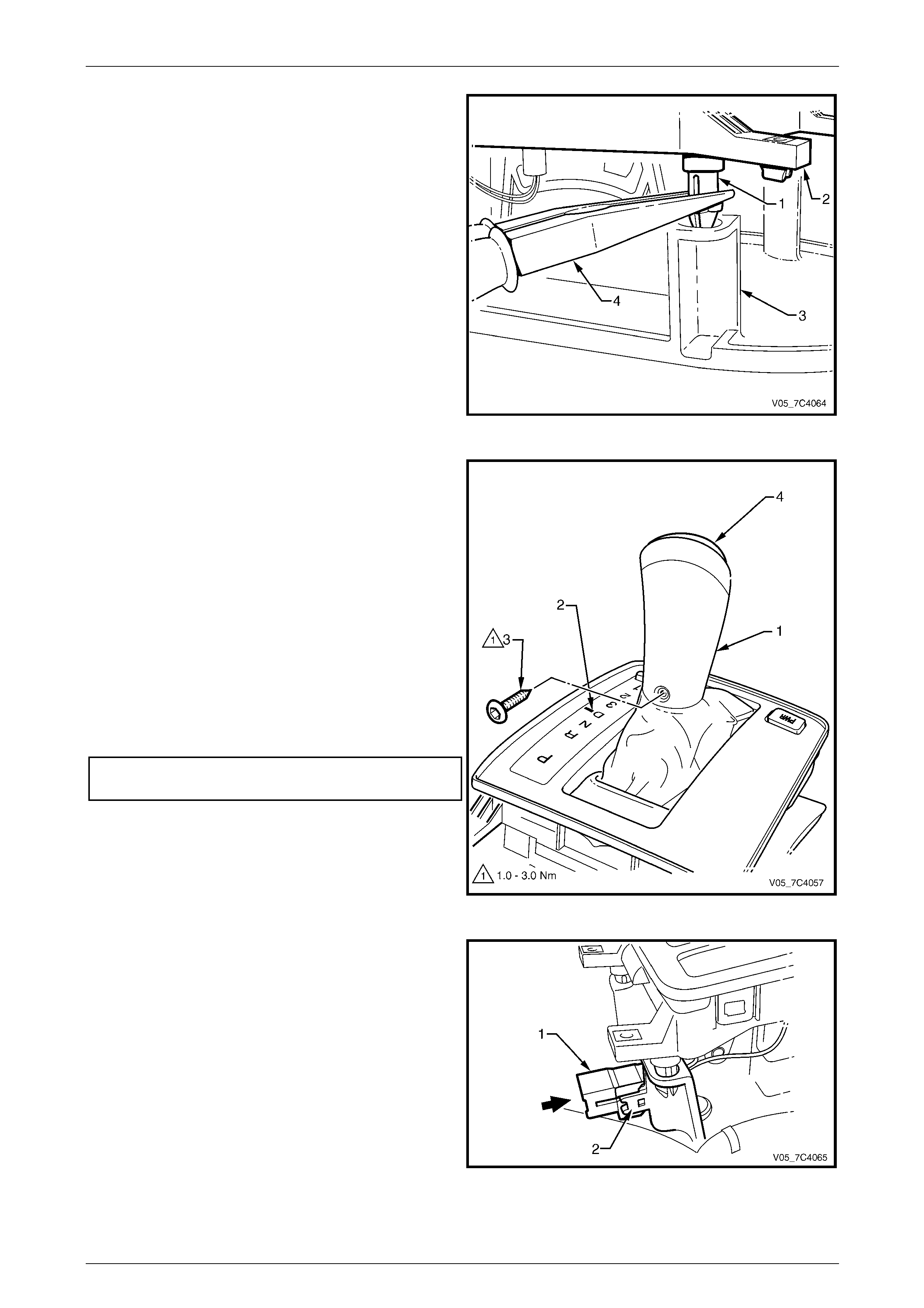
3 Using a small flat blade scre wdriver (1), gentl y prise
the upper end of the selector cable (2) from the pin on
the shift selector lever linkage.
NOTE
To gain clear access to the cable end, release
the two rear selector housing pegs (3) from the
base and lift up.
Figure 7D4 – 7
To prevent personal injury, wear safety
glasses when removing spring loaded
retainers.
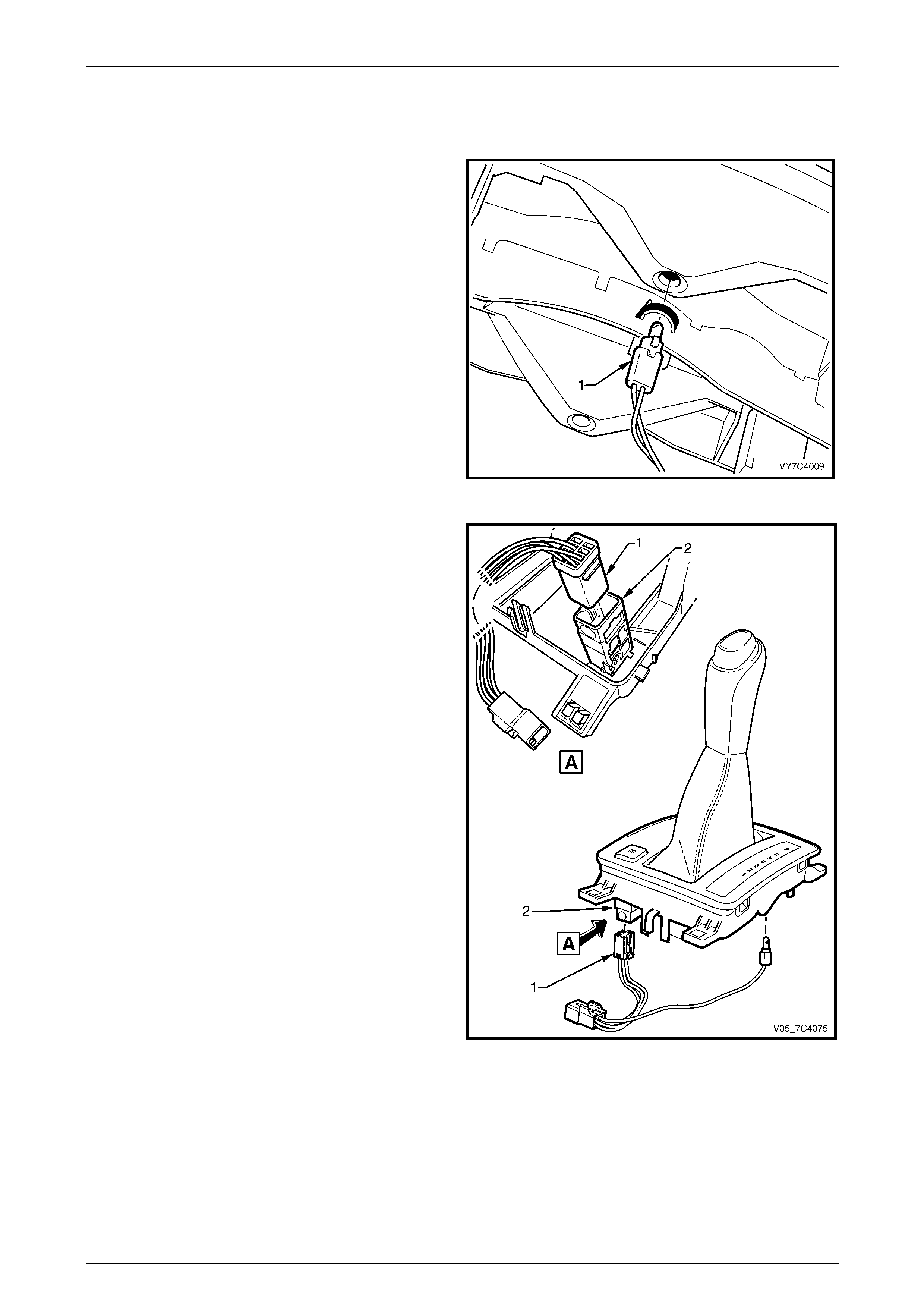
4 From inside the vehicle, use a flat blade screwdriver to
remove the outer cable retainer (1) from the front of
the shift selector base (2).
Figure 7D4 – 8
5 Raise the vehicle and suppor t in a safe manner, refer to Section 0A General Information for the location of support
points.
6 Lower the rear of the transfer case to gain access to the selector cable upper bracket to floor pan attaching nuts,
refer to Section 7F Transfer Case and Adapter Housing.
7 From under the vehicle, remove the two nuts attaching the selector cable upper bracket and seal to the floor pan.
Automatic Transmission – 4L65E – On-vehicle Servicing Page 7D4–14
Page 7D4–14
To prevent personal injury, wear safety
glasses when removing spring loaded
retainers.
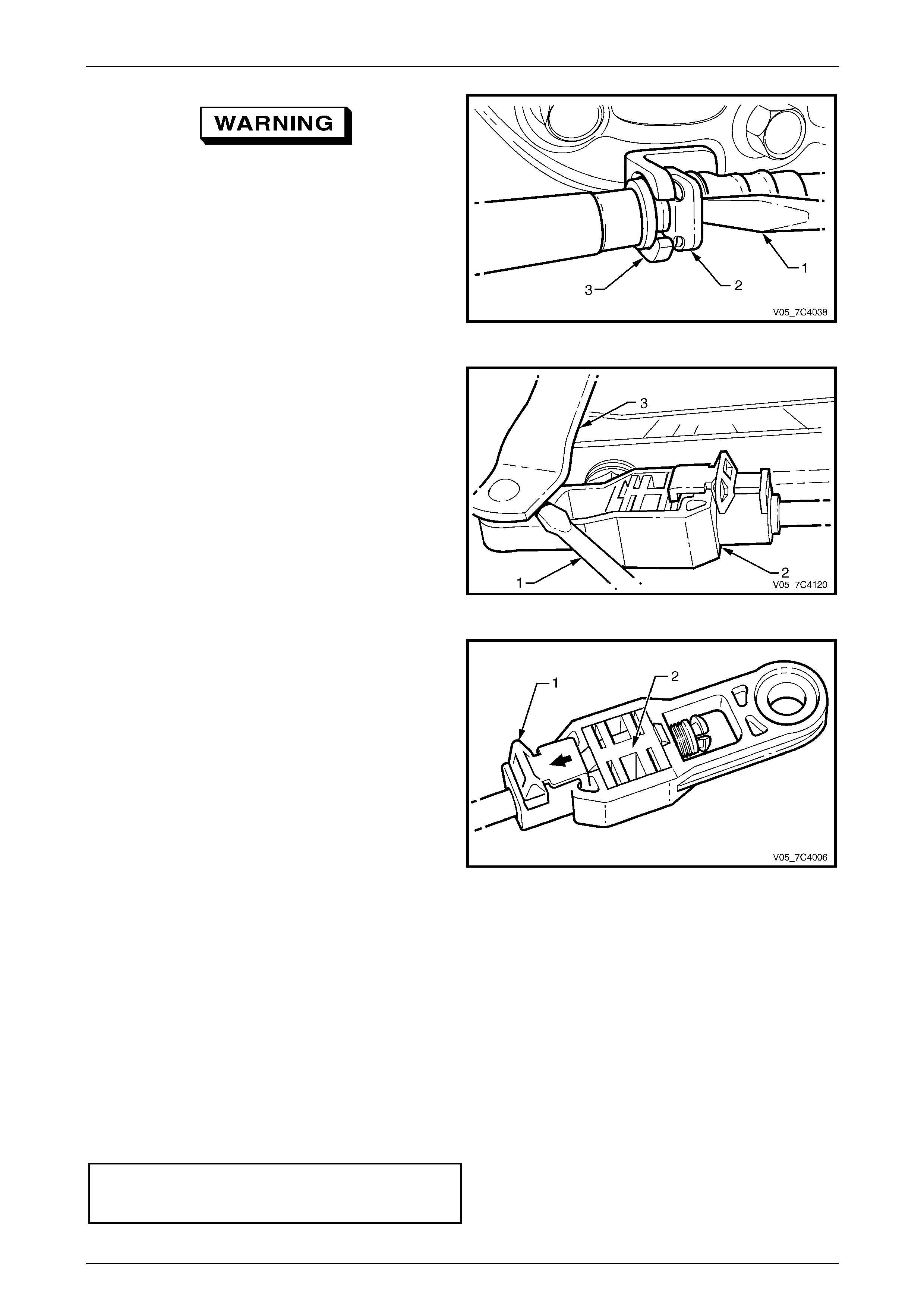
8 From under the vehicle, use a flat blade
screwdriver (1) to release the retainer (2) securing the
outer cable to the transmission bracket (3).
Figure 7D4 – 9
9 Using a small flat blade screwdriver (1) prise the
selector cable end (2) from the transmission external
manual shaft linkage (3).
Figure 7D4 – 10
NOTE
Do not to lose the inner lock during the following
operation.
10 With your fingers slide back the adjustment lock (1)
and then using a small screwdriver, push ou t the white
square inner lock (2).
11 Dislodge the selector cable upper bracket and seal
from the floor pan and remove the selector ca ble
assembly from inside the vehicle.
Figure 7D4 – 11
Reinstall
1 Thread the selector cable ass embly through the aperture in the floor pan until the cable upper bracket studs can be
inserted through the floor pan hol es.
2 Install the selector cable upper end fitting (2 ) to the shift selector linkage pin by pushing it inwards until the fitting is
installed past the pin flange, refer to Figure 7 D4 – 7.
3 Engage the groove in the outer cable upper end with the slot in the shift selector base, then install a new
retainer (1) to secure, refer to Figure 7D4 – 8.
4 Check if the rubber grommet is correctly fitted at the outer cable upper end.
5 From under the vehicle, reinst all the two nuts attaching the selector cable upper bracket and tighten to the correct
torque specification.
Selector cable upper bracket
to floor pan attaching nut
torque specification.................................12.0 – 18.0 Nm
Automatic Transmission – 4L65E – On-vehicle Servicing Page 7D4–15
Page 7D4–15
6 After checking if the selector cable assembly is routed correctly, raise the rear of the transfer case and reinstall to
the vehicle underbody, refer to Section 7F Transfer Case an d Adapter Housing.
7 Reinstall the selector cable lower end (2) to the transmission external manual shaft linkage pin, ensure it is fully
installed to the pin, refer to Figure 7D4 – 10. Leave the cable adjustment lock and the whit e square inner lock in the
released position as the cable must be adjusted after installation.
To prevent personal injury, wear safety
glasses when installing spring loaded
retainers.
8 From under the vehicle, reinst all the outer cable retainer (2). Ensure it is fully engaged and in the correct position,
which is forward of the bracket (3) that is bolted to the transmission case, refer to Figure 7D4 – 9.
9 Check if the rubber grommet is correctly fitted at the cable lower end.
10 Ensure the transmission external manual shaft linkage and the shift selector lever are in the P position.
11 Push the white square inner lock (1) in ward to enga ge
it with the serrated cable end.
Figure 7D4 – 12
12 Secure the adjuster by sliding the adjustme nt lock (1)
forward.
Figure 7D4 – 13
13 Ensure the engine can onl y be started with the transmission selector lever in Park or Neutral position and the
back-up lamps work correctly. If required, adjust the neutral start and back-up lamp switch, refer to
3.8 Neutral Start and Back-up Lamp Switch, AW D.
14 Lower the vehicle and check if t he gear selection operates correctly.
Automatic Transmission – 4L65E – On-vehicle Servicing Page 7D4–16
Page 7D4–16
3.4 Shift Selector Assembly, Except Coupe
and AWD
LT Section No. — 04–190
Remove
1 Remove the following components, refer to Section 1A3 Instrument Panel and Console:
a floor console cover,
b lower extension side trim panels and
c floor console assembly.
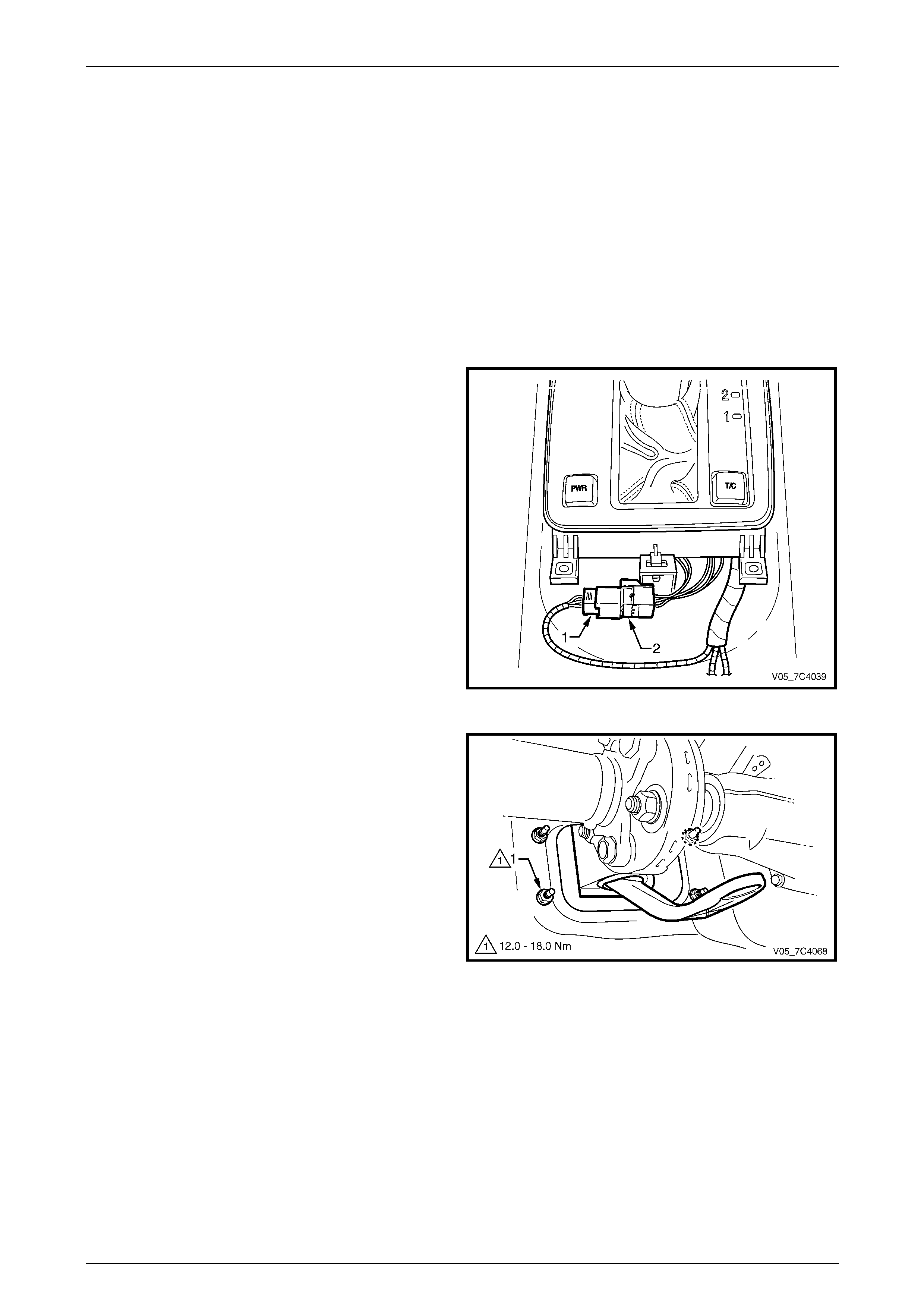
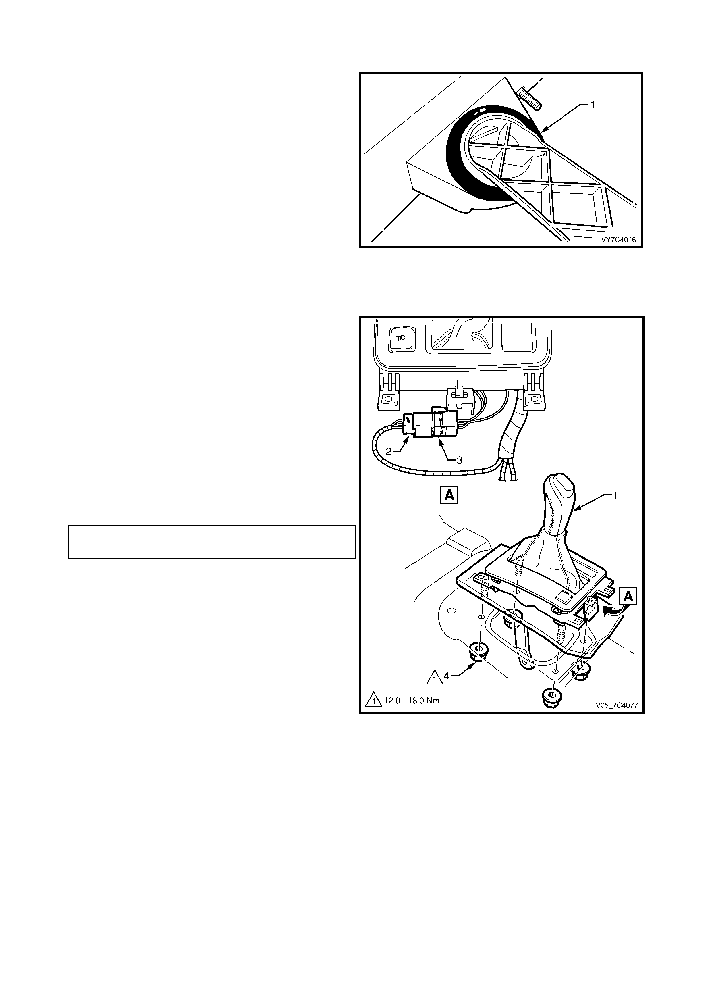
2 At the rear of the shift selector assembly, disconn ect
the harness connector (1) from the selector patch
harness (2).
NOTE
The shift selector assembly needs to be
disconnected and detached from the floor pan
only to service the base and selector lever. The
lower housing and associated components can
be separated from the base for servicing.
3 Raise the vehicle and suppor t in a safe manner,
refer to Section 0A General Information for the location
of support points.
4 From underneath the vehicle, remove the locking bolt
and disconnect the selector rod and trun nion from the
selector linkage, refer to 3.2 Selector Linkage and
Rod, Except AWD.
Figure 7D4 – 14
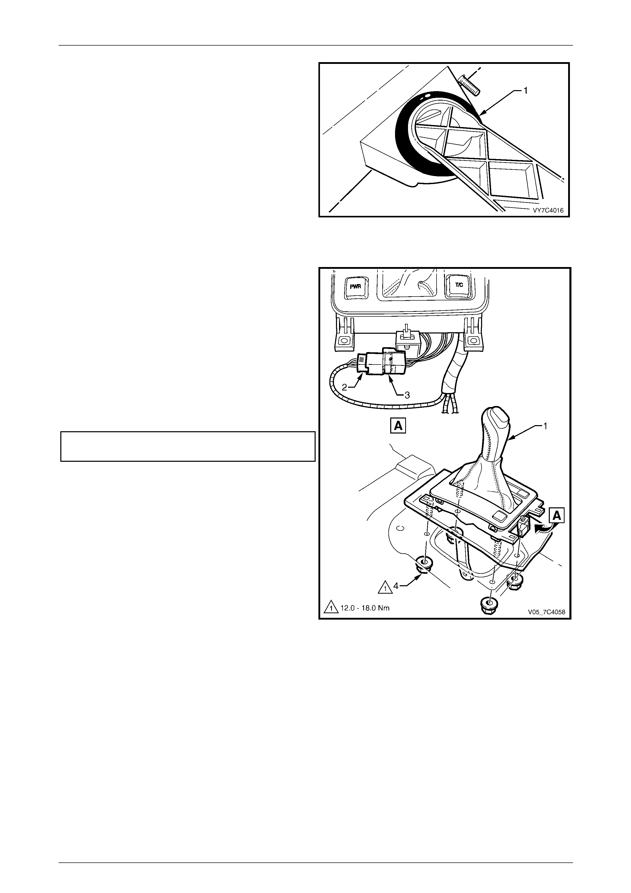
5 From underneath the vehicle, remove the four nuts (1)
attaching the shift selector lever assembly to the floor
pan.
6 From inside the vehicle, lift the shift selector lever
assembly from the floor pan.
Figure 7D4 – 15

Automatic Transmission – 4L65E – On-vehicle Servicing Page 7D4–17
Page 7D4–17
Disassemble
Lower Housing Assembly
Remove
NOTE
The lower housing assembly can be
disassembled without the base being detached
from the floor pan.
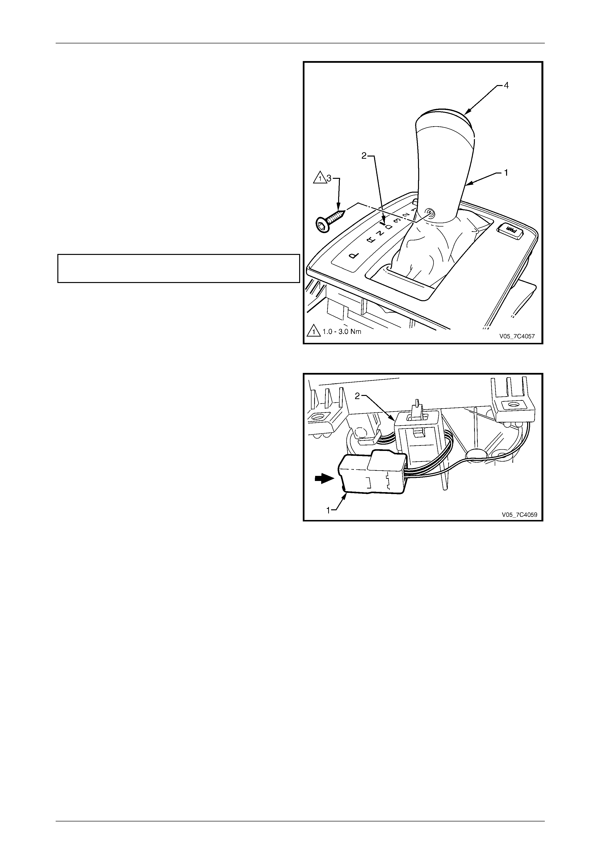
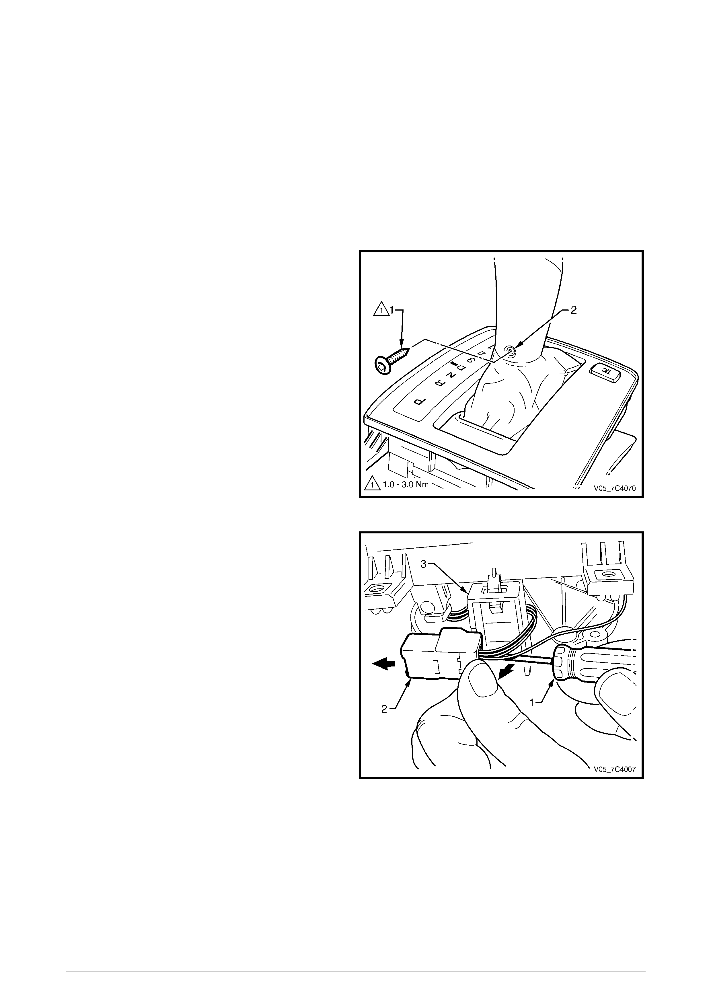
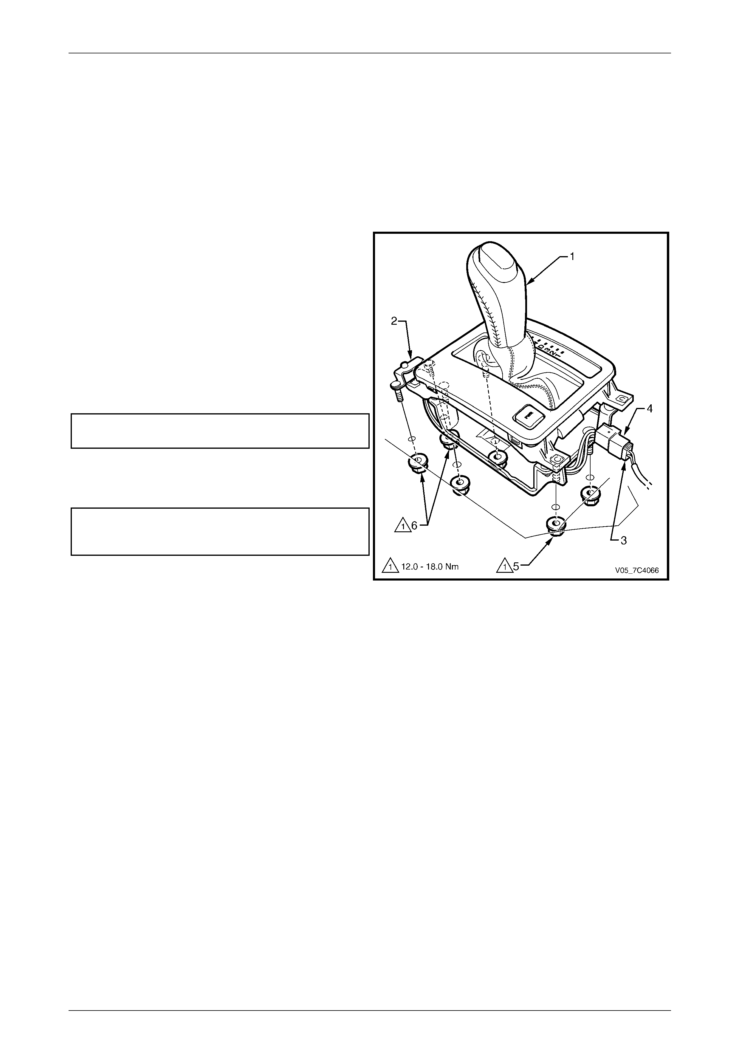
1 With the selector lever in the D position, use a suitable
size Torx bit and remove the screw (1) on the forward
side of the lever (2).
NOTE
This is also the recommended reassembly
position.
Figure 7D4 – 16
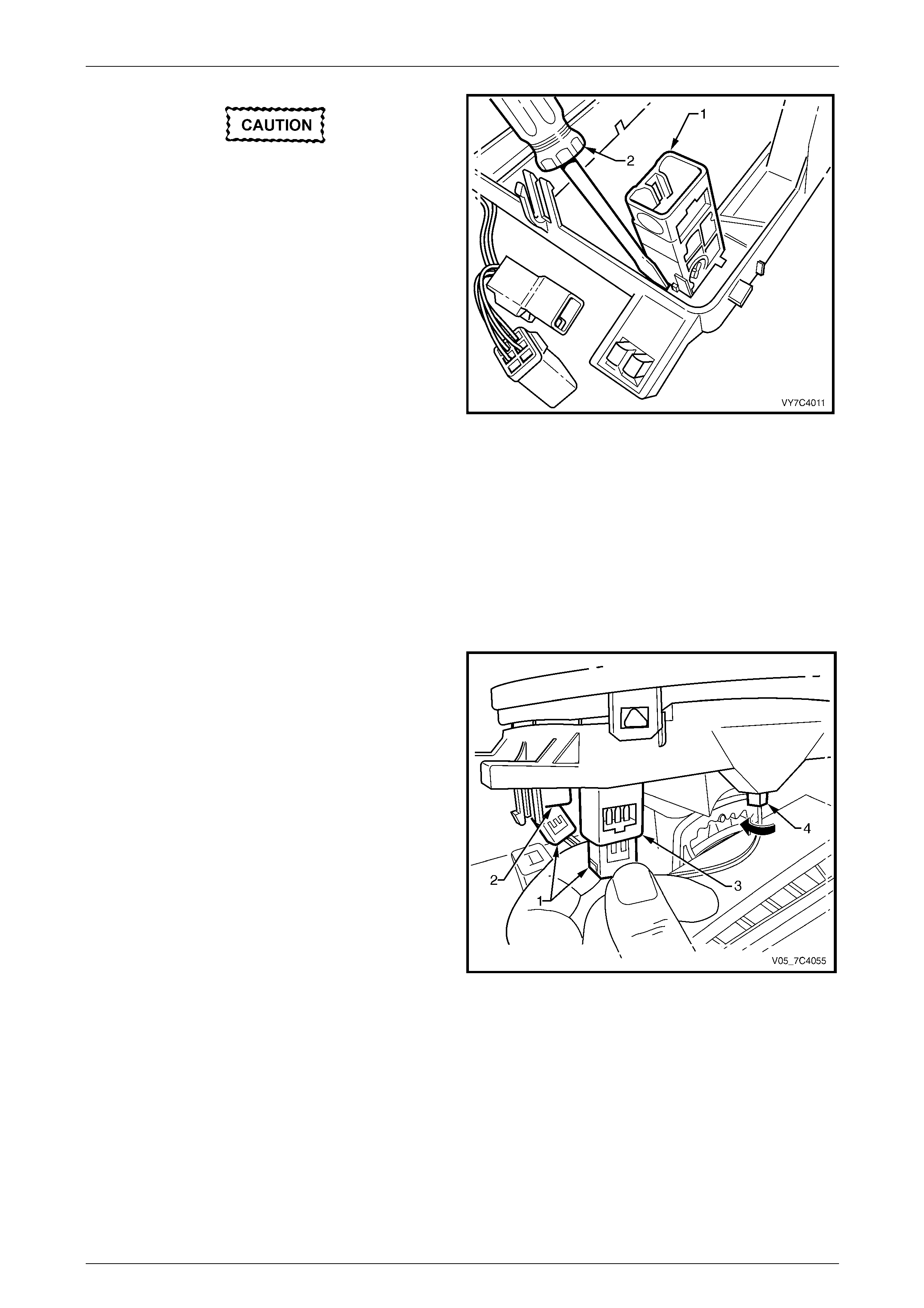
2 From the rear of the selector base, use a small flat
blade screwdriver (1) to gently prise the locking tab on
the patch harness connector (2) and push the
connector away from its support on the shift selector
base (3).
Figure 7D4 – 17
Automatic Transmission – 4L65E – On-vehicle Servicing Page 7D4–18
Page 7D4–18
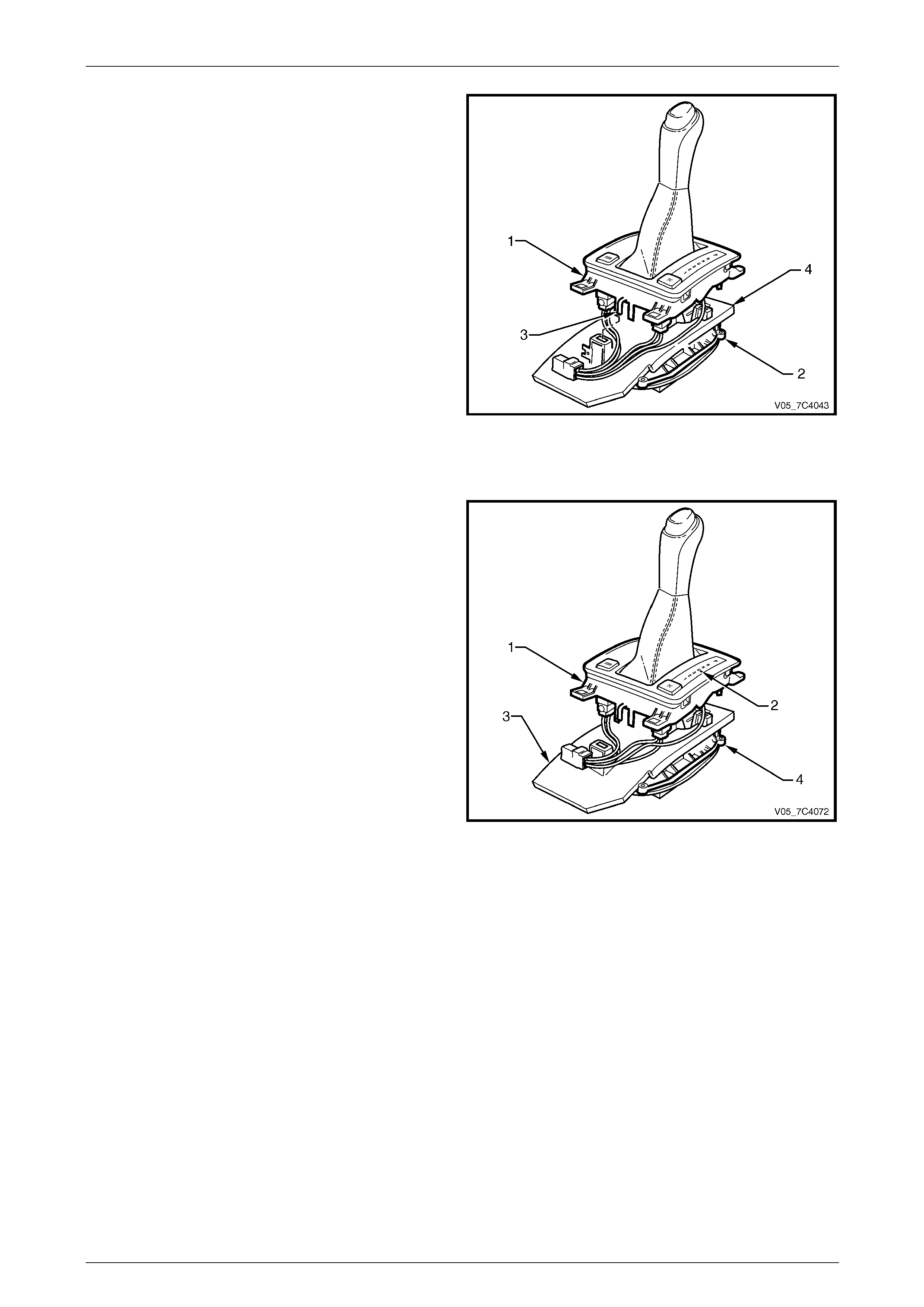
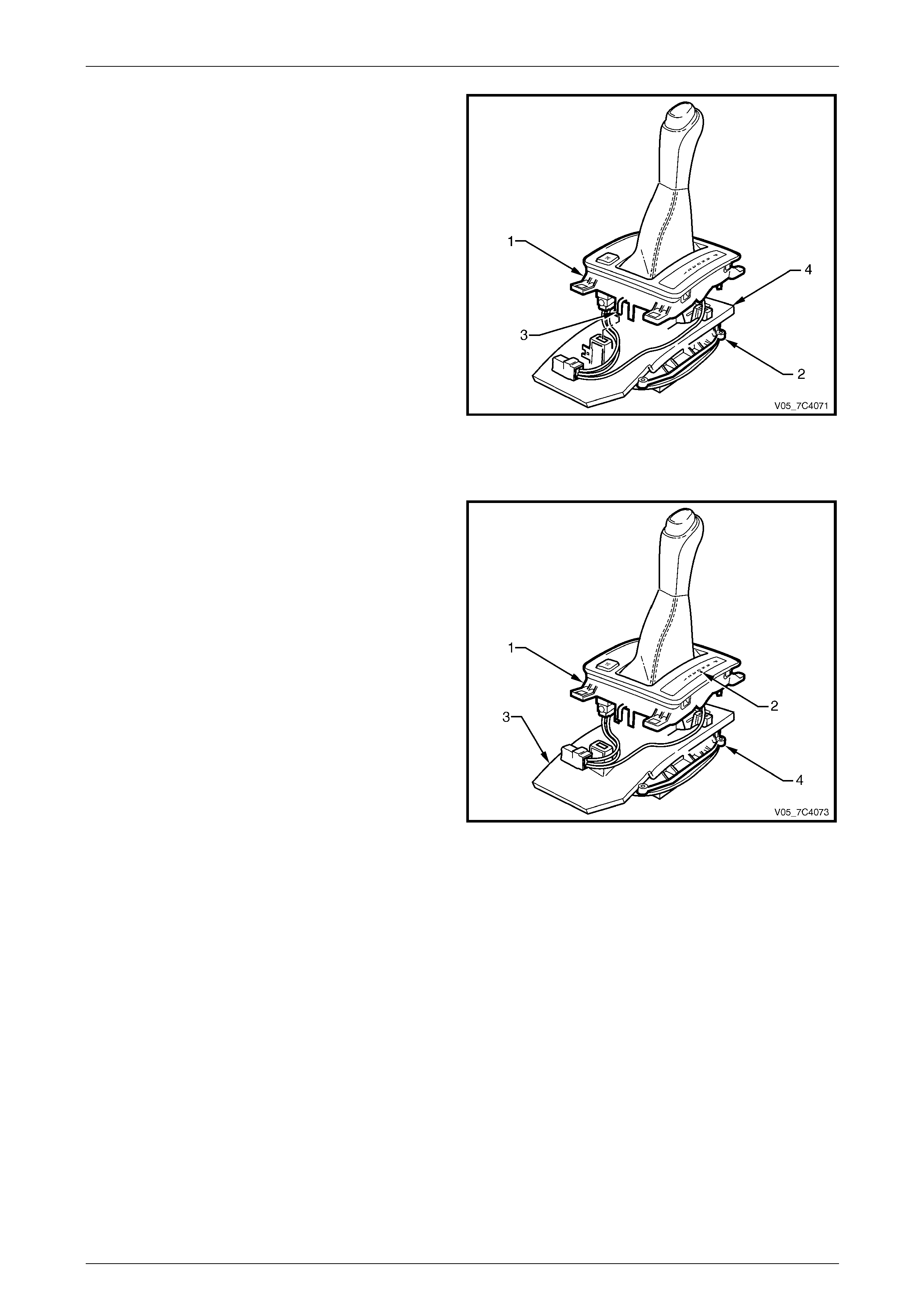
3 Disconnect the lower housing (1) from the base (2) by
pressing the tang (3) on each of the retaining legs.
NOTE
There are two tangs at the front and one at the
rear of the lower housing.
4 Lift the lower housing from the base together with the
switch(s), patch wiring harness, upper cover, boot and
selector knob.
5 As required, lift the insulator (4) from the base.
Figure 7D4 – 18
Reinstall
1 Ensure the PRNDL indicator slide, in the lower
housing (1), is at the D position with the red colour
showing opposite the D in the PRNDL lens (2).
2 Ensure the insulator (3) is undamaged and reinstall it
to the base (4).
3 Ensure the selector lever is in the D position and
reinstall the lower housing assembly over the selector
lever, engage each of the three retaining legs with the
base.
NOTE
Check if the PRNDL indicator slide pin is
engaged with the slot in the selector lever.
Figure 7D4 – 19
Automatic Transmission – 4L65E – On-vehicle Servicing Page 7D4–19
Page 7D4–19
NOTE
If the knob button (4) and spring have not been
removed, some manoeuvring may be necessary
to re-engage the selector lever.
4 Re-engage the selector lever knob (1) with the
selector lever, aligning the control rod with the hole in
the selector knob.
5 Check the correct engagement of the PRNDL indicator
by moving the selector lever. If the coloured portion (2)
does not move with the lever, engagement is incorrect.
To rectify, separate the lower housing from the base
and repeat procedure steps 3 to 5.
6 Reinstall the selector knob attaching Torx screw (3)
and tighten to the recommended torque spec ification.
Selector knob attaching Torx screw
torque specification.....................................1.0 – 3.0 Nm
7 If required, reinstall the knob button (4) and spring,
push the button down until the two locking tangs are
engaged.
Figure 7D4 – 20
8 Secure the patch harness connector (1) to its support
on the rear of the selector base (2).
Figure 7D4 – 21
Automatic Transmission – 4L65E – On-vehicle Servicing Page 7D4–20
Page 7D4–20
Patch Harness and Switch
Remove
1 As required, separate the lower housing from
the base as described in this Section, refer to
Lower Housing Assembly.
2 Remove the selector indicator lamp a nd holder (1)
from the lower housing by turning the lamp holder 90°
counter-clockwise and pull it o utward.
Figure 7D4 – 22
3 Disengage the retaining l ugs and remove the patch
harness connector (1) from the transmission power
control switch (2) and where fitted, the connector (3)
from the traction control switch (4).
NOTE
The wiring for the traction control switch
connector (where fitted), is taped to the PRNDL
indicator lamp wiring (5).
4 Remove the patch harness from the lo wer housing.
Figure 7D4 – 23
Automatic Transmission – 4L65E – On-vehicle Servicing Page 7D4–21
Page 7D4–21
Take note of the locating lug on the switch
body to ensure the switch is in the correct
orientation of when reinstalled.
5 Remove the power control switch (PWR) (1) as
follows:
a Using a small flat blade screwdriver (2) lever one
of the switch retaining tangs from under the
lower housing to free the switch.
b Cock the switch to one side to release the
second tang and remove the switch from the
lower housing.
6 Repeat the procedure to remove the traction control
switch (T/C) where fitted. Figure 7D4 – 24
Reinstall
1 Reinstall the switch(s) to the lower housing ensuring the locating lug on the s witch bod y engages with the slot in
the lower housing, secure the switch with the retaining tangs.
NOTE
If the vehicle is equipped with traction control, the
correct location for the corresponding switch is
behind the PRNDL indic ator lens.
2 Reinstall the patch harness connector(s) (1) to the
PWR switch (2) and where fitted to the T/C switch (3).
NOTE
Both connectors are the same colour (white).
The wiring for the traction control switch
connector (where fitted), is taped to the PRNDL
indicator lamp wiring as this switch is always on
the same side as the lamp (4).
3 Insert the selector indicator lamp and holder (4) in the
lower housing and turn it clockwise to secure.
4 As required, reinstall the lower housing to the
base as described in this Section, refer to
Lower Housing Assembly.
Figure 7D4 – 25

Automatic Transmission – 4L65E – On-vehicle Servicing Page 7D4–22
Page 7D4–22
Upper Cover, Boot and Selector Knob
Remove
1 As required, separate the lower housing from
the base as described in this Section, refer to
Lower Housing Assembly.
2 While holding the lower housing (1) in an inverted
position, gently prise the lug (2), four places and free
the upper cover (3) from the lower housing.
3 Lift the lower housing and separate from the shift
selector knob, boot and upper cover assemb ly.
NOTE
If the lower housing assembly is not inverted
before separation, the bo ot will probably become
dislodged from the locating tangs in the upper
cover.
Figure 7D4 – 26
4 If required, remove the boot from the upper cover
locating tangs being careful not to dislodge or damage
the PRNDL indicator lens in the process.
5 Turn the boot (1) inside out over the selector knob, cut
the plastic tie (2) attaching the boot and rem ove the
boot from the selector knob.
NOTE
The plastic tie is a unique design and is
markedly different from the usual cable tie.
Figure 7D4 – 27
The control rod button is spring loaded and
may fly free once dislodged.
6 If required, dismantle the selector knob (1) as follows:
a Using a small knife (2) or similar, free the lugs
securing the control rod button (3) to the knob,
remove the button and spring (4).
b Remove the two screws (5) attaching the
bezel (6) and separate the knob components.
Figure 7D4 – 28

Automatic Transmission – 4L65E – On-vehicle Servicing Page 7D4–23
Page 7D4–23
Reinstall
1 If installing a new boot, turn it inside out over the shift selector and firmly secure it with the plastic tie included with
the new boot, trim any excess length and disc ard.
NOTE
The plastic tie is a uniqu e design and is mark edly
different from the usual cable tie.
2 With the upper cover (1) inverted, locate the boot (2)
over each of the upper cover locating tangs (3),
working gradually around until every tang is covered.
NOTE
The weight of the selector knob is sufficient to
keep the boot engaged with the tangs.
Figure 7D4 – 29
NOTE
Before reassembling the upper cover to the
lower housing note the following:
• Proceed with the parts in an inverted position
to reduce the possibility of the boot
dislodging from the retaining tangs.
• Ensure the colored indictor is in line with the
two PRNDL display lamp holes (1). This is
the approximate position for correct
reassembly.
3 Engage the tab (2), four places, on the upper cover (3)
with the retaining lugs on the lower housing (4).
NOTE
With the tabs engaged, the boot will be clamped
and can no longer become disengaged.
Figure 7D4 – 30
4 If required, attach the bezel (6) to the knob (1) with the two screws (5), tighten to the correct torque specification,
refer to Figure 7D4 – 28.
Selector knob bezel attaching screw
torque specification.....................................1.0 – 2.0 Nm
NOTE
Reinstall the spring (4) and control rod button (3)
to the knob after the lower housing has been
reinstalled to the base.
5 As required, reinstall the lower housing to the base as described in this Section, refer to Lower Housing Assembly.

Automatic Transmission – 4L65E – On-vehicle Servicing Page 7D4–24
Page 7D4–24
Selector Lever Assembly
Remove
1 As required, remove the shift selector assembly as described in this Section, refer to Remove.
2 As required, separate the lower housing from the base as described in this Section,
refer to Lower Housing Assembly.
NOTE
Ensure the locking bolt, trunnion and associated
parts have previously been removed from the
lower end of the selector linkage, refer to
3.2 Selector Linkage and Rod, Except AWD.
This is necessary to provide clearance for the
removal of the selector lever from the base.
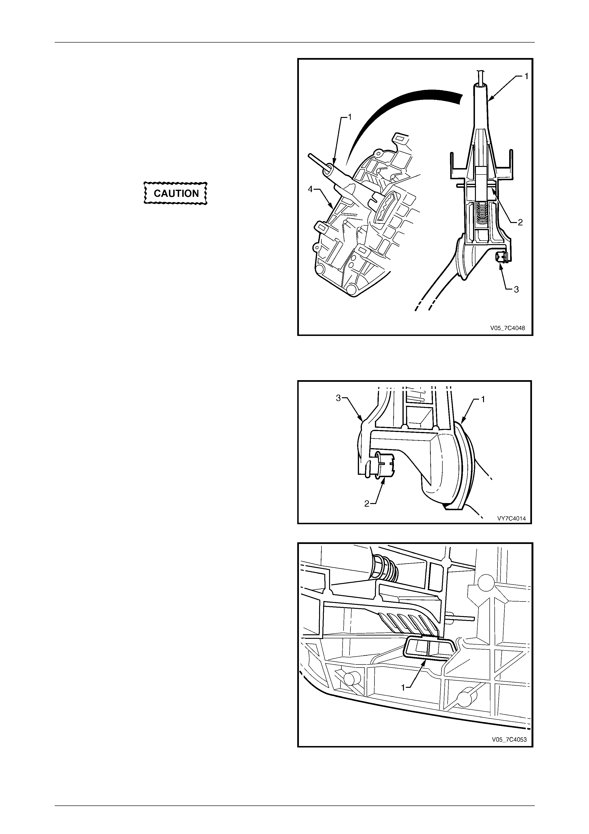
3 Remove the outer seal (1) from the selector lever.
Figure 7D4 – 31
4 Remove the selector lever lock ing piece (1) using a
small screwdriver (2) to lever the locking tang free
while pulling on the locking piece with long nosed
pliers (3).
Figure 7D4 – 32
Automatic Transmission – 4L65E – On-vehicle Servicing Page 7D4–25
Page 7D4–25
NOTE
When removing the selector lever assembly:
• While it will be necessary to manoeuvre the
selector lever somewhat, sufficient space is
provided to overcome any need to apply
force for the removal.
• The bush will probably remain in the base.
5 Push the selector lever assembly (1) inwards to
release the inner support pin (2) and bush (3) and then
lift the selector lever from the base (4) to remove it.
Further disassembly of the selector lever is
not recommended as there is a possibility
that, during reinstallation of the roll pin, the
selector lever will be cracked unless
sophisticated jigs are used. For this reason,
the shift lever is only serviced as an
assembly.
Figure 7D4 – 33
Reinstall
1 Inspect the selector lever inner bush (1) for damage,
replace as required. Lubricate the inner bush with a
multi-purpose chassis grease such as NLGI No. 1
Lithium grease or equivale nt.
2 Lubricate the split inner suppor t bush (2) with a multi-
purpose chassis grease such as NLGI No. 1 Lithium
grease or equivalent and re install the bush to the
selector lever pin aligning the split in the bush with the
key on the pin.
3 Align the inner support bush with the aperture in the
base and push it across to fully install the se lector
lever (3) in the base.
Figure 7D4 – 34
4 Using long nosed pliers, reinstall the selector lever
locking piece (1) into the base.
NOTE
An audible click will indicate if the tang on the
locking piece is correctly inserted in the base.
Figure 7D4 – 35
Automatic Transmission – 4L65E – On-vehicle Servicing Page 7D4–26
Page 7D4–26
5 Apply a smear of multi-purpose chassis grease such
as NLGI No. 1 Lithium grease or equivalent to the
outer seal (1) and install it over the selector lever.
6 Reinstall the lower housin g on the base as described
in this Section, refer to Lower Housing Assembly.
7 Reinstall the shift selector assembly as described in
this Section, refer to Reinstall.
Figure 7D4 – 36
Reinstall
1 Clean the mating surfaces of floor pan and inspect the
base seal for damage, replace as required.
2 From inside the vehicle, reinstall the shift selector
assembly (1) to the floor pan.
3 At the rear of the shift selector assembly, reconnect
the harness connector (2) to the selector patch
harness (3).
4 Raise the vehicle and suppor t in a safe manner,
refer to Section 0A General Information for the location
of support points.
5 From underneath the vehicle, install the four nuts (4)
attaching the shift selector assembly to the floor pan,
tighten to the correct torque specification.
Selector base attaching nut
torque specification.................................12.0 – 18.0 Nm
6 Reconnect the selector rod and trunni on to the
selector linkage, refer to 3.2 Selector Linkage and
Rod, Except AWD.
7 Reinstall the following components, refer to
Section 1A3 Instrument Panel and Co nsole:
a floor console assembly,
b lower extension side trim panels and
c floor console cover.
Figure 7D4 – 37
Automatic Transmission – 4L65E – On-vehicle Servicing Page 7D4–27
Page 7D4–27
3.5 Shift Selector Assembly, Coupe
LT Section No. — 04–190
Remove
1 Remove the following components, refer to Section 1A3 Instrument Panel and Console:
a floor console cover,
b lower extension side trim panels and
c floor console assembly.
2 At the rear of the shift selector assembly, disconn ect
the harness connector (1) from the selector patch
harness (2).
NOTE
The shift selector assembly needs to be
disconnected and detached from the floor pan
only to service the base and selector lever. The
lower housing and associated components can
be separated from the base for servicing.
3 Raise the vehicle and suppor t in a safe manner,
refer to Section 0A General Information for the location
of support points.
4 From underneath the vehicle, remove the locking bolt
and disconnect the selector rod and trun nion from the
selector linkage, refer to 3.2 Selector Linkage and
Rod, Except AWD.
Figure 7D4 – 38
5 From underneath the vehicle, remove the four nuts (1)
attaching the shift selector lever assembly to the floor
pan.
6 From inside the vehicle, lift the shift selector lever
assembly from the floor pan.
Figure 7D4 – 39
Automatic Transmission – 4L65E – On-vehicle Servicing Page 7D4–28
Page 7D4–28
Disassemble
Lower Housing Assembly
Remove
NOTE
The lower housing assembly can be
disassembled without the base being detached
from the floor pan.
1 With the selector lever in the D position, use a suitable
size Torx bit and remove the screw (1) on the forward
side of the lever (2).
NOTE
This is also the recommended reassembly
position.
Figure 7D4 – 40
2 From the rear of the selector base, use a small flat
blade screwdriver (1) to gently prise the locking tab on
the patch harness connector (2) and push the
connector away from its support on the shift selector
base (3).
Figure 7D4 – 41
Automatic Transmission – 4L65E – On-vehicle Servicing Page 7D4–29
Page 7D4–29
3 Disconnect the lower housing (1) from the base (2) by
pressing the tang (3) on each of the retaining legs.
NOTE
There are two tangs at the front and one at the
rear of the lower housing.
4 Lift the lower housing from the base together with the
traction control switch (T/C), patch harness, upper
cover, boot and selector knob.
5 As required, lift the insulator (4) from the base.
Figure 7D4 – 42
Reinstall
1 Ensure the PRNDL indicator slide, in the lower
housing (1), is at the D position with the red colour
showing opposite the D in the PRNDL lens (2).
2 Ensure the insulator (3) is undamaged and reinstall it
to the base (4).
3 Ensure the selector lever is in the D position and
reinstall the lower housing assembly over the selector
lever, engage each of the three retaining legs with the
base.
NOTE
Check if the PRNDL indicator slide pin is
engaged with the slot in the selector lever.
Figure 7D4 – 43

Automatic Transmission – 4L65E – On-vehicle Servicing Page 7D4–30
Page 7D4–30
NOTE
If the knob button (4) and spring have not been
removed, some manoeuvring may be necessary
to re-engage the selector lever.
4 Re-engage the selector lever knob (1) with the
selector lever, aligning the control rod with the hole in
the selector knob.
5 Check the correct engagement of the PRNDL indicator
by moving the selector lever. If the coloured portion (2)
does not move with the lever, engagement is incorrect.
To rectify, separate the lower housing from the base
and repeat procedure steps 3 to 5.
6 Reinstall the selector knob attaching Torx screw (3)
and tighten to the recommended torque spec ification.
Selector knob attaching Torx screw
torque specification.....................................1.0 – 3.0 Nm
7 If required, reinstall the knob button (4) and spring,
push the button down until the two locking tangs are
engaged.
Figure 7D4 – 44
8 Secure the patch harness connector (1) to its support
on the rear of the selector base (2).
Figure 7D4 – 45
Automatic Transmission – 4L65E – On-vehicle Servicing Page 7D4–31
Page 7D4–31
Patch Harness and Switch
Remove
1 As required, separate the lower housing from
the base as described in this Section, refer to
Lower Housing Assembly.
2 Remove the selector indicator lamp a nd holder (1)
from the lower housing by turning the lamp holder 90°
counter-clockwise and pull it o utward.
Figure 7D4 – 46
3 Disengage the retaining l ugs and remove the patch
harness connector (1) from the traction control
switch (2).
4 Remove the patch harness from the lo wer housing.
Figure 7D4 – 47
Automatic Transmission – 4L65E – On-vehicle Servicing Page 7D4–32
Page 7D4–32
Take note of the locating lug on the switch
body to ensure the switch is in the correct
orientation of when reinstalled.
5 Remove the traction control switch (T/C) (1) as
follows:
a Using a small flat blade screwdriver (2) lever one
of the switch retaining tangs from under the
lower housing to free the switch.
b Cock the switch to one side to release the
second tang and remove the switch from the
lower housing.
Figure 7D4 – 48
Reinstall
1 Reinstall the traction control switch (T/C) (1) to the
lower housing ensuring the locating lug on the switch
body engages with the slot in the lower housing,
secure the switch with the retaining tangs.
2 Reinstall the patch harness connector (2) to the T/ C
switch.
3 Insert the selector indicator lamp and holder (3) in the
lower housing and turn it clockwise to secure.
4 As required, reinstall the lower housing to the
base as described in this Section, refer to
Lower Housing Assembly.
Figure 7D4 – 49
Automatic Transmission – 4L65E – On-vehicle Servicing Page 7D4–33
Page 7D4–33
Upper Cover, Boot and Selector Knob
Remove
1 As required, separate the lower housing from
the base as described in this Section, refer to
Lower Housing Assembly.
2 While holding the lower housing (1) in an inverted
position, gently prise the lug (2), four places and free
the upper cover (3) from the lower housing.
3 Lift the lower housing and separate from the shift
selector knob, boot and upper cover assemb ly.
NOTE
If the lower housing assembly is not inverted
before separation, the bo ot will probably become
dislodged from the locating tangs in the upper
cover.
Figure 7D4 – 50
4 If required, remove the boot from the upper cover
locating tangs being careful not to dislodge or damage
the PRNDL indicator lens in the process.
5 Turn the boot (1) inside out over the selector knob, cut
the plastic tie (2) attaching the boot and rem ove the
boot from the selector knob.
NOTE
The plastic tie is a unique design and is
markedly different from the usual cable tie.
Figure 7D4 – 51
The control rod button is spring loaded and
may fly free once dislodged.
6 If required, dismantle the selector knob (1) as follows:
a Using a small knife (2) or similar, free the lugs
securing the control rod button (3) to the knob,
remove the button and spring (4).
b Remove the two screws (5) attaching the
bezel (6) and separate the knob components.
Figure 7D4 – 52
Automatic Transmission – 4L65E – On-vehicle Servicing Page 7D4–34
Page 7D4–34
Reinstall
1 If installing a new boot, turn it inside out over the shift selector and firmly secure it with the plastic tie included with
the new boot, trim any excess length and disc ard.
NOTE
The plastic tie is a uniqu e design and is mark edly
different from the usual cable tie.
2 With the upper cover (1) inverted, locate the boot (2)
over each of the upper cover locating tangs (3),
working gradually around until every tang is covered.
NOTE
The weight of the selector knob is sufficient to
keep the boot engaged with the tangs.
Figure 7D4 – 53
NOTE
Before reassembling the upper cover to the
lower housing note the following:
• Proceed with the parts in an inverted position
to reduce the possibility of the boot
dislodging from the retaining tangs.
• Ensure the colored indictor is in line with the
two PRNDL display lamp holes (1). This is
the approximate position for correct
reassembly.
3 Engage the tab (2), four places, on the upper cover (3)
with the retaining lugs on the lower housing (4).
NOTE
With the tabs engaged, the boot will be clamped
and can no longer become disengaged.
Figure 7D4 – 54
4 If required, attach the bezel (6) to the knob (1) with the two screws (5), tighten to the correct torque specification,
refer to Figure 7D4 – 52.
Selector knob bezel attaching screw
torque specification.....................................1.0 – 2.0 Nm
NOTE
Reinstall the spring (4) and control rod button (3)
to the knob after the lower housing has been
reinstalled to the base.
5 As required, reinstall the lower housing to the base as described in this Section, refer to Lower Housing Assembly.
Automatic Transmission – 4L65E – On-vehicle Servicing Page 7D4–35
Page 7D4–35
Selector Lever Assembly
Remove
1 As required, remove the shift selector assembl y from the floor pan as described in this Section, refer to Remove.
2 As required, separate the lower housing from the base as described in this Section,
refer to Lower Housing Assembly
NOTE
Ensure the locking bolt, trunnion and associated
parts have previously been removed from the
lower end of the selector linkage, refer to
3.2 Selector Linkage and Rod, Except AWD.
This is necessary to provide clearance for the
removal of the selector lever from the base.
3 Remove the outer seal (1) from the selector lever.
Figure 7D4 – 55
4 Remove the selector lever lock ing piece (1) using a
small screwdriver (2) to lever the locking tang free
while pulling on the locking piece with long nosed
pliers (3).
Figure 7D4 – 56

Automatic Transmission – 4L65E – On-vehicle Servicing Page 7D4–36
Page 7D4–36
NOTE
When removing the selector lever assembly:
• While it will be necessary to manoeuvre the
selector lever somewhat, sufficient space is
provided to overcome any need to apply
force for the removal.
• The bush will probably remain in the base.
5 Push the selector lever assembly (1) inwards to
release the inner support pin (2) and bush (3) and then
lift the selector lever from the base (4) to remove it.
Further disassembly of the selector lever is
not recommended as there is a possibility
that, during reinstallation of the roll pin, the
selector lever will be cracked unless
sophisticated jigs are used. For this reason,
the shift lever is only serviced as an
assembly.
Figure 7D4 – 57
Reinstall
1 Inspect the selector lever inner bush (1) for damage,
replace as required. Lubricate the inner bush with a
multi-purpose chassis grease such as NLGI No. 1
Lithium grease or equivale nt.
2 Lubricate the split inner suppor t bush (2) with a multi-
purpose chassis grease such as NLGI No. 1 Lithium
grease or equivalent and re install the bush to the
selector lever pin aligning the split in the bush with the
key on the pin.
3 Align the inner support bush with the aperture in the
base and push it across to fully install the se lector
lever (3) in the base.
Figure 7D4 – 58
4 Using long nosed pliers, reinstall the selector lever
locking piece (1) into the base.
NOTE
An audible click will indicate if the tang on the
locking piece is correctly inserted in the base.
Figure 7D4 – 59
Automatic Transmission – 4L65E – On-vehicle Servicing Page 7D4–37
Page 7D4–37
5 Apply a smear of multi-purpose chassis grease such
as NLGI No. 1 Lithium grease or equivalent to the
outer seal (1) and install it over the selector lever.
6 Reinstall the lower housin g on the base as described
in this Section, refer to Lower Housing Assembly.
7 Reinstall the shift selector assembly as described in
this Section, refer to Reinstall.
Figure 7D4 – 60
Reinstall
1 Clean the mating surfaces of floor pan and inspect the
base seal for damage, replace as required.
2 From inside the vehicle, reinstall the shift selector
assembly (1) to the floor pan.
3 At the rear of the shift selector assembly, reconnect
the harness connector (2) to the selector patch
harness (3).
4 Raise the vehicle and suppor t in a safe manner,
refer to Section 0A General Information for the location
of support points.
5 From underneath the vehicle, install the four nuts (4)
attaching the shift selector assembly to the floor pan,
tighten to the correct torque specification.
Selector base attaching nut
torque specification..................................12.0 –18.0 Nm
6 Reconnect the selector rod and trunni on to the
selector linkage, refer to 3.2 Selector Linkage and
Rod, Except AWD.
7 Reinstall the following components, refer to
Section 1A3 Instrument Panel and Co nsole:
a floor console assembly,
b lower extension side trim panels and
c floor console cover.
Figure 7D4 – 61
Automatic Transmission – 4L65E – On-vehicle Servicing Page 7D4–38
Page 7D4–38
3.6 Shift Selector Assembly, AWD
LT Section No. — 04–190
Remove
1 Remove the following components, refer to Section 1A3 Instrument Panel and Console:
a floor console cover,
b lower extension side trim panels and
c floor console assembly.
2 At the rear of the shift selector assembly, disconn ect
the harness connector (1) from the selector patch
harness (2).
NOTE
The shift selector assembly needs to be
disconnected and detached from the floor pan
only to service the base and selector lever. The
lower housing and associated components can
be separated from the base for servicing.
3 From inside the vehicle, disconn ect the transmission
selector cable from the selector link age and the base,
refer to 3.3 Selector Cable Assembly, AWD.
4 Raise the vehicle and suppor t in a safe manner,
refer to Section 0A General Information for the location
of jacking and support points.
5 Remove the following components, refer to
Section 7F Transfer Case and Adaptor Ho using:
a catalytic converter bracket,
b transmission support and
c transfer case support mount.
6 Lower the rear of the transmission and transfer case to
access the nuts attaching the shift selector assembly
to the vehicle floor pan.
Figure 7D4 – 62
7 Remove the nut (1), four places, attaching the shift
selector assembly to the floor pan.
8 Remove the two nuts attaching the selector cable
upper bracket and grommet to the floor pan, forward of
the shift selector base.
NOTE
This is necessary to provide clearance for the
shift selector assembly removal.
9 From inside the vehicle, lift the shift selector assembly
from the floor pan.
Figure 7D4 – 63
Automatic Transmission – 4L65E – On-vehicle Servicing Page 7D4–39
Page 7D4–39
Disassemble
NOTE
There is no serviceable item in the selector lever
assembly or the base, disassembly is restricted
to the lower housing and associated components.
Lower Housing Assembly
Remove
NOTE
The lower housing assembly can be
disassembled without the base being detached
from the floor pan.
1 With the selector lever in the D position, use a suitable
size Torx bit and remove the screw (1) on the forward
side of the lever (2).
NOTE
This is also the recommended reassembly
position.
Figure 7D4 – 64
2 From the rear of the selector base, use a small flat
blade screwdriver (1) to gently prise, through the
hole (2), the locking tab on the patch harness
connector (3) and pull the connector away from its
support on the shift selector base (4).
Figure 7D4 – 65
Automatic Transmission – 4L65E – On-vehicle Servicing Page 7D4–40
Page 7D4–40
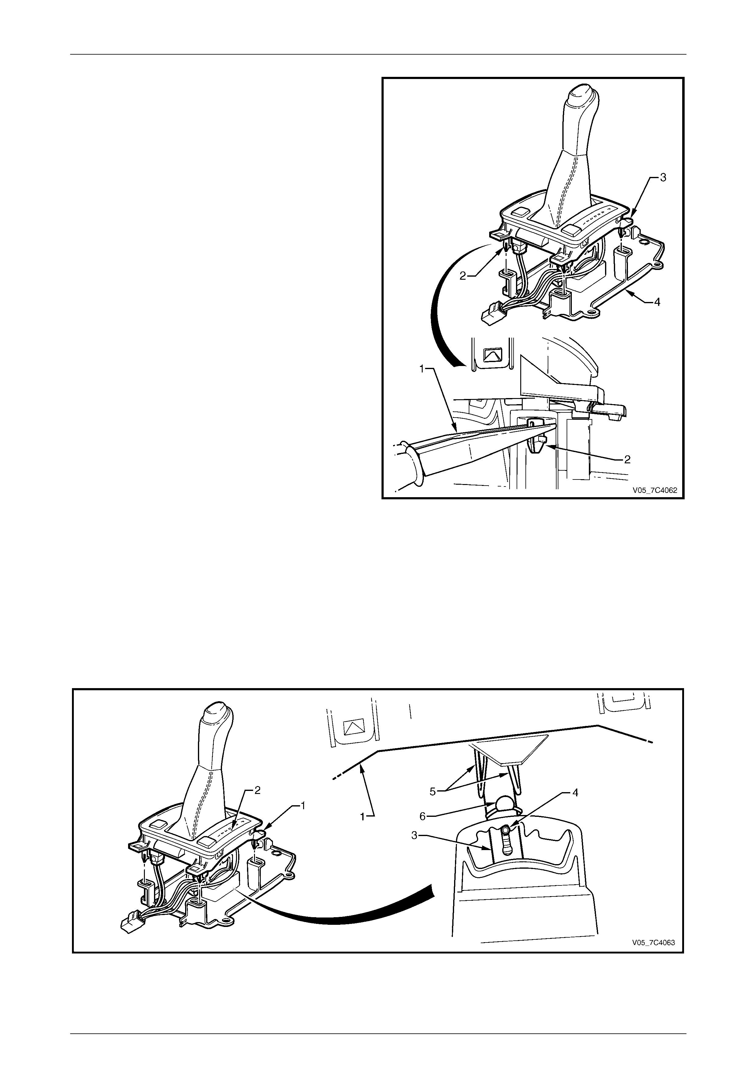
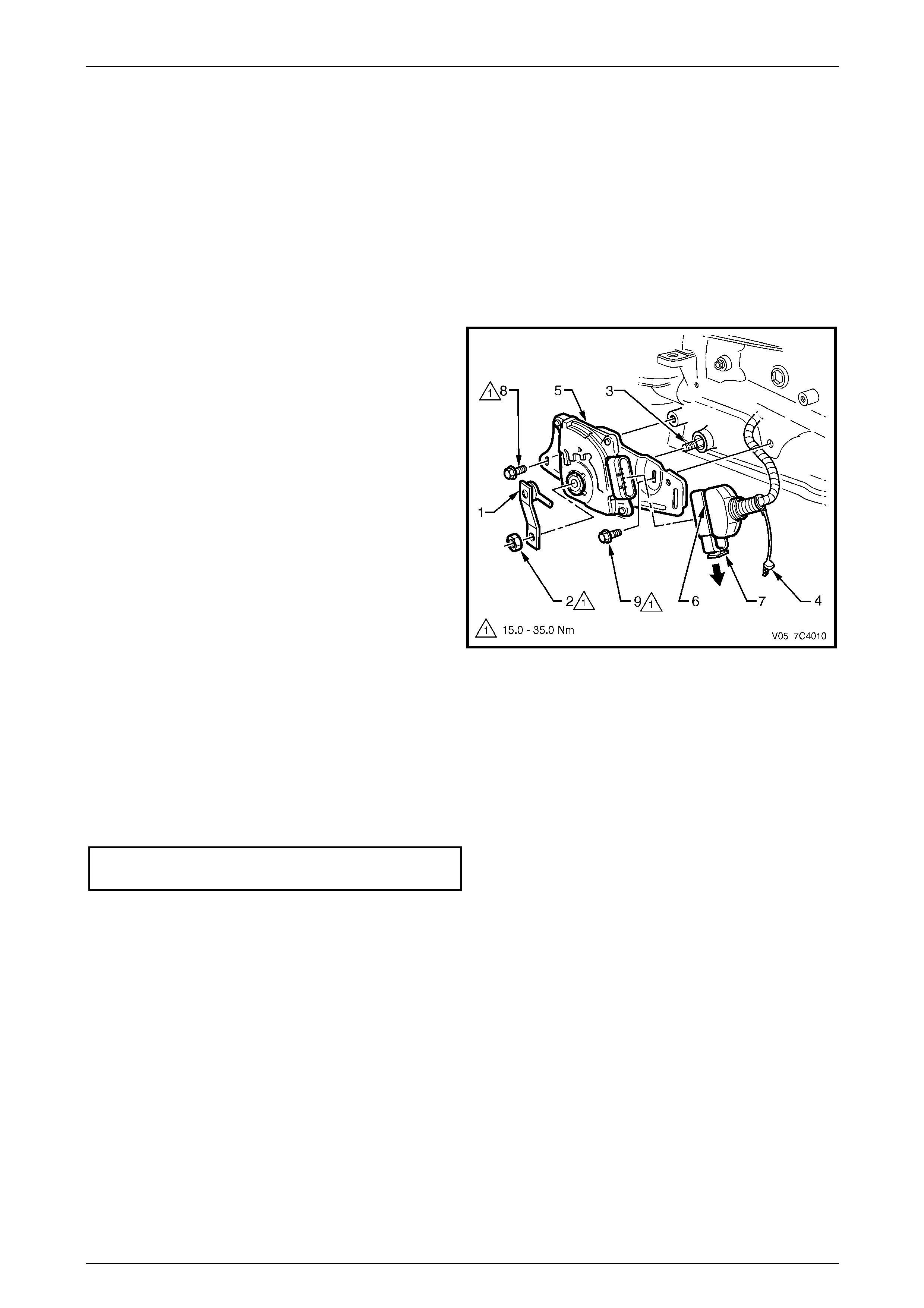
3 Using long nosed pliers (1) compress the peg (2), four
places, on the lower housing (3) and separate each
peg from the base (4).
4 Lift the lower housing from the base together with the
switch(s), patch wiring harness, upper cover, boot and
selector knob.
Figure 7D4 – 66
Reinstall
1 Ensure the PRNDL indicator slide, in the lower ho using (1), is at the D position with the red colour showing
opposite the D in the PRNDL lens (2), refer to Figure 7D4 – 67.
2 Ensure the selector lever (3) is in the D position with the pin (4) located as shown.
3 Reinstall the lower housin g assembly over the selector lever, engaging the PRNDL indicator connection (5) with the
selector lever pin (6).
4 Ensure the PRNDL indicator slide has rema ined at the D position.
Figure 7D4 – 67
Automatic Transmission – 4L65E – On-vehicle Servicing Page 7D4–41
Page 7D4–41
5 Align the pin (1), four places, on the lo wer housi ng (2)
with the corresponding hole i n the base (3) and
engage each pin tapping lightly with the heel of the
hand or use long nosed p liers (4) to compress each
pin.
Figure 7D4 – 68
NOTE
If the knob button (4) and spring have not been
removed, some manoeuvring may be necessary
to re-engage the selector lever.
6 Re-engage the selector lever knob (1) with the
selector lever, aligning the control rod with the hole in
the selector knob.
7 Check the engagement of the PRNDL indicator
connection by moving the selector lever. If the
coloured portion (2) does not move with the lever,
separate the lower housing from the base and repeat
procedure steps 1 to 4.
8 Reinstall the selector knob attaching Torx screw (3)
and tighten to the recommended torque spec ification.
Selector knob attaching Torx screw
torque specification.....................................1.0 – 3.0 Nm
9 If required, reinstall the knob button (4) and spring,
push the button down until the two locking tangs are
engaged.
Figure 7D4 – 69
10 Secure the patch harness connector (1) to its
support (2) on the rear of the selector base.
Figure 7D4 – 70
Automatic Transmission – 4L65E – On-vehicle Servicing Page 7D4–42
Page 7D4–42
Patch Harness and Switch
The patch harness and switch removal and reinstallation procedure for AW D vehicles is identical to the procedure for
RWD vehicles, refer to 3.4 Shift Selector Assembly, Except Coupe and AWD.
Upper Cover, Boot and Selector Knob
The upper cover, boot and selector knob removal and reinstallation procedure for AWD vehicles is identical to the
procedure for RWD vehicles, refer to 3.4 Shift Selector As sembly, Except Coupe and AWD.
Reinstall
1 Clean the mating surfaces of floor pan and inspect the
base seal for damage, replace as required.
2 From inside the vehicle, reinstall the shift selector
assembly (1) and the selector cable upper bracket and
grommet (2) to the floor pan.
3 At the rear of the shift selector assembly, reconnect
the harness connector (3) to the selector patch
harness (4).
4 From underneath the vehicle, install the four nuts (5)
attaching the shift selector assembly to the floor pan,
tighten to the correct torque specification.
Selector base attaching nut
torque specification.................................12.0 – 18.0 Nm
5 From underneath the vehicle, install the two nuts (6)
attaching the selector cable u pper bracket and
grommet to the floor pan.
Selector cable upper bracket
to floor pan attaching nut
torque specification.................................12.0 – 18.0 Nm
Figure 7D4 – 71
6 Reinstall the following components, refer to Section 7F Transfer Case and Adaptor Housing:
a transfer case support mount,
b transmission support and
c catalytic converter bracket.
7 From inside the vehicle, reconnect the trans mission selector cable to the selector linkage and the base, adjust the
cable if required, refer to 3.3 Selector Cable Assembly, AWD.
8 Reinstall the following components, refer to Section 1A 3 Instrument Panel and Console:
a floor console assembly,
b lower extension side trim panels and
c floor console cover.
Automatic Transmission – 4L65E – On-vehicle Servicing Page 7D4–43
Page 7D4–43
3.7 Neutral Start and Back-up Lamp Switch,
Except AWD
LT Section No. — 04–170
Remove
1 Position the transmission selector lever to the Park position.
2 Raise the vehicle and suppor t in a safe manner, refer to Section 0A General Information for the location of support
points.
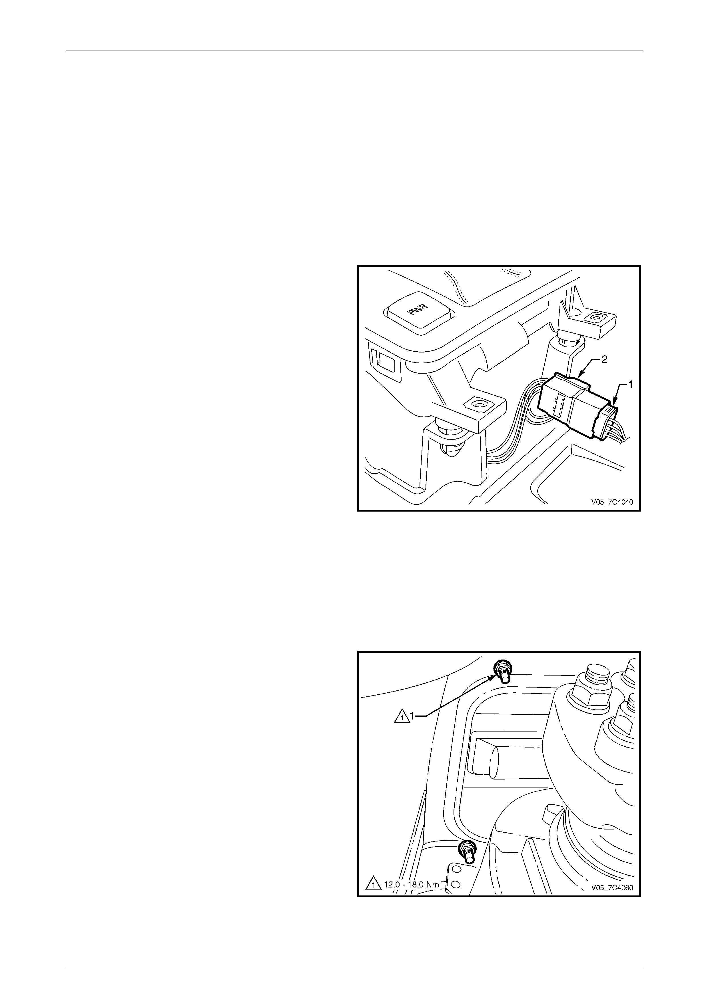
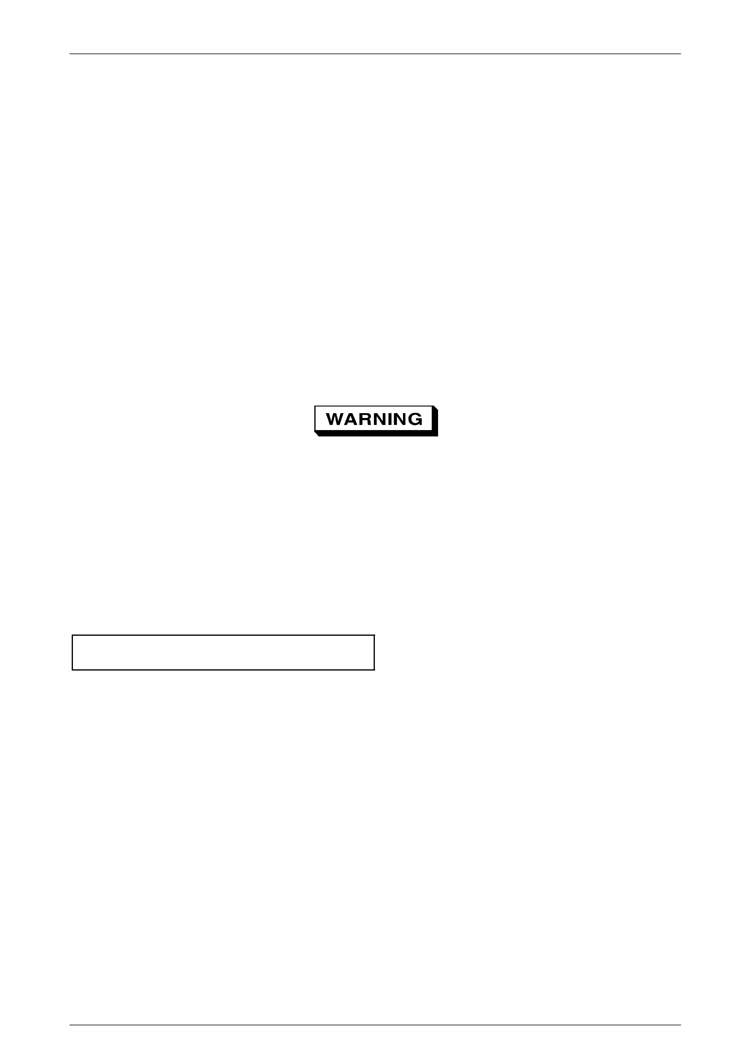
3 Hold the transmission manua l shaft linka ge (1) with an
adjustable wrench and remove the linkage attaching
nut (2).
4 Carefully remove the manual shaft linkage and
selector rod from the transmission manual sh aft (3).
5 Prise the connector position assurance (CPA)
securing pin (4) from the neutral start and back-up
lamp switch (5) taking care not to break the pin in the
process.
6 Disconnect connector (6) from the switch assembly by
pulling down the release bar (7).
NOTE
The connector will automatically disconnect at
the same time the release bar is withdrawn.
7 Remove the two attaching screws (8 and 9) and slide
the switch assembly over the transmission manual
shaft to remove it. Figure 7D4 – 72
Reinstall
1 Slide the neutral start and back-up lam p switch (5) over the transmission manual shaft (3) and reinstall the two
attaching screws (8 and 9), tighten them finger tight until the adjustment process has been completed, refer to
Figure 7D4 – 72.
2 Reinstall the manual sh aft linkage (1) and the attaching nut (2). Hold the linkage with an adjustable wrench and
tighten the nut to the correct torque specification.
Manual shaft linkage attaching nut
torque specification.................................15.0 – 35.0 Nm
3 Reinstall the connector (6) bu t do not reinsert the CPA securing pin (4) at this stage.
4 Check the shift selector linkage operatio n and adjust as required,
refer to 3.2 Selector Linkage and Rod, Except AWD.
5 Check and adjust as required the neutral sta rt and back-up lamp switch as described in this Section, refer to Adjust.
Automatic Transmission – 4L65E – On-vehicle Servicing Page 7D4–44
Page 7D4–44
Adjust
1 Raise the vehicle and suppor t in a safe manner, refer to Section 0A General Information for the location of support
points.
2 If required, loosen the neutral start and back-up lamp switch (5) as follows, refer to Figure 7D4 – 72:
a Prise the connector position assurance (CPA) securing pin (4) from the neutral start and back-up lamp
switch (5) taking care not to break the pin in the process.
b Disconnect connector (6) from the switch assembly by pulling down the release bar (7).
NOTE
The connector will automaticall y disconnect at the
same time the release bar is withdr awn.
c Loosen the two screws (8 and 9) attaching the switch and keep them finger tight.
d Reinstall the connector (6) bu t do not reinsert the CPA securing pin at this stage.
3 Rotate the neutral start and back-up lamp switch back a nd forth until a central position is attained and then lightl y
tighten the front screw (8) to prevent the switch from rotating.
Ensure the four wheels are off the ground
before performing the starting test.
4 With the ignition switched to the ON position, check if the engine can only be started in the Park and Neutral shift
selector positions and ensure the back-up lamps illuminate when Reverse is selected. A further minor adjustment
may be required to achieve this state.
NOTE
To gain access to the rear attaching screw (9) it
will be necessary to remove the connector.
5 After the switch has been adjusted, tighten the two attaching screws to the correct torque specification.
Neutral start and back-up lamp switch
attaching screw torque specification.......15.0 – 35.0 Nm
6 Reinstall the connector an d the CPA securing pin.
7 Lower the vehicle to the ground an d re-check the operation of the neutral start and back-up lamp switch. The
vehicle must start only with the shift selector in the Park or Neutral positions and the back-up lamps should only
illuminate when Reverse is selected.
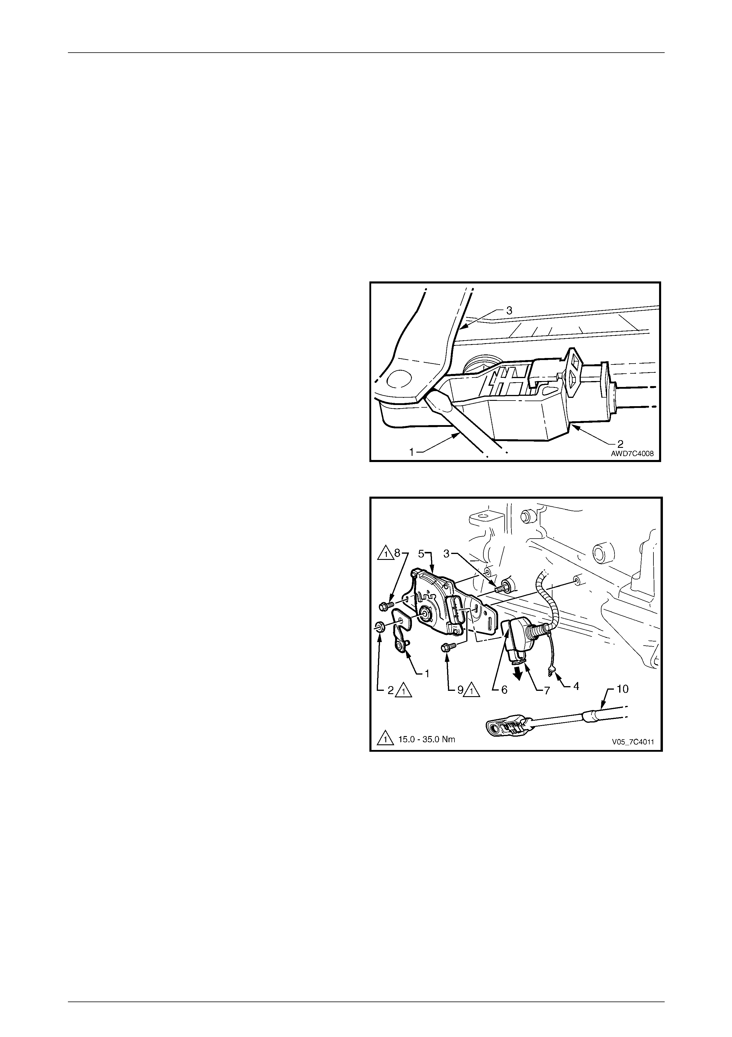
Automatic Transmission – 4L65E – On-vehicle Servicing Page 7D4–45
Page 7D4–45
3.8 Neutral Start and Back-up Lamp Switch,
AWD
LT Section No. — 04–170
Remove
1 Position the transmission selector lever to the Park position.
2 Raise the vehicle and suppor t in a safe manner, refer to Section 0A General Information for the location of support
points.
3 Remove the front propeller shaft, refer to Section 4C2 Front Propeller Shaft and Universal Joints.
4 Using a small flat blade scre wdriver (1), gentl y prise
the selector cable end (2) from the transmission
external manual shaft linkag e (3).
Figure 7D4 – 73
5 Hold the transmission manua l shaft linka ge (1) with an
adjustable wrench and remove the linkage attaching
nut (2).
6 Carefully remove the manual shaft linkage from the
transmission manual shaft (3).
7 Prise the connector position assurance (CPA)
securing pin (4) from the neutral start and back-up
lamp switch (5) taking care not to break the pin in the
process.
8 Disconnect connector (6) from the switch assembly by
pulling down the release bar (7).
NOTE
The connector will automatically disconnect at
the same time the release bar is withdrawn.
9 Remove the two attaching screws (8 and 9) and slide
the switch assembly over the transmission manual
shaft to remove it. Figure 7D4 – 74
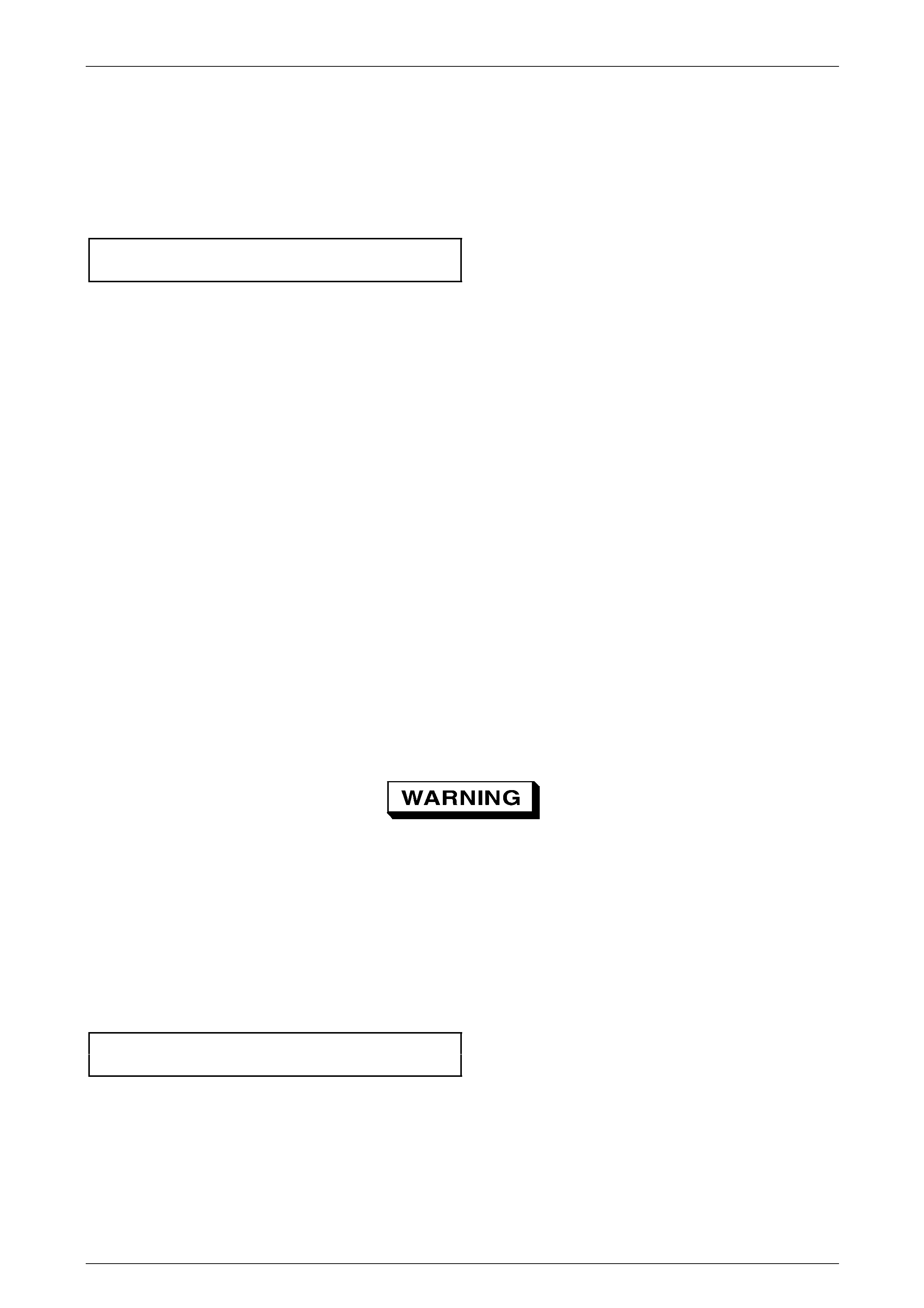
Automatic Transmission – 4L65E – On-vehicle Servicing Page 7D4–46
Page 7D4–46
Reinstall
1 Slide the neutral start and back-up lam p switch (5) over the transmission manual shaft (3) and reinstall the two
attaching screws (8 and 9), tighten them finger tight until the adjustment process has been comp leted, refer to
Figure 7D4 – 74.
2 Reinstall the manual sh aft linkage (1) and the attaching nut (2). Hold the linkage with an adjustable wrench and
tighten the nut to the correct torque specification.
Manual shaft linkage attaching nut
torque specification.................................15.0 – 35.0 Nm
3 Reinstall the connector (6) bu t do not reinsert the CPA securing pin (4) at this stage.
4 Reinstall the shift selector cable (10) to the manual shaft linkage, check and adjust as required the cable
adjustment, refer to 3.3 Selector Cable Assembly, AWD.
5 Check and adjust as required the neutral sta rt and back-up lamp switch as described in this Section, refer to Adjust.
Adjust
1 Raise the vehicle and suppor t in a safe manner, refer to Section 0A General Information for the location of support
points.
2 If required, loosen the neutral start and back-up lamp switch (5) as follows, refer to Figure 7D4 – 74:
a Remove the front propeller shaft, refer to Section 4C2 Front Propeller Shaft and Universal Joints.
b Prise the Connector Position Assurance (CP A) securing pin (4) from the neutral start and back-up lamp
switch (5) taking care not to break the pin in the process.
c Disconnect connector (6) from the switch assembly by pulling down the release bar (7).
NOTE
The connector will automaticall y disconnect at the
same time the release bar is withdr awn.
d Loosen the two screws (8 and 9) attaching th e switch and keep them finger tight.
e Reinstall the connector (6) bu t do not reinsert the CPA securing pin at this stage.
3 Rotate the neutral start and back-up lamp switch back a nd forth until a central position is attained and then lightl y
tighten the front screw (8) to prevent the switch from rotating.
Ensure the vehicle four wheels are off the
ground before performing the starting test.
4 With the ignition switched to the ON position, check if the engine can only be started in the Park and Neutral shift
selector positions and ensure the back-up lamps illuminate when Reverse is selected. A further minor adjustment
may be required to achieve this state.
NOTE
To gain access to the rear attaching screw (9) it
is necessary to remove the connector.
5 After the switch has been adjusted, tighten the two attaching screws to the correct torque specification.
Neutral start and back-up lamp switch
attaching screw torque specification.......15.0 – 35.0 Nm
6 Reinstall the connector an d the CPA securing pin.
7 Reinstall the front propeller shaft, refer to Section 4C2 Front Propeller Shaft and Universal Joints.
8 Lower the vehicle to the ground an d re-check the operation of the neutral start and back-up lamp switch. The
vehicle must start only with the shift selector in the Park or Neutral positions and the back-up lamps should only
illuminate when Reverse is selected.
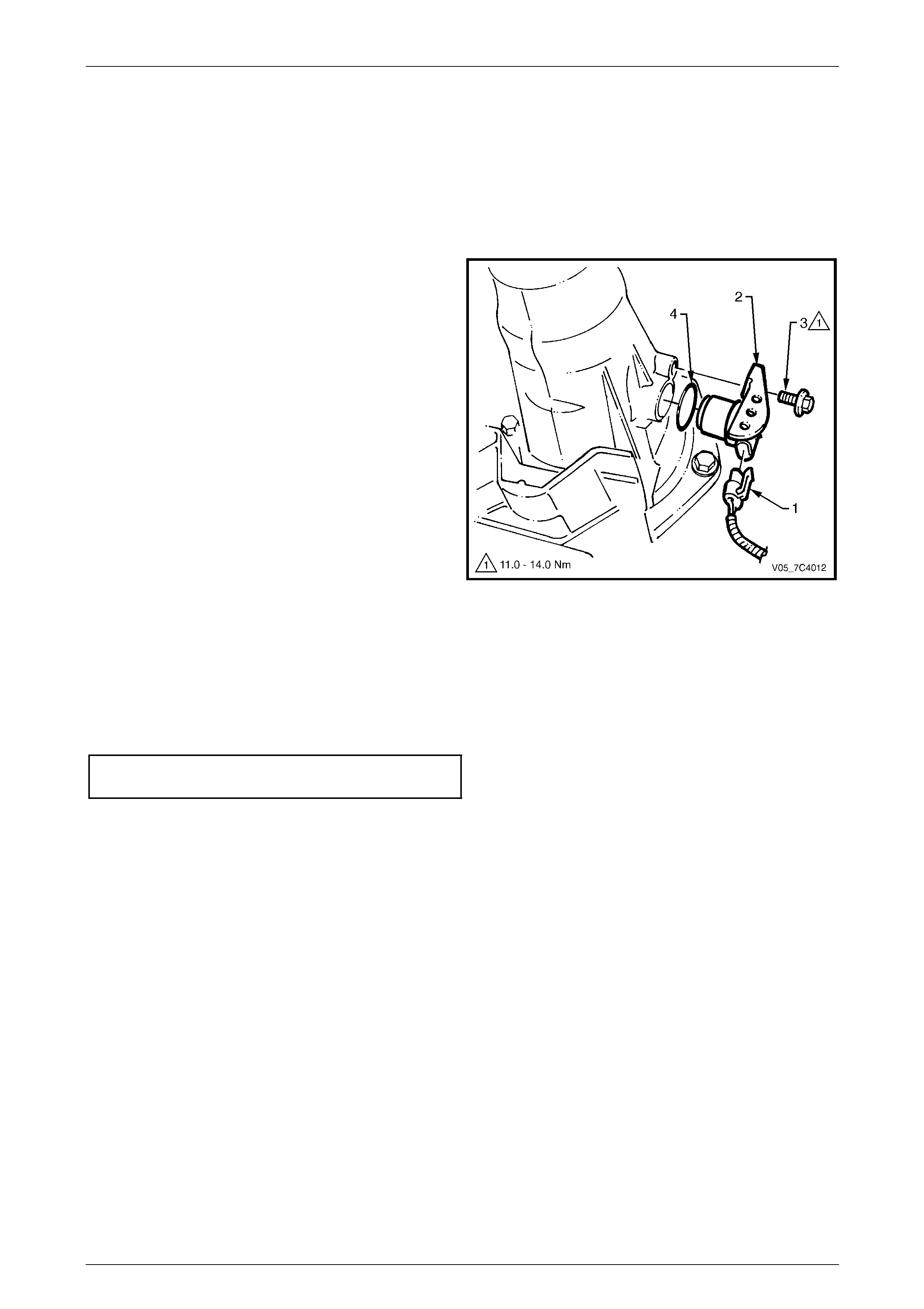
Automatic Transmission – 4L65E – On-vehicle Servicing Page 7D4–47
Page 7D4–47
3.9 Vehicle Speed Sensor, Except AWD
LT Section No. — 04–200
Remove
1 Raise the vehicle and suppor t in a safe manner, refer to Section 0A General Information for the location of support
points.
2 Disconnect connector (1) from the vehicle speed
sensor (2).
3 Remove the bolt (3) attaching the speed sensor to the
transmission extension housing.
4 With a pulling and turning motion, remove the speed
sensor and O-ring seal (4) from the transmission
extension hous ing, discard the O-ring.
Figure 7D4 – 75
Reinstall
1 Lubricate a new O-ring seal with petroleum jell y and install it to the vehicle speed sensor.
2 Reinstall the speed sensor to the transmission extension housing.
3 Reinstall the attachin g bolt and tighten to the correct torque specification.
Vehicle speed sensor attachin g bolt
torque specification..................................11.0 - 14.0 Nm
4 Reconnect the connector to the speed sensor.
5 Lower the vehicle to the ground.
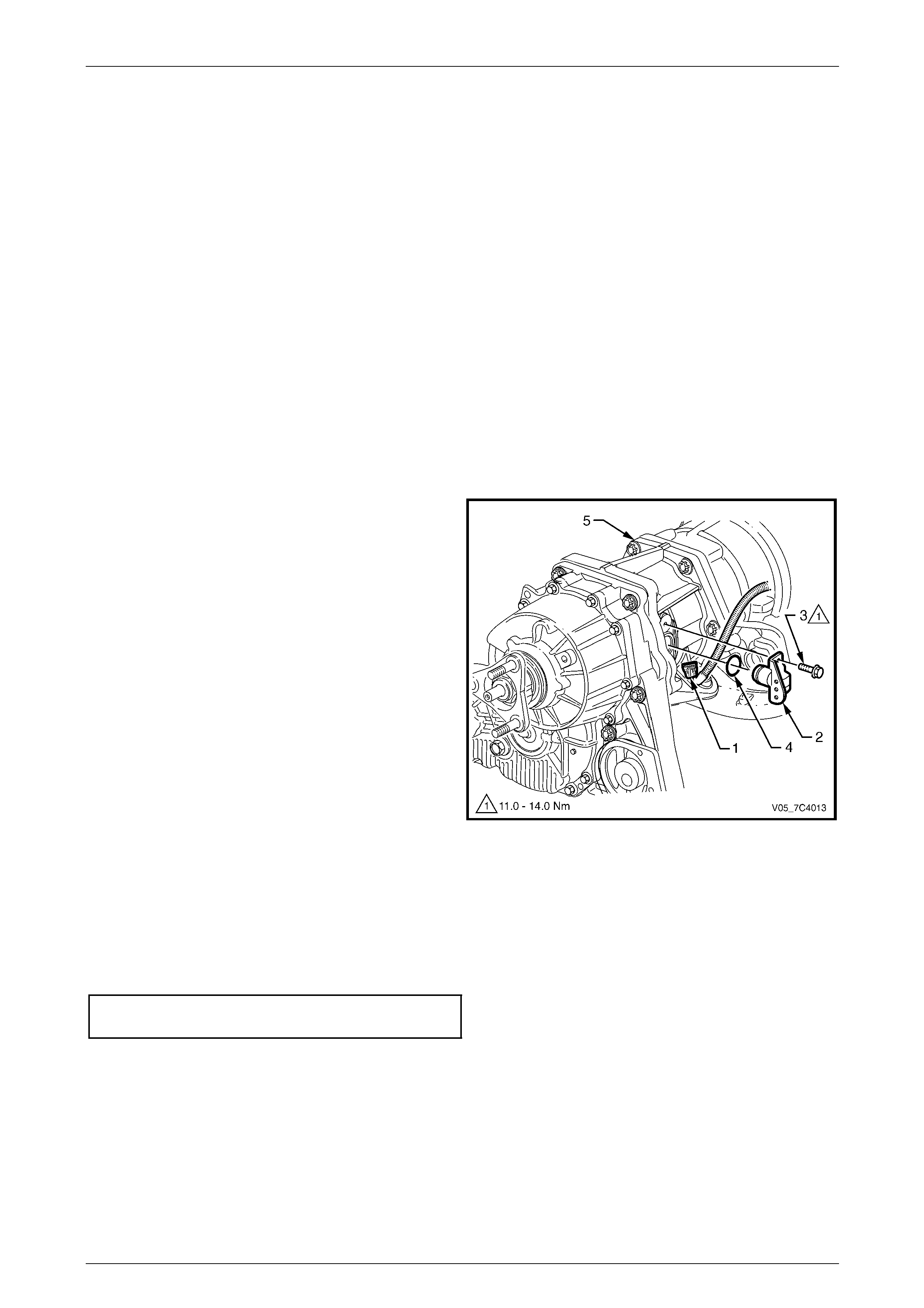
Automatic Transmission – 4L65E – On-vehicle Servicing Page 7D4–48
Page 7D4–48
3.10 Vehicle Speed Sensor, AWD
LT Section No. — 04–200
Remove
1 Raise the vehicle and suppor t in a safe manner, refer to Section 0A General Information for the location of support
points.
2 Remove the following components, refer to Section 7F Transfer Case and Adaptor Housing:
a catalytic converter and adaptor housing bracket,
b transmission support and
c transfer case rear mounting bracket.
NOTE
If necessary, lower the transfer case to access
the vehicle speed sensor attached to the
transmission adaptor housing.
3 Disconnect connector (1) from the vehicle speed
sensor (2).
4 Remove the bolt (3) attaching the speed sensor.
5 With a pulling and turning motion remove the speed
sensor and O-ring seal (4) from the transmission
adaptor housing (5), discard the O-ring.
Figure 7D4 – 76
Reinstall
1 Lubricate a new O-ring seal with petroleum jell y and install it to the vehicle speed sensor.
2 Position the speed sensor on the transmission adaptor housing.
3 Attach the speed sensor with the bolt and tighten to the correct torque specification.
Vehicle speed sensor attachin g bolt
torque specification.................................11.0 – 14.0 Nm
4 Reconnect the connector to the speed sensor.
5 Reinstall the following components, refer to Section 7F Transfer Case and Adaptor Housing:
a transfer case rear mounting bracket,
b transmission support and
c catalytic converter and adaptor housing bracket.
6 Lower the vehicle to the ground.

Automatic Transmission – 4L65E – On-vehicle Servicing Page 7D4–49
Page 7D4–49
3.11 Manual Shaft Oil Seal
LT Section No. —
Replace
NOTE
If the special tool No. AU583 is not available, the
seal can still be replaced but it requires the
removal of the manual shaft from the
transmission case. Refer to Section 7D5
Automatic Transmission – 4L65E – Unit Repair.
1 Raise the vehicle and suppor t in a safe manner, refer to Section 0A General Information for the location of support
points.
2 Remove the neutral start and back-up lamp switch, refer to:
• 3.7 Neutral Start and Back-up Lamp Switch, Except AW D, or
• 3.8 Neutral Start and Back-up Lamp Switch, AW D.
3 Assemble the seal remover, Tool No. AU583-3 (1) b y
installing the remover nut, Tool No. AU583-4 (2) with
its threaded inner diameter closest to the hexagonal
head of the seal remover tool. Install the nut up to the
hexagonal hea d.
4 Install the assembled seal remover tool over the
manual shaft (3) engaging the tapered threa d end (4)
into the seal.
Do not over tighten the seal remover tool in
the seal.
5 Rotate the hexagonal hea d of the seal remover tool
clockwise, until the thread grips the steel shell of the
seal.
Figure 7D4 – 77
6 While holding the hexagonal head of the seal remover
tool (1) rotate the remover nut (2) clockwise, until it
contacts the transmission case.
7 Continue rotating the remov er nut until the seal is
pulled into the remover nut cavit y.
8 Remove and discard the seal.
Figure 7D4 – 78
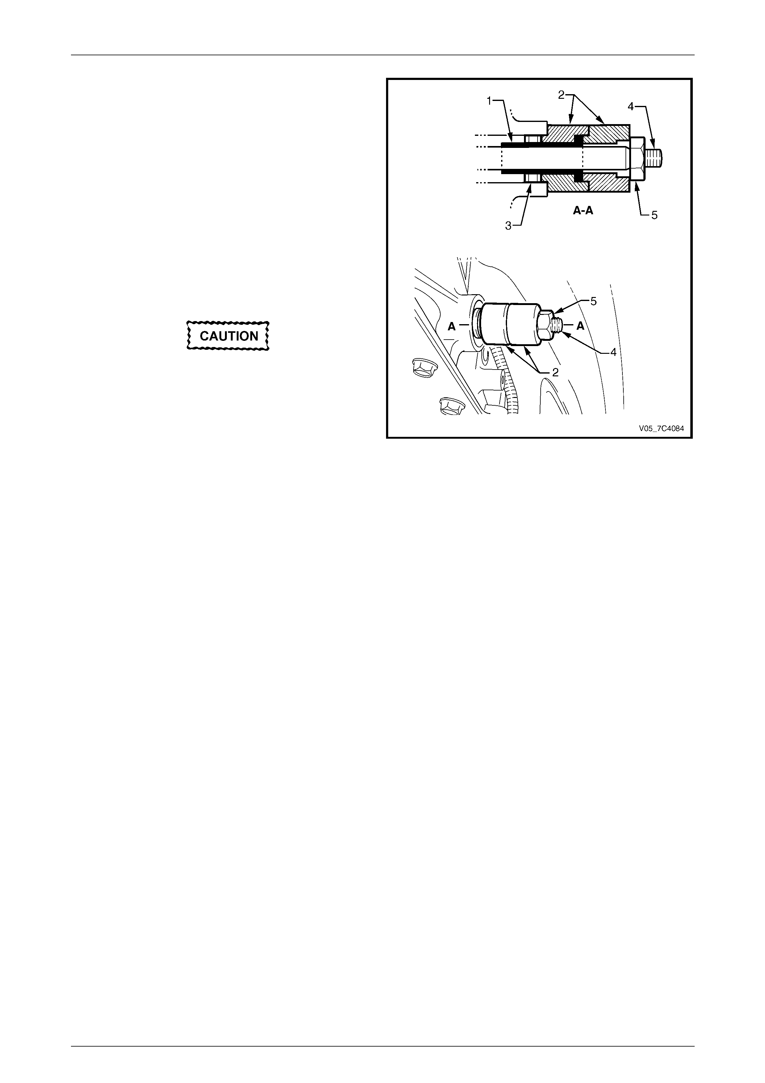
Automatic Transmission – 4L65E – On-vehicle Servicing Page 7D4–50
Page 7D4–50
9 Install the seal protector, Tool No. AU583-1 (1) into
one of the two plastic seal installers, Tool No.
AU583-2 (2).
NOTE
Two plastic seal installers are required because
of the restricted space between the end of the
manual shaft and the floor pan.
10 Lubricate the lip of a new seal (3) with clean automatic
transmission fluid and install it over the seal protector
sleeve, with the steel casing facing the insta ller tool.
11 Install the seal protector with the new seal and installer
tool over the manual shaft (4) and up to the
transmission case.
If the seal protector sleeve jams on the
manual shaft, the flats on the shaft locating
the selector lever will be burred. Use a fine
file to remove any burrs and then proceed.
12 Fit the second plastic seal installer over the manual
shaft until it seats against the first installer.
13 Install the manual shaft linkage attaching nut (5) and
tighten it to drive the seal in position into the
transmission case.
14 Remove the seal installer and protector tools from the
manual shaft.
Figure 7D4 – 79
15 Reinstall the neutral start and back-up lamp switch, refer to:
• 3.7 Neutral Start and Back-up Lamp Switch, Except AW D, or
• 3.8 Neutral Start and Back-up Lamp Switch, AW D.
16 Lower the vehicle to the ground an d as required, check and top up the automatic transmission fluid lev el, refer to
2.1 Transmission Fluid.
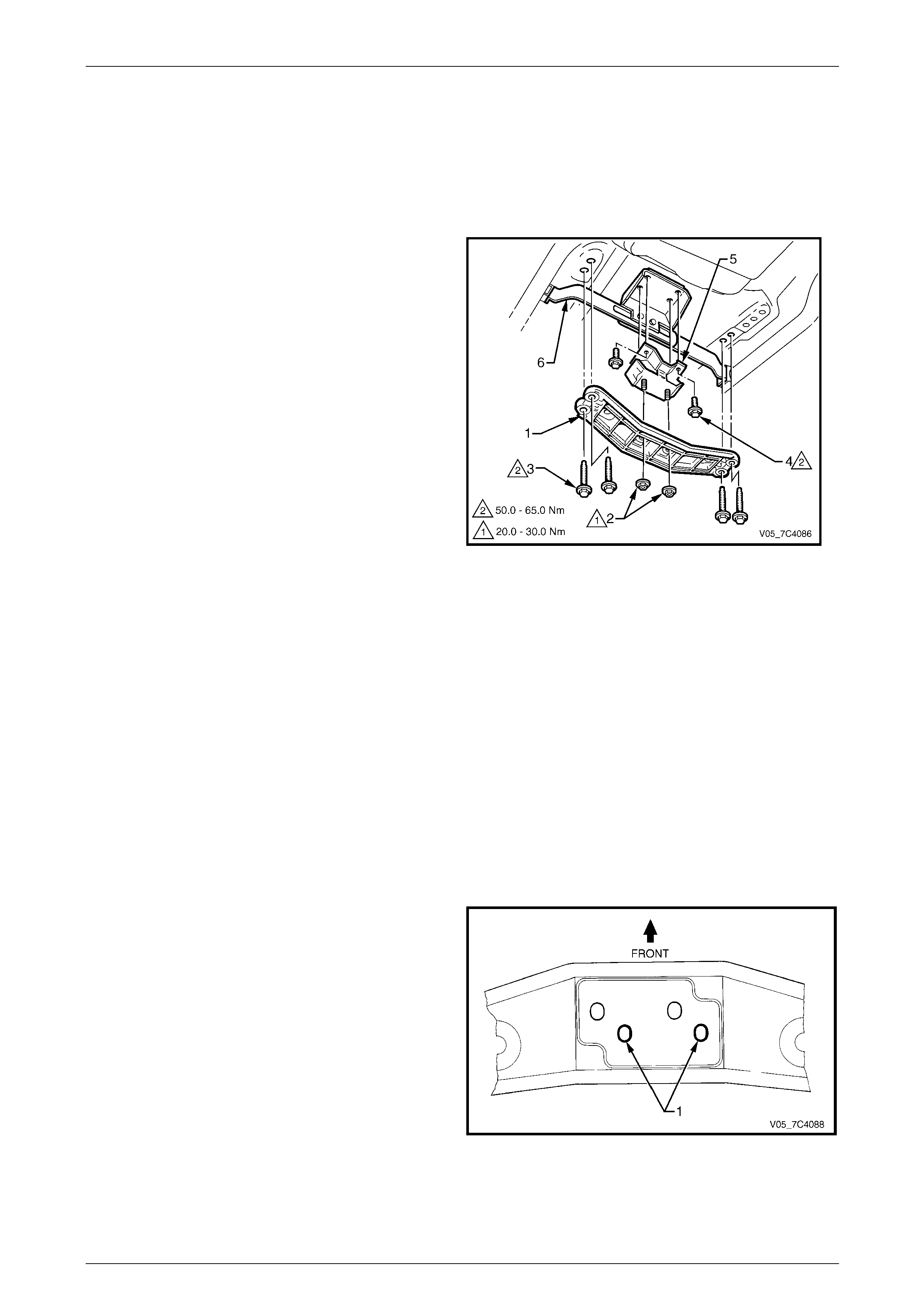
Automatic Transmission – 4L65E – On-vehicle Servicing Page 7D4–51
Page 7D4–51
3.12 Transmission Support and Mount,
Except Coupe and AWD
LT Section No. — 04–020
Remove
1 Raise the vehicle and suppor t in a safe manner,
refer to Section 0A General Information for the location
of support points.
2 Using a felt tipped pen or similar, mark the positio n of
the transmission support (1) to the under body sid e
rails
NOTE
This will assist in aligning the transmission
support on reinstallation.
3 Support the transmission with a Jack, do not plac e the
support underneath the extension housing or the oil
pan.
4 Remove the two nuts (2) attaching the transmission
mount to the support, make note of the through holes
location on the support.
5 Remove the four bolts (3) attaching the transmission
support to the under body side rails and remove the
support.
6 If required, remove the two bolts (4) attaching the
transmission mount (5) to the ext ension housing and
remove the mount.
Figure 7D4 – 80
Reinstall
1 If required, reinstall the transmission mount (5 ) onto the extension housing with the two attaching bolts (4) finger
tight, refer to Figure 7D4 – 80.
NOTE
If there is no locating marks, align all holes
centrally over the studs/bolts in the following
procedure.
2 Position the transmission support (1), aligning it with the marks done during remova l on the under body side rails.
3 Ensure the studs of the transmission mount are fitted
through the rear holes (1) in the support, or as noted
during removal.
Figure 7D4 – 81

Automatic Transmission – 4L65E – On-vehicle Servicing Page 7D4–52
Page 7D4–52
4 Reinstall the support four attachin g bolts (3) finger tight, refer to Figure 7D4 – 80.
5 As required, tighten the transmission mount two attaching bolts (4) to the correct torque specification.
Transmission mount attaching
bolt torque specification..........................50.0 – 65.0 Nm
6 Tighten the transmission support four attaching bolts (3) to the correct torque specification.
Transmission support attaching
bolt torque specification..........................50.0 – 65.0 Nm
7 Reinstall and tighten the transmission mount two attaching nuts (2) to the correct torque specific ation.
Transmission mount attaching
nut torque specification...........................20.0 – 30.0 Nm
8 Lower the vehicle to the ground.
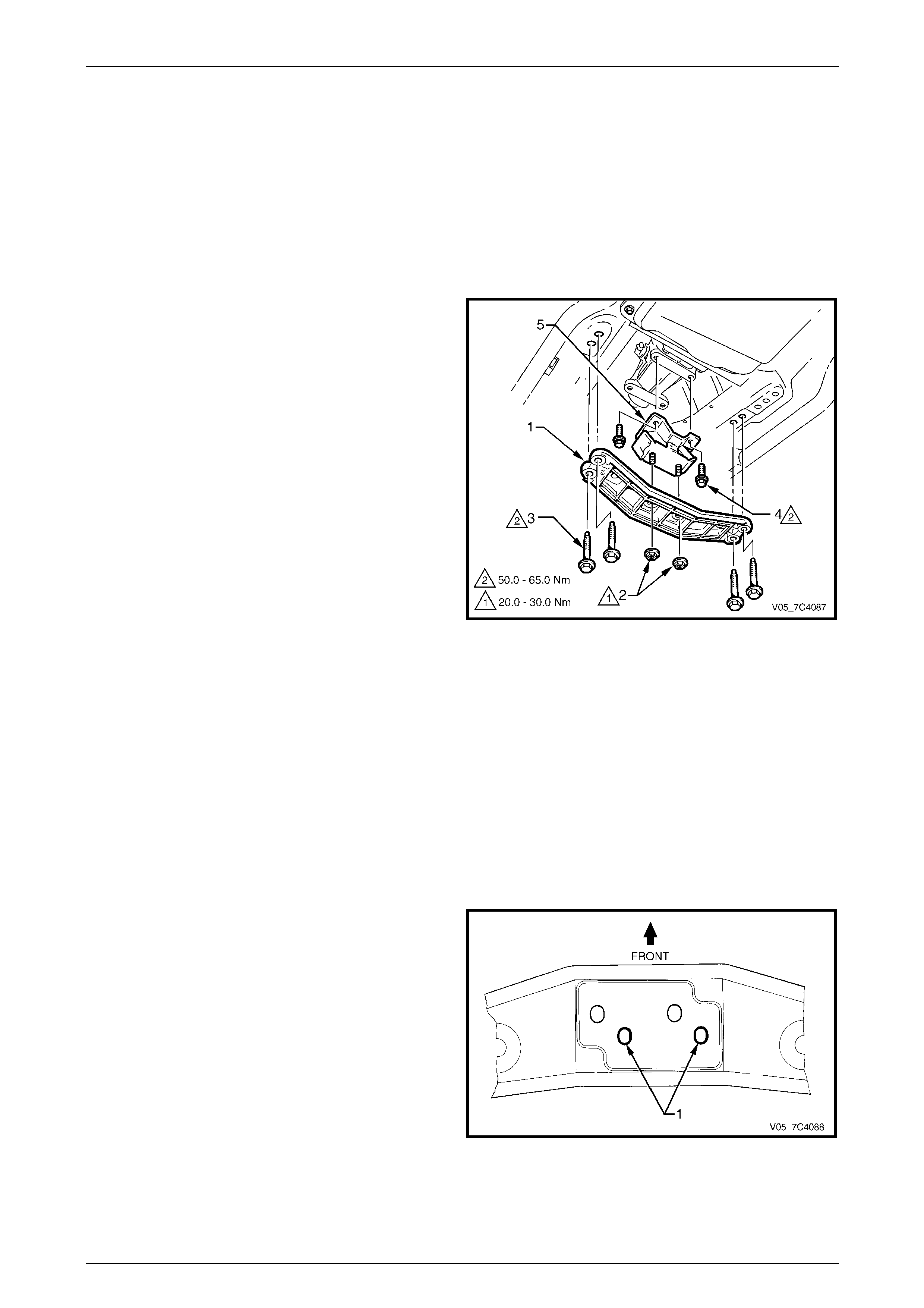
Automatic Transmission – 4L65E – On-vehicle Servicing Page 7D4–53
Page 7D4–53
3.13 Transmission Support and Mount,
Coupe
LT Section No. — 04–020
Remove
1 Raise the vehicle and suppor t in a safe manner, refer to Section 0A General Information for the location of support
points.
2 Using a felt tipped pen or similar, mark the positio n of
the transmission support (1) to the under body sid e
rails
NOTE
This will assist in aligning the transmission
support on reinstallation.
3 Support the transmission with a Jack, do not plac e the
support underneath the extension housing or the oil
pan.
4 Remove the two nuts (2) attaching the transmission
mount to the support, make note of the through holes
location on the support.
5 Remove the four bolts (3) attaching the transmission
support to the under body side rails and remove the
support.
6 If required, remove the two bolts (4) attaching the
transmission mount (5) to the ext ension housing and
remove the mount.
Figure 7D4 – 82
Reinstall
1 If required, reinstall the transmission mount (5 ) onto the extension housing with the two attaching bolts (4) finger
tight, refer to Figure 7D4 – 82.
NOTE
If there is no locating marks, align all holes
centrally over the studs/bolts in the following
procedure.
2 Position the transmission support (1), aligning it with the marks done during remova l on the under body side rails.
3 Ensure the studs of the transmission mount are fitted
through the rear holes (1) in the support, or as noted
during removal.
Figure 7D4 – 83

Automatic Transmission – 4L65E – On-vehicle Servicing Page 7D4–54
Page 7D4–54
4 Reinstall the support four attachin g bolts (3) finger tight, refer to Figure 7D4 – 82.
5 As required, tighten the transmission mount two attaching bolts (4) to the correct torque specification.
Transmission mount attaching
bolt torque specification..........................50.0 – 65.0 Nm
6 Tighten the transmission support four attaching bolts (3) to the correct torque specification.
Transmission support attaching
bolt torque specification..........................50.0 – 65.0 Nm
7 Reinstall and tighten the transmission mount two attaching nuts (2) to the correct torque specific ation.
Transmission mount attaching
nut torque specification...........................20.0 – 30.0 Nm
8 Lower the vehicle to the ground.

Automatic Transmission – 4L65E – On-vehicle Servicing Page 7D4–55
Page 7D4–55
3.14 Extension Housing and Rear Bush,
Except AWD
LT Section No. — 04–200
Remove
1 Raise the vehicle and suppor t in a safe manner, refer to Section 0A General Information for the location of support
points.
2 As required, remove the following c ompo ne nts:
a Exhaust system assembly, refer to Section 8B Exhaust System.
b Rear propeller shaft, refer to Section 4C1 Rear Propeller Shaft and Universal Joints.
c Transmission support and mo unt assembly,
refer to 3.12 Transmission Support and Mo unt, Except Coupe and AWD.
d Vehicle speed sensor, refer to 3.9 Vehicle S peed Sensor, Except AWD.
3 Remove the bolt (1), six places, attaching the
extension hous ing (2) to the transmission case.
4 Remove the extension housin g and seal (3) from the
rear of the transmission case, discard the seal.
Figure 7D4 – 84
Take care not to scratch the machined seal
recess in the extension housing as
transmission fluid may weep past the outer
diameter of the installed seal.
5 If the extension housing rear bush is to be re placed,
remove the oil seal (1) from the extension housing (2),
using a suitable removing tool such as Tool No. E308
and discard the seal.
Figure 7D4 – 85
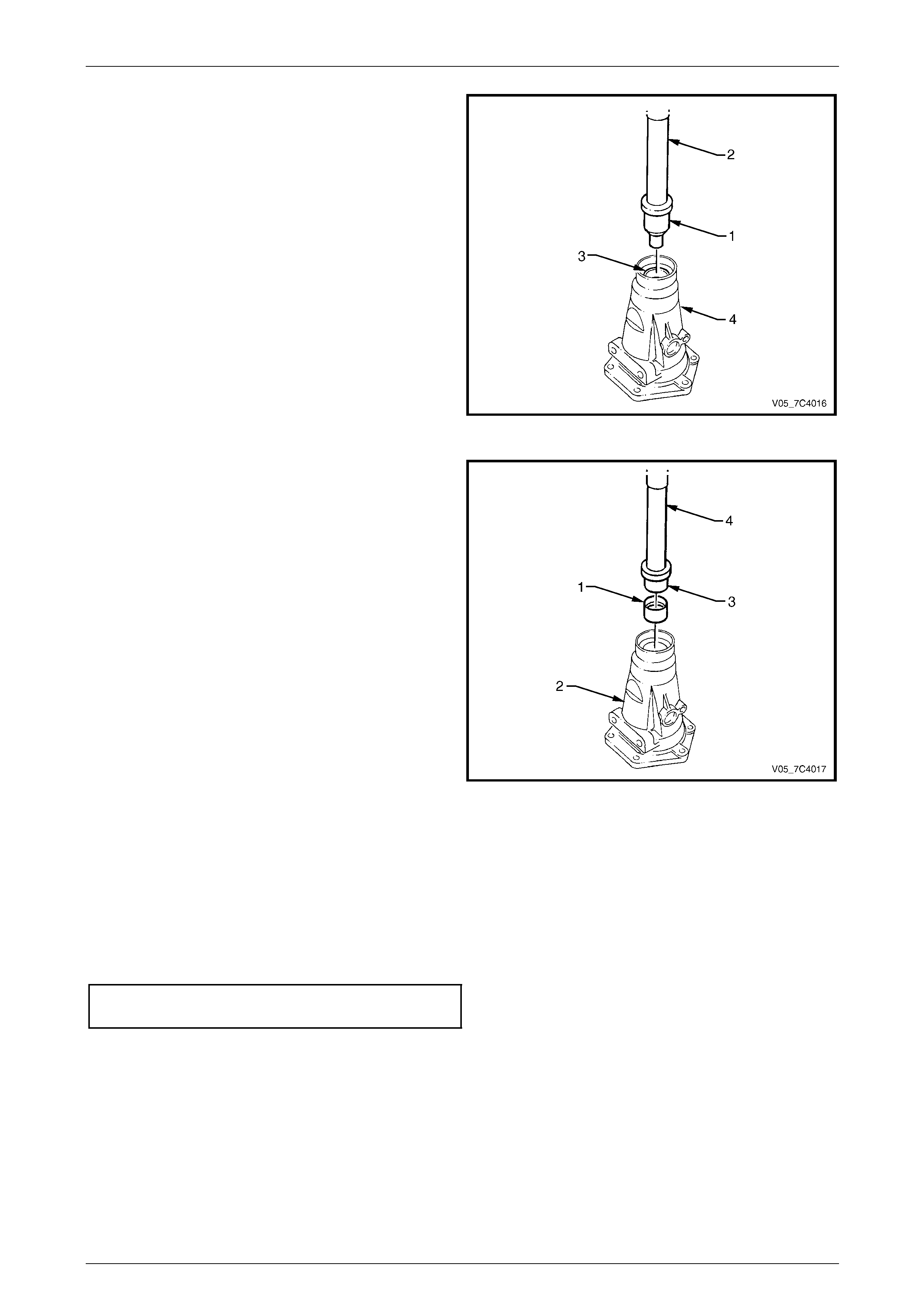
Automatic Transmission – 4L65E – On-vehicle Servicing Page 7D4–56
Page 7D4–56
NOTE
Before removal, take note of the orientation of
the split in the bush to assist in the replacement
process.
6 If required, using the bush remover, Tool
No. J23062-14 (1) and driver handle, Tool
No. J8092 (2), press the bush (3) out of the extensio n
housing (4) and discar d.
Figure 7D4 – 86
7 Lubricate the outside of a ne w bush with automatic
transmission fluid to reduce the chance of material
pick-up.
8 Ensure the split in the new bush (1) is in the same
orientation as noted previously and Install it into the
extension hous ing (2) using the installer tool, Tool
No. J34196-4 (3) and driver h andle, Tool
No. J8092 (4).
Figure 7D4 – 87
Reinstall
Reinstallation of the extension housing is the reverse of the removal procedure, noting the following:
1 If required, install a new oil seal in the e xtension housing, refer to 3.15 Extension Housing Oil Seal.
2 Lubricate a new seal with clean automatic transmission fluid and fit to the extension housing mounting flange.
3 Tighten the six bolts attaching the extension housing to the correct torque specification.
Extension housing attaching bolt
torque specification.................................42.0 – 48.0 Nm
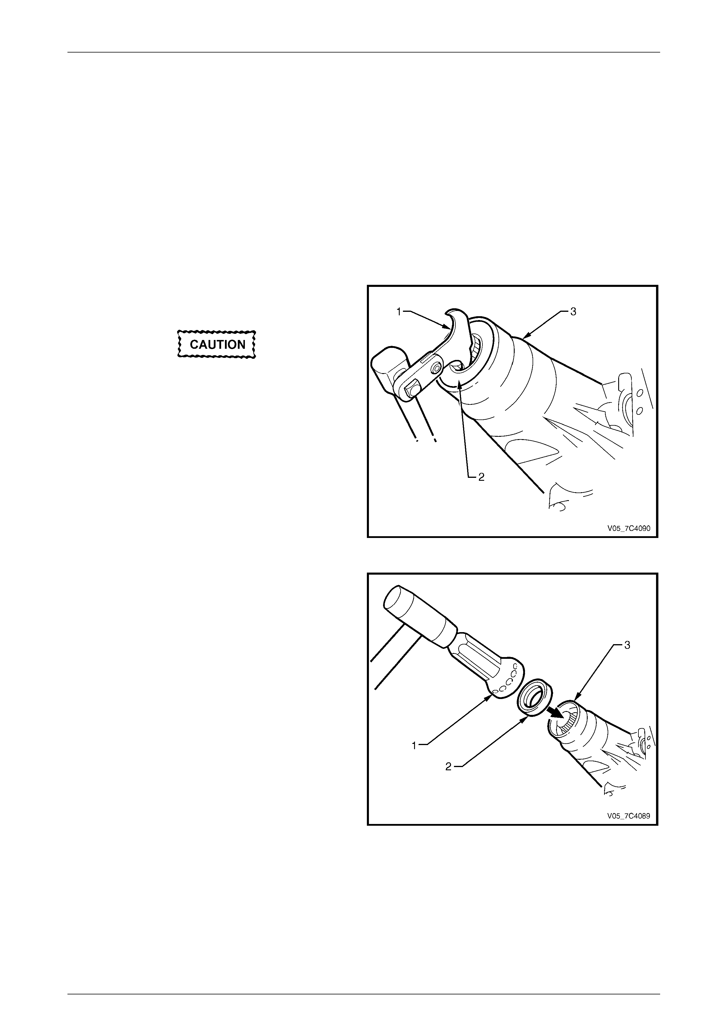
Automatic Transmission – 4L65E – On-vehicle Servicing Page 7D4–57
Page 7D4–57
3.15 Extension Housing Oil Seal, Except AWD
LT Section No. — 04–200
Replace
1 Raise the vehicle and suppor t in a safe manner, refer to Section 0A General Information for the location of support
points.
2 As required, remove the following c ompo ne nts:
a Exhaust system assembly, refer to Section 8B Exhaust System.
b Rear propeller shaft, refer to Section 4C1 Rear Propeller Shaft and Universal Joints.
3 Place a suitable size drip tray underne ath rear of
transmission.
Take care not to scratch the machined seal
recess in the extension housing as
transmission fluid may weep past the outer
diameter of the installed seal.
4 Using the seal remover, Tool No. E308 (1), pr ise the
oil seal (2) from rear of the extension housing (3) and
discard the seal.
5 Thoroughly cle an around the seal bore in the
extension hous ing and ensure there are no burrs.
Figure 7D4 – 88
6 Use the seal installer, Tool No. J21426 (1) and a soft
faced hammer to tap a new oil seal (2) into place in
the extension housing (3).
7 As required, reinstall the following compo ne nts:
a Rear propeller shaft, refer to Section 4C1 Rear
Propeller Shaft and Universal Joints.
b Exhaust system assembly, refer to
Section 8B Exhaust System.
8 Lower the vehicle to the ground an d check the fluid
level, refer to 2.1 Transmission Fluid.
Figure 7D4 – 89

Automatic Transmission – 4L65E – On-vehicle Servicing Page 7D4–58
Page 7D4–58
3.16 Transmission Support and Adaptor
Housing, AWD
LT Section No. — 04–200
Remove and Reinstall
For service operation of the transmission support and adaptor housing for AWD vehicles,
refer to Section 7F Transfer Case and Adaptor Housing.
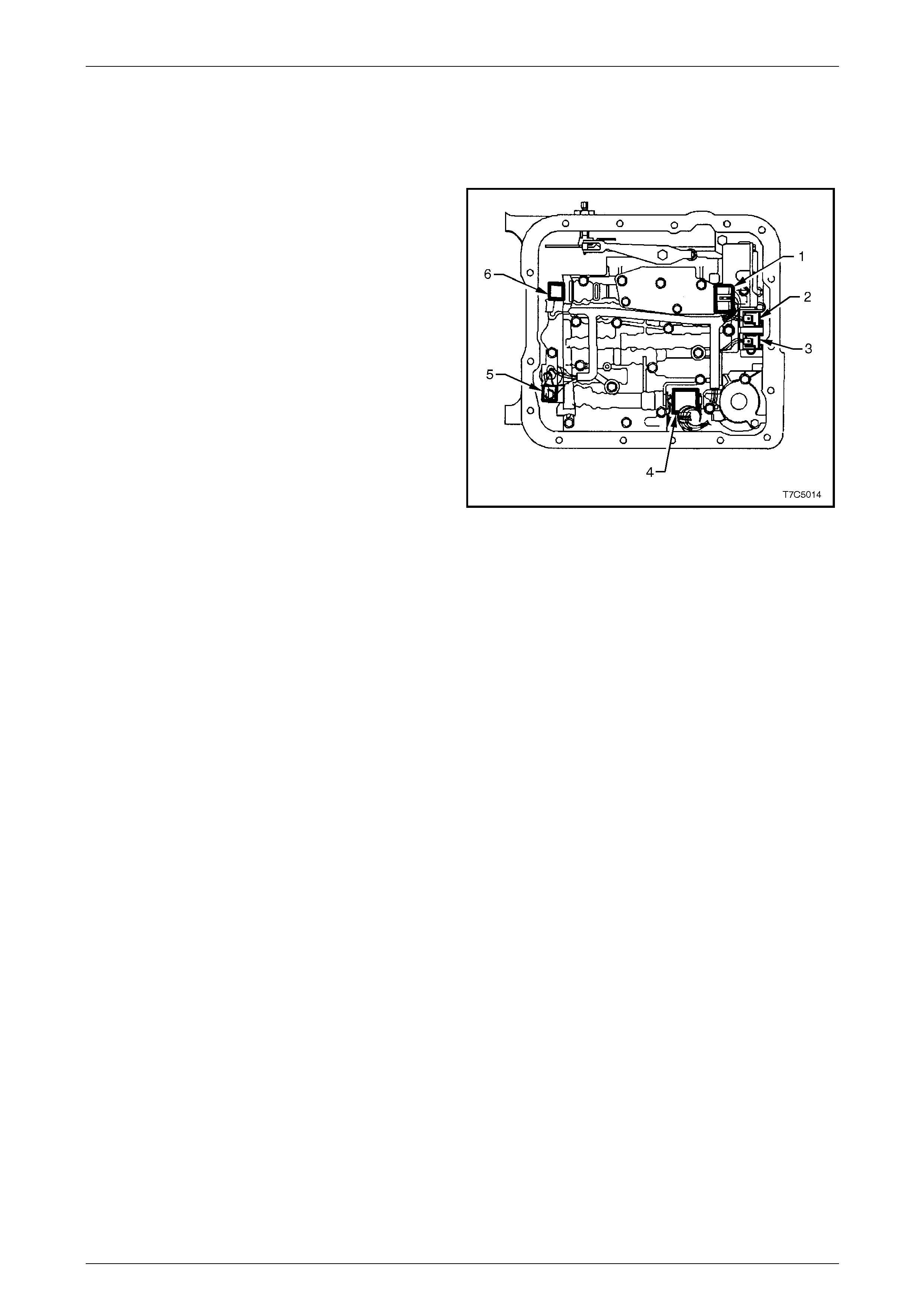
Automatic Transmission – 4L65E – On-vehicle Servicing Page 7D4–59
Page 7D4–59
3.17 Shift Solenoid Locations
Location and Identification
Legend
1 Transmission Fluid Pressure (TFP) Manual
Valve Position Switch.
2 1 – 2 Shift Valve Solenoid A.
3 2 – 3 Shift Valve Solenoid B.
4 Pressure Control Solenoid (PCS).
5 Torque Converter Clutch Pulse Width Modulated
(TCC PWM) Solenoid.
6 3 – 2 Control Solenoid.
Figure 7D4 – 90
To service the TCC PWM solenoid, refer to 3.19 Control Valve Body Harness.
For further information and service procedures of the shift solenoids, refer to
Section 7D5 Automatic Transmission – 4L65E – Unit Repair.
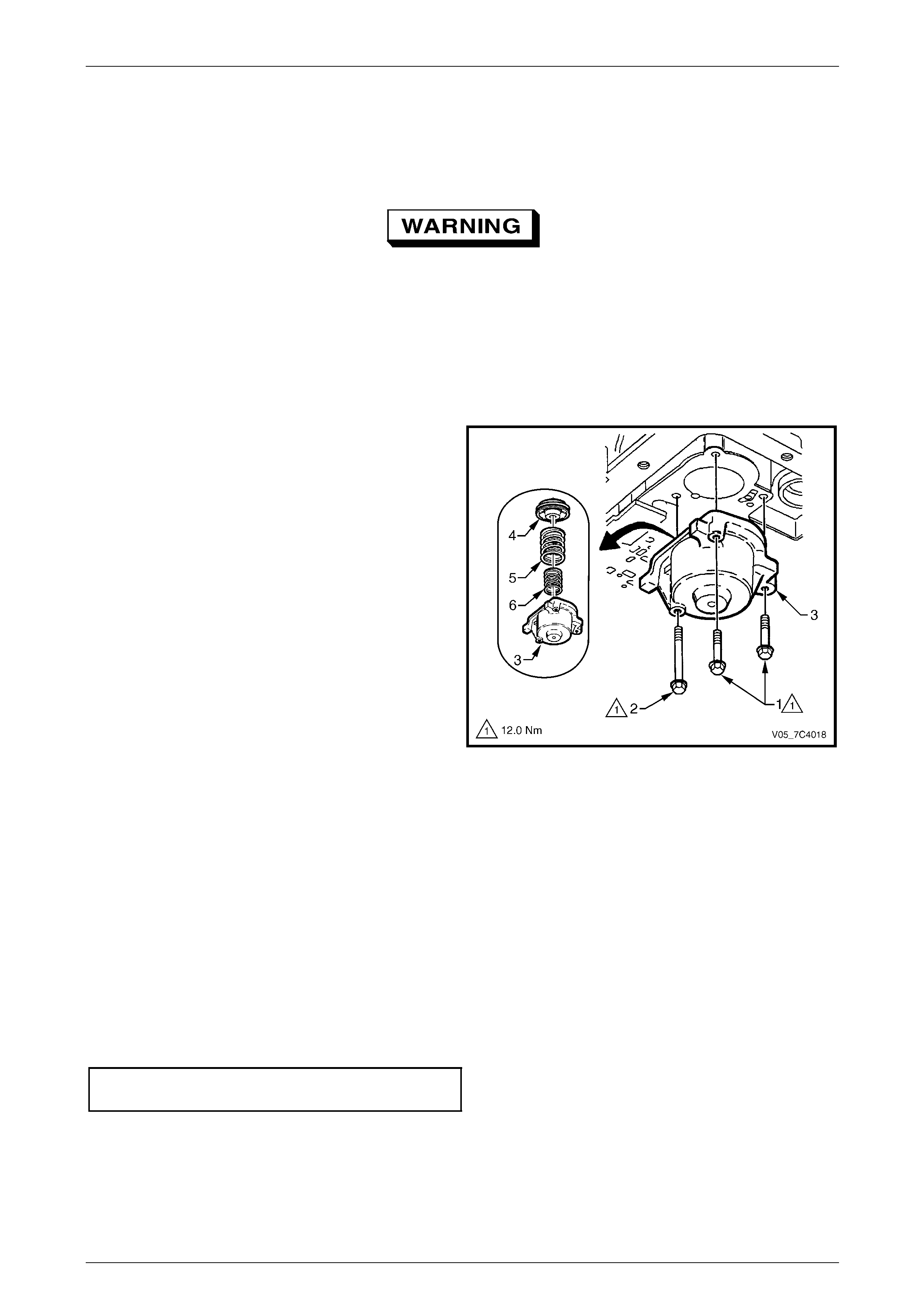
Automatic Transmission – 4L65E – On-vehicle Servicing Page 7D4–60
Page 7D4–60
3.18 1 – 2 Accumulator Assembly
LT Section No. —
Throughout this Section when using
compressed air and cleaning fluids, wear
safety glasses and gloves to avoid personal
injury.
Remove
1 Remove the oil pan and filter, refer to 3.1 Fluid Change and Filter Replacement.
2 Remove the two short bolts (1) and one long bolt (2)
attaching the accumulator cover (3) and rem ove the
cover.
3 Using low pressure compressed air applied to the
drilling in the cover, remove t he 1 – 2 accumulator
piston and seal assembly (4) and the two
springs (5 and 6).
4 Remove the seal from the piston and discard the seal.
Figure 7D4 – 91
Clean and Inspect
1 Clean all components in a commercially available cleaning fluid and blow dry using compressed air.
2 Inspect the springs and ensure they are not distorted or broken, replace as required.
3 Inspect all machined surfaces for damage, wear or burrs.
Reinstall
Reinstallation of the 1 – 2 accumulator assembly is the reverse of the removal procedure , noting the following:
1 Lubricate a new seal with petroleum jelly and install it to the piston. Ensure the piston seal do es not bind in the
piston groove.
2 Tighten the three bolts attaching the acc umul ator cover to the correct torque specification.
1 – 2 Accumulator cover attaching
bolt torque specification.....................................12.0 Nm
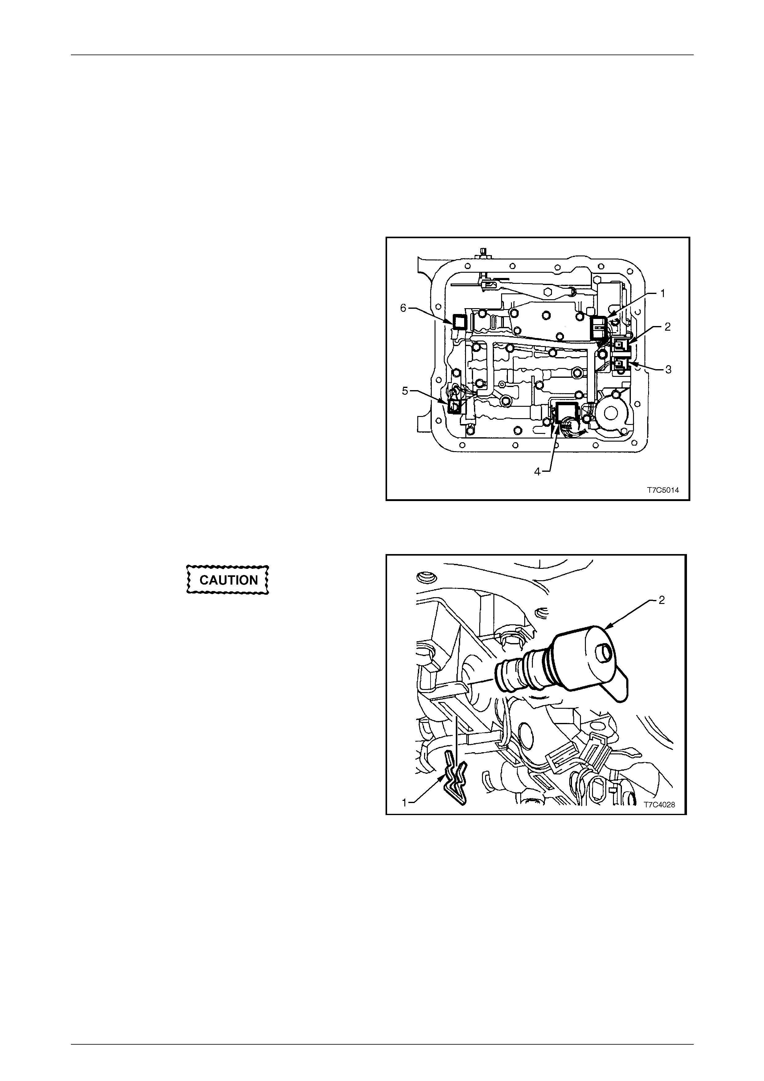
Automatic Transmission – 4L65E – On-vehicle Servicing Page 7D4–61
Page 7D4–61
3.19 Control Valve Body Harness
LT Section No. —
Remove
1 Raise the vehicle and suppor t in a safe manner, refer to Section 0A General Information for the location of support
points.
2 As required, remove the oil pan and filter, refer to 3.1 Fluid Change and Filter Replacement.
3 Disconnect the control valve body har ness connectors
from all electrical components except the torque
converter clutch (TCC) solenoid, which is hard wired.
Connectors identification:
• Transmission Fluid Pressure (TFP) Manual
Valve Position Switch (1)
• 1 – 2 Shift Valve Solenoid A (2)
• 2 – 3 Shift Valve Solenoid B (3)
• Pressure Control Solenoid (PCS) (4)
• Torque Converter Clutch Pulse Width Modulated
(TCC PWM) Solenoid (5)
• 3 – 2 Control Solenoid (6).
NOTE
For information and service procedures of the
shift solenoids, refer to Section 7D5 Automatic
Transmission – 4L65E – Unit Repair. Figure 7D4 – 92
To prevent personal injury, wear safety
glasses when removing the clip.
NOTE
Note the following when remo ving the solenoid:
• If required, rotate the solenoid until the flat
part of the clip becomes visible.
• The removal is only necessary to access the
TCC solenoid attaching bolts.
4 Using a hooked piece of wire or a small flat blade
screwdriver, remove the clip (1) retaining the
TCC PWM solenoid (2).
5 With a twisting and pulling motion remove the
TCC PWM solenoid from the control valve body,
remove and discard the O-ring.
Figure 7D4 – 93
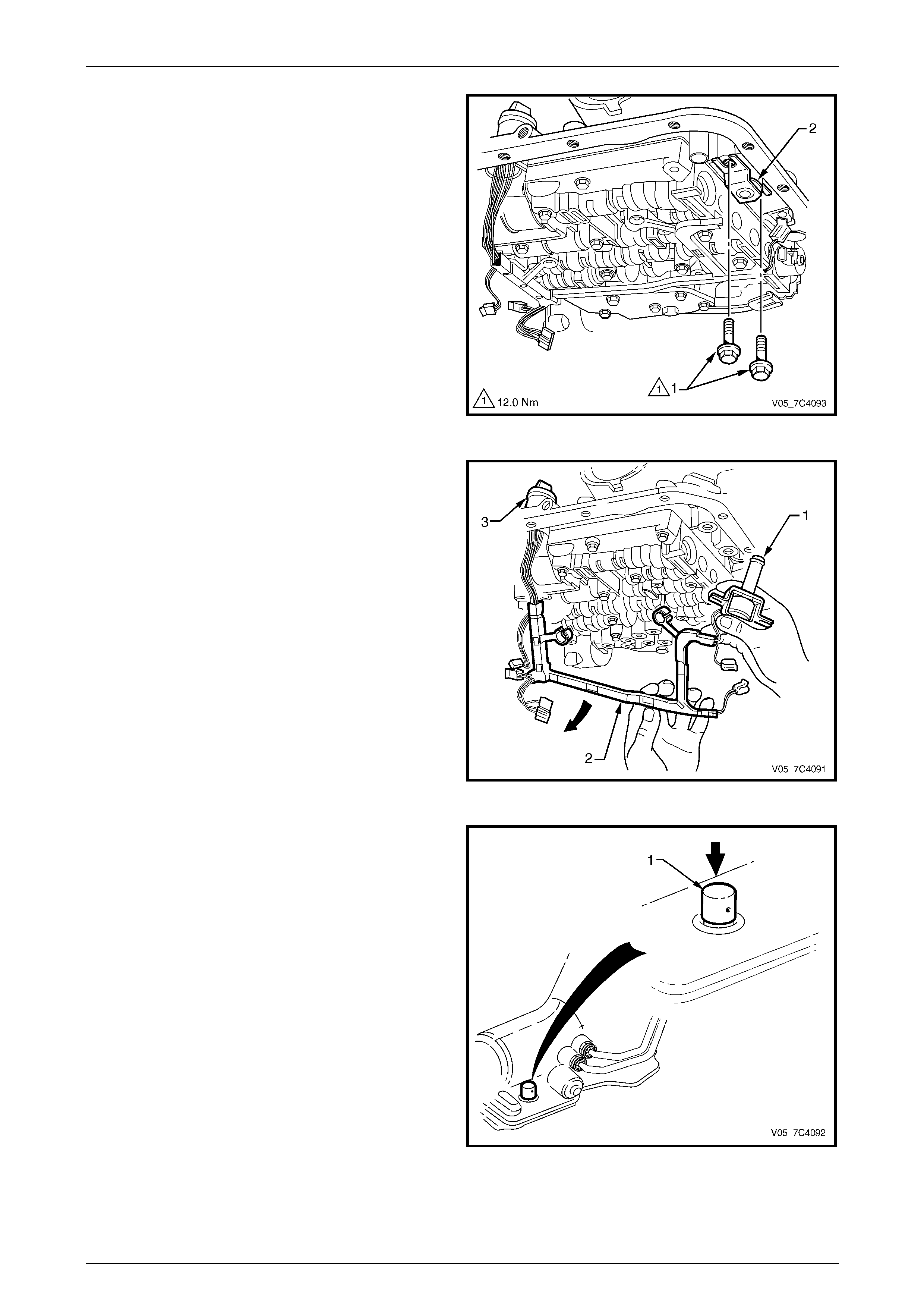
Automatic Transmission – 4L65E – On-vehicle Servicing Page 7D4–62
Page 7D4–62
6 Remove the two bolts (1) attaching the TCC solenoid
assembly (2) to the control valve body.
Figure 7D4 – 94
7 Withdraw the TCC solenoid as sembly (1) from the
control valve body (oil pump hous ing), remove and
discard the O-ring.
8 Lower the harness (2) and TCC solenoid, allow it to
hang from the pass-thru connector (3).
9 Remove the control valve bod y, refer to
3.20 Control Valve Body.
NOTE
This is necessary to provide clearance for the
pass-thru connector to be removed.
Figure 7D4 – 95
10 Lower the transmission to provide clearance between
the floor pan and the pass-thru connector located at
the right-hand rear of the transmission case.
11 Install the connector release, Tool No. 700-4208 (1)
over the pass-thru connector and us e hand force to
push the tool down compressing the four retainin g
tangs on the connector.
12 Pull the pass-thru connector free from the
transmission case and remove the control v alve b od y
harness and TCC solenoid assembly from the
transmission.
13 Remove the O-ring from the pass-thru connector and
discard.
Figure 7D4 – 96
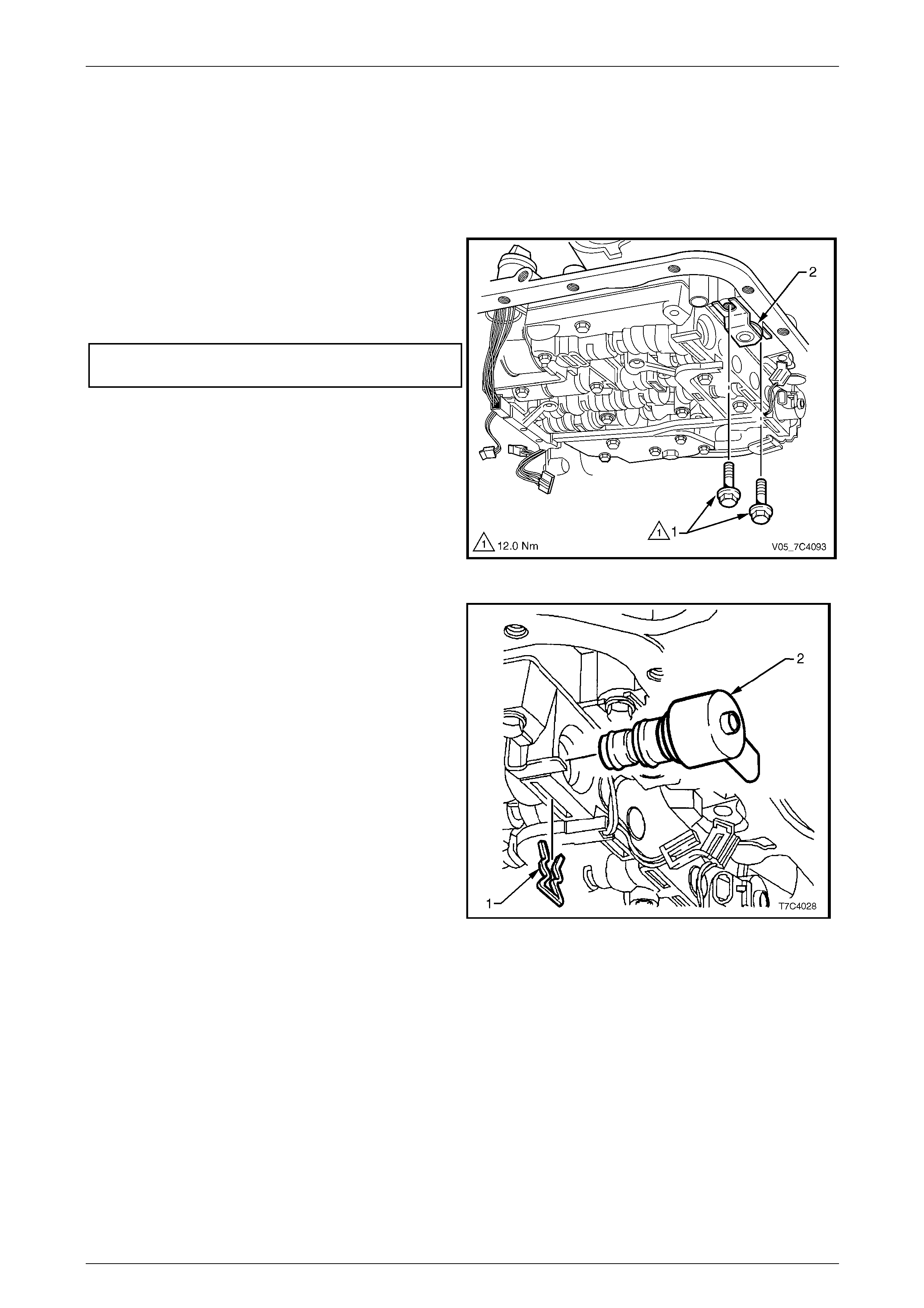
Automatic Transmission – 4L65E – On-vehicle Servicing Page 7D4–63
Page 7D4–63
Reinstall
1 Lubricate a new O-ring with petroleum jelly and fit it to the pass-thru connector.
2 Reinstall the pass-thru connector up through the hole in the transmission case pushing it in until all four r etain ing
tangs have emerged on the outside of the transmission case. Gently pull on the connector to check if engagement
is secured.
3 Reinstall the control valve body, refer to 3.20 Control Valv e Body.
4 Lubricate a new O-ring with petroleum jelly and fit it to
the TCC solenoid (2).
5 Reinstall the TCC solenoid assembly in the control
valve body , tighten the two attaching bo lts (1) to the
correct torque specification.
TCC solenoid attaching bolt
torque specification............................................12.0 Nm
Figure 7D4 – 97
6 Lubricate a new O-ring with petroleum jelly and fit it to
the TCC PWM solenoid (2).
7 Reinstall the TCC PWM solenoid in the control valve
body and secure it with the retaining clip (1).
Figure 7D4 – 98
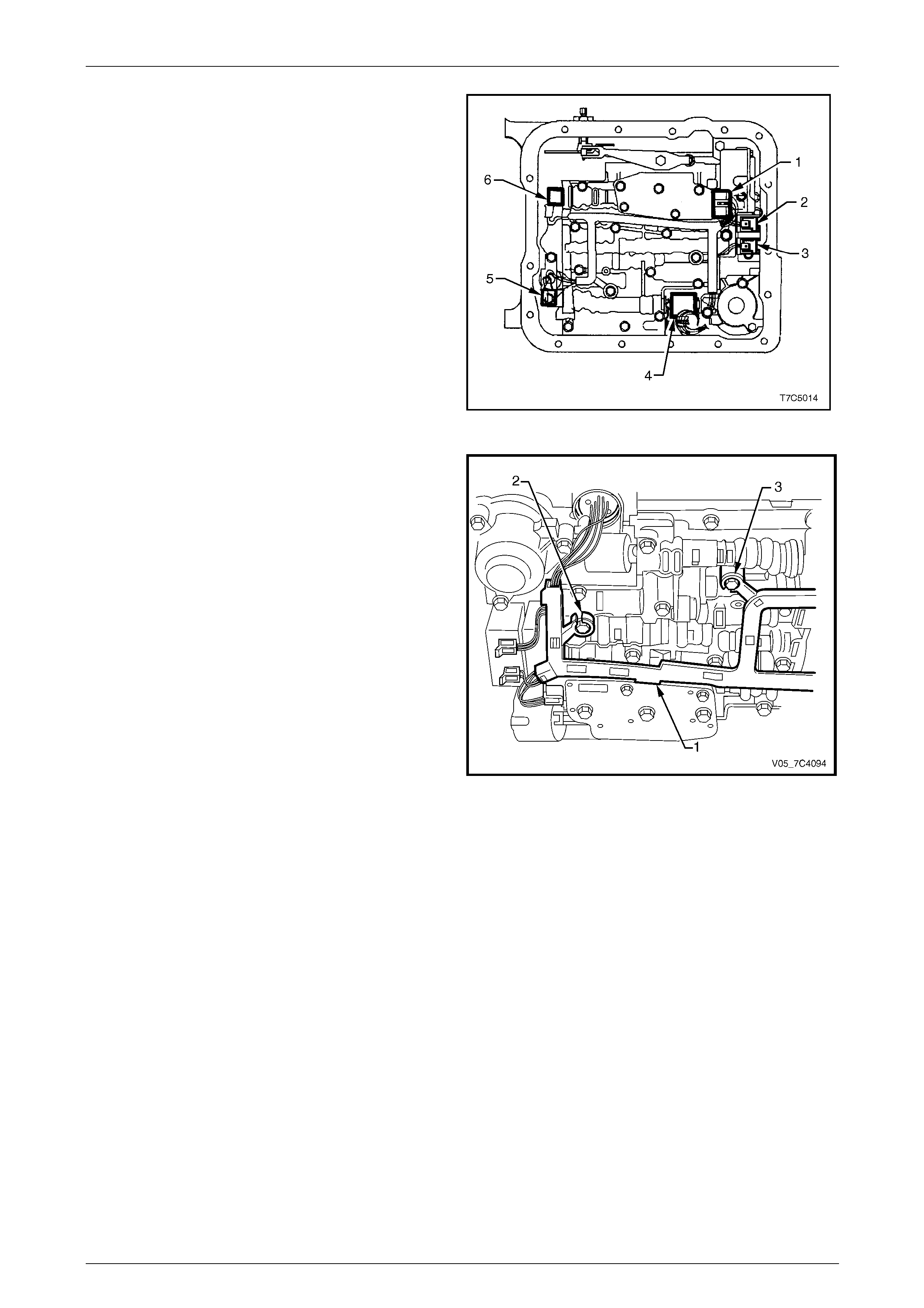
Automatic Transmission – 4L65E – On-vehicle Servicing Page 7D4–64
Page 7D4–64
8 Reconnect the control valve body harness connectors.
Connectors identification:
• Transmission Fluid Pressure (TFP) Manual
Valve Position Switch (1)
• 1 – 2 Shift Valve Solenoid A (2)
• 2 – 3 Shift Valve Solenoid B (3)
• Pressure Control Solenoid (PCS) (4)
• Torque Converter Clutch Pulse Width Modulated
(TCC PWM) Solenoid (5)
• 3 – 2 Control Solenoid (6).
Figure 7D4 – 99
9 Secure the harness frame to the control valv e body,
place the tab between the valve body and pressure
switch in location (1) and press the harness frame in
position on bolt bosses (2 and 3).
Figure 7D4 – 100
10 Reinstall the oil pan and filter and fill the transmission with the recommended automatic transmission fluid, refer to
3.1 Fluid Change and Filter Replacement.
11 Lower vehicle to the ground.
12 Road test until the transmission has reached operating temperature. Re-check the fluid l evel and for any fluid leaks
from the oil pan area, refer to 2.1 Transmission Fluid.
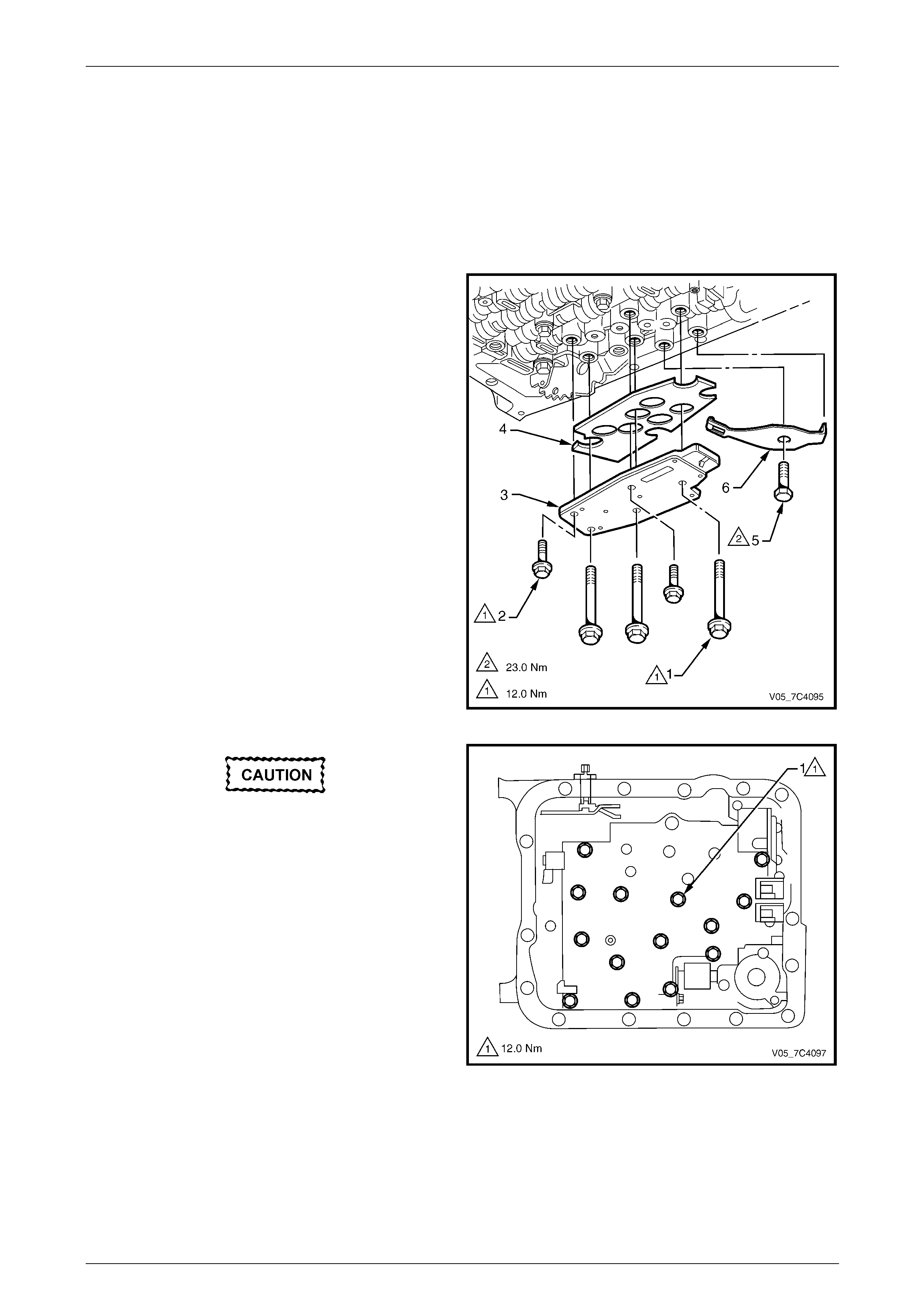
Automatic Transmission – 4L65E – On-vehicle Servicing Page 7D4–65
Page 7D4–65
3.20 Control Valve Body
LT Section No. —
Remove
1 Partially remove the control v alve b ody harness until it hangs from the pass-thru connector, refer to
3.19 Control Valve Body Harness.
2 Remove the three long bolts (1) and the two short
bolts (2) attaching the transmission fluid pressure
(TFP) manual valve position switch assembly (3),
remove the switch and discard the shield (4).
3 Remove the attaching bolt (5) and the manual detent
spring (6).
Figure 7D4 – 101
In the following procedure support the
control valve body before removing the last
bolt.
NOTE
The removal may be more manageable by
removing the bolts in a spiral pattern starting
from the outside, removing the centre bolt last.
4 Remove the fourteen remaining bolts (1) attaching the
control valve body.
Figure 7D4 – 102

Automatic Transmission – 4L65E – On-vehicle Servicing Page 7D4–66
Page 7D4–66
Keep the control valve body level when
lowering it to prevent the loss of the
checkballs located in the body passages.
5 Carefully lower the control valve body (1) from the
transmission case. As the valve body is being lowered,
rotate it slightly to disconnect the manual valve link (2)
from the manual valve (3) and remove the control
valve body.
6 Remove the manual valve link from the inner detent
lever (4).
Figure 7D4 – 103
Disassemble, Clean, Inspect and Reassemble
For these service operations, refer to Section 7D5 Automatic Transmission – 4L65E – Unit Repair.
Reinstall
Different bolt sizes are used to attach the control valve body and components, Figure 7D4 – 104 shows the location of
the attachment bolts with the letters referring to their dimensions.
NOTE
For clarity, the control valve body harness is not
shown in the illustration.
Figure 7D4 – 104
Legend
1 Control Valve Body
2 Torque Converter Clutch (TCC) Solenoid
3 Transmission Fluid Pressure (TFP) Manual Valve Position
Switch
4 Manual Detent Spring
5 1 – 2 Accumulator Cover
A Bolt M6 x 1.00 x 65.0
B Bolt M6 x 1.00 x 54.4
C Bolt M6 x 1.00 x 47.5
D Bolt M6 x 1.00 x 18.0
E Bolt M6 x 1.00 x 35.0
F Bolt M6 x 1.25 x 20.0
G Bolt M6 x 1.00 x 12.0
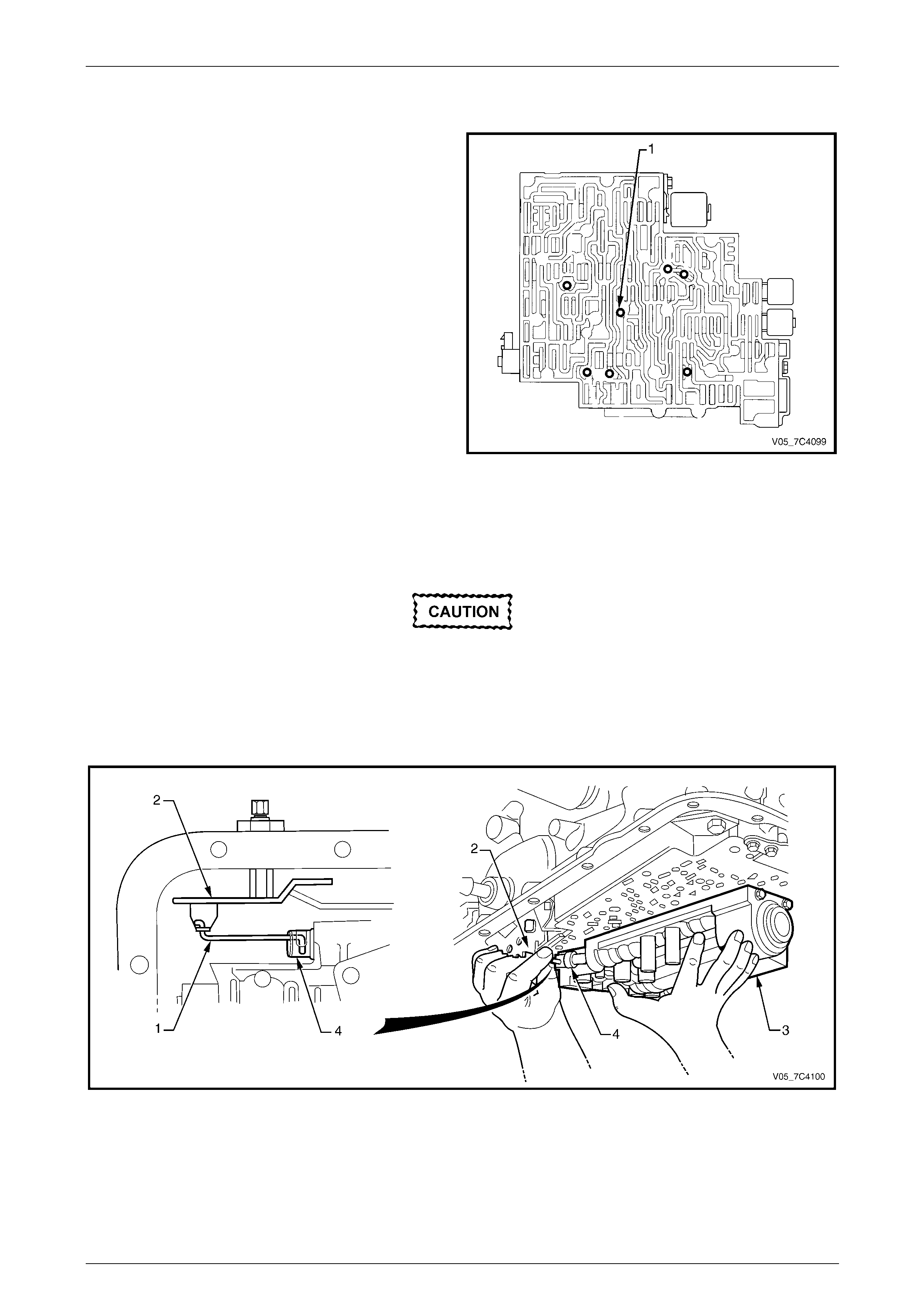
Automatic Transmission – 4L65E – On-vehicle Servicing Page 7D4–67
Page 7D4–67
1 Ensure the spacer plate gasket is in a satisfactory condition, replace as required, refer to
3.21 Spacer Plate, Check Balls, Filter Screens and 3 – 4 Accumulator.
2 If required, reinstall the seven checkballs (1) in the
control valve body securing them with petrole um jelly.
Figure 7D4 – 105
3 Reinstall the manual valve link (1) to the inner detent lever (2), refer to Figure 7D4 – 106.
4 While supporting the control valve b od y (3), rotate it slightly and connect the manual valve link with the manual
valve (4).
Take care not to damage the tw o filter screens
attached to the spacer plate during this
operation.
5 Position the manual valve forward to retai n the li nk connection and carefully raise the valve body into position.
6 Check if the manual valve link is correctly reinstalled in the detent lever and manual valve .
Figure 7D4 – 106
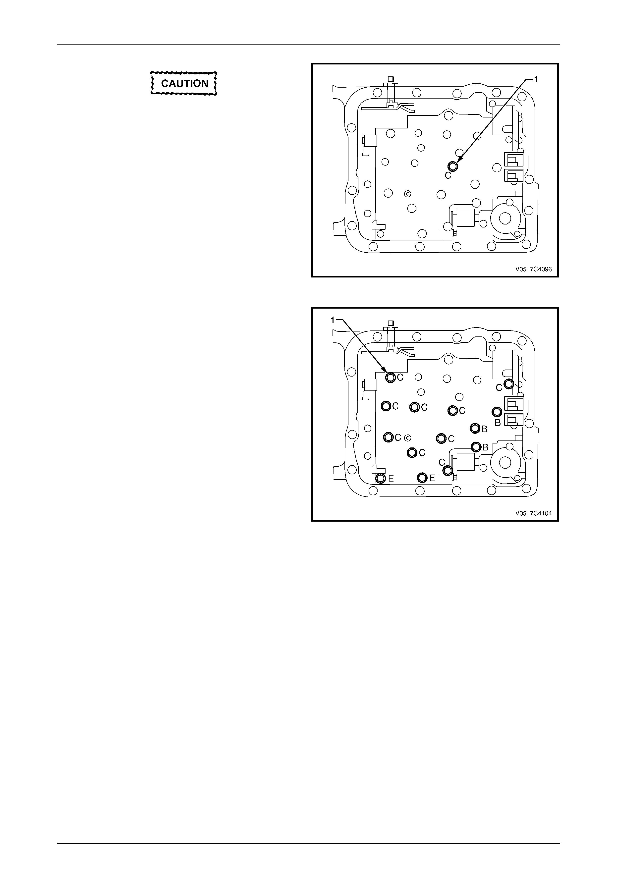
Automatic Transmission – 4L65E – On-vehicle Servicing Page 7D4–68
Page 7D4–68
When reinstalling the bolts throughout this
procedure, ensure to use the correct bolt
dimension in each location.
7 Reinstall one bolt (1) (M6 X 1. 0 X 47.5) hand tight in
the centre of the control valve body to hold it i n place,
at location C as shown.
Figure 7D4 – 107
8 Reinstall hand tight only, the remainder of the fourteen
bolts (1) attaching the control valve body directly.
NOTE
Refer to Figure 7D4 – 104 for each bolt
dimension and corresponding location.
Figure 7D4 – 108
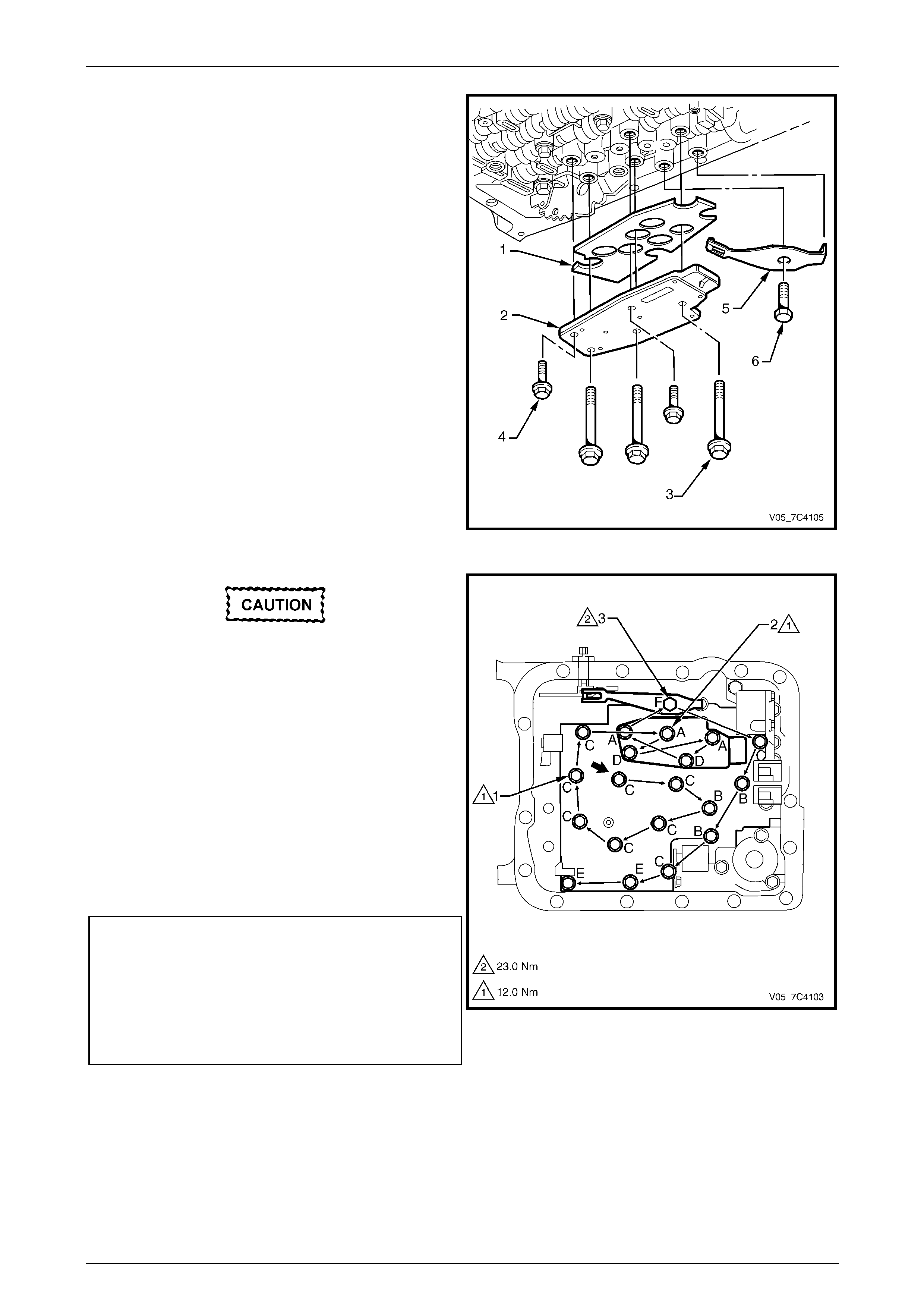
Automatic Transmission – 4L65E – On-vehicle Servicing Page 7D4–69
Page 7D4–69
9 Fit a new shield (1) to the transmission fluid pressure
(TFP) manual valve position switch (2) and reinstall to
the control valve body.
NOTE
Refer to Figure 7D4 – 104 for bolt dimensi on and
corresponding location.
10 Reinstall the three long bolts (3) and the two short
bolts (4) hand tight only.
11 Reinstall the manual d etent sprin g (5) and th e
attaching bolt (6) hand tight only.
Figure 7D4 – 109
The control valve body bolts must be
tightened in an outward spiral starting from
the centre. Failure to follow this pattern may
distort the valve body causing the valves to
jam in their bores.
12 Follow the sequence starting from the centre as shown
by the arrows to tighten the following bolts to the
correct torque specification:
• fourteen bolts (1) attaching the control valve
body,
• five bolts (2) attaching the transmission fluid
pressure (TFP) manual valve position switch and
• one bolt (3) attaching the manual detent spring.
Control valve body attaching bolt
torque specification............................................12.0 Nm
Transmission fluid pressure (TFP)
manual valve position switch attaching
bolt torque specification.....................................12.0 Nm
Manual detent spring attachin g bolt
torque specification............................................23.0 Nm
13 Reinstall the control valve body harness , refer to
3.19 Control Valve Body Harness.
Figure 7D4 – 110
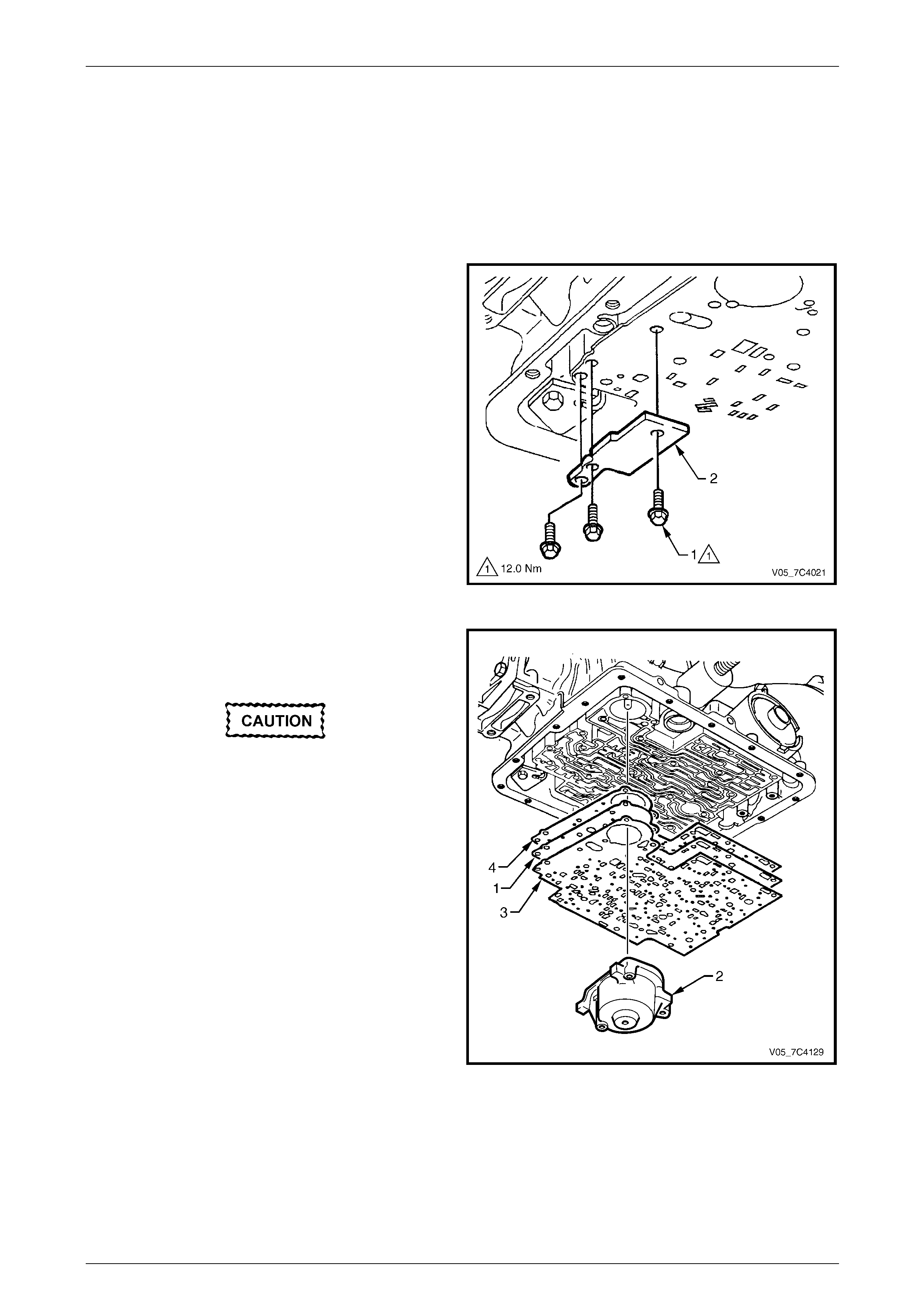
Automatic Transmission – 4L65E – On-vehicle Servicing Page 7D4–70
Page 7D4–70
3.21 Spacer Plate, Check Balls, Filter Screens
and 3 – 4 Accumulator
LT Section No. —
Remove
1 Remove the control valve bod y, refer to 3.20 Control Valve Body.
2 Remove the three attaching bolts (1) and the plate (2)
supporting the spacer plate.
Figure 7D4 – 111
3 While supporting the spacer plate (1), carefully remove
the 1 – 2 accumulator assembly (2), refer to
3.18 1 – 2 Accumulator Assembly.
As the spacer plate and gaskets are lowered
from the transmission, a check ball may
drop. Do not lose the check ball.
4 Remove the two gaskets (3 and 4) and the s pacer
plate from the transmission case.
Figure 7D4 – 112
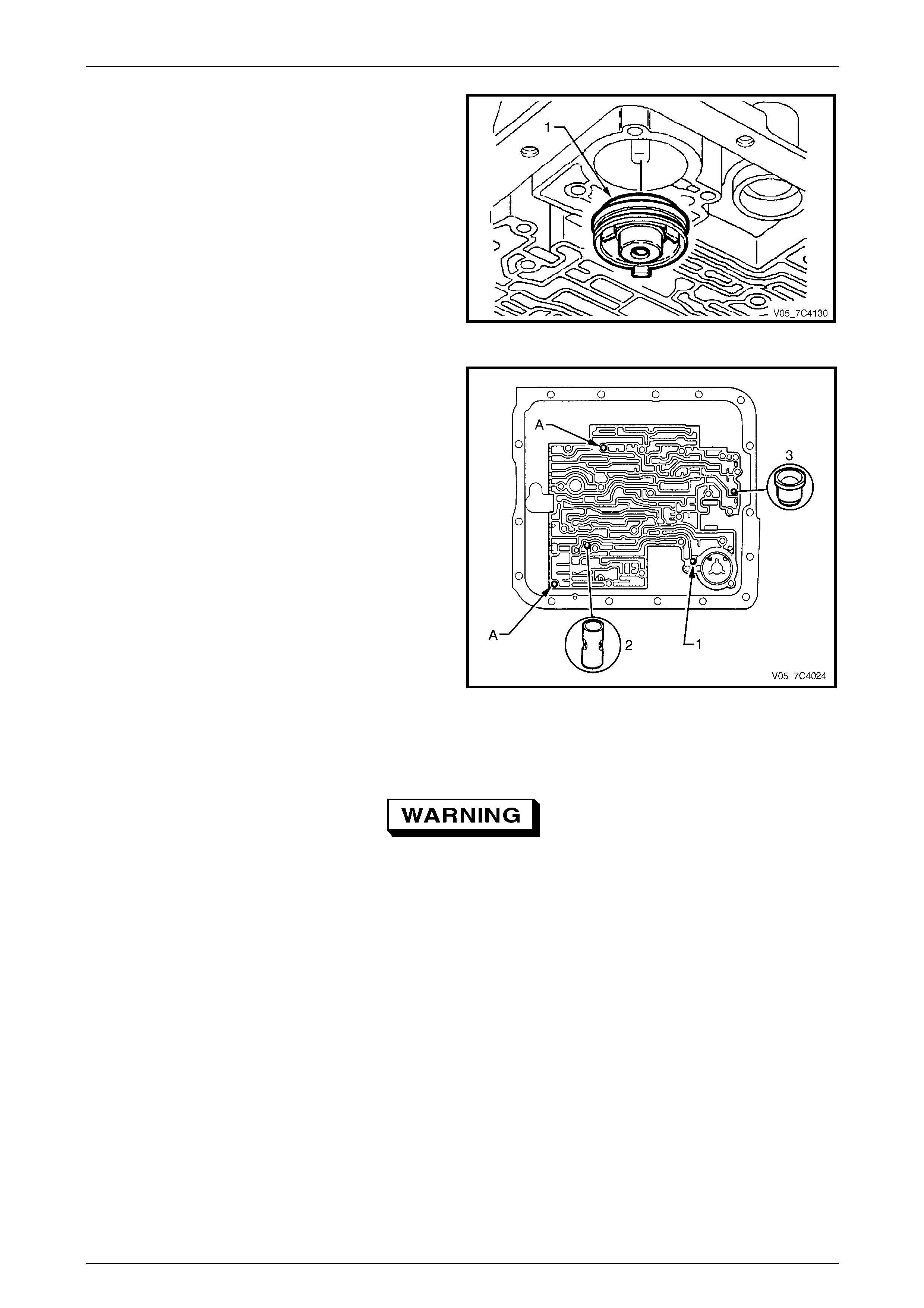
Automatic Transmission – 4L65E – On-vehicle Servicing Page 7D4–71
Page 7D4–71
5 If required, use snap ring plier s to rotate and pull the
3 – 4 accumulator piston (1) to remove it from the
transmission case. Remove and disc ard the piston
seal.
Figure 7D4 – 113
6 Remove the check-ball (1) if not previously dropped.
Remove the 3rd accumulator check ball assembly (2),
the orifice cup plug (3) and the guide pins (A) from the
transmission case.
Figure 7D4 – 114
Clean and Inspect
To avoid personal injury, wear safety glasses
and gloves when using compressed air and
cleaning fluids.
1 Wash all components in a commercially available cleaning fluid and blow dry using compressed air.
2 Inspect the components for the following:
• piston for porosity,
• ring groove or pin hole damage,
• spring for distortion or damage,
• accumulator bore for wear or damage and
• spacer plate, filter screens and check balls for damage.
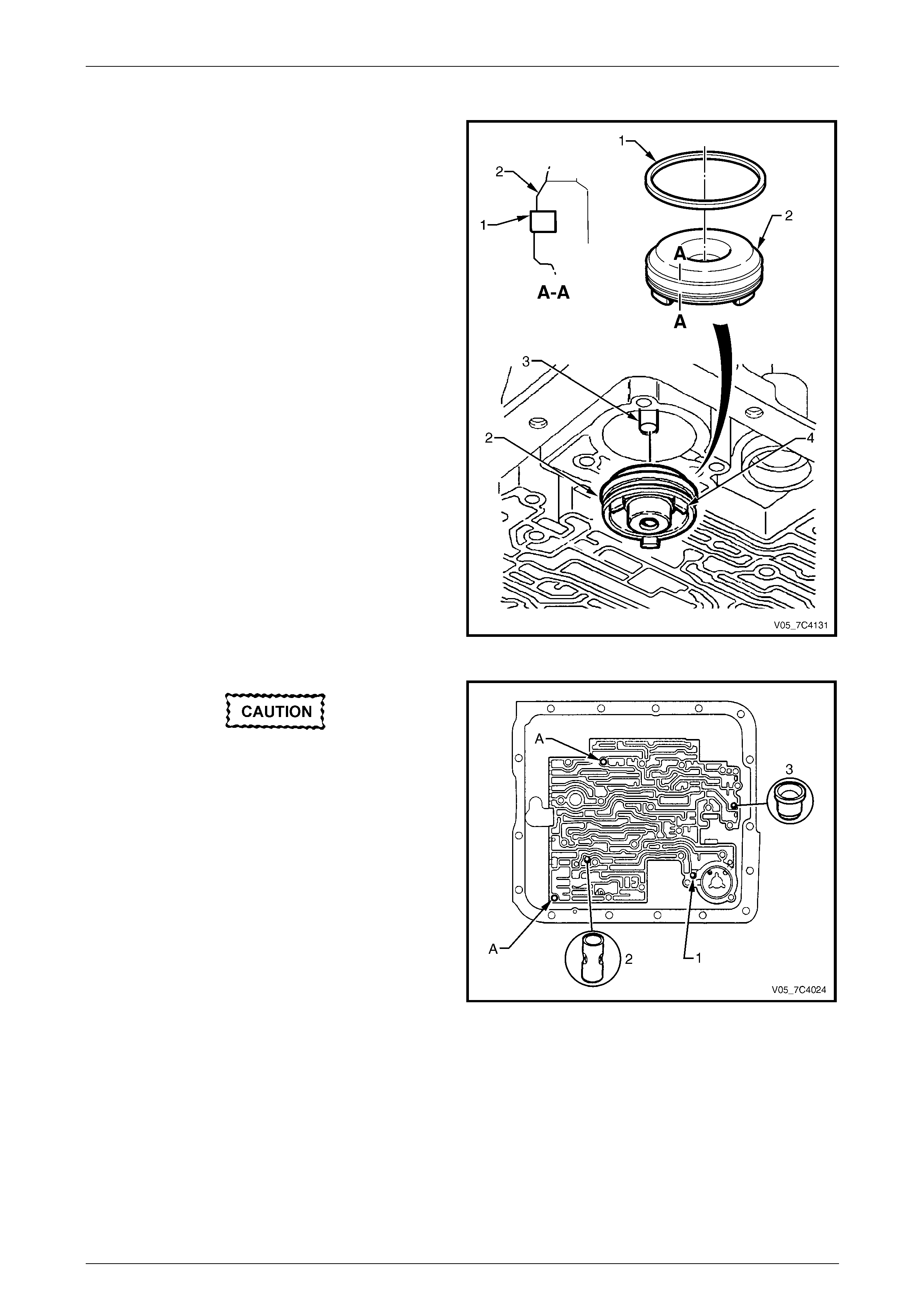
Automatic Transmission – 4L65E – On-vehicle Servicing Page 7D4–72
Page 7D4–72
Reinstall
1 Lubricate a new seal (1) with petroleum jelly and install
it to the 3 – 4 accumulator piston (2).
2 Reinstall the piston onto the pin (3). The piston side
with the three lugs (4) must face out of the bore.
Figure 7D4 – 115
Ensure the guide pins are fully installed with
no thread visible. Otherwise the spacer plate
gasket could be caught in the thread during
installation, resulting in incorrect alignment.
4 Reinstall the guide pins (A) at the correct locations in
the transmission case.
5 Reinstall the check ball (1) in the transmission case
using a small amount of petroleum je lly to hold it in
place.
6 Reinstall the 3rd accumulator check ball assembly (2)
and the orifice cup plug (3) in the transmission case.
Figure 7D4 – 116
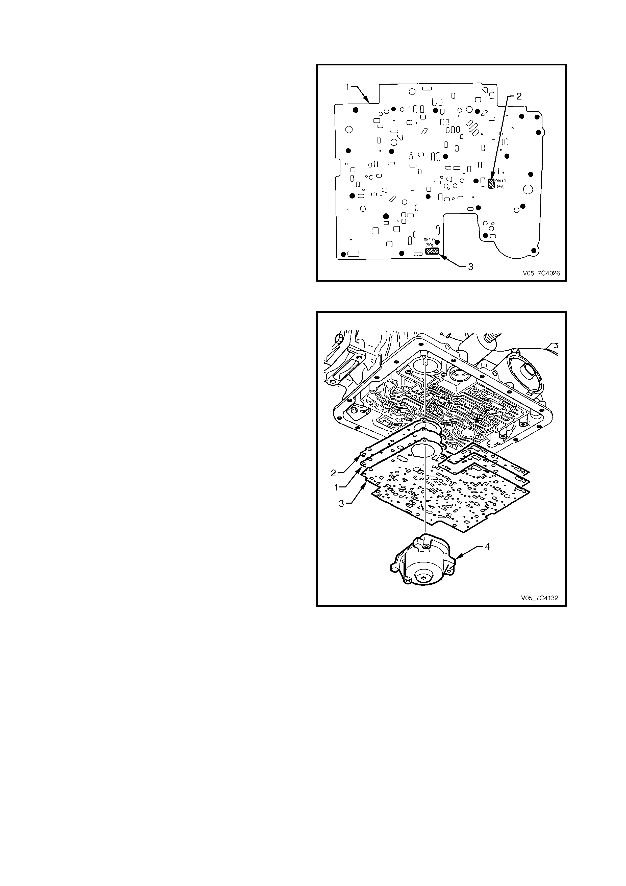
Automatic Transmission – 4L65E – On-vehicle Servicing Page 7D4–73
Page 7D4–73
7 If a new spacer plate (1) is installed, it is necessary to
fit two filter screens (2 and 3) to the spacer plate.
Figure 7D4 – 117
NOTE
When installing the spacer plate locate the
gaskets as follows:
• The gasket (2) marked CA is fitted between
the spacer plate and the transmission case.
• The gasket (3) marked VB is fitted between
the spacer plate and the control valve body.
8 Reinstall the spacer plate (1) wit h the new
gaskets (2 and 3) smeared with petroleum jelly. Hold
the spacer plate in place until the 1 – 2 accumulator is
reinstalled.
9 While supporting the spacer plate, carefully reinstall
the 1 – 2 accumulator assembly (4), refer to
3.18 1 – 2 Accumulator Assembly.
Figure 7D4 – 118
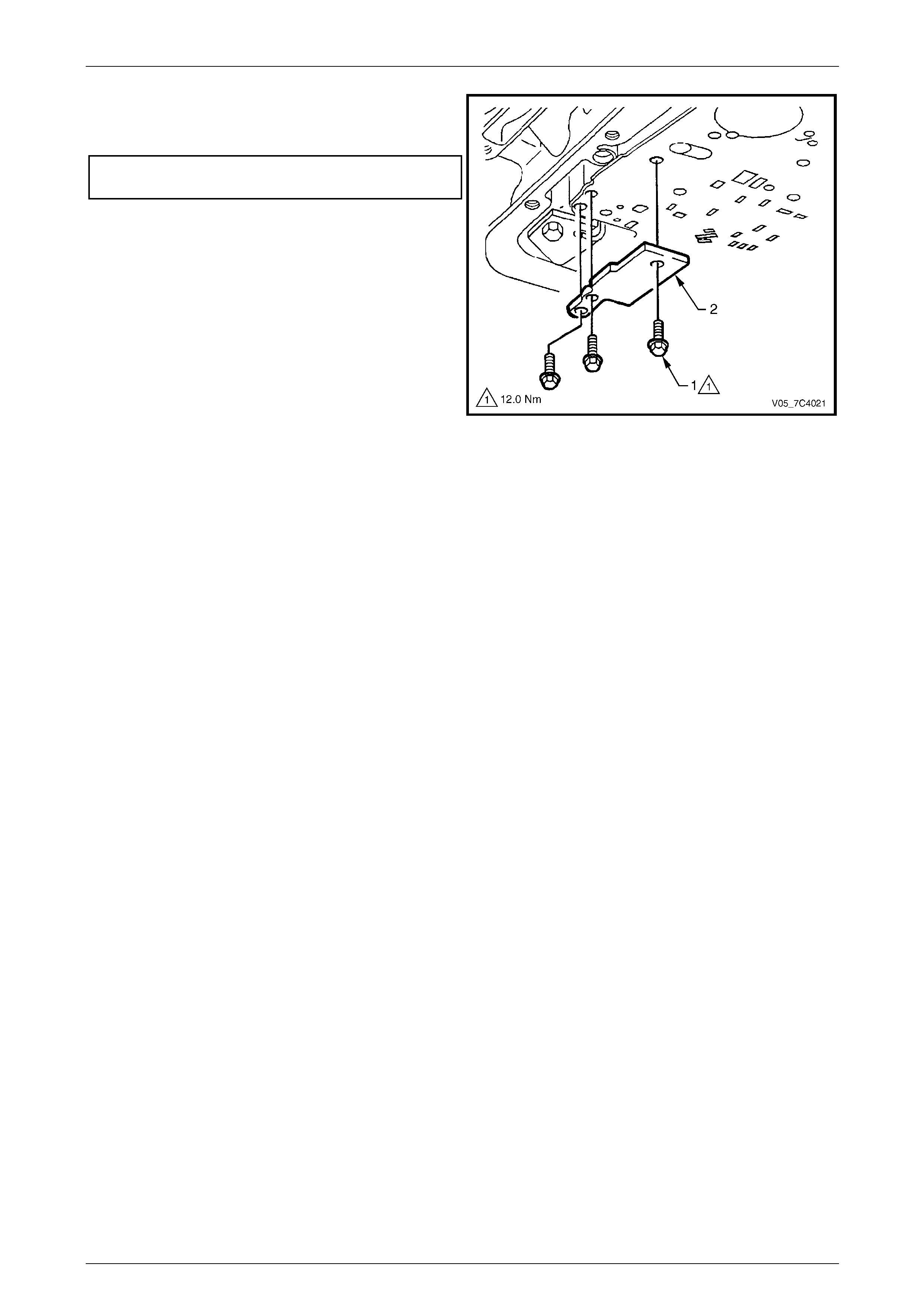
Automatic Transmission – 4L65E – On-vehicle Servicing Page 7D4–74
Page 7D4–74
10 Reinstall the plate (2) supp orting the spacer plate and
tighten the three attaching bolts (1) to the correct
torque specification.
Spacer plate support plate attaching
bolt torque specification.....................................12.0 Nm
11 Reinstall the control valve body, refer to
3.20 Control Valve Body.
12 Reinstall the Oil pan and filter and fill the transmission
with the recommended automatic transmissi on fluid,
refer to 3.1 Fluid Change and Filter Replacement.
13 Lower vehicle to the ground.
14 Road test until the transmission has reached operating
temperature. Re-check the fluid level an d for any fluid
leaks from the oil pan area, refer to
2.1 Transmission Fluid.
Figure 7D4 – 119
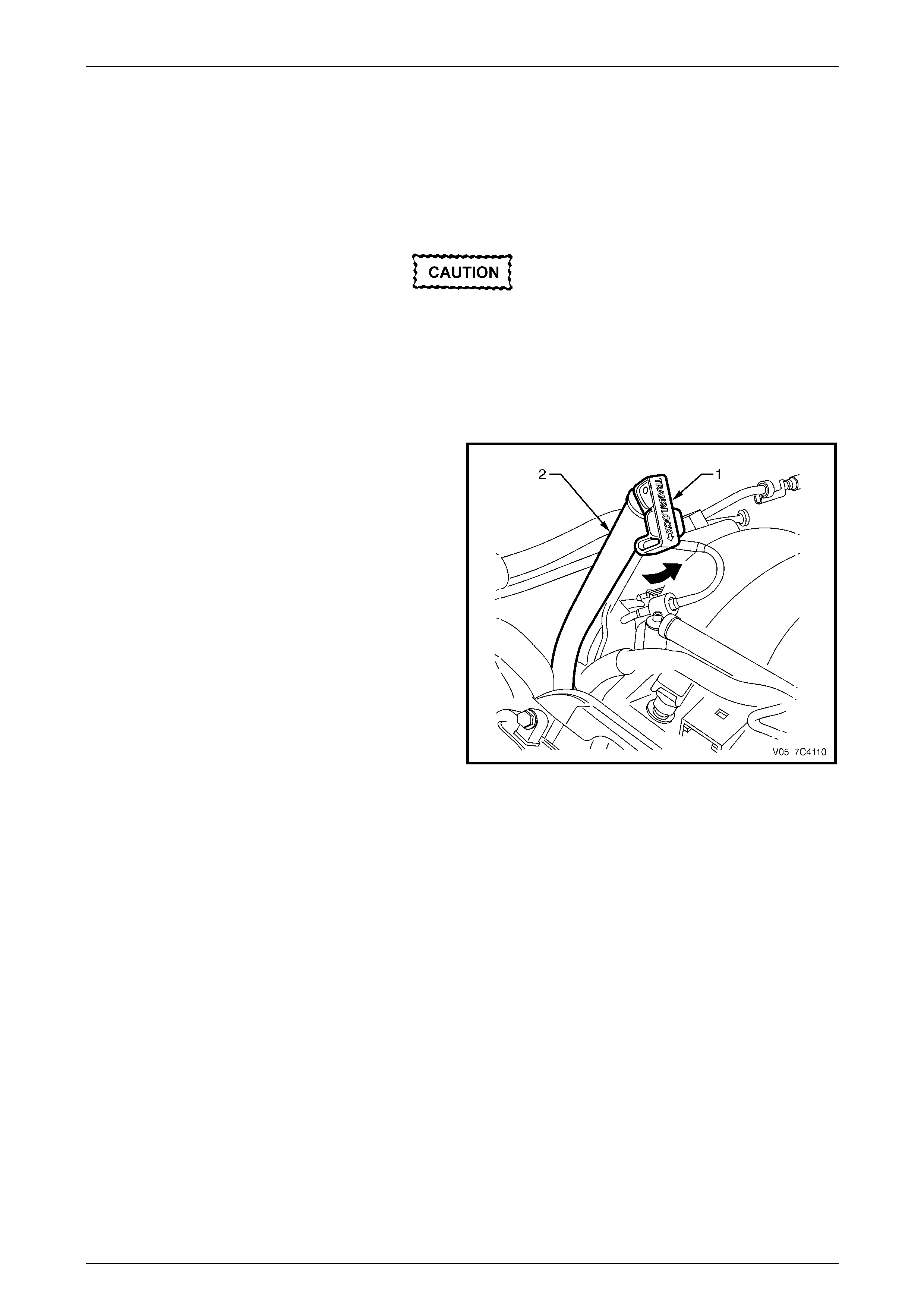
Automatic Transmission – 4L65E – On-vehicle Servicing Page 7D4–75
Page 7D4–75
3.22 Filler Tube and Breather Hose
LT Section No. — 04–010
Remove
Disconnection of the battery affects certain
vehicle electronic systems. Refer to
Section 00 Warnings, Cautions and Notes
before disconnecting the battery.
1 Disconnect the battery ground lead.
2 Remove the right-hand dress cover from the engine, refer to Section 6A3 Engine Mechanical – GEN III V8.
3 Release the lock down lever (1) and remove the
transmission fluid level indica tor from the filler tube (2).
Figure 7D4 – 120
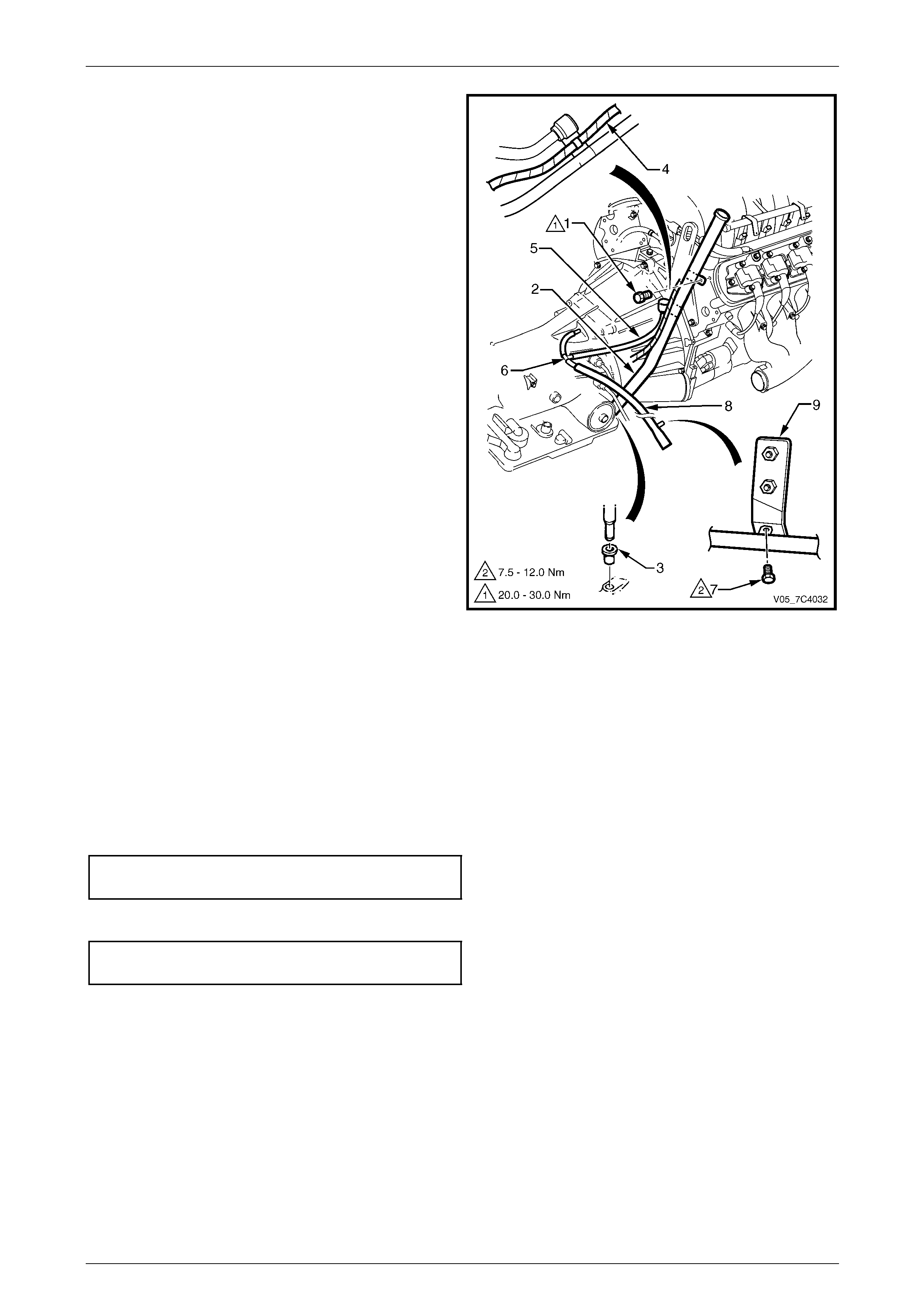
Automatic Transmission – 4L65E – On-vehicle Servicing Page 7D4–76
Page 7D4–76
4 Remove the bolt (1) attaching the filler tube (2), to the
rear of the right-hand cylinder head.
5 Using a twisting and pullin g motion, remove the filler
tube from the seal (3) in the transmission case.
6 Lower the filler tube enough to unclip the harness (4)
and breather hose (5) from the filler tube lo wer
bracket.
7 Remove the filler tube from the engine compartment.
8 Remove the filler tube seal from the transmis s ion case
and discard.
9 If the breather hose needs to be replaced pr oceed as
follows:
a Remove the transmission support and lower the
rear of the transmission sufficiently to get access
to the breather hose, refer to:
• 3.12 Transmission Support and Mount,
Except Coupe and AWD or
• 3.13 Transmission Support and Mount,
Coupe or
• 3.16 Transmission Support and Adaptor
Housing, AWD
b Disconnect the breather hose from the T-joint (6)
and the top of the transmission case and
remove.
c If required, remove the bolt (7) attaching the vent
pipe (8) to the floor pan bracket (9), disconnect
from the T-joint and remove the vent pipe.
Figure 7D4 – 121
Reinstall
Reinstallation of the transmis s ion filler tube and/or the breather hose is the reverse of the removal procedure, noting the
following:
1 Smear a new filler tube seal with clean transmission fluid and fit it to the transmission case.
2 Ensure the transmission breather hose and the harness are secured to the filler tube lower bracket.
3 Tighten the bolt attaching the filler tub e br acket to the correct torque specification.
Filler tube bracket attaching bolt
torque specification.................................20.0 – 30.0 Nm
4 If required, tighten the bolt attaching the ve nt pipe to the flo or pan bracket to the correct torque specification.
Vent pipe attaching bolt
torque specification...................................7.5 – 12.0 Nm
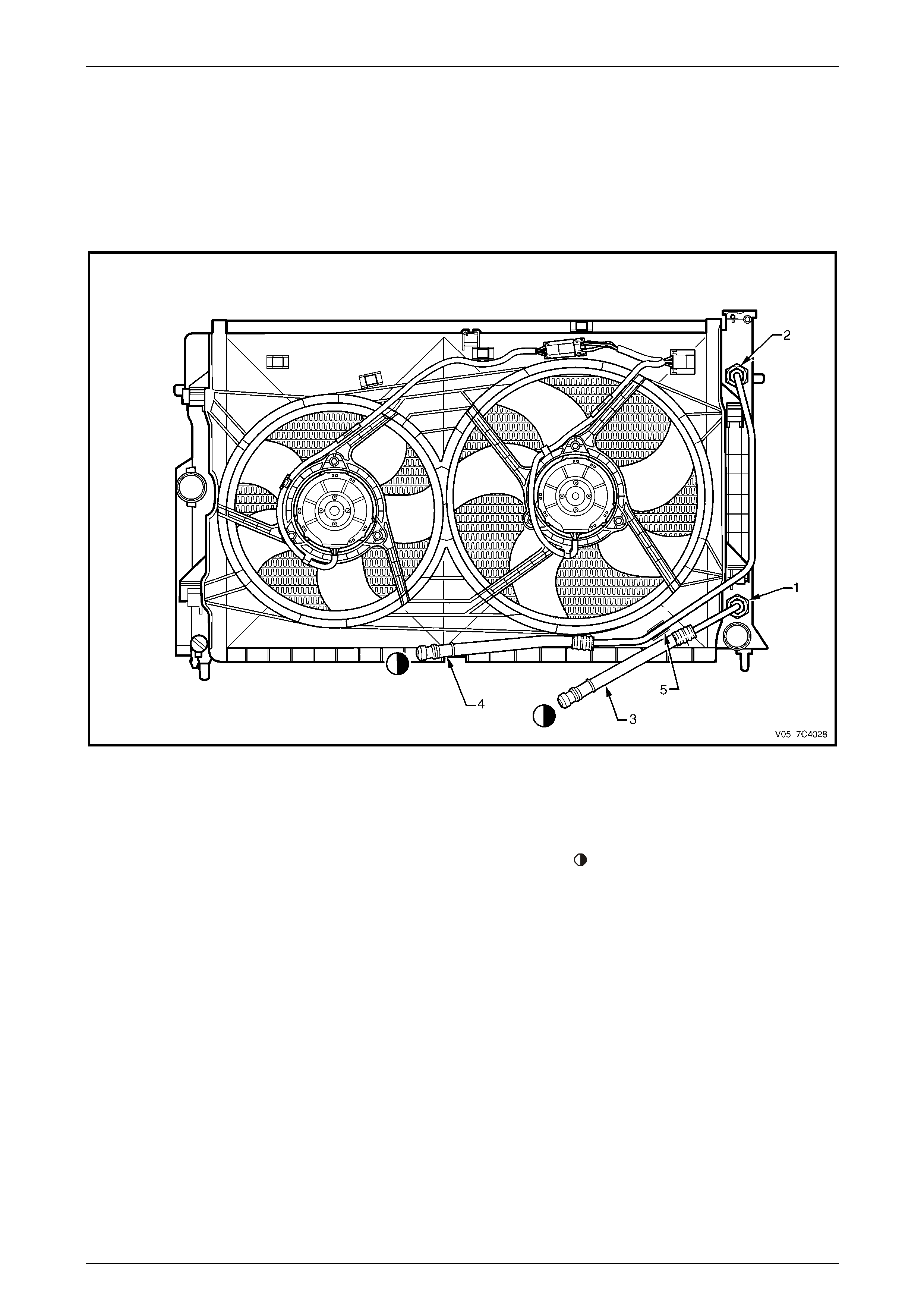
Automatic Transmission – 4L65E – On-vehicle Servicing Page 7D4–77
Page 7D4–77
3.23 Transmission Cooler Lines and Hoses
LT Section No. — 04–150
Arrangement
Radiator
Figure 7D4 – 122
Legend
1 Radiator Cooler Inlet Fitting
2 Radiator Cooler Outlet Fitting 3 Radiator Cooler Inlet Hose / Line
4 Radiator Cooler Outlet Hose / Line 5 Cooler Outlet Hose / Line Attaching Clip
To Transmission Fluid Lines
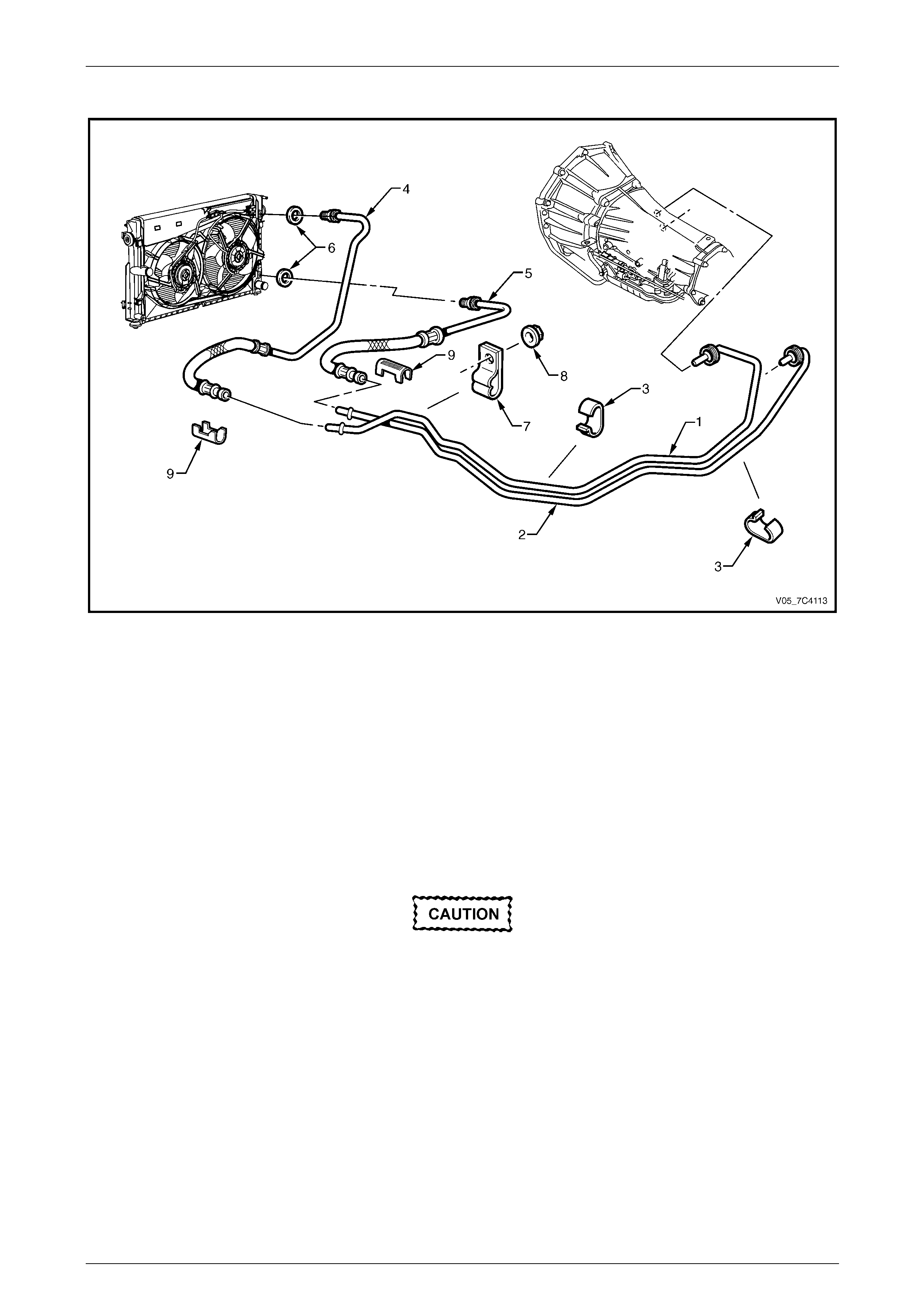
Automatic Transmission – 4L65E – On-vehicle Servicing Page 7D4–78
Page 7D4–78
Fluid Cooler Lines
Figure 7D4 – 123
Legend
1 Transmission Fluid Inlet Line
2 Transmission Fluid Outlet Line
3 Clips – Transmission Fluid Lines
4 Radiator Cooler Outlet Hose / Line
5 Radiator Cooler Inlet Hose / Line
6 Sealing Washers
7 Clamp – Transmission Fluid Lines
8 Attaching Nut
9 Verifier Clip
Radiator Cooler Hoses / Lines
Remove
1 Place a suitable sized drip tra y underneath the connectors.
Mark the flexible hose to the transmission
fluid line prior to removal to ensure correct
orientation during reassembly.
2 While holding the appropriate radiator cooler fitting (1) with a spanner, remove the corresponding cooler hose / line
flare nut (2) with a second spanner, refer to Figure 7D4 – 124.
3 Remove the sealing washer (3) and discard.
4 Plug the radiator cooler and cool er hose / line fittings to prevent fluid loss and contamination.
5 If removing the outlet cooler hose / line (4), unclip it from the radiator fan shroud (5).
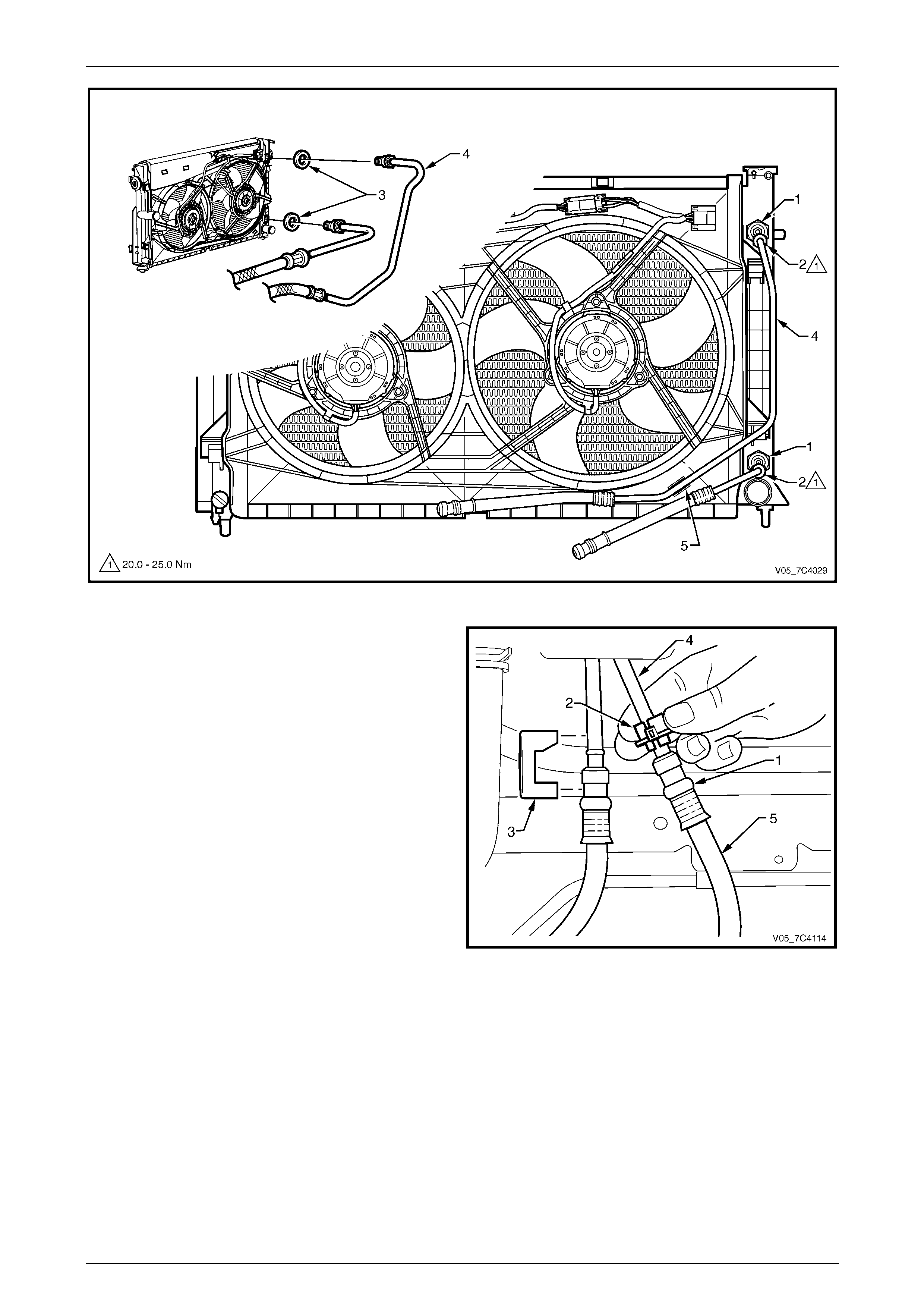
Automatic Transmission – 4L65E – On-vehicle Servicing Page 7D4–79
Page 7D4–79
Figure 7D4 – 124
6 Within the engine bay, disc onnect the radiator cooler
hose / line quick-connect fitting (1) usin g the release
tool, Tool No. AU525 (2), as follows:
a Remove the verifier clip (3) from the quick-
connect fitting.
b Open the release tool, place it and close it over
the transmission fluid line (4) to be disconnected,
on the radiator end.
c While pushing the release too l to wards the
quick-connect fitting, pull back the radiator cooler
flexible hose (5) to release the connection.
d Separate the cooler flexible hose from the
transmission fluid line and plug the openings to
prevent fluid loss and/or contamin ation.
7 Remove the radiator cooler hose / line assembly from
the engine compartment.
8 If required, repeat the procedure to remove t he
remaining radiator cooler hose / line. Figure 7D4 – 125
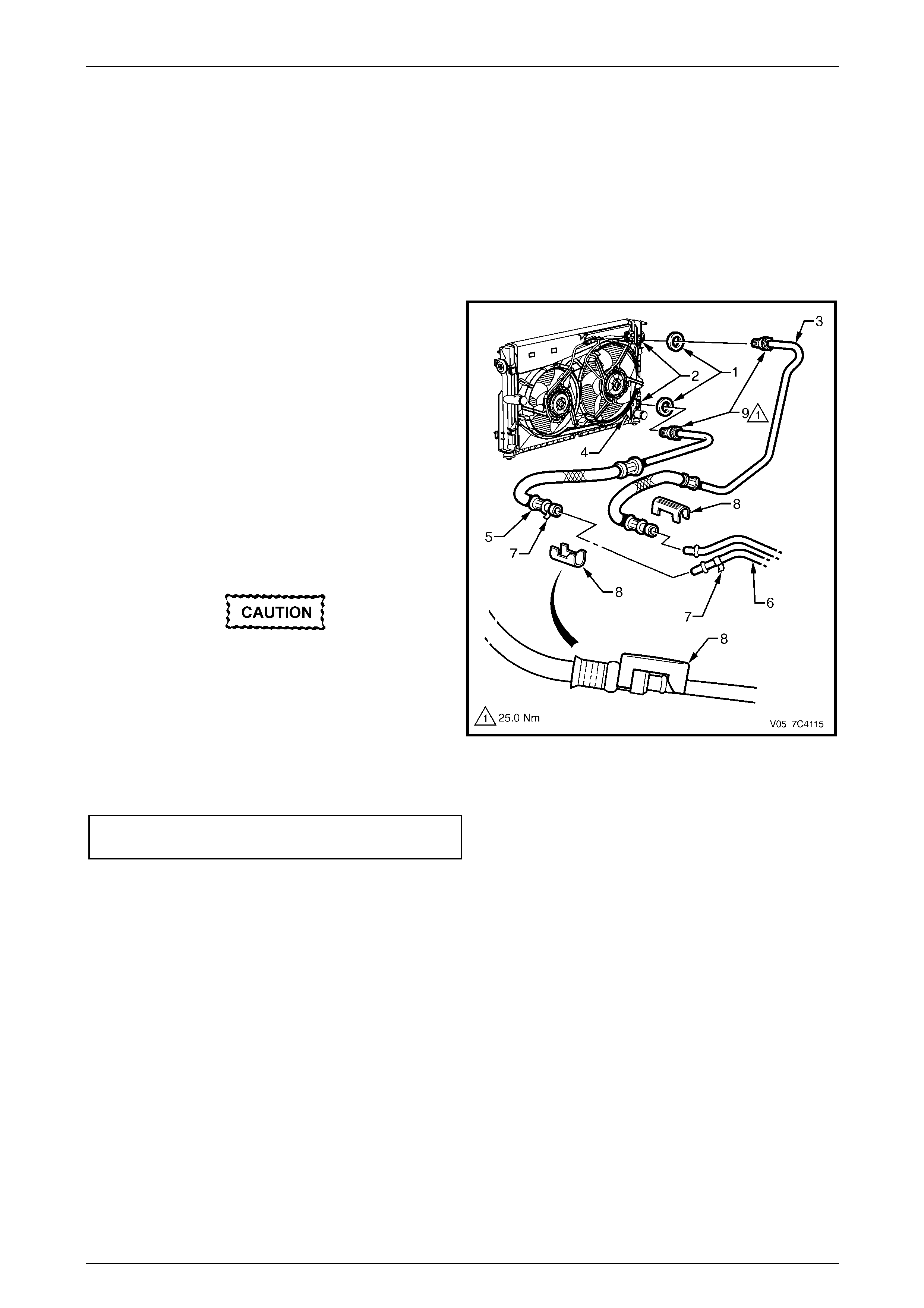
Automatic Transmission – 4L65E – On-vehicle Servicing Page 7D4–80
Page 7D4–80
Reinstall
NOTE
The flexible hose is permanently fitted to the line
leading to the radiator cooler. If the flexible hose
requires replacement a complete hose / line
assembly must be fitted.
1 Remove the plugs from the transmission fluid line and radiator cooler hose / line fittings and wipe all exposed parts
clean.
2 Fit a new sealing washer (1) to the cooler line and
reinstall the line to the radiator cooler fitting (2), do not
tighten at this stage.
3 When reinstalling the outlet cooler hose / line (3), clip it
to the radiator fan shroud (4).
NOTE
The radiator cooler inlet flexible hose quick-
connect fitting (5) and the corresponding
transmission fluid outlet line (6) have each a
white tag (7) to match them on reassembly.
4 Smear the transmission fluid line front fitting with clean
transmission fluid and push the quick-conne c t fitting to
connect the radiator cooler hose / line.
If the verifier clip does not fit, the quick-
connect fitting is not engaged, rectify as
required.
5 As a security check, gently pull on the conn ector to
ensure correct engagement and rei nstall th e verifier
clip (8) to the quick-connect fitting and fluid line.
6 Tighten the flare nut (9) attaching the radiator cooler
hose / line to the correct torque specification.
Radiator cooler hose / line
flare nut torque specification...................20.0 – 25.0 Nm
Figure 7D4 – 126
7 Check the orientation marks done on removal, ensuring there is no fouling of the hose / line and the routeing is
correct, rectify as required.
8 If required, repeat the procedure to reinstall the remaining radiator cooler hose / line.
9 If required, top up the transmission fluid level (cold).
10 Start the engine and check for any fluid leak at the fittings. If a leak is found, stop the engine and rectify the leak.
11 Check and top up the transmission fluid to the correct level as required, refer to 2.1 Transmission Fluid.
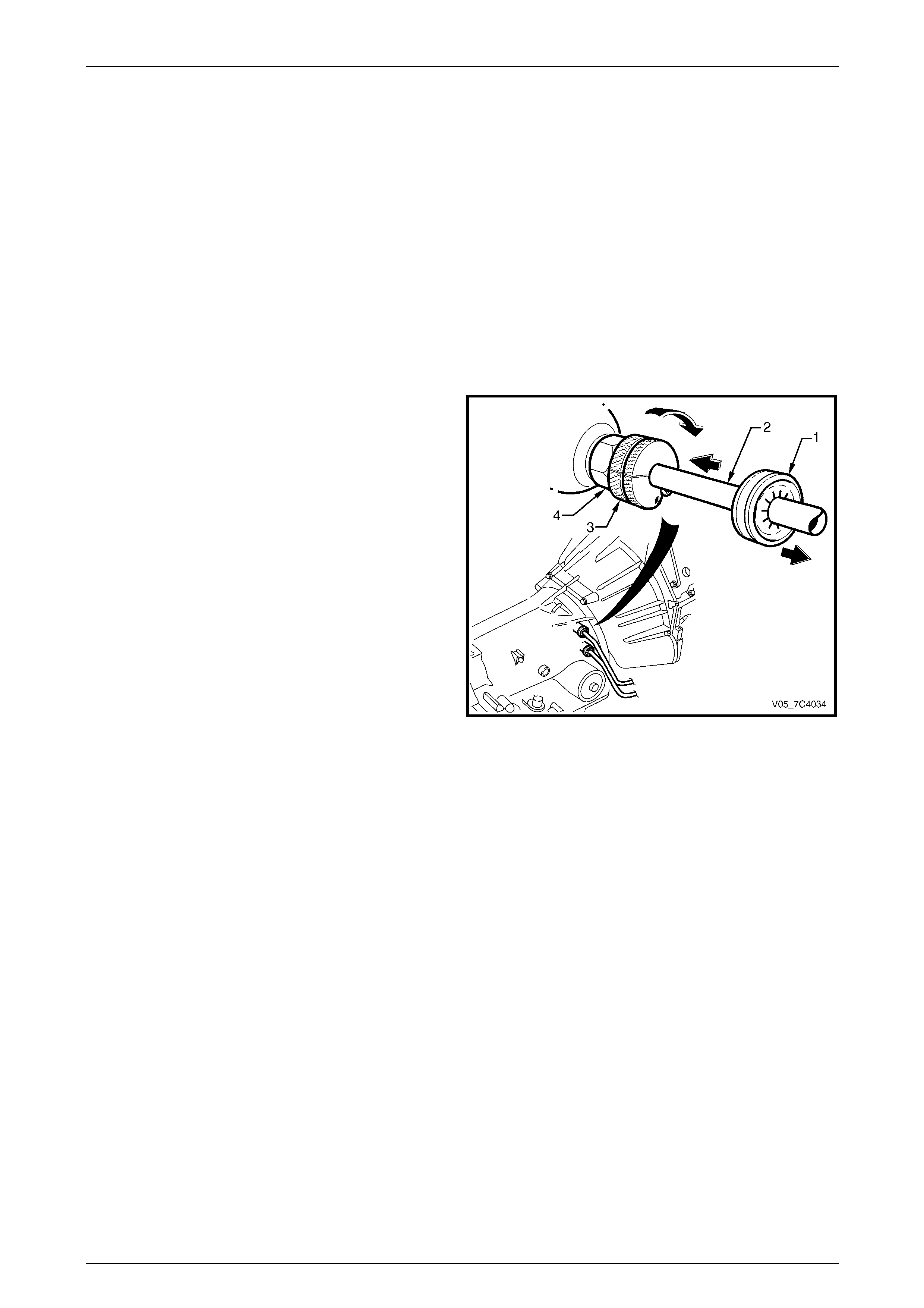
Automatic Transmission – 4L65E – On-vehicle Servicing Page 7D4–81
Page 7D4–81
Transmission Fluid Lines
Remove
1 Disconnect the radiator cooler hose / line fro m the transmission flu id lines as described in this Section,
refer to Radiator Cooler Hoses / Lines.
2 Remove the transmission support, refer to:
• 3.12 Transmission Support and Mount, Except Coupe and AWD, or
• 3.13 Transmission Support and Mount, Cou pe, or
• 3.16 Transmission Support and Adaptor Ho using, AWD.
3 Carefully lower the rear of the transmission sufficiently to get access to the fluid lines.
4 Place a suitable sized drip tray underneath the transmission.
5 With the rear of the transmission lowered, disconnect
the fluid lines from the transmission, as follows:
a Pull back the verifier disc (1) to release it and
slide it back along the fluid line (2).
b Open the release tool, Tool No J-41623-B (3),
slip it over the fluid line to be disconnected from
the transmission, ahead of the verifier disc.
c Slide the release tool along the fluid line and
engage it with the quick-connect fitting (4).
d While pushing in wards, rotate clockwise the
release tool about one sixth of a turn to release
the spring clip holding the fluid line.
e With the release tool held in this position, pull
back on the fluid line to releas e it.
f Plug all openings to prevent fluid loss and/or
contamination.
g Repeat this process with the remainin g fluid line.
NOTE
If the spring clip and/or O-ring seal in the quick-
connect fitting is damaged during the removal
process, the complete fitting must be replaced.
Figure 7D4 – 127
6 Remove the nut (1) attaching the bracket (2) to the right hand side of the engine and remove the two fluid lines (3)
from the vehicle, refer to Figure 7D4 – 128.
7 As required, separate the two fluid lines by removing the bracket and the two clips (4).
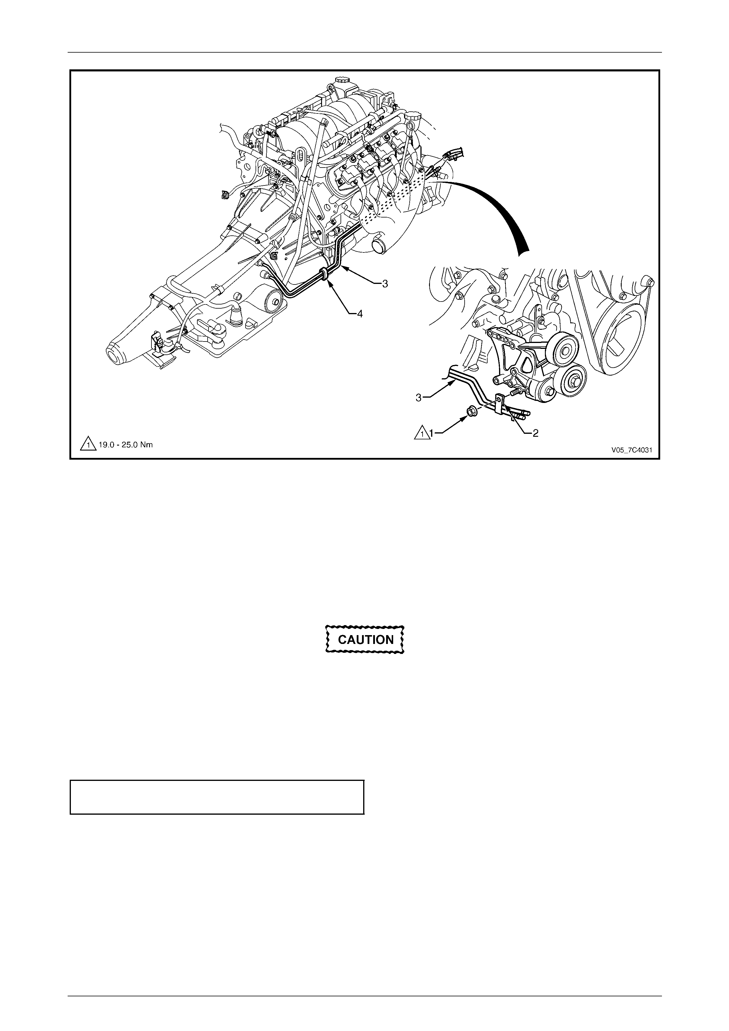
Automatic Transmission – 4L65E – On-vehicle Servicing Page 7D4–82
Page 7D4–82
Figure 7D4 – 128
Reinstall
1 Ensure the spring clip and/or O-ring seal in e ach qu ick-conn ect fitting is not damag ed, replace the complete fitting if
required.
2 As required, fit the bracket (2) and the two clips (4) to the transmission fluid lines, refer to Figure 7D4 – 128.
3 Remove all plugs from the fluid lines and fittings and wipe all exposed parts clean.
4 Position the fluid lines in place and install the nut (1) hand tight.
5 At the transmission end, smear the fluid lines rear fittings with clean automatic transmission fluid and push the
quick-connect fittings together.
If the verifier disc does not clip into place, the
quick-connect fitting is not engaged, rectify
as required.
6 As a security check, push and clip each verification disc into place over the quick-connect fittings. If difficulty is
experienced, repeat the reins tallation process until the verification disc can be clipped into place over the
transmission quick-connect fitting.
7 Ensure the routing of the fluid lines is correct and ther e is no fouling of the fluid lines.
8 Tighten the nut attaching the fluid lines bracket to the correct torque specifications.
Transmission fluid lines bracket
attaching nut torque specification............19.0 – 25.0 Nm
9 Reinstall the transmission su pport, refer to:
• 3.12 Transmission Support and Mount, Except Coupe and AWD, or
• 3.13 Transmission Support and Mount, Cou pe, or
• 3.16 Transmission Support and Adaptor Ho using, AWD.
10 Reconnect the radiator cooler hose / lin e assemblies to the transmission fluid lines as described in this Section,
refer to Radiator Cooler Hoses / Lines.
11 If required, top up the transmission fluid level (cold).
12 Start the engine and check for any fluid leak at the fittings. If a leak is found, stop the engine and rectify the leak.
13 Check and top up the transmission fluid to the correct level as required, refer to 2.1 Transmission Fluid.

Automatic Transmission – 4L65E – On-vehicle Servicing Page 7D4–83
Page 7D4–83
3.24 Transmission Assembly – Except AWD
LT Section No. — 04–200
Remove
Disconnection of the battery affects certain
vehicle electronic systems. Refer to
Section 00 Warnings, Cautions and Notes
before disconnecting the battery.
1 Disconnect the battery ground lead.
2 Raise the vehicle and suppor t in a safe manner, refer to Section 0A General Information for the location of support
points.
3 Disconnect the harness connectors from the following:
a Vehicle speed sensor, refer to 3.9 Vehicle S peed Sensor, Except AWD.
b Neutral start and back-up switch, refer to 3.7 Neutral Start and Back-up L amp Switch, Except AWD.
4 Remove the following components:
a Rear propeller shaft, refer to Section 4C1 Rear Propeller Shaft and Universal Joints.
b Front exhaust assemblies, refer to Section 8B Exhaust System.
c Selector linkage and rod, refer to 3.2 Selector Linkage and Rod, Except AWD.
d Starter motor, refer to Section 6D3-2 Starting System – GEN III V8.
5 From within the starter motor access hole, remove the three bolts (2) attaching the torque converter to the flexplate
and discard, refer to Figure 7D4 – 130.
6 Remove the transmission support, refer to:
• 3.12 Transmission Support and Mount, Except Coupe and AWD, or
• 3.13 Transmission Support and Mount, Cou pe.
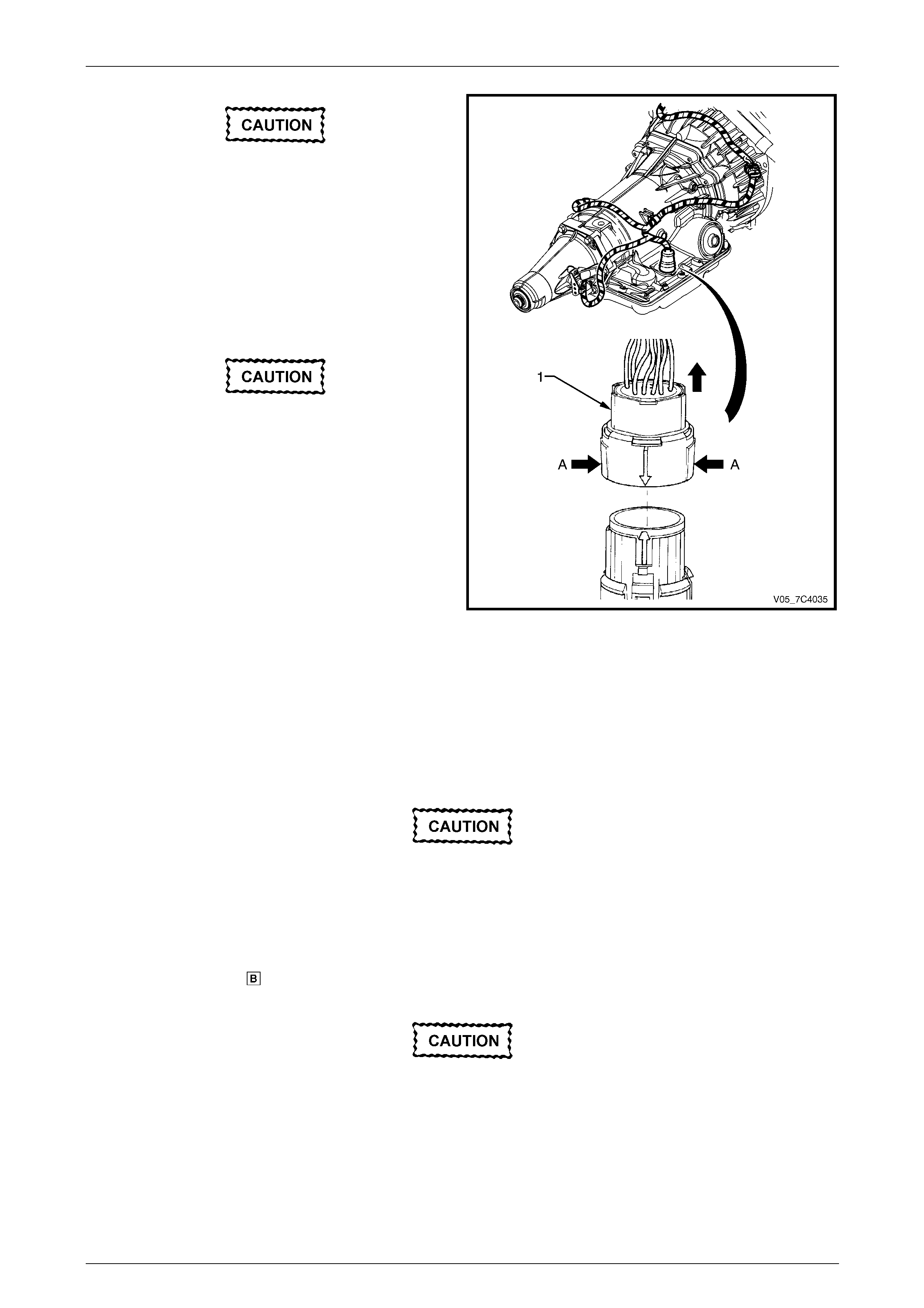
Automatic Transmission – 4L65E – On-vehicle Servicing Page 7D4–84
Page 7D4–84
Before lowerin g the tran sm ission take c a re of
the following:
• Do not strain the harness and connector
as the connector pins could be
permanently damaged.
• Ensure the inlet manifold does not hit the
firewall.
7 Carefully lower the transmissi on to provide enough
clearance to disconnect the h arness co nnector (1).
Do not wiggle the connector from side to side
during removal as the connector pins could
be permanently damaged.
8 Disconnect the harness connector from the
transmission as follows:
a Roll back the dust boot to access the connector.
b Squeeze the widest side of the connector (A)
inward and pull it directly upward.
Figure 7D4 – 129
9 Remove the screws attaching the harness clips to the right- hand and left-hand sides of the transmission case, refer
to Section 12O Fuses, Relays and Wirin g Ha rnesses.
10 Place a suitable sized drip tray underneath the transmission.
11 Remove the transmission fluid lines, refer to 3.23 Transmission Cooler Lines and Hos es.
12 Disconnect the breather hose from the top of the transmission case.
Support the transmission when removing the
attaching bolts to avoid damage to the torque
converter and flexplate. Do not have the
transmission hangin g.
13 With the transmission supported, using a long socket extension, universal joint and suitable size socket, remove
the bolt (1), eight places, attaching the torque converter ho using to the engine, in the reverse order of the torque
sequence shown in within Figure 7D4 – 130.
The transmission assembly must not be
allowed to rest on its oil pan.

Automatic Transmission – 4L65E – On-vehicle Servicing Page 7D4–85
Page 7D4–85
14 Support the transmission assembly on a suitable cradle and secure it. Place a suitable support under the engine oil
pan rail to support the engine after the transmission has been removed.
15 Remove the transmission assembly disengaging the filler tube attached to the engin e.
16 Remove the bolt (3) and torque converter cover (4) on the engine right-hand side, remove the bolt (5) and torque
converter cover (6) on the left-hand side.
17 Install a suitable holding tool to preve nt the torque conv erter from becoming dislodged.
Figure 7D4 – 130

Automatic Transmission – 4L65E – On-vehicle Servicing Page 7D4–86
Page 7D4–86
Reinstall
1 Ensure the transmission and the engine mating surfaces are clean and free of burrs.
2 Lubricate the torque converter spigot (7) with a small amount of high temperature wheel bearing grease, refer to
Figure 7D4 – 130.
3 Install a new filler tube seal into the transmission case.
Support the transmission while installing the
attaching bolts to avoid damage to the torque
converter and flexplate. Do not have the
transmission hangin g.
4 Bring the transmission up to the engine, inserting the filler tube and ensuring the locating dowels completely enter
the torque converter housing.
5 Reconnect the breather hose to the top of the transmission case.
6 With the transmission supported, install th e bolt (1), eight places, attaching the torque converter housing to the
engine and tighten to the correct torque sp ecification following the sequence shown in within Figure 7D4 – 130.
Torque converter housing attaching
bolt torque specification..........................50.0 – 60.0 Nm
7 Push the torque converter forward to meet the flexplate, then hand start three new bolts (2) before tightening to the
correct torque specification.
Torque converter to flexplate attachin g
bolt torque specification..........................60.0 – 70.0 Nm
8 Reinstall the bolt (3) and torque converter cover (4) on the right-hand side and the bolt (5) and torque converter
cover (6) on the left-hand side, tighten the bolts to the correct torque specification.
Torque converter cover attaching
bolt torque specification............................5.0 – 10.0 Nm
9 Reinstall the transmission flu id lines, refer to 3.23 Transmission Cooler Lines and Hoses.
Prior to connecting the harness connector to
the transmission, check that all pins and
seals are in sound condition and the dust
boot is not torn or damaged.
10 Reconnect the transmission harness conn ector to the transmission as follows:
a Push straight down on the connector body until a click is heard.
b Reinstall the dust boot ensuring it is correctl y loc ated.
11 Attach the harness clips to the right-hand and left-hand sides of the transmission case, refer to
Section 12O Fuses, Relays and Wiring Harnesses.

Automatic Transmission – 4L65E – On-vehicle Servicing Page 7D4–87
Page 7D4–87
12 Reinstall the following components:
a Starter motor, refer to Section 6D3-2 Starting System – GEN III V8.
b Transmission support, refer to:
• 3.12 Transmission Support and Mount, Except Coupe and AWD, or
• 3.13 Transmission Support and Mount, Cou pe.
c Selector linkage and rod, refer to 3.2 Selector Linkage and Rod, Except AWD.
d Front exhaust assemblies, refer to Section 8B Exhaust System.
e Rear propeller shaft, refer to Section 4C1 Rear Propeller Shaft and Universal Joints.
13 Reconnect the harness connectors to the following:
a Vehicle speed sensor, refer to 3.9 Vehicle S peed Sensor, Except AWD.
b Neutral start and back-up switch, refer to 3.7 Neutral Start and Back-up L amp Switch, Except AWD.
14 Perform a reverse flush of the cooler lines and a flow rate test, refer to 2.2 Reverse Flush and Flow Rate, if either
of the following applies:
• the transmission fluid is contaminated,
• the transmission has been replaced,
• the torque converter has been replaced, or
• the transmission oil pump has been replaced.
15 Lower the vehicle to the ground.
16 If required, top up the transmission fluid level (cold).
17 Reconnect the battery ground lead.
18 Start the engine and check for any fluid leaking at the fitting s. If a leak is found, stop the engine and rectify the leak.
19 Road test until the transmission has reached operating temperature. Re-check the fluid level and for any fluid
leaks, refer to 2.1 Transmission Fluid.

Automatic Transmission – 4L65E – On-vehicle Servicing Page 7D4–88
Page 7D4–88
3.25 Transmission Assembly – AWD
LT Section No. — 04–200
Remove
Disconnection of the battery affects certain
vehicle electronic systems. Refer to
Section 00 Warnings, Cautions and Notes
before disconnecting the battery.
1 Disconnect the battery ground lead.
2 Raise the vehicle and suppor t in a safe manner, refer to Section 0A General Information for the location of support
points.
3 Remove the following components:
a Transmission support, refer to Section 7F Transfer Case and Adaptor Housing.
b Rear propeller shaft, refer to Section 4C1 Rear Propeller Shaft and Universal Joints.
c Front exhaust assemblies, refer to Section 8B Exhaust System.
d Front propeller shaft, refer to Section 4C2 Front Propeller Shaft and Universal Joints.
e Selector cable assembly, refer to 3.3 Selector Cable Assembly, AWD.
f Transfer case rear mounting bracket, refer to Section 7F Transfer Case and Adaptor Housing.
g Starter motor, refer to Section 6D3-2 Starting System – V8.
4 Disconnect the harness connectors from the following:
a Vehicle speed sensor, refer to 3.10 Vehicle Speed Sensor, AWD.
b Neutral start and back-up switch, refer to 3.8 Neutral Start and Back-up L amp Switch, AWD.
5 From within the starter motor access hole, remove the three bolts (2) attaching the torque converter to the flexplate
and discard, refer to Figure 7D4 – 132.
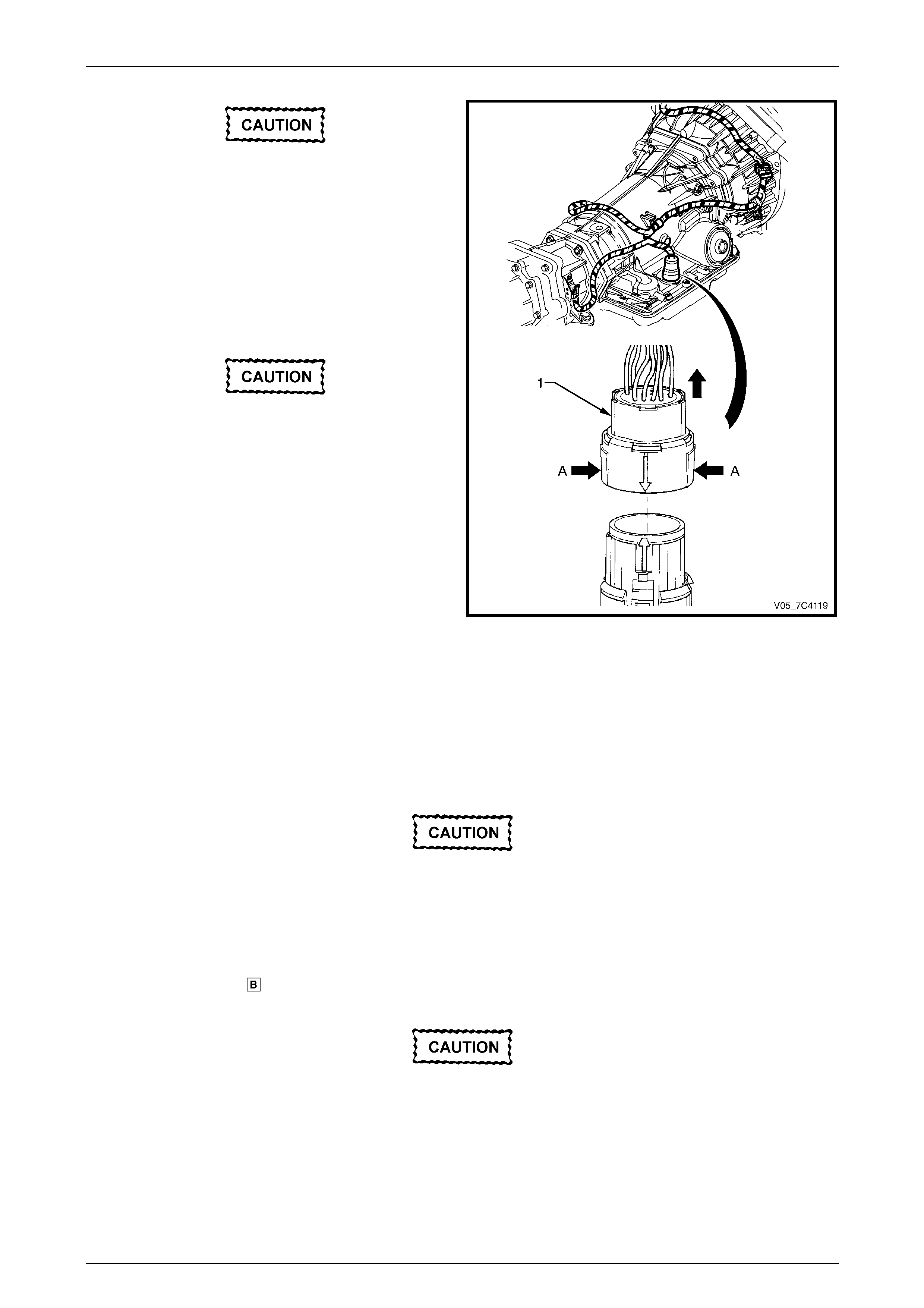
Automatic Transmission – 4L65E – On-vehicle Servicing Page 7D4–89
Page 7D4–89
Before lowerin g the tran sm ission take c a re of
the following:
• Do not strain the harness and connector
as the connector pins could be
permanently damaged.
• Ensure the inlet manifold does not hit the
firewall.
7 Carefully lower the transmissi on to provide enough
clearance to disconnect the h arness co nnector (1).
Do not wiggle the connector from side to side
during removal as the connector pins could
be permanently damaged.
8 Disconnect the harness connector from the
transmission as follows:
a Roll back the dust boot to access the connector.
b Squeeze the widest side of the connector (A)
inward and pull it directly upward.
Figure 7D4 – 131
9 Remove the harness clips from the right-hand and l eft-hand sides of the transmission case, refer to
Section 12O Fuses, Relays and Wiring Harnesses.
10 Place a suitable sized drip tray underneath the transmission.
11 Remove the transmission fluid lines, refer to 3.23 Transmission Cooler Lines and Hos es.
12 Disconnect the breather hose from the top of the transmission case.
Support the transmission when removing the
attaching bolts to avoid damage to the torque
converter and flexplate. Do not have the
transmission hangin g.
13 With the transmission supported, using a long socket extension, universal joint and suitable size socket, remove
the bolt (1), eight places, attaching the torque converter ho using to the engine, in the reverse order of the torque
sequence shown in within Figure 7D4 – 132.
The transmission assembly must not be
allowed to rest on its oil pan.
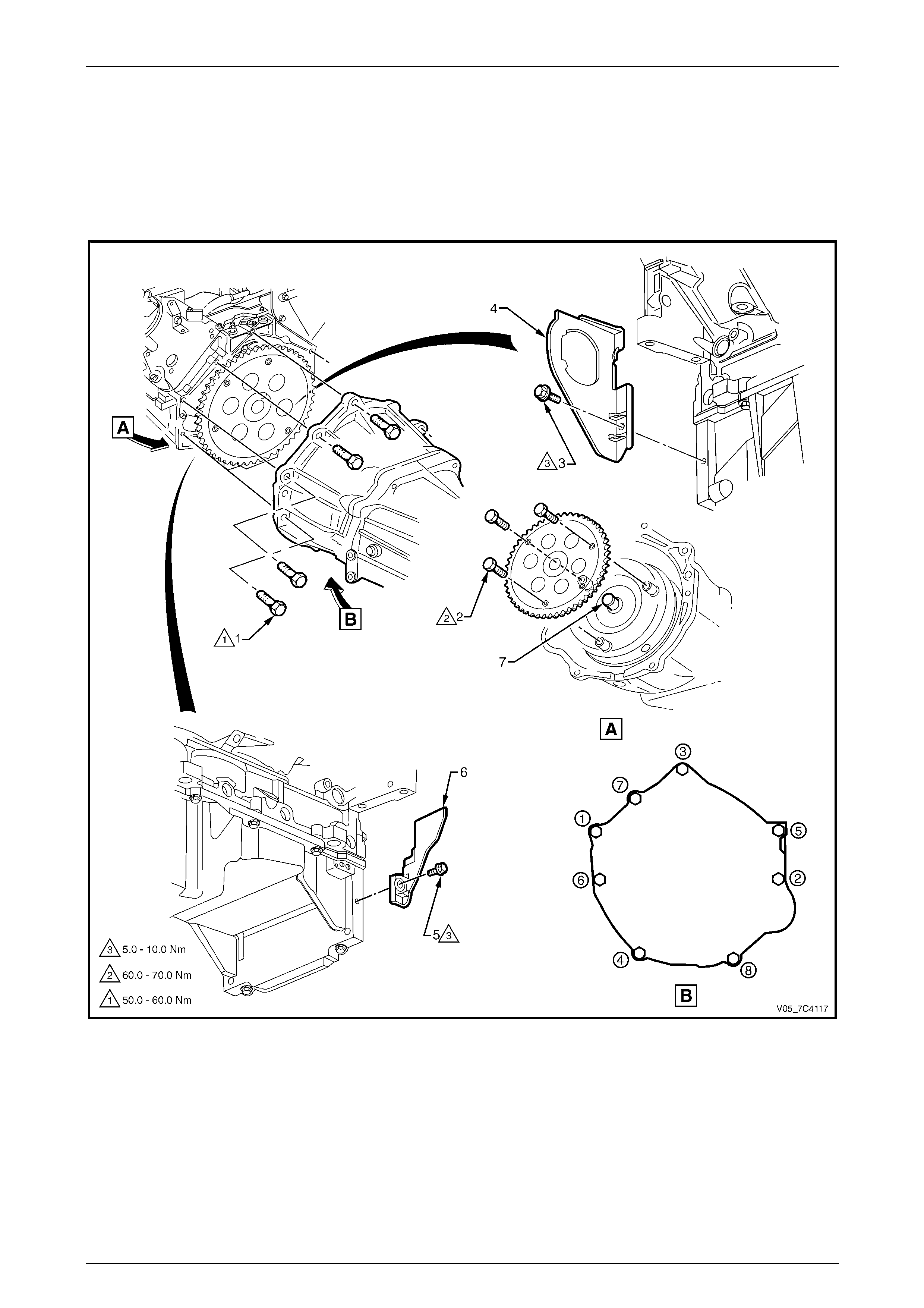
Automatic Transmission – 4L65E – On-vehicle Servicing Page 7D4–90
Page 7D4–90
14 Support the transmission assembly on a suitable cradle and secure it. Place a suitable support under the engine oil
pan rail to support the engine after the transmission has been removed.
15 Remove the transmission assembly disengaging the filler tube attached to the engin e.
16 Remove the bolt (3) and torque converter cover (4) on the transmission right-hand side, remove the bolt (5) and
torque converter cover (6) on the transmission left-hand side.
17 Install a suitable holding tool to preve nt the torque conv erter from becoming dislodged.
Figure 7D4 – 132
Automatic Transmission – 4L65E – On-vehicle Servicing Page 7D4–91
Page 7D4–91
Reinstall
1 Ensure the transmission and the engine mating surfaces are clean and free of burrs.
2 Lubricate the torque converter spigot (7) with a small amount of high temperature wheel bearing grease, refer to
Figure 7D4 – 132.
3 Install a new filler tube seal into the transmission case.
Support the transmission while installing the
attaching bolts to avoid damage to the torque
converter and flexplate. Do not have the
transmission hangin g.
4 Bring the transmission up to the engine, inserting the filler tube and ensuring the locating dowels completely enter
the torque converter housing.
5 Reconnect the breather hose to the top of the transmission case.
6 With the transmission supported, install th e bolt (1), eight places, attaching the torque converter housing to the
engine and tighten to the correct torque sp ecification following the sequence shown in within Figure 7D4 – 132.
Torque converter housing attaching
bolt torque specification..........................50.0 – 60.0 Nm
7 Push the torque converter forward to meet the flexplate, then hand start three new bolts (2) before tightening to the
correct torque specification.
Torque converter to flexplate attachin g
bolt torque specification..........................60.0 – 70.0 Nm
8 Reinstall the bolt (3) and torque converter cover (4) on the transmission right-hand side and the bolt (5) and torque
converter cover (6) on the transmission left-hand sid e, tighten the bolts to the correct torque specification.
Torque converter cover attaching
bolt torque specification............................5.0 – 10.0 Nm
9 Reinstall the transmission flu id lines, refer to 3.23 Transmission Cooler Lines and Hoses.
Prior to connecting the harness connector to
the transmission, check that all pins and
seals are in sound condition and the dust
boot is not torn or damaged.
10 Reconnect the transmission harness conn ector to the transmission as follows:
a Push straight down on the connector body until a click is heard.
b Reinstall the dust boot ensuring it is correctl y loc ated.
11 Attach the harness clips to the right-hand and left-hand sides of the transmission case, refer to
Section 12O Fuses, Relays and Wiring Harnesses.
12 Reconnect the harness connectors to the following:
a Vehicle speed sensor, refer to 3.10 Vehicle Speed Sensor, AWD.
b Neutral start and back-up switch, refer to 3.8 Neutral Start and Back-up L amp Switch, AWD.

Automatic Transmission – 4L65E – On-vehicle Servicing Page 7D4–92
Page 7D4–92
13 Reinstall the following components:
a Starter motor, refer to Section 6D3-2 Starting System – V8.
b Transfer case rear mounting bracket, refer to Section 7F Transfer Case and Adaptor Housing.
c Selector cable assembly, refer to 3.3 Selector Cable Assembly, AWD.
d Front propeller shaft, refer to Section 4C2 Front Propeller Shaft and Universal Joints.
e Front exhaust assemblies, refer to Section 8B Exhaust System.
f Rear propeller shaft, refer to Section 4C1 Rear Propeller Shaft and Universal Joints.
g Transmission support, refer to Section 7F Transfer Case and Adaptor Housing.
14 Perform a reverse flush of the cooler lines and a flow rate test, refer to 2.2 Reverse Flush and Flow Rate, if either
of the following applies:
• the transmission fluid is contaminated,
• the transmission has been replaced,
• the torque converter has been replaced, or
• the transmission oil pump has been replaced.
15 Lower the vehicle to the ground.
16 If required, top up the transmission fluid level (cold).
17 Reconnect the battery ground lead.
18 Start the engine and check for any fluid leaking at the fitting s. If a leak is found, stop the engine and rectify the leak.
19 Road test until the transmission has reached operating temperature. Re-check the fluid level and for any fluid
leaks, refer to 2.1 Transmission Fluid.