
Transfer Case and Adaptor Housing 7F – 1
7F-1
Section 7F
Transfer Case and Adaptor Housing
ATTENTION
Before performing any Service Operation or other procedure described in this Section, refer to
Section 00 Warnings, Cautions and Notes for correct workshop practices with regard to safety and/or
property damage.
1 General Description ...............................................................................................................................3
1.1 General Information............................................................................................................................................... 3
Description............................................................................................................................................................. 3
Arrangement........................................................................................................................................................... 5
Power Flow............................................................................................................................................................. 6
Vehicle Towing....................................................................................................................................................... 6
1.2 Transfer Case Identification.................................................................................................................................. 7
1.3 Transfer Case Maintenance .................................................................................................................................. 8
Inspection............................................................................................................................................................... 8
Lubrication ............................................................................................................................................................. 8
Breather.................................................................................................................................................................. 8
2 Minor Service Operations......................................................................................................................9
2.1 Checking Transfer Case Lubricant Level ............................................................................................................ 9
2.2 Draining and Filling Transfer Case Lubricant ................................................................................................... 10
2.3 Catalytic Converter Bracket................................................................................................................................ 11
Remove................................................................................................................................................................. 11
Reinstall................................................................................................................................................................ 11
2.4 Transmission Support......................................................................................................................................... 12
Remove................................................................................................................................................................. 12
Reinstall................................................................................................................................................................ 12
2.5 Mass Damper........................................................................................................................................................ 13
Remove................................................................................................................................................................. 13
Reinstall................................................................................................................................................................ 14
2.6 Transfer Case Front Output Flange, Slinger and Oil Seal................................................................................ 15
Remove................................................................................................................................................................. 15
Reinstall................................................................................................................................................................ 16
2.7 Transfer Case Rear Output Flange and Oil Seal ............................................................................................... 18
Remove................................................................................................................................................................. 18
Reinstall................................................................................................................................................................ 19
2.8 Transfer Case Support Mount............................................................................................................................. 21
Replace................................................................................................................................................................. 21
3 Major Service Operations....................................................................................................................24
3.1 Transfer Case....................................................................................................................................................... 24
Remove................................................................................................................................................................. 24
Reinstall................................................................................................................................................................ 29
3.2 Transfer Case Input Shaft Oil Seal..................................................................................................................... 32
Remove................................................................................................................................................................. 32
Reinstall................................................................................................................................................................ 33
3.3 Adaptor Housing – 4 Speed Transmission........................................................................................................ 34
Remove................................................................................................................................................................. 34
Reinstall................................................................................................................................................................ 35
3.4 Transmission Adaptor Housing Oil Seal ........................................................................................................... 36
Replace................................................................................................................................................................. 36
Techline

Transfer Case and Adaptor Housing 7F – 2
7F-2
4 Transfer Case Symptom Diagnosis....................................................................................................37
4.1 Preliminary Diagnosis......................................................................................................................................... 37
System Operation................................................................................................................................................ 37
Visual/Physical Inspection.................................................................................................................................. 37
Symptom List....................................................................................................................................................... 37
4.2 Popping Noise...................................................................................................................................................... 38
Definition .............................................................................................................................................................. 38
Diagnostic Table.................................................................................................................................................. 38
4.3 Whine or Rumble Noise....................................................................................................................................... 39
Definition .............................................................................................................................................................. 39
Diagnostic Table.................................................................................................................................................. 39
4.4 Growl or Grinding Noise ..................................................................................................................................... 40
Definition .............................................................................................................................................................. 40
Diagnostic Table.................................................................................................................................................. 40
4.5 Clunk During Acceleration and Deceleration.................................................................................................... 41
Definition .............................................................................................................................................................. 41
Diagnostic Table.................................................................................................................................................. 41
4.6 No Front or Rear Drive ........................................................................................................................................ 42
Definition .............................................................................................................................................................. 42
Diagnostic Table.................................................................................................................................................. 42
4.7 Lubricant Leak Diagnosis................................................................................................................................... 43
Definition .............................................................................................................................................................. 43
Diagnostic Table.................................................................................................................................................. 43
5 Specifications.......................................................................................................................................44
6 Torque Wrench Specifications............................................................................................................45
7 Special Tools ........................................................................................................................................46

Transfer Case and Adaptor Housing 7F – 3
7F-3
1 General Description
1.1 General Information
This Section describes the transfer case and adaptor hous ing fitted to AWD vehicles equipped with automatic
transmission.
Description
The transfer case model NV124GM is a single speed, full time, All Wheel Drive (AWD) transfer case assembly.
The transfer case uses a simple planetary gear train acting as a differential to achieve a 38% – 62% torque split between
the front and rear final drives respectivel y.
By utilising this type of gear set, both final dr ives are constantly being driven for maximum traction and the best balance
or vehicle handling characteristics under all operating conditions.
An adaptor housing provides the means by which the transfer case is attached to the rear of the 4 speed automatic
transmission. For Alloytec V6 engine, an adaptor plate is ad ded between the transfer case and adaptor housing.
An extension housing provides the means by which the transfer case is attached to the rear of the 5 speed autom atic
transmission (Alloytec 190 V6 engine). For service operations of the 5 speed transmission extension housing, refer to
Section 7E4 Automatic Tr ansmission – 5L40E – On-vehicle Servicing.
To cater for shaft length, an adaptor shaft is inserted between the transmission output shaft and the input shaft of the
transfer case. Identical adaptor shafts are fitted for 4 speed transmission on V8 engine and 5 speed transmission on
Alloytec 190 V6 engine. A longer adaptor shaft is fitted for 4 speed transmission on Alloytec V6 engine.
A mass damper is fitted to the rear of the transfer case housing to absorb resonance frequencies from the rotating part s.
For vehicles equipped with 5 speed transmission, the speed sensor is internal to the transmission.
For vehicles equipped with 4 speed transmission, the speed sensor is mo unted externally onto the adaptor housi ng and
is secured by a single bolt as in normal practice. The speed sensor pick-up ring is pressed onto, and is an integral part of
the adaptor shaft.
The only serviceable components in the transfer case assembly, are those that do not requir e the ho usings to be split.
That is, the three oil seals, rear output flang e, front output flan ge and slinger, O-ring seals, filler and drain plugs with their
gaskets and the breather hose.
The adaptor shaft is only serviced as a one-piece assembly. In the adaptor housing, the oil seal in is a serviceable
component.
Service operations for the serviceable components are incl uded in this Section.
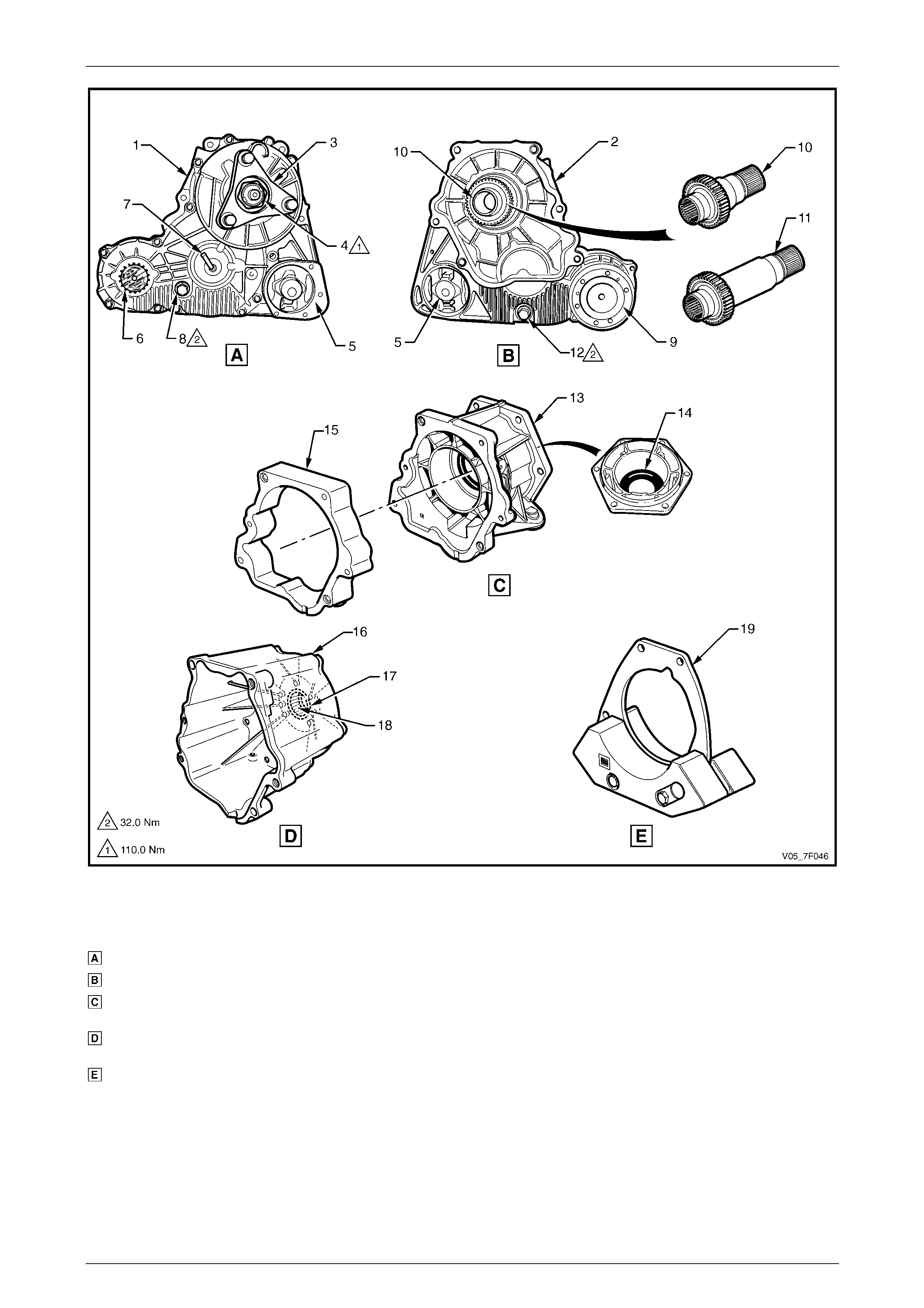
For views of the transfer case, adaptor housing, extension housing and mass damper, refer to Figure 7F – 1.
Transfer Case and Adaptor Housing 7F – 4
7F-4
Figure 7F – 1
Legend
Transfer Case Rear Side
Transfer Case Front Side
Adaptor Housing (4 speed
transmission)
Extension Housing (5 speed
transmission)
Mass Damper
1 Transfer Case Rear Housing
2 Transfer Case Front Housing
3 Rear Output Flange
4 Rear Output Flange Nut
5 Support Mount
6 Identification Tag
7 Breather Pipe
8 Lubricant Filler Plug
9 Front Output Flange
10 Adaptor Shaft
11 Adaptor Shaft (Alloytec V6 engine)
12 Lubricant Drain Plug
13 Adaptor Housing
14 Oil Seal
15 Adaptor plate (Alloytec V6 engine)
16 Extension Housing
17 Oil Seal
18 Needle Bearing
19 Mass Damper (where fitted)
Transfer Case and Adaptor Housing 7F – 5
7F-5
Arrangement
The front and rear housings of the transfer case are made of high density alumini um alloy manufactured by high
pressure injection moulding. The housings contain the input shaft, the front and rear output shafts, a simple planetary
gear set and a connecting gear set. T he internal gears are either supported by ball or roller bearings or caged needle
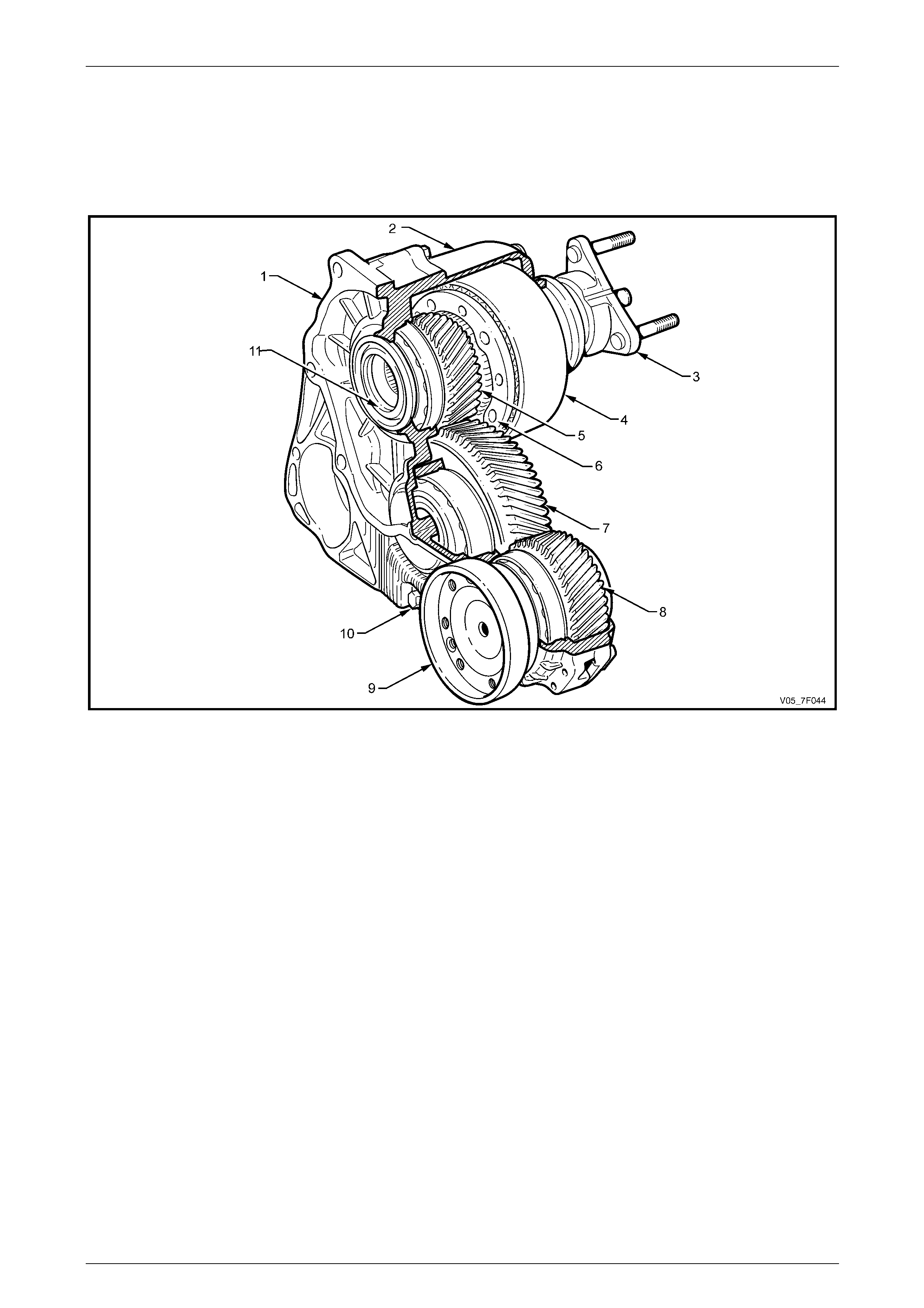
bearings. The organisati on of the gears is displayed in th e following view, refer to Figure 7F – 2.
Figure 7F – 2
Legend
1 Transfer Case Front Housing
2 Transfer Case Rear Housing
3 Rear Output Flange
4 Planetary Gear Set Ring Gear (Annulus)
5 Sun Gear
6 Planetary Gear Set Carrier and Pinions
7 Idler Gear
8 Front Output Gear
9 Front Output Flange
10 Drain Plug
11 Input Shaft
Transfer Case and Adaptor Housing 7F – 6
7F-6
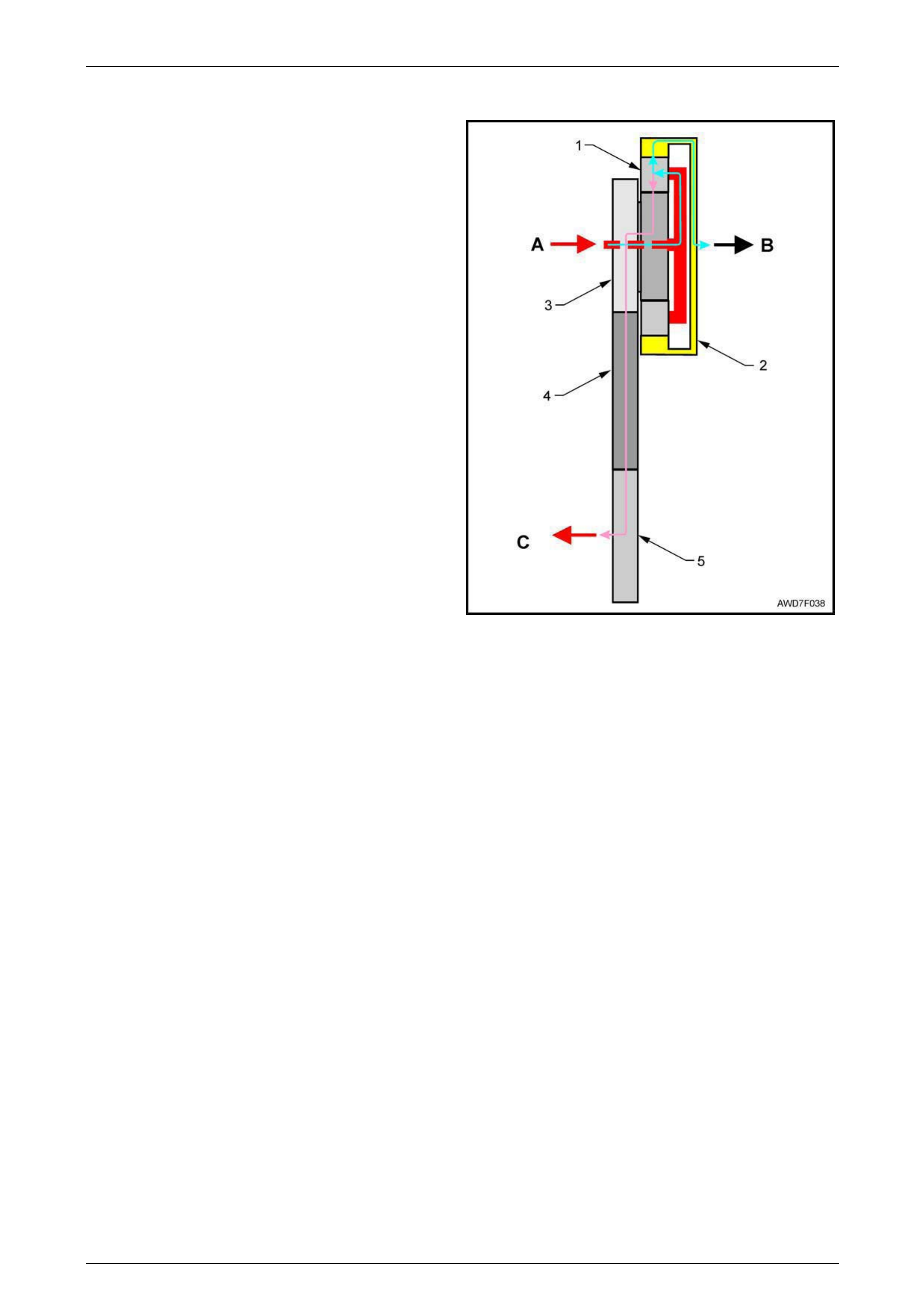
Power Flow
Power from the input shaft (A) is transmitted to the planetary
gears and carrier (1), then out to the rear final drive (B) via
the ring gear (2). Power is also transmitted to the front final
drive (C) via the sun gear (3), idler gear (4) and front output
gear (5).
With the simple planetary gear set, ratio change is achieved
by one member being the inp ut (driver), another being held
(transmitter) and the third being the output (driven).
If any two members are held, the gear set is locked up. If
one or more members is/are free, then neutral is ach ieve d.
With this particular gear arrangement, the torque split from
the planetary gear set is 38/62, front to rear. Should slip
occur from either a front or rear wheel, then a neutral
situation occurs until traction control restore s grip.
Figure 7F – 3
Vehicle Towing
Before towing the vehicle, comply with all the recommendations stated in the MY 2005 VZ AW D Wagon Owner's
Handbook.
In addition it must be realised that as the automatic transmission does n ot have a rear pump, extensive transmissi on and
transfer case damage will occur if the vehicle is towed at speeds in excess of 55 km/h or distances of more than 55 km.
If it is considered to remove a propeller shaft before towing on all four wheels, then both front and rear prope ller shafts
must be removed. Given the constraints previously mentioned, it is strongly recommended that towing on all four wheels
be avoided where possible and that a flat top truck transport is used, particularly for l ong distances.
Transfer Case and Adaptor Housing 7F – 7
7F-7
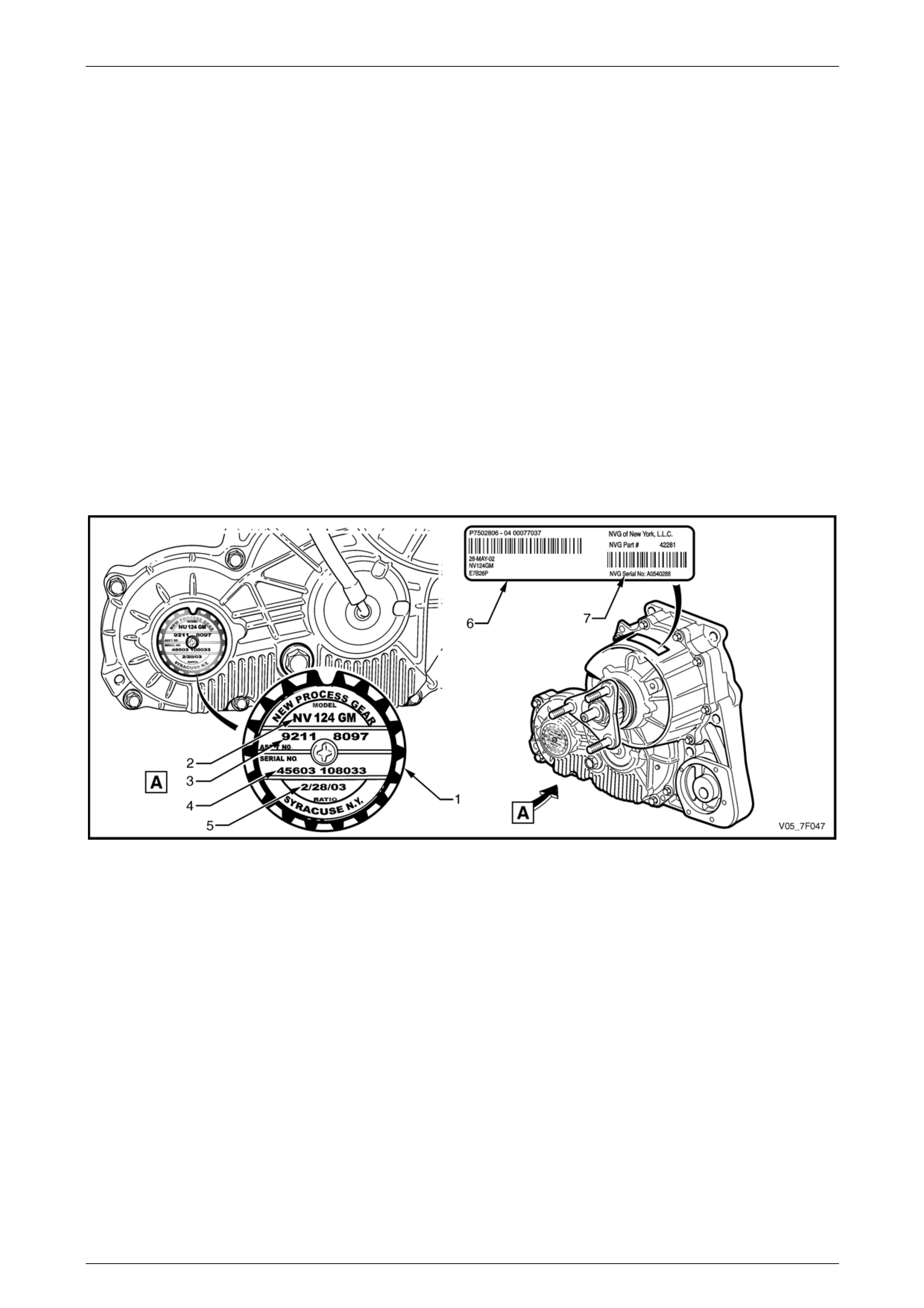
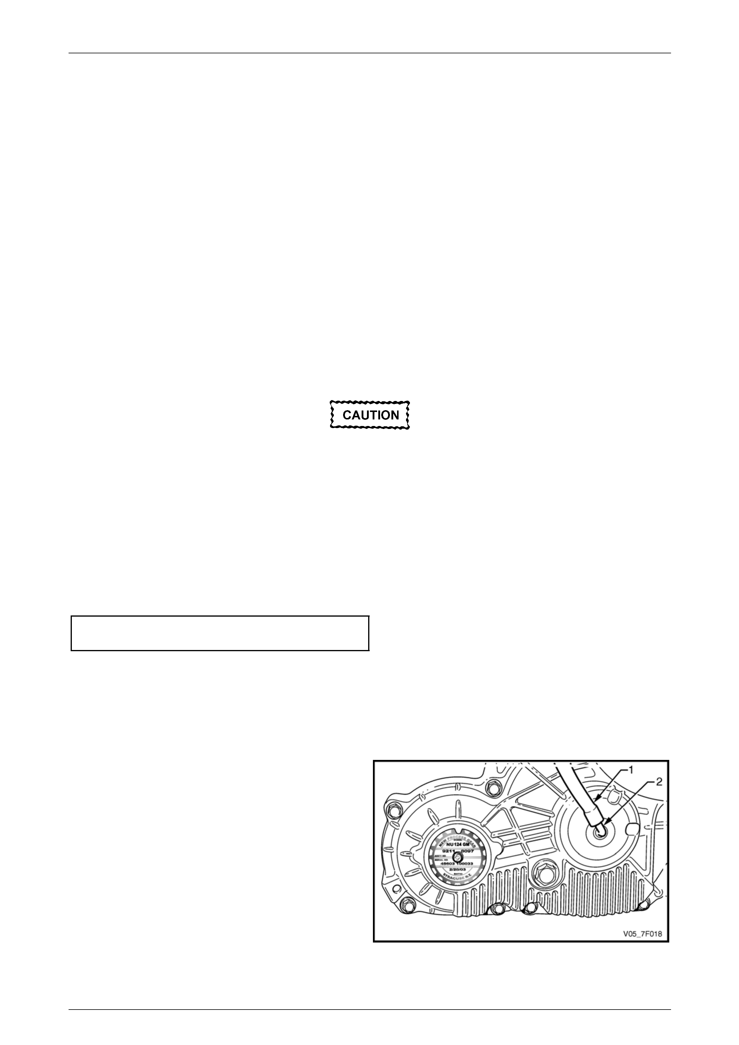
1.2 Transfer Case Identification
An identification tag (1) is attached to the left side of the transfer case rear housing in the location shown, refer to
Figure 7F – 4.
The identification tag provides the following information that may be required for the procurement of correct service parts:
• model number (2),
• assembly part number (3),
• manufacturer part number (4) and
• build date (5).
NOTE
Although marked as serial nu mber, the number at
location (4) on the identification tag is the
manufacturer part number.
If the identification tag is removed or is dislodged during service op erations, it must be kept with the assembly.
An identification label (6) is located at the top of the transfer case rear housing in the loc ation shown and provides similar
information as the identification tag as well as the transfer case serial num ber (7) as shown.
Figure 7F – 4
Transfer Case and Adaptor Housing 7F – 8
7F-8
1.3 Transfer Case Maintenance
Inspection
A check for lubricant leaks should be ma de at each maintenance service. If there is evidence of leakage, the condition
must be corrected using procedures contained in this Section, then dr ain the remaining lubricant and refill the transfer
case with the approved lubricant, refer to 2.2 Draining and Filling Transfer Case Lubricant.
Lubrication
For the transfer case lubricant draining fre qu ency, refer to Section 0B Lubrication a nd Service.
If it is necessary to drain the lubricant and refill because of loss through a leaking seal, it is vital that onl y the
recommended lubricant be used.
The lubricants approved for use in this transfer case are Esso MTF-LT-1 or Castrol BTO 338.
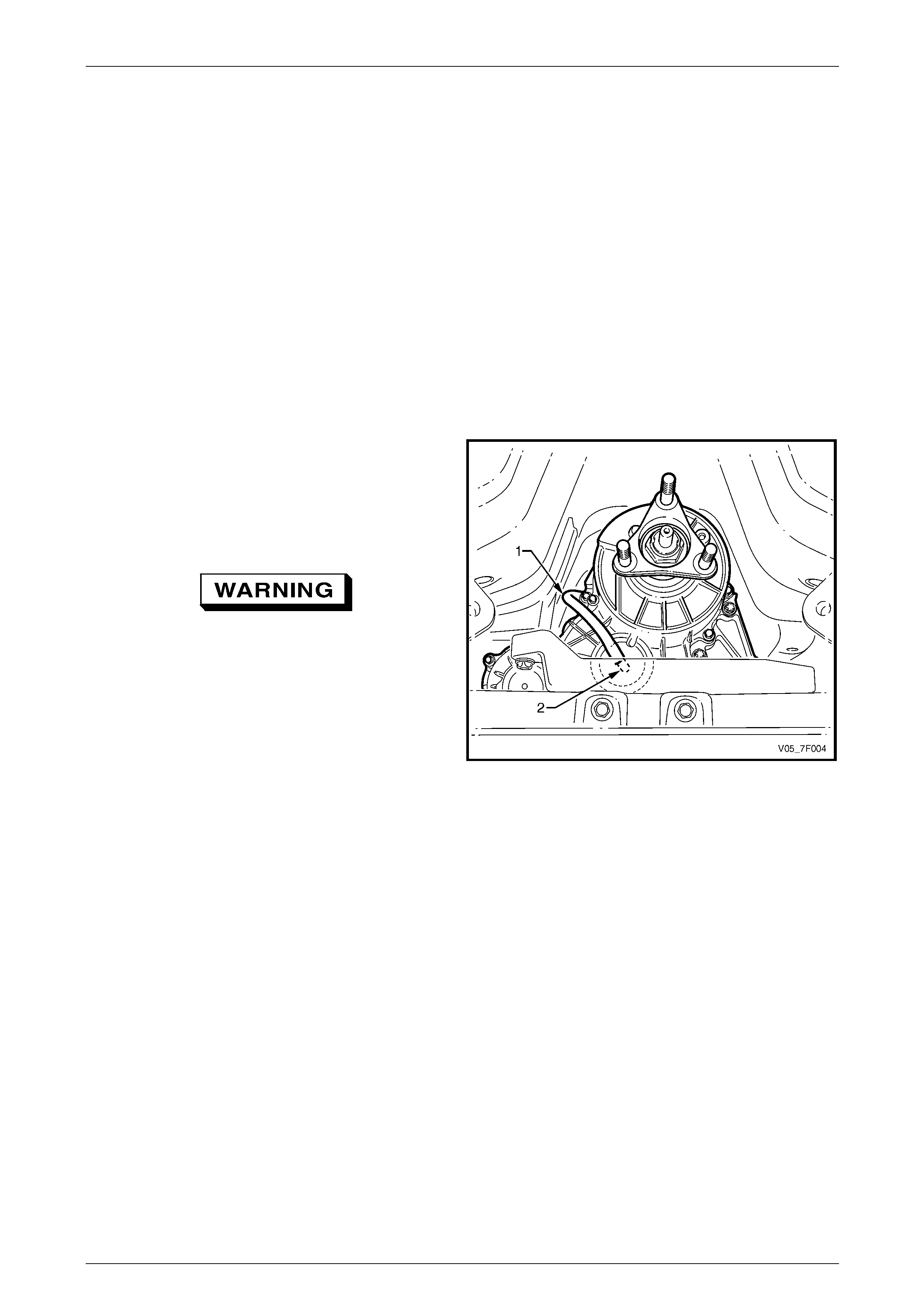
Breather
The breather hose (1) should be inspected at each
maintenance service to ens ure that it is routed correctly and
is in good condition.
Make a check to ensure the open end is not blocked. This
can be achieved by disconn ecting the breather hose from
the breather pipe (2) at the transfer case rear side.
Wear eye protectio n when clearing a b locked
breather hose.
If required, either manually or with compressed air, blow
through the breather hose to unblock it. Then reconnect the
breather hose to the transfer case breather pipe.
Figure 7F – 5
Transfer Case and Adaptor Housing 7F – 9
7F-9
2 Minor Service Operations
2.1 Checking Transfer Case Lubricant Level
LT Section No. — 04–050
1 Raise the vehicle and suppor t in a safe manner,
ensure the vehicle is level,
refer to Section 0A General Information.
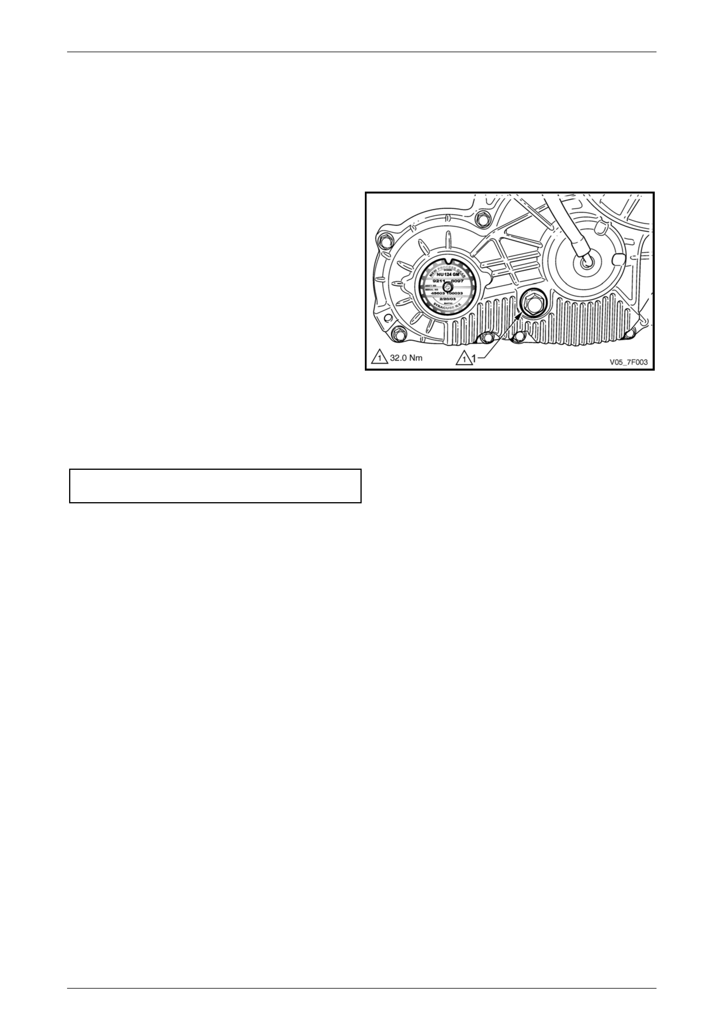
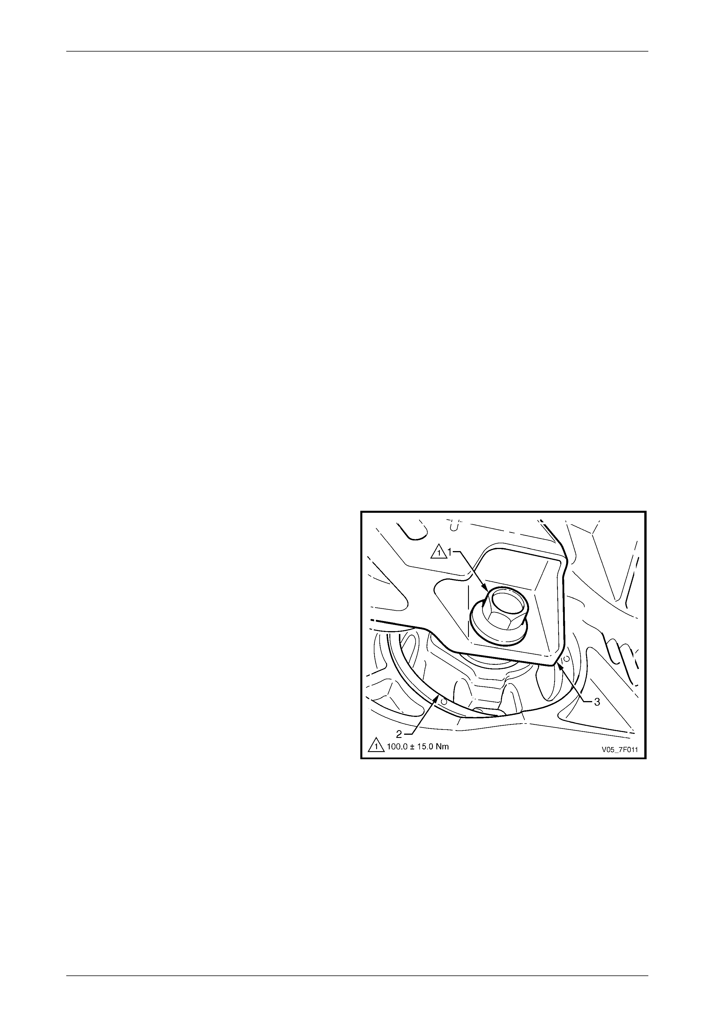
2 Clean the area around the fill er plug (1) on the transfer
case rear housing.
NOTE
For clarity the illustration does not show the
transfer case mounting brac ket and transmission
support.
3 Remove the filler plug and gasket using a suitable size
ring spanner.
4 Check if the lubricant level is correct with the lubric ant
cold and just reaching the filler plug threads in the rear
housing.
5 Replace the filler plug gasket, then reinstall the filler
plug tightening it to the correct torque specification.
Transfer case filler plug
torque specification............................................32.0 Nm
Figure 7F – 6
6 If the lubricant level is low, then the reason must be investigated and corrected. After correction of the l eakage
condition, drain and refill the transfer case, refer to 2.2 Drainin g and Filling Transfer Case Lubricant.
Transfer Case and Adaptor Housing 7F – 10
7F-10
2.2 Draining and Filling Transfer Case
Lubricant
LT Section No. — 04–050
1 Raise the vehicle and suppor t in a safe manner, ensure the vehicle is level,
refer to Section 0A General Information.
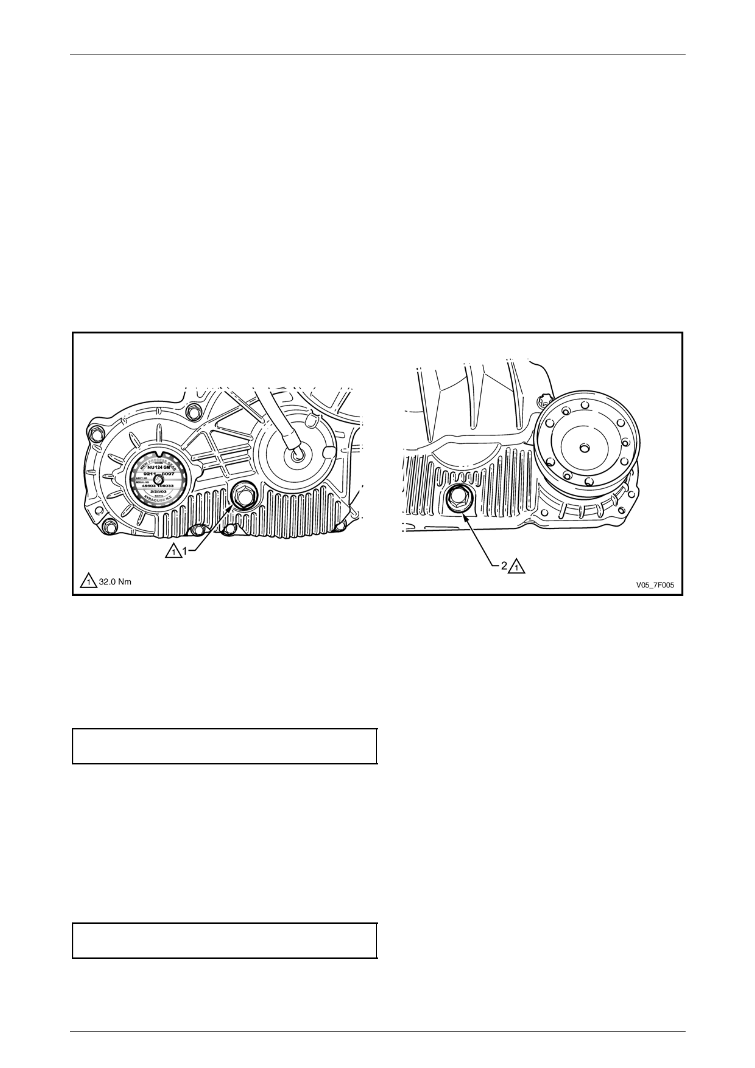
2 Clean the area around the fill er plug (1) on the transfer case rear housing and around the drain plug ( 2) on the
transfer case front housing, refer to Figure 7F – 7.
NOTE
For clarity the illustration does not show the
catalytic converter bracket and front propeller
shaft.
Figure 7F – 7
3 Remove the filler plug, using a suitable size ring spanner.
4 Remove the drain plug using a suitable size ring spanner, draining the lubricant into a suitable container of a
minimum 0.5 litre capac ity.
5 Replace the drain plug gasket, then reinstall the drain plug in the front housing, tightening it to the correct torque
specification.
Transfer case drain plug
torque specification............................................32.0 Nm
6 Refill the transfer case with approximately 100 – 160 ml of Esso MTF-LT-1 or Castrol BTO 338 lubricant, until the
lubricant (cold) just reaches the filler plug threads in the rear housing.
NOTE
This is the approximate refill quantity, the dry fill
quantity is 240 ml.
7 Replace the filler plug gask et, then reinstall the fill er plug in the rear housing, tightening it to the correct torque
specification.
Transfer case filler plug
torque specification............................................32.0 Nm
Transfer Case and Adaptor Housing 7F – 11
7F-11
2.3 Catalytic Converter Bracket
LT Section No. — 03–750
Remove
1 Raise the vehicle and suppor t in a safe manner, refer
to Section 0A General Information.
2 Loosen the nuts (1) on each side of the catal ytic
converter bracket (2).
3 Using a felt tipped pen or similar, mark the positio n of
the two bolts (3) attaching the catalytic converter
bracket to the adaptor housing bracket (4) and remov e
the two bolts.
NOTE
This will assist in keeping the alignment of the
exhaust system undisturbed.
4 Remove the loose nuts and the catalytic converter
bracket from the vehicle.
Figure 7F – 8
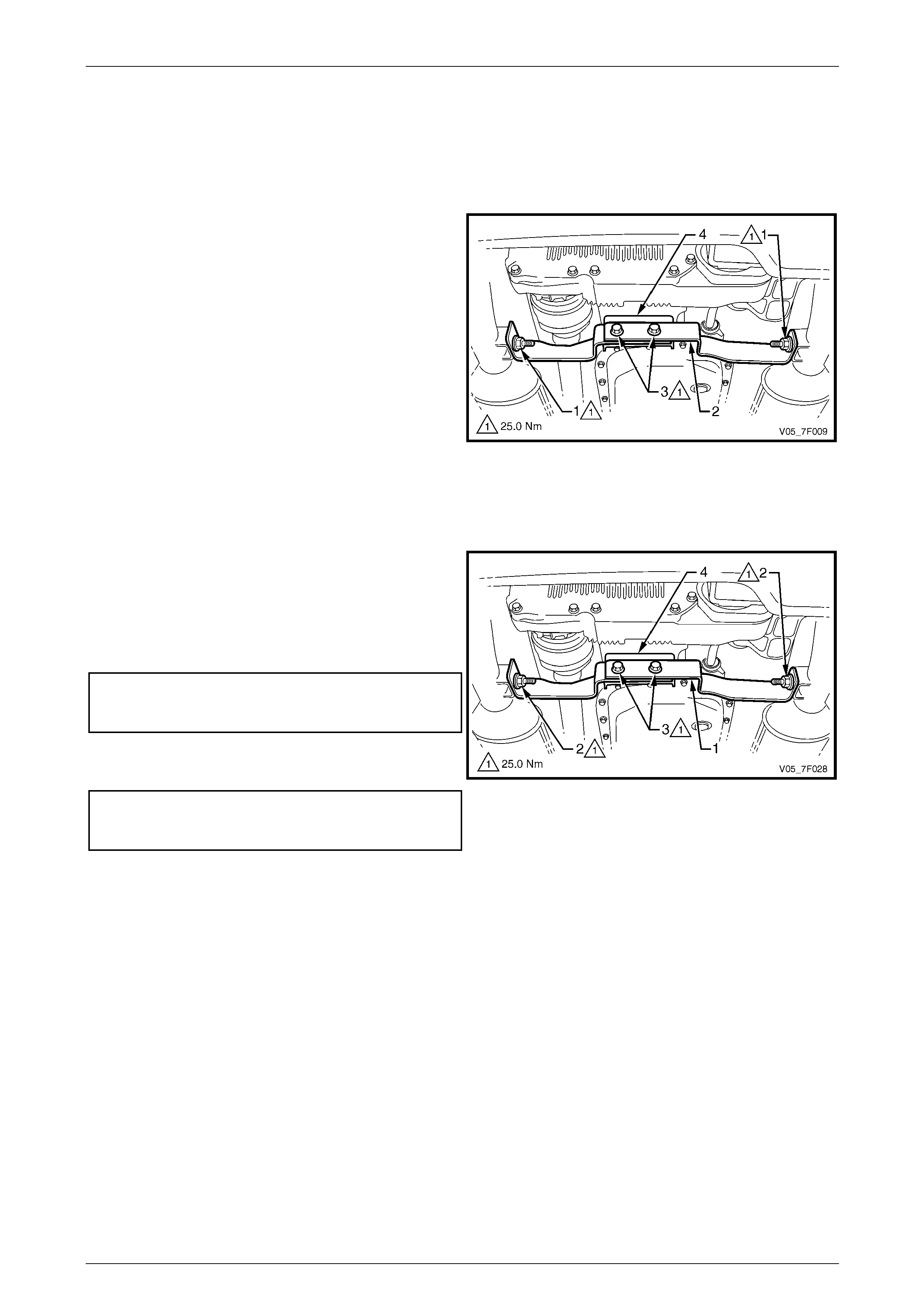
Reinstall
1 Install the catalytic converter bracket (1) and the two
outer nuts (2) finger tight on each side of the bracket.
2 Align the two bolts (3) with the marks made before
removal and attach the catalytic converter bracket to
the adaptor housing bracket (4). Tighten the two bolts
to the correct torque specification.
Catalytic converter bracket to
adaptor housing bracket attaching bolt
torque specification............................................25.0 Nm
3 Tighten the two nuts attaching the catal ytic converter
bracket to the correct torque specification.
Catalytic converter bracket to
catalytic converter attaching nut
torque specification............................................25.0 Nm
Figure 7F – 9
Transfer Case and Adaptor Housing 7F – 12
7F-12
2.4 Transmission Support
LT Section No. — 04–020
Remove
1 Raise the vehicle and suppor t in a safe manner, refer
to Section 0A General Information.
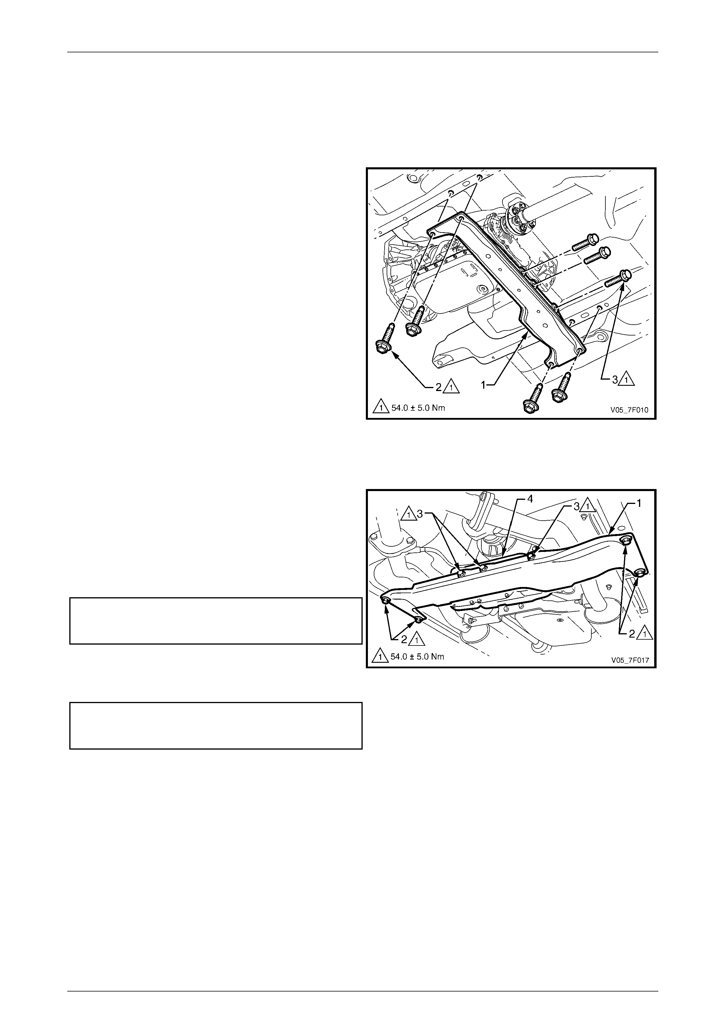
2 Using a felt tipped pen or similar, mark the positio n of
the transmission support (1) to the underbod y side
rails.
NOTE
This will assist in aligning the transmission
support on reinstallation.
3 Remove the four bolts (2) attaching the transmission
support to the underbody side rails.
4 Remove the three bolts (3) attaching the transmission
support to the transfer case rear mounting bracket.
5 Remove the transmission support from the vehicle.
Figure 7F – 10
Reinstall
1 Align the transmission support (1) with the marks
made on the underbody side rail before removal a nd
install the four attaching bolts (2) finger tight.
2 Install the three bolts (3) attaching the transmission
support to the transfer case rear mounting bracket (4).
Tighten the three bolts to the correct torque
specification.
Transmission support to transfer case
rear mounting bracket attaching bolt
torque specification...................................54.0 ± 5.0 Nm
3 Tighten the four bolts attaching the transmiss ion
support to the underbody side rail to the correct torque
specification.
Transmission supp ort to underbody
side rail attaching bolt
torque specification...................................54.0 ± 5.0 Nm
Figure 7F – 11
Transfer Case and Adaptor Housing 7F – 13
7F-13
2.5 Mass Damper
LT Section No. — 04–050
Remove
1 Remove the following components:
a Transmission support, refer to 2.4 T r ansmission Support.
b Exhaust system rearward from the two catalytic converters, refer to Section 8B Exhaust System.
c Rear propeller shaft, refer to Section 4C1 Rear Propeller Shaft and Universal Joints.
2 Remove the four nuts (1) attaching the mass damper (2) to the four studs (3) and remove the mass damper from
the studs.
3 If required, remove the four studs from the transfer case housing (4).
4 If required, disassemble the mass Damper b y removing the two bolts (5) and separating the forward block (6) and
rearward block (7) from the plate (8).
Figure 7F – 12

Transfer Case and Adaptor Housing 7F – 14
7F-14
Reinstall
Reinstallation of the mass damper is the reverse of the removal procedure, noting the following:
1 Tighten the bolts attaching the two blocks to the correct torque specification.
Mass damper blocks attaching bolt
torque specification.................................20.0 – 24.0 Nm
2 Tighten the studs attaching the mass dampe r to the transfer case housing to the correct torque specification.
Mass damper attaching stud
torque specification.................................20.0 – 24.0 Nm
3 Tighten the nuts attaching the mass damp er to the studs to the correct torque specification.
Mass damper attaching nut
torque specification.................................20.0 – 24.0 Nm
Transfer Case and Adaptor Housing 7F – 15
7F-15
2.6 Transfer Case Front Output Flange,
Slinger and Oil Seal
LT Section No. — 04–050
Remove
1 Remove the following components:
a Catalytic converter bracket, refer to 2.3 Catalytic Converter Bracket.
b Front propeller shaft, refer to Section 4C2 Front Propeller Shaft and Universal Joints.
2 Place a drip tray under the transfer case.
3 Using three suitable scre ws (1) 8 mm long, attach the
slide hammer, Tool No. 7374 (2), to the transfer case
front output flange.
4 Use the slide hammer to dislodge the s nap ring from
the front output shaft, then remove the front output
flange and discard the snap ri ng.
5 Remove the slide hammer from the front output flange.
Figure 7F – 13
6 Use a screwdriver (1) or similar lever to prise the
slinger (2) from the front output shaft. Discard the
removed slinger.
NOTE
The front output shaft slinger will be distorted
during the removal operation and can not be
reused.
Figure 7F – 14
Transfer Case and Adaptor Housing 7F – 16
7F-16
Take care during the seal removal operation
not to damage the transfer case machined
surfaces.
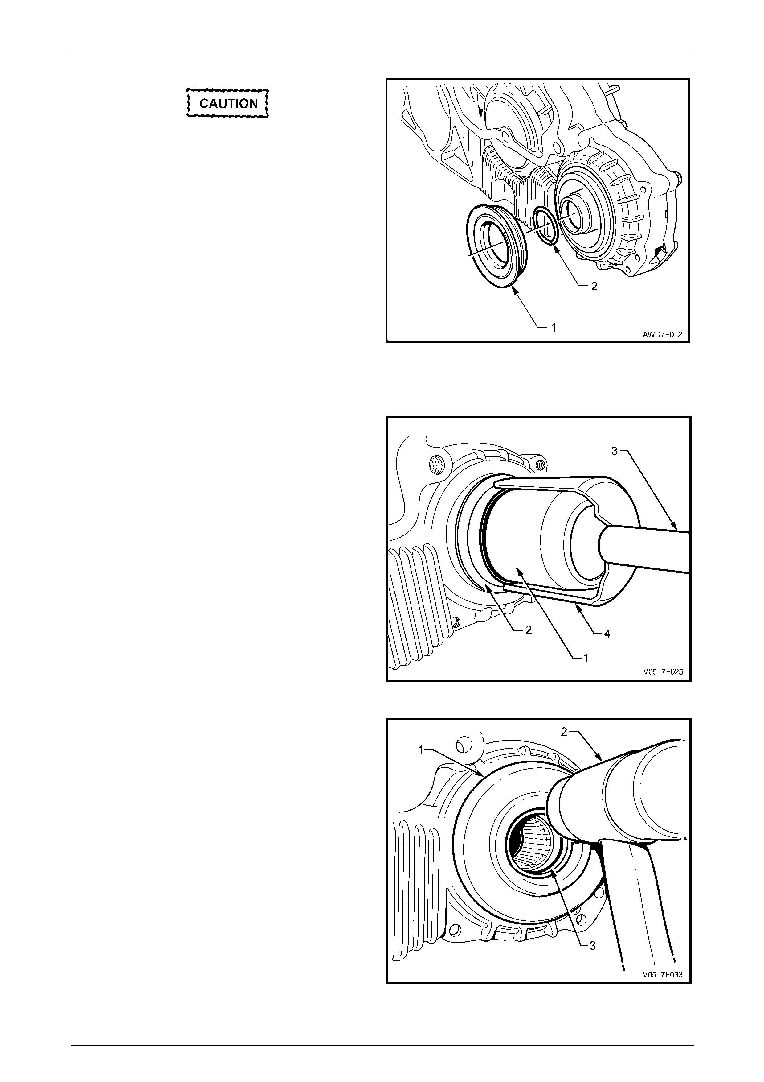
7 Remove the front output oil seal (1) using a large
screwdriver or similar, working around the oil seal
outer perimeter. Discard the removed oil seal.
8 Use a small screwdriver or wire hook to remove the
O-ring seal (2) from the front output shaft inner
diameter. Discard the removed O-ring seal.
Figure 7F – 15
Reinstall
1 Install the seal protector Tool No. DT-47602-1 (1) over
the front output shaft and push to fully install.
2 Lubricate a new front output oil seal (2) with
Mobilgrease XHP 222 or equivalent, ensuring the
recesses between the oil seal lips are filled to
approximately 50%, then slide the oil seal over the
seal protector.
3 Install the driver Tool No. AU-355-A (3) into the seal
installer Tool No. DT-47602-2 (4), then fully install the
oil seal in the transfer case front housing.
4 Remove the seal installation and protector tools.
Figure 7F – 16
5 Install a new slinger (1) onto the front output shaft,
tapping into place using a pl astic hammer (2) until the
slinger contacts the machined step on the fro nt output
shaft.
6 With the transmission in Neutral, rotate the rear
propeller shaft to ensure the slinger has been instal led
square to the front output shaft. Correct as required.
7 Lubricate a new O-ring seal (3) with a smear of
Mobilgrease XHP 222 or equivalent and install in the
groove of the front output shaft inner diameter.
8 Lubricate the internal splines of the front output shaft
with 1 gram of Weicon™ standard grade, anti-seize
grease #37771.
NOTE
This grease is the onl y product approved for use
in this application and is available in a 10 gram
syringe. Figure 7F – 17

Transfer Case and Adaptor Housing 7F – 17
7F-17
9 Install a new snap ring to the end of the front output flange splines.
10 Align the splines of the front output flange with the mating splines in the front output shaft.
If the front propeller shaft is bolted to the
front output flange prior to installation, do not
use the impact of the p l u nge CV joint to install
the front output flange, as brinelling of the
bearing balls will prob a bly result.
11 Using a plastic hammer, drive the flanged front output shaft into the transfer case until the snap ring o n the front
output flange engages behind the front output shaft splines. Tug on the flange to ensure that engagement has
occurred.
12 Check the transfer case lubricant level, refer to 2.1 Checking Transfer Case Lubricant Level.
13 Reinstall the following components:
a Front propeller shaft, refer to Section 4C2 Front Propeller Shaft and Universal Joints.
b Catalytic converter bracket, refer to 2.3 Catalytic Converter Bracket.
Transfer Case and Adaptor Housing 7F – 18
7F-18
2.7 Transfer Case Rear Output Flange and
Oil Seal
LT Section No. — 04–050
Remove
1 Remove the following components:
a Transmission support, refer to 2.4 T r ansmission Support.
b Exhaust system rearward from the two catalytic converters, refer to Section 8B Exhaust System.
c Rear propeller shaft, refer to Section 4C1 Rear Propeller Shaft and Universal Joints.
d Mass damper, if fitted, refer to 2.5 Mass Damper.
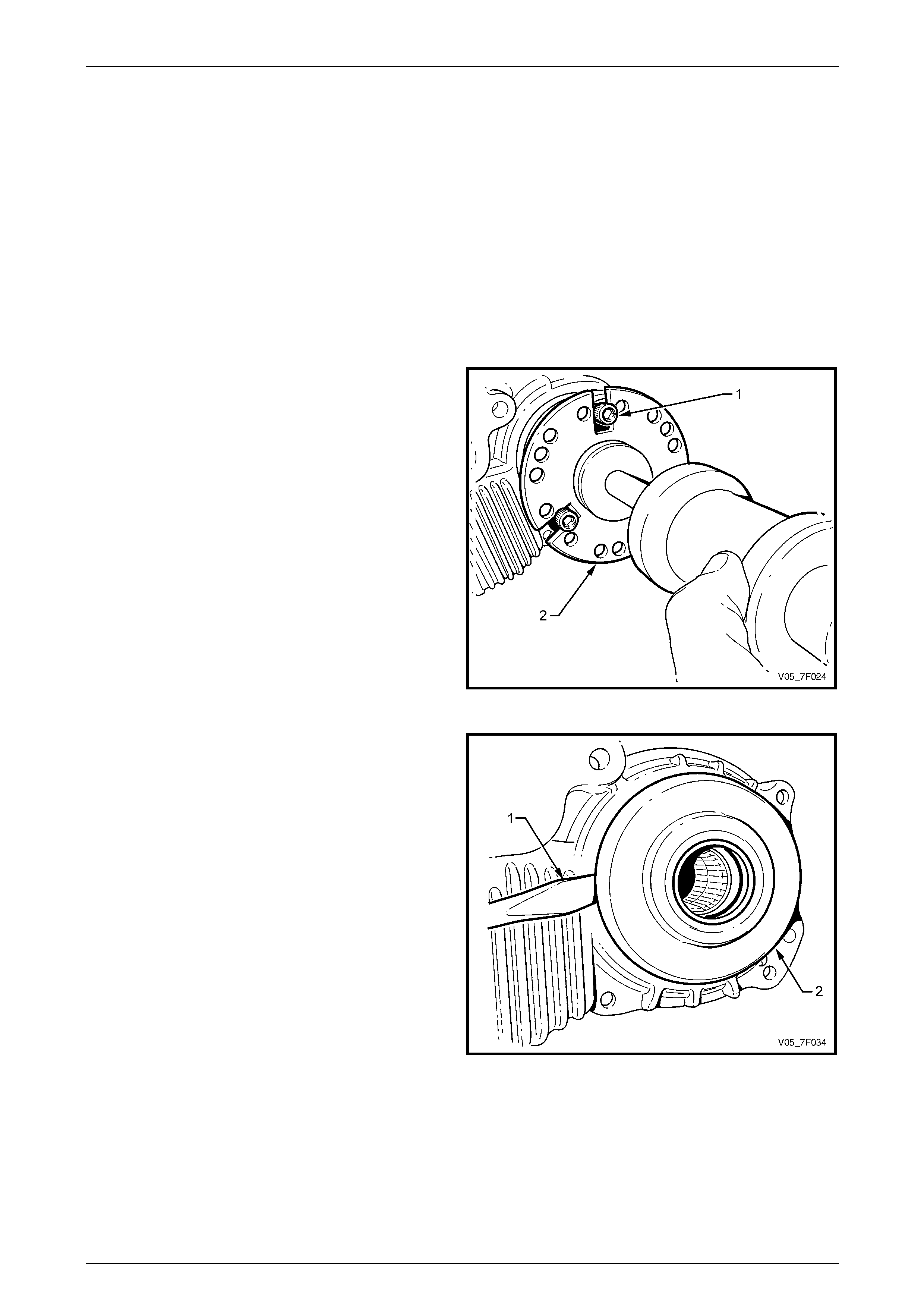
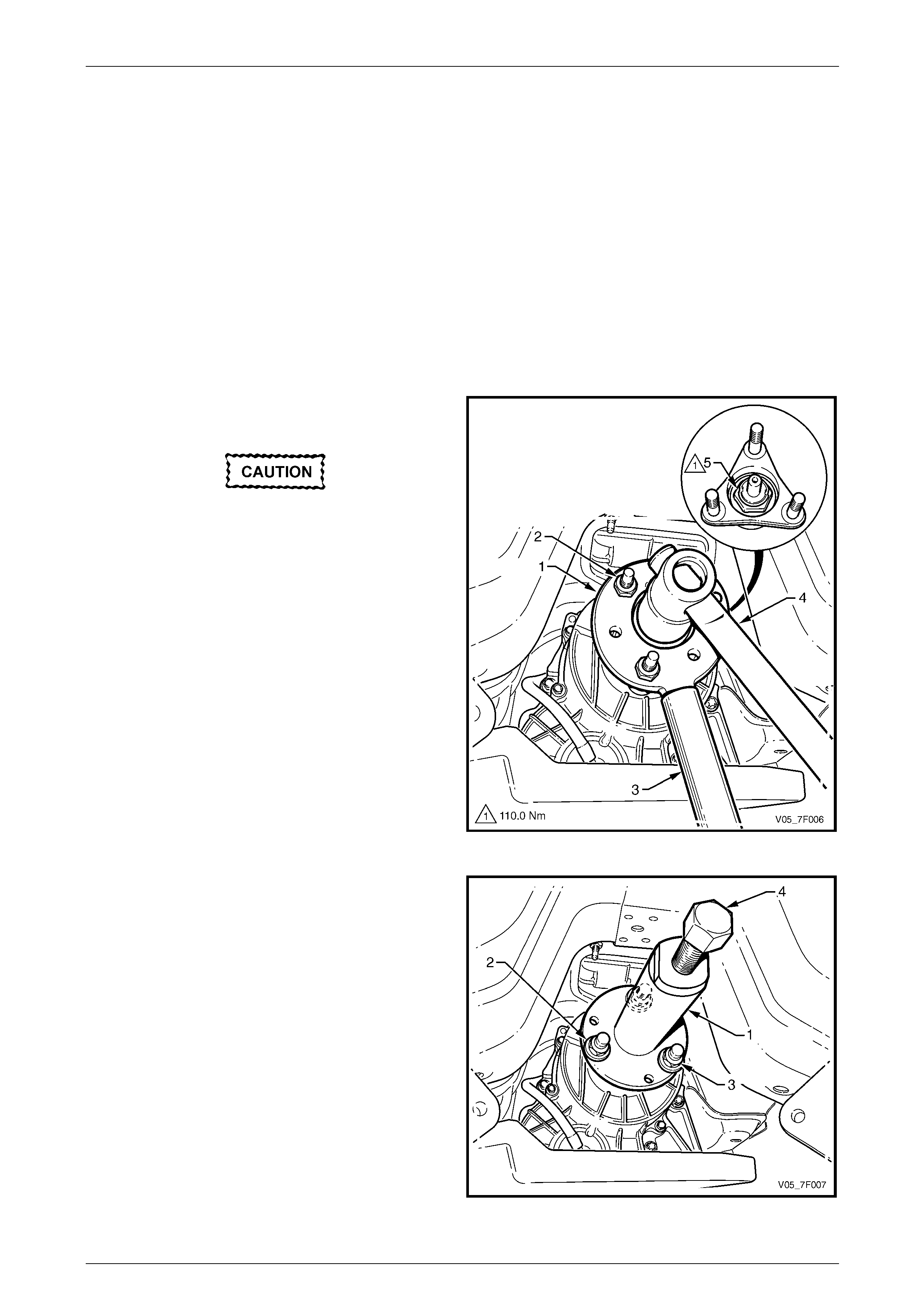
2 Locate the holding tool, Tool No. DT-47735 (1), onto
the transfer case rear output flange.
The holding tool must be firmly clamped to
the transfer case rear output flange to avoid
damaging the studs.
3 Install a suitable flat washer over each stud, then
secure the holding tool with the three ret ain ing nuts (2)
of the rear propeller shaft front rubber coupling.
4 With a suitable size length of pipe (3) fitted over the
tang of the holding tool, use a 36 mm deep s ocket and
suitable socket equipment (4) to remove the rear
output flange retaining nut (5).
NOTE
Do not discard the output flange retaining nut at
this stage as it will be used for the reinstallation
process.
5 Remove the holding tool from the rear output flange.
Figure 7F – 18
6 Locate the extracting tool, Tool No. DT-47736 (1), onto
the rear output flange.
7 Install a 25 mm spacer (2) (e.g. flat washers) over
each stud, then secure the extracting tool with the
three retaining nuts (3) of the rear propeller shaft front
rubber coupling.
NOTE
Unless the extracting tool is clamped up tight to
the rear output flange, there will not be sufficient
thread on the forcing screw (4) to remove the
rear output flange from the rear output shaft
splines.
8 Using suitable size spann ers, whil e holding the
extracting tool rotate the forcing screw (4) to remove
the rear output flange.
9 Remove the extracting tool from the rear output flange. Figure 7F – 19
Transfer Case and Adaptor Housing 7F – 19
7F-19
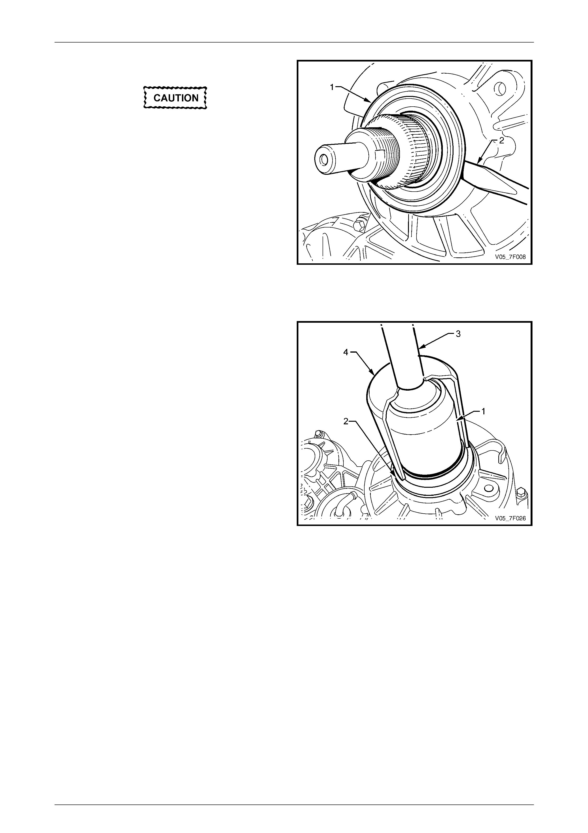
10 Clean the exposed part of the rear output shaft.
Take care during the seal removal operation
not to damage the transfer case machined
surfaces.
11 Remove the rear output oil seal (1) using a large
screwdriver (2) or similar, working ar ound the oil seal
outer perimeter. Discard the removed oil seal.
Figure 7F – 20
Reinstall
1 Install the seal protector, Tool No. DT-47601-2 (1),
over the transfer case rear output shaft and push to
fully install.
2 Lubricate a new rear output oil seal (2) with
Mobilgrease XHP 222 or equi valent, ensuring the
recesses between the oil seal lips are filled to
approximately 50%, then slide the oil seal over the
seal protector.
3 Install the driver, Tool No. AU-355-A (3), into the seal
installer, Tool No. DT-47601-1 (4), then fully install the
oil seal in the transfer case rear housing.
4 Remove the seal installation and protector tools.
Figure 7F – 21
5 Lubricate the splines of the transfer case rear output sh aft with 1 gram of Weicon™ standard grade, anti-seize
grease #37771.
NOTE
This grease is the only product approved for use
in this application and is available in a 10 gram
syringe.
6 Smear the rear output oil seal surface with petroleum jelly (e.g. Vaseli ne™ ), then install the rear output flange
engaging the splines with those on the transfer case rear output shaft.
7 Using a plastic hammer, tap the rear output flange onto the rear output shaft enough to enable the original retaining
nut to be installed.
Transfer Case and Adaptor Housing 7F – 20
7F-20
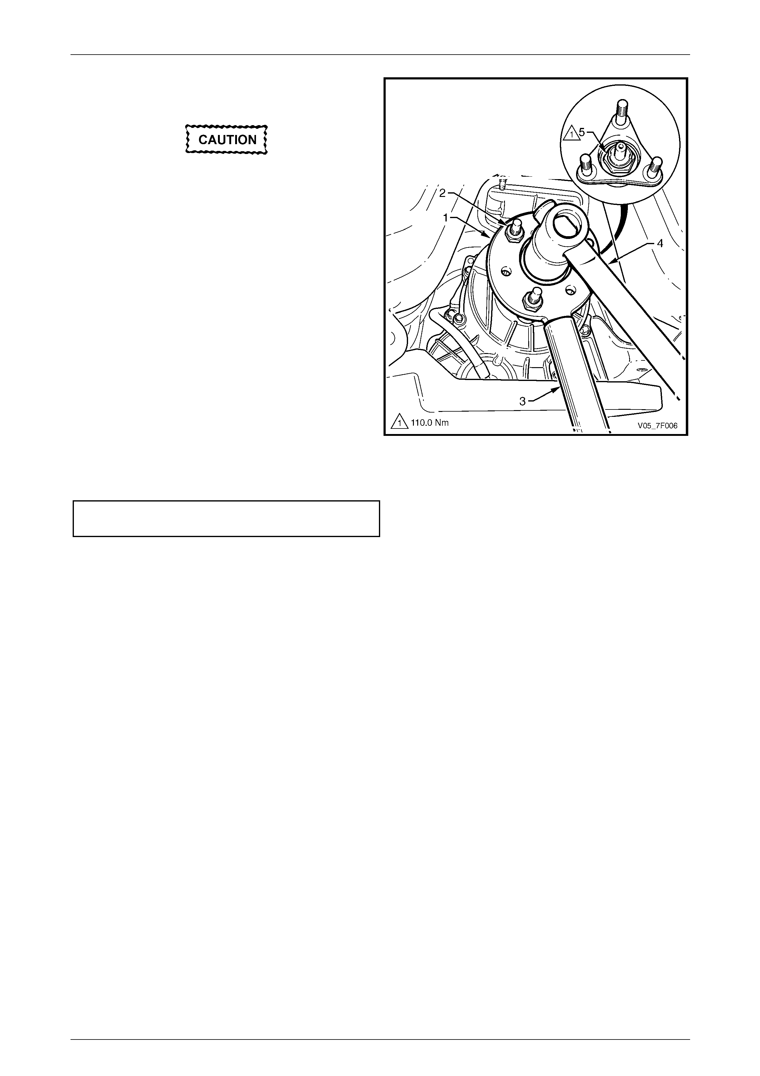
8 Locate the holding tool, Tool No. DT-47735 (1) onto
the transfer case rear output flange.
The holding tool must be firmly clamped to
the transfer case rear output flange to avoid
damaging the studs.
9 Install a suitable flat washer over each stud, then
secure the holding tool with the three ret ain ing nuts (2)
of the rear propeller shaft front rubber coupling.
10 With a suitable size length of pipe (3) fitted o v er the
tang of the holding tool, use a 36 mm deep s ocket and
suitable socket equipment (4) to fully install the rear
output flange by tightening the original reta ining nut.
11 Using the same socket equipment, remove and
discard the original retaining nut, then install a new
retaining nut to the rear output flange.
NOTE
The new nut fitted to the rear output flange has
loctite applied to its thread which will cure when
the nut is installed.
12 Tighten the new retaining nut (5) securing the rear
output flange to the correct torque specification.
Transfer case rear output flange
retaining nut torque specification .....................110.0 Nm
Figure 7F – 22
13 Check the transfer case lubricant level, refer to 2.1 Checking Transfer Case Lubricant Level.
14 Reinstall the following components:
a Mass damper, if fitted, refer to 2.5 Mass Damper.
b Rear propeller shaft, refer to Section 4C1 Rear Propeller Shaft and Universal Joints.
c Exhaust system rearward from the two catalytic converters, refer to Section 8B Exhaust System.
d Transmission support, refer to 2.4 T r ansmission Support.
Transfer Case and Adaptor Housing 7F – 21
7F-21
2.8 Transfer Case Support Mount
LT Section No. — 04–050
Replace
1 Remove the following components:
a Catalytic converter bracket, refer to 2.3 Catalytic Converter Bracket.
b Transmission support, refer to 2.4 T r ansmission Support.
2 With a wooden block and suitable hydraulic lifting equipment, support the transmission / transfer case on the
transfer case housing.
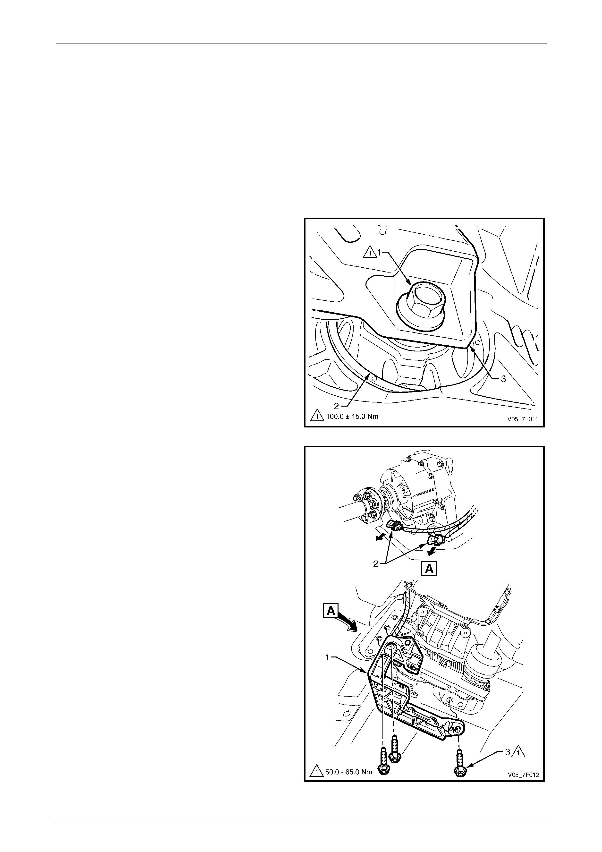
3 Remove the bolt (1) securing the rubber supp ort
mount (2) to the transfer case rear mounting
bracket (3).
Figure 7F – 23
4 Using a felt tipped pen or similar, mark the positio n of
the transfer case rear mounting bracket (1) to the
vehicle underbod y. NOTE
This will assist in aligning the rear mounting
bracket on reinstallation.
5 Disconnect the wiring harness connectors (2) and
separate from the rear mounting bracket by sliding
them off their support.
6 While supporting the rear mounting bracket, remove
the three bolts (3) attaching it to the vehicle
underbody.
7 Remove the rear mounting bracket from the vehicl e.
Figure 7F – 24
Transfer Case and Adaptor Housing 7F – 22
7F-22
8 Lower the rear of the transfer case enough to allow
access to the support mount.
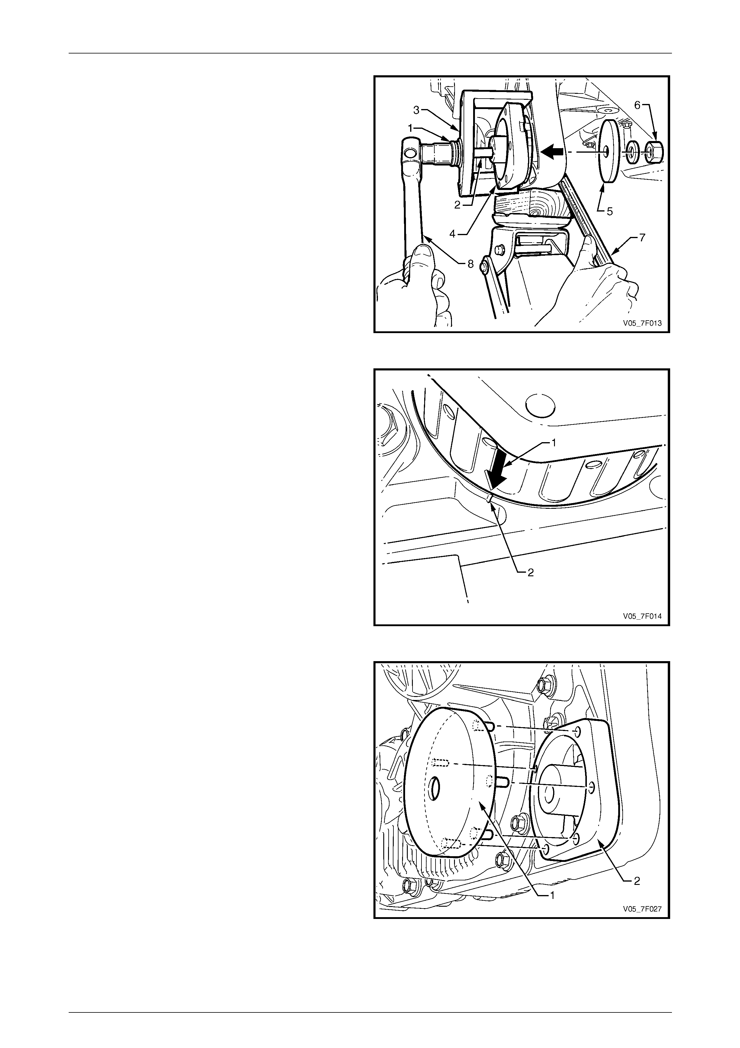
9 Feed the thrust bearing (1) onto the forcing bolt (2) of
the support mount remover/installer tool assembl y,
Tool No. DT-47597.
10 Feed the remover bracket, Tool No. DT-47597-4 (3),
onto the forcing bolt and thrust bearing, then fit these
parts to the support mount (4) on the rear side.
11 Install the remover disc, Tool No. DT-47597-3 (5) over
the forcing bolt on the support mount forward side,
rotate to align as required. Install the flat washer and
nut (6) to complete the remover tool assembly.
12 While holding the nut with a ring spanner (7), tighten
the forcing bolt with a suitable socket equi pment (8) to
remove the support mount towards the rear of the
transfer case housing.
13 Disassemble the remover tool, then remove the
support mount and discard. Figure 7F – 25
14 Wipe clean the mountin g surfaces, both in the transfer
case housing and the replac ement support mount
itself, then coat both surfaces with a soap solution.
15 Place the new support mount in the opening on the
transfer case housing rear side, alignin g the arrow (1)
moulded into the support mount with the notch (2) in
the housing.
Figure 7F – 26
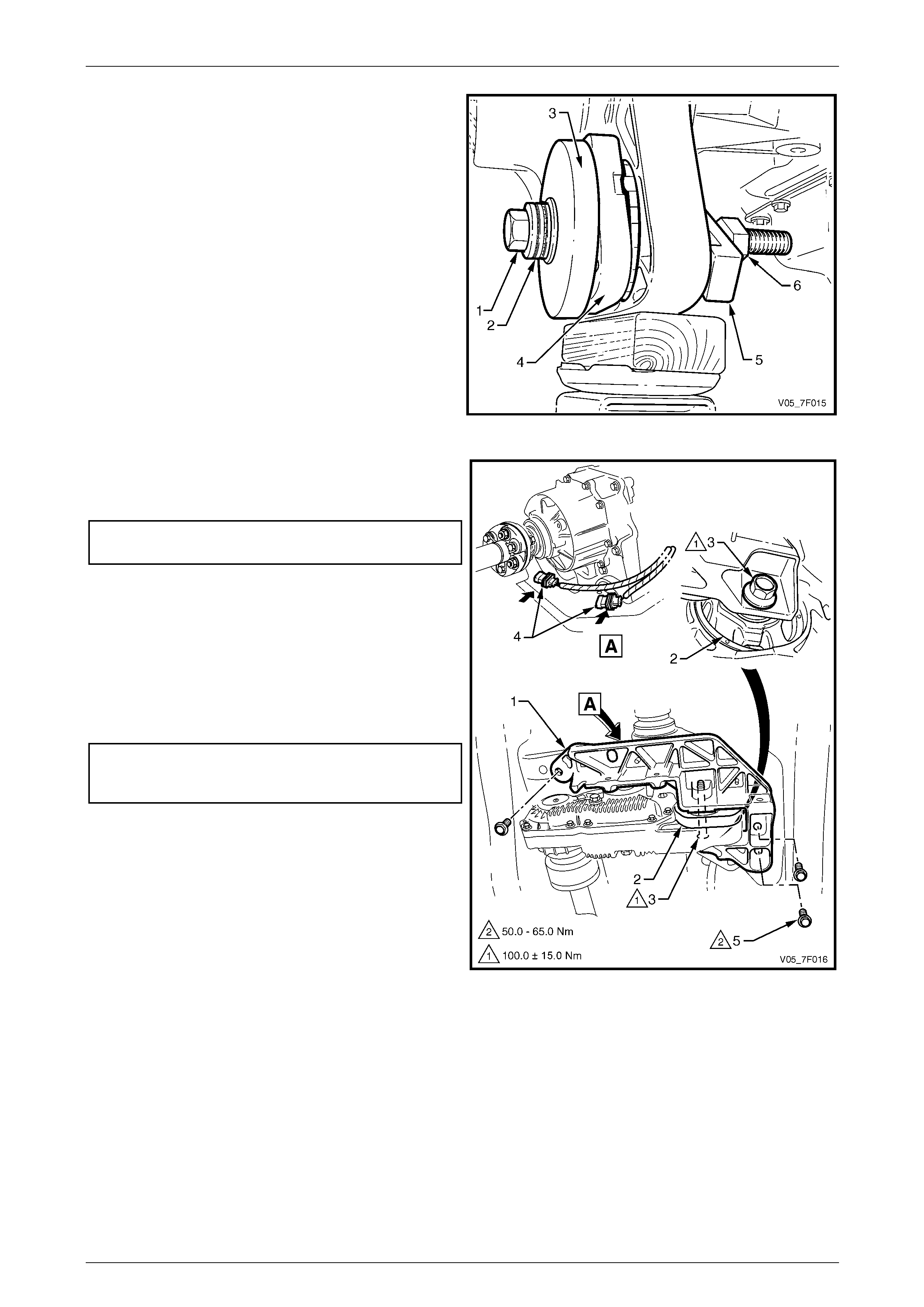
16 Fit the installer plate, Tool No. DT -47597-2 (1), to the
rear surface of the support mount (2), aligning the five
pins on the installer plate with the corresponding holes
in the support mount rear surface.
NOTE
The location of the smaller diameter pin is
closest to the transfer case.
Figure 7F – 27
Transfer Case and Adaptor Housing 7F – 23
7F-23
17 Feed the forcing bolt (1) and thrust bearing (2) in the
installer plate (3), on the support mount (4) rear side.
NOTE
The illustration shows the new support mount
partially installed.
18 Install the stepped installer bracket, T ool
No. DT-47597-1 (5), over the forcing bolt, ali gning it
with the transfer case housing forward side, as shown.
Install the flat washer and nut (6) to complete the
installer tool assembly.
19 While holding the nut with a ring spanner, tighten the
forcing bolt using a suitable socket equipment to fully
install the support mount into the transfer case
housing.
20 Disassemble and remov e the installer tool.
Figure 7F – 28
21 Secure the transfer case rear mounting brac ket (1) to
the support mount (2) with the attaching bolt (3).
Tighten the bolt to the correct torque specification.
Transfer case support mount
attaching bolt torque specification.........100.0 ± 15.0 Nm
22 Secure the wiring harness co nnectors (4) to the rear
mounting bracket by sliding them on their support.
23 With the hydraulic lifting equipment, lift the rear of the
transfer case and align the rear mounting bracket with
the marks made on the underbody before removal.
24 Secure the rear mounting bracket to the underbody
with the three attaching bolts (5). Tighten the three
bolts to the correct torque specification.
Transfer case rear mounting bracket
to underbody attaching bolt
torque specification.................................50.0 – 65.0 Nm
25 Lower the transfer case and remove the hydraulic
lifting equipment.
26 Reinstall the following components:
a Transmission support, refer to
2.4 Transmission Support.
b Catalytic converter bracket, refer to
2.3 Catalytic Converter Bracket.
Figure 7F – 29
Transfer Case and Adaptor Housing 7F – 24
7F-24
3 Major Service Operations
3.1 Transfer Case
LT Section No. — 04–050
Remove
1 Remove the following components:
a Catalytic converter bracket, refer to 2.3 Catalytic Converter Bracket.
b Transmission support, refer to 2.4 T r ansmission Support.
c Exhaust system rearward from the two catalytic converters, refer to Section 8B Exhaust System.
NOTE
Prior to their removal, it is good practice to mark
the flanges of the rear and front propeller shafts,
indicating their relative position to each other.
Use a felt tipped pen or similar. These marks will
assist to match the shafts position on
reassembly.
d Rear propeller shaft, refer to Section 4C1 Rear Propeller Shaft and Universal Joints.
e Front propeller shaft, refer to Section 4C2 Front Propeller Shaft and Universal Joints.
2 With a wooden block and suitable hydraulic lifting equipment, support the adaptor housing or the rear of the
transmission oil pan.
3 Remove the bolt (1) securing the rubber supp ort
mount (2) to the transfer case rear mounting
bracket (3).
Figure 7F – 30
Transfer Case and Adaptor Housing 7F – 25
7F-25
4 Using a felt tipped pen or similar, mark the positio n of
the transfer case rear mounting bracket (1) to the
vehicle underbod y.
NOTE
This will assist in aligning the rear mounting
bracket on reinstallation.
5 Disconnect the wiring harness connectors (2) and
separate from the rear mounting bracket by sliding
them off their support.
6 While supporting the rear mounting bracket, remove
the three bolts (3) attaching it to the vehicle
underbody.
7 Remove the rear mounting bracket from the vehicl e.
8 If fitted, remove the mass damper, refer to
2.5 Mass Damper.
Figure 7F – 31
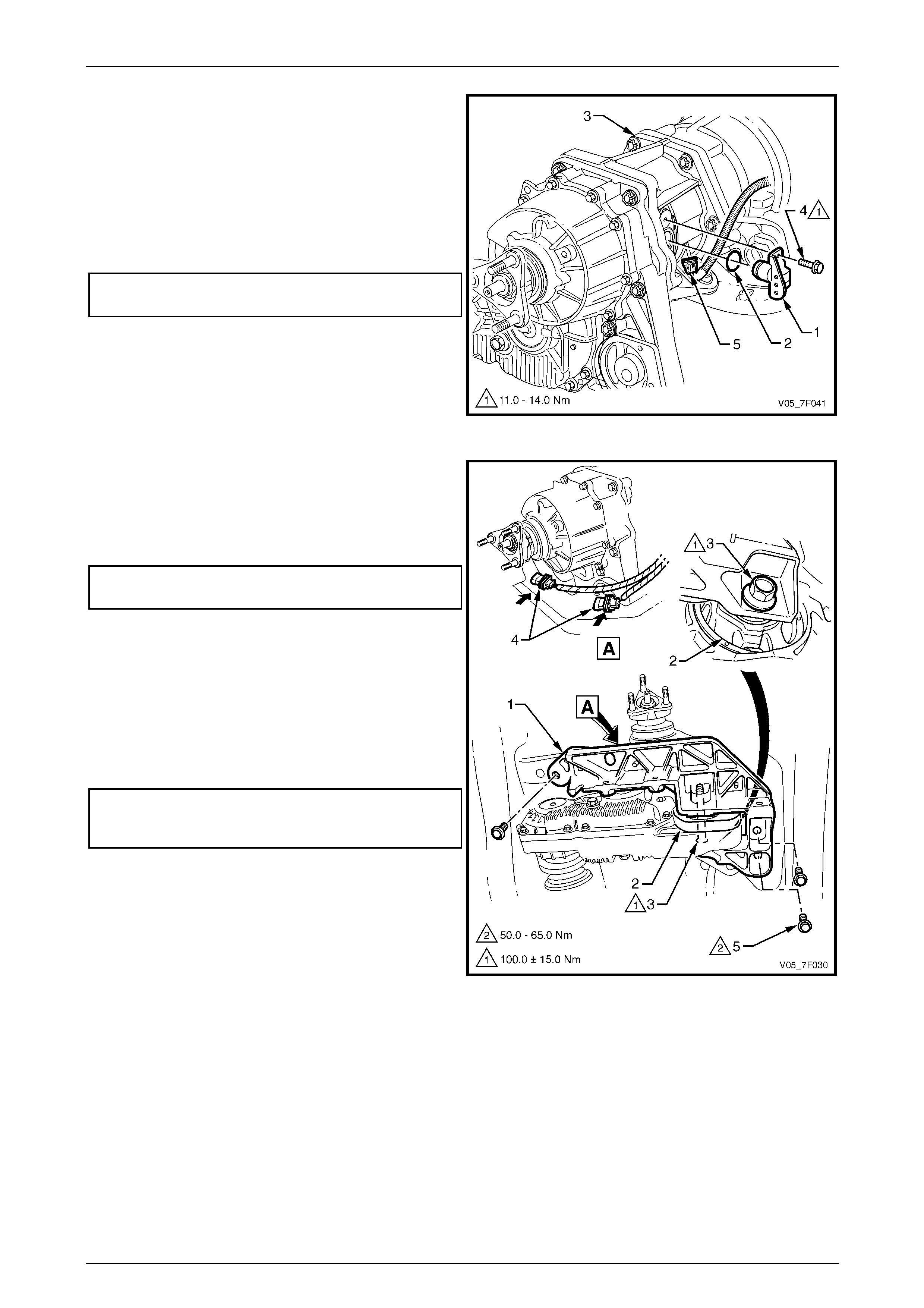
9 If the transfer case is fitted to a 4 speed transmission,
remove the vehicle speed sensor as foll ows:
a Slowly lower the hydraulic support to gain
access to the speed sensor.
b Disconnect the wiring harness connector (1).
c Remove the bolt (2) attaching the speed sensor.
d With a pulling and turning motion, remove the
speed sensor and O-ring seal from the adaptor
housing.
NOTE
The speed sensor removal is a precautionary
measure to avoid possible damage from the
adaptor shaft pick-up ring teeth.
Figure 7F – 32

Transfer Case and Adaptor Housing 7F – 26
7F-26
10 Disconnect the transfer case breather hose (1) from
the vent fitting (2) and secure to one side.
Figure 7F – 33
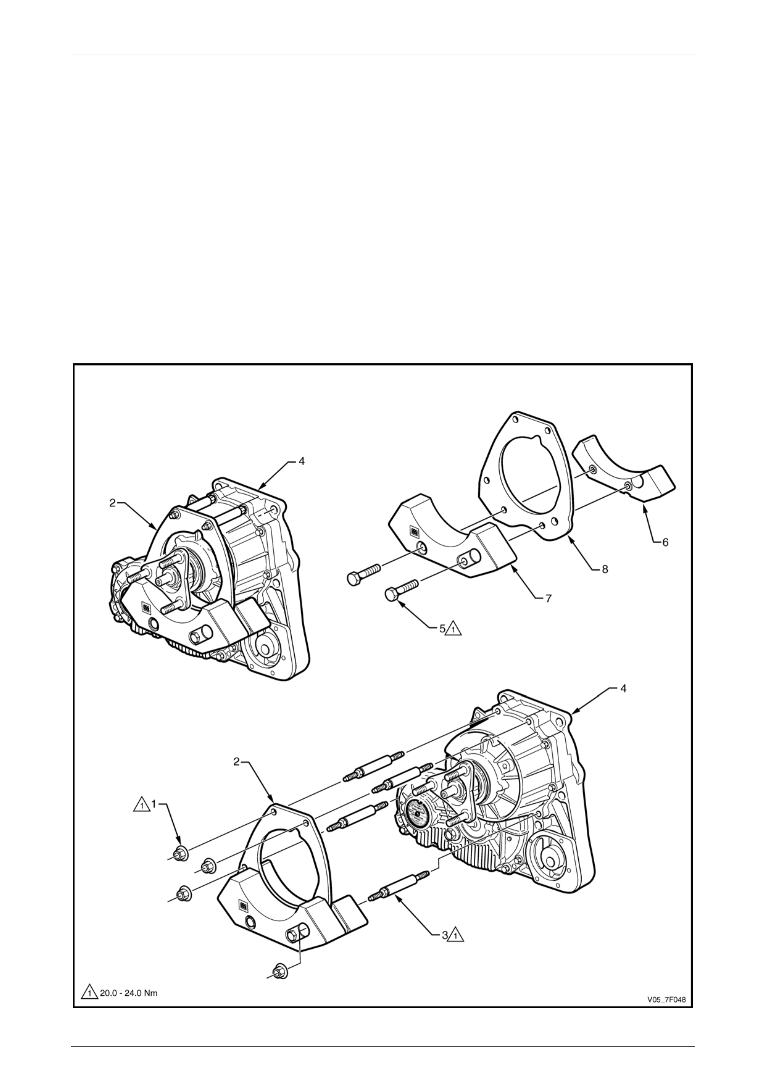
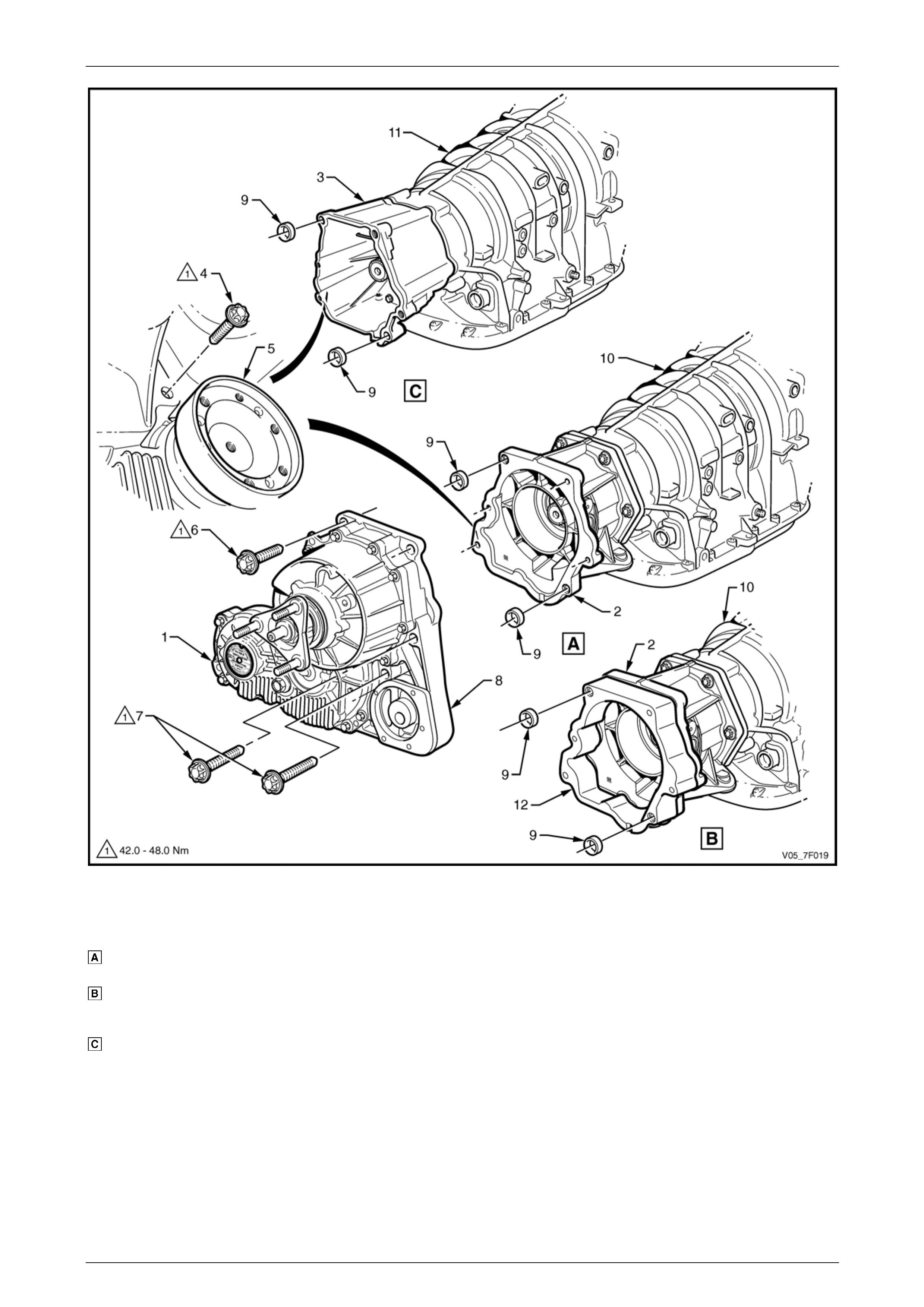
11 Using an E14 Torx socket and suitable socket equipment, remove the bolts attaching the transfer case housing (1)
to the adaptor housing (2) or extension housing (3) located as follows, refer to Figure 7F – 34:
• one bolt (4) on the forward side of the transfer case, adjacen t to the front output flange (5),
• bolt (6), three places, on the rear side of the transfer case and
• two bolts (7) on the rear side of the transfer case, adjacent to the support mount (8).
NOTE
Take note of the location of the two longer
bolts (7).
Transfer Case and Adaptor Housing 7F – 27
7F-27
Figure 7F – 34
Legend
Adaptor Housing with V8 Engine
and 4 Speed Transmission
Adaptor Housing and Plate with
Alloytech V6 Engine and
4 Speed Transmission
Extension Housing with 5 Speed
Transmission
1 Transfer Case Housing
2 Adaptor Housing
3 Extension Housing
4 Transfer Case Bolt (forward flange)
5 Front Output Flange
6 Transfer Case Bolt (rear flange)
7 Transfer Case Bolt (rear flange)
8 Support Mount
9 Locating dowel ring
10 4 Speed Transmission
11 5 Speed Transmission
12 Adaptor Plate (Alloytech V6 engine)
Transfer Case and Adaptor Housing 7F – 28
7F-28
12 While supporting the transfer case (1), pul l rearward to dislodge it from the two locating dowel rings (2) and until the
adaptor shaft (3) internal splines are clear of the transmission main shaft (4), refer to Figure 7F – 35.
13 Carefully lo wer the transfer case and remove it from the vehicle.
NOTE
While the transfer case is removed, do not rotate
the transmission output shaft.
14 If required, remove the two locating dowel rings (2).
15 If required, for a transfer case fitted to a 4 speed transmission on Alloytech V6 engine, remove the adaptor plate (5)
and the two locating dowel rings (6) from the adaptor housing.
Figure 7F – 35
Transfer Case and Adaptor Housing 7F – 29
7F-29
Reinstall
1 For a transfer case fitted to a 4 speed transmission:
a Inspect the front of the adaptor shaft for excess wear in the seal area. If deep grooving is evide nt, then it is
strongly recommended to replace the adaptor shaft, refer to 3.2 Transfer Case Input Shaft Oil Seal and the
oil seal located in the adaptor housing, refer to 3.4 Transmission Adaptor Housing Oil Seal.
b On the adaptor shaft, lubricate the internal splines and the front outer diameter contacting the seal, with
molybdenum disulphide gre ase.
c If previously removed on Alloytech V6 engine, reinstall the two locating dowel rings (6) and the a daptor
plate (5) to the transmission adaptor hous ing, refer to Figure 7F – 35.
2 For a transfer case fitted to a 5 speed transmission, lubricate the internal splines of the adaptor shaft with
molybdenum disulphide gre ase.
3 Check if the adaptor shaft is fully installed with the snap ring engaged in the input shaft groove, tug on the adaptor
shaft to ensure that engagement has occurred.
4 Ensure the two locating dowel rings (2) are correctly positioned on the adaptor housing or adaptor plate or
extension hous ing as applicable, refer to Figure 7F – 35.
5 With a suitable hydraulic lifting equipment, raise the transfer case and line it up with the adaptor/extension housing.
When installing a transfer case onto an
adaptor housing fitted to a 4 speed
transmission, take care not to damage the
housing oil seal while engaging the adaptor
shaft.
6 Align the transfer case front face parallel to the ada pt or/extension housing machined re ar face, then move the
transfer case forward to engage the splines of the adaptor shaft (3) with those of the transmission output shaft (4).
If required, rock the transfer case output flange back and forth to assist with spline engag ement.
7 Push the transfer case forward to engage b oth locating dowel rings (9), ins t all the bolt (4) on the forward flange, the
three bolts (6) and two bolts (7) on the rear flange attachi ng the transfer case to the ada ptor/extension housing,
then tighten to the correct torque specif ication, refer to Figure 7F – 34.
Transfer case to adaptor housing
attaching bolt torque specification...........42.0 – 48.0 Nm
NOTE
Only the presence of an oil leak will determine if
the adaptor housing seal has been damaged
during installation of a transfer case to a 4 speed
transmission.
8 Connect the breather hose (1) to the vent fitting (2) on
the transfer case.
Figure 7F – 36
Transfer Case and Adaptor Housing 7F – 30
7F-30
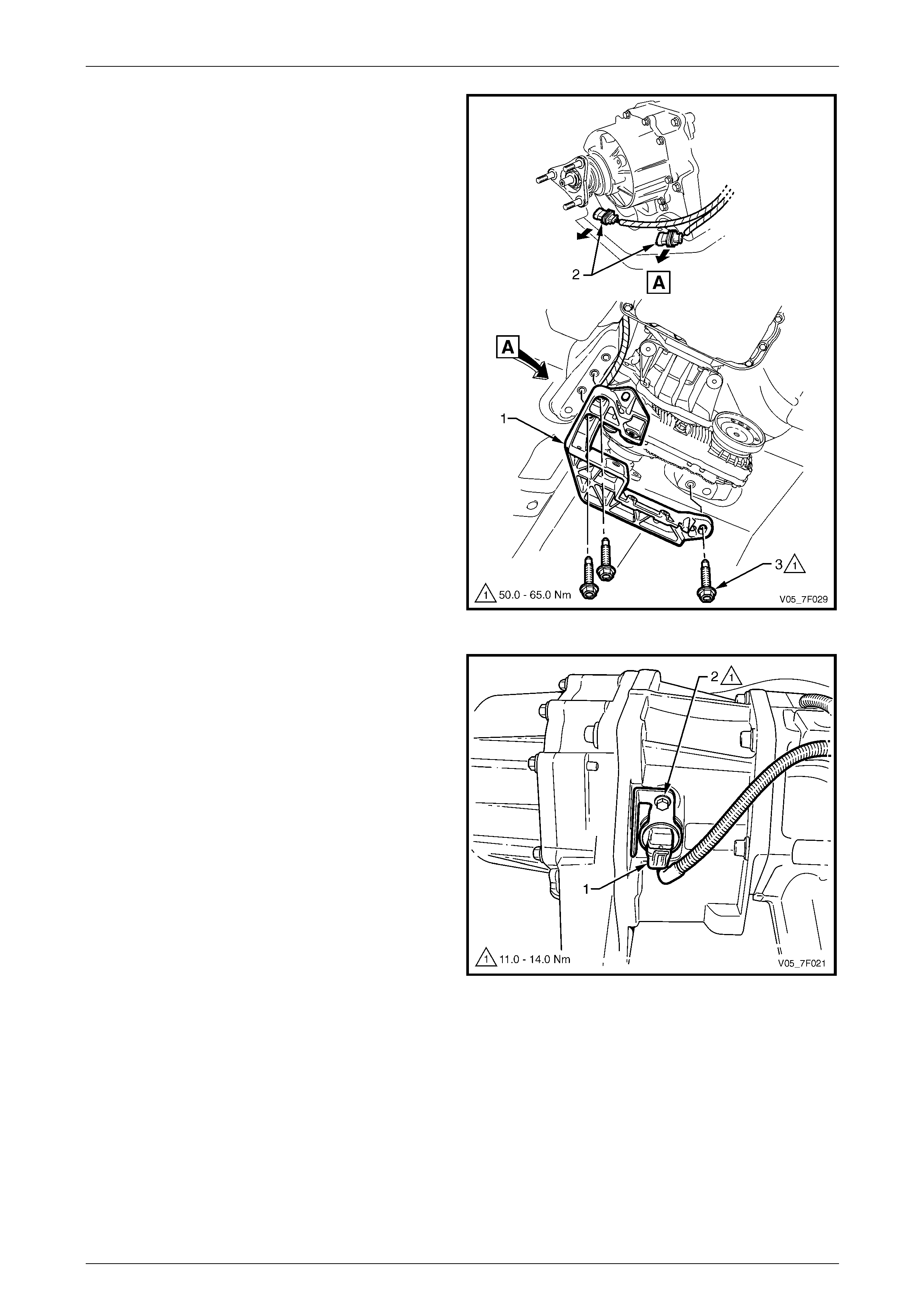
9 For a transfer case fitted to a 4 speed transmission,
install the vehicle speed sens or (1) as follows:
a Lubricate a new O-ring seal (2) with petrole um
jelly and install it to the speed sensor.
b Position the speed sensor in the adaptor
housing (3).
c Secure the speed sensor with the bolt (4),
tightening it to the correct torque specification.
Vehicle speed sensor attachin g bolt
torque specification.................................11.0 – 14.0 Nm
d Connect the wiring harness connector (5) to the
speed sensor.
Figure 7F – 37
10 If fitted, reinstall the mass damper, refer to
2.5 Mass Damper.
11 Secure the transfer case rear mounting brac ket (1) to
the support mount (2) with the attaching bolt (3).
Tighten the bolt to the correct torque specification.
Transfer case support mount
attaching bolt torque specification.........100.0 ± 15.0 Nm
12 Secure the wiring harness co nnectors (4) to the rear
mounting bracket by sliding them on their support.
13 With the hydraulic lifting equipment lift the rear of the
transfer case and align the rear mounting bracket with
the marks made on the underbody before removal.
14 Secure the rear mounting bracket to the underbody
with the three attaching bolts (5). Tighten the three
bolts to the correct torque specification.
Transfer case rear mounting bracket
to underbody attaching bolt
torque specification.................................50.0 – 65.0 Nm
15 Lower the transfer case, then remove the hydraulic
lifting equipment.
16 Ensure the transfer case lubricant level is correct, refer
to 2.1 Checking Transfer Case Lubricant Level.
Figure 7F – 38

Transfer Case and Adaptor Housing 7F – 31
7F-31
17 Reinstall the following components:
NOTE
Prior to installation, align the position of the two
propeller shafts with each other by matching the
marks done prior to removal. It may take up to six
turns for the marks to match.
a Front propeller shaft, refer to Section 4C2 Front Propeller Shaft and Universal Joints.
b Rear propeller shaft, refer to Section 4C1 Rear Propeller Shaft and Universal Joints.
c Exhaust system rearward from the two catalytic converters, refer to Section 8B Exhaust System.
d Transmission support, refer to 2.4 T r ansmission Support.
e Catalytic converter bracket, refer to 2.3 Catalytic Converter Bracket.
18 Check the automatic transmission fluid level, refer to:
• Section 7C4 Automatic Transmission – 4L60E – On-vehicle Servicing, for 4 speed automatic transmission, or
• Section 7E4 Automatic Tr ansmission – 5L40E – On-vehicle Servicing, for 5 speed automatic transmission.
Transfer Case and Adaptor Housing 7F – 32
7F-32
3.2 Transfer Case Input Shaft Oil Seal
LT Section No. — 04–050
Remove
1 Remove the transfer case from the adaptor/extension housing, refer to 3.1 T ransfer Case.
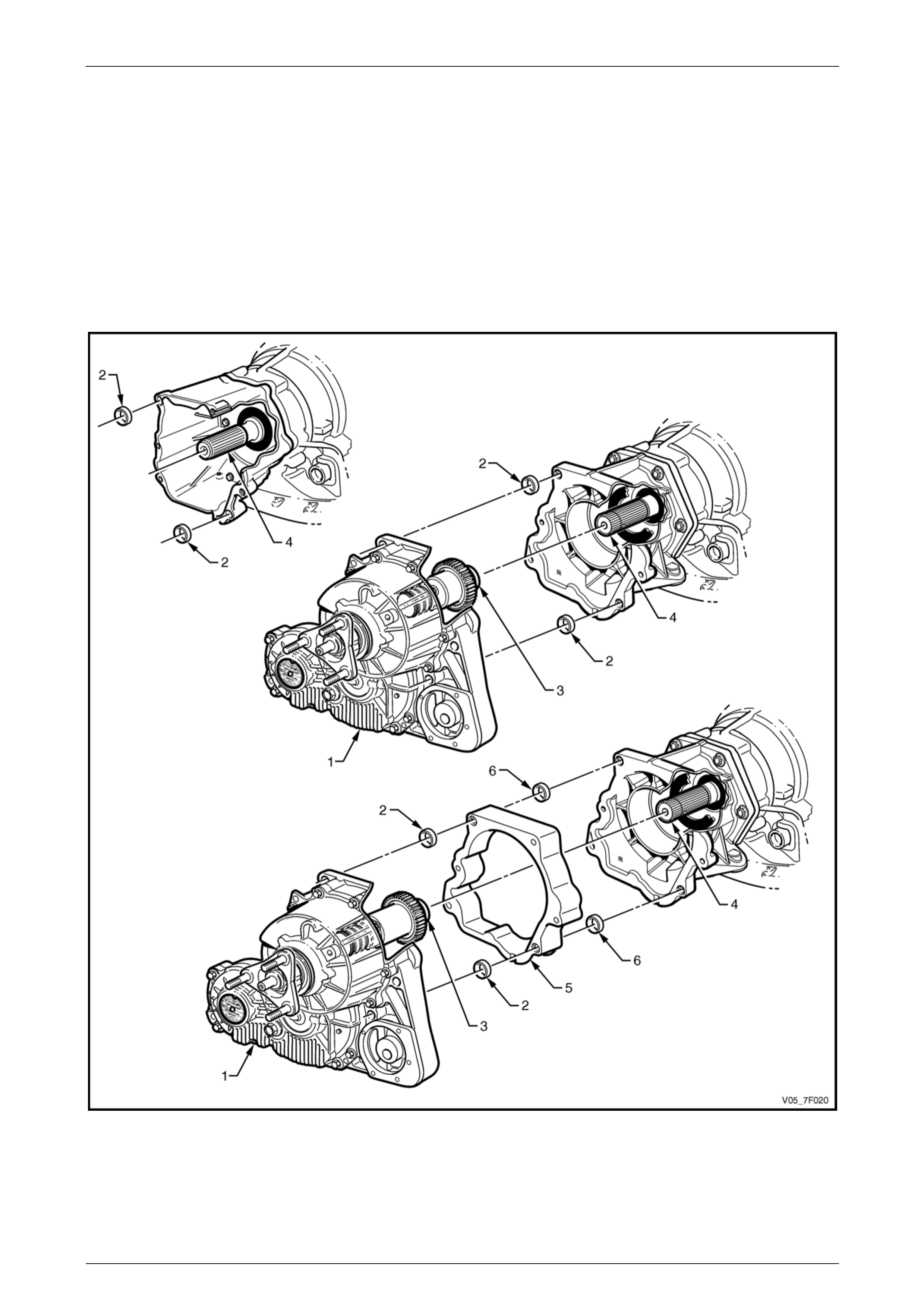
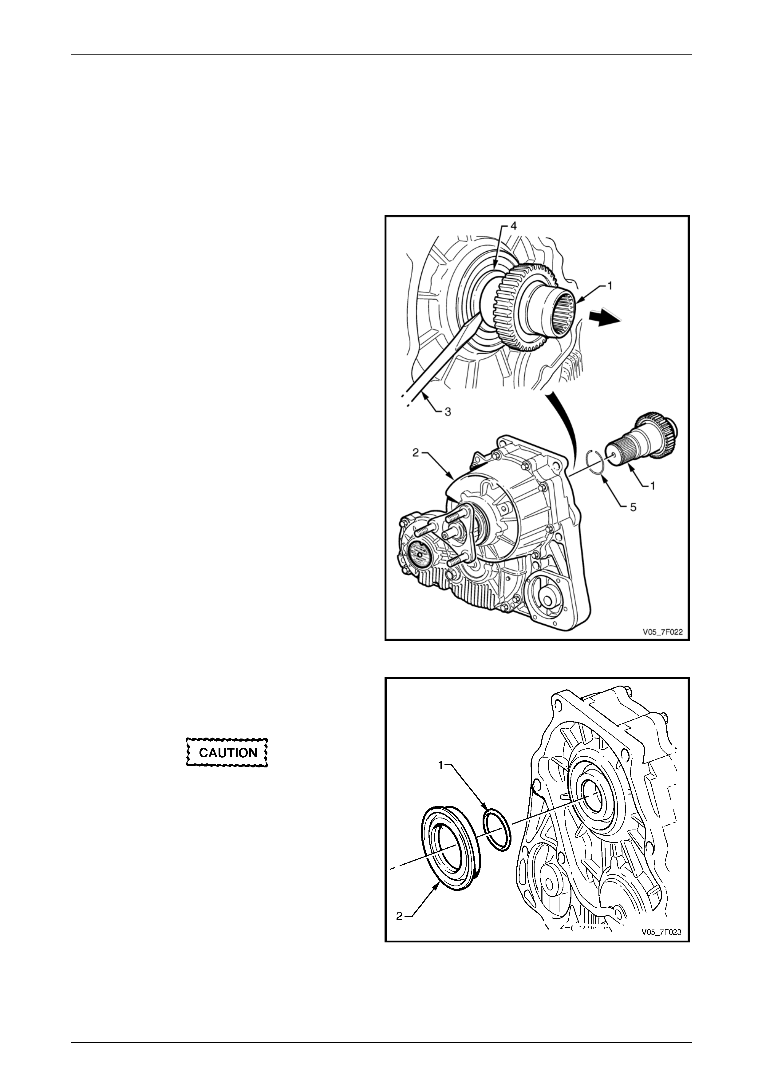
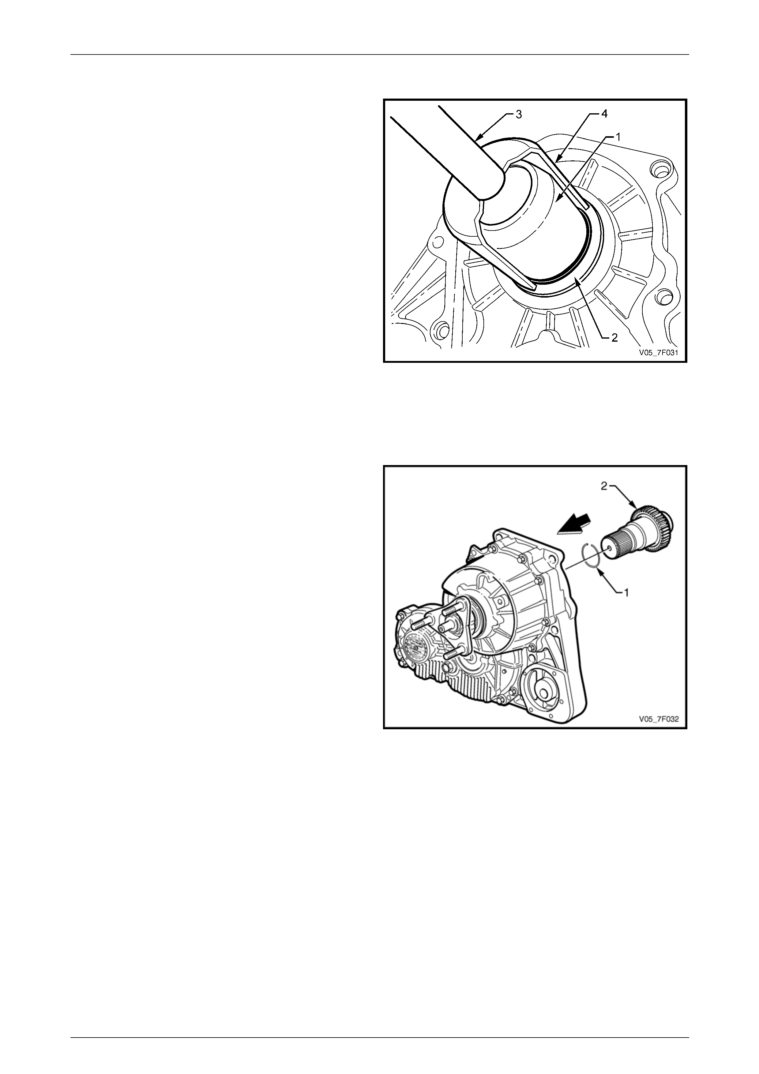
2 Lever the adaptor shaft (1) from the front of the
transfer case (2) by using a large screwdriver (3) or
similar tool between the adaptor shaft step and the oil
seal (4), then remove the adaptor shaft.
NOTE
Some resistance will be felt until the snap
ring (5) at the end of the adaptor shaft is
dislodged from the groove behind the splines in
the inner diameter of the input shaft.
3 Remove the snap ring from the adaptor shaft and
discard the snap ring.
NOTE
Short adaptor shaft shown, longer shaft fitted for
Alloytech V6 engine, refer to F igure 7F – 1.
Figure 7F – 39
4 Use a small screwdriver or wire hook to remove the
O-ring seal (1) from the inside of the front input shaft.
Discard the O-ring seal.
Take care during the seal removal operation
not to damage the transfer case machined
surfaces.
5 Remove the front input oil seal (2) using a large
screwdriver or similar, working around the oil seal
outer perimeter. Discard the removed oil seal.
Figure 7F – 40
Transfer Case and Adaptor Housing 7F – 33
7F-33
Reinstall
1 Install the seal protector, Tool No. DT-47600-1 (1),
over the front input shaft and push to fully install.
2 Lubricate a new front input oil seal (2) with
Mobilgrease XHP 222 or equi valent, ensuring the
recesses between the oil seal lips are filled to
approximately 50%, then slide the oil seal over the
seal protector.
3 Install the driver, Tool No. AU 355-A (3), into the seal
installer, Tool No. DT-47600-2 (4), then fully install the
oil seal in the transfer case front housing.
4 Remove the seal installation and protector tools.
5 Lubricate a new O-ring seal with a smear of
Mobilgrease XHP 222 or equivalent and install into the
groove of the front input shaft inner diameter.
6 Lubricate the internal splines of the front input shaft
with 1 gram of Weicon™ standard grade, anti-seize
grease #37771.
NOTE
This grease is the onl y product approved for use
in this application and is available in a 10 gram
syringe.
Figure 7F – 41
7 Fit a new snap ring (1) onto the end of the adaptor
shaft (2).
NOTE
Short adaptor shaft shown, longer shaft fitted for
Alloytech V6 engine, refer to F igure 7F – 1.
8 Engage the splines of the adaptor shaft with those in
the front input shaft and drive the adaptor shaft until
the snap ring engages the groove behind the front
output shaft splines.
NOTE
It is only necessary to use light force to fully
install the adaptor shaft.
9 Reinstall the transfer case on t o the adaptor housing,
refer to 3.1 Transfer Case.
Figure 7F – 42
Transfer Case and Adaptor Housing 7F – 34
7F-34
3.3 Adaptor Housing – 4 Speed
Transmission
LT Section No. — 04–100
Remove
1 Remove the transfer case and the vehicle s peed sensor from the adaptor housing, refer to 3.1 Transfer Case.
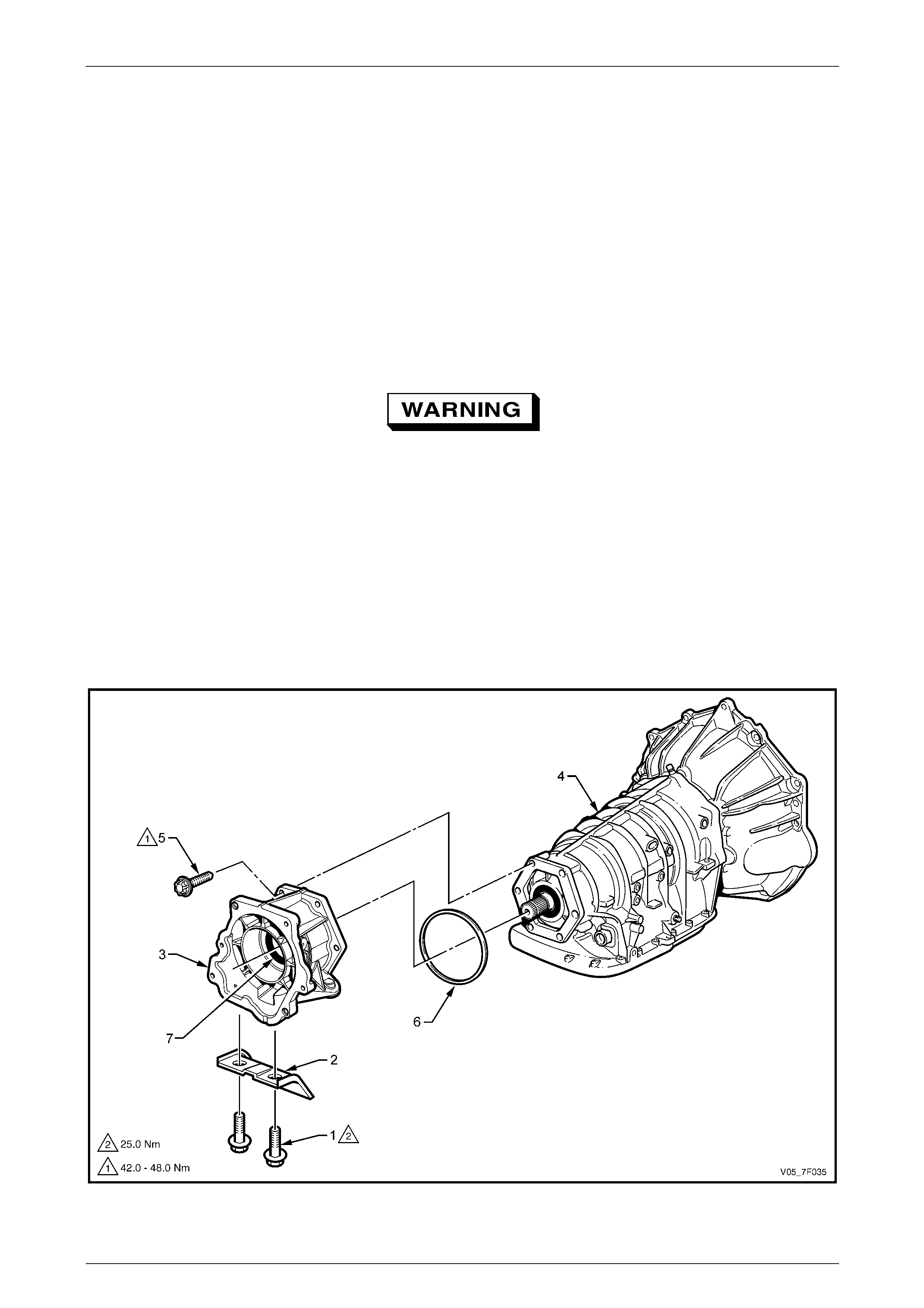
2 Remove the two bolts (1) attaching the bracket (2) to the adaptor ho using (3) and remove the bracket,
refer to Figure 7F – 43.
3 Place a drain tray under the rear of the automatic transmission (4) to catch residual transmission fl uid once the seal
between the transmission and adaptor housing is broken.
If the transmission oil p an feels hot, take care
to avoid scalding from the hot automatic
transmission fluid that will flow from the rear
of the transmission.
4 Using an E14 Torx socket and suitable equipment, remove the bolt (5), six places, attaching the adaptor housing to
the rear of the automatic transmission.
5 If required, support and tap the adaptor housing with a rubber hammer, to break the seal with the transmission
housing.
6 Remove the adaptor housing and O-ring seal (6) from the rear of the automatic transmission, discard the O-ring
seal.
7 If required, remove the oil seal (7) from the adaptor housing, refer to 3.4 Transmission Adaptor Housing Oil Seal .
Figure 7F – 43

Transfer Case and Adaptor Housing 7F – 35
7F-35
Reinstall
1 If required, install a new oil seal in the a da ptor housing, refer to 3.4 Transmission Adaptor Housing Oil Seal.
2 Clean the mating surfaces of the transmission and the adaptor housing.
3 Install a new square section O-ring seal (6) that has be en lubricated with a smear of petr oleum jelly on the adaptor
housing (3) forward side, refer to F igure 7F – 43.
4 Lubricate the oil seal lips (7) wit h petro leum jelly and then reinsta ll the adaptor housing to the rear of the
transmission.
5 Install the Torx bolt (5), six places, attaching the ad aptor housing and tighten to the correct torque specification.
Adaptor housing to transmission case
Torx bolt torque specification..................42.0 – 48.0 Nm
6 Reinstall the adaptor hous ing bracket (2) and tighten the two attaching bolts (1) to the correct torque sp ecification.
Adaptor housing bracket attachin g
bolt torque specification.....................................25.0 Nm
7 Reinstall the transfer case an d the vehicle speed sensor onto the adaptor housing, refer to 3.1 Transfer Case.
8 Check the automatic transmission fluid lev el,
refer to Section 7C4 Automatic Transmission – 4L60E – On-vehicle Servicing.
Transfer Case and Adaptor Housing 7F – 36
7F-36
3.4 Transmission Adaptor Housing Oil Seal
LT Section No. — 04–100
Replace
1 Remove the following compo nents from the vehicle, as required:
a Transfer case, refer to 3.1 Transfer Case.
b Adaptor housing, refer to 3.3 Adaptor Housing.
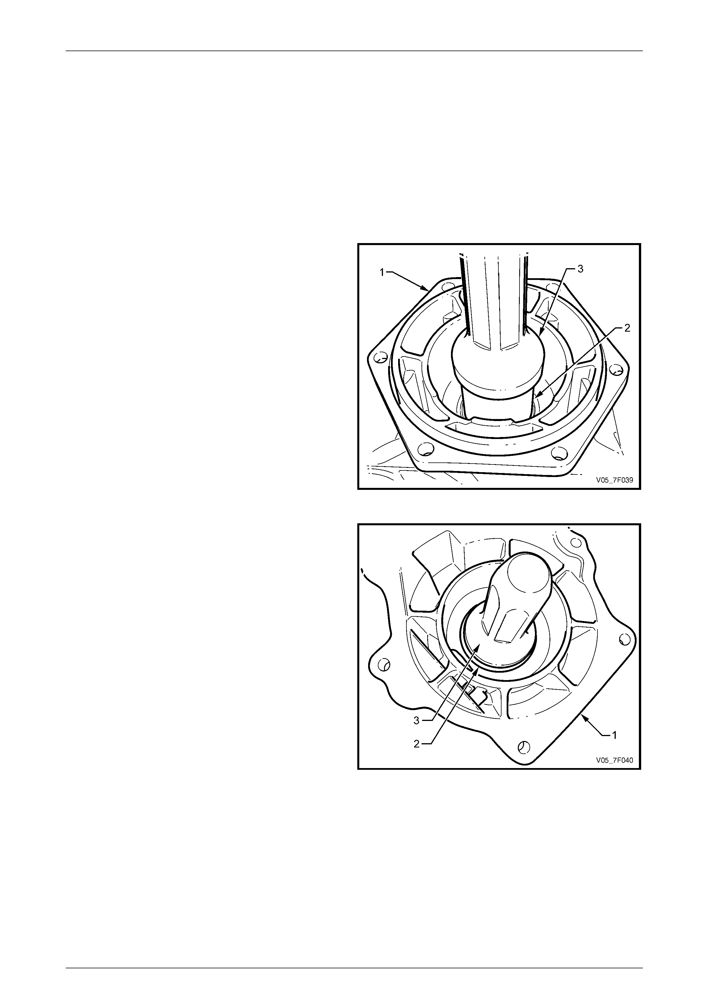
2 Support the adaptor housing (1) on a flat surface,
forward side facing upward.
3 Use the sleeve, Tool No. E1896-6 (or 3A8-6) (2), and
the seal installer, Tool No. J 21426 (3), to drive the oi l
seal out of its location, towards the rear section of the
adaptor housing. Discard the removed oil seal.
NOTE
Alternatively to the sleeve (2) a suitable piece of
pipe (OD 57 mm) can be used to remove the oil
seal.
Figure 7F – 44
4 Support the adaptor housing ( 1) on a flat surface, rear
side facing upward.
5 To facilitate the installation, lu bricate a new oil seal (2)
with petroleum jelly and p osition it into the adaptor
housing.
6 Use the seal installer, Tool No. J 21426 (3), to drive
the new oil seal in place, working from the rear
towards the front of the adaptor housing.
7 Lubricate the seal lips with petroleum jelly, before
reinstalling the adaptor ho using to the rear of the
transmission.
8 Reinstall the following components:
a Adaptor housing, refer to 3.3 Adaptor Housing.
b Transfer case, refer to 3.1 Transfer Case.
Figure 7F – 45

Transfer Case and Adaptor Housing 7F – 37
7F-37
4 Transfer Case Symptom
Diagnosis
4.1 Preliminary Diagnosis
System Operation
Review the system operation to familiarise yo urself with the system functions, refer to 1 General Description.
As the internal components are not serviced separately, should an internal component failure be determined, then the
transfer case must be replaced as an assembly.
Visual/Physical Inspection
1 Inspect the easily accessible or visually inspect the system components for obvious damag e, or for conditions that
could cause the symptom.
2 Inspect for the correct lubrication type and level, refer to 2.1 Checking Transfer Case Lubricant Level.
As this assembly has a very specific lubricati on requirement, if in doubt drain the lubricant and refill with the known
correct fluid, refer to 2.2 Draining and Filling Transfer Case Lubric ant .
Symptom List
To diagnose the symptom, refer to the appro priate symptom diagnostic procedure:
• 4.2 Popping Noise
• 4.3 Whine or Rumble Noise
• 4.4 Growl or Grinding Noise
• 4.5 Clunk During Acceleration and Deceleration
• 4.6 No Front or Rear Drive
• 4.7 Lubricant Leak Diagnosis.
Techline

Transfer Case and Adaptor Housing 7F – 38
7F-38
4.2 Popping Noise
Definition
A faulty internal component that causes a po pping noise in the transfer case.
Diagnostic Table
Cause Defect and Correction
Internal damage Probable gear teeth damage that has caused subsequent bearing failure due to metallic
debris.
Replace the transfer case, refer to 3.1 Transfer Case.

Transfer Case and Adaptor Housing 7F – 39
7F-39
4.3 Whine or Rumble Noise
Definition
A faulty internal component that causes a whine or rumbling noise in the transfer case.
Diagnostic Table
Cause Defect and Correction
Faulty bearings Failure of one or more interna l bearing(s).
Replace the transfer case, refer to 3.1 Transfer Case.

Transfer Case and Adaptor Housing 7F – 40
7F-40
4.4 Growl or Grinding Noise
Definition
A faulty internal component that causes a growl or grinding noise in the transfer case.
Diagnostic Table
Cause Defect and Correction
Internal damage Possible damage to the plane tary carrier pinion teeth, the carrier, the ring gear and/or
sun gear teeth. Loss of lubrica nt contributes to the damage noted.
Replace the transfer case, refer to 3.1 Transfer Case.

Transfer Case and Adaptor Housing 7F – 41
7F-41
4.5 Clunk During Acceleration and
Deceleration
Definition
During acceleration or deceleration, a clunk is heard or felt from the transfer case.
Diagnostic Table
Cause Defect and Correction
Incorrect lubricant level Inspect the transfer case for correct lubricant level, refer to 2.1 Checking Tr ansfer Case
Lubricant Level.
If the lubricant level is low, then the reason must be determined and corrected before
placing the vehicle back into service.
Internal damage Excessive backlash in the geartrain caused b y teeth wear.
Replace the transfer case, refer to 3.1 Transfer Case.
Loose rear output flange nut Rear output flange retaining nut loose, causing flange splines to wear.
Replace the rear output flange, refer to 2.7 Transfer Case Rear Output Fl ange and Oil
Seal.
If a new rear output flange does not correct the condition, then replace the transfer
case, refer to 3.1 Transfer Case.

Transfer Case and Adaptor Housing 7F – 42
7F-42
4.6 No Front or Rear Drive
Definition
The transfer case is not delivering engine torque to the rear and front prope ller shafts.
Diagnostic Table
Cause Defect and Correction
Internal damage Probable planetary gear set damage creating a permanent neutral condition.
Replace the transfer case, refer to 3.1 Transfer Case.

Transfer Case and Adaptor Housing 7F – 43
7F-43
4.7 Lubricant Leak Diagnosis
Definition
A visible indication of lubrica nt external leakage from the transfer case is evident.
Diagnostic Table
Cause Defect and Correction
Drain or fill plug Replace the leaking plug and gasket, refer to 2.2 Draining and Filling T r ansfer Case
Lubricant.
Rear output shaft seal leaking Overfilled or incorrect transfer case lubricant level, refer to 2.1 Checking Transfer Case
Lubricant Level.
Blocked vent, check for correct routing and no kink of vent hose. Cle ar blocked vent
line, refer to 1.3 Transfer Case Maintena nce.
The seal is improperly installe d, worn or damaged. Inspect the rear output flange seal
surface for excessive wear or damage.
Replace the rear output shaft flange and oil seal, refer to 2.7 Transfer Case Rear
Output Flange and Oil Seal.
The seal bore is damaged or the housing is cracked.
Replace the transfer case, refer to 3.1 Transfer Case.
The rear output shaft bearing is worn.
Replace the transfer case, refer to 3.1 Transfer Case.
Front output shaft seal leaking Overfilled or incorrect transfer case lubricant level, refer to 2.1 Checking Transfer Case
Lubricant Level.
The vent hose is blocked, check for correct routing and no kink of vent hose. Clear
blocked vent line, refer to 1.3 Transfer Case Maintenance.
The seal is improperly installe d, worn or damaged. Inspect the front output flange seal
surface for excessive wear or damage.
Replace the front output shaft flange and oil seal, refer to 2.6 Transfer Case Front
Output Flange, Slinger and Oil Seal.
The seal bore is damaged or the housing is cracked.
Replace the transfer case, refer to 3.1 Transfer Case.
The front output shaft bearing is worn.
Replace the transfer case, refer to 3.1 Transfer Case.
Leaking from the vent The transfer case is overfilled.
Restore to correct level, refer to 2.1 Checking Transfer Case Lubricant Level.
The vent hose is blocked, check for correct routing and no kink of vent hose. Clear
blocked vent line, refer to 1.3 Transfer Case Maintenance.
Adaptor housing fluid leak Check if the leaking fluid is automatic transmission fluid.
If it is not, refer to input shaft oil seal leaking, in this Table, otherwise continue.
Remove the transfer case and inspect the front of the adaptor shaft for wear or damage
at the seal contact area, refer to 3.1 Transfer Case.
Replace adaptor housing oil seal, refer to 3.4 Transmission Adaptor H ousing Oil Seal.
Input shaft seal leaking Overfilled or incorrect transfer case lubricant level, refer to 2.1 Checking Transfer Case
Lubricant Level.
The vent hose is blocked, check for correct routing and no kink of vent hose. Clear
blocked vent line, refer to 1.3 Transfer Case Maintenance.
The seal is improperly installe d, worn or damaged. Inspect the input seal surface for
excessive wear or damage.
Replace the input shaft oil seal, refer to 3.2 Transfer Case Input Shaft Oil Seal.
The seal bore is damaged or the housing is cracked.
Replace the transfer case, refer to 3.1 Transfer Case.
The input shaft bearing is worn.
Replace the transfer case, refer to 3.1 Transfer Case.
Lubricant leak from the transfer
case housing join Replace the transfer case, refer to 3.1 Transfer Case.
Lubricant leak from either of
the transfer case housings Replace the transfer case, refer to 3.1 Transfer Case.

Transfer Case and Adaptor Housing 7F – 44
7F-44
5 Specifications
General
Make...........................................................................................................New Process Gear
Model.....................................................................................................................NV 124 GM
Type.....................................................................................................Full Time Single Speed
Torque Split ......................................................................................38% – 62% Front to Rear
Gearing
Input from Transmission Output Shaft............................................. 3 pinion Planetary Carrier
Output to Rear Final Drive....................................................................... Planetary Ring Gear
Output to Front Final Drive .......................................................Sun Gear and Helical Gearing
Lubricants
Lubricant Type.................................................................................................Esso MTF-LT-1
.................................................................................................................. or Castrol BTO 338
Quantity – Dry Fill........................................................................................................240 ml
– Service Refill (after Draining)....................................approximately 100 – 160 ml
Oil Seal Lip and O-Ring Lubricant .........................................................Mobilgrease XHP 222
............................................................................................................................. or equivalent
Front Input, Front Output and Rear Output Shaft Splines...............Weicon™ Standard Grade
Anti-seize Grease #73331

Transfer Case and Adaptor Housing 7F – 45
7F-45
6 Torque Wrench Specifications
Transfer Case Filler Plug......................................................................32.0 Nm
Transfer Case Drain Plug.....................................................................32.0 Nm
Catalytic Converter Bracket to Adaptor Housing
Bracket Attaching Bolt..........................................................................25.0 Nm
Catalytic Converter Bracket to Catalytic Converter
Attaching Nut........................................................................................25.0 Nm
Mass damper blocks attaching bolt ...........................................20.0 – 24.0 Nm
Mass damper attaching stud .....................................................20.0 – 24.0 Nm
Mass damper attaching nut.......................................................20.0 – 24.0 Nm
Transmission Support to Transfer Case Rear
Mounting Bracket Attaching Bolt .................................................54.0 ± 5.0 Nm
Transmission Support to Und erbo dy Side Rail
Attaching Bolt..............................................................................54.0 ± 5.0 Nm
Transfer Case Rear Output Flange Retaining Nut..............................110.0 Nm
Transfer Case Support Mount Attaching Bolt..........................100.0 ± 15.0 Nm
Transfer Case Rear Mounting Bracket to
Underbody Attaching Bolt..........................................................50.0 – 65.0 Nm
Transfer Case to Adaptor Housing Attaching Bolt.....................42.0 – 48.0 Nm
Vehicle Speed Sensor Attaching Bolt........................................11.0 – 14.0 Nm
Adaptor Housing to Transmission Case Torx Bolt.....................42.0 – 48.0 Nm
Adaptor Housing Bracket Attaching Bolt...............................................25.0 Nm
Transfer Case and Adaptor Housing 7F – 46
7F-46
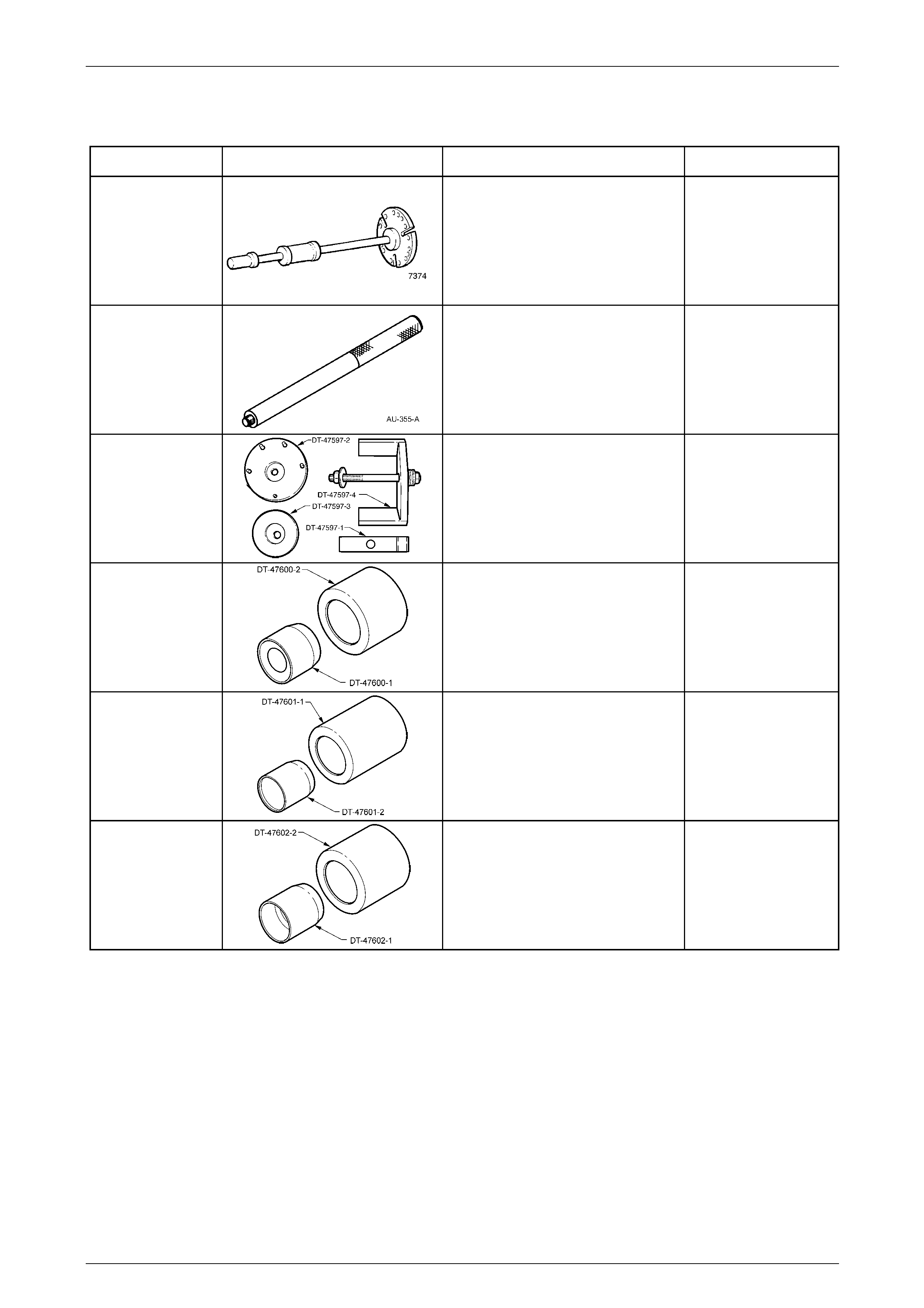
7 Special Tools
Tool Number Illustration Description Tool Classification
7374
Slide Hammer
Used with three screws to remove the
front output flange from the transfer
case.
Previously released.
Desirable
AU-355-A
Driver
Used in conjunction with various
installers.
Previously released.
Available
DT-47597
Support Mount Remover/Installer
Used to remove and install the
support mount from/to the transfer
case rear mounting bracket.
Previously released.
Available
DT-47600
Seal Protector and Installer
Used to protect and install the front
input shaft oil seal to the transfer
case.
Previously released.
Available
DT-47601
Seal Protector and Installer
Used to protect and install the rear
output shaft oil seal to the transfer
case.
Previously released.
Available
DT-47602
Seal Protector and Installer
Used to protect and install the front
output shaft oil seal to the transfer
case.
Previously released.
Available

Transfer Case and Adaptor Housing 7F – 47
7F-47
Tool Number Illustration Description Tool Classification
E1896-6
Sleeve
Used in conjunction with seal installer
J 21426 to remove the oil seal from
the adaptor housing.
Previously released.
Unique
J 21426
Seal Installer
Used in conjunction with sleeve
E1896-6 to remove the oil seal from
the adaptor housing and to install the
new seal.
Previously released.
Unique
DT-47735
Holding Tool
Used to hold the rear output flange
when loosening/tightening the flange
nut.
New release.
Unique
DT-47736
Extractor
Used to remove the rear output flange
from the rear of the transfer case.
New release.
Unique