
Automatic Transmission – 4L60E – General Information Page 7C1–1
Section 7C1
Automatic Transmission – 4L60E – General
Information
ATTENTION
Before performing any ser vice operation or other procedure d escribed in this Section, refer to Sectio n 00
Warnings, Cautions and Notes for correct workshop practices with regard to safety and/or property damage.
1 Section Descriptions..............................................................................................................................3
1.1 7C1 Automatic Transmission – 4L60E – General Information........................................................................... 3
Recommendations................................................................................................................................................. 4
Oil Cooler Pipes..................................................................................................................................................... 4
Clean and Inspect.................................................................................................................................................. 4
1.2 7C2 Automatic Transmission – 4L60E – Electrical Diagnosis........................................................................... 5
1.3 7C3 Automatic Transmission – 4L60E – Hydraulic and Mechanical Diagnosis............................................... 6
1.4 7C4 Automatic Transmission – 4L60E – On-vehicle Servicing.......................................................................... 7
1.5 7C5 Automatic Transmission – 4L60E – Unit Repair.......................................................................................... 8
2 General information ...............................................................................................................................9
2.1 Transmission Control Module – V6...................................................................................................................... 9
2.2 Transmission Variants ........................................................................................................................................ 10
Transmission Identification ................................................................................................................................ 10
2.3 Economy, Power and Cruise Modes.................................................................................................................. 11
Economy Mode .................................................................................................................................................... 11
Power Mode.......................................................................................................................................................... 11
Cruise Mode ......................................................................................................................................................... 11
2.4 Engine Torque Management, Gen III V8............................................................................................................. 12
2.5 System Protection Devices................................................................................................................................. 13
2.6 Self Diagnosis...................................................................................................................................................... 14
2.7 PCM or TCM Sensors and Actuators ................................................................................................................. 15
3 Transmission Control Module Operation Overview .........................................................................16
3.1 Transmission Control Module ............................................................................................................................ 16
Component Location........................................................................................................................................... 16
Transmission Control Module Data Transfer .................................................................................................... 17
Transmission Control Module Operation........................................................................................................... 17
3.2 TCM Wiring Diagrams.......................................................................................................................................... 18
MY05 V6 and V8 (without Input Speed Sensor)................................................................................................. 18
MY06 V6 (with Input Speed Sensor)................................................................................................................... 21
4 Transmission Definitions and Abbreviations....................................................................................24
4.1 Throttle Position Related Definitions................................................................................................................. 24
4.2 Noise Condition Related Definitions.................................................................................................................. 25
4.3 General Definitions.............................................................................................................................................. 26
4.4 Abbreviations....................................................................................................................................................... 29
Page 7C1–1
Techline
Techline

Automatic Transmission – 4L60E – General Information Page 7C1–2
5 Service Notes........................................................................................................................................30
Fasteners.............................................................................................................................................................. 30
General Workshop Practice................................................................................................................................ 30
6 Torque Specifications..........................................................................................................................31
7 Transmission Specifications...............................................................................................................32
7.1 General ................................................................................................................................................................. 32
8 Special Tools ........................................................................................................................................35
Page 7C1–2

Automatic Transmission – 4L60E – General Information Page 7C1–3
1 Section Descriptions
Service information for the Hydra-matic 4L60E Automatic transmission has been divided into five Sections to assist the
tecnician to quickly locate the correct service, maintenance and diagnostic information.
The following provides a brief outline of each of the Sections.
7C1 Automatic Transmission – 4L60E – General Information
7C2 Automatic Transmission – 4L60E – Electrical Diagnosis
7C3 Automatic Transmission – 4L60E – Hydraulic and Mechan ical Diagnosis
7C4 Automatic Transmission – 4L60E – On-vehicle Servici ng
7C5 Automatic Transmission – 4L6 0E – Unit Repair
The following provides a brief outli ne of each of the Sections.
1.1 7C1 Automatic Transmission – 4L60E –
General Information
This section provides general informati on ab out the automatic transmission, including:
A glossary of terms,
Transmission identification information,
Electrical overview of the Transmission Control Module (TCM),
Some notes that address safe workshop practices,
Service notes relating to fasteners and consumable items used at various stages throughout this section,
Special tools required to work on the transmission,
Fastener torque specifications, and
Transmission specific ations.
For all information relating to the mechanical construction and function of the 4L60E autom atic transmission, refer to the
General Motors Powertrain Group Electronically Controlled Automatic Tr ansmission Technician’s Guide.
This guide includes such information as:
Transmission Cutaway Views,
Principles of Operation,
Power Flow,
Complete Hydraulic Circuits,
Bushing and Bearing Locations,
Seal Locations and
Illustrated Parts List.
NOTE
Specifications quoted in this Genera l Motors
Powertrain Group Electronically Controlled
Automatic Transmission Technician Guide may
not be for the vehicle you are working on. For
correct specifications refer to
7 Transmission Specifications.
Page 7C1–3

Automatic Transmission – 4L60E – General Information Page 7C1–4
Recommendations
When servicing the transmission, all parts should be cleane d and inspected. Individual units shoul d be reassembled
before disassembly of other units to avoid confusion and interchangi ng of parts.
a Thoroughly clean the transmission exterior before removal of any component.
b Disassembly and reassembly must be made on a clean work bench. Cleanliness is of the utmost importance, the
bench tools and parts must be kept clean at all times.
c Before installing screws and other fasteners into alum inium parts, dip screw threads into transmission fluid to
prevent galling aluminium threads and to pre vent screws from seizing.
d To prevent thread stripping, alwa ys use a torque wrench when installi ng screws or nuts.
e If threads in aluminium parts are stripped or dama ged, the parts can be made serviceable by the use of
commercially availabl e thread inserts.
f Protective tools must be used when assembling seals to prevent damage. The slightest flaw in the sealing surface
of the seal can cause an oil leak.
g Aluminium castings and valve parts are very susceptible to nicks, burrs, etc. and should be han dled with care.
h Expand Internal snap rings and compress e xternal snap rings if they are to be re-used to ensure proper seating
when reinstalled.
i Do not re-use removed O-rings, gaskets and oil seals.
j Teflon oil seal rings shoul d not be removed unless damaged .
k During assembly of each unit, all internal moving parts must be lubricated with transmission fluid.
Oil Cooler Pipes
Should any transmission fluid cooling pipe suffer accidental damage, a ge nuine replacement pipe must be fitted. Refer to
the current release of PartFinder™ to determine the correct part number for the particul ar engine and pipe involved.
Reworking of damaged pipes or hand made replacements are not permitted.
Clean and Inspect
Do not use solvents on neoprene seals,
composition faced clutch plates or thrust
washers as damage to p arts may occur.
After complete disassembly of a component, wash all metal parts in a clean solvent and dry with compressed air. Blow
oil passages out and check to make sure they are not obstructed, small passages should be checked with tag wire. All
parts should be inspected to determine if replacement is required.
Pay particular attention to the following:
Inspect linkage and pivot points for excessive wear.
Bearing and thrust surfaces of all parts shou ld be checked for excessiv e wear and scoring.
Check for broken seal rings, damaged ring la nds and damaged threads.
Inspect seals for damage.
Mating surfaces of castings should be checked for burrs. Irregularities may be removed by lapping the surface with
emery paper laid on a flat surface, such as a piece of plate glass.
Castings should be checked for cracks and porosity.
Page 7C1–4

Automatic Transmission – 4L60E – General Information Page 7C1–5
1.2 7C2 Automatic Transmission – 4L60E –
Electrical Diagnosis
The electrical diagnosis is divided into two sections. For transmissions fitted to V6 engines, the diagnosis is in this
Section. For GEN III V8 electrical diagnosis refer to Section 6C3-2 Powertrain Management – GEN III V8 – Diagnostics.
A new electrical circuit and control module has been introduced for automatic transmissions fitted to the V6 engines.
Page 7C1–5

Automatic Transmission – 4L60E – General Information Page 7C1–6
1.3 7C3 Automatic Transmission – 4L60E –
Hydraulic and Mechanical Diagnosis
Information contained in Section 7C3 Autom atic Transmission – 4L60E – Hydraulic a nd Mechanical Diagnosis will assist
in the diagnosis of the mechanical and hydraulic components in the 4L60E automatic transmission, while the
transmission remains installed on the vehicle.
Examples of the type of diagnostic information contained within this section are:
transmission functional test,
line pressure information,
transmission fluid diagnosis,
symptom diagnosis and
shift speed charts.
Page 7C1–6

Automatic Transmission – 4L60E – General Information Page 7C1–7
1.4 7C4 Automatic Transmission – 4L60E –
On-vehicle Servicing
Information in Section 7C4 Automatic Transmission – 4L60E – On-vehicle Servicing covers transmission fluid level
checking, as well as specific information for servicing some components while the transmission remains installed on the
vehicle. This Section also covers the transmission removal and reinstallation to the vehicl e.
Page 7C1–7

Automatic Transmission – 4L60E – General Information Page 7C1–8
1.5 7C5 Automatic Transmission – 4L60E –
Unit Repair
Section 7C5 Automatic Transmission – 4L60E – Unit Repair contains the p r ocedures necessary for the inspection and
overhaul of the mechanical components once the transmission is removed from the vehicle. Also included is information
relating to the measurement of clearances and the correct use of special tools.
Page 7C1–8

Automatic Transmission – 4L60E – General Information Page 7C1–9
2 General information
The hydra-matic 4L60E automatic transmission is fitted to vehicles with either V6 engine or GEN III V8 engine.
The mechanical and internal electrical operat ion of the tr ansmission unit is identical for bo th, however there are two
controllers used; transmission control module (TCM) for V6 and powertrain control module (PCM) for GEN III V8.
For information on the mechanical operation of the transmission, refer to General Motors Powertrain Group
Electronically Controlled Automatic Transmission Technician' s Guide.
For information on the PCM, refer to Section 6C3-1 Powertrain Management – GEN III V8 – General Information.
For further information on the TCM, refer to 3.1 Transmission Control Module.
2.1 Transmission Control Module – V6
Vehicles fitted with a V6 engine and the 4L 60E transmission have a ne w control module and data bus architecture from
previous models. This is due to the introduction of the new V6 engine. Mechanically, the transmission has not changed.
V6 equipped vehicles are n ow fitted with a transmission control module (TCM) to control all transmission operations. For
further information on the TCM and its operation, refer to 3 Tr ansmission Control Module Operation Overview.
Page 7C1–9
Automatic Transmission – 4L60E – General Information Page 7C1–10
2.2 Transmission Variants
Transmission Identification
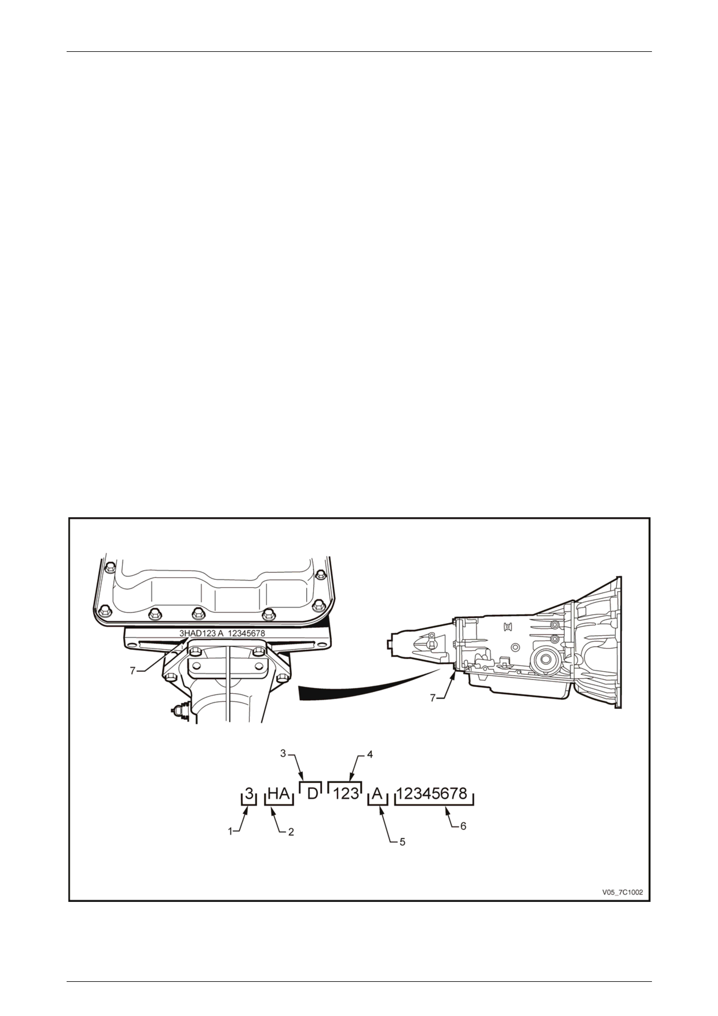
The 4L60E automatic transmission application and identification can be determined from the stamping at the rear of the
transmission , in the location (7) as shown in F igure 7C1 – 1, where:
1= Model year,
(4=2004)
2 = Model,
3.6 litre V6 (without ISS) (HH).
3.6 litre V6 (with ISS) (HS).
3.6 litre V6 AWD (without ISS) (HK).
3.6 litre V6 AWD (with ISS) (HT).
5.7 litre GEN III V8 (HA).
5.7 litre GEN III V8 AWD (HW).
3 = Transmission model identif ier,
('D' = 4L60E).
4 = Julian date (day of the year).
5 = Shift Build,
'A','B','J' = First shift.
'C','H','W' = Second shift,
6 = Individual transmission serial number.
7 = Transmission identificatio n number.
Figure 7C1 – 1
Page 7C1–10

Automatic Transmission – 4L60E – General Information Page 7C1–11
2.3 Economy, Power and Cruise Modes
The programming in the powertrain control module (PCM) for GEN III V8 or transmission control module (TCM) for V6
allows for different shift patterns, which are driver controlla ble through the use of the po wer (PW R) button. T he power
button is located in the centre console.
Economy Mode
The calibration for this mode is for maximum comfort, with minimal intrusion of engine noise and smooth shifts under all
driving conditions. When additional power is required for acceleration, full throttle upshifts are similar to those cal ibrate d
for the power mode.
Power Mode
When activated, the PCM or TCM modifies the transmission calibratio n in the following ways:
1 When the throttle is less than 80% o pe n, later upshift points are provided.
2 Shift time is reduced.
3 The torque converter clutch (TCC) will be applied in both the third and fourth speed ra nges.
Cruise Mode
When the driver activates the cruise control (where fitted), the power icon in the instrument clusters multi-function displ ay
(MFD) will be deactivated (provided the vehicle was operating in po wer mode) and the transmission shift pattern will
switch to the cruise control pattern. When in this mode, the PCM or TCM modifies the shift pattern so that earlier
downshift and later upshift points are provided.
Through the electronic progra mming of the logic processes contained in the PCM or TCM, the frequency of gear shifting
and torque converter clutch application and release is minimis ed. The end result of these logic processes, is that a quick
series of upshifts and downshifts (e.g. a '4 – 3 – 4' shift pattern) is minimised.
Page 7C1–11

Automatic Transmission – 4L60E – General Information Page 7C1–12
2.4 Engine Torque Management, Gen III V8
When a GEN III V8 engine is fitted with the 4L60E transmission, torque management is a function of the PCM which
reduces engine power under certain conditions, including transmission upshifts and downshifts.
Torque management is perform ed for the following reasons:
prevent overstress of the powertrain components,
prevent damage to the vehicle durin g certain abusive manoeuvres, and
reduce engine speed when the idle air control system is out of the normal operating range.
The PCM monitors the following sensors and engine parameters to calculate engine output torque:
air/fuel ratio,
mass air flow,
manifold absolute pressure,
intake air temperature,
spark advance,
engine speed,
engine coolant temperatur e and
A/C clutch status.
The PCM monitors the torque converter status, the transmission gear ratio and the engine speed i n order to determine if
torque reduction is required. If torque reduction is req uire d, the PCM retards the ignition as appropriate to reduce engin e
torque output. The PCM also shuts off the fuel to certain injectors to reduce the engin e p ower in the case of an abusive
manoeuvre.
Instances when engine po wer reduction is likely to be experienced:
during transmission upshifts and do wnshifts,
heavy acceleration from a standi ng start,
the intake air control valve is out of the normal operating range and
when the driver is performing stress-inducing (abusive) manoeuvres, such as shifting into gear at high thr ottle
opening, or shifting the transmission from r everse to drive to create a rocking motion.
The driver is unlikely to notice the torqu e mana gement actions in the first two instances. The engine power output will be
moderate at full throttle in the other two cases.
The PCM calculates the amount of ignition retard necessary to reduce the engine po wer and cuts off spark to certain
cylinders. For example, the PCM disables the fuel injectors and retards spark for cylinders 1, 4, 6, and 7 in the case of a
series of abusive manoeuvres.
Page 7C1–12

Automatic Transmission – 4L60E – General Information Page 7C1–13
2.5 System Protection Devices
Should 1st gear be selected and left in that range, the PCM or TCM will protect the engine from an over-speeding
condition by upshifting to 2nd gear at a pre-determined point. Similarly, the PCM or TCM provides high speed, downshift
protection by preventing a manual shift into 1st gear above pre-determined engine speeds.
Under severe operating conditions such as towing in high ambient temperatures, fluid temperatures ca n rise to a point
where lubrication breakdown can occur. In addition to havin g an oil cooler fitted to the vehicle, the 4L60E transmission is
also fitted with a transmission fluid temperature sensor located in the Tr ansmission Range (T R) Pressure Switch
Assembly (PSA).
When fluid temperatures in excess of 135C a r e sensed, the torque converter clutch is applied as programmed, in 3rd or
4th gear. This action reduces further the fluid temperature d uring normal operation of the torque converter. While these
high fluid temperatures are se nsed however, torque converter clutch appl y is not available when the throttle opening is
above 50%.
Similarly, when the fluid temperature is below 29C, the TCM or PCM prevents torque converter clutch apply.
If a condition occurs, preventing electronic control of the transmission' s functions, a 'Fail Safe' mode will defau lt the
transmission to 3rd gear when either Drive or 3 is selected, applying also maximum line pressure. While in this mode, the
vehicle operator can still manually select 2, 1, Reverse, Park or Neutral, should the need arise.
Page 7C1–13

Automatic Transmission – 4L60E – General Information Page 7C1–14
2.6 Self Diagnosis
If any transmission operation controlled b y the TCM or PCM begins to operate outside its pre-set parameters, the TCM
or PCM has the ability to store a range of diagnostic codes which can be accessed b y the servicing technician, ther eby
localising the problem.
Page 7C1–14

Automatic Transmission – 4L60E – General Information Page 7C1–15
2.7 PCM or TCM Sensors and Actuators
As indicated earlier, there are a number of sensors and switches providing input inform ation for the TCM or PCM
programming that will allow the TCM or PCM to change the shift pattern, shift feel and torque converter clutch operation.
The TCM or PCM does this by comparing this input information with its predetermined values on shift pattern, fluid
pressure maps, shift duration param eters, extreme heat protection programming and a daptive controls.
In addition, each input signal and output actuator operation is also monitored and if outside its pre-set parameters, a
diagnostic code is logged for future reference by the servicing technician.
Page 7C1–15
Automatic Transmission – 4L60E – General Information Page 7C1–16
3 Transmission Control Module
Operation Overview
3.1 Transmission Control Module
With the introduction of the new Alloytec V6 engine, the powertrain architecture has been redesigned to accommodate
this introduction. With this design, a new bus architecture and protoco l has also been introduced. The new bus connects
the following modules:
engine control module (ECM),
transmission control module (TCM),
powertrain interface module (PIM) and
anti-lock brake system (ABS) module.
NOTE
There are various ABS and stability systems
fitted to the vehicles. For further information refer
to Section 5B ABS / TCS / ESP – General
Information.
The protocol used to communicate between these modules is called General Motors Local Area Network (GM LAN)
which is based on Controller Area Network (CAN) communication protocol. For further informatio n on GM LAN protoco l
and data bus structure, refer to Section 6E1 Powertrain Interface Module – V6.
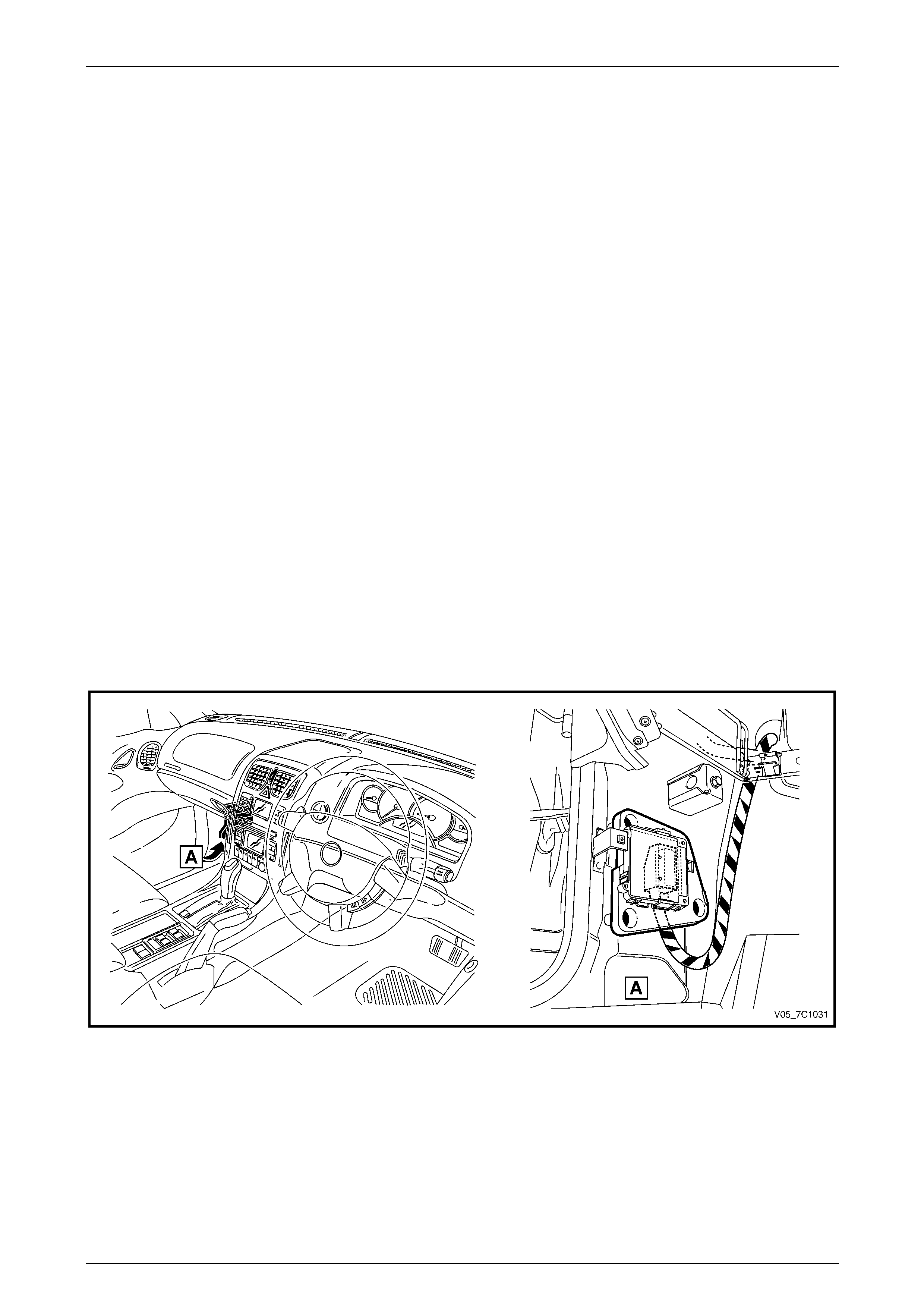
Component Location
The TCM is located under the left-hand hinge pillar trim assembly as shown in Figure 7C1 – 2.
For the other components using the GM LAN databus, refer to Section 6 E1 Powertrain Interface Module – V6.
Figure 7C1 – 2
Page 7C1–16

Automatic Transmission – 4L60E – General Information Page 7C1–17
Transmission Control Module Data Transfer
The TCM uses various information to control the shift of the transmission. Besides the direct inputs from the various
transmission sensors directly into the TCM, the T CM uses data from the GM LAN datab us.
The inputs/outputs directly connecte d to the T CM from the transmission are:
shift solenoids,
torque converter clutch control,
pressure control solenoid,
transmission fluid temperature sensor,
vehicle speed sensor and
input speed sensor.
Refer to 3.2 TCM Wiring Diagrams.
The transmission also receive s inputs from the park/n eutral position and back up lamp switch assembly.
The TCM needs other various data parameters to control the transmission correctly. Thes e include throttle plate angle,
whether cruise control is engaged and active or not, engine RPM etc. These are provided to the TCM from the ECM via
serial data using GM LAN communication p rotocol.
The TCM also supplies inform ation that is used by other components and systems within the vehicle such as the engine
control module (ECM) and instrument cluster. Any information that is required on the body side of the data bus (UART
protocol) is translated by the powertrain interface modu le (PIM). For further information on the data bus structure, the
PIM and its operation, refer to Section 6E1 Po wertrain Interface Module – V6 or Section 6E3 Powertrain Interface
Module – GEN III V8.
Transmission Control Module Operation
The TCM processes data every 10 milliseconds from various sensors, such as throttle position, vehicle speed, gear
range, temperature, engine load and other inputs. The TCM compares all its various input s with the internal programming
and calibration of the TCM using this data, a signal is transmitted to the valve body shift solenoids, which activate the
shift valves for precise shift control. Shift points are therefore precisely controlled and are i dentical from vehicle to
vehicle. The TCM also control torque converter clutch apply and releas e.
Shift feel is also electronically controlled by the T CM, by signals sent to the variable force sole noid, which controls fluid
line pressure and it is this pressure that precisely determines how the shifts will feel. In this way, the TCM electronically
synchronises the engine and transmission into a single integrated powertrain system for optimum performance, shift
timing, fuel efficiency and emission co ntrol.
Page 7C1–17
Automatic Transmission – 4L60E – General Information Page 7C1–18
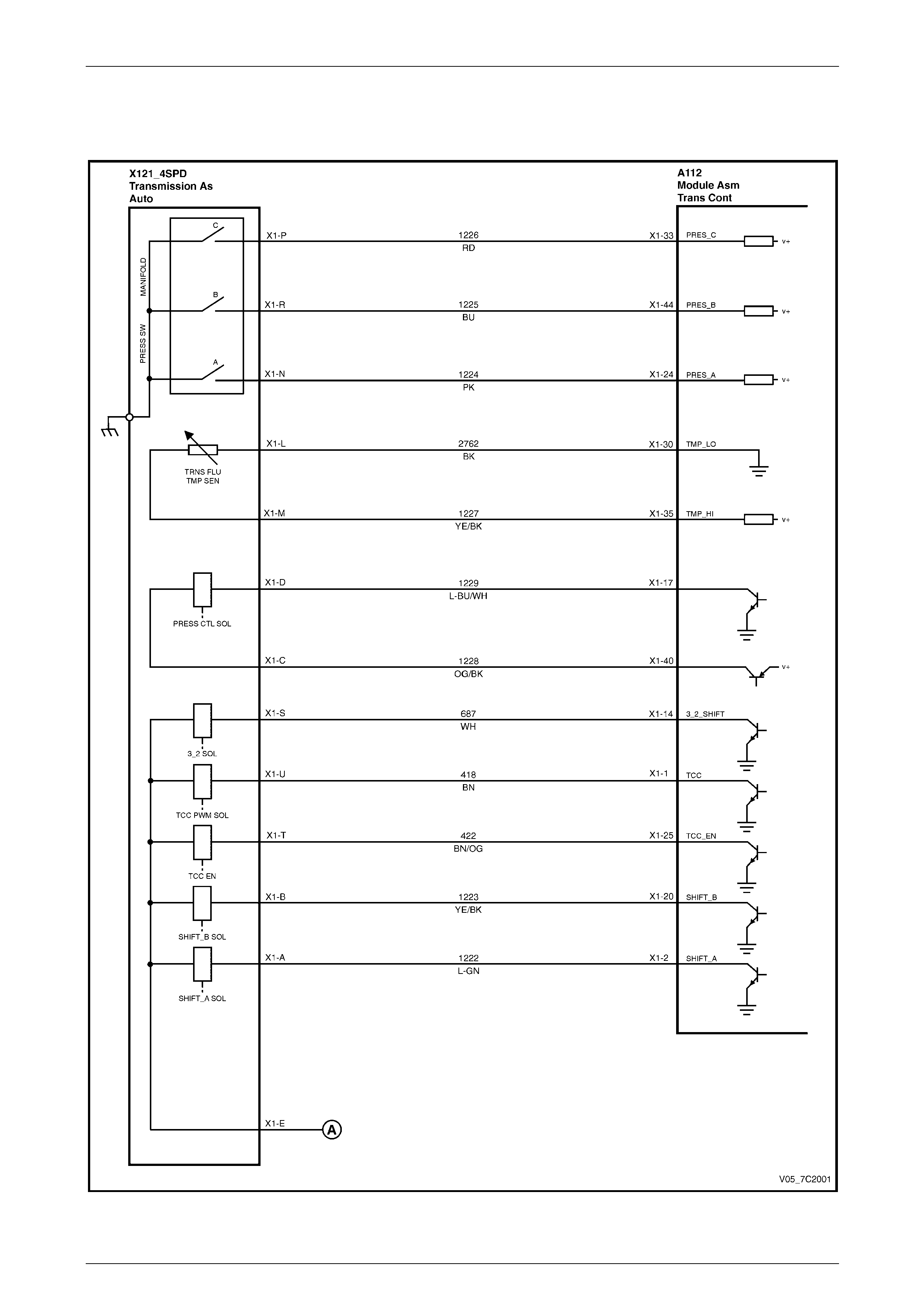
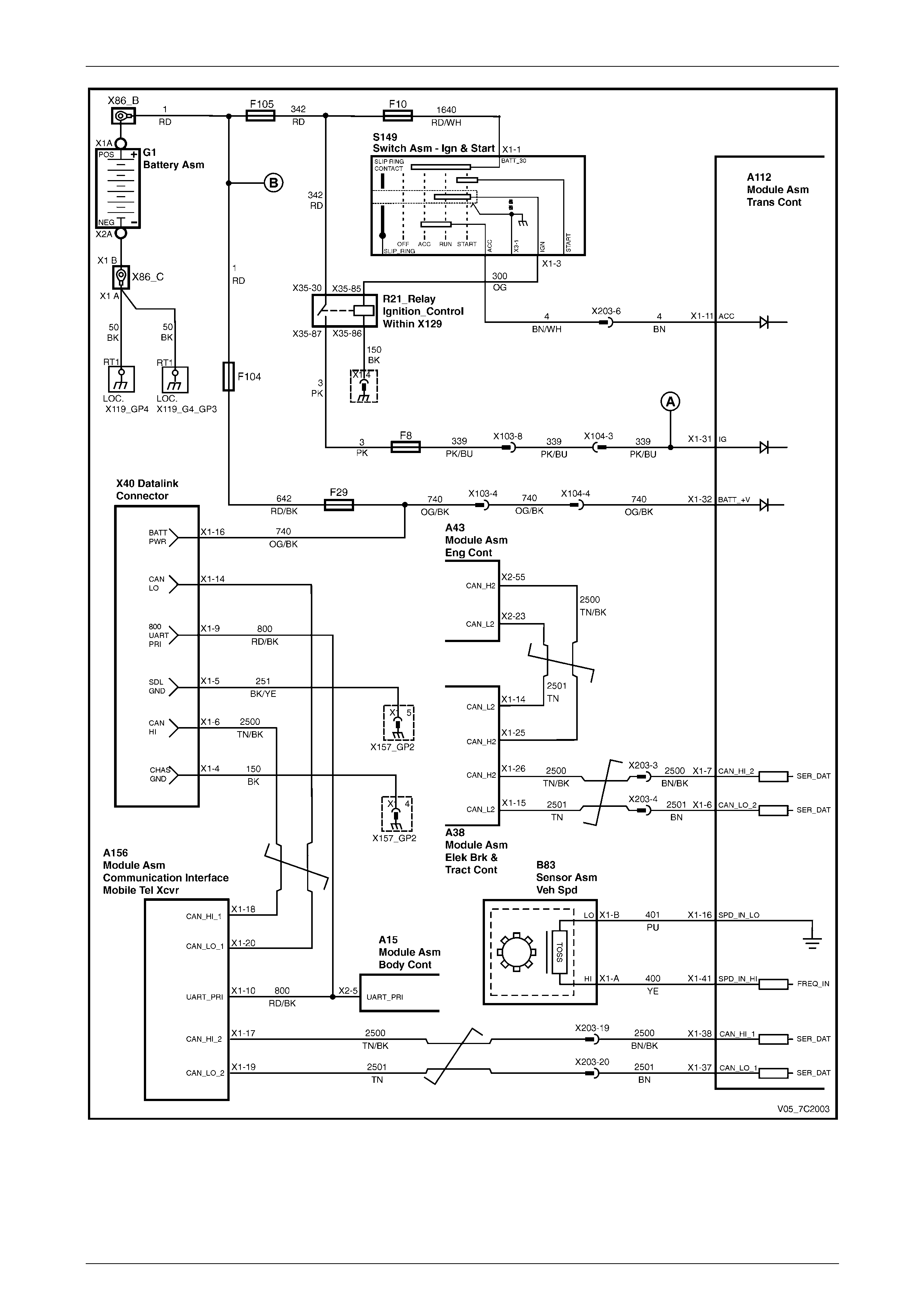
3.2 TCM Wiring Diagrams
MY05 V6 and V8 (without Input Speed Sensor)
Figure 7C1 – 3
Page 7C1–18
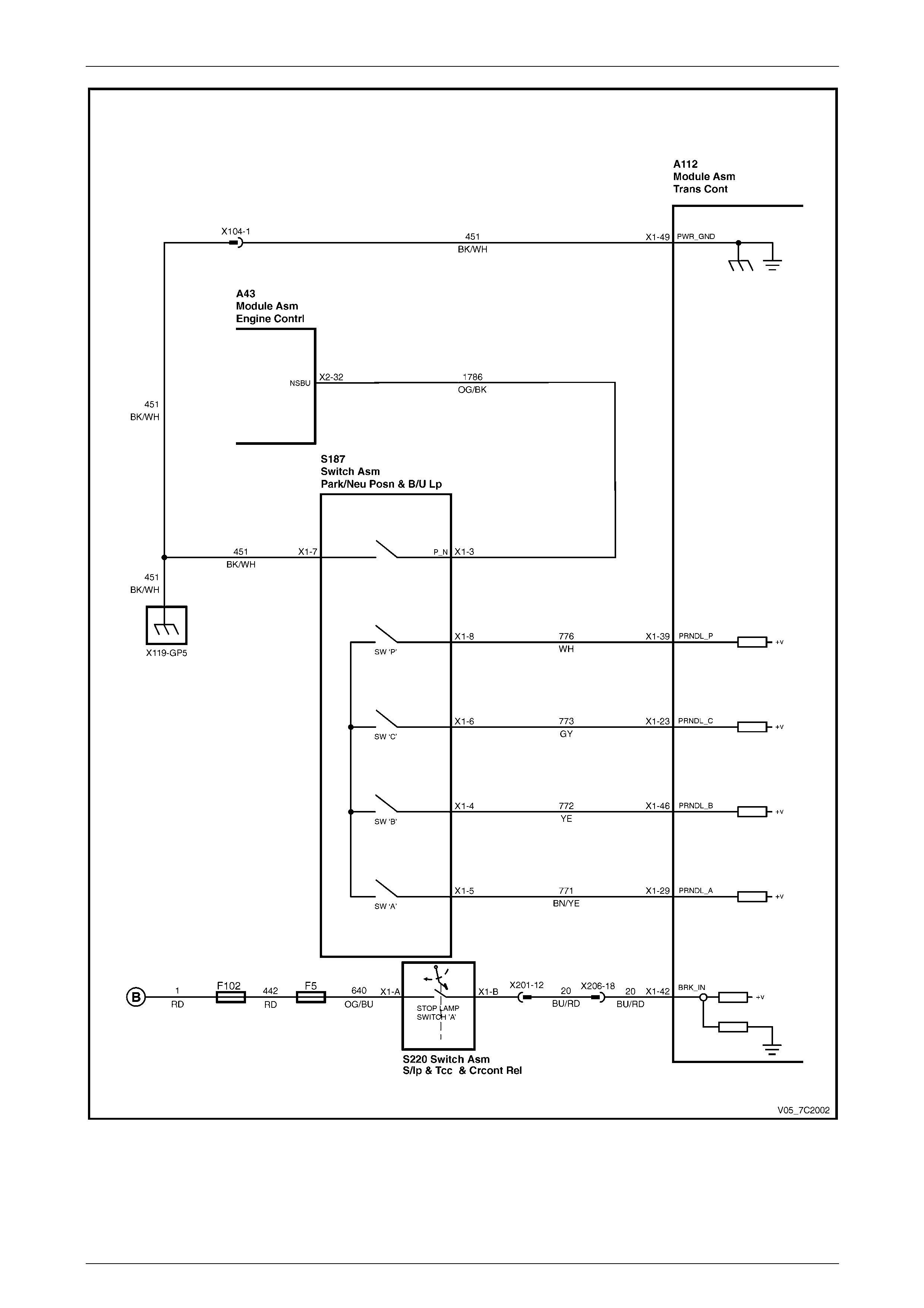
Automatic Transmission – 4L60E – General Information Page 7C1–19
Figure 7C1 – 4
Page 7C1–19
Automatic Transmission – 4L60E – General Information Page 7C1–20
Figure 7C1 – 5
Page 7C1–20
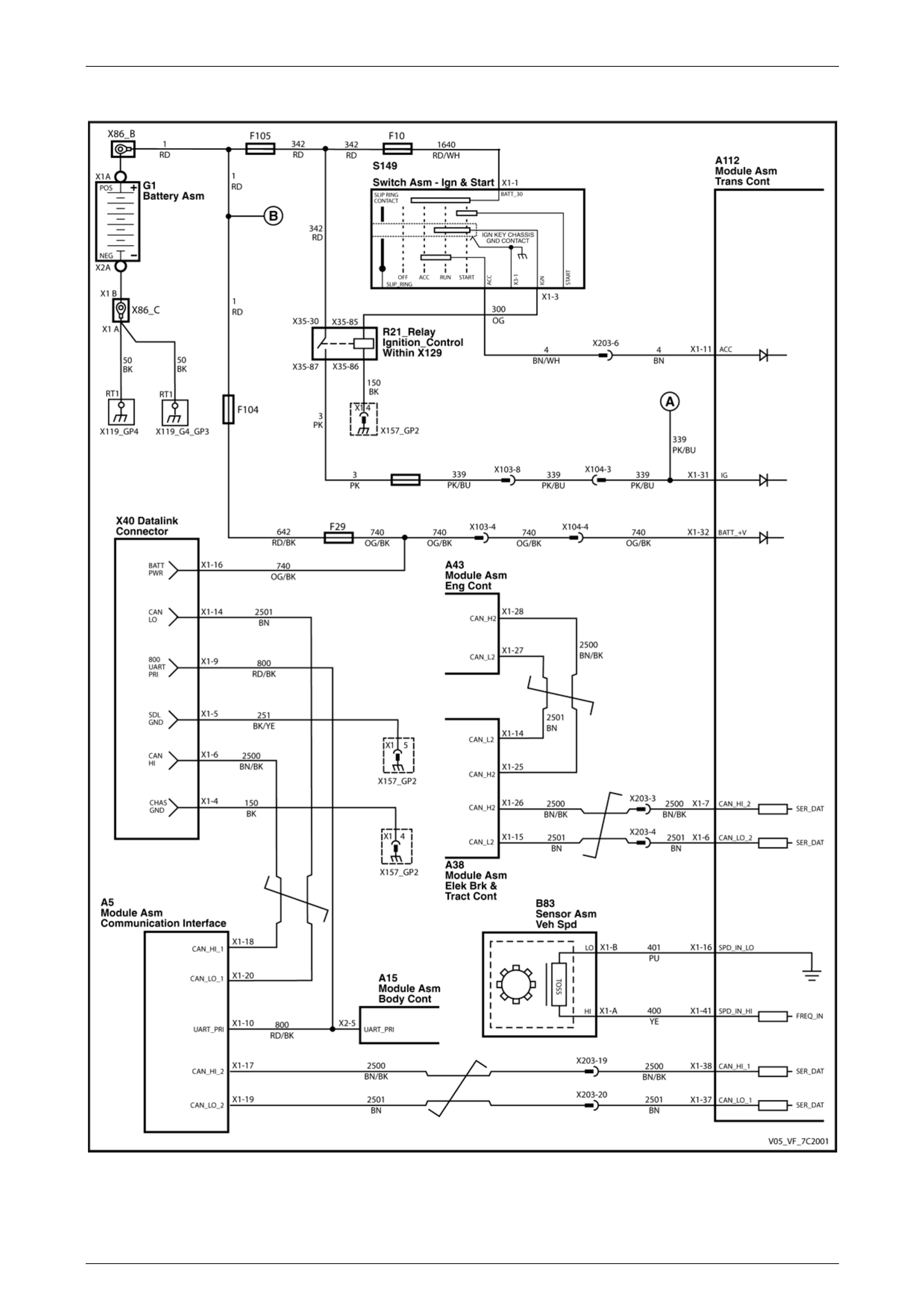
Automatic Transmission – 4L60E – General Information Page 7C1–21
MY06 V6 (with Input Speed Sensor)
Figure 7C1 – 6
Page 7C1–21
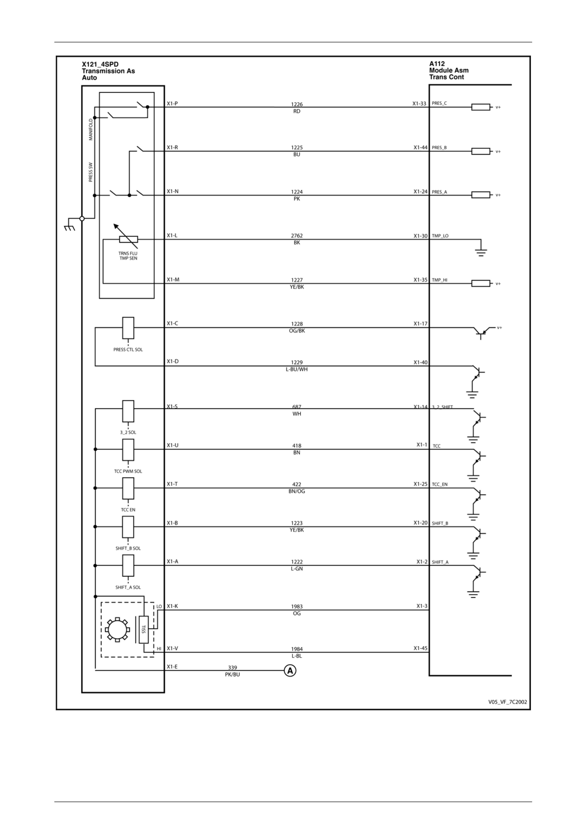
Automatic Transmission – 4L60E – General Information Page 7C1–22
Figure 7C1 – 7
Page 7C1–22
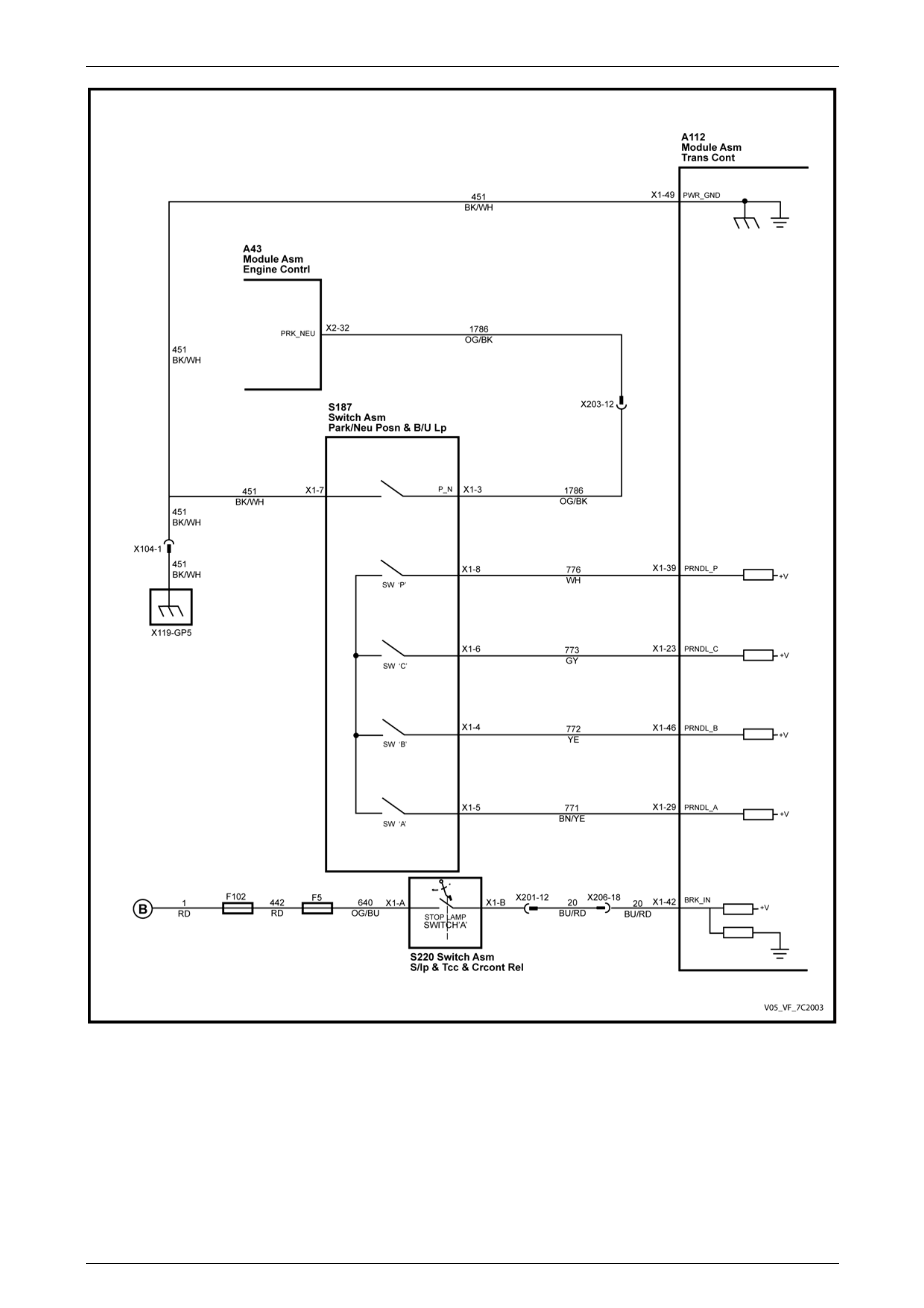
Automatic Transmission – 4L60E – General Information Page 7C1–23
Figure 7C1 – 8
Page 7C1–23

Automatic Transmission – 4L60E – General Information Page 7C1–24
4 Transmission Definitions and
Abbreviations
The following definitions and abbreviations are provi ded to e s tablish a common language and assist the user in
describing transmission related cond itions. The use of these terms and/or conditions c an be found in the various parts of
the automatic transmission sections of the MY2005 Service Information, but more particularly in Section 7C3 Automatic
Transmission – 4L60E – Hydraulic and Mechanical Diagnosis.
4.1 Throttle Position Related Definitions
Throttle Position Definition
Minimum Throttle The least amount of throttle opening required for an upshift.
Light Throttle Approximately 1/4 of accelerator pedal travel (25% Throttle Position).
Medium Throttle Approximately 1/2 of accelerator pedal travel (50% Throttle Position).
Heavy Throttle Approximately 3/4 of accelerator pedal travel (75% Throttle Position).
Wide Open Throttle (WOT) Full travel of the accelerator pedal (100% Throttle Position).
Full Throttle Detent Downshift A quick apply of the accelerator pedal to its full travel, forcing a downshift.
Zero Throttle Coast Down A full release of the accelerator pedal while the car is in motion and in drive range.
Engine Braking A condition where the engi ne is used to slow the car by manually downshifting
during a zero throttle coast down.
Page 7C1–24

Automatic Transmission – 4L60E – General Information Page 7C1–25
4.2 Noise Condition Related Definitions
Noise Condition Definition
Planetary Gear Noise A whine related to car speed most noticeable in first gear or reverse. Becomes less
noticeable after an upshift.
Pump Noise A high pitch whine increasing wit h engine r.p.m.
Page 7C1–25

Automatic Transmission – 4L60E – General Information Page 7C1–26
4.3 General Definitions
General Definition
Accumulator A component of the transmission that absorbs hydraulic pressure during the appl y of a
clutch or band. Accumulators are des igned to control the qualit y of a shift from one
gear range to another.
Adaptive Learning Programming within the PCM or TCM that automatically adjusts hydraulic pressures in
order to compensate for changes in the transmission (i.e. component wear).
Applied An 'Applied Compon ent' is holding another component to which it is splined or
assembled to. Also referred to as "engaged".
Apply Components Hydraulically operated clutches, servo’s, bands and mechanical one-way roller or
sprag clutches that drive or hold members of a pla netary gear set.
Apply Plate A steel clutch plate in a clutch pack, located next to the (appl y) piston.
Backing Plate A steel plate in a clutch pack that is usually the last plate in that clutch assembly
(furthest from the clutch piston).
Band An apply component that consists of a flexible strip of steel and friction material that
wraps around a drum. When applied, it tightens around the drum and prevents the
drum from rotating.
Brake Switch An electrical device that provides sig nals to the powertrain control module or
transmission control module, (PCM or TCM), based on the position of the brake pedal.
The PCM or TCM uses this information to apply or re lease the torque converter clutch
(TCC).
Centrifugal Force A force that is imparted on an object (due to rotation) that increases as that object
moves further away from a centre-point of rotation.
Check Ball A spherical, hydraulicall y controlled component (usually of steel) that either seals or
opens fluid circuits. It is also referred to as a check valve.
Clutch Pack An assembly of components general ly consisting of clutch plates, an apply plate and a
backing plate.
Clutch Plate A hydraulically activated component that has two basic designs: (1) all steel, or (2) a
steel core with friction material bonded to one or two sides of the plate.
Control Valve Body A machined metal casting that contains valve trains an d other hydraulically controlled
components that shift the transmission.
Coupling Speed The speed at which a vehicle is travelling and no longer requires torque multiplication
through the torque converter. At this point, the stator 'free wheels' to allow fluid leaving
the turbine to flow directly to the pump. (Also see Torque Converter).
De-energise(d) To interrupt the electrical current that flows to an electronically controll ed device,
making it electrically inoperable.
Direct Drive A condition in a gears set where the input speed and input torque equals the output
speed and output torque. The gear ratio through the gear set is 1:1.
Downshift A change in a gear ratio where both input speed and torque increases.
Duty Cycle In reference to an electronically controlled solenoid, it is the amount of time (expressed
as a percentage) that current flows through the solenoid coil.
Energise(d) To supply a current to an electronica lly controlled device, e nabling it to perform its
designed function.
Engine Compression Brakin g A condition where compressi on from the engine is used with the transmission to
decrease vehicle speed.
Exhaust The release of fluid pressure from a hydraulic circuit. (T he words ' exhausts' and
'exhausting' are also used and have the same intended meaning.)
Fail-safe Mode A condition whereb y a component (i.e. engine or transmission) will partially function
even if its electrical circuit is disabled.
Page 7C1–26

Automatic Transmission – 4L60E – General Information Page 7C1–27
General Definition
Fluid In this Section of the Service Manual, 'fluid' refers primarily to automatic transmission
fluid (or ATF) and, for the Hydra-matic 4L60E transmissio n, the only recommended
fluid is Dexron III.
Fluid Pressure A pressure that is consistent throughout a given fluid circuit.
Force A measurable effort that is exerted on an object (componen t).
Freewheeling A condition where power is lost through a driving or holdin g device (i.e. roller or sprag
clutches).
Friction Material A heat and wear resistant fibrous material, bonded to clutch plates and bands.
Gear A round, toothed device that is used for transmitting torque through other components.
Gear Range A specific speed to torque ratio at which the transmission is operating (i.e. 1st gear,
2nd gear etc.).
Gear Ratio Revolutions of an input gear as compared to the revolutio ns of an outp ut ge ar. It can
also be expressed as the nu mber of teeth on a gear as c ompared to the number of
teeth on a gear that it is in mesh with.
Hydraulic Circuit A fluid passage which often includes the mechanical com ponents in that circuit
designed to perform a specific function.
Input A starting point for torque, revolutions or energy into anothe r component of the
transmission.
Internal Gear The outermost member of a gear set that has gear teeth in constant mesh with the
planetary pinion gears of the gear set.
Land (Valve Land) The larger diameters of a spool valve that contact the valv e bore or bushing.
Line Pressure The main fluid pressure in a h ydraulic system created by the pump an d pressure
regulator valve.
Manual Valve A spool valve that distributes fluid to various hydraulic circuits and is mechanically
linked to the gear selector lever.
Orifice A restricting device (usually a hole in the spacer plate) for controlling pressure bu ild up
into another circuit.
Overdrive An operating condition in the gear set allowing output speed to be higher than input
speed and output torque to be lower than input torque.
Overrunning The function of a one-way mechan ical clutch that allows the clutch to freewheel during
certain operating conditi ons of the transmission.
Pedal Position The percentage angle of the accelerator pedal as displayed b y Tech 2.
Pinion Gears Pinion gears (housed in a carrier) that are in constant mesh with a circumferential
internal gear and centralised sun gear.
Planetary Gear Set An assembly of gears that consists of an internal gear, planet pin ion gears with a
carrier, and a sun gear.
Powertrain Control Module
(PCM) An electronic device that manages the vehicle's engi ne and automatic transmission
functions.
Pressure A measurable force that is exerted on an area and e xpr essed as kilopascals (kPa).
Pulse Width Modulated (PWM) An electronic signal that continuously cycles the On and Off time of a device (such as
a solenoid) while varyi ng the amount of On time.
Race (Inner or Outer) A highly polished steel surface that contacts bearings or sprag or roller elements.
Reduction (Gear Reduction) An operating condition in the gear set al lowing output speed to be lower than input
speed and output torque to be hig her than input torque.
Residual Fluid Pressure Excess pressure contained within an area after the supply pr essure has been
terminated.
Page 7C1–27

Automatic Transmission – 4L60E – General Information Page 7C1–28
General Definition
Roller Clutch A mechanical clutch (holding device) co nsisting of roller bearings assembled between
inner and outer races.
Servo A spring loaded device consisting of a piston in a bore that is operated (stroked) by
hydraulic pressure to appl y or release a band.
Spool Valve A round hydraulic control valve often containing a variety o f land and valley diameters.
Sprag Clutch A mechanical clutch (holding device consisting of "figure eig ht" like el ements
assembled between inner and outer races.
Staking The effect of deforming, peening over or riveting a shaft to provide a solid mounting.
Throttle Position The travel of the throttle plate that is expressed in percentages and measured by
Tech 2.
Torque A measurable twisting force expressed in terms of Newton metres (Nm).
Torque Converter A component of an automatic transmission, (attached to the engine flex plate) that
transfers torque from the engine to the transmission through a fluid coupling.
Torx Plus Bit A special tool used for the removal of the b ell housing. Precision tip fit means that cam
out of the bolt head is virtually eliminated.
NOTE
Torx Plus Bits are different from normal Torx Bits
Transmission Control Module
(TCM) An electronic device that manages the vehicle's engine and automatic transmission
functions.
Variable Capacity Pump The device that provides fluid for operating the hydraulic circuits in the transmission.
The amount of fluid supplied varies depending on vehicle operating conditions.
Page 7C1–28

Automatic Transmission – 4L60E – General Information Page 7C1–29
4.4 Abbreviations
Abbreviation Definition
2WD Two Wheel Drive.
ABS Anti-lock Brake System
AC Alternating Current
A/C Air Conditioning
AFL Actuator Feed Limit
AWD All Wheel Drive
DC Direct Current
D.C Duty Cycle
DLC Diagnostic Link Connector
DTC Diagnostic Trouble Code
ECM Engine Control Module
ECT Sensor Engine Coolant Temperature Sensor.
ETC Electronic Throttle Control
ISS Input Speed Sensor
N.C Normally Closed
N.O. Normally Open
PCM Powertrain Control Module.
PCS Pressure Control Solenoid (or Force Motor)
PIM Powertrain Interface Module
PWM Pulse Width Modulated
RWD Rear Wheel Drive.
TCC Torque Converter Clutch.
TCM Transmission Control Module
TFP Switch Transmission Fluid Press ure Manual Valve Position Switch
TFT Transmission Fluid Temperature Sensor.
TP Sensor Throttle Position Sensor.
VS Sensor Vehicle Speed Sensor.
Page 7C1–29

Automatic Transmission – 4L60E – General Information Page 7C1–30
5 Service Notes
In the interests of safety to personnel, equipment and to the vehicle and its components, read and adhere to the following
notes whenever servicing operations are to be carried out on the Hydra-matic 4L60E automatic transmission. In addition,
some of this information also refers to sound workshop practices and, to achieve the design life of affected components.
Fasteners
Always reinstall fasteners in the same locations as they were removed.
If a fastener requires replacement, al ways use a part of the correct part number or of equ al size and strength or
stronger.
General Workshop Practice
Keep work area and tools clean.
To avoid unnecessary contamination, always clean the e x terior of the transmission before removing any parts.
Do not use wiping cloths or rags because of the risk of lint being trapped in the transmission.
Do not use solvents on:
neoprene seals,
composition faced clutch plates, or
thrust washers.
Always wear eye protection when using compressed air.
Blow out all passages with compressed air. Only probe small passages with soft, thin wire.
Handle parts with care to avoid nicks and scratches.
Do not remove Teflon oil seal rings unless damaged or performing a com plete overhaul.
Expand internal snap rings an d compress external snap rings to maximise retention and securit y.
Lubricate all internal parts with transmission fluid (only use Dexron® III), as they are being installed.
When installing cap screws into aluminium castings:
always use a torque wrench and
stripped or damaged threads in aluminium castings may be recond itioned by using commercially available
thread inserts.
Once removed, replace all gaskets, seals and O-rings with new parts.
Always use seal protectors where indicated and do not use gasket cement or sealant on any joined face unless
specified to do so.
Page 7C1–30

Automatic Transmission – 4L60E – General Information Page 7C1–31
6 Torque Specifications
Oil pan attaching bolt............................................................................12.0 Nm
Manual shaft linkage attaching nut ...........................................15.0 – 35.0 Nm
Selector rod locking bolt ........................................................... 15.0 – 35.0 Nm
Selector cable upper bracket to floor pan attaching nut ............12.0 – 18.0 Nm
Selector knob attaching Torx screw ..............................................1.0 – 3.0 Nm
Selector knob bezel attaching screw.............................................1.0 – 2.0 Nm
Selector base attaching nut ......................................................12.0 – 18.0 Nm
Neutral start and back-up lamp switch attaching screw.............15.0 – 35.0 Nm
Vehicle speed sensor attaching bolt...........................................11.0 - 14.0 Nm
Transmission mount attaching bolt ...........................................50.0 – 65.0 Nm
Transmission support attaching bolt .........................................50.0 – 65.0 Nm
Transmission mount attaching nut ............................................20.0 – 30.0 Nm
Extension housing attaching bolt...............................................42.0 – 48.0 Nm
1 – 2 Accumulator cover attaching bolt.................................................12.0 Nm
TCC solenoid attaching bolt .................................................................12.0 Nm
Control valve body attaching bolt .........................................................12.0 Nm
Transmission fluid pressure (TFP) manual valve
position switch attaching bolt................................................................12.0 Nm
Manual detent spring attaching bolt......................................................23.0 Nm
Spacer plate support plate attaching bolt .............................................12.0 Nm
Filler tube bracket attaching bolt................................................20.0 – 30.0 Nm
Vent pipe attaching bolt...............................................................7.5 – 12.0 Nm
Radiator cooler hose / line assembly flare nut...........................20.0 – 25.0 Nm
Transmission fluid lines bracket attaching nut...........................19.0 – 25.0 Nm
Torque converter housing attaching bolt (V6)............................52.0 – 66.0 Nm
Torque converter to flexplate attaching bolt...............................60.0 – 70.0 Nm
Torque converter cover attaching bolt (V6) ...............................12.0 – 16.0 Nm
Torque converter housing attaching bolt (V8)............................50.0 – 60.0 Nm
Torque converter cover attaching bolt (V8) .................................5.0 – 10.0 Nm
Oil Cooler Pipe Quick Connect Fitting to Transmission Case...............38.0 Nm
Input Speed Sensor Attaching Bolt..............................................9.0 – 11.0 Nm
Oil Pump Cover to Pump Body Attaching Bolt......................................25.0 Nm
Pressure Control Solenoid Retainer Attaching Bolt..............................12.0 Nm
Forward Accumulator Cover Attaching Bolt..........................................12.0 Nm
Manual Shaft Inner Detent Lever Attaching Nut...................................30.0 Nm
Park Pawl Bracket Attaching Bolt.........................................................30.0 Nm
Oil Pump to Transmission Case Attaching Bolt....................................30.0 Nm
Torque Converter Housing to
Transmission Case Attaching Bolt.............................................65.0 – 75.0 Nm
Page 7C1–31

Automatic Transmission – 4L60E – General Information Page 7C1–32
7 Transmission Specifications
7.1 General
Type
Hydra-matic 4L60E
Special Features
Electronically controlled shift pattern, feel and torque
Converter clutch operatio n
Overdrive 4th speed range
Selector Location................................................................................. Floor mounted console
Gear Ratios
Park (P) ..................................................................................................................................–
Reverse (R) ..................................................................................................................2.294:1
Neutral (N)..............................................................................................................................–
Drive (D – 4) .................................................................................................................0.696:1
Drive (D – 3) .................................................................................................................1.000:1
Second (2)....................................................................................................................1.625:1
First (1).........................................................................................................................3.059:1
Shift Speeds
Refer to Section 7C3 Automatic Transmission – 4L60E – Hydraulic an d Mechanical Diagnosis
Oil Pressure
Refer to Section 7C3 Automatic Transmission – 4L60E – Hydraulic an d Mechanical Diagnosis
Torque Converter
Number of Elements..................................................................3 plus torque converter clutch
Torque Converter Diameter
V6................................................................................................................................258 mm
GEN III V8 Engine .......................................................................................................300 mm
End Play – (All Engines)......................................................................................0.1 – 0.5 mm
Lubricant
Type recommended................................................................................................Dexron® III
Capacity.........................Nominal only. Check when transmission is at operating temperature
Refill........................................................................................................V6 Engine – 4.8 litres
.....................................................................................................GEN III V8 Engine – 5.0 litre
Total (Dry)
................................................................................................................V6 Engine – 7.9 litres
.................................................................................................GEN III V8 Engine – 10.6 litres
Fluid Cooling.................................... Transmission fluid to engine coolant in one radiator tank
Page 7C1–32

Automatic Transmission – 4L60E – General Information Page 7C1–33
Clutches and Band
2 – 4 Band:
Type...........................................................................................Composition lined, steel band
Operation:....................................................................................................................... Servo
Adjustment:................................................................................................ Selective Apply Pin
Pin Size and Identification.
65.82 – 66.12 mm......................................................................................................1 Groove
67.23 – 67.53 mm......................................................................................................2 Groove
68.64 – 68.94 mm....................................................................................................No Groove
Reverse Input Clutch
Type................................................................................................................Multiple wet disc
Backing plate........................................................................................................(1) Selective
Clutch plate (numbers):
Steel .......................................................................................................................................4
Composition............................................................................................................................4
Belleville .................................................................................................................................1
Backing Plate........................................................................................................1 (Selective)
Backing plate, identification and thickness:
'2'.....................................................................................................................7.25 – 7.41 mm
'3'.....................................................................................................................6.52 – 6.68 mm
'4'.....................................................................................................................5.79 – 5.95 mm
Backing plate travel .........................................................................................1.02 – 1.94 mm
Forward Clutch
Type................................................................................................................Multiple wet disc
Clutch plate, (number):
Flat steel plates.................................................................................................................... (5)
Composition plates..............................................................................................................(5)
Waved steel plate................................................................................................................ (1)
Backing plate........................................................................................................(1) Selective
Backing plate, identification and thickness:
'A'.....................................................................................................................6.97 – 7.07 mm
'B'.....................................................................................................................6.38 – 6.48 mm
'C'.....................................................................................................................5.79 – 5.89 mm
'D'.....................................................................................................................5.20 – 5.30 mm
'E'.....................................................................................................................4.61 – 4.71 mm
Backing plate travel – All engines....................................................................0.87 – 1.88 mm
Overrun Clutch
Type................................................................................................................Multiple wet disc
Clutch plates, (number):
Flat steel.............................................................................................................................. (2)
Composition......................................................................................................................... (2)
Page 7C1–33

Automatic Transmission – 4L60E – General Information Page 7C1–34
3 – 4 Clutch
Type................................................................................................................Multiple wet disc
Clutch plates, (number):
Flat steel.............................................................................................................................. (5)
Composition......................................................................................................................... (6)
Stepped apply plate.............................................................................................................(1)
Backing plate........................................................................................................(1) Selective
Backing plate, identification and thickness:
'A'.....................................................................................................................5.88 – 5.68 mm
'B'.....................................................................................................................4.99 – 4.76 mm
'C'.....................................................................................................................4.10 – 3.90 mm
Backing plate travel .........................................................................................2.10 – 0.90 mm
Low and Reverse Clutch
Type................................................................................................................Multiple wet disc
Clutch plates (number):
Flat steel.............................................................................................................................. (5)
Composition......................................................................................................................... (5)
Waved flat steel................................................................................................................... (1)
Selective flat steel plate........................................................................................(1) Selective
Selective plate, (identific ation) and thickness,
measured dimension:
28.06 – 27.54 mm (identification NONE).........................................................1.68 – 1.83 mm
28.59 – 28.07 mm (identification '0')................................................................1.17 – 1.31 mm
27.54 – 27.03 mm (identification '1')................................................................2.20 – 2.34 mm
Transmission End Play Check
Transmission end play check specification......................................................0.13 – 0.92 mm
Identification and washer thic kness:
67.....................................................................................................................1.87 – 1.97 mm
68.....................................................................................................................2.04 – 2.14 mm
69.....................................................................................................................2.21 – 2.31 mm
70.....................................................................................................................2.38 – 2.48 mm
71.....................................................................................................................2.55 – 2.65 mm
72.....................................................................................................................2.72 – 2.82 mm
73.....................................................................................................................2.89 – 2.99 mm
74.....................................................................................................................3.06 – 3.16 mm
Torque Converter End Play Inspection
258 mm diameter converter.................................................................................0.1 – 0.5 mm
300 mm diameter converter.................................................................................0.1 – 0.5 mm
Page 7C1–34
Automatic Transmission – 4L60E – General Information Page 7C1–35
8 Special Tools
The following pages list and illustrate the special service tools required. T he tools are classified into the following
categories:
Mandatory: When required to perform rout ine maintenance operations and adjustments, or are required to carry out
fault diagnosis procedures.
Desirable: T hese tools should be considered for purchase since their use will greatly facilitate performing desig nated
tasks and permit achievement of standard times.
Unique: These tools are those that must be employed when overhauling major assemblies or performing relatively
large tasks.
Available: Are those tools that are of a general nature for which commercially availa ble equivalents exist, or tools
which have had previous application.
Unless otherwise specified, al l tools are available from:
SPX Australia PTY. LTD.
Service Solutions
28 Clayton Road
Notting Hill, Victoria, 3168
Telephone: (03) 9544 6 222
Facsimile: (03) 9544 5222
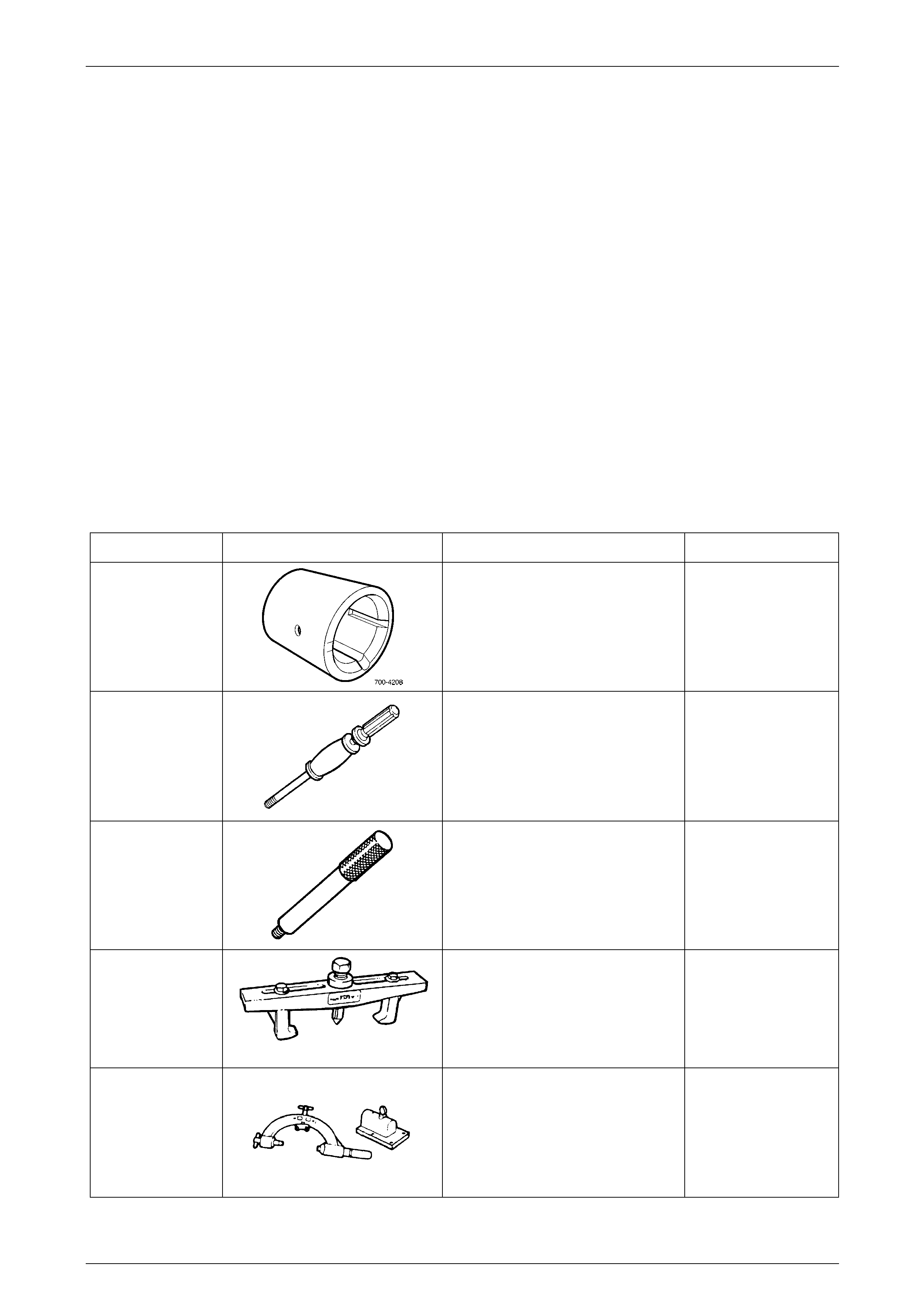
Tool Number Illustration Description Tool Classification
700-4208
Pass-Thru Connector Remover
Used to release the four locking tangs
on the Pass-Thru connector from the
transmission case.
Previously released
Desirable
J6125-1B
Slide Hammer
Used for a number of bush removal
operations.
Previously released
Unique
J8092
Driver Handle
Used for a number of bush installation
operations.
Previously released
Unique
J8433
Puller
Used with J21427-01 to remove the
output speed sensor ring from the
main shaft.
Previously released
Unique
J8763-02
Holding Fixture
Used in conjunction with holdi ng
fixture base J3289-20 to hold
automatic transmission.
Previously released.
Unique
Page 7C1–35
Automatic Transmission – 4L60E – General Information Page 7C1–36
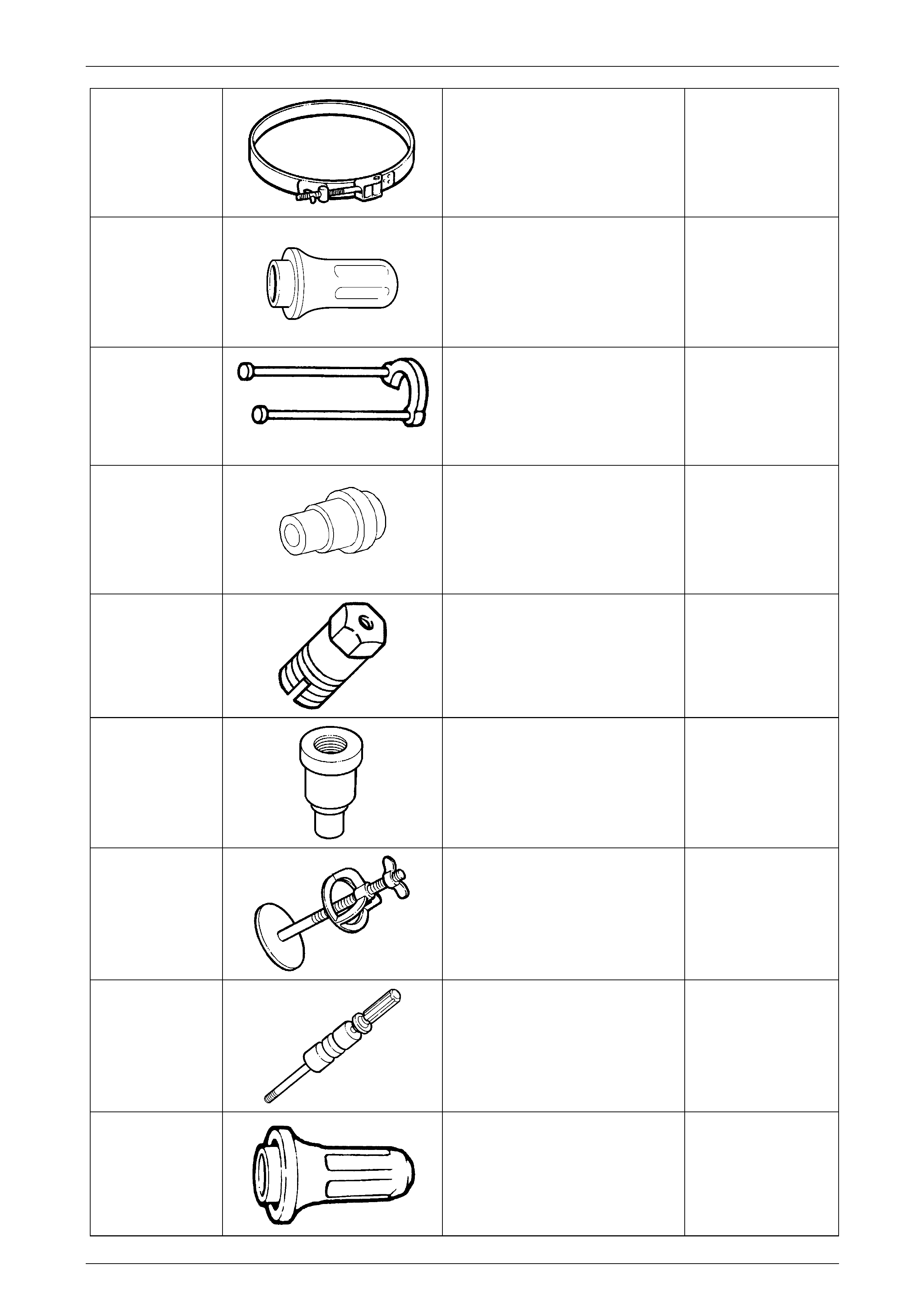
J21368
Oil Pump Alignment Band
Used to align the two oil pump
sections before tightening the
securing bolts.
Previously released
Unique
J21426
Rear Seal Installer
Used to install the extension housi ng
oil seal.
Previously released
Unique
J21427-01
Puller Adaptor
Used with J8433 to remove the output
speed sensor ring from the main
shaft.
Previously released
Unique
J21465-2
Installer
Used with driver J8092 to ins tall the
front stator shaft bush.
Previously released
Unique
J21465-15
Remover
Used in conjunction with slide
hammer J6125-1B to remove the
stator shaft front bushing.
Previously released
Unique
J23062-14
Bush Remover
Used in conjunction with driver handle
J8092.
Previously released
Unique
J23327-1
Clutch Spring Compresso r
Needed to compress the clutch,
before dismantling.
Plate J42628 is also required.
Previously released
Unique
J23907
Slide Hammer
Used with J29369-2 to remov e the
reaction carrier shaft bushes.
Previously released
Unique
J25016
Oil Pump Seal Installer
Used to install the oil pump oil seal.
Previously released
Unique
Page 7C1–36
Automatic Transmission – 4L60E – General Information Page 7C1–37
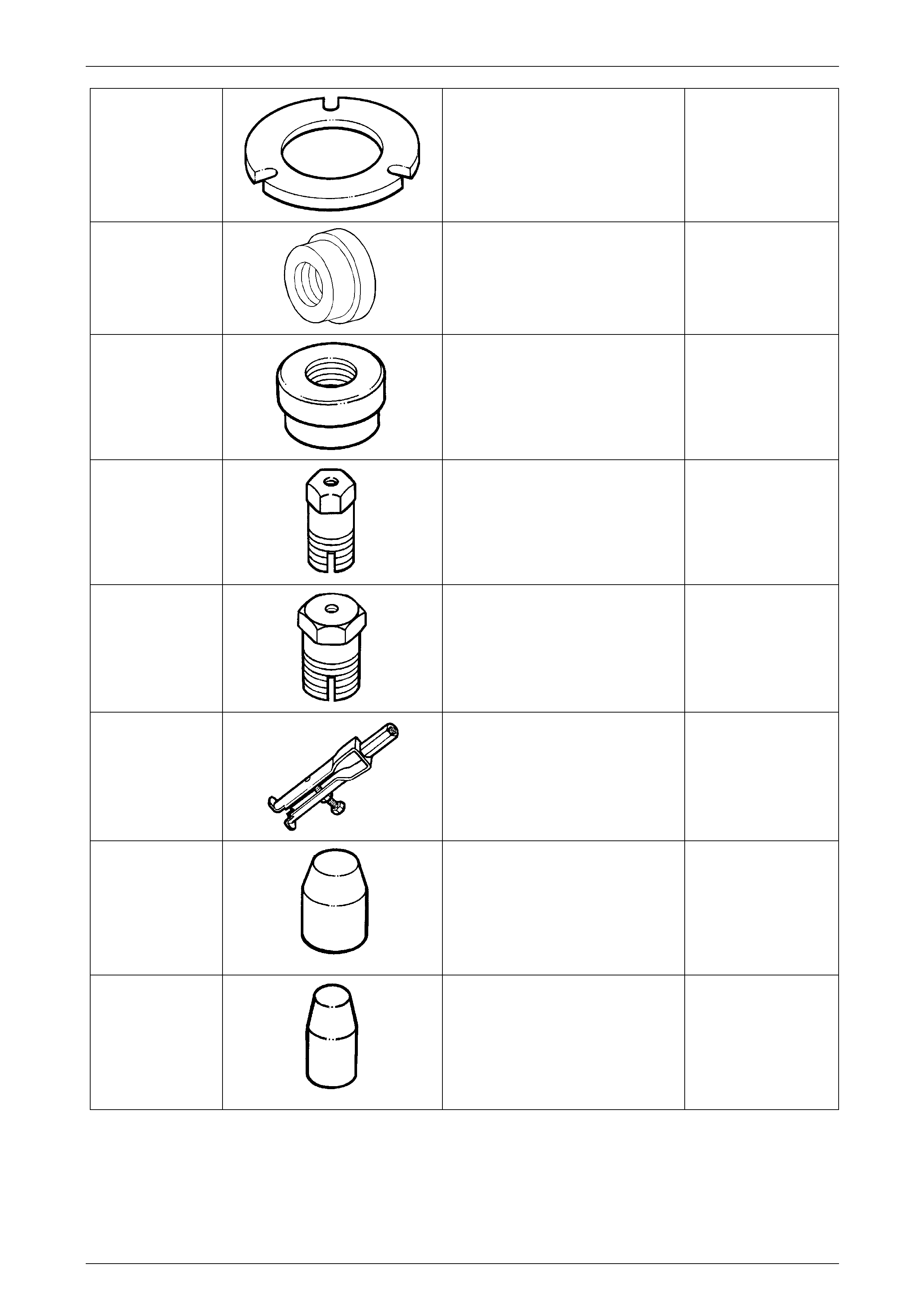
J25018-A
Clutch Spring Compresso r Adaptor
Used with compressor J23327 to
compress the reverse input clutch
during disassembly.
Previously released
Unique
J25019-4
Bush Installer
Used in conjunction with J8092
Installer Handle.
Previously Released
Unique
J25019-9
Bush Installer
Used in conjunction with driver handle
J8092.
Previously released
Unique
J25019-14
Bush Remover
Used with slide hammer J6125-1B.
Previously released
Unique
J25019-16
Bush Remover
Used with slide hammer J6125-1B.
Previously released
Unique
J29369-2
Universal Bush Remover
Used with slide hammer J23907.
Previously released
Unique
J29882
Inner Overrun Clutch Seal
Protector
Used to protect the inner, overrun
clutch piston seal from damage during
installation.
Previously released
Unique
J29883
Inner Forward Clutch Seal
Protector
Used to protect the inner, forward
clutch piston seal from damage during
installation.
Previously released
Unique
Page 7C1–37
Automatic Transmission – 4L60E – General Information Page 7C1–38
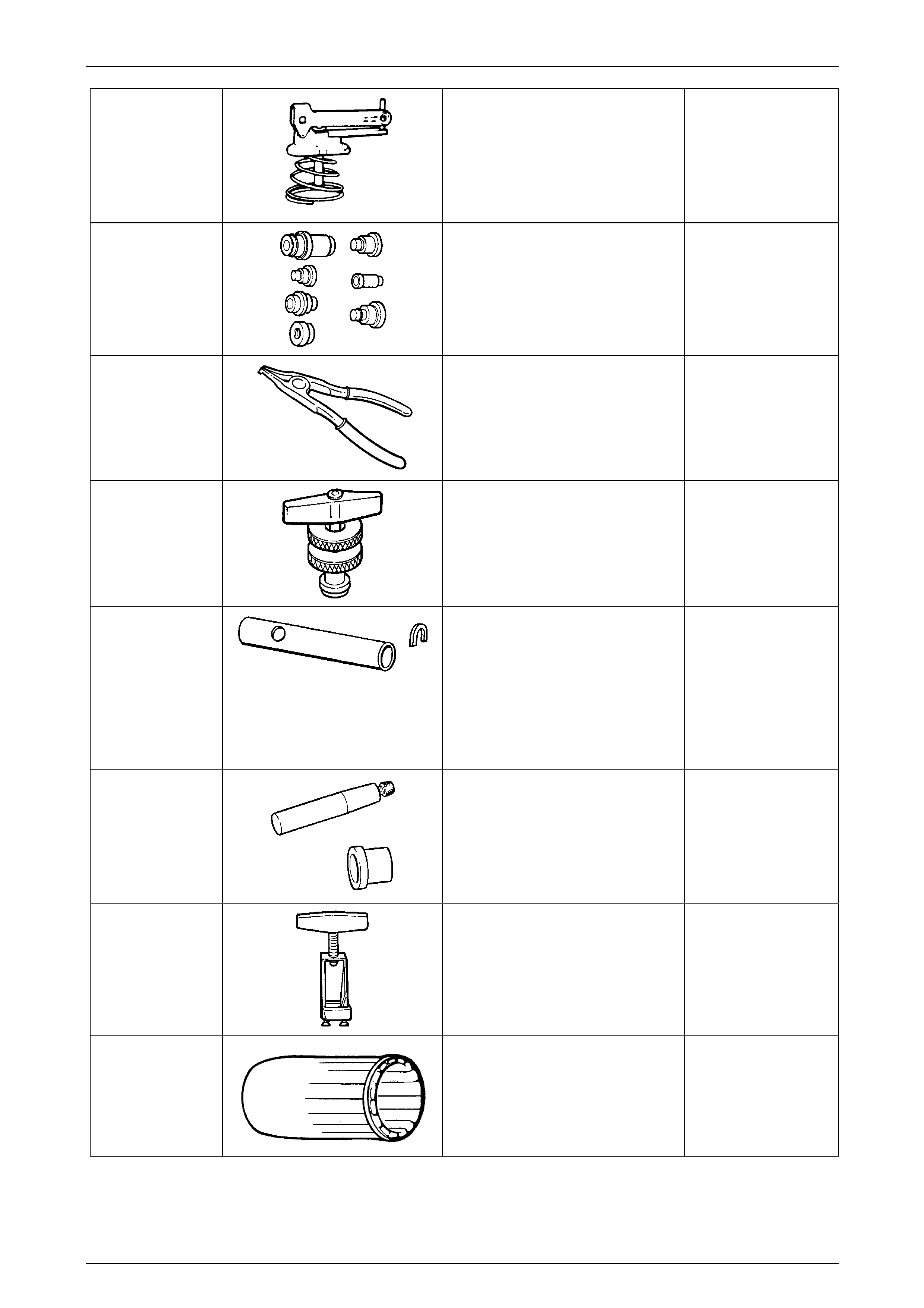
J33037
2 – 4 Band Apply Pin Tool
Used to check the selective apply pin
length.
Previously released
Unique
J34196-B
Bush Remover/Installer Set
Used for various applications,
described in the text.
Previously released
Unique
J34627
Snap Ring Pliers
Specific purpose is to assist in the
removal/replacement of the output
shaft snap ring.
Previously released
Unique
J35138
Torque Converter End Play
To be used in conjunctio n with
commercially available magnetic
stand and dial indicator.
Previously released
Unique
J36352
Speed Sensor Installer &
Gaugi ng Tool
Needed to correctly install the output
speed sensor ring to the main shaft.
Comprises sleeve, J36352-6 and C-
washer J36352-4.
Previously released
Unique
J36418-B
Turbine Shaft Seal Installer &
Resizer
Used to install and re-size the turbine
shaft seal. Comprises J36418-1B
installer and J36418-2A resizer.
Previously released
Unique
J37789-A
Oil Pump Remover
Used with J39119 to remove the oil
pump assembly.
Previously released
Unique
J38735-3
Stator Shaft Sealing Ring Installer
Used with J39855-1 to instal l the
stator shaft seal.
Previously released
Unique
Page 7C1–38
Automatic Transmission – 4L60E – General Information Page 7C1–39
J39119
Oil Pump Remover Adaptor
Used with J37789-A to remove the oil
pump assembly.
Previously released
Unique
J39855-1
Stator Shaft Seal Expander
Used to expand the stator shaft seal
prior to installation.
Previously released
Unique
J39855-2
Stator Shaft Seal Resizer
Used to re-size the stator shaft seal
after installation.
Previously released
Unique
J41510
T50 Torx Plus Bit
Used to loosen and tighten the torque
converter housing to transmission
case bolts.
Also released as 6194.
Previously released
Unique
J41778-1
Oil Pump Bush Installer
Used with a bench press.
Previously released
Unique
J41778-2
Support Plate
Used to support the oil pump during
bush installation.
Previously released
Unique
J42628
Plate
Used with clutch spring compressor,
J23327-1.
Previously released
Unique
16296
12 Volt Black Light
Used with special, fluorescent dyes
for tracing a variety of fluid leaks.
Also previously released as J42220
Desirable
Page 7C1–39

Automatic Transmission – 4L60E – General Information Page 7C1–40
70000861
Tech 2 Diagnostic Tool
Previously released
Mandatory
J21867
Pressure Gauge And Hose
Assembly
Previously released
Mandatory
J28431-B
Fluorescent Oil Dye
Supplied in packs of 24, 1 oz bottles.
Suitable for black light tracing of
engine, transmission and power
steering fluid leaks.
Previously released
Desirable
AU525
A
U525
Quick-Connect Release Tool
This tool is used on all engines with
automatic transmission.
Previously released
Mandatory
AU583
Selector Shaft Seal Remo ver/
Installer
Use to remove and install the manual
shaft oil seal, with the transmission
installed in the vehicle.
Previously released
Unique
J25025-B
Dial Indicator Stand and
Guide Pin Set
Used for the guide pins for aligning
the control valve body sp acer plate.
Previously released
Unique
J41623-B
Cooler Line Disconnect Tool
Used to disconnect cooler lines at the
transmission end, Quick-Connects.
Previously released
Mandatory
7380
(J25765-A)
Pre-load gauge
(3/8” drive)
Used in several applications. In 7C5 it
is used in conjunction with J33037 to
measure selective apply pin length.
(0-17 Nm.)
Previously released
Mandatory
Page 7C1–40
Automatic Transmission – 4L60E – General Information Page 7C1–41
E308
(56750)
(49V012001)
Seal Remover
Used as a universal seal remover.
Previously released
Available
J35616-C
Electronic Kit
Used in conjunction with a multimeter
for measuring voltages and
resistances without damaging wiring
harness connectors.
Previously released
Desirable
J44152
Jumper Harness
Used for checking automatic
transmission during diagnostic
checks.
Previously released
Mandatory
J39200
Digital Multimeter
Tool no. J39200 previously released,
or use commercially available
equivalent. Must have 10 meg ohm
input impedance.
Previously released
Available
J38522
Variable Signal Generator
Used in conjunction with Tech 2 to
simulate sensor signal for checking
automatic transmission during
diagnostic checks.
Unique
Page 7C1–41