
Automatic Transmission – 4L65E – Hydraulic and Mechanical Diagnosis Page 7D3–1
Section 7D3
Automatic Transmission – 4L65E –
Hydraulic and Mechanical Diagnosis
ATTENTION
Before performing any service operation or other procedure described in this Section, refer to 00 Warnings,
Cautions and Notes for correct workshop practices with regard to safety and/or property damage.
1 General Information ...............................................................................................................................4
1.1 General Description............................................................................................................................................... 4
2 Functional Test.......................................................................................................................................5
2.1 Test Description..................................................................................................................................................... 5
2.2 Test Procedure....................................................................................................................................................... 6
3 Line Pressure Check..............................................................................................................................8
3.1 Preliminary Information......................................................................................................................................... 8
3.2 Pressure Check...................................................................................................................................................... 9
Procedure............................................................................................................................................................... 9
Pressure Control Solenoid Readings ............................................................................................................... 10
4 Road Test..............................................................................................................................................11
4.1 Preliminary Information....................................................................................................................................... 11
Electrical Function Check................................................................................................................................... 12
Upshift Control and Torque Converter Clutch (TCC) Apply............................................................................. 14
Part Throttle Detent Downshift........................................................................................................................... 15
Full Throttle Detent Downshift............................................................................................................................ 15
Manual Downshifts.............................................................................................................................................. 15
Manual 4–3 Downshift...................................................................................................................................... 15
Manual 4–2 Downshift...................................................................................................................................... 15
Manual 4–1 Downshift...................................................................................................................................... 15
Coasting Downshifts........................................................................................................................................... 16
Manual Gear Range Selection............................................................................................................................. 16
Reverse............................................................................................................................................................ 16
Manual First ..................................................................................................................................................... 16
Manual Second ................................................................................................................................................ 16
Manual Third .................................................................................................................................................... 16
5 Fluid Diagnosis.....................................................................................................................................17
5.1 Introduction.......................................................................................................................................................... 17
5.2 Diagnosis Procedure........................................................................................................................................... 18
Diagnostic Description........................................................................................................................................ 18
Diagnostic Table Notes ....................................................................................................................................... 18
Diagnostic Table.................................................................................................................................................. 18
6 Torque Converter Diagnosis Procedure............................................................................................20
6.1 Preliminary Information....................................................................................................................................... 20
Torque Converter Stator ..................................................................................................................................... 20
Poor Acceleration at Low Speed...................................................................................................................... 20
Poor Acceleration at High Speed ..................................................................................................................... 20
Page 7D3–1
Techline

Automatic Transmission – 4L65E – Hydraulic and Mechanical Diagnosis Page 7D3–2
Noise..................................................................................................................................................................... 20
Torque Converter Clutch Shudder..................................................................................................................... 21
If Shudder Occurs During TCC Apply or Release ............................................................................................ 21
If Shudder Occurs After TCC has Applied........................................................................................................ 21
Torque Converter/Flexplate Vibration Test........................................................................................................ 22
Evaluation............................................................................................................................................................. 22
Rectification ......................................................................................................................................................... 23
7 Mechanical Component Diagnosis and Repair.................................................................................24
7.1 Noise and Vibration Analysis.............................................................................................................................. 24
7.2 Clutch Plate Diagnosis........................................................................................................................................ 25
Composition Plates ............................................................................................................................................. 25
Steel Plates........................................................................................................................................................... 25
Causes of Burned Clutch Plates....................................................................................................................... 25
7.3 Engine Coolant In Transmission........................................................................................................................ 26
7.4 Fluid Leak Diagnosis and Repair........................................................................................................................ 27
Methods for Locating Leaks ............................................................................................................................... 27
General Method................................................................................................................................................ 27
Powder Method................................................................................................................................................ 27
Dye and Black Light Method ............................................................................................................................ 27
Repairing the Leak............................................................................................................................................... 28
Gaskets............................................................................................................................................................ 28
Seals ................................................................................................................................................................ 28
Possible Points and Cause of Fluid Leaks........................................................................................................ 29
Case Porosity Repair........................................................................................................................................... 31
7.5 Shift Solenoid Leak Test ..................................................................................................................................... 32
8 Symptom Diagnosis.............................................................................................................................33
8.1 General Information............................................................................................................................................. 33
8.2 Symptom Diagnosis Table.................................................................................................................................. 34
9 Diagnostic Tables.................................................................................................................................36
9.1 Transmission Malfunction Diagnosis ................................................................................................................ 36
Introduction.......................................................................................................................................................... 36
Oil Pressure High or Low.................................................................................................................................... 36
Harsh Shifts.......................................................................................................................................................... 37
Inaccurate Shift Points........................................................................................................................................ 37
First Gear Range Only – No Upshift................................................................................................................... 37
Slips in First Gear................................................................................................................................................ 38
Slipping or Rough 1–2 Shift................................................................................................................................ 39
No 2–3 Shift or Shift Slips, Rough or Hunting................................................................................................... 39
2nd/3rd Gear Only or 1st/4th Gears Only........................................................................................................... 40
Third Gear Only.................................................................................................................................................... 40
3–2 Flare or Tie-up............................................................................................................................................... 40
No 3–4 Shift, Slips or Rough 3–4 Shift............................................................................................................... 40
No Reverse or Slips In Reverse.......................................................................................................................... 41
No Part Throttle or Delayed Downshifts ............................................................................................................ 42
Harsh Garage Shift .............................................................................................................................................. 42
No Overrun Braking – Manual 3–2–1.................................................................................................................. 43
No Torque Converter Clutch Apply.................................................................................................................... 43
Torque Converter Clutch Shudder..................................................................................................................... 44
No Torque Converter Clutch Release ................................................................................................................ 44
Drives in Neutral .................................................................................................................................................. 45
2nd Gear Start...................................................................................................................................................... 45
No Park ................................................................................................................................................................. 45
Oil Out the Vent.................................................................................................................................................... 45
Vibration in Reverse and Whining Noise in Park.............................................................................................. 45
Ratcheting Noise.................................................................................................................................................. 45
Page 7D3–2

Automatic Transmission – 4L65E – Hydraulic and Mechanical Diagnosis Page 7D3–3
No Drive in All Ranges ........................................................................................................................................ 45
No Drive in Drive Range...................................................................................................................................... 46
Front Oil Leak....................................................................................................................................................... 46
Delay in Drive and Reverse................................................................................................................................. 46
10 4L65E Shift Speed Charts....................................................................................................................47
10.1 Introduction.......................................................................................................................................................... 47
10.2 GEN III V8 Coupe.................................................................................................................................................. 48
Normal Mode........................................................................................................................................................ 48
Power Mode.......................................................................................................................................................... 48
Cruise Mode ......................................................................................................................................................... 49
10.3 GEN III V8 – RWD Cab Chassis........................................................................................................................... 50
Normal Mode........................................................................................................................................................ 50
Power Mode.......................................................................................................................................................... 50
Cruise Mode ......................................................................................................................................................... 51
10.4 GEN III V8 – AWD Cab Chassis........................................................................................................................... 52
Normal Mode........................................................................................................................................................ 52
Power Mode.......................................................................................................................................................... 52
Cruise Mode ......................................................................................................................................................... 53
10.5 GEN IV V8 (L76) Sedan, Wagon and Ute............................................................................................................ 54
Normal Mode........................................................................................................................................................ 54
Power Mode.......................................................................................................................................................... 54
Cruise Mode ......................................................................................................................................................... 55
10.6 GEN IV V8 (L76) – RWD Cab Chassis................................................................................................................. 56
Normal Mode........................................................................................................................................................ 56
Power Mode.......................................................................................................................................................... 56
Cruise Mode ......................................................................................................................................................... 57
10.7 GEN IV V8 (L98) – RWD Crew Cab...................................................................................................................... 58
Normal Mode........................................................................................................................................................ 58
Power Mode.......................................................................................................................................................... 58
11 Component Layout and Hydraulic Paths...........................................................................................59
11.1 Component Layout.............................................................................................................................................. 59
Control Valve Body Passages and Checkball Locations................................................................................. 59
Control Valve Body Valve Trains........................................................................................................................ 60
Spacer Plate Passages........................................................................................................................................ 61
Spacer Plate to Control Valve Body Gasket...................................................................................................... 62
Spacer Plate to Transmission Case Gasket ...................................................................................................... 63
Transmission Case Fluid Passages and Checkball Locations........................................................................64
Servo Passages 2–4 ............................................................................................................................................ 65
Oil Pump Cover Fluid Passages (Transmission Case Side) ............................................................................ 66
Oil Pump Cover Fluid Passages......................................................................................................................... 67
Oil Pump Body Fluid Passages.......................................................................................................................... 68
Page 7D3–3

Automatic Transmission – 4L65E – Hydraulic and Mechanical Diagnosis Page 7D3–4
1 General Information
This Section contains a description of the Hydra-matic 4L65E procedures for diagnosing and repairing the hydraulic and
mechanical aspects of this transmission.
Before diagnosing an y Hydra- matic 4L65E transmission, always begin with the functional test, refer to 2 Functional Test.
After the cause of a condition has been determined, refer to Section 7D4 Automatic Transmission – 4L65E – On-vehicle
Service or Section 7D5 Automatic T r ansmission – 4L65E – Unit Repair, for the necessary procedures.
Alternatively, if the condition is considered to be electrical/e lectronic in nature, refer to Section 6D3-2 Powertrain
Management –GEN III V8 – Diagnostics or Section 7D2 Auto Trans 4L65E Electrical Diagnosis for GEN IV V8.
For all information relating to the mechanical construction and function of the 4L65E automatic transmission, refer to the
General Motors Powertrain Group Electronically Controlled Automatic Transmission Technician’s Guide.
This guide includes such information as:
• Transmission Cutaway Views,
• Principles of Operation,
• Power Flow,
• Complete Hydraulic Circuits,
• Bushing and Bearing Locations,
• Seal Locations and
• Illustrated Parts List.
1.1 General Description
The Hydra-matic 4L65E is a full y automatic, four speed, transmission. It consists primarily of a four element torque
converter, two planetary gear sets, various clutches, an oil pump and a cont rol valve body.
The four element torque converter contains a pump, a turbine, a pressure plate splined to the turbine and a stator
assembly. The torque converter acts as a fluid coupling to transmit power smoothly from the engi ne to the transmission.
It also hydraulically provides additional torque multiplication when required. The pressur e plate, when applied, provides a
mechanical 'direct drive' coupling of the engine to the transmission.
The two planetary gear sets provide the four forward gear ratios and reverse. Changing of the gear ratios is fully
automatic and is accomplished through the u s e of various el ectronic sensors providing input signals to the PCM. T he
PCM interprets these signals to send current to the various solenoids inside the transmission.
By using electronics, the PCM for GEN III or TCM for GEN IV controls shift points, shift feel and torque converter clutch
apply and release, to provide proper gear ranges for maximum fuel economy and vehicle performa nce.
Five multiple-disc clutches, one roller clutch, a sprag clutch and a brake band provide th e friction elements required to
obtain the various ratios with the planetary gear sets.
A hydraulic system (includin g the control valve body), pressurised by a vane type pump, provides the working pressure
needed to operate the friction elements and automatic controls.
The general arrang ement of the mechanical and hydraulic components is shown in the General Motors Powertrain Group
Electronically Controlled Automatic Transmission Technician’s Guide.
With traditional, hydraulically controlled transmissions, the gear shifts are controlled by the opp osing pressures of
hydraulic fluid in a complex system of spring-loaded valves. In this electron ically controlled Hydra-matic 4L65-E
transmission, gear shift points and shift feel are determined b y electric al signals sent from the PCM.
The PCM / TCM processes data every 25 milliseconds from various sensors, such as throttle positi on, vehicle speed,
gear range, temperature, engine load and other inputs. Using this data, a signal is transmitted to the valve body shift
solenoids, which activate the shift valves for precise sh ift control. Shift points are therefore precisely controlle d and are
identical from vehicle to vehicle.
Shift feel is also electronically controlled by the PCM / TCM, by signals sent to the Variable Force Solenoid, which
controls fluid line pressure and it is this pres sure that precisely determines how the shifts will feel. In this way, the PCM /
TCM electronically synchronises the engin e and transmission into a single, integrated powertrain system, for optimum
performance, shift timing, fuel efficiency and emission control.
Page 7D3–4

Automatic Transmission – 4L65E – Hydraulic and Mechanical Diagnosis Page 7D3–5
2 Functional Test
2.1 Test Description
The functional test procedure is designed to verify the correct operation of components in the transmission and to i dentify
whether a condition is electrical in nature, or not. This will eliminate the unnecessary removal of transmission
components and time loss in rectification. The test is the first step in diagnosing mechanical or hydr aulic transmission
conditions and provides procedures and references to the Symptom Diagn osis table for specific diagnostic information.
Page 7D3–5
Automatic Transmission – 4L65E – Hydraulic and Mechanical Diagnosis Page 7D3–6
2.2 Test Procedure
Step Action Yes No
1
Engine performance can greatly affect transmission
performance. En sure the complaint is not the resu lt of
poor engine performance before continuing.
Verify the customer complaint.
Has the customer complaint been verified?
Go to Step 2 –
2 Has the Diagnostic System Check – Vehicle bee n performed? Go to Step 3 Refer to
0D Vehicle
Diagnostics
3 1 Perform a visual inspection. Look for the following conditions:
• Vehicle damage.
• Transmission oil pan damage.
• Loose, worn, damaged or missing com ponents, brackets,
mounts, etc.
• Transmission cooler or cooler line restrictions.
• Oil leaks.
2 Worn or damaged suspension parts.
3 Worn or damaged steering parts.
4 Transmission range selector linkage damaged or out of
adjustment.
Was an item identified that needs service?
Go to the
appropriate repair or
diagnosis Section Go to Step 4
4 Perform the Transmission Fluid Checkin g Procedure in 7D4 Automatic
Transmission – 4L65E – On-vehicle Service.
Is the procedure complete? Go to Step 5
Refer to
Transmission Fluid
Checking Procedure
in 7D4 Automatic
Transmission –
4L65E – On-vehicle
Service
5 Perform the road test procedure, refer to 4 Road Test.
Did the vehicle exhibit any objectionable condition? Go to Step 6 System OK
6 Did the vehicle exhibit objectionable torque converter operation? Go to Step 15 Go to Step 7
7 Did the vehicle exhibit a nois e condition? Refer to
8.2 Symptom
Diagnosis Table Go to Step 8
8 Did the vehicle exhibit a vibrat ion condition? Go to Step 9 Go to Step 10
9 Did the vibration occur only during TCC apply or release? Go to Step 15 Refer to
8.2 Symptom
Diagnosis Table
10 Did the vehicle exhibit a shift speed condition such as low or high shift
speeds? Refer to
Inaccurate Shift
Points Go to Step 11
Page 7D3–6

Automatic Transmission – 4L65E – Hydraulic and Mechanical Diagnosis Page 7D3–7
Step Action Yes No
11 Check for any if the following shift qual ity (feel) conditions:
• Harsh, soft, delayed or no engagement.
• Harsh, soft or delayed shifts.
• Shift shudder, flare or tie-up.
Were any of these conditions evident?
Go to Step 12 Go to Step 13
12 Perform the line pressure check procedure, refer to
3.2 Pressure Check.
Is the line pressure within specification? Refer to
8.2 Symptom
Diagnosis Table
Refer to the Fluid
Level Check
procedure in 7D4
Automatic
Transmission –
4L65E – On-vehicle
Service.
13 Road test to check for any of the following shift pattern conditions:
• No upshift or downshift
• Only one or two forward gears
• No First gear, no Second gear, no Third gear or no F ourth gear
• Slipping
• No first gear start
Were any of these conditions evident?
Refer to
8.2 Symptom
Diagnosis Table Go to Step 14
14 Check for any of the following range performance conditions:
• No Park, Reverse or Drive
• No engine braking
• No gear selection
• Incorrect gear selection
Were any of the above conditions evident?
Refer to
8.2 Symptom
Diagnosis Table System Serviceable
15 Refer to 6 Torque Converter Diagnosis Procedure to check whether
the vehicle exhibits any of the following TCC conditions:
• Stuck On or Off
• Early or late engagement
• Incorrect apply or release
• Soft or harsh apply
• Clunk or shudder
• No torque multiplication
• Excessive slip
• Poor acceleration
• Engine stalls
Were any of the above T CC conditions evident?
Refer to
8.2 Symptom
Diagnosis Table System Serviceable
Page 7D3–7

Automatic Transmission – 4L65E – Hydraulic and Mechanical Diagnosis Page 7D3–8
3 Line Pressure Check
3.1 Preliminary Information
Line pressures are calibrated for two sets of gear ranges – Drive, Park or Neutral, and Reverse. This allows the
transmission line pressure to be appropriate for two different pressure needs in different gear ranges:
Gear Range Line Pressure Rang e
Drive, Park or Neutral 380 – 1,300 kPa
Reverse 440 – 2,235 kPa
Before performing a line pressure check, verify if the pressure control (PC) solenoid is receivin g the correct electrical
signal from the PCM / TCM, as follows:
1 Install Tech 2. Refer to Section 0C Tech 2, for the necessary procedure.
2 Firmly apply the park brake and start the engine.
3 Check for stored diagnostic trouble code/s (DTC) and in particular, for a pre ssure control solenoid DTC.
4 Rectify as necessary.
NOTE
The transmission may experience harsh, soft or
mushy shifts for up to two days after this
procedure.
Page 7D3–8
Automatic Transmission – 4L65E – Hydraulic and Mechanical Diagnosis Page 7D3–9
3.2 Pressure Check
Procedure
1 Check transmission fluid level, refer to Fluid Level Check in Section 7D4 A utomatic Transmission – 4L65E – On-
vehicle Service.
2 Check manual linkage for correct adjustment and wear, refer to Section 7D4 Automatic Transmission – 4L65E –
On-vehicle Service.
3 If not previously carried out, install Tech 2 to the vehicle. Refer to Section 0C Tech 2, for the necessary procedure.
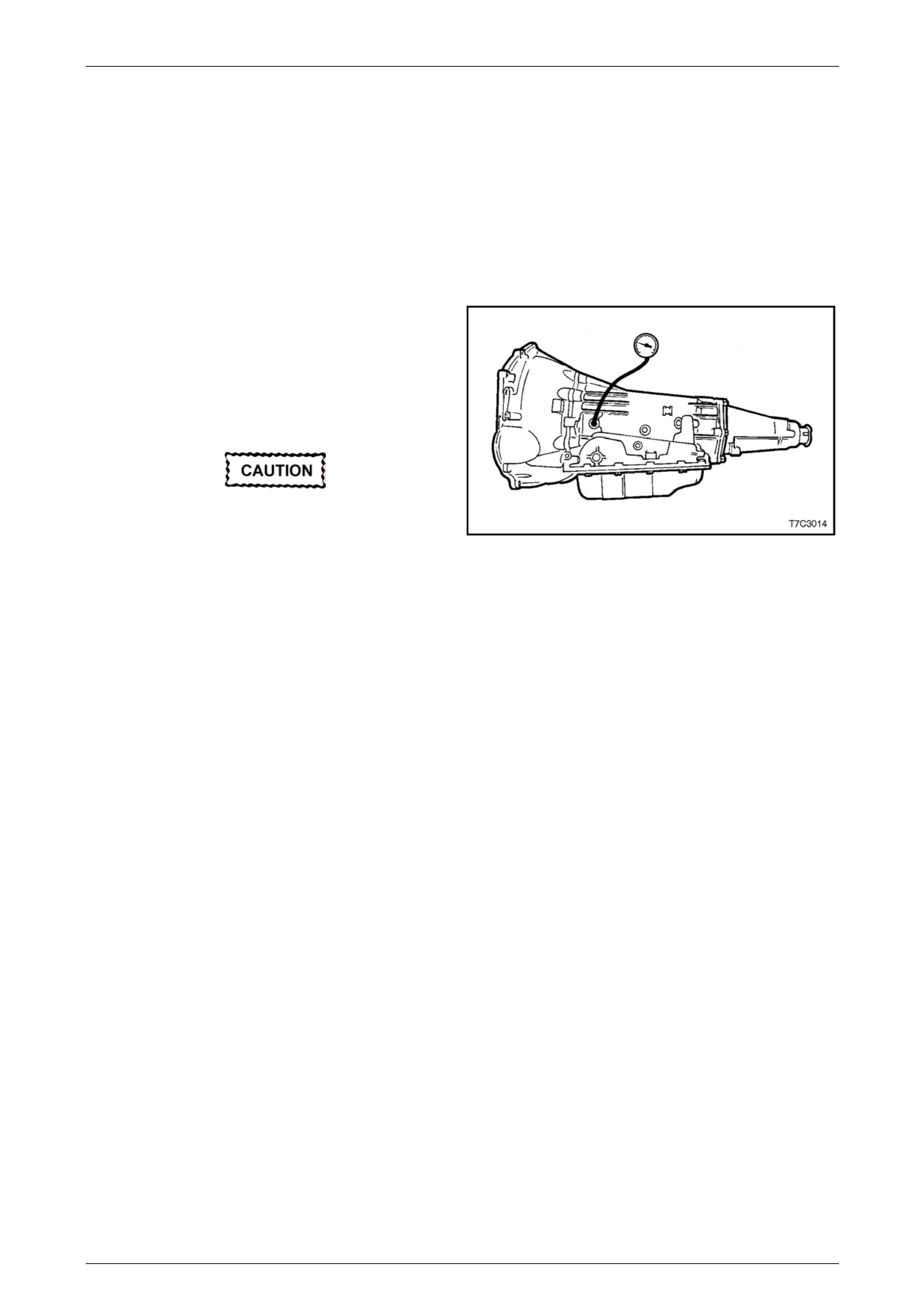
4 Install an oil pressure gauge such as Tool No. J21867
or commercial equivalent, to the line press ure tapping
point on the transmission, as shown.
5 Firmly apply the park brake and select ‘P’ (Park)
range.
6 Start the engine and allow to warm up, at idle.
Total test running time should not exceed 2
minutes or transmission damage could
occur. Figure 7D3 – 1
7 Access Miscellaneous Tests on T ech 2, then the PCS Control test.
8 Increase Actual PCS in 0.1 Amp increments on Tech 2 and read the corresponding line pressure reading on the
fluid pressure gauge. (Allow the pressure to stabilise for 5 seconds after each current change.)
9 Compare the pressure readin gs aga inst the table, refer to Pressure Control Solenoid Readings.
NOTE
When comparing the pressure readings note the
following:
• Pressures are to be taken at an engine speed
of up to 1,500 r.p.m., and a temperature of
approximately 66° C. Line pressure drops as
temperature increases.
• If pressure rea dings d iffer greatly from the line
pressure chart, refer to 8 Symptom Diagnosis.
• Tech 2 is only able to contro l the PC solenoid
in Park and Neutral, with the vehicle stopp ed.
This protects the clutch packs from extremely
high or low pressures in Drive or Reverse
ranges.
Page 7D3–9
Automatic Transmission – 4L65E – Hydraulic and Mechanical Diagnosis Page 7D3–10
Pressure Control Solenoid Readings
Pressure Control Solenoid
Current (Amp) Line Pressure (kPa)
0.00 1,369 – 1,507
0.10 1,356 – 1,494
0.20 1,334 – 1,472
0.30 1,299 – 1,437
0.40 1,229 – 1,367
0.50 1,143 – 1,281
0.60 1,016 – 1,154
0.70 868 – 1,006
0.80 693 – 831
0.90 481 – 619
1.00 333 – 471
Page 7D3–10

Automatic Transmission – 4L65E – Hydraulic and Mechanical Diagnosis Page 7D3–11
4 Road Test
4.1 Preliminary Information
The Road Test Procedure should be
performed only as part of the Functional Test
Procedure, refer to 2 Functional Test.
The following test provides a method of evaluatin g the condition of the automatic transmission. The test is structured so
that most driving conditions would be ac hieved. The test is divided into the following parts:
1 Electrical Function Check.
2 Upshift Control and Torque Converter Clutch (TCC) Apply.
3 Part Throttle Detent Downshifts.
4 Full Throttle Detent Downshifts Manual Downshifts.
5 Coasting Downshifts.
6 Manual Gear Range Selection:
• Reverse,
• Manual First,
• Manual Second and
• Manual Third.
Complete the test in the sequence given.
Incomplete testing cannot guarantee an
accurate evaluation.
• Before the road test, ensure the following:
• the engine is performing properly,
• transmission fluid level is correct, refer to Section 7D4 Automatic Transmission – 4L65E – On-vehicle Servicing,
and
• tyre pressures are correct.
• During the road test:
• perform the test only when traffic conditions permit,
• operate the vehicle in a controlled, safe manner,
• observe all traffic regulations,
• take an assistant to view the Tech 2 data while conductin g this test, and
• observe any unusual sounds or smells.
• After the road test, check the following:
• transmission fluid level, refer to Section 7D4 Automatic Transmission – 4L65E – On-vehicle Servicing,
• Diagnostic Trouble Codes (DTC’s) that may have set during the test. Refer to the applicable DTC in
Section 6D3-2 Powertrain Management –GENIII V8 – Diagnostics or Section 7D2 Auto Trans 4L65E
Electrical Diagnosis for GEN IV V8, and
• Tech 2 data for any abnormal readings or i nformation.
Page 7D3–11

Automatic Transmission – 4L65E – Hydraulic and Mechanical Diagnosis Page 7D3–12
Electrical Function Check
Perform this check first, in order to ensure the electronic transmission components are connecte d and functioning
properly. If these components are not checked, a simple electrical condition could be incorrectly diagno sed.
1 Connect Tech 2.
2 Set the parking brake and ensure the gear selector is in Park.
3 Start the engine.
4 Verify if the following Tech 2 data can be obtained and is functioning properly. Questionable data may indicate a
concern. Refer to Tech 2 information in Section 6D3-2 Powertrain Management – GEN III V8 – Diagnostics or
Section 7D2 Auto Trans 4L65E Electrical Diagnosis for GEN IV V8.
• engine speed,
• transmission output speed,
• vehicle speed,
• TFP manual valve position switch,
• transmission range (engine list),
• commanded gear (current gear),
• PC solenoid reference current,
• PC solenoid actual current,
• PC solenoid duty cycle,
• brake switch,
• engine coolant temperatur e,
• transmission fluid temperature,
• throttle angle,
• ignition voltage,
• 1–2 shift solenoid (A),
• 2–3 shift solenoid (B),
• TCC solenoid dut y cycle and
• TCC slip speed.
5 Monitor the brake switch signal while depressing and rel easing the brake peda l. Tech 2 should display:
• Closed when the brake pedal is released.
• Open when the brake pedal is depressed.
6 Check the garage shifts.
• Apply the brake ped al and ensure the parking brake is set.
• Move the gear selector through the following ranges:
• Park to Reverse,
• Reverse to Neutral and
• Neutral to Drive.
• Pause two to three seconds in each gear position.
• Verify if the gear engagements are immediate and not harsh.
Page 7D3–12

Automatic Transmission – 4L65E – Hydraulic and Mechanical Diagnosis Page 7D3–13
NOTE
Harsh engagement may be caused by any of the
following conditions:
• High idle speed. Compare engine idle speed
to desired idle speed.
• Commanded low PC solenoid current.
Compare PC solenoid reference current to PC
solenoid actual current.
• A default condition caused by certain DTC’s
resulting in maximum li ne pre ssure preventi ng
slippage.
NOTE
Soft or delayed engagement may be caused by
any of the following conditions:
• Low idle speed. Compare engine idle speed
to desired idle speed.
• Low fluid level.
• Commanded high PC solenoid current.
Compare PC solenoid refere nce.
• Current to PC solenoid actual current.
• Cold transmission fluid. Check for low
transmission fluid temperature.
7 Monitor transmission range on Tech 2:
• Apply the brake ped al and ensure the parking brake is set.
• Move the gear selector through all ranges.
• Pause two to three seconds in each range.
• Return gear selector to Park.
• Verify that all selector positions match display on Tech 2.
8 Check throttle angle input:
• Apply the brake ped al and ensure the parking brake is set.
• Ensure the gear selector is in Park.
• Monitor pedal/throttle angle while increasing and decreasing eng ine speed with the pedal. The Tech 2
pedal/throttle angle displa y should increase and decrease with engine speed.
9 If any of the above checks do not perform properly, record the result for referenc e after completion of the road test.
Page 7D3–13

Automatic Transmission – 4L65E – Hydraulic and Mechanical Diagnosis Page 7D3–14
Upshift Control and Torque Converter Clutch (TCC) Apply
The PCM / TCM calculates the upshift points based primarily on two inputs, pedal/throttle angle and vehicle speed.
When the PCM / TCM determines that conditions are met for a shift to occur, the PCM / TCM commands the shift by
closing or opening the earth circuit for the ap propriate solenoid.
Perform the following steps:
1 Refer to 10 4L65E Shift Speed Charts for the appropriate shift pattern and engine configuration.
2 Monitor the following Tech 2 parameters:
• throttle position,
• vehicle speed,
• engine speed,
• AT output speed,
• commanded gear,
• TCC slip speed and
• solenoid states.
3 Place the gear selector in the D position.
4 Accelerate the vehicle using the chosen pedal/throttle angle and hold the pedal steady.
5 As the transmission upshifts, note the vehicle speed when the shift occurs for each gear change. There should be
a noticeable shift feel or engine speed change within one to two seconds of the commanded gear change.
6 Compare the shift speeds to the shift charts. Shift speeds may vary slightly due to transmission fluid temperature or
hydraulic delays in responding to electronic controls. (Note any harsh, soft or delayed shifts or slipping and any
noise or vibration).
7 Repeat steps 1 through 6 to complete all shift patterns exce pt Cruise Mode.
The TCC will not engage until the engine is in
closed loop operation and the vehicle speed is
as shown in the 10 4L65E Shift Speed Charts.
The vehicle must be in a near-cruise condition
(not accelerating or coasting) and on a level
road surface.
8 Check for TCC apply in Third and Fourth gear.
• Note the TCC apply point. When the TCC applies, there should be a noticeable drop in engine speed and a
drop in slip speed to belo w 100 r.p.m.
• If the TCC apply can not be detected:
• Check for DTC’s.
• Refer to the torque converter diagnosis procedure, refer to 6 Torque Converter Diagnosis Procedure.
• Refer to the 10 4L65E Shift Speed Charts for the correct apply speeds.
• Lightly tap and release the bra k e pedal. The TCC will release on most applications.
Page 7D3–14

Automatic Transmission – 4L65E – Hydraulic and Mechanical Diagnosis Page 7D3–15
Part Throttle Detent Downshift
1 Place the gear selector in the D position.
2 Accelerate the vehicle to 64-8 8 km/h in fourth gear.
3 Quickly increase pedal/throttle angle to greater than 50%.
4 Verify the following:
• the TCC releases and
• the transmission downshifts immediately to third gear.
Full Throttle Detent Downshift
1 Place the gear selector in the D position. Accelerate the vehicle to speeds of 64-88 km/h in fourth gear.
2 Quickly increase the pedal/thr ottle angle to 100% (WOT).
3 Verify the following:
• the TCC releases and
• the transmission downshifts immediately to second gear.
Manual Downshifts
The shift solenoid valves do not control the initial downshift for the 4–3 or the 3–2 manual downshifts as these are
hydraulic.
The 2–1 manual downshift ho wever, is el ectronic. The solenoid states should change duri ng or shortly after a manual
downshift is selected.
Manual 4–3 Downshift
1 Place the gear selector in the D position.
2 Accelerate the vehicle to 64-8 8 km/h in fourth gear.
3 Release the throttle while moving the gear se lector to third gear.
4 Verify the following:
• the TCC releases,
• the transmission downshifts immediately to third gear and
• the engine slows the vehicle.
Manual 4–2 Downshift
1 Place the gear selector in the D position.
2 Accelerate the vehicle to 64-72 km/h.
3 Release the throttle while moving the gear se lector to second gear.
4 Verify the following:
• the TCC releases,
• the transmission downshifts immediately to second gear and
• the engine slows the vehicle.
Manual 4–1 Downshift
1 Place the gear selector in the D position.
2 Accelerate the vehicle to 48 km /h.
3 Release the throttle while moving the gear selector to first gear.
4 Verify the following:
• the TCC releases,
• the transmission downshifts immediately to first gear and
• the engine slows the vehicle.
Page 7D3–15

Automatic Transmission – 4L65E – Hydraulic and Mechanical Diagnosis Page 7D3–16
Coasting Downshifts
1 Place the gear selector in the D position.
2 Accelerate the vehicle to fourth gear with the TCC applied. Release the throttle and lightly apply the brakes.
3 Verify the following:
• the TCC releases and
• downshifts occur at speeds shown in the shift speed charts, refer to 10 4L65E Shift Speed Charts.
Manual Gear Range Selection
The shift solenoids control the upshifts in the manual gear ranges.
Perform the following tests using 10% to 15% peda l/throttle angle.
Reverse
1 With the vehicle stopped, move the gear selector to the R positi on.
2 Slowly accelerate the vehicle.
3 Verify if there is no noticeable slip, nois e or vibrati on.
Manual First
1 With the vehicle stopped, move the gear selector to first.
2 Accelerate the vehicle to 32 km /h.
3 Verify the following:
• no upshifts occur,
• the TCC does not apply and
• there is no noticeable slip, noise, or vibration.
Manual Second
1 With the vehicle stopped, move the gear selector to secon d.
2 Accelerate the vehicle to 57 km /h.
3 Verify the following:
• the 1–2 shift occurs,
• the 2–3 shift does not occur and
• there is no noticeable slip, noise or vibrati on.
Manual Third
1 With the vehicle stopped, move the gear selector to third.
2 Accelerate the vehicle to 64 km /h.
3 Verify the following:
• the 1–2 shift occurs,
• the 2–3 shift occurs and
• there is no noticeable slip, noise or vibrati on.
Page 7D3–16

Automatic Transmission – 4L65E – Hydraulic and Mechanical Diagnosis Page 7D3–17
5 Fluid Diagnosis
5.1 Introduction
The fluid diagnosis is designed to verify the condition of the fluid in the automatic transmission.
The following diagnosis pr ovides a method of evaluating the condition of the fluid and assists to identify if a detrimental
condition has developed following fluid contamination, deterioration or incorrect level and if transmission damage has
occurred.
Carry out the fluid level check with the
transmission at normal operating temperature
(82 – 94° C), as the te mper atu re greatl y af fects
the fluid level.
For more information regardi ng the fluid in automatic transmission, refer to Section 7D4 Automatic Transmission – 4L65E
– On-vehicle Servicing.
Page 7D3–17

Automatic Transmission – 4L65E – Hydraulic and Mechanical Diagnosis Page 7D3–18
5.2 Diagnosis Procedure
Diagnostic Description
The following numbers refer to the Steps in the diagnostic table.
1 Checks if the colour of the transmission fluid is red.
2 Checks if the colour of the transmission fluid is a non-transpare nt pink.
3 Checks if the colour of the transmission fluid is light brown.
4 Checks if the colour of the transmission fluid is dark brown with a distinctive burnt smell.
5 Checks if the transmission fluid is foamy or full of bubbles.
6 Checks if the level of the transmission fluid is correct.
7 Checks if the level of the transmission fluid is too high.
8 Checks if the level of the transmission fluid is too low.
9 Checks if the engine coolant is contaminating the transmission fluid. Isolates if the heat exchan ger in the radiator is
causing the contamination.
10 Corrects the transmission fluid level.
11 Checks if the transmission fluid is leaking externally. Isolate if external leakage is affecting the fluid level and if not,
corrects the fluid level.
12 Checks if the fluid contains contaminants and/or has deteriorated. Isolates if the transmission has internal damage.
13 Checks if the transmission operates correctly with the fluid replaced.
Diagnostic Table Notes
1 For transmission fluid level check, fluid replacement or transmission removal, refer to
Section 7D4 Automatic Transmission – 4L65E – On-vehicle Servicing.
2 To pressure test the engine cooling system, refer to Section 6B3 Engine Cooling – GEN III V8.
3 To rectify the contamination of the engine coolant in the transmission fluid, refer to 7.3 Engine Co olant In Transmission.
4 For diagnosis and repair of transmission fluid external leak, refer to 7.4 Fluid Leak Diagnosis and Repair.
5 To overhaul the transmission, refer to Section 7D5 Automatic Transmission – 4L65E – U nit Repair.
6 To check and diagnose the transmission operation, refer to 2 Functional Test.
Diagnostic Table
Step Action Yes No
1 Check the transmission fluid colour.
Is the fluid colour red? Go to Step 5 Go to Step 2
2 Is the fluid colour a non-transparent pink? Go to Step 9 Go to Step 3
3 NOTE
Transmission fluid may turn dark with normal use. This
does not always indicate oxidation or contamination.
Is the fluid colour light brown? Go to Step 5 Go to Step 4
4 Is the fluid dark brown in colour and hav e a burnt smell? Go to Step 12 —
5 Does the transmission fluid appear foamy or full of bubbles on the
dipstick indicator? Go to Step 7 Go to Step 6
Page 7D3–18

Automatic Transmission – 4L65E – Hydraulic and Mechanical Diagnosis Page 7D3–19
Step Action Yes No
6 Check the transmission fluid level, (refer to Note 1).
Is the fluid level satisfactory?
Fluid Checking
Procedure
Completed Go to Step 7
7 Check the transmission fluid level, (refer to Note 1).
Is the fluid level high? Go to Step 10 Go to Step 8
8 Is the fluid level low? Go to Step 11 —
9 1 Disconnect both transmission cooler pipes from the radiator.
2 Pressure test the engine cooling s ystem and check if the engine
coolant leaks from the transmission cooler pi pe fittings, (refer to
Note 2).
Is the engine coolant leaking from the transmission cooler pipe
fittings?
Rectify the fluid
contamination by
the engine coolant
(refer to Note 3)
Replace the
transmission fluid
(refer to Note 1)
10 Remove the excess transmission fluid via the filler tube (dipstick)
using commercially av ailable pumping equipment.
Is the fluid level corrected?
Fluid Checking
Procedure
Completed —
11 Check for external leaks of the transmission fluid, (refer to Note 4).
Was any external leak found? Diagnose and repa ir
the fluid leak(s)
(refer to Note 4)
Add transmission
fluid to the correct
level
(refer to Note 1)
12 1 Drain the transmission fluid, (refer to Note 1).
2 Inspect the transmission fluid and the bottom of the oil pan for
contaminants.
NOTE
A small amount of friction material in the bottom of the oil
pan is a normal condition, but larger pieces of metal or
other material requires an ove r haul of the transmission.
Is there signs of internal transmission dama ge?
Remove and
overhaul the
transmission
(refer to Notes 1
and 5) Go to Step 13
13 1 Replace the transmission fluid (refer to Note 1).
2 Check for correct transmission operation, (refer to Note 6).
Is the transmission operating correctly?
Fluid Checking
Procedure
Completed
Diagnose and rectify
the cause of the
malfunction
(refer to Note 6)
When all diagno sis and repairs are completed, ch eck the system for correct operation.
Page 7D3–19

Automatic Transmission – 4L65E – Hydraulic and Mechanical Diagnosis Page 7D3–20
6 Torque Converter Diagnosis
Procedure
6.1 Preliminary Information
The torque converter clutch (TCC) is applied by fluid pressure, which is controlled by a pulse width modulated (PWM)
solenoid valve. This solenoid valve is located inside of the automatic transmission assembly and is co ntrolled by the
PCM for GEN III or TCM for GEN IV.
Torque Converter Stator
The torque converter stator roller clutch can have two different malfunctions:
• the stator assembly freewheels in both directions and
• the stator assembly remains locked up at all times.
Poor Acceleration at Low Speed
If the stator is freewheeling at all times, the car tends to have poor accel eration from a standstill but at speeds above 50-
55 km/h, the car may act normally.
For poor acceleration, you should first determine if the exhaust system is not blocked, and the transmission is in first gear
when starting out.
If the engine freely accelerates to high r.p.m. in neutra l, you can assume the engine and the exhaust s ys tem are normal.
Check for poor performance in drive and reverse to help determine if the stator is freewheeling at all times.
Poor Acceleration at High Speed
If the stator is locked up at all times, performance is normal when accelerating from a standstill but engine r.p.m. and car
speed are limited or restricted at high speeds. Visual examination of the converter may reveal a b lue colour from
overheating.
If the converter has been removed from the transmission, you can check the stator roller clutch by inserting a finger into
the splined inner race of the roller clutch and trying to turn the race in both directions. You should be able to freel y turn
the inner race clockwise, but you should have difficulty in moving or not be able to move the inner race counter
clockwise.
Noise
NOTE
Do not confuse this nois e with pum p whine noise,
which is usually noticeable in all gear ranges.
Pump whine will vary with line pressure.
You may notice a torque con verter whine when the vehicle is stopped and the transmission is in drive or reverse. This
noise will increase as you increase the engine r.p.m. The noise will stop when the vehicle is moving or when the torque
converter clutch is applied, because both ha lves of the converter are turning at the same speed.
Perform a stall test as follows, to make sure the noise is actually c omin g from the converter:
1 Place your foot on the brake.
2 Put the gear selector in the D position.
You may damage the transmission if you
depress the accelerator for more than six
seconds.
3 Depress the accelerator to approximately 1,200 r.p.m. for no more than six seconds.
NOTE
A torque converter noise will increase under this
load.
Page 7D3–20

Automatic Transmission – 4L65E – Hydraulic and Mechanical Diagnosis Page 7D3–21
Torque Converter Clutch Shudder
The key to diagnosing torque converter clutch (TCC) shudder is to note when it happens and under which conditions.
TCC shudder which is cause d by the transmission should only occur d uring the apply or the release of the converter
clutch. Shudder should never occur after the TCC plate is fully applied.
If Shudder Occurs During TCC Apply or Release
If the shudder occurs while the TCC is applying, the problem can be within the transmission or the torque converter.
Something is causing one of the foll owing conditions to occur:
• something is not allowing the clutch to become fully engaged,
• something is not allowing the clutch to release, or
• the clutch is releasing and applying at the same time.
One of the following conditions may be causing the problem to occur:
• leaking turbine shaft seals,
• a restricted release orifice,
• a distorted clutch or housing surface due to long converter bolts, or
• defective friction material on the TCC plate.
If Shudder Occurs After TCC has Applied
If shudder occurs after the TCC has applied, most of the time there is nothing wrong with the transmission! If in doubt,
compare with another vehicle of the same mechanica l configuration.
The TCC is not likely to slip after the TCC has been applied. Engine problems may go unnoticed under light throttle and
load, but they become noticeable after the TCC apply when goin g up a hill or accelerating. This is due to the mechanical
coupling bet ween the engine and the transmission.
Once TCC is applied, there is no torqu e converter (fluid coupling) assistance. Engine or driveline vibrations could be
unnoticeable before TCC engagement.
Inspect the following components in order to avoid i ncorrect diagnosis of TCC shudder. An inspection will also avoid the
unnecessary disassembl y of a transmission or the unnecessary replacement of a torque converter.
• Spark plugs – Inspect for cracks, high resistance or a broken insulator.
• Plug wires – Look in each end. If there is red dust (ozone) or a black substance (carbon) present, then the wires
are damaged. Also look for a white discolora tion of the wire. This indicates arcing during hard accelerati on.
• Coils – Look for a black discoloration on the bottom of each coil. This indicates arcing while the engine is misfiring.
• Fuel injectors – A filter may be blocked.
• Vacuum leak – The engine will not get a correct amount of fuel. The mixture may run rich or lean depen ding on
where the leak occurs.
• MAP/MAF sensor – Like a vacuum leak, the engine will not get the correct amount of fuel for proper engine
operation.
• Carbon on the intake valves – Carbon restricts the proper flow of air/fuel mixture into the cylinders.
• Worn Camshaft – Valves do not open enough to let the proper fuel/air mixture into the cylinders.
• Oxygen sensor – This sensor may command the engine too rich or too lean for too lon g.
• Fuel pressure – T his may be too low.
• Engine mounts – Vibration of the mounts can be multiplied by TCC engagement.
• Propeller shaft and drive shaft/s – Check for vibration.
• TP Sensor – The TCC appl y and release depen ds on the TP Sensor in many engines. If the TP Sensor is out of
specification, TCC may remain applied during initial engine loading.
• Cylinder balance – Bad piston rings or poorly sealing valves can cause low power in a cylinder.
• Fuel contamination – T his causes po or engine performance.
Page 7D3–21

Automatic Transmission – 4L65E – Hydraulic and Mechanical Diagnosis Page 7D3–22
Replace the torque converter if any of the following conditions exist:
• External leaks appear in the hub weld area.
• The converter hub is scored or damaged.
• The converter pilot is broken, damaged, or fits poorly into the crankshaft.
• You discover steel particles after flushing the cooler and the cooler lines.
• The pump is damaged, or yo u discover steel particles in the converter. The vehicle has TCC shudder and/or no
TCC apply. Replace the torque converter only after all hydraulic and electrical diagnoses have been made. The
converter clutch material may be glazed.
• The converter has an imbalance which cannot be corrected. Refer to Torque Converter/Flexplate Vibration Test.
• The converter is contaminated with engine coolant which contains antifreeze.
• An internal failure occurs in the stator roller clutch.
• You notice excessive end pla y.
• Overheating produces heavy debris in the clutch.
• You discover steel particles or clutch lining material in the fluid filter or on the magnet, when no internal parts in the
unit are worn or damaged. This conditi on indicates that lining material came from the converter.
NOTE
For torque converter replacement procedures,
refer to Section 7D5 Automatic Transmission –
4L65E – Unit Repair, for all engines.
Do not replace the torque converter if you discover any of the following symptoms:
• The oil has an odour or the oi l is discoloured, even though metal or clutch facing particles are not present.
• The threads in one or more of the converter bolt holds are damaged. Correct the condition with a new thread insert.
• Transmission failure did not display evidence of damaged or worn internal parts, steel par ticles or clutch plate lining
material in the unit and inside the fluid filter.
• The vehicle has been e x posed to high mileage on ly. An exception may exist where the lining of the torque
converter clutch dampener plate has seen excess wear by vehicles operated in heavy a nd/or constant traffic, such
as taxi, delivery, or police us e.
Torque Converter/Flexplate Vibration Test
Should an imbalance conditio n with either of these two components be suspected, the following procedures should be
followed.
NOTE
These procedures cover al l engines.
Evaluation
1 Start the engine and run until normal operating temperature is reached.
2 With the engine at idle speed and the tra nsmission in park or neutral, observe the vibrati on condition.
3 Stop the engine.
Page 7D3–22
Automatic Transmission – 4L65E – Hydraulic and Mechanical Diagnosis Page 7D3–23
Rectification
Disconnection of the battery affects certain
vehicle electronic systems. Refer to
Section 00 Cautions, before disconnecting the
battery.
1 Disconnect the battery ground connecti on.
2 Raise the vehicle and suppor t in a safe manner, refer to Section 0A General Information.
3 Remove the starter motor, refer to Section 6D3–2 Starting System – GEN III V8.
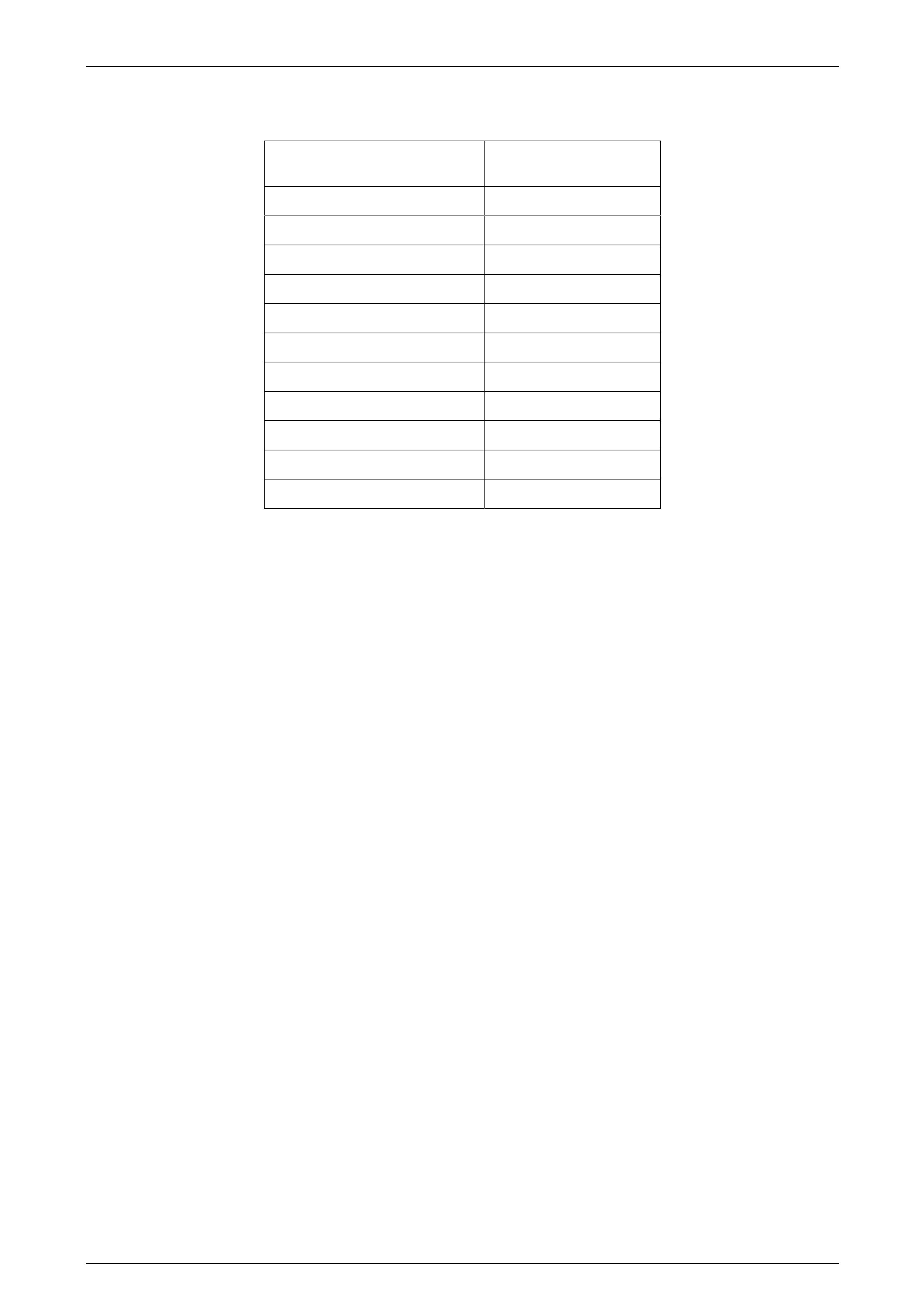
4 Remove the screw (1) and the torque converter
cover (2).
NOTE
Removing the cover on the starter motor side
provides more space to access the bolts
attaching the torque converter to the flexplate.
Figure 7D3 – 2
5 Rotate the flexplate by hand, using a suitable lever in the ring gear teeth, until a torque converter to engine
flexplate bolt becomes accessible.
6 While locking the flexplate by inserting a screwdriver blade or similar into the ring gear teeth, remove the expos ed
torque converter to engine flexplate bolt.
7 Rotate the flexplate by one third of a turn, then repeat step 6, until the three bolts have been removed.
8 Rotate the torque converter through 1/3 turn and reinstall the attaching bolts but only after having cleaned the
threads and applying a thread sealant such as Loctite® 242 or equivalent to the threads. Tighten bolts to the
correct torque specification, while locking the flexplate from turning.
Torque converter to flexplate attachin g
bolt torque specification..........................60.0 – 70.0 Nm
9 Reinstall the torque converter cover and tighten the bolt to the correct torque specification.
Torque converter cover attaching
bolt torque specification............................5.0 – 10.0 Nm
10 Reinstall the starter motor, refer to Section 6D3–2 Starting System – GEN III V8, for the necessary procedure.
11 Start the engine and check for vibration. Repeat the ab ove procedure until the best possible balance is obtained.
Page 7D3–23

Automatic Transmission – 4L65E – Hydraulic and Mechanical Diagnosis Page 7D3–24
7 Mechanical Component
Diagnosis and Repair
7.1 Noise and Vibration Analysis
A noticeable noise or vibration when the vehicle is in motion may not be the result of the transmission.
If noise or vibration is noticeable in park and neutral with the engine at idle, but is less noticeable as r.p.m. increases, the
cause may be from poor engine performance.
a Inspect the tyres for the following:
• uneven wear,
• imbalance,
• mixed sizes, and
• mixed radial tyre tread pattern, refer to Section 10 Wheels and Tyres.
b Inspect the suspension components for the following:
• alignment and wear, and
• loose fasteners, refer to Section 3 Front Suspension and/or Section 4 R ear Suspension.
c Inspect the engine and transmission mounts for damage and loose bolts.
d Inspect the transmission case mounting holes for the following:
• missing bolts, nuts, and studs;
• stripped threads, and
• cracks.
e Inspect the flexplate for the following:
• missing or loose bolts,
• cracks, and
• imbalance.
f Inspect the torque converter for the following:
• missing or loose bolts or lugs,
• missing or loose balanc e weights, and
• imbalance.
Page 7D3–24

Automatic Transmission – 4L65E – Hydraulic and Mechanical Diagnosis Page 7D3–25
7.2 Clutch Plate Diagnosis
Composition Plates
Dry the plates and inspect each one for the following conditions:
• pitting,
• flaking,
• wear,
• glazing,
• cracking,
• charring, and
• chips or metal particles embedded in the lining.
Replace the set, if any composition plate shows any of the above conditions.
Steel Plates
NOTE
If the clutch shows evidence of extreme heat or
burning, replace the release springs. These may
be heat affected as well and have lost their
temper characteristics.
Wipe the plates dry and check them for heat discoloratio n. If the surfaces are smooth, even if colour smear is indicated,
you can reuse the plate. If the plate is discoloured with heat spots or if the surface is scuffed, replace the plate.
Causes of Burned Clutch Plates
The following conditions can result in a burned clutch plate:
• incorrect usage of clutch plates,
• low line pressure,
• valve body conditions, such as:
• the valve body face is not flat
• porosity between channels
• the valve bushing clips are im properly installed
• the checkballs are misplaced
• the Teflon® seal rings are worn or damaged,
• engine coolant in the transmis sion fluid,
• a cracked clutch piston, or
• damaged or missing seals.
Page 7D3–25

Automatic Transmission – 4L65E – Hydraulic and Mechanical Diagnosis Page 7D3–26
7.3 Engine Coolant In Transmission
NOTE
The antifreeze in the engine coolant will cause
both the Viton O-ring seals and the glue bonding
the clutch material to the pressure plate, to
deteriorate. Both conditions may cause damage
to the transmission.
If the transmission oil cooler has developed a leak, allowing engine coolant to enter the tra nsmission, perform the
following operations, refer to Section 7D5 Automatic Transmission – 4L65E – Unit Repair.
1 Disassemble the transmission.
2 Replace all of the rubber type seals.
(The coolant will attack the seal material which will cause leakage.)
3 Replace the composition-faced clutch plate assemblies.
(The facing material may separate from the steel ce ntre portion.)
4 Replace all of the nylon parts ( washers).
5 Replace the torque converter.
6 Thoroughly cle an and rebuild the transmission, using new gaskets and oil filter.
7 Replace the CFRM, refer to Section 6B3 Engi ne Cooling – GEN III V8 or Section 6B4 Engi ne Cooling - GEN IV V8.
8 Flush the cooler lines after the transmission cooler has been properly repair ed or replaced, refer to
Section 7D4 Automatic Transmission – 4L65E – On-vehicle Servicing.
Page 7D3–26

Automatic Transmission – 4L65E – Hydraulic and Mechanical Diagnosis Page 7D3–27
7.4 Fluid Leak Diagnosis and Repair
The cause of most external leaks can usually be located and repaired with the transmission still fitted to the vehicle.
Methods for Locating Leaks
General Method
1 Verify if the leak is in fact transmission fluid.
2 Thoroughly cle an the suspected leak area.
3 Operate the vehicle for about 24 km or until normal operating temperatures are reach ed.
4 Park the vehicle over clean paper or cardboard.
5 Switch the engine off and look for fluid spots on the p aper.
6 Make the necessary repairs.
Powder Method
1 Thoroughly cle an the suspected leak area with a suitable cleaning age nt.
2 Apply an aerosol type powder (eg foot powder) to the suspected leak area.
3 Operate the vehicle for about 24 km or until normal operating temperatures are reach ed.
4 Switch the engine off.
5 Inspect the suspected leak area and trace the leak path through the powder to find the source.
6 Make the necessary repairs.
Dye and Black Light Method
While the following can be used as a guide, always follow the manufactur er’s recommendations for use of this
equipment.
1 Pour the manufacturer's recommended amount of dye such as J28431-B or equivalent, into the transmission.
2 Road test the vehicle under normal operati ng conditions.
3 Direct the black light, Tool No. J42220, to the suspect area. Any fluid leak will appear as a brightly coloured path,
leading to the source.
NOTE
The colour of the dyed fluid can be checked on
the transmission fluid indicator .
4 Make the necessary repairs, then re-check to ensure the leak has been rectified.
Page 7D3–27

Automatic Transmission – 4L65E – Hydraulic and Mechanical Diagnosis Page 7D3–28
Repairing the Leak
NOTE
To obtain a satisfactory repair when a leak has
been detected:
• Once the leak has been traced back to its
source, the cause of the leak must be
determined.
• If a gasket is replaced, but the sealing flange
is distorted or bent (eg oil pan flange), the
new gasket will not stop the leak. Obvious
damage such as this must be rectified before
fitting new gaskets.
Before attempting to repair a leaking seal and/or gasket, check to make sure the following conditions do not apply:
Gaskets
• Fluid level or pressure is too high,
• blocked or partially blocked vent or drain back holes,
• incorrectly tightened fasteners or dirty/damaged threads,
• warped/bent flanges or sealing surface,
• scratches, burrs or other damage to the sealing surface,
• damaged or worn gasket,
• cracking or porosity of the component or adjacent part, an d
• improper sealant used (where applicable).
Seals
• Fluid level or pressure is too high,
• blocked or partially blocked vent or drain back holes,
• damaged seal bore (scratche d burred or nicked),
• damaged or worn seal,
• incorrect previous installation,
• cracks in the component,
• manual or output shaft is scratched, nicked or worn, and
• loose or worn bearing, causing excess seal wear.
Page 7D3–28

Automatic Transmission – 4L65E – Hydraulic and Mechanical Diagnosis Page 7D3–29
Possible Points and Cause of Fluid Leaks
Figure 7D3 – 3 shows the possible points of leakage.
1 Transmission and oil pan:
• attaching bolts not tightened correctly, or
• improperly installed or damag ed gasket.
2 Case leak:
• filler tube multi-lip seal damag ed or missing,
• filler tube bracket misaligned,
• speed sensor seal damaged.
• manual shaft seal worn or damaged,
• oil cooler connector fittings loose or damaged,
• propeller shaft oil seal worn or damaged,
• line pressure plug loose or thread damaged, or
• porous casting.
3 Leak at end of converter:
• converter seal damaged,
• seal lip cut (check converter hub for damag e),
• bushing has moved forward and/or is damaged,
• garter spring is missing from seal,
• converter leak in the weld area, or
• porous casting (case or pump).
4 Fluid comes from vent or the filler tube:
• overfilled,
• water or coolant in fluid (milky/pink flui d colour),
• case porous,
• incorrect fluid level indicator,
• blocked or partially blocked vent,
• drain back holes blocked, or
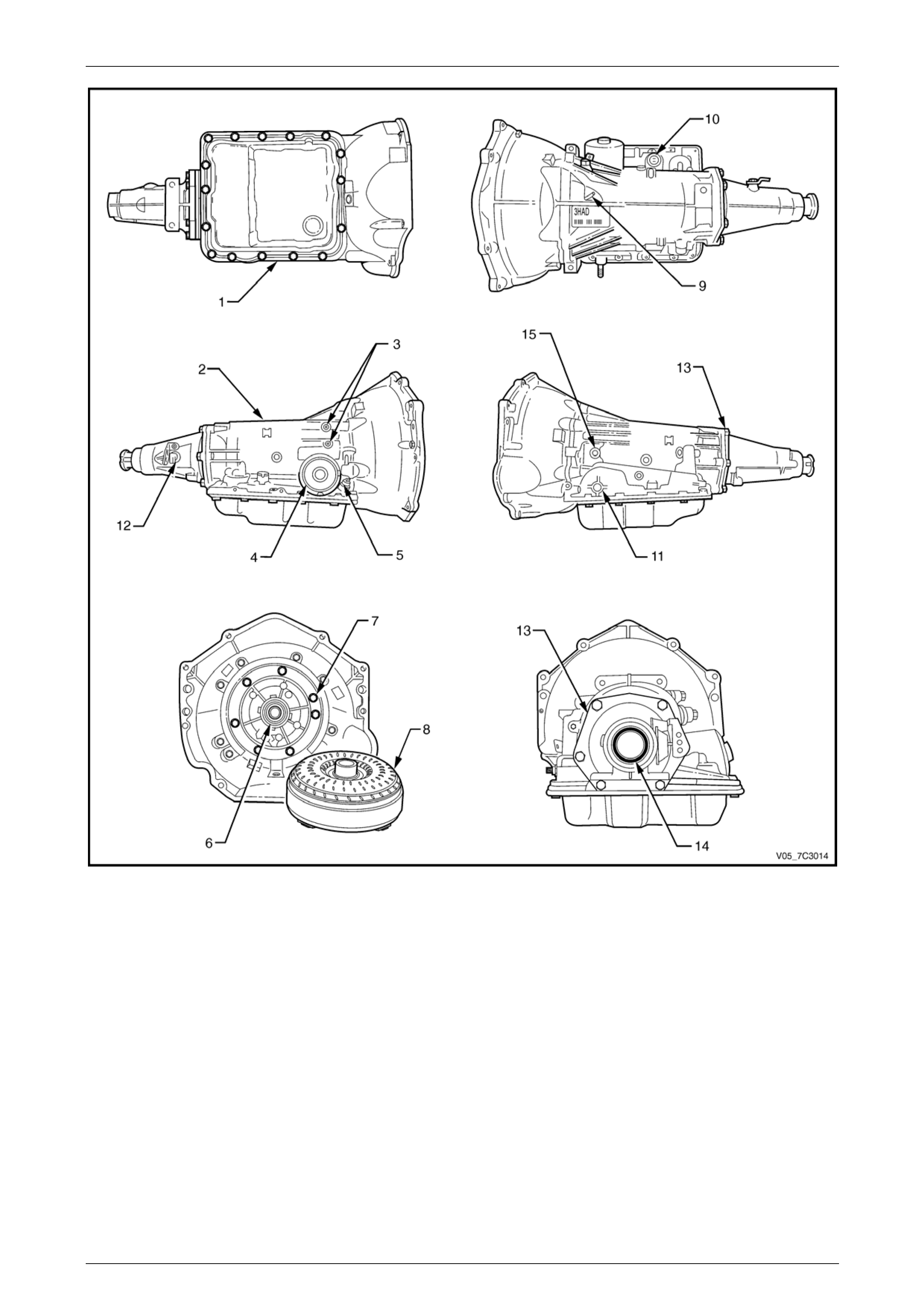
• the alignment of the oil pump to case gasket is incorrect.
Page 7D3–29
Automatic Transmission – 4L65E – Hydraulic and Mechanical Diagnosis Page 7D3–30
Figure 7D3 – 3
Legend
1 Oil Pan Gasket
2 Transmission Main Case
3 Cooler Connections
4 2–4 Servo Cover Seal
5 Filler Tube Seal
6 Oil Pump Seal Assembly
7 Oil Pump to Case Seal
8 Torque Converter
9 Transmission Vent
10 Pass-through Connector O-ring
11 Manual Shaft Oil Seal
12 Vehicle Speed Sensor O-ring
13 Extension Housing to Case Seal
14 Extension Housing Oil Seal Assembly
15 Line Pressure Plug
Page 7D3–30

Automatic Transmission – 4L65E – Hydraulic and Mechanical Diagnosis Page 7D3–31
Case Porosity Repair
Epoxy adhesives may cause skin irritations
and eye damage. Read and follow all
information on the product label, as provided
by the manufacturer.
1 Clean the area with epoxy manufacturer' s recommended solvent and air dry.
2 Mix sufficient amount of epoxy adhesive ('Araldite'™ or an equivalent product), following the manufacturer's
recommendations.
3 While the transmission case is hot, apply epoxy adhesive with a clean, dry stiff brush.
4 Allow the adhesive to dry for the recomm ended time before starting the engine and checking the res ults of the
repair.
5 Repeat the fluid leak diagnosis procedure previously detailed.
Page 7D3–31
Automatic Transmission – 4L65E – Hydraulic and Mechanical Diagnosis Page 7D3–32
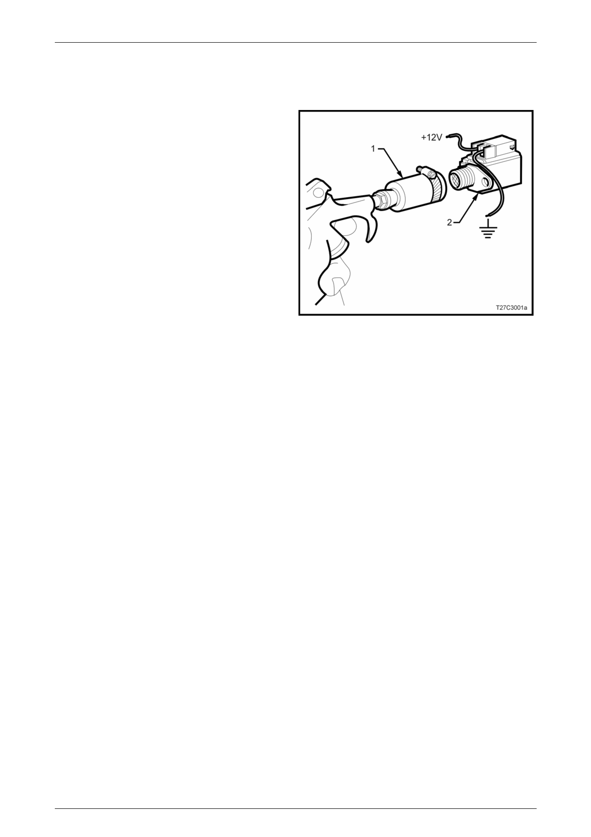
7.5 Shift Solenoid Leak Test
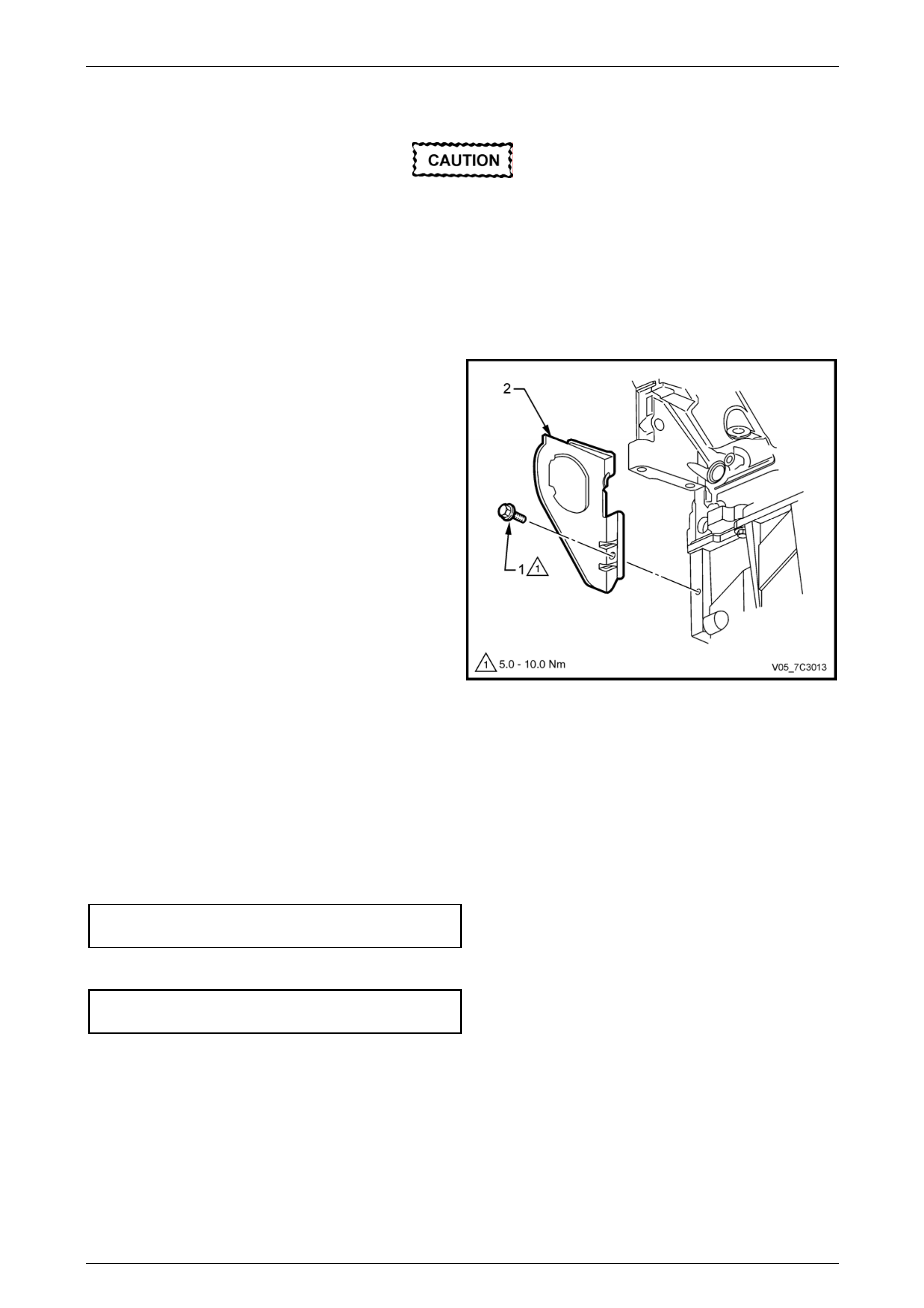
If a shift solenoid is suspected of leaking, perform the following test.
1 Clamp a piece of 12 mm I.D. rubber hos e (1) over the
fluid inlet end of the solenoid ( 2).
2 Connect a wire from one of the solenoid term inals to
the negative terminal (ground) of the battery.
3 Apply compressed air to the rubber hose. Do not use
air pressure in excess of 825 kPa. Excessive pressure
will not allow the solenoid ball check valve to seat
properly.
4 Connect a wire from the other solenoid terminal to the
positive terminal (12 volts) of the battery.
5 Observe air flow through the solenoid. Replace the
solenoid if there is an air leak when the solenoid is
energised.
Figure 7D3 – 4
Page 7D3–32

Automatic Transmission – 4L65E – Hydraulic and Mechanical Diagnosis Page 7D3–33
8 Symptom Diagnosis
8.1 General Information
The following table, refer to 8.2 Symptom Diagnosis Table, consists of seven diagnostic categories which are located in
the left-hand column. Using t his column, choose the appropriate category based on the operating conditions of the
vehicle or transmission. After selecting a cat egory, use the right-hand column to locate the specific sym ptom dia gn ostic
information. Unless otherwise stated, this specific information refers to 9 Diagnostic Tables, with these tables providing
more specific information relating to each of the symptoms listed.
NOTE
Perform the functional test procedure
before beginning any diagnosis, refer to
2 Functional Test.
Page 7D3–33

Automatic Transmission – 4L65E – Hydraulic and Mechanical Diagnosis Page 7D3–34
8.2 Symptom Diagnosis Table
Diagnostic Category Diagnostic Information
Fluid Diagnosis
This category contains the following topics:
• Fluid condition (appeara nce, contaminants, smell,
overheating).
• Line pressure (high or low).
• Fluid leaks.
• Refer to 5 Fluid Diagnosis.
• Refer to Oil Pressure High or Low.
• Refer to 7.4 Fluid Leak Diagnosis an d Repair.
• Refer to Oil Out the Vent.
• Refer to Front Oil Leak.
Noise and Vibration Diagnosis
This category contains the following topics:
• Ratcheting noise.
• Noise (drive gear, final drive, whine, gro wl, rattle,
buzz, popping).
• Vibration.
• Refer to Ratcheting Noise.
• Refer to Vibration in Reverse and Whining Noise in
Park.
Range Performance Diagnosis
This category contains the following topics:
• Drives in Neutral.
• No Park.
• No Reverse.
• No Drive.
• No engine braking.
• Refer to Drives in Neutral.
• Refer to No Park.
• Refer to No Reverse or Slips In Reverse.
• Refer to No Drive in All Ranges.
• Refer to No Drive in Drive Range.
• Refer to No Overrun Braking – Manual 3–2–1.
Shift Quality (Feel) Diagnosis
This category contains the following topic:
• Harsh, soft or slipping shifts.
• Harsh, soft or delayed engagement.
• Shift shudder, flare or tie-up.
• Refer to Harsh Shifts.
• Refer to Slipping or Rough 1–2 Shift.
• Refer to No 2–3 Shift or Shift Slips, Rough or Hunting.
• Refer to No 3–4 Shift, Slips or Rough 3–4 Shift.
• Refer to Harsh Garage Shift.
• Refer to Delay in Drive and Reverse.
• Refer to 3–2 Flare or Tie-up.
Shift Pattern
This category contains the following topics:
• One forward gear only.
• Two forward gears only gear missing or slipping.
• No upshift or slipping upshift.
• No downshifts.
• No first gear start.
• Refer to First Gear Range Only – No Upshift.
• Refer to Third Gear Only.
• Refer to 2nd/3rd Gear Only or 1st/4th Gears Onl y.
• Refer to Slips in First Gear.
• Refer to Slipping or Rough 1–2 Shift.
• Refer to No 2–3 Shift or Shift Slips, Rough or Hunting.
• Refer to No 3–4 Shift, Slips or Rough 3–4 Shift.
• Refer to No Part Throttle or Delayed Downshifts.
• Refer to 2nd Gear Start.
Page 7D3–34

Automatic Transmission – 4L65E – Hydraulic and Mechanical Diagnosis Page 7D3–35
Diagnostic Category Diagnostic Information
Shift Speed Diagnosis
This category contains the following topic:
• Inaccurate or inconsistent shift points.
• Refer to Inaccurate Shift Points.
Torque Converter Diagnosis
This category contains the following topics:
• Torque converter diagnosis.
• TCC does not apply.
• TCC does not release.
• TCC apply/release quality.
• Refer to 6 Torque Converter Diagnosis Procedure.
• Refer to No Torque Converter Clutch App ly.
• Refer to No Torque Converter Clutch Re lease.
• Refer to Torque Converter Clutch Shudder.
Page 7D3–35

Automatic Transmission – 4L65E – Hydraulic and Mechanical Diagnosis Page 7D3–36
9 Diagnostic Tables
9.1 Transmission Malfunction Diagnosis
Introduction
By referring to the Component column, you can identify an area you may think is the cause of the problem. Then refer to
the possible cause column for the most probable cause.
Oil Pressure High or Low
Component Possible Cause
Oil Pump Assembly • Pressure regulator valve stuck
• Pressure regulator valve spring
• Rotor guide omitted or incorrectly assembled
• Rotor cracked or broken
• Reverse boost valve or sleeve stuck, damage d or incorrectly assembled
• Orifice hole in pressure regulator valve plugged
• Sticking slide or excessive rotor clearance
• Pressure relief ball not seated or damaged
• Porosity in pump cover or body
• Wrong pump cover
• Pump faces not flat
• Excessive rotor clearance
Oil Filter • Intake pipe restricted by casting flash
• Cracks in filter body or intake pipe
• O-ring seal missing, cut or damaged
• Wrong grease used on reb uild
Control Valve Body • Manual valve scored or damaged
• Spacer plate or gaskets are incorrect, incorrectly assembled or damaged
• Face not flat
• 2–3 shift valve stuck
• Checkballs omitted or misassemble d
Pressure Control Solenoid • Damage to pins
Transmission Fluid Pressure
Manual Valve Position Switch • Contamination
• Damaged seals
Case • Case to control valve bo dy face not flat
System Voltage • 12 volts not supplied to transmission
• Electrical short (pinched sol en oid wire)
• Solenoid not groun ded
Page 7D3–36
Automatic Transmission – 4L65E – Hydraulic and Mechanical Diagnosis Page 7D3–37
Harsh Shifts
Component Possible Cause
Throttle Position Sensor • Open or shorted circuit
Vehicle Speed Sensor • Open or shorted circuit
Pressure Switch Assembly • Contamination
• Damaged seals
Transmission Fluid
Temperature Sensor • Open or shorted circuit
Engine Coolant Temperature
Sensor • Open or shorted circuit
Pressure Control Solenoid • Damage to pins
• Contamination
Inaccurate Shift Points
Component Possible Cause
Oil Pump Assembly • Stuck pressure regulator valve
• Sticking pump slide
Valve Body Assembly • Spacer plate or gaskets are incorrect, incorrectly assembled or damaged
Case • Porous or damaged valve body pad
• 2–4 servo assembly
• 2–4 accumulator porosity
• Damaged servo piston seals
• Apply pin damaged or impro per length
• 2–4 band assembly
• Burned
• Anchor pin not engaged
Throttle Position Sensor • Disconnected
• Damage
Vehicle Speed Sensor • Disconnected
• Damaged
• Bolt not tightened
First Gear Range Only – No Upshift
Component Possible Cause
Control Valve Body • The 1–2 shift valve is sticking
• Spacer plate is incorrect, incorrectly assembled or damaged
Case • The case to valve body face is damaged or is not flat
Shift Solenoid Valves • Stuck or damaged
• Faulty electrical connection
Page 7D3–37

Automatic Transmission – 4L65E – Hydraulic and Mechanical Diagnosis Page 7D3–38
Component Possible Cause
2–4 Servo Assembly • The apply passage case is restricted or blocked
• Nicks or burrs on the servo pin or on the pin bore in the case
• Fourth servo piston is installed backwards
2–4 Band Assembly • The 2–4 band is worn or damaged
• The band anchor pin is not engaged
Slips in First Gear
Component Possible Cause
Forward Clutch Assembly • Clutch plates worn
• Porosity or damage in for ward clutch piston
• Forward clutch piston inner and outer seals missing, cut or damaged
• Damaged forward clutch housing
• Forward clutch housing retainer and ball assembly not sealing or damaged
Forward Clutch Accumulator • Piston seal missing, cut or damaged
• Piston out of its bore
• Porosity in the piston or valve bod y
• Stuck abuse valve
Input Housing and Shaft
Assembly • Turbine shaft seals missing, cut or damaged
Valve Body • 1–2 accumulator valve stuck
• Face not flat, damaged lands or interconnected passages
• Spacer plate or gaskets are incorrect, incorrectly assembled or damaged
Low Roller Clutch • Damage to lugs to inner ramps
• Rollers not free moving
• Inadequate spring tens ion
• Damage to inner splines
• Lube passage plugged
Torque Converter • Stator roller clu t ch not holding
1–2 Accumulator Assembly • Porosit y in piston or 1– 2 accumulator cover and pin assembly
• Damaged ring grooves on piston
• Piston seal missing, cut or damaged
• Valve body to spacer plate gasket at 1–2 accumul ator cover missing or damaged
• Leak between piston and pin
• Broken 1–2 accumulator spring
Line Pressure • Refer to Oil Pressure High or Low
2–4 Servo Assembly • 4th Servo piston in backwards
Page 7D3–38
Automatic Transmission – 4L65E – Hydraulic and Mechanical Diagnosis Page 7D3–39
Slipping or Rough 1–2 Shift
Component Possible Cause
Valve Body Assembly • 1–2 shift valve train stuck
• Spacer plate or gaskets are incorrect, incorrectly assembled or damaged
• 1–2 accumulator valve stuck
• Face not flat
2–4 Servo Assembly • Apply pin too long or too short
• 2nd servo apply pist on seal missing, cut or damaged
• Restricted or missing oil passages
• Servo bore in case damaged
2nd Accumulator • Porosity in 1–2 accumulator housi ng or piston
• Piston seal or groove damaged
• Nicks or burrs in 1–2 accumulator housing
• Missing or restricted oil passage
2–4 Band • Worn or incorrectly positioned
Oil Pump Assembly or Case • Faces not flat
No 2–3 Shift or Shift Slips, Rough or Hunting
Component Possible Cause
Converter • Internal damage
Oil Pump • Stator shaft sleeve scored or off location
Valve Body Assembly • 2–3 Shift valve train stuck
• Spacer plate or gaskets are incorrect, incorrectly assembled or damaged
• 2–3 accumulator valve stuck
• Face not flat
Input Housing Assembly • 3–4 clutch or forward clutch plates worn
• Excessive clutch plate travel
• Cut or damaged 3–4 clutch or for ward clutch piston seals
• Porosity in input clutch housing or piston
• 3–4 clutch piston checkba ll stuck, damaged or not sealing
• Restricted apply passages
• Forward clutch piston retainer and ball assembly not seating
• Sealing balls loose or missing
Case • 3rd accumulator retainer and ball assembly not seating
2–4 Servo Assembly • 2nd apply piston seals missing, cut or damaged
Page 7D3–39
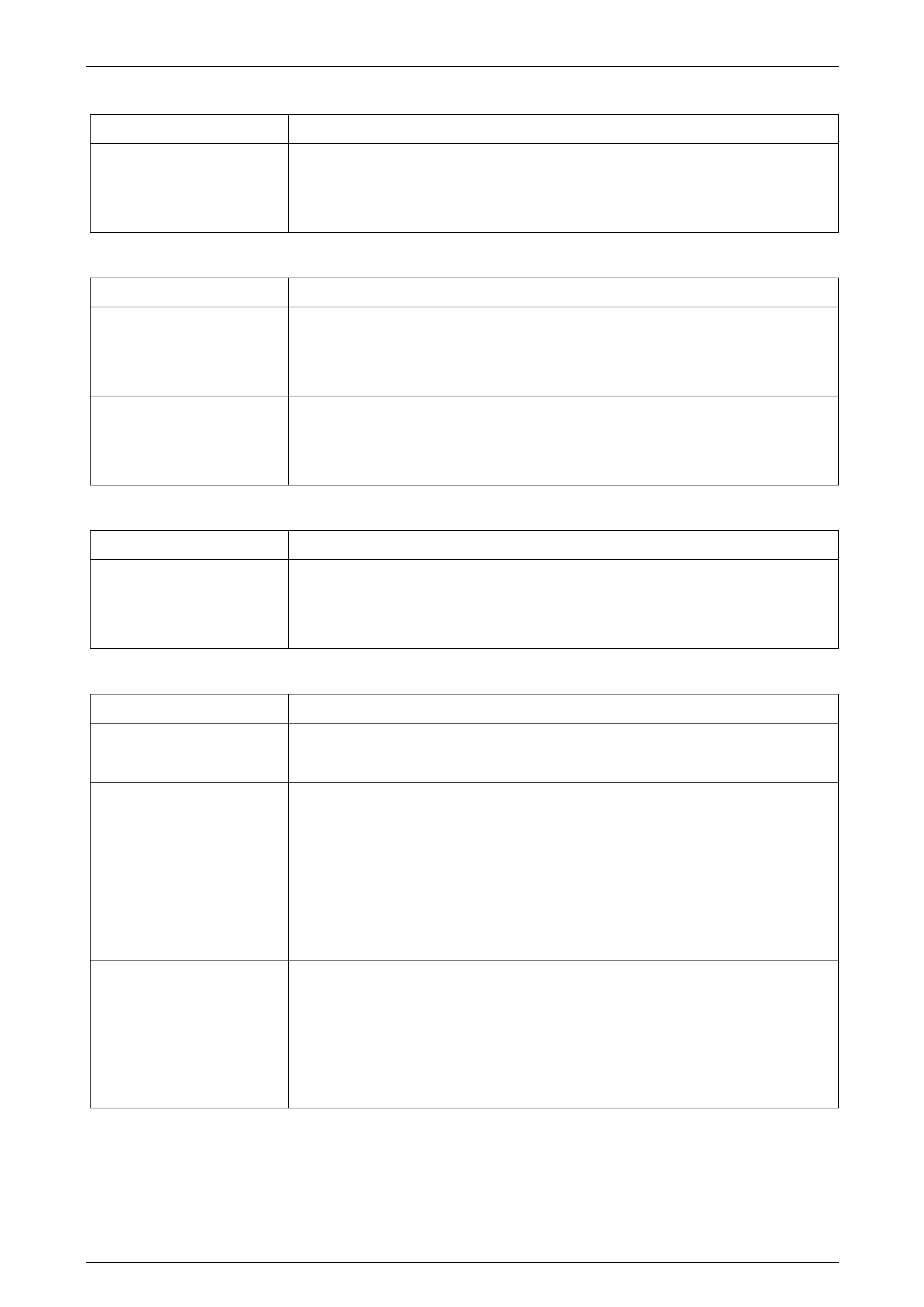
Automatic Transmission – 4L65E – Hydraulic and Mechanical Diagnosis Page 7D3–40
2nd/3rd Gear Only or 1st/4th Gears Only
Component Possible Cause
Shift Solenoid Valves • Sediment is in the valves
• The electrical connectio n is faulty
• Damaged seal
Third Gear Only
Component Possible Cause
System Voltage • 12 volts not supplied to transmission
• Electrical short (pinched sol en oid wire)
• Solenoid not groun ded
3–2 Control Solenoid • Shorted or damaged
• Contamination
• Damaged Seal
3–2 Flare or Tie-up
Component Possible Cause
3–2 Control Solenoid • Shorted or damaged
• Contamination
• Damaged Seal
No 3–4 Shift, Slips or Rough 3–4 Shift
Component Possible Cause
Oil Pump Assembly • Pump cover retainer and ball assembly omitted or damaged
• Faces not flat
Valve Body Assembly • Valves stuck
• 2–3 Shift valve train
• Accumulator valve
• 1–2 Shift valve train
• 3–2 Control valve
• Spacer plate or gaskets are incorrect, incorrectly assembled or damaged
2–4 Servo Assembly • Incorrect band appl y pin
• Missing or damaged servo seals
• Porosity in piston, cover or case
• Damaged piston seal groov es
• Plugged or missing orifice cup plug
Page 7D3–40

Automatic Transmission – 4L65E – Hydraulic and Mechanical Diagnosis Page 7D3–41
Component Possible Cause
Case • 3rd accumulator retainer and ball assembl y leaking
• Porosity in 3–4 accumulator piston or bore
• 3–4 accumulator piston seal o r seal grooves damaged
• Plugged or missing orifice cup plug
• Restricted oil passage
Input Housing Assembly • Refer to No 2–3 Shift or Shift Slips, Rough or Hunting
2–4 Band Assembly • Worn or incorrectly assembled
No Reverse or Slips In Reverse
Component Possible Cause
Input Housing Assembly • 3–4 apply ring stuck in applie d position
• Forward clutch not releasing
• Turbine shaft seals missing, cut or damaged
Manual Valve Link • Disconnected
Valve Body Assembly • 2–3 shift valve stuck
• Manual linkage not adjusted
• Spacer plate or gaskets are incorrect, incorrectly assembled or damaged
• Low overrun valve stuck
• Orificed cup plug restricted, missing or damaged
Reverse Input Clutch
Assembly • Clutch plate worn
• Reverse input housing and drum assembly cracked at weld
• Clutch plate retaining ring out of groove
• Return spring assembly retainin g ring out of groove
• Seals cut or damaged
• Restricted apply passage
• Porosity in piston
• Belleville plate installed incorrectly
• Excessive clutch plate travel
• Oversized housing
Low and Reverse Clutch • Clutch plates worn
• Porosity in piston
• Seals damaged
• Return spring assembly retainin g ring in the wrong position
• Restricted apply passage
Page 7D3–41

Automatic Transmission – 4L65E – Hydraulic and Mechanical Diagnosis Page 7D3–42
No Part Throttle or Delayed Downshifts
Component Possible Cause
Input Housing Assembly • 3–4 apply ring stuck in applie d position
• Forward clutch not releasing
• Turbine shaft seals missing, cut or damaged
Manual Valve Link • Disconnected
Valve Body Assembly • 2–3 shift valve stuck
• Manual linkage not adjusted
• Spacer plate or gaskets are incorrect, incorrectly assembled or damaged
• Low overrun valve stuck
• Orificed cup plug restricted, missing or damaged
Reverse Input Clutch
Assembly • Clutch plate worn
• Reverse input housing and drum assembly cracked at weld
• Clutch plate retaining ring out of groove
• Return spring assembly retainin g ring out of groove
• Seals cut or damaged
• Restricted apply passage
• Porosity in piston
• Belleville plate installed incorrectly
• Excessive clutch plate travel
• Oversized housing
Low and Reverse Clutch • Clutch plates worn
• Porosity in piston
• Seals damaged
• Return spring assembly retainin g ring incorrectly assembled
• Restricted apply passage
Harsh Garage Shift
Component Possible Cause
Valve Body Assembly • Orifice cup plug missing
• Checkball missing
Page 7D3–42
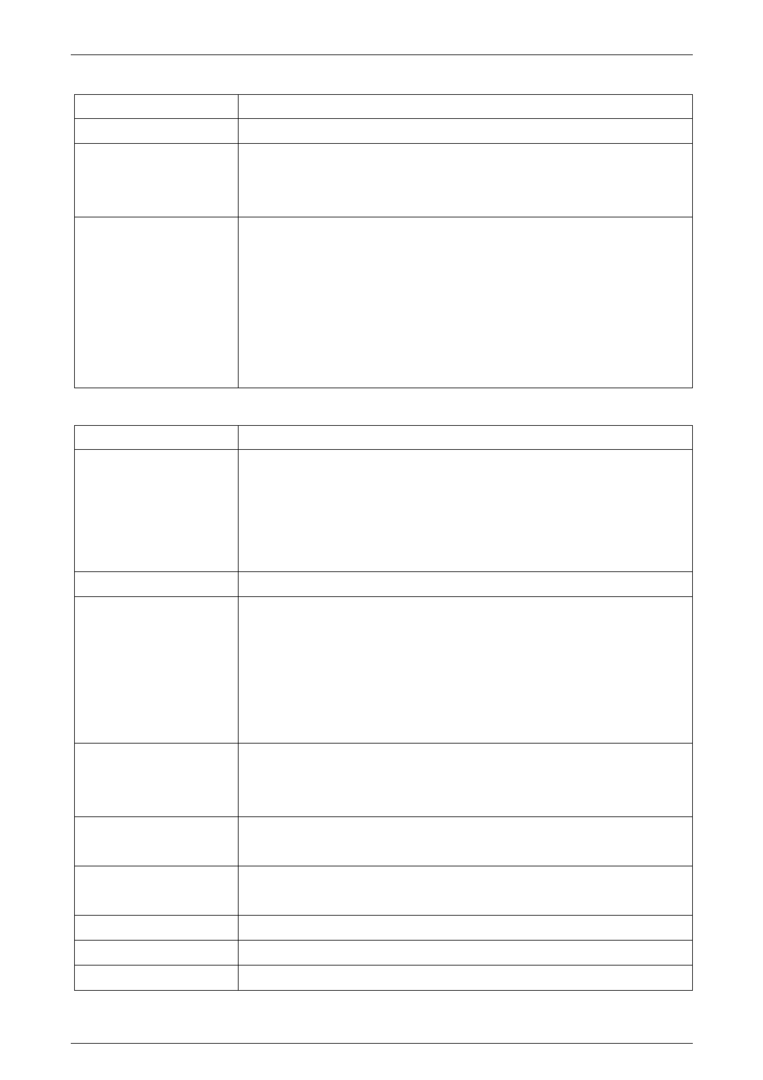
Automatic Transmission – 4L65E – Hydraulic and Mechanical Diagnosis Page 7D3–43
No Overrun Braking – Manual 3–2–1
Component Possible Cause
External Linkage • Not adjusted properly
Valve Body Assembly • 4–3 sequence valve stuck
• Checkball incorrectly positioned
• Spacer plate or gaskets are incorrect, incorrectly assembled or damaged
Input Clutch Assembly • Turbine shaft oil passages plugged or not drilled
• Turbine shaft seal rings dama ged
• Turbine shaft sealing balls loos e or missing
• Turbine shaft sealing balls loos e or missing
• Porosity in forward or overrun clutch pisto n
• Overrun piston seals cut or damaged
• Overrun piston checkball not sealing
No Torque Converter Clutch Apply
Component Possible Cause
Electrical • 12 volts not supplied to transmission
• Outside electrical connector damaged
• Inside electrical connector, wiring harness or solenoid damaged
• Electrical short (pinched sol en oid wire)
• Solenoid not groun ded
Torque Converter Clutch • Internal damage
Oil Pump Assembly • Converter clutch valve stuck or assembled backwards
• Converter clutch valve retaining ring incorrectly assembled
• Pump to case gasket incorrectly positioned
• Orifice cup plug restricted or damaged
• Solenoid O-ring seal cut or damaged
• High or uneven bolt torque ( pump body to cover)
Input Housing and Shaft • Turbine shaft O-ring seal cut or damaged
• Incorrect O-ring fitted (e.g. 300 mm torque converter O-ring on 258 mm converter)
• Turbine shaft retainer and ball assembly restricted or damaged
Transmission Fluid Pressure
Manual Valve Position Switch • Contamination
• Damaged seals
Control Valve Body Assembly • TCC signal valve stuck
• Solenoid O-ring leaking
Solenoid Screen • Blocked
TCC Solenoid Valve • Internal damage
Engine Speed Sensor • Internal damage
Page 7D3–43
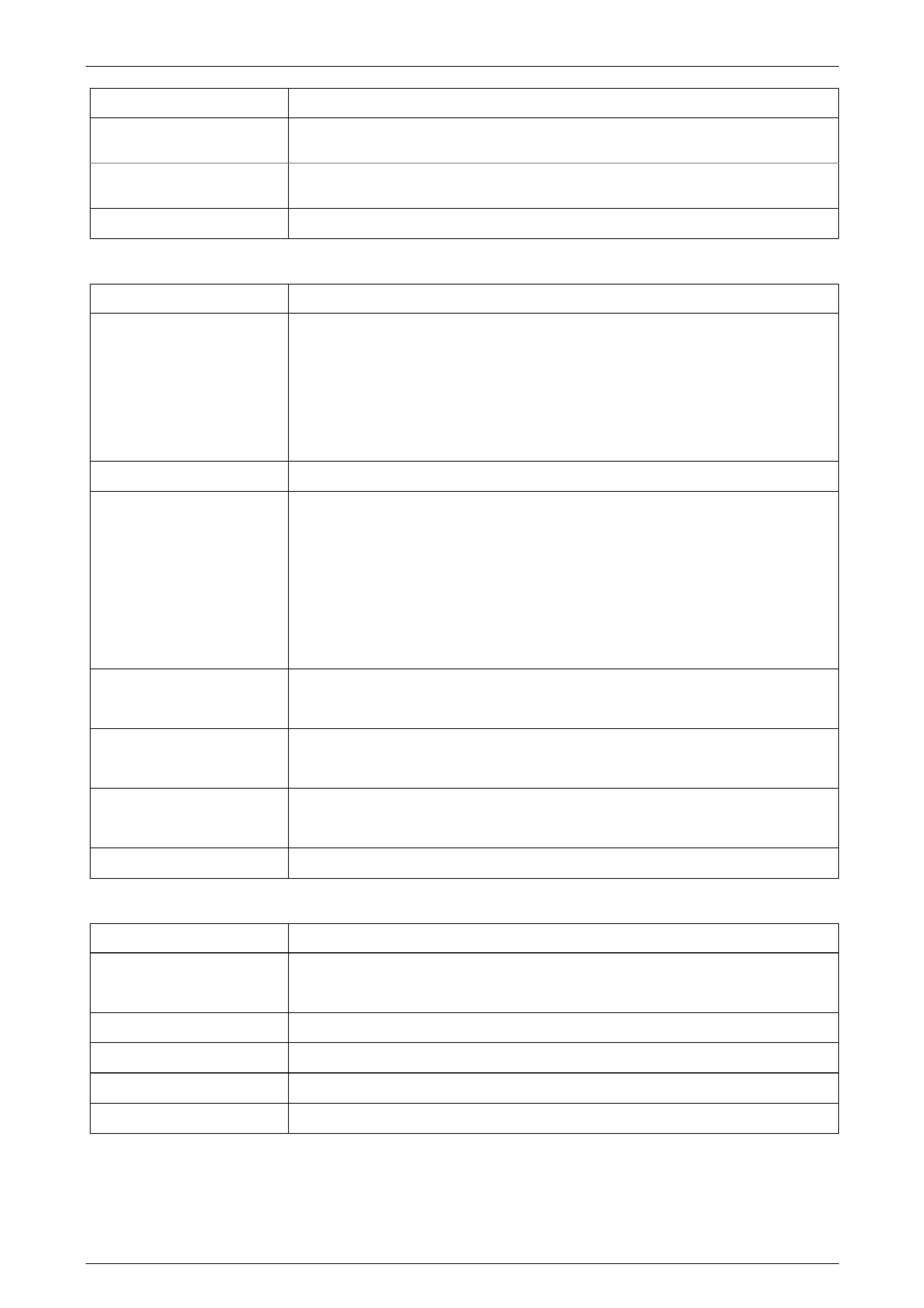
Automatic Transmission – 4L65E – Hydraulic and Mechanical Diagnosis Page 7D3–44
Component Possible Cause
Engine Coolant Temperature
Sensor • Internal damage
Automatic Transmission Fluid
Temperature Sensor • Internal damage
Brake Switch • Internal damage
Torque Converter Clutch Shudder
Component Possible Cause
Electrical • 12 volts not supplied to transmission
• Outside electrical connector damaged
• Inside electrical connector, wiring harness or solenoid damaged
• Electrical short (pinched sol en oid wire)
• Solenoid not groun ded
Converter • Internal damage
Oil Pump Assembly • Converter clutch valve stuck or assembled backwards
• Converter clutch valve retainin g ring incorrectly positioned
• Pump to case gasket incorrectly assembled
• Orifice cup plug restricted or damaged
• Solenoid O-ring seal cut or damaged
• High or uneven bolt torque ( pump body to cover)
Input Housing and Shaft • Turbine shaft O-ring seal cut or damaged
• Turbine shaft retainer and ball assembly restricted or damaged
Pressure Switch Assembly • Contamination
• Damaged seals
Valve Body Assembly • TCC signal valve stuck
• Solenoid O-ring leaking
Solenoid Screen • Blocked
No Torque Converter Clutch Release
Component Possible Cause
TCC Solenoid Valve • External ground
• Clogged exhaust orifice
Converter • Internal damage
Valve Body Assembly • The converter clutch apply valve is stuck in the apply position
Oil Pump Assembly • The converter clutch valve is stuck
PCM • External ground
Page 7D3–44

Automatic Transmission – 4L65E – Hydraulic and Mechanical Diagnosis Page 7D3–45
Drives in Neutral
Component Possible Cause
Forward Clutch • The clutch does not release
Manual Valve Link • Disconnected
Case • The face is not flat
• Internal leakage exists
2nd Gear Start
Component Possible Cause
Forward Clutch Sprag
Assembly • The sprag assembly is installed backwards
No Park
Component Possible Cause
Parking Linkage • Actuator rod assembly bent or damaged
• Actuator rod spring binding or improperly crimped
• Actuator rod not attached to inside detent lever
• Parking lock bracket damaged or not tighten ed properly
• Inside detent lever not tightened properl y
• Parking pawl binding or d amaged
Oil Out the Vent
Component Possible Cause
Oil Pump • Chamber in pump body rotor pocket porous
Miscellaneous • Fluid level-overfilled
Vibration in Reverse and Whining Noise in Park
Component Possible Cause
Oil Pump • Chamber in pump body rotor pocket porous
Miscellaneous • Fluid level-overfilled
Ratcheting Noise
Component Possible Cause
Parking Pawl • The parking pawl return sprin g is weak, damaged, or misassembled
No Drive in All Ranges
Component Possible Cause
Torque Converter • T he converter to flex plate bolts are missing
Page 7D3–45
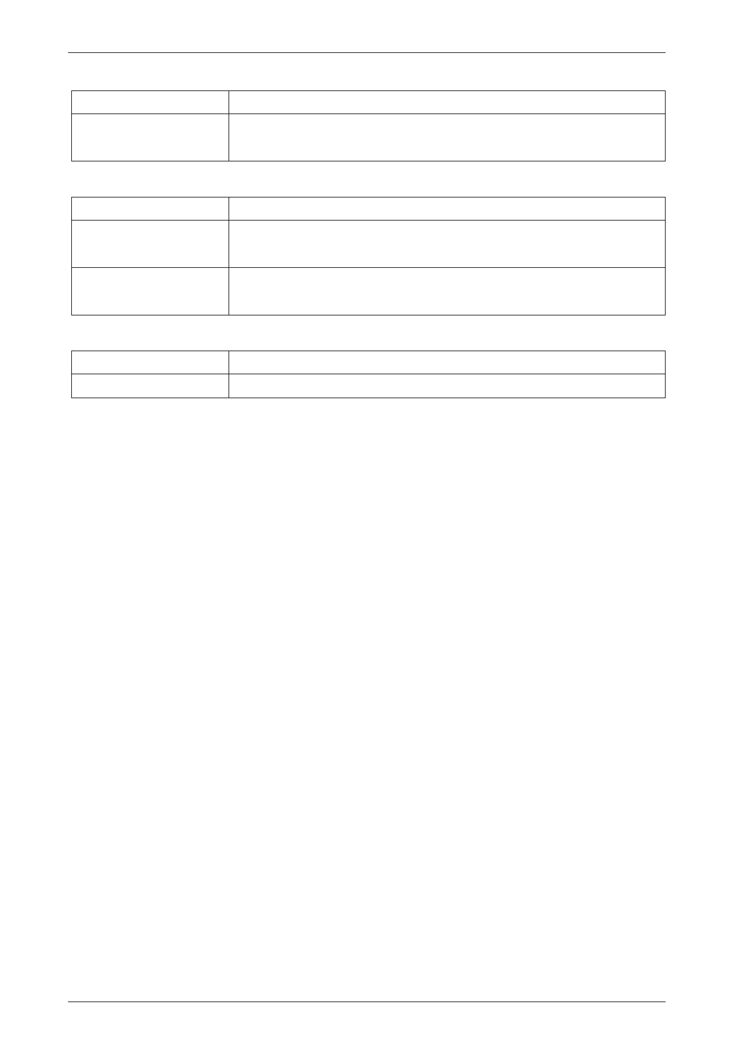
Automatic Transmission – 4L65E – Hydraulic and Mechanical Diagnosis Page 7D3–46
No Drive in Drive Range
Component Possible Cause
Torque Converter • T he stator roller clutch is not holding
• The converter is not bolted to the flexplate
Front Oil Leak
Component Possible Cause
Torque Converter • The welded seam is leaking
• The converter hub is damaged
Torque Converter Seal • The seal assembly is damaged
• The garter spring is missing
Delay in Drive and Reverse
Component Possible Cause
Torque Converter • Converter drainback
Page 7D3–46

Automatic Transmission – 4L65E – Hydraulic and Mechanical Diagnosis Page 7D3–47
10 4L65E Shift Speed Charts
10.1 Introduction
To assist in the interpretation of the following charts, the following criteria have been applied:
• All upshifts have a solid gre en line with:
• 1–2 has black filled diamond plot points,
• 2–3 has black filled square plot points, and
• 3–4 has black filled circular plot points.
• All downshifts have a solid blue line with:
• 2–1 has white filled diamond p lot points,
• 3–2 has white filled square plot points, and
• 4–3 has white filled circular plot points.
• Torque converter clutch apply points (‘3rd App’ and ‘4th Ap p’) have a dashed dark blue line with:
• ‘3rd App’ has white filled square plot points and
• ‘4th App’ has white filled, circular plot points.
• Torque converter clutch release points (‘3rd Rel’ and ‘4th Rel’) have a dashed pink line with:
• ‘3rd Rel’ has white filled square plot points and
• ‘4th Rel’ has white filled, circular pl ot points.
Page 7D3–47
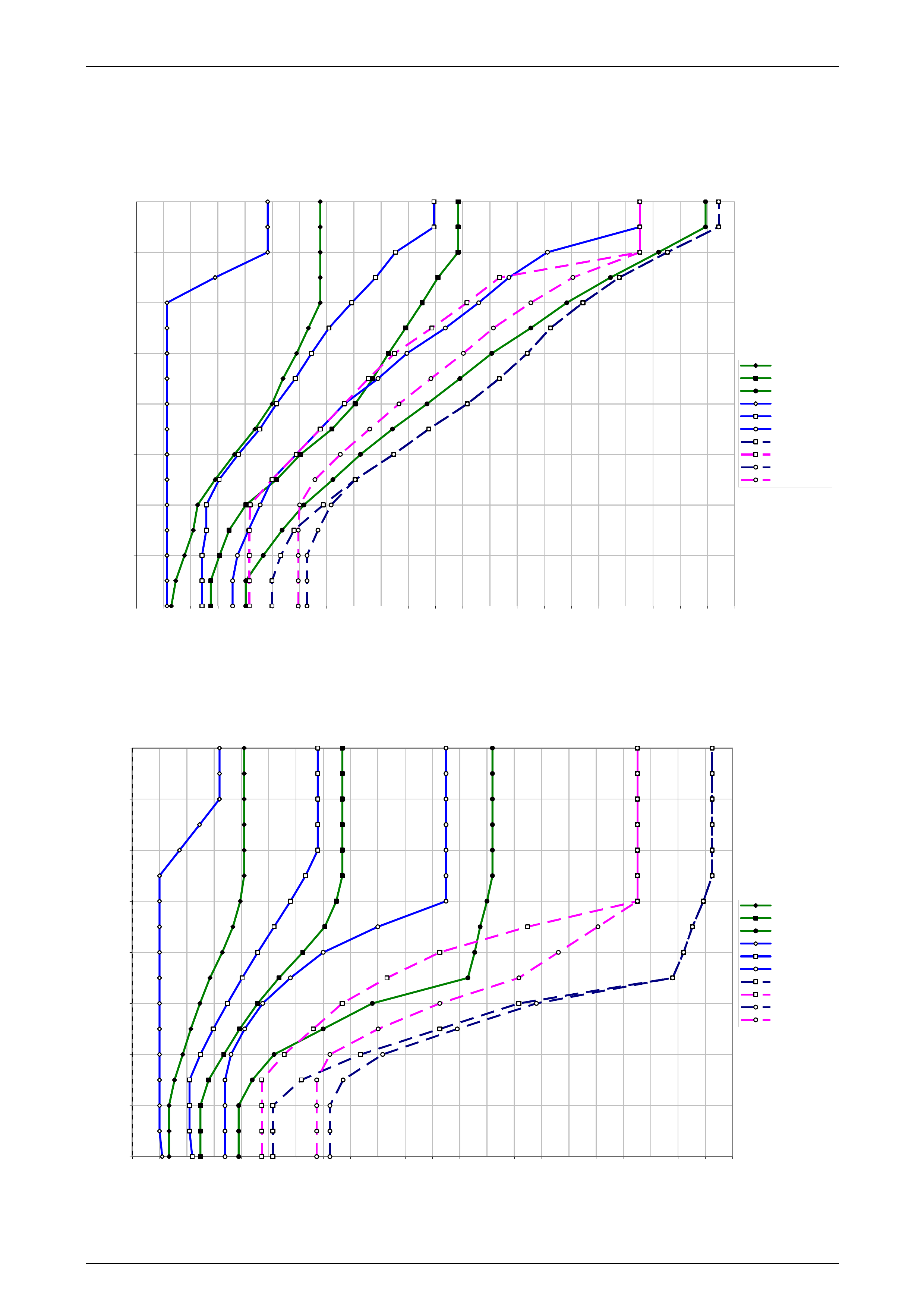
Automatic Transmission – 4L65E – Hydraulic and Mechanical Diagnosis Page 7D3–48
10.2 GEN III V8 Coupe
Normal Mode
0.0
12.5
25.0
37.5
50.0
62.5
75.0
87.5
100.0
0 10 20 30 40 50 60 70 80 90 100 110 120 130 140 150 160 170 180 190 200 210 220
Vehicle Speed KPH
Throttle
1-2
2-3
3-4
2-1
3-2
4-3
TCC 3 Apply
TCC 3 Release
TCC 4 Apply
TCC 4 Release
Figure 7D3 – 5
Power Mode
0.0
12.5
25.0
37.5
50.0
62.5
75.0
87.5
100.0
0 10 20 30 40 50 60 70 80 90 100 110 120 130 140 150 160 170 180 190 200 210 220
Vehicle Speed KP H
Throttle %
1-2
2-3
3-4
2-1
3-2
4-3
TCC 3 Apply
TCC 3 Release
TCC 4 Apply
TCC 4 Release
Figure 7D3 – 6
Page 7D3–48
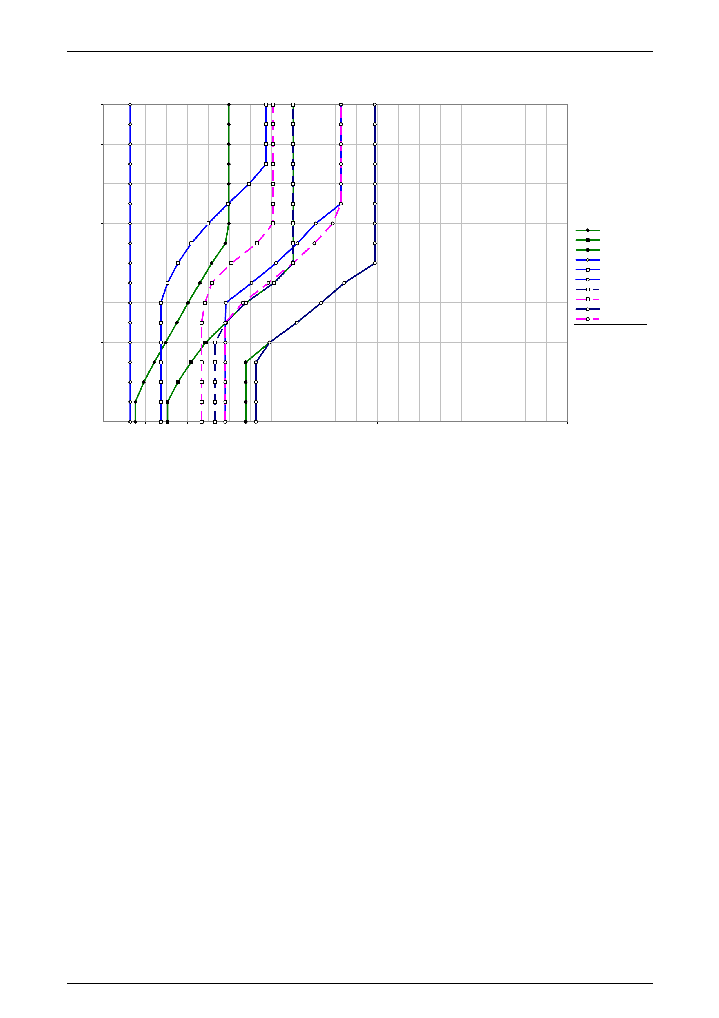
Automatic Transmission – 4L65E – Hydraulic and Mechanical Diagnosis Page 7D3–49
Cruise Mode
0.0
12.5
25.0
37.5
50.0
62.5
75.0
87.5
100.0
0 10 20 30 40 50 60 70 80 90 100 110 120 130 140 150 160 170 180 190 200 210 220
Vehicle Speed KPH
Throttle
1-2
2-3
3-4
2-1
3-2
4-3
TCC 3 Apply
TCC 3 Releas e
TCC 4 Apply
TCC 4 Releas e
Figure 7D3 – 7
Page 7D3–49
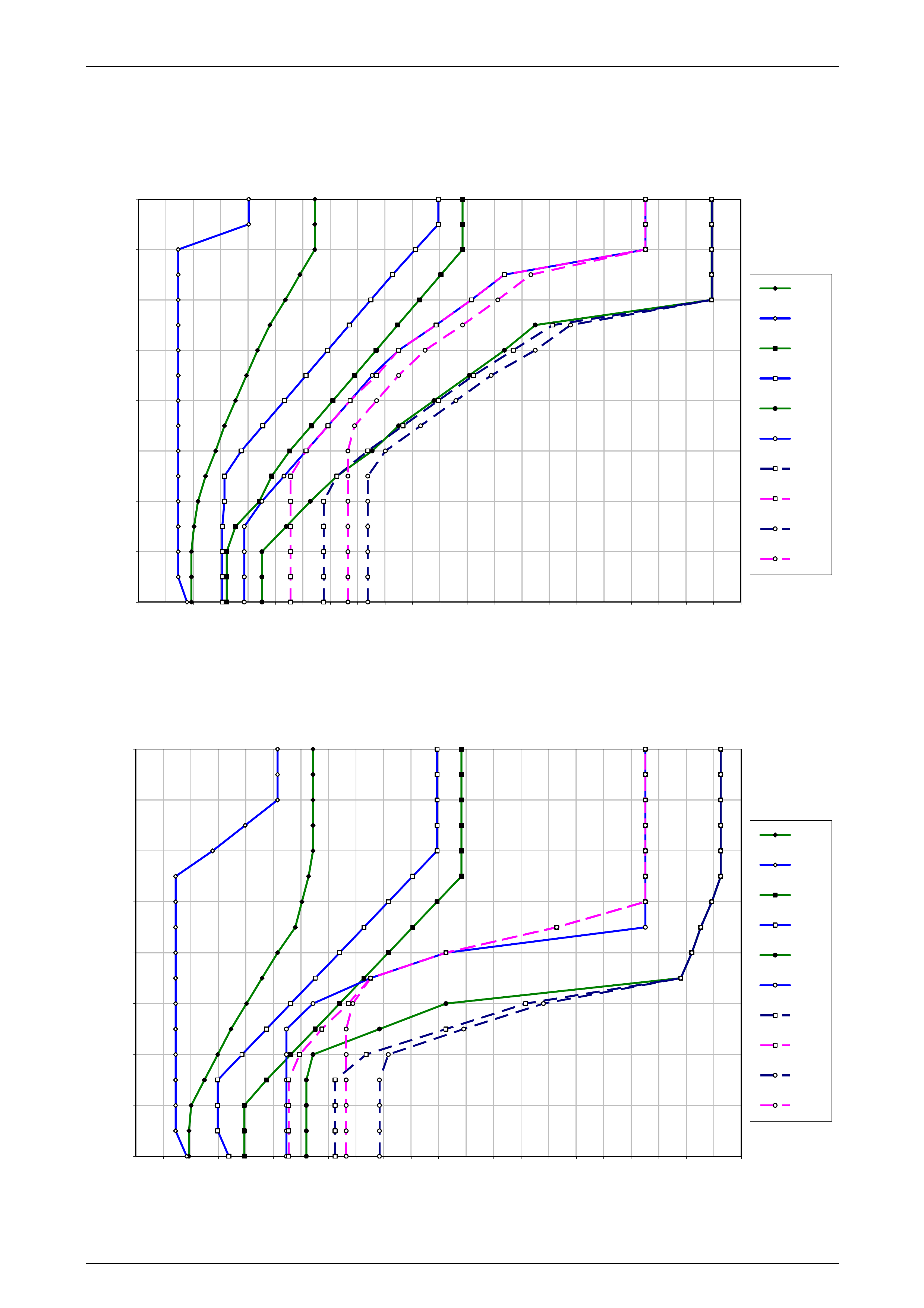
Automatic Transmission – 4L65E – Hydraulic and Mechanical Diagnosis Page 7D3–50
10.3 GEN III V8 – RWD Cab Chassis
Normal Mode
0.0
12.5
25.0
37.5
50.0
62.5
75.0
87.5
100.0
0 102030405060708090100110120130140150160170180190200210220
VEHICLE SPEED - KPH
PERCENT THROTTLE
1-2
2-1
2-3
3-2
3-4
4-3
3rd APP
3rd REL
4th APP
4th REL
Figure 7D3 – 8
Power Mode
0.0
12.5
25.0
37.5
50.0
62.5
75.0
87.5
100.0
0 10 20 30 40 50 60 70 80 90 100 110 120 130 140 150 160 170 180 190 200 210 220
VEHICLE SPEED - KPH
PERCE NT THROTTLE
1-2
2-1
2-3
3-2
3-4
4-3
3rd APP
3rd REL
4th APP
4th REL
Figure 7D3 – 9
Page 7D3–50
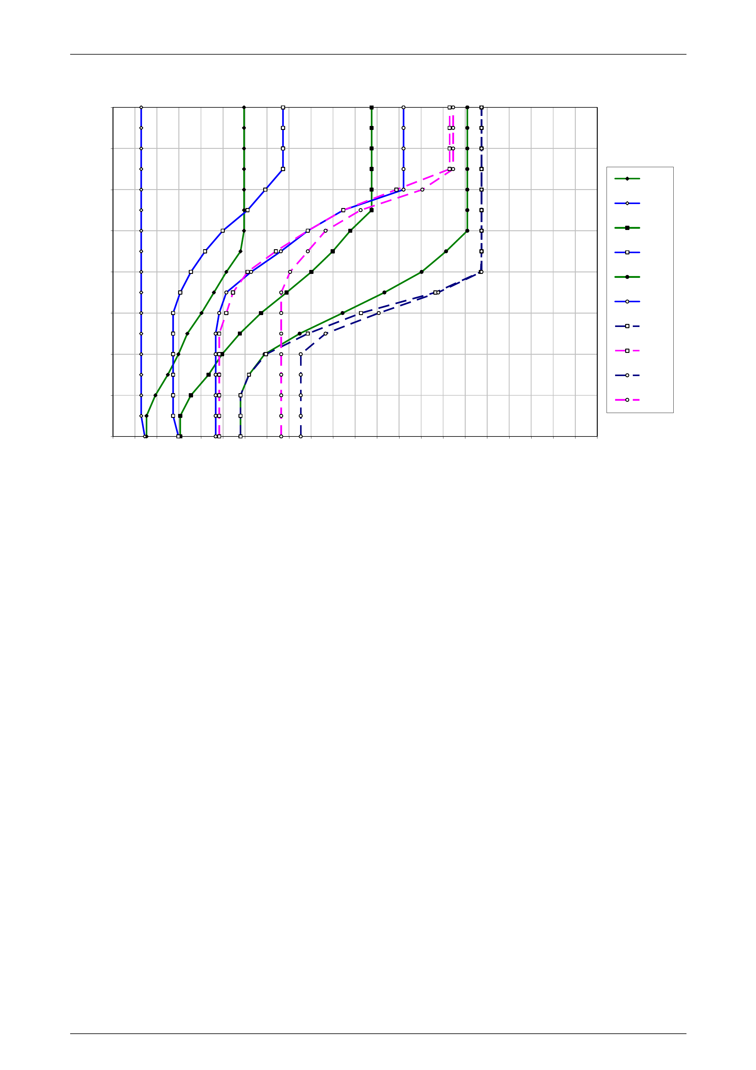
Automatic Transmission – 4L65E – Hydraulic and Mechanical Diagnosis Page 7D3–51
Cruise Mode
0.0
12.5
25.0
37.5
50.0
62.5
75.0
87.5
100.0
0 10 20 30 40 50 60 70 80 90 100 110 120 130 140 150 160 170 180 190 200 210 220
VEHICLE SPEED - KPH
PERCENT THROTTLE
1-2
2-1
2-3
3-2
3-4
4-3
3rd APP
3rd REL
4th APP
4th REL
Figure 7D3 – 10
Page 7D3–51
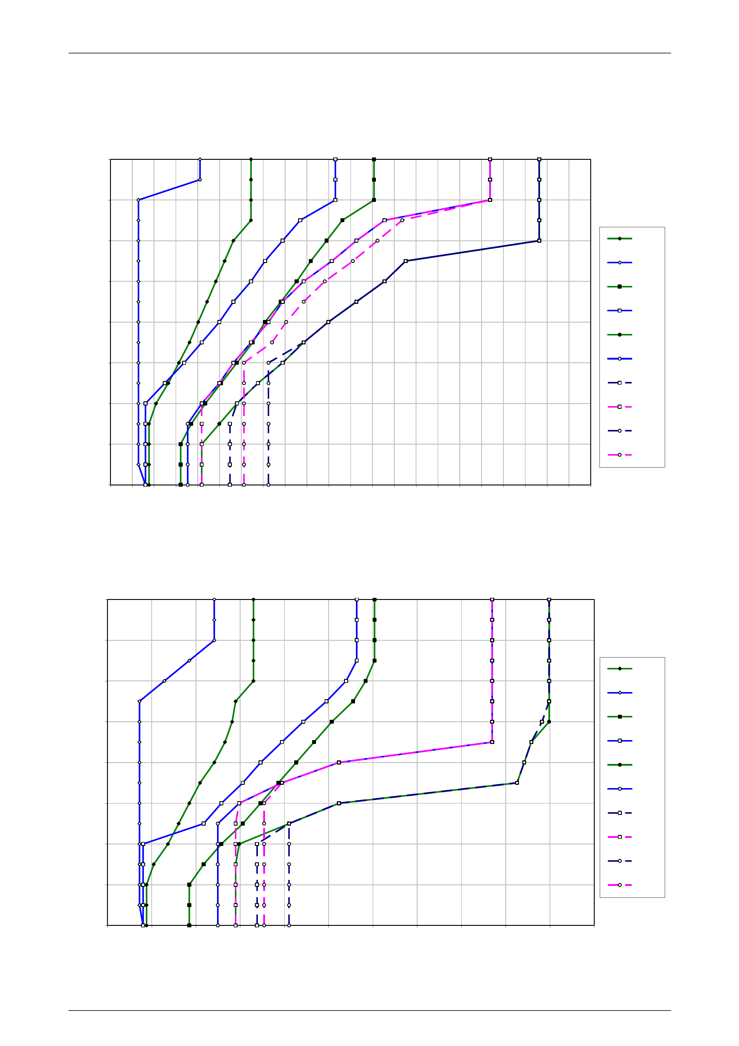
Automatic Transmission – 4L65E – Hydraulic and Mechanical Diagnosis Page 7D3–52
10.4 GEN III V8 – AWD Cab Chassis
Normal Mode
0.0
12.5
25.0
37.5
50.0
62.5
75.0
87.5
100.0
0 10 20 30 40 50 60 70 80 90 100 110 120 130 140 150 160 170 180 190 200 210 220
VEHICLE SPEED - KPH
PERCENT THROTTLE
1-2
2-1
2-3
3-2
3-4
4-3
3rd APP
3rd REL
4th APP
4th REL
Figure 7D3 – 11
Power Mode
0.0
12.5
25.0
37.5
50.0
62.5
75.0
87.5
100.0
0 20 40 60 80 100 120 140 160 180 200 220
VEHICLE SPEED - KPH
PERCENT THROTTLE
1-2
2-1
2-3
3-2
3-4
4-3
3rd APP
3rd REL
4th APP
4th REL
Figure 7D3 – 12
Page 7D3–52
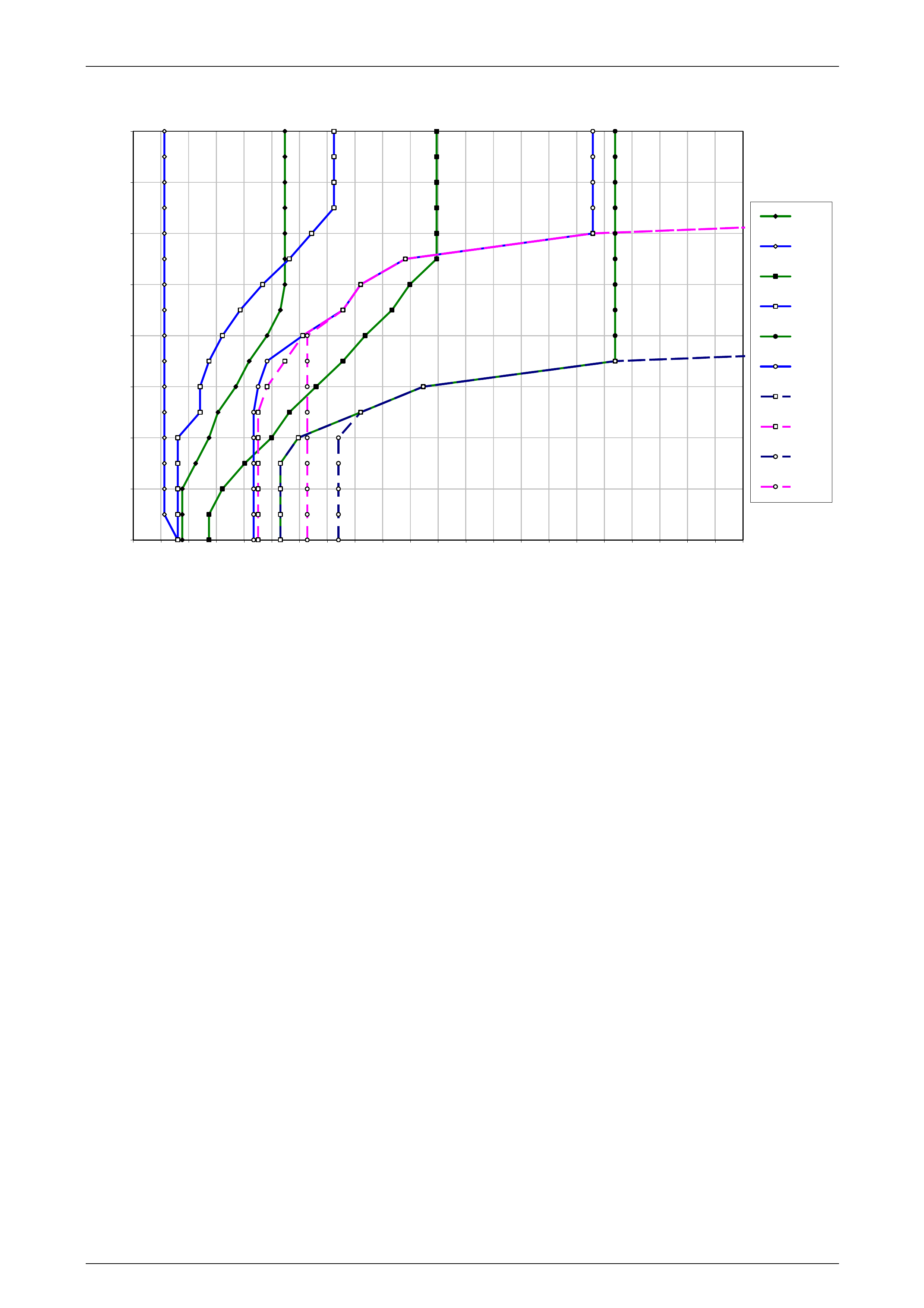
Automatic Transmission – 4L65E – Hydraulic and Mechanical Diagnosis Page 7D3–53
Cruise Mode
0.0
12.5
25.0
37.5
50.0
62.5
75.0
87.5
100.0
0 10 20 30 40 50 60 70 80 90 100 110 120 130 140 150 160 170 180 190 200 210 220
VEHICLE SPEED - KPH
PERCENT THROTTLE
1-2
2-1
2-3
3-2
3-4
4-3
3rd APP
3rd REL
4th APP
4th REL
Figure 7D3 – 13
Page 7D3–53
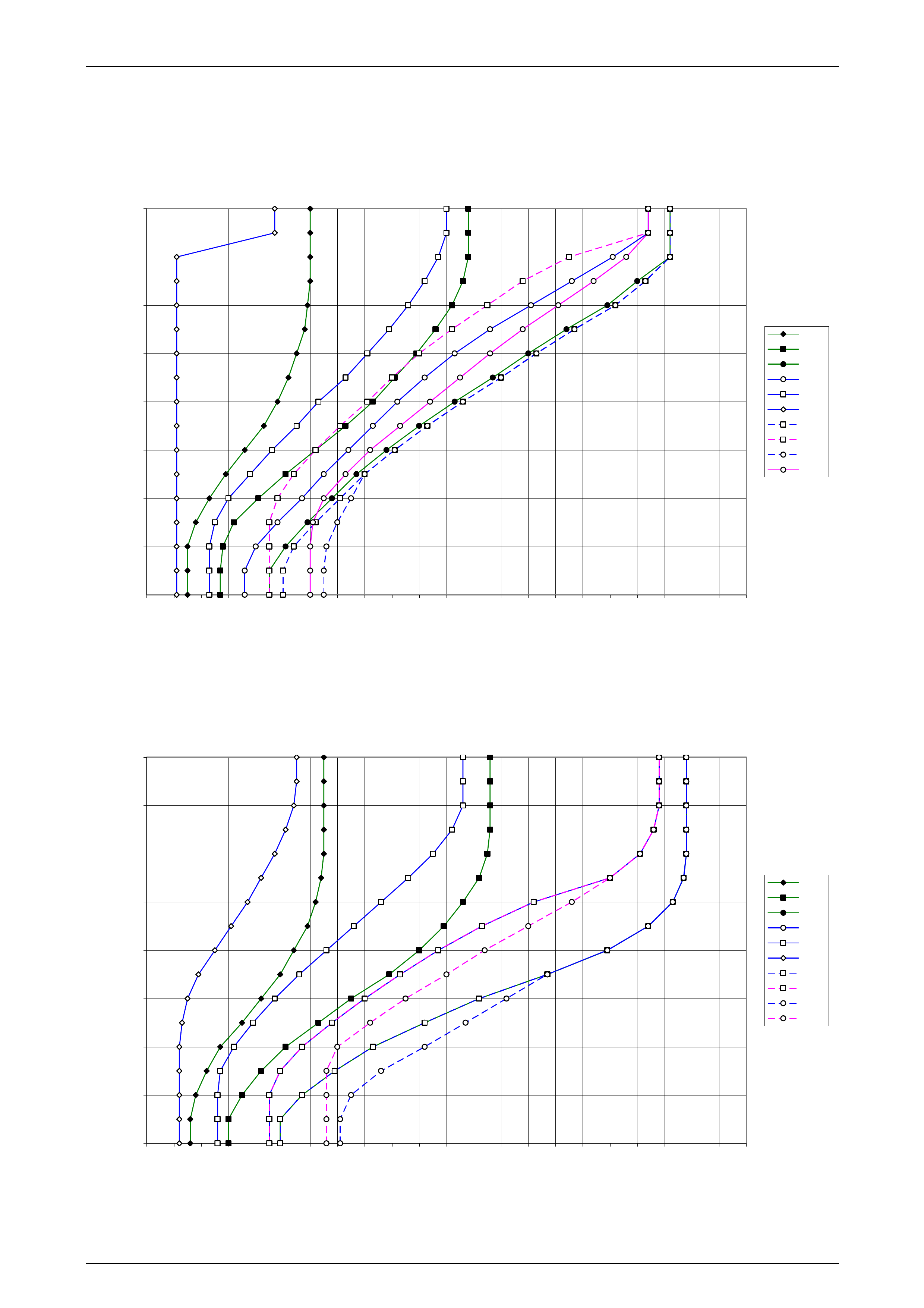
Automatic Transmission – 4L65E – Hydraulic and Mechanical Diagnosis Page 7D3–54
10.5 GEN IV V8 (L76) Sedan, Wagon and Ute
Normal Mode
0
12.5
25
37.5
50
62.5
75
87.5
100
0 10 20 30 40 50 60 70 80 90 100 110 120 130 140 150 160 170 180 190 200 210 220
Vehicle Speed KPH
Throttle
12N
23N
34N
43N
32N
21N
3App
3Rel
4App
4Rel
Figure 7D3 – 14
Power Mode
0
12.5
25
37.5
50
62.5
75
87.5
100
0 10 20 30 40 50 60 70 80 90 100 110 120 130 140 150 160 170 180 190 200 210 220
Vehicle Speed KPH
Throttle
12P
23P
34P
43P
32P
21P
3App
3Rel
4App
4Rel
Figure 7D3 – 15
Page 7D3–54
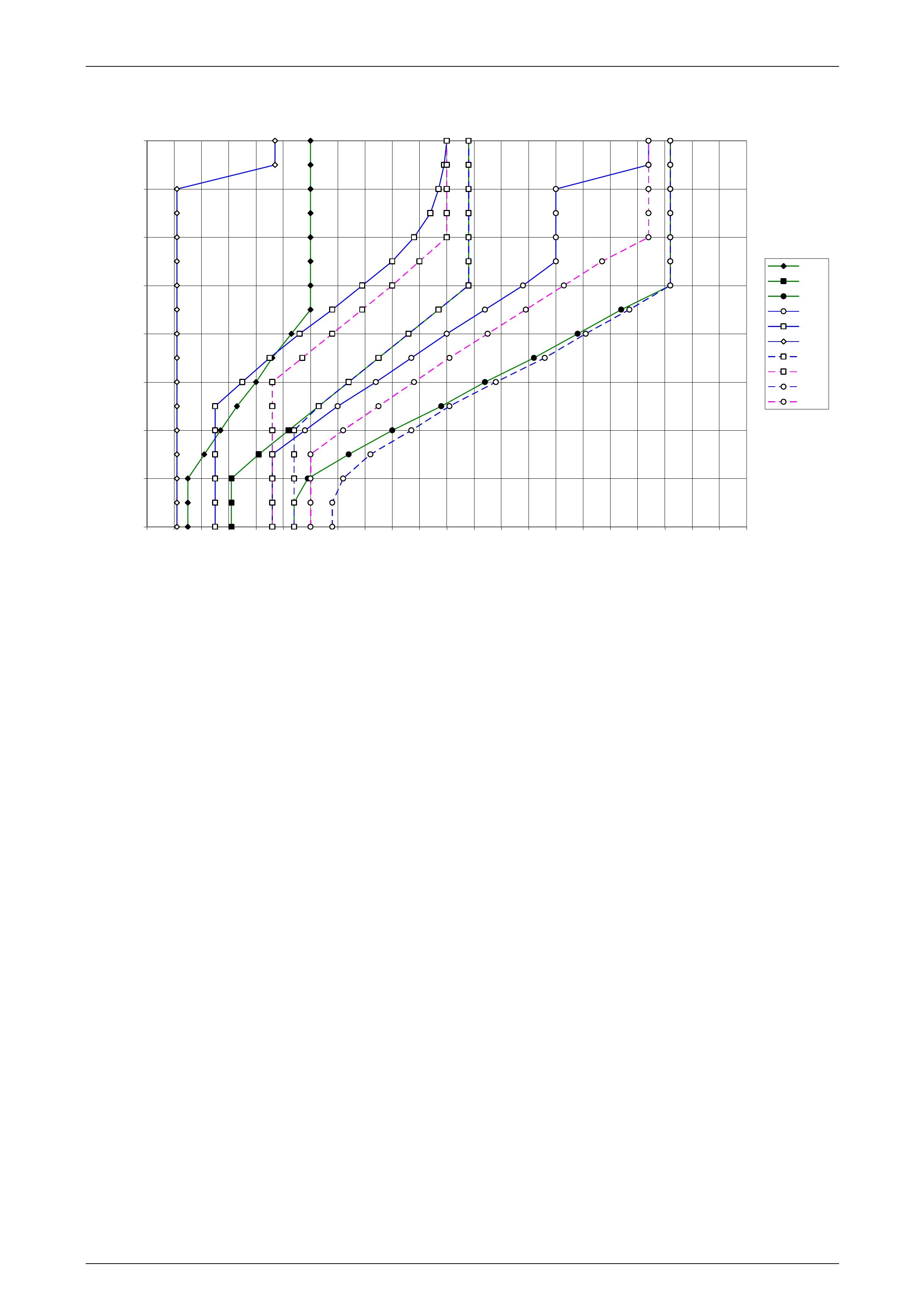
Automatic Transmission – 4L65E – Hydraulic and Mechanical Diagnosis Page 7D3–55
Cruise Mode
0
12.5
25
37.5
50
62.5
75
87.5
100
0 10 20 30 40 50 60 70 80 90 100 110 120 130 140 150 160 170 180 190 200 210 220
Vehicle Speed KPH
Throttle
12C
23C
34C
43C
32C
21C
3App
3Rel
4App
4Rel
Figure 7D3 – 16
Page 7D3–55
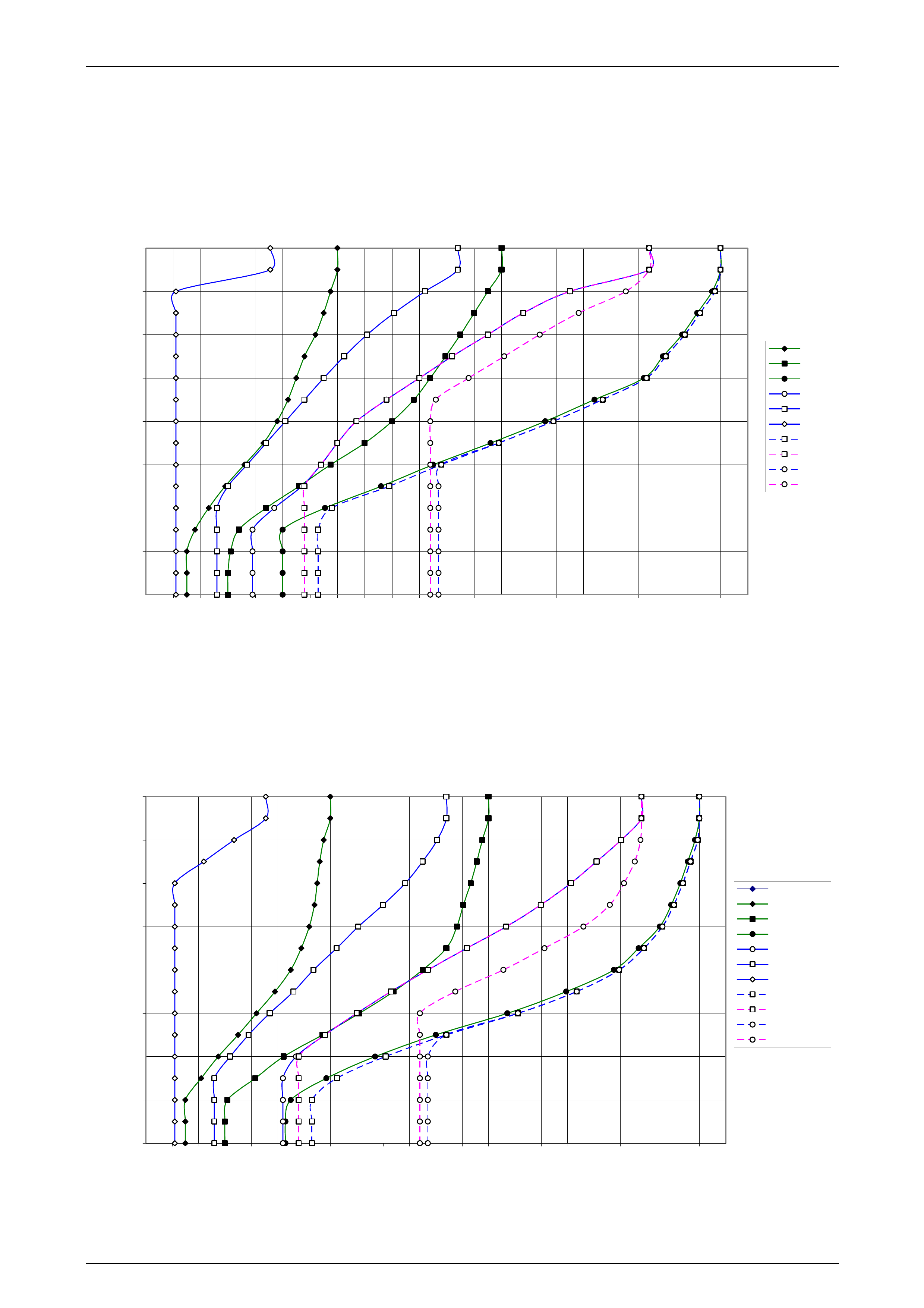
Automatic Transmission – 4L65E – Hydraulic and Mechanical Diagnosis Page 7D3–56
10.6 GEN IV V8 (L76) – RWD Cab Chassis
Normal Mode
0
12.5
25
37.5
50
62.5
75
87.5
100
0 10 20 30 40 50 60 70 80 90 100110120130140150160170180190200210220
Vehicle Speed KPH
Throttle
12N
23N
34N
43N
32N
21N
3App
3Rel
4App
4Rel
Figure 7D3 – 17
Power Mode
0
12.5
25
37.5
50
62.5
75
87.5
100
0 10 20 30 40 50 60 70 80 90 100 110 120 130 140 150 160 170 180 190 200 210 220
Vehicle Speed KMH
Throttle
Power Mode
12N
23N
34N
43N
32N
21N
3App
3Rel
4App
4Rel
Figure 7D3 – 18
Page 7D3–56
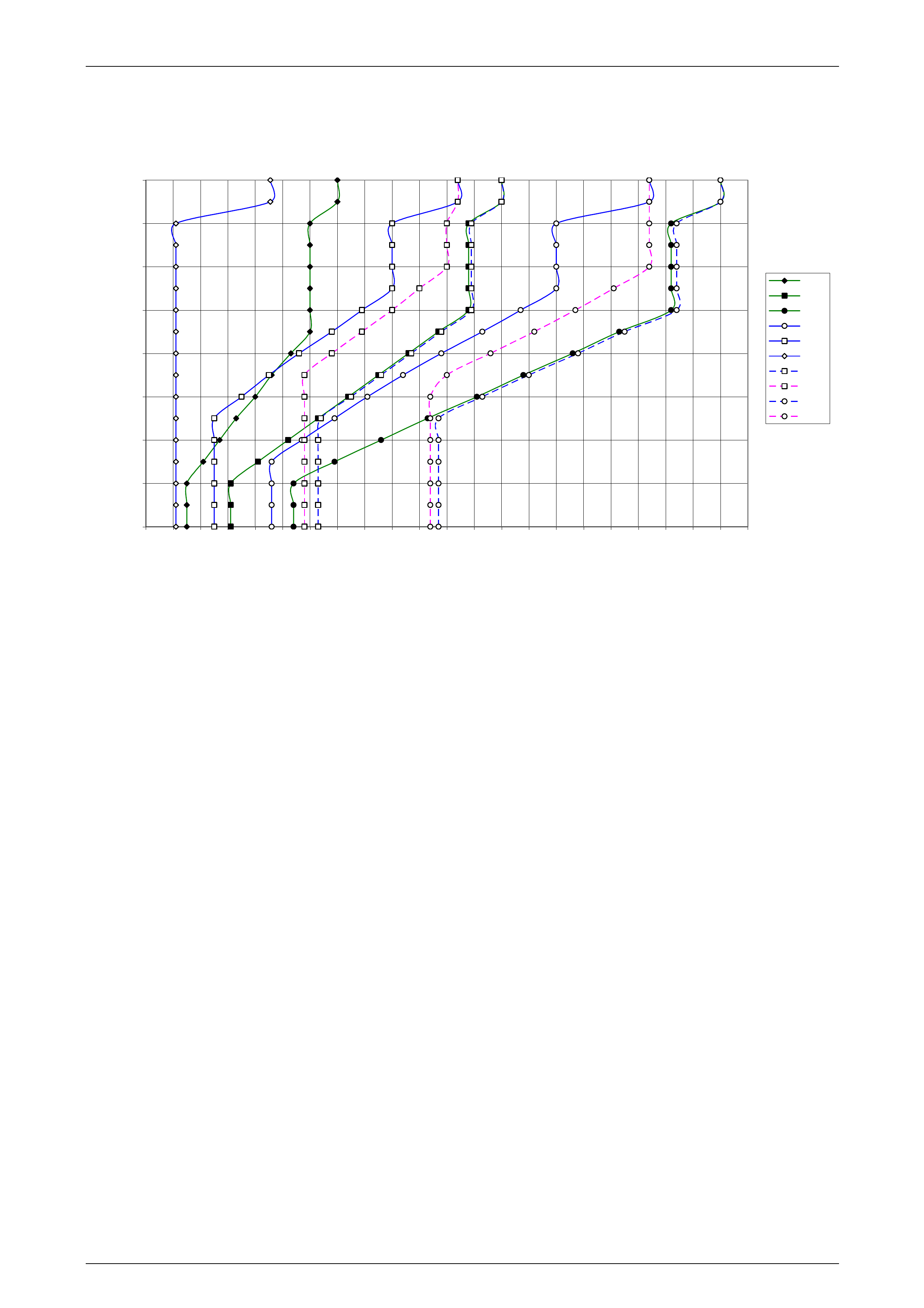
Automatic Transmission – 4L65E – Hydraulic and Mechanical Diagnosis Page 7D3–57
Cruise Mode
0
12.5
25
37.5
50
62.5
75
87.5
100
0 10 20 30 40 50 60 70 80 90 100110120130140150160170180190200210220
Vehicle Speed KPH
Throttle
12N
23N
34N
43N
32N
21N
3App
3Rel
4App
4Rel
Figure 7D3 – 19
Page 7D3–57
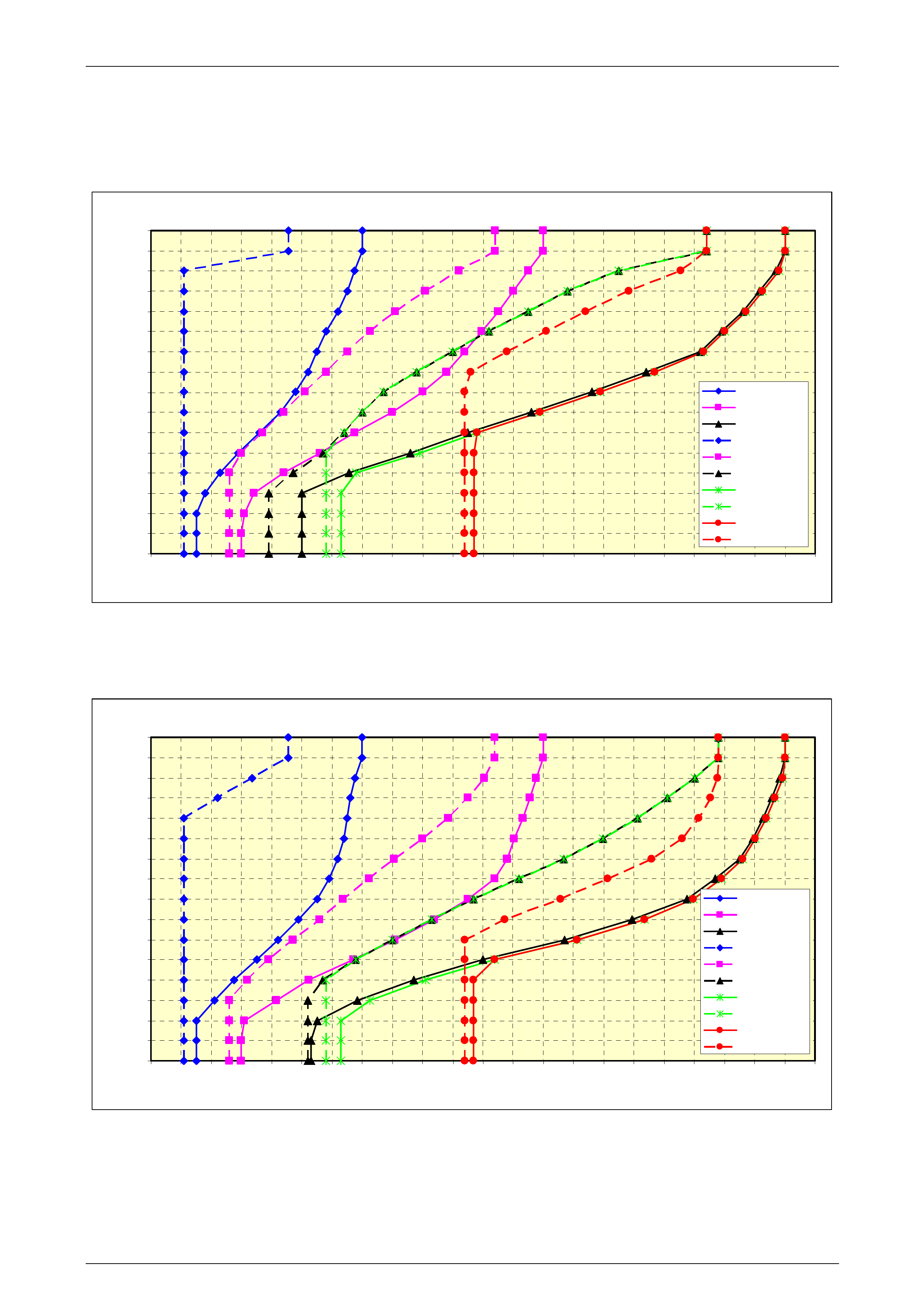
Automatic Transmission – 4L65E – Hydraulic and Mechanical Diagnosis Page 7D3–58
10.7 GEN IV V8 (L98) – RWD Crew Cab
Normal Mode
MY 2006 VZ Update - L98 V8 & 4L65-E Crew Cab
Normal Shift Pattern
0
6.25
12.5
18.75
25
31.25
37.5
43.75
50
56.25
62.5
68.75
75
81.25
87.5
93.75
100
0 10 20 30 40 50 60 70 80 90 100 110 120 130 140 150 160 170 180 190 200 210 220
Vehicle Spee d (km/ h)
Th r o ttle Positio n Se n so r (%)
1-2 MY 06
2-3 MY 06
3-4 MY 06
2-1 MY 06
3-2 MY 06
4-3 MY 06
TCC 3 Apply
TCC 3 Release
TCC 4 Apply
TCC 4 Release
Figure 7D3 – 20
Power Mode
M Y 2006 VZ Update - L98 V8 & 4L65-E Cab Chassis
Power Shift Pattern
0
6.25
12.5
18.75
25
31.25
37.5
43.75
50
56.25
62.5
68.75
75
81.25
87.5
93.75
100
0 10 20 30 40 50 60 70 80 90 100 110 120 130 140 150 160 170 180 190 200 210 220
Vehicle Spee d (km/h)
Throttle Posi tion Sensor (%)
1-2 MY 06
2-3 MY 06
3-4 MY 06
2-1 MY 06
3-2 MY 06
4-3 MY 06
TCC 3 A ppl y
TCC 3 Rel ease
TCC 4 A ppl y
TCC 4 Rel ease
Figure 7D3 – 21
Page 7D3–58
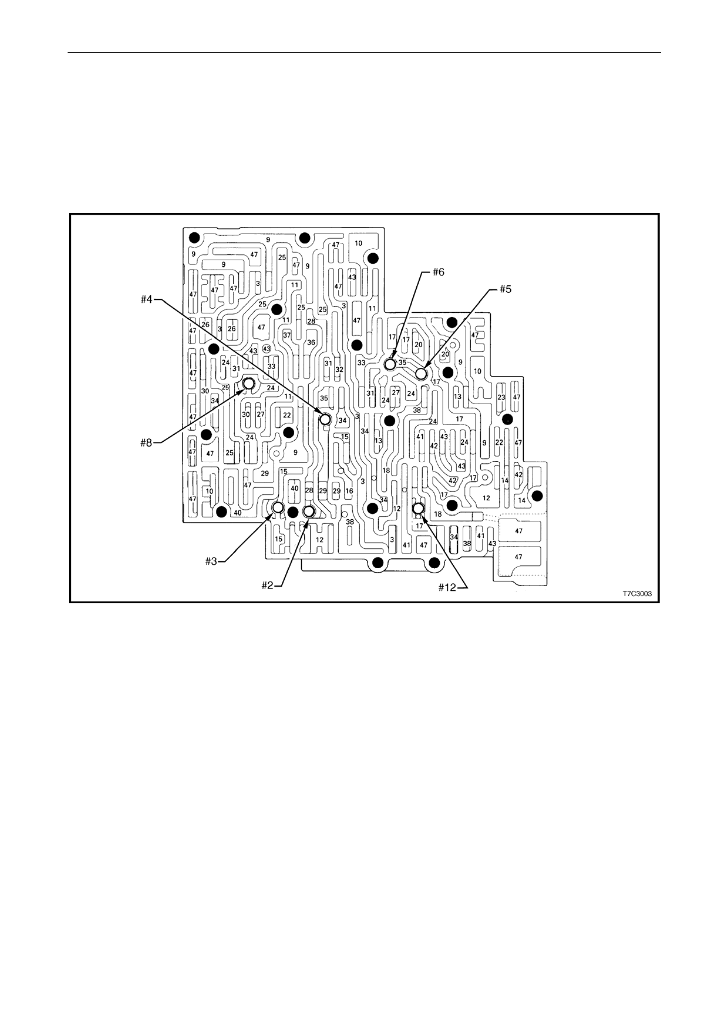
Automatic Transmission – 4L65E – Hydraulic and Mechanical Diagnosis Page 7D3–59
11 Component Layout and
Hydraulic Paths.
11.1 Component Layout
Control Valve Body Passages and Checkball Locations
Figure 7D3 – 22
Legend
#2 Checkball (61)
#3 Checkball (61)
#4 Checkball (61)
#5 Checkball (61)
#6 Checkball (61)
#8 Checkball (61)
#12 Checkball (61)
3 Line
9 Actuator Feed Limit
10 Filtered Actuator Feed
11 Torque Signal
12 PR
13 D4 – 3–2
14 Low/Reverse
15 Reverse
16 Reverse Input (Rev. Cl.)
17 D4
18 Forward Clutch Feed
20 Accumulator
22 Signal A
23 Signal B
24 2nd
25 2nd Clutch
26 CC Signal
27 3–4 Signal
28 3rd Accumulator
29 3–4 Clutch
30 4th Signal
31 Servo Feed
32 4th
33 3–4 Accumulator
34 D3
35 Overrun
36 Overrun Clutch Feed
37 Overrun Clutch
38 D2
40 3–2 Signal
41 Low
42 Low/1st
43 Exhaust
47 Void
Page 7D3–59
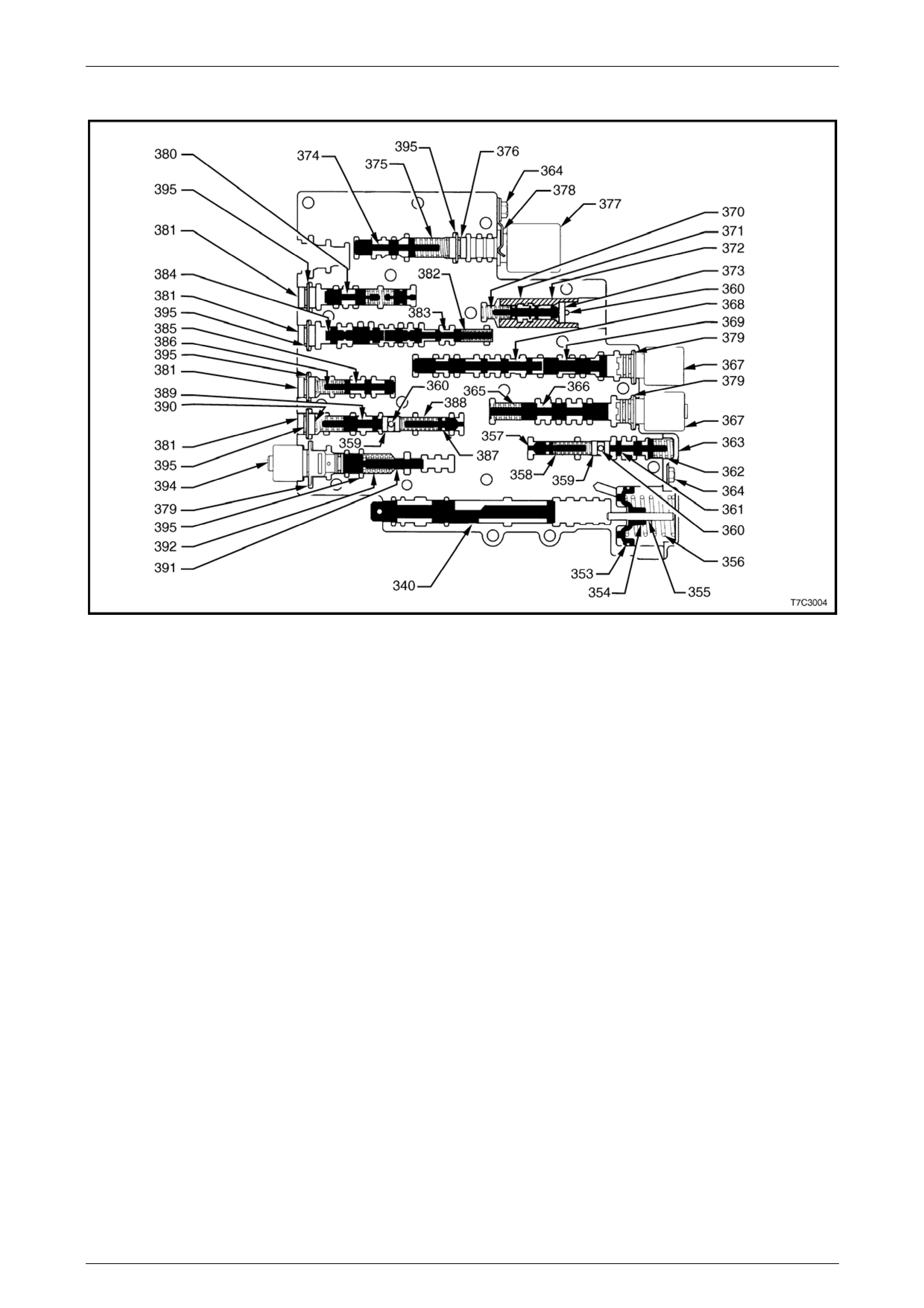
Automatic Transmission – 4L65E – Hydraulic and Mechanical Diagnosis Page 7D3–60
Control Valve Body Valve Trains
Figure 7D3 – 23
Legend
340 Valve, Manual
353 Seal, Forward Accumulator Oil
354 Piston, Forward Accumulator
355 Pin, Forward Accumulator
356 Spring, Forward Accumulator
357 Valve, Forward Abuse
358 Spring, Forward Abuse Valve
359 Plug, Bore
360 Pin, Coiled Spring
361 Valve, Low Overrun
362 Spring, Low Overrun Valve
363 Cover, Forward Accumulator
364 Bolt, Forward Accumulator
Cover
365 Spring, 1–2 Shift Valve
366 Valve, 1–2 Shift
367 2–3 Shift Solenoid
368 Valve, 2–3 Shift
369 Valve, 2–3 Shuttle
370 Spring, 1–2 Accumulator Valve
371 Valve, 1–2 Accumulator
372 Sleeve, 1–2 Accumulator Valve
374 Valve, Actuator Feed Limit
375 Spring, Actuator Feed Limit Valve
376 Plug, Bore
377 Pressure Control Solenoid
378 Retainer, Pressure Control Solenoid
379 Retainer, Solenoid
380 Valve, Converter Clutch Signal
381 Plug, Bore
382 Spring, 4–3 Sequence Valve
383 Valve, 4–3 Sequence
384 Valve, 3–4 Relay
385 Valve, 3–4 Shift
386 Spring, 3–4 Shift Valve
387 Valve, Reverse Abuse
388 Spring, Reverse Abuse Valve
389 Valve, 3–2 Downshift
390 Spring, 3–2 Downshift Valve
391 Valve, 3–2 Control
392 Spring, 3–2 Control Valve
394 3–2 Control Solenoid
395 Retainer, Bore Plug
397 Spring
398 Valve
Page 7D3–60
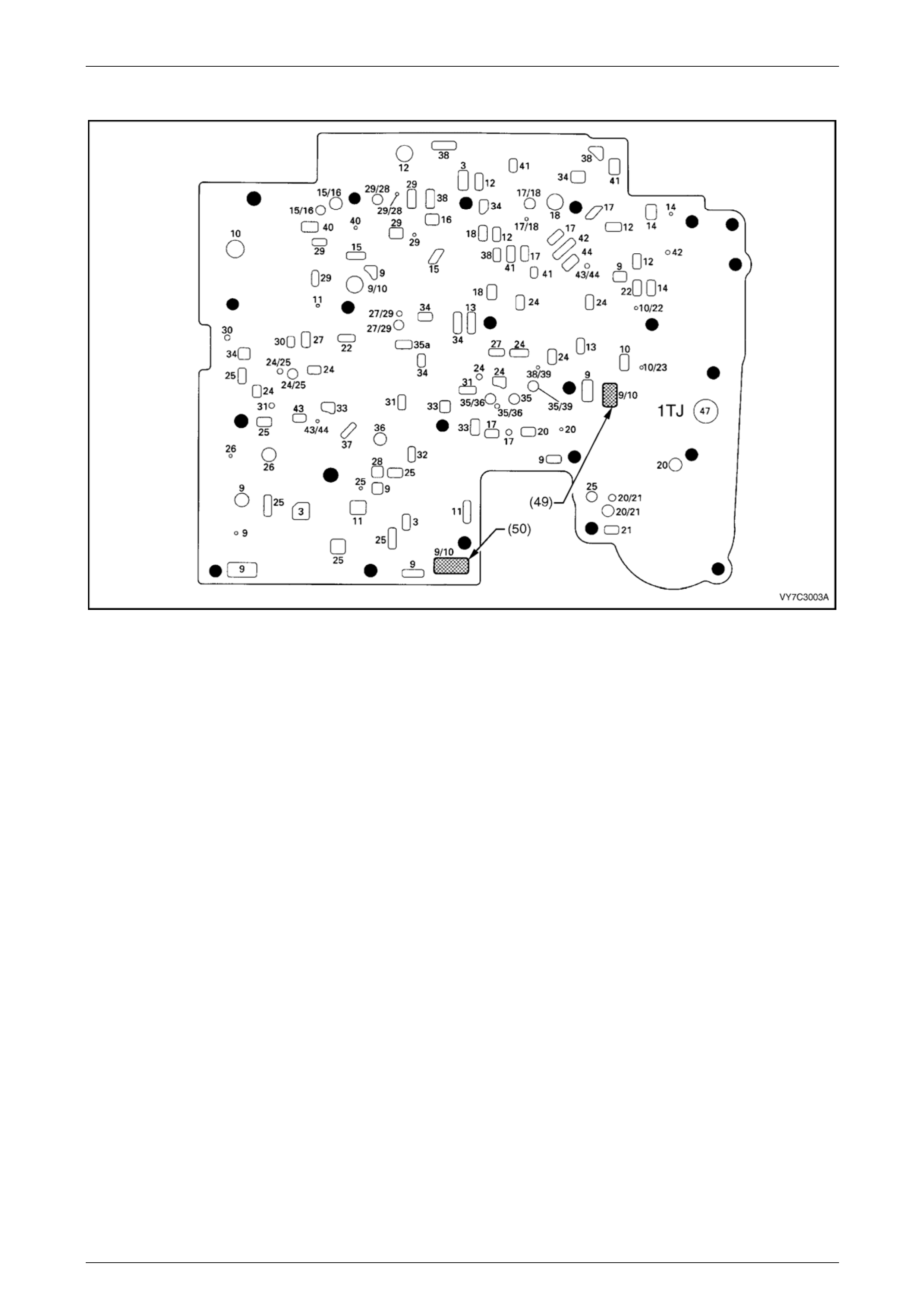
Automatic Transmission – 4L65E – Hydraulic and Mechanical Diagnosis Page 7D3–61
Spacer Plate Passages
Figure 7D3 – 24
Legend
(49) Screen, Shift Solenoids
(50) Screen, Pressure Control
Solenoid
3 Line
9 Actuator Feed Limit
9/10 Actuator Feed Limit/Filtered
Actuator Feed
10 Filtered Actuator Feed
10/22 Filtered Actuator Feed/Signal A
10/23 Filtered Actuator Feed/Signal B
11 Torque Signal
12 PR
13 D4 – 3–2
14 Low/Reverse
15 Reverse
15/16 Reverse/Reverse Input (Rev.
Cl.)
16 Reverse Input (Rev. Cl.)
17 D4
17/18 D4
18 Forward Clutch Feed
20 Accumulator
20/21 Accumulator/Orificed Accumulator
21 Orificed Accumulator
22 Signal A
24 2nd
24/25 2nd/2nd Clutch
25 2nd Clutch
26 CC Signal
27 3–4 Signal
27/29 3–4 Signal
28 3rd Accumulator
29/28 3–4 Clutch/3rd Accumulator
29 3–4 Clutch
30 4th Signal
31 Servo Feed
32 4th
33 3–4 Accumulator
34 D3
35a Overrun
35. Overrun
35/36 Overrun/Overrun Clutch Feed
35/39 Overrun/Orificed D2
36 Overrun Clutch Feed
37 Overrun Clutch
38 D2
38/39 D2/Orificed D2
40 3–2 Signal
41 Low
42 Low/1st
43 Exhaust
43/44 Exhaust/Orificed Exhaust
44 Orificed Exhaust
47 Void
Page 7D3–61
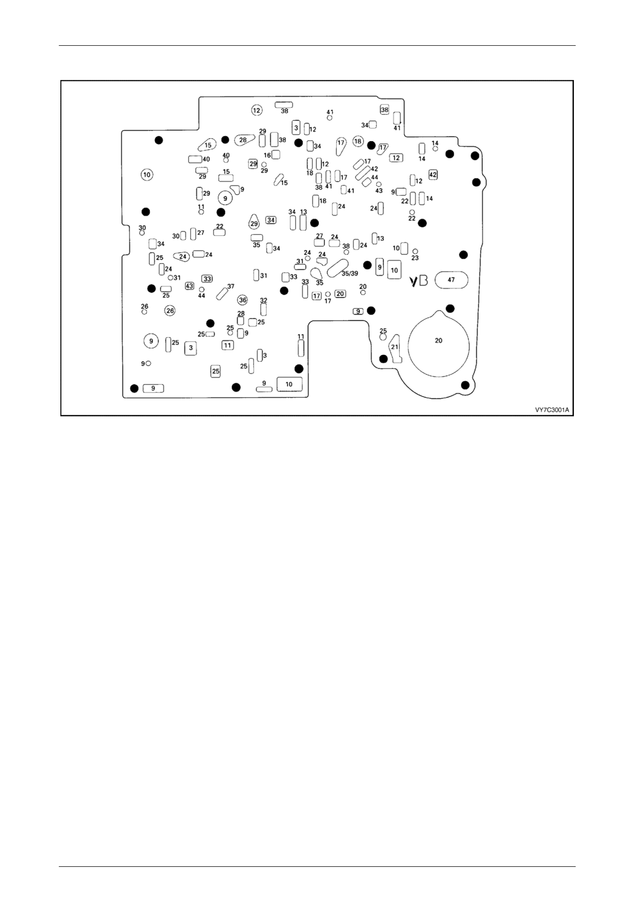
Automatic Transmission – 4L65E – Hydraulic and Mechanical Diagnosis Page 7D3–62
Spacer Plate to Control Valve Body Gasket
Figure 7D3 – 25
Legend
3 Line
9 Actuator Feed Limit
10 Filtered Actuator Feed
11 Torque Signal
12 PR
13 D4 – 3–2
14 Low/Reverse
15 Reverse
16 Reverse Input (Rev. Cl.)
17 D4
18 Forward Clutch Feed
20 Accumulator
21 Orificed Accumulator
22 Signal A
23 Signal B
24 2nd
25 2nd Clutch
26 CC Signal
27 3–4 Signal
28 3rd Accumulator
29 3–4 Clutch
30 4th Signal
31 Servo Feed
32 4th
33 3–4 Accumulator
34 D3
35 Overrun
35/39 Overrun/Orificed D2
36 Overrun Clutch Feed
37 Overrun Clutch
38 D2
40 3–2 Signal
41 Low
42 Low/1st
43 Exhaust
44 Orificed Exhaust
47 Void
Page 7D3–62
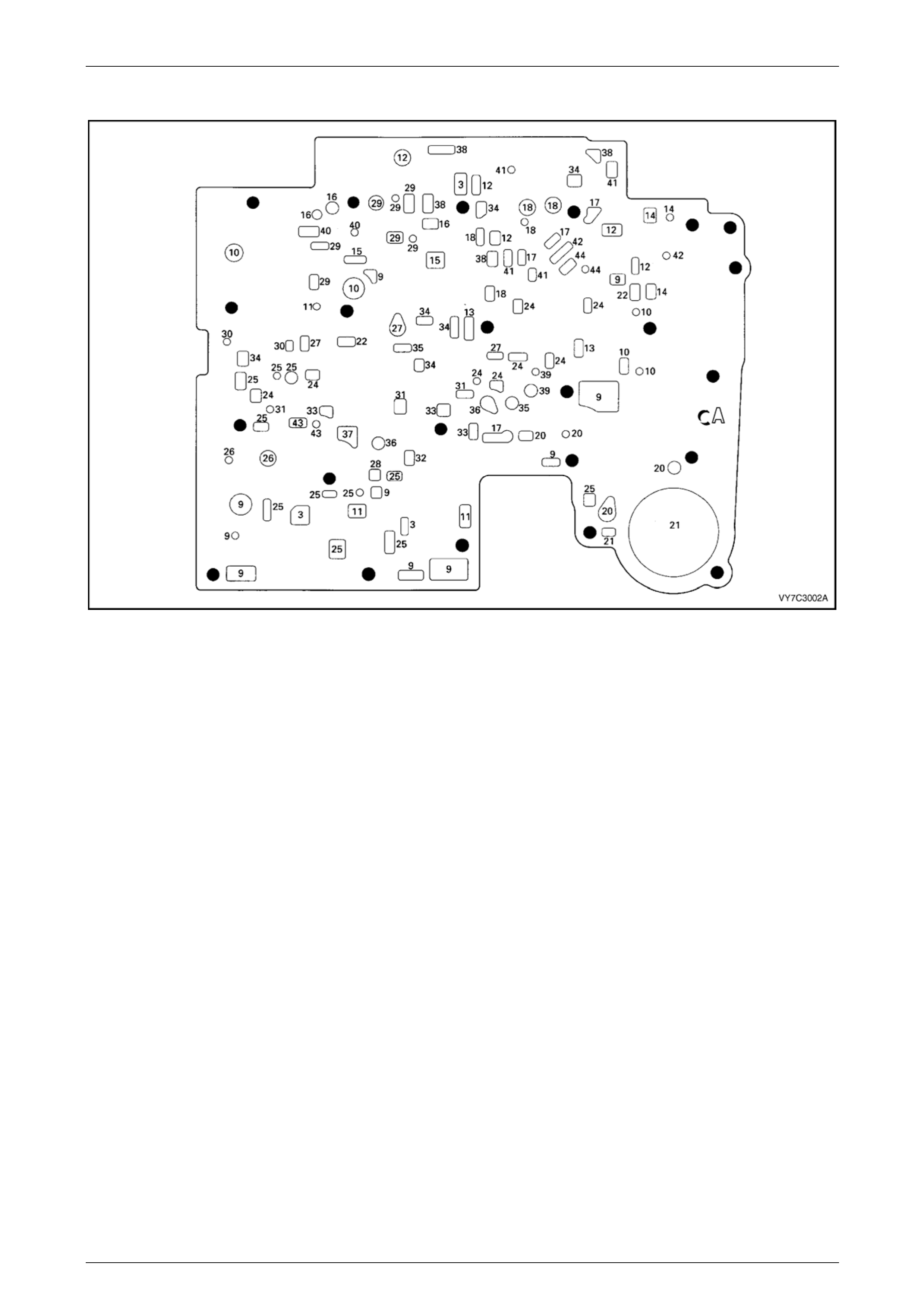
Automatic Transmission – 4L65E – Hydraulic and Mechanical Diagnosis Page 7D3–63
Spacer Plate to Transmission Case Gasket
Figure 7D3 – 26
Legend
2 Line
9 Actuator Feed Limit
10 Filtered Actuator Feed
11 Torque Signal
12 PR
13 D4 – 3–2
14 Low/Reverse
15 Reverse
16 Reverse Input (Rev. Cl.)
17 D4
18 Forward Clutch Feed
20 Accumulator
21 Orificed Accumulator
22 Signal A
24 2nd
25 2nd Clutch
26 CC Signal
27 3–4 Signal
28 3rd Accumulator
29 3–4 Clutch
30 4th Signal
31 Servo Feed
32 4th
33 3–4 Accumulator
34 D3
35 Overrun
36 Overrun Clutch Feed
37 Overrun Clutch
38 D2
39 Orificed D2
40 3–2 Signal
41 Low
42 Low/1st
43 Exhaust
44 Orificed Exhaust
Page 7D3–63
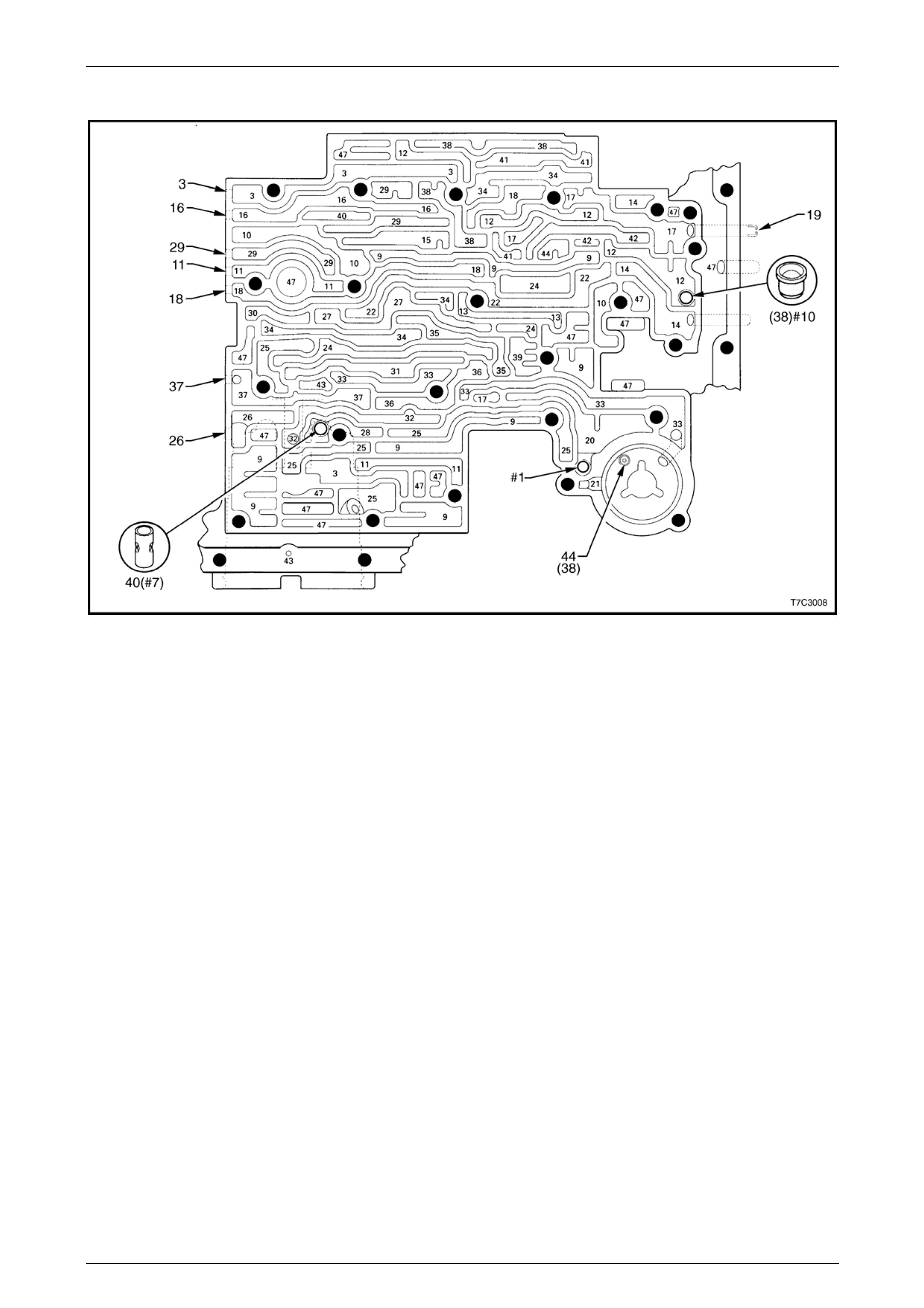
Automatic Transmission – 4L65E – Hydraulic and Mechanical Diagnosis Page 7D3–64
Transmission Case Fluid Passages and Checkball Locations
Figure 7D3 – 27
Legend
#1 Checkball (61)
#7 3rd Accumulator Retainer & Ball
Assembly (40)
#10 Checkball (42)
44 Accumulator Bleed Plug (38)
3 Line
9 Actuator Feed Limit
10 Filtered Actuator Feed
11 Torque Signal
12 PR
13 D4 – 3–2
14 Low/Reverse
15 Reverse
16 Reverse Input (Rev. Cl.)
17 D4
18 Forward Clutch Feed
19 Rear Lube
20 Accumulator
21 Orificed Accumulator
22 Signal A
24 2nd
25 2nd Clutch
26 CC Signal
27 3–4 Signal
28 3rd Accumulator
29 3–4 Clutch
30 4th Signal
31 Servo Feed
32 4th
33 3–4 Accumulator
34 D3
35 Overrun
36 Overrun Clutch Feed
37 Overrun Clutch
38 D2
39 Orificed D2
40 3–2 Signal
41 Low
42 Low/1st
43 Exhaust
44 Orificed Exhaust
47 Void
Page 7D3–64
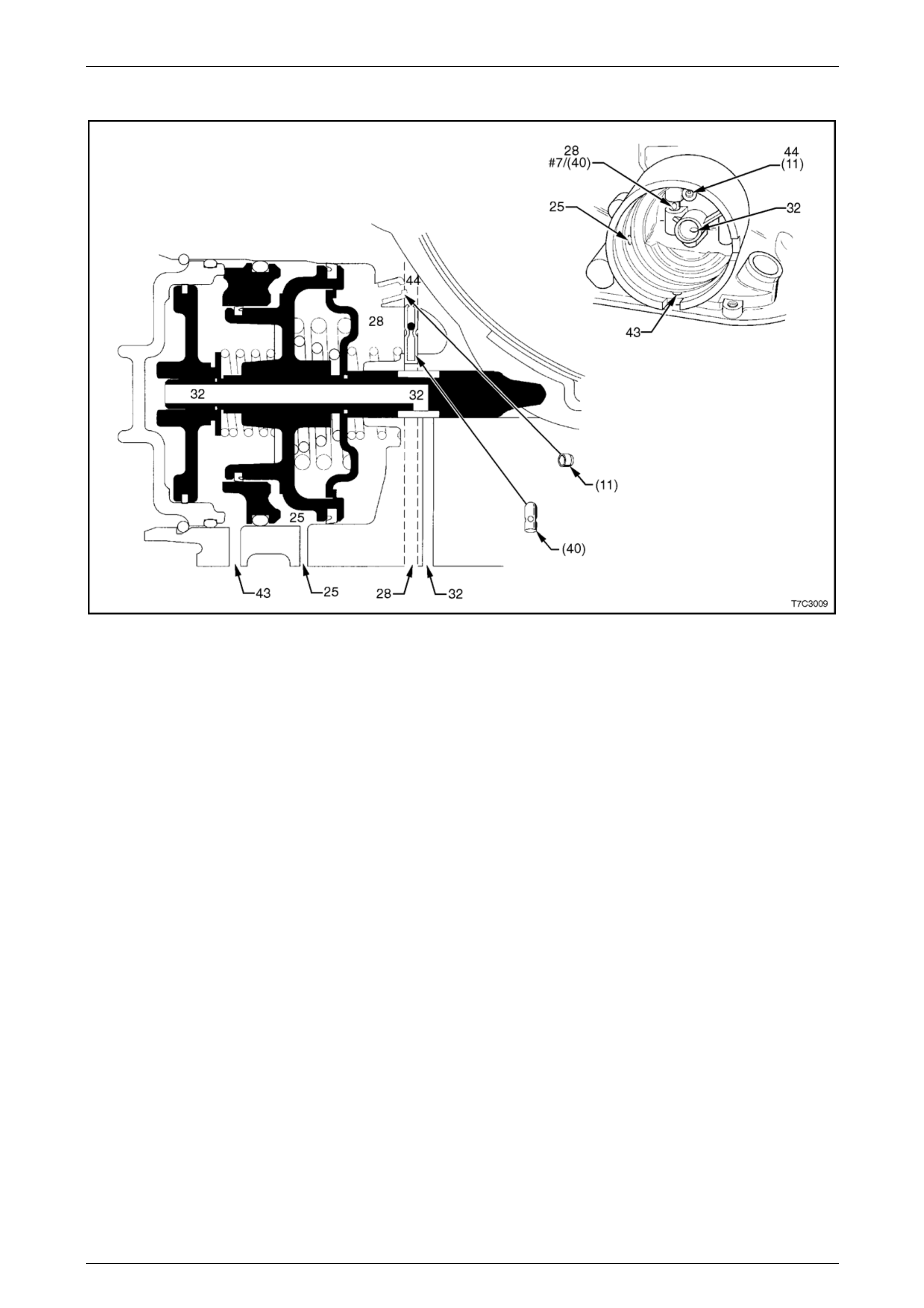
Automatic Transmission – 4L65E – Hydraulic and Mechanical Diagnosis Page 7D3–65
Servo Passages 2–4
Figure 7D3 – 28
Legend
11 Case Servo Orificed Plug
25 2nd Clutch Apply
28 3rd Accumulator Passage
32 4th Band Apply
40 3rd Accumulator Retainer & Ball
Assembly (#7)
43 Exhaust Passage
44 Orificed Exhaust (#11)
Page 7D3–65

Automatic Transmission – 4L65E – Hydraulic and Mechanical Diagnosis Page 7D3–66
Oil Pump Cover Fluid Passages (Transmission Case Side)
Figure 7D3 – 29
Legend
232 Oil Pump Cover Screen
237 Check Valve Retainer & Ball
Assembly
240 Orificed Cup Plug
1 Suction (Intake)
2 Decrease
3 Line
5 Release
7 To Cooler
8 Lube from Cooler
11 Torque Signal
16 Reverse Input (Rev. Cl.)
18 Forward Clutch Feed
26 CC Clutch
29 3–4 Clutch
37 Overrun Clutch
43 Exhaust
45 Vent
46 Seal Drain
47 Void
Page 7D3–66
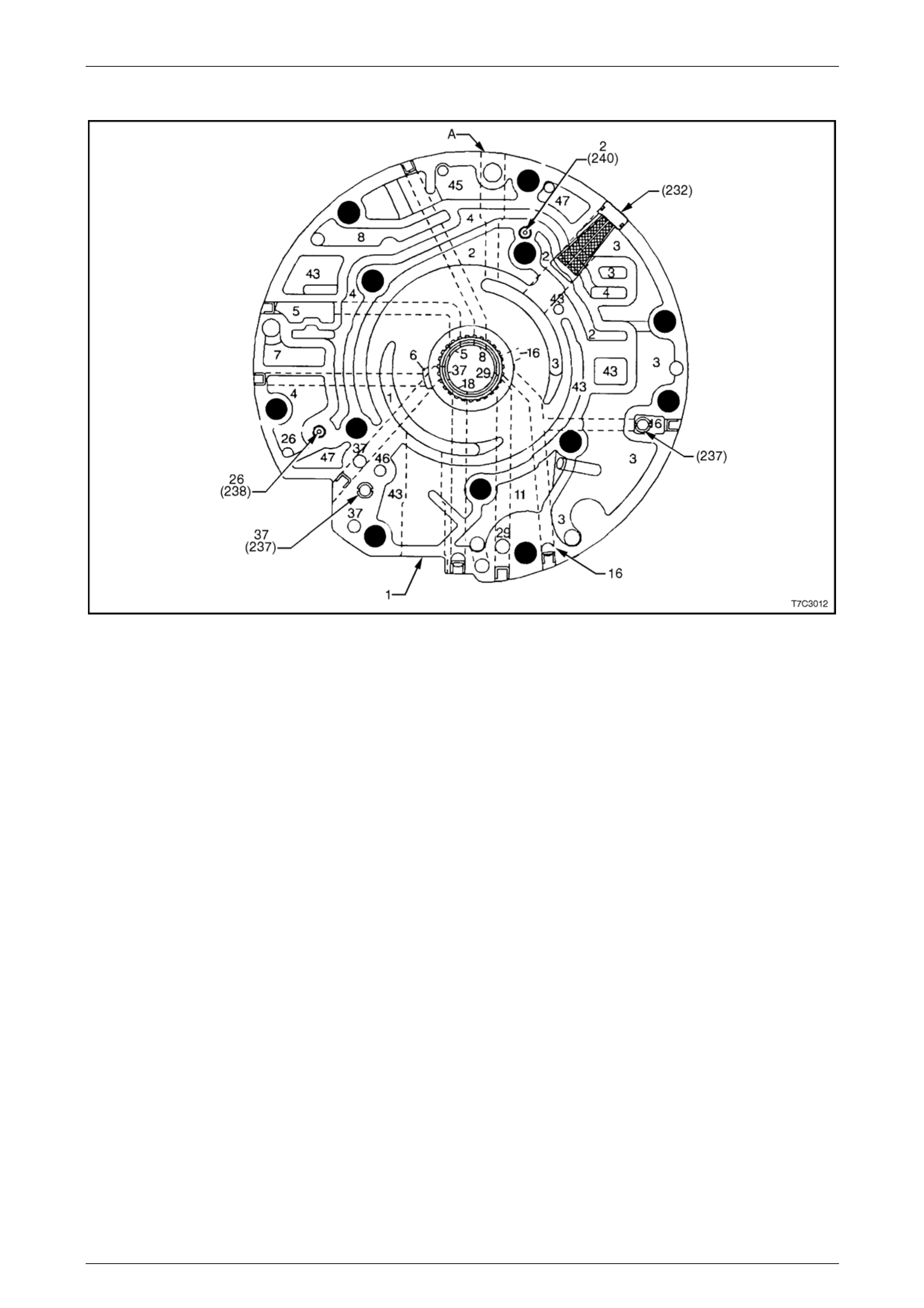
Automatic Transmission – 4L65E – Hydraulic and Mechanical Diagnosis Page 7D3–67
Oil Pump Cover Fluid Passages
Figure 7D3 – 30
Legend
1 Suction (Intake)
2 Decrease
3 Line
4 Converter Feed
5 Release
7 To Cooler
8 Lube from Cooler
11 Torque Signal
16 Reverse Input
18 Forward Clutch Feed
26 CC Clutch
29 3–4 Clutch
37 Overrun Clutch
43 Exhaust
45 Vent
46 Seal Drain
47 Void
Page 7D3–67
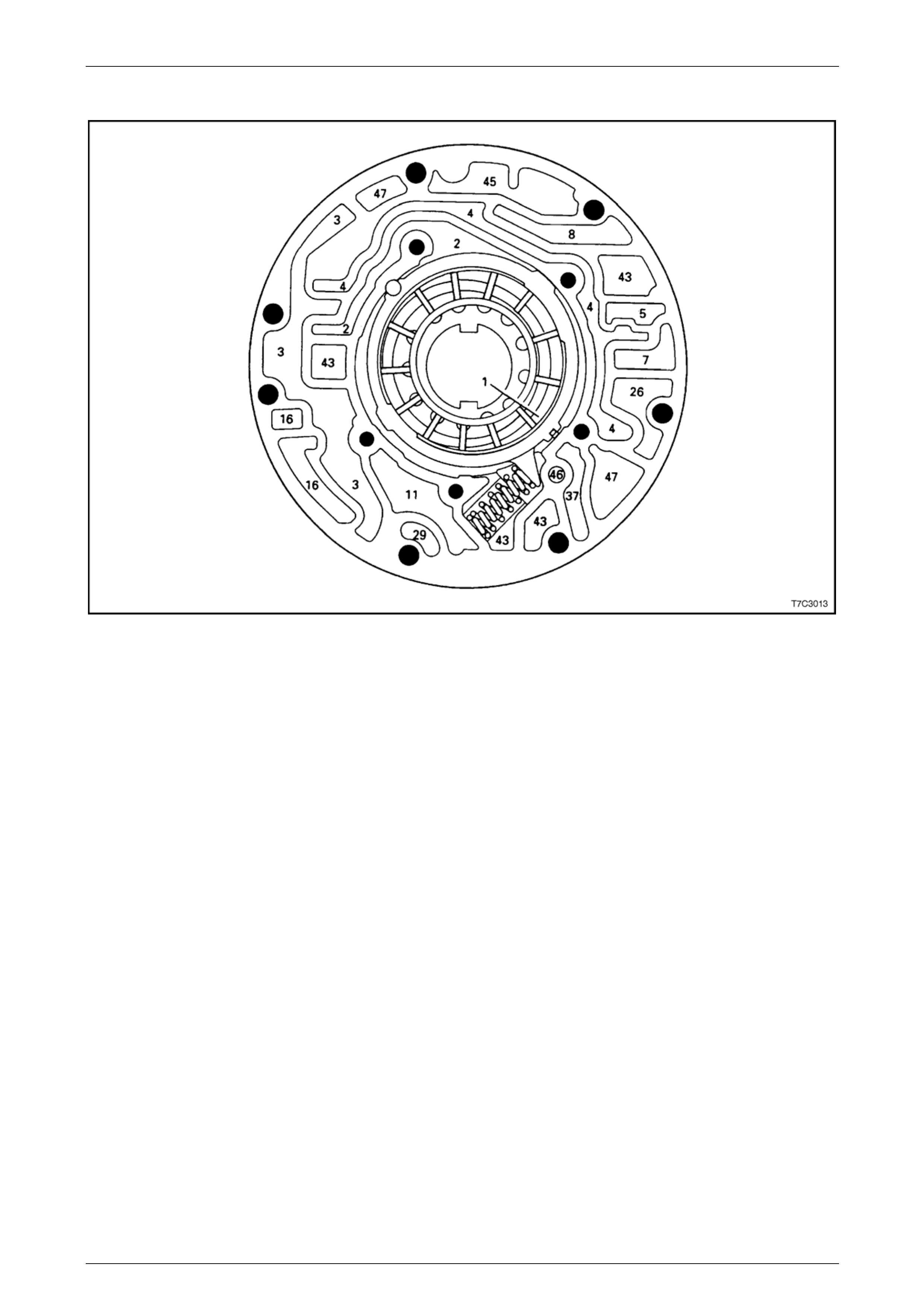
Automatic Transmission – 4L65E – Hydraulic and Mechanical Diagnosis Page 7D3–68
Oil Pump Body Fluid Passages
Figure 7D3 – 31
Legend
1 Suction (Intake)
2 Decrease
3 Line
4 Converter Feed
5 Release
7 To Cooler
8 Lube from Cooler
11 Torque Signal
16 Reverse Input
26 CC Clutch
29 3–4 Clutch
37 Overrun Clutch
43 Exhaust
45 Vent
46 Seal Drain
47 Void
Page 7D3–68