
Steering Page 9–1
Section 9
Steering
ATTENTION
Before performing any service operation or other procedure described in this Section, refer to 00 Warnings,
Cautions and Notes for correct workshop practices with regard to safety and/or property damage.
1 General Information ...............................................................................................................................2
2 Service Operations.................................................................................................................................3
2.1 Rack Pad Adjust..................................................................................................................................................... 3
Stage 1 – Steering Gear Installed – Adjustment.................................................................................................. 3
Stage 2 – Steering Gear Removed – Adjustment................................................................................................ 5
2.2 Tie Rod End............................................................................................................................................................ 6
Remove................................................................................................................................................................... 6
Reinstall.................................................................................................................................................................. 6
2.3 Steering Gear Bellows........................................................................................................................................... 7
Remove................................................................................................................................................................... 7
Reinstall.................................................................................................................................................................. 8
2.4 Power Steering Gear Assembly ............................................................................................................................ 9
Remove................................................................................................................................................................... 9
Reinstall................................................................................................................................................................ 11
2.5 Inner Tie Rod and Ball Joint................................................................................................................................ 14
Remove................................................................................................................................................................. 14
Reinstall................................................................................................................................................................ 15
2.6 Power Steering Lines and Hoses Layout........................................................................................................... 16
3 Specifications.......................................................................................................................................17
4 Torque Wrench Specifications............................................................................................................18
5 Special Tools ........................................................................................................................................19
Page 9–1

Steering Page 9–2
1 General Information
The power assisted steering system fitted to MY 2006 VZ Update vehicles, remains as detailed in earlier service
information except for the items discussed in this Section.
The changes that will be taking place have been driven by the use of a variable ratio steering gear, manufactured by
Kayaba Corporation. Changes that are affected by the use of this steering gear, are:
• A design of rack and pinion type power steering gear, where the rotary valve housing is separate to the steering
gear housing and is attached to the main steering gear assembly by two Torx/hexagon headed screws.
• The outer tie rod end spindles are secured to the steering arms by a ‘Nyloc’ self locking nut that must be replaced
after removal. A feature of using this design of lock nut is that, until the spindle taper jams in the corresponding
taper in the steering arm, the spindle must be held by a 6 mm Allen key.
• The steering gear operation is very similar to the previous design and the variable assistance is still controlled by a
torsion rod in the input shaft. Apart from some minor design changes such as a needle roller support for the lower
pinion shaft and the ‘top hat’ upper pinion support, the steering gear operation is exactly similar in its operation, to
that previously described. Refer to Section 9 Steering, in the MY2005 VZ Series Service Information.
MY 2006 VZ Update, AWD Wagons will continue to be produced, using the existing steering rack assembly.
At the time of publishing approval, no firm introduction date and tag number have been recorded but it is anticipated that
the V6 version of the Kayaba steering rack will be introduced into production in early October, 2006. The V8 version is
anticipated as being introduced in early January, 2007.
Items that carry over from the existing steering of vehicles, are:
• A Kayaba vane type power steering pump is fitted to all MY2006½ vehicles – a constant flow design for all except
AWD Wagon that uses a droop flow pump. This pump design varies the fluid pressure and flow as required under
certain operating conditions.
• Power steering pump principles of operation for all vehicles including AWD are the same as previously described –
refer to Section 9 Steering in the MY2005 Series VZ Service Information.
• A remote fluid reservoir.
• A power steering fluid cooler.
• A four-spoke steering wheel with wheel mounted stereo controls and for vehicles with a 5 speed automatic
transmission, Active Select steering wheel mounted shift paddles.
• A steering wheel inflatable restraint assembly (driver’s airbag) is a standard feature on all vehicles. For steering
wheel inflatable restraint service information, refer to Section 12M Occupant Protection System.
• When performing steering gear or column
service procedures where the steering
gear coupling will be disconnected,
remove the ignition key from the ignition
lock and ensure the steering column is
locked. If this operation is not carried out
and the steering wheel is spun while the
steering gear coupling is removed from
the steering gear, the clockspring will be
destroyed. This could result in a
diagnostic trouble code (DTC) and
possible non deployment of the driver's
inflatable restraint.
• Power steering fluid can reach
temperatures of approximately 75 °C. When
handling power steering fluid or power
steering components that are hot, the
technician must wear the appropriate
safety glasses, gloves and clothing to
protect against possibl e b urn s.
Page 9–2
Steering Page 9–3
2 Service Operations
2.1 Rack Pad Adjust
Stage 1 – Steering Gear Installed – Adjustment
NOTE
Should a knock or rattle be confirmed as
originating from the steering gear assembly, a
rack pad adjustment procedure should be
completed as an on-vehicle procedure first.
1 Raise the vehicle and support in a safe manner. Refer to Section 0A General Information for the location of
recommended lifting and support points.
2 Centralise the rack position by turning the steering wheel from lock to lock counting the number of turns, then turn
the steering wheel back to half the number of turns counted when turned from lock to lock.
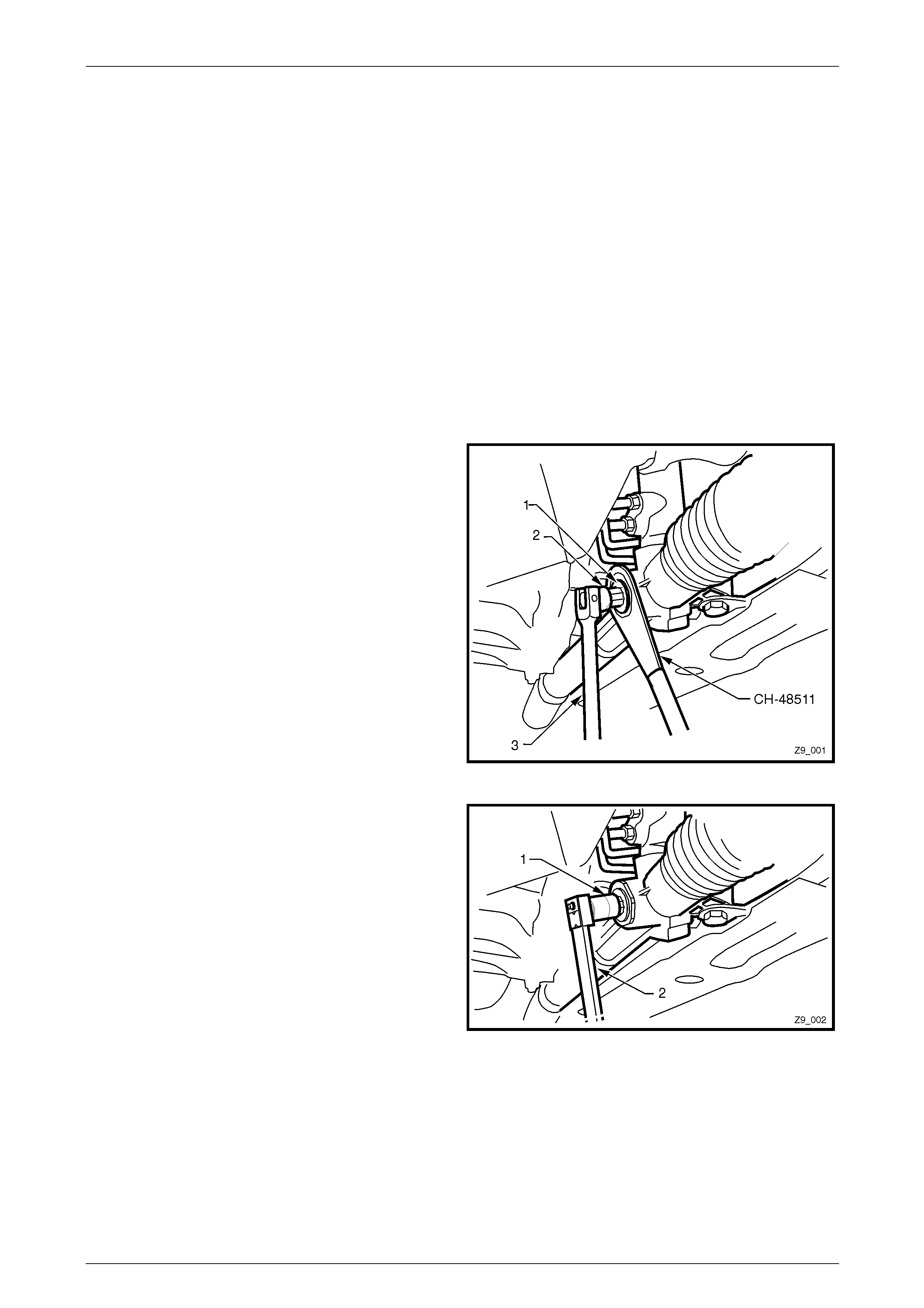
3 While holding the rack pad adjuster (1) with a
commercially available 17 mm hexagon headed
socket (2), use the ring spanner Tool No. CH-48511
and a socket bar (3), to loosen the lock nut.
4 Place a clean drain tray beneath the steering gear to
catch any fluid that may spill during the next three
steps.
5 Using the 17 mm hexagon headed socket, remove the
rack pad adjuster and lock nut from the steering gear
assembly.
6 Clean all traces of thread sealant from the threads of
the rack pad adjuster and the lock nut.
7 Apply Loctite™ 567 (or equivalent) to the rack pad
adjuster threads.
Figure 9 – 1
8 Reinstall the rack pad adjuster and lock nut to the
steering gear housing.
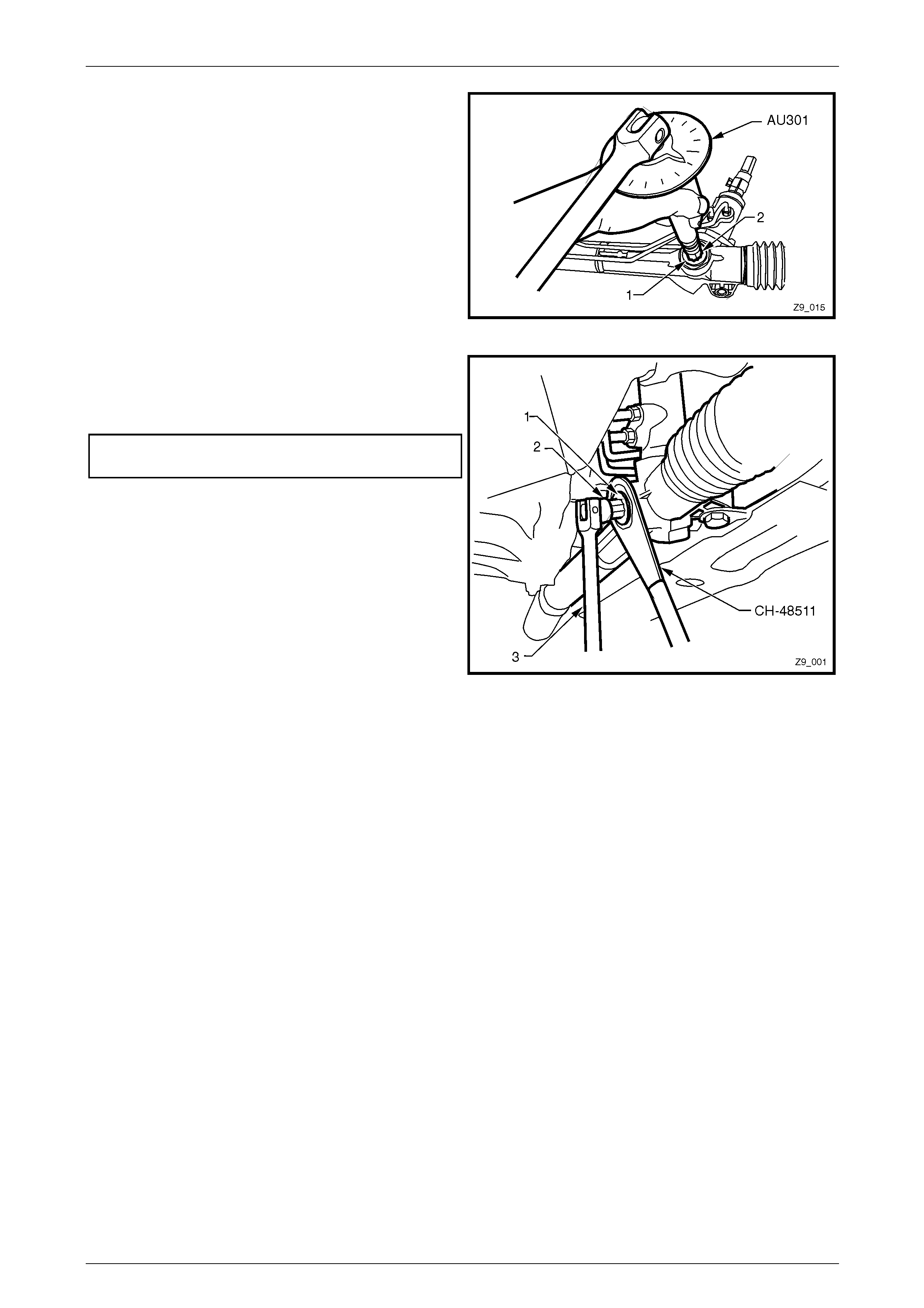
9 Using the 17 mm hexagon headed socket (1) and an
accurate torque wrench (2), tighten the rack pad
adjuster to 20 Nm.
10 Turn the steering wheel through 180° from the
centralised position in each direction, finishing with the
steering rack in the mid-point position.
Figure 9 – 2
Page 9–3
Steering Page 9–4
11 Using angle wrench tool E7115 (or similar) and the 17
mm hexagon headed socket (2), loosen the rack pad
adjusting screw by approximately 30°.
Figure 9 – 3
12 While holding the rack pad adjuster (1) with the 17 mm
hexagon headed socket (2) and a socket breaker bar
(3), use the ring spanner Tool No. CH-48511 to tighten
the lock nut to the correct torque specification..
Rack pad adjusting screw lock
nut torque specification .................................40 – 50 Nm
Figure 9 – 4
13 Lower the vehicle to the ground and road test to check for correct steering performance.
14 Should the knock or rattle be still evident, then the steering gear must be removed and the secondary adjustment
that follows, be completed.
Page 9–4
Steering Page 9–5
Stage 2 – Steering Gear Removed – Adjustment
NOTE
Should an on-car steering gear adjustment fail to
correct a knock/rattle from the steering gear
assembly, then the gear should be removed and
an on-bench adjustment be completed and the
vehicle re-tested before replacing the gear
assembly.
1 Remove the steering gear assembly, refer to 2.4 Power Steering Gear.
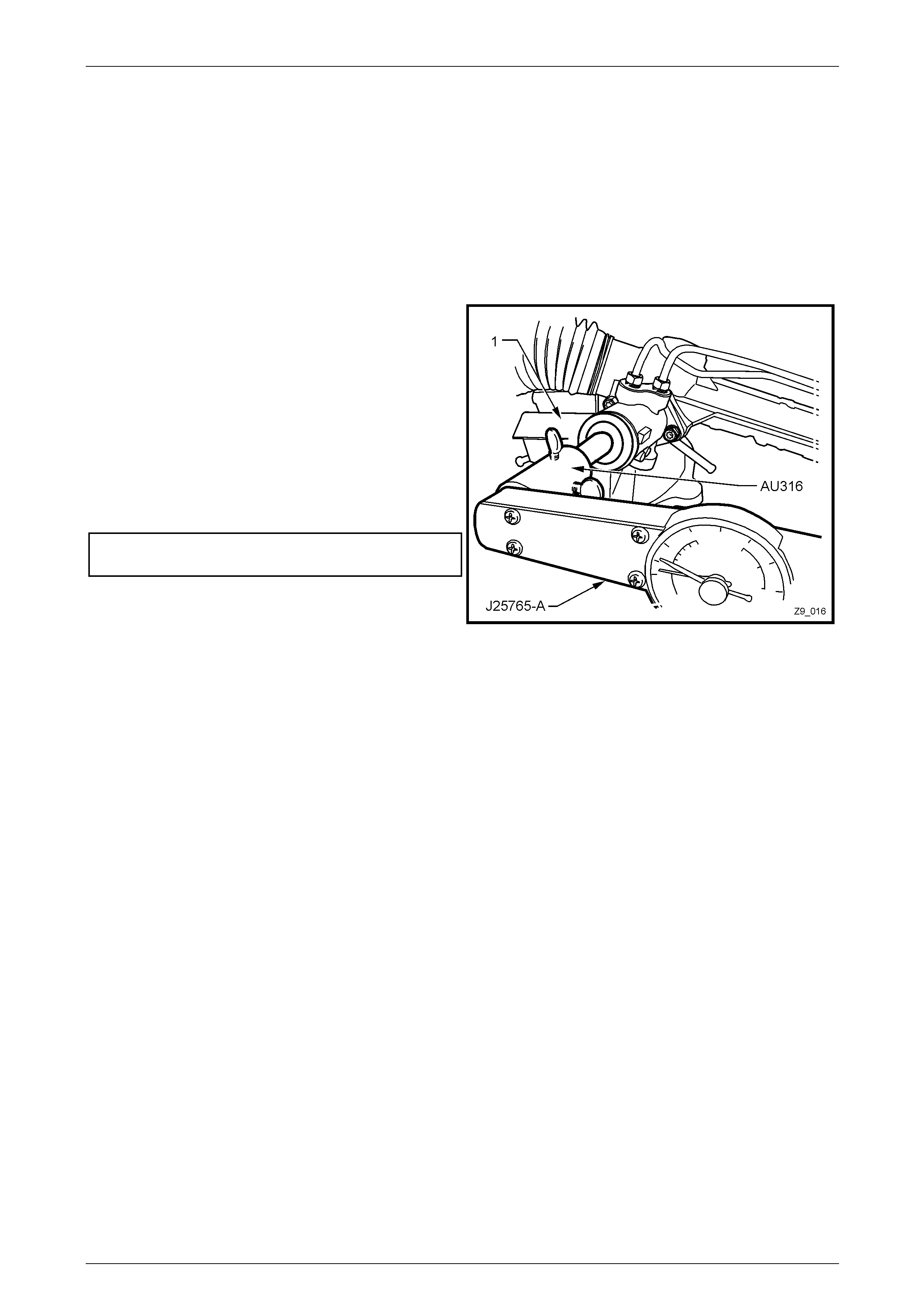
2 Secure the steering gear in a vice fitted with soft jaws
(1).
3 Fit preload adaptor, Tool No. AU316 to the input shaft
and secure with the thumb screws provided.
4 Starting at the centralised position, measure the
rotating torque of the input shaft, using a dial type
torque wrench such as J25765-A (or equivalent), by
turning the input shaft about 90° in each direction.
5 Should the rotational torque not be within the specified
limits, then further adjustment of the rack pad
adjusting screw will be required.
Steering gear input shaft
rotating torque specification ........................1.3 – 1.9 Nm
6 Repeat the steering rack pad adjustment detailed in
Steps 8 to 12 inclusive, in the Stage 1 procedure, until
the specified rotational torque is achieved.
7 Reinstall the steering gear assembly, refer to
2.4 Power Steering Gear.
Figure 9 – 5
8 Lower the vehicle to the ground and road test to check for correct steering performance.
9 Should the knock or rattle still be evident, then the steering gear must be replaced.
Page 9–5
Steering Page 9–6
2.2 Tie Rod End
ATTENTION
The following fasteners MUST be replaced when performing these operations:
Tie rod end spindle Nyloc lock nut
LT Section No. — 06–310
Remove
The tie rod end is serviced as an assembly and must be replaced when any excessive up or down movement is evident
or if any lost motion or end play exists at the ball end of the stud.
1 Raise the vehicle and support in a safe manner. Refer to Section 0A General Information for the location of
recommended lifting and support points.
2 Remove the front road wheel/s, refer to Section 10 Wheels and Tyres.
3 Remove the Nyloc lock nut from the tie rod ball stud
and discard.
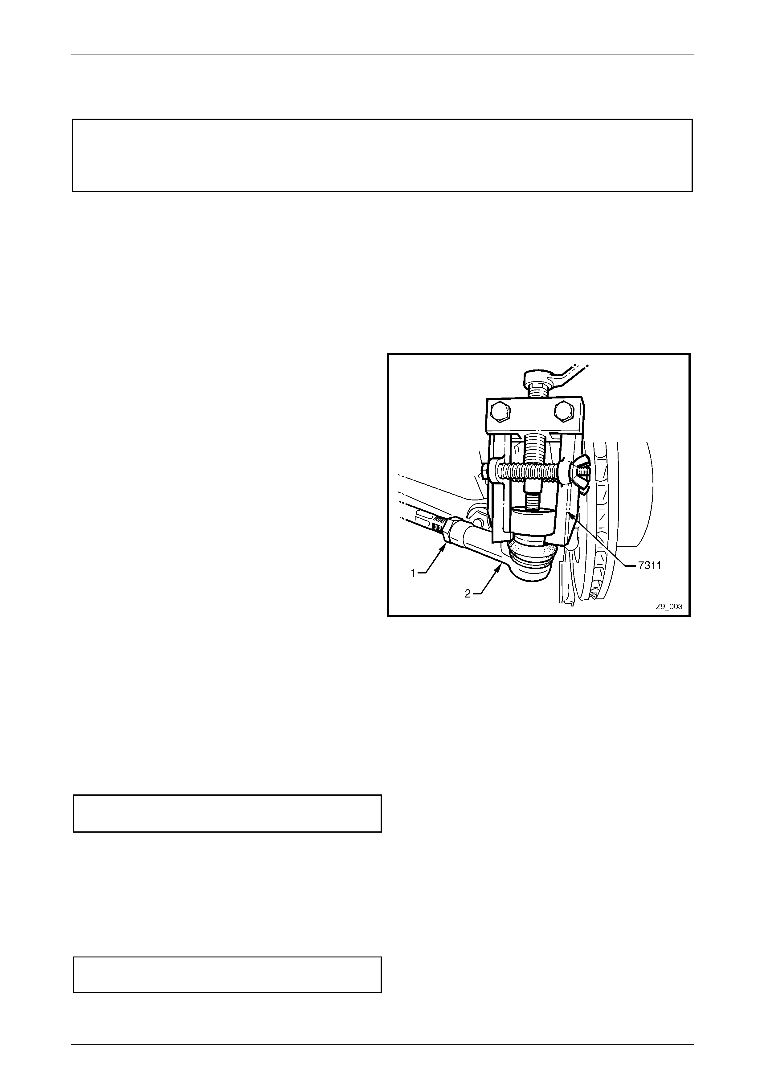
4 While holding the tie rod end (2) with a 19 mm set
spanner across the flats provided, loosen the tie rod
lock nut (1).
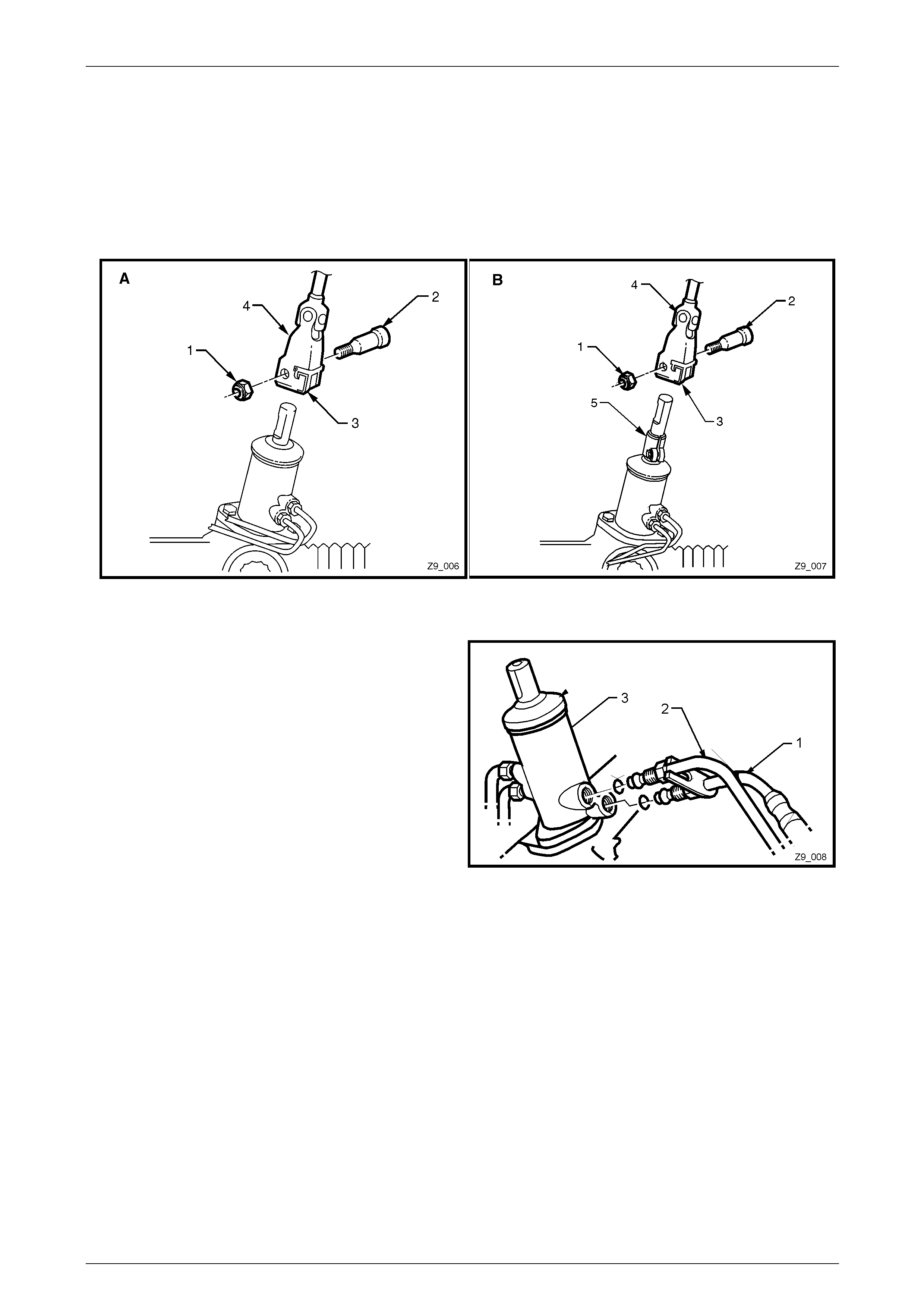
5 Using a universal puller such as Tool No. 7311 or
similar, tighten the centre screw to force the stud from
the taper in the steering arm.
NOTE
Once torque is applied to the forcing screw a
sharp tap with a hammer on the end of the stud
will jar the taper lock free.
6 Unscrew the tie rod end (2) from the inner tie rod,
counting the number of turns to wind the assembly
from the inner tie rod.
Figure 9 – 6
Reinstall
1 Reinstall the tie rod end onto the tie rod and wind it on the same number of turns as noted in Step 6 of the removal
procedure.
2 Reinstall the tie rod end to the steering arm.
3 Install a NEW Nyloc lock nut (19 mm) and hand tighten, using a 6 mm Allen key to hold the spindle while tightening
the nut. Continue until the matching tapers bind and hold the spindle.
4 Tighten the Nyloc nut to the correct torque specification.
■ Tie rod end attaching
nut torque specification .................................65 – 75 Nm
5 Reinstall the road wheel/s, refer to Section 10 Wheel and Tyres.
6 Lower the vehicle to the ground.
7 Check the front wheel toe setting and adjust as required, refer to Section 3A Front Suspension or
Section 3B Front Suspension – AWD.
8 While holding the tie rod end in the correct attitude with a 19 mm set spanner on the flats provided, tighten the tie
rod lock nut (21 mm) to the correct torque specification.
Tie rod end adjuster lock nut
torque specification .......................................40 – 60 Nm
9 Road test the vehicle to check for correct steering operation.
Page 9–6
Steering Page 9–7
2.3 Steering Gear Bellows
LT Section No. — 06–310
Remove
1 Raise the vehicle and support in a safe manner. Refer to Section 0A General Information for the location of
recommended lifting and support points.
2 Remove the front road wheel/s, refer to Section 10 Wheels and Tyres.
3 Using a felt tipped pen or similar, mark the threads of the inner tie rod to indicate the tie rod end lock nut location.
4 Remove the tie rod end, refer to 2.2 Tie Rod End.
5 Remove the tie rod end lock nut.
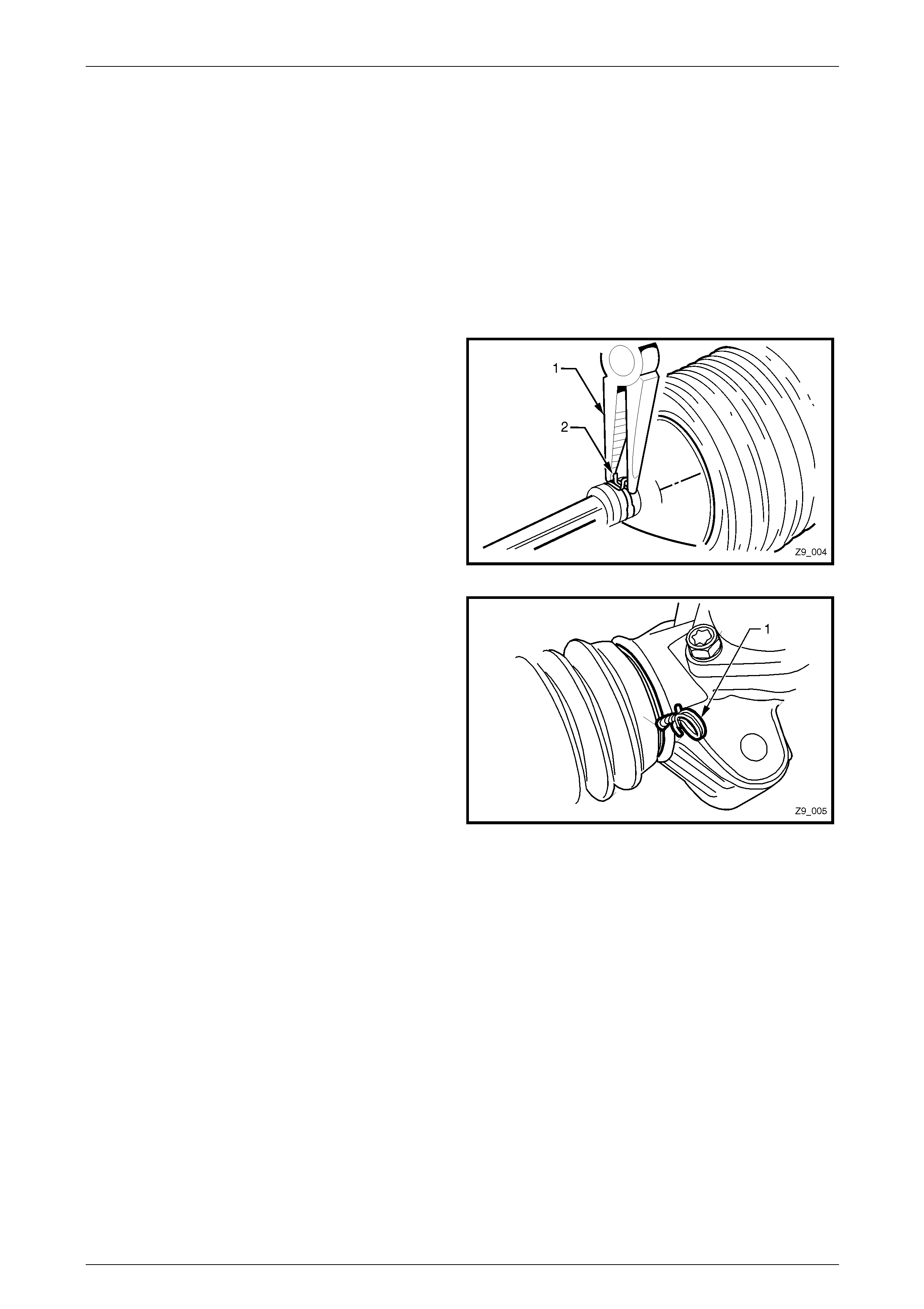
6 Using a pair of combination pliers on the ‘ears’ of the
outer steering gear bellows attaching clamp (1),
loosen the clamp and remove from the bellows and
the inner tie rod.
Figure 9 – 7
7 Untwist or cut (using diagonal cutting pliers) the inner
steering gear bellows attaching wire clamp (1), then
remove.
8 Place a suitable sized tray under the vehicle to contain
any fluid that may be spilt in the following operation.
9 Slide the steering gear bellows from the steering gear
housing and tie rod.
Figure 9 – 8
Page 9–7

Steering Page 9–8
Reinstall
1 Ensure the steering gear is centralised in the straight ahead position. This can be achieved by either of the
following methods:
a Turn the rack from lock to lock counting the number of turns then turn it back to half the number of turns
counted when turned from lock to lock.
b Before installing the steering gear bellows, fold back both bellows and measure the exposed portion of each
end of the rack from the housing. When both measurements are equal, the rack is centralised.
2 Install the steering gear bellows, ensuring that it is not twisted.
3 Fit a new inner attaching wire clamp and twist to tighten. Do not over-tighten.
4 Reinstall a NEW outer bellows clamp.
5 Reinstall the tie rod end lock nut to the inner tie rod, up to the mark made during removal operations.
6 Reinstall the tie rod end, refer to 2.2 Tie Rod End.
7 Reinstall the road wheel/s, refer to Section 10 Wheel and Tyres.
8 Lower the vehicle to the ground.
9 Check the front wheel toe setting and adjust as required, refer to Section 3A Front Suspension or
Section 3B Front Suspension – AWD.
10 While holding the tie rod end in the correct attitude with a 19 mm set spanner on the flats provided, tighten the tie
rod lock nut (21 mm) to the correct torque specification.
Tie rod end adjuster lock nut
torque specification .......................................40 – 60 Nm
11 Road test the vehicle to check for correct steering operation.
Page 9–8
Steering Page 9–9
2.4 Power Steering Gear Assembl y
ATTENTION
The following fasteners MUST be replaced when performing these operations:
Tie rod end spindle Nyloc lock n uts.
Steering gear input shaft cam bolt nut.
Fasteners either have micro encapsulated sealant applied or incorporate a mechanical thread lock and
should only be re-used once. If in doubt, replacement is recommended
Steering gear to crossmem ber nuts.
LT Section No. — 06–275
Remove
Power steering fluid when at operating
temperature can reach temperatures of
approximately 75°C. When handling power
steering fluid or steering components, the
appropriate safety glasses, gloves and
clothing must be worn to protect against
possible burns.
Disconnection of the battery affects certain
vehicle electronic systems. Refer to
Section 00 Warnings, Cautions and Notes
before disconnecting the battery.
NOTE
With the exception of the steering gear pinion
shaft having an extension attached to the input
shaft by a clamp bolt for AWD vehicles, the
removal and reinstallation of the AWD steering
gear is the same as for conventional vehicles.
1 Disconnect the ground lead from the battery.
2 Raise the vehicle and support in a safe manner. Refer to Section 0A General Information for the location of
recommended lifting and support points.
3 Remove the front road wheels, refer to Section 10 Wheels and Tyres.
When carrying out steering gear or column
procedures where the steering gear coupling
will be disconnected, remove the ignition key
from the ignition lock an d ensure the steering
column is locked. If this operation is not
carried out and the steering wheel is spun
while the steering gear coupling is removed
from the steering gear, the clockspring will be
destroyed.
Page 9–9
Steering Page 9–10
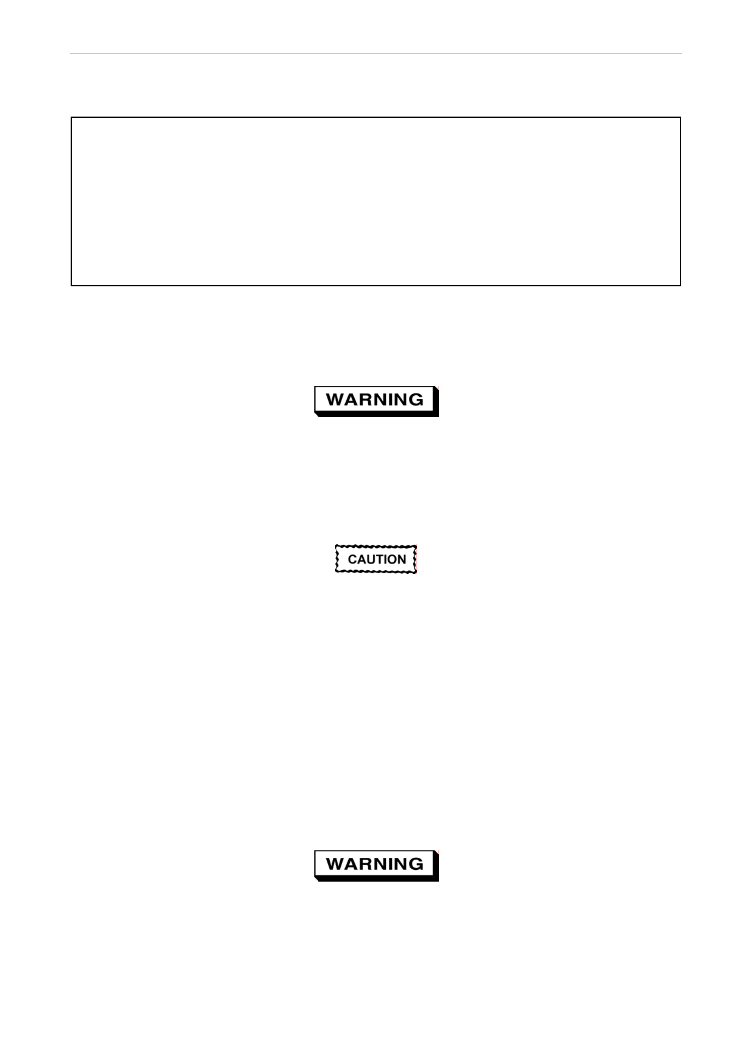
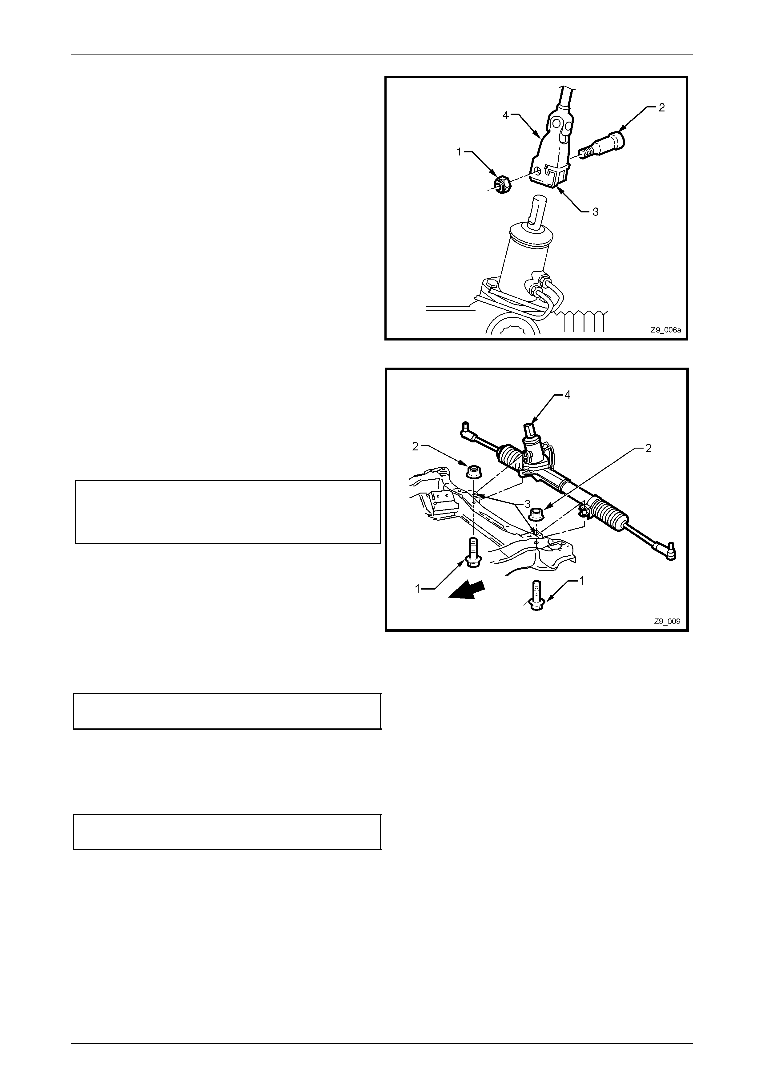
4 Remove the steering column coupling crimp nut (1) and discard.
5 Remove the steering column coupling cam bolt (2) then disengage the retaining clip (3) and slide the coupling (4)
away from the steering gear pinion shaft.
NOTE
View ‘A’ shows the 2WD arrangement while view
‘B’ shows the AWD steering gear, with the
extension to the input shaft.
Figure 9 – 9
6 Place a suitable sized tray under the vehicle to contain any fluid that may be spilled in the following operation.
7 Loosen and remove the hydraulic pipes (1 and 2) from
the steering gear valve housing (3) and allow the
power steering fluid to drain into a suitable container.
NOTE
Check that the O-rings are removed from the
steering gear valve housing when the lines are
removed. Replace the O-rings when reinstalling
the lines.
Figure 9 – 10
Page 9–10
Steering Page 9–11
8 Remove the Nyloc nut from the tie rod spindle.
9 Separate the tie rod end spindle (1) from the steering
arm tapers using a suitable remover, such as Tool
No. 7311 or commercial equivalent.
10 Repeat Steps 8 and 9 for the opposite side.
Figure 9 – 11
11 Remove the two bolts (1) and nuts (2) attaching the
steering gear housing to the front suspension
crossmember mountings (3).
12 Remove the steering gear by pulling it out from the
front suspension crossmember mountings (3) and
slide the pinion (input) shaft (4) from the steering
coupling lower clamp (refer to Figure 9 – 9).
Figure 9 – 12
Reinstall
1 Ensure the steering gear is centralised. This is
achieved by rotating the pinion to the halfway position
of its total lock-to-lock rotation. When the rack is in
the straight ahead position, the flat on the pinion shaft
(1) will be aligned as shown.
2 Check that the steering wheel is in the straight ahead
position.
NOTE
While the 2WD version is shown, the AWD design is
similar.
Figure 9 – 13
Page 9–11
Steering Page 9–12
3 Slide the steering gear pinion shaft (1) into the
steering coupling lower flange (2) and then install the
lower cam bolt (3) and a NEW retaining crimp nut (4)
but do not tighten at this stage.
NOTE
The coupling cam bolt will only fit in the
recessed section of the pinion shaft.
Figure 6A1 – 14
4 Position the steering gear housing into the
crossmember mounting points (3).
5 Install the mounting bolts (1) and nuts (2).
6 While holding the nuts, tighten the bolts to the correct
torque specification (using an angle wrench such as
Tool E7115 or similar).
Steering gear housing to crossmember
mounting bolt torque specification
Stage 1................................................ 60.0 Nm
Stage 2............................. 40° – 50° turn angle.
Figure 6A1 – 15
7 Tighten the steering coupling cam bolt retaining nut to the correct torque specification.
Steering coupling cam bolt retaining
nut torque specification .................................23 – 30 Nm
8 Lubricate two NEW steering gear hydraulic line O-rings with clean power steering fluid and install them to the
hydraulic lines.
9 Install both hydraulic lines to the steering gear valve housing and tighten the flare nuts to the correct torque
specification.
Hydraulic line to valve housing flare nut
torque specification .......................................25 – 35 Nm
NOTE
Ensure the plastic spacers are positioned on tie-
rod end ball studs and they are in good condition
before fitting the studs into the steering arms.
Replace the spacers if damaged.
10 Reinstall the tie-rod end spindles into the steering arms.
11 Install NEW Nyloc lock nuts and hand tighten, using a 6 mm Allen key to hold the spindle while tightening the nut.
Continue until the matching tapers bind and hold the spindle.
Page 9–12

Steering Page 9–13
12 Tighten the Nyloc nut (19 mm) to the correct torque specification.
■ Tie rod end attaching
nut torque specification .................................65 – 75 Nm
13 Reinstall the road wheel/s, refer to Section 10 Wheel and Tyres.
14 Lower the vehicle to the ground and reconnect the battery ground lead.
15 Refill and bleed the hydraulic system, refer to Section 9 Steering in the MY2005 VZ Service Information.
16 Check the front wheel toe setting and adjust as required, refer to Section 3A Front Suspension or
Section 3B Front Suspension – AWD.
17 While holding the tie rod end in the correct attitude with a set spanner on the flats provided, tighten the tie rod lock
nut to the correct torque specification.
Tie rod end adjuster lock nut
torque specification .......................................40 – 60 Nm
18 Road test the vehicle to check for correct steering operation.
Page 9–13
Steering Page 9–14
2.5 Inner Tie Rod and Ball Joint
Remove
1 Remove the power steering gear assembly from the vehicle. Refer to 2.4 Power Steering Gear.
2 Remove the tie rod end from the tie rod to be replaced and set to one side. Refer to 2.2 Tie Rod End.
3 Remove the steering gear bellows from the side where the tie rod is to be replaced. Refer to
2.3 Steering Gear Bellows.
NOTE
Removing the steering gear bellows involves the
removal of the tie rod end lock nut.
4 Using a 15 mm set spanner across the flats of the input shaft, rotate the steering input shaft to fully extend the rack
on the side where the tie rod is to be replaced.
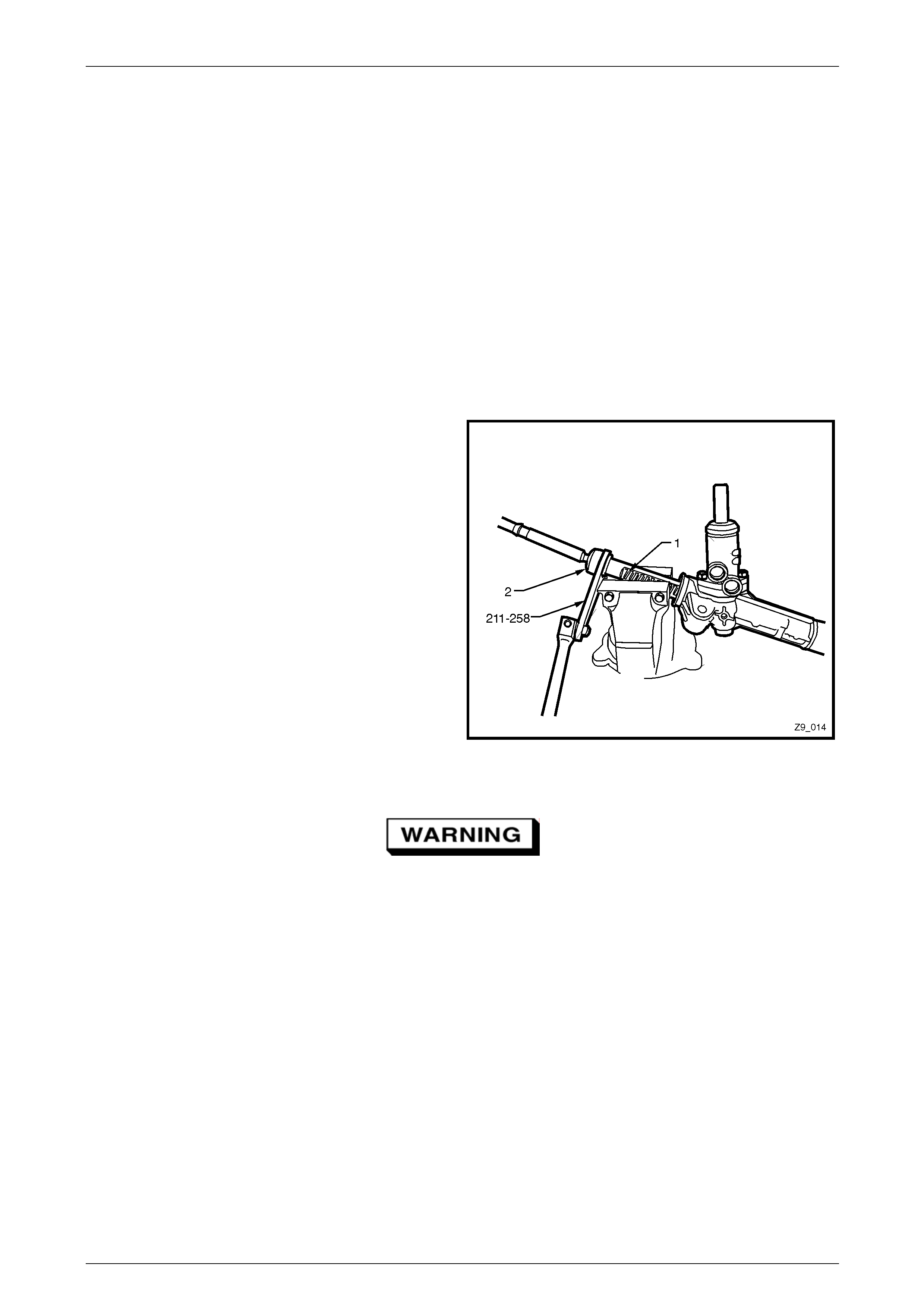
5 Install soft jaws to a bench vice to prevent damage to
the rack teeth (1).
6 Securely clamp the exposed rack in the vice, as
shown.
7 Using Tool No. 211-258, loosen then tighten the inner
tie-rod ball joint (2) to release the thread sealant, then
unscrew the tie rod ball joint from the end of the rack.
NOTE
While the right side situation is shown, the
opposite side is similar.
8 Remove the rack from the vice and check that there is
no foreign material in the rack teeth.
Figure 9 – 16
9 Use an M20 x 1.5 bottoming tap to clean the thread sealant from the internal rack threads.
Wear eye protection to prevent potential
injury.
10 Use compressed air to remove sealant from the threaded hole.
Page 9–14

Steering Page 9–15
Reinstall
1 Apply Loctite™ 262 to the cleaned threads of the replacement tie rod ball joint.
2 With the gear held firmly in vice jaws fitted with soft jaws, install the tie rod ball joint to the rack end.
3 Using tool No. 211-258 and an accurate torque wrench tighten the ball joint to the correct torque specification.
Inner tie rod ball joint to steering
rack torque specification .............................90 – 110 Nm
4 Reinstall the steering gear bellows. Refer to 2.3 Steering Gear Bellows.
5 Reinstall the tie rod end. Refer to 2.2 Tie Rod End.
6 Reinstall the power steering gear assembly to the vehicle. Refer to 2.4 Power Steering Gear.
7 Reinstall the road wheel/s, refer to Section 10 Wheel and Tyres.
8 Lower the vehicle to the ground and reconnect the battery ground lead.
9 Refill and bleed the hydraulic system, refer to Section 9 Steering in the MY2005 VZ Service Information.
10 Check the front wheel toe setting and adjust as required, refer to Section 3A Front Suspension or
Section 3B Front Suspension – AWD.
11 While holding the tie rod end in the correct attitude with a 19 mm set spanner on the flats provided, tighten the tie
rod lock nut (21 mm) to the correct torque specification.
Tie rod end adjuster lock nut
torque specification .......................................40 – 60 Nm
12 Road test the vehicle to check for correct steering operation.
Page 9–15


Steering Page 9–17
3 Specifications
Steering Gear
Steering Gear Type.............................................. Power steering rack and pinion with integral power
cylinder and rotary valve mechanism – variable ratio.
Manufacturer........................................................................................Kayaba Industry Company Ltd
Ratio .......................................................................................................................................Variable
Number of Steering Wheel Turns Lock to Lock.............................................................................2.97
Nominal Rack Travel Total................................................................................................ 164 ± 1 mm
Lubricant
Hydraulic Fluid ................................................................. Dexron ® VI Automatic Transmission Fluid
Power Steering Fluid Capacity (Use reservoir fluid indicator as a final check) ............Approx. 650 ml
Page 9–17

Steering Page 9–18
4 Torque Wrench Specifications
ATTENTION
All steering fasteners are important attaching parts as they affect the performance of vital components and/or
could result in majo r repair expense. Where specified in this Section, fasteners MUST be rep laced with parts
of the same part number or a GM approved equivalent. Do not use fasteners of an inferior quality or
substitute design.
Torque values must be used as specified during reassembly to ensure proper retention of all steering
components.
Through out this Section, fastener torque wrench specifications may be accompanied with the following
Identification marks:
Fasteners must be repl aced after loosening.
Fasteners either have micro encapsulated sealant applied or incorporate a mechanical thread lock and
should only be re-used once. If in doubt, replacement is recommended.
If one of these identification marks is present alongside a fastener torque wrench specification, the
recommendation regarding that fastener must be adhered to.
High Pressure Pipe Flare Nut to Steering Gear Tube ..................... 20 – 30 Nm
Hydraulic Pipe to Valve Housing Flare Nut...................................... 25 – 35 Nm
Rack Pad Adjusting Screw
Stage 1 ................................................................................................... 20 Nm,
Turn rack approximately 90° in each direction, 3 times
Stage 2 ............................................................................................back off 30°
Rack Pad Adjusting Screw Lock Nut ............................................... 40 – 50 Nm
Steering Coupling Cam Bolt Retaining Nut...................................... 23 – 30 Nm
Steering Gear Housing to Crossmember Mounting Bolt
Stage 1.............................................................................................. 60 Nm,
Stage 2 .........................................................................40° – 65° turn angle
Tie Rod End Nyloc Attaching Nut .................................................... 65 – 75 Nm
Tie Rod End Adjuster Lock Nut ...................................................... 40 – 60 Nm
Tie Rod Ball Joint to Steering Rack............................................... 90 – 110 Nm
Valve Housing Attaching Screw ...................................................... 16 – 20 Nm
Page 9–18
Steering Page 9–19
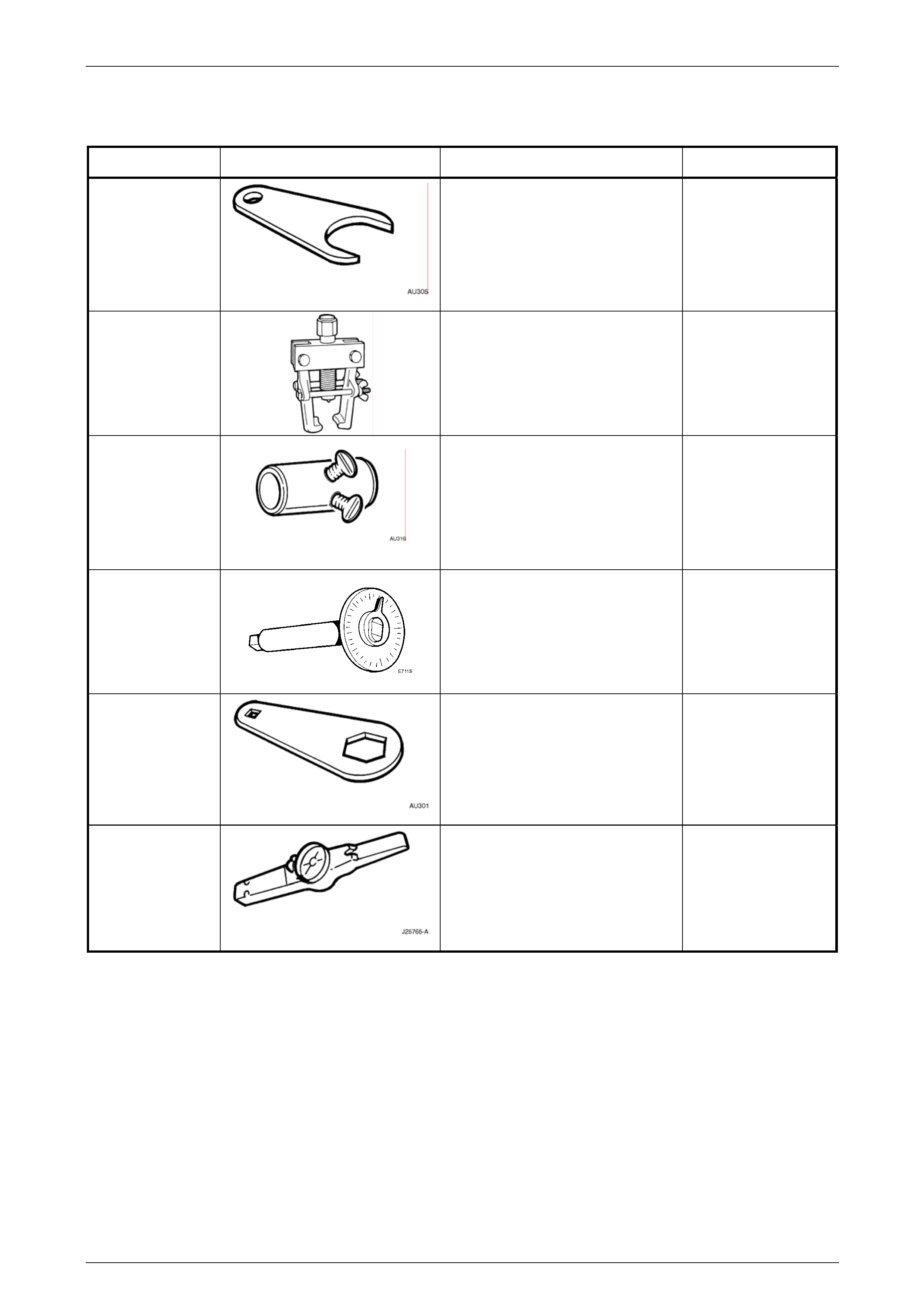
5 Special Tools
Tool number Illustration Description Classification
211-258
Tie Rod Wrench
Used to loosen/tighten the tie rod
assembly from/to the steering rack.
Previously released
Unique
7311
Universal Puller
Used to remove the outer tie rod end
tapered spindle from the steering arm.
Previously released
AU316
Preload Adaptor
Fitted to the input shaft to enable a
turning torque to be measured.
Previously released
Unique
E7115 Angular Torque Wrench
Used to tighten fasteners when an
angle torque is required.
Previously released
Mandatory
CH-48511
Lock Nut Wrench
Used to loosen/tighten the steering
rack pad adjusting screw lock nut.
New release
Unique
J25765-A
Dial Type Torque Wrench
Used to measure a rotational torque.
Capable of measuring between
0.4 – 6.0 Nm
(also commercially available)
Previously released
Mandatory
Page 9–19