
Body Page 1A1–1
Page 1A1–1
Section 1A1
Body
ATTENTION
Before performing any service operation or other procedure described in this Section, refer to Section 00
Warnings, Cautions and Notes for correct w orkshop practices wi th regard to safety and/or property damage.
1 General Information...............................................................................................................................2
2 Body Leak Diagnosis.............................................................................................................................3
3 Body Lubrication....................................................................................................................................4
4 Lock Cylinders and Keys.......................................................................................................................5
5 Plastic Components...............................................................................................................................6
5.1 Exterior ................................................................................................................................................................... 6
5.2 Interior .................................................................................................................................................................. 10
5.3 Plastic Types........................................................................................................................................................ 13
6 Wheelhouse Liners ..............................................................................................................................14
6.1 Front Wheelhouse Liner...................................................................................................................................... 14
Remove................................................................................................................................................................. 14
Reinstall................................................................................................................................................................ 15
6.2 Rear Wheelhouse Liner....................................................................................................................................... 16
Remove................................................................................................................................................................. 16
Reinstall................................................................................................................................................................ 17
7 Fuel Filler Door Assembly and Cable Assembly...............................................................................18
7.1 Fuel Filler Door Assembly................................................................................................................................... 18
Remove................................................................................................................................................................. 18
Disassemble......................................................................................................................................................... 19
Lock Spring ...................................................................................................................................................... 19
Moulding........................................................................................................................................................... 19
Reassemble.......................................................................................................................................................... 19
Lock Spring ...................................................................................................................................................... 19
Moulding........................................................................................................................................................... 19
Reinstall................................................................................................................................................................ 20
7.2 Fuel Filler Door Lock Cable Assembly............................................................................................................... 21
Remove................................................................................................................................................................. 21
Reinstall................................................................................................................................................................ 22
8 Body Braces..........................................................................................................................................23
8.1 Front Suspension Strut Brace............................................................................................................................ 23
Remove................................................................................................................................................................. 23
Reinstall................................................................................................................................................................ 23
9 Torque Wrench Specifications ...........................................................................................................24
Techline

Body Page 1A1–2
Page 1A1–2
1 General Information
This Section contains the service procedures for body components not specific to other Sections of this Service
Information Package such as:
• Body Leak Diagnosis
• Body Lubrication
• Lock Cylinders and Keys
• Wheelhouse Liners
• Fuel Filler Door Assembly and Cable Assembly
• Body Braces

Body Page 1A1–3
Page 1A1–3
2 Body Leak Diagnosis
Diagnosis of body leaks can be complicated as the appearance of dust or water at one point within the vehicle can be
caused by seepage through any one, or more possible locations. For example the cause of wet front floor coverings
could be either water entering past the door weatherstrip, through the door inner panel, between the windshield and its
adhesive compound or through any one of the joins in the body structure. Therefore, the point or points of water or dust
entry must be established before effective resealing can be carried out.
Water leak diagnosis is usually performed by having an assistant spray a gentle fan of water from a hose around the
suspected area until the leak can be generated. Removal of various trim components from the inside may be required to
determine point of entry. Narrowing down the water spray to the point of greatest water flow will assist in determining the
point of entry.
Dust entry quite often requires the following of signs of dust entry around seals or vent inlets or outlets, etc.
Once detected, repair the area by replacing faulty components or applying the correct sealer or adhesive.
Body Page 1A1–4
Page 1A1–4
3 Body Lubrication
Careless or excessive application of body
lubricants can cause staining of the paint
finish and interior trim, damage clothing, and
become a trap for dirt. Use lubricants
sparingly and remove any excess
immediately.
The moving mechanical parts of the body which have metal to metal contact are lubricated at assembly of the vehicle.
Operating conditions, whether normal or otherwise, determine the effective life of the lubricant and for this reason
lubrication in service is important. Equally important is the type of lubricant to be used.
Listed below are the body lubrication points. For the recommended lubricants and maintenance schedule refer to
Section 0B Lubrication and Service.
Parts Readily Accessible:
• Hood Pilot Pin Assembly
• Hood Lock Assembly
• Hood Hinges Door Hinge Pins
• Door Check Assemblies
• Door Lock Cylinder
• Door Lock Striker
• Door Lock Assembly Fork
• Rear Compartment Lid Hinge
• Rear Compartment Lid Latch
• Ignition Lock Cylinder
• Instrument Panel Compartment Lock Cylinder
Parts Concealed Requirin g Disassembly:
• Door Window Regulator
• Door Window Guides and Runners
• Door Lock Mechanism
• Rear Compartment Lid Lock Mechanism
• Front Seat Adjuster
• Driver’s Seat Height Adjuster
Body Page 1A1–5
Page 1A1–5
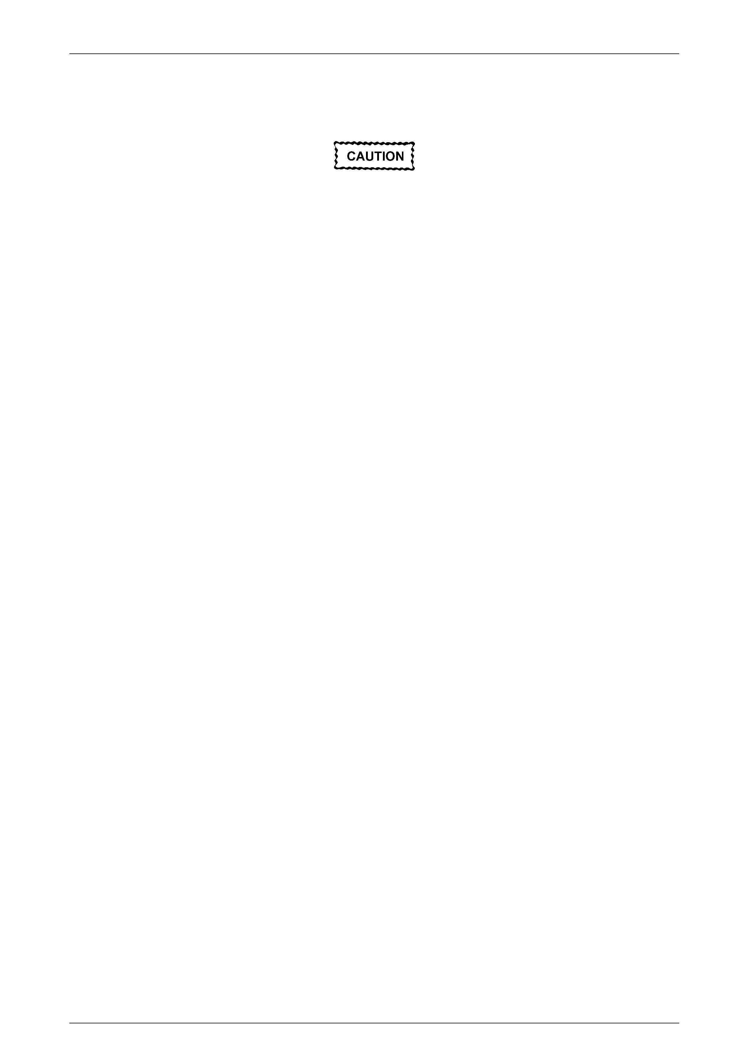
4 Lock Cylinders and Keys
A common-key locking system operates the door and
ignition locks. A unique key is provided for the instrument
panel compartment. All vehicles have a lock cylinder on the
driver’s door handle assembly.
The door and ignition key features a remote function that
activates the central locking system and anti-theft system
from a distance of several metres. Inserting the key into the
lock cylinder incorporated in the driver’s door handle also
performs this same function.
A separate button on the remote key opens the rear
compartment lid.
Figure 1A1 – 1
NOTE
The key identification number is located on the
vehicle security card, stored with the owner’s
manual. It is essential that this key number be
available should a replacement key be required.
In the event of a key replacement, the Body Control Module (BCM) will require reprogramming to accept the new key,
refer to Section 12J Body Control Module for reprogramming and further information regarding the anti-theft system.
For service procedures for the lock cylinders:
• Driver’s door lock cylinder, refer to Section 1A5 Front and Rear Door Assemblies.
• Ignition lock cylinder, refer to Section 9 Steering.
Body Page 1A1–6
Page 1A1–6
5 Plastic Components
Plastic components are used throughout the vehicle. The following table is included to assist with the identification and
composition of common components. refer to 5.3 Plastic Types for a description of handling procedures for each
different plastic composition.
NOTE
Most components are also identified with the
material code in an inconspicuous place.
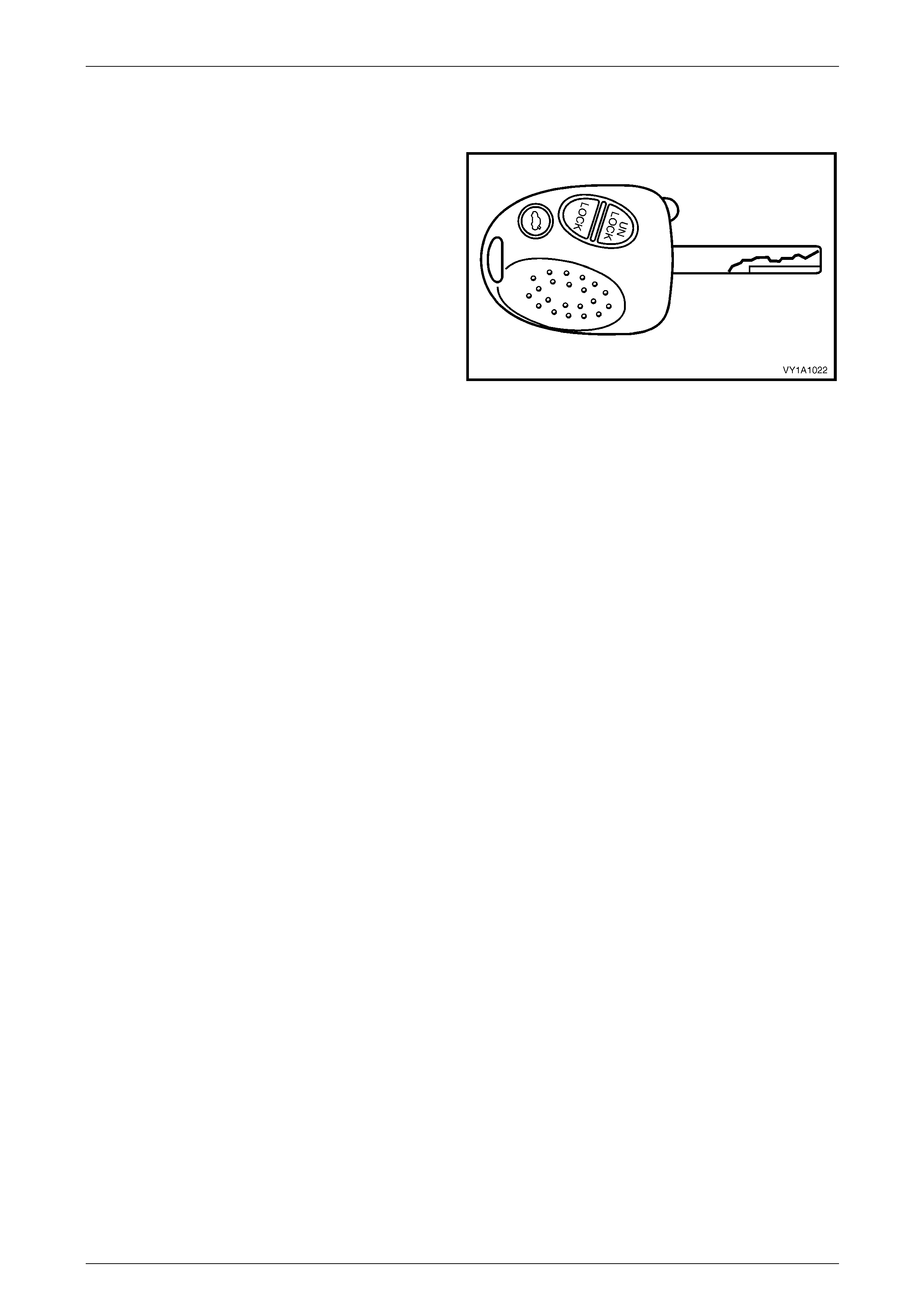
5.1 Exterior
Front Bumper Fascia
Material: PP
Radiator Grille Assembly
Material: Painted – ABS, Unpainted – ASA
Headlamp Assembly
Material: Lens – PC, Housing – PP/T30
Tail lamp Assembly
Material: Lens - PMMA, Housing – ABS
Body Page 1A1–7
Page 1A1–7
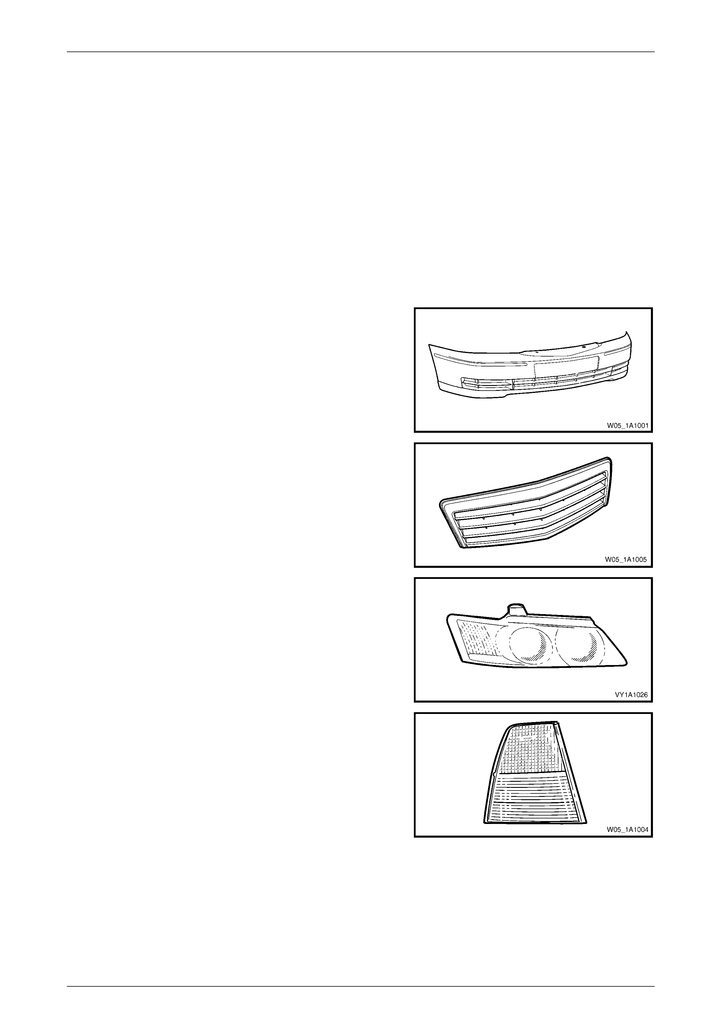
Wheelhouse Liner
Material: PP
Upper Radiator Air Baffle
Material: PP
Radiator Overflow Reservoir Assembly
Material: PP
Plenum Cover Assembly
Material: PP
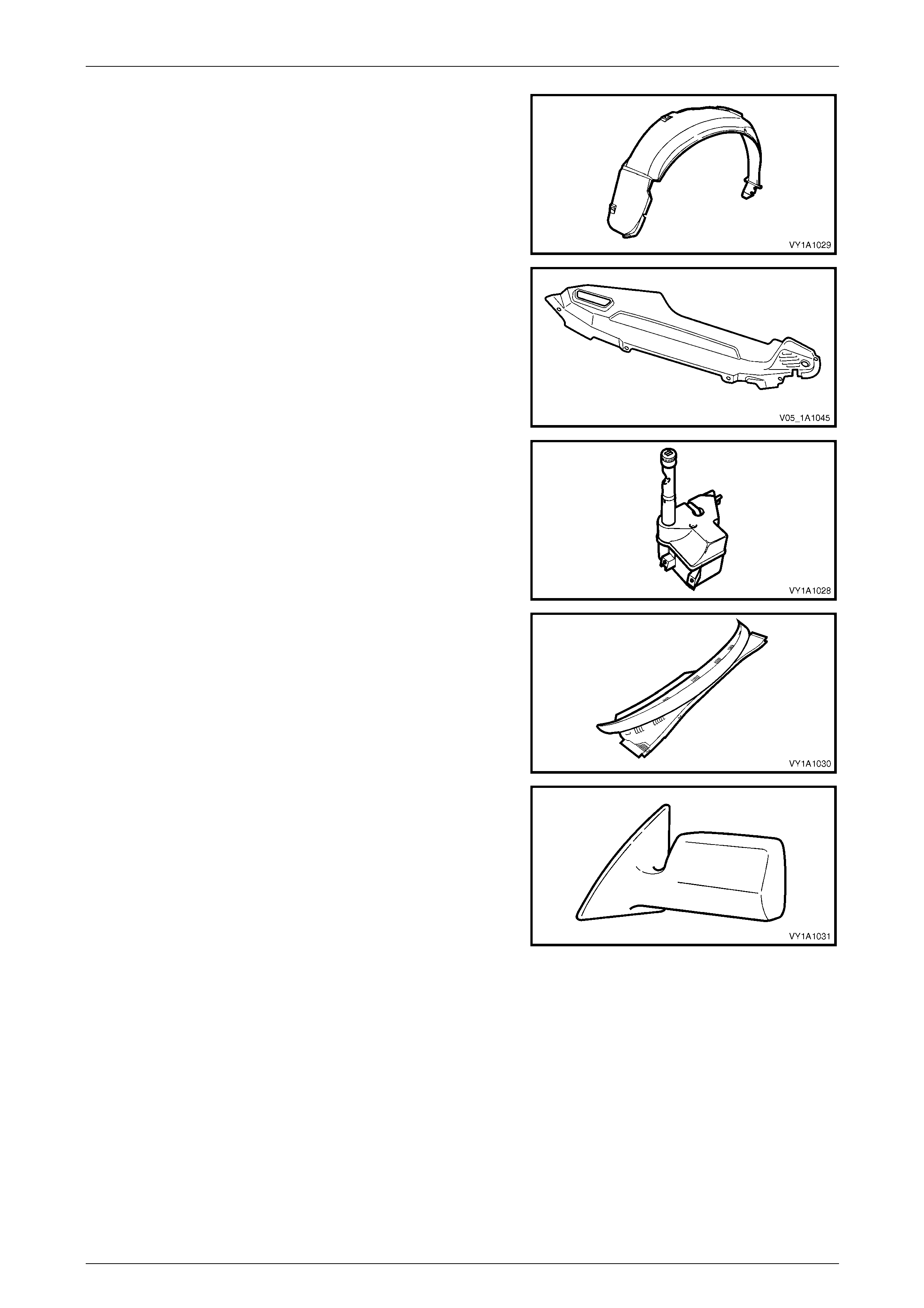
Outside Rear View Mirror Housing
Material: Painted – ABS, Unpainted - ASA / PC
Body Page 1A1–8
Page 1A1–8
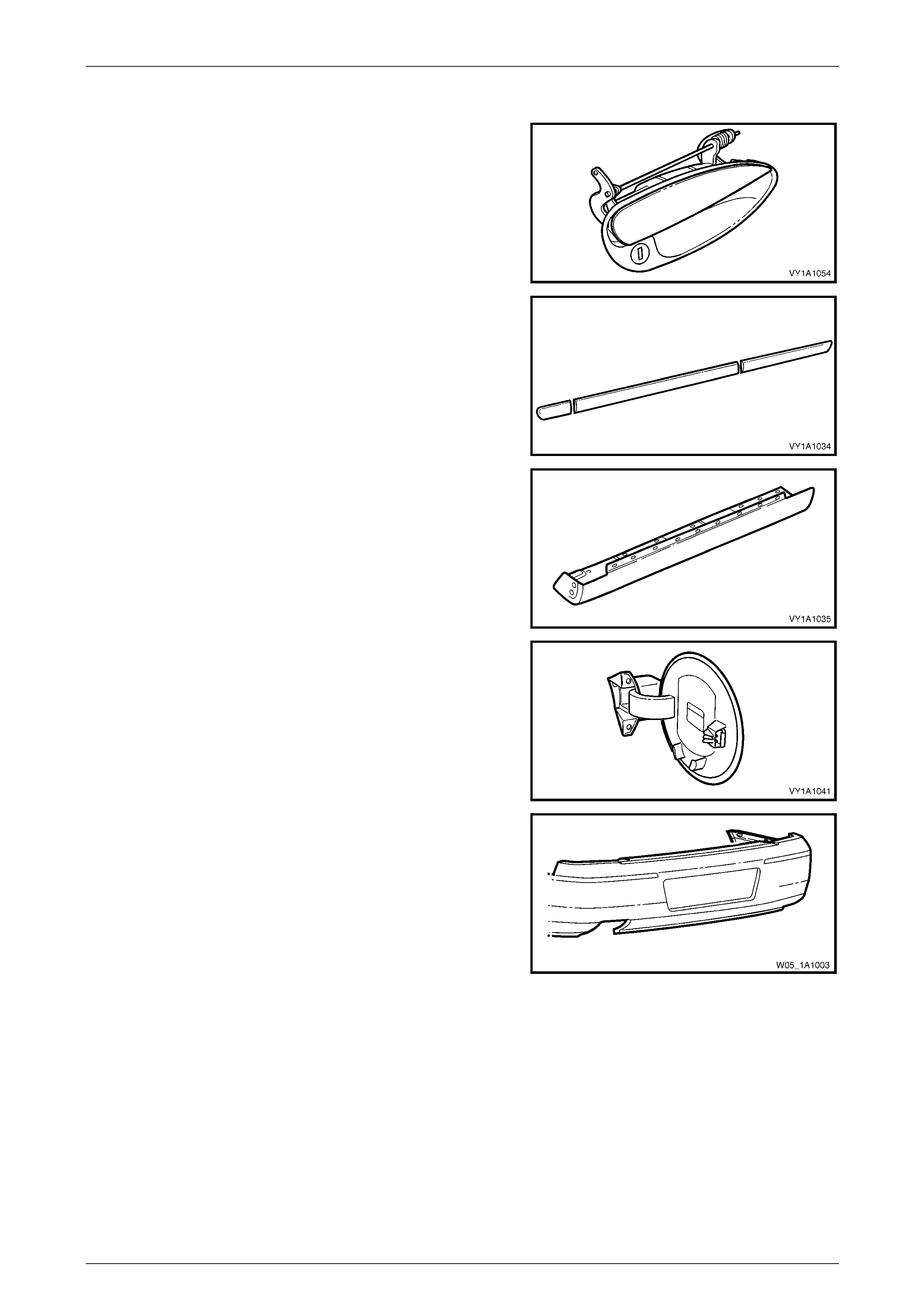
Door Handle Assembly
Material: PA 66
Body Side Moulding
Material: ASA
Rocker Panel Moulding Assembly
Material: PP
Fuel Filler Door Assembly
Material: PPE / PA
Rear Bumper Fascia
Material: PP
Body Page 1A1–9
Page 1A1–9
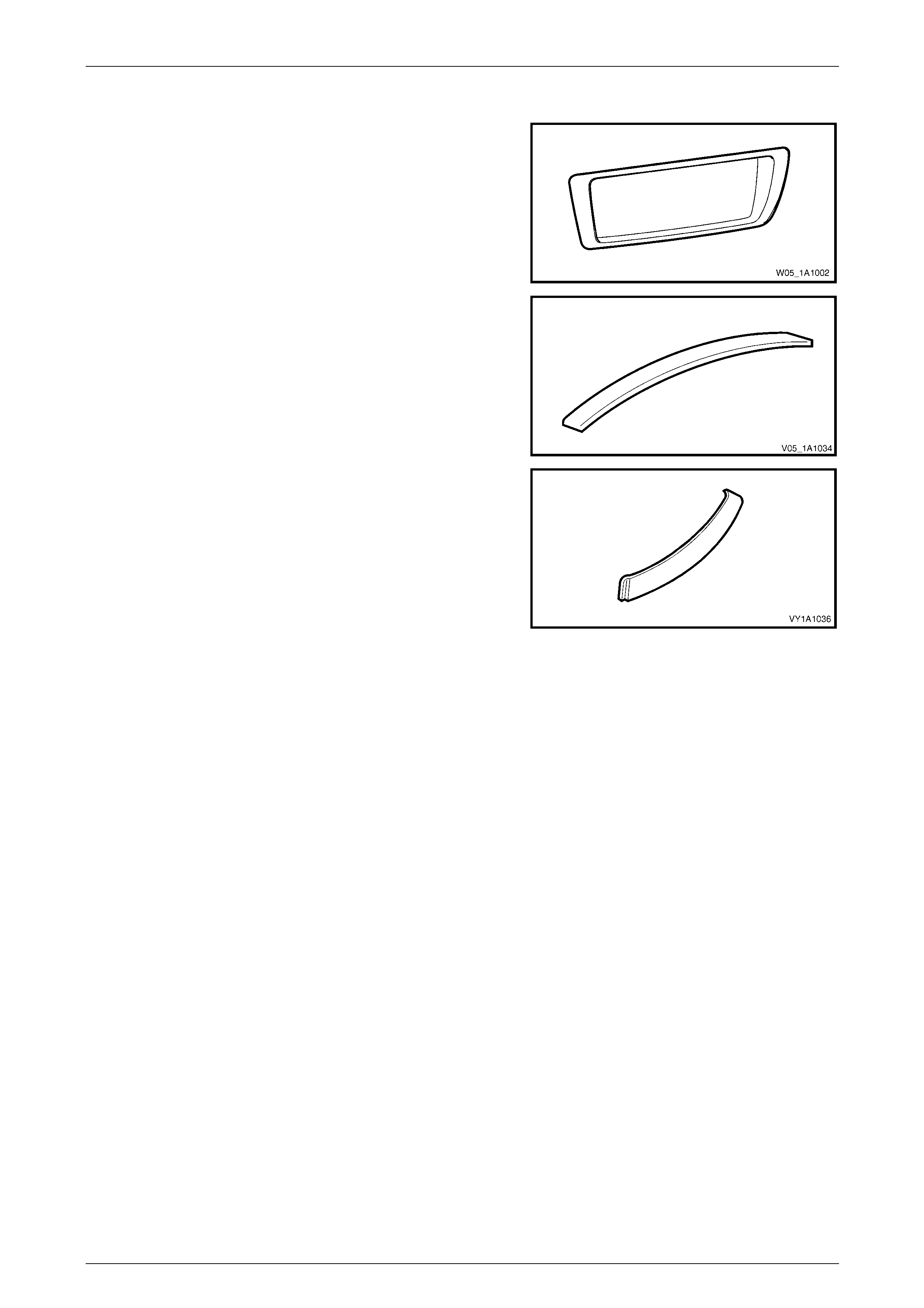
Rear Licence Plate Surround
Material: ABS
Roof Panel Joint Moulding Assembly
Material: PVC
Quarter Panel Belt Moulding
Material: PPE/PA-M20
Body Page 1A1–10
Page 1A1–10
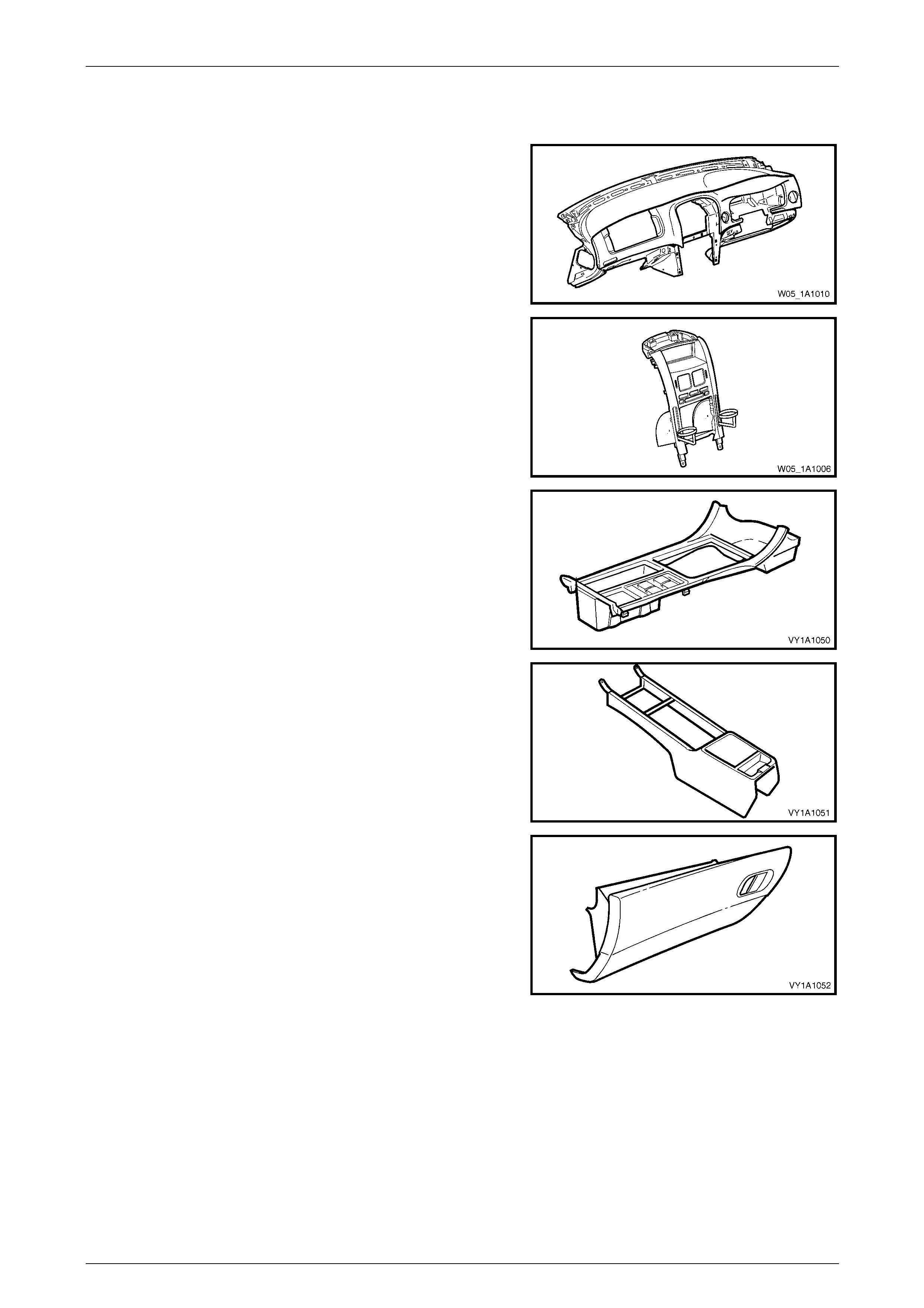
5.2 Interior
Instrument Panel Pad Assembly
Material: Carrier – ABS, Pad Substrate – PP, Foam – PVC, Skin - ABS
Instrument Panel Centre Trim Assembly
Material: PC/ABS
Floor Console Cover Assembly
Material: PC/ABS
Front Floor Console
Material: PP
Instrument Panel Compartment
Material: PP
Body Page 1A1–11
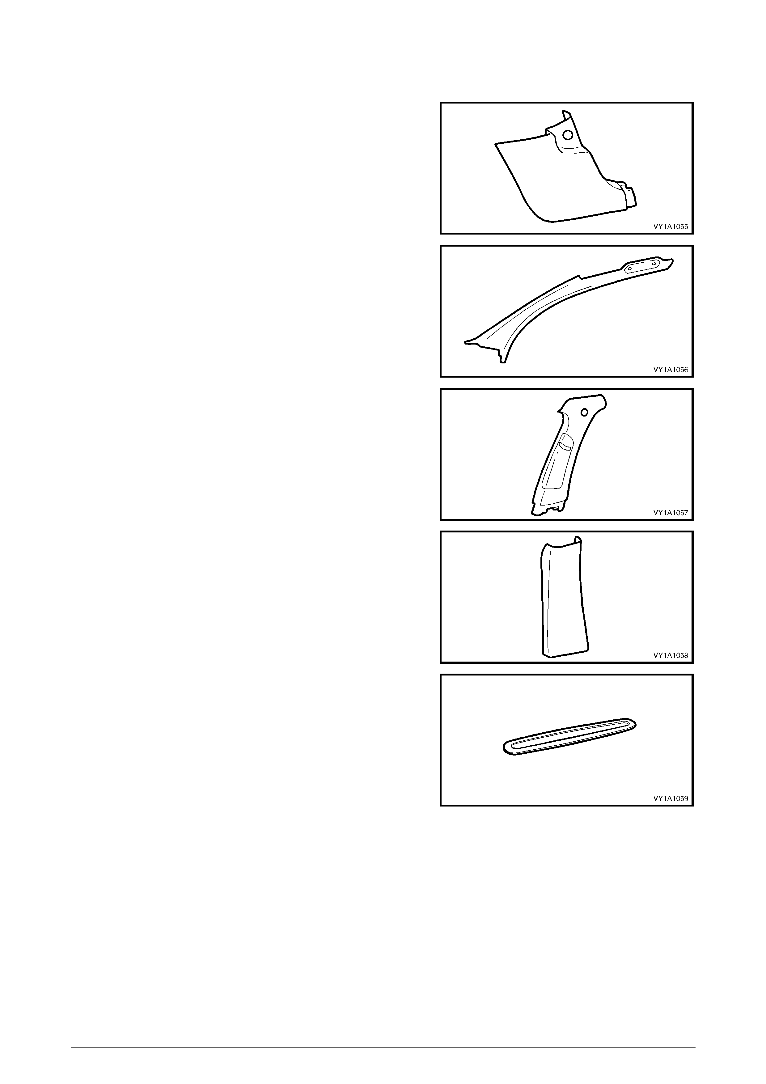
Page 1A1–11
Hinge Pillar Trim
Material: PP
Windscreen Side Garnish
Material: PP
Centre Pillar Upper Trim
Material: PP
Centre Pillar Lower Trim
Material: PP
Side Sill Trim Plate
Material: PP
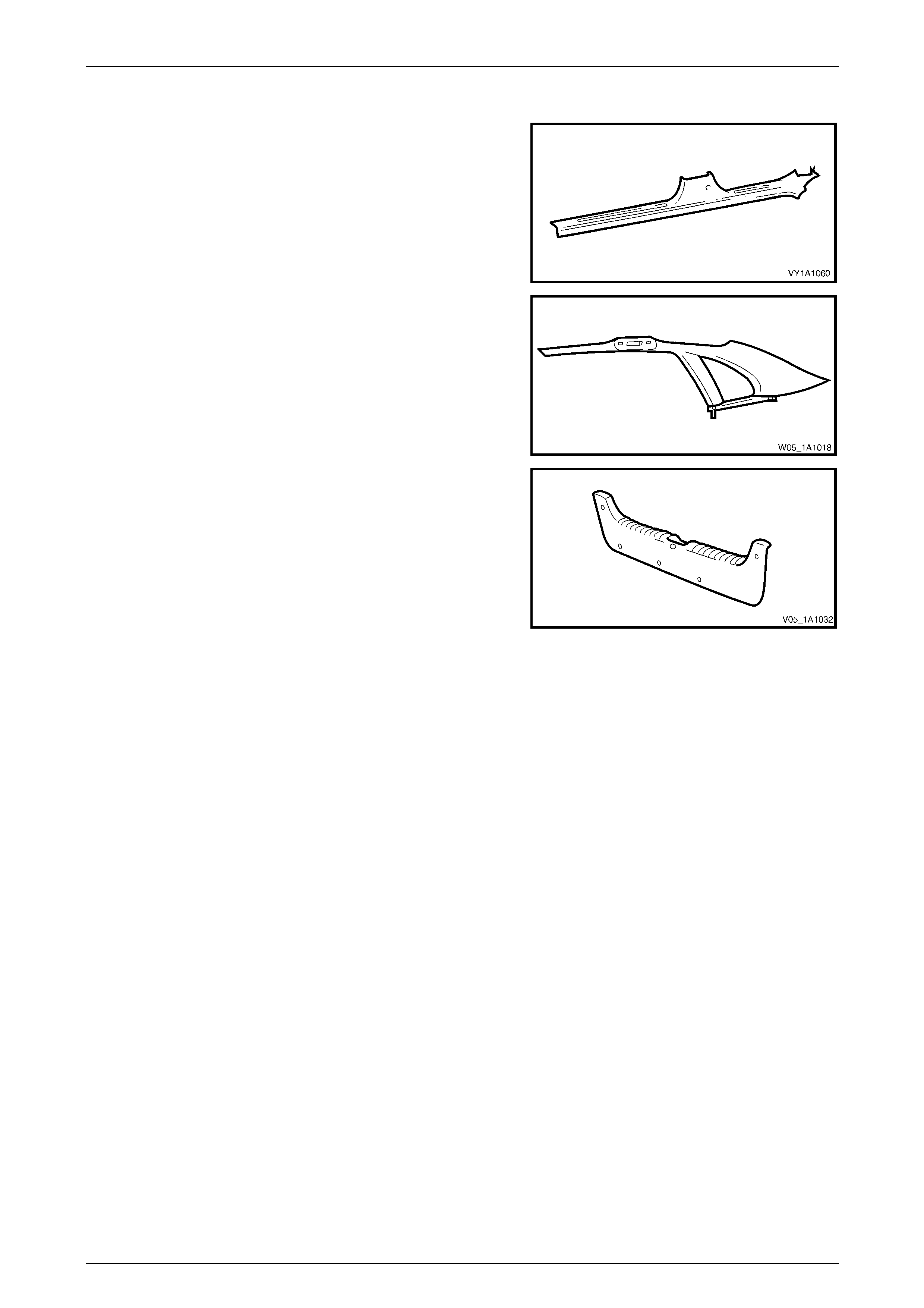
Body Page 1A1–12
Page 1A1–12
Side Sill Trim
Material: PP
Body Lock Pillar Garnish
Material: PP
Rear End Trim Panel
Material: PP

Body Page 1A1–13
Page 1A1–13
5.3 Plastic Types
The repair procedure for plastic body parts must conform with the type of plastic material.
Precautions to be taken with plastic parts are detailed in the following chart:
Code Material Name Heat Resisting
Temp* °C Resistance to
Alcohol or Gasoline NOTES
ABS Acrylonitrile
Butadiene Styrene
Resin
80 Alcohol is harmless if applied only
for short time in small amounts (i.e.
quick wiping to remove grease).
Avoid gasoline and organic
or aromatic solvents.
ASA Acrylate Styrene
Acrylonitrile 80 Alcohol is harmless if applied only
for short time in small amounts (i.e.
quick wiping to remove grease).
Avoid gasoline and organic
or aromatic solvents.
PC Polycarbonate 120 Alcohol is harmless. Avoid gasoline, brake fluid,
wax, wax removers and
organic solvents.
PMMA Polymethyl
Methacrylate 80 Alcohol is harmless if applied only
for short time in small amounts. Avoid dipping or immersing
in alcohol, gasoline, solvents,
etc.
PE Polyethylene 80 Alcohol and gasoline are harmless. Most solvents are harmless.
PP /
PP67 Polypropylene 80 Alcohol and gasoline are harmless. Most solvents are harmless.
PPE Polyphenylene
Ether 100 Alcohol and gasoline are harmless if
applied only for a short time in small
amounts (i.e. quick wiping to remove
grease).
Avoid dipping or immersing
in alcohol, gasoline, solvents,
etc.
PU Polyurethane
Foam 100 Alcohol and gasoline are harmless if
applied only for a short time in small
amounts (i.e. quick wiping to remove
grease).
Avoid dipping or immersing
in alcohol, gasoline, solvents,
etc.
PVC Polyvinyl Chloride 80 Alcohol and gasoline are harmless if
applied only for short time in small
amounts. (i.e. quick wiping to
remove grease).
Avoid dipping or immersing
in alcohol, gasoline, solvents,
etc.
TPO Thermoplastic
Olefin 80 Alcohol is harmless.
Gasoline is harmless if applied only
for short time in small amounts.
Most solvents are harmless
but avoid dipping or
immersing in alcohol,
gasoline, solvents, etc.
PPE/
PA-M20 Modified
Polypropylene
Ether and
Polyamide Alloy
190 Alcohol and gasoline are harmless if
applied only for a short time in small
amounts (i.e. quick wiping to remove
grease).
Avoid dipping or immersing
in alcohol, gasoline, solvents,
etc.
Body Page 1A1–14
Page 1A1–14
6 Wheelhouse Liners
LT Section No. — 12–425
6.1 Front Wheelhouse Liner
Remove
1 Remove the front road wheel, refer to Section 10 Wheels and Tyres.
2 Depending on vehicle complete either step a or b:
a Remove the screw (1) attaching the front bumper
fascia assembly (2) to the wheelhouse liner (3).
To aid in removal of the liner remove the screw
(4) attaching the fascia assembly to the vehicle.
Figure 1A1 – 2
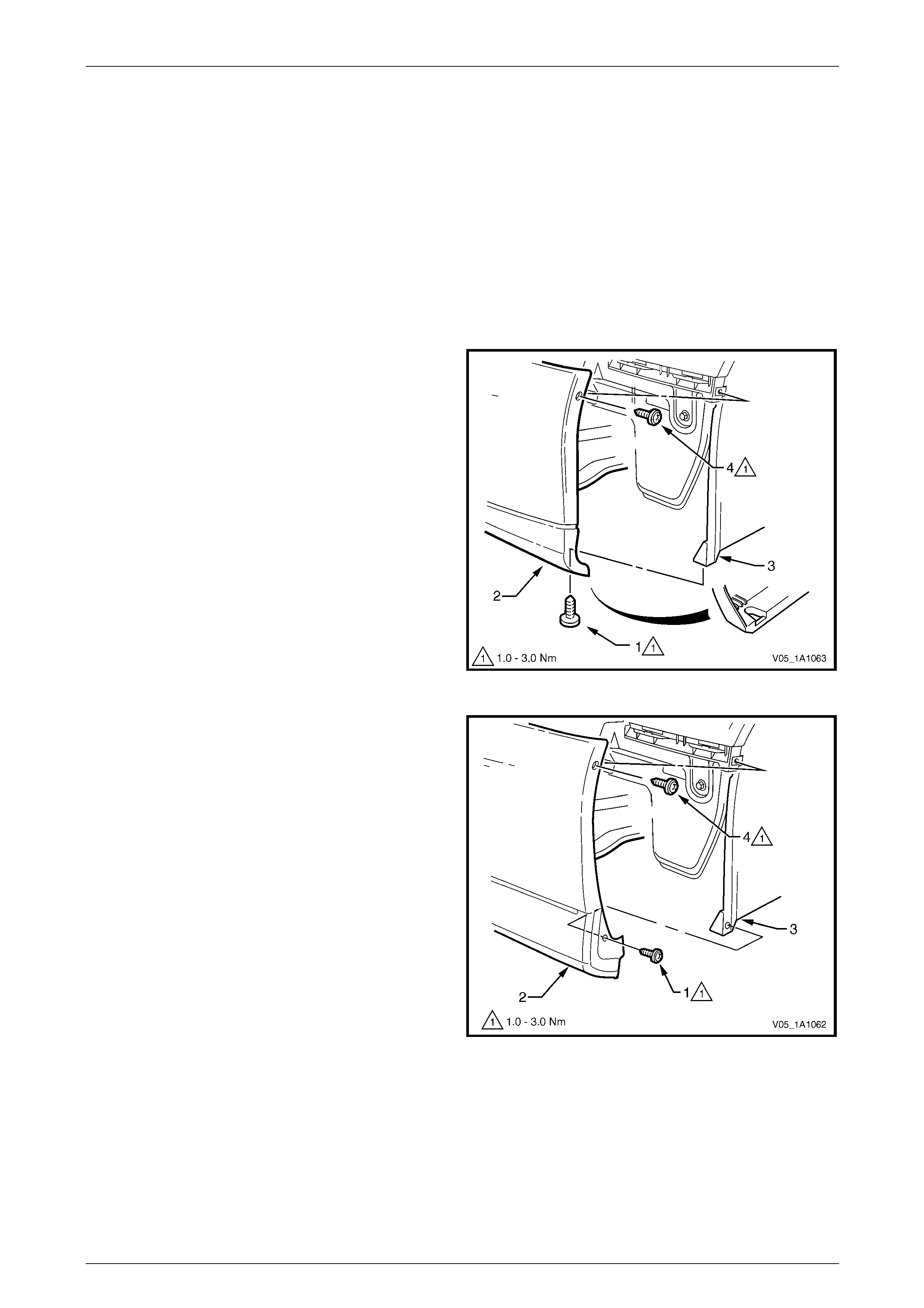
b Remove the screw (1) attaching the front bumper
fascia assembly (2) to the front wheelhouse liner
(3). To aid in removal of the liner remove the
screw (4) attaching the fascia assembly to the
vehicle.
Figure 1A1 – 3
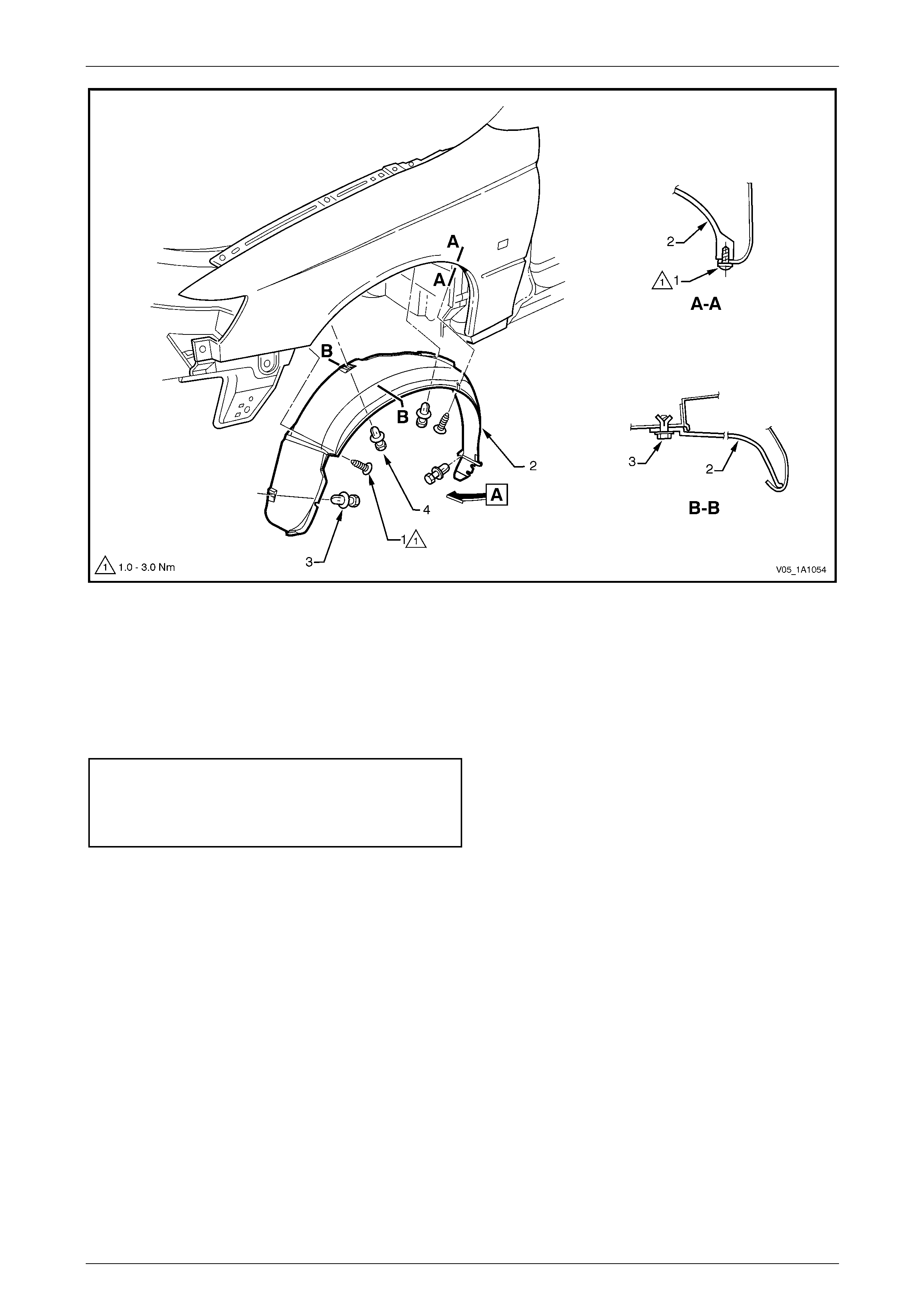
3 Referring to Figure 1A1 – 4, remove the two screws (1) attaching the liner (2) to the fender.
4 Remove the four retainers (4) attaching the liner to the vehicle.
5 Remove the liner.
Body Page 1A1–15
Page 1A1–15
Figure 1A1 – 4
Reinstall
Reinstallation of the front wheelhouse liner is the reverse of the removal procedure, noting the following:
1 Ensure the wheelhouse liner is correctly positioned. Refer to Figure 1A1 – 4.
2 Tighten the screws to the correct torque specification.
Front wheelhouse liner attaching
screw torque specification...........................1.0 – 3.0 Nm
Front bumper fascia assembly attaching
screw torque specification...........................1.0 – 3.0 Nm
Body Page 1A1–16
Page 1A1–16
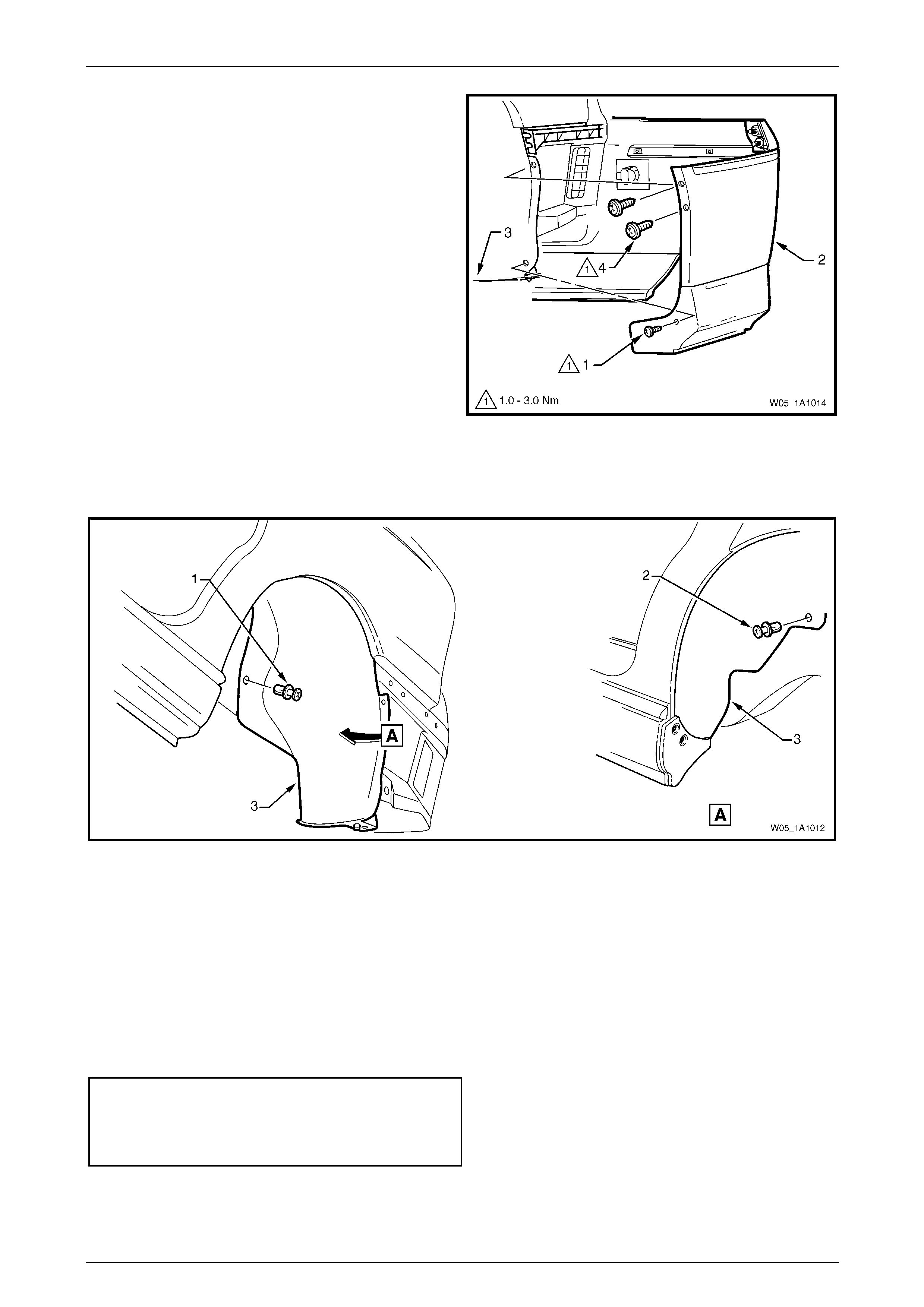
6.2 Rear Wheelhouse Liner
Remove
1 Remove the rear road wheel, refer to Section 10 Wheels and Tyres.
2 Remove the screw (1), two places, attaching the
rocker panel moulding assembly (2) and rear
wheelhouse liner (3).
Figure 1A1 – 5
3 Depending on vehicle complete either step a or b:
a Remove the screw (1) attaching the rear bumper
fascia assembly (2) to the rear wheelhouse
liner (3).
Remove the two screws (4) attaching the fascia
assembly to the liner and rear bumper fascia
guide.
Figure 1A1 – 6
Body Page 1A1–17
Page 1A1–17
b Remove the screw (1) attaching the rear bumper
fascia assembly (2) to the rear wheelhouse
liner (3).
Remove the two screws (4) attaching the fascia
assembly to the liner and rear bumper fascia
guide.
Figure 1A1 – 7
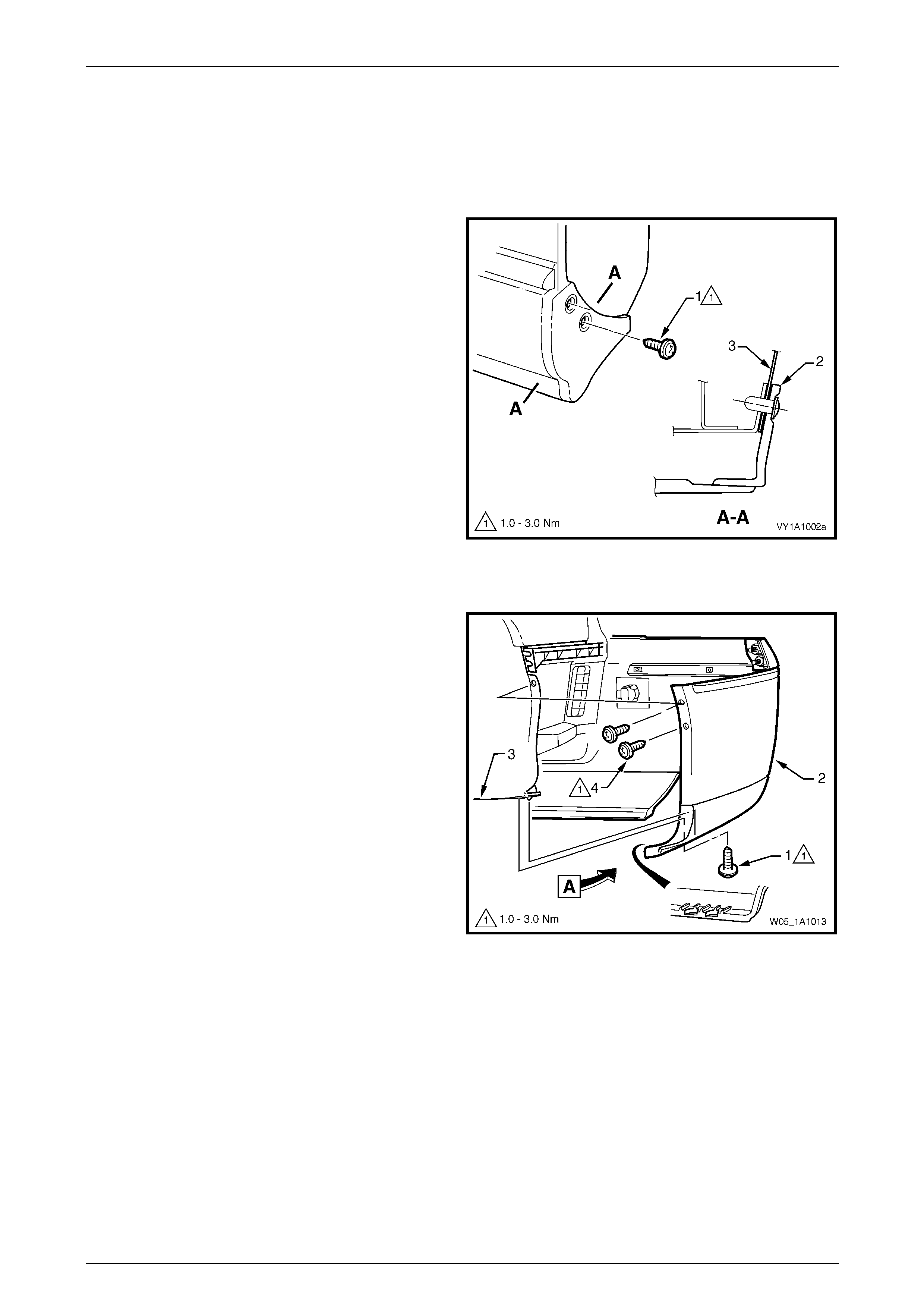
4 To aid removal of the wheelhouse liner partially unclip the bumper fascia from the fascia guide.
5 Referring to Figure 1A1 – 8, remove the retainer (1) and (2) attaching the liner (3) to the wheelhouse panel.
Figure 1A1 – 8
6 Manipulate the liner from behind the rocker panel moulding assembly and bumper fascia, disengage the locating
lug at the base of the liner and remove.
Reinstall
Reinstallation of the rear wheelhouse liner is the reverse of the removal procedure, noting the following:
1 Ensure the liner is correctly located behind the rocker panel moulding assembly and rear bumper fascia assembly.
Refer to Figure 1A1 – 6.
2 Tighten the screws to the correct torque specification.
Rocker panel moulding assembly
attaching screw torque specification ...........1.0 – 3.0 Nm
Rear bumper fascia assembly
attaching screw torque specification ...........1.0 – 3.0 Nm
Body Page 1A1–18
Page 1A1–18
7 Fuel Filler Door Assembly and
Cable Assembly
LT Section No. — 03–028
If the fuel filler door assembly is being
replaced, the warning labels affixed to the
inside of the door must also be replaced.
The fuel filler door assembly is painted the vehicle body colour. A new fuel filler door assembly is supplied unpainted with
the moulding and lock spring unattached. If repainting an existing door, the moulding and lock spring will need to be
removed as described in this procedure. After painting and before reinstallation, the moulding and lock spring must be
fitted as described in this procedure.
Paint the door using the correct materials and techniques for PPE/PA resin (Polyphenylene/Polyamide). As the materials
and techniques required differ between paint brands, refer to the technical data supplied by your paint manufacturer.
7.1 Fuel Filler Door Assembly
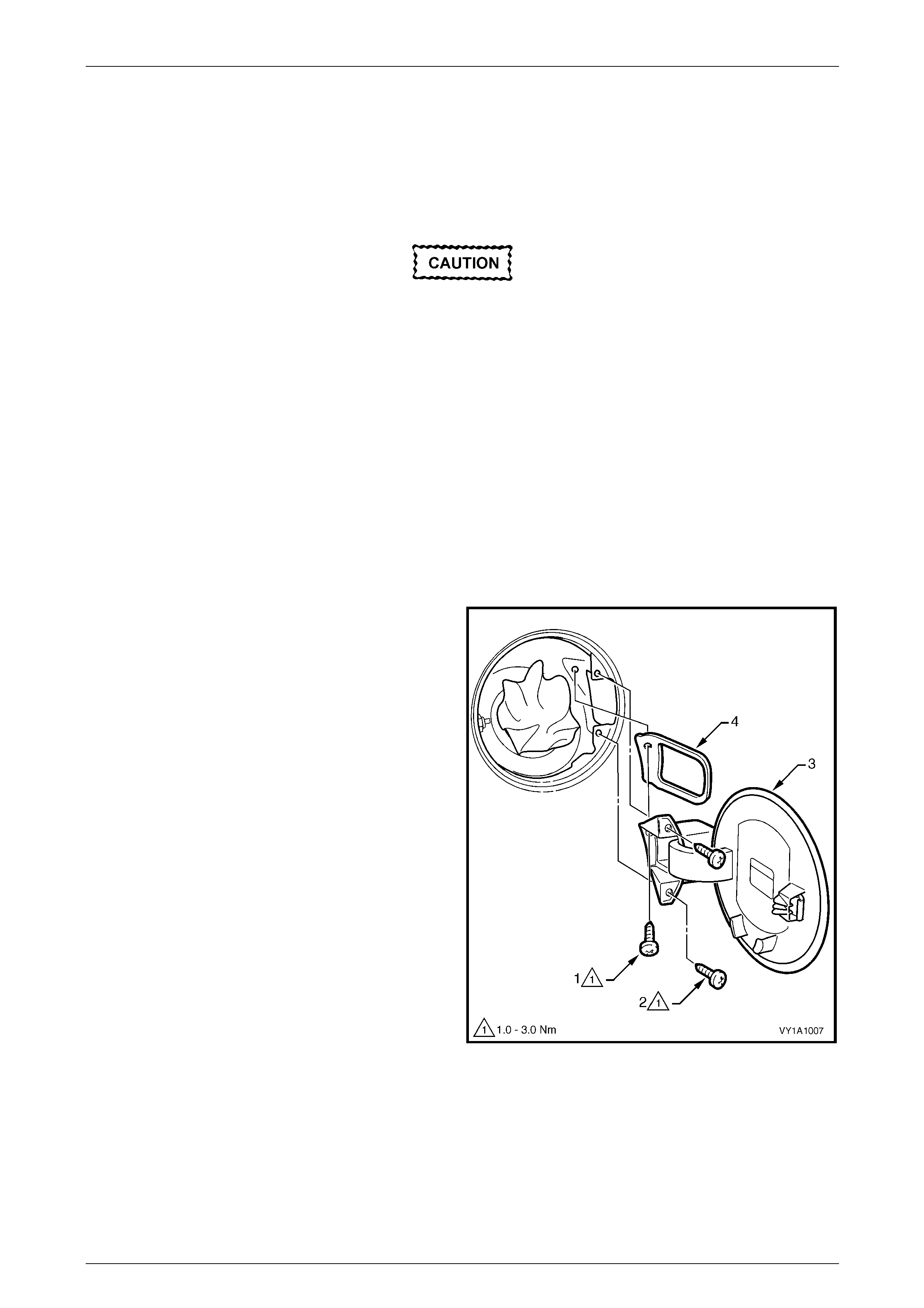
Remove
1 Open the fuel filler door by operating the release lever.
2 Remove the fuel filler cap and cover the opening with
a clean rag as required.
3 Remove the screw (1) and two screws (2), attaching
the fuel filler door assembly (3).
4 Remove the door assembly by withdrawing it rearward,
ensuring the gasket (4) is also removed.
NOTE
When withdrawing the fuel filler door assembly
from the fuel filler pocket, a slight interference
between the rear edge of the plastic hinge
section and the fuel filler neck may occur. In this
instance it will be necessary to flex the rear edge
of the fuel filler door hinge slightly.
Figure 1A1 – 9
Body Page 1A1–19
Page 1A1–19
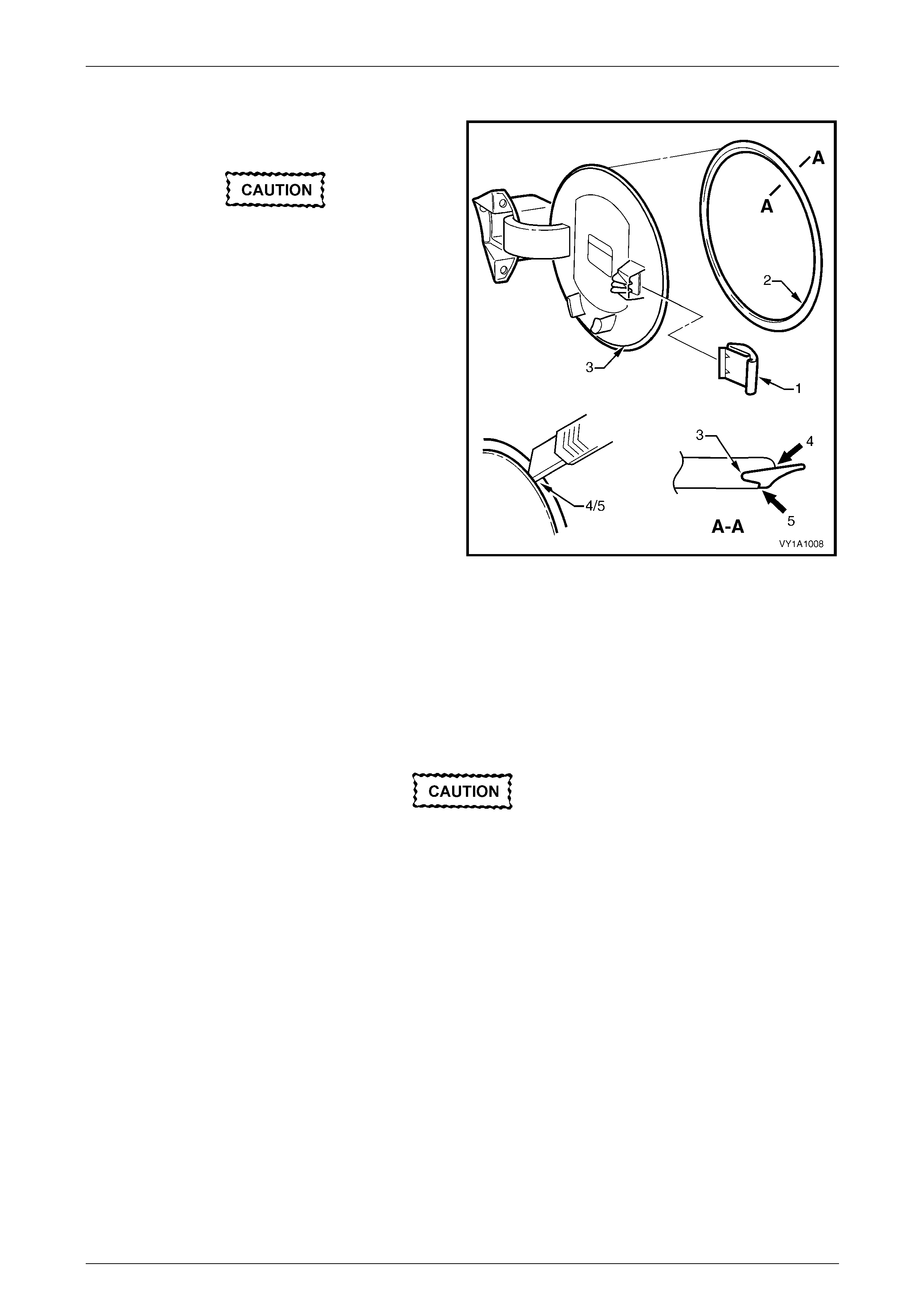
Disassemble
Lock Spring
Take care when removing the lock spring.
The lock spring has several barbs that will
cut into its mounting surface. Take care not
to excessively damage the surface onto
wh ich the lock spring is mounted.
Remove the lock spring (1) by inserting a small screwdriver
and levering the spring outwards.
Moulding
The moulding (2) is seated in the recess (3) around the
circumference of the door and is affixed with superglue gel.
Removal may be difficult, but by carefully peeling the
moulding from the door, it is possible to remove. It will not
be able to be reused.
NOTE
To aid removal, the moulding can be cut around
the inner (4) and outer sides (5) using a sharp
knife. Figure 1A1 – 10
Reassemble
Lock Spring
Push the spring fully onto the mounting tab.
Moulding
Use of superglue can be harmful and can
damage paintwork. Carefully read and follow
all directions and cautions with the product
prior to its use.
1 Carefully apply Loctite 454 (Superglue Gel) or equivalent into the fuel filler door recess around the complete
circumference.
2 Ensuring the moulding is correctly orientated, immediately fit it into the recess and leave the adhesive to cure.
Body Page 1A1–20
Page 1A1–20
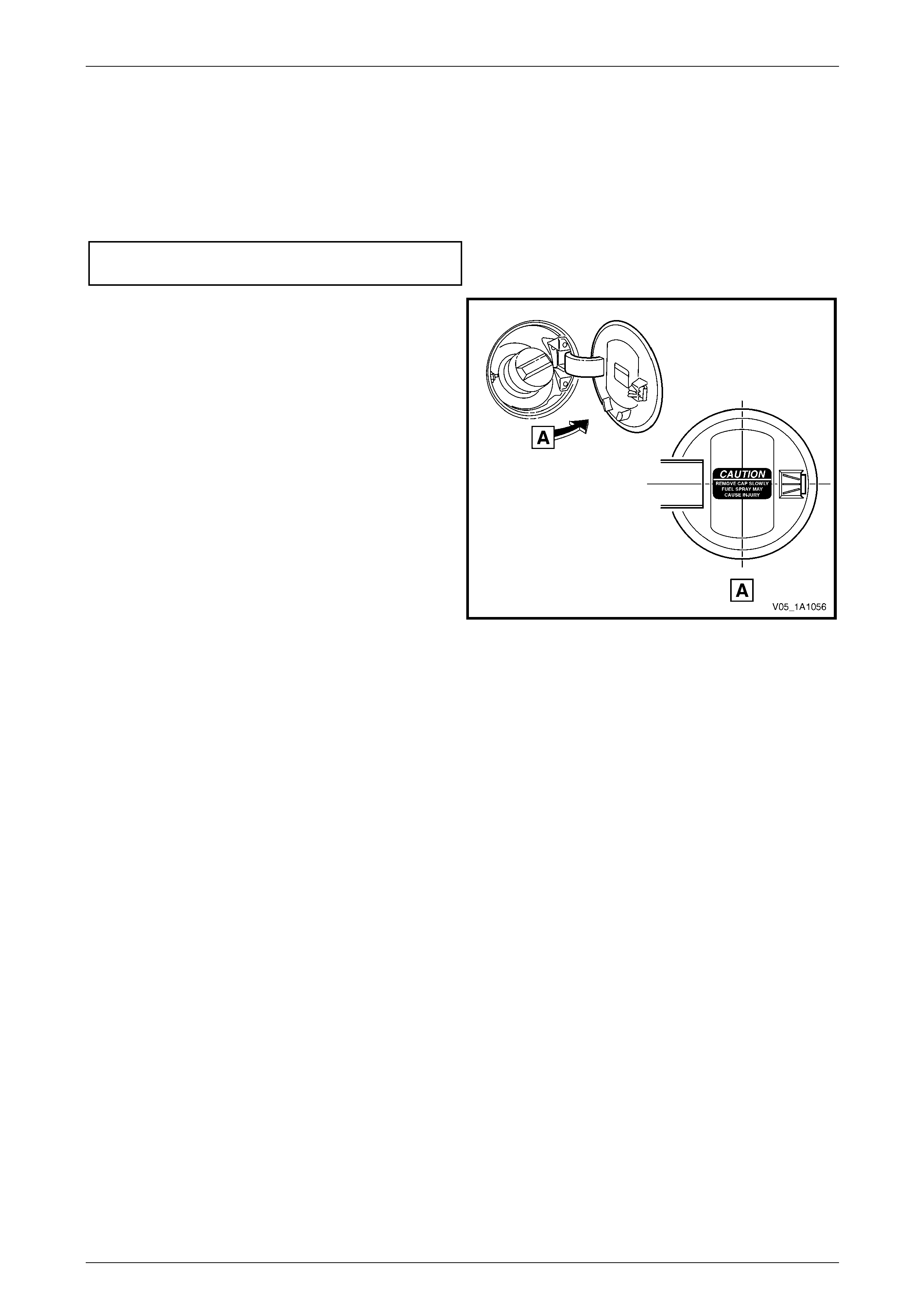
Reinstall
Reinstallation of the fuel filler door assembly is the reverse of the removal procedure, noting the following:
1 If a new door assembly is being installed, or the door has been repainted, install the moulding and lock spring onto
the flap by following the reassemble procedure.
2 Tighten the screws to the correct torque specification.
Fuel filler door assembly attaching screw
torque specification.....................................1.0 – 3.0 Nm
3 If the door has been replaced, apply a new label in the
position shown.
NOTE
Prior to affixing the label, ensure the surface is
clean and dry. Avoid touching the back of the
label.
4 Ensure the fuel filler door closes without the need of
excess force and is flush with the surrounding panel.
Figure 1A1 – 11
Body Page 1A1–21
Page 1A1–21
7.2 Fuel Filler Door Lock Cable Assembly
LT Section No. — 03–028
Remove
1 As required, remove the following components:
a Right-hand side sill trim and quarter inner rear side carpet, refer to Section 1A8 Headlining and Interior Trim.
b Right-hand rear seat-back assembly seat cushion assembly, refer to Section 1A7 Seat Assemblies.
2 Open the fuel filler door by operating the release lever.
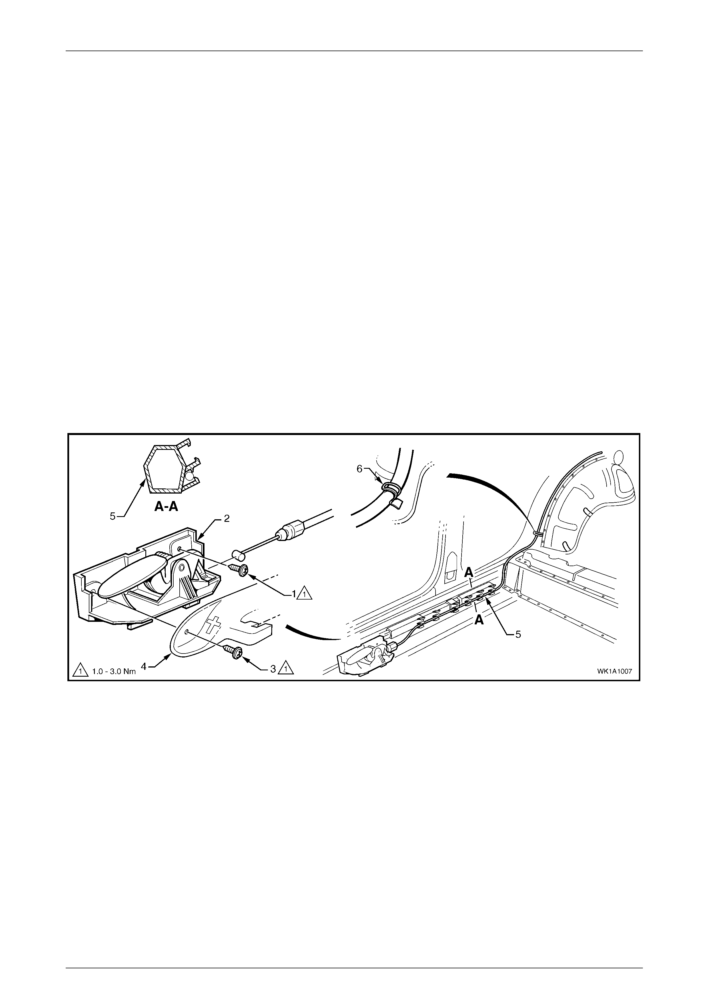
3 From inside the vehicle, remove the screw (1) attaching the cable assembly lever (2) to the rocker panel, refer to
Figure 1A1 – 12.
NOTE
Screw (3) and the front seat outer side cover (4)
should have been removed during step 1, they
are shown here for reference.
4 Unclip the cable from the harness formers (5), six places, and bend the retaining tab (6) to release the cable
assembly.
5 Unclip the cable from the release lever.
Figure 1A1 – 12
Body Page 1A1–22
Page 1A1–22
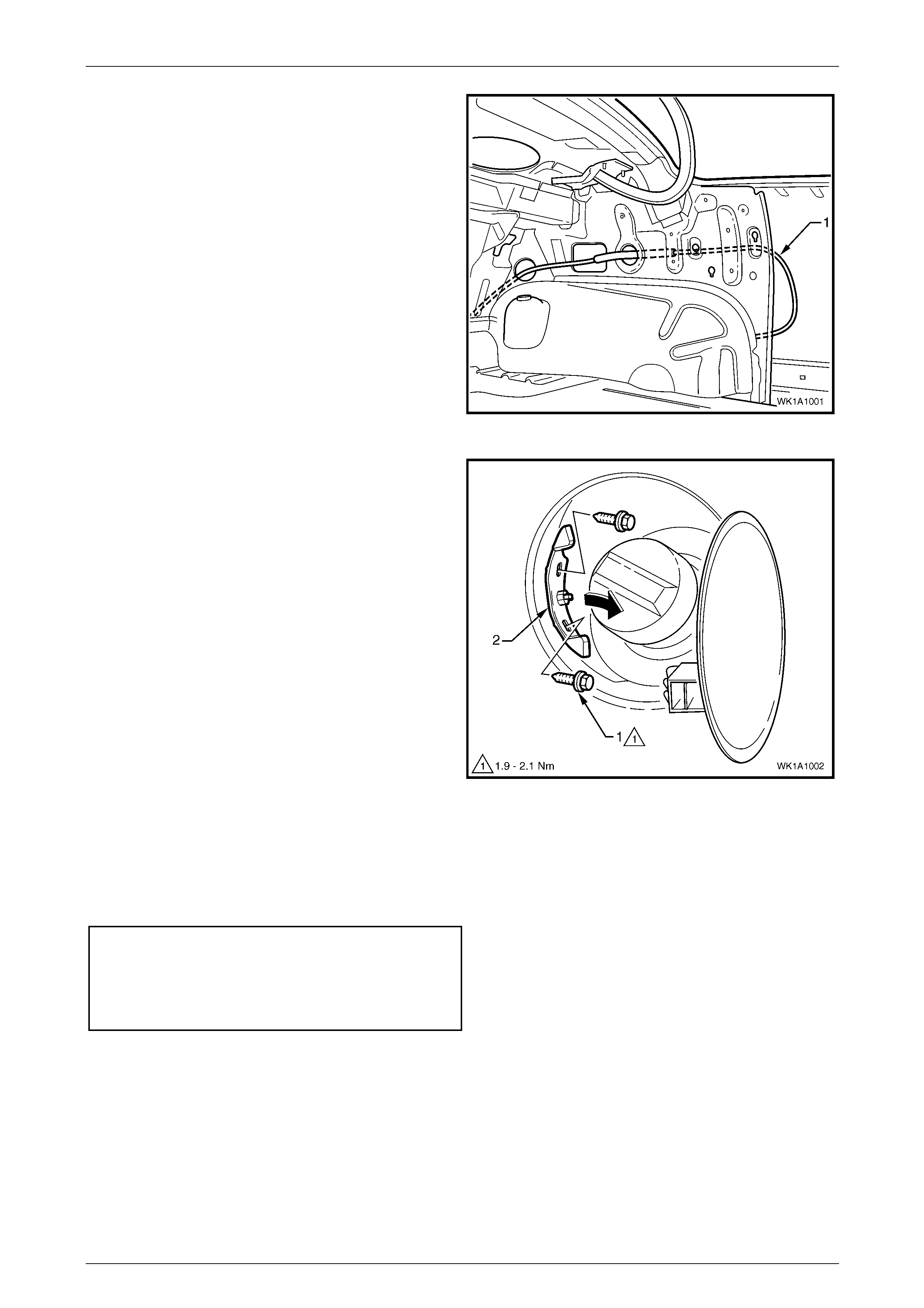
6 Pull the cable (1) through the back panel upper into
the rear compartment.
Figure 1A1 – 13
7 From within the fuel filler housing, remove the two
screws (1) attaching the cable assembly retainer (2).
8 Withdraw the cable assembly from the fuel filler
housing.
Figure 1A1 – 14
Reinstall
Reinstallation of the fuel filler door lock cable assembly is the reverse of the removal procedure, noting the following:
1 Tighten the screws to the correct torque specification.
Fuel filler door lock cable assembly
latch screw torque specification ..................1.9 – 2.1 Nm
Fuel filler door cable assembly
release lever attaching screw
torque specification.....................................1.0 – 3.0 Nm
2 Ensure the cable assembly is routed correctly.
3 Ensure the cable assembly operates correctly and the plunger completely retracts prior to closing the fuel filler door.
If satisfactory, close the door ensuring it does not require excess force. The door should spring ajar when the
release is operated.
Body Page 1A1–23
Page 1A1–23
8 Body Braces
8.1 Front Suspension Strut Brace
Remove
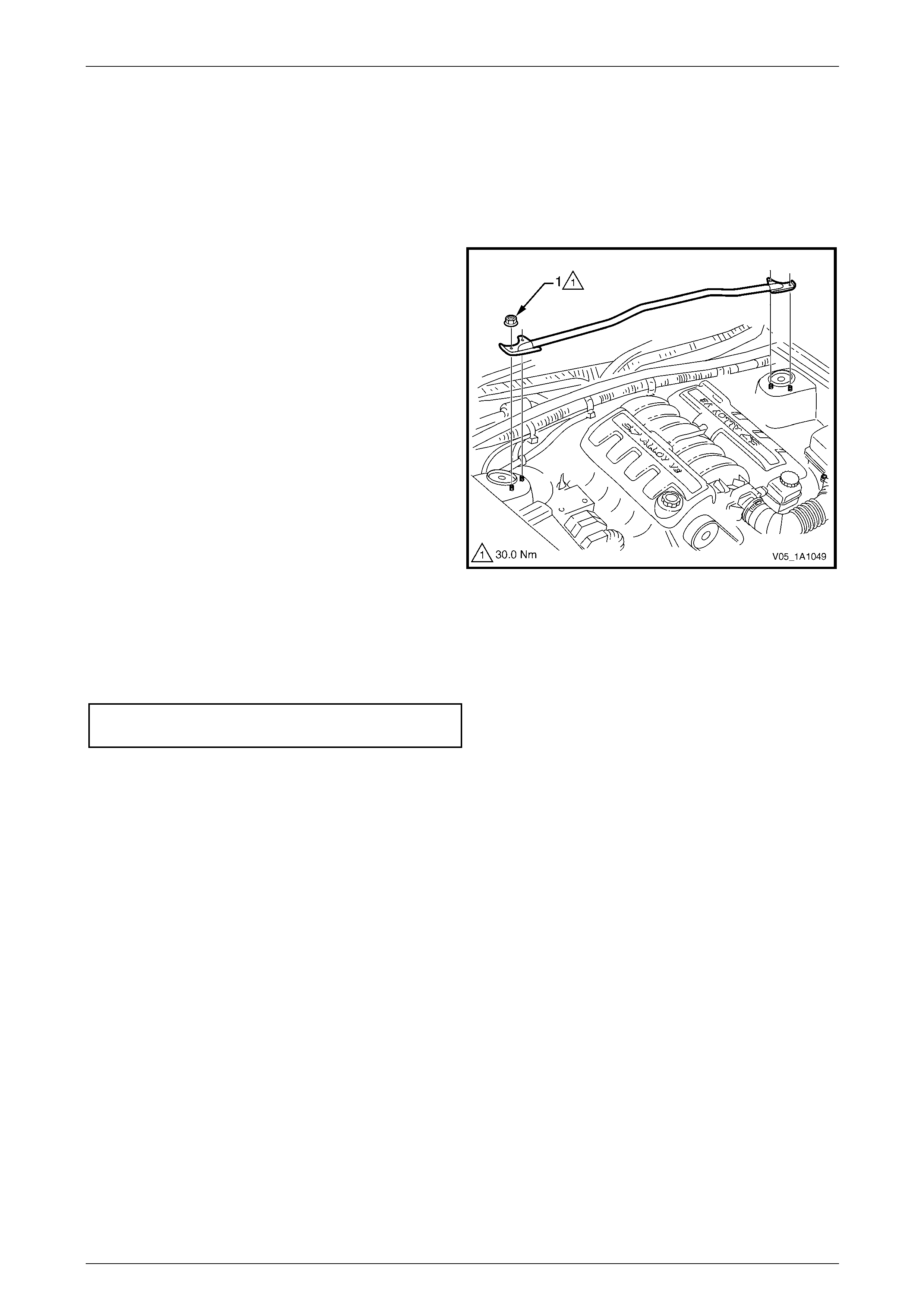
1 Remove the nut (1), four places, attaching the front
suspension strut brace to the suspension strut towers.
2 Remove the brace.
Figure 1A1 – 15
Reinstall
Reinstallation of the front suspension strut brace is the reverse of the removal procedure. Tighten the nuts to the correct
torque specification.
Front suspension strut brace attaching
nut torque specification......................................30.0 Nm

Body Page 1A1–24
Page 1A1–24
9 Torque Wrench Specifications
Front Wheelhouse Liner Attaching Screw....................................1.0 – 3.0 Nm
Front Bumper Fascia Assembly Attaching Screw........................1.0 – 3.0 Nm
Rocker Panel Moulding Assembly Attaching Screw....................1.0 – 3.0 Nm
Rear Bumper Fascia Assembly Attaching Screw ........................1.0 – 3.0 Nm
Fuel Filler Door Assembly Attaching Screw.................................1.0 – 3.0 Nm
Fuel Filler Door Lock Cable Assembly Latch Attaching Screw.... 1.9 – 2.1 Nm
Fuel Filler Door Cable Assembly Release Lever
Attaching Screw...........................................................................1.0 – 3.0 Nm
Front Suspension Strut Brace Attaching Nut......................................30.0 Nm