
Headlining and Interior Trim Page 1A8–1
Page 1A8–1
Section 1A8
Headlining and Interior Trim
ATTENTION
Before performing any service operation or other procedure described in this Section, refer to Section 00
Warnings, Cautions and Notes for correct workshop practices with regard to safety and/or property damage.
1 General Information ...............................................................................................................................3
1.1 Description............................................................................................................................................................. 3
2 Service Operations.................................................................................................................................4
2.1 Components Chart................................................................................................................................................. 4
2.2 Assist Handle Assembly ....................................................................................................................................... 6
Remove................................................................................................................................................................... 6
Reinstall.................................................................................................................................................................. 6
2.3 Centre Pillar Lower Trim ....................................................................................................................................... 7
Remove................................................................................................................................................................... 7
Reinstall.................................................................................................................................................................. 7
2.4 Centre Pillar Upper Trim Assembly...................................................................................................................... 8
Remove................................................................................................................................................................... 8
Reinstall.................................................................................................................................................................. 8
2.5 Outer Rocker Panel Cover Assembly................................................................................................................... 9
Remove................................................................................................................................................................... 9
Reinstall.................................................................................................................................................................. 9
2.6 Side Sill Trim and Plate....................................................................................................................................... 10
Remove................................................................................................................................................................. 10
Reinstall................................................................................................................................................................ 10
2.7 Windshield Side Garnish..................................................................................................................................... 11
Remove................................................................................................................................................................. 11
Reinstall................................................................................................................................................................ 11
2.8 Body Hinge Pillar Trim Assembly....................................................................................................................... 12
Remove................................................................................................................................................................. 12
Reinstall................................................................................................................................................................ 12
2.9 Body Lock Pillar Lower Trim............................................................................................................................... 13
Remove................................................................................................................................................................. 13
Disassemble......................................................................................................................................................... 14
Reassembly.......................................................................................................................................................... 14
Reinstall................................................................................................................................................................ 14
2.10 Body Lock Pillar Garnish .................................................................................................................................... 15
Remove................................................................................................................................................................. 15
Reinstall................................................................................................................................................................ 15
2.11 Rear Window Trim Panel Assembly................................................................................................................... 16
Remove................................................................................................................................................................. 16
Disassemble......................................................................................................................................................... 17
Reassemble.......................................................................................................................................................... 17
Reinstall................................................................................................................................................................ 17
2.12 Convenience Net.................................................................................................................................................. 18
Remove................................................................................................................................................................. 18
Reinstall................................................................................................................................................................ 18
2.13 Rear End Trim Panel Assembly.......................................................................................................................... 19
Remove................................................................................................................................................................. 19
Reinstall................................................................................................................................................................ 19

Headlining and Interior Trim Page 1A8–2
Page 1A8–2
2.14 Sunshade Assembly............................................................................................................................................ 20
Remove................................................................................................................................................................. 20
Reinstall................................................................................................................................................................ 20
2.15 Roof Console........................................................................................................................................................ 21
Remove................................................................................................................................................................. 21
Reinstall................................................................................................................................................................ 21
2.16 Headlining Assembly........................................................................................................................................... 22
Remove................................................................................................................................................................. 22
Reinstall................................................................................................................................................................ 24
2.17 Driver Footrest..................................................................................................................................................... 25
Remove................................................................................................................................................................. 25
Reinstall................................................................................................................................................................ 25
2.18 Front Floor Carpet Assembly.............................................................................................................................. 26
Remove................................................................................................................................................................. 26
Reinstall................................................................................................................................................................ 27
2.19 Rear Compartment Floor Panel Carpet Assembly............................................................................................ 28
Remove................................................................................................................................................................. 28
Disassemble......................................................................................................................................................... 28
Reassemble.......................................................................................................................................................... 28
Reinstall................................................................................................................................................................ 28
2.20 Quarter Inner Rear Side Carpet .......................................................................................................................... 29
Remove................................................................................................................................................................. 29
Left-Hand Side Carpet...................................................................................................................................... 29
Right-Hand Side Carpet................................................................................................................................... 29
Reinstall................................................................................................................................................................ 30
Left-Hand Side Carpet...................................................................................................................................... 30
Right-Hand Side Carpet................................................................................................................................... 31
2.21 Rear Seat Back Panel Carpet.............................................................................................................................. 32
Remove................................................................................................................................................................. 32
Reinstall................................................................................................................................................................ 32
2.22 Spare Wheel Well Container ............................................................................................................................... 33
Remove................................................................................................................................................................. 33
Reinstall................................................................................................................................................................ 33
3 Clearances Specifications...................................................................................................................34
3.1 Interior Trim Clearances...................................................................................................................................... 34
4 Torque Wrench Specifications............................................................................................................35

Headlining and Interior Trim Page 1A8–3
Page 1A8–3
1 General Information
1.1 Description
This Section describes the trim panels and garn ishes fitted to the bod y interior as well as the headlining and carpets.
For the trim fitted to the doors and rear compartment lid, refer respectively to
Section 1A5 Front and Rear D oor Assemblies and
Section 1A4 Hood, Rear Compartment Lid, Liftgate and Endgate.
For the instrument panel and console components, refer to Section 1A3 Instrument Panel and Console.
A complete overview of all trim components is covered by this Section, the components are illustrated and identified at
the start of the service operations Section, an illustration is also provided for interior trim clearances specifications.
NOTE
When working on the interior trim, clean hands
are essential and protective covering must be
placed over the interior trim.
For accurate installation and mating of ad jacent components, a locating pin is a feature of some trims, panels and
garnishes. Care must be taken not to damage the locating pin when removing and installing these components.
On some models, the centre pillar upper trim features a front seat belt sash height adjuster cover.
On high level equipment models, the rear window trim panel assembly features radio speaker grilles and two headphone
Jack connectors.
The sunshade features a vanity mirror and on high level equipment models, an illuminated vanity mirror with cover.
The roof console features t wo map lamps, a concealed sunglasses holder and where fitted, a sunroof switch.
The headlining is of the one-p iece mo ulded type with cut-outs as applicable for the fitment of the roof console or the
dome lamp, the sunroof assembly, two illuminated vanity mirrors and two roof mounted radio speakers. The rear of the
headlining is attached to the roof using hook and loop type fasteners.
The following headlining variations are available:
• Level 4 vehicles without or with a sunroof, these vehicles have a roof console fitted near the front of the headlining.
• Level 5 vehicles without or with a sunroof, these vehicles have a roof console fitted near the front of the headlining
and near the rear, two illuminated vanity mirrors and two roof mounted radio speakers.
When a sunroof is fitted, two configurations ma y occur:
• If an online sunroof is fitted, it can be identified by the absence of a rubber trim ring between the sunroof and the
roof panel. A rigid headlining with a cut-out for the fitment of the sunroof is installed and it can be removed using
the normal procedure.
• If a Holden By Design (HBD) sunroof is fitted, it can be identified by the presence of a rubber trim ring between the
sunroof and the roof panel. A new headlinin g is created using pieces of the original headl ining and a new piece of
cloth, the headlining is then installed with adhesive. Removal may damage the headlining and extreme care is
required.
NOTE
If a HBD sunroof is fitted, service procedures are
not covered in this Section and a new headlining
may have to be manufactured by a motor
trimmer.
The front floor carpet assembly features perforatio ns at the front edge to fa cilitate the removal and installation procedur e.
The rear seat back panel carp et features an opening for a ski hatch.
In the rear compartment, the right-hand quarter inner rear side carpet incorporates a power socket in one of two different
locations depending on the model Level of the vehicle:
• Level 4 vehicles, the power socket is supported b y a brack et off the sheetmetal.
• Level 5 vehicles, the power socket is attached to the top of the DVD amplifier.
With Level 5 vehicles, the right-hand qu arter inner rear side carpet has a different shape to allow for the DVD amplifier
that is fitted behind the carpet in the rear right-hand corner o f the rear compartment. The left-hand quarter inner rear side
carpet is the same for all vehicle Levels.
Headlining and Interior Trim Page 1A8–4
Page 1A8–4
2 Service Operations
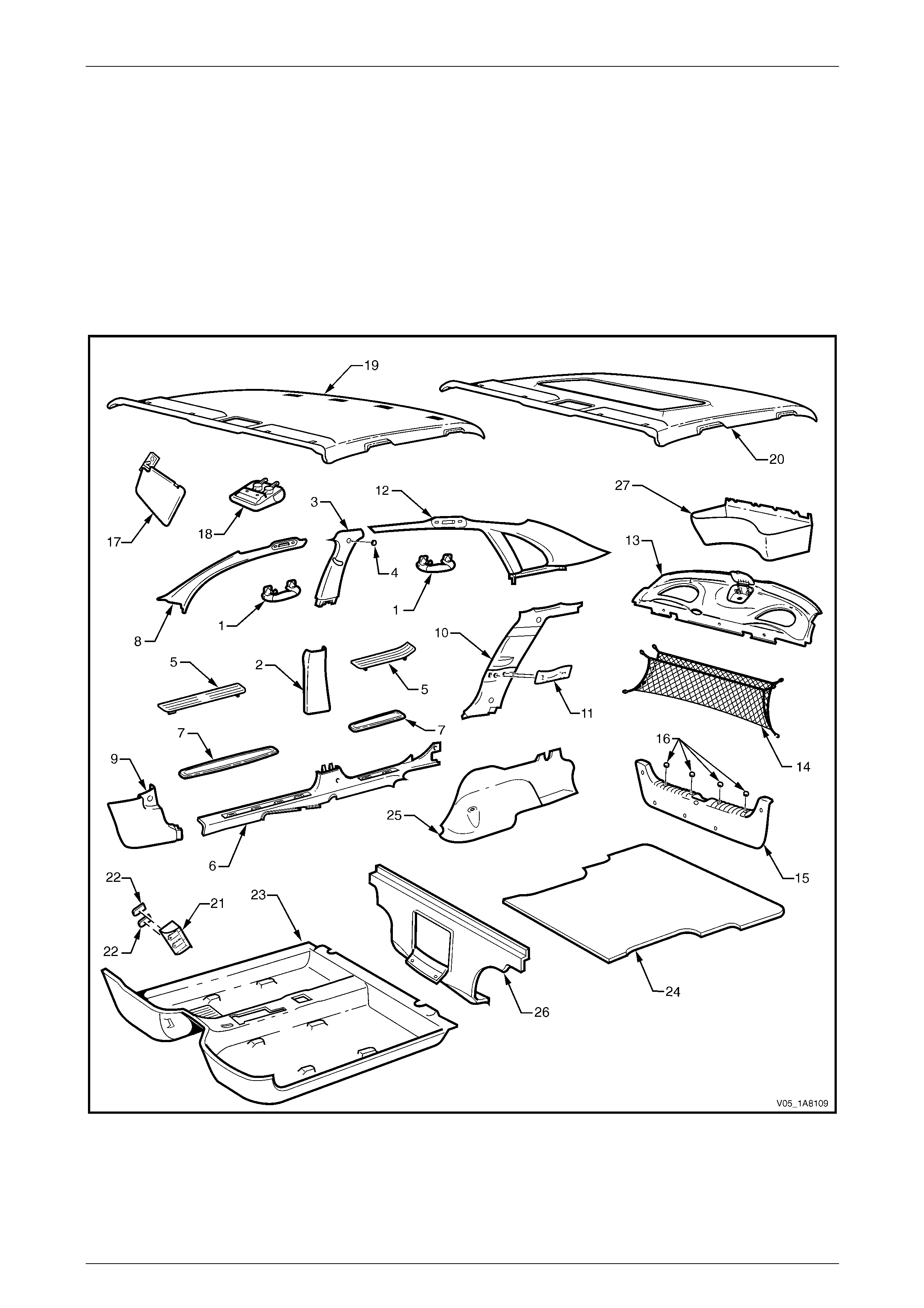
2.1 Components Chart
The headlining and interior trim components are displaye d in the following chart to assist with their identification,
refer to Figure 1A8 – 1.
For the service procedures of the rear compartment lid carpet,
refer to Section 1A4 Hood, Rear Compartment Lid, Liftgate and Endgate.
For the service procedures of the front and re ar door trim panel assemblies,
refer to Section 1A5 Front and Rear Door Assemblies.
Figure 1A8 – 1

Headlining and Interior Trim Page 1A8–5
Page 1A8–5
Legend
1 Assist Handle Assembly
2 Centre Pillar Lower Trim
3 Centre Pillar Upper Trim Assembly
4 Screw Cap
5 Outer Rocker Panel Cover Assembly
6 Side Sill Trim
7 Side Sill Trim Plate
8 Windshield Side Garnish
9 Body Hinge Pillar Trim Assembly
10 Body Lock Pillar Lower Trim Assembly
11 Cap Assembly
12 Body Lock Pillar Garnish
13 Rear Window Trim Panel Assembly
14 Convenience Net
15 Rear End Trim Panel Assembly
16 Screw Caps
17 Sunshade Assembly
18 Roof Console
19 Headlining Assembly (without sunroof, with roof console)
20 Headlining Assembly (with sunroof and roof console)
21 Driver Footrest
22 Screw Cap
23 Front Floor Carpet Assembly
24 Rear Compartment Floor Panel Carpet Assembly
25 Quarter Inner Rear Side Carpet
26 Rear Seat Back Panel Carpet
27 Spare Wheel Well Container
Headlining and Interior Trim Page 1A8–6
Page 1A8–6
2.2 Assist Handle Assembly
LT Section — 14–100
Remove
NOTE
This procedure is app licable to the front and rear
assist handle assemblies.
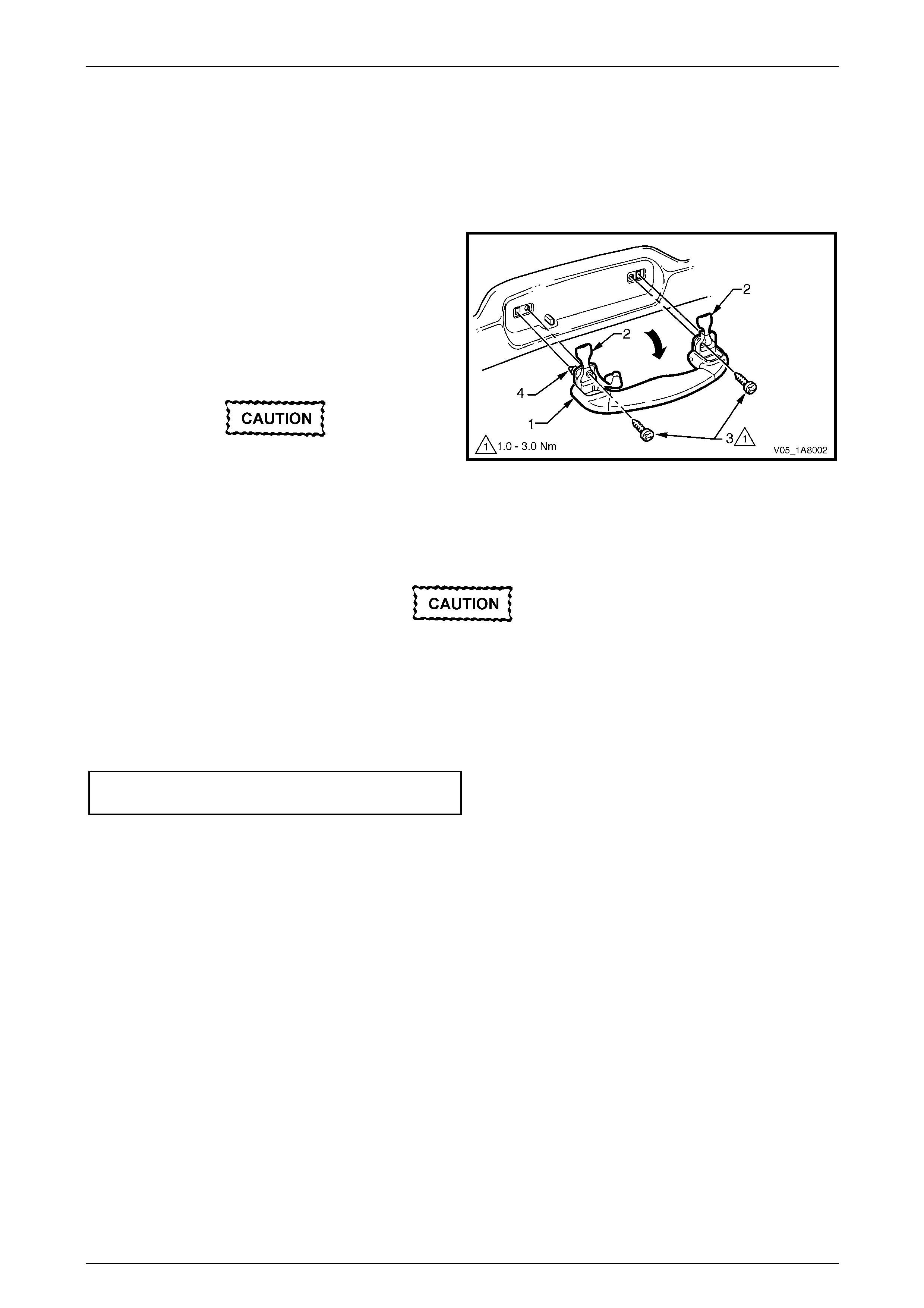
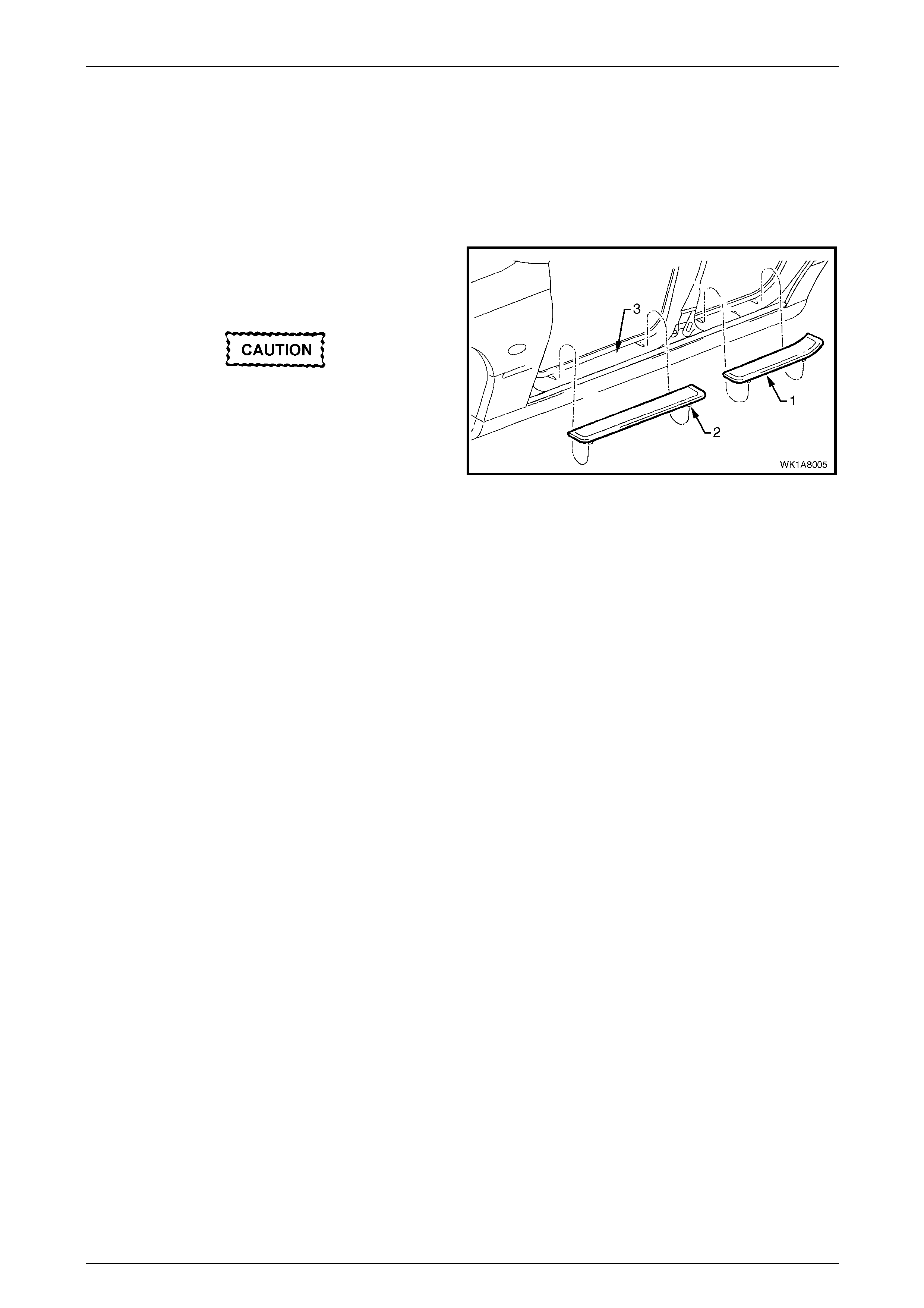
1 Pull the assist handle (1) into the down position.
2 Prise open the assist handle two screw covers (2) and
remove the two attaching screws (3).
When removing the assist handle assembly,
take care not to damage the locating pin s (4).
3 Remove the assist handle assembly.
Figure 1A8 – 2
Reinstall
Take care not to damage the locating pin
when fitting the assist handle assembly.
1 Ensure the locating pins are correctl y align ed with the locating holes.
2 Position the hook over the locating pin.
3 Tighten the assist handle two attaching screws to the correct torque specification.
Assist handle attaching screw
torque specification.....................................1.0 – 3.0 Nm
Headlining and Interior Trim Page 1A8–7
Page 1A8–7
2.3 Centre Pillar Lower Trim
LT Section — 14–100
Remove
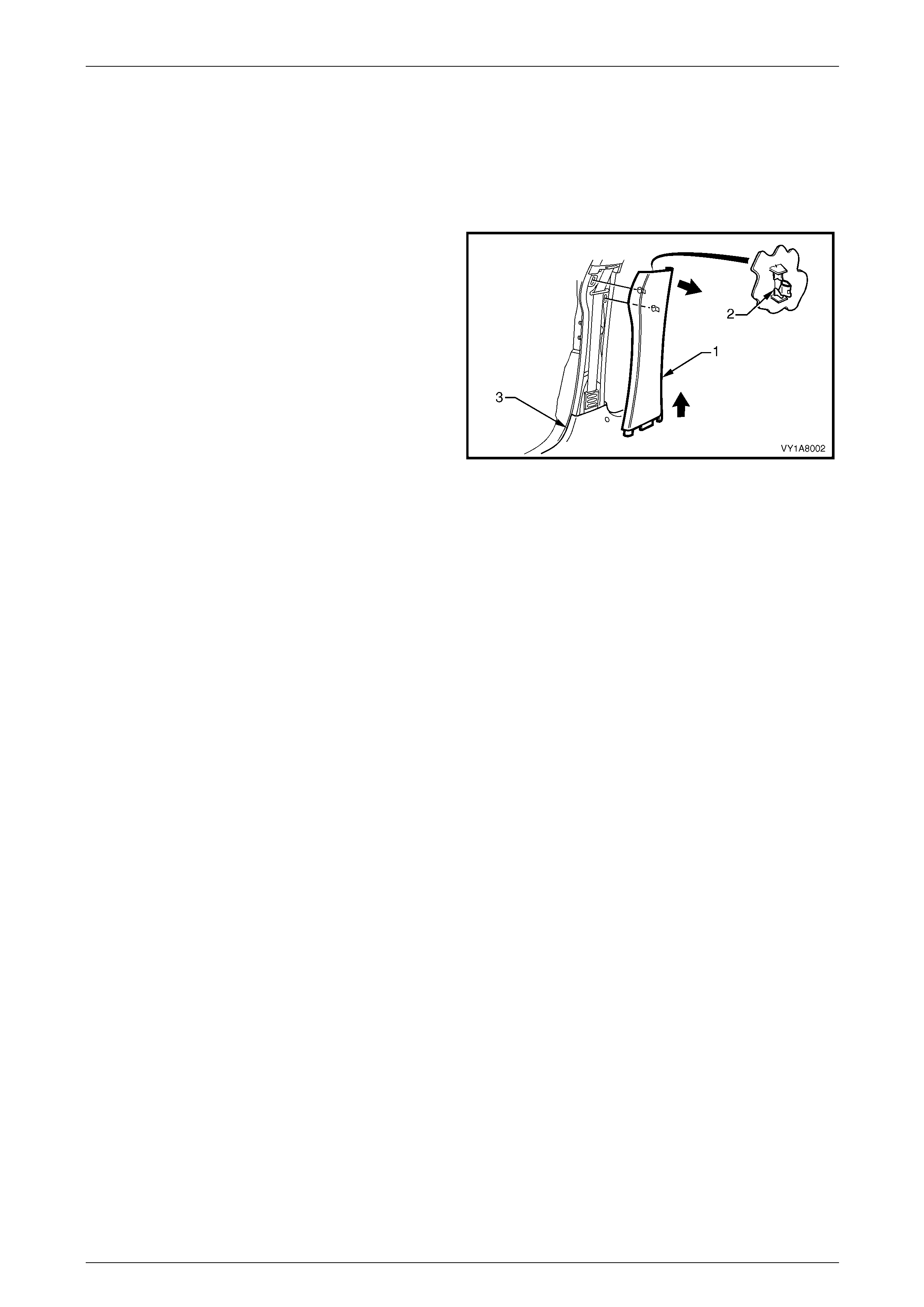
1 Using your fingers, lever the top of the centre pill ar
lower trim (1) away from the front door opening
weatherstrip and pull the trim to ward the centre of the
car, disengaging the two retaining clips (2).
2 Lift the centre pillar lower trim upward, out of the side
sill trim (3) and remove.
3 As required, remove the retaining clips from the
vehicle and fit to the trim.
Figure 1A8 – 3
Reinstall
1 Locate the centre pillar lo wer trim (1) into the side sill trim (3), refer to Figure 1A8 – 3.
2 Locate the two retaining clips (2) into their slots in the centre pillar, then push in firmly ensuring the two clips are
secured to the centre pillar.
3 Ensure the front and rear door opening weatherstrips fit neatly over the outer edges of centre pillar lower trim.
Headlining and Interior Trim Page 1A8–8
Page 1A8–8
2.4 Centre Pillar Upper Trim Assembly
LT Section — 14–100
Remove
1 Remove the following components as required:
a Remove the centre pillar lower trim, refer to 2.3 Centre Pillar Lo wer Trim.
b Remove the front seat belt lower bolt, refer to Section 12M Occupant Prot ection System.
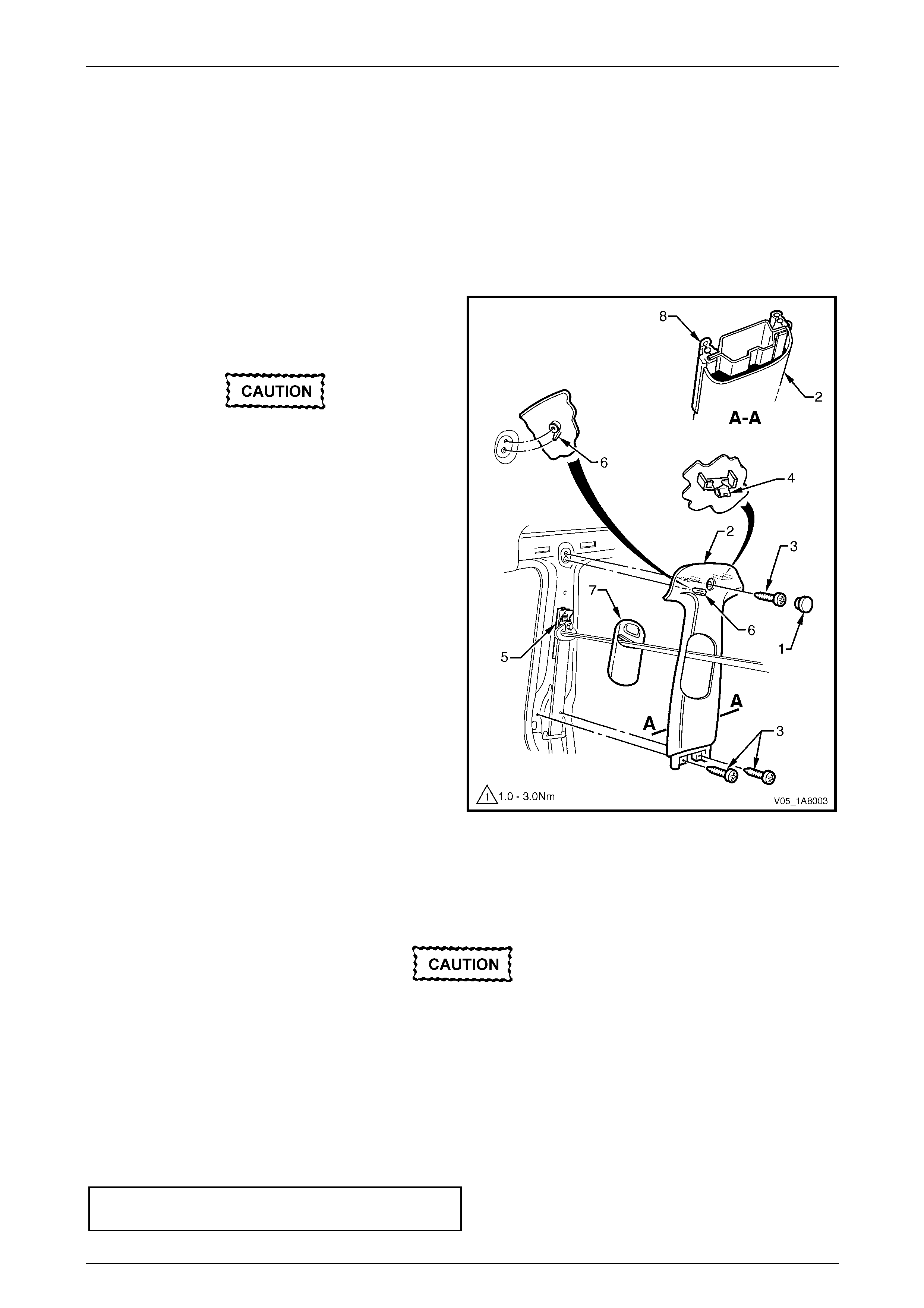
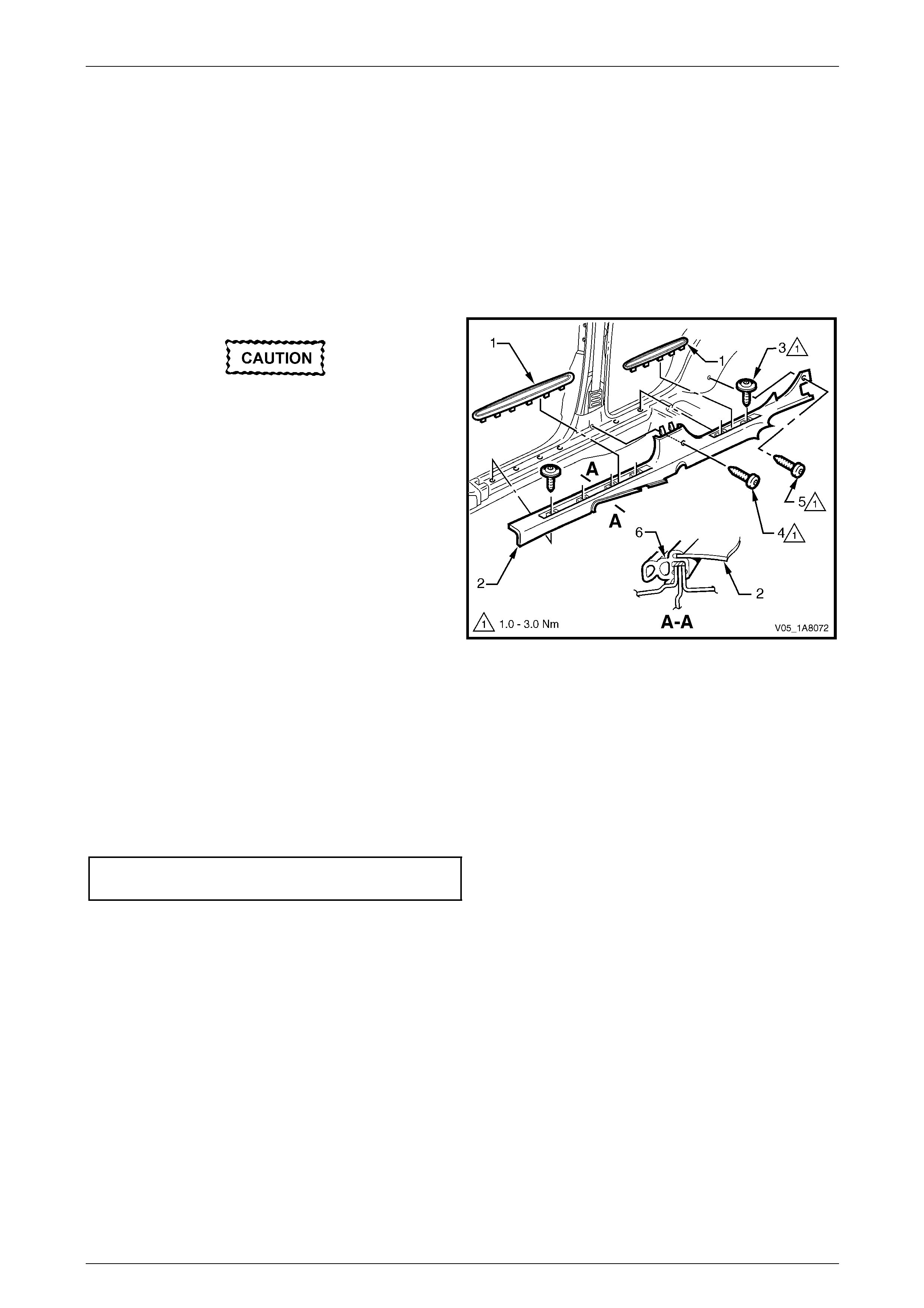
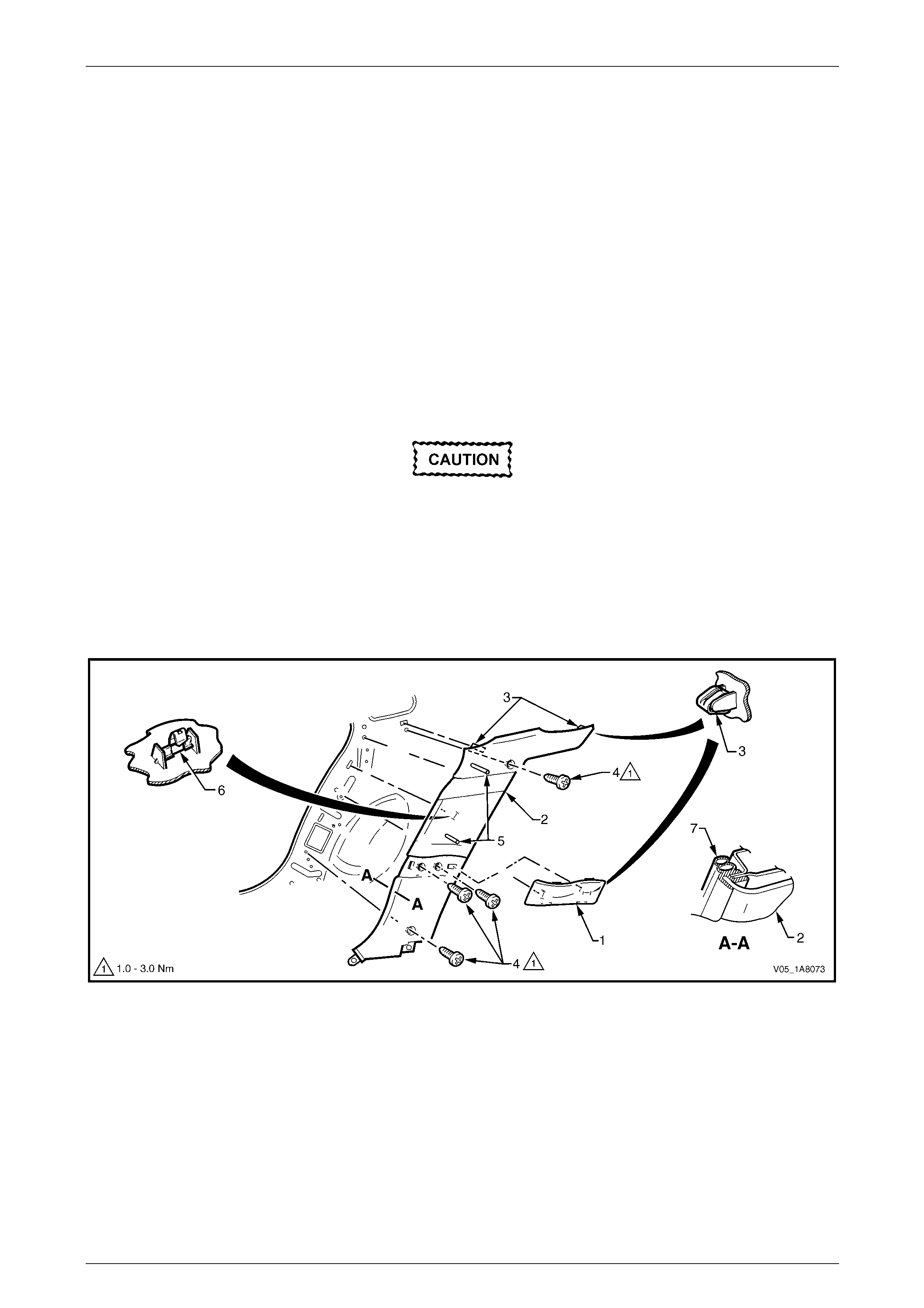
2 Remove the screw cap (1) from the upper attachment
of the centre pillar upper trim assembly (2).
3 Remove the three screws (3) attaching the centre
pillar upper trim assembly.
When removing the centre pillar upper trim
assembly, take care not to damage the
locating pin (6) below the upper attaching
screw position.
4 Pull the upper edge of the centre pillar upper trim
assembly away from the headlining assembly to
disengage the two retaining clips (4) and the seatbelt
guide adjuster assembly (5).
5 Feed the seatbelt and anchor plate thro ugh the centre
pillar upper trim assembly and remove the centre pillar
upper trim assembly.
6 If required, remove the seatbelt adjuster trim (7) by
gently spreading the outer edges of the centre pillar
upper trim assembly and lifting out the seatbelt
adjuster trim.
7 As required, remove the retaining clips from the
vehicle and fit to the trim.
Figure 1A8 – 4
Reinstall
Reinstallation of the centre pillar upper trim assembly is the reverse of the removal procedure, noting the following:
1 Ensure the seatbelt adjuster trim (7) and the seatbelt guide adjuster assembly (5) are in the fully up p osition and
are correctly aligned prior to installing the centre pillar upper trim assembly (2), refer to Figure 1A8 – 4.
Take care not to snap off the locating pin
when fitting the centre pillar upper trim
assembly.
2 Ensure the locating pin belo w the upper attaching screw position in the centre pillar upper trim assembly is correctly
aligned with the locating hole in the centre pillar.
3 Ensure the centre pillar upper trim assembl y two retaining clips are secured to the centre pillar.
4 Ensure the leading edge of the centre pillar upper trim assembly engages the front door opening weatherstrip
assembly (8).
5 Check the seatbelt operation prior to tightening the centre pillar upper trim assembly attaching screws.
6 Tighten the centre pillar uppe r trim assembly three attaching screws to the specified torque.
Centre pillar upper trim assembly
attaching screw torque specification...........1.0 – 3.0 Nm
Headlining and Interior Trim Page 1A8–9
Page 1A8–9
2.5 Outer Rocker Panel Cover Assembly
LT Section — 14–100
Remove
1 Protect the paint and bodywork with tape or a rag.
2 To facilitate the removal process, warm the outer
rocker panel cover assembly (1) with a heat-lamp or
heat-gun to soften the adhesive of the double-sided
tape.
Take care not to cut the two locating tabs (2)
if the outer rocker panel co ver assembly is to
be reused.
3 Using a knife or paint scraper, carefully separate the
outer rocker panel cover assembly from the door
opening frame (3) and remove.
4 As required, remove any rem aining double-sided tape
from the door opening frame.
Figure 1A8 – 5
Reinstall
1 If reinstalling the existing outer rocker panel cover assembly, remove the used double-sided tape and clean the
surface with a wax and grease remover such as Prepsol or equivalent, then apply new polyethylene double-sided
tape such as 3M 4428 or equivalent.
2 Clean the contact surface of the door opening frame with a wax and grease remover such as Prepsol or equivalent.
3 Remove the backing paper from the double-s ided tape.
4 Align the tabs on the outer rocker panel cover assembly with the holes in the door opening frame.
5 Affix the outer rocker panel co ver assembly and press firmly over the entire surface for at least 10 seconds to
ensure sound adh esion.
Headlining and Interior Trim Page 1A8–10
Page 1A8–10
2.6 Side Sill Trim and Plate
LT Section — 14–100
Remove
1 Remove the following components as required:
a Centre pillar lower trim, refer to 2.3 Centre Pillar Lower Tr im.
b Front seat outer front cover and outer rear cover, refer to Section 1A7 Seat Assemblies.
During the following procedure take care not
to snap the sill trim plates.
2 Carefully lever the front and rear side si ll trim
plates (1) from the side sill trim (2), starting at the front
of each plate and moving rearward.
3 Remove the Torx screw (3), six places, attachin g the
side sill trim, four in the front door opening an d two in
the rear door opening.
4 Remove the Torx screw (4) attaching the side sill trim
to the centre pillar.
5 Remove the Torx screw (5) attaching the side sill trim
to the body lock pillar lower trim.
6 Remove the side sill trim through the front door
opening by lifting the front and sliding the rear out from
under the rear seat cushion.
Figure 1A8 – 6
Reinstall
Reinstallation of the side sill trim and plate is the reverse of the removal procedure, noting the following:
1 Ensure the outer edge of the side sil l trim (2) enga ges the front and rear door opening weatherstrips (6),
refer to Figure 1A8 – 6.
2 Tighten the Torx screws attaching the side sill trim to the correct torque specification.
Side sill trim attaching Torx screw
torque specification.....................................1.0 – 3.0 Nm
Headlining and Interior Trim Page 1A8–11
Page 1A8–11
2.7 Windshield Side Garnish
LT Section — 14–100
Remove
1 Remove the following components as required:
a Front assist handle assembly, refer to 2.2 Assist Handle Assembly.
b Partially remove the centre pill ar upper trim assembly by removing the upper attaching screw, refer to
2.4 Centre Pillar Upper Trim Assembly.
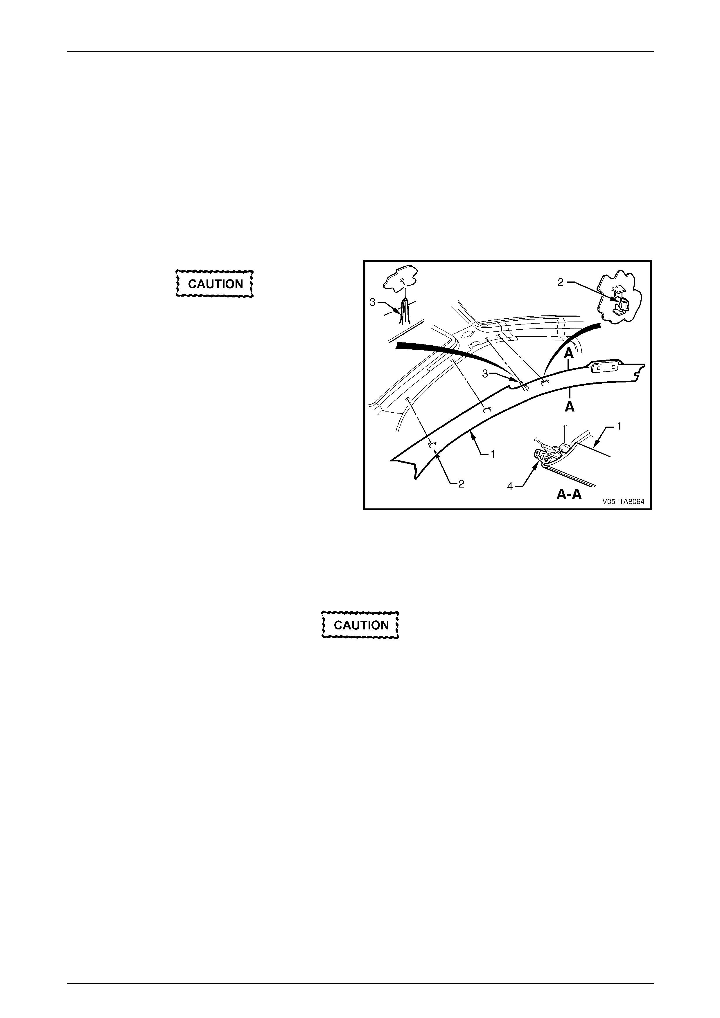
When removing the windshield side garnish,
take care not to damage the locating pin (3).
2 Starting at the upper rear edge of the windshield side
garnish (1) disengage the three retai nin g clips (2).
3 Remove the windshield side garnish.
4 As required, remove the retaining clips from the
vehicle and fit to the garnish.
Figure 1A8 – 7
Reinstall
Reinstallation of the windshield side garnish is the reverse of the removal procedure, noting the following:
Take care not to snap off the locating pin
when fitting the windshield side garnish.
1 Ensure the windshield side ga rnish locating pin is aligned with the locating hole in the hinge pillar inner panel.
2 Ensure the outer edge of the winds hield side garnish (1) engages the front door op ening weatherstrip (4),
refer to Figure 1A8 – 7.
3 Ensure the three retaining clips are secured to the hinge pillar inner panel.
Headlining and Interior Trim Page 1A8–12
Page 1A8–12
2.8 Body Hinge Pillar Trim Assembly
LT Section — 14–100
Remove
1 Partially remove the side sill trim, refer to 2.6 Side Sill Trim and Plate.
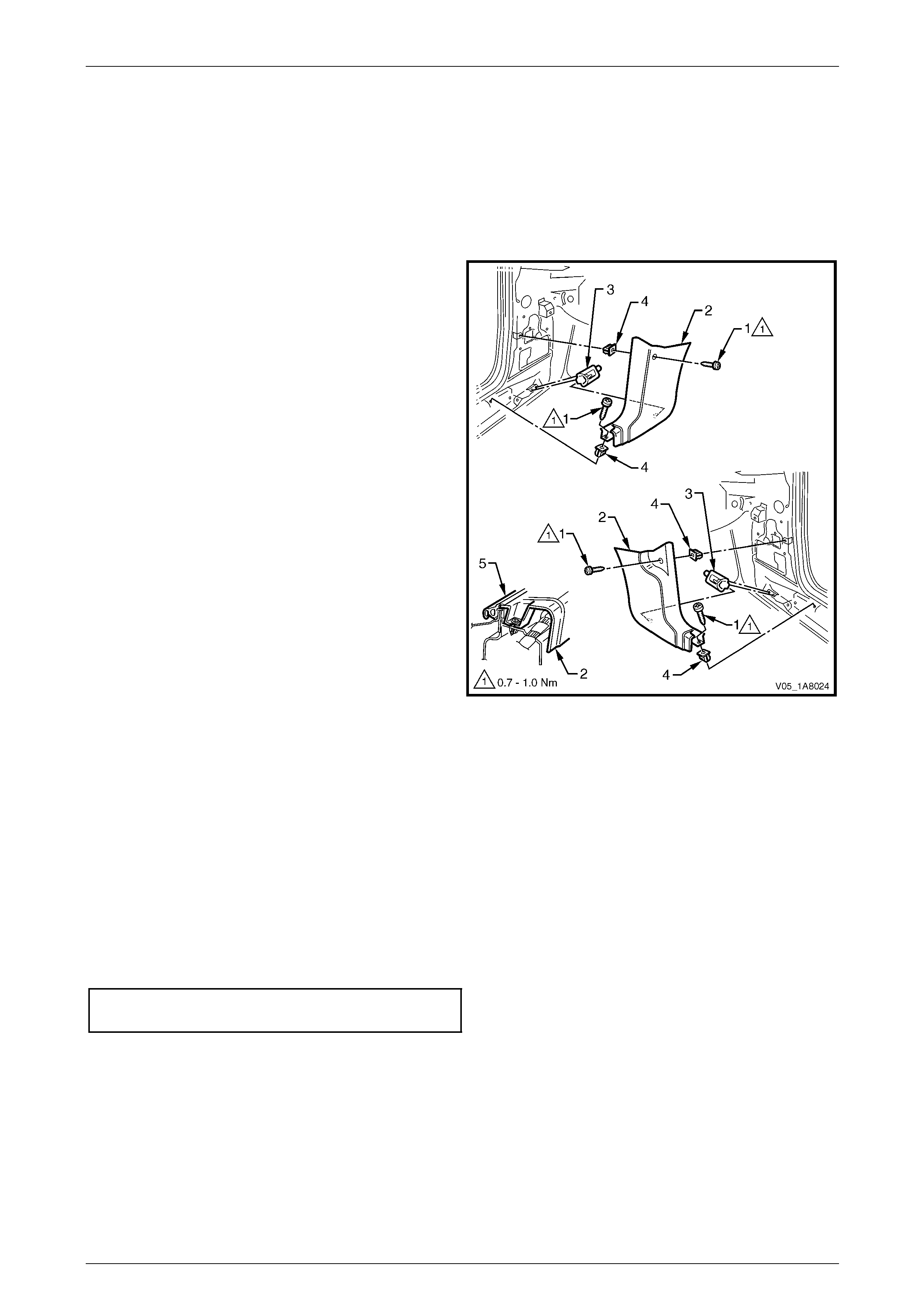
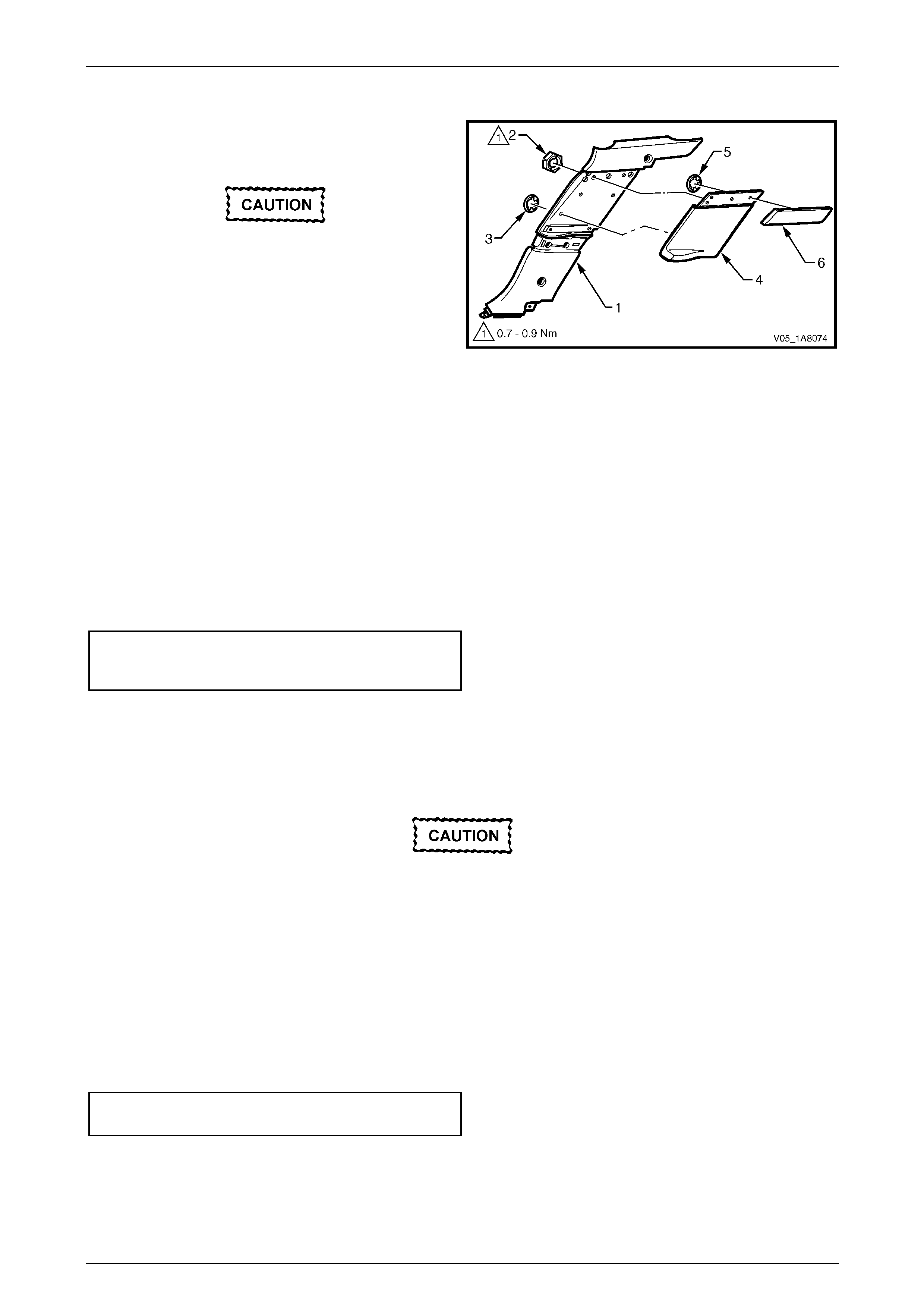
2 Remove the two attaching screws (1) from the body
hinge pillar trim assembly (2).
3 Disengage the body hinge pillar trim clip (3) by pulling
the lower edge of the body hinge p illar trim assembly
rearward and away from the sheetmetal.
4 For Level 5 vehicles only, remove the park assist
alarm assembly from the right-hand side bod y hinge
pillar trim, refer to Section 12F2 Dual Park Assist.
5 Remove the body hinge pillar trim assembly.
6 If required, remove the body hinge pillar trim clip a nd
the two nut inserts (4).
Figure 1A8 – 8
Reinstall
Reinstallation of the body hinge pillar trim assembly is the reverse of the removal procedure, noting the following:
1 Ensure the body hinge pil lar trim clip is correctly engaged in the hinge pillar i nner panel.
2 Ensure the two nut inserts are in good condition and correctly located in the hinge pillar i nn er pan el.
3 For Level 5 vehicles only, ensure the park assist alarm assembly is fitted to the right-hand side body hinge pillar
trim, refer to Section 12F2 Dual Park Assist.
4 Ensure the outer edge of the body hinge pillar trim assembly engages the front door opening weatherstrip (5),
refer to Figure 1A8 – 8.
5 Tighten the body hinge pillar trim assembly two attaching screws to the correct torque specification.
Body hinge pillar trim assembly
attaching screw torque specification...........0.7 – 1.0 Nm
Headlining and Interior Trim Page 1A8–13
Page 1A8–13
2.9 Body Lock Pillar Lower Trim
LT Section — 14–120
Remove
1 Remove the following components as required:
a Partially remove the rear section of the sid e sill trim and plate, refer to 2.6 Side Sill Trim and Plate.
b Rear seat cushion assembly and rear seat ba ck assembly, refer to Section 1A7 Seat Assemblies.
c Rear seat belt lower attaching bolt, refer to Section 12M Occupant Protection System.
2 Gently prise the cap assembly (1) from the body lock pillar lower trim (2) to disengage the two retaining clips (3),
refer to Figure 1A8 – 9.
3 Remove the four screws (4) attaching the body lock pillar lo wer trim to the bod y lock pillar.
When removing the body lock pillar lower
trim, take care not to damage the tw o locating
pins (5).
4 Gently pull the lower edge of the bo dy lock pillar lower trim away from the body lock pillar to disengage the central
retaining clip (6).
5 Pull the body lock pillar lower trim off the body lock pillar to disenga ge the two upper retaining clips (3) and remov e.
6 As required, remove the retaining clips from the vehicle and fit to the trim.
Figure 1A8 – 9
Headlining and Interior Trim Page 1A8–14
Page 1A8–14
Disassemble
1 Remove the insulation from the back of the body lock
pillar lower trim (1), taking care not to tear it.
Take care when removing the speed nuts as
the rotating action may cut off the lugs to
which they are attached.
2 Using side-cutters, cut the speed nut (2), five places,
and one round speed nut (3) attaching the insert (4) to
the body lock pillar lower trim then remove from the
lugs and discard.
3 Remove the insert from the body lock pillar lower trim.
4 Using side-cutters cut the round speed nut (5), four
places, retaining the applique (6) then remove from
the lugs and discard.
5 Remove the applique from the body lock pillar lower
trim.
Figure 1A8 – 10
Reassembly
1 Push a new round speed nut (5), five places, onto the lugs to secure the applique (6), refer to Figure 1A8 – 10.
2 Push a new round speed nut (3) onto the l ug and install then tighten a new speed nut (2), five places, attaching the
insert (4) to the correct torque specification.
Body lock pillar lower trim insert
attaching speed nut
torque specification.....................................0.7 – 0.9 Nm
3 Install the insulation at the back of the bod y lock pillar lower trim, apply adhesive as required.
Reinstall
Reinstallation of the body lock pillar lower trim is the reverse of the removal procedure, noting the following:
Take care not to snap off the locating pins
when fitting the body lock pillar lower trim.
1 Ensure the body lock pillar lower trim locating pins are aligned with the corresponding locating holes in the body
lock pillar.
2 Ensure the outer edge of the body lock pillar lower trim (2) engages the rear door opening weatherstrip (7),
refer to Figure 1A8 – 9.
3 Ensure the retaining clips ar e secured to the body lock pillar.
4 Ensure the body lock pillar lower trim is fully engaged with the side sill trim plate.
5 Tighten the four screws attaching the body lock pillar lower trim to the correct torque specification.
Body lock pillar lo wer trim
attaching screw torque specification...........1.0 – 3.0 Nm
6 Ensure the cap is secured to the body lock pillar lower trim.
Headlining and Interior Trim Page 1A8–15
Page 1A8–15
2.10 Body Lock Pillar Garnish
LT Section — 14–120
Remove
1 Remove the following components as required:
a Body lock pillar lower trim, refer to 2.9 Body Lock Pillar Lower Trim.
b Rear assist handle, refer to 2.2 Assist Handle Assembly.
c Roof rail courtesy and reading lamps, refer to Section 12B Lighting System.
d Partially remove the centre pillar upper trim by removing the upper attaching screw,
refer to 2.4 Centre Pillar Upper Trim Assembly.
e Remove the rear seat cushion and rear seat back assembly, refer to Section 1A7 Seat Assemblies.
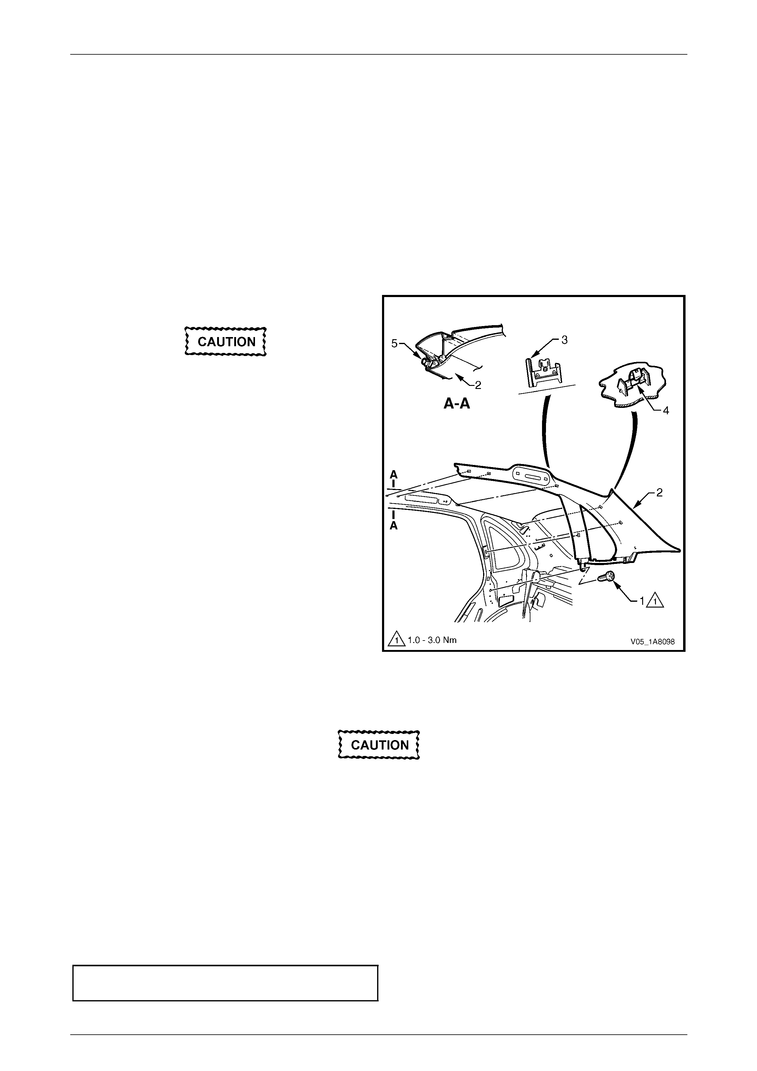
2 Remove the screw (1) from the lower edge of the body
lock pillar garnish (2).
When removing the windshield side garnish,
take care not to damage the locating pin (3).
3 Pull the front edge of the body lock pillar gar nish away
from the body lock pillar and working rearward
disengage the six retaining clips (4).
4 Remove the body lock pillar garnish.
Figure 1A8 – 11
Reinstall
Reinstallation of the body lock pillar garnish is the reverse of the removal procedure, noting the following:
When fitting the body lock pillar garnish take
care of the following:
• do not snap off the locating pi n
• if a sunroof is fitted to the vehicle, do not
crush or dent the sunroof rear drain tubes.
1 Ensure the body lock pillar garnish locating pin is aligned with the locating hole in the body lock pillar inner panel.
2 Ensure the body lock pillar garnish is fully engaged with the body l ock pillar lower trim and the centre pillar upper
trim assembly.
3 Ensure the outer edge of the body lock pillar garnish engages the rear d oo r opening weatherstrip (5),
refer to Figure 1A8 – 11.
4 Ensure the body lock pillar garnish six retaining clips are secured to the body lock pillar inner panel.
5 Tighten the screw attaching the body lock pillar garnish to the correct torque specification.
Body lock pillar garnish attaching screw
torque specification.....................................1.0 – 3.0 Nm
Headlining and Interior Trim Page 1A8–16
Page 1A8–16
2.11 Rear Window Trim Panel Assembly
LT Section — 14–460
Remove
1 Remove the following components as required:
a Rear seat cushion and rear seat back assembly, refer to Section 1A7 Seat Assemblies.
b Rear centre seat belt lower bolt, refer to Section 12M Occupant Protection System.
c Body lock pillar garnish on b oth sides, refer to 2.10 Body Lock Pillar Garnish.
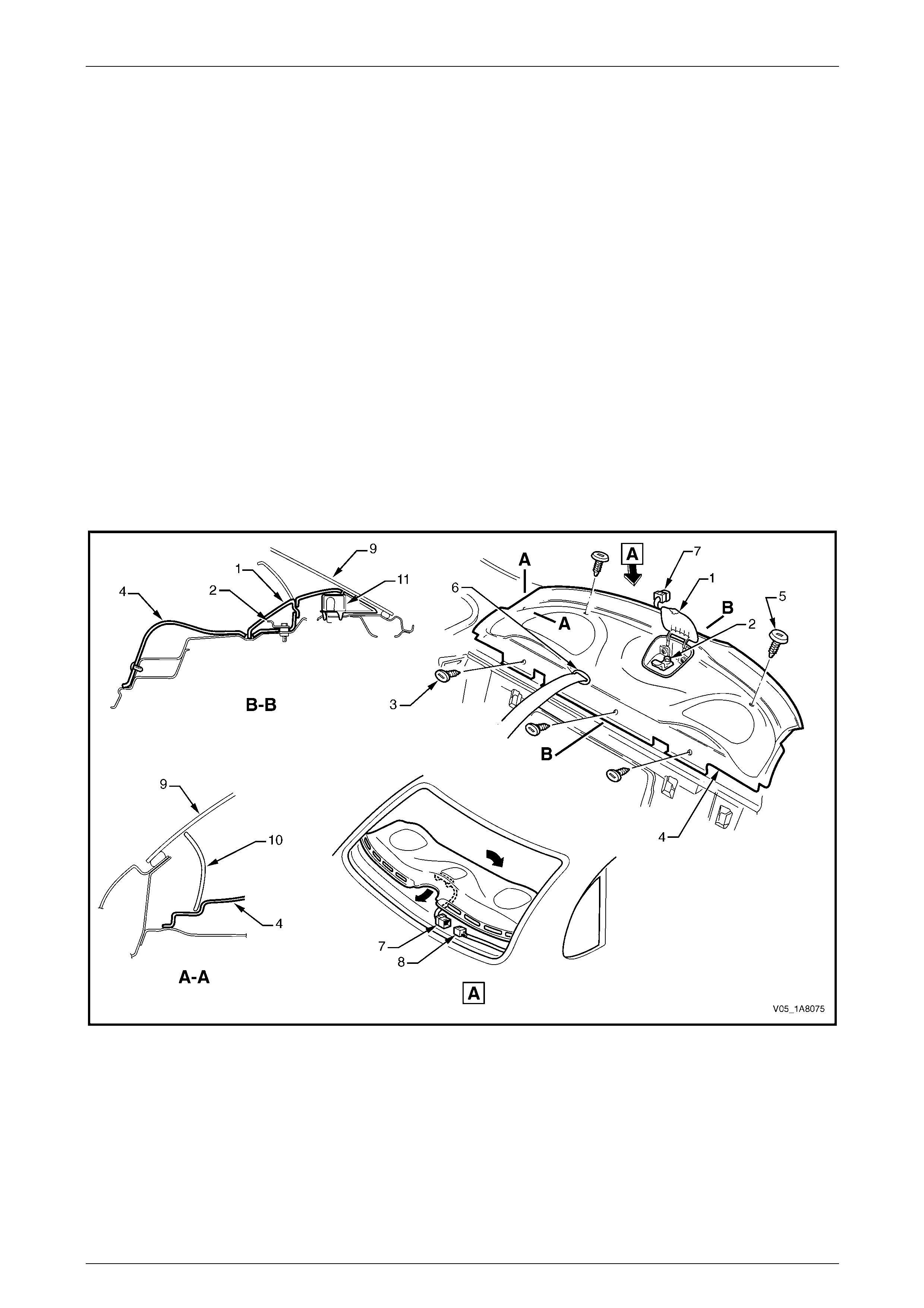
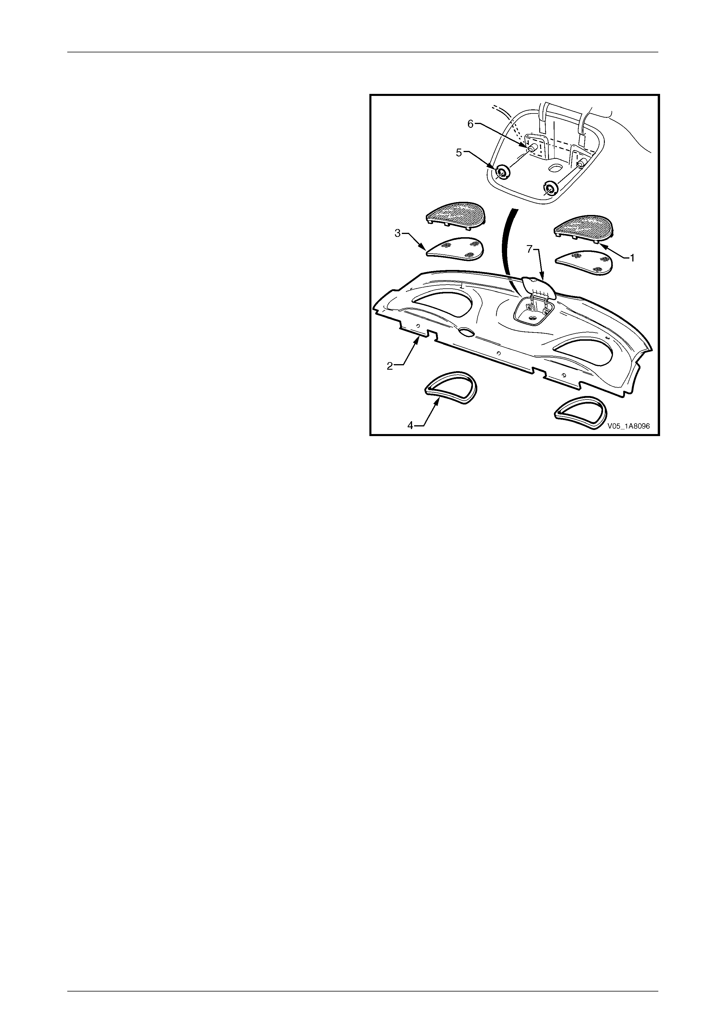
2 Open the receptacle cover (1), refer to Figure 1A8 – 1 2 an d remove the child seat anchor (2),
refer to Section 12M Occupant Protection System.
3 Remove the three retainers (3) attaching the forward edge of the rear window trim panel assembly (4).
4 Remove the two retainers (5) attaching the upper surface of the rear window trim panel assembly.
5 Lift the front edge of the rear window trim panel assembly, then remove the rear centre s eat belt escutcheon (6)
and feed the rear centre seat belt and anchor plate through the opening.
6 Disconnect rear headphone j ack connector (7) from the body wiring harness (8).
7 Remove the rear window trim panel assembly.
Figure 1A8 – 12
Legend
1 Child Seat Anchor Cover
2 Child Seat Anchor
3 Forward Edge Rear Window Trim Panel Retainers
4 Rear Window Trim Panel
5 Upper Surface Rear Window Trim Panel Retainers
6 Seat Belt Escutcheon
7 Headphone Jack Connector
8 Body Wiring Harness Connector
9 Rear Window Glass Panel
10 Body Lock Pillar Garnish
11 High Mount Stop Lamp
Headlining and Interior Trim Page 1A8–17
Page 1A8–17
Disassemble
1 Bend the tab (1), nine places, of the speaker grille to a
vertical position and remove the speaker grille from
the rear window trim panel assembly (2).
2 Remove the dust seal (3) from the speaker grille.
3 Remove the speaker seal (4) from the rear windo w
trim panel assembly.
4 If required, repeat for the opposite side.
5 If required, remove the two nuts (5) then the
headphone Jack control connectors (6) and wiring
harness.
NOTE
The child seat anchor receptacle (7) is part of
the rear window trim panel assembly and is not
serviced separately.
Figure 1A8 – 13
Reassemble
Reassembly of the rear window trim panel assembly is the reverse of the disassembly procedure, noting the following:
1 Ensure the headphone control connectors are secured to the child seat anchor receptacle.
2 Ensure the speaker seal and dust seal are correctly fitted.
3 Bend the nine tabs to a horizontal position to retain the speaker grille in position.
Reinstall
Reinstallation of the rear window trim panel assembly is the reverse of the removal procedure, noting the foll owing:
1 Ensure the speaker seals do not foul on the speaker assemblies.
2 Ensure the rear headphone j ack connector is securely connected the body wiring harn ess.
3 Ensure the rear window trim panel assemb ly retainers are secured to the rear window panel assembl y.
Headlining and Interior Trim Page 1A8–18
Page 1A8–18
2.12 Convenience Net
LT Section — 14–480
Remove
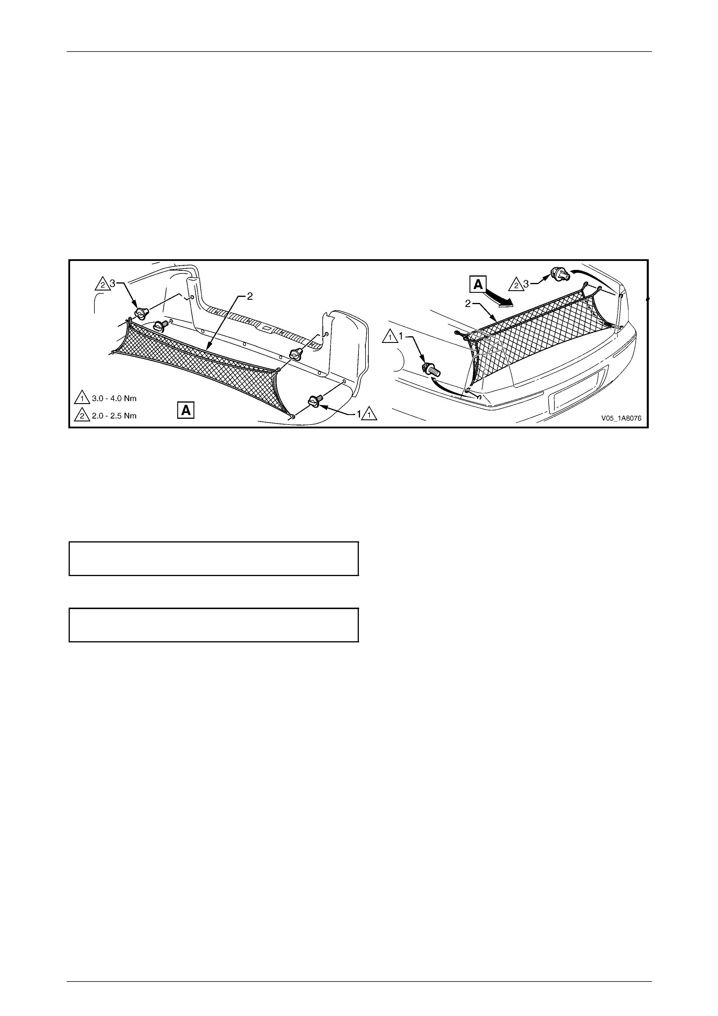
1 Carefully unhook the conv enience net (2) from the two lower retainer hooks (1) and the two upper retainer
hooks (3).
2 Remove the convenience net from the rear co mpartment.
3 If required, unscrew and remove the two upper and two lower retainer hooks.
Figure 1A8 – 14
Reinstall
Reinstallation of the convenie nce net is the reverse of the removal procedure, noting the following:
1 Tighten the two lower retainer hooks to the correct torque specification.
Convenience net lower retainer hook
torque specification.....................................3.0 – 4.0 Nm
2 Tighten the two upper retainer hooks to the correct torque specification.
Convenience net upper retainer hook
torque specification.....................................2.0 – 2.5 Nm
Headlining and Interior Trim Page 1A8–19
Page 1A8–19
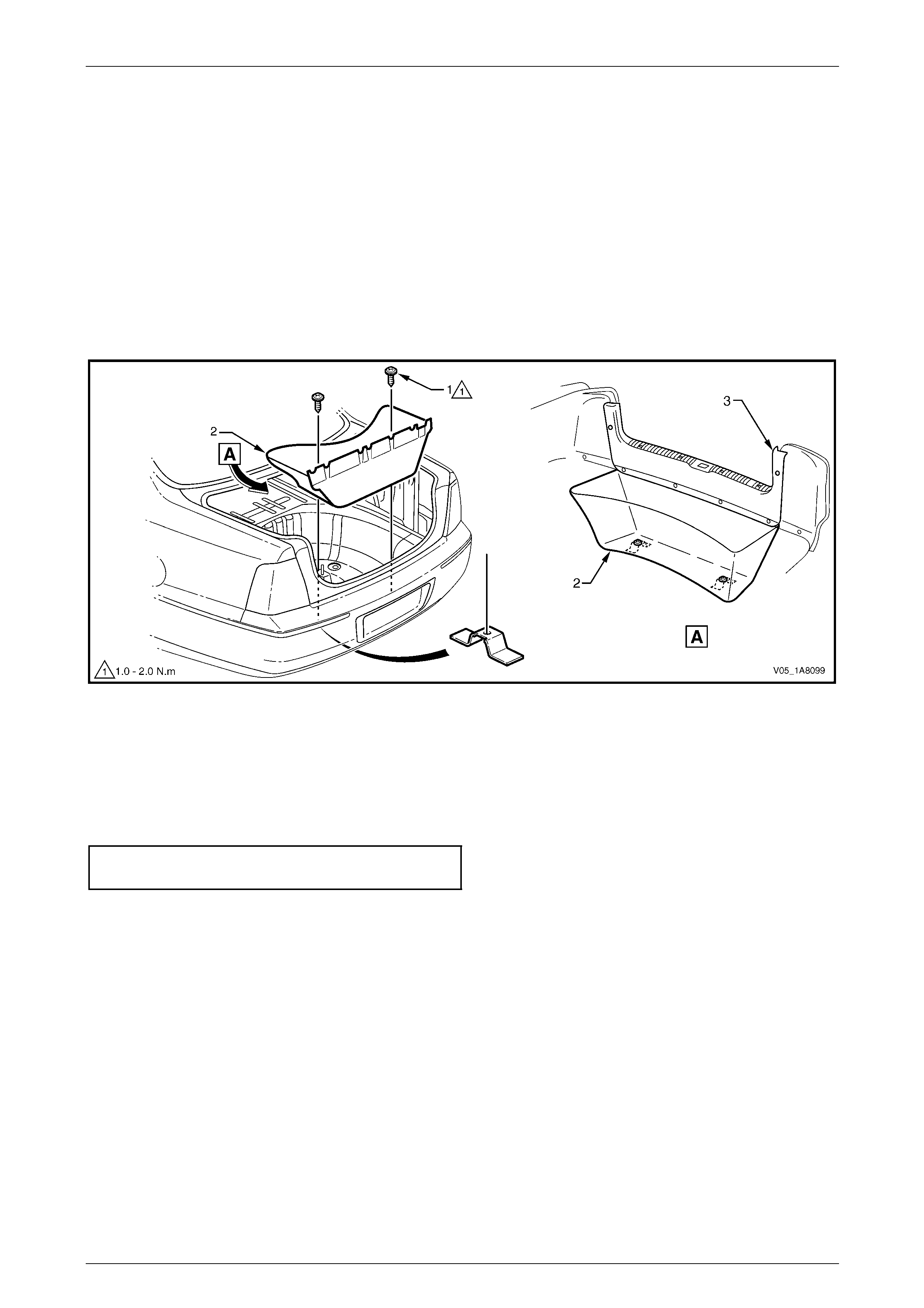
2.13 Rear End Trim Panel Assembly
LT Section — 14–120
Remove
1 Remove the convenience net, refer to
2.12 Convenience Net.
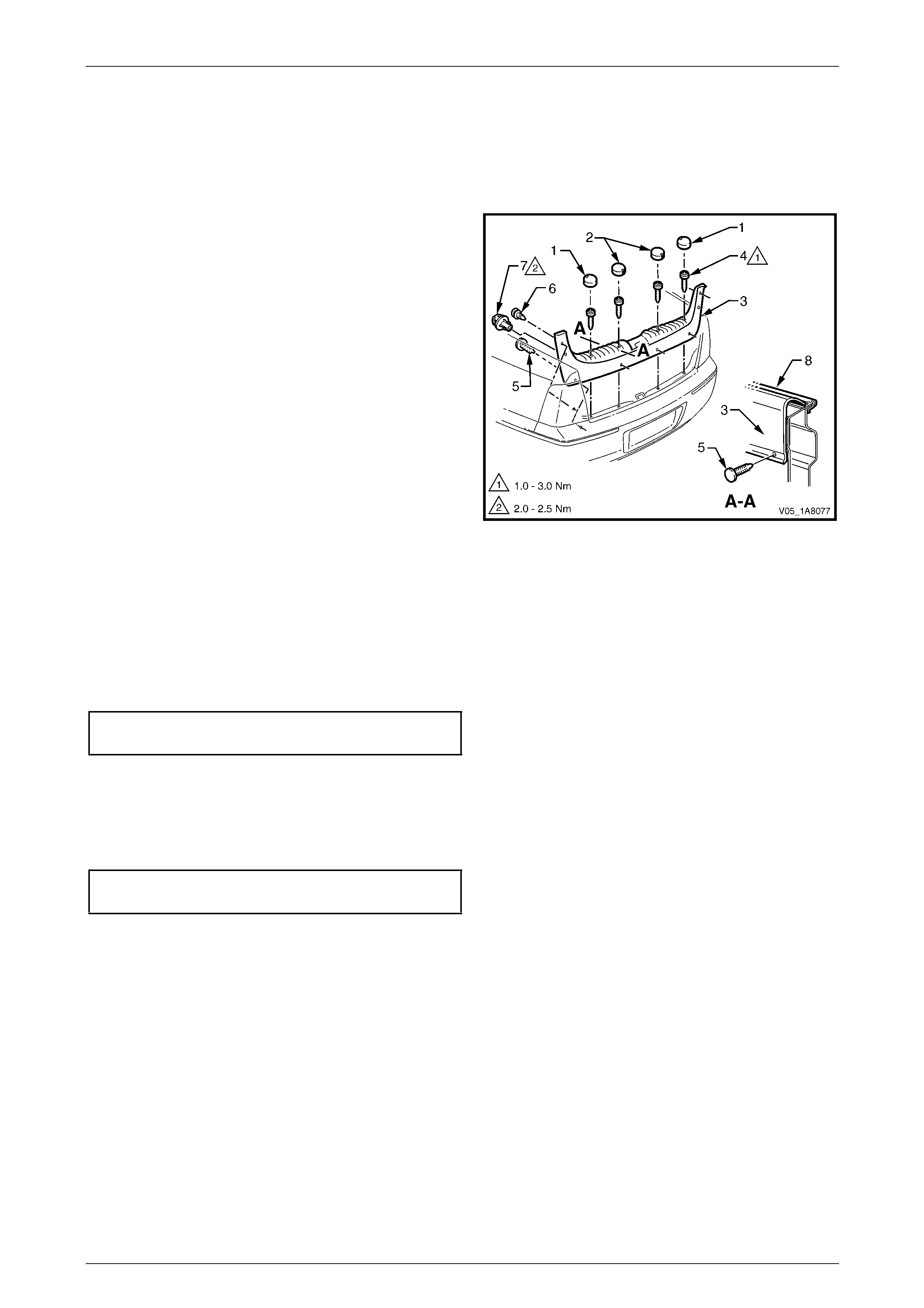
2 Remove the four screw caps (1 and 2) from the rear
end trim panel (3).
3 Remove the attaching screw (4), four places, along the
ribbed upper surface of the rear end trim panel.
4 Remove the four attaching screws (4) along the lower
inner edge of the rear end trim panel.
5 Remove the retainer (6), t wo places, attaching the
upper sides of the rear end trim panel.
6 Remove the convenience net upper retainer hook (7),
two places.
7 Carefully lift the rear end trim panel ov er the rear
compartment lid latch and clear of the rear
compartment. Figure 1A8 – 15
Reinstall
Reinstallation of the rear end trim panel assembly is the reverse of the removal procedure, noting the following:
1 Ensure the outer edge of rear end trim panel (3) engages the rear compartment lid weatherstrip (8),
refer to Figure 1A8 – 15.
2 Tighten the four attaching screws to the correct torque specification.
Rear end trim panel attaching screw
torque specification.....................................1.0 – 3.0 Nm
3 Ensure the screw caps are correctly fitted with the notch on the outer caps (1) pointing for ward and the notch on
the inner caps (2) pointing rearward.
4 Ensure the retainers are secured to the rear end panel assembly.
5 Tighten the convenienc e net two upper retainer hooks to the correct torque specification.
Convenience net upper retainer hook
torque specification.....................................2.0 – 2.5 Nm
Headlining and Interior Trim Page 1A8–20
Page 1A8–20
2.14 Sunshade Assembly
LT Section — 14–050
Remove
1 Remove the fuse F6 from the passenger compartment fuse and relay panel assembly,
refer to Section 12O Fuses, Relays and Wiring Harnesses.
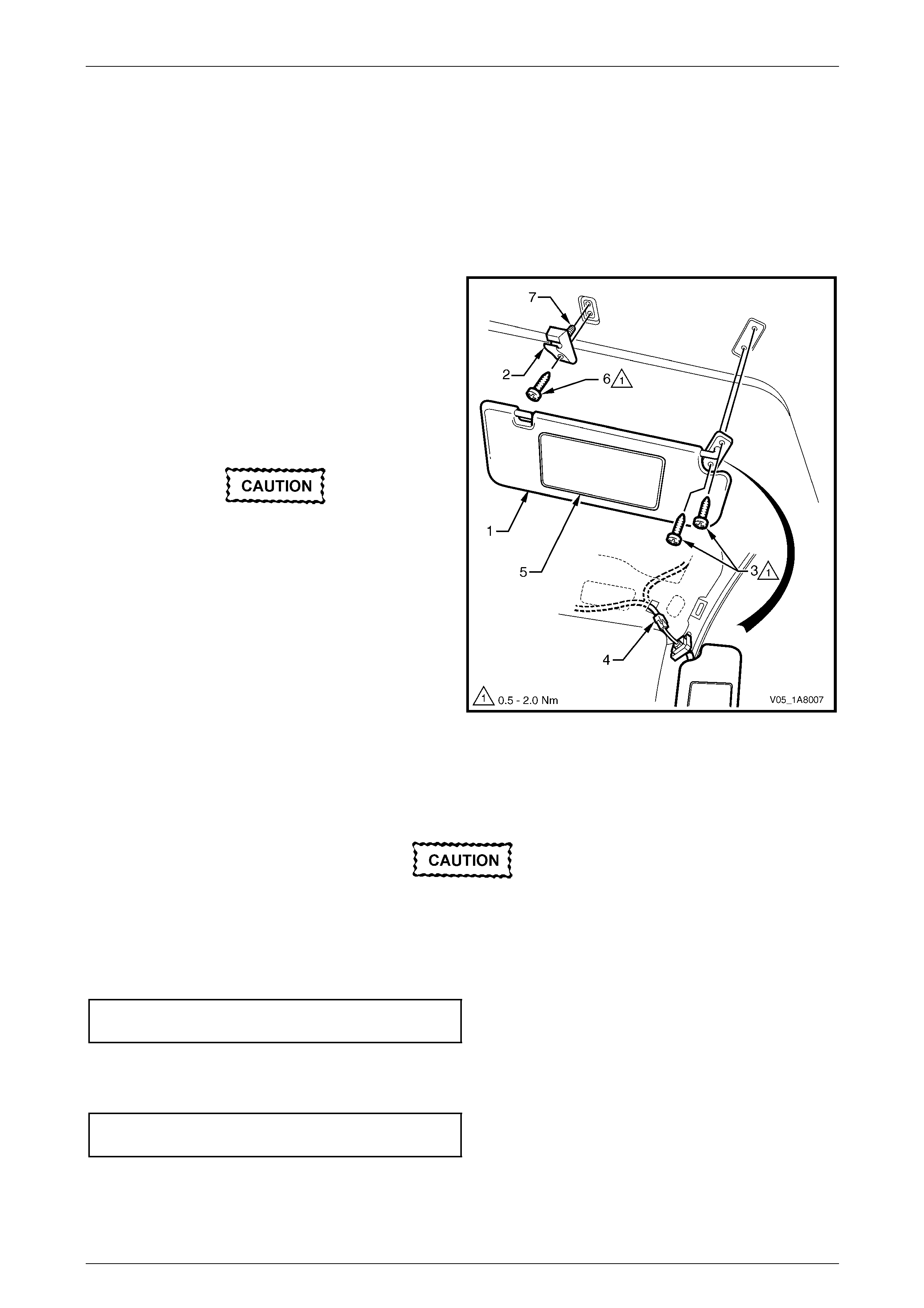
2 Disconnect the sunshade assembly (1) from the
sunshade support (2) and rotate to gain acce ss.
3 Remove the two Torx screws (3) attaching the
sunshade assembly.
4 Pull the sunshade assembly away from the headlining
assembly and disconnect the harness connector (4)
from the illuminated vanity mirrors (5).
5 Remove the sunshade assembly.
When removing the sunshade support, take
care not to damage the locating pin (7).
6 Remove the Torx screw (6) from the sunshade support
and pull the support from the headlining assembly.
Figure 1A8 – 16
Reinstall
Reinstallation of the sunshad e assemb ly is the reverse of the removal procedure, noting the following:
Take care not to damage the locating pin
when fitting the sunshade support.
1 Ensure the sunshade support locati ng pin is aligned with the locating hole in the roof panel.
2 Tighten the Torx screw attaching the sunshade support to the correct torque specification.
Sunshade support attaching Torx screw
torque specification.....................................0.5 – 2.0 Nm
3 Connect the harness connector to the sunshade assembly.
4 Tighten the sunshade ass embly two attaching Torx screws to the correct torque specification.
Sunshade assembly attaching screw
torque specification.....................................0.5 – 2.0 Nm
Headlining and Interior Trim Page 1A8–21
Page 1A8–21
2.15 Roof Console
LT Section — 02–780
Remove
1 Remove the fuse F6 from the passenger compartment fuse and relay panel assembly,
refer to Section 12O Fuses, Relays and Wiring Harnesses.
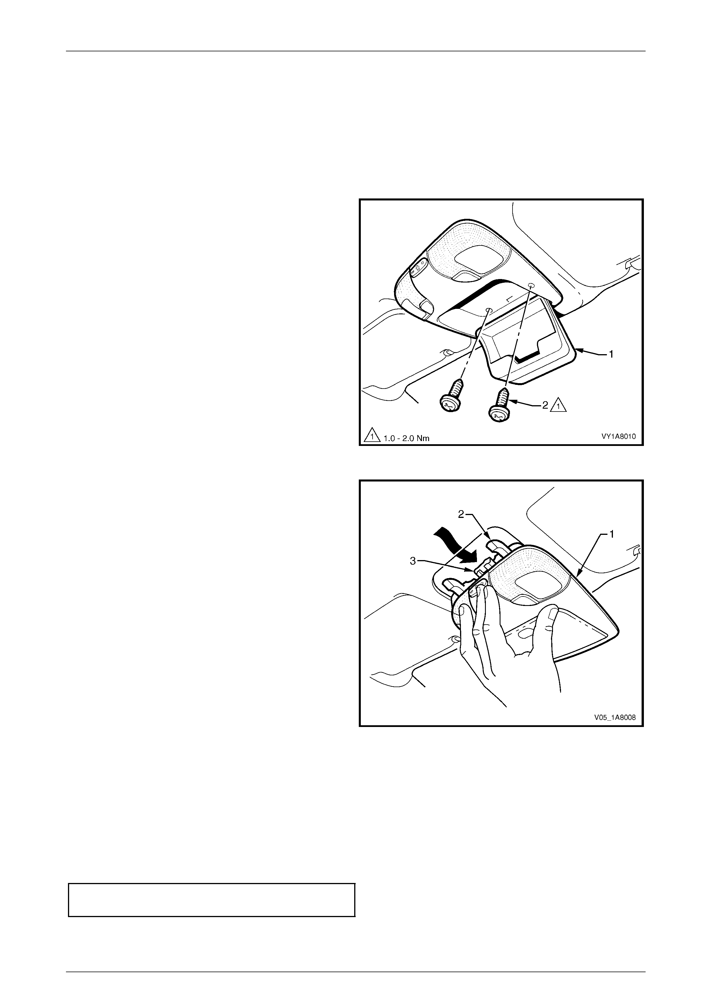
2 Open the compartment door (1) of the roof console.
3 Remove the two attaching screws (2) from inside the
roof console.
4 Close the compartment door.
5 Using your hand, pull down to disengage the front of
the roof console from the roof header pane l.
Figure 1A8 – 17
6 Slide the roof console (1) in a forward motion to allow
the two locator arms (2) to clear the headlini ng.
7 Disconnect the harness from the roof console
connector (3) and remove.
NOTE
For replacement of the map lamp bulbs,
refer to Section 12B Lighting System.
Figure 1A8 – 18
Reinstall
Reinstallation of the roof console is the reverse of the removal procedure, noting the following:
1 Ensure the harness is securely connecte d to the roof console connector.
2 Ensure the two locator arms are correctly inserted and the roof console is secured to the roof panel.
3 Tighten the roof console two attaching screws to the correct torque specification.
Roof console attaching screw
torque specification.....................................1.0 – 2.0 Nm
Headlining and Interior Trim Page 1A8–22
Page 1A8–22
2.16 Headlining Assembly
LT Section — 14–150
Remove
NOTE
If the vehicle is fitted with a sunroof, note the
following:
• Where an online sunroof is fitted, a rigid
headlining is installed and can be removed
using the normal procedure.
• Where a Holden By Design (HBD) sunroof is
fitted, a new headlining ha d to be created a nd
installed with adhesive. Extreme care is
required as the removal may damage the
headlining, then requiring a new one to be
created by a motor trimmer. The procedure
for this headlining is not covered in this
Section.
1 Remove fuse F6 from the passenger compar tment fuse and relay panel assembly,
refer to Section 12O Fuses, Relays and Wiring Harnesses.
2 Place protective covering ov er both front seats and the interior trim.
3 Remove the following components as required:
a Rear seat cushion and rear seat back assembly, refer to Section 1A7 Seat Assemblies.
b Windshield side garnish on b oth sides, refer to 2.7 Windshield Side Garnish.
c Body lock pillar garnish on b oth sides, refer to 2.10 Body Lock Pillar Garnish
d Sunshade assembly on both sides, refer to 2.14 Sunshade Assembl y.
e Roof console, refer to 2.15 Roof Console.
f Rear remote control, refer to
Section 2F HVAC Occupant Climate Control (Auto A/C) – Removal and Reinstallation.
g Roof mounted radio speakers, refer to Section 12D Entertainment System.
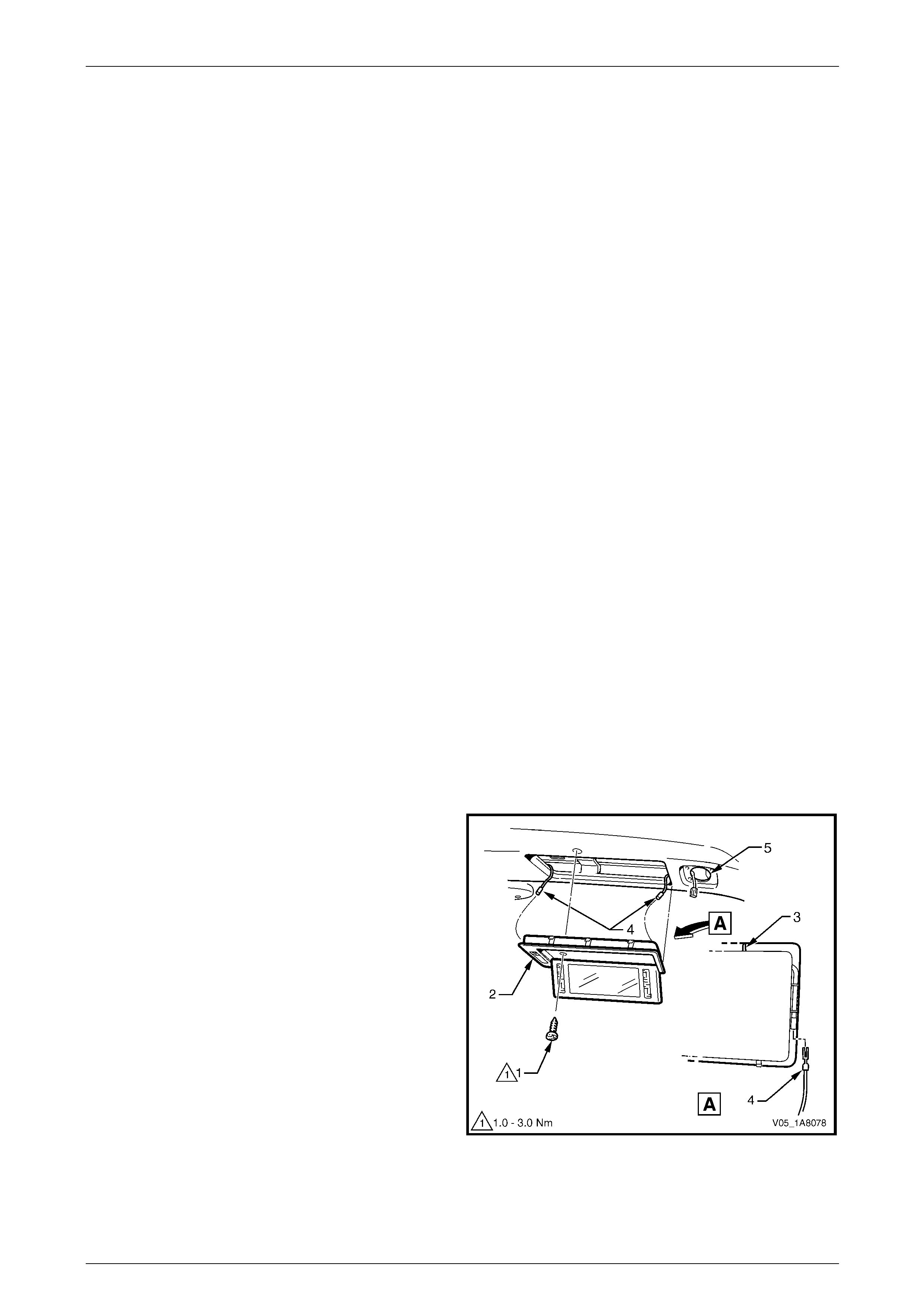
4 Remove the screw (1) securing each illuminated vanity
mirror (2).
5 Lever the rear side of the illuminated vanit y mirror to
release the rear clips and lower rearward to disengage
the front lugs (3), then disconnect the two harness
connectors (4) and remove.
NOTE
Each illuminated vanity mirror can be removed
from its position in the headlining by exerting
pressure on its rear via the roof speaker
cavity (5).
Figure 1A8 – 19
Headlining and Interior Trim Page 1A8–23
Page 1A8–23
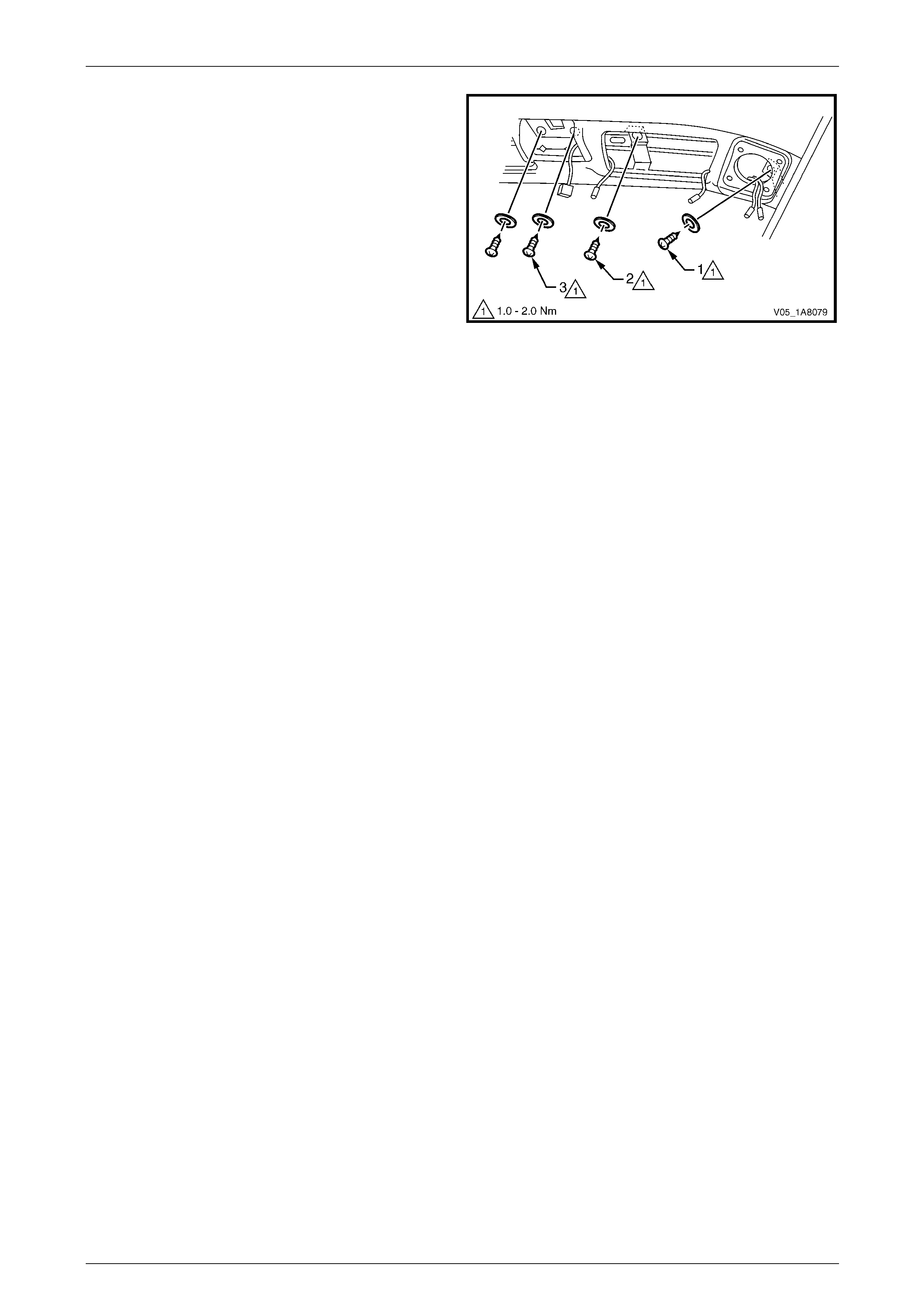
6 On both sides remove the screws attaching the
headlining centre supp ort to the vehicle as follows:
a From within the radio speaker cavit y remove the
screw (1) and washer.
b From within the illuminated vanit y mirror cavity
remove the screw (2) and washer.
c From within the remote control cavity remove the
two screws (3) and washers.
Figure 1A8 – 20
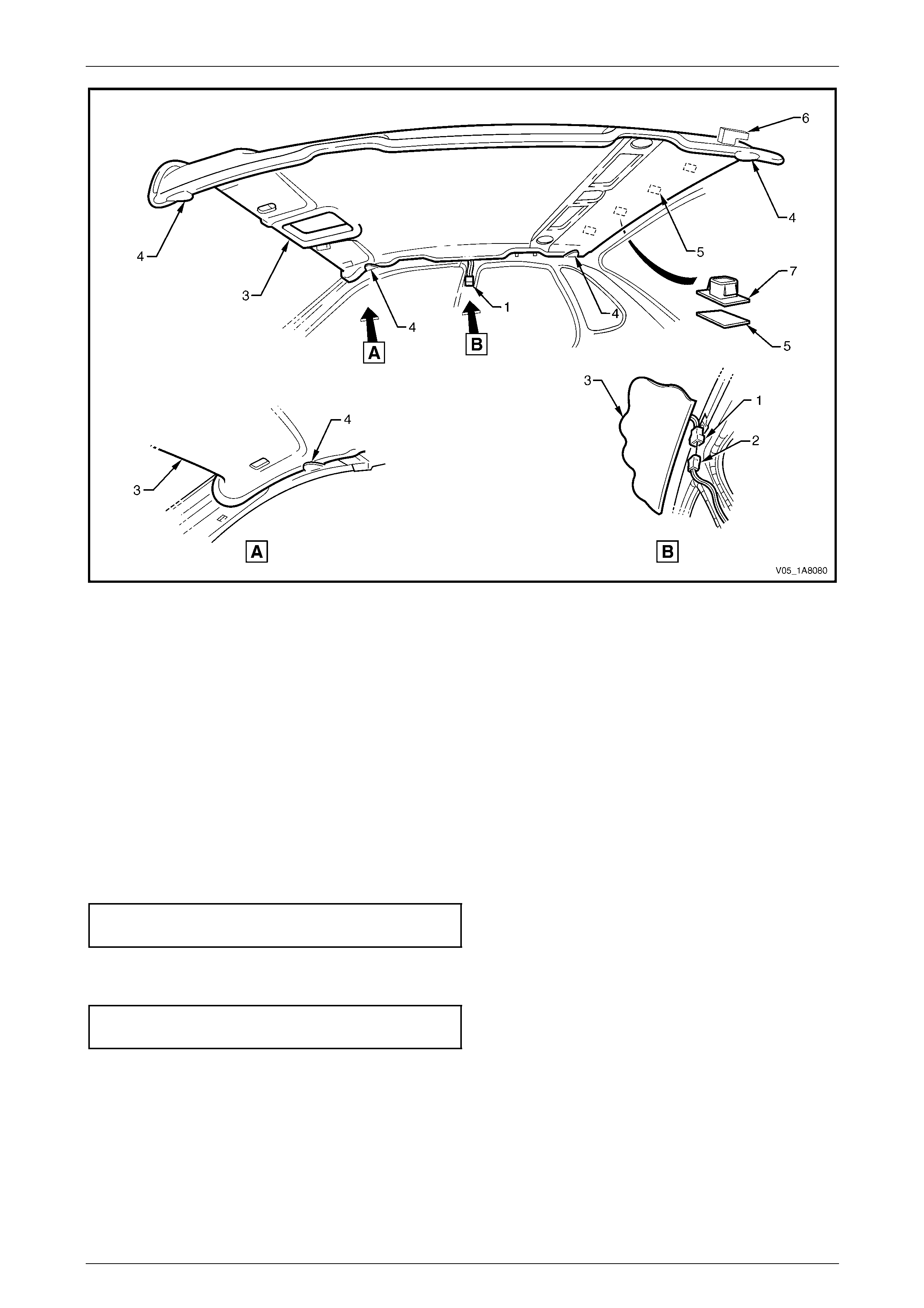
7 Disconnect the headlining assembly harness (1) from the body wiring harness connector (2), located above and
slightly forward of the right-hand centre pillar, refer to Figure 1A8 – 21.
NOTE
It may be necessary to flex the headlining
assembly (3) down slightly to gain access to the
harness connector.
8 With the aid of an assistant, flex the headlining assembly (3) to disengage the corners from the ‘D’ tabs (4), in four
places on the sides of the roof panel.
9 Disengage the hook and l oop fastener (5), four places, attaching the rear edge of the headlining assembly by
gently pulling down the headlining assembly in one corner and working across the rear edge.
10 Remove the foam tab (6) from the slot in the roof panel on each side of the headlini ng, at the rear of the vehicle.
11 Ease the headlining assembly from its position in the roof and turn the assembly so that it can be passed through
the passenger side front door, removing the assembly from the vehicle.
Headlining and Interior Trim Page 1A8–24
Page 1A8–24
Figure 1A8 – 21
Reinstall
Reinstallation of the headlining assembly is the reverse of the removal procedure, noting the following:
1 Replace the clips (7) from the roof bow and t he fasteners (5) from the headlining as required, refer to
Figure 1A8 – 21.
2 Ensure the foam tabs (6) are correctly positioned in the roof panel slots at the rear of the vehicle.
3 Temporarily support the headlining assembly on the ‘D’ tabs (4) before the trim components are installed.
4 Ensure the headlining assembly harness connector is securely connected to the body wiring harness connector.
5 Ensure the hook and loop fasteners at the rear edge of the headlining assembly are secu red to the roof panel.
6 Tighten the screws (1, 2 and 3) attaching the headlining centre support to the correct torque specification,
refer to Figure 1A8 – 20.
Headlining centre support
attaching screw torque specification...........1.0 – 2.0 Nm
7 Ensure the illuminated vanity mirrors (2) are secured with the front lugs (3) engaged, then tighten the attaching
screw (1) to the correct torque specification, refer to Figure 1A8 – 19.
Illuminated vanity mirror
attaching screw torque specification...........1.0 – 3.0 Nm
Headlining and Interior Trim Page 1A8–25
Page 1A8–25
2.17 Driver Footrest
LT Section — 14–475
Remove
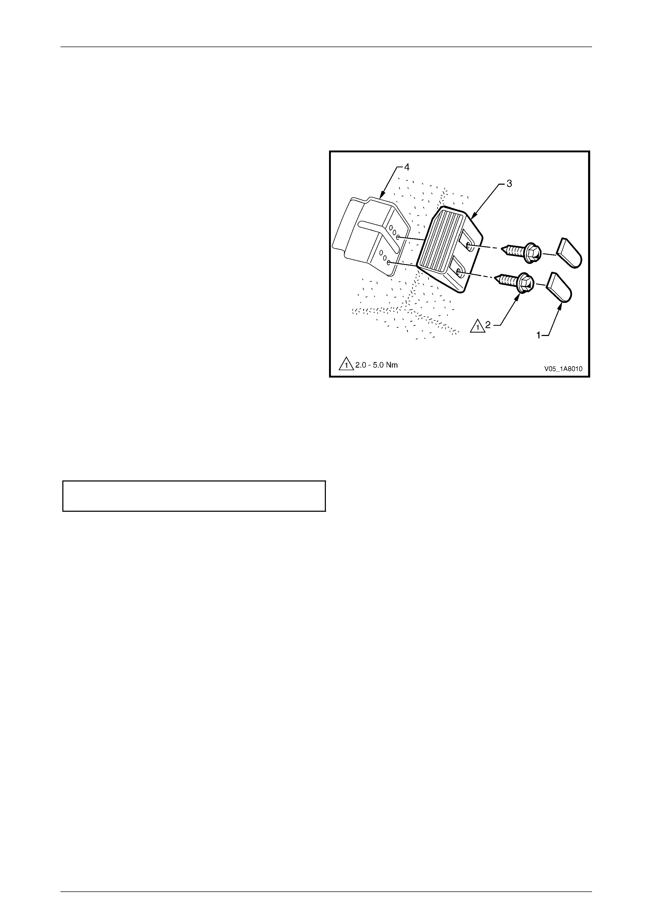
1 Prise the two screw covers (1) and remove from the
driver footrest.
2 Remove the two screws (2) attaching the driver
footrest (3) to the footrest mounting bracket (4).
3 Remove the footrest pad.
Figure 1A8 – 22
Reinstall
Reinstallation of the driver footrest is the reverse of the removal pr ocedure.
Tighten the two screws attaching the driver footrest to the correct torque specification.
Driver footrest attaching screw
torque specification.....................................2.0 – 5.0 Nm
Headlining and Interior Trim Page 1A8–26
Page 1A8–26
2.18 Front Floor Carpet Assembly
LT Section — 14–475
Remove
Disable the occupant protection
system before performing the
following operation. Refer to
Section 12M Occupant Protection System.
1 Remove the following components as required:
a Rear seat cushion, refer to Section 1A7 Seat Assemblies.
b Side sill trims on both sides, refer to 2.6 Side Sill Trim and Plate.
c Front seat belt lower attaching bolts, refer to Section 12M Occupant Protection System.
d Body hinge pillar trim assembly on both sides, refer to 2.8 Body Hinge Pillar Trim Assembly.
e Both front seat assemblies, refer to Section 1A7 Seat Assemblies.
f Driver footrest, refer to 2.17 Driver Footrest.
g Remove the park brake lever cover by grasping the cover firmly by hand and sliding the cover over the park
brake lever, refer to Section 5A Service and Park Braking System.
h Instrument panel lower trim plate assembly, right-hand and left-hand,
refer to Section 1A3 Instrument Panel and Consol e.
i Instrument panel compartment, refer to Section 1A3 Instrument Panel and Console.
j Instrument panel lower trim panel, refer to Section 1A3 Instrument Panel and Consol e.
k Floor console assembly, refer to Section 1A3 Instrument Panel an d Console.
2 Disconnect the inflatable restraint control module (SDM) wiring harness,
refer to Section 12M Occupant Protection System.
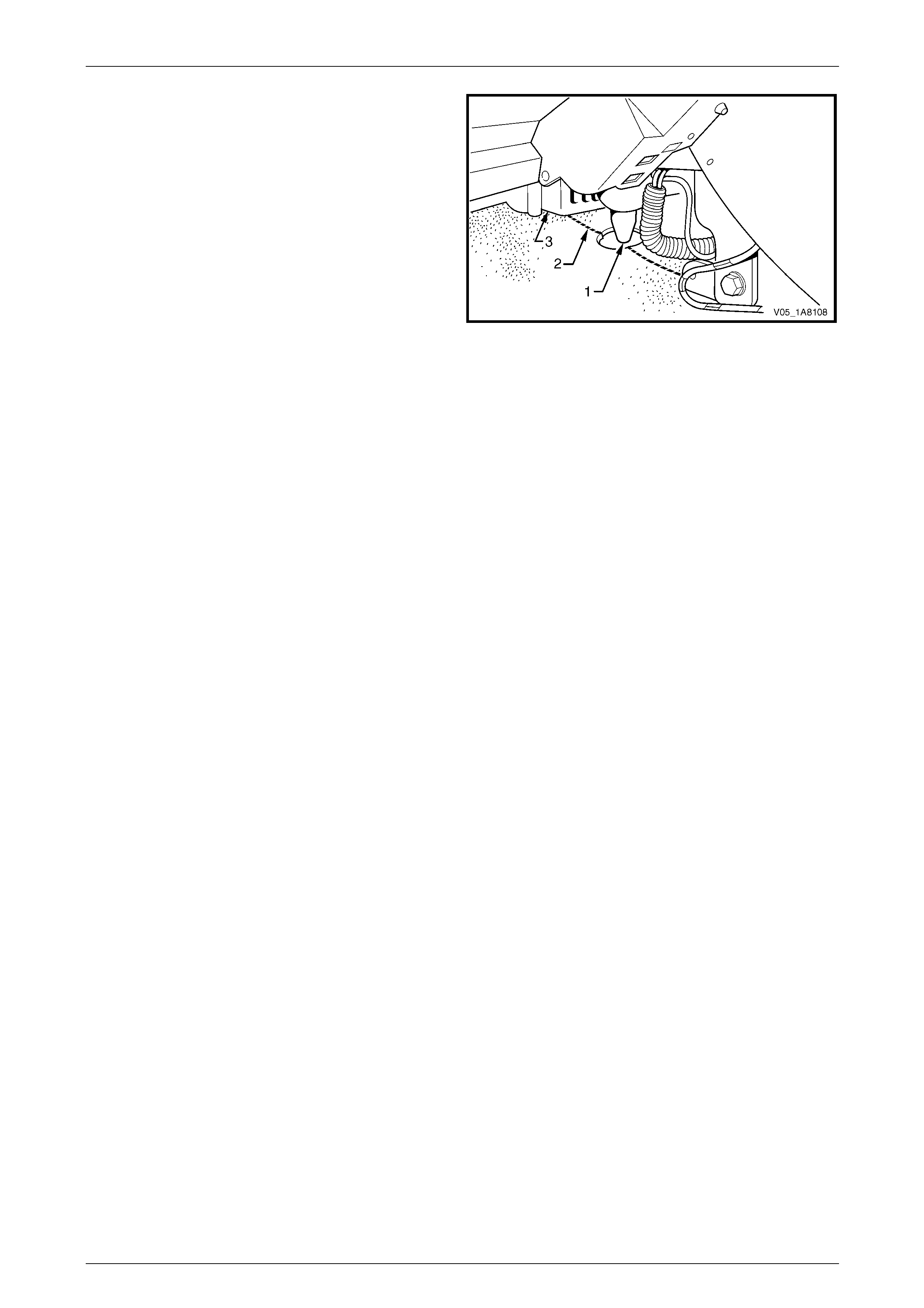
3 Remove the two retaining clips (1) from the front floor
carpet assembly (2) by rotating the clips counter-
clockwise and lifting clear of the attaching studs.
NOTE
To facilitate the removal and installation
procedure, the front floor carpet assembly is
perforated from the front edge (3), through the
centre of the evaporator drain cut-out, to the
forward edge of the lower radio bracket cut-
out (4).
Figure 1A8 – 23
Headlining and Interior Trim Page 1A8–27
Page 1A8–27
4 From inside the left-hand footwell, grasp the edge of
the hole in the front floor carpet assembly around the
evaporator drain hose (1) and tear open the perforated
line (2) by pulling the carpet awa y from the
transmission tunnel.
5 Slide the remaining flap of carpet out from under the
heating, ventilation and air-conditioning (HVAC)
unit (3) and into the right-hand footwell.
6 Carefully manoeuvre the front floor carp et and
insulator assembly out of the vehicle.
Figure 1A8 – 24
Reinstall
Reinstallation of the front floor carpet assembly is the reverse of the removal procedure, noting the follo wing:
1 If a new front floor carpet assembly is being fitted, prior to installation, cut along the perforated line that runs from
the carpet forward edge (3) to the forward edge of the lower radio bracket cut-out (4), refer to Figure 1A8 – 23.
2 Ensure all the cut-outs in the front floor carpet assembl y are correctly alig ned, then install the two retaining clips
and the front seat belt lower attaching bolts, refer to Section 12M Occupant Protection System , to secure the front
floor carpet assembly prior to installing the seats and c onsole.
Headlining and Interior Trim Page 1A8–28
Page 1A8–28
2.19 Rear Compartment Floor Panel Carpet
Assembly
LT Section — 14–480
Remove
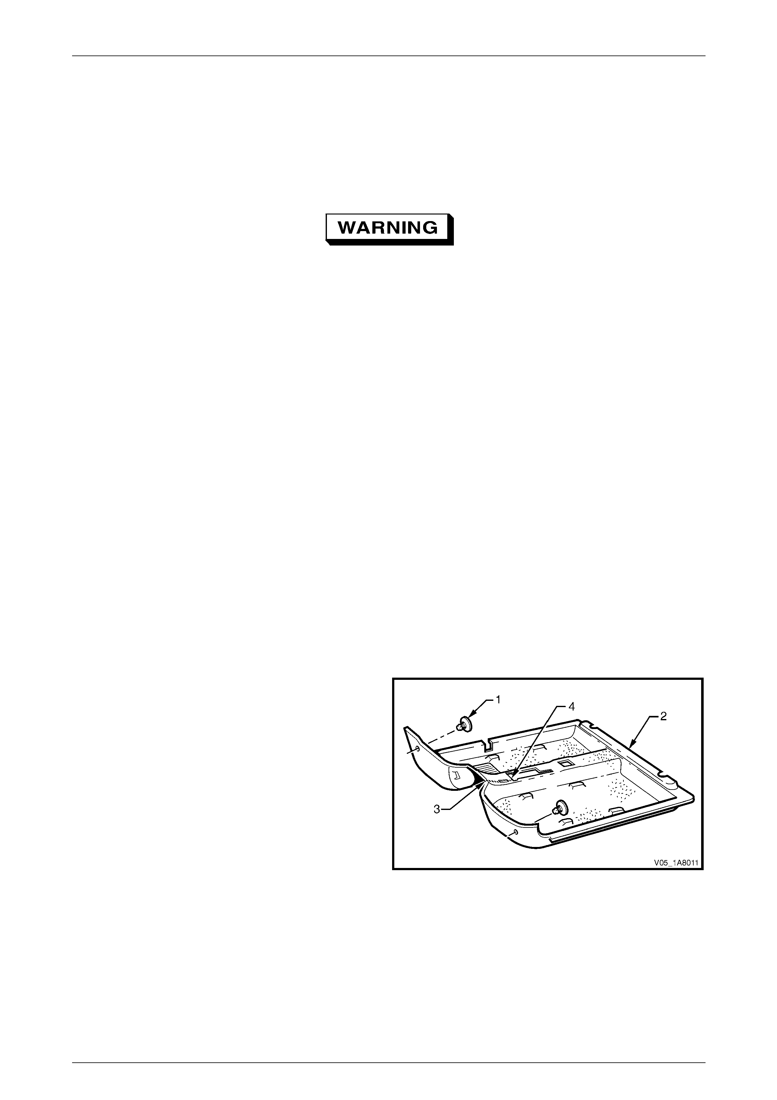
1 Open the rear compartment lid.
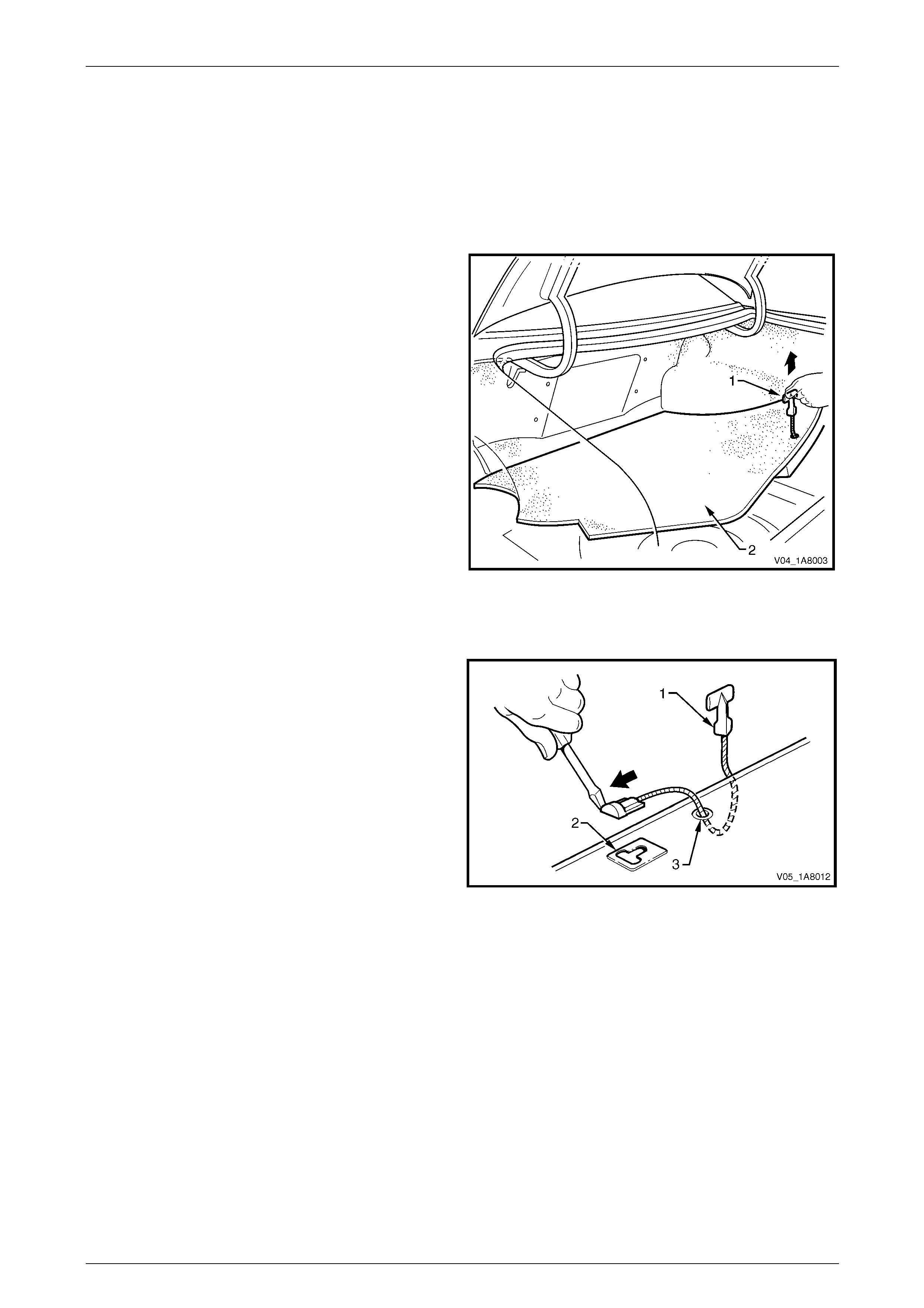
2 Grasp the strap (1) on the rear compartment floor
panel carpet assembly (2) and lift the rear edge
upward.
3 Lift and remove the rear compartment floor panel
carpet assembly from the rear compartment.
Figure 1A8 – 25
Disassemble
1 Lever the strap (1) out of the slot (2) in the rear
compartment floor panel carpet assembly and remove.
2 Feed the strap through the hole (3) in the rear
compartment floor panel carpet assembly and remove.
Figure 1A8 – 26
Reassemble
Reassembly of the rear compartment floor panel carpet assembly is the reverse of the disassembly procedure.
Reinstall
Reinstallation of the rear com partment floor panel carpet assembly is the reverse of the removal procedure.
Headlining and Interior Trim Page 1A8–29
Page 1A8–29
2.20 Quarter Inner Rear Side Carpet
LT Section — 14–480
Remove
Left-Hand Side Carpet
1 Remove the following components as required:
a Convenience net, refer to 2.12 Convenience Net.
b Rear compartment floor pan el carp et assembly,
refer to 2.19 Rear Compartment Floor Panel Carpet Assembly.
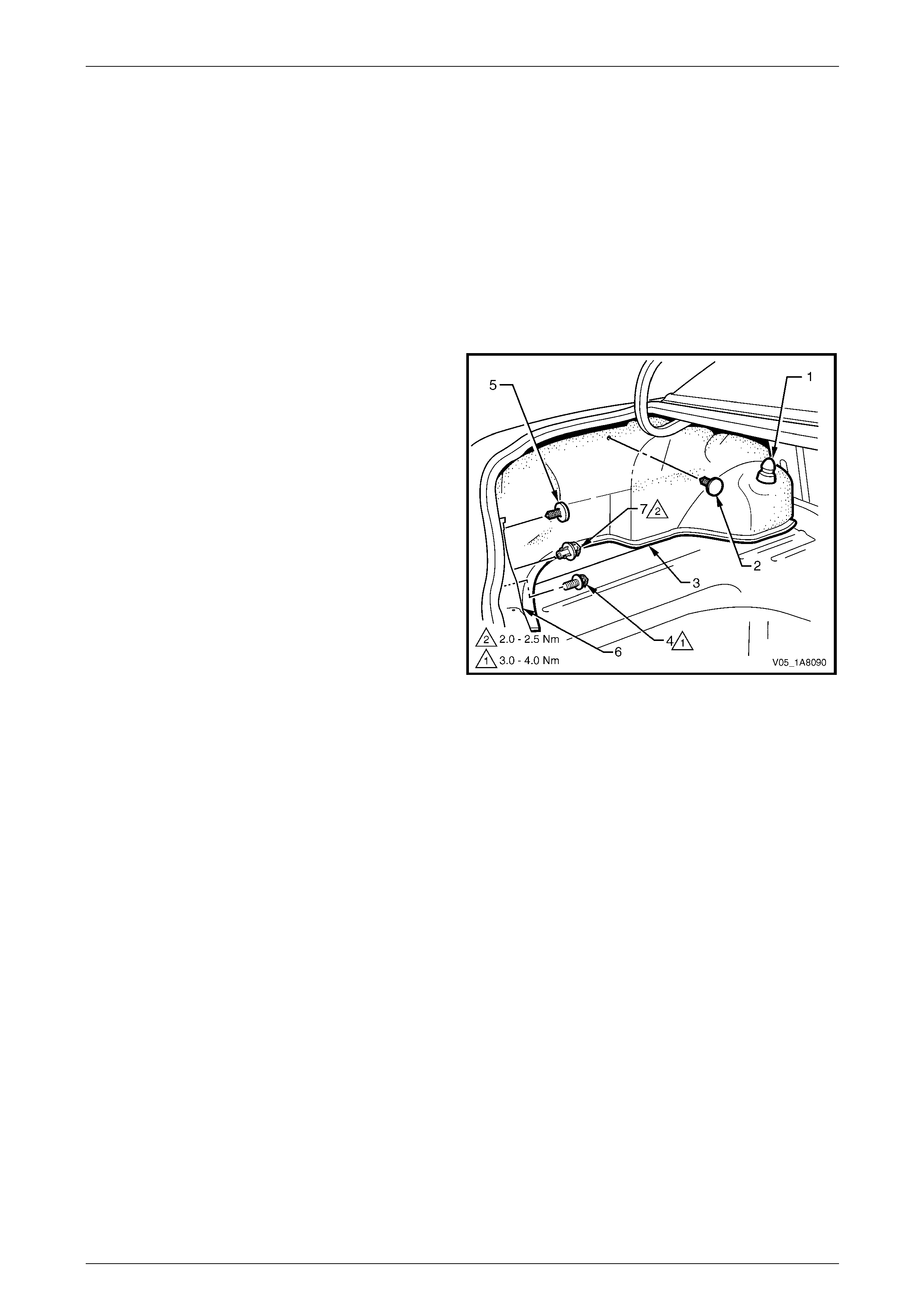
2 Carefully prise off the rear shock absorb er co ver (1).
3 Remove the retainer (2) securing the q uarter inner
rear side carpet (3).
4 Unscrew and remove the conveni ence net lower
retainer hook (4).
5 Remove the retainer (5) attaching the upper side of
the rear end trim panel (6) and the conveni ence net
upper retainer hook (7).
6 If required, remove the Jack.
7 Unhook the carpet flap from the rear compartment lid
hinge bracket.
8 Carefully pull the quarter inner rear side carpet from
behind the outer edge of the rear end trim panel and
remove.
Figure 1A8 – 27
Right-Hand Side Carpet
1 Remove the following components as required:
a Convenience net, refer to 2.12 Convenience Net.
b Rear compartment floor pan el carp et assembly,
refer to 2.19 Rear Compartment Floor Panel Carpet Assembly.
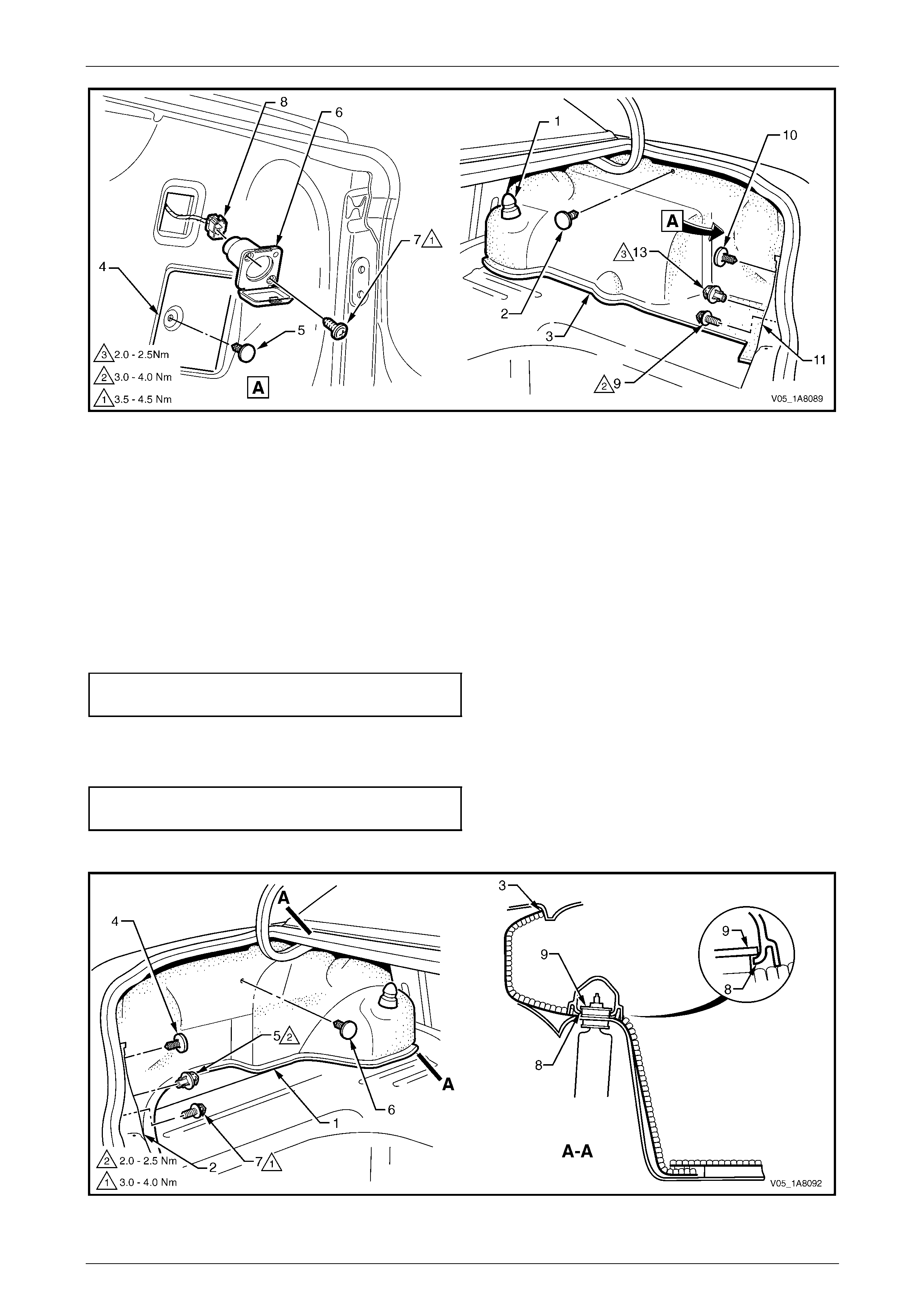
2 Carefully prise off the rear shock absorb er co ver (1), refer to Figure 1A8 – 28.
3 Remove the retainer (2) securing the q uarter inner rear side carpet (3).
4 For the access door (4) remove the retainer (5).
5 Open the cover on the power socket (6), remove the screw (7), two places, pull out the power socket, disconnect
the harness connector (8), remove the power socket and push the harnes s back through the carpet.
6 Remove the convenience net l ower retainer hook (9).
7 Remove the retainer (10) attaching the upper side of the rear end trim panel (11) and the convenience net upper
retainer hook (13).
8 Unhook the carpet flap from the rear compartment lid hinge bracket.
9 Carefully pull the quarter inner rear side carpet from behind the outer edge of the rear en d trim panel and remove.
Headlining and Interior Trim Page 1A8–30
Page 1A8–30
Figure 1A8 – 28
Reinstall
Left-Hand Side Carpet
Reinstallation of the left-hand quarter inner rear side carpet is the reverse of the removal procedure, noting the following:
1 Ensure the quarter inner rear side carpet (1) is correctly positioned behind the outer edge of the rear end trim
panel (2), the flap hooked over the rear comp artment lid hinge bracket and the carpet upper dart (3) engaged in the
quarter panel inner assembly, refer to F igure 1A8 – 29.
2 Ensure the retainer (4) secures the upper side of the rear end trim panel and tighten the convenience net upper
retainer hook (5) to the correct torque specification.
Convenience net upper retainer hook
torque specification.....................................2.0 – 2.5 Nm
3 Ensure the retainer (6) is secured to the quar ter panel inner assembly.
4 Tighten the convenience net lower retainer hook (7) to the correct torque specification.
Convenience net lower retainer hook
torque specification.....................................3.0 – 4.0 Nm
5 Reinstall the rear shock absorber access hole cover by engaging the lip (8) over the washer (9).
Figure 1A8 – 29
Headlining and Interior Trim Page 1A8–31
Page 1A8–31
Right-Hand Side Carpet
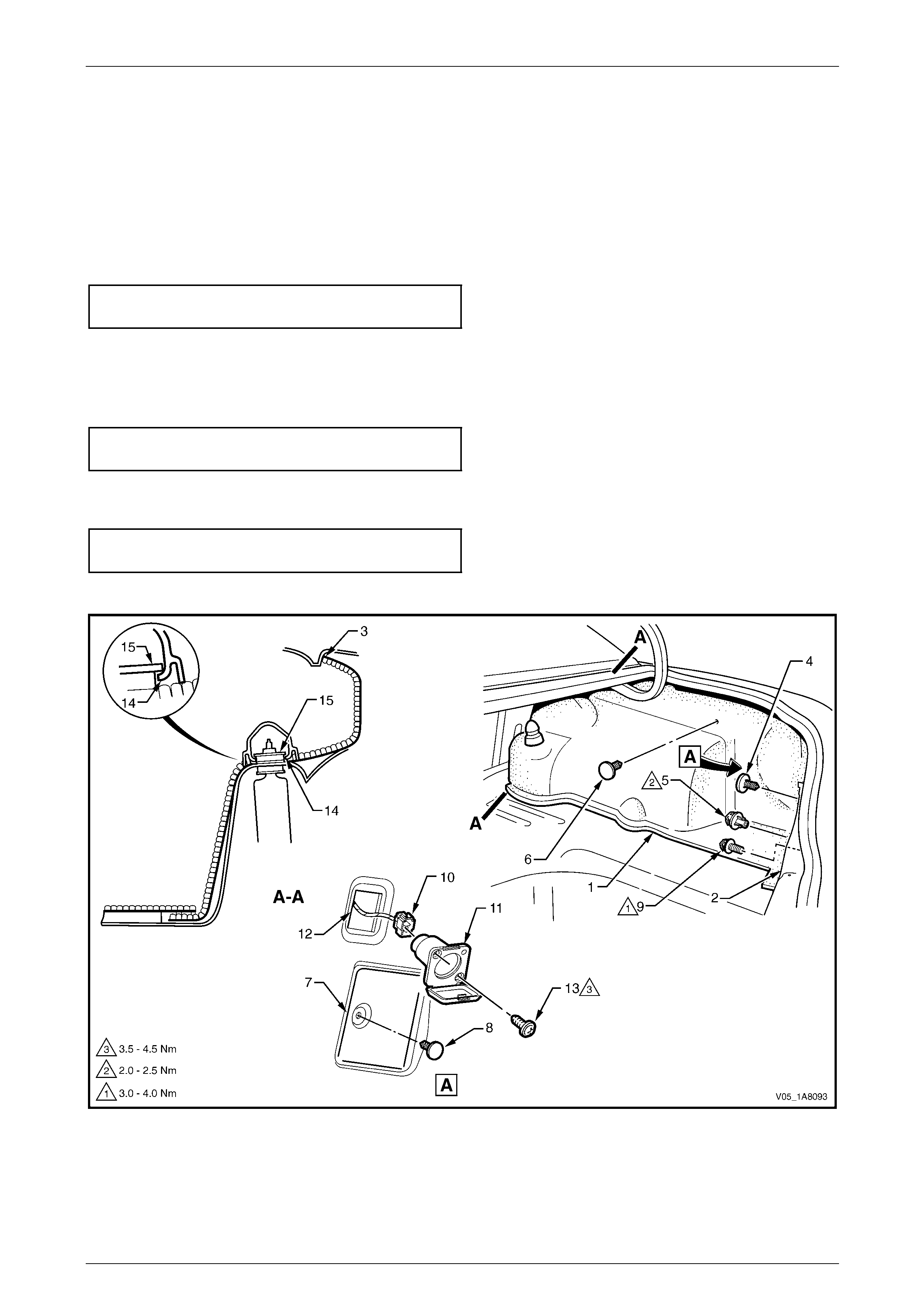
Reinstallation of the right-hand quarter inner rear side carpet is the reverse of the removal procedure, noting the
following:
1 Ensure the quarter inner rear side carpet (1) is correctly position ed behind the outer edge of the rear end trim
panel (2), the flap hooked over the rear comp artment lid hinge bracket, the carpet upper dart (3) engaged in the
quarter panel inner assembly and the harness connector (10) fed through the opening (12) in the carpet,
refer to Figure 1A8 – 30.
2 Ensure the retainer (4) secures the upper side of the rear end trim panel and tighten the convenience n et upper
retainer hook (5) to the correct torque specification.
Convenience net upper retainer hook
torque specification.....................................2.0 – 2.5 Nm
3 Ensure the retainer (6) is secured to the quar ter panel inner assembly.
4 For the access door (7), ensure the retainer (8) is secured to the qu arter panel inner assembly.
5 Tighten the convenience net lower retainer hook (9) to the correct torque specification.
Convenience net lower retainer hook
torque specification.....................................3.0 – 4.0 Nm
6 Ensure the harness connector (10) is secured to the power socket (11) and tighten the screw (13), two places, to
the correct torque specification.
Power socket assembly attaching screw
torque specification.....................................3.5 – 4.5 Nm
7 Reinstall the rear shock absorber access hole cover by engaging the lip (14) over the washer (15).
Figure 1A8 – 30
Headlining and Interior Trim Page 1A8–32
Page 1A8–32
2.21 Rear Seat Back Panel Carpet
LT Section — 14–480
Remove
1 Remove the following components as required:
a Rear end trim panel assembly, refer to 2.13 Rear End Trim Panel Assembly.
b Rear compartment floor pan el carp et assembly,
refer to 2.19 Rear Compartment Floor Panel Carpet Assembly.
c Partially remove the front of the quarter inner rear side carpet on both sides,
refer to 2.20 Quarter Inner Rear Side Carpet.
2 Lower the rear seat back centre armrest assembly.
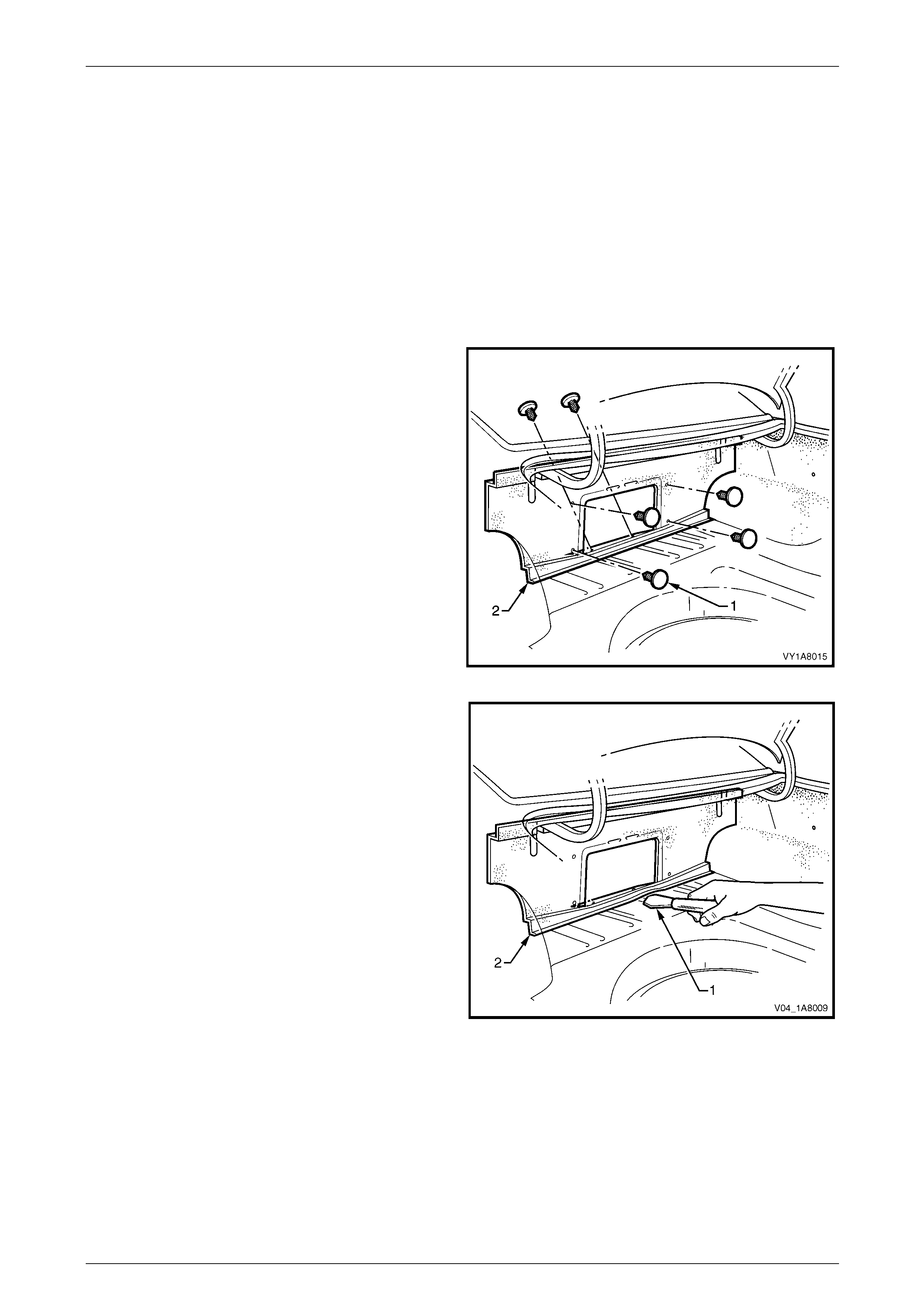
3 Carefully remove the six retai ners (1) from the rear
seat back panel carpet (2).
Figure 1A8 – 31
4 Using a knife or paint scraper (1), carefully prise along
the lower edge of the rear seat back panel ca rpet (2).
5 Remove the rear seat back panel carpet.
Figure 1A8 – 32
Reinstall
Reinstallation of the rear seat back panel carpet is the reverse of the removal procedure, noting the following:
1 Use the existing adhesive bea d along the lower edge to refasten the rear seat back panel carpet to the vehicl e. If
required, add a bead of hot melt adhesive.
2 Ensure the rear seat back panel carpet is fitted behind the quarter inner rear side carpet.
3 Ensure the six retainers are se cure d to the rear seat back.
Headlining and Interior Trim Page 1A8–33
Page 1A8–33
2.22 Spare Wheel Well Container
LT Section — 05–825
Remove
1 Remove the spare wheel from the spare wheel well, refer to Section 10 Wheels and Tyres.
2 Remove the two screws (1) attaching the spa r e wheel well container (2) to the rear compartment floor,
refer to Figure 1A8 – 33.
3 Slide the spare wheel well container down and forward to dislodge it from behind the lower edge of the rear end
trim panel assembly (3).
4 Lift the spare wheel well container and remove from the rear compartment.
Figure 1A8 – 33
Reinstall
1 Ensure the spare wheel well container is correctly positioned behind the lower edge of th e rear end trim panel and
in the spare wheel well.
2 Reinstall and tighten the two screws attaching the spare wheel well container to the correct torque specification.
Spare wheel well container
attaching screw torque specification...........1.0 – 2.0 Nm
3 Reinstall the spare wheel into the spare wheel well, refer to Section 10 Wheels and Tyres.
Headlining and Interior Trim Page 1A8–34
Page 1A8–34
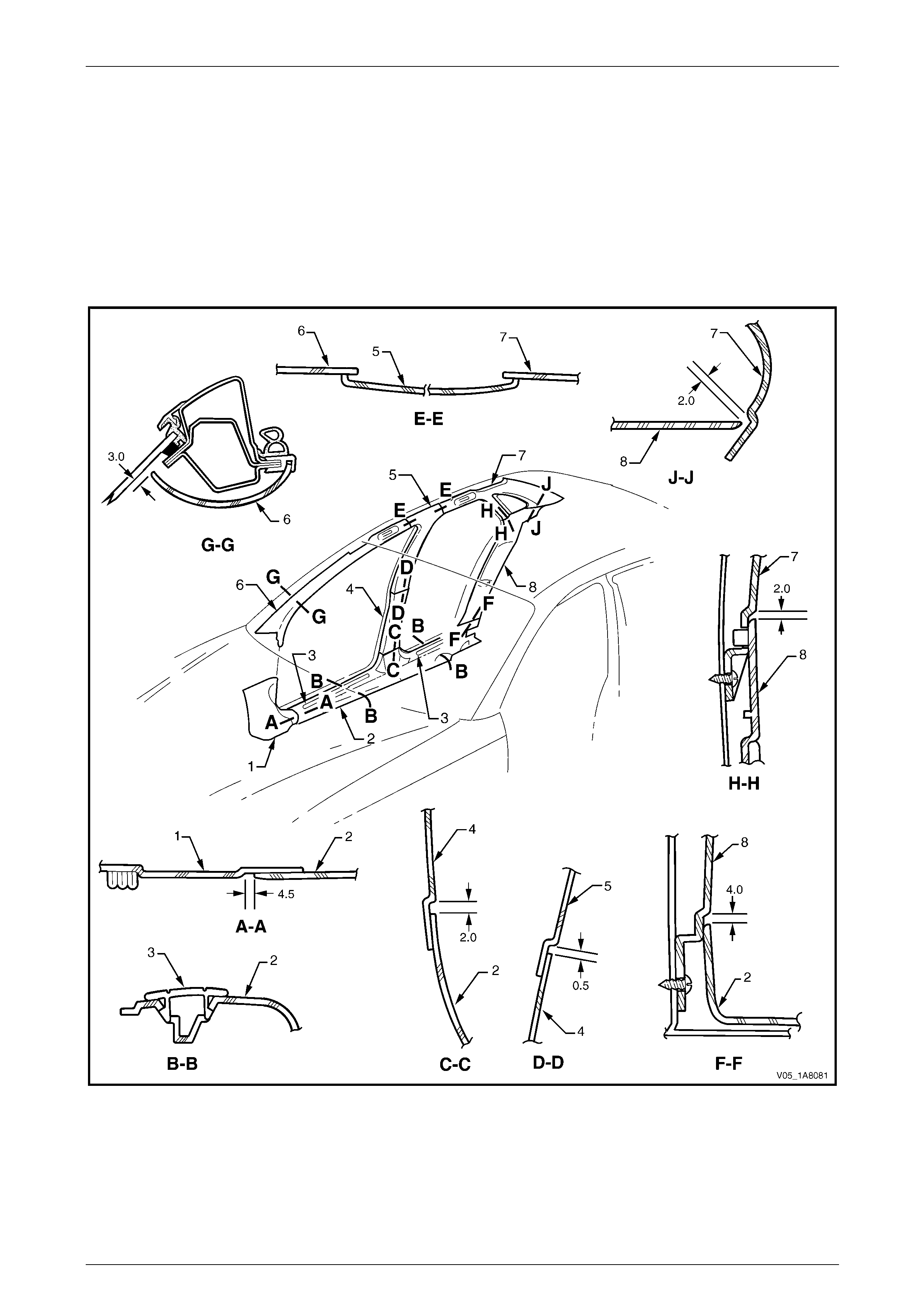
3 Clearances Specifications
3.1 Interior Trim Clearances
The interior trim clearances are provi ded in Figure 1A8 – 34. All measurements are in millim etres and the values given
represent the optimal clearance between the trim panels or garnishes, where no clearance is ind icated there must be
contact between the parts.
Before checking the interior trim clearances, ensure the trim panels and garnishes are correctly attached and secured to
the vehicle.
Figure 1A8 – 34
Legend
1 Body Hinge Pillar Trim
Assembly
2 Side Sill Trim
3 Side Sill Trim Plate
4 Centre Pillar Lower Trim
5 Centre Pillar Upper Trim Assembly
6 Windshield Side Garnish
7 Body Lock Pillar Garnish
8 Body Lock Pillar Lower Trim Assembly

Headlining and Interior Trim Page 1A8–35
Page 1A8–35
4 Torque Wrench Specifications
Assist Handle Attaching Screw......................................................1.0 – 3.0 Nm
Centre Pillar Upper Trim Assembly Attaching Screw ....................1.0 – 3.0 Nm
Side Sill Trim Attaching Torx Screw ..............................................1.0 – 3.0 Nm
Body Hinge Pillar Trim Assembly Attaching Screw .......................0.7 – 1.0 Nm
Body Lock Pillar Lower Trim Insert Attaching Speed Nut..............0.7 – 0.9 Nm
Body Lock Pillar Lower Trim Attaching Screw...............................1.0 – 3.0 Nm
Body Lock Pillar Garnish Attaching Screw ....................................1.0 – 3.0 Nm
Convenience Net Lower Retainer Hook ........................................3.0 – 4.0 Nm
Convenience Net Upper Retainer Hook ........................................2.0 – 2.5 Nm
Rear End Trim Panel Attaching Screw..........................................1.0 – 3.0 Nm
Sunshade Support Attaching Torx Screw......................................0.5 – 2.0 Nm
Sunshade Assembly Attaching Screw...........................................0.5 – 2.0 Nm
Roof Console Attaching Screw......................................................1.0 – 2.0 Nm
Headlining Centre Support Attaching Screw .................................1.0 – 2.0 Nm
Illuminated Vanity Mirror Attaching Screw.....................................1.0 – 3.0 Nm
Driver footrest attaching screw......................................................2.0 – 5.0 Nm
Power Socket Assembly Attaching Screw.....................................3.5 – 4.5 Nm
Spare Wheel Well Container Attaching Screw ..............................1.0 – 2.0 Nm