
Wheels and Tyres Page 10–1
Page 10–1
Section 10
Wheels and Tyres
ATTENTION
Before performing any Service Operation or other procedure described in this Section, refer to Section 00
Warnings, Cautions and Notes for correct workshop practices with regard to safety and / or property damage.
1 General Information – Wheels and Tyres ............................................................................................4
1.1 Tyre Placards ......................................................................................................................................................... 5
1.2 Tyre Markings......................................................................................................................................................... 6
1.3 Spare Wheel Stowage............................................................................................................................................ 7
2 General Information – Tyre Pressure Monitoring System .................................................................8
2.1 Overview................................................................................................................................................................. 8
2.2 System Components............................................................................................................................................. 9
Tyre Pressure Sensor............................................................................................................................................ 9
TPMS module......................................................................................................................................................... 9
2.3 Instrument Cluster Display Information............................................................................................................. 10
System Configuration.......................................................................................................................................... 10
MFD Option Menu Displays................................................................................................................................. 10
Start Display......................................................................................................................................................... 11
Tyre Pressure Warnings ...................................................................................................................................... 11
Tyre Pressure Sensor Fault ................................................................................................................................ 12
2.4 Tyre Pressure Monitoring System Transmitter System Modes....................................................................... 13
Stationary Mode................................................................................................................................................... 13
Wake Mode........................................................................................................................................................... 13
Drive Mode............................................................................................................................................................ 13
Low Battery Mode................................................................................................................................................ 14
Learn Mode........................................................................................................................................................... 14
Re-measure Mode................................................................................................................................................ 14
Normal Pressure Mode........................................................................................................................................ 14
Sleep Mode........................................................................................................................................................... 14
Off Mode ............................................................................................................................................................... 14
2.5 Tyre Pressure Monitoring System Learn Modes............................................................................................... 15
Normal Learn........................................................................................................................................................ 15
End of Line (EOL) Learn...................................................................................................................................... 15
Aftermarket Learn................................................................................................................................................ 15
Spare Wheel Change ........................................................................................................................................... 15
2.6 TPMS Warnings.................................................................................................................................................... 16
Fail Strategy ......................................................................................................................................................... 16
TPMS Module Failures..................................................................................................................................... 16
Pressure Sensor Failures................................................................................................................................. 16
Warning Strategy.............................................................................................................................................. 16
Nominal............................................................................................................................................................ 16
Warning............................................................................................................................................................ 16
Alarm................................................................................................................................................................ 16

Wheels and Tyres Page 10–2
Page 10–2
3 Diagnostics – Wheels and Tyres ................................................................................................. .......17
3.1 Wear...................................................................................................................................................................... 17
3.2 Road Testing........................................................................................................................................................ 18
Tyre and Wheel Inspection.................................................................................................................................. 18
Slow Acceleration Test........................................................................................................................................ 18
Neutral Coast-down Test..................................................................................................................................... 18
Downshift Test..................................................................................................................................................... 18
Steering Input Test .............................................................................................................................................. 19
Standing Start Acceleration................................................................................................................................ 19
3.3 Vibration ............................................................................................................................................................... 20
Radial Force Variation......................................................................................................................................... 21
Lateral Force Variation........................................................................................................................................ 21
3.4 Vehicle Lead......................................................................................................................................................... 22
4 Diagnostics – Tyre Pressure Monitoring System .............................................................................23
4.1 Wiring Diagram and Connector Chart................................................................................................................ 24
Wiring Diagram .................................................................................................................................................... 24
Connector Chart............................................................................................................................................... 25
TPMS Connector (A157).................................................................................................................................. 26
Connector X1................................................................................................................................................... 26
4.2 Tech 2 Information............................................................................................................................................... 27
Diagnostic Trouble Codes................................................................................................................................... 27
Connecting Tech 2............................................................................................................................................... 27
Chassis Menu....................................................................................................................................................... 27
Normal Mode........................................................................................................................................................ 28
Diagnostic Trouble Codes................................................................................................................................... 28
Data Display ......................................................................................................................................................... 28
Data Display..................................................................................................................................................... 28
TPMS Data....................................................................................................................................................... 29
Transmitter ID Data............................................................................................................ .............................. 29
Threshold Data................................................................................................................................................. 29
Snapshot .............................................................................................................................................................. 30
Additional Functions........................................................................................................................................... 30
System Identification........................................................................................................................................ 30
Programming........................................................................................................................................................ 30
4.3 Diagnostic Trouble Codes List........................................................................................................................... 31
4.4 Tyre Pressure Monitoring System Module Fault............................................................................................... 32
DTC Description................................................................................................................................................... 32
Circuit Description............................................................................................................................................... 32
Test Description................................................................................................................................................... 32
Diagnostic Table.................................................................................................................................................. 33
4.5 Tyre Pressure Monitoring System Sensor Error............................................................................................... 34
DTC Description................................................................................................................................................... 34
Circuit Description............................................................................................................................................... 34
Test Description................................................................................................................................................... 34
Diagnostic Table Notes ....................................................................................................................................... 34
Diagnostic Table.................................................................................................................................................. 35

Wheels and Tyres Page 10–3
Page 10–3
5 Service Operations...............................................................................................................................37
5.1 Tyre Inflation and Inspection.............................................................................................................................. 37
Pressure Adjustments to Suit Operating Conditions....................................................................................... 37
5.2 Wheel Removal and Installation......................................................................................................................... 38
5.3 Tyre Removal and Installation............................................................................................................................ 39
TPMS Pressure Sensor ....................................................................................................................................... 39
Tyre Repairs......................................................................................................................................................... 40
5.4 Replacement of Wheels and Tyres..................................................................................................................... 41
5.5 Tyre Rotation........................................................................................................................................................ 42
5.6 Checking Wheel and Tyre Assembly Run-out ................................................................................................... 43
Procedure............................................................................................................................................................. 44
Match Mounting ................................................................................................................................................... 45
5.7 Checking Wheel Run-out .................................................................................................................................... 46
Procedure............................................................................................................................................................. 46
5.8 Wheel and Tyre Balancing .................................................................................................................................. 47
Static Balance ...................................................................................................................................................... 47
Dynamic Balance................................................................................................................................................. 47
Off-vehicle Balancing.......................................................................................................................................... 47
On-vehicle Balancing .......................................................................................................................................... 48
Balance Limits...................................................................................................................................................... 49
5.9 Wheel Attaching Nuts and Studs........................................................................................................................ 50
5.10 Tyre Pressure Monitoring System – Programming........................................................................................... 51
Programming Sensors ........................................................................................................................................ 51
Transponder Tool Procedure ........................................................................................................................... 51
Programming Sequence................................................................................................................................... 52
5.11 Tyre Pressure Monitoring System Module ........................................................................................................ 54
Remove................................................................................................................................................................. 54
Install .................................................................................................................................................................... 54
6 Specifications.......................................................................................................................................55
7 Torque Wrench Specifications............................................................................................................56
8 Special Tools ........................................................................................................................................57
Wheels and Tyres Page 10–4
Page 10–4
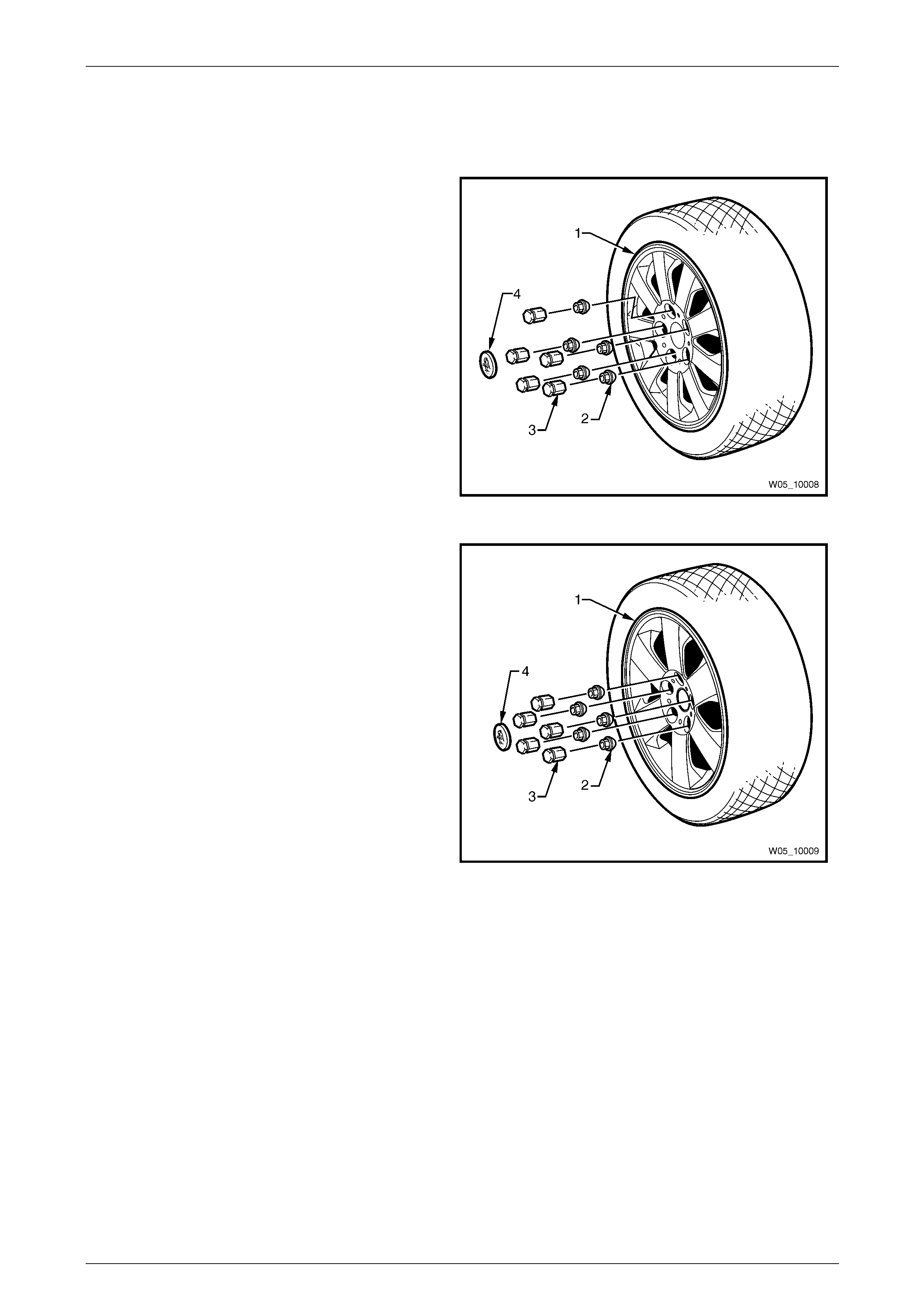
1 General Information – Wheels
and Tyres
STATESMAN
Figure 10 – 1 illustrates the alloy wheel (1), wheel
nuts (2), nut caps (3) and centre cap (4).
Road Wheels ............................7JJ x 16 alloy
Tyres.........................................225/55R16 95V
Figure 10 – 1
CAPRICE
Figure 10 – 2 illustrates the alloy wheel (1), wheel
nuts (2), nut caps (3) and centre cap (4).
Road Wheels ............................ 8JJ x 17 alloy
Tyres......................................... 225/50R17 94V
Figure 10 – 2
Wheels and Tyres Page 10–5
Page 10–5
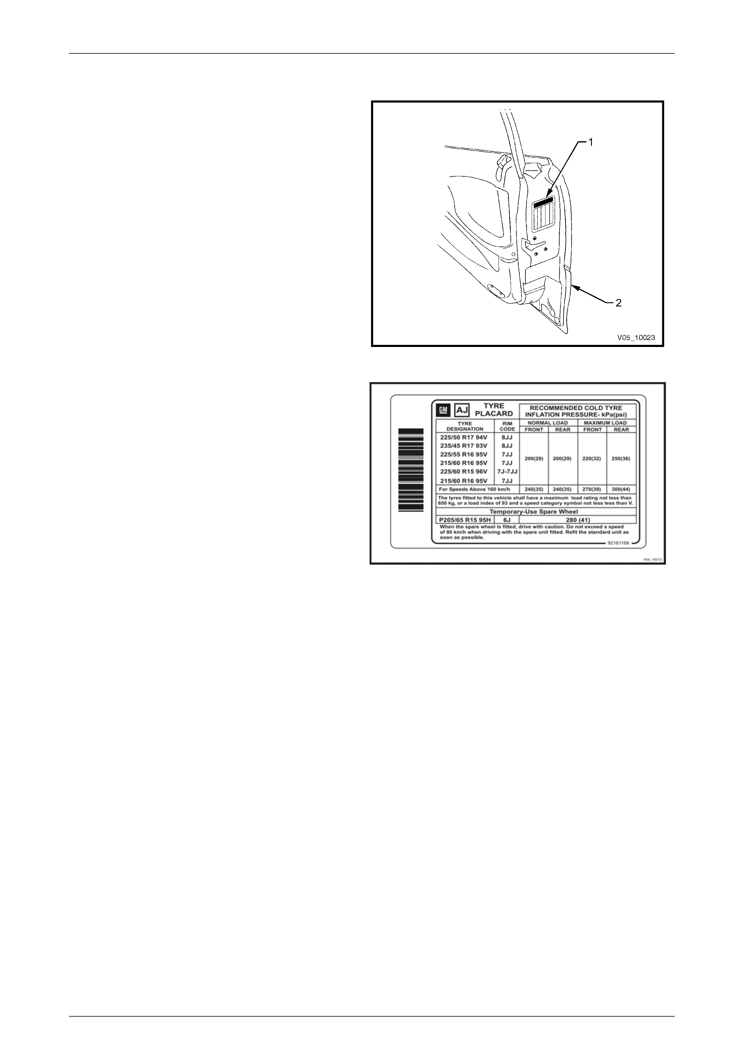
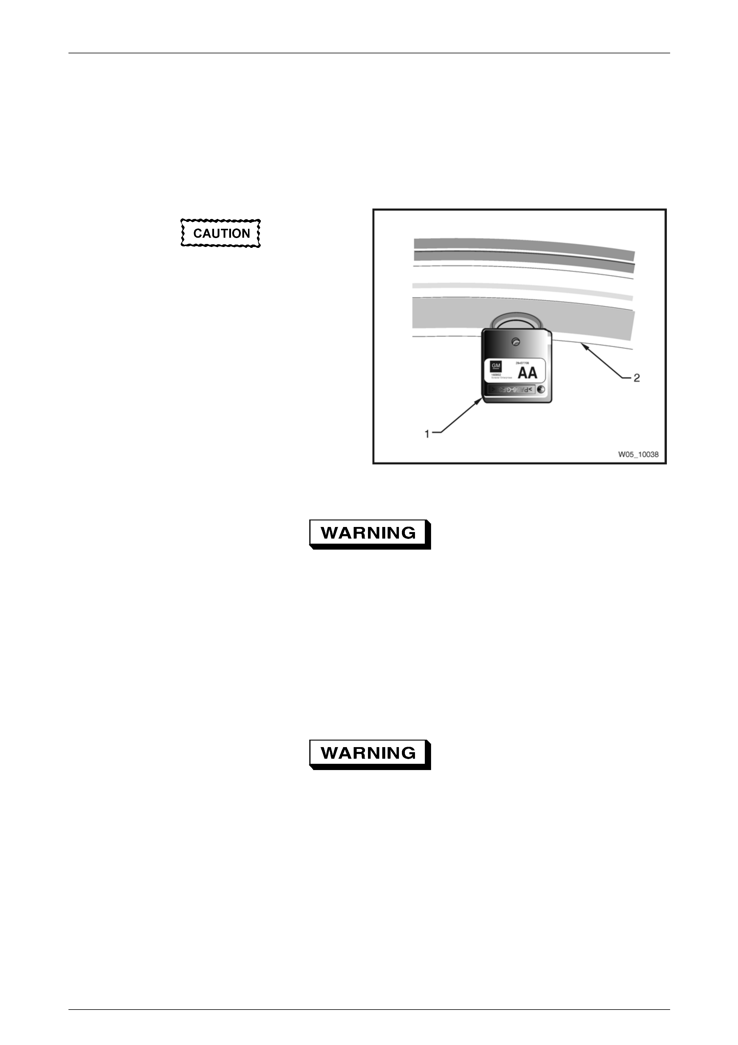
1.1 Tyre Placards
Wheel and tyre sizes, inflation pressures and load
capacity are specified on a tyre placard (1) located on
the end surface of the driver’s door (2).
Always check tyre pressures with COLD tyres (after
vehicle has stood for three hours or more, or driven less
than 2 kilometres) weekly or before any extended trip.
When checking tyre pressure, also visua ll y inspect
tyres for excessive wear, sharp objects embedded in
the tyre or damage to the sidewalls.
NOTE
• Clean the valve exterior, prior to
applying the air pressure nozzle when
inflating the tyre.
• Always install the valv e caps to keep out
dust and water.
Figure 10 – 3
The tyre placard shown is typical of those fitted on th e
vehicle.
Refer to 6 Specifications or the tyre placard on the
driver’s door for the correct wheel and t yre size and t yre
pressures.
Figure 10 – 4
Wheels and Tyres Page 10–6
Page 10–6
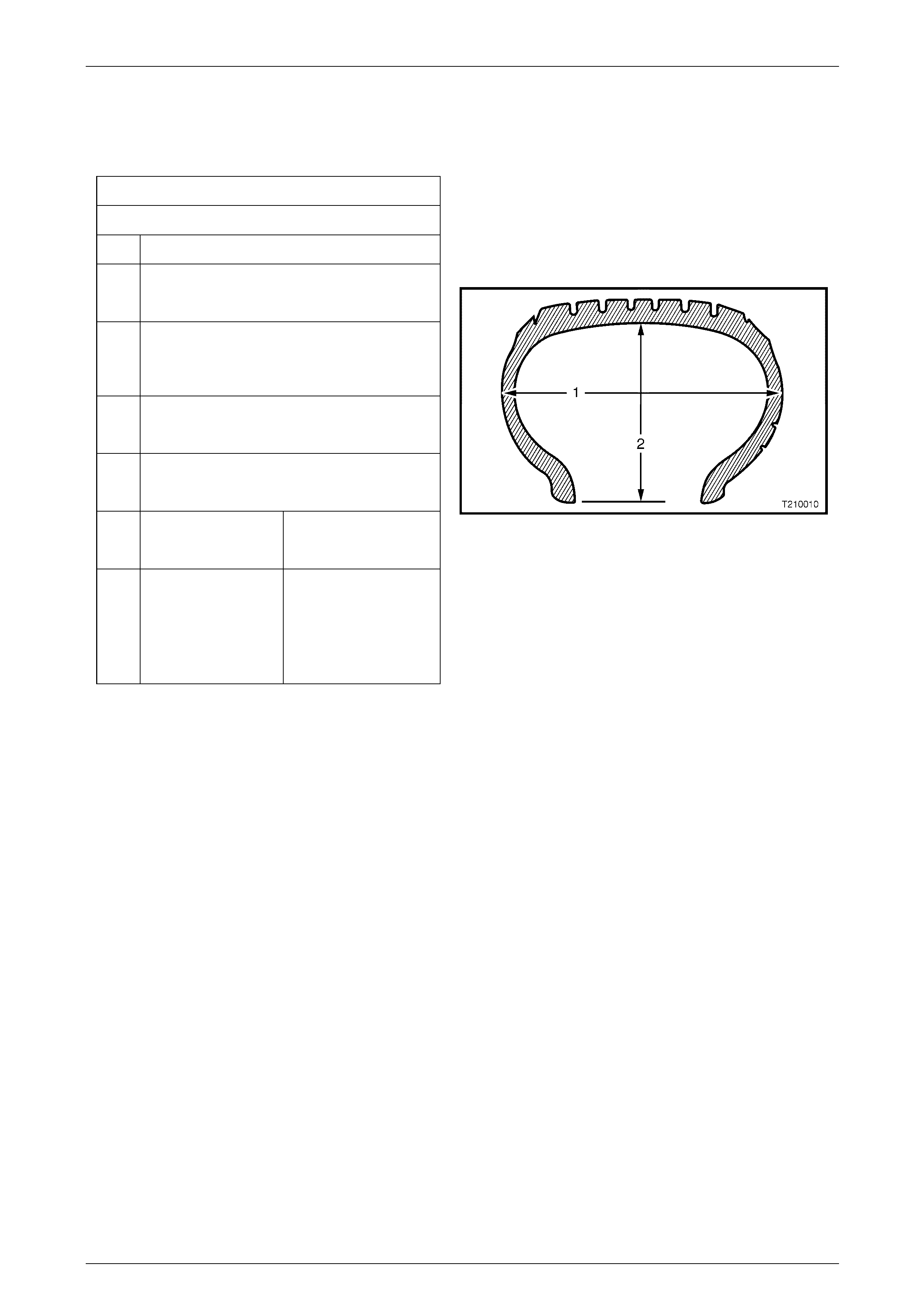
1.2 Tyre Markings
The tyre sidewall has a coded marking system, which provides information about the tyre.
Tyre Marking Example:
P 225 55 R 16 95 V
P Passenger Vehicle Designation
225 Section Width (1) in mm
(225 mm)
55 Aspect Ratio %: Section Width (1) to Section
Height (2)
(55 = 55%)
R Tyre Construction
(R = Radial)
16 Rim Diameter in inches
(16 = 16”)
95 Load Index in kg 94 = 670 kg max loa d
95 = 690 kg max loa d
V Speed Rating
R = 170 km/h
H = 210 km/h
V = 240 km/h
W = 270 km/h
Figure 10 – 5
Wheels and Tyres Page 10–7
Page 10–7
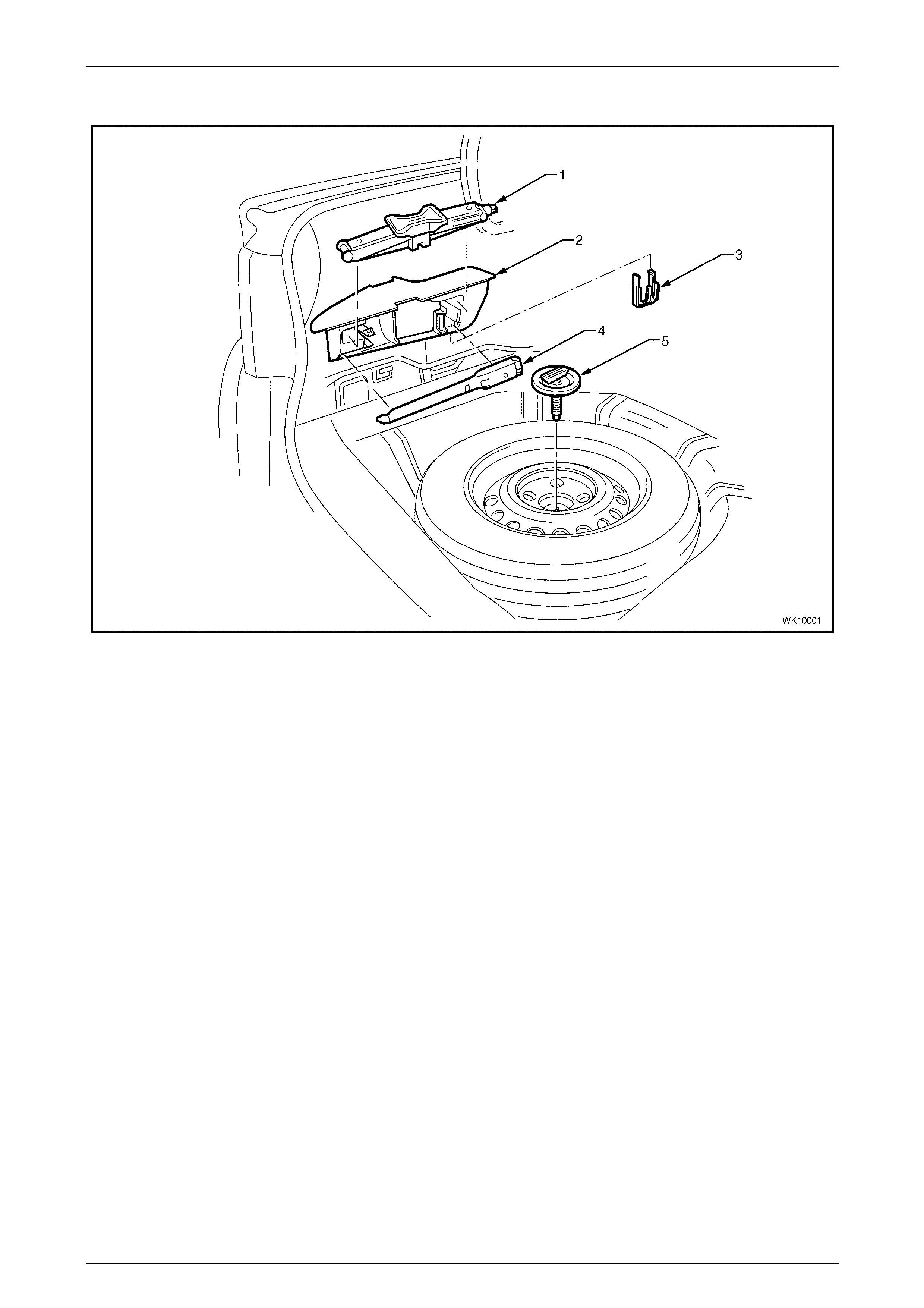
1.3 Spare Wheel Stowage
Figure 10 – 6
Legend
1 Jack 4 Jack / Wheel Nut Wrench
2 Stowage Compartment 5 Spare Wheel Retaining Bolt and Plate
3 Nut Cap Removal Tool
Wheels and Tyres Page 10–8
Page 10–8
2 General Information – Tyre
Pressure Monitoring System
2.1 Overview
The tyre pressure monitoring system (TPMS) continuously monitors the air pressure in all four tyres while the vehicle is
moving. A pressure sensor mounted to the valve stem inside each tyre periodically measures actual tyre pressure. This
pressure information is transmitted to the TP MS module by means of Radio Frequenc y (RF) communication. The TPMS
module is used to decode the incoming RF signals, format the data and transfer the data to the instrument cluster Multi-
function Display (MFD), via the secondary UART bus.
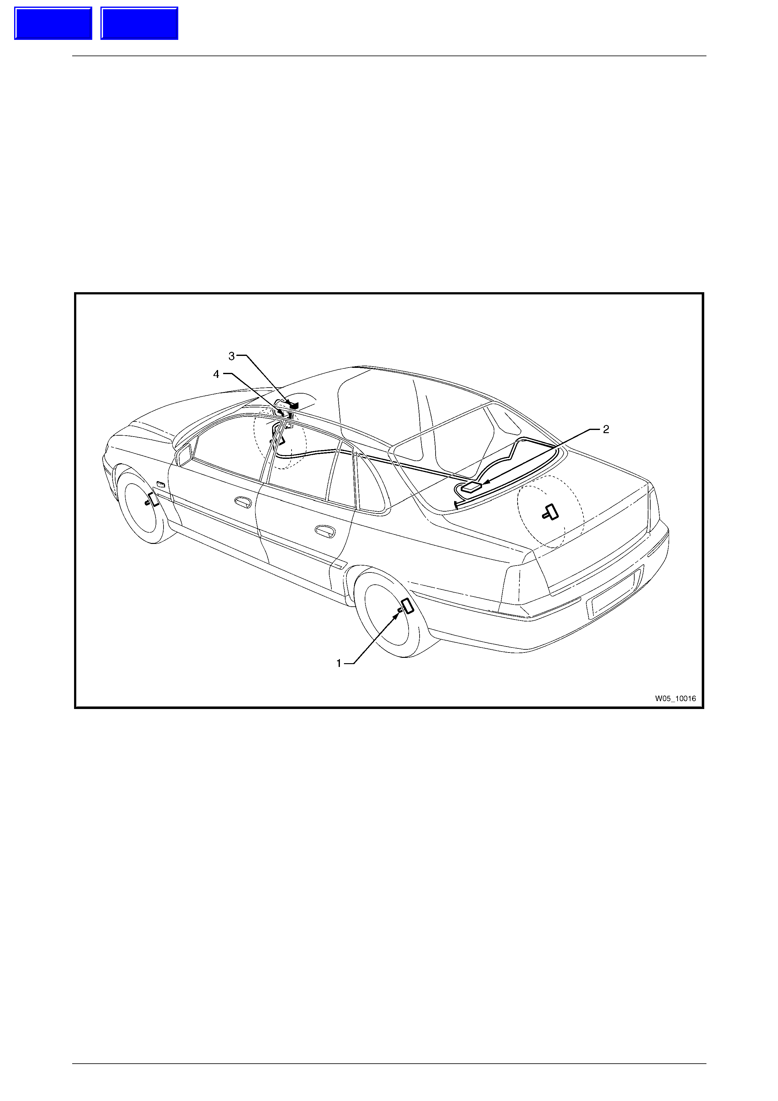
Figure 10 – 7 shows the tyre pressure monitoring system component locations.
Figure 10 – 7
Legend
1 Tyre Pressure Sensor 3 Instrument Cluster Multi-function Display
2 Tyre Pressure Monitoring System Module 4 Body Control Module
Techline
Techline
Wheels and Tyres Page 10–9
Page 10–9
2.2 System Components
The tyre pressure monitoring system (TPMS) consists of two major compo nents:
• T yre pressure sensor, refer to Figure 10 – 8.
• T PMS module, refer to Figure 10 – 9.
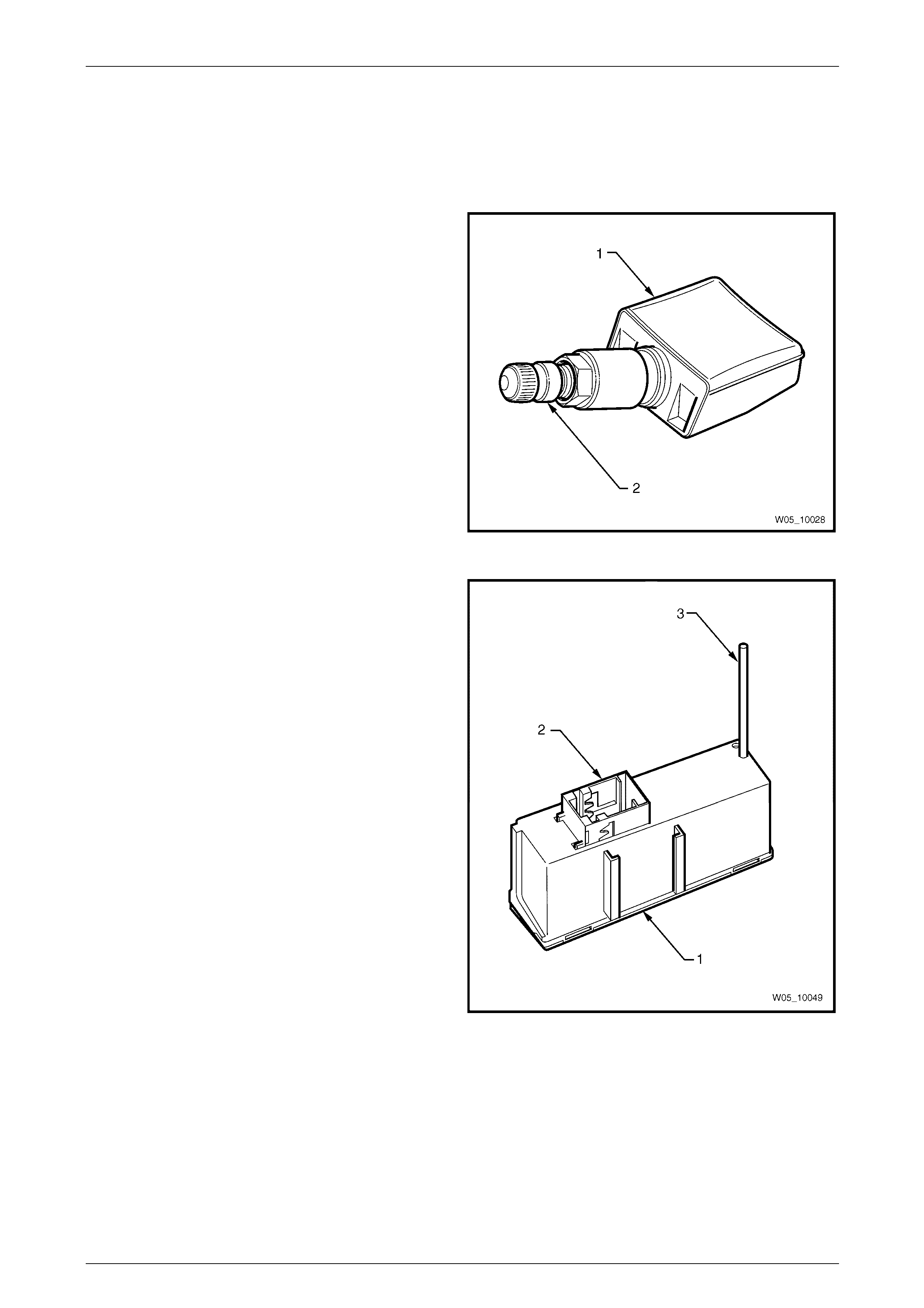
Tyre Pressure Sensor
A tyre pressure sensor (1) is located inside the tyre at the
base of each tyre valve (2). It performs the following
functions:
• Monitor and tra nsmit the tyre pressure readings to the
TPMS module, which in turn provides pressure
information to the instrument cluster MFD.
Figure 10 – 8
TPMS module
The TPMS module is concealed under the rear window trim
panel assembly. It shares a mounting bracket with the rear
park assist alarm buzzer.
The module consists of a plastic housing (1) which contains
a circuit board (not shown). Attached to the circuit board are
a single electrical connector (2) and an antenna (3).
The TPMS module carries out the following functions:
• Receive the tyre pressure RF signals from each t yre
pressure sensor.
• Process the signa ls and forward the readings and / or
warnings to the instrument cluster MFD via the
secondary UART data bus.
• Determines if there ar e abnormal pressure variations
in the tyre.
Figure 10 – 9
Wheels and Tyres Page 10–10
Page 10–10
2.3 Instrument Cluster Display Information
System Configuration
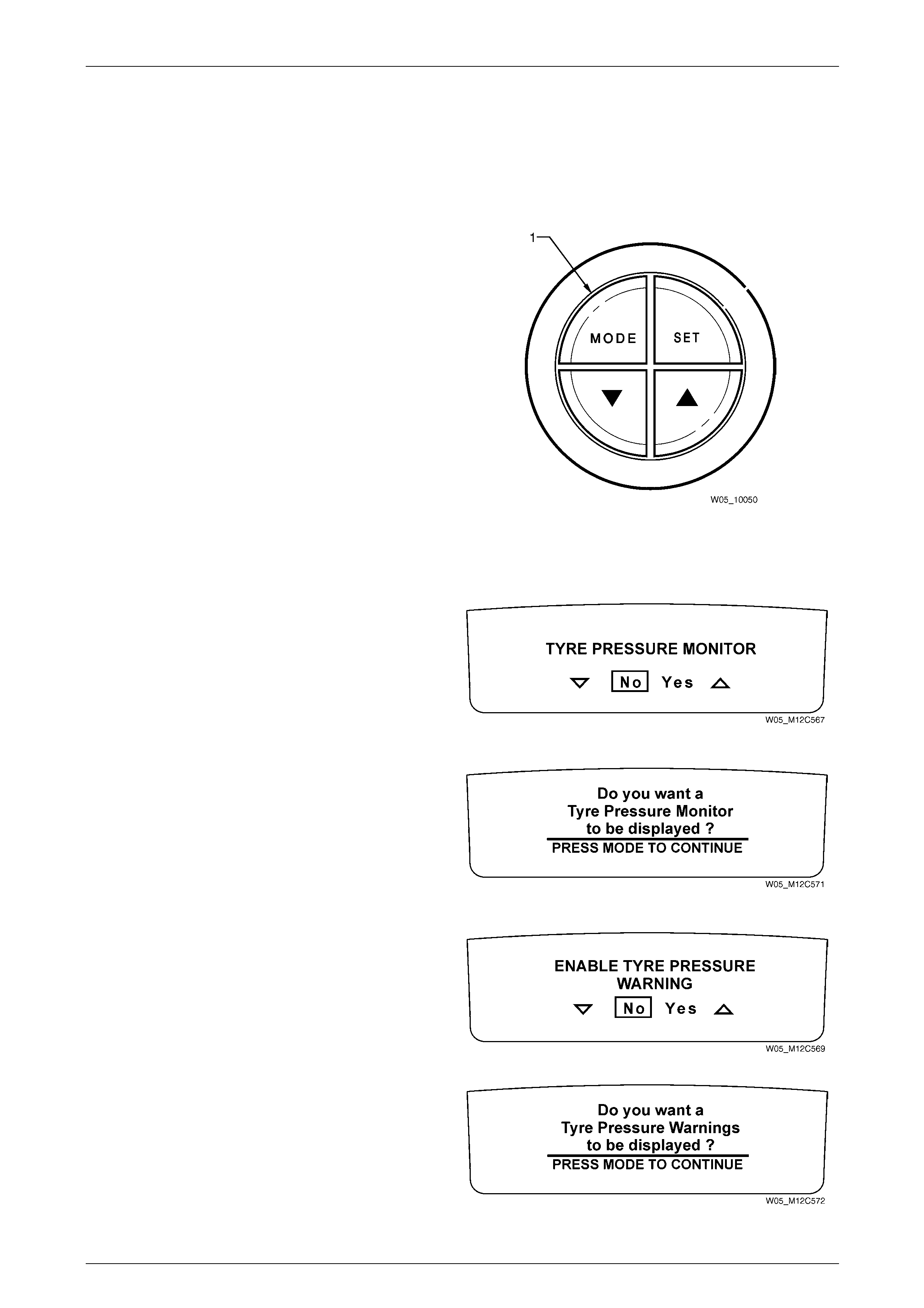
Access of the TPMS displays on the instrument cluster MFD can be achieved through the Options Menu. The Options
menu can be accessed when:
• T he vehicle is stationary and the MODE button (1) on
the trip computer is held do wn while turning on the
ignition.
• If the vehicle has been starte d, the system check
completed and the vehicle speed is less tha n 10 km/h.
The options menu will be dis pla yed for 3 seconds.
NOTE
• If the vehicle speed exceeds 10 km/h, the
Options Menu disappears and the MFD
reverts back to the previous trip computer
function.
• The Options Menu is not accessible if an
alarm warning has been activated or a
warning symbol on the instrument panel has
been activated.
Figure 10 – 10
MFD Option Menu Displays
Use the trip computer switch MODE button to select the
Tyre Pressure Monitor option.
Figure 10 – 11
If no selection is made at the Tyre Pressure Monitor
screen within 5 seconds, this Help screen message
appears.
Press the MODE button to go back to the TPM selection
screen.
Figure 10 – 12
Select Yes to allow the TPM warning messages to be
displayed on the MF D.
Figure 10 – 13
If no selection is made at the Tyre Pressure Warnings
screen within 5 seconds, this Help screen message
appears.
Press the MODE button to go back to the TPM Warnings
screen.
Figure 10 – 14
Wheels and Tyres Page 10–11
Page 10–11
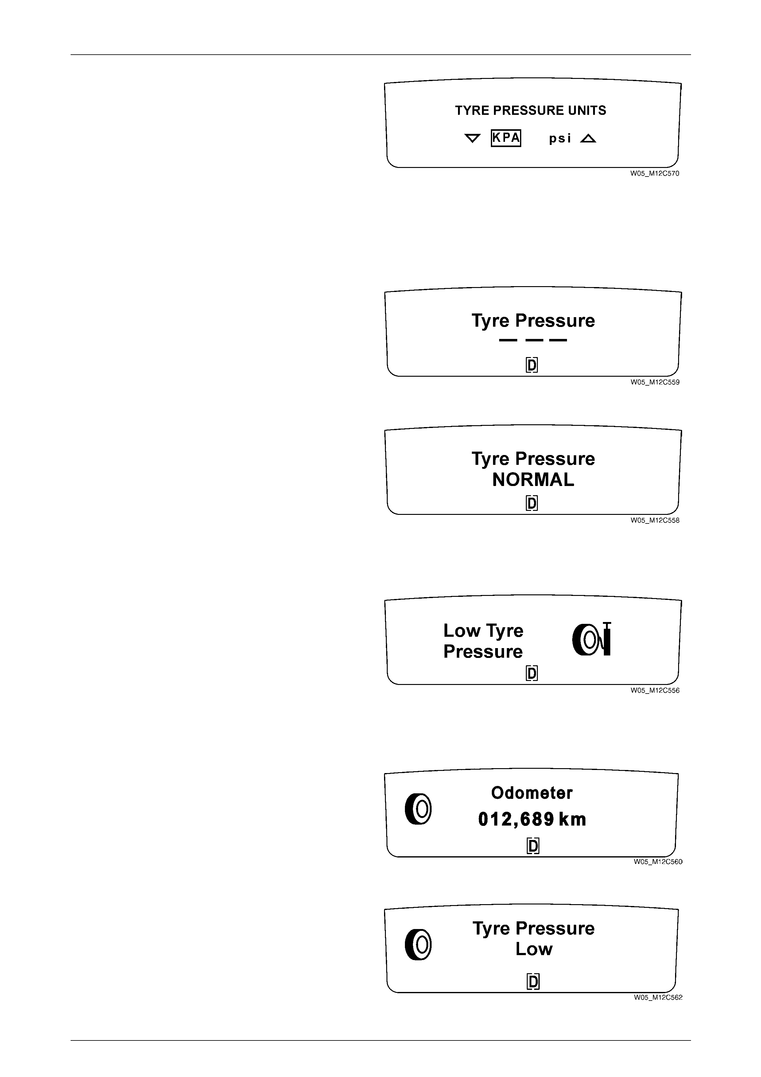
Tyre Pressure Units
Use the trip computer switch UP or DOWN button to
select the tyre pressure units (psi) or (kpa).
Press the MODE button to continue past this option.
Figure 10 – 15
Start Display
When the ignition s witch is turned on, the tyre pressure monitor system (TPMS) does not transmit tyre pressure data on
the bus until the vehicle is moving.
Tyre Pressure Monitor System
Once the vehicle is moving, the TPM sensors transmit
data to the TPMS module. Between this period of no data
transmission and data transmission, the t yre pressure
monitor will display blank information.
Figure 10 – 16
Normal Tyre Pressure Screen
When the MODE button on the trip computer switch is
cycled until the TPM system is displayed, the T yre
Pressure Monitor screen will display the status of the tyre
pressure.
The vehicle must be in motion before the actual tyre
pressure status can be displayed. Figure 10 – 17
Tyre Pressure Warnings
Low Tyre Pressure Warning
If the TPM system detects that the air pressure in one of
the tyre’s has decreased below 175 kPa (25.4 psi), a
warning message to indicate this situation will be
displayed on the MF D.
The warning comprises two graphic images with the
animation of the pump handle moving up/down. When the
MODE button is pressed, the message minimises,
permitting other wheel / tyre warning messages to be
displayed.
Figure 10 – 18
When the MODE button on the trip computer switch has
minimised the message, the display reverts to an icon on
the left of the MFD.
The Low Tyre Pressure reminder remains on the MFD
until the problem is rectified.
Figure 10 – 19
When the MODE button on the trip computer switch is
cycled until the TPM system is displayed, the MFD will
display the tyre pressure status .
Figure 10 – 20
Wheels and Tyres Page 10–12
Page 10–12
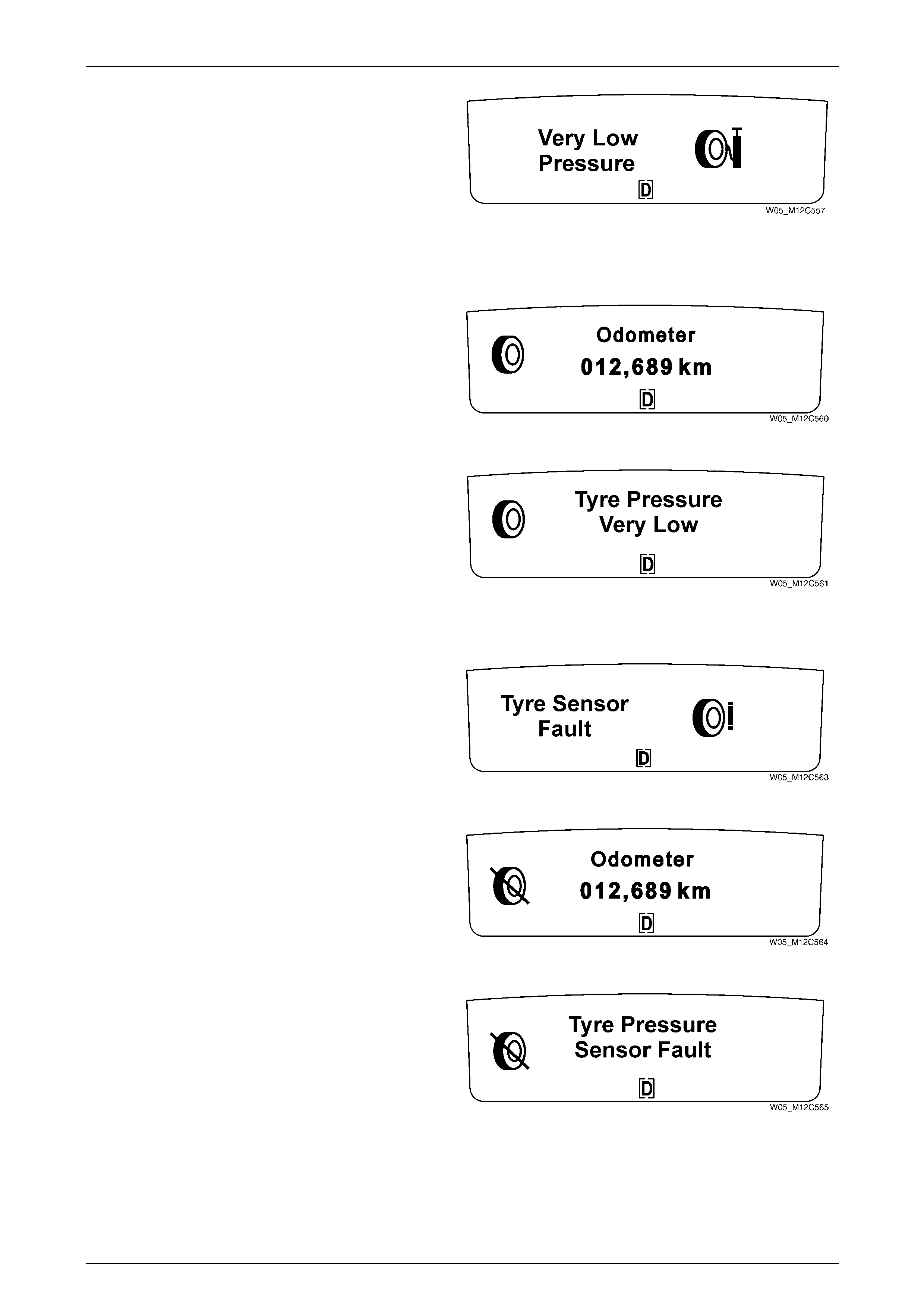
Very Low Tyre Pressure Warning
If the TPM system detects that the air pressure in one of
the tyre’s has decreased below 150 kPa (21.8 psi), a
warning message to indicate this situation will be
displayed on the MF D.
The warning comprises two graphic images with the
animation of the pump handle moving up/down. When the
MODE button is pressed, the message minimises,
permitting other wheel / tyre warning messages to be
displayed.
Figure 10 – 21
When the MODE button on the trip computer switch has
minimised the message, the display reverts to an icon on
the left of the MFD.
The Very Low Tyre Pressure reminder remains on the
MFD until the problem is rectified.
Figure 10 – 22
When the MODE button on the trip computer switch is
cycled until the TPM system is displayed, the MFD will
display the tyre pressure status .
Figure 10 – 23
Tyre Pressure Sensor Fault
Tyre Pressure Sensor Fault Warning
If the TPM system detects that one of the vehicles air
pressure sensors has failed, an animated warning
message appears on the MFD. A flashing bar indicates
that one of the sensors has failed.
Figure 10 – 24
When the MODE button on the trip computer switch is
pressed, the display reverts to the flashing icon on the left
of the MFD.
The Tyre Pressure Sensor Fault reminder remains on the
MFD until the problem is rectified.
Figure 10 – 25
Failed Tyre Pressure Sensor Warning
When the MODE button on the trip computer switch is
cycled until the TPM system is displayed, the MFD will
display the tyre pressure status .
If a tyre sensor has failed it will be displayed on the MFD. Figure 10 – 26
Wheels and Tyres Page 10–13
Page 10–13
2.4 Tyre Pressure Monitoring System
Transmitter System Modes
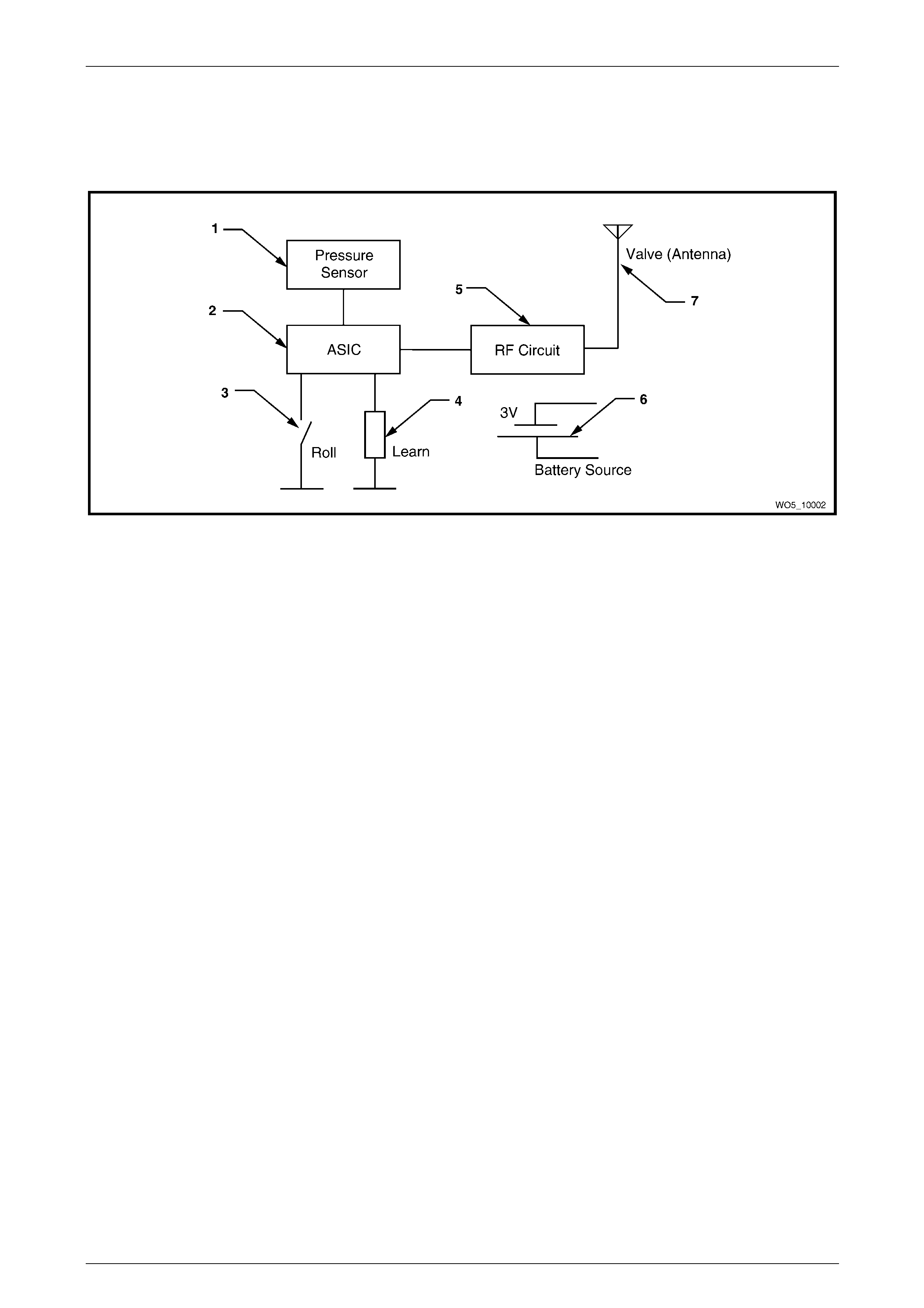
The following is a short description of the transmitter system modes. Refer to Figure 10 – 27 for the transmitter circuit
block diagram:
Figure 10 – 27
Legend
1 Tyre Pressure Sensor
2 Application Specific Integrated Circuit (ASIC)
3 Roll Switch
4 Learn Circuit
5 RF Circuit
6 Battery
7 Antenna (Schrader Valve)
Stationary Mode
The pressure sensor may transmit over a regular i nterval while the vehicle is parked. T his mode is exited by a roll
switch (3) input to the Application Sp ecific Integrated Circuit (2)(ASIC).
Wake Mode
When the vehicle begins to m ove, the roll switch (3) closes and an ASIC (2) input activates the pressure sensor. The roll
switch is closed with a centrifugal force between 2 and 17 G. The relevant speed at which this occurs varies in relation to
the wheel diameter, typically b etween 11 and 32 km/h. As the first transmission cycle after the Stationary Mode, the data
block will contain the function code for the Wake Mode and will only be transmitted once. All other data will transfer as
normal.
Drive Mode
The pressure sensor increases its rate of sampling and transmission when the vehicle is moving (ro ll switch closed). The
pressure sensor will remain in drive mo de for a period of time known as the Service Period after the vehicle comes to
rest (roll switch open). After the Service Period has elapsed the pressure se nsor returns to Stationary Mode.

Wheels and Tyres Page 10–14
Page 10–14
Low Battery Mode
Battery life is approximately 1 0 years or 160,000 km. The circuit in the pressure sensor monitors the battery every time a
pressure measurement is taken. A ‘Low Battery’ function code will be sent when the battery voltage within the pressure
sensor is below a pre-selected level. Under typ ical conditions, the pressure sensor will remain active for at least 3
months after the first low battery signal, and will not degrade RF power of signal measurement accuracy duri ng this
period.
Learn Mode
The receiver / decoder distinguishes this learn code and stores the pressure sensor ID within its memory for future
identification purposes. The ‘memorisation’ or learning of the ID codes of the pressure sensors on the vehicle means that
the receiver is capable of filtering out information coming from adjacent vehicles.
Re-measure Mode
This mode only occurs if the pressure is changin g. The pressure in the tyre is periodically measured and transmitted at a
preset interval. If, during an y measur ement period, the value differs by 100 mbar, a re-m easure will occur immediatel y.
This will confirm a change and if correct, the new pressure will be transmitted with the re-measure function code. If the
re-measure is coincident with a normal transmission, the re-measure will have precedent for that tyre location.
Normal Pressure Mode
Considered as a supervisory mode, during normal rolling and stationary operation, the pressure sensors will send regular
pressure values associated with each wheel giving a ‘state of health’ of the system. Unless in Wake, Low Battery, Learn
or Re-measure Modes, all data transmissions will contain the function code for Normal Pressure.
Sleep Mode
Is a low power mode during pressure sensor activatio n. It occurs in the time period between transmissions and
measurements.
Off Mode
This is a minimum power mode mainly used for shipment and storage of the pressure sensor units. Not all units will be
shipped in this mode. During Off Mode all internal circuitry is disabled. To exit this mode, activate the learn or roll switch
continuously for four seconds, placing the pressure sensor into Learn Mode.

Wheels and Tyres Page 10–15
Page 10–15
2.5 Tyre Pressure Monitoring System Learn
Modes
There are different ways in which the TPMS module can learn the position of the pressure sensors on the vehicle.
Following is a short description of the learn modes to be used with this tyre pressure monitoring system.
Normal Learn
Each time the vehicle is started the TPMS module will be able to learn the four pressure sensors upon the following
conditions:
• Ne w ignition cycle.
• Normal operation.
• Vehicle spe ed above the threshold spe ed of 30 km/h, which allows for the filtering of stray transmissions.
During the normal learn, the TPMS module will detect if the sensors are missing or have developed a fault.
End of Line (EOL) Learn
The TPMS module has to be programmed after being fitted to a vehicle. As such, there is a learn procedure carried out
on the production line which programs the sensor ID’s to the TPMS module.
Aftermarket Learn
If the dealer receives a new vehicle from stock and the T PMS was not programmed correctly on the production line, an
aftermarket learn must be performed. Check if there are an y set DTCs are set. Diagnose an y set DTCs before
continuing, refer to 4 Diagnostics – Tyre Pressure Monitoring System. If no DTCs are set, program the sensors to the
TPMS module, refer to 5.10 Tyre Pressure Monitoring System – Programming.
Spare Wheel Change
If a customer experiences a flat tyre and changes to the spare wheel, then the system will still be able to function without
any noticeable change. This involves TPMS learning the pre ssure sensor ID of the sensor in the spare wheel. This is
possible when only o ne sensor has been changed.

Wheels and Tyres Page 10–16
Page 10–16
2.6 TPMS Warnings
The following will outline the way in which the pressure sensors and the TPMS module are interconnected.
NOTE
In order for location information to remain valid, it
is assumed that only service personnel will rotate
wheels and that they will reprogram the TPMS
system.
Fail Strategy
TPMS Module Failures
The TPMS module can detect internal errors and perform a consequent action. The main types of failure are likely to be
related to the TPMS module are ROM, RAM and EEPROM. Upon an y of these failures, a DTC will be set to indicate that
a fault is present.
Pressure Sensor Failures
The TPMS module is responsible for detection of pressure sensor faults if a pressure sensor has not transmitted within
10 minutes of the last transmission and the vehicl e speed is above 30 km/h, then that pressure sensor is deemed to
have failed.
Warning Strategy
The TPMS module can imple m ent a warning strategy in order to provide information on the serial bus with regard to the
status of tyre pressures. The warning strategy is resilient to pressure fluctuations a nd will only report real problems.
Three levels of pressure information is provided on the serial data bus to the instrument cluster.
• Nominal
• Warning
• Alarm
Nominal
In this state the tyre pressure is acceptable when compared to threshold limits. This stat e is communicated on the serial
data bus to the instrument cluster.
Warning
In this state, a warning is communicated on the serial dat a bus signif ying that a tyre pressure is below the manufacturer’s
recommended threshold, but is still abov e a threshold where it is considered safe to drive. This state is communicated on
the serial data bus to the instrument cluster.
Alarm
In this state, the tyre pressure has fallen below the threshold that is considered safe for normal drivi ng or, the TPMS
module has detected that a tyre is leaking. This state is communicated on the serial data bus to the inst rument cluster.

Wheels and Tyres Page 10–17
Page 10–17
3 Diagnostics – Wheels and Tyres
3.1 Wear
Analysis of tyre wear condition s varies according to the type, size and bran d of the tyre fitted to the vehicle. Refer to the
tyre manufacturer's literature relating to tyre wear when evaluating tyre wear conditions.

Wheels and Tyres Page 10–18
Page 10–18
3.2 Road Testing
As there are many reasons for a vibration co ndition to be present in a vehicle, it is vital that a thorough road test be
conducted to eliminate other possible causes for a vibration condition being present.
Tyre and Wheel Inspection
This visual inspection should be conducted for all vibration complaints unless the disturb ance only occurs with the
vehicle at a standstill.
• T he tyres should be i nspected for unusual wear, including cupping, flat spots and heel-and-toe wear. These
conditions can cause tyre growl, howl, slapping noises and vibrations throughout the vehicle.
• Establish that all tyres are inflated to the correct pressures prior to any road test.
• Check for bulgi ng in the sidewalls.
• Check all wheels for bent rim flanges. In many cases, a cracked hubcap or dented trim ring can indicate a bent
wheel underneath.
Slow Acceleration Test
This test is to identify engine or vehicle speed relate d conditions. It will be necessary to perform additional tests in order
to determine in which category the vibration belongs.
1 On a smooth, level road, slowly accelerate up to high way speed.
2 Look for disturbances that match the customer's description.
3 Note the vehicle speed (km/h) and engi ne speed (rpm) where the disturbance occurs.
Follow this test with the neutral coast-down test, and the downshift test.
Neutral Coast-down Test
1 On a smooth, level road, accelerate to a speed slightly hi gher than the speed at which the vibration occurs.
2 Shift the vehicle into neutral and coast down through the vibration range. Note if the vibration is present in neutral.
If the vibration still occurs in neutral, it is definitely vehicle-speed sensitive. At this point, the engine and torque converter
have been eliminated as a cause. Depending on the symptoms or frequency, the rep air will concentrate on either the
tyres and wheels, or the propeller shaft and rear axle.
Downshift Test
1 On a smooth, level road, accelerate to the speed at which the complaint vibration occurs. Note the engine rpm.
2 Decelerate and safely downshift to the next lower gear.
3 Operate the vehicle at the previous engine rpm.
If the vibration returns at the same rpm, the engine or torque converter is th e most probabl e cause. To confirm these
results, repeat this test in still lower gears and in neutral.

Wheels and Tyres Page 10–19
Page 10–19
Steering Input Test
This test is intended to determine if wheel bearings or other suspension components are contributing to a vibration,
especially those relating to noises, howl or growl, grinding a nd roaring.
• With the vehicle at the vibration speed (km/h), drive through slow sweeping turns – first in one direction, then the
other.
• If the vibration chan ges (worsens or diminishes), the wheel bearings, hubs and tyre tread wear are all possible
causes.
Standing Start Acceleration
The purpose of this test is to duplicate a vibration called take-off-shudder. In some cases, a powertrain mount or the
exhaust contacting the body may also be suspect, depending on the symptoms.
1 With the vehicle at a complete stop and in gear, remove your foot from the brake.
2 Accelerate to 60 or 70 km/h while checking for vibrations that match the customer's desc ription.
Shudder in the seat or steering wheel under these conditions usually results from incorrect driveline angles. Worn, tight
or failed universal joints ma y also be a cause, and should be inspected first.
Grunting or groaning noises a long with a buzzing or roughness in the floor usually points to the vibrati on being conducted
through the engine or transmission mounts, or throug h exhaust mounts and hangers that have grou nded out. Refer to
the respective Sections for rectification procedures.
Wheels and Tyres Page 10–20
Page 10–20
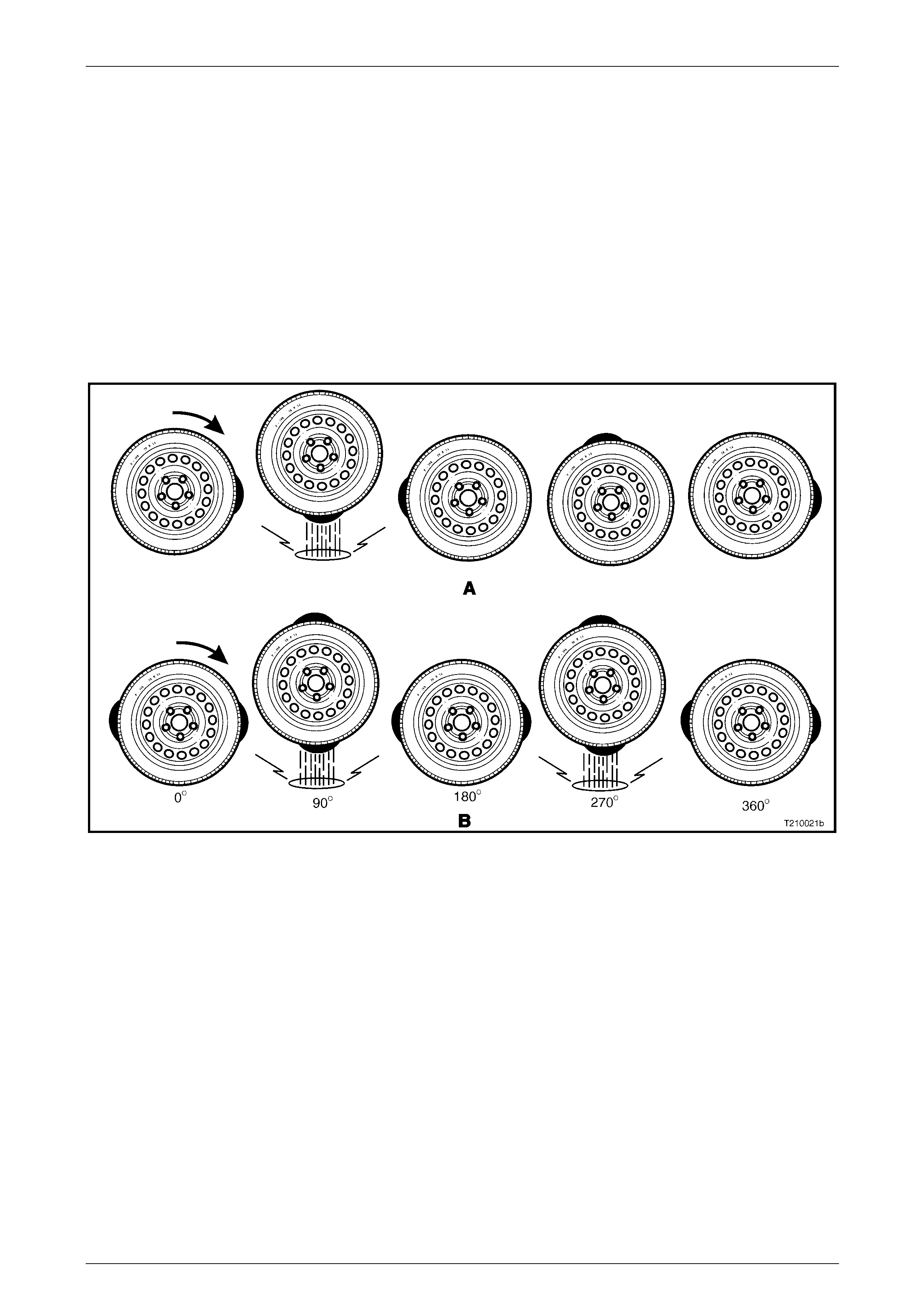
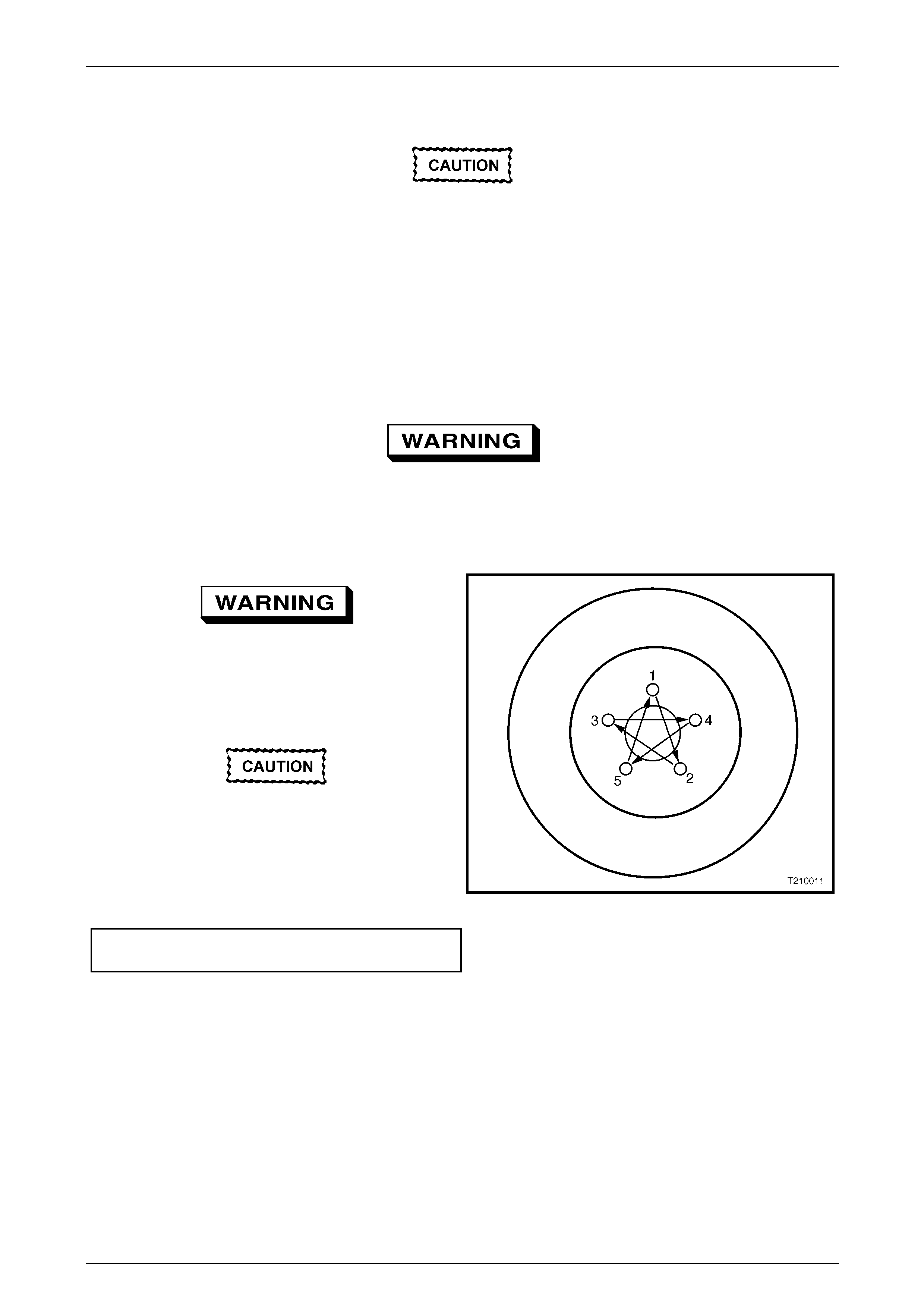
3.3 Vibration
To determine the cause of a vibration con dition that is suspected of being tyre / wheel related, an essential aspect is to
understand the nature of first and second order vibrations (or harmonics).
As shown in Figure 10 – 28, A, a tyre with one high spot would create a d isturbance once every comple te revolution. This
is called first-order vibrations.
An oval shaped tyre with two high spots (as shown B) would create a disturbance twice per revolution. This is called
second-order vibrations. Three high spots would be third order, and so on.
Two first-order vibrations may add to or subtract from the overall amplitude of the disturbance, but that is all. Two
first-order vibrations do not equal a second-order. Due to centrifugal force, an out-of-balance compo ne nt (for exampl e
tyres, drive shafts or engine) will al ways create a first-order vibration.
If wheel and tyre assemblies are balanced to the degree required and vibration is still evident, then tyre run-out or force
variation could be responsi ble.
Figure 10 – 28
Wheels and Tyres Page 10–21
Page 10–21
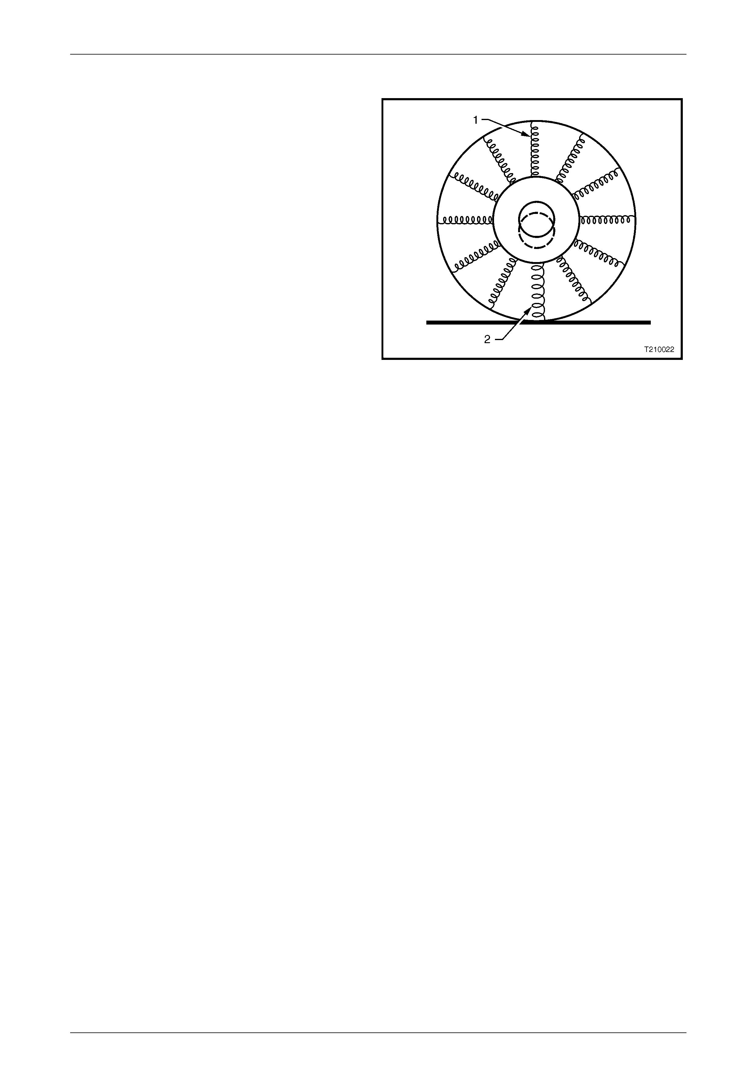
Radial Force Variation
Radial force variation refers to a difference in the stiffness
of a tyre sidewall as it rotates and contacts the road.
Figure 10 – 29 uses springs to illustrate the point. The
lighter springs (1) represent a normal sidewall while the
heavier spring (2) repres ents a stiffer section of the
sidewall. Tyre / wheel assemblies have some of this due to
splices in the different plies of the tyre, but they do not
cause a problem unless the force variati on is excessive.
These stiff spots in the sidewall can deflect the tyre / wheel
assembly upward as they contact the road.
If there is only one stiff spot in the sidewall, it will deflect the
spindle once per each revolution of the tyre / wheel
assembly, causing a first-order tyre / wheel vibration.
If there are two stiff spots, they can cause a second-order
vibration.
First and second order tyre / wheel vibrations are the most
common to occur as a result of radial force variation. Higher
orders (for example third or fourth) are possible, but quite
rare. The most effective way to minimise the possibility of
force variation as a factor in tyre / wheel vibration is to
ensure that the tyre / wheel assembly run-out is at an
absolute minimum.
Figure 10 – 29
Some tyre / wheel assemblies may exhibit vibration-causing amounts of force variation even though the y are within run-
out and balance tolerances. Due to tighter tolerances and higher standards in manufacturing, these instances are
becoming rare. If force variation is suspected as being a fa ctor, substitute one or more known good tyre / wheel
assemblies for the suspect assemblies. If this rectifies the problem, replace the offending tyre.
Lateral Force Variation
This is based on the same concept as radial force variati on, except that lateral force variation tends to deflect the vehicle
sideways or laterally, as the n ame implies. A snaky belt inside the tyre can cause lateral force variation. Tyre
replacement using the substitution method may be necessary.
This condition is very rare and again, the best way to eliminate it as a factor is to ensure that the lateral run-out of the
tyre / wheel assemblies is at an absolute minimum.
In most cases where excessive lateral force variation exists, the vehicle will d isplay a wobble or waddl e at low speeds
(8 to 40 km/h) on a smooth road surface. The condition will usually be re lated to a first order vibration of tyre / wheel
rotation.
Some degree of tyre run-out will always be present, due to dimensional tolerances in both the tyre and wheel and can
often be reduced by rotating the tyre on the whe el to cancel out the overall effect. Force Variation (a variation in stiffness
around the tyre) can also caus e the same problem, resulting in a var ying loaded radius as the t yre rotates.
All of these factors have so far been conside r ed to act radially. However, lateral run-out and lateral force variation can
also be translated into vehicle vibration ranging from low speed waddle to relativ ely high-speed shake or vibrations
similar to those obtained with tyre imbalance.

Wheels and Tyres Page 10–22
Page 10–22
3.4 Vehicle Lead
Vehicle lead is the deviatio n of the vehicle from a straight path, on a level road (no camber) and with no load on the
steering wheel. Lead is usually caused by alignme nt and / or brake drag, but can sometimes be caused by t yres.
The way in which a tyre is built can produce lead in a vehicl e. An exampl e of this is placement of the belt in a radial tyre.
An off-centre belt can cause the tyre to develop a side force while rolling straight down the road.
If one side of the tyre is a little larger in diameter than the other, the tyre will tend to roll up to one side. This will develop a
side force, which can produc e vehicle lead.
The following diagnostic chart can be used to confirm vehicle lead.
Step Action Yes No
1 1 Inflate tyres to the correct pressures.
2 Road test vehicle in opposite directi ons, on a level, uncrowned
road with little or no crosswind.
Does vehicle lead to the same side in both directions? Go to Step 2 Go to Step 8
2 Swap front tyres from one side to the other and road test again in
opposite directions.
Does vehicle lead to the same side as in Step 1?
Put tyres back in
original positions.
Go to Step 8 Go to Step 3
3 Does the vehicle no w lead to the op posite side to that in Step 1? Go to Step 5 Go to Step 4
4 Has the lead condition been corrected? Leave tyres as is. If
roughness
develops, replace
front tyres Go to Step 5
5 Install a known good tyre to replace one front tyre and road test again.
Is the lead condition corrected?
Lead condition has
been isolated.
Replace tyre Go to Step 6
6 Check the test tyre on a known good vehicle.
Has the lead condition been corrected?
Check if tyre is
faulty.
Go to Step 5 Go to Step 7
7 Install a known good tyre to replace remaining front tyre.
Has the lead condition been corrected?
Lead condition has
been isolated.
Replace tyre Go to Step 8
8 1 Check / correct vehicle wheel alignment and maladjusted or
binding steering.
2 Road test again.
Has the lead condition been corrected?
Vehicle is now
operating to
specification Swap tyres, front to
rear and recheck

Wheels and Tyres Page 10–23
Page 10–23
4 Diagnostics – Tyre Pressure
Monitoring System
The tyre pressure monitoring system (TPMS) module provides diagnostic capability. The purpose of this function is to
permit diagnosis of any problem s that may occur within the TPMS. It can also be used as a means to conve y
configurable parameters to the T PMS module.
NOTE
Correct inflation of tyres to recommended
specifications (refer to 6 Specifications) will
prevent low-pressure warning indications. The
TPMS must be enabled before it will operate.
NOTE
If TPMS is fitted, the spare wheel has a sensor
installed that is automatically recognised, along
with its position on the vehicle. If the tyres need
to be rotated, the new wheel sensor locations
need to be programmed.
Wheels and Tyres Page 10–24
Page 10–24
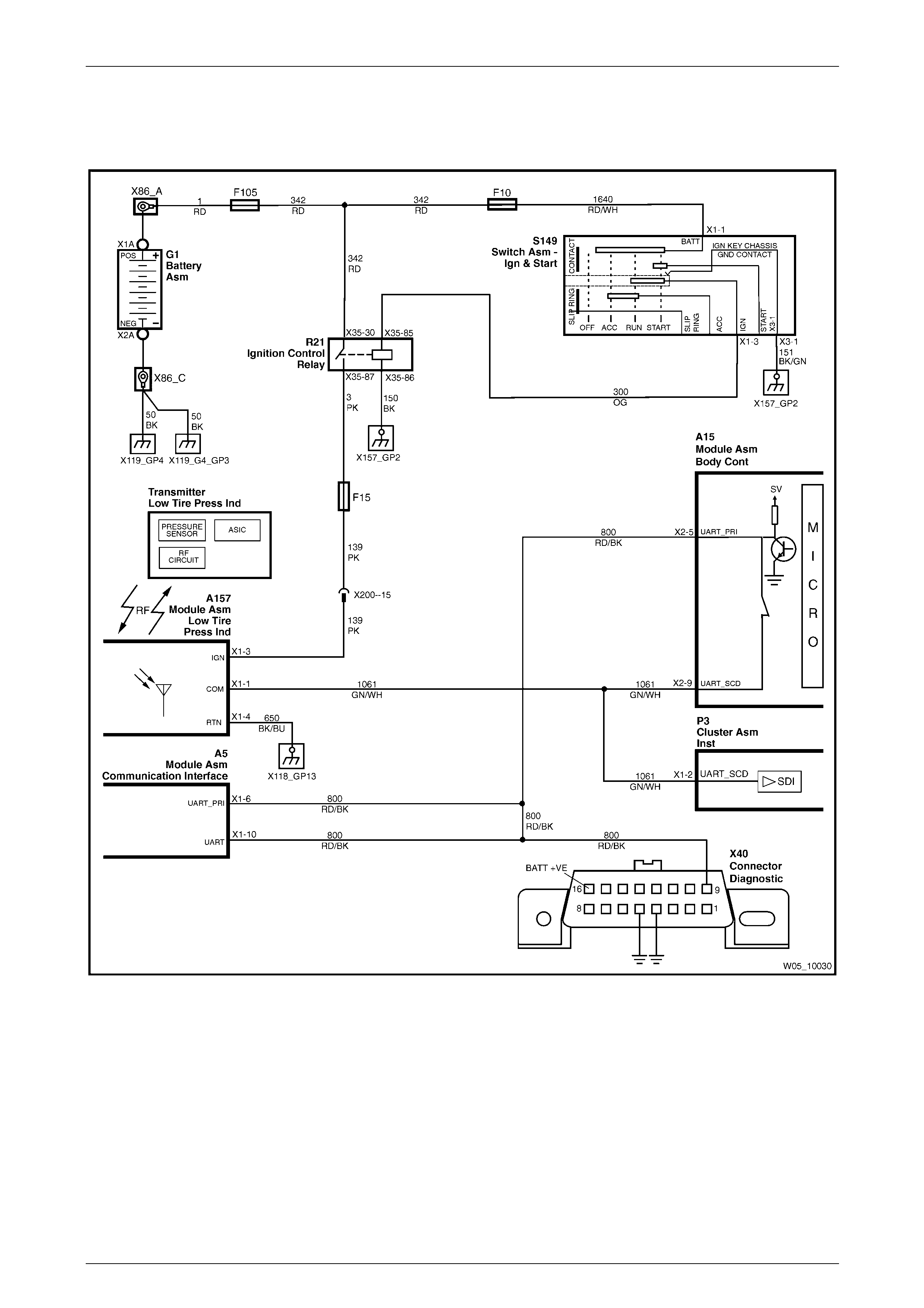
4.1 Wiring Diagram and Connector Chart
Wiring Diagram
Figure 10 – 30
Wheels and Tyres Page 10–25
Page 10–25
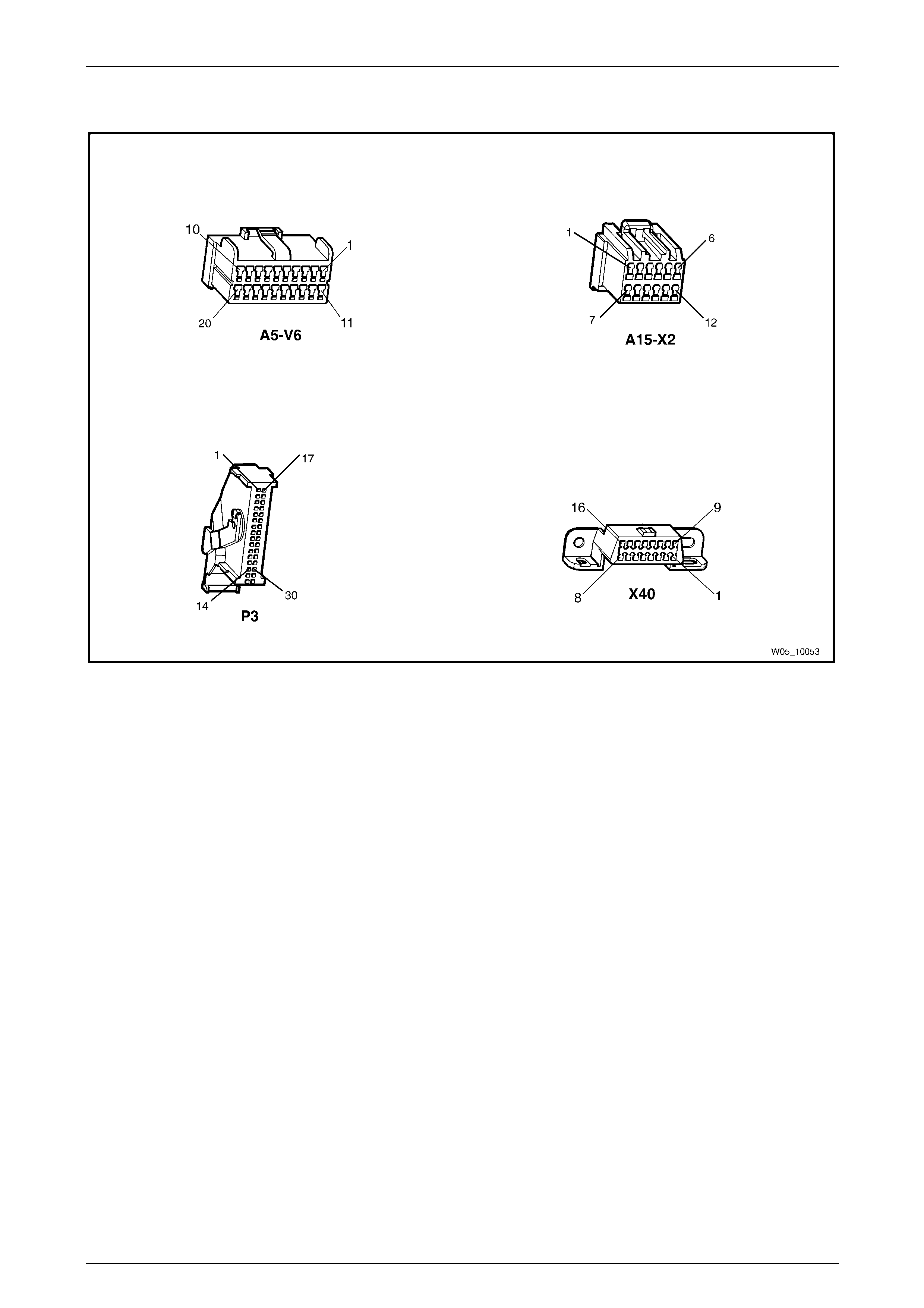
Connector Chart
Figure 10 – 31
Wheels and Tyres Page 10–26
Page 10–26
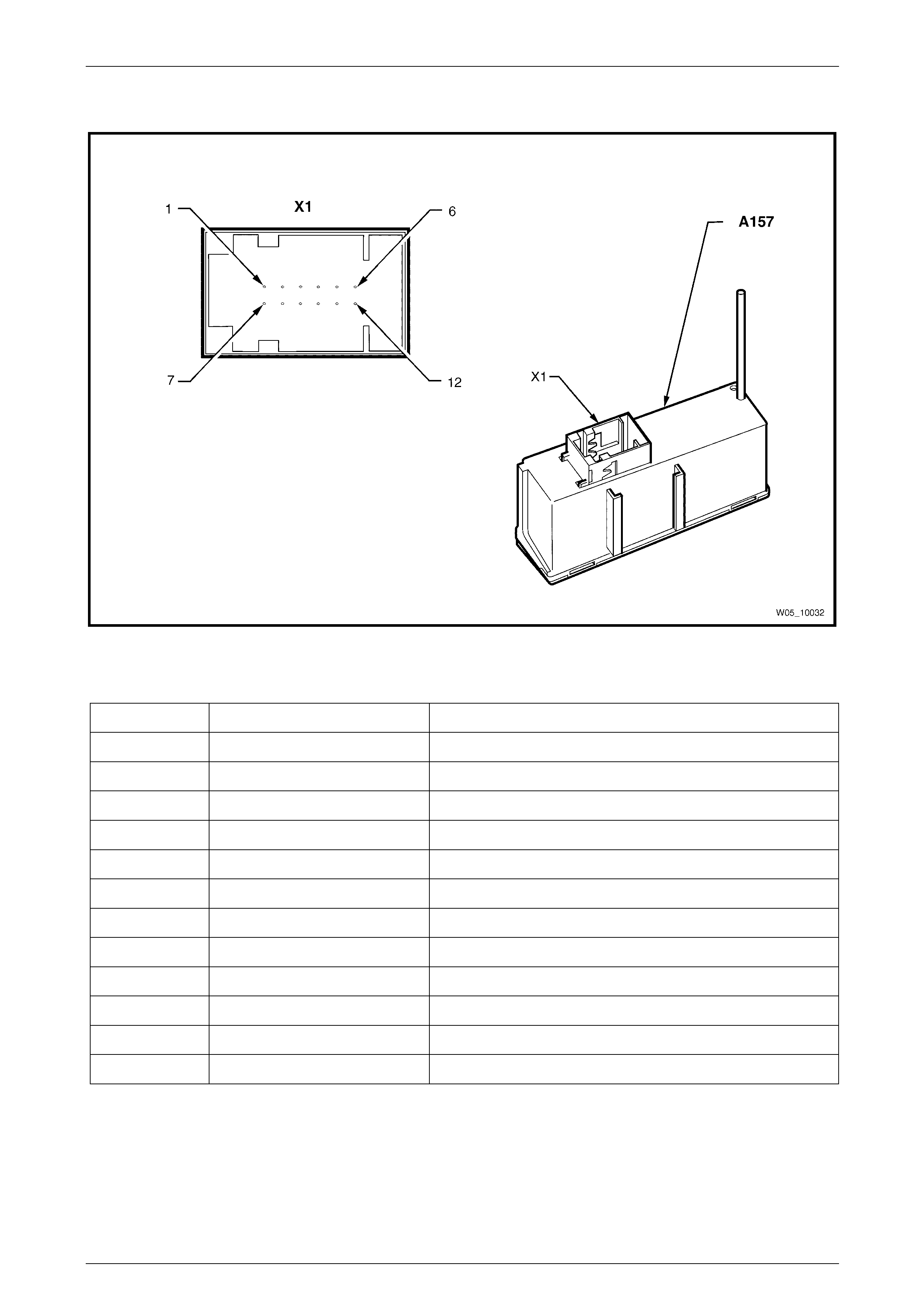
TPMS Connector (A157)
Figure 10 – 32
Connector X1
Pin Number Wire Colour Function
X1-1 Green / White Serial data line
X1-2 – Not Used
X1-3 Pink Ignition voltage
X1-4 Black / Blue Ground
X1-5 – Not Used
X1-6 – Not Used
X1-7 – Not Used
X1-8 – Not Used
X1-9 – Not Used
X1-10 – Not Used
X1-11 – Not Used
X1-12 – Not Used
Wheels and Tyres Page 10–27
Page 10–27
4.2 Tech 2 Information
Diagnostic Trouble Codes
When a fault is detected, the T P MS sets a diagnostic troubl e code (DTC) this represents a particular pro blem or failure,
The DTC remains current as long as the fault remains, and is cleared when the fault is rectified the DTC can be read and
cleared using Tech 2.
A prerequisite of this diagnostic information is for the user to be familiar with the correct use of Tech 2. The following
pages describe only the maj or Tech 2 screen displays and provide a brief explanatio n of their function for diagnosing the
instruments. If additional information is required on the operation of Tech 2, refer to either Section 0C Tech 2 or the
Tech 2 User’s Guide.
1 Connect Tech 2 to the DLC.
2 Turn the ignition on and press the power button (PWR) on the Tech 2.
3 The Tech 2 will perform a series of self-dia gnosing power on self-tests (POST). Once this has been completed
successfully, the Tech 2 Start-up screen will be displayed. Press the Enter key to continue.
NOTE
The TPMS is not a serviceable item if it develo ps
any internal fault the unit must be replaced.
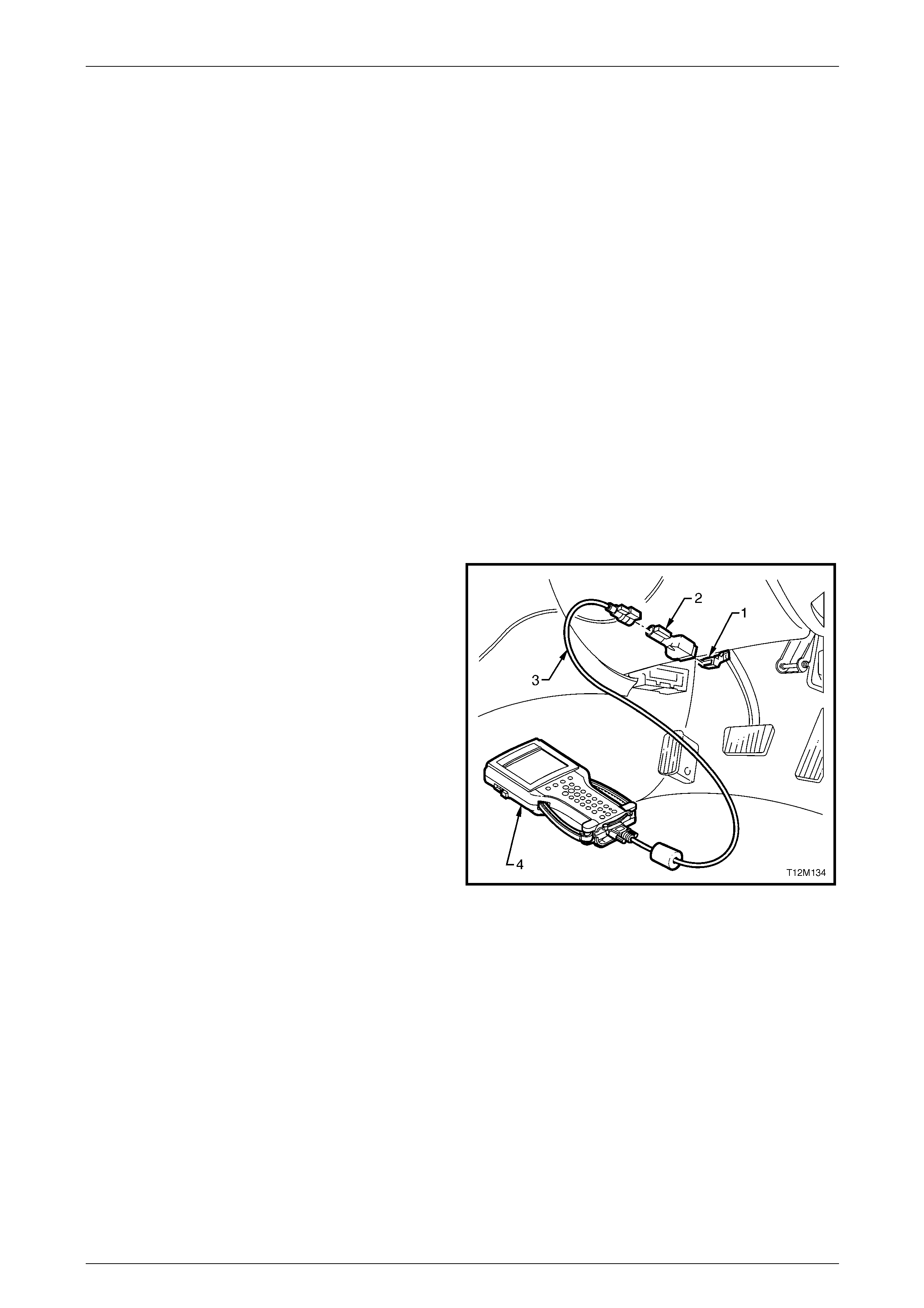
Connecting Tech 2
Tech 2, with the appropriate software, cables and adaptors,
is capable of reading serial d ata associated with the TPMS
when connected to the Data Link Connector ( DLC).
1 Data Link Connector (DLC).
2 DLC Adaptor.
3 DLC Cable.
4 Tech 2.
For additional general information on connecting and
operating Tech 2, refer to Section 0C Tech 2 .
Figure 10 – 33
Chassis Menu
On Tech 2 select:
Chassis / TPMS.
The following functions will now be available:
• Normal Mode
• Diagnostic Trouble Codes
• Data Display
• Snapshot
• Additiona l Functions
• Programming

Wheels and Tyres Page 10–28
Page 10–28
Normal Mode
Displays the details of the serial data received by the TPMS.
Tech 2 Parameter Units Displayed Typical Data Value
DTC Status yes/no No DTC
Learn Mode None None
Front Left Tyre Pressure kPa 228
Front Right Tyre Pressure kPa 228
Rear Right Tyre Pressure kPa 228
Rear Left Tyre Pressure kPa 228
FL Tyre Pressure Status Unknown / Nominal Nominal
FR Tyre Pressure Status Unknown / Nominal Nominal
RR Tyre Pressure Status Unknown / Nominal Nominal
RL Tyre Pressure Status Unknown / Nominal Nominal
Diagnostic Trouble Codes
On Tech 2 select:
Chassis / TPMS / Diagnostic Trouble Codes.
• Read DTC Information: If this mode is selected, a listing of all (if any) DTCs have been set by the TPMS will be
displayed.
• Clear DTC Information: DTCs can be cleared in this mode by simply selecting Clear DTC Information, pressing
the Enter key on Tech 2 and confirming the action as instruc t ed by Tech 2.
Data Display
The Data Display function allows the status of the TPMS inputs and outputs to be monitored.
On Tech 2 select:
Chassis / TPMS / Data Display.
• TPMS Data: When this mode is selected a listing of all serial data associated with the TPMS will be displa yed.
• Transmitter ID Data: Provides details of transmitter identification.
• Threshold Data: Provides details of threshold levels for alarm triggers.
Data Display
The serial data from the TPMS can be checked and tested by selecting the item and pressing the soft key. The list can
be scrolled through by using the up and down arrow keys.

Wheels and Tyres Page 10–29
Page 10–29
TPMS Data
Tech 2 Parameter Units Displayed Typical Data Value
Battery Voltage Volts Approx 12.0 V
FL Framecount Bit 0
FR Framecount Bit 0
RR Framecount Bit 0
RL Framecount Bit 0
Front Left Tyre Pressure kPa 228
Front Right Tyre Pressure kPa 228
Rear Right Tyre Pressure kPa 228
Rear Left Tyre Pressure kPa 228
Vehicle Speed km/h Varies
Outside Temperature °C Varies
Transmitter ID Data
Tech 2 Parameter Units Displayed Typical Data Value
FL Transmitter ID Numerals ( Front 485272
FR Transmitter ID Numerals ( Front 485828
RR Transmitter ID Numerals ( Rear 485669
RL Transmitter ID Numerals ( Rear 485404
Threshold Data
Tech 2 Parameter Units Displayed Typical Data Value
Front Axle Warning / Pressure kPa 28
Front Axle Alarm / Pressure kPa 60
Rear Axle Warning / Pressure kPa 28
Rear Axle Alarm / Pressure kPa 60
Speed Threshold km/h 30
Temperature Threshold °C 30
Front Axle Imbalance Threshold kPa 28
Rear Axle Imbalance Threshold kPa 28
Low Alarm Threshold kPa 140
Front Axle Nominal Pressure kPa 220
Rear Axle Nominal Pressure kPa 220
Imbalance Flags Bit 0

Wheels and Tyres Page 10–30
Page 10–30
Snapshot
On Tech 2 select:
Chassis / TPMS / Snapshot.
The Tech 2 can be used to record system information that is occurring at a particular moment in time, and this is called a
snapshot. For more details, refer to Section 0C Tech 2 .
Additional Functions
Tech 2 can be used to verify the system identification items.
On Tech 2 select:
Chassis / TPMS / Additional Functions.
Scroll through the list to verify the system identification items.
System Identification
The System Identification screen provid es production information relevan t to the TPMS.
• Identifier.
• Part Number.
• Soft ware Version Num ber.
• Production Date.
• Module Seri al Number.
• Code Index.
• Code Version.
• TIS Hardware Key Serial.
Programming
On Tech 2 select:
Chassis / TPMS / Programming.
Tech 2 can be used to reprogram the following using the soft keys:
• Code Index.
• Code Version.
In both cases these items reflect the software level used by the TPMS module.

Wheels and Tyres Page 10–31
Page 10–31
4.3 Diagnostic Trouble Codes List
DTC No DTC Source Description Action
1 TPMS Module ROM Failure Replace TPMS Module
A157 Refer to 5.11 Tyre
Pressure Monitoring
System Module
2 TPMS Module RAM Failure Replace TPMS Module
A157 Refer to 5.11 Tyre
Pressure Monitoring
System Module
3 TPMS Module EEPROM Failure Replace TPMS Module
A157 Refer to 5.11 Tyre
Pressure Monitoring
System Module
4 Tyre Pressure Sensors Tyre Pressure Sensors Not
Programmed Refer to 5.10 Tyre
Pressure Monitoring
System – Programming
5 Secondary UART Bus Loss of Secondary UART
Communications Refer to 4.4 Tyre Pressure
Monitoring System Module
Fault
6 TPMS Module Module not programmed
on assembly line Replace TPMS Module
A157 Refer to
7 TPMS Module Supply Voltage has been
greater than 16V for more
than 3 seconds
Refer to 4.4 Tyre Pressure
Monitoring System Module
Fault
8 TPMS Module Supply Voltage has been
lower than 9V for more
than 3 seconds
Refer to 4.4 Tyre Pressure
Monitoring System Module
Fault
9 Left Front Tyre Pressure
Sensor No Signal Received by
TPMS Module Refer to 4.5 Tyre Pressure
Monitoring System
10 Right Front Tyre Pressure
Sensor No Signal Received by
TPMS Module Refer to 4.5 Tyre Pressure
Monitoring System
11 Left Rear Tyre Pressure
Sensor No Signal Received by
TPMS Module Refer to 4.5 Tyre Pressure
Monitoring System
12 Right Rear Tyre Pressure
Sensor No Signal Received by
TPMS Module Refer to 4.5 Tyre Pressure
Monitoring System
13 Left Front Pressure Sensor
Battery Voltage Low Check if the Sensor is
Activating Refer to 4.5 Tyre Pressure
Monitoring System
14 Right Front Pressure
Sensor Battery Voltage
Low
Check if the Sensor is
Activating Refer to 4.5 Tyre Pressure
Monitoring System
15 Left Rear Pressure Sensor
Battery Voltage Low Check if the Sensor is
Activating Refer to 4.5 Tyre Pressure
Monitoring System
16 Right Rear Pressure
Sensor Battery Voltage
Low
Check if the Sensor is
Activating Refer to 4.5 Tyre Pressure
Monitoring System
Techline
Techline

Wheels and Tyres Page 10–32
Page 10–32
4.4 Tyre Pressure Monitoring System
Module Fault
DTC Description
The diagnostic procedure s upports the following DTCs.
• DT C 5 – Secondary UART Bus.
• DT C 7 – TPMS Voltage High.
• DT C 8 – TPMS Voltage Low.
Circuit Description
With the ignition in the accessories or on position:
• DT C 5 will set if the instrument cluster does not receive secondary UART communications from the TPMS for more
than 10 seconds.
• DT C 7 or 8 will set if the supply voltage to the TPMS module is incorrect.
For circuit information, refer to 4.1 Wiring Diagram and Connector C hart .
Test Description
The following numbers refer to the step numbers in the diagnostic table:
1 Checks the supply voltage to the TP MS module.
2 Checks circuit 139 for continuity.
3 Checks for short to ground on circuit 650.
4 Checks circuit 1061 for continuity.
5 Checks for short to ground on circuit 1061.
6 Clears and then checks for set DTCs using Tech 2.
For further information on using and connecting Tech 2 to the vehicle, refer to Section 0C Tech 2 .

Wheels and Tyres Page 10–33
Page 10–33
Diagnostic Table
Step Action Yes No
1 1 With the ignition in the ON position.
2 Using a multimeter set to measure voltage, probe b etween Fuse
F15 and a known ground.
Is fuse F15 serviceable? Go to Step 2 Replace fuse F15
2 1 With the ignition in the ON position.
2 Using a multimeter set to measure voltage, backprobe between
connector A157 – X1 pin 3 and a known ground.
Does the multimeter indicate battery voltage? Go to Step 3 Repair or replace
circuit 139
3 1 Turn the ignition to the OFF position.
2 Using a multimeter set to measure resistance, backprob e
between connector A157 – X1 pin 4 and a known ground.
Does the multimeter indicate continuity? Go to Step 4 Repair or replace
circuit 650
4 Using a multimeter set to measure resistance, probe between
connectors A157 – X1 pin 1 and P3 – X1 pin 2.
Does the multimeter indicate continuity? Go to Step 5 Repair or replace
circuit 1061
5 Using a multimeter set to measure resistance, probe between
connector A157 – X1 pin 1 and a known ground.
Does the multimeter indicate contin uity? Repair or replace
circuit 1061 Go to Step 6
6 1 On Tech 2 select:
Diagnostic Trouble Codes / Clear DTC Information.
2 On Tech 2 select:
Diagnostic Trouble Codes / Read DTC Information.
Does Tech 2 indicate a set DTC?
Replace the TPMS
module A157, refer
to 5.11 Tyre
Pressure Monitoring
System Module System serviceable
When all diagno sis an d repairs are completed, clear all DTCs and check the system fo r correct operation.

Wheels and Tyres Page 10–34
Page 10–34
4.5 Tyre Pressure Monitoring System
Sensor Error
DTC Description
This diagnostic procedure supports the following DTCs.
• DT C 9 – Left Front Tyre Pressure Sensor – No Signal.
• DT C 10 – Right Front Tyre Pressure Sensor – No Signal.
• DT C 11 – Left Rear T yre Pres sure Sensor – No Signal.
• DT C 12 – Right Rear Tyre Pressure Sensor – No Signal.
• DT C 13 – Left Front Pressure Sensor Battery Voltage Low.
• DT C 14 – Right Front Pressure Sensor Battery Voltage Low.
• DT C 15 – Left Rear Pressure Sensor Battery Voltage Low.
• DT C 16 – Right Rear Pressure Sensor Battery Voltage Low.
Circuit Description
With the ignition in the accessories or on position:
• DT C 9 to 12 will set if the TPMS module does not receive a signal from one or more of the t yre pressur e sensors.
• DT C 13 to 16 will set if the internal battery in one or more of the tyre pressure sensors has low voltage.
For circuit information, refer to 4.1 Wiring Diagram and Connector C hart .
Test Description
The following numbers refer to the step numbers in the diagnostic table:
1 Checks the operation using the options menu.
2 Checks the left front tyre pressure monitor status and battery condition.
3 Checks the right front tyre pressure monitor status and battery condition.
4 Checks the right rear tyre pressure monitor status and battery condition.
5 Checks the left rear tyre pressure monitor status and battery condition.
Diagnostic Table Notes
1 A green LED throughout the test indicates a good battery.
2 A red LED throughout the test indicates a low battery.
3 For information on the transponder tool, refer to 5.10 Tyre Pressure Monitoring System – Programming

Wheels and Tyres Page 10–35
Page 10–35
Diagnostic Table
Step Action Yes No
1 Press the MODE button on the trip computer switch until it displays
the TPM system screen.
Does the display show Tyre Pressure Sens or F ault? Go to Step 2
Refer to 4.4 Tyre
Pressure Monitoring
System Module
Fault
2 1 Follow the programming sequence, refer to 5.10 T yre Pressure
Monitoring System – Program ming.
2 Using the transponder tool held against the left front tyre rubber
with the end of the tool adjacent to the valve and p erpendicular
to the tyre wall.
3 Press the Activate button once.
Does the LED flash and the buzzer sound i ndicating a working
pressure sensor?
NOTE
• A constant LED indicates that the tool is activating the
pressure sensor.
• A green LED throughout the test indicates a good
battery.
• A red LED throughout the test indicates a low battery. Go to Step 3
Replace the tyre
pressure sensor,
refer to 5.3 Tyre
Removal and
Installation
3 1 Follow the programming sequence, refer to 5.10 T yre Pressure
Monitoring System – Program ming.
2 Using the transponder tool hel d against the right front tyre
rubber with the end of the tool adjacent to the valve a nd
perpendicular to the tyre wall.
3 Press the Activate button once.
Does the LED flash and the buzzer sound i ndicating a working
pressure sensor?
NOTE
• A constant LED indicates that the tool is activating the
pressure sensor.
• A green LED throughout the test indicates a good
battery.
• A red LED throughout the test indicates a low battery. Go to Step 4
Replace the tyre
pressure sensor,
refer to 5.3 Tyre
Removal and
Installation

Wheels and Tyres Page 10–36
Page 10–36
Step Action Yes No
4 1 Follow the programming sequence, refer to 5.10 T yre Pressure
Monitoring System – Program ming.
Go to Step 5
Replace the tyre
pressure sensor,
refer to 5.3 Tyre
Removal and
Installation
5 1 Follow the programming sequence, refer to 5.10 T yre Pressure
Monitoring System – Program ming.
2 Using the transponder tool hel d against the left rear tyre rubber
with the end of the tool adjacent to the valve and p erpendicular
to the tyre wall.
3 Press the Activate button once.
Does the LED flash and the buzzer sound i ndicating a working
pressure sensor?
NOTE
• A constant LED indicates that the tool is activating the
pressure sensor.
• A green LED throughout the test indicates a good
battery.
• A red LED throughout the test indicates a low battery.
All Sensors
serviceable, refer to
4.4 Tyre Pressure
Monitoring System
Module Fault
Replace the tyre
pressure sensor,
refer to 5.3 Tyre
Removal and
Installation
When all diagno sis an d repairs are completed, clear all DTCs and check the system fo r correct operation.
Wheels and Tyres Page 10–37
Page 10–37
5 Service Operations
5.1 Tyre Inflation and Inspection
The pressure recommended for any vehicle is carefully calculated to give satisfactory ride, stability, steering, tread wear,
tyre life and resistance to wheel / tyre damage. All spec ified pressures are for COLD tyres (after the vehicle has stood for
three hours or more, or driven less than two kilometres).
Tyre pressures should be checked weekly or before any extended trip, and set to the specifications on the t yre placard
located on the end surface of the driver ’s front door, refer to 1.1 T yre Placards.
When checking tyre pressure, visually inspect tyres for excessive wear, sharp objects embedded in the tyre or damage
to the sidewalls.
Clean the exterior of the valve, prior to
applying the air pressure nozzle when
inflating a tyre.
NOTE
Always install valve caps to keep out dust and
water.
Pressure Adjustments to Suit Operating Conditions
Tyre pressure can increase as much as 40 kPa when hot.
Do not reduce pressures to offset this
build-up.
For continuous high-spee d operation, increase pressures as recommende d on the tyre placard.
For operation on unsealed rough roads, increase COLD tyre pressures 28 kPa above that shown on the tyre placard.
Tyre pressures are not to be increased for
unsealed rough road conditions if the tyre
pressures have already been increased for
high-speed operation.
Wheels and Tyres Page 10–38
Page 10–38
5.2 Wheel Removal and Installation
Either corrosion or a tight fit between the
wheel centre and the mo unting or brake disc /
hub flange can cause difficulty in wheel
removal. If tightness is caused by corrosion,
do not use heat or heavy impact.
NOTE
Before removing any wheel, mark the relationship
of the wheel to the mounting flange or brake
disc/hub.
Wheel nuts for alloy wheels have a different
mounting taper to those for steel wheels. DO
NOT interchange or mix wheel nuts from both
types of wheel, as incorrect wheel nuts will
not allow the wheels to be tightened securely.
Installing wheels without good metal-to-metal
contact at the mounting surfaces can result in
wheel nuts loosening. Tighten road wheel
attaching nuts to the specified torque and in
the orde r sh own.
Do not use an impact gun to tighten wheel
nuts unless it is fitted with a torque limiter
bar (commercially available). Failure to
correctly tighten wheel nuts to the correct
torque specification may result in a warped
brake disc, which may lead to development
of brake shudder.
Road wheel attaching nut
torque specification .................................. 110 – 140 Nm
Figure 10 – 34
Wheels and Tyres Page 10–39
Page 10–39
5.3 Tyre Removal and Installation
Whenever possible, tyre removal and installation should be carried out on a tyre-changing machi ne. The use of tyre
levers and mallets is likely to damage tyre carcasses and wheel rims.
Alloy rims must always be replaced if significantly damaged.
TPMS Pressure Sensor
• Damage may occur to the TPMS tyre
pressure sensors, w hen removing tyres if
the following precautio ns are not taken.
• The pressure sensor valve (1) must first
be released and pushed inside the tyre
when removing and refitting the tyre from
a rim (2) fitted with tyre pressure
monitoring type valves. This will prevent
the bead of the tyre being forced onto the
sensor during removal, which may cause
damage to the sensor.
• When fitting the tyre to the rim care
should be taken to ensure that the top
bead finishing point is at the TPMS
pressure sensor. This will prevent any
damage occurring to the sensor.
Figure 10 – 35
Wheels must not be welded, brazed, peened
or treated in any manner, wh ich could w eaken
them.
The bead set of the rim must be clean and s m ooth; rust, rubber etc. may be removed with a wire brush or steel wool.
1 Before installing a tyre, or a valve stem, apply an approved tyre lubricant to the tyre bead and rim flanges.
2 Install the valve stem and tyre before the lubricant dries.
3 Initially, inflate the tyre to 280 kPa to ensure that the tyre beads seat correctly in the rim flanges.
4 If the tyre beads fail to seal at this pressure, deflate the tyre, lubricate the tyre beads and wheel rim agai n and then
inflate.
Exercise care to avoid personal injury when
the tyre bead snaps o ver the wheel rim safety
humps.
NOTE
When fitting a tyre to the rim, ensure the tyre
is correctly indexed to the rim. The first
harmonic high point of the tyre should be
matched to the first harmonic lo w point of the rim.
This matching minimises forc e variations inherent
with tyre and rim manufacture, refer to
3 Diagnostics – Wheels and Tyres.

Wheels and Tyres Page 10–40
Page 10–40
As different origins of tyres have different standards regarding the first harmonic point, re fer to the following as a guide to
the correct tyre fitting position.
• Australian man ufactured tyres have a red dot indicating the first harmonic high point.
• European man ufactured tyres have a white dot indicating the first harmonic low point.
• Some Japanese manufactured tyres have a red dot indicating the first harmonic high point and a yellow dot (that
should be ignored), which ind icates a static balance point.
As independent rear suspension is more sensitive to a wheel / tyre imbalance condition than other susp ension designs,
particular care should be given to correct fitment of tyres to all vehicles with independent rear suspension.
Australian Manufactured Tyres
(Red dot on sidewall)
Align the red dot on tyre to mark on outer flange of wheel,
or if there is no mark on the wheel, align the red dot to low
spot of wheel as measured with dial indicator.
European Manufactured Tyres
(White dot on sidewall)
Align the white dot on tyre 180° from the mark on outer
flange of wheel, or if there is no mark on the wheel, align
the white dot 180° from the low spot of the wheel as
measured with the dial indicator.
Japanese Manufactured Tyres If there is a yellow dot but not a red dot use the rule for
Australian tyres. If there is a yellow and a red dot, ignore
the yellow dot and use the red dot as per rule for Australian
tyres.
Tyre Repairs
There are many different materials and techniques avail able to repair tyres. It is suggested that details of materials and
procedures for the repair of tyres should be obtained from the tyre manufacturer.
As a minimum requirement, all tyre repairs must comply with local standards.

Wheels and Tyres Page 10–41
Page 10–41
5.4 Replacement of Wheels and Tyres
Wheels must be replaced if they are bent, de nted or have excessive lateral or radial run-o ut. W heels with run-out greater
than specified may cause objectionable vibration through the vehicle.
Replacement wheels must be equival ent to the original equipment wheels in load capacity, diameter, rim width, profile,
offset and mounting configuration. A wheel of incorrect size or type may affect wheel and bearing life, brake cooling,
speedometer / odometer cali bration, vehicle to ground clearance or tyre to body or chassis cleara nce.
The selection of replacem ent tyres requires careful consideration if vehicle handling, braking, steering response and rid e
comfort are to be preserved.
In the course of vehicle development, all of the factors influencing handling and ride com fort are considered and
particular emphasis is placed on the role of tyres in order to achieve optimum standards i n vehicle performance.
When selecting replacement tyres, consult the tyre placard to determine appropriate tyre sizes. It is advisable that
replacement tyres be of the same size, type and sp eed / load rating in order to maintain the intended rid e, hand ling and
braking. This also ensures compatibility of ne w tyres with existing tyres and the spare tyre. If such tyres are not available,
choose tyres that meet the requirements specified on the lower section of the tyre placard.
The mixing of different tyre types / profiles
may adversely affect vehicle handling and
control. Do not mix different types of tyres on
the same vehicle except in emergencies.
It is recommended that new tyres be installed in pairs on the same axle. If it is necessary to replace only one tyre, it
should be paired with the tyre having the most tread, to equalise braking traction.
Wheels and Tyres Page 10–42
Page 10–42
5.5 Tyre Rotation
It is recommended that tyre rotation be carried out when brake inspections are performed, as per the service schedule,
refer to Section 0B Lubrication and Service, or when:
1 Difference in tread depth between front and rear tyres is 1.5 mm.
2 When any unusual tyre wear pattern develops.
If uneven tyre wear is evident, the reason for the wear should be corrected if possib le.
NOTE
If the vehicle is fitted with a Tyre Pressure
Monitoring System (TPMS), the system will
require reprogramming so that it can ‘learn’ the
new positions of the tyre pressure sensors. Refer
to 5.10 Tyre Pressure Monitoring System –
Programming.
If the tyres are rotated, it is recommended that the tyre and wheel assembly balance be checked at the same time,
refer to 5.8 Wheel and Tyre Balancing.
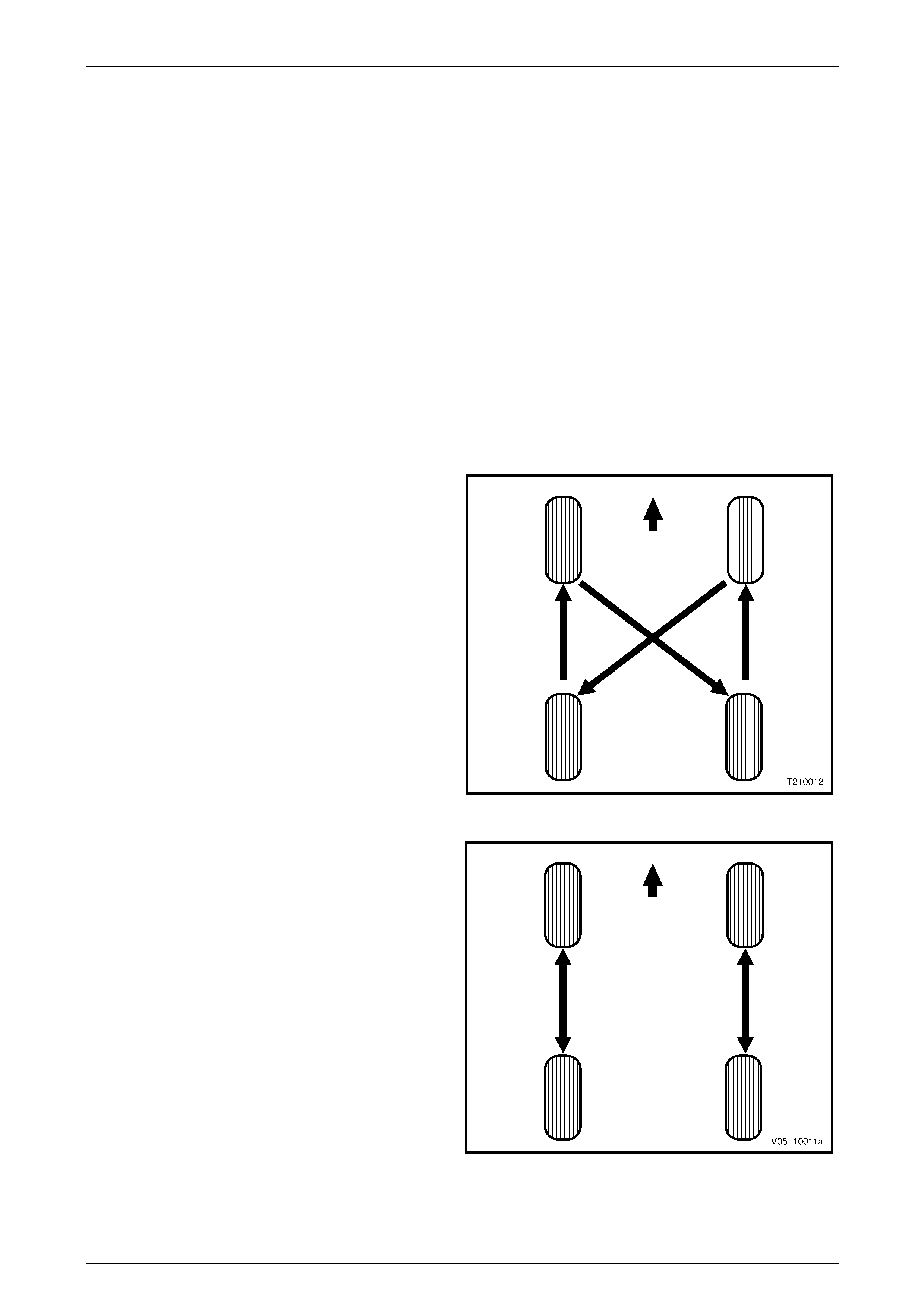
Tyre rotation in accordance with Figure 10 – 36 will assist in
obtaining optimum performance, except where a
‘Directional’ tyre is fitted
Figure 10 – 36
For ‘Directional’ tyre rotation carry out in accordance with
the procedure in and Figure 10 – 37.
Figure 10 – 37

Wheels and Tyres Page 10–43
Page 10–43
5.6 Checking Wheel and Tyre Assembly
Run-out
Because the run-out of a tyre / wheel assembly will directly affect the amount of imbalance and radial force variation, it
should be corrected first. The smaller the amount of run-out, the less imbalance and force variation. Radial and lateral
run-out can be corrected at the same time. There are two methods to measure run-out of the tyre / wheel assemblies:
• On the vehicle (mounted to the hub), the wheel bearing must be in good condition.
• Off the vehicle (mounted on a spin-t ype wheel balancer).
NOTE
Initial on-vehicle inspection should be made prior
to off-vehicle run-out checks.
Measuring the tyre / wheel run-out off the vehicle is easiest. It is usually easier to mount a dial indicator in the correct
location, and the chances of water, dirt, or slush getting on the dial indicator are decreased. Once the run-out has been
measured and corrected off the vehic le, a qu ick visual check of run-out on the veh icle will indicate if any further problems
exist.
If there is a large difference in the run-out measurements from on-vehicl e to off-vehicl e, then the run-out problem is due
to stud pattern run-out, or hub flange run-out, or a mounting problem between the wheel and the vehicle.
Before measuring or attempting to correct excessive run-out, carefull y check the tyre for an uneven bead seat. T he
distance from the edge of the ring to the concentric rim locating-ring should be equal around the entire circumfere nce. If
the beads are not seated properly, the t yre should be remounted. Otherwise, excessive run-out and imbalance will result.
NOTE
If the vehicle has been sitting in one place for a
long time, flat spots may exist at the point where
the tyres are resting on the ground. As the flat
spots affect run-out readings, they should be
removed by driving the vehicle far enough to
warm-up the tyres before conducting any run-out
measurements.
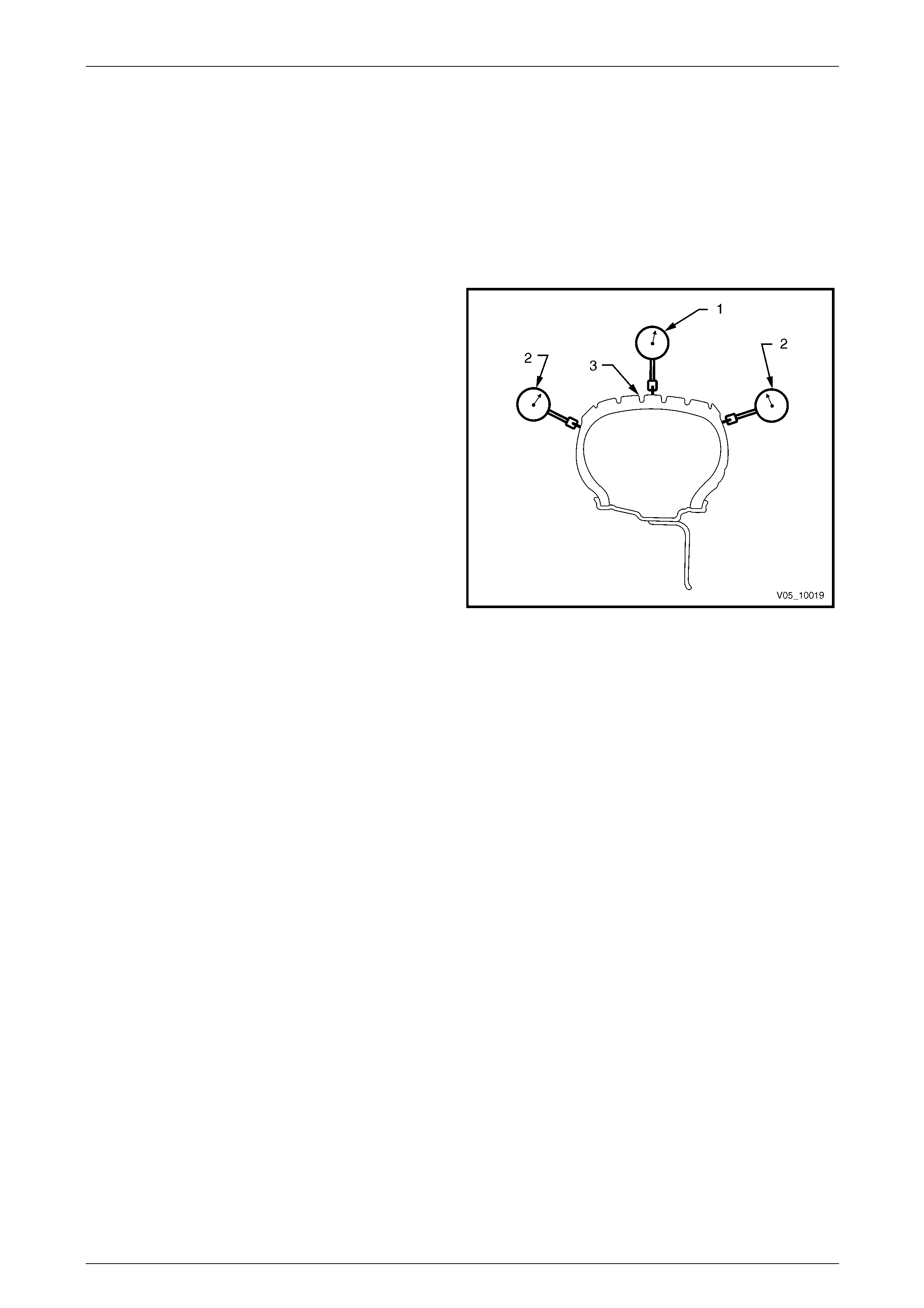
Wheels and Tyres Page 10–44
Page 10–44
Procedure
1 Raise the vehicle on a hoist or jack and supp ort with safety stands, refer to Section 0A General Information.
2 To obtain an initial indication of how much run-out exists, spin each wheel on the vehicle by hand. Visually check
the amount of run-out from the front or rear.
3 Mark the location of each tyre / wheel assembly in relation to the wheel studs and to their position on the vehicl e
(for example, the right front, left rear) for future reference.
4 Remove the tyre / wheel assemblies one at a time and mount on a spin-type wheel balancer.
5 Using a dial indicator fitted with a roller, measure the
radial (1) and lateral run-outs (2) of the tyre / wheel
assembly.
NOTE
With tyres that have an aggr essive tread pattern,
it will be necessary to wrap the outer
circumference (3) with tape when measuring
radial run-out, to provide a smooth surface for a
more accurate measurement.
NOTE
Lateral run-out should be measured on a
smooth area of the sidewall, as close to the
tread as possible. Any jumps or dips due to
sidewall splices should be ignored and an
average amount of run-out attained.
Figure 10 – 38
6 Slowly rotate the assembly one complete revolution a nd zero the dial indicator on the low spot.
7 Rotate the assembly one more complete revolution a nd note the total amount of run-out indicated.
As a guide the radial and later al run-out of the tyre / wheel assembly should be no more than 1.5 mm when measured off
the vehicle.
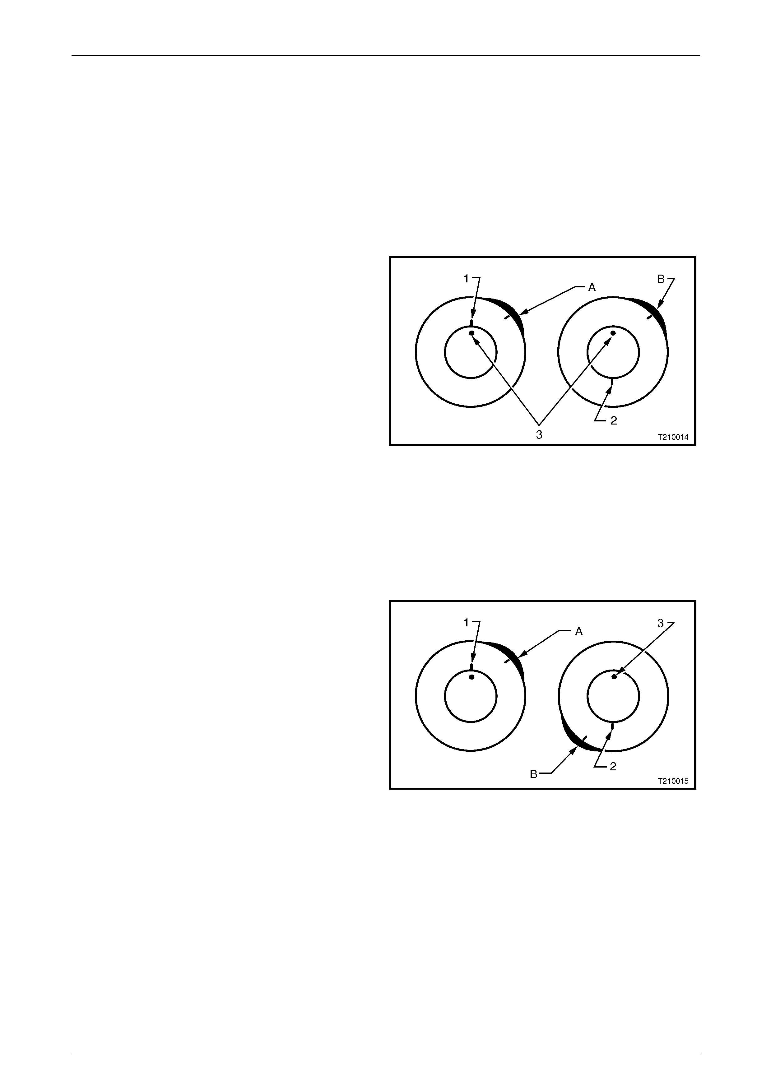
Wheels and Tyres Page 10–45
Page 10–45
Match Mounting
NOTE
Match mounting is recommended to obtain
optimum performance with minimal or no
vibration.
If tyre / wheel assembly run-out is excessive, mark the location of the high and low spots on the t yre and the wheel. The
next step will be to determine if the run-out problem exists in the tyre, wheel, or a combination of both and then to correct
it. The procedure used to accomplis h this is called match mounting or s ystem matching.
1 Place a mark on the tyre sidewall (1) at the location of
the valve stem (3). This will be referred to as the
12 o’clock position. T he location of the high spot A will
always be referred to in relatio n to its clock positio n on
the wheel.
2 Mount the tyre and wheel assembly on a tyre machine
and break down the bead. Do not dismount the tyre
from the wheel at this time.
3 Rotate the tyre 180° on the rim so the valve stem
reference mark (2) is now at 6 o’clock in relation to the
valve stem itself. Inflate the tyre and make sure the
bead is seated properly. You may have to lube the
bead to enable eas y rotation of the tyre on the wheel.
4 Install the assembly on the tyr e balancer and again
measure the run-out. Mark the ne w location of the
run-out high spot B on the tyre.
Figure 10 – 39
If the run-out is now within tolerance, no further steps are necessary. The tyre may be balanced and installed on the
vehicle.
Alternatively, if the clock location of the high spot B remained at or near the clock location of the original high spot A (as
in Figure 10 – 39), the wheel is the major contributor to the run-out problem. It should be measured for excessive run-out,
as detailed in 5.7 Checking Wheel Run-out and replaced if found to exceed specification.
If the high spot is now at or near a position 180° (6 o’clock)
from the original high spot, the tyre is the major contributor
(as in Figure 10 – 40) and should be replaced.
Always measure the tyre / wheel assembly run-out after
replacing the tyre and make sure the run-out is within
tolerance before continuing. In the majority of cases, the
first 180° rotation of the tyre will either correct the run-out
problem or indicate which compon ent to replace.
If the high spot is between the t wo extremes, then bot h the
tyre and wheel are contributing to the run-out. Tr y rotating
the tyre an additional 90° in both the clockwise (9 o’clock)
and anticlockwise (3 o’clock) directions, measuring the run-
out after each rotation. Figure 10 – 40
If run-out cannot be corrected by match mounting, then the tyre must be removed and the wheel run-out measured,
refer to 5.7 Checking Wheel Run-out.
Once run-out has been brought within the tolerance, the tyre / wheel assembly should be balanced.
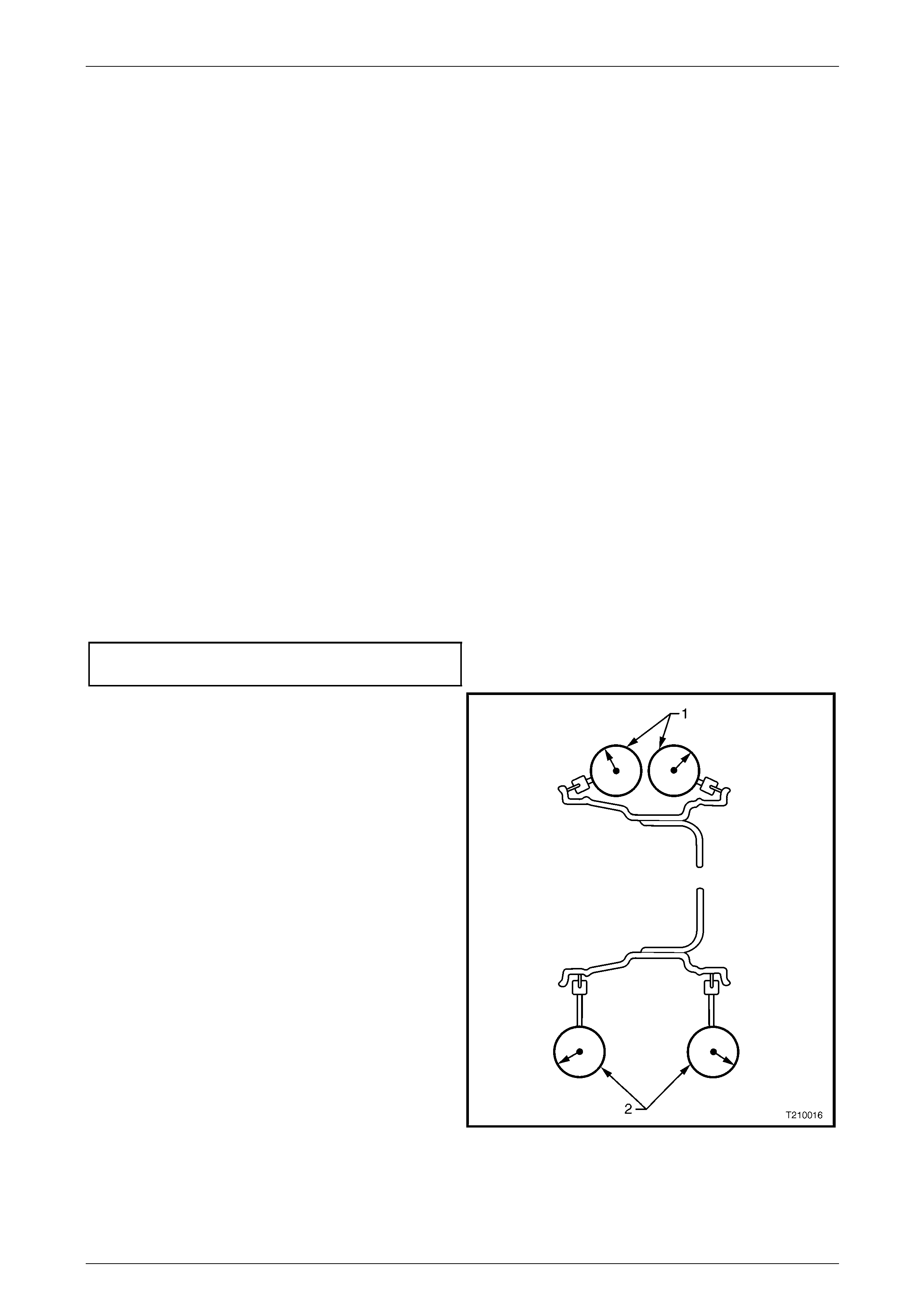
Wheels and Tyres Page 10–46
Page 10–46
5.7 Checking Wheel Run-out
Wheel run-out should be measured on the inside bead area of the wheel. Measur e the run-out in the same fashion as
tyre run-out. Ignore any jumps or dips due to paint drips, chips, or welds, measure both inboard and outboard.
If the run-out of the wheel is within tolerance, and the tyre / wheel assembl y run- out cannot be reduced to an acceptable
level by using the match-mounting technique, the tyre must be replaced.
NOTE
Always measure the assembly run-out after
replacing the tyre.
If there is a large difference in the run-out measurements from on-vehicl e to off-vehicl e, then the run-out problem is due
to stud pattern run-out, or hub flange run-out, or a mounting problem between the wheel and the vehicle.
The tolerances listed are to serve as gui delines, 6 Specifications. If run-out measurements are within tolerance but are
marginal, some sensitive vehicles ma y still be affected. It is always advisable to reduce ru n-out to as little as possible in
order to attain optimum results under all con ditio ns.
Procedure
NOTE
The following measuring procedure can be
performed on either steel or alloy road wheels .
1 Raise the vehicle on a hoist or jack and support with safety stands.
2 Remove the centre cap.
3 Mark the relationship of the wheel to the mounting flange or the brake disc / hub. Remove the wheel attaching nuts
and remove the wheel.
4 Mark the relationship of the tyre to the wheel rim and then remove the tyre from the rim.
5 Check the wheel and mounting flange or brake disc / hub mating surfaces are clean a nd free from burrs.
6 Install the wheel onto the mounting flange or brake disc / hub and install the wheel attaching nuts. Tighten the nuts
to the correct torque specification.
Road wheel attaching nut
torque specification...................................110 – 140 Nm
7 Using a dial indicator with a roller fitted to the prob e,
secure the body of the indicator to a fixed point, and
butt the roller and probe agai nst the wheel rim at the
points shown. Then, slowly rotate the road wheel and
measure the wheel run-out.
1 = Lateral Run-out.
2 = Radial Run-out.
Wheel run-out should be within the specified values,
refer to 6 Specifications.
If not within specification, replace the wheel.
Figure 10 – 41
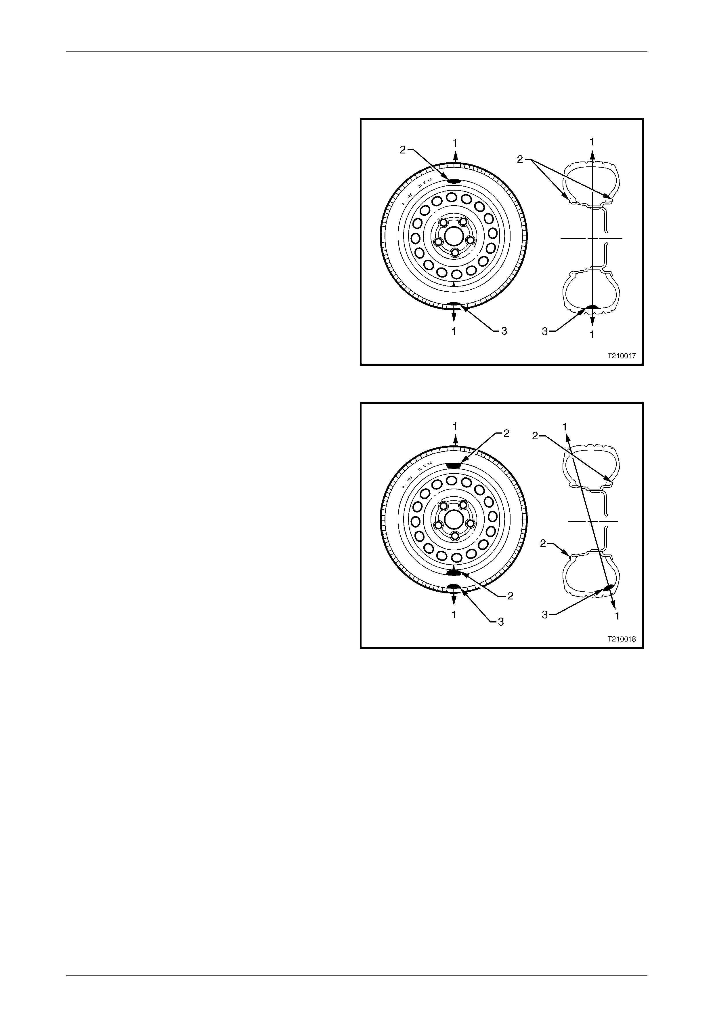
Wheels and Tyres Page 10–47
Page 10–47
5.8 Wheel and Tyre Balancing
There are two types of wheel and tyre balance, static and dynamic.
Static Balance
Static balance is the equal distribution of weight around the
wheel.
Vibrations caused by static imbalance will c ause a vertical
or bouncing motion of the tyre.
Legend
1 Direction of Motion of Wheel.
2 Position for Balance Weight.
3 Heavy Point.
Figure 10 – 42
Dynamic Balance
Dynamic balance affects the distribution of weight on each
side of the tyre / wheel centreline.
Dynamic imbalance res ults in a side-to-side motion of the
tyre sometimes referred to as shimmy.
Legend
1 Direction of Motion of Wheel.
2 Position for Balance Weight.
3 Heavy Point.
Figure 10 – 43
Off-vehicle Balancing
When wheel and tyre assem blies require balancing, they should be removed from the vehicle and bal anced on a
machine capable of ensuring correct static and dynamic balance. Balanci ng should be carried out in accordance with the
machine manufacturer's instructions.
Before balancing, remove all accumulated mud from the wheel and any embedded stones from the tyre treads.

Wheels and Tyres Page 10–48
Page 10–48
On-vehicle Balancing
When using on-vehicle balancing equipment,
observe the Limited Slip Differential
Precautions, refer to Section 4B1 Rear Final
Drive and Dri ve Shafts.
If checking and / or correcting a tyre / wheel imbalance condition off the vehicle and it does not correct the vibration, it
may be necessary to balance the tyre and wheel assembly with the assembly mounted on the vehicle. Use an
on-vehicle, high-speed spin b ala ncer, as this will balance the hubs, rotors, and wheel trims simultaneously. Additionally,
it can compensate for any amount of residual run-out encountered due to mounting the tyre / wheel assembly on the
vehicle, as opposed to the balance that was achieved on the off-vehicle balance.
NOTE
• Although the hub and brake discs do not
normally contribute significantly to an out of
balance condition, if wheels are rem oved from
the vehicle after balancing it is good practice
to fit the wheels to the same position when
installing on the vehicle. Accordingly, it is
good practice to mark the relationship of the
wheel to the axle flange or hub / brake disc
prior to wheel removal.
• Always follow the on-vehicle balancer
manufacturer’s Operator Manual for specific
instructions.
• Do not remove the off-vehicle balance
weights. The purpos e of on-vehicle balance is
to fine tune the assembly balance already
achieved, not to begin again.
• If the on-vehicle balance calls for more than
10 grams of additional weight, split the weight
between the inboard and outboard flanges of
the wheel. This will avoid disturbing the
dynamic balanc e of t he assembl y, ac hiev ed in
the off-vehicle balance procedure.
• Evaluate the condition following the on-
vehicle balance to determine if the vibration
has been eliminated.
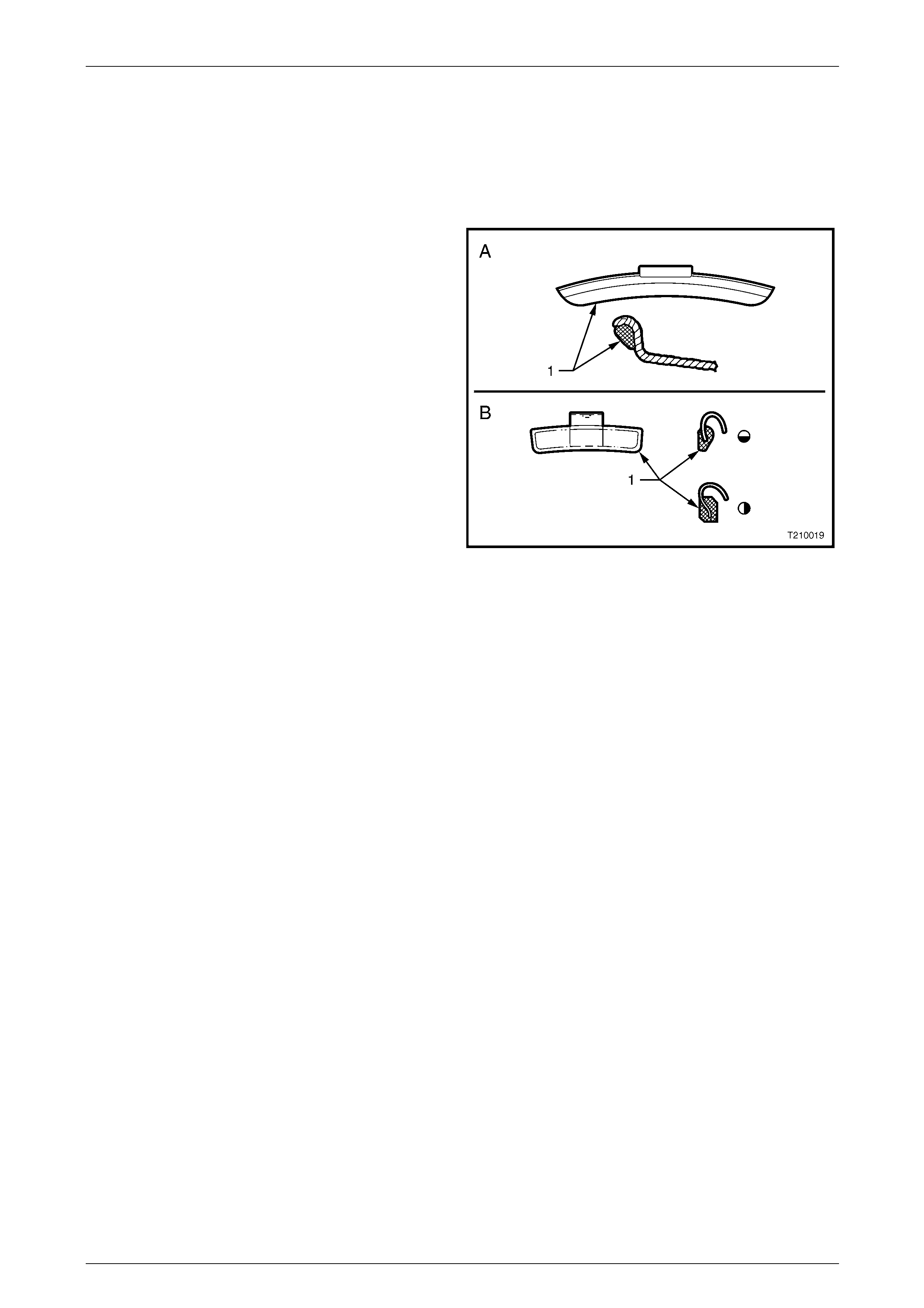
Wheels and Tyres Page 10–49
Page 10–49
Balance Limits
NOTE
Specific wheel weights for each design of wheel
are used. This is due to the differences in wheel
rim profile.
A wheel weight and profile for steel wheels is shown A.
Weights of this design are availa ble in 10 grams and
15 grams.
A wheel weight and profiles for alloy wheels are shown B.
Weights of this design are availa ble in 20, 30, 40 and
50 grams.
A third style of wheel weight is the ribbon weight (not
illustrated) which has a self-adhesive backing enabling
weights to be adhered to clean flat surfaces on the inside
diameter of the wheel. These ribbon weights are used
primarily on alloy wheels a nd are available marked in
increments of 5 grams or 10 grams.
Figure 10 – 44
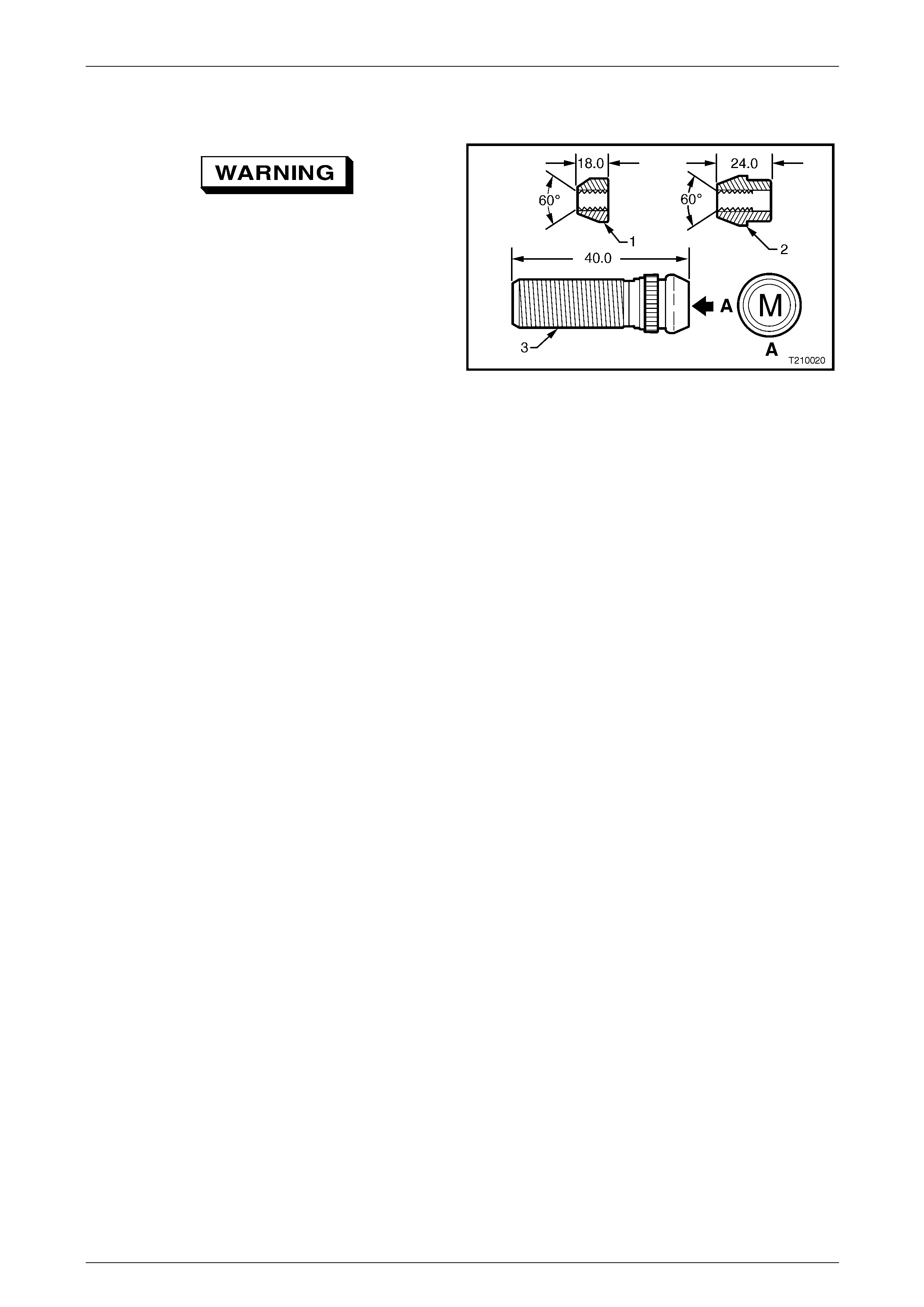
Wheels and Tyres Page 10–50
Page 10–50
5.9 Wheel Attaching Nuts and Studs
Wheel nuts for alloy wheels have a different
mounting taper to those for steel wheels (1
and 2). Do not interchange or mix wheel nuts
from both types of wheel, as incorrect wheel
nuts will not allow the wheels to be tighten ed
securely.
For removal and installation instructions for the wheel
attaching studs (3), either refer to
Section 3A Front Suspension or
Section 4B1 Rear Final Drive and Drive Shafts. All vehicles
use metric (M12 x 1.5) wheel attaching studs and nuts
which are identified as shown A. Figure 10 – 45
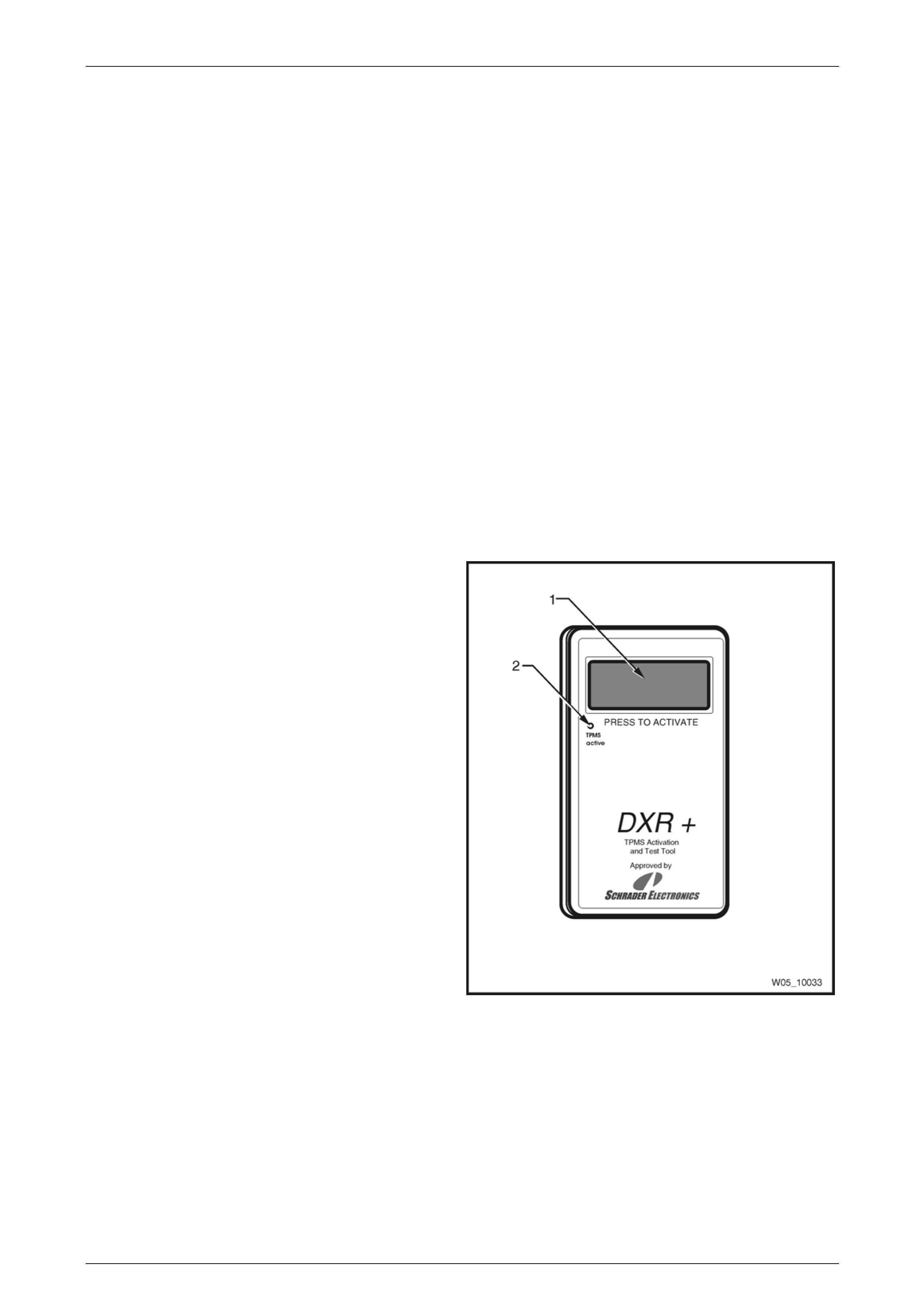
Wheels and Tyres Page 10–51
Page 10–51
5.10 Tyre Pressure Monitoring System –
Programming
Programming Sensors
If TPMS is fitted, the spare wheel will have a TPMS pressure sensor inst alled that is automatically recognised, along with
its position on the vehicle. If the t yres need to be rotated, the new locations of the TPMS tyre pressure sensors will need
to be programmed.
NOTE
If TPMS pressure sensors are not programmed
into the TPMS module, a DTC will be set.
Pressure sensors will need to be programme d when:
• T PMS pressure sensors are replaced.
• T he TPMS module is replaced.
• Wheels ar e rotated to different positions on the vehicle.
In order to program TPMS pressure sensor IDs into the TPMS module, a transponder tool will be required. The
transponder tool forces each pressure sensor to send its own ID to the TPMS module.
Transponder Tool Procedure
The transponder tool should be held against the tyre
rubber with the end of the tool adjacent to the valve
and perpendicular to the tyre wall.
Press the ‘Press to Activate’ button (1) once.
• A flashing LED (2) and beeping sound indicates a
working pressure sensor.
• A constant LED indicates that the tool is activating the
pressure sensor.
• A green LED throughout indicates a good battery.
• A red LED through out indicates a low battery.
Figure 10 – 46
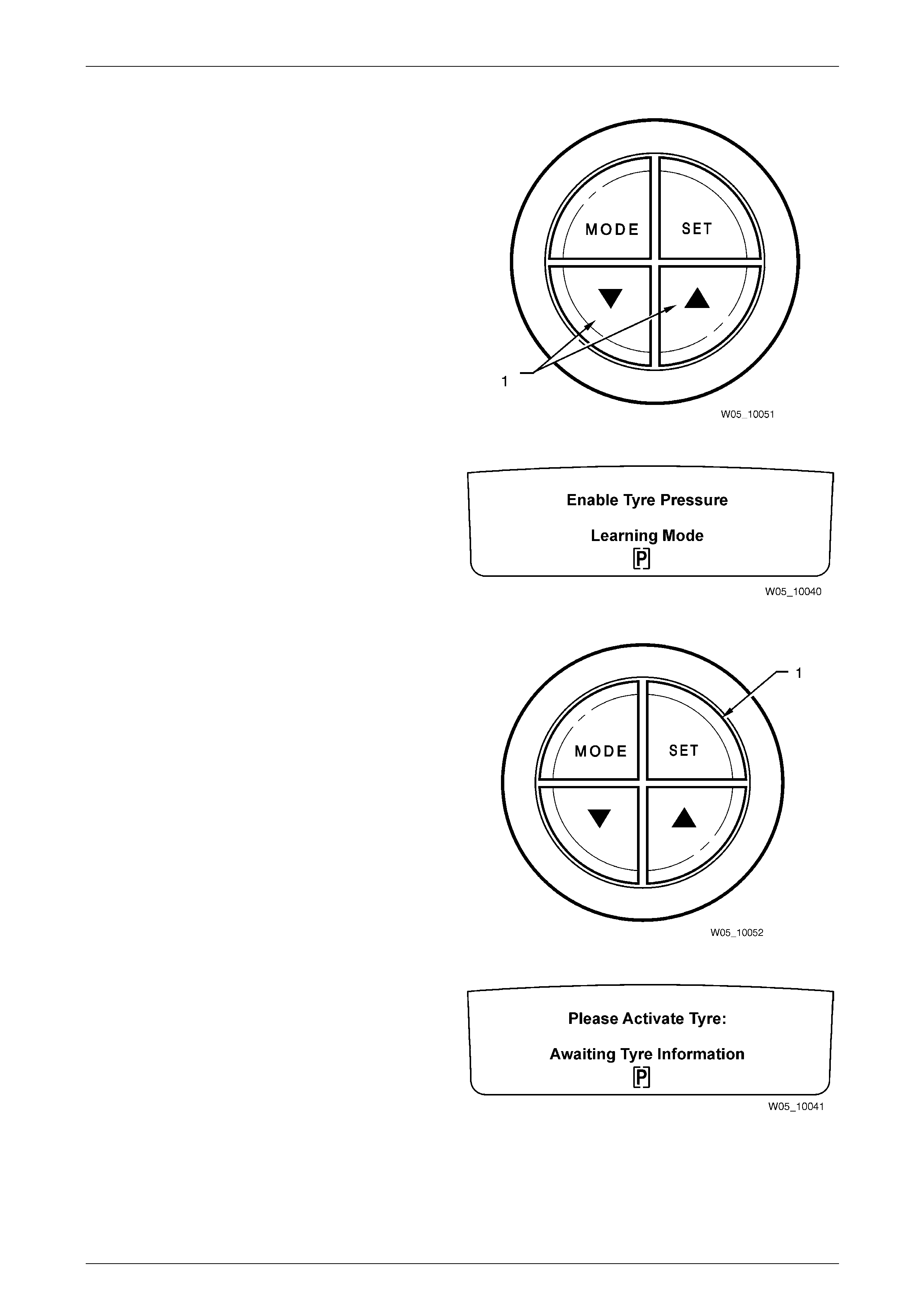
Wheels and Tyres Page 10–52
Page 10–52
Programming Sequence
To commence the programming sequence:
1 Press and hold both the UP and DOWN (1) arrow
buttons together on the trip computer.
Figure 10 – 47
2 Turn the ignition switch on. Wait until ‘Enable Tyre
Pressure Learning Mode’ is displayed on the
instrument cluster MFD.
Figure 10 – 48
3 Press and hold the SET button (1) on the trip
computer.
Figure 10 – 49
4 ‘Please Activate Tyre: Awaiting Tyre Information’ will
then be displayed on instrument cluster MFD.
Figure 10 – 50
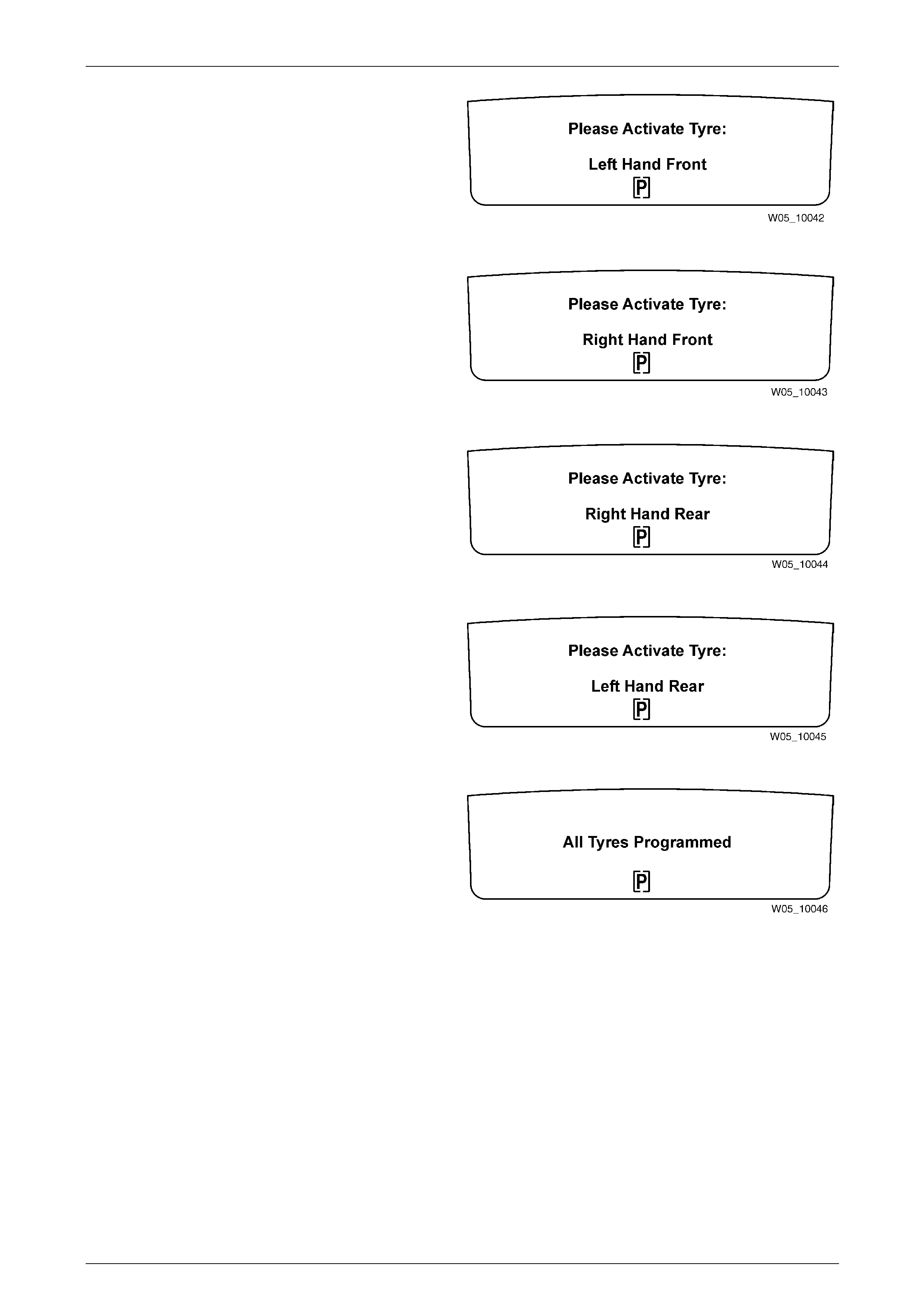
Wheels and Tyres Page 10–53
Page 10–53
5 ‘Please Activate Tyre: Left Hand Front’ (LHF) will be
activated next. Go to the LHF wheel and utilising the
Transponder Tool Procedure as a reference, press
and hold the ‘Press to Activate’ button until the tool
beeps and flashes indicati ng that the TPMS pressure
sensor signal has been transmitted to the TPMS
module.
Figure 10 – 51
6 ‘Please Activate Tyre: Right Hand Front’ (RHF) will be
displayed next. Go to the RHF tyre and activate the
transponder tool as before.
Figure 10 – 52
7 ‘Please Activate Tyre: Right Hand R ear’ (RHR) will be
displayed next. Go to the RHR tyre and activate the
transponder tool as before.
Figure 10 – 53
8 ‘Please Activate Tyre: Left Hand Rear’ (LHR) will be
displayed next. Go to the LHR tyre and activate the
transponder tool as before.
Figure 10 – 54
9 If programming is successful, the message ‘All Tyres
Programmed’ will be dis played. The pressure sensor
IDs are now stored in the TPMS module an d the Tyre
Pressure Monitoring System will be fully operational.
Figure 10 – 55
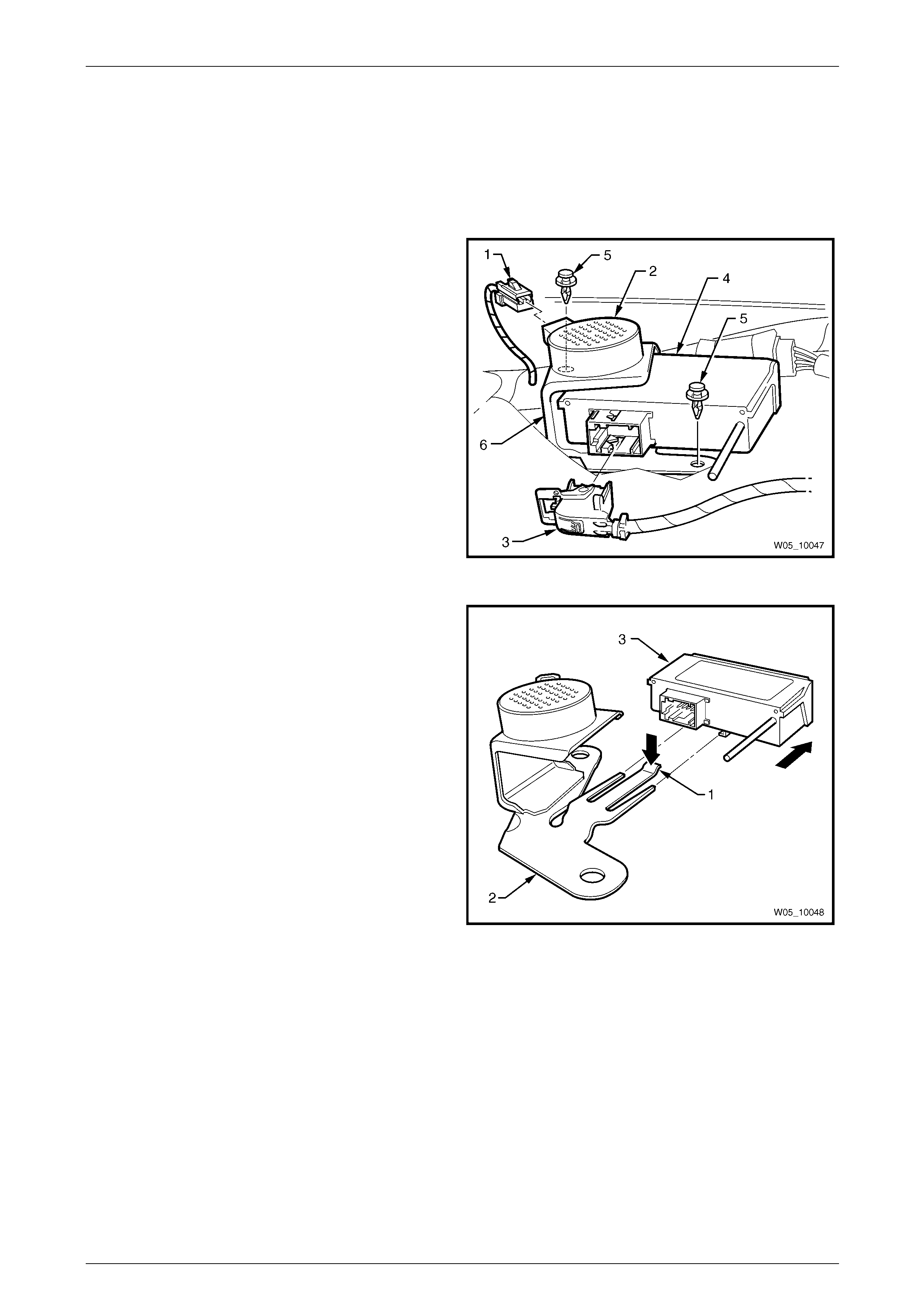
Wheels and Tyres Page 10–54
Page 10–54
5.11 Tyre Pressure Monitoring System
Module
Remove
1 Remove the rear window trim panel assembl y. refer to Section 1A8 Hea dlining and Interior Trim .
2 Remove the harness connector (1) from the park
assist alarm (2).
3 Remove the lever lock harness connector (3) from the
tyre pressure monitoring system (TPMS) module (4).
4 Remove the two retainers (5) retaining the TP MS
module / park assist alarm mounting bracket (6) to the
vehicle body.
NOTE
The TPMS module cannot be removed from the
mounting bracket prior to removing the bracket
and module assembly from the vehicle body.
Figure 10 – 56
5 Press the tang (1) at the rear of the bracket (2)
downward, slide the TPMS module (3) rearward and
remove it from the bracket.
Figure 10 – 57
Install
Installation is the reverse to removal proced ure.

Wheels and Tyres Page 10–55
Page 10–55
6 Specifications
Alloy Wheels
Rim Width Code..................................................................................................................7JJ
............................................................................................................................................8JJ
Diameter Code .....................................................................................................................16
.............................................................................................................................................. 17
Maximum Permissible Radial Run-out........................................................................0.45 mm
Maximum Permissible Lateral Run-out.......................................................................0.45 mm
Offset............................................................................................................. 48 mm (positive)
Inflation Pressures
Recommended Cold Inflation – kPa
Normal Load Maximum Load Model Wheel Tyre designation
Front Rear Front Rear
Statesman 7JJ x 16 Alloy 225/55R16 95 V 200 200 220 250
Caprice 8JJ x 17 Alloy 225/50R17 94V 200 200 220 250
For speeds above 160 km/h 240 240 270 300

Wheels and Tyres Page 10–56
Page 10–56
7 Torque Wrench Specifications
Road Wheel Attaching Nuts ........................................................110 – 140 Nm

Wheels and Tyres Page 10–57
Page 10–57
8 Special Tools
Tool Number Illustration Description Classification
AU534
Torque Limiting Socket
Released to allow the use of impact
gun to tighten road wheel nuts
Mandatory
Tyre Pressure Monitoring System
(TPMS) Transponder
Released to programme tyre pressure
sensor locations on vehicles with
TPMS.
Mandatory