
Wipers, Washers and Horn Page 12N–1
Section 12N
Wipers, Washers and Horn
ATTENTION
Before performing any service operation or other procedure described in this Section, refer to Section 00
Warnings, Cautions and Notes for correct workshop practices with regard to safety and/or property damage.
1 General Information ...............................................................................................................................3
1.1 Wiper Assemblies.................................................................................................................................................. 3
Wiper Assemblies.................................................................................................................................................. 3
Wiper Motor............................................................................................................................................................ 3
1.2 Washer Assemblies...............................................................................................................................................4
1.3 Horn Assemblies....................................................................................................................................................5
Horn Assembly....................................................................................................................................................... 5
Description ......................................................................................................................................................... 5
Horn Relay ......................................................................................................................................................... 5
Steering Wheel Horn Contact............................................................................................................................. 5
Theft-deterrent Horn Assembly............................................................................................................................ 5
Description ......................................................................................................................................................... 5
Theft-deterrent Horn Relay................................................................................................................................. 5
2 Preliminary Test – Wipers and Washers..............................................................................................6
2.1 Test Wipers and Washers Assemblies ................................................................................................................ 6
Introduction............................................................................................................................................................ 6
Test Description..................................................................................................................................................... 6
Diagnostic Table Notes ......................................................................................................................................... 6
Diagnostic Table.................................................................................................................................................... 7
3 Diagnostics – Wipers and Washers .....................................................................................................8
3.1 Prerequisites.......................................................................................................................................................... 8
Safety Requirements ............................................................................................................................................. 8
Equipment .............................................................................................................................................................. 8
Testing Procedures ............................................................................................................................................... 8
3.2 Wiring Diagram – Wiper/Washer...........................................................................................................................9
3.3 Connector Diagrams – Wiper/Washer................................................................................................................ 10
3.4 Diagnose Wiper Motor Wiring System Malfunction.......................................................................................... 11
Introduction.......................................................................................................................................................... 11
Electrical Test Description.................................................................................................................................. 11
Diagnostic Table Notes ....................................................................................................................................... 12
Diagnostic Table.................................................................................................................................................. 12
3.5 Diagnose Wiper Motor Assembly Operation.....................................................................................................14
Introduction.......................................................................................................................................................... 14
Electrical Test Description.................................................................................................................................. 14
Diagnostic Table Notes ....................................................................................................................................... 14
Diagnostic Table.................................................................................................................................................. 15
3.6 Diagnose Washer Pump and Wiring System Malfunction................................................................................ 16
Introduction.......................................................................................................................................................... 16
Electrical Test Description.................................................................................................................................. 16
Diagnostic Table Notes ....................................................................................................................................... 16
Diagnostic Table.................................................................................................................................................. 16
4 Diagnostics – Horn...............................................................................................................................17
4.1 Prerequisites........................................................................................................................................................ 17
Equipment ............................................................................................................................................................ 17
Testing Procedures ............................................................................................................................................. 17
Page 12N–1

Wipers, Washers and Horn Page 12N–2
4.2 Wiring Diagram – Horn Assembly...................................................................................................................... 18
4.3 Connector Diagrams – Horn Assembly ............................................................................................................. 19
4.4 Diagnose Horn and Wiring System Malfunction............................................................................................... 20
Introduction.......................................................................................................................................................... 20
Electrical Test Description.................................................................................................................................. 20
Diagnostic Table Notes ....................................................................................................................................... 21
Diagnostic Table.................................................................................................................................................. 21
5 Service Operations – Wiper Assemblies ...........................................................................................23
5.1 Wiper Blade Insert ............................................................................................................................................... 23
Replace................................................................................................................................................................. 23
5.2 Wiper Blade Assembly ........................................................................................................................................ 24
Remove................................................................................................................................................................. 24
Reinstall................................................................................................................................................................ 24
5.3 Wiper Arm Assembly............................................................................................................................................ 25
Remove................................................................................................................................................................. 25
Reinstall................................................................................................................................................................ 26
5.4 Plenum Cover Assembly..................................................................................................................................... 27
Remove................................................................................................................................................................. 27
Disassemble......................................................................................................................................................... 27
Reassemble.......................................................................................................................................................... 28
Reinstall................................................................................................................................................................ 28
5.5 Wiper Motor Assembly and Linkages................................................................................................................ 29
Remove................................................................................................................................................................. 29
Reinstall................................................................................................................................................................ 29
6 Service Operations – Washer Assemblies ........................................................................................31
6.1 Washer Reservoir Assembly............................................................................................................................... 31
Remove................................................................................................................................................................. 31
Reinstall................................................................................................................................................................ 31
Filling the Washer Reservoir Assembly............................................................................................................. 32
6.2 Washer Hose and Nozzle Assemblies................................................................................................................ 33
Remove................................................................................................................................................................. 33
Reinstall................................................................................................................................................................ 34
Spray Pattern Check............................................................................................................................................ 34
7 Service Operations – Wipers and Washers Control Switch ............................................................35
7.1 Wipers and Washers Control Switch ................................................................................................................. 35
Remove................................................................................................................................................................. 35
Reinstall................................................................................................................................................................ 37
7.2 Wipers and Washers Control Switch Testing.................................................................................................... 38
Test procedure..................................................................................................................................................... 38
8 Service Operations – Horn..................................................................................................................39
8.1 Horn Assembly..................................................................................................................................................... 39
Remove................................................................................................................................................................. 39
Reinstall................................................................................................................................................................ 39
8.2 Theft-deterrent Horn Assembly.......................................................................................................................... 40
Remove................................................................................................................................................................. 40
Reinstall................................................................................................................................................................ 40
Test ....................................................................................................................................................................... 40
9 Torque Wrench Specifications............................................................................................................41
10 Special Tools ........................................................................................................................................42
Page 12N–2

Wipers, Washers and Horn Page 12N–3
1 General Information
This Section describes the service, testing procedures and diagnos is for the wipers and washer systems as well as the
horns fitted to MY 2005 WL Series vehicles.
1.1 Wiper Assemblies
Wiper Assemblies
The two wiper assemblies consist each of a wiper blade secured to a wiper arm which is attached to a drive spindle part
of linkages attached to the plenum chamber and driven by the wiper motor assembly.
A one piece plenum cover is fitted to Seda n and Utility vehicles. The washer nozzle assemblies and part of the washer
hose are secured to the plenu m cover. An air deflector and a water deflector are attached to the plenum cover.
The wiper assemblies are ope r ated via the wipers and washers control switch assembly fitted to the steering column.
The operation includin g the intermittent dwell function is controlled by the body control module (BCM), refer to
Section 12J Body Control Module.
The wipers and washers control switch in the variable intermittent position decreases or i ncreases the frequency the
wiper motor is actuated, through the détente. The wipers and washers control s witch has seven increments, and the
dwell time is determined via a combinatio n of vehicle road speed an d the wiper control stalk.
Wiper Motor
The wiper motor assembly operates in one direction to drive the wiper arms for the wiping of the windshield.
The wiper motor assembly has three modes of operation:
• intermittent wipe cycle,
• continuous low speed wipe mode, an d
• continuous high speed wipe mode.
With the ignition switch on ACC or ON position, when the wipers and washers control switch is moved to position 1 or 2,
power is directly supplied to the wiper motor for lo w or high spee d wipe operation. When the wipers and washers control
switch is moved to INT position, power is supplied to the wiper motor via the body control module (BCM) for intermittent
wipe operation.
When the wipers and washers control switch is moved to the OFF position, the park switch included in the wiper motor
assembly supplies power to the wiper motor via the BCM until the wiper arms reach the park position. At this point the
park switch opens and discon nects the power supply to the wiper mot or an d the wiper arms remain stationary at the p ark
position.
For a complete wiring diagram of the wiper system, refer to 3.2 Wiring Diag r am – Wiper/Washer.
Page 12N–3

Wipers, Washers and Horn Page 12N–4
1.2 Washer Assemblies
The washer reservoir assembl y has the washer pump attached to it and is located below the right-hand front wheelhous e
panel assembly.
The washer nozzles are a dual outlet type and are mounted to the plenum cover assembly.
The washer pump assembly is operated via the wipers and washers control switch fitted to the steering column; the
operation is controlled by the (BCM), refer to Section 12J Body Control Module.
With the ignition switch on ACC or ON position, the accessory control relay within the passenger compartment fuse and
relay panel assembl y, is activated. Then when the wipers and washers control switch is pulled a nd held back, power is
supplied to the washer motor until the wipers and washers control switch is releas ed.
For a complete wiring diagram of the washer system, refer to 3.2 Wiring Diagram – Wiper/Washer.
Page 12N–4

Wipers, Washers and Horn Page 12N–5
1.3 Horn Assemblies
Horn Assembly
Description
Two trumpet type horns are fitted to the vehicle.
The trumpet type dual horns are fitted behind the front bumper fascia with the high-note horn on the right-hand side and
the low-note horn on the left-hand side.
The horn assembly is operated via the steering wheel horn contact, the operation is controlled by the BCM, refer to
Section 12J Body Control Module.
Power is supplied to the horn assembly when the horn relay located withi n the passenger compartment fuse and relay
panel assembly is activated. The horn relay is activated by a circuit which is closed when the steering wheel horn contact
switch is pushed in.
For a complete wiring diagram of the horn s ystem, refer to 4.2 Wiring Diag r am – Horn Assembly.
Horn Relay
The horn relay is locate d in the engine compartment fuse and relay panel assembly, refer to Section 12O Fuses, Relays
and Wiring Harnesses.
Steering Wheel Horn Contact
The horn contact is incorporated into the steering wheel inflatable restraint module in the centre of the steering wheel.
The horn contact is not serviced separatel y; for all servic e operations, refer to Section 12M Occupant Protection System.
Theft-deterrent Horn Assembly
Description
The theft-deterrent horn is a disc type horn located at the rear of the engine bay and is attache d to the front left-han d
wheelhouse panel ass embly.
Power is supplied to the theft-deterrent horn assembly when the theft-deterrent horn relay located within the BCM is
activated. The operation of the theft-deterrent horn is controlled by the BCM, refer to Section 12J Bod y Control Module.
For a complete wiring diagram of the theft-deterrent hor n system, refer to 4.2 Wiring Diagram – Horn Assembly.
Theft-deterrent Horn Relay
The theft-deterrent horn relay is located in the BCM; for details refer to Section 12J Body Control Module.
Page 12N–5

Wipers, Washers and Horn Page 12N–6
2 Preliminary Test – Wipers and
Washers
2.1 Test Wipers and Washers Assemblies
Introduction
The preliminary test is used to aid in localising the cause to malfunction in the wipers and washers wiring system and
confirms the serviceability of the wipers and washers control switch.
For a complete wiring diagram of the wipers and washers wiring circuits, refer to 3.2 Wiring Diagram – Wiper/Washer.
Test Description
The following numbers refer to the step numbers in the diagnostic table:
1 Checks if the accessories operate. Isolates if the accessory control relay and/or associated circuits is at fault.
2 Checks if the wipers operate with the wipers and washers control switch in position 1 and position 2.
3 Checks if the washers operate with the wipers functioning.
4 Checks if the wipers and washers control switch is serviceable. Isolates whether the wipers and washers control
switch or the washers wiring system is at fault.
5 Checks if the washers operate with the wipers not functioning.
6 Checks if the wipers and washers control switch is serviceable. Isolates whether the wipers and washers control
switch or the wipers wiring system is at fault.
7 Checks if the fuse F18 within the passenger compartment fuse and relay panel assembly is serviceable.
8 Checks if battery voltage is delivered to switch connector S247 – X1 pin 6, with the ignition switch in the ACC or
ON position. Isolates whether the battery power supply circuits 243 or 70 are at fault.
9 Checks if the wipers and washers control switch is serviceable. Isolates whether the wipers and washers control
switch or the wipers and washers wiring systems are at fault.
Diagnostic Table Notes
1 To diagnose the accessory control relay and associated wiring circuits, refer to Section 12J Body Control Module.
2 To test and/or replace the wipers and washers control switch, refer to 7 Service Operations – Wipers and W ashers
Control Switch.
3 To diagnose the washers wiring system, refer to 3.6 Diagnose Washer Pump and Wiring S ystem Malfunction.
4 To diagnose the wipers wiring system, refer to 3.4 Diagnose Wiper Motor Wiring System Malfunction.
5 Refer to Section 12O Fuses, Relays and Wiring Harnesses for harness rout eing.
6 For wiring harness repairs, refer to Section 12P Wiring Diagrams.
Page 12N–6

Wipers, Washers and Horn Page 12N–7
Diagnostic Table
Step Action Yes No
1 1 Switch the ignition to the ACC or ON position.
2 Check if the accessories operate (eg. radio).
Do the accessories operate? Go to Step 2
Diagnose the
accessory control
relay and associated
circuits
(refer to Note 1)
2 With the ignition switch in the ACC or ON position, switch the wipers
and washers control switch in the position 1 then position 2.
Do the wipers operate, with the switch in both positions? Go to Step 3 Go to Step 5
3 With the ignition switch in the ACC or ON position, pull back and hold
the wipers and washers control switch.
Do the washers operate? System serviceable Go to Step 4
4 Test the wipers and washers control switch S247, (refer to Note 2).
Is the wipers and washers control switch serviceable?
Diagnose the
washers wiring
system
(refer to Note 3)
Replace the wipers
and washers control
switch
(refer to Note 2)
5 With the ignition switch in the ACC or ON position, pull back and hold
the wipers and washers control switch.
Do the washers operate? Go to Step 6 Go to Step 7
6 Test the wipers and washers control switch S247, (refer to Note 2).
Is the wipers and washers control switch serviceable? Diagnose the wipers
wiring system
(refer to Note 4)
Replace the wipers
and washers control
switch
(refer to Note 2)
7 Check the wipers and washers fuse F18 within the passenger
compartment fuse and relay panel assembly, (refer to Note 5).
Is the fuse serviceable?
Go to Step 8
Replace the fuse,
if the fuse blows
again check for a
short to ground in
circuit 243
(refer to Note 5)
8 1 Remove the wipers and washers control switch S247, (refer to
Note 2).
2 With the ignition switch in the ACC or ON position, back pro be
connector S247-X1 pin 6 with a test lamp.
Does the test lamp illuminate? Go to Step 9
Repair or replace
circuits 243 or 70
(refer to Note 6)
9 Test the wipers and washers control switch S247, (refer to Note 2).
Is the wipers and washers control switch serviceable?
Diagnose the wipers
and the washers
wiring systems
(refer to Note 4 and
Note 3)
Replace the wipers
and washers control
switch
(refer to Note 2)
When all diagno sis and repairs are completed, check the system for correct operation.
Page 12N–7
Wipers, Washers and Horn Page 12N–8
3 Diagnostics – Wipers and
Washers
3.1 Prerequisites
Safety Requirements
When operating the wipers and washers as
part of any steps in the diagnostic tables,
ensure fingers and limbs are clear of moving
parts.
Equipment
The following equipment is required to diagnose the wipers and washers:
• an unpowered test lamp with a current dra w of less than 3 A, and
• a digital multimeter with a minimum impe dance of 10 MΩ.
Testing Procedures
Adhere to the following points when
performing diagnostic testing on
components:
• Take care when using testing equipment
to diagnose wiring harness connectors.
Backprobe the connector to avoid terminal
damage.
• When tests are required on connector
terminals, use the adapters in the
connector adapter kit KM–609 to prevent
damage to the terminals.
• Unless the multimeter being used has an
auto-ranging function, ensure the correct
range is selected.
• When backpro bing connectors, ensure the
test lamp ground lead is connected to an
appropriate ground point on the vehicle.
Ensure this ground point is not part of the
circuit being tested.
NOTE
Perform the wipers and washers preliminary test
before diagnosing the wiring systems, refer to
2.1 Test Wipers and Washers Assemblies. When
following the steps in the diagnostic tables,
perform them in the order cited. If the required
nominal value or result is not achi eved, rectif y t he
problem before proceeding.
Page 12N–8
Wipers, Washers and Horn Page 12N–9
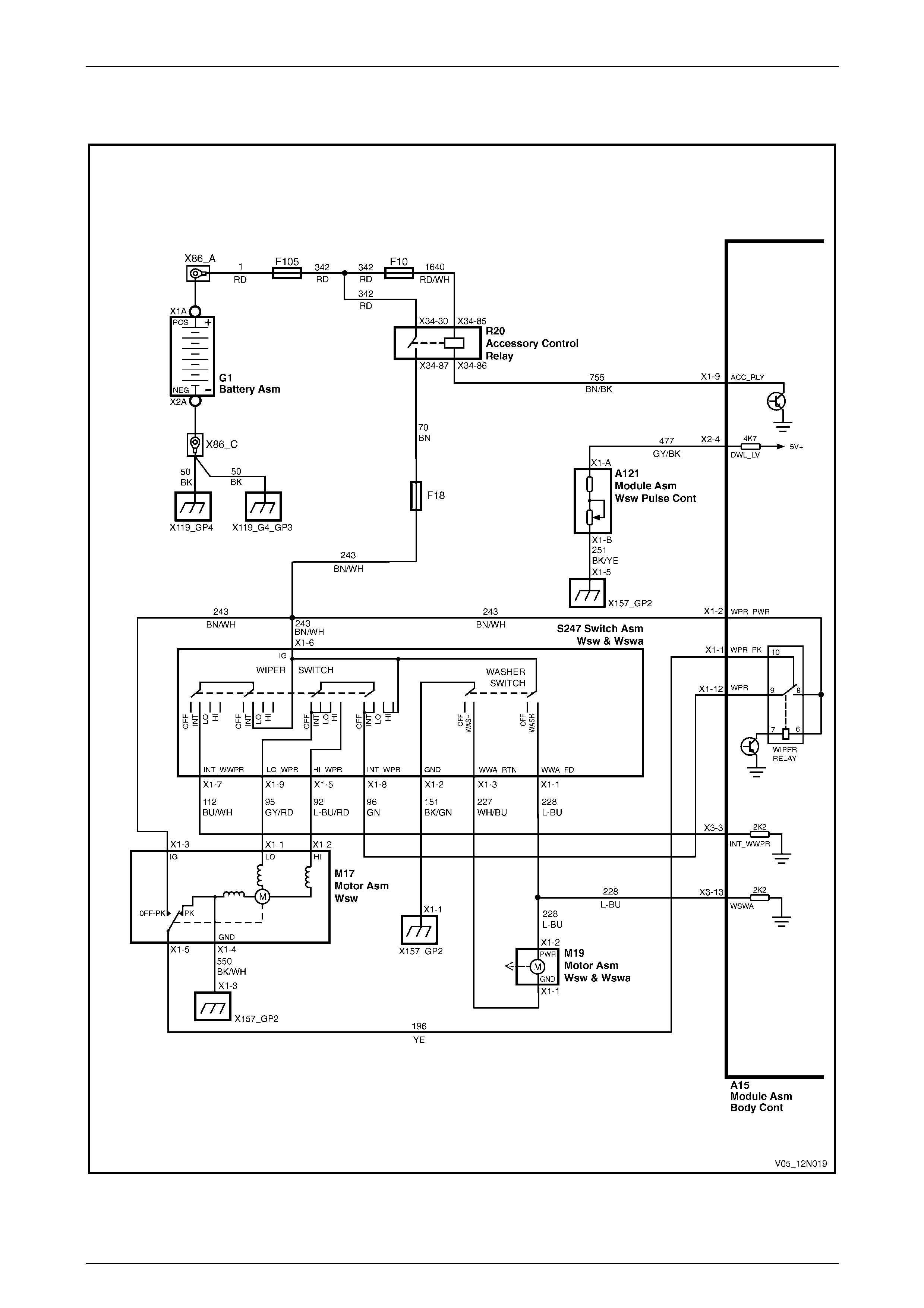
3.2 Wiring Diagram – Wiper/Washer
Figure 12N – 1
Page 12N–9
Wipers, Washers and Horn Page 12N–10
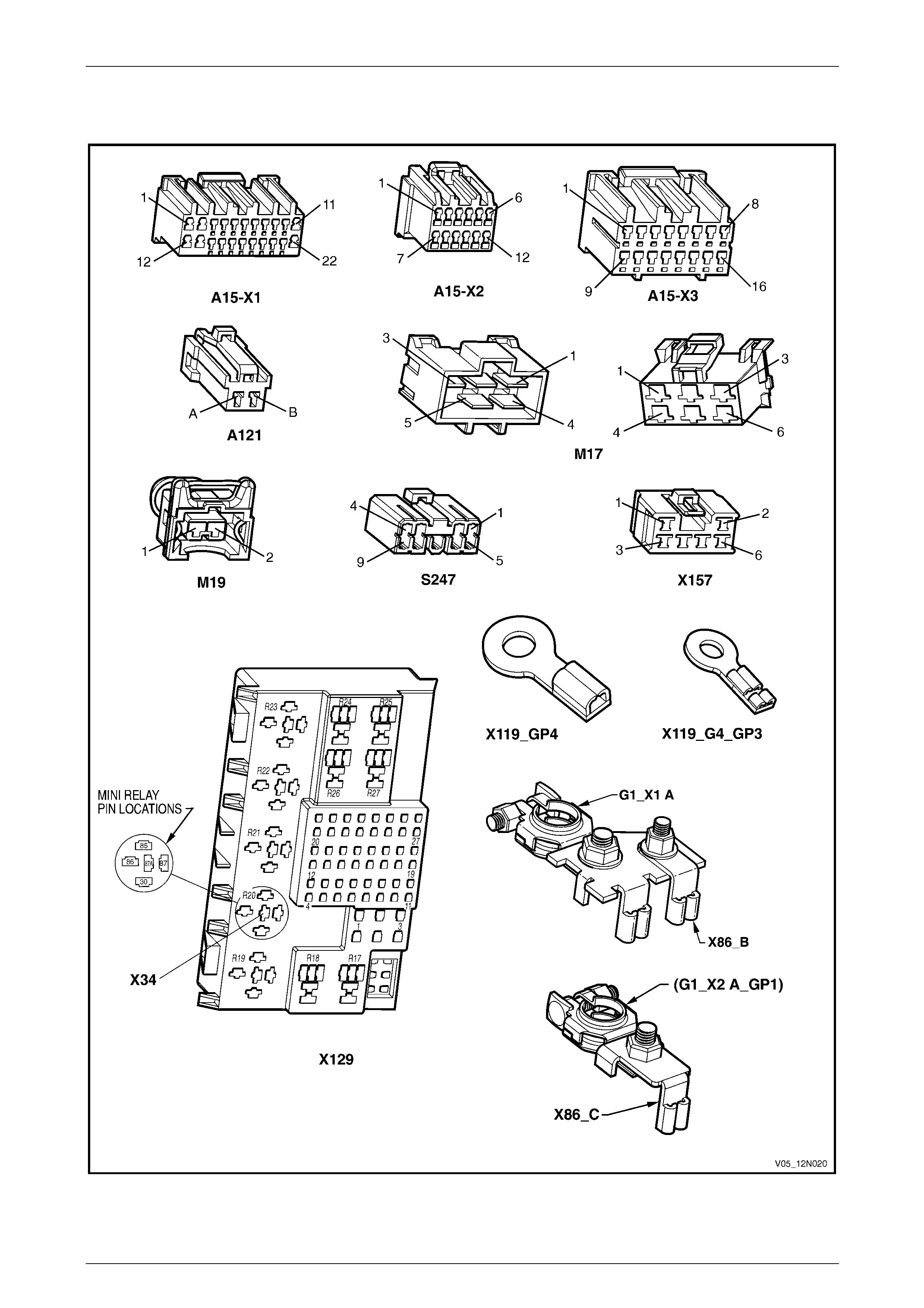
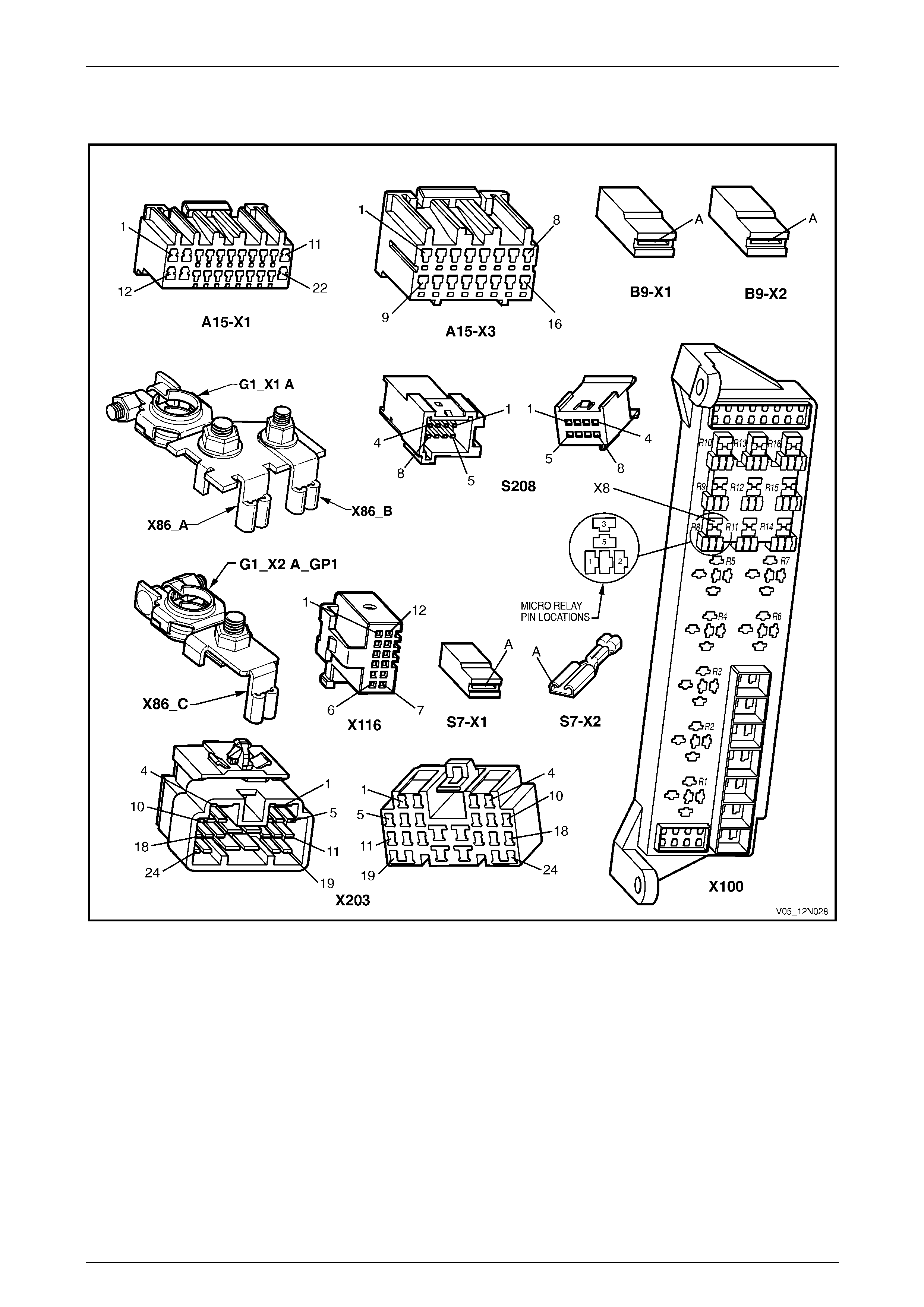
3.3 Connector Diagrams – Wiper/Washer
Figure 12N – 2
Page 12N–10
Wipers, Washers and Horn Page 12N–11
3.4 Diagnose Wiper Motor Wiring System
Malfunction
Introduction
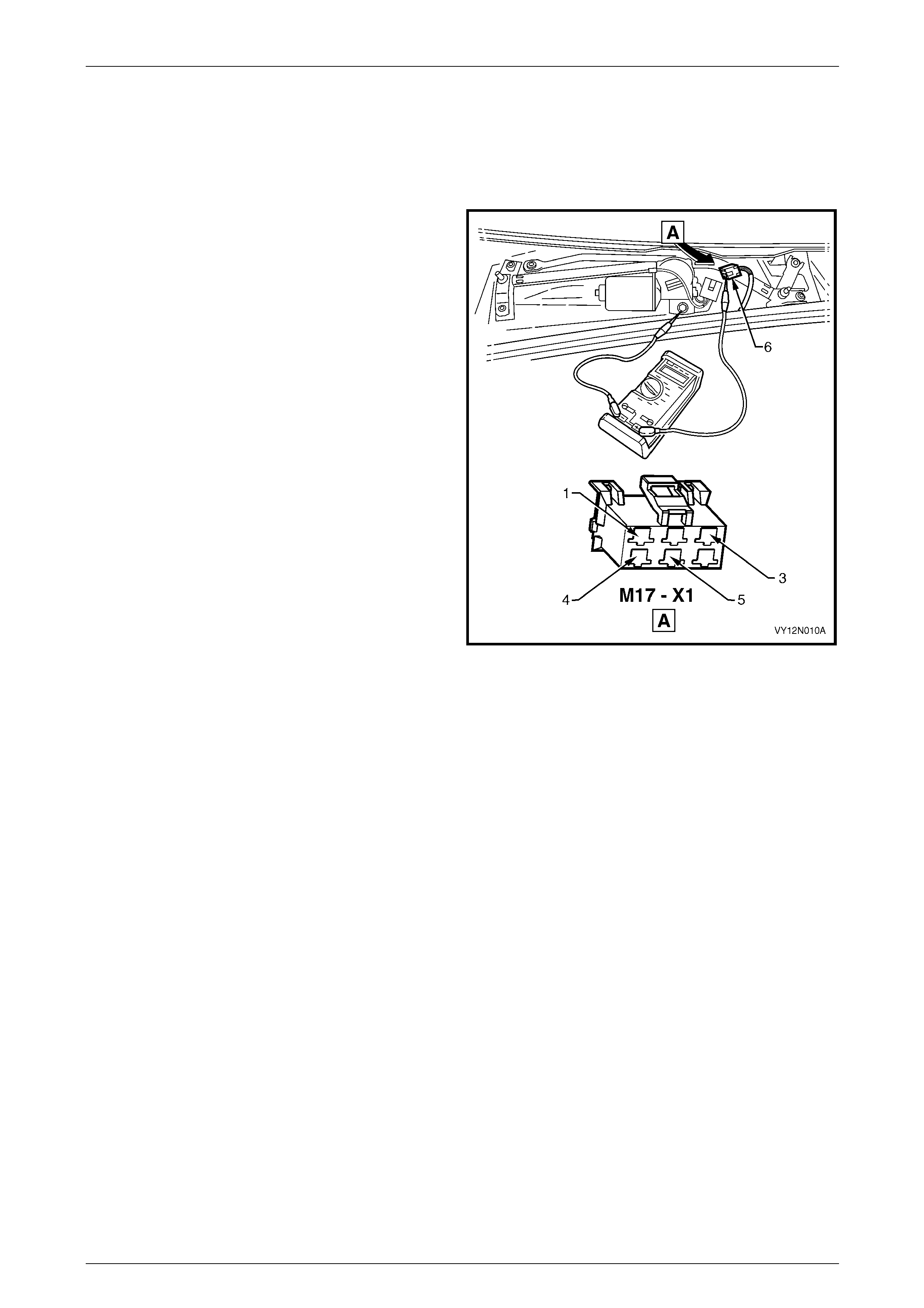
The following operation checks the wiper motor assembly
wiring at the wiper motor connector
M17 – X1 (6), as an aid to diagnosing a fault in the wiper
motor assembly system. This test confirms the serviceability
of the wiper motor assembly wiring system.
For a complete wiring diagram of the wiper motor assemb ly
circuits, refer to 3.2 Wiring Diagram – Wiper/Washer.
For connector pin location, refer to: 3.3 Connector
Diagrams – Wiper/Washer.
NOTE
The operation of the wiper intermittent dwell is
controlled by the body control module A15 and
can be checked with a Tech 2, refer to
Section 12J Body Control Module.
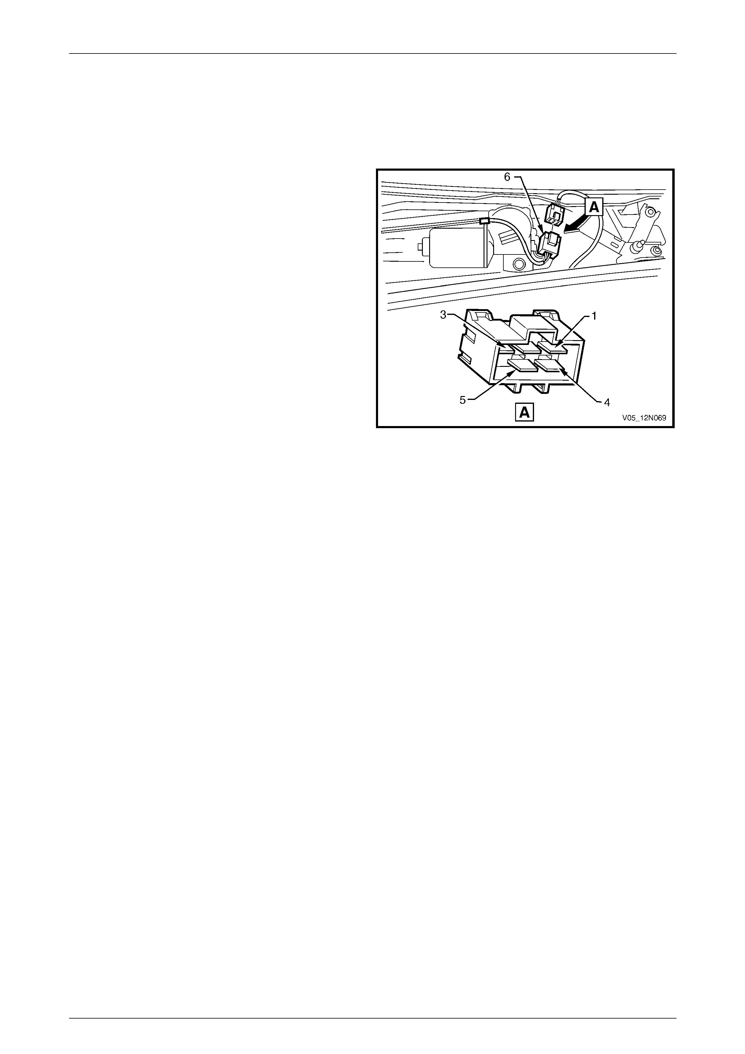
Figure 12N – 3
Electrical Test Description
The following numbers refer to the step numbers in the diagnostic table:
1 Checks if the wipers and washers preliminary test has been performed.
2 Checks if battery voltage is delivered to connector M17 – X1 pin 3, with the ignition switch in the ACC or ON
position. Isolates if the battery power supply circuit 243 is at fault.
3 Checks if battery voltage is delivered to connector M17 – X1 pin 1, with the ignition switch in the ACC or ON
position and the wipers and washers control switch in position 1 (low speed).
4 Checks if the wiper motor assembly ground circuit is serviceable. Isolates if the wiper motor assembly ground
circuit 550 is at fault.
5 Checks if the wiper motor assembly M17 is serviceable.
6 Checks if battery voltage is delivered to connector M17 – X1 pin 1, with the ignition switch in the ACC or ON
position and the wipers and washers control switch in position 1 (low speed). Isolates if the battery power supply
circuit 95 is at fault.
7 Checks if battery voltage is delivered to connector M17 – X1 pin 2, with the ignition switch in the ACC or ON
position and the wipers and washers control switch in position 2 (high speed). Isolates if the battery power supply
circuit 92 is at fault.
8 Checks if battery voltage is delivered to connector M17 – X1 pin 1, with the ignition switch in the ACC or ON
position and the wipers and washers control switch in INT position. Isolates whether the battery power supply
circuit 96 or 112 is at fault.
9 Checks if the wiper motor assembly circuit 196 is serviceable. Isolates if the wiper motor assembl y circuit 196 is at
fault.
Page 12N–11

Wipers, Washers and Horn Page 12N–12
Diagnostic Table Notes
1 To perform the wipers and washers preliminary test, refer to 2.1 Test Wipers and Washers Assemblies.
2 For removal of the wiper arm assemblies, plenum cover as sembly and replacement of the wiper motor assembly,
refer to 5 Service Operations – Wiper Assemblies.
3 For all wiring harness fault diagnosis, refer to Section 12P Wiring Diagrams.
4 For wiring harness repair, refer to Section 12P Wiring Diagrams.
5 To diagnose the wiper motor assembly, refer to 3.5 Diagnose Wiper Motor Assembly Operation.
Diagnostic Table
Step Action Yes No
1 Has the wipers and washers pr eliminary test been performed?
Go to Step 2
Perform the
preliminary test
(refer to Note 1)
2 1 Remove the wiper arm assemblies, (refer to Note 2).
2 Remove the plenum cover assembl y, (refer to Note 2).
3 Switch the ignition to the ACC or ON position.
4 Backprobe connector M17 – X1 pin 3 with a test lamp, (refer to
Note 3).
Does the test lamp illuminate? Go to Step 3
Repair or replace
circuit 243
(refer to Note 4)
3 1 With the ignition in the ACC or ON position, switch the wipers
and washers control switch to position 1 (low speed).
2 Backprobe connector M17 – X1 pin 1 with a test lamp, (refer to
Note 3).
Does the test lamp illuminate? Go to Step 4 Go to Step 6
4 1 Disconnect connector M17 – X1 from the wiper motor.
2 With a multimeter, check for continuity of the ground circu it 550
between connector M17 – X1 pin 4 and ground connector GP2,
(refer to Note 3).
Does the multimeter indicate continuity? Go to Step 5
Repair or replace
ground circuit 550
(refer to Note 4)
5 Diagnoses the wiper motor assembly M17, (refer to Note 5).
Is the wiper motor assembly serviceable?
For further diagnosis
refer to 12J Body
Control Module
Replace the wiper
motor assembly
(refer to Note 2)
6 1 Disconnect connector M17 – X1 from the wiper motor.
2 Switch the ignition to the ACC or ON position and the wipers and
washers control switch to position 1 (low speed).
3 With a multimeter, probe with the positive le ad to connector
M17 – X1 pin 1 and the negati v e lead to a ground point, (refer to
Note 3).
Does the multimeter indicate batter y voltage? Go to Step 7
Repair or replace
circuit 95
(refer to Note 4)
7 1 With the ignition in the ACC or ON position, switch the wipers
and washers control switch to position 2 (high speed).
2 With a multimeter, probe with the positive le ad to connector
M17 – X1 pin 2 and the negati v e lead to a ground point, (refer to
Note 3).
Does the multimeter indicate batter y voltage ? Go to Step 8
Repair or replace
circuit 92
(refer to Note 4)
Page 12N–12

Wipers, Washers and Horn Page 12N–13
Step Action Yes No
8 1 With the ignition in the ACC or ON position, switch the wipers
and washers control switch to INT position.
2 With a multimeter, probe with the positive le ad to connector
M17 – X1 pin 1 and the negati v e lead to a ground point, (refer to
Note 3).
Does the multimeter indicate batter y voltage? Go to Step 9
Repair or replace
circuit 96 or 112
(refer to Note 4)
9 1 Disconnect the body control module connector A15 – X1.
2 With a multimeter, check for continuity of the circuit 196 between
connector M17 – X1 pin 5 and connector A15 – X1 pin 1, (refer
to Note 3).
Does the multimeter indicate continuity?
System serviceable,
for further diagnosis
refer to 12J Body
Control Module
Repair or replace
circuit 196
(refer to Note 4)
When all diagno sis and repairs are completed, check the system for correct operation.
Page 12N–13
Wipers, Washers and Horn Page 12N–14
3.5 Diagnose Wiper Motor Assembly
Operation
Introduction
This test checks the operation of the wiper motor assembl y
at the motor connector M17 – X1 (6) and confirms the
serviceability of the wiper motor assemb ly.
The test diagnoses four functions:
• the low-speed drive,
• the high-speed drive,
• the off PARK position, and
• the PARK position.
For a diagram of the wiper motor assembly, refer to
3.2 Wiring Diagram – Wiper/ Washer.
For pins numbering within the motor connect or
M17 – X1 (6), refer to Figure 12N – 4.
NOTE
If there is a fault in the wiper system and the
following test proves the wiper motor assembly is
serviceable, refer to 3.4 Diagnose Wiper Motor
Wiring System Malfunction.
Figure 12N – 4
Electrical Test Description
The following numbers refer to the step numbers in the diagnostic table:
1 Checks the low speed operati on of the wiper motor assembly. Isolates if the circuit within the wiper motor assembly
is serviceable bet ween the motor connector M17 – X1 pin 1 and pin 4.
2 Checks the high speed operation of the wiper motor assembly. Isolates if the circuit within the wiper motor
assembly is serviceable between the motor connector M17 – X1 pin 2 and pin 4.
3 Checks if there is continuity within the wiper motor contacts when the motor rotates past the PARK position.
Isolates whether the contacts within the motor assembly are fault y or the circuit 196 is shorted to ground.
4 Checks if the wiper linkages are stoping at the park position. Isolates if the contacts within the motor assembly are
faulty.
Diagnostic Table Notes
1 For all wiring harness fault diagnosis, refer to Section 12P Wiring Diagrams.
2 For removal of the wiper arm assemblies, plenum cover as sembly and replacement of the wiper motor assembly,
refer to 5 Service Operations – Wiper Assemblies.
Page 12N–14

Wipers, Washers and Horn Page 12N–15
Diagnostic Table
Step Action Yes No
1 1 Remove the wiper arm assemblies, (refer to Note 2).
2 Remove the plenum cover assembl y, (refer to Note 2).
3 Disconnect the wiper motor connector M17 – X1.
4 Connect a fused jumper lead from the vehicle battery positive
terminal to the motor connector M17 – X1 pin 1 and a lead from
the motor connector M17 – X1 pin 4 to a ground point, (refer to
Note 1).
Does the wiper motor assembly operate at lo w speed? Go to Step 2
Replace the wiper
motor assembly
(refer to Note 2)
2 Connect a fused jumper lead from the vehicle battery positive terminal
to the motor connector M17 – X1 pin 2 and a lead from the motor
connector M17 – X1 pin 4 to a ground po int, (refer to Note 1).
Does the wiper motor assembly operate at high speed? Go to Step 3
Replace the wiper
motor assembly
(refer to Note 2)
3 1 Connect a fused jumper lead from the vehicle battery positive
terminal to the motor connector M17 – X1 pin 1 and a lead from
the motor connector M17 – X1 pin 4 to a ground point, (refer to
Note 1).
2 Allow the motor to turn the linkages appro ximately 1/4 of a turn
past the PARK position and disconnect the lead from the motor
connector M17 – X1 pin 1.
3 Connect a test lamp between the battery positive terminal and
the motor connector M17 – X1 pin 5, (refer to Note 1).
Does the test lamp illuminate?
Replace the wiper
motor assembly
(refer to Note 2) Go to Step 4
4 1 Connect motor connector M17 – X1 pins 1 and 5 together with a
fused jumper lead.
2 Connect a fused jumper lead from the vehicle battery positive
terminal to the motor connector M17 – X1 pin 3 and a lead from
the motor connector M17 – X1 pin 4 to a ground point, (refer to
Note 1).
Does the wiper motor assembly turn the linkages to the PARK position
and then stop?
The wiper motor
assembly is
serviceable
Replace the wiper
motor assembly
(refer to Note 2)
When all diagno sis and repairs are completed, check the system for correct operation.
Page 12N–15

Wipers, Washers and Horn Page 12N–16
3.6 Diagnose Washer Pump and Wiring
System Malfunction
Introduction
This test confirms the serviceability of the washer reservoir pump assembly and the associated wiring system.
For a complete wiring diagram of the pump and washer circuits, refer to 3.2 Wiring Diagram – Wiper/Washer.
For connector pin location, refer to: 3.3 Connector Diagrams – Wiper/Washer.
Electrical Test Description
The following numbers refer to the step numbers in the diagnostic table:
1 Checks if the wipers and washers preliminary test has been performed.
2 Checks if battery voltage is supplied to the washer pump assembly.
3 Checks if the washer hose or nozzle assemblies are blocked. Isolates whether the washer hose, nozzle assemblies
or washer pump assembly are at fault.
4 Checks if battery voltage is supplied to connector M19 – X1 pin 2. Isolates whether the ba ttery supply circuit 228 or
the ground circuits 227 or 151 are faulty.
Diagnostic Table Notes
1 To perform the wipers and washers preliminary test, refer to 2.1 Test Wipers and Washers Assemblies.
2 For all wiring harness fault diagnosis, refer to Section 12P Wiring Diagrams.
3 For the replacement of the washer hos e, washer nozzle assemblies or washer pump assembly, refer to
6 Service Operations – Washer Assemblies.
4 For wiring harness repairs, refer to Section 12P Wiring Diagrams.
Diagnostic Table
Step Action Yes No
1 Has the wipers and washers pr eliminary test been performed?
Go to Step 2
Perform the
preliminary test
(refer to Note 1)
2 1 If required, hoist the vehicle, refer to 0A General Information.
2 From beneath the vehicle disconnect connector M19 – X1 from
the washer pump.
3 With a multimeter, probe with the positive le ad to connector
M19 – X1 pin 2 and the negati ve lead to pin 1, (refer to Note 2).
4 Switch the ignition to the ACC or ON position.
5 Pull back and hold the wipers and washers control s witch.
Does the reading on the multimeter indicate battery voltage? Go to Step 3 Go to Step 4
3 Is there a blockage in either the washer hose or nozzle assemblies? Repair or replace
the washer hose or
nozzle assemblies
(refer to Note 3)
Replace the washer
pump assembly
(refer to Note 3)
4 1 Probe connector M19 – X1 pin 2 with the positive lead of a
multimeter and the negative lead to a ground point, (refer to
Note 2).
2 With the ignition in the ACC or ON position, pull back and hold
the wipers and washers control switch.
Does the multimeter indicate batter y voltage ?
Repair or replace
circuit 227 or 151
(refer to Note 4)
for further diagnosis,
refer to 12J Body
Control Module
Repair or replace
circuit 228
(refer to Note 4)
for further diagnosis,
refer to 12J Body
Control Module
When all diagno sis and repairs are completed, check the system for correct operation.
Page 12N–16

Wipers, Washers and Horn Page 12N–17
4 Diagnostics – Horn
4.1 Prerequisites
Equipment
A digital multimeter with a minimum impedance of 10 MΩ is required to diagnose the hor n assembly.
Testing Procedures
Adhere to the following points when
performing diagnostic testing on
components:
• Take care when using testing equipment
to diagnose wiring harness connectors.
Backprobe the connector to avoid terminal
damage.
• When tests are required on connector
terminals, use the adapters in the
connector adapter kit KM–609 to prevent
damage to the terminals.
• Unless the multimeter being used has an
auto-ranging function, ensure the correct
range is selected.
• When backpro bing connectors, ensure the
test lamp ground lead is connected to an
appropriate ground point on the vehicle.
Ensure this ground point is not part of the
circuit being tested.
NOTE
When following the steps in th e diagnostic tables,
perform them in the order cited. If the required
nominal value or result is not achi eved, rectif y t he
problem before proceeding.
Page 12N–17

Wipers, Washers and Horn Page 12N–18
4.2 Wiring Diagram – Horn Assembly
Figure 12N – 5
Page 12N–18
Wipers, Washers and Horn Page 12N–19
4.3 Connector Diagrams – Horn Assembly
Figure 12N – 6
Page 12N–19

Wipers, Washers and Horn Page 12N–20
4.4 Diagnose Horn and Wiring System
Malfunction
Introduction
This test checks the operation of the horn assembly at conn ectors B9 – X1 and B9 – X2 and confirms the serviceability of
the horn assembly, steering wheel coil, steering wheel horn contact and associated circuits.
There are four ranges in voltage that affect the horn assembly operatio n:
• 0 Volt,
• below 9 Volt,
• between 9 and 11 Volt, or
• above 11 Volt.
NOTE
The wiring system includes a single disc type
horn or alternatively two optional trumpet type
horns.
For a complete wiring diagram of the horn cir c uits refer to 4.2 Wiring Diagram – Horn Assembly.
For connector pin location, refer to 4.3 Connector Diagrams – Horn Assembly.
Electrical Test Description
The following numbers refer to the step numbers in the diagnostic table:
1 Checks if the horn fuse F9 within the passenger compartment fuse and relay panel assembly is serviceable.
2 Checks if the horn relay within the engine compartment fuse and relay panel assembly is serviceable.
3 Checks the voltage supplied to the horn assembly as follo ws:
• checks if there is no voltage reading on the multimeter,
• checks if there is a low voltage reading on the multimeter above 0 V to less than 9 V,
• checks if the system operates correctly, with a normal voltage reading on the multimeter of 9 – 11 V, and
• checks if there is a high voltage reading on the multimeter above 11 V, caused by a faulty horn assembly.
4 Checks if there is battery voltage through connectors B9 – X1 and X2. Isolates if the horn assembly is at fault.
5 Checks if the horn assembly ground circuit 550 is serviceable.
6 Checks the circuit continuity between connector X116 – X1 pins 1 and 6 on the connector coil steering wheel
inflatable restraint module.
7 Checks the circuit continuity between harness connector S208 pins 6 and 7 on the steering wheel inflatable
restraint module. Isolates if the connector coil steering wheel inflatable restraint module is at fault.
8 Checks the circuit continuity between harness connectors S208 pin 6 a nd S7 – X1 pin A, then bet ween connectors
S208 pin 7 and S7 – X2 pin A.
9 Checks the circuit continuity between connector X116 – X1 pin 1 and harness connector S208 pin 6 on the
connector coil steering wheel inflatable restraint module , then between connectors X116 – X1 pin 6 and S208
pin 7. Isolates whether the steering wheel horn contact S7 within the steering wheel inflatable restraint module
or/and the connector coil steering wheel inflatable restraint module is/are at fault.
10 Checks if there is battery voltage through connector X116 – X1 pins 1 and 6. Isolates whether there is a fault in
circuit 1240, 28 or 151 or in circuit 1240 or 29 .
11 Checks if battery voltage is delivered to connector B9 – X1. Isolates if the horn assembly is at fault, or if there is a
fault in ground circuit 550 or in po wer supply circuit 1240 or 29.
Page 12N–20

Wipers, Washers and Horn Page 12N–21
Diagnostic Table Notes
1 Refer to Section 12O Fuses, Relays and Wiring Harnesses for harness rout eing.
2 For all wiring harness fault diagnosis, refer to Section 12 P Wiring Diagrams.
3 If there is a fault in the horn assembly system and the following test prov es the system is serviceable, for further
diagnosis refer to Section 12J Body Control Module.
4 For replacement of the horn assembly, refer to 8.1 Horn Assembly.
5 For wiring harness repairs, refer to Section 12P Wiring Diagrams.
6 For removal of the steering column covers, refer to Section 9 Steering.
7 For removal / replacement of the steering wheel inflatable restraint module, refer to Section 12M Occupa nt
Protection System.
8 If at any time the fault is deemed to be intermittent, refer to Section 12P Wiring Diagra m s.
Diagnostic Table
Step Action Yes No
1 Check the horn fuse F9 within the passenger compartment fuse and
relay panel assembly, (refer to Note 1).
Is the fuse serviceable?
Go to Step 2
Replace the fuse,
if the fuse blows
again check for a
short to ground in
circuit 1240
(refer to Note 1)
2 Check the horn relay within the engine compartment fuse and relay
panel assembly, (refer to Note 1).
Is the relay serviceable? Go to Step 3 Replace the relay
(refer to Note 1)
1 If required, hoist the vehicle, refer to 0A General Information.
2 From beneath the vehicle, reach up between the bumper bar and
the front end panel assembly. With a multimeter, backprob e with
the positive lead to connector B9 – X1 pin A, and with the
negative lead to connector B9 – X2 pin A, (refer to Note 2).
3 Press the steering wheel hor n contact to activate the horn
assembly.
Does the multimeter indicate voltage as follows:
• 0 V
Go to Step 4
• above 0 V to less than 9 V
Go to Step 11
• 9 – 11 V
System serviceable
(refer to Note 3)
3
• above 11 V Replace the horn
assembly
(refer to Note 4)
4 1 Disconnect connectors B9 – X1 and X2 from the horn.
2 With a multimeter, probe with the positive le ad to connector
B9 – X1 pin A and with the negative lea d to conn ector B9 – X2
pin A, (refer to Note 2).
3 Press the steering wheel hor n contact to activate the horn
assembly.
Does the multimeter indicate batter y voltage ?
Replace the horn
assembly
(refer to Note 4) Go to Step 5
Page 12N–21

Wipers, Washers and Horn Page 12N–22
Step Action Yes No
5 With a multimeter, check for continuity of the ground circu it 550
between connector B9 – X2 pin A and ground point X1 57_GP2, (refer
to Note 2).
Does the multimeter indicate continuity? Go to Step 6
Repair or replace
ground circuit 550
(refer to Note 5)
6 1 Remove the steering column covers (refer to Note 6).
2 Disconnect connector X116 – X1 from the rear of the connector
coil steering wheel inflatable restraint module.
3 Probe between connector X11 6 – X1 pins 1 and 6 on the
connector coil steering wheel inflatable restraint module, (refer to
Note 2).
4 Press the steering wheel hor n contact to activate the horn
assembly.
Does the multimeter indicate continuity? Go to Step 10 Go to Step 7
7 1 Remove the steering wheel inflatable restraint module (refer to
Note 7).
2 Disconnect the harness connector S208.
3 Probe between steering wheel inflatable restraint module
harness connector S208 pins 6 and 7, (refer to Note 2).
4 Press the steering wheel hor n contact to activate the horn
assembly.
Does the multimeter indicate continuity?
Replace the
connector coil
steering wheel
inflatable restraint
module
(refer to Note 7) Go to Step 8
8 1 Probe between harness connector S208 pin 6 and connector
S7 – X1 pin A on the steering wheel inflat able restraint module,
(refer to Note 2).
2 Probe between harness connector S208 pin 7 and connector
S7 – X2 pin A on the steering wheel inflat able restraint module,
(refer to Note 2).
Does the multimeter indicate continuity in each step? Go to Step 9
Repair or replace
circuit 28 or 151
(refer to Note 5)
9 1 Probe between connector X11 6 – X1 pin 1 and harness
connector S208 pin 6 on the connector coil steering wheel
inflatable restraint module, (refer to Note 2).
2 Probe between connector X11 6 – X1 pin 6 and harness
connector S208 pin 7 on the connector coil steering wheel
inflatable restraint module, (refer to Note 2).
Does the multimeter indicate continuity in each step?
Replace the steering
wheel inflatable
restraint module
(refer to Note 7)
Replace the steering
wheel inflatable
restraint module and
the connector coil
steering wheel
inflatable restraint
module
(refer to Note 7)
10 With a multimeter, probe with the positive lead to connector X116 – X1
pin 1 and with the negative lead to connector X116 – X1 pin 6, (refer to
Note 2).
Does the multimeter indicate batter y voltage?
Repair or replace
circuit 1240 or 29
(refer to Note 5)
Repair or replace
circuit 1240, 28 or
151
(refer to Note 5)
11 1 Disconnect connector B9 – X1 from the horn.
2 With a multimeter, probe connector B9 – X1 pin A with the
positive lead and with the negative lead to body ground, (refer to
Note 2).
3 Press the steering wheel hor n contact to activate the horn
assembly.
Does the multimeter indicate batter y voltage ?
Replace the horn
assembly
(refer to Note 4),
if the new horn does
not operate, repair
or replace circuit
550
(refer to Note 5)
Repair or replace
circuit 1240 or 29
(refer to Note 5)
When all diagno sis and repairs are completed, check the system for correct operation.
Page 12N–22
Wipers, Washers and Horn Page 12N–23
5 Service Operations – Wiper
Assemblies
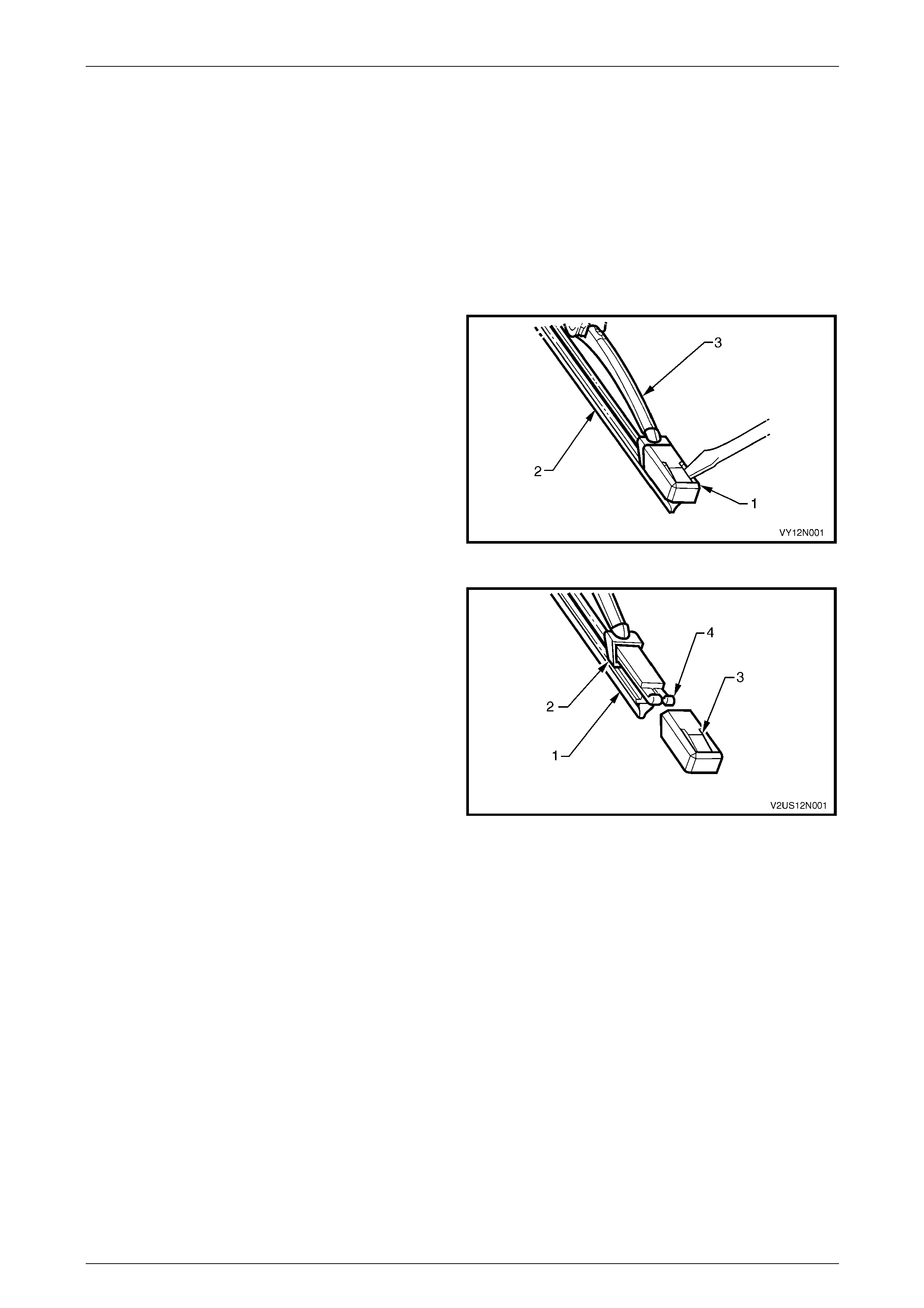
5.1 Wiper Blade Insert
LT Section — 10–505
Replace
1 Using a small scre wdriver, lift the retention l ug and
slide the end cap (1) off the wiper insert (2), on both
ends of the wiper blade (3).
NOTE
Do not re-use the end cap. The replacement
insert will be supplied with end caps fitted.
2 Slide the insert out of the wiper blade and discard.
Figure 12N – 7
3 Remove the end caps from the insert (1) and slide the
insert into the wiper blade ens uring the insert passes
through each metal claw (2).
4 Assemble the new end cap onto the ends of the insert,
ensuring the retention lug (3) on the end cap is located
securely behind the two uptur ned ends of the metal
rails (4).
Figure 12N – 8
Page 12N–23
Wipers, Washers and Horn Page 12N–24
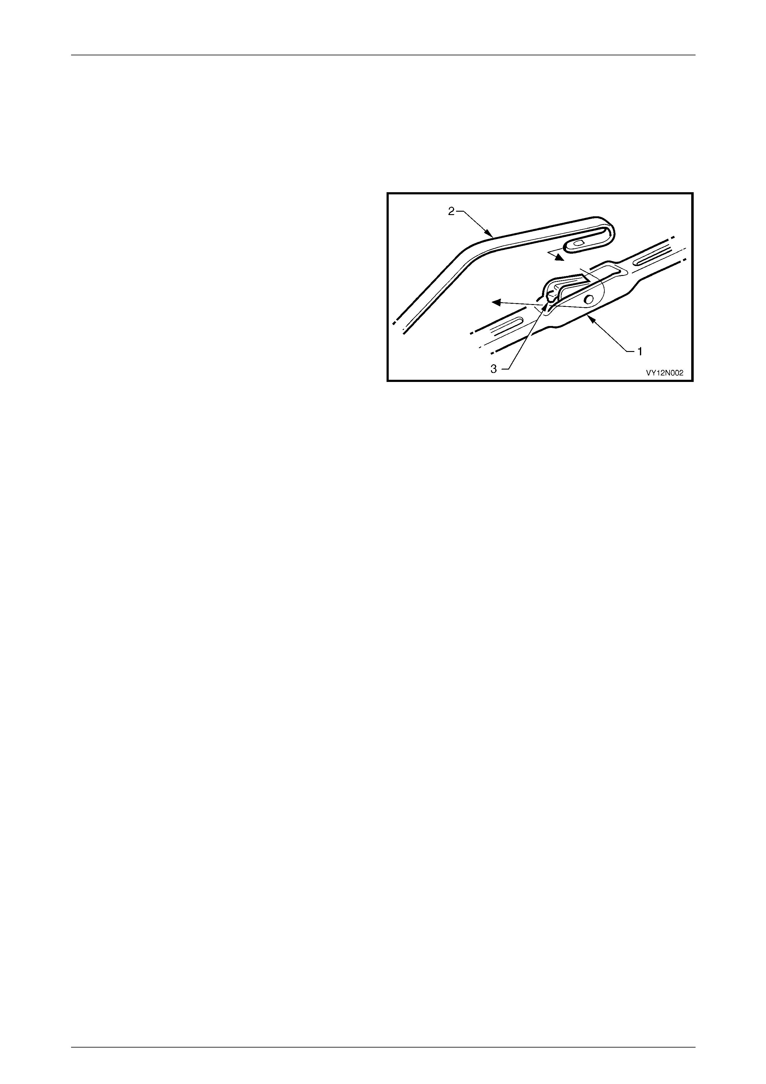
5.2 Wiper Blade Assembly
LT Section — 10–505
Remove
1 With the engine hood lo wered, lift the wiper arm
assembly (2) from the glass.
2 Remove the wiper blade assembly (1) from the arm by
lifting up the retainer (3) on the wiper blade assembly
and pulling the blade assembly out of the arm.
Figure 12N – 9
Reinstall
1 Slide the wiper blade assembly into the wiper arm until the wiper blade retainer locks into position.
2 Lower the wiper arm assembly onto the windshiel d.
Page 12N–24
Wipers, Washers and Horn Page 12N–25
5.3 Wiper Arm Assembly
LT Section — 10–505
Remove
1 Ensure the wiper motor and linkages are in the park
position.
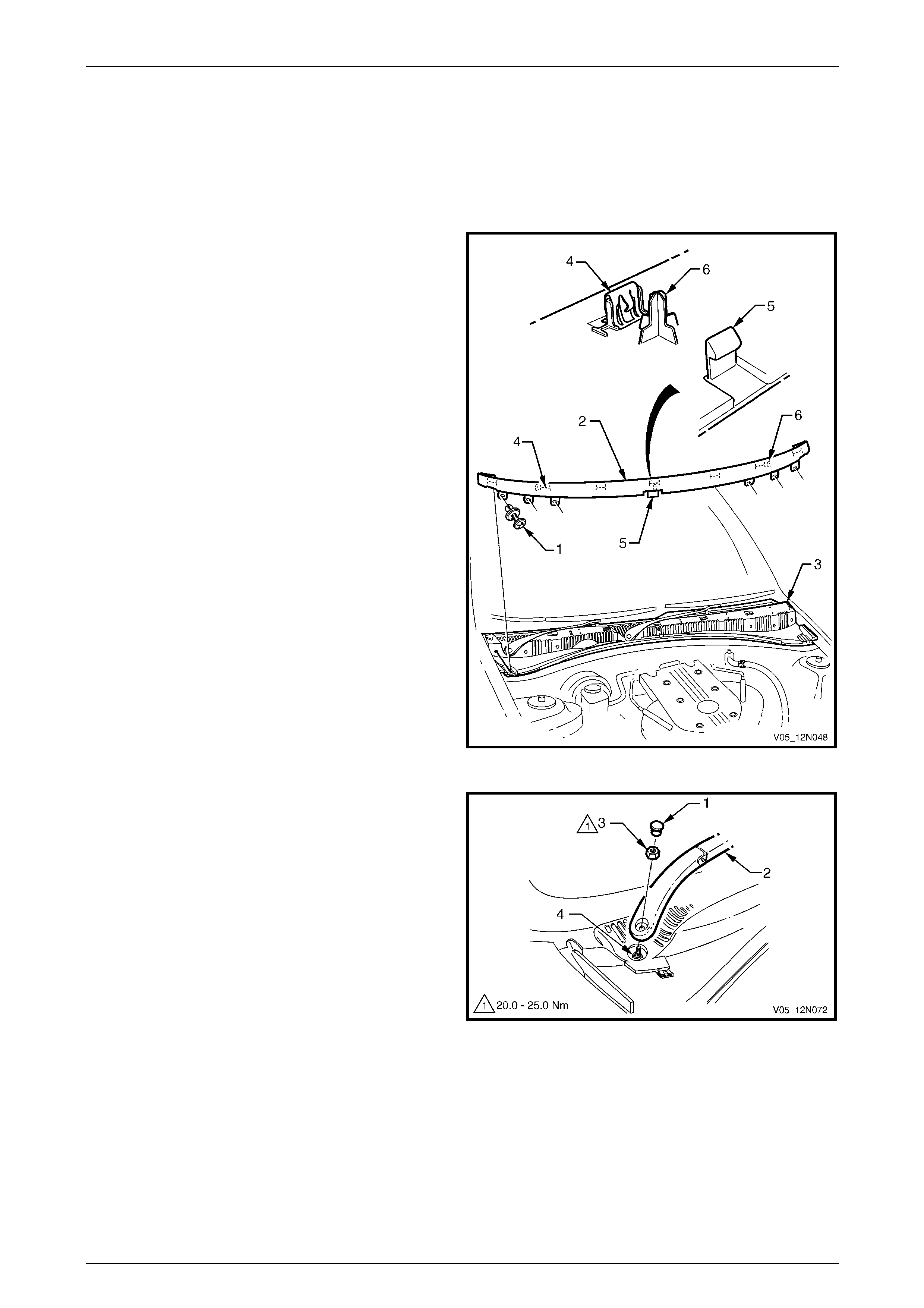
2 Open the engine hood.
3 Remove the retainer (1), six places, secur ing the air
deflector assembly (2) to the plenum cover
assembly (3).
4 Pull the air deflector assembly along the top edge to
release the seven clips (4) and rele ase the clip (5) in
the centre of the bottom edge.
5 Remove the air deflector assembly taking care not to
damage the three locating pins (6) and not to contact
the rear edge of the engine hood.
6 As required, remove the retaining clips from the
vehicle and fit to the plenum cover assem bly.
Figure 12N – 10
7 Using a small scre wdriver or scribe, gentl y pry the
cap (1) from the wiper arm assembly (2).
8 Remove the nut (3) attaching the wiper arm assembly
to the drive spindle (4).
9 Remove the wiper arm assembly from the drive
spindle, taking care not to allow the wiper arm to
contact the rear edge of the engine hood.
10 If required, remove the wiper blade assembly from the
wiper arm, refer to 5.2 Wiper Blade Assembly.
Figure 12N – 11
Page 12N–25
Wipers, Washers and Horn Page 12N–26
Reinstall
Reinstallation of the wiper arm assembly is the reverse of the removal procedure, noting the following:
1 Ensure the wiper motor and linkages are in the park
position.
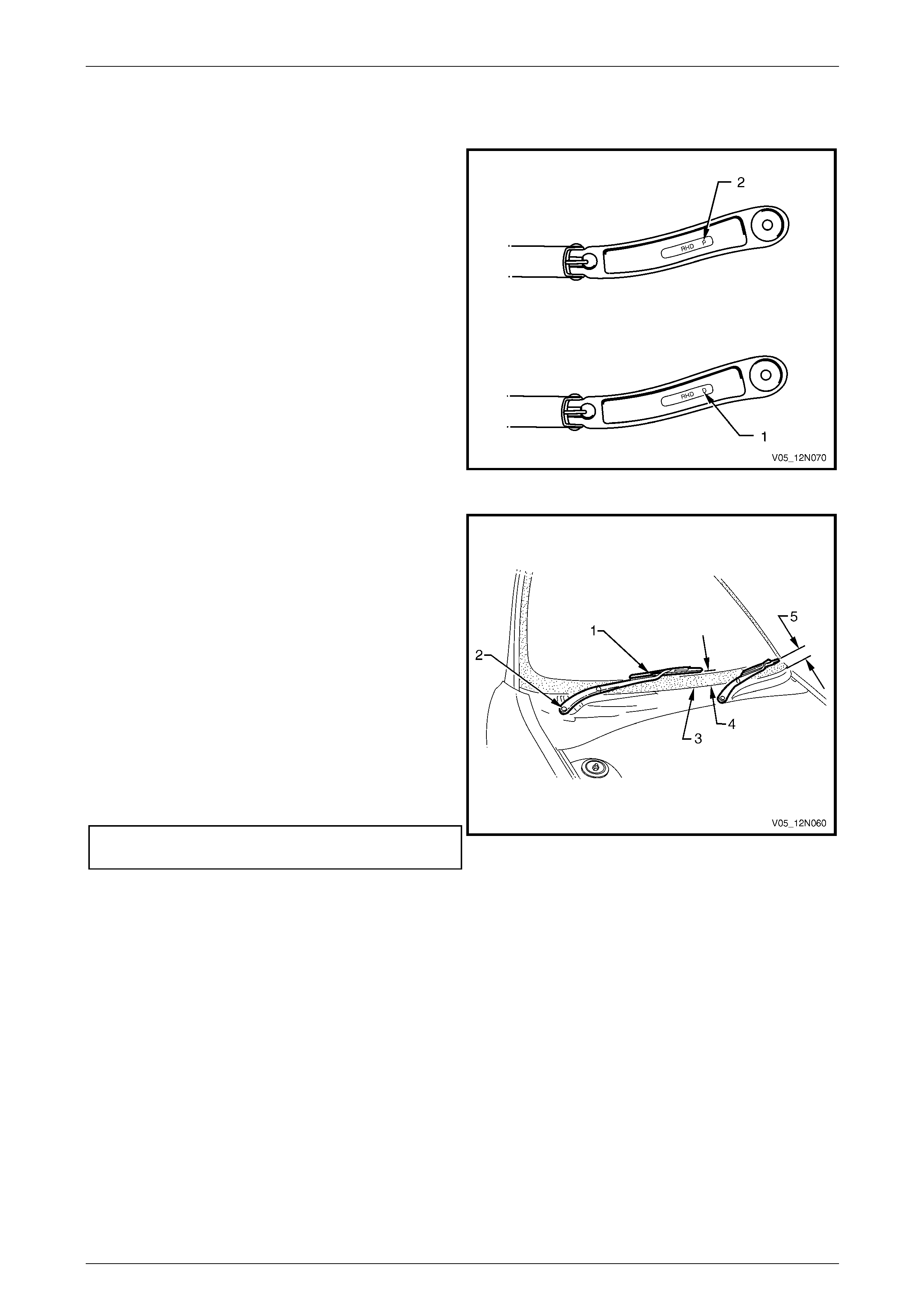
NOTE
There is a specific wiper arm for each side of the
vehicle. The arms are identified by the letters
RHD for right-hand drive ve hicles followed by ‘D’
for the driver side (1) and ‘P’ for the passenger
side (2), located on the underside of the arm.
2 Ensure the correct wiper arm and blade assemblies
are being fitted to each side of the vehicle.
Figure 12N – 12
NOTE
This illustration shows the wiper assemblies with
the hood removed, this is for clarity only. The
procedure can be performed with the hood fitted
and open.
3 Install the wiper arm assembly (1) onto the drive
spindle (2) so the blade is positioned with the tip
above the edge of the plenum cover assembly (3)
within the following limits:
• right-hand blade 25 mm +10/-0 mm (4)
• left-hand blade 40 mm +10/-0 mm (5)
4 Install the nut attaching the wiper arm assembly to the
drive spindle and tighten to the correct torque
specification.
Wiper arm assembly attaching
nut torque specification...........................20.0 – 25.0 Nm
Figure 12N – 13
5 Ensure both outer end of the air deflector engage the windshield reveal moulding assembly.
6 Check the wiper for correct operation.
Page 12N–26
Wipers, Washers and Horn Page 12N–27
5.4 Plenum Cover Assembly
LT Section — 10–510
Remove
1 Remove the air deflector assembly and the wiper arm
assemblies, refer to 5.3 Wiper Arm Assembly.
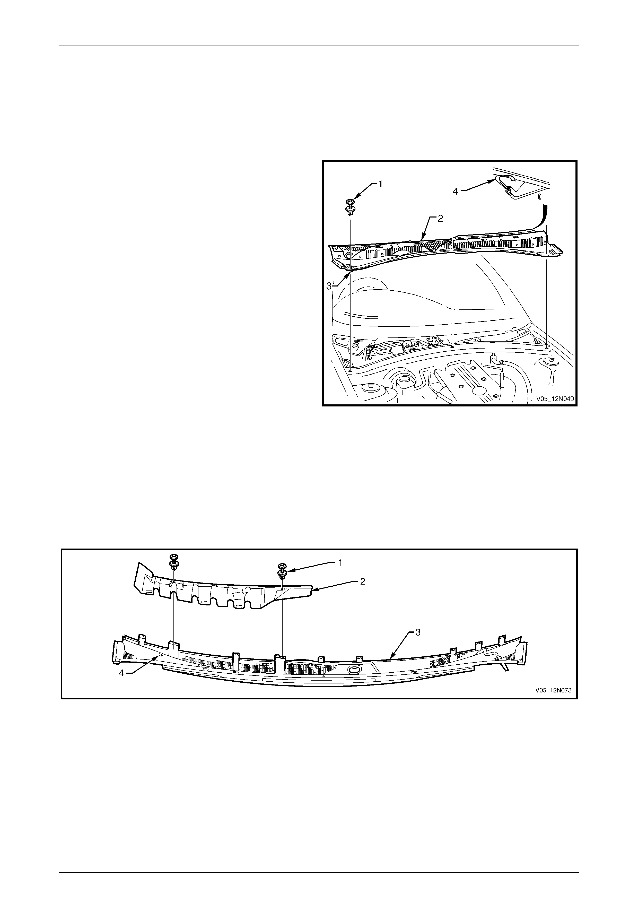
2 Remove the retainer (1), three places, securing the
plenum cover assembly (2) to the plenum chamber.
3 Disconnect the washer hose from the connector
joint (3).
4 Lift the plenum cover assembly up, while pul ling
forward to release the nine retaini ng tabs (4) securing
it to the windshield. Manoeuvre the cover away from
the engine hood hinge, an d lift out.
Figure 12N – 14
Disassemble
1 Remove the two fasteners (1) securing the water deflector (2) to the plenum cover assembly (3), refer to
Figure 12N – 15.
2 Pull the water deflector up and forward to release the three retaining lugs (4) securi ng it to the plenum cover
assembly.
3 Remove the water deflector.
Figure 12N – 15
Page 12N–27
Wipers, Washers and Horn Page 12N–28
4 Unclip the washer hose (1) from the fasteners
securing it to the plenum cover assembly.
5 Pull the washers (2) out from the plenum cover
assembly.
6 Separate the washer hose from the front washers.
Figure 12N – 16
Reassemble
Reassembly of the plenum cover assembly is the reverse of the disassembly procedure, noting the following:
1 Ensure the water deflector is secured to the plen um cover assembly with the three retaining lugs engaged.
2 Ensure the washers are pushed fully up and secured in the plenum cover assembly.
Reinstall
Reinstallation of the plenum cover assembly is the reverse of the removal procedure, noting the following:
1 Ensure the seal along the rear edge of the plenum cover assembl y fits snug alo ng the windshield.
2 Ensure the washer hose is reconn ected at the front edge of the plenum cover assembly.
3 Ensure the plenum chamber cover is secured to the plenum chamber and the windshield.
4 Check the spray pattern of the washers on the windshield, adjust if necessary, refer to
6.2 Washer Hose and Nozzle Assemblies.
Page 12N–28
Wipers, Washers and Horn Page 12N–29
5.5 Wiper Motor Assembly and Linkages
LT Section — 10–506
Remove
1 Remove the plenum cover assembly, refer to
5.4 Plenum Cover Assembly.
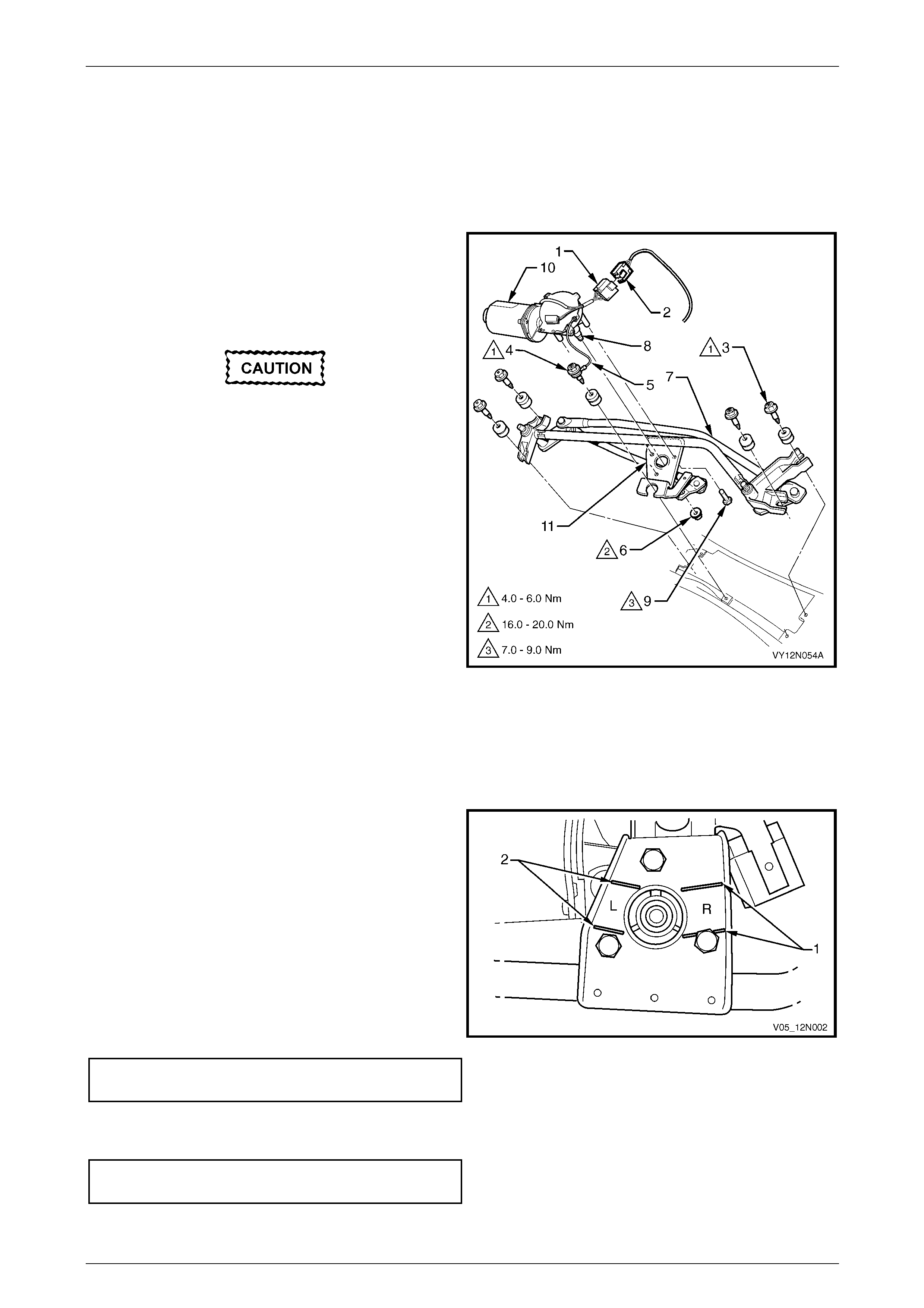
2 Squeeze the tang at the main wiring harness
connector (2) and disconnect the wiper motor harness
connector (1).
The screw (4) attaching the wiper motor and
ground strap (5) is secured to the strap by a
spacer and cannot be separated.
3 Remove the five fasteners (3 and 4) attaching the
wiper motor assembly and linkages to the plenum
chamber and remove the wiper motor assembly and
linkages.
4 If required, remove the wiper motor from the wiper
linkages as follows :
a Remove the nut (6) attaching the wiper
linkages (7) to the wiper motor pivot (8).
b Remove the screw (9), three places, attaching
the wiper motor (10) to the bracket (11) on the
wiper linkages.
c Separate the wiper motor from the wiper
linkages.
Figure 12N – 17
Reinstall
Reinstallation of the wiper motor assemb ly is the reverse of the removal procedure, notin g the following:
1 If the wiper motor has been removed from the
linkages:
a The wiper motor pivot must be installed in the
park position, by aligning the pivot within the
lines on the mounting bracket marked R (1).
NOTE
The lines on the mounting bracket marked L (2)
are used for left-hand drive vehicles only.
b Ensure the screws attaching the wiper motor to
the wiper linkages are tightened to the correct
torque specification.
Wiper motor to linkages attaching
screw torque specification...........................7.0 – 9.0 Nm
c Ensure the nut attaching the wiper motor pivot is
tightened to the correct torque specification.
Wiper motor pivot to linkages
attaching nut torque specification............16.0 – 20.0 Nm
Figure 12N – 18
Page 12N–29

Wipers, Washers and Horn Page 12N–30
2 Secure the wiper motor assembly and linkages to the plenum chamber, ensure all fasteners are tightened to the
correct torque specification.
Wiper motor and linkages assembly
attaching screw torque specification...........4.0 – 6.0 Nm
Ensure the wires from the wiper motor
harness are free and do not foul the wiper
linkages.
3 Operate the wiper motor assembly before ins talling the wiper arms to ensure it is in the correct park position.
Page 12N–30
Wipers, Washers and Horn Page 12N–31
6 Service Operations – Washer
Assemblies
6.1 Washer Reservoir Assembly
LT Section — 10–500
Remove
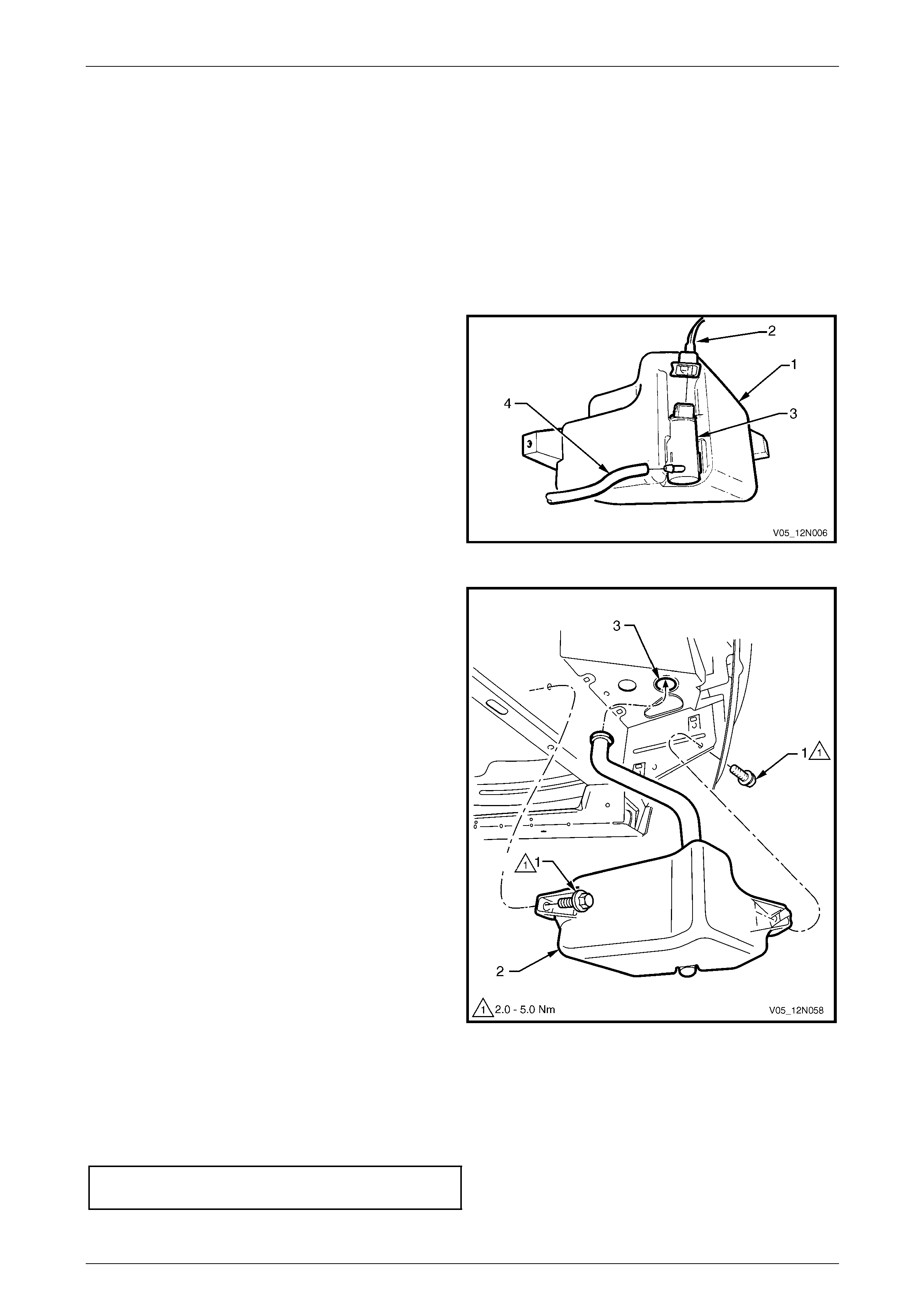
1 If required, remove the front right-hand road whe el,
refer to Section 10 Wheels and T yres.
2 Reach between the bumper a ssembly and the washer
reservoir assembly (1) and disconnect the wiring
harness connector (2) from the washer pump
assembly (3).
3 Place a container under the washer reservoir
assembly, and disconnect the washer hose ( 4) from
the washer pump assembly.
4 Allow the washer fluid to drain from the washer
reservoir assembly.
Figure 12N – 19
5 Remove the two attaching screws (1) securing the
washer reservoir assembly (2).
6 Lower the washer reservoir assembl y and manoeuvre
the filler neck down through the hole in the front
wheelhouse panel (3). If required remove the battery
to allow more space, refer to Section 12A Battery.
7 Unclip the washer pump from the washer reservoir.
Figure 12N – 20
Reinstall
Reinstallation of the washer reservoir assembly is the reverse of the removal procedure, noting the following:
1 Ensure the washer reservoir assemb ly attaching screws are tightened to the correct torque specificatio n.
Washer reservoir attaching screw
torque specification.....................................2.0 – 5.0 Nm
2 Ensure the washer hose is installed before filling the washer reservoir assembly.
Page 12N–31

Wipers, Washers and Horn Page 12N–32
Filling the Washer Reservoir Assembly
1 Open the flip top cap (1) located within the engine bay
at the top of the washer reservoir assembly (2).
2 Fill the washer reservoir assembl y with the correct
amount of Optikleen or equivalent.
3 Secure the flip top cap.
Figure 12N – 21
Page 12N–32
Wipers, Washers and Horn Page 12N–33
6.2 Washer Hose and Nozzle Assemblies
LT Section — 10–500
Remove
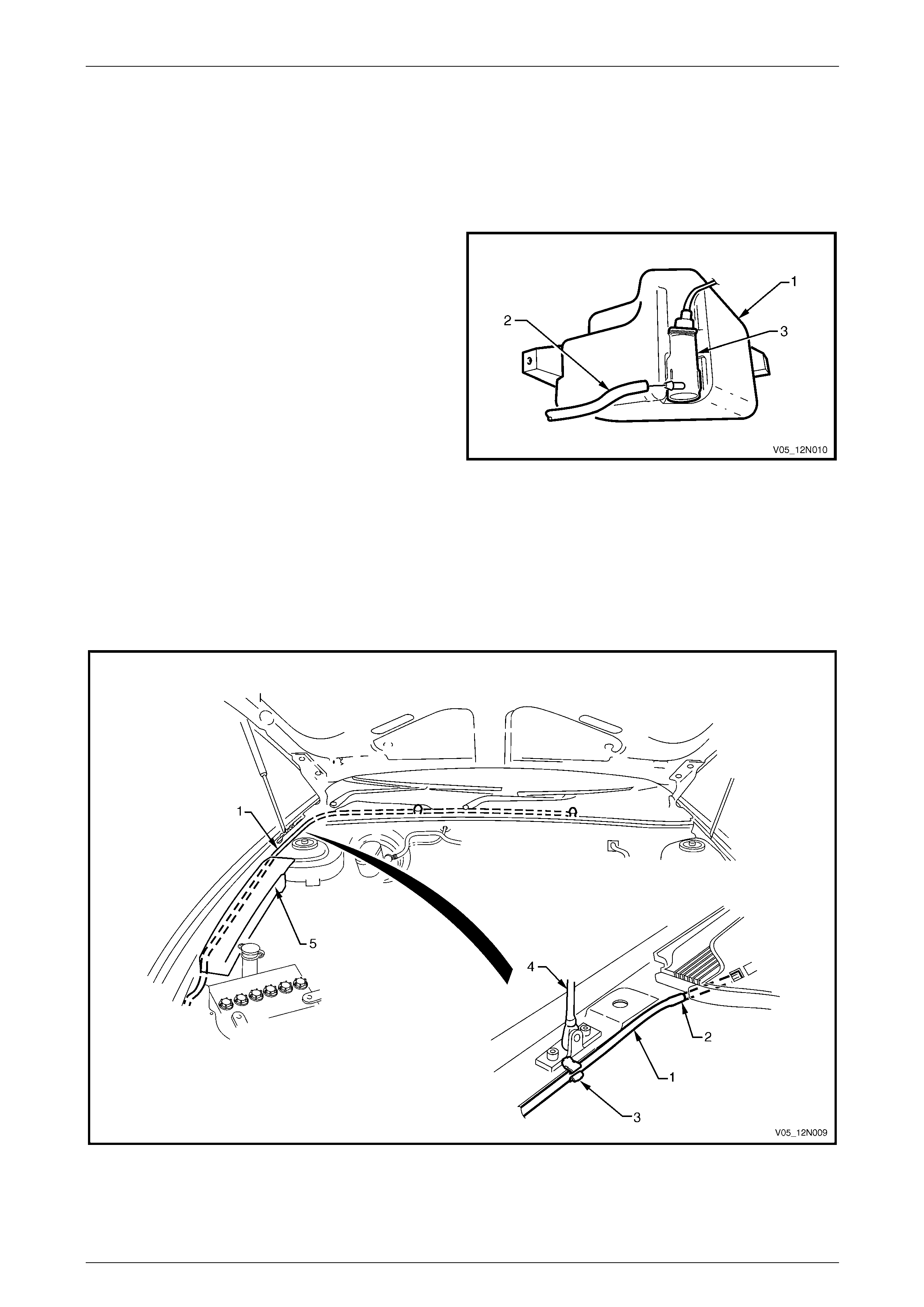
1 Place a container underneath the washer reservoir
assembly (1).
2 Reach between the bumper a ssembly and the washer
reservoir assembly and disconnect the washer
hose (2) from the washer pump assembly (3).
3 Allow the washer fluid to drain from the washer
reservoir assembly.
Figure 12N – 22
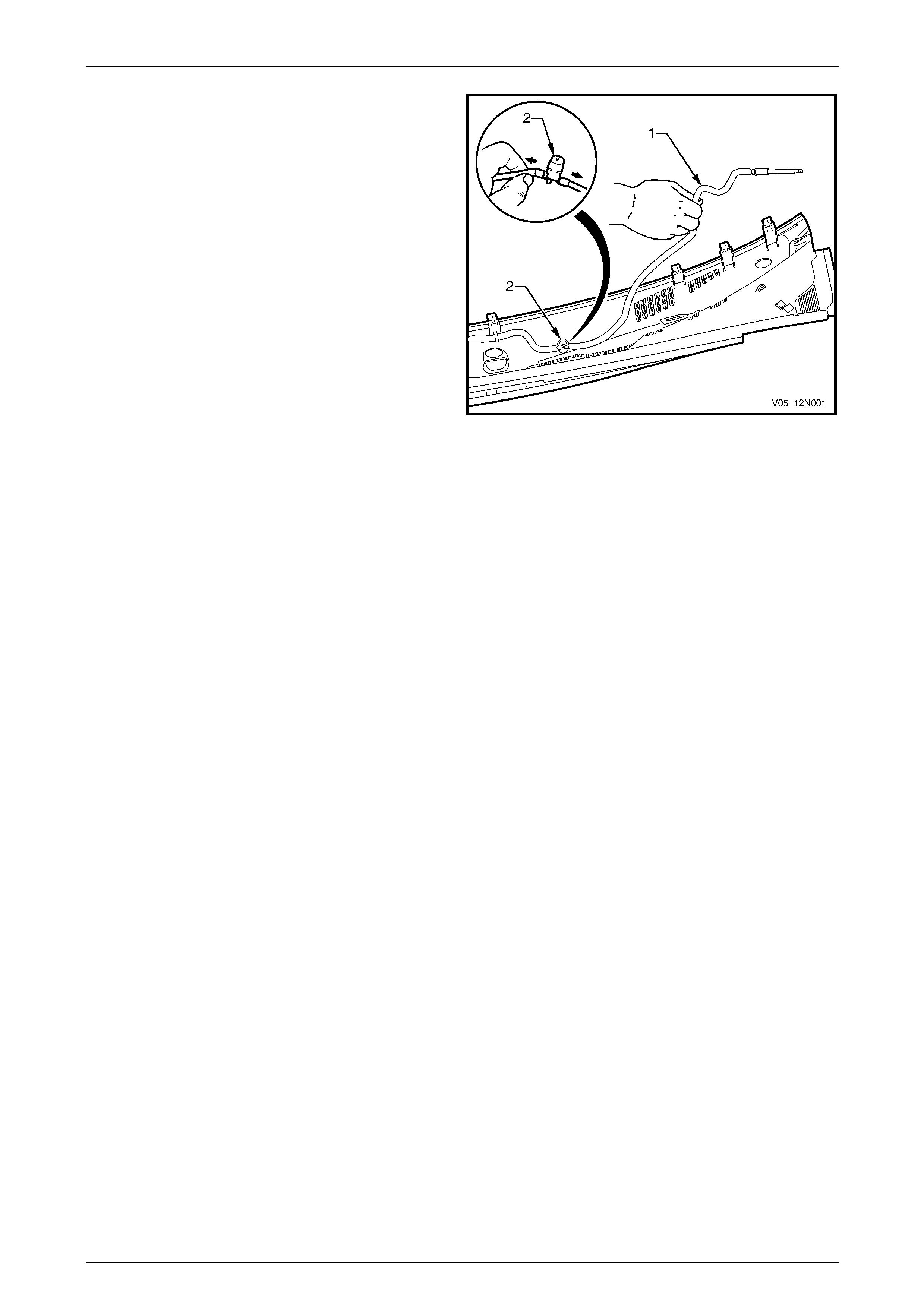
4 Split the washer hose (1) at the point (2) before it enters the plenum chamber, refer to Figure 12N – 23.
5 Unclip the washer hose from the fastener (3) adj acent to the hood strut (4).
6 Carefully pull the washer hose from behind the en gine compartment fuse and relay panel assembly (5) and remove
the washer hose.
7 Remove the section of the washer hose and the two washers located within the plenum chamber, refer to
5.4 Plenum Cover Assembly.
Figure 12N – 23
Page 12N–33
Wipers, Washers and Horn Page 12N–34
Reinstall
Reinstallation of the washer hose a nd the two washers is the reverse of the remov al pr ocedure, noting the follo wing:
1 Connect the washer hose to the washer pump assembl y before fill ing the washer reservoir assembly.
2 For information on filling the washer reservoir assembly, refer to 6.1 Washer Reservoir Assembly.
3 Check the washers spray pattern on the windshield as detailed in this Section, refer to Spray Pattern Check.
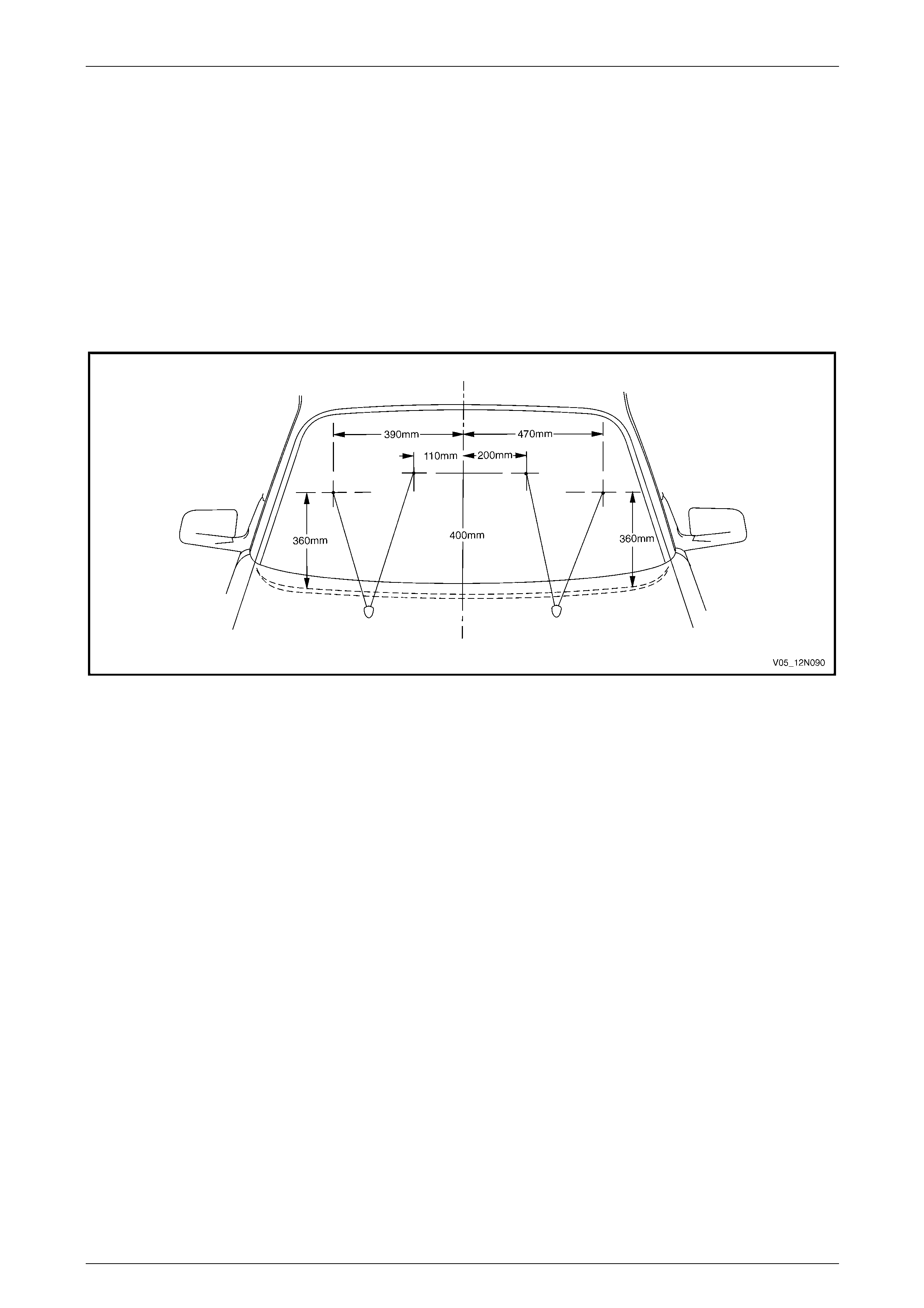
Spray Pattern Check
1 Check the washers spray pattern on the windshield and ensure the washer fluid strikes the glass panel wit hin a
100 mm diameter of the target points, refer to Figure 12N – 24.
2 If required, use a pin inserted into the ba ll of the washer nozzle and swivel to correct the aim of the jet.
Figure 12N – 24
Page 12N–34

Wipers, Washers and Horn Page 12N–35
7 Service Operations – Wipers and
Washers Control Switch
7.1 Wipers and Washers Control Switch
LT Section — 06–250
Remove
Disable the occupant protection system
before starting the removal procedure of the
wipers and washers control switch. Refer to
Section 12M Occupant Protection System.
1 Turn the ignition to the OFF position, and remove the
ignition key from the ignition switch.
2 Gain access to the passenger compartment fuse and
relay panel assembly, grasp the upper edge of the
instrument panel lower trim panel assembly ( 1) and
disengage the three clips (2). S wing the panel
assembly open.
3 Remove the wiper and washer fuse F 18 from the
passenger compartment fuse and relay panel
assembly. Refer to Section 12O Fuses, Relays and
Wiring Harnesses.
Figure 12N – 25
Page 12N–35
Wipers, Washers and Horn Page 12N–36
4 Remove the steering column upp er and lower covers,
refer to Section 9 Steering.
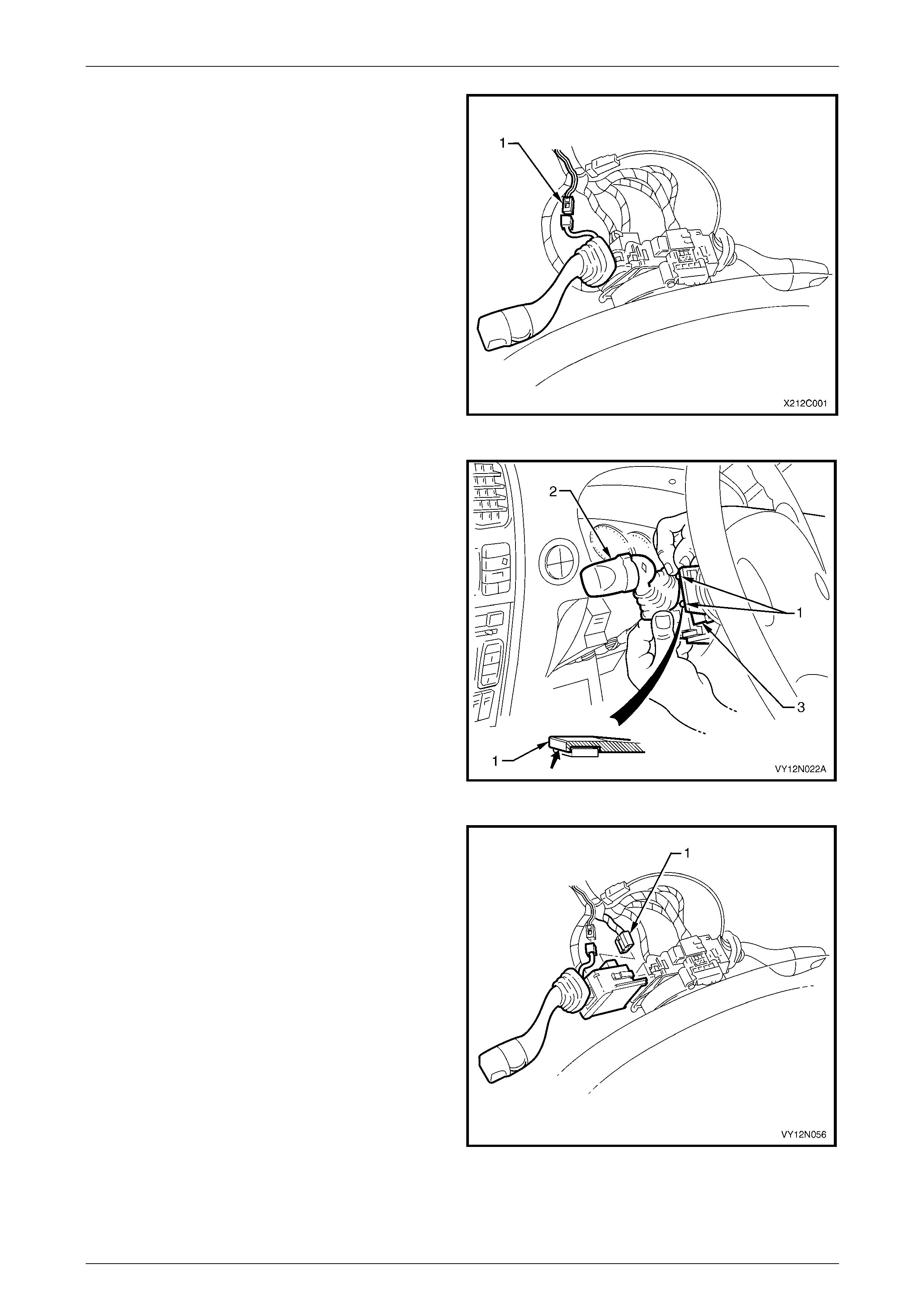
5 On vehicles fitted with intermittent d well control,
disconnect the harness connector (1) from the wiper
dwell control switch connector by depressing the
retaining tang and pulling the connectors apart.
Figure 12N – 26
6 Depress the retaining tangs (1) on the switch
assembly and withdraw the wipers and washers
control switch (2) from the switch housing on the
steering column (3).
Figure 12N – 27
7 Lift up the harness connector retaining tangs on either
side of the wipers and washers control switch body
and pull the connector (1) from the switch.
8 Remove the wipers and washers control switch.
Figure 12N – 28
Page 12N–36

Wipers, Washers and Horn Page 12N–37
Reinstall
Reinstallation of the wipers and washers control switch is the reverse of the removal pro cedure, noting the following:
1 If required, test the wiper and washer switch as detailed in this section prior to reinstallation, refer to
7.2 Wipers and Washers Control S witch Testing.
2 Ensure the harness connector is secured to the wipers and washers control switch.
3 Ensure the wipers and washers control switch is properly inserted and secured to the hou s ing on the steering
column.
4 If fitted, ensure the wiper dwell control switch connector is secured.
NOTE
The wiper dwell control connector, on the switch
side, is wrapped in foam for anti–rattle protection.
If the foam wrap is damaged during the removal
or test procedures, it must be replaced with a
suitable alternative.
5 Check the operation of all the wipers and washers control switch functions .
Page 12N–37
Wipers, Washers and Horn Page 12N–38
7.2 Wipers and Washers Control Switch
Testing
Test procedure
1 If required, disconnect the wipers and washers control switch as detailed in this Section, but do not unclip and
remove it from the steering column, as it provides a stable platform with which to carry out the testing, refer to
7.1 Wipers and Washers Control S witch.
2 Referring to the following chart, check the
serviceability of the wipers and washers control s witch
with a multimeter by probing the various pin
combinations as follows:
a Place the switch into the positions as detailed in
the following chart.
b Place the multimeter probe tip s onto the
corresponding pins.
c Take the reading and compare it with the
indication in the chart.
3 If the reading differs from the following chart, or there
is continuity between any t wo pins other than the
combinations listed, the switch assembly is faulty.
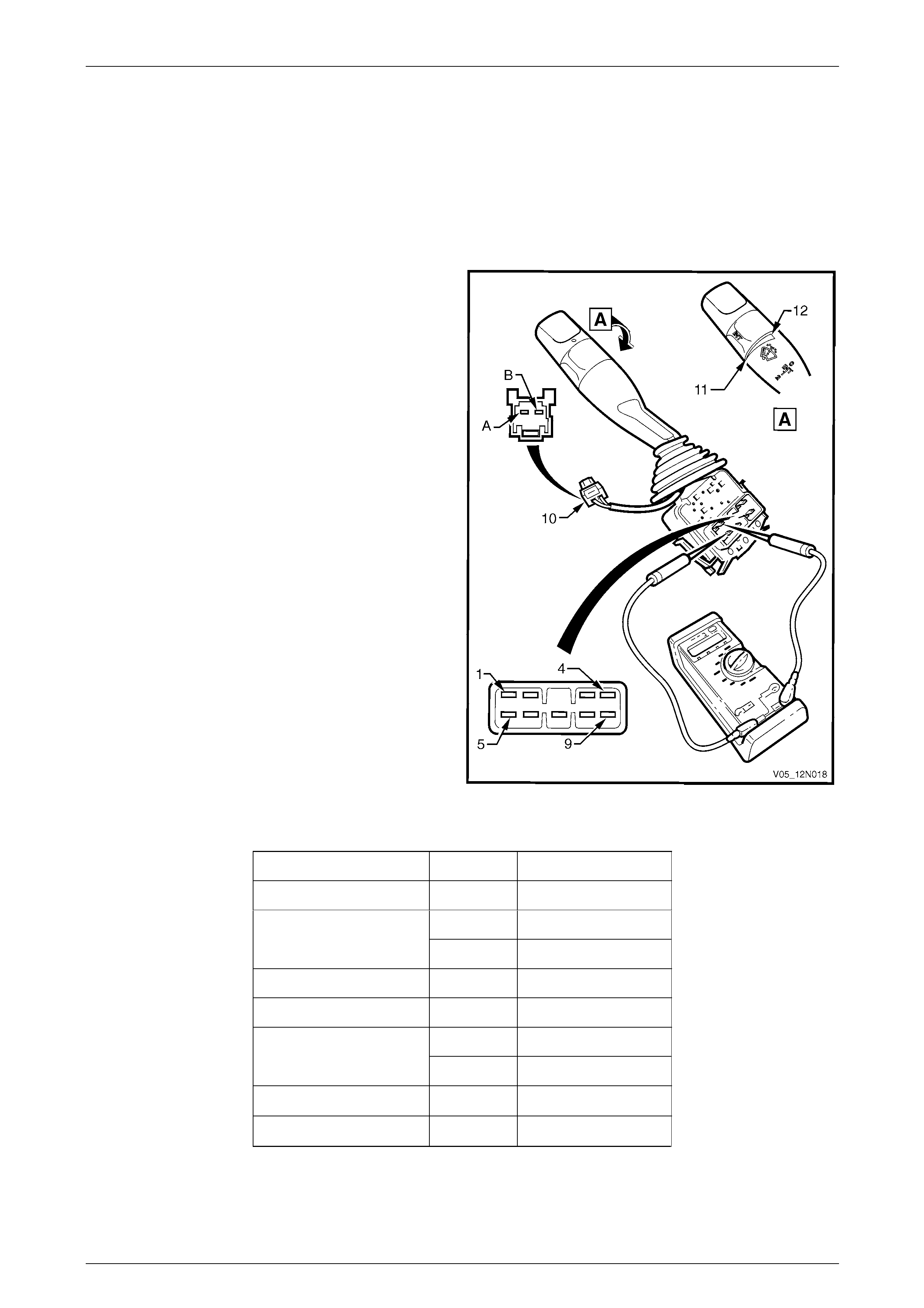
4 Check the intermittent dwell control as follows :
a Turn the wipers and washers control switch to
INT (maximum dwell time position) (11).
b Place the multimeter probe tips onto the pins A
and B on the dwell control connector A121 –
X1 (10).
c Take the reading, and compare it with the chart
below.
d Repeat the check with the wipers and washers
control switch turned to INT (minimum dwell time
position) (12).
5 If the wipers and washers control switch fails any part
of the test, replace it with a serviceable item. Figure 12N – 29
Switch Position Pins Indication if O.K.
0 (Off) 8 and 9 Continuity
8 and 9 Continuity
INT 6 and 7 Continuity
1 (Low Speed) 6 and 9 Continuity
2 (High Speed) 5 and 6 Continuity
1 and 6 Continuity
Wash 2 and 3 Continuity
INT on max. dwell time. A and B 476 Ω to 889 Ω
INT on min. dwell time. A and B 4204 Ω to 6528 Ω
Page 12N–38
Wipers, Washers and Horn Page 12N–39
8 Service Operations – Horn
8.1 Horn Assembly
LT Section — 02–400
Remove
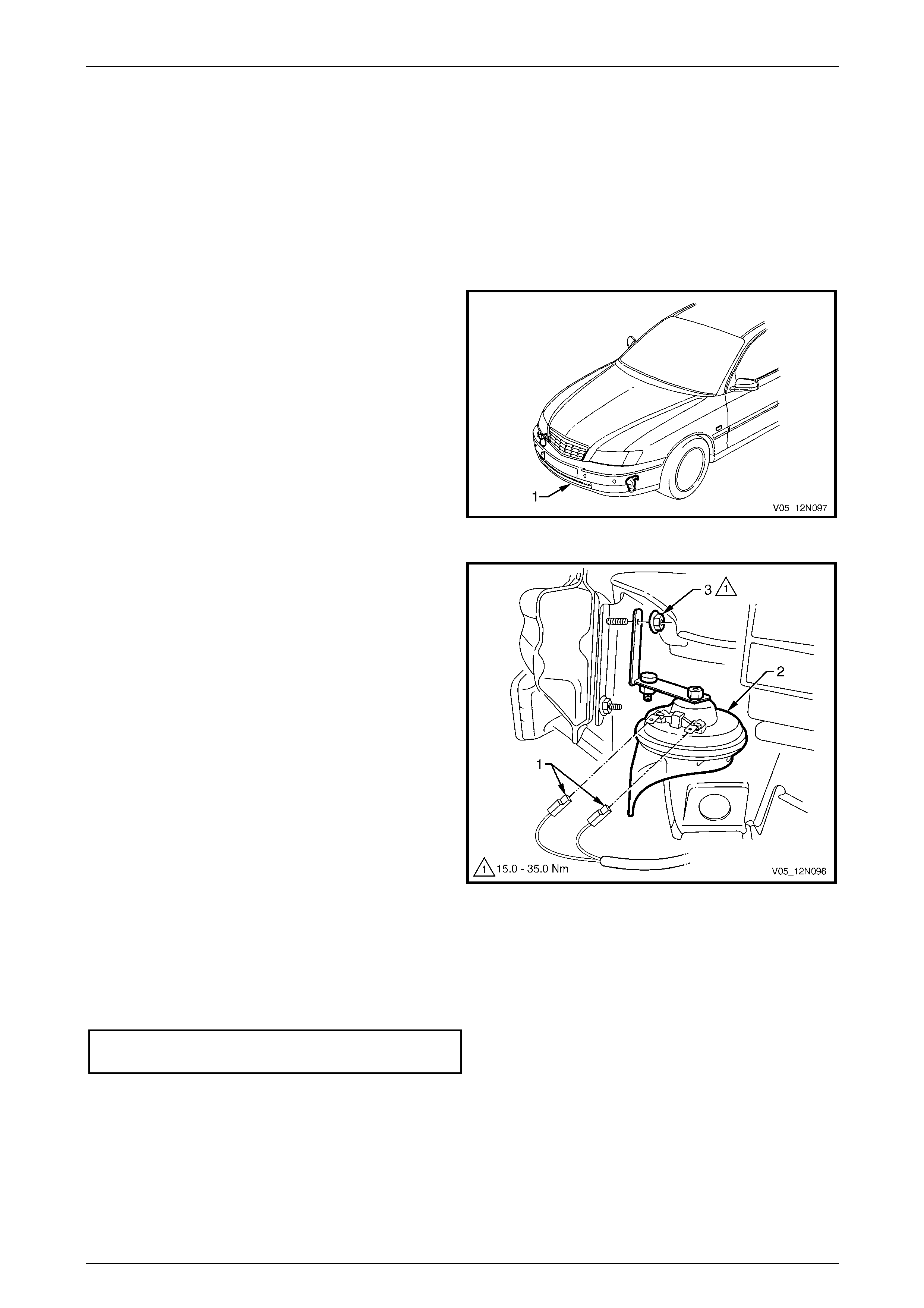
1 For ease of access, raise the vehicle, refer to
Section 0A General Information.
2 If required remove the front bumper fascia
assembly (1), refer to Section 1D Bumper Bars.
Figure 12N – 30
3 Disconnect the wiring harness connectors (1) from the
horn assembly (2).
4 Unscrew the horn attaching nut (3) and remove the
horn assembly.
Figure 12N – 31
Reinstall
Reinstallation of the horn ass embly is the reverse of the removal procedure, noting th e following:
Ensure the nut attaching the horn assembly is tightened to the correct torque specification.
Horn assembly attaching nut
torque specification.................................15.0 – 35.0 Nm
Page 12N–39
Wipers, Washers and Horn Page 12N–40
8.2 Theft-deterrent Horn Assembly
LT Section — 09–552
Remove
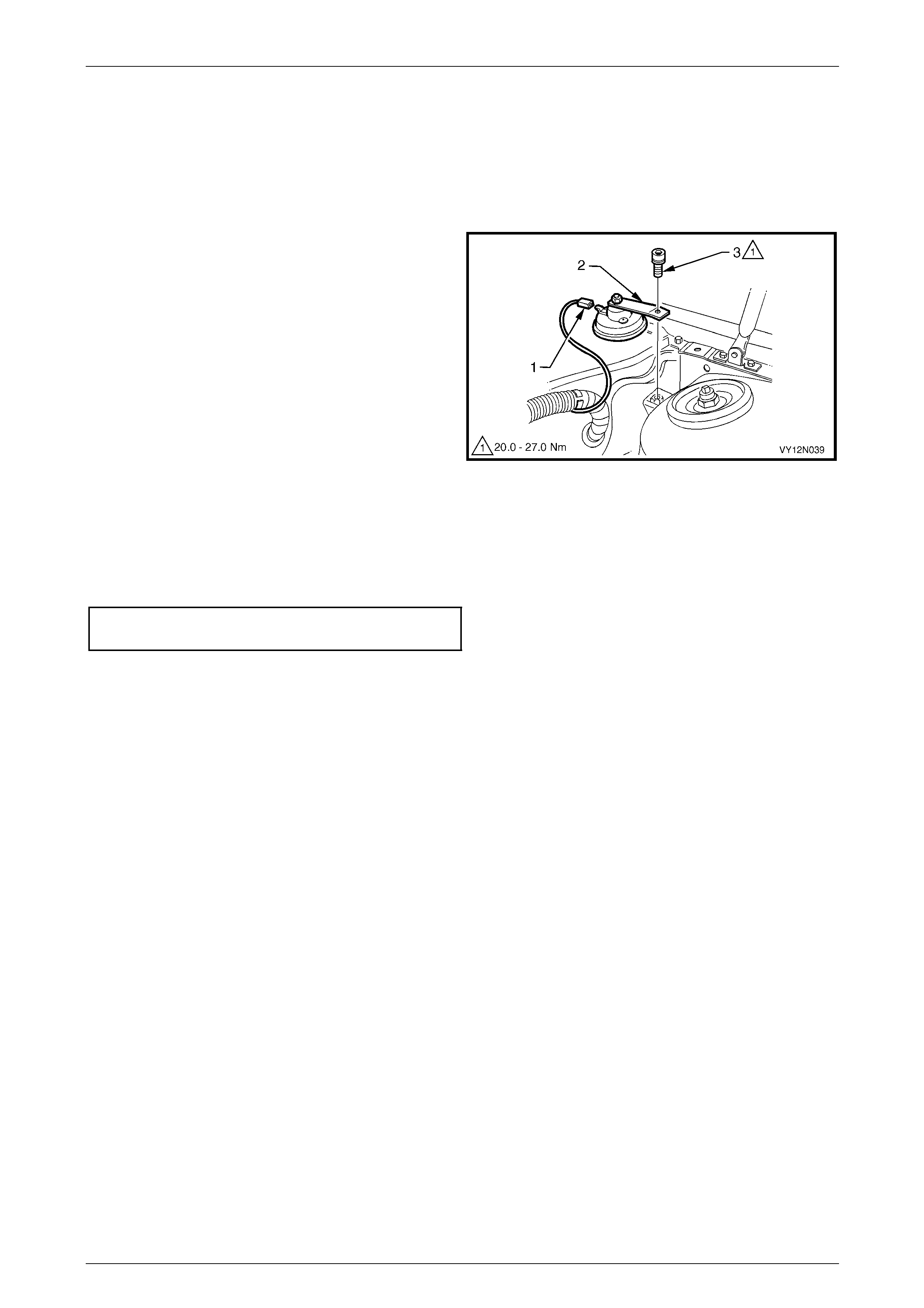
1 Disconnect the wiring harness connector (1) from the
theft-deterrent horn assembly (2).
2 Unscrew the attaching bolt (3) and remove the
theft-deterrent horn assembly.
Figure 12N – 32
Reinstall
Reinstallation of the theft-deterrent hor n assembly is the reverse of the removal procedure, noting the following:
Ensure the theft-deterrent horn attaching bolt is tightened to the correct torque specification.
Theft-deterrent horn attaching bolt
torque specification.................................20.0 – 27.0 Nm
Test
The test for the theft-deterrent horn assembly is included within the entry deterrent system diagnostic c hart, refer to
Section 12J Body Control Module.
Page 12N–40

Wipers, Washers and Horn Page 12N–41
9 Torque Wrench Specifications
Wiper Arm Assembly Attaching Nut ..........................................20.0 – 25.0 Nm
Wiper Motor to Linkages Attaching Screw.....................................7.0 – 9.0 Nm
Wiper Motor Pivot to Linkages Attaching Nut............................16.0 – 20.0 Nm
Wiper Motor and Linkages Assembly Attaching Screw.................4.0 – 6.0 Nm
Washer Reservoir Attaching Screw...............................................2.0 – 5.0 Nm
Horn Assembly Attaching Nut....................................................15.0 – 35.0 Nm
Theft-deterrent Horn Attaching Bolt...........................................20.0 – 27.0 Nm
Page 12N–41
Wipers, Washers and Horn Page 12N–42
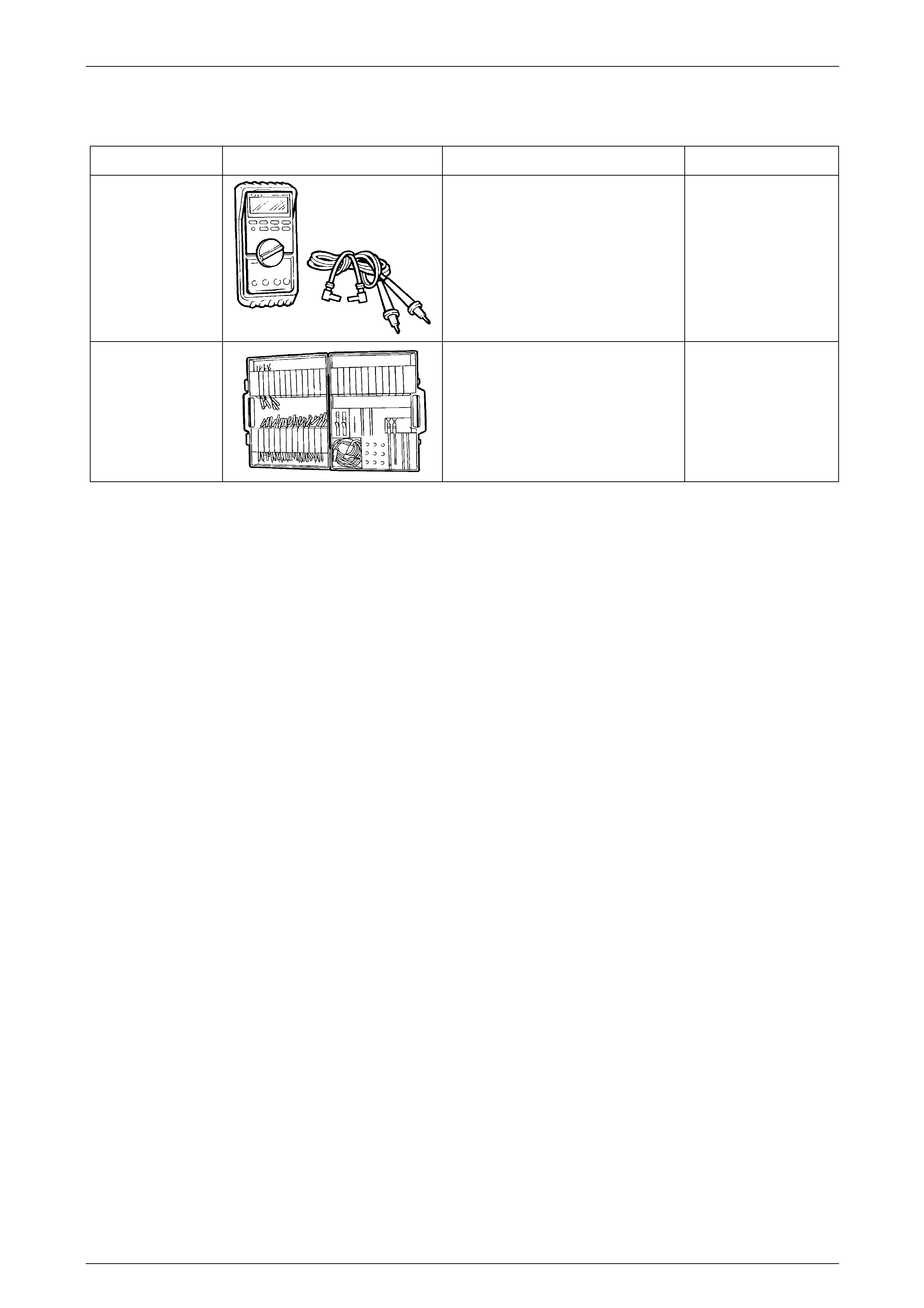
10 Special Tools
Tool Number Illustration Description Tool Classification
J39200
(3588)
Digital Multimeter.
Tool no. J39200 previously released,
or use commercially available
equivalent. Must have 10 meg ohm
input impedance.
Previously released.
Available.
KM-609
(J35616-A)
Electronic Kit.
Used in conjunction with a multimeter
for measuring voltages and
resistances without damaging wiring
harness connectors.
Desirable.
Page 12N–42