
Rear Suspension 4A1 – 1
4A1-1
Section 4A1
Rear Suspension
ATTENTION
Before performing any Service Operation or other procedure described in this Section, refer to Section 00
Warnings, Cautions and Notes for correct workshop practices with regard to safety and/or property damage.
1 General Information ...............................................................................................................................3
1.1 General Description............................................................................................................................................... 3
1.2 Automatic Level Ride Suspension....................................................................................................................... 5
General Information............................................................................................................................................... 5
Automatic Level Ride Suspension Operation ..................................................................................................... 6
Activation............................................................................................................................................................ 6
Loaded Vehicle................................................................................................................................................... 6
Unloaded Vehicle............................................................................................................................................... 7
Deactivation ....................................................................................................................................................... 7
Reset Procedure ................................................................................................................................................ 7
2 Service Maintenance Operations..........................................................................................................8
2.1 Automatic Level Ride Suspension....................................................................................................................... 8
Air Lines ................................................................................................................................................................. 8
Wiring Harness....................................................................................................................................................... 8
Air Filter.................................................................................................................................................................. 8
3 Service Operations.................................................................................................................................9
3.1 Service Warnings, Cautions and Notes............................................................................................................... 9
3.2 Rear Suspension Control Arm............................................................................................................................ 10
Remove................................................................................................................................................................. 10
Rear Suspension Control Arm Pivot Bushing, Replace................................................................................... 16
Reinstall................................................................................................................................................................ 17
3.3 Outer Rear Wheel Drive Shaft, Flange or Bearing............................................................................................. 19
Replace................................................................................................................................................................. 19
3.4 Rear Suspension Crossmember......................................................................................................................... 26
Remove................................................................................................................................................................. 27
Reinstall................................................................................................................................................................ 32
3.5 Rear Suspension Crossmember Front Mount Bushing ................................................................................... 36
Off-Car Replacement........................................................................................................................................... 36
On-Car Replacement ........................................................................................................................................... 37
3.6 Rear Suspension Crossmember Mass Damper ................................................................................................ 40
Remove................................................................................................................................................................. 40
Reinstall................................................................................................................................................................ 41
3.7 Rear Suspension Crossmember Rear Mount.................................................................................................... 43
Remove................................................................................................................................................................. 43
Reinstall................................................................................................................................................................ 44
3.8 Stabiliser Bar and/or Mountings......................................................................................................................... 46
Remove................................................................................................................................................................. 46
Stabiliser Bar Link Insulators, Replace.............................................................................................................. 47
Reinstall................................................................................................................................................................ 48
3.9 Rear Spring and Insulators................................................................................................................................. 49
Remove................................................................................................................................................................. 49
Reinstall................................................................................................................................................................ 52

Rear Suspension 4A1 – 2
4A1-2
3.10 Rear Shock Absorbers and/or Bushing............................................................................................................. 54
Remove................................................................................................................................................................. 54
Lower Bushing, Replace ..................................................................................................................................... 55
Reinstall................................................................................................................................................................ 56
3.11 Additional Control Arm ....................................................................................................................................... 57
Inspect .................................................................................................................................................................. 57
Remove................................................................................................................................................................. 58
Disassemble......................................................................................................................................................... 58
Reassemble.......................................................................................................................................................... 58
Reinstall................................................................................................................................................................ 59
3.12 Rear Wheel Alignment Checking........................................................................................................................ 60
Camber and Toe Check....................................................................................................................................... 60
Preliminary Checks and Information................................................................................................................. 60
Rear Wheel Toe Adjustment ............................................................................................................................... 61
4 Service Operations – Automatic Level Ride Suspension ................................................................62
4.1 Initial Air Charge.................................................................................................................................................. 62
4.2 Air Leak Test ........................................................................................................................................................ 63
4.3 Relieving System Air Pressure........................................................................................................................... 64
4.4 Compressor Assembly........................................................................................................................................ 65
Remove................................................................................................................................................................. 65
Disassemble......................................................................................................................................................... 66
Reassemble.......................................................................................................................................................... 66
Reinstall................................................................................................................................................................ 67
4.5 Air Lines ............................................................................................................................................................... 68
Remove................................................................................................................................................................. 68
Reinstall................................................................................................................................................................ 69
4.6 Automatic Level Ride Shock Absorber.............................................................................................................. 70
Remove................................................................................................................................................................. 70
Reinstall................................................................................................................................................................ 71
4.7 Ride Height Sensor.............................................................................................................................................. 72
Remove................................................................................................................................................................. 72
Reinstall................................................................................................................................................................ 73
5 Diagnosis......................................................................................................................................................74
5.1 Checking and Testing Shock Absorbers........................................................................................................... 74
Leakage Criteria................................................................................................................................................... 74
5.2 Diagnosis – Automatic Level Ride Suspension................................................................................................ 75
Equipment ............................................................................................................................................................ 75
Ride Height Sensor Reset................................................................................................................................... 75
5.3 Preliminary Diagnostic Procedure ..................................................................................................................... 76
5.4 Compressor Assembly Test – Motor.................................................................................................................. 77
5.5 Compressor Assembly Test – Solenoid ............................................................................................................ 78
5.6 Ride Height Sensor Test – Compressor ............................................................................................................ 79
5.7 Ride Height Sensor Test – Solenoid .................................................................................................................. 80
5.8 Wiring Diagram – Automatic Level Ride Suspension....................................................................................... 81
5.9 Wiring Harness Layout – Automatic Level Ride Suspension .......................................................................... 82
6 Specifications.......................................................................................................................................83
Rear Suspension Service Alignment Data......................................................................................................... 83
Rear Spring Details.............................................................................................................................................. 83
Rear Shock Absorber Details.............................................................................................................................. 84
Rear Stabiliser Bar Details.................................................................................................................................. 84
7 Torque Wrench Specifications............................................................................................................85
8 Special Tools ........................................................................................................................................86

Rear Suspension 4A1 – 3
4A1-3
1 General Information
1.1 General Description
Independent coil spring rear suspension is fitted as standard equipment on all MY 2005 WL Series Models, using
variable rate minibloc coil rear springs and direct acting shock absorbers.
The rear suspension is contained within a rear suspension crossmember assembly that is attached by a large volume
rubber bushing at each front corner to the ve hicle underbody. Rear location is provided by a rear mounting bolted to the
differential carrier assembly that is in turn, attached to the crossmember.
Those vehicles fitted with the GEN III V8 and automatic transmission, have a mass damper located on the rear
suspension cross member, forward of each of the front mounts.
Two rear suspension control arms are attached to the crossmember pivot points through rubber bushings. The rear
suspension control arms provide attachment of the additional control arms, the rear brake components, rear wheel drive
shaft flanges and outer rear wheel drive sh aft (rear wheel) bearings.
A decoupled type stabiliser bar is attached to the top of the crossmember by two brackets and insulating bushings. The
outer ends of the stabiliser bar are attached to each rear suspension control arm by a link and insulating bushings.
Depending on the vehicle specification for different markets, automatic leve l ride (Production Option FX3) may be
available as an option on lev els 4 and 5 for MY 2005 WL Series Models.
Sports suspension (Production Option FE2) is not available on MY 2005 WL Series Level 5 Models.
An additional control arm is al so fitted as standard equipment to all MY 2005 WL Series vehicles. The inner ends of the
additional control arms contain rubber b ush ing and are attached to brackets welded to the rear suspension
crossmember. The outer end of the additional control arm is secured to the rear suspension control arm by a socket
assembly. The purpose of the addition al co ntrol arm is to maintain the rear wheel camber and toe angles during
suspension travel, while also provi din g a means of adjusting the rear wheel toe.
The standard (Production Option FE1) suspension application utilises twin tube hydrau lic shock absorbers that are
double acting and are mounted between the vehicle underbody and each trailing arm. The sports suspension (Production
Option FE2) application, utilises twin tube, gas pressurised shock absorbers. The level ride suspensi on (Production
Option FX3) application utilises the pneumatically adjustable (Superlift) type rear shock absorbers that may also be
available as an accessory or as part of a 2100 kg tow bar package.
NOTE
For further information regarding how to identify
which suspension applicati on (Production Option)
is fitted to a particular vehicle, refer to
Section 0A General Information in this Service
Information.
Rear Suspension 4A1 – 4
4A1-4
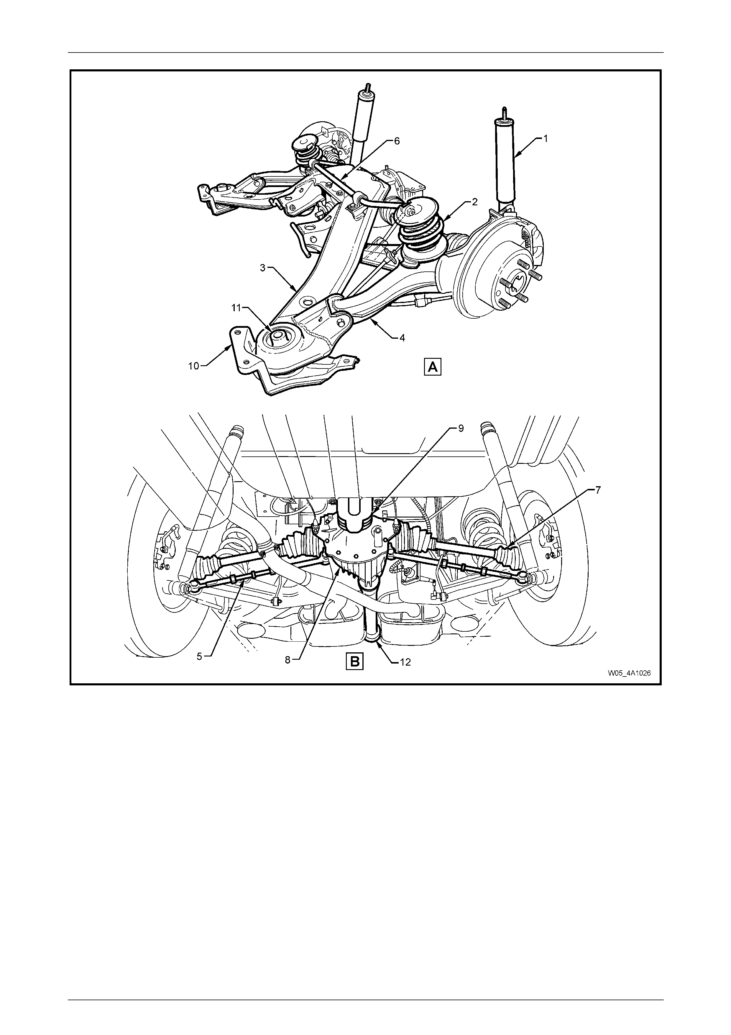
Figure 4A1 – 1
Legend
[A] General View
[B] Installed in Vehicle – Looking Forward
1 Rear Shock Absorber
2 Rear Spring
3 Rear Suspension Crossmember Assembly
4 Rear Suspension Control Arm Assembly
5 Additional Control Arm Assembly
6 Stabiliser Bar
7 Driveshaft (2 Places)
8 Rear Final Drive Assembly
9 Rear Suspension Crossmember Rear Mount
10 Rear Suspension Crossmember Front Mounting Brace
11 Rear Suspension Crossmember Front Mount Bushing
12 Propeller Shaft Assembly
Rear Suspension 4A1 – 5
4A1-5
1.2 Automatic Level Ride Suspension
General Information
Automatic level ride is an electr onically controlled system that maintains the vehicle at a constant trim height, regardless
of vehicle load. This feature u s es a specifically designed elec tronic ride height sensor (5), fixed to the rear crossmember
on the right-hand side. This sensor controls an electric motor driving a single cylinder air compressor (2) and an e xhaust
solenoid valve. The compressor (2) supplies the necessary pressure to operate the Superlift shock absorbers (1) via
snap-on air lines (4). The Superlift shock ab sorbers assist the rear springs in supporting the vehicle body under all loads.
The ride height sensor (5) has an integrated electronic controller that is programmed to adjust the ride height only when
necessary, ignoring sudden changes, as experienced on bumpy roads. The design of the s ystem mainta ins trim at all
times when the ignition is on. As a safeguard to prevent the battery discharging, an electronic timer switches off the
compressor if it runs for a prolonged period (i.e. due to an ai r leak in the system).
The compressor assembly includes a maximum pressure release valve and an air drier. All air entering or exhausting the
system flows through the drier, which has an internal minimum retention valve preventing the airbag, surrounding each
shock absorber, from completely exhausting, independent of the sensor controlled exhaust valve.
Electric power to operate the system is supplied by an integrated wiring harness (3).
There are two main benefits resulting from the automatic level ride feature:
• Headlamp aim and rear view mirror adjustment being maintained indep endent of load.
• Rear tyre camber and toe-in are held to their optimum alig nment to minimise tyre wear.
NOTE
If air pressure is lost from the system while the
vehicle is in service (eg. an ai r leak), the Superlift
shock absorber airbag will most likely be
damaged, requiring replacement.
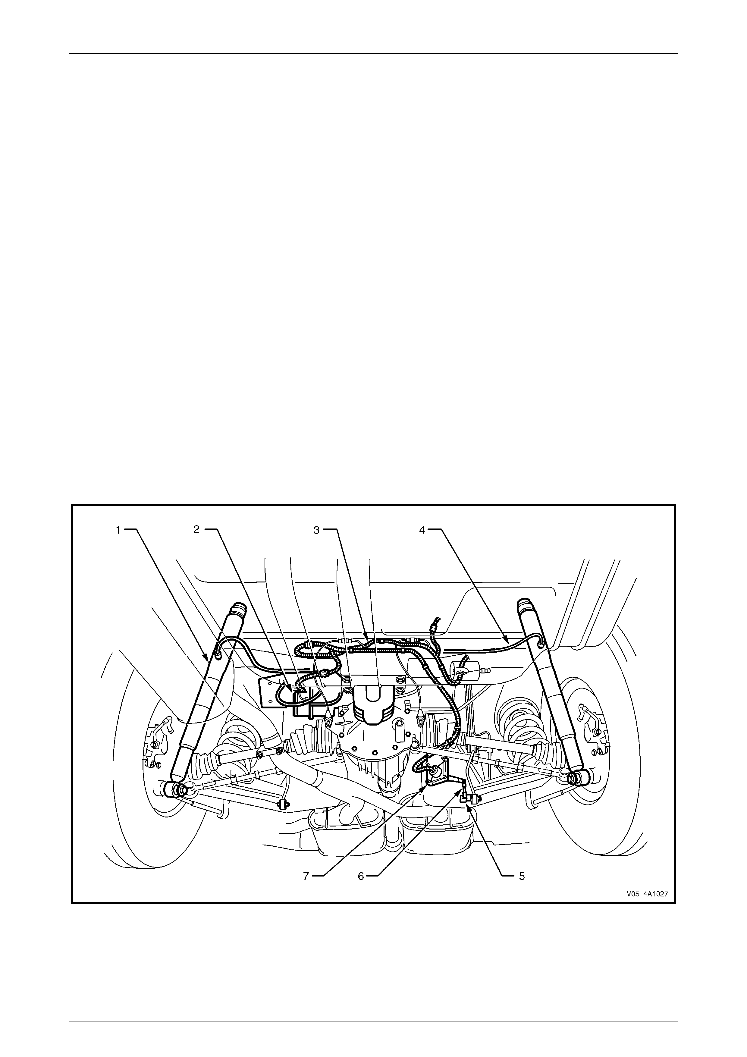
Figure 4A1 – 2
Legend
1 Superlift shock absorbers
2 Air compressor assembly
3 Level ride wiring harness
4 Air lines
5 Ride height sensor ball stud plate
6 Ride height sensor connecting link
7 Ride height sensor
Rear Suspension 4A1 – 6
4A1-6
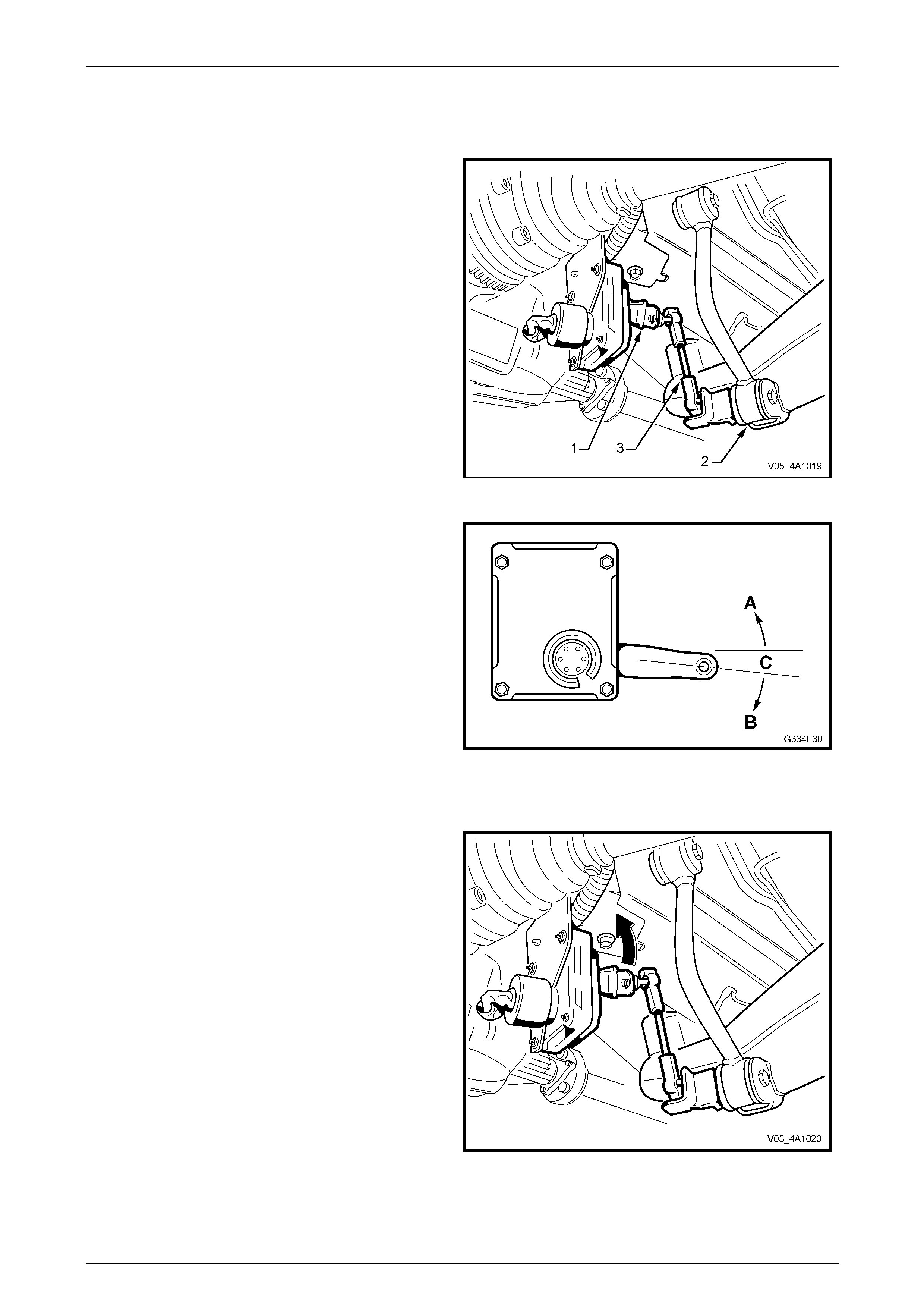
Automatic Level Ride Suspension Operation
Activation
The sensor's actuating arm (1) is attached to the lower
control arm (2) via a connecting link (3).
Figure 4A1 – 3
Before any activation can occur, the actuating arm must
remain in either the intake (A) or exhaust zone (B) for a
approximately 20 seconds. This time delay prevents the
compressor or exhaust valve from activating when the
vehicle encount ers sudden bumps.
Another stability feature is a 'dead band' zone (C), which
helps to minimise hunting, by deactiv atin g the compressor
and solenoid when the v ehicle trim goes into or onto the
deadband zone or one of its edges.
Figure 4A1 – 4
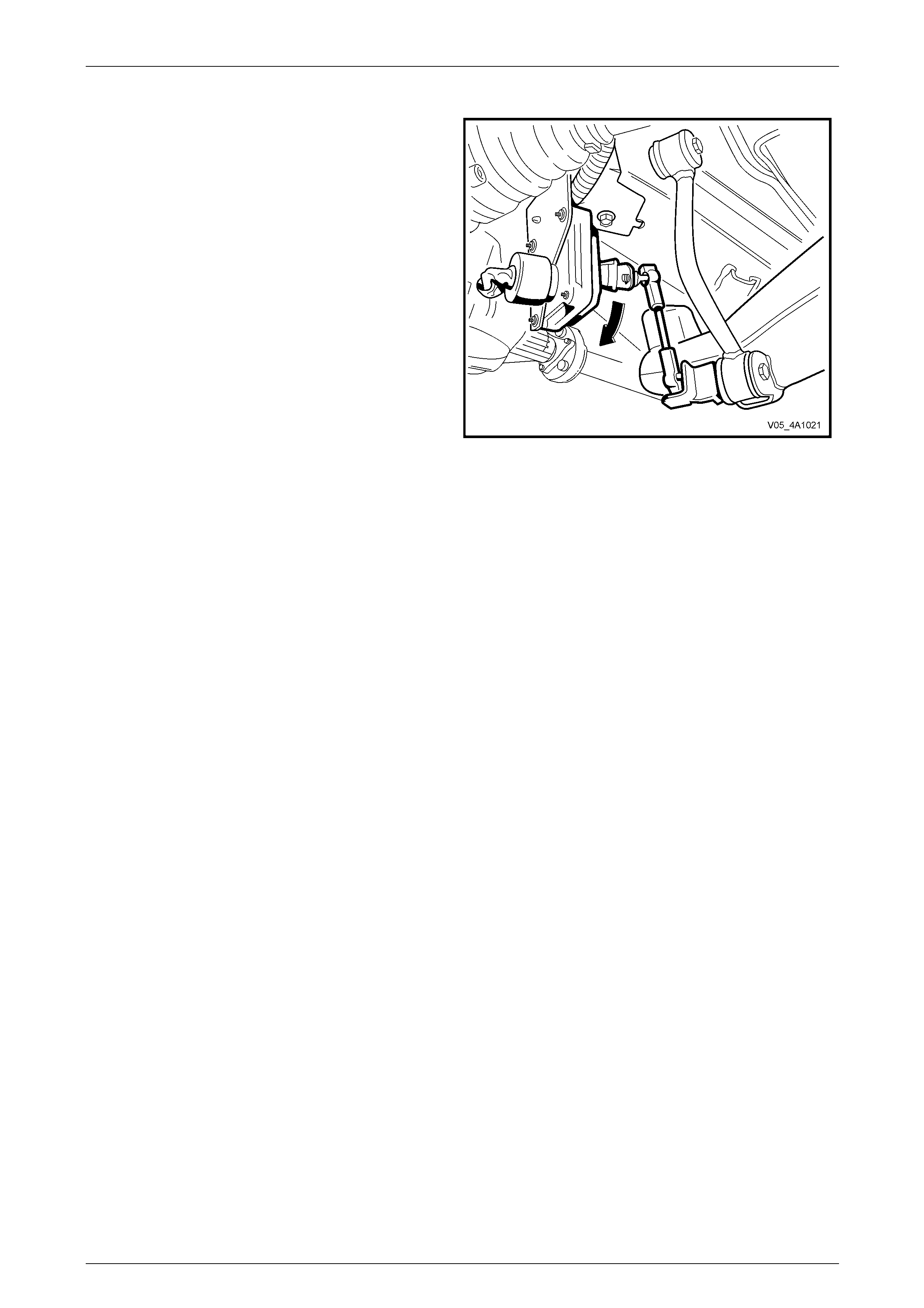
Loaded Vehicle
When the vehicle is loade d, the vehicle body moves
downward into the intake zone, causing the actuating arm
to move upwards (arrow).
After approximately 20 seconds in this position, the sensor
relieves the compressor head pressure by br iefly activating
the compressor relay. The compressor starts and
pressurises the Superlift shock absorbers until the vehicle
body aligns with the bottom edge of the d ead band, at
which point the compressor stops.
Figure 4A1 – 5
Rear Suspension 4A1 – 7
4A1-7
Unloaded Vehicle
When the vehicle is unloade d, the vehicle body moves
upward into the exhaust zone, causing the actuating arm to
move downwards.
After approximately 20 seconds in this position, the sensor
activates the exhaust relay. The exhaust soleno id activates
and vents pressure from the Superlift shock absorbers until
the vehicle body aligns with the top edge of the dead band,
at which point the solenoid deactivates.
Figure 4A1 – 6
Deactivation
The compressor and exhaust solen oid operations are monitored and controlled by individual but interconnected timers.
The timers deactivate specific trimming operations under the following conditions:
• If the compressor runs for a cumulative time of more than four and a half minutes, the compressor timer
deactivates all system operations.
• If the exhaust solenoid is active for a cumulative time of more than four and a half minutes, the solenoid timer
deactivates the solenoid.
No further operation of these components can take place until the timers are reset.
Reset Procedure
The procedure to reset the timers is:
1 Turn the ignition ON.
2 Turn the ignition OFF for one minute.
3 Turn the ignition ON, once more to complete the operation.
Rear Suspension 4A1 – 8
4A1-8
2 Service Maintenance Operations
2.1 Automatic Level Ride Suspension
If air pressure in the level ride system is lost
during service procedures, do not lower the
vehicle until system pressure has been
restored, as damage will most likely result.
Charge the system as detailed in
4.1 Initial Air Charge in this Section
The level ride system has been designed to be virtually maintenance free. However, at each scheduled service, the
following components must be inspected and rectified if found to be faulty.
Air Lines
Inspect the air lines for rubbing or fouling with the body and other components. Ensure the lines are not kinked and that
they are fitted into the retaining clips. Check the connections for correct fit.
Wiring Harness
Inspect the wiring harness for rubbing or fo uling with the body and other components. Ensure that it is fitted and secured
into the retaining clips and/or cable ties. Check the connections for correct fit.
Air Filter
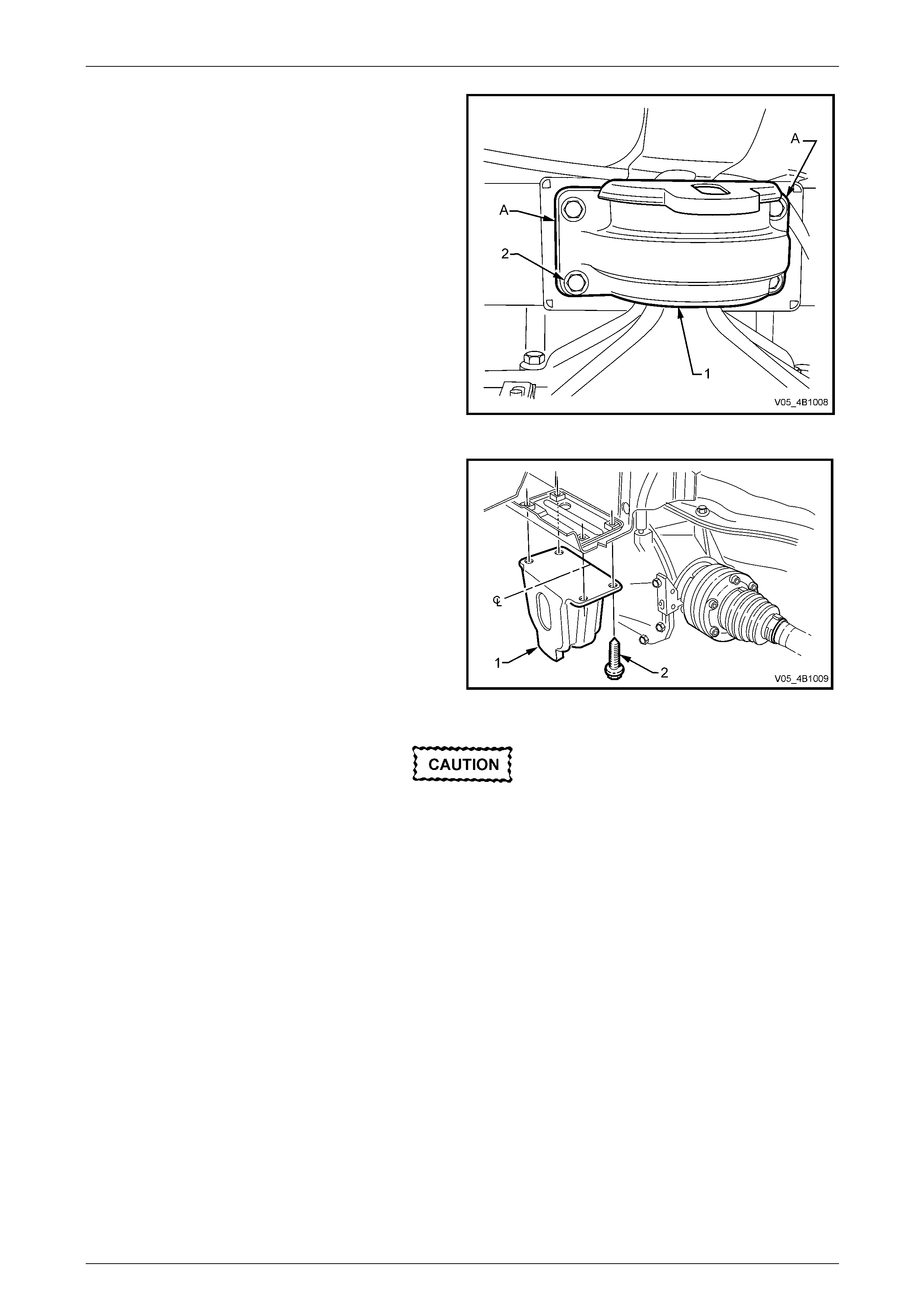
The compressor air filter (1) should be repla c ed at the
scheduled service intervals set down in the Owner’s
Handbook. Inspect and replace more frequently if required,
where the vehicle is driven in dusty conditions.
To service the compressor air filter, depress the two locking
tabs on the clip retaining the air intake hose (2) and filter to
the hole (3) in the compressor mounting bracket (4) and
withdraw the filter.
Test that the filter is clean and free from restrictions by
removing the filter form the tube and blo wing throu gh it from
the hose connection end. If any restriction is felt, replace
the filter.
Figure 4A1 – 7
Rear Suspension 4A1 – 9
4A1-9
3 Service Operations
ATTENTION
All fasteners are important attaching parts as they affect the performance of vital components and/or could
result in major repair expense. W here specified in this Section, fasteners MUST be replaced w ith parts of the
same part number or an approved equivalent. Do not use fasten ers of an inferior quality or substitute design.
Torque values must be used as specified during reassembly to ensure proper retention of all components.
Throughout this Section, fastener torque wrench specifications may be accompanied with the following
identification marks:
Fasteners must be repl aced after loosening.
Vehicle must be at curb height before final tightening.
Fasteners either have micro encapsulated sealant applied or incorporate a mechanical thread lock and
should only be re-used once. If in doubt, replacement is recommended.
If one or more of these identification marks is present alongside a fastener torque wrench specification, the
recommendation regarding that fastener must be adhered to.
3.1 Service Warnings, Cautions and Notes
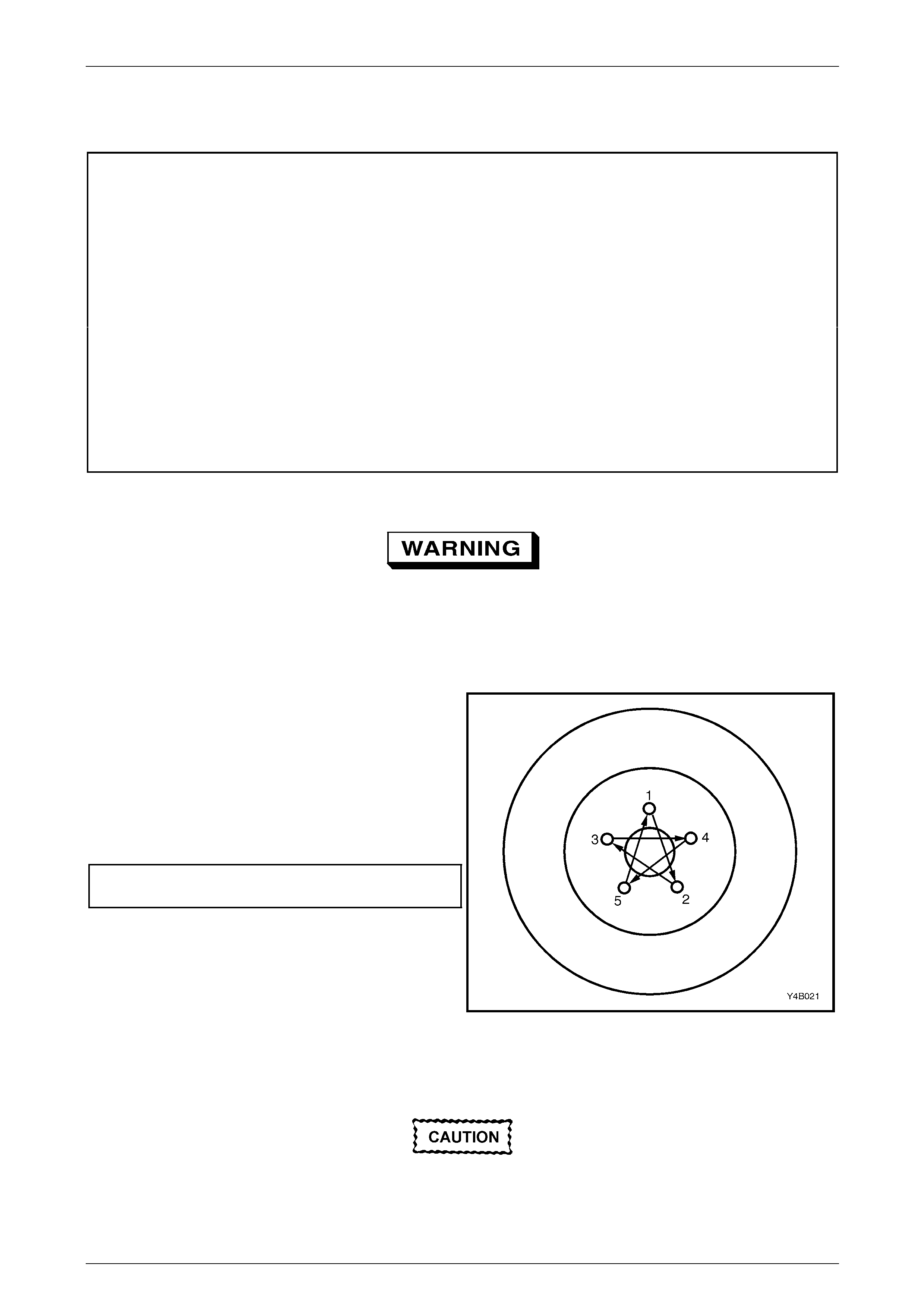
Road Wheels
• Whenever a road wheel is removed from or installed to any MY 2005 VZ and WL Series vehicle, it
MUST be done in accordance with the procedure p rovided in Section 10, Wheels and Tyres.
• Whenever a road w heel is removed from the vehicle, the relationshi p of the road wheel to the hub
MUST be marked with a felt tipped pen or similar, to allow those parts to be reinstalled in their
original positions. This is critical to minimise the road wheel runout dimension.
• When reinstalling road wheels, do not use
an impact gun to tighten wheel nuts
unless the impact gun is fitted with a
torque limiter socket (Tool No. AU 534 or
a commercial equivalent). Failure to
correctly tighten w heel nuts to the correct
torque specification and in the correct
order (as shown), may result in a
distorted brake disc, leading to the
development of brake shudder.
Road wheel attaching nut
torque specification..................................110 – 140 N.m
Figure 3A – 8
ABS/TC Components
• Whenever any component that forms part of the ABS (if fitted) is disturbed during Service
Operations, it is vital that the complete ABS system be checked, refer to
Section 5B, ABS, ABS/TC, Electronic Brake Assist (EBA).
To ensure correct retention of the additional
control arm, the socket assembly stud and
the corresponding tapered hole in the rear
suspension control arm must be cleaned of
dirt and foreign matter prior to installation.
Rear Suspension 4A1 – 10
4A1-10
3.2 Rear Suspension Control Arm
LT Section No. – 06-212
ATTENTION
The following fasteners have either micro encapsulation or incorporate a mechanical thread lock and should
only be used once. If in doubt, replacement is recommended when performing this operation:
Brake caliper anchor plate to rear susp ension control arm bol t.
Additional control arm socket assembly retaining nut.
Stabiliser bar link to rear suspen sio n control arm attaching nut and bolt.
Rear susp ension control arm to rear suspension crossmember attaching nut.
The following fasteners MUST be replaced when performing these operation:
Rear suspension crossmember mount to under body attaching bolt.
Rear brake dust shield to rear su spension control arm lower bolts.
Drive shaft constant velocity joint to rear wheel drive shaft flange attaching bolt.
The following fasteners MUST be at curb height with the vehicle weight on all four wheels before final
tightening is undertaken:
• Shock absorber lower mounting bolt.
• Stabiliser bar link to rear suspension control arm attach ing nut and bolt.
• Rear suspension control arm to rear suspension crossmember attaching nut.
Before disturbing the crossmember rear
mounting bolts, an alignment procedure is
required on installation and a special tool is
required for this purpose. If this tool is not
available, then the crossmember cannot be
correctly aligned and steering and/or handling
abnormali t ies will result.
Remove
1 Raise the vehicle and suppor t in a safe manner. Refer to Section 0A General Information in this Service Information
for the location of recommended lifting and supp ort points.
2 Remove the decorative wheel nut caps, on the side of the ve hicle where the rear suspension control arm is to be
removed.
3 Mark the relationship of the road wheel to hub (eg. end of wheel stud), with a felt tipped pen or similar. Loosen,
then remove the road wheel attaching n uts. Remove the road wheel.
Rear Suspension 4A1 – 11
4A1-11
4 If the vehicle is fitted with the Automatic Level Ride
Suspension (production option FX3), disconnect the
ride height sensor link from the rear suspension
control arm.
Figure 4A1 – 9
5 Loosen both stabiliser bar link (1), attaching bolts (2)
and nuts, to reduce stress on the insulator bushing.
6 Remove the stabiliser bar link to rear suspension
control arm attaching bolt and nut (2) from side of
vehicle where the rear suspension control arm is to be
removed.
Figure 4A1 – 10
7 Loosen the additional control arm socket assembly
retaining nut until level with the top of the socket
assembly stud.
8 Using special tool No. E-9332-A (1), tighten the lever
forcing screw (2) to press the socket assembly stud
free from the taper in the rear suspension control arm,
remove socket assembly retaining nut and discard.
9 Remove the additional control arm socket assembly
from the rear suspension control arm.
Figure 4A1 – 11
Rear Suspension 4A1 – 12
4A1-12
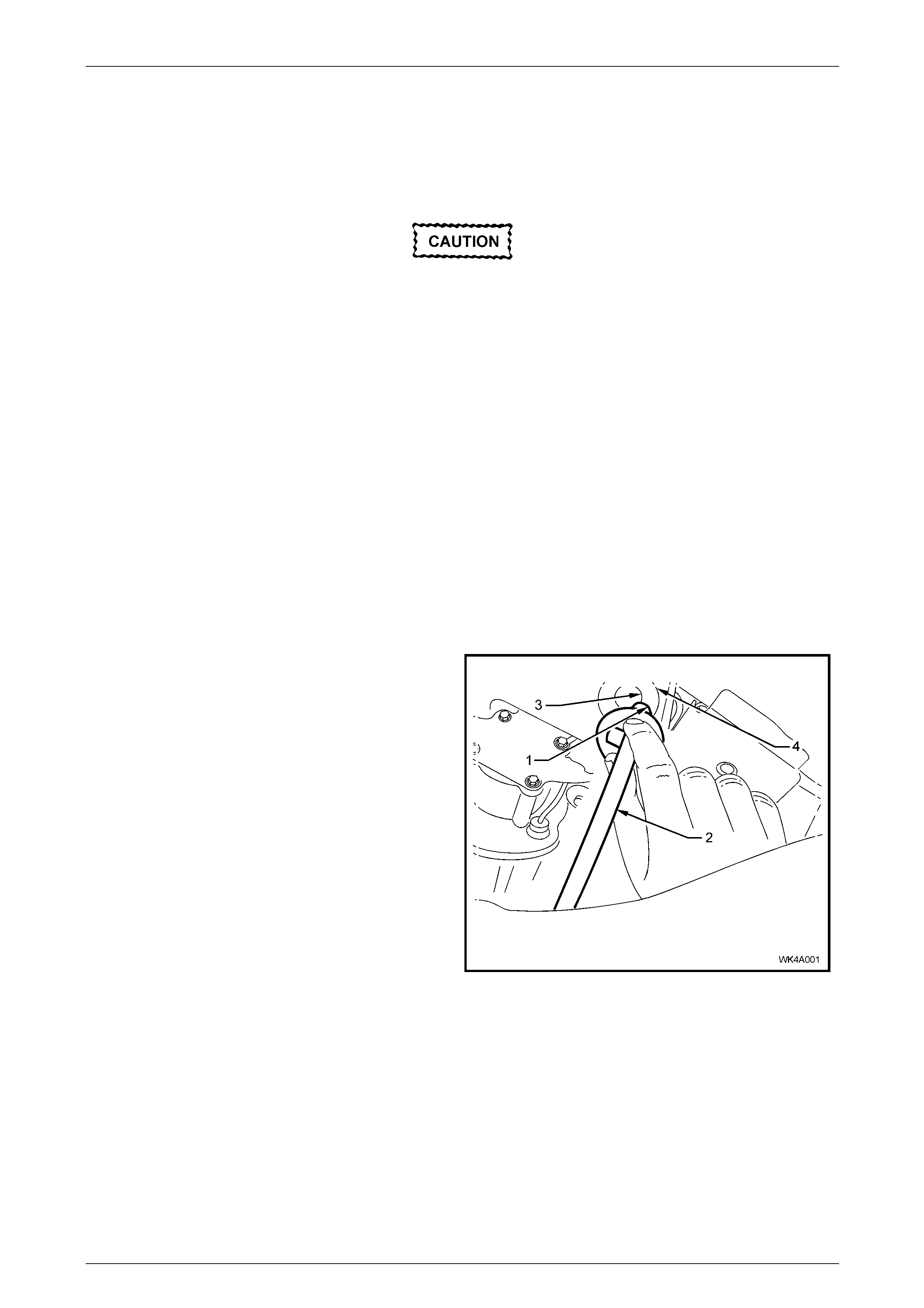
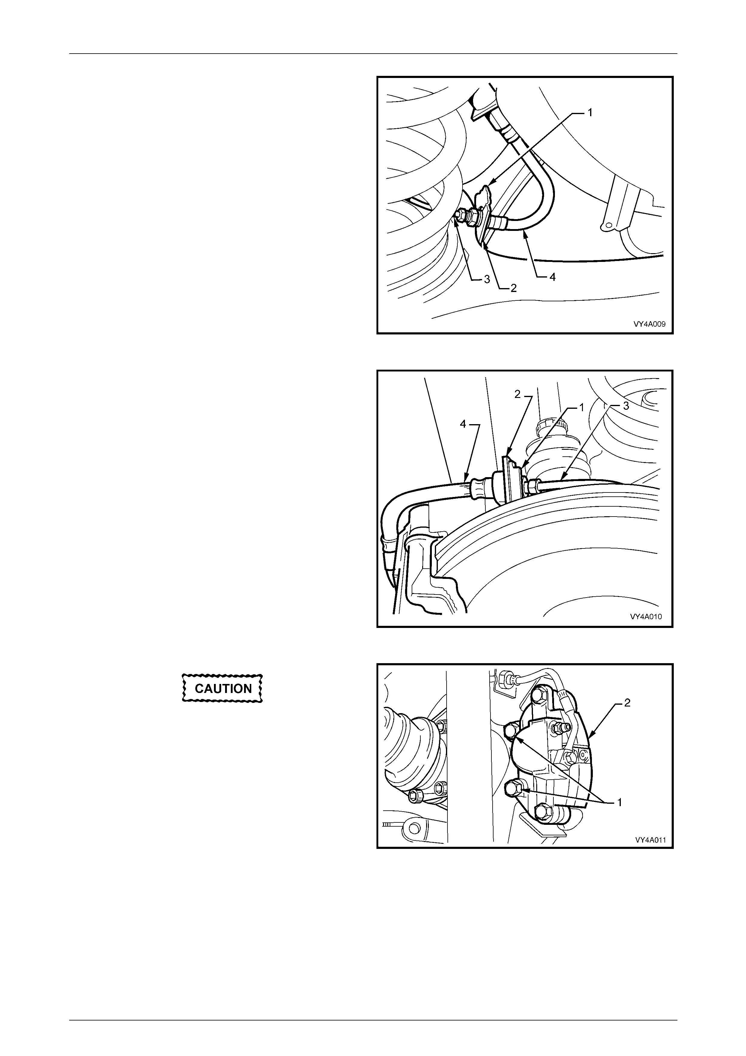
10 Remove the rear brake hose retaining clip (1) from the
rear suspension control arm bracket (2) on the side to
be removed. Pull the brake pi pe (3) and hose (4)
forward from the bracket, and then disconnect from
the rear suspension control arm by lifting the brake
pipe up through the slot in the bracket.
Figure 4A1 – 12
11 Remove the brake hose retai ning clip (1) from the
brake backing plate bracket (2). Disconnect the rear
caliper brake pipe (3) from the brake hose (4) and
disconnect the pipe from the backing plate bracket.
Plug the open ends of the brake pipe and hose to
prevent fluid loss and foreign matter entry.
Figure 4A1 – 13
If the brake pipe to hose is not disconnected,
the brake caliper must be supported with tie
wire secured to the vehicle underbody. THE
CALIPER IS NOT TO HANG BY THE BRAKE
HOSE.
12 Remove the brake caliper anchor plate to rear
suspension control arm attaching bolts (1) and remove
the caliper (2) from the rotor. Set the brake caliper to
one side.
Figure 4A1 – 14
Rear Suspension 4A1 – 13
4A1-13
13 Check that the park brake is in the fully released
position.
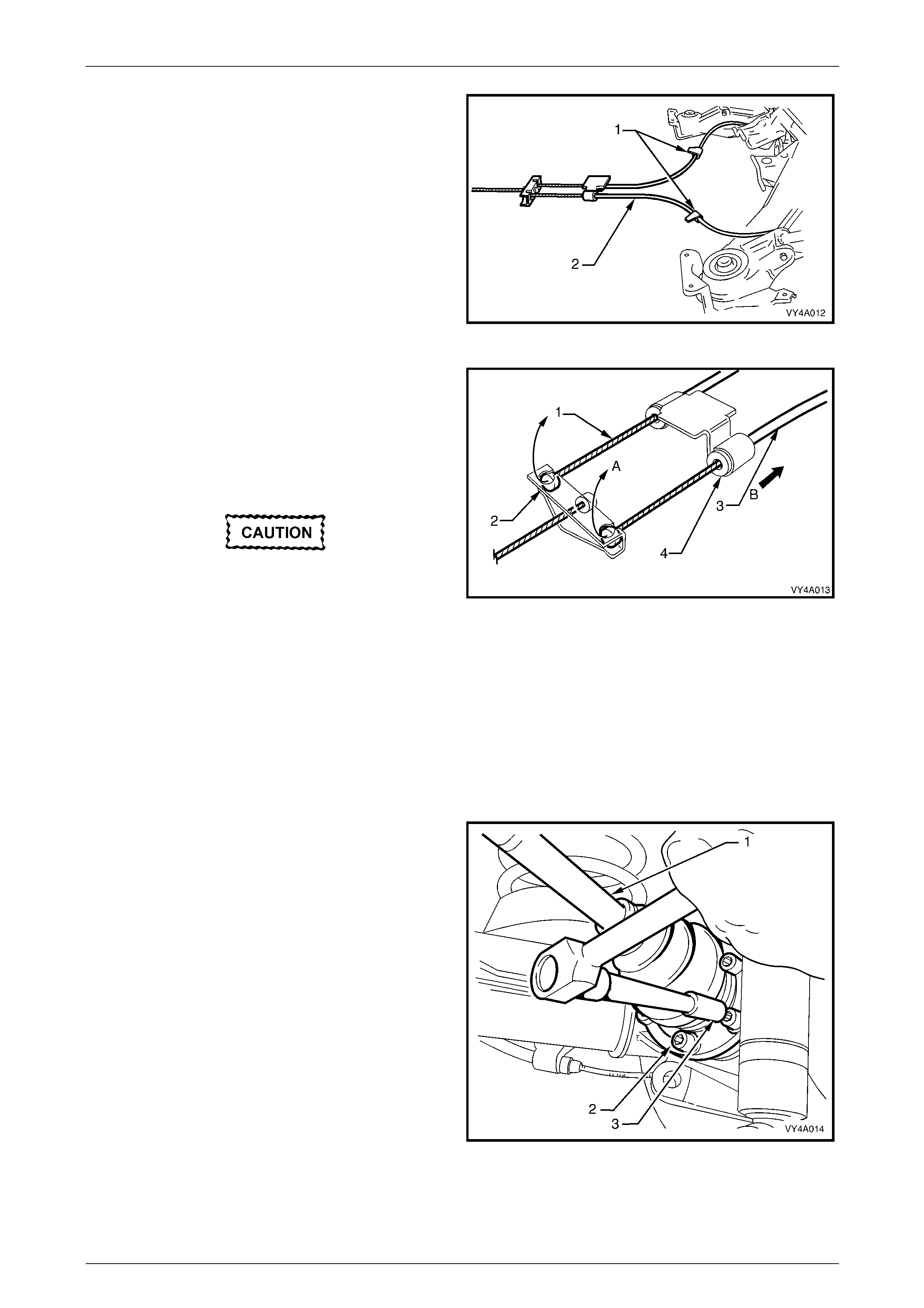
14 Release the park brake cable retaining clips (1) on
each of the underbody and free the cables (2).
Figure 4A1 – 15
15 Remove the park brake outer cable retaining bracket
bolt (bolt is not shown) from the vehicle underbody.
16 Pull each park brake inner cable (1) forward and up
(A), out of the cable retainer (2) to release each cable.
17 Pull the outer cable (3) rearward (B) to remove from
the underbody retainer (4).
While the brake rotor to hub location is
marked in production, ensure that the rotor
to hub position is carefully marked (eg. rotor
to end of wheel stud), with a felt tipped pen
or similar. This is necessary to o vercome the
possibility of inducing a brake shudder
condition after reassembly.
Figure 4A1 – 16
18 Remove the brake rotor from the wheel bearing hub.
NOTE
If necessary, adjust the park brake shoe to allow
the brake rotor to be removed, refer to
Section 5A Service and Park Braking Systems for
the necessary procedure.
19 Using Tool No. KM468 over the wheel studs to hold
outer rear wheel drive shaft hub from rotating, loosen
the six drive shaft (1) outer constant velocity joint to
rear wheel drive shaft flange attaching bolts (2), using
an 8 mm Allen key socket (3). Remove and discard
the bolts.
Figure 4A1 – 17
Rear Suspension 4A1 – 14
4A1-14
Bruising to the inside of the drive shaft
constant velocity joint boots will occur if the
rear suspension control arm is lowered. This
will lead to premature failure of the boot and
eventual failure of the joint.
This is why it is important that the constant
velocity joint be disconnected from the rear
wheel drive shaft flange before removing the
shock absorber lower mounting bolt.
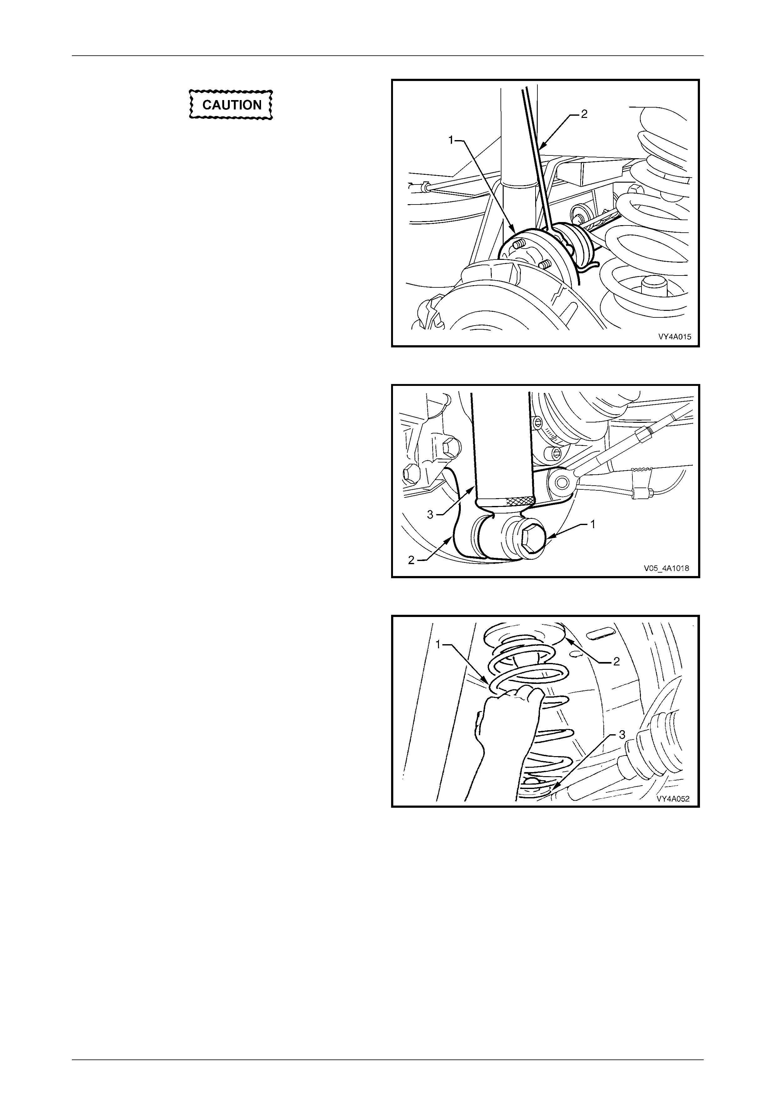
20 Disconnect the drive shaft (1) from the flange and lift
upward. While keeping the outer constant velocity joint
in the same plane as the driveshaft, use a length of
wire (2), to tie up the drive shaft to the lower end of the
shock absorber upper mounting.
Figure 4A1 – 18
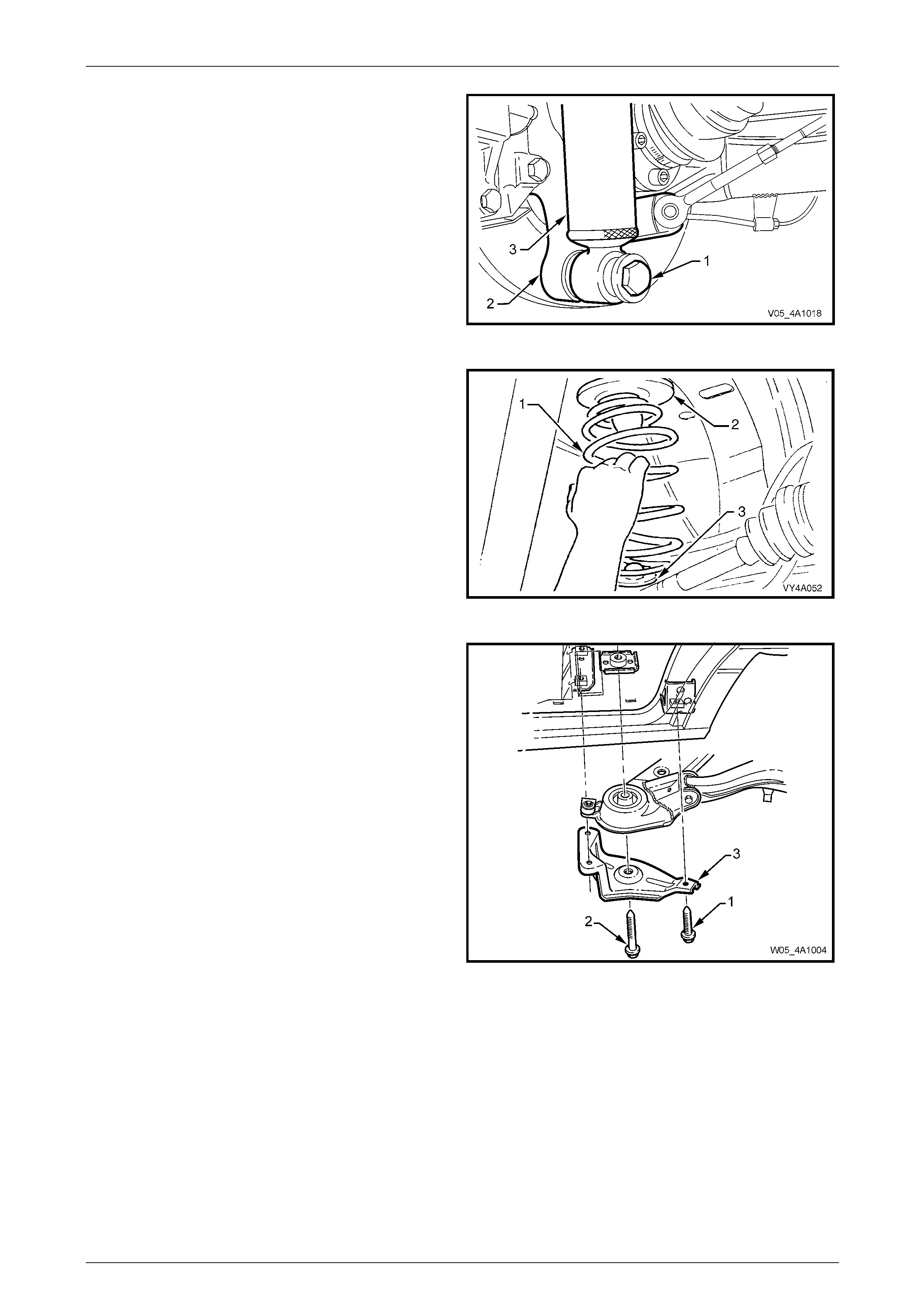
21 Position the floor jack with a block of wood under the
rear suspension control arm.
22 Raise the jack slightly to take the spring load off the
rear suspension control arm.
23 Remove the rear shock absorber lower mounting bolt
(1) and washer (2) from the rear suspension control
arm (3), then pull the lower end of the shock absorber
(4) from the rear suspension control arm.
Figure 4A1 – 19
24 Lower the floor jack and if necessar y, push down on
the rear suspension control arm and remove the rear
spring (1), upper insulator (2) and lower insulator (3)
from the vehicle underbody and rear sus pe nsion
control arm.
Figure 4A1 – 20
Rear Suspension 4A1 – 15
4A1-15
25 Pull out the differential carrier breather hose (1) from
the vehicle underbody crossmember hole (2).
Figure 4A1 – 21
26 Pull both ABS sensor lead connectors (3) from the
underbody retaining clips (4). Separate the sensor
connectors from the body harness connectors by
levering with a screwdriver.
Figure 4A1 – 22
27 Using a scriber, mark the rear mount (1) to vehicle
under body location (A). This will assist in the rear
suspension crossmember alignment on instal lation.
28 Support the weight of the differential carrier with a floor
jack.
Figure 4A1 – 23

Rear Suspension 4A1 – 16
4A1-16
29 Remove the rear mount (1) to vehicle underbody
attaching bolts (2) and discard.
Figure 4A1 – 24
30 Lower the differential carrier and rear suspe nsion
crossmember assembly enough to allow access to the
outboard rear suspension control arm to front
crossmember attaching bolt and nut.
31 Remove the rear suspension control arm to rear
suspension crossmember attaching bolts and nuts.
32 Remove the rear suspension control arm fro m the
vehicle and discard the nuts.
Figure 4A1 – 25
Rear Suspension Control Arm Pivot Bushing, Replace
1 With the rear suspension control arm (1) removed,
press the bushing (2) from the rear suspensi on control
arm using special tool number s KM619-3 and
KM619-4.
Figure 4A1 – 26
Rear Suspension 4A1 – 17
4A1-17
2 Lightly coat the outside surface of the new bushing
with a soapy water solution.
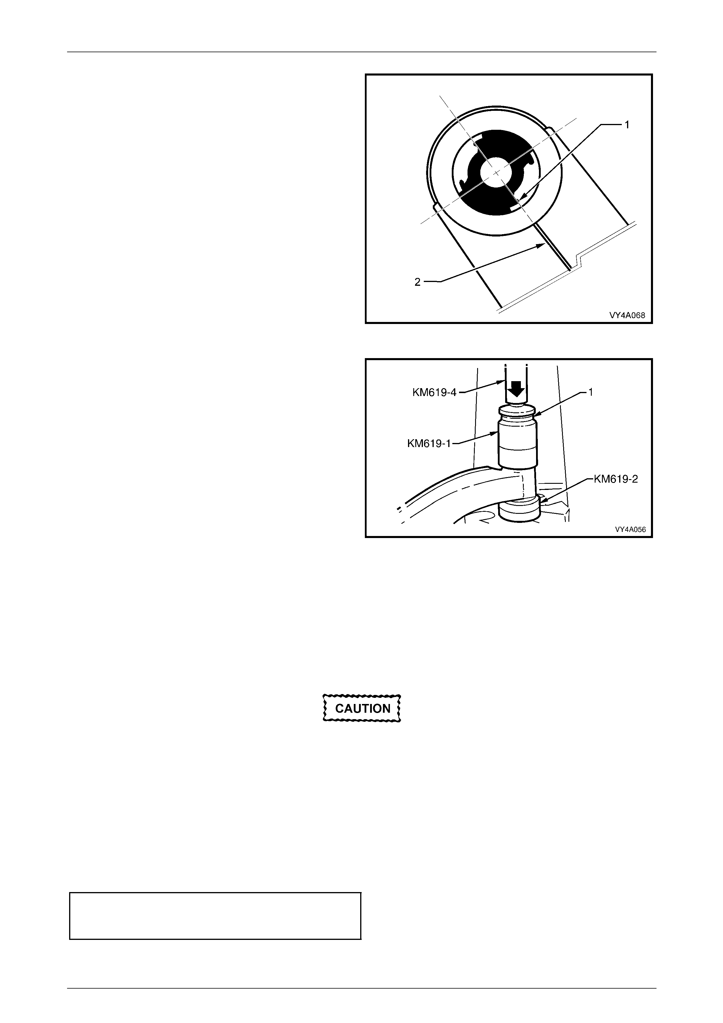
3 If the bushing is pf the voided type, align the edge of
one of the voids (1), with the welded seam in the
trailing arm (2) as shown.
Figure 4A1 – 27
4 Press the new bushing into rear suspension control
arm (2) using Special tools number KM619-1, KM619-
2 and KM619-4.
Figure 4A1 – 28
Reinstall
The reinstallation of the rear suspension control arm is the reverse of the removal procedure, with the exceptio n of the
following steps:
1 Reinstall the rear suspension control arm to the rear suspension crossmem ber, using bolts and NEW nuts but do
not fully tighten at this stage.
If the rear wheel drive shaft flange or outer
rear wheel drive shaft was replaced, then
runout checks must be carried out on the
installed brake rotor. Refer to
Section 5A Service and Park Braking Sys tems
for important information regarding these
checks.
2 Reinstall the brake rotor, aligning the marks made before removal.
3 Reinstall the brake caliper a nchor plate to the rear suspension control arm, install the attaching bolts and tighten to
the correct torque specification.
Rear brake caliper anchor
plate to control arm
bolt torque specification.......................................85 N.m

Rear Suspension 4A1 – 18
4A1-18
4 Support rear suspension control arm with a floor jack and wooden block and raise enough to allow the shock
absorber to be reinstalled.
5 Reinstall the shock absorber and stabiliser bar link attaching bolts and nuts but do not fully tighten at this stage.
6 Reinstall the additional control arm socket assembly and a NEW nut and tighten to the correct torque wrench
specification.
Additional control arm ball joint
nut torque specification........................................65 N.m
7 Reinstall new drive shaft outer constant velocity joint to rear wheel drive shaft flange attac hin g bolts and plates,
then tighten to the correct torque specification.
Drive shaft constant velocity joint
to rear wheel drive shaft flange
bolt torque specification..............................50 N.m, then
turn through 70°
8 After reconnecting all brake li ne connections, bleed the rear brakes and check for leaks. For the recommended
procedure, refer to Section 5A Service and Park Braking S ystems.
9 Raise the differential carrier and rear suspension crossmember assembly until the rear mount contacts the vehicle
underbody.
10 Align rear suspension crossmember mo unt with the scribed ali gnment mark (refer to step 27 in the Remove section
of this service operation).
11 Install NEW rear suspension crossmember mount to vehicle underbody mounting bolts and tighte n to the correct
torque specification.
Rear suspension crossmember
rear mount to underbody attachin g
bolt torque specification..............................35 N.m, then
turn through 60°
Failure to correctly align the rear suspension
crossmember to the centreline of the vehicle
will result in steering abnormalities and
uneven tyre wear!
12 The rear suspension crossmember alignment MUST be checked, using the special tool and procedure. Refer to
Section 1A2 Body Dimensions.
13 If the vehicle is fitted with Automatic Level Ride Sus pensio n (prod uction option FX3), reconnect the level ride
sensor link to the rear control arm.
14 Reinstall the road wheel/s, aligni ng the marks made prior to removal and secure with the attaching nuts.
15 Lower the vehicle to the ground an d bounce the rear of the vehicl e several times to settle the suspension
components.
16 With the weight of the vehicle on the four wheels and at curb weight, tighten the follo wing bolts and nuts to the
respective, correct torque specifications.
Shock absorber lower mounting
bolt torque specification.....................................115 N.m
Stabiliser bar link to rear
suspension control arm
nut torque specification........................................95 N.m
Rear suspension control arm to
rear crossmember attaching
bolt torque specification.....................................100 N.m
17 Tighten the road wheel attaching nuts to the correct tor que specification, working in a ‘star’ pattern. Refer to
3.1 Service Warnings, Cautions and Notes in this Section for detailed information regarding the inst allation
procedure for the road wheels.
Road wheel attaching
nut torque specification............................110 – 140 N.m
18 Reinstall the wheel nut dec orative caps.
19 Road test the vehicle to check for correct vehicle operation.
Rear Suspension 4A1 – 19
4A1-19
3.3 Outer Rear Wheel Drive Shaft, Flange or
Bearing
LT Section No. – 05-290
ATTENTION
The following fasteners MUST be replaced when performing these operations:
Lower rear disc brake shield to rear suspension control arm bolts.
Outer rear wheel drive shaft collar nut.
Replace
The rear wheel bearing should only be
removed if it is faulty, or the outer rear wheel
drive shaft is to be removed.
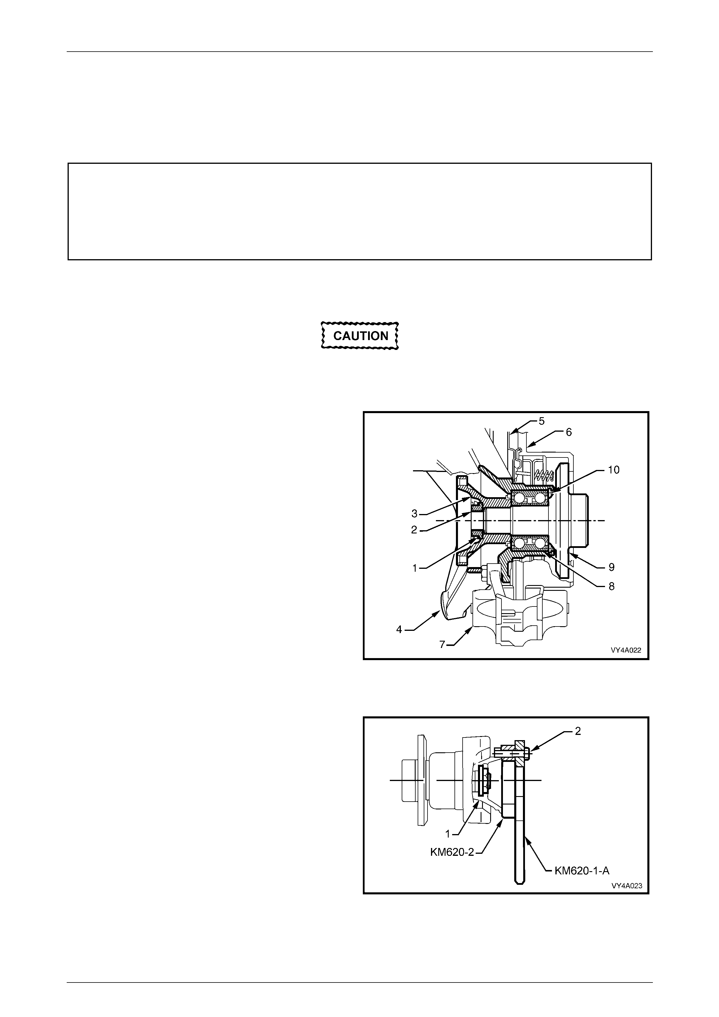
Trunnion Assembly – Sectioned View
Legend:
1 Collar Nut Lock Plate
2 Collar Nut
3 Rear Wheel Drive Shaft Flange
4 Rear Suspension Control Arm
5 Brake Backing Plate
6 Brake Rotor
7 Brake Caliper
8 Rear Wheel Bearing
9 Outer Rear Wheel Drive Shaft
10 Rear Wheel Bearing Retaining Ring
Figure 4A1 – 29
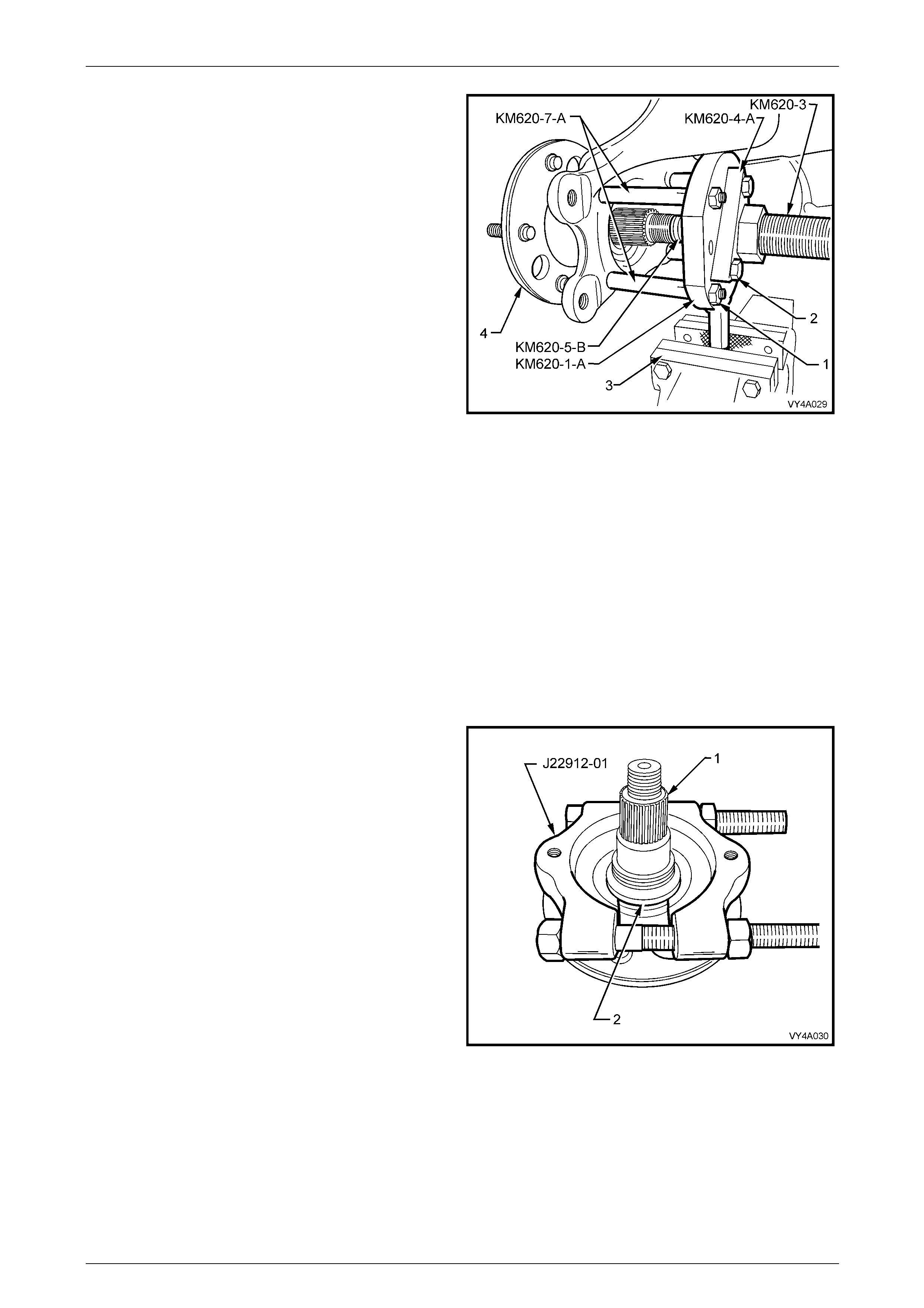
1 Remove the rear suspension control arm. R efer 3.2 Rear Suspensio n Control Arm in this Section.
2 Secure the flange holding tool, KM620-1-A and rear
wheel drive shaft flange ring tool KM620-2 to the rear
wheel drive shaft flange (1) with three of the remove d
drive shaft constant velocity joint to rear wheel drive
shaft flange attaching bolts (2).
NOTE
Align holes marked ‘B’ on the flange holding tool
KM620-1-A and KM620-2 with holes in the rear
wheel drive shaft flange before installing and
tightening bolts.
Figure 4A1 – 30
Rear Suspension 4A1 – 20
4A1-20
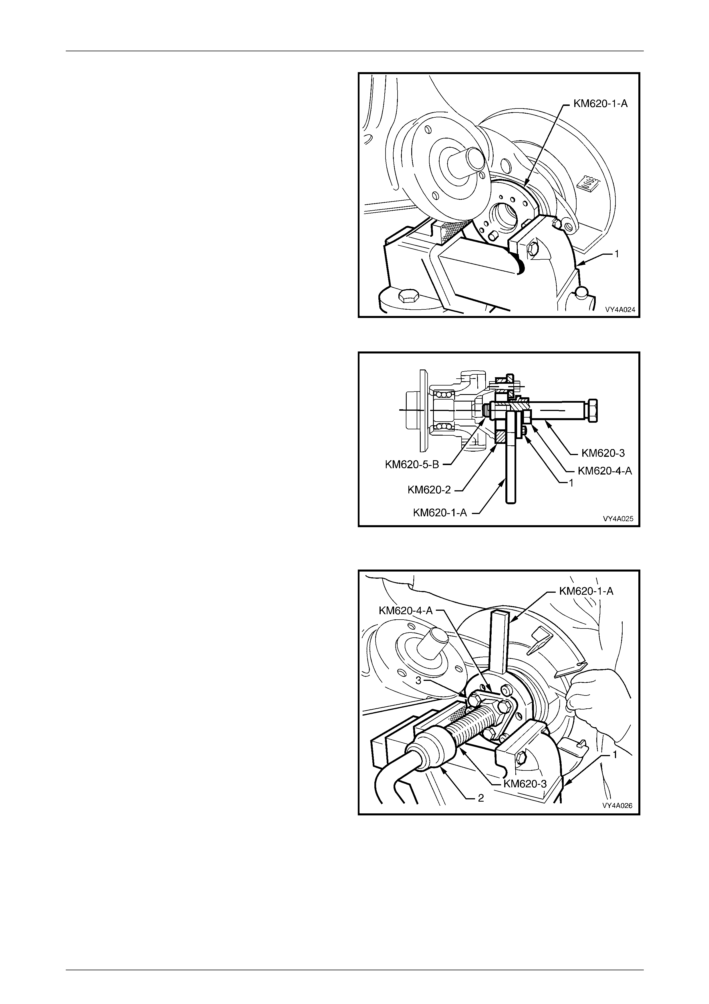
3 Distort the rear wheel drive shaft flange collar nut lock
plate, using a suitable size pin punch and hammer,
then remove and discard the lock plate.
4 Mount the assembly in a vice (1), gripping the handle
or the flats of the flange holding tool KM620-1-A.
Loosen, then remove and discard the rear wheel drive
shaft flange to outer rear wheel drive shaft collar nut
and lock plate.
NOTE
The collar nut and the lock plate must be
replaced on reassembly.
5 Leave the holding tool KM620-1-A and the rear wheel
drive shaft flange ring tool KM620-2 assemb led to the
rear wheel drive shaft flange.
Figure 4A1 – 31
6 Lubricate the threads of the forcing screw KM620-3,
then install the screw to adaptor KM620-4-A. Appl y
grease to the ball end of the plung er, Tool No. KM620-
5-B, then install that, into the end of the forcing screw
KM620-3.
7 Install the whole sub-assembly through the central
opening of the flange holding tool KM620-1-A. Secure
the adaptor KM620-4-A to the flang e holding tool
KM620-1-A, using three suitable bolts (1).
NOTE
Adjust the position of the forcing scre w KM620-3
in the adaptor KM620-4-A, to allow the adaptor
to be in full contact with the flange holding tool
KM620-1-A. Figure 4A1 – 32
8 With the flange holding tool KM620-1-A held in a vice
(1), turn the forcing screw (KM620-3) using suitable
socket equipment (2), until the flange is free from the
outer rear wheel drive shaft.
NOTE
Use an assistant to hold and support the weight
of the rear suspension control arm assembly
during this operation.
9 Remove and separate the sp ecial tool components
from the rear wheel drive shaft flange.
Figure 4A1 – 33
Rear Suspension 4A1 – 21
4A1-21
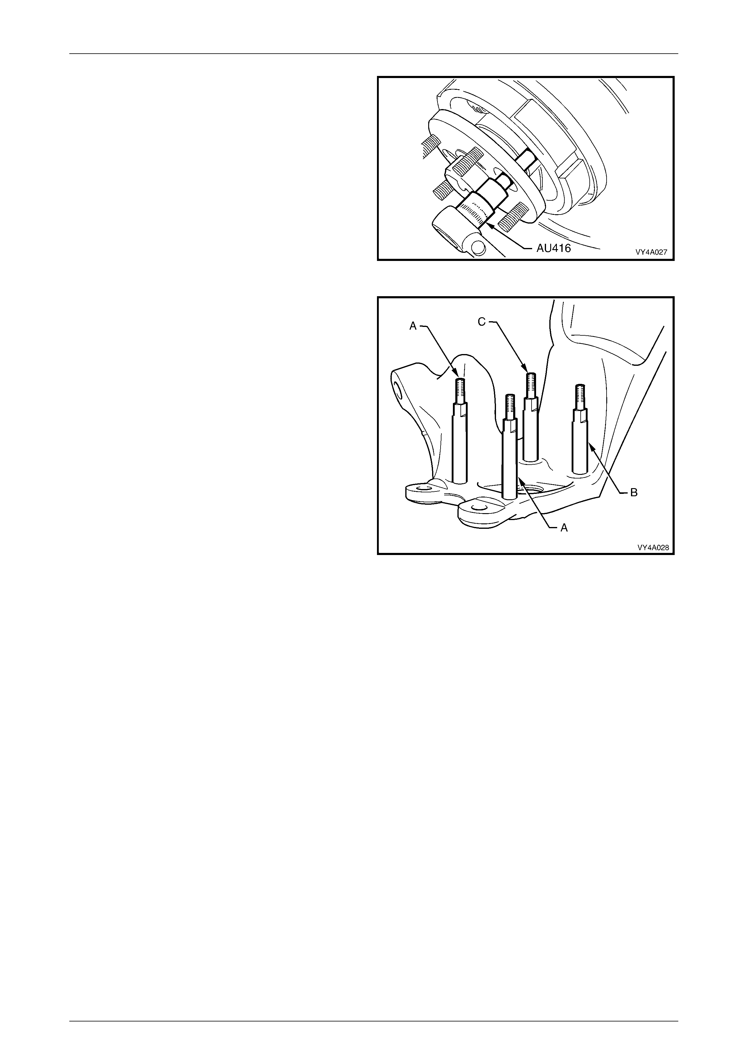
10 Using Torx bit socket, Tool No. AU416, remove the
two upper bolts attaching the brake backing plate to
the rear suspension control arm.
11 Using suitable socket equipment, remove the two
longer, hexagonal headed, lo wer bo lts. Discard the
removed lower bolts.
Figure 4A1 – 34
12 Prior to removing the outer rear wheel drive shaft and
rear wheel bearing from the rear suspension control
arm, use a commercially available M10 x 1.25
bottoming tap and a suitable lubricant, clean the four
backing plate to rear suspension control arm bolt
threads working from the outer rear wheel drive shaft
side.
NOTE
This step is necessary to clear any dried mud,
dirt etc, from the exposed portion of the threads
on the inboard side of the rear suspension
control arm. Also, the deepest thread (position
‘C’) may not be completely formed throu gh to the
inboard side.
13 Install two supports KM620-7-A in positions ‘A’ and
two KM620-7-AUS to ‘B’ and ‘C’ in th e rear
suspension control arm, as indicated.
NOTE
As a guide, the two longest supports (KM620-7-
A) are to be installed at the brake caliper
mounting side (position ‘A’). The longer of
KM620-7-AUS supports is installed at position
‘B’ and the shorter is installed at positio n ‘C’.
14 After installing all four supports in the correct positions,
tighten with a set spanner.
Figure 4A1 – 35
Rear Suspension 4A1 – 22
4A1-22
15 Install the flange holding tool KM620-1-A over the four
supports, KM620-7-A (2 places) and KM620-7-AUS (2
places), install four suitable nuts (1) and tig hten to
secure.
16 Pre-assemble the lubricated forcin g screw KM620-3 to
the adaptor KM620-4-A. App ly grease to the ball end
of the plunger KM620-5-B, then install that, into the
end of the forcing screw KM620-3.
17 Install this sub-assembly through the central opening
of holding tool KM620-1-A. Secure the adaptor
KM620-4-A to the flange holdi ng tool KM620-1-A,
using three suitable bolts (2).
NOTE
Adjust the position of the forcing scre w KM620-3
into the adaptor KM620-4-A, to allow full contact
of the adaptor to the flange holding tool KM620-
1-A.
18 Tighten the three bolts securing adaptor KM620-4-A to
the flange holding Tool KM620-1-A.
19 Mount the assembly in a vice (3) by the handle of the
flange holding tool KM620-1-A as shown, then turn the
forcing screw KM620-3 and press the out er rear wheel
drive shaft (4) from the rear wheel bearing.
Figure 4A1 – 36
20 When the outer rear wheel drive shaft has been removed, unscrew the forcing screw, as this same arrangement is
used to press the rear wheel bearing from the rear suspension control arm.
NOTE
The inner rear wheel bearing cone will separate
from the bearing assembly and be retained on
the outer rear wheel drive shaft.
21 Remove the brake backing plate and park brake assem bly from the rear suspension control arm an d set to one
side.
22 If the outer rear wheel drive shaft (1) is to be re-used,
then the outer half of the inner rear wheel bearing
cone (2) will need to be removed from the outer rear
wheel drive shaft.
23 Install the press plates J22912-01 over the bearing
cone and tighten the press plate bolts to grip the
bearing cone.
24 Press the outer rear wheel drive shaft from the bearing
cone and discard bearing cone.
NOTE
• If the outer rear wheel drive shaft is to be
replaced, then step 20, is not required.
• A new outer rear wheel drive shaft is
supplied with wheel studs already installed.
Figure 4A1 – 37
Rear Suspension 4A1 – 23
4A1-23
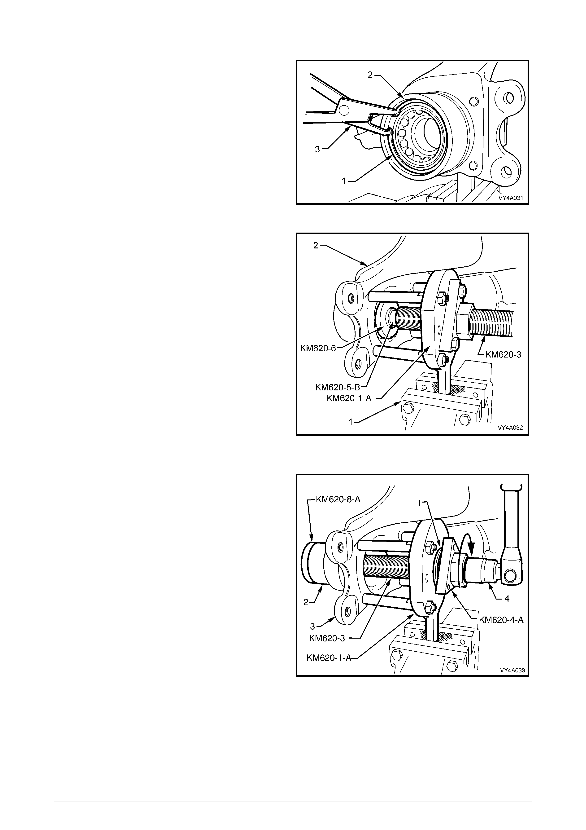
25 Remove the wheel bearin g retaining ring (1) from the
rear suspension control arm (2), using suitable circlip
pliers (3).
Figure 4A1 – 38
26 With the tool components set up as sho wn, insert the
rear axle bearing removing disc KM620-6 into the rear
of the axle bearing.
27 Reposition the forcing screw KM620- 3 and the adaptor
KM620-5-B to retain the removing plate KM620-6 in
place.
28 With KM620-1-A mounted in the vice jaws (1), turn the
forcing screw KM620-3 clockwise to press the wheel
bearing from the rear suspension control arm (2).
29 If installing a replacement rear suspension control arm
without bushing, install new bushing. Refer to
3.2 Rear Suspension Control Arm in this Section.
30 Ensure that the bearing bore of the rear suspension
control arm is clean and free of any foreign matter.
31 Coat the outside diameter of a new wheel bearing and
the bore of the rear suspension control arm wit h an
NLGI No. 2 lithium soap based EP grease with
molybdenum disulphide, such as Shell Retinax HDX2
grease or BP Energrease LMS-EP 23 (or eq uivalent). Figure 4A1 – 39
32 Remove the bolts securing adaptor KM620-4 - A to the
holding tool KM620-1-A, then remove the adaptor and
forcing screw KM620-3.
33 Lubricate the thrust ball bearing race (1) (part of
KM620-A) with lubricant such as with an NLGI No. 2
lithium soap based EP grease with molybdenum
disulphide, such as Shell Retinax HDX2 grease or BP
Energrease LMS-EP 23 (or equivalent).
34 Assemble the bearing onto the flang ed end of adaptor
KM620-4-A.
35 Install the forcing screw and adaptor/bearing assembly
to the flange holding tool KM620-1-A. Do not install the
adaptor (KM620-4-A) to holding tool (KM620 -1-A)
attaching bolts.
36 Install the bearing installer KM620-8-A into a new
bearing (2) and install both into the rear suspension
control arm (3).
37 Join the forcing screw (KM620-3), and the bearing
installer (KM620-8-A) by engaging the screw thread of
the forcing screw (KM620-3) with the installer (KM620-
8-B) and tightening the forcing screw to engage at
least 8 full threads.
Figure 4A1 – 40
38 While holding the forcing screw (KM620-3) from turning by using suitable socket equipment (4), rotate the adaptor
KM620-4-A in the direction shown, with a suitable 40 mm wrench to draw the new bearin g (2) fully into position.
Rear Suspension 4A1 – 24
4A1-24
39 Remove the installer KM620-8-A once the bearing is fully install ed, then install the retaining ring into the rear
suspension control arm using suitable circlip pliers, ensuring that the ring is seated correctly.
40 Separate all special tool comp onents from the rear wheel drive shaft flange, after the bearing has been fully
installed.
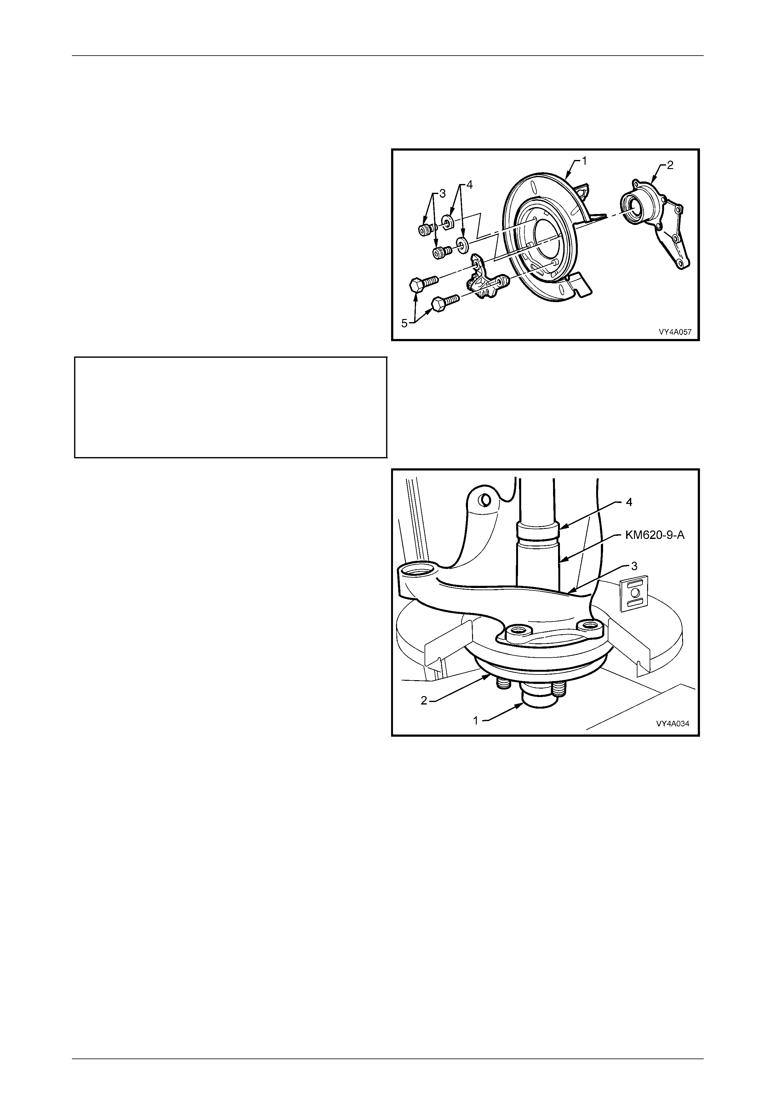
41 Reinstall the upper two Torx headed bolts (3) and
washers (4) to secure the rear brake dust shield to the
rear suspension control arm.
NOTE
The two washers (4) are to be installed with the
cut-out edge facing around the rear suspension
control arm hub outer surface.
42 Install NEW rear brake shield (1) to rear suspens ion
control arm (2) bolts (5).
43 Tighten all four fasteners to the correct torque
specification.
Rear brake shield to rear
suspension control arm
upper bolt torque specification.............................75 N.m
Rear brake shield to rear
suspension control arm
lower bolt torque specification..............................88 N.m
Figure 4A1 – 41
44 Position the outer rear wheel drive shaft (2) with the
centre hub section resting on a suitable support (1)
and press plates.
NOTE
Check that the outer rear wheel drive shaft
wheel studs do not contact press plates.
45 Position the rear suspension control arm (3) with the
wheel bearing onto the outer rear wheel drive shaft.
46 With an assistant supporting the rear suspension
control arm assembly in this position, use installer
KM620-9-A and steel pipe (4) of suitable length and
diameter, press wheel bearin g onto the outer rear
wheel drive shaft.
Figure 4A1 – 42
Rear Suspension 4A1 – 25
4A1-25
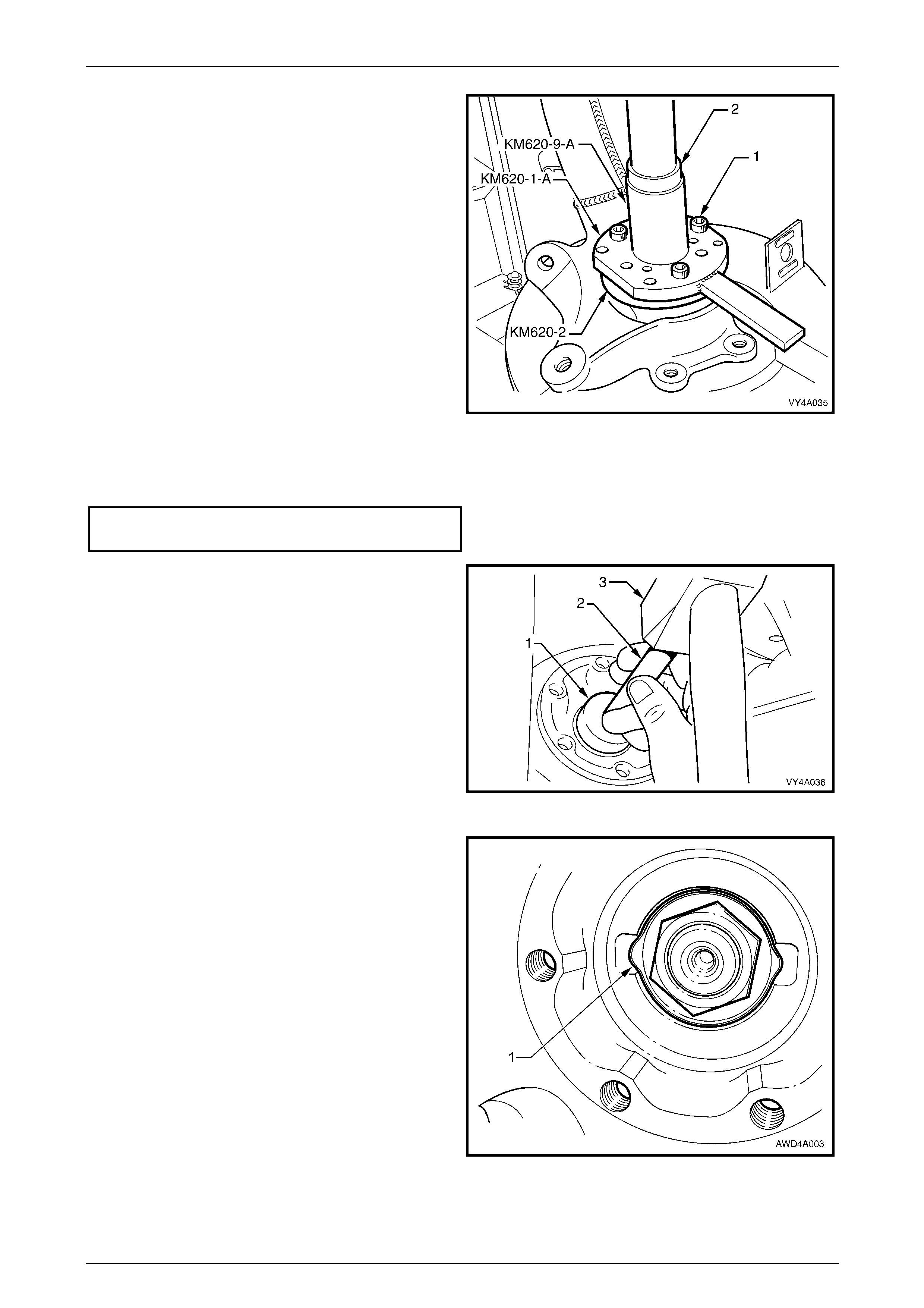
47 Remove the installer KM620-9-A and steel pipe.
Assemble the flange holding t ool KM620-1-A and rear
wheel drive shaft flange ring KM620-2 to the rear
wheel drive shaft flange using three drive shaft
attaching bolts (1).
48 Lubricate the rear wheel drive shaft flange splines and
the outer rear wheel drive shaft threads with an NLGI
No. 2 lithium soap based EP grease with molybdenum
disulphide, such as Shell Retinax HDX2 grease or BP
Energrease LMS-EP 23 (or equivalent).
49 Reinstall the rear wheel drive shaft flange, flange ring
and holder assembly onto the outer rear wheel drive
shaft, aligning the splines on each.
50 With the outer rear wheel drive shaft supp orted on
press plates, as in step 36, press the rear wheel drive
shaft flange onto the outer rear wheel drive shaft using
installer KM620-9-A and a suitable steel pipe (2).
51 Remove the rear suspension control arm assembly
from the press and support the assembly in a vice b y
the flats on flange holding tool KM620- 1-A. Figure 4A1 – 43
52 Install a new collar nut to the outer rear wheel drive shaft and tighte n to the correct torqu e specification.
Collar nut to outer rear wheel
drive shaft nut torque specification.....................300 N.m
53 Remove the rear suspension control arm assembly
from the vice and remove all the spec ial tools from the
rear wheel drive shaft flange.
54 Using a suitable diameter socket (1), 150 mm socket
shaft (2) and hammer (3), install a new lock plate over
the collar nut.
Figure 4A1 – 44
55 Use a suitable sized pin punc h and hammer to distort
the rear wheel drive shaft flange (1) into the cut-outs
on each side of the driveshaft flange.
56 Reinstall the rear suspension control to the vehicle.
Refer to 3.2 Rear Suspension Control Arm, Reinsta ll,
in this Section.
Figure 4A1 – 45
Rear Suspension 4A1 – 26
4A1-26
3.4 Rear Suspension Crossmember
LT Section No. – 07-150
ATTENTION
The following fasteners have either micro encapsulation or incorporate a mechanical thread lock and should
only be used once. If in doubt, replacement is recommended when performing this operation:
Additional control arm socket assembly retaining nut.
Stabiliser bar link to rear suspen sio n control arm attaching nut and bolt.
Rear susp ension control arm to rear suspension crossmember attaching nut.
The following fasteners MUST be replaced when performing these operation:
Rear suspension crossmember rear mounting to underbody attaching bolts.
Final drive assembly to rear suspension crossmember bolts.
Rear suspensi o n crossmember front mounting bolt.
The following fasteners MUST be at curb height with the vehicle weight on all four wheels before final
tightening is undertaken:
• Shock absorber lower mounting bolt.
• Stabiliser bar link to rear suspension control arm attach ing nut and bolt.
• Rear suspension control arm to rear suspension crossmember attaching nut.
Whenever any component that forms part of
the ABS (if fitted) is disturbed during Service
Operations, it is vital that the complete ABS
system be checked; refer ABS Function
Check, in Section 5B ABS & ABS/TC &
Electronic Brake Assist (EBA).
Before disturbing the rear suspension
crossmember mounting bolts, an alignment
procedure is required on reinstallation and a
special tool is required for this purpose. If this
tool is not available, then the crossmember
cannot be correctly aligned and steering
and/or handling abnormalities will result.
Rear Suspension 4A1 – 27
4A1-27
Remove
1 Raise the vehicle and suppor t in a safe manner. Refer to Section 0A General Information for the location of
recommended lifting and support points.
2 Mark the relationship of the road wheel to hub or brake rotor. Loosen, then remove the road wheel attaching nuts,
working in a 'star' pattern. Refer to 3.1 Service Warnings, Cautions and Notes, in this Section.
NOTE
Step 2 is necessary to maint ain part relationships
and to avoid brake rotor distortion and the
creation of brake shudder, after the vehicle is
placed back in service.
3 Disconnect and remove the exhaust system from the rear of the catalytic converter/s, rearward.
Refer to Section 8B Exhaust System.
4 Remove the intermediate muffler heat shield from the vehicle underbody. Refer to Section 8B Exhaust S ystem.
5 If the vehicle is fitted with the Automatic Level Ride
Suspension (production option FX3), disconnect the
ride height sensor link from the rear suspension
control arm.
Figure 4A1 – 46
6 To enable the propell er shaft to be installed in the
original position relative to the pinion flange, use a felt
tipped pen or similar to identify the relationship (‘A’)
between the two components.
7 Select the ‘Park’ position with the shift select lever and
firmly apply the park brake.
Do not loosen and remove any of the Torx
headed bolts (1) before relieving any torque
loading on the rubber coupling.
8 Using a commerciall y available E20 Torx socket and
suitable socket equipment loosen the three Torx
headed bolts (1).
9 Release the park brake to relieve any torque loading
on the rubber coupling, then remove the three Torx
headed bolts. Figure 4A1 – 47
Rear Suspension 4A1 – 28
4A1-28
10 Remove the centre bearing he at shield, if fitted.
11 While supporting the centre bearing carrier (1),
remove the two bolts (2) securing the centre bearing
carrier to the underbody reinforcement.
12 While supporting the centre beari ng section, slide the
propeller shaft assembly forward to disengage from
the rear suspension differential assembly pinion
support pin.
Figure 4A1 – 48
Do not allow the rear of the propeller shaft to
hang without support. This would place
undue stress on the front constant velocity
joint, causing premature failure.
13 Temporarily reinstall the centre bear i ng support bolts (do not tighten) and use a suitable length of wire to tie the
rear of the propeller shaft to a suitable point on the vehicle underbody.
14 Check that the park brake is in the fully released
position.
15 Release the park brake cable retaining clips (1) on
each of the underbody and free the cables (2).
Figure 4A1 – 49
16 Remove the park brake outer cable retaining bracket
bolt (underbody bracket and bolt are not shown) from
the vehicle underbody.
17 Pull each park brake inner cable (1) forward and up in
the direction of the arro w (A) and out of the cable
retainer (2) to release each cable.
18 Pull the outer cable (3) rearward (B) to remove from
the underbody retainer (4).
Figure 4A1 – 50
Rear Suspension 4A1 – 29
4A1-29
19 Disconnect the brake pipe (1) from the brake hose (2)
at the rear suspension control arm bracket (3) and
remove the brake hose retaining clip (4).
20 Plug the open ends of both pipes and hos es to prevent
unnecessary fluid loss and/or foreign matter entry.
21 Repeat for the other side.
Figure 4A1 – 51
22 Pull the differential carrier breather hose (1) out of the
hole (2) in the vehicle underbody rear suspension
crossmember.
Figure 4A1 – 52
23 Pull both ABS sensor lead connectors (3) from the
underbody retaining clips (4). Separate the sensor
connectors from the body harness connectors by
levering with a screwdriver.
Figure 4A1 – 53
Rear Suspension 4A1 – 30
4A1-30
24 Using a scriber, mark the location (A) of the rear
mount (1) to vehicle under body location. This will
assist in rear suspension crossmember alig nment on
installation.
25 Support the weight of the differential carrier with a floor
jack.
Figure 4A1 – 54
26 Remove the rear mount (1) to vehicle underbody
attaching bolts (2) and discard.
27 Lower the differential carrier and rear suspe nsion
crossmember assembly by at least 60 mm.
Figure 4A1 – 55
• If automatic level ride suspension is fitted
to the vehicle, there are specific
procedures relating to the system
pressure and the removal of the shock
absorber. Refer to 4 Service Operations –
Automatic Level Ride Suspension, in this
Section.
• During driveshaft removal and
reinstallation, the driveshaft 'free' end
MUST be supported to keep constant
velocity joint angles to a minimum.
Excessive angles and/or dropping the
'free' end will cause damage to the boot
cap and the joint itself.
Rear Suspension 4A1 – 31
4A1-31
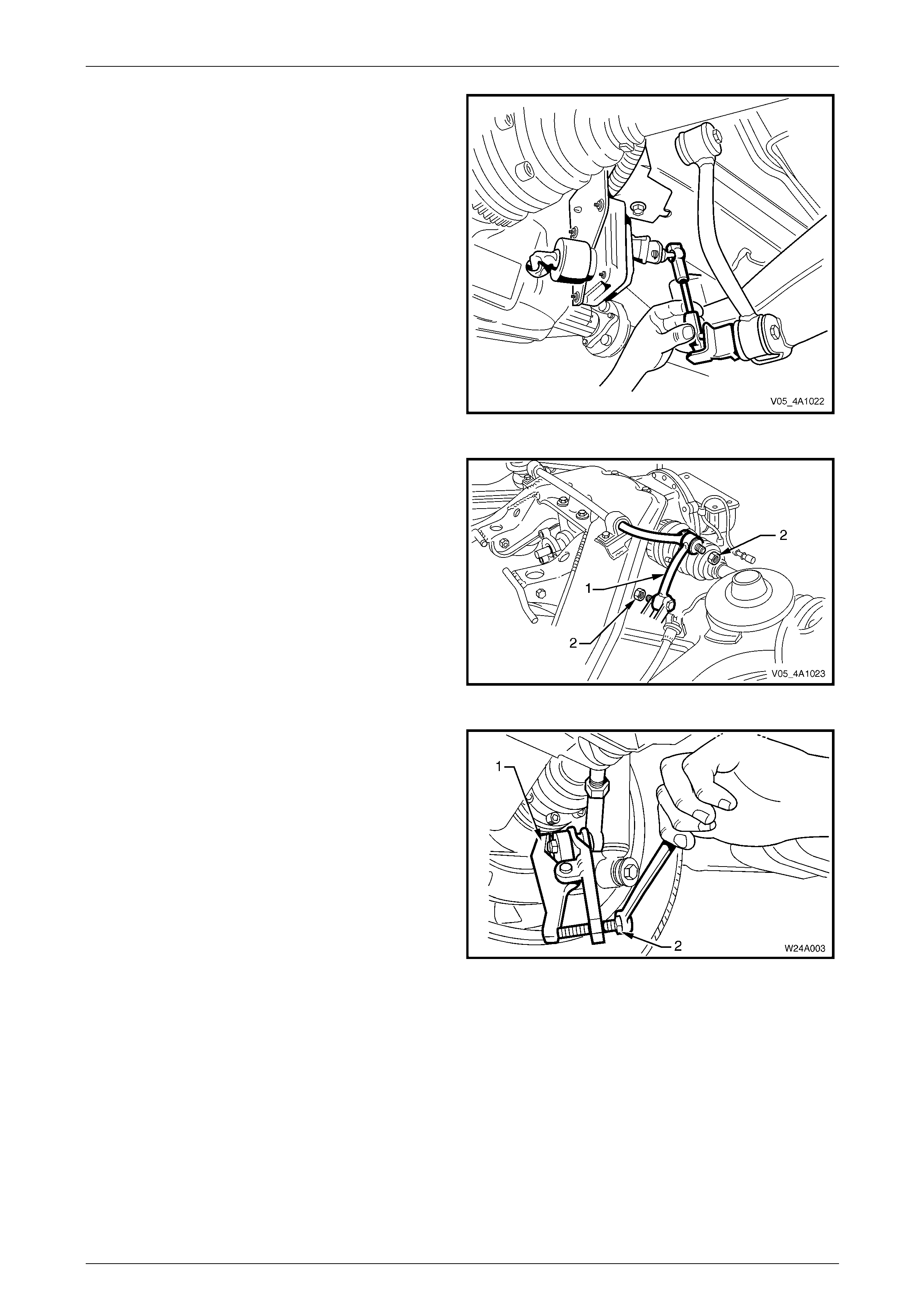
Position the floor jack with a block of wood under the rear
suspension control arm.
28 Raise the jack slightly to take the spring load off the
rear suspension control arm.
29 Remove the rear shock absorber lower mounting bolt
and washer (1) from the rear suspension control arm
(2), then pull the lower end of the shock absorber (3)
from the rear suspension control arm (2).
Figure 4A1 – 56
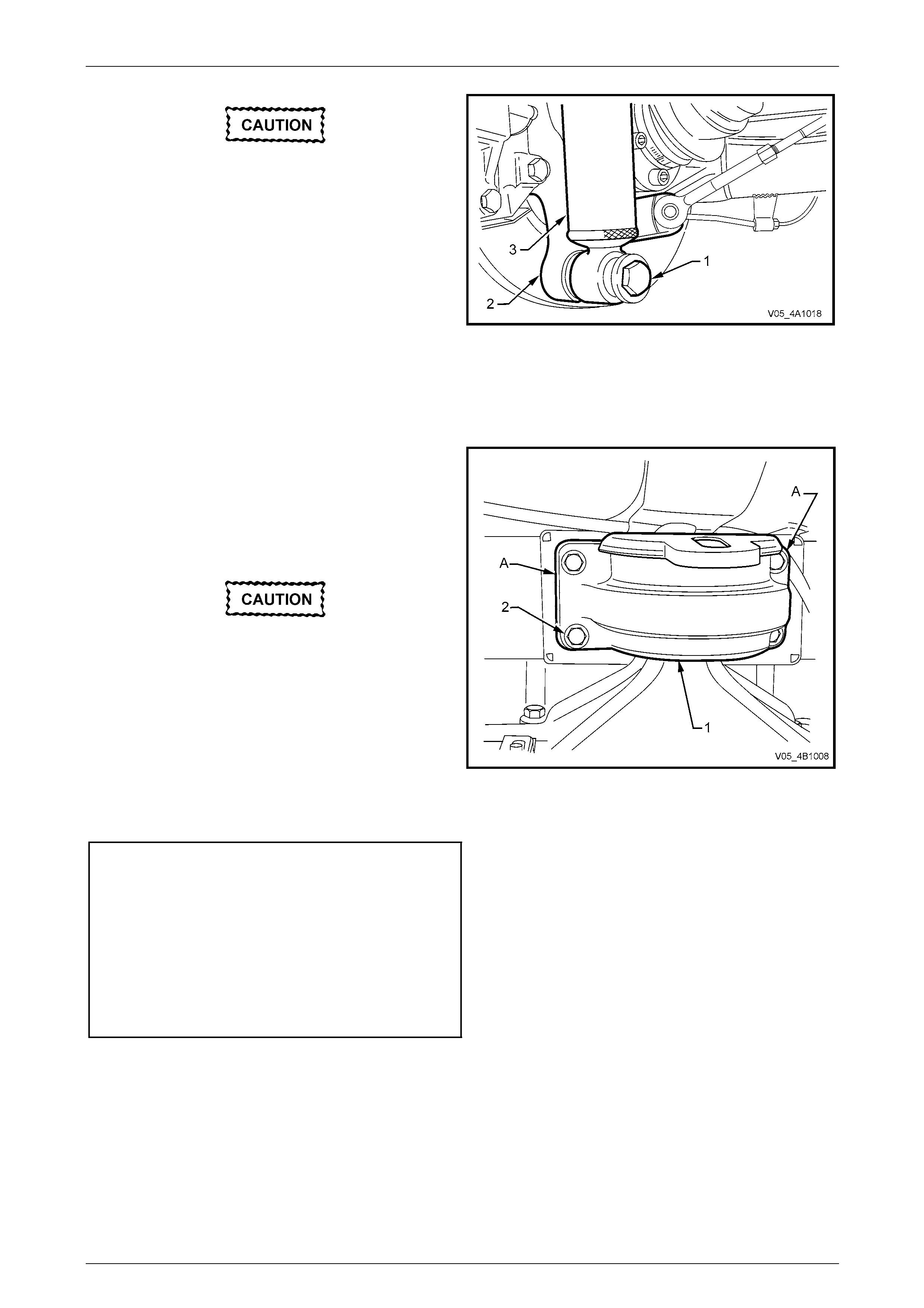
30 Remove the rear springs (1), the upper insulators (2)
and the lower insulators (3) from the vehicle
underbody and rear suspensi on control arms.
31 Raise the differential carrier and rear suspension
crossmember on a floor jack until the rear mount
contacts the vehicle underbody.
Figure 4A1 – 57
32 Use a floor jack and a block of wood to support the
differential carrier and crossmember assembly.
33 Remove brace to underbody bolts (1) (3 places) and
crossmember to vehicle underbod y attaching bolt (2)
from each side.
34 Remove the braces (3) from the vehicle.
35 With an assistant supporting front end of rear
crossmember, lower assembly on jack and remove
from beneath vehicle.
Figure 4A1 – 58
Rear Suspension 4A1 – 32
4A1-32
36 Remove the stabiliser bar mounting bracket attaching
bolts (1). Use a screwdriver to lever up the brackets
(2) from the mounting points and remove the brackets.
37 Remove and discard the differential carrier to
crossmember attaching bolts (3).
38 Remove the rear suspension control arm to
crossmember attaching bolts and nuts (4). Discard the
nuts, as new ones must be used on reassembly.
Disengage the rear suspensi on control arms from the
crossmember.
39 After loosening the stabiliser li nk attaching nuts (5) at
each end and on each side to avoid stress on the
bushing, swing the stabiliser bar (6) back from the
crossmember.
40 Remove the additional control arm inner shaft to rear
suspension crossmember retaining nut and bolt and
manoeuvre the additional control arm free from the
crossmember.
41 Lift up and remove the crossmember from the vehicle.
Figure 4A1 – 59
Reinstall
Installation of the rear suspension crossmember is the reverse of the removal procedur es, except for the following steps:
1 If replacing a crossmember that does not have front mount bushing, install new bushing.
Refer to 3.5 Rear Suspension Crossmember Front Mount Bushing in this Section.
2 Reinstall the crossmember ov er the differential carrier and rear suspension control arms.
3 Assemble the rear suspension control arms into the crossmember brackets and install the attaching bolts and new
self-locking nuts. Do not fully tighten nuts at this stage.
4 Align the crossmember and final drive assembly mounting holes, install new attaching bolts and tighten to the
correct torque specification.
Final drive assembly to rear
crossmember attaching bolt
torque specification.....................................90 N.m, then
turn through 40°
5 Position the stabiliser bar onto the crossmember, with the insulators located over the crossmember mounting
points.
6 Engage the brackets into the mounting points and install over the insulators, install attaching bolts and tighten to
the correct torque specification.
Stabiliser bar mounting bracket
bolt torque specification.......................................22 N.m
7 Reinstall the additional control arm into the rear suspension crossmember, install attaching bolt and a NEW nut and
tighten to the correct torque specification.
Additional control arm, inner
shaft nut torque specification ...............................65 N.m
Rear Suspension 4A1 – 33
4A1-33
8 With the aid of two assistants, place the differentia l carrier and rear suspension crossmember assembly onto a floor
jack.
When raising the crossmember into place,
ensure that the rear suspension control arms
are also supported on safety stands, to keep
the drive shafts as near to horizontal as
possible.
If not, then bruising to the insides of the
constant velocity joint boots will result,
leading to boots splitting and eventually joint
failure, if left unchecked.
9 Position the assembly under the vehicle, raise with the jack and, with the aid of the assistants and guide the
crossmember front mounting points into pos ition.
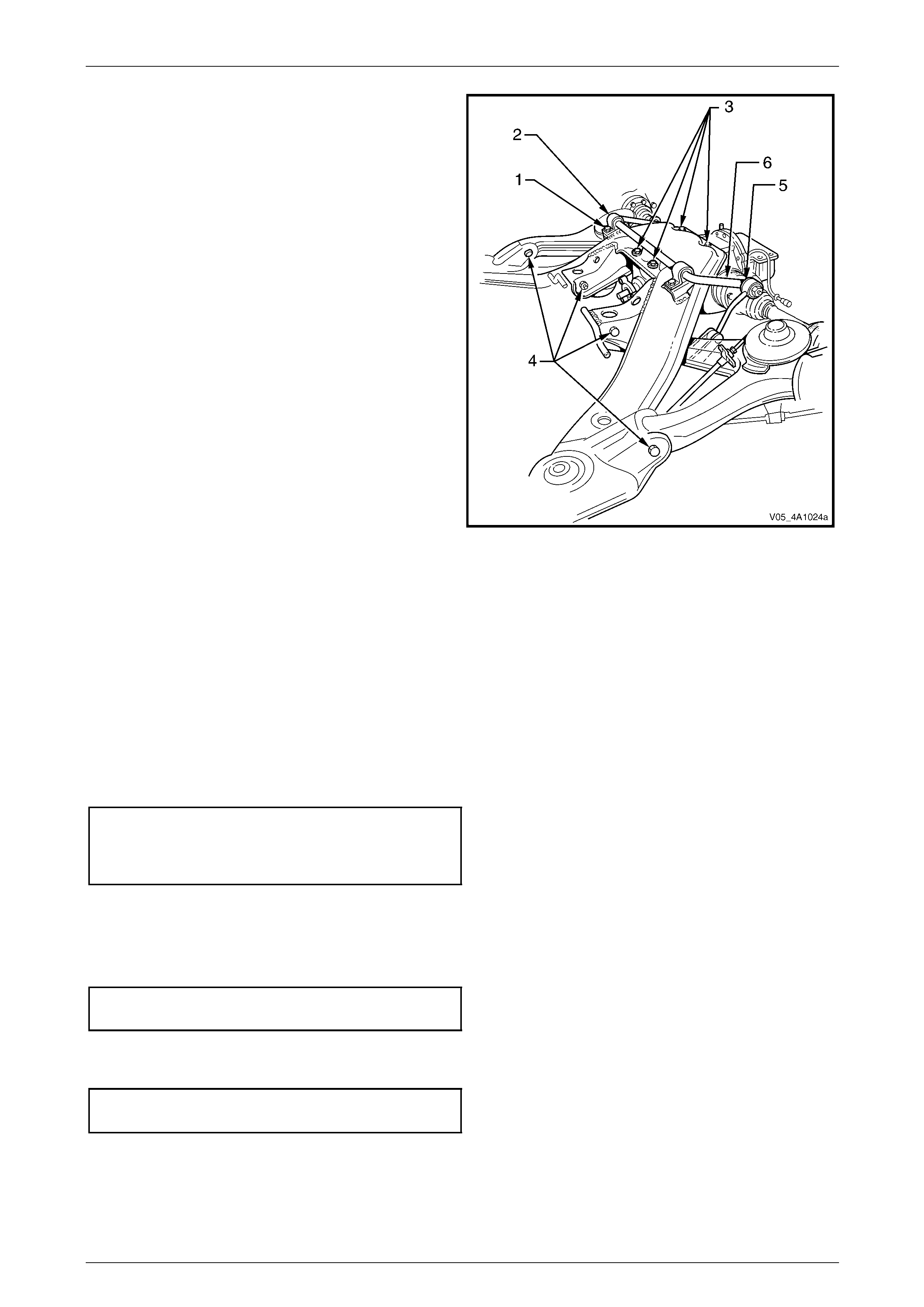
10 Install both crossmember front mounting braces (3),
the six mounting brace attaching bolts (1) and the two
rear suspension crossmember front mounting bolts (2)
but do not fully tighten any of these bolts at this stage.
Figure 4A1 – 60
11 Lower the final drive assembly and rear suspension
crossmember assembly on the floor jack and safety
stands.
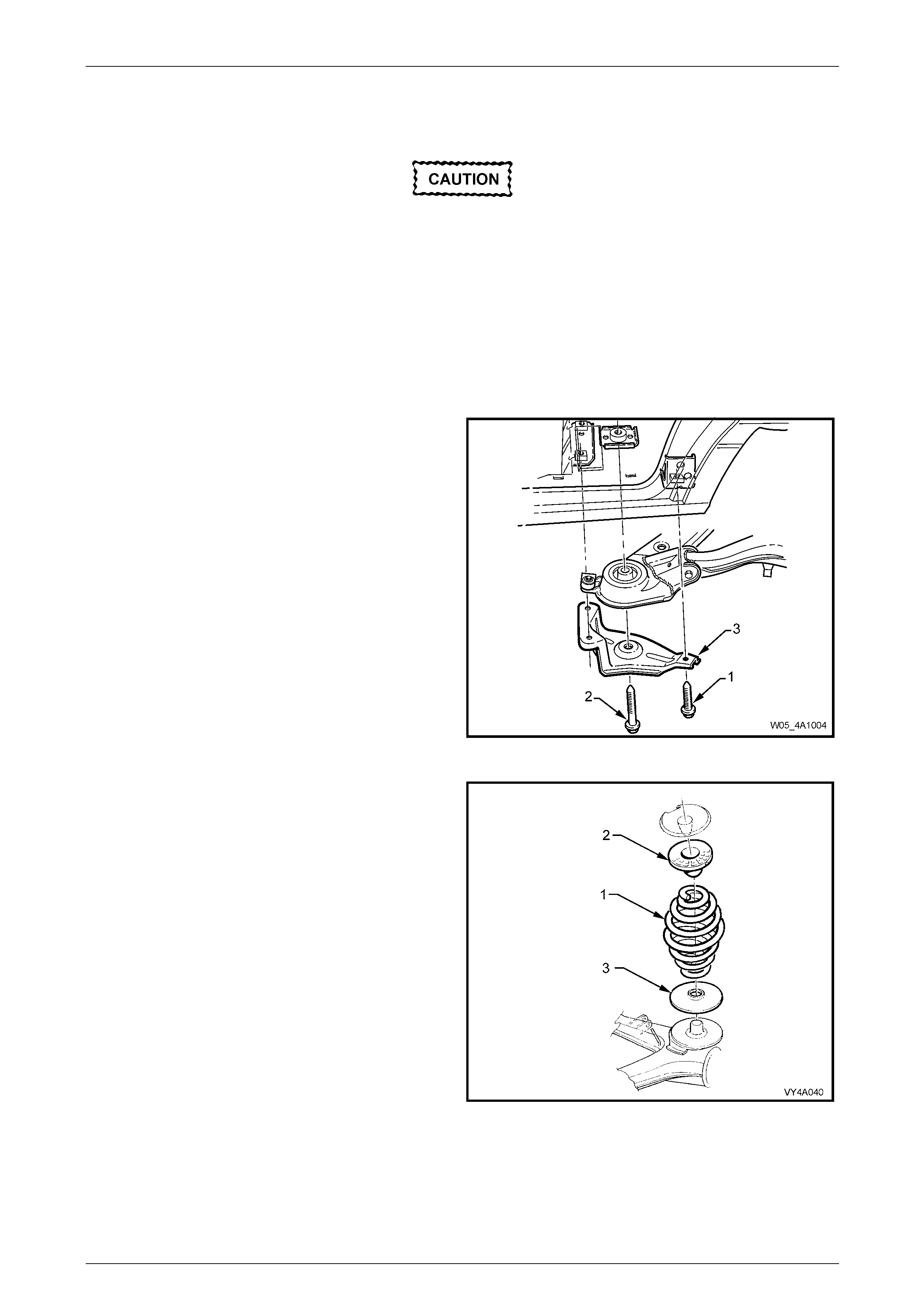
12 Reinstall rear springs (1) and t he upper (2) and lower
(3) spring insulators between the rear susp ension
control arm and the vehicle underbody.
Figure 4A1 – 61
Rear Suspension 4A1 – 34
4A1-34
If automatic level ride suspension is fitted to
the vehicle, there are specific procedures
relating to the system pressure and the
installation of the shock absorbers. These
operations MUST be carried out before
lowering the vehicle to the ground. Refer to
4 Service Operations – Automatic Level Ride
Suspension, in this Section.
13 With both springs and insulators installed, use a
second floor jack to raise each rear suspension control
arm (2), enough to allow the shock absorber (3) lower
mounting to be installed to the rear suspension control
arm.
14 Install washers and bolts (1) into the shock absorber
lower mounts but do not fully tighten at this stage.
Repeat for the other side.
Figure 4A1 – 62
15 Raise the assembly until the rear mount contacts the
vehicle underbod y.
16 Align the rear mount (1) with the marks (A) on the
underbody, made on disassembly, then loosely install
new attaching bolts but do not fully tighten at this
stage.
Failure to correctly alig n the rear suspension
crossmember to the centreline of the vehicle
will result in steering abnormalities and
uneven tyre wear!
17 The rear suspension crossmember MUST now be
aligned to the vehicle centreline, using the special tool
and procedure as detai led in
Section 1A2 Body Dimensions. Figure 4A1 – 63
18 Tighten all crossmember mou nting faste ners to the correct torque specification.
Rear suspension crossmember
rear mount to vehicle underbody
attaching bolt torque specification................35 N.m then
turn through 60°
Rear suspension crossmember
front mounting bolt torque specification 125 N.m, then
turn through 40°
Rear suspension crossmember
front mounting brace bolt
torque specification..............................................75 N.m
19 Install the differential carrier breather hose i nto t he hole in the vehicle under body rear suspension crossmember,
ensuring that the end of the hose is pushe d into the hole approximately 25 mm.
20 Reconnect the ABS wheel speed sens or wiring harness connectors and install the connectors into the retaining
clips.
21 Check the park brake adjustment and bleed the brake hydraulic s ystem, refer to
Section 5A Service and Park Braking Systems.
22 Reinstall the exhaust system, using new gasket/seal at the flanges on the catalytic converters.
Refer to Section 8B Exhaust System.
Rear Suspension 4A1 – 35
4A1-35
23 Tighten the intermediate e xhaust pip e to catalytic converter bolts to the correct torque specification.
Intermediate exhaust pipe to
catalytic converter bolt
torque specification (All engines).........................45 N.m
24 Check the exhaust clearances. Refer to Section 8B Exhaust System.
25 If the vehicle is fitted with Automatic Level Ride Sus pensio n (prod uction option FX3), reconnect the level ride
sensor link to the rear control arm.
26 Reinstall the road wheel/s, aligni ng the marks made prior to removal and secure with the attaching nuts but do not
fully tighten at this stage.
If automatic level ride suspension is fitted to
the vehicle, there are specific procedures
relating to the system pressure and the
installation of the shock absorbers. These
operations MUST be carried out before
lowering the vehicle to the ground. Refer to
4 Service Operations – Automatic Level Ride
Suspension, in this Section.
27 Lower the vehicle to the ground.
28 Bounce the rear of the vehicle several times to settle the suspension.
29 With the vehicle at curb weight and the vehicl e weight on all four wheels, tighten rear suspensi on control arm to
crossmember attaching nuts, stabiliser bar link nuts an d the shock absorber lower mounting bolts to the correct
torque specifications.
Rear suspension control arm
to rear crossmember nut
torque specification............................................100 N.m
Stabiliser bar link, upper and lower
nut torque specification........................................95 N.m
Shock absorber lower mounting
nut torque specification......................................115 N.m
30 Tighten road wheel attaching nuts to the correct torque specification, working in a ‘star ’ pattern, refer to
3.1 Service Warnings, Cautions and Notes, in this Section.
Road wheel attaching
nut torque specification............................110 – 140 N.m
31 Reinstall the decorative wheel nut caps.
32 Start the vehicle and check the exhaust system for leaks. Repair as necessary.
33 Road test the vehicle to check for correct operation.
Rear Suspension 4A1 – 36
4A1-36
3.5 Rear Suspension Crossmember Front
Mount Bushing
LT Section No. – 07-150A
ATTENTION
The following fasteners MUST be replaced when performing these operations:
Rear suspensi o n crossmember front mounting bolt.
Rear suspension crossmember front mounting brace to underbody bolts.
Whenever any component that forms part of
the ABS (if fitted) is disturbed during Service
Operations, it is vital that the complete ABS
system be checked; refer ABS Function
Check, in Section 5B ABS & ABS/TC &
Electronic Brake Assist (EBA).
Before disturbing the rear suspension
crossmember mounting bolts, an alignment
procedure is required on reinstallation and a
special tool is required for this purpose. If this
tool is not available, then the crossmember
cannot be correctly aligned and steering
and/or handling abnormalities will result.
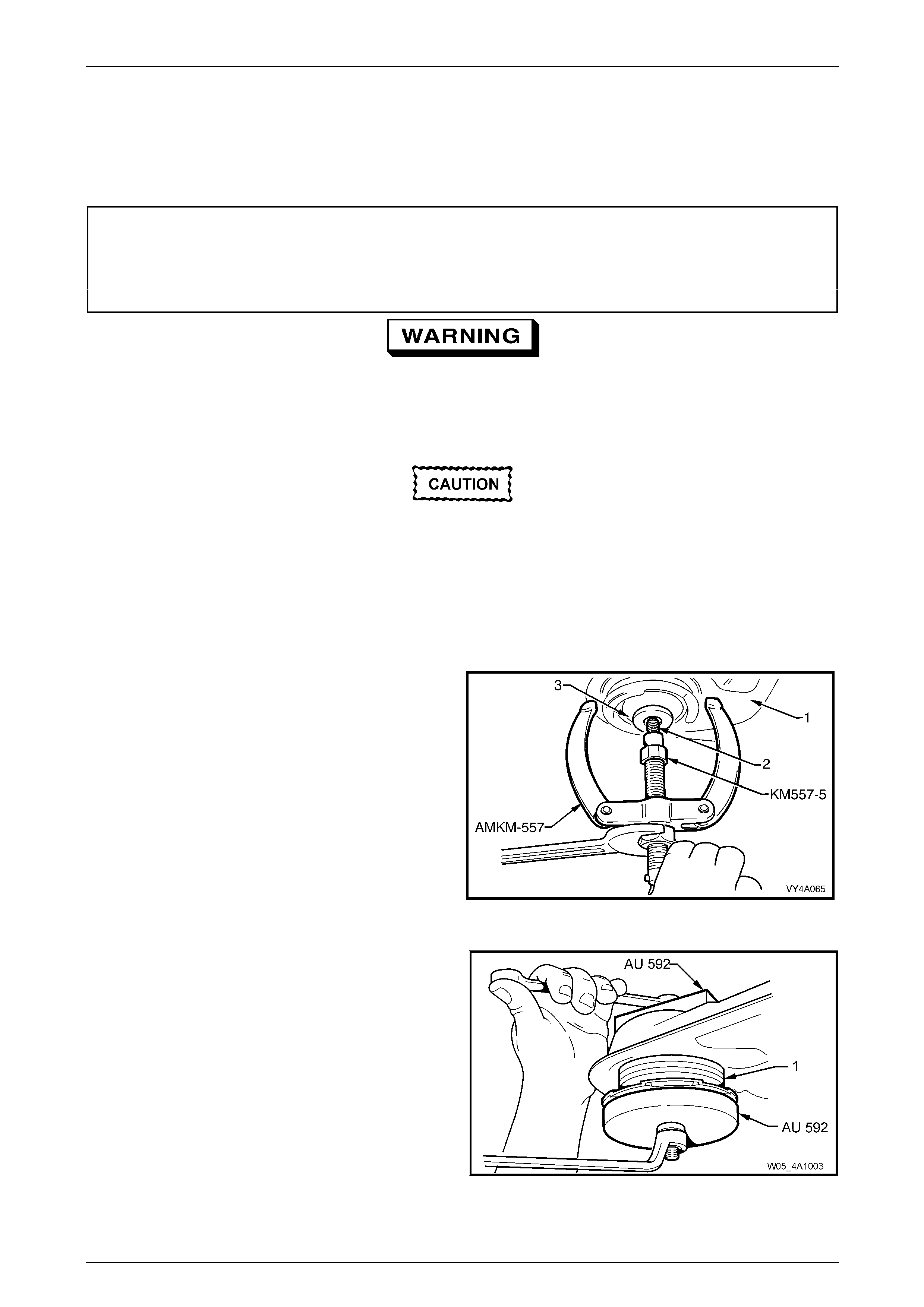
Off-Car Replacement
1 With the rear suspension crossmember (1) removed,
install the crossmember to underbody attaching bolt
(2) into the bushing (3) from above.
NOTE
Refer to 3.4 Rear Suspension Crossmember in
this Section for removal details.
2 Screw the underbody attaching bolt into puller, Tool
No. AMKM-557 and adaptor, Tool No. KM-557-5 (part
of Tool No. AMKM-557).
3 Tighten the forcing nut while holdin g the threaded
shaft of Tool No. AMKM-557 until the bushing is
removed from the crossmember.
4 Remove the crossmember to underbody attachin g bolt
from the puller and adaptor assembly and discard the
bush. Figure 4A1 – 64
5 Draw the new bushing (1) into the crossmember (2)
using Tool No. AU 592.
Figure 4A1 – 65

Rear Suspension 4A1 – 37
4A1-37
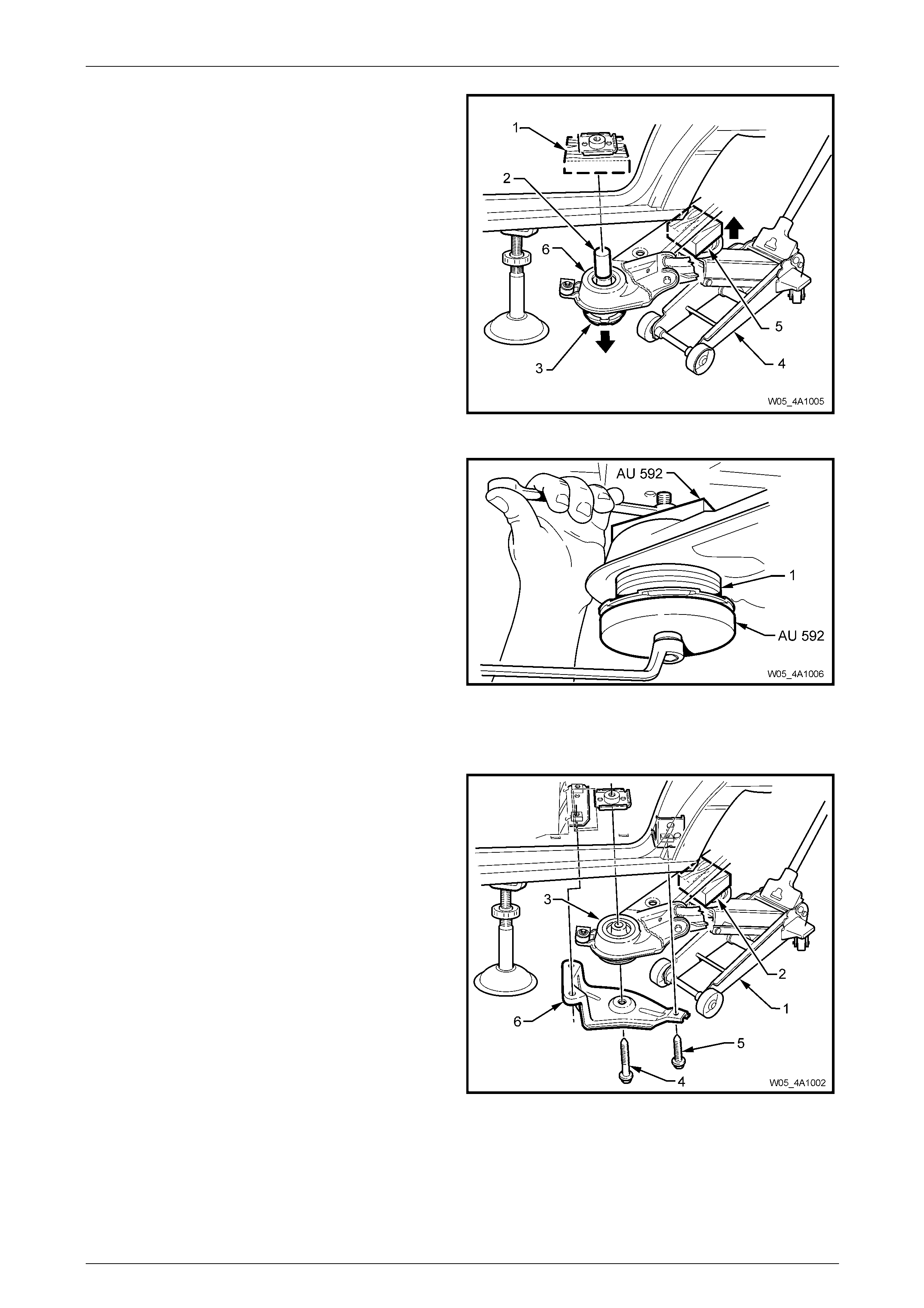
On-Car Replacement
1 Using a floor jack (2) with a suitable wood block (1)
mounted on top of the floor jack to support and protect
the underside of the centre differential carr ier, raise
the rear of the vehicle.
Figure 4A1 – 66
2 Position safety stands (2) to support the vehicle weight
at both the LH side and RH side under b od y rear
jacking points (1).
Refer to Section 0A General Information for the
location of recommended lifting and supp ort points.
Figure 4A1 – 67
3 Position a floor jack (1) with a suitable bl ock of wood
(2) mounted on top of the jack lifting pad to support
and protect the rear suspension crossmember
assembly.
4 Take up the weight of the crossmember by raising the
floor jack to make contact, nearest to the side where
the bushing is to be replaced.
5 Remove the brace attaching bolts (4 & 5) and the
crossmember brace (6) from the same side of the
vehicle. Discard the removed bolt (4).
6 Lower the floor jack slightly to allo w clearance
between the crossmember and the vehicle underbod y.
Figure 4A1 – 68
Rear Suspension 4A1 – 38
4A1-38
7 Support a suitable block of wood (1) (approximately
100 mm square by 40 mm thick), positioned over the
bush mounting bolt hole.
8 Raise the floor jack (4), until the clearance between
the crossmember bush, distance piece (2) and the
block of wood (1) is reduced to zero and a d ownward
force is applied to the bush.
9 Increase the pressure applied by the floor jack ,
gradually pressing the bush ing downward, freeing it
from the crossmember.
NOTE
The vehicle weight and the upward m ovement of
the jack will apply enough force to remove the
bush.
10 Discard the removed bushing.
Figure 4A1 – 69
11 Lower the floor jack to allow cleara nce for installation
of the new bush.
12 Apply a soap solution to the o uter diameter of the new
bush, to assist in the installation of the bushing into the
crossmember.
13 Apply hand pressure to initially start the leading edge
of the bushing (1) into crossmember bushing aperture.
14 Apply the installation Tool No. AU 592 to the bushing
and crossmember.
15 Draw the remaining exposed section of the new
bushing into the crossmember.
Figure 4A1 – 70
16 With the floor jack still in position to support and protect the rear suspension crossmem ber assembly, raise the
crossmember using the floor jack.
17 Reinstall the brace (6), a new crossmember front
mounting to underbody bolt (4), and the three smaller
original brace attaching bolts (5), but do not tighten the
bolts at this stage.
Figure 4A1 – 71
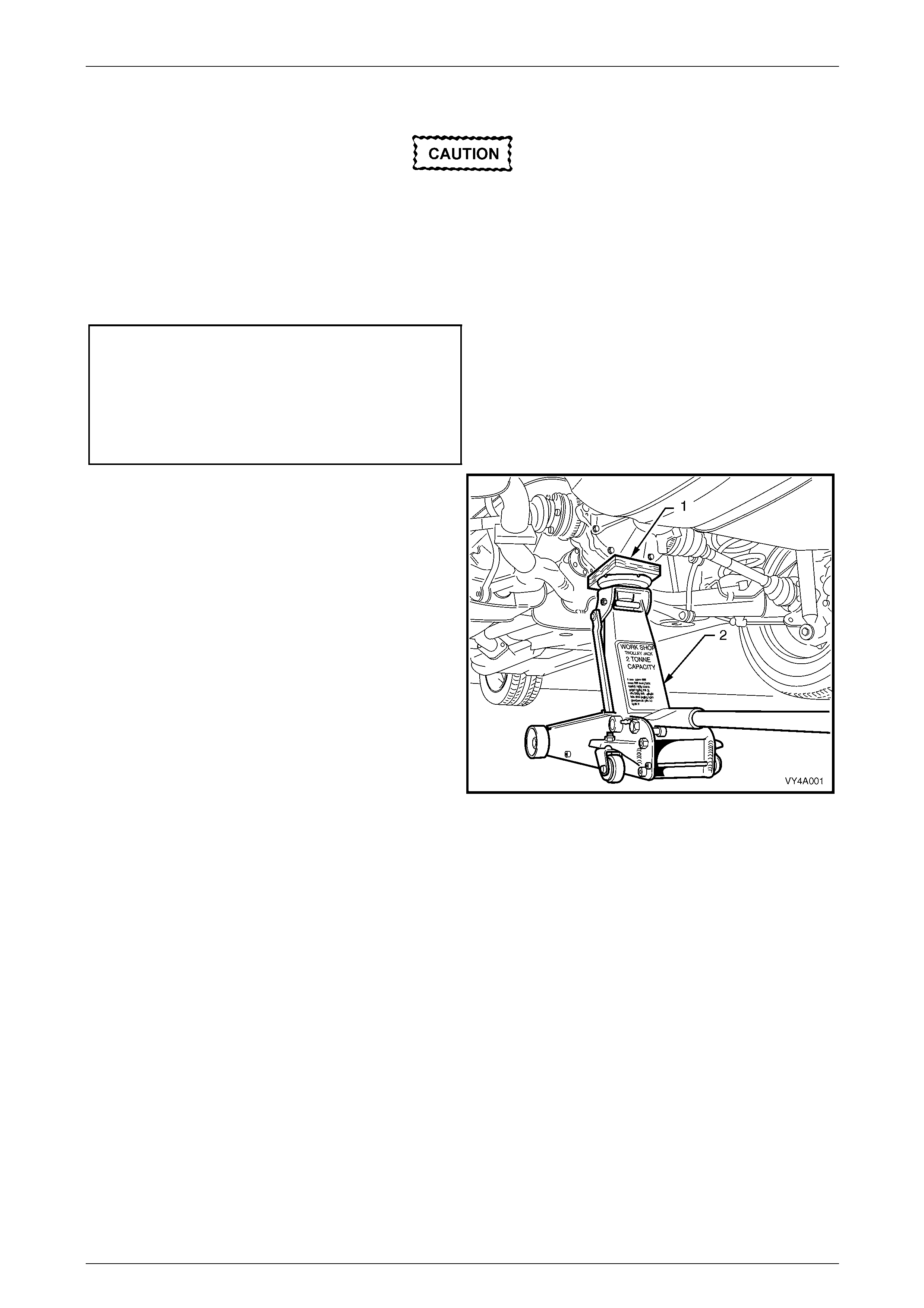
Rear Suspension 4A1 – 39
4A1-39
18 If necessary, repeat steps 3 to 17 for the opposite side.
Failure to correctly align the rear suspension
crossmember to the centreline of the vehicle
will result in steering abnormalities and
uneven tyre wear!
19 The rear suspension crossmember MUST now be checked for correct alignment to the vehicle centrelin e. Using the
special tool and procedure. Refer to Section 1A2 Body Dimensions.
20 Tighten bolts (4 and 5) to the correct torque specification.
Rear suspension crossmember
to underbody front mounting
bolt torque specification..............................35 N.m, then
turn through 35°
Rear suspension crossmember
brace mounting bolt
torque specification..............................................75 N.m
21 Using a floor jack (2) with a suitable block of wood (1)
mounted on top of the jack lifting pad to support and
protect under the centre of the differential carrier, raise
the rear of the vehicle from the safety stands.
22 Remove the safety stands and lo wer the vehicle to the
floor.
23 Remove the floor jack.
24 Road test the vehicle to check for correct operation.
Figure 4A1 – 72

Rear Suspension 4A1 – 40
4A1-40
3.6 Rear Suspension Crossmember Mass
Damper
LT Section No. – 07-150A
ATTENTION
The following fasteners MUST be replaced when performing these operations:
Rear suspension crossmember front mounting brace to under body attaching bolts.
Rear suspensi o n crossmember front mounting bolt.
Whenever any component that forms part of
the ABS (if fitted) is disturbed during Service
Operations, it is vital that the complete ABS
system be checked; refer ABS Function
Check, in Section 5B ABS & ABS/TC &
Electronic Brake Assist (EBA).
Before disturbing the rear suspension
crossmember mounting bolts, an alignment
procedure is required on reinstallation and a
special tool is required for this purpose. If this
tool is not available, then the crossmember
cannot be correctly aligned and steering
and/or handling abnormalities will result.
Remove
1 Raise the vehicle and suppor t in a safe manner. Refer to Section 0A General Information for the location of
recommended lifting and support points.
2 Position a floor jack (1) with a suitable bl ock of wood
(2) mounted on top of the jack lifting pad to support
and protect the rear suspension crossmember
assembly (3).
3 Take up the weight of the crossmember by raising the
floor jack to make contact with the crossmember on
side where the rear suspension crossmemb er mass
damper is to be replaced.
4 Remove the rear suspension crossmemb er front
mounting attaching bolt (4). Discard the removed bolt.
5 Remove the bolt (5), three places, and remove the
rear suspension crossmember front mounting brace
(6). Discard the removed bolts.
6 Lower the floor jack slightly to allo w clearance
between the crossmember and the vehicle underbod y.
Figure 4A1 – 73
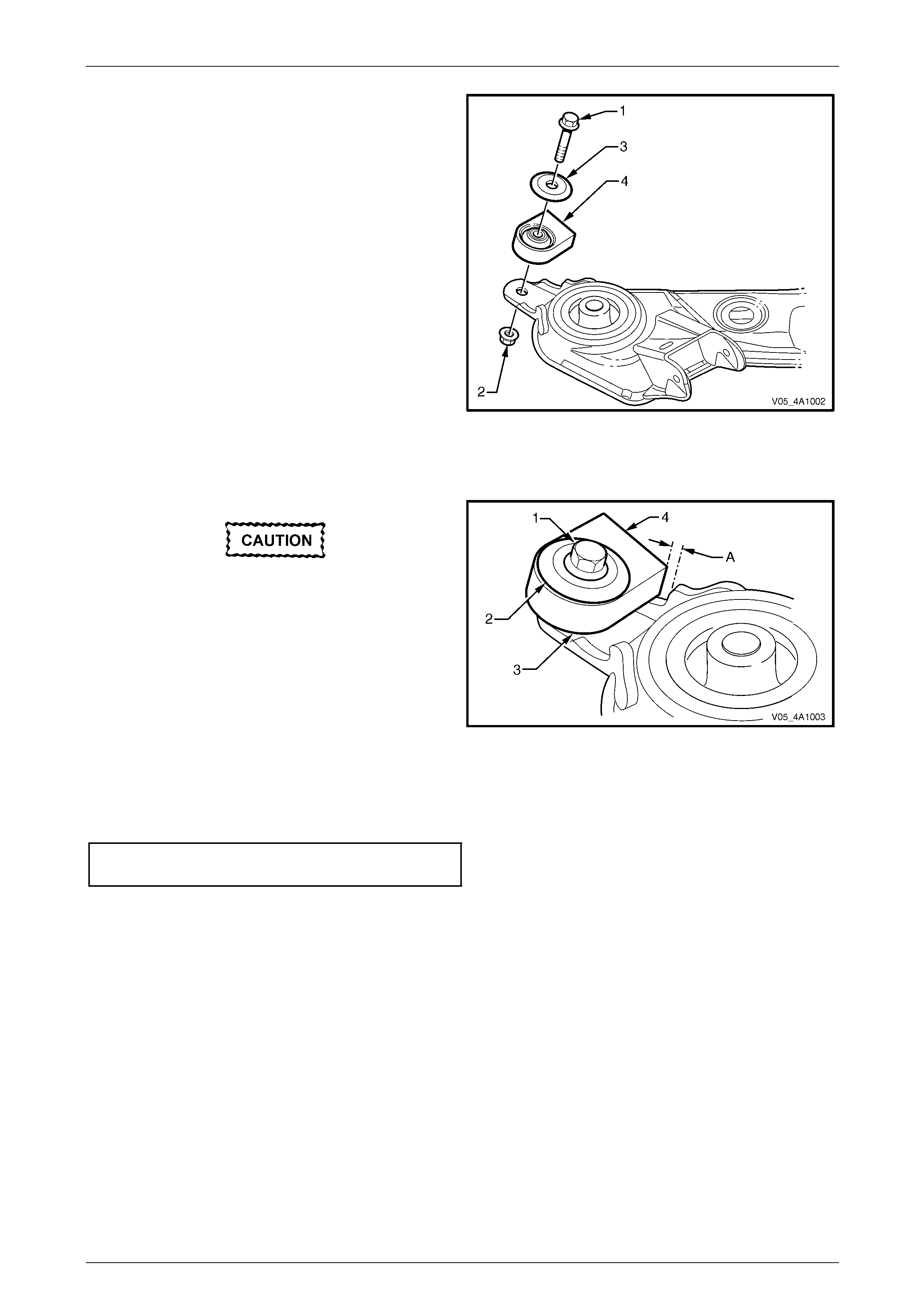
Rear Suspension 4A1 – 41
4A1-41
7 Using a back-up spanner on the rear sus pe nsion
crossmember mass damper bolt (1), remove the nut
(2).
8 Remove the bolt, washer (3) and rear suspension
crossmember mass damper (4) from the
crossmember.
Figure 4A1 – 74
Reinstall
Failure to achieve the correct clearance may
result in driveline vibration.
1 Reinstall the bolt (1), washer (2), rear suspension
crossmember mass damper (3) and nut to the
crossmember. Check that there is a 4 mm clearance
(A) from the rear suspension crossmember mass
damper to the bracket edge. Do not tighten the
retaining nut and bolt at this stage.
NOTE
The squared edge (4) of the rear suspension
crossmember mass damper, faces towards the
centre of the vehicle.
Figure 4A1 – 75
2 Using a back-up spanner on the rear suspe nsion crossmember mass damper bolt, tighten the nut to the correct
torque specification.
Rear suspension crossmem ber mass
damper bolt torque specification..........................45 N.m
NOTE
Make sure the mass damper does not rotate
when tightening the retaining nut
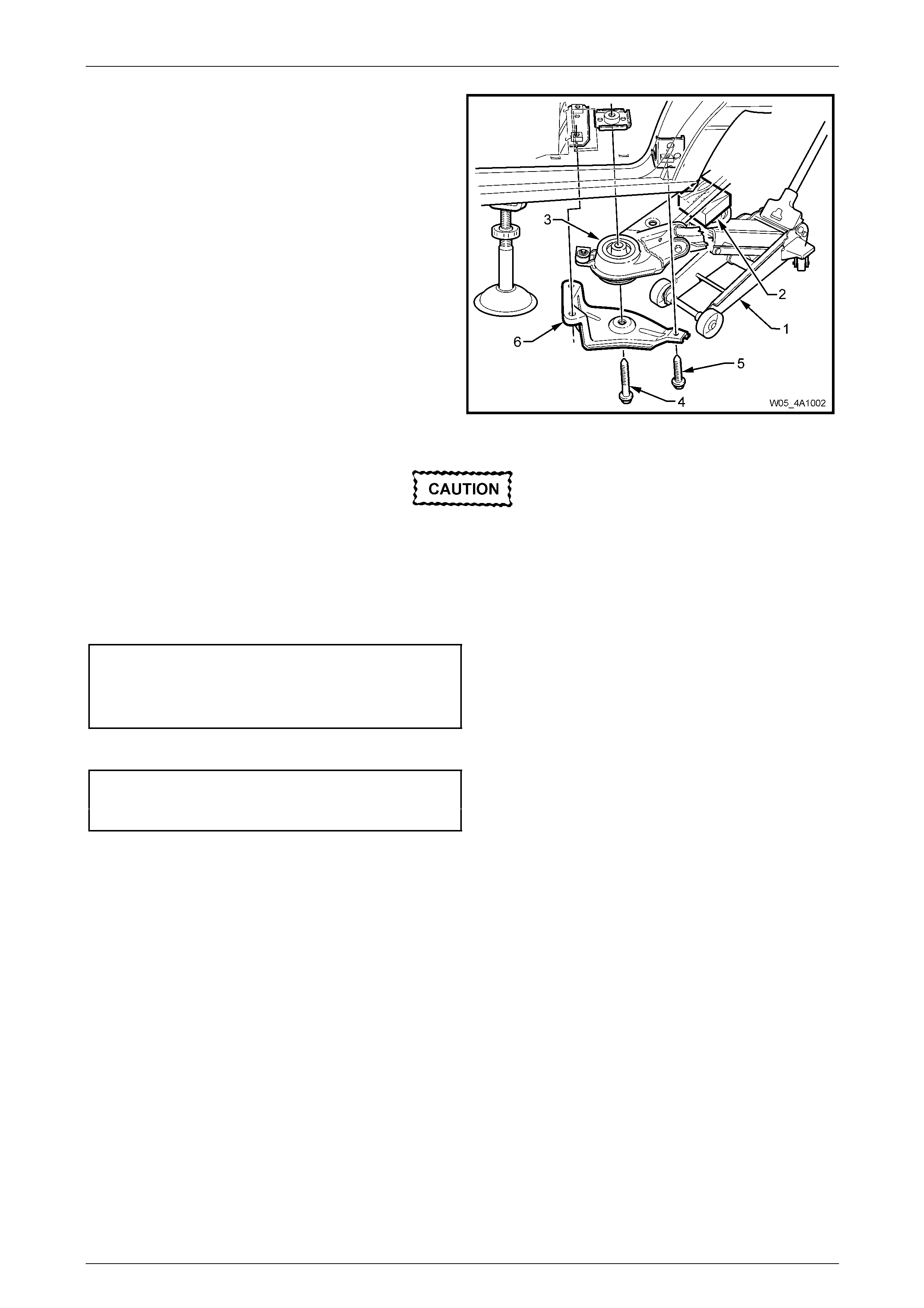
Rear Suspension 4A1 – 42
4A1-42
3 With the floor jack (1) still in position to support and
protect the rear suspension crossmember assembly,
raise the crossmember into position, using the floor
jack.
4 Install the brace (6), a new rear suspension
crossmember front mounting bolt (4), and the rear
suspension crossmember front mounting bra c e
attaching bolt (5), three places. Do not tighte n the
bolts at this stage.
Figure 4A1 – 76
Failure to correctly align the rear suspension
crossmember to the centreline of the vehicle
will result in steering abnormalities and
uneven tyre wear!
5 Check the rear suspension crossmember alignment. Refer to Section 1A2 Body Dimensi ons.
6 Tighten the rear suspension crossmember front mounting bolt to the correct torque specification.
Rear suspension crossmember
front mount to underbody
bolt torque specification............................125 N.m, then
turn through 40°
7 Tighten the rear suspension crossmember front mounting brace attachi ng bolts to the correct torque specification.
Rear suspension crossmember
brace mounting bolt
torque specification..............................................75 N.m
8 Remove the safety stands and lo wer the vehicle.
9 Road test the vehicle to check for correct operation.
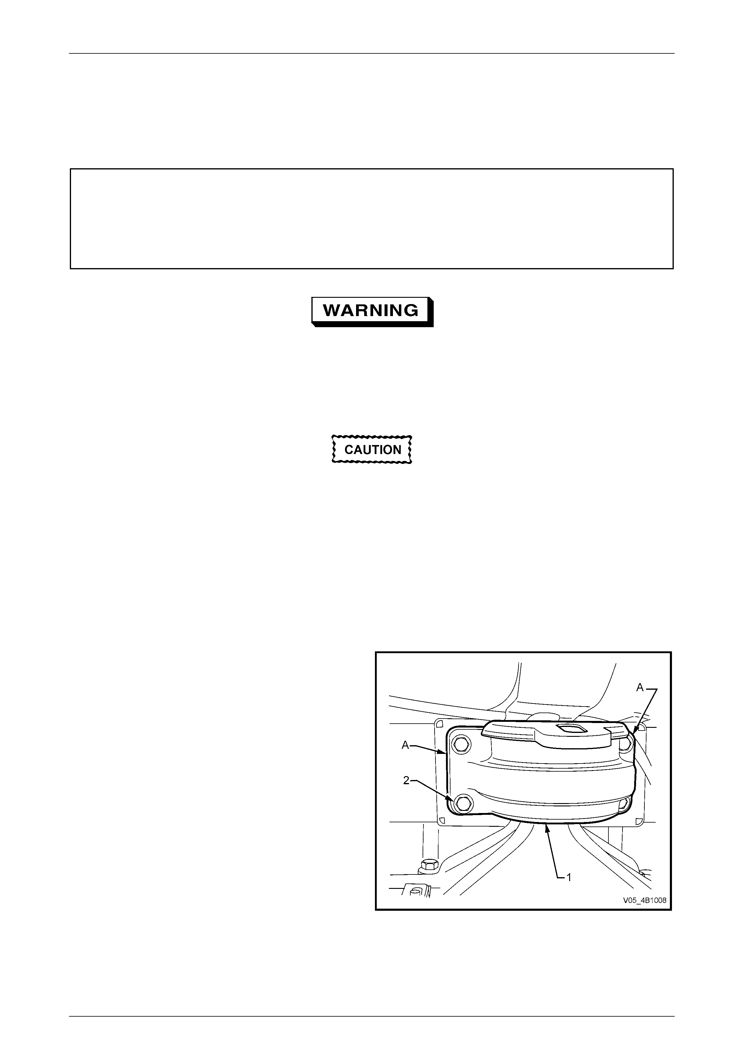
Rear Suspension 4A1 – 43
4A1-43
3.7 Rear Suspension Crossmember Rear
Mount
LT Section No. – 07-150A
ATTENTION
The following fasteners MUST be replaced when performing these operations:
Rear suspension crossmember rear mount to underbody attaching bolt.
Rear suspension crossmember rear mount to rear final drive cover, attaching bolts.
Whenever any component that forms part of
the ABS (if fitted) is disturbed during Service
Operations, it is vital that the complete ABS
system be checked; refer ABS Function
Check, in Section 5B ABS & ABS/TC &
Electronic Brake Assist (EBA).
Before disturbing the rear suspension
crossmember rear mounting bolts, an
alignment procedure is required on
reinstallation and a special tool is required for
this purpose. If this tool is not available, then
the crossmember cannot be correctly aligned
and steering and/or handling abnormalities
will result.
Remove
1 Raise the vehicle and suppor t in a safe manner. Refer to Section 0A General Information for the location of
recommended lifting and support points.
2 Using a scriber, mark the rear mount (1) to the vehicle
under body location (A). This will aid with the rear
suspension crossmember alignment on instal lation.
3 Support the weight of the differential carrier with a floor
jack.
Figure 4A1 – 77
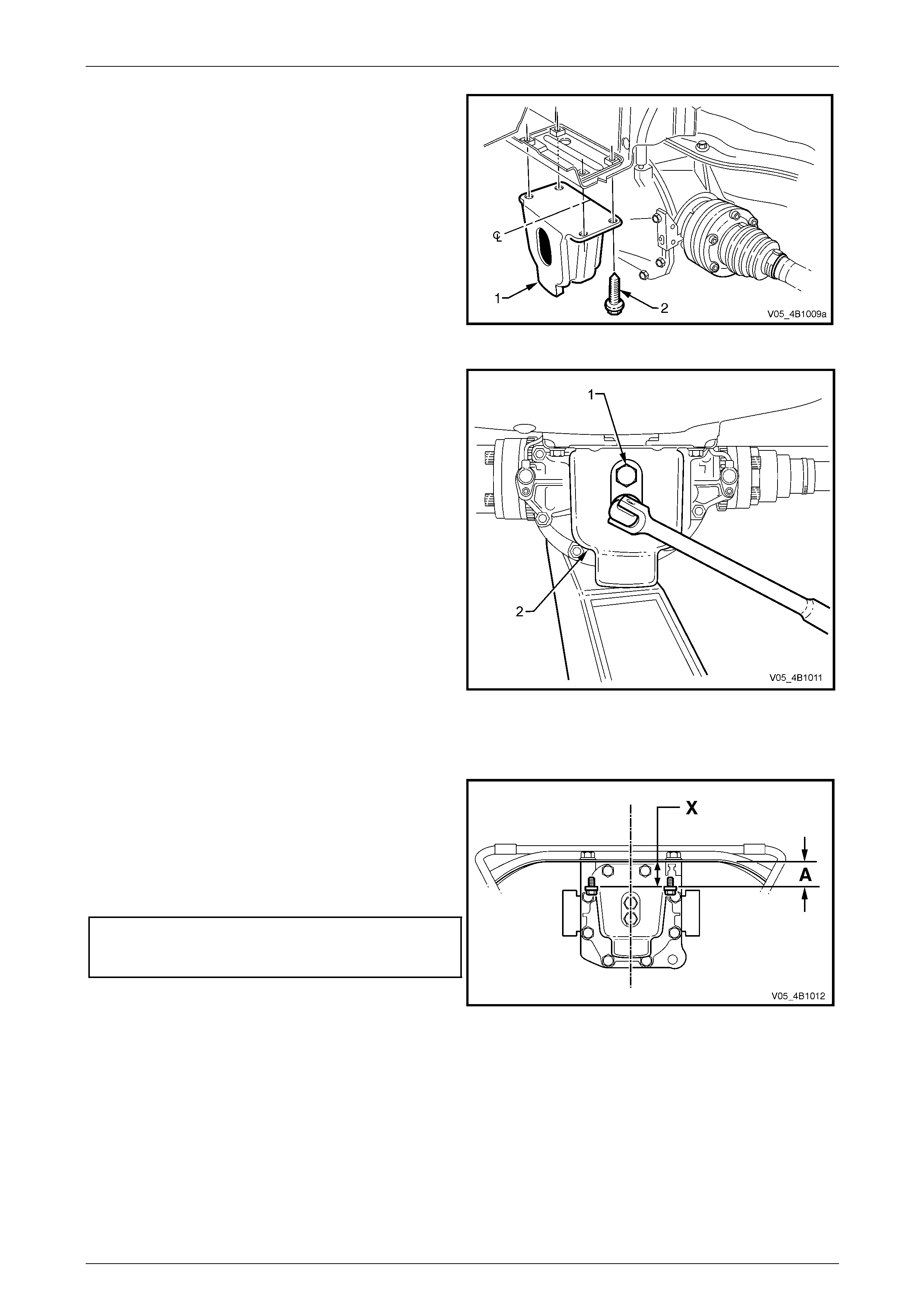
Rear Suspension 4A1 – 44
4A1-44
4 Remove the rear mount (1) to vehicle underbody
attaching bolts (2) and discard.
5 Lower the differential carrier and rear suspe nsion
crossmember assembly by at least 60 mm.
Figure 4A1 – 78
6 Remove and discard the rear mount to differential
carrier attaching bolts (1) and remove the rear mount
(2).
Figure 4A1 – 79
Reinstall
1 Install the rear mount to differential carrier rear cover,
using NEW attaching bolts .
2 While tightening the attaching bolts to the correct
torque specification, check that the mount does not
twist. The mount to vehicle underbody mating surface
should be parallel to within 1 mm (‘X’) of the rear
suspension crossmember.
Rear mount to final drive
carrier rear cover bolt
torque specification..............................................95 N.m
NOTE
Use a spirit level on t he r ear mount to u nder bod y
surface and the top surface of the crossmember
to ensure that both surfaces are parallel.
Dimension ‘A’ is to be 56.7 mm.
Figure 4A1 – 80
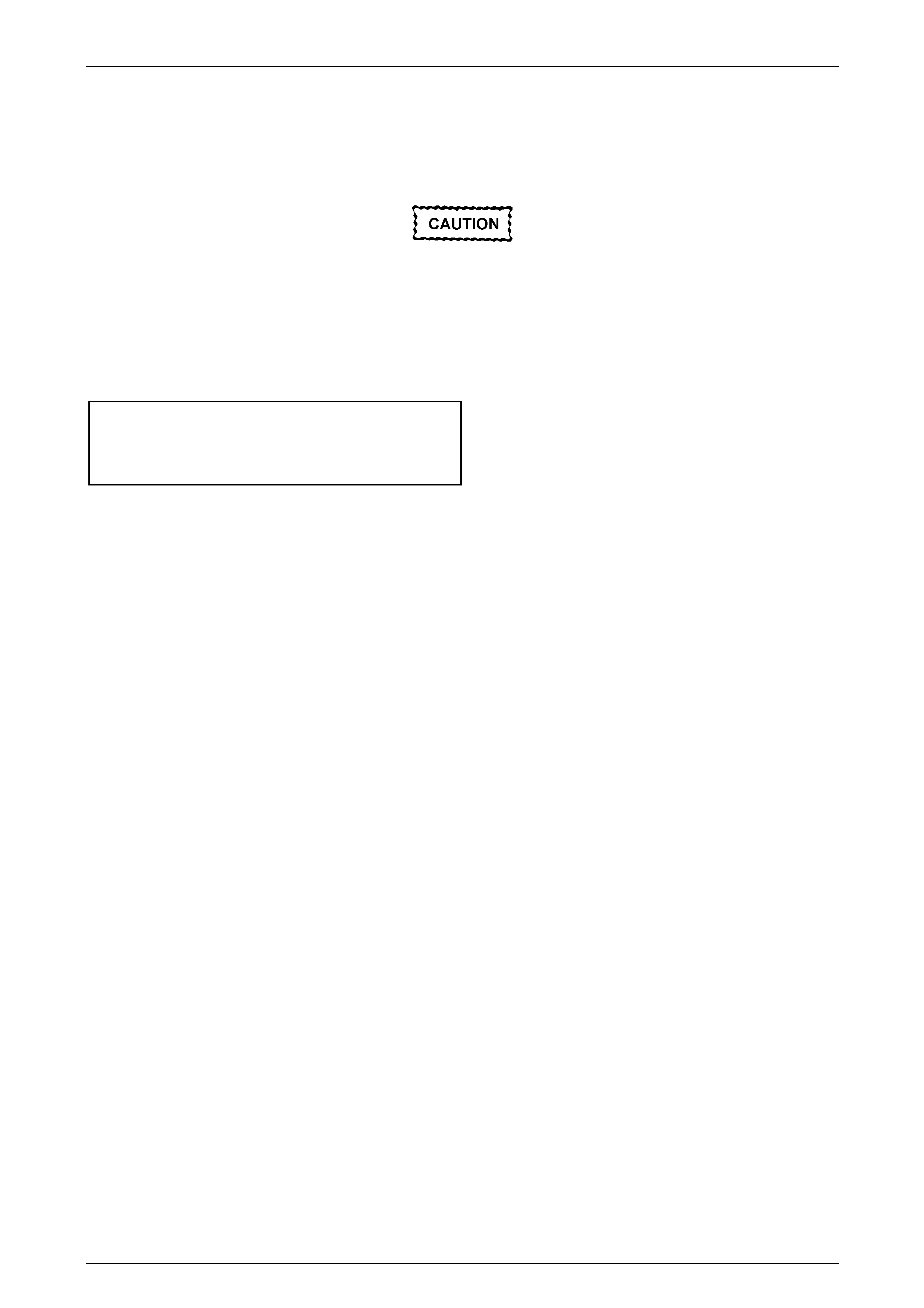
Rear Suspension 4A1 – 45
4A1-45
3 Raise the final drive carrier and rear susp ension crossmember assembly until the rear mou nt contacts veh icle
underbody.
4 Align the mount with the marks made on the und erbody during disassembly and install new attaching bolts but do
not tighten at this stage.
Failure to correctly align the rear suspension
crossmember to the centreline of the vehicle
will result in steering abnormalities and
uneven tyre wear!
5 The rear suspension crossmember MUST now be aligned to the vehicle centreline, using the special tool and
procedure as detailed in Section 1A2 Body Dimensions.
6 Tighten the rear suspension crossmember rear mount to underbody bolts to the correct torque specification.
Rear suspension crossmember
rear mount to vehicle underbody
bolt torque specification..............................35 N.m, then
turn through 60°
7 Lower the vehicle to the ground.
Rear Suspension 4A1 – 46
4A1-46
3.8 Stabiliser Bar and/or Mountings
LT Section No. – 07-150A
ATTENTION
The following fasteners have either micro encapsulation or incorporate a mechanical thread lock and should
only be used once. If in doubt , rep lacement is recommended when performing these operations:
Stabiliser bar link attaching nuts and bolts.
The following fasteners MUST be replaced when performing these operations:
Rear suspension crossmember rear mount to underbody attaching bolt.
The following fasteners MUST be at curb weight with the vehicle weight on all four wheels:
• Brake caliper to steerin g knuckle retaining bolts.
Before disturbing the rear suspension
crossmember rear mounting bolts, an
alignment procedure is required on
reinstallation and a special tool is required for
this purpose. If this tool is not available, then
the crossmember cannot be correctly aligned
and steering and/or handling abnormalities
will result.
Remove
1 Raise the vehicle and suppor t in a safe manner. Refer to Section 0A General Information for the location of
recommended lifting and support points.
2 Using a scriber, mark the rear mount (1) to vehicle
under body location (A). This will assist in the rear
suspension crossmember alignment on instal lation.
3 Support the weight of the differential carrier with a floor
jack.
4 Remove and discard the rear mount to vehicle
underbody attaching bolts (2).
5 Lower the differential carrier and rear suspe nsion
crossmember assembly enough to allow access to the
brackets securing the stabiliser bar to the rear
suspension crossmember.
NOTE
Do not allow the propeller shaft or left-hand side
drive shaft to rest on the exhaust system.
Figure 4A1 – 81
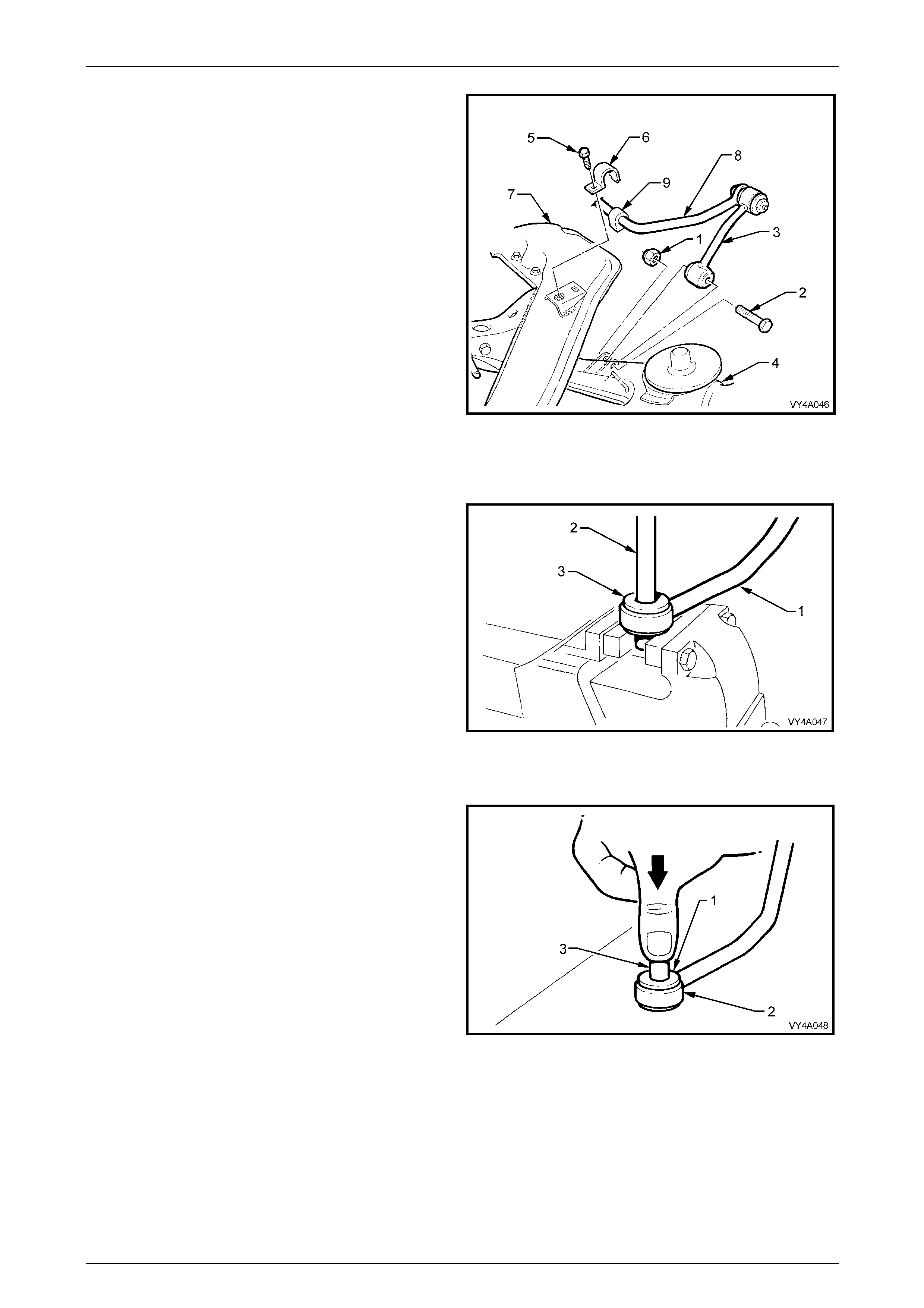
Rear Suspension 4A1 – 47
4A1-47
6 Remove both stabiliser bar link to rear suspension
control arm attaching nuts (1) and bolts (2).
7 Rotate links (3) until clear of the rear suspension
control arms (4).
8 Remove the stabiliser bar to the crossmember bracket
attaching bolts (5).
9 Using a screwdriver, lever the brackets (6) up an d out
of the crossmember (7).
10 Remove the stabiliser bar (8) from the vehicle.
11 Remove the insulators (9) from the stabiliser bar.
12 Remove the stabiliser bar to link mounting bolts and
nuts.
13 Separate the links from the stabiliser bar.
Figure 4A1 – 82
Stabiliser Bar Link Insulators, Replace
NOTE
The same procedure is used to replace both the
upper and lower insulator.
1 While supporting link (1) on open vice jaws, use a
suitable drift (2) and hammer to remove the steel
sleeve from the centre of the insulator (3).
2 Distort the flanged edge of the insulator and remove
from the link.
3 Repeat the procedure for the remainin g insulator if
required.
Figure 4A1 – 83
4 To reduce the installation force requ ired, apply
petroleum jelly (such as Vase line™ or equivalent), to
insulator (1), then install into the eye of the link (2).
5 Apply a smear of petroleum jelly to the steel inner
sleeve (3), then insert into the insulator until the sleeve
is centralised.
Figure 4A1 – 84
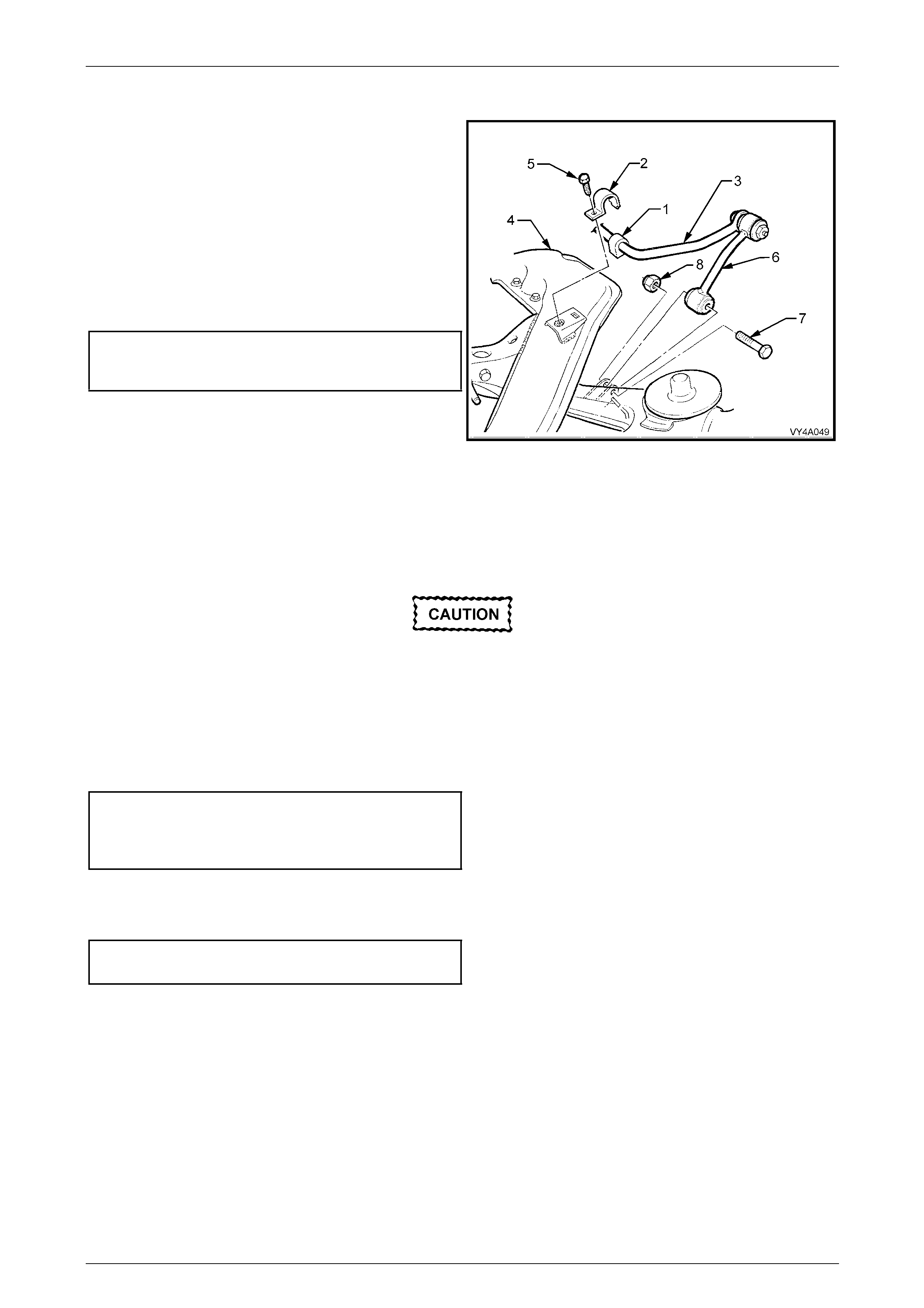
Rear Suspension 4A1 – 48
4A1-48
Reinstall
1 Loosely install the stabiliser bar link to stabiliser bar
bolts and nuts but do not fully tighten at this stage.
2 Install the insulators (1) and brackets (2) to the
stabiliser bar (3).
3 Position the stabiliser bar onto the crossmember (4),
engaging the tangs on the brackets with the slots in
the mounting points on the rear suspension
crossmember.
4 Install and tighten the bracket attaching bolts (5) to the
correct torque specification.
Stabiliser bar mounting bracket
to rear suspension crossmember
bolt torque specification.......................................22 N.m
5 Reinstall the links (6) into position between the rear
suspension control arm brackets and loosely install
NEW attaching bolts (7) and nuts (8), but do not fully
tighten at this stage. Figure 4A1 – 85
6 Raise the final drive assembly and suspension crossmember assembly until the rear mount contacts the vehicle
underbody.
7 Align the mount with the marks made on the und erbody during disassembly, and install NEW attaching bolts but do
not tighten at this stage.
Failure to correctly align the rear suspension
crossmember to the centreline of the vehicle
will result in steering abnormalities and
uneven tyre wear!
8 The rear suspension crossmember MUST now be aligned to the vehicle centreline, using the special tool and
procedure as detailed in Section 1A2 Body Dimensions.
9 Tighten the rear suspension crossmember, rear mount to underbody bolts to the correct torque specification.
Rear suspension crossmember
rear mount to vehicle underbody
bolt torque specification..............................35 N.m, then
turn through 60°
10 Lower the vehicle, then bounce the rear of th e vehicle several times to settle the suspension.
11 Tighten the stabiliser bar link mounting bolts and nuts to the correct torque specification.
Stabiliser bar link bolts
and nuts torque specification ...............................95 N.m
12 Road test the vehicle to check for correct operation.
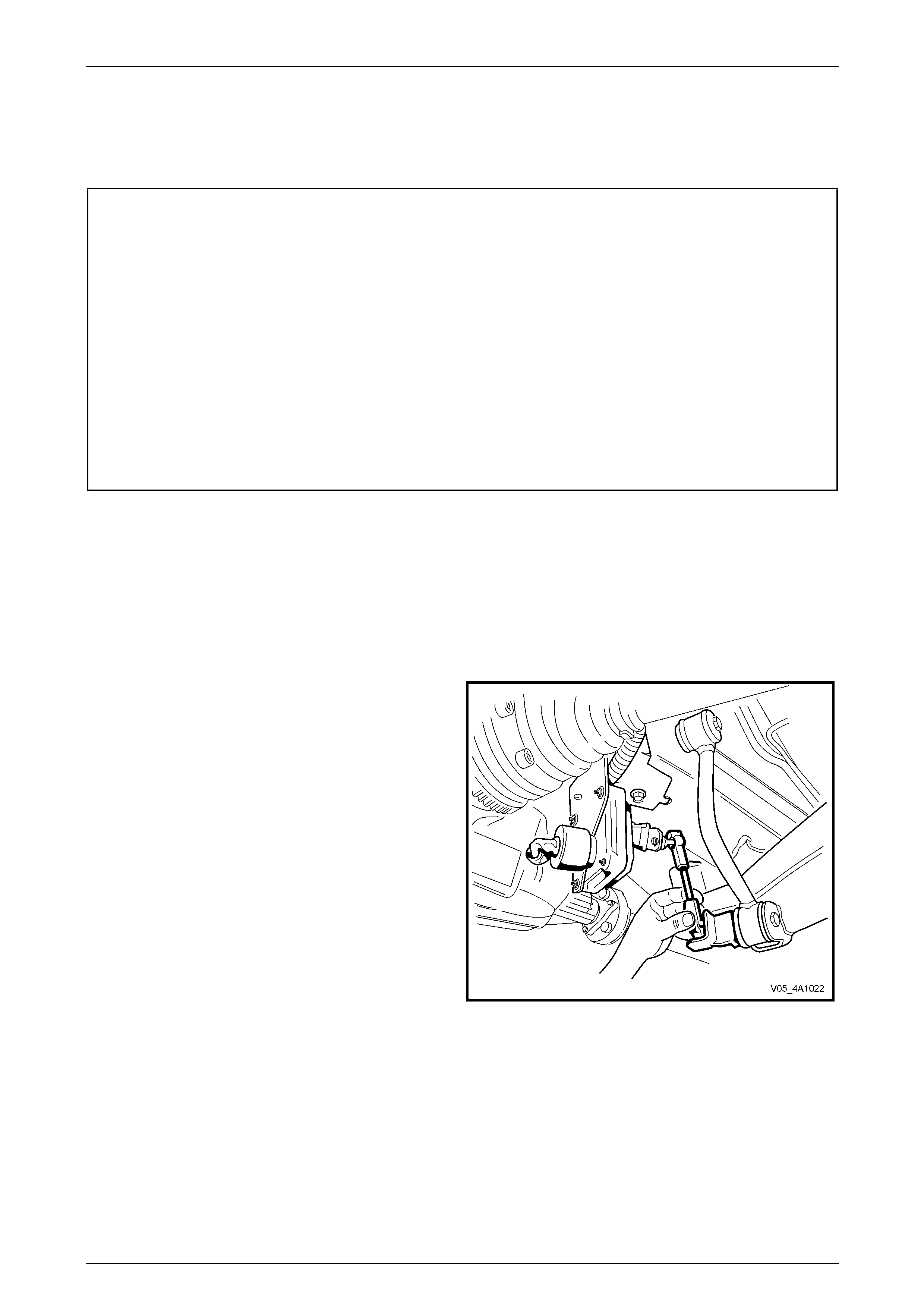
Rear Suspension 4A1 – 49
4A1-49
3.9 Rear Spring and Insulators
LT Section No. – 07-150
ATTENTION
The following fasteners have either micro encapsulation or incorporate a mechanical thread lock and should
only be used once. If in doubt , rep lacement is recommended when performing these operations:
Additional control arm socket assembly retaining nu t.
Stabiliser bar link to rear suspen sio n control arm attaching nut and bolt.
The following fasteners MUST be replaced when performing these operations:
Drive shaft constant velocity joint to rear wheel drive shaft flange attaching bolt.
Final tightening of the following fasteners MUST be with the vehicle weight on all four wheels and at curb
weight:
• Stabiliser bar link to rear suspension control arm attach ing nut and bolt.
• Shock absorber lower mounting bolt.
Remove
1 Raise the vehicle and suppor t in a safe manner. Refer to Section 0A General Information for the location of
recommended lifting and support points.
2 Remove the decorative wheel nut covers from the rear wheel on the side of the vehicle where the sprin g is to be
removed.
3 Mark the relationship of the road wheel to hub or brake rotor. Loosen, then remove the road wheel attaching nuts,
working in a 'star' pattern. Refer to 3.1 Service Warnings, Cautions and Notes, in this Section.
4 If the vehicle is fitted with the Automatic Level Ride
Suspension (production option FX3), disconnect the
ride height sensor link from the rear suspension
control arm.
Figure 4A1 – 86
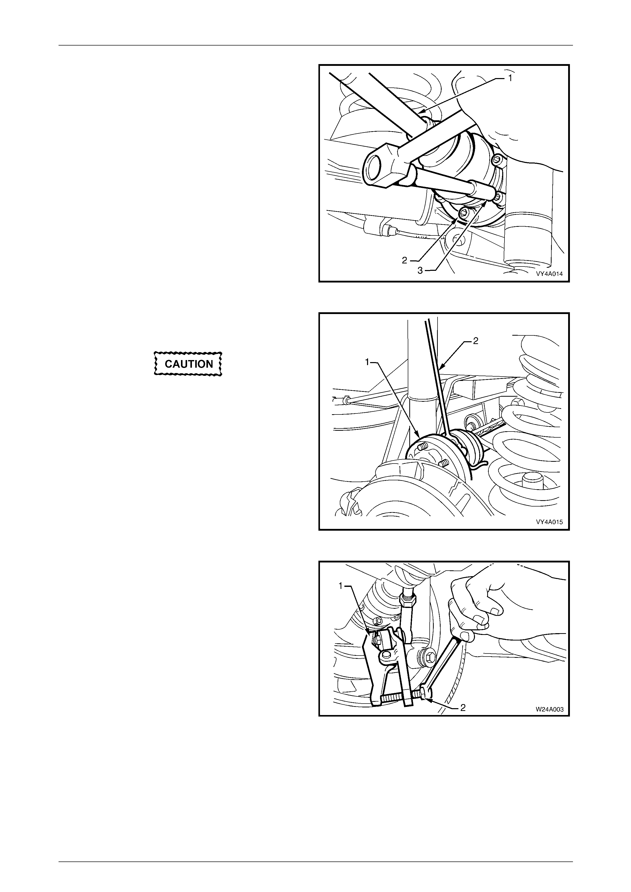
Rear Suspension 4A1 – 50
4A1-50
5 Either firmly apply the park brake with the vehicle in
Park, or use two wheel nuts to secure holding tool No.
KM 468 to the wheel studs.
6 Remove the six drive shaft (1) outer constant velocity
joint to rear wheel drive shaft flange attaching bolts (2)
with an 8 mm Allen key socket (3). Discard the
removed bolts.
Figure 4A1 – 87
7 Disconnect the drive shaft (1) from the flange and lift
upward.
• Bruising to the inside of the drive shaft
constant velocity joint boots will occur if
the rear suspension control arm is
lowered any further. This will lead to
premature failure of the boot and eventual
failure of the joint if left unchecked.
• For this reason, it is important that the
constant velocity joint is disconnected
from the rear wheel drive shaft flange
before removing the shock absorber
lower mounting bolt.
8 Keep the drive shaft horizontal, using a length of wire
(2), support the driveshaft to the lower end of the
shock absorber upper mounting. Figure 4A1 – 88
9 Loosen the additional control arm socket assembly
retaining nut until level with the top of the socket
assembly stud.
10 Using special tool No. E-9332-A (1), tighten the lever
forcing screw (2) until the socket assembly stud
breaks free from the taper in the rear suspension
control arm, then remove and discard the socket
assembly retaining nut.
11 Remove the additional control arm socket assembly
from the rear suspension control arm.
Figure 4A1 – 89
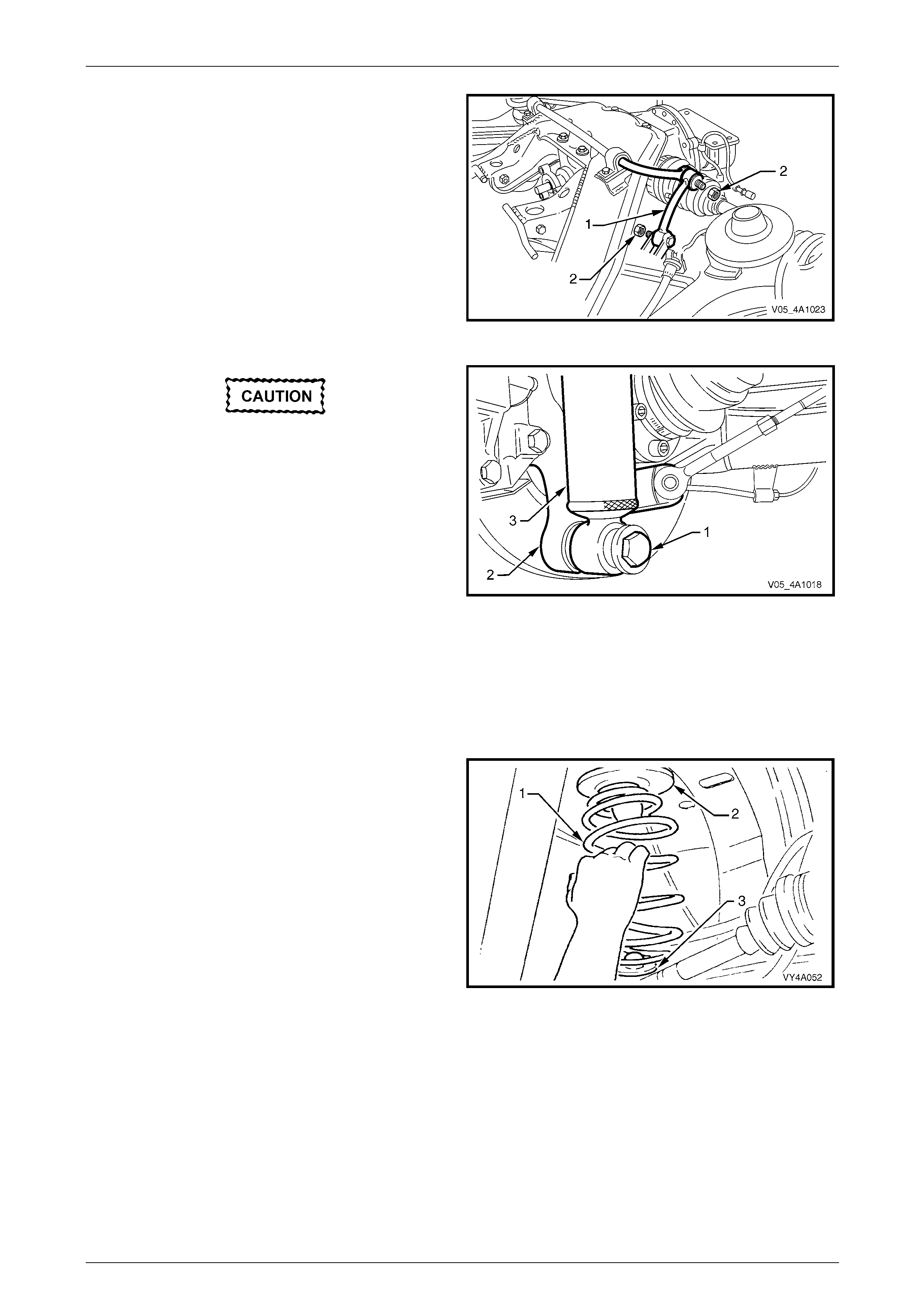
Rear Suspension 4A1 – 51
4A1-51
12 Remove the stabiliser bar link (1) to rear suspension
control arm attaching bolt (2) and nut from the side of
the vehicle where the spring is bein g removed.
Figure 4A1 – 90
If automatic level ride suspension is fitted to
the vehicle, there are specific procedures
relating to the system pressure and the
installation of the shock absorbers. These
operations MUST be carried out before
lowering the vehicle to the ground. Refer to
4 Service Operations – Automatic Level Ride
Suspension, in this Section.
13 Position a floor jack under the rear suspension control
arm.
14 Raise the jack slightly to take the spring load off the
rear suspension control arm.
15 Disconnect rear shock absorber lower mounting bolt
(1) and washer (2) from the rear suspension control
arm (3).
16 then remove the lower end of the shock absorber (4)
from the rear suspension control arm.
Figure 4A1 – 91
17 Lower the jack and remove the rear spring (1), upper
insulator (2) and lower insulator (3) from between the
vehicle underbod y and the rear suspension control
arm.
NOTE
• It may be necessary to push the rear
suspension control arm downward by hand
slightly to provide sufficient space for the
spring to be removed.
• Ensure that the rear brake hose is not pulled
tight while pushing down on the rear
suspension control arm.
Figure 4A1 – 92
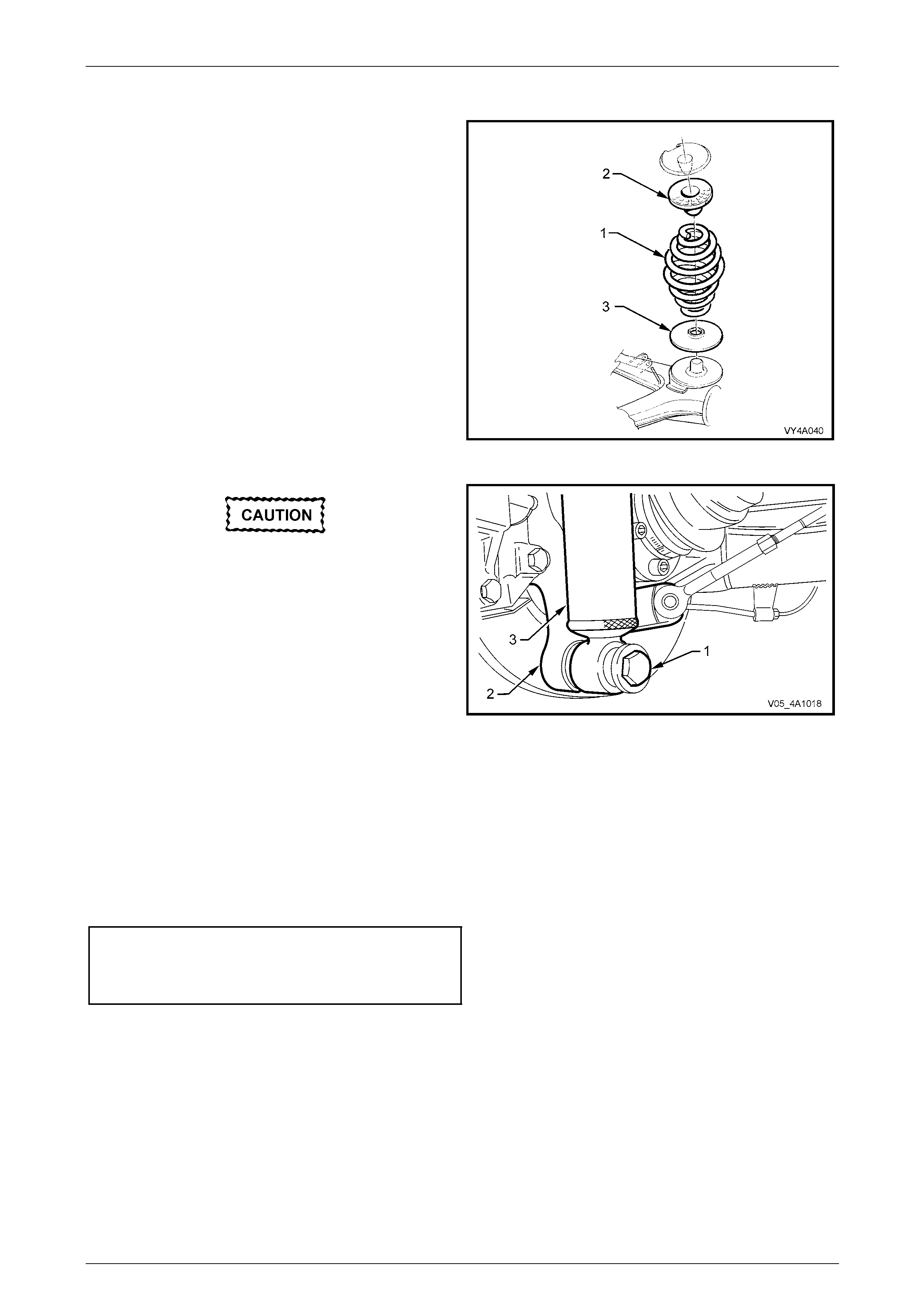
Rear Suspension 4A1 – 52
4A1-52
Reinstall
1 Reinstall the lower insulator (3) onto the rear
suspension control arm. Assemble the upper insulator
(2) into the spring (1) then push down on the rear
suspension control arm and install the spr in g and
upper insulator.
Figure 4A1 – 93
If automatic level ride suspension is fitted to
the vehicle, there are specific procedures
relating to the system pressure and the
installation of the shock absorbers. These
operations MUST be carried out before
lowering the vehicle to the ground. Refer to
4 Service Operations – Automatic Level Ride
Suspension, in this Section.
2 Position the jack under the rear suspension control
arm (2) and raise it sufficiently to allo w the shock
absorber (3) lower mounting washer and bolt (1) to be
reinstalled.
3 Reinstall the washer and bolt on to the shock absorber
lower mount and into the rear suspension control arm,
but do not tighten at this stage.
Figure 4A1 – 94
4 Remove the wire from the drive shaft and shock absorber upper mount. Lower the drive shaft and align the drive
shaft constant velocity joint to rear wheel drive shaft flange, then fit NEW attaching bolts into the corresponding
holes in the rear wheel drive shaft flange
5 Tighten the drive shaft constant velocity joint to rear wheel drive shaft flange attaching bolts to the correct torque
specification.
Drive shaft constant velocity joint
to rear wheel drive shaft flange
bolt torque specification..............................50 N.m, then
turn through 70°
6 Rotate the stabiliser bar link into position over the rear suspension control arm bracket.
7 Reinstall the attachin g bolt and a NEW nut but do not tighten at this stage.
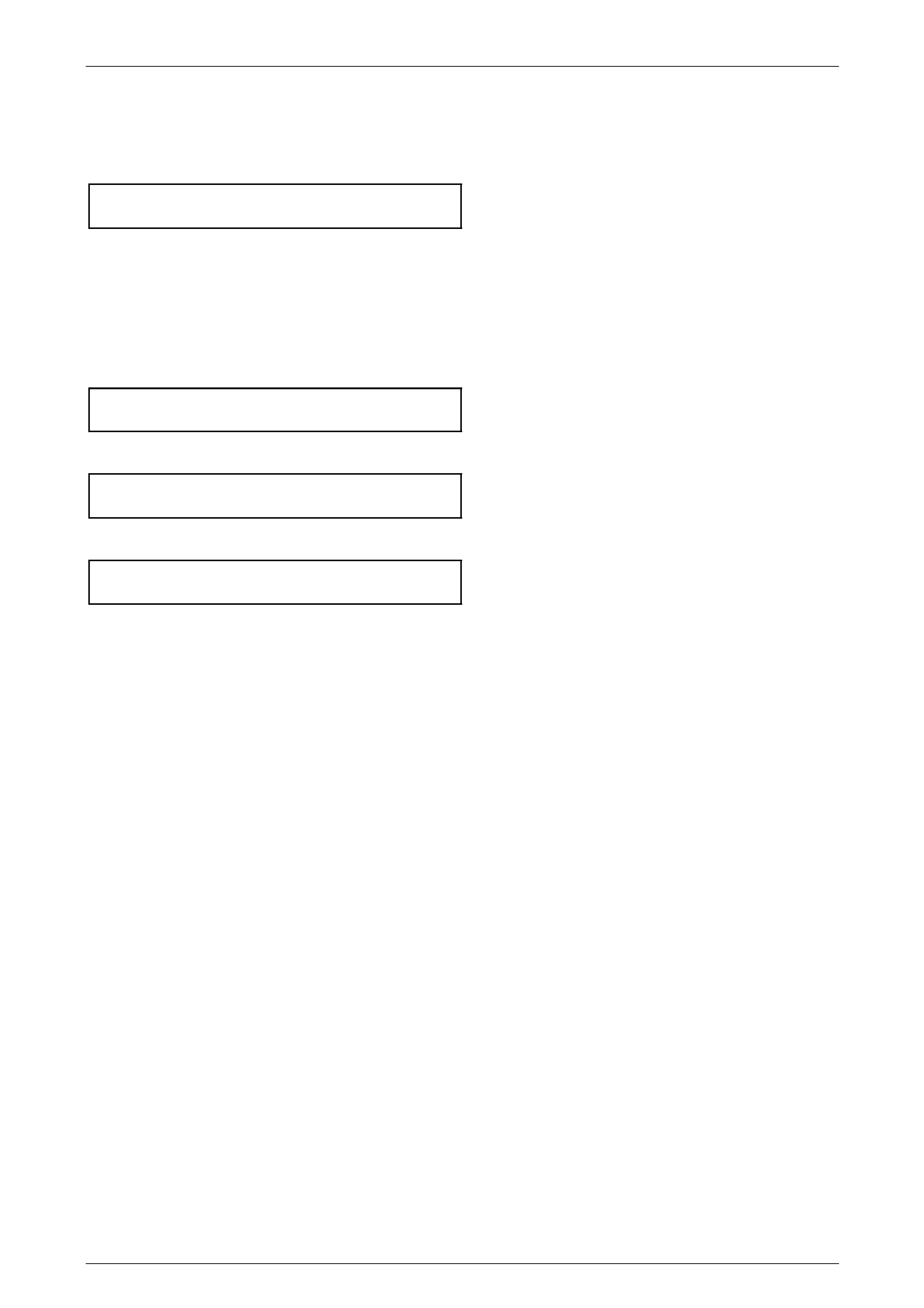
Rear Suspension 4A1 – 53
4A1-53
8 If the vehicle is fitted with Automatic Level Ride Sus pensio n (prod uction option FX3), reconnect the level ride
sensor link to the rear control arm.
9 Reinstall the additional control arm socket assembly with a NEW nut and tighten to the correct torque wrench
specification.
Additional control arm ball joint
retaining nut torque specification .........................65 N.m
10 Reinstall the road wheel, aligning the previously made marks and secure with the attaching nuts but do not tighten
at this stage.
11 Lower the vehicle to the ground.
12 Bounce the rear suspension several times to settle components.
13 Tighten road wheel attaching nuts to the correct torque specification, working in a ‘star’ pa ttern, refer to
3.1 Service Warnings, Cautions and Notes, in this Section.
Road wheel attaching
nut torque specification............................110 – 140 N.m
14 Tighten the stabiliser bar link to rear suspension control arm nut to the correct torque specification.
Stabiliser bar link bolts
and nuts torque specification .............................100 N.m
15 Tighten the shock absorber l ower mount to rear suspension control arm attaching bolt to the correct specification.
Shock absorber lower mounting
bolt torque specification.....................................115 N.m
16 Reinstall the wheel cover/ decorative wheel nut covers.
17 Road test the vehicle to check for correct operation.
Rear Suspension 4A1 – 54
4A1-54
3.10 Rear Shock Absorbers and/or Bushing
LT Section No. – 07-150
ATTENTION
The following fasteners have either micro encapsulation or incorporate a mechanical thread lock and should
only be used once. If in doubt , rep lacement is recommended when performing these operations:
Upper shock absorber mounting plate retaining nut (Wagon and Utility only).
Final tightening of the following fasteners MUST be with the vehicle weight on all four wheels and at curb
weight:
• Stabiliser bar link to rear suspension control arm attach ing nut and bolt.
• Shock absorber lower mounting bolt.
Remove
If the vehicle is fitted with Automatic Level
Ride Suspension, there are unique
procedures required when removing the rear
shock absorbers f rom thes e vehicles. Refer to
4.6 Automatic Level Ride Shock Absorber, in
this Section, for details.
1 Raise the vehicle at the rear, using a floor jack under the centre of the differential carrier.
2 Place safety stands under the rear suspension control arms to support weight of the vehicle.
3 Loosen and remove the shock absorber lower
mounting bolt and washer (1) and remove th e shock
absorber (3) from the rear suspension c ontrol arm (2).
Figure 4A1 – 95
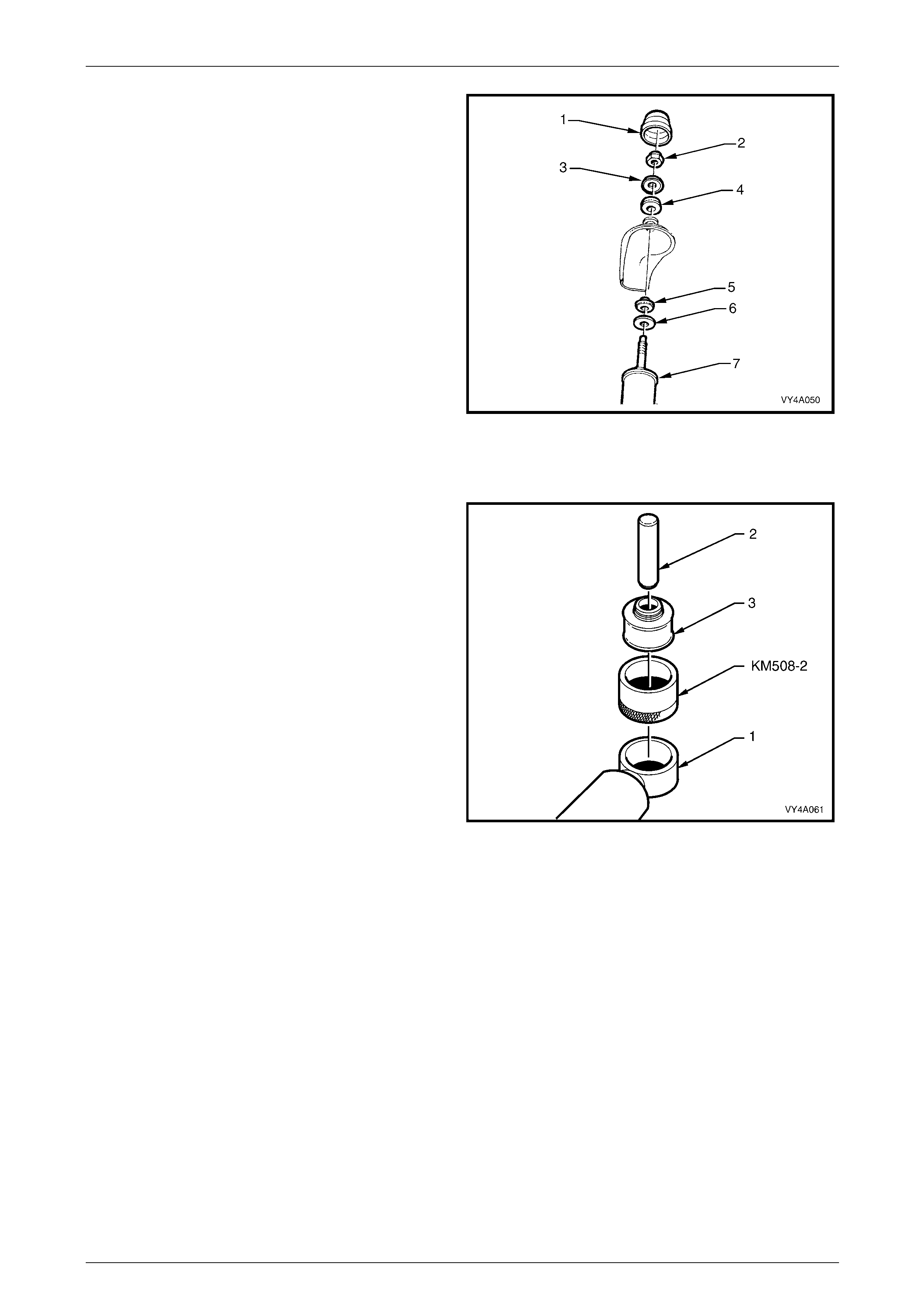
Rear Suspension 4A1 – 55
4A1-55
4 Open the rear compartment lid and prise off the shock
absorber upper mounting cap cover (1).
5 Remove the shock absorber upper mo unting nut (2),
upper plate (3) and upper bushing (4).
6 Remove the upper mounting lower bushing (5) and
lower plate (6) from the shock absorber (7).
Figure 4A1 – 96
Lower Bushing, Replace
1 To replace the shock absorber lower bushing:
a. With the shock absorber (1) lower mount
supported on suitable press plates, use a
suitable press tool (2) such as Tool No. KM619
to press the bushing (3) from the mount.
b. Lubricate the ne w bushin g with soapy water and
place in sleeve, Tool No. KM508-2
c With the shock absorber lower mount supp orted
on press plates, position KM508-2 onto the lower
mount. Press the new bushing into the lower
mount using a suitable press t ool such as Tool
No. KM619.
Figure 4A1 – 97
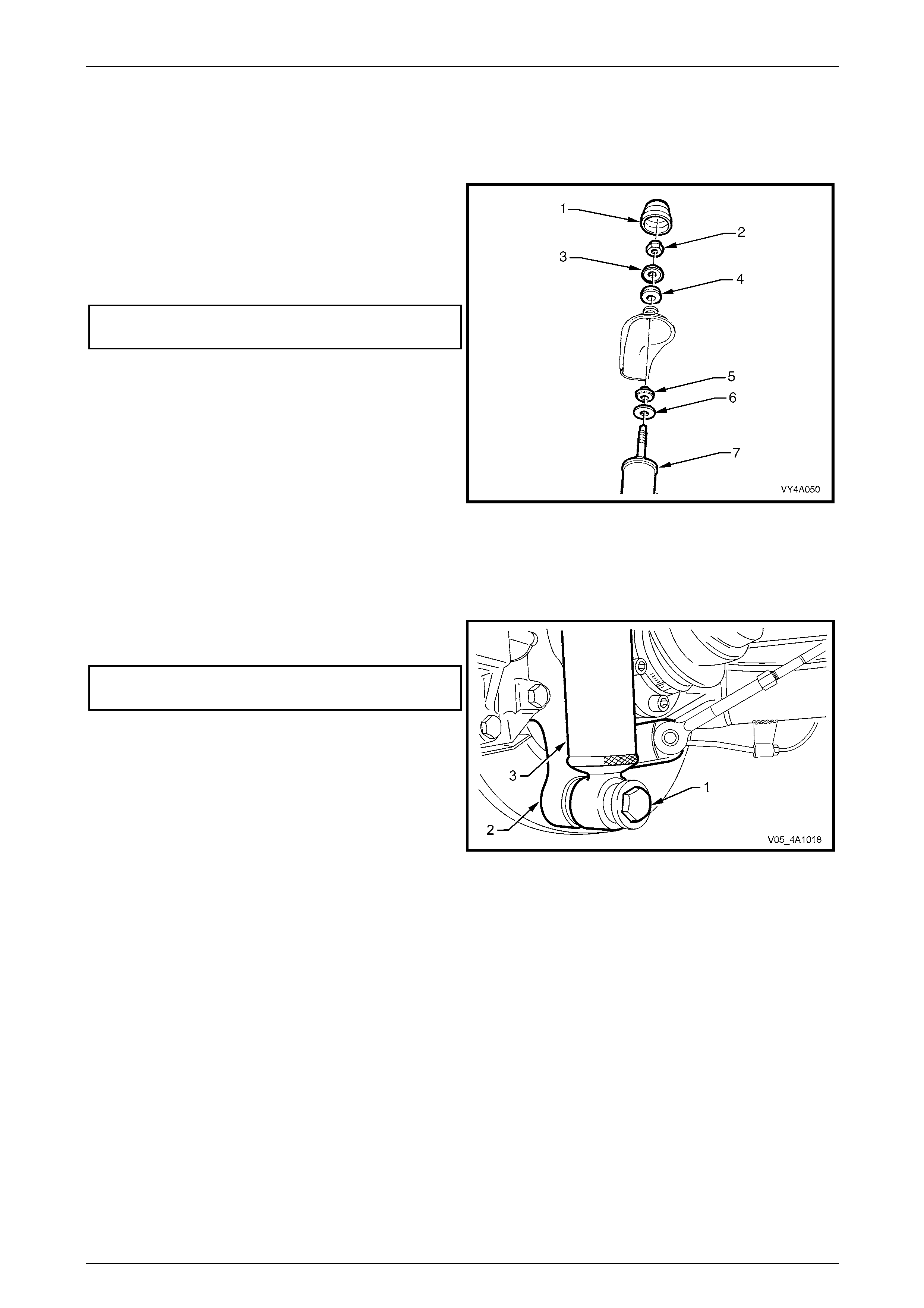
Rear Suspension 4A1 – 56
4A1-56
Reinstall
1 Before installation, check shock the absorb er action and inspect the rubber bushi ng. Replace components as
required. Refer to 5 Diagnosis in this Section for testing details.
2 Assemble the upper mounting lower plate (6) and
bushing (5) to the shock absorber (7).
3 Position the shock absorber into the upper mounting
hole. Install the upper mounting upper bushing (4),
upper plate (3) and mounting nut (2), then hand
tighten the nut to the correct torque specification.
Upper shock absorber retaining
nut torque specification........................................14 N.m
NOTE
Do not use power operated tools for this
operation, as thread damage will result.
4 Reinstall the upper mounting cap cover (1).
Figure 4A1 – 98
5 Install the shock absorber (3) lower mount into the rear suspension control arm (2) and install the washer and bolt
(1) but do not fully tighten at this stage.
6 Lower the vehicle to the ground an d bounce the rear of the vehicle several times to settle the suspension.
7 Tighten the shock absorber l ower mounting bolt (1) to
the correct torque specification.
Shock absorber lower mounting
nut torque specification......................................115 N.m
8 Road test the vehicle to check for correct operation.
Figure 4A1 – 99
Rear Suspension 4A1 – 57
4A1-57
3.11 Additional Control Arm
LT Section No. – 07-150A
ATTENTION
The following fasteners have either micro encapsulation or incorporate a mechanical thread lock and should
only be used once. If in doubt , rep lacement is recommended when performing these operations:
Additional control arm inner shaft attaching nut.
Additional control arm socket assembly retaining nut.
The following fasteners MUST be replaced when performing these operations:
Additional control arm adjusting shaft lock nut.
Inspect
Inspection of the additional control arm may be required in
the following circumstances:
• Poor handling.
• Uneven tyre wear.
A visual inspection of the additiona l control arm should be
performed with the arm installed in the vehicle. The
following conditions would require replacement of the
additional control arm or some of its components:
• Bent or damaged shafts.
• Bent or damaged adjusting shaft.
• Excessive play in the socket assembly.
• Excessive play in the inner bushing.
• Damaged socket assembly boot. Figure 4A1 – 100
Legend
1 Socket Assembly Retaining Nut
2 Additional Control Arm Outer Shaft and Ball Joint
3 Outer Adjuster Lock Nut
4 Adjusting Shaft
5 Inner Adjuster Lock Nut
6 Additional Control Arm Inner Shaft
7 Additional Control Arm Inner Bushing
8 Additional Control Arm to Rear Crossmember Retaining Bolt
Rear Suspension 4A1 – 58
4A1-58
Remove
1 Raise the vehicle and suppor t in a safe manner. Refer to Section 0A General Information for the location of
recommended lifting and support points.
2 If the additional control arm is being disassembled, measure and record the len gth of the adjusting shaft between
the lock nuts.
3 Loosen the additional control arm socket assembly
retaining nut until level with the top of the socket
assembly stud.
4 Using special tool No. E-9332-A (1), tighten the lever
forcing screw (2) to press the socket assembly stud
free from the taper in the rear suspension control arm
then remove the socket assembly retaining nut.
5 Remove the additional control arm to rear suspension
crossmember retaining nut and bolt.
6 Carefully manoeuvre the add itional control arm from
the vehicle.
Figure 4A1 – 101
Disassemble
1 Using a suitable vice fitted with soft jaws, hold the
centre adjusting shaft (1) and loosen the two lock nuts
(2).
2 Rotate the inner shaft (3) clockwise (noting the
number of turns) until the inner shaft is disengaged
from the threaded area of the adjusting shaft.
NOTE
The inner additional control arm shaft, the inner
lock nut and the corresponding end of the
adjuster shaft have left-hand threads.
3 Rotate the outer shaft counter clockwise (noting the
number of turns) until the outer shaft is disengage d
from the threaded area of the adjusting shaft.
4 Remove the lock nuts from the adjusting shaft.
Figure 4A1 – 102
Reassemble
The reassembly procedure for the additional control arm is t he reverse of the disassembly proced ure. The inner and
outer shafts are to be installed onto the adjusting shaft with the same number of turns and the arm when assembled, is
adjusted to the correct length.
NOTE
• The inner additional control arm shaft, the
inner lock nut and the corresponding end of
the adjuster contain left-hand threads.
• The additional control arm lock nuts should
only be tightened when the arm is installed
into the vehicle and the suspension is under
load.
Rear Suspension 4A1 – 59
4A1-59
Reinstall
NOTES
• The additional control arm lock nuts should
only be tightened when the arm is installed
into the vehicle and the suspension is under
load.
• The socket assembly may be rotated and
misaligned, if allowed to move during the
tightening of the lock nut, resultin g in possible
damage to socket assembly internals. When
tightening the additional co ntrol arm lock nuts,
use a suitable spanner on the hexagonal
crimped section near the socket assembly to
prevent the socket assembly from being
deflected.
• To ensure proper retention of the additional
control arm, the socket assembl y stud and t he
corresponding tapered hole in the rear
suspension control arm must be cleaned of
dirt and foreign matter prior to installation.
NOTES
• The inner addit ional control arm shaft, MUST
be installed into the vehicle with the
protruding side of the bushing towards the
front of the vehicle (as indicated).
• Check the rear wheel toe setting, refer to
3.12 Rear Wheel Alignment Checking in this
Section.
1 Tighten all fasteners to the correct torque
specification.
Additional control arm ball joint
nut torque specification........................................65 N.m
Additional control arm inner shaft
nut and bolt torque specification ..........................65 N.m
Additional control arm adjusting
shaft lock nut torque specification........................50 N.m
Figure 4A1 – 103
Rear Suspension 4A1 – 60
4A1-60
3.12 Rear Wheel Alignment Checking
LT Section No. – 06-212
ATTENTION
The following fasteners have either micro encapsulation or incorporate a mechanical thread lock and should
only be used once. If in doubt , rep lacement is recommended when performing these operations:
Rear susp ension control arm to rear suspension crossmember attaching nut.
The following fasteners MUST be replaced when performing these operations:
Rear suspensi o n crossmember front mounting bolt.
Rear suspension crossmember mount to under body attaching bolt.
Rear suspension crossmember mounting brace to underbody attaching bolts.
The following fasteners MUST be at curb height before final tightening:
• Rear suspension control arm to rear suspension crossmember attaching nut.
Camber and Toe Check
Preliminary Checks and Information
The following conditions must be checked to ensure accurate measurement of rear wheel alignment.
1 Tread on rear tyres must be uniform and in a roadworthy condition.
2 Tyre pressures must be equal on both sides and to the correct pressure. Refer to the tyre placard on the vehicle for
correct tyre pressures.
3 Wheel rim flange lateral run-out should be checked and be to specification, refer to Section 10 Wheels and Tyres.
4 The vehicle must be at curb height: i.e. vehicle ready to drive with all fluids at recommended lev els, fuel tank full,
without driver, passengers or luggage.
5 Stabilise vehicle springs by bounci ng the rear of vehicle several times.
NOTE
This step is very important, particularly if the
vehicle was raised before checking. In that
instance, the camber angle measured will be
incorrect, because the rear suspension control
arms will not have resumed their normal position.
Camber
Camber is not adjustable. If there is any deviation from specification, the condition and alignment of the crossmember,
rear suspension control arms and b ush ing should be checked.
Wheel Toe
1 When checking wheel toe, if one side h as e xcessive toe-in and the opposite side h as excessive toe-out, this may
be due to:
a The rear suspension control a rm attaching nuts being tightened when the vehicle was not at curb height.
b The rear suspension crossmember not correctly aligned to the vehicle centreline.
2 To correct such a condition, check the rear suspension cros smember a lignment.
Refer to Section 1A2 Body Dimensions . NOTE
Alignment of the rear suspension crossmember
requires the use of a special tool. Attempting to
align the rear suspension crossmember without it
will not prove to be successful.
3 Re-check the rear wheel alignment toe setting and adjust as required. Refer to Rear Wheel Toe Adjustment, in this
Section.
Rear Suspension 4A1 – 61
4A1-61
Rear Wheel Toe Adjustment
The rear suspension toe setting is adjustab le in vehicles equipped with the additional control arm by varying the length of
the additional control arm. To adjust toe setting:
1 Loosen the two lock nuts (1).
NOTE
The inner additional control arm shaft, the inner
lock nut and the corresponding end of the
adjuster have left-hand threads.
2 Rotate the centre adjusting shaft, using a suitable
spanner (2).
3 Tighten the two lock nuts (1) by holding onto the
hexagonal crimped secti on near the socket assembly
(3). NOTE
• Increasing the additional control arm length
will increase rear wheel toe in and vice versa.
• The socket assembly may be over extended
if allowed to move during the tightening of the
lock nuts, causing damage to socket
assembly internals. During the toe
adjustment procedure, use a suitable
spanner (3) to prevent the socket assembly
from being deflected.
Figure 4A1 – 104
4 Tighten all fasteners to the correct torque specifications.
Rear suspension crossmember
front mounting bolt
torque specification...................................125 N.m, then
turn through 35°
Rear suspension crossmember
rear mount to vehicle body
torque specification.....................................35 N.m, then
turn through 60°
Rear suspension control arm
to rear suspension crossmember
bolt and nut torque specification ........................100 N.m
Rear Suspension 4A1 – 62
4A1-62
4 Service Operations – Automatic
Level Ride Suspension
4.1 Initial Air Charge
LT Section No. - 06-212
1 Turn ignition ON.
2 Disconnect the lower end of the sensor connectin g
link.
3 Push the sensor arm upward, above the horizontal
plane for approximately 2 0 se conds, until the
compressor is activated.
4 Leave the compressor runni ng for approximately 30
seconds to inflate the Superlift shock absorbers.
5 Turn ignition OFF .
6 Check the system for leaks.
Refer to 4.2 Air Leak Test, in this Section.
7 Reconnect the sensor connecting li nk.
Figure 4A1 – 105

Rear Suspension 4A1 – 63
4A1-63
4.2 Air Leak Test
LT Section No. - 06-212
If air pressure in the level ride system is lo st
during service procedures, do not lower the
vehicle until system pressure has been
restored, as damage will most likely result.
Charge the system as detailed in
4.1 Initial Air Charge in this Section.
1 Ensure the system is pressurised. Refer to
4.1 Initial Air Charge in this Section if required.
2 Starting at the shock absorber connections, apply a
foaming leak check solution (commercially available,
or a soap solution mixed with water) to all fittings and
connections.
3 Carefully inspect the fittings and con nections for the
presence of air bubbles in the solution. Figure 4A1 – 106
4 Repair any detected leaks as required.
5 Retest the system for air leaks.
6 If air still leaks from the system, isolate sections of the system until the source of the leak is found.
7 Clean off the residual solution.
Rear Suspension 4A1 – 64
4A1-64
4.3 Relieving System Air Pressure
LT Section No. - 06-212
If air pressure in the level ride system is lost
during service procedures, do not lower the
vehicle until system pressure has been
restored, as damage will most likely result.
Charge the system; refer to
4.2 Initial Air Charge in this Section.
Prior to carrying out service operations on
the level ride suspension system where the
air pressure in the system needs to be
released, the following procedure must be
followed
1 With the rear of the vehicle raised an d supported on
safety stands under the trailing arms, turn ignition ON.
2 Disconnect the lower end of the sensor connectin g
link.
3 Pull the sensor arm downward, below the horizontal
plane and hold until the exhaust solenoid is activated.
4 Maintain the sensor lever position, allow the exhaust
solenoid to remain active for approximately 30
seconds to relieve the system air pressure or until no
sound of exhausting air remains. Figure 4A1 – 107
Do not leave the sensor lever in the lowered
position for more than four and a half minutes
(with the ignition on), otherwise the solenoid
timer will deactivate the solenoid and the
timer must then be reset.
5 Turn ignition OFF .
6 Proceed with service operations as required.
NOTE
After service work has been completed, the
system pressure must be reinstated before
lowering the vehicle. Refer to 4.1 Initial Air
Charge in this Section for the procedure.
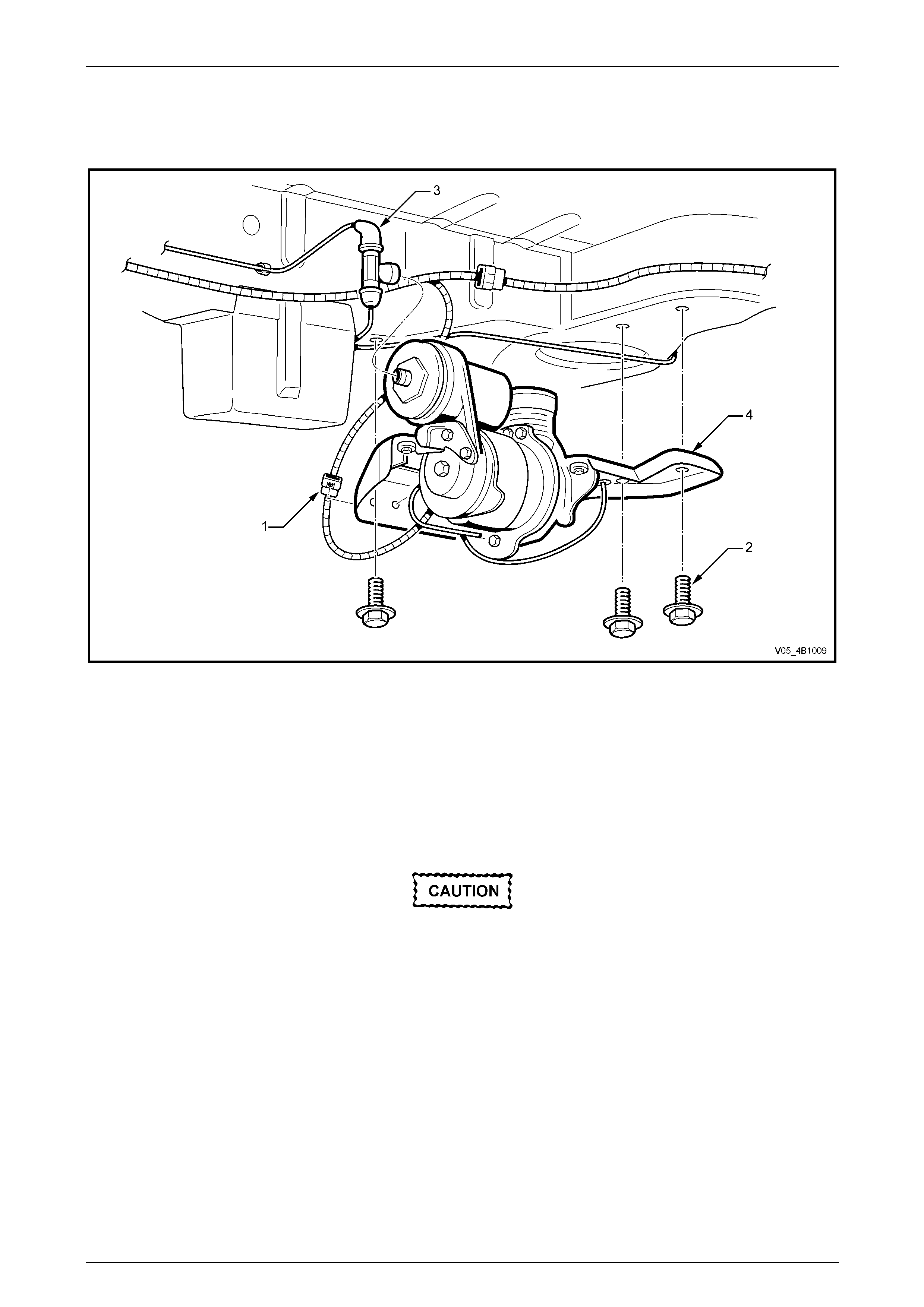
Rear Suspension 4A1 – 65
4A1-65
4.4 Compressor Assembly
LT Section No. - 06-212
Figure 4A1 – 108
Legend
1 Level Ride Compressor Wiring Harness Connector
2 Level Ride Compressor Bracket to Underbody Mounting
Bolts (3 Places).
3 Airline to Compressor T-piece
4 Level Ride Compressor Mounting Bracket
Remove
• If air pressure in the level ride system is
lost during service procedures, do not
lower the vehicle until system pressure
has been restored, as damage will most
likely result. Charge the system a s detaile d
in 4.1 Initial Air Charge in this Section.
• Disconnection of the battery affects
certain vehicle electronic systems. Refer
to Section 00 Cautions and Notes,
5. Battery Disconnection Procedures
before disconnecting the battery.
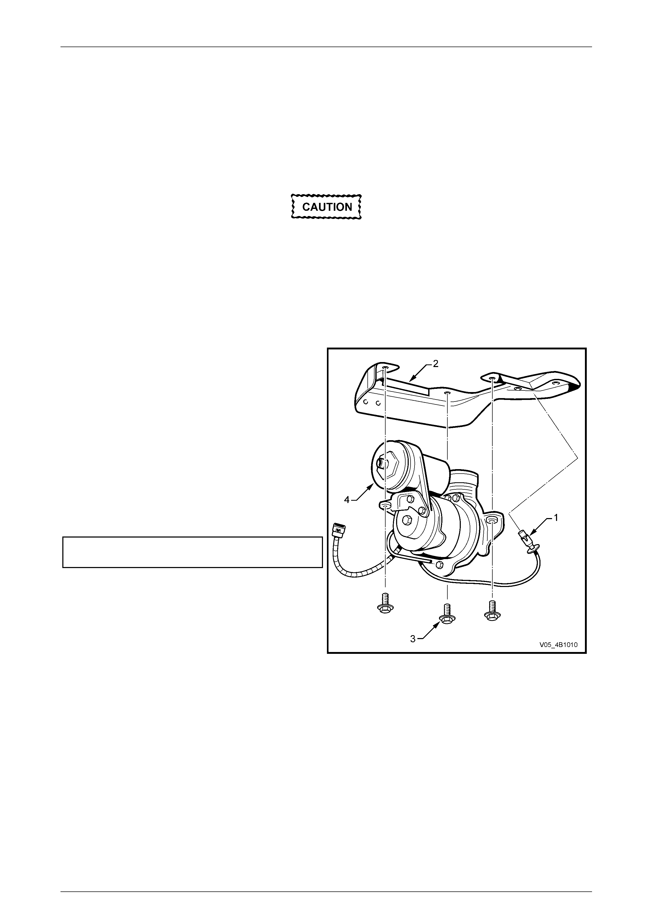
Rear Suspension 4A1 – 66
4A1-66
1 Disconnect the battery, negative lead first.
2 Raise the vehicle.
3 Relieve system air pressure. Refer to 4.3 Relieving System Air Pressure, in this Section.
4 Unclip the level ride wiring har ness (1) from the compressor assembly mounting bracket (4) and disconnect the
wiring connector, refer to Figure 4A1 – 108.
5 Remove the three bolts (2) attaching the compressor assembly mounting bracket (4) to the vehic le body.
Support the compressor assembly. Do not
allow it to drop.
6 Disconnect the airline T-connector (3) from the compressor by rotating the T-piece 90°, then carefully pull it away
from the compressor.
7 Lower the compressor assembly.
Disassemble
1 Remove the filter (1) from the mounting bracket (2).
2 Remove the three bolts (3) attaching the compressor
(4) to the mounting bracket.
3 Test that the filter is clean and free from restrictions
by removing the filter form the tube and blowing
through it from the hose connection end. If an y
restriction is felt, replace the filter.
Reassemble
1 Reinstall the components in the reverse order to
disassembly.
2 Tighten the bolts to the specified torque.
Compressor mounting bolt
torque specification.............................................5.0 N.m
Figure 4A1 – 109
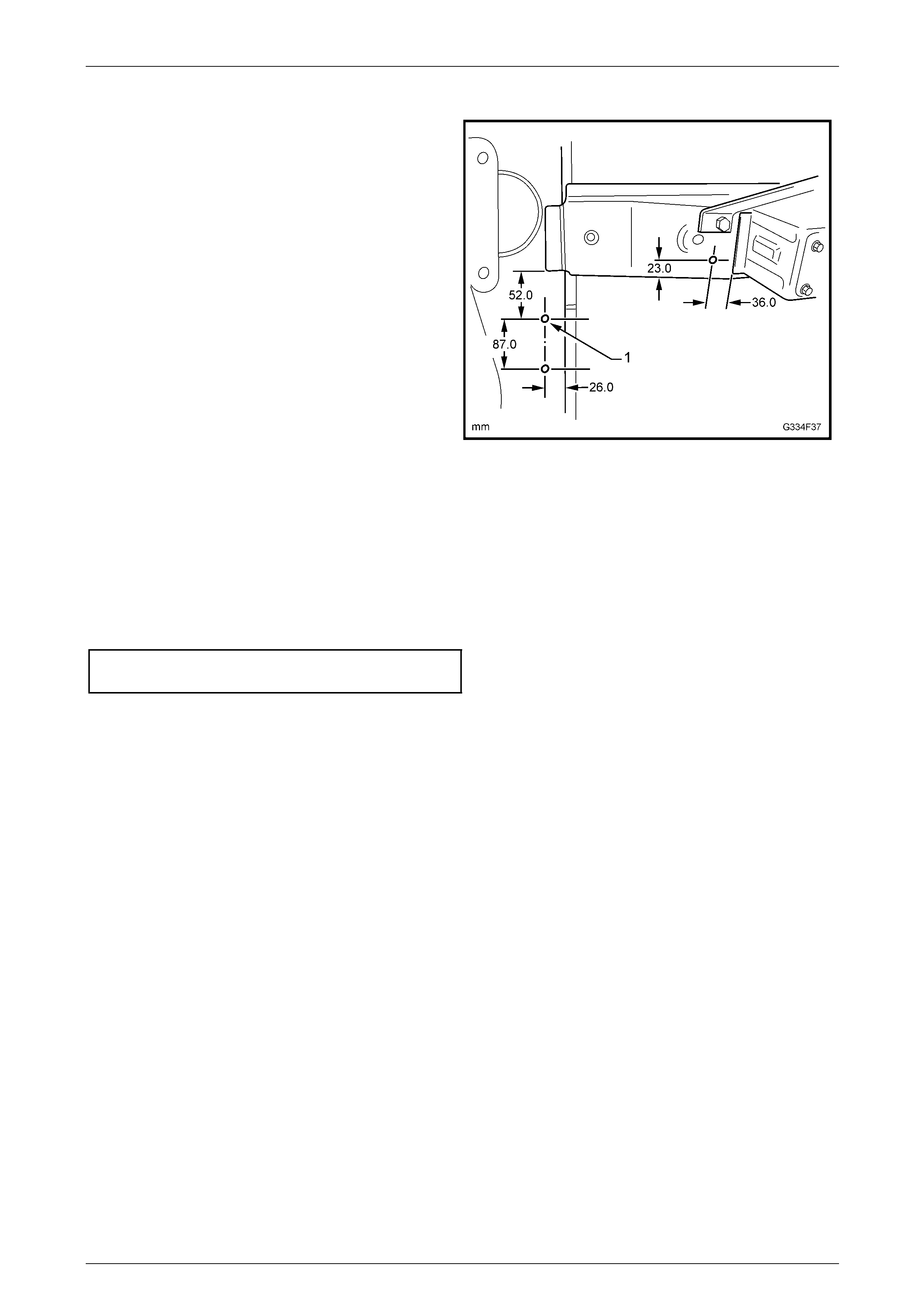
Rear Suspension 4A1 – 67
4A1-67
Reinstall
1 If the left-hand rear longitudin al an d/or crossmember
has been replaced, compressor assemb ly mounting
holes (1) will have to be drilled as requ ired.
Figure 4A1 – 110
2 Bring the compressor assembly up to the air li ne and connect the T-piece.
NOTE
Ensure that the airline is correctly routed, placed
in all of its mounting clips and does not foul with,
or rub against any components or body fittings.
3 Reinstall the three mounting bolts and tighten to the specified torque.
Compressor assembly mounting
bolts torque specification ....................................5.0 N.m
4 Connect the wiring harness connector and clip the harness into position.
NOTE
Ensure that the harness is correctly routed,
placed in all of its mounting clips/ties and does
not foul with, or rub against any components or
body fittings.
5 Connect the battery.
NOTE
Do not completely lower the vehicle until the
system air pressure has been reinstated.
6 Charge the system with air and check the system for leaks; refer to 4.1 Initial Air Charge and 4.2 Air Leak Test in
this Section.
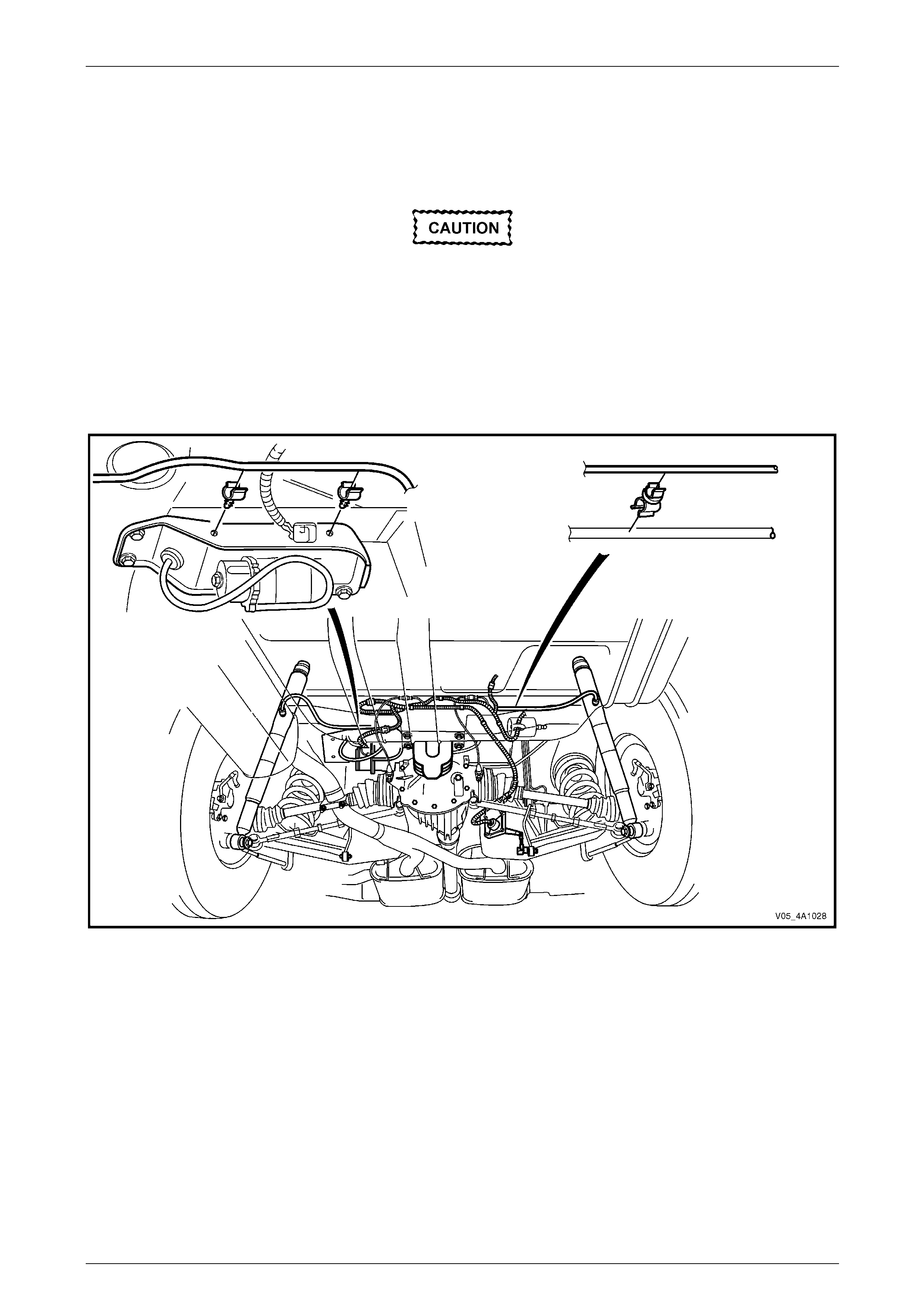
Rear Suspension 4A1 – 68
4A1-68
4.5 Air Lines
LT Section No. - 06-212
If air pressure in the level ride system is lost
during service procedures, do not lower the
vehicle until system pressure has been
restored, as damage will most likely result.
Charge the system as detailed in
4.1 Initial Air Charge in this Section.
The air lines are routed between the compressor and each shock absorber. Retaining clips are placed along each line to
secure the air line to the vehicle. Either scre w-on t ype or clip-on type connectors are used to attach the air line to the
shock absorbers, and a clip-on T-piece attaches the air line to the compress or.
Figure 4A1 – 111
Remove
1 De-pressurise the system. Refer to 4.3 Relieving System Air Pressure in this Section.
2 Rotate the applicable connector 90°, then carefully pull the conn ector and air line away from the component.
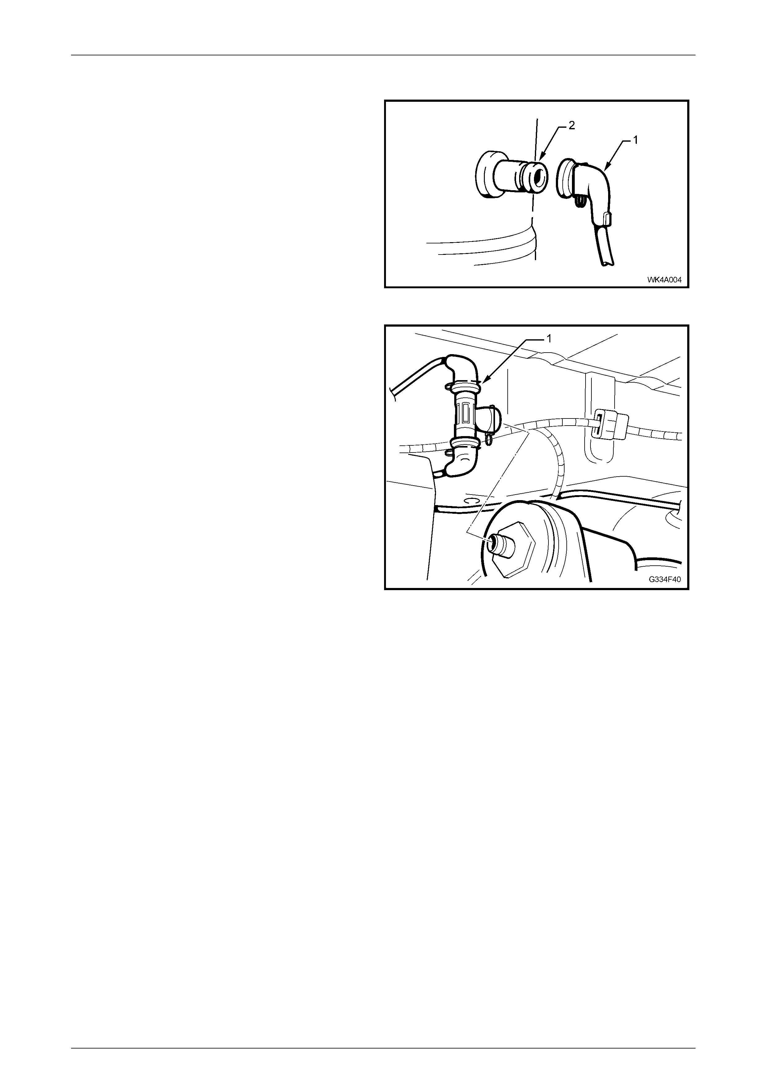
Rear Suspension 4A1 – 69
4A1-69
Reinstall
1 Route the airline in the retaine r s ensuring that there
are no kinks and it does not foul on the body or any
components.
2 Push the connection cap (1) onto the shock absor ber
port (2) until the spring clip engages the gro ove in the
shock absorber fitting.
3 Charge the system with air and test for air leaks as
detailed in 4.1 Initial Air Char ge and
4.2 Air Leak Test, in this Section.
Figure 4A1 – 112
4 Fit each air line connection onto the T-piece (1).
5 Push the T-piece onto the compressor fitting,
ensuring it is secure.
Figure 4A1 – 113
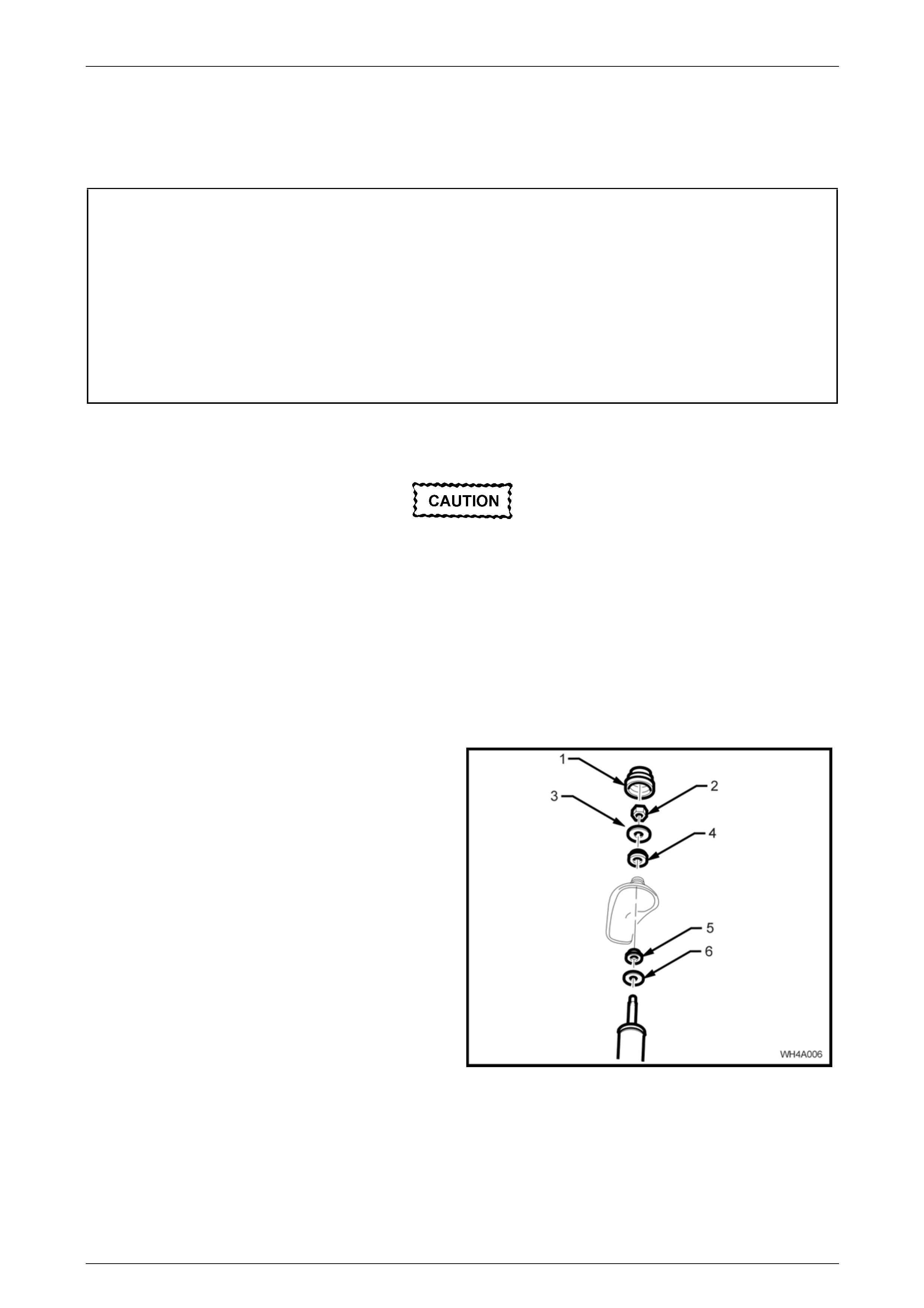
Rear Suspension 4A1 – 70
4A1-70
4.6 Automatic Level Ride Shock Absorber
LT Section No. - 06-212
ATTENTION
The following fasteners have either micro encapsulation or incorporate a mechanical thread lock and should
only be used once. If in doubt , rep lacement is recommended when performing these operations
Upper shock absorber mounting plate retaining nut (AWD Wagon only).
Final tightening of the following fasteners MUST be with the vehicle weight on all four wheels and at curb
weight:
• Stabiliser bar link to rear suspension control arm attach ing nut and bolt.
• Shock absorber lower mounting bolt.
Remove
If air pressure in the level ride system is lost
during service procedures, do not lower the
vehicle until system pressure has been
restored, as damage will most likely result.
Charge the system as detailed in
4.1 Initial Air Charge in this Section.
1 Raise the rear of the vehicle by placing a jack under the centre of the differential carrier, raise the ve hicle and place
safety stands under the trailing arms to support the weight of the vehicle.
2 De-pressurise the system. Refer to 4.3 Relieving System Air Pressure in this Section.
3 Disconnect the air line connec tion from the shock absorber. Refer to 4.5 Air Lines in this Section.
4 Open the rear compartment lid and prise off the shock
absorber upper mounting cap cover (1).
5 Remove the shock absorber upper mo unting nut (2),
upper plate (3) and bush (4).
Figure 4A1 – 114
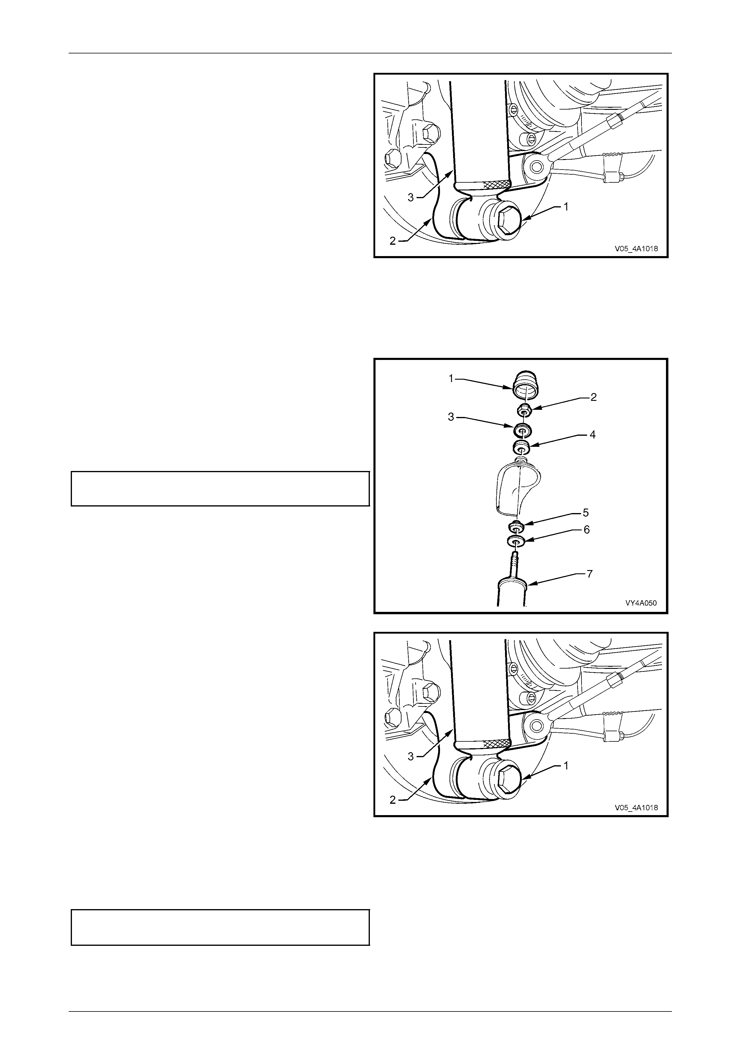
Rear Suspension 4A1 – 71
4A1-71
6 Loosen then remove the lo wer shock absorber
mounting bolt (1) and washer from the lower mounting
(2).
Figure 4A1 – 115
7 Lower the shock absorber (3) to clear the upper mounting stud from the bo dy, then remove the shock absorber
assembly from the vehicle.
8 Remove the upper mounting, lo wer bush (5) and washer (6) from the shock absorber, as required.
Reinstall
The installation procedure is the reverse of the removal procedures e xcept for the following:
1 Reassemble the upper mounting lower plate (6) and
bushing (5) to the shock absorber (7).
2 Position the shock absorber into the upper mounting
hole.
3 Reinstall the upper mounting upper bushing (4), upper
plate (3).
4 Reinstall the mounting nut (2), then hand tighten the
nut to the correct torque specification.
Upper shock absorber retaining
nut torque specification........................................14 N.m
NOTE
Do not use power operated tools for this
operation, as thread damage will result.
5 Reinstall the upper mounting cap cover (1).
Figure 4A1 – 116
6 Reinstall the shock absorber (3) lower mount into the
rear suspension control arm (2) and i nstall th e washer
and bolt (1) but do not fully tighten at this stage.
Figure 4A1 – 117
7 Reinstall the air line to the shock absorber. Refer to 4.5 Air Lines in this Section.
8 Before lowering the vehicle to the groun d, charge the system with air and test for air leaks as detailed in
4.1 Initial Air Charge and 4.2 Air Leak Test in this Section.
9 Lower the vehicle to the ground, then bounce the vehicle s evera l times to settle the suspension.
10 Tighten the shock absorber l ower mounting bolt to the correct torque specification.
• Shock absorber lower mounting
bolt torque specification......................................115 Nm
11 Road test the vehicle to check for correct operation.
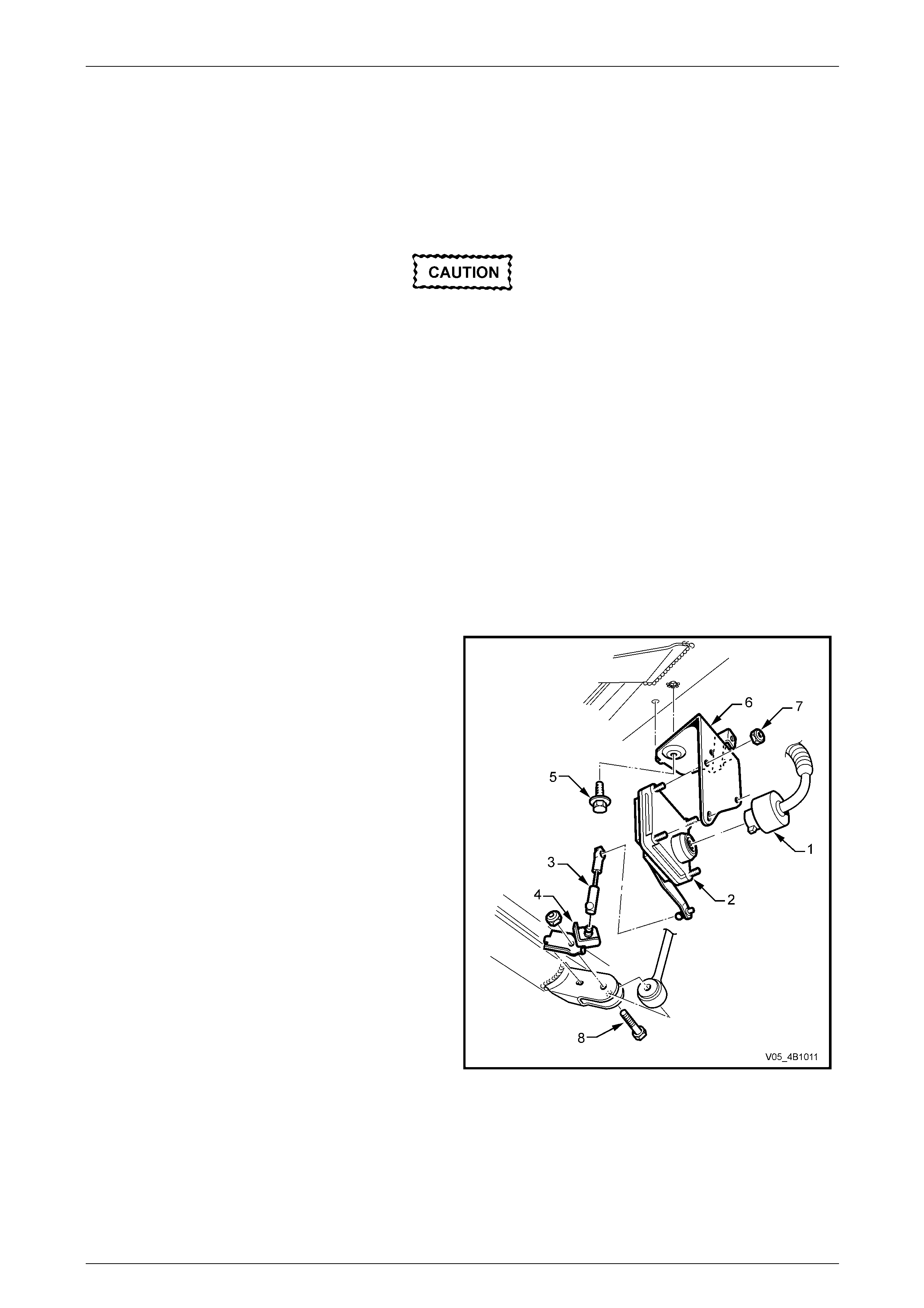
Rear Suspension 4A1 – 72
4A1-72
4.7 Ride Height Sensor
LT Section No. - 06-212
Remove
• If air pressure in the level ride system is
lost during service procedures, do not
lower the vehicle until system pressure
has been restored, as damage will most
likely result. Charge the system a s detaile d
in 4.1 Initial Air Charge in this Section.
• The position of the ride height sensor is
critical to the level ride system's operation.
A bent or damaged mounting bracket,
connecting link or ball stud plate, or
incorrect installation of the sensor and
components can cause incorrect
operation.
• Disconnection of the battery affects
certain vehicle electronic systems. Refer
to Section 00 Cautions and Notes,
5. Battery Disconnection Procedures
before disconnecting the battery.
1 Disconnect the battery, ground lead.
2 Unclip or cut the cable ties securing the sensor wiring
harness to the sensor bracket.
3 Disconnect the wiring harness connector (1) from the
sensor (2).
4 Disconnect the sensor link (3) from either the sensor
arm or ball stud plate (4).
5 While holding the sensor assembly, remove the
bolt (5) attaching the sensor mounting bracket (6) to
the crossmember.
6 Remove the sensor assembly.
7 If required, remove the nuts (7) attaching the sensor
to the mounting bracket.
8 If required, remove the bolt (8) attaching the ball stud
plate to the trailing arm.
Figure 4A1 – 118
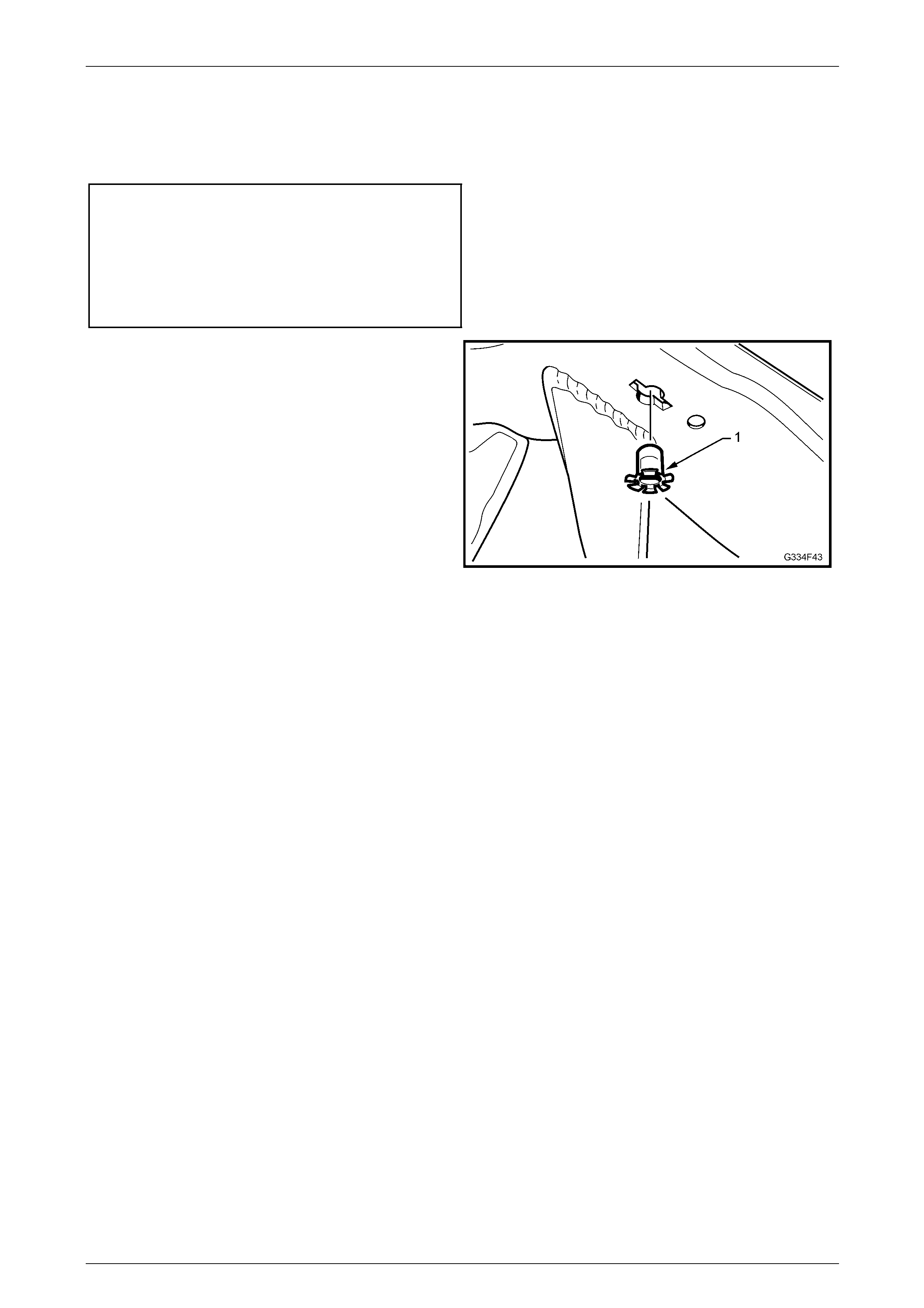
Rear Suspension 4A1 – 73
4A1-73
Reinstall
Installation of the ride height sensor is the reverse to removal procedures, ensuring to tighten all fasteners to the correct
torque specification.
Ride height sensor bracket
to crossmember
bolt (5) torque specification..................................25 N.m
Sensor to bracket nut (7)
torque specification.............................................5.0 N.m
• Stabiliser bar link bolt (8)
and nut torque specification...............................100 N.m
NOTE
If the rear suspension crossmember has been
replaced, insert the nut cage (1) into the
crossmember as shown.
Figure 4A1 – 119
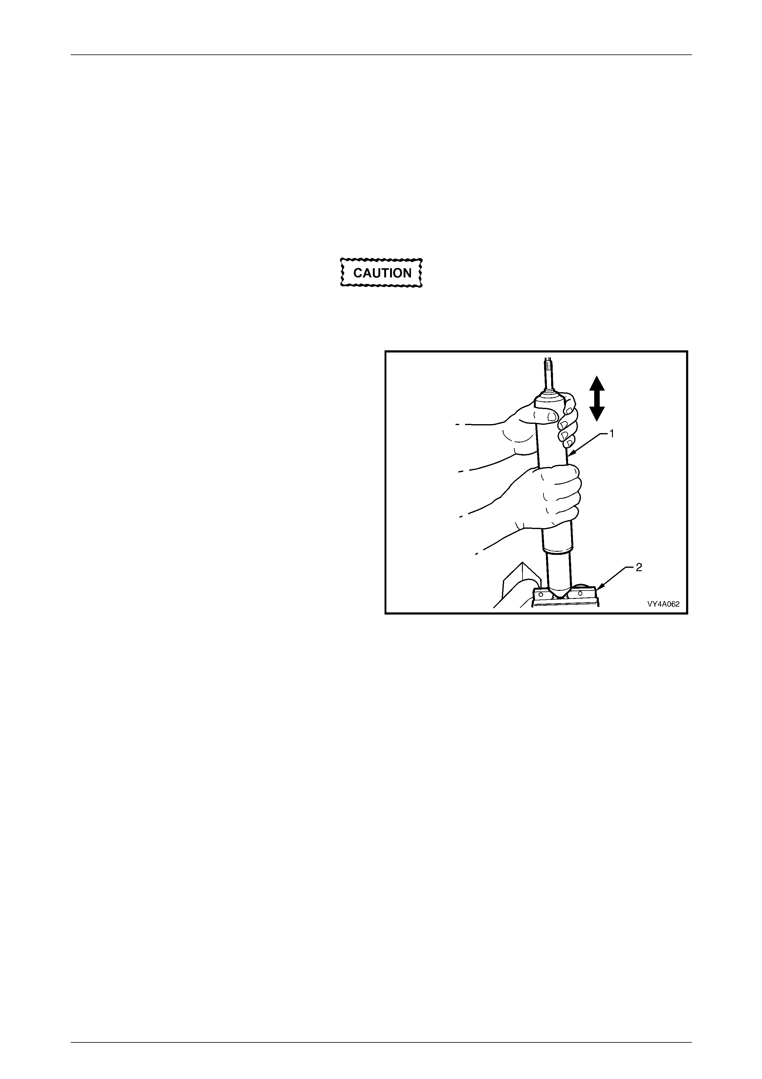
Rear Suspension 4A1 – 74
4A1-74
5 Diagnosis
5.1 Checking and Testing Shock Absorbers
For a positive check of shock absorber operation it is advisable to remove them from the vehicle. However, before
proceeding with the removal, it is good pr actice to ensure that the noise causing concern, is not coming from another
source.
Check the shock absorber mountings for tightness; check the rubber mou nt bushing and replace if worn.
This test proc edure is not fo r gas pressurised
shock absorbers.
Test shock absorber action as follows:
1 Clamp the shock absorber (1) by its lower mount in a
vice (2).
2 Slowly pump the shock absorber up an d down the full
stroke at least six times before checking its resistance.
3 Pump the shock absorber by hand at various rates of
speed and observe the resist ance.
When extending the shock ab sorber, the resistance should
be marginally greater than when collapsing the unit. The
resistance should be consistent throughout both strokes and
there should be no ‘slack' spots.
‘Slack' spots indicate either loss of oil – which is usually
visible on the outside – or the internal valves not seating.
4 It is normal to detect a hissing noise (orifice swish).
5 The following conditions are considered abnormal and
replacement is recommended:
a. A skip or lag at reversal near mid-stroke.
b. A seize (except at either extreme end of travel).
c. A noise such as a grunt or squeal after
completing one full stroke in both directions.
d. A clicking noise at fast reversal.
e. Fluid leakage. Refer to Leak age Criteria for
guidelines.
Figure 4A1 – 120
Leakage Criteria
A shock absorber DOES NOT require replacement if any or a combination of the following, are present :
• An oily build-up at the end of the piston rod, up to 1 cm wide.
• Oily ‘sludge’ accumulated from normal operating conditions to 4 cm from the top of the shock absorb er body.
• Road grease, oil, sand and dust discol ouration on the body, does not constitute a leaking shock absorber. If this
condition is evident, the shock absorber should be wiped cle an and checked at a later service.
NOTE
Should one shock absorber prove to be leaking
and require replac ement, providing the remaining
shock absorber is serviceable, it does not also
need to be replaced.

Rear Suspension 4A1 – 75
4A1-75
5.2 Diagnosis – Automatic Level Ride
Suspension
The following procedures are designed to assist in the diagnosis of a fau lt in the level ride system. To achieve an
accurate diagnosis, the Technician must be famili ar with the principles of operation of the system before proceeding.
The diagnosis tables contained in this Section are to be used in conjunction with the wiring schematic and wiring harness
diagrams, also provided.
Equipment
A digital multimeter with a minimum 10 Mega ohm impedance must be used when undertaking any electrical checks with
this system.
When performing tests on the wiring harness, use the appropriate probe adaptor to ensure the wiring and/or connectors
are not damaged during testing.
Ride Height Sensor Reset
If the compressor or exhaust solenoid operat e for more than four and a half minutes, the sensor timers must be reset by
turning the ignition on, then off for 1 minute, then on again.
Rear Suspension 4A1 – 76
4A1-76
5.3 Preliminary Diagnostic Procedure
Step Action Value(s) Yes No
1 Does the vehicle trim? – Go to Step 2. Go to Step 3.
2
Does the vehicle trim to the correct height?
Refer to 6
Specifications
in this Service
Information.
System OK.
Check all
suspension
components for
wear and damage,
particularly the ride
height sensor
mounting and
bracket.
3 Does the vehicle rise after the specifie d time whe n the
vehicle is loaded?
Place load in the vehicle.
20 seconds.
Go to Step 4.
Refer to
5.2 Compressor
Assembly Test -
Motor.
4 Does the vehicle lower after the specified time when
the vehicle is unloaded.
Remove load from the vehicle.
20 seconds.
System OK.
Refer to
5.3 Compressor
Assembly Test -
Solenoid.

Rear Suspension 4A1 – 77
4A1-77
5.4 Compressor Assembly Test – Motor
Step Action Value(s) Yes No
1 Has a system reset been performed? – Go to Step 2.
Perform ride height
sensor reset, in this
Section.
2 Is fuse F105 OK?
(Located in the engine compar tment fuse and relay
panel assembly).
–
Go to Step 3.
Replace blown fuse.
Check wiring for the
cause of the blown
fuse. Re-check
system.
3 Are fuses F38 and F15 OK?
(Located in the passenger compartment fuse and
relay panel assembly).
–
Go to Step 4.
Replace blown
fuse(s). Check
wiring for the cause
of the blown fuse(s).
Re-check system.
4
1 Disconnect the wiring harness at the ride height
sensor.
2 Turn the ignition on.
3 Bridge pins 3 and 4 in the ride height sensor
connector X1.
Listen for the compressor motor running, or check for
voltage between pins B and D at the compressor
harness connector X1.
Is the compressor motor running or the voltage as
specified?
Motor running.
OR
12 volts at the
compressor
harness
connector A8,
pins X1-B and
X1-D.
Compressor motor
OK. Refer to
5.4 Ride Height
Sensor Test -
Compressor. Go to Step 5.
5 Check the level ride wiring har ness for continuity.
Is the wiring harness continuity OK?
Continuity.
Replace the
compressor
assembly. Refer to
3.5 Compressor
Assembly in this
Section. Repair or replace
harness.

Rear Suspension 4A1 – 78
4A1-78
5.5 Compressor Assembly Test – Solenoid
Step Action Value(s) Yes No
1 Has a system reset been performed? – Go to Step 2.
Perform ride height
sensor reset, in this
Section.
2 Is fuse F102 OK?
(Located in the engine compar tment fuse and relay
panel assembly).
–
Go to Step 3.
Replace blown fuse.
Check wiring for the
cause of the blown
fuse. Re-check
system.
3 Are fuses F6 and F15 OK?
(Located in the passenger compartment fuse and
relay panel assembly).
–
Go to Step 4.
Replace blown
fuse(s). Check
wiring for the cause
of the blown fuse(s).
Re-check system.
4
1 Disconnect the wiring harness at the ride height
sensor connector X1.
2 Turn the ignition on.
3 Bridge pin 2 and pin 4 in the ri de height sensor
connector X1.
Listen for a clicking of the solenoid valve and air
escaping from the system, or check for voltage
between pins A and C at the compressor harness
connector.
Are all conditions present or voltage as specified?
Clicking sound
from the
solenoid and
air escaping.
OR
12 volts at the
compressor
harness
connector A8,
pins X1-A and
X1-C.
Compressor motor
OK. Refer to
5.5 Ride Height
Sensor Test –
Solenoid. Go to Step 5.
5 Check the level ride wiring har ness for continuity.
Is the wiring harness continuity OK?
Continuity.
Replace the
compressor
assembly. Refer to
3.5 Compressor
Assembly - Level
Ride Suspension in
this Section. Repair or replace
harness.
Rear Suspension 4A1 – 79
4A1-79
5.6 Ride Height Sensor Test – Compressor
Step Action Value(s) Yes No
1 Has a system reset been performed? – Go to Step 2.
Perform ride height
sensor reset, in this
Section.
2
1 Disconnect the ride height sensor connecting
link. Refer to 3.8 Ride Height Sensor - Lev el
Ride Suspension in this Section.
2 Turn the ignition on.
3 Raise the ride height sensor arm 45 degrees
and wait 20 seconds.
4 Listen for the compressor motor running, or
check for voltage between pins B and D at the
compressor harness connector.
Does the compressor run or is the voltage as
specified?
Compressor
motor running
OR
12 volts at
compressor
harness
connector A8,
pins X1-B and
X1-D.
Go to Step 3. Go to Step 6.
3
The compressor motor may be operating but the
compressor may have failed.
Run the motor for 2 minutes and check the shock
absorber air bags are bein g pressurised.
Is air pressure present in the shock absorber air
bags?
– System OK.
Recheck system for
correct operation if
necessary. Go to Step 4.
4
Check the air compressor filter for blockage.
Is the filter blocked? Filter OK.
Go to Step 5.
Replace filter and
recheck the system,
refer to 4 Service
Maintenance
Operations in this
Section.
5
Check the air lines for correct fitment, kinks and
damage.
Are all air lines OK? –
Replace the
compressor
assembly and
recheck the system.
Refer to 3.5
Compressor
Assembly in this
Section.
Replace air line and
recheck the system,
refer to 4 Service
Maintenance
Operations in this
Section.
6
Check ride height sensor wiring harness for continuity.
Is the wiring harness continuity OK? Continuity.
Replace the ride
height sensor
assembly. Refer to
3.8 Ride Height
Sensor in this
Section.
Repair or replace
harness, refer to
12P, Wiring
Diagrams.
Rear Suspension 4A1 – 80
4A1-80
5.7 Ride Height Sensor Test – Solenoid
Step Action Value(s) Yes No
1 Has a system reset been performed? – Go to Step 2.
Perform ride height
sensor reset, in this
Section.
2
1 Disconnect the ride height sensor connecting
link. Refer to 3.8 Ride Height Sensor in this
Section.
2 Turn the ignition on.
3 Lower the ride height sensor arm 45 de grees
and wait 20 seconds.
4 Listen for clicking of the solenoid valve and air
escaping from the system, or check for voltage
between pins A and C at the compressor
harness connector X1.
Are all conditions present and voltage as specified?
Clicking sound
from the
solenoid and
air escaping.
OR
12 volts at
compressor
harness
connector A8,
pins X1-A and
X1-C.
System OK.
Recheck system for
correct operation if
necessary. Go to Step 3.
3 Check the ride height sensor wiring har ness for
continuity.
Is the wiring harness continuity OK?
Continuity.
Replace the ride
height sensor
assembly. Refer to
3.8 Ride Height
Sensor in this
Section.
Repair or replace
harness, refer to
12P Wiring
Diagrams.
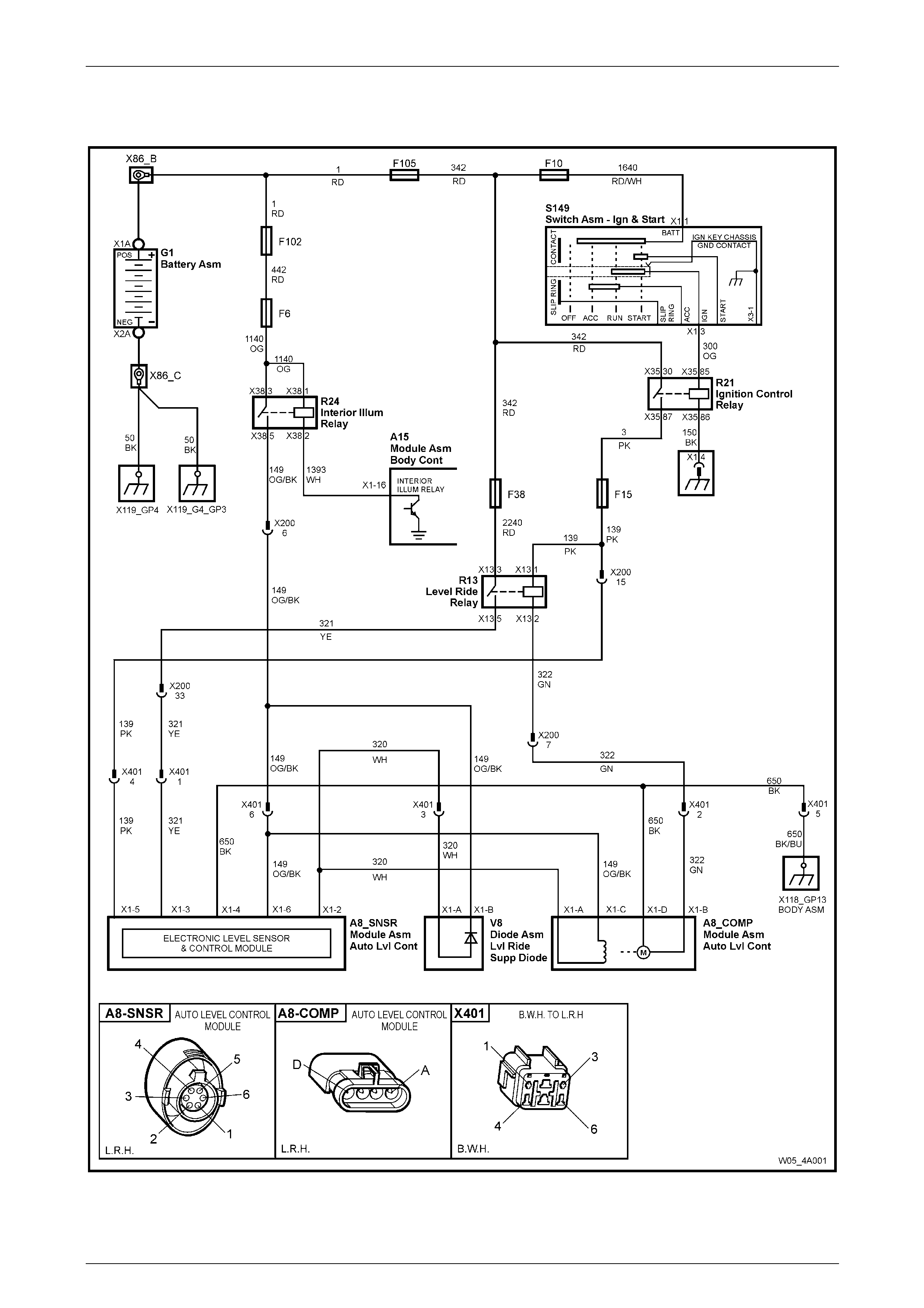
Rear Suspension 4A1 – 81
4A1-81
5.8 Wiring Diagram – Automatic Level Ride
Suspension
Figure 4A1 –121
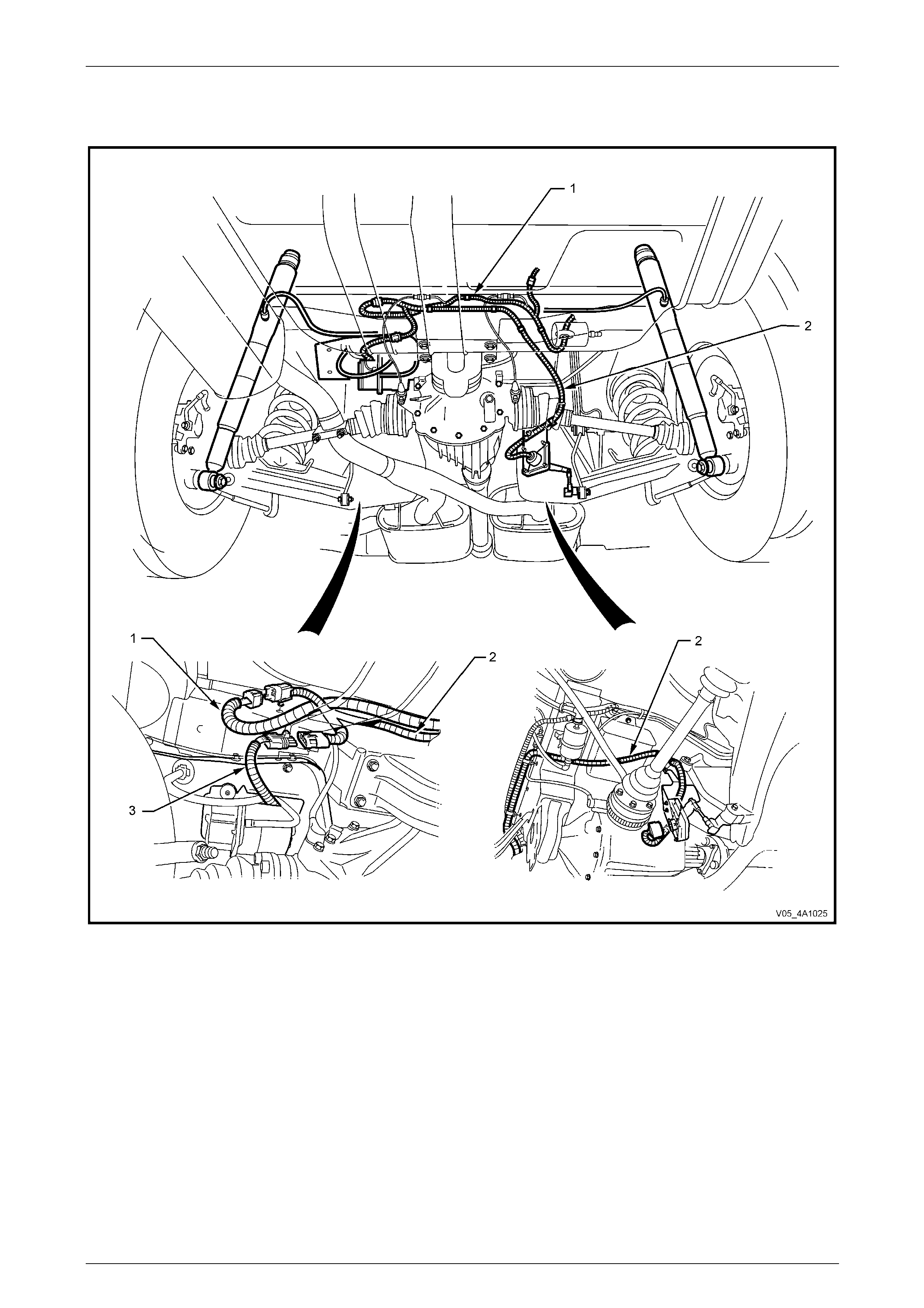
Rear Suspension 4A1 – 82
4A1-82
5.9 Wiring Harness Layout – Automatic
Level Ride Suspension
Figure 4A1 – 122
Legend
1 Level Ride Compressor Wiring Harness
2 Body Wiring Harness
3 Level Ride Wiring Harness
4 Level Ride Harness to Body Harness Connector
5 Level Ride Harness to Level Ride Sensor Connector
6 Level Ride Harness-to-Compressor Harness
Connector
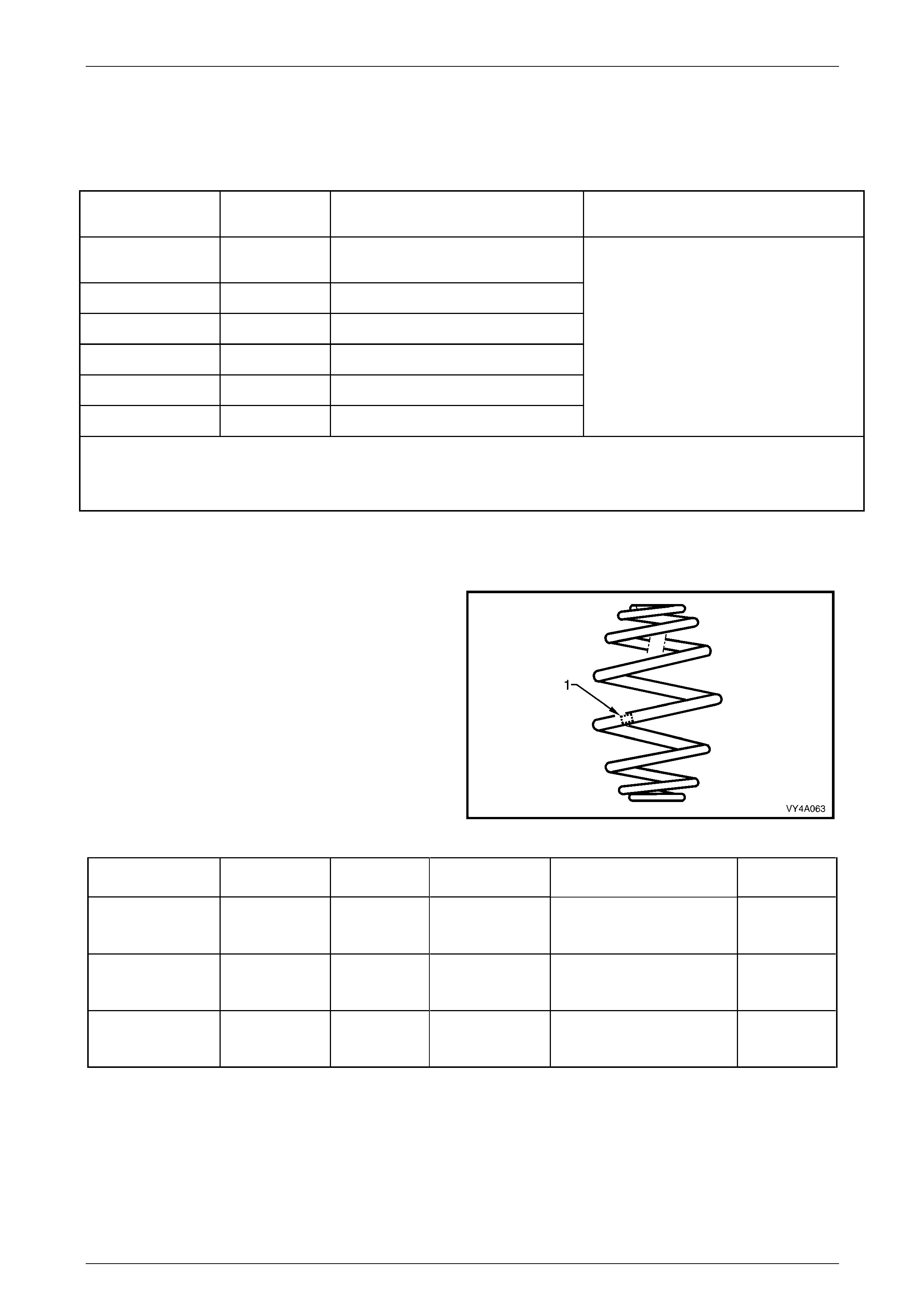
Rear Suspension 4A1 – 83
4A1-83
6 Specifications
Rear Suspension Service Alignment Data
Suspension
Configuration Rear Track
(mm) Rear Wheel Camber
(Variation Side to Side) Toe – Deg rees per Wheel
(Variation Side to side)
Level 1 with LPG &
FE1 1587 -1°23’ to -0°07’ (0°35’ Maximum)
Level 1 & FE2 1587 -1°41’ to -0°25’ (0°35’ Maximum)
Level 1 & FX3 1587 -1°23’ to -0°07’ (0°35’ Maximum)
Levels 2 to 5 & FE1 1577 -1°23’ to -0°07’ (0°35’ Maximum)
Levels 2 to 5 & FE2 1577 -1°41’ to -0°25’ (0°35’ Maximum)
Levels 2 to 5 & FX3 1577 -1°23’ to -0°07’ (0°35’ Maximum)
+0° 40' to 0° 00' (0° 10' Maximum)
Dimensions shown are for a vehicle at curb height, i.e. vehicle ready to drive with all fluids at the recommended levels, the
fuel tank full and without the driver, passenger/s or luggage.
Refer to 3.12 Rear Wheel Alignment Checkin g in this Section for specific details.
Rear Spring Details
Type Variable rate 'Minibloc'
Identification of the rear spring fitted to a particular ve hicle
can be achieved by cross-referenci ng the two digit code,
which is provided on the production identification tag (1)
with the table below.
Figure 4A1 – 123
Suspension No. of Coils Free Length
(mm) Outside
Diameter (mm) Spring Type and Rate Production
I.D. Code
All with FE1 7.8 284 158 Variable
40 N/mm – 71 N/mm
(5200 ± 180 N @ 156 mm) EV
All with FE2 7.5 250 158 Variable
40 N/mm – 71 N/mm
(5200 ± 180 N @ 156 mm) EM
All with FX3 7.8 284 158 Variable
40 N/mm – 71 N/mm
(5200 ± 180 N @ 156 mm) EY
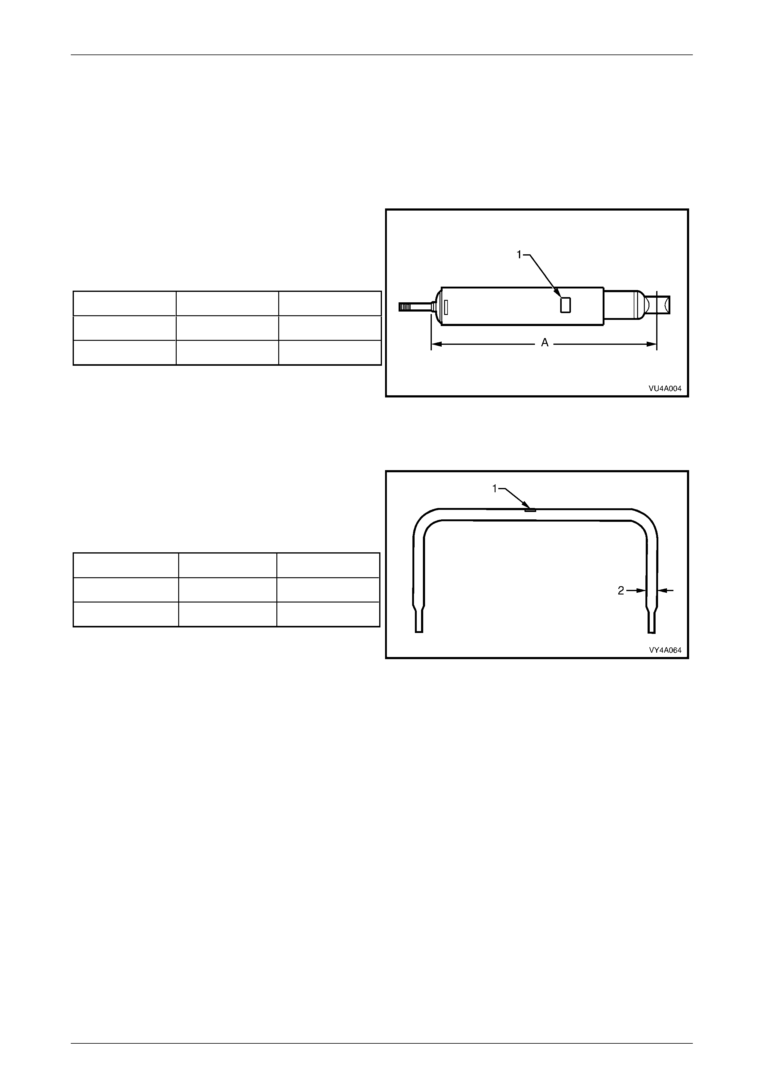
Rear Suspension 4A1 – 84
4A1-84
Rear Shock Absorber Details
Type
Production Option FE1 (Standard) Twin tube hydraulic
Production Option FE2 (Sports) Twin tube hydraulic, gas pressurise d
Production Option FR1 (Country Pack) Twin tube hydraulic, gas pressurised
Identification of the rear shock absorber fitted to a particular
vehicle can be achieved by cross-referencing the two digit
code which is provided on the production identification tag
(1) with the table below.
The table also provides nominal extended lengths (A).
All with FE1 670 MO
All with FE2 670 HJ
All with FX3 664 ME
Figure 3A – 124
Rear Stabiliser Bar Details
Identification of the rear stabilis er shaft fitted to a particular
vehicle can be achieved by cross-referencing the two digit
code which is provided on the production identification tag
(1) with the table below.
The table also provides stabi liser shaft diameters (2).
All with FE1 13 FL
All with FE2 15 F J
All with FX3 13 FL
Figure 3A – 125

Rear Suspension 4A1 – 85
4A1-85
7 Torque Wrench Specifications
ATTENTION
Fasteners must be repl aced after loosening.
Vehicle must be at curb height before final tightening.
Fasteners either ha ve micro encapsu lated seal ant ap plied o r incorpo rate a mechan ical thread lo ck and
should only be re-used once. If in doubt, replacement is recommended.
If one of these identification marks is present alongside a fastener torque wrench specification, the
recommendation regarding that fastener must be adhered to .
Additional Control Arm Adjusting Shaft Lock Nut...............................................50 N.m
Additional Control Arm Ball Joint to Trailing Arm Nut.........................................65 N.m
Additional Control Arm Inner Shaft to Rear Suspension Crossmember Nut ......65 N.m
Collar Nut to Outer Rear Wheel Drive Shaft.....................................................300 N.m
Compressor Assembly Mounting Bolts .............................................................5.0 N.m
Control Arm to Rear Suspension Crossmember Nut .......................................100 N.m
Crossmember Front Mounting Bolt.........................................................125 N.m, then
turn through 40°
Crossmember Front Mounting Brace Bolt to Underbody....................................75 N.m
Crossmember Rear Mount to Final Drive Rear Cover Attaching Bolt ................95 N.m
Crossmember Rear Mount to Underbody Attaching Bolt ..........................35 N.m, then
turn through 60°
Drive Shaft Constant Velocity Joint to Rear Wheel Flange Bolt................50 N.m, then
turn through 70°
Final Drive Assembly to Crossmember Bolt..............................................90 N.m, then
turn through 40°
Intermediate Exhaust Pipe to Catalytic Converter Attaching Bolt .......................45 N.m
Rear Brake Caliper Anchor Plate to Control Arm Bolt........................................85 N.m
Rear Brake Shield to Rear Suspension Control Arm Attachin g Bolt
Upper..............................................75 N.m
Lower..............................................88 N.m
Rear Crossmember Mass Damper Attaching Bolt .............................................45 N.m
Ride Height Sensor Bracket to Crossmember Bolt ............................................25 N.m
Ride Height Sensor to Bracket Nut ...................................................................5.0 N.m
Road Wheel Attaching Nut.....................................................................110 – 140 N.m
Shock Absorber Lower Mounting Bolt..............................................................115 N.m
Shock Absorber Upper Mounting Nut.................................................................14 N.m
Stabiliser Bar Link to Rear Suspension Control Arm Nut.................................100 N.m
Stabiliser Bar Mounting Bracket to Rear Suspension Crossmember Bolt .........22 N.m
Rear Suspension 4A1 – 86
4A1-86
8 Special Tools
Tool Number Illustration Description Classification
AMKM-557
Puller
Used for removing bushing from
crossmember front mounting.
Previously released.
Desirable
AU 385-4
Remover/Installer
Used to remove and install bushin g
into stabiliser bar.
Previously released.
Desirable
AU 416
Torx Bit
Used to remove and install brake
backing plate to rear suspension
control arm attaching bolts.
Previously released.
Unique
AU 534
Torque Limiting Socket
Used in conjunction with an impact
gun to tighten wheel nuts.
Previously released.
Mandatory
AU 592
Bush Remover/Installer
Used to remove and install the rear
crossmember, front bush.
Previously released.
Desirable
C4150-C
Stud Remover
Used to remove the wheel studs from
the rear trunnion.
Previously released.
Unique
E7110
Press Plate
Used for supporting stabiliser bar li nk
while pressing out or installin g
bushing.
Previously released.
Available
Rear Suspension 4A1 – 87
4A1-87
Tool Number Illustration Description Classification
E7115
Angle Wrench
Used to tighten various components
where a turn angle is specifie d in
addition to an initial torque s etting.
Previously released.
Mandatory
E9332-A
Socket Assembly Release Tool
Used to release the additional control
arm socket assembly from the rear
suspension control arm.
Previously released.
Desirable
J22912-01
Press Plates
Used for various press support
operations.
Previously released.
Desirable
KM 307-B
Press Plates
Used to support rear trunnion during
trunnion removal.
Previously released.
Desirable
KM468
Holding Bar
Used to hold outer rear wheel drive
shaft hub from rotating.
Previously released.
Unique
KM508-2
Installing Sleeve
Used to install new bushing in shock
absorber lower mount.
Previously released.
Unique
Rear Suspension 4A1 – 88
4A1-88
Tool Number Illustration Description Classification
KM557-5
Adaptor
Used with puller AMKM-557 for
removing bushing from crossmember
front mounting.
Previously released.
Desirable
KM619
Remover/Installer
Used to press bushing from and into
rear suspension control arms.
Previously released.
Desirable
KM620-7-AUS
Supports
The two revised length supports are
required when undertaking:
Rear wheel drive shaft flange
Rear wheel bearing
Rear outer rear wheel drive shaft
Previously released.
Desirable
KM620-A
Remover/Installer
Used to remove and install rear wheel
drive shaft flange, rear wheel bearing
and outer rear wheel drive shaft.
Previously released.
Unique