
Powertrain Management – GEN III V8 – Diagnostics Page 6C3-2–1
Page 6C3-2–1
Section 6C3-2
Powertrain Management – GEN III V8 –
Diagnostics
ATTENTION
Before performing any service operation or other procedure described in this Section, refer to Section 00
Warnings, Cautions and Notes for correct workshop practices with regard to safety and/or property damage.
1 General Information .............................................................................................................................12
1.1 Starting Diagnostics............................................................................................................................................ 12
1.2 DTC Tables........................................................................................................................................................... 13
Multiple DTCs Fault Condition............................................................................................................................ 13
1.3 Symptoms Diagnostics ....................................................................................................................................... 14
1.4 Diagnostic Trouble Codes (DTCs)...................................................................................................................... 15
Type A – Emission Related DTCs....................................................................................................................... 15
Type B – Emission Related DTCs....................................................................................................................... 15
Conditions for Clearing Type A or Type B DTCs.............................................................................................. 15
Type C – Non-emission Related DTCs............................................................................................................... 15
Condition for Clearing the Type C DTCs.......................................................................................................... 15
Current DTCs........................................................................................................................................................ 16
History DTCs........................................................................................................................................................ 16
2 Wiring Diagram and Connector Chart................................................................................................17
2.1 Wiring Diagram .................................................................................................................................................... 17
2.2 Connector Chart................................................................................................................................................... 26
2.3 Connector Information ........................................................................................................................................ 29
PCM Connector A84 – X1 (Blue)......................................................................................................................... 29
PCM Connector A84 – X2 (Green) ...................................................................................................................... 32
2.4 PCM Connector Terminal Definitions................................................................................................................. 35
PCM Connector A84 – X1 (Blue)......................................................................................................................... 35
PCM Connector A84 – X2 (Green) ...................................................................................................................... 39
3 Diagnostics Starting Point ..................................................................................................................43
3.1 Basic Requirements ............................................................................................................................................ 43
Basic Knowledge Required................................................................................................................................. 43
Basic Tools Required .......................................................................................................................................... 43
3.2 Diagnostic Precautions....................................................................................................................................... 44
3.3 Preliminary Checks.............................................................................................................................................. 45
3.4 Diagnostic System Check................................................................................................................................... 46
4 Symptoms Diagnosis Tables ..............................................................................................................47
4.1 Symptoms Diagnosis Table................................................................................................................................ 47
4.2 Intermittent Fault Conditions.............................................................................................................................. 48
Description........................................................................................................................................................... 48
Diagnostic Table.................................................................................................................................................. 48
4.3 Backfire................................................................................................................................................................. 50
Description........................................................................................................................................................... 50
4.4 Cranks But Does Not Run................................................................................................................................... 52
Definition .............................................................................................................................................................. 52
4.5 Misfires, Cuts Out................................................................................................................................................ 53
Description........................................................................................................................................................... 53
Techline
Techline

Powertrain Management – GEN III V8 – Diagnostics Page 6C3-2–2
Page 6C3-2–2
4.6 Detonation/Spark Knock ..................................................................................................................................... 55
Description........................................................................................................................................................... 55
4.7 Dieseling, Run-On................................................................................................................................................ 56
Description........................................................................................................................................................... 56
4.8 Hard Start ............................................................................................................................................................. 57
Definition .............................................................................................................................................................. 57
4.9 Hesitation, Sag and Stumble............................................................................................................................... 58
Description........................................................................................................................................................... 58
4.10 Lack of Power, Sluggishness or Sponginess.................................................................................................... 59
Description........................................................................................................................................................... 59
4.11 Poor Fuel Economy............................................................................................................................................. 60
Description........................................................................................................................................................... 60
4.12 Rough, Unstable, Incorrect Idle or Stalling ....................................................................................................... 62
Description........................................................................................................................................................... 62
4.13 Surges/Chuggles ................................................................................................................................................. 64
Description........................................................................................................................................................... 64
4.14 Fuel Pump Not Operating.................................................................................................................................... 66
Circuit Description............................................................................................................................................... 66
Additional Information......................................................................................................................................... 66
Test Description................................................................................................................................................... 66
Fuel Pump Not Operating Diagnostic Table...................................................................................................... 66
4.15 Fuel Pump Continuously Operating................................................................................................................... 69
Circuit Description............................................................................................................................................... 69
Additional Information......................................................................................................................................... 69
Test Description................................................................................................................................................... 69
Fuel Pump Continuously Operating Fault Condition Diagnostic Table.......................................................... 69
4.16 Automatic Transmission Functional Check procedure.................................................................................... 71
Description........................................................................................................................................................... 71
4.17 Automatic Transmission Power / Economy Switch.......................................................................................... 74
Circuit Description............................................................................................................................................... 74
Additional Information......................................................................................................................................... 74
Fuel Pump Continuously Operating Fault Condition Diagnostic Table.......................................................... 74
5 Diagnostic Trouble Codes...................................................................................................................76
5.1 DTC List................................................................................................................................................................ 76
5.2 DTC P1539 – A/C Clutch Feedback Circuit........................................................................................................ 83
DTC Description................................................................................................................................................... 83
Circuit Description............................................................................................................................................... 83
Additional Information......................................................................................................................................... 83
Conditions for Running the DTC........................................................................................................................ 83
Conditions for Setting the DTC........................................................................................................................... 83
Conditions for Clearing the DTC ........................................................................................................................ 83
DTC P1539 Diagnostic Table............................................................................................................................... 83
5.3 DTC P0645 – A/C Clutch Relay Control Circuit ................................................................................................. 86
DTC Description................................................................................................................................................... 86
Circuit Description............................................................................................................................................... 86
Additional Information......................................................................................................................................... 86
Conditions for Running the DTC........................................................................................................................ 86
Conditions for Setting the DTC........................................................................................................................... 86
Conditions for Clearing the DTC ........................................................................................................................ 86
DTC P0645 Diagnostic Table............................................................................................................................... 87
5.4 DTC P0530 – A/C Refrigerant Pressure Sensor Circuit .................................................................................... 88
DTC Description................................................................................................................................................... 88
Circuit Description............................................................................................................................................... 88
Additional Information......................................................................................................................................... 88
Conditions for Running the DTC........................................................................................................................ 88
Conditions for Setting the DTC........................................................................................................................... 88
Conditions for Clearing the DTC ........................................................................................................................ 88
Test Description................................................................................................................................................... 88
DTC P0530 Diagnostic Table............................................................................................................................... 89

Powertrain Management – GEN III V8 – Diagnostics Page 6C3-2–3
Page 6C3-2–3
5.5 DTC P1637 – Generator L Terminal Circuit Malfunction................................................................................... 91
DTC Description................................................................................................................................................... 91
Circuit Description............................................................................................................................................... 91
Additional Information......................................................................................................................................... 91
Conditions for Running the DTC........................................................................................................................ 91
Key ON Test..................................................................................................................................................... 91
Engine Run Test............................................................................................................................................... 91
Conditions for Setting the DTC........................................................................................................................... 91
Conditions for Clearing the DTC ........................................................................................................................ 91
DTC P1637 Diagnostic Table............................................................................................................................... 92
5.6 DTC P1125, P2120 or P2125 – APP Sensor Circuit........................................................................................... 93
DTC Description................................................................................................................................................... 93
Circuit Description............................................................................................................................................... 93
Additional Information......................................................................................................................................... 93
Conditions for Running the DTC........................................................................................................................ 93
Conditions for Setting the DTC........................................................................................................................... 93
DTC P1125 ...................................................................................................................................................... 93
DTC P2120 and P2125 .................................................................................................................................... 93
Conditions for Clearing the DTC ........................................................................................................................ 93
Test Description................................................................................................................................................... 94
DTC P1125, P2120 or P2125 Diagnostic Table .................................................................................................. 94
5.7 DTC P0894 – Automatic Transmission Component Slipping...........................................................................96
DTC Description................................................................................................................................................... 96
Circuit Description............................................................................................................................................... 96
Additional Information......................................................................................................................................... 96
Conditions for Running the DTC........................................................................................................................ 96
Conditions for Setting the DTC........................................................................................................................... 97
Condition 1....................................................................................................................................................... 97
Condition 2....................................................................................................................................................... 97
Condition 3....................................................................................................................................................... 97
Conditions for Clearing the DTC ........................................................................................................................ 97
DTC P0894 Diagnostic Table............................................................................................................................... 97
5.8 DTC P1574 – Stop Lamp Switch Circuit Malfunction...................................................................................... 101
Circuit Description............................................................................................................................................. 101
Additional Information....................................................................................................................................... 101
Conditions for Running the DTC...................................................................................................................... 101
Conditions for Setting the DTC......................................................................................................................... 101
Conditions for Clearing the DTC ...................................................................................................................... 101
DTC P1574 Diagnostic Table............................................................................................................................. 101
5.9 DTC P1575 – Extended Brake Travel Switch Circuit....................................................................................... 103
Circuit Description............................................................................................................................................. 103
Additional Information....................................................................................................................................... 103
Conditions for Running the DTC...................................................................................................................... 103
Conditions for Setting the DTC......................................................................................................................... 103
Conditions for Clearing the DTC ...................................................................................................................... 103
DTC P1575 Diagnostic Table............................................................................................................................. 103
5.10 DTC P0341, P0342 or P0343 – Camshaft Position Sensor Circuit................................................................. 105
DTC Description................................................................................................................................................. 105
Circuit Description............................................................................................................................................. 105
Additional Information....................................................................................................................................... 105
Conditions for Running the DTC...................................................................................................................... 105
Conditions for Setting the DTC......................................................................................................................... 105
Conditions for Clearing the DTC ...................................................................................................................... 105
Test Description................................................................................................................................................. 105
DTC P0341, P0342 or P0343 Diagnostic Table ................................................................................................ 106
5.11 DTC P0481 – Cooling Fan High Speed Relay Circuit...................................................................................... 108
DTC Description................................................................................................................................................. 108
Circuit Description............................................................................................................................................. 108
Additional Information....................................................................................................................................... 108
Conditions for Running the DTC...................................................................................................................... 108

Powertrain Management – GEN III V8 – Diagnostics Page 6C3-2–4
Page 6C3-2–4
Conditions for Setting the DTC......................................................................................................................... 108
Conditions for Clearing the DTC ...................................................................................................................... 108
DTC P0481 Diagnostic Table............................................................................................................................. 108
5.12 DTC P0335 or P0336 – Crankshaft Position Sensor Circuit........................................................................... 110
DTC Description................................................................................................................................................. 110
Circuit Description............................................................................................................................................. 110
Additional Information....................................................................................................................................... 110
Conditions for Running the DTC...................................................................................................................... 110
DTC P0335 .................................................................................................................................................... 110
DTC P0336 .................................................................................................................................................... 110
Conditions for Setting the DTC......................................................................................................................... 111
Conditions for Clearing the DTC ...................................................................................................................... 111
DTC P0335 or P0336 Diagnostic Table............................................................................................................. 111
5.13 DTC P0567– Cruise Control Resume/Accel Malfunction................................................................................ 113
DTC Description................................................................................................................................................. 113
Circuit Description............................................................................................................................................. 113
Additional Information....................................................................................................................................... 113
Conditions for Running the DTC...................................................................................................................... 113
Conditions for Setting the DTC......................................................................................................................... 113
Action Taken When the DTC Sets .................................................................................................................... 113
Conditions for Clearing the DTC ...................................................................................................................... 113
DTC P0567 Diagnostic Table............................................................................................................................. 114
5.14 DTC P0568– Cruise Control Set/Coast Malfunction........................................................................................ 115
DTC Description................................................................................................................................................. 115
Circuit Description............................................................................................................................................. 115
Additional Information....................................................................................................................................... 115
Conditions for Running the DTC...................................................................................................................... 115
Conditions for Setting the DTC......................................................................................................................... 115
Action Taken When the DTC Sets .................................................................................................................... 115
Conditions for Clearing the DTC ...................................................................................................................... 115
DTC P0568 Diagnostic Table............................................................................................................................. 116
5.15 DTC P0571 – Cruise Control Brake Switch Circuit 1 Malfunction.................................................................. 117
DTC Description................................................................................................................................................. 117
Circuit Description............................................................................................................................................. 117
Additional Information....................................................................................................................................... 117
Conditions for Running the DTC...................................................................................................................... 117
Conditions for Setting the DTC......................................................................................................................... 117
Conditions for Clearing the DTC ...................................................................................................................... 117
DTC P0571 Diagnostic Table............................................................................................................................. 117
5.16 DTC P2108 – Electronic Throttle Control Malfunction.................................................................................... 119
DTC Description................................................................................................................................................. 119
Circuit Description............................................................................................................................................. 119
Additional Information....................................................................................................................................... 119
Conditions for Running the DTC...................................................................................................................... 119
Conditions for Setting the DTC......................................................................................................................... 119
Conditions for Clearing the DTC ...................................................................................................................... 119
DTC P2108 Diagnostic Table............................................................................................................................. 119
5.17 DTC P0116, P0117, P0118, P0125, P1114, P1115 or P1258 – Engin e Co olant Temperature Sensor Circui t121
DTC Description................................................................................................................................................. 121
Circuit Description............................................................................................................................................. 121
Additional Information....................................................................................................................................... 121
Conditions for Running the DTC...................................................................................................................... 122
DTC P0116 .................................................................................................................................................... 122
DTC P0117 .................................................................................................................................................... 122
DTC P0118 .................................................................................................................................................... 122
DTC P0125 .................................................................................................................................................... 122
DTC P1114 .................................................................................................................................................... 122
DTC P1115 .................................................................................................................................................... 122
DTC P1258 .................................................................................................................................................... 122

Powertrain Management – GEN III V8 – Diagnostics Page 6C3-2–5
Page 6C3-2–5
Conditions for Setting the DTC......................................................................................................................... 122
DTC P0116 .................................................................................................................................................... 122
DTC P0117 .................................................................................................................................................... 122
DTC P0118 .................................................................................................................................................... 122
DTC P0125 .................................................................................................................................................... 123
DTC P1114 .................................................................................................................................................... 123
DTC P1115 .................................................................................................................................................... 123
DTC P1258 .................................................................................................................................................... 123
Conditions for Clearing the DTC ...................................................................................................................... 123
DTC P0116, P0117, P0118, P0125, P1114, P1115 or P1258 Diagnostic Table............................................... 123
5.18 DTC P0522 or P0523 – Engine Oil Pressure Sensor Circuit........................................................................... 125
DTC Description................................................................................................................................................. 125
Circuit Description............................................................................................................................................. 125
Additional Information....................................................................................................................................... 125
Conditions for Running the DTC...................................................................................................................... 125
Conditions for Setting the DTC......................................................................................................................... 125
Conditions for Clearing the DTC ...................................................................................................................... 125
Test Description................................................................................................................................................. 125
DTC P0522 or P0523 Diagnostic Table............................................................................................................. 126
5.19 DTC P0654 – Engine Speed Output Circuit...................................................................................................... 128
DTC Description................................................................................................................................................. 128
Circuit Description............................................................................................................................................. 128
Additional Information....................................................................................................................................... 128
Conditions for Running the DTC...................................................................................................................... 128
Conditions for Setting the DTC......................................................................................................................... 128
Conditions for Clearing the DTC ...................................................................................................................... 128
DTC P0654 Diagnostic Table............................................................................................................................. 128
5.20 DTC P0443 – Evaporative Emission Control System Purge Control Circuit................................................. 130
DTC Description................................................................................................................................................. 130
Circuit Description............................................................................................................................................. 130
Additional Information....................................................................................................................................... 130
Conditions for Running the DTC...................................................................................................................... 130
Conditions for Setting the DTC......................................................................................................................... 130
Conditions for Clearing the DTC ...................................................................................................................... 130
DTC P0443 Diagnostic Table............................................................................................................................. 130
5.21 DTC P0200 – Fuel Injector Control Circuit....................................................................................................... 132
DTC Description................................................................................................................................................. 132
Circuit Description............................................................................................................................................. 132
Additional Information....................................................................................................................................... 132
Conditions for Running the DTC...................................................................................................................... 132
Conditions for Setting the DTC......................................................................................................................... 132
Conditions for Clearing the DTC ...................................................................................................................... 132
Test Description................................................................................................................................................. 132
DTC P0200 Diagnostic Table............................................................................................................................. 133
5.22 DTC P0461, P0462 or P0463 – Fuel Level Sensor Circuit............................................................................... 135
DTC Description................................................................................................................................................. 135
Circuit Description............................................................................................................................................. 135
Additional Information....................................................................................................................................... 135
Conditions for Running the DTC...................................................................................................................... 135
Conditions for Setting the DTC......................................................................................................................... 135
DTC P0461 .................................................................................................................................................... 135
DTC P0462 and P0463 .................................................................................................................................. 135
Conditions for Clearing the DTC ...................................................................................................................... 136
DTC P0461, P0462 or P0463 Diagnostic Table ................................................................................................ 136
5.23 DTC P0230 – Fuel Pump Control Circuit.......................................................................................................... 138
DTC Description................................................................................................................................................. 138
Circuit Description............................................................................................................................................. 138
Additional Information....................................................................................................................................... 138
Conditions for Running the DTC...................................................................................................................... 138
Conditions for Setting the DTC......................................................................................................................... 138

Powertrain Management – GEN III V8 – Diagnostics Page 6C3-2–6
Page 6C3-2–6
Conditions for Clearing the DTC ...................................................................................................................... 138
Test Description................................................................................................................................................. 138
DTC P0230 Diagnostic Table............................................................................................................................. 139
5.24 DTC P0135 or P0155 – Heated Oxygen Sensor Heater Control Circuit......................................................... 141
DTC Description................................................................................................................................................. 141
Circuit Description............................................................................................................................................. 141
Additional Information....................................................................................................................................... 141
Conditions for Running the DTC...................................................................................................................... 141
Current Monitor .............................................................................................................................................. 141
Resistance Out of Range............................................................................................................................... 141
Conditions for Setting the DTC......................................................................................................................... 142
Conditions for Clearing the DTC ...................................................................................................................... 142
Test Description................................................................................................................................................. 142
DTC P0135 or P0155 Diagnostic Table............................................................................................................. 142
5.25 DTC P0131, P0132, P0134, P0151, P0152, P0154, P0171, P0172, P0174 or P0175 – Heated Oxygen Sensor
Reference Circuit............................................................................................................................................... 144
DTC Description................................................................................................................................................. 144
Circuit Description............................................................................................................................................. 144
Additional Information....................................................................................................................................... 144
Conditions for Running the DTC...................................................................................................................... 145
DTC P0131, P0132, P0151 and P0152.......................................................................................................... 145
DTC P0134 and P0154 .................................................................................................................................. 145
DTC P0171, P0172, P0174 and P0175.......................................................................................................... 145
Conditions for Setting the DTC......................................................................................................................... 146
DTC P0131 and P0151 .................................................................................................................................. 146
DTC P0132 and P0152 .................................................................................................................................. 146
DTC P0134 and P0154 .................................................................................................................................. 146
DTC P0171 and P0174 .................................................................................................................................. 146
DTC P0172 and P0175 .................................................................................................................................. 146
Conditions for Clearing the DTC ...................................................................................................................... 146
DTC P0131, P0132, P0134, P0151, P0152, P0154, P0171, P0172, P0174 or P0175 Diagnostic Table.......... 146
5.26 DTC P0351, P0352, P0353, P0354, P0355, P0356, P0357 or P0358 – Ignition Control Circuits.................... 148
DTC Description................................................................................................................................................. 148
Circuit Description............................................................................................................................................. 148
Additional Information....................................................................................................................................... 148
Conditions for Running the DTC...................................................................................................................... 148
Conditions for Setting the DTC......................................................................................................................... 148
Conditions for Clearing the DTC ...................................................................................................................... 149
Test Description................................................................................................................................................. 149
DTC P0351, P0352, P0353, P0354, P0355, P0356, P0357 or P0358 Diagnostic Table................................... 149
5.27 DTC P1626, P1630 or P1631 – Immobiliser Signal.......................................................................................... 151
DTC Description................................................................................................................................................. 151
Circuit Description............................................................................................................................................. 151
Additional Information....................................................................................................................................... 151
Conditions for Running the DTC...................................................................................................................... 152
DTC P1626 .................................................................................................................................................... 152
DTC P1630 .................................................................................................................................................... 152
DTC P1631 .................................................................................................................................................... 152
Conditions for Setting the DTC......................................................................................................................... 152
DTC P1626 .................................................................................................................................................... 152
DTC P1630 .................................................................................................................................................... 152
DTC P1631 .................................................................................................................................................... 152
Conditions for Clearing the DTC ...................................................................................................................... 152
Test Description................................................................................................................................................. 152
DTC P1626, P1630 or P1631 Diagnostic Chart ................................................................................................ 152
5.28 DTC P0112, P0113, P1111 or P1112 – Intake Air Temperature Sensor Circuit ............................................. 154
DTC Description................................................................................................................................................. 154
Circuit Description............................................................................................................................................. 154
Additional Information....................................................................................................................................... 154

Powertrain Management – GEN III V8 – Diagnostics Page 6C3-2–7
Page 6C3-2–7
Conditions for Running the DTC...................................................................................................................... 154
DTC P0112 .................................................................................................................................................... 154
DTC P0113 .................................................................................................................................................... 155
DTC P1111 .................................................................................................................................................... 155
DTC P1112 .................................................................................................................................................... 155
Conditions for Setting the DTC......................................................................................................................... 155
DTC P0112 .................................................................................................................................................... 155
DTC P0113 .................................................................................................................................................... 155
DTC P1111 .................................................................................................................................................... 155
DTC P1112 .................................................................................................................................................... 155
Conditions for Clearing DTCs........................................................................................................................... 155
Test Description................................................................................................................................................. 155
DTC P0112, P0113, P1111 or P1112 Diagnostic Table.................................................................................... 156
5.29 DTC P0325, P0327 or P0332 – Knock Sensor System.................................................................................... 158
DTC Description................................................................................................................................................. 158
Circuit Description............................................................................................................................................. 158
Additional Information....................................................................................................................................... 158
Conditions for Running the DTC...................................................................................................................... 158
DTC P0325 .................................................................................................................................................... 158
DTC P0327 and P0332 .................................................................................................................................. 158
Conditions for Setting the DTC......................................................................................................................... 159
DTC P0325 .................................................................................................................................................... 159
DTC P0327 and P0332 .................................................................................................................................. 159
Conditions for Clearing the DTC ...................................................................................................................... 159
Test Description................................................................................................................................................. 159
DTC P0325, P0327 or P0332 Diagnostic Table ................................................................................................ 159
5.30 DTC P0106, P0107, P0108, P1106 or P1107 – Manifold Absolute Pressure Sensor Circuit......................... 161
DTC Description................................................................................................................................................. 161
Circuit Description............................................................................................................................................. 161
Additional Information....................................................................................................................................... 161
Conditions for Running the DTC...................................................................................................................... 162
DTC P0106 .................................................................................................................................................... 162
DTC P0107 .................................................................................................................................................... 162
DTC P0108 .................................................................................................................................................... 162
DTC P1106 .................................................................................................................................................... 162
DTC P1107 .................................................................................................................................................... 162
Conditions for Setting the DTC......................................................................................................................... 163
DTC P0106 .................................................................................................................................................... 163
DTC P0107 .................................................................................................................................................... 163
DTC P0108 .................................................................................................................................................... 163
DTC P1106 .................................................................................................................................................... 163
DTC P1107 .................................................................................................................................................... 163
Conditions for Clearing the DTC ...................................................................................................................... 163
Test Description................................................................................................................................................. 163
DTC P0106, P0107, P0108, P1106 or P1107 Diagnostic Table........................................................................ 163
5.31 DTC P0068 – MAP / MAF and Throttle Position Correlation Fault................................................................. 166
DTC Description................................................................................................................................................. 166
Circuit Description............................................................................................................................................. 166
Additional Information....................................................................................................................................... 166
Conditions for Running the DTC...................................................................................................................... 166
Conditions for Setting the DTC......................................................................................................................... 166
Conditions for Clearing the DTC ...................................................................................................................... 166
Test Description................................................................................................................................................. 166
DTC P0068 Diagnostic Table............................................................................................................................. 167
5.32 DTC P0101, P0102 or P0103 – Mass Air Flow Sensor Circuit ........................................................................ 168
DTC Description................................................................................................................................................. 168
Circuit Description............................................................................................................................................. 168
Additional Information....................................................................................................................................... 168
Conditions for Running the DTC...................................................................................................................... 169
DTC P0101 .................................................................................................................................................... 169

Powertrain Management – GEN III V8 – Diagnostics Page 6C3-2–8
Page 6C3-2–8
DTC P0102 .................................................................................................................................................... 169
DTC P0103 .................................................................................................................................................... 169
Conditions for Setting the DTC......................................................................................................................... 169
DTC P0101 .................................................................................................................................................... 169
DTC P0102 .................................................................................................................................................... 169
DTC P0103 .................................................................................................................................................... 169
Conditions for Clearing the DTC ...................................................................................................................... 169
Test Description................................................................................................................................................. 169
DTC P0101, P0102 or P0103 Diagnostic Table ................................................................................................ 170
5.33 DTC P0601, P0602, P0604 or P2610 – Powertrain Control Module Internal Performance, Programming or
Memory Fault...................................................................................................................................................... 172
DTC Description................................................................................................................................................. 172
Circuit Description............................................................................................................................................. 172
Additional Information....................................................................................................................................... 172
Conditions for Running the DTC...................................................................................................................... 172
Conditions for Setting the DTC......................................................................................................................... 173
Test Description................................................................................................................................................. 173
DTC P0601, P0602, P0604 or P2610 Diagnostic Table.................................................................................... 173
5.34 DTC P0748 – Pressure Control Solenoid Circuit............................................................................................. 174
DTC Description................................................................................................................................................. 174
Circuit Description............................................................................................................................................. 174
Additional Information....................................................................................................................................... 174
Conditions for Running the DTC...................................................................................................................... 174
Conditions for Setting the DTC......................................................................................................................... 174
Conditions for Clearing the DTC ...................................................................................................................... 174
Test Description................................................................................................................................................. 174
DTC P0748 Diagnostic Table............................................................................................................................. 175
5.35 DTC P0801 – Reverse Inhibit Solenoid Control Circuit .................................................................................. 176
DTC Description................................................................................................................................................. 176
Circuit Description............................................................................................................................................. 176
Additional Information....................................................................................................................................... 176
Conditions for Running the DTC...................................................................................................................... 176
Conditions for Setting the DTC......................................................................................................................... 176
Conditions for Clearing the DTC ...................................................................................................................... 176
DTC P0801 Diagnostic Table............................................................................................................................. 176
5.36 DTC P0562 or P0563 – System Voltage............................................................................................................ 178
DTC Description................................................................................................................................................. 178
Circuit Description............................................................................................................................................. 178
Additional Information....................................................................................................................................... 178
Conditions for Running the DTC...................................................................................................................... 178
Conditions for Setting the DTC......................................................................................................................... 178
Conditions for Clearing the DTC ...................................................................................................................... 178
DTC P0562 or P0563 Diagnostic Table............................................................................................................. 179
5.37 DTC P0506, P0507, P2101 or P2119 – TAC Motor Control Circuit ................................................................. 180
DTC Description................................................................................................................................................. 180
Circuit Description............................................................................................................................................. 180
Additional Information....................................................................................................................................... 180
Conditions for Running the DTC...................................................................................................................... 180
DTC P0506 and P0507 .................................................................................................................................. 180
DTC P2101 .................................................................................................................................................... 181
DTC P2119 .................................................................................................................................................... 181
Conditions for Setting the DTC......................................................................................................................... 181
DTC P0506 .................................................................................................................................................... 181
DTC P0507 .................................................................................................................................................... 181
DTC P2101 and P2119 .................................................................................................................................. 181
Conditions for Clearing the DTC ...................................................................................................................... 181
Test Description................................................................................................................................................. 181
DTC P0506, P0507, P2101 or P2119 Diagnostic Table.................................................................................... 182
5.38 DTC P1810 – TFP Valve Position Switch Circuit............................................................................................. 184
DTC Description................................................................................................................................................. 184

Powertrain Management – GEN III V8 – Diagnostics Page 6C3-2–9
Page 6C3-2–9
Circuit Description............................................................................................................................................. 184
Additional Information....................................................................................................................................... 184
TFP Manual Valve Position Switch Logic Table .............................................................................................. 185
Conditions for Running the DTC ...................................................................................................................... 185
Conditions for Setting the DTC......................................................................................................................... 185
Condition1 ...................................................................................................................................................... 185
Condition 2 ..................................................................................................................................................... 185
Condition 3 ..................................................................................................................................................... 185
Conditions for Clearing the DTC ...................................................................................................................... 185
Test Description................................................................................................................................................. 186
DTC P1810 Diagnostic Table............................................................................................................................. 186
5.39
DTC U0107 – Throttle Actuator Control Serial Communication Malfunction................................................ 188
DTC Description................................................................................................................................................. 188
Circuit Description............................................................................................................................................. 188
Additional Information....................................................................................................................................... 188
Conditions for Running the DTC ...................................................................................................................... 188
Conditions for Setting the DTC......................................................................................................................... 188
Conditions for Clearing the DTC ...................................................................................................................... 188
DTC U0107 Diagnostic Table ............................................................................................................................ 188
5.40
DTC P0120, P0121, P0122, P0123, P0220, P1121, P1122, P1516 or P2135 – Throttle Position Sensor
Circuit ................................................................................................................................................................. 190
DTC Description................................................................................................................................................. 190
Circuit Description............................................................................................................................................. 190
Additional Information....................................................................................................................................... 190
Conditions for Running the DTC ...................................................................................................................... 191
DTC P0120, P0220 and P2135...................................................................................................................... 191
DTC P0121 .................................................................................................................................................... 191
DTC P0122, P0123, P1121 and P1122.......................................................................................................... 191
DTC P1516 .................................................................................................................................................... 191
Conditions for Setting the DTC......................................................................................................................... 191
Except DTC P1516......................................................................................................................................... 191
DTC P1516 .................................................................................................................................................... 191
Conditions for Clearing the DTC ...................................................................................................................... 191
Test Description................................................................................................................................................. 191
DTC P0120, P0121, P0122, P0123, P0220, P1121, P1122, P1516 or P2135 Diagnostic Table....................... 192
5.41
DTC P0740, P0741, P0742 or P2761 – Torque Converter Clutch Solenoid Circuit ....................................... 194
DTC Description................................................................................................................................................. 194
Circuit Description............................................................................................................................................. 194
Additional Information....................................................................................................................................... 194
Conditions for Running the DTC ...................................................................................................................... 194
DTC P0740 .................................................................................................................................................... 194
DTC P0741 and P2761 .................................................................................................................................. 194
DTC P0742 .................................................................................................................................................... 195
Conditions for Setting the DTC......................................................................................................................... 195
DTC P0740 .................................................................................................................................................... 195
DTC P0741 and P2761 .................................................................................................................................. 195
DTC P0742 .................................................................................................................................................... 195
Conditions for Clearing the DTC ...................................................................................................................... 195
Test Description................................................................................................................................................. 195
DTC P0740, P0741, P0742 or P2761 Diagnostic Table .................................................................................... 196
5.42
DTC P0218, P0711, P0712 or P0713 – Transmission Fluid Temperature Sensor Circuit............................. 198
DTC Description................................................................................................................................................. 198
Circuit Description............................................................................................................................................. 198
Additional Information....................................................................................................................................... 198
Conditions for Running the DTC ...................................................................................................................... 198
DTC P0218 .................................................................................................................................................... 198
DTC P0711 .................................................................................................................................................... 199
DTC P0712 and P0713 .................................................................................................................................. 199
Conditions for Setting the DTC......................................................................................................................... 199
DTC P0218 .................................................................................................................................................... 199

Powertrain Management – GEN III V8 – Diagnostics Page 6C3-2–10
Page 6C3-2–10
DTC P0711 .................................................................................................................................................... 199
DTC P0712 .................................................................................................................................................... 199
DTC P0713 .................................................................................................................................................... 199
Conditions for Clearing the DTC ...................................................................................................................... 199
Test Description................................................................................................................................................. 199
DTC P0218, P0711, P0712 or P0713 Diagnostic Table .................................................................................... 200
5.43
DTC P0705 or P0706 – Transmission Range Sensor ...................................................................................... 202
DTC Description................................................................................................................................................. 202
Circuit Description............................................................................................................................................. 202
Additional Information....................................................................................................................................... 202
Transmission Range Switch Valid Combination Table................................................................................... 202
Conditions for Running the DTC ...................................................................................................................... 202
Conditions for Setting the DTC......................................................................................................................... 203
Conditions for Clearing the DTC ...................................................................................................................... 203
Test Description................................................................................................................................................. 203
DTC P0705 or P0706 Diagnostic Table............................................................................................................. 203
5.44
DTC P0608 – Vehicle Speed Output Circuit..................................................................................................... 206
DTC Description................................................................................................................................................. 206
Circuit Description............................................................................................................................................. 206
Additional Information....................................................................................................................................... 206
Conditions for Running the DTC ...................................................................................................................... 206
Conditions for Setting the DTC......................................................................................................................... 206
Conditions for Clearing the DTC ...................................................................................................................... 206
Test Description................................................................................................................................................. 206
DTC P0608 Diagnostic Table............................................................................................................................. 207
5.45
DTC P0500, P0502 or P0503 – Vehicle Speed Sensor Circuit ........................................................................ 209
DTC Description................................................................................................................................................. 209
Circuit Description............................................................................................................................................. 209
Additional Information....................................................................................................................................... 209
Conditions for Running the DTC ...................................................................................................................... 209
DTC P0500 .................................................................................................................................................... 209
DTC P0502 .................................................................................................................................................... 209
DTC P0503 .................................................................................................................................................... 210
Conditions for Setting the DTC......................................................................................................................... 210
DTC P0500 .................................................................................................................................................... 210
DTC P0502 .................................................................................................................................................... 210
DTC P0503 .................................................................................................................................................... 210
Conditions for Clearing the DTC ...................................................................................................................... 210
DTC P0500, P0502 or P0503 Diagnostic Table ................................................................................................ 210
5.46
DTC P0751, P0752 or P0753 – 1-2 Shift Solenoid A ........................................................................................ 213
DTC Description................................................................................................................................................. 213
Circuit Description............................................................................................................................................. 213
Additional Information....................................................................................................................................... 213
Shift Solenoid Valid Combination Table .......................................................................................................... 213
Conditions for Running the DTC ...................................................................................................................... 214
DTC P0751 .................................................................................................................................................... 214
DTC P0752 .................................................................................................................................................... 214
DTC P0753 .................................................................................................................................................... 214
Conditions for Setting the DTC......................................................................................................................... 214
DTC P0751 .................................................................................................................................................... 214
DTC P0752 .................................................................................................................................................... 215
DTC P0753 .................................................................................................................................................... 215
Conditions for Clearing the DTC ...................................................................................................................... 215
Test Description................................................................................................................................................. 215
DTC P0751, P0752 or P0753 Diagnostic Table ................................................................................................ 215
5.47
DTC P0756, P0757 or P0758 – 2-3 Shift Solenoid B ........................................................................................ 217
DTC Description................................................................................................................................................. 217
Circuit Description............................................................................................................................................. 217
Additional Information....................................................................................................................................... 217
Shift Solenoid Valid Combination Table .......................................................................................................... 217

Powertrain Management – GEN III V8 – Diagnostics Page 6C3-2–11
Page 6C3-2–11
Conditions for Running the DTC ...................................................................................................................... 217
DTC P0756 .................................................................................................................................................... 217
DTC P0757 .................................................................................................................................................... 218
DTC P0758 .................................................................................................................................................... 218
Conditions for Setting the DTC......................................................................................................................... 218
DTC P0756 .................................................................................................................................................... 218
DTC P0757 .................................................................................................................................................... 218
DTC P0758 .................................................................................................................................................... 219
Conditions for Clearing the DTC ...................................................................................................................... 219
Test Description................................................................................................................................................. 219
DTC P0756, P0757 or P0758 Diagnostic Table ................................................................................................ 219
5.48
DTC P0785 – 3-2 Downshift Control Solenoid Circuit..................................................................................... 221
DTC Description................................................................................................................................................. 221
Circuit Description............................................................................................................................................. 221
Additional Information....................................................................................................................................... 221
Conditions for Running the DTC ...................................................................................................................... 221
Conditions for Setting the DTC......................................................................................................................... 221
Conditions for Clearing the DTC ...................................................................................................................... 221
Test Description................................................................................................................................................. 221
DTC P0785 Diagnostic Table............................................................................................................................. 222
5.49
DTC P0641 – 5 Volt Reference Circuit 1 Malfunction...................................................................................... 224
DTC Description................................................................................................................................................. 224
Circuit Description............................................................................................................................................. 224
Additional Information....................................................................................................................................... 224
Conditions for Running the DTC ...................................................................................................................... 224
Conditions for Setting the DTC......................................................................................................................... 224
Conditions for Clearing the DTC ...................................................................................................................... 224
DTC P0641 Diagnostic Table............................................................................................................................. 225
5.50
DTC P0651 – 5 Volt Reference Circuit 2 Malfunction...................................................................................... 227
DTC Description................................................................................................................................................. 227
Circuit Description............................................................................................................................................. 227
Additional Information....................................................................................................................................... 227
Conditions for Running the DTC ...................................................................................................................... 227
Conditions for Setting the DTC......................................................................................................................... 227
Conditions for Clearing the DTC ...................................................................................................................... 227
DTC P0651 Diagnostic Table............................................................................................................................. 227

Powertrain Management – GEN III V8 – Diagnostics Page 6C3-2–12
Page 6C3-2–12
1 General Information
1.1 Starting Diagnostics
The GEN III V8 Powertrain Management diagnostic procedures are organised in a logical structure that begins with the
Diagnostic System Check. The Diagnostic S ystem Check directs the diagnostic procedure in logical steps necess ary to
diagnose an engine driveability fault conditio n. Refer to 3.4 Diagnostic System Check.

Powertrain Management – GEN III V8 – Diagnostics Page 6C3-2–13
Page 6C3-2–13
1.2 DTC Tables
The Diagnostic System Check directs the diagnostic procedure to the appr opriate Diagnostic Trouble Code (DTC) Tables
if there is a DTC currently stored in the PCM.
The diagnostic tables locate a faulty circuit or component through a logic based on the process of elimination. These
diagnostic tables are developed with the following assumptions:
• the vehicle functioned correctly at the time of assembly,
• there are no multiple faults, and
• the problem currently exists.
Understanding and the correct use of the diagnostic tables are essential to reduce diagnostic time and to prevent
misdiagnosis.
Multiple DTCs Fault Condition
Some fault conditions trigger multiple comp onent DTCs even if the fault condition exists only on a single compo nent. If
there are multiple DTCs stored in the PCM, the service tech nician must view and record all DTCs logged .
The relationship between the logged DTCs can then be analysed to det ermine the source of the fault condition. Always
begin the diagnostic process with the DTC Table of the fault condition that may trigger other DTCs to set.
The following fault conditions ma y trigger multiple DTCs:
• A fault in the serial data communication circuit.
• A system voltage that is too low may cause incorrect engine management system operation or engine
management component malfunctio n.
• A system voltage that is too high may damage the PCM and/or other engine management components.
• Fault condition in the PCM Read Only Memory (ROM) or Random Access Memory (RAM).
• Fault condition in the PCM internal circuitry or programming.
• Improperly connected sensor or component wiring connector.
• An electrical fault condition in the following shared PCM electrical circuits trigger DTCs on components or sensors
that share in the faulty shared circuit. Test the electrical circuit of the appropriate sensors or components to isolate
the fault condition. Refer to 2 Wiring Diagram and Connector Chart.
• 5 V Reference Circuit,
• Low Reference Circuit, or
• Ignition Control Voltage Circuit .
If there are no obvious faults to begin a multiple DTC fault condition diagnostic proced ure, diagnose the DTCs in the
following order unless directed otherwise:
1 Always start with the lowest numbered Component Level DTCs such as:
• sensor DTCs,
• solenoid DTCs, or
• relay DTCs.
2 Then follow with System Level DTCs such as:
• fuel trim DTCs

Powertrain Management – GEN III V8 – Diagnostics Page 6C3-2–14
Page 6C3-2–14
1.3 Symptoms Diagnostics
The Diagnostic System Check directs the service technician to the Symptoms Diagnostics if the following conditions
exist.
• An PCM fault condition exists.
• There is no Current Diagnostic T r ouble Code presently stored in the PCM.
• All the Tech 2 engine data parameters are within normal operating range.

Powertrain Management – GEN III V8 – Diagnostics Page 6C3-2–15
Page 6C3-2–15
1.4 Diagnostic Trouble Codes (DTCs)
The PCM constantly performs self-diagnostic tests on the powertrain management system. When the PCM detects a
fault condition in the engine o perating parameters, the PCM sets a DTC that represents the fault condition. T he following
are the types of DTCs programmed in the PCM. In addition, DTCs are classified as either Current or History DTC.
• Type A – Emission Related DTCs
• Type B – Emission Related DTCs
• Type C – Non-Emission Related DTCs
Depending on the type of DTC set, the PCM may request the instrument cluster to activate a Check Powertrain warning
in the Multi-function Display (MFD) in the instrument cluster to warn the driver there is a fault in the Powertrain
Management System.
Refer to Section 12C Instrumentation for further information on the Ch eck Powertrain icon.
Type A – Emission Related DTCs
The PCM takes the following action when a Type A DTC runs and fails:
• Sets a current Type A DTC that represents the fault condition.
• The PCM activates a warning in the MFD.
• The PCM records the operating condition at the time the diagnostic fails and stores this information in the Freeze
Frame / Failure Record.
Type B – Emission Related DTCs
The PCM takes the following action when a Type B DTC runs and fails:
• On the first time a Type B DTC fails, the PCM takes the following actions:
• Sets a current Type B DTC that represents the fault condition.
• Records the operating conditions at the time the fault sets an d stores this information in the Failure Records.
• On the second consecutive ignition cycle that a Type B DTC fails, the PCM takes the following actions:
• The PCM activates a warning in the MFD.
• The PCM records the operating condition at the time the diagnostic fails and stores this inf ormatio n in the
Freeze Frame/ Failure R ecord.
Conditions for Clearing Type A or Type B DTCs
• The current DTC clears when there is no fa ult condition in the current PCM self-diagnostics.
• Type A or Type B History DTC clears when there is no fault condition after 40 consecutive warm-up cycles.
• Use of Tech 2 to clear the DTC
If there are no DTCs logged after three or four consecutive ignition cycles, the PCM deactivates the warning message in
the MFD.
Type C – Non-emission Related DTCs
The PCM takes the following action when a Type A DTC runs and fails:
• Sets a current Type C DTC that represents the fault condition.
• The PCM records the operating conditions at the time the DTC is logged a nd stores this i nformatio n in the F ail ure
Record.
• The PCM may activate a Service Vehicle Soon message in the MFD.
Condition for Clearing the Type C DTCs
• The current DTC clears when there is no fa ult condition in the current PCM self-diagnostics.
• Type C History DTC clears when there is no fault condition after 40 consecutive warm-up cycles.
• Use of Tech 2 to clear the DTC

Powertrain Management – GEN III V8 – Diagnostics Page 6C3-2–16
Page 6C3-2–16
Current DTCs
A DTC is a Current DTC if the fault condition that triggers tha t DTC is present during the current PCM self-diagnostics.
History DTCs
A DTC is a History DTC if the fault condition that triggers tha t DTC is not present during the current PCM self-
diagnostics.
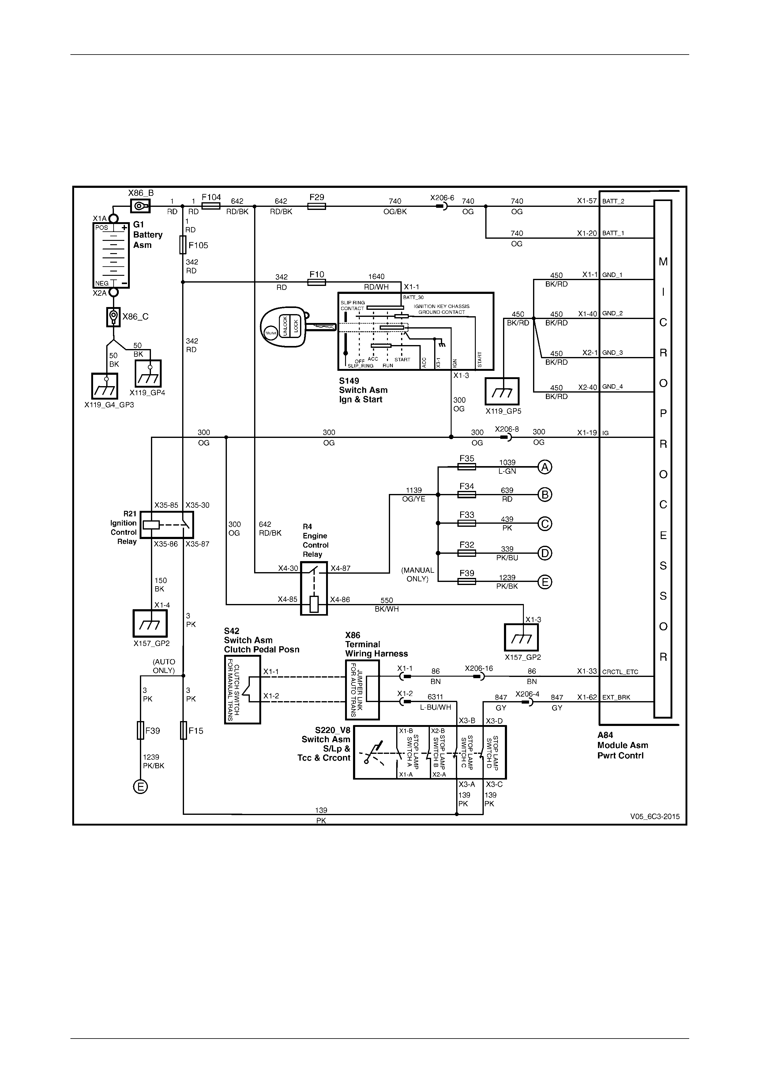
Powertrain Management – GEN III V8 – Diagnostics Page 6C3-2–17
Page 6C3-2–17
2 Wiring Diagram and Connector
Chart
2.1 Wiring Diagram
Figure 6C3-2 – 1
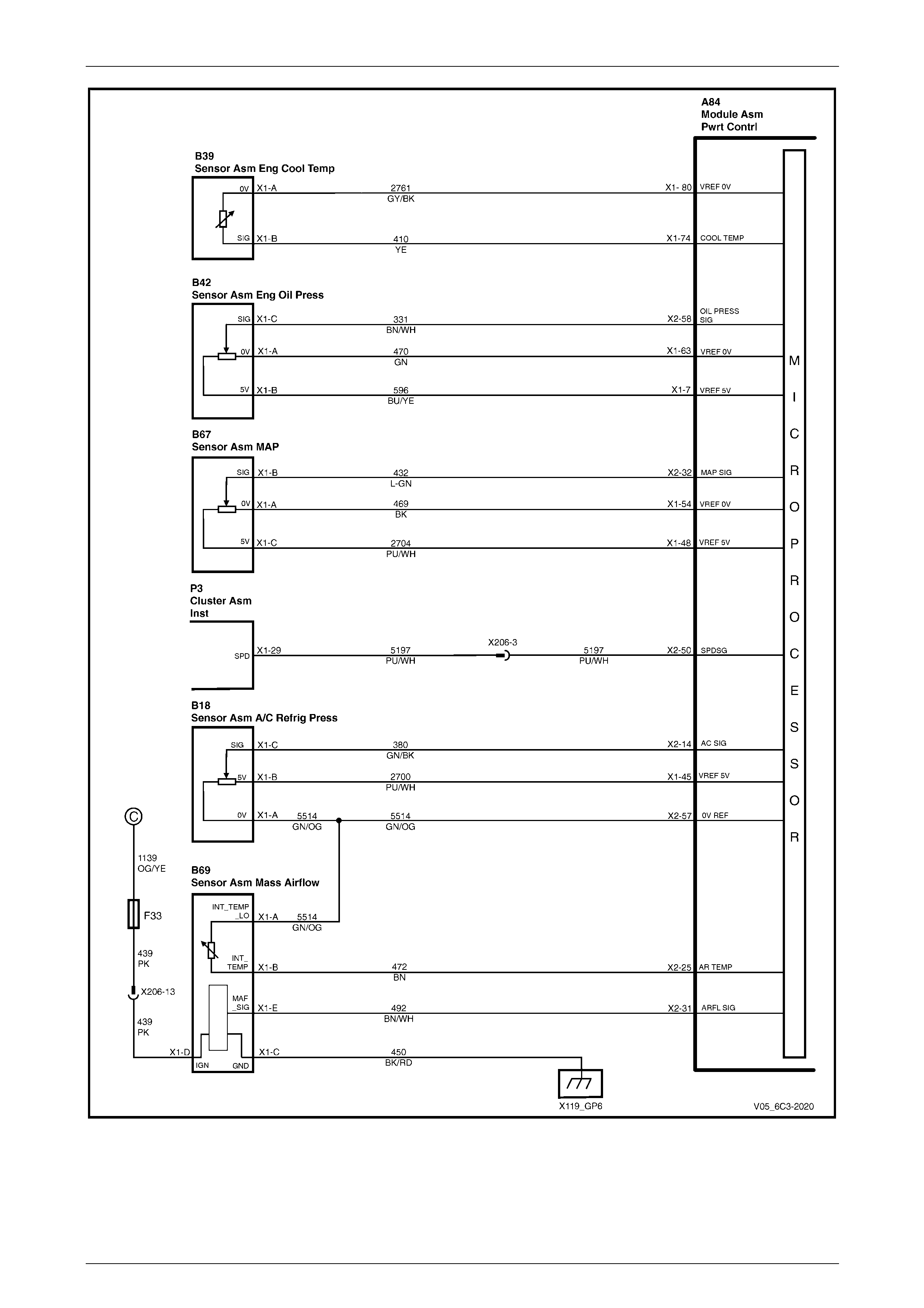
Powertrain Management – GEN III V8 – Diagnostics Page 6C3-2–18
Page 6C3-2–18
Figure 6C3-2 – 2
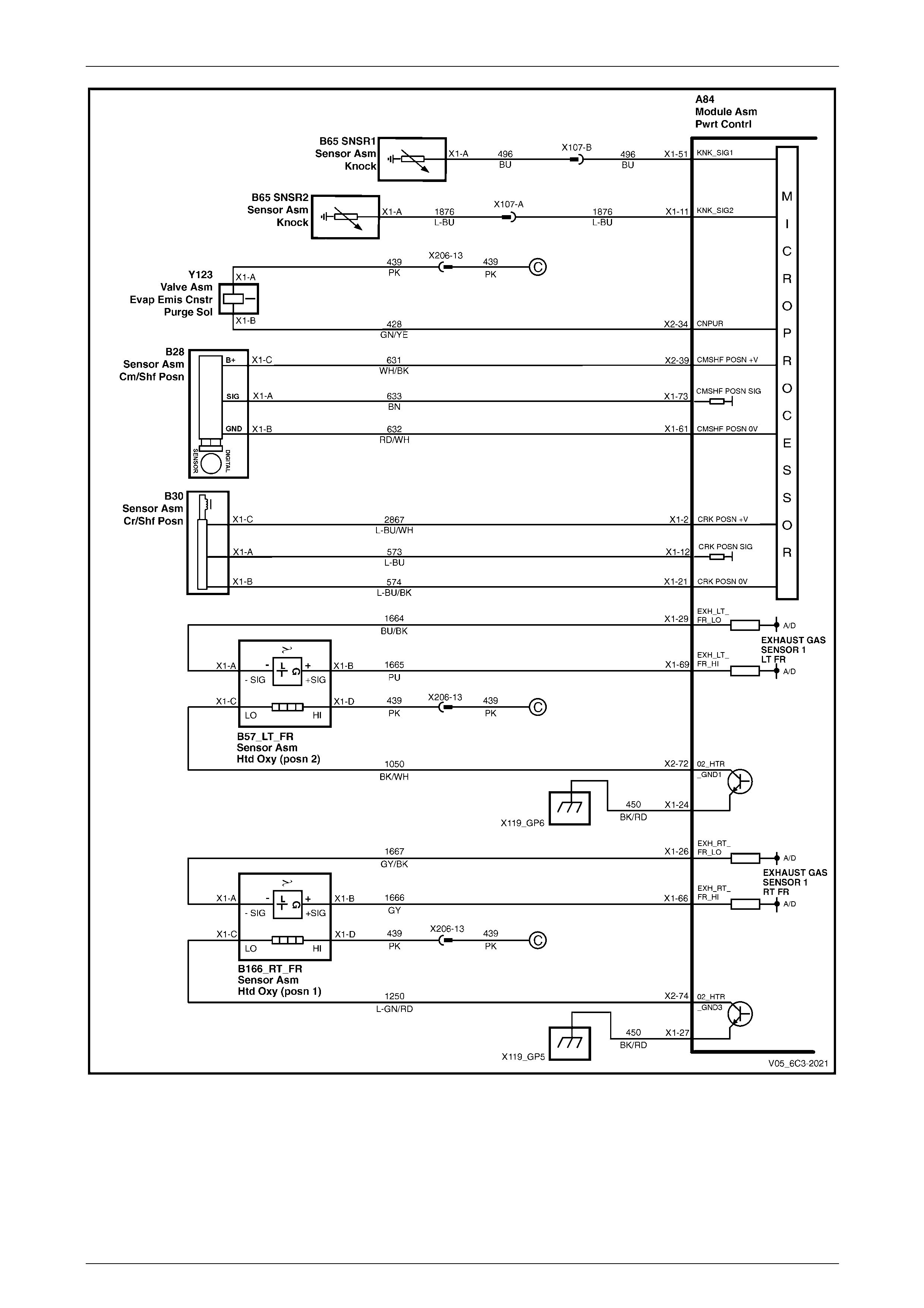
Powertrain Management – GEN III V8 – Diagnostics Page 6C3-2–19
Page 6C3-2–19
Figure 6C3-2 – 3
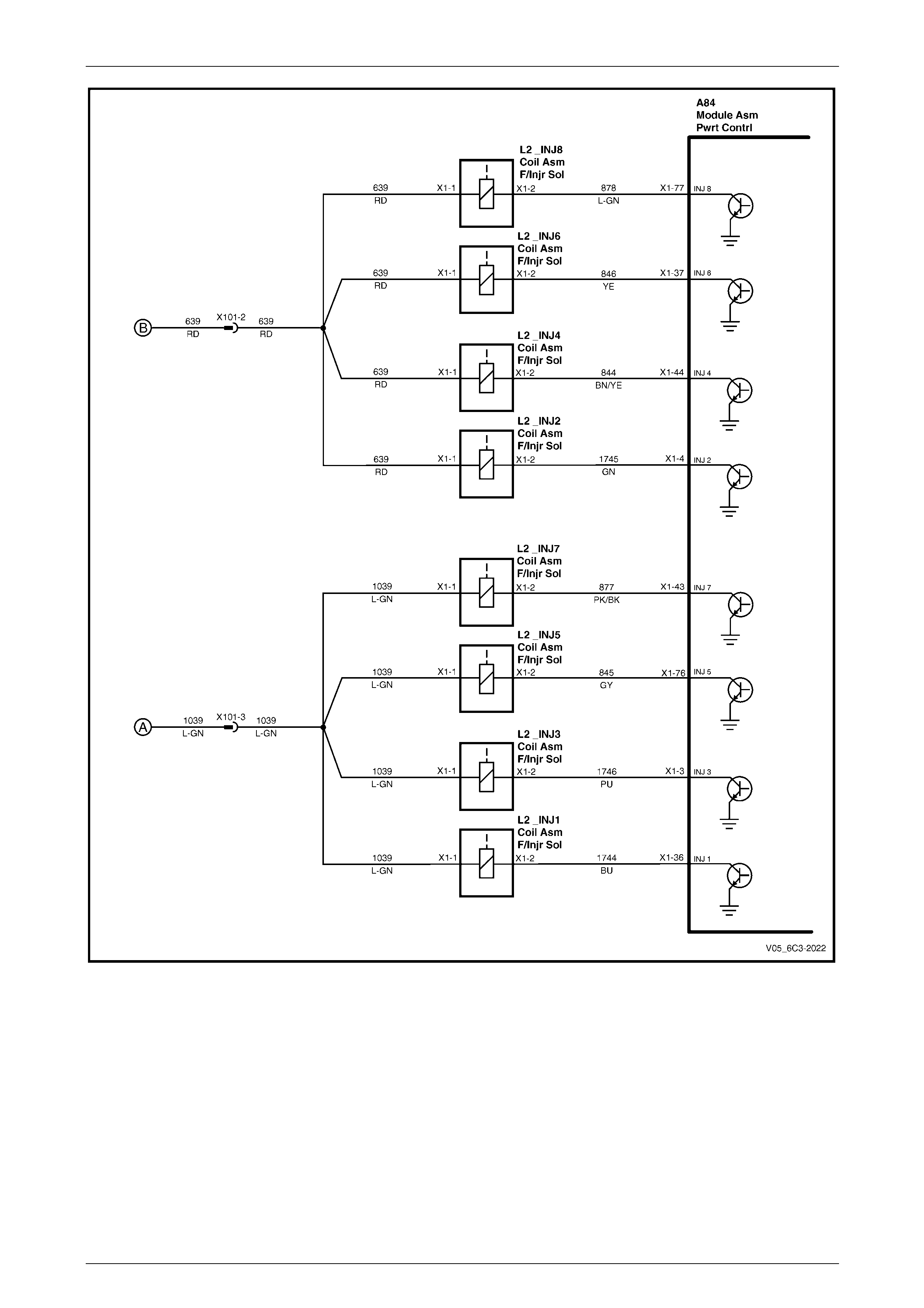
Powertrain Management – GEN III V8 – Diagnostics Page 6C3-2–20
Page 6C3-2–20
Figure 6C3-2 – 4
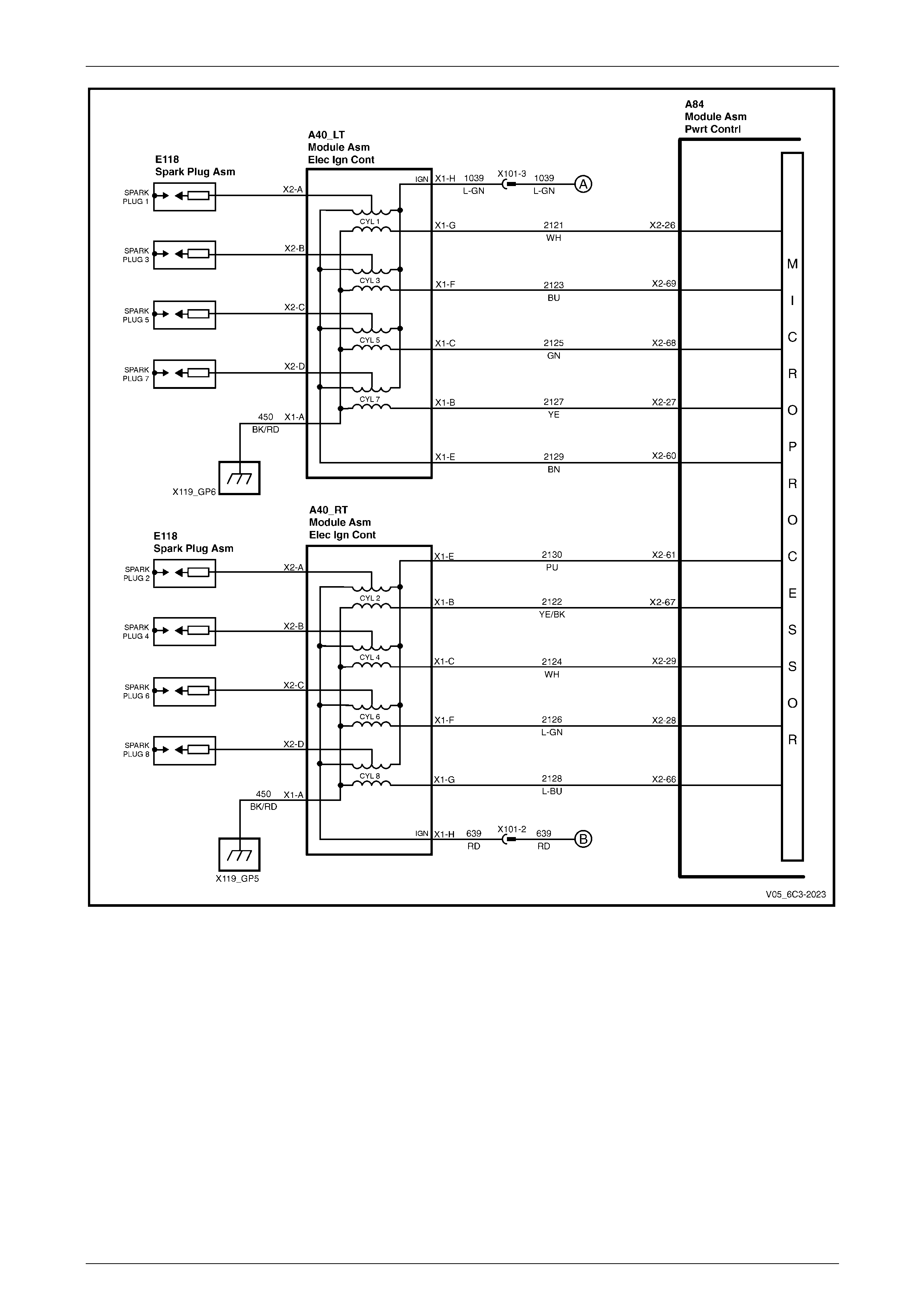
Powertrain Management – GEN III V8 – Diagnostics Page 6C3-2–21
Page 6C3-2–21
Figure 6C3-2 – 5
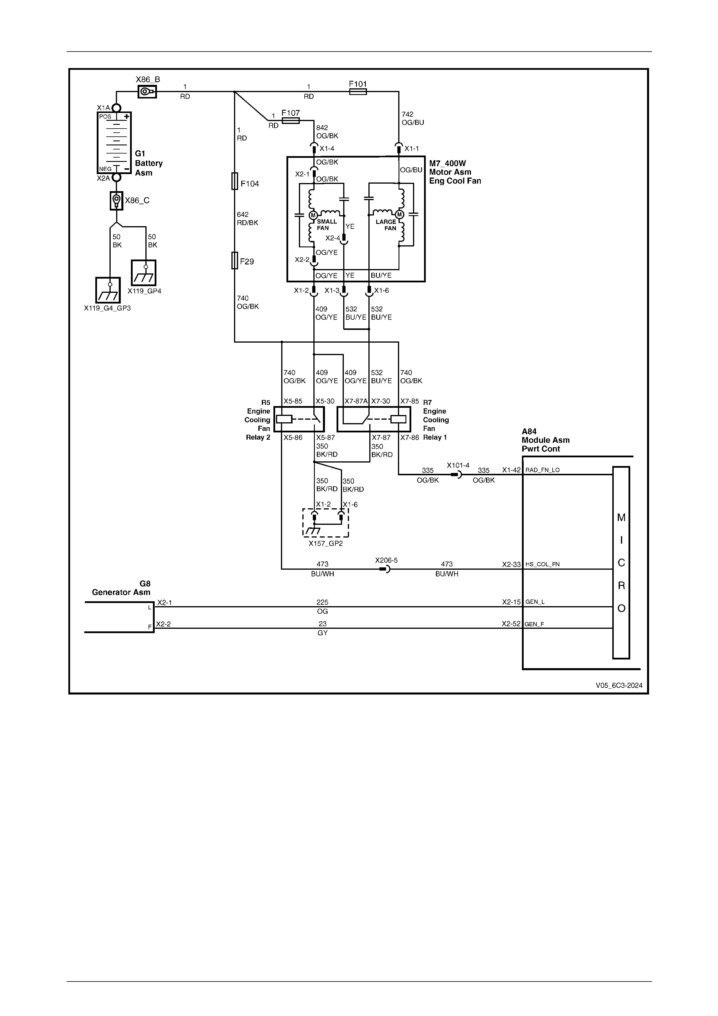
Powertrain Management – GEN III V8 – Diagnostics Page 6C3-2–22
Page 6C3-2–22
Figure 6C3-2 – 6
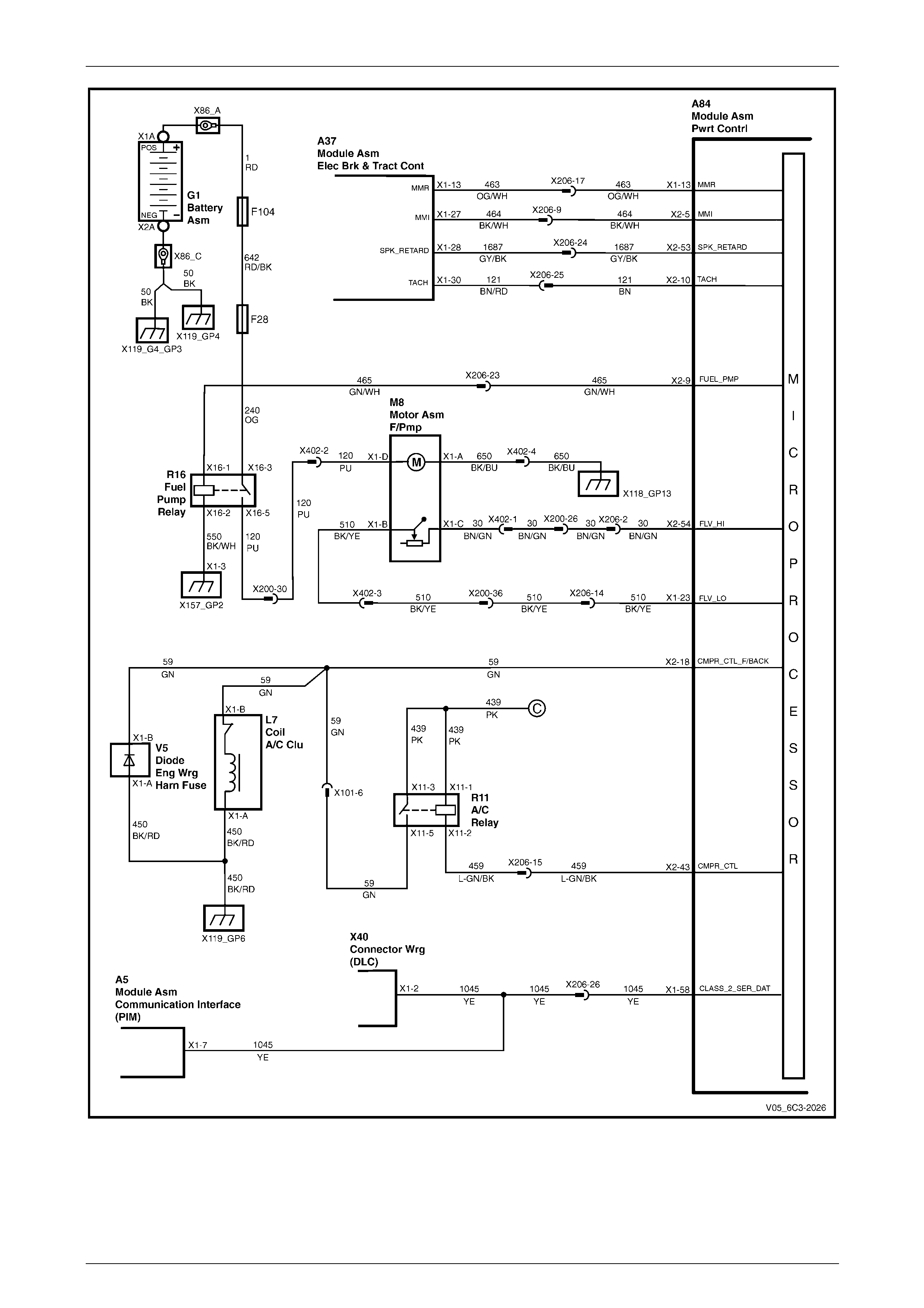
Powertrain Management – GEN III V8 – Diagnostics Page 6C3-2–23
Page 6C3-2–23
Figure 6C3-2 – 7
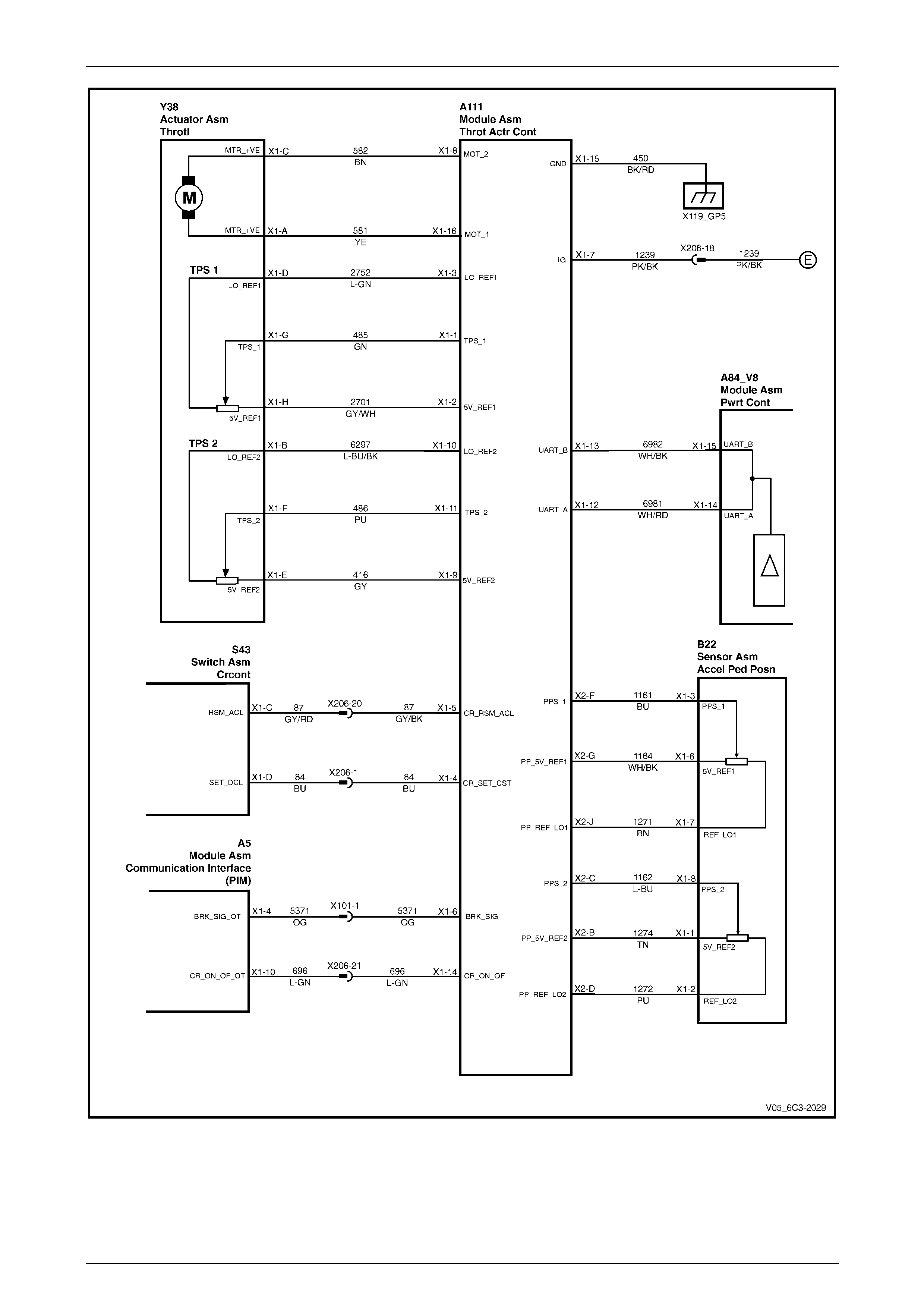
Powertrain Management – GEN III V8 – Diagnostics Page 6C3-2–24
Page 6C3-2–24
Figure 6C3-2 – 8
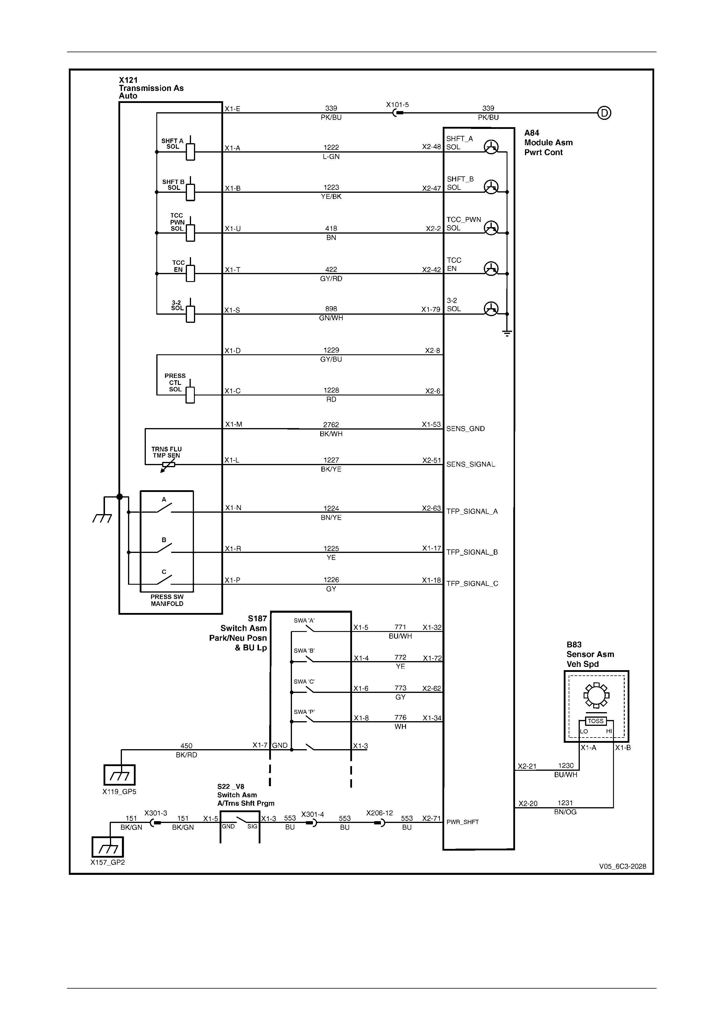
Powertrain Management – GEN III V8 – Diagnostics Page 6C3-2–25
Page 6C3-2–25
Figure 6C3-2 – 9
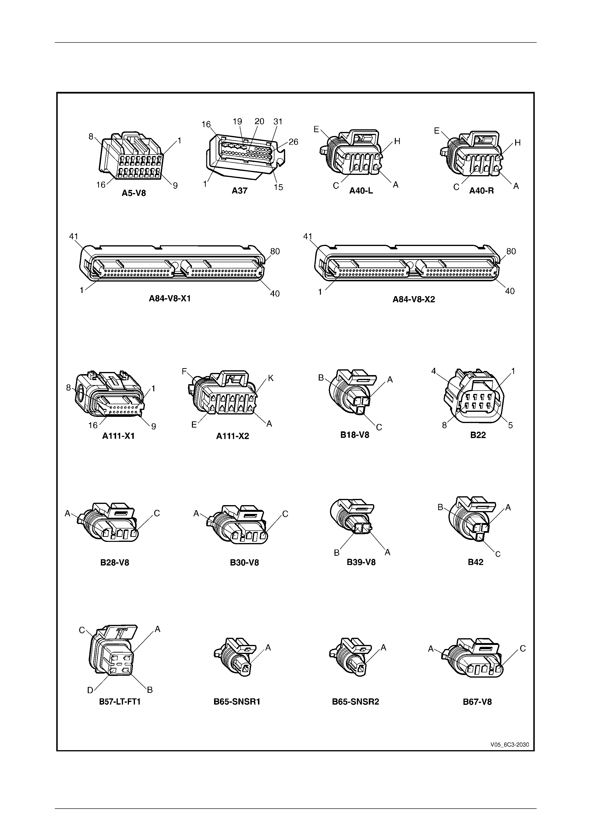
Powertrain Management – GEN III V8 – Diagnostics Page 6C3-2–26
Page 6C3-2–26
2.2 Connector Chart
Figure 6C3-2 – 10
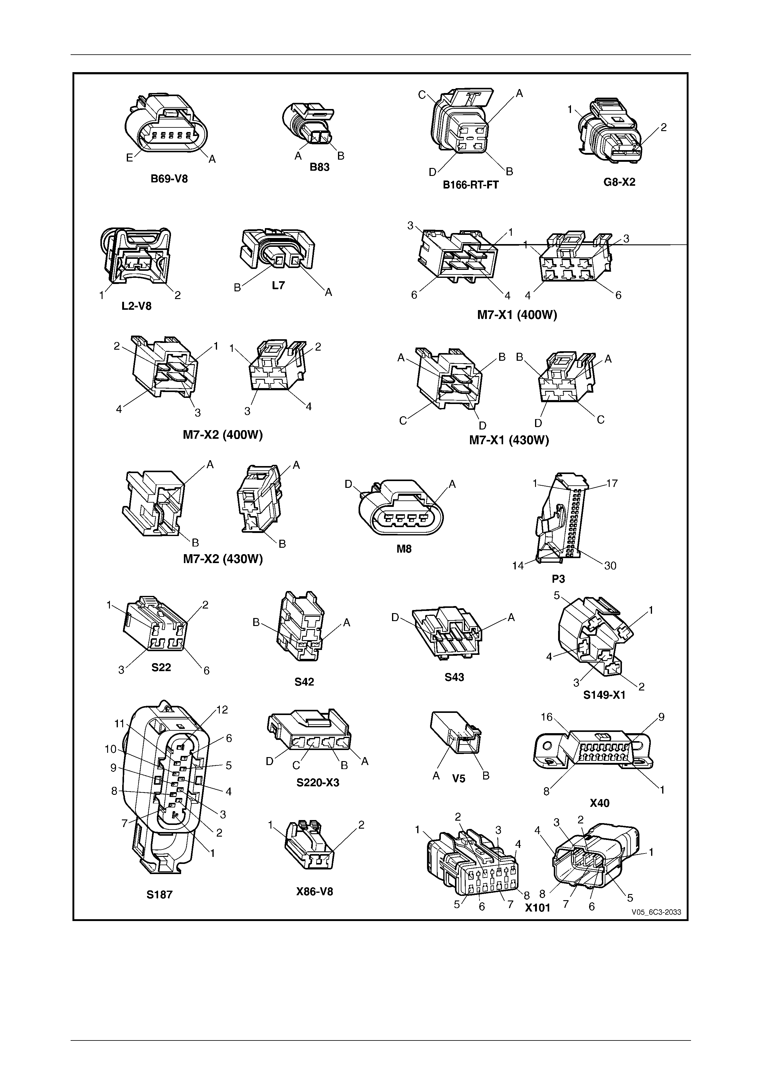
Powertrain Management – GEN III V8 – Diagnostics Page 6C3-2–27
Page 6C3-2–27
Figure 6C3-2 – 11
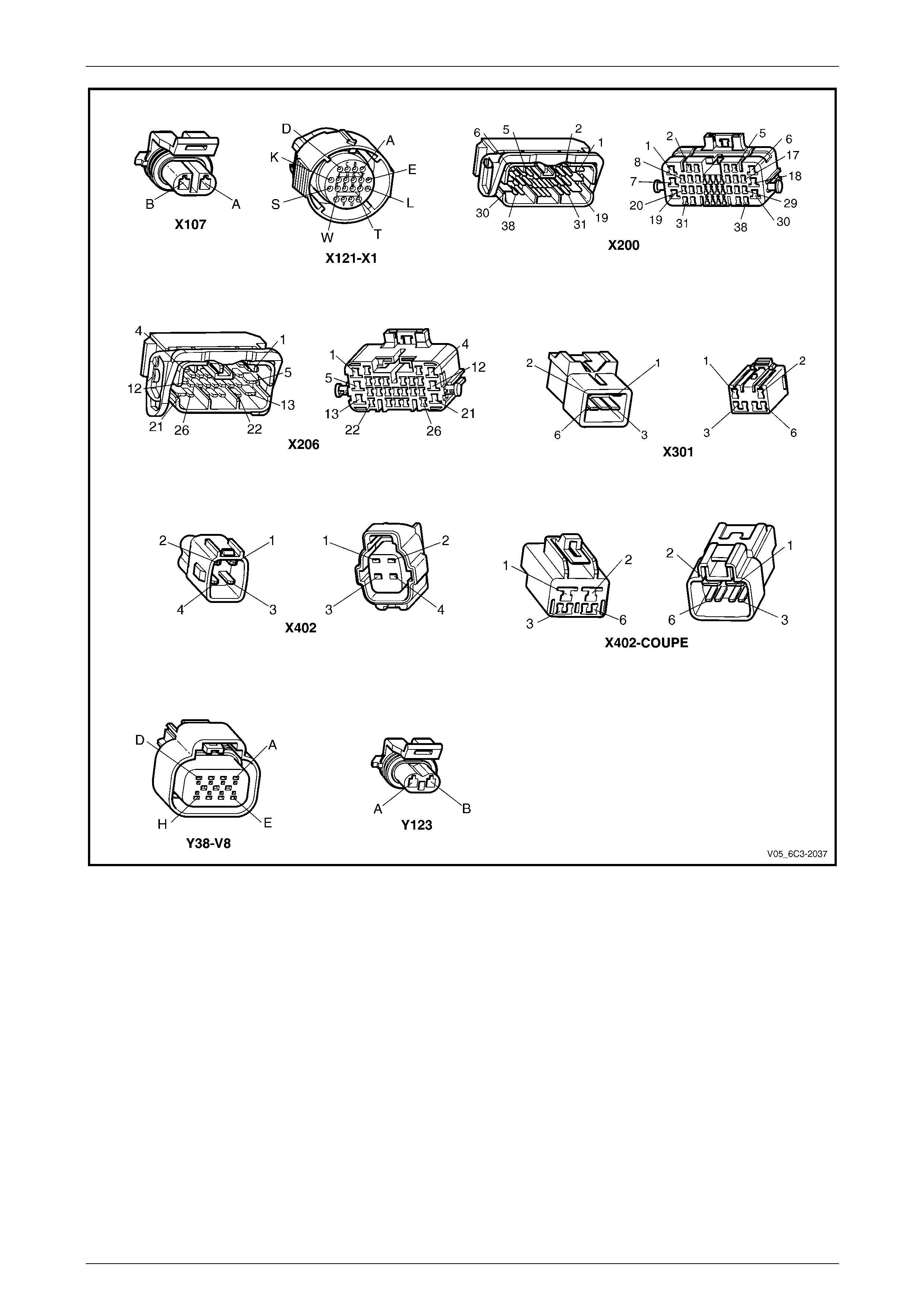
Powertrain Management – GEN III V8 – Diagnostics Page 6C3-2–28
Page 6C3-2–28
Figure 6C3-2 – 12
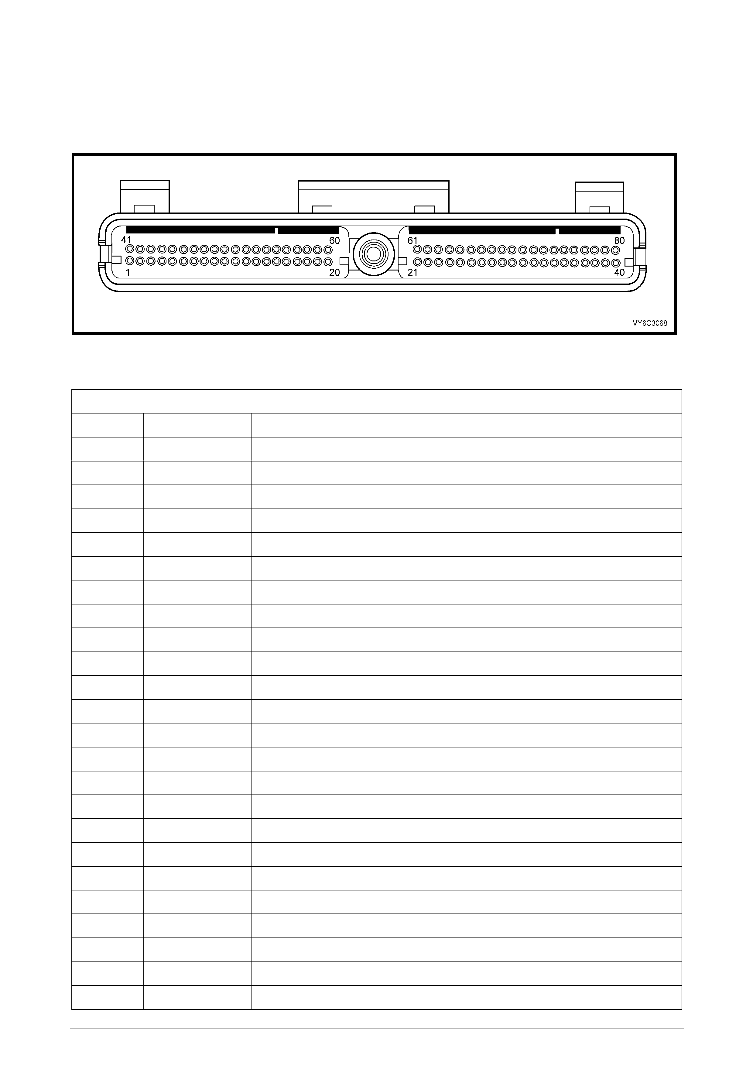
Powertrain Management – GEN III V8 – Diagnostics Page 6C3-2–29
Page 6C3-2–29
2.3 Connector Information
PCM Connector A84 – X1 (Blue)
Figure 6C3-2 – 13
PCM Connector A84 – X1 (Blue 80 Pin Con n ector)
Pin Circuit No. Function
1 450 System Ground 1
2 2867 Crankshaft Position Sensor Ignition Volt age Feed
3 1746 Fuel Injector #3 Driver
4 1745 Fuel Injector #2 Driver
5 – –
6 – –
7 596 Oil Pressure Sensor 5 Volt Reference
8 – –
9 – –
10 – –
11 1876 Rear Knock Sensor Input Signal
12 573 Crankshaft Position Sensor Input Signal
13 463 MMR Circuit
14 6981 Dedicated Serial Data (UA RT _A) line to TACM
15 6982 Dedicated Serial Data (UA RT _B) line to TACM
16 – –
17 1225 Transmission Pressure Switch B Input
18 1226 Transmission Pressure Switch C Input
19 300 Ignition Positive Voltage
20 740 Battery Feed 1
21 574 Crankshaft Position Sensor Reference Low
22 – –
23 510 Fuel Sender Signal Low
24 450 Heated Oxygen Sensor Dedicated Heater Groun d, Bank 1, Sensor 1

Powertrain Management – GEN III V8 – Diagnostics Page 6C3-2–30
Page 6C3-2–30
PCM Connector A84 – X1 (Blue 80 Pin Con n ector)
Pin Circuit No. Function
25 – –
26 1667 Heated Oxygen Sensor Signal Low, Bank 2 Sensor 1
27 450 Heated Oxygen Sensor Dedicated Heater Groun d, Bank 2, Sensor 1
28 – –
29 1664 Heated Oxygen Sensor Signal Low, Bank 1 Sensor 1
30 – –
31 – –
32 771 Transmission Range Switch (PRNDL) Switch, Signal 'A'
33 86 Clutch Switch / Cruise Brake Switch Input Signal
34 776 Transmission Range Switch (PRNDL) Switch, Signal 'P'
35 – –
36 1744 Fuel Injector #1 Driver
37 846 Fuel Injector #6 Driver
38 – –
39 – –
40 450 System Ground 2
41 – –
42 335 Engine Cooling Fan Relay Low Speed Control
43 877 Fuel Injector #7 Driver
44 844 Fuel Injector #4 Driver
45 2700 A/C Refrigerant Pressure Sensor 5 Volt Reference
46 – –
47 – –
48 2704 Manifold Absolute Pressure Sensor 5 Volt Reference
49 – –
50 – –
51 496 Front Knock Sensor Input Signal
52 – –
53 2762 Transmission Fluid Temperature Sensor Ground
54 469 Manifold Absolute Pressure Sensor Ground
55 – –
56 – –
57 740 Battery Feed 2
58 1045 Class 2 Serial Data
59 – –
60 – –
61 632 Camshaft Position Sensor Reference Low

Powertrain Management – GEN III V8 – Diagnostics Page 6C3-2–31
Page 6C3-2–31
PCM Connector A84 – X1 (Blue 80 Pin Con n ector)
Pin Circuit No. Function
62 847 Extended Brake T r avel Switch Input
63 470 Oil Pressure Sensor Ground
64 – –
65 – –
66 1666 Heated Oxygen Sensor Signal High, Bank 2 Sensor 1
67 – –
68 – –
69 1665 Heated Oxygen Sensor Signal High, Bank 1 Sensor 1
70 – –
71 – –
72 772 Transmission Range Switch (PRNDL) Switch, Signal 'B'
73 633 Camshaft Position Sensor Input Signal
74 410 Engine Coolant T emperature Sensor Signal
75 – –
76 845 Fuel Injector #5 Driver
77 878 Fuel Injector #8 Driver
78 – –
79 898 3-2 Shift Solenoid Control
80 2761 Engine Coolant Temperature Sensor Ground
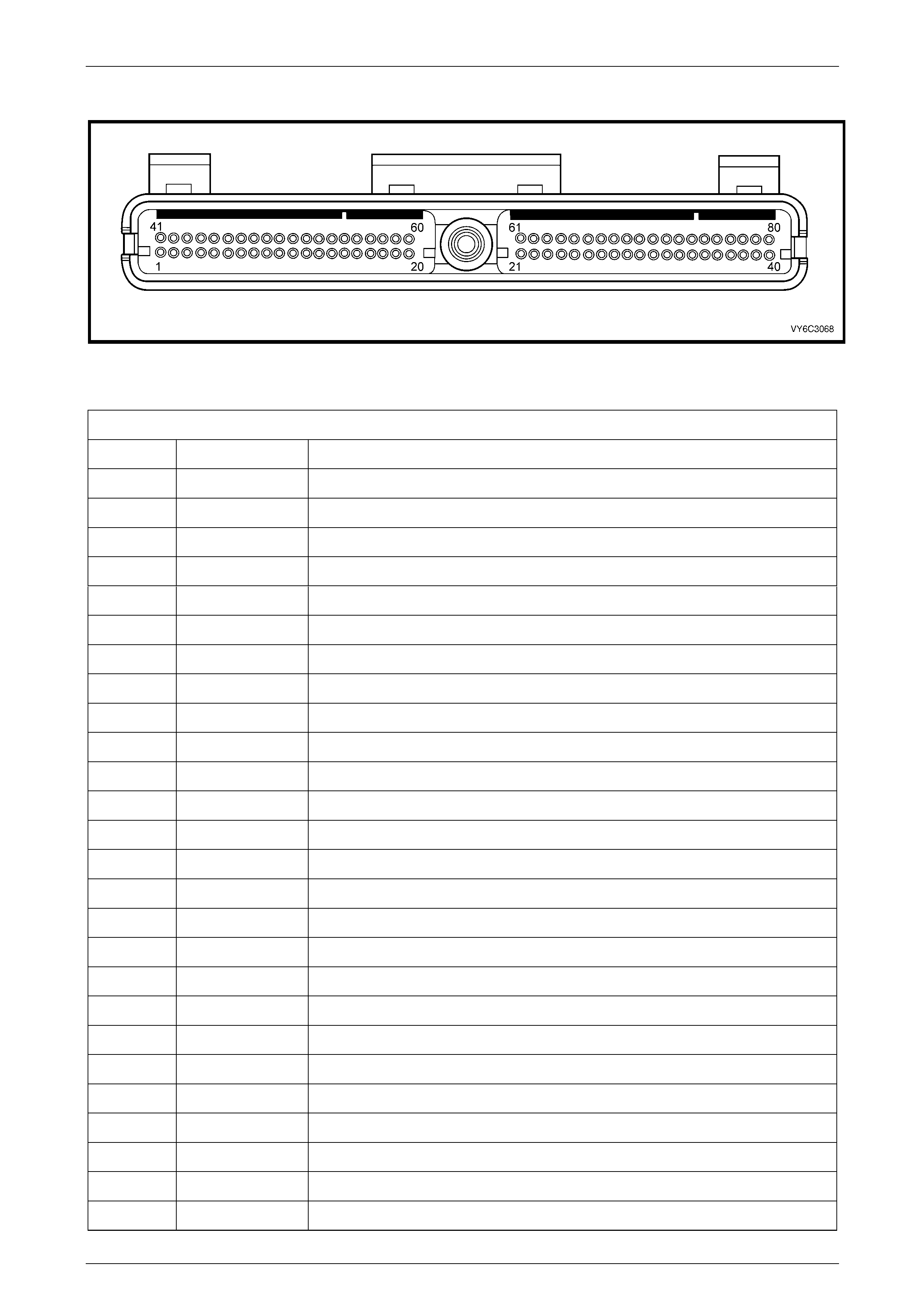
Powertrain Management – GEN III V8 – Diagnostics Page 6C3-2–32
Page 6C3-2–32
PCM Connector A84 – X2 (Green)
Figure 6C3-2 – 14
PCM Connector A84 – X2 (Green 80 Pin Connector)
Pin Circuit No. Function
1 450 System Ground 3
2 418 Torque Converter Clutch Pulse Width Modulation Solenoid Control
3 – –
4 – –
5 464 MMI Circuit
6 1228 Pressure Control Solenoid Signal High
7 – –
8 1229 Pressure Control Solenoid Signal Low
9 465 Fuel Pump Relay Control
10 121 Tachometer Output Signal
11 – –
12 – –
13 – –
14 380 A/C Refrigerant Pressure Sensor Input Signal
15 225 Generator L Terminal
16 – –
17 – –
18 59 A/C Compressor Clutch Relay Status
19 – –
20 1231 Vehicle Speed Sensor Signal High
21 1230 Vehicle Speed Sensor Si gnal Low
22 – –
23 – –
24 – –
25 472 Intake Air Temperature Sensor Signal
26 2121 Ignition Coil/Module Control #1

Powertrain Management – GEN III V8 – Diagnostics Page 6C3-2–33
Page 6C3-2–33
PCM Connector A84 – X2 (Green 80 Pin Connector)
Pin Circuit No. Function
27 2127 Ignition Coil/Module Control #7
28 2126 Ignition Coil/Module Control #6
29 2124 Ignition Coil/Module Control #4
30 – –
31 492 Mass Air Flow Sensor Signal
32 432 Manifold Absolute Pressure Sensor Input Sig nal
33 473 Engine Cooling Fan Relay High Speed Co ntrol
34 428 Evaporative Emission Can ister Purge Solenoid Control
35 – –
36 – –
37 – –
38 – –
39 631 Camshaft Sensor Ignition Voltage Feed
40 450 System Ground 4
41 – –
42 422 Torque Converter Clutch Enable So lenoid Control
43 459 A/C Compressor Clutch Relay Control
44 –
45 – –
46 – –
47 1223 2-3 Shift Solenoid B Control
48 1222 1-2 Shift Solenoid A Control
49 – –
50 5197 Vehicle Speed Sensor Output Sign al
51 1227 Transmission Fluid Temperature Sensor Input Signal
52 23 Generator F Terminal
53 1687 Spark Retard
54 30 Fuel Level Sensor Input Sig na l
55 – –
56 – –
57 5514 Intake Air Temperature / A/C Refrigerant Pressure Sens or Ground
58 331 Oil Pressure Sensor Input Signal
59 – –
60 2129 Ignition Reference Low – Bank 1
61 2130 Ignition Reference Low – Bank 2
62 773 Transmission Range Switch (PRNDL) Switch, Signal 'C'
63 1224 Transmission Pressure Switch A Input

Powertrain Management – GEN III V8 – Diagnostics Page 6C3-2–34
Page 6C3-2–34
PCM Connector A84 – X2 (Green 80 Pin Connector)
Pin Circuit No. Function
64 – –
65 – –
66 2128 Ignition Coil/Module Control #8
67 2122 Ignition Coil/Module Control #2
68 2125 Ignition Coil/Module Control #5
69 2123 Ignition Coil/Module Control #3
70 – –
71 553 Power / Economy Switch Input
72 1050 Heated Oxygen Sensor Dedicated Heater Ground, Bank 1, Sensor 1
73 – –
74 1250 Heated Oxygen Sensor Dedicated Heater Ground, Bank 2, Sensor 1
75 – –
76 – –
77 – –
78 – –
79 – –
80 – –

Powertrain Management – GEN III V8 – Diagnostics Page 6C3-2–35
Page 6C3-2–35
2.4 PCM Connector Terminal Definitions
PCM Connector A84 – X1 (Blue)
Pin Name Circuit Description
1 System Ground This terminal should have zero volts. This circuit is conn ected directly to engine
ground.
2 Crankshaft Position
Sensor Ignition Voltage
Feed
This terminal should have B+ anytime the ignition is on. It is a regulated voltage
output from the PCM and supplies B+ to the CKP sensor.
3 Fuel Injector #3 Driver With the engine off and the ignition on, the voltage should be B+. With higher
engine r.p.m. or more engine load, the resulting increase in injector pulse
frequency or injector pulse width will cause this voltage to become slightly less.
4 Fuel Injector #2 Driver With the engine off and the ignition on, the voltage should be B+. With higher
engine r.p.m. or more engine load, the resulting increase in injector pulse
frequency or injector pulse width will cause this voltage to become slightly less.
5 Not Used –
6 Not Used –
7 Oil Pressure Sensor 5v
Reference This voltage should always be 5 volts whenever the ignition is on. The reference
voltage is a regulated voltage from the PCM and supplies 5 volts to the oil
pressure sensor.
8 Not Used –
9 Not Used –
10 Not Used –
11 Rear Knock Sensor Input
Signal The knock sensor detects when detonation i s occurring in the combustion
chambers. When detected, the PCM will reduce the amoun t of spark advance
being delivered on the EST output circuits to the ignition coil / modules.
12 Crankshaft Position
Sensor Input Signal This terminal could be called the ‘tach’ input. It provides the PCM with r.p.m. and
crankshaft position information. The PCM uses this signal to control fuel injection
and spark timing.
13 MMR Circuit Used for ABS functions.
14 UART_A Serial Data Dedicated serial data comm unication circuit between the PCM and the T ACM.
Voltage on the line varies depending on the communic atio n levels between the
modules.
15 UART_B Serial Data Dedicated serial data comm unication circuit between the PCM and the T ACM.
Voltage on the line varies depending on the communic atio n levels between the
modules.
16 Not Used –
17 Transmission Pressure
Switch B Input The PCM sends out a buffered B+ signal to the pressure switch assembly located
in the automatic transmission valve body. When the switch is closed, the circuit is
grounded and the signal should be near 0 volts. The PCM monitors the status of
this signal in conjunction with transmission pressure switch A and C inputs to
determine which gear servo is actually receiving hydrau lic apply pressure.
18 Transmission Pressure
Switch C Input The PCM sends out a buffered B+ signal to the pressure switch assembly located
in the automatic transmission valve body. When the switch is closed, the circuit is
grounded and the signal should be near 0 volts. The PCM monitors the status of
this signal in conjunction with transmission pressure switch A and B inputs to
determine which gear servo is actually receiving hydrau lic apply pressure.
19 Ignition Positive Voltage This is the wake up signal to the PCM from the ignition switch. It is not the power
supply to the PCM, it only tells the PCM the ignition switch is on. The voltage
should equal the battery voltage when the key is in either the RUN or CRANK
position.

Powertrain Management – GEN III V8 – Diagnostics Page 6C3-2–36
Page 6C3-2–36
Pin Name Circuit Description
20 Battery Feed 1 This supplies the PCM with constant B+ volts. This circuit stays hot even when the
ignition is turned off. The battery voltage feed circuit receives voltage through fuse
F29.
21 Crankshaft Position
Sensor Reference Low This terminal should always be zero volts. It is connected from the PCM to the
CKP sensor and provides the ground signal needed for the sensor to operate.
22 Not Used –
23 Fuel Level Sensor Sign al
Low This terminal should have zero volts. This terminal provides the PCM ground
circuitry for the fuel level sensor monitor inside the PCM.
24 Heated Oxygen Sensor
Dedicated Heater
Ground, Bank 1 Sensor 1
Provides a dedicated grou nd for the bank 1 sensor 1 heated oxygen sensor heater
control circuit in the PCM.
25 Not Used –
26 Heated Oxygen Sensor
Signal Low, Bank 2
Sensor 1
This terminal should have zero volts. It is connected to the HO2S. This terminal
ground’s the PCM circuitry for the HO2S voltage monitor inside the PCM.
27 Heated Oxygen Sensor
Signal Dedicated Heater
Ground, Bank 2 Sensor 1
Provides a dedicated grou nd for the bank 2 sensor 1 heated oxygen sensor heater
control circuit in the PCM.
28 Not Used –
29 Heated Oxygen Sensor
Signal Low, Bank 1
Sensor 1
This terminal should have zero volts. It is connected to the HO2S. This terminal
ground’s the PCM circuitry for the HO2S voltage monitor inside the PCM.
30 Not Used –
31 Not Used –
32 Transmission Range
Switch (PRNDL) Signal A This signal, along with the transmission range switch signals B, C and P, indicates
to the PCM what transmission gear the driver has selected.
33 Clutch Switch / Cruise
Brake Switch Input Signal This signal indicates to the PCM when the driver has depressed the brake and / or
clutch pedal. The PCM will then disengage the TCC and or cruise if activated.
34 Transmission Range
Switch (PRNDL) Signal P This signal, along with the transmission range switch signals A, B and C, indicates
to the PCM what transmission gear the driver has selected.
35 Not Used –
36 Fuel Injector #1 Driver With the engine off and the ignition on, the voltage should be B+. With higher
engine r.p.m. or more engine load, the resulting increase in injector pulse
frequency or injector pulse width will cause this voltage to become slightly less.
37 Fuel Injector #6 Driver With the engine off and the ignition on, the voltage should be B+. With higher
engine r.p.m. or more engine load, the resulting increase in injector pulse
frequency or injector pulse width will cause this voltage to become slightly less.
38 Not Used –
39 Not Used –
40 System Ground 2 This terminal should have zero volts. This circuit is conn ected directly to engine
ground.
41 Not Used –
42 Engine Cooling Fan
Relay Low Speed Control This terminal will have battery voltage until the PCM energises the low speed
cooling fan relay by supplying the ground; then it will be close to zero.
43 Fuel Injector #7 Driver With the engine off and the ignition on, the voltage should be B+. With higher
engine r.p.m. or more engine load, the resulting increase in injector pulse
frequency or injector pulse width will cause this voltage to become slightly less.

Powertrain Management – GEN III V8 – Diagnostics Page 6C3-2–37
Page 6C3-2–37
Pin Name Circuit Description
44 Fuel Injector #4 Driver With the engine off and the ignition on, the voltage should be B+. With higher
engine r.p.m. or more engine load, the resulting increase in injector pulse
frequency or injector pulse width will cause this voltage to become slightly less.
45 A/C Refrigerant Pressure
Sensor 5 Volt Reference This voltage should always be 5 volts anytime the ignition is on. It is a regulated
voltage output from the PCM and supplies 5 volts to the A/C Pressure Sensor.
46 Not Used –
47 Not Used –
48 Manifold Absolute
Pressure Sensor 5 Volt
Reference
This voltage should always be 5 volts anytime the ignition is on. It is a regulated
voltage output from the PCM and supplies 5 volts to the MAP Sensor.
49 Not Used –
50 Not Used –
51 Front Knock Sensor The Knock Sensor detects when detonation is occurring in the combustion
chambers and provides an AC voltage to the PCM. When detected, the PCM will
reduce the amount of spark advanc e being delivered on the EST output circuits to
the ignition Coil / Modules.
52 Not Used –
53 Transmission Fluid
Temperature Sensor
Ground
This terminal should be zero volts. It is connected through the PCM circuitry to
engine ground.
54 Manifold Absolute
Pressure Sensor Ground This terminal should have zer o volts. This circuit is conn ected directly to ground
through the PCM.
55 Not Used –
56 Not Used –
57 Battery Feed 2 This supplies the PCM with full time B+ volts. This circuit stays hot even when the
ignition is turned off. The battery voltage feed circuit receives voltage through fuse
F29.
58 Serial Data (Class II) This is a dedicated line for the Tech 2 communication. The circuit connects the
PCM to the PIM. Tech 2 can talk to the PCM by sending a message and asking it
to respond. The messages carried on Class II data streams are prioritised. The
normal voltage on this line is 0 volts, but when communication is occurring, the
voltage will fluctuate from 0 – 7 volts indicating communication.
59 Not Used –
60 Not Used –
61 Camshaft Position
Sensor Reference Low This terminal should always be zero volts. It is connecte d to the CMP sensor and
provides the ground signal n eeded for the sensor to operate.
62 Extended Travel Brake
Switch Input Used for brake torque management.
63 Oil Pressure Sensor
Ground This terminal should always be zero volts. It is connected to the oil pressure
sensor and provides the ground signal needed for the sensor to operate.
64 Not Used –
65 Not Used –
66 Heated Oxygen Sensor
Signal High, Bank 2
Sensor 1
With the ignition on and the engi ne not running, the voltage should be 350 – 450
millivolts (0.350 0.450 volts). This is the PCM supplied HO2S circuit bias voltage.
When the HO2S is hot and the engine is running, the voltag e should be rapidly
changing, some where between 10 – 1000 millivolts (0.010 – 1.0 volts).
67 Not Used –
68 Not Used –

Powertrain Management – GEN III V8 – Diagnostics Page 6C3-2–38
Page 6C3-2–38
Pin Name Circuit Description
69 Heated Oxygen Sensor
Signal High, Bank 1
Sensor 1
With the ignition on and the engi ne not running, the voltage should be 350 – 450
millivolts (0.350 0.450 volts). This is the PCM supplied HO2S circuit bias voltage.
When the HO2S is hot and the engine is running, the voltag e should be rapidly
changing, some where between 10 – 1000 millivolts (0.010 – 1.0 volts).
70 Not Used –
71 Not Used –
72 Transmission Range
Switch (PRNDL) Signal B This signal, along with the transmission range switch signals A, C and P, indicates
to the PCM what transmission gear the driver has selected.
73 Camshaft Position
Sensor Input Signal This signal indicates to the PCM when num ber 1 cylinder is on the compression
stroke. The PCM uses this signal for correct injector and ignition coil sequencin g.
74 Engine Coolant
Temperature Sensor
Signal
The PCM sends a 5 volt signal voltage to the Engine Coolant Temperature sensor,
which is a temperature variable resistor called a thermistor. The sensor will alter
the voltage according to engin e coolant temperature. As the engine coolant
temperature increases, the voltage detected by the PCM decreases. At 0°C
engine coolant temperature, the voltage will be above 4 volts. At normal ope rating
temperature, the voltage will be less than 2 volts.
75 Not Used –
76 Fuel Injector #5 Driver With the engine off and the ignition on, the voltage should be B+. With higher
engine r.p.m. or more engine load, the resulting increase in injector pulse
frequency or injector pulse width will cause this voltage to become slightly less.
77 Fuel Injector #8 Driver With the engine off and the ignition on, the voltage should be B+. With higher
engine r.p.m. or more engine load, the resulting increase in injector pulse
frequency or injector pulse width will cause this voltage to become slightly less.
78 Not Used –
79 3-2 Shift Solenoid Control The 3-2 shift solenoid is a normally closed, p ulse width modulated solenoid used
to control the 3-2 downshift. The PCM operates the 3-2 shift solenoid at a
frequency of 50 Hz (cycles per second). The solenoid is constantly fed B+ and the
PCM controls the length of time the path to grou nd for the electrical circuit is
closed.
80 Engine Coolant
Temperature Sensor
Ground
This terminal should have zero volts. This circuit is conn ected directly to ground
through the PCM.

Powertrain Management – GEN III V8 – Diagnostics Page 6C3-2–39
Page 6C3-2–39
PCM Connector A84 – X2 (Green)
Pin Name Circuit Description
1 System Ground 3 This terminal should have zero volts. This circuit is conn ected directly to engine
ground.
2 Torque Converter Clutch
Pulse Width Modulation
Solenoid Control
The PCM uses the pulse width modulation (PWM) TCC apply solenoid to smoothly
engage the torque converter clutch after the TCC enable solenoid is energised. By
varying the duty cycle pulse width modulation, the PCM can slowly engage the
torque converter clutch, allowing smooth TCC engagement.
3 Not Used –
4 Not Used –
5 MMI Circuit Used for ABS functions.
6 Pressure Control
Solenoid High The duty cycle and amount of current flow to the PCS, is controlled by the PCM.
This circuit is the B+ supply line from the PCM to the PCS. The duty cycle and
current are controlled by the PCM.
7 Not Used –
8 Pressure Control
Solenoid Low The automatic transmission uses an electrical solenoid to control hydra ulic
pressure inside the transmission. This electrical solenoid allows the PCM to
control line pressure. The duty cycle and amount of curre nt flow to the PCS, are
both controlled by the PCM. By monitoring this line, the PCM can determi ne if the
commanded current has gone to the PCS and returned to the PCM.
9 Fuel Pump Relay Control Turning the ignition o n causes the PCM to energise the fuel pump relay. If no
crankshaft reference input pulses are received, the PCM turns off the relay. As
soon as the PCM receives crankshaft reference in put pulses, the PCM will turn the
fuel pump relay on again.
10 Tacho Output Signal This signal is g enerated by the PCM to provide a tacho signal for other s ystems
and the tachometer located in the instrument panel cluster.
11 Not Used –
12 Not Used –
13 Not Used –
14 A/C Refrigerant Pressure
Sensor Input Signal The signal that is sent from the pressure sensor to the PCM indic ates to the PCM
what the A/C pressure is. Depending on the voltage, this signal will indicate to the
PCM if A/C pressure is too low or too high.
15 Generator L Terminal Used for charging system functions.
16 Not Used –
17 Not Used –
18 A/C Compressor Clutch
Status This circuit is a feed back signal to the PCM indicating the A/C compressor relay
has supplied the signal to the compressor clutch. The PCM uses this circuit to
determine if there is a fault with the A/C compressor relay.
19 Not Used –
20 Vehicle Speed Sensor
Signal High The transmission has an output shaft speed sensor used by the PCM to calculate
Vehicle Speed and to help determine various transmission shifting functions. It is a
magnetic inductive sensor that generates an AC voltage signal sent to the PCM. If
measured with the digital AC multimeter, no voltage will appear until the output
shaft begins turning.
21 Vehicle Speed Sensor
Signal Low The transmission has an output shaft speed sensor used by the PCM to calculate
vehicle speed and to help determine various automatic transmission shifting
functions. It is a magnetic inductive sensor that generates an AC voltage signal
sent to the PCM. If measured with the digital AC multimeter, no voltage will appear
until the output shaft begins turning.
22 Not Used –
23 Not Used –

Powertrain Management – GEN III V8 – Diagnostics Page 6C3-2–40
Page 6C3-2–40
Pin Name Circuit Description
24 Not Used –
25 Intake Air Temperature
Sensor Signal The PCM sends a 5 volt signal voltage to the IAT sensor, which is a
temperature variable resistor. The sensor is also connected to ground and will
alter the signal voltage according to incoming air temperature. As the air
temperature increases, the voltage seen o n this termin al de creases. At 0°C, the
voltage will be above 4 volts. At normal operating temperature (10°C to 80°C) the
voltage will be less than 4 volts.
26 Ignition Coil / Module
Control #1 This terminal is the EST output signal for cylinder #1. This terminal is connected to
the #1 ignition coil/modul e connector terminal X1 – G.
27 Ignition Coil / Module
Control #7 This terminal is the EST output signal for cylinder #7. This terminal is connected to
the #7 ignition coil/modul e connector terminal X1 – B.
28 Ignition Coil / Module
Control #6 This terminal is the EST output signal for cylinder #6. This terminal is connected to
the #6 ignition coil/modul e connector terminal X1 – F.
29 Ignition Coil / Module
Control #4 This terminal is the EST output signal for cylinder #4. This terminal is connected to
the #4 ignition coil/modul e connector terminal X1 – C.
30 Not Used –
31 Mass Air Flow Sensor
Signal The PCM supplies a 5 volt signal voltage to the mass air flow sensor on this
circuit. The mass air flow sensor pulses the 5 volt signal to ground. These ground
pulses occur at a very fast rate – from less than 500 per second (500 Hz) with no
airflow through the sensor, to upwards of many thousands of pulses per second at
high air flow rates such as during acceleration. If measured, the voltage seen will
be between 0.5 and 4.5 volts, depending on air flow through the sensor.
32 Manifold Absolute
Pressure Sensor Input
Signal
The voltage seen will vary with intake manifo ld pressure. With the ignition on but
the engine not running (high manifold pressure), the voltage will be above 4 volts.
At this time the sensor actually is measuring the barometric pressure, so this
voltage will change with both barometric pr essure and altitude changes. When the
engine is running at idle, the manifold pressure is quite low because of engine
vacuum and the voltage will also be low, 1 to 2 volts. The voltage is variable ,
mostly from engine load changes, but can al so change with barometric pressure or
altitude changes. This input is typicall y called the engine load input.
33 Engine Cooling Fan
Relay High Speed
Control
This terminal will have battery voltage until the PCM energises the high speed
cooling fan relay by supplying the ground; then it will be close to zero.
34 Evaporative Emission
Canister Purge Solenoid
Control
The PCM operates this normally closed solenoid valve, which controls vacuum to
purge the evaporative emissions storage canister of stored fuel vapours. The PCM
turns on the pulse width modulated control of the purge solenoid to control purging
of the stored vapours. If the PCM is not energising the purge sole noid, the voltage
measured at this terminal should equal battery voltage. If the PCM is controlling
the solenoid, the measured voltage will be between battery voltage and 0.5 0 volts.
35 Not Used –
36 Not Used –
37 Not Used –
38 Not Used –
39 Camshaft Sensor Ignition
Voltage Feed This voltage should be a lways be B+ anytime the ignition is on. It is a regulated
voltage output from the PCM and supplies B+ to the CMP sensor.
40 System Ground 4 This terminal should have zero volts. This circuit is connected directly to the
engine ground.
41 Not Used –
42 Torque Converter Clutch
Solenoid Control The PCM is used to either open or prov ide a path to ground for the torque
converter solenoid. When the PCM provides a path to ground, the TCC solenoid is
considered on and voltage should be near 0 volts. The PCM uses both the TCC
enable solenoid and the TCC PWM solenoid to control the torque converte r clutch.

Powertrain Management – GEN III V8 – Diagnostics Page 6C3-2–41
Page 6C3-2–41
Pin Name Circuit Description
43 A/C Clutch Relay Control When the A/C is requested, the BCM or OCC will communicate to the PCM
through the PIM via the serial data line, requesting A/C. The PCM supplies the
ground path on this terminal to energise the A / C control relay. When the PCM
does energise the A/C control relay, the voltage will be close to zero volts.
44 Not Usedf –
45 Not Used –
46 Not Used –
47 2-3 Shift Solenoid B
Control The PCM is used to either open or prov ide a path to ground for the 2-3 shift
solenoid. When the PCM provides a path to grou nd, the 2-3 shift solenoid is
considered on and the voltag e should read close to 0 volts.
48 1-2 Shift Solenoid A
Control The PCM is used to either open or prov ide a path to ground for the 1-2 shift
solenoid. When the PCM provides a path to grou nd, the 1-2 shift solenoid is
considered on and the voltag e should read close to 0 volts.
49 Not Used –
50 Vehicle Speed Sensor
Output Signal The PCM alternately ground’s this signal, in pulses, when it receives a veh icle
speed signal from the vehicle speed sensor in the transmission. This pulsing
action takes place about 625 0 times per kilo metre. T he instrument cluster and
cruise control module calculate vehicle speed based on the time between pulses.
51 Transmission Fluid
Temperature Sensor
Input Signal
The PCM sends a 5 volt signal voltage out to the transmissi on fluid temperature
sensor, which is a temperature-variable-resi stor called a thermistor. The sensor,
being also connected to ground, will alter the voltage according to transmission
fluid temperature. As the fluid temperature increases, the voltage seen on this
terminal will decrease.
52 Generator F Terminal Used for charging system functions.
53 Spark Retard Used for ABS functions.
54 Fuel Level Sensor Input
Signal The fuel level sensor chan ges resistance as the fuel level in the fuel tank changes.
The PCM interprets this changing resistance into the amount of fuel in the fuel
tank.
55 Not Used –
56 Not Used –
57 Intake Air Temperature
Sensor and A/C
Refrigerant Pressure
Sensor Ground
This terminal should be zero volts. It is connected through the PCM circuitry to
engine ground.
58 Oil Pressure Sensor
Input Signal This signal indicates to the PCM when the oil pressure is low. When the PCM
receives this predetermine d voltage from the oil pressure sensor, the PCM will turn
on the oil warning indicator in the instrument cluster.
59 Not Used –
60 Ignition Reference Lo w –
Bank 1 This terminal should always be zero volts. It is the groun d signal for the Left Bank,
ignition coil/modules 1, 3, 5, & 7.
61 Ignition Reference Lo w –
Bank 2 This terminal should always be zero volts. It is the ground signa l for the Right Bank
ignition coil/modules 2, 4, 6, & 8.
62 PRNDL C This circuit, along with the circuits on PCM (Blue) connector A84 X1-32, 34 and
72, indicates to the PCM what transmission gear the driver h as selecte d. The PCM
will then send a command via the serial data line to the Instrument to indicate to
the driver what gear has been selected.
63 Transmission Pressure
Switch A Input The PCM sends out a buffered B+ signal to the pressure switch assembly located
in the automatic transmission valve body. When the switch is closed, the circuit is
grounded and the signal should be near 0 volts. The PCM monitors the status of
this signal in conjunction with transmission pressure switch B and C inputs to
determine which gear servo is actually receiving hydrau lic apply pressure.

Powertrain Management – GEN III V8 – Diagnostics Page 6C3-2–42
Page 6C3-2–42
Pin Name Circuit Description
64 Not Used –
65 Not Used –
66 Ignition Coil / Module
Control #8 This terminal is the EST output signal for cylinder #8. This terminal is connected to
the #8 ignition coil / module connector terminal X1 – G.
67 Ignition Coil / Module
Control #2 This terminal is the EST output signal for cylinder #2. This terminal is connected to
the #2 ignition coil / module connector terminal X1 – B.
68 Ignition Coil / Module
Control #5 This terminal is the EST output signal for cylinder #5. This terminal is connected to
the #5 ignition coil / module connector terminal X1 – C.
69 Ignition Coil / Module
Control #3 This terminal is the EST output signal for cylinder #3. This terminal is connected to
the #3 ignition coil / module connector terminal X1 – F.
70 Not Used –
71 Power / Economy Switch
Input The PCM supplies voltage to the PWR switch on the floor console. While the
switch is pressed, the switch grounds the circuit and the PCM detects 0 V on the
line.
72 Heated Oxygen Sensor
Heater Ground Circuit,
Bank 1 Sensor 1
The PCM controls the ground for the oxygen sensor heater to control the sensor
heater rate of heating.
73 Not Used –
74 Heated Oxygen Sensor
Heater Ground Circuit,
Bank 2 Sensor 1
The PCM controls the ground for the oxygen sensor heater to control the sensor
heater rate of heating.
75 Not Used –
76 Not Used –
77 Not Used –
78 Not Used –
79 Not Used –
80 Not Used –

Powertrain Management – GEN III V8 – Diagnostics Page 6C3-2–43
Page 6C3-2–43
3 Diagnostics Starting Point
3.1 Basic Requirements
Basic Knowledge Required
A lack of basic understanding regarding
electronics, electrical wiring circuits and use
of electrical circuit testing tools when
performing the powertrain management
system diagnostic procedures could result in
incorrect diagnostic results or damage to
PCM System components.
A general understanding of th e following is required to perform the diagnostic procedures detailed in this Section. Refer
to Section 12P Wiring Diagrams and to Basic Tools Required.
• Basic electronics
• Electrical wiring circuits
• Electrical circuits testing
• Correct use of the basic PCM System diagnostic tools
In addition, a general understanding of the GEN III V8 Powertrain Management System is essential to prevent misdiagn osis
and component damage, refer to Section 6C3-1 Powertrain Management – GEN III V8 – General Information.
Basic Tools Required
• Use of incorrect electrical circuit
diagnostic tools when performing the
powertrain management diagnostic
procedures could result in incorrect
diagnostic results or damage to
powertrain management system
components.
• When tests are required on connector
terminals, use the adapters in the
connector adapter kit KM–609 to prevent
damage to the terminals.
The following electrical circuit testing tools are required to perform the diagnostic procedures detailed in this section:
• Tech 2, refer to Section 0C Tech 2
• Test light, refer to Section 12P Wiring Diagrams
• Digital multimeter with 10 megohms impedance, refer to Section 12P Wiring Diagrams
• Connector adapter kit, special tool No. J 35616-A.

Powertrain Management – GEN III V8 – Diagnostics Page 6C3-2–44
Page 6C3-2–44
3.2 Diagnostic Precautions
The following precautions must be observed when performing engine diagnostic procedures, other wise incorrect
diagnostic results or damage to PCM System components will occur:
• Disconnection of the battery affects certain vehicle electronic systems. Refer to the battery disconnection
procedure in Section 00 Warnings, Cautions and Notes before disconnecting the batter y.
• Disconnect the battery negative lead when performing the following procedures:
• disconnecting the PCM conne c tors
• charging the battery
• Disconnect the battery terminal lead and the PCM connectors before attempting any electric arc welding on the
vehicle.
• Do not start the engine if the battery terminal is not properly secured to the batter y.
• Do not disconnect or reconnect the following while the ignition is switched on or when the engi ne is running:
• any powertrain manageme nt system component electrical wiring connector
• any battery terminal lea ds
• Ensure the correct procedure for disconnecti ng and connecting powertrain manag ement system electrical wiring
connectors is always follo wed. For information on the correct procedure for disconnecting and connecting specific
wiring connectors, refer to Section 6C3-3 Powertrain Management – GEN III V8 – Service Operatio ns .
• Ensure that all wiring harness connectors are fitted correctly.
• When steam or pressure cleanin g en gines, do not direct the cleaning nozzle at powertrain management s ystem
components.
• Do not clear any DTCs unless instructed.
• The fault must be present when using the Diagnostic Trouble Code (DTC) Diagnostic Tables. Otherwise,
misdiagnosis or replacement of good parts may occur.
• Do not touch the PCM connector pins or soldered components on the PCM circuit board to prevent PCM
Electrostatic Discharge damage. Refer to Section 12P Wiring Dia grams for information on Electrostatic Discharge.
• Use only the test equipment specified in the diagnostic tables as other test equipment may give incorrect results or
damage good components.
• The PCM is designed to withstand norm al current draw associated with vehicle operation s . However, the following
fault conditions or incorrect test procedure may overload the PCM internal circuit and damage the PCM :
• A short to voltage fault condition in any of the PCM low reference circuits may cause internal PCM and/or
sensor damage. Therefore, any short to voltage fault condition in the PCM low reference circuits must be
rectified before replacing a faulty component.
• A short to ground fault condition in any of the PCM 5 volts reference circuits may cause internal PCM and/or
sensor damage. Therefore, any short to ground fault condition in the PCM 5 volt reference circuits must be
rectified before replacing a faulty component.
• When using a test light to test an electrical circuit, do not use any of the PCM low reference circuits or 5 volts
reference circuits as a reference point. Otherwise, excessive current draw from the test light may damage the
PCM.
• Disregard DTCs that set while performing the following diagnostic Steps:
• using the Tech 2 output control function, or
• disconnecting an powertrain management system sensor connector then switching on th e ignition.
• After completing the required diagnostics an d service operations, road test the vehicle t o ensure correct powertrain
management system operation.

Powertrain Management – GEN III V8 – Diagnostics Page 6C3-2–45
Page 6C3-2–45
3.3 Preliminary Checks
The Preliminary Checks are a set of visual and physical checks or inspections that may quickly identify a powertrain
management system fault condition.
• Refer to the appropriate Service Techlines for relevant infor mation regarding the fault condition.
• Ensure the battery is fully charged.
• Inspect the battery connections for corrosion or a loose terminal.
• Ensure all powertrain management system related fuses are serviceable.
• Inspect for incorrect aftermarket theft deterrent devices, lights or mobile phone i nstall atio n.
• Ensure no speaker magnet is positione d too close to an y electronic module that contains rela ys.
• Inspect the engine wiring harness for proper connections, pinches or cuts.
• Ensure all powertrain management related electrical wiring connectors are fitted correctly.
• Inspect the PCM ground connections for corrosio n, loose terminal or incorrect position.
• Ensure the resistance between the PCM housing and the battery negative cable is less than 0.5 ohms.
• Check the PCM bracket fasteners for correct torque value.
• Check all powertrain management related compo nents for correct installation.
• Inspect the vacuum hoses for splits, kinks, oil contamination and pr oper connections, Refer to the Vehicle Emission
Control Information Label. Check the hoses thoro ugh ly for any type of leak or restriction.
• Inspect the air intake ducts for being collapsed, split or for having damaged areas.
• Inspect for air leaks at the throttle body mounting area, Mass Air Flow (MAF) sensor, intake manifold and intake
manifold sealing surfaces.
• Check for wiring harness routing that may be positione d too close to a hi gh voltage or high current device such as
the following:
• secondary ignition components, and
• motors and generators.
NOTE
High voltage or high current devices may induce
electrical noise on a circuit, which can interfere
with normal circuit operation.

Powertrain Management – GEN III V8 – Diagnostics Page 6C3-2–46
Page 6C3-2–46
3.4 Diagnostic System Check
Step Action Yes No
1 Have you performed the Vehicle Diagnostic Check?
Go to Step 2
Refer to
OD Vehicle
Diagnostic Check
2 Have you read the Basic Requirements?
Go to Step 3
Refer to
3.1 Basic
Requirements
3 Have you read the Diagnostic Precautions ?
Go to Step 4
Refer to
3.2 Diagnostic
Precautions
4 Have you performed the Preliminar y Checks?
Go to Step 5
Refer to
3.3 Preliminary
Checks
5 1 Switch off the ignition.
2 Connect Tech 2 to the Diagnostic Link Connector (DLC).
3 Switch on the ignition with the engine not running.
4 Push the Tech 2 power button.
Does Tech 2 screen illuminate and display Tech 2? Go to Step 6 Refer to 0C Tech 2
6 Using T ech 2, attempt to communicate with the following control
modules:
• Body Control Module,
• Powertrain Interface Module,
• Instrument Cluster,
• ABS Module,
• HVAC Control Module, and
• Powertrain Control Module.
Does any of the control modules fail to communicate?
Refer to 6E3
Powertrain Interface
Module – GEN III
V8 Go to Step 7
7 Using T ech 2, view and record all DTCs set in the PCM.
Does Tech 2 display a ny DTC? Go to Step 8
Refer to
4.1 Symptoms
Diagnosis Table
8 Does Tech 2 display multiple DTCs?
Go to Step 9
Go to the DTC
Table of the DTC
displayed, refer to
5.1 DTC List
9 Does Tech 2 display any Serial Data Communication DTC? Refer to the
appropriate Serial
Data
Communication
DTC Table Go to Step 10
10 Does Tech 2 display any Immobiliser Signal DTC? Refer to 5.27 DTC
P1626, P1630 or
P1631 – Immobiliser
Signal Go to Step 11
11 Refer to the DTC Table of the fault condition that is most likely to
trigger multiple DTCs. Refer to 1.2 DTC Tables for information on
multiple DTCs fault condition. – –
When all diagno sis an d repairs are completed, clear all DTCs and check the system for correct o peration.

Powertrain Management – GEN III V8 – Diagnostics Page 6C3-2–47
Page 6C3-2–47
4 Symptoms Diagnosis Tables
4.1 Symptoms Diagnosis Table
Step Action Yes No
1 Has the Diagnostic System Check been performed? Go to Step 2
Refer to
3.4 Diagnostic
System Check
2 Is the fault intermittent? Refer to
4.2 Intermittent
Fault Conditions Go to Step 3
3 Does the engine backfire? Refer to
4.3 Backfire Go to Step 4
4 Does the engine crank but not run? Refer to
4.4 Cranks But
Does Not Run Go to Step 5
5 Does the engine cut-out or miss? Refer to
4.5 Misfires Go to Step 6
6 Is there a detonatio n or spark knock noise coming from
the engine? Refer to
4.6 Detonation/
Spark Knock Go to Step 7
7 Is there an eng ine dieseling or run-on condition? Refer to
4.7 Dieseling, Run-
On Go to Step 8
8 Is there an eng ine hard starting condition? Refer to
4.8 Hard Start Go to Step 9
9 Is there an eng ine hesitation, sag or stumble condition? Refer to
4.9 Hesitation, Sag
and Stumble Go to Step 10
10 Does the engine suffer from lack of power, sluggishness
or sponginess? Refer to
4.10 Lack of Power,
Sluggishness or
Sponginess Go to Step 11
11 Does the engine suffer from poor fuel econom y? Refer to
4.11 Poor Fuel
Economy Go to Step 12
12 Does the engine suffer from rough, unstable or incorrect
idle and engine stalling? Refer to
4.12 Rough,
Unstable, Incorrect
Idle or Stalling Go to Step 13
13 Does the engine surge or chuggl e? Refer to
4.13
Surges/Chuggles Go to Step 14
14 Does the fuel pump operate? Refer to
4.14 Fuel Pump
Not Operating Go to Step 15
15 Does the fuel pump operate continuously? Refer to
4.15 Fuel Pump
Continuously
Operating —
When all diagno sis an d repairs are completed, check the system for correct operati on.

Powertrain Management – GEN III V8 – Diagnostics Page 6C3-2–48
Page 6C3-2–48
4.2 Intermittent Fault Conditions
Description
A fault condition is intermittent if one of the following conditions exists:
• The fault condition is not al ways present.
• The fault condition cannot be presently duplicated.
• There is no Current DTC but a Histor y DTC is stored.
Diagnostic Table
Checks Actions
Preliminary • Perform the Preliminary Checks. Refer to 3.3 Preliminary Checks.
• Gather information from the customer regarding the conditions that trigger the
intermittent fault such as:
• At what engine or ambient temperature range does the fault occur.
• Does the fault occur when operating aftermarket electrical equi pment inside
the vehicle?
• Does the fault occur on rough roads or in wet road conditions?
• If the intermittent fault is a start and then stall condition, check for DTCs relating to
the Theft Deterrent Device. Refer to 12J Body Control Module.
Tech 2 tests The following are lists of Tech 2 diagnostic tests that may be used to diagnose
intermittent faults:
• Wriggle test the suspected wiring harness and connectors while observing the
Tech 2 operating parameters. If the Tech 2 read-out fluctuates during this
procedure, check the tested wiring harness ci rcuit for a loose connection.
• Observe the Freeze Frame / Failure Records for the suspected history DTC and
then operate the vehicle in the conditions that triggers the intermittent fault while
an assistant observes the suspected Tech 2 operating parameter data.
• Capture and store data in the Snapshot mode when the fault occurs. The stored
data may be played back at a slower rate to aid in diagnostics. Refer to the Tech 2
User Instructions for more information on the Snapshot fun ction.
• Compare the engine operating parameters of the engine being diagnos ed to the
engine operating parameters of a known good engine.
Malfunction Indicator Lamp The following condition may cause an interm i ttent Malfunction Indicator Lamp fault with
no DTC listed.
• Electromagnetic Interference (EMI) caused by a faulty relay, PCM controlled
solenoid, switch or other external source.
• Incorrect installation of aftermarket electrical equipment such as the following:
• Mobile phones
• Theft deterrent alarms
• Lights
• Radio equipment
• PCM grounds are unsatisfactor y.

Powertrain Management – GEN III V8 – Diagnostics Page 6C3-2–49
Page 6C3-2–49
Checks Actions
Temperature Related Temperature related intermittent fault condition occurs only when the engine or ambient
temperature is hot or only when it is cold.
• If the intermittent fault is heat related, review the Tech 2 data in relationshi p to the
following:
• High ambient temperature.
• Underhood/engine ge nerated heat.
• Circuit generated heat due to a poor electrical connection or high electrical
load.
• Higher than normal load condit ions (towing, etc.).
• If the intermittent fault is related to cold ambient or engine temperature, review the
Tech 2 data in relationship to the following:
• Low ambient temperature.
• The fault condition that occurs only on a cold start situation.
Additional Tests • Incorrect installation of aftermarket electrical equipment such as the following:
• Mobile phones
• Theft deterrent alarms
• Lights
• Radio equipment
• Electromagnetic Interference (EMI) caused by a faulty relay, PCM controlled
solenoid or switch. The fault is triggere d when the relay or solenoid is activated.
• Test the A/C compressor clutch and some relays that contain a clamping diode or
resistor for an open circuit.
• Test the generator for a faulty rectifier bridge that ma y allow the A/C noise into the
PCM electrical circuit
When all diagno sis an d repairs are completed, check the system for correct operati on.

Powertrain Management – GEN III V8 – Diagnostics Page 6C3-2–50
Page 6C3-2–50
4.3 Backfire
Description
The air/fuel mixture in the intake manifold or in the exhaust system ignites which produces a lou d popping noise.
Checks Actions
Preliminary Perform the Preliminary Checks. Refer to 3.3 Preliminary Checks.
Sensor/System • Check the air intake system and crankcase for air leaks.
• Check the PCV System for correct operation. Refer to 6A3 Engine Mechanical –
GEN III V8.
• Use Tech 2 to monitor the knock sensor system for excessi ve spark retard activity.
Check for items that cause spark retard activity.
Fuel System • Check the fuel system for the following fault conditions. Refer to 8A1 Fuel System.
• restricted fuel filter,
• incorrect fuel pressure, and
• contaminated fuel.
• Check the operation of the fuel injectors. Refer to 6C3-3 Powertrain Management
– GEN III V8 – Service Operations.
• Perform the fuel injector balance test. Refer to 6C3-3 Powertrain Management –
GEN III V8 – Service Operations.
• Check the items that can cause an engi ne to run lean.
• Check the items that cause an engine to run rich.
Ignition System • Check for an intermittent ignition circuit malfunction. Refer to 1.5 Tech 2
powertrain management Diagnostic Tests.
• Inspect for moisture or corrosion around the spark plug/ignition coil area.
• Test the ignition coil voltage output. Refer to 6C3-3 Powertrain Management –
GEN III V8 – Service Operations.
• Remove and inspect the spark plugs. Refer to 6C3-3 Powertrain Management –
GEN III V8 – Service Operations.
NOTE
If the spark plugs are fouled, determine the cause of the fouling before
replacing the spark plugs. Ref er to 6C3-3 Powertrain M anagement – GEN III
V8 – Service Operations.
• Check for loose ignition coil g r ound circuit.
Engine Cooling System Check the engine for over-heating, Refer to 6B3 Engine Cooling – GEN III V8.
Engine Mechanical Check for the following engine fault conditio ns. Refer to 6A3 Engine Mechanical – GEN
III V8.
• low compression, and
• worn valve train components.

Powertrain Management – GEN III V8 – Diagnostics Page 6C3-2–51
Page 6C3-2–51
Checks Actions
Additional Checks • Check the exhaust system for possible restrictions. Refer to 8B Exhaust System.
• Electromagnetic Interference (EMI) on the Crankshaft Position (CKP) sensor can
cause an engine misfire condition.
Using Tech 2, monitor the engine speed parameter. A sudden increase in the
engine speed parameters without moving the throttle position indicates that an
Electromagnetic Interference fault may be present.
Wiring harness routing which ma y be positioned very close to a high voltage or
high current device such as the following may induce EMI:
• secondary ignition components, or
• motors and generators.
Dirty starter motor commutator or brushes can mask the crankshaft positi on
sensor signal.
• Check the Torque Converter Clutch (TCC) operation. A TCC that applies too soo n
can cause engine detonation, which will trigger spark retard activity. Refer to 7D1
Automatic Transmission.
When all diagno sis an d repairs are completed, check the system for correct operati on.

Powertrain Management – GEN III V8 – Diagnostics Page 6C3-2–52
Page 6C3-2–52
4.4 Cranks But Does Not Run
Definition
The engine cranks normally but does not start.
Checks Actions
Preliminary • Perform the Preliminary Checks. Refer to 3.3 Preliminary Checks.
• Check the Theft Deterrent System for correct operation. Refer to 12J Body Control
Module.
Sensor/System • Check the Engine Coolant Temperature (ECT) sensor for an incorrect valu e.
Compare the Engine Coolant Temperature against the Intake Air Temperature
(IAT) on a cold engine. The ECT and IAT sensor values should be within ± 3°C of
each other. Refer to 6C3-3 Powertrain Manageme nt – GEN III V8 – Service
Operations for details of the Temperature vs Resistance Table.
• Check the Mass Air Flow (MAF) sensor installation. Incorrect installation of the
MAF sensor may cause hard start condition. Refer to 6C3-3 Po wertrain
Management – GEN III V8 – Service Operations.
• Check for dirty starter motor commutator or brushes that can mask the crankshaft
position sensor signal.
Fuel System • Check the fuel system for the following fault conditions. Refer to 8A1 Fuel System.
• restricted fuel filter,
• incorrect fuel pressure,
• contaminated fuel, and
• incorrect fuel pump relay operation.
• Check the operation of the fuel injectors. Refer to 6C3-3 Powertrain Management
– GEN III V8 – Service Operations.
Ignition System • Inspect for moisture or corrosion around the spark plug, ignition coil and sp ark
plug lead area.
• Test the ignition coil voltage output. Refer to 6C3-3 Powertrain Management –
GEN III V8 – Service Operations.
• Test the spark plug leads. Refer to 6C3-3 Powertrain Management – GEN III V8 –
Service Operations.
• Remove and inspect the spark plugs. Refer to 6C3-3 Powertrain Management –
GEN III V8 – Service Operations.
NOTE
If the spark plugs are fouled, determine the cause of the fouling before
replacing the spark plugs. Ref er to 6C3-3 Powertrain M anagement – GEN III
V8 – Service Operations.
• Check for loose ignition coil g r ound circuit.
Engine Mechanical • Check for excessive oil in combustion chamber. Refer to 6A3 Engine Mechanical
– GEN III V8.
• Check for the following engine fault conditio ns. Refer to 6A3 Engine Mechanical –
GEN III V8.
• low compression, and
• worn valve train components.
When all diagno sis an d repairs are completed, check the system for correct operati on.

Powertrain Management – GEN III V8 – Diagnostics Page 6C3-2–53
Page 6C3-2–53
4.5 Misfires, Cuts Out
Description
Steady pulsation or jerking th at is usually more severe as the engine load increases. T his condition is not normal ly felt
above 1500 r.p.m. or 48 km/h. The exhaust has a steady spitting sound at idle or l ow speed.
Checks Actions
Preliminary • Perform the Preliminary Checks. Refer to 3.3 Preliminary Checks.
• Check the air filter element and intake air duc ts for blockages.
Sensor/System • Using Tech 2, check the Heated Oxygen Sensor (HO2S) operating param eters.
The Heated Oxygen Sensors ( HO2S) shou ld respond quickly to different throttle
positions.
• Use Tech 2 to monitor the knock sensor system for excessi ve spark retard activity.
Check for items that cause spark retard activity. Refer to Knock Sensor DTCs.
Fuel System • Check the fuel system for the following fault conditions. Refer to 8A1 Fuel System.
• restricted fuel filter,
• incorrect fuel pressure, and
• contaminated fuel.
• Check the operation of the fuel injectors. Refer to 6C3-3 Powertrain Management
– GEN III V8 – Service Operations.
• Perform the fuel injector balance test. Refer to 6C3-3 Powertrain Management –
GEN III V8 – Service Operations.
• Check for fault conditions that cause an engine to run rich or to run lean.
Ignition System • Inspect for moisture or corrosion around the spark plug/ignition coil are a.
• Test the ignition coil voltage output. Refer to 6C3-3 Powertrain Management –
GEN III V8 – Service Operations.
• Remove and inspect the spark plugs. Refer to 6C3-3 Powertrain Management –
GEN III V8 – Service Operations.
NOTE
If the spark plugs are fouled, determine the cause of the fouling before
replacing the spark plugs. Ref er to 6C3-3 Powertrain M anagement – GEN III
V8 – Service Operations.
• Check for loose ignition coil g r ounds.
Engine Mechanical Check for the following engine fault conditio ns. Refer to 6A3 Engine Mechanical – GEN
III V8.
• low compression,
• worn valve train components, and
• vacuum leaks.

Powertrain Management – GEN III V8 – Diagnostics Page 6C3-2–54
Page 6C3-2–54
Checks Actions
Additional Checks • Check the exhaust system for possible restrictions. Refer to 8B Exhaust System.
• Check all vacuum hoses and seals for splits, restrictions and improper connection.
• Electromagnetic Interference (EMI) on the Crankshaft Position (CKP) sensor can
cause an engine misfire condition.
Using Tech 2, monitor the engine speed parameter. A sudden increase in the
engine speed parameters without moving the throttle position indicates that an
Electromagnetic Interference fault may be present.
• Wiring harness routing which ma y be positioned very close to a high voltage or
high current device such as the following may induce EMI:
• secondary ignition components, or
• motors and generators.
When all diagno sis an d repairs are completed, check the system for correct operati on.

Powertrain Management – GEN III V8 – Diagnostics Page 6C3-2–55
Page 6C3-2–55
4.6 Detonation/Spark Knock
Description
The engine produces sharp ra pid metallic knocks that are more audible during acceleration.
Checks Actions
Preliminary Perform the Preliminary Checks. Refer to 3.3 Preliminary Checks.
Sensor System Use Tech 2 to monitor the knock sensor system.
Fuel System • Check the fuel system for the following fault conditions. Refer to 8A1 Fuel System.
• restricted fuel filter,
• incorrect fuel pressure, and
• contaminated fuel.
• Check the operation of the fuel injectors. Refer to 6C3-3 Powertrain Management
– GEN III V8 – Service Operations.
• Perform the fuel injector balance test. Refer to 6C3-3 Powertrain Management –
GEN III V8 – Service Operations.
• Ensure the fuel tank is filled with petrol that has a minimum octane read ing of 92.
• Check for fault conditions that can cause an engine to run lean. Refer to DTCs
that relate to fuel trim.
Ignition System Check the spark plugs for proper heat range. Refer to 6C3-3 Po wertrain Mana gement –
GEN III V8 – Service Operations.
Engine Mechanical • Check the combustion chambers for excessive carbon build-up. Refer to 6A3
Engine Mechanical – GEN III V8.
• Check the camshaft timing. Refer to 6A3 Engine Mechanical – GEN III V8.
Additional Checks • Check the Torque Converter Clutch (TCC) operation. The TCC applying too soon
can cause the engine to spark knock. Refer to 7D2 Automatic Transmission –
4L65E – Electrical Diagnosis.
When all diagno sis an d repairs are completed, check the system for correct operati on.

Powertrain Management – GEN III V8 – Diagnostics Page 6C3-2–56
Page 6C3-2–56
4.7 Dieseling, Run-On
Description
The engine continues to run after the ignition is switched off but runs very roughly and then stalls.
Checks Actions
Preliminary Perform the Preliminary Checks. Refer to 3.3 Preliminary Checks.
Fuel System Inspect the injectors for leaking condition. Refer to 6C3-3 Powertrain Management –
GEN III V8 – Service Operations.
Engine Cooling System • Check for engine overheating. Refer to 6B3 Engine Cooling – GEN III V8.
• Check the engine thermostat for proper operation and correct heat range. Refer to
6B3 Engine Cooling – GEN III V8.
Engine Mechanical • Check for build up of carbon deposit in the combustion chamber, which may cause
hot spots and increased compression ratio. Refer to 6A3 Engine Mechan ical –
GEN III V8.
• Using Tech 2, check for incorrect engine i dle speed.
Additional • If the engine continues to run after the ignition is switched off but the engine runs
normally, check the follo wing:
• ignition switch operation,
• voltage feedback from generator L terminal to ignition switch, and
• sticking ignition control rela y.
When all diagno sis an d repairs are completed, check the system for correct operati on.

Powertrain Management – GEN III V8 – Diagnostics Page 6C3-2–57
Page 6C3-2–57
4.8 Hard Start
Definition
The engine cranks normally but takes more time to start than usual. As soon as the e ngi ne runs, the engine may stall
immediately.
Checks Actions
Preliminary • Perform the Preliminary Checks. Refer to 3.3 Preliminary Checks.
• Check the Theft Deterrent System for correct operation. Refer to 12J Body Control
Module.
Sensor/System • Check the Engine Coolant Temperature (ECT) sensor for an incorrect valu e.
Compare the Engine Coolant Temperature against the Intake Air Temperature
(IAT) on a cold engine. The ECT and IAT sensor values should be within ± 3°C of
each other. Refer to 6C3-3 Powertrain Manageme nt – GEN III V8 – Service
Operations for details of the Temperature vs Resistance Table.
• Check the Mass Air Flow (MAF) sensor installation. Incorrect installation of the
MAF sensor may cause hard start condition. Refer to 6C3-3 Po wertrain
Management – GEN III V8 – Service Operations.
• Test the resistance of the Crankshaft Position (CKP) sensor. The CKP sensor
resistance must be within 700 – 1,200 ohms at all temperatures.
• Check for dirty starter motor commutator or brushes that can mask the crankshaft
position sensor signal.
Fuel System • Check the fuel system for the following fault conditions. Refer to 8A1 Fuel System.
• restricted fuel filter,
• incorrect fuel pressure, and
• contaminated fuel.
• Check the operation of the fuel injectors. Refer to 6C3-3 Powertrain Management
– GEN III V8 – Service Operations.
Ignition System • Inspect for moisture or corrosion around the spark plug/ignition coil are a.
• Test the ignition coil voltage output. Refer to 6C3-3 Powertrain Management –
GEN III V8 – Service Operations.
• Remove and inspect the spark plugs. Refer to 6C3-3 Powertrain Management –
GEN III V8 – Service Operations.
NOTE
If the spark plugs are fouled, determine the cause of the fouling before
replacing the spark plugs. Ref er to 6C3-3 Powertrain M anagement – GEN III
V8 – Service Operations.
• Check for loose ignition coil g r ound circuit.
Engine Mechanical • Check for excessive oil in combustion chamber. Refer to 6A3 Engine Mechanical
– GEN III V8.
• Check for the following engine fault conditio ns. Refer to 6A3 Engine Mechanical –
GEN III V8.
• low compression, and
• worn valve train components.
When all diagno sis an d repairs are completed, check the system for correct operati on.

Powertrain Management – GEN III V8 – Diagnostics Page 6C3-2–58
Page 6C3-2–58
4.9 Hesitation, Sag and Stumble
Description
Momentary lack of response or hesitation as the accelerator is depressed. This condition is usually more severe when
first trying to make the vehicle move from a standing start but can occur at any vehicle speed.
Checks Actions
Preliminary • Perform the Preliminary Checks. Refer to 3.3 Preliminary Checks.
• Check the air filter element and intake air duc ts for blockages.
Sensor/System • Using Tech 2, check the Heated Oxygen Sensor (HO2S) operating param eters.
The Heated Oxygen Sensors ( HO2S) shou ld respond quickly to different throttle
positions.
• Inspect the Accelerator Pedal Position (APP) sensor harness connector for correct
connection. Poor connection of this connector will not set a DTC.
Fuel System • Check the fuel system for the following fault conditions. Refer to 8A1 Fuel System.
• restricted fuel filter,
• incorrect fuel pressure, and
• contaminated fuel.
• Check the operation of the fuel injectors. Refer to 8A1 F uel System.
• Perform the fuel injector balance test. Refer to 6C3-3 Powertrain Management –
GEN III V8 – Service Operations.
• Check for fault conditions that cause an engine to run rich or to run lean.
Ignition System • Inspect for moisture or corrosion around the spark plug/ignition coil are a.
• Test the ignition coil voltage output. Refer to 6C3-3 Powertrain Management –
GEN III V8 – Service Operations.
• Remove and inspect the spark plugs. Refer to 6C3-3 Powertrain Management –
GEN III V8 – Service Operations.
NOTE
If the spark plugs are fouled, determine the cause of the fouling before
replacing the spark plugs. Ref er to 6C3-3 Powertrain M anagement – GEN III
V8 – Service Operations.
• Check for loose ignition coil g r ound circuit.
Engine Cooling System Check the engine thermostat for correct operat ion and heat range. Refer to 6B3 Engine
Cooling – GEN III V8.
Additional Checks • If fitted, check for the correct operation of the intake manifold runner control
system. Refer to 6C3-3 Powertrain Management – GEN III V8 – Service
Operations.
• Check the generator output voltage. Refer to 6D3-1 Charging System – GEN III
V8.
When all diagno sis an d repairs are completed, check the system for correct operati on.

Powertrain Management – GEN III V8 – Diagnostics Page 6C3-2–59
Page 6C3-2–59
4.10 Lack of Power, Sluggishness or
Sponginess
Description
The engine delivers less than normal power. There is little or no increase in vehicle speed when the accelerator pedal is
partially depressed.
Checks Actions
Preliminary • Perform the Preliminary Checks. Refer to 3.3 Preliminary Checks.
• Check the air filter element and intake air duc ts for blockages.
Sensor/System • Use Tech 2 to monitor the knock sensor system for excessi ve spark retard activity.
Check for items that cause spark retard activity.
• Inspect the Accelerator Pedal Position (APP) sensor harness connector for correct
connection. Poor connection of this connector will not set a DTC.
Fuel System • Check the fuel system for the following fault conditions. Refer to 8A1 Fuel System.
• restricted fuel filter,
• incorrect fuel pressure, and
• contaminated fuel.
• Check the operation of the fuel injectors. Refer to 6C3-3 Powertrain Management
– GEN III V8 – Service Operations.
• Perform the fuel injector balance test. Refer to 6C3-3 Powertrain Management –
GEN III V8 – Service Operations.
• Check for fault conditions that can cause the engine to run rich or run lean.
Ignition System • Inspect for moisture or corrosion around the spark plug/ignition coil are a.
• Test the ignition coil voltage output. Refer to 6C3-3 Powertrain Management –
GEN III V8 – Service Operations.
• Remove and inspect the spark plugs. Refer to 6C3-3 Powertrain Management –
GEN III V8 – Service Operations.
NOTE
If the spark plugs are fouled, determine the cause of the fouling before
replacing the spark plugs. Ref er to 6C3-3 Powertrain M anagement – GEN III
V8 – Service Operations.
• Check for loose ignition coil g r ound circuit.
Engine Mechanical • Check for the following engine mechanical fault con diti on. Refer to 6A3 Engine
Mechanical – GEN III V8.
• low engine compression, and
• worn valve train components.
Additional Checks • Check the exhaust system for possible restrictions. Refer to 8B Exhaust System.
• Test for other TCM related faults that may cause the transmission to operate in the
default mode.
• Check for transmission mechanical faults that may produce similar symptoms
such as slipping clutch.
• If fitted, check for the correct operation of the intake manifold runner control
system. Refer to 6C3-3 Powertrain Management – GEN III V8 – Service
Operations.
When all diagno sis an d repairs are completed, check the system for correct operati on.

Powertrain Management – GEN III V8 – Diagnostics Page 6C3-2–60
Page 6C3-2–60
4.11 Poor Fuel Economy
Description
As confirmed by an actual road test, the fuel economy as compared to the previous fuel consumption of the same vehicle
is noticeably lower.
Checks Actions
Preliminary • Perform the Preliminary Checks. Refer to 3.3 Preliminary Checks.
• Check the air filter element and intake air duc ts for blockages.
• Check for correct tyre pressure. Refer to 10 Wheels and T yres.
• Check the recent driving condi t ions are the same compared to the previous when
the fuel consumption is normal. The following are list of driving conditions that may
affect fuel consumption:
• vehicle load,
• acceleration rate,
• A/C or other electrical equipment use, an d
• vehicle used for towing.
Sensor/System • Check the air intake system and crankcase for air leaks.
• Check the PCV System for correct operation. Refer to 6A3 Engine Mechanical –
GEN III V8.
• Check for the correct calibration of the speedometer. Refer to 12C
Instrumentation.
• Use Tech 2 to monitor the knock sensor system for excessi ve spark retard activity.
Check for items that cause spark retard activity.
• Using Tech 2, check the Heated Oxygen Sensor (HO2S) operating param eters.
The Heated Oxygen Sensors ( HO2S) shou ld respond quickly to different throttle
positions.
Fuel System • Check the fuel system for the following fault conditions. Refer to 8A1 Fuel System.
• restricted fuel filter,
• incorrect fuel pressure, and
• contaminated fuel.
• Check the operation of the fuel injectors. Refer to 6C3-3 Powertrain Management
– GEN III V8 – Service Operations.
• Perform the fuel injector balance test. Refer to 6C3-3 Powertrain Management –
GEN III V8 – Service Operations.
• Check the items that cause an engine to run rich.
• Check for foreign material accumulation i n the throttle bore, carbon build-up on the
throttle valve or on the throttle shaft.
• Check the throttle body for tamperin g.

Powertrain Management – GEN III V8 – Diagnostics Page 6C3-2–61
Page 6C3-2–61
Checks Actions
Ignition System • Inspect for moisture or corrosion around the spark plug/ignition coil are a.
• Test the ignition coil voltage output. Refer to 6C3-3 Powertrain Management –
GEN III V8 – Service Operations.
• Remove and inspect the spark plugs. Refer to 6C3-3 Powertrain Management –
GEN III V8 – Service Operations.
NOTE
If the spark plugs are fouled, determine the cause of the fouling before
replacing the spark plugs. Ref er to 6C3-3 Powertrain M anagement – GEN III
V8 – Service Operations.
• Check for loose ignition coil g r ound circuit.
Engine Cooling System • Check the engine thermostat for proper operation and correct heat range. Refer to
6B3 Engine Cooling – GEN III V8.
Engine Mechanical Check for the following engine fault conditio ns. Refer to 6A3 Engine Mechanical – GEN
III V8.
• low compression, and
• worn valve train components.
Additional Checks • Check the exhaust system for possible restrictions. Refer to 8B Exhaust System.
• Electromagnetic Interference (EMI) on the Crankshaft Position (CKP) sensor can
cause an engine misfire condition.
Using Tech 2, monitor the engine speed parameter. A sudden increase in the
engine speed parameters without moving the throttle position indicates that an
Electromagnetic Interference fault may be present.
Wiring harness routing which ma y be positioned very close to a high voltage or
high current device such as the following may induce EMI:
• secondary ignition components, and
• motors and generators.
• Check the Torque Converter Clutch (TCC) operation. A TCC that applies too soo n
can cause engine detonation, which will trigger spark retard activity. Refer to 7D2
Automatic Transmission – 4L65E – Electrical Diagnosis – 4L65E – Electrical
Diagnosis.
• Test for other TCM related faults that may cause the transmission to operate in the
default mode. Refer to 7D2 Automatic Tr ansmission – 4L65E – Electrical
Diagnosis – 4L65E – Electrical Diagnosis.
• Check for transmission mechanical faults such as sliding clutch. Refer to 7D3
Automatic Transmission – 4L65E – Hydraulic and Mechanical Diagnosis.
• Check the brake system including the parking brake for sticking or incorrect
operation. Refer to 5A Service and Park Braking System.
When all diagno sis an d repairs are completed, check the system for correct operati on.

Powertrain Management – GEN III V8 – Diagnostics Page 6C3-2–62
Page 6C3-2–62
4.12 Rough, Unstable, Incorrect Idle or
Stalling
Description
Engine idle speed fluctuates causing the engine to run unevenly. If the engine idle speed drops too low, the engine may
stall.
Checks Actions
Preliminary • Perform the Preliminary Checks. Refer to 3.3 Preliminary Checks.
• Check the air filter element and intake air duc ts for blockages.
Sensor/System • Check the Throttle Actuator Control (TAC) system. Refer to 6C3- 3 Powertrain
Management – GEN III V8 – Service Operations.
• Check the air intake system and crankcase for air leaks. Refer to 6C3-3
Powertrain Management – GEN III V8 – Service Operations.
• Check the PCV System for correct operation. Refer to 6A3 Engine Mechanical –
GEN III V8.
• Use Tech 2 to monitor the knock sensor system for excessi ve spark retard activity.
Check for items that cause spark retard activity.
• Using Tech 2, check the Heated Oxygen Sensor (HO2S) operating param eters.
The Heated Oxygen Sensors ( HO2S) shou ld respond quickly to different throttle
positions.
Fuel System • Check the fuel system for the following fault conditions. Refer to 8A1 Fuel System.
• restricted fuel filter,
• incorrect fuel pressure, and
• contaminated fuel.
• Check the operation of the fuel injectors. Refer to 6C3-3 Powertrain Management
– GEN III V8 – Service Operations.
• Perform the fuel injector balance test. Refer to 6C3-3 Powertrain Management –
GEN III V8 – Service Operations.
• Check the items that cause an engine to run rich.
Ignition System • Inspect for moisture or corrosion around the spark plug and ignition coil ar ea.
• Test the ignition coil voltage output. Refer to 6C3-3 Powertrain Management –
GEN III V8 – Service Operations.
• Remove and inspect the spark plugs. Refer to 6C3-3 Powertrain Management –
GEN III V8 – Service Operations.
NOTE
If the spark plugs are fouled, determine the cause of the fouling before
replacing the spark plugs. Ref er to 6C3-3 Powertrain M anagement – GEN III
V8 – Service Operations.
• Check for loose ignition coil g r ounds.

Powertrain Management – GEN III V8 – Diagnostics Page 6C3-2–63
Page 6C3-2–63
Checks Actions
Engine Mechanical • Parasitic load on the engine such as the following:
• automatic transmission fault condition, or
• a belt driven accessory fault condition.
• Check for the following engine fault conditio ns. Refer to 6A3 Engine Mechanical –
GEN III V8.
• low compression, or
• worn valve train components.
When all diagno sis an d repairs are completed, check the system for correct operati on.

Powertrain Management – GEN III V8 – Diagnostics Page 6C3-2–64
Page 6C3-2–64
4.13 Surges/Chuggles
Description
With the accelerator pedal in a stead y position, the vehicle speeds up and slows down or the engine power fluctuates.
Checks Actions
Preliminary Perform the Preliminary Checks. Refer to 3.3 Preliminary Checks.
Sensor/System • Using Tech 2, check the Heated Oxygen Sensor (HO2S) operating param eters.
The Heated Oxygen Sensors ( HO2S) shou ld respond quickly to different throttle
positions.
• Test the resistance of the Crankshaft Position (CKP) sensor. The CKP sensor
resistance must be within 700 – 1,200 ohms at all temperatures.
Fuel System • Check the fuel system for the following fault conditions. Refer to 8A1 F uel System.
• restricted fuel filter,
• incorrect fuel pressure, and
• contaminated fuel.
• Check the operation of the fuel injectors. Refer to 6C3-3 Powertrain Management
– GEN III V8 – Service Operations.
• Perform the fuel injector balance test. Refer to 6C3-3 Powertrain Management –
GEN III V8 – Service Operations.
• Check the items that cause an engine to run rich.
• Check for fault conditions that can cause an engine to run lean.
Ignition System • Inspect for moisture or corrosion around the spark plug/ignition coil are a.
• Test the ignition coil voltage output. Refer to 6C3-3 Powertrain Management –
GEN III V8 – Service Operations.
• Remove and inspect the spark plugs. Refer to 6C3-3 Powertrain Management –
GEN III V8 – Service Operations.
NOTE
If the spark plugs are fouled, determine the cause of the fouling before
replacing the spark plugs. Ref er to 6C3-3 Powertrain M anagement – GEN III
V8 – Service Operations.
• Check for loose ignition coil g r ound circuit.

Powertrain Management – GEN III V8 – Diagnostics Page 6C3-2–65
Page 6C3-2–65
Checks Actions
Additional Checks • Check the Torque Converter Clutch (TCC) operation. A TCC that applies too soo n
can cause engine detonation, which will trigger spark retard activity. Refer to 7D2
Automatic Transmission – 4L65E – Electrica l Diag nosis.
• Test the A/C clutch for correct operation. Refer to 2B HVAC Climate Control
(Manual A/C) – Servicing and Diagnosis.
• Check the Evaporative Emissions (EVAP) canister purge solenoid for the f ollowing
conditions: Refer to 6C3-3 Powertrain Mana gement – GEN III V8 – Service
Operations.
• stuck open condition, and
• charcoal contaminati on.
• Check the exhaust system for possible restrictions. Refer to 8B Exhaust System.
• Electromagnetic Interference (EMI) on the Crankshaft Position (CKP) sensor can
cause an engine misfire condition.
Using Tech 2, monitor the engine speed parameter. A sudden increase in the
engine speed parameters without moving the throttle position indicates that an
Electromagnetic Interference fault may be present.
Wiring harness routing which ma y be positioned very close to a high voltage or
high current device such as the following may induce EMI:
• secondary ignition components, or
• motors and generators.
When all diagno sis an d repairs are completed, check the system for correct operati on.

Powertrain Management – GEN III V8 – Diagnostics Page 6C3-2–66
Page 6C3-2–66
4.14 Fuel Pump Not Operating
Circuit Description
Positive voltage from the battery is supplied to the fuel pump relay through circuit 240. The PCM applies control voltage
to circuit 465 to activate the fuel pump relay.
The fuel pump relay the n ap plies ignition voltage from the ignition control relay to the fuel pump through circuit 120. The
fuel pump ground circuit is directly connected to ground through circuit 650. Therefore, the application of positive battery
voltage to circuit 120 operates the fuel pump.
The PCM continuously applies control voltage to the fuel pump relay as long as the engine is cranking or running and the
PCM detects Crankshaft Position (CKP) sensor signal pu lses. If the CKP sensor signal pulses stop, the PCM deactivates
the fuel pump relay within two seconds, which stops the fuel pump operatio n.
The diagnostic procedure is directed to the Fuel Pump Not Operating Diagnostic Table if the fuel pump fails to operate.
Additional Information
• Refer to Section 8A1 Fuel System for details of the fuel pump operation.
• Refer to 2 Wiring Diagram and Connector Chart to aid in diagnosis.
• For intermittent fault conditions, refer to 4.2 Intermittent Fault Conditions.
• The Fuel Pump Not Working Diag nostic Table is developed with the following assumptions:
• The Immediate Engine Immobilisation System (if activated) is functioning correctly. Ensure the fuel system is
not immobilised before proce eding with the diagnostic table. Refer to Section 12K Telematics.
• The Crankshaft Position (CKP) sensor circuit is functioning correctly. A fault in the CKP sensor circuit triggers
a DTC. Ensure the CKP sensor circuit is functioni ng correct ly before proceeding with the diagnostic table.
Test Description
The following numbers refer to the step numbers in the diagnostic table:
2 Checks if the fuel system is immobilised.
4 Determines if the fault condition is in the coil side or the s witch side of the fuel pump relay.
Fuel Pump Not Operating Diagnostic Table
Step Action Yes No
1 Has the Diagnostic System Check been performed?
Go to Step 2
Refer to
3.4 Diagnostic
System Check
2 Check the Immediate Engine Immobilisation System (if activated).
Refer to 12K Telematics.
Was any fault found and rectified? Go to Step 18 Go to Step 3
3 1 Switch on the ignition with the engine not running.
2 Using Tech 2, command the fuel pump relay on and th en off.
3 Observe the fuel pump while comman din g the fuel pump on and
off.
Does the fuel pump turn on and off?
Refer to Additional
Information in this
Section Go to Step 4
4 Does the fuel p ump relay produce a clicking noise when the fuel pump
is commanded on and then off? Go to Step 5 Go to Step 7

Powertrain Management – GEN III V8 – Diagnostics Page 6C3-2–67
Page 6C3-2–67
Step Action Yes No
5 1 Remove the fuel pump relay. Refer to 12O Fuses, Relays a nd
Wiring Harnesses.
2 Connect a test light between the fuel pump r elay ignition voltage
circuit and a good ground.
3 Switch on the ignition with the engine not running.
Does the test light illuminate? Go to Step 6 Go to Step 9
6 1 Switch off the ignition.
2 Connect a 3 amp fused jump er wire between the fuel pump relay
ignition voltage circuit and fuel pump supply circuit.
3 Switch on the ignition with the engine not running.
Does the fuel pump operate? Go to Step 13 Go to Step 10
7 1 Remove the fuel pump relay. Refer to 12O Fuses, Relays a nd
Wiring Harnesses.
2 Connect a test light between the fuel pump relay control circuit
and a good ground.
3 Switch on the ignition with the engine not running.
4 Using Tech 2, command the fuel pump relay on and th en off.
Does the test light turn on and off when the fuel pump is commanded
on and off? Go to Step 8 Go to Step 11
8 1 Switch off the ignition.
2 Connect a test light between the fuel pump relay control circuit
and the fuel pump relay groun d circuit.
3 Switch on the ignition with the engine not running.
4 Using Tech 2, command the fuel pump relay on and th en off.
Does the test light turn on and off when the fuel pump is commanded
on and off? Go to Step 14 Go to Step 12
9 Repair the hi gh resistance or open circuit fault condition in the fuel
pump relay ignition voltage circuit. Refer to 12P Wiring Diagrams for
information on electrical wiring repair procedures.
Was the repair completed? Go to Step 18 —
10 Test the fuel pump voltage supply circuit for a high resistance or an
open circuit fault condition. Refer to 12P Wiring Diagrams for
information on electrical fault diagnosis.
Was any fault found and rectified? Go to Step 18 Go to Step 14
11 Test the fuel pump relay control circuit for a high resistance or an
open circuit fault condition. Refer to 12P Wiring Diagrams for
information on electrical fault diagnosis.
Was any fault found and rectified? Go to Step 18 Go to Step 15
12 Repair the high resistance or open circuit fault condition in the fuel
pump relay ground circuit. Refer to 12P Wiring Diagrams for
information on electrical wiring repair procedures.
Was the repair completed? Go to Step 18 —
13 Replace the fuel pump relay. Refer to 12O Fuses, Relays and Wiring
Harnesses.
Was the repair completed? Go to Step 18 —

Powertrain Management – GEN III V8 – Diagnostics Page 6C3-2–68
Page 6C3-2–68
Step Action Yes No
14 Test the fuel pump ground circuit and the fuel pump wiring connector
for poor wiring connection. Refer to 12P W iring Di agrams for
information on electrical fault diagnosis.
Was any fault found and rectified? Go to Step 18 Go to Step 16
15 Test the PCM wiring connector for shorted terminals or poor wiring
connection. Refer to 12P Wiring Diagrams for information on electrical
fault diagnosis.
Was any fault found and rectified? Go to Step 18 Go to Step 17
16 Replace the fuel pump. Refer to 8A1 Fuel System.
Was the repair completed? Go to Step 18 —
17 Replace the PCM. Refer to 6C3-3 Powertrain Management – GEN III
V8 – Service Operations.
Was the repair completed? Go to Step 18 —
18 Test the fuel pump operation.
Does the fuel pump operate correctly? Go to Step 19 Go to Step 3
19 Using Tech 2, select the DTC displa y function.
NOTE
Disregard and clear DTCs that are set while using Tech 2
Output Controls.
Does Tech 2 display a ny DTCs?
Go to the
appropriate DTC
Table System OK
When all diagno sis an d repairs are completed, check the system for correct operati on.

Powertrain Management – GEN III V8 – Diagnostics Page 6C3-2–69
Page 6C3-2–69
4.15 Fuel Pump Continuously Operating
Circuit Description
Positive voltage from the battery is supplied to the fuel pump relay through circuit 240. The PCM applies control voltage
to circuit 465 to activate the fuel pump relay.
The fuel pump relay the n ap plies ignition voltage from the ignition control relay to the fuel pump through circuit 120. The
fuel pump ground circuit is directly connected to ground through circuit 650. Therefore, the application of positive battery
voltage to circuit 120 operates the fuel pump.
The PCM continuously applies control voltage to the fuel pump relay as long as the engine is cranking or running and the
PCM detects a Crankshaft Position (CKP) sensor signal pulses. If the CKP sensor signal pulses stop, the PCM
deactivates the fuel pump relay within two seconds, which stops the fuel pump operation.
The diagnostic procedure is directed to the Fuel Pump Continuously Opera t ing Fault Condition Diagnostic Table if there
is a Fuel Pump Continuously Operating F ault Condition.
Additional Information
• Refer to Section 8A1 Fuel System for details of the fuel pump operation.
• Refer to 2 Wiring Diagram and Connector Chart to aid in diagnosis.
• For intermittent fault conditions, refer to 4.2 Intermittent Fault Conditions.
Test Description
The following numbers refer to the step numbers in the diagnostic table:
3 Determines if the fault condition is in the fuel pump voltage supply side or in the fuel pump relay switch side.
Fuel Pump Continuously Operating Fault Condition Diagnostic Table
Step Action Yes No
1 Has the Diagnostic System Check been performed?
Go to Step 2
Refer to
3.4 Diagnostic
System Check
2 1 Switch on the ignition with the engine not running.
2 Using Tech 2, command the fuel pump relay on and th en off.
3 Observe the fuel pump while comman din g the fuel pump on and
off.
Does the fuel pump continuously operate? Go to Step 3
Refer to Additional
Information in this
Section
3 1 Remove the fuel pump relay. Refer to 12O Fuses, Relays a nd
Wiring Harnesses.
2 Switch on the ignition with the engine not running.
Does the fuel pump continuously operate? Go to Step 6 Go to Step 4
4 1 Connect a test light b etween the fuel pump relay control circuit
and a good ground.
2 Using Tech 2, command the fuel pump relay on and th en off.
Does the test light turn on and off when the fuel pump is commanded
on and off? Go to Step 7 Go to Step 5
5 T est the fuel pump rel ay control circuit for a short to voltage fault
condition. Refer to 12P Wiring Diagr ams for information on electrical
fault diagnosis.
Was any fault found and rectified? Go to Step 10 Go to Step 8

Powertrain Management – GEN III V8 – Diagnostics Page 6C3-2–70
Page 6C3-2–70
Step Action Yes No
6 Repair the fuel pump voltage supply circuit short to voltage fault
condition. Refer to 12P Wiring Diagr ams for information on electrical
wiring repair procedures.
Was the repair completed? Go to Step 10 —
7 Replace the fuel pump relay. Refer to 12O Fuses, Rela ys and Wiring
Harnesses.
Was the repair completed? Go to Step 10 —
8 T est the PCM wiring con nector for shorted terminals or poor wiring
connection. Refer to 12P Wiring Diagrams for information on electrical
fault diagnosis.
Was any fault found and rectified? Go to Step 10 Go to Step 9
9 Replace th e PCM. Refer to 6C3-3 Powertrain Management – GEN III
V8 – Service Operations.
Was the repair completed? Go to Step 10 —
10 Test the fuel pump operation.
Does the fuel pump operate correctly? Go to Step 11 Go to Step 2
11 Using Tech 2, select the DTC displa y function.
NOTE
Disregard and clear DTCs that are set while using Tech 2
Output Controls.
Does Tech 2 display a ny DTCs?
Go to the
appropriate DTC
Table System OK
When all diagno sis an d repairs are completed, check the system for correct operati on.

Powertrain Management – GEN III V8 – Diagnostics Page 6C3-2–71
Page 6C3-2–71
4.16 Automatic Transmission Functional
Check procedure
Description
The Functional Test Procedure is the first step in diagnosing mechanical or hydraulic transmission conditions and
provides procedures and references to other service information sections for specific diagnostic information.
Step Action Yes No
1 NOTE
Engine performance can greatly affect transmission
performance. Ensure the complaint is not the result of po or
engine performance before co ntinuing.
Verify the customer complaint.
Has the customer complaint been verified? Go to Step 2 —
2 NOTE
Many transmissions have default actions that take place
once a DTC fault is detected. These actions may be
interpreted as being a transmission concern.
Has the Powertrain Main Diagnostic Table been performed? Go to Step 3
Refer to
3.4 Diagnostic
System Check
3 Perform the T ransmission F luid Checking Procedure. Refer to
7C3 Automatic Transmission – 4L60E – Hydraulic and Mechanical
Diagnosis.
Is the procedure complete? Go to Step 4 —
4 1 Perform a visual inspection. Look for the following conditions:
• Vehicle damage.
• Transmission oil pan dama ge. Refer to 7C4 Automatic
Transmission – 4L60E – On-vehicle Servicing.
• Worn or damaged suspension parts. Refer to 3A Front
Suspension.
• Worn or damaged steering parts. Refer to 9 Steering.
• Transmission range selector li nkage damaged or out of
adjustment. Refer to 7C4 Automatic Transmission – 4L60E
– On-vehicle Servicing.
• Loose, worn, damaged or missing:
• mounts or struts.
• brackets.
• mounting hardware.
2 Transmission cooler or cooler line restrictions. Refer to 7C4
Automatic Transmission – 4L60E – On-vehicle Servicing.
3 Fluid leaks. Refer to 7C4 Automatic T r ansmission – 4L60E –
On-vehicle Servicing.
Was any fault found?
Go to the
Appropriate Repair
or Diagnosis
Section Go to Step 5
5 Perform the Road Test Procedure. Refer to 7C3 Automatic
Transmission – 4L60E – Hydraulic and Mechanical Diagnosis.
Did the vehicle exhibit any objectionable condition? Go to Step 6 System OK
6 Did the vehicle exhibit objectionable torque converter operation? Go to Step 15 Go to Step 7

Powertrain Management – GEN III V8 – Diagnostics Page 6C3-2–72
Page 6C3-2–72
Step Action Yes No
7 Did the vehicle exhibit a noise condition ?
Refer to 7C3
Automatic
Transmission –
4L60E – Hydraulic
and Mechanical
Diagnosis Go to Step 8
8 Did the vehicle exhibit a vibration condition? Go to Step 9 Go to Step 10
9 Did the vibration occur only during Torque Converter Clutch (TCC)
apply or release?
Go to Step 15
Refer to 7C3
Automatic
Transmission –
4L60E – Hydraulic
and Mechanical
Diagnosis
10 Did the vehicle exhibit a shift speed con ditio n such as low or high shift
speeds?
Refer to 7C3
Automatic
Transmission –
4L60E – Hydraulic
and Mechanical
Diagnosis Go to Step 11
11 Did the vehicle exhibit any of the following shift quality (feel)
conditions?
• Harsh, soft, delayed or no engagement.
• Harsh, soft or delayed shifts.
• Shift shudder, flare or tie-up. Go to Step 12 Go to Step 13
12 Perform the Line Pressure Check Procedur e. Refer to 7C3 Automatic
Transmission – 4L60E – Hydraulic and Mechanical Diagnosis.
Is the line pressure within specification?
Go to Step 13
Refer to 7C3
Automatic
Transmission –
4L60E – Hydraulic
and Mechanical
Diagnosis
13 Did the vehicle exhibit any of the following shift pattern conditions?
• No upshift or downshift.
• Only one or two forward gears.
• No First, Second, Third or Fourth gear.
• Slipping.
• Non-first gear start.
Refer to 7C3
Automatic
Transmission –
4L60E – Hydraulic
and Mechanical
Diagnosis Go to Step 14
14 Did the vehicle exhibit any of the following range performance
conditions?
• No Park, Reverse or Drive.
• No engine braking.
• No gear selection.
• Incorrect gear selection.
Refer to 7C3
Automatic
Transmission –
4L60E – Hydraulic
and Mechanical
Diagnosis System OK

Powertrain Management – GEN III V8 – Diagnostics Page 6C3-2–73
Page 6C3-2–73
Step Action Yes No
15 1 Refer to Torque Converter Diagnosis Procedure, in 7C3
Automatic Transmission – 4L60E – Hydraulic and Mechanical
Diagnosis.
2 Did the vehicle exhibit any of the following TCC conditions?
• Stuck on or off.
• Early or late engagement.
• Incorrect apply or release.
• Soft or harsh apply.
• Clunk or shudder.
• No torque multiplication.
• Excessive slip.
• Poor acceleration.
• Engine stalls.
7C3 Automatic
Transmission –
4L60E – Hydraulic
and Mechanical
Diagnosis System OK
When all diagno sis an d repairs are completed, check the system for correct operati on

Powertrain Management – GEN III V8 – Diagnostics Page 6C3-2–74
Page 6C3-2–74
4.17 Automatic Transmission Power /
Economy Switch
Circuit Description
The driver can select three transmission shift modes, economy, power or cruise. Economy and power modes are
selected using the PWR switch mounted in the centre console and cruise is selected by the CRUISE switch on the
steering column stalk. The PWR switch is wired directly to the PCM. When power is selected, the transmission shifts at
higher engine r. p.m. and uses higher line pressure and less torque converter lock-up. When cruise control is activated
the transmission overrides the power or economy mode and enters cruise mode, which provides shift points suitable for
operation with the cruise control on.
The transmission supplies ignition voltage to the power/economy switch via circuit 553. When the switch is depressed,
the circuit is grounded and the PCM detects the voltage on circuit 553 is low. Each depressio n of the PW R switch toggles
the transmission mode, that is if the transmission was in power mode, pressing the PWR switch changes the
transmission mode to econom y and vice versa.
Additional Information
• Refer to 2 Wiring Diagram and Connector Chart to aid in diagnosis.
• For intermittent fault conditions, refer to 4.2 Intermittent Fault Conditions.
Fuel Pump Continuously Operating Fault Condition Diagnostic Table
Step Action Yes No
1 Has the Diagnostic System Check been performed?
Go to Step 2
Refer to
3.4 Diagnostic
System Check
2 1 Switch on the ignition with the engine not running.
2 Install Tech 2.
3 Press the transmission PWR switch.
Does Tech 2 indicate a change between power and economy modes? Go to Step 3 Go to Step 5
3 Is the Power Icon in the instrument panel MFD active when Tech 2
displays Power? Go to Step 4 Refer to 12C
Instrumentation
4 Is the Power Icon in the instrument panel MFD inactive when Tech 2
displays Economy? The power /
economy switch
operation is
serviceable Refer to 12C
Instrumentation
5 1 Disconnect connector S22 from the PWR switch.
2 Connect a 3 amp fused jumper wire between the PWR switch
ignition voltage and groun d circuits.
Does Tech 2 indicate a chan ge between power and economy modes
each time the circuits are bridged? Go to Step 7 Go to Step 6
6 Connect a 3 a m p fused jumper wire between the PWR s wit ch ignition
voltage circuit and a kno wn ground.
Does Tech 2 indicate a chan ge between power and economy modes
each time the circuit is grounded? Go to Step 12 Go to Step 9
7 Check the PW R switch connector for a poor wiring / terminal
connection.
Was any fault found and rectified? Go to Step 13 Go to Step 8
8 Replace the PWR switch.
Was the repair completed? Go to Step 13 —

Powertrain Management – GEN III V8 – Diagnostics Page 6C3-2–75
Page 6C3-2–75
Step Action Yes No
9 T est the PW R switch ignitio n voltag e circuit for a high resistance, open
circuit, short to ground or short to voltage fault condition. Refer to 12P
Wiring Diagrams for information on electrical fault diagnosis.
Was any fault found and rectified? Go to Step 13 Go to Step 10
10 Test the PCM wiring connector for shorted terminals or poor wiring
connection. Refer to 12P Wiring Diagrams for information on electrical
fault diagnosis.
Was any fault found and rectified? Go to Step 13 Go to Step 11
11 Replace the PCM. Refer to 6C3-3 Powertrain Management – GEN III
V8 – Service Operations.
Was the repair completed? Go to Step 13 —
12 Repair the high resistance, open circuit or short to voltage fault
condition in the PWR switch ground circuit. Refer to 12P W iring
Diagrams for information on electrical fault diagnosis.
Was the repair completed? Go to Step 13 —
13 Test the PWR switch operation.
Does the PWR switch operate correctly? Go to Step 14 Go to Step 2
14 Using Tech 2, select the DTC displa y function.
NOTE
Disregard and clear DTCs that are set while using Tech 2
Output Controls.
Does Tech 2 display a ny DTCs?
Go to the
appropriate DTC
Table System OK
When all diagno sis an d repairs are completed, check the system for correct operati on.

Powertrain Management – GEN III V8 – Diagnostics Page 6C3-2–76
Page 6C3-2–76
5 Diagnostic Trouble Codes
5.1 DTC List
DTC Type Description Diagnostic Table
P0068 A Throttle Body Airflow Performance 5.31 DTC P0068 – MAP / MAF and
Throttle Position Correlation Fault
P0101 B Mass Air Flow System Performance 5.32 DTC P0101, P0102 or P010 3 –
Mass Air Flow Sensor Circuit
P0102 B Mass Air Flow Sensor Circuit Low Frequency 5.32 DTC P0101, P0102 or P010 3 –
Mass Air Flow Sensor Circuit
P0103 B Mass Air Flow Sensor Circuit High Frequency 5.32 DTC P0101, P0102 or P010 3 –
Mass Air Flow Sensor Circuit
P0106 B Manifold Absolute Pressure Sensor Circuit Range /
Performance
5.30 DTC P0106, P0107, P0108, P1106
or P1107 – Manifold Absolute Pressure
Sensor Circuit
P0107 B Manifold Absolute Pressure Sensor Circuit Low
Voltage
5.30 DTC P0106, P0107, P0108, P1106
or P1107 – Manifold Absolute Pressure
Sensor Circuit
P0108 B Manifold Absolute Pressure Sensor Circuit High
Voltage
5.30 DTC P0106, P0107, P0108, P1106
or P1107 – Manifold Absolute Pressure
Sensor Circuit
P0112 B Intake Air Temperature Circuit Low Voltage 5.28 DTC P0112, P0113, P1111 or
P1112 – Intake Air Temperature Sensor
Circuit
P0113 B Intake Air Temperature Circuit High Voltage 5.28 DTC P0112, P0113, P1111 or
P1112 – Intake Air Temperature Sensor
Circuit
P0116 B Engine Coolant Temperature Sensor Ran ge /
Performance
5.17 DTC P0116, P0117, P0118,
P0125, P1114, P1115 or P1258 –
Engine Coolant Temperature Sensor
Circuit
P0117 B Engine Coolant Temperature Sensor Low Voltage
5.17 DTC P0116, P0117, P0118,
P0125, P1114, P1115 or P1258 –
Engine Coolant Temperature Sensor
Circuit
P0118 B Engine Coolant Temperature Sensor High V oltage
5.17 DTC P0116, P0117, P0118,
P0125, P1114, P1115 or P1258 –
Engine Coolant Temperature Sensor
Circuit
P0120 A Throttle Position Sensor 1 Circuit Range /
Performance
5.40 DTC P0120, P0121, P0122,
P0123, P0220, P1121, P1122, P1516 or
P2135 – Throttle Position Sen sor Circuit
P0121 B Throttle Position Sensor Circuit Insufficient Activity 5.40 DTC P0120, P0121, P0122,
P0123, P0220, P1121, P1122, P1516 or
P2135 – Throttle Position Sen sor Circuit
P0122 B Throttle Position Circuit Low Voltage 5.40 DTC P0120, P0121, P0122,
P0123, P0220, P1121, P1122, P1516 or
P2135 – Throttle Position Sen sor Circuit
P0123 B Throttle Position Circuit High Voltage 5.40 DTC P0120, P0121, P0122,
P0123, P0220, P1121, P1122, P1516 or
P2135 – Throttle Position Sen s or Circuit

Powertrain Management – GEN III V8 – Diagnostics Page 6C3-2–77
Page 6C3-2–77
DTC Type Description Diagnostic Table
P0125 B Engine Coolant Temperature Sensor Excess ive
Time to Closed Loop Fuel Control
5.17 DTC P0116, P0117, P0118,
P0125, P1114, P1115 or P1258 –
Engine Coolant Temperature Sensor
Circuit
P0131 B HO2S Sensor Circuit Low Voltage (Bank 1, Sensor
1)
5.25 DTC P0131, P0132, P0134,
P0151, P0152, P0154, P0171, P0172,
P0174 or P0175 – Heated Oxygen
Sensor Reference Circuit
P0132 B HO2S Sensor Circuit High Voltage (Bank 1, Sensor
1)
5.25 DTC P0131, P0132, P0134,
P0151, P0152, P0154, P0171, P0172,
P0174 or P0175 – Heated Oxygen
Sensor Reference Circuit
P0134 B HO2S Sensor Circuit No Activity Detected (Bank 1,
Sensor 1)
5.25 DTC P0131, P0132, P0134,
P0151, P0152, P0154, P0171, P0172,
P0174 or P0175 – Heated Oxygen
Sensor Reference Circuit
P0135 B HO2S Sensor Heater Circuit (Bank 1, Sensor 1) 5.24 DTC P0135 or P0155 – Heated
Oxygen Sensor Heater Control Circuit
P0151 B HO2S Sensor Circuit Low Voltage (Bank 2, Sensor
1)
5.25 DTC P0131, P0132, P0134,
P0151, P0152, P0154, P0171, P0172,
P0174 or P0175 – Heated Oxygen
Sensor Reference Circuit
P0152 B HO2S Sensor Circuit High Voltage (Bank 2, Sensor
1)
5.25 DTC P0131, P0132, P0134,
P0151, P0152, P0154, P0171, P0172,
P0174 or P0175 – Heated Oxygen
Sensor Reference Circuit
P0154 B HO2S Sensor Circuit No Activity Detected (Bank 2,
Sensor 1)
5.25 DTC P0131, P0132, P0134,
P0151, P0152, P0154, P0171, P0172,
P0174 or P0175 – Heated Oxygen
Sensor Reference Circuit
P0155 B HO2S Sensor Heater Circuit (Bank 2, Sensor 1) 5.24 DTC P0135 or P0155 – Heated
Oxygen Sensor Heater Control Circuit
P0171 B Fuel System Lean Bank 1
5.25 DTC P0131, P0132, P0134,
P0151, P0152, P0154, P0171, P0172,
P0174 or P0175 – Heated Oxygen
Sensor Reference Circuit
P0172 B Fuel System Rich Bank 1
5.25 DTC P0131, P0132, P0134,
P0151, P0152, P0154, P0171, P0172,
P0174 or P0175 – Heated Oxygen
Sensor Reference Circuit
P0174 B Fuel System Lean Bank 2
5.25 DTC P0131, P0132, P0134,
P0151, P0152, P0154, P0171, P0172,
P0174 or P0175 – Heated Oxygen
Sensor Reference Circuit
P0175 B Fuel System Rich Bank 2
5.25 DTC P0131, P0132, P0134,
P0151, P0152, P0154, P0171, P0172,
P0174 or P0175 – Heated Oxygen
Sensor Reference Circuit
P0200 B Injector Circuit Malfunction 5.21 DTC P0200 – Fuel Injec t or Control
Circuit
P0218 B Transmission Fluid Over-temperature 5.42 DTC P0218, P0711, P0712 or
P0713 – Transmission Fluid
Temperature Sensor Circuit
P0220 A Throttle Position Sensor 2 Circuit Range /
Performance
5.40 DTC P0120, P0121, P0122,
P0123, P0220, P1121, P1122, P1516 or
P2135 – Throttle Position Sen sor Circuit

Powertrain Management – GEN III V8 – Diagnostics Page 6C3-2–78
Page 6C3-2–78
DTC Type Description Diagnostic Table
P0230 B Fuel Pump Control Circuit 5.23 DTC P0230 – Fuel Pump Control
Circuit
P0325 C Knock Sensor System 5.29 DTC P0325, P0327 or P033 2 –
Knock Sensor System
P0327 C Knock Sensor Circuit Front Sensor 5.29 DTC P0325, P0327 or P0332 –
Knock Sensor System
P0332 C Knock Sensor Circuit Rear Sensor 5.29 DTC P0325, P0327 or P0332 –
Knock Sensor System
P0335 B Crankshaft Position Sensor Circuit 5.12 DTC P0335 or P0336 – Crankshaft
Position Sensor Circuit
P0336 B Crankshaft Position Sensor Circuit Performance 5.12 DTC P0335 or P0336 – Crankshaft
Position Sensor Circuit
P0341 B Camshaft Position Sensor Circuit Performance 5.10 DTC P0341, P0342 or P034 3 –
Camshaft Position Sensor Circuit
P0342 B Camshaft Position Sensor Circuit Low Voltage 5.10 DTC P0341, P0342 or P0343 –
Camshaft Position Sensor Circuit
P0343 B Camshaft Position Sensor Circuit High Voltage 5.10 DTC P0341, P0342 or P0343 –
Camshaft Position Sensor Circuit
P0351 B Ignition 1 Control Circuit 5.26 DTC P0351, P0352, P0353,
P0354, P0355, P0356, P0357 or P0358
– Ignition Control Circuits
P0352 B Ignition 2 Control Circuit 5.26 DTC P0351, P0352, P0353,
P0354, P0355, P0356, P0357 or P0358
– Ignition Control Circuits
P0353 B Ignition 3 Control Circuit 5.26 DTC P0351, P035 2, P0353,
P0354, P0355, P0356, P0357 or P0358
– Ignition Control Circuits
P0354 B Ignition 4 Control Circuit 5.26 DTC P0351, P0352, P0353,
P0354, P0355, P0356, P0357 or P0358
– Ignition Control Circuits
P0355 B Ignition 5 Control Circuit 5.26 DTC P0351, P035 2, P0353,
P0354, P0355, P0356, P0357 or P0358
– Ignition Control Circuits
P0356 B Ignition 6 Control Circuit 5.26 DTC P0351, P0352, P0353,
P0354, P0355, P0356, P0357 or P0358
– Ignition Control Circuits
P0357 B Ignition 7 Control Circuit 5.26 DTC P0351, P0352, P0353,
P0354, P0355, P0356, P0357 or P0358
– Ignition Control Circuits
P0358 B Ignition 8 Control Circuit 5.26 DTC P0351, P035 2, P0353,
P0354, P0355, P0356, P0357 or P0358
– Ignition Control Circuits
P0443 B Evaporative Emission Control System Purge Control
Circuit
5.20 DTC P0443 – Evaporative
Emission Control System Purge Control
Circuit
P0461 C Fuel Level Sensor Range / Performance 5.22 DT C P0461, P0462 or P0463 –
Fuel Level Sensor Circuit
P0462 C Fuel Level Sensor Low Voltage 5.22 DTC P0461, P0462 or P046 3 –
Fuel Level Sensor Circuit
P0463 C Fuel Level Sensor High Voltage 5.22 DTC P0461, P0462 or P046 3 –
Fuel Level Sensor Circuit

Powertrain Management – GEN III V8 – Diagnostics Page 6C3-2–79
Page 6C3-2–79
DTC Type Description Diagnostic Table
P0481 B Cooling Fan High Speed Relay Circuit 5.11 DTC P0481 – Cooling Fan High
Speed Relay Circuit
P0500 B Vehicle Speed Sensor Circuit 5.45 DTC P0500, P0502 or P050 3 –
Vehicle Speed Sensor Circuit
P0502 B Vehicle Speed Sensor Low Input 5.45 DTC P0500, P0502 or P050 3 –
Vehicle Speed Sensor Circuit
P0503 B Output Speed Sensor Circuit No Signal 5.45 DTC P0500, P0502 or P050 3 –
Vehicle Speed Sensor Circuit
P0506 A Idle Speed Control r.p.m. Too Low 5.37 DTC P0506, P0507, P2101 or
P2119 – TAC Motor Control Circuit
P0507 A Idle Speed Control r.p.m. Too High 5.37 DTC P0506, P0507, P2101 or
P2119 – TAC Motor Control Circuit
P0522 C Engine Oil Pressure Sensor Low Voltage 5.18 DTC P0522 or P0523 – Engine Oil
Pressure Sensor Circuit
P0523 C Engine Oil Pressure Sensor High Voltage 5.18 DTC P0522 or P0523 – Engine Oil
Pressure Sensor Circuit
P0530 C A/C Refrigerant Pressure Sensor Circuit 5.4 DTC P0530 – A/C Refrigerant
Pressure Sensor Circuit
P0562 C System Voltage Low 5.36 DTC P0562 or P0563 – System
Voltage
P0563 C System Voltage High 5.36 DTC P0562 or P0563 – System
Voltage
P0567 Cruise Control Resume Sign al 5.13 DTC P0567– Cruise Control
Resume/Accel Malfunction
P0568 Cruise Control Set Signal 5.14 DTC P0568– Cruise Control
Set/Coast Malfunction
P0571 Cruise Control Brake Switch Circuit 1 5.15 DTC P0571 – Cruise Control Brake
Switch Circuit 1 Malfunction
P0601 A Powertrain Control Module Memory
5.33 DTC P0601, P0602, P0604 or
P2610 – Powertrain Control Module
Internal Performance, Programming or
Memory Fault
P0602 A Powertrain Control Module Not Programmed
5.33 DTC P0601, P0602, P0604 or
P2610 – Powertrain Control Module
Internal Performance, Programming or
Memory Fault
P0604 A Internal Control Module Random Access Memory
(RAM) Error
5.33 DTC P0601, P0602, P0604 or
P2610 – Powertrain Control Module
Internal Performance, Programming or
Memory Fault
P0608 C Vehicle Speed Output Circuit 5.44 DTC P0608 – Vehicle Spee d
Output Circuit
P0641 B 5V Reference Circuit 1 Malfunction 5.49 DTC P0641 – 5 Volt Reference
Circuit 1 Malfunction
P0645 C A/C Relay Circuit Malfunction 5.3 DTC P0645 – A/C Clutch Relay
Control Circuit
P0651 B 5V Reference Circuit 2 Malfunction 5.50 DTC P0651 – 5 Volt Reference
Circuit 2 Malfunction
P0654 C Engine Speed Output Circuit 5.19 DTC P0654 – Engine Spee d
Output Circuit

Powertrain Management – GEN III V8 – Diagnostics Page 6C3-2–80
Page 6C3-2–80
DTC Type Description Diagnostic Table
P0705 C Transmission Range Sensor Circuit Range /
Performance 5.43 DTC P0705 or P0706 –
Transmission Range Sensor
P0706 C Transmission Range Sensor Circuit 5.43 DTC P0705 or P0706 –
Transmission Range Sensor
P0711 C Transmission Fluid Temperature Sensor Circuit
Range / Performance
5.42 DTC P0218, P0711, P0712 or
P0713 – Transmission Fluid
Temperature Sensor Circuit
P0712 C Transmission Fluid Temperature Sensor Circuit Low
Input
5.42 DTC P0218, P0711, P0712 or
P0713 – Transmission Fluid
Temperature Sensor Circuit
P0713 C Transmission Fluid Temperature Sensor Circuit High
Input
5.42 DTC P0218, P0711, P0712 or
P0713 – Transmission Fluid
Temperature Sensor Circuit
P0719 C Brake Switch Circuit Low 5.8 DTC P1574 – Stop Lamp Switch
Circuit Malfunction
P0724 C Brake Switch Circuit High 5.8 DTC P1574 – Stop Lamp S witch
Circuit Malfunction
P0740 B Torque Converter Clutch (TCC) Enable Solenoid
Circuit Fault
5.41 DTC P0740, P0741, P0742 or
P2761 – Torque Converter Clutch
Solenoid Circuit
P0741 B Torque Converter Clutch (TCC) Stuck Off 5.41 DTC P0740, P0741, P0742 or
P2761 – Torque Converter Clutch
Solenoid Circuit
P0742 B Torque Converter Clutch (TCC) Stuck On 5.41 DTC P0740, P0741, P0742 or
P2761 – Torque Converter Clutch
Solenoid Circuit
P0748 C Pressure Control Solenoid Electrical 5.34 DTC P0748 – Pressure Control
Solenoid Circuit
P0751 B 1-2 Shift Solenoid A Performance or Stuck Off 5.46 DTC P0751, P0752 or P0753 – 1-2
Shift Solenoid A
P0752 B 1-2 Shift Solenoid A Performance or Stuck On 5.46 DTC P0751, P0752 or P0753 – 1-2
Shift Solenoid A
P0753 B 1-2 Shift Solenoid A Electrical 5.46 DTC P0751, P0752 or P0753 – 1-2
Shift Solenoid A
P0756 A 2-3 Shift Solenoid B Performance or Stuck Off 5.47 DTC P0756, P0757 or P0758 – 2-3
Shift Solenoid B
P0757 A 2-3 Shift Solenoid B Performance or Stuck On 5.47 DTC P0756, P0757 or P0758 – 2-3
Shift Solenoid B
P0758 A 2-3 Shift Solenoid B Electrical 5.47 DTC P0756, P0757 or P0758 – 2-3
Shift Solenoid B
P0785 B 3-2 Downshift Control Solenoid Circuit Fault 5.48 DTC P0785 – 3-2 Do wnshift
Control Solenoid Circuit
P0801 C Reverse Inhibit Solenoid Circuit Fault 5.35 DTC P0801 – Reverse Inhibit
Solenoid Control Circuit
P0894 B Transmission Component Slipping 5.7 DTC P0894 – Automatic
Transmission Component Slippi ng
P1106 C Manifold Absolute Pressure Circuit Intermittent High 5.30 DTC P0106, P0107, P0108, P1106
or P1107 – Manifold Absolute Pressure
Sensor Circuit

Powertrain Management – GEN III V8 – Diagnostics Page 6C3-2–81
Page 6C3-2–81
DTC Type Description Diagnostic Table
P1107 C Manifold Absolute Pressure Circuit Intermittent Low 5.30 DTC P0106, P0107, P0108, P1106
or P1107 – Manifold Absolute Pressure
Sensor Circuit
P1111 C Intake Air Temperature Circuit Intermittent High 5.28 DTC P0112, P0113, P1111 or
P1112 – Intake Air Temperature Sensor
Circuit
P1112 C Intake Air Temperature Circuit Intermittent Low 5.28 DTC P0112, P0113, P1111 or
P1112 – Intake Air Temperature Sensor
Circuit
P1114 C Engine Coolant Temperature Circuit Intermittent Low
5.17 DTC P0116, P0117, P0118,
P0125, P1114, P1115 or P1258 –
Engine Coolant Temperature Sensor
Circuit
P1115 C Engine Coolant Temperature Circuit Intermittent
High
5.17 DTC P0116, P0117, P0118,
P0125, P1114, P1115 or P1258 –
Engine Coolant Temperature Sensor
Circuit
P1121 C Throttle Position Sensor Circuit Intermittent High 5.40 DTC P0120, P0121, P0122,
P0123, P0220, P1121, P1122, P1516 or
P2135 – Throttle Position Sen sor Circuit
P1122 C Throttle Position Sensor Circuit Intermittent Low 5.40 DTC P0120, P0121, P0122,
P0123, P0220, P1121, P1122, P1516 or
P2135 – Throttle Position Sen sor Circuit
P1125 A Accelerator Pedal Position System 5.6 DTC P1125, P2120 or P2125 – APP
Sensor Circuit
P1258 A Engine Coolant Over Temperature F uel Disabled
5.17 DTC P0116, P0117, P0118,
P0125, P1114, P1115 or P1258 –
Engine Coolant Temperature Sensor
Circuit
P1516 A Throttle Actuator Control Module T hrottle Actuator
Position Performance
5.40 DTC P0120, P0121, P0122,
P0123, P0220, P1121, P1122, P1516 or
P2135 – Throttle Position Sen sor Circuit
P1539 C A/C Clutch Status Circuit High Voltage 5.2 DTC P1539 – A/C Clutch Feedback
Circuit
P1574 C Brake Switch Circuit Malfunction 5.8 DTC P1574 – Stop Lamp S witch
Circuit Malfunction
P1575 C Extended Travel Brake Switch Circuit Malfu nction 5.9 DTC P1575 – Extended Brake
Travel Switch Circuit
P1626 C Theft Deterrent System Fuel Enable Circuit (VTD
Input Not Received) 5.27 DTC P1626, P1630 or P163 1 –
Immobiliser Signal
P1630 C Theft Deterrent Powertrain Control Module In Learn
Mode 5.27 DTC P1626, P1630 or P163 1 –
Immobiliser Signal
P1631 C Theft Deterrent Password Incorrect 5.27 DTC P1626, P1630 or P163 1 –
Immobiliser Signal
P1637 C Generator L Terminal Circuit Malfunction 5.5 DTC P1637 – Generator L Terminal
Circuit Malfunction
P1810 B Pressure Switch Circuit 5.38 DTC P1810 – TFP Valve Position
Switch Circuit
P2101 A Throttle Actuator Control Position Performan ce 5.37 DTC P0506, P0507, P2101 or
P2119 – TAC Motor Control Circuit
P2108 A Electronic Throttle Control Malfunction 5.16 DTC P2108 – Electronic Throttle
Control Malfunction

Powertrain Management – GEN III V8 – Diagnostics Page 6C3-2–82
Page 6C3-2–82
DTC Type Description Diagnostic Table
P2119 A Closed Throttle Position Range / Performance 5.37 DTC P0506, P0507, P2101 or
P2119 – TAC Motor Control Circuit
P2120 A Accelerator Pedal Position Sensor 1 Range /
Performance 5.6 DTC P1125, P2120 or P2125 – APP
Sensor Circuit
P2125 A Accelerator Pedal Position Sensor 2 Range /
Performance 5.6 DTC P1125, P2120 or P2125 – APP
Sensor Circuit
P2135 A Throttle Position Sensor 1-2 Correlation 5.40 DTC P0120, P0121, P0122,
P0123, P0220, P1121, P1122, P1516 or
P2135 – Throttle Position Sen s or Circuit
P2610 B Control Module Ignition Off Timer Performance
5.33 DTC P0601, P0602, P0604 or
P2610 – Powertrain Control Module
Internal Performance, Programming or
Memory Fault
P2761 B Torque Converter Clutch (TCC) Solenoid Circuit
Fault
5.41 DTC P0740, P0741, P0742 or
P2761 – Torque Converter Clutch
Solenoid Circuit
U0107 A Throttle Actuator Control Serial Communication
Malfunction
5.39 DTC U0107 – Throttle Actuator
Control Serial Communication
Malfunction

Powertrain Management – GEN III V8 – Diagnostics Page 6C3-2–83
Page 6C3-2–83
5.2 DTC P1539 – A/C Clutch Feedback
Circuit
DTC Description
This diagnostic procedure su pports DTC P1539 – A/C Clutch Status Circuit High Voltage.
Circuit Description
The Powertrain Control Module (PCM) activates the A/C clutch relay when the PCM detects that A/C has bee n
requested. When activated, voltage should be present at both the A/C compressor clutch and the A/C clutch status circuit
at the PCM.
DTC P1539 sets if the PCM detects voltage on the A/C clut ch status terminal when the system has not requested the
A/C.
Additional Information
• Refer to Section 6C3-1 Powertrain Management – GEN III V8 – General Information for details of the PCM
operation.
• The A/C refrigerant pressure sensor circuit di agnostic table is developed with the assumption the A/C refri gerant
system is functioning correctly. Therefore, rectify any A/C refrigerant system fault conditions before proceeding with
this diagnostic procedure.
• Since fault condition in a wiring connector may trigger DTCs, always test the connectors related to this diagnostic
procedure for shorted terminals or poor wiring connection before replacing any component. Refer to Section 12P
Wiring Diagrams for information on electrical fault diagnosis.
• Refer to 2 Wiring Diagram and Connector Chart to aid in diagnosis.
• For intermittent fault conditions, refer to 4.2 Intermittent Fault Conditions.
Conditions for Running the DTC
The A/C clutch is not requested.
Conditions for Setting the DTC
Voltage is detected on the A/C status circuit for longer than 15 seconds after the PCM has disengaged the A/C clutch
relay.
Conditions for Clearing the DTC
The A/C Clutch Feedback Circuit DTC is a Type C DTC. Refer to 1.4 Diagnostic Trouble Codes (DTCs) for action taken
when a Type C DTC sets and conditions for clearing a Type C DT C.
DTC P1539 Diagnostic Table
Step Action Yes No
1 Has the Diagnostic System Check been performed?
Go to Step 2
Refer to
3.4 Diagnostic
System Check
2 Using T ech 2 select:
Engine / Diagnostic Trouble Codes / Read DTC Information.
Does DTC P0645 fail this ignition cycle?
Refer to
5.3 DTC P0645 –
A/C Clutch Relay
Control Circuit Go to Step 3
3 T est the A/C refrigera nt system. Refer to 2B HVAC Climate Control
(Manual A/C) – Servicing and Diagnosis.
Was any fault found and rectified? Go to Step 12 Go to Step 4

Powertrain Management – GEN III V8 – Diagnostics Page 6C3-2–84
Page 6C3-2–84
Step Action Yes No
4 1 Observe the Freeze F rame / Failure Record for this DTC.
2 Switch off the ignition for 30 seconds.
3 Operate the vehicle within the conditions for running the DTC or
within the conditions in the Freeze Frame / Failure Records.
4 Using Tech 2 select:
Engine / Diagnostic Trouble Codes / Read DTC Information.
Does DTC P1539 fail this ignition cycle? Go to Step 4
Refer to Additional
Information in this
Section
4 1 Turn on the ignition, with the engine not running.
2 Ensure the A/C is switched off.
3 Using a digital multimeter, measure the voltage between the A/C
clutch feedback circuit and the PCM housing.
Is any voltage detected? Go to Step 5 Go to Step 11
5 1 Switch off the ignition.
2 Remove the A/C relay.
3 Turn on the ignition, with the engine not running.
4 Using a digital multimeter, measure the voltage between the A/C
clutch feedback circuit and the PCM housing.
Is any voltage detected? Go to Step 9 Go to Step 6
6 1 Start the engin e.
2 Using Tech 2 select:
Engine / Data Display / Engine Data 1 and scroll down to A/C
Request (Air Conditioning).
Does Tech 2 indicate the A/C turns On and Off when the A/C switch is
toggled? Go to Step 7
Refer to 2B HVAC
Climate Control
(Manual A/C) –
Servicing and
Diagnosis
7 1 Turn on the ignition, with the engine not running.
2 Using Tech 2 select:
Engine / Data Display / Engine Data 1 and scroll down to A/C
Request (Air Conditioning).
3 Ensure the A/C is switched off.
4 Using a digital multimeter, test for continuity between the control
circuit of the A/C clutch relay and a known ground.
Does the multimeter indicate continuity when Tech 2 indicates the A/C
is Off? Go to Step 8 Go to Step 10
8 T est the control circuit of the A/C clutch relay for a short to ground
fault condition. Refer to 12P Wiring Diagrams for information on
electrical fault diagnos is.
Was any fault found and rectified? Go to Step 12 Go to Step 11
9 Repair the short to voltage fault condition in the A/C clutch circuit or
A/C clutch feedback circuit. Refer to 12P Wiring Diagrams for
information on electrical fault diagnosis.
Was the repair completed? Go to Step 12 —
10 Replace the A/C Relay R11.
Was the repair completed? Go to Step 12 —
11 Replace the PCM. Refer to 6C3-3 Powertrain Management – GEN III
V8 – Service Operations.
Was the repair completed? Go to Step 12 —

Powertrain Management – GEN III V8 – Diagnostics Page 6C3-2–85
Page 6C3-2–85
Step Action Yes No
12 1 Using Tech 2, clear the DTCs.
2 Switch off the ignition for 30 seconds.
3 Start the engine.
4 Operate the vehicle within the conditions for running the DTC.
Does DTC P1539 fail this ignition cycle? Go to Step 2 Go to Step 13
13 Using Tech 2, select the DTC displa y function.
Does Tech 2 display a ny DTCs?
Go to the
appropriate DTC
Table System OK
When all diagno sis an d repairs are completed, check the system for correct operati on.

Powertrain Management – GEN III V8 – Diagnostics Page 6C3-2–86
Page 6C3-2–86
5.3 DTC P0645 – A/C Clutch Relay Control
Circuit
DTC Description
This diagnostic procedure su pports DTC P0645 – A/C Relay Circuit Malfun ction.
Circuit Description
The engine control rela y applies battery voltage to the coil circuit of the Air-conditioning (A/C) clutch relay through the
ignition circuit. Using a devic e called a Driver, the PCM grounds control circ uit of the A/C clutch relay to activate the A/C
clutch and operate the A/C compressor. Refer to Section 2 A HVAC Climate Control (Manual A/C) – Description and
Operation for details of the A/C compressor operation.
The Driver has a feedback circuit that is pull ed-up to a voltage. The PCM monitors the Driver feedback circuit to
determine if the control circuit is open, shorted to grou nd or shorted to a positive voltage.
An A/C clutch relay control circuit DT C sets if the PCM detects a fault condition in the A/C clutch relay control circuit.
Additional Information
• Refer to Section 2A HVAC Climate Control (Manu al A/C) – Description and Operation for details of the A/C system
operation.
• For diagnosis on any furth er concerns with the A/C system, refer to Section 2A HVAC Climate Control (Manual
A/C) – Description and Operation.
• Since fault condition in a wiring connector may trigger DTCs, always test the connectors related to this diagnostic
procedure for shorted terminals or poor wiring connection before replacing any component. Refer to Section 12P
Wiring Diagrams for information on electrical fault diagnosis.
• Refer to 2 Wiring Diagram and Connector Chart to aid in diagnosis.
• For intermittent fault conditions, refer to 4.2 Intermittent Fault Conditions.
Conditions for Running the DTC
The ignition is on and the A/C is switched on.
Conditions for Setting the DTC
The PCM detects the commanded state of the driver and the actual state of the circuit do not match.
Conditions for Clearing the DTC
The Vehicle Speed Output Circuit DTC is a Type C DTC. Refer to 1.4 Diagnostic Trouble Codes (DT Cs) for action taken
when a Type C DTC sets and conditions for clearing a Type C DT C.

Powertrain Management – GEN III V8 – Diagnostics Page 6C3-2–87
Page 6C3-2–87
DTC P0645 Diagnostic Table
Step Action Yes No
1 Has the Diagnostic System Check been performed?
Go to Step 2
Refer to
3.4 Diagnostic
System Check
2 1 Using T ech 2, observe the Freeze Frame / Failure Records for
this DTC.
2 Switch off the ignition for 30 seconds.
3 Operate the vehicle within the conditions for running the DTC or
within the conditions in the Freeze Frame / Failure Records.
4 Using Tech 2 select:
Engine / Diagnostic Trouble Codes / Read DTC Information.
Does DTC P0645 fail this ignition cycle? Go to Step 3
Refer to Additional
Information in this
Section
3 1 Remove the A/C clutch relay. Refer to 12O Fuses, Relays and
Wiring Harnesses.
2 Connect a test lamp between the ignition circ uit of the A/C clutch
relay coil and the PCM housing.
3 Switch on the ignition with the engine not running.
Does the test lamp illuminate? Go to Step 4 Go to Step 5
4 1 Connect a test lamp b etween the control circuit of the A/C clutch
relay and B+.
2 Switch on the ignition with the engine not running.
3 Using Tech 2, command the A/C clutch relay On and then Off.
Does the test lamp turn on and off when the A/C clutch relay is
commanded On and Off? Go to Step 7 Go to Step 6
5 Repair the hi gh resistance or open circuit fault condition in the ig nition
voltage circuit of the A/C clutch relay. Refer to 12P Wiring Diagrams
for information on electrical wiring repair procedures.
Was the repair completed? Go to Step 9 —
6 T est the control circuit of the A/C clutch relay for a high resistance,
open circuit, short to ground or short to voltage fault condition. Refer
to 12P Wiring Diagrams for information o n el ectrical fault diagnosis.
Was any fault found and rectified? Go to Step 9 Go to Step 8
7 Replace th e A/C clutch relay. Refer to 12O Fuses, Relays and Wiring
Harnesses.
Was the repair completed? Go to Step 9 —
8 Replace th e PCM. Refer to 6C3-3 Powertrain Management – GEN III
V8 – Service Operations.
Was the repair completed? Go to Step 9 —
9 1 Using T ech 2, clear the DTCs.
2 Switch off the ignition for 30 seconds.
3 Start the engine.
4 Operate the vehicle within the conditions for running the DTC.
Do any of the A/C clutch relay cont rol circuit DTCs fail this ignition
cycle? Go to Step 2 Go to Step 10
10 Using Tech 2, select the DTC displa y function.
Does Tech 2 display a ny DTCs?
Go to the
appropriate
DTC Table System OK
When all diagno sis an d repairs are completed, check the system for correct operati on.

Powertrain Management – GEN III V8 – Diagnostics Page 6C3-2–88
Page 6C3-2–88
5.4 DTC P0530 – A/C Refrigerant Pressure
Sensor Circuit
DTC Description
This diagnostic procedure su pports DTC P0530 – A/C Refrigerant Pressure Sensor Circuit.
Circuit Description
The PCM supplies a positive 5 V reference voltage to the Air-conditioning (A/C) refrigerant pressure sensor through
reference circuit and the ground through the low reference circuit.
The A/C pressure sensor provides signal voltage to the PCM through the signal circuit that is proportional to the A/C
refrigerant pressure. The PCM monitors the signal voltage of the A/C pressure sensor to determine the refrigerant
pressure.
• The A/C pressure sensor volt age increases as the refrigerant pressure i ncreases.
• When the PCM detects the refrigerant pressure exc ee ds a predetermined value, the PCM activates the cooling
fans to reduce the refrigerant pressure.
• When the PCM detects the refrigerant pressure is too high or too low, the PCM disables the A/C clutch to protect
the A/C compressor from damage.
An A/C refrigerant pressure sensor circuit DT C sets if the PCM detects the A/C pressure sensor sign al is not within the
specified range.
Additional Information
• Refer to Section 6C3-1 Powertrain Management – GEN III V8 – General Information for details of the A/C
Refrigerant Pressure Sensor operati on.
• The A/C refrigerant pressure sensor circuit di agnostic table is developed with the assumption the A/C refri gerant
system is functioning correctly. Therefore, rectify any A/C refrigerant system fault conditions before proceeding with
this diagnostic procedure.
• Since fault condition in a wiring connector may trigger DTCs, always test the connectors related to this diagnostic
procedure for shorted terminals or poor wiring connection before replacing any component. Refer to Section 12P
Wiring Diagrams for information on electrical fault diagnosis.
• Refer to 2 Wiring Diagram and Connector Chart to aid in th e diagnosis procedures.
• For intermittent fault conditions, refer to 4.2 Intermittent Fault Conditions.
Conditions for Running the DTC
The engine is running or when the A/C is switched on.
Conditions for Setting the DTC
The A/C refrigerant pressure signal voltage is outside the predetermined range.
Conditions for Clearing the DTC
The A/C Refrigerant Pressure Sensor Circuit DTC is a Type C DTC. Refer to 1.4 Diagnostic Trouble Codes (DTCs) for
action taken when a T ype C DTC sets and conditions for clearing a Type C DTC.
Test Description
The following numbers refer to the step numbers in the diagnostic table:
2 Determines if there is an A/C refrigerant system fault condition.
6 Measures the integrity of the A/C pressure sensor low reference circuit. Removal of the PCM Fuse 29 enables the
PCM to power down completely prior to the test procedure.

Powertrain Management – GEN III V8 – Diagnostics Page 6C3-2–89
Page 6C3-2–89
DTC P0530 Diagnostic Table
Step Action Yes No
1 Has the Diagnostic System Check been performed?
Go to Step 2
Refer to
3.4 Diagnostic
System Check
2 T est the A/C refrigera nt system. Refer to 2B HVAC Climate Control
(Manual A/C) – Servicing and Diagnosis.
Was any fault found and rectified? Go to Step 12 Go to Step 3
3 1 Observe the Freeze F rame / Failure Record for this DTC.
2 Switch off the ignition for 30 seconds.
3 Operate the vehicle within the conditions for running the DTC or
within the conditions in the Freeze Frame / Failure Records.
4 Using Tech 2 select:
Engine / Diagnostic Trouble Codes / Read DTC Information.
Does DTC P0530 fail this ignition cycle? Go to Step 4
Refer to Additional
Information in this
Section
4 1 Switch off the ignition.
2 Disconnect the A/C pressure sensor connector.
3 Switch on the ignition with the engine not running.
4 Using a digital multimeter, measure the voltage between the A/C
pressure sensor 5 V reference circuit an d the PCM housing.
Does the multimeter indicate 4.8 – 5.2 V? Go to Step 5 Go to Step 7
5 1 Connect a 3 a m p fused jumper wire between the A/C pressure
sensor 5 V reference circuit and signal circu it.
2 Switch on the ignition with the engine not running.
3 Using Tech 2, observe the PCM A/C high side voltage
parameter.
Does the multimeter indicate 4.8 – 5.2 V? Go to Step 6 Go to Step 8
6 1 Switch off the ignition.
2 Remove PCM Fuse 29 from the engine compartment fuse and
relay panel assembly.
3 Using a digital multimeter, measure the resistance between the
A/C refrigerant pressure low reference circuit and the PCM
housing.
NOTE
Install the PCM Fuse 29 to the engine compartment fuse
and relay panel assembly after completing the test.
Does the multimeter indicate less than 5 Ω? Go to Step 10 Go to Step 9
7 T est the A/C pressure se nsor 5 volt reference circuit for a high
resistance, open circuit, short to ground or short to voltage fault
condition. Refer to 12P Wiring Diagr ams for information on electrical
fault diagnosis.
Was any fault found and rectified? Go to Step 12 Go to Step 11
8 T est the A/C pressure se nsor signal circuit for a high resistance, open
circuit, short to ground or short to voltage fault condition. Refer to 12P
Wiring Diagrams for information on electrical fault diagnosis.
Was any fault found and rectified? Go to Step 12 Go to Step 11

Powertrain Management – GEN III V8 – Diagnostics Page 6C3-2–90
Page 6C3-2–90
Step Action Yes No
9 T est the A/C pressure se nsor low reference circuit for a high
resistance or open circuit condition. Refer to 12P Wiring Diagrams for
information on electrical fault diagnosis.
Was any fault found and rectified? Go to Step 12 Go to Step 11
10 Replace the A/C pressure sensor. Refer to 6C3-3 Powertrain
Management – GEN III V8 – Service Operations.
Was the repair completed? Go to Step 12 —
11 Replace the PCM. Refer to 6C3-3 Powertrain Management – GEN III
V8 – Service Operations.
Was the repair completed? Go to Step 12 —
12 1 Using Tech 2, clear the DTCs.
2 Switch off the ignition for 30 seconds.
3 Start the engine.
4 Operate the vehicle within the conditions for running the DTC.
Do any of the A/C refrigerant pressure sens or circuit DTCs fail this
ignition cycle? Go to Step 2 Go to Step 13
13 Using Tech 2, select the DTC displa y function.
Does Tech 2 display a ny DTCs?
Go to the
appropriate DTC
Table System OK
When all diagno sis an d repairs are completed, check the system for correct operati on.

Powertrain Management – GEN III V8 – Diagnostics Page 6C3-2–91
Page 6C3-2–91
5.5 DTC P1637 – Generator L Terminal
Circuit Malfunction
DTC Description
This diagnostic procedure supports DTC P1637 – Generator L Terminal Circuit Malfunction.
Circuit Description
The Powertrain Control Module (PCM) applies a signal voltage to the Generator L (GEN L) terminal circuit to control the
load of the generator on the engine. The field circuit of the voltage regulator within the generator switches on when the
PCM applies a control voltage to the GEN L terminal circuit. Refer to Section 6D3-1 Charging System – GEN III V8 for
details of the charging system operation.
A GEN L terminal circuit DTC sets if the PCM detects the Gen L circuit voltage is outside the specifi ed range for a
predetermined set of parameters.
Additional Information
• Refer to Section 6C3-1 Powertrain Management – GEN III V8 – General Information for details of the PCM
operation.
• Refer to Section 6D3-1 Charging System – GEN III V8 for details of the charging system operation.
• For diagnosis on any further concerns with the charging system, refer to Section 6D3-1 Charging System –
GEN III V8.
• Since fault condition in a wiring connector may trigger DTCs, always test the connectors related to this diagnostic
procedure for shorted terminals or poor wiring connection before replacing any component. Refer to Section 12P
Wiring Diagrams for information on electrical fault diagnosis.
• Refer to 2 Wiring Diagram and Connector Chart to aid in th e diagnosis procedures.
• For intermittent fault conditions, refer to 4.2 Intermittent Fault Conditions.
Conditions for Running the DTC
Key ON Test
• The Key is in the ON position for 5 seconds.
• The engine is OFF.
Engine Run Test
• The engine is running.
• The engine speed is less than 3000 RPM.
Conditions for Setting the DTC
During the RUN test, the ECM detects a low signal voltage on the generator turn on signal circuit for at least 5 seconds.
Conditions for Clearing the DTC
The Generator L Terminal Circuit DTC is a Type C DTC. Refer to 1.4 Diagnostic Trouble Codes (DTCs) for action taken
when a Type C DTC sets and conditions for clearing a Type C DT C.

Powertrain Management – GEN III V8 – Diagnostics Page 6C3-2–92
Page 6C3-2–92
DTC P1637 Diagnostic Table
Step Action Yes No
1 Has the Diagnostic System Check been performed?
Go to Step 2
Refer to
3.4 Diagnostic
System Check
2 1 Switch off the ignition for 30 seconds.
2 Operate the vehicle within the conditions for running the DTC.
3 Using Tech 2, select the DTC displa y function.
Does DTC P1637 fail this ignition cycle? Go to Step 3
Refer to Additional
Information in this
Section
3 1 Disconnect the generator wiring connector.
2 Switch on the ignition with the engine not running.
3 Using a digital multimeter, measure the voltage between the
GEN L circuit and the PCM housing.
Does the multimeter indicate 4.5 – 5.5 V? Go to Step 4 Go to Step 5
4 Test the charging system operation. Refer to 6D3-1 Charging System
– GEN III V8.
Was any fault found and rectified? Go to Step 7
Refer to Additional
Information in this
Section
5 Test the Gen L signal circuit for a high resistance, open circuit, short
to ground or short to voltage fault condition. Refer to 12P W iring
Diagrams for information on electrical fault diagnosis.
Was any fault found and rectified? Go to Step 7 Go to Step 6
6 Replace the PCM. Refer to 6C3-3 Powertrain Management – GEN III
V8 – Service Operations.
Was the repair completed? Go to Step 7 —
7 1 Using Tech 2, clear the DTCs.
2 Switch off the ignition for 30 seconds.
3 Start the engine.
4 Operate the vehicle within the conditions for running the DTC.
Do any of the Generator L terminal circ uit DTCs fail this ignition cycle? Go to Step 2 Go to Step 8
8 Using Tech 2, select the DTC display function.
Does Tech 2 display a ny DTCs?
Go to the
appropriate DTC
Table System OK
When all diagno sis an d repairs are completed, check the system for correct operati on.

Powertrain Management – GEN III V8 – Diagnostics Page 6C3-2–93
Page 6C3-2–93
5.6 DTC P1125, P2120 or P2125 – APP
Sensor Circuit
DTC Description
This diagnostic procedure supports the following DTCs:
• DTC P1125 – Accelerator Pedal Position System
• DTC P2120 – Accelerator Pedal Position Sensor 1 Range / Performance
• DTC P2125 – Accelerator Pedal Position Sensor 2 Range / Performance
Circuit Description
The TACM applies a separate 5 V reference circuit and low reference circuit to the Accelerator Pedal Position (APP)
sensor 1 and sensor 2. The APP sensors produce a signal voltage that represents the a ccelerator pedal position.
• The APP sensor 1 signal voltage increases from 1 V at rest position to greater than 4 V when the accelerator pedal
is fully depressed.
• The APP sensor 2 signal voltage increases from 0.5 V at rest position to greater than 2 V when the accelerator
pedal is fully depressed.
The TACM monitors and evaluates the APP sensors signal voltage along with other sensor inputs to determine the
desired throttle opening. An APP sensor circuit DTC sets if the signal voltage of the APP sensor is outside the
predetermined range.
Additional Information
• Refer to Section 6C3-1 Powertrain Management – GEN III V8 – General Information for details of the APP sensor
operation.
• Since fault condition in a wiring connector may trigger DTCs, always test the connectors related to this diagnostic
procedure for shorted terminals or poor wiring connection before replacing any component. Refer to Section 12P
Wiring Diagrams for information on electrical fault diagnosis.
• Refer to 2 Wiring Diagram and Connector Chart to aid in diagnosis.
• For intermittent fault conditions, refer to 4.2 Intermittent Fault Conditions.
Conditions for Running the DTC
• The ignition is in run or crank.
• The ignition voltage is greater than 5.23 V.
• The TACM - PCM serial data is valid.
• No TACM processor DTCs are set.
Conditions for Setting the DTC
DTC P1125
The PCM determines a limp home mode of operation due to multiple APP sensor faults.
DTC P2120 and P2125
The TACM determines the signal vo ltage of an APP sensor is outside the predetermined range.
Conditions for Clearing the DTC
The APP Sensor Circuit DTCs are Type A DTCs. Refer to 1.4 Diagnostic Trouble Codes (DT Cs) for action taken when
Type A DTCs set and conditions for cleari ng Type A DTCs.

Powertrain Management – GEN III V8 – Diagnostics Page 6C3-2–94
Page 6C3-2–94
Test Description
The following numbers refer to the step numbers in the diagnostic table:
2 Tests the APP sensor internal circuits throughout its range of motion. If the DTC fails while performing this test,
there is an internal fault condition in the APP sensor internal circuitry.
5 Measures the integrity of the TP sensor low reference circuit. Removal of the TACM Fuse 39 ena bles the TACM to
power down completely prior to the test procedur e.
DTC P1125, P2120 or P2125 Diagnostic Table
Step Action Yes No
1 Has the Diagnostic System Check been performed?
Go to Step 2
Refer to
3.4 Diagnostic
System Check
2 1 Switch off the ignition for 30 seconds.
2 Start the engine.
3 Quickly depress the accelerator pedal to wide-open throttle then
release pedal. Repeat this procedure several times or operate
the vehicle within the conditio ns for running the DTC.
4 Using Tech 2 select:
Engine / Diagnostic Trouble Codes / Read DTC Information.
Does DTC P1125, P2120 or P 2125 fail this ignition cycle? Go to Step 3
Refer to Additional
Information in this
Section
3 1 Disconnect the APP sensor wiring connector.
2 Switch on the ignition with the engine not running.
3 Using a digital multimeter, measure the voltage between the 5 V
reference circuit of the appropriate APP sensor and the TACM
housing.
Does the multimeter indicate 4.8 – 5.2 V? Go to Step 4 Go to Step 6
4 1 Connect a 3 amp fused jumper wire between the 5 V reference
circuit and the signal circuit of the appropriate APP sensor.
2 Switch on the ignition with the engine not running.
3 Using Tech 2, observe the voltage parameter for the appropriate
APP sensor.
Does the multimeter indicate 4.8 – 5.2 V? Go to Step 5 Go to Step 7
5 1 Switch off the ignition.
2 Remove TACM Fuse 39 from the engine compartme nt fuse and
relay panel assembly.
3 Using a digital multimeter, measure the resistance between the
TP sensor low reference circuit and the TACM housing.
NOTE
Install the TACM Fuse 39 to the engine compartment fuse
and relay panel assembly after completing this test.
Does the multimeter indicate less than 5 Ω? Go to Step 9 Go to Step 8
6 Test the 5 V reference circuit of the appropriate APP sensor for a high
resistance, open circuit, short to ground or short to voltage fault
condition. Refer to 12P Wiring Diagr ams for information on electrical
fault diagnosis.
Was any fault found and rectified? Go to Step 11 Go to Step 10

Powertrain Management – GEN III V8 – Diagnostics Page 6C3-2–95
Page 6C3-2–95
Step Action Yes No
7 Test the signal circuit of the appropriate APP sensor for a high
resistance, open circuit, short to ground or short to voltage fault
condition. Refer to 12P Wiring Diagr ams for information on electrical
fault diagnosis.
Was any fault found and rectified? Go to Step 11 Go to Step 10
8 Test the low reference circuit of the appropriate APP senso r for a high
resistance or an open circuit fault condition. Refer to 12P Wiring
Diagrams for information on electrical fault diagnosis.
Was any fault found and rectified? Go to Step 11 Go to Step 10
9 Replace the accelerator pedal assembly. Refer to 6C3-3 Powertrain
Management – GEN III V8 – Service Operations.
Was the repair completed? Go to Step 11 —
10 Replace the TACM. Refer to 6C3-3 Powertrain Management – GEN III
V8 – Service Operations.
Was the repair completed? Go to Step 11 —
11 1 Using Tech 2, clear the DTCs.
2 Switch off the ignition for 30 seconds.
3 Start the engine.
4 Operate the vehicle within the conditions for running the DTC.
Do any of the APP Sensor Circuit DTCs fail this ignition cycle? Go to Step 2 Go to Step 12
12 Using Tech 2, select the DTC displ ay function.
Does Tech 2 display a ny DTCs?
Go to the
appropriate DTC
Table System OK
When all diagno sis an d repairs are completed, check the system for correct operati on.

Powertrain Management – GEN III V8 – Diagnostics Page 6C3-2–96
Page 6C3-2–96
5.7 DTC P0894 – Automatic Transmission
Component Slipping
DTC Description
This diagnostic procedure su pports DTC P0894 – Transmission Component Slipping.
Circuit Description
The Powertrain Control Module (PCM) monit ors the differen c e between engine speed and transmission output speed. In
D3 drive range with the Torque Converter Clutch (TCC) engaged, the engine sp eed should closely match the
transmission output speed. In D4 drive range, with the TCC engaged, the TCC slip speed should be -20 to +50 r.p.m.
When the PCM detects exces s ive disparity between the engine speed and transmission output speed, an automatic
transmission component slipping DTC will set.
Additional Information
• Verify the transmission shift pattern complies with the shift pattern charts, refer to Section 7C3 Automatic
Transmission – 4L60E – Hydraulic and Mechanical Diagnosis. Other internal transmission failures may cause more
than one shift to occur.
• Refer to Section 6C3-1 Powertrain Management – GEN III V8 – General Information for details of the PCM
operation.
• Since a fault condition in a wiring connector may trigger DTCs, always test the connectors related to this diagnostic
procedure for shorted terminals or poor wiring connection before replacing any component. Refer to Section 12P
Wiring Diagrams for information on electrical fault diagnosis.
• Refer to 2 Wiring Diagram and Connector Chart to aid in diagnosis.
• For intermittent fault conditions, refer to 4.2 Intermittent Fault Conditions.
Conditions for Running the DTC
• No VSS, TCC solenoid, 1-2 Shift Solenoid, 2-3 Shift Solen oid, 3-2 Shift Sol enoid, TFP manual valve position switch
or MAF sensor DTCs are set.
• The engine speed is greater than 450 r.p.m. for 5 seconds.
• The engine is not in fuel cut-off.
• The engine torque is 68 – 542 Nm.
• The engine vacuum is 0 – 105 kPa.
• The TP angle is 20 – 99%.
• The vehicle speed is 48 – 131 km/h.
• The engine speed is 1,500 – 3,000 r.p.m.
• The speed ratio is 0.69 – 0.88 (speed ratio is engine speed divided by the transmissio n o utput speed).
• The gear range is D4.
• The commanded gear is not 1st gear.
• The TFT is 20 – 150°C.
• The shift solenoid performance diagn ostic co unters are zero.
Techline

Powertrain Management – GEN III V8 – Diagnostics Page 6C3-2–97
Page 6C3-2–97
Conditions for Setting the DTC
DTC P0894 sets if the following conditions o ccur for three T CC cycles:
• The TCC is commanded on for 5 seconds.
• The TCC is at 40 percent duty cycle for 5 seconds.
• The TCC slip speed is 130 – 800 r.p.m. for 7 seconds.
NOTE
The following actions may occur before the DTC
sets.
If the TCC is commanded on for 5 seconds, the TCC is at 40% duty cycle for 5 seconds, the T P angle is 20 – 99% and
the transmission slip counter has incremented to either 1 or 2 out of 3, to increment the fail counter for the current igniti on
cycle, then the following slip conditions and actions may increment the fail counter for the current ignition cycle and must
occur sequentially:
Condition 1
• If the TCC slip speed is 130 – 800 r.p.m. for 7 seconds, the PCM will comm and maximum line pressure and freeze
shift adapts from being updated.
Condition 2
• If Condition 1 is met and the TCC slip speed is 130 – 800 r.p.m. for 7 seconds, the PCM will command the TCC off
for 1.5 seconds.
Condition 3
• If Condition 2 is met and the TCC slip speed is 130 – 800 r.p.m. for 7 seconds, the fail counter on the current
ignition cycle is incremented.
• The above slip conditions and actions may be disregarded if the TCC is commanded off at any time as a result of a
driving manoeuvre or sudden acceleration or deceleration.
Conditions for Clearing the DTC
The Automatic Transmission Component Slipping DTC is a Type B DTC. Refer to 1.4 Diagnostic Trouble Codes (DTCs)
for action taken when Type B DTCs set and cond itions for clearing Type B DT Cs.
DTC P0894 Diagnostic Table
Step Action Yes No
1 Has the Diagnostic System Check been performed?
Go to Step 2
Refer to
3.4 Diagnostic
System Check
2 Inspect for correct transmission fluid level, refer to 7C4 Automatic
Transmission – 4L60E – On-vehicle Servicing.
Was any fault found and rectified? Go to Step 12 Go to Step 3
3 1 Using T ech 2, observe the Freeze Frame / Failure Records for
this DTC.
2 Switch off the ignition for 30 seconds.
3 Operate the vehicle within the conditions for running the DTC or
within the conditions in the Freeze Frame / Failure Records.
4 Using Tech 2 select:
Engine / Diagnostic Trouble Codes / Read DTC Information.
Does DTC P0894 fail this ignition cycle? Go to Step 4
Refer to Additional
Information in this
Section

Powertrain Management – GEN III V8 – Diagnostics Page 6C3-2–98
Page 6C3-2–98
Step Action Yes No
4 Inspect the following solenoids and valves for incorrect operation,
blockages and sediment or damaged seals, refer to 7C3 Automatic
Transmission – 4L60E – Hydraulic and Mechanical Diagnosis:
• Torque converter clutch solenoid a nd valve
• Torque converter clutch pulse width modulation solenoid and
valve
• 1-2 shift solenoid and valve
• 2-3 shift solenoid and valve
• 3-2 shift solenoid and valve
Was any fault found and rectified? Go to Step 12 Go to Step 5
5 Inspect the valve body assembly for the following conditions:
• Stuck regulator apply valve.
• Scored regulator apply valve body, refer to 7C4 Automatic
Transmission – 4L60E – On-vehicle Servicing.
Was any fault found and rectified? Go to Step 12 Go to Step 6
6 Inspect the torque converter assembly for the following conditions.
• Front stator shaft bushing for wear.
• Stator roller clutch not holding.
• External damage/leaks.
Refer to 7C3 Automatic Transmission – 4L60E – Hydraulic and
Mechanical Diagnosis.
Was any fault found and rectified? Go to Step 12 Go to Step 7
7 Inspect the oil pump assembly for the following conditions:
• A stuck converter clutch valve.
• The converter clutch valve is assembled b ackwards.
• A mispositioned converter clutch valve retaining ring.
• A cocked converter clutch outer valve spring.
• A mispositioned pump to case gasket.
• Restricted orifice cup plugs.
• Damaged orifice cup pl ugs.
• Over-tightened or unevenly tightened, pump bod y to cover bolts.
Refer to 7C5 Automatic Transmission – 4L6 0E – Unit Repair.
Was any fault found and rectified? Go to Step 12 Go to Step 8
8 Inspect the inp ut housi ng and shaft assembly for the following
conditions:
• Cut turbine shaft O-ring seal.
• Damaged turbine shaft O-ring seal.
• Restricted or damaged turbine shaft retainer and ball assembly.
Refer to 7C5 Automatic Transmission – 4L6 0E – Unit Repair.
Was any fault found and rectified? Go to Step 12 Go to Step 9

Powertrain Management – GEN III V8 – Diagnostics Page 6C3-2–99
Page 6C3-2–99
Step Action Yes No
9 1 Inspect the 2-4 band assembly for the following conditions, refer
to 7C5 Automatic Transmission – 4L60E – Unit Repair:
• Worn or damaged 2-4 band.
• Mispositioned or misassembl ed 2-4 band.
• The band anchor pin is n ot en gaged.
2 Inspect the 2-4 servo assembly for the following conditions, refer
to 7C5 Automatic Transmission – 4L60E – Unit Repair:
• Blocked or restricted apply passages in the 2-4 servo
assembly.
• Nicks or burrs on the 2nd apply piston pin.
• Damaged 2nd apply piston pin.
• Incorrect 2nd apply piston pin.
• Nicks or burrs on the pin bore in the case.
• Damaged fourth servo piston.
• Misassembled fourth servo piston.
• Damaged servo bore in the case.
• Missing piston seals.
• Damaged piston seals.
• Porosity in the pistons, cover or case.
• Damaged piston seal groov es.
• Plugged orifice cup plug.
• Missing orifice cup plug.
Was any fault found and rectified? Go to Step 12 Go to Step 10
10 Inspect the forward clutch assembly for the following conditions, refer
to 7C5 Automatic Transmission – 4L60E – Unit Repair:
• Worn clutch plates.
• Porosity in the forward clutch piston.
• Damaged forward clutch piston.
• Missing forward clutch piston inn er and outer seals.
• Damaged forward clutch piston inner and outer seals.
• Missing input housing to for ward clutch housi ng O-ring seal.
• Cut input housing to forward clutch housing O-ring seal.
• Damaged input housing to forward clutch housing O-ring seal.
• Damaged forward clutch housing.
• Damaged forward clutch housing retainer and ball assembly.
• Forward clutch housing retainer and ball assembly is not
sealing.
Was any fault found and rectified? Go to Step 12 Go to Step 11

Powertrain Management – GEN III V8 – Diagnostics Page 6C3-2–100
Page 6C3-2–100
Step Action Yes No
11 Inspect the 3-4 clutch assembly for the following conditions, refer to
7C5 Automatic Transmission – 4L60E – Unit Repair:
• Worn clutch plates.
• Porosity in the 3-4 clutch piston.
• Damaged 3-4 clutch piston.
• Missing 3-4 clutch inner and outer seals.
• Damaged 3-4 clutch inner an d outer sea ls.
• Damaged 3-4 clutch spring assembly.
• Damaged 3-4 clutch apply ring.
• Damaged piston seal groov es.
• Plugged orifice cup plug.
• Missing orifice cup plug.
Was any fault found and rectified? Go to Step 12
Refer to Additional
Information in this
Section
12 1 Change the Automatic Transmission fluid and filter, refer to 7C4
Automatic Transmission – 4L60E – On-vehicle Servicing.
NOTE
The Clear TAPS function will clear all adapt cells. This may
affect transmission performance. The PCM will update the
transmission adapt cell values as the vehicle is driven.
2 Using Tech 2, perform the Clear TAPS function.
Was the repair completed? Go to Step 14 —
13 1 Using Tech 2, clear the DTCs.
2 Switch off the ignition for 30 seconds.
3 Start the engine.
4 Operate the vehicle within the conditions for running the DTC or
within the conditions in the Freeze Frame / Failure Records.
Does DTC P0894 fail this ignition cycle? Go to Step 2 Go to Step 14
14 Using Tech 2, select the DTC displa y function.
Does Tech 2 display a ny DTCs?
Go to the
appropriate DTC
Table System OK
When all diagno sis an d repairs are completed, check the system for correct operati on.

Powertrain Management – GEN III V8 – Diagnostics Page 6C3-2–101
Page 6C3-2–101
5.8 DTC P1574 – Stop Lamp Switch Circuit
Malfunction
Circuit Description
The stop lamp switch is a normally open switch located on the brak e pedal assembly. When the brake pedal is pressed,
12 V is supplied to the ABS electronic control unit. The electronic control unit then sends a serial data message to the
PCM notifying the status of the stop lamp switch. If the status of the stop lamp switch is not detected when there is
braking or is supplying 1 2 V when the vehicle is accelerating , DTC P1574 will set.
Additional Information
• Refer to Section 5B ABS/TCS/ESP General Information regarding the operation of the ABS electronic control unit.
• Since fault condition in a wiring connector may trigger DTCs, always test the connectors related to this diagnostic
procedure for shorted terminals or poor wiring connection before replacing any component. Refer to Section 12P
Wiring Diagrams for information on electrical fault diagnosis.
• Refer to 2 Wiring Diagram and Connector Chart to aid in diagnosis.
• For intermittent fault conditions, refer to 4.2 Intermittent Fault Conditions.
Conditions for Running the DTC
• The engine speed is gr eater than 700 r.pm.
• The engine operates for great er than 2 seconds.
• The wheel speed is greater than 48 km/h in order to enable the diagnostic. The diagnostic disables when the wheel
speed is below 16 km/h.
• The vehicle is decelerating at more than 16.7 km/s indicating that the brake pedal has b een pressed.
Conditions for Setting the DTC
• When the brake pedal is released, the ABS e lectron ic control unit detects a high voltage signal on the stop lamp
switch signal circuit and transmits this data to the PCM.
• The above conditions are present for 2 seco nds.
Conditions for Clearing the DTC
The Stop Lamp Switch Circuit Malfunction DTC is a Type C DTC. Refer to 1.4 Diagnostic T r ouble Codes (DTCs) for
action taken when T ype C DTCs set and co nditions for clearing Type C DT Cs.
DTC P1574 Diagnostic Table
Step Action Yes No
1 Has the Diagnostic System Check been performed?
Go to Step 2
Refer to
3.4 Diagnostic
System Check
2 1 Observe the F r eeze Frame / Failure Record for this DTC.
2 Switch off the ignition for 30 seconds.
3 Operate the vehicle within the conditions for running the DTC or
within the conditions in the Freeze Frame / Failure Records.
4 Using Tech 2 select:
Engine / Diagnostic Trouble Codes / Read DTC Information.
Does DTC P1574 fail this ignition cycle? Go to Step 3
Refer to Additional
Information in this
Section

Powertrain Management – GEN III V8 – Diagnostics Page 6C3-2–102
Page 6C3-2–102
Step Action Yes No
3 1 Switch the ignition on with the engine not running.
2 Ensure the brake pedal is at rest.
3 Using a test lamp, backprobe between A84 – X1 pin 33 and a
known ground.
Does the test lamp illuminate? Go to Step 4 Go to Step 5
4 Press the brake pedal.
Does the test lamp extinguish? Go to Step 10 Go to Step 7
5 1 Switch the ignition on with the engine not running.
2 Disconnect the cruise control release switch connector.
3 Using a test lamp, probe between harness connector S220 –
X3 pin A and a known ground.
Does the test lamp illuminate? Go to Step 7 Go to Step 6
6 Check circuits 139 and 3 for an open circuit or short to ground.
Was any fault found and rectified? Go to Step 11 —
7 Test the cruise control release switch, refer to 12E Cruise Control.
Is the cruise control release switch servicea ble? Go to Step 8 Go to Step 9
8 Check circuits 6311 and 86 for a short to ground, short to voltage or
open circuit.
Was any fault found and rectified? Go to Step 11 —
9 Replace the cruise control release switch, refer to 12E Cruise Control.
NOTE
If the clutch pedal position switch assembly was found to
be faulty, replace the switch assembly, refer to 12E Cruis e
Control.
Was the repair completed? Go to last step —
10 Replace the PCM. Refer to 6C3-3 Powertrain Management – GEN III
V8 – Service Operations.
Was the repair completed? Go to Step 11 —
11 1 Using Tech 2, clear the DTCs.
2 Switch off the ignition for 30 seconds.
3 Operate the vehicle within the conditions for running the DTC or
within the conditions in the Freeze Frame / Failure Records.
Does DTC P1574 fail this ignition cycle? Go to Step 2 Go to Step 12
12 Using Tech 2, select the DTC displ ay function.
Does Tech 2 display a ny DTCs?
Go to the
appropriate DTC
Table System OK
When all diagno sis an d repairs are completed, check the system for correct operati on.

Powertrain Management – GEN III V8 – Diagnostics Page 6C3-2–103
Page 6C3-2–103
5.9 DTC P1575 – Extended Brake Travel
Swit c h Circuit
Circuit Description
The extended brake trave l switch is mounted on the brake peda l assembly and is a normally closed switch when the
brake pedal is in the rest position. In the rest position, 12 V is supplied to the PCM through circuit 874 to A84 – X1 pin 62.
When the brake pedal is pressed, the switch becomes open and 0 V is supplied to the PCM thus informing the PCM th at
the brake pedal has been pressed. The PCM will then cancel the cruise control if it is activated. T he po wer supply to the
switch assembly is protected by fuse F15.
Additional Information
• Refer to Section 12E Cruise Control for details on the extended brake travel switch.
• Since fault condition in a wiring connector may trigger DTCs, always test the connectors related to this diagnostic
procedure for shorted terminals or poor wiring connection before replacing any component. Refer to Section 12P
Wiring Diagrams for information on electrical fault diagnosis.
• Refer to 2 Wiring Diagram and Connector Chart to aid in diagnosis.
• For intermittent fault conditions, refer to 4.2 Intermittent Fault Conditions.
Conditions for Running the DTC
• The engine speed is gr eater than 700 r.pm.
• The engine operates for great er than 2 seconds.
• The wheel speed is greater than 48 km/h in order to enable the diagnostic. The diagnostic disables when the wheel
speed is below 16 km/h.
• The vehicle is decelerating at more than 16.7 km/s indicating that the brake pedal has b een pressed.
Conditions for Setting the DTC
• When the brake pedal is releas ed, the PCM detects a low voltage signal on the extended brake travel switch circuit.
• The above conditions are present for 2 seco nds.
Conditions for Clearing the DTC
The Extended Brake Travel Switch Circuit DTC is a Type C DTC. Refer to 1.4 Diagnostic T r ouble Codes (DTCs) for
action taken when T ype C DTCs set and co nditions for clearing Type C DT Cs.
DTC P1575 Diagnostic Table
Step Action Yes No
1 Has the Diagnostic System Check been performed?
Go to Step 2
Refer to
3.4 Diagnostic
System Check
2 1 Observe the F r eeze Frame / Failure Record for this DTC.
2 Switch off the ignition for 30 seconds.
3 Operate the vehicle within the conditions for running the DTC or
within the conditions in the Freeze Frame / Failure Records.
4 Using Tech 2 select:
Engine / Diagnostic Trouble Codes / Read DTC Information.
Does DTC P1574 fail this ignition cycle? Go to Step 3
Refer to Additional
Information in this
Section

Powertrain Management – GEN III V8 – Diagnostics Page 6C3-2–104
Page 6C3-2–104
Step Action Yes No
3 1 Switch the ignition on with the engine not running.
2 Ensure the brake pedal is at rest.
3 Using a test lamp, backprobe between A84 – X1 pin 62 and a
known ground.
Does the test lamp illuminate? Go to Step 4 Go to Step 5
4 Press the brake pedal.
Does the test lamp extinguish? Go to Step 10 Go to Step 7
5 1 Switch the ignition on with the engine not running.
2 Disconnect the cruise control release switch connector.
3 Using a test lamp, probe between harness connector S220 –
X3 pin C and a known ground.
Does the test lamp illuminate? Go to Step 7 Go to Step 6
6 Check circuits 139 and 3 for an open circuit or short to ground.
Was any fault found and rectified? Go to Step 11 —
7 Test the extended brake travel switch, refer to 12E Cruise Control.
Is the extended brake travel switch serviceable? Go to Step 8 Go to Step 9
8 Check circuit 847 for a short to ground, short to voltage or open circuit.
Was any fault found and rectified? Go to Step 11 —
9 Replace the extended brake travel switch, refer to 12E Cruise Control.
Was the repair completed? Go to last step —
10 Replace the PCM. Refer to 6C3-3 Powertrain Management – GEN III
V8 – Service Operations.
Was the repair completed? Go to Step 11 —
11 1 Using Tech 2, clear the DTCs.
2 Switch off the ignition for 30 seconds.
3 Operate the vehicle within the conditions for running the DTC or
within the conditions in the Freeze Frame / Failure Records.
Does DTC P1574 fail this ignition cycle? Go to Step 2 Go to Step 12
12 Using Tech 2, select the DTC displ ay function.
Does Tech 2 display a ny DTCs?
Go to the
appropriate DTC
Table System OK
When all diagno sis an d repairs are completed, check the system for correct operati on.

Powertrain Management – GEN III V8 – Diagnostics Page 6C3-2–105
Page 6C3-2–105
5.10 DTC P0341, P0342 or P0343 – Camshaft
Position Sensor Circuit
DTC Description
This diagnostic procedure supports the following DTCs:
• DTC P0341 – Camshaft Position Sensor Circuit Performance
• DTC P0342 – Camshaft Position Sensor Circuit Low Voltage
• DTC P0343 – Camshaft Position Sensor Cir cuit High Voltage
Circuit Description
The Powertrain Control Module (PCM) provides a 12 V power supply to the CMP sensor as well as a ground and a signal
circuit.
The CMP sensor is a Hall effect switch. In conjunction with a 1X reluctor wheel, the CMP sensors provide a sign al to the
PCM. The PCM uses this signal to determine the position of the camshaft.
The PCM compares the CMP signal volta ge to the number of crankshaft revolutions. A CMP sensor DTC sets if the PCM
detects a fault condition in the CMP sensor circuits.
Additional Information
• Refer to Section 6C3-1 Powertrain Management – GEN III V8 – General Information for details of the Camshaft
Position (CMP) Sensor System.
• The following conditions may cause CMP sensor circuit DTCs to set:
• Poor connections / terminal tension at the sensor.
• Camshaft reluctor wheel damage or improper installation.
• The sensor coming in contact with the reluctor wheel.
• Since fault condition in a wiring connector may trigger DTCs, always test the connectors related to this diagnostic
procedure for shorted terminals or poor wiring connection before replacing any component. Refer to Section 12P
Wiring Diagrams for information on electrical fault diagnosis.
• Refer to 2 Wiring Diagram and Connector Chart to aid in diagnosis.
• For intermittent fault conditions, refer to 4.2 Intermittent Fault Conditions.
Conditions for Running the DTC
The engine is running.
Conditions for Setting the DTC
The PCM detects a signal from the CMP sensor signal circ uit and the sensor sign al range is not within the predetermined
parameter or the when the CMP sensor doe s not correlate with the crankshaft position.
Conditions for Clearing the DTC
The CMP sensor circuit DTCs are Type B DTCs. Refer to 1.4 Diagnostic Trouble Codes (DTCs) for action taken when a
Type B DTC sets and conditions for clearing a Type B DTC.
Test Description
The following numbers refer to the step numbers in the diagnostic table:
3 Tests the signal circuit of the CMP sensor.
4 Measures the integrity of the CMP sensor low reference circuit. Removal of the PCM F use 29 en ables the PCM to
power down completely prior to the test procedur e.

Powertrain Management – GEN III V8 – Diagnostics Page 6C3-2–106
Page 6C3-2–106
DTC P0341, P0342 or P0343 Diagnostic Table
Step Action Yes No
1 Has the Diagnostic System Check been performed?
Go to Step 2
Refer to
3.4 Diagnostic
System Check
2 1 Observe the F r eeze Frame / Failure Record for this DTC.
2 Switch off the ignition for 30 seconds.
3 Operate the vehicle within the conditions for running the DTC or
within the conditions in the Freeze Frame / Failure Records.
4 Using Tech 2 select:
Engine / Diagnostic Trouble Codes / Read DTC Information.
Does DTC P0341, P0342 or P 0343 fail this ignition cycle? Go to Step 3
Refer to Additional
Information in this
Section
3 1 Switch off the ignition.
2 Disconnect the CMP sensor wiring connector.
3 Switch on the ignition with the engine not running.
4 Using a digital multimeter, measure the voltage between the
signal circuit of the CMP sensor and the PCM housing.
Does the multimeter indicate 11 – 14 V ? Go to Step 4 Go to Step 7
4 1 Switch off the ignition.
2 Remove PCM Fuse 29 from the engine compartment fuse and
relay panel assembly.
3 Using a digital multimeter, measure the resistance between the
CMP sensor low reference cir cuit and the PCM housing.
Does the multimeter indicate less than 5 Ω? Go to Step 5 Go to Step 8
5 Test the signal circuit of the CMP sensor for a high resistance, open
circuit, short to ground or short to voltage fault condition. Refer to 12P
Wiring Diagrams for information on electrical fault diagnosis.
Was any fault found and rectified? Go to Step 11 Go to Step 6
6 Perform the following CMP sensor inspection:
• Inspect the sensor wiring harness for conditions that may induce
electromagnetic interference, refer to 4.2 Intermittent Fault
Conditions.
• Inspect the sensor for incorrect sensor installation or incorrect
attaching bolt torque value, refer to 6C3-3 Powertrain
Management – GEN III V8 – Service Operations.
• Inspect the CMP sensor reluctor wheel for damage or conditions
causing misalignment.
Was any fault found and rectified? Go to Step 11 Go to Step 9
7 Test the CMP sensor 5 V reference circuit for a high resistance, ope n
circuit, short to voltage or short to ground fault condition. Refer to 12P
Wiring Diagrams for information on electrical fault diagnosis.
Was any fault found and rectified? Go to Step 11 Go to Step 10
8 Test the CMP sensor low reference circuit for a high resistance, ope n
circuit or short to voltage fault condition. Refer to 12P Wiring Diagrams
for information on electrical fault diagnosis.
Was any fault found and rectified? Go to Step 11 Go to Step 10

Powertrain Management – GEN III V8 – Diagnostics Page 6C3-2–107
Page 6C3-2–107
Step Action Yes No
9 Replace the CMP Sensor, refer to 6C3-3 Powertrain Management –
GEN III V8 – Service Operations.
Was the repair completed? Go to Step 11 —
10 Replace the PCM, refer to 6C3-3 Powertrain Management – GEN III
V8 – Service Operations.
Was the repair completed? Go to Step 11 —
11 1 Using Tech 2, clear the DTCs.
2 Switch off the ignition for 30 seconds.
3 Start the engine.
4 Operate the vehicle within the conditions for running the DTC or
within the conditions in the Freeze Frame / Failure Records.
Do any of the CMP Sensor Circuit DTCs fail this ignition c yc le? Go to Step 2 Go to Step 12
12 Using Tech 2, select the DTC displ ay function.
Does Tech 2 display a ny DTCs?
Go to the
appropriate DTC
Table System OK
When all diagno sis an d repairs are completed, check the system for correct operati on.

Powertrain Management – GEN III V8 – Diagnostics Page 6C3-2–108
Page 6C3-2–108
5.11 DTC P0481 – Cooling Fan High Speed
Relay Circuit
DTC Description
This diagnostic procedure supports DTC P0481 – Cooling Fan High Speed Relay Circuit.
Circuit Description
The Engine Control Re lay applies ignition p ositive battery voltage to the engine cooling fan relay 2. Using a device called
a driver, the PCM applies gro und to the engine cooling fan relay 2 control signal circuit to provide hig h speed cooling fan.
The PCM monitors the driver feedback circuit to determine if the control circ uit is open, shorted to ground or shorted to a
positive voltage. DTC P0481 sets if the PCM detects a fault condition in the engine cooling fan relay control circuit.
Additional Information
• Refer to Section 6B3 Engine Cooling – GEN III V8 for details of the engine cooling fan operation.
• Refer to 2 Wiring Diagram and Connector Chart to aid in diagnosis.
• For intermittent fault conditions, refer to 4.2 Intermittent Fault Conditions.
Conditions for Running the DTC
• The ignition volt age is 10 – 18 V.
• The engine speed is gr eater than 400 r.p.m.
Conditions for Setting the DTC
The PCM detects the commanded state of the driver and the actual state of the control circuit do not match.
Conditions for Clearing the DTC
The cooling fan high speed relay circuit DTC is a Type B DT C. Refer to 1.4 Diagnostic T r ouble Codes (DTCs) for action
taken when Type B DTCs set and conditions for clearing Type B DTCs.
DTC P0481 Diagnostic Table
Step Action Yes No
1 Has the Diagnostic System Check been performed?
Go to Step 2
Refer to
3.4 Diagnostic
System Check
2 1 Using T ech 2, observe the Freeze Frame / Failure Records for
this DTC.
2 Switch off the ignition for 30 seconds.
3 Operate the vehicle within the conditions for running the DTC or
within the conditions in the Freeze Frame / Failure Records.
4 Using Tech 2 select:
Engine / Diagnostic Trouble Codes / Read DTC Information.
Does DTC P0481 fail this ignition cycle? Go to Step 3
Refer to Additional
Information in this
Section

Powertrain Management – GEN III V8 – Diagnostics Page 6C3-2–109
Page 6C3-2–109
Step Action Yes No
3 1 Switch off the ignition.
2 Remove the engine cooling fan relay 2 (R5) from the engine
compartment fuse & relay panel.
3 Connect a test lamp between the cooling fan relay 2 control
circuit and the cooling fan relay 2 ground circuit.
4 Switch on the ignition with the engine not running.
5 Using Tech 2, command the cooling fan relay 2 On and Off.
Does the test lamp turn on and off when commanded? Go to Step 7 Go to Step 4
4 1 Connect a test lamp b etween the cooling fan relay 2 control
circuit and a known ground.
2 Switch on the ignition with the engine not running.
3 Using Tech 2, command the cooling fan relay 2 On and Off.
Does the test lamp turn on and off when commanded? Go to Step 6 Go to Step 5
5 Test the cooling fan relay 2 control circuit for a high res istance, open
circuit, short to voltage or short to ground fault condition. Refer to 12P
Wiring Diagrams for information o n el ectrical wiring repair procedures.
Was any fault found and rectified? Go to Step 9 Go to Step 8
6 Repair the hi gh resistance or open circuit fault condition in the coo ling
fan relay 2 ground circuit. Refer to 12P W iring Diagrams for
information on electrical wiring repair procedures.
Was the repair completed? Go to Step 9 —
7 Replace the cooling fan relay 2.
Was the repair completed? Go to Step 9 —
8 Replace th e PCM. Refer to 6C3-3 Powertrain Management – GEN III
V8 – Service Operations.
Was the repair completed? Go to Step 9 —
9 1 Using T ech 2, clear the DTCs.
2 Switch off the ignition for 30 seconds.
3 Start the engine.
4 Operate the vehicle within the conditions for running the DTC or
within the conditions in the Freeze Frame / Failure Records.
Does DTC P0481 fail this ignition cycle? Go to Step 2 Go to Step 10
10 Using Tech 2, select the DTC displa y function.
Does Tech 2 display a ny DTCs?
Go to the
appropriate DTC
Table System OK
When all diagno sis an d repairs are completed, check the system for correct operati on.

Powertrain Management – GEN III V8 – Diagnostics Page 6C3-2–110
Page 6C3-2–110
5.12 DTC P0335 or P0336 – Crankshaft
Position Sensor Circuit
DTC Description
This diagnostic procedure supports the following DTCs:
• DTC P0335 – Crankshaft Position Sensor C ircuit
• DTC P0336 – Crankshaft Position Sensor C ircuit Performance
Circuit Description
The Crankshaft Position Sensor (CKP) is mounted in the right rear of the engine block behind the starter. The CKP
Sensor works in conjunction with a 24X reluctor wheel mounted on the rear of the crankshaft. The CKP Sensor has a
B+ power supply, a ground and a signal circuit.
As the crankshaft rotates, the reluctor wheel teeth interrupt a magnetic field produced by a magnet within the sensor.
Internal circuitry detects these fluctuations and enable the sensor to produce a signal which the Po wertrain Control
Module (PCM) reads. The PCM uses this signal to accurately measure crankshaft velocity which is a variable used to
detect engine speed for spark and fuelling.
A CKP sensor DTC sets if the PCM detects a fault condition in the CKP s ensor signal circuit.
Additional Information
• Refer to Section 6C3-1 Powertrain Management – GEN III V8 – General Information for details of the Crankshaft
Position (CKP) Sensor System.
• The following conditions may cause a CKP Sensor Circuit to set:
• Poor connections / terminal tension at the sensor.
• Crankshaft reluctor wheel damage or improper installation.
• The sensor coming in contact with the reluctor wheel.
• Excess crankshaft end play will cause the CKP Sensor reluctor wheel to move out of alignment with the CKP
sensor. This could result in any one of the foll owing:
• The engine may not start.
• The engine may start and then stall.
• Erratic performance.
• If the crankshaft rotates backwards with the ignition switched on, DTC P0336 may set.
• Since fault condition in a wiring connector may trigger DTCs, always test the connectors related to this diagnostic
procedure for shorted terminals or poor wiring connection before replacing any component. Refer to Section 12P
Wiring Diagrams for information on electrical fault diagnosis.
• Refer to 2 Wiring Diagram and Connector Chart to aid in diagnosis.
• For intermittent fault conditions, refer to 4.2 Intermittent Fault Conditions.
Conditions for Running the DTC
DTC P0335
• No camshaft position sensor or airflow, DTCs set.
• The MAF is greater than 3 g/s.
• Ignition is on.
DTC P0336
Ignition is on.
Powertrain Management – GEN III V8 – Diagnostics Page 6C3-2–111
Page 6C3-2–111
Conditions for Setting the DTC
DTC P0335
The PCM determines there is no signal from the CKP sensor.
DTC P0336
The PCM determines there is no signal from the CKP sensor for longer than 0.5 seconds.
Conditions for Clearing the DTC
The CKP Sensor Circuit DTCs are Type B DTCs. Refer to 1.4 Diagnostic Trouble Codes (DTCs) for action taken when a
Type B DTC sets and conditions for clearing a Type B DTC.
DTC P0335 or P0336 Diagnostic Table
Step Action Yes No
1 Has the Diagnostic System Check been performed?
Go to Step 2
Refer to
3.4 Diagnostic
System Check
2 Does the engine start and continue to run? Go to Step 3 Go to Step 4
3 1 Observe the Freeze F rame / Failure Record for this DTC.
2 Switch off the ignition for 30 seconds.
3 Operate the vehicle within the conditions for running the DTC or
within the conditions in the Freeze Frame / Failure Records.
4 Using Tech 2 select:
Engine / Diagnostic Trouble Codes / Read DTC Information.
Does DTC P0335 or P0336 fail this ignition cycle? Go to Step 4
Refer to Additional
Information in this
Section
4
Before proceeding, remove fuses F34 and F35 for the
ignition coil and fuel injector feed circuits to prevent
personal injury from engine rotation, sparks and
excessive engine fuelling.
1 Switch off the ignition.
2 Raise the vehicle and suppor t on safety stands, refer to 00
Warnings, Cautions and Notes.
3 Disconnect the CKP Sensor wiring connector.
4 Switch on the ignition with the engine not running.
5 Connect a test lamp between the CKP Senso r ignition feed
circuit and the PCM housing.
Does the test lamp illuminate? Go to Step 5 Go to Step 8
5 Connect the test lamp between the CKP sensor ignition feed circuit
and the CKP sensor low reference circuit.
Does the test lamp illuminate? Go to Step 6 Go to Step 9

Powertrain Management – GEN III V8 – Diagnostics Page 6C3-2–112
Page 6C3-2–112
Step Action Yes No
6 1 Switch off the ignition.
2 Connect a 3 amp fused jumper wire between the CKP sensor
ignition voltage circuit and signal circuit.
3 Switch on the ignition with the engine not running.
4 Using Tech 2, observe the CKP sensor voltage parameter.
Does Tech 2 indicate battery voltage? Go to Step 10 Go to Step 7
7 T est the CKP sensor si gnal circuit for a short to ground, high
resistance, open circuit or short to voltage fault condition. Refer to 12P
Wiring Diagrams for information on el ectrical fault diagnosis.
Was any fault found and rectified? Go to Step 14 Go to Step 13
8 T est the CKP sensor i gnition feed circuit for a short to ground, high
resistance or an open circuit fault condition. Refer to 12P Wiring
Diagrams for information on electrical fault diagnosis.
Was any fault found and rectified? Go to Step 14 Go to Step 13
9 T est the CKP sensor l ow reference circuit for a high resistance, open
circuit or short to voltage fault condition. Refer to 12P Wiring Diagrams
for information on electrical fault diagnosis.
Was any fault found and rectified? Go to Step 14 Go to Step 13
10 Remove the CKP Sensor and visually inspect the CKP Sensor for the
following conditions:
• Physical damage.
• Loose or improper installation.
• Wiring routed too closely to secondary ignition components.
• Poor connections / terminal tension at the sensor.
Was any fault found and rectified? Go to Step 14 Go to Step 11
11 Visually inspect the CKP Sensor reluctor wheel for damage, refer to
6A3 Engine Mechanical – GEN III V8.
Was any fault found and rectified? Go to Step 14 Go to Step 12
12 Replace the CKP sensor. Refer to 6C3-3 Powertrain M anagement –
GEN III V8 – Service Operations.
Was the repair completed? Go to Step 14 —
13 Replace the PCM. Refer to 6C3-3 Powertrain Management – GEN III
V8 – Service Operations.
Was the repair completed? Go to Step 14 —
14 1 Using Tech 2, clear the DTCs.
2 Switch off the ignition for 30 seconds.
3 Start the engine.
4 Operate the vehicle within the conditions for running the DTC or
within the conditions in the Freeze Frame / Failure Records.
Does DTC P0335 or P0336 fail this ignition cycle? Go to Step 2 Go to Step 15
15 Using Tech 2, select the DTC displa y function.
Does Tech 2 display a ny DTCs?
Go to the
appropriate DTC
Table System OK
When all diagno sis an d repairs are completed, check the system for correct operati on.

Powertrain Management – GEN III V8 – Diagnostics Page 6C3-2–113
Page 6C3-2–113
5.13 DTC P0567– Cruise Control
Resume/Accel Malfunction
DTC Description
This diagnostic procedure su pports DTC P0567 – Cruise Control Resume/Accel Malfunction.
Circuit Description
The cruise control resume/accel switch is an input to the throttle actuator control (TAC) module. The TAC module uses
the cruise control resume/accel switch signal circuit in ord er to detect when the driver has requested to accelerate the set
vehicle speed or to resume the cruise control system. The TAC module detects a voltage signal on the cruise control
resume/accel switch signal circuit when the switch is applied. The TAC module sends a serial data signal to the PCM via
the UART serial data circuit. T his DTC sets if the PCM receives a serial data sign al from the TAC module indicating that
voltage is present on the cruise control resume/accel switch signal circuit for longer than 90 seconds.
Additional Information
• Refer to Section 12E Cruise Control for further information on the cruise control switch assembly.
• Ensure the cruise control switch assembl y is not stuck in any p osition other than neutral.
• Refer to Section 6C3-1 Powertrain Management – GEN III V8 – General Information for details of the PCM
operation.
• Since a fault condition in a wiring connector may trigger DTCs, always test the sensor connectors relate d to this
diagnostic procedur e for shorted terminals or poor wiring connection befor e replacing any component. Refer to
Section 12P Wiring Diagrams for information on electrical fault dia gn osis.
• Refer to 2 Wiring Diagram and Connector Chart to aid in diagnosis.
• For intermittent fault conditions, refer to 4.2 Intermittent Fault Conditions.
Conditions for Running the DTC
• The ignition is ON.
• The cruise control switch is ON.
Conditions for Setting the DTC
The PCM receives a serial data signal from the TAC module indicating that the resume/accel switch is applied for longer
than 90 seconds.
Action Taken When the DTC Sets
• The PCM stores the DTC information into me mory when the diagnostic runs and fails.
• The PCM records the operating conditions at the time the diagnostic fails. T he PCM stores this information in the
Failure Records.
• The cruise control system is disabled.
Conditions for Clearing the DTC
• A last test failed, or the current DTC, clears when the diagnostic runs and does not fail.
• A history DTC clears after 40 consecutive warm-up cycles, if failures are not reported by this or any other emission
related diagnostic.
• Use a scan tool in order to clear the DTC.

Powertrain Management – GEN III V8 – Diagnostics Page 6C3-2–114
Page 6C3-2–114
DTC P0567 Diagnostic Table
Step Action Yes No
1 Has the Diagnostic System Check been performed?
Go to Step 2
Refer to
3.4 Diagnostic
System Check
2 1 Connect Tech 2 to the DLC.
2 Turn the ignition on with the engine off.
3 On Tech 2 select:
Engine / V8 Gen III / Data Display / Cruise Control
and scroll to Cruise Resume/Accelerat.
Does Tech 2 display Active? Go to Step 3
Go to Additional
Information in this
Section
3 1 T urn off the ignition switch.
2 Disconnect the cruise control switch assembly, refer to 12E
Cruise Control.
3 Turn the ignition on with the engine off.
4 On Tech 2 select:
Engine / V8 Gen III / Data Display / Cruise Control
and scroll to Cruise Resume/Accelerat.
Does Tech 2 display Active? Go to Step 5 Go to Step 4
4 Replace the cruise control switch assembly, refer to 12E Cruise
Control.
Was the repair complete? Go to Step 7 —
5 T est circuit 87 for a short to voltage.
Was a fault found and rectified? Go to Step 7 Go to Step 6
6 Replace th e T ACM. Refer to 6C3-3 Powertrain Management – GEN III
V8 – Service Operations.
Was the repair completed? Go to Step 7 —
7 1 Using T ech 2, clear the DTCs.
2 Switch off the ignition for 30 seconds.
3 Start the engine.
4 Operate the vehicle within the conditions for running the DTC or
within the conditions in the Freeze Frame / Failure Records.
Does DTC P0567 fail this ignition cycle? Go to Step 2 Go to Step 8
8 Using T ech 2, select the DTC display function.
Does Tech 2 display a ny DTCs?
Go to the
appropriate DTC
Table System OK
When all diagno sis an d repairs are completed, check the system for correct operati on.

Powertrain Management – GEN III V8 – Diagnostics Page 6C3-2–115
Page 6C3-2–115
5.14 DTC P0568– Cruise Control Set/Coast
Malfunction
DTC Description
This diagnostic procedure supports DTC P0568 – Cruise Control Set/Coast Malfunction.
Circuit Description
The cruise control set/coast switch is an input to the throttle actuator control (TAC) module. The TAC module uses the
cruise control set/coast switch signal circuit in order to detect when the driver has reques ted to set the vehicle speed or
to decelerate the vehicle s pe ed. The TAC module detects a voltage signal on the cruise control set/coast switch signal
circuit when the switch is applied. The TAC module sends a serial data signal to the PCM via the UART serial data
circuit. This DTC sets if the PCM receives a serial data signal from the TAC module indicating that voltage is present on
the cruise control set/coast switch signal circuit for longer than 90 second s.
Additional Information
• Refer to Section 12E Cruise Control for further information on the cruise control switch assembly.
• Ensure the cruise control switch assembl y is not stuck in any p osition other than neutral.
• Refer to Section 6C3-1 Powertrain Management – GEN III V8 – General Information for details of the PCM
operation.
• Since a fault condition in a wiring connector may trigger DTCs, always test the sensor connectors relate d to this
diagnostic procedur e for shorted terminals or poor wiring connection befor e replacing any component. Refer to
Section 12P Wiring Diagrams for information on electrical fault dia gn osis.
• Refer to 2 Wiring Diagram and Connector Chart to aid in diagnosis.
• For intermittent fault conditions, refer to 4.2 Intermittent Fault Conditions.
Conditions for Running the DTC
• The ignition is ON.
• The cruise control switch is ON.
Conditions for Setting the DTC
The PCM receives a serial data signal from the TAC module indicating that the set/coast switch is ON for longer than
90 seconds.
Action Taken When the DTC Sets
• The PCM stores the DTC information into me mory when the diagnostic runs and fails.
• The PCM records the operating conditions at the time the diagnostic fails. T he PCM stores this information in the
Failure Records.
• The cruise control system is disabled.
Conditions for Clearing the DTC
• A last test failed, or the current DTC, clears when the diagnostic runs and does not fail.
• A history DTC clears after 40 consecutive warm-up cycles, if failures are not reported by this or any other emission
related diagnostic.
• Use a scan tool in order to clear the DTC.

Powertrain Management – GEN III V8 – Diagnostics Page 6C3-2–116
Page 6C3-2–116
DTC P0568 Diagnostic Table
Step Action Yes No
1 Has the Diagnostic System Check been performed?
Go to Step 2
Refer to
3.4 Diagnostic
System Check
2 1 Connect Tech 2 to the DLC.
2 Turn the ignition on with the engine off.
3 On Tech 2 select:
Engine / V8 Gen III / Data Display / Cruise Control
and scroll to Cruise Set/Decel Swit.
Does Tech 2 display Active? Go to Step 3
Go to Additional
Information in this
Section
3 1 T urn off the ignition switch.
2 Disconnect the cruise control switch assembly, refer to 12E
Cruise Control.
3 Turn the ignition on with the engine off.
4 On Tech 2 select:
Engine / V8 Gen III / Data Display / Cruise Control
and scroll to Cruise Set/Decel Swit.
Does Tech 2 display Active? Go to Step 5 Go to Step 4
4 Replace the cruise control switch assembly, refer to 12E Cruise
Control.
Was the repair complete? Go to Step 7 —
5 T est circuit 84 for a short to voltage.
Was a fault found and rectified? Go to Step 7 Go to Step 6
6 Replace th e T ACM. Refer to 6C3-3 Powertrain Management – GEN III
V8 – Service Operations.
Was the repair completed? Go to Step 7 —
7 1 Using T ech 2, clear the DTCs.
2 Switch off the ignition for 30 seconds.
3 Start the engine.
4 Operate the vehicle within the conditions for running the DTC or
within the conditions in the Freeze Frame / Failure Records.
Does DTC P0568 fail this ignition cycle? Go to Step 2 Go to Step 8
8 Using T ech 2, select the DTC display function.
Does Tech 2 display a ny DTCs?
Go to the
appropriate DTC
Table System OK
When all diagno sis an d repairs are completed, check the system for correct operati on.

Powertrain Management – GEN III V8 – Diagnostics Page 6C3-2–117
Page 6C3-2–117
5.15 DTC P0571 – Cruise Control Brake
Switch Circuit 1 Malfunction
DTC Description
This diagnostic procedure su pports DTC P0571 – Cruise Control Brake Switch Circuit Malfunction.
Circuit Description
The cruise control release sig nal circuit is incorporated into the stop lamp switch. T he cruise control release signal circuit
portion of the stop lamp switch is a normally close d switch. The stop lamp switch signal circuit portion of the stop lamp
switch is a normally open switch. When the brake pedal is released, the PCM detects a high voltage signal on the TCC
brake switch/cruise control release sign al circuit and a low signal voltage signal on the stop lamp switch signal circuit.
Additional Information
• Refer to Section 6C3-1 Powertrain Management – GEN III V8 – General Information for details of the PCM
operation.
• Since a fault condition in a wiring connector may trigger DTCs, always test the sensor connectors relate d to this
diagnostic procedur e for shorted terminals or poor wiring connection befor e replacing any component. Refer to
Section 12P Wiring Diagrams for information on electrical fault dia gn osis.
• Refer to 2 Wiring Diagram and Connector Chart to aid in diagnosis.
• For intermittent fault conditions, refer to 4.2 Intermittent Fault Conditions.
Conditions for Running the DTC
• The engine speed is gr eater than 700 r.pm.
• The engine operates for great er than 2 seconds.
• The wheel speed is greater than 48 km/h in order to enable the diagnostic. The diagnostic disables when the wheel
speed is below 16 km/h.
• The vehicle is decelerating at more than 16.7 km/s indicating that the brake pedal has b een pressed.
Conditions for Setting the DTC
• When the brake pedal is releas ed, the PCM detects a low voltage signal on the cruise control release signa l circuit.
• The above conditions are present for 2 seco nds.
Conditions for Clearing the DTC
The Cruise Control Brake S wit ch Circuit 1 Malfunction DTC is a Type C DTC. Refer to 1.4 Diagnostic Trouble Codes
(DTCs) for action taken when Type C DTCs set and conditions for clearing Type C DTCs.
DTC P0571 Diagnostic Table
Step Action Yes No
1 Has the Diagnostic System Check been performed?
Go to Step 2
Refer to
3.4 Diagnostic
System Check
2 1 Observe the F r eeze Frame / Failure Record for this DTC.
2 Switch off the ignition for 30 seconds.
3 Operate the vehicle within the conditions for running the DTC or
within the conditions in the Freeze Frame / Failure Records.
4 Using Tech 2 select:
Engine / Diagnostic Trouble Codes / Read DTC Information.
Does DTC P0571 fail this ignition cycle? Go to Step 3
Refer to Additional
Information in this
Section

Powertrain Management – GEN III V8 – Diagnostics Page 6C3-2–118
Page 6C3-2–118
Step Action Yes No
3 1 Switch the ignition on with the engine not running.
2 Ensure the brake pedal is at rest.
3 Using a test lamp, backprobe between A84 – X1 pin 33 and a
known ground.
Does the test lamp illuminate? Go to Step 4 Go to Step 5
4 Press the brake pedal.
Does the test lamp extinguish? Go to Step 10 Go to Step 7
5 1 Switch the ignition on with the engine not running.
2 Disconnect the cruise control release switch connector.
3 Using a test lamp, probe between harness connector S220 –
X3 pin A and a known ground.
Does the test lamp illuminate? Go to Step 7 Go to Step 6
6 Check circuits 139 and 3 for an open circuit or short to ground.
Was any fault found and rectified? Go to Step 11 —
7 Test the cruise control release switch, refer to 12E Cruise Control.
Is the cruise control release switch servicea ble? Go to Step 8 Go to Step 9
8 Check circuits 6311 and 86 for a short to ground, short to voltage or
open circuit.
Was any fault found and rectified? Go to Step 11 —
9 Replace the cruise control release switch, refer to 12E Cruise Control.
NOTE
If the clutch pedal position switch assembly was found to
be faulty, replace the switch assembly, refer to 12E Cruis e
Control.
Was the repair completed? Go to last step —
10 Replace the PCM. Refer to 6C3-3 Powertrain Management – GEN III
V8 – Service Operations.
Was the repair completed? Go to Step 11 —
11 1 Using Tech 2, clear the DTCs.
2 Switch off the ignition for 30 seconds.
3 Operate the vehicle within the conditions for running the DTC or
within the conditions in the Freeze Frame / Failure Records.
Does DTC P0571 fail this ignition cycle? Go to Step 2 Go to Step 12
12 Using Tech 2, select the DTC displ ay function.
Does Tech 2 display a ny DTCs?
Go to the
appropriate DTC
Table System OK
When all diagno sis an d repairs are completed, check the system for correct operati on.

Powertrain Management – GEN III V8 – Diagnostics Page 6C3-2–119
Page 6C3-2–119
5.16 DTC P2108 – Electronic Throttle Control
Malfunction
DTC Description
This diagnostic procedure su pports DTC P2108 – Electronic Throttle Contr ol Malfunction.
Circuit Description
The Throttle Actuator Control Modul e (TACM) is the control centre of the throttle actuator control (TAC) system. The
programming and calibration needed by the TACM to control the TAC system is stored in the T ACM internal memory.
If there is an internal microprocessor integrity fault condition with the TACM, DTC P2108 will set.
Additional Information
• Refer to Section 6C3-1 Powertrain Management – GEN III V8 – General Information for details of the PCM
operation.
• Since a fault condition in a wiring connector may trigger DTCs, always test the sensor connectors relate d to this
diagnostic procedur e for shorted terminals or poor wiring connection befor e replacing any component. Refer to
Section 12P Wiring Diagrams for information on electrical fault dia gn osis.
• Refer to 2 Wiring Diagram and Connector Chart to aid in diagnosis.
• For intermittent fault conditions, refer to 4.2 Intermittent Fault Conditions.
Conditions for Running the DTC
• The ignition is in run or crank.
• The ignition voltage is greater than 5.23 V.
• The TACM - PCM serial data is valid.
Conditions for Setting the DTC
• The TACM detects an internal microprocessor integrity fault, or
• The TACM is unable to correctly write and read data to a nd from RAM, or
• The TACM is unable to correctly read data from the flash memory.
Conditions for Clearing the DTC
The Electronic Throttle Control Malfunction DTC is a Type A DTC. Refer to 1.4 Diagnostic Trouble Codes (DTCs) for
action taken when Type A DTCs set and conditions for clearing Type A DTCs.
DTC P2108 Diagnostic Table
Step Action Yes No
1 Has the Diagnostic System Check been performed?
Go to Step 2
Refer to
3.4 Diagnostic
System Check
2 T est all TACM fuses. Refer to 12O Relays, Fuses and Wiring
Harnesses.
Was any fault found and rectified? Go to Step 4 Go to Step 3
3 Replace th e PCM. Refer to 6C3-3 Powertrain Management – GEN III
V8 – Service Operations.
Was the repair completed? Go to Step 4 —

Powertrain Management – GEN III V8 – Diagnostics Page 6C3-2–120
Page 6C3-2–120
Step Action Yes No
4 1 Using T ech 2, clear the DTCs.
2 Switch off the ignition for 30 seconds.
3 Start the engine.
4 Operate the vehicle within the conditions for running the DTC or
within the conditions in the Freeze Frame / Failure Records.
Does DTC P2108 fail this ignition cycle? Go to Step 2 Go to Step 5
5 Using T ech 2, select the DTC display function.
Does Tech 2 display a ny DTCs?
Go to the
appropriate DTC
Table System OK
When all diagno sis an d repairs are completed, check the system for correct operati on.

Powertrain Management – GEN III V8 – Diagnostics Page 6C3-2–121
Page 6C3-2–121
5.17 DTC P0116, P0117, P0118, P0125, P1114,
P1115 or P1258 – Engine Coolant
Temperature Sensor Circuit
DTC Description
This diagnostic procedure supports the following DTCs:
• DTC P0116 – Engine Cool ant Temperature Sensor Range / Performance
• DTC P0117 – Engine Cool ant Temperature Sensor Lo w Voltage
• DTC P0118 – Engine Cool ant Temperature Sensor High Voltag e
• DTC P0125 – Engine Cool ant Temperature Sensor Excessive T ime to Closed Loop Fuel Control
• DTC P1114 – Engine Coolant Temperature Circuit Intermittent Lo w
• DTC P1115 – Engine Coolant Temperature Circuit Intermittent High
• DTC P1258 – Engine Cool ant Over Temperature Fuel Disabled
Circuit Description
The PCM applies a reference 5 V to the Engine Coolant Temperature (EC T) sensor signal circuit 410 and groun d
through ground circuit 2761. The ECT sensor is a variable resistor that measures the temperature of the engine coolant.
• Increased engine coolant temperatur e results in the following:
• the ECT sensor resistance decreases,
• increased ECT sensor signal circuit pull-down rate to ground, and
• the ECT sensor signal voltage is decreased.
• Decreased engine coolant temperature results in the following:
• the ECT sensor resistance increases,
• decreased ECT sensor signal circuit pull-down rate to ground, and
• the ECT sensor signal voltage is increased.
DTC P0116, P0117, P0118, P0125, P111 4, P1115 or P1258 sets if the PCM detects the engine coolant temperature is
outside the predetermined range.
Additional Information
• Refer to Section 6C3-1 Powertrain Management – GEN III V8 – General Information for details of the ECT Sensor
operation.
• The Engine Coolant Temperature Sensor Circuit Diagnostic Table is developed with the as sumption the engine
cooling system is functioning correctly. Rectify any engine cooling system fault conditions before proceed ing with
this diagnostic table.
• Test the ECT sensor using the ECT Temperature vs Resistance in Section 6C3-3 Powertrain Management – GEN
III V8 – Service Operations. If the engine has been switched off for an extended period, overnight for example, the
ECT sensor should displa y within 3°C of the IAT sensor values. When the engine is first started, the ECT should
rise steadily to about 90°C then stabilise when the thermostat opens.
• Refer to 2 Wiring Diagram and Connector Chart to aid in diagnosis.
• For intermittent fault conditions, refer to 4.2 Intermittent Fault Conditions.

Powertrain Management – GEN III V8 – Diagnostics Page 6C3-2–122
Page 6C3-2–122
Conditions for Running the DTC
DTC P0116
• The vehicle speed is greater than 24 km/h for 400 seconds
• IAT is greater than 15°C.
• IAT drop is less than 3°C.
• The vehicle has a minimum s oak time (ignition is off) of 10 hours.
DTC P0117
• The engine run time is greater than 10 seconds.
• The engine run time is less than 10 secon ds when the IAT is less than 50°C
DTC P0118
• The engine run time is greater than 60 seconds.
• The engine run time is less than 60 secon ds when the IAT is greater than 0°C.
DTC P0125
• The engine airflow is between 20 - 75 g/s.
• The average engine airflow is greater than 15 g/s.
• The engine runtime is less than 160 0 seconds before the test completes.
• The engine runtime is greater than 120 seconds.
• The IAT is -7 – 54.5°C.
• The vehicle speed is greater than 8 km/h for 2.4 km.
• The ECT at start-up is less than 70°C.
DTC P1114
• The engine run time is greater than 10 seconds.
• The engine run time is less than 10 secon ds when the IAT is less than 50°C.
DTC P1115
• The engine run time is greater than 60 seconds.
• The engine run time is less than 60 secon ds when the IAT is greater than 0°C.
DTC P1258
No other ECT sensor DTCs are set.
Conditions for Setting the DTC
DTC P0116
If the PCM detects a temperature difference between the ECT sensor and the IAT sensor of greater than 15°C, the
vehicle must be driven for 400 seconds over 24 km/h. If the IAT sensor temperatur e decreases greater than 3° C, the test
is aborted. If the IAT sensor temperature does not decrease, DTC P0116 will set.
DTC P0117
The PCM detects the ECT sensor signal is less than 0.035 V.
DTC P0118
The PCM detects the ECT sensor signal is greater than 4.9 5 V.

Powertrain Management – GEN III V8 – Diagnostics Page 6C3-2–123
Page 6C3-2–123
DTC P0125
The PCM detects the coolant temperature has not reached a predetermined temperature based on the amount of air
ingested by the engine and coolant temperature at start-up.
DTC P1114
The PCM detects the ECT sensor signal is intermittently less than 0.035 V.
DTC P1115
The PCM detects the ECT sensor signal is intermittently greater than 4.95 V.
DTC P1258
The PCM detects the engine cool ant temper ature is greater than 129.4°C for longer than 10 seconds and the PCM has
activated engine protection mode.
Conditions for Clearing the DTC
• DTC P1258 is a Type A DTCs. Refer to 1.4 Diagnostic Trouble Codes (DTCs) for action taken when a Type A
DTC sets and conditions for cleari ng Type A DTCs.
• DTCs P0116, P0117, P0118 and P0125 are Type B DTCs. Refer to 1.4 Diagnostic T r ouble Codes (DTCs) for
action taken when a T ype B DTC sets and conditions for clearing Type B DTC.
• DTCs P1114 and P1115 are Type C DTCs. Refer to 1.4 Diagnostic T r ouble Codes (DTCs) for action taken when a
Type C DTC sets and conditions for clear ing Type C DTC.
DTC P0116, P0117, P0118, P0125, P1114, P1115 or P1258 Diagnostic Table
Step Action Yes No
1 Has the Diagnostic System Check been performed?
Go to Step 2
Refer to
3.4 Diagnostic
System Check
2 Test the engine cooling system for correct operation. Refer to
6B3 Engine Cooling – GEN III V8.
Was any fault found and rectified? Go to Step 10 Go to Step 3
3 1 Observe the F r eeze Frame / Failure Record for this DTC.
2 Switch off the ignition for 30 seconds.
3 Operate the vehicle within the conditions for running the DTC or
within the conditions in the Freeze Frame / Failure Records.
4 Using Tech 2 select:
Engine / Diagnostic Trouble Codes / Read DTC Information.
Does DTC P0116, P0117, P0118, P0125, P1114, P1115 or P1258 fail
this ignition cycle? Go to Step 4
Refer to Additional
Information in this
Section
4 1 Switch off the ignition.
2 Disconnect the ECT sensor wiring connector.
3 Switch on the ignition with the engine not running.
4 Using a digital multimeter, measure the voltage between the
ECT sensor signal circuit and the PCM housing.
Does the multimeter indicate 4.8 – 5.2 V? Go to Step 5 Go to Step 6

Powertrain Management – GEN III V8 – Diagnostics Page 6C3-2–124
Page 6C3-2–124
Step Action Yes No
5 1 Switch off the ignition.
2 Remove PCM Fuse 29 from the engine compartment fuse and
relay panel assembly.
3 Using a digital multimeter, measure the resistance between the
ECT sensor low reference cir cuit and the PCM housing.
NOTE
Install the PCM Fuse 29 to the engine compartment fuse
and relay panel assembly after completing this test.
Does the multimeter indicate less than 5 Ω? Go to Step 8 Go to Step 7
6 Test the ECT sensor signal circuit for a high resistance, open circuit,
short to ground or short to voltage fault condition. Refer to 12P Wiring
Diagrams for information on electrical fault diagnosis.
Was any fault found and rectified? Go to Step 10 Go to Step 9
7 Test the ECT sensor low reference circuit for a high resistance, open
circuit, short to ground or short to voltage fault condition. Refer to 12P
Wiring Diagrams for information on electrical fault diagnosis.
Was any fault found and rectified? Go to Step 10 Go to Step 9
8 Replace the ECT sensor. Refer to 6C3-3 Powertrain Mana gement –
GEN III V8 – Service Operations.
Was the repair completed? Go to Step 10 —
9 Replace the PCM. Refer to 6C3-3 Powertrain Management – GEN III
V8 – Service Operations.
Was the repair completed? Go to Step 10 —
10 1 Using Tech 2, clear the DTCs.
2 Switch off the ignition for 30 seconds.
3 Start the engine.
4 Operate the vehicle within the conditions for running the DTC or
within the conditions in the Freeze Frame / Failure Records.
Do any ECT sensor circuit DTCs fail this ignition cycle? Go to Step 2 Go to Step 11
11 Using Tech 2, select the DTC displ ay function.
Does Tech 2 display a ny DTCs?
Go to the
appropriate DTC
Table System OK
When all diagno sis an d repairs are completed, check the system for correct operati on.

Powertrain Management – GEN III V8 – Diagnostics Page 6C3-2–125
Page 6C3-2–125
5.18 DTC P0522 or P0523 – Engine Oil
Pressure Sensor Circuit
DTC Description
This diagnostic procedure supports the following DTCs:
• DTC P0522 – Engine Oil Pressure Sensor Low Voltage.
• DTC P0523 – Engine Oil Pressure Sensor High Voltage.
Circuit Description
The Engine Oil Pressure (EOP) Sensor is mounte d in the top rear of the engine and measures changes in engine oil
pressure. The EOP Sensor has a 5 V reference, a ground and a signal circuit.
The EOP Sensor changes resistance b ase d on engine oil pressure and is used to determine when the oil pressure is
outside a specified range.
When the oil pressure is below a predetermined value, the Powertrain Control Module (PCM) will determine this as low
oil pressure. The PCM will then send a seri al data message to the instru ment cluster to activate the Check Oil warning
icon.
When the PCM senses a signal voltage outside the normal operating range of the sensor, DTC P0522 or DTC P0523 will
set.
Additional Information
• Refer to Section 6C3-1 Powertrain Management – GEN III V8 – General Information for details of the Engine Oil
Pressure Sensor.
• An engine oil pressure fault could cause DTC P0522 or DTC P0523 to set.
• Since a fault condition in a wiring connector may trigger DTCs, always test the sensor connectors relate d to this
diagnostic procedur e for shorted terminals or poor wiring connection befor e replacing any component. Refer to
Section 12P Wiring Diagrams for information on electrical fault dia gn osis.
• Refer to 2 Wiring Diagram and Connector Chart to aid in diagnosis.
• For intermittent fault conditions, refer to 4.2 Intermittent Fault Conditions.
Conditions for Running the DTC
The engine is running.
Conditions for Setting the DTC
The PCM detects the EOP sensor signal is outside a predetermined range.
Conditions for Clearing the DTC
The Engine Oil Pressure Sensor Circuit DTCs are Type C DTCs. Refer to 1.4 Diagnostic Trouble Codes (DTCs) for
action taken when T ype C DTCs set and co nditions for clearing Type C DT Cs.
Test Description
The following numbers refer to the step numbers in the diagnostic table:
3 An engine oil pressure fault could cause DTC P0522 or DTC P0523 to set. Al ways verify there are no engine oil
pressure concerns before co ntinuing with this table.

Powertrain Management – GEN III V8 – Diagnostics Page 6C3-2–126
Page 6C3-2–126
DTC P0522 or P0523 Diagnostic Table
Step Action Yes No
1 Has the Diagnostic System Check been performed?
Go to Step 2
Refer to
3.4 Diagnostic
System Check
2 1 Observe the F r eeze Frame / Failure Record for this DTC.
2 Switch off the ignition for 30 seconds.
3 Operate the vehicle within the conditions for running the DTC or
within the conditions in the Freeze Frame / Failure Records.
4 Using Tech 2 select:
Engine / Diagnostic Trouble Codes / Read DTC Information.
Does DTC P0522 or P0523 fail this ignition cycle? Go to Step 3
Refer to Additional
Information in this
Section
3 Perform an engine oil pressure check, refer to 6A3 Engine Mechanica l
– GEN III V8.
Was any fault found and rectified? Go to Step 12 Go to Step 4
4 1 Switch off the ignition.
2 Disconnect the EOP sensor electrical connector.
3 Turn on the ignition, with the engine not running.
4 Using a digital multimeter, measure the voltage between the
EOP sensor 5 V reference circuit and the PCM housing.
Does the multimeter indicate 4.8 – 5.2 V? Go to Step 5 Go to Step 7
5 1 Switch off the ignition.
2 Connect a 3 amp fused jumper wire between the EOP sensor
5 V reference circuit and signal circuit.
3 Switch on the ignition with the engine not running.
4 Using Tech 2, observe the EOP sensor voltage parameter.
Does the multimeter indicate 4.8 – 5.2 V? Go to Step 6 Go to Step 9
6 1 Switch off the ignition.
2 Remove PCM Fuse 29 from the engine compartment fuse and
relay panel assembly.
3 Using a digital multimeter, measure the resistance between the
EOP sensor low reference circuit and th e PCM housing.
NOTE
Install PCM Fuse 29 to the engine compartment fuse and
relay panel assembly after completing the test.
Does the multimeter indicate less than 5 Ω? Go to Step 10 Go to Step 9
7 Test the EOP sensor 5 V reference circuit for a high resistance, open
circuit, short to ground or short to voltage fault condition. Refer to 12P
Wiring Diagrams for information on electrical fault diagnosis.
Was any fault found and rectified? Go to Step 12 Go to Step 11
8 Test the EOP sensor signal circuit for a short to voltage, short to
ground, high resistance or an open circuit fau lt conditi on. Refer to 12P
Wiring Diagrams for information on electrical fault diagnosis.
Was any fault found and rectified? Go to Step 12 Go to Step 10

Powertrain Management – GEN III V8 – Diagnostics Page 6C3-2–127
Page 6C3-2–127
Step Action Yes No
9 Test the EOP sensor low reference circuit for an open circuit or high
resistance fault condition. Refer to 12P Wiring Diagrams for
information on electrical fault diagnosis.
Was any fault found and rectified? Go to Step 12 Go to Step 11
10 Replace the EOP sensor. Refer to 6A3 Engi ne Mechanical – GEN III
V8.
Was the repair completed? Go to Step 12 —
11 Replace the PCM. Refer to 6C3-3 Powertrain Management – GEN III
V8 – Service Operations.
Was the repair completed? Go to Step 12 —
12 1 Using Tech 2, clear the DTCs.
2 Switch off the ignition for 30 seconds.
3 Start the engine.
4 Operate the vehicle within the conditions for running the DTC or
within the conditions in the Freeze Frame / Failure Records.
Does DTC P0522 or P0523 fail this ignition cycle? Go to Step 2 Go to Step 13
13 Using Tech 2, select the DTC displ ay function.
Does Tech 2 display a ny DTCs?
Go to the
appropriate DTC
Table System OK
When all diagno sis an d repairs are completed, check the system for correct operati on.

Powertrain Management – GEN III V8 – Diagnostics Page 6C3-2–128
Page 6C3-2–128
5.19 DTC P0654 – Engine Speed Output
Circuit
DTC Description
This diagnostic procedure su pports DTC P0654 – Engine Speed Output Circuit.
Circuit Description
The Powertrain Control Module (PCM) creates an Engine Speed Output signal by rapidl y grounding the circuit via an
internal switch called a driver. The driver has a fault line which the PCM monitors. If the fault line senses a voltage other
than what is expected, the fault line status changes causing an Engine Speed Output Circuit DTC to set.
Additional Information
• Refer to Section 6C3-1 Powertrain Management – GEN III V8 – General Information for details of the PCM
operation.
• For diagnosis on any furth er concerns with the instrument system, refer to Section 12C Instrumentation.
• Since fault condition in a wiring connector may trigger DTCs, always test the connectors related to this diagnostic
procedure for shorted terminals or poor wiring connection before replacing any component. Refer to Section 12P
Wiring Diagrams for information on electrical fault diagnosis.
• Refer to 2 Wiring Diagram and Connector Chart to aid in diagnosis.
• For intermittent fault conditions, refer to 4.2 Intermittent Fault Conditions.
Conditions for Running the DTC
• The engine speed is gr eater than 600 r.p.m.
• The ignition volt age is 6.0 – 16.0 V.
Conditions for Setting the DTC
The PCM detects the commanded state of the driver and the actual state of the circuit do not match.
Conditions for Clearing the DTC
The Engine Speed Output Circuit DTC is a Type C DTC. Refer to 1.4 Diagnostic Trouble Codes (DTCs) for action taken
when a Type C DTC sets and conditions for clearing a Type C DT C.
DTC P0654 Diagnostic Table
Step Action Yes No
1 Has the Diagnostic System Check been performed?
Go to Step 2
Refer to
3.4 Diagnostic
System Check
2 1 Using Tech 2, observe the Freeze Frame / Failure Records for
this DTC.
2 Switch off the ignition for 30 seconds.
3 Operate the vehicle within the conditions for running the DTC or
within the conditions in the Freeze Frame / Failure Records.
4 Using Tech 2 select:
Engine / Diagnostic Trouble Codes / Read DTC Information.
Does DTC P0654 fail this ignition cycle? Go to Step 3
Refer to Additional
Information in this
Section

Powertrain Management – GEN III V8 – Diagnostics Page 6C3-2–129
Page 6C3-2–129
Step Action Yes No
3 1 Switch on the ignition.
2 Connect a digital multimet er between the speed signal circuit
and a known ground.
Does the multimeter indicate battery voltage? Go to Step 4 Go to Step 5
4 1 Start the engine.
2 Connect a digital multimet er between the speed signal circuit
and a known ground.
Does the multimeter indicate 0.5 V AC?
Refer to Additional
Information in this
Section Go to Step 6
5 1 Switch off the ignition.
2 Disconnect connector A43-X2 from the PCM.
3 Switch on the ignition with the engine not running.
4 Connect a digital multimet er between the speed signal circuit
and a known ground.
Does the multimeter indicate battery voltage? Go to Step 9 Go to Step 7
6 Test the speed signal output circuit for a short to voltage fault
condition. Refer to 12P Wiring Diagr ams for information on electrical
fault diagnosis.
Was any fault found and rectified? Go to Step 10 Go to Step 8
7 Test the speed signal output circuit for a high resistance, op en circuit
or short to ground fault condition. Refer to 12P Wiring Dia grams for
information on electrical fault diagnosis.
Was any fault found and rectified? Go to Step 10 Refer to 12C
Instrumentation
8 Test the speed signal output circuit for a high resistance, op en circuit
or short to ground fault condition. Refer to 12P Wiring Dia grams for
information on electrical fault diagnosis.
Was any fault found and rectified? Go to Step 10 Go to Step 9
9 Replace the PCM. Refer to 6C3-3 Powertrain Management – GEN III
V8 – Service Operations.
Was the repair completed? Go to Step 10 —
10 1 Using Tech 2, clear the DTCs.
2 Switch off the ignition for 30 seconds.
3 Start the engine.
4 Operate the vehicle within the conditions for running the DTC or
within the conditions in the Freeze Frame / Failure Records.
Does DTC P0654 fail this ignition cycle? Go to Step 2 Go to Step 10
11 Using Tech 2, select the DTC displ ay function.
Does Tech 2 display a ny DTCs?
Go to the
appropriate DTC
Table System OK
When all diagno sis an d repairs are completed, check the system for correct operati on.

Powertrain Management – GEN III V8 – Diagnostics Page 6C3-2–130
Page 6C3-2–130
5.20 DTC P0443 – Evaporative Emission
Control System Purge Control Circuit
DTC Description
This diagnostic procedure su pports DTC P0443 – Evaporative Emission Control System Purge Control Circuit.
Circuit Description
Battery voltage is supplied to the Evaporative Emission Cont rol System (EVAP) purge solenoid relay coil via the Engine
Control Relay. The Powertrain Control Module (PCM) controls the EVAP purge solenoid by grounding the control circuit
via an internal switch called a driver. The driver has a fault line, which the PCM monitors. If the fault detection circuit
senses a voltage other than what the PCM expected, the fault line status changes, causing DTC P0443 to set.
Additional Information
• Refer to Section 6C3-1 Powertrain Management – GEN III V8 – General Information for details of the Evaporative
Emission system.
• Refer to 2 Wiring Diagram and Connector Chart to aid in diagnosis.
• For intermittent fault conditions, refer to 4.2 Intermittent Fault Conditions.
Conditions for Running the DTC
• The ignition volt age is 10.0 – 18.0 V.
• The engine speed is gr eater than 400 r.p.m.
Conditions for Setting the DTC
The PCM detects the commanded state of the circu it and the actual state of the circuit does not match.
Conditions for Clearing the DTC
The EVAP Canister Purge Solenoid Control Circuit DTC is a Type B DTC. Refer to 1.4 Diagnostic Trouble Codes
(DTCs) for action taken when a Type B DTC sets and conditions for cle aring a Type B DTC.
DTC P0443 Diagnostic Table
Step Action Yes No
1 Has the Diagnostic System Check been performed?
Go to Step 2
Refer to
3.4 Diagnostic
System Check
2 1 Using T ech 2, observe the Freeze Frame / Failure Records for
this DTC.
2 Switch off the ignition for 30 seconds.
3 Operate the vehicle within the conditions for running the DTC or
within the conditions in the Freeze Frame / Failure Records.
4 Using Tech 2 select:
Engine / Diagnostic Trouble Codes / Read DTC Information.
Does DTC P0443 fail this ignition cycle? Go to Step 3
Refer to Additional
Information in this
Section

Powertrain Management – GEN III V8 – Diagnostics Page 6C3-2–131
Page 6C3-2–131
Step Action Yes No
3 1 Switch off the ignition.
2 Disconnect the EVAP purge solenoid wiring connector.
3 Switch on the ignition with the engine not running.
4 Using Tech 2, command the EVAP purge solenoid to 0%.
5 Connect a test lamp between the EVAP purge solenoid ignition
voltage circuit and the EVAP purge solenoid control circuit.
Does the test lamp illuminate? Go to Step 6 Go to Step 4
4 Using T ech 2, command the EVAP purge solenoid to 50%.
Does the test lamp illuminate or puls e? Go to Step 8 Go to Step 5
5 Connect a test lamp between the EVAP purge solenoid ignition
voltage circuit and a kno wn ground.
Does the test lamp illuminate? Go to Step 6 Go to Step 7
6 T est the EVAP purge solenoid control circuit for an open circuit, short
to ground, high resistance or short to voltage fault condition. Refer to
12P Wiring Diagrams for information on el ectrical fault diagnosis.
Was any fault found and rectified? Go to Step 10 Go to Step 9
7 Repair the open circuit, short to ground, high resistance or short to
voltage fault condition in the EVAP purge solenoid ignition voltage
circuit. Refer to 12P Wiring Diagrams for information on electrical
wiring repair procedures.
Was the repair completed? Go to Step 10 —
8 Replace the EVAP purge solenoid. Refer to 6C3-3 Powertrain
Management – GEN III V8 – Service Operations.
Was the repair completed? Go to Step 10 —
9 Replace th e PCM. Refer to 6C3-3 Powertrain Management – GEN III
V8 – Service Operations.
Was the repair completed? Go to Step 10 —
10 1 Using Tech 2, clear the DTCs.
2 Switch off the ignition for 30 seconds.
3 Start the engine.
4 Operate the vehicle within the conditions for running the DTC or
within the conditions in the Freeze Frame / Failure Records.
Does DTC P0443 fail this ignition cycle? Go to Step 2 Go to Step 11
11 Using Tech 2, select the DTC displa y function.
Does Tech 2 display a ny DTCs?
Go to the
appropriate DTC
Table System OK
When all diagno sis an d repairs are completed, check the system for correct operati on.

Powertrain Management – GEN III V8 – Diagnostics Page 6C3-2–132
Page 6C3-2–132
5.21 DTC P0200 – Fuel Injector Control Circuit
DTC Description
This diagnostic procedure supports DTC P0200 – Injector Circuit Malfuncti on.
Circuit Description
The Engine Control Re lay applies ignition p ositive voltage to the fuel injectors throug h circuits 639 and 1039. The PCM
applies a pulse width modulated (PWM) ground to each Injector Control Circuit through a device within the PCM called a
Driver, to control the on time for each fuel inj ector. The PCM monitors the Driver feed back circuit to determine if the
control circuit is open, shorted to ground or shorted to a p ositive voltage.
The fuel injector control circuit DTC sets if the PCM detects a fault condition in a fuel injector control circuit.
Additional Information
• Refer to Section 6C3-1 Powertrain Management – GEN III V8 – General Information for details of the fuel injector
operation.
• Using Tech 2, observe the appropriate fuel injector status parameter while wiggle testing related harness and
connectors. The Tech 2 reading will change from Ok to Fault if there is an intermittent fault condition in the harness
or connector being tested.
• Perform the fuel injector balance test to help isolate an intermittent conditi on. Refer to Section 6C3-3 Powertrain
Management – GEN III V8 – Service Operations.
• Since fault condition in a wiring connector may trigger DTCs, always test the connectors related to this diagnostic
procedure for shorted terminals or poor wiring connection before replacing any component. Refer to Section 12P
Wiring Diagrams for information on electrical fault diagnosis.
• Refer to 2 Wiring Diagram and Connector Chart to aid in diagnosis.
• For intermittent fault conditions, refer to 4.2 Intermittent Fault Conditions.
Conditions for Running the DTC
• The ignition volt age is 10.0 – 18.0 V.
• Engine speed is greater than 400 r.p.m.
Conditions for Setting the DTC
The PCM detects the commanded state of a fuel injector co ntrol circuit and the actual state of that circuit does not match.
Conditions for Clearing the DTC
DTC P0200 is a Type B DTC. Refer to 1.4 Diagnostic Trouble Codes (DTCs) for action taken when a Type B DTC sets
and conditions for clearing a Type B DTC.
Test Description
The following numbers refer to the step numbers in the diagnostic table:
5 Determines if there is a fault condition in the ignition volt age supply circuit. Note there is a separate fuse for each
bank of fuel injectors.

Powertrain Management – GEN III V8 – Diagnostics Page 6C3-2–133
Page 6C3-2–133
DTC P0200 Diagnostic Table
Step Action Yes No
1 Has the Diagnostic System Check been performed?
Go to Step 2
Refer to
3.4 Diagnostic
System Check
2 1 Switch off the ignition for 30 seconds.
2 Start the engine.
3 Using Tech 2 select:
Engine / Diagnostic Trouble Codes / Read DTC Information.
Does DTC P0200 set? Go to Step 3
Refer to Additional
Information in this
Section
3 For each fuel injector, perform the following test:
1 Switch off the ignition.
2 Connect the fuel injector test lamp, Tool No. J 34730-2C, to the
fuel injector wiring connector.
NOTE
Reconnect the fuel injector wiring connector to the fuel
injector after testing each circuit.
3 Start the engine.
Does the test lamp flash for each injector? Go to Step 4 Go to Step 5
4 Perform the fuel injector resis t ance test for each fuel injector. Refer to
6C3-3 Powertrain Management GEN III V8 – Service Operat ions.
Does any fuel injector fail the test? Go to Step 8 Go to Step 7
5 1 Switch on the ignition with the engine not running.
2 Connect a test lamp between the ignition voltage circuit of the
appropriate fuel injector and the PCM housing.
Does the test lamp illuminate? Go to Step 7 Go to Step 6
6 Repair the open circuit, hig h resistance or short to ground fault
condition in the ignition voltage circuit of the appropriate fuel injector.
Refer to 12P Wiring Diagra m s for information on electrical wiring
repair procedures.
Was the repair completed? Go to Step 10 —
7 T est the control circuit of the appropriate fuel injector for a high
resistance, open circuit, short to ground or short to voltage fault
condition. Refer to 12P Wiring Diagr ams for information on electrical
fault diagnosis.
Was any fault found and rectified? Go to Step 10 Go to Step 9
8 Replace the appropriate fuel injector. Refer to 6C3-3 Powertrain
Management – GEN III V8 – Service Operations.
Was the repair completed? Go to Step 10 —
9 Replace th e PCM. Refer to 6C3-3 Powertrain Management – GEN III
V8 – Service Operations.
Was the repair completed? Go to Step 10 —

Powertrain Management – GEN III V8 – Diagnostics Page 6C3-2–134
Page 6C3-2–134
Step Action Yes No
10 1 Using Tech 2, clear the DTCs.
2 Switch off the ignition for 30 seconds.
3 Start the engine.
4 Operate the vehicle within the conditions for running the DTC.
Do any of the fuel injector con t rol circuit DTCs fail this ignition cycle? Go to Step 2 Go to Step 11
11 Using Tech 2, select the DTC displa y function.
Does Tech 2 display a ny DTCs?
Go to the
appropriate
DTC Table System OK
When all diagno sis an d repairs are completed, check the system for correct operati on.

Powertrain Management – GEN III V8 – Diagnostics Page 6C3-2–135
Page 6C3-2–135
5.22 DTC P0461, P0462 or P0463 – Fuel Level
Sensor Circuit
DTC Description
This diagnostic procedure supports the following DTCs:
• DTC P0461 – Fuel Level Se nsor Range / Performance
• DTC P0462 – Fuel Level Se nsor Low Voltage
• DTC P0463 – Fuel Level Se nsor High Voltage
Circuit Description
The fuel level sensor chan ges resistance based on the fuel level in the fuel tank. T he Powertrain Control Module (PCM)
monitors changes in the resist ance of the sensor to determine the fuel level. This information is then sent to the
instrument cluster via the Class 2 serial data circuit.
When the fuel tank is full, the sensor resistance is high and the PCM senses high signal voltage. When the fuel tank is
empty, the sensor resistance is low and the PCM senses a low signal voltage.
When the PCM senses a signal voltage outside the normal operating range of the sensor, a F uel Level Sensor DTC will
set.
Additional Information
• Refer to Section 12C Instrumentation for further information on the F uel Gauge System.
• Depending on the current fuel level, it may be difficult to locate a malfunctioning sending unit. The malfunction may
only occur when the fuel level is full or ne ar empty. The fuel sender unit may need to be removed for further
diagnosis. A fuel level sensor that has an intermittent condition may cause a DT C to set. Remove the fuel level
sensor to test the resistance of the sensor, refer to Section 8A1 Fuel System. The resistance of the sensor should
change from 40 to 250 ohms as the float arm is moved from the empty to full positions. Replace the sensor if the
resistance did not change or is out of range.
• The following may occur with a fuel level sensor DTC set:
• The vehicle fuel gauge displays empty.
• The Instrument Multi-function Display (MFD) displays a message.
• Since fault condition in a wiring connector may trigger DTCs, always test the connectors related to this diagnostic
procedure for shorted terminals or poor wiring connection before replacing any component. Refer to Section 12P
Wiring Diagrams for information on electrical fault diagnosis.
• Refer to 2 Wiring Diagram and Connector Chart to aid in diagnosis.
• For intermittent fault conditions, refer to 4.2 Intermittent Fault Conditions.
Conditions for Running the DTC
The ignition is on.
Conditions for Setting the DTC
DTC P0461
The PCM detects that greater than 170 km have been accumulate d and the fuel level in the fuel tank has not chan ged by
at least 3.0 litres.
DTC P0462 and P0463
The PCM detects the fuel level signal is outside the predetermined range.

Powertrain Management – GEN III V8 – Diagnostics Page 6C3-2–136
Page 6C3-2–136
Conditions for Clearing the DTC
The fuel level sensor circuit DTCs are Type C DTCs. Refer to 1.4 Diagnostic Trouble Codes (DTCs) for action taken
when Type C DTCs set and conditions for cleari ng Type C DTCs.
DTC P0461, P0462 or P0463 Diagnostic Table
Step Action Yes No
1 Has the Diagnostic System Check been performed?
Go to Step 2
Refer to
3.4 Diagnostic
System Check
2 1 Observe the F r eeze Frame / Failure Record for this DTC.
2 Switch off the ignition for 30 seconds.
3 Operate the vehicle within the conditions for running the DTC or
within the conditions in the Freeze Frame / Failure Records.
4 Using Tech 2 select:
Engine / Diagnostic Trouble Codes / Read DTC Information.
Does DTC P0461, P0462 or P 0463 fail this ignition cycle? Go to Step 3
Refer to Additional
Information in this
Section
3 1 Switch off the ignition.
2 Disconnect the fuel level sensor wiring connector.
3 Switch on the ignition with the engine not running.
4 Using a digital multimeter, measure the voltage between the fuel
level sensor signal circuit and the PCM housing.
Does the multimeter indicate 4.8 – 5.2 V? Go to Step 4 Go to Step 5
4 1 Switch off the ignition.
2 Remove PCM Fuse 29 from the engine compartment fuse and
relay panel assembly.
3 Using a digital multimeter, measure the resistance between the
fuel level sensor low reference circuit and the PCM housing.
NOTE
Install the PCM Fuse 29 to the engine compartment fuse
and relay panel assembly after completing this test.
Does the multimeter indicate less than 5 Ω? Go to Step 7 Go to Step 6
5 Test the fuel level sensor signal circuit for a high res istance, open
circuit, short to ground or short to voltage fault condition. Refer to
12P Wiring Diagrams for information on el ectrical fault diagnosis.
Was any fault found and rectified? Go to Step 9 Go to Step 8
6 Test the fuel level sensor low reference circuit for a high res istance,
open circuit, short to ground or short to voltage fault condition. Refer
to 12P Wiring Diagrams for information o n el ectrical fault diagnosis.
Was any fault found and rectified? Go to Step 9 Go to Step 8
7 Replace the fuel level sensor. Refer to 8A1 Fuel S ystems.
Was the repair completed? Go to Step 9 –
8 Replace the PCM. Refer to 6C3-3 Powertrain Management – GEN III
V8 – Service Operations.
Was the repair completed? Go to Step 9 –

Powertrain Management – GEN III V8 – Diagnostics Page 6C3-2–137
Page 6C3-2–137
Step Action Yes No
9 1 Using Tech 2, clear the DTCs.
2 Switch off the ignition for 30 seconds.
3 Start the engine.
4 Operate the vehicle within the conditions for running the DTC or
within the conditions in the Freeze Frame / Failure Records.
Do any fuel level sensor DTCs fail this ignition cycle? Go to Step 2 Go to Step 10
10 Using Tech 2, select the DTC displ ay function.
Does Tech 2 display a ny DTCs?
Go to the
appropriate DTC
Table System OK
When all diagno sis an d repairs are completed, check the system for correct operati on.

Powertrain Management – GEN III V8 – Diagnostics Page 6C3-2–138
Page 6C3-2–138
5.23 DTC P0230 – Fuel Pump Control Circuit
DTC Description
This diagnostic procedure supports DTC P0230 – Fuel Pump Control Circuit.
Circuit Description
When the ignition s witch is turned on, the PCM energises the fuel pump circuit and the fuel pum p runs and builds up
pressure in the fuel system. If the PCM does not receive reference pulses from the cranks haft position sensor, the fuel
pump circuit will be de-energised after 2 seconds. When the ignition switch is moved to the START position, the fuel
pump circuit will become energised by the PCM once reference pulses are received from the crankshaft position sensor.
The PCM controls the fuel pump relay by applying B+ to the control circuit via an internal switch called a driver. The
primary function of the driver is to supply a v oltage to the fuel pump relay. The driver has a fault line which the PCM
monitors. When the PCM commands the fuel pump on, th e voltage of the control circ uit should be high (near battery
voltage). When the PCM commands the control circuit to the fuel pump off, the voltage potential of the circuit should be
low (near 0 V). DTC P0230 will set when the PCM detects the fuel pump control circuit is shorted to ground while the
engine is running. If the short occurs befor e the ignition is switched on, the DTC will not set and the fuel pump will not
operate.
Additional Information
• Refer to Section 6C3-1 Powertrain Management – GEN III V8 – General Information for details of the fuel pump
operation.
• Since fault condition in a wiring connector may trigger DTCs, always test the connectors related to this diagnostic
procedure for shorted terminals or poor wiring connection before replacing any component. Refer to Section 12P
Wiring Diagrams for information on electrical fault diagnosis.
• Refer to 2 Wiring Diagram and Connector Chart to aid in diagnosis.
• For intermittent fault conditions, refer to 4.2 Intermittent Fault Conditions.
Conditions for Running the DTC
• The engine speed is gr eater than 400 r.p.m.
• The ignition volt age is 10.0 – 18.0 V.
Conditions for Setting the DTC
The PCM detects the commanded state of the circu it and the actual state of the circuit does not match.
Conditions for Clearing the DTC
DTC P0230 – Fuel Pump Control Circuit is a Type B DTC. Refer to 1.4 Diagnostic Trouble Codes (DTCs) for action
taken when a Type B DTC sets and conditions for clearing Type B DTC.
Test Description
The following numbers refer to the step numbers in the diagnostic table:
5 The telematics system, where fitted, has the ability to isolate the fuel pump relay control circuit.

Powertrain Management – GEN III V8 – Diagnostics Page 6C3-2–139
Page 6C3-2–139
DTC P0230 Diagnostic Table
Step Action Yes No
1 Has the Diagnostic System Check been performed?
Go to Step 2
Refer to
3.4 Diagnostic
System Check
2 1 Observe the Freeze F rame / Failure Record for this DTC.
2 Switch off the ignition for 30 seconds.
3 Operate the vehicle within the conditions for running the DTC or
within the conditions in the Freeze Frame / Failure Records.
4 Using Tech 2 select:
Engine / Diagnostic Trouble Codes / Read DTC Information.
Does DTC P0230 fail this ignition cycle? Go to Step 3
Refer to Additional
Information in this
Section
3 1 Switch off the ignition.
2 Remove the fuel pump relay (R16) from the engine compartment
fuse & relay panel.
3 Connect a test lamp between the fuel pump relay control circuit
and the fuel pump relay groun d circuit.
4 Switch on the ignition with the engine not running.
5 Using Tech 2, command the fuel pump relay On and Off.
Does the test lamp turn on and off when command ed? Go to Step 10 Go to Step 4
4 1 Connect a test lamp b etween the fuel pump relay control circuit
and a known ground.
2 Switch on the ignition with the engine not running.
3 Using Tech 2, command the fuel pump relay On and Off.
Does the test lamp turn on and off when commanded? Go to Step 9 Go to Step 5
5 Is the vehicle fitted with telematics? Go to Step 6 Go to Step 8
6 1 Disconnect co nnector A158 – X1 from the telematics transceiver
module.
2 Connect a test lamp between the fuel pump relay control circuit
(PCM side) and a known ground.
3 Switch on the ignition with the engine not running.
4 Using Tech 2, command the fuel pump relay On and Off.
Does the test lamp turn on and off when command ed? Go to Step 7 Go to Step 8
7 1 Connect a test lamp b etween the fuel pump relay control circuit
(relay side) and a known ground.
3 Switch on the ignition with the engine not running.
4 Using Tech 2, command the fuel pump relay On and Off.
Does the test lamp turn on and off when command ed? Go to Step 8 Refer to 12K
Telematics
8 T est the fuel pump relay control circuit for a high resistance, open
circuit, short to voltage or short to ground fault condition. Refer to 12P
Wiring Diagrams for information o n el ectrical wiring repair procedures.
Was any fault found and rectified? Go to Step 12 Go to Step 11
9 Repair the hi gh resistance or open circuit fault condition in the fuel
pump relay ground circuit. Refer to 12P Wiring Diagrams for
information on electrical wiring repair procedures.
Was the repair completed? Go to Step 12 —

Powertrain Management – GEN III V8 – Diagnostics Page 6C3-2–140
Page 6C3-2–140
Step Action Yes No
10 Replace the Fuel Pump Relay R16.
Was the repair completed? Go to Step 12 —
11 Replace the PCM. Refer to 6C3-3 Powertrain Management –
GEN III V8 – Service Operations.
Was the repair completed? Go to Step 12 —
12 1 Using Tech 2, clear the DTCs.
2 Switch off the ignition for 30 seconds.
3 Start the engine.
4 Operate the vehicle within the conditions for running the DTC or
within the conditions in the Freeze Frame / Failure Records.
Does DTC P0230 fail this ignition cycle? Go to Step 2 Go to Step 13
13 Using Tech 2, select the DTC displa y function.
Does Tech 2 display a ny DTCs?
Go to the
appropriate DTC
Table System OK
When all diagno sis an d repairs are completed, check the system for correct operati on.

Powertrain Management – GEN III V8 – Diagnostics Page 6C3-2–141
Page 6C3-2–141
5.24 DTC P0135 or P0155 – Heated Oxygen
Sensor Heater Control Circuit
DTC Description
This diagnostic procedure supports the following DTCs:
• DTC P0135 – HO2S Heater Circuit Bank 1.
• DTC P0155 – HO2S Heater Circuit Bank 2.
Circuit Description
The Engine Control Re lay applies ignition p ositive voltage to the Heated Oxygen Se nsor (HO2S) heater circuit through
circuit 439.
When the HO2S is warm or when the sensor has reached its normal operating temperature, the PCM applies a pulse
width modulated (PWM) ground to the HO2S heater co ntrol circuit through a device within the PCM called a Driver to
control the HO2S rate of heating. Other wise, the PCM applies a continuous ground to the HO2S Heater Control Circuit.
The PCM monitors the Driver feedback circuit to determine if the control circuit is open, shorted to ground or shorted to a
positive voltage. When the HO2S are cold the PCM measures the resistance of the HO 2S heater circuits and then
monitors the current flow through the HO2S heater circuits when the sensors are warm. A HO2S heater control circuit
DTC sets if the PCM detects a malfunction in the HO2S heater control circuit.
Additional Information
• Refer to Section 6C3-1 Powertrain Management – GEN III V8 – General Information for details of the HO2S system
operation.
• A faulty HO2S heater element may cause an open heater circuit condition. This fault may be intermittent or only
evident after the sensor has operated for a period.
• Inspect the HO2S wiring harness for contact with the exhaust system.
• Since fault condition in a wiring connector may trigger DTCs, always test the connectors related to this diagnostic
procedure for shorted terminals or poor wiring connection before replacing any component. Refer to Section 12P
Wiring Diagrams for information on electrical fault diagnosis.
• Refer to 2 Wiring Diagram and Connector Chart to aid in diagnosis.
• For intermittent fault conditions, refer to 4.2 Intermittent Fault Conditions.
Conditions for Running the DTC
Current Monitor
• No Throttle, IAT, Injector, Coolant, Air Flow, Purge Control, MAP, Engine Protection DTCs are set.
• The engine coolant temperature is greater than 50°C.
• The ignition volt age is 10.0 – 18.0 V.
• The engine air flow is 3 – 40 g/s.
• The engine has been runn ing for longer than 2 minutes.
• Engine speed is 500 – 3000 r.p.m.
Resistance Out of Range
• The difference between the ECT and IAT is less than 8°C.
• The engine has not been running for greater than 10 hours.
• The ECT is -30 – 45°C.

Powertrain Management – GEN III V8 – Diagnostics Page 6C3-2–142
Page 6C3-2–142
Conditions for Setting the DTC
• The PCM detects the resistance of, or the current flow through, the HO2S heater circuit is outside the specified
range.
Conditions for Clearing the DTC
• DTCs P0135 and P0155 are Type B DTCs. Refer to 1.4 Diagnostic Trouble Codes (DTCs) for action taken when
Type B DTC sets and conditions for clearing Type B DTCs.
Test Description
The following numbers refer to the step numbers in the diagnostic table:
2 The PCM monitors the Driver feedback circuit to determine if the heater control circuit is open, shorted to ground or
shorted to a positive voltage. If the voltage is outside the specified range, there is a fault condition with the heater
control circuit.
DTC P0135 or P0155 Diagnostic Table
Step Action Yes No
1 Has the Diagnostic System Check been performed?
Go to Step 2
Refer to
3.4 Diagnostic
System Check
2 1 Switch off the ignition for 30 seconds.
2 Start the engine.
3 Allow the engine to run at idle speed for at least 30 seconds.
4 Increase the engine speed to 2,000 r.p.m. for 10 seconds.
5 Using Tech 2 select:
Engine / Diagnostic Trouble Codes / Read DTC Information.
Does DTC P0135 or P0155 fail this ignition cycle? Go to Step 3
Refer to Additional
Information in this
Section
3 1 Disconnect the appropriate HO2S wiring connector.
2 Switch on the ignition with the engine not running.
3 Connect a test lamp between the HO2S heater ignition voltage
circuit and the PCM housing.
Does the test lamp illuminate? Go to Step 4 Go to Step 5
4 Using a digital multimeter, measure the voltage between the HO2S
heater control circuit and a good ground.
Does the multimeter indicate 3.5 – 5.2 V? Go to Step 7 Go to Step 6
5 NOTE
The HO2S ignition voltage circuit is shared with other
sensors. Ensure that all circuits and components that
share this ignition voltage circuit are tested for a short to
ground.
Repair the high resistance, open circuit or short to ground fault
condition in the HO2S heater ignition voltage circuit. Refer to 12P
Wiring Diagrams for information on electrical wiring repair procedures.
Was the repair completed? Go to Step 9 —
6 Test the HO2S heater control circuit for a high resistance, open circuit,
short to ground or short to voltage fault condition. Refer to 12P Wiring
Diagrams for information on electrical fault diagnosis.
Was any fault found and rectified? Go to Step 9 Go to Step 8

Powertrain Management – GEN III V8 – Diagnostics Page 6C3-2–143
Page 6C3-2–143
Step Action Yes No
7 Replace the appropriate HO2S. Refer to 6C3-3 Powertrain
Management – GEN III V8 – Service Operations.
Was the repair completed? Go to Step 9 —
8 Replace the PCM. Refer to 6C3-3 Powertrain Management – GEN III
V8 – Service Operations.
Was the repair completed? Go to Step 9 —
9 1 Using Tech 2, clear the DTCs.
2 Switch off the ignition for 30 seconds.
3 Start the engine.
4 Operate the vehicle within the conditions for running the DTC or
within the conditions in the Freeze Frame / Failure Records.
Do any HO2S heater control circuit DTCs fail this ignition cycle? Go to Step 2 Go to Step 10
10 Using Tech 2, select the DTC displ ay function.
Does Tech 2 display a ny DTCs?
Go to the
appropriate DTC
Table System OK
When all diagno sis an d repairs are completed, check the system for correct operati on.

Powertrain Management – GEN III V8 – Diagnostics Page 6C3-2–144
Page 6C3-2–144
5.25 DTC P0131, P0132, P0134, P0151, P0152,
P0154, P0171, P0172, P0174 or P0175 –
Heated Oxygen Sensor Reference Circuit
DTC Description
This diagnostic procedure supports the following DTCs:
• DTC P0131 – HO2S Sensor Circuit Low Voltage Bank 1
• DTC P0132 – HO2S Sensor Circuit High Voltage Bank 1
• DTC P0134 – HO2S Sensor Circuit No Activity Detected Bank 1
• DTC P0151 – HO2S Sensor Circuit Low Voltage Bank 2
• DTC P0152 – HO2S Sensor Circuit High Voltage Bank 2
• DTC P0154 – HO2S Sensor Circuit No Activity Detected Bank 2
• DTC P0171 – Fuel System Lean Bank 1
• DTC P0172 – Fuel System Rich Bank 1
• DTC P0174 – Fuel System Lean Bank 2
• DTC P0175 – Fuel System Rich Bank 2
Circuit Description
The PCM applies a voltage of approximately 450 mV between the Heated Oxygen Sensor (HO2S) signal circuit and
HO2S low reference circuit. The HO2S varies the signa l voltage, which constantly fluctuates between the high voltage
output and the low voltage output.
• The low voltage output is 0 – 450 mV, which occurs if the air fuel mixture is lean.
• The high voltage output is 450 – 1,000 mV, which occurs if the air fuel mi xture is rich.
The PCM monitors and evaluates the HO2S voltage fluctuation information in order to de termine the level of oxygen
concentration in the exhaust. A HO2S reference circuit DTC sets if the PCM detects the HO2S signal voltage is outside a
predetermined range for a spec ified time.
Additional Information
• Refer to Section 6C3-1 Powertrain Management – GEN III V8 – General Information for details of the HO2S system
operation.
• The HO2S must be torqued correctly. A loose HO2S will trigger these DTCs.
• A fault condition in the fuel delivery system, air intake system or exhaust system may trigger these DTCs.
• Inspect the HO2S wiring harness for contact with the exhaust system.
• An oxygen supply inside the HO2S is necessary for proper operation. The HO2S wires provide the supply of
oxygen. Inspect the HO2S wires and connections for breaks or contamination.
• Since fault condition in a wiring connector may trigger DTCs, always test the connectors related to this diagnostic
procedure for shorted terminals or poor wiring connection before replacing any component. Refer to Section 12P
Wiring Diagrams for information on electrical fault diagnosis.
• Refer to 2 Wiring Diagram and Connector Chart to aid in diagnosis.
• For intermittent fault conditions, refer to 4.2 Intermittent Fault Conditions.

Powertrain Management – GEN III V8 – Diagnostics Page 6C3-2–145
Page 6C3-2–145
Conditions for Running the DTC
DTC P0131, P0132, P0151 and P0152
Criteria 1
• No TP, IAT, Fuel Injector, ECT, Air Flow, Purge Control, MAP or Engine Protection faults active.
• The system is operating in closed loop.
• The TP Sensor signal is 3 – 7 0%.
• The system voltage is 10 – 18 V.
• The fuel tank level is greater than 10%.
• The above conditions met for 2 seconds.
Criteria 2
(Power Enrichment Mode – DT Cs P0131 and P0151)
• Power Enrichment Mode is enabled for at least 1 second.
• No TP, IAT, Fuel Injector, ECT, Air Flow, Purge Control, MAP or Engine Protection faults active.
• The fuel tank level is greater than 10%.
• The system voltage is 10 – 18 V.
• The engine has been running for longer than 30 seconds.
Criteria 2
(Deceleration Fuel Cut Off Mode – DTCs P0132 and P0152)
• Deceleration Fuel Cut Off Mode is enabled for at least 2 seconds.
• No TP, IAT, Fuel Injector, ECT, Air Flow, Purge Control, MAP or Engine Protection faults active.
• The fuel tank level is greater than 10%.
• The system voltage is 10 – 18 V.
• The engine has been running for longer than 30 seconds.
DTC P0134 and P0154
• No TP, IAT, Fuel Injector, ECT, Air Flow, Purge Control, MAP or Engine Protection faults active.
• The engine has been running for longer than 300 seconds.
• The system voltage is 10 – 18 V.
DTC P0171, P0172, P0174 and P0175
• No Throttle, Fuel Injector, Air Flow, Purge Control, MAP or other HO2S faults active.
• The engine coolant temperature is -40 – 139°C.
• The MAF signal is 1 – 250 g/s.
• The MAP signal is 15 – 105 kPa.
• The IAT signal is 0 – 152°C.
• The engine speed is 400 – 6500 r.p.m.
• The vehicle speed is less than 130 km/h.
• The fuel tank level is greater than 10%.

Powertrain Management – GEN III V8 – Diagnostics Page 6C3-2–146
Page 6C3-2–146
Conditions for Setting the DTC
DTC P0131 and P0151
Criteria 1
• The PCM detects the HO2S signal voltage is less than 200 mV.
Criteria 2
(Power Enrichment Mode)
• The PCM detects the HO2S signal voltage is less than 360 mV.
DTC P0132 and P0152
Criteria 1
• The PCM detects the HO2S signal voltage is greater tha n 9 00 mV.
Criteria 2
(Deceleration Fuel Cut Off)
• The PCM detects the HO2S signal voltage is greater tha n 5 40 mV.
DTC P0134 and P0154
• The HO2S signal voltage is steady between 350 mV and 550 mV.
DTC P0171 and P0174
• The average Long Term fuel trim value is greater than +24%.
DTC P0172 and P0175
• The average Long Term fuel trim value is less than -17%, with no excessive canister purge vapours present.
Conditions for Clearing the DTC
DTCs P0131, P0132, P0134, P0151, P0152, P0154, P0171, P0172, P0174 and P0175 are Type B DTCs. Refer to
1.4 Diagnostic Trouble Codes (DTCs) for action taken when Type B DTCs set and conditions for clear ing Type B DTCs.
DTC P0131, P0132, P0134, P0151, P0152, P0154, P0171, P0172, P0174 or P0175 Diagnostic
Table
Step Action Yes No
1 Has the Diagnostic System Check been performed?
Go to Step 2
Refer to
3.4 Diagnostic
System Check
2 1 Switch off the ignition for 30 seconds.
2 Start the engine.
3 Allow the engine to reach the normal operating temperature.
4 Increase the engine speed to 2,000 r.p.m. for 10 seconds or
operate the vehicle within the conditions for setting the DTC.
5 Using Tech 2 select:
Engine / Diagnostic Trouble Codes / Read DTC Information.
Does DTC P0131, P0132, P0134, P0151, P0152, P0154, P0171,
P0172, P0174 or P0175 fail this ignition cycle? Go to Step 3
Refer to Additional
Information in this
Section
3 Are any DTCs relating to the heater circ uit of the HO2S also set? Refer to appropriate
DTC table Go to Step 4

Powertrain Management – GEN III V8 – Diagnostics Page 6C3-2–147
Page 6C3-2–147
Step Action Yes No
4 1 Switch off the ignition.
2 Disconnect the appropriate HO2S wiring connector.
3 Switch on the ignition with the engine not running.
4 Using a digital multimeter, measure the voltage between the
HO2S reference signal circuit and low reference circuit.
Does the multimeter indicate 350 – 550 mV? Go to Step 7 Go to Step 5
5 Test the reference signal circuit of the HO2S for a high resistance,
open circuit, short to ground or short to voltage fault condition. Refer
to 12P Wiring Diagrams for information o n el ectrical fault diagnosis.
Was any fault found and rectified? Go to Step 10 Go to Step 6
6 Test the low reference circuit of the O2 sensor for a high resistance,
open circuit, short to ground or short to voltage fault condition. Refer
to 12P Wiring Diagrams for information o n el ectrical fault diagnosis.
Was any fault found and rectified? Go to Step 10 Go to Step 9
7 Test or inspect for the following conditions that may cause the O2
sensor to detect an incorrect air/fuel mi xture:
• lean or rich fuel injector fuel delivery,
• restricted air intake system,
• contaminated fuel,
• low fuel line pressure,
• exhaust leak near the O2 sensor, and
• leak in the crankcase or vacuum line.
Was any fault found and rectified? Go to Step 10 Go to Step 8
8 Replace the appropriate HO2S. Refer to 6C3-3 Powertrain
Management – GEN III V8 – Service Operations.
Was the repair completed? Go to Step 10 —
9 Replace the PCM. Refer to 6C3-3 Powertrain Management – GEN III
V8 – Service Operations.
Was the repair completed? Go to Step 10 —
10 1 Using Tech 2, clear the DTCs.
2 Switch off the ignition for 30 seconds.
3 Start the engine.
4 Operate the vehicle within the conditions for running the DTC or
within the conditions in the Freeze Frame / Failure Records.
Do any HO2S reference circuit DTCs fail this ignition cycle? Go to Step 2 Go to Step 11
11 Using Tech 2, select the DTC displ ay function.
Does Tech 2 display a ny DTCs?
Go to the
appropriate DTC
Table System OK
When all diagno sis an d repairs are completed, check the system for correct operati on.

Powertrain Management – GEN III V8 – Diagnostics Page 6C3-2–148
Page 6C3-2–148
5.26 DTC P0351, P0352, P0353, P0354, P0355,
P0356, P0357 or P0358 – Ignition Control
Circuits
DTC Description
This diagnostic procedure supports the following DTCs:
• DTC P0351 – Ignition 1 Control Circuit
• DTC P0352 – Ignition 2 Control Circuit
• DTC P0353 – Ignition 3 Control Circuit
• DTC P0354 – Ignition 4 Control Circuit
• DTC P0355 – Ignition 5 Control Circuit
• DTC P0356 – Ignition 6 Control Circuit
• DTC P0357 – Ignition 7 Control Circuit
• DTC P0358 – Ignition 8 Control Circuit
Circuit Description
The Engine Control Relay applies positive voltage to the ignition voltage circuit of the ignition coil and the ignition coil
ground circuits are directly connected to gr ound.
The PCM applies control voltage to the control circuit of the ignition coil during the calculated dwell period that allows
current flow to the ignition coil primary winding to generate a magnetic flux field. At the appropriate firing point, the PCM
interrupts the control voltage applied to the ignition coil.
Interruption of voltage applied to the cont rol circuit of the ignition coil primary winding induces the transfer of electrical
energy from the ignition coil primary winding to the ignition coil second ary winding, which triggers the ignition coil to
produce a spark at the spark plug.
An ignition coil control circuit DTC sets if the PCM detects a fault condition in the control circuit of an ignition coil.
Additional Information
• Refer to Section 6C3-1 Powertrain Management – GEN III V8 – General Information for details of the Ignition
Control (IC) System.
• The ignition coils for each ba nk of the engine are fused separately. If all DTCs for a single bank are set, there may
be a fault in one of the ignition supply circuits.
• There is a ground connection shared between the four ignition coi ls on each bank of the engine. If all DTCs for a
single bank are set, there may be a fault in one of the ground circuits.
• Since fault condition in a wiring connector may trigger DTCs, always test the connectors related to this diagnostic
procedure for shorted terminals or poor wiring connection before replacing any component. Refer to Section 12P
Wiring Diagrams for information on electrical fault diagnosis.
• Refer to 2 Wiring Diagram and Connector Chart to aid in diagnosis.
• For intermittent fault conditions, refer to 4.2 Intermittent Fault Conditions.
Conditions for Running the DTC
The ignition volt age is 10.0 – 18.0 V.
Conditions for Setting the DTC
The PCM detects the Ignition Control circuit is grounded, open or shorted to voltage.

Powertrain Management – GEN III V8 – Diagnostics Page 6C3-2–149
Page 6C3-2–149
Conditions for Clearing the DTC
The ignition control circuit DTCs are Type B DTCs. Refer to 1.4 Diagnostic Trouble Codes (DTCs) for action taken when
Type B DTCs set and conditions for cleari ng Type B DTCs.
Test Description
The following numbers refer to the step numbers in the diagnostic table:
3 If DTCs P0351, P0353, P0355 and P0357 or P0352, P0354, P0356 and P0358 are set at the same time, this
indicates there is a fault with a shared circuit.
DTC P0351, P0352, P0353, P0354, P0355, P0356, P0357 or P0358 Diagnostic Table
Step Action Yes No
1 Has the Diagnostic System Check been performed?
Go to Step 2
Refer to
3.4 Diagnostic
System Check
2 1 Observe the Freeze F rame / Failure Record for this DTC.
2 Switch off the ignition for 30 seconds.
3 Operate the vehicle within the conditions for running the DTC or
within the conditions in the Freeze Frame / Failure Records.
4 Using Tech 2 select:
Engine / Diagnostic Trouble Codes / Read DTC Information.
Does DTC P0351, P0352, P0353, P0354, P0355, P0356, P0357 or
P0358 fail this ignition cycle? Go to Step 3
Refer to Additional
Information in this
Section
3 Are DTCs P0351, P0353, P0355 and P0357 or P0352, P0354, P0356
and P0358 set at the same time? Go to Step 6 Go to Step 4
4 1 Switch off the ignition.
2 Disconnect the appropriate ig nition coil electrical harness
connector.
3 Connect a test lamp between the applicable ignition control
circuit and the PCM housing.
4 Crank the engine.
Does the test lamp flash on and off? Go to Step 6 Go to Step 5
5 T est the IC control circuit for a short to ground, an open circuit, high
resistance or short to voltage fault condition. Refer to 12P W iring
Diagrams for information on electrical fault diagnosis.
Was any fault found and rectified? Go to Step 9 Go to Step 8
6 T est the IC ground circuit for an open circuit or high resistance fault
condition. Refer to 12P Wiring Diagr ams for information on electrical
fault diagnosis.
Was any fault found and rectified? Go to Step 9 Go to Step 7
7 Replace the appropriate ignition coil, refer to 6C3-3 Powertrain
Management – GEN III V8 – Service Operations.
Was the repair completed? Go to Step 9 —
8 Replace th e PCM, refer to 6C3-3 Powertrain Management – GEN III
V8 – Service Operations.
Was the repair completed? Go to Step 9 —

Powertrain Management – GEN III V8 – Diagnostics Page 6C3-2–150
Page 6C3-2–150
Step Action Yes No
9 1 Using T ech 2, clear the DTCs.
2 Switch off the ignition for 30 seconds.
3 Start the engine.
4 Operate the vehicle within the conditions for running the DTC or
within the conditions in the Freeze Frame / Failure Records.
Do any of the ignition control circuit DTCs fail this ignition cycle? Go to Step 2 Go to Step 10
10 Using Tech 2, select the DTC displa y function.
Does Tech 2 display a ny DTCs?
Go to the
appropriate DTC
Table System OK
When all diagno sis an d repairs are completed, check the system for correct operati on.

Powertrain Management – GEN III V8 – Diagnostics Page 6C3-2–151
Page 6C3-2–151
5.27 DTC P1626, P1630 or P1631 –
Immobiliser Signal
DTC Description
This diagnostic procedure supports the following DTCs:
• DTC P1626 – Theft Deterrent System Fuel Enable Circuit (VTD Input Not Received).
• DTC P1630 – Theft Deterrent Powertrain Control Module in Learn Mode.
• DTC P1631 – Theft Deterrent Password Incorrect.
Circuit Description
The Powertrain Control Module (PCM), the Powertrain Interface Module (PIM) and the Body Control Module (BCM) are
integral parts of the vehicle theft deterrent system. The theft deterrent system authenticat es the security code
programmed into each of these modules to prevent unauthorised vehicl e operation. This authentication process includes
the following steps:
1 When the ignition is switched on, the BCM sends a security code to the PIM.
2 The PIM receives and compares this security code from the BCM against the securit y code programmed into the
PIM.
3 Once the PIM receives the correct security co de from the BCM, it sends a security code to the PCM.
4 The PCM receives and compares this security code from the PIM against the security code programmed into the
PCM.
5 The authentication proc ess is complete once the PCM receives the correct security code from the PIM within the
specified time frame.
6 The PIM allows starter operat ion and the PCM allows normal fuel injector operation.
NOTE
If any of these authentication processes fail, the
vehicle will not start and DT Cs will set. For further
information on the theft deterrent system, refer to
Section 12J Body Control Module.
If the BCM does not send a password or if the PCM does not receive it, the vehicle will not start unless the PCM is in
VTD Fail-Enable mode. If the BCM and PCM lose communi cations with each other after the system has received the
correct password, the PCM goes into VTD F ail-Enable mod e. This allows the driver to restart the vehicle on future
ignition cycles until communications between the BCM and PCM are restored. If the BCM and PCM lose communication
before the PCM receives the BCM password, the PCM disables the fuel injection until communication is restored to
prevent vehicle theft. The PCM will not disable the fuel injection once the PCM enables the fuel within a given ignition
cycle to prevent stalling as a result of theft deterrent system faults.
An immobiliser signal DTC sets if the theft deterrent system authentication process fails.
Additional Information
• Refer to Section 6C3-1 Powertrain Management – GEN III V8 – General Information for details of the PCM
operation.
• For further information regarding the operation of the theft deterrent system, refer to Section 12J Body Control
Module.
• Since fault condition in a wiring connector may trigger DTCs, always test the connectors related to this diagnostic
procedure for shorted terminals or poor wiring connection before replacing any component. Refer to Section 12P
Wiring Diagrams for information on electrical fault diagnosis.
• Refer to 2 Wiring Diagram and Connector Chart to aid in diagnosis.
• For intermittent fault conditions, refer to 4.2 Intermittent Fault Conditions.

Powertrain Management – GEN III V8 – Diagnostics Page 6C3-2–152
Page 6C3-2–152
Conditions for Running the DTC
DTC P1626
The engine is cranking.
DTC P1630
The PCM is in the learn password mode.
DTC P1631
The ignition is on and the PC M is waiting for the correct password.
Conditions for Setting the DTC
DTC P1626
• The system has reached fuel enable decision point.
• The PCM is in Fail Enable Mode due to loss of communication with the PIM after the system received the correct
password earlier in the ignition cycle.
• The PCM does not receive the pass word message from the PIM prior to the theft deterrent F uel Decision Point.
DTC P1630
DTC P1630 is a DTC for servicing personnel as an indication the system has enabl ed the learn mode. This means the
PCM is now ready to learn a new password from the PIM but the PCM did not receive a valid password.
DTC P1631
The PCM detects an incorrect password from the PIM.
Conditions for Clearing the DTC
The Immobiliser Signal DTCs are Type C DTCs. Refer to 1.4 Diagnostic Troub le Codes (DTCs) for action taken when
Type C DTCs set and conditions for clearing Type C DTCs.
Test Description
The following numbers refer to the step numbers in the diagnostic table:
2 Always rectify any concerns wit h the BCM before proceeding with this table.
3 Always rectify any concerns wit h the PIM before proceeding with this table.
4 If a PIM or BCM was replaced but not linked, this may set DTC P1631.
5 Performing the link procedure will ensure that all controllers are linked to gether. If DTC P1631 does not reset, the
linking procedure may not have been performed correctly.
DTC P1626, P1630 or P1631 Diagnostic Chart
Step Action Yes No
1 Has the Diagnostic System Check been performed?
Go to Step 2
Refer to
3.4 Diagnostic
System Check
2 Using T ech 2, check for an y BCM DTCs.
Are there any DTCs set in the BCM? Refer to 12J Body
Control Module Go to Step 3
3 Using T ech 2, check for an y PIM DTCs.
Are there any DTCs set in the PIM?
Refer to 6E3
Powertrain Interface
Module – GEN III
V8 – GEN III V8 Go to Step 4

Powertrain Management – GEN III V8 – Diagnostics Page 6C3-2–153
Page 6C3-2–153
Step Action Yes No
4 1 Using T ech 2, observe the Freeze Frame / Failure Records for
this DTC.
2 Switch off the ignition for 30 seconds.
3 Operate the vehicle within the conditions for running the DTC or
within the conditions in the Freeze Frame / Failure Records.
4 Using Tech 2 select:
Engine / Diagnostic Trouble Codes / Read DTC Information.
Does only DTC P1631 fail this ignition cycle? Go to Step 5 Go to Step 6
5 1 Perform the password linking procedure, refer to 12J Body
Control Module.
NOTE
Performing the linking procedure causes DTC P1630 to set
when the procedure is complete. This is the intended
functionality. When P1630 sets, switch off the ignition for
30 seconds. Switch on the ignition and P1630 clears. If the
DTC P1630 does not clear, go to Step 6 in this diagnostic
table.
2 Start the engine.
Does the engine start and run correctly? Go to Step 11 Go to Step 2
6 1 Using T ech 2, observe the Freeze Frame / Failure Records for
this DTC.
2 Switch off the ignition for 30 seconds.
3 Operate the vehicle within the conditions for running the DTC or
within the conditions in the Freeze Frame / Failure Records.
4 Using Tech 2 select:
Engine / Diagnostic Trouble Codes / Read DTC Information.
Does DTC P1626 or P1630 fail this ignition cycle? Go to Step 7
Refer to Additional
Information in this
Section
7 T est the class 2 seria l circuit between the PCM and PIM for a high
resistance, open circuit, short to ground or short to voltage fault
condition. Refer to 12P Wiring Diagr ams for information on electrical
fault diagnosis.
Was any fault found and rectified? Go to Step 11 Go to Step 8
8 T est the PIM for any faults, refer to 6E3 Powertrain Interface Module –
GEN III V8 – GEN III V8.
Was any fault found and rectified? Go to Step 11 Go to Step 9
9 T est the BCM for an y faults, 12J Body Control Module.
Was any fault found and rectified? Go to Step 11 Go to Step 10
10 Replace the PCM. Refer to 6C3-3 Powertrain Management –
GEN III V8 – Service Operations.
Was the repair completed? Go to Step 11 —
11 1 Using Tech 2, clear the DTCs.
2 Switch off the ignition for 30 seconds.
3 Start the engine.
4 Operate the vehicle within the conditions for running the DTC.
Does any of the immobiliser signal DTCs fail this ignition cycle? Go to Step 2 Go to Step 12
12 Using Tech 2, select the DTC displa y function.
Does Tech 2 display a ny DTCs?
Go to the
appropriate DTC
Table System OK
When all diagno sis an d repairs are completed, check the system for correct operati on.

Powertrain Management – GEN III V8 – Diagnostics Page 6C3-2–154
Page 6C3-2–154
5.28 DTC P0112, P0113, P1111 or P1112 –
Intake Air Temperature Sensor Circuit
DTC Description
This diagnostic procedure supports the following DTCs:
• DTC P0112 – Intake Air Temperature Circuit Low Voltage
• DTC P0113 – Intake Air Temperature Circuit High Voltage
• DTC P1111 – Intake Air Temperature Circuit Intermittent High
• DTC P1112 – Intake Air Temperature Circuit Intermittent Low
Circuit Description
The PCM applies a reference 5 V to the Intake Air Temperature (IAT) sensor signal circuit 472 an d ground through
ground circuit 5514. The IAT sensor is a var iable resistor that measures the engine intake air temperature.
• Increased intake air temperature results in the following:
• the IAT sensor resistance decreases,
• increased IAT sensor signal circuit pull-down rate to ground, and
• the IAT sensor signal voltage is decreas ed.
• Decreased intake air temperature results in the foll owing:
• the IAT sensor resistance increases,
• decreased IAT sensor signal circuit pull-d own rate to ground, and
• the IAT sensor signal voltage is increas ed.
An Intake Air Temperature (IAT) Sensor Circuit DTC sets if the PCM detects the intake air temperature is outside the
specified range.
Additional Information
• Refer to Section 6C3-1 Powertrain Management – GEN III V8 – General Information for details of the IAT Sensor
operation.
• Test the IAT sensor using the IAT Temperature vs Resistance in Section 6C3-3 Powertrain Management – GEN III
V8 – Service Operations. If the engine has been switched off for an extended period, overnight for example, the
IAT sensor should display within 3°C of the ECT sensor values.
• Since a fault condition in a wiring connector may trigger DTCs, always test the sensor connectors relate d to this
diagnostic procedur e for shorted terminals or poor wiring connection befor e replacing any component. Refer to
Section 12P Wiring Diagrams for information on electrical fault dia gn osis.
• Refer to 2 Wiring Diagram and Connector Chart to aid in diagnosis.
• For intermittent fault conditions, refer to 4.2 Intermittent Fault Conditions.
Conditions for Running the DTC
DTC P0112
• No Vehicle Speed sensor DTCs are set.
• The engine run time is greater than 45 seconds.
• The vehicle speed is greater than 40 km/h.
• The Engine Coolant temperature is less than 125°C.

Powertrain Management – GEN III V8 – Diagnostics Page 6C3-2–155
Page 6C3-2–155
DTC P0113
• No Vehicle Speed sensor, Mass Air Flow sensor or Engine Coolant Temperature sensor DTC(s) are set.
• The engine run time is greater than 120 seconds.
• The vehicle speed is less than 11 km/h.
• The Engine Coolant temperature is greater than 60°C.
• Mass Air Flow is less than 15 g/s.
DTC P1111
• No Mass Air Flow sensor or IAT sensor high DTCs are set.
• The engine run time is greater than 120 seconds.
• The vehicle speed is less than 11 km/h.
• The Engine Coolant temperature is greater than 60°C.
• Mass Air Flow is less than 15 g/s.
DTC P1112
• No IAT sensor low DTCs are set.
• The engine run time is greater than 45 seconds.
• The vehicle speed is greater than 40 km/h.
• The Engine Coolant temperature is less than 125°C.
Conditions for Setting the DTC
DTC P0112
The IAT sensor signal is less than 0.244 V.
DTC P0113
The IAT sensor signal is great er than 4.95 V.
DTC P1111
The IAT sensor signal is inter mittentl y great er than 4.95 V.
DTC P1112
The IAT sensor signal is intermittently less than 0.244 V.
Conditions for Clearing DTCs
DTCs P0112 and P0113 are Type B DTCs. Refer to 1.4 Diagnostic Trouble Codes (DTCs) for action taken when a Type
B DTC sets and conditions for clearing Type B DTC.
DTCs P1111 and P1112 are Type C DTCs. Refer to 1.4 Diagnostic T r ouble Codes (DTCs) for action taken when a Type
C DTC sets and conditions for clearing Type C DTC.
Test Description
The following numbers refer to the step numbers in the diagnostic table:
3 Tests the signal circuit of the IAT sensor.
4 Measures the integrity of the IAT sensor low reference circuit. Removal of the PCM Fuse 29 enab les the PCM to
power down completely prior to the test procedur e.

Powertrain Management – GEN III V8 – Diagnostics Page 6C3-2–156
Page 6C3-2–156
DTC P0112, P0113, P1111 or P1112 Diagnostic Table
Step Action Yes No
1 Has the Diagnostic System Check been performed?
Go to Step 2
Refer to
3.4 Diagnostic
System Check
2 1 Observe the F r eeze Frame / Failure Record for this DTC.
2 Switch off the ignition for 30 seconds.
3 Operate the vehicle within the conditions for running the DTC or
within the conditions in the Freeze Frame / Failure Records.
4 Using Tech 2 select:
Engine / Diagnostic Trouble Codes / Read DTC Information.
Does DTC P0112, P0113, P1111 or P1112 fail this ignition c ycle? Go to Step 3
Refer to Additional
Information in this
Section
3 1 Switch off the ignition.
2 Disconnect the IAT sensor wiring conn ector.
3 Switch on the ignition with the engine not running.
4 Using a digital multimeter, measure the voltage between the IAT
sensor signal circuit and the PCM housing.
Does the multimeter indicate 4.8 – 5.2 V? Go to Step 4 Go to Step 5
4 1 Switch off the ignition.
2 Remove PCM Fuse 29 from the engine compartment fuse and
relay panel assembly.
3 Using a digital multimeter, measure the resistance between the
IAT sensor low reference circuit and the PCM housing.
NOTE
Install the PCM Fuse 29 to the engine compartment fuse
and relay panel assembly after completing this test.
Does the multimeter indicate less than 5 Ω? Go to Step 7 Go to Step 6
5 Test the IAT sensor signal circuit for a short to voltage, an open circuit
or high resistance fault condition. Refer to 12P Wiring Diagrams for
information on electrical fault diagnosis.
Was any fault found and rectified? Go to Step 9 Go to Step 8
6 Test the IAT sensor low reference circuit for a short to voltage, an
open circuit or high resistance fault condition. Refer to 12P Wiring
Diagrams for information on electrical fault diagnosis.
NOTE
The IAT sensor shares the low reference circuit with other
sensors. A fault condition in the low reference circuit may
trigger DTCs on sensors that share this circuit. Refer to
2 Wiring Diagram and Conne c tor Chart.
Was any fault found and rectified? Go to Step 9 Go to Step 8
7 Replace the MAF / IAT sensor assembly. Refer to 6C3-3 Powertrain
Management – GEN III V8 – Service Operations.
Was the repair completed? Go to Step 9 —
8 Replace the PCM. Refer to 6C3-3 Powertrain Management – GEN III
V8 – Service Operations.
Was the repair completed? Go to Step 9 —

Powertrain Management – GEN III V8 – Diagnostics Page 6C3-2–157
Page 6C3-2–157
Step Action Yes No
9 1 Using Tech 2, clear the DTCs.
2 Switch off the ignition for 30 seconds.
3 Start the engine.
4 Operate the vehicle within the conditions for running the DTC or
within the conditions in the Freeze Frame / Failure Records.
Do any IAT sensor DTCs fail this ignition cycle? Go to Step 2 Go to Step 10
10 Using Tech 2, select the DTC displ ay function.
Does Tech 2 display a ny DTCs?
Go to the
appropriate DTC
Table System OK
When all diagno sis an d repairs are completed, check the system for correct operati on.

Powertrain Management – GEN III V8 – Diagnostics Page 6C3-2–158
Page 6C3-2–158
5.29 DTC P0325, P0327 or P0332 – Knock
Sensor System
DTC Description
This diagnostic procedure supports the following DTCs:
• DTC P0325 – Knock Sensor System
• DTC P0327 – Knock Sensor Circuit Front Sensor
• DTC P0332 – Knock Sensor Circuit Rear Se nsor
Circuit Description
The PCM supplies the ground to the Knock Sensor (KS) low reference circuit. The KS produces a signal voltage when an
engine spark knock is detected. The amplitude and the frequency of the signal voltage produced are proportional to the
level of vibration created by the spark knock. When the PCM detects an excessive spark knock, it retards the ignition
timing until the spark knock stops.
To differentiate between a normal engine vibration and the vibration created by a spark knock, the PCM samples the KS
signal under different engine spee ds and load condition. The PCM uses these samp les to determine maximum and
minimum KS signal voltage produced when the engine is ru nning under normal conditions.
The PCM incorporates a filter which process es the sign al for use by other parts of the PCM.
If the PCM determines there is a fault with the knock control system, a knock sensor system DTC will set.
Additional Information
• Refer to Section 6C3-1 Powertrain Management – GEN III V8 – General Information for details of the Knock
Sensor System.
• Since fault condition in a wiring connector may trigger DTCs, always test the connectors related to this diagnostic
procedure for shorted terminals or poor wiring connection before replacing any component. Refer to Section 12P
Wiring Diagrams for information on electrical fault diagnosis.
• Refer to 2 Wiring Diagram and Connector Chart to aid in diagnosis.
• For intermittent fault conditions, refer to 4.2 Intermittent Fault Conditions.
Conditions for Running the DTC
DTC P0325
• The engine run time is greater than 10 seconds.
• The ignition volt age is greater than 10.0 V.
DTC P0327 and P0332
• There are no ECT or TP sensor DTCs set.
• The engine speed is 1500 – 300 0 r.p.m.
• ECT is greater than 60°C.
• The engine run time is greater than 10 seconds.
• The MAP is less than 45 kPa.
• The ignition volt age is greater than 10.0 V.

Powertrain Management – GEN III V8 – Diagnostics Page 6C3-2–159
Page 6C3-2–159
Conditions for Setting the DTC
DTC P0325
The PCM filtered Knock sensor voltag e is less than 0.05 V or greater than 4.95 V.
DTC P0327 and P0332
The PCM detects the KS activity is insufficient.
Conditions for Clearing the DTC
The Knock Sensor System DTCs are Type C DTCs. Refer to 1.4 Diagnostic Trouble Codes (DTCs) for action taken
when a Type C DTC sets and conditions for clearing Type C DT C.
Test Description
The following numbers refer to the step numbers in the diagnostic table:
3 This DTC indicates an interna l PCM prob lem.
DTC P0325, P0327 or P0332 Diagnostic Table
Step Action Yes No
1 Has the Diagnostic System Check been performed?
Go to Step 2
Refer to
3.4 Diagnostic
System Check
2 1 Observe the Freeze F rame / Failure Record for this DTC.
2 Switch off the ignition for 30 seconds.
3 Operate the vehicle within the conditions for running the DTC or
within the conditions in the Freeze Frame / Failure Records.
4 Using Tech 2 select:
Engine / Diagnostic Trouble Codes / Read DTC Information.
Does DTC P0325 fail this ignition cycle? Go to Step 8 Go to Step 3
3 1 Observe the Freeze F rame / Failure Record for this DTC.
2 Switch off the ignition for 30 seconds.
3 Operate the vehicle within the conditions for running the DTC or
within the conditions in the Freeze Frame / Failure Records.
4 Using Tech 2 select:
Engine / Diagnostic Trouble Codes / Read DTC Information.
Does DTC P0327 or P0332 fail this ignition cycle? Go to Step 4
Refer to Additional
Information in this
Section
4 T est the appro priate KS signal circuit for a short to ground, high
resistance, short to voltage or open circuit fault condition. Refer to
12P Wiring Diagrams for information on el ectrical fault diagnosis.
Was any fault found and rectified? Go to Step 9 Go to Step 5
5 T est the appro priate KS low reference circuit for a short to ground,
high resistance, short to voltage or open circuit fault condition. Refer
to 12P Wiring Diagrams for information o n el ectrical fault diagnosis.
Was any fault found and rectified? Go to Step 9 Go to Step 6

Powertrain Management – GEN III V8 – Diagnostics Page 6C3-2–160
Page 6C3-2–160
Step Action Yes No
6 Check the appropriate KS for the following fault condition. Refer to
6C3-3 Powertrain Management – GEN III V8 – Service Operations.
• incorrect KS resistance value,
• incorrect KS attaching bolt torque value,
• burrs, casting flash or foreign material between the knock sensor
and engine,
• hoses, brackets or engine wiring touch ing the KS, and
• damaged KS wiring harness.
Was any fault found and rectified? Go to Step 9 Go to Step 7
7 Replace th e appropriate KS. Refer to 6C3-3 Powertrain Management
– GEN III V8 – Service Operations.
Was the repair completed? Go to Step 9 —
8 Replace th e PCM. Refer to 6C3-3 Powertrain Management – GEN III
V8 – Service Operations.
Was the repair completed? Go to Step 4 —
9 1 Using T ech 2, clear the DTCs.
2 Switch off the ignition for 30 seconds.
3 Start the engine.
4 Operate the vehicle within the conditions for running the DTC or
within the conditions in the Freeze Frame / Failure Records.
Does DTC P0325 fail this ignition cycle? Go to Step 2 Go to Step 10
10 Using Tech 2, select the DTC displa y function.
Does Tech 2 display a ny DTCs?
Go to the
appropriate
DTC Table System OK
When all diagno sis an d repairs are completed, check the system for correct operati on.

Powertrain Management – GEN III V8 – Diagnostics Page 6C3-2–161
Page 6C3-2–161
5.30 DTC P0106, P0107, P0108, P1106 or
P1107 – Manifold Absolute Pressure
Sensor Circuit
DTC Description
This diagnostic procedure supports the following DTCs:
• DTC P0106 – Manifold Absolute Pressure Sensor Circuit Range / Performance
• DTC P0107 – Manifold Absolute Pressure Sensor Circuit Low Voltage
• DTC P0108 – Manifold Absolute Pressure Sensor Circuit High Voltage
• DTC P1106 – Manifold Absolute Pressure Circuit Intermittent High
• DTC P1107 – Manifold Absolute Pressure Circuit Intermittent Low
Circuit Description
The Manifold Absolute Pressure (MAP) sensor responds to pressure changes in the i ntake manifold. The pressure
changes in the intake manifold occur base d on engine load. The Powertrain Control Modul e (PCM) supplies 5 V to the
MAP sensor on the 5 V reference circuit and a ground on the low reference circuit. The MAP sensor provides a signal to
the PCM on the signal circuit.
The MAP Sensor contains a diaphragm which changes the resistance based on pressure. When the manifold pressure is
low (high vacuum), the sensor output voltage is low. When the manifold pressure is high (low vacuum), the sensor output
voltage is high. The MAP Sensor voltage can range from 1.0 – 1.5 V at idle (high vacuum) to 4.0 – 4.9 V at wide open
throttle (low vacuum).
The PCM monitors the MAP sensor signal for voltage outside the normal range. The PCM calculates a predicted value
for the MAP sensor based on the throttle position and the engine speed. The PCM then compares the predicted value to
the actual MAP sensor signal. A MAP sensor DT C will set if the MAP sensor signal is not within the predicted rang e.
Additional Information
• Refer to Section 6C3-1 Powertrain Management – GEN III V8 – General Information for details of the MAP sensor
operation.
• Inspect the MAP sensor for a misrouted harness or if the harness is too close to the following:
• ignition coil,
• solenoids,
• relays, and
• motors.
• Inspect for the following conditions:
• Restrictions in the MAP sensor vacuum source.
• Inspect for vacuum leaks in the following:
• intake manifold,
• throttle body,
• MAP sensor seal,
• EVAP canister purge valve seal,
• brake booster system,
• air induction system, and
• crankcase ventilation system.

Powertrain Management – GEN III V8 – Diagnostics Page 6C3-2–162
Page 6C3-2–162
• Since a fault condition in a wiring connector may trigger DTCs, always test the sensor connectors relate d to this
diagnostic procedur e for shorted terminals or poor wiring connection befor e replacing any component. Refer to
Section 12P Wiring Diagrams for information on electrical fault diagnosis.
• Refer to 2 Wiring Diagram and Connector Chart to aid in diagnosis.
• For intermittent fault conditions, refer to 4.2 Intermittent Fault Conditions.
Conditions for Running the DTC
DTC P0106
• The engine is running.
• There are no MAP sensor, TP sensor, MAF sensor, Evap or TAC DTCs set.
• Traction control is not active.
• Change in the engine speed is less than 125 r.p.m. in one second.
• The power steering is stable for one second.
• The A/C compressor clutch is steady for one second.
• The clutch switch state does not change for one second.
• The brake switch state does not change for one second.
• Throttle position does not change to wide open for one second.
• The idle air changes greater than 1 0 g/s in o ne second.
• The engine speed is 500 – 5000 r.p.m.
DTC P0107
• The engine is running.
• There are no TPS or 5 V reference circuit DTCs set.
• The throttle position is greater than 0% when the engine speed is less than 800 r.p.m. or the throttle pos ition is
greater than 12.5% when the engine speed is greater than 800 r.p.m.
DTC P0108
• The engine is running.
• There are no TPS DTCs set.
• The throttle position is less than 1% when the engine speed is less than 1200 r.p.m. or the throttle position is less
than 20% when the engin e spee d is greater than 1200 r.p.m.
DTC P1106
• The engine is running.
• There are no TPS DTCs set.
• The throttle position is less than 0.4% when the engine speed is less than 1200 r.p.m. or the throttle p osi tion is less
than 20% when the engin e spee d is greater than 1200 r.p.m.
DTC P1107
• The engine is running.
• There are no TPS or 5 V reference circuit DTCs set.
• The throttle position is greater than 0% when the engine speed is less than 800 r.p.m. or the throttle pos ition is
greater than 12.5% when the engine speed is greater than 800 r.p.m.

Powertrain Management – GEN III V8 – Diagnostics Page 6C3-2–163
Page 6C3-2–163
Conditions for Setting the DTC
DTC P0106
The PCM detects the actual MAP signal does not match the predicted MAP signal as established by the TPS and engine
r.p.m.
DTC P0107
The PCM detects the MAP sensor signal is less than .04 V.
DTC P0108
The PCM detects the MAP sensor signal is greater than 4.89 V.
DTC P1106
The PCM detects the MAP sensor signal is intermittently greater than 4.89 V.
DTC P1107
The PCM detects the MAP sensor signal is intermittently less than .04 V.
Conditions for Clearing the DTC
• DTCs P0106, P0107 and P0108 are Type B DTCs. Refer to 1.4 Diagnostic Trouble Codes (DTCs) for action taken
when a Type B DTC sets and cond itions for clearing a Type B DT C.
• DTCs P1106 and P1107 are Type C DTCs. Refer to 1.4 Diagnostic T r ouble Codes (DTCs) for action taken when a
Type C DTC sets and conditions for clear ing a Type C DTC.
Test Description
The following numbers refer to the step numbers in the diagnostic table:
3 Restricted intake air flow or engine vacuum leaks may trigger these DTCs.
DTC P0106, P0107, P0108, P1106 or P1107 Diagnostic Table
Step Action Yes No
1 Has the Diagnostic System Check been performed?
Go to Step 2
Refer to
3.4 Diagnostic
System Check
2 1 Observe the F r eeze Frame / Failure Record for this DTC.
2 Switch off the ignition for 30 seconds.
3 Operate the vehicle within the conditions for running the DTC or
within the conditions in the Freeze Frame / Failure Records.
4 Using Tech 2 select:
Engine / Diagnostic Trouble Codes / Read DTC Information.
Does DTC P0106, P0107, P0108, P1106 or P1107 fail this ignition
cycle? Go to Step 3
Refer to Additional
Information in this
Section

Powertrain Management – GEN III V8 – Diagnostics Page 6C3-2–164
Page 6C3-2–164
Step Action Yes No
3 Inspect for the following fault conditions:
• engine vacuum leak,
• plugged or collapsed intake air duct, including the MAF sensor,
• restricted air filter element,
• restricted throttle plate or carbon build-up around the throttle
plate,
• unseated engine oil dipstick,
• loose or missing engine oil cap, and
• over filled crankcase.
Was any fault found and rectified? Go to Step 12 Go to Step 4
4 1 Switch off the ignition.
2 Disconnect the MAP sensor electrical connector.
3 Turn on the ignition, with the engine not running.
4 Using a digital multimeter, measure the voltage between the
MAP sensor 5 V reference circuit and the PCM hous ing.
Does the multimeter indicate 4.8 – 5.2 V? Go to Step 5 Go to Step 7
5 1 Switch off the ignition.
2 Connect a 3 amp fused jumper wire between the MAP sensor
5 V reference circuit and signal circuit.
3 Switch on the ignition with the engine not running.
4 Using Tech 2, observe the MAP sensor voltage p arameter.
Does the multimeter indicate 4.8 – 5.2 V? Go to Step 6 Go to Step 8
6 1 Switch off the ignition.
2 Remove PCM Fuse 29 from the engine compartment fuse and
relay panel assembly.
3 Using a digital multimeter, measure the resistance between the
MAP sensor low reference circuit and th e PCM housing.
NOTE
Install PCM Fuse 29 to the engine compartment fuse and
relay panel assembly after completing the test.
Does the multimeter indicate less than 5 Ω? Go to Step 10 Go to Step 9
7 Test the MAP sensor 5 V reference circuit for a high resistance, open
circuit, short to ground or short to voltage fault condition. Refer to
12P Wiring Diagrams for information on el ectrical fault diagnosis.
Was any fault found and rectified? Go to Step 12 Go to Step 11
8 Test the MAP sensor signal circuit for a high resistance, open circuit,
short to ground or short to voltage fault condition. Refer to 12P Wiring
Diagrams for information on electrical fault diagnosis.
Was any fault found and rectified? Go to Step 12 Go to Step 10
9 Test the MAP sensor low reference circuit for a high resistance or an
open circuit fault condition. Refer to 12P Wiring Diagrams for
information on electrical fault diagnosis.
Was any fault found and rectified? Go to Step 12 Go to Step 11

Powertrain Management – GEN III V8 – Diagnostics Page 6C3-2–165
Page 6C3-2–165
Step Action Yes No
10 Replace the MAP sensor. Refer to 6C3-3 Po wertrain Management –
GEN III V8 – Service Operations.
Was the repair completed? Go to Step 12 —
11 Replace the PCM. Refer to 6C3-3 Po wertrain Management –
GEN III V8 – Service Operations.
Was the repair completed? Go to Step 12 —
12 1 Using Tech 2, clear the DTCs.
2 Switch off the ignition for 30 seconds.
3 Start the engine.
4 Operate the vehicle within the conditions for running the DTC or
within the conditions in the Freeze Frame / Failure Records.
Do any MAP sensor circuit DTCs fail this ignition cycle? Go to Step 2 Go to Step 13
13 Using Tech 2, select the DTC displ ay function.
Does Tech 2 display a ny DTCs?
Go to the
appropriate DTC
Table System OK
When all diagno sis an d repairs are completed, check the system for correct operati on.

Powertrain Management – GEN III V8 – Diagnostics Page 6C3-2–166
Page 6C3-2–166
5.31 DTC P0068 – MAP / MAF and Throttle
Position Correlation Fault
DTC Description
This diagnostic procedure supports DTC P0068 – Throttle Body Airflow Performance.
Circuit Description
The Powertrain Control Module (PCM) uses the T hrottle Position Sensors (TPS), Intake Air Temperature (IAT) and
Engine r.p.m. in order to calculate a predicted mass air flo w rate. T he PCM compares the predicted mass air flow value
to the actual Mass Air Flow value established by the Mass Air Flow (MAF) sensor and the speed density calculation, in
order to verify the proper throttle operation. If the PCM detects the difference between the actual mass air flow and the
predicted air flow is greater than expected, DTC P0068 sets.
Additional Information
• Refer to Section 6C3-1 Powertrain Management – GEN III V8 – General Information for details of the Throttle
Actuator Control system operation.
• A broken, bent or missing throttle plate may cause DTC P0068 to set.
• Refer to 2 Wiring Diagram and Connector Chart to aid in diagnosis.
• For intermittent fault conditions, refer to 4.2 Intermittent Fault Conditions.
Conditions for Running the DTC
• MAP based airflow is greater than 150 mg/c yl and MAF based airflow is greater than 150 mg/cyl.
• The engine is running.
• The engine speed is gr eater than 500 r.p.m.
• There are no PCM processor, throttle actuation, TACM processor, PCM-TACM serial dat a or both TPS DTCs set.
Conditions for Setting the DTC
The PCM detects the actual airflow (MAF) does not match the estimated airflo w as established by the TPS.
Conditions for Clearing the DTC
DTC P0068 is a Type A DTC. Refer to 1.4 Diagnostic Trouble Codes (DTCs) for action taken when a Type A DTC sets
and conditions for clearing a Type A DTC.
Test Description
The following numbers refer to the step numbers in the diagnostic table:
Disconnect the throttle body wiring connector
before inserting fingers into the throttle bore.
Unexpected movement of the throttle blade
could cause personal injury.
3 Physically and visually inspect the throttle body assembly and correct any problems found. Manually move the
throttle plate from closed to wide open throttle (WOT). Excessive force should not be required to move the throttle
plate which must move smoothly through the full range and return to a slightly open position on its own.
5 When the PCM detects a condition within the TAC system, more than one TAC system related DTC ma y set. T his
is due to the many redundant tests that run continuousl y on this system. Locating and repairing one individual
condition may correct more than one DTC. Disconnecting components during testing may set additional DTCs.

Powertrain Management – GEN III V8 – Diagnostics Page 6C3-2–167
Page 6C3-2–167
DTC P0068 Diagnostic Table
Step Action Yes No
1 Has the Diagnostic System Check been performed?
Go to Step 2
Refer to
3.4 Diagnostic
System Check
2 1 Observe the Freeze F rame / Failure Record for this DTC.
2 Switch off the ignition for 30 seconds.
3 Operate the vehicle within the conditions for running the DTC or
within the conditions in the Freeze Frame / Failure Records.
4 Using Tech 2 select:
Engine / Diagnostic Trouble Codes / Read DTC Information.
Are any TPS, MAF, MAP, IAT or TAC DTCs set?
Go to the
appropriate DTC
Table Go to Step 3
3
Disconnect the throttle body wiring connector before
inserting fingers into the throttle bore. Unexpected
movement of the throttle blade could cause personal
injury.
NOTE
If any of the conditions listed below exist, replace the
throttle body assembly, refer to 6C3-3 Powertrain
Management – GEN III V8 – Service Operations.
Inspect the throttle body for the following conditions:
• A loose or damaged throttle blade.
• A cracked or bent throttle shaft.
• Drive mechanism damage.
Was any fault found and rectified? Go to Step 4
Refer to Additional
Information in this
Section
4 1 Using T ech 2, clear the DTCs.
2 Switch off the ignition for 30 seconds.
3 Start the engine.
4 Operate the vehicle within the conditions for running the DTC or
within the conditions in the Freeze Frame / Failure Records.
Does DTC P0068 fail this ignition cycle? Go to Step 2 Go to Step 5
5 Using T ech 2 select:
Engine / Diagnostic Trouble Codes / Read DTC Information.
Does Tech 2 display a ny DTCs?
Go to the
appropriate DTC
Table System OK
When all diagno sis an d repairs are completed, check the system for correct operati on.

Powertrain Management – GEN III V8 – Diagnostics Page 6C3-2–168
Page 6C3-2–168
5.32 DTC P0101, P0102 or P0103 – Mass Air
Flow Sensor Circuit
DTC Description
This diagnostic procedure supports the following DTCs:
• DTC P0101 – Mass Air Flow System Performance
• DTC P0102 – Mass Air Flow Sensor Circuit Low Frequency
• DTC P0103 – Mass Air Flow Sensor Circuit High F r equency
Circuit Description
The Mass Air Flow (MAF) sensor is supplied with ignition positive voltage via the ignition control relay. The sensor has a
dedicated ground circuit and a signal circuit to the PCM. The MAF Sensor signal is a function of the air inducted b y the
engine.
A mass air flow sensor circuit DTC sets if the PCM detects the MAF sensor signal is not within the predetermined range
of the calculated MAF value.
Additional Information
• Refer to Section 6C3-1 Powertrain Management – GEN III V8 – General Information for details of the MAF sensor
operation.
• Inspect the MAF sensor for a misrouted harness or if the harness is too close to the following:
• ignition coil,
• solenoids,
• relays, and
• motors.
• A low minimum air rate may cause this DTC to set during deceleration. Inspect for the following conditions:
• a plugged or a collapsed intake air duct or a dirty air filter element,
• objects that block the MAF sensor air inlet screen, an d
• sticking or dirty throttle plate or throttle bore.
• Any un-metered air that enters the engine may cause this DTC to set. Inspect for vacuu m leaks in the following:
• intake manifold,
• throttle body,
• Manifold Absolute Pressure (MAP) sensor seal,
• EVAP canister purge valve seal,
• brake booster system,
• air induction system, and
• crankcase ventilation system.
• Since a fault condition in a wiring connector may trigger DTCs, always test the sensor connectors relate d to this
diagnostic procedur e for shorted terminals or poor wiring connection befor e replacing any component. Refer to
Section 12P Wiring Diagrams for information on electrical fault dia gn osis.
• Refer to 2 Wiring Diagram and Connector Chart to aid in diagnosis.
• For intermittent fault conditions, refer to 4.2 Intermittent Fault Conditions.

Powertrain Management – GEN III V8 – Diagnostics Page 6C3-2–169
Page 6C3-2–169
Conditions for Running the DTC
DTC P0101
• The engine is running.
• There are no TP sensor, MAP sensor, Evap, MAF sensor high/low, CKP sensor, DT Cs set.
• Traction control is not active.
• The system voltage is greater than 11 V but less than 1 8 V.
• Carbon canister purge is less than 100%.
• The change in throttle position is less than 5 %.
• Engine vacuum is less than 80 kPa.
• The throttle position is less than 95%.
• All above conditions present for greater than 1.5 seconds.
DTC P0102
• The engine is running.
• The engine speed is gr eater than 400 r.p.m.
• The system voltage is 8.0 V or greater.
• Above conditions present for longer than thre e seconds.
DTC P0103
• The engine is running.
• The engine speed is gr eater than 400 r.p.m.
• The system voltage is 8.0 V or greater.
• Above conditions present for longer than thre e seconds.
Conditions for Setting the DTC
DTC P0101
The PCM detects the MAF sensor signal is not within the predetermined range of the calculated MAF value.
DTC P0102
The PCM detects the MAF sensor signal is less than 1200 Hz.
DTC P0103
The PCM detects the MAF sensor signal is greater than 13500 Hz.
Conditions for Clearing the DTC
DTCs P0101, P0102 and P0103 are Type B DTCs. Refer to 1.4 Diagnostic Trouble Codes (DTCs) for action taken when
a Type B DTC sets and conditions for clearing a Type B DTC.
Test Description
The following numbers refer to the step numbers in the diagnostic table:
3 Correct any MAP sensor faults before proc eeding with this Diagnostic Table.
4 Restricted intake air flow may trigger these DTCs.

Powertrain Management – GEN III V8 – Diagnostics Page 6C3-2–170
Page 6C3-2–170
DTC P0101, P0102 or P0103 Diagnostic Table
Step Action Yes No
1 Has the Diagnostic System Check been performed?
Go to Step 2
Refer to
3.4 Diagnostic
System Check
2 1 Observe the F r eeze Frame / Failure Record for this DTC.
2 Switch off the ignition for 30 seconds.
3 Operate the vehicle within the conditions for running the DTC or
within the conditions in the Freeze Frame / Failure Records.
4 Using Tech 2 select:
Engine / Diagnostic Trouble Codes / Read DTC Information.
Does DTC P0101, P0102 or P 0103 fail this ignition cycle? Go to Step 3
Refer to Additional
Information in this
Section
3 Are any MAP sensor DTCs also set? Go to the
appropriate DTC
Table Go to Step 4
4 Inspect for the following fault conditions:
• engine vacuum leak,
• air leak in the intake air duct bet ween the MAF sensor and the
throttle body,
• plugged or collapsed intake air duct,
• objects that block the MAF sensor inlet screen,
• restricted air filter element,
• restricted throttle plate or carbon build-up around the throttle
plate,
• unseated engine oil dipstick,
• loose or missing engine oil cap, and
• over filled crankcase.
Was any fault found and rectified? Go to Step 13 Go to Step 5
5 1 Switch off the ignition.
2 Disconnect the MAF sensor wiring connector.
3 Connect a test lamp between the MAF sensor ignition voltage
circuit and the PCM housing.
4 Switch on the ignition with the engine not running.
Does the test lamp illuminate? Go to Step 6 Go to Step 10
6 1 Switch off the ignition.
2 Connect a 3 amp fused jumper wire between the MAP sensor
ignition voltage circuit and signal circuit.
3 Switch on the ignition with the engine not running.
4 Using Tech 2, observe the MAP sensor voltage p arameter.
Does Tech 2 indicate battery voltage? Go to Step 7 Go to Step 8
7 Using a digital multimeter, measure the resistance between the MAF
sensor low reference circuit and a known ground.
Does the multimeter indicate less than 5 Ω? Go to Step 11 Go to Step 9

Powertrain Management – GEN III V8 – Diagnostics Page 6C3-2–171
Page 6C3-2–171
Step Action Yes No
8 Test the MAF sensor signal circuit for a high resistance, open circuit,
short to ground or short to voltage fault condition. Refer to 12P Wiring
Diagrams for information on electrical fault diagnosis.
Was any fault found and rectified? Go to Step 13 Go to Step 12
9 Repair the high resistance or open circuit fault conditi on in the MAF
sensor ground circuit. Refer to 12P W iring Diagrams for information on
electrical wiring repair proced ures.
Was the repair completed? Go to Step 13 —
10 Repair the high resistance or open circuit fault condition in the MAF
sensor circuit ignition volt age circuit. Refer to 12P Wiring Diagrams for
information on electrical wiring repair procedures.
Was the repair completed? Go to Step 15 —
11 Replace the MAF sensor. Refer to 6C3-3 Powertrain M anagement –
GEN III V8 – Service Information.
Was the repair completed? Go to Step 15 —
12 Replace the PCM. Refer to 6C3-3 Powertrain Management – GEN III
V8 – Service Information.
Was the repair completed? Go to Step 15 —
13 1 Using Tech 2, clear the DTCs.
2 Switch off the ignition for 30 seconds.
3 Start the engine.
4 Operate the vehicle within the conditions for running the DTC or
within the conditions in the Freeze Frame / Failure Records.
Does DTC P0101, P0102 or P0103 fail this ignition cycle? Go to Step 2 Go to Step 14
14 Using Tech 2, select the DTC displ ay function.
Does Tech 2 display a ny DTCs?
Go to the
appropriate DTC
Table System OK
When all diagno sis an d repairs are completed, check the system for correct operati on.

Powertrain Management – GEN III V8 – Diagnostics Page 6C3-2–172
Page 6C3-2–172
5.33 DTC P0601, P0602, P0604 or P2610 –
Powertrain Control Module Internal
Performance, Programming or Memory
Fault
DTC Description
This diagnostic procedure supports the following DTCs:
• DTC P0601 – Powertrain Control Module Memory
• DTC P0602 – Powertrain Control Module Not Programme d
• DTC P0604 – Internal Control Module Random Access Memory (RAM) Error
• DTC P2610 – Control Module Ignition Off Timer Performance
Circuit Description
The Powertrain Control Module (PCM) is the control centre of the powertrain management system. The programming
and calibration needed b y the PCM to control the following systems are stored in the PCM Read Only Memory (ROM).
• fuel injection system,
• ignition system,
• emission control systems,
• on-board diagnostics, and
• A/C and fan systems.
If there is an internal microprocessor integrity fault condition with the PCM or if the PCM is not programmed, DTCs
P0601, P0602, P0604 or P2610 will set.
Additional Information
• The following are Type A DTCs. Refer to 1.4 Diagnostic Trouble Cod es (DTCs) for action taken when Type A
DTCs set and conditions for cleari ng Type A DTCs.
• DTC P0601 – Control Module Read Only Memory (ROM).
• DTC P0602 – Control Module Not Programmed.
• DTC P0604 – Control Module Random Access Memory.
• The following are Type B DTCs. Refer to 1.4 Diagnostic Trouble Cod es (DTCs) for action taken when Type B
DTCs set and conditions for cleari ng Type B DTCs.
• DTC P2610 – Ignition Off Timer Performance.
• Refer to Section 6C3-1 Powertrain Management – GEN III V8 – General Information for details of the PCM
operation.
• Since a fault condition in a wiring connector may trigger DTCs, always test the sensor connectors relate d to this
diagnostic procedur e for shorted terminals or poor wiring connection befor e replacing any component. Refer to
Section 12P Wiring Diagrams for information on electrical fault dia gn osis.
• Refer Section 0C Tech 2 for details of the Service Programming System (SPS).
• Refer to 2 Wiring Diagram and Connector Chart to aid in diagnosis.
• For intermittent fault conditions, refer to 4.2 Intermittent Fault Conditions.
Conditions for Running the DTC
Not Applicable

Powertrain Management – GEN III V8 – Diagnostics Page 6C3-2–173
Page 6C3-2–173
Conditions for Setting the DTC
Not Applicable
Test Description
The following numbers refer to the step numbers in the diagnostic table:
2 DTC P0602 indicates the PCM is not programmed.
5 If the PCM fails to program the second time, replace the PCM.
DTC P0601, P0602, P0604 or P2610 Diagnostic Table
Step Action Yes No
1 Has the Diagnostic System Check been performed?
Go to Step 2
Refer to
3.4 Diagnostic
System Check
2 T est all PCM fuses. Refer to 12O Relays, Fuses an d Wiring
Harnesses.
Was any fault found and rectified? Go to Step 7 Go to Step 3
3 Does DT C P0602 set? Go to Step 4 Go to Step 6
4 1 Program the PCM. Refer to 0C Tech 2.
2 Using Tech 2, select the DTC displa y function.
Does DTC P0602 fail this ignition cycle? Go to Step 5 Go to Step 7
5 1 Attempt to program the PCM for the second time. Refer to 0C
Tech 2.
2 Using Tech 2, select the DTC displa y function.
Does DTC P0602 fail this ignition cycle? Go to Step 6 Go to Step 7
6 Replace th e PCM. Refer to 6C3-3 Powertrain Management – GEN III
V8 – Service Operations.
Was the repair completed? Go to Step 7 —
7 1 Using T ech 2, clear the DTCs.
2 Switch off the ignition for 30 seconds.
3 Start the engine.
4 Operate the vehicle within the conditions for running the DTC or
within the conditions in the Freeze Frame / Failure Records.
Does DTC P0601, P0602, P0604 or P02610 fail this ignition cycle? Go to Step 2 Go to Step 7
8 Using T ech 2, select the DTC display function.
Does Tech 2 display a ny DTCs?
Go to the
appropriate DTC
Table System OK
When all diagno sis an d repairs are completed, check the system for correct operati on.

Powertrain Management – GEN III V8 – Diagnostics Page 6C3-2–174
Page 6C3-2–174
5.34 DTC P0748 – Pressure Control Solenoid
Circuit
DTC Description
This diagnostic procedure su pports DTC P0748 – Pressure Control Soleno id Electrical.
Circuit Description
The Pressure Control (PC) solenoid regulates transmission line pressure. T he Powertrain Control Module (PCM) controls
the PC solenoid by applying a varying amount of current to the solenoid. The applied current can vary from 0.1 amps
(high line pressure) to 1.1 amps (low line pressure).
The current is controlled by var ying the duty cycle (circuit on time) expressed as a percentage. No current flo w is
represented as 0% and approximately 60% indicates maximum on time or high current flow. The PCM determines the
appropriate line pressur e for a give n load depending on various system inputs.
When the PCM detects a fault in the PC solenoid control circuit or the PC solenoid, a pressure control solenoid circu it
DTC sets.
Additional Information
• Refer to Section 6C3-1 Powertrain Management – GEN III V8 – General Information for details of the PC solenoid
operation.
• Since a fault condition in a wiring connector may trigger DTCs, always test the connectors related to this diagnostic
procedure for shorted terminals or poor wiring connection before replacing any component. Refer to Section 12P
Wiring Diagrams for information on electrical fault diagnosis.
• Refer to 2 Wiring Diagram and Connector Chart to aid in diagnosis.
• For intermittent fault conditions, refer to 4.2 Intermittent Fault Conditions.
Conditions for Running the DTC
• The system voltage is 8.0 – 18 V.
• The engine is running.
Conditions for Setting the DTC
The PC solenoid valve duty cycle reaches its high limit (appro ximately 95% duty cycle) or low limit (approximately 0%
duty cycle) for 200 milliseconds.
Conditions for Clearing the DTC
The PC solenoid circuit DTCs are Type C DTCs. Refer to 1.4 Diagnostic Trouble Codes ( DTCs) for action taken when
Type C DTCs set and conditions for clearing Type C DTCs.
Test Description
The following numbers refer to the step numbers in the diagnostic table:
4 This step tests the PC solenoid circuits inside the transmission for a short to ground. Check for damaged wiring or
poor connections inside the transmission assembly before replacing the P C solenoid.
6 This diagnostic table only tests the PC solen oid circuits outside the transmission. Check for damaged wiring or poor
connections inside the transmission assembly before replacing the PC solenoid.

Powertrain Management – GEN III V8 – Diagnostics Page 6C3-2–175
Page 6C3-2–175
DTC P0748 Diagnostic Table
Step Action Yes No
1 Has the Diagnostic System Check been performed?
Go to Step 2
Refer to
3.4 Diagnostic
System Check
2 1 Using Tech 2, observe the Freeze Frame / Failure Records for
this DTC.
2 Switch off the ignition for 30 seconds.
3 Operate the vehicle within the conditions for running the DTC or
within the conditions in the Freeze Frame / Failure Records.
4 Using Tech 2 select:
Engine / Diagnostic Trouble Codes / Read DTC Information.
Does DTC P0748 fail this ignition cycle? Go to Step 3
Refer to Additional
Information in this
Section
3 1 Switch off the ignition.
2 Disconnect connector X121 – X2 from the Automatic
Transmission.
3 Using a digital multimeter, measure the resistance bet ween the
PC solenoid terminals on the transmission.
Does the multimeter indicate 3 – 7 Ω? Go to Step 4 Go to Step 6
4 Using a digital multimeter, measure the resistance bet ween each of
the PC solenoid terminals on the transmission and a known ground.
Does the multimeter indicate continuity? Go to Step 6 Go to Step 5
5 Test both PC solenoid control circuits for a high resistance, ope n
circuit, short to ground or short to voltage fault condition. Refer to
12P Wiring Diagrams for information on el ectrical fault diagnosis.
Was any fault found and rectified? Go to Step 8 Go to Step 7
6 Replace the PC solenoid. Refer to 7C4 Automatic Transmission –
4L60E – On-vehicle Servicing.
NOTE
Check for damaged wiring (short to ground, short to
voltage, high resistance or open circuit) or poor
connections inside the transmission assembly before
replacing the PC solenoi d.
Was the repair completed? Go to Step 8 —
7 Replace the PCM. Refer to 6C3-3 Powertrain Management – GEN III
V8 – Service Operations.
Was the repair completed? Go to Step 8 —
8 1 Using Tech 2, clear the DTCs.
2 Switch off the ignition for 30 seconds.
3 Start the engine.
4 Operate the vehicle within the conditions for running the DTC or
within the conditions in the Freeze Frame / Failure Records.
Does DTC P0748 fail this ignition cycle? Go to Step 2 Go to Step 9
9 Using Tech 2, select the DTC display function.
Does Tech 2 display a ny DTCs?
Go to the
appropriate DTC
Table System OK
When all diagno sis an d repairs are completed, check the system for correct operati on.

Powertrain Management – GEN III V8 – Diagnostics Page 6C3-2–176
Page 6C3-2–176
5.35 DTC P0801 – Reverse Inhibit Solenoid
Control Circuit
DTC Description
This diagnostic procedure su pports DTC P0801 – Reverse Inhibit Soleno id Circuit Fault.
Circuit Description
The Engine Control rel ay supplies an ignition voltage throu gh fuse F32 to the reverse inhibit solenoid. The Powertrain
Control Module (PCM) controls the solenoid by grounding the control circu it via an internal switch called a driver. The
driver has a fault line which the PCM monitors. When the PCM commands the solenoid on, the voltage of the control
circuit should be low (near 0 V) and high (near battery voltage) when the PCM commands the solenoid off.
If the internal fault detection circuit senses a voltage other than what is expected, the fault line status changes causing
DTC P0801 to set.
Additional Information
• Refer to Section 6C3-1 Powertrain Management – GEN III V8 – General Information for details of the reverse
inhibit solenoid operation.
• Since fault condition in a wiring connector may trigger DTCs, always test the connectors related to this diagnostic
procedure for shorted terminals or poor wiring connection before replacing any component. Refer to Section 12P
Wiring Diagrams for information on electrical fault diagnosis.
• Refer to 2 Wiring Diagram and Connector Chart to aid in diagnosis.
• For intermittent fault conditions, refer to 4.2 Intermittent Fault Conditions.
Conditions for Running the DTC
The engine speed is gr eater than 600 r.p.m.
Conditions for Setting the DTC
The PCM detects the commanded state of the circu it and the actual state of the circuit does not match.
Conditions for Clearing the DTC
The Reverse Inhibit Solenoid Control Circuit DTC is a T ype C DTC. Refer to 1.4 Diagnostic Trouble Codes (DTCs) for
action taken when a T ype C DTC sets and conditions for clearing a Type C DTC.
DTC P0801 Diagnostic Table
Step Action Yes No
1 Has the Diagnostic System Check been performed?
Go to Step 2
Refer to
3.4 Diagnostic
System Check
2 1 Using T ech 2, observe the Freeze Frame / Failure Records for
this DTC.
2 Switch off the ignition for 30 seconds.
3 Operate the vehicle within the conditions for running the DTC or
within the conditions in the Freeze Frame / Failure Records.
4 Using Tech 2 select:
Engine / Diagnostic Trouble Codes / Read DTC Information.
Does DTC P0801 fail this ignition cycle? Go to Step 3
Refer to Additional
Information in this
Section

Powertrain Management – GEN III V8 – Diagnostics Page 6C3-2–177
Page 6C3-2–177
Step Action Yes No
3 1 Switch off the ignition.
2 Disconnect the reverse inhibit solenoid wiring connector.
3 Switch on the ignition with the engine not running.
4 Using Tech 2, command the reverse inhibit solenoid Off.
5 Connect a test lamp between the reverse inhibit solenoid ignition
voltage circuit and the reverse inhibit solenoid control circuit.
Does the test lamp illuminate? Go to Step 6 Go to Step 4
4 Using T ech 2, comman d the reverse inhibit solenoid On.
Does the test lamp illuminate? Go to Step 8 Go to Step 5
5 Connect a test lamp b etween the reverse inhibit solenoid ignition
voltage circuit and a kno wn ground.
Does the test lamp illuminate? Go to Step 6 Go to Step 7
6 T est the reverse inh ibit solenoid control circuit for an open circuit,
short to ground, high resistance or short to voltage fault condition.
Refer to 12P Wiring Diagra ms for information on electrical fault
diagnosis.
Was any fault found and rectified? Go to Step 10 Go to Step 9
7 Repair the open circuit, short to ground, high resistance or short to
voltage fault condition in the reverse inhibit solenoid ignition voltage
circuit. Refer to 12P Wiring Diagrams for information on electrical
wiring repair procedures.
Was the repair completed? Go to Step 10 —
8 Replace the reverse inhibit solenoid. Refer to 6C3-3 Powertrain
Management – GEN III V8 – Service Operations.
Was the repair completed? Go to Step 10 —
9 Replace th e PCM. Refer to 6C3-3 Powertrain Management – GEN III
V8 – Service Operations.
Was the repair completed? Go to Step 10 —
10 1 Using Tech 2, clear the DTCs.
2 Switch off the ignition for 30 seconds.
3 Start the engine.
4 Operate the vehicle within the conditions for running the DTC or
within the conditions in the Freeze Frame / Failure Records.
Does P0801 fail this ignition cycle? Go to Step 2 Go to Step 11
11 Using Tech 2, select the DTC displa y function.
Does Tech 2 display a ny DTCs?
Go to the
appropriate DTC
Table System OK
When all diagno sis an d repairs are completed, check the system for correct operati on.

Powertrain Management – GEN III V8 – Diagnostics Page 6C3-2–178
Page 6C3-2–178
5.36 DTC P0562 or P0563 – System Voltage
DTC Description
This diagnostic procedure supports the following DTCs:
• DTC P0562 – System Voltage Lo w
• DTC P0563 – System Voltage High
Circuit Description
Battery voltage is supplied continuously to the PCM through the continuous battery supply circuit and the ground through
the ground connection of the PCM housing to the engine. Turning the ignition switch on supplies battery voltage to the
PCM ignition circuit.
The PCM monitors the battery voltage circuit to ensure the voltage available to the powertrain managem ent system stays
within the specified range. Incorrect system voltage may cause improper powertrain management system operation or
component malfunction.
An PCM system voltage DTC sets if the PCM detects the voltage available to an y of the PCM voltage supply circuit is
outside the specified range.
Additional Information
• Refer to Section 6C3-1 Powertrain Management – GEN III V8 – General Information for details of the PCM
operation.
• Since fault condition in a wiring connector may trigger DTCs, always test the connectors related to this diagnostic
procedure for shorted terminals or poor wiring connection before replacing any component. Refer to Section 12P
Wiring Diagrams for information on electrical fault diagnosis.
• Refer to 2 Wiring Diagram and Connector Chart to aid in diagnosis.
• For intermittent fault conditions, refer to 4.2 Intermittent Fault Conditions.
Conditions for Running the DTC
• The ignition is on.
• The engine speed is gr eater than 1,000 r.p.m.
Conditions for Setting the DTC
The PCM senses the system voltage is outside the pre determined range.
Conditions for Clearing the DTC
The system voltage DTCs are Type C DTCs. Refer to 1.4 Diagnostic Trouble Codes (DTCs) for action taken when a
Type C DTC sets and conditions for clear ing a Type C DTC.

Powertrain Management – GEN III V8 – Diagnostics Page 6C3-2–179
Page 6C3-2–179
DTC P0562 or P0563 Diagnostic Table
Step Action Yes No
1 Has the Diagnostic System Check been performed?
Go to Step 2
Refer to
3.4 Diagnostic
System Check
2 1 Observe the Freeze F rame / Failure Record for this DTC.
2 Switch off the ignition for 30 seconds.
3 Operate the vehicle within the conditions for running the DTC or
within the conditions in the Freeze Frame / Failure Records.
4 Using Tech 2 select:
Engine / Diagnostic Trouble Codes / Read DTC Information.
Does DTC P0562 or P0563 fail this ignition cycle? Go to Step 3
Refer to Additional
Information in this
Section
3 T est the battery co ndition. Refer to 12A Battery.
Was any fault found and rectified? Go to Step 9 Go to Step 4
4 T est the charging system operation. Refer to 6D3-1 Charging System
– GEN III V8.
Was any fault found and rectified? Go to Step 9 Go to Step 5
5 T est all the PCM fuses. Refer to 12O Relays, Fuses and Wiring
Harnesses.
Was any fault found and rectified? Go to Step 9 Go to Step 6
6 Check the PCM ground connections for corrosion, loose terminal or
incorrect position. Refer to 12P Wiring Diagrams for information on
electrical fault diagnos is.
Was any fault found and rectified? Go to Step 9 Go to Step 7
7 T est the following circuits for a high resistance or open circuit fault
condition.
• Continuous batter y supply 1 circuit,
• continuous battery supply 2 circuit, and
• ignition circuit.
Refer to 12P Wiring Diagra ms for information on electrical fault
diagnosis.
Was any fault found and rectified? Go to Step 9 Go to Step 8
8 Replace th e PCM. Refer to 6C3-3 Powertrain Management – GEN III
V8 – Service Operations.
Was the repair completed? Go to Step 9 —
9 1 Using T ech 2, clear the DTCs.
2 Switch off the ignition for 30 seconds.
3 Start the engine.
4 Operate the vehicle within the conditions for running the DTC or
within the conditions in the Freeze Frame / Failure Records.
Does any of the system voltage DTCs fail this ignition cycle? Go to Step 2 Go to Step 10
10 Using Tech 2, select the DTC displa y function.
Does Tech 2 display a ny DTCs?
Go to the
appropriate DTC
Table System OK
When all diagno sis an d repairs are completed, check the system for correct operati on.

Powertrain Management – GEN III V8 – Diagnostics Page 6C3-2–180
Page 6C3-2–180
5.37 DTC P0506, P0507, P2101 or P2119 –
TAC Motor Control Circuit
DTC Description
This diagnostic procedure supports the following DTCs:
• DTC P0506 – Idle Speed Control r.p.m. Too Low
• DTC P0507 – Idle Speed Con trol r.p.m. Too High
• DTC P2101 – Throttle Actuator Control Posi tion Performance
• DTC P2119 – Closed Throttle Position Range / Performance
Circuit Description
The PCM monitors and evaluates the Accelerator Pedal Position (APP) sensors signal voltage along with other sensor
inputs to determine the desired throttle opening. To control the throttle plate movement, the PCM applies a Pulse Width
Modulated (PWM) signal voltage to the thro ttle actuator motor through the throttle actua tor motor control circuits.
• At engine idle speed or when no current is flowing into the throttle actuator motor, a constant force return spring
holds the throttle plate at a constant 7 percent throttle opening position.
• To control the throttle opening, the PCM applies PWM voltage to the throttle actuator motor. The PCM increases
this PWM voltage duty cycle to increase the throttle opening.
• To decrease the throttle opening from the 7 p ercent rest position, the PCM reverses the polarity of the throttle
actuator motor control circuit then applies a p ulse width modulated voltage to the throttle actuator motor.
In addition, the PCM monitors the signal voltage applied to the throttle actuator motor control circuit. A TAC motor control
circuit DTC sets if the PCM detects a fault condition in the TAC circuits or motor performance.
Additional Information
• Refer to Section 6C3-1 Powertrain Management – GEN III V8 – General Information for details of the Throttle
Actuator Control System operation.
• Since fault condition in a wiring connector may trigger DTCs, always test the connectors related to this diagnostic
procedure for shorted terminals or poor wiring connection before replacing any component. Refer to Section 12P
Wiring Diagrams for information on electrical fault diagnosis.
• Refer to 2 Wiring Diagram and Connector Chart to aid in diagnosis.
• For intermittent fault conditions, refer to 4.2 Intermittent Fault Conditions.
Conditions for Running the DTC
DTC P0506 and P0507
• No MAF, MAP, IAT, ECT, TP, Injector, Fuel System, VSS or Purge DTCs are set.
• System voltage is 9.0 – 18.0 V
• Engine run time is greater than 60 seconds.
• Vehicle speed is less than or equa l to 1.6 km/h.
• The engine coolant temperature is greater than 60°C.
• The intake air temperature is greater than -10°C.
• The Throttle Position is less than 1%.

Powertrain Management – GEN III V8 – Diagnostics Page 6C3-2–181
Page 6C3-2–181
DTC P2101
• Ignition is in run or crank.
• The TACM determines the PCM desired throttle position is valid.
• No TACM processor, PCM processor, TPS, PCM to TACM serial data or throttle actuation DT Cs are set.
• The ignition volt age is greater than 8.5 V.
• Not in battery saver mode.
DTC P2119
• The ignition is on.
• The vehicle speed is 0 km/h.
• The engine speed is less than 40 r.p.m.
• The engine coolant temperature (ECT) is 5-60 °C.
• The intake air temperature (IAT ) is 5-60 °C.
• The ignition 1 voltage is more than 10 V.
• The accelerator pedal position (APP) is less than 15 %.
• DTC P2119 runs once per ignition cycle when the above conditions are met for more than 1 second.
Conditions for Setting the DTC
DTC P0506
The actual engine idle speed is less than the desired idle speed by at least 100 r.p.m.
DTC P0507
The actual engine idle spee d is greater than the desired idle speed by at least 200 r.p.m.
DTC P2101 and P2119
The TPS signal voltage is outside the correct range.
Conditions for Clearing the DTC
The TAC motor control circuit DTCs are Type A DTCs. Refer to 1.4 Diagnostic Tr ouble Codes (DTCs) for action taken
when Type A DTCs set and conditions for cleari ng Type A DTCs.
Test Description
The following numbers refer to the step numbers in the diagnostic table:
4 A constant force return spring holds the throttle plate at a constant 7 percent throttle opening position and should
move in either direction under spring pressure and without bindi ng.
8 When the ignition is switched on, the PCM operates the throttle actuator motor to verify the integrit y of the TAC
system prior to start up. This is indicated by the momentary flash of the test light as the ignition is switched on.
Powertrain Management – GEN III V8 – Diagnostics Page 6C3-2–182
Page 6C3-2–182
DTC P0506, P0507, P2101 or P2119 Diagnostic Table
Step Action Yes No
1 Has the Diagnostic System Check been performed?
Go to Step 2
Refer to
3.4 Diagnostic
System Check
2 1 Switch off the ignition for 30 seconds.
2 Operate the vehicle within the conditions for running the DTC.
3 Start the engine.
4 Quickly depress the accelerator pedal to wide-open throttle then
release pedal. Repeat this procedure several times.
5 Using Tech 2 select:
Engine / Diagnostic Trouble Codes / Read DTC Information.
Does DTC P0506, P0507, P2101 or P2119 fail this ignition c ycle? Go to Step 3
Refer to Additional
Information in this
Section
3 Does any throttle position DTCs set? Refer to the
appropriate DTC
table Go to Step 4
4 1 Discon nect the throttle actuator wiring connector.
Accidental operation of the TAC motor while
performing throttle plate inspection may cause severe
personal injury. Refer to 6C3-3 Powertrain
Management – GEN III V8 – Service Operations for
additional precautions on throttle body service
procedure.
2 Inspect the throttle plate for the following:
• excessive dirt build-up in the throttle body,
• not in rest position,
• binding open or binding close,
• binding when moving from open to close or close to open
position, and
• free to move open or close without spring pressure.
Was any fault found and rectified? Go to Step 13 Go to Step 5
5 Inspect the en gine for fault conditions that causes incorrect idle speed.
Refer to 4.12 Rough, Unstable, Incorrect Idle or Stalling.
Was any fault found and rectified? Go to Step 13 Go to Step 6
6 1 Switch on the ignition with the engine not runnin g.
2 Using a digital multimeter, measure the voltage between the
TAC positive circuit and the TACM housing.
Does the multimeter indicate 2.0 – 4.0 V? Go to Step 6 Go to Step 7
7 1 Switch on the ignition with the engine not runnin g.
2 Using a digital multimeter, measure the voltage between the
TAC negative control circuit and the TACM housing.
Does the multimeter indicate 2.0 – 4.0 V? Go to Step 8 Go to Step 9

Powertrain Management – GEN III V8 – Diagnostics Page 6C3-2–183
Page 6C3-2–183
Step Action Yes No
8 1 Switch off the ignition.
2 Connect the fuel injector test lamp, Tool No. J 3473 0-2C
between the positive and negative control circuit of the TAC.
3 Switch on the ignition for about 5 seconds then switch off while
observing the test lamp.
Does the test lamp illuminate briefly each time the ignition cycles? Go to Step 11 Go to Step 10
9 Test the TAC control circuit that measured outside the spec ified value
for a high resistance, open circuit, short to ground or short to voltage
fault condition. Refer to 12P Wiring Diagrams for information on
electrical fault diagnos is.
Was any fault found and rectified? Go to Step 13 Go to Step 12
10 Test the positive and negative control circuits of the TAC for a shorted
together fault condition. Refer to 12P Wiring Diagrams for information
on electrical fault diagnosis.
Was any fault found and rectified? Go to Step 13 Go to Step 12
11 Replace the throttle body assembly. Refer to 6C3-3 Powertrain
Management – GEN III V8 – Service Operations.
Was the repair completed? Go to Step 13 —
12 Replace the TACM. Refer to 6C3-3 Powertrain Management – GEN III
V8 – Service Operations.
Was the repair completed? Go to Step 13 —
13 1 Using Tech 2, clear the DTCs.
2 Switch off the ignition for 30 seconds.
3 Start the engine.
4 Operate the vehicle within the conditions for running the DTC or
within the conditions in the Freeze Frame / Failure Records.
Do any of the TAC motor control circuit DTCs fail this ignition cycle? Go to Step 2 Go to Step 14
14 Using Tech 2, select the DTC displ ay function.
Does Tech 2 display a ny DTCs?
Go to the
appropriate DTC
Table System OK
When all diagno sis an d repairs are completed, check the system for correct operati on.

Powertrain Management – GEN III V8 – Diagnostics Page 6C3-2–184
Page 6C3-2–184
5.38 DTC P1810 – TFP Valve Position Switch
Circuit
DTC Description
This diagnostic procedure supports DTC P1810 – Pressure Switch Circuit.
Circuit Description
The Transmission Fluid Pressure (TFP) manual valve positi on switch consists of five pressure switches (two normally-
closed and three normally-open) and a Transmission F luid Temperature (TFT) Sensor combined into one unit.
The combined unit mounts on the valve body. The Powertrain Control Module (PCM) supplies the battery voltage for
each range signal. By grounding one or more of the circuits through various combinations of the pressure switches, the
PCM detects which manual valve position is selected.
The PCM compares the actual voltage combination of the switches to a TFP manual valve positi on switch combination
table stored in memory.
The TFP manual valve position switch cannot distinguish between Park and Neutral because the monitored valv e body
pressures are identical. With the en gine off and the ignition switch in the ON position, the TFP manual valve position
switch indicates PARK/NEUTRAL.
Disconnecting the transmissio n 20 pin (X121-X2) connector removes the ground potential for the three range signals to
the PCM. In this case, with the engine off and the ignition switch in the ON position, D2 will be indic ated.
When the PCM detects an invalid state of the TFP manual valve position switch or the TFP manual valve position switch
circuit, by deciphering the TFP manual valve position switch inputs, then DTC P1810 sets, which is a type 'B' DTC.
Additional Information
• Verify the transmission shift pattern complies with the shift pattern charts, refer to Section 7C3 Automatic
Transmission – 4L60E – Hydraulic and Mechanical Diagnosis. Other internal transmission failures may cause more
than one shift to occur.
• Refer to Section 6C3-1 Powertrain Management – GEN III V8 – General Information for details of the PCM
operation.
• Since a fault condition in a wiring connector may trigger DTCs, always test the connectors related to this diagnostic
procedure for shorted terminals or poor wiring connection before replacing any component. Refer to Section 12P
Wiring Diagrams for information on electrical fault diagnosis.
• Refer to 2 Wiring Diagram and Connector Chart to aid in diagnosis.
• For intermittent fault conditions, refer to 4.2 Intermittent Fault Conditions.

Powertrain Management – GEN III V8 – Diagnostics Page 6C3-2–185
Page 6C3-2–185
TFP Manual Valve Position Switch Logic Table
Gear
Position Range
Signal A Range
Signal B Range
Signal C
Park Open 12 V Closed 0 V Open 12 V
Reverse Closed 0 V Closed 0 V Open 12 V
Neutral Open 12 V Closed 0 V Open 12 V
D Open 12 V Closed 0 V Closed 0 V
3 Open 12 V Open 12 V Closed 0 V
2 Open 12 V Open 12 V Open 12 V
1 Closed 0 V Open 12 V Open 12 V
Invalid Closed 0 V Open 12 V Closed 0 V
Invalid Closed 0 V Closed 0 V Closed 0 V
Conditions for Running the DTC
• No VSS DTCs are set.
• The system voltage is 8.0 – 18.0 V.
• The engine speed is greater than 300 r.p.m. for 5 seconds.
• The engine is not in fuel cut-off.
• The engine torque is 54 – 542 Nm.
• The engine vacuum is 0 – 105 kPa.
Conditions for Setting the DTC
Condition1
The PCM detects an invalid TFP manual va lve position switch state for 60 seconds.
Condition 2
• The engine speed is less than 80 r.p.m. for 0.1 seconds; then the engine speed is 80-550 r.p.m. for 0.07 seconds;
then the engine speed is greater than 5 50 r.p.m.
• The vehicle speed is less than 3 km/h.
• The PCM detects a gear range of 2, D or R during an e ngine start.
• All conditions are met for 5 seconds.
Condition 3
• The TP angle is 10 – 50%.
• The PCM commands 4th gear.
• The TCC is locked on.
• The speed ratio is 0.60 – 0.75 (speed ratio is engine speed divided by transmission output speed).
• The PCM detects a gear range of P or N when operating in D.
• All conditions are met for 10 seconds.
Conditions for Clearing the DTC
The TFP Valve Position Switch Circuit DTC is a Type B DTC. Refer to 1.4 Diagnostic Trouble Codes (DTCs) for action
taken when Type B DTCs set and conditions for clearing Type B DTCs.

Powertrain Management – GEN III V8 – Diagnostics Page 6C3-2–186
Page 6C3-2–186
Test Description
The following numbers refer to the step numbers in the diagnostic table:
5 By providing the ground for each transmissi on range switch circuit, the PCM should respond by changing the TR
switch display from Open 12 V to Closed 0 V. For the circuits that do not change, an open circuit may exist.
DTC P1810 Diagnostic Table
Step Action Yes No
1 Has the Diagnostic System Check been performed?
Go to Step 2
Refer to
3.4 Diagnostic
System Check
2 1 Using T ech 2, observe the Freeze Frame / Failure Records for
this DTC.
2 Switch off the ignition for 30 seconds.
3 Operate the vehicle within the conditions for running the DTC or
within the conditions in the Freeze Frame / Failure Records.
4 Using Tech 2 select:
Engine / Diagnostic Trouble Codes / Read DTC Information.
Does DTC P1810 fail this ignition cycle? Go to Step 3
Refer to Additional
Information in this
Section
3 Perform the T ransmission F luid Checking Procedure, refer to 7C4
Automatic Transmission– 4L60E – On-vehicle Servicing.
Was any fault found and rectified? Go to Step 10 Go to Step 4
4 1 Start the engin e.
2 Using Tech 2 select:
Transmission / Data Display / Transmission Data and scroll
down to
TFP Switch A (Transmission Fluid Pressure)
TFP Switch B (Transmission Fluid Pressure)
TFP Switch C (Transmission Fluid Pressure).
3 Observe the TFP Switch displays while selecting each gear
position.
4 Compare the display at each gear position selected to the
TFP Manual Valve Position Switch Logic Table.
Does the Tech 2 display matc h the TFP Manual Valve Position Switch
Logic Table for each gear pos ition?
Refer to Additional
Information in this
Section Go to Step 5
5 1 Switch the ignition off.
2 Disconnect connector X121 – X2 from the Transmission
Assembly.
3 Connect a 3 amp fused jumper wire between each TFP switch
signal circuit, one at a time and a known ground.
4 Switch the ignition on with the engine not running.
5 Using Tech 2 select:
Transmission / Data Display / Transmission Data and scroll
down to
TFP Switch A (Transmission Fluid Pressure)
TFP Switch B (Transmission Fluid Pressure)
TFP Switch C (Transmission Fluid Pressure).
Does each TFP Switch display o n Tech 2 change from Open 12 V to
Closed 0 V when the respective circuit is grounded ? Go to Step 7 Go to Step 6

Powertrain Management – GEN III V8 – Diagnostics Page 6C3-2–187
Page 6C3-2–187
Step Action Yes No
6 T est each TFP switch signal circuit(s) that did not change status for a
high resistance, open circuit, short to ground or short to voltage fault
condition.
Was any fault found and rectified? Go to Step 10 Go to Step 9
7 Ensure the transmission linkage from the select lever to the manual
valve is adjusted correctly, refer to 7C4 Automatic Transmission –
4L60E – On-vehicle Servicing.
Was any fault found and rectified? Go to Step 10 Go to Step 8
8 Replace th e T FP switch, refer to 7C4 Automatic Transmission –
4L60E – On-vehicle Servicing.
NOTE
Check for damaged wiring (short to ground, short to
voltage, high resistance or open circuit) or poor
connections inside the transmission assembly before
replacing the TFP s witch.
Was the repair completed? Go to Step 10 —
9 Replace th e PCM. Refer to 6C3-3 Powertrain Management – GEN III
V8 – Service Operations.
Was the repair completed? Go to Step 10 —
10 1 Using Tech 2, clear the DTCs.
2 Switch off the ignition for 30 seconds.
3 Start the engine.
4 Operate the vehicle within the conditions for running the DTC or
within the conditions in the Freeze Frame / Failure Records.
Do any TFP Valve Pos ition Switch Circuit DTCs fail this ignition cycle? Go to Step 2 Go to Step 11
11 Using Tech 2, select the DTC displa y function.
Does Tech 2 display a ny DTCs?
Go to the
appropriate DTC
Table System OK
When all diagno sis an d repairs are completed, check the system for correct operati on.

Powertrain Management – GEN III V8 – Diagnostics Page 6C3-2–188
Page 6C3-2–188
5.39 DTC U0107 – Throttle Actuator Control
Serial Communication Malfunction
DTC Description
This diagnostic procedure su pports DTC U0107 – Throttle Actuator Control Serial Communication Malfunction.
Circuit Description
The TACM monitors the accelerator pedal position through the two APP sensors and forwards this signal to the PCM via
a dedicated serial data line. The PCM processes this information along with other system sensor inputs to command the
throttle plate to a certain position. T his throttle position requ est is sent back the TACM along the same serial data line
and the TACM sends a pulse width modulated signal to the throttle body.
If the PCM detects the serial data line between the TACM and the PCM has intermittently or continuously failed, DTC
U0107 will set.
Additional Information
• Refer to Section 6C3-1 Powertrain Management – GEN III V8 – General Information for details of the TAC system
operation.
• Since fault condition in a wiring connector may trigger DTCs, always test the connectors related to this diagnostic
procedure for shorted terminals or poor wiring connection before replacing any component. Refer to Section 12P
Wiring Diagrams for information on electrical fault diagnosis.
• Refer to 2 Wiring Diagram and Connector Chart to aid in diagnosis.
• For intermittent fault conditions, refer to 4.2 Intermittent Fault Conditions.
Conditions for Running the DTC
• The engine is running.
• The ignition voltage is greater than 5.23 V.
• The TACM - PCM serial data is valid.
Conditions for Setting the DTC
The PCM detects the serial data line between the TACM and the PCM has intermittently or continuously faile d.
Conditions for Clearing the DTC
The Throttle Actuator Control Serial Commu nication Malfunction DTCs are Type A DTCs. Refer to 1.4 Diagnostic
Trouble Codes (DTCs) for action taken when Type A DTCs set and conditio ns for clearing Type A DTCs.
DTC U0107 Diagnostic Table
Step Action Yes No
1 Has the Diagnostic System Check been performed?
Go to Step 2
Refer to
3.4 Diagnostic
System Check
2 Test all TACM and PCM fuses. Refer to 12O Relays, Fuses and
Wiring Harnesses.
Was any fault found and rectified? Go to Step 6 Go to Step 3

Powertrain Management – GEN III V8 – Diagnostics Page 6C3-2–189
Page 6C3-2–189
Step Action Yes No
3 1 Using Tech 2, observe the Freeze Frame / Failure Records for
this DTC.
2 Switch off the ignition for 30 seconds.
3 Operate the vehicle within the conditions for running the DTC or
within the conditions in the Freeze Frame / Failure Records.
4 Using Tech 2, select the DTC displa y function.
Does DTC U0107 fail this ignition cycle? Go to Step 4
Refer to Additional
Information in this
Section
4 Test the UART A and UART B communication circuits for a high
resistance, open circuit, short to ground or short to voltage fault
condition. Refer to 12P Wiring Diagr ams for information on electrical
fault diagnosis.
Was any fault found and rectified? Go to Step 6 Go to Step 5
5 Replace the TACM. Refer to 6C3-3 Powertrain Manageme nt – GEN III
V8 – Service Operations.
Was the repair completed? Go to Step 6 —
6 1 Using Tech 2, clear the DTCs.
2 Switch off the ignition for 30 seconds.
3 Start the engine.
4 Operate the vehicle within the conditions for running the DTC or
within the conditions in the Freeze Frame / Failure Records.
Does DTC U0107 fail this ignition cycle? Go to Step 2 Go to Step 7
7 Using Tech 2, select the DTC display function.
Does Tech 2 display a ny DTCs?
Go to the
appropriate DTC
Table System OK
When all diagno sis an d repairs are completed, check the system for correct operati on.

Powertrain Management – GEN III V8 – Diagnostics Page 6C3-2–190
Page 6C3-2–190
5.40 DTC P0120, P0121, P0122, P0123, P0220,
P1121, P1122, P1516 or P2135 – Throttle
Position Sensor Circuit
DTC Description
This diagnostic procedure supports the following DTCs:
• DTC P0120 – Throttle Position Sensor 1 Circuit Range / Performance
• DTC P0121 – Throttle Position Sensor Circuit Insufficient Activity
• DTC P0122 – Throttle Position Circuit Low Voltage
• DTC P0123 – Throttle Position Circuit High Voltage
• DTC P0220 – Throttle Position Sensor 2 Circuit Range / Performance
• DTC P1121 – Throttle Position Sensor Circu it Intermittent High
• DTC P1122 – Throttle Position Sensor Circuit Intermittent Low
• DTC P1516 – Throttle Actuator Control Module Throttle Actuator Position Performance
• DTC P2135 – Throttle Position Sensor 1-2 Correlation
Circuit Description
The TACM applies 5 V to each Throttle Position Sensor (TPS) through a 5 V reference a nd a ground through a low
reference circuit. Each TPS signa l circuit provides the TACM with a signal voltage that is proportion al to the throttle plate
movement. The TP sensor signal volta ge is below one V when the throttle plate is in the closed position and increases to
above 4 V when the throttle plate is moved to wide-open throttle.
The TACM monitors and compares the TP sensor 1 signal voltage to the TP sensor signal voltage 2. In addition, the
TACM compares the TP sensor signal to the MAF sensor signal to determine a calculated TP sensor signal.
A Throttle Position Sensor DTC will set if the TACM detects an unacceptable difference bet ween T P sensor 1 and TP
sensor 2 signals, an unacceptable difference from the calculated TP sensor signal or that either TPS is outside a
predetermined range.
NOTE
Although the TACM performs the diagnostic
evaluation for the TAC system, the DTC is set in
the PCM. Refer to Section 6C3-1 Powertrain
Management – GEN III V8 – General Information
for further information on the TAC system
operation.
Additional Information
• Refer to Section 6C3-1 Powertrain Management – GEN III V8 – General Information for details of the TAC system
operation.
• The PCM defaults to a reduced power mode if there is a fault condition in the TP sensor circuits for the entire
ignition cycle, even if the fault condition is corrected.
• Since fault condition in a wiring connector may trigger DTCs, always test the connectors related to this diagnostic
procedure for shorted terminals or poor wiring connection before replacing any component. Refer to Section 12P
Wiring Diagrams for information on electrical fault diagnosis.
• Refer to 2 Wiring Diagram and Connector Chart to aid in diagnosis.
• For intermittent fault conditions, refer to 4.2 Intermittent Fault Conditions.

Powertrain Management – GEN III V8 – Diagnostics Page 6C3-2–191
Page 6C3-2–191
Conditions for Running the DTC
DTC P0120, P0220 and P2135
• Ignition is in run or crank.
• No TACM processor DTCs are set.
• The ignition volt age is greater than 5.2 V.
• The TACM to PCM serial data is valid.
DTC P0121
• No TPS, MAP or MAF DTCs are set.
• Engine coolant temperature is greater than 6 0°C.
• The engine has been runn ing for longer than 2 minutes.
• The MAP sensor has changed less than 1.5 kPa in one second.
DTC P0122, P0123, P1121 and P1122
No 5 V reference DTCs are set.
DTC P1516
• Ignition is in run or crank.
• The ignition volt age is greater than 5.2 V.
• The TACM to PCM serial data is valid.
• Not in battery saver mode.
Conditions for Setting the DTC
Except DTC P1516
The TPS signal voltage is outside the correct range.
DTC P1516
• The TACM has detected a throttle position in g error, or
• The TACM or PCM cannot determine throttle position, or
• Both throttle position (TP) sensors are invalid.
Conditions for Clearing the DTC
DTCs P0120, P0220, P1516 and P2135 are Type A DTCs. Refer to 1.4 Diagnostic T r ouble Codes (DTCs) for action
taken when a Type A DTC sets and conditions for clearing a Type A DTC.
DTCs P0121, P0122 and P0123 are Type B DTCs. Refer to 1.4 Diagnostic Trouble Codes (DTCs) for action taken when
a Type B DTC sets and conditions for clearing a Type B DTC.
DTCs P1121 and P1122 are Type C DTCs. Refer to 1.4 Diagnostic T r ouble Codes (DTCs) for action taken when a Type
C DTC sets and conditions for clearing a Type C DTC.
Test Description
The following numbers refer to the step numbers in the diagnostic table:
2 This Step verifies that a fault condition exists. Tech 2 will display Disagree if there is a fault condition in the TP
sensor circuit.
8 This Step tests for high resistance in the TP sensor low reference circuit. The PCM must be completely powered
down to obtain an accurate resistance reading. It may take up to 30 minutes for the PCM to power down after the
ignition key is removed. Removal of the PCM/TCM fuse allows the PCM to power down completely.

Powertrain Management – GEN III V8 – Diagnostics Page 6C3-2–192
Page 6C3-2–192
DTC P0120, P0121, P0122, P0123, P0220, P1121, P1122, P1516 or P2135 Diagnostic Table
Step Action Yes No
1 Has the Diagnostic System Check been performed?
Go to Step 2
Refer to
3.4 Diagnostic
System Check
2 1 Start the engine.
2 On Tech 2 select:
Engine / Data Display / Throttle Actuator Control / TAC/PCM
Communication Signal
Does Tech 2 display Okay? Go to Step 3
Refer to
5.39 DTC U0107 –
Throttle Actuator
Control Serial
Communication
Malfunction
3 1 Switch off the ignition for 30 seconds.
2 Switch on the ignition.
3 Perform the following tests several times:
• Quickly depress the accelerator pedal to wide-open throttle
then release pedal.
• Slowly depress the accelerator pedal to wide-open throttle
then slowly return the pedal to the closed th rottle position.
3 Using Tech 2 select:
Engine / Diagnostic Trouble Codes / Read DTC Information.
Does DTC P0120, P0121, P0122, P0123, P0220, P1121, P1122 or
P2135 fail this ignition cycle? Go to Step 4
Refer to Additional
Information in this
Section
4 1 Discon nect the throttle actuator wiring connector.
2 Switch on the ignition with the engine not running.
3 Using a digital multimeter, measure the voltage between each of
the TP sensor 5 V reference circuits and the T A CM housing.
Does the multimeter indicate 4.8 – 5.2 V? Go to Step 5 Go to Step 8
5 1 Connect a 3 amp fused jumper wire between the TP sensor 1 5
V reference circuit 1 and the TP sensor 1 signa l circuit.
2 Switch on the ignition with the engine not running.
3 Using Tech 2, observe the TP sensor 1 voltage parameter.
Does the multimeter indicate 4.8 – 5.2 V? Go to Step 6 Go to Step 9
6 1 Connect a 3 amp fused jumper wire between the TP sensor 2 5
V reference circuit 2 and the TP sensor 2 signa l circuit.
2 Using Tech 2, observe the TP sensor 2 voltage parameter.
Does the multimeter indicate 4.8 – 5.2 V? Go to Step 7 Go to Step 10
7 1 Switch off the ignition.
2 Remove TACM Fuse 39 from the engine compartme nt fuse and
relay panel assembly.
3 Using a digital multimeter, measure the resistance between the
TP sensor low reference circuit and the TACM housing.
NOTE
Install the TACM Fuse 39 to the engine compartment fuse
and relay panel assembly after completing the test.
Does the multimeter indicate less than 5 Ω? Go to Step 12 Go to Step 11

Powertrain Management – GEN III V8 – Diagnostics Page 6C3-2–193
Page 6C3-2–193
Step Action Yes No
8 Test the appropriate TP sensor 5 V reference circuit for a hi gh
resistance, open circuit, short to ground or short to voltage fault
condition. Refer to 12P Wiring Diagr ams for information on electrical
fault diagnosis.
Was any fault found and rectified? Go to Step 14 Go to Step 13
9 Test the TP sensor 1 signal circuit for a high resistance, open circuit,
short to ground or short to voltage fault condition. Refer to 12P Wiring
Diagrams for information on electrical fault diagnosis.
Was any fault found and rectified? Go to Step 14 Go to Step 13
10 Test the TP sensor 2 signal circuit for a high resistance, open circuit,
short to ground or short to voltage fault condition. Refer to 12P Wiring
Diagrams for information on electrical fault diagnosis.
Was any fault found and rectified? Go to Step 14 Go to Step 13
11 Test the appropriate TP sensor low reference circuit for a high
resistance or an open circuit fault condition. Refer to 12P Wiring
Diagrams for information on electrical fault diagnosis.
Was any fault found and rectified? Go to Step 14 Go to Step 13
12 Replace the throttle body assembly. Refer to 6C3-3 Powertrain
Management – GEN III V8 – Service Operations.
Was the repair completed? Go to Step 14 —
13 Replace the TACM. Refer to 6C3-3 Powertrain Management – GEN III
V8 – Service Operations.
Was the repair completed? Go to Step 14 —
14 1 Using Tech 2, clear the DTCs.
2 Switch off the ignition for 30 seconds.
3 Start the engine.
4 Operate the vehicle within the conditions for running the DTC or
within the conditions in the Freeze Frame / Failure Records.
Do any of the TP Sensor Circuit DTCs fail this ignition cycle? Go to Step 2 Go to Step 15
15 Using Tech 2, select the DTC displ ay function.
Does Tech 2 display a ny DTCs?
Go to the
appropriate DTC
Table System OK
When all diagno sis an d repairs are completed, check the system for correct operati on.

Powertrain Management – GEN III V8 – Diagnostics Page 6C3-2–194
Page 6C3-2–194
5.41 DTC P0740, P0741, P0742 or P2761 –
Torque Converter Clutch Solenoid
Circuit
DTC Description
This diagnostic procedure supports the following DTCs:
• DTC P0740 – Torque Conver ter Clutch (TCC) Enable Solenoid Circuit Fault
• DTC P0741 – Torque Converter Clutch (TCC) Stuck Off
• DTC P0742 – Torque Conver ter Clutch (TCC) Stuck On
• DTC P2761 – Torque Converter Clutch (TCC) Solenoid Circuit Fault
Circuit Description
The Torque Converter Clutch (TCC) solenoid is used in conjunction with the Torque Converter Clutch Pulse Width
Modulation (TCC PWM) solenoi d to control TCC apply and release. The TCC solenoid provides the enable and disable
functions, while the TCC PWM solenoid co ntrols the actual rate of TCC application. The TCC solenoid valve attaches to
the transmission case assembly and extends into the pump cover.
The TCC solenoid valve rece ives ignition voltage through circuit 339. The Powertrain Control Module (PCM) controls the
solenoid by providing the ground path on circuit 422. T he PCM monitors various inputs to determine when to energise
the TCC solenoid valve.
When the PCM detects a fault with the TCC solenoid system, a torque converter clutch solenoid circuit DTC will set.
Additional Information
• Refer to Section 6C3-1 Powertrain Management – GEN III V8 – General Information for details of the TCC solenoid
operation.
• Since a fault condition in a wiring connector may trigger DTCs, always test the connectors related to this diagnostic
procedure for shorted terminals or poor wiring connection before replacing any component. Refer to Section 12P
Wiring Diagrams for information on electrical fault diagnosis.
• Refer to 2 Wiring Diagram and Connector Chart to aid in diagnosis.
• For intermittent fault conditions, refer to 4.2 Intermittent Fault Conditions.
Conditions for Running the DTC
DTC P0740
• The system voltage is 8.0 – 18 V.
• The engine speed is greater than 300 r.p.m. for 5 seconds.
• The engine is not in fuel cut-off.
DTC P0741 and P2761
• The system voltage is 10 – 18 V.
• The engine speed is greater than 450 r.p.m. for 5 seconds.
• The engine is not in fuel cutoff.
• The PCM commands first gear.
• The TCC duty cycle is less than 10 percent or greater tha n 90 percent.

Powertrain Management – GEN III V8 – Diagnostics Page 6C3-2–195
Page 6C3-2–195
DTC P0742
• No MAP, TP, VSS, other TCC solenoid, or TFP manual valve position switch, DTCs are set.
• The Throttle Position angle is 10 – 45%.
• The engine speed is greater than 300 r.p.m. for 5 seconds.
• The engine is not in fuel cut-off.
• The engine speed is 1,000 – 3,500 r.p.m.
• The engine torque is 54 – 542 Nm
• The engine vacuum is 0 – 105 kPa.
• The speed ratio is 0.65 – 1.30 (the speed ra tio is engine speed divided by output sp eed).
• The vehicle speed is 32 – 88 km/h.
• The commanded gear is not 1st.
• The gear range is D.
• The gear range does not change within 6 seconds.
• The PCM commands the TCC off.
Conditions for Setting the DTC
DTC P0740
• The PCM commands the solenoid on and the voltage input remains high (12 V), or
• The PCM commands the solenoid off and the voltage input remains low (0 V).
DTC P0741 and P2761
Condition 1
The PCM commands the solenoid on, 90 percent, and the voltage feedback remains high, battery positive.
Condition 2
The PCM commands the solenoid off, 0 percent, and the voltage feedback remains low, 0 V.
DTC P0742
The following condition occurs three times; the TCC slip speed is -20 – +30 r.p.m. for 4 seconds.
Conditions for Clearing the DTC
The TCC solenoid circuit DTCs are Type B DTCs. Refer to 1.4 Diagnostic Trouble Codes (DTCs) for action taken when
Type B DTCs set and conditions for cleari ng Type B DTCs.
Test Description
The following numbers refer to the step numbers in the diagnostic table:
8 This diagnostic table onl y tests the T CC solenoid circuits outside the transmission. Check for damaged wiring or
poor connections inside the transmission assembly before replacing the TCC sole noid. Measure the resistance of
the TCC solenoid, refer to Specifications in Section 6C3-3 Powertrain Management – GEN III V8 – Service
Operations.

Powertrain Management – GEN III V8 – Diagnostics Page 6C3-2–196
Page 6C3-2–196
DTC P0740, P0741, P0742 or P2761 Diagnostic Table
Step Action Yes No
1 Has the Diagnostic System Check been performed?
Go to Step 2
Refer to
3.4 Diagnostic
System Check
2 1 Using T ech 2, observe the Freeze Frame / Failure Records for
this DTC.
2 Switch off the ignition for 30 seconds.
3 Operate the vehicle within the conditions for running the DTC or
within the conditions in the Freeze Frame / Failure Records.
4 Using Tech 2 select:
Engine / Diagnostic Trouble Codes / Read DTC Information.
Does DTC P0740, P0741, P0742 or P2761 fail this ignition c ycle? Go to Step 3
Refer to Additional
Information in this
Section
3 1 Switch on the ignition with the engine not running.
2 Connect a test lamp between the T CC solenoid ignition voltage
circuit and a known ground.
Does the test lamp illuminate? Go to Step 4 Go to Step 6
4 1 Switch off the ignition.
2 Disconnect connector X121 – X2 from the transmission
assembly.
3 Switch on the ignition with the engine not running.
4 Using Tech 2, command the TCC solenoid On and Off.
5 Connect a test lamp between the T CC solenoid ignition voltage
circuit and the TCC solenoid control circ uit.
Does the test lamp illuminate on an d off when the TCC is commanded
On and Off? Go to Step 7 Go to Step 5
5 T est the T CC solenoid control circuit for an open circuit, short to
ground, high resistance or short to voltage fault condition. Refer to
12P Wiring Diagrams for information on el ectrical fault diagnosis.
Was any fault found and rectified? Go to Step 9 Go to Step 8
6 Repair the open circuit, short to ground, high resistance or short to
voltage fault condition in the TCC solenoid ignition voltage circuit.
Refer to 12P Wiring Diagra m s for information on electrical wiring
repair procedures.
Was the repair completed? Go to Step 9 —
7 Replace the TCC solenoid. Refer to 7C4 Automatic Transmission –
4L60E – On-vehicle Servicing.
NOTE
Check for damaged wiring (short to ground, short to
voltage, high resistance or open circuit) or poor
connections inside the transmission assembly before
replacing the TCC solenoid.
Was the repair completed? Go to Step 9 —
8 Replace th e PCM. Refer to 6C3-3 Powertrain Management – GEN III
V8 – Service Operations.
Was the repair completed? Go to Step 9 —

Powertrain Management – GEN III V8 – Diagnostics Page 6C3-2–197
Page 6C3-2–197
Step Action Yes No
9 1 Using T ech 2, clear the DTCs.
2 Switch off the ignition for 30 seconds.
3 Start the engine.
4 Operate the vehicle within the conditions for running the DTC or
within the conditions in the Freeze Frame / Failure Records.
Do any transmission range sensor circuit DTCs fail this ignit ion cycle? Go to Step 2 Go to Step 10
10 Using Tech 2, select the DTC displa y function.
Does Tech 2 display a ny DTCs?
Go to the
appropriate DTC
Table System OK
When all diagno sis an d repairs are completed, check the system for correct operati on.

Powertrain Management – GEN III V8 – Diagnostics Page 6C3-2–198
Page 6C3-2–198
5.42 DTC P0218, P0711, P0712 or P0713 –
Transmission Fluid Temperature Sensor
Circuit
DTC Description
This diagnostic procedure supports the following DTCs:
• DTC P0218 – Transmission Fluid Over-temperature.
• DTC P0711 – Transmission Fluid Temperature Sensor Circuit Range / Performance
• DTC P0712 – Transmission Fluid Temperature Sens or Circuit Low Input
• DTC P0713 – Transmission Fluid Temperature Sensor Circuit High Input
Circuit Description
The PCM applies a reference 5 V to the Transmission Fluid Temperature (TFT) sensor signal circuit 1227 and ground
through ground circuit 2762. The TFT sensor is a variable resistor that measures the temperature of the transmission
fluid.
• Increased transmission fluid temperature results in the following:
• the TFT sensor resistance decreases,
• increased TFT sensor signal circuit pu ll-down rate to ground, and
• the TFT sensor signal voltage is decreased.
• Decreased transmission fluid temperature results in the following:
• the TFT sensor resistance increases,
• decreased TFT sensor signal circuit pull-down rate to ground, and
• the TFT sensor signal voltage is increased.
A Transmission Fluid Over-temperature DTC sets if the PCM detects the transmission fluid temperature is outside the
predetermined range.
Additional Information
• Refer to Section 6C3-1 Powertrain Management – GEN III V8 – General Information for details of the TFT sensor
operation.
• The Transmission Fluid Temperature Sensor Circuit Diagnostic Table is developed with the assumpti on the
transmission cooling system and mechanical integrity is servicea ble. Rectify any transmission cooling system or
mechanical fault conditions bef ore proceeding with this diagnostic table.
• Since a fault condition in a wiring connector may trigger DTCs, always test the connectors related to this diagnostic
procedure for shorted terminals or poor wiring connection before replacing any component. Refer to Section 12P
Wiring Diagrams for information on electrical fault diagnosis.
• Refer to 2 Wiring Diagram and Connector Chart to aid in diagnosis.
• For intermittent fault conditions, refer to 4.2 Intermittent Fault Conditions.
Conditions for Running the DTC
DTC P0218
• No TFT sensor DTCs are set.
• The ignition is on for great er than 5 seconds.

Powertrain Management – GEN III V8 – Diagnostics Page 6C3-2–199
Page 6C3-2–199
DTC P0711
• No VSS or transmission component slipping DTCs are set.
• The system voltage is 8.0 – 18.0 V.
• The engine is running for gr eater than 409 seconds.
• The vehicle speed is greater than 8 km/h for 409 seconds cumulative during the current i gnition cycle.
• The TCC slip speed is greater than 120 r.p.m. for 409 seconds cumulative during the current ignition cycle.
• The TFT at startup is–40 – +21°C.
• The engine coolant temperature (ECT) is greater than 70°C and has changed by 50°C since startup.
DTC P0712 and P0713
• The system voltage is 8.0 – 18.0 V.
• The ignition is on.
Conditions for Setting the DTC
DTC P0218
The TFT is greater than 130°C for 10 minutes.
DTC P0711
• The TFT does not change gr eater than 1.5°C for 409 seconds since startup, or
• The TFT changes greater than 20°C in 200 milliseconds, 14 times within 7 seconds.
DTC P0712
The TFT sensor indicates a si gnal voltage less than 0.2 V for 10 seconds.
DTC P0713
The TFT sensor indicates a si gnal voltage greater than 4.92 V for 10 seconds.
Conditions for Clearing the DTC
DTC P0218 is a Type B DTC. Refer to 1.4 Diagnostic Trouble Codes (DTCs) for action taken when Type B DTCs set
and conditions for clearing Type B DTCs.
DTCs P0711, P0712 and P0713, are Type C DTCs. Refer to 1.4 Diagnostic Trouble Codes (DTCs) for action taken
when Type C DTCs set and conditions for cleari ng Type C DTCs.
Test Description
The following numbers refer to the step numbers in the diagnostic table:
8 This diagnostic table only tests the TFT circuits outside the transmission. Check for damaged wiring or poor
connections inside the transmission assembly before replacing the TFT sensor.

Powertrain Management – GEN III V8 – Diagnostics Page 6C3-2–200
Page 6C3-2–200
DTC P0218, P0711, P0712 or P0713 Diagnostic Table
Step Action Yes No
1 Has the Diagnostic System Check been performed?
Go to Step 2
Refer to
3.4 Diagnostic
System Check
2 1 Test the transmission assembly for correct operation, refer to
7C3 Automatic Transmission – 4L60E – Hydraulic and
Mechanical Diagnosis. In particular, check for the following
conditions:
• Transmission fluid level.
• Transmission fluid cooling system restrictions / blockages.
• Air flow restrictions / blockages.
• Debris in the transmission fluid.
• Incorrect line pressure.
• Torque converter stator operation.
• Transmission overloading.
2 Test the engine cooling s ystem for correct operation. Refer to
6B3 Engine Cooling – GEN III V8.
Was any fault found and rectified? Go to Step 10 Go to Step 3
3 1 Observe the F r eeze Frame / Failure Record for this DTC.
2 Switch off the ignition for 30 seconds.
3 Operate the vehicle within the conditions for running the DTC or
within the conditions in the Freeze Frame / Failure Records.
4 Using Tech 2 select:
Engine / Diagnostic Trouble Codes / Read DTC Information.
Does DTC P0218, P0711, P0712 or P0713 fail this ignition c ycle? Go to Step 4
Refer to Additional
Information in this
Section
4 1 Switch off the ignition.
2 Disconnect connector X121 – X2 from the transmission.
3 Switch on the ignition with the engine not running.
4 Using a digital multimeter, measure the voltage between the
TFT sensor signal circuit and t he PCM housing.
Does the multimeter indicate 4.8 – 5.2 V? Go to Step 5 Go to Step 6
5 1 Switch off the ignition.
2 Remove PCM Fuse 29 from the engine compartment fuse and
relay panel assembly.
3 Using a digital multimeter, measure the resistance between the
TFT sensor low reference cir c uit and the PCM housing.
NOTE
Install the PCM Fuse 29 to the engine compartment fuse
and relay panel assembly after completing this test.
Does the multimeter indicate less than 5 Ω? Go to Step 8 Go to Step 7
6 Test the TFT sensor signal circuit for a high resistance, open circuit,
short to ground or short to voltage fault condition. Refer to 12P Wiring
Diagrams for information on electrical fault diagnosis.
Was any fault found and rectified? Go to Step 10 Go to Step 9

Powertrain Management – GEN III V8 – Diagnostics Page 6C3-2–201
Page 6C3-2–201
Step Action Yes No
7 Test the TFT sensor low reference circuit for a high resista nce, open
circuit, short to ground or short to voltage fault condition. Refer to 12P
Wiring Diagrams for information on electrical fault diagnosis.
Was any fault found and rectified? Go to Step 10 Go to Step 9
8 Replace the TFT sensor. Refer to 7C4 Automatic T ransmission –
4L60E – On-vehicle Servicing.
NOTE
Check for damaged wiring (short to ground, short to
voltage, high resistance or open circuit) or poor
connections inside the transmission assembly before
replacing the TFT sensor.
Was the repair completed? Go to Step 10 —
9 Replace the PCM. Refer to 6C3-3 Powertrain Management – GEN III
V8 – Service Operations.
Was the repair completed? Go to Step 10 —
10 1 Using Tech 2, clear the DTCs.
2 Switch off the ignition for 30 seconds.
3 Start the engine.
4 Operate the vehicle within the conditions for running the DTC or
within the conditions in the Freeze Frame / Failure Records.
Do any TFT sensor circuit DTCs fail this ignition cycle? Go to Step 2 Go to Step 11
11 Using Tech 2, select the DTC displ ay function.
Does Tech 2 display a ny DTCs?
Go to the
appropriate DTC
Table System OK
When all diagno sis an d repairs are completed, check the system for correct operati on.

Powertrain Management – GEN III V8 – Diagnostics Page 6C3-2–202
Page 6C3-2–202
5.43 DTC P0705 or P0706 – Transmission
Range Sensor
DTC Description
This diagnostic procedure supports the following DTCs:
• DTC P0705 – Transmission Range Sensor Circuit Range / Performance.
• DTC P0706 – Transmission Range Sensor Circuit.
Circuit Description
The Transmission Range (TR) Switch is part of the Transmission Park / Neutral Position Switch mounted on the
transmission manual shaft. The four inputs from the transmission range switch indicate to the Powertrain Control Module
(PCM) which position is selected by the transmission s elector lever. The input voltage level at the PCM is high (B+) when
the transmission range s witch is open an d low when the switch is closed to ground. The state of each input is available
for display on Tech 2. The four parameters on Tech 2 represent transmission range switch A, B, C and P (Parity) inputs
respectively. Valid transmission range input combinations are shown in the T r ansmission Range Switch Valid
Combination table.
When the PCM detects an invalid transmissi on range input combination, a TR Sensor DTC will set.
Additional Information
• Refer to Section 6C3-1 Powertrain Management – GEN III V8 – General Information for details of the TFT sensor
operation.
• Since a fault condition in a wiring connector may trigger DTCs, always test the connectors related to this diagnostic
procedure for shorted terminals or poor wiring connection before replacing any component. Refer to Section 12P
Wiring Diagrams for information on electrical fault diagnosis.
• Refer to 2 Wiring Diagram and Connector Chart to aid in diagnosis.
• For intermittent fault conditions, refer to 4.2 Intermittent Fault Conditions.
Transmission Range Switch Valid Combination Table
Tech 2 TR Switch P/ A/B/C Display
Gear Selector
Position P A B C
Park (P) Closed
0 V Closed
0 V Open
12 V Open
12 V
Reverse (R) Open
12 V Closed
0 V Closed
0 V Open
12 V
Neutral (N) Closed
0 V Open
12 V Closed
0 V Open
12 V
D Open
12 V Open
12 V Closed
0 V Closed
0 V
3 Closed
0 V Closed
0 V Closed
0 V Closed
0 V
2 Open
12 V Closed
0 V Open
12 V Closed
0 V
1 Closed
0 V Open
12 V Open
12 V Closed
0 V
Conditions for Running the DTC
The ignition is on.

Powertrain Management – GEN III V8 – Diagnostics Page 6C3-2–203
Page 6C3-2–203
Conditions for Setting the DTC
• The Transmission Rang e Switch inputs indicate an invalid combination.
• The above condition is presen t for longer than 30 seconds.
Conditions for Clearing the DTC
The Transmission Range Switch DTCs are Type C DTCs. Refer to 1.4 Diagnostic Trouble Codes (DTCs) for action
taken when Type C DTCs set and conditions for clearing Type C DTCs.
Test Description
The following numbers refer to the step numbers in the diagnostic table:
4 Disconnecting the transmissio n range switch connector should cause the PCM to interpret all the circuits as open
and the TR switch display on Tech 2 should indicate Open 12 V for all four switches. This would indicate the
circuits from the TR Switch and the PCM, are all serviceable.
5 If all the TR Switch displays on Tech 2 are Open 12 V, the fault could be in the TR switch ground circuit.
7 By providing the ground for each transmissi on range switch circuit, the PCM should respond by changing the TR
switch display from Open 12 V to Closed 0 V. For the circuits that do not change, an open circuit may exist.
DTC P0705 or P0706 Diagnostic Table
Step Action Yes No
1 Has the Diagnostic System Check been performed?
Go to Step 2
Refer to
3.4 Diagnostic
System Check
2 1 Observe the Freeze F rame / Failure Record for this DTC.
2 Switch off the ignition for 30 seconds.
3 Operate the vehicle within the conditions for running the DTC or
within the conditions in the Freeze Frame / Failure Records.
4 Using Tech 2 select:
Engine / Diagnostic Trouble Codes / Read DTC Information.
Does DTC P0705 or P0706 fail this ignition cycle? Go to Step 3
Refer to Additional
Information in this
Section
3 1 Switch the ignition on with the engine not running.
2 Using Tech 2 select:
Transmission / Data Display / Transmission Data and scroll
down to
TR Switch P (Transmission Range)
TR Switch A (Transmission Range)
TR Switch B (Transmission Range)
TR Switch C (Transmission Range).
3 Observe the TR Switch displays while sel ecting each gear
position.
4 Compare the display at each gear position selected to the
Transmission Range Switch Valid Combination Table.
Does the Tech 2 display matc h the Transmission Range Switch Valid
Combinations table for each gear position?
Refer to Additional
Information in this
Section Go to Step 4

Powertrain Management – GEN III V8 – Diagnostics Page 6C3-2–204
Page 6C3-2–204
Step Action Yes No
4 1 Switch the ignition off.
2 Disconnect connector S187 – X1 from the Transmission Park /
Neutral Position Switch.
3 Switch the ignition on with the engine not running.
4 Using Tech 2 select:
Transmission / Data Display / Transmission Data and scroll
down to
TR Switch P (Transmission Range)
TR Switch A (Transmission Range)
TR Switch B (Transmission Range)
TR Switch C (Transmission Range).
Is:
TR Switch P (Transmission Range): Open 12 V
TR Switch A (Transmission Range): Open 12 V
TR Switch B (Transmission Range): Open 12 V
TR Switch C (Transmission Range): Open 12 V
displayed on Tech 2? Go to Step 5 Go to Step 9
5 Reconnect co nnector S187 – X1 to the Transmission Park / Neutral
Position Switch.
Is:
TR Switch P (Transmission Range): Open 12 V
TR Switch A (Transmission Range): Open 12 V
TR Switch B (Transmission Range): Open 12 V
TR Switch C (Transmission Range): Open 12 V
displayed on Tech 2? Go to Step 6 Go to Step 7
6 T est the T R switch ground circuit for a high resistance, open circuit or
short to voltage fault condition. Refer to 12P Wiring Dia grams for
information on electrical fault diagnosis.
Was any fault found and rectified? Go to Step 12 Go to Step 10
7 1 Switch the ignition off.
2 Disconnect connector S187 – X1 from the Transmission Park /
Neutral Position Switch.
3 Connect a 3 amp fused jumper wire between each TR switch
signal circuit, one at a time and a known ground.
4 Switch the ignition on with the engine not running.
5 Using Tech 2 select:
Transmission / Data Display / Transmission Data and scroll
down to
TR Switch P (Transmission Range)
TR Switch A (Transmission Range)
TR Switch B (Transmission Range)
TR Switch C (Transmission Range).
Does each TR Switch display on Tech 2 change from Open 12 V to
Closed 0 V when the respective circuit is grounded? Go to Step 10 Go to Step 8
8 T est each TR switch signal circuit(s) that did not change stat us for a
high resistance, open circuit, short to ground or short to voltage fault
condition.
Was any fault found and rectified? Go to Step 12 Go to Step 11
9 T est each TR switch signal circuit(s) that Tech 2 did not indicate as
Closed 12 V, for a short to ground fault condition.
Was any fault found and rectified? Go to Step 12 Go to Step 11

Powertrain Management – GEN III V8 – Diagnostics Page 6C3-2–205
Page 6C3-2–205
Step Action Yes No
10 Replace the transmission park / neutral position switch, refer to 7C4
Automatic Transmission – 4L60E – On-vehicle Servicing.
Was the repair completed? Go to Step 12 —
11 Replace the PCM. Refer to 6C3-3 Powertrain Management – GEN III
V8 – Service Operations.
Was the repair completed? Go to Step 12 —
12 1 Using Tech 2, clear the DTCs.
2 Switch off the ignition for 30 seconds.
3 Start the engine.
4 Operate the vehicle within the conditions for running the DTC or
within the conditions in the Freeze Frame / Failure Records.
Do any transmission range sensor circuit DTCs fail this ignit ion cycle? Go to Step 2 Go to Step 13
13 Using Tech 2, select the DTC displa y function.
Does Tech 2 display a ny DTCs?
Go to the
appropriate DTC
Table System OK
When all diagno sis an d repairs are completed, check the system for correct operati on.

Powertrain Management – GEN III V8 – Diagnostics Page 6C3-2–206
Page 6C3-2–206
5.44 DTC P0608 – Vehicle Speed Output
Circuit
DTC Description
This diagnostic procedure su pports DTC P0608 – Vehicle Speed Output Ci rcuit.
Circuit Description
The Powertrain Control Module (PCM) creates a Vehicle Speed Output signal by rapidly grounding the circuit via an
internal switch called a driver. The driver operates at the same rate as the VSS signal input. The driver has a fault lin e
which the PCM monitors. If the fault line senses a voltage other than what is expected, the fault line status changes
causing a Vehicle Speed Output Circuit DTC to set.
Additional Information
• Refer to Section 6C3-1 Powertrain Management – GEN III V8 – General Information for details of the PCM
operation.
• For diagnosis on any furth er concerns with the instrument system, refer to Section 12C Instrumentation.
• Since fault condition in a wiring connector may trigger DTCs, always test the connectors related to this diagnostic
procedure for shorted terminals or poor wiring connection before replacing any component. Refer to Section 12P
Wiring Diagrams for information on electrical fault diagnosis.
• Refer to 2 Wiring Diagram and Connector Chart to aid in diagnosis.
• For intermittent fault conditions, refer to 4.2 Intermittent Fault Conditions.
Conditions for Running the DTC
• The engine speed is gr eater than 600 r.p.m.
• The ignition volt age is 6.0 – 16.0 V.
Conditions for Setting the DTC
The PCM detects the commanded state of the driver and the actual state of the circuit does not match.
Conditions for Clearing the DTC
The Vehicle Speed Output Circuit DTC is a Type C DTC. Refer to 1.4 Diagnostic Trouble Codes (DT Cs) for action taken
when a Type C DTC sets and conditions for clearing a Type C DT C.
Test Description
The following numbers refer to the step numbers in the diagnostic table:
7 If the instrument cluster does not provide a voltage to the vehicl e speed output circuit, there is a fault with the
instrument system.

Powertrain Management – GEN III V8 – Diagnostics Page 6C3-2–207
Page 6C3-2–207
DTC P0608 Diagnostic Table
Step Action Yes No
1 Has the Diagnostic System Check been performed?
Go to Step 2
Refer to
3.4 Diagnostic
System Check
2 1 Using Tech 2, observe the Freeze Frame / Failure Records for
this DTC.
2 Switch off the ignition for 30 seconds.
3 Operate the vehicle within the conditions for running the DTC or
within the conditions in the Freeze Frame / Failure Records.
4 Using Tech 2 select:
Engine / Diagnostic Trouble Codes / Read DTC Information.
Does DTC P0608 fail this ignition cycle? Go to Step 3
Refer to Additional
Information in this
Section
3 1 Switch on the ignition.
2 Connect a digital multimet er between the speed signal circuit
and a known ground.
Does the multimeter indicate battery voltage? Go to Step 4 Go to Step 5
4
To avoid damage to the drive axles, support the lower
control arms in the normal horizontal position. Do not
run the vehicle in gear with the wheels hanging down
at full travel.
1 Switch off the ignition.
2 Raise the vehicle and suppor t the drive axles with safety stands.
Refer to 0A General Information for the location of jackin g and
support points.
3 Start the engine.
4 Disable the ABS/TCS system.
5 Select a forward gear.
6 Connect a digital multimet er between the speed signal circuit
and a known ground.
Does the multimeter indicate greater than 0.5 V AC?
Refer to Additional
Information in this
Section Go to Step 6
5 1 Switch off the ignition.
2 Disconnect connector A43-X2 from the PCM.
3 Switch on the ignition with the engine not running.
4 Connect a digital multimet er between the speed signal circuit
and a known ground.
Does the multimeter indicate battery voltage? Go to Step 9 Go to Step 7
6 Test the speed signal output circuit for a short to voltage fault
condition. Refer to 12P Wiring Diagr ams for information on electrical
fault diagnosis.
Was any fault found and rectified? Go to Step 10 Go to Step 8
7 Test the speed signal output circuit for a high resistance, op en circuit
or short to ground fault condition. Refer to 12P Wiring Dia grams for
information on electrical fault diagnosis.
Was any fault found and rectified? Go to Step 10 Refer to 12C
Instrumentation

Powertrain Management – GEN III V8 – Diagnostics Page 6C3-2–208
Page 6C3-2–208
Step Action Yes No
8 Test the speed signal output circuit for a high resistance, op en circuit
or short to ground fault condition. Refer to 12P Wiring Dia grams for
information on electrical fault diagnosis.
Was any fault found and rectified? Go to Step 10 Go to Step 9
9 Replace the PCM. Refer to 6C3-3 Powertrain Management – GEN III
V8 – Service Operations.
Was the repair completed? Go to Step 10 —
10 1 Using Tech 2, clear the DTCs.
2 Switch off the ignition for 30 seconds.
3 Start the engine.
4 Operate the vehicle within the conditions for running the DTC or
within the conditions in the Freeze Frame / Failure Records.
Does DTC P0608 fail this ignition cycle? Go to Step 2 Go to Step 10
11 Using Tech 2, select the DTC displ ay function.
Does Tech 2 display a ny DTCs?
Go to the
appropriate DTC
Table System OK
When all diagno sis an d repairs are completed, check the system for correct operati on.

Powertrain Management – GEN III V8 – Diagnostics Page 6C3-2–209
Page 6C3-2–209
5.45 DTC P0500, P0502 or P0503 – Vehicle
Speed Sensor Circuit
DTC Description
This diagnostic procedure supports the following DTCs:
• DTC P0500 – Vehicle Speed Sensor Circuit
• DTC P0502 – Vehicle Speed Sensor Circuit Low Input
• DTC P0503 – Output Speed Sensor Circuit No Signal
Circuit Description
Vehicle speed information is provided to the Powertrain Control Module (PCM) by the Vehicle Speed Sensor (VSS). The
VSS is an AC voltage generator that is mounted on the transmission an d produces an AC voltage of which amplitude
and frequency increases with vehicle spe ed. The PCM converts the AC volt age into a signal that is a function of vehicle
speed. The PCM supplies the necessary signal to the instrument cluster for speedometer and odometer operation and to
the Body Control Module (BCM).
If the PCM detects no vehicle speed for 100 secon ds, while other sensors indicate the vehicle is movin g, DTC P0500
sets.
Additional Information
• Refer to Section 6C3-1 Powertrain Management – GEN III V8 – General Information for details of the vehicle speed
sensor operation.
• Ensure the VSS is correctly torqued to the transmission housing.
• Since fault condition in a wiring connector may trigger DTCs, always test the connectors related to this diagnostic
procedure for shorted terminals or poor wiring connection before replacing any component. Refer to Section 12P
Wiring Diagrams for information on electrical fault diagnosis.
• Refer to 2 Wiring Diagram and Connector Chart to aid in diagnosis.
• For intermittent fault conditions, refer to 4.2 Intermittent Fault Conditions.
Conditions for Running the DTC
DTC P0500
• No MAP sensor, ECT sensor, TP sensor or idle system DTCs are set.
• The ECT is 35°C or greater.
• The engine speed is gr eater than 1,000 r.p.m.
• The throttle position is 5 – 100%.
• The MAP is 40 – 100 kPa when the A/C is off.
• The MAP is 45 – 100 kPa when the A/C is on.
• All conditions are met for 2 seconds.
DTC P0502
• No MAP sensor, Throttle Position or TFP manual valve posi t ion switch DTCs are set.
• The transmission is not in park or neutral.
• The Throttle Position angle is greater than 15%.
• The engine vacuum is 0 – 105 kPa.
• The engine speed is gr eater than 3,000 r.p.m.
• The engine torque is 40 – 543 Nm.

Powertrain Management – GEN III V8 – Diagnostics Page 6C3-2–210
Page 6C3-2–210
DTC P0503
• No TFP manual valve position DTCs are set.
• The time since the last gear range change is greater than six seconds.
• The engine speed is gr eater than 300 r.p.m. for five seconds.
• The engine is not in fuel cut-off.
• The transmission output speed rise does not exceed 600 r.p.m. within six seconds.
Conditions for Setting the DTC
DTC P0500
The PCM detects vehicle speed at 0 km/h when the enable conditions are met.
DTC P0502
The transmission output speed is less than 150 r.p.m. for at least three seconds.
DTC P0503
The transmission output speed drop is gr eater than 1300 r.p.m. for three secon ds when the transmission is not in park or
neutral.
Conditions for Clearing the DTC
The Vehicle Speed Sensor Cir cuit DTCs are Type B DTCs. Refer to 1.4 Diagnostic Trouble Codes (DTCs) for action
taken when a Type B DTC sets and conditions for clearing a Type B DTC.
DTC P0500, P0502 or P0503 Diagnostic Table
Step Action Yes No
1 Has the Diagnostic System Check been performed?
Go to Step 2
Refer to
3.4 Diagnostic
System Check
2 1 Using Tech 2, observe the Freeze Frame / Failure Records for
this DTC.
2 Switch off the ignition for 30 seconds.
3 Operate the vehicle within the conditions for running the DTC or
within the conditions in the Freeze Frame / Failure Records.
4 Using Tech 2 select:
Engine / Diagnostic Trouble Codes / Read DTC Information.
Does DTC P0500, P0502 or P 0503 fail this ignition cycle? Go to Step 3
Refer to Additional
Information in this
Section
3 1 Switch off the ignition.
2 Disconnect the wiring connector from the VSS.
3 Using a multimeter, measure the resistance across the VSS
sensor connector pins.
Does the multimeter indicate 1,655 – 2,900 Ω? Go to Step 4 Go to Step 8
Powertrain Management – GEN III V8 – Diagnostics Page 6C3-2–211
Page 6C3-2–211
Step Action Yes No
4
To avoid damage to the drive axles, support the lower
control arms in the normal horizontal position. Do not
run the vehicle in gear with the wheels hanging down
at full travel.
1 Raise the vehicle and suppor t the drive axles with safety stands.
Refer to 0A General Information for the location of jackin g and
support points.
2 Connect a multimeter across the VSS pins.
Use the adapters in the connector adapter kit KM–609
to allow the multimeter to be viewed from the drivers
seat. Do not get under the vehicle while it is running.
3 Start the vehicle.
4 Disable the ABS/TCS system.
5 Select a forward gear.
6 Observe the multimeter reading.
Does the multimeter indicate greater than 0.5 V AC? Go to Step 5 Go to Step 6
5 Test both VSS signal circuits for a high resistance, open circuit, short
to ground or short to voltage fault condition. Refer to 12P W iring
Diagrams for information on electrical fault diagnosis.
Was any fault found and rectified? Go to Step 10 Go to Step 9
6 Remove the VSS and visually inspect the VSS for the following
conditions:
• Physical damage.
• Loose or improper installation.
• Poor connections / terminal tension at the sensor.
Was any fault found and rectified? Go to Step 10 Go to Step 7
7 Visually inspect the VSS rotor for damage, refer to the appropriate
transmission section.
Was any fault found and rectified? Go to Step 10 Go to Step 8
8 Replace the VSS, refer to 6C3-3 Powertrain Management – GEN III
V8 – Service Operations.
Was the repair completed? Go to Step 10 —
9 Replace the PCM. Refer to 6C3-3 Powertrain Management – GEN III
V8 – Service Operations.
Was the repair completed? Go to Step 10 —

Powertrain Management – GEN III V8 – Diagnostics Page 6C3-2–212
Page 6C3-2–212
Step Action Yes No
10 1 Using Tech 2, clear the DTCs.
2 Switch off the ignition for 30 seconds.
3 Start the engine.
4 Operate the vehicle within the conditions for running the DTC or
within the conditions in the Freeze Frame / Failure Records.
Do any VSS DTCs fail this ignition cycle? Go to Step 2 Go to Step 11
11 Using Tech 2, select the DTC displ ay function.
Does Tech 2 display a ny DTCs?
Go to the
appropriate DTC
Table System OK
When all diagno sis an d repairs are completed, check the system for correct operati on.

Powertrain Management – GEN III V8 – Diagnostics Page 6C3-2–213
Page 6C3-2–213
5.46 DTC P0751, P0752 or P0753 – 1-2 Shift
Solenoid A
DTC Description
This diagnostic procedure supports the following DTCs:
• DTC P0751 – 1-2 Shift Solenoid A Performance or Stuck Off.
• DTC P0752 – 1-2 Shift Solenoid A Performance or Stuck On.
• DTC P0753 – 1-2 Shift Solenoid A Electrical.
Circuit Description
The 1-2 shift solenoid A contr ols the fluid flow acting on the 1-2 and 3-4 shift valves. The 1-2 shift solenoid A is a
normally-open exhaust valve that is used with the 2-3 shift solenoid B valve, to allow four different shifting combinations.
The solenoid attaches to the control valve body within the transmission. The 1-2 shift solenoid A receives ignition voltage
through circuit 339. The Powertrain Control Module (PCM) controls the solenoid b y providing the ground path on circuit
1222.
When the PCM detects a shift pattern other than what it expects or a fault in the electrical circuit, a 1-2 Shift Solenoid A
DTC sets.
Additional Information
• Verify the transmission shift pattern complies with the shift pattern charts, refer to Section 7C3 Automatic
Transmission – 4L60E – Hydraulic and Mechanical Diagnosis. Other internal transmission failures may cause
more than one shift to occur.
• Refer to Section 6C3-1 Powertrain Management – GEN III V8 – General Information for details of the 1-2 shift
solenoid A operation.
• Since a fault condition in a wiring connector may trigger DTCs, always test the connectors related to this diagnostic
procedure for shorted terminals or poor wiring connection before replacing any component. Refer to Section 12P
Wiring Diagrams for information on electrical fault diagnosis.
• Refer to 2 Wiring Diagram and Connector Chart to aid in diagnosis.
• For intermittent fault conditions, refer to 4.2 Intermittent Fault Conditions.
Shift Solenoid Valid Combination Table
Gear 1-2 Shift Solenoid A 2-3 Shift Solenoid B Gear Ratio
1 On On 3.059:1
2 Off On 1.625:1
3 Off Off 1.000:1
4 On Off 0.696:1

Powertrain Management – GEN III V8 – Diagnostics Page 6C3-2–214
Page 6C3-2–214
Conditions for Running the DTC
DTC P0751
• No TPS, VSS, TCC solenoid, other 1-2 shift sole noid or TFP manual valve position switch DTCs are set.
• The engine speed is greater than 450 r.p.m. for 5 seconds.
• The engine is not in fuel cut-off.
• The gear range is D4.
• The TP angle is greater than 10 percent.
• The transmission fluid temperature is 20 – 130°C.
• The system voltage is 10.0 – 18.0 V.
• The engine torque is 68 – 542 Nm.
• The transmission output speed is 150 r.p.m. or greater.
DTC P0752
• No TPS, VSS, TCC solenoid, other 1-2 shift sole noid, 2-3 shift solenoid, 3-2 shift solenoid or TFP manual valve
position switch DTCs are set.
• The engine speed is greater than 450 r.p.m. for 5 seconds.
• The engine is not in fuel cut-off.
• The gear range is D4.
• The TP angle is greater than 10 percent.
• The transmission fluid temperature is 20 – 130°C.
• The system voltage is 10.0 – 18.0 V.
• The transmission output speed is 150 r.p.m. or greater.
DTC P0753
• The system voltage is bet ween 8.0 – 18 V.
• The engine speed is greater than 300 r.p.m. for 5 seconds.
• The engine is not in fuel cutoff.
Conditions for Setting the DTC
DTC P0751
DTC P0751 sets if both of the following conditions occ ur twice:
Condition 1
• The PCM commands first gear for 2 seconds.
• The estimated gear ratio is 1.2 – 1.8.
• Speed ratio is greater than 0.35 (speed ratio is engine speed divi ded by transmission output speed).
• All conditions are met for 0.5 seconds.
Condition 2
• The PCM commands fourth gear for 1 second.
• The estimated gear ratio is 0.95 – 1.15.
• Speed ratio is greater than 0.85 (speed ratio is engine speed divi ded by transmission output speed).
• All conditions are met for 6 seconds.

Powertrain Management – GEN III V8 – Diagnostics Page 6C3-2–215
Page 6C3-2–215
DTC P0752
DTC P0752 sets if both of the following conditions occ ur twice:
Condition 1
• The PCM commands second gear for 1 second.
• The engine torque is 33 – 610 Nm.
• The estimated gear ratio is 3.0 – 3.3.
• Speed ratio is greater than 0.5 (speed ratio is engine speed divided by transmission output speed).
• All conditions are met for 2 seconds.
Condition 2
• The PCM commands third gear for 1 secon d.
• The engine torque is 68 – 542 Nm.
• The estimated gear ratio is 0.65 – 0.9.
• Speed ratio is greater than 0.5 (speed ratio is engine speed divided by transmission output speed).
• All conditions are met for 3 seconds.
DTC P0753
• The PCM commands the solenoid on and the voltage input remains high (12 V), or
• The PCM commands the solenoid off and the voltage input remains low (0 V).
Conditions for Clearing the DTC
The 1-2 Shift Solenoid A DTCs are Type B DTCs. Refer to 1.4 Diagnostic Trouble Codes (DTCs) for action taken when
Type B DTCs set and conditions for cleari ng Type B DTCs.
Test Description
The following numbers refer to the step numbers in the diagnostic table:
5 A mechanical fault causes DTC P0752 or P0753 to set.
10 This diagnostic table only tests the 1-2 shift solenoid A circuits outside the transmission. C heck for damaged wiring
or poor connections inside the transmission assembly before replacing the 1-2 shift solenoid A. Measure the
resistance of the 1-2 shift solenoid A, refer to Specifications in Section 6C3-3 Powertrain Management – GEN III V8
– Service Operations.
DTC P0751, P0752 or P0753 Diagnostic Table
Step Action Yes No
1 Has the Diagnostic System Check been performed?
Go to Step 2
Refer to
3.4 Diagnostic
System Check
2 1 Using T ech 2, observe the Freeze Frame / Failure Records for
this DTC.
2 Switch off the ignition for 30 seconds.
3 Operate the vehicle within the conditions for running the DTC or
within the conditions in the Freeze Frame / Failure Records.
4 Using Tech 2 select:
Engine / Diagnostic Trouble Codes / Read DTC Information.
Does DTC P0751, P0752 or P 0753 fail this ignition cycle? Go to Step 3
Refer to Additional
Information in this
Section
3 Does DT C P0751 and/or P0752, but not P0753 set? Go to Step 5 Go to Step 4
4 Does DT C P0753 set? Go to Step 6 –

Powertrain Management – GEN III V8 – Diagnostics Page 6C3-2–216
Page 6C3-2–216
Step Action Yes No
5 Inspect the shif t solenoid/hydraulic circuit for the following conditions,
refer to 7C3 Automatic Transmission – 4L6 0E – Hydraulic and
Mechanical Diagnosis:
• An internal malfunction.
• Damaged seals on the shift solenoid valve.
Was any fault found and rectified? Go to Step 12
Refer to Additional
Information in this
Section
6 1 Switch on the ignition with the engine not running.
2 Connect a test lamp between the 1-2 shift solenoid A ignition
voltage circuit and a kno wn ground.
Does the test lamp illuminate? Go to Step 7 Go to Step 9
7 1 Switch off the ignition.
2 Disconnect connector X121 – X2 from the transmission
assembly.
3 Switch on the ignition with the engine not running.
4 Using Tech 2, command the 1-2 shift solenoid A On and Off.
5 Connect a test lamp between the 1-2 shift solenoid A ignition
voltage circuit and the 1-2 shift solenoid A control circuit.
Does the test lamp illuminate on an d off when the 1-2 shift solenoid A
is commanded On and Off? Go to Step 10 Go to Step 8
8 T est the 1-2 shift soleno id A control circuit for an open circuit, short to
ground, high resistance or short to voltage fault condition. Refer to
12P Wiring Diagrams for information on el ectrical fault diagnosis.
Was any fault found and rectified? Go to Step 12 Go to Step 11
9 Repair the open circuit, short to ground, high resistance or short to
voltage fault condition in the 1-2 shift solenoid A ignition voltage
circuit. Refer to 12P Wiring Diagrams for information on electrical
wiring repair procedures.
Was the repair completed? Go to Step 12 —
10 Replace the 1-2 shift solenoi d A. Refer to 7C4 Automatic
Transmission – 4L60E – On-vehicle Servicing.
NOTE
Check for damaged wiring (short to ground, short to
voltage, high resistance or open circuit) or poor
connections inside the transmission assembly before
replacing the 1-2 shift solenoid A.
Was the repair completed? Go to Step 12 —
11 Replace the PCM. Refer to 6C3-3 Powertrain Management –
GEN III V8 – Service Operations.
Was the repair completed? Go to Step 12 —
12 1 Using Tech 2, clear the DTCs.
2 Switch off the ignition for 30 seconds.
3 Start the engine.
4 Operate the vehicle within the conditions for running the DTC or
within the conditions in the Freeze Frame / Failure Records.
Does any 1-2 Shift Solenoid A DT Cs fail this ignition cycle? Go to Step 2 Go to Step 13
13 Using Tech 2, select the DTC displa y function.
Does Tech 2 display a ny DTCs?
Go to the
appropriate DTC
Table System OK
When all diagno sis an d repairs are completed, check the system for correct operati on.

Powertrain Management – GEN III V8 – Diagnostics Page 6C3-2–217
Page 6C3-2–217
5.47 DTC P0756, P0757 or P0758 – 2-3 Shift
Solenoid B
DTC Description
This diagnostic procedure supports the following DTCs:
• DTC P0756 – 2-3 Shift Solenoid B Performance or Stuck Off.
• DTC P0757 – 2-3 Shift Solenoid B Performance or Stuck On.
• DTC P0758 – 2-3 Shift Solenoid B Electrical.
Circuit Description
The 2-3 shift solenoid B controls the fluid flow acting on the 2-3 shift valve. T he 2-3 shift solenoid B is a normally-open
exhaust valve that is used with the 1-2 shift solenoi d A valve, to allow four different shifting combinations. The solenoid
attaches to the control valve body within the transmission. The 2-3 shift solenoid B receives ignition v oltage thro ugh
circuit 339. The Powertrain Control Module (PCM) controls the sole noid by providing the ground path on circuit 1223.
When the PCM detects a shift pattern other than what it expects or a fault in the electrical circuit, a 2-3 Shift Solenoid A
DTC sets.
Additional Information
• Verify the transmission shift pattern complies with the shift pattern charts, refer to Section 7C3 Automatic
Transmission – 4L60E – Hydraulic and Mechanical Diagnosis. Other internal transmission failures may cause
more than one shift to occur.
• Refer to Section 6C3-1 Powertrain Management – GEN III V8 – General Information for details of the 2-3 shift
solenoid B operation.
• Since a fault condition in a wiring connector may trigger DTCs, always test the connectors related to this diagnostic
procedure for shorted terminals or poor wiring connection before replacing any component. Refer to Section 12P
Wiring Diagrams for information on electrical fault diagnosis.
• Refer to 2 Wiring Diagram and Connector Chart to aid in diagnosis.
• For intermittent fault conditions, refer to 4.2 Intermittent Fault Conditions.
Shift Solenoid Valid Combination Table
Gear 1-2 Shift Solenoid A 2-3 Shift Solenoid B Gear Ratio
1 On On 3.059:1
2 Off On 1.625:1
3 Off Off 1.000:1
4 On Off 0.696:1
Conditions for Running the DTC
DTC P0756
• No TPS, VSS, TCC solenoid, 1-2 shift soleno id, 3-2 shift solenoid, other 2-3 shift solenoid, or TFP manual valve
position switch DTCs are set.
• The engine speed is greater than 450 r.p.m. for 5 seconds.
• The engine is not in fuel cut-off.
• The gear range is D4.
• The TP angle is greater than 10 percent.
• The transmission fluid temperature is 20 – 130°C.
• The system voltage is 10.0 – 18.0 V.

Powertrain Management – GEN III V8 – Diagnostics Page 6C3-2–218
Page 6C3-2–218
DTC P0757
• No TPS, VSS, TCC solenoid, 1-2 shift soleno id, 3-2 shift solenoid, other 2-3 shift solenoid, or TFP manual valve
position switch DTCs are set.
• The engine speed is greater than 450 r.p.m. for 5 seconds.
• The engine is not in fuel cut-off.
• The gear range is D4.
• The TP angle is greater than 10 percent.
• The transmission fluid temperature is 20 – 130°C.
• The system voltage is 10 – 18 V.
• The transmission output speed is 150 r.p.m. or greater.
DTC P0758
• The system voltage is 8.0 – 18.0 V.
• The engine speed is greater than 300 r.p.m. for 5 seconds.
• The engine is not in fuel cut-off.
Conditions for Setting the DTC
DTC P0756
DTC P0756 sets if both of the following conditions occur:
Condition 1
• The PCM commands first gear for 2 seconds.
• The estimated gear ratio is 0 – 1.4.
• The engine torque is 68 – 542 Nm.
• The transmission output speed is 200 r.p.m. or greater.
• TCC Slip Speed is –3,000 – + 200 r.p.m.
• All conditions are met for 1 second.
Condition 2
• The PCM commands second gear for 1 second.
• The estimated gear ratio is 0.9 – 1.2.
• The engine torque is 68 – 542 Nm.
• Speed ratio is 0.5 or greater (speed ratio is engine speed divided by transmission output speed).
• All conditions are met for 2 seconds.
DTC P0757
DTC P0757 sets if both of the following conditions occur:
Condition 1
• The PCM commands third gear for 1 secon d.
• The estimated gear ratio is 1.6 – 1.8.
• Speed ratio is 0.5 or greater (speed ratio is engine speed divided by transmission output speed).
• Engine torque is 68 – 542 Nm.
• All conditions are met for 2 seconds.

Powertrain Management – GEN III V8 – Diagnostics Page 6C3-2–219
Page 6C3-2–219
Condition 2
• The PCM commands fourth gear for 1 second.
• The estimated gear ratio is 1.8 – 3.3.
• Speed ratio is 0.5 or greater (speed ratio is engine speed divided by transmission output speed).
• Engine torque is 0 – 542 Nm.
• All conditions are met for 2 seconds.
DTC P0758
• The PCM commands the solenoid on and the voltage input remains high (12 V), or
• The PCM commands the solenoid off and the voltage input remains low (0 V).
Conditions for Clearing the DTC
The 2-3 Shift Solenoid B DTCs are Type A DTCs. Refer to 1.4 Diagnostic Trouble Codes (DTCs) for action taken when
Type A DTCs set and conditions for cleari ng Type A DTCs.
Test Description
The following numbers refer to the step numbers in the diagnostic table:
5 A mechanical fault causes DTC P0756 or P0757 to set.
10 This diagnostic table only tests the 2-3 shift solenoid B circuits outside the transmission. C heck for damaged wiring
or poor connections inside the transmission assembly before replacing the 2-3 shift solenoid B. Measure the
resistance of the 2-3 shift solenoid B, refer to Specifications in Section 6C3-3 Powertrain Management – GEN III V8
– Service Operations.
DTC P0756, P0757 or P0758 Diagnostic Table
Step Action Yes No
1 Has the Diagnostic System Check been performed?
Go to Step 2
Refer to
3.4 Diagnostic
System Check
2 1 Using T ech 2, observe the Freeze Frame / Failure Records for
this DTC.
2 Switch off the ignition for 30 seconds.
3 Operate the vehicle within the conditions for running the DTC or
within the conditions in the Freeze Frame / Failure Records.
4 Using Tech 2 select:
Engine / Diagnostic Trouble Codes / Read DTC Information.
Does DTC P0756, P0757 or P 0758 fail this ignition cycle? Go to Step 3
Refer to Additional
Information in this
Section
3 Does DT C P0756 and/or P0757, but not P0758 set? Go to Step 5 Go to Step 4
4 Does DT C P0758 set? Go to Step 6 —
5 Inspect the shif t solenoid/hydraulic circuit for the following conditions,
refer to 7C3 Automatic Transmission – 4L6 0E – Hydraulic and
Mechanical Diagnosis:
• An internal malfunction.
• Damaged seals on the shift solenoid valve.
Was any fault found and rectified? Go to Step 12
Refer to Additional
Information in this
Section

Powertrain Management – GEN III V8 – Diagnostics Page 6C3-2–220
Page 6C3-2–220
Step Action Yes No
6 1 Switch on the ignition with the engine not running.
2 Connect a test lamp between the 2-3 shift solenoid B ignition
voltage circuit and a kno wn ground.
Does the test lamp illuminate? Go to Step 7 Go to Step 9
7 1 Switch off the ignition.
2 Disconnect connector X121 – X2 from the transmission
assembly.
3 Switch on the ignition with the engine not running.
4 Using Tech 2, command the 2-3 shift solenoid B On and Off.
5 Connect a test lamp between the 2-3 shift solenoid B ignition
voltage circuit and the 2-3 shift solenoid B control circuit.
Does the test lamp illuminate on an d off when the 2-3 shift solenoid B
is commanded On and Off? Go to Step 10 Go to Step 8
8 T est the 2-3 shift soleno id B control circuit for an open circuit, short to
ground, high resistance or short to voltage fault condition. Refer to
12P Wiring Diagrams for information on el ectrical fault diagnosis.
Was any fault found and rectified? Go to Step 12 Go to Step 11
9 Repair the open circuit, short to ground, high resistance or short to
voltage fault condition in the 2-3 shift solenoid B ignition voltage
circuit. Refer to 12P Wiring Diagrams for information on electrical
wiring repair procedures.
Was the repair completed? Go to Step 12 —
10 Replace the 2-3 shift solenoi d B. Refer to 7C4 Automatic
Transmission – 4L60E – On-vehicle Servicing.
NOTE
Check for damaged wiring (short to ground, short to
voltage, high resistance or open circuit) or poor
connections inside the transmission assembly before
replacing the 2-3 shift solenoid B.
Was the repair completed? Go to Step 12 —
11 Replace the PCM. Refer to 6C3-3 Powertrain Management – GEN III
V8 – Service Operations.
Was the repair completed? Go to Step 12 —
12 1 Using Tech 2, clear the DTCs.
2 Switch off the ignition for 30 seconds.
3 Start the engine.
4 Operate the vehicle within the conditions for running the DTC or
within the conditions in the Freeze Frame / Failure Records.
Do any 2-3 shift soleno id B DTCs fail this ignition cycle? Go to Step 2 Go to Step 13
13 Using Tech 2, select the DTC displa y function.
Does Tech 2 display a ny DTCs?
Go to the
appropriate DTC
Table System OK
When all diagno sis an d repairs are completed, check the system for correct operati on.

Powertrain Management – GEN III V8 – Diagnostics Page 6C3-2–221
Page 6C3-2–221
5.48 DTC P0785 – 3-2 Downshift Control
Solenoid Circuit
DTC Description
This diagnostic procedure su pports DTC P0785 – 3-2 Downshift Control S ole noid Circuit Fault.
Circuit Description
The 3-2 Shift Solenoid controls the normally-closed, 3-port, 3-2 downshift valve. The solenoid attaches to the control
valve body within the transmission. The solenoid receives ignition voltage through circuit 339. The Powertrain Control
Module (PCM) controls the solenoid by providing a ground path on circuit 898. During a 3-2 downshift, the 2-4 band
applies as the 3-4 clutch releases. The PCM varies the timing between the 3-4 clutch release and the 2-4 band apply
depending on the veh icle speed and the throttle position.
When the PCM detects a fault in the 3-2 shift solenoi d circuit 3-2 downshift control solenoid circuit DTC sets.
Additional Information
• Verify the transmission shift pattern complies with the shift pattern charts, refer to Section 7C3 Automatic
Transmission – 4L60E – Hydraulic and Mechanical Diagnosis. Other internal transmission failures may cause more
than one shift to occur.
• Refer to Section 6C3-1 Powertrain Management – GEN III V8 – General Information for details of the 3-2 shift
solenoid operat ion.
• Since a fault condition in a wiring connector may trigger DTCs, always test the connectors related to this diagnostic
procedure for shorted terminals or poor wiring connection before replacing any component. Refer to Section 12P
Wiring Diagrams for information on electrical fault diagnosis.
• Refer to 2 Wiring Diagram and Connector Chart to aid in diagnosis.
• For intermittent fault conditions, refer to 4.2 Intermittent Fault Conditions.
Conditions for Running the DTC
• The system voltage is 8.0 – 18.0 V.
• The engine speed is greater than 300 r.p.m. for 5 seconds.
• The engine is not in fuel cut-off.
Conditions for Setting the DTC
• The PCM commands the solenoid on and the voltage input remains high (12 V), or
• The PCM commands the solenoid off and the voltage input remains low (0 V).
Conditions for Clearing the DTC
The 3-2 shift solenoid DTC is a Type B DTC. Refer to 1.4 Diagnostic Trouble Codes (DTCs) for action taken when Type
B DTCs set and conditions for clearing Type B DTCs.
Test Description
The following numbers refer to the step numbers in the diagnostic table:
7 This diagnostic table only tests the 3-2 shift sole noid circuits outside the transmission. Check for damaged wiring or
poor connections inside the transmission assembly before replacing the 3- 2 shift solenoid. Measure the resistance
of the 3-2 shift solenoid, refer to Specifications in Section 6C3-3 Powertrain Management – GEN III V8 – Service
Operations.

Powertrain Management – GEN III V8 – Diagnostics Page 6C3-2–222
Page 6C3-2–222
DTC P0785 Diagnostic Table
Step Action Yes No
1 Has the Diagnostic System Check been performed?
Go to Step 2
Refer to
3.4 Diagnostic
System Check
2 1 Using T ech 2, observe the Freeze Frame / Failure Records for
this DTC.
2 Switch off the ignition for 30 seconds.
3 Operate the vehicle within the conditions for running the DTC or
within the conditions in the Freeze Frame / Failure Records.
4 Using Tech 2 select:
Engine / Diagnostic Trouble Codes / Read DTC Information.
Does DTC P0785 fail this ignition cycle? Go to Step 3
Refer to Additional
Information in this
Section
3 1 Switch on the ignition with the engine not running.
2 Connect a test lamp between the 3-2 shift solenoid ignition
voltage circuit and a kno wn ground.
Does the test lamp illuminate? Go to Step 4 Go to Step 6
4 1 Switch off the ignition.
2 Disconnect connector X121 – X2 from the transmission
assembly.
3 Switch on the ignition with the engine not running.
4 Using Tech 2, command the 3-2 shift solenoid On and Off.
5 Connect a test lamp between the 3-2 shift solenoid ignition
voltage circuit and the 3-2 shift solenoid control circuit.
Does the test lamp illuminate on an d off when the 3-2 shift solenoid is
commanded On and Off? Go to Step 7 Go to Step 5
5 T est the 3-2 shift soleno id control circuit for an open circuit, short to
ground, high resistance or short to voltage fault condition. Refer to
12P Wiring Diagrams for information on el ectrical fault diagnosis.
Was any fault found and rectified? Go to Step 9 Go to Step 8
6 Repair the open circuit, short to ground, high resistance or short to
voltage fault condition in the 3-2 shift solenoid ignition voltage circuit.
Refer to 12P Wiring Diagra m s for information on electrical wiring
repair procedures.
Was the repair completed? Go to Step 9 —
7 Replace the 3-2 shift solenoid. Refer to 7C4 Automatic T ransmission –
4L60E – On-vehicle Servicing.
NOTE
Check for damaged wiring (short to ground, short to
voltage, high resistance or open circuit) or poor
connections inside the transmission assembly before
replacing the 3-2 shift solenoid.
Was the repair completed? Go to Step 9 —
8 Replace th e PCM. Refer to 6C3-3 Powertrain Management – GEN III
V8 – Service Operations.
Was the repair completed? Go to Step 9 —

Powertrain Management – GEN III V8 – Diagnostics Page 6C3-2–223
Page 6C3-2–223
Step Action Yes No
9 1 Using T ech 2, clear the DTCs.
2 Switch off the ignition for 30 seconds.
3 Start the engine.
4 Operate the vehicle within the conditions for running the DTC or
within the conditions in the Freeze Frame / Failure Records.
Does DTC P0785 fail this ignition cycle? Go to Step 2 Go to Step 10
10 Using Tech 2, select the DTC displa y function.
Does Tech 2 display a ny DTCs?
Go to the
appropriate DTC
Table System OK
When all diagno sis an d repairs are completed, check the system for correct operati on.

Powertrain Management – GEN III V8 – Diagnostics Page 6C3-2–224
Page 6C3-2–224
5.49 DTC P0641 – 5 Volt Reference Circuit 1
Malfunction
DTC Description
This diagnostic procedure su pports DTC P0641 – 5 Volt Reference Circuit 1 Malfunction.
Circuit Description
The powertrain control module (PCM) provides 5-volts to the following sensors:
• The manifold absolute pressu re (MAP) sensor
• The engine oil pressur e (EOP) sensor
These 5-volt reference circuits are independent of each other outside the PCM, but are bussed toget her inside the PCM.
Therefore a circuit condition on one se nsor 5-volt reference circuit may affect the other sensor 5-volt reference circuits.
The PCM monitors the voltage on the 5-volt referenc e circuit. If the PCM detects that the voltage is out of tolerance,
DTC P0641 sets.
Additional Information
• Refer to Section 6C3-1 Powertrain Management – GEN III V8 – General Information for details of the MAP and
EOP sensor operation.
• Since a fault condition in a wiring connector may trigger DTCs, always test the connectors related to this diagnostic
procedure for shorted terminals or poor wiring connection before replacing any component. Refer to Section 12P
Wiring Diagrams for information on electrical fault diagnosis.
• Refer to 2 Wiring Diagram and Connector Chart to aid in diagnosis.
• For intermittent fault conditions, refer to 4.2 Intermittent Fault Conditions.
Conditions for Running the DTC
The engine is running.
Conditions for Setting the DTC
• The PCM detects a voltage out of tolerance condition of the 5-volt reference circuit.
• The above condition is presen t for longer than 10 seconds.
Conditions for Clearing the DTC
The 5 Volt Reference Circuit 1 Malfunction DTC is a Type B DTC. Refer to 1.4 Diagnostic Trouble Codes (DTCs) for
action taken when Type B DTCs set and conditions for clearing Type B DTCs.

Powertrain Management – GEN III V8 – Diagnostics Page 6C3-2–225
Page 6C3-2–225
DTC P0641 Diagnostic Table
Step Action Yes No
1 Has the Diagnostic System Check been performed?
Go to Step 2
Refer to
3.4 Diagnostic
System Check
2 1 Using T ech 2, observe the Freeze Frame / Failure Records for
this DTC.
2 Switch off the ignition for 30 seconds.
3 Operate the vehicle within the conditions for running the DTC or
within the conditions in the Freeze Frame / Failure Records.
4 Using Tech 2 select:
Engine / Diagnostic Trouble Codes / Read DTC Information.
Does DTC P0641 fail this ignition cycle? Go to Step 3
Refer to Additional
Information in this
Section
3 1 T urn the ignition off.
2 Disconnect the MAP sensor connector.
3 Using a multimeter set to measure voltage, probe b etween the
harness connector B67 – X1 pin C and a known ground.
4 Turn the ignition on.
Does the multimeter display b etween 4.8 – 5.2 V? Go to Step 5 Go to Step 4
4 Was the voltag e displayed in Step 3 greater than 5.2 V? Go to Step 8 Go to Step 6
5 1 T urn the ignition off.
2 Connect the MAP sensor connector.
3 Disconnect the EOP sensor connector
3 Using a multimeter set to measure voltage, probe b etween the
harness connector B42 – X1 pin B and a known ground.
4 Turn the ignition on.
Does the multimeter display b etween 4.8 – 5.2 V?
Refer to Additional
Information in this
Section Go to Step 9
6 1 Using a multimeter set to measure voltage, probe between the
harness connector B67 – X1 pin C and a known ground.
2 Monitor the multimeter and disconnect the EOP sensor
connector.
Does the multimeter display b etween 4.8 – 5.2 V when the EOP
sensor is disconnected? Go to Step 12 Go to Step 7
7 1 T urn the ignition off.
2 Disconnect the PCM connector.
3 Using a multimeter, test circuits 596 and 2704 for a short to
ground or short to other circuits in the harness .
Was a fault found and rectified? Go to Step 13 Go to Step 11
8 1 T urn the ignition off.
2 Disconnect the PCM connector.
3 Turn the ignition on with the engine not running.
4 Using a multimeter, test circuits 596 and 2704 for a short to
voltage.
Was a fault found and rectified? Go to Step 13 Go to Step 11

Powertrain Management – GEN III V8 – Diagnostics Page 6C3-2–226
Page 6C3-2–226
Step Action Yes No
9 1 T urn the ignition off.
2 Disconnect the PCM connector.
3 Turn the ignition on with the engine not running.
4 Using a multimeter, test circuit 432 for a short to voltage.
Was a fault found and rectified? Go to Step 13 Go to Step 10
10 Replace the MAP sensor. Refer to 6C3-3 Powertrain M anagement –
GEN III V8 – Service Operations.
Was the repair completed? Go to Step 13 —
11 Replace the PCM. Refer to 6C3-3 Powertrain Management – GEN III
V8 – Service Operations.
Was the repair completed? Go to Step 13 —
12 Replace the EOP sensor. Refer to 6C3-3 Powertrain Management –
GEN III V8 – Service Operations.
Was the repair completed? Go to Step 13 —
13 Using Tech 2, select the DTC displa y function.
Does Tech 2 display a ny DTCs?
Go to the
appropriate DTC
Table System OK
When all diagno sis an d repairs are completed, check the system for correct operati on.

Powertrain Management – GEN III V8 – Diagnostics Page 6C3-2–227
Page 6C3-2–227
5.50 DTC P0651 – 5 Volt Reference Circuit 2
Malfunction
DTC Description
This diagnostic procedure su pports DTC P0651 – 5 Volt Reference Circuit 2 Malfunction.
Circuit Description
The powertrain control module (PCM) provides 5-volts to air - conditioning (A/C) pressure switch. The PCM monitors the
voltage on the 5-volt reference circuit. If the PCM detects that the voltage is out of tolerance, DTC P0651 sets.
Additional Information
• For A/C pressure switch information, refer to Section 2B HVAC Climate Control (Manual A/C) – Servicin g and
Diagnosis.
• Since a fault condition in a wiring connector may trigger DTCs, always test the connectors related to this diagnostic
procedure for shorted terminals or poor wiring connection before replacing any component. Refer to Section 12P
Wiring Diagrams for information on electrical fault diagnosis.
• Refer to 2 Wiring Diagram and Connector Chart to aid in diagnosis.
• For intermittent fault conditions, refer to 4.2 Intermittent Fault Conditions.
Conditions for Running the DTC
The engine is running.
Conditions for Setting the DTC
• The PCM detects a voltage out of tolerance condition of the 5-volt reference circuit.
• The above condition is presen t for longer than 10 seconds.
Conditions for Clearing the DTC
The 5 Volt Reference Circuit 2 Malfunction DTC is a Type B DTC. Refer to 1.4 Diagnostic Trouble Codes (DTCs) for
action taken when Type B DTCs set and conditions for clearing Type B DTCs.
DTC P0651 Diagnostic Table
Step Action Yes No
1 Has the Diagnostic System Check been performed?
Go to Step 2
Refer to
3.4 Diagnostic
System Check
2 1 Using T ech 2, observe the Freeze Frame / Failure Records for
this DTC.
2 Switch off the ignition for 30 seconds.
3 Operate the vehicle within the conditions for running the DTC or
within the conditions in the Freeze Frame / Failure Records.
4 Using Tech 2 select:
Engine / Diagnostic Trouble Codes / Read DTC Information.
Does DTC P0651 fail this ignition cycle? Go to Step 3
Refer to Additional
Information in this
Section

Powertrain Management – GEN III V8 – Diagnostics Page 6C3-2–228
Page 6C3-2–228
Step Action Yes No
3 1 T urn the ignition off.
2 Disconnect the A/C pressure switch connector.
3 Using a multimeter set to measure voltage, probe b etween the
harness connector B18 – X1 pin B and a known ground.
4 Turn the ignition on.
Does the multimeter display b etween 4.8 – 5.2 V? Go to Step 7 Go to Step 4
4 Was the voltag e displayed in Step 3 greater than 5.2 V? Go to Step 6 Go to Step 5
5 1 T urn the ignition off.
2 Disconnect the PCM connector.
3 Using a multimeter, test circuit 2700 for a short to ground or
short to other circuits in the harness.
Was a fault found and rectified? Go to Step 9 Go to Step 8
6 1 T urn the ignition off.
2 Disconnect the PCM connector.
3 Turn the ignition on with the engine not running.
4 Using a multimeter, test circuit 2700 for a short to voltage.
Was a fault found and rectified? Go to Step 9 Go to Step 8
7 Replace th e A/C pressure switch. 2B HVAC Climate Control
(Manual A/C) – Servicing and Diagnosis.
Was the repair completed? Go to Step 9 —
8 Replace the PCM. Refer to 6C3-3 Powertrain Management –
GEN III V8 – Service Operations.
Was the repair completed? Go to Step 9 —
9 Using T ech 2, select the DTC display function.
Does Tech 2 display a ny DTCs?
Go to the
appropriate DTC
Table System OK
When all diagno sis an d repairs are completed, check the system for correct operati on.