
Automatic Transmission – 5L40-E – Electrical Diagnosis Page 7E – 1
Page 7E2 – 1
Section 7E2
Automatic Transmission – 5L40-E –
Electrical Diagnosis
ATTENTION
Before performing any Service Operation or other procedure described in this Section, refer to Section 00
Warnings, Cautions and Notes for correct workshop practices with regard to safety and/or property damage.
1 General Information ...............................................................................................................................4
1.1 General Description............................................................................................................................................... 4
Transmission Adaptive Functions ....................................................................................................................... 5
Safety Mode Description....................................................................................................................................... 5
1.2 Transmission Indicators and Messages.............................................................................................................. 6
MFD Displays ......................................................................................................................................................... 6
Shift Mode.......................................................................................................................................................... 6
Active Select Mode............................................................................................................................................. 6
Shift Range Selected.......................................................................................................................................... 7
1.3 Automatic Transmission Electrical Circuits........................................................................................................ 8
1.4 Electronic Component Description.................................................................................................................... 10
Transmission Control Module (TCM)................................................................................................................. 10
Transmission Manual Shift Shaft Switch Assembly......................................................................................... 11
Transmission Output Shaft Speed (OSS) Sensor............................................................................................. 12
Transmission Input Shaft Speed (ISS) Sensor.................................................................................................. 13
Transmission Fluid Temperature (TFT) Sensor ................................................................................................ 14
Shift Solenoid (SS) Valves .................................................................................................................................. 15
Torque Converter Clutch Pulse Width Modulated (TCC PWM) Solenoid Valve.............................................. 15
Pressure Control (PC) Solenoid Valve............................................................................................................... 16
Duty Cycle, Frequency and Current Flow......................................................................................................... 16
Transmission Adapt Function........................................................................................................................... 16
20 Way Wiring Harness Connector .................................................................................................................... 17
1.5 Automatic Transmission Wiring Harness Connectors..................................................................................... 18
In-Line 20-Way Connector End View.................................................................................................................. 18
Transmission Side – X121–X1......................................................................................................................... 18
Wiring Harness Side – X121–X1...................................................................................................................... 19
Internal Connector End Views............................................................................................................................ 20
Transmission Manual Shift Shaft Switch Assembly.......................................................................................... 20
1–2 Shift Solenoid (SS) Valve Connector......................................................................................................... 20
2–3 Shift Solenoid (SS) Valve Connector......................................................................................................... 20
4–5 Shift Solenoid (SS) Valve Connector......................................................................................................... 20
Pressure Control (PC) Solenoid Valve Connector............................................................................................ 21
Torque Converter Clutch (TCC) Pulse-Width M odulated (PWM) Solenoid Valve Connector........................... 21
Output Speed (OSS) Sensor Connector .......................................................................................................... 21
Input Speed (ISS) Sensor Connector............................................................................................................... 21
Automatic Transmission Related Connector End Views ................................................................................. 22
Stop Lamp, Torque Converter Clutch & Cruise Control Release Switch S220–X1 .......................................... 22
Transmission Control Module A112 – T68 Connector X1 ................................................................................ 22
1.6 Automatic Transmission Diagnostic Trouble Codes........................................................................................ 24
Diagnostic Trouble Code (DTC) Definitions ...................................................................................................... 24
Type A.............................................................................................................................................................. 24
Type B.............................................................................................................................................................. 24
Type C .............................................................................................................................................................. 24
Diagnostic Trouble Code (DTC) Listing............................................................................................................. 24

Automatic Transmission – 5L40-E – Electrical Diagnosis Page 7E – 2
Page 7E2 – 2
2 Automatic Transmission Diagnostic Information and Procedures.................................................26
2.1 Introduction.......................................................................................................................................................... 26
2.2 General Diagnostic Procedures.......................................................................................................................... 27
Diagnostic System Check – Vehicle................................................................................................................... 27
Symptoms Diagnostics ....................................................................................................................................... 27
Diagnostic Trouble Code (DTC) Tables ............................................................................................................. 27
Multiple DTCs Fault Condition............................................................................................................................ 27
2.3 Diagnostic System Check – Automatic Transmission (5L40-E) ...................................................................... 28
Description........................................................................................................................................................... 28
Diagnostic Aids.................................................................................................................................................... 28
Test Description................................................................................................................................................... 28
Diagnostic System Check – Automatic Transmission ..................................................................................... 29
3 Tech 2 – Automatic Transmission......................................................................................................30
3.1 Introduction.......................................................................................................................................................... 30
3.2 Automatic Transmission Data Lists................................................................................................................... 31
Ignition ON:...................................................................................................................................................... 31
Engine Running................................................................................................................................................ 31
F0: Transmission Data......................................................................................................................................... 31
F0: Transmission Data List Definitions ............................................................................................................. 32
F1: TCC Data......................................................................................................................................................... 35
F1: TCC Data List Definitions ........................................................................................................................... 35
F2: 1-2 Shift Data .................................................................................................................................................. 37
F2: 1-2 Shift Data List Definitions ..................................................................................................................... 37
F3: 2-3 Shift Data .................................................................................................................................................. 39
F3: 2-3 Shift Data List Definitions ..................................................................................................................... 39
F4: 3-4 Shift Data .................................................................................................................................................. 40
F4: 3-4 Shift Data List Definitions ..................................................................................................................... 41
F5: 4-5 Shift Data .................................................................................................................................................. 42
F5: 4-5 Shift Data List Definitions ..................................................................................................................... 42
F6: Pressure Control Solenoid Data ................................................................................................................... 44
F6: Pressure Control Solenoid Data................................................................................................................. 44
F7: Transmission Adapts..................................................................................................................................... 45
F0: 1-2 Adapt Data ........................................................................................................................................... 45
F1: 2-3 Adapt Data ........................................................................................................................................... 46
F2: 3-4 Adapt Data ........................................................................................................................................... 47
F3: 4-5 Adapt Data ........................................................................................................................................... 48
F4: Steady State Adapt Data............................................................................................................................ 50
F8: System Identification..................................................................................................................................... 51
3.3 Tech 2 – Output Controls.................................................................................................................................... 52
4 Automatic Transmission Diagnostic Trouble Code Charts.............................................................55
DTC P0115 – GMLAN Engine Coolant Temperature Fault (No valid GMLAN signal)..................................... 55
DTC P0120 – Throttle Position Signal (No valid GMLAN signal) ..................................................................... 57
DTC P0218 – Transmission Fluid Over-Temperature ....................................................................................... 59
DTC P0562 – System Voltage Low ..................................................................................................................... 63
DTC P0563 – System Voltage High..................................................................................................................... 66
DTC P0572 – Brake Switch ‘Stuck Off’............................................................................................................... 68
DTC P0573 – Brake Switch ‘Stuck On’............................................................................................................... 71
DTC P0601 – TCM ROM Test............................................................................................................................... 73
DTC P0602 – No Start Calibration....................................................................................................................... 75
DTC P0603 – Power-Up Copy of NVM to RAM................................................................................................... 77
DTC P0604 – RAM Test........................................................................................................................................ 79
DTC P0711 – Transmission Fluid Temperature Sensor Circuit – Performance Test ..................................... 81
DTC P0712 – Transmission Fluid Temperature Sensor Circuit – Low Input (High Temperature)................. 85
DTC P0713 – Transmission Fluid Temperature Sensor Circuit – High Input (Low Temperature)................. 87
DTC P0716 – Transmission Input Speed Sensor – Performance Signal Drop................................................ 89
DTC P0717 – Transmission Input Speed Sensor – Low Input, No Activity..................................................... 93
DTC P0722 – Transmission Output Speed Sensor – Low Input....................................................................... 97

Automatic Transmission – 5L40-E – Electrical Diagnosis Page 7E – 3
Page 7E2 – 3
DTC P0723 – Transmission Output Speed Sensor – Intermittent.................................................................. 101
DTC P0727 – Engine Speed Sensor Circuit – No Valid GMLAN Signal......................................................... 105
DTC P0741 – TCC System Stuck OFF .............................................................................................................. 107
DTC P0742 – TCC System Stuck ON................................................................................................................ 112
DTC P0748 – Pressure Control Solenoid Circuit Fault................................................................................... 117
DTC P0751 – 1–2 Shift Solenoid Stuck On ...................................................................................................... 121
DTC P0752 – 1–2 Shift Solenoid Stuck Off ...................................................................................................... 126
DTC P0756 – 2–3 Shift Solenoid Stuck Off ...................................................................................................... 131
DTC P0757 – 2–3 Shift Solenoid Stuck On ...................................................................................................... 136
DTC P0761 – 4–5 Shift Solenoid Stuck Off ...................................................................................................... 141
DTC P0762 – 4–5 Shift Solenoid Stuck On ...................................................................................................... 146
DTC P0815 – Transmission Upshift Switch Circuit Stuck On........................................................................ 151
DTC P0816 – Transmission Downshift Switch Circuit Stuck On................................................................... 154
DTC P0826 – Tap Circuit Reads An Invalid Voltage Range............................................................................ 157
DTC P0973 – 1–2 Shift Solenoid Electrical Fault (Open or Short to Ground)............................................... 161
DTC P0974 – 1–2 Shift Solenoid Electrical Fault (Short to Voltage).............................................................. 164
DTC P0976 – 2–3 Shift Solenoid Electrical Fault (Open or Short to Ground)............................................... 167
DTC P0977 – 2–3 Shift Solenoid Electrical Fault (Short to Voltage).............................................................. 170
DTC P0979 – 4–5 Shift Solenoid Electrical Fault (Open or Short to Ground)............................................... 173
DTC P0980 – 4–5 Shift Solenoid Electrical Fault (Short to Voltage).............................................................. 176
DTC P1621 – Power Down Copy Of RAM to NVM ........................................................................................... 179
DTC P1793 – Wheel Speed Sensor Signal – No Valid GMLAN Signal........................................................... 181
DTC P1815 – IMS Start In Wrong Range .......................................................................................................... 183
DTC P1820 – IMS Circuit A Low........................................................................................................................ 188
DTC P1822 – IMS Circuit B High....................................................................................................................... 191
DTC P1823 – IMS Circuit P Low........................................................................................................................ 194
DTC P1825 – IMS Illegal Range......................................................................................................................... 197
DTC P1826 – IMS Circuit C High....................................................................................................................... 201
DTC P1831 – High Side Driver 1 Short To Ground.......................................................................................... 204
DTC P1832 – High Side Driver 1 Short To Voltage.......................................................................................... 207
DTC P1833 – High Side Driver 2 Short To Ground.......................................................................................... 209
DTC P1834 – High Side Driver 2 Short To Voltage.......................................................................................... 212
DTC P2544 – Torque Reduction Signal Circuit – CAN.................................................................................... 214
DTC P2637 – Engine Torque Signal Circuit – No Valid GMLAN Signal......................................................... 216
DTC P2763 – TCC PWM Solenoid Fault – Short to Voltage............................................................................ 218
DTC P2764 – TCC PWM Solenoid Fault – Open or Short to Ground............................................................. 221
DTC U0100 – GMLAN Bus Error Betw een Engine ECU and TCM.................................................................. 225
5 Specifications.....................................................................................................................................228
6 Special Tools ......................................................................................................................................229
Automatic Transmission – 5L40-E – Electrical Diagnosis Page 7E – 4
Page 7E2 – 4
1 General Information
1.1 General Description
The Hydra-matic 5L40-E autom atic transmission incorporates electronic c ontrols that utilise a Transmission Control
Module (TCM) to control shift points (through the three shift solenoi d valves), Torque Converter Clutch (TCC) apply and
release (through the TCC Pulse W idth Modulated (PWM) solenoid) and line pressure (through the Pressure Control (PC)
solenoid valve). Electrical signals from various sensors provide the information to the TCM about vehicle speed, throttle
position, engine coolant temperature, transmission fluid temperature, gear range selector position, engine speed,
converter turbine speed, engine load braking and operating mode. The TCM uses this information to determine the
precise moment to upshift or downshift, apply or release the TCC and what fluid pressure is needed to apply the
clutches. This type of control provides consistent and precise shift points and shift quality based on the operating
conditions of the vehicle.
If for any reason the entire electronic control systems of the transmission becomes disabl ed, all three of the shift
solenoids will be de-energised (turned off). This ‘Safety Mode’ operating state of the solenoids forces the transmission to
operate in fifth gear regardless of the other vehicl e operating conditions when the gear selector is in a forward drive
range. Also in ‘Safety Mode’, the PC solenoid is turned off which causes an increase in line pressure to maximum and
the TCC PWM solenoid can not apply the TCC. This allows the vehicle to be operated safely, despite the electronic
controls being disabled, until the condition can be corrected.
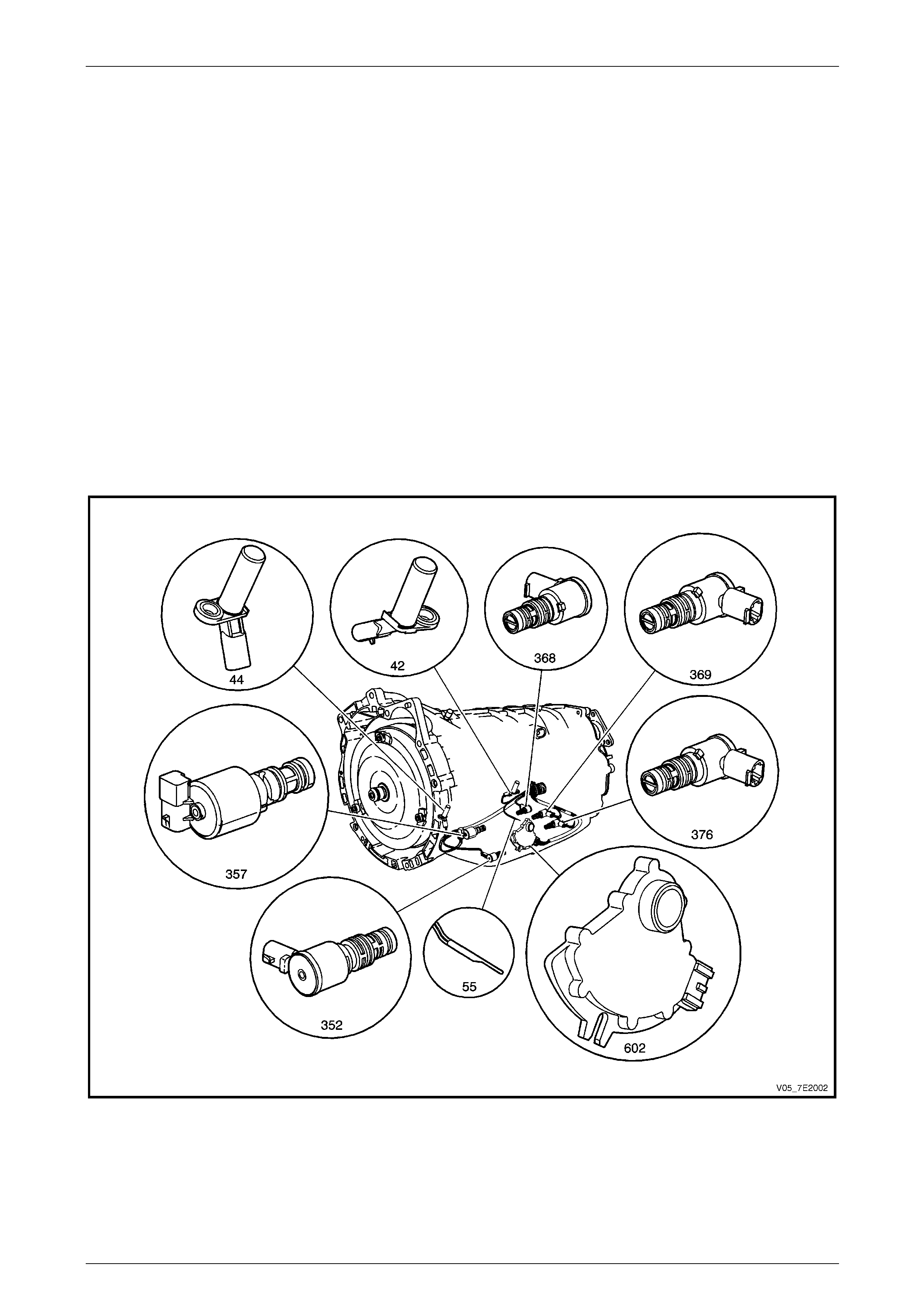
The electronic components of the 5L40–E automatic transmission are as shown next:
Figure 7E2 – 1

Automatic Transmission – 5L40-E – Electrical Diagnosis Page 7E – 5
Page 7E2 – 5
Legend
42 Output Speed Sensor (OSS) 368 4–5 Shift Solenoid
44 Input Speed Sensor (ISS) 369 2–3 Shift Solenoid
55 Transmission Fluid Temperature (TFT) Sensor 376 1–2 Shift Solenoid
352 Torque Converter Clutch (TCC) Pulse Width Modulated
(PWM) Solenoid Valve 602 Transmission manual shift shaft switch assembly. Tech 2
refers to as an Internal Mode Switch (IMS)
357 Pressure Control (PC) Solenoid
• Internal Wiring Harness Assembly, with 20-way Wiring Harness Connector (located at right-hand rear of
transmission case.
• Transmission Control Module (TCM) – not shown.
Transmission Adaptive Functions
The Hydra-matic 5L40-E uses a line pressure control system which has the ability to adapt the system line pressure to
compensate for normal wear within the transmission, such as the clutch pack fibre plates, seals, springs, etc. The adapt
feature is similar in function to the long term/short term fuel trim feature of the engine management system.
The 5L40-E transmission uses the adapt function for ‘garage shifts’, upshifts and T orque Converter Clutch (TCC)
application. The TCM monitors the input shaft speed to determine if the shift is occurring too fast or too slow and adjusts
the pressure control solenoid to maintain the correct shift feel.
Safety Mode Description
If a major electrical system failure occurs which could affect vehicle safety or damage the transmission during norma l
operation, the TCM enters a safety mode. In this mode, the transmission operates in the following manner:
• The pressure control solenoid is off and the li ne pressure is at maximum to minimise clutch slippage.
• The TCC solenoid is off, therefore the torque converter clutch is disabled.
• All three of the shift solenoids are turned off. The transmission will operate in fifth gear if the vehicle has
successfully completed a 1–2 upshift in the current ignition cycle. If the vehicle has not completed a 1–2 upshift in
the current ignition cycle, the transmission will operate in fourth gear. If the transmission is operating in fifth gear,
fourth gear may be obtained if the engine is stopped briefly and re-started.
In safety mode, the gear selector lever is ineffective at selecting forward gear ranges. In fourth or fifth gear, heat builds
up in the transmission quickly, particularly in stop and go tra ffic. Excessive heat build-up may cause transmission failure
if the vehicle is driven for extended distances in safety mode.
Automatic Transmission – 5L40-E – Electrical Diagnosis Page 7E – 6
Page 7E2 – 6
1.2 Transmission Indicators and Messages
While there are no telltale displays in the Instrument that relate to the operation of the 5L40-E automatic transmission,
the Multi Function Display (MFD) compo nent of the Instrument may display messages relating to this transmission.
MFD Displays
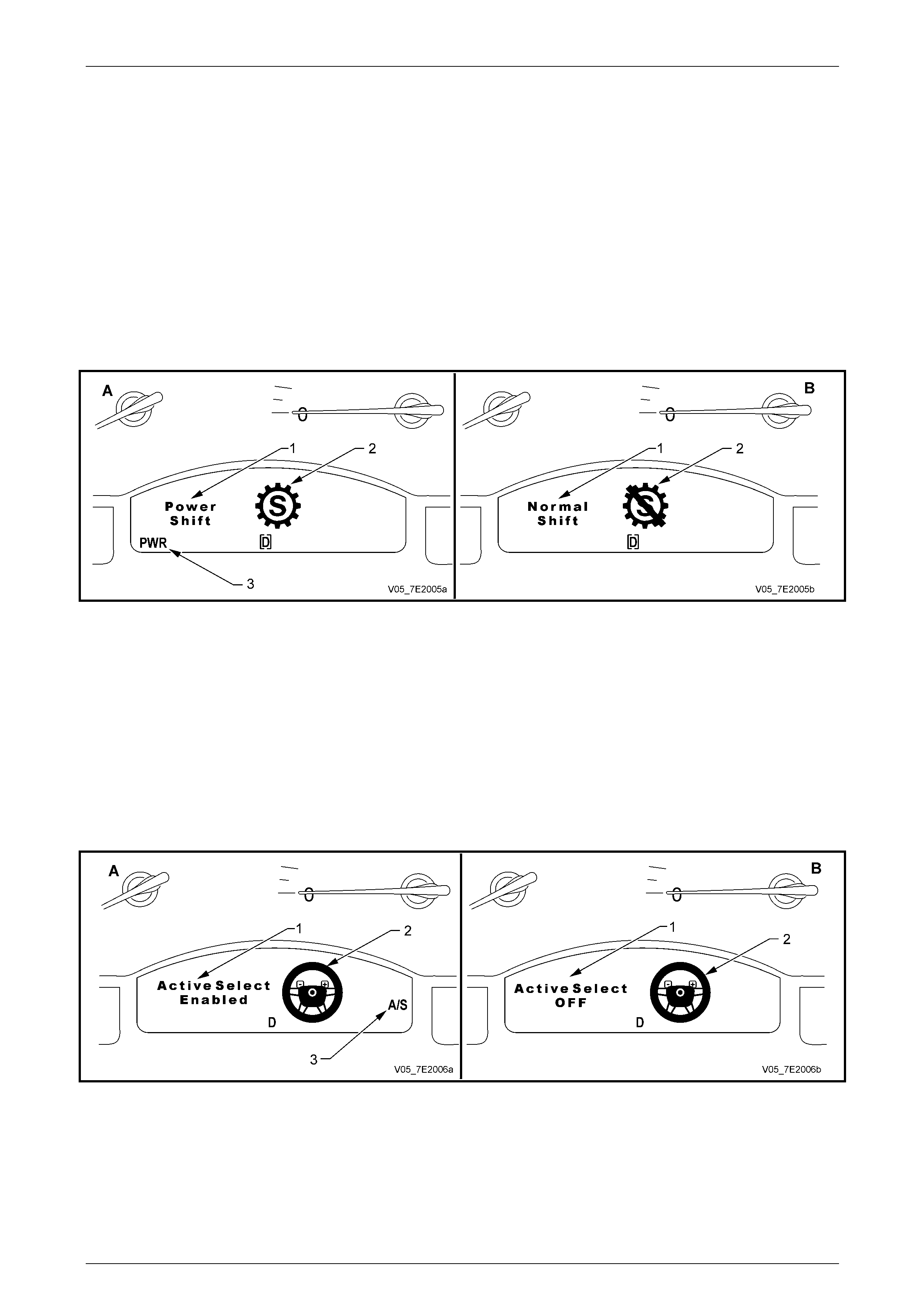
Shift Mode
By pressing the ‘PWR’ momentary contact switch in the centre console, the MFD displays ‘Power Shift’ (1) and the gear
symbol (2) will rotate for approximately 2 seconds. After this time, the display will revert to the icon ‘PWR’ (3) in the lower
left of the display. Refer to view ‘A’.
When the ‘PWR’ button is pre ssed again (view ‘B’), the MFD display will show the message ‘Normal Mode’ (1) and the
gear symbol will have a line through it (2). After approximately 2 seconds, the display and the ‘PWR’ icon will disappear.
Figure 7E2 – 2
Active Select Mode
When the Active Select mode of transmission shifting is selected by pressing the ‘A/S’ momentary contact switch in the
centre console, the MFD will display an icon of the steering wheel (2) and a message ‘Act ive Select Enabled’, (‘1’ in A),
for approximately 2 seconds. After this perio d, the letters ‘A/S’ (3) are displayed in the right side of the MFD displa y.
When the vehicle is moving, the driver may upshift by tapping the ‘+’ paddle on the right side of the horn bar or downshift
by tapping the ‘–‘ paddle on the left side of th e horn bar. Provided the driver command is wit hin th e TCM calibration, an
upshift/downshift will occur.
With a closed throttle coastdown, the TCM will automatically cause downshifts to occur, within the TCM calibratio n.
When the ‘A/S’ switch button is pressed again, the MFD will display the message ‘Active Select Off’, as shown in ‘B’,
again for approximately 2 seconds, after which time the message (1) and the steering wheel icon (2) are deactivate d.
Figure 7E2 – 3
Automatic Transmission – 5L40-E – Electrical Diagnosis Page 7E – 7
Page 7E2 – 7
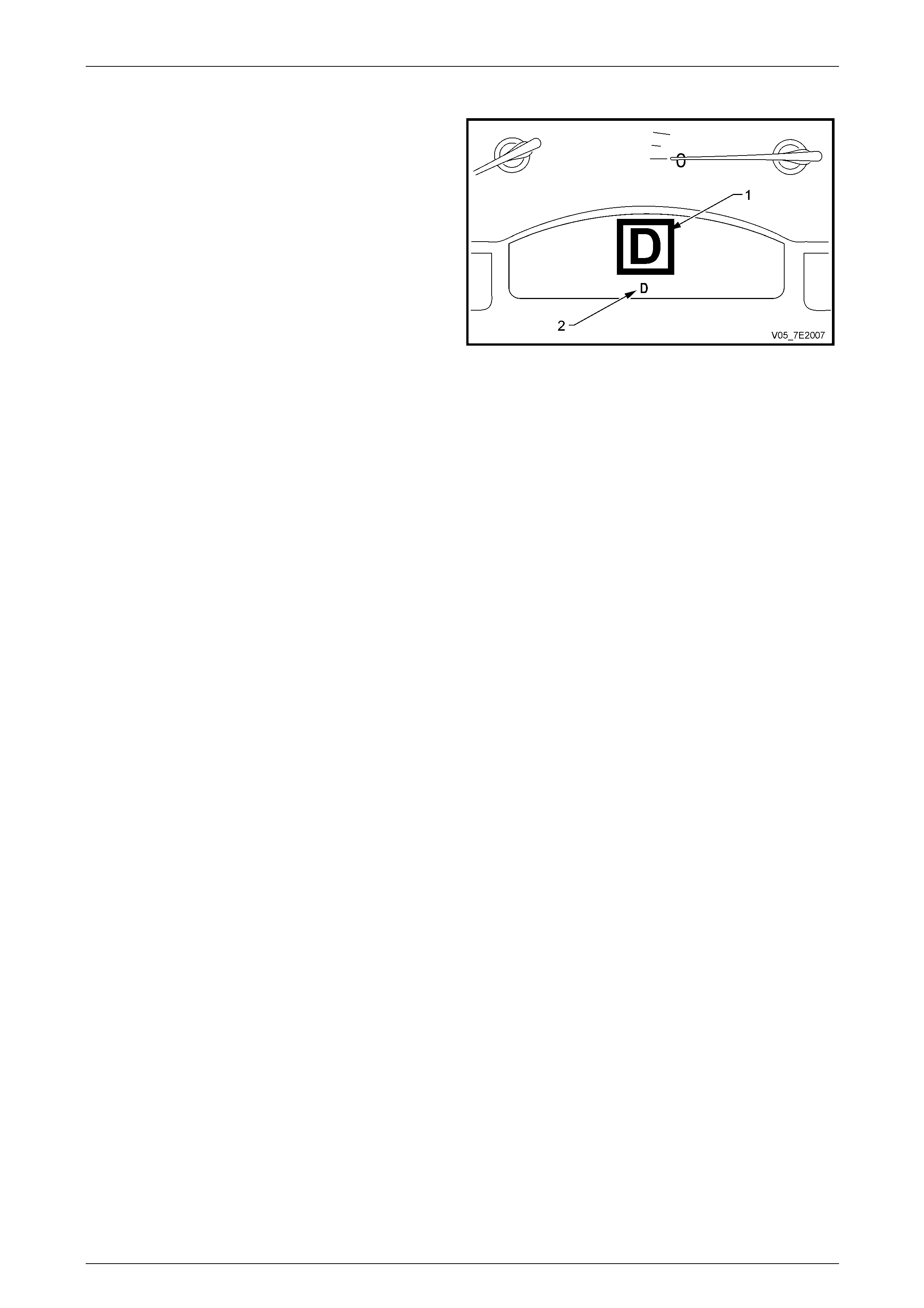
Shift Range Selected
The automatic transmission range select position, is
displayed as a larg e icon (1) in the MFD for approximately
1 second, after which time the appropriate sector of the
smaller icons (2) will be displayed.
Figure 7E2 – 4
Automatic Transmission – 5L40-E – Electrical Diagnosis Page 7E – 8
Page 7E2 – 8
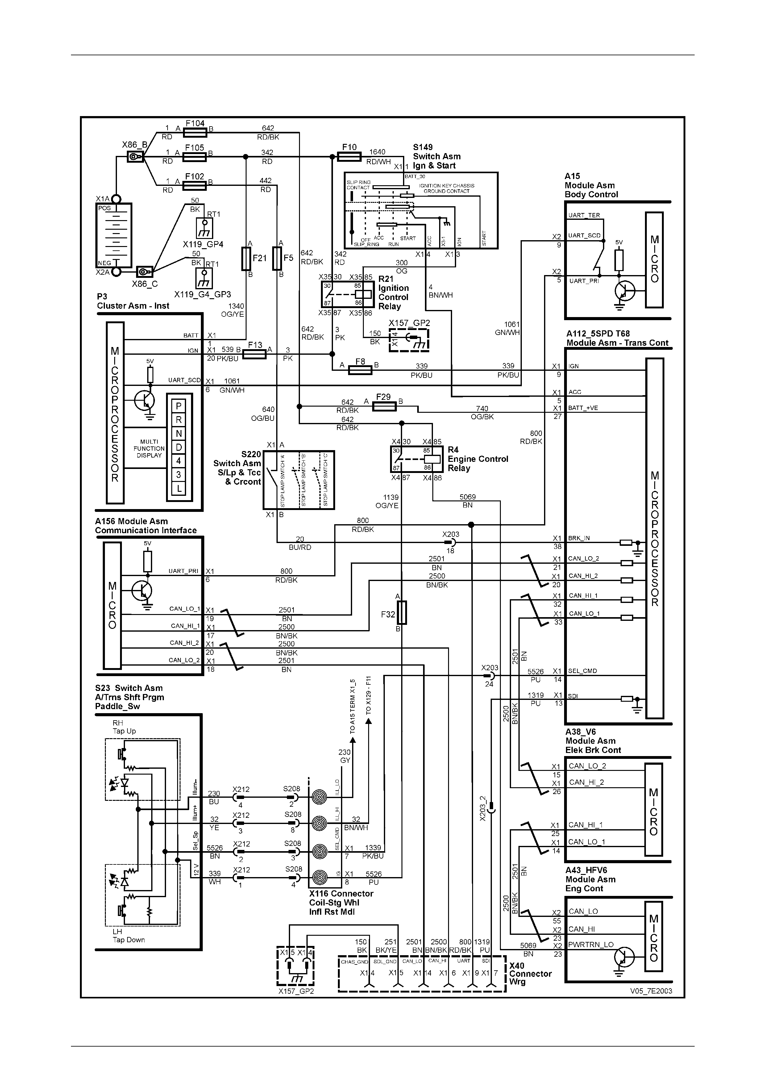
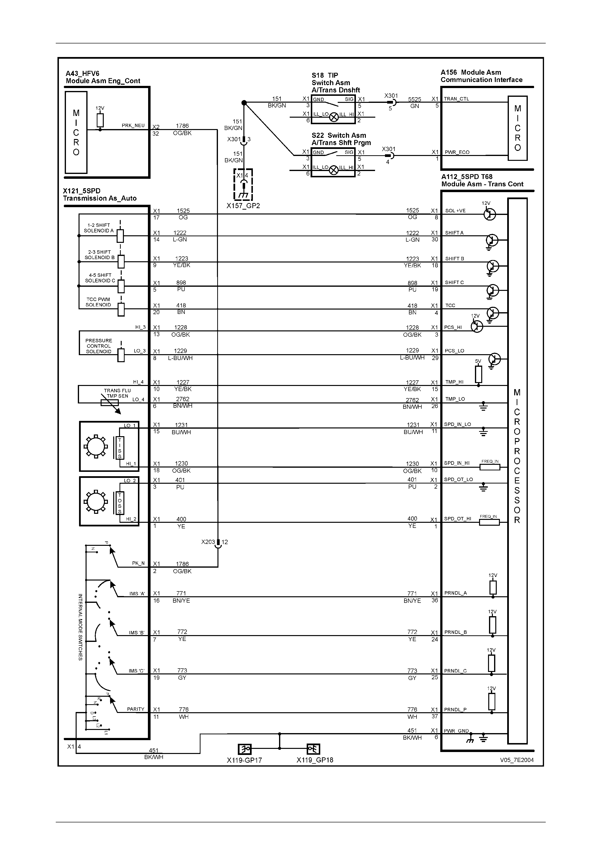
1.3 Automatic Transmission Electrical
Circuits
Figure 7E2 – 5 – Automatic Tran smission Electrical Circuits – 1 of 2
Automatic Transmission – 5L40-E – Electrical Diagnosis Page 7E – 9
Page 7E2 – 9
Figure 7E2 – 6 – Automatic Tran smission Electrical Circuits – 2 of 2
Automatic Transmission – 5L40-E – Electrical Diagnosis Page 7E – 10
Page 7E2 – 10
1.4 Electronic Component Description
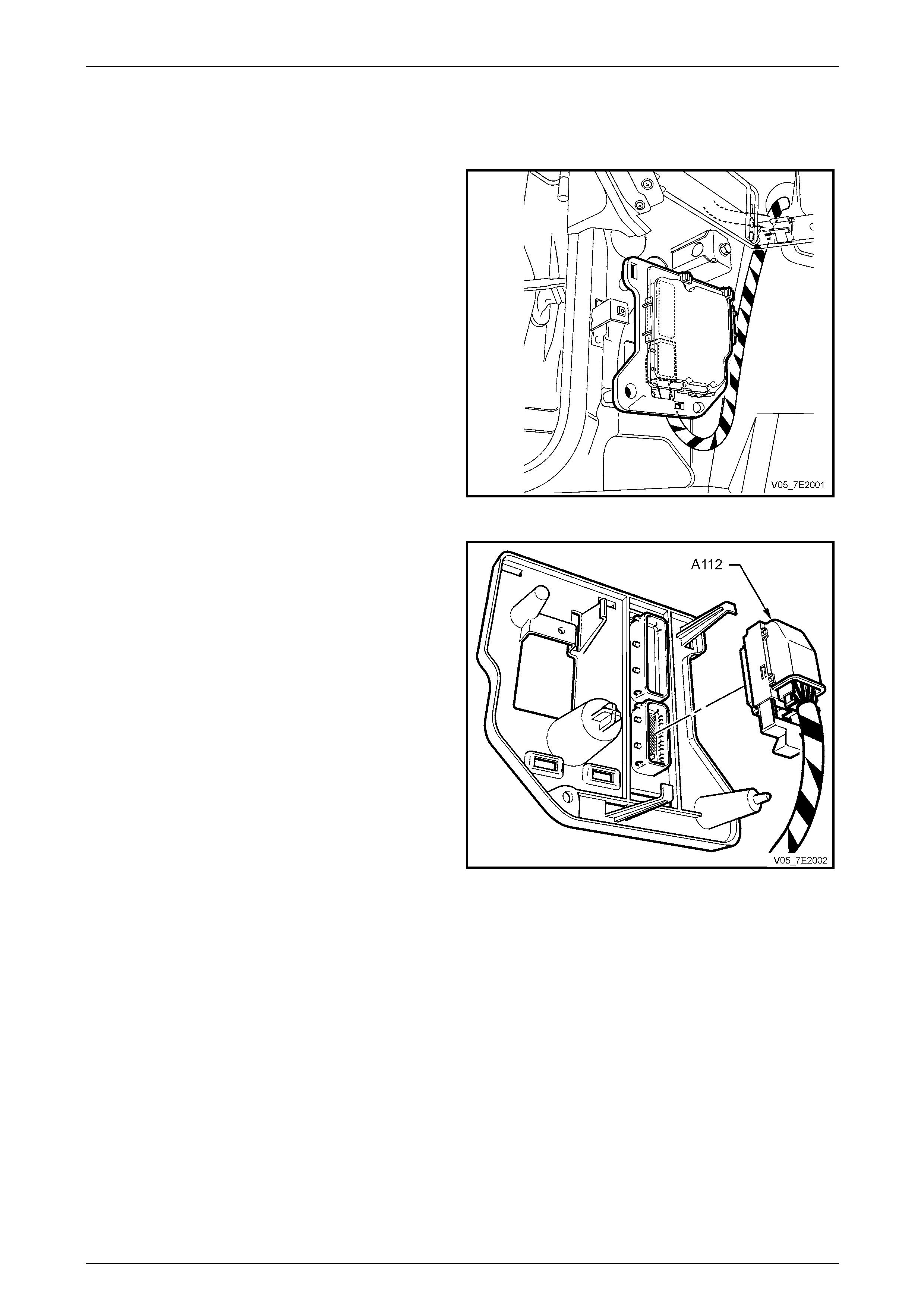
Transmission Control Module (TCM)
The Transmission Control Mo dule (TCM) is located
behind the left side kick panel and connects directly to
the transmission wiring harness. A single 42-way
connector is used to make the connection b etween the
vehicle wiring and the T CM.
Figure 7E2 – 7
The TCM is an electronic control module that receives
input or provides output to control the operation of the
5L40-E automatic transmission.
The TCM receives the following inputs from the Engine
Control Module (ECM):
• Engine speed and torque values
• Engine Intake Air Temperature (IAT),
Accelerator Pedal Position (APP) information
• Engine Coolant Temperature (ECT)
• Kick-down request
• Traction control status
• Driver selected shift mode
• Air conditioning (A/C) status
The ECM provides this data to the TCM through the GM
Local Area Network (GMLAN).
Figure 7E2 – 8
The GMLAN is a 2-wire communic ation connection between the ECM, TCM, ABS/T C/ESP and PIM control modules,
plus a connection to the Data Link C onnector (DLC).
Other TCM inputs are the following:
• Battery and ignition voltage
• Brake switch status
• Transmission manual shift sh aft switch assembly
• Transmission Fluid Temperature (TFT)
• Transmission Input (Shaft) Speed (ISS) sensor
• Transmission Output (Shaft) Speed (OSS) sensor
Automatic Transmission – 5L40-E – Electrical Diagnosis Page 7E – 11
Page 7E2 – 11
The TCM provides the following outputs to control the automatic transmission:
• Shift solenoids to control transmission shifting
• Torque Converter Clutch (T CC) Pulse Width Modulated (PWM) solenoid operation controls the apply and
release of the torque converter clutch assem bl y
• Pressure Control (PC) solenoi d which regulates transmission line pressure.
Other TCM outputs provided to the ECM / PIM are the following:
• Check Powertrain Malfunction Indicator Lamp (MIL) illumination request.
• Vehicle speed.
• Transmission input speed.
• Transmission fluid temperature.
• Commanded gear status.
• TCC status.
• Torque reduction requests.
• Manual shift shaft switch status.
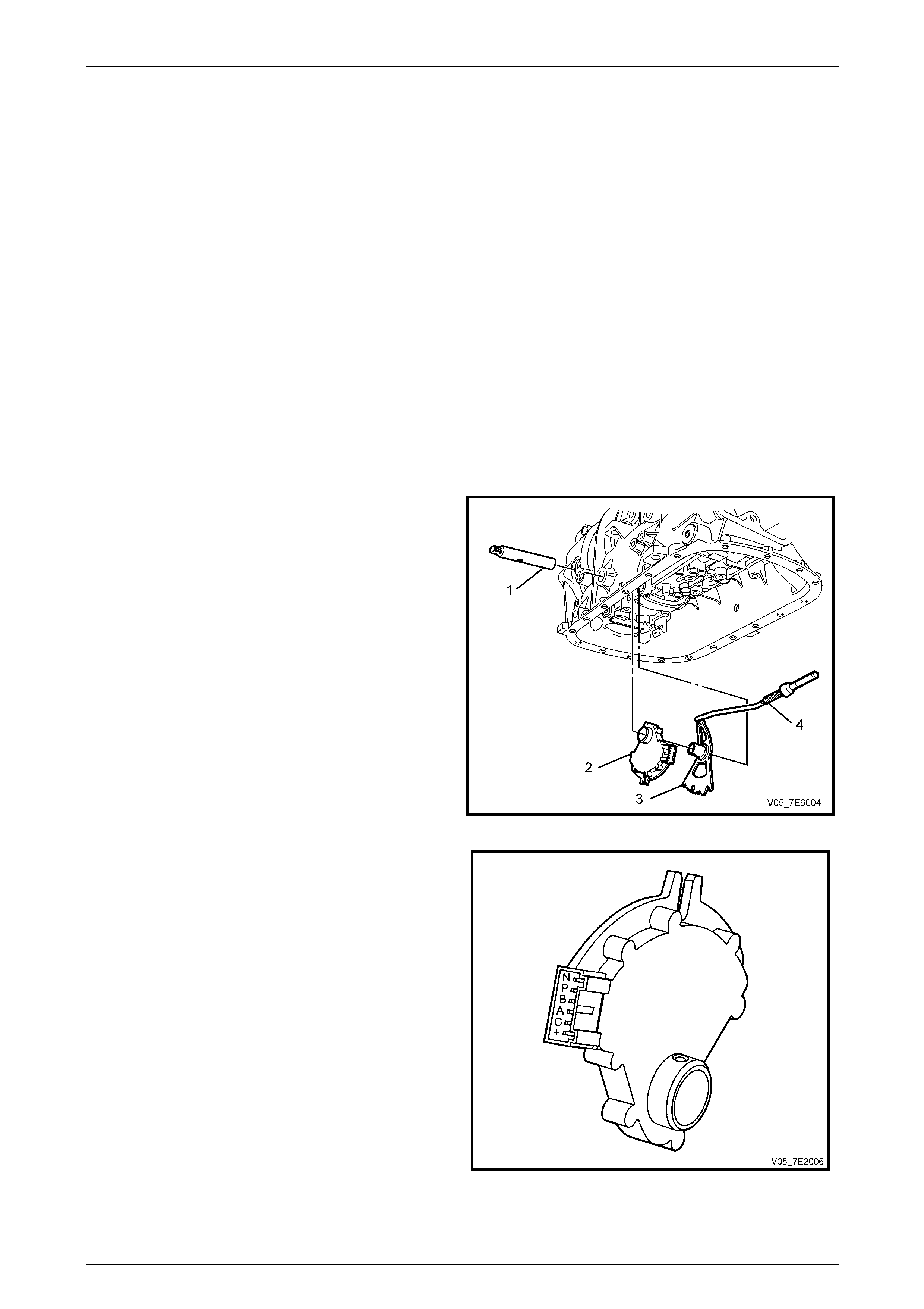
Transmission Manual Shift Shaft Switch Assembly
The transmission manual shift shaft switch assembly (2)
is a sliding contact switch attached to the manual shift
shaft (1) and is located inside the transmissi on case.
For Tech 2 data and diagnostic purpos es, the manual
shift shaft switch assembly is referred to as the IMS
(Internal Mode Switch).
Figure 7E2 – 9
There are four inputs to the TCM from the transmission
manual shift shaft switch assembly which indi cate the
transmission gear selector lever position, with a fifth input
directed to the Engine Control Module (ECM). This
information is used for engine controls as well as
determining the transmission shift patterns.
The state of each input is available for display on the
Tech 2. The four input parameters represented are
Signal A, Signal B, Signal C and Signal P (Parity).
The fifth input (to the ECM) is Signal N (P/N Start).
Figure 7E2 – 10
Automatic Transmission – 5L40-E – Electrical Diagnosis Page 7E – 12
Page 7E2 – 12
Manual Shift Shaft Switch Assembly Logic
Gear Selector Position A B C P P/N
Park LOW HIGH HIGH LOW LOW
Park / Reverse LOW HIGH HIGH HIGH –
Reverse LOW LOW HIGH HIGH HIGH
Reverse / Neutral HIGH LOW HIGH HIGH –
Neutral HIGH LOW HIGH LOW LOW
Neutral / Drive 5 HIGH LOW LOW LOW –
Drive 5 HIGH LOW LOW HIGH HIGH
Drive 5 / Drive 4 LOW LOW LOW HIGH –
Drive 4 LOW LOW LOW LOW HIGH
Drive 4 / Drive 3 LOW HIGH LOW LOW –
Drive 3 LOW HIGH LOW HIGH HIGH
Drive 3 / Drive 2 HIGH HIGH LOW HIGH –
Drive 2 HIGH HIGH LOW LOW HIGH
Open HIGH HIGH HIGH HIGH –
Invalid HIGH HIGH HIGH LOW –
HIGH = Ignition Voltage LOW = 0 voltage
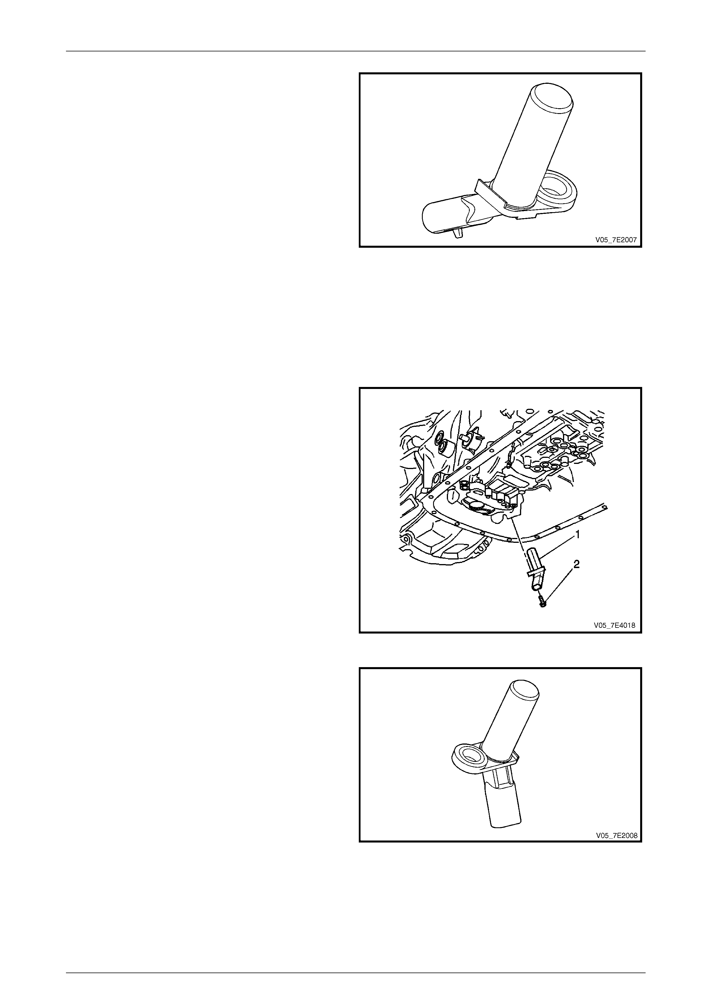
Transmission Output Shaft Speed (OSS) Sensor
The transmission Output (Shaft) Speed (OSS) sensor (1) is
a variable reluctance magnetic pickup located in the rear
underside of the transmission case. The sensor is mounted
inside the transmission case opposite the rear internal gear.
The rear internal gear is splined to the transmission output
shaft assembly.
Access to the OSS sensor is by removing the transmission
fluid pan and filter.
Physically, the OSS and the Input (Shaft) Speed (ISS)
sensor are identical.
Figure 7E2 – 11
Automatic Transmission – 5L40-E – Electrical Diagnosis Page 7E – 13
Page 7E2 – 13
The sensor consists of a permanent magne t surrounded
by a coil of wire. As the output shaft and rear internal
gear rotate, an alternating current (AC) is induced in the
coil by the 'teeth' on the rear internal gear as they pass
by the magnetic pickup. Therefore, whenever the vehicle
is moving, the OSS sensor produces an AC voltage
signal proportional to vehic le speed.
Figure 7E2 – 12
At the TCM, the AC signal is electronically converted to a 5 volt square wave pattern. The square wave pattern can then
be interpreted as transmission output speed by the TCM through the frequency of square waves in a given time frame.
The square waves can be thought of as a representation of the rear internal gear teeth. Therefore, the more teeth or
waves that pass by the magnetic pickup in a given time frame, the faster the vehicle is moving. The square wave pattern
is compared to a fixed clock signa l internal to the TCM to determine transmission output spee d.
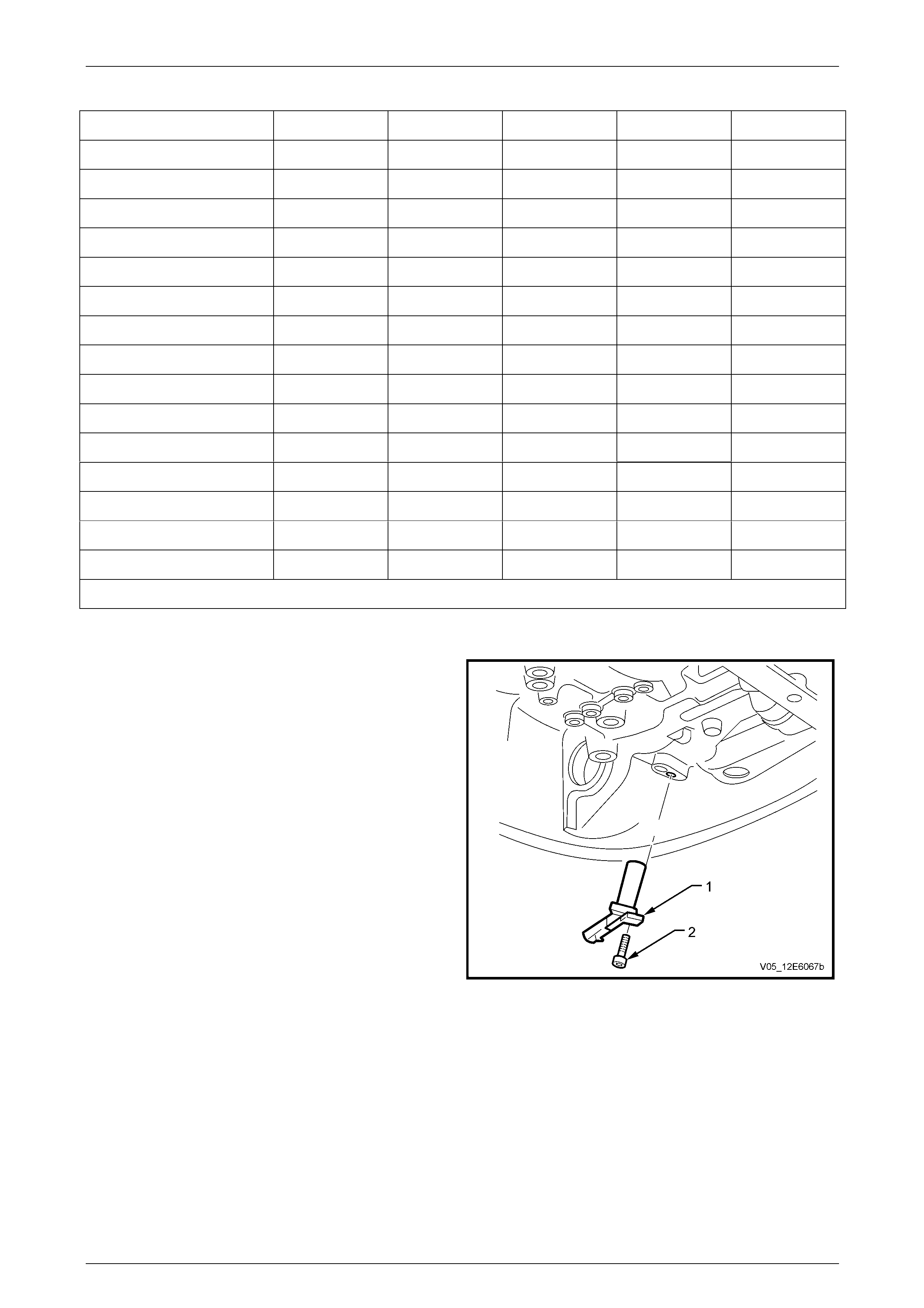
Transmission Input Shaft Speed (ISS) Sensor
The transmission Input (Shaft) Speed (ISS) sensor is
located in the front underside of the transmission case.
The ISS operates identically to the OSS sensor except
that is uses the stamped teeth on the reverse clutch input
housing assembl y as the rotor reluctor. The reverse
clutch input housing assembly is driv en at torque
converter turbine speed.
Figure 7E2 – 13
The ISS sensor square wave pattern is als o compared to
a fixed clock signal internal to the TCM to determine
actual converter turbine speed. T he T CM uses
transmission input and output speeds to help determine
line pressure, transmission shift patterns, TCC applied
pressure, gear ratios and T CC slippage for diagnostic
purposes.
Access to the ISS sensor is by removing the
transmission fluid pan and filt er.
Physically, the ISS and the Output (Shaft) Speed (OSS)
sensor are identical.
Figure 7E2 – 14

Automatic Transmission – 5L40-E – Electrical Diagnosis Page 7E – 14
Page 7E2 – 14
Transmission Fluid Temperature (TFT) Sensor
The TFT sensor is part of the transmission interna l wiring
harness assembly. The TFT sensor is a type of resistor,
known as a thermistor, which changes value based on
temperature. Refer to the following Transmission Fluid
Temperature (TFT) Sensor Specifications chart. The
sensor has a negative-temperature coeffici ent. This
means that as the temperature increases, the resistance
decreases and as the temperature decreas es the
resistance increases. The TCM supplies a 5-volt
reference signal to the sensor and measures the voltage
drop in the circuit. When the transmission fluid is cold the
sensor resistance is high and the TCM detects high
signal voltage. As the fluid temperature warms to a
normal operating temperature, the resistance becomes
less and the signal voltage decreases. The TCM uses
this information to maintain shift quality and torque
converter clutch application quality over operating
temperature range.
Figure 7E2 – 15
If transmission fluid temperatures become excessively high, above approximately 140°C, the TCM will disable the
Electronic Converter Clutch Control (ECCC) function a nd command lock up mode. Applying the TCC serves to reduce
transmission fluid temperatures created by the fluid coupling in the torque converter with the TCC released.
Above approximately 149°C, the TCM will set a transmission fluid temperature DT C (P0218). This causes the TCM to
use a fixed default val ue of 135°C as the transmission fluid temperature inp ut signal.
TRANSMISSION FLUID TEMPERATURE (TFT) SENSOR SPECIFICATIONS
Temperature
(° C)
Minimum
Resistance
(Ohm)
Nominal
Resistance
(Ohm)
Maximum
Resistance
(Ohm)
-40°C 89 500 100 000 110 500
-30°C 46419 51 400 56 381
-20°C 25 120 27 610 30 100
-10°C 14 160 15 450 16 740
0°C 8278 8972 9666
10°C 5005 5391 5777
20°C 3120 3342 3564
30°C 2000 2132 2264
40°C 1317 1397 1477
50°C 888 938 988
60°C 613 645 677
70°C 432 453 474
80°C 310 324 338
90°C 228 237 246
100°C 170 176 182
110°C 128 132 136
120°C 98 101 104
130°C 77 79 81
140°C 60 62 64
150°C 48 49 50
Automatic Transmission – 5L40-E – Electrical Diagnosis Page 7E – 15
Page 7E2 – 15
Shift Solenoid (SS) Valves
The Hydra-matic 5L40-E uses three electromagnetic shift
solenoid (SS) valves 1–2, 2–3 and 4–5 to control upshifts
and downshifts in all for ward gear ran ges.
The shift solenoid valves are all id entical, normally
closed, 3-port, ON / OFF type solenoids controlled by the
TCM. These shift solenoid valves work together in a
combination of ON and OFF sequenc es to control the
various shift valves.
The TCM uses numerous inputs to determine which
solenoid state combination the transmission should be in.
Refer to the following Shift Solenoid Valv e State and
Gear Ratio chart for these combinations, noting that the
combination for the 1 – 2 and 3 – 4 shifts are the same.
Figure 7E2 – 16
Shift Solenoid Valve State and Gear Ratio
Gear Range 1–2 / 3-4 Shift Solenoid 2-3 Shift Solenoid 4-5 Shift Solenoid Gear Ratio
Park, Reverse, Neutral OFF ON OFF 3.16:1
First OFF ON OFF 3.45:1
Second ON ON OFF 2.21:1
Third ON OFF OFF 1.59:1
Fourth OFF OFF ON 1.00:1
Fifth OFF OFF OFF 0.76:1
• All shift solenoids are normally closed.
• The 4–5 shift solenoid also enables engine brakin g.
Shift solenoid valve resistance should measure between 15.0 – 17.0 Ohms when measured at 20°C. The resistance
should measure approximately 17.9 – 20.3 ohms at 158°C.
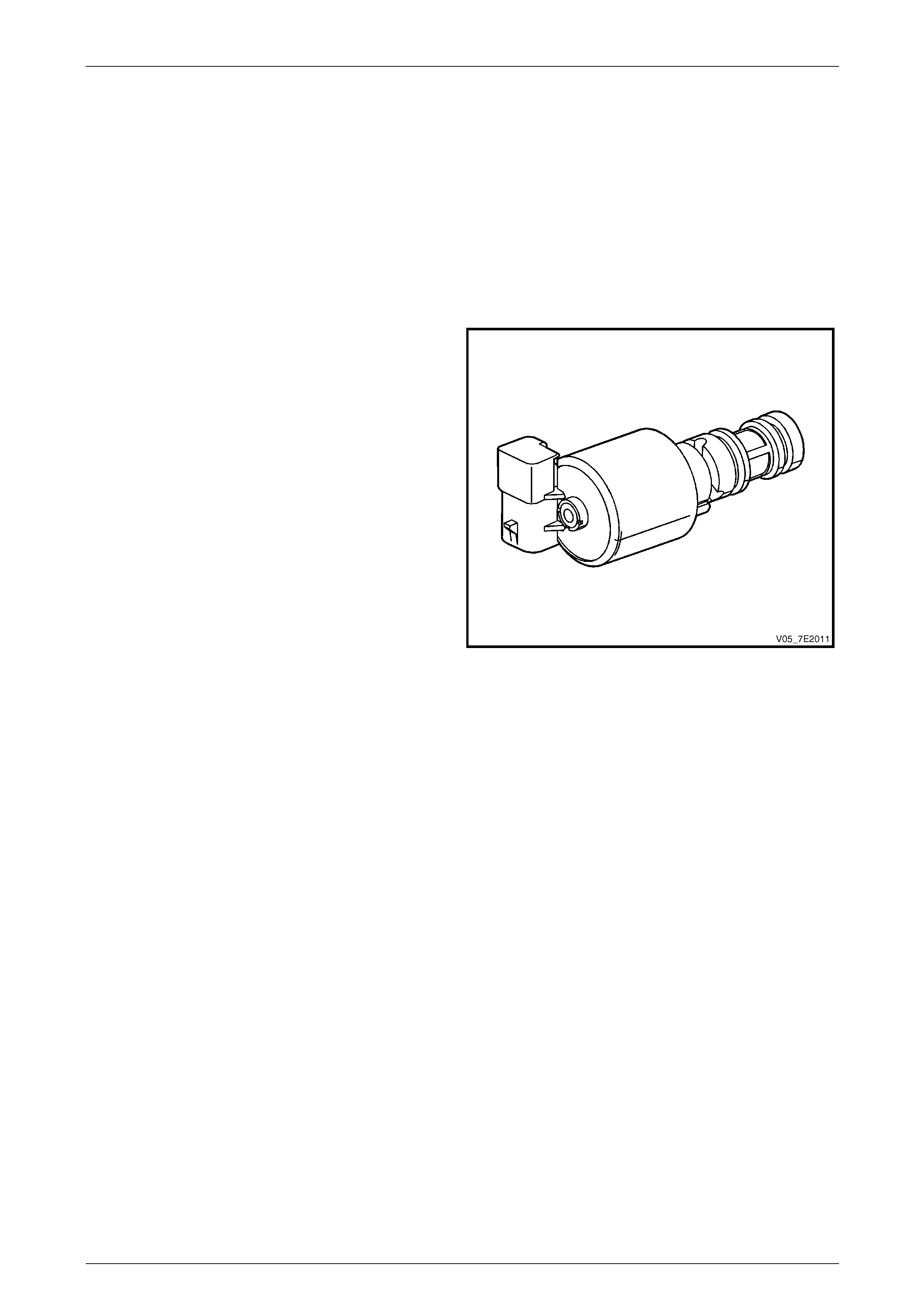
Torque Converter Clutch Pulse Width Modulated (TCC PWM) Solenoid Valve
The TCC PWM solenoid valve is a normally-closed pulse
width modulated (PWM) solenoid used to control the
apply and release of the converter clutch. The TCM
operates the solenoid with a negative duty cycle, at a
fixed frequency of 32 Hz, to control the rate of T CC
apply / release. The solenoid's ability to 'ramp' the TCC
apply and release pressures results in a smoother TCC
operation.
When vehicle operating conditions are appropri ate to
apply the TCC, the TCM increases the duty cycle to
allow the TCC PWM soleno id valve to command TCC
signal fluid pressure at a level sufficient to move the TCC
enable valve and the TCC control valve to the apply
position. Release pressure is directed to exh aust and
regulated apply fluid is directed to the apply side of the
converter pressure plate/damper assembly.
The TCM then increases the duty cycle to control a
slippage of 20 – 80 rpm between the pressure
plate/damper assembly and the converter cover.
Figure 7E2 – 17
Automatic Transmission – 5L40-E – Electrical Diagnosis Page 7E – 16
Page 7E2 – 16
This provides for improved absorption of eng ine vibrations and allows the TCC to appl y at low engine speeds in 2nd, 3rd,
4th and 5th gear. At high speed, lock up mode is set by activating the TCC PWM solenoid valve at maximum duty cycle.
Release of the TCC is achieve d b y decreasing the duty cycle to a level low enough to allow spring force to move the
TCC enable valve and the TCC control valve to the release position. Appl y fluid is directed to exhaust and converter feed
fluid is directed into the release circuit to the release side of the pressure plate / damper assembly.
There are also some operating conditions that may prevent or enab le TCC apply under various cond itions, engine
temperature, transmission temperature, or brake switch activation, depending on vehicle application.
TCC PWM solenoid valve resistance should measure between 10.0–11.5 ohms when measured at 20°C. The resistance
should measure approximately 11.8 – 13.6 ohms at 158° C.
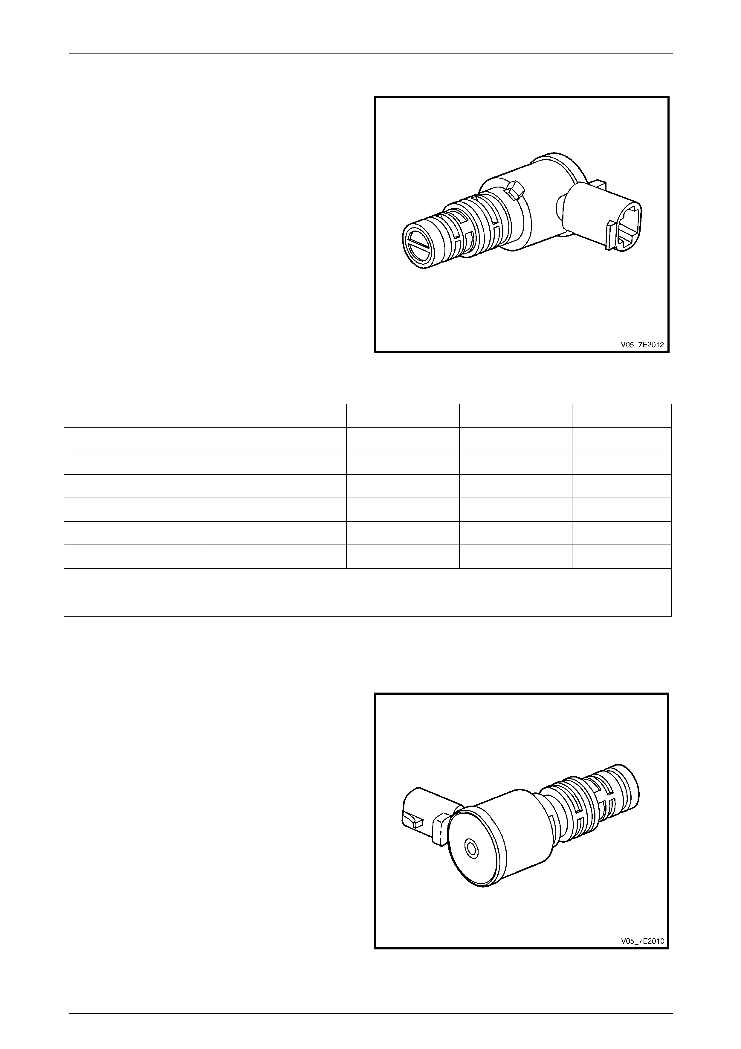
Pressure Control (PC) Solenoid Valve
The Pressure Control (PC) solenoid valve is a precision
electronic pressure regulator that controls transmission
line pressure based on curren t flow through its coil
windings. As current flow is increased, the magnetic field
produced by the coil moves the solenoi d' s plunger further
away from the exhaust port. Opening the exhaust port
decreases the output fluid pressure regulated by the PC
solenoid valve, which ultimately decreases line pressure.
The TCM controls the PC solenoid valve based on
various inputs including throttle position, tran smission
fluid temperature and gear state.
The pressure control solenoid valve resistance should
measure between 3.5 – 4.6 ohms when measured at
20°C. The resistance should measur e approximately
4.2 – 5.5 ohms at 158°C.
Duty Cycle, Frequency and Current Flo w
A duty cycle may be defined as the percent age of time
current is flowing through a sole noid coil during each
cycle. The number of cycles that occur within a specified
amount of time, usually measured in seconds, is called
'frequency'. Typically, the operation of an electronica lly
controlled pulse width modulated solenoid is explained in
terms of duty cycles and frequency.
Figure 7E2 – 18
The TCM controls the PC solenoid valve on a positive duty cycle at a fixed frequency of 292.5 Hz cycles per second. A
higher duty cycle provides a greater current flow through the solenoid. The high positive side of the PC solenoi d valve
electrical circuit at the TCM controls the PC solenoid valve operation. The TCM provides a ground path for the circuit,
monitors average current and continuously varies the PC solenoid valve duty cycle to maintain the correct average
current flowing through the PC solenoid valve.
The duty cycle and current flow to the PC solenoid valve are mainly affected by throttle position and engine torque. As
the throttle angle engine torque increases, the duty cycle is decreased b y the TCM which decreases current flow to the
PC solenoid valve. Current flow to the PC soleno id valve creates a magnetic field that moves the solenoid armature
against spring force.
Transmission Adapt Function
Programming within the TCM also allows for automatic adjustments in shift pressure that are based on the changing
characteristics of the transmission components. As the apply components within the transmission wear, the shift time
and the time required to apply a clutch, increases. To compensate for this wear, the TCM adjusts trim pressure by
controlling the PC solenoi d valve to maintain the originall y calibrated sh ift timing. The automatic adjusting process is
referred to as adaptive learnin g and it is used to ensure consistent shift feel plus increase transmission d urab ility. The
TCM monitors the Transmission Input Speed Sensor (TISS) and the Transmission Output Speed Sensor (TOSS) during
commanded shifts to determine if a shift is occurring too fast / slow or harsh / soft and adjusts the PC solenoi d valve
signal to maintain a set shift feel.
Automatic Transmission – 5L40-E – Electrical Diagnosis Page 7E – 17
Page 7E2 – 17
20 Way Wiring Harness Connector
The transmission 20-way wiring harness connector is an
important part of the transmission operating system. Any
interference with the electrical conn ection can cause the
transmission to set Diagnostic Trouble Codes (DTC) or
affect proper operation.
The following items can affect the electrical conn ection:
• Bent terminals in the connector from rough
handling during connectio n and disconnection.
• Wires backing away from the pins or coming
uncrimped, in either the internal or the e xternal
wiring harness.
• Dirt or moisture contamination entering the
connector when disconnected.
• Pins in the internal wiring connector backing out of
the connector during connecti on.
• Transmission fluid leaki ng into the connector,
wicking up into the external wiring harness and
degrading the wire insulation.
Figure 7E2 – 19
• Low terminal tension in the external connector from excessive connection and disconnection of the wiring
connector assembly.
• Terminal corrosion from contamin ation.
• Damaged connector or connector lock assembly.
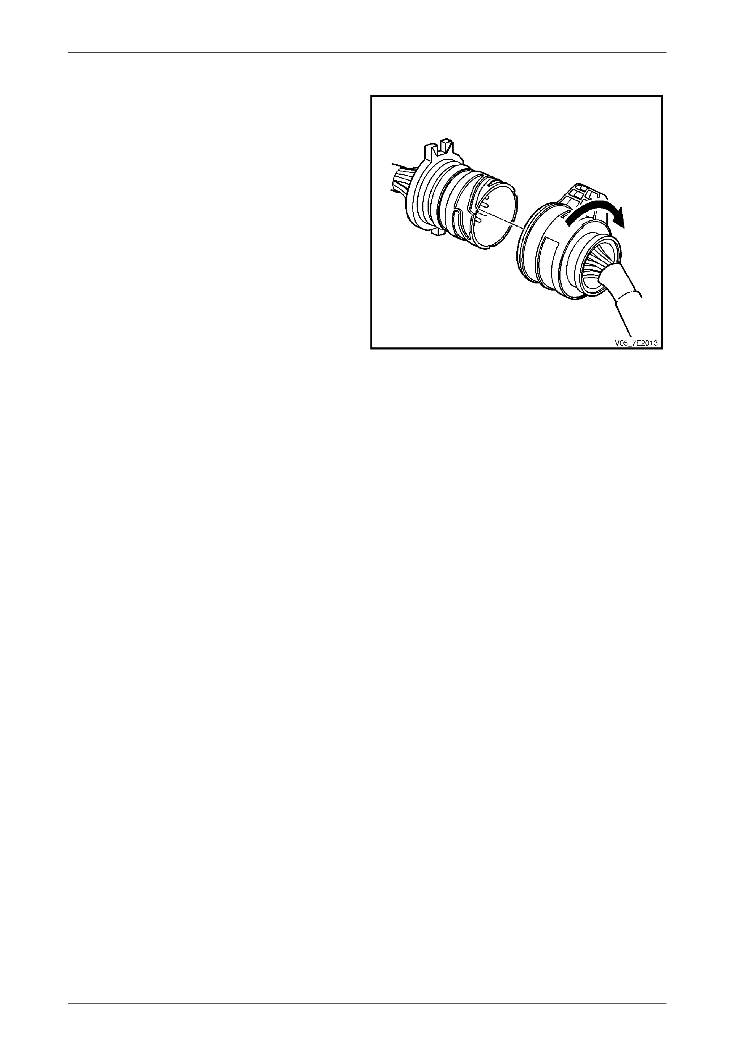
Remember the following points:
• To disconnect the connector, turn the connector clockwise and pull.
• Do not prise on the connector with a screwdriver or other too l.
• The connector should screw into place with a positive feel and lock when properly installed.
Whenever the vehicle external wiring connector is disconnected from the internal harness and the ignition is ON,
transmission DTCs will set. Clear these DTCs after reconn ecting to the transmission 20-way connector.
Automatic Transmission – 5L40-E – Electrical Diagnosis Page 7E – 18
Page 7E2 – 18
1.5 Automatic Transmission Wiring Harness
Connectors
NOTE
Apart from the 20-Way wiring harness connector
to the automatic transmission, the remaining
electrical harness connectors are secured by a
latch that must be carefully lifted with either the
fingertips or a small bladed screwdriver before
disconnection.
In-Line 20-Way Connector End View
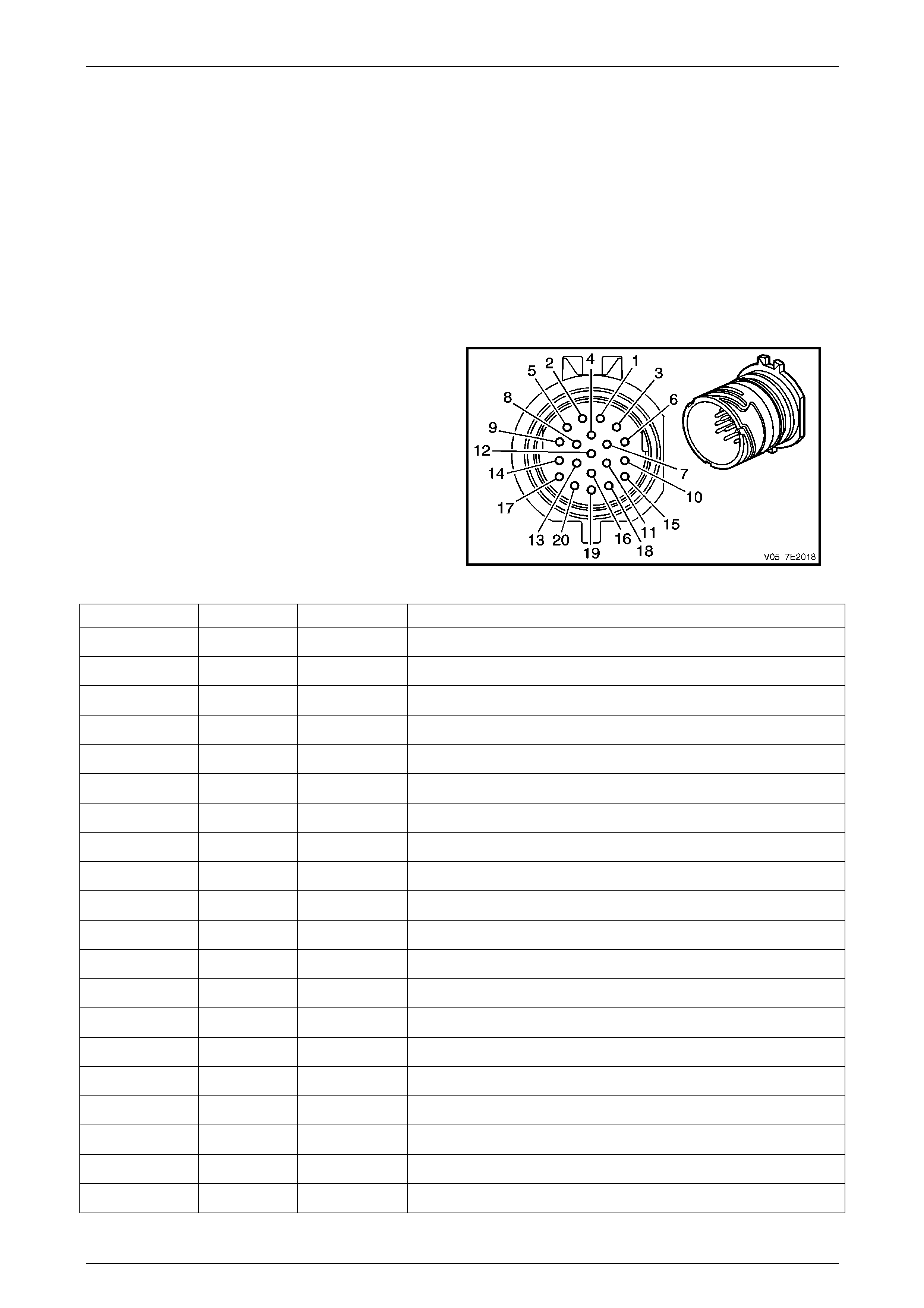
Transmission Side – X121–X1
Figure 7E2 – 20
Terminal / Pin Wire Colour Circuit No. Function
X1–1 OG 400 Output Speed (OSS) Sensor – High Si gnal
X1–2 BN 1786 Park / Neutral Signal
X1–3 WH 401 Output Speed (OSS) Sensor – Low Signal
X1–4 GN 451 Ground
X1–5 GY 898 4–5 Shift Solenoid Valve Co ntrol
X1–6 WH 2762 Transmission Fluid Temperature (TFT) Sensor Low Reference
X1–7 BK 772 Transmission Range Signal B
X1–8 WH 1229 Pressure Control (PC) Solenoid Valve H igh Control
X1–9 BU 1223 2–3 Shift Solenoid Valve Control
X1–10 RD 1227 Transmission Fluid Temperature (TFT) Sensor Signal
X1–11 GY 776 Transmission Range Signal Parit y
X1–12 — — Not Used
X1–13 GN 1228 Pressure Control (PC) Solenoid Valve High C ontrol
X1–14 BK 1222 1–2 Shift Solenoid Valve Control
X1–15 WH 1231 Input Speed (ISS) Sensor Low Signal
X1–16 RD 771 Transmission Range Signal A
X1–17 WH 1525 Solenoid Power Supply
X1–18 YE 1230 Input Speed (ISS) High Si gnal
X1–19 BU 773 Transmission Range Signal C
X1–20 YE 418 Torque Converter Clutch (TCC) PWM Solenoid Valve Cont rol
Automatic Transmission – 5L40-E – Electrical Diagnosis Page 7E – 19
Page 7E2 – 19
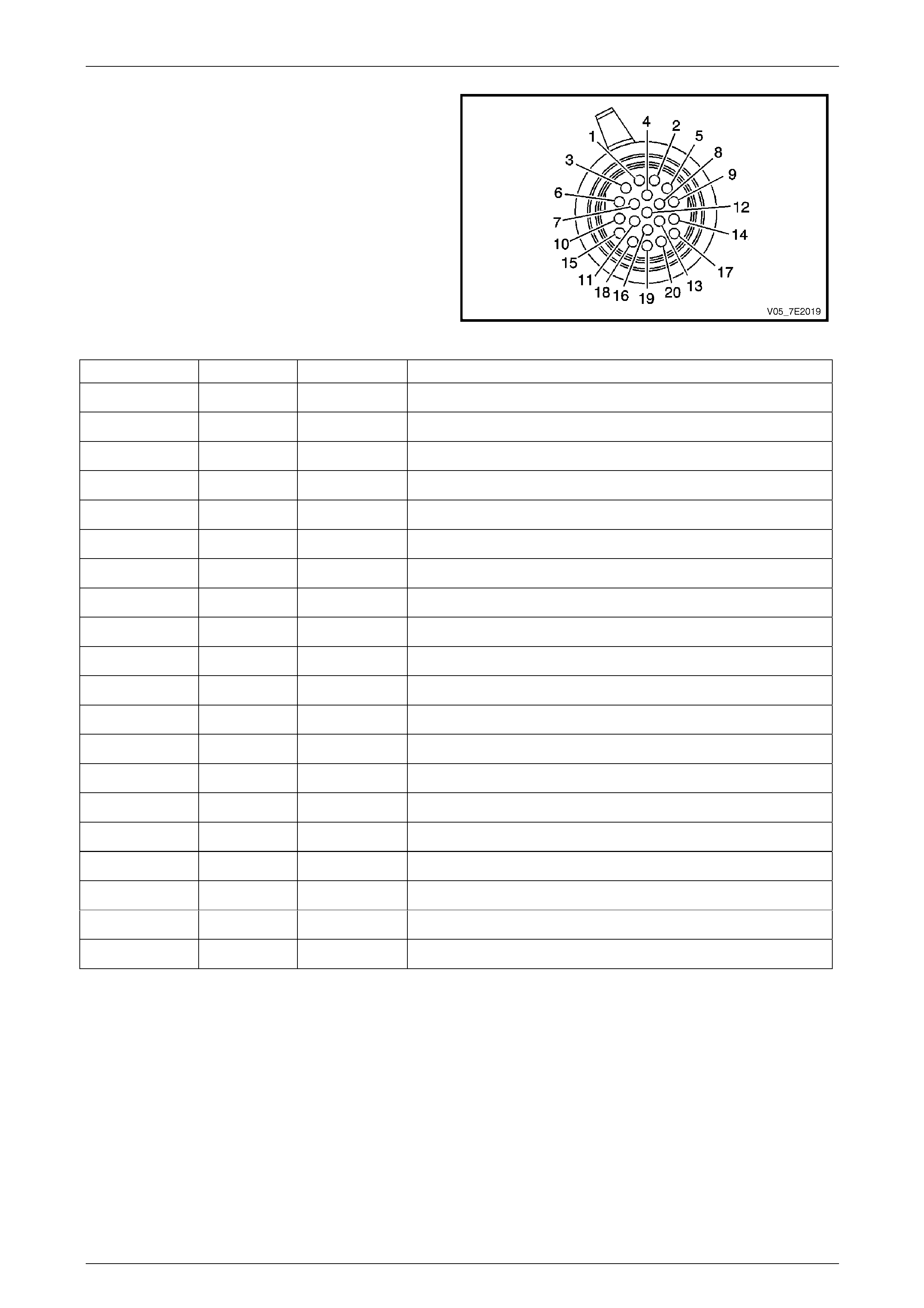
Wiring Harness Side – X121–X1
Figure 7E2 – 21
Terminal / Pin Wire Colour Circuit No. Function
X1–1 YE 400 Output Speed (OSS) Sensor – High Signal
X1–2 OG / BK 1786 Park / Neutral Signal
X1–3 PU 401 Output Speed (OSS) Sensor – Low Signal
X1–4 BK / WH 451 Ground
X1–5 PU 898 4–5 Shift Solenoid Valve Control
X1–6 BN / WH 2762 Transmission Fluid Temperature (TFT) Sensor Low Reference
X1–7 YE 772 Transmission Range Signal B
X1–8 L-BU / WH 1229 Pressure Control (PC) Solenoid Valve Low Control
X1–9 YE / BK 1223 2–3 Shift Solenoid Valve Control
X1–10 YE / BK 1227 Transmission Fluid Temperature (TFT ) Sensor Signal
X1–11 WH 776 Transmission Range Signa l Parity
X1–12 — — Not Used
X1–13 OG / BK 1228 Pressure Control (PC) Soleno id Valve High Control
X1–14 L-GN 1222 1–2 Shift Solenoid Valve Control
X1–15 BU / WH 1231 Input Speed (ISS) Sensor Low Signal
X1–16 BN / YE 771 Transmission Range Signal A
X1–17 OG 1525 Solenoid Power Supply
X1–18 OG / BK 1230 Input Speed (ISS) High Signal
X1–19 GY 773 Transmission Range Signal C
X1–20 BN 418 Torque Converter Clutch (TCC) PWM Solenoid Va lve Control
Automatic Transmission – 5L40-E – Electrical Diagnosis Page 7E – 20
Page 7E2 – 20
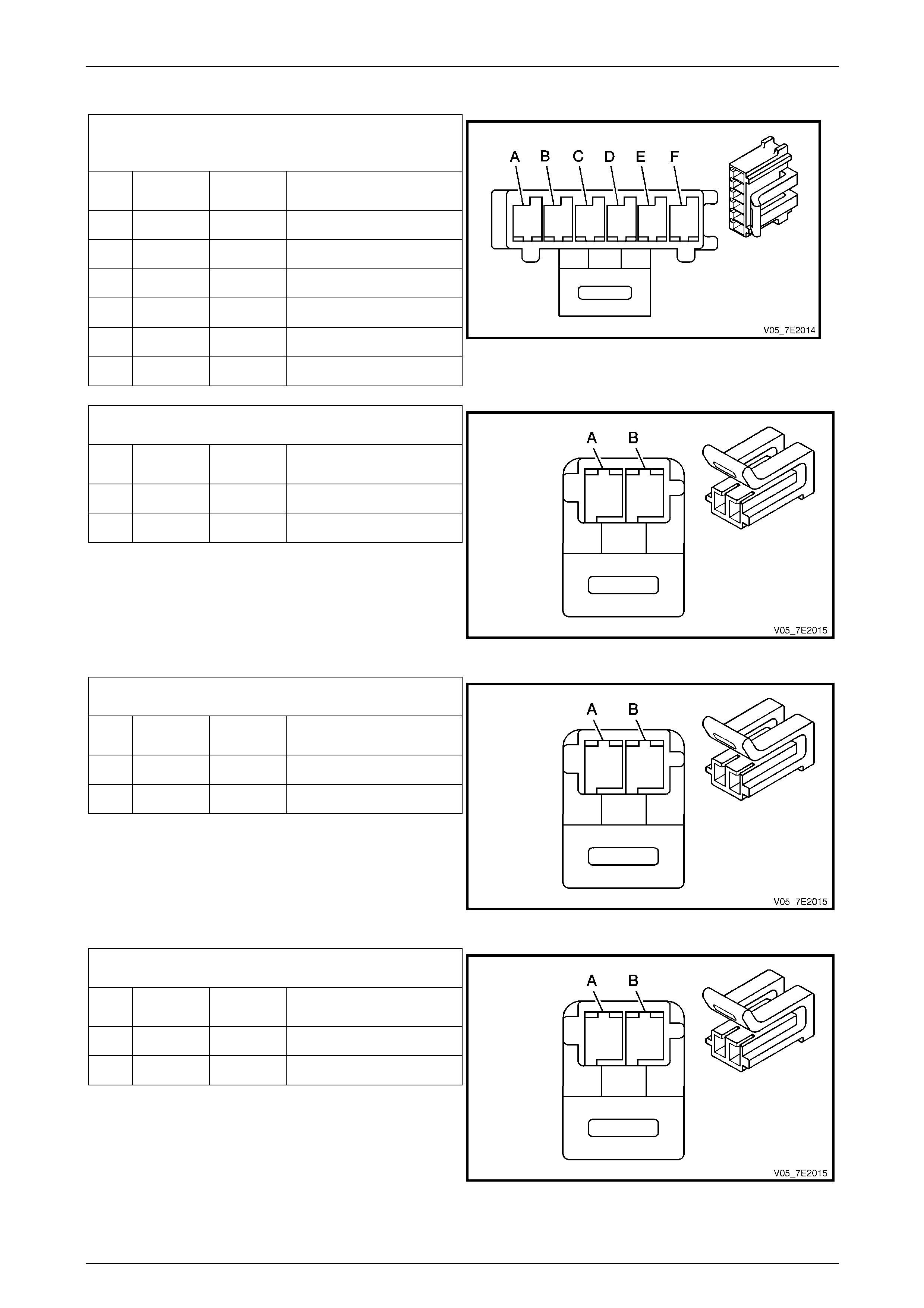
Internal Connector End Views
Transmission Manual Shift Shaft S witch
Assembly
Pin Wire
Colour Circuit
No. Function
A BN 1786 Park / Neutral Signal
B GY 776 TR P (Parity) Signal
C BK 772 TR Signal B
D RD 771 TR Signal A
E BU 773 TR Signal C
F GN 451 TR Ground
Figure 7E2 – 22
1–2 Shift Solenoid (SS) Valve Connec tor
Pin
Wire
Colour Circuit
No. Function
A BK 1222 1–2 SS Control
B WH 1525 Solenoid Power Supply
Figure 7E2 – 23
2–3 Shift Solenoid (SS) Valve Connec tor
Pin
Wire
Colour Circuit
No. Function
A BU 1223 2–3 SS Control
B WH 1525 Solenoid Power Supply
Figure 7E2 – 24
4–5 Shift Solenoid (SS) Valve Connec tor
Pin
Wire
Colour Circuit
No. Function
A GY 898 4–5 SS Control
B WH 1525 Solenoid Power Supply
Figure 7E2 – 25
Automatic Transmission – 5L40-E – Electrical Diagnosis Page 7E – 21
Page 7E2 – 21
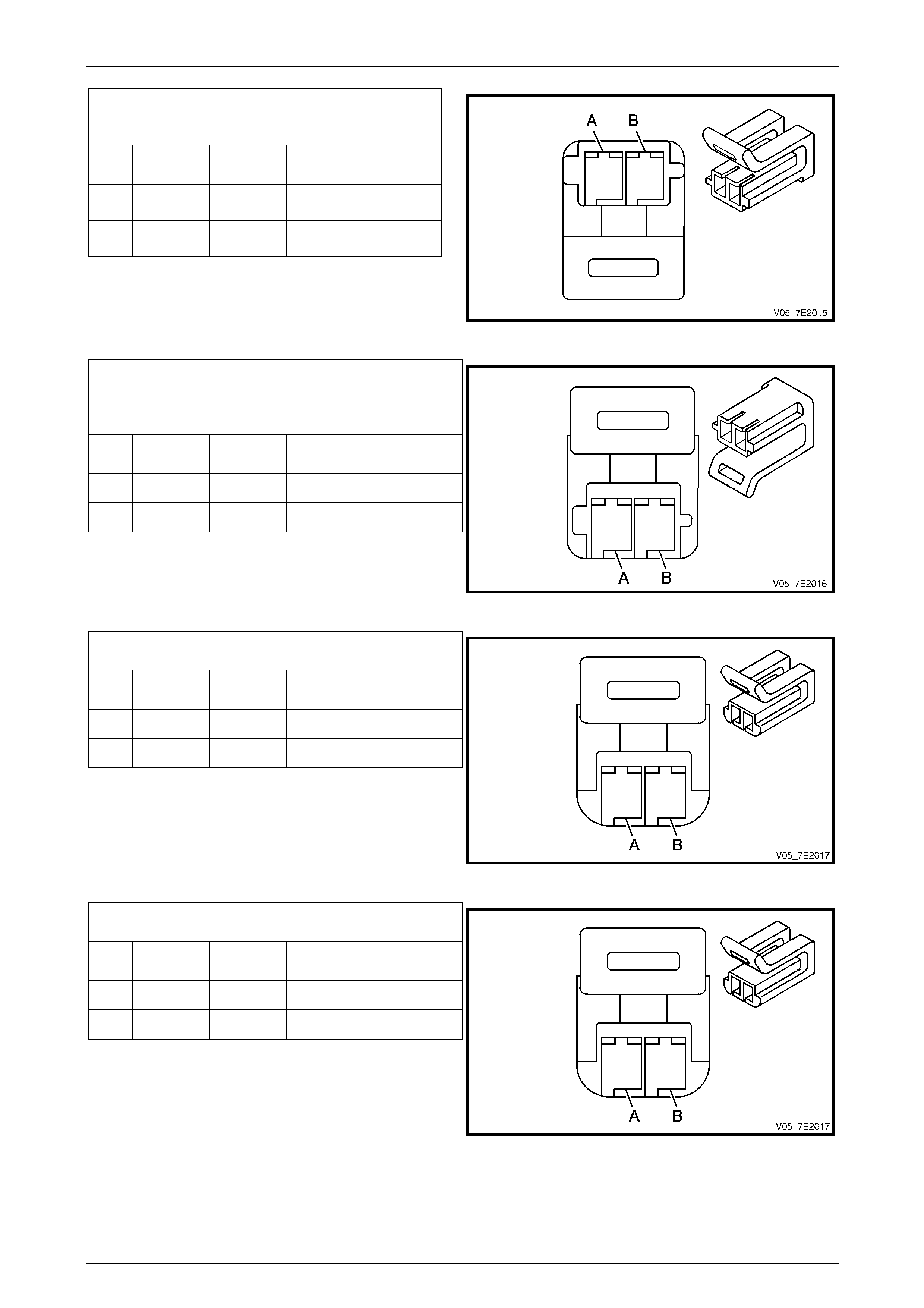
Pressure Control (PC) Solenoid Valve
Connector
Pin
Wire
Colour Circuit
No. Function
A GN 1228 PC Solenoid High
Control
B WH 1229 PC Solenoid Low
Control
Figure 7E2 – 26
Torque Converter Clutch (TCC) Pulse-Width
Modulated (PWM) Solenoid Valve
Connector
Pin
Wire
Colour Circuit
No. Function
A YE 418 TCC PWM Control
B WH 1525 Solenoid Power Supply
Figure 7E2 – 27
Output Speed (OSS) Sensor Connector
Pin
Wire
Colour Circuit
No. Function
A OG 400 OSS High Signal
B WH 401 OSS Low Signal
Figure 7E2 – 28
Input Speed (ISS) Sensor Connector
Pin
Wire
Colour Circuit
No. Function
A YE 1230 ISS High Signal
B WH 1231 ISS Low Signal
Figure 7E2 – 29
Automatic Transmission – 5L40-E – Electrical Diagnosis Page 7E – 22
Page 7E2 – 22
Automatic Transmission Related Connector End Views
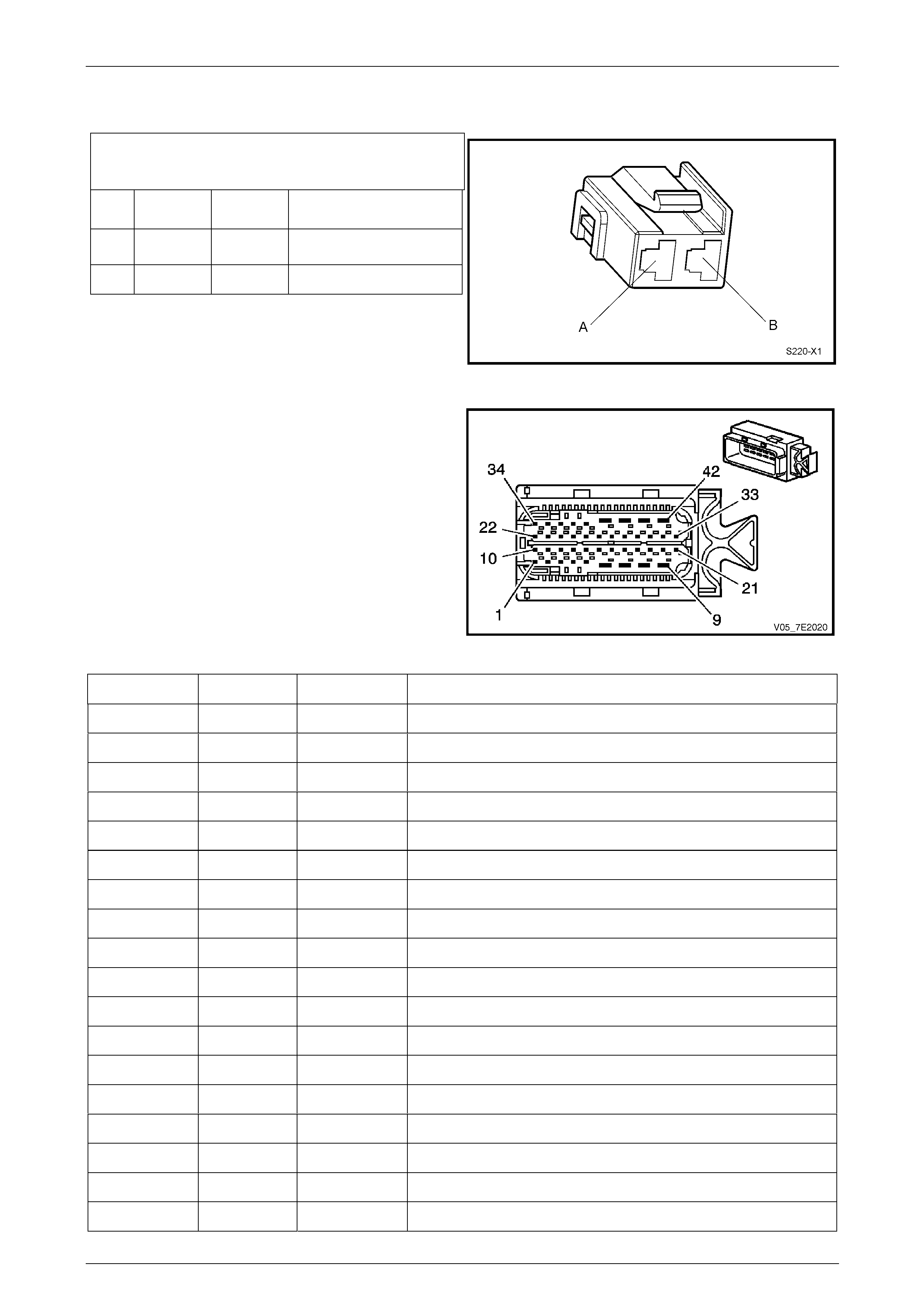
Stop Lamp, Torque Converter Clutch & Cruise
Control Release Switch S220–X1
Pin
Wire
Colour Circuit
No. Function
A OG / BU 640 Power from Stop Lamps
Fuse F5
B BU / RD 20 Switch Signal To TCM
Figure 7E2 – 30
Transmission Control Module A112 – T68
Connector X1
Figure 7E2 – 31
Terminal / Pin Wire Colour Circuit No. Function
X1–1 YE 400 Output Speed (OSS) Sensor – High Signal
X1–2 PU 401 Output Speed (OSS) Sensor – Low Signal
X1–3 OG / BK 1228 Pressure Control (PC) Solenoid Valve High Control (HSD1)
X1–4 BN 418 Torque Converter Clutch (TCC) PWM Solen oid Va lve Control
X1–5 BN / WH 4 Accessory Voltage
X1-6 BK / WH 451 Power Ground
X1–7 — — Not Used
X1–8 OG 1525 Solenoid Power Supply (HSD2)
X1–9 PK / BU 339 Ignition Voltage
X1–10 OG / BK 1230 Input Speed (ISS) Sensor Hi gh Signal
X1–11 BU / WH 1231 Input Speed (ISS) Sensor Low Signal
X1–12 — — Not Used
X1-13 PU 1319 Serial Data
X1–14 PU 5526 Steerin g Wheel Tap Up and Tap Down Switch Signal
X1–15 YE / BK 1227 Tr ansmission Fluid Temperature (TFT) Sensor High Signal
X1–16 — — Not Used
X1–17 — — Not Used
X1–18 YE / BK 1223 2–3 Shift Solenoid Valve Control

Automatic Transmission – 5L40-E – Electrical Diagnosis Page 7E – 23
Page 7E2 – 23
X1–19 PU 898 4–5 Shift Solenoid Valve Control
X1–20 BN / BK 2500 High Speed GMLAN Serial Data Bus (CAN 2 High)
X1–21 BN 2501 High Speed GMLAN Serial Data Bus – (CAN 2 Low)
X1–22 — — Not Used
X1–23 — — Not Used
X1–24 YE 772 Transmission Ran ge Switch Signal B
X1–25 GY 773 Transmission Ran ge S witch Signal C
X1–26 BN / WH 2762 Transmission Fluid Temperature (TFT) Sensor Low Reference
X1–27 OG / BK 740 Battery Positive Voltage
X1–28 — — Not Used
X1–29 L-BU / WH 1229 Pressure Control (PC) Solenoid Valve Low Control
X1–30 L-GN 1222 1–2 Shift Solenoid Valve Control
X1–31 — — Not Used
X1–32 BN / BK 2500 High Speed GMLAN Serial Data Bus (CAN 1 High)
X1–33 BN 2501 High Speed GMLAN Serial Data Bus - (CAN 1 Lo w)
X1–34 — — Not Used
X1–35 — — Not Used
X1–36 BN / YE 771 Transmission Range Switch Signal A
X1-37 — — Not Used
X1-39 L-BU 20 Stop Lamp Signal – Switch S220 X1

Automatic Transmission – 5L40-E – Electrical Diagnosis Page 7E – 24
Page 7E2 – 24
1.6 Automatic Transmission Diagnostic
Trouble Codes
Diagnostic Trouble Code (DTC) Definitions
Diagnostic Trouble Cod es (DTCs) are grouped into several types. Each type has a unique set of characteristics for the
Malfunction Indicator Lamp (MIL) operation, DTC storage and DTC clearing. The following list contains a brief summary
of the DTC types and the associated propert ies of each.
Typ e A
This DTC is emissions related. The MIL illuminates and default actions, if any, are activated immediately after a failure is
detected. The DTC is then stored in histor y and the Freeze Frame data is captured.
Typ e B
This DTC is emissions related. Default actions, if any, are activated and a Failure Record is stored after the first failure is
detected. At the time of the first failure, the DTC will appear in memory as pending. If the next trip reports a pass, the
pending DTC is deleted. If the failure reoccurs on the ne xt consecutive drive cycle, the MIL illuminates, the DTC is stored
in history and the Freeze Fr ame data is captured at the time of failure.
Typ e C
This DTC is non emission related and does not turn on the MIL. When a Type C DTC sets, a message may be displayed
in the instrument cluster multi-function display.
Diagnostic Trouble Code (DTC) Listing
The following chart lists the Diagnostic Trouble Codes for the Hydra-matic 5L40-E transmission.
DTC Description DTC Type Illuminate MIL
P0115 GMLAN Engine Coolant Temperature Fault (No Valid GM LAN Signal) C No
P0120 Throttle Position Sign al (No Valid GM LAN Signal) B Yes
P0218 Tr ansmission Fluid Over Temperature C No
P0562 System Voltage Low C No
P0563 System Voltage High C No
P0572 Brake S witch ‘Stuck Off’ C No
P0573 Brake S witch ‘Stuck On’ C No
P0601 TCM ROM Test A Yes
P0602 No Start Calibration A Yes
P0603 Power–up Copy of NVM to RAM A Yes
P0604 RAM Test B Yes
P0711 Tr ansmission Fluid Temperature Sensor Circuit – Performance Test C No
P0712 Tr ansmission Fluid Temperature Sensor Circuit – Low Input (High Temp) C No
P0713 Tr ansmission Fluid Temperature Sensor Circuit – High Input (Lo w Temp) C No
P0716 Tr ansmission Input Speed Sensor – Performance Signal Drop B Yes
P0717 Transmission Input Speed Sensor – Low Input, No Activity B Yes
P0722 Tr ansmission Output Speed Sensor – Low Input B Yes
P0723 Transmission Output Speed Sensor – Intermittent B Yes
P0727 Engine Speed Sensor Circuit – No Valid GMLAN Signal B Yes
P0741 TCC System Stuck OFF B Yes

Automatic Transmission – 5L40-E – Electrical Diagnosis Page 7E – 25
Page 7E2 – 25
P0742 TCC System Stuck ON B Yes
P0748 Pressure Contr ol Solenoid Circuit Fault C No
P0751 1–2 Shift Solenoid Stuck On B Yes
P0752 1–2 Shift Solenoid Stuck Off B Yes
P0756 2–3 Shift Solenoid Stuck Off B Yes
P0757 2–3 Shift Solenoid Stuck On B Yes
P0761 4–5 Shift Solenoid Stuck Off B Yes
P0762 4–5 Shift Solenoid Stuck On B Yes
P0815 Transmission Upshift Switch Circuit Stuck On C No
P0816 Transmission Downshift Switch Circuit Stuck On C No
P0826 Tap Circuit Reads An Invalid Voltage Range C No
P0973 1–2 Shift Solenoid El ectrical Fault (Open or Short to Ground) B Yes
P0974 1–2 Shift Solenoid Electrical Fault (Short to Voltage) B Yes
P0976 2–3 Shift Solenoid El ectrical Fault (Open or Short to Ground) B Yes
P0977 2–3 Shift Solenoid Electrical Fault (Short to Voltage) B Yes
P0979 4–5 Shift Solenoid El ectrical Fault (Open or Short to Ground) B Yes
P0980 4–5 Shift Solenoid Electrical Fault (Short to Voltage) B Yes
P1621 Power Down Copy of RAM to NVM A Yes
P1793 Wheel Speed Sensor Signal – No Valid GMLAN Signal C No
P1815 IMS Start In Wrong Range B Yes
P1820 IMS Circuit A Low B Yes
P1822 IMS Circuit B High B Yes
P1823 IMS Circuit P Low B Yes
P1825 IMS Illegal Range B Yes
P1826 IMS Circuit C High B Yes
P1831 High Side Driver 1 Short To Ground C No
P1832 High Side Driver 1 Short to Voltage C No
P1833 High Side Driver 2 Short To Ground B Yes
P1834 High Side Driver 2 Short to Voltage B Yes
P2544 Torque Reduction Signal Circuit – CAN B Yes
P2637 Engine Torque Signal Circuit – No Valid GMLAN Signal B Yes
P2763 TCC PWM Solenoid Fault – Short to Voltage B Yes
P2764 TCC PWM Solenoid Fault – Open or Short to Ground B Yes
U0100 GMLAN Bus Error Between Engine ECM and TCM B Yes

Automatic Transmission – 5L40-E – Electrical Diagnosis Page 7E – 26
Page 7E2 – 26
2 Automatic Transmission
Diagnostic Information and
Procedures
2.1 Introduction
As with any electronic system in a MY 2005
VZ/WL Series vehicle, the Diagnostic System
Check – Vehicle must be completed before
any other diagnostic procedure is carried out.
During the course of completing the
Diagnostic System Check – Vehicle, a number
of statements are made, reg ard ing preliminar y
checks. These must al so be referr ed to before
undertaking any diagnostic procedure. Refer
to Section 0D Vehicle Diagnostics for
information on;
2.1 Basic Knowledge Required
2.2 Basic Diagnostic Tools Required
2.3 Diagnostic Precautions
2.4 Preliminary Checks

Automatic Transmission – 5L40-E – Electrical Diagnosis Page 7E – 27
Page 7E2 – 27
2.2 General Diagnostic Procedures
Diagnostic System Check – Vehicle
All vehicle diagnostic procedures are organised in a log ica l structure that begins with the Diagnostic System Check –
Vehicle, refer to Section 0D Vehicle Diagnostics. The Diagnostic System Check – Vehicle must always be referred to
first, as you will be directed through the logical steps necessary to diagnose any vehicl e electrical fault condition.
Vehicle system diagnostic tables locate a faulty circuit or component through a logic al approach, based on a process of
elimination. These diagnostic tables are developed with the following assumptions:
• The vehicle functioned correctly at the time of assembly,
• There are no multiple faults, and
• The problem currently exists.
An understanding of and the correct use of the diagnostic tables is essential if the diagnostic time is to be minimis ed
and/or to prevent poor diagnosis.
Symptoms Diagnostics
Provided all of the following conditions exist, refer to the Symptoms Tables, in Section 7E3 Automatic T r ansmission –
5L40-E – Hydraulic/Mecha nical Diagnosis:
• An automatic transmission fault condition exists,
• There is no Current Diagnostic T r ouble Code presently stored in the ECM, and
• All the Tech 2 automatic transmission data parameters are within the normal operating range.
Diagnostic Trouble Code (DTC) Tables
Through the process of completing the Automatic Transmission Diagnostic Circuit Check, you will be directed to the
Diagnostic Trouble Cod e (DTC) Tables if there is a DTC currently stored in the Transmission Control Module (TCM).
Multiple DTCs Fault Condition
In any given electronic system, some fault conditions trigger multiple component DTCs even if the fault condition exists
only in a single component. If there are multiple DTCs stored in the TCM, the Technician must view and record all DTCs
logged.
The relationship between the logged DTCs can then be reviewed to determine the sourc e of the fault condition. Always
begin the diagnostic process by compl eting the Diagnostic Tabl e for the fault condition that may trigger other DTCs to
set.
The following fault conditions ma y trigger multiple DTCs:
• A system voltage that is too low may cause incorrect automatic transmission system management operation or a
component to malfunction.
• A system voltage that is too high may damage the TCM and/or other sensitive automatic transmission components.
• A fault condition in the TCM Read Only Memory (ROM) or Random Access Memory (RAM).
• A fault condition in the TCM internal circuitry or programming.
• An improperly connected sen sor or component wiring harness connector.
• An electrical fault condition in shared TCM electrical circuits may trigger DTCs for components or sensors that are
connected to the same faulty circuit (e.g. open in one of the GMLAN circuits). Test the electrical circuit of the
appropriate sensors or components to isolate the fault condition. Refer to Figures 7C2 – 2 and 7C2 – 3 for
electrical circuit diagrams.
If there are no obvious faults to begin a multiple set DTC fault condition, always start with the lowest number, then work
progressively through each.

Automatic Transmission – 5L40-E – Electrical Diagnosis Page 7E – 28
Page 7E2 – 28
2.3 Diagnostic System Check – Automatic
Transmission (5L40-E)
NOTE
Do not perform the Diagnostic System Check –
Automatic Transmission unless one of the
concerns noted is present. Failure to follow this
procedure could lead to misdiagnosis of the
system.
Description
The Diagnostic System Check – Automatic Transmission is an organised approach to identifying a condition identified by
the transmission electronic control system.
When an emission related DTC (type B) sets because of an automatic transmission fault, the TCM requests the Engine
Control Module (ECM) to activate the instrument cluster Check Powertrain Malfunction Indicator Lamp (MIL). The ECM
may also independently activate the MIL. Although either module may cause the MIL to activate, Tech 2 can display
DTCs from only one module at a time. However, the ‘Clear DTC Info’ command clears DTC data from both modules. If
the DTC failure records are not recorded from both modules before the DTC data is cleared, important diagnostic
information will be erased.
Your training and experience as a Technician may cause you to focus on either the TCM or the ECM, instead of both
modules at the same time. To ensure that both modul es are properly diagnosed, separate system checks are included.
The process detailed in the Diagnostic System Check – Vehicle identifies whether ECM related DTCs are recorded. If no
ECM DTCs are present, you will then be directed to this, Diagnostic System Check – Automatic T ransmission.
The ECM diagnostics do not require automatic transmission data to run. Correct use of the tables will reduce d iagnostic
time and prevent the replacement of good parts.
Diagnostic Aids
Inspect all of the related wiring and connections including those at the TCM, as these may cause an intermittent
condition. Inspect the terminals for any damage or a ny corrosion. Inspect the connector for any pushed-out terminals.
Test Description
The following number(s) refer to the step number(s) on the diagnostic table.
1 Do not perform the Diagnostic S ystem Check – Automatic Transmission unless the Diagnostic System Check –
Vehicle, refer Section 0D Vehicle Diagnostics is completed first. Failure to follow this procedure could lead to
misdiagnosis of the system.
2 Checks that Tech 2 powers up and that communication can be established with the Transmission Control Module
(TCM).
3 Check for any applicable Service Techlines before proceeding with the di agnosis.
4 If multiple automatic transmission DTCs are stored, diagnose the DTCs in numerical order, starting with the lowest
DTC number. When there is a known exception, a DTC table however, may direct you to diagnose a different DTC
first.
5 Compare the actual control system data with the values in the Transmission Tech 2 Data List in this Section, to
determine if any parameter is not within limits. A base engine condition, such as advanced cam timing, may
substantially alter the sensor values. If the actual data does not correspo nd with the values in the Tech 2
Transmission Data List, but the correspo nding DTC is not set, this indicates that some specific conditions have not
been met before some diagno stics will run. This information is in the supporting text for the DTC table. If you
suspect a system fault, such as Shift Solenoid operation, TCC operation, refer to the DTCs that apply to that
system. The DTC tables are not, by design, for use unless a DTC is set; however, many tables begin with a
functional test of the related component. This information can be a useful aid in diagnosis.

Automatic Transmission – 5L40-E – Electrical Diagnosis Page 7E – 29
Page 7E2 – 29
Diagnostic System Check – Automatic Transmission
Step Action Yes No
1 Is the fault specifically isolated to this system / module? Go to Step 2 Go to Section 0D
Vehicle Diagnostics
2 1 Connect Tech 2 to the DLC.
2 Ignition ON, engine OFF.
3 Select transmission data on Tech 2.
Does the Tech 2 display trans mission data? Go to Step 4 Go to Section 0C
Tech 2.
3 1 Check for any applicable S ervice Techline that ma y address the
problem.
2 Perform repair procedures as necessary.
Did a Service Techline procedure correct the condition? System OK Go to Step 4
4 Using Tech 2, check for any transmission D TCs stored in the TCM.
Are any DTCs present?
Go to the
appropriate DTC
Table in this
Section. Go to Step 5
5 On Tech 2, compare the transmission data with the values shown in
the Automatic Transmission Data Lists. Refer to 3.2 Automatic
Transmission Data Lists in this Section.
Are the displayed values nor m al or within typical ranges?
Go to Symptoms
Tables, in Section
7E3 Automatic
Transmission –
5L40-E – Hydraulic /
Mechanical
Diagnosis.
Go to 1.4 Electronic
Component
Description in this
Section.

Automatic Transmission – 5L40-E – Electrical Diagnosis Page 7E – 30
Page 7E2 – 30
3 Tech 2 – Automatic
Transmission
3.1 Introduction
Use the Tech 2 Data List under the following conditions:
• The Diagnostic System Check – Automatic Transmission has been compl eted.
• The On-Board Diagnostics are function ing correctly.
• No DTCs are present.
Do not use a Tech 2 that displays faulty data;
have the Tech 2 repaired. The use of a faulty
Tech 2 can result in misdiagnosis and the
unnecessary repl acement of parts.
Only the parameters listed as follows are used in this service information for diagnosing.

Automatic Transmission – 5L40-E – Electrical Diagnosis Page 7E – 31
Page 7E2 – 31
3.2 Automatic Transmission Data Lists
The following Tech 2 values were recorded under the following con diti ons:
Ignition ON:
• Engine stopped, ignition i n the ON positio n.
• Closed throttle.
• Transmission selector in the Park position.
• Engine, transmission at ambient temperature.
• Accessories are OFF.
• Brake pedal is not applied.
Engine Running
• Engine running.
• Closed throttle.
• Transmission selector in the Park position.
• Engine, transmission at normal operating temperature.
• Accessories are OFF.
• Brake pedal not applied.
A number of data lists are provided, that can save time when diagnosing symptomatic conditions.
F0: Transmission Data
Tech 2 Display Units Displayed Ignition On Engine Running
Engine Torque Nm Varies Varies
Throttle Position % Varies Varies
Engine Speed RPM 0 RPM Varies
AT Input Speed (Automatic
Transmission) RPM 0 RPM Varies
AT Output Speed (Automatic
Transmission) RPM 0 RPM 0 RPM
Vehicle Speed km/h 0 km/h 0 km/h
Commanded Gear 5 1
Shift Solenoid A Off / On Off Off
Shift Solenoid B Off / On Off On
Shift Solenoid C Off / On Off Off
Estimated Gear Ratio :1 0.00:1 3.98:1
Active Select Off / Enabled Off Off
Active Select Request None / Shift Up / Shift
Down / Invalid None None
Engine Coolant Temperature ° C Varies Varies
Transmission Fluid Temperat ure ° C Varies Varies
Transmission Hot Mode Off / On Off Off
PCS Actual Current (Pressure
Control Solenoid) mA 0 mA Varies
PCS Desired Current (Pressure
Control Solenoid) mA 0 mA Varies
PCS Duty Cycle (Pressure
Control Solenoid) % 0% Varies
High Side Driver 1 Disabled / Enabled Enabled Enabled
TCC PWM Solenoid (Torque
Converter Clutch) % 0% 0%
TCC Slip Speed (T orque
Converter Clutch) RPM 0 RPM Varies
TCC Brake Switch (Torque
Converter Clutch) Closed / Open Closed Closed
High Side Driver 2 Disabled / Enabled Enabled Enabled
Internal Mode Switch Park / Reverse / Neutral /
Drive 5 / Drive 4 / Drive 3
/ Drive 2 / Invalid Park Park
Internal Mode Switch A High 12V / Low 0V High 12V High 12V
Internal Mode Switch B High 12V / Low 0V Low 0V Low 0V
Internal Mode Switch C High 12V / Low 0V Low 0V Low 0V
Internal Mode Switch P High 12V / Low 0V High 12V High 12V

Automatic Transmission – 5L40-E – Electrical Diagnosis Page 7E – 32
Page 7E2 – 32
Tech 2 Display Units Displayed Ignition On Engine Running
Latest Shift sec 0.00 sec 0.00 sec
1-2 Shift Time sec 0.00 sec 0.00 sec
2-3 Shift Time sec 0.00 sec 0.00 sec
3-4 Shift Time sec 0.00 sec 0.00 sec
4-5 Shift Time sec 0.00 sec 0.00 sec
Cruise Control Active / Inactive /
Not Programmed Inactive Inactive
A/C Clutch (Air Conditioning) Off / On Off Off
Traction Control Inactive / Active Inactive Inactive
Ignition Voltage V 12 – 14.7 V 12 – 14.7 V
Shift Pattern Active Select / Cruise /
Power / Normal / Detent Normal Normal
F0: Transmission Data List Definitions
Engine Torque
This display indicates the amount of torque that is delivere d from the engine.
Throttle Position
The Throttle Position parameter indicates the position of the throttle. A 0 % reading indicates that the throttle is fully
released. A 100% reading ind icates that the throttle is fully depressed.
Engine Speed
This parameter indicates the rotational speed of the engine expressed in revol utions per minute. Engine speed is
computed by the ECM from the crankshaft position sensor input.
AT Input Speed
The Transmission Input (Shaft) Speed (TISS) sensor parameter displays the rotational speed of the transmission input
shaft expressed in revolutions per minute.
AT Output Speed
The Transmission Output (Shaft) Speed (OSS) sensor parameter displays the rotational speed of the transmissio n outp ut
shaft expressed in revolutions per minute.
Vehicle Speed
The vehicle speed sensor signal is converted by the TCM and is displaye d in km/h.
Commanded Gear
This display indicates the commanded gear of the TCM. With the engine off, ignition on and the selector in the Park
position, it is normal to have ‘5’ displayed on Tech 2.
Shift Solenoid A
The Shift Solenoid A parameter ind icates the current commanded state of the shift solenoids. All three of the 5L4 0-E shift
solenoids are normally-c losed, which means that no fluid passes through when the solenoid is commanded OF F. W hen
the TCM commands the solenoid ON, the solenoid opens and allows fluid to flow through.
Refer to 1.4 Electronic Component Description – Shift Solenoid (SS) Valves in this Section.
Shift Solenoid B
The Shift Solenoid B parameter ind icates the current commanded state of the shift solenoids. All three of the 5L4 0-E shift
solenoids are normally-c losed, which means that no fluid passes through when the solenoid is commanded OF F. W hen
the TCM commands the solenoid ON, the solenoid opens and allows fluid to flow through.
Refer to 1.4 Electronic Component Description – Shift Sole noid (SS) Valves in this Section.
Shift Solenoid C
The Shift Solenoid C parameter indicates the current commanded state of the shift solenoids. All three of the 5L40-E shift
solenoids are normally-c losed, which means that no fluid passes through when the solenoid is commanded OF F. W hen
the TCM commands the solenoid ON, the solenoid opens and allows fluid to flow through.
Refer to 1.4 Electronic Component Description – Shift Solenoid (SS) Valves in this Section.

Automatic Transmission – 5L40-E – Electrical Diagnosis Page 7E – 33
Page 7E2 – 33
Estimated Gear Ratio
This display is the actual transmission gear ratio as the transmission operates through all drive ra nges including
REVERSE and PARK / NEUTRAL. The gear ratio parameter is obtained by dividing the input shaft speed by the output
shaft speed.
Active Select
When activated by the driver pressing the m omentary switch ‘A/S’ in the centre consol e, this parameter indicates that this
is the current transmission shift mode
Active Select Request
When active select is enabled this request displays the requested status from the ‘+’ or ‘–‘ paddle switches.
Engine Coolant Temperature
The Engine Coolant Temperature (ECT) parameter displays the engine coolant temperature data that the TCM receives
from the ECM on the GMLAN bus. The TCM uses the ECT information to modify shift patterns in cold weather and as a
rationality check for the transmission fl uid temperature sensor.
Transmission Fluid Temperature
The Transmission Fluid Temperature parameter displays the temperature conversion of the voltage input signal to the
TCM from the Transmission Fluid Temperature (TFT) sensor. The TFT sensor is a negative temperature coefficient
thermistor. The resistance decreases as the t emperature increases. As the transmission fluid temperature increases, the
decreasing resistance causes the 5 volt reference voltage to be pulled progressively lower.
Transmission Hot Mode
This display indicates transm ission hot mode operation due to high transmission fluid temperatur e. OFF indicates that
the transmission fluid temperature has not exceeded 132° C. ON indicates that the transmission fluid tem perature has
exceeded 132° C and has not cooled below 129° C for more than 5 seconds.
Pressure Control Solenoid (PCS) Actual Current
The Pressure Control Solenoid (PCS) Actual Current p ara meter displays the actual current flow through the pressur e
control solenoid circuit which is monitored by the TCM. High current results in low line pressure. Low current results in
high line pressure.
Pressure Control Solenoid (PCS) Desired Current
The Pressure Control Solenoid Desired Current displays the amount of current which the TCM has commanded through
the pressure control solenoid circuit. High current results in low line pressure. Low current results in high line pressure.
Pressure Control Solenoid (PCS) Duty Cycle
The Pressure Control Solenoid Duty Cycle parameter displays the commanded state of the press ure co ntrol solenoid
expressed as a percentage of ON time. No current flow indicates zero ON time or 0% duty cycle. High current flow is
approximately 60% duty cycle at idle.
High Side Driver 1
The Transmission Control Mo dule (TCM) provides voltage to automatic transmission internal electrical components,
through two solid state devices , called HSD1 and HSD2. The High Side Driver 1 (HSD1) provides electrical power to the
pressure control solenoid. A normal function of the TCM is to run tests on each driver to ensure that it is functioning
correctly. Provided this testing passes, HSD1 will be disp layed on Tech 2 as ‘Enabled’. If the testing fails, then ‘Disabled’
will be displayed.
Torque Converter Clutch (TCC) PWM Solenoid
The Torque Converter Clutch (TCC) PWM Solenoid parameter displays the commanded state of the TCC PWM solenoid
expressed as a percent of ON time. 90% represents a fully energ ised commanded state and 0% represents a de-
energised commanded state.
Torque Converter Clutch (TCC) Slip Speed
Torque Converter Clutch (T CC) Slip Speed parameter displays the difference between the engine rpm and the rpm of the
input shaft of the transmission. A negative value indicates that the engine rpm is less than the rpm of the input shaft,
deceleration. A positive value indicates that the engine rpm is greater than the rpm of the input shaft.
Torque Converter Clutch (TCC) Brake Switch
The Torque Converter Clutch (TCC) Brake Switch parameter displays the status of the TCC brake switch circuit input to
the TCM. When the brake pe dal is released, Tech 2 shoul d indicate OPEN. When the brake pedal is ap plied, Tech 2
should indicate CLOSED.

Automatic Transmission – 5L40-E – Electrical Diagnosis Page 7E – 34
Page 7E2 – 34
High Side Driver 2
The Transmission Control Mo dule (TCM) provides voltage to automatic transmission internal electrical components,
through two solid state devices , called HSD1 and HSD2. The High Side Driver 2 (HSD2) provides electrical power to the
shift solenoids and the torque converter cl utch solenoid. A normal function of the TCM is to run tests on each driver to
ensure that it is functioning correctly. Provided this testing passes, HSD2 will be displayed on Tech 2 as ‘Enabled’. If the
testing fails, then ‘Disabled’ will be displayed.
Internal Mode Switch (IMS)
For Tech 2 data purposes, the manual shift shaft switch assembly is referred to as the IMS (Internal Mode Switch). The
IMS displays the decoded status of the four A / B / C / P inputs from the automatic transmission. If a valid combination of
inputs is not received by the TCM, ‘Invalid’ will be displayed. An additional signal is directed to the ECM that is used for
engine controls as well as determining the transmission shift patterns.
Internal Mode Switch A / B / C / P
The Internal Mode Switch (IMS) parameter displays th e four inputs from the automatic tra nsmissio n. HI indicates an
ignition voltage signal and LOW indicates a 0 voltage signal.
Last Shift
This display indicates the actual shift time of the most recent upshift.
Torque Converter Clutch (TCC) Duty Cycle
The Torque Converter Clutch (TCC) Duty Cycle status parameter interprets the solenoid driver feedback voltage signa l
and displays the circuit status on T ech 2. If the voltag e is within the calibration parameters, Tech 2 will display ‘Okay’.
However, if the voltage is low when the solenoid is commanded OFF, Tech 2 will display ‘Short to Ground’. If the voltage
is high when the solenoid is commanded ON, Tech 2 will display ‘Open or Shorted’.
1-2 Shift Time
This display is the actual time of the last shift. The actual shift time is obtained by measuring the time required for the
input shaft to decelerate from the previous ratio to the current ratio.
2–3 Shift Time
This display is the actual time of the last shift. The actual shift time is obtained by measuring the time required for the
input shaft to decelerate from the previous ratio to the current ratio.
3–4 Shift Time
This display is the actual time of the last shift. The actual shift time is obtained by measuring the time required for the
input shaft to decelerate from the previous ratio to the current ratio.
4–5 Shift Time
This display is the actual time of the last shift. The actual shift time is obtained by measuring the time required for the
input shaft to decelerate from the previous ratio to the current ratio.
Cruise Control
When the display indicates ‘Active’, the ECM is allowing cruise control operation. When the display indicates ‘Inactive’,
the ECM has disabled cruise control operation. If the Tech 2 display shows ‘Not Programmed’, . The TCM modifies
upshift and downshift patterns when cruise control is enabled.
A/C Clutch
The Air Conditioner (A/C) represents the comm anded state of the A/C clutch control relay. The clutch should be engaged
whenever ‘On’ is displayed. The ECM will then compensate for the additional engine lo ad that is accompanied with the
A/C clutch engaged. An ‘Off’ display indicates that the relay is deactivated.
Traction Control
This parameter indicates if the ECM is reducing torque to a level below that which the driver has comma nded due to
drive wheel slippage. Tech 2 will either display ‘Inactive’ or ‘‘Active’, depe nding on the traction control status.
Ignition Voltage
This represents the system voltage measured by the TCM at its ignition input.
Shift Pattern
This parameter indicates which transmission shift pattern the TCM is currently controlling. The display will show ‘Active
Select’, ‘Cruise’, ‘Power’, ‘Normal’, or ‘Detent’.

Automatic Transmission – 5L40-E – Electrical Diagnosis Page 7E – 35
Page 7E2 – 35
F1: TCC Data
Tech 2 Display Units Displayed Ignition On Engine Running
TCC PWM Solenoid (Torque
Converter Clutch) % 0% 0%
TCC Slip Speed (T orque
Converter Clutch) RPM 0 RPM Varies
TCC Brake Switch (Torque
Converter Clutch) Closed / Open Closed Closed
TCC Duty Cycle Circuit (Torque
Converter Clutch) Okay / Open or Shorted /
Short to Ground Okay Okay
High Side Driver 2 Disabled / Enabled Enabled Enabled
High Side Driver 2 Circuit Okay / Open / Short to
Battery / Short to Ground Okay Okay
Throttle Position % Varies Varies
Engine Speed RPM 0 RPM Varies
AT Input Speed (Automatic
Transmission) RPM 0 RPM Varies
AT Output Speed (Automatic
Transmission) RPM 0 RPM 0 RPM
Engine Torque Nm Varies Varies
Vehicle Speed km/h 0 km/h 0 km/h
Commanded Gear 5 1
Engine Coolant Temperature ° C Varies Varies
Transmission Fluid Temperat ure ° C Varies Varies
Estimated Gear Ratio :1 0.00:1 3.98:1
Transmission Hot Mode Off / On Off Off
F1: TCC Data List Definitions
Torque Converter Clutch (TCC) PWM Solenoid
The Torque Converter Clutch (TCC) PWM Solenoid parameter displays the commanded state of the TCC PWM solenoid
expressed as a percent of ON time. 90% represents a fully energ ised commanded state and 0% represents a de-
energised commanded state.
Torque Converter Clutch (TCC) Slip Speed
Torque Converter Clutch (T CC) Slip Speed parameter displays the difference between the engine rpm and the rpm of the
input shaft of the transmission. A negative value indicates that the engine rpm is less than the rpm of the input shaft,
deceleration. A positive value indicates that the engine rpm is greater than the rpm of the input shaft.
Torque Converter Clutch (TCC) Brake Switch
The Torque Converter Clutch (TCC) Brake Switch parameter displays the status of the TCC brake switch circuit input to
the TCM. When the brake pe dal is released, Tech 2 shoul d indicate OPEN. When the brake pedal is ap plied, Tech 2
should indicate CLOSED.
Torque Converter Clutch (TCC) Duty Cycle
The Torque Converter Clutch (TCC) Duty Cycle status parameter interprets the solenoid driver feedback voltage signa l
and displays the circuit status on T ech 2. If the voltag e is within the calibration parameters, Tech 2 will display ‘Okay’.
However, if the voltage is low when the solenoid is commanded OFF, Tech 2 will display ‘Short to Ground’. If the voltage
is high when the solenoid is commanded ON, Tech 2 will display ‘Open or Shorted’.
High Side Driver 2
The Transmission Control Mo dule (TCM) provides voltage to automatic transmission internal electrical components,
through two solid state devices , called HSD1 and HSD2. The High Side Driver 2 (HSD2) provides electrical power to the
shift solenoids and the torque converter cl utch solenoid. A normal function of the TCM is to run tests on each driver to
ensure that it is functioning correctly. Provided this testing passes, HSD2 will be displayed on Tech 2 as ‘Enabled’. If the
testing fails, then ‘Disabled’ will be displayed.
High Side Driver 2 Circuit
The Transmission Control Mo dule (TCM) provides voltage to automatic transmission internal electrical components,
through two solid state devices , called HSD1 and HSD2. The High Side Driver 2 (HSD2) provides electrical power to the
shift solenoids and the torque converter cl utch solenoid. A normal function of the TCM is to run tests on each driver and
circuit to ensure that it is functioning correctly. Dependent on the TCM testing outcome, TECH2 will display ‘Okay’,
‘Open’, ‘Short to Battery’ or ‘Short to Ground’.

Automatic Transmission – 5L40-E – Electrical Diagnosis Page 7E – 36
Page 7E2 – 36
Throttle Position
The Throttle Position parameter indicates the position of the throttle. A 0 % reading indicates that the throttle is fully
released. A 100% reading ind icates that the throttle is fully depressed.
Engine Speed
This parameter indicates the rotational speed of the engine expressed in revol utions per minute. Engine speed is
computed by the ECM from the crankshaft position sensor input.
AT Input Speed
The Transmission Input (Shaft) Speed (TISS) sensor parameter displays the rotational speed of the transmission input
shaft expressed in revolutions per minute.
AT Output Speed
The Transmission Output (Shaft) Speed (OSS) sensor parameter displays the rotational speed of the transmissio n outp ut
shaft expressed in revolutions per minute.
Engine Torque
This display indicates the amount of torque that is delivere d from the engine.
Vehicle Speed
The vehicle speed sensor signal is converted by the TCM and is displaye d in km/h.
Commanded Gear
This display indicates the commanded gear of the TCM. With the engine off, ignition on and the selector in the Park
position, it is normal to have ‘5’ displayed on Tech 2.
Engine Coolant Temperature
The Engine Coolant Temperature (ECT) parameter displays the engine coolant temperature data that the TCM receives
from the ECM on the GMLAN bus. The TCM uses the ECT information to modify shift patterns in cold weather and as a
rationality check for the transmission fl uid temperature sensor.
Transmission Fluid Temperature
The Transmission Fluid Temperature parameter displays the temperature conversion of the voltage input signal to the
TCM from the Transmission Fluid Temperature (TFT) sensor. The TFT sensor is a negative temperature coefficient
thermistor. The resistance decreases as the t emperature increases. As the transmission fluid temperature increases, the
decreasing resistance causes the 5 volt reference voltage to be pulled progressively lower.
Estimated Gear Ratio
This display is the actual transmission gear ratio as the transmission operates through all drive ranges including Reverse
and Park / Neutral. The gear ratio parameter is obtained by dividing the inp ut shaft speed by the output shaft speed.
Transmission Hot Mode
This display indicates transm ission hot mode operation due to high transmission fluid temperatur e. OFF indicates that
the transmission fluid temperature has not exceeded 132° C. ON indicates that the transmission fluid tem perature has
exceeded 132° C and has not cooled below 129° C for more than 5 seconds.

Automatic Transmission – 5L40-E – Electrical Diagnosis Page 7E – 37
Page 7E2 – 37
F2: 1-2 Shift Data
Tech 2 Display Units Displayed Ignition On Engine Running
Shift Solenoid A Off / On Off Off
Shift Solenoid B Off / On Off On
Shift Solenoid C Off / On Off Off
Commanded Gear 5 1
1-2 Shift Time sec 0.00 sec 0.00 sec
1-2 Shift Error sec 0.00 sec 0.00 sec
Shift Solenoid A Circuit Okay / Open or Shorted /
Short to Battery Okay Okay
High Side Driver 2 Disabled / Enabled Enabled Enabled
High Side Driver 2 Circuit Okay / Open / Short to
Battery / Short to Ground Okay Okay
Throttle Position % Varies Varies
Engine Speed RPM 0 RPM Varies
AT Input Speed (Automatic
Transmission) RPM 0 RPM Varies
AT Output Speed (Automatic
Transmission) RPM 0 RPM 0 RPM
Vehicle Speed km/h 0 km/h 0 km/h
Estimated Gear Ratio :1 0.00:1 3.98:1
F2: 1-2 Shift Data List Definitions
Shift Solenoid A
The Shift Solenoid A parameter ind icates the current commanded state of the shift solenoids. All three of the 5L4 0-E shift
solenoids are normally-c losed, which means that no fluid passes through when the solenoid is commanded OF F. W hen
the TCM commands the solenoid ON, the solenoid opens and allows fluid to flow through.
Refer to 1.4 Electronic Component Description – Shift Solenoid (SS) Valves in this Section.
Shift Solenoid B
The Shift Solenoid B parameter ind icates the current commanded state of the shift solenoids. All three of the 5L4 0-E shift
solenoids are normally-c losed, which means that no fluid passes through when the solenoid is commanded OF F. W hen
the TCM commands the solenoid ON, the solenoid opens and allows fluid to flow through.
Refer to 1.4 Electronic Component Description – Shift Sole noid (SS) Valves in this Section.
Shift Solenoid C
The Shift Solenoid C parameter indicates the current commanded state of the shift solenoids. All three of the 5L40-E shift
solenoids are normally-c losed, which means that no fluid passes through when the solenoid is commanded OF F. W hen
the TCM commands the solenoid ON, the solenoid opens and allows fluid to flow through.
Refer to 1.4 Electronic Component Description – Shift Solenoid (SS) Valves in this Section.
Commanded Gear
This display indicates the commanded gear of the TCM. With the engine off, ignition on and the selector in the Park
position, it is normal to have ‘5’ displayed on Tech 2.
1-2 Shift Time
This display is the actual time of the last shift. The actual shift time is obtained by measuring the time required for the
input shaft to decelerate from the previous ratio to the current ratio.
1–2 Shift Error
This display is the difference between the desired shift time and the actual shift time for the specific shift indicated on
Tech 2. The desired shift time is calculated by the TCM. The actual shift time is obtained by measuring t he time required
for the input shaft to decelerate from the previous ratio to the current ratio. If the number i s negative, the actual shift took
longer than desired. If the number is positive, the shift occurred more qui ckly than desired.
Shift Solenoid A Circuit
The Shift Solenoid A Circuit status parameter interprets the solenoid driv er feedback voltage signal and displays the
circuit status on the Tech 2. If the voltage is low when the solenoid is comm anded OFF, Tech 2 will display ‘Open or
Shorted’. If the voltage is high when the solenoid is commanded ON, the T ech 2 will display ‘Short to Battery’. If the
voltage signal is considered normal, the display will show ‘Okay’.

Automatic Transmission – 5L40-E – Electrical Diagnosis Page 7E – 38
Page 7E2 – 38
High Side Driver 2
The Transmission Control Mo dule (TCM) provides voltage to automatic transmission internal electrical components,
through two solid state devices , called HSD1 and HSD2. The High Side Driver 2 (HSD2) provides electrical power to the
shift solenoids and the torque converter cl utch solenoid. A normal function of the TCM is to run tests on each driver to
ensure that it is functioning correctly. Provided this testing passes, HSD2 will be displayed on Tech 2 as ‘Enabled’. If the
testing fails, then ‘Disabled’ will be displayed.
High Side Driver 2 Circuit
The Transmission Control Mo dule (TCM) provides voltage to automatic transmission internal electrical components,
through two solid state devices , called HSD1 and HSD2. The High Side Driver 2 (HSD2) provides electrical power to the
shift solenoids and the torque converter cl utch solenoid. A normal function of the TCM is to run tests on each driver and
circuit to ensure that it is functioning correctly. Dependent on the TCM testing outcome, TECH2 will display ‘Okay’,
‘Open’, ‘Short to Battery’ or ‘Short to Ground’.
Throttle Position
The Throttle Position parameter indicates the position of the throttle. A 0 % reading indicates that the throttle is fully
released. A 100% reading ind icates that the throttle is fully depressed.
Engine Speed
This parameter indicates the rotational speed of the engine expressed in revol utions per minute. Engine speed is
computed by the ECM from the crankshaft position sensor input.
AT Input Speed
The Transmission Input (Shaft) Speed (TISS) sensor parameter displays the rotational speed of the transmission input
shaft expressed in revolutions per minute.
AT Output Speed
The Transmission Output (Shaft) Speed (OSS) sensor parameter displays the rotational speed of the transmissio n outp ut
shaft expressed in revolutions per minute.
Vehicle Speed
The vehicle speed sensor signal is converted by the TCM and is displaye d in km/h.
Estimated Gear Ratio
This display is the actual transmission gear ratio as the transmission operates through all drive ranges including Reverse
and Park / Neutral. The gear ratio parameter is obtained by dividing the inp ut shaft speed by the output shaft speed.

Automatic Transmission – 5L40-E – Electrical Diagnosis Page 7E – 39
Page 7E2 – 39
F3: 2-3 Shift Data
Tech 2 Display Units Displayed Ignition On Engine Running
Shift Solenoid A Off / On Off Off
Shift Solenoid B Off / On Off On
Shift Solenoid C Off / On Off Off
Commanded Gear 5 1
2-3 Shift Time sec 0.00 sec 0.00 sec
2-3 Shift Error sec 0.00 sec 0.00 sec
Shift Solenoid B Circuit Okay / Open or Shorted /
Short to Battery Okay Okay
High Side Driver 2 Disabled / Enabled Enabled Enabled
High Side Driver 2 Circuit Okay / Open / Short to
Battery / Short to Ground Okay Okay
Throttle Position % Varies Varies
Engine Speed RPM 0 RPM Varies
AT Input Speed (Automatic
Transmission) RPM 0 RPM Varies
AT Output Speed (Automatic
Transmission) RPM 0 RPM 0 RPM
Vehicle Speed km/h 0 km/h 0 km/h
Estimated Gear Ratio :1 0.00:1 3.98:1
F3: 2-3 Shift Data List Definitions
Shift Solenoid A
The Shift Solenoid A parameter ind icates the current commanded state of the shift solenoids. All three of the 5L4 0-E shift
solenoids are normally-c losed, which means that no fluid passes through when the solenoid is commanded OF F. W hen
the TCM commands the solenoid ON, the solenoid opens and allows fluid to flow through.
Refer to 1.4 Electronic Component Description – Shift Solenoid (SS) Valves in this Section.
Shift Solenoid B
The Shift Solenoid B parameter ind icates the current commanded state of the shift solenoids. All three of the 5L4 0-E shift
solenoids are normally-c losed, which means that no fluid passes through when the solenoid is commanded OF F. W hen
the TCM commands the solenoid ON, the solenoid opens and allows fluid to flow through.
Refer to 1.4 Electronic Component Description – Shift Sole noid (SS) Valves in this Section.
Shift Solenoid C
The Shift Solenoid C parameter indicates the current commanded state of the shift solenoids. All three of the 5L40-E shift
solenoids are normally-c losed, which means that no fluid passes through when the solenoid is commanded OF F. W hen
the TCM commands the solenoid ON, the solenoid opens and allows fluid to flow through.
Refer to 1.4 Electronic Component Description – Shift Solenoid (SS) Valves in this Section.
Commanded Gear
This display indicates the commanded gear of the TCM. With the engine off, ignition on and the selector in the Park
position, it is normal to have ‘5’ displayed on Tech 2.
2-3 Shift Time
This display is the actual time of the last shift. The actual shift time is obtained by measuring the time required for the
input shaft to decelerate from the previous ratio to the current ratio.
2-3 Shift Error
This display is the difference between the desired shift time and the actual shift time for the specific shift indicated on
Tech 2. The desired shift time is calculated by the TCM. The actual shift time is obtained by measuring t he time required
for the input shaft to decelerate from the previous ratio to the current ratio. If the number i s negative, the actual shift took
longer than desired. If the number is positive, the shift occurred more qui ckly than desired.
Shift Solenoid B Circuit
The Shift Solenoid B Circuit status parameter interprets the solenoid driv er feedback voltage signal and displays the
circuit status on the Tech 2. If the voltage is low when the solenoid is comm anded OFF, Tech 2 will display ‘Open or
Shorted’. If the voltage is high when the solenoid is commanded ON, the T ech 2 will display ‘Short to Battery’. If the
voltage signal is considered normal, the display will show ‘Okay’.

Automatic Transmission – 5L40-E – Electrical Diagnosis Page 7E – 40
Page 7E2 – 40
High Side Driver 2
The Transmission Control Mo dule (TCM) provides voltage to automatic transmission internal electrical components,
through two solid state devices , called HSD1 and HSD2. The High Side Driver 2 (HSD2) provides electrical power to the
shift solenoids and the torque converter cl utch solenoid. A normal function of the TCM is to run tests on each driver to
ensure that it is functioning correctly. Provided this testing passes, HSD2 will be displayed on Tech 2 as ‘Enabled’. If the
testing fails, then ‘Disabled’ will be displayed.
High Side Driver 2 Circuit
The Transmission Control Mo dule (TCM) provides voltage to automatic transmission internal electrical components,
through two solid state devices , called HSD1 and HSD2. The High Side Driver 2 (HSD2) provides electrical power to the
shift solenoids and the torque converter cl utch solenoid. A normal function of the TCM is to run tests on each driver and
circuit to ensure that it is functioning correctly. Dependent on the TCM testing outcome, TECH2 will display ‘Okay’,
‘Open’, ‘Short to Battery’ or ‘Short to Ground’.
Throttle Position
The Throttle Position parameter indicates the position of the throttle. A 0 % reading indicates that the throttle is fully
released. A 100% reading ind icates that the throttle is fully depressed.
Engine Speed
This parameter indicates the rotational speed of the engine expressed in revol utions per minute. Engine speed is
computed by the ECM from the crankshaft position sensor input.
AT Input Speed
The Transmission Input (Shaft) Speed (TISS) sensor parameter displays the rotational speed of the transmission input
shaft expressed in revolutions per minute.
AT Output Speed
The Transmission Output (Shaft) Speed (OSS) sensor parameter displays the rotational speed of the transmissio n outp ut
shaft expressed in revolutions per minute.
Vehicle Speed
The vehicle speed sensor signal is converted by the TCM and is displaye d in km/h.
Estimated Gear Ratio
This display is the actual transmission gear ratio as the transmission operates through all drive ra nges including
REVERSE and PARK / NEUTRAL. The gear ratio parameter is obtained by dividing the input shaft speed by the output
shaft speed.
F4: 3-4 Shift Data
Tech 2 Display Units Displayed Ignition On Engine Running
Shift Solenoid A Off / On Off Off
Shift Solenoid B Off / On Off On
Shift Solenoid C Off / On Off Off
Commanded Gear 5 1
3-4 Shift Time sec 0.00 sec 0.00 sec
3-4 Shift Error sec 0.00 sec 0.00 sec
High Side Driver 2 Disabled / Enabled Enabled Enabled
High Side Driver 2 Circuit Okay / Open / Short to
Battery / Short to Ground Okay Okay
Throttle Position % Varies Varies
Engine Speed RPM 0 RPM Varies
AT Input Speed (Automatic
Transmission) RPM 0 RPM Varies
AT Output Speed (Automatic
Transmission) RPM 0 RPM 0 RPM
Vehicle Speed km/h 0 km/h 0 km/h
Estimated Gear Ratio :1 0.00:1 3.98:1

Automatic Transmission – 5L40-E – Electrical Diagnosis Page 7E – 41
Page 7E2 – 41
F4: 3-4 Shift Data List Definitions
Shift Solenoid A
The Shift Solenoid A parameter ind icates the current commanded state of the shift solenoids. All three of the 5L4 0-E shift
solenoids are normally-c losed, which means that no fluid passes through when the solenoid is commanded OF F. W hen
the TCM commands the solenoid ON, the solenoid opens and allows fluid to flow through.
Refer to 1.4 Electronic Component Description – Shift Solenoid (SS) Valves in this Section.
Shift Solenoid B
The Shift Solenoid B parameter ind icates the current commanded state of the shift solenoids. All three of the 5L4 0-E shift
solenoids are normally-c losed, which means that no fluid passes through when the solenoid is commanded OF F. W hen
the TCM commands the solenoid ON, the solenoid opens and allows fluid to flow through.
Refer to 1.4 Electronic Component Description – Shift Sole noid (SS) Valves in this Section.
Shift Solenoid C
The Shift Solenoid C parameter indicates the current commanded state of the shift solenoids. All three of the 5L40-E shift
solenoids are normally-c losed, which means that no fluid passes through when the solenoid is commanded OF F. W hen
the TCM commands the solenoid ON, the solenoid opens and allows fluid to flow through.
Refer to 1.4 Electronic Component Description – Shift Solenoid (SS) Valves in this Section.
Commanded Gear
This display indicates the commanded gear of the TCM. With the engine off, ignition on and the selector in the Park
position, it is normal to have ‘5’ displayed on Tech 2.
3-4 Shift Time
This display is the actual time of the last shift. The actual shift time is obtained by measuring the time required for the
input shaft to decelerate from the previous ratio to the current ratio.
3-4 Shift Error
This display is the difference between the desired shift time and the actual shift time for the specific shift indicated on
Tech 2. The desired shift time is calculated by the TCM. The actual shift time is obtained by measuring t he time required
for the input shaft to decelerate from the previous ratio to the current ratio. If the number i s negative, the actual shift took
longer than desired. If the number is positive, the shift occurred more qui ckly than desired.
High Side Driver 2
The Transmission Control Mo dule (TCM) provides voltage to automatic transmission internal electrical components,
through two solid state devices , called HSD1 and HSD2. The High Side Driver 2 (HSD2) provides electrical power to the
shift solenoids and the torque converter cl utch solenoid. A normal function of the TCM is to run tests on each driver to
ensure that it is functioning correctly. Provided this testing passes, HSD2 will be displayed on Tech 2 as ‘Enabled’. If the
testing fails, then ‘Disabled’ will be displayed.
High Side Driver 2 Circuit
The Transmission Control Mo dule (TCM) provides voltage to automatic transmission internal electrical components,
through two solid state devices , called HSD1 and HSD2. The High Side Driver 2 (HSD2) provides electrical power to the
shift solenoids and the torque converter cl utch solenoid. A normal function of the TCM is to run tests on each driver and
circuit to ensure that it is functioning correctly. Dependent on the TCM testing outcome, TECH2 will display ‘Okay’,
‘Open’, ‘Short to Battery’ or ‘Short to Ground’.
Throttle Position
The Throttle Position parameter indicates the position of the throttle. A 0 % reading indicates that the throttle is fully
released. A 100% reading ind icates that the throttle is fully depressed.
Engine Speed
This parameter indicates the rotational speed of the engine expressed in revol utions per minute. Engine speed is
computed by the ECM from the crankshaft position sensor input.

Automatic Transmission – 5L40-E – Electrical Diagnosis Page 7E – 42
Page 7E2 – 42
AT Input Speed
The Transmission Input (Shaft) Speed (TISS) sensor parameter displays the rotational speed of the transmission input
shaft expressed in revolutions per minute.
AT Output Speed
The Transmission Output (Shaft) Speed (OSS) sensor parameter displays the rotational speed of the transmissio n outp ut
shaft expressed in revolutions per minute.
Vehicle Speed
The vehicle speed sensor signal is converted by the TCM and is displaye d in km/h.
Estimated Gear Ratio
This display is the actual transmission gear ratio as the transmission operates through all drive ra nges including
REVERSE and PARK / NEUTRAL. The gear ratio parameter is obtained by dividing the input shaft speed by the output
shaft speed.
F5: 4-5 Shift Data
Tech 2 Display Units Displayed Ignition On Engine Running
Shift Solenoid A Off / On Off Off
Shift Solenoid B Off / On Off On
Shift Solenoid C Off / On Off Off
Commanded Gear 5 1
4-5 Shift Time sec 0.00 sec 0.00 sec
4-5 Shift Error sec 0.00 sec 0.00 sec
Shift Solenoid C Circuit Okay / Open or Shorted /
Short to Battery Okay Okay
High Side Driver 2 Disabled / Enabled Enabled Enabled
High Side Driver 2 Circuit Okay / Open / Short to
Battery / Short to Ground Okay Okay
Throttle Position % Varies Varies
Engine Speed RPM 0 RPM Varies
AT Input Speed (Automatic
Transmission) RPM 0 RPM Varies
AT Output Speed (Automatic
Transmission) RPM 0 RPM 0 RPM
Vehicle Speed km/h 0 km/h 0 km/h
Estimated Gear Ratio :1 0.00:1 3.98:1
F5: 4-5 Shift Data List Definitions
Shift Solenoid A
The Shift Solenoid A parameter ind icates the current commanded state of the shift solenoids. All three of the 5L4 0-E shift
solenoids are normally-c losed, which means that no fluid passes through when the solenoid is commanded OF F. W hen
the TCM commands the solenoid ON, the solenoid opens and allows fluid to flow through.
Refer to 1.4 Electronic Component Description – Shift Solenoid (SS) Valves in this Section.
Shift Solenoid B
The Shift Solenoid B parameter ind icates the current commanded state of the shift solenoids. All three of the 5L4 0-E shift
solenoids are normally-c losed, which means that no fluid passes through when the solenoid is commanded OF F. W hen
the TCM commands the solenoid ON, the solenoid opens and allows fluid to flow through.
Refer to 1.4 Electronic Component Description – Shift Sole noid (SS) Valves in this Section.
Shift Solenoid C
The Shift Solenoid C parameter indicates the current commanded state of the shift solenoids. All three of the 5L40-E shift
solenoids are normally-c losed, which means that no fluid passes through when the solenoid is commanded OF F. W hen
the TCM commands the solenoid ON, the solenoid opens and allows fluid to flow through.
Refer to 1.4 Electronic Component Description – Shift Solenoid (SS) Valves in this Section.

Automatic Transmission – 5L40-E – Electrical Diagnosis Page 7E – 43
Page 7E2 – 43
Commanded Gear
This display indicates the commanded gear of the TCM. With the engine off, ignition on and the selector in the Park
position, it is normal to have ‘5’ displayed on Tech 2.
4-5 Shift Time
This display is the actual time of the last shift. The actual shift time is obtained by measuring the time required for the
input shaft to decelerate from the previous ratio to the current ratio.
4-5 Shift Error
This display is the difference between the desired shift time and the actual shift time for the specific shift indicated on
Tech 2. The desired shift time is calculated by the TCM. The actual shift time is obtained by measuring t he time required
for the input shaft to decelerate from the previous ratio to the current ratio. If the number i s negative, the actual shift took
longer than desired. If the number is positive, the shift occurred more qui ckly than desired.
Shift Solenoid C Circuit
The Shift Solenoid B Circuit status parameter interprets the solenoid driv er feedback voltage signal and displays the
circuit status on the Tech 2. If the voltage is low when the solenoid is commanded OFF, Tech 2 will display ‘Open’, or
‘Short to Ground’. If the voltage is high when the sole noid is commanded ON, the Tech 2 will displa y ‘Short to Battery’. If
the voltage signal is consider ed normal, the display will show ‘Okay’.
High Side Driver 2
The Transmission Control Mo dule (TCM) provides voltage to automatic transmission internal electrical components,
through two solid state devices , called HSD1 and HSD2. The High Side Driver 2 (HSD2) provides electrical power to the
shift solenoids and the torque converter cl utch solenoid. A normal function of the TCM is to run tests on each driver to
ensure that it is functioning correctly. Provided this testing passes, HSD2 will be displayed on Tech 2 as ‘Enabled’. If the
testing fails, then ‘Disabled’ will be displayed.
High Side Driver 2 Circuit
The Transmission Control Mo dule (TCM) provides voltage to automatic transmission internal electrical components,
through two solid state devices , called HSD1 and HSD2. The High Side Driver 2 (HSD2) provides electrical power to the
shift solenoids and the torque converter cl utch solenoid. A normal function of the TCM is to run tests on each driver and
circuit to ensure that it is functioning correctly. Dependent on the TCM testing outcome, TECH2 will display ‘Okay’,
‘Open’, ‘Short to Battery’ or ‘Short to Ground’.
Throttle Position
The Throttle Position parameter indicates the position of the throttle. A 0 % reading indicates that the throttle is fully
released. A 100% reading ind icates that the throttle is fully depressed.
Engine Speed
This parameter indicates the rotational speed of the engine expressed in revol utions per minute. Engine speed is
computed by the ECM from the crankshaft position sensor input.
AT Input Speed
The Transmission Input (Shaft) Speed (TISS) sensor parameter displays the rotational speed of the transmission input
shaft expressed in revolutions per minute.
AT Output Speed
The Transmission Output (Shaft) Speed (OSS) sensor parameter displays the rotational speed of the transmissio n outp ut
shaft expressed in revolutions per minute.
Vehicle Speed
The vehicle speed sensor signal is converted by the TCM and is displaye d in km/h.
Estimated Gear Ratio
This display is the actual transmission gear ratio as the transmission operates through all drive ra nges including
REVERSE and PARK / NEUTRAL. The gear ratio parameter is obtained by dividing the input shaft speed by the output
shaft speed.

Automatic Transmission – 5L40-E – Electrical Diagnosis Page 7E – 44
Page 7E2 – 44
F6: Pressure Control Solenoid Data
Tech 2 Display Units Displayed Ignition On Engine Running
PCS Actual Current (Pressure
Control Solenoid) mA 0 mA Varies
PCS Desired Current (Pressure
Control Solenoid) mA 0 mA Varies
PCS Duty Cycle (Pressure
Control Solenoid) % 0% Varies
High Side Driver 1 Disabled / Enabled Enabled Enabled
High Side Driver 1 Circuit Okay / Open / Short to
Battey / Short to Ground Okay Okay
Engine Speed RPM 0 RPM Varies
Transmission Fluid Temperat ure ° C Varies Varies
Throttle Position % Varies Varies
Vehicle Speed km/h 0 km/h 0 km/h
Commanded Gear – 5 1
F6: Pressure Control Solenoid Data
Pressure Control Solenoid (PCS) Actual Current
The Pressure Control Solenoid (PCS) Actual Current p ara meter displays the actual current flow through the pressur e
control solenoid circuit which is monitored by the TCM. High current results in low line pressure. Low current results in
high line pressure.
Pressure Control Solenoid (PCS) Desired Current
The Pressure Control Solenoid Desired Current displays the amount of current which the TCM has commanded through
the pressure control solenoid circuit. High current results in low line pressure. Low current results in high line pressure.
Pressure Control Solenoid (PCS) Duty Cycle
The Pressure Control Solenoid Duty Cycle parameter displays the commanded state of the press ure co ntrol solenoid
expressed as a percentage of ON time. No current flow indicates zero ON time or 0% duty cycle. High current flow is
approximately 60% duty cycle at idle.
High Side Driver 1
The Transmission Control Mo dule (TCM) provides voltage to automatic transmission internal electrical components,
through two solid state devices , called HSD1 and HSD2. The High Side Driver 1 (HSD1) provides electrical power to the
pressure control solenoid. A normal function of the TCM is to run tests on each driver to ensure that it is functioning
correctly. Provided this testing passes, HSD1 will be disp layed on Tech 2 as ‘Enabled’. If the testing fails, then ‘Disabled’
will be displayed.
High Side Driver 1 Circuit
The Transmission Control Mo dule (TCM) provides voltage to automatic transmission internal electrical components,
through two solid state devices , called HSD1 and HSD2. The High Side Driver 1 (HSD1) provides electrical power to the
pressure control solenoid. A normal function of the TCM is to run tests on each driver and circuit to ensure that it is
functioning correctly. Dependent on the TCM testing outcome, TECH2 will displa y ‘Okay’, ‘Open’, ‘Short to Battery’ or
‘Short to Ground’.
Engine Speed
This parameter indicates the rotational speed of the engine expressed in revol utions per minute. Engine speed is
computed by the ECM from the crankshaft position sensor input.
Transmission Fluid Temperature
The Transmission Fluid Temperature parameter displays the temperature conversion of the voltage input signal to the
TCM from the Transmission Fluid Temperature (TFT) sensor. The TFT sensor is a negative temperature coefficient
thermistor. The resistance decreases as the t emperature increases. As the transmission fluid temperature increases, the
decreasing resistance causes the 5 volt reference voltage to be pulled progressively lower.

Automatic Transmission – 5L40-E – Electrical Diagnosis Page 7E – 45
Page 7E2 – 45
Throttle Position
The Throttle Position parameter indicates the position of the throttle. A 0 % reading indicates that the throttle is fully
released. A 100% reading ind icates that the throttle is fully depressed.
Vehicle Speed
The vehicle speed sensor signal is converted by the TCM and is displaye d in km/h.
Commanded Gear
This display indicates the commanded gear of the TCM. With the engine off, ignition on and the selector in the Park
position, it is normal to have ‘5’ displayed on Tech 2.
F7: Transmission Adapts
F0: 1-2 Adapt Data
Tech 2 Display Units Displayed Ignition On Engine Running
1-2 Shift Time sec 0.00 sec 0.00 sec
1-2 Shift Error sec 0.00 sec 0.00 sec
Current TAP Cell (Transmission
Adaptive Pressure) 0 0
Throttle Position % Varies Varies
1-2 TAP Cell 1 (Transmission
Adaptive Pressure) kPa 0.00 kPa 0.00 kPa
1-2 TAP Cell 2 (Transmission
Adaptive Pressure) kPa 0.00 kPa 0.00 kPa
1-2 TAP Cell 3 (Transmission
Adaptive Pressure) kPa 0.00 kPa 0.00 kPa
1-2 TAP Cell 4 (Transmission
Adaptive Pressure) kPa 0.00 kPa 0.00 kPa
1-2 TAP Cell 5 (Transmission
Adaptive Pressure) kPa 0.00 kPa 0.00 kPa
1-2 TAP Cell 6 (Transmission
Adaptive Pressure) kPa 0.00 kPa 0.00 kPa
1-2 TAP Cell 7 (Transmission
Adaptive Pressure) kPa 0.00 kPa 0.00 kPa
1-2 TAP Cell 8 (Transmission
Adaptive Pressure) kPa 0.00 kPa 0.00 kPa
1-2 TAP Cell 9 (Transmission
Adaptive Pressure) kPa 0.00 kPa 0.00 kPa
1-2 TAP Cell 10 (Transmission
Adaptive Pressure) kPa 0.00 kPa 0.00 kPa
1-2 TAP Cell 11 (Transmission
Adaptive Pressure) kPa 0.00 kPa 0.00 kPa
1-2 TAP Cell 12 (Transmission
Adaptive Pressure) kPa 0.00 kPa 0.00 kPa
1-2 TAP Cell 13 (Transmission
Adaptive Pressure) kPa 0.00 kPa 0.00 kPa
1-2 TAP Cell 14 (Transmission
Adaptive Pressure) kPa 0.00 kPa 0.00 kPa
1-2 TAP Cell 15 (Transmission
Adaptive Pressure) kPa 0.00 kPa 0.00 kPa
1-2 TAP Cell 16 (Transmission
Adaptive Pressure) kPa 0.00 kPa 0.00 kPa
1-2 TAP Cell 17 (Transmission
Adaptive Pressure) kPa 0.00 kPa 0.00 kPa
F0: 1-2 Adapt Data List Definitions
1-2 Shift Time
This display is the actual time of the last shift. The actual shift time is obtained by measuring the time required for
the input shaft to decelerate from the previous ratio to the current ratio.

Automatic Transmission – 5L40-E – Electrical Diagnosis Page 7E – 46
Page 7E2 – 46
1–2 Shift Error
This display is the difference between the desired shift time and the actual shift time for the specific shift indicated
on Tech 2. The desired shift time is calculated by the TCM. The actual shift time is obtained b y measur ing the time
required for the input shaft to decelerate from the previous ratio to the current ratio. If the number is negative, the
actual shift took longer than desired. If the number is positive, the shift occurred more quickly than desired.
Current TAP Cell
The current Transmission Adaptive Press ure cell, is that cell the TCM is currently working in, to trim the fluid
pressure to maintain the calibrated shift timing.
Throttle Position
The Throttle Position parameter indicates the position of the throttle. A 0 % reading indicates that the throttle is fully
released. A 100% reading ind icates that the throttle is fully depressed.
1–2 TAP Cell (1 – 17)
The 1–2 Transmission Adaptive Pressure (TAP) Cell param eter displays the amount of adaptive pressure, based
on 17 N.m of engine torque increment per cell, added or subtracted from shift pressure during an upshift. A positive
number indicates that the TCM has detected long shifts and has increased the PC solenoid duty cycle to decrease
shift time. A negative number indicates that the TCM has detected short shifts decreased the PC solen oi d duty
cycle to increase shift time.
F1: 2-3 Adapt Data
Tech 2 Display Units Displayed Ignition On Engine Running
2-3 Shift Time sec 0.00 sec 0.00 sec
2-3 Shift Error sec 0.00 sec 0.00 sec
Current TAP Cell (Transmission
Adaptive Pressure) 0 0
Throttle Position % Varies Varies
2-3 TAP Cell 1 (Transmission
Adaptive Pressure) kPa 0.00 kPa 0.00 kPa
2-3 TAP Cell 2 (Transmission
Adaptive Pressure) kPa 0.00 kPa 0.00 kPa
2-3 TAP Cell 3 (Transmission
Adaptive Pressure) kPa 0.00 kPa 0.00 kPa
2-3 TAP Cell 4 (Transmission
Adaptive Pressure) kPa 0.00 kPa 0.00 kPa
2-3 TAP Cell 5 (Transmission
Adaptive Pressure) kPa 0.00 kPa 0.00 kPa
2-3 TAP Cell 6 (Transmission
Adaptive Pressure) kPa 0.00 kPa 0.00 kPa
2-3 TAP Cell 7 (Transmission
Adaptive Pressure) kPa 0.00 kPa 0.00 kPa
2-3 TAP Cell 8 (Transmission
Adaptive Pressure) kPa 0.00 kPa 0.00 kPa
2-3 TAP Cell 9 (Transmission
Adaptive Pressure) kPa 0.00 kPa 0.00 kPa
2-3 TAP Cell 10 (Transmission
Adaptive Pressure) kPa 0.00 kPa 0.00 kPa
2-3 TAP Cell 11 (Transmission
Adaptive Pressure) kPa 0.00 kPa 0.00 kPa
2-3 TAP Cell 12 (Transmission
Adaptive Pressure) kPa 0.00 kPa 0.00 kPa
2-3 TAP Cell 13 (Transmission
Adaptive Pressure) kPa 0.00 kPa 0.00 kPa
2-3 TAP Cell 14 (Transmission
Adaptive Pressure) kPa 0.00 kPa 0.00 kPa
2-3 TAP Cell 15 (Transmission
Adaptive Pressure) kPa 0.00 kPa 0.00 kPa
2-3 TAP Cell 16 (Transmission
Adaptive Pressure) kPa 0.00 kPa 0.00 kPa
2-3 TAP Cell 17 (Transmission
Adaptive Pressure) kPa 0.00 kPa 0.00 kPa

Automatic Transmission – 5L40-E – Electrical Diagnosis Page 7E – 47
Page 7E2 – 47
F1: 2-3 Adapt Data List Definitions
2–3 Shift Time
This display is the actual time of the last shift. The actual shift time is obtained by measuring the time required for
the input shaft to decelerate from the previous ratio to the current ratio.
2–3 Shift Error
This display is the difference between the desired shift time and the actual shift time for the specific shift indicated
on the Tech 2. The desired shift time is calcul ated by the TCM. The actual shift time is obtained by measuring the
time required for the input shaft to deceler ate from the previous ratio to the current ratio. If the number is negative,
the actual shift took longer than desired. If the number is positive, the shift occurred more quickly than desired.
Current TAP Cell
The current Transmission Adaptive Press ure cell, is that cell the TCM is currently working in, to trim the fluid
pressure, to maintain the calibrated shift timing.
Throttle Position
The Throttle Position parameter indicates the position of the throttle. A 0 % reading indicates that the throttle is fully
released. A 100% reading ind icates that the throttle is fully depressed.
2–3 TAP Cell (1 – 17)
The 2–3 Transmission Adaptive Pressure (TAP) Cell param eter displays the amount of adaptive pressure, based
on 17 N.m of engine torque increment per cell, added or subtracted from shift pressure during an upshift. A positive
number indicates that the TCM has detected long shifts and has increased the PC solenoid duty cycle to decrease
shift time. A negative number indicates that the TCM has detected short shifts decreased the PC solen oi d duty
cycle to increase shift time.
F2: 3-4 Adapt Data
Tech 2 Display Units Displayed Ignition On Engine Running
3-4 Shift Time sec 0.00 sec 0.00 sec
3-4 Shift Error sec 0.00 sec 0.00 sec
Current TAP Cell (Transmission
Adaptive Pressure) 0 0
Throttle Position % Varies Varies
3-4 TAP Cell 1 (Transmission
Adaptive Pressure) kPa 0.00 kPa 0.00 kPa
3-4 TAP Cell 2 (Transmission
Adaptive Pressure) kPa 0.00 kPa 0.00 kPa
3-4 TAP Cell 3 (Transmission
Adaptive Pressure) kPa 0.00 kPa 0.00 kPa
3-4 TAP Cell 4 (Transmission
Adaptive Pressure) kPa 0.00 kPa 0.00 kPa
3-4 TAP Cell 5 (Transmission
Adaptive Pressure) kPa 0.00 kPa 0.00 kPa
3-4 TAP Cell 6 (Transmission
Adaptive Pressure) kPa 0.00 kPa 0.00 kPa
3-4 TAP Cell 7 (Transmission
Adaptive Pressure) kPa 0.00 kPa 0.00 kPa
3-4 TAP Cell 8 (Transmission
Adaptive Pressure) kPa 0.00 kPa 0.00 kPa
3-4 TAP Cell 9 (Transmission
Adaptive Pressure) kPa 0.00 kPa 0.00 kPa
3-4 TAP Cell 10 (Transmission
Adaptive Pressure) kPa 0.00 kPa 0.00 kPa
3-4 TAP Cell 11 (Transmission
Adaptive Pressure) kPa 0.00 kPa 0.00 kPa
3-4 TAP Cell 12 (Transmission
Adaptive Pressure) kPa 0.00 kPa 0.00 kPa
3-4 TAP Cell 13 (Transmission
Adaptive Pressure) kPa 0.00 kPa 0.00 kPa
3-4 TAP Cell 14 (Transmission
Adaptive Pressure) kPa 0.00 kPa 0.00 kPa

Automatic Transmission – 5L40-E – Electrical Diagnosis Page 7E – 48
Page 7E2 – 48
Tech 2 Display Units Displayed Ignition On Engine Running
3-4 TAP Cell 15 (Transmission
Adaptive Pressure) kPa 0.00 kPa 0.00 kPa
3-4 TAP Cell 16 (Transmission
Adaptive Pressure) kPa 0.00 kPa 0.00 kPa
3-4 TAP Cell 17 (Transmission
Adaptive Pressure) kPa 0.00 kPa 0.00 kPa
F2: 3-4 Adapt Data List Definitions
3–4 Shift Time
This display is the actual time of the last shift. The actual shift time is obtained by measuring the time required for
the input shaft to decelerate from the previous ratio to the current ratio.
3–4 Shift Error
This display is the difference between the desired shift time and the actual shift time for the specific shift indicated
on the Tech 2. The desired shift time is calcul ated by the TCM. The actual shift time is obtained by measuring the
time required for the input shaft to deceler ate from the previous ratio to the current ratio. If the number is negative,
the actual shift took longer than desired. If the number is positive, the shift occurred more quickly than desired.
Current TAP Cell
The current Transmission Adaptive Press ure cell, is that cell the TCM is currently working in, to trim the fluid
pressure, to maintain the calibrated shift timing.
Throttle Position
The Throttle Position parameter indicates the position of the throttle. A 0 % reading indicates that the throttle is fully
released. A 100% reading ind icates that the throttle is fully depressed.
3–4 TAP Cell (1 – 17)
The 3–4 Transmission Adaptive Pressure (TAP) Cell param eter displays the amount of adaptive pressure, based
on 17 N.m of engine torque increment per cell, added or subtracted from shift pressure during an upshift. A positive
number indicates that the TCM has detected long shifts and has increased the PC solenoid duty cycle to decrease
shift time. A negative number indicates that the TCM has detected short shifts decreased the PC solen oi d duty
cycle to increase shift time.
F3: 4-5 Adapt Data
Tech 2 Display Units Displayed Ignition On Engine Running
4-5 Shift Time sec 0.00 sec 0.00 sec
4-5 Shift Error sec 0.00 sec 0.00 sec
Current TAP Cell (Transmission
Adaptive Pressure) 0 0
Throttle Position % Varies Varies
4-5 TAP Cell 1 (Transmission
Adaptive Pressure) kPa 0.00 kPa 0.00 kPa
4-5 TAP Cell 2 (Transmission
Adaptive Pressure) kPa 0.00 kPa 0.00 kPa
4-5 TAP Cell 3 (Transmission
Adaptive Pressure) kPa 0.00 kPa 0.00 kPa
4-5 TAP Cell 4 (Transmission
Adaptive Pressure) kPa 0.00 kPa 0.00 kPa
4-5 TAP Cell 5 (Transmission
Adaptive Pressure) kPa 0.00 kPa 0.00 kPa
4-5 TAP Cell 6 (Transmission
Adaptive Pressure) kPa 0.00 kPa 0.00 kPa
4-5 TAP Cell 7 (Transmission
Adaptive Pressure) kPa 0.00 kPa 0.00 kPa
4-5 TAP Cell 8 (Transmission
Adaptive Pressure) kPa 0.00 kPa 0.00 kPa
4-5 TAP Cell 9 (Transmission
Adaptive Pressure) kPa 0.00 kPa 0.00 kPa
4-5 TAP Cell 10 (Transmission
Adaptive Pressure) kPa 0.00 kPa 0.00 kPa

Automatic Transmission – 5L40-E – Electrical Diagnosis Page 7E – 49
Page 7E2 – 49
Tech 2 Display Units Displayed Ignition On Engine Running
4-5 TAP Cell 11 (Transmission
Adaptive Pressure) kPa 0.00 kPa 0.00 kPa
4-5 TAP Cell 12 (Transmission
Adaptive Pressure) kPa 0.00 kPa 0.00 kPa
4-5 TAP Cell 13 (Transmission
Adaptive Pressure) kPa 0.00 kPa 0.00 kPa
4-5 TAP Cell 14 (Transmission
Adaptive Pressure) kPa 0.00 kPa 0.00 kPa
4-5 TAP Cell 15 (Transmission
Adaptive Pressure) kPa 0.00 kPa 0.00 kPa
4-5 TAP Cell 16 (Transmission
Adaptive Pressure) kPa 0.00 kPa 0.00 kPa
4-5 TAP Cell 17 (Transmission
Adaptive Pressure) kPa 0.00 kPa 0.00 kPa
F3: 4-5 Adapt Data List Definitions
4–5 Shift Time
This display is the actual time of the last shift. The actual shift time is obtained by measuring the time required for
the input shaft to decelerate from the previous ratio to the current ratio.
4–5 Shift Error
This display is the difference between the desired shift time and the actual shift time for the specific shift indicated
on the Tech 2. The desired shift time is calcul ated by the TCM. The actual shift time is obtained by measuring the
time required for the input shaft to deceler ate from the previous ratio to the current ratio. If the number is negative,
the actual shift took longer than desired. If the number is positive, the shift occurred more quickly than desired.
Current TAP Cell
The current Transmission Adaptive Press ure cell, is that cell the TCM is currently working in, to trim the fluid
pressure, to maintain the calibrated shift timing.
Throttle Position
The Throttle Position parameter indicates the position of the throttle. A 0 % reading indicates that the throttle is fully
released. A 100% reading ind icates that the throttle is fully depressed.
4–5 TAP Cell (1 – 17)
The 4–5 Transmission Adaptive Pressure (TAP) Cell param eter displays the amount of adaptive pressure, based
on 17 N.m of engine torque increment per cell, added or subtracted from shift pressure during an upshift. A positive
number indicates that the TCM has detected long shifts and has increased the PC solenoid duty cycle to decrease
shift time. A negative number indicates that the TCM has detected short shifts decreased the PC solen oi d duty
cycle to increase shift time.

Automatic Transmission – 5L40-E – Electrical Diagnosis Page 7E – 50
Page 7E2 – 50
F4: Steady State Adapt Data
Tech 2 Display Units Displayed Ignition On Engine Running
Current TAP Cell (Transmission
Adaptive Pressure) 0 0
Throttle Position % Varies Varies
Gear 1 TAP Cell (Transmission
Adaptive Pressure) kPa 0.00 kPa 0.00 kPa
TCC 1 TAP Cell (T ransmission
Adaptive Pressure) kPa 0.00 kPa 0.00 kPa
Gear 2 TAP Cell (Transmission
Adaptive Pressure) kPa 0.00 kPa 0.00 kPa
TCC 2 TAP Cell (T ransmission
Adaptive Pressure) kPa 0.00 kPa 0.00 kPa
Gear 3 TAP Cell (Transmission
Adaptive Pressure) kPa 0.00 kPa 0.00 kPa
TCC 3 TAP Cell (T ransmission
Adaptive Pressure) kPa 0.00 kPa 0.00 kPa
Gear 4 TAP Cell (Transmission
Adaptive Pressure) kPa 0.00 kPa 0.00 kPa
TCC 4 TAP Cell (T ransmission
Adaptive Pressure) kPa 0.00 kPa 0.00 kPa
Gear 5 TAP Cell (Transmission
Adaptive Pressure) kPa 0.00 kPa 0.00 kPa
TCC 5 TAP Cell (T ransmission
Adaptive Pressure) kPa 0.00 kPa 0.00 kPa
Reverse Gear TAP Cell
(Transmission Adaptive Pressure) kPa 0.00 kPa 0.00 kPa
F4: Steady State Adapt Data List Defini tio ns
Current TAP Cell
The current Transmission Adaptive Press ure cell, is that cell the TCM is currently working in, to trim the fluid
pressure, to maintain the calibrated shift timing.
Throttle Position
The Throttle Position parameter indicates the position of the throttle. A 0 % reading indicates that the throttle is fully
released. A 100% reading ind icates that the throttle is fully depressed.
Gear 1 TAP Cell
The Steady State Transmission Adapt Pressure (TAP) Gear 1 parameter displays the amount of pressure used to
help prevent transmission component slip. By analysing the transmission gear ratio when commanding first gear,
the TCM will command additional line pressure to maintain correct first gear ratio. The amount of additional
pressure is determined by the T CM and is used to increase the base line pressure. T he larger the value, the
greater the increase to line pressure.
TCC 1 TAP Cell
The Steady State Transmission Adapt Pressure (TAP) Gear 1 with Torque Converter Clutch (TCC) apply
parameter, displays the amount of pressure used to help prevent transmission com ponent slip. By analysing the
transmission gear ratio when commanding first gear and the TCC ‘ON’, the TCM will command additional li ne
pressure to maintain correct first gear ratio with the TCC applied. The amount of additional pressure is determined
by the TCM and is used to increase the base line pressure. The larger the value, the greater the increas e to line
pressure.
Gear 2 TAP Cell
The Steady State Transmission Adapt Pressure (TAP) Gear 2 parameter displays the amount of pressure used to
help prevent transmission component slip. By analysing the transmission gear ratio when commanding second
gear, the TCM will command additional line pressure to maintain correct second gear ratio. T he amount of
additional pressure is determined by the TCM and is used to increase the base line pressure. The larger the value,
the greater the increase to line pressure.

Automatic Transmission – 5L40-E – Electrical Diagnosis Page 7E – 51
Page 7E2 – 51
TCC 2 TAP Cell
The Steady State Transmission Adapt Pressure (TAP) Gear 2 with Torque Converter Clutch (TCC) apply
parameter displays the amount of pressure used to help prevent transmission component slip. By analysi ng the
transmission gear ratio when commandin g second gear and the TCC on, the T CM will command additional line
pressure to maintain correct second gear ratio with the TCC app lied. The amount of additional pressure is
determined by the TCM and is used to incre ase the base line pressure. The larger the value, the greater the
increase to line pressure.
Gear 3 TAP Cell
The Steady State Transmission Adapt Pressure (TAP) Gear 3 parameter displays the amount of pressure used to
help prevent transmission component slip. By analysing the transmission gear ratio when commanding third gear,
the TCM will command additional line pressure to maintain correct third gear ratio. The amount of additiona l
pressure is determined by the T CM and is used to increase the base line pressure. T he larger the value, the
greater the increase to line pressure.
TCC 3 TAP Cell
The Steady State Transmission Adapt Pressure (TAP) Gear 3 with Torque Converter Clutch (TCC) apply
parameter displays the amount of pressure used to help prevent transmission component slip. By analysi ng the
transmission gear ratio when commanding third gear and the TCC on, the TCM will command a dditional line
pressure to maintain correct third gear ratio with the TCC applied. The amount of additional pressure is determined
by the TCM and is used to increase the base line pressure. The larger the value, the greater the increas e to line
pressure.
Gear 4 TAP Cell
The Steady State Transmission Adapt Pressure (TAP) Gear 4 parameter displays the amount of pressure used to
help prevent transmission component slip. By analysing the transmission gear ratio when commanding fourth gear,
the TCM will command additional line pressure to maintain correct fourth gear ratio. The amount of addition al
pressure is determined by the T CM and is used to increase the base line pressure. T he larger the value, the
greater the increase to line pressure.
TCC 4 TAP Cell
The Steady State Transmission Adapt Pressure (TAP) Gear 4 with Torque Converter Clutch (TCC) apply
parameter displays the amount of pressure used to help prevent transmission component slip. By analysi ng the
transmission gear ratio when commanding fourth gear and the TCC on, the TCM will command additio nal line
pressure to maintain correct fourth gear ratio with the TCC applied. The amount of additional pressur e i s
determined by the TCM and is used to incre ase the base line pressure. The larger the value, the greater the
increase to line pressure.
Gear 5 TAP Cell
The Steady State Transmission Adapt Pressure (TAP) Gear 5 parameter displays the amount of pressure used to
help prevent transmission component slip. By analysing the transmission gear ratio when commanding fifth gear,
the TCM will command additional line pressure to maintain correct fifth gear ratio. The amount of additional
pressure is determined by the T CM and is used to increase the base line pressure. T he larger the value, the
greater the increase to line pressure.
TCC 5 TAP Cell
The Steady State Transmission Adapt Pressure (TAP) Gear 5 with Torque Converter Clutch (TCC) apply
parameter displays the amount of pressure used to help prevent transmission component slip. By analysi ng the
transmission gear ratio when commanding fifth gear and the TCC on, the TCM will command additional line
pressure to maintain correct fifth gear ratio with the TCC applied. The amount of additional pressure is determined
by the TCM and is used to increase the base line pressure. The larger the value, the greater the increas e to line
pressure.
Reverse Gear TAP Cell
The Steady State Transmission Adapt Pressure (TAP) Reverse Gear parameter displays the amount of pressure
used to help prevent transmission com ponent slip. By analysing the transmission gear ratio when commanding
reverse gear, the TCM will command additio nal line pressure to maintain correct reverse gear ratio. The amount of
additional pressure is determined by the TCM and is used to increase the base line pressure. The larger the value,
the greater the increase to line pressure.
F8: System Identification
Identifier Number Varies Varies
Partnumber Number Varies Varies
Hardware Number Number Varies Varies
Alpha Code Letters Varies Varies
Software Version Number Number Varies Varies
Software Partnumber Number Varies Varies

Automatic Transmission – 5L40-E – Electrical Diagnosis Page 7E – 52
Page 7E2 – 52
3.3 Tech 2 – Output Controls
In this test mode, the Tech 2 performs software overrides of the TCM to assist in problem isolation durin g dia gnostics.
1–2 Solenoid
The TCM commands the 1–2 shift soleno id valve ON and OFF. The Tech 2 1–2 Sol.
parameter should match the commanded state. The Tech 2 Commanded Gear parameter
should correspond with the shift solenoid combination. Refer to Refer to 1.4 Electronic
Component Description – Shif t Solenoid (SS) Valves in this Section.
When the ignition is ON and the engine is OFF, there are no limits to this control. The
solenoid remains ON until commanded OFF and vice versa. When the output control is
exited, the solenoid state is determined by the TCM.
When the engine is running, the following control limits apply:
• Only sequential gear chan ges are allowed. For example, 1st to 3rd is not allowed. If a
non-sequential gear chang e i s attempted, the message ‘Non-sequential gear
changes not allowed. Gear changes must be’ appears on the Tech 2 display.
• The vehicle speed must be below a calibrated value. If the vehicle speed is too high,
the message ‘Vehicle speed too high’ appears on the Tech 2 display.
• The engine speed must be below a calibrated value. If the engine speed is too high,
the message ‘Engine speed too high’ appea rs on the Tech 2 display.
• Downshifts are allowed only when the vehicle speed is below a calibrated value. If
the vehicle speed is too high, the messa ge ‘Eng. is on and veh. speed too hi for 3-2
or 2–1 downshift’ appears on the Tech 2 display.
• The gear requested may not be greater than the current selected transmission range.
For example, 3rd gear is not allowed if the transmission range is D2. If the gear
requested is greater than the current selected transmissi on range, the message ‘Eng.
running and gear request is greater than the current TR’ appears on the Tech 2
display.
The solenoid remains ON until commande d OF F and vice versa. When the output control
is exited, the solenoid state is determined by the TCM.
2–3 Solenoid
The TCM commands the 2–3 shift soleno id valve ON and OFF. The Tech 2 2–3 Sol.
parameter should match the commanded state. The Tech 2 Commanded Gear parameter
should correspond with the shift solenoid combination. Refer to 1.4 Electronic Component
Description – Shift Solenoid (SS) Valves in this Section.
When the ignition is ON and the engine is OFF, there are no limits to this control. The
solenoid will remain ON until comman ded OFF and vice versa. When the output control is
exited, the solenoid state is determine d by the TCM.
When the engine is running, the following control limits apply:
• Only sequential gear chan ges are allowed. For example, 1st to 3rd is not allowed. If a
non-sequential gear chang e i s attempted, the message ‘Non-sequential gear
changes not allowed. Gear changes must be ’ appears on the Tech 2 displa y.
• The vehicle speed must be below a calibrated value. If the vehicle speed is too high,
the message ‘Vehicle speed too high’ appears on the Tech 2 display.
• The engine speed must be below a calibrated value. If the engine speed is too high,
the message ‘Engine speed too high’ appea rs on the Tech 2 display.
• Downshifts are allowed only when the vehicle speed is below a calibrated value. If
the vehicle speed is too high, the messa ge ‘Eng. is on and veh. speed too hi for 3–2
or 2–1 downshift’ appears on the Tech 2 display.
• The gear requested may not be greater than the current selected transmission range.
For example, 3rd gear is not allowed if the transmission range is D2. If the gear
requested is greater than the current selected transmissi on range, the message ‘Eng.
running and gear request is greater than the current TR’ appears on the Tech 2
display.
The solenoid remains ON until commande d OF F and vice versa. When the output control
is exited, the solenoid state is determined by the TCM.

Automatic Transmission – 5L40-E – Electrical Diagnosis Page 7E – 53
Page 7E2 – 53
4–5 Solenoid
The TCM commands the 4–5 shift soleno id valve ON and OFF. The Tech 2 4–5 Sol.
parameter should match the commanded state. The Tech 2 Commanded Gear parameter
should correspond with the shift solenoid combination. Refer to 1.4 Electronic Component
Description – Shift Solenoid (SS) Valves in this Section.
When the ignition is ON and the engine is OFF, there are no limits to this control. The
solenoid will remain ON until comman ded OFF and vice versa. When the output control is
exited, the solenoid state is determine d by the TCM.
When the engine is running, the following control limits apply:
• Only sequential gear chan ges are allowed. For example, 1st to 3rd is not allowed. If a
non-sequential gear chang e i s attempted, the message ‘Non-sequential gear
changes not allowed. Gear changes must be ’ appears on the Tech 2 displa y.
• The vehicle speed must be below a calibrated value. If the vehicle speed is too high,
the message ‘Vehicle speed too high’ appears on the Tech 2 display.
• The engine speed must be below a calibrated value. If the engine speed is too high,
the message ‘Engine speed too high’ appea rs on the Tech 2 display.
• Downshifts are allowed only when the vehicle speed is below a calibrated value. If
the vehicle speed is too high, the messa ge ‘Eng. is on and veh. speed too high for 3–
2 or 2–1 downshift’ appears on the Tech 2 display.
• The gear requested may not be greater than the current selected transmission range.
For example, 3rd gear is not allowed if the transmission range is D2. If the gear
requested is greater than the current selected transmissi on range, the message ‘Eng.
running and gear request is greater than the current TR’ appears on the Tech 2
display.
The solenoid remains ON until commande d OF F and vice versa. When the output control
is exited, the solenoid state is determined by the TCM.
Reset Transmission
Adapts
The TCM clears or resets all T AP cells to zero.
There are no limits to using this control. It may be performe d with the engine running or
when the ignition is ON and the en gine is OFF.
PC Solenoid
The TCM commands the amperage to the pressure control solenoid to control
transmission line pressure. As the amperage increases, the line pressure decreases. As
the amperage decreases, the line pressure increases. The amperage range is 0.10 – 1.10
and may be commanded in one-tenth amp increments.
When the ignition is ON and the engine is OFF, the reference commanded amperage may
be controlled within calibrated limits. The Tech 2 parameter ‘PC Sol. Ref. Current’
changes, but the parameter ‘PC Sol. Actual Current’ does not change. The reference
current remains until commanded otherwise.
When the engine is running, the following control limits apply:
• When the transmission range i s Park or Neutral, the reference commanded
amperage may be controlled within calibrated limits. The engine speed must be less
than 1 500 rpm. If the engine speed is greater than 1 500 rpm, the message ‘TR in
park / neutral and engine spe ed over 1 500 rpm’ appears on the Tech 2 displa y. Both
the Tech 2 parameters ‘PC Sol. Ref. Current’ and ‘P C Sol. Actual Current’ change.
Both current readings remain until commanded otherwise.
• When the transmission range i s not in Park or Neutral, the reference amperage can
only be controlled less than th e current determined by the TCM. The TCM does not
allow a value to be selected that may cause damage to the transmission. If the
requested amperage is more than allowed by the TCM, the message ‘Requested
current for the PC Solenoid is too high’ appears on the Tech 2 display.
Transmission IMS DTCs must not be active. If a transmission IMS DTC is active, the
message ‘Engine running with transmission DTC present’ appears on the Tech 2 display.

Automatic Transmission – 5L40-E – Electrical Diagnosis Page 7E – 54
Page 7E2 – 54
Shift Transmission
The TCM commands upshifts and downshifts. The Tech 2 Commanded Gear parameter
should correspond with the shift solenoid combination. Refer to 1.4 Electronic Component
Description – Shift Solenoid (SS) Valves in this Section.
When the ignition is ON and the engine is OFF, there are no limits to this control. The Tech
2 shift solenoid states change to match the Commanded Ge ar selected.
When the engine is running, the following control limits apply:
• The TCM does not allow a shift if it causes the eng ine rpm to exceed a calibrated
limit. If a gear is requested and the engine speed is too high, the message ‘Engine
speed too high’ appears on the Tech 2 display.
• The TCM does not allow a 3–2 or 2–1 d ownshift if the vehicle speed exce eds a
calibrated limit. If either downshift is requested and the vehic le spe ed is too high, the
message ‘Eng. is on and veh. speed too hi for 3–2 or 2–1 downshift’ appears on the
Tech 2 display.
• The TCM does not allow a 4–3 downshift if the vehicle speed exceeds a calibrated
limit. If a 4–3 downshift is requested and the vehicle spe ed is too high, the message
‘Vehicle speed too high’ appe ars on the Tech 2 display.
• The TCM does not allow an upshift if the vehicle sp eed exceeds a calibrated limit. If
an upshift is requested and the vehicle speed is too high, the message ‘Vehicle
speed too high’ appears on the Tech 2 display.
The TCM does not allow an upshift that is greater than the current selected transmission
range. For example 3rd ge ar is not allowed if the transmission range is D2. If an upshift is
requested that is greater than the current selected transmission range, the message ‘Eng.
running and gear request is greater than th e current TR’ appears on the Tech 2 display.
TCC Control Solenoid
The TCM commands the dut y c ycle of the TCC PWM solenoid. The duty cycle is
represented by a percentage of ON, energised, time. Approximately 90–100 perce nt duty
cycle represents an ON, energized commanded state. Zero percent represents an OFF,
non-energised commanded state. The Tech 2 TCC Duty Cycle parameter should match
the commanded state.
When the ignition is ON and the engine is OFF, there are no limits to this control. The
solenoid remains ON, 90–100 percent duty cycle until commanded OFF, zero percent duty
cycle and vice versa. When the output co ntrol is exited, the solenoid duty cycle is
determined by the TCM.
When the engine is running, the following control limits apply:
• If the transmission range is Park and the transmission is in h ot mode, the TCC
control solenoid may not be commanded OFF . If the solenoid is requested OFF, the
message ‘TCC OFF command disabled in Hot Mode’ appears on the Tech 2 display.
The TCC control solenoid may not be commanded OFF for more than a calibrated amount
of time. If the solenoid is commanded OFF, for a certain amount of time, the message
‘TCC OFF time has been exceeded’ appears on the Tech 2 display.
High Side Driver 1
The TCM commands the driv er for the solenoid voltage supply ON and OFF.
When the ignition is ON and the engine is OFF, there are no limits to this control.
High side driver 1 may not be commanded ON and OFF with Tech 2 if the engine is
running.
High Side Driver 2
The TCM commands the driv er for the solenoid voltage supply ON and OFF.
When the ignition is ON and the engine is OFF, there are no limits to this control.
High side driver 2 may not be commanded ON and OFF with Tech 2 if the engine is
running.

Automatic Transmission – 5L40-E – Electrical Diagnosis Page 7E – 55
Page 7E2 – 55
4 Automatic Transmission
Diagnostic Trouble Code Charts
DTC P0115 – GMLAN Engine Coolant Temperature Fault (No valid GMLAN signal)
Circuit Description
The Engine Control Module (ECM) sends engine coolant temperature data to the Transmission Control Module (TCM)
through a communication network called the GM Local Area Network (GMLAN). Two circuits are used to communicate
GMLAN data between the ECM / TCM and other modules. T he T CM uses this engi ne coolant temperature data to initiate
warm-up shift patterns and to establish default Transmission Fluid Temperature (TFT) values.
A fault in the GMLAN will not cause DTC P0115 to set by itself. If a GMLAN fault occurs, other DT Cs will set before DTC
P0115.
When the TCM receives invalid engine coolant temperature data from the ECM, then DT C P0115 will be set, which is a
type ‘C‘ DTC.
Conditions for Running the DTC
• Ignition voltage is bet ween 8.0 and 18. 0 volts.
• Engine speed is between 450 and 6,800 rpm.
• Engine run time is greater than 5 seconds.
• No other GMLAN errors are present.
Conditions for Setting the DTC
• The ECM GMLAN message received by the T CM does not contain a valid engine coolant temperature value for 2
seconds.
Action Taken when the DTC sets
• The TCM does not request the Powertrain Interface Module (PIM) to activate the Check Powertrain Malfunction
Indicator Lamp (MIL).
• The TCM uses 25° C as a default en gine coolant temperature value.
• The TCM records the operating cond itions when the ‘Conditions for Settin g the DTC’ are met. The TCM stores this
information as a Failure Record.
• The TCM stores DTC P0115 in TCM history.
Conditions for Clearing the DTC
• Tech 2 can clear the DTC.
• The TCM clears the DTC from its memory (history DTC) if the vehicle completes 40 warm-up cycles without a non-
emission related DTC occurring.
• The TCM cancels the DTC default actions when the fault no longer exists and the DTC passes.
NOTE
• Refer to Figures 7E2–5 and 7E2–6 for 5 L40 –
E automatic transmission electrical circuits.
• For procedures on checking wiring faults,
refer to Section 12P Wiring Diagrams.

Automatic Transmission – 5L40-E – Electrical Diagnosis Page 7E – 56
Page 7E2 – 56
DTC P0115 – GMLAN Engine Coolant Temperature Fault (No valid GMLAN signal)
Step Action Yes No
1
Has the Diagnostic System Check – Automatic
Transmission been complete d?
–
Go to Step 2
Go to
2.3 Diagnostic
System Check –
Automatic
Transmission
in this Section.
2
1 Connect Tech 2 to the DLC.
2 Ignition ON, engine OFF.
3 Record any stored ECM DTCs.
Did you record any ECM DTCs?
Go to Section 6C1–
2 Engine
Management – V6 –
Diagnostics and
rectify any ECM
related DTC/s. Go to Step 3
3
1 Clear the DTC.
2 Turn the ignition off for at least 30 seconds.
3 Start engine and allow to idle.
Did DTC P0115 reset? Go to Step 4
Go to 3.2
Intermittent Fault
Conditions, in
Section 6C1–2
Engine
Management – V6 –
Diagnostics
4
Did other DTCs set?
Go to Section 6C1–
2 Engine
Management – V6 –
Diagnostics and
rectify any ECM
related DTC/s. Go to Step 5
5 1 Replace TCM. Refer to Section 7E4 Automatic Transmission –
5L40-E – On-Vehicle Servicing for replacement procedur es.
Is the replacement complete? Go to Step 6 –
6
1 Perform the following operation to verify the repair.
• Select DTC on Tech 2.
• Select ‘Clear info’.
• Operate the vehicle in the Conditions for Running the DTC.
Does the DTC reset? Go to Step 7 Go to Step 2
7 1 Use Tech 2, to read DTC information.
Does Tech 2 display a ny DTCs that have not been dia gnosed and
rectified?
Go to the Vehicle
System Diagnostics
that belongs to the
undiagnosed D TC. System OK
When all diagnosis and repairs are completed, clear all DTCs and verify correct operation

Automatic Transmission – 5L40-E – Electrical Diagnosis Page 7E – 57
Page 7E2 – 57
DTC P0120 – Throttle Position Signal (No valid GMLAN signal)
Circuit Description
The Engine Control Module (ECM) sends accelerator pedal position data to the Transmission Control Module (TCM),
which then uses this information to modify the transmission shift speeds. The data from the ECM to the TCM is through a
communication network called the GM Local Area Network (GMLAN). Two circuits are used to communicate GMLAN
data between the ECM / TCM and other modules.
A fault in the GMLAN will not cause DTC P0120 to set by itself. If a GMLAN fault occurs, other DT Cs will set before DTC
P0120.
When the TCM receives invali d accelerator pedal data from the ECM, then DT C P0120 will set. DTC P0120 is a type ‘B’
DTC.
Conditions for Running the DTC
• Ignition voltage is bet ween 8.0 and 18. 0 volts.
• Engine speed is between 450 and 6,800 rpm.
• The engine run time is greater than 5 seconds.
• No other GM LAN errors are present.
Conditions for Setting the DTC
• The ECM GMLAN message received by the TCM does not contain a valid throttle position value for 2 seconds.
Action Taken when the DTC sets
• The TCM requests the Powertrain Interface Module (PIM) to illumin ate the Check Powertrain Malfunction Indicator
Lamp (MIL) in the instrument cluster during the second consecutive trip in which the ‘Conditions for Setting the
DTC’ have been met.
• At the time of the first failure, the TCM records the operating conditions when the ‘Conditions for Setting the DTC’
are met. The TCM stores this information as a Failure Reco rd.
• At the time of a second failure, the TCM will record the operating condition s when the ‘Conditions for Setting the
DTC’ are met. The TCM stores this information as a Freeze Frame.
• The TCM uses the ECM default accelerator pedal value for determining shift speeds.
• The TCM stores the DTC information i nto me mory when the diagnostic runs and fails.
• The TCM turns off the Pressure Control Solenoid (PCS) (causing maximum line pressure).
• The TCM commands the TCC off and the T CC solenoid is disabled.
• The TCM freezes the transmission adaptive learning function.
• The TCM stores DTC P0120 into TCM history.
Conditions for Clearing the MIL/DTC
• The PIM turns off the Check Powertrain MIL after the sixth consecutive drive trip in which the TCM does not send a
Check Powertrain MIL illumination request.
• Use Tech 2 to clear the DTC.
• The TCM clears the DTC from its memory (history DTC) if the vehicle completes 40 warm-up cycles without a non-
emission related DTC occurring.
• The TCM cancels the DTC default actions when the ignition is off long enough to po wer down the TCM.
NOTE
• Refer to Figures 7E2–5 and 7E2–6 for 5 L40 –
E automatic transmission electrical circuits.
• For procedures on checking wiring faults,
refer to Section 12P Wiring Diagrams.

Automatic Transmission – 5L40-E – Electrical Diagnosis Page 7E – 58
Page 7E2 – 58
DTC P0120 – Throttle Positio n Signal (No valid GM LAN signal)
Step Action Yes No
1
Has the Diagnostic System Check – Automatic T ransmission been
completed? Go to Step 2
Go to
2.3 Diagnostic
System Check –
Automatic
Transmission
in this Section.
2
1 Connect Tech 2 to the DLC.
2 Ignition ON, engine OFF.
3 Record any stored ECM DTCs.
Did you record any ECM Failure Records?
Go to Section 6C1–
2 Engine
Management – V6 –
Diagnostics and
rectify any ECM
related DTC/s. Go to Step 3
3
1 Clear the DTC.
2 Turn the ignition off for at least 30 seconds.
3 Start engine and allow to idle.
Did DTC P0120 reset? Go to Step 4
Go to 3.2
Intermittent Fault
Conditions, in
Section 6C1–2
Engine
Management – V6 –
Diagnostics
4
Did other DTCs set?
Go to the Vehicle
System Diagnostics
that belongs to the
undiagnosed D TC. Go to Step 5
5 1 Replace TCM. Refer to Section 7E4 Automatic Transmission –
5L40-E – On-Vehicle Servicing for replacement procedur es.
Is the replacement complete? Go to Step 6 –
6
1 Perform the following operation to verify the repair.
• Select DTC on Tech 2.
• Select ‘Clear info’.
• Operate the vehicle in the Conditions for Running the DTC.
Does the DTC reset? Go to Step 7 Go to Step 2
7 1 Use Tech 2 to read DTC information.
Does Tech 2 display a ny DTCs that have not been dia gnosed and
rectified?
Go to the Vehicle
System Diagnostics
that belongs to the
undiagnosed D TC. System OK
When all diagno sis an d repairs are completed, clear all DTCs and verify correct operation

Automatic Transmission – 5L40-E – Electrical Diagnosis Page 7E – 59
Page 7E2 – 59
DTC P0218 – Transmission Fluid Over-Temperature
Circuit Description
The primary source of heat in an automatic transmission is the torque converter. In the 5L40-E transmission, hot fluid
exits the torque converter through the Torque Converter Clutch (TCC) control valve and fl ows to the transmission cooler
supply line. The supply line conn ects to the cooler, which is located in the radiator. From the cooler, the fluid returns
through the fluid cooler return line and enters the lubrication circuits. After lubricating the internal components, the fluid
returns to the transmission fluid pan. The fluid pump draws fluid through the filter from the fluid pan, where the
Transmission Fluid Temperature (TFT) sensor is located. The flui d pump pressurises the fluid and directs it to the
pressure regulator valve. The pressure re gulator valve is the starting point for the main supply of fluid to the torque
converter and the transmissio n hydraulic components.
The TFT sensor is part of the automatic transmission internal wiring harness assembl y. The TFT sensor is a thermistor
or a resistor that changes value when the temperatur e changes. The sensor has a negative temperature coefficient,
which means that as the temperature increa s es, the sensors internal resistance decreases. As the temperature
decreases, the sensors internal resistance increases.
The Transmission Control Mo dule (TCM), supplies a 5 volt reference signal to the sensor via terminal X1–15 and
measures the voltage drop in the circuit.
When the transmission fluid is cold, the sensor’s resistance is high and the TCM detects a high signal voltage. As the
fluid temperature increases, the internal resistance of the sensor decreases, which inturn lo wers the signa l voltage.
When the TCM detects high transmission fluid temperature for an extended period of time, DTC P0218 sets which is a
type ‘C’ DTC.
Conditions for Running the DTC
• The transmission fluid temperature is –39 to +149 degrees Celsius for greater than 5 sec onds.
• Ignition voltage is bet ween 8.0 and 18. 0 volts.
Conditions for Setting the DTC
• The TCM senses the transmission fluid is 132° C or greater for 600 seconds (10 minutes).
Action Taken When the DT C Sets
• The TCM does not request the Powertrain Interface Module (PIM) to illuminate the Check Powertrain Malfunction
Indicator Lamp (MIL).
• The TCM records the operating conditions when the ‘Condit ions for Setting the DTC’ are met. The TCM records
this information as a Failure Record.
• The TCM freezes the transmission adaptive learning function.
• The TCM stores DTC P0218 into TCM history.
Conditions for Clearing the DTC
• Tech 2 can clear the DTC.
• The TCM cancels the DTC default actions when the condition no longer exists.
• The TCM clears the DTC from its memory (history DTC) if the vehicle completes 40 warm-up cycles without a non-
emission related DTC occurring.
Diagnostic Aids
Check if the instrument cluster displays any cond itions relating to the engine cooling system, as high engine
temperatures will affect the cooling s ystems capacity to cool the transmission fluid.
On Tech 2, scroll to Transmission Fluid T emperature data list parameter. While driving the vehicle, the fluid temperature
should rise steadily to a normal operating temperature, then stabilise.

Automatic Transmission – 5L40-E – Electrical Diagnosis Page 7E – 60
Page 7E2 – 60
Test Description
The following number(s) refer to the step number(s) on the diagnostic table.
2 – 6 Checks for transmission mechanical conditions that could be causing the transmission fluid temperature sensor to
sense high fluid temperature.
7 Checks for short to voltage on the sensor signal circuit.
9 Checks for short to ground on the sensor signal circuit.
11 Checks for open circuit in the sensor signal circuit.
13 Checks for internal shorting of the transmission wiring harness from the TCM connector to the transmission wiring
harness connector X121–X1.
NOTE
• Refer to Figures 7E2–5 and 7E2–6 for 5L40 –
E automatic transmission electrical circuits.
• For procedures on checking wiring faults,
refer to Section 12P Wiring Diagrams.
A112-T68 – X1 X121-X1
Figure 7E2 – 32
DTC P0218 – Transmission F luid Over Temperature
Step Action Value(s) Yes No
1
Has the Diagnostic System Check – Automatic
Transmission been com pleted?
–
Go to Step 2
Go to
2.3 Diagnostic
System Check –
Automatic
Transmission
in this Section.
2
1 Connect Tech 2 to the DLC.
2 Ignition ON, engine OFF.
3 Record any stored ECM DTCs.
Is the engine coolant temperature above the specified
value when the DTC set?
125°C
Go to Section 6C1–
2 Engine
Management – V6 –
Diagnostics and
rectify any ECM
related DTC/s. Go to Step 3
3
1 Perform the transmission fluid level checking
procedure. Refer to Section 7E4 Automatic
Transmission – 5L40-E On-Vehicle Servicing.
2 Leave Tech 2 connected to the veh icle for the
remainder of this diagnostic table.
Did you perform the fluid level checking procedure and
is the level now OK?
–
Go to Step 4
Go to Section 7E3
Automatic
Transmission –
5L40-E – Hydraulic /
Mechanical
Diagnosis
4
1 Inspect the transmission cooling system for
restrictions or damage. Refer to 2.2 Transmission
Cooler Reverse Flush an d Flow Rate Test in
Section 7E4 Automatic Tr ansmission – 5L40-E
On-Vehicle Servicing.
Did you find a problem with the cooling system?
–
Repair or replace
cooling system
components as
necessary.
Go to Step 17 Go to Step 5

Automatic Transmission – 5L40-E – Electrical Diagnosis Page 7E – 61
Page 7E2 – 61
Step Action Value(s) Yes No
5
1 Check transmission line pr essure. Refer to 2.4
Line Pressure Check procedu r e in Section 7E3
Automatic Transmission – 5L40-E – H ydrauli c /
Mechanical Diagnosis.
Did you find a problem with the transmission line
pressure?
–
Remove and repair
the transmission as
necessary.
Go to Step 17 Go to Step 6
6
1 Test the torque converter for a seized stator.
Refer to 2.6 Torque Converter Diagnosis
Procedure in Section 7E3 Automatic Transmission
– 5L40-E – Hydraulic / Mechanical Diagnosis.
Did you find a problem with the torque converter?
–
Remove and
replace the torque
converter as
necessary.
Go to Step 17 Go to Step 7
7
1 Ignition OFF.
2 Disconnect the transmission wiring harness
connector from the TCM.
3 Using a digital voltmeter, measure the volta ge
between the TCM transmission wiring harness
connector A112 – T68, terminal X1–15 a nd
ground.
Is voltage reading less than the specified val ue?
Less than
0.3 volts
Go to Step 9 Go to Step 8
8
1 Using digital voltmeter check transmission wiring
for short to voltage condition between the TCM
wiring harness connector A112 – T68, terminal
X1–15 and the transmission wiring harness
connector X121–X1, terminal X1–1 0.
2 Also, check between the TCM wiring harness
connector A112 – T68, terminal X1–26 a nd the
transmission wiring harness connector X121–X1,
terminal X1–6.
Does either check indicate a short to voltage in the
wiring?
–
Repair short to
voltage in relevant
circuit.
Go to Step 17 Go to Step 16
9
1 Using a digital ohmmeter, measure the resistance
between the TCM wiring harness connector
A112 – T68, terminal X1–15 and a sound ground.
Is resistance greater than the specified value ?
Greater than
500 kOhm Go to Step 11 Go to Step 10
10
1 Using digital ohmmeter check transmission wirin g
for short to ground between the TCM transmission
wiring harness connector A112 – T68, terminal
X1–15 and the transmission wiring harness
connector X121–X1, terminal X1–1 0.
2 Also, check for a short to ground between the
TCM wiring harness connector A112 – T68,
terminal X1–26 and the transmission wiring
harness connector X121–X1, terminal X1–6.
Does either check indicate a short to ground in the
wiring?
–
Repair short to
ground in relevant
circuit.
Go to Step 17 Go to Step 16
11
1 Using Tech 2, scroll to Transmission Flu id
Temperature data list parameter.
2 Using digital ohmmeter, measure the resistance
between the TCM wiring harness connector
A112 – T68, , terminals X1–15 and X1–26.
Is resistance within specified values with the
transmission fluid temperature between 0 and 150° C?
0.37 to 65
kOhm
Go to Step 15 Go to Step 12
12 Is resistance greater than the specified value? Greater then
65 kOhm Go to Step 14 Go to Step 13

Automatic Transmission – 5L40-E – Electrical Diagnosis Page 7E – 62
Page 7E2 – 62
Step Action Value(s) Yes No
13
1 Using digital ohmmeter check TCM wiring harness
connector A112 – T68, terminal X1–15 a nd the
transmission wiring harness connector X121–X1,
terminal X1–10 for internal short circuit.
2 Also, check between the TCM wiring harness
connector A112 – T68, terminal X1–26 a nd the
transmission wiring harness connector X121–X1,
terminal X1–6.
Does either check indicate an internal short circuit in the
wiring?
–
Repair internal short
circuit in relevant
circuit.
Go to Step 17 Go to Step 16
14
1 Using digital ohmmeter check TCM wiring harness
connector A112 – T68, terminal X1–15 a nd the
transmission wiring harness connector X121–X1,
terminal X1–10 for an open circuit.
2 Also, check for an open circuit between the TCM
wiring harness connector A112 – T68, terminal
X1–26 and the transmission wiring harness
connector X121–X1, terminal X1–6.
Does either check indicate an open circuit in the wiring?
–
Repair open in
relevant circuit.
Go to Step 17 Go to Step 16
15
1 Replace TCM. Refer to Section 7E4 Automatic
Transmission – 5L40-E – On-V ehicle Servicing for
replacement procedures.
Is the replacement complete?
–
Go to Step 17 –
16
1 Remove transmission fluid pan. Refer to Se ction
7E4 Automatic Transmission – 5L40-E – On-
Vehicle Servicing for the proc edure.
2 Inspect transmission internal wiring harness for
any signs of damage or shorting.
Is wiring harness damaged?
– Carry out repairs as
necessary.
Go to Step 17
Transmission fluid
temperature sensor
faulty. Replace
transmission
internal wiring
harness assembly.
Go to Step 17
17
1 Perform the following operation to verify the repair.
• Select DTC on Tech 2, the ‘Clear DT Cs’.
• Operate the vehicle long enough to ensure that the
transmission fluid temperature remains bel ow 132° C.
• Operate the vehicle in the Conditions for Running the DTC.
Does the DTC reset? Go to Step 18 Go to Step 2
18 1 Use Tech 2 to read DTC infor m ation.
Does Tech 2 display a ny DTCs that have not been dia gnosed and
rectified?
Go to the Vehicle
System Diagnostics
that belongs to the
undiagnosed DTC. System OK
When all diagnosis and repairs are completed, clear all DTCs and verify correct operation

Automatic Transmission – 5L40-E – Electrical Diagnosis Page 7E – 63
Page 7E2 – 63
DTC P0562 – System Voltage Low
Circuit Description
The Transmission Control Mo dule (TCM) continually monitors the system voltage on the ignition and bat tery circuits.
Lower than normal voltage may be inadequate to operate the transmission control solenoids properly. Improper solenoid
operation may cause erratic transmissi on operation and tie-up conditions, which unchecked may resu lt in internal
transmission damage.
When the TCM detects low system voltage, DTC P0562 sets, which is a type ‘C’ DTC.
Conditions for Running the DTC
• The engine speed is gr eater than 1,200 rpm.
Conditions for Setting the DTC
• The TCM detects the system voltage is 11 volts or less for 10 seconds.
Action Taken When the DT C Sets
• The TCM does not request the Powertrain Interface Module (PIM) to illuminate the Check Powertrain Malfunction
Indicator Lamp (MIL).
• The TCM records the operating conditions when the ‘Condit ions for Setting the DTC’ are met. The TCM records
this information as a Failure Record.
• The TCM stores DTC P0562 into TCM history.
Conditions for Clearing the DTC
• Use Tech 2 to clear the DTC.
• The TCM clears the DTC from its memory (history DTC) if the vehicle completes 40 warm-up cycles without a non-
emission related DTC occurring.
Diagnostic Aids
Inspect the vehicle electrical system for any of the following conditions:
• Loose or damaged generator terminals.
• Loose or worn generator drive belt.
• Loose battery terminals.
• Loose, corroded or damage c onnection at the battery ground connection at the engine, X1 19_GP4 and
X119_G4_GP3, at the ABS mounting bracket.
Test Description
The following number(s) refer to the step number(s) on the diagnostic table.
3 Initial check to ensure that the cause of the problem may be the generator output being low.
4 Checks to ensure that generator output and or battery / generator wiring are not the cause of the problem.
5 Uses Tech 2 is determine if the TCM is sensing the correct system voltages (battery and ignition feed).
6 Checks for wiring voltage drops in the ignition and battery voltage feed circuits.
7 Checks for high resistance in the TCM ground circuit.
NOTE
• Refer to Figures 7E2–5 and 7E2–6 for 5L40 –
E automatic transmission electrical circuits.
• For procedures on checking wiring faults,
refer to Section 12P Wiring Diagrams.
A112-T68 – X1 X121-X1
Figure 7E2 – 33

Automatic Transmission – 5L40-E – Electrical Diagnosis Page 7E – 64
Page 7E2 – 64
DTC P0562 – System Voltage Low
Step Action Value(s) Yes No
1
Has the Diagnostic System Check – Automatic
Transmission been com pleted?
–
Go to Step 2
Go to
2.3 Diagnostic
System Check –
Automatic
Transmission
in this Section.
2
1 Connect Tech 2 to the DLC.
2 Ignition ON, engine OFF.
3 Record any stored ECM DTCs.
4 Clear TCM and ECM DTCs.
5 Using a digital voltmeter, measure an d record
battery voltage across the battery terminals.
Is the voltage higher than the specified value?
Greater than
11 volts
Go to Step 3 Go to Section 12A
Battery and Cables.
3
1 Start engine and allow to it come up to normal
operating temperature.
Is the battery charge warning lamp illuminate d in the
instrument cluster?
– Go to Section 6D1–
1 Charging System. Go to Step 4
4
1 Run engine at appr oximately 1,200 rpm or
greater. Turn headlamps and rear window
demister on and heater fan to high speed.
2 Using a digital voltmeter, measure volta ge
between battery positive terminal and ground
points X119_GP4 and X119 _G4_GP3.
Is charge voltage within the specified range?
13.8 – 14.5
volts
Go to Step 5
Go to Section 12A
Battery and Cables
or, Section 6D1–1
Charging System.
5
1 With Tech 2 connected to the DLC, scroll through
Tech 2 screens to observe Ignition Voltage in the
TCM data list parameters.
2 Increase engine speed to approximatel y
2,000 rpm.
Does the Tech 2 display ignition voltage with the
specified range?
13.8 – 14.5
volts
Go to Intermittent
Conditions in
Section 6C1–2
Engine
Management – V6
Diagnostics. Go to Step 6
6
1 Turn ignition, headlamp, rear window demister
and heater fan off.
2 Disconnect transmission wiring harness
connector A112–T68 from the TCM.
3 Using a digital voltmeter and a 21W test lamp
connected in parallel, measure voltage bet ween
A112–T68 connector, terminal X1–9 (ignition
voltage) and ground with ignition turned on.
4 Also, measure voltage between A112–T68
connector, terminal X1–27 (battery voltage) and
ground with ignition turned on.
Are voltage readings greater than the specified value?
Greater than
11 volts
Go to Step 7
Repair cause of
high resistance or
open in circuits 339
or 740.
Go to Step 9
7
1 Using a digital voltmeter and a 21W test lamp
connected in parallel, measure voltage bet ween
A112–T68 connector, terminal X1–6 (power
ground) and battery voltage with ignition turn ed
on.
Is voltage reading greater than the specified value?
Greater than
11 volts
Go to Step 8
Repair cause of
high resistance or
open in ground
circuit 451.
Go to Step 9

Automatic Transmission – 5L40-E – Electrical Diagnosis Page 7E – 65
Page 7E2 – 65
Step Action Value(s) Yes No
8
1 Replace TCM. Refer to Section 7E4 Automatic
Transmission – 5L40-E – On-V ehicle Servicing for
replacement procedures.
Is the replacement complete?
–
Go to Step 9 –
9
1 Perform the following operation to verify the repair.
• Select DTC on Tech 2, then ‘Clear info’.
• Start the engine and allow to warm up to normal operating
temperature.
• Raise the engine speed to at least 1,200 rpm.
• TCM voltage must be greater than 11 volts for 12 seconds.
• Operate the vehicle in the Conditions for Running the DTC.
Does the DTC reset? Go to Step 7 Go to Step 2
10 1 Use Tech 2 to read DTC infor m ation.
Does Tech 2 display a ny DTCs that have not been dia gnosed and
rectified?
Go to the Vehicle
System Diagnostics
that belongs to the
undiagnosed D TC. System OK
When all diagnosis and repairs are completed, clear all DTCs and verify correct operation

Automatic Transmission – 5L40-E – Electrical Diagnosis Page 7E – 66
Page 7E2 – 66
DTC P0563 – System Voltage High
Circuit Description
The Transmission Control Module (TCM) continuously monitors the system voltage on the ignition and battery circuits.
Higher that normal voltages ma y cause th e various solenoids with the transmission to operate improperly or damage
solid state components within the TCM.
When the TCM detects a high voltage, DTC P0563 sets, which is a type ‘C’ DTC.
Conditions for Running the DTC
• Ignition is switched on.
Conditions for Setting the DTC
• The TCM detects that the system voltage is greater than 18 volts for 10 seconds.
Action Taken When the DT C Sets
• The TCM does not request the Powertrain Interface Module (PIM) to illuminate the Check Powertrain Malfunction
Indicator Lamp (MIL).
• The TCM records the operating conditions when the ‘Condit ions for Setting the DTC’ are met. The TCM records
this information as a Failure Record.
• The TCM stores DTC P0563 into TCM history.
Conditions for Clearing the DTC
• Tech 2 can clear the DTC.
• The TCM clears the DTC from its memory (history DTC) if the vehicle completes 40 warm-up cycles without a non-
emission related DTC occurring.
Diagnostic Aids
1 Using Tech 2, check other system control modu les for voltage related DTCs. If other modules have voltage related
DTCs logged, this would indic ate that the fault is not in the TCM.
2 Running the engine with a battery charger attached may cause DTC P0563 to set.
3 Inspect the vehicle electrical system for any of the following conditions:
• Inspect the charging system for high resistance or loose connections. These could cause an intermittent
overcharging condition.
• Check the vehicle battery for open or sulpha ted cells.
Test Description
NOTE: The following number(s) refer to the step number(s) on the di agnostic table.
3 This step checks the generator output. For testing procedures, refer to Section 6D1–1 Charging System.
NOTE
• Refer to Figures 7E2–5 and 7E2–6 for 5 L40 –
E automatic transmission electrical circuits.
• For procedures on checking wiring faults,
refer to Section 12P Wiring Diagrams.
A112-T68 – X1 X121-X1
Figure 7E2 – 34

Automatic Transmission – 5L40-E – Electrical Diagnosis Page 7E – 67
Page 7E2 – 67
DTC P0563 – System Voltage High
Step Action Value(s) Yes No
1
Has the Diagnostic System Check – Automatic
Transmission been com pleted?
–
Go to Step 2
Go to
2.3 Diagnostic
System Check –
Automatic
Transmission
in this Section.
2
1 Connect Tech 2 to the DLC.
2 Ignition ON, engine OFF.
3 Record any stored ECM and T CM DTCs.
Did you record any other system DTCs set?
–
Go to the applicable
DTC chart. Go to Step 3
3
1 Turn off ignition and disconnect Tech 2 from the
DLC.
2 Ensure that all electrical cons umers are turned
off.
3 Start engine and run at approximately 2,000 rpm
or greater. Turn headlamps on and heater fan to
high speed.
4 Using a voltmeter, measure voltage between
battery positive terminal and gr ound points
X119_GP4 and X119_G4_GP3.
Is battery voltage within the specified range?
13.8 – 14.5
volts
Go Diagnostic Aids Go to Step 4.
4
1 Turn the ignition, headlamps and heater fan OFF.
2 Disconnect the transmission wiring harness
connector from the TCM.
3 Using a digital voltmeter and a 21W test lamp
connected in parallel, measure voltage bet ween
the transmission wiring harness TCM connector,
terminal X1–9 (ignition voltage) and ground with
ignition turned ON.
4 Also, measure voltage between the transmission
wiring harness TCM connector, terminal X1– 27
(battery voltage) and ground wit h ig nition turned
ON.
Are voltage readings within the specified ra nge?
13.8 – 14.5
volts
Go to Step 5
Repair charging
system. Refer to
Section 6D1–1
Charging System
5
1 Replace TCM. Refer to Section 7E4 Automatic
Transmission – 5L40-E – On-V ehicle Servicing for
replacement procedures.
Is the replacement complete?
–
Go to Step 6 –
6
1 Perform the following operation to verify the
repair.
• Select DTC on Tech 2.
• Select ‘Clear info’.
• Operate the vehicle in the Conditions for
Running the DT C.
Does the DTC reset?
–
Go to Step 7 Go to Step 2
7 1 Use Tech 2 to read DTC information.
Does Tech 2 display any DTCs that have not been
diagnosed and rectified?
–
Go to the Vehicle
System Diagnostics
that belongs to the
undiagnosed D TC. System OK
When all diagnosis and repairs are completed, clear all DTCs and verify correct operation

Automatic Transmission – 5L40-E – Electrical Diagnosis Page 7E – 68
Page 7E2 – 68
DTC P0572 – Brake Switch ‘Stuck Off’
Circuit Description
The Stop Lamp / Torque Converter Clutch (TCC) brake switch is used as an input to the T r ansmission Control Module
(TCM) to indicate the status of the brake pedal; applied or released.
The normally open TCC brake switch contacts supplies a zero voltage input to the TCM at terminal X1–3 8. By applying
the brake pedal, the TCC brake switch contacts close, supplying battery voltage to the TCM. When the brakes are
released, the switch contacts open once again, reducing the voltage ap plied to TCM terminal X1–38, to zero.
When the TCM senses battery voltage at terminal X1–38, the TCM de-energis es the TCC solenoid valve.
If the TCM detects an open TCC brake switch circuit (stuck off condition) during deceleration, then DTC P0572 sets,
which is a type ‘C’ DT C.
Conditions for Running the DTC
• Ignition voltage is bet ween 8.0 and 18. 0 volts.
• Engine speed is between 450 and 6,800 rpm for a time greater than 5 seconds.
Conditions for Setting the DTC
• The brake switch is detected as OFF in the time of 6.25 minutes without going ON.
Action Taken when the DTC Sets
• The TCM does not request the Engine C ontrol Module (ECM) to illuminate the Malfunction Indicator Lamp (MIL).
• The TCM records the operating conditions when the ‘Condit ions for Setting the DTC’ are met. The TCM records
this information as a Failure Record.
• The TCM stores DTC P0572 into TCM history.
• When fitted, the TCM inhibits autograde braking.
Conditions for Clearing the DTC
• Tech 2 can clear the DTC.
• The TCM clears the DTC from its memory (history DTC) if the vehicle completes 40 warm-up cycles without a non-
emission related DTC occurring.
• The TCC brake switch input indicates ignition voltage for 2 seconds.
• The TCM cancels the DTC default actions when the fault no longer exists and the DTC passes.
Diagnostic Aids
1 Inspect the wiring at the TCM, the brake switch connector and all other circuit connecting points for the following
conditions:
• A backed out terminal
• A damaged terminal
• Reduced terminal tension
• A chafed wire
• A broken wire inside the insulation
• Moisture intrusion
• Corrosion
2 When diagnosing for an intermittent short or open condition, massage the wiring harness while watching the test
equipment for a change. Also, refer to 4.6 Detecting Intermittent Electrical Faults, in Section 12P Wiring Diagr ams.
3 Inspect the brake switch for proper mounting and operation.

Automatic Transmission – 5L40-E – Electrical Diagnosis Page 7E – 69
Page 7E2 – 69
Test Description
The following number(s) refer to the step number(s) on the diagnostic table.
3 This step isolates the brake switch as the source of setting the DTC.
NOTE
• Refer to Figures 7E2–5 and 7E2–6 for 5L40 –
E automatic transmission electrical circuits.
• For procedures on checking wiring faults,
refer to Section 12P Wiring Diagrams.
DTC P0572 – Brake Switch ‘Stuck Off’
Step Action Yes No
1
Has the Diagnostic System Check – Automatic T ransmission been
completed? Go to Step 2
Go to
2.3 Diagnostic
System Check –
Automatic
Transmission
in this Section.
2
1 Connect Tech 2 to the DLC.
2 Ignition ON, engine OFF.
3 Clear any stored DTCs.
4 Select ‘TCC Brake Switch’ on Tech 2 (Automatic Transmission /
F1: Data Display / F0: Transmission Data).
5 Apply and release the brake pedal.
Did the TCC Brake Switch status on Tech 2 change from Open to
Closed, then Open?
System OK.
Check for an
intermittent. Refer to
Diagnostic Aids in
this Diagnostic Go to Step 3
3
1 Disconnect the TCC brake switch connector S220 –X1 from the
brake switch, S220.
2 Using a fused jumper wire, connect between connector S220–
X1 terminals X1–A, circuit 640 and X1 –B, circuit 20 of the brake
switch connector.
Did the TCC Brake Switch status change from Open to Closed? Go to Step 4 Go to Step 5
4 1 Replace the TCC Brake S witch. Refer to Section 5A Service and
Park Braking Systems.
Is replacement complete? Go to Step 10 –
5 1 Check fuse F5 and fusible link F102 for an open.
Was an open circuit found and corrected ? Go to Step 10 Go to Step 6
6
1 Check circuit 640 for an open circuit condition between brake
switch connector S220, terminal X1 –A and fuse F5.
2 Check circuit 20 for an open circuit con dition between brake
switch connector S220, terminal X1–B and TCM terminal X1-38.
Was an open circuit condition found i n eith er circuit?
Repair open circuit
condition.
Go to Step 10 Go to Step 7
7 1 Check for an open in circuit 442 between fuse F5 and fusible link
F102.
Was an open circuit condition found ?
Repair open circuit
condition.
Go to Step 10 Go to Step 8
8
1 Check circuit 640 for a short to ground condi tion between brake
switch connector, terminal X1–A and th e fuse F 5.
2 Check circuit 20 for a short to ground condition between brake
switch connector S220, terminal X1–B and TCM terminal X1-38.
Was a short to ground condition found in e ither circuit?
Repair short to
ground in the
affected circuit.
Go to Step 10 Go to Step 9

Automatic Transmission – 5L40-E – Electrical Diagnosis Page 7E – 70
Page 7E2 – 70
Step Action Yes No
9 1 Replace TCM. Refer to Section 7E4 Automatic Transmission –
5L40-E – On-Vehicle Servicing for replacement procedur es.
Is the replacement complete? Go to Step 9 –
10
1 Perform the following procedur e to verify the repair:
• Using Tech 2, select ‘DTC’ and then ‘C lear Info’.
• Ignition ON, engine OFF.
• Apply and release the brake pedal.
• The TCM must receive 12 volts for 2 seconds (brake
switch closed) and then 0 volts, when the brake pedal is
released.
Does the test run and pass? System OK Go to Step 2
When all diagnosis and repairs are completed, clear all DTCs and verify correct operation

Automatic Transmission – 5L40-E – Electrical Diagnosis Page 7E – 71
Page 7E2 – 71
DTC P0573 – Brake Switch ‘Stuck On’
Circuit Description
The brake switch, torque converter clutch (T CC) and cruise control release switch is used as an input to the
Transmission Control Module (TCM) to indicate the status of the brake pedal; appli ed or released.
The normally open TCC brake switch contacts supplies a zero voltage input to the TCM at terminal X1–38. By applying
the brake pedal, the TCC brake switch contacts close, supplying battery voltage to the TCM. When the brakes are
released, the switch contacts open once again, reducing the voltage ap plied to TCM terminal X1–38, to zero.
When the TCM senses battery voltage at terminal X1–38, the TCM de-energis es the TCC solenoid valve.
If the TCM detects battery voltage in the TCC brake switch circuit (stuck on condition) during acceleration, then DTC
P0573 sets, which is a type ‘C’ DTC.
Conditions for Running the DTC
• Ignition voltage is bet ween 8.0 and 18. 0 volts.
• Engine speed is between 450 and 6,800 rpm for at least 5 seconds.
Conditions for Setting the DTC
• The brake switch is detected as ON in the time of 6.25 minutes without going OFF.
Action Taken When the DT C Sets
• The TCM stores DTC P0573 into TCM history.
• TCM inhibits autograde braking.
Conditions for Clearing the DTC
• Tech 2 can clear the DTC.
• The TCM clears the DTC from its memory (history DTC) if the vehicle completes 40 warm-up cycles without a non-
emission related DTC occurring.
• The TCC brake switch input indicates ignition voltage for 2 seconds.
• The TCM cancels the DTC default actions when the fault no longer exists and the DTC passes.
Diagnostic Aids
1 Inspect the wiring at the TCM, the brake switch connector and all other circuit connecting points for the following
conditions:
• A backed out terminal
• A damaged terminal
• Reduced terminal tension
• A chafed wire
• A broken wire inside the insulation
• Moisture intrusion
• Corrosion
2 When diagnosing for an intermittent short or open condition, massage the wiring harness while watching the test
equipment for a change. Also, refer to 4.6 Detecting Intermittent Electrical F aults, in Section 12P Wiring Diagrams.
3 Inspect the brake switch for proper mounting and operation.
Test Description
NOTE
The following number(s) refer to the step
number(s) on the diagnostic table.
4 Disconnecting the brake switch connector and jumping the circuit while observing a status change on the Tech 2,
isolates the brake switch as the source of the DTC.
NOTE
• Refer to Figures 7E2–5 and 7E2–6 for 5L40 –
E automatic transmission electrical circuits.
• For procedures on checking wiring faults,
refer to Section 12P Wiring Diagrams.

Automatic Transmission – 5L40-E – Electrical Diagnosis Page 7E – 72
Page 7E2 – 72
A112-T68 – X1
Figure 7E2 – 35
DTC P0573 – Brake Switch ‘Stuck On’
Step Action Yes No
1
Has the Diagnostic System Check – Vehicle been completed? Go to Step 2
Go to Diagnostic
System Check –
Vehicle, in
Section 0D
Vehicle
Diagnostics.
2
1 Connect TECH 2 to the DLC.
2 Ignition ON, engine OFF.
3 Clear any stored DTCs.
4 Select ‘TCC Brake Switch’ on Tech 2. (Automatic Transmission /
F1: Data Display / F0: Transmission Data).
5 Apply and release the brake pedal.
Did the TCC Brake Switch status on Tech 2 change from Open to
Closed, then Open?
System OK.
Check for an
intermittent. Refer to
Diagnostic Aids in
this Diagnostic. Go to Step 3
3
1 With Tech 2 still connected, disconnect TCC brake switch
connector S220–X1 from the brake switch.
Did the TCC Brake Switch status on Tech 2 change from Closed to
Open? Go to Step 4 Go to Step 6
4
1 Using a fused jumper wire, connect between connector S220–
X1 terminals X1–A, circuit 640 and X1–B, circuit 20 of the brake
switch connector.
Did the TCC brake switch status on the Tech 2 change from Open to
Closed? Go to Step 5 Go to Step 6
5
1 Replace the TCC Brake Switch S220. Refer to Section 5A
Service and Park Brake Systems.
Is replacement complete? Go to Step 8 –
6
1 Check circuit 20 for a short to voltage between brake switch
connector S220, terminal X1-B and TCM connector, terminal X1-
38
Was a short to voltage found?
Repair circuit 20.
Go to Step 8 Go to Step 7
7
1 Replace TCM. Refer to Section 7E4 Automatic Transmission –
5L40-E – On-Vehicle Servicing for replacement procedures.
Is the replacement complete? Go to Step 8 –
8
1 Perform the following procedure to verify the repair:
• Using the Tech 2, select ‘DTC’ and then ‘Clear Info’.
• Ignition ON, engine OFF.
• Apply and release the brake pedal.
• The TCM must receive 12 volts, brake applied, then zero
volts on brake release, on circuit 20 at TCM, terminal X1-
38.
Has the test run and passed? System OK Go to Step 2
When all diagnosis and repairs are completed, clear all DTCs and verify correct operation

Automatic Transmission – 5L40-E – Electrical Diagnosis Page 7E – 73
Page 7E2 – 73
DTC P0601 – TCM ROM Test
Circuit Description
A normal function of the Transmission Contro l Module (TCM) is to perform an internal test that verifies the integrity of the
Read Only Memory (ROM) allocation. This diagnostic detects faults in the allocation of flash memor y that contai ns the
program and calibration b y comparing a calculated checksum with a stored checksum.
When the TCM detects that the calculated checksum is different from the stored checksum, DT C P0601 sets, which is a
type ‘A’ DTC.
Conditions for Running the DTC
• The ignition is switched is ON.
Conditions for Setting the DTC
• The TCM EEPROM checksums do not match.
Action Taken When the DT C Sets
• The TCM requests the Powertrain Interface Module (PIM) to illumin ate the Check Powertrain Malfunction Indicator
Lamp (MIL) in the instrument cluster.
• The TCM turns off power to the shift solenoids.
• The transmission will operate in fifth gear if the veh icle has successfully completed a 1–2 upsh ift in the current
ignition cycle. If the vehicle has not completed a 1–2 upshift in the current ignition cycle, the transmission will
operate in fourth gear.
• The ECM records the operating conditions when the ‘Conditions for Settin g the DTC’ are met. The ECM stores this
information as a freeze frame.
• The TCM freezes the transmission adaptive learning function.
• The TCM stores DTC P0601 into TCM history.
• The TCM also turns off the pressure control sole noid (causing maximum line pressure).
• Powertrain braking is disabled (i.e. no coast do wn clutch operation).
• The torque converter clutch is disa bled.
Conditions for Clearing the MIL/DTC
• The PIM turns off the Check Powertrain MIL after the sixth consecutive drive trip in which the TCM does not send a
Check Powertrain MIL illumination request.
• Tech 2 can clear the DTC.
• The TCM clears the DTC from its memory (history DTC) if the vehicle completes 40 warm-up cycles without a non-
emission related DTC occurring.
• The TCM cancels the default actions when the ignition is off long enou gh to power down the TCM.
Diagnostic Aids
DTC P0601 may set as a result of TCM programming.
Test Description
The following number(s) refer to the step number(s) on the diagnostic table.
3 This step eliminates the TCM software as a possible cause of the DTC. If the DTC continues to set after
reprogramming, the fault is in the TCM hardware.
NOTE
• Refer to Figures 7E2–5 and 7E2–6 for 5 L40 –
E automatic transmission electrical circuits.
• For procedures on checking wiring faults,
refer to Section 12P Wiring Diagrams.

Automatic Transmission – 5L40-E – Electrical Diagnosis Page 7E – 74
Page 7E2 – 74
DTC P0601 – TCM ROM Test
Step Action Yes No
1
Has the Diagnostic System Check – Automatic T ransmission been
completed? Go to Step 2
Go to
2.3 Diagnostic
System Check –
Automatic
Transmission
in this Section.
2
1 Connect Tech 2 to the DLC.
2 Ignition ON, engine OFF.
3 Record the DTC.
4 Clear the DTC.
5 Turn off the ignition for at least 30 seconds.
6 Ignition ON.
Did DTC P0601 reset? Go to Step 3 Go to Diagnostic
Aids.
3 1 Perform the TCM programming procedure. Refer to Section 7E4
Automatic Transmission – 5L40-E – On-Vehi cle Servicing.,
Is the action complete? Go to Step 5 Go to Step 4
4 1 Replace TCM. Refer to Section 7E4 Automatic Transmission –
5L40-E – On-Vehicle Servicing for replacement procedur es.
Is the replacement complete? Go to Step 5 –
5
1 Perform the following procedur e to verify the repair:
• Using Tech 2, select ‘DTC’ and then ‘C lear Info’.
• Turn off the ignition for at least 30 seconds.
2 Operate the vehicle in the Conditions for Running the DTC.
Does the DTC reset? Go to Step 6 Go to Step 2
6 1 Use Tech 2 to read DTC information.
Does Tech 2 display a ny DTCs that have not been dia gnosed and
rectified?
Go to the Vehicle
System Diagnostics
that belongs to the
undiagnosed D TC. System OK

Automatic Transmission – 5L40-E – Electrical Diagnosis Page 7E – 75
Page 7E2 – 75
DTC P0602 – No Start Calibration
Circuit Description
A normal function of the Transmission Contro l Module (TCM) is to perform an internal test that verifies the security of the
diagnostic and shift calibration programming. The programming must contain security codes that enable a software lock
to engage. The software lock is designed to prevent unauthorised changes to the diagnostics or shift calibrations. The
software lock utility is processed independently from the diagnostic and shift calibration software and contains application
specific data. This software lock data is entered into the TCM during the final assembly of the vehicle.
When the security codes from the diagnostic and shift calibration software fail to engage the software lock, the TCM sets
DTC P0602, which is a type ‘A’ DTC.
Conditions for Running the DTC
• The ignition is switched on.
Conditions for Setting the DTC
• The TCM detects an unlocked calibration memory range (i.e. the flash memory has not been programmed).
Action Taken When the DT C Sets
• The TCM requests the Powertrain Interface Module (PIM) to illumin ate the Check Powertrain Malfunction Indicator
Lamp (MIL).
• The TCM also turns off the pressure control sole noid (causing maximum line pressure).
• The TCM turns off power to the shift solenoids.
• The transmission will operate in fifth gear if the veh icle has successfully completed a 1–2 upsh ift in the current
ignition cycle. If the vehicle has not completed a 1–2 upshift in the current ignition cycle, the transmission will
operate in fourth gear.
• The ECM records the operating conditions when the ‘Conditions for Settin g the DTC’ are met. The ECM stores this
information as a freeze frame.
• The TCM freezes the transmission adaptive learning function.
• Powertrain braking is disabled (i.e. no coast do wn clutch operation).
• The torque converter clutch is disa bled.
• The TCM stores DTC P0602 into TCM history.
Conditions for Clearing the MIL/DTC
• The PIM turns off the Check Powertrain MIL after the sixth consecutive drive trip in which the TCM does not send a
Check Powertrain MIL illumination request.
• Tech 2 can clear the DTC.
• The TCM clears the DTC from its memory (history DTC) if the vehicle completes 40 warm-up cycles without a non-
emission related DTC occurring.
• The TCM cancels the default actions when the ignition is off long enou gh to power down the TCM.
Diagnostic Aids
DTC P0602 may set as a result of TCM programming.
Test Description
The following number(s) refer to the step number(s) on the diagnostic table:
3 This step eliminates the TCM software as a possible cause of the DTC. If the DTC continues to set after
programming, the fault is in the TCM hardware.
NOTE
• Refer to Figures 7E2–5 and 7E2–6 for 5L40 –
E automatic transmission electrical circuits.
• For procedures on checking wiring faults,
refer to Section 12P Wiring Diagrams.

Automatic Transmission – 5L40-E – Electrical Diagnosis Page 7E – 76
Page 7E2 – 76
DTC P0602 – No Start Calibration
Step Action Yes No
1
Has the Diagnostic System Check – Automatic T ransmission been
completed? Go to Step 2
Go to
2.3 Diagnostic
System Check –
Automatic
Transmission
in this Section.
2
1 Connect the Tech 2 to the DLC.
2 Turn ignition on with engine off.
3 Record the DTC.
4 Clear the DTC.
5 Turn off the ignition for at least 30 seconds.
6 Turn ignition ON.
Did DTC P0602 reset? Go to Step 3 Go to Diagnostic
Aids
3 1 Perform the TCM programming procedure. Refer to Section 7E4
Automatic Transmission – 5L40-E – On-Vehicle Servicing.
Is the action complete? Go to Step 5 Go to Step 4
4 1 Replace TCM. Refer to Section 7E4 Autom atic Transmission –
5L40-E – On-Vehicle Servicing for replacement procedur es.
Is the replacement complete? Go to Step 5 –
5
1 Perform the following operation to verify the repair.
• Select DTC on Tech 2.
• Select ‘Clear info’.
• Operate the vehicle in the Conditions for Running the DTC.
Does the DTC reset? Go to Step 6 Go to Step 2
6 1 Use Tech 2 to read DTC infor m ation.
Does Tech 2 display a ny DTCs that have not been dia gnosed and
rectified?
Go to the Vehicle
System Diagnostics
that belongs to the
undiagnosed D TC. System OK
When all diagnosis and repairs are completed, clear all DTCs and verify correct operation

Automatic Transmission – 5L40-E – Electrical Diagnosis Page 7E – 77
Page 7E2 – 77
DTC P0603 – Power-Up Copy of NVM to RAM
Circuit Description
A normal function of the Transmission Contro l Module (TCM) is to perform an internal test that verifies the integrity of the
Non-Volatile Random Access Memory (NVRAM) allocation. This diagnostic detects faults in the allocation of NVRAM that
contain the transmission adaptive pressure memory cells by comparing a calculated c hecksum with a stored checksum.
When the TCM detects that the calculated checksum is different from the stored checksum, DT C P0603 sets, which is a
type ‘A’ DTC.
Conditions for Running the DTC
• The ignition is switched on.
Conditions for Setting the DTC
• The TCM NVRAM checksums do not match.
Action Taken When the DT C Sets
• The TCM requests the Powertrain Interface Module (PIM) to illumin ate the Check Powertrain Malfunction Indicator
Lamp (MIL) in the instrument cluster.
• The TCM turns off the pressure control solenoid (causing maximum line pressure).
• The TCM freezes the transmission adaptive learning function.
• The TCM stores DTC P0603 into TCM history.
• The ECM records the operating conditions when the ‘Conditions for Settin g the DTC’ are met. The ECM stores this
information as freeze frame.
Conditions for Clearing the MIL/DTC
• The PIM turns off the Check Powertrain MIL after the sixth consecutive drive trip in which the TCM does not send a
Check Powertrain MIL illumination request.
• Tech 2 can clear the DTC.
• The TCM clears the DTC from its memory (history DTC) if the vehicle completes 40 warm-up cycles without a non-
emission related DTC occurring.
• The TCM cancels the default actions when the ignition is off long enou gh to power down the TCM.
Diagnostic Aids
DTC P0603 may set as a result of TCM programming.
Test Description
The following number(s) refer to the step number(s) on the diagnostic table.
3 This step eliminates the TCM software as a possible cause of the DTC. If the DTC continues to set after
programming, the fault is in the TCM hardware.
NOTE
• Refer to Figures 7E2–5 and 7E2–6 for 5L40 –
E automatic transmission electrical circuits.
• For procedures on checking wiring faults,
refer to Section 12P Wiring Diagrams.

Automatic Transmission – 5L40-E – Electrical Diagnosis Page 7E – 78
Page 7E2 – 78
DTC P0603 – Power–Up Copy of NVM to RAM
Step Action Yes No
1
Has the Diagnostic System Check – Automatic T ransmission been
completed? Go to Step 2
Go to
2.3 Diagnostic
System Check –
Automatic
Transmission
in this Section.
2
1 Connect the Tech 2 to the DLC.
2 Turn ignition on with engine off.
3 Record the DTC.
4 Clear the DTC.
5 Turn off the ignition for at least 30 seconds.
6 Turn on the ignition.
Did DTC P0603 reset? Go to Step 3 Go to Diagnostic
Aids.
3 1 Perform the TCM programming procedure. Refer to Section 7E4
Automatic Transmission – 5L40-E – On-Vehicle Servicing.
Is the action complete? Go to Step 5 Go to Step 4
4 1 Replace TCM. Refer to Section 7E4 Automatic Transmission –
5L40-E – On-Vehicle Servicing for replacement procedur es.
Is the replacement complete? Go to Step 5 –
6
1 Perform the following operation to verify the repair.
• Select DTC on Tech 2.
• Select ‘Clear info’.
• Operate the vehicle in the Conditions for Running the DTC.
Does the DTC reset? Go to Step 7 Go to Step 2
7 1 Use Tech 2 to read DTC information.
Does Tech 2 display a ny DTCs that have not been dia gnosed and
rectified?
Go to the Vehicle
System Diagnostics
that belongs to the
undiagnosed D TC. System OK
When all diagnosis and repairs are completed, clear all DTCs and verify correct operation

Automatic Transmission – 5L40-E – Electrical Diagnosis Page 7E – 79
Page 7E2 – 79
DTC P0604 – RAM Test
Circuit Description
A normal function of the Transmission Control Module (TCM) is to perform an internal test that verifies the read and write
capability of the Random Access Memory (RAM). This diagnostic detects faults in the RAM by writing test data to the
RAM, reading back the same data and then compari ng the two data sets.
When the TCM detects that the data that was read from the RAM is different from the test data that was written to the
RAM, DTC P0604 sets, which is a type ‘A’ DTC.
Conditions for Running the DTC
• The ignition is switched on.
Conditions for Setting the DTC
• The data read from RAM does not match the test data written to the RAM.
Action Taken When the DT C Sets
• The TCM turns off power to all shift solenoids.
• The transmission will operate in fifth gear if the veh icle has successfully completed a 1–2 upsh ift in the current
ignition cycle. If the vehicle has not completed a 1–2 upshift in the current ignition cycle, the transmission will
operate in fourth gear.
• The ECM records the operating conditions when the ‘Conditions for Settin g the DTC’ are met. The ECM stores this
information as a freeze frame.
• The TCM freezes the transmission adaptive learning function.
• The TCM also turns off the pressure control sole noid (causing maximum line pressure).
• Powertrain braking is disabled (i.e. no coast do wn clutch operation).
• The torque converter clutch is disa bled.
• The TCM stores DTC P0604 into TCM history.
Conditions for Clearing the MIL/DTC
• The PIM turns off the Check Powertrain MIL after the sixth consecutive drive trip in which the TCM does not send a
Check Powertrain MIL illumination request.
• Tech 2 can clear the DTC.
• The TCM clears the DTC from its memory (history DTC) if the vehicle completes 40 warm-up cycles without a non-
emission related DTC occurring.
• The TCM cancels the default actions when the ignition is off long enou gh to power down the TCM.
Diagnostic Aids
DTC P0604 may set as a result of TCM programming.
Test Description
The following number(s) refer to the step number(s) on the diagnostic table.
3 This step eliminates the TCM software as a possible cause of the DTC. If the DTC continues to set after
programming, the fault is in the TCM hardware.
NOTE
• Refer to Figures 7E2–5 and 7E2–6 for 5L40 –
E automatic transmission electrical circuits.
• For procedures on checking wiring faults,
refer to Section 12P Wiring Diagrams.

Automatic Transmission – 5L40-E – Electrical Diagnosis Page 7E – 80
Page 7E2 – 80
DTC P0604 – RAM Test
Step Action Yes No
1
Has the Diagnostic System Check – Automatic T ransmission been
completed? Go to Step 2
Go to
2.3 Diagnostic
System Check –
Automatic
Transmission
in this Section.
2
1 Connect the Tech 2 to the DLC.
2 Turn ignition on with engine off.
3 Record the DTC.
4 Clear the DTC.
5 Turn off the ignition for at least 30 seconds.
6 Turn on the ignition.
Did DTC P0604 reset? Go to Step 3 Go to Diagnostic
Aids.
3 1 Perform the TCM programming procedure. Refer to Section 7E4
Automatic Transmission – 5L40-E – On-Vehicle Servicing.
Is the action complete? Go to Step 5 Go to Step 4
4 1 Replace TCM. Refer to Section 7E4 Automatic Transmission –
5L40-E – On-Vehicle Servicing for replacement procedur es.
Is the replacement complete? Go to Step 5 –
5
1 Perform the following operation to verify the repair.
• Select DTC on Tech 2.
• Select ‘Clear info’.
• Operate the vehicle in the Conditions for Running the DTC.
Does the DTC reset? Go to Step 6 Go to Step 2
6 1 Use Tech 2 to read DTC information.
Does Tech 2 display a ny DTCs that have not been dia gnosed and
rectified?
Go to the Vehicle
System Diagnostics
that belongs to the
undiagnosed D TC. System OK
When all diagnosis and repairs are completed, clear all DTCs and verify correct operation

Automatic Transmission – 5L40-E – Electrical Diagnosis Page 7E – 81
Page 7E2 – 81
DTC P0711 – Transmission Fluid Temperature Sensor Circuit – Performance Test
Circuit Description
The Transmission Fluid Temperature (TFT) sensor is p art of the automatic transmission internal wiring harness
assembly. The TFT sensor is a thermistor, which is a type of resistor that changes value when the temperature changes.
The sensor has a negative te mperature coefficient, which means that as the temperature increases, the sensors internal
resistance decreases. As the temperature d ecreases, the sensors internal resistance increases.
The Transmission Control Mo dule (TCM), supplies a 5 volt reference signal to the sensor via terminal X1–15 and
measures the voltage drop in the circuit.
When the transmission fluid is cold, the sensor’s resistance is high and the TCM detects a high signal voltage. As the
fluid temperature increases, the internal resistance of the sensor decreases, which inturn lo wers the signa l voltage.
This diagnostic monitors the TFT sensor circuit. T he circuit may be functional, but not in normal operating range. The
diagnostic indicates stuck, erratic, intermittent, skewed or inaccurate values, indicating poor system performance. The
TFT sensor’s range is – 40 to + 51° C.
If the TCM detects a rapid or no voltage change in the TFT sensor circuit, then DTC P0711 sets, which is a type ‘C’ DTC.
Conditions for Running the DTC
• Ignition voltage is bet ween 8.0 and 18. 0 volts.
• Engine speed is between 450 to 6,800 rpm for at least 5 seconds.
• The following DTCs are not set:
• P0115 – GMLAN Engine Coolant Temperature Fault (No valid GMLAN si gnal)
• P0716 or P0717 – Transmission Input Sp eed Sensor.
• P0722 or P0723 – Transmission Output Speed Sensor.
• DTC P0711 has not passed in the current ignition cycle.
• Engine run time is greater than 5 seconds.
• The transmission fluid temperature is – 39 to +149° C.
• For conditions 1 and 2 und er ‘Conditions for setting the DTC’:
• The engine coolant temperature is greater than 70° C and has changed by at least 50° C since engi ne start-
up.
• Transmission torque converter clutch slip speed is 120 rpm or greater for 600 seconds (10 minutes)
cumulatively.
Conditions for Setting the DTC
One of the following three conditions occurs for this DTC P0711 to set.
Condition 1
• The transmission fluid temperature at engine start-up is – 40 to +21° C.
• The vehicle speed is greater than 8 km / h for 900 seconds (15 minutes) cumulatively.
• The transmission fluid temperature has not changed by more than 2° C since engine start-up for
100 seconds.
Condition 2
• The transmission fluid temperature at engine start-up is 129 to 150° C.
• The vehicle speed is greater than 8 km / h for 900 seconds (15 minutes) cumulatively.
• The transmission fluid temperature has not changed by more than 2 degrees Celsius since engine start-up for
100 seconds.
Condition 3
• The transmission fluid temperature has changed by 20° C or greater within 250 mil liseconds; 14 times in 7
seconds.
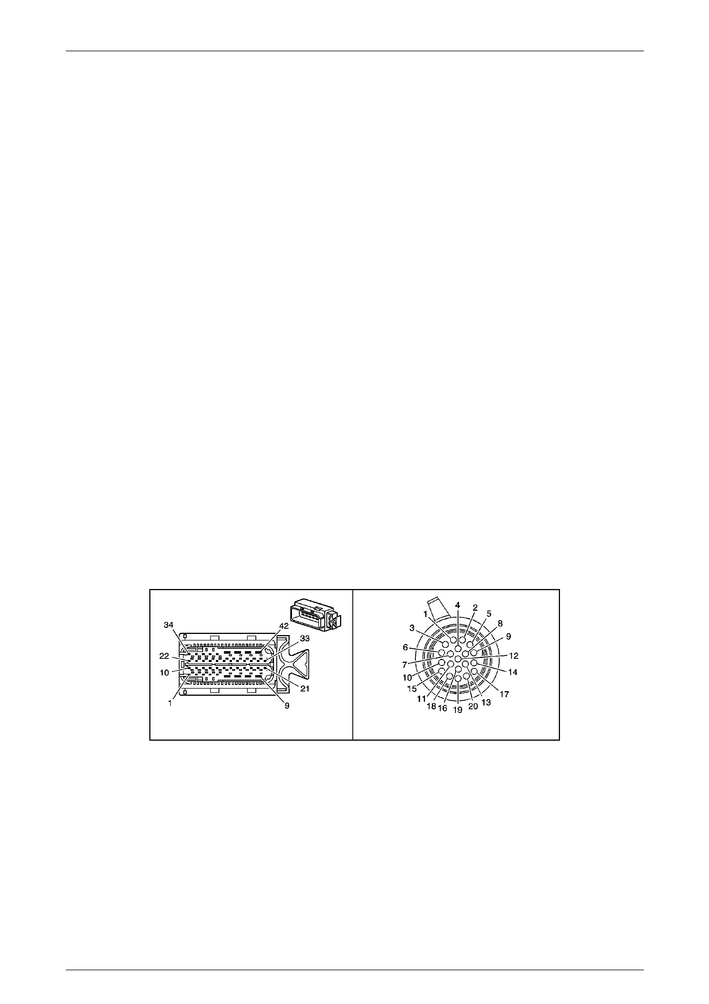
Automatic Transmission – 5L40-E – Electrical Diagnosis Page 7E – 82
Page 7E2 – 82
Action Taken When the DT C Sets
• The TCM does not request the Powertrain Interface Module (PIM) illuminate the Check Powertrain MIL.
• The TCM records the operating cond itions when the ‘Conditions for Settin g the DTC’ are met. The TCM
stores this information as a Failure Recor d.
• The TCM calculates a default transmission fluid temperature base d on e ngine coolant temperature, intake air
temperature and engine run ti me.
• The TCM freezes the transmission adaptive learning function.
• The TCM stores DTC P0711 into TCM history.
Conditions for Clearing the DTC
• Tech 2 can clear the DTC.
• The TCM clears the DTC from its memory (history DTC) if the vehicle completes 40 warm-up cycles without a
non-emission related DTC occurring.
• The TCM cancels the DTC default actions when the fault no longer exists and the DTC passes.
Test Description
The following number(s) refer to the step number(s) on the diagnostic table:
2 Checks for mechanical conditions that could be causing the transmission fluid temperature sensor to sense high
fluid temperature.
4 Checks whether the fault is in the vehicle wiring or in the transmission internal wiring harness.
5 Checks for an intermittent open circuit in the TFT sensor signal and l ow reference circuits.
8 Checks for an intermittent internal short of the sensor signal and low reference circuits.
10 Checks for in the intermittent short to ground in either the sensor signal or lo w reference circuits.
NOTE
• Refer to Figures 7E2–5 and 7E2–6 for 5L40 –
E automatic transmission electrical circuits.
• For procedures on checking wiring faults,
refer to Section 12P Wiring Diagrams.
A112-T68 – X1 X121-X1

Automatic Transmission – 5L40-E – Electrical Diagnosis Page 7E – 83
Page 7E2 – 83
DTC P0711 – Transmission Fluid Temperatu re Sensor Circuit – Perf ormance Test
Step Action Value(s) Yes No
1
Has the Diagnostic System Check – Automatic
Transmission been com pleted?
–
Go to Step 2
Go to
2.3 Diagnostic
System Check –
Automatic
Transmission
in this Section.
2
1 Perform the transmission fluid checking
procedure. Refer to Section 7E4 Automatic
Transmission 5L40-E – On-Vehicle Servicing.
2 Connect and leave Tech 2 connected to the DLC
for the remainder of this diagnostic.
Did you perform the fluid checking procedure and is the
level now OK?
–
Go to Step 3
Go to Section 7E4
Automatic
Transmission 5L40-
E – On-Vehicle
Servicing.
3
1 Clear DTCs using the Tech 2.
2 On the Tech 2, scroll to Transmission Fluid
Temperature data list parameter.
3 Drive the vehicle and observe the Tech 2 while
checking for either of the following conditions:
• The TFT does not change more than 2° C
within 1 minute 40 seconds after engine
start–up.
• The TFT changes by 20° C or greater in
0.250 of a second, 14 times within 10
seconds (unrealistic changes).
Did either of the above conditions occur?
–
Go to Step 4
Go to Intermittent
Conditions, in
Section 6C1–2
Engine
Management – V6 –
Diagnostics.
4
1 Ignition OFF.
2 Disconnect transmission wiring harness connector
X121–X1 from the transmission 20-way
connector.
3 Using suitable test leads, connect a test light
between terminals X1–10 and X1–6 of wiring
harness side of connector X121–X1.
4 While observing the T ech 2 T ransmissi on Fluid
Temperature data list parameter, move or wiggle
the transmission wiring harness from the TCM
connector to the transmission wiring harness
connector X121–X1.
Does the TFT change by greater than the specified
value?
20° C
Go to Step 5
Transmission fluid
temperature sensor
faulty. Replace
transmission
internal wiring
harness assembly.
Refer to Section
7E4 Automatic
Transmission –
5L40-E – On-
Vehicle Servicing.
5
1 Using digital ohmmeter, check transmission wiring
harness for intermittent open circuit condition
between TCM connector A112_5SP D T68,
terminal X1–15 and transmission wiring harness
connector X121_5SPD, terminal X1 –10.
2 Also, check between transmission wiring harness
TCM connector A112_5SPD T68, terminal X1–26
and transmission wiring harness connector
X121_5SPD, terminal X1–6.
Does either check indicate an intermittent open circuit in
the transmission wiring harness?
–
Repair open in
relevant circuit.
Go to Step 9 Go to Step 6

Automatic Transmission – 5L40-E – Electrical Diagnosis Page 7E – 84
Page 7E2 – 84
Step Action Value(s) Yes No
6
1 Using digital ohmmeter, check transmission wiring
harness for intermittent internal short circuit
condition between TCM connector A112_5SPD
T68, terminal X1–15 and trans mission wiring
harness connector X121_5SPD, terminal X1–10.
2 Also check between TCM connector A112_5SPD
T68, terminal X1–26 and trans mission wiring
harness connector X121_5SPD, terminal X1-6.
Does either check indicate an intermittent internal short
circuit in the transmission wiring harness?
–
Repair internal short
circuit in relevant
circuit.
Go to Step 9 Go to Step 7
7
1 Using digital ohmmeter check transmission wirin g
harness for intermittent short to ground condition
between TCM connector A112_5SP D T68,
terminal X1–15 and transmission wiring harness
connector X121_5SPD, terminal X1 –10.
2. Also, check between TCM connector A112_5SPD
T68, terminal X1–26 and trans mission wiring
harness connector X121_5SPD, terminal X1–6.
Does either check indicate an intermittent short to
ground in the transmission wiring harness?
–
Repair short to
ground in relevant
circuit.
Go to Step 9 Go to Step 8
8
1 Replace TCM. Refer to Section 7E4 Automatic
Transmission – 5L40-E – On-V ehicle Servicing for
replacement procedures.
Is the replacement complete?
–
Go to Step 9 -
9
1 Perform the following procedur e to verify the
repair:
• Using Tech 2, select ‘DTC’, then ‘Clear
DTCs’.
• Drive the vehicle and observe Tech 2 while
checking for either of the following
conditions:
• The TFT is between 39 to 149° C.
• The TFT changes by greater than 2°C since
engine start-up.
• The TFT does not change b y 20° C or
greater in 0.250 of a second.
Has the test run and passed?
–
System OK Go to Step 2
When all diagnosis and repairs are completed, clear all DTCs and verify correct operation

Automatic Transmission – 5L40-E – Electrical Diagnosis Page 7E – 85
Page 7E2 – 85
DTC P0712 – Transmission Fluid Temperature Sensor Circuit – Low Input (High
Temperature)
Circuit Description
The Transmission Fluid Temperature (TFT) sensor is p art of the automatic transmission internal wiring harness
assembly. The TFT sensor is a thermistor, a type of resistor that changes value when the temperature changes. The
sensor has a negative temperature coefficient, which means that as the temperature incr eases, the sensors internal
resistance decreases. As the temperature d ecreases, the sensors internal resistance increases.
The Transmission Control Mo dule (TCM), supplies a 5 volt reference signal to the sensor via terminal X1–15 and
measures the voltage drop in the circuit.
When the transmission fluid is cold, the sensor’s resistance is high and the TCM detects a high signal voltage. As the
fluid temperature increases, the internal resistance of the sensor decreases, which inturn lo wers the signa l voltage.
If the TCM detects a short to ground in the TFT sensor, or in the signal circuit, then a DTC P071 2 sets, which is a type
‘C’ DTC.
Conditions for Running the DTC
• Engine running between 450 to 6.800 rpm for at least 5 seconds.
• Ignition voltage is bet ween 8.0 and 18. 0 volts.
Conditions for Setting the DTC
• The TCM detects a TFT resistance of less than 46.18 Ohms for 10 seconds.
Action Taken When the DT C Sets
• The TCM does not request the Powertrain Interface Module (PIM) to illuminate the Check Powertrain Malfunction
Indicator Lamp (MIL).
• The TCM records the operating cond itions when the ‘Conditions for Settin g the DTC’ are met. The TCM stores this
information as a Failure Record.
• The TCM calculates a default transmission fluid temperature base d on e ngine coolant temperature, intake air
temperature and engine run ti me.
• The TCM freezes the transmission adaptive learning function.
• The TCM stores DTC P0712 into TCM history.
Conditions for Clearing the DTC
• Tech 2 can clear the DTC.
• The TCM clears the DTC from its memory (history DTC) if the vehicle completes 40 warm-up cycles without a non-
emission related DTC occurring.
• The TCM cancels the DTC default actions when the fault no longer exists and the DTC passes.
Test Description
The following number(s) refer to the step number(s) on the diagnostic table:
3 This step tests the ability of the TCM to detect an open circuit. If the TCM recognises the open circuit, this
eliminates the TCM and the wiring up to the transmission connector. The fault must be internal to the transmission.
4 As the TFT sensor is an integral part of the transmission internal wiring harness, the entir e internal harness must
be replaced. NOTE
• Refer to Figures 7E2–5 and 7E2–6 for 5L40 –
E automatic transmission electrical circuits.
• For procedures on checking wiring faults,
refer to Section 12P Wiring Diagrams.
A112-T68 – X1 X121-X1

Automatic Transmission – 5L40-E – Electrical Diagnosis Page 7E – 86
Page 7E2 – 86
DTC P0712 – Transmission Fluid Temperature Sensor Circuit – Low Input (High Temperature)
Step Action Value(s) Yes No
1
Has the Diagnostic System Check – Automatic
Transmission been com pleted?
–
Go to Step 2
Go to
2.3 Diagnostic
System Check –
Automatic
Transmission
in this Section.
2
1 Clear DTCs using Tech 2.
2 On Tech 2, scroll to Transmission Fluid
Temperature data list parameter.
Does the Tech 2 display trans mission fluid temperature
equal to or greater than the specified val ue ?
150° C
Go to Step 3
Go to Intermittent
Conditions, Section
6C1–2 Engine
Management – V6 –
Diagnostics.
3
1 Ignition OFF.
2 Disconnect the transmission wiring harness
connector X121_5SPD, terminal from the
transmission 20-way connector.
3 With ignition ON, engine OFF observe the Tech 2
Transmission Fluid Temperature data list
parameter.
Does the Tech 2 display trans mission fluid temperature
equal to the specified value?
– 40° C
Go to Step 4 Go to Step 5
4
1 Replace transmission interna l wiring harness
assembly. Refer to Section 7E4 Automatic
Transmission – 5L40-E – On-V ehicle Servicing for
the procedure.
Is the replacement complete?
–
Go to Step 7 –
5
1 Using digital ohmmeter check transmission wirin g
harness TFT signal circuit for short to ground
condition between TCM connector A112_5SPD
T68, terminal X1–15 and trans mission wiring
harness connector X121_5SPD, terminal X1–10.
Does check indicate a short to ground in the
transmission wiring?
– Repair short to
ground in TFT
signal circuit.
Go to Step 7 Go to Step 6
6
1 Replace TCM. Refer to Section 7E4 Automatic
Transmission – 5L40-E – On-V ehicle Servicing for
replacement procedures.
Is the replacement complete?
–
Go to Step 10 –
7
1 Perform the following procedur e to verify the
repair:
• Using the Tech 2, select ‘DTC’, then ‘Cle ar
DTCs’.
• Drive the vehicle and observe the Tech 2
while checking that the TFT must be 150° C
or less for 2 seconds.
Has the test run and passed?
–
System OK Go to Step 2
When all diagnosis and repairs are completed, clear all DTCs and verify correct operation

Automatic Transmission – 5L40-E – Electrical Diagnosis Page 7E – 87
Page 7E2 – 87
DTC P0713 – Transmission Fluid Temperature Sensor Circuit – High Input (Low
Temperature)
Circuit Description
The Transmission Fluid Temperature (TFT) sensor is p art of the automatic transmission internal wiring harness
assembly. The TFT sensor is a thermistor, a type of resistor that changes value when the temperature changes. The
sensor has a negative temperature coefficient, which means that as the temperature incr eases, the sensors internal
resistance decreases. As the temperature d ecreases, the sensors internal resistance increases.
The Transmission Control Mo dule (TCM), supplies a 5-volt reference sig nal to the sensor via terminal X1–15 and
measures the voltage drop in the circuit.
When the transmission fluid is cold, the sensor’s resistance is high and the TCM detects a high signal voltage. As the
fluid temperature increases, the internal resistance of the sensor decreases, which inturn lo wers the signa l voltage.
If the TCM detects an open or short to voltage in the TFT sensor, or the signal circuit, then a DTC P0713 sets, which is a
type ‘C’ DTC.
Conditions for Running the DTC
• The following DTCs are not set:
• P0716 or P0717 – Transmission Input Sp eed Sensor.
• P0722 or P0723 – Transmission Output Speed Sensor.
• Engine speed is between 450 to 6,800 rpm for at least 5 seconds.
• Ignition voltage is bet ween 8.0 and 18. 0 volts.
• The transmission output shaft speed is greater than 200 rpm for 200 seconds (3 minutes and 20 seconds)
cumulatively.
• Transmission torque converter clutch slip speed is 120 rpm or greater for 200 seconds (3 minutes and 20 seconds)
cumulatively.
Conditions for Setting the DTC
• The TCM detects a TFT resistance of more than 111.605 k Ohm for 25 seconds.
Action Taken When the DTC sets
• The TCM does not request the Powertrain Interface Module (PIM) to illuminate the Check Powertrain Malfunction
Indicator Lamp (MIL).
• The TCM records the operating cond itions when the ‘Conditions for Settin g the DTC’ are met. The TCM stores this
information as a Failure Record.
• The TCM calculates a default transmission fluid temperature base d on e ngine coolant temperature, intake air
temperature and engine run ti me.
• The TCM freezes the transmission adaptive learning function.
• The TCM stores DTC P0713 into TCM history.
Conditions for Clearing the DTC
• Tech 2 can clear the DTC.
• The TCM clears the DTC from its memory (history DTC) if the vehicle completes 40 warm-up cycles without a non-
emission related DTC occurring.
• The TCM cancels the DTC default actions when the fault no longer exists and the DTC passes.
NOTE
• Refer to Figures 7E2–5 and 7E2–6 for 5 L40 –
E automatic transmission electrical circuits.
• For procedures on checking wiring faults,
refer to Section 12P Wiring Diagrams.
A112-T68 – X1 X121-X1 X121-X1a
Figure 7E2 – 36

Automatic Transmission – 5L40-E – Electrical Diagnosis Page 7E – 88
Page 7E2 – 88
DTC P0713 – Transmission Fluid Temperature Sensor Circuit – High Input (Low Temperature)
Step Action Value(s) Yes No
1
Has the Diagnostic System Check – Automatic
Transmission been com pleted?
–
Go to Step 2
Go to
2.3 Diagnostic
System Check –
Automatic
Transmission
in this Section.
2
1 Clear DTCs using Tech 2.
2 Using Tech 2, scroll to Transmission Flu id
Temperature data list parameter.
Does the Tech 2 display trans mission fluid temperature
less than the specified value?
– 39° C
Go to Step 3
Go to Intermittent
Conditions in
Section 6C1–2
Engine Module
Control Diagnosis
3
1 Ignition OFF.
2 Disconnect the transmission wiring harness
connector X121–X1 from the transmission 20-way
connector.
3 Using suitable test leads and a digital ohmmeter,
measure the transmission internal resistance of
the TFT sensor bet ween 20-way connector
terminals X1-10 and X1-6.
Is the resistance less than the specified value ?
100 kΩ
Go to Step 5 Go to Step 4
4
1 Transmission internal wiring harness faulty.
Replace transmission interna l wiring harness
assembly. Refer to Section 7E4 Automatic
Transmission – on-Vehicle Servicing.
Has replacement been compl eted?
–
Go to Step 8 –
5
1 Using digital voltmeter, check transmission wiring
harness for short to voltage between TCM
connector A112-T68, terminal X1–15 and
transmission wiring harness connector X121–X1,
terminal X1–10.
Does check indicate a short to voltage in the wiring?
– Repair short to
voltage in TFT
signal circuit.
Go to Step 8 Go to Step 6
6
1 Using a digital ohmmeter, check transmissio n
wiring harness for an open circuit between TCM
connector A112-T68, terminal X1–15 and
transmission wiring harness connector X121–X1,
terminal X1–10.
2 Also check between TCM connector A112-T68,
terminal X1–26 and transmission wiring harness
connector X121–X1, terminal X1–6.
Does either check indicate an open circuit in the
transmission wiring harness?
–
Repair open in
relevant circuit.
Go to Step 8 Go to Step 7
7
1 Replace TCM. Refer to Section 7E4 Automatic
Transmission – 5L40-E – On-V ehicle Servicing for
replacement procedures.
Is the replacement complete?
–
Go to Step 8 –
8
1 Perform the following procedur e to verify the
repair:
• Using Tech 2, select ‘DTC’, then ‘Clear
DTCs’.
• Ignition ON, engine OFF and observe the
Tech 2 Transmission Fluid Temperature
data parameter.
• The TFT must be greater than – 40° C or
less for 12.5 seconds.
Has the test run and passed?
–
System OK Go to Step 2
When all diagnosis and repairs are completed, clear all DTCs and verify correct operation

Automatic Transmission – 5L40-E – Electrical Diagnosis Page 7E – 89
Page 7E2 – 89
DTC P0716 – Transmission Input Speed Sensor – Performance Signal Drop
Circuit Description
The automatic transmission input speed sensor is a variable reluctance magnetic pickup sensor a nd is located in the
inside front of the transmission case, above the control valv e body and accumulator assembly. It is mounted in the cas e
opposite the reverse clutch input hous ing assembly and uses the stamped teeth on the reverse clutch housing as the
rotor (reluctor) for sensor output operation.
The output of the input speed sensor produc es an AC voltage signal proportional to the r otation al speed of the reverse
clutch input housing, which is driven at torque converter turbine speed.
Within the TCM, the generated AC voltage is converted to a 5 volt square wave form and this wave form is interpreted as
the transmission input speed.
The TCM uses transmission input and output speeds to help determine line pressure, transmission shift patterns, TCC
apply pressure, gear ratios an d TCC slippage for diagnostic purpos es.
If the TCM detects an unrealistic drop in input shaft speed, DTC P0716 sets, which is a type ‘B’ DTC.
Conditions for Running the DTC
• Ignition voltage is bet ween 8.0 and 18. 0 volts.
• Engine speed is between 450 and 6,800 rpm for at least 5 seconds.
• The following DTCs are not set:
• P0716 or P0717 – Transmission Input Sp eed Sensor – Low Input, No Activity.
• P0722 or P0723 – Transmission Output Speed Sensor.
• P0752 – 1–2 Shift Solenoid Performance.
• P1842 or P1843 – 1–2 Shift Solenoid Electrical.
• No engine torque DTCs.
• Throttle system DTCs P1791 or P1795.
• Vehicle speed is greater than 16 km / h.
• Throttle position opening is greater than 12%.
• The transmission input speed is greater than 1,050 rpm for more than 2 seconds.
• One of the following conditions exist:
• The transmission input speed has not cha ng ed for at least 2 seconds.
• The transmission input speed has incre ase d by greater than 500 rpm within 2 seconds.
Conditions for Setting the DTC
The transmission input shaft speed drops mo re than 1 000 rpm for at least 4 seconds.
Action Taken When the DTC sets
• The TCM requests the Powertrain Interface Module (PIM) to illumin ate the Check Powertrain Malfunction Indicator
Lamp (MIL) during the second consecutive trip in which the ‘Conditions for Setting the DTC’ have been met.
• At the time of the first failure, the TCM records the operating conditions when the ‘Conditions for Setting the DTC’
are met. The TCM stores this information as a Failure Reco rd.
• At the time of the second failure, the ECM records the operating conditions when the ‘Conditions for Set ting the
DTC’ are met. The ECM stores this information as a Freeze Frame.
• The TCM stores the DTC information i nto me mory when the diagnostic runs and fails.
• TCM will determine the transmission input spee d from the output speed sensor signal as well as the commanded
gear ratio (signals to the TCM from the three shift solenoids).
• The TCM also turns off the pressure control sole noid (causing maximum line pressure).
• The TCM freezes the transmission adaptive learning function.
• The TCM stores DTC P0716 into TCM history.
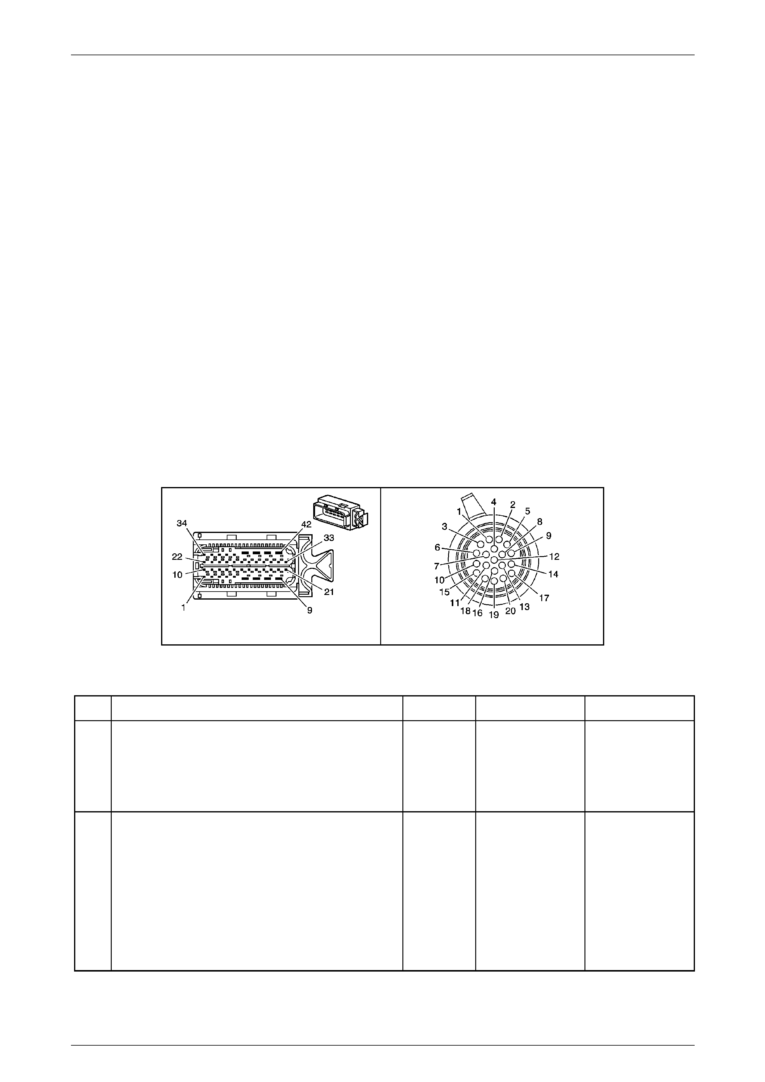
Automatic Transmission – 5L40-E – Electrical Diagnosis Page 7E – 90
Page 7E2 – 90
Conditions for Clearing the MIL / DTC
• The PIM turns off the Check Powertrain MIL after the sixth consecutive drive trip in which the TCM does not send a
Check Powertrain MIL illumination request.
• Tech 2 can clear the DTC.
• The TCM clears the DTC from its memory (history DTC) if the vehicle completes 40 warm-up cycles without a non-
emission related DTC occurring.
• The TCM cancels the default actions when the ignition is off long enou gh to power down the TCM.
Diagnostic Aids
Ensure that the transmission input speed sensor to transmission case bolt is correct tightened.
Test Description
The following number(s) refer to the step number(s) on the diagnostic table.
3 Checks to determine if there is a short to voltage on the input speed s ensor signal circuit.
4 Checks to determine if there is a short to ground on the input speed sensor signal circuit.
6 Verifies the circuit continuity from the TCM connector to, through and from the input speed sensor.
NOTE
• Refer to Figures 7E2–5 and 7E2–6 for 5L40 –
E automatic transmission electrical circuits.
• For procedures on checking wiring faults,
refer to Section 12P Wiring Diagrams.
A112-T68 – X1 X121-X1
Figure 7E2 – 37
DTC P0716 – Transmission In p ut Sp eed Sensor – Performance Signal Dro p
Step Action Value(s) Yes No
1
Has the Diagnostic System Check – Automatic
Transmission been com pleted?
–
Go to Step 2
Go to
2.3 Diagnostic
System Check –
Automatic
Transmission
in this Section.
2
1 Connect Tech 2 to the DLC.
2 Ignition ON, engine OFF.
3 Record then clear stored DTCs.
4 Start the engine and using Tech 2, scroll to
Transmission Input Speed Sensor data list
parameter.
Does Tech 2 display i nput speed sensor above the
specified value?
500 rpm Go to Intermittent
Conditions, in
Section 6C1–2
Engine Module
Control Diagnosis. Go to Step 3

Automatic Transmission – 5L40-E – Electrical Diagnosis Page 7E – 91
Page 7E2 – 91
Step Action Value(s) Yes No
3
1 Ignition OFF.
2 Disconnect the transmission wiring harness
connector A112 – T68 from the TCM.
3 Ignition ON.
4 Using a digital voltmeter, measure volta ge
between transmission wiring harness TCM
connector, terminal X1–10 and ground.
Is voltage reading less than the specified val ue?
Less than
0.3 volts
Go to Step 4 Go to Step 5
4
1 Ignition OFF.
2 Using a digital ohmmeter, measure the resistance
between transmission wiring harness TCM
connector A112 – T68, terminal X1–10 a nd
ground.
Is resistance greater than the specified value ?
500 kΩ
Go to Step 6 Go to Step 9
5
1 Using a digital voltmeter, check transmission
wiring for short to voltage condition between
transmission wiring harness TCM connector
A112 – T68, terminal X1–10 a nd transmission
connector X121–X1, terminal X1–1 8.
2 Also, check between transmission wiring harness
TCM connector A112 – T68, termina l X1–11 and
transmission connector X121–X1, terminal X1–15.
Does either check indicate a short to voltage in the
transmission wiring?
–
Repair short to
voltage in relevant
circuit.
Go to Step 13 Go to Step 11
6
1 Using a digital ohmmeter, measure the resistance
between transmission wiring harness TCM
connector A112 – T68, terminals X1–11 a nd
X1–10.
Is resistance within specified values?
325 – 485 Ω
@ 20° C
385 – 575 Ω
@ 70° C Go to Step 10
If less than
specified, go to
Step 7.
If greater than
specified, go to
Step 8.
7
1 Using a digital ohmmeter, check transmissio n
wiring harness for internal short circuit condition
between TCM connector A112 – T 68, terminal
X1–10 and transmission con nector X121–X1,
terminal X1–18.
2 Also, check between transmission wiring harness
TCM connector A112 – T68, termina l X1–11 and
transmission connector X121–X1, terminal X1–15.
Does either check indicate an internal short circuit in the
transmission wiring?
–
Repair internal short
circuit in relevant
circuit.
Go to Step 13 Go to Step 11
8
1 Using a digital ohmmeter che ck transmission
wiring harness for open circuit condition between
TCM connector A112 – T68, termina l X1–10 and
transmission connector X121–X1, terminal X1–18.
2 Also, check between transmission wiring harness
TCM connector A112 – T68, termina l X1–11 and
transmission connector X121–X1, terminal X1–15.
Does either check indicate an open circuit in the
transmission wiring?
–
Repair open in
relevant circuit.
Go to Step 13 Go to Step 11

Automatic Transmission – 5L40-E – Electrical Diagnosis Page 7E – 92
Page 7E2 – 92
Step Action Value(s) Yes No
9
1 Using digital ohmmeter check transmission wirin g
for short to ground condition between
transmission wiring harness TCM connector
A112 – T68, terminal X1–10 a nd transmission
connector X121–X1, terminal X1–1 8.
2 Also, check between transmission wiring harness
TCM connector A112 – T68, termina l X1–11 and
transmission connector X121–X1, terminal X1–15.
Does either check indicate a short to ground in the
transmission wiring?
–
Repair short to
ground in relevant
circuit.
Go to Step 13 Go to Step 11
10
1 Remove transmission fluid pan, refer to Section
7E4 Automatic Transmission On-Vehicle
Servicing, for the procedure.
2 Inspect transmission internal wiring harness for
any sign of damage.
Is transmission internal wiring harness OK?
–
Go to Step 11
Replace
transmission
internal wiring
harness. Refer to
Section 7E4
Automatic
Transmission On-
Vehicle Servicing.
Go to Step 13
11
1 Remove transmission input speed sensor. Refer
to Section 7E4 Automatic Transmission On-
Vehicle Servicing, for the proc edure.
2 Inspect sensor for any sign of damage.
3 Through sensor mounting hole in transmission
case, inspect reluctor teeth on the reverse clutch
input housing for any signs of damage.
Was any damage to components found?
–
For sensor damage,
replace the
damaged
component.
If reverse clutch
input housing
damage is found,
replace the
transmission. Refer
to Section 7E4
Automatic
Transmission On-
Vehicle Servicing. Go to Step 12
12
1 Replace TCM. Refer to Section 7E4 Automatic
Transmission – 5L40-E – On-V ehicle Servicing for
replacement procedures.
Is the replacement complete?
–
Go to Step 13 –
13
1 Perform the following procedur e to verify the
repair:
• Using the Tech 2, select ‘DTC’ and the n
‘Clear DTCs.
• Start the engine and allo w to idle.
2 Verify that Tech 2 indicates an input transmission
speed sensor signal of greater than 500 rpm for 2
seconds.
Has the test run and passed?
–
System OK Go to Step 2
When all diagnosis and repairs are completed, clear all DTCs and verify correct operation

Automatic Transmission – 5L40-E – Electrical Diagnosis Page 7E – 93
Page 7E2 – 93
DTC P0717 – Transmission Input Speed Sensor – Low Input, No Activity
Circuit Description
The automatic transmission input speed sensor is a variable reluctance magnetic pickup sensor a nd is located in the
inside front of the transmission case, above the control valv e body and accumulator assembly. It is mounted in the cas e
opposite the reverse clutch input hous ing assembly and uses the stamped teeth on the reverse clutch housing as the
rotor (reluctor) for sensor operation.
The output of the input speed sensor pro duces an AC voltage signal proportional to rotational speed of the reverse clutch
input housing, which is drive n at torque converter turbine speed.
Within the TCM, the AC voltage is converted to a 5 volt square wave form and this wave form is interpreted as the
transmission input speed.
The TCM uses transmission input and output speeds to help determine line pressure, transmission shift patterns, TCC
apply pressure, gear ratios an d TCC slippage for diagnostic purpos es.
If the TCM detects no input speed sensor signa l when there is vehicle speed in drive gear range, then DTC P0717 sets,
which is a type ‘B’ DTC.
Conditions for Running the DTC
• Ignition voltage is bet ween 8.0 and 18. 0 volts.
• Engine speed is between 450 to 6,800 rpm for at least 5 seconds.
• The following DTCs are not set:
• P0722 or P0723 – Transmission Output Speed Sensor.
• No engine torque DTCs.
• Vehicle speed is greater than 16 km / h.
Conditions for Setting the DTC
• The transmission input speed sensor sig nal is less than 100 rpm for 5 seconds.
Action Taken When the DT C Sets
• The TCM requests the Powertrain Interface Module (PIM) to illumin ate the Check Powertrain Malfunction Indicator
Lamp (MIL) during the second consecutive trip in which the ‘Conditions for Setting the DTC’ have been met.
• At the time of the first failure, the TCM records the operating conditions when the ‘Conditions for Setting the DTC’
are met. The TCM stores this information as a Failure Reco rd.
• At the time of the second failure, the ECM records the operating conditions when the ‘Conditions for Set ting the
DTC’ are met. The ECM stores this information as a Freeze Frame.
• The TCM stores the DTC information i nto me mory when the diagnostic runs and fails.
• TCM will determine the transmission input spee d from the output speed sensor signal as well as the commanded
gear ratio (signals to the TCM from the three shift solenoids).
• The TCM also turns off the pressure control sole noid (causing maximum line pressure).
• The TCM freezes the transmission adaptive learning function.
• The TCM stores DTC P0717 into TCM history.
Conditions for Clearing the MIL / DTC
• The PIM turns off the Check Powertrain MIL after the sixth consecutive drive trip in which the TCM does not send a
Check Powertrain MIL illumination request.
• Tech 2 can clear the DTC.
• The TCM clears the DTC from its memory (history DTC) if the vehicle completes 40 warm-up cycles without a non-
emission related DTC occurring.
• The TCM cancels the default actions when the ignition is off long enou gh to power down the TCM.
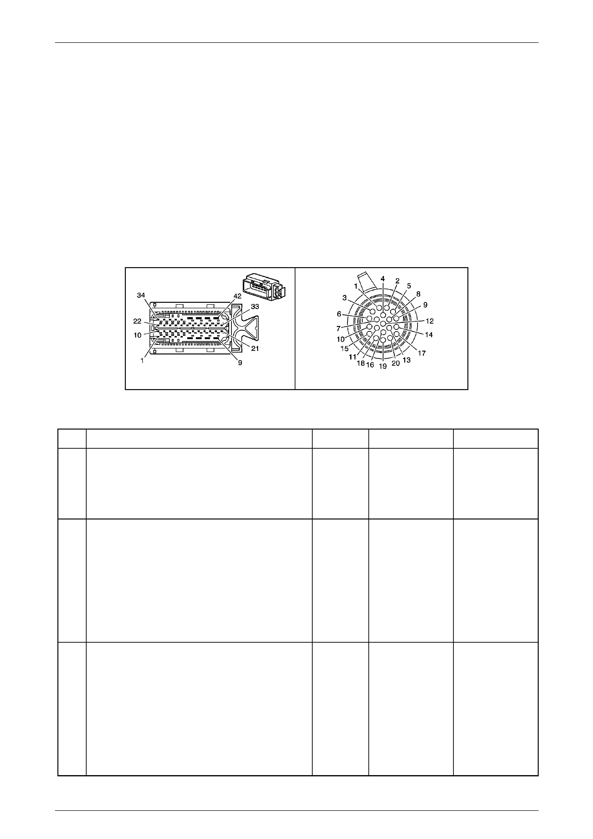
Automatic Transmission – 5L40-E – Electrical Diagnosis Page 7E – 94
Page 7E2 – 94
Diagnostic Aids
Ensure that the transmission input speed sensor to transmission case bolt is correct tightened.
Test Description
The numbers (s) below refer to the step number(s) on the di agnostic table.
3 Checks to determine if there is a short to voltage on the input speed sensor signal circuit.
4 Checks to determine if there is a short to ground on the input speed sensor signal circuit.
6 Verifies the circuit continuity from the TCM connector to, through and from the input speed sensor.
NOTE
• Refer to Figures 7E2–5 and 7E2–6 for 5L40 –
E automatic transmission electrical circuits.
• For procedures on checking wiring faults,
refer to Section 12P Wiring Diagrams.
A112-T68 – X1 X121-X1
Figure 7E2 – 38
DTC P0717 – Transmission Input Speed Sensor – Low Input, No Activity
Step Action Value(s) Yes No
1
Has the Diagnostic System Check – Automatic
Transmission been com pleted?
–
Go to Step 2
Go to
2.3 Diagnostic
System Check –
Automatic
Transmission
in this Section.
2
1 Connect Tech 2 to the DLC.
2 Ignition ON, engine OFF.
3 Record then clear stored DTC/s.
4 Start the engine and with Tech 2, scroll to
Transmission Input Speed Sensor data list
parameter.
Does the Tech 2 display input speed sensor above the
specified value?
Greater than
500 rpm Go to Intermittent
Conditions, in
Section 6C1–2
Engine Module
Control Diagnosis Go to Step 3
3
1 Ignition OFF.
2 Disconnect transmission wiring harness connector
from the TCM.
3 Ignition ON.
4 Using a digital voltmeter, measure volta ge
between transmission wiring harness TCM
connector A112 – T68, terminal X1–10 a nd
ground.
Is voltage reading less than the specified val ue?
Less than
0.3 volts
Go to Step 4 Go to Step 5

Automatic Transmission – 5L40-E – Electrical Diagnosis Page 7E – 95
Page 7E2 – 95
Step Action Value(s) Yes No
4
1 Ignition OFF.
2 Using a digital ohmmeter, measure the resistance
between transmission wiring harness TCM
connector terminals X1–10 and ground.
Is resistance greater than the specified value ?
Greater than
500 kOhm
Go to Step 6 Go to Step 9
5
1 Using digital voltmeter check transmission wiring
harness for short to voltage condition between
TCM connector A112 – T68, termina l X1–10 and
transmission wiring harness connector X121–X1,
terminal X1–18.
2 Also, check between transmission wiring harness
TCM connector A112 – T68, termina l X1–11 and
transmission wiring harness connector X121–X1,
terminal X1–15.
Does either check indicate a short to voltage in the
transmission wiring?
–
Repair short to
voltage in relevant
circuit.
Go to Step 13 Go to Step 11
6
1 Using a digital ohmmeter, measure the resistance
between transmission wiring harness TCM
connector A112 – T68, terminals X1–11 a nd
X1–10.
Is resistance within specified values?
325 – 485 Ω
@ 20° C
385 – 575 Ω
@ 70° C Go to Step 10
If less than
specified, go to
step 7.
If greater than
specified, go to
step 8
7
1 Using digital ohmmeter check transmission wirin g
harness for internal short circuit condition between
TCM connector A112 – T68, termina l X1–10 and
transmission connector X121–X1, termina l
X1–18.
2 Also, check between transmission wiring harness
TCM connector A112 – T68, termina l X1–11 and
transmission wiring harness connector X121–X1,
terminal X1–15.
Does either check indicate an internal short circuit in the
transmission wiring?
–
Repair internal short
circuit in relevant
circuit.
Go to Step 13 Go to Step 11
8
1 Using digital ohmmeter check transmission wirin g
for open circuit condition b etween transmission
wiring harness T CM connector A112 – T68,
terminal X1–10 and transmission wiring harness
connector X121–X1, terminal X1–1 8.
2 Also, check between transmission wiring harness
TCM connector A112 – T68, termina l X1–11 and
transmission wiring harness connector X121–X1,
terminal X1–15.
Does either check indicate an open circuit in the
transmission wiring?
–
Repair open in
relevant circuit.
Go to Step 13 Go to Step 11
9
1 Using a digital ohmmeter, check transmissio n
wiring harness for short to ground condition
between TCM connector A112 – T 68, terminal
X1–10 and transmission wiring harness connector
X121–X1, terminal X1–18.
2 Also, check between transmission wiring harness
TCM connector A112 – T68, termina l X1–11 and
transmission wiring harness connector X121–X1,
terminal X1–15.
Does either check indicate a short to ground in the
transmission wiring?
–
Repair short to
ground in relevant
circuit.
Go to Step 13 Go to Step 11

Automatic Transmission – 5L40-E – Electrical Diagnosis Page 7E – 96
Page 7E2 – 96
Step Action Value(s) Yes No
10
1 Remove transmission fluid pan, refer to Section
7E4 Automatic Transmission On-Vehicle
Servicing, for the procedure.
2 Inspect transmission internal wiring harness for
any sign of damage.
Is transmission internal wiring harness OK?
–
Go to Step 11
Replace
transmission
internal wiring
harness. Refer to
Section 7E4
Automatic
Transmission On-
Vehicle Servicing.
Go to Step 13
11
1 Remove transmission input speed sensor. Refer
to Section 7E4 Automatic Transmission On-
Vehicle Servicing, for the proc edure.
2 Inspect sensor for any sign of damage.
3 Through sensor mounting hole in transmission
case, inspect reluctor teeth on the reverse clutch
input housing for any signs of damage.
Was any damage to components found?
–
For sensor damage,
replace the
damaged
component.
If reverse clutch
input housing
damage is found,
replace the
transmission. Refer
to Section 7E4
Automatic
Transmission On-
Vehicle Servicing. Go to Step 12
12
1 Replace TCM. Refer to Section 7E4 Automatic
Transmission – 5L40-E – On-V ehicle Servicing for
replacement procedures.
Is the replacement complete?
–
Go to Step 13 –
13
1 Perform the following procedur e to verify the
repair:
• Using the Tech 2, select ‘DTC’ and the n
‘Clear DTCs.
• Start the engine and allo w to idle.
2 Verify that Tech 2 indicates an input transmission
speed sensor signal of greater than 500 rpm for 2
seconds.
Has the test run and passed?
–
System OK Go to Step 2
When all diagnosis and repairs are completed, clear all DTCs and verify correct operation

Automatic Transmission – 5L40-E – Electrical Diagnosis Page 7E – 97
Page 7E2 – 97
DTC P0722 – Transmission Output Speed Sensor – Low Input
Circuit Description
The automatic transmission output speed sensor is a variable reluctance magnetic pickup sensor and is located in the
inside rear of the transmission case, above the control valve body and accumulator assembly. It is mounted in the cas e
opposite the rear internal gear . T he rear internal gear is splined to the transmission output shaft assembly.
The sensor consists of a permanent magn et surrounded by a coil of wire. As the output shaft and rear internal gear
rotate, an alternating current (AC) is induced into the coil by the ‘teeth’ on the rear internal gear as they pass by the
magnetic pickup.
The output of this speed sens or produces an AC voltage signal proportional to rotational speed of the rear internal gear,
which is rotating at vehicle speed.
Within the TCM, the AC voltage is converted to a 5 volt square wave form and this wave form is interpreted as the
transmission output speed.
The TCM uses transmission input and output speeds to help determine line pressure, transmission shift patterns, TCC
apply pressure, gear ratios an d TCC slippage for diagnostic purpos es.
If the TCM detects no vehicle speed when there is engine speed in a drive gear range, th en DTC P0722 sets, which is a
type ‘B’ DTC.
Conditions for Running the DTC
• Ignition voltage is bet ween 8.0 and 18. 0 volts.
• Engine speed is between 450 and 6,800 rpm for at least 5 seconds.
• The following DTCs are not set:
• P0716 or P0717 – Transmission Input Sp eed Sensor.
• P0723 – Transmission Output Speed Sensor.
• No engine torque DTCs.
• No throttle system DTCs.
• Vehicle speed is greater than 16 km / h.
• Throttle position is greater than 12%.
• Engine torque is between 70 and 450 N.m.
• The transmission input speed is 1,500 to 6,8 00 rpm.
Conditions for Setting the DTC
• The transmission output speed sensor sign al is less than 100 rpm for 3 seconds.
Action Taken When the DT C Sets
• The TCM requests the Powertrain Interface Module (PIM) to illumin ate the Check Powertrain Malfunction Indicator
Lamp (MIL) during the second consecutive trip in which the ‘Conditions for Setting the DTC’ have been met.
• At the time of the first failure, the TCM records the operating conditions when the ‘Conditions for Settin g the DTC’
have been met. The TCM stores this information as a failure record.
• At the time of the second failure, the ECM records the operating conditions when the ‘Conditions for Set ting the
DTC’ have been met. The ECM stores this information as a freeze frame.
• TCM will determine the vehicle speed from the automatic transmission input speed sensor signal as well as the
commanded gear ratio (signals to the TCM from the three shift solenoids).
• The TCM also turns off the pressure control sole noid (causing maximum line pressure).
• The TCM freezes the transmission adaptive learning function.
• The TCM stores DTC P0722 into TCM history.
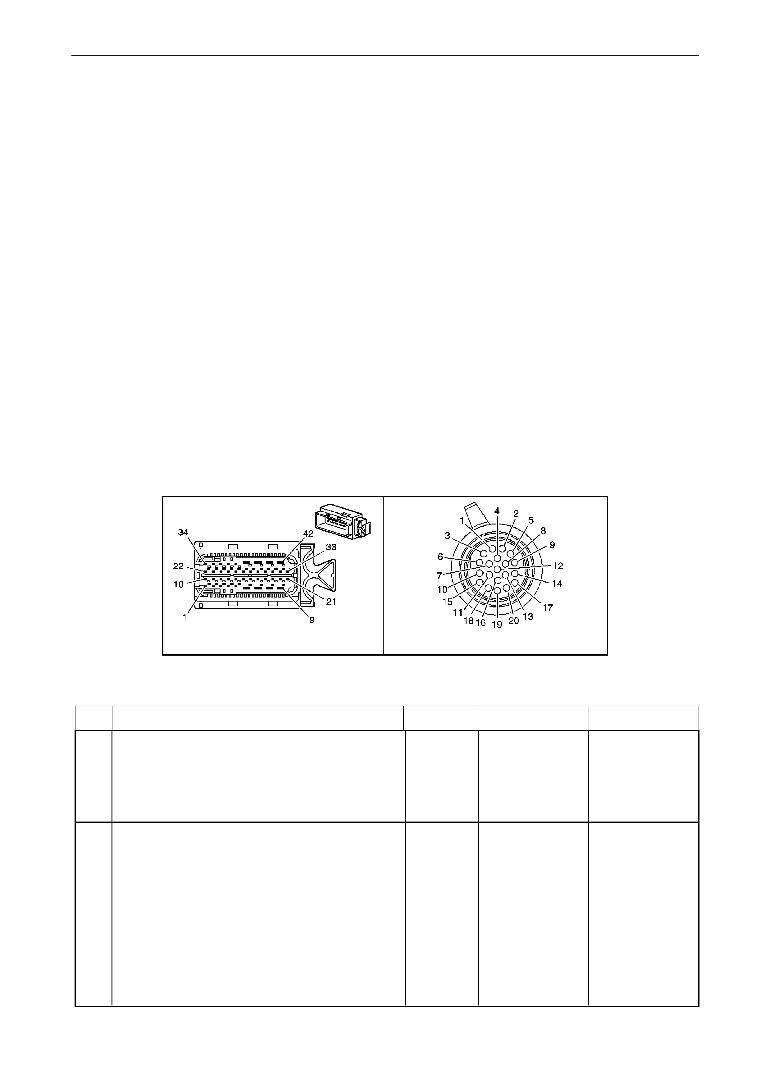
Automatic Transmission – 5L40-E – Electrical Diagnosis Page 7E – 98
Page 7E2 – 98
Conditions for Clearing the MIL / DTC
• The PIM turns off the Check Powertrain MIL after the sixth consecutive drive trip in which the TCM does not send a
Check Powertrain MIL illumination request.
• Tech 2 can clear the DTC.
• The TCM clears the DTC from its memory (history DTC) if the vehicle completes 40 warm-up cycles without a non-
emission related DTC occurring.
• The TCM cancels the default actions when the ignition is off long enou gh to power down the TCM.
Diagnostic Aids
Ensure that the transmission output speed sensor to transmission case bolt is correct tightened.
Test Description
The following number(s) refer to the step number(s) on the diagnostic table.
3 Checks to determine if there is a short to voltage on the output spee d sensor signal circuit.
4 Checks to determine if there is a short to ground on the out put speed sensor signal circuit.
6 Verifies the circuit continuity from the TCM connector to, through and from the output speed sens or.
NOTE
• Refer to Figures 7E2–5 and 7E2–6 for 5L40 –
E automatic transmission electrical circuits.
• For procedures on checking wiring faults,
refer to Section 12P Wiring Diagrams.
A112-T68 – X1 X121-X1
Figure 7E2 – 39
DTC P0722 – Transmission Ou tpu t Speed Sensor – Low Input
Step Action Value(s) Yes No
1
Has the Diagnostic System Check – Automatic
Transmission been com pleted?
–
Go to Step 2
Go to
2.3 Diagnostic
System Check –
Automatic
Transmission
in this Section.
2
1 Connect Tech 2 to the DLC.
2 Ignition ON, engine OFF.
3 Record then clear stored DTC/s.
4 Start the engine and with Tech 2, scroll to
Transmission Input Speed Sensor data list
parameter.
5 Drive the vehicle in D5 range.
Does the Tech 2 display outpu t speed sensor above the
specified value?
Greater than
100 rpm Go to Intermittent
Conditions, in
Section 6C1–2
Engine
Management – V6 –
Diagnostics. Go to Step 3

Automatic Transmission – 5L40-E – Electrical Diagnosis Page 7E – 99
Page 7E2 – 99
Step Action Value(s) Yes No
3
1 Ignition OFF.
2 Disconnect transmission wiring harness connector
from the TCM.
3 Ignition ON.
4 Using a digital voltmeter, measure volta ge
between transmission wiring harness TCM
connector A112 – T68, terminal X1–1 an d ground.
Is voltage reading less than the specified val ue?
Less than
0.3 volts
Go to Step 4 Go to Step 5
4
1 Ignition OFF.
2 Using a digital ohmmeter, measure the resistance
between transmission wiring harness TCM
connector A112 – T68, terminal X1–1 an d ground.
Is resistance greater than the specified value ?
Greater than
500 kΩ
Go to Step 6 Go to Step 9
5
1 Using a digital voltmeter check transmission wiring
harness for short to voltage condition between
TCM connector A112 – T68, terminal X1–1 and
transmission wiring harness connector X121–X1,
terminal X1–1.
2 Also, check between transmission wiring harness
TCM connector A112 – T68, terminal X1–2 and
transmission wiring harness connector X121–X1,
terminal X1–3.
Does either check indicate a short to voltage in the
transmission wiring?
–
Repair short to
voltage in relevant
circuit.
Go to Step 13 Go to Step 11
6
1 Using a digital ohmmeter, measure the resistance
between transmission wiring harness TCM
connector A112 – T68, terminals X1–1 and
X1–2.
Is resistance within specified values?
325 – 485 Ω
@ 20° C
385 – 575 Ω
@ 70° C Go to Step 10
If less than
specified, go to
step 7.
If greater than
specified, go to
step 8
7
1 Using a digital ohmmeter, check transmissio n
wiring harness for internal short circuit condition
between TCM connector A112 – T 68, terminal
X1–1 and transmission connector X121–X1,
terminal X1–1.
2 Also, check between transmission wiring harness
TCM connector A112 – T68, terminal X1–2 and
transmission wiring harness connector X121–X1,
terminal X1–3.
Does either check indicate an internal short circuit in the
transmission wiring?
–
Repair internal short
circuit in relevant
circuit.
Go to Step 13 Go to Step 11
8
1 Using a digital ohmmeter, check transmissio n
wiring for open circuit condition between
transmission wiring harness TCM connector
A112 – T68, terminal X1–1 and transmission
wiring harness connector X121– X1, terminal
X1–1.
2 Also, check between transmission wiring harness
TCM connector A112 – T68, terminal X1–2 and
transmission wiring harness connector X121–X1,
terminal X1–3.
Does either check indicate an open circuit in the
transmission wiring?
–
Repair open in
relevant circuit.
Go to Step 13 Go to Step 11

Automatic Transmission – 5L40-E – Electrical Diagnosis Page 7E – 100
Page 7E2 – 100
Step Action Value(s) Yes No
9
1 Using a digital ohmmeter, check transmissio n
wiring harness for short to ground condition
between TCM connector A112 – T 68, terminal
X1–1 and transmission wiring harness connector
X121–X1, terminal X1–1.
2 Also, check between transmission wiring harness
TCM connector A112 – T68, terminal X1–2 and
transmission wiring harness connector X121–X1,
terminal X1–3.
Does either check indicate a short to ground in the
transmission wiring?
–
Repair short to
ground in relevant
circuit.
Go to Step 13 Go to Step 11
10
1 Remove transmission fluid pan, refer to Section
7E4 Automatic Transmission On-Vehicle
Servicing, for the procedure.
2 Inspect transmission internal wiring harness for
any sign of damage.
Is transmission internal wiring harness OK?
–
Go to Step 11 –
11
1 Remove transmission output speed sensor. Refer
to Section 7E4 Automatic Transmission On-
Vehicle Servicing, for the proc edure.
2 Inspect sensor for any sign of damage.
3 Through sensor mounting hole in transmission
case, inspect reluctor teeth on the rear internal
gear for any signs of damage.
Was any damage to components found?
–
For sensor damage,
replace the
damaged
component.
If rear internal gear
damage is found,
replace the
transmission. Refer
to Section 7E4
Automatic
Transmission On-
Vehicle Servicing. –
12
1 Replace TCM. Refer to Section 7E4 Automatic
Transmission – 5L40-E – On-V ehicle Servicing for
replacement procedures.
Is the replacement complete?
–
Go to Step 13 –
13
1 Perform the following procedur e to verify the
repair:
• Using the Tech 2, select ‘DTC’ and the n
‘Clear DTC’.
• Drive vehicle in D5 Range and observe the
Tech 2 Transmission Output Speed data
parameter.
2 Verify that Tech 2 indicates an output speed
sensor signal of greater than 500 rpm for more
than 2 seconds.
Has the test run and passed?
–
System OK Go to Step 2
When all diagnosis and repairs are completed, clear all DTCs and verify correct operation

Automatic Transmission – 5L40-E – Electrical Diagnosis Page 7E – 101
Page 7E2 – 101
DTC P0723 – Transmission Output Speed Sensor – Intermittent
Circuit Description
The automatic transmission output speed sensor is a variable reluctance magnetic pickup sensor and is located in the
inside rear of the transmission case, above the control valve body and accumulator assembly. It is mounted in the cas e
opposite the rear internal gear . T he rear internal gear is splined to the transmission output shaft assembly.
The sensor consists of a permanent magn et surrounded by a coil of wire. As the output shaft and rear internal gear
rotate, an alternating current (AC) is induced into the coil by the ‘teeth’ on the rear internal gear as they pass by the
magnetic pickup.
The output of this speed sens or produces an AC voltage signal proportional to rotational speed of the rear internal gear,
which is rotating at vehicle speed.
Within the TCM, the AC voltage is converted to a 5 volt square wave form and this wave form is interpreted as the
transmission output speed.
The TCM uses transmission input and output speeds to help determine line pressure, transmission shift patterns, TCC
apply pressure, gear ratios an d TCC slippage for diagnostic purpos es.
If the TCM detects no vehicle speed when there is engine speed in a drive gear range, th en DTC P0723 sets, which is a
type ‘B’ DTC.
Conditions for Running the DTC
• Ignition voltage is bet ween 8.0 and 18. 0 volts.
• Engine speed is between 450 to 6,800 rpm for at least 5 seconds.
• The following DTCs are not set:
• P0716 or P0717 – Transmission Input Sp eed Sensor.
• P1843 – 1–2 Shift Solenoid Electrical Fault (Short to Voltage).
• The transmission input speed has not incre ased more than 500 rpm for at least 2 seconds.
• The transmission output speed is greater tha n 1,400 rpm for 2 seconds or greater.
• The transmission output speed has not changed greater than 500 rpm for at least 2 seconds.
OR
• The transmission output speed has not decr eased for at least 2 seconds.
Conditions for Setting the DTC
• The transmission output speed drops greater than 1,300 rpm for at least 3 seconds.
Action Taken When the DTC sets
• The TCM requests the Powertrain Interface Module (PIM) to illumin ate the Check Powertrain Malfunction Indicator
Lamp (MIL) during the second consecutive trip in which the ‘Conditions for Setting the DTC’ have been met.
• At the time of the first failure, the TCM records the operating conditions when the ‘Conditions for Settin g the DTC’
have been met. The TCM stores this information as a failure record.
• At the time of the second failure, the ECM records the operating conditions when the ‘Conditions for Set ting the
DTC’ have been met. The ECM stores this information as a freeze frame.
• TCM will determine the vehicle speed from the automatic transmission input speed sensor signal as well as the
commanded gear ratio (signals to the TCM from the three shift solenoids).
• The TCM also turns off the pressure control sole noid (causing maximum line pressure).
• The TCM freezes the transmission adaptive learning function.
• The TCM stores DTC P0722 into TCM history.

Automatic Transmission – 5L40-E – Electrical Diagnosis Page 7E – 102
Page 7E2 – 102
Conditions for Clearing the MIL / DTC
• The PIM turns off the Check Powertrain MIL after the sixth consecutive drive trip in which the TCM does not send a
Check Powertrain MIL illumination request.
• Tech 2 can clear the DTC.
• The TCM clears the DTC from its memory (history DTC) if the vehicle completes 40 warm-up cycles without a non-
emission related DTC occurring.
• The TCM cancels the default actions when the ignition is off long enou gh to power down the TCM.
Diagnostic Aids
Ensure that the transmission output speed sensor to transmission case bolt is correct tightened.
Test Description
The following number(s) refer to the step number(s) on the diagnostic table.
3 Checks to determine if there is a short to voltage on the input speed s ensor signal circuit.
4 Checks to determine if there is a short to ground on the input speed sensor signal circuit.
6 Verifies the circuit continuity from the TCM connector to, through and from the output speed sensor.
NOTE
• Refer to Figures 7E2–5 and 7E2–6 for 5 L40 –
E automatic transmission electrical circuits.
• For procedures on checking wiring faults,
refer to Section 12P Wiring Diagrams.
A112-T68 – X1 X121-X1
Figure 7E2 – 40
DTC P0723 – Transmission Ou tpu t Speed Sensor – Intermittent
Step Action Value(s) Yes No
1
Has the Diagnostic System Check – Automatic
Transmission been com pleted?
–
Go to Step 2
Go to
2.3 Diagnostic
System Check –
Automatic
Transmission
in this Section.
2
1 Connect the Tech 2 to the DLC.
2 Turn ignition on with engine off.
3 Record the DTC freeze frame and failure records.
4 Clear DTCs.
5 Start the engine and on the Tech 2, scroll to
Transmission Output Speed Sensor d ata list
parameter.
6 Drive vehicle in D5 range.
Does the Tech 2 display outpu t speed sensor above the
specified value?
More than
100 rpm Go to Intermittent
Conditions, in
Section 6C1–2
Engine
Management – V6
Diagnosis Go to Step 3

Automatic Transmission – 5L40-E – Electrical Diagnosis Page 7E – 103
Page 7E2 – 103
Step Action Value(s) Yes No
3
1 Ignition OFF.
2 Disconnect transmission wiring harness connector
from the TCM.
3 Turn ignition on.
4 Using a digital voltmeter, measure volta ge
between transmission wiring harness TCM
connector, terminal X1–1 and ground.
Is voltage reading less than the specified val ue?
Less than
0.3 volts
Go to Step 4 Go to Step 5
4
1 Ignition OFF.
2 Using a digital ohmmeter, measure the resistance
between transmission wiring harness TCM
connector A112 – T68, terminals X1–1 and
ground.
Is resistance greater than the specified value ?
More than
500 kΩ
Go to Step 6 Go to Step 9
5
1 Using a digital voltmeter check transmission wiring
harness for short to voltage condition between
TCM connector A112 – T68, terminal X1–1 and
transmission wiring harness connector X121–X1,
terminal X1–1.
2 Also, check between transmission wiring harness
TCM connector A112 – T68, terminal X1–2 and
transmission wiring harness connector X121–X1,
terminal X1–3.
Does either check indicate a short to voltage in the
transmission wiring?
–
Repair short to
voltage in relevant
circuit.
Go to Step 13 Go to Step 11
6 1 Using a digital ohmmeter, measure the resistance
between transmission wiring harness TCM
connector A112 – T68, terminals X1–1 and X1–2.
Is resistance within specified values?
325 – 485 Ω
@ 20° C
385 – 575 Ω
@ 70° C Go to Step 10
If less than
specified, go to
Step 7.
If greater than
specified, go to
Step 8.
7
1 Using digital ohmmeter check transmission wirin g
harness for internal short circuit condition between
TCM connector A112 – T68, terminal X1–1 and
transmission wiring harness connector X121–X1,
terminal X1–1.
2 Also, check between transmission wiring harness
TCM connector A112 – T68, terminal X1–2 and
transmission wiring harness connector X121–X1,
terminal X1–3.
Does either check indicate an internal short circuit in the
transmission wiring?
–
Repair internal short
circuit in relevant
circuit.
Go to Step 13 Go to Step 11
8
1 Using a digital ohmmeter, check transmissio n
wiring harness for open circuit condition between
TCM connector A112 – T68, terminal X1–1 and
transmission wiring harness connector X121–X1,
terminal X1–1.
2 Also, check between transmission wiring harness
TCM connector A112 – T68, terminal X1–2 and
transmission wiring harness connector X121–X1,
terminal X1–3.
Does either check indicate an open circuit in the
transmission wiring?
–
Repair open in
relevant circuit.
Go to Step 13 Go to Step 11

Automatic Transmission – 5L40-E – Electrical Diagnosis Page 7E – 104
Page 7E2 – 104
Step Action Value(s) Yes No
9
1 Using a digital ohmmeter, check transmissio n
wiring harness for short to ground condition
between TCM connector A112 – T 68, terminal
X1–1 and transmission wiring harness connector
X121–X1, terminal X1–1.
2 Also, check between transmission wiring harness
connector A112 – T68, terminal X1–2 and
transmission wiring harness connector X121–X1,
terminal X1–3.
Does either check indicate a short to ground in the
transmission wiring?
Repair short to
ground in relevant
circuit.
Go to Step 13 Go to Step 11
10
1 Remove transmission fluid pan, refer to Section
7E4 Automatic Transmission On-Vehicle
Servicing, for the procedure.
2 Inspect transmission internal wiring harness for
any sign of damage.
Is transmission internal wiring harness OK?
–
Go to Step 11
Replace
transmission
internal wiring
harness. Refer to
Section 7E4
Automatic
Transmission On-
Vehicle Servicing.
Go to Step 13
11
1 Remove transmission output speed sensor. Refer
to Section 7E4 Automatic Transmission On-
Vehicle Servicing, for the proc edure.
2 Inspect sensor for any sign of damage.
3 Through sensor mounting hole in transmission
case, inspect reluctor teeth on the rear internal
gear for any signs of damage.
Was any damage to components found?
–
For sensor damage,
replace the
damaged
component.
If rear internal gear
damage is found,
replace the
transmission. Refer
to Section 7E4
Automatic
Transmission On-
Vehicle Servicing. Go to Step 12
12
1 Replace TCM. Refer to Section 7E4 Automatic
Transmission – 5L40-E – On-V ehicle Servicing for
replacement procedures.
Is the replacement complete?
–
Go to Step 13 –
13
1 Perform the following procedur e to verify the
repair:
• Using Tech 2, select ‘DTC’ and then ‘Clear
DTCs’.
• Drive vehicle in D5 Range and observe the
Tech 2 Transmission Output Speed data
parameter.
2 Verify that Tech 2 indicates an output speed
sensor signal of greater than 500 rpm for more
than 2 seconds.
Has the test run and passed?
–
System OK Go to Step 2
When all diagnosis and repairs are completed, clear all DTCs and verify correct operation

Automatic Transmission – 5L40-E – Electrical Diagnosis Page 7E – 105
Page 7E2 – 105
DTC P0727 – Engine Speed Sensor Circuit – No Valid GMLAN Signal
Circuit Description
The Engine Control Module (ECM) sends engine speed data to the Transmission Control Module (TCM) through a
communication network called the GM Local Area Network (GMLAN). Two circuits are used to communicate GMLAN
data between the ECM / TCM and other modules. T he T CM uses this data to help determine shift patterns and torque
converter clutch apply and release.
A fault in the GMLAN will not cause DTC P0727 to set by itself. If a GMLAN fault occurs, other DTCs will set before DTC
P0727.
When the TCM receives invali d eng ine speed data from the ECM, then DTC P0727 will set, which is a type ‘B’ DTC.
Conditions for Running the DTC
• Ignition voltage is bet ween 8.0 and 18. 0 volts.
• The engine is running.
Conditions for Setting the DTC
• The ECM GMLAN message does not contain a valid eng ine speed value for 2 seconds.
Action Taken When the DT C Sets
• The TCM requests the Powertrain Interface Module (PIM) to illumin ate the Check Powertrain Malfunction Indicator
Lamp (MIL) during the second consecutive trip in which the ‘Conditions for setting the DTC’ have been met.
• At the time of the first failure, the TCM records the operating conditions when the ‘Conditions for Setting the DTC’
have been met. The TCM stores this information as a failure record.
• At the time of the second failure, the ECM records the operating conditions when the ‘Conditions for Set ting the
DTC’ have been met. The ECM stores this information as a freeze frame.
• The TCM also turns off the pressure control sole noid (causing maximum line pressure).
• The TCM freezes the transmission adaptive learning function.
• The TCM stores DTC P0727 into TCM history.
Conditions for Clearing the MIL / DTC
• The PIM turns off the Check Powertrain MIL after the sixth consecutive drive trip in which the TCM does not send a
Check Powertrain MIL illumination request.
• Tech 2 can clear the DTC.
• The TCM clears the DTC from its memory (history DTC) if the vehicle completes 40 warm-up cycles without a non-
emission related DTC occurring.
• The TCM cancels the default actions when the ignition is off long enou gh to power down the TCM.
NOTE
• Refer to Figures 7E2–5 and 7E2–6 for 5L40 –
E automatic transmission electrical circuits.
• For procedures on checking wiring faults,
refer to Section 12P Wiring Diagrams.

Automatic Transmission – 5L40-E – Electrical Diagnosis Page 7E – 106
Page 7E2 – 106
DTC P0727 – Engine Speed Sensor Circuit – No Valid GMLAN Signal
Step Action Value(s) Yes No
1
Has the Diagnostic System Check – Automatic
Transmission been com pleted?
–
Go to Step 2
Go to
2.3 Diagnostic
System Check –
Automatic
Transmission
in this Section.
2
1 Connect Tech 2 to the DLC.
2 Ignition ON, engine OFF.
3 Record any stored ECM DTCs.
Did you record any ECM DTCs?
–
Go to Section
6C1–2 Engine
Management – V6 –
Diagnostics and
rectify any ECM
related DTC/s. Go to Step 3
3 Did you record a TCM failure record for DTC U0100? – Go to DTC U0100 in
this Section. Go to Step 4
4
1 Clear the DTC.
2 Turn the ignition off for at least 30 seconds.
3 Start engine and allow to idle.
4 Using Tech 2, scroll to Engine Speed data list
parameter and observe readin g.
Is the engine speed within the specified range?
500 –
1,000 rpm
Go to Step 5 Go to Step 6
5 1 Road test vehicle at various engine sp eeds.
Does DTC P0727 reset?
–
Go to Step 7
Go to Intermittent
Conditions, in
Section 6C1-2
Engine
Management – V6
Diagnosis.
6
1 Using Tech 2, select Engine Data and scroll to
Engine Speed data list par ameter and observe
reading.
Is the engine speed within the specified range?
500 –
1,000 rpm Go to Step 7 Go to Step
7
Did any other engine related DTCs set?
–
Go to Section 6C1–
2 Engine
Management – V6
Diagnosis and
rectify any ECM
related diagnostic
trouble code(s). Go to Step
8
1 Replace TCM. Refer to Section 7E4 Automatic
Transmission – 5L40-E – On-V ehicle Servicing for
replacement procedures.
Is the replacement complete?
–
Go to Step 9 –
9
1 Perform the following operation to verify the
repair:
• Select DTC on Tech 2.
• Select ‘Clear info’.
• Ignition ON, engine OFF.
• Operate the vehicle in the Conditions for
Running the DTC..
Has the test run and passed?
–
Go to Step 10 Go to Step 2
10
1 With Tech 2, observe the stored information,
capture information and DTC information.
Does the Tech 2 display any DTCs that have not been
diagnosed and rectified?
– Go to the Vehicle
System Diagnostics
that belongs to the
undiagnosed D TC. System OK
When all diagnosis and repairs are completed, clear all DTCs and verify correct operation

Automatic Transmission – 5L40-E – Electrical Diagnosis Page 7E – 107
Page 7E2 – 107
DTC P0741 – TCC System Stuck OFF
Circuit Description
The Transmission Control Mo dule (TCM) controls the Torque Converter Clutch (TCC) solenoid valve Pulse Width
Modulation (PWM). The solenoid directs the hydraulic fluid for TCC apply and release. When the TCC is appl ied, the
engine is coupled directly to the transmission through the TCC. The T CC slip speed should be near zero.
If the TCM detects high torque converter slip when the TCC is command ed on, then DTC P0741 sets, which is a type ‘B’
DTC.
Conditions for Running the DTC
• Ignition voltage is bet ween 8.0 and 18. 0 volts.
• The engine speed is between 450 and 6,800 rpm for at least 5 seconds.
• No engine torque defaults are current.
• The following DTCs are not set:
• P1791 or P1795 – Throttle System
• P0716 or P0717 – Transmission Input Sp eed Sensor.
• P0722 or P0723 – Transmission Output Speed Sensor.
• P0742 – TCC System Stuck ON
• P01815, P1820, P1822, P1823, P182 5 or P1826 – Internal Mode S witch (IMS) Assembly.
• P02637 – Engine T orque Signal Circuit – No Valid CAN Signa l
• P02763 or P02764 – T CC PWM Solenoid
• The transmission fluid temperature is between 20 to 130° C.
• The Internal Mode Switch (IMS) is in D2, D3, D4 or D5 range, without a range change in the last 6 seconds.
• The engine torque is between 55 to 450 N.m.
• The throttle position is 12 – 90 %.
• The gear ratio is within the following ranges:
• 1.56:1 to 1.64:1 – 3rd gear
• 0.98:1 to 1.03:1 – 4th gear
• 0.73:1 to 0.77:1 – 5th gear
• The TCC apply pressure is greater than 200 kPa for more than 2 seconds.
• The TCC duty cycle is greater than 80% for more than 2 seconds.
Conditions for Setting the DTC
• The TCM commands the TCC ON and the TCC slip is between 150 to 250 rpm for greater than 8 seconds.

Automatic Transmission – 5L40-E – Electrical Diagnosis Page 7E – 108
Page 7E2 – 108
Action Taken When the DT C Sets
• The TCM requests the Powertrain Interface Module (PIM) to illumin ate the Check Powertrain Malfunction Indicator
Lamp (MIL) in the instrument cluster during the second consecutive trip in which the ‘Conditions for Setting the
DTC’ have been met.
• At the time of the first failure, the TCM records the operating conditions when the ‘Conditions for Setting the DTC’
have been met. The TCM stores this information as a failure record.
• At the time of the second failure, the ECM records the operating conditions when the ‘Conditions for Set ting the
DTC’ have been met. The ECM stores this information as a freeze frame.
• The TCM inhibits 5th gear if the transmission is in Hot Mode.
• The TCC is commanded OFF and the T CC PW M solenoid is switched OFF.
• The TCM freezes the transmission adaptive learning function.
• The TCM stores DTC P0741 into TCM history.
Conditions for Clearing the MIL / DTC
• Tech 2 can clear the DTC.
• The TCM clears the DTC from its memory (history DTC) if the vehicle completes 40 warm-up cycles without a non-
emission related DTC occurring.
• The TCM cancels the default actions when the ignition is off long enou gh to power down the TCM.
• The PIM turns off the Check Powertrain MIL after the sixth consecutive drive trip in which the TCM does not send a
Check Powertrain MIL illumination request.
Diagnostic Aids
Inspect the automatic transmission fluid lines to the radiator. The lines may be pinched, plugged or t wisted.
Test Description
The following number(s) refer to the step number(s) on the diagnostic table.
2 This step inspects that the transmission fluid to ensure that it is at the proper level.
3 This step verifies that the TCC engages when commanded on by Tech 2.
4 & 5 Checks for short to ground or open circuit in solenoid sup pl y circuit.
6 Checks for short to voltage on the solenoid supply circuit.
7 Checks for short to ground on the solenoid suppl y circ uit.
NOTE
• Refer to Figures 7E2–5 and 7E2–6 for 5L40 –
E automatic transmission electrical circuits.
• For procedures on checking wiring faults,
refer to Section 12P Wiring Diagrams.
A112-T68 – X1 X121-X1
Figure 7E2 – 41

Automatic Transmission – 5L40-E – Electrical Diagnosis Page 7E – 109
Page 7E2 – 109
DTC P0741 – TCC System Stuck OFF
Step Action Value(s) Yes No
1
Has the Diagnostic System Check – Automatic
Transmission been com pleted?
–
Go to Step 2
Go to
2.3 Diagnostic
System Check –
Automatic
Transmission
in this Section.
2
1 Perform the transmission fluid checking
procedure. Refer to Section 7E4 Automatic
Transmission On-Vehicle Servicing.
Did you perform the fluid checking procedure and is the
fluid level now OK?
–
Go to Step 3 –
3
1 Connect the Tech 2 to the DLC.
2 Ignition ON, engine OFF.
3 Record the DTC and clear stored DTC/s.
4 Drive the vehicle in D5 at 72 km / h.
5 Using Tech 2 command the TCC PWM solenoid
valve ON.
6 Monitor the TCC slip speed on T ech 2.
Is the slip speed within the specified range?
–20 to
+75 rpm Go to Intermittent
Conditions, in
Section 6C1–2
Engine
Management. Go to Step 4
4
1 Ignition OFF.
2 Disconnect transmission wiring harness connector
X121–X1 from the transmission 20-way
connector.
3 Turn ignition ON.
4 Using a digital voltmeter, measure volta ge
between transmission wiring harness connector
X121–X1, terminal X1–17 and ground.
Is voltage reading greater than the specified value?
6.0 volts
Go to Step 6 Go to Step 5
5
1 Ignition OFF.
2 Disconnect transmission wiring harness connector
A112 – T68 from the TCM.
3 Using a digital ohmmeter, check wiring for open
circuit or short to ground condition between
transmission wiring harness TCM connector
A112 – T68, terminal X1–8 and transmission
connector X121–X1, terminal X1–1 7.
Does either check indicate an open circuit or short to
ground in the wiring?
–
Repair open or short
to ground in relevant
circuit.
Go to Step 18 Go to Step 11
6
1 Turn ignition OFF .
2 Disconnect transmission wiring harness connector
from TCM.
3 Turn ignition ON.
4 Using a digital voltmeter, measure volta ge
between transmission wiring harness TCM
connector A112 – T68, terminal X1–4 an d ground.
Is voltage reading less than the specified val ue?
0.3 volts
Go to Step 7 Go to Step 8
7
1 Turn ignition OFF .
2 Using a digital ohmmeter, measure resistance
between transmission wiring harness TCM
connector A112 – T68, terminal X1–4 an d ground.
Is resistance reading greater than the specified valve?
500 kΩ
Go to Step 9 Go to Step 12

Automatic Transmission – 5L40-E – Electrical Diagnosis Page 7E – 110
Page 7E2 – 110
Step Action Value(s) Yes No
8
1 Using a digital voltmeter, check wiring for short to
voltage condition between transmission wiring
harness TCM connector A112 – T68, terminal X1–
4 and connector X121–X1, terminal X1–20.
Does check indicate a short to voltage in the wiring?
– Repair short to
voltage in relevant
circuit.
Go to Step 18 –
9
1 Reinstall transmission wiring harness connector
X121–X1 to transmission 20-way connector.
2 Using a digital ohmmeter, measure resistance
between transmission wiring harness TCM
connector A112 – T68, terminals X1–4 and X1–8.
Is resistance reading within the specified valve?
10.0–11.5 Ω
@ 20° C
(11.8-13.6Ω
@ 70° C) Go to Step 10
If reading is more
than specified, go to
Step 13.
If reading is less
than specified, go to
Step 14.
10
1 Connect a fused jumper wire between vehicle
battery supply and transmission wiring harness
TCM connector A112 – T68, terminal X1–8.
2 Connect a second fused jumper wire to vehicle
ground.
3 Cyclically contact transmission wiring harnes s
TCM connector A112 – T68, terminal X1–4 with
second fused jumper wire and carefully listen for
the TCC PWM solenoid clicking.
Does solenoid click as jumper wire is connected and
disconnected?
–
Go to Step 11
Replace faulty TCC
PWM solenoid.
Refer to Section
7E4 Automatic
Transmission On-
Vehicle Servicing.
11
1 Replace TCM. Refer to Section 7E4 Automatic
Transmission – 5L40-E – On-V ehicle Servicing for
replacement procedures.
Is the replacement complete?
–
Go to Step 18 –
12
1 Using a digital voltmeter, check wiring for short to
ground condition between transmission wiring
harness TCM connector A112 – T68, terminal X1–
4 and transmission wiring harness connector
X121–X1, terminal X1–20.
Does check indicate a short to ground in the wiring?
– Repair short to
voltage in relevant
circuit.
Go to Step 18 –
13
1 Using a digital voltmeter, check wiring for open
circuit condition between transmission wiring
harness TCM connector A112 – T68, terminal 4
and transmission wiring harness connector X121–
X1, terminal X1–20.
Does check indicate an open circuit or hig h resistance
in the wiring?
– Repair caus e of
open circuit or high
resistance in
relevant circuit.
Go to Step 18 Go to Step 15
14
1 Using a digital voltmeter, check wiring for internal
short circuit condition bet ween transmission wirin g
harness TCM connector A112 – T68 and
transmission wiring harness connector X121–X1
connector, circuits 1525 and 418.
Does check indicate an internal short circuit condition in
the wiring?
– Repair caus e of
internal short circuit
condition in circuits
1525 and 418.
Go to Step 18 Go to Step 15
15
1 Remove transmission fluid pan, refer to Section
7E4 Automatic Transmission On-Vehicle
Servicing, for the procedure.
2 Inspect transmission internal wiring harness for
any sign of damage.
Is transmission internal wiring harness OK?
–
Go to Step 16
Replace
transmission
internal wiring
harness. Refer to
Section 7E4
Automatic
Transmission On-
Vehicle Servicing.
Go to Step 13

Automatic Transmission – 5L40-E – Electrical Diagnosis Page 7E – 111
Page 7E2 – 111
Step Action Value(s) Yes No
16
1 With the fluid pan removed, inspect the front
control valve body (refer to Section 7E4
Automatic Transmission On-Vehicle Servicing) for
the following conditions:
• TCC PWM solenoid valve (352)
mechanically stuck off or leaking.
• TCC regulator appl y valve (34 8) stuck.
2 Inspect the rear control valve body (310) for the
control valve body ball check valve #2 stuck or
missing. Refer to Section 7E4 Automatic
Transmission On-Vehicle Servicing, for location of
check balls.
Did you find any of the above conditions?
–
Repair or replace
components as
necessary.
Go to Step 18 Go to Step 17
17
1 As the checking of the following items req uires the
transmission to be removed and dismantled, the
transmission must be replaced:
• Check the fluid pump assembly (202) for the
following conditions:
– TCC control valve (235) stuck in the off
position.
– TCC enable valve (237) stuck in the off
position.
• Check the forward clutch input housing
assembly (433) for the input shaft fluid seal
ring (432) leaking or worn 4–5 shift valve
(374) stuck.
Did you find any of the above conditions?
–
Replace the
transmission.
Refer to Zone Office
for procedure. Go to Step 11
18
1 Perform the following operations to verify the
repair:
• Select DTC on Tech 2.
• Select ‘Clear Info’.
2 Operate the vehicle under the following
conditions:
• The TFT is 20 to 130° C.
• The engine torque is between 55 and 450
N.m.
• Drive the vehicle in D5 with the throttle
position at 12 – 90%.
• Check that the TCC applies and the sli p
speed is –20 to +75 rpm for 4 seconds.
Has the test run and passed?
–
Go to Step 19 Go to Step 2
19
1 On the Tech 2, observe the stored information,
capture information and DTC information.
Does the Tech 2 display any DTCs that you have not
diagnosed?
– Go to the Vehicle
System Diagnostics
that belongs to the
undiagnosed DTC. System OK
When all diagnosis and repairs are completed, clear all DTCs and verify correct operation

Automatic Transmission – 5L40-E – Electrical Diagnosis Page 7E – 112
Page 7E2 – 112
DTC P0742 – TCC System Stuck ON
Circuit Description
The Transmission Control Module (TCM) controls the torque converter clutch (TCC) solenoid valve pulse width
modulation (PWM). The solenoid directs the hydraulic fluid for TCC apply and release. When the TCC is released, the
engine is coupled b y flui d to the transmission and TCC slip speeds of –300 to +1,500 rpm, during heavy a cceleration are
normal.
If the TCM detects a low torque converter slip when the TCC is commanded off, then DTC P0742 sets, which is a type
‘B’ DTC.
Conditions for Running the DTC
• Ignition voltage is bet ween 8.0 and 18. 0 volts.
• The engine speed is between 450 and 6,800 rpm for at least 5 seconds.
• The following DTCs are not set:
• P0121, P0122 or P01230 – Throttle Position Signa)
• P0716 or P0717 – Transmission Input Sp eed Sensor.
• P0722 or P0723 – Transmission Output Speed Sensor.
• P0741 – TCC System Stuck OFF
• P01815, P1820, P1822, P1823, P182 5 or P1826 – Transmission Manu al Shift Shaft Switch Assembly.
• P02637 – Engine Torque Signal Circuit – No Valid GMLAN Signal
• P02763 or P02764 – T CC Solenoid.
• The transmission is not in 1st gear and the gear ratio is 0.7 3:1 to 2.27:1.
• The transmission fluid temperature is between 20 to 130° C.
• The transmission manual shift shaft switch assembly is D5 range.
• The engine torque is between 80 and 450 N.m.
• The engine speed is gr eater than 500 rpm
• The throttle position is 15 – 90%.
• The TCC is commanded OFF.
• The vehicle speed is greater than 15 km/h.
Conditions for Setting the DTC
• The following condition occurs more than three times in the one ignition cycle.
• The TCC slip is between –20 to +20 rpm for a time period of greater than 3.5 seconds.
Action Taken When the DT C Sets
• The TCM requests the ECM to illuminate the Malfunction Indicator Lamp ( MIL) during the second consecutive trip
in which the ‘Conditions for Setting the DTC’ have been met.
• At the time of the first failure, the TCM records the operating conditions when the ‘Conditions for Setting the DTC’
have been met. The TCM stores this information as a failure record.
• At the time of the second failure, the ECM records the operating conditions when the ‘Conditions for Set ting the
DTC’ have been met. The ECM stores this information as a freeze frame.
• The TCM freezes the transmission adaptive learning function.
• The TCM stores DTC P0742 into TCM history.
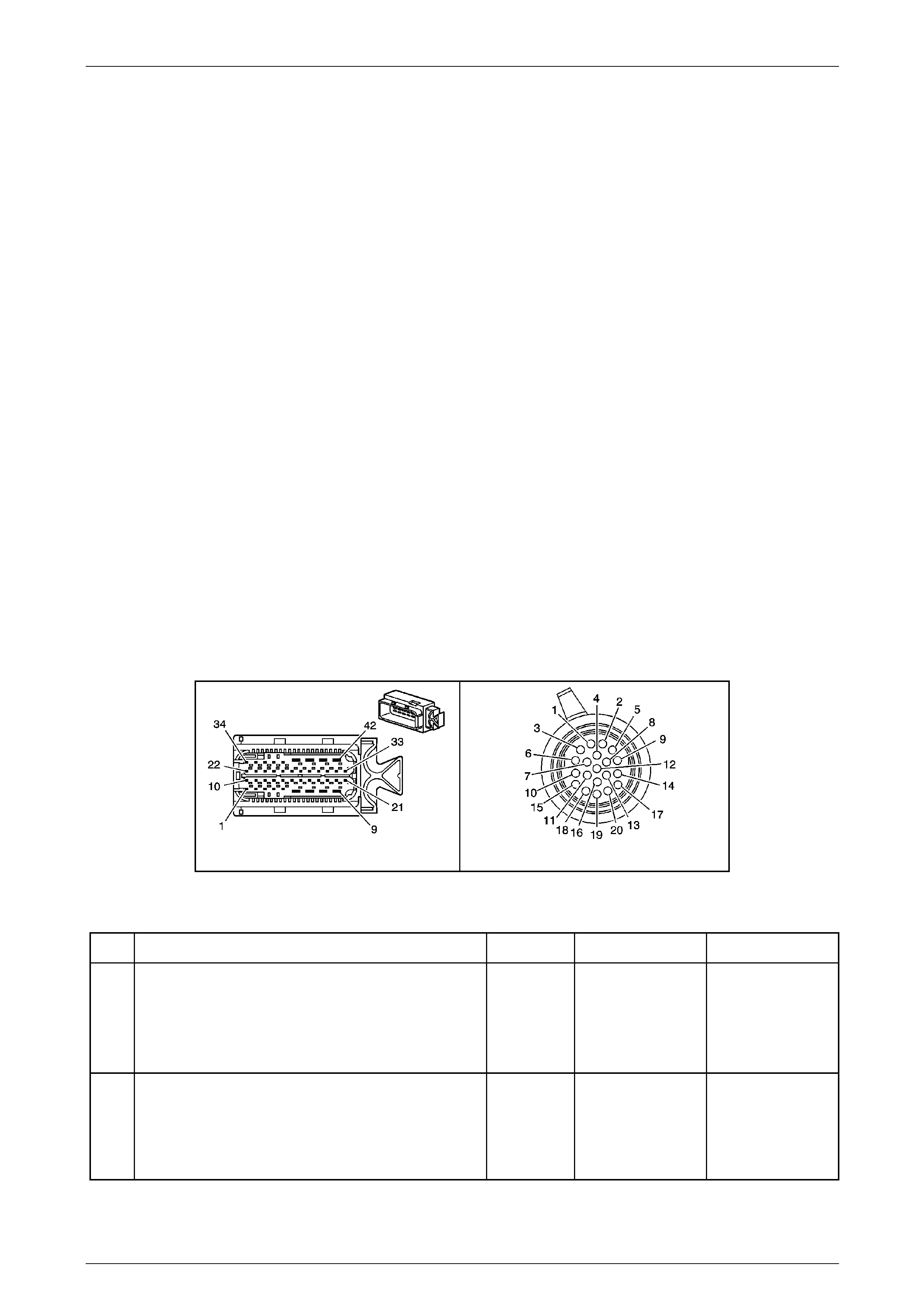
Automatic Transmission – 5L40-E – Electrical Diagnosis Page 7E – 113
Page 7E2 – 113
Conditions for Clearing the MIL / DTC
• Tech 2 can clear the DTC.
• The TCM clears the DTC from its memory (history DTC) if the vehicle completes 40 warm-up cycles without a non-
emission related DTC occurring.
• The TCM cancels the default actions when the ignition is off long enou gh to power down the TCM.
• The TCM turns off the MIL after the sixth consecutive drive trip in which the TCM does not send a MIL illumination
request.
Diagnostic Aids
Rapid fluctuations in line pressure may set DTC P0742.
The customer may notice an engine stalling condition.
Test Description
The following number(s) refer to the step number(s) on the diagnostic table.
2 This step inspects that the transmission fluid to ensure that it is at the proper level.
3 This step verifies that the TCC engages when commanded on, by Tech 2.
4 & 5 Checks for short to ground or open circuit in solenoid sup pl y circuit.
6 Checks for short to voltage on the solenoid supply circuit.
7 Checks for short to ground on the solenoid suppl y circ uit.
NOTE
• Refer to Figures 7E2–5 and 7E2–6 for 5L40 –
E automatic transmission electrical circuits.
• For procedures on checking wiring faults,
refer to Section 12P Wiring Diagrams.
A112-T68 – X1 X121-X1
Figure 7E2 – 42
DTC P0742 – TCC System Stuck ON
Step Action Value(s) Yes No
1
Has the Diagnostic System Check – Automatic
Transmission been com pleted?
–
Go to Step 2
Go to
2.3 Diagnostic
System Check –
Automatic
Transmission
in this Section.
2
1 Perform the transmission fluid checking
procedure. Refer to Section 7E4 Automatic
Transmission On-Vehicle Servicing.
Did you perform the fluid checking procedure and is the
fluid level now OK?
–
Go to Step 3 –

Automatic Transmission – 5L40-E – Electrical Diagnosis Page 7E – 114
Page 7E2 – 114
Step Action Value(s) Yes No
3
1 Connect the Tech 2 to the DLC.
2 Ignition ON, engine OFF.
3 Record the DTC/s in both the TCM and the ECM.
4 Clear DTCs.
5 Select TCC Duty Cycle and TCC Slip Speed from
Tech 2 data list parameters.
6 Drive the vehicle in D5 with the throttle angle
greater than 15 percent. Allow the transmission to
shift to 5th gear.
7 Using Tech 2, command the TCC PW M solenoid
valve ON.
While the TCC Duty Cycle is 0 percent, does Tech 2
display a TCC slip sp eed within the specified range?
–20 to
+20 rpm
Go to Step 4
Go to Intermittent
Conditions, in
Section 6C1–2
Engine
Management – V6 –
Diagnostics.
4
1 Ignition OFF.
2 Disconnect transmission wiring harness connector
X121–X1 from the transmission 20-way
connector.
3 Ignition ON.
4 Using a digital voltmeter, measure volta ge
between transmission wiring harness connector
X121–X1, terminal X1–17 and ground.
Is voltage reading greater than the specified value?
6.0 volts
Go to Step 6 Go to Step 5
5
1 Ignition OFF.
2 Disconnect transmission wiring harness connector
A112 – T68 from the TCM.
3 Using a digital ohmmeter, check wiring for open
circuit or short to ground condition between
transmission wiring harness TCM connector
A112 – T68, terminal X1–8 and transmission
connector X121–X1, terminal X1–1 7.
Does either check indicate an open circuit or short to
ground in the wiring?
–
Repair open or short
to ground in relevant
circuit.
Go to Step 17 Go to Step 11
6
1 Turn ignition OFF .
2 Disconnect transmission wiring harness connector
A112 – T68 from TCM.
3 Turn ignition ON.
4 Using a digital voltmeter, measure volta ge
between transmission wiring harness TCM
connector A112 – T68, terminal X1–4 an d ground.
Is voltage reading less than the specified val ue?
0.3 volts
Go to Step 7 Go to Step 8
7
1 Turn ignition OFF .
2 Using a digital ohmmeter, measure resistance
between transmission wiring harness TCM
connector A112 – T68, terminal X1–4 an d ground.
Is resistance reading greater than the specified valve?
500 kΩ
Go to Step 9 Go to Step 12

Automatic Transmission – 5L40-E – Electrical Diagnosis Page 7E – 115
Page 7E2 – 115
Step Action Value(s) Yes No
8
1 Using a digital voltmeter, check wiring for short to
voltage condition between transmission wiring
harness TCM connector A112 – T68, terminal
X1–4 and connector X121–X1, terminal X1–20.
Does check indicate a short to voltage in the wiring?
– Repair short to
voltage in relevant
circuit.
Go to Step 17 –
9
1 Reinstall transmission wiring harness connector
X121–X1 to transmission 20-way connector.
2 Using a digital ohmmeter, measure resistance
between transmission wiring harness TCM
connector A112 – T68, terminals X1–4 and X1–8.
Is resistance reading within the specified valve?
10.0–11.5 Ω
@ 20° C
11.8-13.6Ω
@ 70° C Go to Step 10
If reading is more
than specified, go to
Step 13.
If reading is less
than specified, go to
Step 14.
10
1 Connect a fused jumper wire between vehicle
battery supply and transmission wiring harness
TCM connector A112 – T68, terminal X1–8.
2 Connect a second fused jumper wire to vehicle
ground.
3 Cyclically contact transmission wiring harnes s
TCM connector A112 – T68, terminal X1–4 with
second fused jumper wire and carefully listen for
the TCC PWM solenoid clicking.
Does solenoid click as jumper wire is connected and
disconnected?
–
Go to Step 11
Replace faulty TCC
PWM solenoid.
Refer to Section
7E4 Automatic
Transmission On-
Vehicle Servicing.
11
1 Replace TCM. Refer to Section 7E4 Automatic
Transmission – 5L40-E – On-V ehicle Servicing for
replacement procedures.
Is the replacement complete?
–
Go to Step 17 –
12
1 Using a digital voltmeter, check wiring for short to
ground condition between transmission wiring
harness TCM connector A112 – T68, terminal X1–
4 and transmission wiring harness connector
X121–X1, terminal X1–20.
Does check indicate a short to ground in the wiring?
– Repair short to
voltage in relevant
circuit.
Go to Step 17 –
13
1 Using a digital voltmeter, check wiring for open
circuit condition between transmission wiring
harness TCM connector A112 – T68, terminal
X1–4 and transmission wiring harness connector
X121–X1, terminal X1–20.
Does check indicate an open circuit or hig h resistance
in the wiring?
– Repair caus e of
open circuit or high
resistance in
relevant circuit.
Go to Step 17 Go to Step 15
14
1 Using a digital voltmeter, check wiring for internal
short circuit condition bet ween transmission wirin g
harness TCM connector A112 – T68 and
transmission wiring harness connector X121–X1
connector, circuits 1525 and 418.
Does check indicate an internal short circuit condition in
the wiring?
– Repair caus e of
internal short circuit
condition in circuits
1525 and 418.
Go to Step 17 Go to Step 15

Automatic Transmission – 5L40-E – Electrical Diagnosis Page 7E – 116
Page 7E2 – 116
Step Action Value(s) Yes No
15
1 Remove transmission fluid pan, refer to Section
7E4 Automatic Transmission On-Vehicle
Servicing, for the procedure.
2 Inspect transmission internal wiring harness for
any sign of damage.
Is transmission internal wiring harness OK?
–
Go to Step 16
Replace
transmission
internal wiring
harness. Refer to
Section 7E4
Automatic
Transmission On-
Vehicle Servicing.
Go to Step 17
16
1 With the fluid pan removed, inspect the front
control valve body (refer to Section 7E4
Automatic Transmission On-Vehicle Servicing) for
the following conditions:
• TCC PWM solenoid valve (352)
mechanically stuck on due to sediment.
• TCC regulator appl y valve (34 8) stuck due to
sediment.
Did you find any of the above conditions?
– Repair or replace
components as
necessary.
Go to Step 17 Go to Step 17
17
1 Perform the following operations to verify the
repair:
• Select ‘DTC’ on Tech 2.
• Select ‘Clear Info’.
2 Operate the vehicle under the following
conditions:
• Drive the vehicle in D5 with the throttle
position at 15 – 90% and a road speed of
more than 15 km/h.
• The engine torque is between 80 and 450
N.m.
• The TFT is 20 to 130° C.
• Check that the TCC slip speed is 130 –
1,500 rpm for 2.5 seconds.
3 Drive the vehicle as noted in Steps 1 to 3 ab ove,
to cycle the TCC a second time.
Has the test run and passed?
–
Go to Step 18 Go to Step 2
18
1 On Tech 2, observe the stored information,
capture information and DTC information.
Does Tech 2 display any DTCs that you have not
diagnosed?
– Go to the Vehicle
System Diagnostics
that belongs to the
undiagnosed D TC. System OK
When all diagnosis and repairs are completed, clear all DTCs and verify correct operation

Automatic Transmission – 5L40-E – Electrical Diagnosis Page 7E – 117
Page 7E2 – 117
DTC P0748 – Pressure Control Solenoid Circuit Fault
Circuit Description
The Pressure Control (PC) solenoid assembly is a precision electronic pressure regulator that controls transmission line
pressure based on current flow through its coil windings. The magnetic field produced by the coil moves the solenoid’s
internal valve which varies pressure to the p r essure regul ator valve. The Transmission Control Module (TCM) controls
the PC solenoid assembly by applying a varying amount of current to the solenoid. The applied current can vary from
0.1 to 1.1 amps. Low current (0.1 amp) indicates high li ne pressure. High current (1.1 amps) indicates lo w line pressure.
An internal current monitor within the T CM provid es feedback to determine actual PC solenoid assembly current draw.
The TCM controls the PC solenoid assembly on a positive duty cycle at a fixed frequency. T he high (positive) side of the
PC solenoid electrical circuit at the T CM (terminal X1-3) controls the PC solenoid assembly operation. The TCM
(terminal X1-29) provides a groun d path for the circuit, monitors average current and continuously varies the PC solenoid
valve duty cycle to maintain the correct average current flowing thr ough the PC solenoid assembly.
The duty cycle of the PC solenoid assembly is expressed as a percentage of energised ON time. Zero percent indicates
zero ON time (non-energised) or no current flow. Approximately 60% at idle indicates maximum ON time (energised) or
high current flow. The TCM determines the appropriate line pressure for a given load by comparing various inputs
including throttle position, transmission fluid temperature and gear state.
If the TCM detects a continuous open, short to voltage or short to ground in the PC solenoid circuit, then DTC P0748
sets, which is a type ‘C’ DTC.
Conditions for Running the DTC
• Ignition voltage is bet ween 8.0 and 18. 0 volts.
• The engine is running.
Conditions for Setting the DTC
• The PC solenoid assembly feedback circuit indicates a continuous open or short to ground for greater than 1.2
seconds.
Action Taken When the DT C Sets
• The TCM does not request the Powertrain Interface Module (PIM) to illuminate the Check Powertrain Malfunction
Indicator Lamp (MIL).
• The TCM records the operating conditions when the ‘Conditions for Setting the DTC’ have been met. The T CM
stores this information as a failure record.
• The TCM also turns off the pressure control sole noid (causing maximum line pressure).
• The TCM freezes the transmission adaptive learning function.
• The TCM stores DTC P0748 into TCM history.
Conditions for Clearing the DTC
• Tech 2 can clear the DTC.
• The TCM clears the DTC from its memory (history DTC) if the vehicle completes 40 warm-up cycles without a non-
emission related DTC occurring.
• The TCM cancels the default actions when the ignition is off long enou gh to power down the TCM.
Test Description
The following number(s) refer to the step number(s) on the diagnostic table.
2 This step verifies the ability of the T CM command of the PC solenoid valve.
3 Checks for short to voltage on the solenoid signal circuit.
4 Checks for short to ground on the solenoid signa l circuit.
5 Checks for open circuit of the solenoid signal circuit.
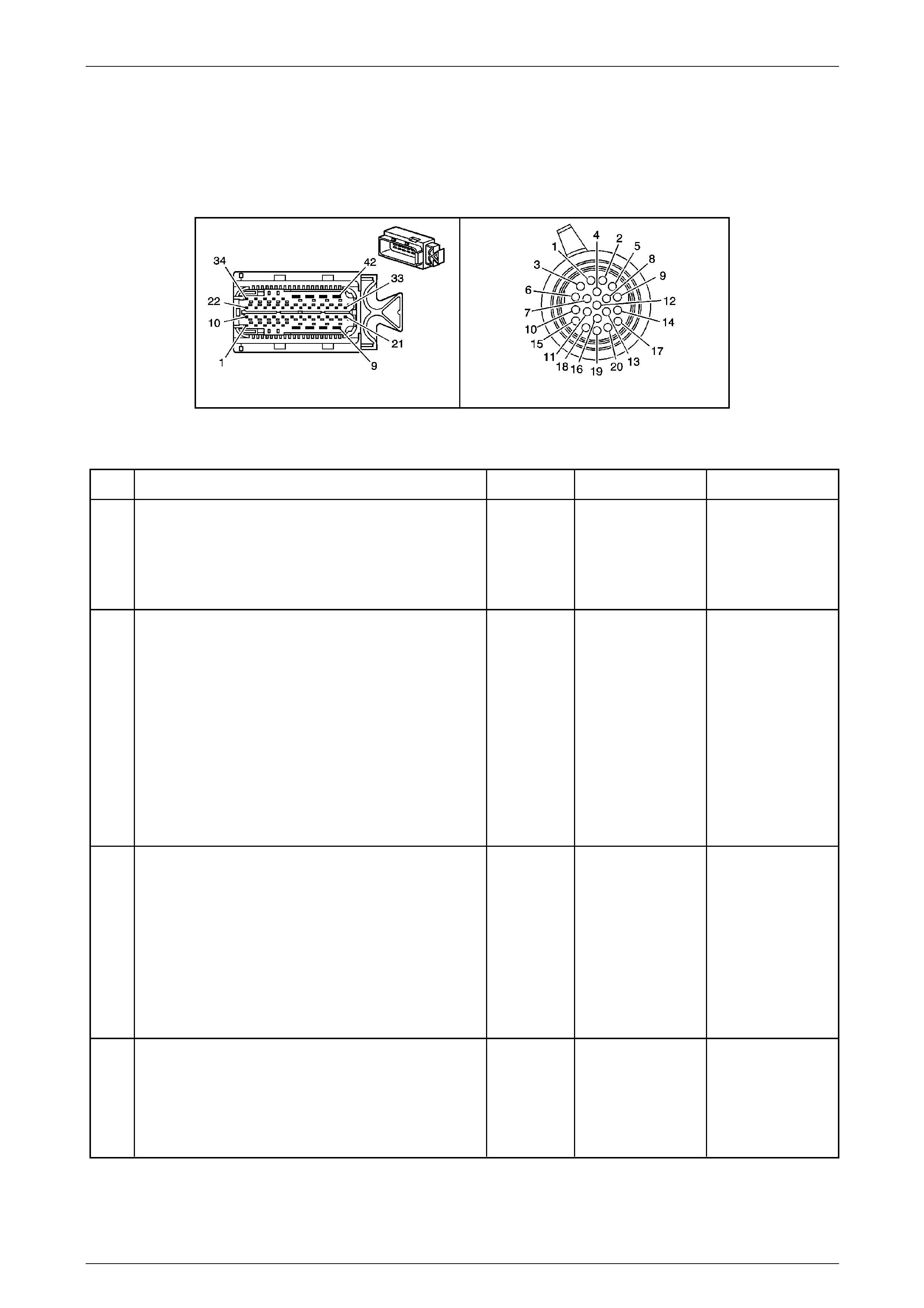
Automatic Transmission – 5L40-E – Electrical Diagnosis Page 7E – 118
Page 7E2 – 118
NOTE
• Refer to Figures 7E2–5 and 7E2–6 for 5L40 –
E automatic transmission electrical circuits.
• For procedures on checking wiring faults,
refer to Section 12P Wiring Diagrams.
A112-T68 – X1 X121-X1
Figure 7E2 – 43
DTC P0748 – Pressure Cont ro l Solenoid Circuit Fault
Step Action Value(s) Yes No
1
Has the Diagnostic System Check – Automatic
Transmission been com pleted?
–
Go to Step 2
Go to
2.3 Diagnostic
System Check –
Automatic
Transmission
in this Section.
2
1 Connect the Tech 2 to the DLC.
2 Ignition ON, engine OFF.
3 Clear DTCs.
4 Start the engine.
5 Using Tech 2, increase and decrease the PC
solenoid amperage and observe the Tech 2
display.
Does the PC Sol. Actual Current reading vary from the
PC Sol. Ref. Current by more than the specified
amount?
0.05 Amps
Go to Step 3
Go to Intermittent
Conditions, in
Section 6C1–2
Engine
Management – V6 –
Diagnostics.
3
1 Ignition OFF.
2 Disconnect transmission wiring harness connector
A112 – T68 from the TCM.
3 Ignition ON.
4 Using a digital voltmeter, measure volta ge
between transmission wiring harness TCM
connector A112 – T68, terminal X1–3 an d ground.
Is voltage reading less than specified?
0.3 volts
Go to Step 4 Go to Step 8
4
1 Ignition OFF.
2 Using a digital ohmmeter, measure resistance
between transmission wiring harness TCM
connector A112 – T68, terminal X1–3 an d ground.
Is resistance reading greater than specified?
500 kΩ
Go to Step 5 Go to Step 10

Automatic Transmission – 5L40-E – Electrical Diagnosis Page 7E – 119
Page 7E2 – 119
Step Action Value(s) Yes No
5
1 Using a digital ohmmeter, measure resistance
between transmission wiring harness TCM
connector A112 – T68, terminals X1–3 (PCS high
control) and X1–29 (PCS low control).
Is resistance reading within specification?
3.5 – 4.6 Ω
@ 20° C
4.2 – 5.5 Ω
@ 70 ° C Go to Step 6
If reading is more
than specified, go to
Step 13.
If reading is less
than specified, go to
Step 14.
6
1 Connect a fused jumper wire between vehicle
battery supply and transmission wiring harness
TCM connector A112 – T68, terminal X1–3.
2 Connect a second fused jumper wire to vehicle
ground.
3 Contact second fused jumper wire to transmission
wiring harness T CM connector A112 – T68,
terminal X1–4 and carefull y listen for TCC PWM
solenoid clicking.
Does solenoid click as jumper wire is connected?
–
Go to Step 7
PC PWM solenoid
assembly faulty,
replace solenoid.
Refer to Section
7E4, 3.5 Pressure
Control (PC)
Solenoid Assembly
in this Service
Information.
Go to Step 15
7
1 Replace TCM. Refer to Section 7E4 Automatic
Transmission – 5L40-E – On-V ehicle Servicing for
replacement procedures.
Is the replacement complete?
–
Go to Step 15 –
8
1 Using a digital voltmeter, check wiring for short to
voltage condition between transmission wiring
harness TCM connector A112 – T68, terminal X1–
3 and transmission wiring harness connector
X121–X1, terminal X1–13.
2 Also check between transmission wiring harness
TCM connector A112 – T68, termina l X1–29 and
transmission wiring harness connector X121–X1,
terminal X1–8.
Does either check indicate a short to voltage in the
wiring?
–
Repair short to
voltage in relevant
circuits.
Go to Step 15 Go to Step 9
9 1 Remove transmission fluid pan and filter.
2 Inspect transmission internal wiring harness for
any sign of damage.
Is transmission internal wiring harness OK?
–
PC PWM solenoid
assembly faulty,
replace solenoid.
Refer to Section
7E4 On-Vehicle
Servicing.
Go to Step 15
Replace
transmission
internal wiring
harness. Refer to
Section 7E4 On-
Vehicle Servicing.
Go to Step 15
10
1 Disconnect transmission wiring harness connector
X121–X1 from transmission 20-way connector.
2 Using a digital ohmmeter, measure resistance
between transmission wiring harness TCM
connector A112 – T68, terminal X1–3 an d ground.
Is resistance reading greater than specified?
500 kΩ
Go to Step 11 Go to Step12
11
1 Using a digital voltmeter, check wiring for short to
ground condition between transmission wiring
harness TCM connector A112 – T68, terminal X1–
29 and transmission wiring harness con nector
X121–X1, terminal X1–8.
Does check indicate a short to ground in the wiring?
– Repair short to
ground in relevant
circuit.
Replace faulty PCS
PWM solenoid
assembly. Refer to
Section 7E4 On-
Vehicle Servicing.
Go to Step 15

Automatic Transmission – 5L40-E – Electrical Diagnosis Page 7E – 120
Page 7E2 – 120
Step Action Value(s) Yes No
12
1 Using a digital voltmeter, check wiring for short to
ground condition between transmission wiring
harness TCM connector A112 – T68, terminal X1–
3 and transmission wiring harness connector
X121–X1, terminal X1–13.
Does check indicate a short to ground in the wiring?
– Repair short to
ground in relevant
circuit.
Go to Step 15 –
13
1 Using a digital voltmeter, check wiring for open
circuit condition between transmission wiring
harness TCM connector A112 – T68, terminal X1–
3 and transmission wiring harness connector
X121–X1, terminal X1–13.
2 Also check between transmission wiring harness
TCM connector A112 – T68, terminal X1–8 and
transmission wiring harness connector X121–X1,
terminal X1–29.
Does either check indicate an open circuit or high
resistance in the wiring?
– Repair caus e of
open circuit or high
resistance in
relevant circuit.
Go to Step 15 Go to Step 9
14
1 Using digital voltmeter check for internal shor t
circuit condition between transmission wiring
harness TCM connector A112 – T68 and
transmission wiring harness connector X121–X1,
circuits 1228 and 1229.
Does check indicate an internal short circuit condition in
the wiring?
– Repair caus e of
internal short circuit
condition in relevant
circuits.
Go to Step 15 Go to Step 9
15
1 Perform the following operation to verify the
repair:
• Select DTC on Tech 2.
• Select Clear info.
2 Operate the vehicle under the following
conditions:
• Start and idle the engine.
• System voltage must be at least 11 volts.
Has the test run and passed?
–
Go to Step 16 Go to Step 2
16
1 On Tech 2, observe the stored information,
capture information and DTC information.
Does Tech 2 display any DTCs that you have not
diagnosed?
– Go to the Vehicle
System Diagnostics
that belongs to the
undiagnosed D TC. System OK
When all diagnosis and repairs are completed, clear all DTCs and verify correct operation

Automatic Transmission – 5L40-E – Electrical Diagnosis Page 7E – 121
Page 7E2 – 121
DTC P0751 – 1–2 Shift Solenoid Stuck On
Circuit Description
The 1–2 Shift Solenoid (SS) valve is a normally closed exhaust valve that, in conj unction with the 2–3 Shift Solenoid (SS)
valve, allows four different shifting combinations. The 1–2 SS valve is attached to the control valve body, within the
transmission.
The Transmission Control Module (TCM) monitors the actual gear ratio and compares the actual gear ratio with the
commanded gear ratio. DTC P0751 sets un der the two conditions:
• A stuck on 1–2 SS valve.
• A stuck on 1–2 shift valve.
If the TCM detects a 2–2–3–3–3 shift pattern, then DTC P0751 sets, which is a type ‘B’ DTC.
Conditions for Running the DTC
• Ignition voltage is bet ween 8.0 and 18. 0 volts.
• Engine speed is between 450 and 6,800 rpm for at least 5 seconds.
• The following DTCs are not set:
• P0120 – Throttle Position Signal (No valid GMLAN signal)
• P0716 or P0717 – Transmission Input Sp eed Sensor.
• P0722 or P0723 – Transmission Output Speed Sensor.
• P0742 – TCC System Stuck ON.
• P0973, P0974, P0976, P0977, P0979 or P0980 – Shift Solenoids Electrical.
• P01815, P1820, P1822, P1823, P182 5 or P1826 – Transmission Manu al Shift Shaft Switch Assembly.
• P02637 – Engine Torque Signal Circuit – No Valid GMLAN Signal
• The transmission fluid temperature is between 20 to 130 degrees Celsius.
• The transmission manual shift shaft switch assembly does not indicate Park, Neutral or Reverse.
• The input shaft speed is 200 – 6 800 rpm.
• The output shaft speed is greater than 100 rpm
• The throttle position is 10 percent or more.
Conditions for Setting the DTC
Both of the following conditions must occur twice during the same ignition cycle.
• The TCM commands 1st gear when the engine torque is from 40 – 450 N.m and the re ported gear ratio is
2.16:1 – 2.27:1 for 1.25 seconds.
• The TCM commands 4th or 5th gear when the engine torque is from 36 – 450 N.m and the reported g ear ratio
is 1.56:1 – 1.64:1 for 5 seconds.

Automatic Transmission – 5L40-E – Electrical Diagnosis Page 7E – 122
Page 7E2 – 122
Action Taken When the DT C Sets
• The TCM requests the Powertrain Interface Module (PIM) to illumin ate the Check Powertrain Malfunction Indicator
Lamp (MIL) in the instrument cluster during the second consecutive trip in which the ‘Conditions for Setting the
DTC’ have been met.
• At the time of the first failure, the TCM records the operating conditions when the ‘Conditions for Setting the DTC’
have been met. The TCM stores this information as a failure record.
• At the time of the second failure, the ECM records the operating conditions when the ‘Conditions for Set ting the
DTC’ have been met. The ECM stores this information as a freeze frame.
• The TCM also turns off the pressure control sole noid (causing maximum line pressure).
• The TCM freezes the transmission adaptive learning function.
• The TCM stores DTC P0751 into TCM history during the second consecutive trip in which the ‘Conditions for
Setting the DTC’ have been met.
Conditions for Clearing the MIL / DTC
• Tech 2 can clear the DTC.
• The TCM clears the DTC from its memory (history DTC) if the vehicle completes 40 warm-up cycles without a non-
emission related DTC occurring.
• The TCM cancels the default actions when the ignition is off long enou gh to power down the TCM.
• The PIM turns off the Check Powertrain MIL after the sixth consecutive drive trip in which the TCM does not send a
Check Powertrain MIL illumination request.
Diagnostic Aids
If you clear DTC P0751 and then cannot reset DTC P0751, the following conditions may exist:
• Fluid contamination
• Plugged / blocked fluid circuits
• Restricted fluid circuits
Refer to Shift Solenoid Valve State and Gear Ratio chart in
1.4 Electronic Component Description – Shift Solenoid (SS) Valves in this Section.
Test Description
The following number(s) refer to the step number(s) on the diagnostic table.
3 This step verifies a 2–2–3–3– 3 shift pattern.
4 Checks for short to ground or open circuit in solenoid supply circuit.
5 Checks for short to voltage on the solenoid supply circuit.
6 Checks for short to ground on the solenoid suppl y circ uit.
7 Checks for open circuit in transmission internal wiring harness.
17 This step tests for a mechanical or hydraulic condition causing the 1–2 SS valve to be stuck on, or the circuit to be
released.

Automatic Transmission – 5L40-E – Electrical Diagnosis Page 7E – 123
Page 7E2 – 123
NOTE
• Refer to Figures 7E2–5 and 7E2–6 for 5L40 –
E automatic transmission electrical circuits.
• For procedures on checking wiring faults,
refer to Section 12P Wiring Diagrams.
A112-T68 – X1 X121-X1
Figure 7E2 – 44
DTC P0751 – 1–2 Shift Solenoi d Stuck On
Step Action Value(s) Yes No
1
Has the Diagnostic System Check – Automatic
Transmission been com pleted?
–
Go to Step 2
Go to
2.3 Diagnostic
System Check –
Automatic
Transmission
in this Section.
2
1 Perform the transmission fluid checking
procedure. Refer to Section 7E4 Automatic
Transmission – 5L40-E – On-V ehicle Servicing.
Did you perform the fluid checking procedure and is
level now OK?
–
Go to Step 3 –
3
1 Connect the Tech 2 to the DLC.
2 Ignition ON, engine OFF.
3 Clear DTCs.
4 Using the Tech 2 Snapshot feature, record the
commanded gear and gear ratio.
5 Drive the vehicle in D5 to obtain 1–2, 2–3, 3–4
and 4–5 shifts with a throttle position angle of 10%
or greater.
Are the commanded gear and gear rati o within the
specified range?
1st
2.16:1–2.27:1
4th / 5th
1.56:1–1.64:1
Go to Step 4
Go to Intermittent
Conditions, in
Section 6C1–2
Engine
Management – V6
Diagnostics.
4
1 Ignition OFF.
2 Disconnect transmission wiring harness connector
X121–X1 from transmission 20-way connector.
3 Ignition ON.
4 Using a digital voltmeter, measure volta ge
between transmission wiring harness connector
X121–X1, terminal X1–17 and ground.
Is voltage reading greater than specified?
More than 6.0
Volts
Go to Step 5 Go to Step 10

Automatic Transmission – 5L40-E – Electrical Diagnosis Page 7E – 124
Page 7E2 – 124
Step Action Value(s) Yes No
5
1 Ignition OFF.
2 Disconnect transmission wiring harness connector
A112 – T68 from the TCM.
3 Ignition ON.
4 Using a digital voltmeter, measure volta ge
between transmission wiring harness TCM
connector A112 – T68, terminal X1–30 a nd
ground.
Is voltage reading less than specified?
Less than
0.3 volts
Go to Step 6 Go to Step 12
6
1 Ignition OFF.
2 Using a digital ohmmeter, measure resistance
between transmission wiring harness TCM
connector A112 – T68, terminal X1–30 a nd
ground.
Is resistance reading greater than specified?
More than
500 kΩ
Go to Step 7 Go to Step 13
7
1 Reconnect transmission wiring harness connector
X121–X1 to transmission 20-way connector.
2 Using a digital ohmmeter, measure resistance
between transmission wiring harness TCM
connector A112 – T68, terminals X1–30 a nd
X1–8.
Is resistance reading within specification?
15 – 17.0Ω
@ 20° C
17.9 – 20.3Ω
@ 70 ° C
Go to Step 8
If reading is more
than specified, go to
Step 15.
If reading is less
than specified, go to
Step 14.
8
1 Connect a fused jumper wire between vehicle
battery supply and transmission wiring harness
TCM connector A112 – T68, terminal X1–8.
2 Connect a second fused jumper wire to vehicle
ground.
3 Cyclically contact second fused jumper wire to
transmission wiring harness TCM connector
A112 – T68, terminal X1–30 and carefully listen
for 1–2 shift solenoid clicking.
Does solenoid click as jumper wire is connected?
–
Go to Step 9
Replace faulty
1–2 shift solenoid.
Refer to Section
7E4 Automatic
Transmission –
5L40-E – On-
Vehicle Servicing.
Go to Step 18
9
1 Replace TCM. Refer to Section 7E4 Automatic
Transmission – 5L40-E – On-V ehicle Servicing for
replacement procedures.
Is the replacement complete?
–
Go to Step 18 –
10
1 Using a digital ohmmeter, check wiring for short to
ground condition between transmission wiring
harness TCM connector A112 – T68, terminal
X1–8 and transmission wiring harness connector
X121–X1, terminal X1–17.
Does check indicate a short to ground in the wiring?
– Repair short to
ground in relevant
circuit.
Go to Step 18 Go to Step 11
11
1 Using a digital ohmmeter, check wiring for open
circuit condition between transmission wiring
harness TCM connector A112 – T68, terminal
X1–8 and transmission wiring harness connector
X121–X1, terminal X1–17.
Does check indicate an open circuit or hig h resistance
in the wiring?
– Repair cause o f
open circuit or high
resistance in
relevant circuit.
Go to Step 18 Go to Step 9
12
1 Using a digital voltmeter, check wiring for short to
voltage condition between transmission wiring
harness TCM connector A112 – T68, terminal
X1–30 and transmission wiring harness connector
X121–X1, terminal X1–14.
Does check indicate a short to voltage in the wiring?
– Repair short to
voltage in relevant
circuit.
Go to Step 18 –

Automatic Transmission – 5L40-E – Electrical Diagnosis Page 7E – 125
Page 7E2 – 125
Step Action Value(s) Yes No
13
1 Using a digital ohmmeter, check wiring for short to
ground condition between transmission wiring
harness TCM connector A112 – T68, terminal
X1–30 and transmission wiring harness connector
X121–X1, terminal X1–14.
Does check indicate a short to ground in the wiring?
– Repair short to
ground in relevant
circuit.
Go to Step 18 –
14
1 Using a digital voltmeter, check wiring for internal
short circuit condition bet ween transmission wirin g
harness TCM connector A112 – T68 and
transmission wiring harness connector X121–X1,
circuits 1525 and 1222.
Does check indicate an internal short circuit condition in
the wiring?
– Repair cause o f
internal short
circuit condition in
relevant circuits.
Go to Step 18 Go to Step 9
15
1 Using a digital ohmmeter, check wiring for open
circuit condition between transmission wiring
harness TCM connector A112 – T68, terminal
X1–30 and transmission wiring harness connector
X121–X1, terminal X1–14.
Does check indicate an open circuit or hig h resistance
in the wiring?
– Repair cause o f
open circuit or high
resistance in
relevant circuit.
Go to Step 18 Go to Step 16
16 1 Remove transmission fluid pan and filter, refer to
Section 7E4 Automatic Tr ansmission – 5L40-E –
On-Vehicle Servicing.
2 Inspect transmission internal wiring harness for
any sign of damage.
Is transmission internal wiring harness OK?
–
Replace faulty 1–2
shift solenoid, refer
to Section 7E4
Automatic
Transmission –
5L40-E – On-
Vehicle Servicing.
Go to Step 18
Replace
transmission
internal wiring
harness. Refer to
Section 7E4
Automatic
Transmission –
5L40-E – On-
Vehicle Servicing.
Go to Step 18
17
1 With the fluid pan removed, inspect the rear
control valve body for the following conditions:
• 1–2 SS valve mechanicall y s t uck on.
• 1–2 SS valve O-ring worn or damaged.
• 1–2 shift valve stuck in the released
position.
Refer to Section 7E4 Automatic Transmission –
5L40-E – On-Vehicle Servicing.
Did you find any of the above conditions?
–
Repair or replace
components as
necessary.
Go to Step 18 Go to Step 18
18
1 Perform the following operation to verify the
repair.
• Select DTC on Tech 2.
• Select Clear info.
2 Operate the vehicle under the following
conditions:
• Drive the vehicle in D5 with a throttle angle
of 10% or more
• Allow the transmission to shift through all
gears at least twice.
• Monitor the commanded gear and ge ar
ratios. The actual gear ratios must match the
commanded gears for 1 second, for all
gears.
Has the test run and passed?
–
System OK Go to Step 2
When all diagnosis and repairs are completed, clear all DTCs and verify correct operation

Automatic Transmission – 5L40-E – Electrical Diagnosis Page 7E – 126
Page 7E2 – 126
DTC P0752 – 1–2 Shift Solenoid Stuck Off
Circuit Description
The 1–2 Shift Solenoid (SS) valve is a normally closed exhaust valve that, in conj unction with the 2–3 Shift Solenoid (SS)
valve, allows four different shifting combinations. The 1–2 SS valve is attached to the control valve body, within the
transmission.
The Transmission Control Module (TCM) monitors the actual gear ratio and compares the actual gear ratio with the
commanded gear ratio. DTC P0752 sets un der the two conditions:
• A stuck off 1–2 SS valve.
• A stuck off 1–2 shift valve.
If the TCM detects a 1–1–4–4–5 shift pattern, then DTC P0752 sets, which is a type ‘B’ DTC.
Conditions for Running the DTC
• Ignition voltage is bet ween 8.0 and 18. 0 volts.
• Engine speed is between 450 and 6,800 rpm for at least 5 seconds.
• The following DTCs are not set:
• P0120 – Throttle Position Signal (No valid GMLAN signal)
• P0716 or P0717 – Transmission Input Sp eed Sensor.
• P0722 or P0723 – Transmission Output Speed Sensor.
• P0742 – TCC System Stuck ON.
• P0973, P0974, P0976, P0977, P0979 or P0980 – Shift Solenoids Electrical.
• P01815, P1820, P1822, P1823, P182 5 or P1826 – Transmission Manu al Shift Shaft Switch Assembly.
• P2637 – Engine Torque Sign al Circuit – No Valid GMLAN Signal
• The transmission fluid temperature is between 20 to 130° C.
• The transmission manual shift shaft switch assembly does not indicate Park, Neutral or Reverse.
• The input shaft speed is 200 – 6,800 rpm.
• The output shaft speed is more than 100 rpm.
Conditions for Setting the DTC
Both of the following conditions must occur twice during the same ignition cycle:
• The TCM commands 2nd gear for more than 1 second when the engine torque is from 32 – 450 N.m and the
reported gear ratio is 3.33:1 – 3.50:1 for 2 seconds, with a throttle position of 10% or more.
• The TCM commands 3rd gear for more than 1 second when the engine torque is from 32 – 450 N.m and the
reported gear ratio is 1.56:1 – 1.64:1 for 5 seconds.

Automatic Transmission – 5L40-E – Electrical Diagnosis Page 7E – 127
Page 7E2 – 127
Action Taken When the DT C Sets
• The TCM requests the Powertrain Interface Modu le to illuminate the Check Powertrain Malfunction Indicator Lamp
(MIL) in the instrument cluster during the second consecutive trip in which the ‘C onditions for Setting the DTC’ have
been met.
• At the time of the first failure, the TCM records the operating conditions when the ‘Conditions for Setting the DTC’
have been met. The TCM stores this information as a failure record.
• At the time of the second failure, the ECM records the operating conditions when the ‘Conditions for Set ting the
DTC’ have been met. The ECM stores this information as a freeze frame.
• The TCM inhibits 3–2 downshifts if the vehicle speed is less than 8 km/h.
• The TCM also turns off the pressure control sole noid (causing maximum line pressure).
• The TCM freezes the transmission adaptive learning function.
• The TCM stores DTC P0752 into TCM history during the second consecutive trip in which the ‘Conditions for
Setting the DTC’ have been met.
Conditions for Clearing the MIL / DTC
• Tech 2 can clear the DTC.
• The TCM clears the DTC from its memory (history DTC) if the vehicle completes 40 warm-up cycles without a
non-emission related DTC occurring.
• The TCM cancels the default actions when the ignition is off long enou gh to power down the TCM.
• The PIM turns off the Check Powertrain MIL after the sixth consecutive drive trip in which the TCM does not send a
Check Powertrain MIL illumination request.
Diagnostic Aids
If you clear DTC P0752 and then cannot reset DTC P0752, the following conditions may exist:
• Fluid contamination.
• Plugged / blocked fluid circuits.
• Restricted fluid circuits.
Refer to Shift Solenoid Valve State and Gear Ratio chart in
1.4 Electronic Component Description – Shift Solenoid (SS) Valves in this Section.
Test Description
The following number(s) refer to the step number(s) on the diagnostic table.
3 This step verifies a 1–1–4–4– 5 shift pattern.
4 Checks for short to ground or open circuit in solenoid supply circuit.
5 Checks for short to voltage on the solenoid supply circuit.
6 Checks for short to ground on the solenoid suppl y circ uit.
7 Checks for open circuit in transmission internal wiring harness.
17 This step tests for a mechanical or hydraulic condition causing the 1–2 SS valve to be stuck in the off position, or
the circuit to be applied.

Automatic Transmission – 5L40-E – Electrical Diagnosis Page 7E – 128
Page 7E2 – 128
NOTE
• Refer to Figures 7E2–5 and 7E2–6 for 5L40 –
E automatic transmission electrical circuits.
• For procedures on checking wiring faults,
refer to Section 12P Wiring Diagrams.
A112-T68 – X1 X121-X1
Figure 7E2 – 45
DTC P0752 – 1–2 Shift Solenoi d Stuck Off
Step Action Value(s) Yes No
1
Has the Diagnostic System Check – Automatic
Transmission been com pleted?
–
Go to Step 2
Go to
2.3 Diagnostic
System Check –
Automatic
Transmission
in this Section.
2
1 Perform the transmission fluid checking
procedure. Refer to Section 7E4 Automatic
Transmission – 5L40-E – On-V ehicle Servicing.
Did you perform the fluid checking procedure and is
level now OK?
–
Go to Step 3 –
3
1 Connect the Tech 2 to the DLC.
2 Ignition ON, engine OFF.
3 Clear DTCs.
4 Using the Tech 2 Snapshot feature, record the
commanded gear and gear ratio.
5 Drive the vehicle in D5 to obtain 1–2, 2–3, 3–4
and 4–5 shifts with a throttle position angle of 10%
or greater.
Are the commanded gear and gear rati o within the
specified range?
2nd
3.33 – 3.50:1
3rd
0.98 – 1.03:1
Go to Step 4
Go to Intermittent
Conditions, in
Section 6C1–2
Engine
Management – V6
Diagnostics.
4
1 Ignition OFF.
2 Disconnect transmission wiring harness connector
X121–X1 from transmission 20-way connector.
3 Ignition ON.
4 Using a digital voltmeter, measure volta ge
between transmission wiring harness connector
X121–X1, terminal X1–17 and ground.
Is voltage reading greater than specified?
More than
6.0 Volts
Go to Step 5 Go to Step 10

Automatic Transmission – 5L40-E – Electrical Diagnosis Page 7E – 129
Page 7E2 – 129
Step Action Value(s) Yes No
5
1 Ignition OFF.
2 Disconnect transmission wiring harness connector
A112 – T68 from the TCM.
3 Ignition ON.
4 Using a digital voltmeter, measure volta ge
between transmission wiring harness TCM
connector A112 – T68, terminal X1–30 a nd
ground.
Is voltage reading less than specified?
Less than
0.3 volts
Go to Step 6 Go to Step 12
6
1 Ignition OFF.
2 Using a digital ohmmeter, measure resistance
between transmission wiring harness TCM
connector A112 – T68, terminal X1–30 a nd
ground.
Is resistance reading greater than specified?
More than
500 kΩ
Go to Step 7 Go to Step 13
7
1 Reconnect transmission wiring harness connector
X121–X1 to transmission 20-way connector.
2 Using a digital ohmmeter, measure resistance
between transmission wiring harness TCM
connector A112 – T68, terminals X1–30 a nd
X1–8.
Is resistance reading within specification?
15 – 17.0Ω
@ 20° C
17.9 – 20.3Ω
@ 70 ° C
Go to Step 8
If reading is more
than specified, go to
Step 15.
If reading is less
than specified, go to
Step 14.
8
1 Connect a fused jumper wire between vehicle
battery supply and transmission wiring harness
TCM connector A112 – T68, terminal X1–8.
2 Connect a second fused jumper wire to vehicle
ground.
3 Cyclically contact second fused jumper wire to
transmission wiring harness TCM connector
A112 – T68, terminal X1–30 and carefully listen
for 1–2 shift solenoid clicking.
Does solenoid click as jumper wire is connected?
–
Go to Step 9
Replace faulty shift
solenoid. Refer to
Section 7E4
Automatic
Transmission –
5L40-E – On-
Vehicle Servicing.
Go to Step 18
9
1 Replace TCM. Refer to Section 7E4 Automatic
Transmission – 5L40-E – On-V ehicle Servicing for
replacement procedures.
Is the replacement complete?
–
Go to Step 18 –
10
1 Using a digital ohmmeter, check wiring for short to
ground condition between transmission wiring
harness TCM connector A112 – T68, terminal
X1–8 and transmission wiring harness connector
X121–X1, terminal X1–17.
Does check indicate a short to ground in the wiring?
– Repair short to
ground in relevant
circuit.
Go to Step 18 Go to Step 11
11
1 Using a digital ohmmeter, check wiring for open
circuit condition between transmission wiring
harness TCM connector A112 – T68, terminal
X1–8 and transmission wiring harness connector
X121–X1, terminal X1–17.
Does check indicate an open circuit or hig h resistance
in the wiring?
– Repair caus e of
open circuit or high
resistance in
relevant circuit.
Go to Step 18 Go to Step 9
12
1 Using a digital voltmeter, check wiring for short to
voltage condition between transmission wiring
harness TCM connector A112 – T68, terminal
X1–30 and transmission wiring harness connector
X121–X1, terminal X1–14.
Does check indicate a short to voltage in the wiring?
– Repair short to
voltage in relevant
circuit.
Go to Step 18 –

Automatic Transmission – 5L40-E – Electrical Diagnosis Page 7E – 130
Page 7E2 – 130
Step Action Value(s) Yes No
13
1 Using a digital ohmmeter, check wiring for short to
ground condition between transmission wiring
harness TCM connector A112 – T68, terminal
X1–30 and transmission wiring harness connector
X121–X1, terminal X1–14.
Does check indicate a short to ground in the wiring?
– Repair short to
ground in relevant
circuit.
Go to Step 18 –
14
1 Using a digital voltmeter, check wiring for internal
short circuit condition bet ween transmission wirin g
harness TCM connector A112 – T68 and
transmission wiring harness connector X121–X1,
circuits 1525 and 1222.
Does check indicate an internal short circuit condition in
the wiring?
– Repair caus e of
internal short circuit
condition in relevant
circuits.
Go to Step 18 Go to Step 9
15
1 Using a digital ohmmeter, check wiring for open
circuit condition between transmission wiring
harness TCM connector A112 – T68, terminal
X1–30 and transmission wiring harness connector
X121–X1, terminal X1–14.
Does check indicate an open circuit or hig h resistance
in the wiring?
– Repair caus e of
open circuit or high
resistance in
relevant circuit.
Go to Step 18 Go to Step 16
16 1 Remove transmission fluid pan and filter, refer to
Section 7E4 Automatic Tr ansmission – 5L40-E –
On-Vehicle Servicing.
2 Inspect transmission internal wiring harness for
any sign of damage.
Is transmission internal wiring harness OK?
–
Replace faulty 1–2
shift solenoid, refer
to Section 7E4
Automatic
Transmission –
5L40-E – On-
Vehicle Servicing.
Go to Step 18
Replace
transmission
internal wiring
harness. Refer to
Section 7E4
Automatic
Transmission –
5L40-E – On-
Vehicle Servicing.
Go to Step 18
17
1 With the fluid pan removed, inspect the rear
control valve body for the following conditions:
• 1–2 SS valve mechanicall y s t uck on.
• 1–2 SS valve O-ring worn or damaged.
• 1–2 shift valve stuck in the applied position.
Refer to Section 7E4 Automatic Transmission –
5L40-E – On-Vehicle Servicing.
Did you find any of the above conditions?
– Repair or replace
components as
necessary.
Go to Step 18 Go to Step 18
18
1 Perform the following operation to verify the
repair.
• Select DTC on Tech 2.
• Select Clear info.
2 Operate the vehicle under the following
conditions:
• Drive the vehicle in D5 with a throttle angle
of 10% or more
• Allow the transmission to shift through all
gears at least twice.
• Monitor the commanded gear and ge ar
ratios. The actual gear ratios must match the
commanded gears for 1 second, for all
gears.
Has the test run and passed?
–
System OK Go to Step 2
When all diagnosis and repairs are completed, clear all DTCs and verify correct operation

Automatic Transmission – 5L40-E – Electrical Diagnosis Page 7E – 131
Page 7E2 – 131
DTC P0756 – 2–3 Shift Solenoid Stuck Off
Circuit Description
The 2–3 Shift Solenoid (SS) valve is a normally closed exhaust valve that, in conj unction with the 1–2 Shift Solenoid (SS)
valve, allows four different shifting combinations. The 2–3 SS valve is attached to the control valve body, within the
transmission.
The Transmission Control Module (TCM) monitors the actual gear ratio and compares the actual gear ratio with the
commanded gear ratio. DTC P0756 sets un der the two conditions:
• A stuck off 2–3 SS valve.
• A stuck off 2–3 shift valve.
If the TCM detects a 5–3–3–4–5 shift pattern, then DTC P0756 sets, which is a type ‘B’ DTC.
Conditions for Running the DTC
• Ignition voltage is bet ween 8.0 and 18. 0 volts.
• Engine speed is between 450 and 6,800 rpm for at least 5 seconds.
• The following DTCs are not set:
• P0120 – Throttle Position Signal (No valid GMLAN signal).
• P0716 or P0717 – Transmission Input Sp eed Sensor.
• P0722 or P0723 – Transmission Output Speed Sensor.
• P0742 – TCC System Stuck ON.
• P0973, P0974, P0976, P0977, P0979 or P0980 – Shift Solenoids Electrical.
• P01815, P1820, P1822, P1823, P182 5 or P1826 – Transmission Manu al Shift Shaft Switch Assembly.
• P02637 – Engine Torque Signal Circuit – No Valid GMLAN Signal.
• The transmission fluid temperature is between 20 to 130° C.
• The transmission manual shift shaft switch (IMS) assembly does not indicate Park, Neutral or Reverse.
• The input shaft speed is 200 – 6,800 rpm.
• The output shaft speed is greater than 200 rpm.
• The throttle position is 10% or more.
Conditions for Setting the DTC
Both of the following conditions must occur twice during the same ignition cycle.
• The TCM commands 1st gear for more than 1 second when the engine torque is from 40 – 450 N.m, the
transmission output shaft speed is more than 200 rpm and the reported gear ratio is 0.73:1 – 0.77:1 for 2.8
seconds, with a throttle position of 10% or more.
• The TCM commands 2nd gear for more than 1 second when the engine torque is from 36 – 450 N.m and the
reported gear ratio is 1.56:1 – 1.64:1 for 1 second, with a throttle position of 10% or more.

Automatic Transmission – 5L40-E – Electrical Diagnosis Page 7E – 132
Page 7E2 – 132
Action Taken When the DT C Sets
• The TCM requests the ECM to illuminate the Malfunction Indicator Lamp ( MIL) during the second consecutive trip
in which the ‘Conditions for Setting the DTC’ have been met.
• At the time of the first failure, the TCM records the operating conditions when the ‘Conditions for Setting the DTC’
have been met. The TCM stores this information as a failure record.
• At the time of the second failure, the ECM records the operating conditions when the ‘Conditions for Set ting the
DTC’ have been met. The ECM stores this information as a freeze frame.
• The TCM inhibits 1st gear.
• The TCM also turns off the pressure control sole noid (causing maximum line pressure).
• The TCM freezes the transmission adaptive learning function.
• The TCM stores DTC P0756 into TCM history.
Conditions for Clearing the MIL / DTC
• Tech 2 can clear the DTC.
• The TCM clears the DTC from its memory (history DTC) if the vehicle completes 40 warm-up cycles without a
non-emission related DTC occurring.
• The TCM cancels the default actions when the ignition is off long enou gh to power down the TCM.
• The ECM turns off the MIL after the sixth consecutive drive trip in which the TCM does not send a MIL ill umination
request.
Diagnostic Aids
If you clear DTC P0756 and then cannot reset DTC P0756, the following conditions may exist:
• Fluid contamination
• Plugged / blocked fluid circuits
• Restricted fluid circuits
Refer to Shift Solenoid Valve State and Gear Ratio chart in
1.4 Electronic Component Description – Shift Solenoid (SS) Valves in this Section.
Test Description
The following number(s) refer to the step number(s) on the diagnostic table.
3 This step verifies a 5–3–3–4– 5 shift pattern.
4 Checks for short to ground or open circuit in solenoid supply circuit.
5 Checks for short to voltage on the solenoid supply circuit.
6 Checks for short to ground on the solenoid suppl y circ uit.
7 Checks for open circuit in transmission internal wiring harness.
17 This step tests for a mechanical or hydraulic condition causing the 2–3 SS valve to be in the stuck off position, or
the circuit to be applied.

Automatic Transmission – 5L40-E – Electrical Diagnosis Page 7E – 133
Page 7E2 – 133
NOTE
• Refer to Figures 7E2–5 and 7E2–6 for 5L40 –
E automatic transmission electrical circuits.
• For procedures on checking wiring faults,
refer to Section 12P Wiring Diagrams.
A112-T68 – X1 X121-X1
Figure 7E2 – 46
DTC P0756 – 2–3 Shift Solenoi d Stuck Off
Step Action Value(s) Yes No
1
Has the Diagnostic System Check – Automatic
Transmission been com pleted?
–
Go to Step 2
Go to
2.3 Diagnostic
System Check –
Automatic
Transmission
in this Section.
2
1 Perform the transmission fluid checking
procedure. Refer to Section 7E4 Automatic
Transmission – 5L40-E – On-V ehicle Servicing.
Did you perform the fluid checking procedure and is
level now OK?
–
Go to Step 3 –
3
1 Connect the Tech 2 to the DLC.
2 Ignition ON, engine OFF.
3 Clear DTCs.
4 Using the Tech 2 Snapshot feature, record the
commanded gear and gear ratio.
5 Drive the vehicle in D5 to obtain 1–2, 2–3, 3–4
and 4–5 shifts with a throttle position angle of 10%
or greater.
Are the commanded gear and gear rati o within the
specified range?
1st
0.73 – 0.77:1
2nd
1.56 – 1.64:1
Go to Step 4
Go to Intermittent
Conditions, in
Section 6C1–2
Engine
Management – V6
Diagnostics.
4
1 Ignition OFF.
2 Disconnect transmission wiring harness connector
X121–X1 from transmission 20-way connector.
3 Ignition ON.
4 Using a digital voltmeter, measure volta ge
between transmission wiring harness connector
X121–X1, terminal X1–17 and ground.
Is voltage reading greater than specified?
More than 6.0
Volts
Go to Step 5 Go to Step 10

Automatic Transmission – 5L40-E – Electrical Diagnosis Page 7E – 134
Page 7E2 – 134
Step Action Value(s) Yes No
5
1 Ignition OFF.
2 Disconnect transmission wiring harness connector
A112 – T68 from the TCM.
3 Ignition ON.
4 Using a digital voltmeter, measure volta ge
between transmission wiring harness TCM
connector A112 – T68, terminal X1–18 a nd
ground.
Is voltage reading less than specified?
Less than
0.3 volts
Go to Step 6 Go to Step 12
6
1 Ignition OFF.
2 Using a digital ohmmeter, measure resistance
between transmission wiring harness TCM
connector A112 – T68, terminal X1–18 a nd
ground.
Is resistance reading greater than specified?
More than
500 kΩ
Go to Step 7 Go to Step 13
7
1 Reconnect transmission wiring harness connector
X121–X1 to transmission 20-way connector.
2 Using a digital ohmmeter, measure resistance
between transmission wiring harness TCM
connector A112 – T68, terminals X1–18 a nd
X1–8.
Is resistance reading within specification?
15.0 – 17.0 Ω
@ 20 ° C
17.9 – 20.3 Ω
@ 70° C
Go to Step 8
If reading is more
than specified, go to
Step 15.
If reading is less
than specified, go to
Step 14.
8
1 Connect a fused jumper wire between vehicle
battery supply and transmission wiring harness
TCM connector A112 – T68, terminal X1–8.
2 Connect a second fused jumper wire to vehicle
ground.
3 Cyclically contact second fused jumper wire to
transmission wiring harness TCM connector
A112 – T68, terminal X1–18 and carefully listen
for 2–3 shift solenoid clicking.
Does solenoid click as jumper wire is connected?
–
Go to Step 9
Replace faulty 2–3
shift solenoid. Refer
to Section 7E4
Automatic
Transmission –
5L40-E – On-
Vehicle Servicing.
Go to Step 18
9
1 Replace TCM. Refer to Section 7E4 Automatic
Transmission – 5L40-E – On-V ehicle Servicing for
replacement procedures.
Is the replacement complete?
–
Go to Step 18 –
10
1 Using a digital ohmmeter, check wiring for short to
ground condition between transmission wiring
harness TCM connector A112 – T68, terminal
X1–8 and transmission wiring harness connector
X121–X1, terminal X1–17.
Does check indicate a short to ground in the wiring?
– Repair short to
ground in relevant
circuit.
Go to Step 18 Go to Step 11
11
1 Using a digital ohmmeter, check wiring for open
circuit condition between transmission wiring
harness TCM connector A112 – T68, terminal
X1–8 and transmission wiring harness connector
X121–X1, terminal X1–17.
Does check indicate an open circuit or hig h resistance
in the wiring?
– Repair cause o f
open circuit or high
resistance in
relevant circuit.
Go to Step 18 Go to Step 9
12
1 Using a digital voltmeter, check wiring for short to
voltage condition between transmission wiring
harness TCM connector A112 – T68, terminal
X1–18 and transmission wiring harness connector
X121–X1, terminal X1–9.
Does check indicate a short to voltage in the wiring?
– Repair short to
voltage in relevant
circuit.
Go to Step 18 –

Automatic Transmission – 5L40-E – Electrical Diagnosis Page 7E – 135
Page 7E2 – 135
Step Action Value(s) Yes No
13
1 Using a digital ohmmeter, check wiring for short to
ground condition between transmission wiring
harness TCM connector A112 – T68, terminal
X1–18 and transmission wiring harness connector
X121–X1, terminal X1–9.
Does check indicate a short to ground in the wiring?
– Repair short to
ground in relevant
circuit.
Go to Step 18 –
14
1 Using a digital voltmeter, check wiring for internal
short circuit condition bet ween transmission wirin g
harness TCM connector A112 – T68 and
transmission wiring harness connector X121–X1,
circuits 1525 and 1223.
Does check indicate an internal short circuit condition in
the wiring?
– Repair cause o f
internal short
circuit condition in
relevant circuits.
Go to Step 18 Go to Step 9
15
1 Using a digital ohmmeter, check wiring for open
circuit condition between transmission wiring
harness TCM connector A112 – T68, terminal
X1–18 and transmission wiring harness connector
X121–X1, terminal X1–9.
Does check indicate an open circuit or hig h resistance
in the wiring?
– Repair cause o f
open circuit or high
resistance in
relevant circuit.
Go to Step 18 Go to Step 16
16 1 Remove transmission fluid pan and filter, refer to
Section 7E4 Automatic Tr ansmission – 5L40-E –
On-Vehicle Servicing.
2 Inspect transmission internal wiring harness for
any sign of damage.
Is transmission internal wiring harness OK?
–
Replace faulty 2–3
shift solenoid, refer
to Section 7E4
Automatic
Transmission –
5L40-E – On-
Vehicle Servicing.
Go to Step 18
Replace
transmission
internal wiring
harness. Refer to
Section 7E4
Automatic
Transmission –
5L40-E – On-
Vehicle Servicing.
Go to Step 18
17
1 With the fluid pan removed, inspect the rear
control valve body for the following conditions:
• 2–3 SS valve mechanicall y s t uck on.
• 2–3 SS valve O-ring worn or damaged.
• 2–3 shift valve stuck in the applied position.
Refer to Section 7E4 Automatic Transmission –
5L40-E – On-Vehicle Servicing.
Did you find any of the above conditions?
– Repair or replace
components as
necessary.
Go to Step 18 Go to Step 18
18
1 Perform the following operation to verify the
repair.
• Select DTC on Tech 2.
• Select Clear info.
2 Operate the vehicle under the following
conditions:
• Drive the vehicle in D5 with a throttle angle
of 10% or more
• Allow the transmission to shift through all
gears at least twice.
• Monitor the commanded gear and ge ar
ratios. The actual gear ratios must match the
commanded gears for 1 second, for all
gears.
Has the test run and passed?
–
System OK Go to Step 2
When all diagnosis and repairs are completed, clear all DTCs and verify correct operation

Automatic Transmission – 5L40-E – Electrical Diagnosis Page 7E – 136
Page 7E2 – 136
DTC P0757 – 2–3 Shift Solenoid Stuck On
Circuit Description
The 2–3 Shift Solenoid (SS) valve is a normally closed exhaust valve that, in conj unction with the 1–2 Shift Solenoid (SS)
valve, allows four different shifting combinations. The 2–3 SS valve is attached to the control valve body, within the
transmission.
The Transmission Control Module (TCM) monitors the actual gear ratio and compares the actual gear ratio with the
commanded gear ratio. DTC P0757 sets un der the two conditions:
• A stuck on 2–3 SS valve.
• A stuck on 2–3 shift valve.
If the TCM detects a 1–2–2–1–1 shift pattern, then DTC P0757 sets, which is a type ‘B’ DTC.
Conditions for Running the DTC
• Ignition voltage is bet ween 8.0 and 18. 0 volts.
• Engine speed between 450 to 6,800 rpm for at least 5 seconds.
• The following DTCs are not set:
• P0120 – Throttle Position Signal (No valid GMLAN signal).
• P0716 or P0717 – Transmission Input Sp eed Sensor.
• P0722 or P0723 – Transmission Output Speed Sensor.
• P0742 – TCC System Stuck ON.
• P0973, P0974, P0976, P0977, P0979 or P0980 – Shift Solenoids Electrical.
• P01815, P1820, P1822, P1823, P182 5 or P1826 – Transmission Manu al Shift Shaft Switch Assembly.
• P02637 – Engine Torque Signal Circuit – No Valid GMLAN Signal.
• The transmission fluid temperature is between 20 to 130 degrees Celsius.
• The transmission manual shift shaft switch assembly does not indicate Park, Neutral or Reverse.
• The input shaft speed is 200 – 6,800 rpm.
• The output shaft speed is greater than 100 rpm.
• The throttle position is 10 percent or more.
Conditions for Setting the DTC
Both of the following conditions must occur twice during the same ignition cycle.
• The TCM commands 3rd gear for more than 1 second when the engine torque is from 20 – 450 N.m, the
transmission output shaft speed is more than 200 rpm and the reported gear ratio is 2.16:1 – 2.27:1 for 2.0
seconds, with a throttle position of 10% or more.
• The TCM commands 4th or 5th gear for more than 1 second when the engi ne torque is from 12 – 450 N.m and
the reported gear ratio is 3.33:1 – 3.50:1 for 2 seconds, with a throttle position of 10% or more.

Automatic Transmission – 5L40-E – Electrical Diagnosis Page 7E – 137
Page 7E2 – 137
Action Taken When the DT C Sets
• The TCM requests the Powertrain Interface Module (PIM) to illumin ate the Check Powertrain Malfunction Indicator
Lamp (MIL) in the instrument cluster during the second consecutive trip in which the ‘Conditions for Setting the
DTC’ have been met.
• At the time of the first failure, the TCM records the operating conditions when the ‘Conditions for Settin g the DTC’
have been met. The TCM stores this information as a failure record.
• At the time of the second failure, the ECM records the operating conditions when the ‘Conditions for Set ting the
DTC’ have been met. The ECM stores this information as a freeze frame.
• The TCM inhibits 4th and 5th gears.
• The TCM turns off the pressure control solenoid (causing maximum line pressure).
• The TCM inhibits the torque converter clutch apply.
• The TCM freezes the transmission adaptive learning function.
• The TCM stores DTC P0757 into TCM history.
Conditions for Clearing the MIL / DTC
• Tech 2 can clear the DTC.
• The TCM clears the DTC from its memory (history DTC) if the vehicle completes 40 warm-up cycles without a non-
emission related DTC occurring.
• The TCM cancels the default actions when the ignition is off long enou gh to power down the TCM.
• The PIM turns off the Check Powertrain MIL after the sixth consecutive drive trip in which the TCM does not send a
Check Powertrain MIL illumination request.
Diagnostic Aids
If you clear DTC P0757 and then cannot reset DTC P0757, the following conditions may exist:
• Fluid contamination
• Plugged / blocked fluid circuits
• Restricted fluid circuits
Refer to Shift Solenoid Valve State and Gear Ratio chart in
1.4 Electronic Component Description – Shift Solenoid (SS) Valves in this Section.
Test Description
The following number(s) refer to the step number(s) on the diagnostic table.
3 This step verifies a 1–2–2–1– 1 shift pattern.
4 Checks for short to ground or open circuit in solenoid supply circuit.
5 Checks for short to voltage on the solenoid supply circuit.
6 Checks for short to ground on the solenoid suppl y circ uit.
7 Checks for open circuit in transmission internal wiring harness.
17 This step tests for a mechanical or hydraulic condition causing the 2–3 SS valve to be stuck on, or the circuit to be
released.

Automatic Transmission – 5L40-E – Electrical Diagnosis Page 7E – 138
Page 7E2 – 138
NOTE
• Refer to Figures 7E2–5 and 7E2–6 for 5L40 –
E automatic transmission electrical circuits.
• For procedures on checking wiring faults,
refer to Section 12P Wiring Diagrams.
A112-T68 – X1 X121-X1
Figure 7E2 – 47
DTC P0757 – 2–3 Shift Solenoi d Stuck On
Step Action Value(s) Yes No
1
Has the Diagnostic System Check – Automatic
Transmission been com pleted?
–
Go to Step 2
Go to
2.3 Diagnostic
System Check –
Automatic
Transmission
in this Section.
2
1 Perform the transmission fluid checking
procedure. Refer to Section 7E4 Automatic
Transmission – 5L40-E – On-V ehicle Servicing.
Did you perform the fluid checking procedure and is
level now OK?
–
Go to Step 3 –
3
1 Connect the Tech 2 to the DLC.
2 Ignition ON, engine OFF.
3 Clear DTCs.
4 Using the Tech 2 Snapshot feature, record the
commanded gear and gear ratio.
5 Drive the vehicle in D5 to obtain 1–2, 2–3, 3–4
and 4–5 shifts with a throttle position angle of 10%
or greater.
Are the commanded gear and gear rati o within the
specified range?
3rd
2.16 – 2.27:1
4th / 5th
3.33 – 3.50:1
Go to Step 4
Go to Intermittent
Conditions, in
Section 6C1–2
Engine
Management – V6
Diagnostics.
4
1 Ignition OFF.
2 Disconnect transmission wiring harness connector
X121–X1 from transmission 20-way connector.
3 Ignition ON.
4 Using a digital voltmeter, measure volta ge
between transmission wiring harness connector
X121–X1, terminal X1–17 and ground.
Is voltage reading greater than specified?
More than
6.0 Volts
Go to Step 5 Go to Step 10

Automatic Transmission – 5L40-E – Electrical Diagnosis Page 7E – 139
Page 7E2 – 139
Step Action Value(s) Yes No
5
1 Ignition OFF.
2 Disconnect transmission wiring harness connector
A112 – T68 from the TCM.
3 Ignition ON.
4 Using a digital voltmeter, measure volta ge
between transmission wiring harness TCM
connector A112 – T68, terminal X1–18 a nd
ground.
Is voltage reading less than specified?
Less than
0.3 volts
Go to Step 6 Go to Step 12
6
1 Ignition OFF.
2 Using a digital ohmmeter, measure resistance
between transmission wiring harness TCM
connector A112 – T68, terminal X1–18 a nd
ground.
Is resistance reading greater than specified?
More than
500 kΩ
Go to Step 7 Go to Step 13
7
1 Reconnect transmission wiring harness connector
X121–X1 to transmission 20-way connector.
2 Using a digital ohmmeter, measure resistance
between transmission wiring harness TCM
connector A112 – T68, terminals X1–18 a nd
X1–8.
Is resistance reading within specification?
15.0 – 17.0Ω
@ 20° C
17.9 – 20.3Ω
@ 70° C
Go to Step 8
If reading is more
than specified, go to
Step 15.
If reading is less
than specified, go to
Step 14.
8
1 Connect a fused jumper wire between vehicle
battery supply and transmission wiring harness
TCM connector A112 – T68, terminal X1–8.
2 Connect a second fused jumper wire to vehicle
ground.
3 Cyclically contact second fused jumper wire to
transmission wiring harness TCM connector
A112 – T68, terminal X1–18 and carefully listen
for 2–3 shift solenoid clicking.
Does solenoid click as jumper wire is connected?
–
Go to Step 9
Replace faulty 2–3
shift solenoid. Refer
to Section 7E4
Automatic
Transmission –
5L40-E – On-
Vehicle Servicing.
Go to Step 18
9
1 Replace TCM. Refer to Section 7E4 Automatic
Transmission – 5L40-E – On-V ehicle Servicing for
replacement procedures.
Is the replacement complete?
–
Go to Step 18 –
10
1 Using a digital ohmmeter, check wiring for short to
ground condition between transmission wiring
harness TCM connector A112 – T68, terminal
X1–8 and transmission wiring harness connector
X121–X1, terminal X1–17.
Does check indicate a short to ground in the wiring?
– Repair short to
ground in relevant
circuit.
Go to Step 18 Go to Step 11
11
1 Using a digital ohmmeter, check wiring for open
circuit condition between transmission wiring
harness TCM connector A112 – T68, terminal
X1–8 and transmission wiring harness connector
X121–X1, terminal X1–17.
Does check indicate an open circuit or hig h resistance
in the wiring?
– Repair caus e of
open circuit or high
resistance in
relevant circuit.
Go to Step 18 Go to Step 9
12
1 Using a digital voltmeter, check wiring for short to
voltage condition between transmission wiring
harness TCM connector A112 – T68, terminal
X1–18 and transmission wiring harness connector
X121–X1, terminal X1–9.
Does check indicate a short to voltage in the wiring?
– Repair short to
voltage in relevant
circuit.
Go to Step 18 –

Automatic Transmission – 5L40-E – Electrical Diagnosis Page 7E – 140
Page 7E2 – 140
Step Action Value(s) Yes No
13
1 Using a digital ohmmeter, check wiring for short to
ground condition between transmission wiring
harness TCM connector A112 – T68, terminal
X1–18 and transmission wiring harness connector
X121–X1, terminal X1–9.
Does check indicate a short to ground in the wiring?
– Repair short to
ground in relevant
circuit.
Go to Step 18 –
14
1 Using a digital voltmeter, check wiring for internal
short circuit condition bet ween transmission wirin g
harness TCM connector A112 – T68 and
transmission wiring harness connector X121–X1,
circuits 1525 and 1223.
Does check indicate an internal short circuit condition in
the wiring?
– Repair caus e of
internal short circuit
condition in relevant
circuits.
Go to Step 18 Go to Step 9
15
1 Using a digital ohmmeter, check wiring for open
circuit condition between transmission wiring
harness TCM connector A112 – T68, terminal
X1–18 and transmission wiring harness connector
X121–X1, terminal X1–9.
Does check indicate an open circuit or hig h resistance
in the wiring?
– Repair caus e of
open circuit or high
resistance in
relevant circuit.
Go to Step 18 Go to Step 16
16 1 Remove transmission fluid pan and filter, refer to
Section 7E4 Automatic Tr ansmission – 5L40-E –
On-Vehicle Servicing.
2 Inspect transmission internal wiring harness for
any sign of damage.
Is transmission internal wiring harness OK?
–
Replace faulty 2–3
shift solenoid, refer
to Section 7E4
Automatic
Transmission –
5L40-E – On-
Vehicle Servicing.
Go to Step 18
Replace
transmission
internal wiring
harness. Refer to
Section 7E4
Automatic
Transmission –
5L40-E – On-
Vehicle Servicing.
Go to Step 18
17
1 With the fluid pan removed, inspect the rear
control valve body for the following conditions:
• 2–3 SS valve mechanicall y s t uck on.
• 2–3 SS valve O-ring worn or damaged.
• 2–3 shift valve stuck in the released
position.
Refer to Section 7E4 Automatic Transmission –
5L40-E – On-Vehicle Servicing.
Did you find any of the above conditions?
–
Repair or replace
components as
necessary.
Go to Step 18 Go to Step 18
18
1 Perform the following operation to verify the
repair.
• Select DTC on Tech 2.
• Select Clear info.
2 Operate the vehicle under the following
conditions:
• Drive the vehicle in D5 with a throttle angle
of 10% or more
• Allow the transmission to shift through all
gears at least twice.
• Monitor the commanded gear and ge ar
ratios. The actual gear ratios must match the
commanded gears for 1 second, for all
gears.
Has the test run and passed?
–
System OK Go to Step 2
When all diagnosis and repairs are completed, clear all DTCs and verify correct operation

Automatic Transmission – 5L40-E – Electrical Diagnosis Page 7E – 141
Page 7E2 – 141
DTC P0761 – 4–5 Shift Solenoid Stuck Off
Circuit Description
The 4–5 Shift Solenoid (SS) valve is a normally closed exhaust valve. When the 1–2 and the 2–3 SS valves are both off,
the 4–5 SS valve turns off to shift the transmission into 5th gear. When either of the other two shift solenoids are on, the
4–5 SS allows powertrain braking. The 4–5 SS valve is attached to the control valve body, within the transmission.
The Transmission Control Module (TCM) monitors the actual gear ratio and compares the actual gear ratio with the
commanded gear ratio. DTC P0761 sets un der two conditions:
• A stuck off 4–5 SS valve.
• A stuck off 4–5 shift valve.
If the TCM detects a 1–2–3–5–5 shift pattern, then DTC P0761 sets, which is a type ‘B’ DTC.
Conditions for Running the DTC
• Ignition voltage is bet ween 8.0 and 18. 0 volts.
• Engine speed is between 450 and 6,800 rpm for at least 5 seconds.
• The following DTCs are not set:
• P0120 – Throttle Position Signal (No valid GMLAN signal).
• P0716 or P0717 – Transmission Input Sp eed Sensor (TISS).
• P0722 or P0723 – Transmission Output Spe ed Sensor (TOSS).
• P0742 – TCC System Stuck ON.
• P0973, P0974, P0976, P0977, P0979 or P0980 – Shift Solenoids Electrical.
• P01815, P1820, P1822, P1823, P182 5 or P1826 – Transmission Manu al Shift Shaft Switch Assembly.
• P02637 – Engine Torque Signal Circuit – No Valid GMLAN Signal.
• The transmission fluid temperature is between 20 to 130° C.
• The transmission manual shift shaft switch assembly does not indicate Park, Neutral or Reverse.
• The input shaft speed is 200 – 6,800 rpm.
• The output shaft speed is greater than 100 rpm.
Conditions for Setting the DTC
The following conditions must occur twice during the same ignition cycle.
• The TCM commands 4th gear for more than 1 second when the engine torque is between 36 – 450 N.m, the
transmission output shaft speed is more than 200 rpm and the reported gear ratio is 0.73:1 – 0.77:1 for 4.0
seconds, with a throttle position of 10% or more.
Action Taken When the DT C Sets
• The TCM requests the Powertrain Interface Module (PIM) to illumin ate the Check Powertrain Malfunction Indicator
Lamp (MIL) in the instrument cluster during the second consecutive trip in which the ‘Conditions for Setting the
DTC’ have been met.
• At the time of the first failure, the TCM records the operating conditions when the ‘Conditions for Setting the DTC’
have been met. The TCM stores this information as a failure record.
• At the time of the second failure, the ECM records the operating conditions when the ‘Conditions for Set ting the
DTC’ have been met. The ECM stores this information as a freeze frame.
• The TCM also turns off the pressure control sole noid (causing maximum line pressure).
• Engine braking is inhibited.
• The TCM freezes the transmission adaptive learning function.
• The TCM stores DTC P0761 into TCM history.
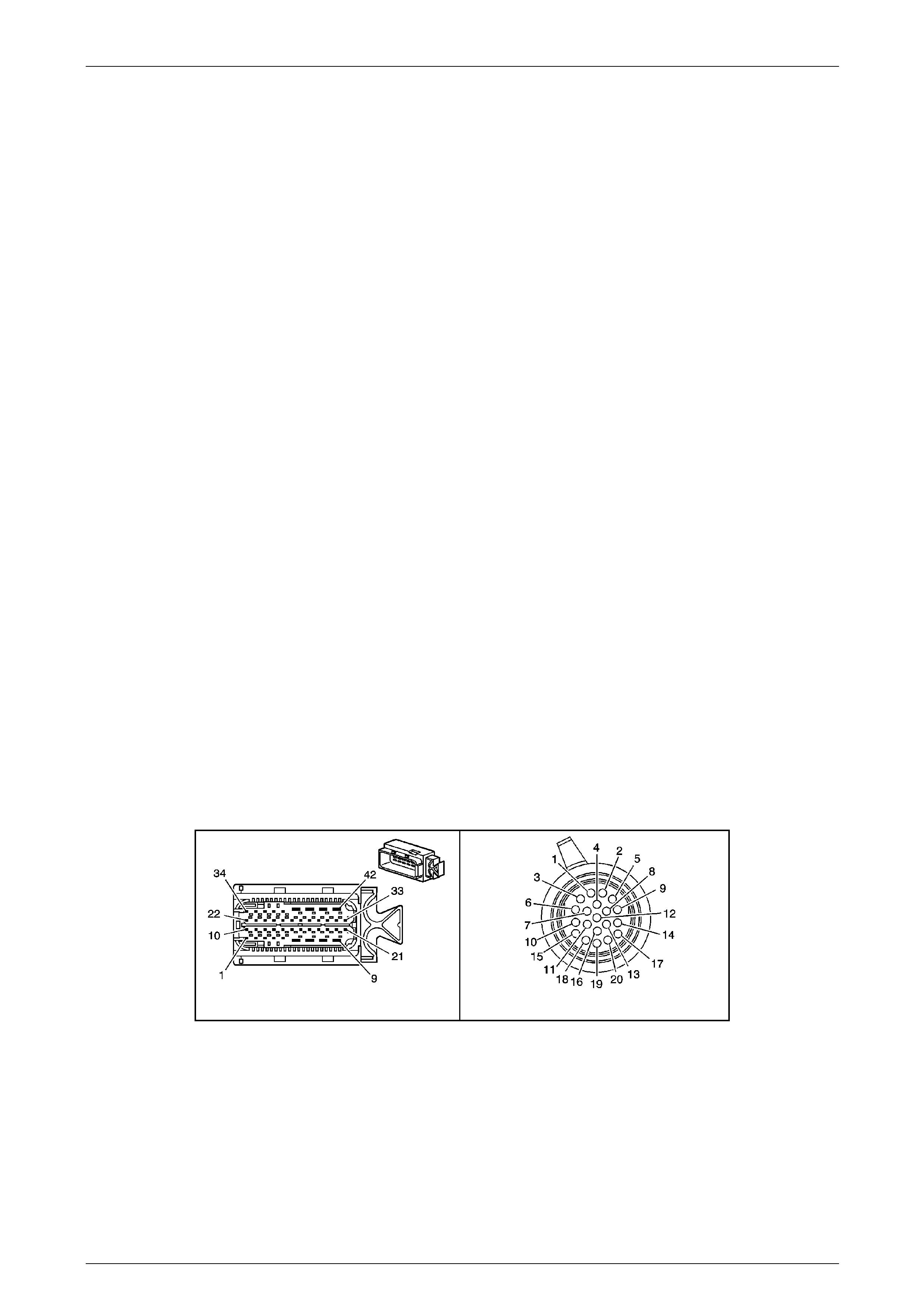
Automatic Transmission – 5L40-E – Electrical Diagnosis Page 7E – 142
Page 7E2 – 142
Conditions for Clearing the MIL / DTC
• Tech 2 can clear the DTC.
• The TCM clears the DTC from its memory (history DTC) if the vehicle completes 40 warm-up cycles without a
non-emission related DTC occurring.
• The TCM cancels the default actions when the ignition is off long enou gh to power down the TCM.
• The PIM turns off the Check Powertrain MIL after the sixth consecutive drive trip in which the TCM does not send a
Check Powertrain MIL illumination request.
Diagnostic Aids
If you clear DTC P0761 and then cannot reset DTC P0761, the following conditions may exist:
• Fluid contamination
• Plugged / blocked fluid circuits
• Restricted fluid circuits
Refer to Shift Solenoid Valve State and Gear Ratio chart in
1.4 Electronic Component Description – Shift Solenoid (SS) Valves in this Section.
Test Description
The following number(s) refer to the step number(s) on the diagnostic table.
3 This step verifies a 1–2–3–5– 5 shift pattern.
4 Checks for short to ground or open circuit in solenoid supply circuit.
5 Checks for short to voltage on the solenoid supply circuit.
6 Checks for short to ground on the solenoid suppl y circ uit.
7 Checks for open circuit in transmission internal wiring harness.
17 This step tests for a mechanical or hydraulic condition causing the 4–5 SS valve to be stuck off, or the circuit to be
applied.
NOTE
• Refer to Figures 7E2–5 and 7E2–6 for 5L40 –
E automatic transmission electrical circuits.
• For procedures on checking wiring faults,
refer to Section 12P Wiring Diagrams.
A112-T68 – X1 X121-X1
Figure 7E2 – 48

Automatic Transmission – 5L40-E – Electrical Diagnosis Page 7E – 143
Page 7E2 – 143
DTC P0761 – 4–5 Shift Solenoi d Stuck Off
Step Action Value(s) Yes No
1
Has the Diagnostic System Check – Automatic
Transmission been com pleted?
–
Go to Step 2
Go to
2.3 Diagnostic
System Check –
Automatic
Transmission
in this Section.
2
1 Perform the transmission fluid checking
procedure. Refer to Section 7E4 Automatic
Transmission – 5L40-E – On-V ehicle Servicing.
Did you perform the fluid checking procedure and is
level now OK?
–
Go to Step 3 –
3
1 Connect the Tech 2 to the DLC.
2 Ignition ON, engine OFF.
3 Clear DTCs.
4 Using the Tech 2 Snapshot feature, record the
commanded gear and gear ratio.
5 Drive the vehicle in D5 to obtain 1–2, 2–3, 3–4
and 4–5 shifts with a throttle position angle of 10%
or greater.
Are the commanded gear and gear rati o within the
specified range?
4th
0.73 – 0.77:1
Go to Step 4
Go to Intermittent
Conditions, in
Section 6C1–2
Engine
Management – V6
Diagnostics.
4
1 Ignition OFF.
2 Disconnect transmission wiring harness connector
X121–X1 from transmission 20-way connector.
3 Ignition ON.
4 Using a digital voltmeter, measure volta ge
between transmission wiring harness connector
X121–X1, terminal X1–17 and ground.
Is voltage reading greater than specified?
More than
6.0 Volts
Go to Step 5 Go to Step 10
5
1 Ignition OFF.
2 Disconnect transmission wiring harness connector
A112 – T68 from the TCM.
3 Ignition ON.
4 Using a digital voltmeter, measure volta ge
between transmission wiring harness TCM
connector A112 – T68, terminal X1–19 a nd
ground.
Is voltage reading less than specified?
Less than
0.3 volts
Go to Step 6 Go to Step 12
6
1 Ignition OFF.
2 Using a digital ohmmeter, measure resistance
between transmission wiring harness TCM
connector A112 – T68, terminal X1–19 a nd
ground.
Is resistance reading greater than specified?
More than
500 kΩ
Go to Step 7 Go to Step 13

Automatic Transmission – 5L40-E – Electrical Diagnosis Page 7E – 144
Page 7E2 – 144
Step Action Value(s) Yes No
7
1 Reconnect transmission wiring harness connector
X121–X1 to transmission 20-way connector.
2 Using a digital ohmmeter, measure resistance
between transmission wiring harness TCM
connector A112 – T68, terminals X1–19 a nd
X1–8.
Is resistance reading within specification?
15.0 – 17.0Ω
@ 20° C
17.9 – 20.3Ω
@ 70° C
Go to Step 8
If reading is more
than specified, go to
Step 15.
If reading is less
than specified, go to
Step 14.
8
1 Connect a fused jumper wire between vehicle
battery supply and transmission wiring harness
TCM connector A112 – T68, terminal X1–8.
2 Connect a second fused jumper wire to vehicle
ground.
3 Cyclically contact second fused jumper wire to
transmission wiring harness TCM connector
A112 – T68, terminal X1–19 and carefully listen
for 4–5 shift solenoid clicking.
Does solenoid click as jumper wire is connected?
–
Go to Step 9
Replace faulty 4–5
shift solenoid. Refer
to Section 7E4
Automatic
Transmission –
5L40-E – On-
Vehicle Servicing.
Go to Step 18
9
1 Replace TCM. Refer to Section 7E4 Automatic
Transmission – 5L40-E – On-V ehicle Servicing for
replacement procedures.
Is the replacement complete?
–
Go to Step 18 –
10
1 Using a digital ohmmeter, check wiring for short to
ground condition between transmission wiring
harness TCM connector A112 – T68, terminal
X1–8 and transmission wiring harness connector
X121–X1, terminal X1–17.
Does check indicate a short to ground in the wiring?
– Repair short to
ground in relevant
circuit.
Go to Step 18 Go to Step 11
11
1 Using a digital ohmmeter, check wiring for open
circuit condition between transmission wiring
harness TCM connector A112 – T68, terminal
X1–8 and transmission wiring harness connector
X121–X1, terminal X1–17.
Does check indicate an open circuit or hig h resistance
in the wiring?
– Repair caus e of
open circuit or high
resistance in
relevant circuit.
Go to Step 18 Go to Step 9
12
1 Using a digital voltmeter, check wiring for short to
voltage condition between transmission wiring
harness TCM connector A112 – T68, terminal
X1–19 and transmission wiring harness connector
X121–X1, terminal X1–5.
Does check indicate a short to voltage in the wiring?
– Repair short to
voltage in relevant
circuit.
Go to Step 18 –
13
1 Using a digital ohmmeter, check wiring for short to
ground condition between transmission wiring
harness TCM connector A112 – T68, terminal
X1–19 and transmission wiring harness connector
X121–X1, terminal X1–5.
Does check indicate a short to ground in the wiring?
– Repair short to
ground in relevant
circuit.
Go to Step 18 –
14
1 Using a digital voltmeter, check wiring for internal
short circuit condition bet ween transmission wirin g
harness TCM connector A112 – T68 and
transmission wiring harness connector X121–X1,
circuits 1525 and 898.
Does check indicate an internal short circuit condition in
the wiring?
– Repair caus e of
internal short circuit
condition in relevant
circuits.
Go to Step 18 Go to Step 9

Automatic Transmission – 5L40-E – Electrical Diagnosis Page 7E – 145
Page 7E2 – 145
Step Action Value(s) Yes No
15
1 Using a digital ohmmeter, check wiring for open
circuit condition between transmission wiring
harness TCM connector A112 – T68, terminal
X1–19 and transmission wiring harness connector
X121–X1, terminal X1–5.
Does check indicate an open circuit or hig h resistance
in the wiring?
– Repair caus e of
open circuit or high
resistance in
relevant circuit.
Go to Step 18 Go to Step 16
16
1 Remove transmission fluid pan and filter, refer to
Section 7E4 Automatic Tr ansmission – 5L40-E –
On-Vehicle Servicing.
2 Inspect transmission internal wiring harness for
any sign of damage.
Is transmission internal wiring harness OK?
–
Replace faulty 4–5
shift solenoid, refer
to Section 7E4
Automatic
Transmission –
5L40-E – On-
Vehicle Servicing.
Go to Step 18
Replace
transmission
internal wiring
harness. Refer to
Section 7E4
Automatic
Transmission –
5L40-E – On-
Vehicle Servicing.
Go to Step 18
17
1 With the fluid pan removed, inspect the rear
control valve body for the following conditions:
• 4–5 SS valve mechanicall y s t uck on.
• 4–5 SS valve O-ring worn or damaged.
• 4–5 shift valve stuck in the applied position.
Refer to Section 7E4 Automatic Transmission –
5L40-E – On-Vehicle Servicing.
Did you find any of the above conditions?
–
Repair or replace
components as
necessary.
Go to Step 18 Go to Step 18
18
1 Perform the following operation to verify the
repair.
• Select DTC on Tech 2.
• Select Clear info.
2 Operate the vehicle under the following
conditions:
• Drive the vehicle in D5 with a throttle angle
of 10% or more
• Allow the transmission to shift through all
gears at least twice.
• Monitor the commanded gear and ge ar
ratios. The actual gear ratios must match the
commanded gears for 1 second, for all
gears.
Has the test run and passed?
–
System OK Go to Step 2
When all diagnosis and repairs are completed, clear all DTCs and verify correct operation

Automatic Transmission – 5L40-E – Electrical Diagnosis Page 7E – 146
Page 7E2 – 146
DTC P0762 – 4–5 Shift Solenoid Stuck On
Circuit Description
The 4–5 Shift Solenoid (SS) valve is a normally closed exhaust valve. When the 1–2 and the 2–3 SS valves are both off,
the 4–5 SS valve turns off to shift the transmission into 5th gear. When either of the other two shift solenoids are on, the
4–5 SS allows powertrain braking. The 4–5 SS valve is attached to the control valve body, within the transmission.
The Transmission Control Module (TCM) monitors the actual gear ratio and compares the actual gear ratio with the
commanded gear ratio. DTC P0761 sets un der two conditions:
• A stuck on 4–5 SS valve.
• A stuck on 4–5 shift valve.
If the TCM detects a 1–2–3–4–4 shift pattern, then DTC P0762 sets which is a type ‘B’ DTC.
Conditions for Running the DTC
• Ignition voltage is bet ween 8.0 and 18. 0 volts.
• Engine speed is between 450 and 6,800 rpm for at least 5 seconds.
• The following DTCs are not set:
• P0120 – Throttle Position Signal (No valid GMLAN signal).
• P0716 or P0717 – Transmission Input Sp eed Sensor.
• P0722 or P0723 – Transmission Output Speed Sensor.
• P0742 – TCC System Stuck ON.
• P0973, P0974, P0976, P0977, P0979 or P0980 – Shift Solenoids Electrical.
• P01815, P1820, P1822, P1823, P182 5 or P1826 – Transmission Manu al Shift Shaft Switch (IMS) Assembly.
• P02637 – Engine Torque Signal Circuit – No Valid GMLAN Signal.
• The transmission fluid temperature is between 20 to 130° C.
• The transmission manual shift shaft switch assembly does not indicate Park, Neutral or Reverse.
• The input shaft speed is 200 – 6,800 rpm.
• The output shaft speed is greater than 100 rpm.
Conditions for Setting the DTC
The following conditions must occur twice during the same ignition cycle.
• The TCM commands 5th gear for more than 1 second when the engine torque is between 36 to 450 N.m, the
reported gear ratio is 0.98:1 – 1.03:1 for 3.5 s econds, with a throttle position of 10% or more.
• The TCM has commanded either 2nd or 3rd gear for 3 secon ds or more.

Automatic Transmission – 5L40-E – Electrical Diagnosis Page 7E – 147
Page 7E2 – 147
Action Taken When the DT C Sets
• The TCM requests the Powertrain Interface Module (PIM) to illumin ate the Check Powertrain Malfunction Indicator
Lamp (MIL) in the instrument cluster during the second consecutive trip in which the ‘Conditions for Setting the
DTC’ have been met.
• At the time of the first failure, the TCM records the operating conditions when the ‘Conditions for Setting the DTC’
have been met. The TCM stores this information as a failure record.
• At the time of the second failure, the ECM records the operating conditions when the ‘Conditions for Set ting the
DTC’ have been met. The ECM stores this information as a freeze frame.
• The TCM also turns off the pressure control sole noid (causing maximum line pressure).
• The TCM freezes the transmission adaptive learning function.
• Engine braking is inhibited.
• The TCM inhibits 5th gear.
• The TCM stores DTC P0762 into TCM history.
Conditions for Clearing the MIL / DTC
• Tech 2 can clear the DTC.
• The TCM clears the DTC from its memory (history DTC) if the vehicle completes 40 warm-up cycles without a
non-emission related DTC occurring.
• The TCM cancels the default actions when the ignition is off long enou gh to power down the TCM.
• The PIM turns off the Check Powertrain MIL after the sixth consecutive drive trip in which the TCM does not send a
Check Powertrain MIL illumination request.
Diagnostic Aids
If you clear DTC P0762 and then cannot reset DTC P0762, the following conditions may exist:
• Fluid contamination.
• Plugged / blocked fluid circuits.
• Restricted fluid circuits.
Refer to Shift Solenoid Valve State and Gear Ratio chart in
1.4 Electronic Component Description – Shift Solenoid (SS) Valves in this Section.
Test Description
The following number(s) refer to the step number(s) on the diagnostic table.
3 This step verifies a 1–2–3–4– 4 shift pattern.
4 Checks for short to ground or open circuit in solenoid supply circuit.
5 Checks for short to voltage on the solenoid supply circuit.
6 Checks for short to ground on the solenoid suppl y circ uit.
7 Checks for open circuit in transmission internal wiring harness.
17 This step tests for a mechanical or hydraulic condition causing the 4–5 SS valve to be stuck on, or the circuit to be
released.

Automatic Transmission – 5L40-E – Electrical Diagnosis Page 7E – 148
Page 7E2 – 148
NOTE
• Refer to Figures 7E2–5 and 7E2–6 for 5L40 –
E automatic transmission electrical circuits.
• For procedures on checking wiring faults,
refer to Section 12P Wiring Diagrams.
A112-T68 – X1 X121-X1
Figure 7E2 – 49
DTC P0762 – 4–5 Shift Solenoi d Stuck On
Step Action Value(s) Yes No
1
Has the Diagnostic System Check – Automatic
Transmission been com pleted?
–
Go to Step 2
Go to
2.3 Diagnostic
System Check –
Automatic
Transmission
in this Section.
2
1 Perform the transmission fluid checking
procedure. Refer to Section 7E4 Automatic
Transmission – 5L40-E – On-V ehicle Servicing.
Did you perform the fluid checking procedure and is
level now OK?
–
Go to Step 3 –
3
1 Connect the Tech 2 to the DLC.
2 Ignition ON, engine OFF.
3 Clear DTCs.
4 Using the Tech 2 Snapshot feature, record the
commanded gear and gear ratio.
5 Drive the vehicle in D5 to obtain 1–2, 2–3, 3–4
and 4–5 shifts with a throttle position angle of 10%
or greater.
Are the commanded gear and gear rati o within the
specified range?
4th
0.98 – 1.03:1
Go to Step 4
Go to Intermittent
Conditions, in
Section 6C1–2
Engine
Management – V6
Diagnostics.
4
1 Ignition OFF.
2 Disconnect transmission wiring harness connector
X121–X1 from transmission 20-way connector.
3 Ignition ON.
4 Using a digital voltmeter, measure volta ge
between transmission wiring harness connector
X121–X1, terminal X1–17 and ground.
Is voltage reading greater than specified?
More than
6.0 Volts
Go to Step 5 Go to Step 10

Automatic Transmission – 5L40-E – Electrical Diagnosis Page 7E – 149
Page 7E2 – 149
Step Action Value(s) Yes No
5
1 Ignition OFF.
2 Disconnect transmission wiring harness connector
A112 – T68 from the TCM.
3 Ignition ON.
4 Using a digital voltmeter, measure volta ge
between transmission wiring harness TCM
connector A112 – T68, terminal X1–19 a nd
ground.
Is voltage reading less than specified?
Less than
0.3 volts
Go to Step 6 Go to Step 12
6
1 Ignition OFF.
2 Using a digital ohmmeter, measure resistance
between transmission wiring harness TCM
connector A112 – T68, terminal X1–19 a nd
ground.
Is resistance reading greater than specified?
More than
500 kΩ
Go to Step 7 Go to Step 13
7
1 Reconnect transmission wiring harness connector
X121–X1 to transmission 20-way connector.
2 Using a digital ohmmeter, measure resistance
between transmission wiring harness TCM
connector A112 – T68, terminals X1–19 a nd
X1–8.
Is resistance reading within specification?
16 to 20 Ω
Go to Step 8
If reading is more
than specified, go to
Step 15.
If reading is less
than specified, go to
Step 14.
8
1 Connect a fused jumper wire between vehicle
battery supply and transmission wiring harness
TCM connector A112 – T68, terminal X1–8.
2 Connect a second fused jumper wire to vehicle
ground.
3 Cyclically contact second fused jumper wire to
transmission wiring harness TCM connector
A112 – T68, terminal X1–19 and carefully listen
for 4–5 shift solenoid clicking.
Does solenoid click as jumper wire is connected?
–
Go to Step 9
Replace faulty 4–5
shift solenoid. Refer
to Section 7E4
Automatic
Transmission –
5L40-E – On-
Vehicle Servicing.
Go to Step 18
9
1 Replace TCM. Refer to Section 7E4 Automatic
Transmission – 5L40-E – On-V ehicle Servicing for
replacement procedures.
Is the replacement complete?
–
Go to Step 18 –
10
1 Using a digital ohmmeter, check wiring for short to
ground condition between transmission wiring
harness TCM connector A112 – T68, terminal
X1–8 and transmission wiring harness connector
X121–X1, terminal X1–17.
Does check indicate a short to ground in the wiring?
– Repair short to
ground in relevant
circuit.
Go to Step 18 Go to Step 11
11
1 Using a digital ohmmeter, check wiring for open
circuit condition between transmission wiring
harness TCM connector A112 – T68, terminal
X1–8 and transmission wiring harness connector
X121–X1, terminal X1–17.
Does check indicate an open circuit or hig h resistance
in the wiring?
– Repair caus e of
open circuit or high
resistance in
relevant circuit.
Go to Step 18 Go to Step 9
12
1 Using a digital voltmeter, check wiring for short to
voltage condition between transmission wiring
harness TCM connector A112 – T68, terminal
X1–19 and transmission wiring harness connector
X121–X1, terminal X1–5.
Does check indicate a short to voltage in the wiring?
– Repair short to
voltage in relevant
circuit.
Go to Step 18 –

Automatic Transmission – 5L40-E – Electrical Diagnosis Page 7E – 150
Page 7E2 – 150
Step Action Value(s) Yes No
13
1 Using a digital ohmmeter, check wiring for short to
ground condition between transmission wiring
harness TCM connector A112 – T68, terminal
X1–19 and transmission wiring harness connector
X121–X1, terminal X1–5.
Does check indicate a short to ground in the wiring?
– Repair short to
ground in relevant
circuit.
Go to Step 18 –
14
1 Using a digital voltmeter, check wiring for internal
short circuit condition bet ween transmission wirin g
harness TCM connector A112 – T68 and
transmission wiring harness connector X121–X1,
circuits 1525 and 898.
Does check indicate an internal short circuit condition in
the wiring?
– Repair caus e of
internal short circuit
condition in relevant
circuits.
Go to Step 18 Go to Step 9
15
1 Using a digital ohmmeter, check wiring for open
circuit condition between transmission wiring
harness TCM connector A112 – T68, terminal
X1–19 and transmission wiring harness connector
X121–X1, terminal X1–5.
Does check indicate an open circuit or hig h resistance
in the wiring?
– Repair caus e of
open circuit or high
resistance in
relevant circuit.
Go to Step 18 Go to Step 16
16 1 Remove transmission fluid pan and filter, refer to
Section 7E4 Automatic Tr ansmission – 5L40-E –
On-Vehicle Servicing.
2 Inspect transmission internal wiring harness for
any sign of damage.
Is transmission internal wiring harness OK?
–
Replace faulty 4–5
shift solenoid, refer
to Section 7E4
Automatic
Transmission –
5L40-E – On-
Vehicle Servicing.
Go to Step 18
Replace
transmission
internal wiring
harness. Refer to
Section 7E4
Automatic
Transmission –
5L40-E – On-
Vehicle Servicing.
Go to Step 18
17
1 With the fluid pan removed, inspect the rear
control valve body for the following conditions:
• 4–5 SS valve mechanicall y s t uck on.
• 4–5 SS valve O-ring worn or damaged.
• 4–5 shift valve stuck in the released
position.
Refer to Section 7E4 Automatic Transmission –
5L40-E – On-Vehicle Servicing.
Did you find any of the above conditions?
–
Repair or replace
components as
necessary.
Go to Step 18 Go to Step 18
18
1 Perform the following operation to verify the
repair.
• Select DTC on Tech 2.
• Select Clear info.
2 Operate the vehicle under the following
conditions:
• Drive the vehicle in D5 with a throttle angle
of 10% or more
• Allow the transmission to shift through all
gears at least twice.
• Monitor the commanded gear and ge ar
ratios. The actual gear ratios must match the
commanded gears for 1 second, for all
gears.
Has the test run and passed?
–
System OK Go to Step 2
When all diagnosis and repairs are completed, clear all DTCs and verify correct operation

Automatic Transmission – 5L40-E – Electrical Diagnosis Page 7E – 151
Page 7E2 – 151
DTC P0815 – Transmission Upshift Switch Circuit Stuck On
Circuit Description
When the ‘A/S’ momentary contact switch in the centre console is pressed and the ‘Active Shift’ is enabled, the TAP shift
system allows the driver to manually shift gears by using the TAP Shift s witches loc ated at the top of the horn bar o n the
steering wheel. Pushing the ‘+’ (up) switch will command the transmission to upshift and pushing the ‘ –‘ (down) switch
will command a downshift. The TAP shift system is activated when the gear selector is in the D position and is
deactivated in all other positions.
If the Transmission Control Module (TCM) detects the upshift circuit active for an extended period of time, then P0815
sets, which is a type ‘C’ DTC.
Conditions for Running the DTC
• Ignition voltage is bet ween 8.0 and 18. 0 volts.
• Engine speed is between 450 and 6,800 rpm for at least 5 seconds.
• The following DTCs are not set:
• P0826– Tap Circuit Reads An Invalid Voltage Range.
• P1815, P1820, P1822, P1823, P1825 or P1826 – Transmission Manual Shift Shaft Switch (IMS) Assembly.
• The time since the last gear selector range change is more than 6 seconds.
Conditions for Setting the DTC
Both of the following two conditions must occur before this DTC P0815 will set.
• In any PRDNL range, the upshift switch is stuck on for 2 seconds.
• In any PRDNL range, the upshift switch is stuck on for 10 minutes (600 seconds).
Action Taken When the DT C Sets
• The TCM does not request the Powertrain Interface Module (PIM) to illuminate the Check Powertrain Malfunction
Indicator Lamp (MIL).
• The TCM records the operating cond itions when the ‘Conditions for setting the DTC’ are met. The TCM stores this
information as a Failure Record.
• The TCM disables the TAP shift operati on.
• The TCM stores DTC P0815 in TCM history.
Conditions for Clearing the DTC
• Tech 2 can clear the DTC.
• The TCM clears the DTC from its memory (history DTC) if the vehicle completes 40 warm-up cycles without a
non-emission related DTC occurring.
• The TCM cancels the default actions when the ignition is off long enou gh to power down the TCM.
Test Description
The following number(s) refer to the step number(s) on the diagnostic table.
2 Confirms that a problem exists.
3 Checks if the ‘+’ paddle s witch is stuck in the ON position.
4 Checks whether the ‘+’ paddle switch circuit is valid.
5 Confirms power is available to the circuit.
6 Confirms circuit and voltage validity at the TCM.
7 Checks the ‘+’ paddle switch internal resistance is valid.
9 Checks the paddle switch circuit for overall resistance.
10 Confirms the value of the ‘+’ paddle switch resistance.
12/13 Checks the continuity of circuit 5526.

Automatic Transmission – 5L40-E – Electrical Diagnosis Page 7E – 152
Page 7E2 – 152
NOTE
• Refer to Figures 7E2–5 and 7E2–6 for 5 L40 –
E automatic transmission electrical circuits.
• For procedures on checking wiring faults,
refer to Section 12P Wiring Diagrams.
A112-T68 – X1 S208 X212
Figure 7E2 – 50
DTC P0815 – Transmission Up sh ift Switch Circuit Stuck On
Step Action Value(s) Yes No
1
Has the Diagnostic System Check – Automatic
Transmission been com pleted?
–
Go to Step 2
Go to
2.3 Diagnostic
System Check –
Automatic
Transmission
in this Section.
2
1 Connect Tech 2 to the DLC.
2 Ignition ON, engine OFF.
3 Clear DTCs.
4 Select ‘Active Select Request’ status on T ech 2.
Does the Tech 2 ‘Active Select Request’ data
parameter display ‘None’?
–
Go to Step 4 Go to Step 3
3 Does the Tech 2 ‘Active Select Request’ data
parameter display ‘Shift Up’? – Go to Step 11 Go to Step 4
4
1 Select ‘Active Select Request’ status on Tech 2.
2 Press the ‘+’ paddle s witch at the steering wheel,
hold, then release.
Does the Tech 2 ‘Active Shift Request’ data parameter
change from ‘None’ to ‘Shift Up’, then back to ‘None’?
–
Go to Intermittent
Conditions in
Section 6C1–2
Engine
Management – V6
Diagnostics. Go to Step 5
5
1 Inspect fuse F32 in the under hood e lectrical
centre X100, for an open (blown) con ditio n.
2 Replace fuse if necessary.
Was fuse open?
–
Go to Step 13 Go to Step 6
6
1 Ignition OFF.
2 Remove TCM from its cradle, refer to Section 7E4
Automatic Transmission – 5L40-E – On-Vehicle
Servicing.
3 Carefully remove wiring protective cover from the
back of connector A112 – T68.
4 Ignition ON, engine OFF.
5 With TCM connector A112 – T 68 still installed,
check voltage bet ween back probed terminal
X1-14 and a sound ground, using a digit al
voltmeter.
Is the voltage check within the specified range?
0.5 – 0.7
volts
Go to Step 7 Go to Step 9
7
1 With voltmeter still connected (as in Step 5), press
the ‘+’ paddle switch at the steering wheel and
hold.
Is the voltage check within the specified range?
1.4 – 1.6
volts Go to Step 8 Go to Step 9

Automatic Transmission – 5L40-E – Electrical Diagnosis Page 7E – 153
Page 7E2 – 153
Step Action Value(s) Yes No
8
1 Replace TCM. Refer to Section 7E4 Automatic
Transmission – 5L40-E – On-V ehicle Servicing for
replacement procedures.
Is the replacement complete?
–
Go to Step 14 –
9
1 Remove driver side air bag. Refer to Section 12M
Occupant Protection System, for procedur e.
2 Disconnect 4 wire patch harness connector X212
from the paddle switch harness.
3 Using a digital ohmmeter and appr opriate lea ds
from J 35616-A Connector Test Adaptor Kit, check
resistance between X212-1 (Red wire) and X212-
2 (Black wire).
Is the resistance check within the specified ra nge?
8.2 – 8.3 kΩ
Go to Step 9 Go to Step 10
10
1 With ohmmeter still connected (as in Step 9),
press the ‘+’ paddle switch at the steering wheel
and hold.
Is the resistance check within the specified ra nge?
2.8 – 2.9 kΩ
Go to Step 12 Go to Step 11
11 1 Replace the automatic transmi ssion shift paddle
switches. Refer to Section 9 Steering.
Did you complete the replacement? – Go to Step 14 –
12
1 Ignition OFF.
2 Disconnect TCM connector A112 – T68.
3 Using a digital ohmmeter and appr opriate lea ds
from J 35616-A Connector Test Adaptor Kit, check
for an open in circuit 5526 between TCM
connector A112 – T68, terminal X1-14 and paddle
switch connector X212, terminal X212-2.
Did you find and correct a condition?
–
Go to Step 14 Go to Step 13
13
1 Ignition ON.
2 Using a digital voltmeter, test paddle switch circuit
5526 connector X212-2 (sign al circuit) for a short
to voltage condition.
2 Also check for a short to ground in the same
circuit.
Did you find and correct a condition?
–
Go to Step 14 –
14
1 Perform the following operation to verify the
repair.
• Select DTC on Tech 2, then clear DT C.
2 Operate the vehicle under the following
conditions:
• Ignition ON, engine OFF.
• Observe ‘Active Select Request’ on T ech 2.
• Monitor Tech 2 and ensure that the ‘Active
Select Request’ is not displaying upshift for
at least 1 second.
• Operate the ‘+’ paddle switch and monitor
Tech 2 to ensure that the ‘Active Select
Request’ display changes fro m ‘None’ to
‘Shift Up’, then back to ‘None’.
Has the test run and passed?
–
System OK Go to Step 2
When all diagnosis and repairs are completed, clear all DTCs and verify correct operation

Automatic Transmission – 5L40-E – Electrical Diagnosis Page 7E – 154
Page 7E2 – 154
DTC P0816 – Transmission Downshift Switch Circuit Stuck On
Circuit Description
When the ‘A/S’ momentary contact switch in the centre console is pressed and the ‘Active Shift’ is enabled, the TAP shift
system allows the driver to manually shift gears by using the TAP Shift s witches loc ated at the top of the horn bar o n the
steering wheel. Pushing the ‘+’ (up) switch will command the transmission to upshift and pushing the ‘ –‘ (down) switch
will command a downshift. The TAP shift system is activated when the gear selector is in the D position and is
deactivated in all other positions.
If the Transmission Control Module (TCM) detects the downshift circuit active for an extended period of time, then P0816
sets, which is a type ‘C’ DTC.
Conditions for Running the DTC
• Ignition voltage is bet ween 8.0 and 18. 0 volts.
• Engine speed is between 450 and 6,800 rpm for at least 5 seconds.
• The following DTCs are not set:
• P0826 – Tap Circuit Reads An Invalid Voltage Range.
• P01815, P1820, P1822, P1823, P182 5 or P1826 – Transmission Manu al Shift Shaft Switch Assembly.
• The time since the last gear selector range change is greater than 6 seco nds.
Conditions for Setting the DTC
Both of the following two conditions must occur before this DTC P0815 will set.
• In any PRDNL range, the upshift switch is stuck on for 2 seconds.
• In any PRDNL range, the upshift switch is stuck on for 10 minutes (600 seconds).
Action Taken When the DT C Sets
• The TCM does not request the Powertrain Interface Module (PIM) to illuminate the Check Powertrain Malfunction
Indicator Lamp (MIL).
• The TCM records the operating cond itions when the ‘Conditions for Settin g the DTC’ are met. The TCM stores this
information as a Failure Record.
• The TCM stores DTC P0816 in TCM history.
• The TCM disables the TAP shift operati on.
Conditions for Clearing the DTC
• Tech 2 can clear the DTC.
• The TCM clears the DTC from its memory (history DTC) if the vehicle completes 40 warm-up cycles without a
non-emission related DTC occurring.
• The TCM cancels the default actions when the ignition is off long enou gh to power down the TCM.
Test Description
The following number(s) refer to the step number(s) on the diagnostic table.
2 Confirms that a problem exists.
3 Checks if the ‘–’ paddle switch is stuck in the ON position.
4 Checks whether the ‘–’ paddle switch circuit is valid.
5 Confirms power is available to the circuit.
6 Confirms circuit and voltage validity at the TCM.
7 Checks the ‘–’ paddle switch internal resistance is valid.
9 Checks the paddle switch circuit for overall resistance.
10 Confirms the value of the ‘–’ paddle switch resistance.
12/13 Checks the continuity of circuit 5526.
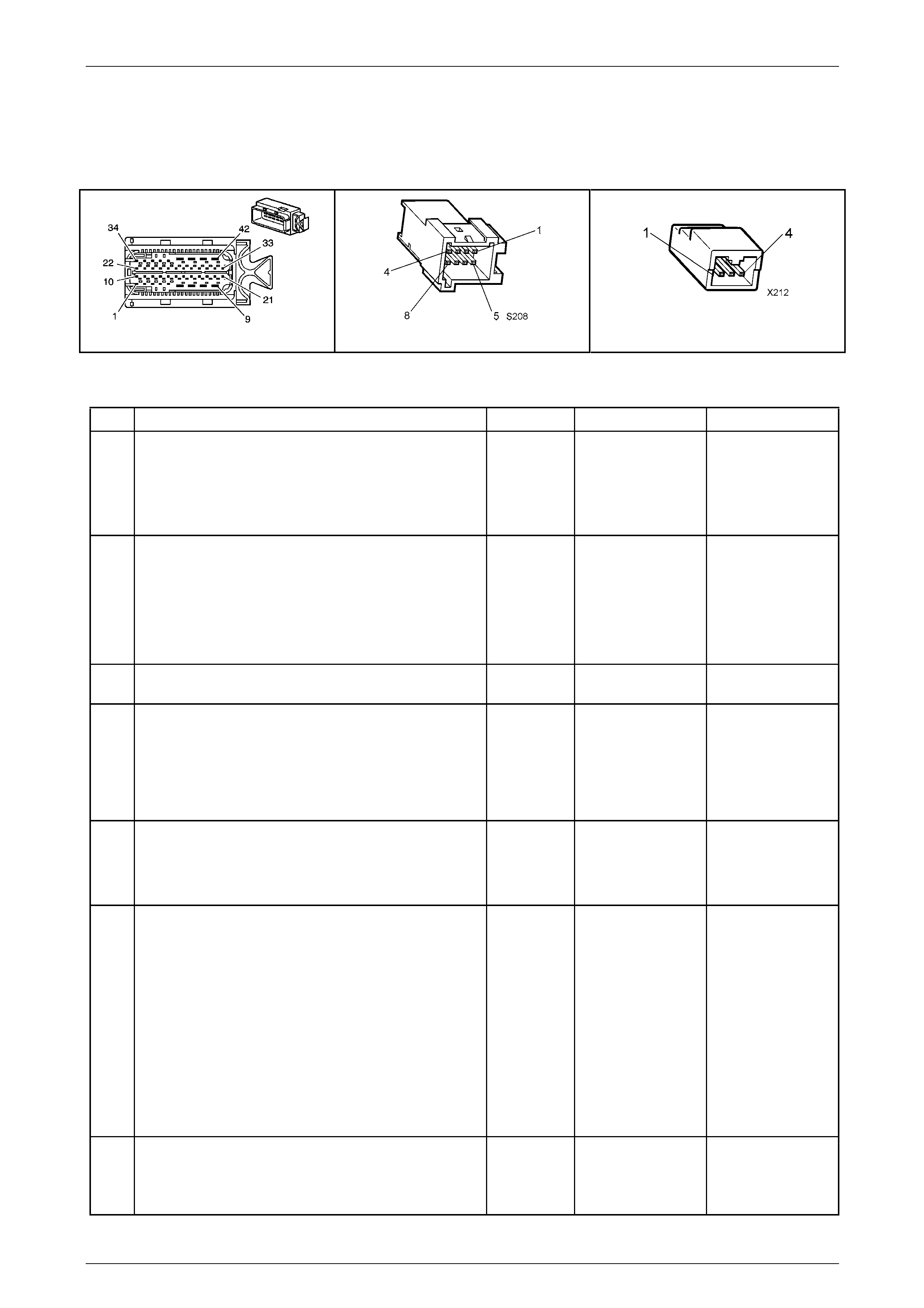
Automatic Transmission – 5L40-E – Electrical Diagnosis Page 7E – 155
Page 7E2 – 155
NOTE
• Refer to Figures 7E2–5 and 7E2–6 for 5L40 –
E automatic transmission electrical circuits.
• For procedures on checking wiring faults,
refer to Section 12P Wiring Diagrams.
A112-T68 – X1 S208 X212
Figure 7E2 – 51
DTC P0816 – Transmission Downshift Switch Circuit Stuck On
Step Action Value(s) Yes No
1
Has the Diagnostic System Check – Automatic
Transmission been com pleted?
–
Go to Step 2
Go to
2.3 Diagnostic
System Check –
Automatic
Transmission
in this Section.
2
1 Connect Tech 2 to the DLC.
2 Ignition ON, engine OFF.
3 Clear DTCs.
4 Select ‘Active Select Request’ status on T ech 2.
Does the Tech 2 ‘Active Select Request’ data
parameter display ‘None’?
–
Go to Step 4 Go to Step 3
3 Does the Tech 2 ‘Active Select Request’ data
parameter display ‘Shift Do wn’? – Go to Step 11 Go to Step 4
4
1 Select ‘Active Select Request’ status on Tech 2.
2 Press the ‘–’ paddle switch at the steering wheel,
hold, then release.
Does the Tech 2 ‘Active Shift Request’ data parameter
change from ‘None’ to ‘Shift Down’, then back to
‘None’?
–
Go to Intermittent
Conditions in
Section 6C1–2
Engine
Management – V6
Diagnostics. Go to Step 5
5
1 Inspect fuse F32 in the under hood e lectrical
centre X100, for an open (blown) con ditio n.
2 Replace fuse if necessary.
Was fuse open?
–
Go to Step 13 Go to Step 6
6
1 Ignition OFF.
2 Remove TCM from its cradle, refer to Section 7E4
Automatic Transmission – 5L40-E – On-Vehicle
Servicing.
3 Carefully remove wiring protective cover from the
back of connector A112 – T68.
4 Ignition ON, engine OFF.
5 With TCM connector A112 – T 68 still installed,
check voltage bet ween back probed terminal
X1-14 and a sound ground, using a digit al
voltmeter.
Is the voltage check within the specified range?
0.5 – 0.7
volts
Go to Step 7 Go to Step 9
7
1 With voltmeter still connected (as in Step 6), press
the ‘–’ paddle switch at the steering wheel and
hold.
Is the voltage check within the specified range?
2.8 – 3.0
volts Go to Step 8 Go to Step 9

Automatic Transmission – 5L40-E – Electrical Diagnosis Page 7E – 156
Page 7E2 – 156
Step Action Value(s) Yes No
8
1 Replace TCM. Refer to Section 7E4 Automatic
Transmission – 5L40-E – On-V ehicle Servicing for
replacement procedures.
Is the replacement complete?
–
Go to Step 14 –
9
1 Remove driver side air bag. Refer to Section 12M
Occupant Protection System, for procedur e.
2 Disconnect 4 wire patch harness connector X212
from the paddle switch harness.
3 Using a digital ohmmeter and appr opriate lea ds
from J 35616-A Connector Test Adaptor Kit, check
resistance between X212-1 (Red wire) and X212-
2 (Black wire).
Is the resistance check within the specified ra nge?
8.2 – 8.3 kΩ
Go to Step 9 Go to Step 10
10
1 With ohmmeter still connected (as in Step 9),
press the ‘–’ paddle switch at the steering wheel
and hold.
Is the resistance check within the specified ra nge?
1.2 – 1.3 kΩ
Go to Step 12 Go to Step 11
11 1 Replace the automatic transmi ssion shift paddle
switches. Refer to Section 9 Steering.
Did you complete the replacement? – Go to Step 14 –
12
1 Ignition OFF.
2 Disconnect TCM connector A112 – T68.
3 Using a digital ohmmeter and appr opriate lea ds
from J 35616-A Connector Test Adaptor Kit, check
for an open in circuit 5626 between TCM
connector A112 – T68, terminal X1-14 and paddle
switch connector X212, terminal X212-2.
Did you find and correct a condition?
–
Go to Step 14 Go to Step 13
13
1 Ignition ON.
2 Using a digital voltmeter, test paddle switch circuit
5526 connector X212-2 (sign al circuit) for a short
to voltage condition.
2 Also check for a short to ground in the same
circuit.
Did you find and correct a condition?
–
Go to Step 14 –
14
1 Perform the following operation to verify the
repair.
• Select DTC on Tech 2, then clear DT C.
2 Operate the vehicle under the following
conditions:
• Ignition ON, engine OFF.
• Observe ‘Active Select Request’ on T ech 2.
• Monitor Tech 2 and ensure that the ‘Active
Select Request’ is not displaying downshift
for at least 1 second.
• Operate the ‘–’ paddle switch and monitor
Tech 2 to ensure that the ‘Active Select
Request’ display changes fro m ‘None’ to
‘Shift Down’, then back to ‘None’.
Has the test run and passed?
–
System OK Go to Step 2
When all diagnosis and repairs are completed, clear all DTCs and verify correct operation

Automatic Transmission – 5L40-E – Electrical Diagnosis Page 7E – 157
Page 7E2 – 157
DTC P0826 – Tap Circuit Reads An Invalid Voltage Range
Circuit Description
When the ‘A/S’ momentary contact switch in the centre console is pressed and the ‘Active Shift’ is enabled, the TAP shift
system allows the driver to manually shift gears by using the TAP Shift s witches loc ated at the top of the horn bar o n the
steering wheel. Pushing the ‘+’ (up) switch will command the transmission to upshift and pushing the ‘ –‘ (down) switch
will command a downshift. The TAP shift system is activated when the gear selector is in the D position and is
deactivated in all other positions.
If the Transmission Control Module (TCM) detects an invalid voltage on the tap up / tap d own switch signal circuit, then
P0826 sets, which is a type ‘C’ DTC.
Conditions for Running the DTC
• Ignition voltage is bet ween 8.0 and 18. 0 volts.
• Engine speed is between 450 and 6,800 rpm for at least 5 seconds.
Conditions for Setting the DTC
• The TCM detects an invalid voltage on the tap up / tap down switch sign al circuit for 5 minutes (300 seconds).
Action Taken When the DT C Sets
• The TCM does not request the Powertrain Interface Module (PIM) to illuminate the Check Powertrain Malfunction
Indicator Lamp (MIL).
• The TCM records the operating cond itions when the ‘Conditions for Settin g the DTC’ are met. The TCM stores this
information as a Failure Record.
• The TCM disables the TAP shift operati on.
• The TCM stores DTC P0826 in TCM history.
Conditions for Clearing the DTC
• Tech 2 can clear the DTC.
• The TCM clears the DTC from its memory (history DTC) if the vehicle completes 40 warm-up cycles without a
non-emission related DTC occurring.
• The TCM cancels the default actions when the ignition is off long enou gh to power down the TCM.
Test Description
The following number(s) refer to the step number(s) on the diagnostic table.
2 Checks the current state of the Active Select Request circuit.
3 Confirms that an invalid signal has been registered by the TCM.
4/5 Checks whether either paddle switch is causing the problem.
7 Checks for a correct value voltage supply to the TCM.
8/9 Checks whether either paddle switch has the correct internal resistance.
11 – 13 Checks the resistance of the paddle switches, as a group and individuall y.
15 Checks for battery voltage being available at the paddle s witches.
16 Checks for and open or short to ground on power circuit 1339.
17 Checks for and open or short to ground on circuit 5526 between the paddl e switches and the TCM.
18 Checks for a short to voltage on circuit 5526 between the paddle switches and the TCM.
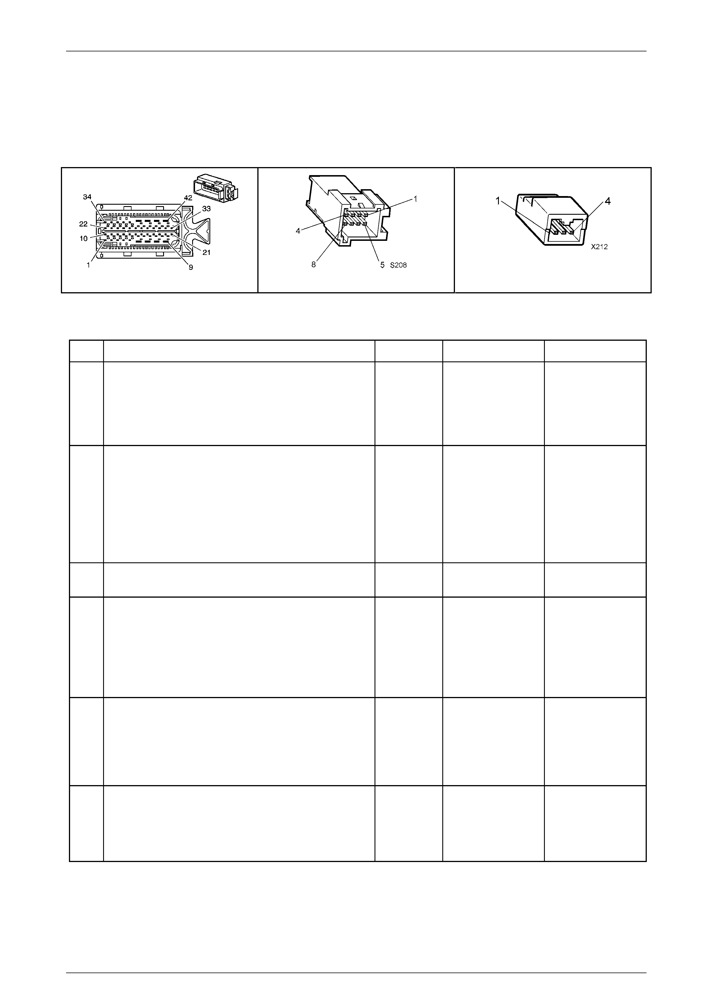
Automatic Transmission – 5L40-E – Electrical Diagnosis Page 7E – 158
Page 7E2 – 158
NOTE
• Refer to Figures 7E2–5 and 7E2–6 for 5L40 –
E automatic transmission electrical circuits.
• For procedures on checking wiring faults,
refer to Section 12P Wiring Diagrams.
A112-T68 – X1 S208 X212
Figure 7E2 – 52
DTC P0826 – Tap Circuit Reads An Invalid Voltage Range
Step Action Value(s) Yes No
1
Has the Diagnostic System Check – Automatic
Transmission been com pleted?
–
Go to Step 2
Go to
2.3 Diagnostic
System Check –
Automatic
Transmission
in this Section.
2
1 Connect Tech 2 to the DLC.
2 Ignition ON, engine OFF.
3 Clear DTCs.
4 Select ‘Active Select Request’ status on T ech 2.
Does the Tech 2 ‘Active Select Request’ data
parameter display ‘None’?
–
Go to Step 4 Go to Step 3
3 Does the Tech 2 ‘Active Select Request’ data
parameter display ‘Invalid’? – Go to Step 6 Go to Step 4
4
1 Select ‘Active Select Request’ status on Tech 2.
2 Press the ‘–’ paddle switch at the steering wheel,
hold, then release.
Does the Tech 2 ‘Active Shift Request’ data parameter
change from ‘None’ to ‘Shift Down’, then back to
‘None’?
–
Go to Step 5 Go to Step 6
5
1 Select ‘Active Select Request’ status on Tech 2.
2 Press the ‘+’ paddle s witch at the steering wheel,
hold, then release.
Does the Tech 2 ‘Active Shift Request’ data parameter
change from ‘None’ to ‘Shift Up’, then back to ‘None’?
–
Go to Intermittent
Conditions in
Section 6C1–2
Engine
Management – V6
Diagnostics. Go to Step 6
6
1 Inspect fuse F32 in the under hood e lectrical
centre X100, for an open (blown) con ditio n.
2 Replace fuse if necessary.
Was a fuse replacement requir ed?
–
Go to Step 19 Go to Step 7

Automatic Transmission – 5L40-E – Electrical Diagnosis Page 7E – 159
Page 7E2 – 159
Step Action Value(s) Yes No
7
1 Ignition OFF.
2 Remove TCM from its cradle, refer to Section 7E4
Automatic Transmission – 5L40-E – On-Vehicle
Servicing.
3 Carefully remove wiring protective cover from the
back of TCM connector A112 – T68.
4 Ignition ON, engine OFF.
5 With TCM connector A112 – T 68 still installed,
check voltage bet ween back probed terminal
X1-14 and a sound ground, using a digit al
voltmeter.
Is the voltage check within the specified range?
0.5 – 0.7
volts
Go to Step 8 Go to Step 11
8
1 With voltmeter still connected (as in Step 7), press
the ‘–’ paddle switch at the steering wheel and
hold.
Is the voltage check within the specified range?
2.8 – 3.0
volts Go to Step 9 Go to Step 11
9
1 With voltmeter still connected (as in Step 7), press
the ‘+’ paddle switch at the steering wheel and
hold.
Is the voltage check within the specified range?
1.4 – 1.6
volts Go to Step 10 Go to Step 11
10
1 Replace TCM. Refer to Section 7E4 Automatic
Transmission – 5L40-E – On-V ehicle Servicing for
replacement procedures.
Is the replacement complete?
–
Go to Step 19 –
11
1 Remove driver side air bag. Refer to Section 12M
Occupant Protection System, for procedur e.
2 Disconnect 4 wire patch harness connector X212
from the paddle switch harness.
3 Using a digital ohmmeter and appr opriate lea ds
from J 35616-A Connector Test Adaptor Kit, check
resistance between X212-1 (Red wire) and X212-
2 (Black wire).
Is the resistance check within the specified ra nge?3
8.2 – 8.3 kΩ
Go to Step 12 Go to Step 14
12
1 With ohmmeter still connected (as in Step 11),
press the ‘–’ paddle switch at the steering wheel
and hold.
Is the resistance check within the specified ra nge?
1.2 – 1.3 kΩ
Go to Step 13 Go to Step 14
13
1 With ohmmeter still connected (as in Step 11),
press the ‘+’ paddle switch at the steering wheel
and hold.
Is the resistance check within the specified ra nge?
2.8 – 2.9 kΩ
Go to Step 15 Go to Step 14
14 1 Replace the automatic transmi ssion shift paddle
switches. Refer to Section 9 Steering.
Did you complete the replacement? – Go to Step 19 –

Automatic Transmission – 5L40-E – Electrical Diagnosis Page 7E – 160
Page 7E2 – 160
Step Action Value(s) Yes No
15
1 Disconnect the 4 wire patch harness connector
X212.
2 Ignition ON.
3 Using a digital voltmeter and appropriate leads
from J 35616-A Connector Test Adaptor Kit, check
voltage between X212- 1 (White wire) and a sound
ground point.
Is the voltage check within the specified range?
Battery
voltage
Go to Step 17 Go to Step 16
16
1 Using a digital voltmeter and appropriate leads
from J 35616-A Connector Test Adaptor Kit, check
for an open or short to ground at X212-1 on power
circuit 1339.
Did you find and correct a condition?
–
Go to Step 19 Go to Step 17
17
1 Ignition OFF.
2 Disconnect TCM connector A112 – T68.
3 Using a digital ohmmeter and appr opriate lea ds
from J 35616-A Connector Test Adaptor Kit, check
for an open or short to ground in circuit 5526
between TCM connector A112 – T 68, terminal X1-
14 and paddle switch connector X212, terminal
X212-2.
Did you find and correct a condition?
–
Go to Step 19 Go to Step 18
18
1 Ignition ON.
2 Using a digital voltmeter, test paddle switch circuit
5526 connector X212-2 (sign al circuit) for a short
to voltage condition.
Did you find and correct a condition?
–
Go to Step 19 Go to Step 10
19
1 Perform the following operation to verify the
repair.
• Reinstall removed comp onents.
• Select DTC on Tech 2, then clear DT C.
2 Operate the vehicle under the following
conditions:
• Ignition ON, engine OFF.
• Observe ‘Active Select Request’ on T ech 2.
• Monitor Tech 2 and ensure that the ‘Active
Select Request’ is not displaying ‘Invalid’ for
at least 1 second.
• Operate the ‘–’ paddle switch while
monitoring Tech 2, to ensure that the ‘Active
Select Request’ display changes from
‘None’ to ‘Shift Down’, then back to ‘None’,
when the paddle switch is released.
• Operate the ‘+’ paddle switch while
monitoring Tech 2, to ensure that the ‘Active
Select Request’ display changes from
‘None’ to ‘Shift Up’, then back to ‘None’,
when the paddle switch is released.
Has the test run and passed?
–
System OK Go to Step 2
When all diagnosis and repairs are completed, clear all DTCs and verify correct operation

Automatic Transmission – 5L40-E – Electrical Diagnosis Page 7E – 161
Page 7E2 – 161
DTC P0973 – 1–2 Shift Solenoid Electrical Fault (Open or Short to Ground)
Circuit Description
The 1–2 shift solenoid (SS) valve is located in the control valve body of the transmission. The Transmission Control
Module (TCM) selects the required gear by turning the appropriate shift solenoid on or off, enabling the transmission to
shift. Refer to Shift Solenoid Valve State and Gear Ratio chart in
1.4 Electronic Component Description – Shift Solenoid (SS) Valves in this Section.
The TCM provides voltage to the solen oid through the High Side Driver 2 (HSD2). The TCM uses a second driver to
control the solenoid ground cir c uit. T he controlled ground driver reports feedback voltage to the TCM. When the TCM
commands the 1–2 shift solenoid valve on, the voltage of the control circ uit should be approximately 0 volts. When the
TCM commands the 1–2 shift solenoid valve off, the voltage of the control circuit should be approximately system
voltage.
When the TCM detects a continuous open or short to ground in the 1–2 shift solenoid valve circuit, then DTC P0973 sets,
which is a type ‘B’ DTC.
Conditions for Running the DTC
• Ignition voltage is bet ween 8.0 and 18. 0 volts.
• Engine speed is between 450 and 6,800 rpm for at least 5 seconds.
• The HSD2 is commanded on.
Conditions for Setting the DTC
• DTC P0973 sets when either of the following two conditions occur:
• The TCM detects an open in the 1–2 shift sol enoid valve circuit when the HSD2 is commanded ON.
• The TCM detects a short to ground in the 1–2 shift solenoid valve circuit when the HSD2 is commanded OFF.
Action Taken When the DT C Sets
• Powertrain braking is disabled at the time that the TCM first detects the failure, before the DTC sets.
• The TCM requests the Powertrain Interface Module (PIM) to illumin ate the Check Powertrain Malfunction Indicator
Lamp (MIL) in the instrument cluster during the second consecutive drive trip in which the ‘Conditions for Setting
the DTC’ are met.
• The TCM turns off power to all solenoids. When the solenoids are off:
• The transmission will operate in fifth gear if the vehicle has successfully completed a 1–2 upshift in the
current ignition cycle. If the vehicle has not completed a 1–2 shift in the current ign ition cycle, the
transmission will operate in fourth gear. If the transmission is operating in fifth gear, fourth gear may be
obtained if the engine is stopp ed briefly and started again.
• Line pressure is at maximum.
• Torque converter clutch is disabled.
• The TCM freezes the transmission adaptive learning function.
• At the time of the first failure, the TCM records the operating conditions when the ‘Conditions for Setting the DTC’
have been met. The TCM stores this information as a failure record.
• At the time of the second failure, the ECM records the operating conditions when the ‘Conditions for Set ting the
DTC’ have been met. The ECM stores this information as a freeze frame.
• The TCM stores DTC P0973 into TCM history.
Conditions for Clearing the MIL / DTC
• Tech 2 can clear the DTC.
• The TCM clears the DTC from its memory (history DTC) if the vehicle completes 40 warm-up cycles without a non-
emission related DTC occurring.
• The TCM cancels the default actions when the ignition is off long enou gh to power down the TCM.
• The PIM turns off the Check Powertrain MIL after the sixth consecutive drive trip in which the TCM does not send a
Check Powertrain MIL illumination request.
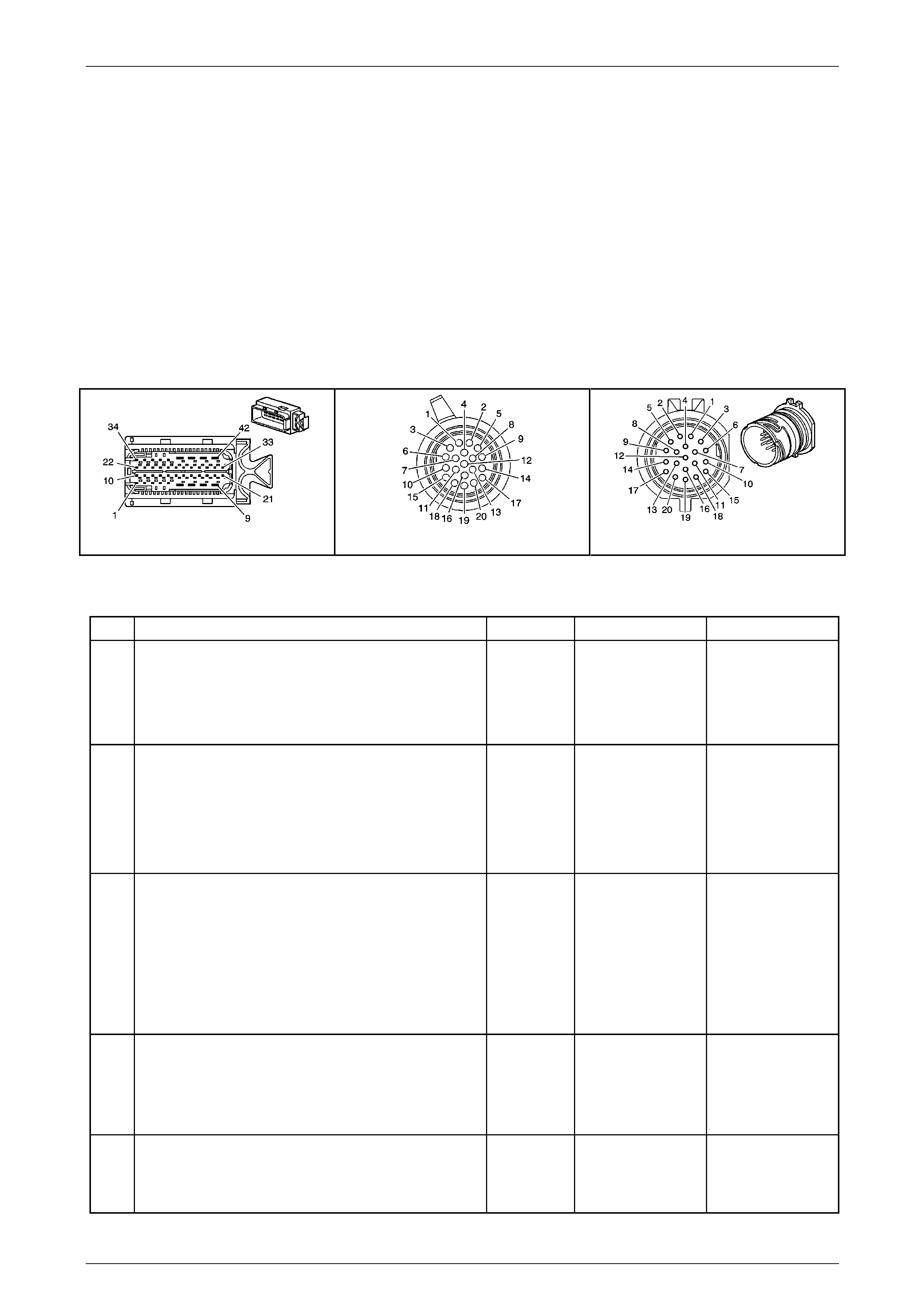
Automatic Transmission – 5L40-E – Electrical Diagnosis Page 7E – 162
Page 7E2 – 162
Test Description
The following number(s) refer to the step number(s) on the diagnostic table.
4 Checks for short to ground or open circuit in sole noid supply circuit.
5 Checks for short to voltage on the solenoid supply circuit.
6 Checks for short to ground on the solenoid suppl y circ uit.
7 Checks for open circuit in transmission internal wiring harness.
NOTE
• Refer to Figures 7E2–5 and 7E2–6 for 5L40 –
E automatic transmission electrical circuits.
• For procedures on checking wiring faults,
refer to Section 12P Wiring Diagrams.
A112-T68 – X1 X121-X1 X121-X1a
Figure 7E2 – 53
DTC P0973 – 1–2 Shift Solenoi d Electrical Fault (Open or Short to Ground)
Step Action Value(s) Yes No
1
Has the Diagnostic System Check – Automatic
Transmission been com pleted?
–
Go to Step 2
Go to
2.3 Diagnostic
System Check –
Automatic
Transmission
in this Section.
2
1 Connect the Tech 2 to the DLC.
2 Ignition ON, engine OFF.
3 Clear DTCs.
4 Using the Tech 2, command the 1–2 shift solenoid
ON.
Does the solenoid operat e?
–
Go to Step 10 Go to Step 3
3
1 Ignition OFF.
2 Disconnect transmission wiring harness connector
X121–X1 from transmission 20-way connector.
3 Ignition ON, engine OFF.
4 With a test light connected to ground, probe
terminal X1–17 of transmission wiring har ness
connector X121–X1.
Does the test light illuminate?
–
Go to Step 4 Go to Step 8
4
1 Ignition OFF.
2 Using a digital ohmmeter, measure resistance
between terminals X1-17 and X1-14 of the
transmission 20-way connector, X1 21-X1a.
Is resistance reading within the specified value?
15.0 – 20.3Ω
Go to Step 5 Go to Step 9
5
1 Using a digital ohmmeter, measure resistance
between terminal 17 of the transmission 2 0-way
connector, X121-X1a and ground.
Is the resistance greater than the specified va lue?
More than
50 kΩ Go to Step 6 Go to Step 9

Automatic Transmission – 5L40-E – Electrical Diagnosis Page 7E – 163
Page 7E2 – 163
Step Action Value(s) Yes No
6
1 Disconnect the transmission wiring harness
connector, A112 – T68 from the TCM.
2 Using a digital ohmmeter, check circuit 122 2
between transmission wiring harness TCM
connector A112 – T68, terminal X1–30 a nd the
transmission wiring harness connector X121–X1,
terminal X1–14 for an open circuit condition.
Did you find an open circuit condition?
–
Repair open in
circuit 1222.
Go to Step 13 Go to Step 7
7
1 Using a digital ohmmeter, check circuit 122 2
between transmission wiring harness TCM
connector A112 – T68, terminal X1–30 a nd the
transmission wiring harness connector X121–X1,
terminal X1–14 for a short to ground conditio n.
Did you find a short to ground condition?
– Repair short to
ground in circuit
1222.
Go to Step 13 Go to Step 10
8
1 Ignition OFF.
2 Disconnect transmission wiring harness connector
A112 – T68 from the TCM.
3 Using a digital ohmmeter, check circuit 152 5
between transmission wiring harness TCM
connector A112 – T68, terminal X1–8 and the
transmission wiring harness connector X121–X1,
terminal X1–17 for an open circuit condition.
Did you find an open circuit condition?
–
Repair open in
circuit 1525.
Go to Step 13 Go to Step 10
9
1 Remove transmission fluid pan. Refer to Se ction
7E4 Automatic Transmission – 5L40-E – On-
Vehicle Servicing.
2 Inspect transmission internal wiring harness for
any sign of damage.
3 Using a digital ohmmeter, check the 1–2 sh ift
solenoid wiring circuit between the transmission
20-way connector X1 21-1a, terminals X1-17 and
X1-14 for an open circ uit condition.
4 Also check the circuit for short to ground
condition.
Did you find and correct a condition?
–
Go to Step 11 Go to Step 12
10
1 Replace TCM. Refer to Section 7E4 Automatic
Transmission – 5L40-E – On-V ehicle Servicing for
replacement procedures.
Is the replacement complete?
–
Go to Step 13 –
11
1 Remove and replace transmission internal wiring
harness. Refer to Section 7E4 Automatic
Transmission – 5L40-E – On-V ehicle Servicing.
Is the replacement complete?
–
Go to Step 13 –
12
1 Remove and replace the 1–2 shift solenoid valve.
Refer to Section 7E4 Automatic Transmission –
5L40-E – On-Vehicle Servicing.
Is the replacement complete?
–
Go to Step 13 –
13
1 Perform the following operation to verify the
repair:
• Select DTC on the Tech 2.
• Select Clear info.
2 Operate the vehicle in the Conditions for Running
the DTC.
Has the test run and passed?
–
System OK Go to Step 2
When all diagnosis and repairs are completed, clear all DTCs and verify correct operation

Automatic Transmission – 5L40-E – Electrical Diagnosis Page 7E – 164
Page 7E2 – 164
DTC P0974 – 1–2 Shift Solenoid Electrical Fault (Short to Voltage)
Circuit Description
The 1–2 shift solenoid (SS) valve is located in the control valve body of the transmission. The Transmission Control
Module (TCM) selects the required gear by turning the appropriate shift solenoid on or off, enabling the transmission to
shift. Refer to Shift Solenoid Valve State and Gear Ratio chart in
1.4 Electronic Component Description – Shift Solenoid (SS) Valves in this Section.
The TCM provides voltage to the solen oid through the High Side Driver 2 (HSD2). The TCM uses a second driver to
control the solenoid ground cir c uit. T he controlled ground driver reports feedback voltage to the TCM. When the TCM
commands the 1–2 shift solenoid valve on, the voltage of the control circ uit should be approximately 0 volts. When the
TCM commands the 1–2 shift solenoid valve off, the voltage of the control circuit should be approximately system
voltage.
When the TCM detects a continuous short to voltage in the 1–2 shift solenoid valve circuit, then DTC P0974 sets, which
is a type ‘B’ DTC.
Conditions for Running the DTC
• Ignition voltage is bet ween 8.0 and 18. 0 volts.
• Engine is running between 450 and 6,800 rpm for at least 5 seconds.
• The HSD2 is commanded on.
Conditions for Setting the DTC
• DTC P0974 sets when the TCM detects a short to voltage in the 1– 2 shift solenoid valve circuit.
Action Taken When the DT C Sets
• The TCM requests the Powertrain Interface Module (PIM) to illumin ate the Check Powertrain Malfunction Indicator
Lamp (MIL) in the instrument cluster during the second consecutive drive trip in which the ‘Conditions for Setting
the DTC’ are met.
• At the time of the first failure, the TCM records the operating conditions when the ‘Conditions for Settin g the DTC’
have been met. The TCM stores this information as a failure record.
• At the time of the second failure, the ECM records the operating conditions when the ‘Conditions for Set ting the
DTC’ have been met. The ECM stores this information as a freeze frame.
• The TCM turns off the pressure control solenoid (causing maximum line pressure).
• The TCM freezes the transmission adaptive learning function.
• The TCM inhibits 3–2 downshifts if the vehicle speed is less than 8 km/h.
• The TCM stores DTC P0974 into TCM history.
Conditions for Clearing the MIL / DTC
• Tech 2 can clear the DTC.
• The TCM clears the DTC from its memory (history DTC) if the vehicle completes 40 warm-up cycles without a non-
emission related DTC occurring.
• The TCM cancels the default actions when the ignition is off long enou gh to power down the TCM.
• The PIM turns off the Check Powertrain MIL after the sixth consecutive drive trip in which the TCM does not send a
Check Powertrain MIL illumination request.
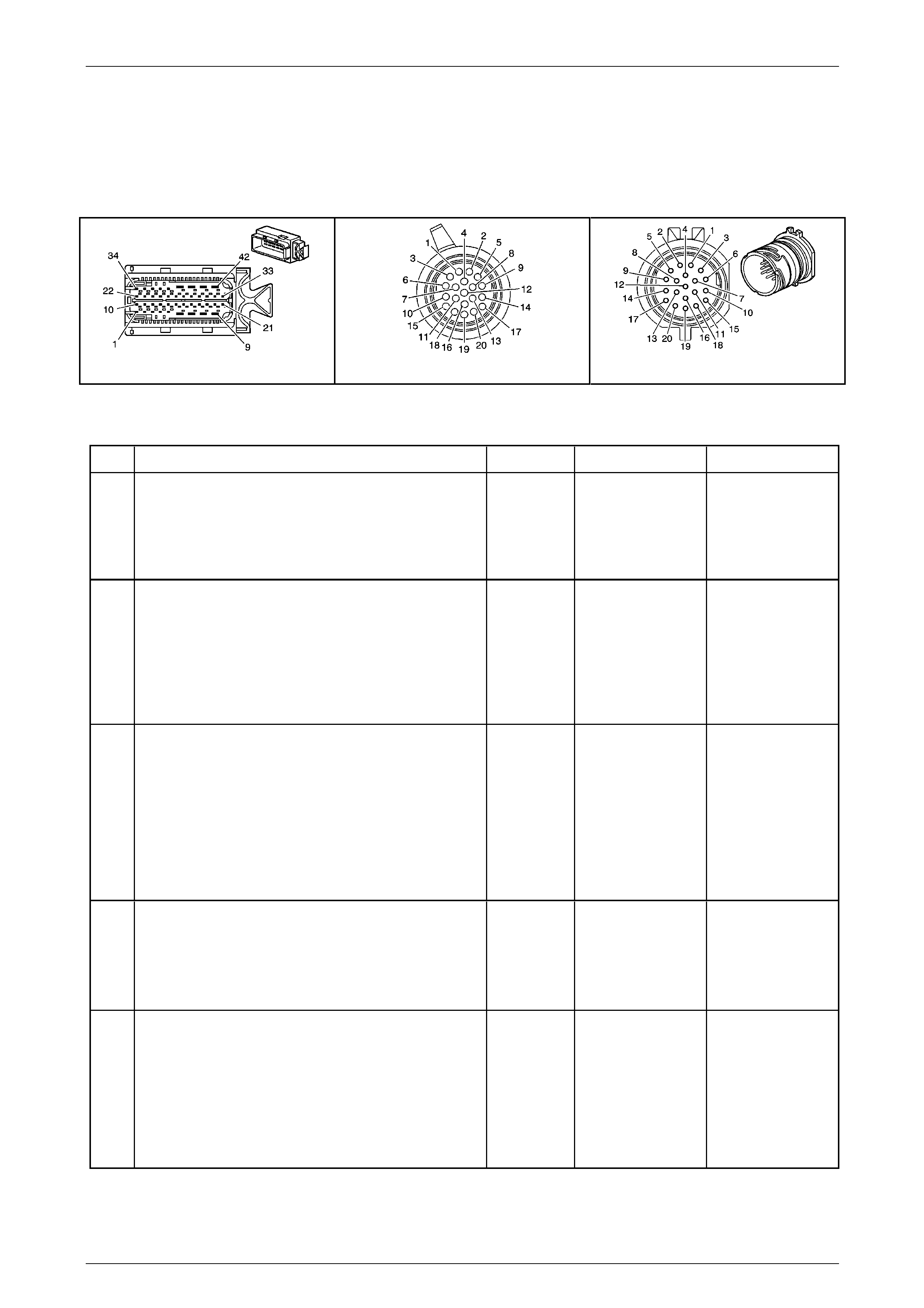
Automatic Transmission – 5L40-E – Electrical Diagnosis Page 7E – 165
Page 7E2 – 165
NOTE
• Refer to Figures 7E2–5 and 7E2–6 for 5L40 –
E automatic transmission electrical circuits.
• For procedures on checking wiring faults,
refer to Section 12P Wiring Diagrams.
A112-T68 – X1 X121-X1 X121-X1a
Figure 7E2 – 54
DTC P0974 – 1–2 Shift Solenoi d Electrical Fault (Short to Voltage)
Step Action Value(s) Yes No
1
Has the Diagnostic System Check – Automatic
Transmission been com pleted?
–
Go to Step 2
Go to
2.3 Diagnostic
System Check –
Automatic
Transmission
in this Section.
2
1 Connect the Tech 2 to the DLC.
2 Ignition ON, engine OFF.
3 Clear DTCs.
4 Using the Tech 2, command the 1–2 shift solenoid
ON.
Does the solenoid operat e?
–
Go to Step 10 Go to Step 3
3
1 Ignition OFF.
2 Disconnect transmission wiring harness connector
X12-X1 from transmission 20-way connector
3 Ignition ON, engine OFF.
4 With a test light connected to ground, probe
terminal X1–17 of transmission wiring har ness
connector X121–X1.
Does the test light illuminate?
–
Go to Step 4 Go to Step 6
4
1 Ignition OFF.
2 Using a digital ohmmeter, measure resistance
between terminals X1-17 and X1-14 of the
transmission 20-way connector, X1 21-X1a.
Is resistance reading within the specified value?
15.0 – 20.3Ω
Go to Step 5 Go to Step 7
5
1 Disconnect the transmission wiring harness
connector A112 – T68 from the TCM.
2 Using a digital voltmeter, check the 1–2 solenoid
valve control circuit 1222 for short to voltage
condition bet ween transm ission wiring harness
TCM connector A112 – T68, termina l X1–30 and
connector X121–X1, terminal X1–1 4.
Does check indicate a short to voltage in the wiring?
–
Go to Step 9 Go to Step 8

Automatic Transmission – 5L40-E – Electrical Diagnosis Page 7E – 166
Page 7E2 – 166
Step Action Value(s) Yes No
6
1 Ignition OFF.
2 Disconnect the wiring harness connector,
A112 – T68, from the TCM.
3 Using a digital ohmmeter, check the HSD2 ci rcuit
1525 between transmission wiring harness TCM
connector A112 – T68, terminal X1–8 and the
connector X121–X1, terminal X1–17 for an open
circuit condition.
Did you find an open circuit condition?
–
Repair open in
circuit 1525.
Go to Step 11 Go to Step 8
7
1 Remove transmission fluid pan. Refer to Se ction
7E4 Automatic Transmission – 5L40-E – On-
Vehicle Servicing.
2 Inspect transmission internal wiring harness for
any sign of damage.
3 Using a digital voltmeter, check the 1–2 shift
solenoid wiring circuit between TCM 20-way
connector, terminals 17 and 14 for a short to
voltage condition.
Did you find a short to voltage condition?
–
Repair short to
voltage condition in
relevant circuit.
Go to Step 11 Go to Step 10
8
1 Replace TCM. Refer to Section 7E4 Automatic
Transmission – 5L40-E – On-V ehicle Servicing for
replacement procedures.
Is the replacement complete?
–
Go to Step 11 –
9
1 Remove and replace transmission internal wiring
harness. Refer to Section 7E4 Automatic
Transmission – 5L40-E – On-V ehicle Servicing.
Is the replacement complete?
–
Go to Step 11 –
10
1 Remove and replace the 1–2 shift solenoid valve.
Refer to Section 7E4 Automatic Transmission –
5L40-E – On-Vehicle Servicing.
Is the replacement complete?
–
Go to Step 11 –
11
1 Perform the following operation to verify the
repair:
• Select DTC on the Tech 2.
• Select Clear info.
2 Operate the vehicle in the Conditions for Running
the DTC.
Has the test run and passed?
–
System OK Go to Step 2
When all diagnosis and repairs are completed, clear all DTCs and verify correct operation

Automatic Transmission – 5L40-E – Electrical Diagnosis Page 7E – 167
Page 7E2 – 167
DTC P0976 – 2–3 Shift Solenoid Electrical Fault (Open or Short to Ground)
Circuit Description
The 2–3 shift solenoid (SS) valve is located in the control valve body of the transmission. The Transmission Control
Module (TCM) selects the required gear by turning the appropriate shift solenoid on or off, enabling the transmission to
shift. Refer to Shift Solenoid Valve State and Gear Ratio chart in
1.4 Electronic Component Description – Shift Solenoid (SS) Valves in this Section.
The TCM provides voltage to the solen oid through the High Side Driver 2 (HSD2). The TCM uses a second driver to
control the solenoid ground cir c uit. T he controlled ground driver reports feedback voltage to the TCM. When the TCM
commands the 2–3 shift solenoid valve on, the voltage of the control circ uit should be approximately 0 volts. When the
TCM commands the 2–3 shift solenoid valve off, the voltage of the control circuit should be approximately system
voltage.
When the TCM detects a continuous open or short to ground in the 2–3 shift solenoid valve circuit, then DTC P0976 sets,
which is a type ‘B’ DTC.
Conditions for Running the DTC
• Ignition voltage is bet ween 8.0 and 18. 0 volts.
• Engine is running between 450 and 6,800 rpm for at least 5 seconds.
• The HSD2 is commanded ON.
Conditions for Setting the DTC
• DTC P0976 sets when either of the following two conditions occur:
• The TCM detects an open in the 2–3 shift sol enoid valve circuit when the HSD2 is commanded ON.
• The TCM detects a short to ground in the 2–3 shift solenoid valve circuit when the HSD2 is commanded OFF.
Action Taken When the DT C Sets
• Powertrain braking is disabled at the time that the TCM first detects the failure, before the DTC sets.
• The TCM requests the Powertrain Interface Module (PIM) to illumin ate the Check Powertrain Malfunction Indicator
Lamp (MIL) in the instrument cluster during the second consecutive drive trip in which the ‘Conditions for Setting
the DTC’ are met.
• The TCM turns off power to all solenoids. When the solenoids are off:
• The transmission will operate in fifth gear if the vehicle has successfully completed a 1–2 upshift in the
current ignition cycle. If the vehicle has not completed a 1–2 shift in the current ign ition cycle, the
transmission will operate in fourth gear. If the transmission is operating in fifth gear, fourth gear may be
obtained if the engine is stopp ed briefly and started again.
• Line pressure is at maximum.
• Torque converter clutch is disabled.
• The TCM freezes the transmission adaptive learning function.
• At the time of the first failure, the TCM records the operating conditions when the ‘Conditions for Setting the DTC’
have been met. The TCM stores this information as a failure record.
• At the time of the second failure, the ECM records the operating conditions when the ‘Conditions for Set ting the
DTC’ have been met. The ECM stores this information as a freeze frame.
• The TCM stores DTC P0976 into TCM history.
Conditions for Clearing the MIL / DTC
• Tech 2 can clear the DTC.
• The TCM clears the DTC from its memory (history DTC) if the vehicle completes 40 warm-up cycles without a non-
emission related DTC occurring.
• The TCM cancels the default actions when the ignition is off long enou gh to power down the TCM.
• The PIM turns off the Check Powertrain MIL after the sixth consecutive drive trip in which the TCM does not send a
Check Powertrain MIL illumination request.
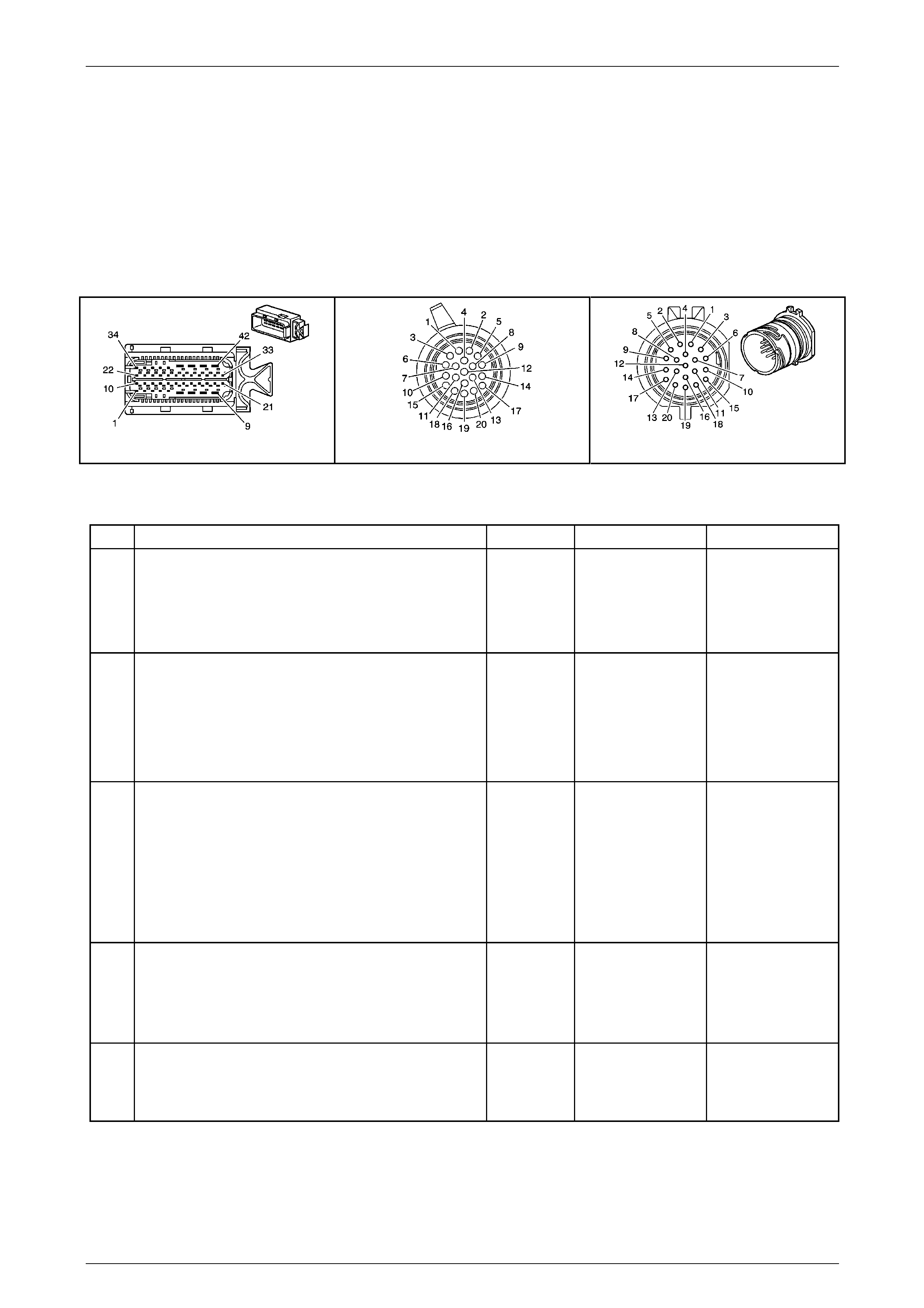
Automatic Transmission – 5L40-E – Electrical Diagnosis Page 7E – 168
Page 7E2 – 168
Test Description
The following number(s) refer to the step number(s) on the diagnostic table.
2 Listen for an audible click when the solenoid energises.
NOTE
• Refer to Figures 7E2–5 and 7E2–6 for 5L40 –
E automatic transmission electrical circuits.
• For procedures on checking wiring faults,
refer to Section 12P Wiring Diagrams.
A112-T68 – X1 X121-X1 X121-X1a
Figure 7E2 – 55
DTC P0976 – 2–3 Shift Solenoi d Electrical Fault (Open or Short to Ground)
Step Action Value(s) Yes No
1
Has the Diagnostic System Check – Automatic
Transmission been com pleted?
–
Go to Step 2
Go to
2.3 Diagnostic
System Check –
Automatic
Transmission
in this Section.
2
1 Connect the Tech 2 to the DLC.
2 Ignition ON, engine OFF.
3 Clear DTCs.
4 Using the Tech 2, command the 2–3 shift solenoid
ON.
Does the solenoid operat e?
–
Go to Step 10 Go to Step 3
3
1 Ignition OFF.
2 Disconnect transmission wiring harness connector
X121–X1 from transmission 20-way connector.
3 Ignition ON, engine OFF.
4 With a test light connected to ground, probe
terminal X1–17 of transmission wiring har ness
connector X121–X1.
Does the test light illuminate?
–
Go to Step 4 Go to Step 8
4
1 Ignition OFF.
2 Using a digital ohmmeter, measure resistance
between terminals X1-17 and X1-9 of the
transmission 20-way connector, X1 21-X1a.
Is resistance reading within the specified value?
15.0 – 20.3Ω
Go to Step 5 Go to Step 9
5
1 Using a digital ohmmeter, measure resistance
between terminal 17 of the transmission 2 0-way
connector, X121-X1a and ground.
Is the resistance greater than the specified va lue?
More than
50 kΩ Go to Step 6 Go to Step 9

Automatic Transmission – 5L40-E – Electrical Diagnosis Page 7E – 169
Page 7E2 – 169
Step Action Value(s) Yes No
6
1 Disconnect the transmission wiring harness
connector, A112 – T68 from the TCM.
2 Using a digital ohmmeter, check circuit 122 3
between transmission wiring harness TCM
connector A112 – T68, terminal X1–18 a nd the
transmission wiring harness connector X121–X1,
terminal X1–9 for an open circ uit condition.
Did you find an open circuit condition?
–
Repair open in
circuit 1223.
Go to Step 13 Go to Step 7
7
1 Using a digital ohmmeter, check circuit 122 3
between transmission wiring harness TCM
connector A112 – T68, terminal X1–18 a nd the
transmission wiring harness connector X121–X1,
terminal X1–9 for a short to ground conditio n.
Did you find a short to ground condition?
– Repair short to
ground in circuit
1223.
Go to Step 13 Go to Step 10
8
1 Ignition OFF.
2 Disconnect transmission wiring harness connector
A112 – T68 from the TCM.
3 Using a digital ohmmeter, check circuit 152 5
between transmission wiring harness TCM
connector A112 – T68, terminal X1–8 and the
transmission wiring harness connector X121–X1,
terminal X1–17 for an open circuit condition.
Did you find an open circuit condition?
–
Repair open in
circuit 1525.
Go to Step 13 Go to Step 10
9
1 Remove transmission fluid pan. Refer to Se ction
7E4 Automatic Transmission – 5L40-E – On-
Vehicle Servicing.
2 Inspect transmission internal wiring harness for
any sign of damage.
3 Using a digital ohmmeter, check the 2–3 sh ift
solenoid wiring circuit between the transmission
20-way connector X1 21-1a, terminals X1-17 and
X1-9 for an open circuit condition.
4 Also check the circuit for short to ground
condition.
Did you find and correct a condition?
–
Go to Step 11 Go to Step 12
10
1 Replace TCM. Refer to Section 7E4 Automatic
Transmission – 5L40-E – On-V ehicle Servicing for
replacement procedures.
Is the replacement complete?
–
Go to Step 13 –
11
1 Remove and replace transmission internal wiring
harness. Refer to Section 7E4 Automatic
Transmission – 5L40-E – On-V ehicle Servicing.
Is the replacement complete?
–
Go to Step 13 –
12
1 Remove and replace the 2–3 shift solenoid valve.
Refer to Section 7E4 Automatic Transmission –
5L40-E – On-Vehicle Servicing.
Is the replacement complete?
–
Go to Step 13 –
13
1 Perform the following operation to verify the
repair:
• Select DTC on the Tech 2.
• Select Clear info.
2 Operate the vehicle in the Conditions for Running
the DTC.
Has the test run and passed?
–
System OK Go to Step 2
When all diagnosis and repairs are completed, clear all DTCs and verify correct operation

Automatic Transmission – 5L40-E – Electrical Diagnosis Page 7E – 170
Page 7E2 – 170
DTC P0977 – 2–3 Shift Solenoid Electrical Fault (Short to Voltage)
Circuit Description
The 2–3 shift solenoid (SS) valve is located in the control valve body of the transmission. The Transmission Control
Module (TCM) selects the required gear by turning the appropriate shift solenoid on or off, enabling the transmission to
shift. Refer to Shift Solenoid Valve State and Gear Ratio chart in
1.4 Electronic Component Description – Shift Solenoid (SS) Valves in this Section.
The TCM provides voltage to the solen oid through the High Side Driver 2 (HSD2). The TCM uses a second driver to
control the solenoid ground cir c uit. T he controlled ground driver reports feedback voltage to the TCM. When the TCM
commands the 2–3 shift solenoid valve on, the voltage of the control circ uit should be approximately 0 volts. When the
TCM commands the 2–3 shift solenoid valve off, the voltage of the control circuit should be approximately system
voltage.
When the TCM detects a continuous open or short to ground in the 2–3 shift solenoid valve circuit, then DTC P0977 sets,
which is a type ‘B’ DTC.
Conditions for Running the DTC
• Ignition voltage is bet ween 8.0 and 18. 0 volts.
• Engine is running between 450 and 6,800 rpm for at least 5 seconds.
• The HSD2 is commanded on.
Conditions for Setting the DTC
• DTC P0977 sets when the TCM detects a short to voltage in the 2– 3 shift solenoid valve circuit.
Action Taken When the DT C Sets
• The TCM requests the Powertrain Interface Module (PIM) to illumin ate the Check Powertrain Malfunction Indicator
Lamp (MIL) in the instrument cluster during the second consecutive drive trip in which the ‘Conditions for Setting
the DTC’ are met.
• The TCM turns off the pressure control solenoid (causing maximum line pressure).
• The TCM freezes the transmission adaptive learning function.
• The TCM inhibits first gear.
• At the time of the first failure, the TCM records the operating conditions when the ‘Conditions for Settin g the DTC’
have been met. The TCM stores this information as a failure record.
• At the time of the second failure, the ECM records the operating conditions when the ‘Conditions for Set ting the
DTC’ have been met. The ECM stores this information as a freeze frame.
• The TCM stores DTC P0977 into TCM history.
Conditions for Clearing the MIL / DTC
• Tech 2 can clear the DTC.
• The TCM clears the DTC from its memory (history DTC) if the vehicle completes 40 warm-up cycles without a non-
emission related DTC occurring.
• The TCM cancels the default actions when the ignition is off long enou gh to power down the TCM.
• The ECM turns off the MIL after the sixth consecutive drive trip in which the TCM does not send a MIL ill umination
request.
Test Description
The following number(s) refer to the step number(s) on the diagnostic table.
2 Listen for an audible click when the solenoid energises.

Automatic Transmission – 5L40-E – Electrical Diagnosis Page 7E – 171
Page 7E2 – 171
NOTE
• Refer to Figures 7E2–5 and 7E2–6 for 5L40 –
E automatic transmission electrical circuits.
• For procedures on checking wiring faults,
refer to Section 12P Wiring Diagrams.
A112-T68 – X1 X121-X1 X121-X1a
Figure 7E2 – 56
DTC P0977 – 2–3 Shift Solenoi d Electrical Fault (Short to Voltage)
Step Action Value(s) Yes No
1
Has the Diagnostic System Check – Automatic
Transmission been com pleted?
–
Go to Step 2
Go to
2.3 Diagnostic
System Check –
Automatic
Transmission
in this Section.
2
1 Connect the Tech 2 to the DLC.
2 Ignition ON, engine OFF.
3 Clear DTCs.
4 Using the Tech 2, command the 2–3 shift solenoid
ON.
Does the solenoid operat e?
–
Go to Step 8 Go to Step 3
3
1 Ignition OFF.
2 Disconnect transmission wiring harness connector
X121-X1 from transmission 20 -way connector
3 Ignition ON, engine OFF.
4 With a test light connected to ground, probe
terminal X1–17 of transmission wiring har ness
connector X121–X1.
Does the test light illuminate?
–
Go to Step 4 Go to Step 6
4
1 Ignition OFF.
2 Using a digital ohmmeter, measure resistance
between terminals X1-17 and X1-9 of the
transmission 20-way connector, X1 21-X1a.
Is resistance reading within the specified value?
15.0 – 20.3Ω
Go to Step 5 Go to Step 7
5
1 Disconnect the transmission wiring harness
connector A112 – T68 from the TCM.
2 Using a digital voltmeter, check the 2–3 solenoid
valve control circuit 1223 for short to voltage
condition bet ween transm ission wiring harness
TCM connector A112 – T68, termina l X1–18 and
connector X121–X1, terminal X1–9.
Does check indicate a short to voltage in the wiring?
–
Go to Step 9 Go to Step 8

Automatic Transmission – 5L40-E – Electrical Diagnosis Page 7E – 172
Page 7E2 – 172
Step Action Value(s) Yes No
6
1 Ignition OFF.
2 Disconnect the wiring harness connector,
A112 – T68, from the TCM.
3 Using a digital ohmmeter, check the HSD2 ci rcuit
1525 between transmission wiring harness TCM
connector A112 – T68, terminal X1–8 and the
connector X121–X1, terminal X1–17 for an open
circuit condition.
Did you find an open circuit condition?
–
Repair open in
circuit 1525.
Go to Step 11 Go to Step 8
7
1 Remove transmission fluid pan. Refer to
Section 7E4 Automatic Tr ansmission – 5L40-E –
On-Vehicle Servicing.
2 Inspect transmission internal wiring harness for
any sign of damage.
3 Using a digital voltmeter, check the 2–3 shift
solenoid wiring circuit between TCM 20-way
connector X121-X1a terminals X1-17 and X1-14
for a short to voltage condition.
Did you find a short to voltage condition?
–
Repair short to
voltage condition in
relevant circuit.
Go to Step 11 Go to Step 10
8
1 Replace TCM. Refer to Section 7E4 Automatic
Transmission – 5L40-E – On-V ehicle Servicing for
replacement procedures.
Is the replacement complete?
–
Go to Step 11 –
9
1 Remove and replace transmission internal wiring
harness. Refer to Section 7E4 Automatic
Transmission – 5L40-E – On-V ehicle Servicing.
Is the replacement complete?
–
Go to Step 11 –
10
1 Remove and replace the 2–3 shift solenoid valve.
Refer to Section 7E4 Automatic Transmission –
5L40-E – On-Vehicle Servicing.
Is the replacement complete?
–
Go to Step 11 –
11
1 Perform the following operation to verify the
repair:
• Select DTC on the Tech 2.
• Select Clear info.
2 Operate the vehicle in the Conditions for Running
the DTC.
Has the test run and passed?
–
System OK Go to Step 2
When all diagnosis and repairs are completed, clear all DTCs and verify correct operation

Automatic Transmission – 5L40-E – Electrical Diagnosis Page 7E – 173
Page 7E2 – 173
DTC P0979 – 4–5 Shift Solenoid Electrical Fault (Open or Short to Ground)
Circuit Description
The 4–5 shift solenoid (SS) valve is located in the control valve body of the transmission. The Transmission Control
Module (TCM) selects the required gear by turning the appropriate shift solenoid on or off, enabling the transmission to
shift. Refer to Shift Solenoid Valve State and Gear Ratio chart in
1.4 Electronic Component Description – Shift Solenoid (SS) Valves in this Section.
The TCM provides voltage to the solen oid through the High Side Driver 2 (HSD2). The TCM uses a second driver to
control the solenoid ground cir c uit. T he controlled ground driver reports feedback voltage to the TCM. When the TCM
commands the 4–5 shift solenoid valve on, the voltage of the control circ uit should be approximately 0 volts. When the
TCM commands the 4–5 shift solenoid valve off, the voltage of the control circuit should be approximately system
voltage.
When the TCM detects a continuous open or short to ground in the 4–5 shift solenoid valve circuit, then DTC P0979 sets,
which is a type ‘B’ DTC.
Conditions for Running the DTC
• Ignition voltage is bet ween 8.0 and 18. 0 volts.
• Engine is running between 450 and 6,800 rpm for at least 5 seconds.
• The HSD2 is commanded on.
Conditions for Setting the DTC
• DTC P0979 sets when either of the following two conditions occur:
• The TCM detects an open in the 4–5 shift sol enoid valve circuit when the HSD2 is commanded ON.
• The TCM detects a short to ground in the 4–5 shift solenoid valve circuit when the HSD2 is commanded OFF.
Action Taken When the DT C Sets
• The TCM requests the Powertrain Interface Module (PIM) to illumin ate the Check Powertrain Malfunction Indicator
Lamp (MIL) in the instrument cluster during the second consecutive drive trip in which the ‘Conditions for Setting
the DTC’ are met.
• The TCM turns off power to all solenoids. When the solenoids are off:
• The transmission will operate in fifth gear if the vehicle has successfully completed a 1–2 upshift in the
current ignition cycle. If the vehicle has not completed a 1–2 shift in the current ign ition cycle, the
transmission will operate in fourth gear. If the transmission is operating in fifth gear, fourth gear may be
obtained if the engine is stopp ed briefly and started again.
• Line pressure is at maximum.
• The TCM freezes the transmission adaptive learning function.
• Torque converter clutch is disabled.
• At the time of the first failure, the TCM records the operating conditions when the ‘Conditions for Setting the DTC’
have been met. The TCM stores this information as a failure record.
• At the time of the second failure, the ECM records the operating conditions when the ‘Conditions for Set ting the
DTC’ have been met. The ECM stores this information as a freeze frame.
• The TCM stores DTC P0979 into TCM history.
Conditions for Clearing the MIL / DTC
• Tech 2 can clear the DTC.
• The TCM clears the DTC from its memory (history DTC) if the vehicle completes 40 warm-up cycles without a non-
emission related DTC occurring.
• The TCM cancels the default actions when the ignition is off long enou gh to power down the TCM.
• The ECM turns off the MIL after the sixth consecutive drive trip in which the TCM does not send a MIL ill umination
request.
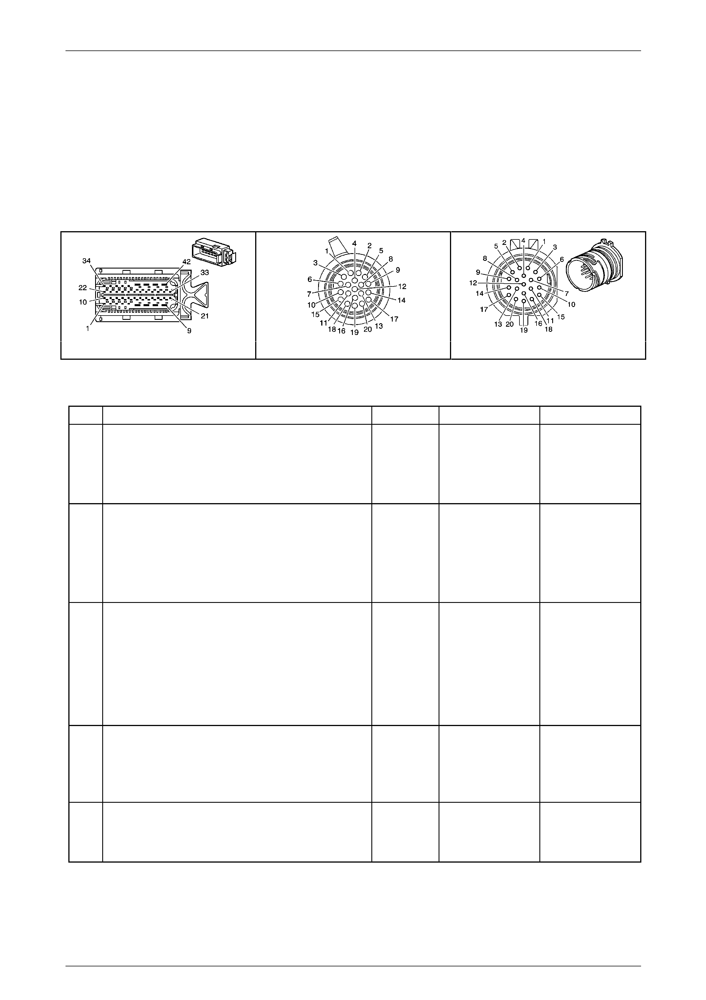
Automatic Transmission – 5L40-E – Electrical Diagnosis Page 7E – 174
Page 7E2 – 174
Test Description
The following number(s) refer to the step number(s) on the diagnostic table.
2 Listen for an audible click when the solenoid energises.
NOTE
• Refer to Figures 7E2–5 and 7E2–6 for 5L40 –
E automatic transmission electrical circuits.
• For procedures on checking wiring faults,
refer to Section 12P Wiring Diagrams.
A112-T68 – X1 X121-X1 X121-X1a
Figure 7E2 – 57
DTC P0979 – 4–5 Shift Solenoi d Electrical Fault (Open or Short to Ground)
Step Action Value(s) Yes No
1
Has the Diagnostic System Check – Automatic
Transmission been com pleted?
–
Go to Step 2
Go to
2.3 Diagnostic
System Check –
Automatic
Transmission
in this Section.
2
1 Connect the Tech 2 to the DLC.
2 Ignition ON, engine OFF.
3 Clear DTCs.
4 Using the Tech 2, command the 4–5 shift solenoid
ON.
Does the solenoid operat e?
–
Go to Step 10 Go to Step 3
3
1 Ignition OFF.
2 Disconnect transmission wiring harness connector
X121–X1 from transmission 20-way connector.
3 Ignition ON, engine OFF.
4 With a test light connected to ground, probe
terminal X1–17 of transmission wiring har ness
connector X121–X1.
Does the test light illuminate?
–
Go to Step 4 Go to Step 8
4
1 Ignition OFF.
2 Using a digital ohmmeter, measure resistance
between terminals X1-17 and X1-5 of the
transmission 20-way connector, X1 21-X1a.
Is resistance reading within the specified value?
15.0 – 20.3Ω
Go to Step 5 Go to Step 9
5
1 Using a digital ohmmeter, measure resistance
between terminal 17 of the transmission 2 0-way
connector, X121-X1a and ground.
Is the resistance greater than the specified va lue?
More than
50 kΩ Go to Step 6 Go to Step 9

Automatic Transmission – 5L40-E – Electrical Diagnosis Page 7E – 175
Page 7E2 – 175
Step Action Value(s) Yes No
6
1 Disconnect the transmission wiring harness
connector, A112 – T68 from the TCM.
2 Using a digital ohmmeter, check circuit 122 2
between transmission wiring harness TCM
connector A112 – T68, terminal X1–19 a nd the
transmission wiring harness connector X121–X1,
terminal X1–5 for an open circ uit condition.
Did you find an open circuit condition?
–
Repair open in
circuit 898.
Go to Step 13 Go to Step 7
7
1 Using a digital ohmmeter, check circuit 898
between transmission wiring harness TCM
connector A112 – T68, terminal X1–19 a nd the
transmission wiring harness connector X121–X1,
terminal X1–5 for a short to ground conditio n.
Did you find a short to ground condition?
– Repair short to
ground in circuit
898.
Go to Step 13 Go to Step 10
8
1 Ignition OFF.
2 Disconnect transmission wiring harness connector
A112 – T68 from the TCM.
3 Using a digital ohmmeter, check circuit 152 5
between transmission wiring harness TCM
connector A112 – T68, terminal X1–8 and the
transmission wiring harness connector X121–X1,
terminal X1–17 for an open circuit condition.
Did you find an open circuit condition?
–
Repair open in
circuit 1525.
Go to Step 13 Go to Step 10
9
1 Remove transmission fluid pan. Refer to
Section 7E4 Automatic Tr ansmission – 5L40-E –
On-Vehicle Servicing.
2 Inspect transmission internal wiring harness for
any sign of damage.
3 Using a digital ohmmeter, check the 4–5 sh ift
solenoid wiring circuit between the transmission
20-way connector X1 21-1a, terminals X1-17 and
X1-14 for an open circ uit condition.
4 Also check the circuit for short to ground
condition.
Did you find and correct a condition?
–
Go to Step 11 Go to Step 12
10
1 Replace TCM. Refer to Section 7E4 Automatic
Transmission – 5L40-E – On-V ehicle Servicing for
replacement procedures.
Is the replacement complete?
–
Go to Step 13 –
11
1 Remove and replace transmission internal wiring
harness. Refer to Section 7E4 Automatic
Transmission – 5L40-E – On-V ehicle Servicing.
Is the replacement complete?
–
Go to Step 13 –
12
1 Remove and replace the 4–5 shift solenoid valve.
Refer to Section 7E4 Automatic Transmission –
5L40-E – On-Vehicle Servicing.
Is the replacement complete?
–
Go to Step 13 –
13
1 Perform the following operation to verify the
repair:
• Select DTC on the Tech 2.
• Select Clear info.
2 Operate the vehicle in the Conditions for Running
the DTC.
Has the test run and passed?
–
System OK Go to Step 2
When all diagnosis and repairs are completed, clear all DTCs and verify correct operation

Automatic Transmission – 5L40-E – Electrical Diagnosis Page 7E – 176
Page 7E2 – 176
DTC P0980 – 4–5 Shift Solenoid Electrical Fault (Short to Voltage)
Circuit Description
The 4–5 shift solenoid (SS) valve is located in the control valve body of the transmission. The Transmission Control
Module (TCM) selects the required gear by turning the appropriate shift solenoid on or off, enabling the transmission to
shift. Refer to Shift Solenoid Valve State and Gear Ratio chart in
1.4 Electronic Component Description – Shift Solenoid (SS) Valves in this Section.
The TCM provides voltage to the solen oid through the High Side Driver 2 (HSD2). The TCM uses a second driver to
control the solenoid ground cir c uit. T he controlled ground driver reports feedback voltage to the TCM. When the TCM
commands the 4–5 shift solenoid valve on, the voltage of the control circ uit should be approximately 0 volts. When the
TCM commands the 4–5 shift solenoid valve off, the voltage of the control circuit should be approximately system
voltage.
When the TCM detects a continuous open or short to ground in the 4–5 shift solenoid valve circuit, then DTC P0979 sets,
which is a type ‘B’ DTC.
Conditions for Running the DTC
• Ignition voltage is bet ween 8.0 and 18. 0 volts.
• Engine is running between 450 and 6,800 rpm for at least 5 seconds.
• The HSD2 is commanded on.
Conditions for Setting the DTC
DTC P0980 sets when the TCM detects a short to voltage in the 4– 5 shift solenoid valve circuit.
Action Taken When the DT C Sets
• The TCM requests the Powertrain Interface Module (PIM) to illumin ate the Check Powertrain Malfunction Indicator
Lamp (MIL) in the instrument cluster during the second consecutive drive trip in which the ‘Conditions for Setting
the DTC’ are met.
• The TCM turns off power to all solenoids. When the solenoids are off:
• The transmission will operate in fifth gear if the vehicle has successfully completed a 1–2 upshift in the
current ignition cycle. If the vehicle has not completed a 1–2 shift in the current ign ition cycle, the
transmission will operate in fourth gear. If the transmission is operating in fifth gear, fourth gear may be
obtained if the engine is stopp ed briefly and started again.
• The maximum line pressure is at maximum.
• The TCM freezes the transmission adaptive learning function.
• Torque management is inhibited.
• At the time of the first failure, the TCM records the operating conditions when the ‘Conditions for Setting the DTC’
have been met. The TCM stores this information as a failure record.
• At the time of the second failure, the ECM records the operating conditions when the ‘Conditions for Set ting the
DTC’ have been met. The ECM stores this information as a freeze frame.
• The TCM stores DTC P0980 into TCM history.
Conditions for Clearing the MIL / DTC
• Tech 2 can clear the DTC.
• The TCM clears the DTC from its memory (history DTC) if the vehicle completes 40 warm-up cycles without a non-
emission related DTC occurring.
• The TCM cancels the default actions when the ignition is off long enou gh to power down the TCM.
• The PIM turns off the Check Powertrain MIL after the sixth consecutive drive trip in which the TCM does not send a
Check Powertrain MIL illumination request.
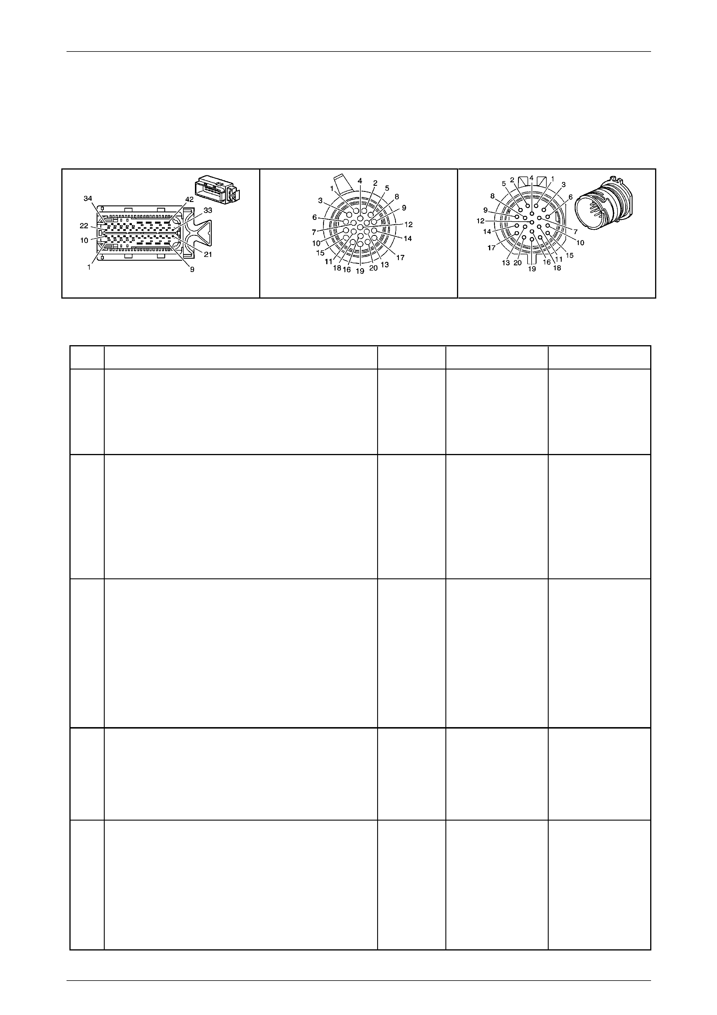
Automatic Transmission – 5L40-E – Electrical Diagnosis Page 7E – 177
Page 7E2 – 177
NOTE
• Refer to Figures 7E2–5 and 7E2–6 for 5L40 –
E automatic transmission electrical circuits.
• For procedures on checking wiring faults,
refer to Section 12P Wiring Diagrams.
A112-T68 – X1 X121-X1 X121-X1a
Figure 7E2 – 58
DTC P0980 – 4–5 Shift Solenoi d Electrical Fault (Short to Voltage)
Step Action Value(s) Yes No
1
Has the Diagnostic System Check – Automatic
Transmission been com pleted?
–
Go to Step 2
Go to
2.3 Diagnostic
System Check –
Automatic
Transmission
in this Section.
2
1 Connect the Tech 2 to the DLC.
2 Ignition ON, engine OFF.
3 Clear DTCs.
4 Using the Tech 2, command the 4–5 shift solenoid
ON.
Does the solenoid operat e?
–
Go to Step 8 Go to Step 3
3
1 Ignition OFF.
2 Disconnect transmission wiring harness connector
X12-X1 from transmission 20-way connector
3 Ignition ON, engine OFF.
4 With a test light connected to ground, probe
terminal X1–17 of transmission wiring har ness
connector X121–X1.
Does the test light illuminate?
–
Go to Step 4 Go to Step 6
4
1 Ignition OFF.
2 Using a digital ohmmeter, measure resistance
between terminals X1-17 and X1-5 of the
transmission 20-way connector, X1 21-X1a.
Is resistance reading within the specified value?
15.0 – 20.3Ω
Go to Step 5 Go to Step 7
5
1 Disconnect the transmission wiring harness
connector A112 – T68 from the TCM.
2 Using a digital voltmeter, check the 4–5 solenoid
valve control circuit 898 for short to voltage
condition bet ween transm ission wiring harness
TCM connector A112 – T68, termina l X1–19 and
connector X121–X1, terminal X1–5.
Does check indicate a short to voltage in the wiring?
–
Go to Step 9 Go to Step 8

Automatic Transmission – 5L40-E – Electrical Diagnosis Page 7E – 178
Page 7E2 – 178
Step Action Value(s) Yes No
6
1 Ignition OFF.
2 Disconnect the wiring harness connector,
A112 – T68, from the TCM.
3 Using a digital ohmmeter, check the HSD2 ci rcuit
1525 between transmission wiring harness TCM
connector A112 – T68, terminal X1–8 and the
connector X121–X1, terminal X1–17 for an open
circuit condition.
Did you find an open circuit condition?
–
Repair open in
circuit 1525.
Go to Step 11 Go to Step 8
7
1 Remove transmission fluid pan. Refer to
Section 7E4 Automatic Tr ansmission – 5L40-E –
On-Vehicle Servicing.
2 Inspect transmission internal wiring harness for
any sign of damage.
3 Using a digital voltmeter, check the 4–5 shift
solenoid wiring circuit between TCM 20-way
connector X121-X1a terminals X1- 17 and X1-5 for
a short to voltage condition.
Did you find a short to voltage condition?
–
Repair short to
voltage condition in
relevant circuit.
Go to Step 11 Go to Step 10
8
1 Replace TCM. Refer to Section 7E4 Automatic
Transmission – 5L40-E – On-V ehicle Servicing for
replacement procedures.
Is the replacement complete?
–
Go to Step 11 –
9
1 Remove and replace transmission internal wiring
harness. Refer to Section 7E4 Automatic
Transmission – 5L40-E – On-V ehicle Servicing.
Is the replacement complete?
–
Go to Step 11 –
10
1 Remove and replace the 4–5 shift solenoid valve.
Refer to Section 7E4 Automatic Transmission –
5L40-E – On-Vehicle Servicing.
Is the replacement complete?
–
Go to Step 11 –
11
1 Perform the following operation to verify the
repair:
• Select DTC on the Tech 2.
• Select Clear info.
2 Operate the vehicle in the Conditions for Running
the DTC.
Has the test run and passed?
–
System OK Go to Step 2
When all diagnosis and repairs are completed, clear all DTCs and verify correct operation

Automatic Transmission – 5L40-E – Electrical Diagnosis Page 7E – 179
Page 7E2 – 179
DTC P1621 – Power Down Copy Of RAM to NVM
Circuit Description
While the vehicle is being driven, engine and transmission data accumulates in a Random Access Memory (RAM)
device, which cannot store data reliably when the Transmission Control Module (TCM) powers down. Before the TCM
powers down, the data is copied from RAM to an Electrically Erasable Programmable Read-Only Memory (EEPROM)
device, sometimes referred to as Non-Volatile Memory (NVM).
Both the RAM and the EEPROM are inside the T CM. A normal function of the T CM programming is to te st the EEPROM
at TCM power-down by copying test data from RAM to the EEPROM and then comparin g the two copies. If they do not
match, DTC P1621 will set, which is a type ‘A’ DTC.
Conditions for Running the DTC
• The ignition is ON.
Conditions for Setting the DTC
• The TCM detects a checksum error when the RAM and EEPROM test data are compared.
Action Taken When the DT C Sets
• The TCM requests the Powertrain Interface Module (PIM) to illumin ate the Check Powertrain Malfunction Indicator
Lamp (MIL) when the ‘Conditions for Setting the DTC’ are met.
• The TCM turns off the pressure control solenoid (causing maximum line pressure).
• The TCM freezes the transmission adaptive learning function.
• At the time of the first failure, the TCM records the operating conditions when the ‘Conditions for Settin g the DTC’
have been met. The TCM stores this information as a failure record.
• The TCM stores DTC P1621 into TCM history.
Conditions for Clearing the MIL / DTC
• Tech 2 can clear the DTC.
• The TCM clears the DTC from its memory (history DTC) if the vehicle completes 40 warm-up cycles without a non-
emission related DTC occurring.
• The TCM cancels the default actions when the ignition is off long enou gh to power down the TCM.
• The PIM turns off the Check Powertrain MIL after the sixth consecutive drive trip in which the TCM does not send a
Check Powertrain MIL illumination request.
Diagnostic Aids
TCM programming may caus e a P1621 to set.
Test Description
The following number(s) refer to the step number(s) on the diagnostic table.
2 Performing this step helps verify that an external anomaly, such as Electromagnetic Interference (EMI), did not
cause the DTC to set originally.
NOTE
• Refer to Figures 7E2–5 and 7E2–6 for 5L40 –
E automatic transmission electrical circuits.
• For procedures on checking wiring faults,
refer to Section 12P Wiring Diagrams.

Automatic Transmission – 5L40-E – Electrical Diagnosis Page 7E – 180
Page 7E2 – 180
DTC P1621 – Power Down Copy Of RAM to NVM
Step Action Yes No
1
Has the Diagnostic System Check – Automatic T ransmission been
completed? Go to Step 2
Go to
2.3 Diagnostic
System Check –
Automatic
Transmission
in this Section.
2
1 Connect Tech 2 to the DLC.
2 Ignition ON, engine OFF.
3 Clear DTCs.
4 Turn off the ignition for at least 30 seconds.
5 Ignition ON, engine OFF.
Did P1621 reset? Go to Step 3
Go to Intermittent
Conditions, in
Section 6C1–2
Engine
Management – V6 –
Diagnostics.
3 1 Replace TCM. Refer to Section 7E4 Automatic Transmission –
5L40-E – On-Vehicle Servicing for replacement procedur es.
Is the replacement complete? Go to Step 4 –
4
1 Perform the following operation to verify the repair:
• Select DTC on the Tech 2.
• Select Clear info.
2 Operate the vehicle in the Conditions for Running the DTC.
Has the test run and passed? System OK Go to Step 2
When all diagnosis and repairs are completed, clear all DTCs and verify correct operation

Automatic Transmission – 5L40-E – Electrical Diagnosis Page 7E – 181
Page 7E2 – 181
DTC P1793 – Wheel Speed Sensor Signal – No Valid GMLAN Signal
Circuit Description
The Engine Control Module (ECM) sends wheel speed data to the Tr ansmission Control Module (TCM). The data is sent
to the TCM through a communication network called the GM Controller Ar ea Network (GMLAN). Two circuits are used to
communicate GMLAN data between the ECM / TCM and other modules. A fault in the GMLAN will not cause DTC P1793
to set by itself. If a GMLAN fault occurs, other DTCs will set before DTC P1793.
When the TCM receives a invalid wheel speed data from the ECM, then DTC P1793 will set, which is a type ‘C’ DTC.
Conditions for Running the DTC
• Ignition voltage is bet ween 8.0 and 18. 0 volts.
• Engine is running between 450 and 6,800 rpm for at least 5 seconds.
• No other GMLAN errors are present.
Conditions for Setting the DTC
• The TCM receives no valid wheel speed data from the ECM for 2 seconds.
Action Taken When the DT C Sets
• The TCM records the operating conditions when the ‘Conditions for Setting the DTC’ have been met. The T CM
stores this information as a failure record.
• The TCM does not request the Powertrain Interface Module (PIM) to illuminate the Check Powertrain Malfunction
Indicator Lamp (MIL).
• The TCM stores DTC P1793 into TCM history.
Conditions for Clearing the DTC
• Tech 2 can clear the DTC.
• The TCM clears the DTC from its memory (history DTC) if the vehicle completes 40 warm-up cycles without a non-
emission related DTC occurring.
• The TCM cancels the default actions when the ignition is off long enou gh to power down the TCM.
NOTE
• Refer to Figures 7E2–5 and 7E2–6 for 5L40 –
E automatic transmission electrical circuits.
• For procedures on checking wiring faults,
refer to Section 12P Wiring Diagrams.

Automatic Transmission – 5L40-E – Electrical Diagnosis Page 7E – 182
Page 7E2 – 182
DTC P1793 – Wheel Speed Sensor Signal – No Valid GMLAN Signal
Step Action Yes No
1
Has the Diagnostic System Check – Automatic T ransmission been
completed? Go to Step 2
Go to
2.3 Diagnostic
System Check –
Automatic
Transmission
in this Section.
2
1 Connect T ech 2 to the DLC.
2 Ignition ON, engine OFF.
3 Record any EC M DTCs.
Did you record any ECM DTCs?
Go to Section 6C1–
2 Engine
Management – V6 –
Diagnostics and
rectify any ECM
related DTC/s. Go to Step 3
3
1 Clear the DT C.
2 Turn the ignition off for at least 30 seconds.
3 Start engine and allow to idle.
Did DTC P1793 reset? Go to Step 4
Go to Intermittent
Conditions, in
Section 6C1–2
Engine
Management – V6 –
Diagnostics
4
Did any other DTCs set?
Go to the Vehicle
System Diagnostics
that belongs to the
undiagnosed D TC. Go to Step 5
5 1 Replace TCM. Refer to Section 7E4 Automatic Transmission –
5L40-E – On-Vehicle Servicing for replacement procedur es.
Is the replacement complete? Go to Step 6 –
6
1 Perform the following operation to verify the repair:
• Select DTC on the Tech 2.
• Select ‘Clear info’.
2 Operate the vehicle in the Conditions for Running the DTC.
Has the test run and passed? System OK Go to Step 2
When all diagnosis and repairs are completed, clear all DTCs and verify correct operation

Automatic Transmission – 5L40-E – Electrical Diagnosis Page 7E – 183
Page 7E2 – 183
DTC P1815 – IMS Start In Wrong Range
Circuit Description
The transmission internal manua l shift shaft switch assembly is a sliding contact switch attached to the manual shift shaft
inside the transmission case. There are four inputs to the Transmission Control Module (TCM) from the switch which
indicate the position selected by the transmission selector lever. This information is used for engine controls as well as
determining the transmission shift patterns. The input voltage at the TCM is high when the switch is open and low when
the switch is closed to ground. The stat e of each input is displayed on the Tech 2 as IMS (Internal Mode Switch). The
IMS input parameters represented are trans mission range Signal A, Signal B, Signal C and Sign al P (Parity).
If the TCM detects an invalid switch state while the engine is being started, then DTC P1815 sets, which is a type ‘B’
DTC.
Conditions for Running the DTC
• Tested once per ignition cycle, during engine start–up.
• Ignition voltage is bet ween 6.0 and 18. 0 volts.
• No transmission output speed sensor (T OSS) DTCs P0722 or P0723 set.
• Transmission output shaft speed is less than 100 rpm.
Conditions for Setting the DTC
• The manual shift shaft switch assembly indicates a transitional state (not park or neutral) during the following
sequence:
• The engine speed is less than 60 rpm for more than 0.25 second, then,
• The engine speed is 81 to 625 rpm for more than 0.15 seconds, then,
• The engine speed is greater than 651 rpm for more than 1.5 seconds and the transmission input shaft speed is
greater than 200 rpm for more than 1.5 seconds.
Action Taken When the DT C Sets
• The TCM requests the Powertrain Interface Module (PIM) to illumin ate the Check Powertrain Malfunction Indicator
Lamp (MIL) in the instrument cluster during the second consecutive drive trip in which the ‘Conditions for Setting
the DTC’ are met.
• The TCM turns off the pressure control solenoid (causing maximum line pressure).
• The TCM freezes the transmission adaptive learning function.
• The TCM assumes a D5 shift pattern.
• At the time of the first failure, the TCM records the operating conditions when the ‘Conditions for Settin g the DTC’
have been met. The TCM stores this information as a failure record.
• At the time of the second failure, the ECM records the operating conditions when the ‘Conditions for Set ting the
DTC’ have been met. The ECM stores this information as a freeze frame.
• The TCM stores DTC P1815 into TCM history.
Conditions for Clearing the MIL / DTC
• Tech 2 can clear the DTC.
• The TCM clears the DTC from its memory (history DTC) if the vehicle completes 40 warm-up cycles without a non-
emission related DTC occurring.
• The TCM cancels the default actions when the ignition is off long enou gh to power down the TCM.
• The PIM turns off the Check Powertrain MIL after the sixth consecutive drive trip in which the TCM does not send a
Check Powertrain MIL illumination request.
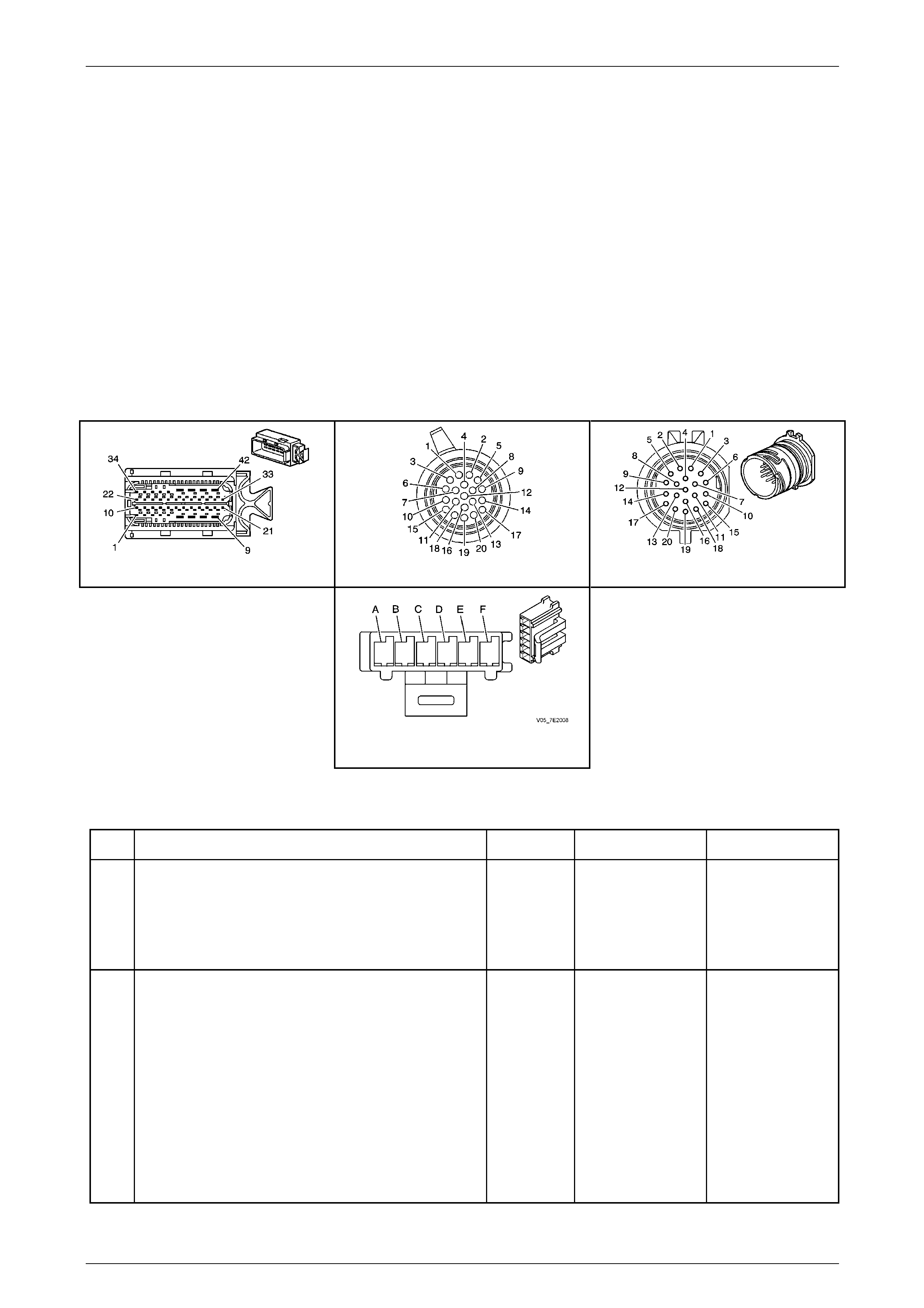
Automatic Transmission – 5L40-E – Electrical Diagnosis Page 7E – 184
Page 7E2 – 184
Test Description
The following number(s) refer to the step number(s) on the diagnostic table.
3 All HI values, in both Park and Drive 5, indicate an open i n the grou nd circuit.
5 With the transmission wiring harness con ne c tor X121–X1 disconnected from the transmission 20-way connector,
all IMS values on the Tech 2 should indicate HI.
7 If one circuit affects the other, this indicates a short between the two circuits.
13 This step tests the transmission internal wiring harness. If no fault is found in the harness, the fault must be in the
switch.
NOTE
• Refer to Figures 7E2–5 and 7E2–6 for 5L40 –
E automatic transmission electrical circuits.
• For procedures on checking wiring faults,
refer to Section 12P Wiring Diagrams.
A112-T68 – X1 X121-X1 X121-X1a
Transmission Manual Shift Shaft
Switch Assembly Connector
Figure 7E2 – 59
DTC P1815 – IMS Start In Wrong Range
Step Action Value(s) Yes No
1
Has the Diagnostic System Check – Automatic
Transmission been com pleted?
–
Go to Step 2
Go to
2.3 Diagnostic
System Check –
Automatic
Transmission
in this Section.
2
1 Connect the Tech 2 to the DLC.
2 Ignition ON, engine OFF.
3 Clear the DTCs.
4 Select ‘Transmission Data’ on the Tech 2.
5 Select IMS range data parameter on TECH2.
6 Place the gear selector lever into Park, then move
to Neutral.
Does each range selected match the Tech 2 IMS range
display?
– Go to Intermittent
Conditions, in
Section 6C1–2
Engine
Management – V6 –
Diagnostics Go to Step 3

Automatic Transmission – 5L40-E – Electrical Diagnosis Page 7E – 185
Page 7E2 – 185
Step Action Value(s) Yes No
3
1 Select IMS A / B / C / P on Tech 2.
2 Place the gear selector lever in park, then move to
‘D’.
Does the Tech 2 IMS A / B / C / P display indicate the
specified value for each range?
HI / HI / HI /
HI
Go to Step 14 Go to Step 4
4
1 Check the transmission linkage from the rang e
selector to the manual shift shaft for proper
adjustment.
2 Adjust the linkage as necessary. Refer to
Section 7E4 Automatic Tr ansmission – 5L40-E –
On-Vehicle Servicing.
Did the linkage require adjustment?
–
Go to Step 19 Go to Step 5
5
1 Ignition OFF.
2 Disconnect transmission wiring harness connector
X121–X1 from the transmission 20-way
connector.
3 Ignition ON, engine OFF.
4 Select IMS A / B / C / P on the Tech 2.
Does the Tech 2 IMS A / B / C / P display all HI?
–
Go to Step 6 Go to Step 10
6
1 Ignition OFF.
2 Using a digital voltmeter, check voltage at each of
the following terminals of the transmissi on wiring
harness TCM connector A112 – T68:
• Transmission Range A circuit, terminal
X1–36.
• Transmission Range B circuit, terminal
X1–24.
• Transmission Range C circu it, terminal
X1–25.
• Transmission Range P circuit, terminal
X1–37.
Did you measure ignition vo ltage at all four terminals?
–
Go to Step 7 Go to Step 11
7
1 Using a fused jumper wire, connect between the
transmission wiring harness TCM connector A112
– T68, terminal X1–36 (Transmission Range A
circuit) and ground.
2 Monitor Tech 2 IMS A / B / C / P display
When terminal X1–3 6 was grounded, did any other
circuits indicate LOW on the Tech 2 display?
–
Go to Step 12 Go to Step 8
8
1 Connect fused jumper wire between the
transmission wiring harness TCM connector,
terminal X1–24 (T ransmission Range B circuit)
and ground.
2 Monitor Tech 2 IMS A / B / C / P display.
When terminal X1–2 4 was grounded, did any other
circuits indicate LOW on the Tech 2 display?
–
Go to Step 12 Go to Step 9

Automatic Transmission – 5L40-E – Electrical Diagnosis Page 7E – 186
Page 7E2 – 186
Step Action Value(s) Yes No
9
1 Connect fused jumper wire between the
transmission wiring harness TCM connector,
terminal X1–25 (T ransmission Range C circuit)
and ground.
2 Monitor Tech 2 IMS A / B / C / P display.
When terminal X1–2 5 was grounded, did any other
circuits indicate LOW on the Tech 2 display?
–
Go to Step 12 Go to Step 13
10
1 Using a digital ohmmeter, test the Transmissi on
Range signal circuits of the transmission shift
shaft switch assembly that did not indicate HI for a
short to ground condition between the
transmission wiring harness TCM connector
A112 – T68 and transmission wiring harness
connector X121–X1.
Did any circuit indicate a short to ground condition?
– Repair short to
ground condition in
relevant circuit.
Go to Step 19 Go to Step 18
11
1 Using a digital ohmmeter, test the Transmissi on
Range signal circuits of the transmission shift
shaft switch assembly that did not indicate ignition
voltage for an open circuit conditi on between the
transmission wiring harness TCM connector
A112 – T68 and transmission wiring harness
connector X121–X1.
Did any circuit indicate an open circuit condition?
– Repair open circuit
condition in relevant
circuit.
Go to Step 19 Go to Step 18
12
1 Using a digital ohmmeter, test the affected
Transmission Range sig na l circuits of the
transmission shift shaft switch assembly for an
internal short circuit condition between the
transmission wiring harness TCM connector A112
– T68 and transmission wiring harness connector
X121–X1.
Did any circuits indicate an internal short circuit
condition?
– Repair internal short
circuit condition in
relevant circuits.
Go to Step 19 Go to Step 18
13
1 Remove transmission fluid pan. Refer to
Section 7E4 Automatic Tr ansmission – 5L40-E –
On-Vehicle Servicing.
2 Inspect transmission internal wiring harness for
any sign of damage.
3 Using a digital ohmmeter, test the transmission
range signal circuits of the transmission shift shaft
switch for an open or internal short circuit
condition between transmission 20-way connector
and the transmission internal switch connector.
Is transmission internal wiring harness OK?
–
Go to Step 17 Go to Step 16
14
1 Using a digital ohmmeter, check transmissio n
manual shift shaft switch ground circuit for an
open circuit condition between the transmission
wiring harness connector X12 1– X1, terminal X1–4
and vehicle ground point X119-GP17 and GP19.
Did you find an open circ uit condition in ground circuit
451?
– Repair open in
ground circuit 451.
Go to Step 19 Go to Step 15
15
1 Using a digital ohmmeter, check transmissio n
manual shift shaft switch ground circuit for an
open circuit condition between transmission
internal switch connector, terminal ‘F’ and 20-way
connector X121-X1a, terminal X1-4.
Did you find an open circuit condition in ground circuit?
–
Go to Step 16 Go to Step 17

Automatic Transmission – 5L40-E – Electrical Diagnosis Page 7E – 187
Page 7E2 – 187
Step Action Value(s) Yes No
16
1 Remove and replace transmission internal wiring
harness. Refer to Section 7E4 Automatic
Transmission – 5L40-E – On-V ehicle Servicing.
Is replacement complete?
–
Go to Step 19 –
17
1 Replace the transmission manual shift shaft
switch assembly. Refer to Section 7E4 Automatic
Transmission – 5L40-E – On-V ehicle Servicing.
Is replacement complete?
–
Go to Step 19 –
18
1 Replace TCM. Refer to Section 7E4 Automatic
Transmission – 5L40-E – On-V ehicle Servicing for
replacement procedures.
Is the replacement complete?
–
Go to Step –
19
1 Perform the following operation to verify the
repair:
• Select DTC on the Tech 2.
• Select ‘Clear info’.
• Start the engine in Park.
• Turn ignition off.
• Start the engine in Neutral.
Has the test run and passed?
–
System OK Go to Step 2
When all diagnosis and repairs are completed, clear all DTCs and verify correct operation

Automatic Transmission – 5L40-E – Electrical Diagnosis Page 7E – 188
Page 7E2 – 188
DTC P1820 – IMS Circuit A Low
Circuit Description
The transmission manual shift shaft switch assembly is a sliding contact s witch attached to the manual shift shaft inside
the transmission case. There are four inputs to the Transmission Control Module (TCM) from the switch which indicate
the position selected by the transmission selector lever. This information is used for engine controls as well as
determining the transmission shift patterns. The input voltage at the TCM is high when the switch is open and low when
the switch is closed to ground. The stat e of each input is displayed on the Tech 2 as IMS. The IMS input parameters
represented are transmission range Signal A, Signal B, Signal C a nd Signal P (Parity).
If the TCM detects a short to ground on the IMS signal A circuit, then DTC P1820 sets, which is a type ‘B’ DTC.
Conditions for Running the DTC
• Ignition voltage is bet ween 8.0 and 18. 0 volts.
• Engine is running between 450 and 6,800 rpm for at least 5 seconds.
• DTC P2637 Engine T orque Si gnal Circuit – No Valid GMLAN Signal is not set.
• The engine torque is between 55 and 450 N.m.
Conditions for Setting the DTC
• The transmission manual shift shaft switch assembly indicates Park for more than 1 second.
• The switch indicates a transitional state for greater than 4 seconds.
Action Taken When the DT C Sets
• The TCM requests the Powertrain Interface Module (PIM) to illumin ate the Check Powertrain Malfunction Indicator
Lamp (MIL) in the instrument cluster during the second consecutive drive trip in which the ‘Conditions for Setting
the DTC’ are met.
• At the time of the first failure, the TCM records the operating conditions when the ‘Conditions for Setting the DTC’
have been met. The TCM stores this information as a failure record.
• At the time of the second failure, the ECM records the operating conditions when the ‘Conditions for Set ting the
DTC’ have been met. The ECM stores this information as a freeze frame.
• The TCM turns off the pressure control solenoid (causing maximum line pressure).
• The TCM freezes the transmission adaptive learning function.
• The TCM defaults to a D5 shift pattern.
• The TCM stores DTC P1820 into TCM history during the second consecutive trip in which the ‘Conditions for
Setting the DTC’ are met.
Conditions for clearing the MIL / DTC
• Tech 2 can clear the DTC.
• The TCM clears the DTC from its memory (history DTC) if the vehicle completes 40 warm-up cycles without a non-
emission related DTC occurring.
• The TCM cancels the default actions when the ignition is off long enou gh to power down the TCM.
• The PIM turns off the Check Powertrain MIL after the sixth consecutive drive trip in which the TCM does not send a
Check Powertrain MIL illumination request.
Test Description
The following number(s) refer to the step number(s) on the diagnostic table.
3 This step determines if the fault is internal or external to the transmission.
4 This step determines if the transmission wiring harness circuit or the T CM is at fault.
5 This step determines if the automatic transmission wiring harness or the transmission manual shift shaft switch
assembly is at fault.
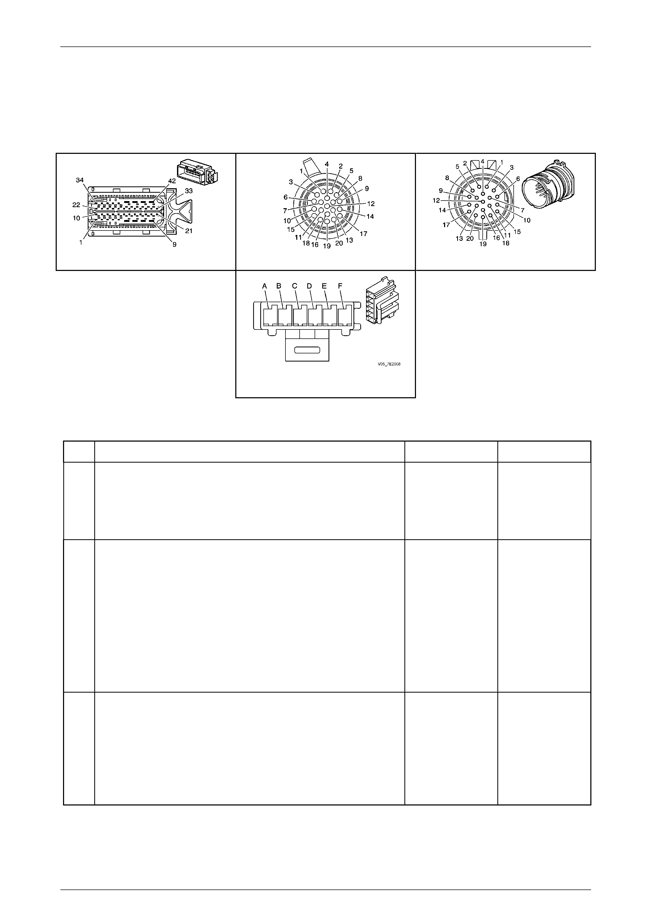
Automatic Transmission – 5L40-E – Electrical Diagnosis Page 7E – 189
Page 7E2 – 189
NOTE
• Refer to Figures 7E2–5 and 7E2–6 for 5L40 –
E automatic transmission electrical circuits.
• For procedures on checking wiring faults,
refer to Section 12P Wiring Diagrams.
A112-T68 – X1 X121-X1 X121-X1a
Transmission Manual Shift Shaft
Switch Assembly Connector
Figure 7E2 – 60
DTC P1820 – IMS Circuit A Low
Step Action Yes No
1
Has the Diagnostic System Check – Automatic T ransmission been
completed? Go to Step 2
Go to
2.3 Diagnostic
System Check –
Automatic
Transmission
in this Section.
2
1 Connect the Tech 2 to the DLC.
2 Ignition ON, engine OFF.
3 Clear the DTCs.
4 Select ‘Transmission Data’ on the Tech 2.
5 Select IMS range data parameter on TECH2.
6 Place the gear selector lever into Park and then move to
Neutral.
Does each range selected match the Tech 2 IMS range display?
Go to Intermittent
Conditions, in
Section 6C1–2
Engine
Management – V6 –
Diagnostics Go to Step 3
3
1 Ignition OFF.
2 Disconnect the transmission wiring harness connector X121–X1
from the transmission 20-way connector.
3 Ignition ON, engine OFF.
4 Select IMS A / B / C / P on Tech 2.
Does the Tech 2 IMS Signal ‘A‘ display LOW? Go to Step 4 Go to Step 5

Automatic Transmission – 5L40-E – Electrical Diagnosis Page 7E – 190
Page 7E2 – 190
Step Action Yes No
4
1 Using a digital ohmmeter, test the Transmission Range signal A
circuit 771 of the transmission shift shaft switch assembly for a
short to ground condition between transmission wiring harness
TCM connector A112 – T68, terminal X1-36 and the
transmission wiring harness connector X121–X1, terminal
X1-16.
Id you find a short to ground condition?
Repair short to
ground condition in
relevant circuit.
Go to Step 9. Go to Step 8
5
1 Ignition OFF.
2 Remove transmission fluid pan. Refer to Se ction 7E4 Automatic
Transmission – 5L40-E – On-V ehicle Servicing.
3 Inspect transmission internal wiring harness for any sign of
damage.
4 Disconnect transmission internal wiring harness connector from
the transmission shift shaft switch assembly.
5 Ignition ON, engine OFF.
6 Select IMS A / B / C / P on Tech 2.
Does the Tech 2 IMS Signal A display LOW? Go to Step 6 Go to Step 7
6
1 Remove and replace transmission internal wiring harness. Refer
to Section 7E4 Automatic Transmission – 5L40-E – On-Vehicle
Servicing.
Is replacement complete? Go to Step 9 –
7
1 Replace the transmission manual shift shaft switch assem bl y .
Refer to Section 7E4 Automatic Transmission – 5L4 0-E – On-
Vehicle Servicing.
Is replacement complete? Go to Step 9 –
8 1 Replace TCM. Refer to Section 7E4 Automatic Transmission –
5L40-E – On-Vehicle Servicing for replacement procedur es.
Is the replacement complete? Go to Step 9 –
9
1 Perform the following operation to verify the repair:
• Select DTC on Tech 2.
• Select ‘Clear info’.
• Operate the vehicle under the following conditions:
• Drive the vehicle in D4.
• The engine torque is between 55 and 450 N.m.
• IMS Signal A must be HI for 0.025 second.
Has the test run and passed? System OK Go to Step 2
When all diagnosis and repairs are completed, clear all DTCs and verify correct operation

Automatic Transmission – 5L40-E – Electrical Diagnosis Page 7E – 191
Page 7E2 – 191
DTC P1822 – IMS Circuit B High
Circuit Description
The transmission manual shift shaft switch assembly is a sliding contact s witch attached to the manual shift shaft inside
the transmission case. There are four inputs to the Transmission Control Module (TCM) from the switch which indicate
the position selected by the transmission selector lever. This information is used for engine controls as well as
determining the transmission shift patterns. The input voltage at the TCM is high when the switch is open and low when
the switch is closed to ground. The stat e of each input is displayed on the Tech 2 as IMS. The IMS input parameters
represented are transmission range Signal A, Signal B, Signal C a nd Signal P (Parity).
If the TCM detects an open circuit in the IMS signal B circuit, then DTC P1822 sets, which is a type ‘B’ DTC.
Conditions for Running the DTC
• Ignition voltage is bet ween 8.0 and 18. 0 volts.
• Engine is running between 450 and 6,800 rpm for at least 5 seconds.
• DTC P2637 Engine T orque Si gnal Circuit – No Valid GMLAN Signal is not set.
• The engine torque is between55 and 450 N.m.
Conditions for Setting the DTC
• The transmission manual shift shaft switch assembly indicates park for more than 1 second.
• The switch indicates a transitiona l state for more than 4 seconds.
Action Taken When the DT C Sets
• The TCM requests the Powertrain Interface Module (PIM) to illumin ate the Check Powertrain Malfunction Indicator
Lamp (MIL) in the instrument cluster during the second consecutive drive trip in which the ‘Conditions for Setting
the DTC’ are met.
• The TCM turns off the pressure control solenoid (causing maximum line pressure).
• The TCM freezes the transmission adaptive learning function.
• The TCM assumes a D5 shift pattern.
• At the time of the first failure, the TCM records the operating conditions when the ‘Conditions for Settin g the DTC’
have been met. The TCM stores this information as a failure record.
• At the time of the second failure, the ECM records the operating conditions when the ‘Conditions for Set ting the
DTC’ have been met. The ECM stores this information as a freeze frame.
• The TCM stores DTC P1822 into TCM history during the second consecutive trip in which the ‘Conditions for
Setting the DTC’ are met.
Conditions for Clearing the MIL / DTC
• Tech 2 can clear the DTC.
• The TCM clears the DTC from its memory (history DTC) if the vehicle completes 40 warm-up cycles without a non-
emission related DTC occurring.
• The TCM cancels the default actions when the ignition is off long enou gh to power down the TCM.
• The PIM turns off the Check Powertrain MIL after the sixth consecutive drive trip in which the TCM does not send a
Check Powertrain MIL illumination request.
Test Description
The following number(s) refer to the step number(s) on the diagnostic table.
3 This step determines is the fault is internal or external to the transmission.
4 This step determines if the transmission wiring harness circuit or the T CM is at fault.
5 This step determines if the automatic transmission wiring harness or the transmission manual shift shaft switch
assembly is at fault.

Automatic Transmission – 5L40-E – Electrical Diagnosis Page 7E – 192
Page 7E2 – 192
NOTE
• Refer to Figures 7E2–5 and 7E2–6 for 5L40 –
E automatic transmission electrical circuits.
• For procedures on checking wiring faults,
refer to Section 12P Wiring Diagrams.
A112-T68 – X1 X121-X1 X121-X1a
Transmission Manual Shift Shaft
Switch Assembly Connector
Figure 7E2 – 61
DTC P1822 – IMS Circuit B High
Step Action Yes No
1
Has the Diagnostic System Check – Automatic T ransmission been
completed? Go to Step 2
Go to
2.3 Diagnostic
System Check –
Automatic
Transmission
in this Section.
2
1 Connect Tech 2 to the DLC.
2 Ignition ON, engine OFF.
3 Clear the DTCs.
4 Select transmission data on the T ech 2.
5 Select IMS range data parameter on TECH2.
6 Place the gear selector lever into D5.
Does the Tech 2 IMS range display Drive 5?
Go to Intermittent
Conditions, in
Section 6C1–2
Engine
Management – V6 –
Diagnostics. Go to Step 3
3
1 Ignition OFF.
2 Disconnect transmission wiring harness connector X121–X1
from the transmission 20-way connector.
3 Connect a fused jumper wire between connector X121–X1,
terminal 24 (Transmission R ange B circuit) and ground.
4 Ignition ON, engine OFF.
5 On the Tech 2, select 2 IMS A / B / C / P display.
Does the Tech 2 IMS Signal B display LOW? Go to Step 5 Go to Step 4

Automatic Transmission – 5L40-E – Electrical Diagnosis Page 7E – 193
Page 7E2 – 193
Step Action Yes No
4
1 Using a digital ohmmeter, test the Transmission Range signal B
circuit of the transmission shift shaft switch assembly for an
open circuit condition between transmission wiring harness TCM
connector A112 – T68, terminal X1–24 a nd transmission wiring
harness connector X121–X1, terminal X1–7.
Did you find an open circuit condition?
Repair open circuit
condition.
Go to Step 9. Go to Step 8
5
1 Ignition OFF.
2 Remove transmission fluid pan. Refer to Se ction 7E4 Automatic
Transmission – 5L40-E – On-V ehicle Servicing.
3 Inspect transmission internal wiring harness for any sign of
damage.
4 Using a digital ohmmeter, check the signa l B circuit of the
transmission manual shift shaft switch assembly for an open
circuit condition between transmission internal switch connector,
terminal ‘C’ and 20- way connector X121-X1a, terminal X1-7.
Did you find an open circuit condition? Go to Step 6 Go to Step 7
6
1 Replace transmission interna l wiring harness. Refer to
Section 7E4 Automatic Tr ansmission – 5L40-E – On-Vehicle
Servicing.
Is replacement complete? Go to Step 9 –
7
1 Replace the transmission manual shift shaft switch assem bl y .
Refer to Section 7E4 Automatic Transmission – 5L4 0-E – On-
Vehicle Servicing.
Is replacement complete? Go to Step 9 –
8 1 Replace TCM. Refer to Section 7E4 Automatic Transmission –
5L40-E – On-Vehicle Servicing.
Is the replacement complete? Go to Step 9 –
9
1 Perform the following operation to verify the repair:
• Select DTC on Tech 2.
• Select ‘Clear info’.
2 Operate the vehicle under the following conditions:
• Drive the vehicle in D5.
• The engine torque is between 55 and 450 N.m.
• IMS Signal P must be HI for 0.025 second.
Has the test run and passed? System OK Go to Step 2
When all diagnosis and repairs are completed, clear all DTCs and verify correct operation

Automatic Transmission – 5L40-E – Electrical Diagnosis Page 7E – 194
Page 7E2 – 194
DTC P1823 – IMS Circuit P Low
Circuit Description
The transmission manual shift shaft switch assembly is a sliding contact s witch attached to the manual shift shaft inside
the transmission case. There are four inputs to the Transmission Control Module (TCM) from the switch which indicate
the position selected by the transmission selector lever. This information is used for engine controls as well as
determining the transmission shift patterns. The input voltage at the TCM is high when the switch is open and low when
the switch is closed to ground. The stat e of each input is displayed on the Tech 2 as IMS. The IMS input parameters
represented are transmission range Signal A, Signal B, Signal C a nd Signal P (Parity).
If the TCM detects a short to ground in the IMS signal P circuit, then DTC P1823 sets, which is a type ‘B’ DTC.
Conditions for Running the DTC
• Ignition voltage is bet ween 8.0 and 18. 0 volts.
• Engine is running between 450 and 6,800 rpm for at least 5 seconds.
• DTC P2637 Engine T orque Si gnal Circuit – No Valid GMLAN Signal is not set.
• The engine torque is between 25 and 450 N.m
Conditions for Setting the DTC
• The transmission manual shift shaft switch assembly indicates Park for more than 1 second.
• The switch indicates a transitiona l state for more than 5 seconds.
Action Taken When the DT C Sets
• The TCM requests the Powertrain Interface Module (PIM) to illumin ate the Check Powertrain Malfunction Indicator
Lamp (MIL) in the instrument cluster during the second consecutive drive trip in which the ‘Conditions for Setting
the DTC’ are met.
• The TCM turns off the pressure control solenoid (causing maximum line pressure).
• The TCM freezes the transmission adaptive learning function.
• The TCM assumes a D5 shift pattern.
• At the time of the first failure, the TCM records the operating conditions when the ‘Conditions for Setting the DTC’
have been met. The TCM stores this information as a failure record.
• At the time of the second failure, the ECM records the operating conditions when the ‘Conditions for Set ting the
DTC’ have been met. The ECM stores this information as a freeze frame.
• The TCM stores DTC P1823 into TCM history during the second consecutive trip in which the ‘Conditions for
Setting the DTC’ are met.
Conditions for Clearing the MIL / DTC
• Tech 2 can clear the DTC.
• The TCM clears the DTC from its memory (history DTC) if the vehicle completes 40 warm-up cycles without a non-
emission related DTC occurring.
• The TCM cancels the default actions when the ignition is off long enou gh to power down the TCM.
• The PIM turns off the Check Powertrain MIL after the sixth consecutive drive trip in which the TCM does not send a
Check Powertrain MIL illumination request.
Test Description
The following number(s) refer to the step number(s) on the diagnostic table.
3 This step determines is the fault is internal or external to the transmission.
4 This step determines if the transmission wiring harness circuit or the T CM is at fault.
5 This step determines if the automatic transmission wiring harness or the transmission manual shift shaft switch
assembly is at fault.
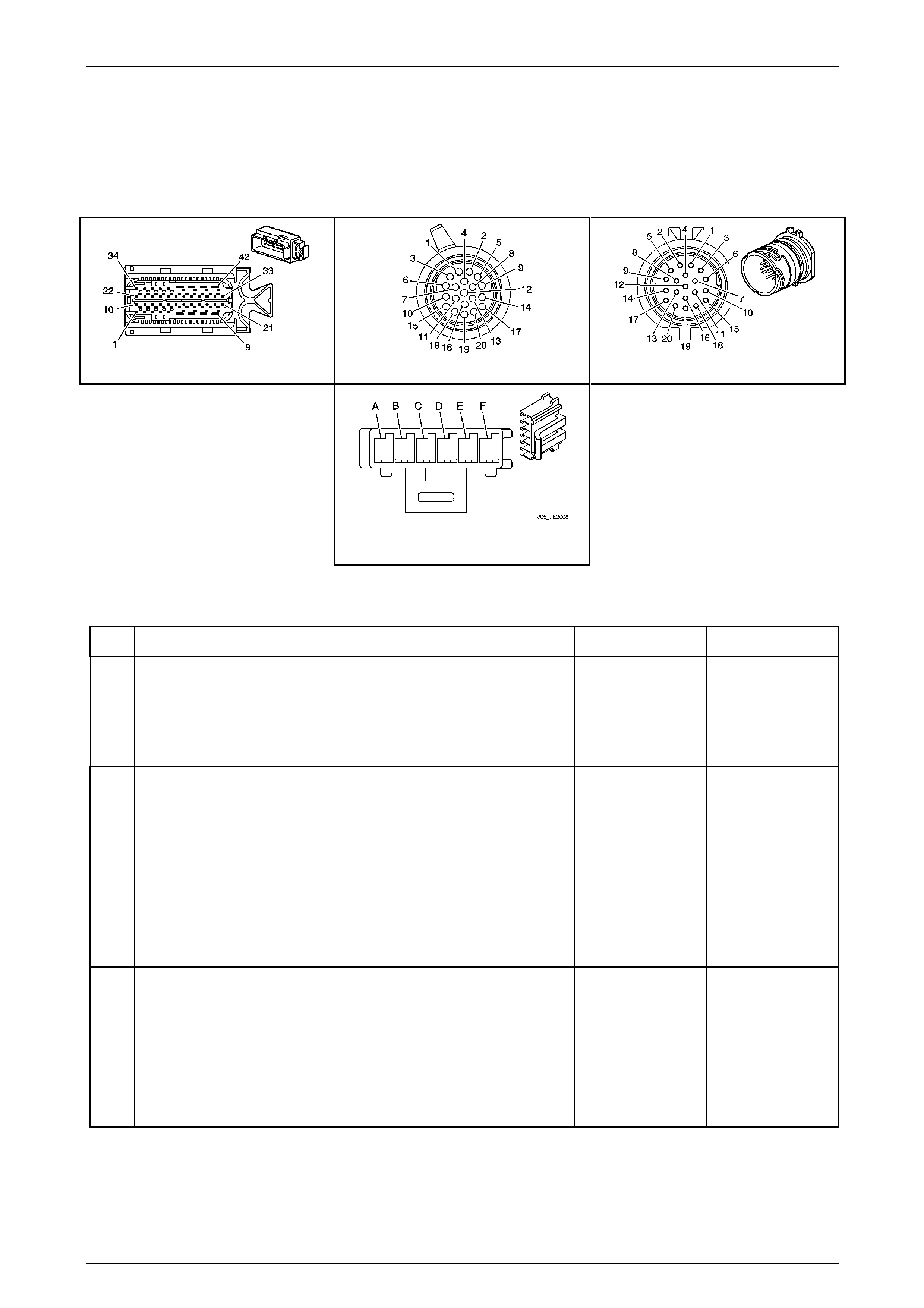
Automatic Transmission – 5L40-E – Electrical Diagnosis Page 7E – 195
Page 7E2 – 195
NOTE
• Refer to Figures 7E2–5 and 7E2–6 for 5L40 –
E automatic transmission electrical circuits.
• For procedures on checking wiring faults,
refer to Section 12P Wiring Diagrams.
A112-T68 – X1 X121-X1 X121-X1a
Transmission Manual Shift Shaft
Switch Assembly Connector
Figure 7E2 – 62
DTC P1823 – IMS Circuit P Low
Step Action Yes No
1
Has the Diagnostic System Check – Automatic T ransmission been
completed? Go to Step 2
Go to
2.3 Diagnostic
System Check –
Automatic
Transmission
in this Section.
2
1 Connect Tech 2 to the DLC.
2 Ignition ON, engine OFF.
3 Clear the DTCs.
4 Select transmission data on Tech 2.
5 Select IMS range data parameter on TECH2.
6 Place the gear selector lever into D5.
Does the Tech 2 IMS range display Drive 5?
Go to Intermittent
Conditions, in
Section 6C1–2
Engine
Management – V6 –
Diagnostics. Go to Step 3
3
1 Ignition OFF.
2 Disconnect transmission wiring harness connector X121–X1
from the transmission 20-way connector.
3 Ignition ON, engine OFF.
4 On Tech 2, select 2 IMS A / B / C / P display.
Does the Tech 2 IMS Signal P display LOW? Go to Step 4 Go to Step 5

Automatic Transmission – 5L40-E – Electrical Diagnosis Page 7E – 196
Page 7E2 – 196
Step Action Yes No
4
1 Using a digital ohmmeter, test the Transmission Range signal P
circuit of the transmission shift shaft switch assembly for a short
to ground condition between transmission wiring harness T CM
connector A112 – T68, terminal X1–37 a nd transmission wiring
harness connector X121–X1, terminal X1–11.
Did you find a short to ground condition?
Repair short to
ground condition.
Go to Step 9 Go to Step 8
5
1 Turn ignition OFF .
2 Remove transmission fluid pan. Refer to Se ction 7E4 Automatic
Transmission – 5L40-E – On-V ehicle Servicing.
3 Inspect transmission internal wiring harness for any sign of
damage.
4 Disconnect the transmission internal wiring harness connector
from the transmission manual shift shaft switch assembly.
5 Ignition ON, engine OFF.
Does the Tech 2 IMS Signal P display LOW? Go to Step 6 Go to Step 7
6
1 Remove and replace transmission internal wiring harness. Refer
to Section 7E4 Automatic Transmission – 5L40-E – On-Vehicle
Servicing.
Is replacement complete? Go to Step 9 –
7
1 Replace the transmission manual shift shaft switch assem bl y .
Refer to Section 7E4 Automatic Transmission – 5L4 0-E – On-
Vehicle Servicing.
Is replacement complete? Go to Step 9 –
8 1 Replace TCM. Refer to Section 7E4 Automatic Transmission –
5L40-E – On-Vehicle Servicing for replacement procedur es.
Is the replacement complete? Go to Step 9 –
9
1 Perform the following operation to verify the repair:
• Select DTC on Tech 2.
• Select ‘Clear info’.
2 Operate the vehicle under the following conditions:
• Drive the vehicle in D4.
• The engine torque is between 55 and 450 N.m.
• IMS Signal P must be HI for 0.025 second.
Has the test run and passed? System OK Go to Step 2
When all diagnosis and repairs are completed, clear all DTCs and verify correct operation

Automatic Transmission – 5L40-E – Electrical Diagnosis Page 7E – 197
Page 7E2 – 197
DTC P1825 – IMS Illegal Range
Circuit Description
The transmission manual shift shaft switch assembly is a sliding contact s witch attached to the manual shift shaft inside
the transmission case. There are four inputs to the Transmission Control Module (TCM) from the switch which indicate
the position selected by the transmission selector lever. This information is used for engine controls as well as
determining the transmission shift patterns. The input voltage at the TCM is high when the switch is open and low when
the switch is closed to ground. The stat e of each input is displayed on the Tech 2 as IMS. The IMS input parameters
represented are transmission range Signal A, Signal B, Signal C a nd Signal P (Parity).
If the TCM detects an invalid IMS range, then DTC P1825 sets, which is a type ‘B’ DTC.
Conditions for Running the DTC
• Ignition voltage is bet ween 8.0 and 18. 0 volts.
• Engine is running between 450 and 6,800 rpm for at least 5 seconds.
Conditions for Setting the DTC
• The TCM detects an invalid switch ran ge for 5 seconds.
Action Taken When the DT C Sets
• The TCM requests the Powertrain Interface Module (PIM) to illumin ate the Check Powertrain Malfunction Indicator
Lamp (MIL) in the instrument cluster during the second consecutive drive trip in which the ‘Conditions for Setting
the DTC’ are met.
• The TCM turns off the pressure control solenoid (causing maximum line pressure).
• The TCM freezes the transmission adaptive learning function.
• The TCM assumes a D5 shift pattern.
• At the time of the first failure, the TCM records the operating conditions when the ‘Conditions for Setting the DTC’
have been met. The TCM stores this information as a failure record.
• At the time of the second failure, the ECM records the operating conditions when the ‘Conditions for Set ting the
DTC’ have been met. The ECM stores this information as a freeze frame.
• The TCM stores DTC P1825 into TCM history.
Conditions for Clearing the MIL / DTC
• Tech 2 can clear the DTC.
• The TCM clears the DTC from its memory (history DTC) if the vehicle completes 40 warm-up cycles without a non-
emission related DTC occurring.
• The TCM cancels the default actions when the ignition is off long enou gh to power down the TCM.
• The PIM turns off the Check Powertrain MIL after the sixth consecutive drive trip in which the TCM does not send a
Check Powertrain MIL illumination request.
Test Description
The following number(s) refer to the step number(s) on the diagnostic table.
3 This step tests the transmission manual shift shaft switch assembly for an open in the ground circuit.
5 This step tests for correct reference voltage from the TCM.

Automatic Transmission – 5L40-E – Electrical Diagnosis Page 7E – 198
Page 7E2 – 198
NOTE
• Refer to Figures 7E2–5 and 7E2–6 for 5L40 –
E automatic transmission electrical circuits.
• For procedures on checking wiring faults,
refer to Section 12P Wiring Diagrams.
A112-T68 – X1 X121-X1 X121-X1a
Transmission Manual Shift Shaft
Switch Assembly Connector
Figure 7E2 – 63
DTC P1825 – IMS Illegal Range
Step Action Value(s) Yes No
1
Has the Diagnostic System Check – Automatic
Transmission been com pleted?
–
Go to Step 2
Go to
2.3 Diagnostic
System Check –
Automatic
Transmission
in this Section.
2
1 Connect Tech 2 to the DLC.
2 Turn ignition on with engine off.
3 Clear the DTCs.
4 Select transmission data on Tech 2.
5 Select IMS range data parameter on Tech 2.
6 Place the gear selector lever in each transm ission
range, P, R, N, D5, D4 D3 and D2.
Does each range selected match the Tech 2 IMS range
display?
– Go to Intermittent
Conditions, in
Section 6C1–2
Engine Module
Control Diagnosis. Go to Step 3
3
1 Select IMS A / B / C / P on Tech 2.
2 Place the gear selector lever in each transm ission
range, P, R, N, D5, D4 D3 and D2.
Does the Tech 2 IMS A / B / C / P display indicate the
specified value for each range?
HI / HI / HI /
HI
Go to Step 13 Go to Step 4
4
1 Ignition OFF.
2 Disconnect transmission wiring harness connector
X121–X1 from the transmission 20-way
connector.
3 Turn ignition ON, engine OF F.
4 Select IMS A / B / C / P on Tech 2.
Does the Tech 2 IMS A / B / C / P display all HI for all
range states?
–
Go to Step 5 Go to Step 9

Automatic Transmission – 5L40-E – Electrical Diagnosis Page 7E – 199
Page 7E2 – 199
Step Action Value(s) Yes No
5
1 Ignition ON, engine OFF.
2 Using a digital voltmeter check voltage at each of
the following terminals of 20-way connector
X121–X1a.
• Transmission Range A circuit, terminal
X1–16.
• Transmission Range B circuit, terminal
X1–7.
• Transmission Range C circu it, terminal
X1–19.
• Transmission Range P circuit, terminal
X1–11.
Did you measure ignition vo ltage at all four terminals?
–
Go to Step 6 Go to Step 10
6
1 Using a fused jumper wire, connect between
transmission wiring harness 20-way connector
X121–X1a, terminal X1–16 (Transmission Range
A circuit) and ground.
2 Monitor Tech 2 IMS A / B / C / P display.
When terminal X1–1 6 was grounded, did any other
circuits indicate LOW on the Tech 2 display?
–
Go to Step 11 Go to Step 7
7
1 Connect fused jumper wire between transmission
wiring harness 20-way connector X121–X1a,
terminal X1–7 (Transmission Range B circuit) and
ground.
2 Monitor Tech 2 IMS A / B / C / P display.
When terminal X1–7 was grounded, did any other
circuits indicate LOW on the Tech 2 display?
–
Go to Step 11 Go to Step 8
8
1 Connect fused jumper wire between transmission
wiring harness 20-way connector X121–X1a,
terminal X1–19 (T ransmission Range C circuit)
and ground.
2 Monitor Tech 2 IMS A / B / C / P display.
When terminal X1–1 9 was grounded, did any other
circuits indicate LOW on the Tech 2 display?
–
Go to Step 11 Go to Step 12
9
1 Using a digital ohmmeter, test the Transmissi on
range signal circuits of the transmission shift shaft
switch assembly that did not indicate HI for a short
to ground condition between transmission wiring
harness TCM connector A112 – T68 and
transmission wiring harness connector X121–X1.
Did any circuit indicate a short to ground condition?
– Repair short to
ground condition in
relevant circuit.
Go to Step 18 Go to Step 17
10
1 Using a digital ohmmeter, test the Transmissi on
Range signal circuits of the transmission shift
shaft switch assembly that did not indicate ignition
voltage for an open circuit conditi on between TCM
connector A112 – T68 and connector X121–X1.
Did any circuit indicate an open circuit condition?
– Repair open circuit
condition in relevant
circuit.
Go to Step 18 Go to Step 17
11
1 Using a digital ohmmeter, test the affected
Transmission Range sig na l circuits of the
transmission shift shaft switch assembly for an
internal short circuit condition between the
transmission wiring harness TCM connector
A112 – T68 and the transmission wiring harness
connector X121–X1.
Did any circuits indicate an internal short circuit
condition?
– Repair internal short
circuit condition in
relevant circuits.
Go to Step 18 Go to Step 17

Automatic Transmission – 5L40-E – Electrical Diagnosis Page 7E – 200
Page 7E2 – 200
Step Action Value(s) Yes No
12
1 Remove transmission fluid pan. Refer to
Section 7E4 Automatic Tr ansmission – 5L40-E –
On-Vehicle Servicing.
2 Inspect transmission internal wiring harness for
any sign of damage.
3 Using a digital ohmmeter, test the transmission
range signal circuits of the transmission shift shaft
switch for an open or internal short circuit
condition between transmission 20-way connector
X121-X1a and transmission internal switch
connector.
Is transmission internal wiring harness OK?
–
Go to Step 17 Go to Step 16
13
1 Using a digital ohmmeter, check transmissio n
manual shift shaft switch ground circuit 451 for an
open circuit condition between transmission wiring
harness connector X121–X1A, terminal X1– 4 and
vehicle ground point X119-GP17/X119-GP18.
Did you find an open circuit condition in ground circuit?
– Repair open in
ground circuit.
Go to Step 18 Go to Step 14
14
1 Using a digital ohmmeter, check transmissio n
manual shift shaft switch ground circuit for an
open circuit condition between transmission
internal switch connector, terminal F and 20-way
connector X121–X1a, terminal X1-4.
Did you find an open circuit condition in ground circuit?
–
Go to Step 15 Go to Step 16
15
1 Remove and replace transmission internal wiring
harness. Refer to Section 7E4 Automatic
Transmission – 5L40-E – On-V ehicle Servicing.
Is replacement complete?
–
Go to Step 18 –
16
1 Replace the transmission manual shift shaft
switch assembly. Refer to Section 7E4 Automatic
Transmission – 5L40-E – On-V ehicle Servicing.
Is replacement complete?
–
Go to Step 18 –
17
1 Replace TCM. Refer to Section 7E4 Automatic
Transmission – 5L40-E – On-V ehicle Servicing for
replacement procedures.
Is the replacement complete?
–
Go to Step 18 –
18
1 Perform the following operation to verify the
repair:
• Select DTC on Tech 2.
• Select ‘Clear info’.
• Ignition ON, engine OFF.
2 The transmission manual shift shaft s witch
assembly must indicate a valid range for 5
seconds.
Has the test run and passed?
–
System OK Go to Step 2
When all diagnosis and repairs are completed, clear all DTCs and verify correct operation

Automatic Transmission – 5L40-E – Electrical Diagnosis Page 7E – 201
Page 7E2 – 201
DTC P1826 – IMS Circuit C High
Circuit Description
The transmission manual shift shaft switch assembly is a sliding contact s witch attached to the manual shift shaft inside
the transmission case. There are four inputs to the Transmission Control Module (TCM) from the switch which indicate
the position selected by the transmission selector lever. This information is used for engine controls as well as
determining the transmission shift patterns. The input voltage at the TCM is high when the switch is open and low when
the switch is closed to ground. The stat e of each input is displayed on the Tech 2 as IMS. The IMS input parameters
represented are transmission range Signal A, Signal B, Signal C a nd Signal P (Parity).
If the TCM detects the IMS signal C circuit is high while the vehicle is being driven in a forward gear, the n DTC P1826
sets which is a type ‘B’ DTC.
Conditions for Running the DTC
• Ignition voltage is bet ween 8.0 and 18. 0 volts.
• DTC P1826 has not passed durin g the curre nt ignition cycle.
• The following DTCs are not set:
• P2637 Engine Torque Signal Circuit – No Valid GMLAN Signal
• P0722 or P0723 – Transmission Output Speed Sensor.
• The engine torque is more than 20 N.m.
• Vehicle speed is more than 8 km/h.
• The gear ratio is within one of the following ranges:
• 3.33:1 to 3.50:1 for first gear OR
• 2.16:1 to 2.27:1 for second gear OR
• 1.56:1 to 1.64:1 for third gear OR
• 0.98:1 to 1.03:1 for fourth gear OR
• 0.73:1 to 0.77:1 for fifth gear
Conditions for Setting the DTC
• The TCM detects Signal C is high while the gear ratio indicates first, second, third, fourth or fifth gear for 3 seconds.
Action Taken When the DT C Sets
• The TCM requests the Powertrain Interface Module (PIM) to illumin ate the Check Powertrain Malfunction Indicator
Lamp (MIL) in the instrument cluster during the second consecutive drive trip in which the ‘Conditions for Setting
the DTC’ are met.
• The TCM turns off the pressure control solenoid (causing maximum line pressure).
• The TCM freezes the transmission adaptive learning function.
• The TCM assumes a D5 shift pattern.
• At the time of the first failure, the TCM records the operating conditions when the ‘Conditions for Setting the DTC’
have been met. The TCM stores this information as a failure record.
• At the time of the second failure, the ECM records the operating conditions when the ‘Conditions for Set ting the
DTC’ have been met. The ECM stores this information as a freeze frame.
• The TCM stores DTC P1826 into TCM history during the second consecutive trip in which the ‘Conditions for
Setting the DTC’ are met.
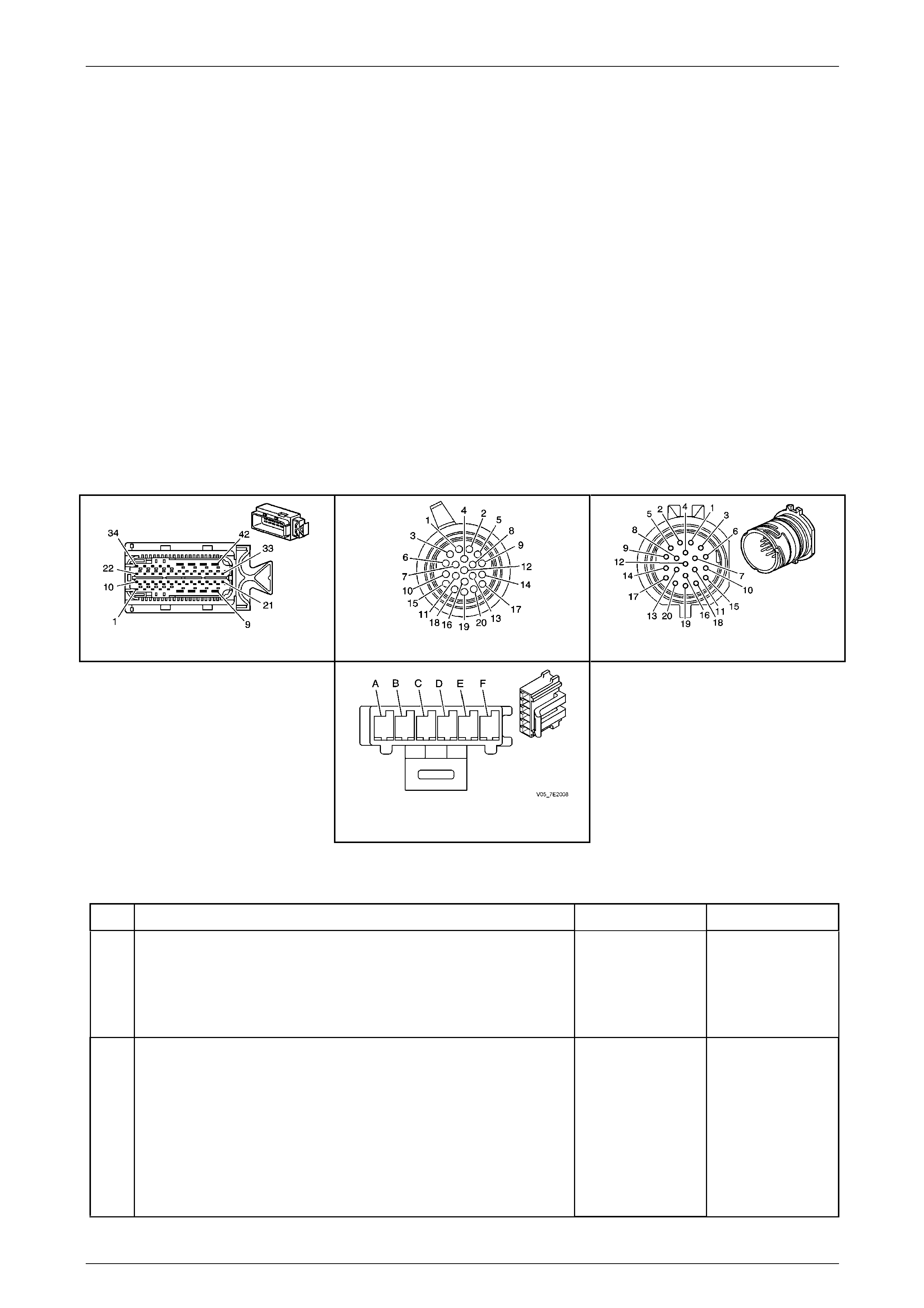
Automatic Transmission – 5L40-E – Electrical Diagnosis Page 7E – 202
Page 7E2 – 202
Conditions for Clearing the MIL / DTC
• Tech 2 can clear the DTC.
• The TCM clears the DTC from its memory (history DTC) if the vehicle completes 40 warm-up cycles without a non-
emission related DTC occurring.
• The TCM cancels the default actions when the ignition is off long enou gh to power down the TCM.
• The PIM turns off the Check Powertrain MIL after the sixth consecutive drive trip in which the TCM does not send a
Check Powertrain MIL illumination request.
Test Description
The following number(s) refer to the step number(s) on the diagnostic table.
3 This step tests the integrity of the transmissio n wiring harness and TCM by checking for the Signal C state change
from HI to LOW. A LOW signal indicates the fault is in the internal transmission harness or the switch. A HI signal
indicates the fault is in the transmission wiring harness or the TCM.
NOTE
• Refer to Figures 7E2–5 and 7E2–6 for 5L40 –
E automatic transmission electrical circuits.
• For procedures on checking wiring faults,
refer to Section 12P Wiring Diagrams.
A112-T68 – X1 X121-X1 X121-X1a
Transmission Manual Shift Shaft
Switch Assembly Connector
Figure 7E2 – 64
DTC P1826 – IMS Circuit C High
Step Action Yes No
1
Has the Diagnostic System Check – Automatic T ransmission been
completed? Go to Step 2
Go to
2.3 Diagnostic
System Check –
Automatic
Transmission
in this Section.
2
1 Connect Tech 2 to the DLC.
2 Ignition ON, engine OFF.
3 Clear the DTCs.
4 Select transmission data on Tech 2.
5 Select IMS range data parameter on TECH2.
6 Place the gear selector lever into D5.
Does the Tech 2 IMS range display Drive 5?
Go to Intermittent
Conditions, in
Section 6C1–2
Engine
Management – V6 –
Diagnostics. Go to Step 3

Automatic Transmission – 5L40-E – Electrical Diagnosis Page 7E – 203
Page 7E2 – 203
Step Action Yes No
3
1 Turn ignition OFF .
2 Disconnect the transmission wiring harness connector X121–X1
from the transmission 20-way connector.
3 Connect a fused jumper wire between the transmission wiring
harness connector X121–X1, terminal X1–19 (Transmission
Range C circuit) and ground.
4 Turn ignition on, engine OFF .
5 Tech 2, select IMS A / B / C / P display.
Does the Tech 2 IMS Signal C display LOW? Go to Step 5 Go to Step 4
4
1 Using a digital ohmmeter, test the Transmission Range signal C
circuit of the transmission shift shaft switch assembly for an
open circuit condition between the transmission wiring harness
TCM connector A112 – T68, termina l X1–25 and the
transmission wiring harness connector X121–X1, terminal
X1–19.
Did you find an open circuit condition?
Repair open circuit
condition.
Go to Step 9 Go to Step 8
5
1 Turn ignition OFF .
2 Remove transmission fluid pan. Refer to Se ction 7E4 Automatic
Transmission – 5L40-E – On-V ehicle Servicing.
3 Inspect transmission internal wiring harness for any sign of
damage.
4 Using a digital ohmmeter, check the Rang e signal C circuit of
the transmission manual shift shaft switch assembly for an ope n
circuit condition between transmission internal switch connector,
terminal E and 20- way conn ector X121-X1a, termina l 19.
5 Turn ignition ON, engine OF F.
Did you find an open circuit condition? Go to Step 6 Go to Step 7
6
1 Remove and replace transmission internal wiring harness. Refer
to Section 7E4 Automatic Transmission – 5L40-E – On-Vehicle
Servicing.
Is replacement complete? Go to Step 9 –
7
1 Replace the transmission manual shift shaft switch assem bl y .
Refer to Section 7E4 Automatic Transmission – 5L4 0-E – On-
Vehicle Servicing.
Is replacement complete? Go to Step 9 –
8 1 Replace TCM. Refer to Section 7E4 Automatic Transmission –
5L40-E – On-Vehicle Servicing for replacement procedur es.
Is the replacement complete? Go to Step 9 –
9
1 Perform the following operation to verify the repair:
• Select DTC on Tech 2.
• Select ‘Clear info’.
• Start the engine and idle in Park.
• Observe IMS A / B / C / P on the Tech 2.
• Move the range selector to L, D3, D4 and D5 positions.
Ensure that IMS Signal C indicates LOW for each range.
2 Operate the vehicle to more than 8 km/h.
Has the test run and passed? System OK Go to Step 2
When all diagnosis and repairs are completed, clear all DTCs and verify correct operation
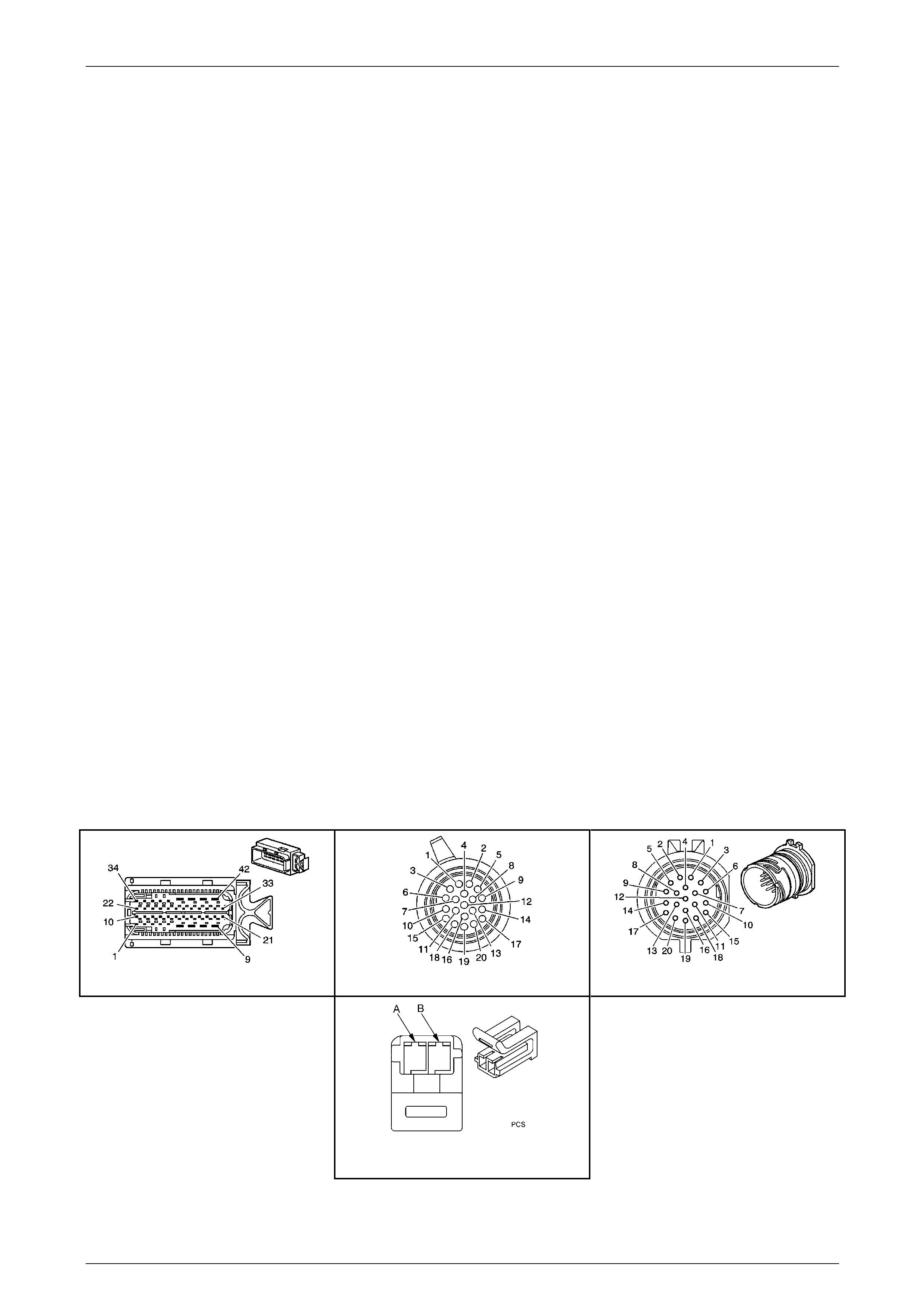
Automatic Transmission – 5L40-E – Electrical Diagnosis Page 7E – 204
Page 7E2 – 204
DTC P1831 – High Side Driver 1 Short To Ground
Circuit Description
The Transmission Control Module (TCM) provides voltage to the pressur e control solenoid, the shift solenoids and the
torque converter clutch pulse width modulated solenoid through two separate solid state devices called High Side
Drivers, called HSD1 and HSD2. HSD1 provides electrical power to the pressure control solenoid. HSD2 provides power
to the shift solenoids and the torque converter clutch solenoid. A normal function of the TCM is to run tests on each
driver to ensure that it is functioning pr operly.
When the TCM detects a short to ground on HSD1 driver circuit, then DTC P1831 sets, which is a type ‘C’ DTC.
Conditions for Running the DTC
• Ignition voltage is bet ween 8.0 and 18. 0 volts.
• Engine is running between 450 and 6,800 rpm for at least 5 seconds.
Conditions for Setting the DTC
• The TCM detects a short to ground on the HSD1 circuit when the HSD1 is commanded on.
Action Taken When the DT C Sets
• The TCM does not request the Powertrain Interface Module to illuminate th e Check Powertrain Malfunction
Indicator Lamp (MIL).
• The TCM turns off the pressure control solenoid (causing maximum line pressure).
• The TCM freezes the transmission adaptive learning function.
• At the time of the first failure, the TCM records the operating conditions when the ‘Conditions for Setting the DTC’
have been met. The TCM stores this information as a failure record.
• The TCM stores DTC P1831 into TCM history.
Conditions for Clearing the DTC
• Tech 2 can clear the DTC.
• The TCM clears the DTC from its memory (history DTC) if the vehicle completes 40 warm-up cycles without a non-
emission related DTC occurring.
• The TCM cancels the default actions when the ignition is off long enou gh to power down the TCM.
NOTE
• Refer to Figures 7E2–5 and 7E2–6 for 5L40 –
E automatic transmission electrical circuits.
• For procedures on checking wiring faults,
refer to Section 12P Wiring Diagrams.
A112-T68 – X1 X121-X1 X121-X1a
Pressure Control Solenoid (PCS)
Connector
Figure 7E2 – 65

Automatic Transmission – 5L40-E – Electrical Diagnosis Page 7E – 205
Page 7E2 – 205
DTC P1831 – High Side Driver 1 Short To Ground
Step Action Yes No
1
Has the Diagnostic System Check – Automatic T ransmission been
completed? Go to Step 2
Go to
2.3 Diagnostic
System Check –
Automatic
Transmission
in this Section.
2
1 Connect Tech 2 to the DLC.
2 Ignition ON, engine OFF.
3 Clear the DTCs
4 Turn ignition OFF for at least 30 seconds.
5 Start the engine.
Did DTC P1831 reset? Go to Step 3
Go to Intermittent
Conditions, in
Section 6C1-2
Engine
Management – V6 –
Diagnostics.
3
1 Ignition OFF.
2 Disconnect the transmission wiring harness connector X121–X1
from the transmission 20-way connector.
3 Turn ignition ON, with the engine OFF .
4 Clear the DTCs.
5 Turn ignition off for at least 30 seconds.
6 Start the engine (additional DTCs may have set).
Did DTC P1831 reset? Go to Step 4 Go to Step 5
4
1 Ignition OFF.
2 Disconnect the TCM.
3 Using a digital ohmmeter, check the HSD1 ci rcuit 1228 between
the transmission wiring harness TCM connector A112 – T68,
terminal X1–3 and the transmission wiring harness connector
X121–X1, terminal X1–1 3 for a short to ground condition.
Did you find a short to ground condition? Go to Step 8 Go to Step 7
5
1 Ignition OFF.
2 Remove transmission fluid pan. Refer to Se ction 7E4 Automatic
Transmission – 5L40-E – On-V ehicle Servicing.
3 Inspect transmission internal wiring harness for any sign of
damage.
4 Using a digital ohmmeter, check the HSD1 ci rcuit 1228 for a
short to ground condition between the 20-way connector X121-
X1a, terminal X1-13 and the pressure control soleno id terminal
‘A’.
Did you find a short circuit condition? Go to Step 9 Go to Step 6

Automatic Transmission – 5L40-E – Electrical Diagnosis Page 7E – 206
Page 7E2 – 206
Step Action Yes No
6 1 Replace the pressure control solenoid. Refer to Section 7E4
Automatic Transmission – 5L40-E – On-Vehicle Servicing.
Go to Step 10 –
7 1 Replace TCM. Refer to Section 7E4 Automatic Transmission –
5L40-E – On-Vehicle Servicing for replacement procedur es.
Is the replacement complete? Go to Step 10 –
8 1 Repair the short to ground on the HSD1 circu it.
Is the action completed? Go to Step 10 –
9
1 Remove and replace transmission internal wiring harness. Refer
to Section 7E4 Automatic Transmission – 5L40-E – On-Vehicle
Servicing.
Is replacement complete? Go to Step 10 –
10
1 Perform the following operation to verify the repair.
• Select DTC on the Tech 2.
• Select Clear info.
• Start the engine.
2 Operate the vehicle in the Conditions for Running the DTC.
Has the test run and passed? System OK Go to Step 2
When all diagnosis and repairs are completed, clear all DTCs and verify correct operation
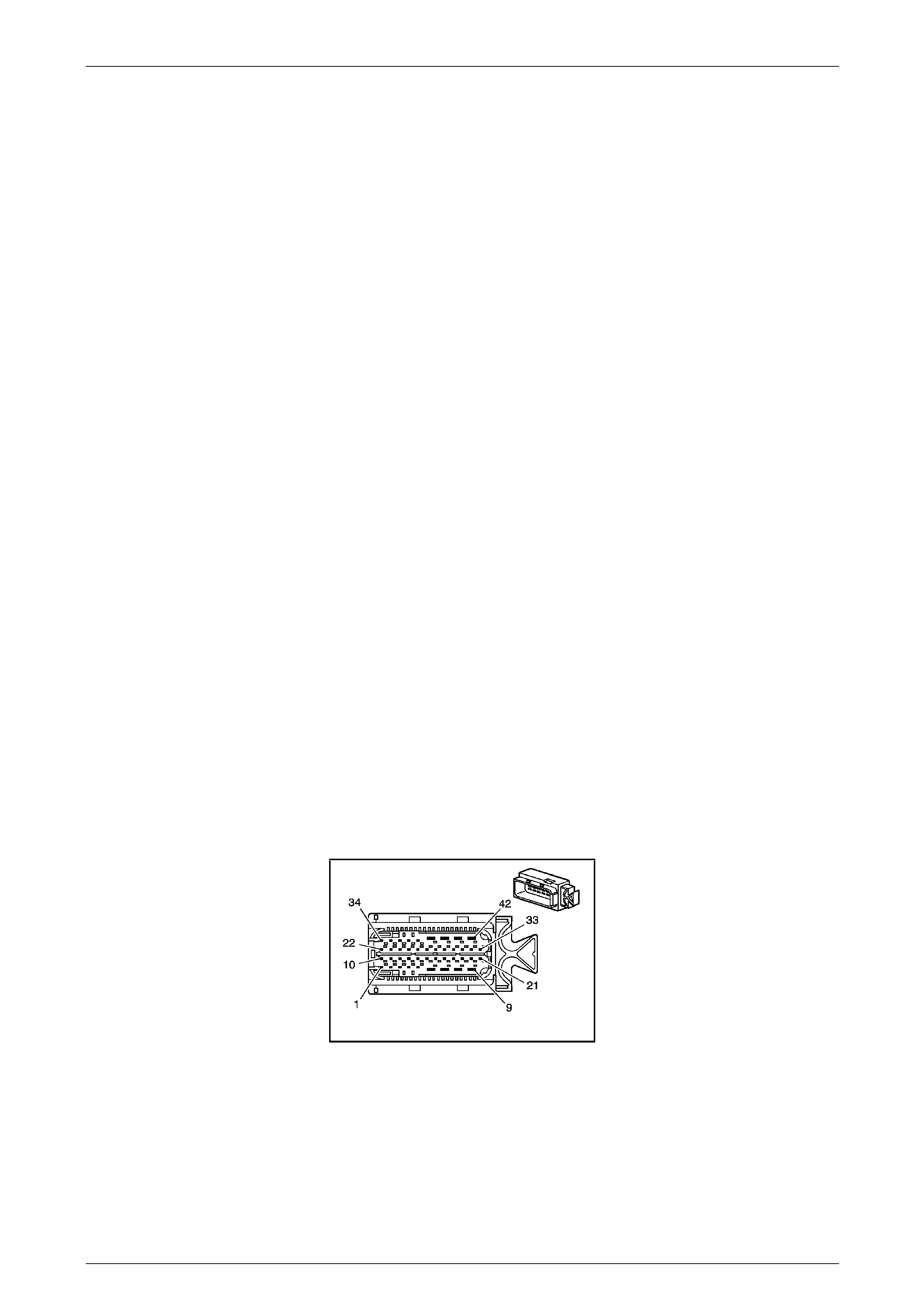
Automatic Transmission – 5L40-E – Electrical Diagnosis Page 7E – 207
Page 7E2 – 207
DTC P1832 – High Side Driver 1 Short To Voltage
Circuit Description
The Transmission Control Module (TCM) provides voltage to the pressur e control solenoid, the shift solenoids and the
torque converter clutch pulse width modulated solenoid through two separate solid state devices called High Side
Drivers, called HSD1 and HSD2. HSD1 provides electrical power to the pressure control solenoid. HSD2 provides power
to the shift solenoids and the torque converter clutch solenoid. A normal function of the TCM is to run tests on each
driver to ensure that it is functioning pr operly.
When the TCM detects a short to voltage on HSD1 driver circuit, then DTC P1832 sets, which is a type ‘C’ DT C.
Conditions for Running the DTC
• The ignition is ON.
Conditions for Setting the DTC
• The TCM detects greater than 6.4 volts at the HDS1 terminal prior to commanding the HSD1 on.
Action Taken When the DT C Sets
• The TCM does not request the Powertrain Interface Module (PIM) to illuminate the Check Powertrain Malfunction
Indicator Lamp (MIL).
• The TCM turns off the pressure control solenoid (causing maximum line pressure).
• The TCM freezes the transmission adaptive learning function.
• At the time of the first failure, the TCM records the operating conditions when the ‘Conditions for Setting the DTC’
have been met. The TCM stores this information as a failure record.
Conditions for Clearing the MIL / DTC
• Tech 2 can clear the DTC.
• The TCM clears the DTC from its memory (history DTC) if the vehicle completes 40 warm-up cycles without a non-
emission related DTC occurring.
• The TCM cancels the default actions when the ignition is off long enou gh to power down the TCM.
• The TCM clears the multi-info display when the condition no longer exists.
NOTE
• Refer to Figures 7E2–5 and 7E2–6 for 5L40 –
E automatic transmission electrical circuits.
• For procedures on checking wiring faults,
refer to Section 12P Wiring Diagrams.
A112-T68 – X1
Figure 7E2 – 66

Automatic Transmission – 5L40-E – Electrical Diagnosis Page 7E – 208
Page 7E2 – 208
DTC P1832 – High Side Driver 1 Short To Voltage
Step Action Value(s) Yes No
1
Has the Diagnostic System Check – Automatic
Transmission been com pleted?
–
Go to Step 2
Go to
2.3 Diagnostic
System Check –
Automatic
Transmission
in this Section.
2
1 Connect Tech 2 to the DLC.
2 Ignition ON, engine OFF.
3 Clear the DTCs
4 Turn ignition OFF for at least 30 seconds.
5 Start the engine.
Did DTC P1832reset?
–
Go to Step 3
Go to Intermittent
Conditions, in
Section 6C1–2
Engine
Management – V6 –
Diagnostics
3
1 Ignition OFF.
2 Disconnect the TCM.
3 Using a digital voltmeter, measure volta ge at the
transmission wiring harness TCM connector
A112 – T68, HSD1 circuit 1228, terminal X1 –3.
Is the voltage greater than the specified value?
More than
6.4 volts
Go to Step 4 Go to Step 5
4 1 Repair the short to voltage on the HSD1 circuit.
Is the action complete? – Go to Step 6 –
5
1 Replace TCM. Refer to Section 7E4 Automatic
Transmission – 5L40-E – On-V ehicle Servicing for
replacement procedures.
Is the replacement complete?
–
Go to Step 6 –
6
1 Perform the following operation to verify the
repair.
• Select DTC on Tech 2.
• Select ‘Clear info’.
• Ignition ON, engine OFF.
2 Operate the vehicle in the Conditions for Running
the DTC.
Has the test run and passed?
–
System OK Go to Step 2
When all diagnosis and repairs are completed, clear all DTCs and verify correct operation

Automatic Transmission – 5L40-E – Electrical Diagnosis Page 7E – 209
Page 7E2 – 209
DTC P1833 – High Side Driver 2 Short To Ground
Circuit Description
The Transmission Control Module (TCM) provides voltage to the pressur e control solenoid, the shift solenoids and the
torque converter clutch pulse width modulated solenoid through two separate solid state devices called High Side
Drivers, called HSD1 and HSD2. HSD1 provides electrical power to the pressure control solenoid. HSD2 provides power
to the shift solenoids and the torque converter clutch solenoid. A normal function of the TCM is to run tests on each
driver to ensure that it is functioning pr operly.
When the TCM detects a short to ground on HSD2 driver circuit, then DTC P1833 sets, which is a type ‘B’ DTC.
Conditions for Running the DTC
• Ignition voltage is bet ween 8.0 and 18. 0 volts.
• Engine is running between 450 and 6,800 rpm for at least 5 seconds.
Conditions for Setting the DTC
• The TCM detects a short to ground on the HSD2 circuit when the HSD2 is commanded ON.
Action Taken When the DT C Sets
• The TCM requests the Powertrain Interface Module (PIM) to illumin ate the Check Powertrain Malfunction Indicator
Lamp (MIL) in the instrument cluster during the second consecutive drive trip in which the ‘Conditions for Setting
the DTC’ are met.
• The TCM turns off power to all solenoids.
• The transmission will operate in fifth gear if the veh icle has successfully completed a 1–2 upsh ift in the current
ignition cycle. If the vehicle has not completed a 1–2 upshift in the current ignition cycle, the transmission will
operate in fourth gear.
• At the time of the first failure, the TCM records the operating conditions when the ‘Conditions for Setting the DTC’
are met. The TCM stores this information as a failure record.
• At the time of the second failure, the ECM records the operating conditions when the ‘Conditions for Set ting the
DTC’ are met. The ECM stores this information as a freeze frame.
• The TCM freezes the transmission adaptive learning function.
• The TCM stores DTC P1833 into TCM history.
• The TCM also turns off the pressure control sole noid (causing maximum line pressure).
• The torque converter clutch is disa bled.
Conditions for clearing the MIL / DTC
• The PIM turns off the Check Powertrain MIL after the sixth consecutive drive trip in which the TCM does not send a
Check Powertrain MIL illumination request.
• Tech 2 can clear the DTC.
• The TCM clears the DTC from its memory (history DTC) if the vehicle completes 40 warm-up cycles without a non-
emission related DTC occurring.
• The TCM cancels the DTC default actions when the ignition is off long enough to po wer down the TCM.

Automatic Transmission – 5L40-E – Electrical Diagnosis Page 7E – 210
Page 7E2 – 210
NOTE
• Refer to Figures 7E2–5 and 7E2–6 for 5L40 –
E automatic transmission electrical circuits.
• For procedures on checking wiring faults,
refer to Section 12P Wiring Diagrams.
A112-T68 – X1 X121-X1
Figure 7E2 – 67
DTC P1833 – High Side Driver 2 Short To Ground
Step Action Yes No
1
Has the Diagnostic System Check – Automatic T ransmission been
completed? Go to Step 2
Go to
2.3 Diagnostic
System Check –
Automatic
Transmission
in this Section.
2
1 Connect Tech 2 to the DLC.
2 Ignition ON, engine OFF.
3 Clear the DTCs
4 Turn ignition off for at least 30 seconds.
5 Start the engine.
Did DTC P1833 reset? Go to Step 3
Go to Intermittent
Conditions, in
Section 6C1–2
Engine
Management – V6 –
Diagnostics and
rectify any ECM
related DTC/s.
3
1 Turn ignition OFF .
2 Disconnect the transmission wiring harness connector X121–X1
from the transmission 20-way connector.
3 Ignition ON, engine OFF.
4 Clear the DTCs.
5 Turn ignition off for at least 30 seconds.
6 Start the engine (additional DTCs may set).
Did DTC P1833 reset? Go to Step 4 Go to Step 5
4
1 2 Disconnect the TCM.
3 Using a digital ohmmeter, test the HSD2 circuit for a short to
ground condition between the transmission wiring harness TCM
connector A112 – T68, terminal X1–8 and transmission wiring
harness connector X121–X1, terminal X1–17.
Did you find a short to ground condition? Go to Step 9 Go to Step 7

Automatic Transmission – 5L40-E – Electrical Diagnosis Page 7E – 211
Page 7E2 – 211
Step Action Yes No
5
1 Ignition OFF.
2 Remove transmission fluid pan. Refer to Se ction 7E4 Automatic
Transmission – 5L40-E – On-V ehicle Servicing.
3 Inspect transmission internal wiring harness for any sign of
damage.
4 Using a digital ohmmeter, check the solen oid voltage supply
circuit for a short to ground condition between the transmission
20-way connector X1 21-X1, terminal X1-17 and the torq ue
converter clutch solenoid and each shift solenoid.
Did you find a short circuit condition? Go to Step 8 Go to Step 6
6
1 Replace the respective faulty solenoid as applicable. Refer to
Section 7E4 Automatic Tr ansmission – 5L40-E – On-Vehicle
Servicing.
Is the action complete? Go to Step 9 –
7 1 Replace TCM. Refer to Section 7E4 Automatic Transmission –
5L40-E – On-Vehicle Servicing for replacement procedur es.
Is the replacement complete? Go to Step 9 –
8
1 Remove and replace transmission internal wiring harness. Refer
to Section 7E4 Automatic Transmission – 5L40-E – On-Vehicle
Servicing.
Is replacement complete? Go to Step 9 –
9
1 Perform the following operation to verify the repair.
• Select DTC on Tech 2.
• Select ‘Clear info’.
• Start the engine.
2 Operate the vehicle in the Conditions for Running the DTC.
Has the test run and passed? System OK Go to Step 2
When all diagnosis and repairs are completed, clear all DTCs and verify correct operation

Automatic Transmission – 5L40-E – Electrical Diagnosis Page 7E – 212
Page 7E2 – 212
DTC P1834 – High Side Driver 2 Short To Voltage
Circuit Description
The Transmission Control Module (TCM) provides voltage to the pressur e control solenoid, the shift solenoids and the
torque converter clutch pulse width modulated solenoid through two separate solid state devices called High Side
Drivers, called HSD1 and HSD2. HSD1 provides electrical power to the pressure control solenoid. HSD2 provides power
to the shift solenoids and the torque converter clutch solenoid. A normal function of the TCM is to run tests on each
driver to ensure that it is functioning pr operly.
When the TCM detects a short to voltage on HSD2 driver circuit, then DTC P1834 sets which is a type ‘B’ DT C.
Conditions for Running the DTC
• Ignition voltage is bet ween 8.0 and 18. 0 volts.
• Engine is running between 450 and 6,800 rpm for at least 5 seconds.
Conditions for Setting the DTC
• The TCM detects a short to power on the HSD2 circuit when the HSD2 is commanded on.
Action Taken When the DT C Sets
• The TCM requests the Powertrain Interface Module (PIM) to illumin ate the Check Powertrain Malfunction Indicator
Lamp (MIL) in the instrument cluster during the second consecutive drive trip in which the ‘Conditions for Setting
the DTC’ are met.
• The TCM turns off power to all solenoids.
• The transmission will operate in fifth gear if the veh icle has successfully completed a 1–2 upsh ift in the current
ignition cycle. If the vehicle has not completed a 1–2 upshift in the current ignition cycle, the transmission will
operate in fourth gear.
• At the time of the first failure, the TCM records the operating conditions when the ‘Conditions for Setting the DTC’
are met. The TCM stores this information as a failure record.
• At the time of the second failure, the ECM records the operating conditions when the ‘Conditions for Set ting the
DTC’ are met. The ECM stores this information as a freeze frame.
• The TCM freezes the transmission adaptive learning function.
• The TCM stores DTC P1834 into TCM history.
• The TCM also turns off the pressure control sole noid (causing maximum line pressure).
• Torque management is inhibited.
Conditions for Clearing the MIL / DTC
• The ECM turns off the MIL after the sixth consecutive drive trip in which the TCM does not send a MIL ill umination
request.
• Tech 2 can clear the DTC.
• The TCM clears the DTC from its memory (history DTC) if the vehicle completes 40 warm-up cycles without a non-
emission related DTC occurring.
• The TCM cancels the DTC default actions when the ignition is off long enough to po wer down the TCM.

Automatic Transmission – 5L40-E – Electrical Diagnosis Page 7E – 213
Page 7E2 – 213
NOTE
• Refer to Figures 7E2–5 and 7E2–6 for 5L40 –
E automatic transmission electrical circuits.
• For procedures on checking wiring faults,
refer to Section 12P Wiring Diagrams.
A112-T68 – X1
Figure 7E2 – 68
DTC P1834 – High Side Driver 2 Short To Voltage
Step Action Value(s) Yes No
1
Has the Diagnostic System Check – Automatic
Transmission been com pleted?
–
Go to Step 2
Go to
2.3 Diagnostic
System Check –
Automatic
Transmission
in this Section.
2
1 Connect Tech 2 to the DLC.
2 Ignition ON, engine OFF.
4 Clear the DTCs
5 Turn ignition off for at least 30 seconds.
6 Start the engine.
Did DTC P1834 reset?
–
Go to Step 3
Go to Intermittent
Conditions, in
Section 6C1–2
Engine
Management – V6 –
Diagnostics.
3
1 Ignition OFF.
2 Disconnect the TCM.
3 Ignition ON, engine OFF.
4 Using a digital voltmeter, measure volta ge at the
transmission wiring harness TCM connector
A112 – T68, solenoid suppl y voltage circuit 1525,
terminal X1–8.
Is the voltage greater than the specified value?
More than
6.4 volts
Go to Step 4 Go to Step 5
4 1 Repair the short to voltage on the solenoi d supp ly
voltage circuit.
Is the action complete? – Go to Step 6 –
5
1 Replace TCM. Refer to Section 7E4 Automatic
Transmission – 5L40-E – On-V ehicle Servicing for
replacement procedures.
Is the replacement complete?
–
Go to Step 6 –
6
1 Perform the following operation to verify the
repair:
• Select DTC on Tech 2.
• Select ‘Clear info’.
• Ignition ON, engine OFF.
2 Operate the vehicle in the Conditions for Running
the DTC.
Has the test run and passed?
–
System OK Go to Step 2
After all diagnosis and repairs are completed, clear all DTCs and verify correct operation

Automatic Transmission – 5L40-E – Electrical Diagnosis Page 7E – 214
Page 7E2 – 214
DTC P2544 – Torque Reduction Signal Circuit – CAN
Circuit Description
To improve shift feel, the transmission contr ol mod ule (TCM) may request that the engine control module (ECM) reduce
engine torque during shift events. When such a request is received, the ECM responds by retardin g the base ignition
timing and notifying the TCM that the req uest has succeeded.
If the ECM is unable to comply with the request, the ECM sends the TCM a message that the request h as faile d.
The torque reduction request is sent to the ECM throug h a communication network called the controller area n etwork
(GMLAN). Two circuits are used to communicate GMLAN data between the ECM and TCM. A fault in the GMLAN will not
cause DTC P2544 to set by itself. If a GMLAN fault occurs, other DTCs will set before DTC P254 4.
When the TCM receives a torque reduction failure message from the ECM, then DTC P2544 will set, which is a type ‘B’
DTC.
Conditions for Running the DTC
• Ignition voltage is bet ween 8.0 and 18. 0 volts.
• The engine speed is between 450 and 6,800 rpm for more than 5 seconds.
• No other CAN errors are present.
Conditions for Setting the DTC
The ECM notifies the TCM that a torque reduction request has fail ed for 2 seconds.
Action Taken When the DT C Sets
The TCM requests the ECM to illuminate the malfunction indicator lamp (MIL) during the second consecutive trip in
which the Conditions for Setting the DTC are met.
The TCM disables the pressure control solenoid (PCS). This results in maximum line pressure.
The TCM freezes transmission adaptive functions.
At the time of the first failure, the TCM records the operating conditio ns when the Conditions for Setting the DTC are met.
The TCM stores this information as a Failure Record.
At the time of the second failure, the ECM records the operating co nditions when the Conditions for Set ting the DTC are
met. The ECM stores this information as a Freeze Frame.
The TCM stores DTC P2544 in TCM history.
Conditions for Clearing the MIL/DTC
The ECM turns OFF the MIL after the sixth co nsecutive drive trip in which the TCM does not send a MIL illumination
request.
Tech 2 can clear the DTC.
The TCM clears the DTC from TCM history if the vehic le completes 40 warm-up cycles without a non em ission related
diagnostic fault occurring.
The TCM cancels the DTC default actions when the ignition is OFF long enough in order to power down the TCM.

Automatic Transmission – 5L40-E – Electrical Diagnosis Page 7E – 215
Page 7E2 – 215
DTC P2544 – Torque Reduction Signal Circuit – CAN
Step Action Yes No
1
Has the Diagnostic System Check – Automatic T ransmission been
completed? Go to Step 2
Go to
2.3 Diagnostic
System Check –
Automatic
Transmission
in this Section.
2
1 Connect Tech 2 to the DLC.
2 Ignition ON, engine OFF.
3 Record any ECM DT Cs.
Did you record any ECM DTCs?
Go to Section 6C1–
2 Engine
Management – V6 –
Diagnostics and
rectify any ECM
related DTC/s. Go to Step 3
3
1 Clear the DTC.
2 Turn the ignition off for at least 30 seconds.
3 Start engine and allow to idle.
Did DTC P2544 reset? Go to Step 4
Go to 3.2
Intermittent Fault
Conditions, in
Section 6C1–2
Engine
Management – V6 –
Diagnostics
4 Did any other DTCs set?
Go to the
appropriate DTC
Table Go to Step 5
5
1 Replace TCM. Refer to Section 7E4 Automatic Transmission –
5L40-E – On-Vehicle Servicing for replacement procedur es.
2 Perform the TCM programming procedure. Refer to Section 7E4
Automatic Transmission – 5L40-E – On-Vehicle Servicing.
Is the action complete? Go to Step 6 –
6
1 Perform the following operation to verify the repair.
• Select DTC on Tech 2.
• Select ‘Clear info’.
• Operate the vehicle in the Conditions for Running the DTC.
Does the DTC reset? Go to Step 7 Go to Step 2
7 1 Using Tech 2, observe the stored information, capture inf o and
DTC info.
Does Tech 2 display any DTCs that you have not diagnosed?
Go to the Vehicle
System Diagnostics
that belongs to the
undiagnosed D TC. System OK
When all diagnosis and repairs are completed, clear all DTCs and verify correct operation

Automatic Transmission – 5L40-E – Electrical Diagnosis Page 7E – 216
Page 7E2 – 216
DTC P2637 – Engine Torque Signal Circuit – No Valid GMLAN Signal
Circuit Description
Engine torque information is sent to the Transmission C ontrol Module (TCM) by the Engine Control Module (ECM)
through a communication network called the Controller Area Network (GMLAN).Two circuits are used to communicate
GMLAN data between the ECM / TCM and other modules. A fault in the GMLAN will not cause DTC P2637 to set by
itself. If a GMLAN fault occurs, other DTCs will set before DTC P2637.
When the ECM sends the TCM an eng ine torque signal is invalid, DTC P2637 will set, which is a type ‘B’ DTC.
Conditions for Running the DTC
• Ignition voltage is bet ween 8.0 and 18. 0 volts.
• Engine is running between 450 and 6,800 rpm for at least 5 seconds.
• No other GMLAN errors are present.
Conditions for Setting the DTC
• The ECM GMLAN message does not contain a valid eng ine torque value for 2 seconds.
Action Taken When the DT C Sets
• The TCM requests the Powertrain Interface Module (PIM) to illumin ate the Check Powertrain Malfunction Indicator
Lamp (MIL) in the instrument cluster during the second consecutive drive trip in which the ‘Conditions for setting the
DTC’ are met.
• At the time of the first failure, the TCM records the operating conditions when the ‘Conditions for setting the DTC’
are met. The TCM stores this information as a failure record.
• At the time of the second failure, the ECM records the operating conditions when the ‘Conditions for setting the
DTC’ are met. The ECM stores this information as a freeze frame.
• The TCM freezes the transmission adaptive learning function.
• The TCM stores DTC P2637 into TCM history.
• The TCM also turns off the pressure control sole noid (causing maximum line pressure).
• TCM inhibits autograde braking and shift stabilisation.
Conditions for Clearing the MIL / DTC
• Tech 2 can clear the DTC.
• The TCM clears the DTC from its memory (history DTC) if the vehicle completes 40 warm-up cycles without a non-
emission related DTC occurring.
• The TCM cancels the default actions when the ignition is off long enou gh to power down the TCM.
• The PIM turns off the Check Powertrain MIL after the sixth consecutive drive trip in which the TCM does not send a
Check Powertrain MIL illumination request.
NOTE
• Refer to Figures 7E2–5 and 7E2–6 for 5L40 –
E automatic transmission electrical circuits.
• For procedures on checking wiring faults,
refer to Section 12P Wiring Diagrams.

Automatic Transmission – 5L40-E – Electrical Diagnosis Page 7E – 217
Page 7E2 – 217
DTC P2637 – Engine Torque Signal Circuit – No Valid GMLAN Signal
Step Action Yes No
1
Has the Diagnostic System Check – Automatic T ransmission been
completed? Go to Step 2
Go to
2.3 Diagnostic
System Check –
Automatic
Transmission
in this Section.
2
1 Connect T ech 2 to the DLC.
2 Ignition ON, engine OFF.
3 Record any EC M DTCs.
Did you record any ECM DTCs?
Go to Section 6C1–
2 Engine
Management – V6 –
Diagnostics and
rectify any ECM
related DTC/s. Go to Step 3
3
1 Clear the DT C.
2 Turn the ignition off for at least 30 seconds.
3 Start engine and allow to idle.
Did DTC P2637 reset? Go to Step 4
Go to Intermittent
Conditions, in
Section 6C1–2
Engine
Management – V6 –
Diagnostics
4 Did any other DTCs set?
Go to the
appropriate DTC
Table Go to Step 5
5 1 Replace TCM. Refer to Section 7E4 Automatic Transmission –
5L40-E – On-Vehicle Servicing for replacement procedur es.
Is the replacement complete? Go to Step 6 –
6
1 Perform the following operation to verify the repair:
• Select DTC on Tech 2.
• Select ‘Clear info’.
2 Operate the vehicle in the Conditions for Running the DTC.
Has the test run and passed? System OK Go to Step 2
When all diagnosis and repairs are completed, clear all DTCs and verify correct operation

Automatic Transmission – 5L40-E – Electrical Diagnosis Page 7E – 218
Page 7E2 – 218
DTC P2763 – TCC PWM Solenoid Fault – Short to Volta ge
Circuit Description
The Transmission Control Module (TCM) provides voltage to the T orque Converter Clutch Pulse Width Modulate d (TCC
PWM) solenoid valve through the High Side Driver 2 (HSD2). The TCM controls the on and off time of the solenoid by
providing a ground through the Output Driver Module (ODM). The TCM uses a PWM duty cycle to control application
and release of the TCC. When the solenoid is command ed off, the TCM senses high voltage. When the solenoid is
commanded on, the TCM senses low voltage.
When the TCM detects a continuous short to voltag e in the TCC PWM solenoid valv e circuit, then DTC P2763 sets,
which is a type ‘B’ DTC.
Conditions for Running the DTC
• Ignition voltage is bet ween 8.0 and 18. 0 volts.
• Engine is running between 450 and 6,800 rpm for at least 5 seconds.
• HSD2 is commanded ON.
Conditions for Setting the DTC
• DTC P02763 sets when the TCM detects a short to voltage in the TCC PWM solenoid valve circuit when the PWM
duty cycle is 45% or more.
Action Taken When the DT C Sets
• The TCM requests the Powertrain Interface Module (PIM) to illumin ate the Check Powertrain Malfunction Indicator
Lamp (MIL) in the instrument cluster during the second consecutive drive trip in which the ‘Conditions for Setting
the DTC’ are met.
• At the time of the first failure, the TCM records the operating conditions when the ‘Conditions for Setting the DTC’
are met. The TCM stores this information as a failure record.
• At the time of the second failure, the ECM records the operating conditions when the ‘Conditions for Set ting the
DTC’ are met. The ECM stores this information as a freeze frame.
• The TCM freezes the transmission adaptive learning function.
• The TCM stores DTC P2763 into TCM history.
• The TCM commands the TCC OF F and disables the TCC solenoid.
• The TCM inhibits fifth gear if the transmissio n is in Hot Mode.
Conditions for Clearing the MIL / DTC
• The PIM turns off the Check Powertrain MIL after the sixth consecutive drive trip in which the TCM does not send a
Check Powertrain MIL illumination request.
• Tech 2 can clear the DTC.
• The TCM clears the DTC from its memory (history DTC) if the vehicle completes 40 warm-up cycles without a non-
emission related DTC occurring.
• The TCM cancels the DTC default actions when the ignition is off long enough to po wer down the TCM.
NOTE
• Refer to Figures 7E2–5 and 7E2–6 for 5L40 –
E automatic transmission electrical circuits.
• For procedures on checking wiring faults,
refer to Section 12P Wiring Diagrams.

Automatic Transmission – 5L40-E – Electrical Diagnosis Page 7E – 219
Page 7E2 – 219
DTC P2763 – TCC PWM Solenoid Fault – Short to Voltage
Step Action Value(s) Yes No
1
Has the Diagnostic System Check – Automatic
Transmission been com pleted?
–
Go to Step 2
Go to
2.3 Diagnostic
System Check –
Automatic
Transmission
in this Section.
2
1 Connect Tech 2 to the DLC.
2 Ignition ON, engine OFF
3 Clear the DTCs.
4 Use Tech 2 to command the TCC PWM solenoid
ON.
Does the solenoid operat e?
–
Go to Step 8 Go to Step 3
3
1 Ignition OFF.
2 Disconnect the transmission wiring harness
connector X121–X1 from transmission 20-way
connector.
3 Ignition ON, engine OFF.
4 With a test light connected to ground, probe
terminal X1–17 of the transmission wiring harness
connector X121–X1.
Does the test light illuminate?
–
Go to Step 4 Go to Step 6
4
1 Ignition OFF.
2 Using a digital ohmmeter, measure resistance
between terminals X1-17 and X1-20 of the
transmission 20-way connector, X121a.
Is resistance reading within the specified value?
10.0 – 11.5Ω
@ 20° C
11.8 – 13.6Ω
@ 70° C Go to Step 5 Go to Step 7
5
1 Disconnect the transmission wiring harness
connector A112 – T68 from the TCM.
2 Using digital voltmeter check the TCC PWM
solenoid valve control circuit 418 for short to
voltage condition between transmission wiring
harness TCM connector A112 – T68, terminal
X1–4 and transmission wiring harness connector
X121–X1, terminal X1–20.
Does check indicate a short to voltage in the wiring?
–
Go to Step 9 Go to Step 8
6
1 Ignition OFF.
2 Disconnect the transmission wiring harness
connector A112 – T68 from the TCM.
3 Using a digital ohmmeter, check the HSD2 ci rcuit
1525 between transmission wiring harness TCM
connector A112 – T68, terminal X1–8 and the
transmission wiring harness connector X121–X1,
terminal X1–17 for an open circuit condition.
Did you find an open circuit condition?
–
Repair open in
circuit 1525. Go to Step 8

Automatic Transmission – 5L40-E – Electrical Diagnosis Page 7E – 220
Page 7E2 – 220
Step Action Value(s) Yes No
7
1 Remove transmission fluid pan. Refer to
Section 7E4 Automatic Tr ansmission – 5L40-E –
On-Vehicle Servicing.
2 Inspect transmission internal wiring harness for
any sign of damage.
3 Using a digital ohmmeter, check the TCC PWM
solenoid wiring circuit between transmission 20-
way connector X121- X1a, terminals X1-17 and
X1-20 for a short to voltage condition.
–
Repair short to
voltage condition in
circuit. Go to Step 10
8
1 Replace TCM. Refer to Section 7E4 Automatic
Transmission – 5L40-E – On-V ehicle Servicing for
replacement procedures.
Is the replacement complete?
–
Go to Step 11 –
9
1 Remove and replace transmission internal wiring
harness. Refer to Section 7E4 Automatic
Transmission – 5L40-E – On-V ehicle Servicing.
Is the replacement complete?
–
Go to Step 11 –
10
1 Remove and replace the TCC PWM solenoid
valve Refer to Section 7E4 Automatic
Transmission – 5L40-E – On-V ehicle Servicing.
Is the replacement complete?
–
Go to Step 11 –
11
1 Perform the following operation to verify the
repair:
• Select DTC on the Tech 2.
• Select ‘Clear info’.
2 Operate the vehicle in the Conditions for Running
the DTC.
Has the test run and passed?
–
System OK Go to Step 2
When all diagnosis and repairs are completed, clear all DTCs and verify correct operation

Automatic Transmission – 5L40-E – Electrical Diagnosis Page 7E – 221
Page 7E2 – 221
DTC P2764 – TCC PWM Solenoid Fault – Open or Short to Ground
Circuit Description
The Transmission Control Module (TCM) provides voltage to the T orque Converter Clutch Pulse Width Modulate d (TCC
PWM) solenoid valve through the High Side Driver 2 (HSD2). The TCM controls the on and off time of the solenoid by
providing a ground through the Output Driver Module (ODM). The TCM uses a PWM duty cycle to control application
and release of the TCC. When the solenoid is command ed off, the TCM senses high voltage. When the solenoid is
commanded on, the TCM senses low voltage.
When the TCM detects a continuous open or short to ground in the TCC PWM solenoid valve circuit, then DTC P2764
sets, which is a type ‘B’ DTC.
Conditions for Running the DTC
• Ignition voltage is bet ween 8.0 and 18. 0 volts.
• Engine is running between 450 and 6,800 rpm for at least 5 seconds.
• HSD2 is commanded on.
Conditions for Setting the DTC
• DTC P2764 will set when either of the follo wing con diti ons occur:
• The TCM detects a short to ground in the TCC PWM solenoid valve circuit when the PW M duty cycle is 20%
or more, or the TCC duty cycle is 50% or less.
• The TCM detects an open circuit in the TCC PWM solenoid valve circuit when the PWM duty cycle is 2 0% or
more.
Action Taken When the DT C Sets
• The TCM requests the Powertrain Interface Module (PIM) to illumin ate the Check Powertrain Malfunction Indicator
Lamp (MIL) during the second consecutive drive trip in which the ‘Conditions for Setting the DTC’ are met.
• The TCM turns off power to all solenoids. When the solenoids are off:
• The transmission will operate in fifth gear without TCC, if the vehicle has successfully completed a 1–2
upshift in the current ignition cycle. If the vehicle has not completed a 1–2 shift in the current ign ition cycle,
the transmission will operate in fourth gear. If the transmission is operating in fifth gear, fourth gear may be
obtained if the engine is stopp ed briefly and started again.
• The line pressure is at maxim um.
• The TCM freezes the transmission adaptive learning function.
• Torque management is inhibited.
• At the time of the first failure, the TCM records the operating conditions when the ‘Conditions for Settin g the DTC’
have been met. The TCM stores this information as a failure record.
• At the time of the second failure, the ECM records the operating conditions when the ‘Conditions for Set ting the
DTC’ have been met. The ECM stores this information as a freeze frame.
• The TCM stores DTC P2764 into TCM history.
Conditions for Clearing the MIL / DTC
• The PIM turns off the Check Powertrain MIL after the sixth consecutive drive trip in which the TCM does not send a
Check Powertrain MIL illumination request.
• Tech 2 can clear the DTC.
• The TCM clears the DTC from its memory (history DTC) if the vehicle completes 40 warm-up cycles without a non-
emission related DTC occurring.
• The TCM cancels the DTC default actions when the ignition is off long enough to po wer down the TCM.
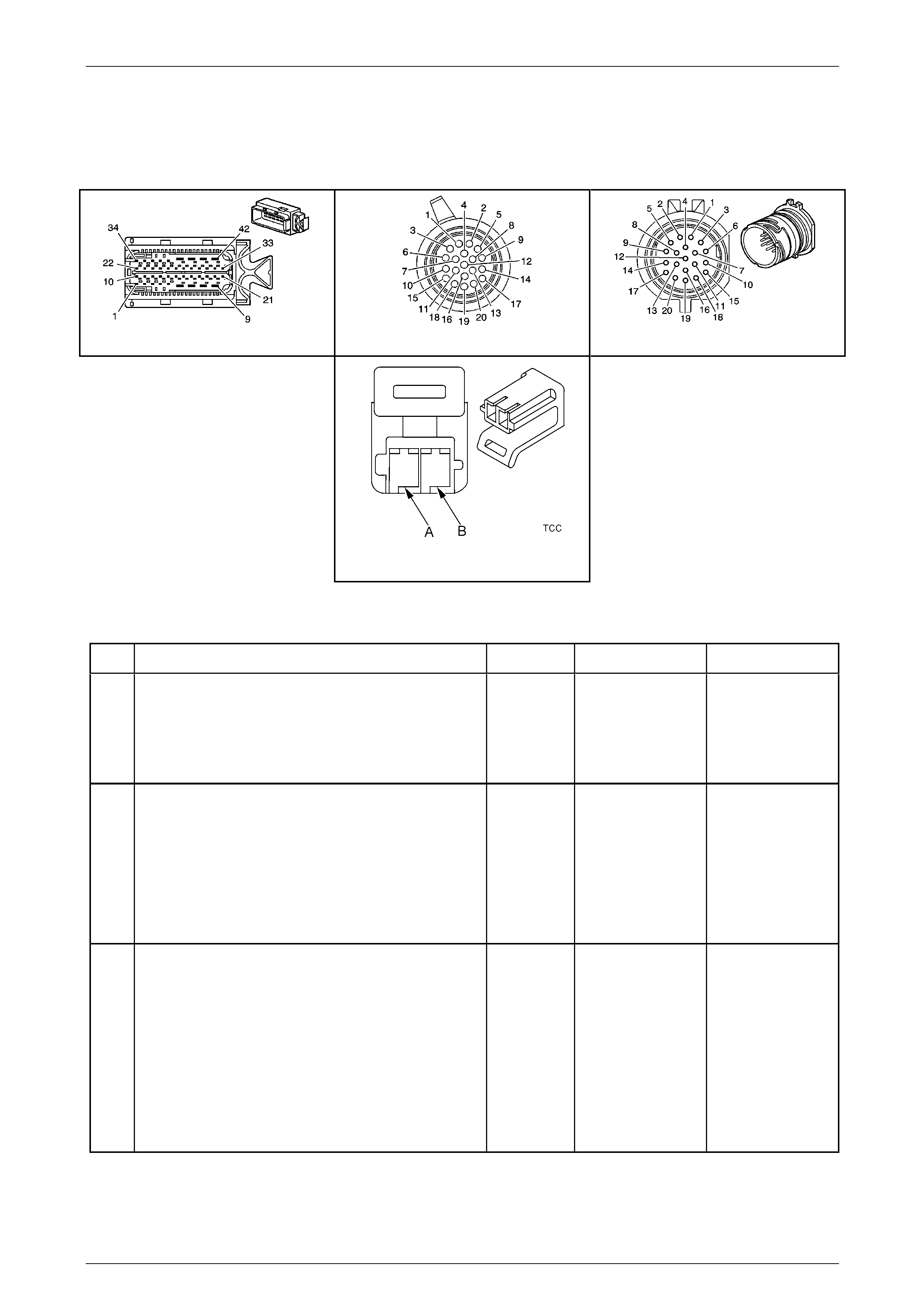
Automatic Transmission – 5L40-E – Electrical Diagnosis Page 7E – 222
Page 7E2 – 222
NOTE
• Refer to Figures 7E2–5 and 7E2–6 for 5L40 –
E automatic transmission electrical circuits.
• For procedures on checking wiring faults,
refer to Section 12P Wiring Diagrams.
A112-T68 – X1 X121-X1 X121-X1a
Torque Converter Clutch (TCC)
Solenoid Connector
Figure 7E2 – 69
DTC P2764 – TCC PWM Solenoid Fault – Open or Short to Ground
Step Action Value(s) Yes No
1
Has the Diagnostic System Check – Automatic
Transmission been com pleted?
–
Go to Step 2
Go to
2.3 Diagnostic
System Check –
Automatic
Transmission
in this Section.
2
1 Connect Tech 2 to the DLC.
2 Ignition ON, engine OFF
3 Clear the DTCs.
4 Use Tech 2 to command the TCC PWM solenoid
ON.
Does the solenoid operat e?
–
Go to Step 10 Go to Step 3
3
1 Ignition OFF.
2 Disconnect the transmission wiring harness
connector X121–X1 from transmission 20-way
connector.
3 Ignition ON, engine OFF.
4 With a test light connected to ground, probe
terminal X1–17 of the transmission wiring harness
connector X121–X1.
Does the test light illuminate?
–
Go to Step 4 Go to Step 8

Automatic Transmission – 5L40-E – Electrical Diagnosis Page 7E – 223
Page 7E2 – 223
Step Action Value(s) Yes No
4
1 Ignition OFF.
2 Using a digital ohmmeter, measure resistance
between terminals 17 and 20 of the transmission
20-way connector.
Is resistance reading within the specified value?
10.0 – 13.6Ω
Go to Step 5 Go to Step 9
5
1 Using a digital ohmmeter, measure resistance
between transmission 20-way connector X121-X1,
terminal X1-17 and ground.
Does check indicate a short to voltage in the wiring?
More than
50 kΩ Go to Step 6 Go to Step 9
6
1 Disconnect the transmission wiring harness
connector A112 – T68 from the TCM.
2 Using a digital ohmmeter, check the TCC PWM
solenoid valve control circuit 418 between the
transmission wiring harness TCM connector
A112 – T68, terminal X1–4 an d the transmission
wiring harness connector X121– X1, terminal
X1–20 for an open circuit con ditio n.
Did you find an open circuit condition?
–
Repair open in
circuit 418. Go to Step 10
7
1 Using a digital ohmmeter, check the TCC PWM
solenoid valve control circuit 418 between the
transmission wiring harness TCM connector
A112 – T68, terminal X1–4 an d the transmission
wiring harness connector X121– X1, terminal X1–
20 for a short to ground condition.
Did you find a short to ground condition?
– Repair short to
voltage condition in
circuit 418. Go to Step 10
8
1 Ignition OFF.
2 Disconnect the transmission wiring harness
connector A112 – T68 from the TCM.
3 Using a digital ohmmeter, check the HSD2 ci rcuit
1525 between the transmission wiring harness
TCM connector A112 – T68, terminal X1–8 and
the transmission wiring harness connector
X121–X1, terminal X1–17 for an open circuit
condition.
Did you find an open circuit condition?
–
Repair open in
circuit 1525. Go to Step 10
9
1 Remove transmission fluid pan. Refer to
Section 7E4 Automatic Tr ansmission – 5L40-E –
On-Vehicle Servicing.
2 Inspect transmission internal wiring harness for
any sign of damage.
3 Using a digital ohmmeter, check the TCC PWM
solenoid wiring circuit between transmission
20-way connec tor X121-X1a, terminals X1-17 and
X1-20 for an open circ uit condition.
4 Also check the same circuit for a short to ground
condition.
Did you find and correct a condition?
–
Go to Step 11 Go to Step 12
10
1 Replace TCM. Refer to Section 7E4 Automatic
Transmission – 5L40-E – On-V ehicle Servicing for
replacement procedures.
Is the replacement complete?
–
Go to Step 13 –

Automatic Transmission – 5L40-E – Electrical Diagnosis Page 7E – 224
Page 7E2 – 224
Step Action Value(s) Yes No
11
1 Remove and replace transmission internal wiring
harness. Refer to Section 7E4 Automatic
Transmission – 5L40-E – On-V ehicle Servicing.
Is the replacement complete?
–
Go to Step 13 –
12
1 Remove and replace the TCC PWM solenoid
valve Refer to Section 7E4 Automatic
Transmission – 5L40-E – On-V ehicle Servicing.
Is the replacement complete?
–
Go to Step 13 –
13
1 Perform the following operation to verify the
repair:
• Select DTC on the Tech 2.
• Select ‘Clear info’.
2 Operate the vehicle in the Conditions for Running
the DTC.
Has the test run and passed?
–
System OK Go to Step 2
When all diagnosis and repairs are completed, clear all DTCs and verify correct operation

Automatic Transmission – 5L40-E – Electrical Diagnosis Page 7E – 225
Page 7E2 – 225
DTC U0100 – GMLAN Bus Error Between Engine ECU and TCM
Circuit Description
Modules connected to the high speed GMLAN serial data circuits monitor each other for serial data communications
during normal vehicle operation. Operating information and commands are exchanged among the mo dules. The modules
have pre-recorded information about what messages are needed to be e xchanged on the serial data circuits, for each
virtual network. The messages are supervised and also, some periodic messages are used by the receiver module as an
availability indication of the transmitter module. The super vision time-out period is 250 ms.
GMLAN serial data messages contain the identification number of the transmitter module which, in the case of the
engine ECU, is ‘100’. When a message that indicates the availability of the transmitter module is not received by (in this
case) the TCM, that can communicate, sets a DTC U0100, indicating that it is the Engine ECU that cannot communicate.
U0100 is a type ‘B’ DTC.
Conditions for Running the DTC
• Voltage supplied to the modules is in the n ormal operating voltage range of 8.0 to 18.0 volts.
• No ECU engine speed, torque, throttle position and wheel speed sensor messages have been received for 50
milliseconds or more.
AND
• No ECU general status message, nor eng in e coolant temperature and barometric readings have been received for
2 seconds or more.
Conditions for Setting the DTC
A valid ECU message on the GMLAN has not been received for 2 seconds.
Action Taken When the DT C Sets
• The TCM requests the Powertrain Interface Module (PIM) to illumin ate the Check Powertrain Malfunction Indicator
Lamp (MIL) in the instrument cluster during the second consecutive drive trip in which the ‘Conditions for Setting
the DTC’ are met.
• At the time of the first failure, the TCM records the operating conditions when the ‘Conditions for Setting the DTC’
have been met. The TCM stores this information as a failure record.
• At the time of the second failure, the ECM records the operating conditions when the ‘Conditions for Set ting the
DTC’ have been met. The ECM stores this information as a freeze frame.
• The TCM freezes the transmission adaptive learning function.
• The TCM turns off the pressure control solenoid (causing maximum line pressure).
• The TCM stores DTC P1826 into TCM history during the second consecutive trip in which the ‘Conditions for
Setting the DTC’ are met.
Conditions for Clearing the MIL / DTC
• A current DTC clears when the malfunction is no longer present.
• A history DTC clears when the module ignition cycle counter reaches the reset threshold , without a repeat of the
malfunction.
Diagnostic Aids
• A poor connection at the inoperative module may cause this code to set.
• An improperly powered module may cause this code to set.
Test Description
The numbers below refer to the step numbers on the diagnostic table.
2 This DTC sets when a communication fault exists between the engine control module (ECM) and the TCM. Check
for DTCs U0001 or U0101. If any of these DT Cs are present, diagnose them first.
3 If a module is not awake, the modules expecting to receive data can not detect the presence of the transmitting
module.
7 The TCM needs time to reset memory.
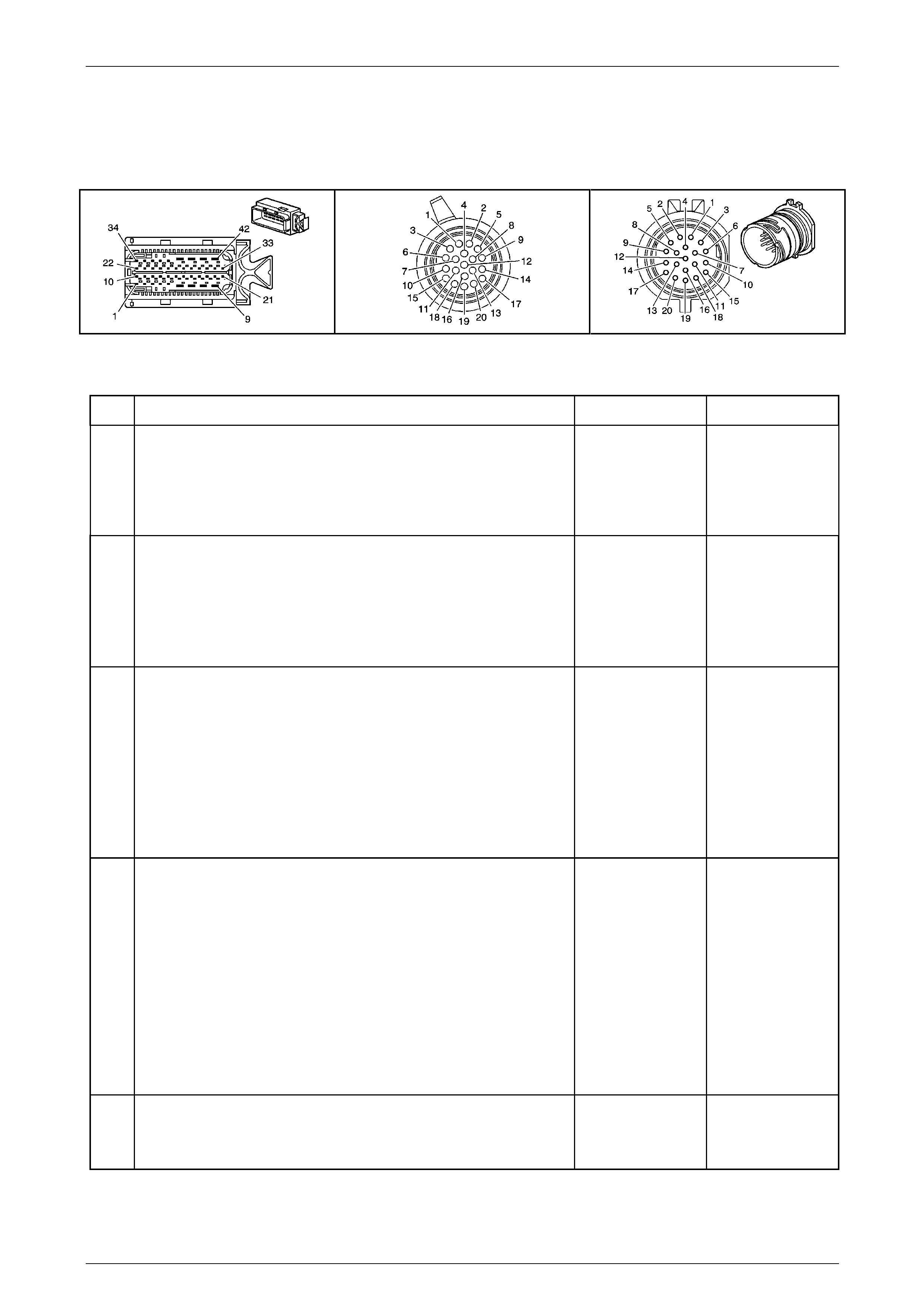
Automatic Transmission – 5L40-E – Electrical Diagnosis Page 7E – 226
Page 7E2 – 226
NOTE
• Refer to Figures 7E2–5 and 7E2–6 for 5L40 –
E automatic transmission electrical circuits.
• For procedures on checking wiring faults,
refer to Section 12P Wiring Diagrams.
Figure 7E2 – 70
DTC U0100 – GML AN Bus error Between Engine ECU and TCM
Step Action Yes No
1
Has the Diagnostic System Check – Automatic T ransmission been
completed? Go to Step 2
Go to
2.3 Diagnostic
System Check –
Automatic
Transmission
in this Section.
2
1 Connect Tech 2 to the DLC.
2 Ignition ON, engine OFF.
3 Use Tech 2 to check for stored DTCs.
Does Tech 2 indicate that DTCs U0001 or U010 1 are either current or
history DTCs?
Go to the DTC
indicated as being
either current or
history. Go to Step 3
3
1 Test the following circuits of the TCM for an open or high
resistance:
• The battery positive voltage circuits.
• The ignition positive voltage circuits.
• The ground circuits.
Refer to Section 12P Wiring Diagrams for references.
Did you find and correct the condition? Go to Step 7 Go to Step 4
4
1 Test the CAN serial data lo w circuit and the CAN serial data high
circuit between the engine control mod ule (ECM) and TCM for
the following conditions:
• Open circuit
• Short to voltage
• Short to ground
• Shorted together
Refer to Section 12P Wiring Diagrams for assistance.
Did you find and correct the condition? Go to Step 7 Go to Step 5
5 1 Inspect for poor connections at the harness connector of the
ECM. Refer to Section 12P Wiring Diagrams.
Did you find and correct the condition? Go to Step 7 Go to Step 6

Automatic Transmission – 5L40-E – Electrical Diagnosis Page 7E – 227
Page 7E2 – 227
Step Action Yes No
6 1 Replace the ECM. Refer to Section 6C1–2 Engine Management
– V6 Diagnostics.
Did you complete the replacement? Go to Step 7 –
7
1 Perform the following operations to confirm the repair:
• Select DTC on Tech 2.
• Select ‘Clear Info’.
• Switch the ignition OFF for at least 10 seconds.
• Ignition ON, engine OFF.
• Check for ECM and TCM DTCs.
Does the DTC reset? Go to Step 2 System OK
When all diagnosis and repairs are completed, clear all DTCs and verify correct operation

Automatic Transmission – 5L40-E – Electrical Diagnosis Page 7E – 228
Page 7E2 – 228
5 Specifications
NOTE
Only those specifications that relate to the items
contained in this Section are detailed here.
Electrical Component Resistance Specifications
Component Circuit
Number Wire
Colour In-line
Connector Pin Resistance
at 20°C Resistance
at 70°C Resistance to Ground
(Transmission Case)
1525 WH 17
1 – 2 Shift
Solenoid Valve 1222 BK 14 15.0 – 17.0 Ω 17.9 – 20.3 Ω Greater than 50 kΩ
1525 WH 17
2 – 3 Shift
Solenoid Valve 1223 BU 9 15.0 – 17.0 Ω 17.9 – 20.3 Ω Greater than 50 kΩ
1525 WH 17
4 – 5 Shift
Solenoid Valve 898 GY 5 15.0 – 17.0 Ω 17.9 – 20.3 Ω Greater than 50 kΩ
1228 GN 13
Pressure Control
Solenoid Valve 1229 WH 8 3.5 – 4.6 Ω 4.2 – 5.5 Ω Greater than 50 kΩ
1525 WH 17
TCC PWM
Solenoid Valve 422 YE 20 10.0 – 11.5 Ω 11.8 – 13.6 Ω Greater than 50 kΩ
1230 YE 18
Input Speed
Sensor 1231 WH 15 325 – 485 Ω 385 – 575 Ω Greater than 50 kΩ
400 OR 1
Output Speed
Sensor 401 WH 3 325 – 485 Ω 385 – 575 Ω Greater than 50 kΩ
1227 RD 10
TFT Sensor 2762 WH 6
Refer to following chart for TFT Sensor Resistance
Specifications
All wire colours are internal to the transmission
Transmission Fluid Temperature (TFT) Sensor Resistance Specifications
Temperature (°C) Minimum
Resistance (Ω) Nominal
Resistance (Ω) Maximum
Resistance (Ω)
-40 89 500 100 000 110 500
-30 46 419 51 400 56 381
-20 25 120 27 610 30 100
-10 14 160 15 450 16 740
0 8 278 8 972 9 666
10 5 005 5 391 5 777
20 3 120 3 342 3 564
30 2 000 2 132 2 264
40 1 317 1 397 1 477
50 888 938 988
60 613 645 677
70 432 453 474
80 310 324 338
90 228 237 246
100 170 176 182
110 128 132 136
120 98 101 104
130 77 79 81
140 60 62 64
150 48 49 50
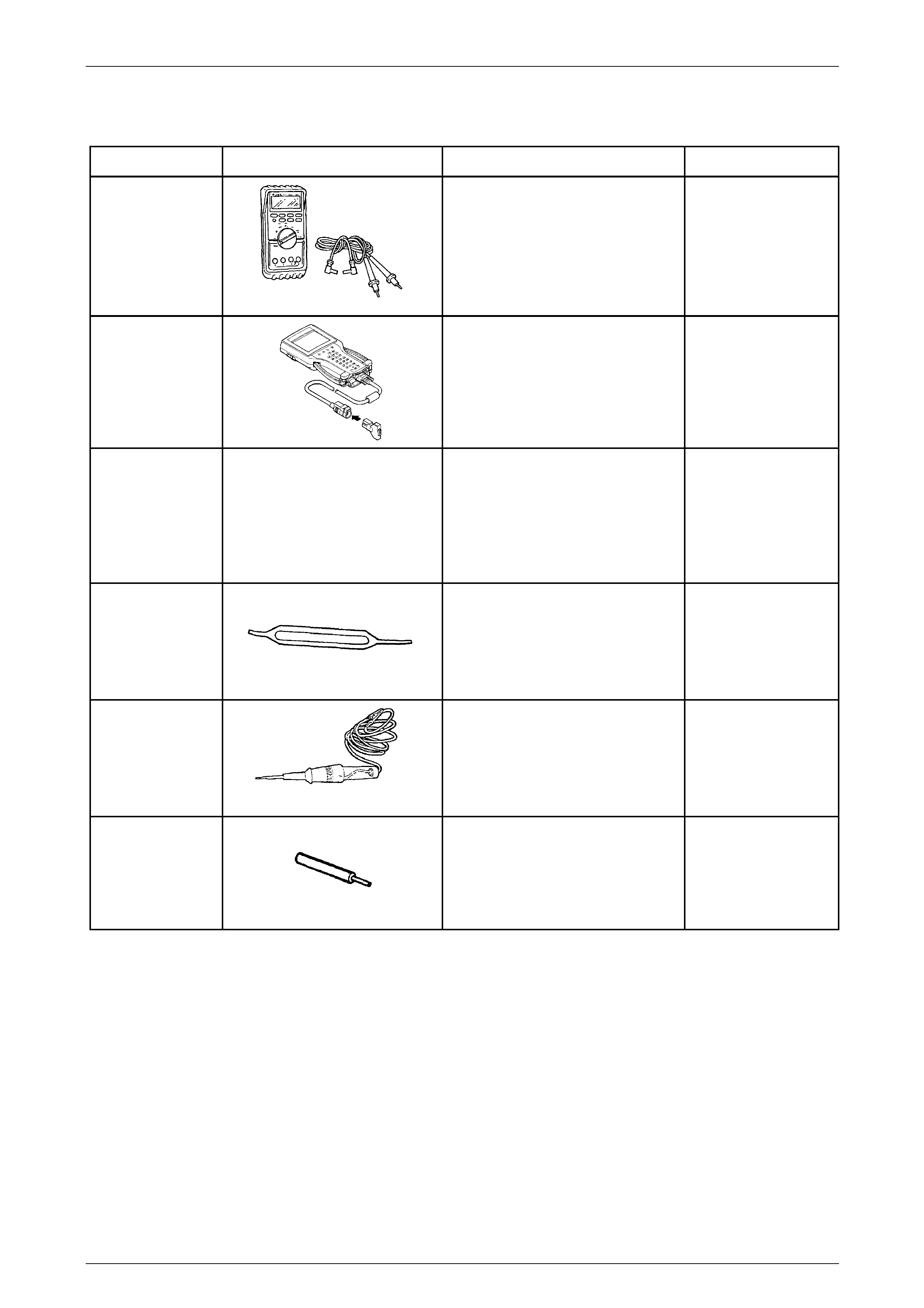
Automatic Transmission – 5L40-E – Electrical Diagnosis Page 7E – 229
Page 7E2 – 229
6 Special Tools
Tool Number Illustration Description Tool Classification
3588
Digital Multimeter
Used for various measurement
functions as detailed in the text.
Previously released as J 39200, 3545
GM and also commercially av ailable
with a minimum of 10 Megohm
impedance
Available
7000086I
Tech 2 Scan Tool
Used for diagnosis of vehicle electrical
systems. Previously released
Mandatory
J 35616-A
Connector Test Adaptor Kit
Used when carrying out electric al
diagnostic circuit checks
Previously released
Desirable
J 33095
Micro-Pack Terminal Remover
Used for the safe removal of Micro-
Pack connector terminals.
Previously released.
Unique
J 34142-A
Unpowered Test Lamp
Previously released as CT-40-C. Also
commercially available
Must have a current draw less than
0.3 Amp
Mandatory
J 36400-5
Weather Pack Terminal Remover
Used for the safe removal of Weather-
Pack connector terminals.
Previously released
Desirable