
Automatic Transmission – 5L40-E – On-Vehicle Servicing 7E4 – 1
7E4 – 1
Section 7E4
Hydra-Matic 5L40-E Automatic Transmission –
On-Vehicle Servicing
ATTENTION
Before performing any Service Operation or other procedure described in this Section, refer to Section 00
Warnings, Cautions and Notes for correct workshop practices with regard to safety and/or property damage.
1 General Information ...............................................................................................................................3
1.1 General Service Precautions ................................................................................................................................ 3
Recommendations................................................................................................................................................. 3
Oil Cooler Pipes..................................................................................................................................................... 4
Cleaning and Inspection ....................................................................................................................................... 4
2 Maintenance Operations........................................................................................................................5
2.1 Transmission Fluid Check .................................................................................................................................... 5
General Information............................................................................................................................................... 5
Transmission Fluid Colour....................................................................................................................................5
Using TECH 2 To Check Fluid Temperature........................................................................................................ 5
Transmission Fluid Checking Procedure ............................................................................................................ 6
2.2 Transmission Cooler Reverse Flush and Flow Rate Check............................................................................. 11
Reverse Flush ...................................................................................................................................................... 11
Flow Rate Check.................................................................................................................................................. 12
3 On-Vehicle Service Operations...........................................................................................................13
3.1 Fluid Change and Filter Replace ........................................................................................................................ 13
Remove................................................................................................................................................................. 13
Reinstall................................................................................................................................................................ 15
3.2 Selector Linkage.................................................................................................................................................. 16
Remove................................................................................................................................................................. 16
Inspect .................................................................................................................................................................. 16
Reinstall................................................................................................................................................................ 16
Adjust.................................................................................................................................................................... 16
3.3 Shift Selector Assembly...................................................................................................................................... 17
Remove................................................................................................................................................................. 17
Disassemble......................................................................................................................................................... 17
Boot, Shift Lever Knob Remove....................................................................................................................... 18
Patch Harness Remove ................................................................................................................................... 19
Switch Remove................................................................................................................................................ 20
Base Disassembly............................................................................................................................................ 21
Lever Disassembly........................................................................................................................................... 21
Reassemble.......................................................................................................................................................... 22
Base Reassembly ............................................................................................................................................ 22
Lower Housing ................................................................................................................................................. 23
Reinstall................................................................................................................................................................ 25
3.4 Transmission Fluid Cooler Pipes/Hoses ........................................................................................................... 26
Remove................................................................................................................................................................. 26
Transmission Fluid Cooler Pipes...................................................................................................................... 26
Radiator Cooler Pipes/Hoses........................................................................................................................... 27
Reinstall................................................................................................................................................................ 28
Radiator Cooler Pipes/Hoses........................................................................................................................... 28
Transmission Fluid Cooler Pipes...................................................................................................................... 29
Techline
Techline

Automatic Transmission – 5L40-E – On-Vehicle Servicing 7E4 – 2
7E4 – 2
3.5 Fluid Pressure Test Plug..................................................................................................................................... 30
Replace................................................................................................................................................................. 30
3.6 Transmission Mount and Mount Plate ............................................................................................................... 31
Inspect .................................................................................................................................................................. 31
Remove................................................................................................................................................................. 32
Reinstall................................................................................................................................................................ 33
3.7 Output Drive Flange and Oil Seal....................................................................................................................... 34
Remove................................................................................................................................................................. 34
Reinstall................................................................................................................................................................ 36
3.8 Extension Housing .............................................................................................................................................. 38
Remove................................................................................................................................................................. 38
Reinstall................................................................................................................................................................ 39
3.9 Transmission Internal Electrical Harness.......................................................................................................... 40
Replace................................................................................................................................................................. 40
3.10 Manual Shaft Oil Seal .......................................................................................................................................... 43
Replace................................................................................................................................................................. 43
3.11 Manual Shaft Position Switch............................................................................................................................. 45
Remove................................................................................................................................................................. 45
Reinstall................................................................................................................................................................ 47
3.12 Input Speed Sensor............................................................................................................................................. 49
Replace................................................................................................................................................................. 49
3.13 Output Speed Sensor.......................................................................................................................................... 50
Replace................................................................................................................................................................. 50
3.14 1-2 Shift Solenoid................................................................................................................................................. 51
Replace................................................................................................................................................................. 51
3.15 2-3 Shift Solenoid................................................................................................................................................. 52
Replace................................................................................................................................................................. 52
3.16 4-5 Shift Solenoid................................................................................................................................................. 54
Replace................................................................................................................................................................. 54
3.17 Pressure Control Solenoid.................................................................................................................................. 55
Replace................................................................................................................................................................. 55
3.18 Torque Converter Clutch (TCC) PWM Solenoid................................................................................................ 57
Replace................................................................................................................................................................. 57
3.19 Solenoid Leak Testing......................................................................................................................................... 59
3.20 Control Valve Body and Accumulator Assembly.............................................................................................. 60
3.21 Transmission Control Module (TCM)................................................................................................................. 61
Remove................................................................................................................................................................. 61
Reinstall................................................................................................................................................................ 61
TCM Programming Procedure............................................................................................................................ 62
3.22 5L40-E Automatic Transmission ........................................................................................................................ 63
Remove................................................................................................................................................................. 63
Reinstall................................................................................................................................................................ 68
Transmission Final Test and Inspection............................................................................................................ 70
3.23 Torque Converter and/or Seal............................................................................................................................. 71
Replace................................................................................................................................................................. 71
4 Specifications.......................................................................................................................................74
5 Torque Wrench Specifications............................................................................................................76
6 Special Tools ........................................................................................................................................77
Automatic Transmission – 5L40-E – On-Vehicle Servicing 7E4 – 3
7E4 – 3
1 General Information
The service operations detailed in this Section, relate to tasks that can be carried out on the 5L40-E Automatic
Transmission while it is still installed in the vehicle. In addition, the procedures required to remove and reinstall the
transmission assembly and torque converter from/to the vehicle are also provided.
It is strongly recommended that the General Service Precautions provided in this Section be read and followed,
whenever servicing operations are to be carried out on this transmission.
1.1 General Service Precautions
ATTENTION
All fasteners are important attaching parts as they affect the performance of vital components and/or could
result in major repair expense. W h ere specified in this section, fasteners MUST be replaced with parts of the
same part number or an approved equivalent. Do not use fasteners o f an inferior quality or substitute design.
Torque values must be used as specified during reassembly to ensure proper retention of all components.
Throughout this section, fastener torque wrench specifications may be accompanied with the following
identification marks:
Fasteners must be replaced after loosening.
Vehicle must be at curb height before final tightening.
Fasteners either have micro encapsulated sealant applied or incorporate a mechanical thread lock and
should only be re-used once. If in doubt, replacement is recommended.
If one of these identification marks is present alongside a fastener torque wrench specification, the
recommendation regarding that fastener must be adhered to.
Recommendations
When servicing this transmission, all parts should be cleaned and inspected as outlined under 'Cleani ng and Inspection',
in this Section. Individual units should be reassembled before disassembly of other units to avoid confusion and
interchanging of parts.
Machined surfaces of alloy transmission
components (e.g. transmission case) have
extremely sharp edges that are a very real
safety hazard. It is recommended that
machined edges are ‘broken’ with a sharp
second cut file, taking care not to allow metal
particles to enter the transmission.
1 Thoroughly clean the transmission exterior before removal of any component.
2 Disassembl y and reassembly must be made on a clean work bench. Cleanliness is of the utmost importance. The
bench tools, and parts must be kept clean at all times.
3 Before installin g screws and other fasteners into aluminium parts, dip screws into transmission fluid (Only use
Dexron® III) to prevent galling of the aluminium threads and to prevent screws from seizing.
4 To prevent thread stripping, always use a torque wrench when insta lling fasteners.
5 If threads in aluminium parts are stripped or damaged, the part can be recovered by the use of commercially
available, thread inserts.
6 Protective tools must be used when assembling seals to prevent damage. The slightest flaw in the sealing surface
of the seal can cause a fluid leak.
7 Aluminium cast ings and valve parts are very susceptible to nicks, burrs, etc., and should be handled with care.
8 Internal snap rings should be expanded and external snap rings compressed if they are to be re-used. This will
ensure proper seatin g when reinstalled.
9 O-rings, gaskets and oil seals that are removed, should be replaced with ne w parts.
10 Teflon oil seal rings shoul d not be removed unless damaged.
11 During assembly of each unit, all internal moving parts must be lubricated with new transmission fluid of th e correct
specification.

Automatic Transmission – 5L40-E – On-Vehicle Servicing 7E4 – 4
7E4 – 4
Oil Cooler Pipes
Should any transmission fluid cooling pipe suffer accidental damage, then a genuine replacement pipe must be fitted.
Refer to the current release of PartFinder™ to determine the correct part n umber for the specific engine and pipe
involved. Reworking of damaged pipes or hand made replacements are not permitted.
Cleaning and Inspection
Wear eye protection to prevent potential
injury.
After the complete disassembly of a compon ent, wash all metal parts in a clean solvent and dry with compressed air.
Blow oil passages out and check to make sure they are not obstructed. Small passages shou ld be checked with tag wire.
All parts should be inspected to determine which parts are to be replaced.
Pay particular attention to the follo wing:
1 Inspect linkage and pivot points for excessive wear.
2 Bearing and thrust surfaces of all parts should be checked for exc essive wear and scoring.
3 Check for broken seal rings, damaged ring lands and damaged threads.
4 Inspect seal and O-rings.
5 Mating surfaces of castings should be checked for burrs. Irregularities may be removed by lapping the
surface with emery paper. The emery paper is laid on a flat surface, such as a piece of plate glass.
6 Castings should be checked for cracks and porosit y.
7 Do not use solv ents on neoprene seals, composition faced clutch plates or thrust washers, as damage to
these parts may occur.

Automatic Transmission – 5L40-E – On-Vehicle Servicing 7E4 – 5
7E4 – 5
2 Maintenance Operations
ATTENTION
All fasteners are important attaching parts as they affect the performance of vital components and/or could
result in major repair expense. W h ere specified in this section, fasteners MUST be replaced with parts of the
same part number or an approved equivalent. Do not use fasteners o f an inferior quality or substitute design.
Torque values must be used as specified during reassembly to ensure proper retention of all components.
Throughout this section, fastener torque wrench specifications may be accompanied with the following
identification marks:
Fasteners must be replaced after loosening.
Vehicle must be at curb height before final tightening.
Fasteners either have micro encapsulated sealant applied or incorporate a mechanical thread lock and
should only be re-used once. If in doubt, replacement is recommended.
If one of these identification marks is present alongside a fastener torque wrench specification, the
recommendation regarding that fastener must be adhered to.
2.1 Transmission Fluid Check
General Information
When adding or changing the transmission fluid, use only Dexron® III automatic transmission fluid. Refer to the
appropriate Owner's Handbook for servicing intervals.
Because this transmission fluid changes colour and develops an odour very early in its lif e, these indicators should not
necessarily be relied upon to diagnose either transmission internal condition nor fluid deterioration.
If, when following the Fluid Checking Procedure, a dark brown fluid colour is observed, coupled with a reported delayed
shift pattern, this may only indicate that the fluid requires replacement and alone, is not a definite indication of a potential
transmission failure.
NOTE
Do not overfill the transmission. Overfilling will
cause foaming of the fluid, loss of fluid, shift
complaints and possible damage to the
transmission.
Transmission Fluid Colour
Transmission fluid colour when new and unused, is red. A red dye is added so that it can be distinguished from other oils
and lubricants. The red dye is not an indicator of fluid quality and is not permanent. As the vehicle is driven, the
transmission fluid will quickly begin to look darker in colour. The colour will then appear light brown. A DARK brown
colour with a distinctively burnt odour MAY in dicate fluid deterioration and a need for the fluid to be changed.
Using TECH 2 To Check Fluid Temperature
1 Connect the TECH 2 scan to ol to the ALDL connector in the vehicle, then press the 'ON' button, to activate the
scan tool.
2 At the 'Main Menu', select 'F0: Diagnostics / Model Year (05) 2005 / Vehicle Type'.
3 At the 'System Select' menu, select 'F1: T r ansmission / Automatic Transmission’, turn ‘Ignition ON', then 'Confirm'
with the Soft Key.
4 At the 'Transmission Ide ntifier' screen, press the 'Confirm' soft key once again, to show the 'Transmission
Application' menu.
5 From the functions sho wn, select 'F 2: Data Displa y', then scroll d own until the 'Transmission Fluid Temperature'
display is visible.
Techline
Automatic Transmission – 5L40-E – On-Vehicle Servicing 7E4 – 6
7E4 – 6
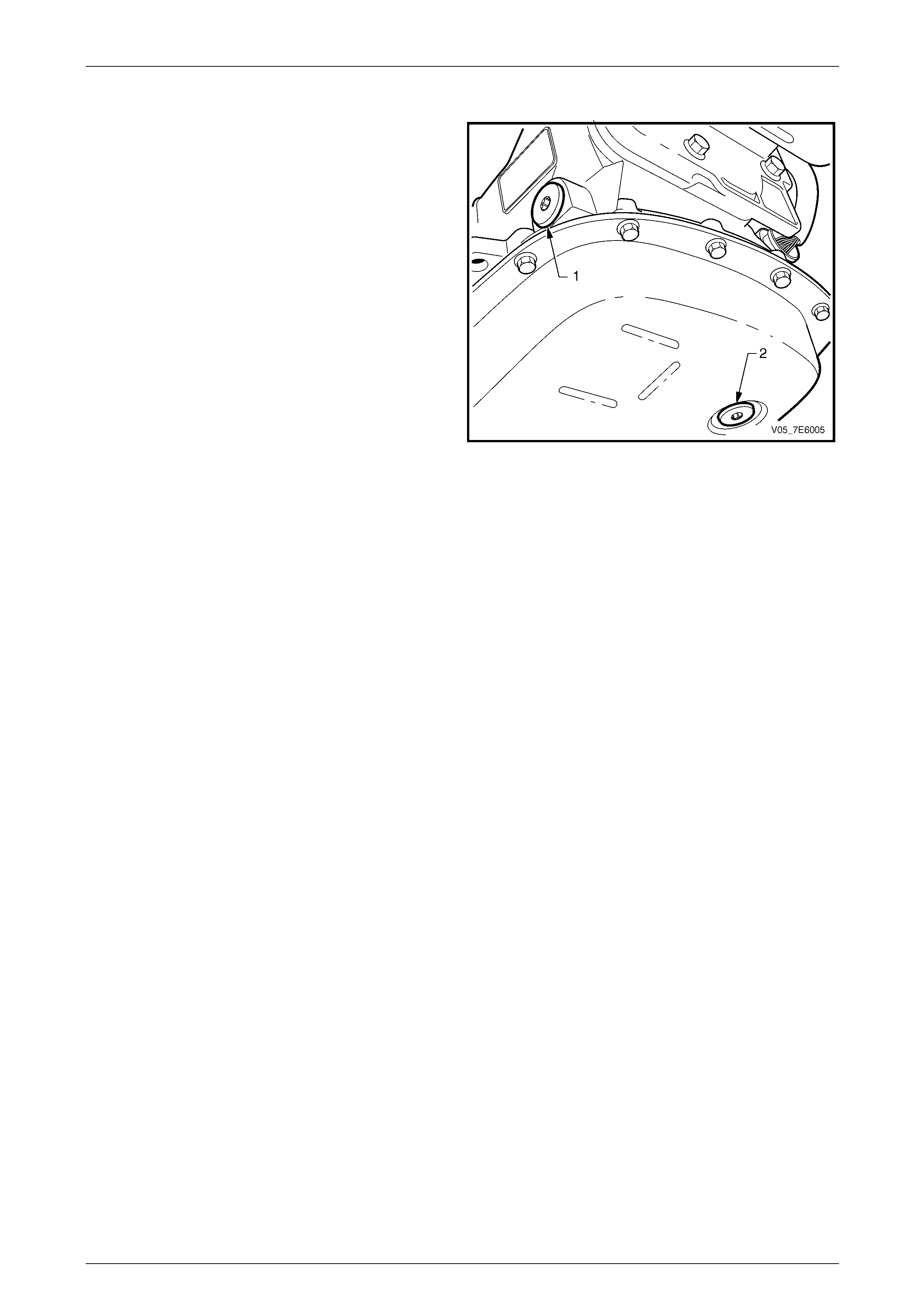
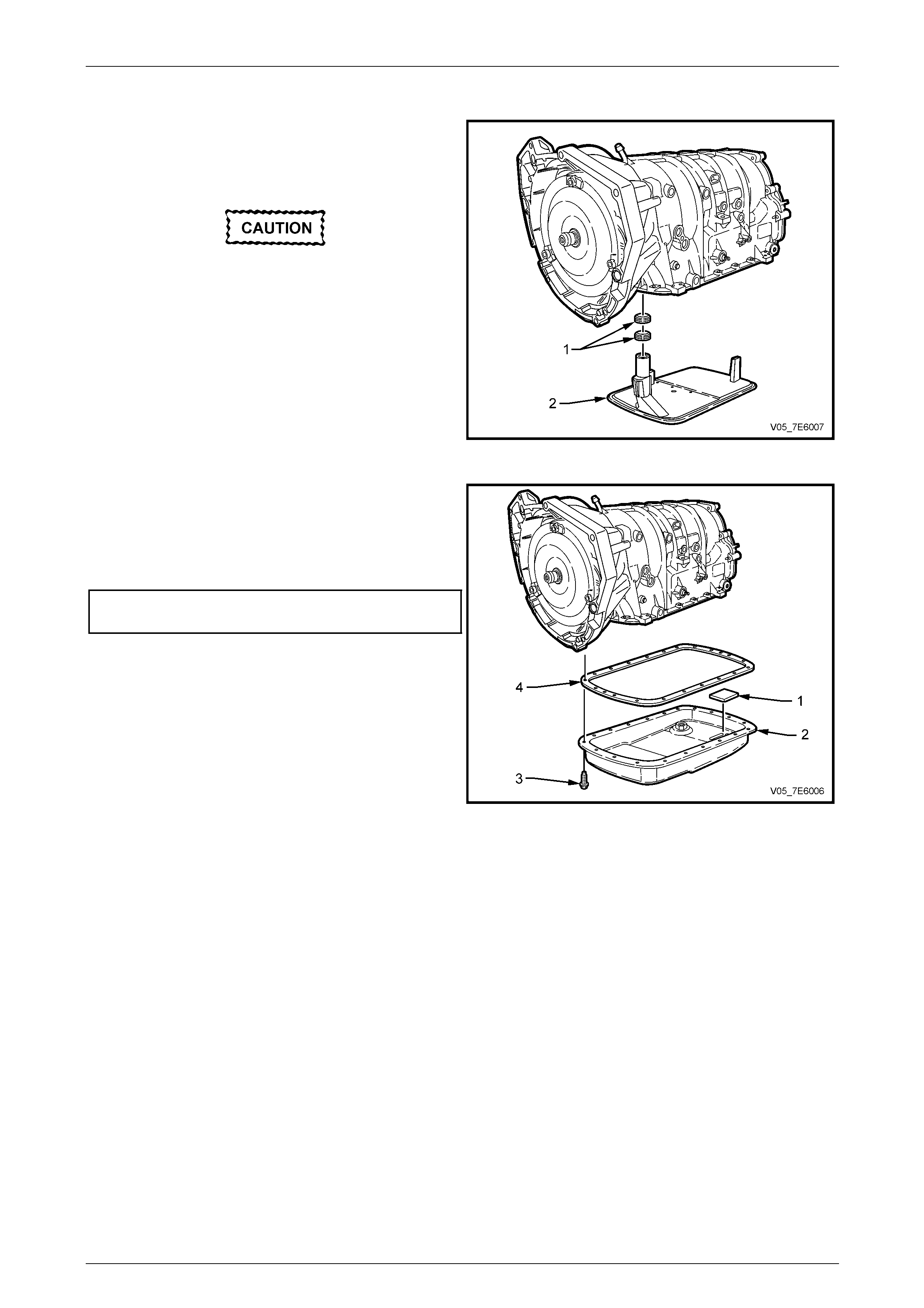
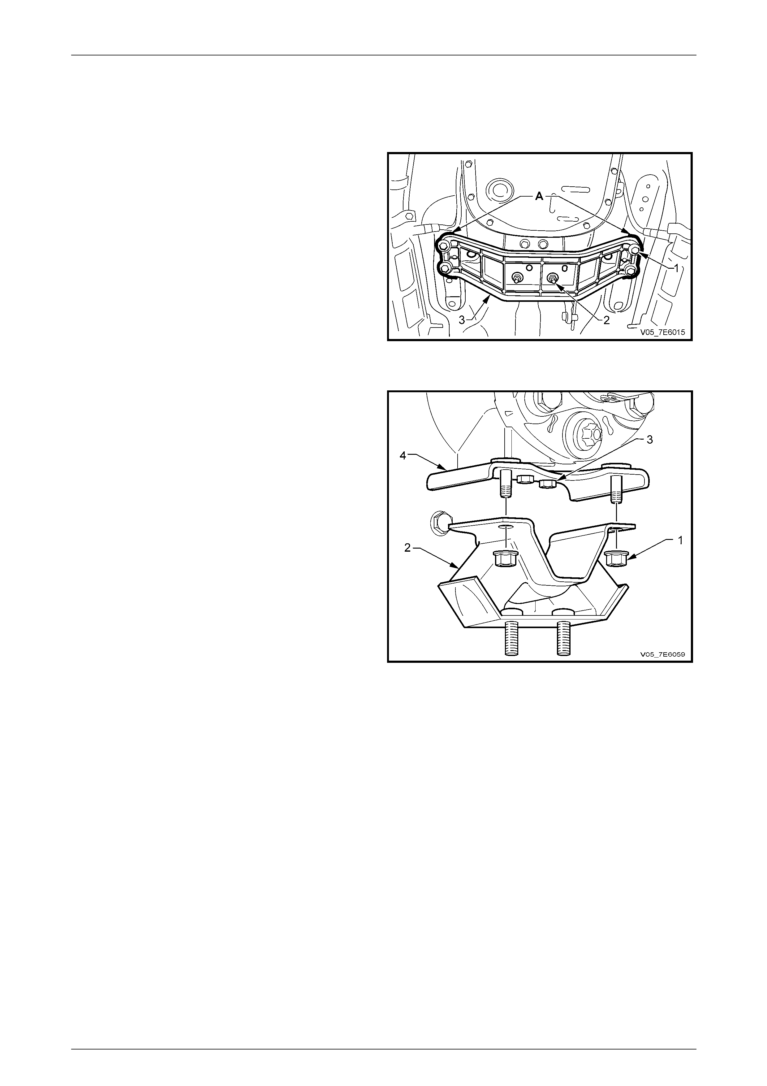
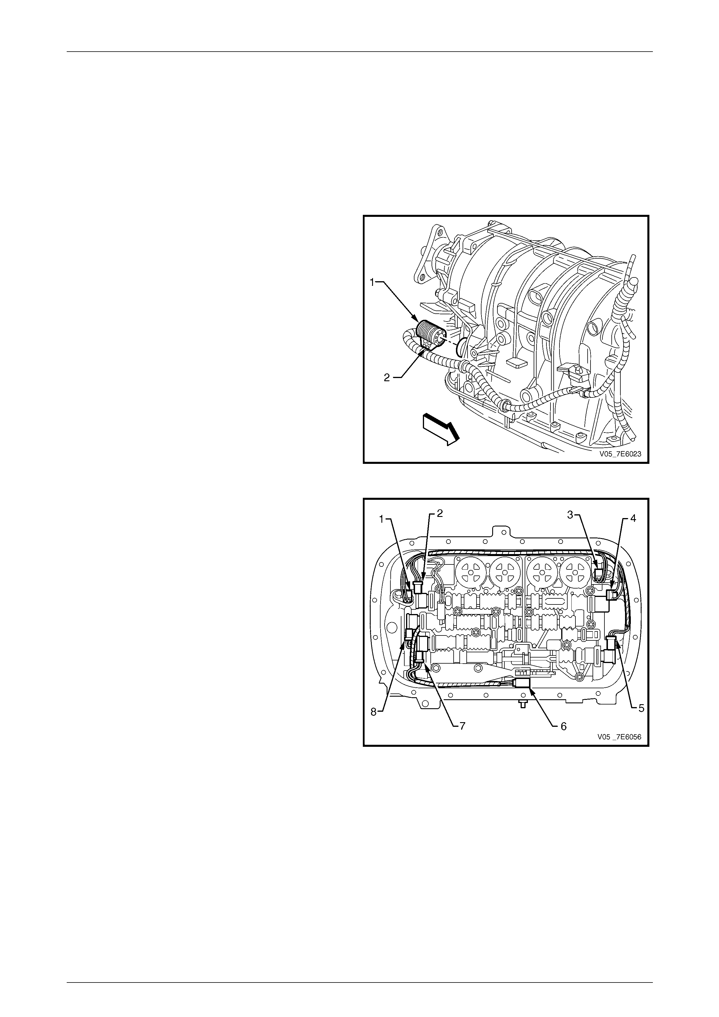
Transmission Fluid Checking Procedure
Legend
1 Fluid level plug.
2 Fluid drain plug.
Figure 7E4 – 1
Automatic Transmission – 5L40-E – On-Vehicle Servicing 7E4 – 7
7E4 – 7
Step Action Value Yes No
1 1 Start the engine.
2 Depress the brake pedal and move the shift
lever through all of the gear ranges, pausing a
few seconds in each range. Return the shift
lever to the Park range.
3 Raise the vehicle and support in a safe manner.
The vehicle must be level, the eng ine running
and the shift lever in the Park range. Refer to
Section 0A General Information for the location
of recommended lifting and support poi nts.
• The engine must be running when
the transmission fluid filler plug is
removed, or exce ssi ve fluid loss w ill
occur.
• Take extreme care when removing
the filler plug as it is very close to
the catalytic converter and personal
injury through burning can easily
occur.
• Transmission fluid may be hot.
Since the actual fluid level is
unknown, stand clear when
removing the filler plug. Have a
container ready to capture any lost
fluid.
• Do not turn the engine off with the
filler plug removed, as you can be
injured by hot transmission fluid
being expelled out of the fluid level
plug opening.
4 Remove the transmission fluid level plug (1).
See Figure 7E4-1 for the loc ation.
5 Inspect the fluid colour. If necessary, use a
small screwdriver as a dipstick.
NOTE
The transmission fluid may darken with
normal use and does not always indicate
contamination or oxidation.
Is the fluid colour red or light brown with no burnt
odour?
–
Go to Step 4 Go to Step 2
2 Does the fluid have a burnt odour or a dark brown
colour? – Go to Step 8 Go to Step 3

Automatic Transmission – 5L40-E – On-Vehicle Servicing 7E4 – 8
7E4 – 8
Step Action Value Yes No
3 Does the fluid have a cloudy or milky appearance? – Go to Step 7 Go to Step 8
4
1 Let the fluid temperature rise until it has reached
the specified value. Check temperature using
TECH 2.
2 Check the fluid level. The level should be even
with the bottom of the threaded plug hole.
Is the fluid level low?
30 – 50° C
Go to Step 5 Go to Step 11
5 1 Add Dexron® III automatic transmission fluid in
increments of 0.5 litre until the fluid drains from
the filler plug hole.
Did you add more than 1.5 litres to the transmission?
–
Go to Step 6 Go to Step 11
6 1 The transmission may have a leak. Refer to
Fluid Leak Diagnosis in Section 7E3 Automatic
Transmission – Hydrau lic/Mechanical
Diagnosis.
Was a transmission leak found?
–
Go to Step 9 Go to Step 11
7 1 The transmission fluid is contaminated with
engine coolant.
2 Repair or replace the transmission cooler in the
radiator.
Is the transmission cooler repair complete?
–
Go to Step 9 –
8 1 Drain the fluid by removing the transmission
fluid pan drain plug (2).
2 Remove the transmission fluid pan. Refer to
3.1 Fluid Change and Filter Replace.
NOTE
A very small amount of material in the
bottom of the pan is a normal condition.
3 Inspect the bottom pan for an y excessive debris.
Was excessive debris found?
–
Go to Step 9 Go to Step 10
Automatic Transmission – 5L40-E – On-Vehicle Servicing 7E4 – 9
7E4 – 9
Step Action Value Yes No
9 1 Repair/replace the transmission, as required.
NOTE
If the transmission is replac ed/overhauled,
then flushing the fluid cooler and pipes will
be required. Refer to 2.2 Transmission
Cooler/Lines Reverse Flush and Flow
Rate Check, in this Section.
2 Add enou gh Dexron® III automatic transmission
fluid to bring the fluid to the fluid level to the
bottom of the threaded filler plug hole.
3 Start the engine and ru n at idle speed.
4 Depress the brake pedal and move the shift
lever through all of the gear ranges, pausing a
few seconds in each range. Return the shift
lever to the Park range.
5 Raise the vehicle and support in a safe manner.
The vehicle must be level, the eng ine running
and the shift lever in the Park range. Refer to
Section 0A General Information for the location
of recommended lifting and support poi nts.
• The engine must be running when
the transmission fluid filler plug is
removed, or exce ssi ve fluid loss w ill
occur.
• Take extreme care when removing
the filler plug as it is very close to
the catalytic converter and personal
injury through burning can easily
occur.
• Transmission fluid may be hot.
Since the actual fluid level is
unknown, stand clear when
removing the filler plug. Have a
container ready to capture any lost
fluid.
• Do not turn the engine off with the
filler plug removed, as you can be
injured by hot transmission fluid
being expelled out of the fluid level
plug opening.
6 With TECH 2 still connecte d to the vehicle, allow
the A/T fluid temperature to rise until it has
reached the specified value. Remov e the
transmission filler plug.
7 If needed, add DEXRON®III automatic
transmission fluid in increments of 0.5 litre until
the fluid drains from the threaded filler plug hole.
8 Allow fluid to finish dr aining from the filler plug
hole. Inspect the filler plug (1) and O-ring and , if
undamaged, may be re-used. Reinstall the
transmission filler plug (1) and tighten to the
specified value.
9 Wipe any excess fluid from the transmission
with a rag or shop towel.
Is the repair complete?
30 – 50° C
20 N.m
System OK –
Automatic Transmission – 5L40-E – On-Vehicle Servicing 7E4 – 10
7E4 – 10
Step Action Value Yes No
10 1 Change the fluid and fluid filter. Refer to
3.1 Fluid Change and Filter Replace.
2 Start the engine and ru n at idle speed.
3 Depress the brake pedal and move the shift
lever through all of the gear ranges, pausing a
few seconds in each range. Return the shift
lever to the Park range.
4 Raise the vehicle and support in a safe manner.
The vehicle must be level, the eng ine running
and the shift lever in the Park range. Refer to
Section 0A General Information for the location
of recommended lifting and support poi nts.
• The engine must be running when
the transmission fluid filler plug is
removed, or exce ssi ve fluid loss w ill
occur.
• Take extreme care when removing
the filler plug as it is very close to
the catalytic converter and personal
injury through burning can easily
occur.
• Transmission fluid may be hot.
Since the actual fluid level is
unknown, stand clear when
removing the filler plug. Have a
container ready to capture any lost
fluid.
• Do not turn the engine off with the
filler plug removed, as you can be
injured by hot transmission fluid
being expelled out of the fluid level
plug opening.
5 With TECH 2 still connecte d to the vehicle, allow
the A/T fluid temperature to rise until it has
reached the specified value. Remov e the
transmission filler plug (1).
6 If needed, add Dexron® III automatic
transmission fluid in increments of 0.5 litre until
the fluid drains from the threaded filler plug hole.
7 Allow fluid to finish dr aining from the filler plug
hole. Inspect the filler plug (1) and O-ring and , if
undamaged, they may be re-used. Reinstall the
transmission filler plug (1) and tighten to the
specified value.
8 Wipe any excess fluid from the transmission
with a rag or shop towel.
Is the repair complete?
30 – 50° C
20 N.m
System OK –
11 1 With TECH 2 still connected to the vehicle, allow
the A/T fluid temperature to rise until it has
reached the specified value. Remov e the
transmission filler plug (1).
2 Allow fluid to finish dr aining from the filler plug
hole. Inspect the filler plug (1) and O-ring and , if
undamaged, they may be re-used. Reinstall the
transmission filler plug (1) and tighten to the
specified value.
3 Wipe any excess fluid from the transmission
with a shop towel or rag.
Is the repair complete?
30 – 50° C
20 N.m
System OK –

Automatic Transmission – 5L40-E – On-Vehicle Servicing 7E4 – 11
7E4 – 11
2.2 Transmission Cooler Reverse Flush and
Flow Rate Check
It is essential that a reverse flush and oil
cooler flow rate check is p erformed, after ANY
of the following situations:
• Transmission is replaced.
• Fluid contamination is suspected.
• Whenever the oil pump and/or torque
converter is replaced.
NOTE
The reverse flush must be completed prior to
conducting a flow rate check.
Reverse Flush
The recommended proce dure for reverse flushing the transmission cooler and lines, particularly after an overhauled or
replaced transmission has been installed into the vehicle, is as follows:
1 Disconnect the cooler l ine flange at the transmission and the quick connect fittings at the radiator cooler end.
Refer to 3.4 Transmission Cooler Pi pes/Hoses, in this Section. Do not lose the pipe sealing O-rings, when they are
removed.
2 Disconnect the cooler p ipe/hose combinations from the radiator, right hand tank.
Refer to 3.4 Transmission Cooler Pi pes/Hoses, in this Section.
3 Carefully check the cooler inlet fitting (upper) at the radiator end, to see whether any material is evident at this
point. If so, dislodge and remove with a suitable tool and/or compressed air blown in the reverse direction through
the cooler.
4 Using a comm ercially available pressure spray gun and clean solvent, such as white spirit:
a Back flush through all co oler lines and hoses.
b Back flush through the cooler, including an external cooler (if fitted).
c Blow compressed air through the cooler and all cooler lines and hoses, to remove solvent.
d Flush the cooler and pipes/hoses with transmission fluid.
5 Check the cooler pipe to cooler fitting and cooler pipe to transmission flange, sealing O-rings for damage, replacing
as required.
6 Lubricate al l O-rings with automatic transmission fluid before installing.
7 Reconnect cooler pi pes to the cooler and transmission (refer to 3.4 Transmission Cooler Pipes/Hoses, in this
Section) but leave the cooler return line to transmission co nnection open at the flexible hose, quick connect fitting
from the lower cooler fitting.
8 Tighten the co oler pipe flange nuts at the cooler end to the specified torque.
Refer to 3.4 Transmission Cooler Pipes/Hoses, Reinstall for the correct procedure.
Oil cooler pipe to radiator fitting
torque specification..............................................25 N.m
Automatic Transmission – 5L40-E – On-Vehicle Servicing 7E4 – 12
7E4 – 12
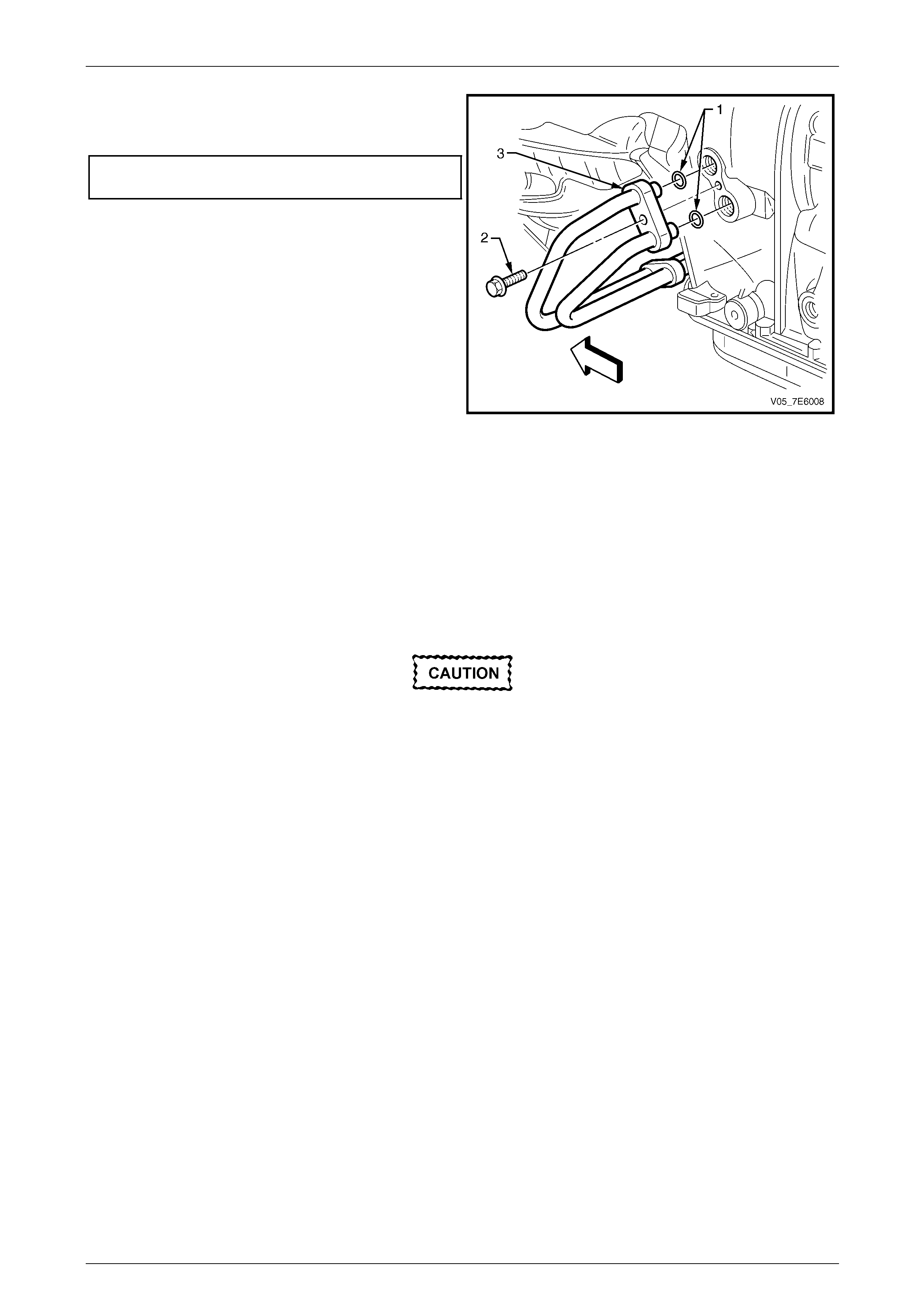
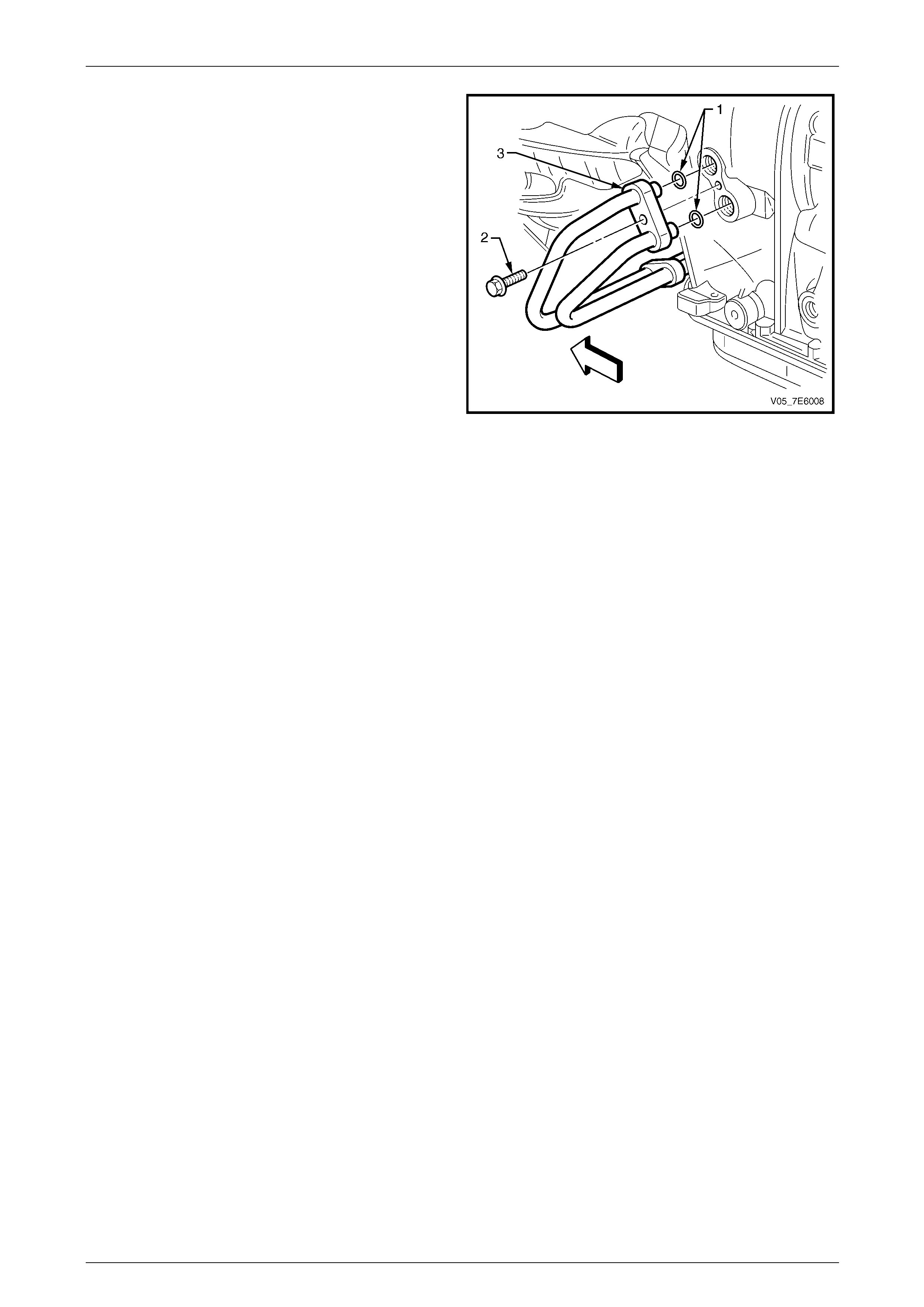
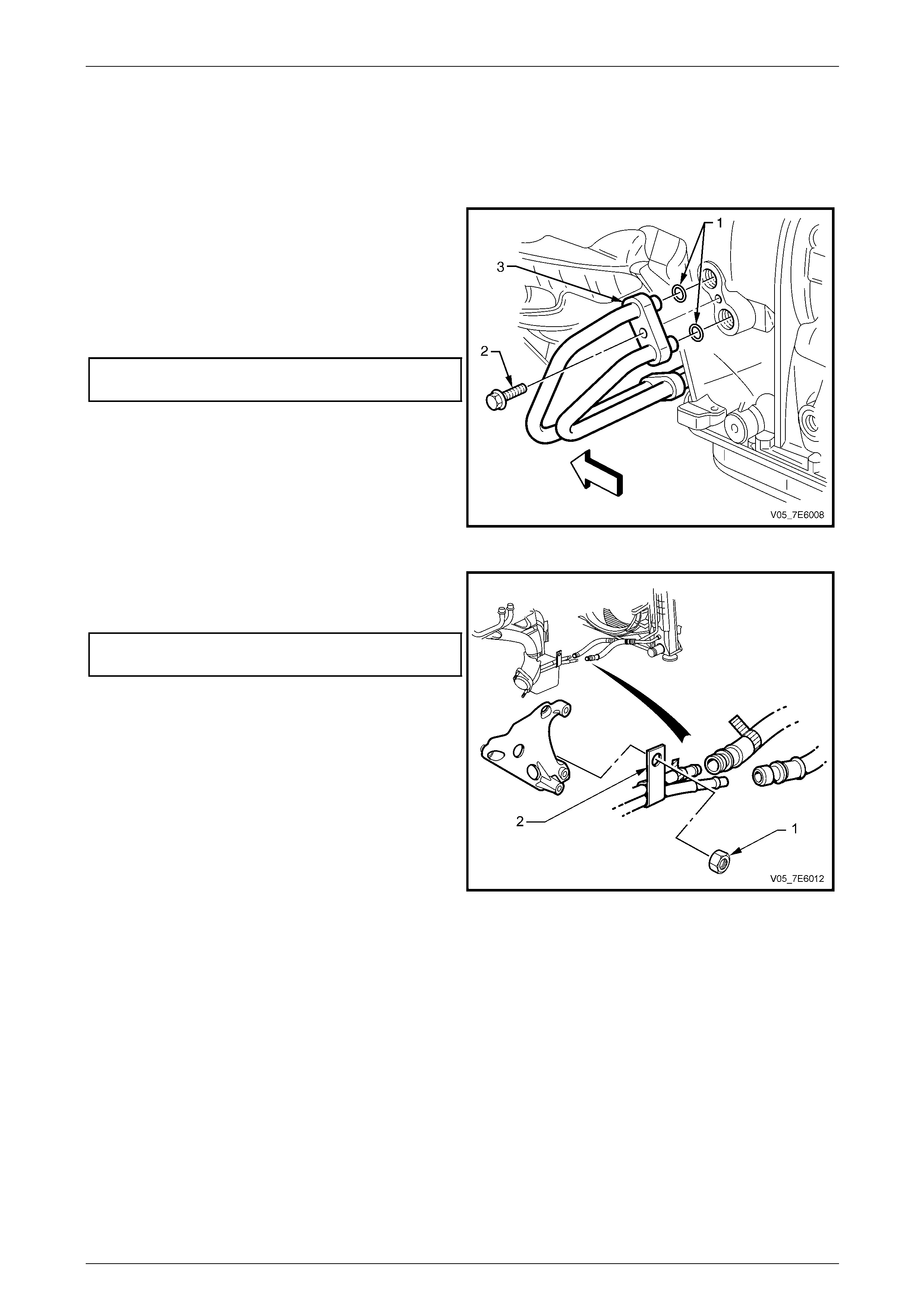
9 Tighten the co oler pipe flange (3) to transmission
housing retaining bolt (2) to the correct torque
specification.
Fluid cooler pipe flange bolt
to transmission torque specification.....................20 N.m
Figure 7E4 – 2
10 Conduct a flow rate test as described next, to ensure that any restriction has been cleared.
11 If flow rate is satisfactory, reconnect the return line, quick connect fitting.
Refer to 3.4 Transmission Cooler Pipes/Hoses, in this Section.
12. Check fluid level as detailed in 2.1 Transmission Fluid Check, in this Section.
13 Lower vehicle to the ground and road test to check for correct operation.
Flow Rate Check
Do not run engine any longer than absolutely
necessary, as too low a fluid level can cause
aeration and foaming.
1 Follo wing the flushing of the transmission cooler, pipes and flexible hoses, leave the cooler return line to
transmission connection open at the flexib le hose, quick connect fitting from the lower cooler fitting.
2 Ensure that the fluid is at the recommended level, refer to 2.1 Transmission F luid Check, in this Section.
3 Place an empty, clean container underneath the disconnected cooler hose. Clip the hose to the container.
4 With the selector lever in the PARK position, have an assistant start the engine and run at idle speed.
5 Observe the fluid flo w into the container, after all air bubbles have ceased a nd a steady flow is evident. Measure
the flow rate.
Result: The fluid flow rate should be approximatel y 1.9 litres in a 30 second period, with cold automatic
transmission fluid (ATF). W ith AT F at normal operating temperature (86 – 93° C), the flow rate will increase and
should be approximatel y 3 litres in a 30 second period.
If the flow rate is less than this specification, the source of the restriction must be located and rectified. Possibilities
are either radiator tank cooler, faulty flexible hose/s and/or external cooler (if fitted).
6 Reinstall the cooler return line to the transmission quick connect.
Refer to 3.4 Transmission Cooler Pi pes/Hoses, Reinstall for the correct procedure.
7 Clean up an y spilled automatic transmission fluid, start the engine and check for fluid leaks.
8 Check and correct the fluid level as detailed in 2.1 Transmission Fluid Check, in this Section, topping up as
required.
Automatic Transmission – 5L40-E – On-Vehicle Servicing 7E4 – 13
7E4 – 13
3 On-Vehicle Service Operations
ATTENTION
All fasteners are important attaching parts as they affect the performance of vital components and/or could
result in major repair expense. Where specified in this Section, fasteners MUST be replaced with parts of the
same part number or an approved equivalent. Do not use fasteners o f an inferior quality or substitute design.
Torque values must be used as specified during reassembly to ensure proper retention of all components.
Throughout this section, fastener torque wrench specifications may be accompanied with the following
identification marks:
Fasteners must be replaced after loosening.
Vehicle must be at curb height before final tightening.
Fasteners either have micro encapsulated sealant applied or incorporate a mechanical thread lock and
should only be re-used once. If in doubt, replacement is recommended.
If one of these identification marks is present alongside a fastener torque wrench specification, the
recommendation regarding that fastener must be adhered to.
3.1 Fluid Change and Filter Replace
Remove
1 Raise the vehicle and support in a safe manner. Refer to Section 0A General Information in this Service Information
for the location of recommended lifting and supp ort points.
2 Place a suitable drain pan under the transmission fluid drain plu g.
Wear eye protection and protective clothing
to prevent potential scalding from hot
automatic transmission fluid.
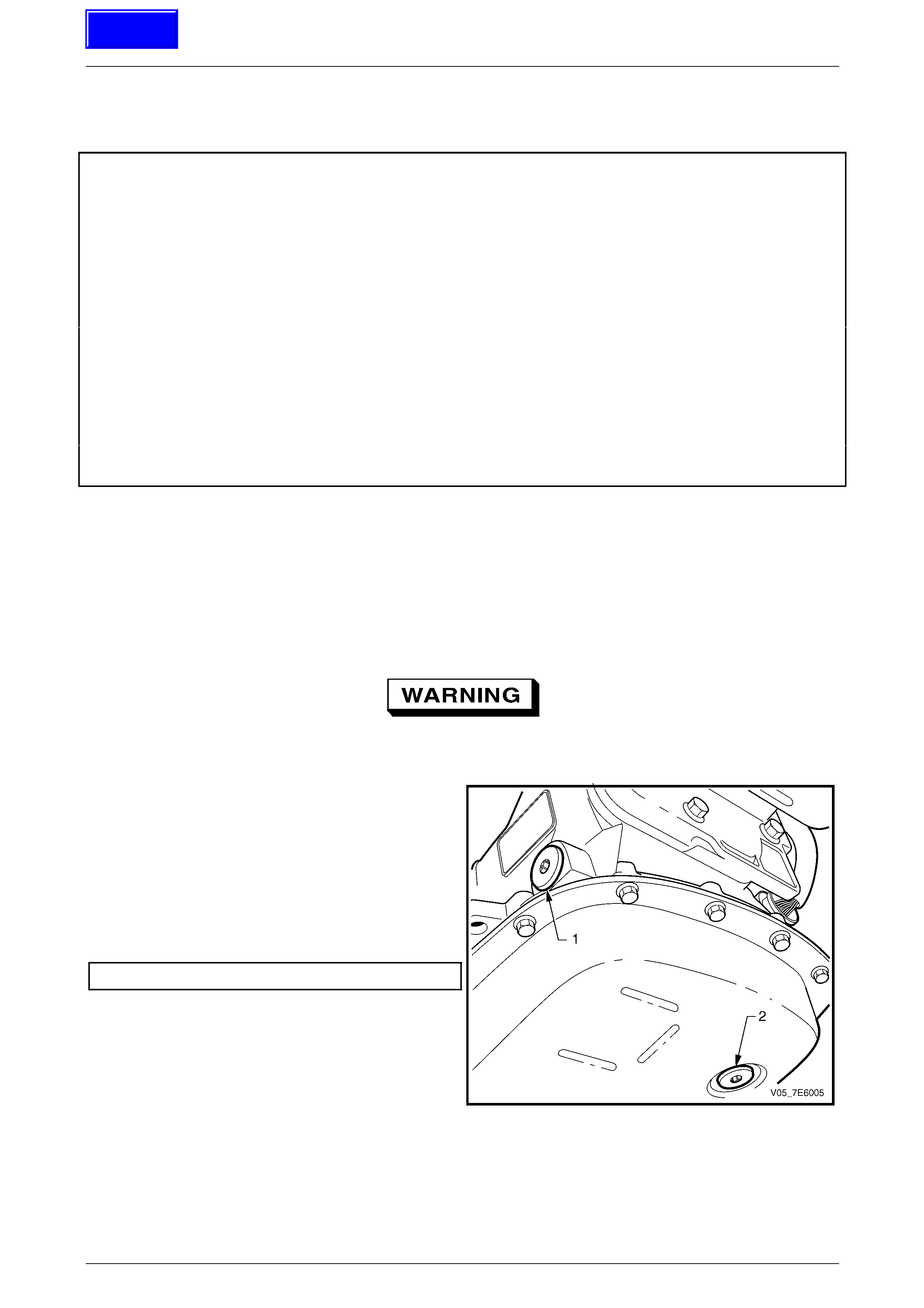
3 Remove and discard the transmission fluid drain plug
(2) and seal.
4 Allow the transmission fl uid to drain.
5 Inspect the transmission fluid for discoloration and
contamination while draining.
6 After the fluid has stopped draining, install a NEW
transmission drain plug (2) and seal, then tighten the
plug to the correct torque specification.
Drain plug torque specification.............................20 N.m
Figure 7E4 – 3
Techline
Automatic Transmission – 5L40-E – On-Vehicle Servicing 7E4 – 14
7E4 – 14
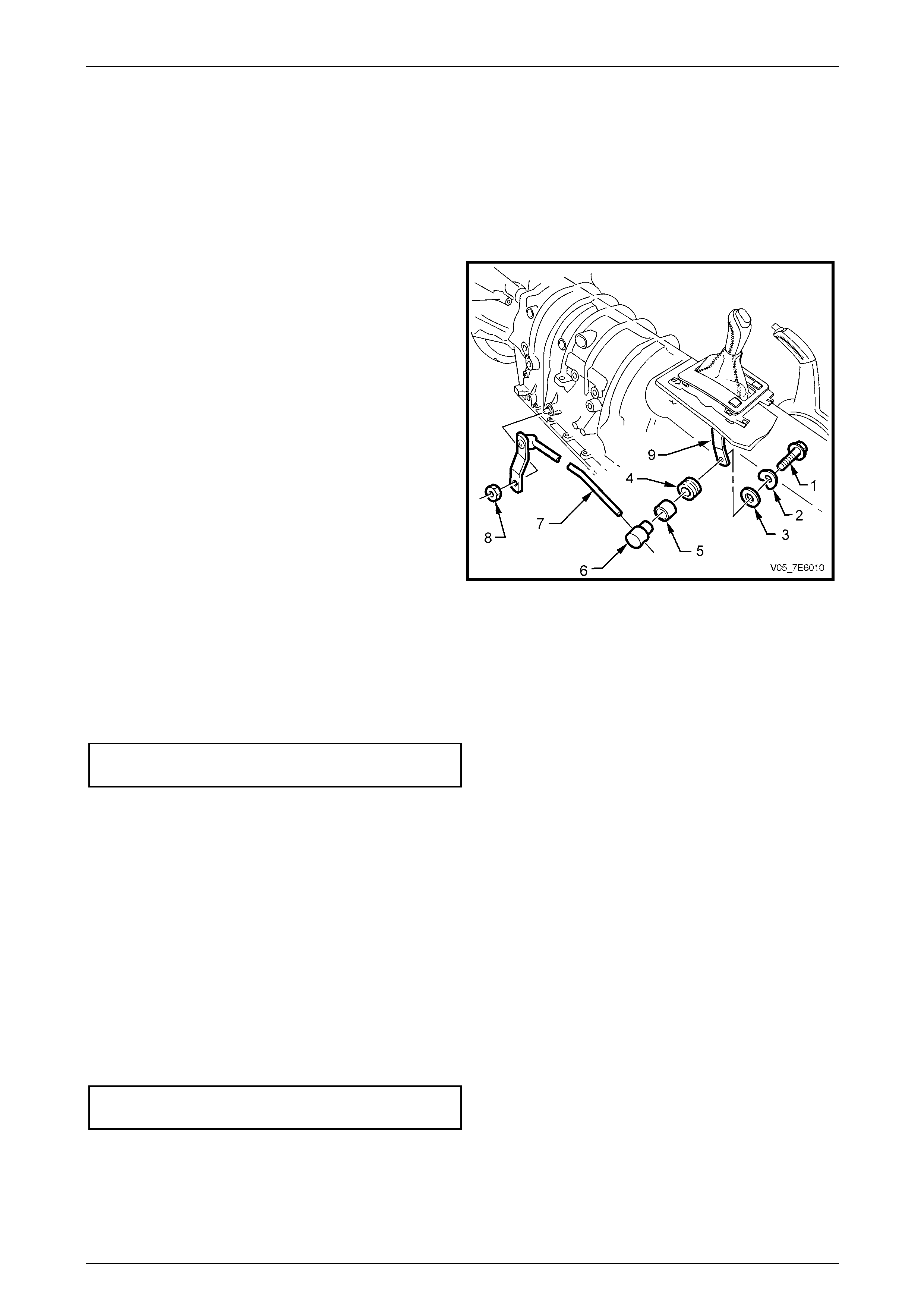
7 Remove the fluid pan bolts.
The fluid pan will retain a residual quantity of
fluid that can splash, as w ill the fluid draini ng
from the transmission components
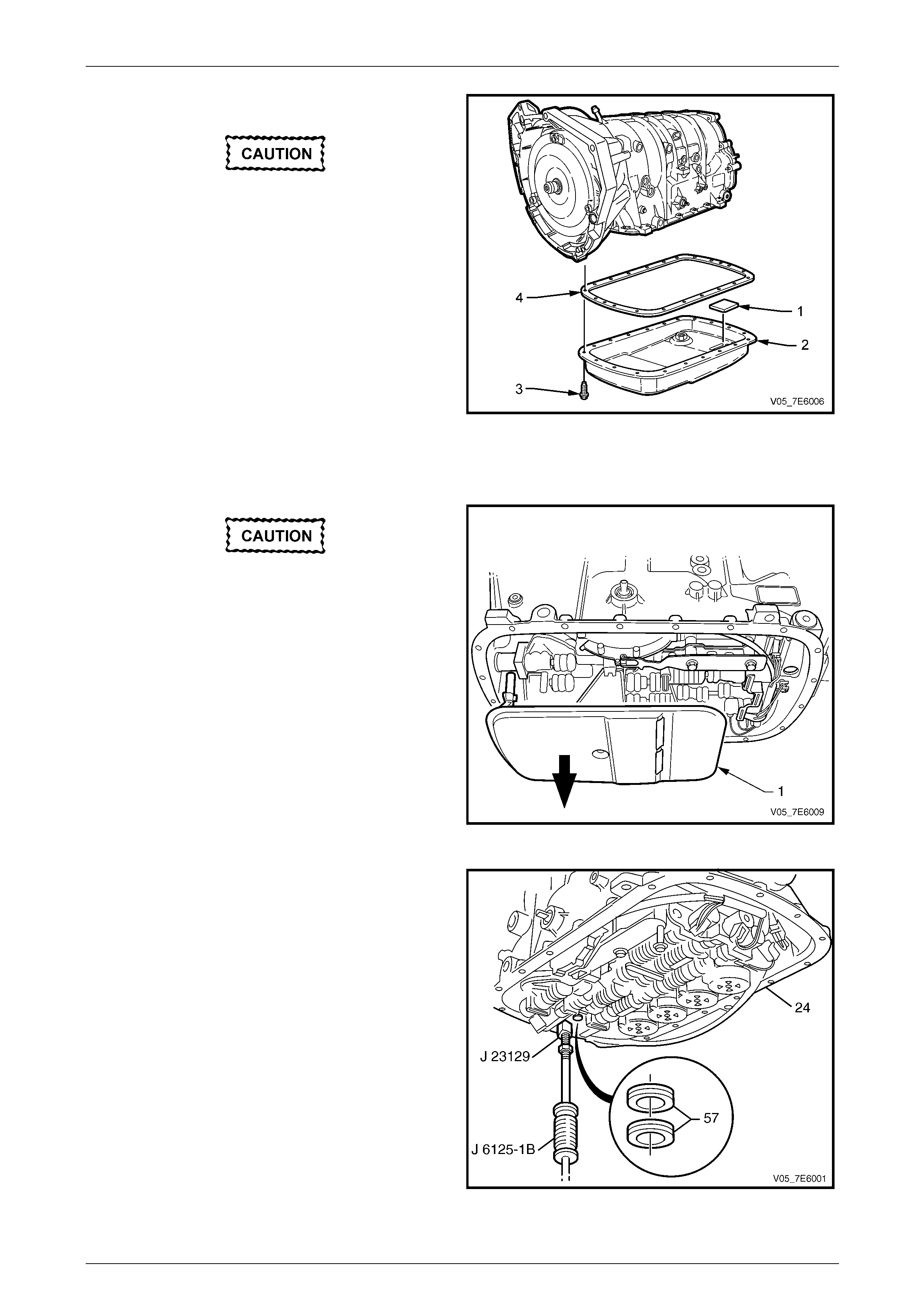
8 Lightly tap the fluid pan (2) with a rubber mallet if
necessary, to loosen.
9 Remove the fluid pan (2) and the gasket (4).
NOTE
The fluid pan gasket is re-usable, if undama ged.
10 Clean and inspect the following for damage or wear;
a Magnet (1)
b Fluid pan (2)
c Bolts (3)
d Fluid pan gasket (4)
Figure 7E4 – 4
Do not lose the fluid filter neck spacer,
following the filter removal.
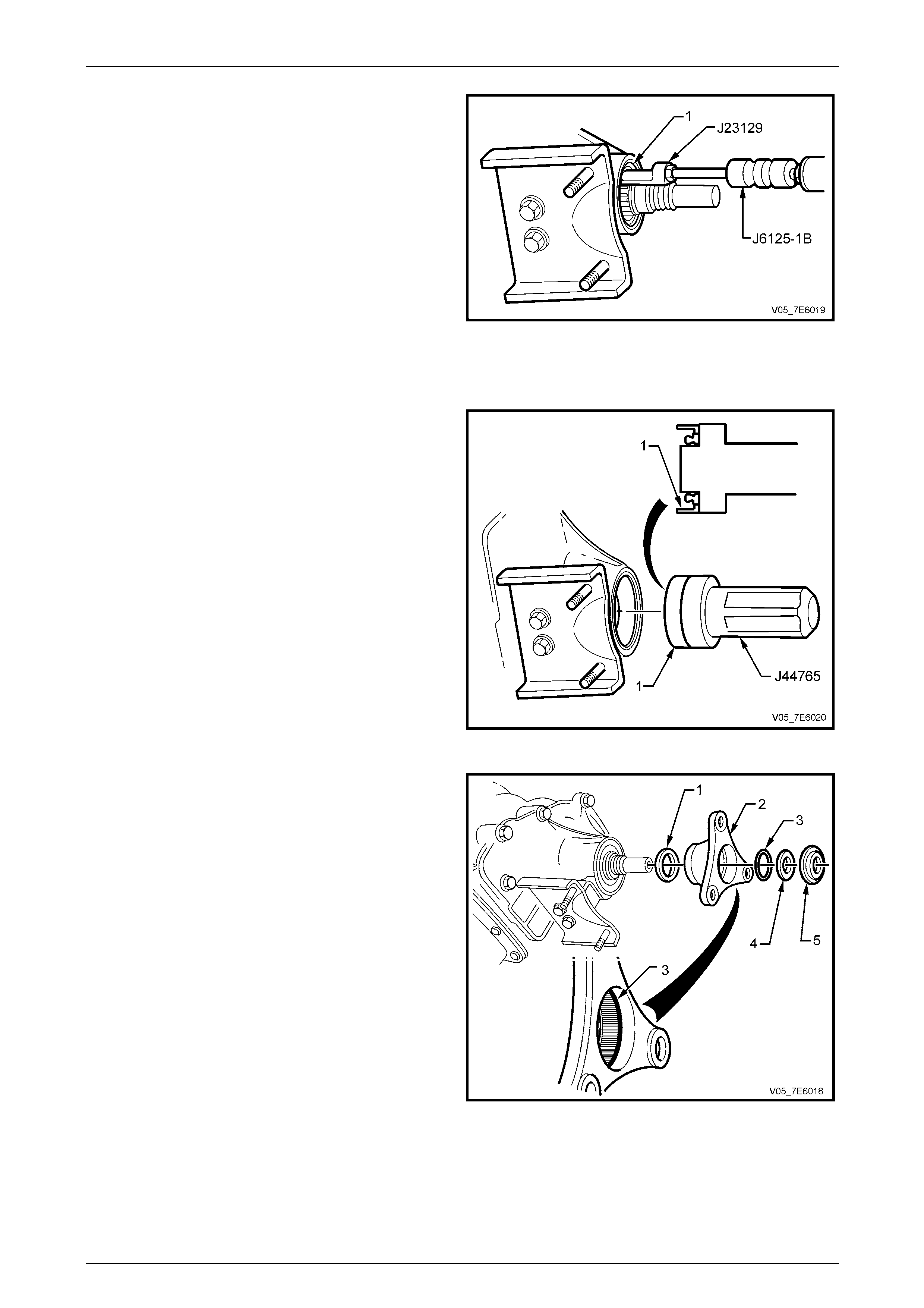
11 Remove the fluid filter (1). Use a long screwdriver to
prise the fluid filter neck from the seals in the fluid
pump housing.
Figure 7E4 – 5
12 Using slide hammer, Tool No. J 6125-1B a nd remover
J 23129, remove the two filter neck seals (57) from the
transmission case. Discard the removed seals.
NOTE
If the filter is not being replac ed, then removal of
the seals is not necessary
Figure 7E4 – 6
Automatic Transmission – 5L40-E – On-Vehicle Servicing 7E4 – 15
7E4 – 15
Reinstall
1 Coat the two 2 fluid filter seals (1) (supplied with a
replacement filter assembly) with petroleum jell y (e.g.
Vaseline™ or equivalent), then install into the
transmission fluid filter neck.
Do not install the fluid filter without the
spacer sleeve being fitted to the filter neck.
2 Install a NEW transmission flu id filter (2) and spacer
sleeve into the case.
Figure 7E4 – 7
3 After checking that the magnet (1) is in the correct
location in the fluid pan (2), install the flui d pan (2) and
the gasket (4) at the same time.
4 Reinstall the fluid pan bolts (3), tightening to the
correct torque specification.
Fluid pan bolt
torque specification..............................................11 N.m
5 Fill the transmission to the corr ect level. Refer to
2.1 Transmission Fluid Check procedure, in this
Section.
6 Lower the vehi cle to the ground.
7 Run the engine and inspect in the oil pan gasket area
for leaks.
8 Lower the vehi cle to the ground and road test for
correct vehicle operation. Figure 7E4 – 8
Automatic Transmission – 5L40-E – On-Vehicle Servicing 7E4 – 16
7E4 – 16
3.2 Selector Linkage
Remove
1 Set transmission selector lev er to the Park positi on.
2 Raise the vehicle and support in a safe manner. Refer to Section 0A General Information for the location of the
recommended jacking and support po ints.
3 Remove lockin g bolt (1), dish ed washer (2), flat
washer (3), insulator (4) and sleeve (5) from lower end
of selector lever (9).
4 Slide trunnion (6) from selector rod (7).
5 While holding the transmission selector lever with an
adjustable wrench, remove retaining nut (8), rod and
lever assembly (7) from transmission manual shaft.
Inspect
Check all items for wear and/or damage, replace all worn or
damaged items.
Figure 7E4 – 9
Reinstall
Reinstallation is the reverse of the removal procedure, except for:
1 While holding the selector lever with an adjustable wrench, tighten the retaining nut (8) to the correct torque
specification.
Manual shift shaft lever
nut torque specification........................................ 12 N.m
NOTE
Do not tighten the selector lever locking bolt (1)
until the adjustment procedure is completed.
2 Adjust the selector linkage as described next.
Adjust
Refer to Figure 7E4 – 9.
1 Loosen lockin g bolt (1) at shift selector lever (9).
2 Position transmission shift selector lever in the Park position.
3 Position transmission manual shaft lever in the Park position (lever fully clockwise), then tighten the locking bolt at
the shift selector lever, to the specified torque.
Shift selector lever locking
bolt torque specification.......................................30 N.m
4 Lower vehicle and test that the vehicle operates correctly.
5 Ensure that engine can only be started in Park and Neutral.
Automatic Transmission – 5L40-E – On-Vehicle Servicing 7E4 – 17
7E4 – 17
3.3 Shift Selector Assembly
Remove
1 Raise vehicle support in a safe manner. Refer to Section 0A General Information for the location of recommend ed
jacking and support points.
2 Remove floor c onsole cover, lower extension side trim
panels and the floor console assembly.
Refer to Section 1A3 Instrument Panel & Console.
3 Disconnect the wiring harness connector from the
selector patch harness.
4 From beneath the vehicle, disconnect the selector rod
and trunnion from the shift selector lever.
Refer to 3.2 Selector Linkage in this Section.
5 Remove the four nuts securing the selector lever
assembly to the floor pan.
6 From inside the vehic le, lift the selector lever assembly
from the floor pan.
Figure 7E4 – 10
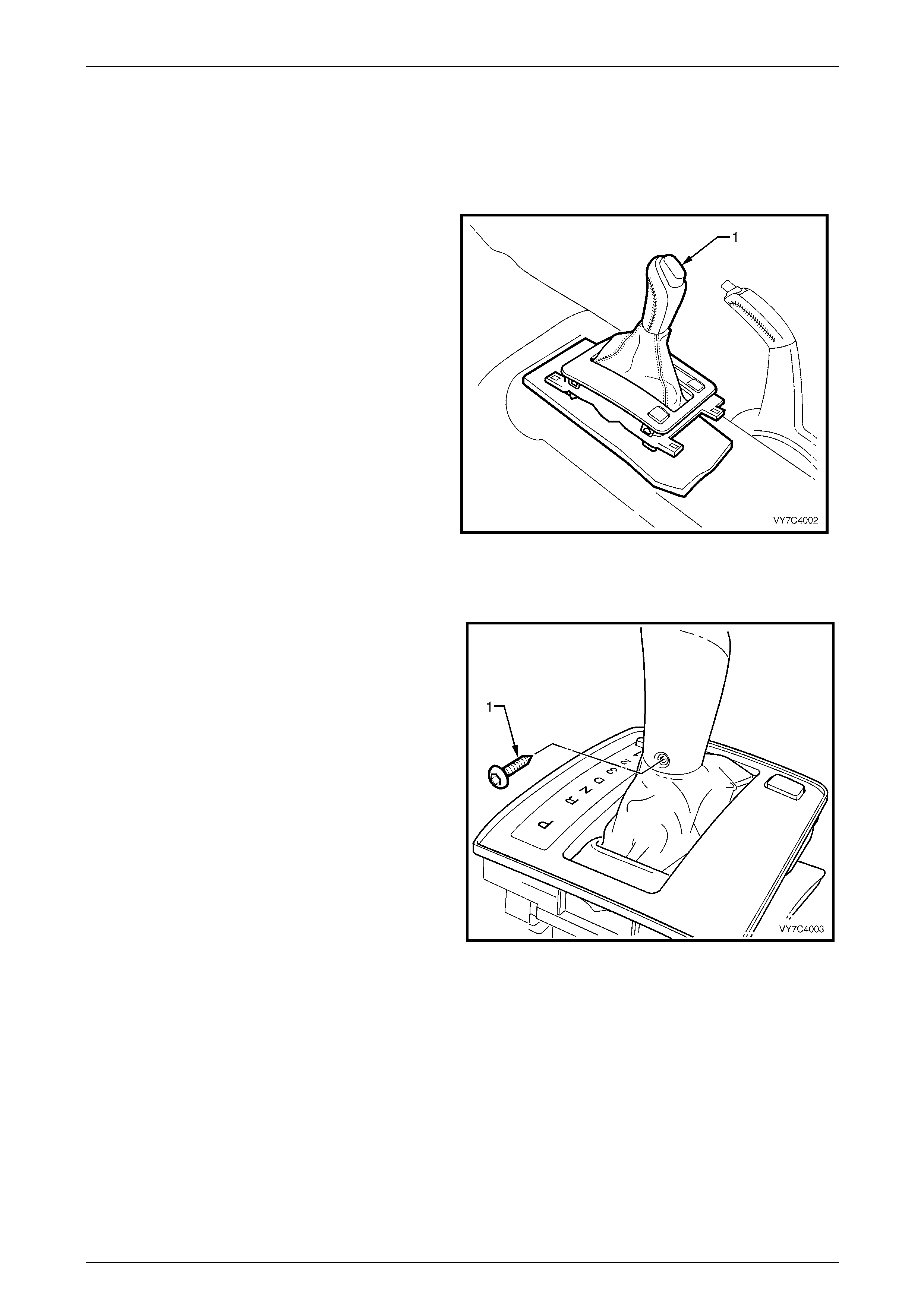
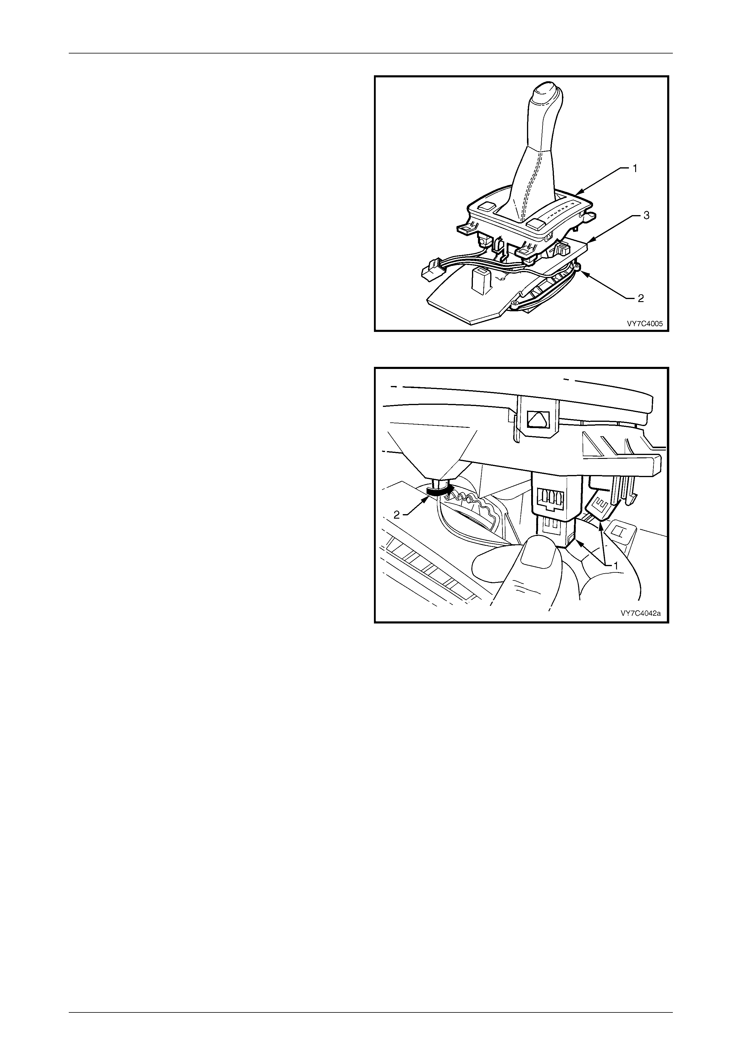
Disassemble
1 Using a commercially available Torx Plus (TX2 0) bit
and suitable equipment, remo ve the self tapping screw
(1). Select ‘D’ Drive.
Figure 7E4 – 11
Automatic Transmission – 5L40-E – On-Vehicle Servicing 7E4 – 18
7E4 – 18
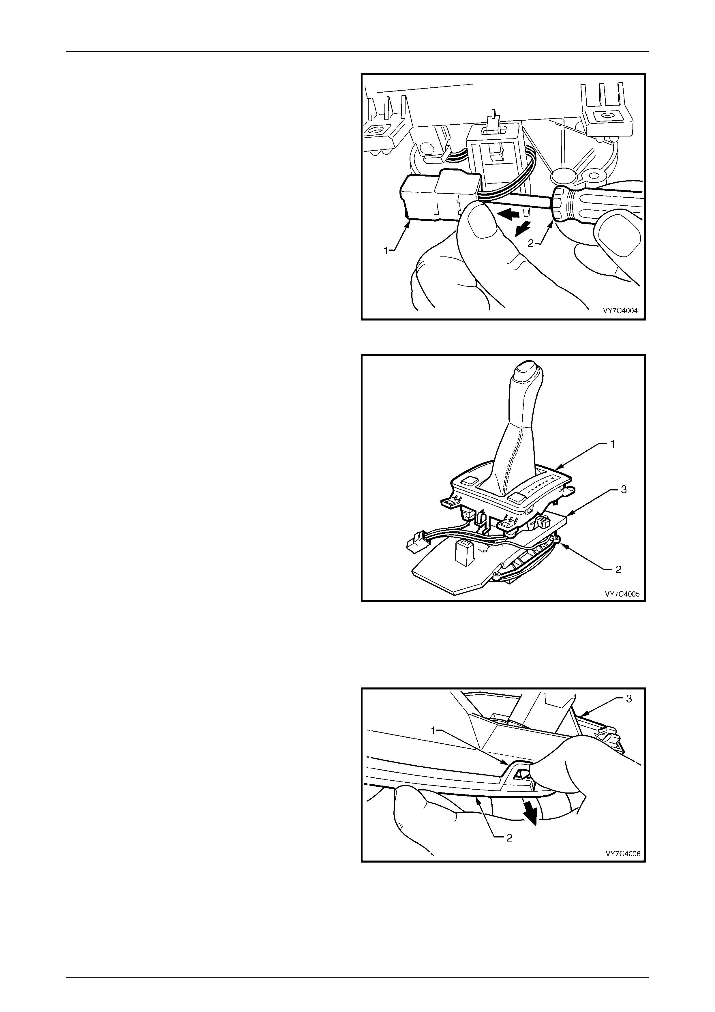
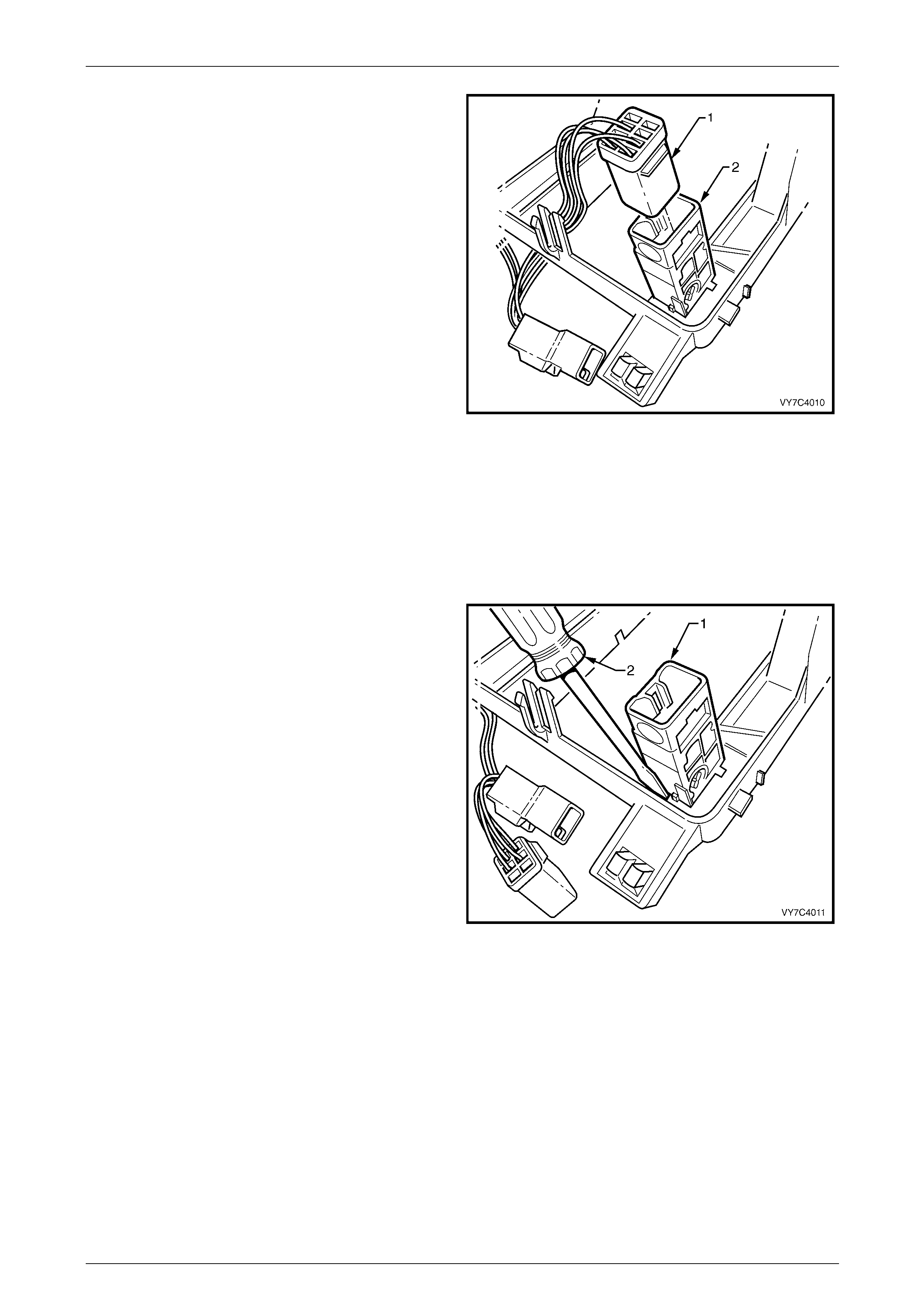
2 Using a small s c rewdriver (2), prise the locking tab on
the wiring harness connector (1) at the rear of the shift
selector assembly, while pushing away from the lower
housing, as shown.
Figure 7E4 – 12
3 With the wiring harness connector free, disconnect the
lower housing from the base (1) b y pressi ng the tangs
on each of the retaining legs (two front, one rear).
4 Lift the lower housing (1) from the base (2), together
with the switch/es, patch wiring harness, boot and shift
lever knob. Set the assembly to one side.
5 As required, lift the insul ator (3) from the base (2) and
set to one side.
Figure 7E4 – 13
With the shift lever assembly now separated, select from the following choices for the service operation/s requir ed.
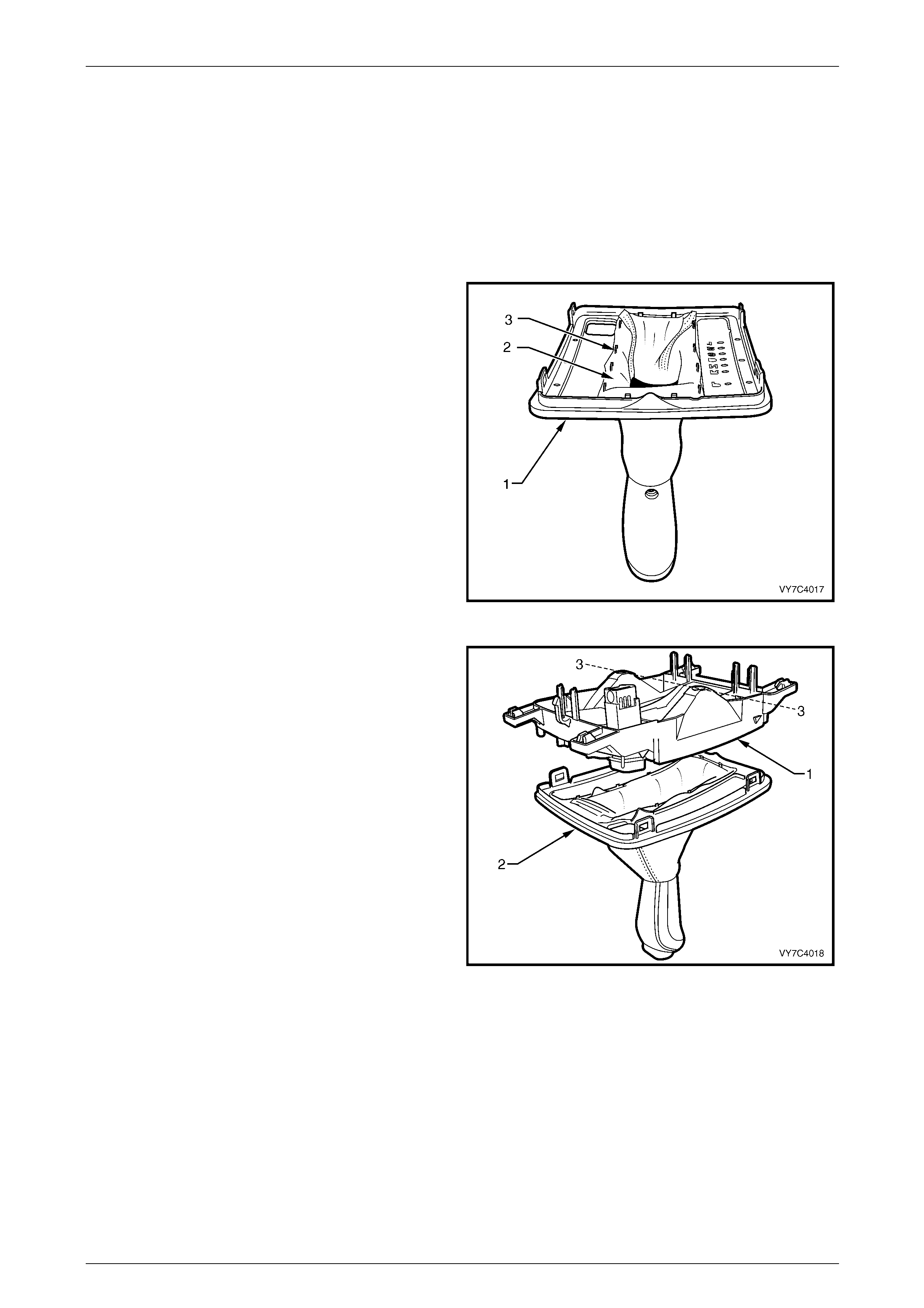
Boot, Shift Lever Knob Remov e
1 While hold ing the lower housing in an inverted
position, gently prise each of the four securing lugs (1)
to free the cover (2) from the lower housing (3). Lift the
lower housing (3) from the gearshift selector knob,
boot and upper cover assembl y (2) and set to one
side.
NOTE
If the lower housing assembly is not inverted
before separation, then the boot will probably
become dislodged from the locating tangs in the
upper cover.
2 If boot replacem ent is required, free the boot from the
upper cover locating tangs and set the cover to one
side, being careful not to dislo dge nor damage the
PRNDL indicator lens in the process. Figure 7E4 – 14
Automatic Transmission – 5L40-E – On-Vehicle Servicing 7E4 – 19
7E4 – 19
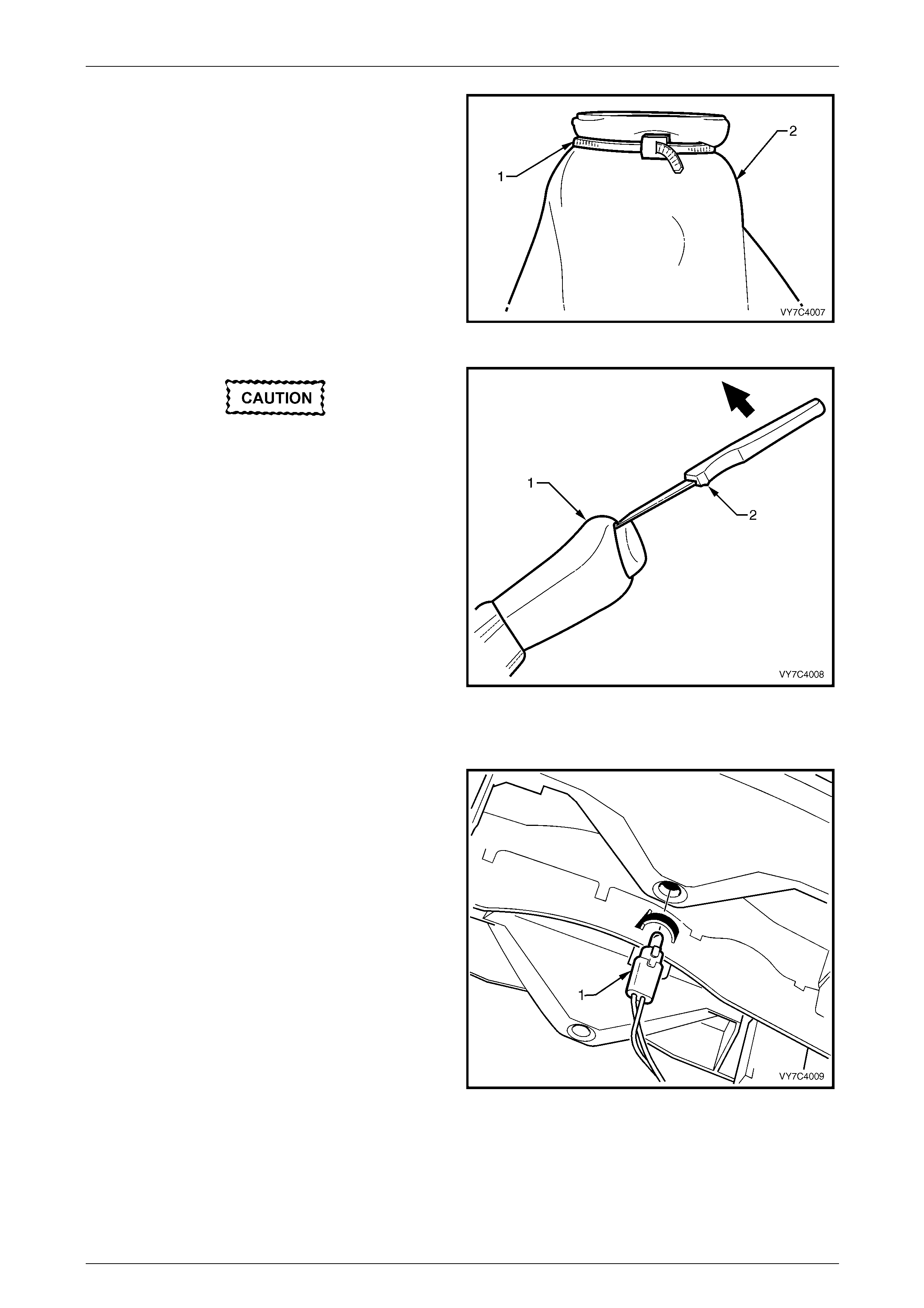
3 Turn the boot (2) inside out, over the gearshift selector
knob, then cut the plastic tie (1) securing the boot to
the knob. Remove the boot from the gearshift lever
knob and discard.
NOTE
The plastic tie is a unique design and is
markedly different from the usual cable tie.
Figure 7E4 – 15
• The knob is spring loaded and may fly
free once dislodged.
• Take care when releasing th e plated kn ob,
as it is easily scratched.
4 If the gearshift knob needs to be dism antled, use a
small knife (2) or similar to free the lugs securing the
control rod button from the gearshift knob (1) .
5 Remove the two Phillips head self tapping screws,
(located under the control rod button), then separate
the knob components.
Figure 7E4 – 16
Patch Harness Remove
1 Remove the selector indicator lamp and holder from
the switch housing by turning the lamp hol de r 90° to
the left (counter-clockwise), then pull.
Figure 7E4 – 17
Automatic Transmission – 5L40-E – On-Vehicle Servicing 7E4 – 20
7E4 – 20
2 If not removed previously (step 3), release the switch
connector retaining lug/s, then remove the
connector/s.
NOTE
While each switch patch harness connector is
the same colour (white), the Power/Economy
(“PWR”) switch (when fitted) connector wiring is
taped to the PRNDL indicator lamp wiring, as
this switch will always be on the same side as
this lamp.
Figure 7E4 – 18
Switch Remove
NOTE
For this operation, the cover must be split from
the lower housing. Refer to Step 4 in the
Disassembly procedure.
1 To remove the PWR and/or A/S switch (if fitted), use a
small bladed screwdriver and lever one of the switch
retaining tangs from under the lower housing to free
the particular switch, cock to one side, release the
second tang and then remove the switch from above.
NOTE
Take note of the locating lug on the switch body
that ensures the correct orientation of the switch
when reinstalled.
Figure 7E4 – 19
Automatic Transmission – 5L40-E – On-Vehicle Servicing 7E4 – 21
7E4 – 21
Base Disassembly
1 If not removed previously, remove the shift ro d trunnion bolt from the lower end of the shift lever arm. Slide the
trunnion from the arm, then remove the insulating grommet.
NOTE
This is necessary to provide clearance for the
lever to be removed from the lower housing.
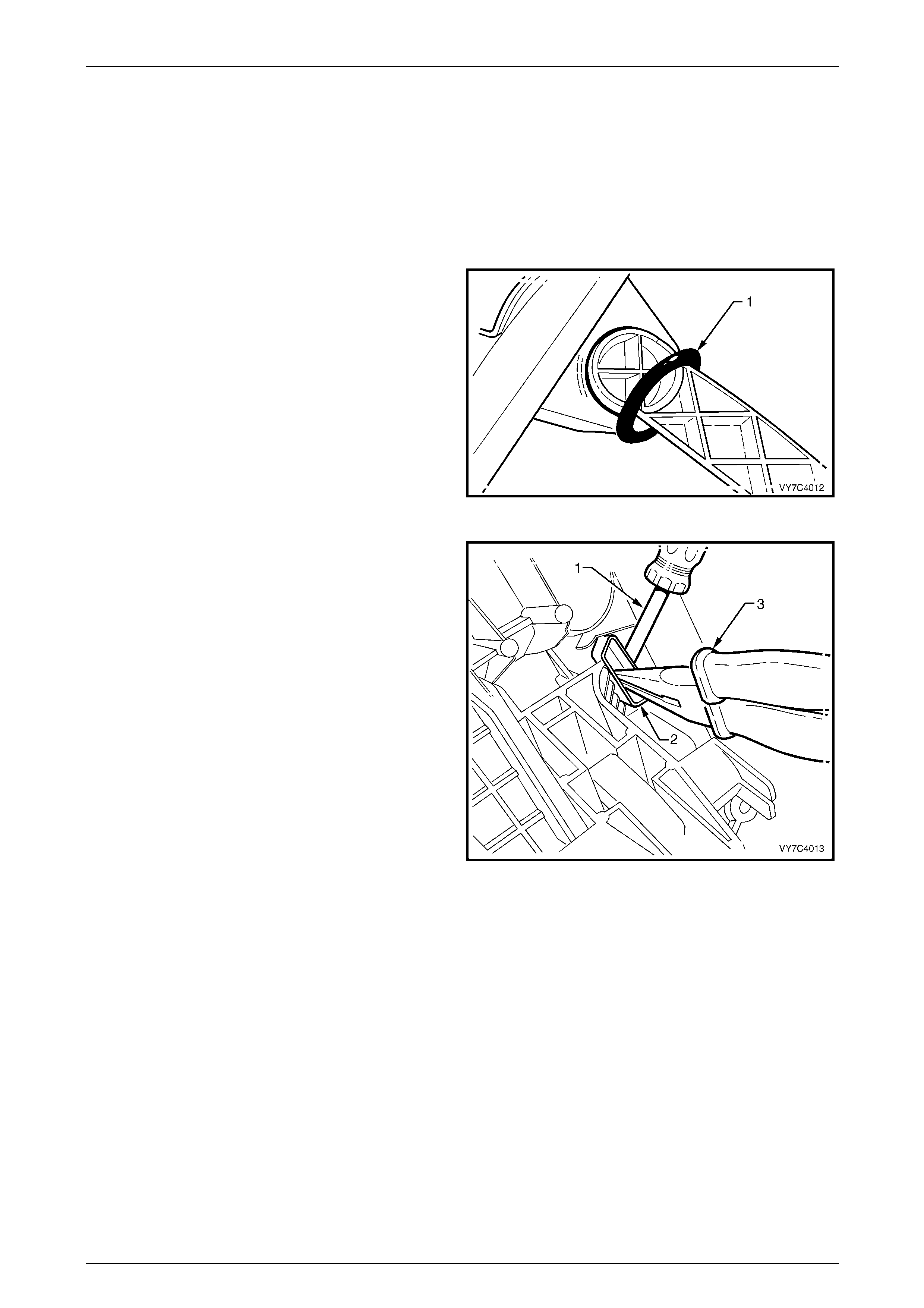
1 Remove the external seal (1) from the lever arm and
set to one side.
Figure 7E4 – 20
2 To remove the lever l ockin g piece, use a small
screwdriver (1) to lever the locking tan g free while
pulling on the locking piece (2) with long nosed pliers
(3).
3. Push the lever assembly inwards to release the inner
support pin and bush
NOTE
The bush may remain in the lower housing.
4 Lift the shift lever from the lower housing.
NOTE
While it will be necessar y to manoeuvre the l ever
somewhat, sufficient space is provided to
overcome any need to apply force to the lever
assembly.
Figure 7E4 – 21
Lever Disassembly
Further disassembly of the base is not recommended, as there is a very r eal possibility that, during reinstallation of the
roll pin, the shift lever will be c r acked, unless sophisticated jigs are used. For this reason, the shift lever is only serviced
as an assembly.
Automatic Transmission – 5L40-E – On-Vehicle Servicing 7E4 – 22
7E4 – 22
Reassemble
Base Reassembly
1 Inspect the external lever, inner bushing (1) for
damage, replacing as requir ed. Lubricate with a multi-
purpose chassis grease such as NLGI No. 1 Lithium
grease.
2 Reinstall the split inner support bush (2) to the selector
lever pin, aligning the split in the bush with the key on
the selector lever pin. Lubricate the external bush
surface with a multi-purpose chassis gr ease such as
NLGI No. 1 Lithium grease.
3 Reinstall the selector lever assembly (3), into the
base. Align the small bush with the aperture in the
base then push across to fully inst all the lever.
Figure 7E4 – 22
4 Reinstall the lever locking piece (1), using long nosed
pliers. Correct reinstallation will have occurred when
an audible click is heard, indicating that the tang on
the locking piece has been installed correctly.
Figure 7E4 – 23
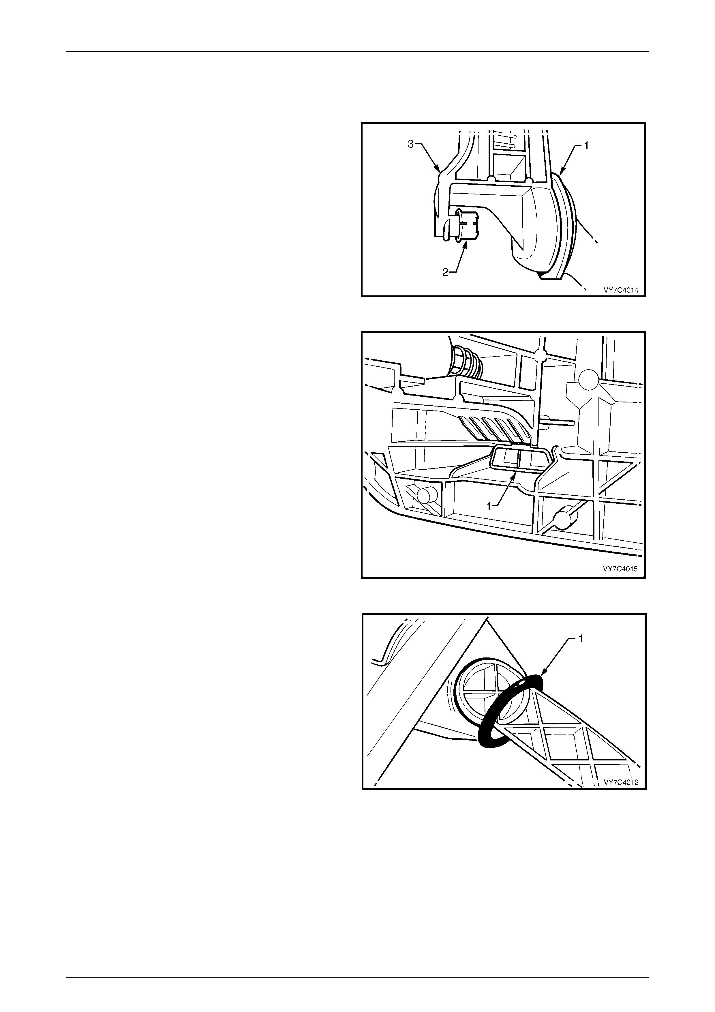
5 Apply a smear of multi-purpose chassis grease such
as NLGI No. 1 Lithium grease to the outer, lipped seal
(1), then reinstall over the external lever.
Figure 7E4 – 24
Automatic Transmission – 5L40-E – On-Vehicle Servicing 7E4 – 23
7E4 – 23
Lower Housing
1 If removed, reinstall the switch/es to the lower housing, ensuring that the locating lug on the switch body engages
with the slot in the lower housing. If the vehicle is equipped with Active Select control, the correct location for this
switch, is in the right hand aperture, behind the PRNDL indicator lens.
2 Reinstall the p atch wiring harness, ensuring that the switch connector/s connection is correct. Also reinstall the
PRNDL lamp and holder, by inserting an d turning the holder a quarter turn to the left (counter-clockwise).
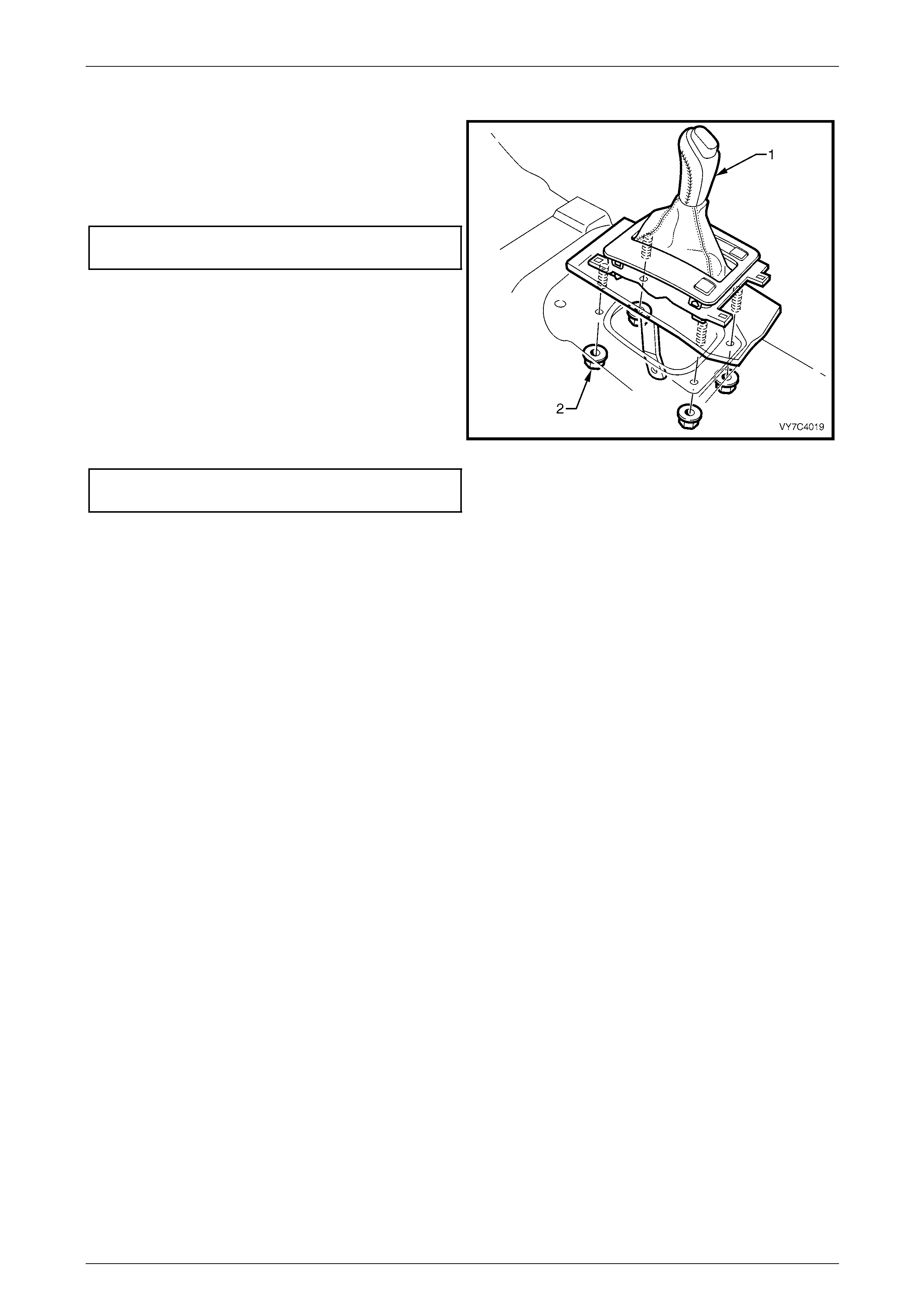
3 If a new selector lever boot is to be installed, use the tie strap included with the new boot to firmly secure the boot
to the gearshift selector knob. Trim excess length and discard.
4 With the upper cover (1) inv erted, locate th e boot (2)
over each of the cover locating tangs (3), working
gradually around unti l every tang is covered.
NOTE
The weight of the selector knob will be sufficient
to keep the boot engaged with the tangs.
Figure 7E4 – 25
5 To reduce the possibility of the boot from becoming
dislodged from the upper cov er retain ing tangs,
reinstall the lower housing (1 ) to the cover (2), working
in an inverted position, as shown.
NOTE
Before reassembling the lower cover to the
base, check that the coloured indictor is in line
with the two PRNDL displa y lamp holes (3). This
will be the approximate position for correct
reassembly.
6 Engage each of the tabs on the upper cover with the
retaining lugs on the lower housing. When all four tabs
have been engaged, the boot will be clamped and can
no longer become disengaged.
Figure 7E4 – 26
Automatic Transmission – 5L40-E – On-Vehicle Servicing 7E4 – 24
7E4 – 24
7 Ensure that the PRNDL indicator slide in the lower
housing, is at the “D” position (the red colour will sh ow
opposite the “D” in the PRNDL lens).
8 After checking that the insulator (3) is undamaged,
reinstall to the base (2).
9 After checking that the selector lever is also in the
Drive position, reinstall the lower housing (1 ) over the
shift lever and engage each of the three legs with the
base apertures. Check that the PRND L indicator slide
pin is engaged with the slot in the selector lever.
Figure 7E4 – 27
10 Reinstall the selector indicator lamp and holder (2) by
inserting, then turn to the right (clockwise), to secure.
11 Re-engage the selector lever knob with the selector
lever, aligning the control rod with the ho le in the
selector knob.
NOTE
Correct engagement of the PRNDL indicator can
be easily checked by moving the selector lever.
Should the coloured portion not move with the
lever, then engagement is incorrect. Separate
the lower housing and base and repeat steps 5
to 9 above.
Figure 7E4 – 28
12 Reinstall the selector knob retaining screw, using a TX20 Torx bit and suitable eq uipment, being careful not to
over-tighten.
13 Reinstall the selector lever knob and spring, pushing down until the two locking tangs engage.
NOTE
If the selector lever knob and spring have not
been removed, then re-engagement with the
selector lever can still be achieved but some
manoeuvring may be necessary.
14 If removed, reinstall the wiring harness connector to the bracket at the end of the base and push until the looking
tang engages.
Automatic Transmission – 5L40-E – On-Vehicle Servicing 7E4 – 25
7E4 – 25
Reinstall
1 Clean mating surfaces of floor pan and inspect the
base seal for damage, replacing if necess ary.
2 Reinstall se lector lever assembly (1) to the floor pan,
install the four retaining nuts (2) and tighten to the
correct torque specification.
Shift selector base retaining
nut torque specification........................................ 15 N.m
3 The remainder of the reinstallation is the reverse of the
removal procedure. As required, refer to
Section 1A3 Instrument Panel & Consol e for
installation procedures of the floor cons ole assembly,
lower extension side trim panels and floor console
cover.
4 Adjust shift linkage; refer to
3.2 Selector Linkage, Adjust in this Section, tightening
the selector rod locking bolt to the correct torque
specification.
Shift selector lever locking
bolt torque specification.......................................30 N.m
Figure 7E4 – 29
Automatic Transmission – 5L40-E – On-Vehicle Servicing 7E4 – 26
7E4 – 26
3.4 Transmission Fluid Cooler Pipes/Hoses
LT Section No. – 04-150
Remove
Transmission Fluid Cooler Pipes
1 Raise the vehicle and support in a safe manner. Refer to Section 0A General Information for the location of
recommended lifting and support points.
2 Place an oil drain tray under the transmission fluid cooler pipes/hoses near the radiator.
3 Check that one of the fluid cooler flexible lines has a
white tag attached and that the mating transmission
cooler pipe has a similar tag. If these have been
removed, apply adhesive tap e to one pair of
pipes/lines to ensure correct reassembly.
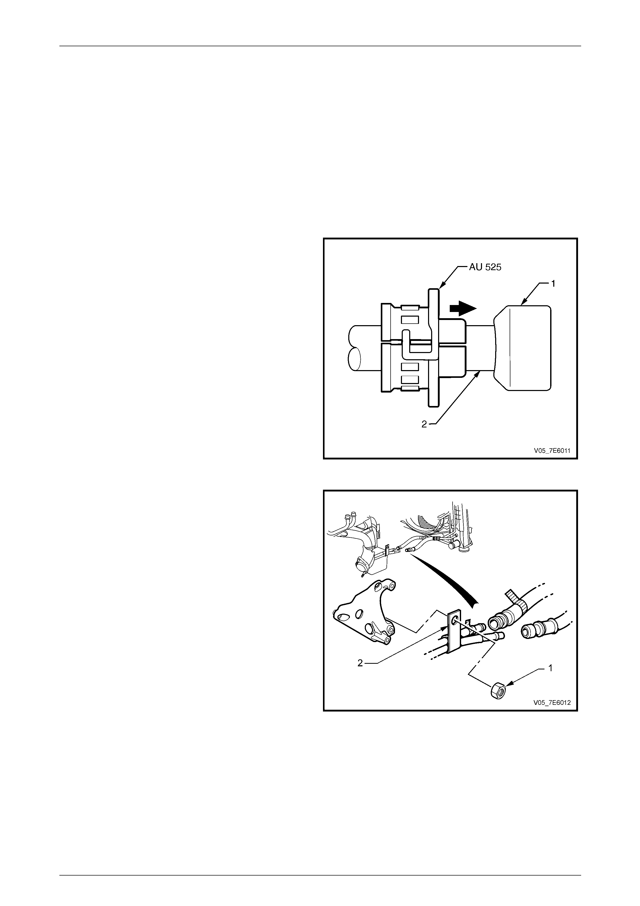
4 Remove each of the quick connect security clips by
prising loose with a suitable le ver (i.e. screwdriver).
5 Using disconnect Tool No. AU 525, disconnect each
fluid cooler flexible line (1) from each pipe.
NOTE
The fluid cooler flexible lines are permanently
attached to the radiator fluid cooler pipes.
Figure 7E4 – 30
6 Remove the nut (1) securing the transmission fluid
cooler pipe bracket (2) to the alternator mounting
bracket stud.
Figure 7E4 – 31
Automatic Transmission – 5L40-E – On-Vehicle Servicing 7E4 – 27
7E4 – 27
7 Remove the screw securing the transmission fluid
cooler pipes bracket to the transmission case.
8 Remove the transmission fluid cooler pipes from the
transmission.
9 Remove the two O-rings and discard, as they must be
replaced on assembly.
Figure 7E4 – 32
Radiator Cooler Pipes/Hoses
NOTE
As the hoses are permanently fitted to the cooler
pipes leading to and from the radiator cooler, if
hose replacement is required, then the complete
pipe/hose combination must be fitted.
1 Raise the vehicle and support in a safe manner. Refer to Section 0A General Information for the location of
recommended lifting and support points.
2 Place an oil drain tray under the transmission fluid cooler pipes/hoses near the radiator.
3 Disconnect the transmissio n cool er pipes from the cooler hoses at the front, lower right side of the engine bay (refer
to Step 3 in the Transmission Fluid Cooler Pipes removal procedure).
4 Referring to Figure 7E 4 – 48, hold the lower cooler nut (4) at the radiator right hand header tank (1) with a back-up
spanner and disconnect the oil cooler fluid return pipe (5) from that location. Plug the o pened connections to
prevent foreign matter entry.
5 Repeat this procedure for the upper cooler nut (2) and pipe/hose assembl y (3) at the radiator right hand header
tank (1).
6 Remove the radiator cooler pipes/hoses (3 and 5) from the vehicle.
Automatic Transmission – 5L40-E – On-Vehicle Servicing 7E4 – 28
7E4 – 28
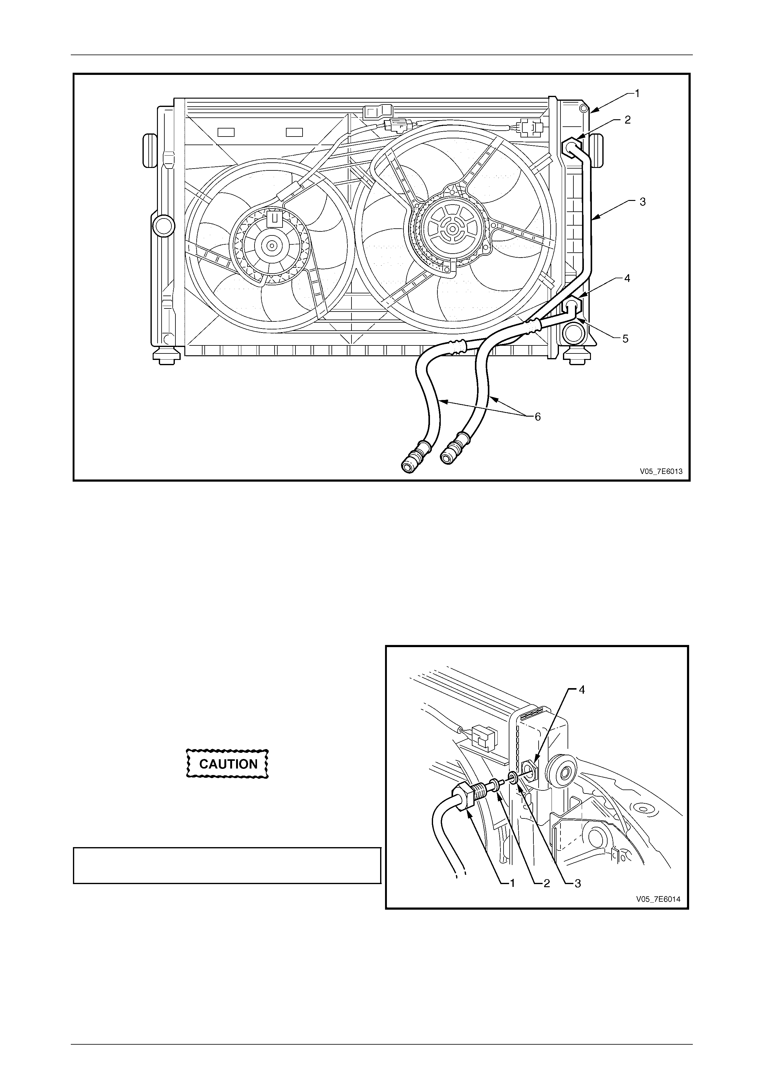
Figure 7E4 – 33 – Oil Cooler Pipe/Hose Layout
Legend
1 Radiator End Tank – Right
2 Cooler Retaining Nut – Upper 3 Fluid Cooler Pipe – Fluid Feed
4 Cooler Retaining Nut – Lower 5 Fluid Cooler Pipe – Fluid Return
6 Flexible Hoses & Quick Connect Fittings
Reinstall
The installation process of the oil cooler pipes/hoses, is the reverse to removal, except for the following:
Radiator Cooler Pipes/Hoses
1 Before reinstalling e ach p ipe to the cooler, carefully
inspect the pipe O-ring (3). If the centre, silicone
portion shows signs of distress or damage, it must be
replaced.
2 Remove the plugging from the pipe and fittings, fit the
O-ring (3) to the cleaned cooler pipe (2), then reinstall
the pipe into the radiator fluid cooler retaining nut (4).
Always use a back-u p spanner to prevent the
turning of the fluid cooler flare nut fitting (4).
3 Reinstall the tu be nut (1) and tighten to the correct
torque specification.
Cooler pipe tube nut to cooler
fitting torque specification ....................................25 N.m
Figure 7E4 – 34
4 Repeat Steps 1 to 3 for the second pipe/hose assembly.
5 Check and adjust the transmission fluid level, as required. Refer to 2.1 Transmission Fluid Check, in this Section.
6 Inspect for transmission fluid leaks.
Automatic Transmission – 5L40-E – On-Vehicle Servicing 7E4 – 29
7E4 – 29
Transmission Fluid Cooler Pipes
1 Before reinstalling any quick connect fitting, remove plugs from pipes and hose fittings and wipe all exposed parts.
2 Smear, clean automatic transmission fluid over each cooler pipe end, the n push into the flexible hose quick
connect fittings until an audible ' c lick' is heard. As a security check, tug gently on each pipe to ensure correct
engagement.
3 At the transmission end, again clean the pipe ends
and install NEW O-rings (1) after lubricatin g each with
clean, automatic transmission fluid.
4 Install the cooler pipes and bracket (3) to the
transmission case.
5 Reinstall the securing bolt (2) and tighten to the
correct torque specification.
Fluid cooler pipe flange to
transmission bolt torque specification..................20 N.m
Figure 7E4 – 35
6 Reinstall the p ipe bracket retaining nut (1) to the
alternator bracket stud and tighten to the correct
torque specification.
Transmission fluid cooler pipe
bracket nut torque specification ...........................20 N.m
Figure 7E4 – 36
7 Check and top up transmission fluid level as required. Refer to 2.1 Transmission Fluid Check, in this Section.
8 Inspect for transmission fluid leaks.
9 Lower the vehi cle to the ground.
Automatic Transmission – 5L40-E – On-Vehicle Servicing 7E4 – 30
7E4 – 30
3.5 Fluid Pressure Test Plug
LT Section No. – 04-200
Replace
1 Raise the vehicle and support in a safe manner. Refer to Section 0A General Information for the location of
recommended lifting and support points.
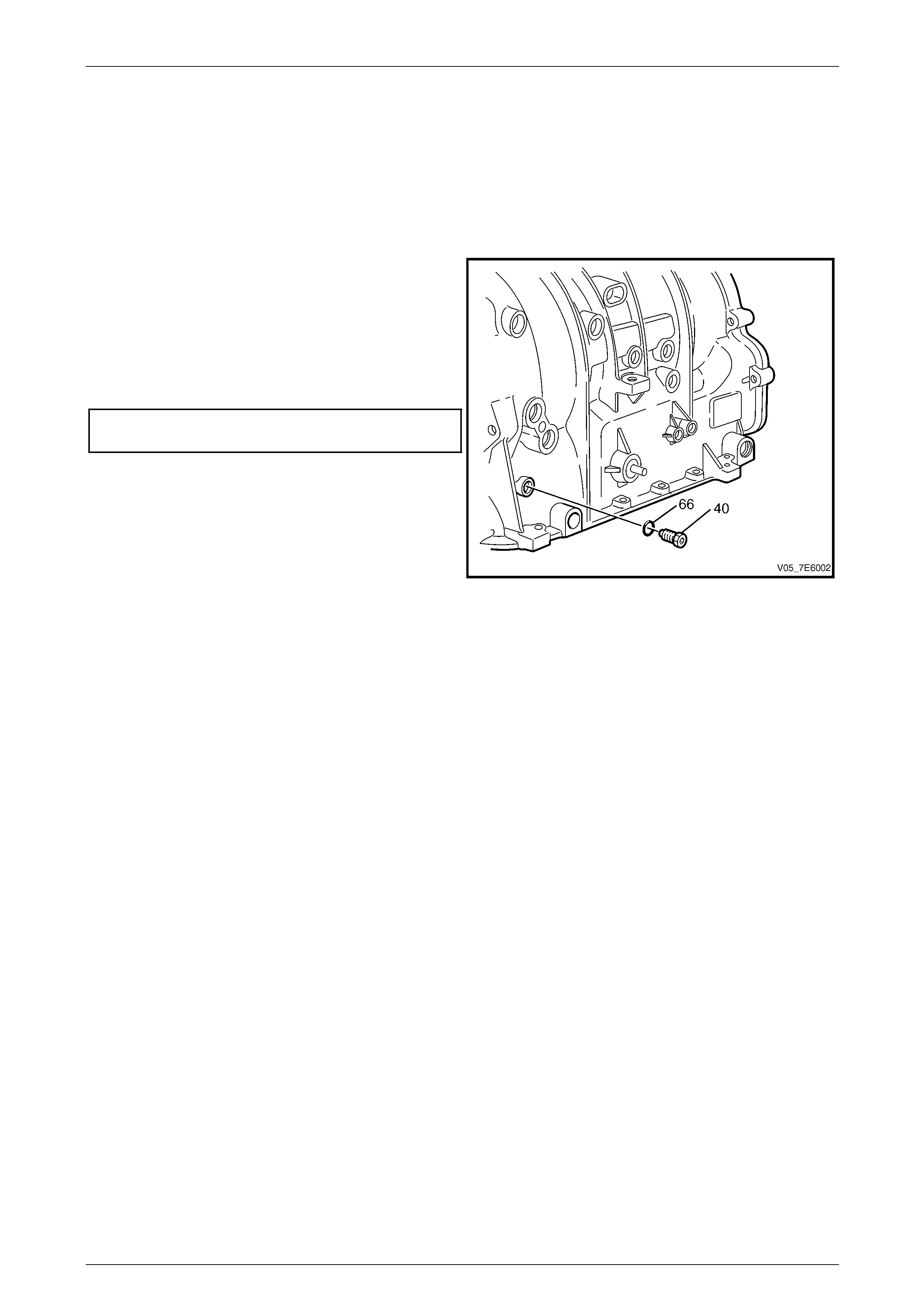
2 Using a 5 mm Allen key socket and suitable
equipment, remove the pressure test plug (40) and O-
ring seal (66).
3 Inspect the pressure test hole plug (40) and O-ring
(66) for damage.
4 Install the pressure test plug (40) and O-ring (66), then
tighten the plug to the correct torque specification.
Transmission pressure test plug
to case torque specification..................................11 N.m
5 Check the transmission fluid level, topping up as
required. Refer to 2.1 Transmission Flu id Check, in
this Section.
6 Check for transmission fl uid leaks.
7 Lower vehicle to the grou nd.
Figure 7E4 – 37

Automatic Transmission – 5L40-E – On-Vehicle Servicing 7E4 – 31
7E4 – 31
3.6 Transmission Mount and Mount Plate
LT Section No. – 04-020
Inspect
To avoid oil pan damage and possible engine
failure, insert a block of wood that spans the
width of the oil pan bottom between the oil
pan and the jack support.
1 Raise the vehicle and support in a safe manner. Refer to Section 0A General Information for the location of
recommended lifting and support points.
2 Raise the transmission to remove the weight from the transmission mount and create slight tension in th e rubber.
3 Observe the transmission mount while raising the transmission. Replace the transmission mount if the mount
exhibits any of the following conditions:
a The hard rubber surface is covered with heat cracks.
NOTE
Black paint on the rubber will crack with time; this
does not constitute a failure.
b The rubber is separated from the metal plate of the transmission mount.
c The rubber is split throu gh the centre of the transmission mount.
4 If there is movement between the metal plate of the transmission mount and its attaching points, lower the
transmission on the transmission mount. T ighten all fasteners attaching th e transmission mount to the frame or
transmission mount bracket to the correct torque specification
Transmission mount plate to extension
housing bolt torque specification..........................55 N.m
Transmission mount to moun t plate
nut torque specification........................................ 55 N.m
Transmission mount to crossmember
nut torque specification........................................ 25 N.m
Automatic Transmission – 5L40-E – On-Vehicle Servicing 7E4 – 32
7E4 – 32
Remove
1 Raise the vehicle and support in a safe manner. Refer to Section 0A General Information for the location of
recommended lifting and support points.
2 Mark the relationship of the transmissi on mount
crossmember to each body side rail with a felt tipped
pen or similar ('A'). NOTE
This is necessary to maintain alignment on
reassembly.
3 Support the rear of the transmission oil pan with a
block of wood that spans the width of the oil pan
between the oil pan and the ja ck support.
4 Remove the four bolts (1) sec urin g the transmission
mount crossmember to the body side rails.
5 Remove the two nuts (2) securing the transmission
mount to the crossmember (3). Remove the
crossmember from the vehicle. Fig ure 7E4 – 38
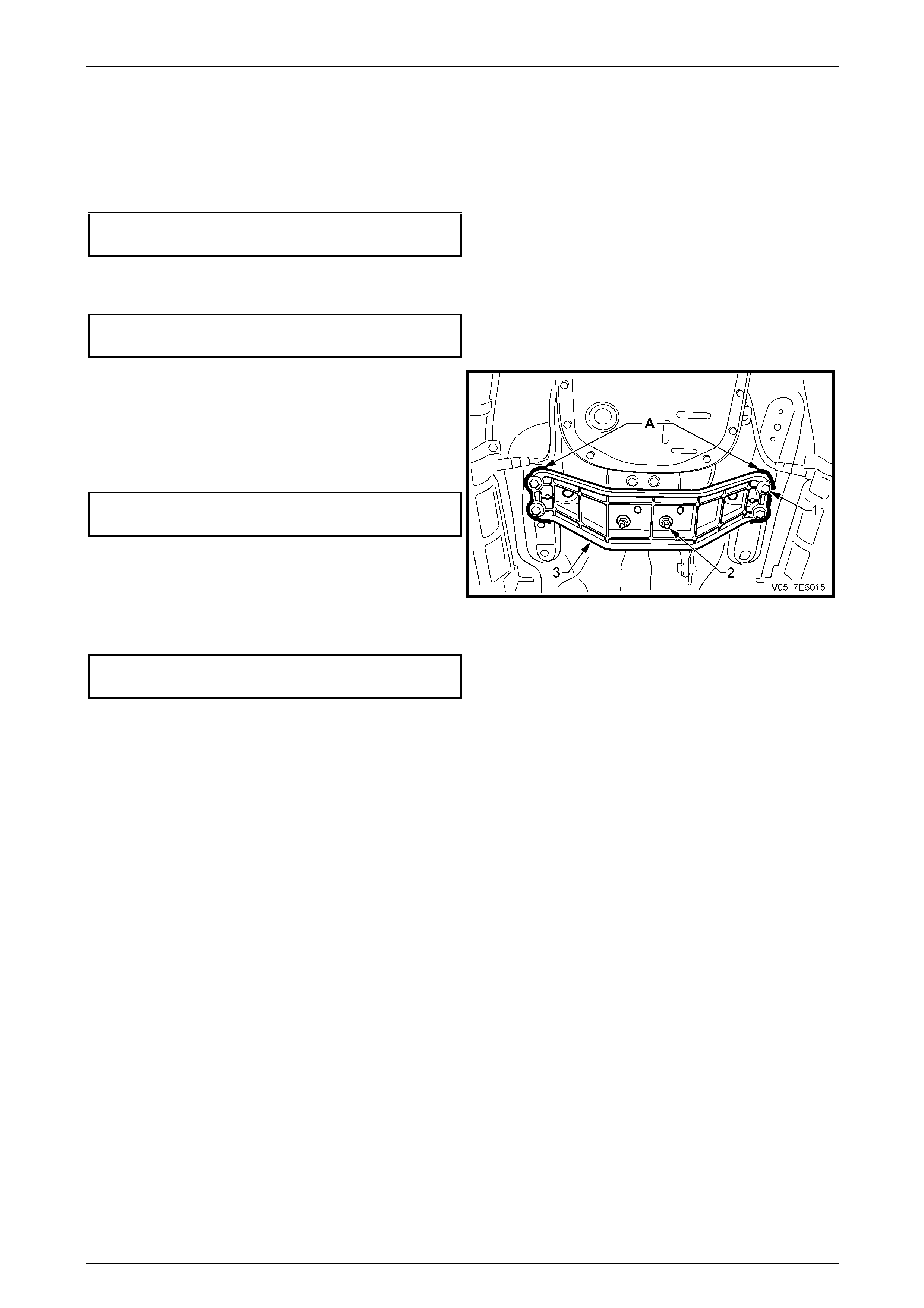
6 Remove the two nuts (1) securing the transmission
mount (2) to the transmission mount plate (4), then
remove the mount from the vehicle.
7 If required, remove the two bolts (3) securing the
mount plate (4) to the transmission extension housing,
then remove the plate from the vehicle.
Figure 7E4 – 39
Automatic Transmission – 5L40-E – On-Vehicle Servicing 7E4 – 33
7E4 – 33
Reinstall
The reinstallation procedure is the reverse to removal, except for the items mentioned here:
1 If removed, reinstall the transmission mount plate to the transmission extension housing and tighten the two bolts
to the correct torque specification.
Transmission mount plate to extension
housing bolt torque specification..........................55 N.m
2 Reinstall the transmission mount to the mount plate, securing with the two nuts tightened to the correct torque
specification.
Transmission mount to moun t plate
nut torque specification........................................ 55 N.m
3 Reinstall the transmission mount crossmember (3),
noting the orientation and aligning the marks (‘A’)
made before removal.
4 Reinstall the fo ur bolts (1) securing the crossmember
(3) to the body side rails and tighten to the correct
torque specification.
Rear crossmember to side
rail bolt torque specification..................................58 N.m
5 Lower the transmission support and remove the block
of wood under the transmission oil pan.
6 Centralise the t r ansmission mount studs in the
crossmember holes, reinstall the nuts and tighten to
the correct torque specification. Figure 7E4 – 40
Transmission rear mount to
crossmember nut torque specification .................25 N.m
7 Lower the vehi cle to the ground.
Automatic Transmission – 5L40-E – On-Vehicle Servicing 7E4 – 34
7E4 – 34
3.7 Output Drive Flange and Oil Seal
ATTENTION
The following fasteners MU ST be replaced when performing these operatio ns:
Output flange retaining nut.
Front coupling to transmission output flange fastener s as noted in the text.
A number of different methods of attaching
the front coupling to the transmission output
flange can be noted:
• Hexagon headed bolts into threaded
flange holes. With this method, the output
flange threads are of the 'Spiralock' form
that can only be loosened/tightened a
maximum of ten times. Because of the
safety factor involved, if the complete
vehicle service history is not known, then
both the flange and the bolts MUST be
replaced on reassembly.
• Studs installed into the transmission
output flange facing rearward, with the
flange being secured by nuts.
• Torx headed bo lts and nu ts. Figu re 7E4–56
shows this method.
LT Section No. – 04-200
Remove
1 Raise the vehicle and support in a safe manner. Refer to Section 0A General Information in this Service Information
for the location of recommended lifting and supp ort points.
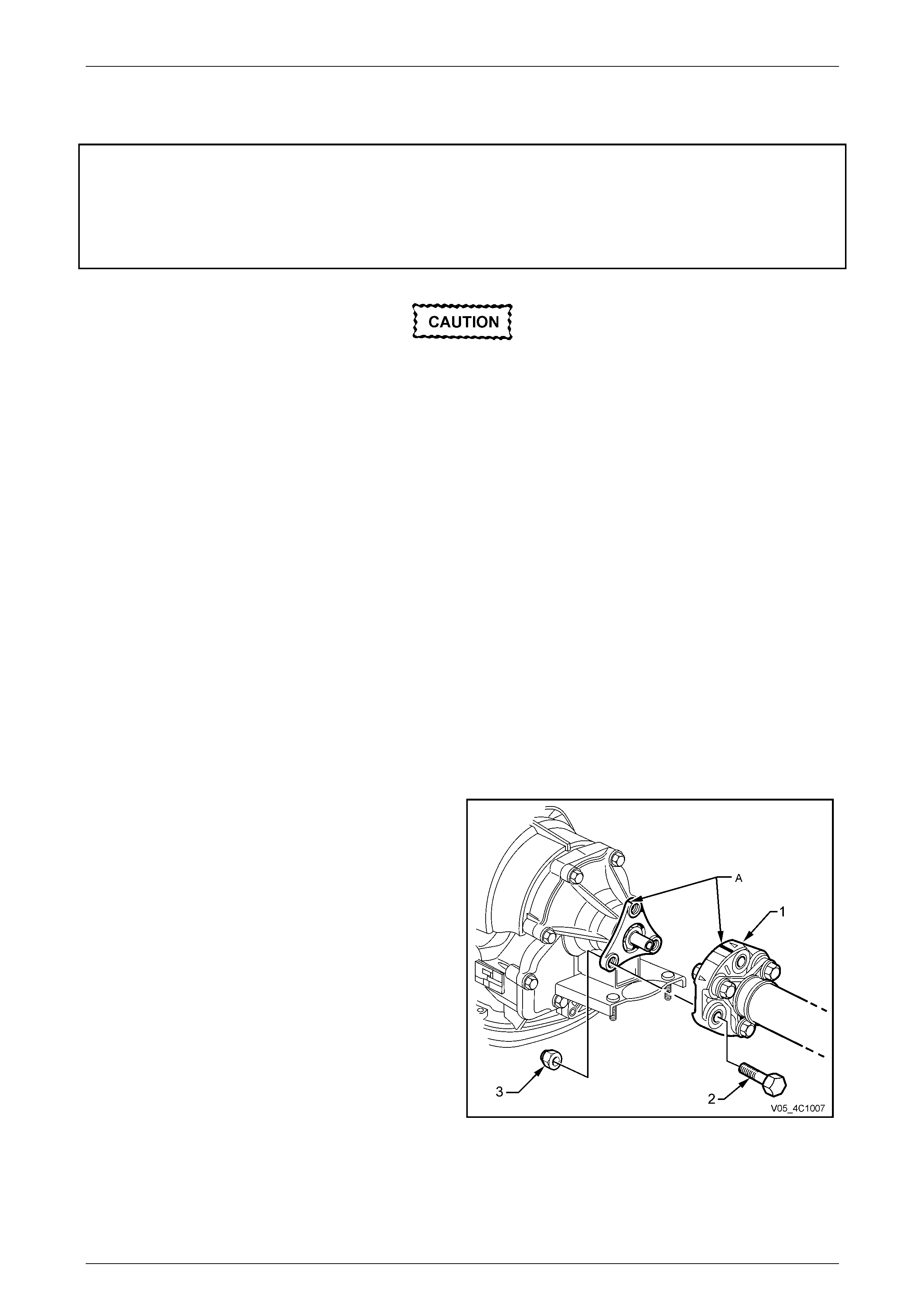
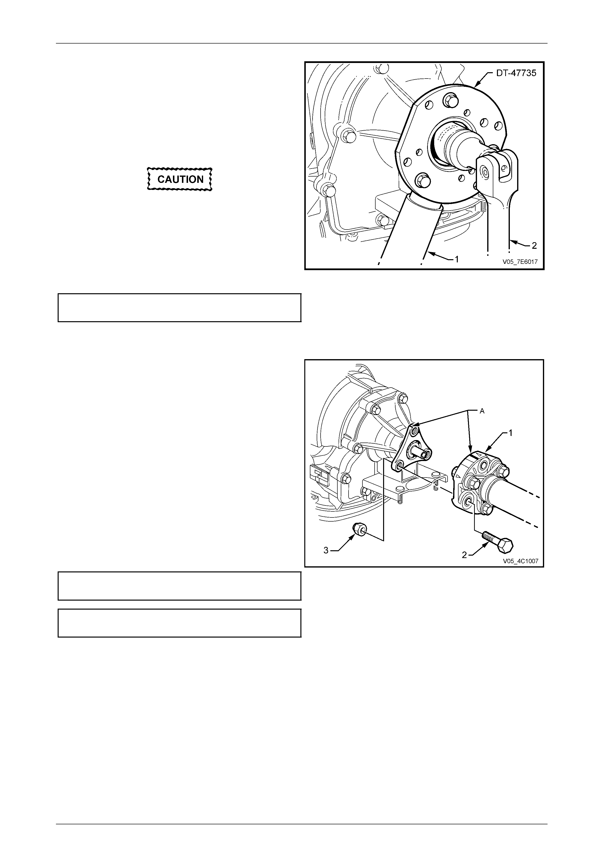
2 Loosen, then remove the three front propeller shaft
coupling (1) to output flange bolts (2), nuts (3) and
washers (4).
3 Push the front propeller shaft to the rear of the vehicle
to release the front propeller shaft couplin g from the
transmission output shaft spigot.
Figure 7E4 – 41
Automatic Transmission – 5L40-E – On-Vehicle Servicing 7E4 – 35
7E4 – 35
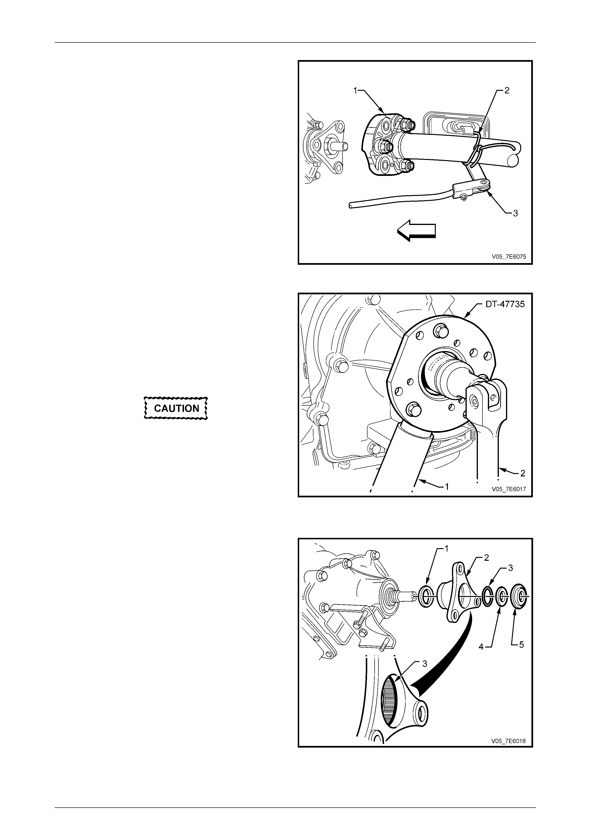
4 Use tie wire (2) or similar to support the front propeller
shaft (1) to a convenient underbody point, such as the
shift lever (3).
Figure 7E4 – 42
5 Install holding tool DT-47735 (also released as
KM620-1A) to the transmission output flange, using
three, fully threaded, M10 bo lts and nuts.
NOTE
Using smaller OD bolts and nuts will not impact
on the output flange 'Spiralock' thread forms, if
used.
If Park is selected to lock the output shaft,
DO NOT use impact equipment to loosen the
flange nut.
6 Insert a suitable length of pipe (1) over the tang of the
installed tool for leverage, then remove the output
flange retaining nut, using a commercia lly available,
30 mm deep socket and socket bar (2).
7 Remove holding tool DT-47735 (or KM 620-1A) from
the output flange. Figure 7E4 – 43
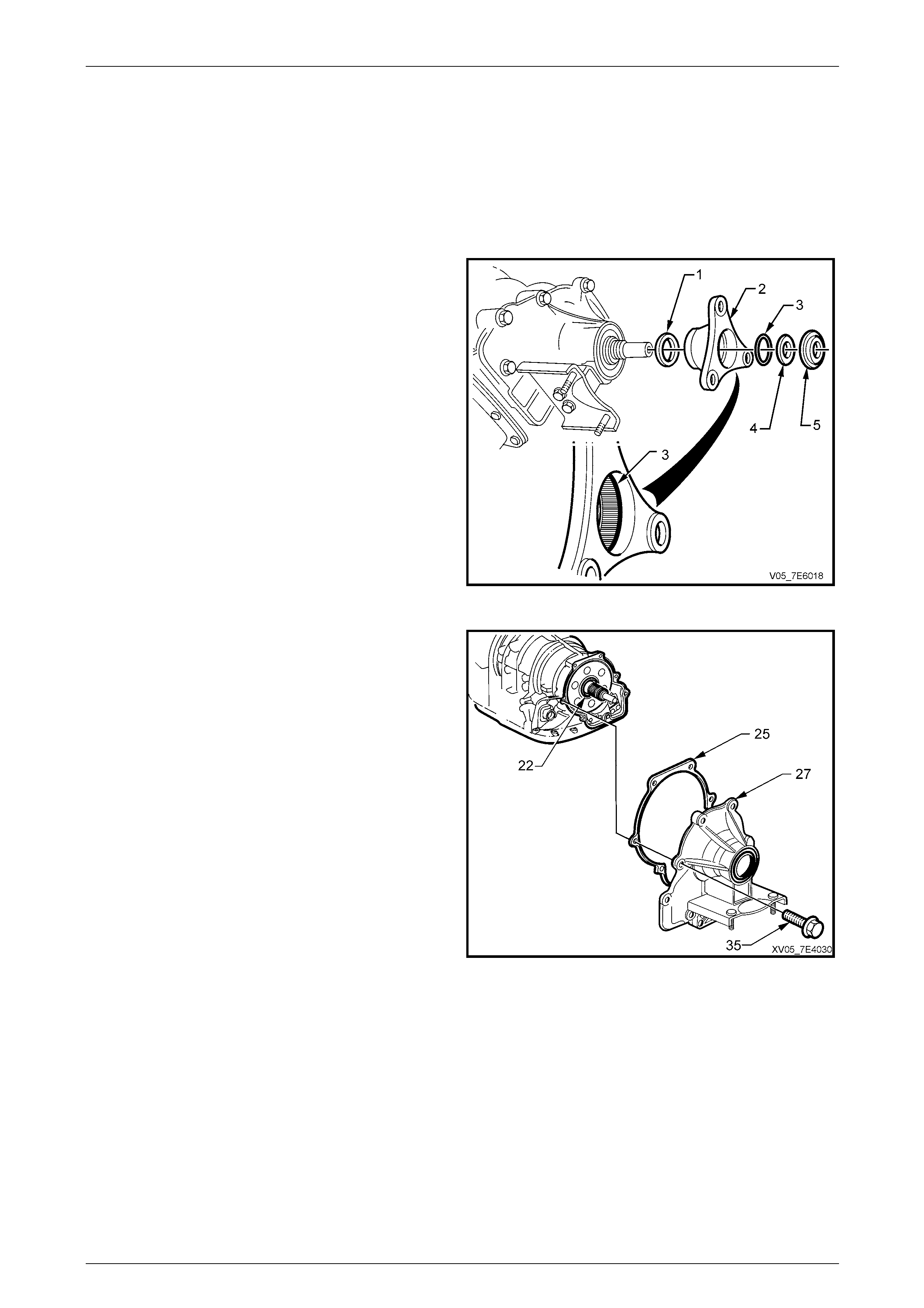
8 Remove the dished washer (4), then the output flange
(2) and O-ring seal (3), from the transmission output
shaft.
9 Remove the O-ring seal (3) from the output flange(2).
NOTE
• Discard parts ‘3’, ‘4’ and ‘5’, as they are
included in the one service kit. Refer to the
current release of Partfinder™ for the correct
part number.
• The output shaft assembly retainer (1) can
only be removed after the oil seal is removed
(Step 11). This retainer is als o incl uded in th e
service kit.
Figure 7E4 – 44
Automatic Transmission – 5L40-E – On-Vehicle Servicing 7E4 – 36
7E4 – 36
10 Remove the output flange oil seal (1), using seal
remover J 23129 and slide hammer J 6125-1B or seal
remover E308 (or commercial equivalent).
11 Using suitable snap ring pliers, remove the output
shaft assembly retainer ('1' in Figure 7E4 – 46), then
discard the removed retainer.
Figure 7E4 – 45
Reinstall
1 Install a NEW output shaft assembl y retaine r (' 1' in
Figure 7E4 – 70). Position the retainer over the end of
the output shaft splines. The retainer will be installed
to the correct depth when the output flange is install ed.
2 Lubricate the l ips of a NEW oil seal (1) then install
onto the installation tool J 44765.
NOTE
Fitting the seal onto the installation tool before
installation will prevent seal lip damage.
3 Install the NEW oil seal (1) into the transmission
extension housing, using tool J 44765 and a hammer.
Figure 7E4 – 46
4 Clean all traces of thread sealant from the
transmission output shaft threads, using a wire brush.
5 Lubricate a NEW O-ring seal (3) with transmission
fluid, then install into the output flange (2).
6 Install the output flange (2) and O-ring (3) assembly
over the splines of the transmission output shaft.
NOTE
Refer to the 'Caution' stateme nt at the beginning
of this Service operation to determine whether
the flange is to be replaced or not.
7 Install a NEW dished thrust washer (4), with the curve
facing outward.
8 Install a NEW output flange retaining nut (5).
NOTE
A new nut has micro-encapsulation applied to
the threads. Figure 7E4 – 47
Automatic Transmission – 5L40-E – On-Vehicle Servicing 7E4 – 37
7E4 – 37
9 Install holding tool DT-47735 (also released as
KM620-1A) to the transmission output flange, using
three, fully threaded, M10 bo lts and nuts.
NOTE
Using smaller OD bolts and nuts will not impact
on the output flange 'Spiralock' thread forms, if
used.
If Park is selected to lock the output shaft,
DO NOT use impact equipment to tighten the
flange nut.
10 Insert a suitable length of pipe (1) over the tang of the
installed tool for leverage, then instal l the NEW output
flange retaining nut, using a commercia lly available,
30 mm deep socket and socket bar (2). T ighten to the
correct torque specification.
Transmission output flange
retaining nut torque specification .........................60 N.m
11 Remove holding tool DT-47735 (or KM620-1A) from
the output flange.
Figure 7E4 – 48
12 Remove the tie wire supporting the front propeller
shaft.
13 Smear NLGI No. 2 lithium soap based EP grease with
molybdenum disulphide such as Shell Retinax HDX2
grease, BP Energrease LMS-EP 23 or equivalent over
the transmission output shaft spigot.
14 Install the propeller shaft front coupling to the output
flange.
NOTE
Refer to the 'Caution' stateme nt at the beginning
of this service operation to determine whether
the bolts are to be replaced or not.
15 Install fasteners to secure the coupling to the
transmission output flange. Tighten the bolts to the
correct torque specification.
Front propeller shaft couplin g nuts
or bolts and nuts torque specification.................115 N.m Figure 7E4 – 49
Front coupling bolts to ‘Spiralock’
flange threads torque specification ......................85 N.m
16 Check the transmission fluid level, topping up as required. Refer to 2.1 Transmission Fluid Check, in this Section.
17 Check for transmission fluid leaks.
18 Lower vehicle to the ground.
Automatic Transmission – 5L40-E – On-Vehicle Servicing 7E4 – 38
7E4 – 38
3.8 Extension Housing
LT Section No. – 04-200
Remove
1 Raise the vehicle and support in a safe manner. Refer to Section 0A General Information in this Service Information
for the location of recommended lifting and supp ort points.
2 Remove the transmission o utput flang e (2), refer to
3.7 Output Drive Flange and Oil Seal, in this Section
for the necessary procedure.
NOTE
• If the extension housing oil seal is not
removed, the output shaft assembly retainer
(1) will be withdrawn, when the extension
housing is removed.
• Discard parts ‘1’, ‘3’, ‘4’ and ‘5’, as they are
included in the one service kit. Refer to the
current release of Partfinder™ for the correct
part number.
3 Remove the transmission mo unt. Refer to
3.6 Transmission Mount and Mount Plate, in this
Section.
Figure 7E4 – 50
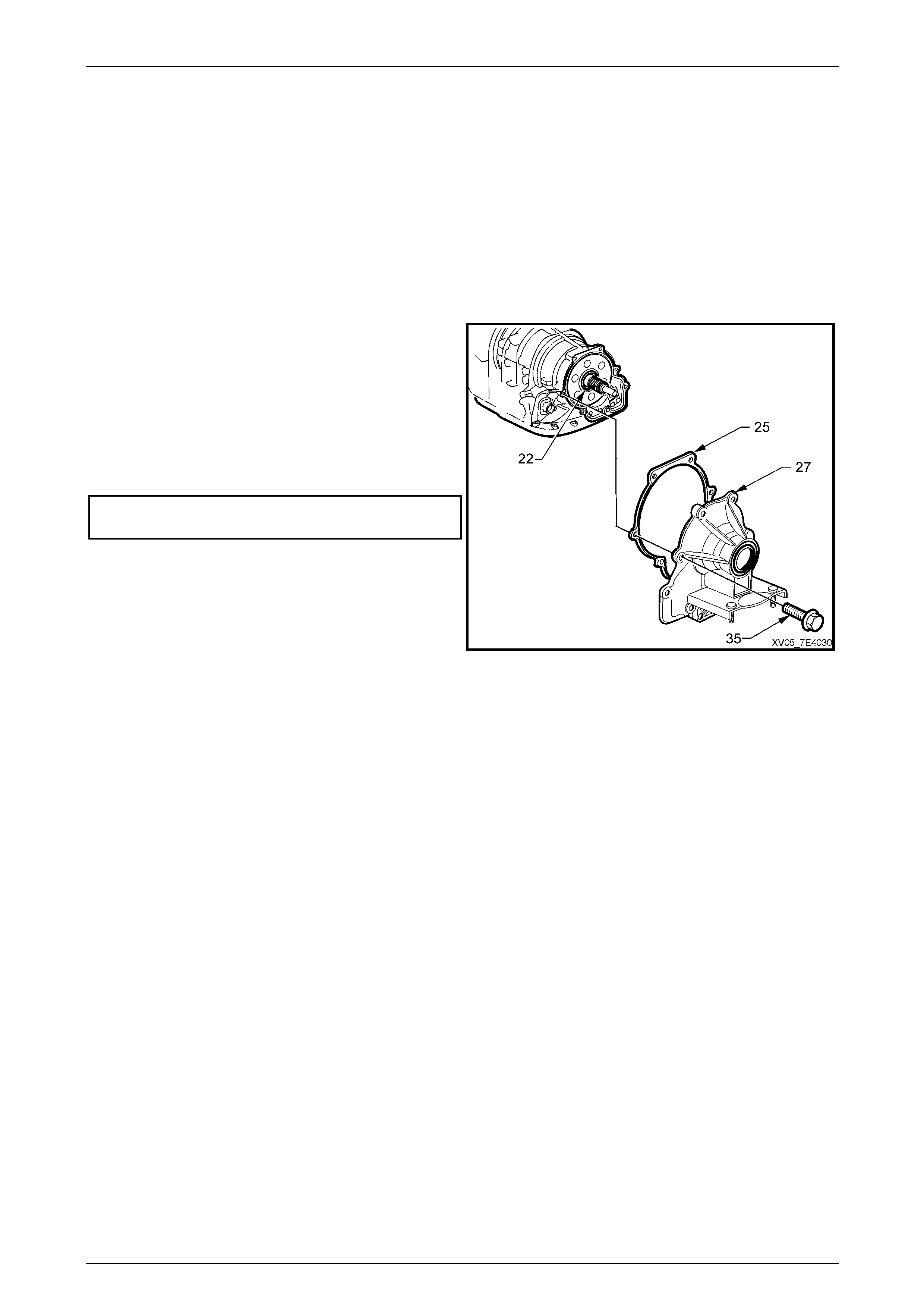
4 Place an oil drain pan under the rear of the
transmission.
5 Remove the extension housing bolts (35).
6 Remove the ex tension housing (27) and sealing
gasket (25).
NOTE
• In not removed previously, the output shaft
retainer ('1' in Figure 7E4 – 50), will slide
from the output shaft during the extension
housing removal operation.
7 Do not lose the selective thrust washer (22) and
bearing when the extension housing is removed.
Figure 7E4 – 51
Automatic Transmission – 5L40-E – On-Vehicle Servicing 7E4 – 39
7E4 – 39
Reinstall
1 Smear the selective washer (22) and thrust bearing (23) with petroleum jelly (e.g. Vaseline™ or equivalent), install
‘22’ then ‘23’ over the output shaft.
NOTE
The selection of the thrust washer (22) thickness
is dependent upon the relationship of the
transmission case end machined surface to the
face of the output shaft. This dimension is not
affected by an extension h ousing replacement.
2 Reinstall the extension housing (27) and the sealing
gasket (25) to the rear of the transmission.
NOTE
If the sealing gasket is undamaged, then it may
be reused.
3 Reinstall the e xtension housing retaining bolts (35)
and tighten to the correct torque specification.
Extension housing retaining
bolt torque specification.......................................22 N.m
Figure 7E4 – 52
4 Reinstall the transmission rear mount and crossmember. Refer to 3.6 Transmission Mount and Mount Plate, in this
Section.
5 Install a NEW drive flange oil seal, then reinstall the drive flange. Refer to 3.7 Output Drive Flange and Oil Seal, in
this Section.
Automatic Transmission – 5L40-E – On-Vehicle Servicing 7E4 – 40
7E4 – 40
3.9 Transmission Internal Electrical Harness
Replace
1 Raise the vehicle and support in a safe manner. Refer to Section 0A General Information for the location of
recommended lifting and support points.
2 Release the transmissio n wiring harness connector (1)
by rotating the locking sleeve (2) in a counter-
clockwise direction (to the left).
3 Pull on the connector to disconnect from the
transmission internal harness connector.
Figure 7E4 – 53
4 Remove the transmission fluid pan and filter. Refer to
3.1 Fluid Change and Filter Replace, in this Section.
5 Lift the locking latch an d disconnect the connectors
from items 1 – 8.
Legend:
1 Output Speed Sensor
2 1-2 Shift Solenoid
3 Input Speed Sensor
4 Pressure Control Solenoid
5 Torque Converter Clutch (TCC) PWM Solenoid
6 Manual Shaft Shift Position Switch
7 4-5 Shift Solenoid
8 2-3 Shift Solenoid
Figure 7E4 – 54
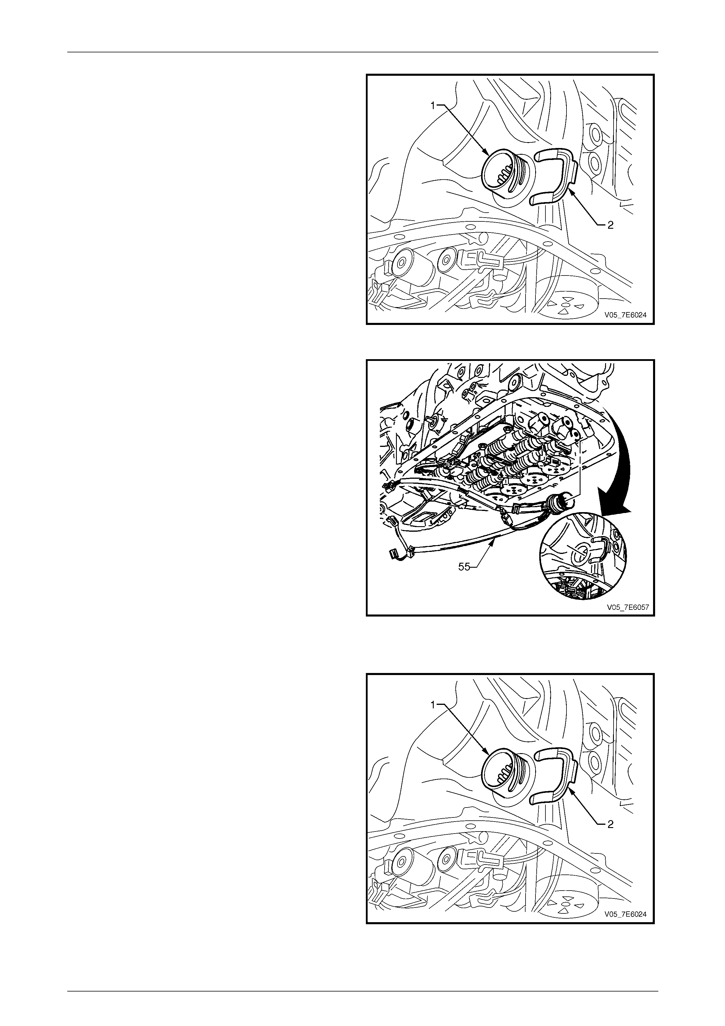
Automatic Transmission – 5L40-E – On-Vehicle Servicing 7E4 – 41
7E4 – 41
6 Remove the internal wiring harness connector retainer
(2) from the connector (1).
7 Gently tap on the en d of the wirin g harness connector
with a plastic hammer to dislodge the O-ring seal.
Figure 7E4 – 55
8 Remove the internal wiring harness (55) from the
transmission.
9 Only remove the O-rings from the wiring harness
connector, if they are worn or damaged.
Figure 7E4 – 56
The installation process is the reverse to removal, except for the follo wing:
10 If removed, apply transmission fluid to NEW O-ring
seals and install to the internal wiring harness
connector.
11 Install the wiring harness connector to the
transmission case, aligning the lug on the connector
body with the gap in the trans m ission case casting.
12 Secure the wiring harness connector (1) to the
transmission case, with the retainer (2), noting the
orientation.
Figure 7E4 – 57
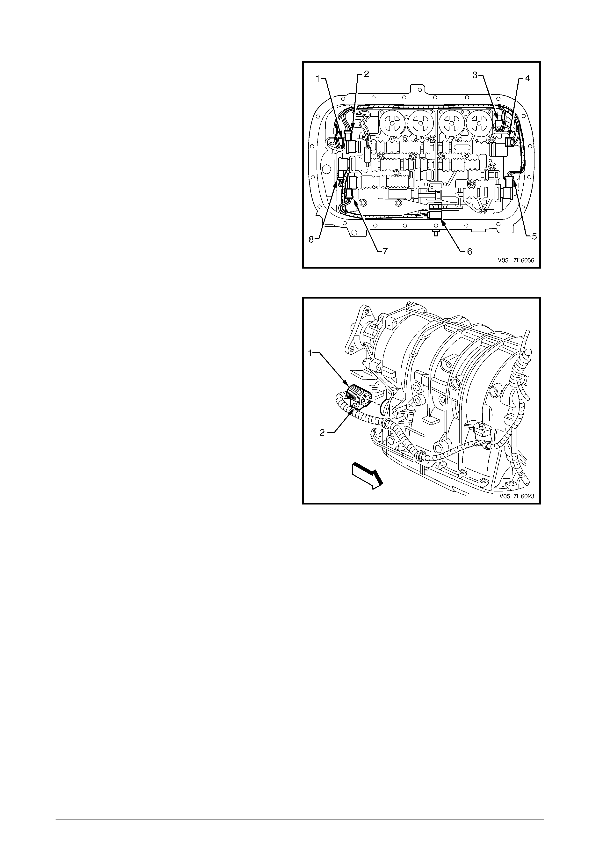
Automatic Transmission – 5L40-E – On-Vehicle Servicing 7E4 – 42
7E4 – 42
13 Reinstall each of the connectors to parts 1 – 8,
checking that each connector security latch is
engaged.
Legend:
1 Output Speed Sensor
2 1-2 Shift Solenoid
3 Input Speed Sensor
4 Pressure Control Solenoid
5 Torque Converter Clutch (TCC) PWM Solenoid
6 Manual Shaft Shift Position Switch
7 4-5 Shift Solenoid
8 2-3 Shift Solenoid
Figure 7E4 – 58
14 Install a NEW transmission fluid filter and the fluid pa n
to the transmission, reusing the original pan gasket
seal, if undamaged.
Refer to 3.1 Fluid Change and F ilter Replace, in this
Section.
15 Reinstall the transmission wiring harness connector
(1) to the transmission internal wiring harnes s
connector and secure by rotating the locking sleeve
(2) in a clockwise direction.
Figure 7E4 – 59
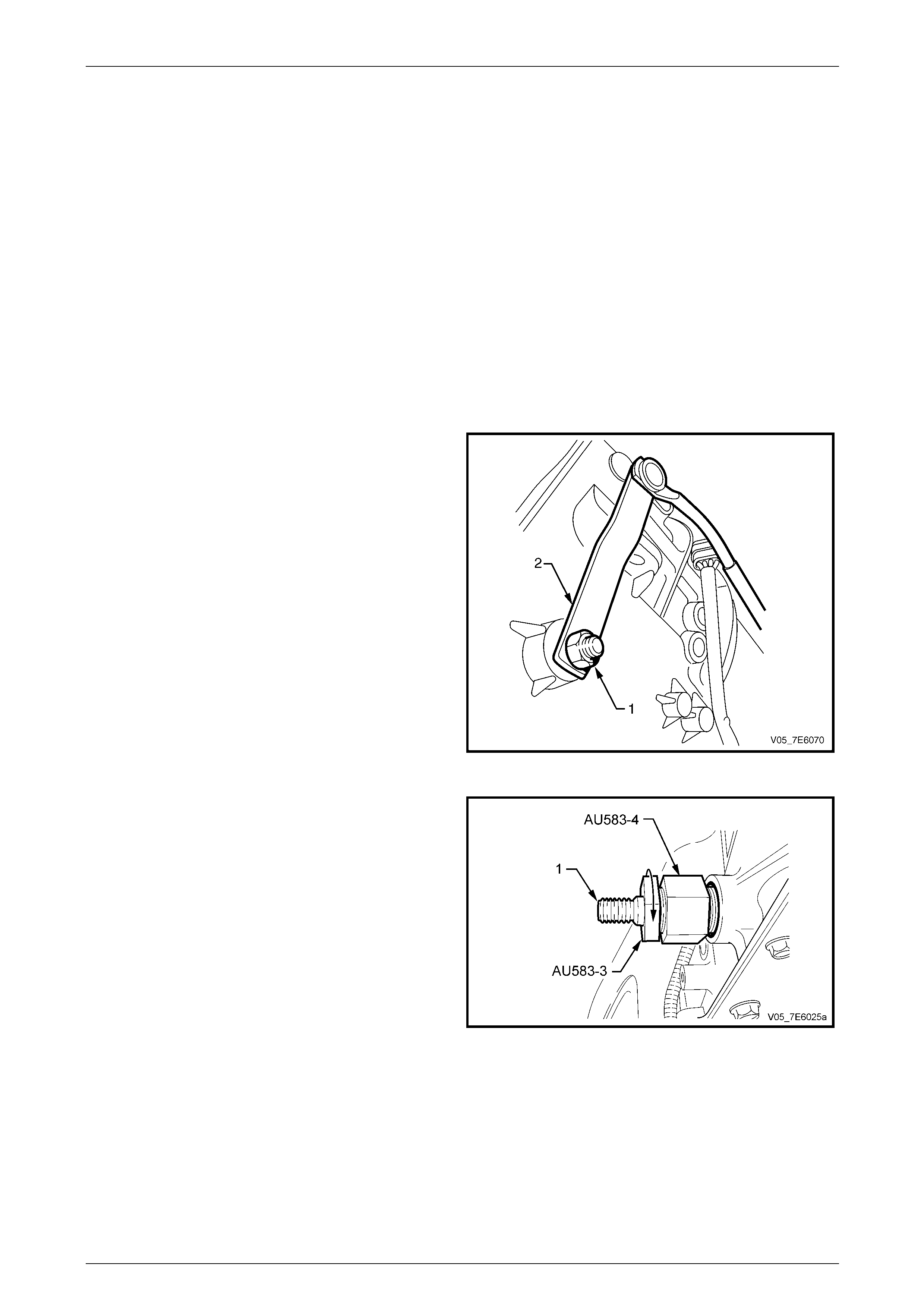
Automatic Transmission – 5L40-E – On-Vehicle Servicing 7E4 – 43
7E4 – 43
3.10 Manual Shaft Oil Seal
NOTE
This procedure requires the use of special tool
No. AU 583. Should this tool not be available, the
seal can still be replaced but involves the removal
of the selector shaft from the transmission case.
Refer to 3.11 Manual Shaft Position Switch, in
this Section for the procedure.
LT Section No. – 04-200
Replace
1 Raise the vehicle and support in a safe manner. Refer to Section 0A General Information in this Service Information
for the location of recommended lifting and supp ort points.
2 While holding the transmission shift lever (2) with an
adjustable wrench, remove the nut (1) securing the
shift lever (2) to the transmission manual shift shaft.
3 Disconnect the shift lever from the transmission
manual shift shaft.
Figure 7E4 – 60
4 Assemble the remover nut (Tool No. AU 583-4) with
the threaded section closest to the hexago nal head of
the seal remover AU 583-3. Install the nut up to the
hexagonal e nd.
5 Install the pre-assembled remover (Tool Nos. AU 583-
3 and AU 583-4) over the manual shaft (1) a nd
engage the tapered thread en d of the seal re mover
into the seal. Tighten the seal remover until the tool
thread grips the outer shell of the seal.
NOTE
Do not overtighten the seal remover into the
seal.
Figure 7E4 – 61
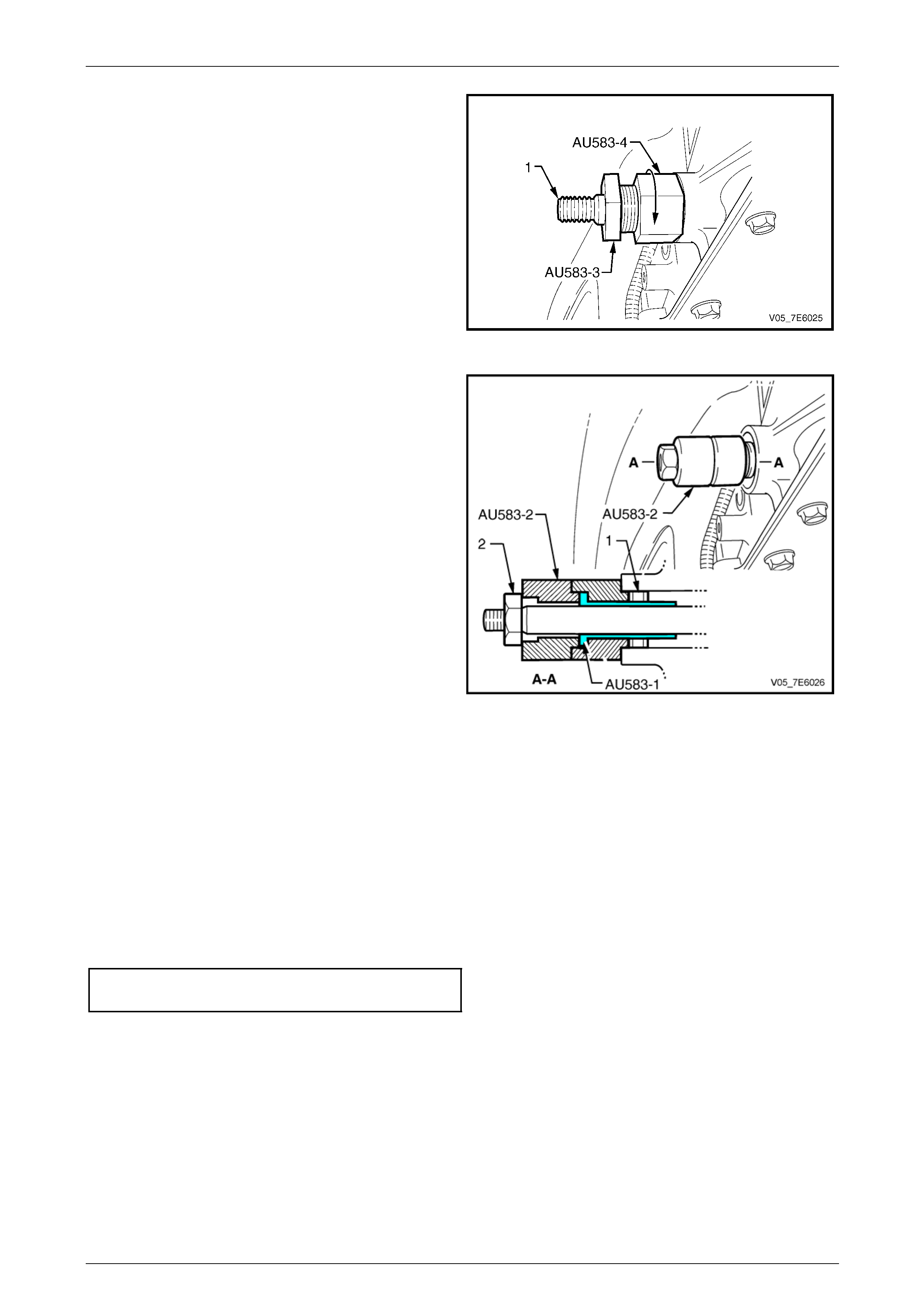
Automatic Transmission – 5L40-E – On-Vehicle Servicing 7E4 – 44
7E4 – 44
6 While holding the seal remover (AU 583-3) with a
suitable spanner, use a second spann er to screw the
remover nut (AU 583-4) up to the transmissio n case.
7 Continue tightening the remover nut until the seal is
removed into the remover nut cavity.
8 Discard the removed se al.
Figure 7E4 – 62
9 Pre-assemble the seal protector sleeve (AU 583-1)
into one of the plastic seal installers (AU 583-2), as
shown in the sectioned view.
10 Lubricate the seal lip of a new seal (1) with Dexron® III
automatic transmission fluid, then install it (wit h the
steel seal casing facing the installer) over the seal
protector sleeve (AU 583-1).
11 Install the seal protector sleeve (AU 583- 1), seal (1)
and seal installer (AU 583-2), over the manu al shaft
and up to the transmission case.
NOTE
If the seal protector sleeve (AU 583-1) jams on
the manual shaft, then the shaft will be burred
over the flats that locate the shift lever. Use a
fine file to remove burrs, then proceed.
12 Install the second plastic seal installer over the manual
shaft until it seats against the first installer.
NOTE
The two plastic seal installers (AU 583-2) are
required, because of the restricted space
between the end of the manual shaft and the
floor pan.
Figure 7E4 – 63
13 Install the manual shaft lever retaining nut (2) and tighte n it to install the seal fully into place in the transmission
case.
14 Remove installer tools, AU 583-2 (two pieces) and seal protector sleeve AU 583- 1 from the manual shaft.
15 Reinstall the shift shaft lever to the transmission manual shaft, then install the retaining nut.
16 While holding the manual shift lever with an adjustable wrench, tighten the retaining nut to the correct torque
specification.
Manual shift shaft lever retaining
nut torque specification........................................ 12 N.m
17 Check and adjust the shift control linkage. Refer to 3.2 Selector Linkage, Adjust, in this Section.
18 Check and top up transmission fluid level as required. Refer to 2.1 Transmission Flu id Check, in this Section.
19 Inspect for transmission fluid leaks.
20 Lower the vehicle to the ground.
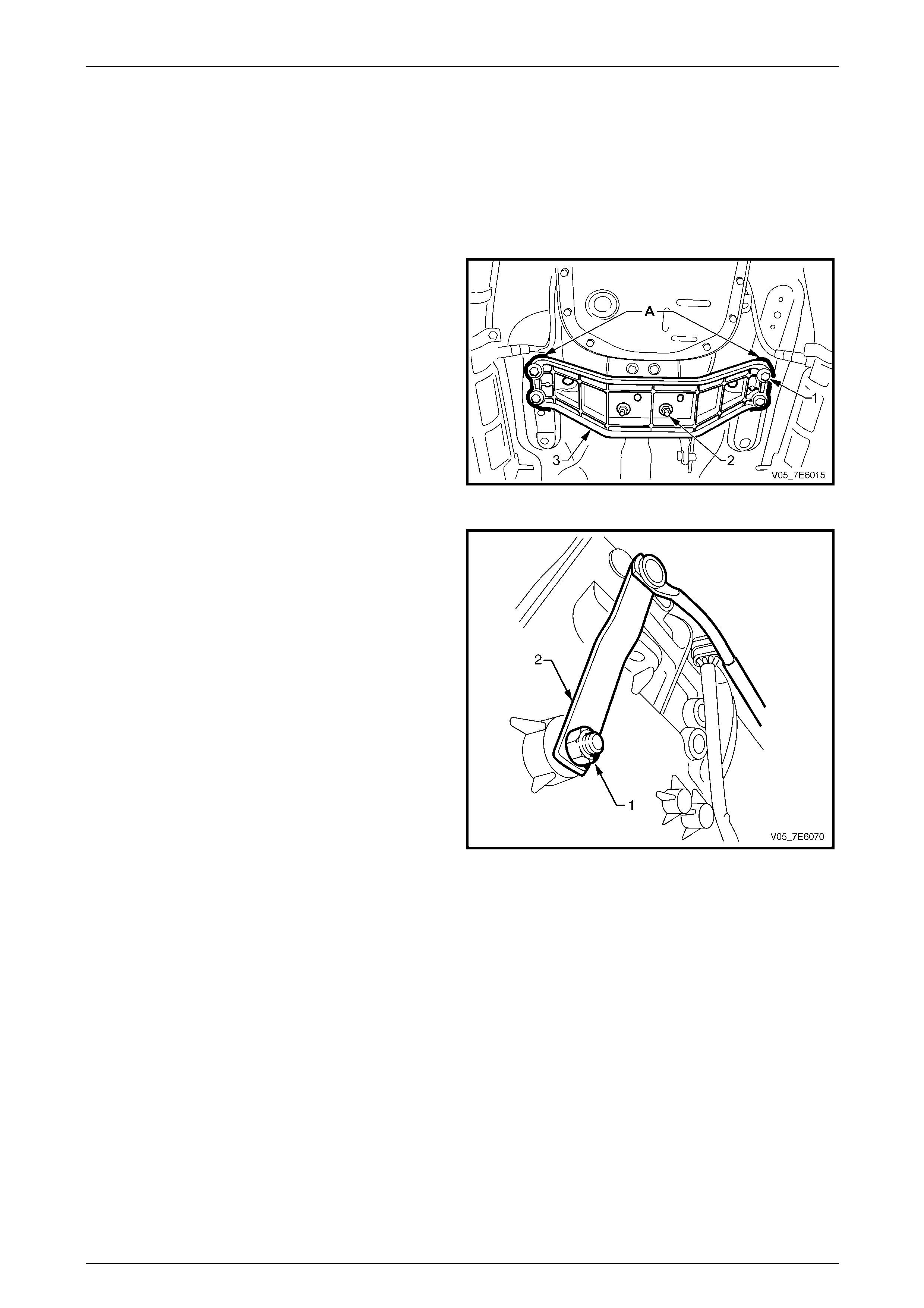
Automatic Transmission – 5L40-E – On-Vehicle Servicing 7E4 – 45
7E4 – 45
3.11 Manual Shaft Position Switch
LT Section No. – 04-170
Remove
1 Raise the vehicle and support in a safe manner. Refer to Section 0A General Information for the location of
recommended lifting and support points.
2 Mark the relationship of the transmissi on mount
crossmember to each body side rail (‘A’) with a felt
tipped pen or similar.
NOTE
This is necessary to maintain alignment on
reassembly.
3 Position a suitable transm issio n jack under the
transmission rear mount crossmember.
4 Remove the four bolts secur in g the transmission
mount crossmember to the body side rails.
Figure 7E4 – 64
5 While holding the shift lever with an adjustable
wrench, remove the nut (1) securing the transmission
shift lever (2) to the transmission manual shift shaft.
6 Disconnect the shift lever from the transmission
manual shift shaft.
7 Remove the transmission fluid pan and filter. Refer to
3.1 Fluid Change and Filter Replace, in this Section.
8 Remove the electrical connector from the manual shift
shaft position switch, after releasing the connector
security latch.
Figure 7E4 – 65
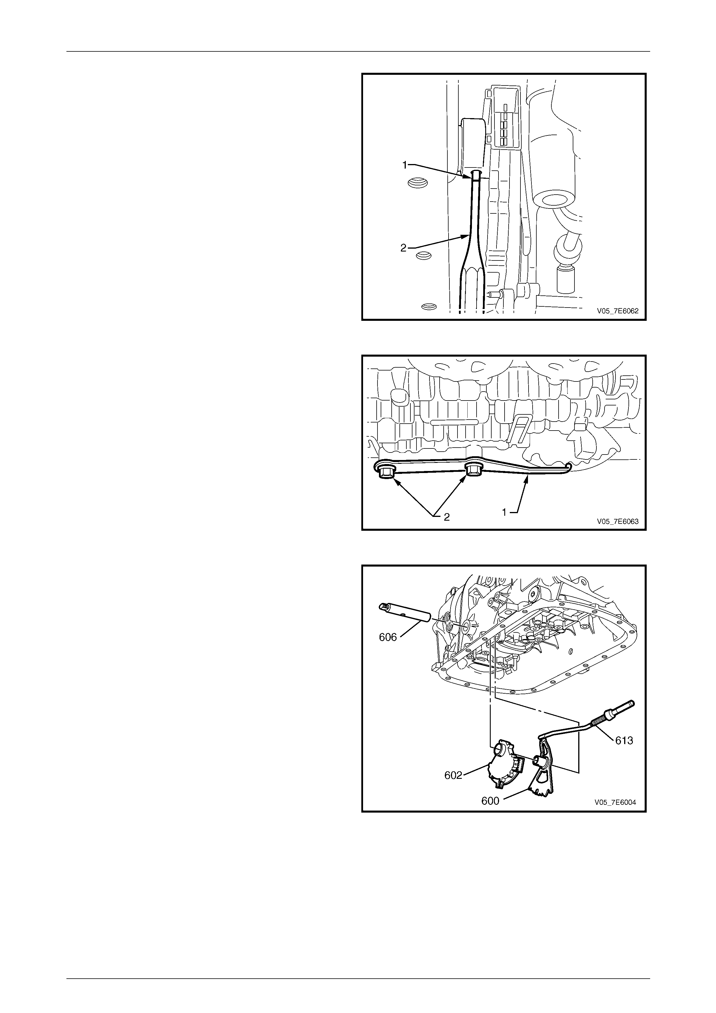
Automatic Transmission – 5L40-E – On-Vehicle Servicing 7E4 – 46
7E4 – 46
9 Using a suitable pin punch (2), remove the roll pin ( 1)
securing the manual shaft position switch to the
manual shaft.
Figure 7E4 – 66
10 Remove the manual shaft detent spring (1) by
removing the two bolts (2).
Figure 7E4 – 67
11 Lower the rear of the transmission, enough to provide
clearance bet ween the manu al shift shaft (606) and
the vehicle floor pan.
12 Remove the manual shift shaft (606) from the
transmission case, enough to allow removal of the
shift shaft position switch and associated components.
13 Remove the manual shift shaft position switch (602),
manual shift shaft detent lever (600) and the park pawl
actuator (613), as an assembly.
14 Disassemble the manual shift shaft position switch
(602) from the manual shift shaft detent lever (600).
Figure 7E4 – 68
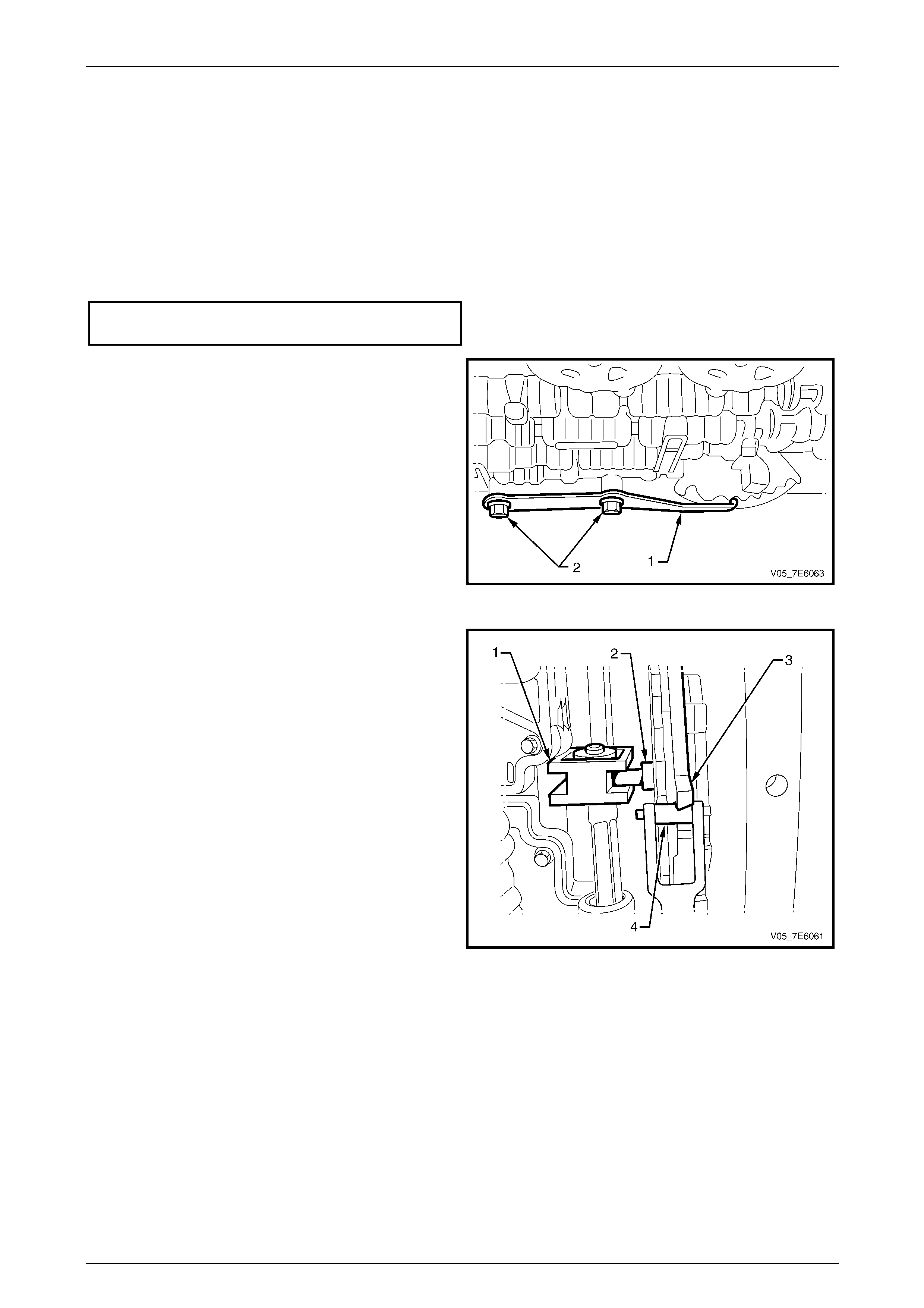
Automatic Transmission – 5L40-E – On-Vehicle Servicing 7E4 – 47
7E4 – 47
Reinstall
1 Refer to Figure 7E4 – 68. Reinstall the manual shift shaft position switch (602), the manual shift shaft detent
lever (600) and the park pawl actuator (613) as an assem bl y.
2 Align the manu al shift shaft detent lever (600) shaft hole with the case, then fully insert the manual shift shaft (606)
into the transmission case.
3 Raise the rear of the transmission and align the crossmember position marks, made before removal.
4 Reinstall the fo ur bolts securing the crossmember to the body side rails and tighten to the correct torque
specification. Remove the transmission jack.
Transmission crossmember to side
rail bolt torque specification..................................58 N.m
5 Reinstall the manual shift shaft detent spring (1).
6 Reinstall the two control valve body and manual sh ift
shaft detent spring retaining bolts(2). Do not fully
tighten at this time.
Figure 7E4 – 69
7 Confirm that the manual shift shaft detent pin (2) is
engaged with the manual shaft link (1).
8 Confirm also, that the detent spring roll er (4) is
correctly engaged with the manual shift shaft
switch (3).
Figure 7E4 – 70
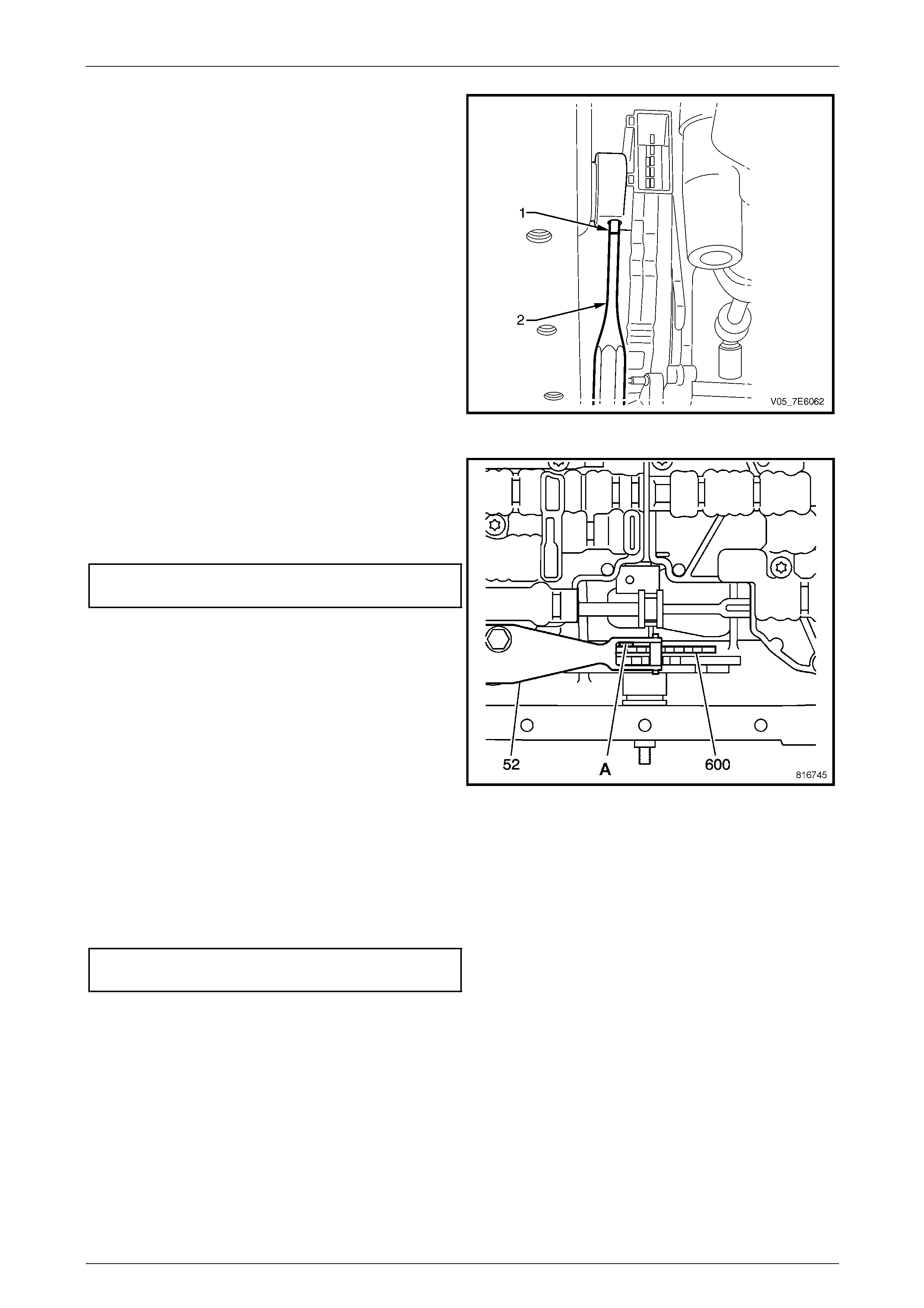
Automatic Transmission – 5L40-E – On-Vehicle Servicing 7E4 – 48
7E4 – 48
9 Using a suitable size pin punch, align the pin hol e in
the manual shift position switch with the hole in the
manual shift shaft.
NOTE
With the pin punch inserted in the manual shift
shaft, rotate the manual shift shaft detent
lever (600) and check that the park pawl
mechanism engages correctly.
10 Using a suitable size pin pu nch (2), install a NEW roll
pin (1) to secure the manual shift shaft position switch
to the manual shift shaft.
11 Reinstall the electrical connector to the manual shift
shaft position switch and check that the secu rity latch
is fully engaged.
Figure 7E4 – 71
12 Install an 0.8 mm spacer ('A') (e.g. feeler gauges)
between the manual shaft detent lever (600) and the
manual shaft detent spring (52).
13 Tighten the two detent spring retaini ng bolts to the
correct torque specification.
Manual shaft detent spring
bolt torque specification.......................................11 N.m
14 Remove the spacer.
15 Install a NEW transmission fluid filter, then the
transmission fluid pan to the transmission, reusin g the
original pan gasket seal, if undamaged.
Refer to 3.1 Fluid Change and F ilter Replace, in this
Section.
Figure 7E4 – 72
16 If the manual shift shaft oil seal was removed, install a NEW oil seal. Refer to 3.10 Manual Shaft Oil Seal, in this
Section.
17 Reinstall the manual shift shaft select lever to the manual shift shaft.
18 Reinstall the manual sh aft shift select lever retaining nut then, while holding the lever with an adjustable wrench,
tighten the nut to the correct torque specification.
Manual shift shaft lever retaining
nut torque specification........................................ 12 N.m
19 Check and adjust the shift control linkage as required. Refer to 3.2 Selector Linkage – RWD Models, Adjust, in this
Section.
20 Check and top up transmission fluid level as required. Refer to 2.1 Transmission Flu id Check, in this Section.
21 Inspect for transmission fluid leaks.
22 Lower the vehicle to the ground.
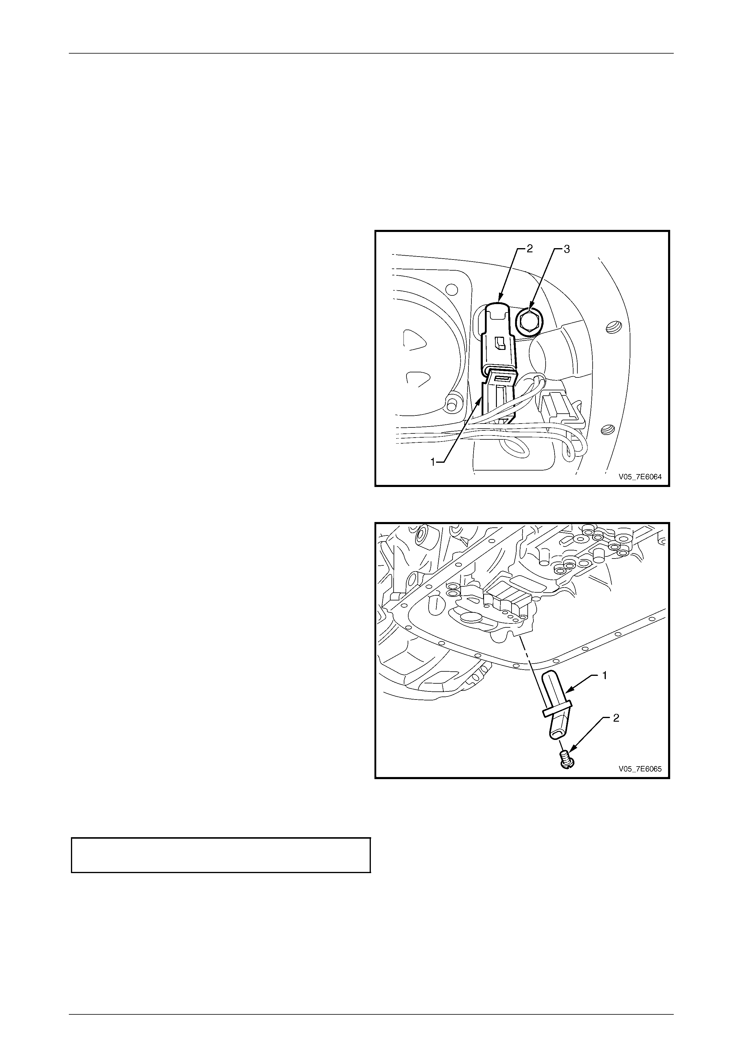
Automatic Transmission – 5L40-E – On-Vehicle Servicing 7E4 – 49
7E4 – 49
3.12 Input Speed Sensor
Replace
1 Raise the vehicle and support in a safe manner. Refer to Section 0A General Information for the location of
recommended lifting and support points.
2 Remove the transmission fluid pan and fluid filter. Refer to 3.1 Fluid Chan ge and Filter Replace, in this Section.
3 Release the wiring harness connector security latch,
then disconnect the connector (1) from the input speed
sensor (2).
4 Remove the input speed sensor retaining screw (3),
using a 10 mm socket and suitable equipment.
Figure 7E4 – 73
5 Remove the input speed sensor (1) from the
transmission case.
6 Inspect the input speed sensor for the following:
a A damaged or missing magnet.
b Damaged housing.
c Bent or missing electrical terminals.
d Metal contamination adhered to the magnet.
Figure 7E4 – 74
7 After reinstalling the input spe ed sensor, install the retaining screw, tightening to the correct torque specification.
Input speed sensor retaining
screw torque specification....................................11 N.m
8 Reinstall the e lectrical connector to the input speed sensor ensuring that the security latch is fully installed.
9 Install a NEW transmission flu id filter, then the transmission fluid pan to the transmission, reusing the original pan
gasket seal, if undamaged. Refer to 3.1 Fluid Chang e and Filter Replace, in this Section.
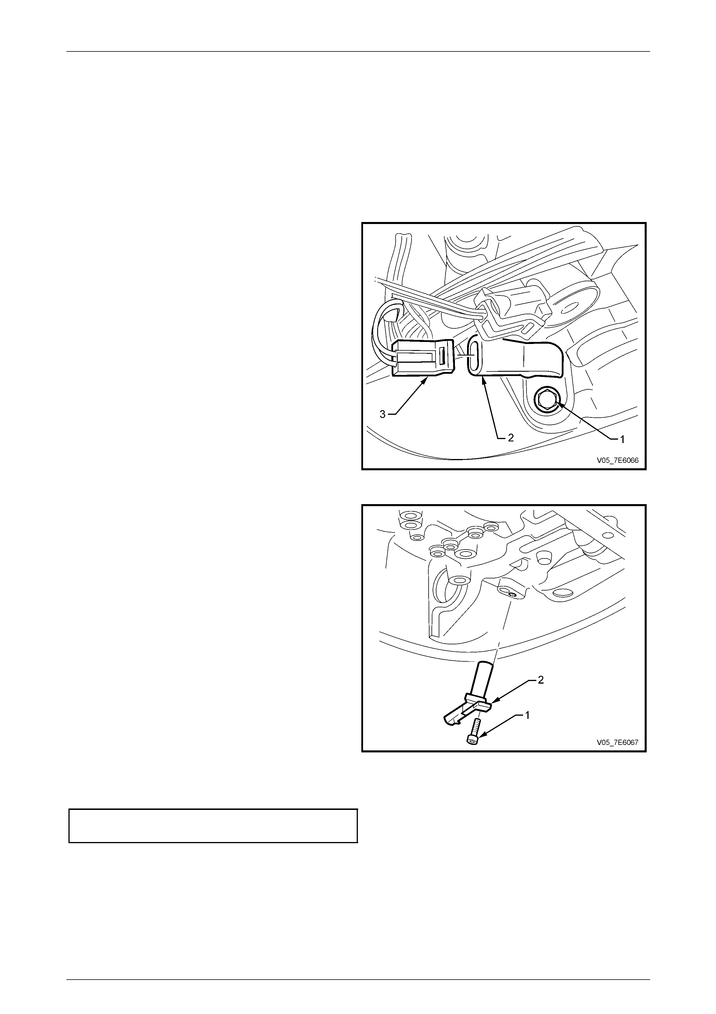
Automatic Transmission – 5L40-E – On-Vehicle Servicing 7E4 – 50
7E4 – 50
3.13 Output Speed Sensor
Replace
1 Raise the vehicle and support in a safe manner. Refer to Section 0A General Information for the location of
recommended lifting and support points.
2 Remove the transmission fluid pan and fluid filter. Refer to 3.1 Fluid Chan ge and Filter Replace, in this Section.
3 Release the wiring harness connector security latch,
the disconnect the connector (3) from the output
speed sensor (2).
4 Using a 10 mm socket and suitable equipment,
remove the output speed sensor retaining screw (1).
Figure 7E4 – 75
5 Remove the output speed sensor (2) from the
transmission case.
6 Inspect the output spee d sensor for the following:
a A damaged or missing magnet.
b Damaged housing.
c Bent or missing electrical terminals.
d Metal contamination adhered to the magnet.
Figure 7E4 – 76
7 After reinstalling the output speed se nsor, install the retaining screw and tighten to the correct torque specification.
Output speed sensor retaining
screw torque specification....................................11 N.m
8 Reinstall the e lectrical connector to the output speed sensor ensuring that the security latch is fully installed.
9 Install the fluid filter and the fluid pan to the transmission, reusing the original pa n gasket seal, if undamaged. Refer
to 3.1 Fluid Change and Filter Replace, in this Section.
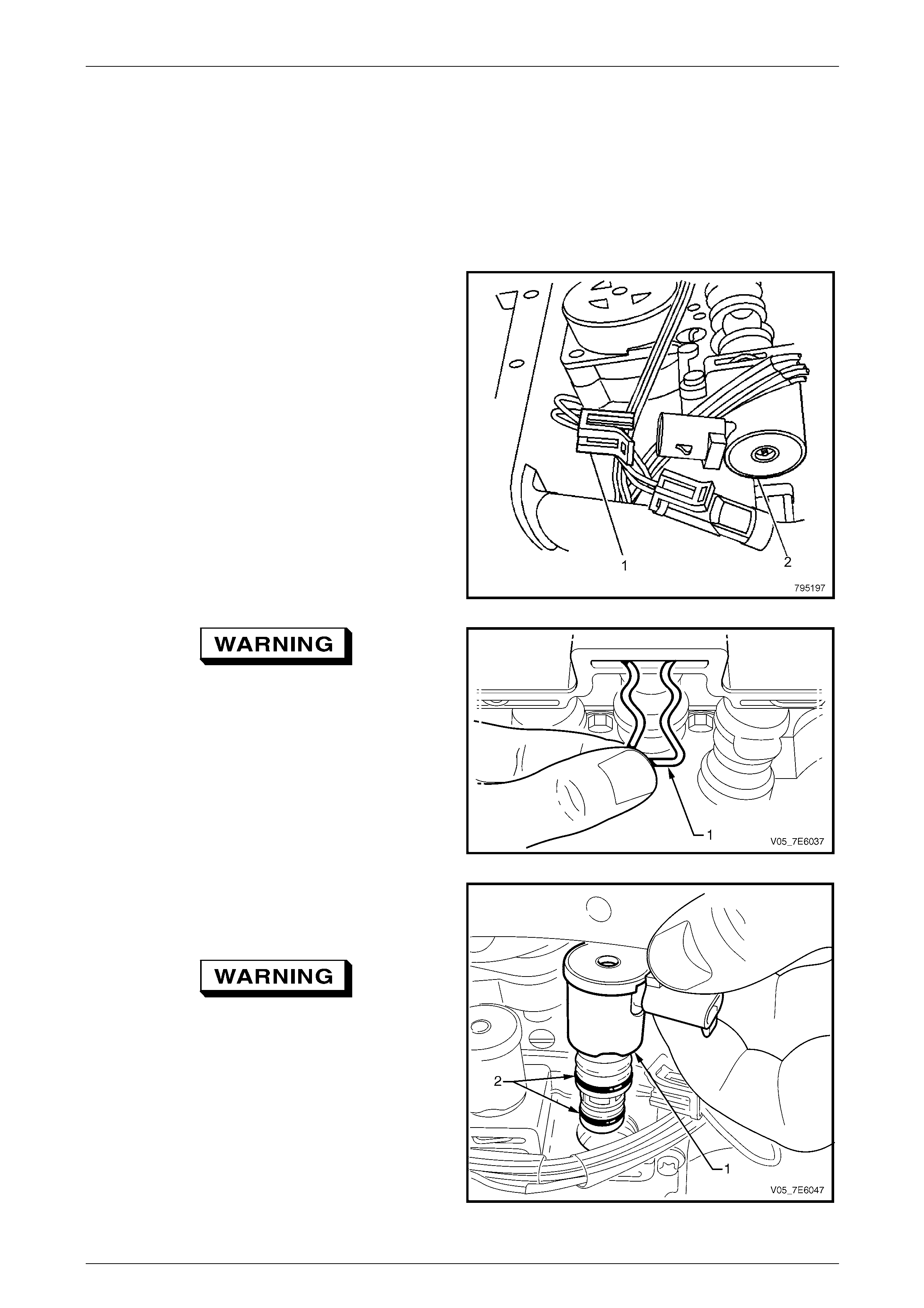
Automatic Transmission – 5L40-E – On-Vehicle Servicing 7E4 – 51
7E4 – 51
3.14 1-2 Shift Solenoid
Replace
1 Raise the vehicle and support in a safe manner. Refer to Section 0A General Information for the location of
recommended lifting and support points.
2 Remove the transmission fluid pan and fluid filter. Refer to 3.1 Fluid Chan ge and Filter Replace, in this Section.
3 Release the wiring harness connector security latch,
then disconnect the connector (1) from the 1-2 shift
solenoid (2).
Figure 7E4 – 77
Wear eye protection to prevent potential
injury.
4 Using a small bladed screwdriver or a hooked piece of
wire, remove the 1-2 shift solenoid retainer (1) from
the control valve body.
5 Twist and pull on the 1-2 solenoid to remove it from
the control valve body.
Figure 7E4 – 78
6 Remove the 1- 2 shift solenoid (1) from the control
valve body.
Reinstallation of the 1-2 shift solenoid is the reverse to
removal, taking note of the following items:
Wear eye protection to prevent potential
injury.
7 After installing the 1-2 shift solenoid into the control
valve body, install the retainer, to secure.
8 After installing the electrical connector, check that the
connector security latch is secure.
9 Reinstall the fluid filter and fluid pan.
Refer to 3.1 Fluid Change and F ilter Replace, in this
Section.
Figure 7E4 – 79
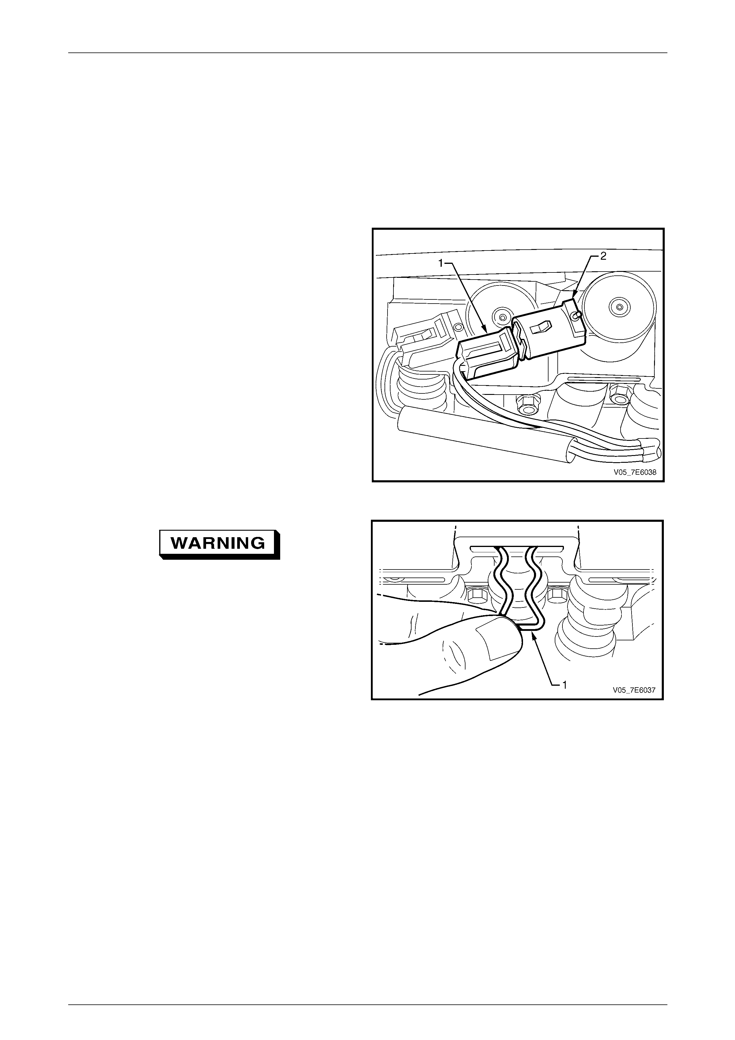
Automatic Transmission – 5L40-E – On-Vehicle Servicing 7E4 – 52
7E4 – 52
3.15 2-3 Shift Solenoid
Replace
1 Raise the vehicle and support in a safe manner. Refer to Section 0A General Information for the location of
recommended lifting and support points.
2 Remove the transmission fluid pan and fluid filter. Refer to 3.1 Fluid Chan ge and Filter Replace, in this Section.
3 Release the wiring harness connector security latch,
the disconnect the connector (1) from the 2-3 shift
solenoid (2).
Figure 7E4 – 80
Wear eye protection to prevent potential
injury.
4 Using a small bladed screwdriver or a hooked piece of
wire, remove the 2-3 shift solenoid retainer (1) from
the control valve body.
5 Twist and pull on the 2-3 solenoid to remove it from
the control valve body.
Figure 7E4 – 81
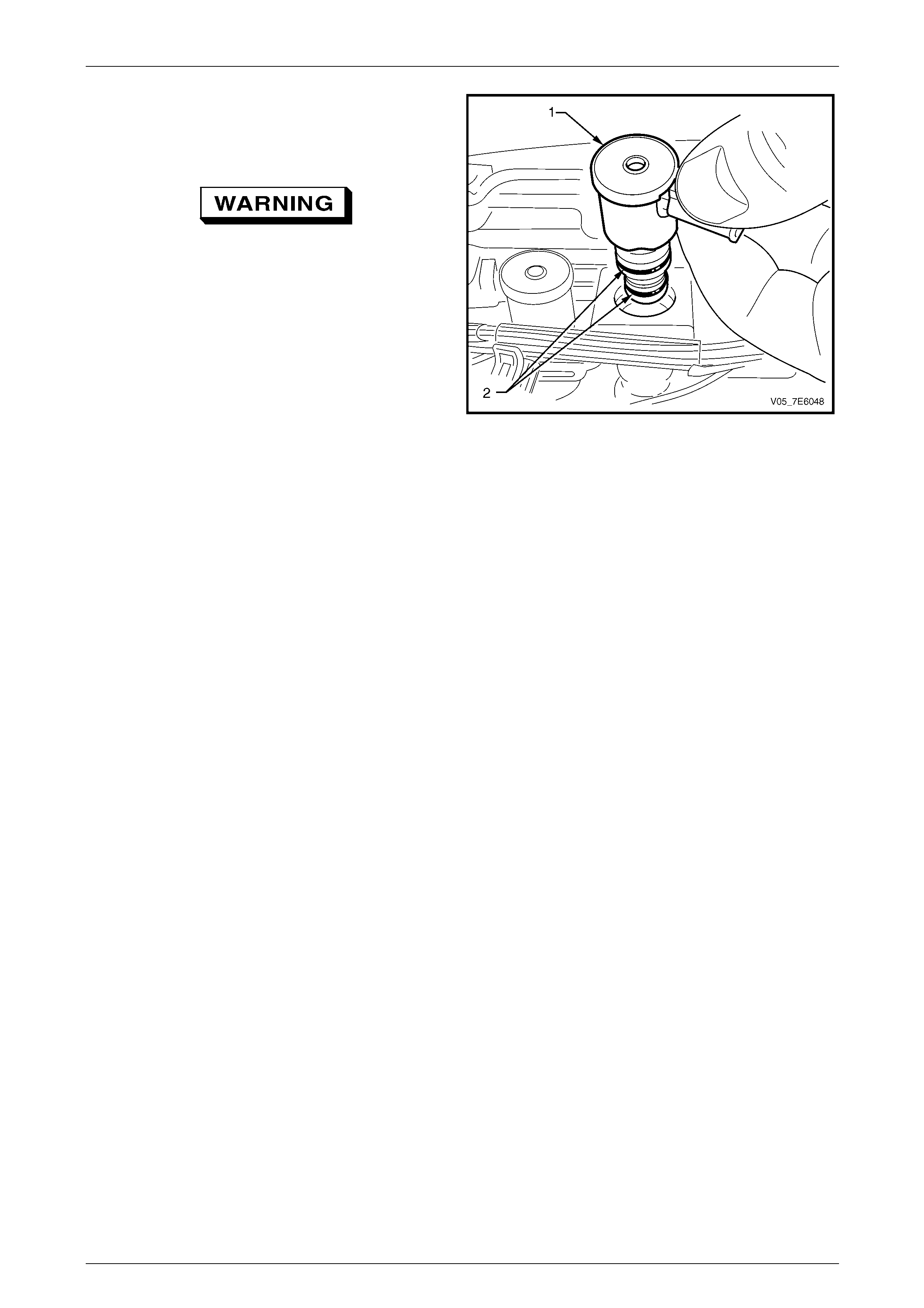
Automatic Transmission – 5L40-E – On-Vehicle Servicing 7E4 – 53
7E4 – 53
6 Remove the 2- 3 shift solenoid (1) from the control
valve body.
Reinstallation of the 2-3 shift solenoid is the reverse to
removal, taking note of the following items:
Wear eye protection to prevent potential
injury.
7 Reinstall the 2-3 shift solenoid into the control valve
body, then install the retainer, to secure.
8 Reinstall the e lectrical connector and check that the
connector security latch is secure.
9 Reinstall the fluid filter and fluid pan.
Refer to 3.1 Fluid Change and F ilter Replace, in this
Section.
Figure 7E4 – 82
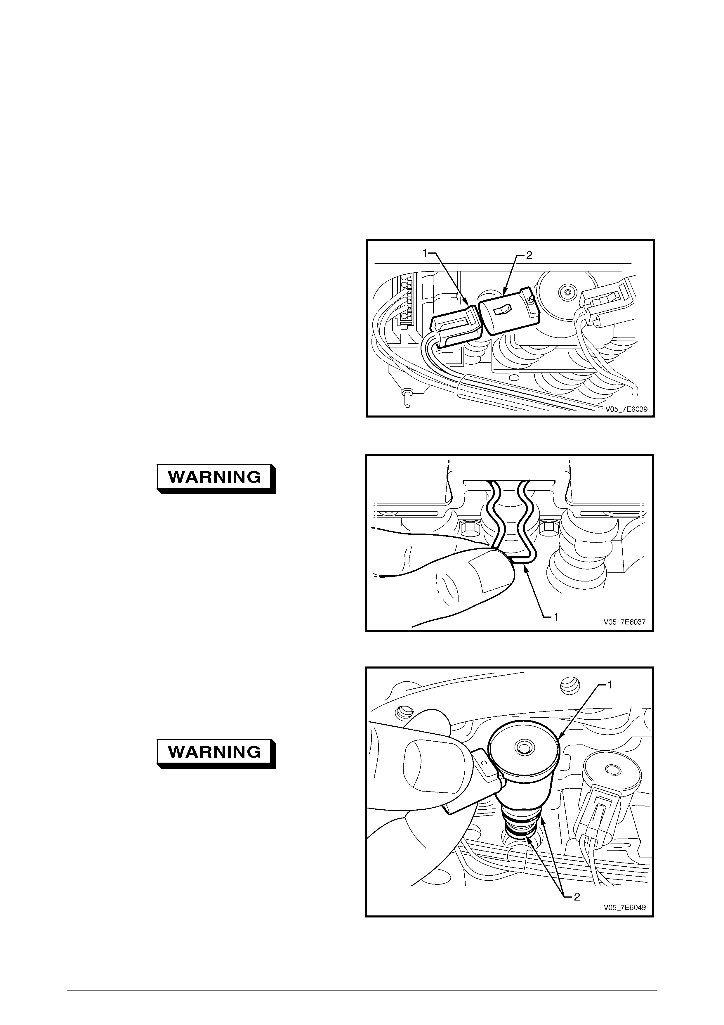
Automatic Transmission – 5L40-E – On-Vehicle Servicing 7E4 – 54
7E4 – 54
3.16 4-5 Shift Solenoid
Replace
1 Raise the vehicle and support in a safe manner. Refer to Section 0A General Information for the location of
recommended lifting and support points.
2 Remove the transmission fluid pan and fluid filter. Refer to 3.1 Fluid Chan ge and Filter Replace, in this Section.
3 Release the wiring harness connector security latch,
the disconnect the connector (1) from the 4-5 shift
solenoid (2).
Figure 7E4 – 83
Wear eye protection to prevent potential
injury.
4 Using a small bladed screwdriver or a hooked piece of
wire, remove the 4-5 shift solenoid retainer (1) from
the control valve body.
5 Twist and pull on the 4-5 solenoid to remove it from
the control valve body.
Figure 7E4 – 84
6 Remove the 2- 3 shift solenoid (1) from the control
valve body.
Reinstallation of the 4-5 shift solenoid is the reverse to
removal, taking note of the following items:
Wear eye protection to prevent potential
injury.
7 After installing the 2-3 shift solenoid into the control
valve body, install the retainer, to secure.
8 After installing the electrical connector, check that the
connector security latch is secure.
9 Reinstall the fluid filter and fluid pan.
Refer to 3.1 Fluid Change and F ilter Replace, in this
Section.
Figure 7E4 – 85
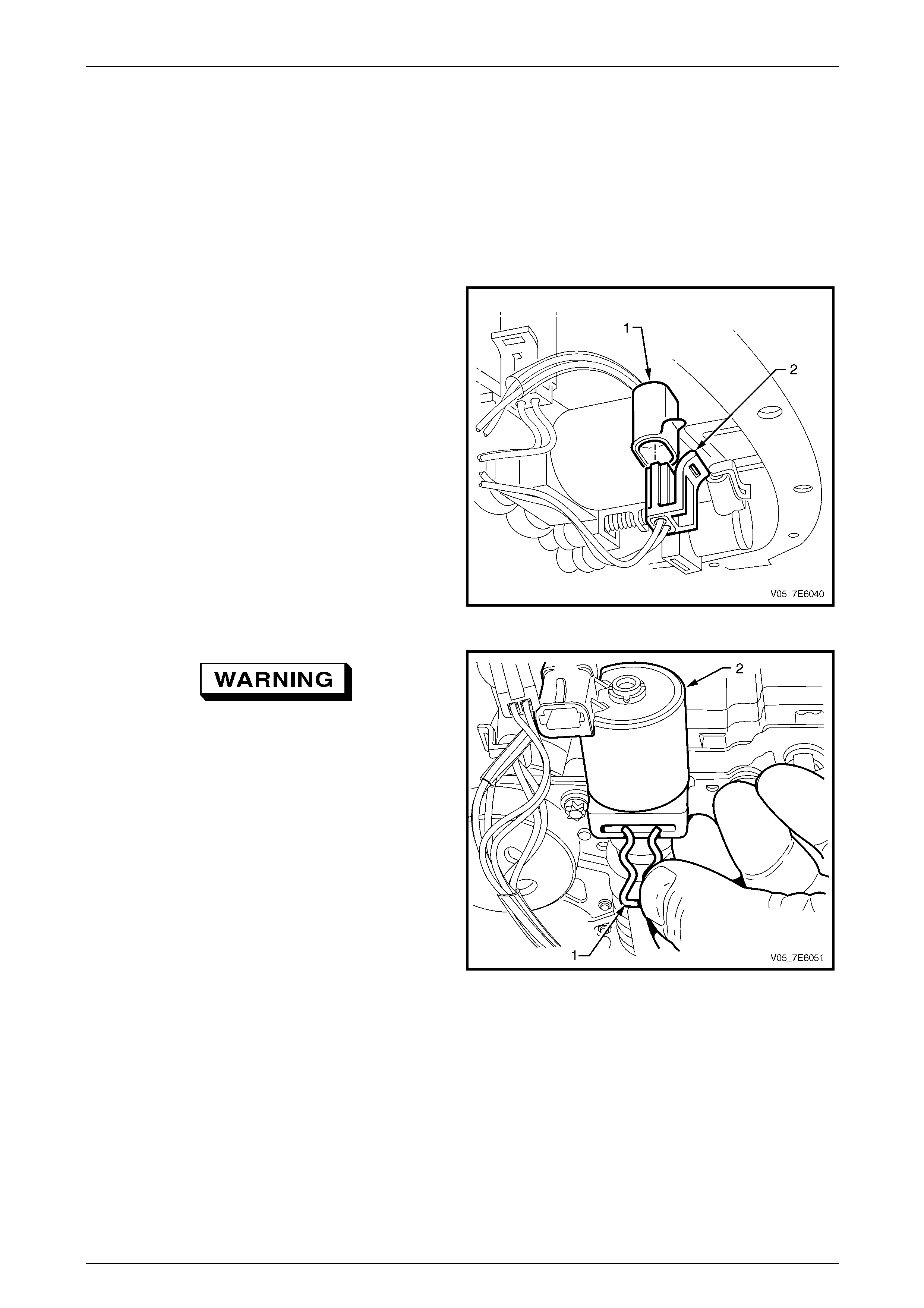
Automatic Transmission – 5L40-E – On-Vehicle Servicing 7E4 – 55
7E4 – 55
3.17 Pressure Control Solenoid
Replace
1 Raise the vehicle and support in a safe manner. Refer to Section 0A General Information for the location of
recommended lifting and support points.
2 Remove the transmission fluid pan and fluid filter. Refer to 3.1 Fluid Chan ge and Filter Replace, in this Section.
3 Release the wiring harness connector security latch,
the disconnect the connector (2) from the pressure
control solenoid (PCS) (1).
Figure 7E4 – 86
Wear eye protection to prevent potential
injury.
4 Using a small bladed screwdriver or a hooked piece of
wire, remove the pressure control solenoid retainer (1)
from the control valve body.
Figure 7E4 – 87
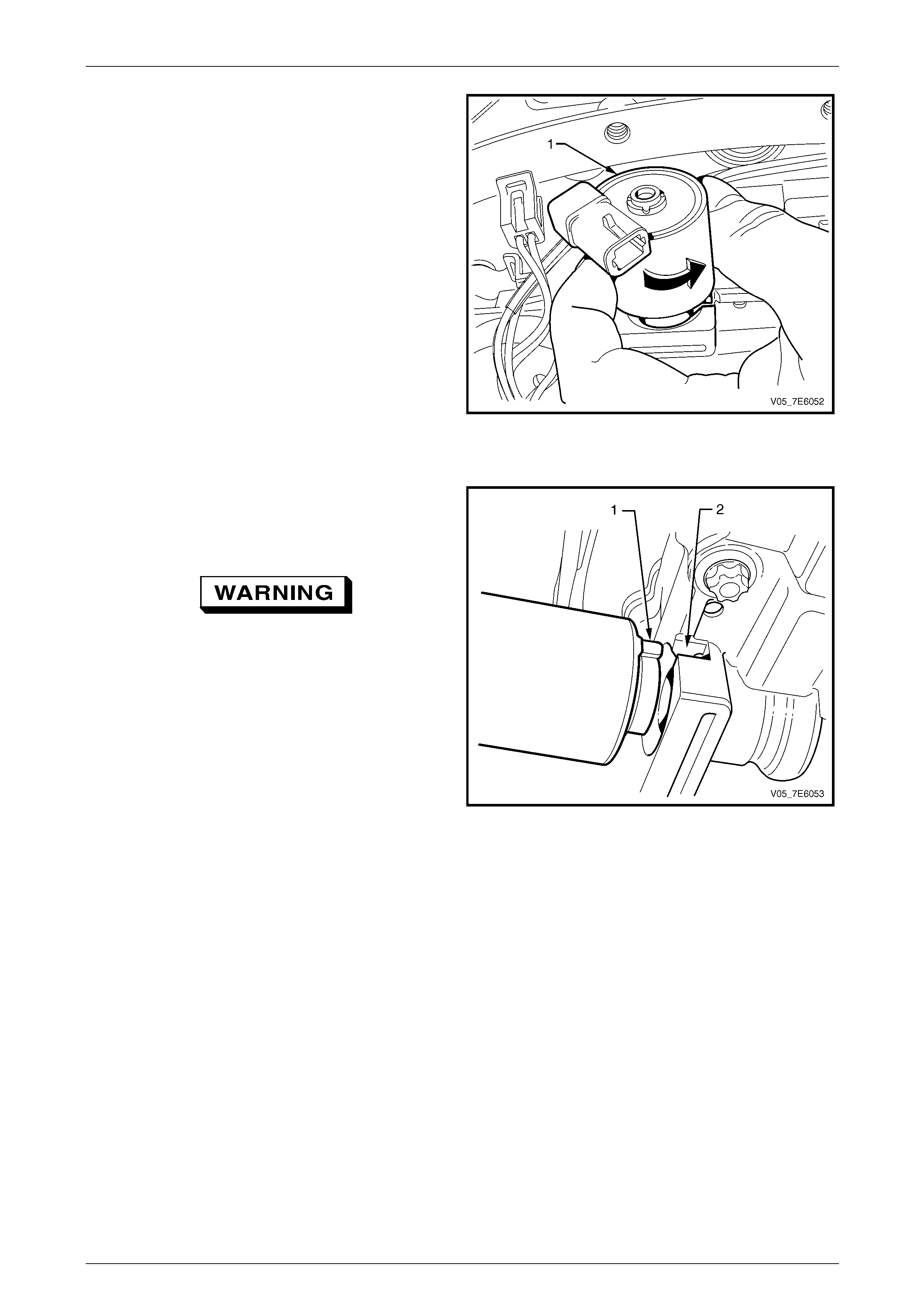
Automatic Transmission – 5L40-E – On-Vehicle Servicing 7E4 – 56
7E4 – 56
5 Twist the pressure control soleno id (1) through 90° to
provide enough clearance, then pull to remove it from
the control valve body.
Figure 7E4 – 88
Reinstallation of the pressur e control solenoid is the reverse to removal, taking note of the following items:
6 Reinstall the pressure control solenoid to the control
valve body, then rotate the solenoid until the tang (1)
on the solenoid body aligns with the slot (2) in the
control valve body, as shown.
Wear eye protection to prevent potential
injury.
7 Install the retainer to secure t he solenoid.
8 After installing the electrical connector, check that the
connector security latch is secure.
9 Reinstall the fluid filter and fluid pan.
Refer to 3.1 Fluid Change and F ilter Replace, in this
Section.
Figure 7E4 – 89
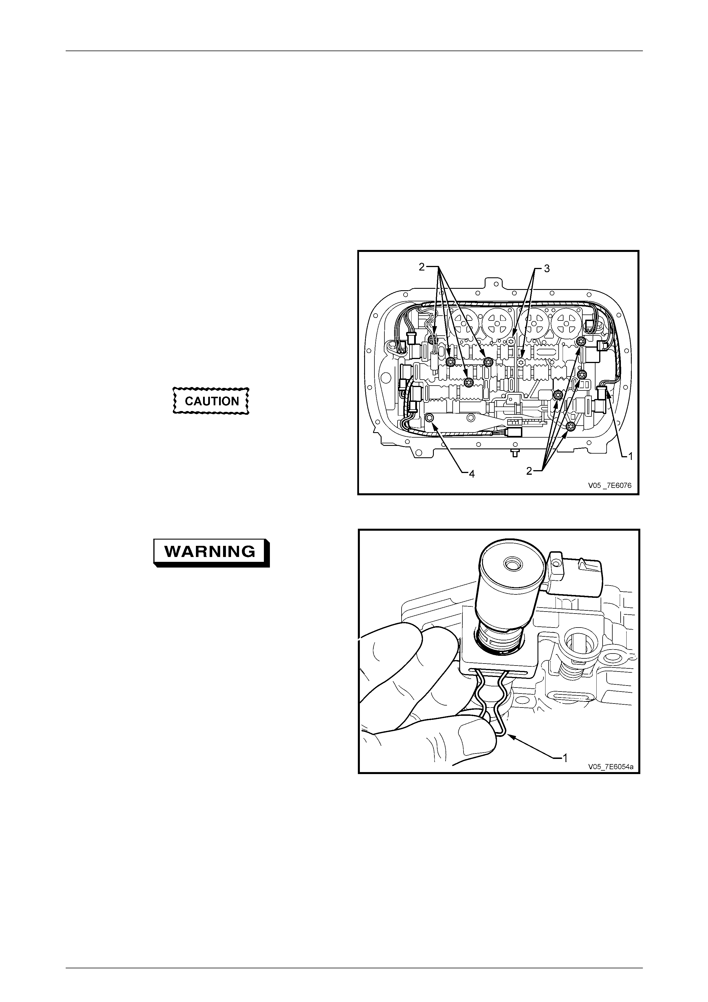
Automatic Transmission – 5L40-E – On-Vehicle Servicing 7E4 – 57
7E4 – 57
3.18 Torque Converter Clutch (TCC) PWM
Solenoid
Replace
1 Raise the vehicle and support in a safe manner. Refer to Section 0A General Information for the location of
recommended lifting and support points.
2 Remove the transmission fluid pan and fluid filter. Refer to 3.1 Fluid Chan ge and Filter Replace, in this Section.
3 Release the wiring harness connector security latch,
the disconnect the connector (1) from the torque
converter clutch PWM solenoid.
NOTE
There is insufficient clearance to remove the
TCC PWM solenoid with the control valve body
fully installed. Compl ete removal however, is not
necessary.
DO NOT loosen the two TX-30 Torx screws
(3).
4 Loosen the eight, E8 Torx headed control valve body
bolts (2).
5 Loosen the one detent spring retaining bolt (4).
Figure 7E4 – 90
• Hold the solenoid in place while the
retaining clip is removed, as the spring
loaded TCC Regulator Valve will cause
the solenoid to be ejected from the
control valve body accumulator
assembly.
• Wear eye protection to prevent potential
injury.
6 Using a small bladed screwdriver or a hooked piece of
wire, remove the pressure control solenoid retainer (1)
from the control valve body.
7 Release the sp ring pressure.
Figure 7E4 – 91
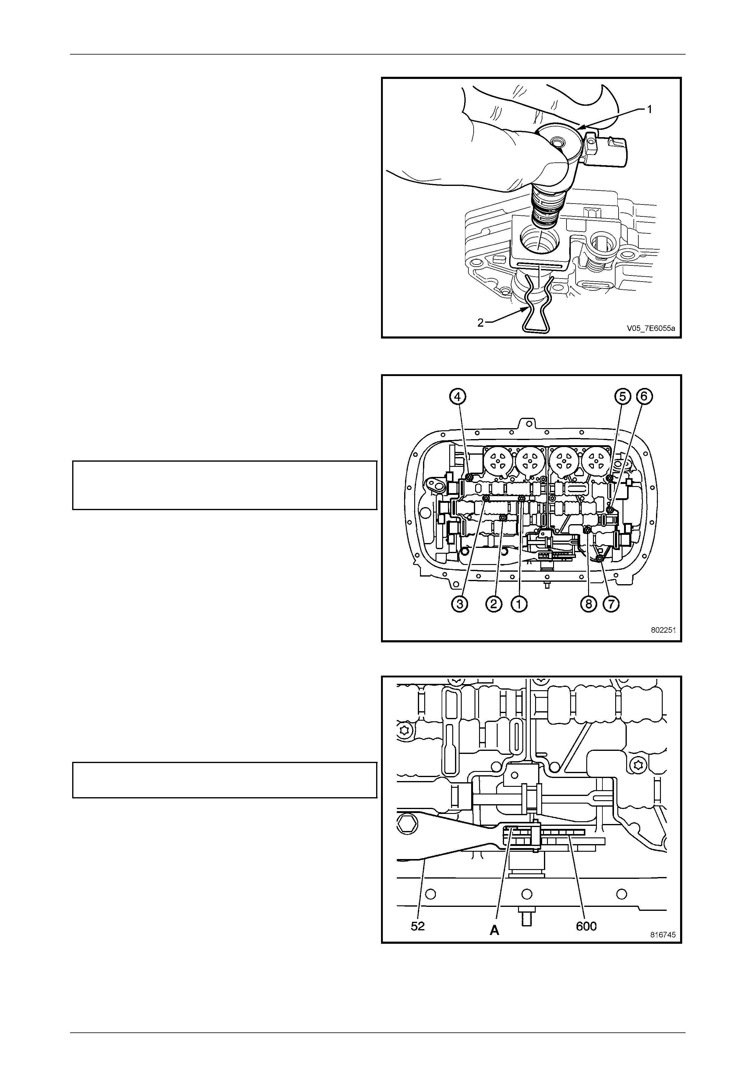
Automatic Transmission – 5L40-E – On-Vehicle Servicing 7E4 – 58
7E4 – 58
8 If necessary, loosen the c ontrol valve body bolts,
lowering the valve body until sufficient clearance is
gained to allow solen oid removal.
9 Remove the TCC PW M solenoid from the control
valve body assembly.
Reinstallation of the TCC PWM solenoid is the reverse to
removal, taking note of the following items:
10 Reinstall the TCC PWM solenoid to the Control Valve
Body Accumulator assembly then, while holding the
solenoid in against spring force, reinstall the retainer to
secure the solenoid (see Figur e 7E4 – 120).
11 Reinstall the wiring harness connector to the TCC
PWM solenoid then check that the connector security
latch is secure.
Figure 7E4 – 92
12 Gradually tighten the eight control valve body bolts but
do not fully tighten, out of sequence.
13 Finally tighten the eight control valve body and
accumulator to case bolts in the correct sequence as
shown and to the correct torque specificatio n.
Control valve body assembly
to transmission case bolt
torque specification..............................................11 N.m
Figure 7E7 – 93
14 Install an 0.8 mm spacer ('A') (e.g. feeler gauges)
between the manual shaft detent lever (600) and the
manual shaft detent spring (52).
15 Tighten the loosened detent spring retaining bolt to the
correct torque specification.
Manual shaft detent spring
bolt torque specification.......................................11 N.m
16 Remove the spacer.
17 Reinstall the fluid filter and fluid pan.
Refer to 3.1 Fluid Change and F ilter Replace, in this
Section.
Figure 7E4 – 94
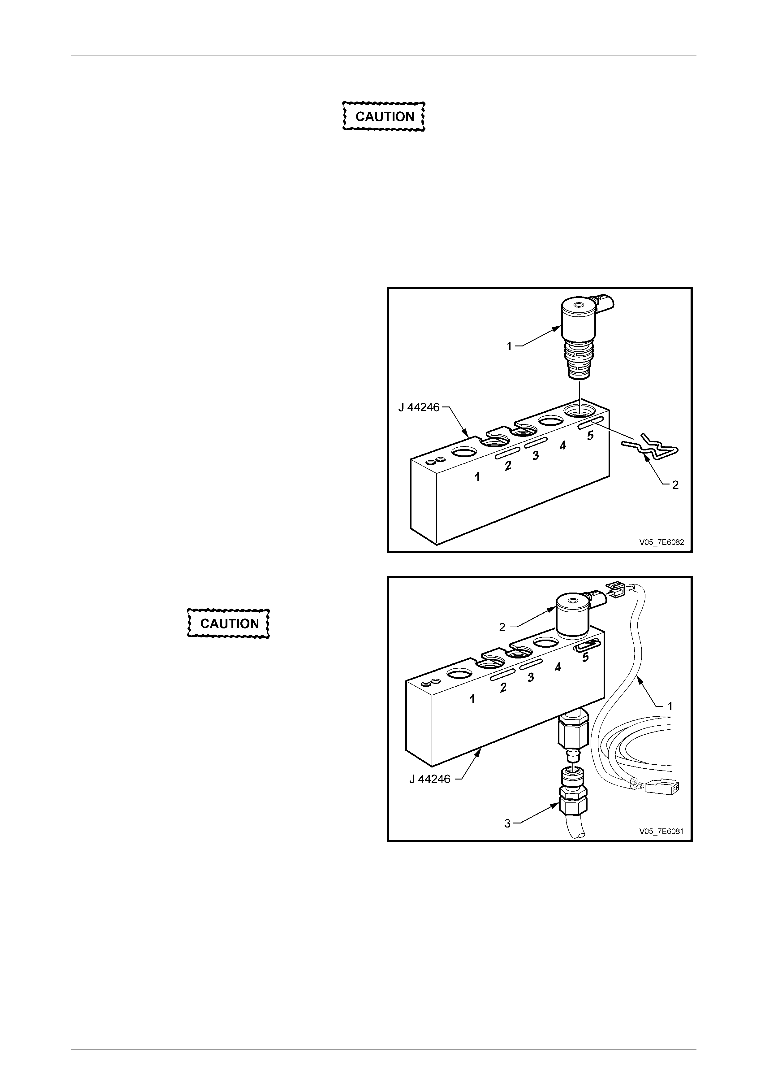
Automatic Transmission – 5L40-E – On-Vehicle Servicing 7E4 – 59
7E4 – 59
3.19 Solenoid Leak Testing
• This procedure only tests ON/OFF
solenoids such as the 1–2, 2–3 and 4–5
shift solenoid valves.
• Visually inspect the physical condition of
the solenoid valve before testing. Also
check the O-rings before and after testing
to ensure that they are not cut or
damaged.
1 Remove the shift solenoid valve from the control valve body. Refer to 3.14 1-2 Shift Solenoid,
3.15 2-3 Shift Solenoid, or 3.16 4-5 Shift Solenoi d, in this Section.
2 Install the shift solenoid valve (1) to be tested, into
bore number 5 of Tool J 44246 T est Block. Secure
with the original retaining clip ( 2).
Figure 7E4 – 95
3 Connect the solen oid test harness (1) supplied with
the J 44246 Solenoid Testing Kit to the solenoid (2).
Do not use air pressure exceeding 800 kPa.
Excessive pressure will not allow the
solenoid ball check valve to seat properly.
Recommended air pressu re is 350 kPa.
4 Apply compressed air (3) to the test kit block, as
shown.
5 Connect the test harness to the 12 vo lt battery
terminals.
6 Check that the solenoid is operating electrically by
listening for an audible clicking noise as the test
harness makes and breaks voltage contact.
NOTE
• All solenoids need to be ener gised to seal.
• A small amount of air leakage is normal
(± 21 kPa). Figure 7E4 – 96
7 Observe the air flow through the solenoid. The flow will either completely or nearly stop, when the sole noid is
energised. Replace any sol en oid where an obvious air leak is observed when the solenoid is energ ised.
NOTE
Inspect the O-rings after testing to ensure that
they are not cut or damaged.
8 Reinstall the solenoid valve to the control valve body. Ref er to 3.14 1-2 Shift Solenoid, 3.15 2-3 Shift Solenoid, or
3.16 4-5 Shift Solenoid, in this Section.

Automatic Transmission – 5L40-E – On-Vehicle Servicing 7E4 – 60
7E4 – 60
3.20 Control Valve Body and Accumulator
Assembly
The control valve body a nd accumulator assembly is not serviced. Therefore, if replacement is required, the complete
transmission must be changed. Refer to 3.22 5L40-E Automatic Transmission, in this Section.
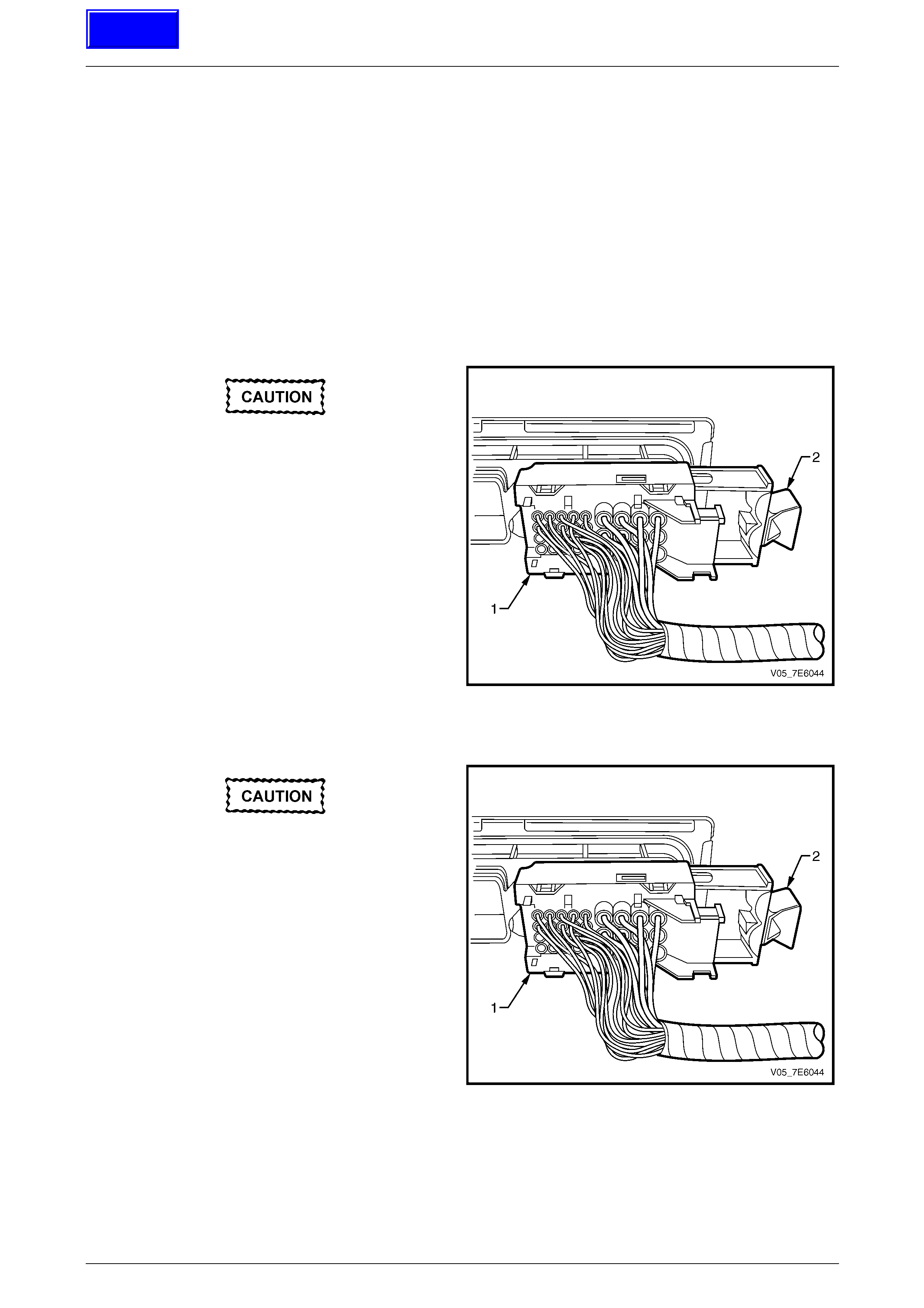
Automatic Transmission – 5L40-E – On-Vehicle Servicing 7E4 – 61
7E4 – 61
3.21 Transmission Control Module (TCM)
LT Section No. – 04-999
Remove
1 Ignition OFF.
2 Remove left hand front hin ge pillar trim assembly. Refer to 2.8 Hinge Pillar Trim Assembly, Remove, in
Section 1A8 Headlining & Interior Trim.
3 Prise the TCM free from the holder plastic cli ps. F inger tip pressure is only required.
4 Push the TCM up ward, then pull outward and down at the lower edge, freeing the wiring harness and connector
from the holder.
Twisting or tilting the transmission control
module electrical connector while
disconnecting, may result in bent or
misaligned electrical terminal pins.
5 Unlock the transmission control module electrical
connector by pulling the retainer (2) out from the
electrical connector (1).
6 Carefully pull the electrical connector (1) straight out,
from the TCM.
Figure 7E4 – 97
Reinstall
Twisting or tilting the transmission control
module electrical connector while
disconnecting, may result in bent or
misaligned electrical terminal pins.
1 Carefully connect the transmission control module
electrical connector (1) to the TCM.
2 Lock the transmission control module electrical
connector securely to the TCM by pushing the retainer
(2) into the electrical connector (1) until ful ly seated.
3 Reinstall the TCM to the mounting bracket, in the
reverse to removal, ensuring that the T CM holding
clips are all engaged.
NOTE
If the TCM is difficult to secure in the holding
clips, check that the wiring harness is not fouli ng
the TCM connector on the inside of the mountin g
bracket.
Figure 7E4 – 98
4 Reinstall the l eft hand front hinge pillar trim assembly. Refer to 2.8 Hinge Pillar trim Assembly, Reinstall, in
Section 1A8 Headlining & Interior Trim..
5 The transmission control module must be programmed with the correct software/calibration.
Refer to TCM Programming Procedure, in this Section.
Techline

Automatic Transmission – 5L40-E – On-Vehicle Servicing 7E4 – 62
7E4 – 62
TCM Programming Procedure
1 The transmission contro l module (TCM) must be programmed with the correct software/calibration. Ensure that the
following conditions exist bef ore starting the TCM programming procedur e:
a The battery is fully charged.
b The TE CH 2 cable connection at the data link connector (DLC) is secure.
c The ignition switch is in the ON position.
2 Program the TCM usin g the latest software for the vehicle. Refer to the current release of TIS for the latest software
and Section 0C Tech 2 for user instructions.
3 If the TCM fails to program, procee d as follows:
a Ensure that the TCM connection is OK.
b Check that TECH 2 is programmed with the latest software version.
c Attempt to re-program the TCM. If the TCM still cannot be programmed properly, replace the TCM.
Automatic Transmission – 5L40-E – On-Vehicle Servicing 7E4 – 63
7E4 – 63
3.22 5L40-E Automatic Transmission
ATTENTION
The following fasteners MUST be replaced when performin g these operations:
Torque converter to flexplate attaching bolts.
Front propeller shaft fasteners, as noted in th e text.
LT Section No. – 04-200
Remove
A number of different methods of attaching
the front coupling to the transmission output
flange can be noted:
• Hexagon headed bolts into threaded
flange holes. With this method, the output
flange threads are of the 'Spiralock' form
that can only be loosened/tightened a
maximum of ten times. Because of the
safety factor involved, if the complete
vehicle service history is not known, then
both the flange and the bolts MUST be
replaced on reassembly.
• Studs installed into the transmission
output flange facing rearward, with the
flange being secured by nuts.
• Hexagon headed bolts and nuts. Figure
7E4–116 shows this method.
NOTE
Disconnection of the battery affects certain
vehicle electronic systems. Refer to
Section 00 Cautions and Notes,
5 Battery Disconnection Procedures before
disconnecting the batter y.
1 Disconnect the negative battery cable.
2 Drain the engin e coolant into a clean container. Depending on the age of the coolant it may be able to be used
again. Refer to Section 6B1 Engine Cooling – V6 Engine for further information.
3 Remove the engine thermostat housing. This is necessary to enable access to the upper transmission to engine
attaching bolts. Refer to Section 6B1 Engine Cooling – V6 Engine.
4 Raise the vehicle and support in a safe manner. Refer to Section 0A General Information in this Service Information
for the location of recommended lifting and supp ort points.
5 Drain the transmission fluid. Refer to 3.1 Fluid Change and/or F ilter Replace, in this Section.
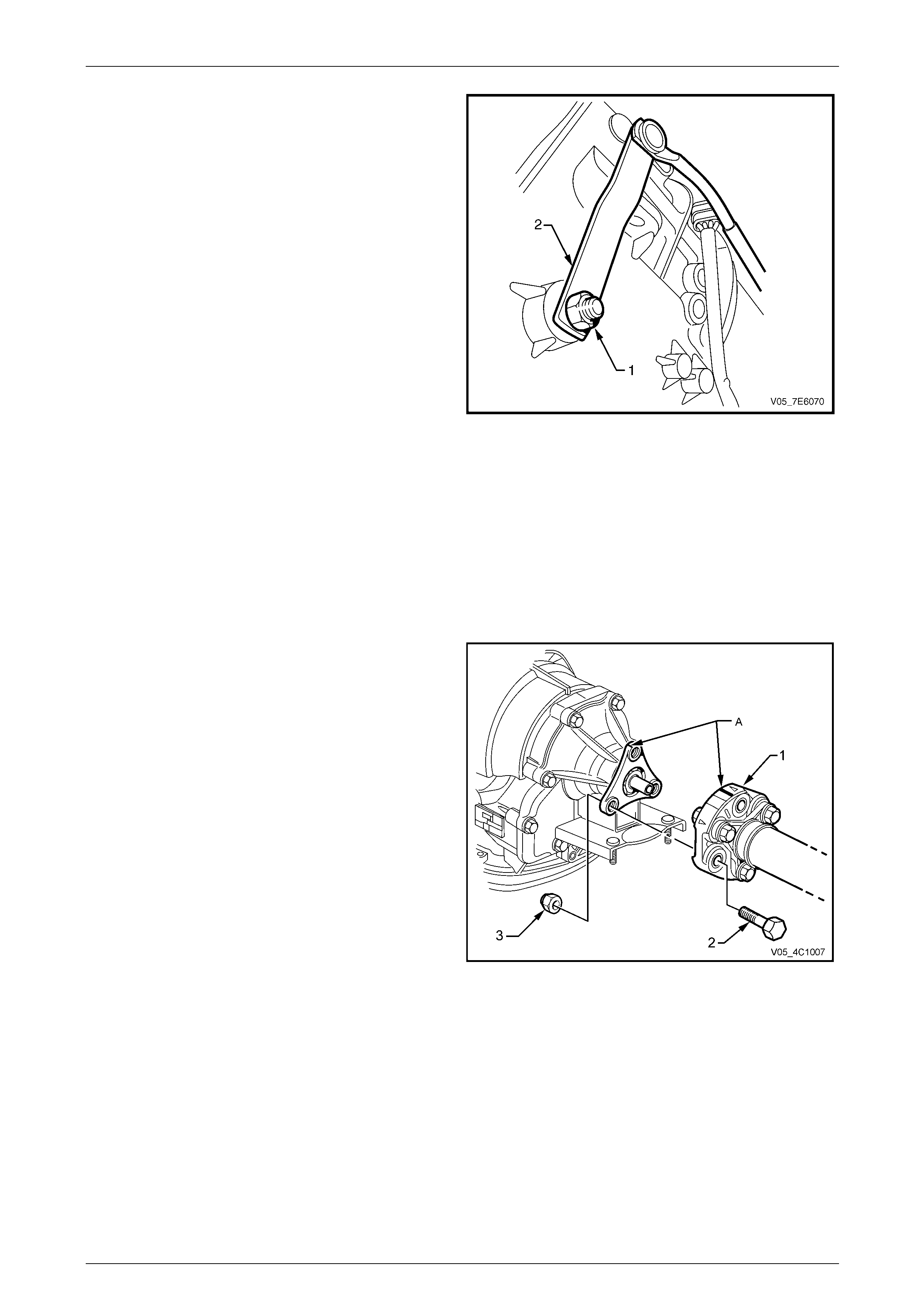
Automatic Transmission – 5L40-E – On-Vehicle Servicing 7E4 – 64
7E4 – 64
6 While holding the transmission manual shaft lever (2)
with an adjustable wrench, loosen then remove the
transmission manual shaft lever retaining nut (1).
7 Disconnect the shift lever from the manual shaft.
8 Place the transm ission in the Neutral range.
Figure 7E4 – 99
9 Remove both exhaust pi pes and catalytic converters, back to the intermediate pipe flanges.
Refer to Section 8B Exhaust System.
NOTE
While this operation is not essential, removal of
the exhaust pipes does provide additional space
around the transmission and will remove the
possibility of accidental damage to the oxygen
sensors.
10 Using a felt tipped pen or similar, mark the relationship
of the front coupling to the transmission output shaft
flange (A).
11 Loosen, then remove the three front propeller shaft
coupling (1) to output flange bolts (2) and nuts (3).
12 Push the front propeller shaft to the rear of the vehicle
to release the front propeller shaft couplin g from the
transmission output shaft spigot.
Figure 7E4 – 100
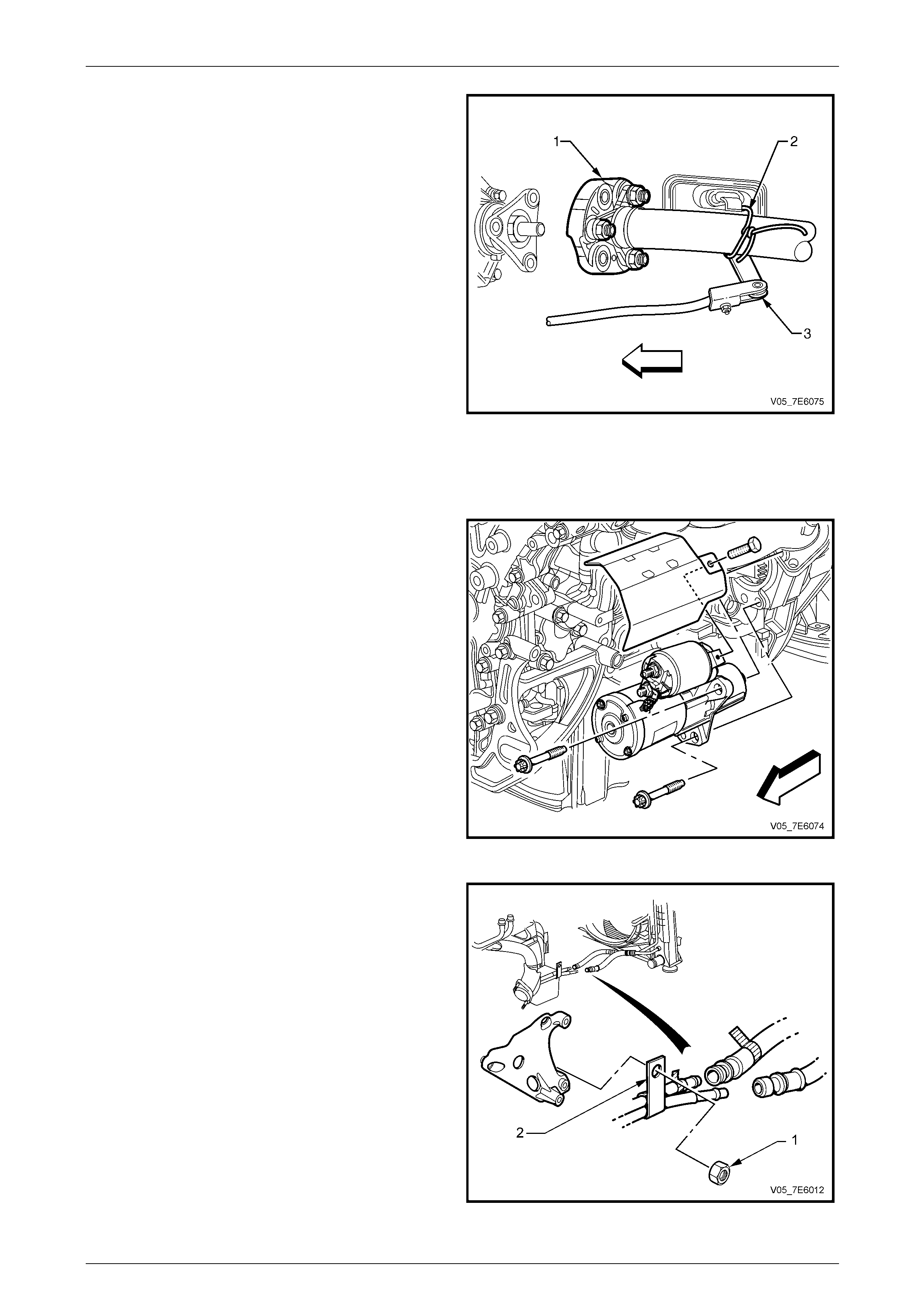
Automatic Transmission – 5L40-E – On-Vehicle Servicing 7E4 – 65
7E4 – 65
13 Use tie wire (2) or similar to support the front prop eller
shaft (1) to a convenient underbody point.
Figure 7E4 – 101
14 As access to the transmission wiring harness cable ties around the transmission is restricted, it is recommended
that the transmission wiring harness be disconnected from the transmission control module (TCM) and removed
with the transmission. Refer to 3.21 Transmission Control Module, in this Section.
15 Remove the starter motor.
Refer to Section 6D1-2 Starting System – V6.
16 Mark the torque converter to flexplate orientation to
ensure correct reinstallation al ignment.
17 Rotate the engine harmonic bala ncer in a clockwise
direction ONLY, to align a torque converter bolt with
the starter motor opening.
18 Remove and discard the torqu e converter b ol ts, as
they MUST be replaced on reassembly.
19 Repeat Steps 15 and 16 for the remaini ng two t orque
converter bolts.
Figure 7E4 – 102
20 Place an oil drain pan under the transmission fluid
cooler pipes.
21 Remove the nut (1) securing the transmission cooler
pipe bracket (2) to the alternator mounting bracket
stud.
Figure 7E4 – 103
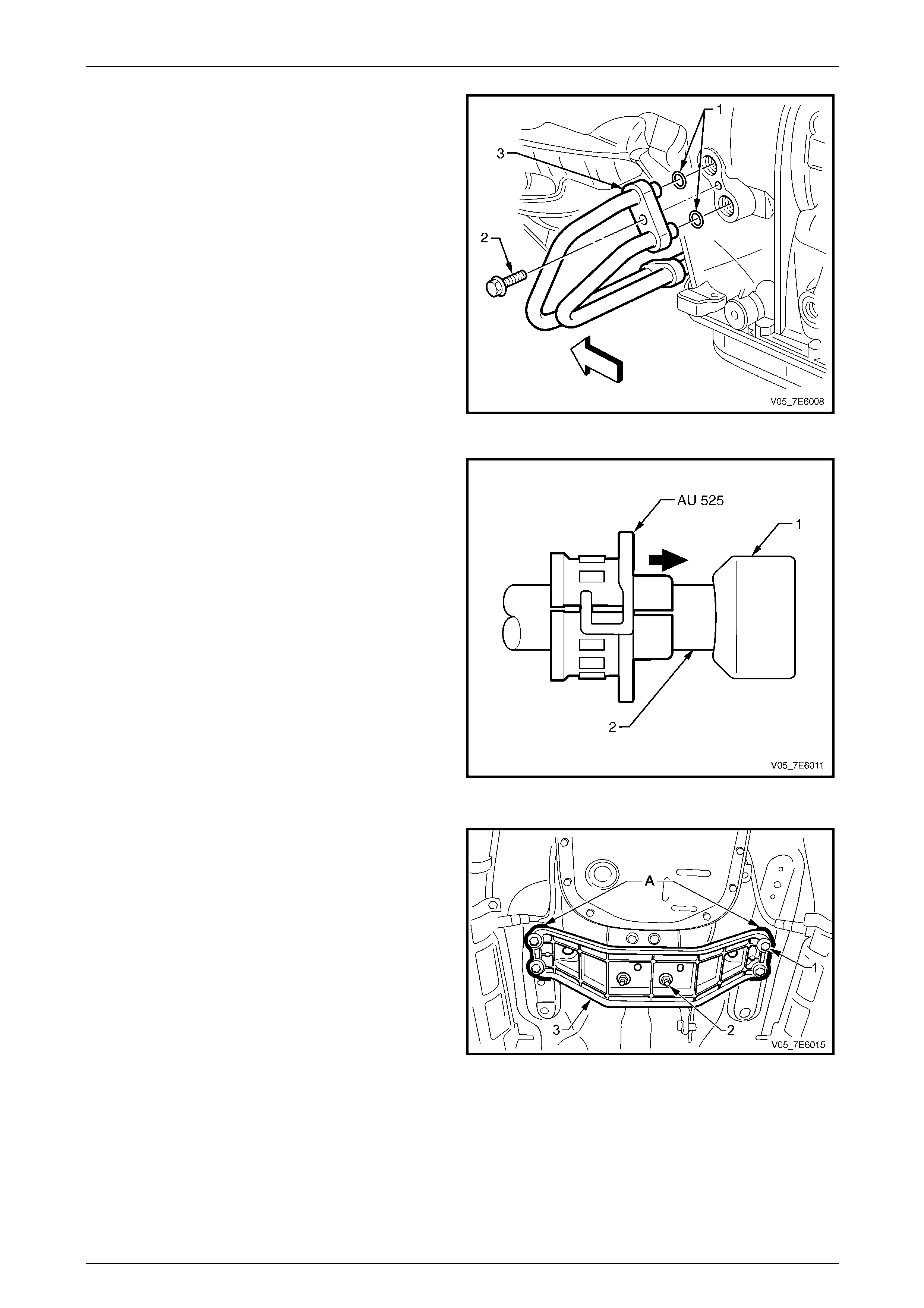
Automatic Transmission – 5L40-E – On-Vehicle Servicing 7E4 – 66
7E4 – 66
22 Remove the bolt (2) securing the transmission fluid
cooler pipes bracket (3) to the transmission case.
23 Remove the transmission fluid cool er pipes from the
transmission.
24 Remove the two O-rings (1) and discard, as they must
be replaced on assembly.
25 Plug all open ends to stop fluid loss and foreign matter
entry.
Figure 7E4 – 104
26 Check that one of the fluid cooler flexible lines has a
white tag attached and that the mating transmission
cooler pipe has a similar tag. If these have been
removed, apply adhesive tap e to one pair of
pipes/lines to ensure correct reassembly.
27 Using disconnect Tool No. AU 525, disc onnect each
fluid cooler flexible line quick connect fitting (1) from
each pipe.
NOTE
The fluid cooler flexible lines are permanently
attached to the radiator fluid cooler pipes.
28 Plug all open ends to prevent fluid loss an d foreign
matter entry.
29 Remove the transmission cooler pipes from the
vehicle.
30 Position a suitable transmission jack under the
transmission fluid pan. Figure 7E4 – 105
31 Mark the relationship of the transmission mount
crossmember to each body side rail (‘A’) with a felt
tipped pen or similar.
NOTE
This is necessary to maintain alignment on
reassembly.
32 Remove the four bolts (1) securing the transmission
mount crossmember to the body side rails.
33 Remove the two nuts (2) securing the transmission
mount to the crossmember.
34 Remove the crossmember from the vehicle. Figure 5A – 106
35 Lower the engine and transmission enough to gain access to the wiring har ness securing clips (1 and 2).
36 Prise the two ‘fir tree’ wiring harness retaining clips (1 and 2) free from their locations.
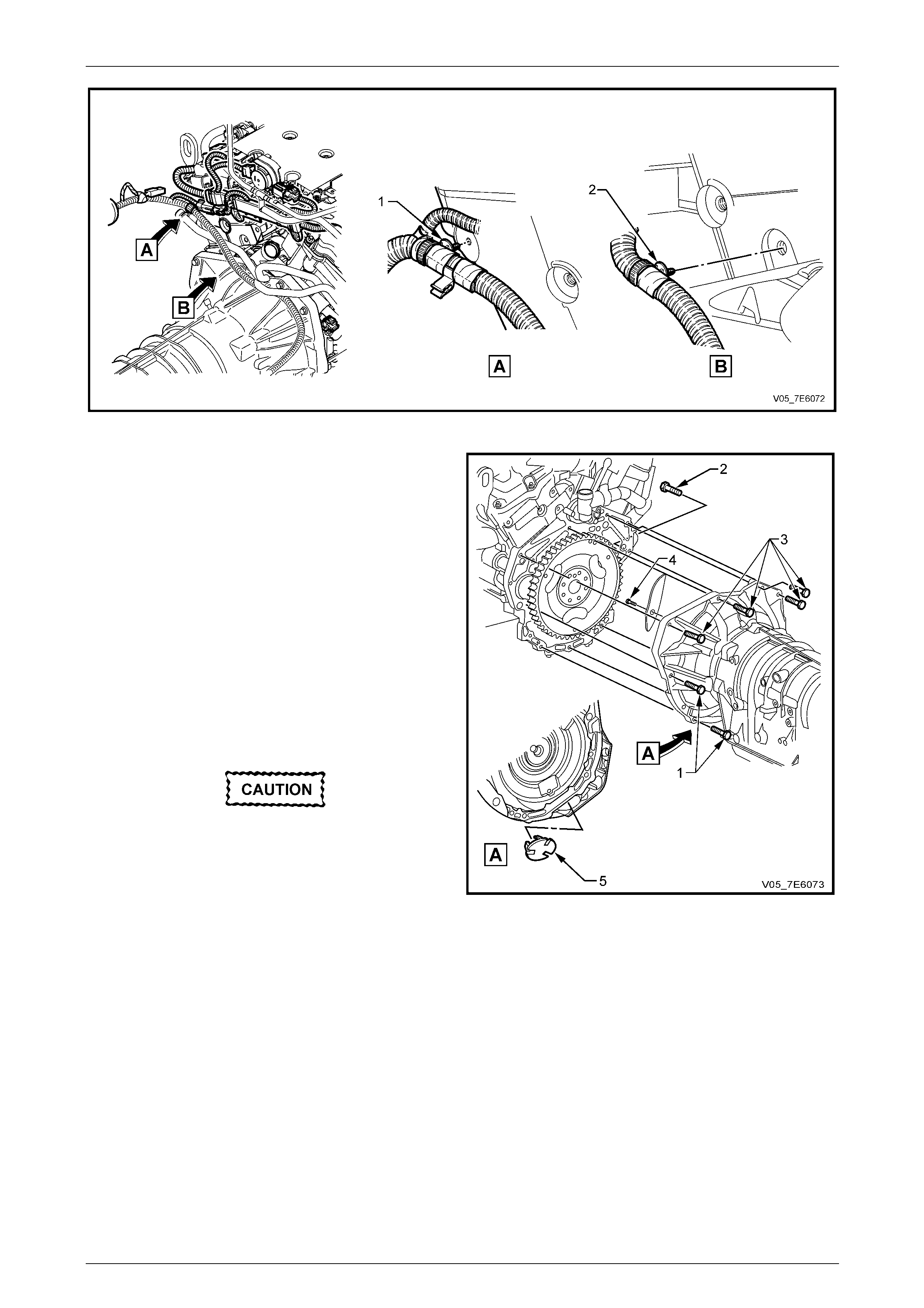
Automatic Transmission – 5L40-E – On-Vehicle Servicing 7E4 – 67
7E4 – 67
Figure 7E4 – 107
37 Remove the close-out cover screw (4), then remove
the cover.
38 Lower the engine and transmi ssion enough to gain
access to the four upper transmission to engine
mounting bolts (3).
39 Remove the four upper transmission to engine
mounting bolts (3).
40 Remove the remaining six l ower transmission to
engine mounting bolts (‘1’ and ‘2’).
NOTE
Three bolts are hidden from view.
41 Pull the transmission rearwards, enough to free the
transmission from the two engine dowels.
Ensure clearance is maintained between the
transmission and the following:
• The catalytic converters and oxygen
sensors [if the exhaust pipes were not
removed (Step 9)].
• Wiring harnesses.
• The propeller shaft.
42 Carefully lower the transmissi on from the vehicle.
Figure 7E4 – 108
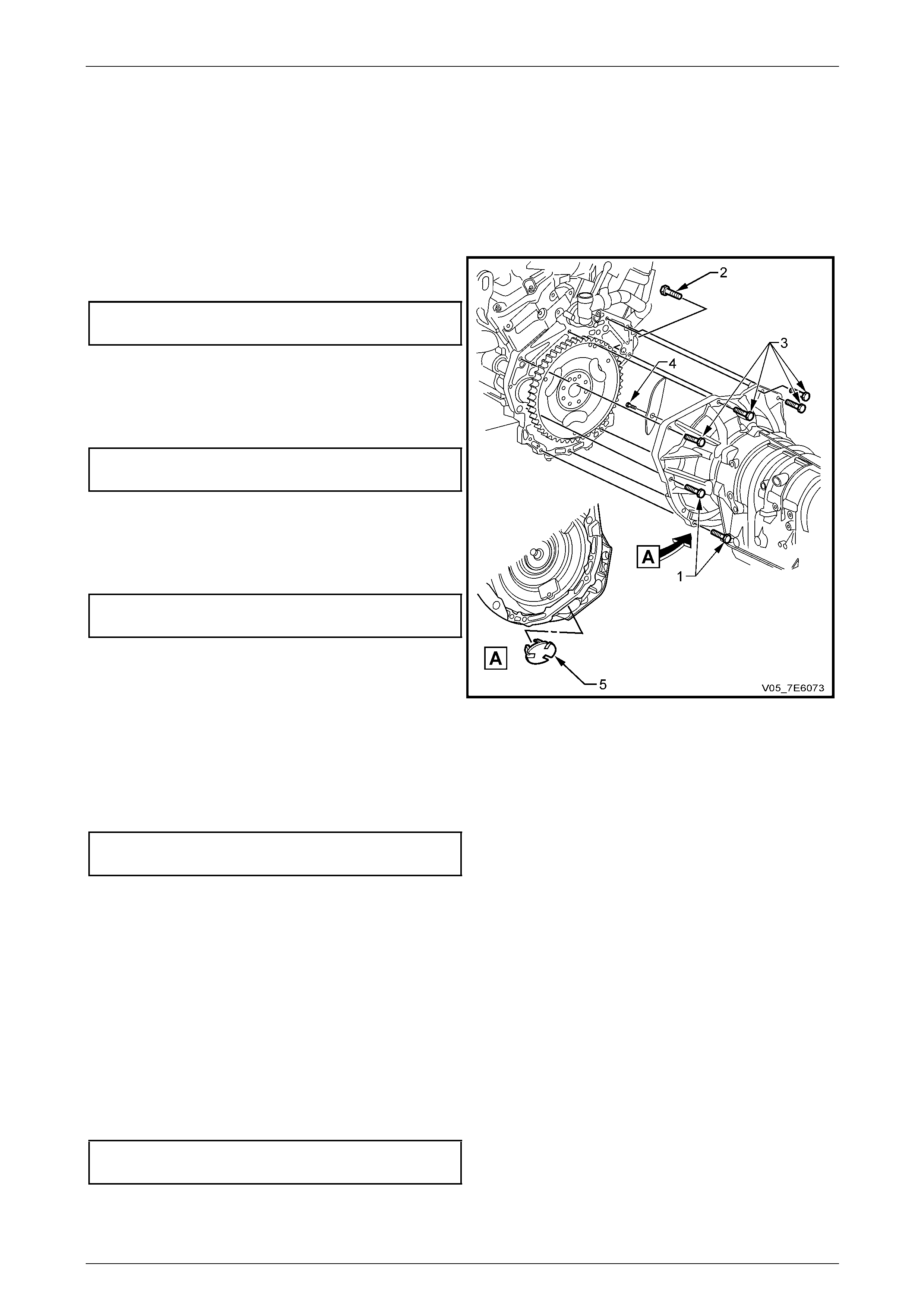
Automatic Transmission – 5L40-E – On-Vehicle Servicing 7E4 – 68
7E4 – 68
Reinstall
The reinstallation process is the reverse to the removal procedure except fort the items detailed here.
1 Lubricate the torque converter spigot with an NLGI No. 2 lithium soap bas ed EP grease with molybdenum
disulphide, such as Shell Reti nax HDX2 grease or BP Energrease LMS-EP 23 (or equivalent).
2 After carefully r einsta lling the transmission, using a transmission jack, align the engine do wels with the
transmission and fully install t o the rear of th e engine.
3 Reinstall the six lower bolts (‘1’ and ‘2’), then tighten to
the correct torque specification.
Transmission to engine
bolt torque specification.......................................60 N.m
4 If necessary lower transmission at the rear to gain
access to the upper transmission to engine fasteners.
5 Reinstall the fo ur upper transmission to engine bolts
(3) and tighten to the correct torque specificat ion.
Transmission to engine
bolt torque specification.......................................60 N.m
6 Reinstall the wiring harness retaining clips.
7 Reinstall the close-out cover and secure with the
retaining screw (4), tightening to the correct torque
specification.
Close-out cover retaining
screw torque specification....................................14 N.m
8 Reinstall the engine thermostat housing and replenish
the engine coolant.
Refer to Section 6B1 Engine Coolin g – V6 Engine.
Figure 7E4 – 109
9 Raise the transmission, then reinstall the rear mount crossmember.
Refer to 3.6 Transmission Mount and Mount Plate, Reinstall, in this Section.
10 Reinstall the transmission flu id cooler pipes and secure with a nut attaching the pipe bracket to the alternator
bracket stud. Tighten the nut to the correct torque specification.
Transmission oil cooler pi pe to alternator
bracket nut torque specification ...........................20 N.m
11 Remove all plugged cooler pipe/hose openings, wipe clean and recon ne c t each of the cooler hose quick connect
fittings to the cooler pipes. Tug on each after installation, to check that engagement is correct.
Refer to 3.4 Transmission Fluid Cooler Pipes/Hoses, Reinstall, in this Section.
12 Install NEW O-rings to the fluid cooler pipes at the transmis sion end, then reinstall them to the transmission.
Refer to 3.4 Transmission Fluid Cooler Pi pes/Hoses, Reinstall, in this Section.
13 Align the torque converter to flexplate orientation marks made before removal of the three attaching bolts.
14 Loosely install a NEW torque converter to flexplate attaching bolt.
15 Rotate the engine harmonic bala ncer attaching bolt in a clockwise direction only, to align the next torque converter
to flexplate attaching bolt hole, then loosely installing a NEW bolt.
16 Repeat Step 9 for the remaining torqu e to fle xplate attaching bolt, then tighten all bolts to the correct torque
specification.
Torque converter to flexplate
attaching bolt torque specification........................65 N.m
17 Reinstall the lower cover to the torque co nverter housing (‘5’ in Figure 7E4 – 109).
18 Reinstall the starter motor. Refer to Section 6D1-2 Starting System – V6.
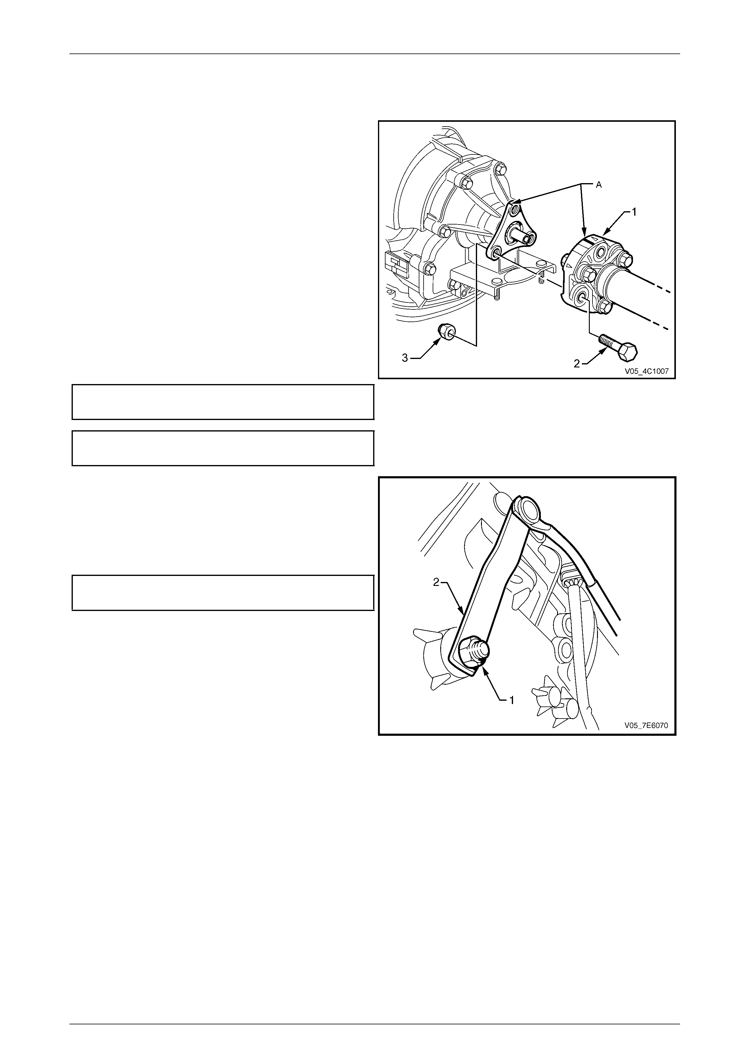
Automatic Transmission – 5L40-E – On-Vehicle Servicing 7E4 – 69
7E4 – 69
19 Reinstall the transmission wiring harness connector to the transmission control module (TCM) and check that the
sealing grommet is correctly installed to the cockpit mod ule from the engine side.
Refer to 3.21 Transmission Control Modul e, in this Section.
20 Remove the tie wire supporting the front propeller
shaft.
21 Smear some NLGI No. 2 lithium soap based EP
grease with molybdenum disulphide such as Shell
Retinax HDX2 grease, BP Energrease LMS-EP 23 or
equivalent over the transmission outp ut shaft spigot.
22 Install the propeller shaft front coupling to the output
flange, aligning the marks (A) made before removal.
NOTE
Refer to the 'Caution' stateme nt at the beginning
of this service operation to determine whether
the bolts are to be replaced or not.
23 Install fasteners to secure the coupling to the
transmission output flange. Tighten the bolts to the
correct torque specification.
Front propeller shaft couplin g nuts
or bolts and nuts torque specification.................115 N.m Figure 7E4 – 110
Front coupling bolts to ‘Spiralock’
flange threads torque specification ......................85 N.m
24 Reinstall the transmission ma nual shaft lever and its
attaching nut.
25 While holding the transmiss ion manual shaft lever with
an adjustable wrench, tighten the transmissi on manual
shaft lever retaining nut to the correct torque
specification.
Transmission manual shaft le ver
attaching nut torque specification.........................12 N.m
26 Check and adjust the shift control linkage, as required.
Refer to 3.2 Selector Linkage, Adjust, in this Section.
Figure 7E4 – 111
27 Reinstall the exhaust pipes and catalytic converters. Refer to Section 8B Exhaust System.
28 Reinstall the engine thermostat housing and replenish the engine c oolant.
Refer to Section 6B1 Engine Coolin g – V6 Engine.
29 Connect the battery negative cable. Refer to Section 0 0 Ca utions and Notes, 5 Battery Disconnection Procedures.
30 Re-program the transmission control mo dule (TCM).
Refer to 3.21 Transmission Control Modul e (TCM), Programming Procedure, in this Section.

Automatic Transmission – 5L40-E – On-Vehicle Servicing 7E4 – 70
7E4 – 70
Transmission Final Test and Inspection
Complete the following procedure after the transmission has been installed in the vehicle:
1 Flush the transmission oil cooler, pipes and hoses.
Refer to 2.2 Transmission Cooler R everse F lush and Flow Rate Check, in this Section.
2 Remove the engine control relay. Refer to Section 6C1-1 Engine Management – V6 – General Information for the
location of this relay.
3 Crank the engi ne several times and listen for any unusual noises or evidence that any parts are binding.
4 Reinstall the e ngine control relay, start the engine and listen for an y abnormal conditions.
5 With the engin e runn ing at idle speed, raise the vehicle and support in a s afe mann er.
Refer to Section 0A General Information for the location of recomme nded lifting and support points.
6 With the engin e contin uing to run at idle speed, inspect under the vehicle for any fluid leaks. Correct any condition
not considered to be to specification.
7 Check the transmission fluid level, topping up as required. Refer to 2.1 Transmission Fluid Check, in this Section.
8 Lower vehicle to the grou nd.
9 Perform a final inspection of all fluid levels.
10 Road test the vehicle to ensure correct operation.
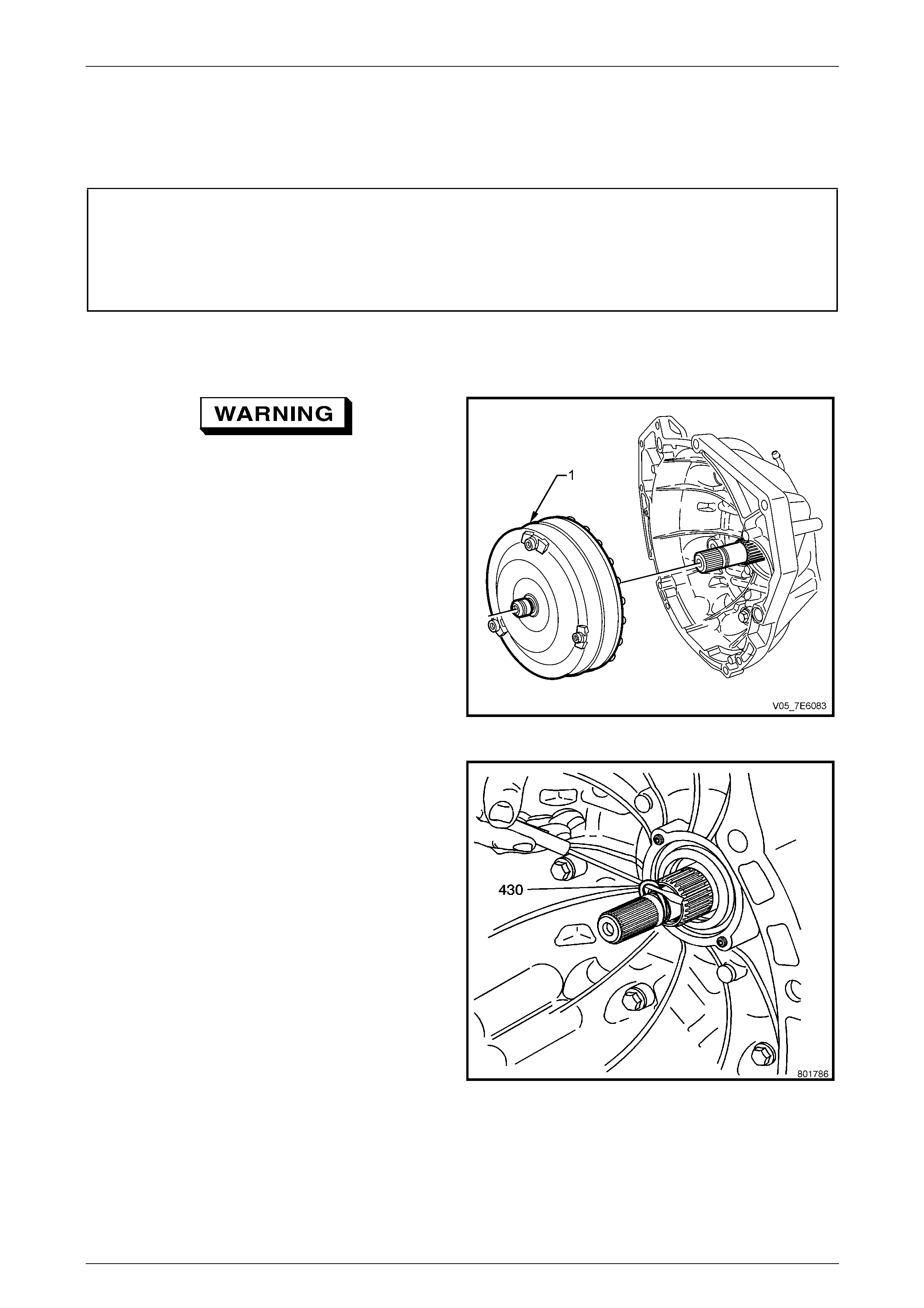
Automatic Transmission – 5L40-E – On-Vehicle Servicing 7E4 – 71
7E4 – 71
3.23 Torque Converter and/or Seal
LT Section No. – 04-200
ATTENTION
The following fasteners MUST be replaced when performin g these operations:
Torque converter to flexplate attaching bolts.
Front propeller shaft fasteners, as noted in th e text.
Replace
1 Remove the transmission from the vehicle. Refer to 3.22 5L40E – Automatic Transmission, in this Section.
Take care when removing the torque
converter as it is a heavy assembly
(approximately 12 kilograms) and personal
injury may result if lifted incorrectly.
2 Remove the torque converter assembly (1) by sliding it
clear of the input turbine shaft. Drain fluid stored into
the converter, into a suitable container.
Figure 7E4 – 112
3 Using a fine bladed screwdriver, lever out and remove
the input turbine shaft seal (430). Discard the removed
O-ring.
Figure 7E4 – 113
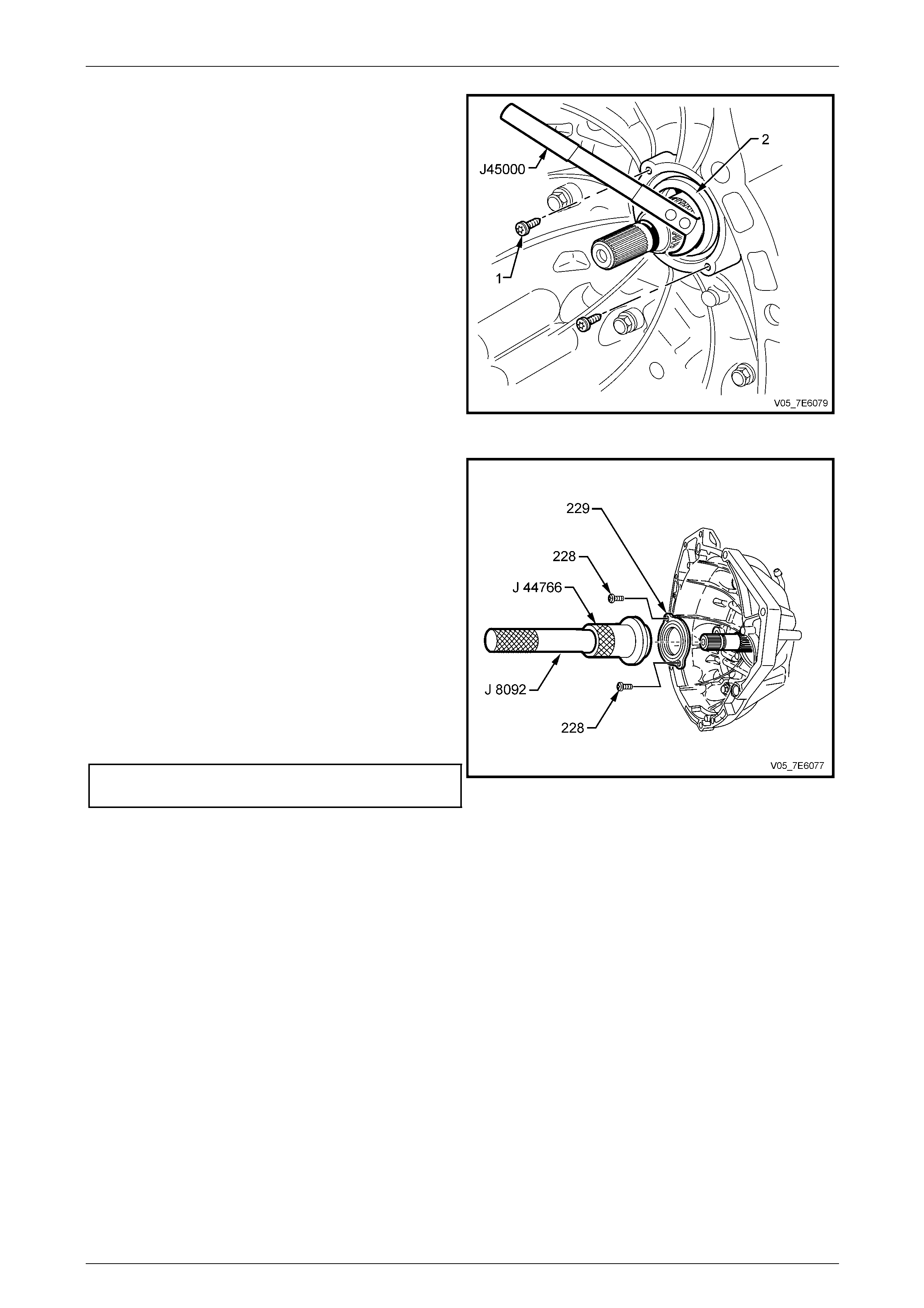
Automatic Transmission – 5L40-E – On-Vehicle Servicing 7E4 – 72
7E4 – 72
4 Remove the two screws (1), using Torx bit T20 and
suitable equipment.
5 Remove the torque converter seal (2) using Tool
J 45000 (as shown), E308 or commercial equivalent.
Figure 7E4 – 114
6 Assemble driver, T ool J 8092 to seal installer, Tool
J 44766.
NOTE
Install the seal onto the installation tool before
installing into the case to prevent damage to the
seal lips.
7 Lubricate the l ips of a new oil seal (229) with clean
automatic transmission fluid (Dexron III ®).
8 Install the seal (229) onto installer, Tool J 44766.
9 While alig ning the retaining screw holes, install the
new seal (229) into the housing (3).
10 Install new seal screws (228) and tighten to the correct
torque specification.
Torque converter seal to housing
screw torque specification...................................... 4 N.m F igure 7E4 – 115
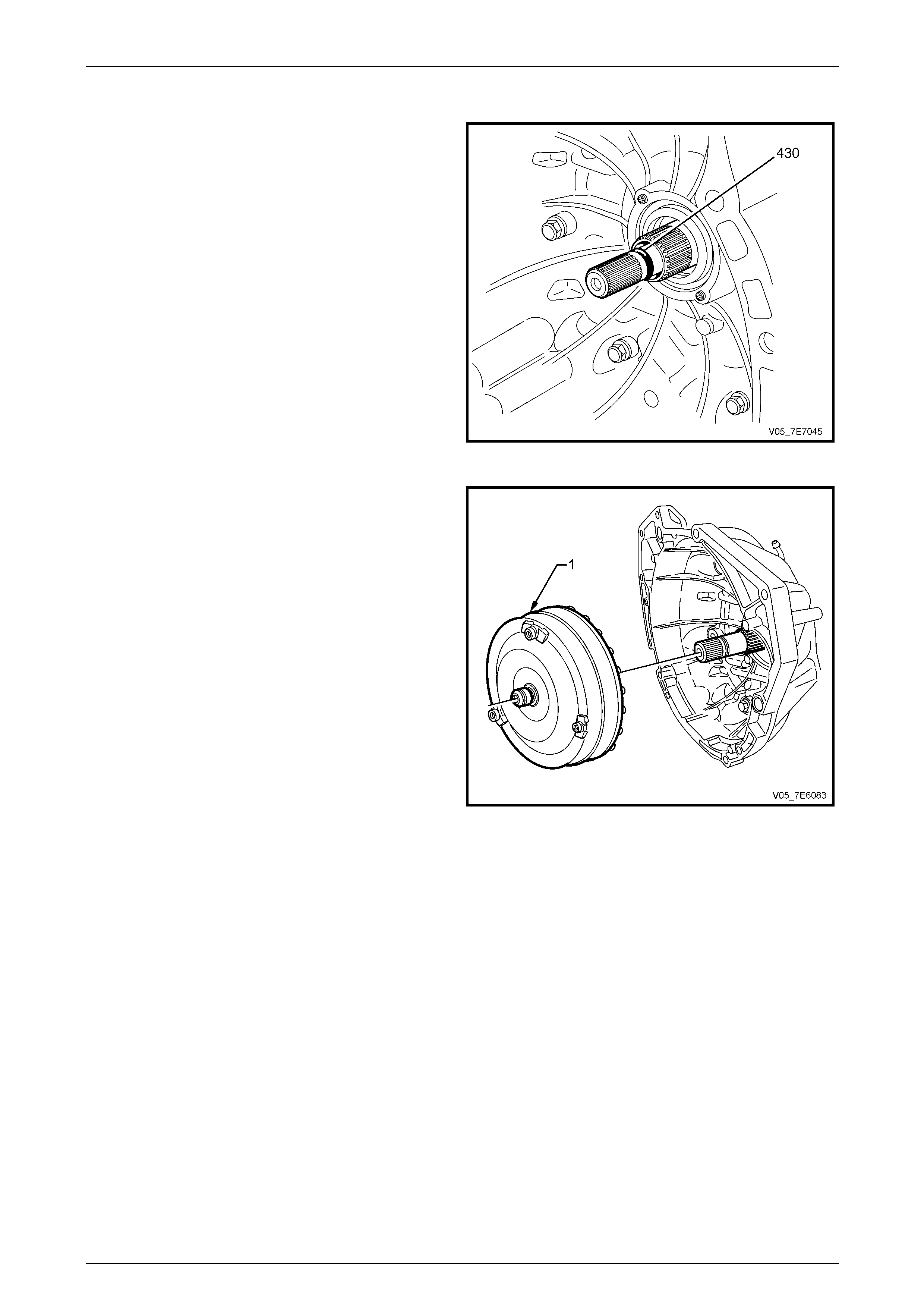
Automatic Transmission – 5L40-E – On-Vehicle Servicing 7E4 – 73
7E4 – 73
11 Lubricate a NEW input shaft O-ring seal (43 0) with
transmission fluid and install to the groove provided.
Figure 7E4 – 116
12 Lubricate the seal running area of the torque converter
hub with clean, Dexron III™ transmission fluid.
13 Reinstall the torque converter assembly (1) by sliding
it onto the input turbine shaft.
14 Rotate the torque converter back and forth to ensure
spline engagement and full installation.
15 Lubricate the torque converter spigot with a smear of
an NLGI No. 2 lithium soap based EP grease with
molybdenum disulphide, such as Shell Retinax HDX2
grease or BP Energrease LMS-EP 23 (or eq uivalent).
16 Reinstall the transmission, refer to
3.22 5L40-E Automatic Transmission, Reinstall, in this
Section.
Figure 7E4 – 117

Automatic Transmission – 5L40-E – On-Vehicle Servicing 7E4 – 74
7E4 – 74
4 Specifications
NOTE
Only those specifications related to the service
operations contained in this Section, are listed
here.
General
Type..........................................................................................................Hydra-matic 5L40-E
Transmission Model Application HFV6 3.6 litre Petrol (RWD – P/O LY7).....................5HAG
Special Features....Electronically controlled shift pattern, feel and torque converter operation
Selector Location................................................................................. Floor mounted console
Gear Ratios
Park (P) ................................................................................................................................. –
Reverse ® .......................................................................................................................3.03:1
Neutral (N)............................................................................................................................. –
5th Gear (D).....................................................................................................................0.75:1
4th Gear (4).....................................................................................................................1.00:1
3rd Gear (3).....................................................................................................................1.60:1
2nd Gear (2).....................................................................................................................2.21:1
1st Gear (L) .....................................................................................................................3.42:1
Shift Speeds
Refer to Automatic Transmission – Section 7E3 – 5L40-E – Hydraulic and Mechanical Diagnosis.
Fluid Pressure
Refer to Automatic Transmission – Section 7E3 – 5L40-E – Hydraulic and Mechanical Diagnosis.
Torque Converter
Number of Elements..................................................................3 plus torque converter clutch
Maximum Torque Ratio at Stall 3.6 litre petrol engine (P/O LY7)...................1.90:1 (k=149)
Nominal Diameter 3.6 litre petrol engine (P/O LY7).............................258 mm
Lubricant
Type Recommended....................................................................................Dexron® III
Total (Dry) .......................................................................................................8.5 litres
Service Refill (Approximate for an ‘On-Car’ situation)................................................. 4.6 litres
Fluid Cooling..................................................Engine coolant to fluid in right side radiator tank
Techline
Automatic Transmission – 5L40-E – On-Vehicle Servicing 7E4 – 75
7E4 – 75
Electrical Component Resistance Specifications
Component Circuit
Number Wire
Colour
Inline
Connector
Pin
Resistance at
20°C Resistance at
70°C Resistance to Ground
(Transmission Case)
1525 WH 17
1 – 2 Shift
Solenoid Valve 1222 BK 14 15.0 – 17.0 Ω 17.9 – 20.3 Ω Greater than 50 kΩ
1525 WH 17
2 – 3 Shift
Solenoid Valve 1223 BU 9 15.0 – 17.0 Ω 17.9 – 2 0.3 Ω Greater than 50 kΩ
1525 WH 17
4 – 5 Shift
Solenoid Valve 898 GY 5 15.0 – 17.0 Ω 17.9 – 20.3 Ω Greater than 50 kΩ
1228 GN 13
Pressure Control
Solenoid Valve 1229 WH 8 3.5 – 4.6 Ω 4.2 – 5.5 Ω Greater than 50 kΩ
1525 WH 17
TCC PWM
Solenoid Valve 422 YE 20 10.0 – 11.5 Ω 11.8 – 13.6 Ω Greater than 50 kΩ
1230 YE 18
Input Speed
Sensor 1231 WH 15 325 – 485 Ω 385 – 575 Ω Greater than 50 kΩ
400 OR 1
Output Speed
Sensor 401 WH 3 325 – 485 Ω 385 – 575 Ω Greater than 50 kΩ
1227 RD 10
TFT Sensor 2762 WH 6 Refer to following chart for TFT Sensor Resistance
Specifications
All wire colours are internal to the transmission
Transmission Fluid Temperature (TFT) Sensor Resistance Specifications
Temperature (°C) Minimum
Resistance (Ω) Nominal
Resistance (Ω) Maximum
Resistance (Ω)
-40 89 500 100 000 110 500
-30 46 419 51 400 56 381
-20 25 120 27 610 30 100
-10 14 160 15 450 16 740
0 8 278 8 972 9 666
10 5 005 5 391 5 777
20 3 120 3 342 3 564
30 2 000 2 132 2 264
40 1 317 1 397 1 477
50 888 938 988
60 613 645 677
70 432 453 474
80 310 324 338
90 228 237 246
100 170 176 182
110 128 132 136
120 98 101 104
130 77 79 81
140 60 62 64
150 48 49 50

Automatic Transmission – 5L40-E – On-Vehicle Servicing 7E4 – 76
7E4 – 76
5 Torque Wrench Specifications
ATTENTION
Fastener torque wrench specifications may be accompanied with the following identification marks:
Fasteners must be replaced after loosening.
Vehicle must be at curb height before final tightening.
Fasteners either have micro encapsulated sealant applied or incorporate a mechanical thread lock and
should only be re-used once. If in doubt, replacement is recommended.
If one or more of these identification marks is present alongside a fastener torque wrench specification, the
recommendation regarding that fastener must be adhered to.
Close out cover to torque converter housing screw................................14 N.m
Cooler pipe tube nut to cooler fitting.......................................................25 N.m
Control valve body assembly to transmission case bolt .........................11 N.m
Drain plug...............................................................................................20 N.m
Extension housing retaining bolt.............................................................22 N.m
Filler plug................................................................................................20 N.m
Fluid cooler pipe bracket nut to alternator bracket..................................20 N.m
Fluid cooler pipe flange bolt to transmission case torque.......................20 N.m
Fluid pan bolt..........................................................................................11 N.m
Front propeller shaft coupling attaching bolts or bolts and nuts............115 N.m
Front propeller shaft coupling bolts to ‘Spiralock’ flange threads............85 N.m
Input speed sensor retaining screw........................................................11 N.m
Manual shift shaft lever retaining nut......................................................12 N.m
Manual shaft detent spring bolt ..............................................................11 N.m
Oil cooler pipe to radiator fitting..............................................................25 N.m
Output flange retaining nut.....................................................................60 N.m
Output speed sensor retaining screw.....................................................11 N.m
Pressure test plug ..................................................................................11 N.m
Rear crossmember to underbody side rail bolt.......................................58 N.m
Shift selector lever locking bolt...............................................................30 N.m
Shift selector base retaining nut.............................................................15 N.m
Torque converter oil seal to front housing retaining scre w .......................4 N.m
Torque converter to flexplate attaching bolt............................................65 N.m
Transmission mount to crossmember nut...............................................25 N.m
Transmission mount plate to extension housing bolt..............................55 N.m
Transmission mount to mount plate nut .................................................55 N.m
Transmission to engine bolt....................................................................60 N.m
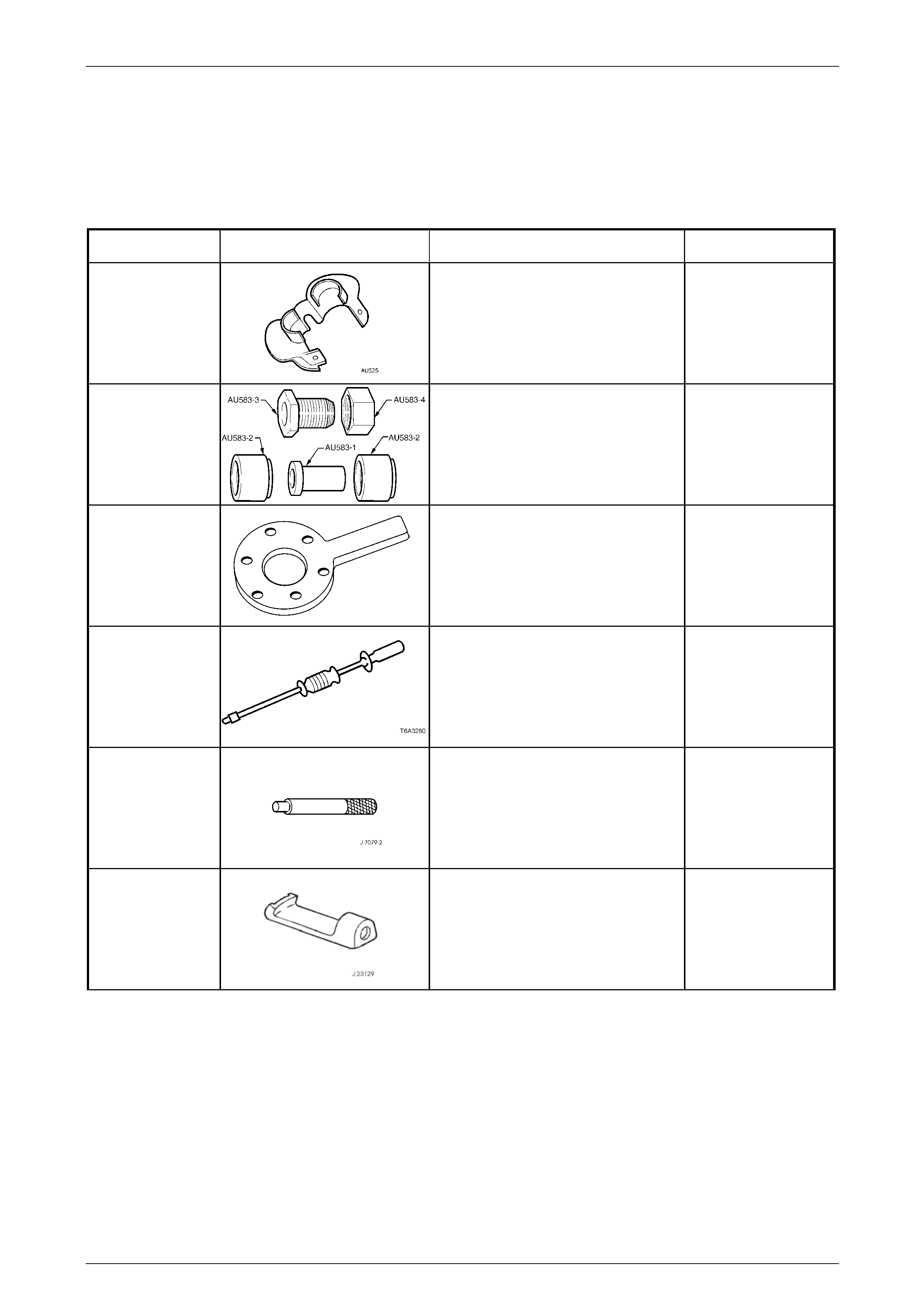
Automatic Transmission – 5L40-E – On-Vehicle Servicing 7E4 – 77
7E4 – 77
6 Special Tools
NOTE
Only those special tools quoted in this Section,
are listed here.
Tool Number Illustration Description Classification
AU 525
Quick Connect Release Tool
Used to release the quick connect
fittings on the automatic transmission
fluid cooler lines at the radiator end.
Previously released.
Unique
AU 583 Selector Shaft Seal Remo ver/
Installer
Used to remove and install the manual
shaft oil seal with the transmission
installed in the vehicle.
Previously released.
Unique
DT-47735
Holding Tool
Used to hold the final drive pin ion
flange when loosening/ti ghtening the
pinion nut.
New release
Unique
J 6125-1B Slide Hammer & Adaptor
Used in conjunction with seal
remover, J 23129 to remove both fluid
filter seals from the fluid pump
Previously released.
Unique
J 8092
Driver Handle
Used in conjunction with J 44766 to
install new torque converter seal
Previously released
Unique
J 23129 Universal Seal Remover
Used in conjunction with slide hammer
J 6125-1B to remove fluid seals.
New release.
Unique
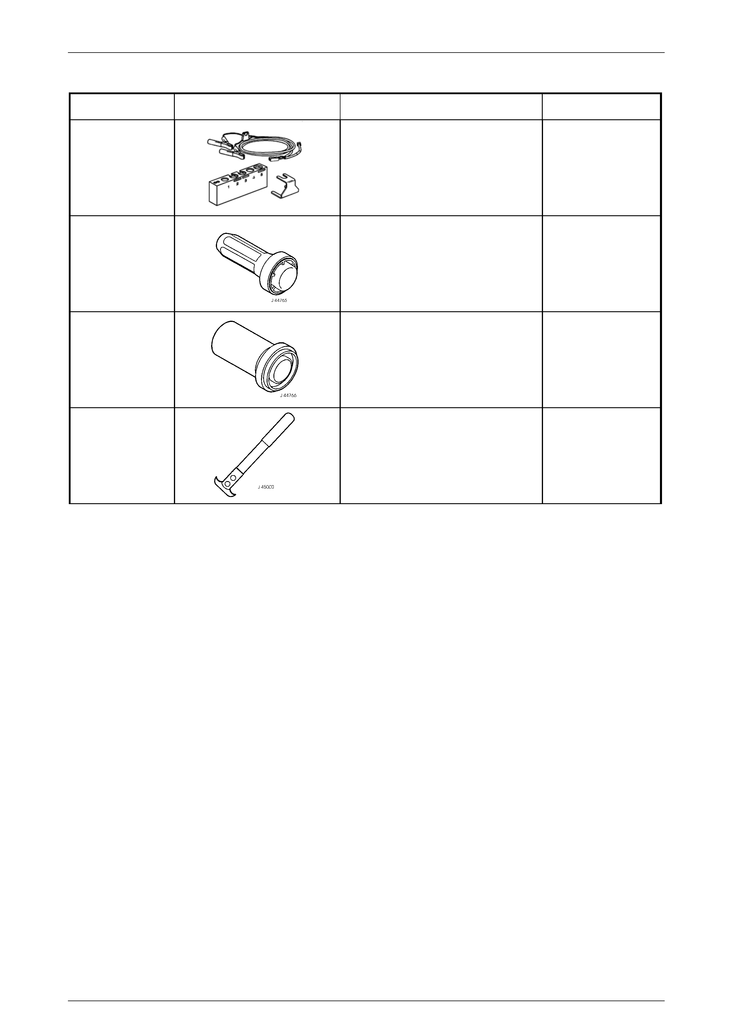
Automatic Transmission – 5L40-E – On-Vehicle Servicing 7E4 – 78
7E4 – 78
Tool Number Illustration Description Classification
J 44246 Solenoid Testing Kit
Used to test the shift solenoid valves
for leakage.
New release
Available
J 44765
Seal Installer
Used to install the extension housi ng,
propeller shaft oil seal.
New release
Unique
J44766
Seal Installer
Used in conjunction with driver handle
J 8092 to install new torque converter
seal.
New release.
Unique
J 45000
Seal Remover
Used to remove lipped seals.
Also released as E308 and is
commercially available.
New release.
Available