
Steering Page 9–1
Page 9–1
Section 9
Steering
ATTENTION
Before performing any service operation or other procedure described in this Section, refer to Section 00
Warnings, Cautions and Notes for correct workshop practices with regard to safety and/or property damage.
1 General Information ...............................................................................................................................4
1.1 General Description – Power Steering Rack and Pinion.................................................................................... 5
Principles of Operation ......................................................................................................................................... 5
Power Steering Fluid Flow....................................................................................................................................6
Neutral Position – Straight Ahead ...................................................................................................................... 6
Turning Right...................................................................................................................................................... 7
Turning Left........................................................................................................................................................ 8
Inner Rotating Valve........................................................................................................................................... 8
1.2 General Description – Power Steering Pump Assembly.................................................................................... 9
Location and Mounting ......................................................................................................................................... 9
V6 Engine........................................................................................................................................................... 9
GEN III V8 Engine.............................................................................................................................................. 9
Pump Construction.............................................................................................................................................. 10
Thrust Plate...................................................................................................................................................... 11
Pump Ring ....................................................................................................................................................... 11
Rear Plate........................................................................................................................................................ 12
Drive Shaft and Rotor....................................................................................................................................... 12
Operation.............................................................................................................................................................. 13
1.3 Filling the Pump................................................................................................................................................... 14
1.4 General Description – Steering Column ............................................................................................................ 15
Cautionary Notes................................................................................................................................................. 17
2 Diagnosis ..............................................................................................................................................18
2.1 General Diagnostic Information.......................................................................................................................... 18
2.2 Hydraulic System Pressure Test........................................................................................................................ 19
Procedure............................................................................................................................................................. 19
2.3 Hydraulic System Leak Test ............................................................................................................................... 21
General Procedure............................................................................................................................................... 21
External Leakage Check.................................................................................................................................. 21
Power Steering Pump Leak Test ........................................................................................................................ 22
Steering Gear ....................................................................................................................................................... 22
Seal Replacement Recommendations ............................................................................................................... 22
2.4 Power Steering Pump Diagnostic Check........................................................................................................... 23
Techline
Techline
Techline
Techline

Steering Page 9–2
Page 9–2
3 Service Operations...............................................................................................................................24
3.1 Steering Wheel Assembly................................................................................................................................... 24
Remove................................................................................................................................................................. 24
Disassemble......................................................................................................................................................... 26
Rear Cover....................................................................................................................................................... 26
Steering Wheel Inflatable Restraint Retaining Clip........................................................................................... 27
Horn Bar Stereo Control Switch Assembly....................................................................................................... 28
Active Select Shift Control Paddle Assembly................................................................................................... 29
Reassemble.......................................................................................................................................................... 30
Active Select Shift Control Paddle Assembly................................................................................................... 30
Horn Bar Stereo Control Switch Assembly....................................................................................................... 30
Rear Cover....................................................................................................................................................... 31
Reinstall................................................................................................................................................................ 31
3.2 Steering Column Covers..................................................................................................................................... 32
Remove................................................................................................................................................................. 32
Reinstall................................................................................................................................................................ 32
3.3 Ignition Barrel and Lock Cylinder....................................................................................................................... 33
Remove................................................................................................................................................................. 33
Reinstall................................................................................................................................................................ 34
3.4 Ignition Switch ..................................................................................................................................................... 35
Remove................................................................................................................................................................. 35
Test ....................................................................................................................................................................... 35
Reinstall................................................................................................................................................................ 36
3.5 Steering Column Assembly ................................................................................................................................ 37
Remove................................................................................................................................................................. 37
Inspect .................................................................................................................................................................. 39
Disassemble......................................................................................................................................................... 39
Non-serviced Components............................................................................................................................... 39
Clock Spring Assembly .................................................................................................................................... 39
Tilt/ Reach Handle............................................................................................................................................ 40
Reinstall................................................................................................................................................................ 40
3.6 Power Steering Fluid Level Check ..................................................................................................................... 41
V6 Engine ............................................................................................................................................................. 41
GEN III V8 Engine................................................................................................................................................. 41
3.7 Drive Belt Adjustment ......................................................................................................................................... 42
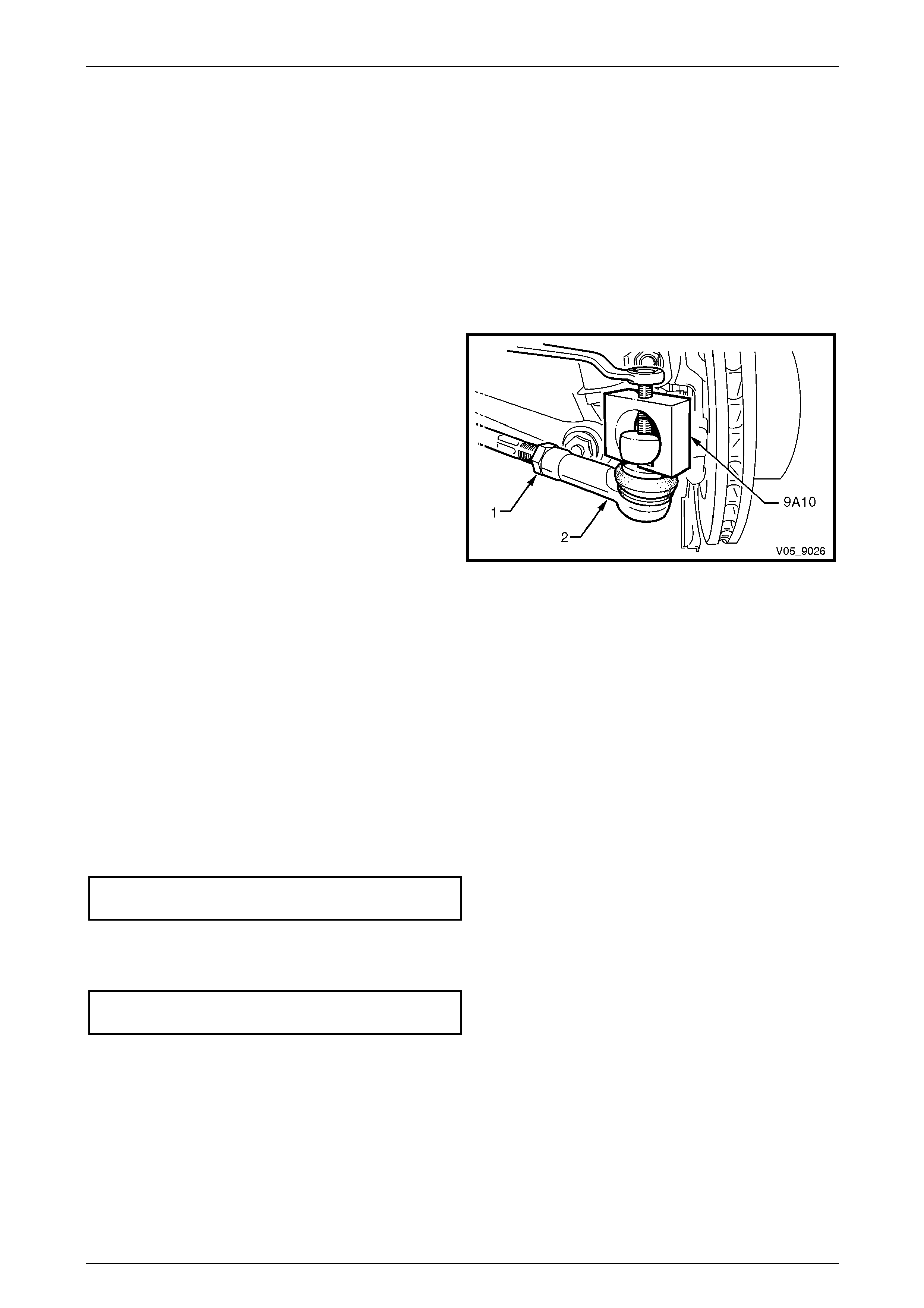
3.8 Tie-rod Socket...................................................................................................................................................... 43
Remove................................................................................................................................................................. 43
Reinstall................................................................................................................................................................ 43
3.9 Steering Gear Boot.............................................................................................................................................. 44
Remove................................................................................................................................................................. 44
Reinstall................................................................................................................................................................ 45
3.10 Power Steering Gear Assembly.......................................................................................................................... 46
Remove................................................................................................................................................................. 46
Disassemble......................................................................................................................................................... 48
Clean and Inspect ............................................................................................................................................ 56
Reassemble.......................................................................................................................................................... 57
Reinstall................................................................................................................................................................ 67
3.11 Power Steering Fluid Reservoir.......................................................................................................................... 69
Remove................................................................................................................................................................. 69
V6 Engine......................................................................................................................................................... 69
GEN III V8 Engine............................................................................................................................................ 70
Reinstall................................................................................................................................................................ 70
V6 and GEN III V8 Engine................................................................................................................................ 70

Steering Page 9–3
Page 9–3
3.12 Power Steering Pump.......................................................................................................................................... 71
Remove................................................................................................................................................................. 71
V6 Engine......................................................................................................................................................... 71
GEN III V8 Engine............................................................................................................................................ 72
Disassemble......................................................................................................................................................... 73
Clean and Inspect................................................................................................................................................ 76
Reassemble.......................................................................................................................................................... 79
Reinstall................................................................................................................................................................ 84
V6 Engine......................................................................................................................................................... 84
GEN III V8 Engine............................................................................................................................................ 84
3.13 Power Steering Pump Pulley .............................................................................................................................. 85
Remove................................................................................................................................................................. 85
Method 1 .......................................................................................................................................................... 85
Method 2 .......................................................................................................................................................... 85
Reinstall................................................................................................................................................................ 86
Method 1 .......................................................................................................................................................... 86
Method 2 .......................................................................................................................................................... 86
3.14 Hydraulic System Bleeding and Refilling.......................................................................................................... 87
Procedure............................................................................................................................................................. 87
4 Power Steering Hoses, Pipes and Fluid Cooler................................................................................88
4.1 Power Steering Lines and Hoses Layout........................................................................................................... 88
Arrangement......................................................................................................................................................... 89
V6 Engine......................................................................................................................................................... 89
GEN III V8 Engine............................................................................................................................................ 91
Remove................................................................................................................................................................. 92
Inspect .................................................................................................................................................................. 93
Reinstall................................................................................................................................................................ 93
4.2 Power Steering Fluid Cooler............................................................................................................................... 94
Arrangement......................................................................................................................................................... 94
Remove................................................................................................................................................................. 95
Reinstall................................................................................................................................................................ 95
5 Specifications.......................................................................................................................................96
6 Torque Wrench Specifications............................................................................................................97
7 Special Tools ........................................................................................................................................99
Steering Page 9–4
Page 9–4
1 General Information
A power assisted steering system is fitted which incorporates:
• An energy absorbing, coll apsible steering column that is designed to pro gre ssively compress under impact from
either direction, which incorpor ates a tilt/reach feature that allows the height and length of the steering column to be
adjusted for driver comfort,
• a rack and pinion type power steering gear, that has a two piece steering gear assembly where the rotary valve
housing is separate to the steering gear housing,
• a Kayaba vane type constant flow power steering pump,
• a remote fluid reservoir,
• a power steering fluid cooler,
• a four-spoke steering wheel with wheel mounted stereo controls an d for vehicles with a 5 speed automatic
transmission, Active Select steering wheel mounted shift paddles, and
• a steering wheel inflatable restraint assembly (driver’s airbag) is a standard feature of all vehicles. For steering
wheel inflatable restraint service information, refer to Section 12M Occupa nt Protection System.
• When performing steering gear or column
service procedures where the steering
gear coupling will be disconnected,
remove the ignition key from the ignition
lock and ensure the steering column is
locked. If this operation is not carried out
and the steering wheel is spun while the
steering gear coupling is removed from
the steering gear, the clockspring will be
destroyed. This could result in a
diagnostic trouble code (DTC) and
possible non deployment of the driver's
inflatable restraint.
• Power steering fluid can reach
temperatures of approximately 75°
Celsius. When handling power steering
fluid or power steering components that
are hot, the technician must wear the
appropriate safety glasses, gloves and
clothing to protect again st p ossible burns.
Steering Page 9–5
Page 9–5
1.1 General Description – Power Steering
Rack and Pinion
The power steering gear features a variabl e ratio rack and pinion that is made possible by the unique design of the rack
teeth. This means the effective pitch radius of the pinion is less in the strai ght-ahea d position than on turns, which results
in less turns being required from lock to lock. F or exampl e, 3.5 turns would be req uired if the ‘on centre’ ratio was used
from lock to lock, whereas only 2.7 turns are required with this gear design.
Principles of Operation
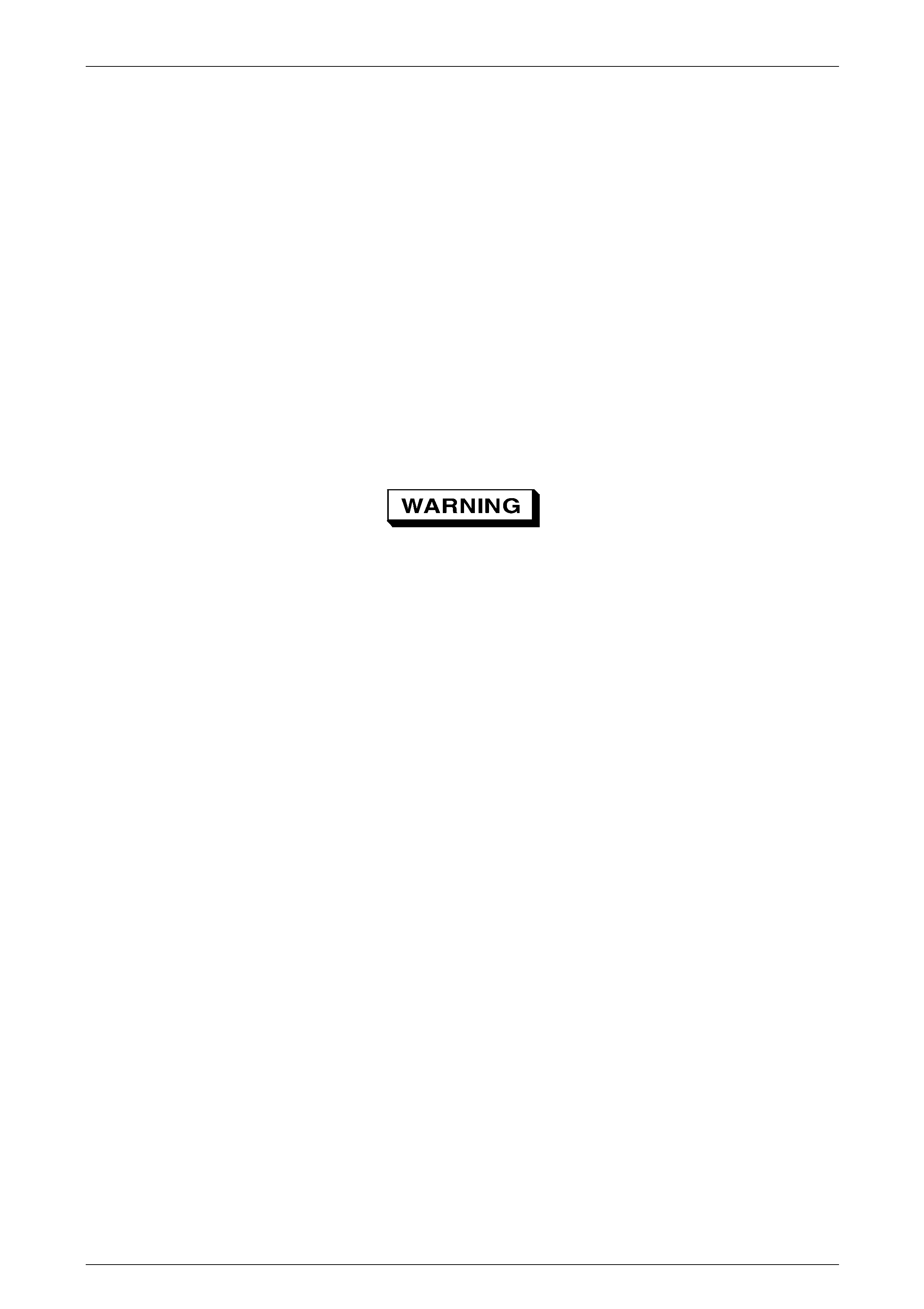
The helical toothed pinion (1) is supported in the steering
gear housing (2) by a needle roller bearing (3) at the upper
end, a ball race (4) at the lower end and a roller bearing (5)
at the centre of the pinion.
The steering rack (6) operates within the housing and is
supported at one end by a rack beari ng and at the other
end by the pinion and a spring loaded pad (7), which
maintains slack free adjustment of the rack with the pinion.
The tie-rods are connected to each end of the rack by pre-
assembled sockets and to the steering arms by sealed-for-
life type tie-rod end sockets. Sealed-for-life means the y do
not require additional lubricati on during service.
With the engine running and the steering wheel in the
neutral position (straight ahead), power steering fluid flows
continuously from the power steering pump to the steerin g
gear and back to the pump via the power steering fluid
reservoir. In this steering mode, very little pressure is
required to maintain the high power steering fluid flow rate
that occurs at this time. As a result, little engine power is
required to operate the system.
When turning the steering wheel to eith er side, power
steering fluid flow from the pump is directed by a rotary
control valve fitted to the steering gear, to whichever side of
the rack piston is appropriate as indicate d by the steering
wheel position. The power steering fluid pressure then
increases as necessary to provide the required steering
assistance.
This rotary control valve assembl y is loc ated between the
pinion shaft (8) and the pinion in the steering gear. The
rotary valve assembly consists of an inn er member, which
forms part of the pinion shaft and a surroundi ng sleeve
member (9). The whole valve rotates within t he steering
gear housing as the steering wheel is turned but it is the
slight relative movement of the inner and the sleeve
members that controls and directs the power steering fluid
flow.
Power steering fluid is fed to the valve and from there to the
left (10) and right (11) sides of the po wer piston via
circumferential grooves in the outer sle eve th at are sealed
by four Teflon (PTFE) seals (12). Excess power steering
fluid is returned to the reservoir.
The outer sleeve is coupled by a stepped pin (13) to the
rack pinion, while the pinion shaft is coupled to the rack
pinion by a pinned (14), flexible, torsion bar (15) that
provides a mechanical but flex ible link between the two
members.
In the straight ahead position, the valve remains centred. As
steering effort requirements increase, the tors ion bar flexes
causing slight relative rotation between the pinion shaft and
sleeve, directing power steering flui d and providing power
assistance as needed.
Figure 9 – 1
Steering Page 9–6
Page 9–6
Power Steering Fluid Flow
Neutral Position – Straight Ahead
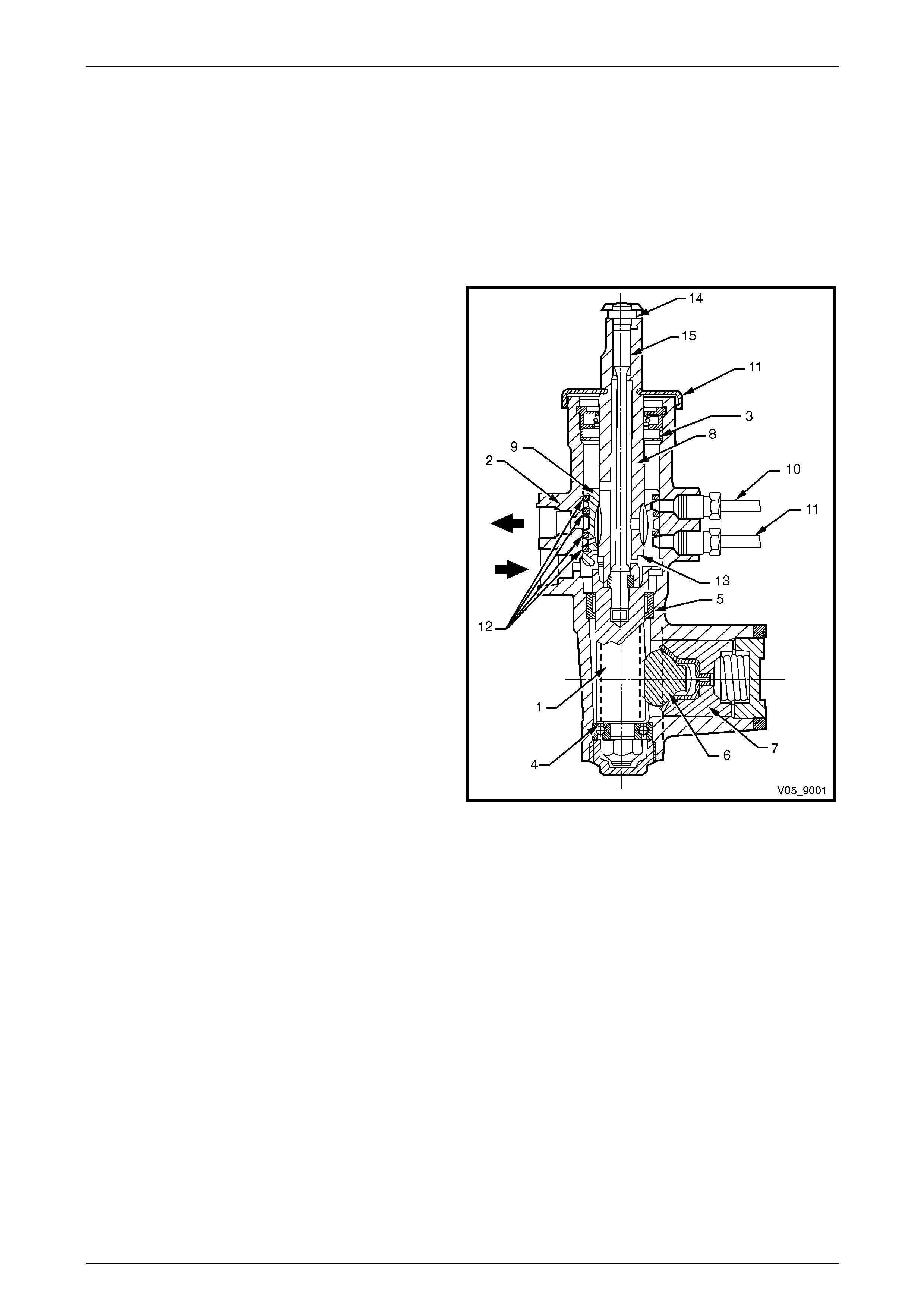
In the straight ahead position, power steering fluid flo w from
the pump (1) is directed into the cavity (A) of the inner valve
assembly (2) and out through a number of drilled holes (B)
in the outer sleeve (3). In this steering position, the inner
valve allows power steering fluid to pass e qually to both
sides of the rack (4) piston (shown as static because no
power steering fluid actually flows to and from the steering
gear).
The bypassed power steering fluid returns to the power
steering fluid reservoir (5) through holes drilled in the
longitudinal grooves of the inner valve. W ith an eq ual
pressure applied to both side s of the rack piston, no power
assistance is provided.
Figure 9 – 2

Steering Page 9–7
Page 9–7
Turning Right
When turning to the right, as soon as relative motion
between the inner rotating val ve (1) and outer sleeve (2)
occurs, power steering fluid is restricted in its free return to
the pump and is routed to the right-hand si de of the rack
piston.
At the same time, power steering fluid on the opposite side
of the piston is directed to the return circuit, leading to the
reservoir (3) and the pump (4). This action is slight at first,
providing only a small amount of driver assistance but
becomes progressively greater with a higher steering load,
which in turn causes the torsion bar in the rotar y valve
assembly to twist.
Figure 9 – 3
Steering Page 9–8
Page 9–8
Turning Left
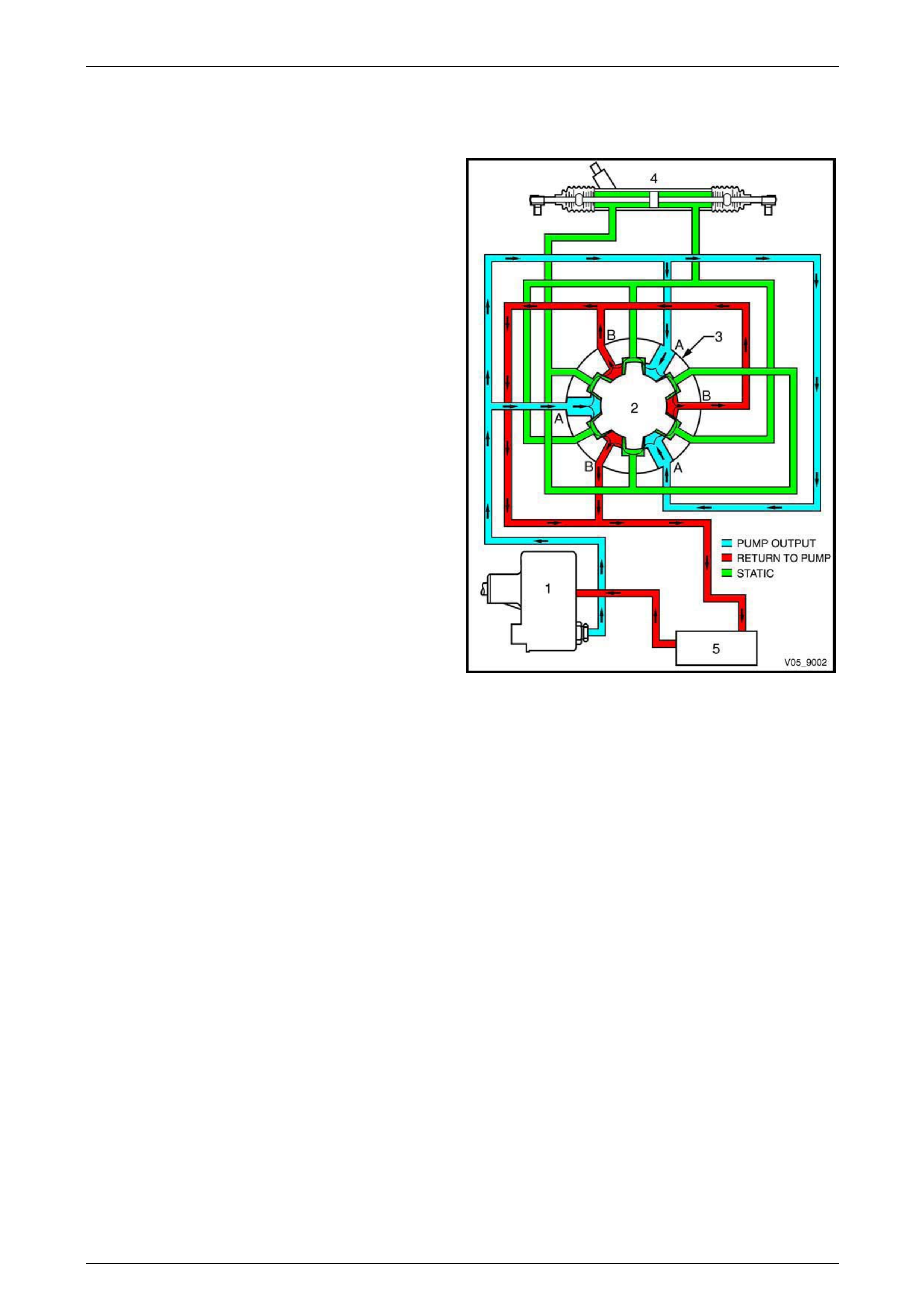
When turning left, the opposite situation occurs. Once the
relative motion between the inner valve (1) and the outer
sleeve (2) causes a return restriction, power steering fluid is
routed to the left-hand side of the rack piston (3), providing
the required assistance.
At the same time power steering fluid on the opposite si de
of the piston is free to flow back to the reservoir (4) and the
pump (5) through the return circuit.
As before, the amount of assistance provided by the po wer
steering fluid is determined by the restriction caused by the
interaction of the inner valve and outer rotary sleeve. This is
controlled by the twisting of the torsion bar connected
between these t wo valve mem bers.
Figure 9 – 4
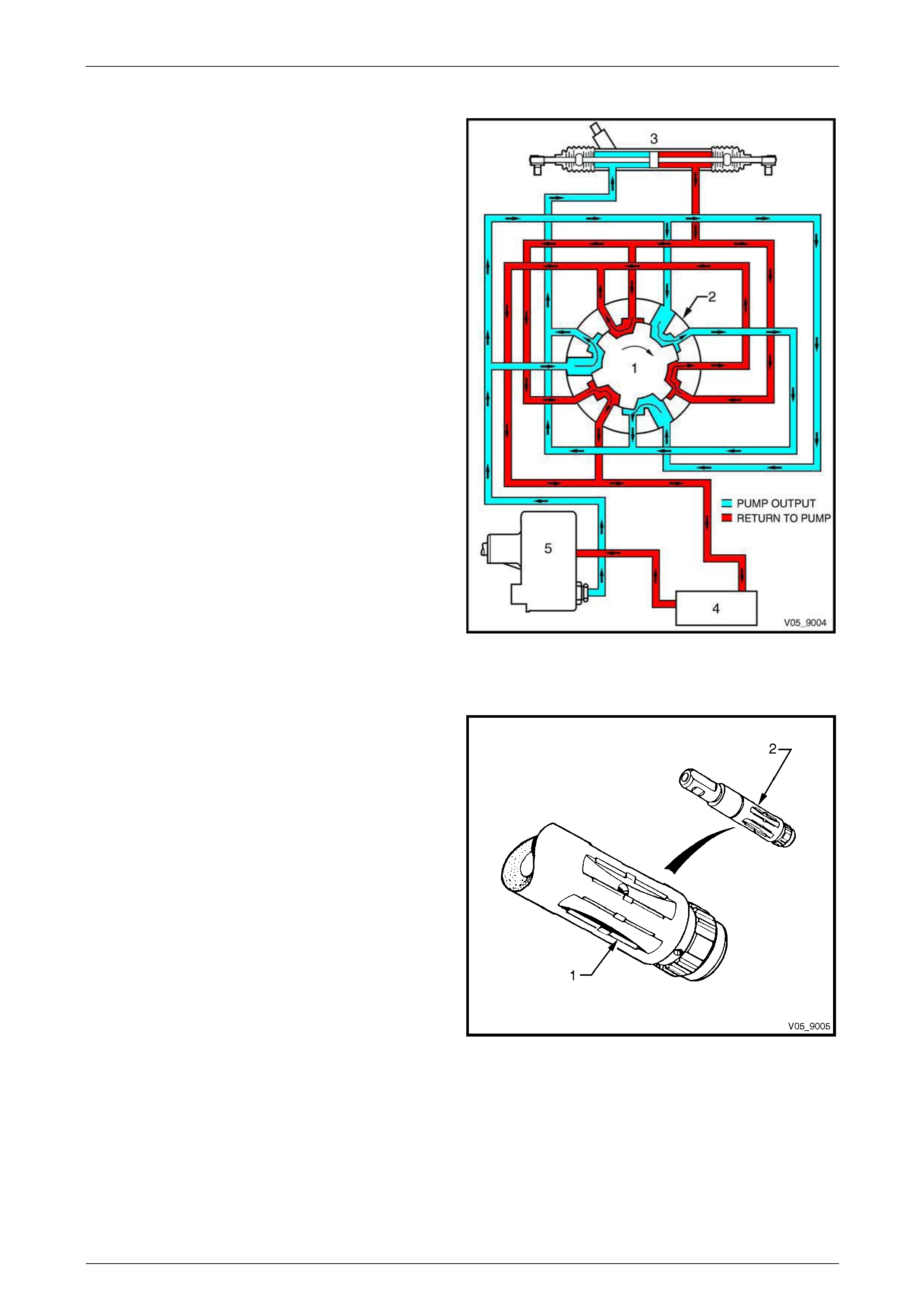
Inner Rotating Valve
When parking the vehicle more than 90% of the work is
done by the power steering fluid. To achieve a balance
between this graduated increase of assistance and maintain
a realistic feel with good response as the road speed
increases, the grooves (1) of the inner rotating valve (2) are
precisely shaped to meter the flow of power steering fluid.
Under extreme load conditions or for an y reason the
hydraulic system becomes inoperative, the torsion b ar will
deflect to a pre-determined point, then allow the pinion shaft
to drive the steering pinion directly. This is achieved by
having a loose fitting spline between the lower end of the
pinion shaft and the surrounding upper end of the pinion.
Under these operating conditions, steering loads will be
high and a noticeable amount of slack will develop because
of the torsion bar flexing. Therefore, while the steering gear
remains entirely operable, the vehicle should only be
operated in this manner for the minimum distance needed
to reach a point where the system can be serviced.
Figure 9 – 5
Steering Page 9–9
Page 9–9
1.2 General Description – Power Steering
Pump Assembly
Hydraulic pressure for the power steering system is provided by a Kayaba vane type constant flow pump.
Location and Mounting
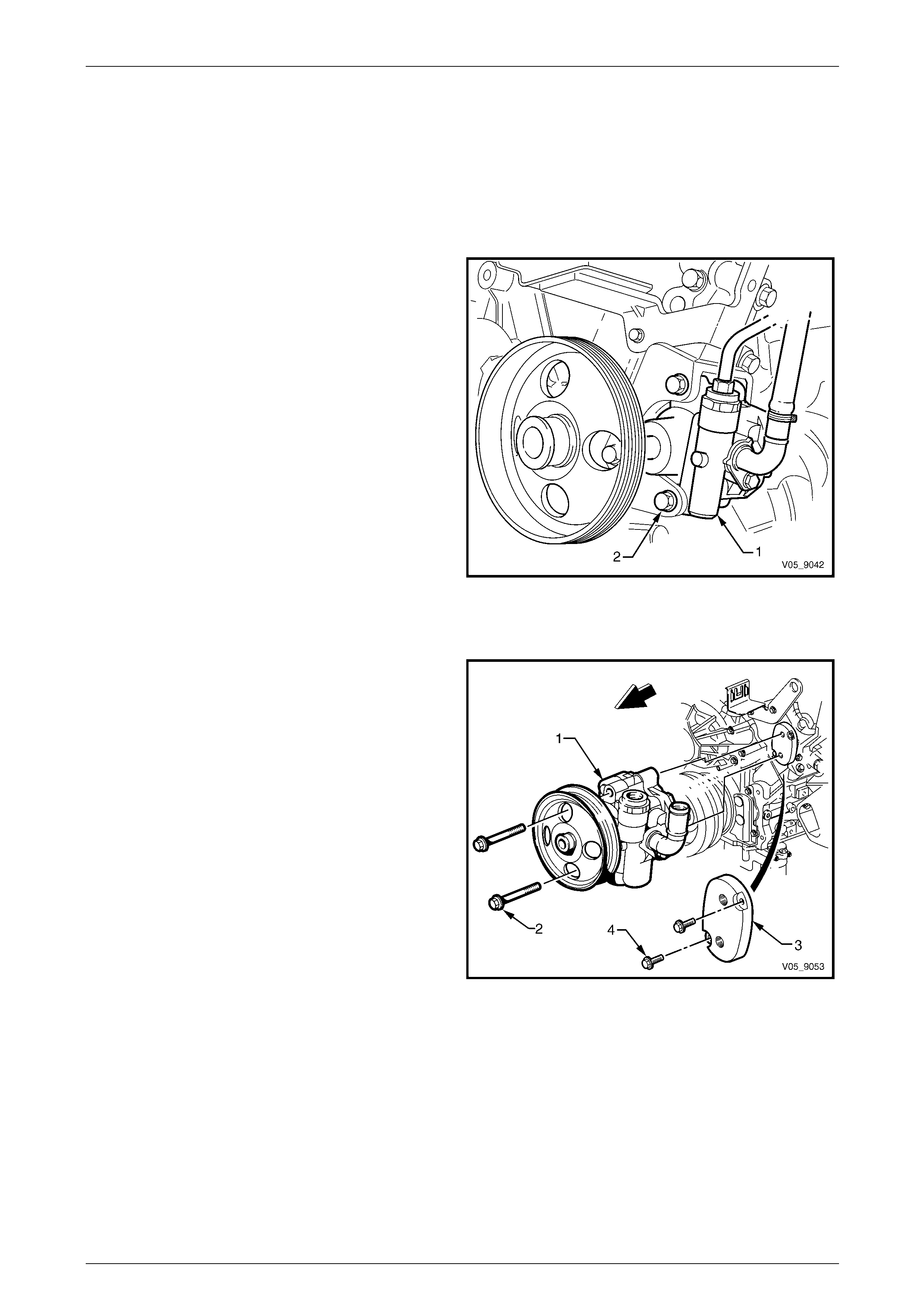
V6 Engine
The power steering pump assembly (1) is attached by two
bolts (2) to a bracket attached to the left-hand side of the
cylinder block and head Access to the two attaching bolts is
made through the pulley holes, using a suitable socket an d
extension.
NOTE
The pump is removed with the pulle y attache d to
the pump, however it is shown here partially
removed for clarity.
Figure 9 – 6
GEN III V8 Engine
The power steering pump assembly (1) is attached by two
bolts (2) to an adapter plate (3), which is attached to the
left-hand cylinder head with two bolts (4). The pump
attaching bolts are accessed through the drive belt pulley.
Figure 9 – 7
Steering Page 9–10
Page 9–10
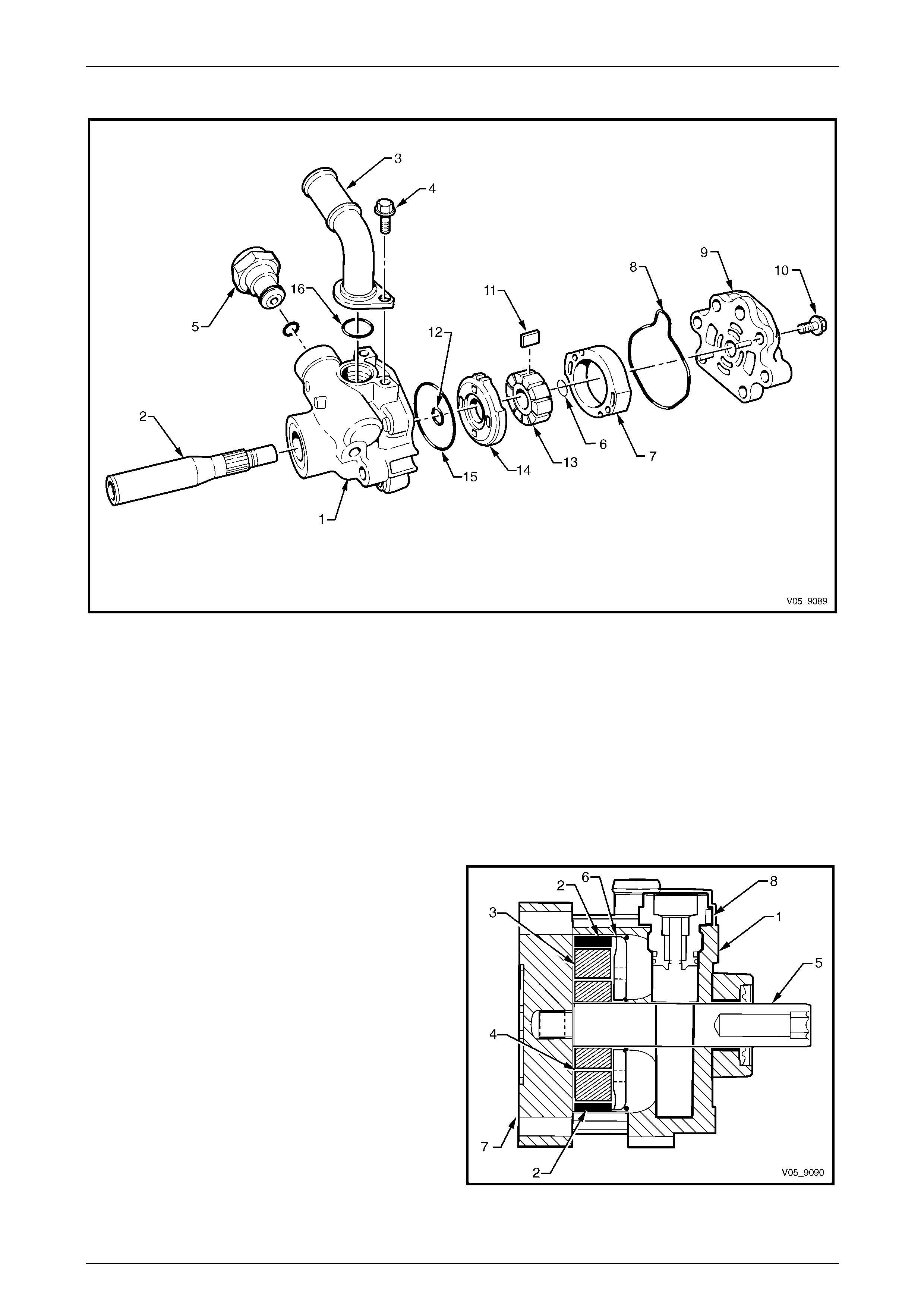
Pump Construction
Figure 9 – 8
Legend
1 Pump Housing
2 Drive Shaft
3 Low Pressure Inlet Pipe
4 Low Pressure Inlet Pipe Attaching Bolt
5 High Pressure Outlet Fitting
6 Full Circumference Retainer Ring
7 Pump Ring
8 Rear Endplate Seal
9 Rear Endplate
10 Rear Endplate Attaching Bolt
11 Vane, 10 places
12 Thrust Plate O-ring – Small
13 Rotor
14 Thrust Plate
15 Thrust Plate O-ring – Large
16 Low Pressure Inlet Pipe O-ring
In the rear of the pump housing (1), there is a cavit y that
contains the following parts:
• Pump ring (2)
• Rotor (3) splined to the drive shaft
• Vanes (4)
• Drive shaft (5)
• Thrust plate (6)
• Rear endplate (7)
• High Pressure Outlet Fitting (8)
Figure 9 – 9
Steering Page 9–11
Page 9–11
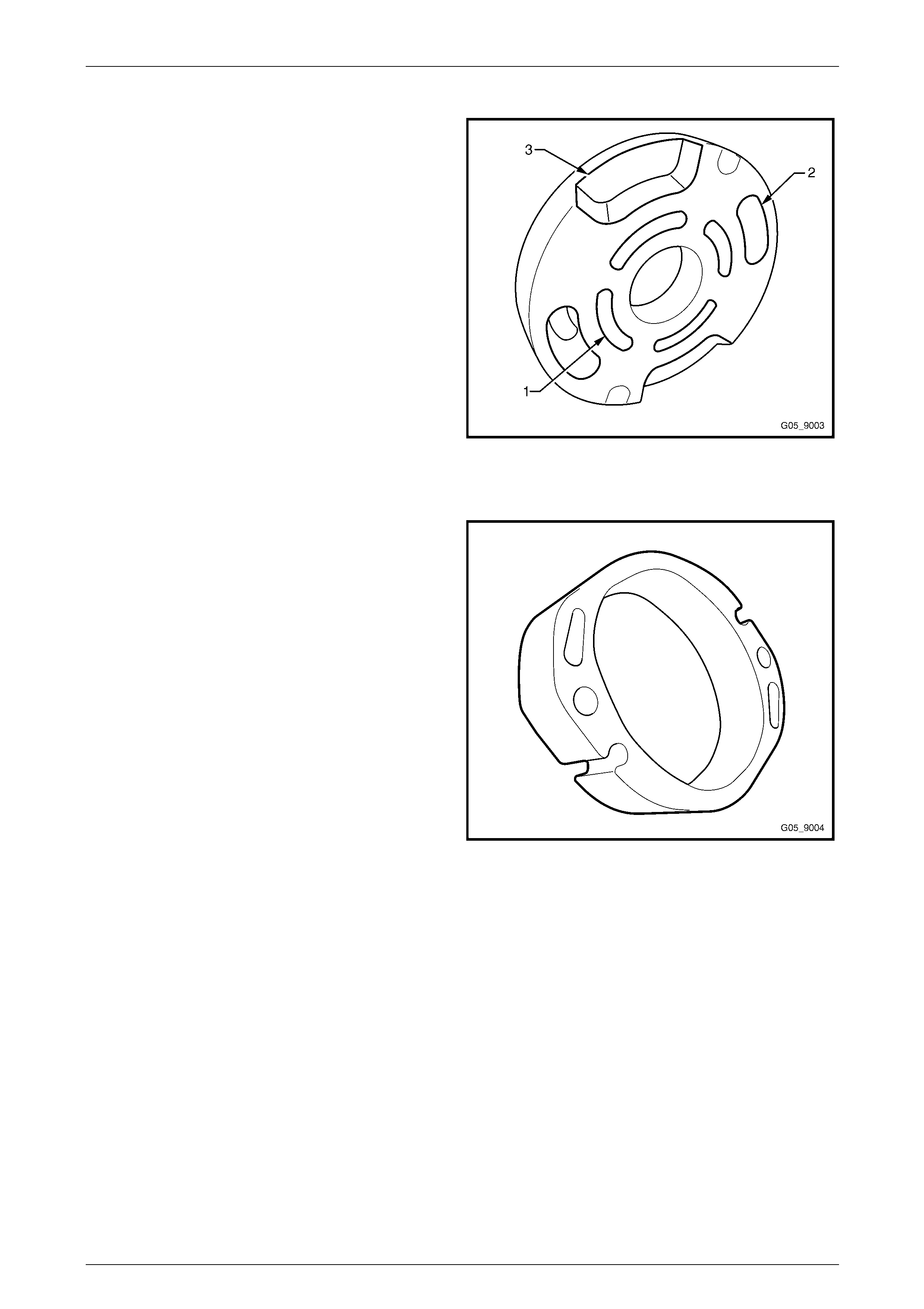
Thrust Plate
The thrust plate is located on the inner face of the pump
housing and is located by two dowel pins attached to the
rear endplate. The thrust plate has six cavities:
• Four central cavities (1) supply power steering fluid
pressure under the vanes.
• Two outer cavities (2) direct discharge press ure
through the cross-over holes in the pump ring, through
to the steering gear.
The outside slots (3) are for the power steering fluid intake
from the suction part of the pump to the rotor.
Figure 9 – 10
Pump Ring
The pump ring is placed next to the thrust plate and rear
housing. The ring is located with the same two dowel pins
used to locate the thrust plate on the inner face of the
housing. The end faces of the pump rin g are ground flat and
parallel. The centre hole is a two lobed cam in which the
rotor and vanes operate, providing two cycles per
revolution.
Figure 9 – 11
Steering Page 9–12
Page 9–12
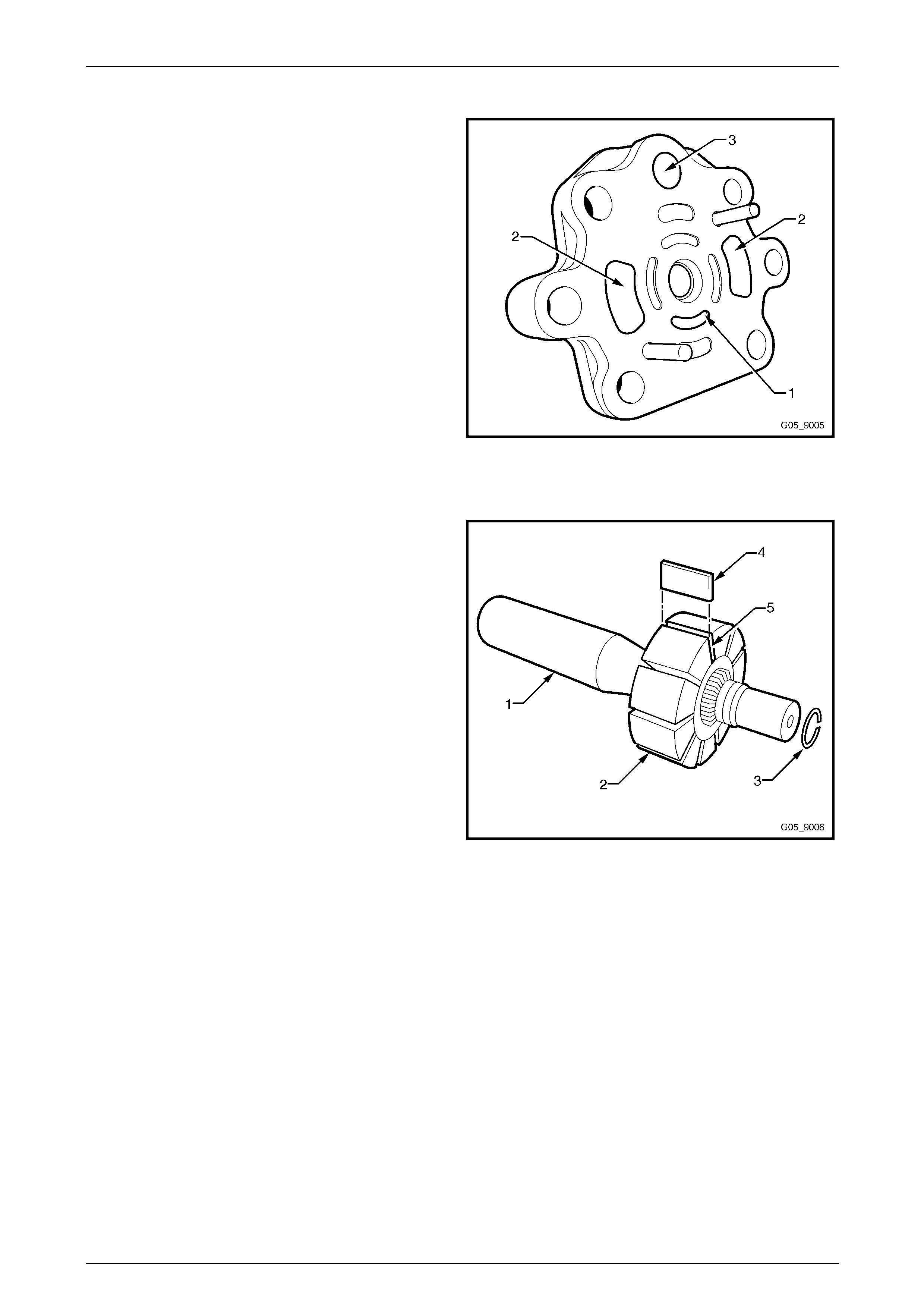
Rear Plate
The central port (1), four places, supply under-vane power
steering fluid pressure. T he two outer ports (2) supply
power steering fluid from the remote fluid reservoir through
the low pressure inlet (3).
The rear plate incorporates two dowel pins used to locate
the thrust plate and pump ring.
NOTE
Do not damage or attempt to remove the dowel
pins. These pins cannot be removed and any
damage to the pins will result in the rear plate
having to be replaced.
Figure 9 – 12
Drive Shaft and Rotor
The drive shaft (1) is fitted with a pulley, which is driven by
the serpentine belt from the engine crankshaft. The pump
rotor (2), is splined to the drive shaft and is retained on the
shaft with a full circumference C-clip (3). Ten vanes (4) are
positioned in radial slots (5) around the rotor. The shaft is
supported at each end by a bush pressed into the front of
the pump housing and i n the rear plate.
Figure 9 – 13

Steering Page 9–13
Page 9–13
Operation
Fluid from the low pressure inlet pipe (1) flows through a
passage (2) in the pump housing to the rear endplate (3),
which will then supply the vanes with under-vane pressure
and to fill the cavity between t he rotor and the pump ring as
well as filling the high pressure chamber.
Figure 9 – 14
As the rotor (1) rotates, power steering fluid enters the
cavities between the vanes (2). The vanes move outward
and inward twice with eac h revolution causing the fluid to
compress under high pressure within the pump ring (3). The
fluid then passes through the thrust plate located behind the
pump ring to the high pressure cavity in the front of the
pump housing and to the steering g ear via the high
pressure outlet.
Figure 9 – 15

Steering Page 9–14
Page 9–14
1.3 Filling the Pump
When the pump and power steering gear are completely empty of power steering fluid, adding power steering fluid to the
reservoir will partially fill the pump housing assembly.
Suction and gravity will draw power steering fluid into the intake section of the pump, ca using it to flow through a drilled
passage in the pump housing and rear end plate, leading to the large cavity around the rotor and pump ring. The power
steering fluid fills this area and the t wo intake ope nings on the thrust plate, filling the space between the ring and rotor
assembly. Any air that might enter the system is automatically removed by the circulating power steering fluid from the
pump, through the power steering fluid circuit to the steering gear and then to the reservoir, where it vents to atmospher e
via the reservoir cap.

Steering Page 9–15
Page 9–15
1.4 General Description – Steering Column
The energy absorbing steeri ng column is designed to progressively c ompress under impact from either direction and
includes a combination ignitio n/steerin g lock. In addition, the steering column is equipped with a tilt/reach feature as an
integral part of its design, which allows the column length and height to be adjusted to suit driver comfort.
The ignition/steering lock is located to the right of the column assembly. The body of the lock assembly forms an integral
part of the steering column outer tube an d cannot be removed or replaced as a separate component.
The steering lock is activated when the ignition switch is turned to the lock position and the key removed. The lock then
engages into a slot in the steering shaft (when the slot is facing the lock mechanism).
The end of the ignition barrel assembly shaft is stepped and engages with the ignition switch, which is attached to the
lock housing. The ignition switch is then activated as the lock cylinder is rotated.
An integral steering coupling, which features two universal joints and a vibration damper connects the steering shaft to
the steering gear.
As part of the electronic stability program (ESP), a steering angle sensor is attached to the clockspring mounting bracke t,
which is mounted on top of the steering column assembly and is used to measure the steering wheel angle. Refer to
Section 12M Occupant Protection System for clockspring service information and for ESP and steering a ngle sensor
information, refer to Section 5B4 ABS-TCS / ESP – General Information.
The following features determine the steering column assembly collapse behaviour in the event of a col lision.
The upper end of the steering colum n is attached to the instrument pa nel by a bracket with two inserts at the mounting
point and is held in position by two bolts. Should the vehicle be involved in a collision and sufficient force be exerted by
the driver against the steering wheel and the deployed inflatable restraint assembly, the bracket will move away from the
inserts. The amount of movement is controlled by a coiled spring on e ach side. This enables the upper end of the
steering column to move down, within a specified l oad range, in this extreme situation.
Collapse load control is achieved primarily by the br eaking away of the mounting bracket from the two inserts and the
tension applied by the two control springs.
The telescopic shaft assembly consists of an upp er tube that slides over a lower shaft thus allowing the shaft to transmit
torque but still collapse during impact.
Steering Page 9–16
Page 9–16
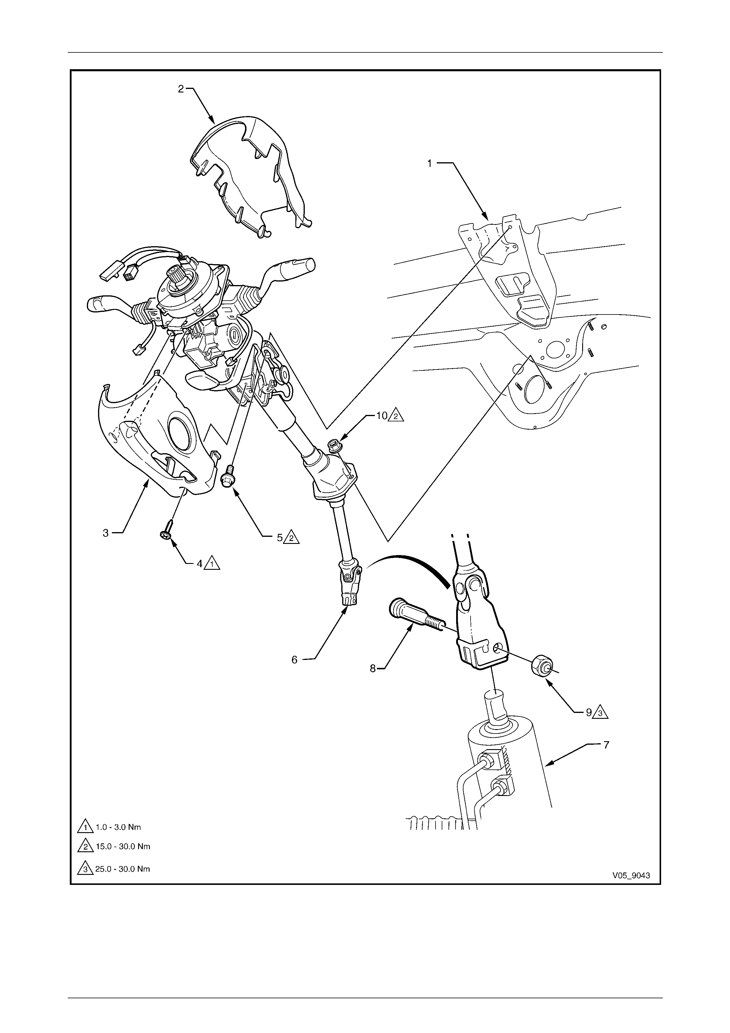
Figure 9 – 16
Steering Page 9–17
Page 9–17
Legend
1 Steering Column Bracket Assembly *
2 Steering Column Upper Trim Cover
3 Steering Column Lower Trim Cover
4 Steering Column Lower Trim Cover Attaching Screw
5 Steering Column Upper Mount Attaching Bolt, 2 places
6 Steering Column Coupling
* Part of the dash panel assembly
7 Rotary Valve Housing
8 Steering Column Coupling Cam Bolt
9 Steering Column Coupling Crimp Nut
10 Steering Shaft Lower Bearing Support Attaching Nut, 2
places
Cautionary Notes
The outer tube, steering shaft and instrument panel mou ntin g bracket are designed as energy absorbing units. Becaus e
of the design of these components, it is essential the steering column assembly be handled with care when performing
any service operations. Avoid hammering, jarring, dropping, or leaning on any portion of the column.
Before performing any service operations that
could effect the occupant protection system,
the system must be disabled prior to
commencement of service operations. At the
completion of the service operation, it is
essential the occupant protection system be
re-activated. For Occupant Protection System
information, refer to Section 12M Occupant
Protection System.

Steering Page 9–18
Page 9–18
2 Diagnosis
2.1 General Diagnostic Information
Faulty steering can be caused by problems in areas other than the power steering pump or steering gear. Areas of the
steering system that can be easily checked and quickly corrected without disassembly and overhaul of any major
components should be attempted first.
Problems such as hard or loose steering, road shock or vibrations are not always caused b y probl ems with the steering
gear or pump, but are often related instead to such factors as low tyre pressure, un-balanc ed wheels, front end alignment
or even loose or worn drive belts. These items should be checked and corrected before any adjustment or disassem bly
of the steering gear or pump is attempted.
Other factors that may affect the correct operation of the steering system are:
1 Loose component mountings.
2 Power steering fluid level and condition.
3 Damaged or restricted fluid lines.
These factors must be checked and corrected before making any further diagnosis of the steering system.
After the source of the problem has been located, the cause of any further problems can be diagnose d and corrected.
For example, if the power steering fluid level in the reservoir is found to be low, refill and check the entire hydraulic
system for power steering fluid leaks. Refilling the reservoir will not necessarily correct the problem.
Steering Page 9–19
Page 9–19
2.2 Hydraulic System Pressure Test
Power steering fluid when at operating
temperature can reach temperatures of
approximately 75° Celsius. When handling
power steering fluid or steering components,
the technician must wear the appropriate
safety glasses, gloves and clothing to protect
against possible burns.
The following procedures outline methods to identify and isolate po wer steering hydraulic circuit difficulties. This test is
divided into two parts. Test number one provides a means of determining whether any power steering system hydraulic
parts are faulty. If test number one results in readings ind icating faulty hydraulic parts operation, test number two will
identify the faulty part.
Before performing the hydraulic circuit test, carefully check the following:
a Power steering fluid level.
b Drive belt condition and tens ion.
c Idler and driving pulleys for smooth operation.
d The engine must be at normal operating temperature.
e Front tyres are inflated to the correct pressure.
All tests must be performed with the engine
idling and at normal operating temperature,
however keep clear of belts and pulleys while
the engine is running to avoid injury.
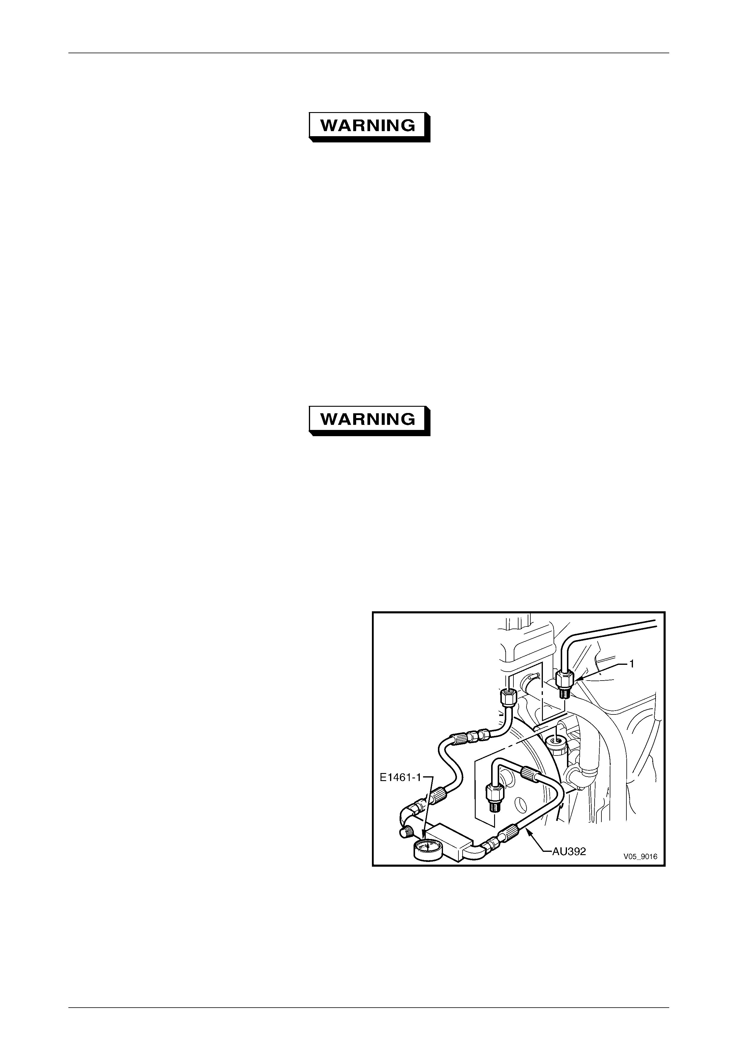
To perform the two pressure checks, it is necessary to connect the pressure gauge assembly, Tool 1461- 1 and adaptor
hoses Tool AU392 into the hydraulic line between the pump and steering gear.
Procedure
1 Ensure the engine is switched off.
2 Place a drain tray beneath the power steering pump assembly to contain any loss of fluid from the following
operation.
3 Loosen and remove the high pressure hydraulic line
fitting (1) and O-ring from the power steering pump.
4 Install the pressure gauge assembly, hose set AU392
and gauge assembly E1461-1 in series between the
power steering pump outlet fitting and the hi gh
pressure hose fitting.
NOTE
• Ensure the hoses and gauge are tied back
and secured away from any belts, pulleys or
the exhaust manifolds.
• The illustration shows the GEN III V8 engine
and pump, however the connection method
for the V6 engine is the same.
5 Refill the system with power steering fluid to the
correct level, refer to 3.6 Power Steering Fluid Level
Check. Ensure there are no leaks at either th e hose or
gauge connections.
6 Bleed the air from the system, refer to 3.14 Hydraulic
System Bleeding and Refilling. Figure 9 – 17

Steering Page 9–20
Page 9–20
Hydraulic System Pressure Test
Step Action Yes No
1 1 Start engine and allow it to idle.
2 Check the power steering fluid level.
Is power steering fluid level correct?
Go to Step 2
Top up as required
and check for
leaks. Refer to
3.14 Hydraulic
System Bleeding
and Refilling
Go to Step 2
2 1 Check the power steering fluid condition.
Is the power steering fluid serviceable ?
Go to Step 3
Drain and flush the
system and then
refill with clean
power steering
fluid.
Go to Step 3
3 1 With the test gauge valve fully open, check the pressure
reading.
Is the pressure reading for power steering approximately 350
kPa? Go to Step 5
Check hoses and
pipes for
restriction. Repair
or replace as
necessary.
Go to Step 4
4 1 Is system pressure now approximately 350 kPa?
Go to Step 5
Replace the
Steering Gear
valve assembly.
Go to Step 3
5 1 Close and then open the valve fully three times, noting
the highest pressure reading each time.
NOTE
Do not leave the valve closed for more than five
seconds, as damage to the pump could result.
Are all the readings between the 7,580 kPa – 8,270 kPa
specified pressures and within 340 kPa of each other?
Hydraulic system is
operating within the
specification Go to Step 6
6 1 Are the pressures within the specified range but not
within 340 kPa of each other? Go to Step 7 Go to Step 9
7 1 Remove the pump, disassemble, clea n, reassemble and
reinstall.
2 Repeat Step 4.
Are the pressure readings now within 340 kPa of each other?
Hydraulic system is
now operating to
specification Go to Step 10

Steering Page 9–21
Page 9–21
2.3 Hydraulic System Leak Test
General Procedure
1 Wipe the suspected area dry.
2 Check for an overfilled reservoir.
3 Check for aeration and overflow of foaming power steering fluid.
4 Check hose connections. As required, tighten to the specified torque.
5 Verify exact point of leakage.
NOTE
The location the po wer steering fluid drips from is
not necessarily the leakage point. For example,
the power steering fluid could overflow from the
reservoir, run along a hose and then drip.
6 When service is requir ed:
a Clean the leakage ar ea upon disassembly.
b Replace the leaking seal.
c Check the component sealing surfaces for da mage and replace the damaged component if necessar y.
d Tighten fastener/s to the correct torque specification where required.
External Leakage Check
The purpose of this procedure is to pinpoint the location of the leak. In some cases, the leak can easily be locate d.
Seepage type leaks may be more difficult to isolate. To locate seepage leaks, use the following method.
1 With the engine stopped, wipe the complete power steering system dry (steering gear, pump, hoses an d
connections).
2 Check the power steering fluid level in the re servoir. Add power steering fluid if necessary,
refer to 3.6 Power Steering Fluid Level Check.
3 Start the engine then turn the steering wheel from lock to lock several times. Do not hold it at a full lock for any
length of time, as this can damage the power steering pump. It is recommended that someone else operates the
steering wheel while you search for the seepage.
4 Find the exact area of the leak. Remove and repair as necessary the faulty component and re-check for leaks on
completion to validate the repairs.
Steering Page 9–22
Page 9–22
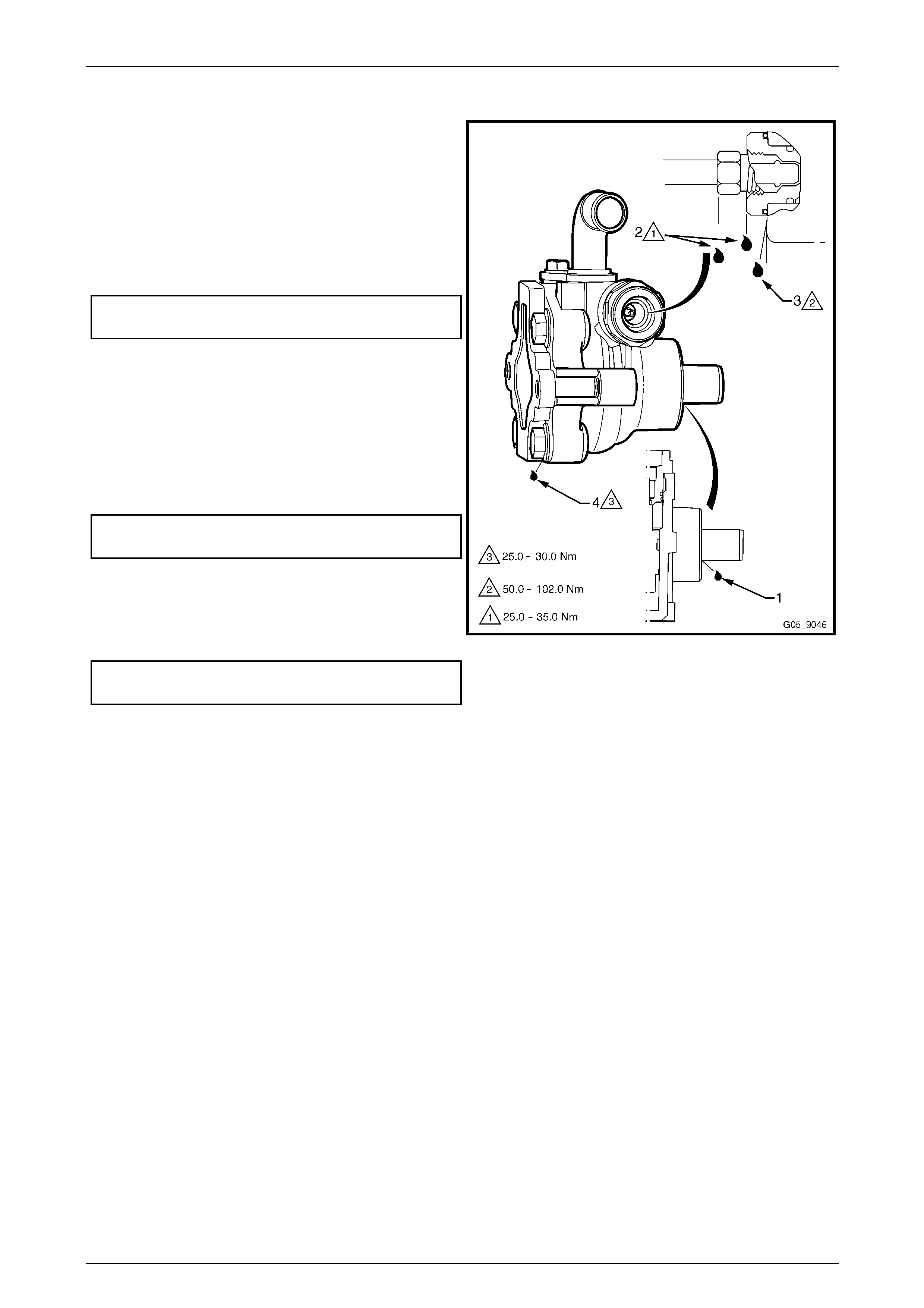
Power Steering Pump Leak Test
Inspect the pump for leaks at the following locations:
1 Drive shaft seal (1).
a Replace the drive shaft seal. Ensure the drive
shaft is clean and free of pitting in the seal ar ea.
2 High pressure pipe flare nut (2).
a Tighten the high pressure pipe flare nut to the
correct torque specification.
High pressure pipe flare nut
torque specification ................................25.0 – 35.0 Nm
b If leakage persists, replace the O-ring seal.
3 High pressure pipe outlet fitting (3).
a Tighten the outlet fitting to the correct torque
specification.
b If the leak continues, replace the two O-rings on
the high pressure outlet fitting, refer to
3.12 Power Steering Pump.
High pressure pipe outlet fitting
torque specification .............................. 50.0 – 102.0 Nm
4 Rear endplate O-ring seal (4).
a Replace the rear endplate O-ring seal and
tighten the rear endplate attachin g bolts to the
specified torque.
Rear endplate attaching bolt
torque specification ................................25.0 – 30.0 Nm
Figure 9 – 18
Steering Gear
1 Check the power steering gear for leaks at the following locations:
a Pipe connections at the steering gear ho using.
b Pinion seal.
c From within the steering rack boots. Remove the steering gear boot inner retaining clip and check behin d the
boot for leakage.
NOTE
A small amount of fluid may be present from
assembly and seal sweating.
2 If any leaks are present, remove the steering gear assembl y and repair as required.
3 Upon completion of repairs, re-check for leaks to validate the repairs.
Seal Replacement Recommendations
Lip seals, which seal rotating shafts, require special treatment. This type of seal is used on the steering gear pinion shaft
and on the drive shaft of the pump. When there is a leak in o ne of these areas, always replace the seal/s after inspecting
and thoroughly cleaning the sealing surfaces. Replace the s haft only if very severe pitting is found. If corrosion in the lip
seal contact area is slight, clean the surface of the shaft with crocus cloth. Replace the shaft only if the leakage cannot
be stopped by first smoothing with crocus cloth.

Steering Page 9–23
Page 9–23
2.4 Power Steering Pump Diagnostic Check
Symptom Possible Cause
Chirp noise in steering pump. 1 Incorrectly tension ed or worn drive belt
Drive belt squeal (particularl y
noticeable at full wheel travel
and standstill parking) 1 Incorrectly tensioned or worn drive belt
Growl noise in steering pump. 1 Excessive back-pressur e in hoses or steering gear caused by a restriction of flow.
Growl noise in steering pump
(particularly noticeable at
standstill parking).
1 Scored or worn rear plate, thrust plate or rotor.
2 Extreme wear of the pump ring and vanes.
Groan noise in steering pump. 1 Low power steering fluid level.
2 Air in the power steering fluid.
3 Poor pressure hose connectio n.
Rattle noise in steering pump. 1 Worn, loose or incorrectly inst alled vanes.
2 Worn bushes.
3 Worn rotor or drive shaft splines.
Momentary increase i n effort
when turning the wheel fast,
from right or left.
1 Low power steering fluid level.
2 Drive belt slipping.
3 High internal leakag e
Steering wheel surges or jerks
when turning with the engine
running, especiall y during
parking.
1 Low power steering fluid level.
2 Incorrectly tensioned or worn drive belt.
3 Insufficient pump pressure.
Hard steering or lack of assist,
especially during parking.
Further possible causes could
be:
1 Incorrectly tensioned or worn drive belt.
2 Low power steering fluid level.
3 Steering gear to column misalignm ent.
4 Tyres not inflated to the correct pressure.
If rectification of checks 1 through 4 does not correct the hard steering, follow the
Hydraulic System Check – Procedure, refer to 2.2 Hydraulic System.
1 Insufficient pump pressure output.
2 Excessive internal pump leakage.
3 Excessive internal s ystem leakage.
Foaming or milky po wer
steering fluid, low fluid level
and possible low pressure.
1 Air or water in the power steering fluid.
2 Loss of power steering fluid due to internal pump leakage.
3 External leakage from the pump or conn ections.
Low pressure from steering
pump 1 Rear endplate is not flat again st pump ring.
2 Extreme wear of the pump ring and vanes.
3 Scored rear endplate, thrust plate or rotor.
4 Vanes not installed correctly.
5 Vanes sticking in rotor slots.
6 Cracked or broken thrust plate.
7 High internal leakage.
Steering Page 9–24
Page 9–24
3 Service Operations
ATTENTION
All steering fasteners are important attaching parts as they affect the performance of vital components and/or
could result in majo r repair expense. Where specified in this Section, fasteners MUST be rep laced with parts
of the same part number or a GM approved equivalent. Do not use fasteners of an inferior quality or
substitute design.
Torque values must be used as specified during reassembly to ensure proper retention of all steering
components.
Through out this Section, fastener torque wrench specifications may be accompanied with the following
Identification marks:
Fasteners must be repl aced after loosening.
Fasteners either have micro encapsulated sealant applied or incorporate a mechanical thread lock and
should only be re-used once. If in doubt, replacement is recommended.
If one of these identification marks is present alongside a fastener torque wrench specification, the
recommendation regarding that fastener must be adhered to.
3.1 Steering Wheel Assembly
LT Section No. — 06–225
Remove
Disable the occupant protection system
prior to commencing any service operations
on the steering column, refer to
Section 12M Occupant Protection System.
Turn the ignition to the off position and
remove the key to lock the steering w heel and
prevent the steering shaft from being rotated
during the removal.
Disconnection of the battery affects certain
vehicle electronic systems. Refer to
Section 00 Warnings, Cautions and Notes
before disconnecting the battery.
Techline
Steering Page 9–25
Page 9–25
1 Disconnect the battery ground lead a nd remove the ignition keys from the ignition switch.
2 Remove the steering wheel inflatabl e restraint assembly, refer to Section 12M Occupant Protection System.
3 Ensure the front wheels and the steering wheel are in
the straight-ahead position and remove key from
ignition switch.
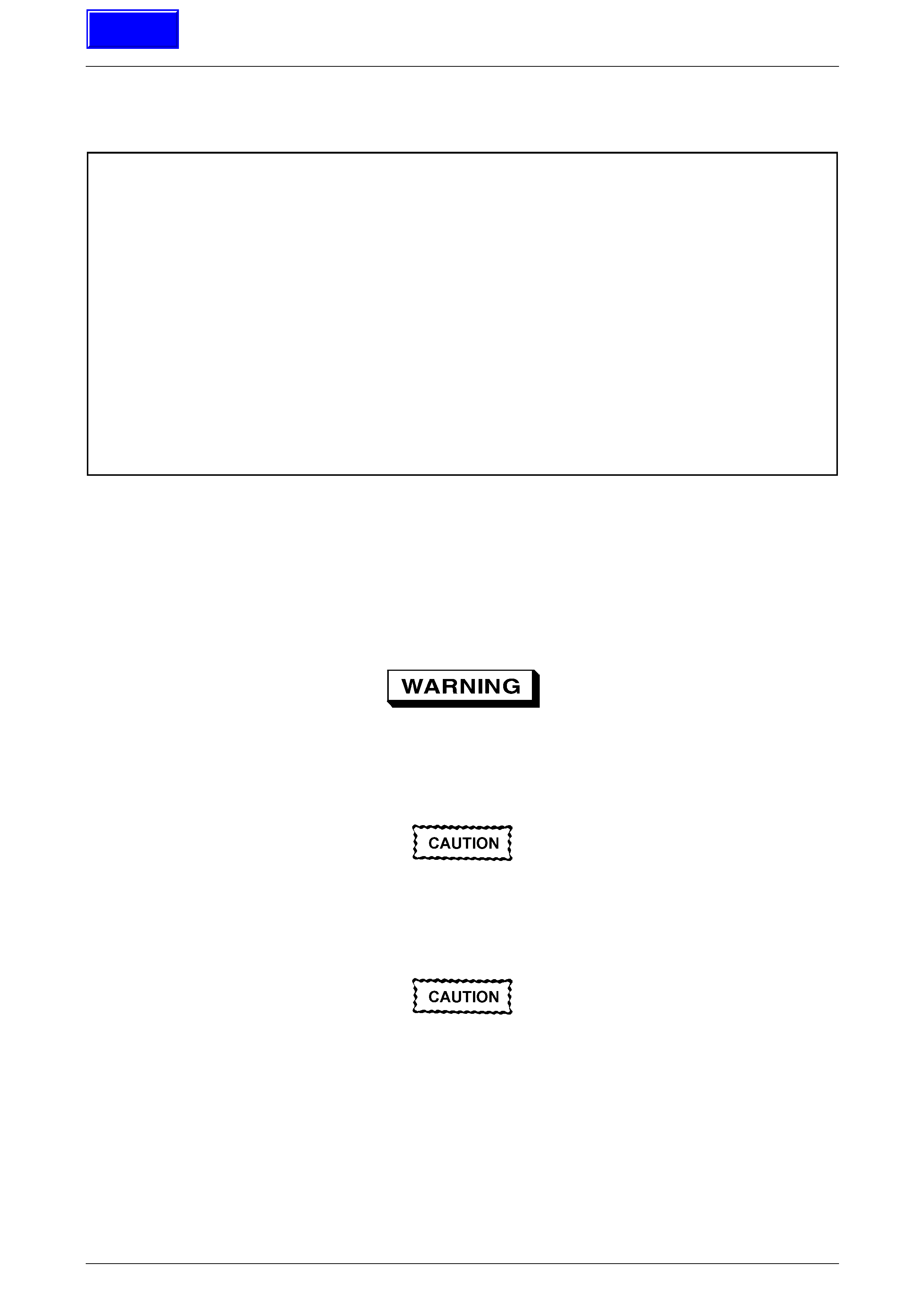
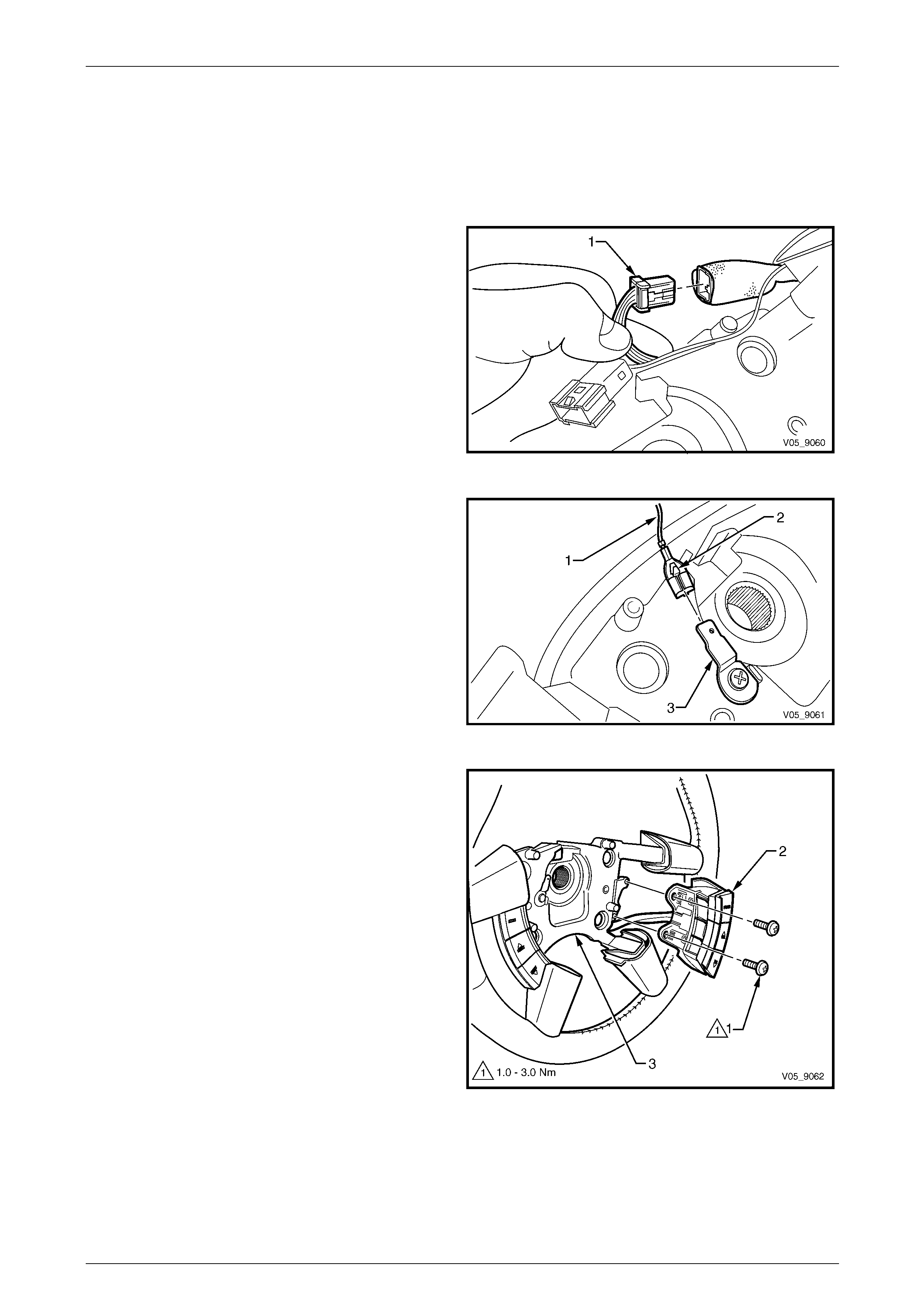
4 Remove the steering wheel wiring harness from the
retaining clips located in the rear housing and
disconnect the wiring harness connector (1).
5 Remove the steering wheel retaining bolt (2).
Do not use a centre punch for the following
operation.
6 To aid the installation of the steering wheel to its
original position, place a mark on the steering wheel
centre section and steering shaft (3). A felt tipped pen
should be used.
Figure 9 – 19
7 Remove the steering wheel from the steering shaft splines and feed the clock spring coil wiring and connectors
through the steering wheel aperture.
NOTE
• When the steering wheel is removed, the
inner clock spring coil inner hub should
automatically lock in the centralised position.
• A steering wheel puller is not normally
required to remove the steering wheel.
However, if a puller is required, use steering
wheel puller, Tool No. J1859-A in conjunction
with legs Tool No. E1408.
Steering Page 9–26
Page 9–26
Disassemble
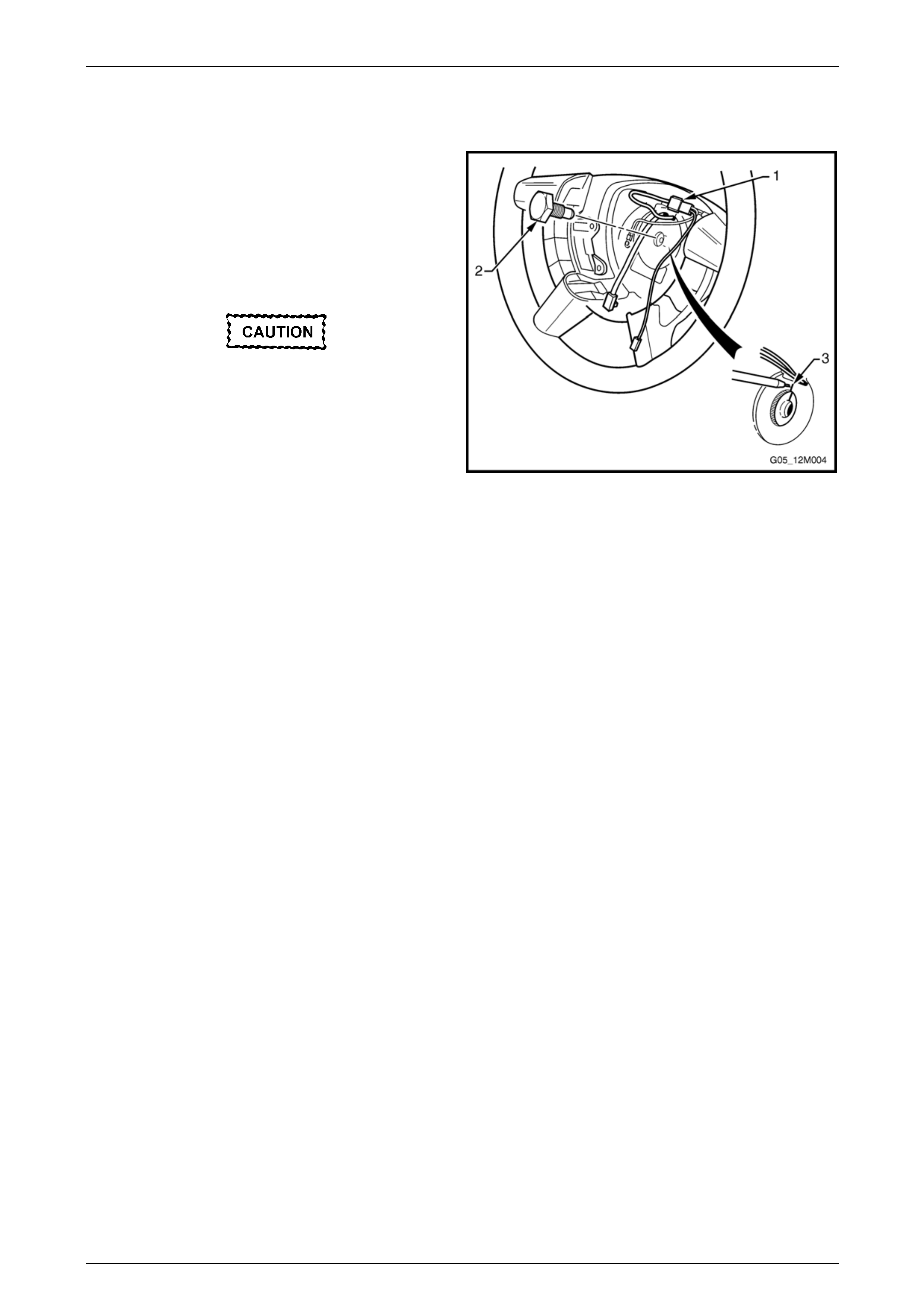
Figure 9 – 20
Legend
1 Steering Wheel Assembly
2 Rear Cover Attaching Screw, 2 places
3 Horn Bar Stereo Control Switch Assembly
4 Horn Bar Stereo Control Switch Assembly Attaching Screw,
2 places
5 Steering Wheel Inflatable Restraint Retaining Clip, 2 places
6 Active Select Shift Control Paddle Assembly
7 Active Select Shift Control Paddle Assembly Attaching
Screw, 2 places
8 Rear Cover
Rear Cover
1 Remove the two screws (1), attaching the rear cover
to the steering wheel hub.
Figure 9 – 21
Steering Page 9–27
Page 9–27
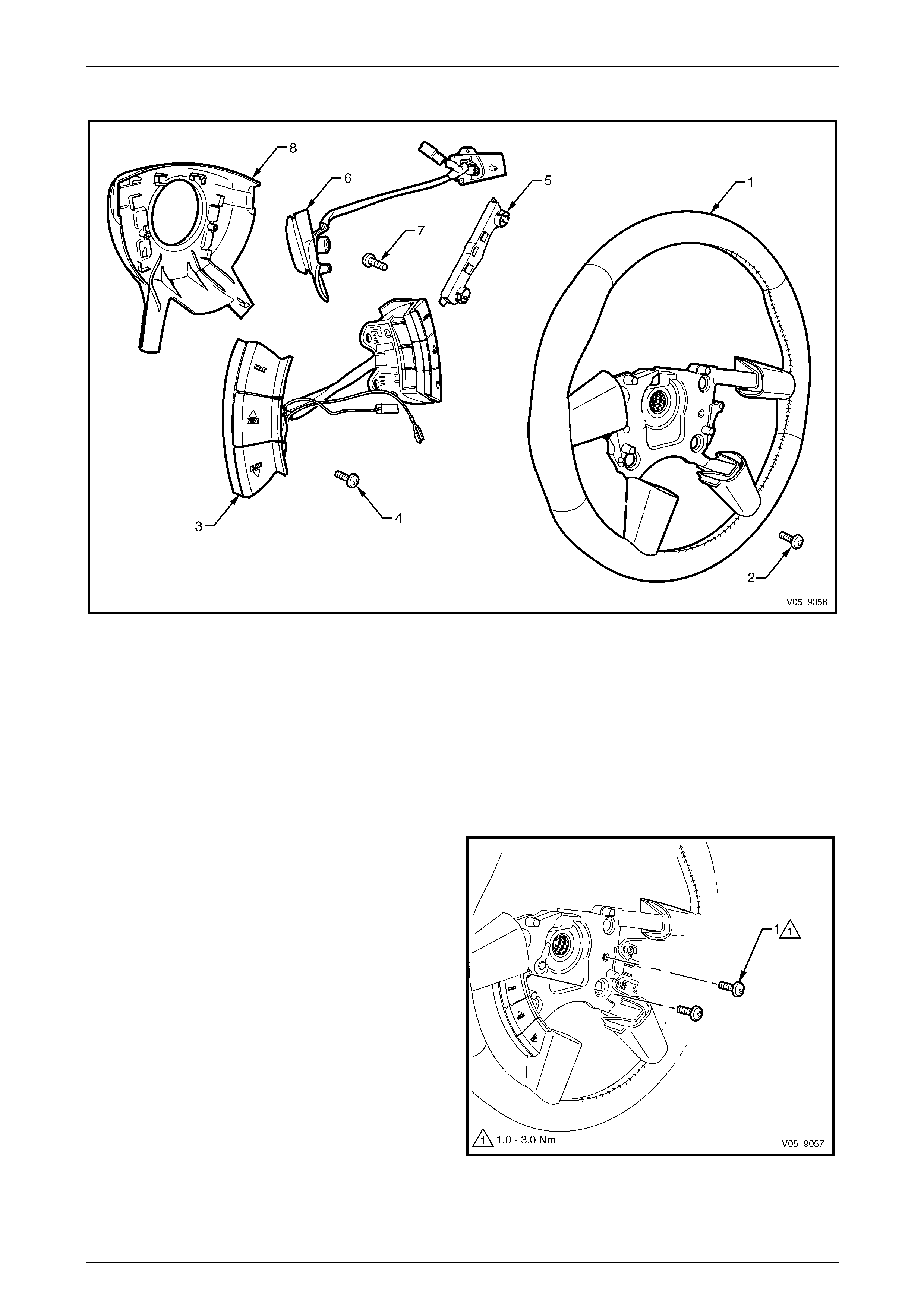
2 From the rear of the steering wheel assembly (1),
gently prise the rear cover (2), releasing the retaining
clips from the steering wheel assembly hub and
remove the cover.
NOTE
Ensure the wiring harness is free from the
retaining clips in the cover.
Figure 9 – 22
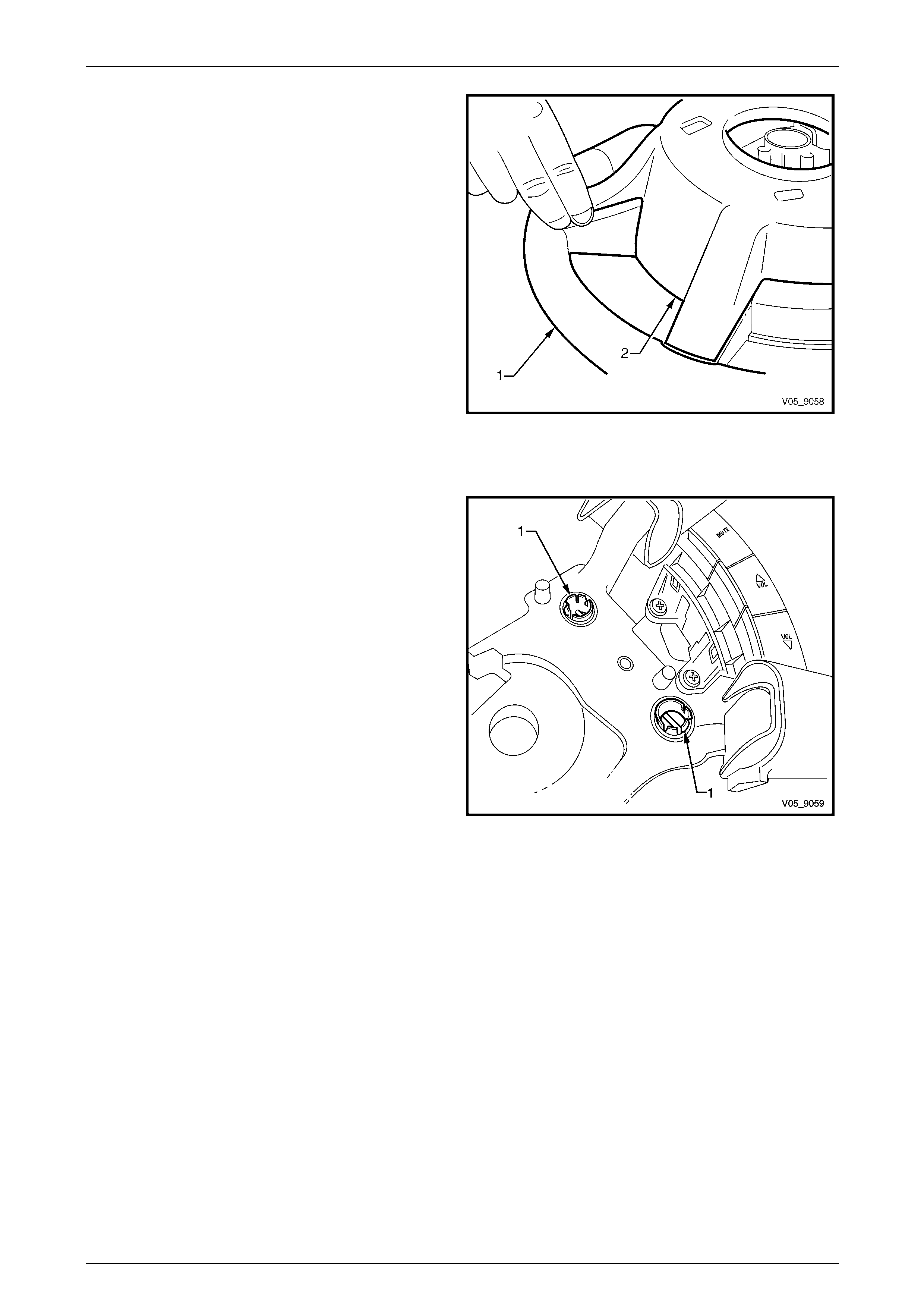
Steering Wheel Inflatable Restraint Retaining Clip
1 Remove the steering wheel inflatable restraint
retaining clip by pressing the tangs (1) and pushing
the clip out through to the rear of the steering wheel
assembly hub.
2 Repeat for the remaining clip as required.
Figure 9 – 23
Steering Page 9–28
Page 9–28
Horn Bar Stereo Control Switch Assembly
NOTE
The horn bar stereo control switch assembly
consists of two switches connected together by a
wiring harness.
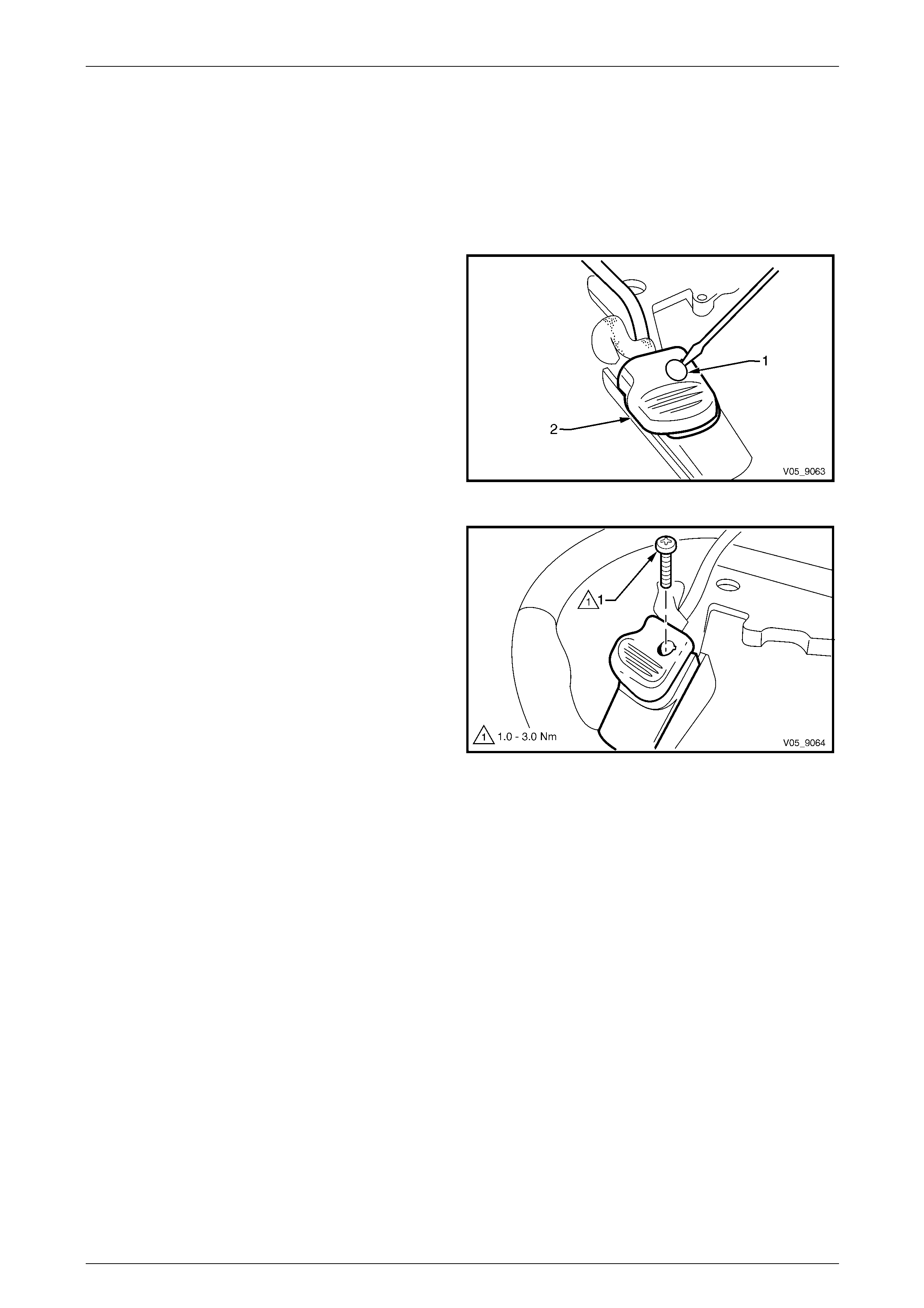
1 If required, disconnect the active select shift control
paddle wiring harness connector (1).
Figure 9 – 24
2 Disconnect the ground lead (1) by pushing on the clip
(2) in the connector terminal (3).
Figure 9 – 25
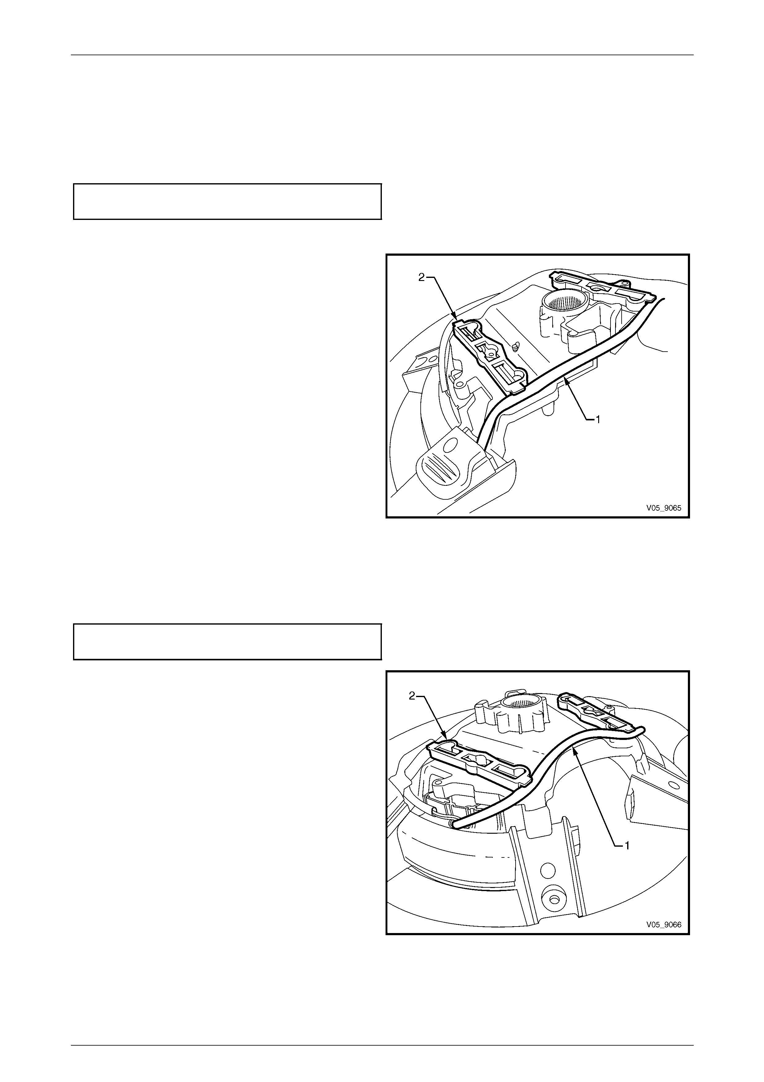
3 Remove the two screws (1) attaching the horn bar
stereo control switch (2) to the steering wheel
assembly hub (3) and remove the switch from the
hub.
4 Repeat for the remaining stereo control switch.
Figure 9 – 26
Steering Page 9–29
Page 9–29
Active Select Shift Contro l Paddle Assembly
NOTE
The active select shift control paddle assembly
consists of two switches connected together by a
wiring harness.
1 Disconnect the active select shift control paddle wiring harness connector (1), refer to Figure 9 – 24.
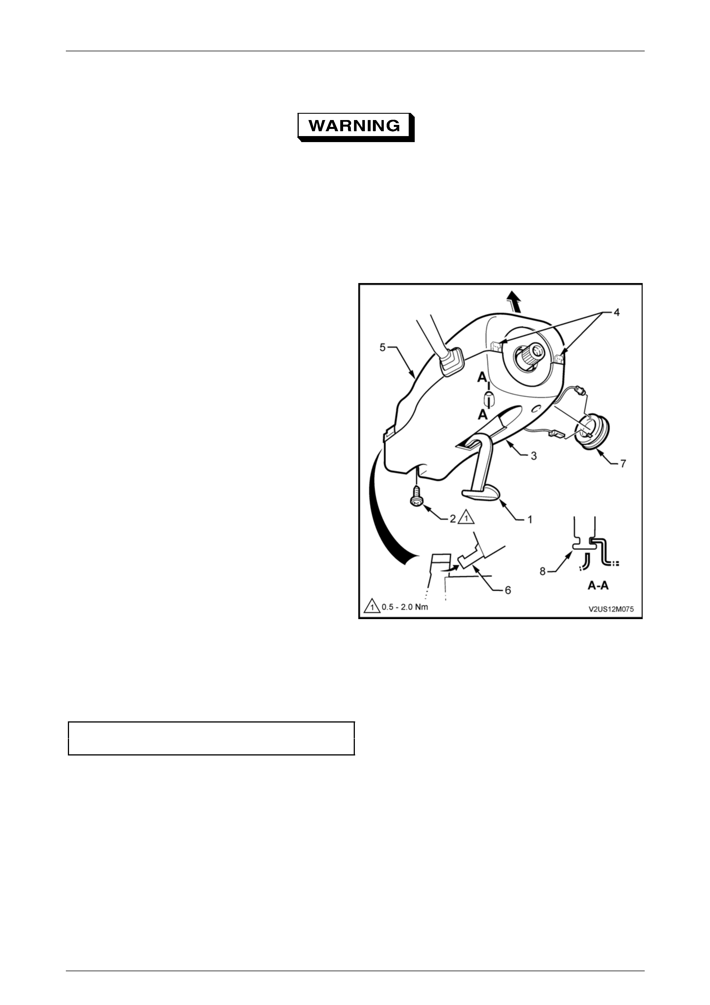
2 Using a small flat-blade screwdriver, carefully prise
the shift paddle attaching screw cover (1) from the
rear of the shift paddle (2).
Figure 9 – 27
3 Remove the screw (1) attaching the shift paddle to the
steering wheel assembly and remove the sh ift paddle.
4 Repeat Steps 2 and 3 for the remainin g shift paddle.
Figure 9 – 28
Steering Page 9–30
Page 9–30
Reassemble
Active Select Shift Contro l Paddle Assembly
1 Reinstall the active select shift control paddle assembly to the steering wheel ass embly and tighten the attaching
screw to the correct torque specification.
Active select shift control paddle assembly
attaching screw torque specification...........1.0 – 3.0 Nm
2 Reconnect the shift paddle wiring harness connector, refer to Figure 9 – 24.
3 Ensure the wiring harness (1) is positioned under the
two inflatable restraint retaining clips (2).
4 Reinstall the shift paddle attaching screw covers.
NOTE
The shift paddle attaching screw covers are
marked as + and - on the underside of the
cover. Ensure the covers a fitted to the correct
paddle.
Figure 9 – 29
Horn Bar Stereo Control Switch Assembly
1 Reinstall the horn bar stereo control switch assembly to the steering wheel hub and tighten the attaching screws to
the correct torque specification.
Horn bar stereo control switch assembly
attaching screw torque specification...........1.0 – 3.0 Nm
2 Position the wiring harness (1) under the inflatable
restraint retaining clips (2).
3 Reconnect the ground lead with the release tang
facing up, refer to Figure 9 – 25.
Figure 9 – 30

Steering Page 9–31
Page 9–31
Rear Cover
Reinstallation of the rear cov er is the reverse of the removal procedure, noting the follo wing:
1 Tighten the attaching screws to the correct torque specification.
Rear cover attaching screw
torque specification.....................................1.0 – 3.0 Nm
2 If required, check the active shift paddle s witches operate correctly and are not restricted by the rear cover.
3 Ensure the wiring harness an d conn ectors are located in their retainer and the wiring is not exposed or trapped
between the cover and the steering wheel hub.
Reinstall
1 Ensure the road wheels are in the straight-ahead position.
2 Centralise the clockspring coil, refer to Section 12M Occupant Protection System.
3 Install the steering wheel assembl y in its corr ect orientation as marked in the removal procedure and carefully feed
the clockspring wires through the aperture in the wheel assembly.
4 Clean the threads of the steering wheel attaching bolt and steering shaft thread and apply Loctite 242 or equivalent
to the thread of the attaching bolt.
5 Tighten the steering wheel attaching bolt to the correct torque specification.
¡ Steering wheel assembly
attaching bolt
torque specification.................................40.0 – 50.0 Nm
6 Connect the wiring connectors as required and ensure the wiring harness connectors are located in their retainer
and the wiring is not exposed or trapped between the inflatable restraint assembly and the steering wheel hub.
7 Reinstall the steering wheel inflatable restraint assembly, refer to Section 12M Occupant Protection System.
8 Check there is no fouling of the steering column covers. Check for correct operation of;
• the horn,
• turn signals,
• entertainment system,
• active select shift control paddles, and
• occupant protection system.
Steering Page 9–32
Page 9–32
3.2 Steering Column Covers
Disable the occupant protection system
prior to commencing any service operations
on the steering column, refer to
Section 12M Occupant Protection System.
LT Section No. — 06–250
Remove
1 Release steering column height adjuster (1),
completely lower steering col umn and leave the
adjuster in the released position.
NOTE
The steering column covers can be removed
with the steering wheel assembly installed,
however the steering wheel assembly is not
shown for clarity.
2 From below the steering column, remove the screw
(2) attaching the lower cover (3).
3 Depress the face of the lower cover inwards to
disengage the tabs (4) and lift the steering column
upper cover (5).
4 Raise the upper cover as high as possible to
disengage the lugs (6) and remove the cover.
5 Push the outer ring of the theft deterrent key read er
assembly (7) into the steering column lower cover.
6 Slide the lower cover rearward to disengage it from
the lugs (8) and remove the cover.
Figure 9 – 31
Reinstall
Reinstallation of the steering column covers is the reverse of the removal procedure. Tighten the screws to the correct
torque specification.
Steering column lower cover
attaching screw torque specification...........0.5 – 2.0 Nm
Steering Page 9–33
Page 9–33
3.3 Ignition Barrel and Lock Cylinder
LT Section No. — 06–255
Remove
Disable the occupant protection system
prior to commencing any service operations
on the steering column, refer to
Section 12M Occupant Protection System.
Disconnection of the battery affects certain
vehicle electronic systems. Refer to
Section 00 Warnings, Cautions and Notes
before disconnecting the battery.
1 Disconnect the battery ground lead a nd remove the ignition keys from the ignition switch.
2 Remove the instrument panel lower trim panel assembly, refer to Section 1A3 Instrument Panel and Console.
3 Remove the steering column upp er and lower covers, refer to 3.2 Steering Column Covers.
Lock the steering wheel so the front wheels
are in the straight-ahead position to prevent
the steering shaft from being rotated during
the removal of the clock spring coil.
4 Release the steering column tilt/reach clamp lever, lower the column to the lowest point and lock the clamp lever in
this position.
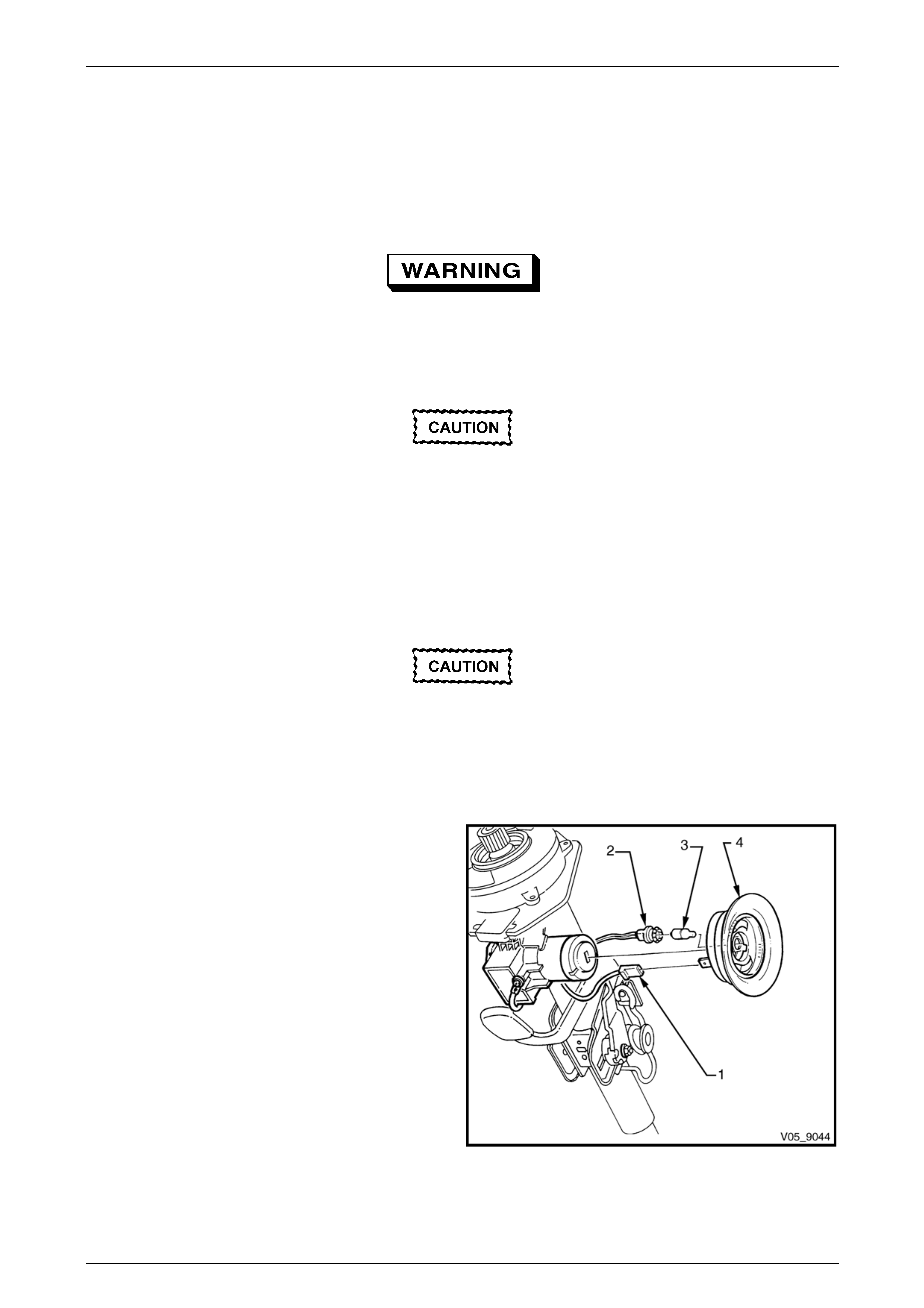
5 Disconnect the key reader wiring harness connector
(1), ignition lock illumination socket (2) and bulb (3)
from the key reader assembly (4).
NOTE
The ignition ba rrel lock cylinder can be rem oved
with the steering wheel installed, however the
steering wheel is not shown for clarity.
6 Carefully, pull the key reader from the ignition lock
assembly housing.
Figure 9 – 32
Steering Page 9–34
Page 9–34
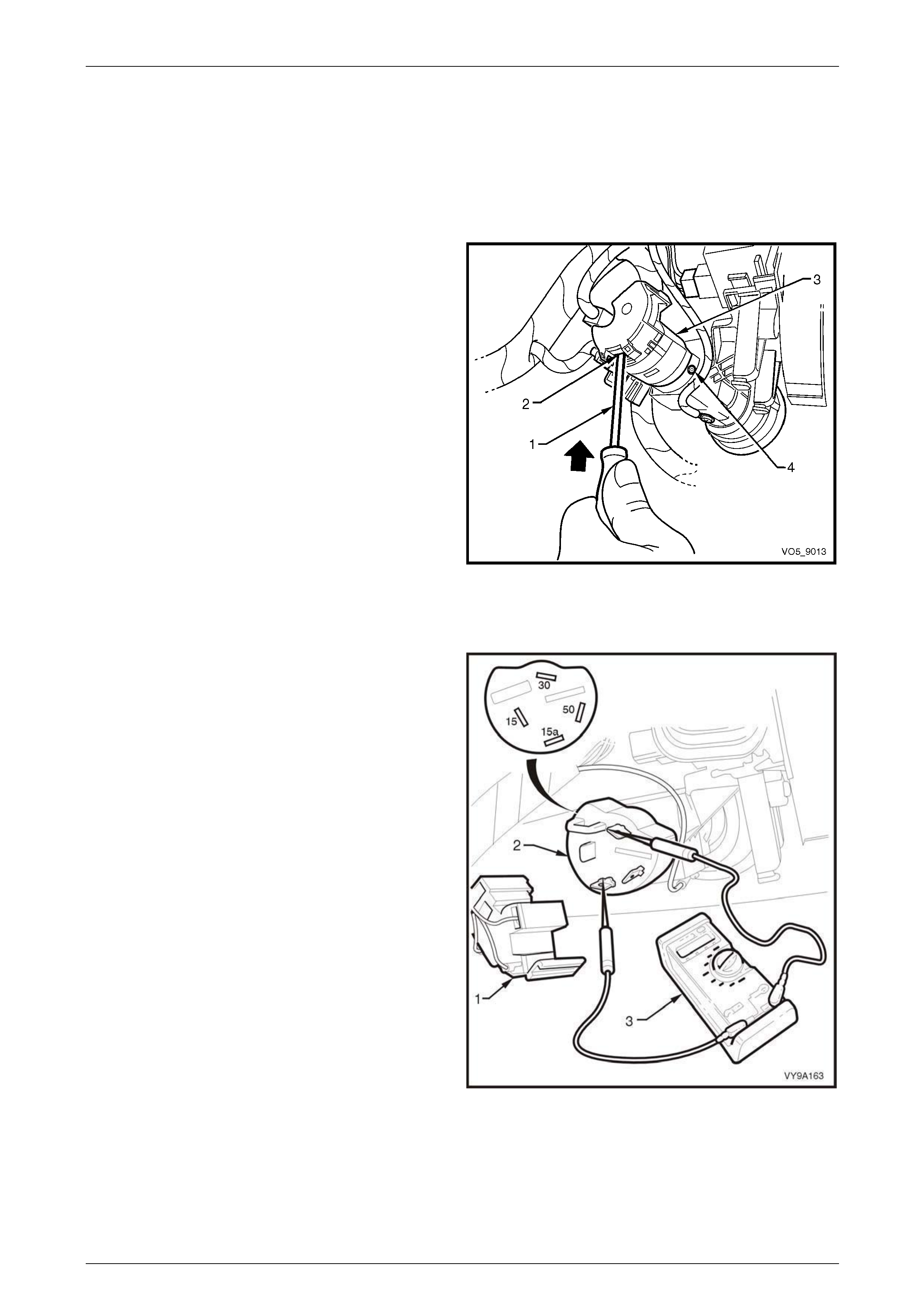
7 Insert the ignition key (3) into the barrel an d turn the
key to the ON position.
8 Insert a 2.5 mm diameter pin (1) into the locking pin
hole, depress the spring loaded barrel locking latch to
release the lock cylinder.
NOTE
An Allen key could be used as an alternative.
9 Remove the pin and pull the barrel (2) from the lock
housing.
Figure 9 – 33
Reinstall
1 Install the key into the ignition barrel and turn the ignition to the ON position.
2 Insert the barrel into the lock housing until the latch locks into the housing.
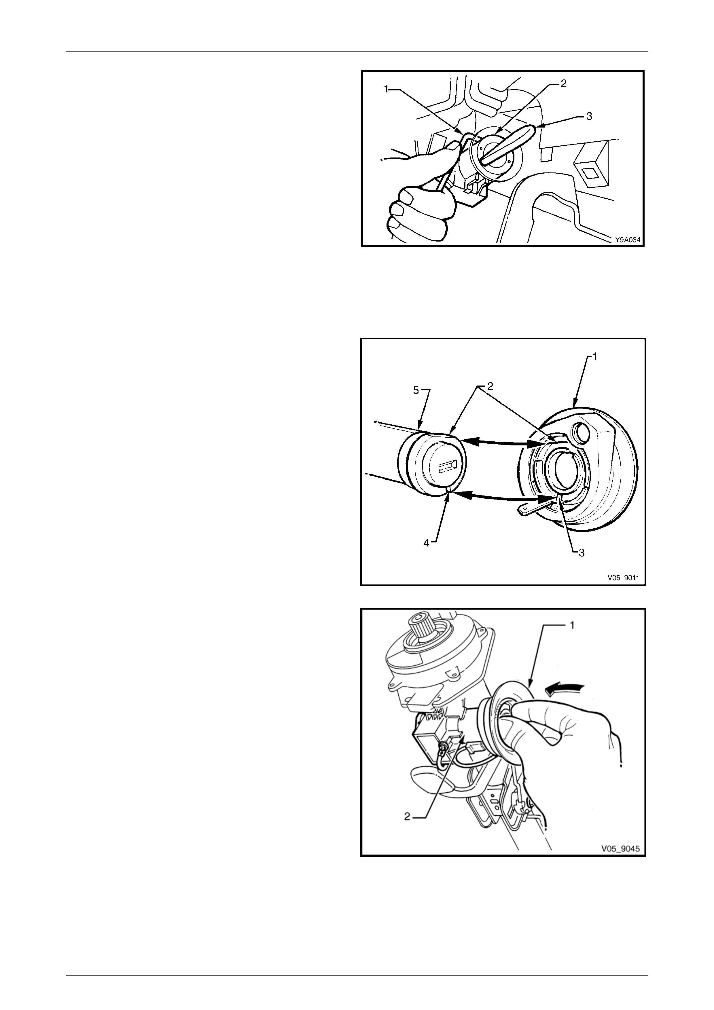
3 Install the ignition key reader ( 1). Align the flats (2)
and indexing lug (3) of the key reader, with the mating
groove (4) on the ignition lock assembly (5).
Figure 9 – 34
4 Gently press the key reader assembly (1) ont o the
ignition lock (2) by pushing evenly between the two
key reader seats, until the reader assembly locates
onto the ignition lock.
5 Install the wiring harness connector, ignition lock
illumination bulb and socket to the key reader
assembly.
6 Reinstall the steering column covers, refer to
3.2 Steering Column Covers.
7 Reinstall the steering wheel inflatable restraint
assembly, refer to Section 12M Occupant Protection
System.
8 Check there is no fouling of the steering column
covers. Check for correct operation of:
• the horn,
• turn signals,
• entertainment system,
• active shift paddles, and
• occupant protection system. Figure 9 – 35
Steering Page 9–35
Page 9–35
3.4 Ignition Switch
LT Section No. — 06–255
Remove
1 Remove the ignition barrel lock cylinder, refer to 3.3 Ignition Barrel and Lock Cylinder.
2 Insert a fine bladed screw driver (1) into the conn ector
housing clip opening (2) and push the clip inwards to
disengage.
3 Disconnect the wiring harness connector (3) from the
ignition switch.
4 Remove the ignition s witch to steering lock housi ng
retaining grub screw (4).
5 Pull the switch from the steering lock housing,
disengaging the roll pin from the sid e opposite the
grub screw.
Figure 9 – 36
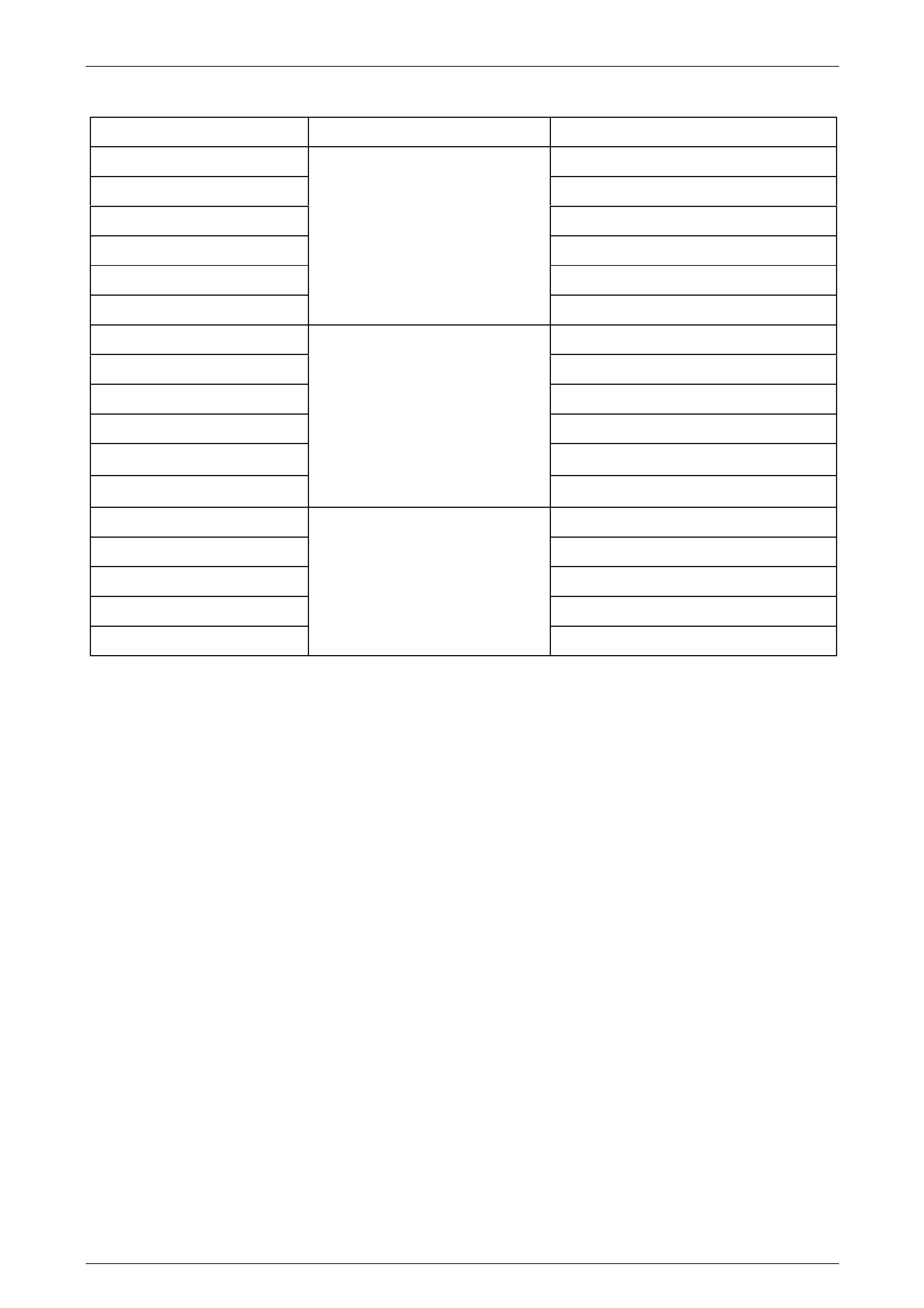
Test
1 Disconnect the wiring harness connector (1) from the
ignition switch (2).
2 Using an Ohmmeter (3), check the ignition switch
contacts at each switch position as indicate d in the
following chart.
3 If the circuit condition is not as specified, replace the
switch assembly.
NOTE
With the switch in the off/lock position, an open
circuit reading should occur between all
terminals.
Figure 9 – 37
Steering Page 9–36
Page 9–36
Switch Terminals Switch Position Indication
30 and 15a Continuity
30 and 15 Open
30 and 50 Open
15a and 15 Open
15 and 50 Open
15 and 50
ACCESSORIES
Open
30 and 15a Continuity
30 and 15 Continuity
30 and 50 Open
15a and 15 Continuity
15a and 50 Open
15 and 50
IGNITION
Open
30 and 15a Open
30 and 15 Continuity
30 and 50 Continuity
15a and 15 Open
15 and 50
START
Open
Reinstall
Reinstallation of the ignition switch is the reverse of the removal procedure, noting the following:
1 Install the ignition switch into the housing taki ng note of the following:
a Ensure the switch body e ngages the locating roll pin in the housing.
b The slot in the end of the switch aligns with the stepped end of the ignition barrel shaft.
2 Secure the switch by tightening the grub screw firmly.
3 Reconnect the wiring harness connector to the ignition switch and reconnect the battery ground lea d
4 Insert the ignition key and check the igniti on switch lock and barrel operations.
5 Reinstall the steering column covers, refer to 3.2 Steering Column Covers.
6 Ensure all steering column mounte d contro ls and switches are operating correctly.
Steering Page 9–37
Page 9–37
3.5 Steering Column Assembly
LT Section No. — 06–253
Remove
Disable the occupant protection system
prior to commencing any service operations
on the steering column, refer to
Section 12M Occupant Protection System.
Disconnection of the battery affects certain
vehicle electronic systems. Refer to
Section 00 Warnings, Cautions and Notes
before disconnecting the battery.
1 Disconnect the ground lead from the batter y.
2 Remove the steering wheel, refer to 3.1 Steering W heel Assembly.
3 Steering column upper and lower trim covers , refer to 3.2 Steering Column Covers.
Lock the steering wheel so the front wheels
are in the straight-ahead position to prevent
the steering shaft from being rotated during
the removal of the clock spring coil.
NOTE
For steering column removal, it is not necessary
to completely remove the instrument panel lower
trim panel. For this procedure, leave the data link
connector (DLC) attached to the panel, swing the
panel to one side and secure with a cable tie or
similar.
4 Refer to Section 1A3 Instrument Panel and Console and remove the foll owing:
• Instrument panel lower trim retainer,
• instrument lower trim plate assembly, and
• driver’s side instrument panel outer cover.
5 Remove the driver’s side HVAC unit to driver’s door inner duct,
refer to Section 2E HVAC Occupation Climate Control (Auto A/C) Removal and Installation.
6 Remove the turn signal switch, refer to Section 12B Lighting System.
7 Remove the wiper/washer switch, refer to Section 12N Wipers, Washers and Horn.
8 Loosen but do not remove the steering column to instrument panel mounting bolts.
9 Raise the front of the vehicle and place on safety stands. Refer to Section 0A General Information for the locations
of the jacking points.
Steering Page 9–38
Page 9–38
When performing steering gear or column
service procedures where the steering gear
coupling will be disconnected, remove the
ignition key from the ignition lock and ensure
the steering column is locked in the straight
ahead position. If this operation is not carried
out and the steering wheel is spun while the
steering gear coupling is removed from the
steering gear, the clockspring will be
destroyed. This could result in a diagnostic
trouble code (DTC) and possible non-
deployment of the inflatable restraint.
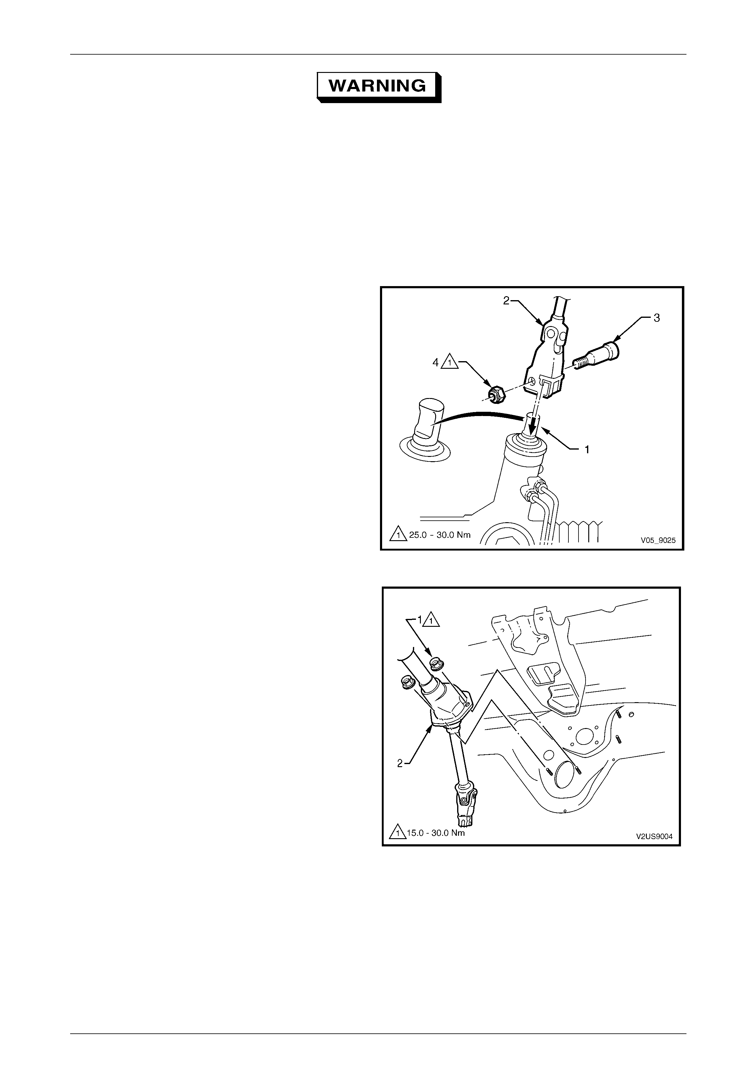
10 From under the vehicle, remove the steering coupling
crimp nut (1).
11 Remove the steering coupling cam bolt (2) and
disengage the retaining cl ip (3).
12 Slide the coupling (4) away from the steering gear
pinion shaft.
Figure 9 – 38
13 From inside the vehicle, remove the t wo nuts (1),
attaching the lower housing assembly (2) to the dash
panel assembly.
14 Remove the previously loosened upper column
attaching bolts while supportin g the steerin g column.
15 Remove the steering column assemb ly from the
vehicle.
Figure 9 – 39

Steering Page 9–39
Page 9–39
Inspect
NOTE
Any vehicle that has been involved in a collision
resulting in major b ody or sheetmetal damage, or
where the steering column has been impacted,
may suffer steering column damage or
misalignment.
1 Check to see if either of the two mounting lugs have been dislodged from the column bracket and the control
springs are undamaged.
2 Check for any damage to the steerin g column and/or shaft that can cause binding or jamming.
NOTE
Should any component of the steering column
assembly show signs that distortion has occurred
the steering column must be replaced as an
assembly.
Disassemble
Non-serviced Components
The following components are not serviced separately:
• Steering lock,
• Steering column lower bearing,
• Steering column upper bearing, or
• Steering column coupling.
If any of these components are found to be faulty, the steering column assembly must be replaced.
Clock Spring Assembly
For clock spring assembly service operations refer to Section 12M Occupant Protection System.
Steering Page 9–40
Page 9–40
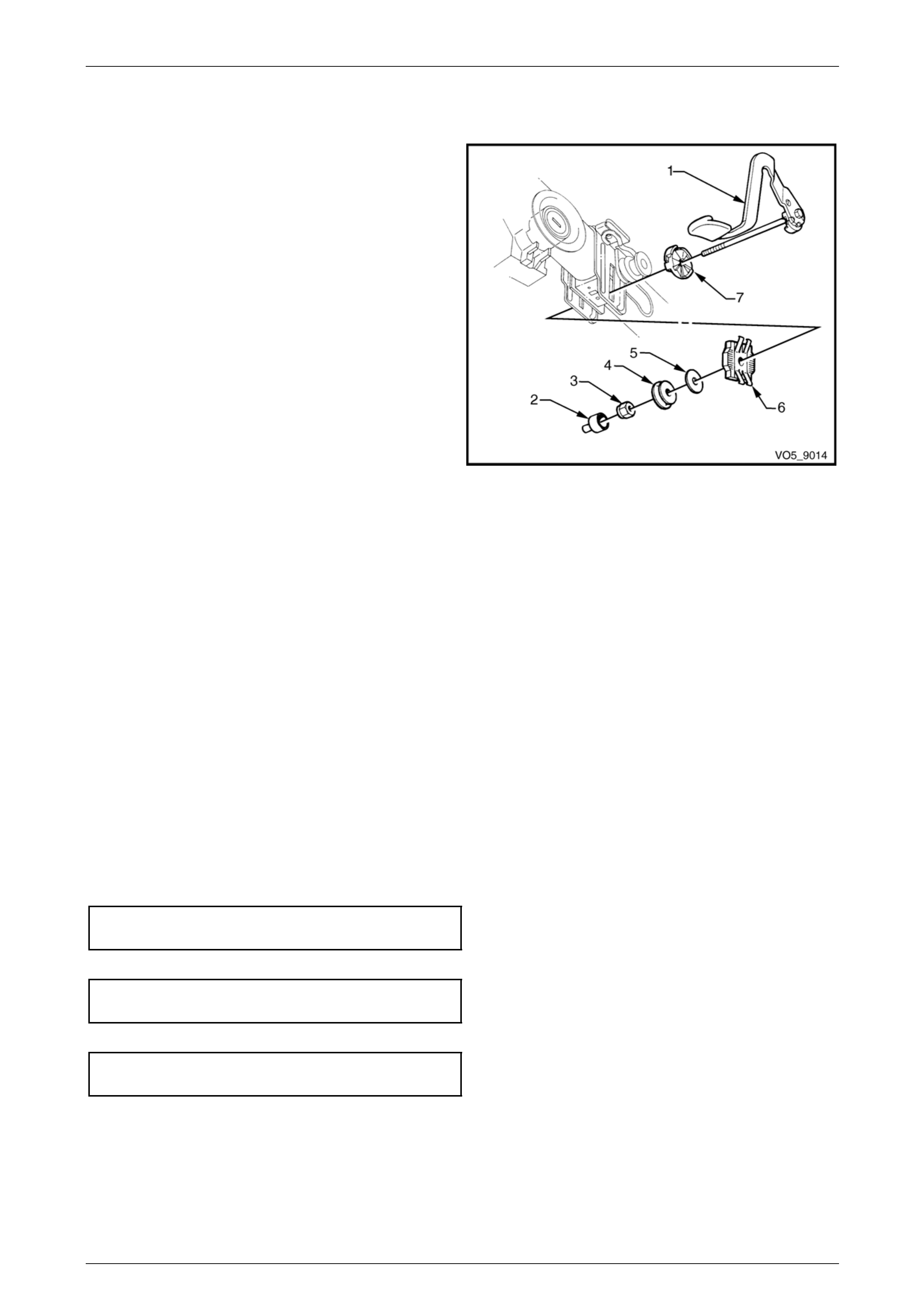
Tilt/ Reach Handle
Remove
1 Release the tilt/reach handle ( 1). W hile sup porting the
tilt/reach handle with one hand, remove the nut cover
(2) and attaching nut (3).
2 Withdraw the through bolt and han dle, removing the
bearing (4), washer (5), outer rack (6) and in ner cam
(7).
Reinstall
NOTE
• The final tension on the through bolt
determines the security of the upper steeri ng
column assembly. T he final nut tension must
be determined by adopting the following
procedure.
• A commercially available force gauge is
required to accurately measure the force.
1 Install the through bolt and the replaceme nt han dle,
through the inner cam. Figure 9 – 40
2 Apply Loctite 242 or equi valent to the bolt thread. NOTE
The attaching nut must be replaced when
removed from the tilt/reach handle.
3 Install the remaining components in the reverse order of removal and install a new attaching nut.
4 Tighten the tilt/reach handle throu gh bolt attaching nut until a force of 80 N is required to push the lever closed.
5 With the lever released, check the column is free to slide up and down. If the outer rack grates, loosen the nut just
sufficient enough to allow free movement of the column.
6 Install the attaching nut cover.
Reinstall
Reinstallation of the steering column assembly is the reverse of the removal procedur e, noting the following:
1 Inspect the foam seal affixed to the lower housing to ensure it is serviceable. If required, apply a co ntinuous bead
of silicone sealant such as RTV 732 or equivalent to the seal material.
2 Install the steering coupling through the floor panel and install the two lower housing attaching nuts. Do not tighten
at this stage.
3 Raise the column assembly and loosely install the two upper support bracket attaching bolts.
4 Engage the steering coupling with the steering rack pinion shaft, install the cam bolt and a new crimp nut to the
lower coupling, refer to F igure 9 – 38. Do not tighten at this stage.
5 Tighten the lower housing attaching nuts from inside the vehicle to the correct torque specification.
Steering column lower housing
attaching nut torque specification............15.0 – 30.0 Nm
6 Tighten the upper bracket to instrument panel attaching nuts to the correct torque specification.
Upper steering column mount
attaching nut torque specification............15.0 – 30.0 Nm
7 Tighten the cam bolt attaching nut to the correct torque specification.
Steering coupling cam bolt
retaining nut torque specification ............25.0 – 30.0 Nm
8 Connect the battery ground lead and check for correct operation of:
• the horn,
• turn signals,
• entertainment system,
• active shift paddles, and
• the occupant protection system, refer to Section 12M Occupant Protection System.
Steering Page 9–41
Page 9–41
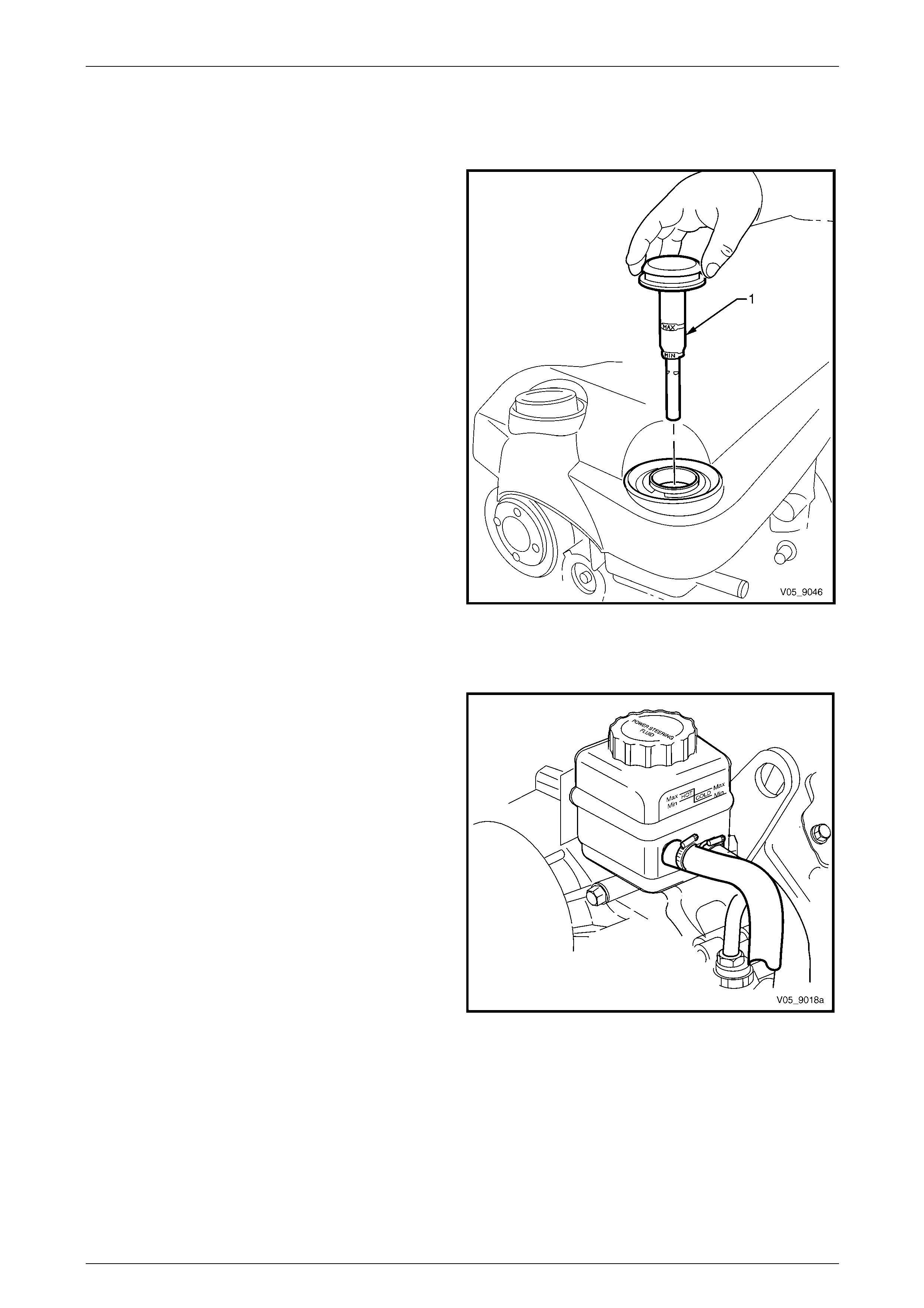
3.6 Power Steering Fluid Level Check
V6 Engine
The power steering fluid can be checked by carefully
removing the dipstick (1) from the reservoir and checking
the level on the dipstick.
The power steering fluid should be mi dway between the
MIN and MAX range when at operating temperature.
If the power steering fluid level is at the low side of the MIN
range, new power steering fluid sho uld be added to bring
the level to the correct point and the system checked for the
cause of the leakage and corr ected as necessary.
NOTE
Use only the recommended power steering fluid
Dexron® III automatic transmission fluid or the
equivalent.
Figure 9 – 41
GEN III V8 Engine
The power steering fluid level can be checked by viewing
the level through the translucent plastic side of the
reservoir.
If the power steering fluid is cold, the level should be at the
COLD MAx position. Similarly, if it is hot, the power steering
fluid should be in the HOT Max position. If the po wer
steering fluid level is at the low side of either range, new
power steering fluid should be added to bring the level to
the correct point and the system checked for the cause of
the leakage and corrected as necessary.
NOTE
Use only the recommended power steering fluid
Dexron® III automatic transmission fluid or the
equivalent.
Figure 9 – 42

Steering Page 9–42
Page 9–42
3.7 Drive Belt Adjustment
The power steering pump is driven b y the engi ne serpentine drive belt. The belt is self adjusting within the tensioner
operating limits. For further information, refer to either:
• Section 6B1 Engine Co oling – V6.
• Section 6B3 Engine Cooling – GEN III V8.
Drive belt condition and tension is crucial to the correct operation of the power steering system. A worn or loose drive
belt can cause the steering to become heavy and inconsistent.
Steering Page 9–43
Page 9–43
3.8 Tie-rod Socket
LT Section No. — 06–310
Remove
The tie-rod socket is serviced as an assembl y and must be replaced when any excessive up or down movement is
evident or if any lost motion or end play exists at the ball end of the stud.
1 Raise the front of the vehicle and place on safety stands. Refer to Section 0A General Information.
2 Remove the front road wheel/s, refer to Section 10 Wheels and Tyres.
3 Loosen the tie-rod lock nut (1).
4 Remove the split pin and nut from the tie-rod ball stud.
5 Using tie-rod end separator Tool No. 9A10 or similar,
tighten the centre screw to force the stud from the
taper in the steering arm.
6 Unscrew the socket (2) from the tie-rod, counting the
number of turns to wind the socket from the tie-rod.
Figure 9 – 43
Reinstall
1 Reinstall the tie-rod socket onto the tie-ro d and wind it on the same number of turns as noted in Step 6 of the
removal procedure.
NOTE
Ensure the nylon spacer is positioned in the tie-
rod socket stud before installing the tie-rod socket
into the steering knuckle. Replace the spacer if
damaged.
2 Reinstall the tie-rod socket to the steering arm.
3 Reinstall the castellated nut and tighte n to the correct torque specification.
Tie-rod socket castellated attaching nut
torque specification.................................50.0 – 85.0 Nm
4 Install a new split pin into the tie-rod ball stud.
5 Tighten the tie-rod adjuster end lock nut to the correct torque specification.
Tie-rod end adjuster lock nut
torque specification.................................50.0 – 85.0 Nm
6 Reinstall the road wheel/s, refer to Section 10 Wheels a nd Tyres.
7 Lower the vehicle to the ground.
8 Check the front wheel toe-in setting and ad just as required, refer to Section 3A Front Suspension.
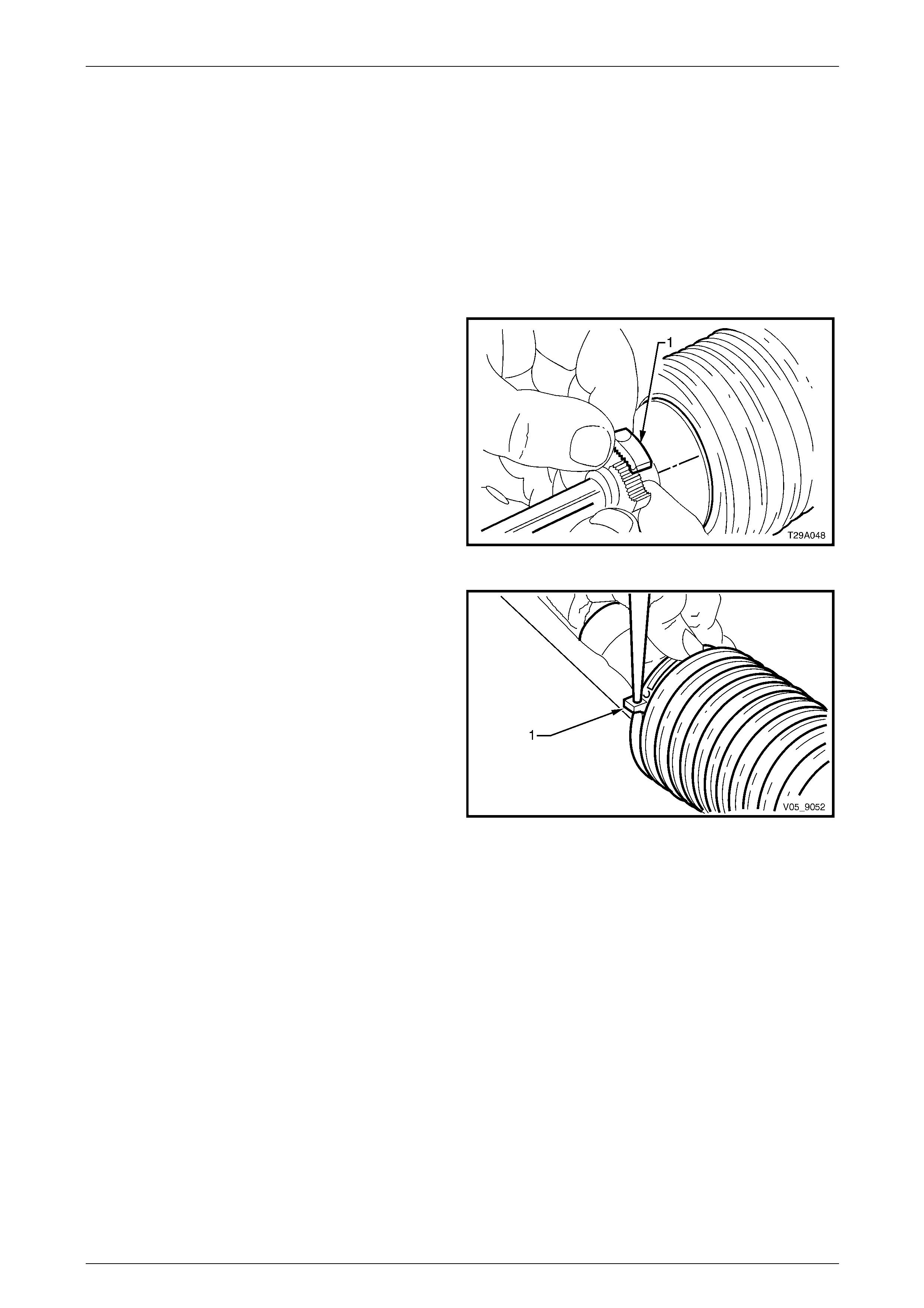
Steering Page 9–44
Page 9–44
3.9 Steering Gear Boot
LT Section No. — 06–310
Remove
1 Raise the front of the vehicle and place on safety stands, refer to Section 0A General Information.
2 Remove the front road wheel/s, refer to Section 10 Wheels and Tyres.
3 Remove the tie-rod socket, refer to 3.8 Tie-rod Socket.
4 Unclip and remove the outer steering ge ar boot
attaching clip (1) by moving ends of clips sideways
until it disengages. Then slide it off the steering ge ar
boot.
Figure 9 – 44
5 Remove the inner attaching clip (1), b y pushing out
the pin retaining the clip ends together using a fine pin
punch. Alternatively use a suitable pair of pliers and
carefully cut the attaching clip.
6 Place a suitable sized tray under the vehicl e to
contain any fluid that may be spilt in the follo wing
operation.
7 Slide the steering gear boot from the steerin g gear
housing and tie-rod.
Figure 9 – 45
Steering Page 9–45
Page 9–45
Reinstall
1 Ensure the steering gear is centralised in the straight ahead position, this is achieved by either of the following
methods.
a Turn the rack from lock to lock counting the number of turns then turn it back to half the number of turns
counted when turned from lock to lock.
b Before installing the steering gear boot, fold back both boots and measure the exposed portion of each end of
the rack from the housing. When both measur ements are equal, the rack is centralised.
2 Position the steering gear boot on the steering ge ar and the tie-rod so that it is not twisted.
3 Fit a new inner attaching clip and reinstall the outer clip.
NOTE
Ensure the plastic spacer that is positioned on
tie-rod end ball stud is in good condition before
fitting the tie-rod end stud into the steering
knuckle. Replace the spacer if damaged.
4 Reinstall the tie-rod socket, refer to 3.8 Tie-rod Socket.
5 Install the road wheel, refer to Section 10 Wheels and Tyres.
6 If required, refill and bleed the power steering hydraulic system,
refer to 3.14 Hydraulic System Bleeding and Refilling.
7 Check the front wheel alignment setting and adjust as required, refer to Section 3A Front Suspensio n.
8 Tighten the tie-rod lock nut to the correct torque specification.
Tie-rod adjuster lock nut
torque specification.................................40.0 – 60.0 Nm
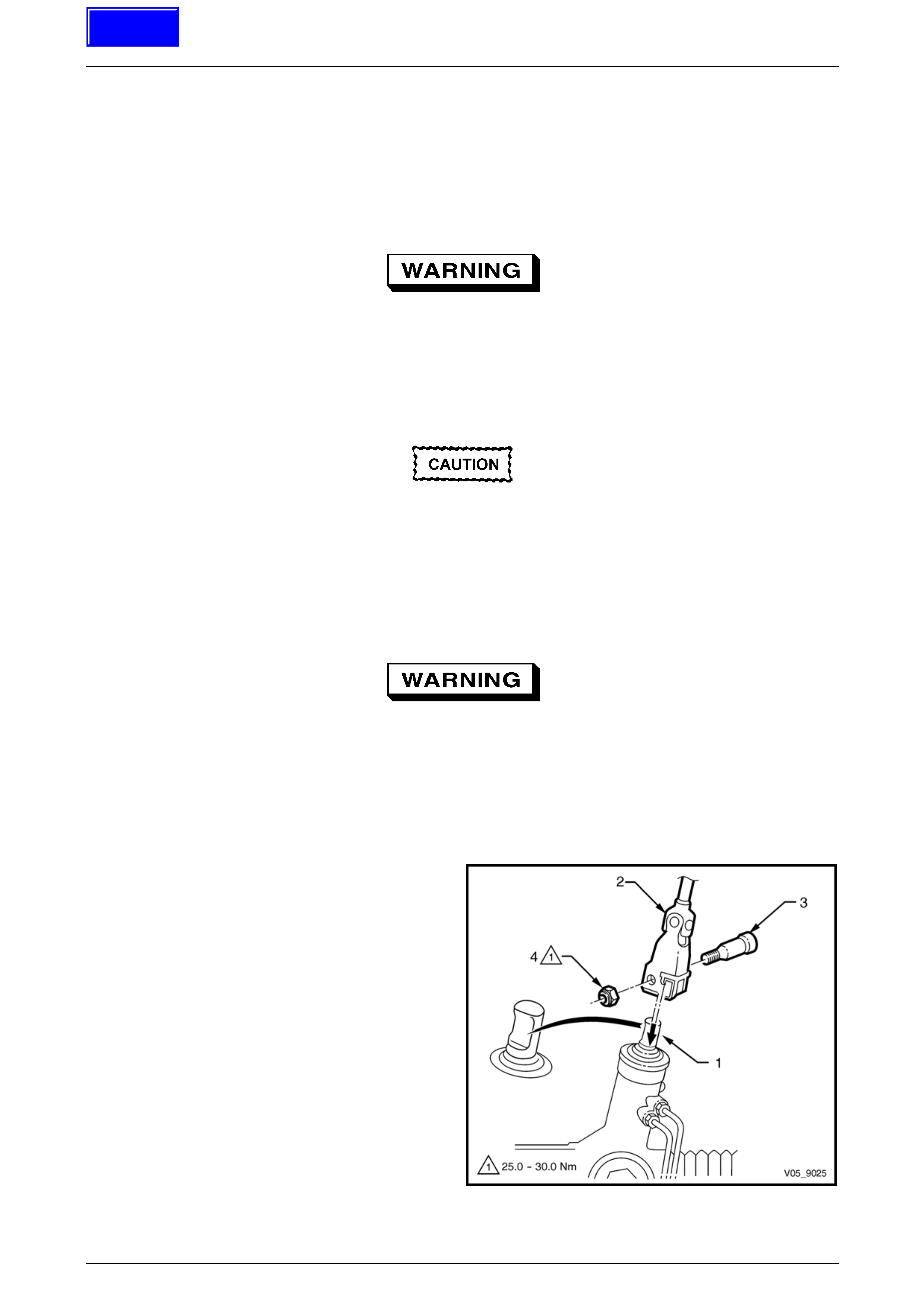
Steering Page 9–46
Page 9–46
3.10 Power Steering Gear Assembl y
LT Section No. — 06–275
Remove
Power steering fluid when at operating
temperature can reach temperatures of
approximately 75° Celsius. When handling
power steering fluid or steering components,
the appropriate safety glasses, gloves and
clothing must be worn to protect against
possible burns.
Disconnection of the battery affects certain
vehicle electronic systems. Refer to
Section 00 Warnings, Cautions and Notes
before disconnecting the battery.
1 Disconnect the ground lead from the batter y.
2 Raise the front of the vehicle and place on safety stands, refer to Section 0A General Information.
3 Remove the front road wheels, refer to Section 10 Wheels and Tyres.
When carrying out steering gear or column
procedures where the steering gear coupling
will be disconnected, remove the ignition key
from the ignition lock and ensure the steering
column is locked. If this operation is not
carried out and the steering wheel is spun
while the steering gear coupling is removed
from the steering gear, the clockspring will be
destroyed.
4 Remove the steering column coupling crimp nut (1).
5 Remove the steering column coup ling cam bolt (2)
then disengage the retaining clip (3) and slide the
coupling (4) away from the steering gear pinion shaft.
6 Place a suitable sized tray under the vehicl e to
contain any fluid that may be spilt in the follo wing
operation.
Figure 9 – 46
Techline

Steering Page 9–47
Page 9–47
7 Loosen and remove the hydraulic lines (1 and 2) from
the steering gear valve housing (3) and allow the
power steering fluid to drain into a suitable container.
NOTE
Ensure the O-rings are removed from the
steering gear valve housing when the lines are
removed. Replace the O-rings when reinstalling
the lines.
Figure 9 – 47
8 Remove the tie-rod end split pins and castellated nuts.
9 Separate the tie-rod end ball stud (1) from the steering
arm tapers using a suitable remover, such as Tool
No. 9A10.
10 Repeat Steps 8 and 9 for the opposite side.
Figure 9 – 48
11 Remove the two bolts (1) and nuts (2) attaching the
steering gear housing to the front suspension
crossmember (3).
12 Remove the steering gear by pullin g it out from the
front suspension crossmember mountin g.
Figure 9 – 49
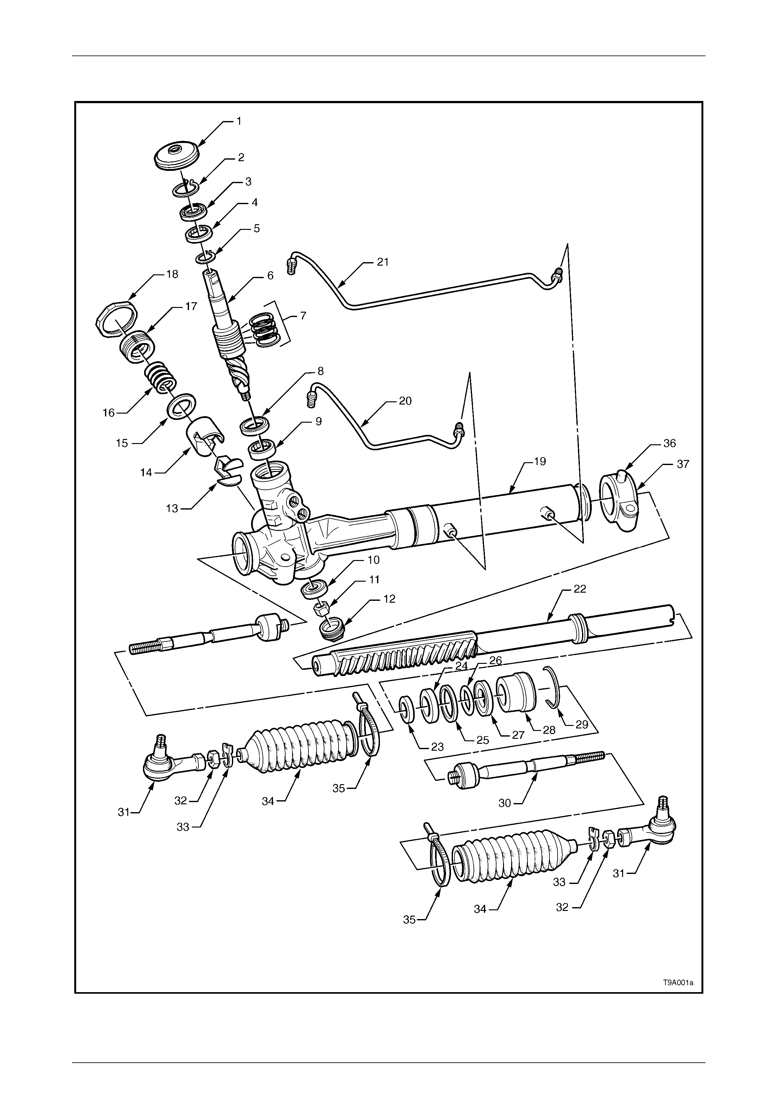
Steering Page 9–48
Page 9–48
Disassemble
Figure 9 – 50
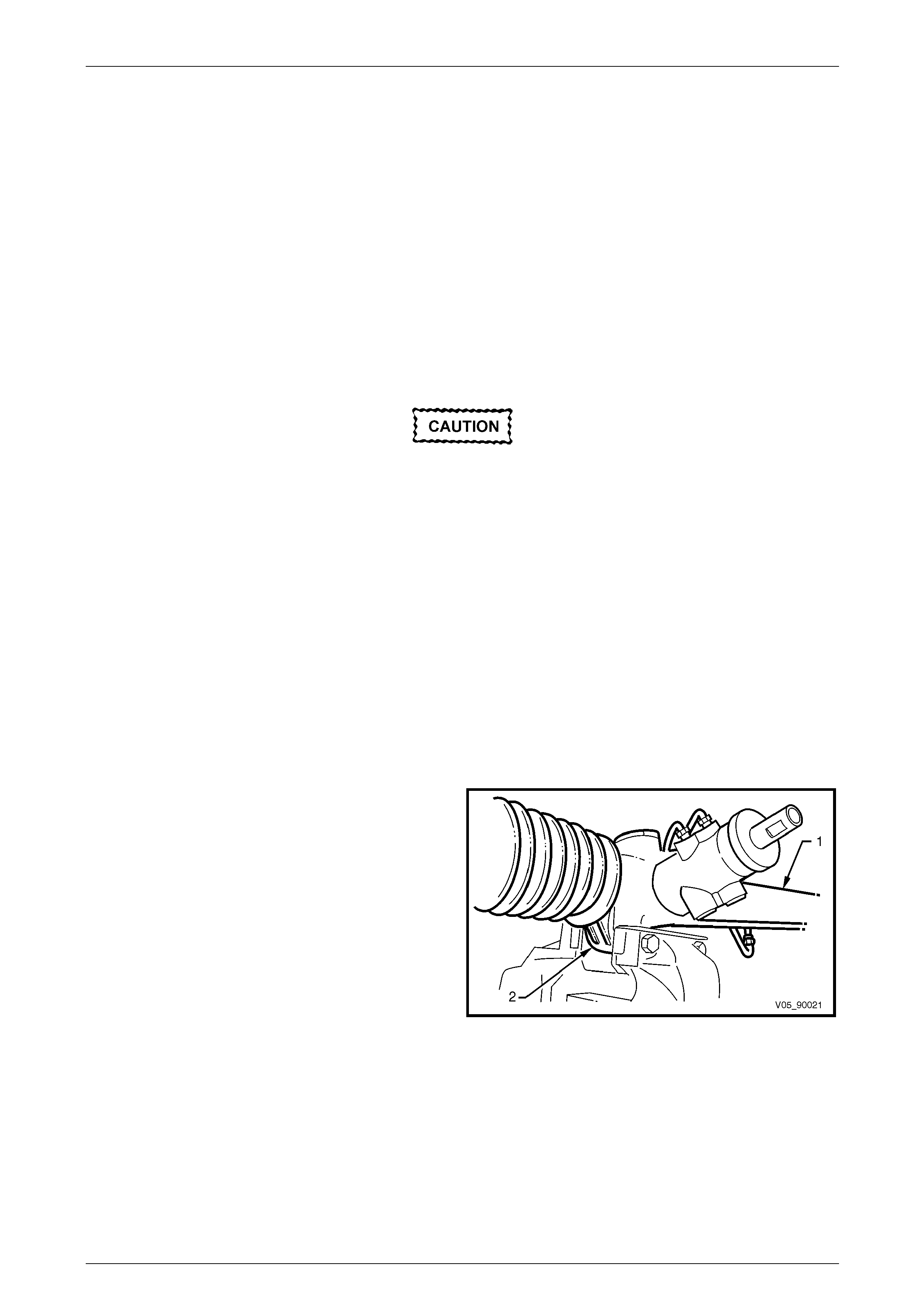
Steering Page 9–49
Page 9–49
Legend
1 Dust Seal
2 Pinion Seal Retaining Circlip
3 Upper Pinion Seal
4 Pinion Upper Roller Bearing
5 Circlip
6 Rotary Valve Assembly
7 Sealing Rings, 4 places
8 Intermediate Pinion Seal
9 Intermediate Pinion Roller Bearing
10 Pinion Lower Ball Bearing
11 Pinion Nut
12 Sealing Plug
13 Rack Pad Insert
14 Rack Pad
15 Washer (plastic)
16 Spring
17 Rack Pad Plug
18 Lock Nut
19 Steering Gear Housing
20 Short Rack Piston Fluid Line
21 Long Rack Piston Fluid Line
22 Rack and Piston Assembly
23 Inner Rack Seal Spacer
24 Inner Rack Seal
25 Rack Piston Sealing Ring
26 Rack Piston O-ring
27 Rack Outer Seal
28 Rack Outer Bushing
29 Retainer Wire
30 Tie-rod, 2 places
31 Tie-rod End, 2 places
32 Lock Nut, 2 places
33 Boot Retaining Clip, 2 places
(outer)
34 Boot, 2 places
35 Boot Inner Zip Tie, 2 places
36 Mounting Bracket
37 Mounting Bracket Insulator
During the manufacturing process, the
threaded ends o f the steering rack and piston
assembly are staked to the tie-rod inner
socket housing. Consequently, during
disassembly of the power steering gear,
damage to the threads on the end of the tie-
rod inner socket and the rack and piston
assembly may occur. Whenever damage to
the threads on the rack and piston assembly
or tie-rod occurs, the inner tie-rods and the
rack and piston assemb ly MUST be replaced.
1 Clean all dirt and foreign material from the exterior of the steering gear assembly.
NOTE
Ensure the fluid inlets in the steering gear valve
housing have been seal ed off to prevent dirt from
entering the system.
2 Mount the steering gear housing (1) by gripping the
right-hand mounting boss (2) in a vice fitted with soft
jaws.
3 Place a drain tray beneath the steering gear.
Figure 9 – 51
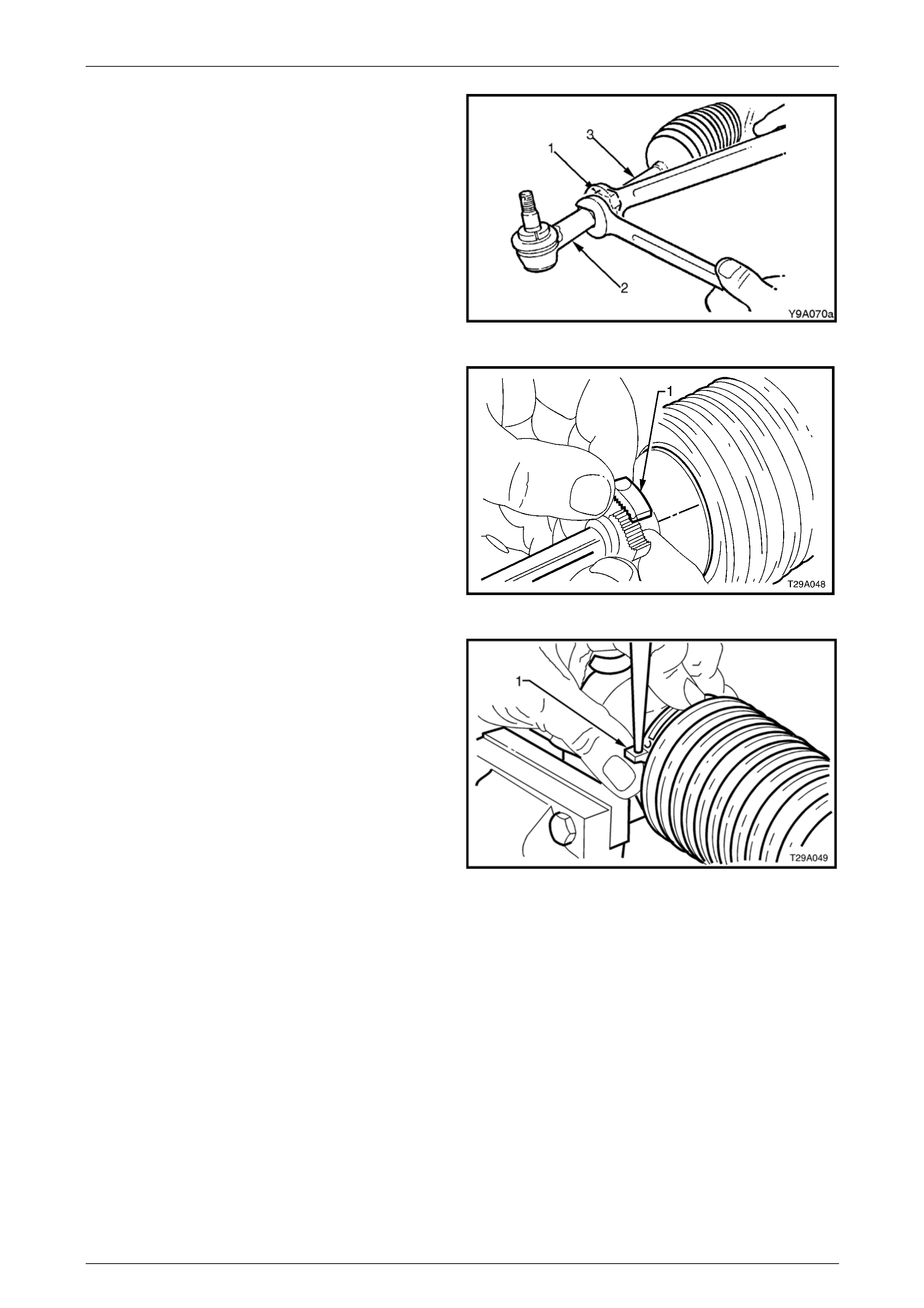
Steering Page 9–50
Page 9–50
4 Loosen the tie-rod lock nut (1). Remove the tie-rod
socket (2) and lock nut from the tie-rod (3) counting
the number of turns.
5 Slide the rack bellow from the steering gear housing
and tie-rod. Repeat Steps 4 to 6 for the opposite side.
Figure 9 – 52
6 Unclip and remove all clips attaching the boot.
a To remove the outer clips (1), move the ends of
clips sideways until they disengage.
Figure 9 – 53
b To remove the inner clips (1), push out the pin
retaining the clip ends together using a fin e pin
punch. Alternatively use a suitable pair of pliers
and carefully cut the attaching clip
Figure 9 – 54
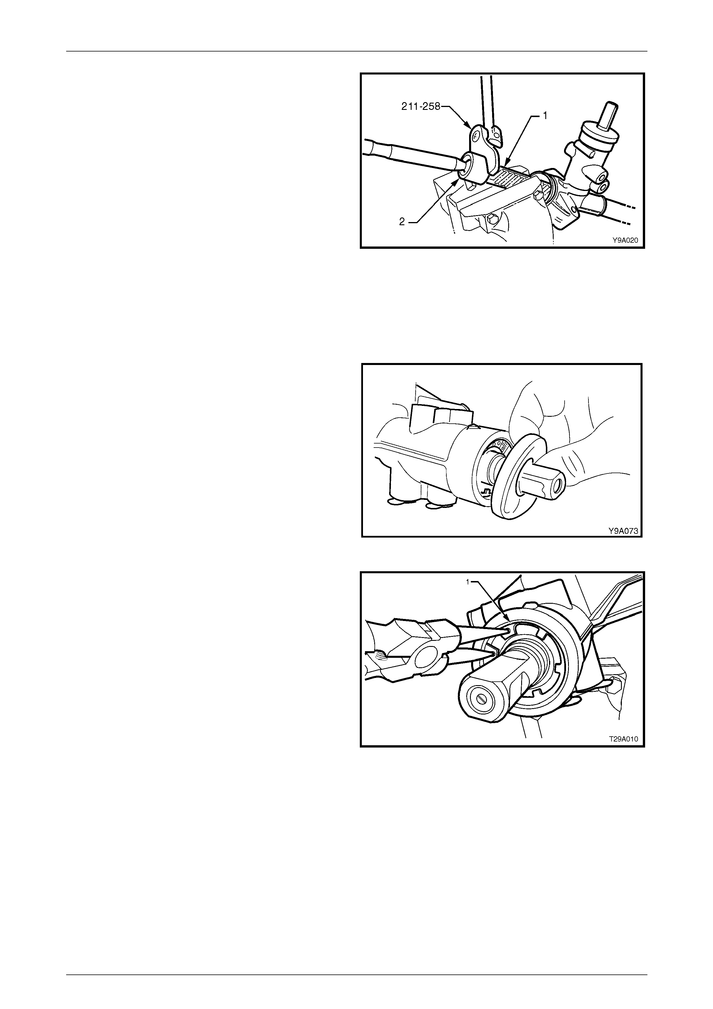
Steering Page 9–51
Page 9–51
7 Rotate the pinion input shaft fully counter-clockwise
(full left-hand lock).
8 Remove the steering gear housin g from the vice and
grip the exposed tooth end of the rack (1), using soft
jaws to prevent damage to the steering rack teeth.
9 Using Tool No. 211-258, loosen then tighten the
right-hand tie-rod inner socket housing (2) to break
the staking, then unscrew the housing from the end of
the rack.
10 Remove the housing assembl y from the vice and
ensure there is no foreign material on the rack teeth.
11 Rotate the pinion input shaft fully clockwise, (full right-
hand lock) to expose the left-hand side of the rack and
tie-rod inner socket housing.
12 Re-mount the steering gear in the vice, gripping
around the exposed end of the rack usin g soft jaws as
in Step 8.
13 Remove the left-hand tie-rod assembly as in step 9.
Figure 9 – 55
14 Remove the dust seal from the valve housing and
input shaft.
Figure 9 – 56
15 Using a suitable set of circlip pliers, compress and
remove the pinion seal retaining circli p (1) from the
top of the housing.
Figure 9 – 57
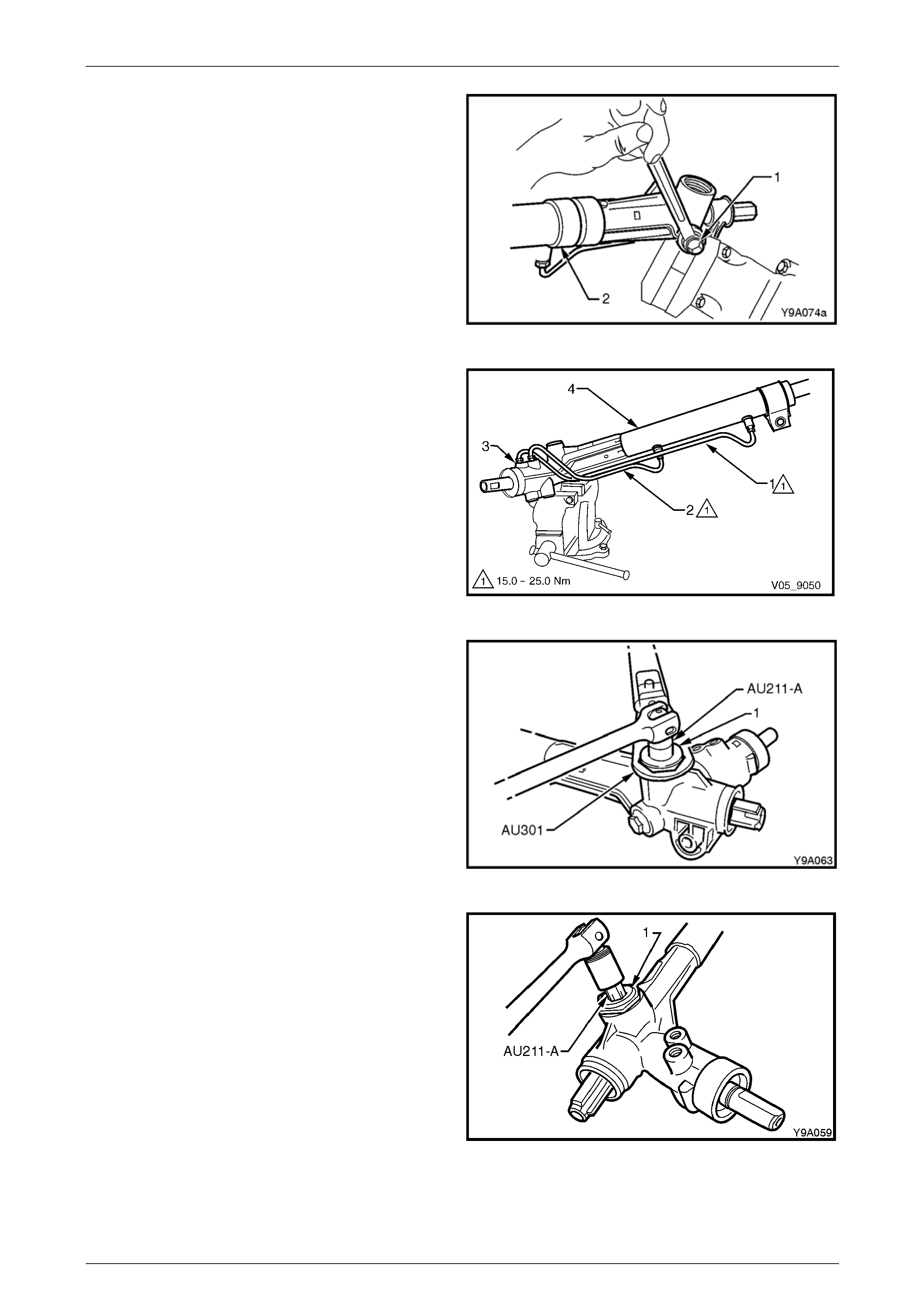
Steering Page 9–52
Page 9–52
16 Remove the pinion lo wer bea ring retaining plug (1)
from the housing.
Figure 9 – 58
17 Remove the feed line (1 and 2) from the valve housing
(3) and steering gear tube (4).
Figure 9 – 59
18 Remove the rack pad adjuster lock nut (1) using Tool
No. AU301.
19 Rotate the input shaft fully clockwise (full right lock).
Figure 9 – 60
20 Loosen and remove the rack pad adjuster screw (1),
using Tool No. AU211-A.
Figure 9 – 61
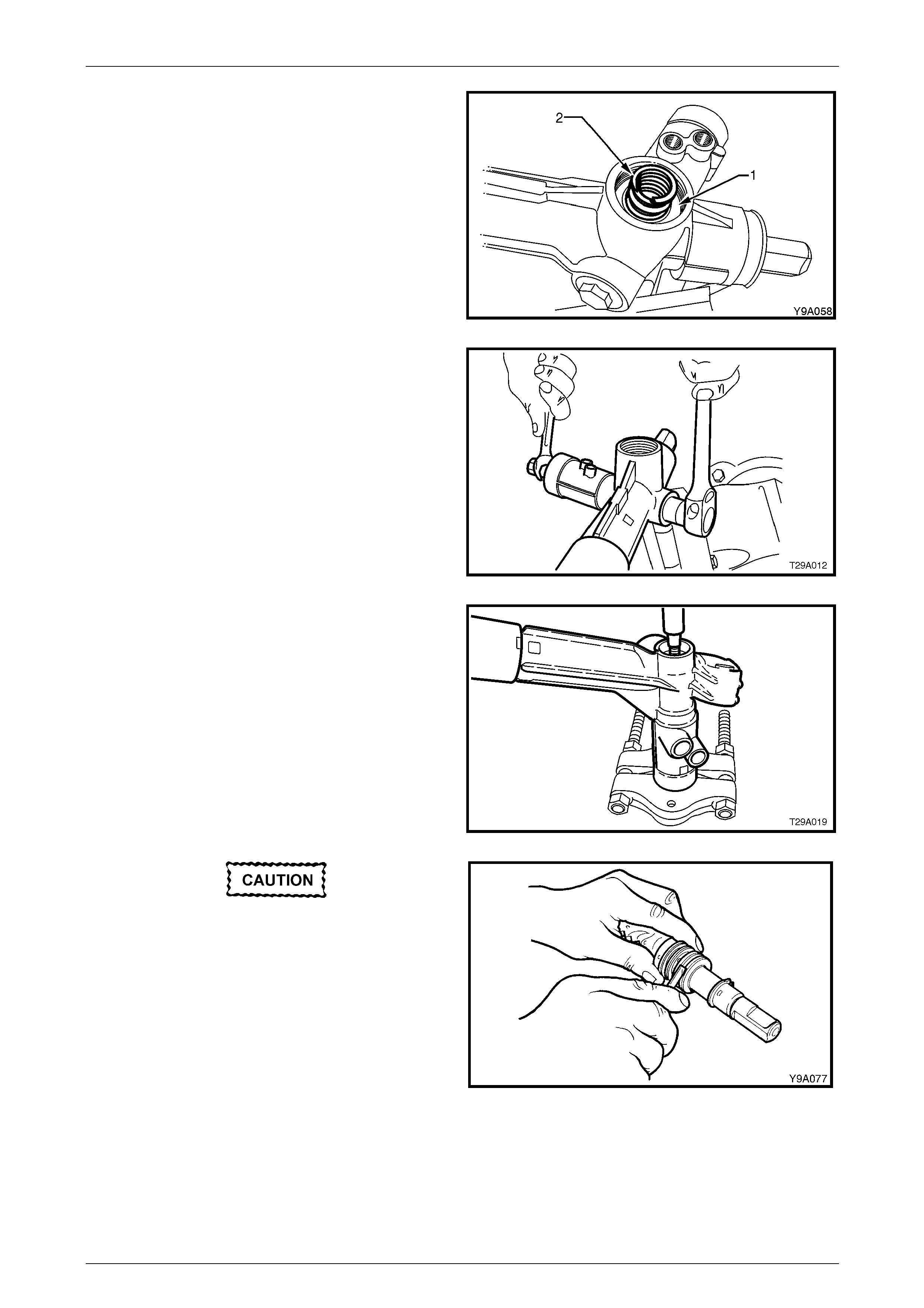
Steering Page 9–53
Page 9–53
21 Remove the rack pad assembly (1) and rack pad
spring (2) from the steering gear housing.
NOTE
The rack pad assembly may be assisted from
the steering gear housing with a pair of internal
circlip pliers, however, it may be necessary to
remove the housing from the vice a nd tap gently
on a wooden block to dislodge the rack pad
assembly.
Figure 9 – 62
22 Using a spanner across the flats, remove the pinion
lower bearing attaching nut from the pin io n.
Figure 9 – 63
23 Support the housing an press plates Tool No J22912-
1 or a commercially available equivalent.
24 Use a brass drift and a soft faced hammer and gently
knock on the lower end of the pinion to remove the
pinion and top bearing assembly from the housing.
Figure 9 – 64
When removing the seals with a knife, care
must be taken to avoid scratching the sides
of the grooves in the rotary valve otherwise
subsequent internal leakage may occur,
resulting in heavy or inconsistent steering.
25 Remove and discard the four Teflon (PTFE) sealing
rings from the rotary valve outer sleeve. T he seals ar e
best removed by cutting diagonally with a sharp knife.
NOTE
Because of component matching that is critical
to the safe operation of the sleeve and valve
assembly, the pinion assembly must not be
further dismantled. Figure 9 – 65

Steering Page 9–54
Page 9–54
26 Using a white paint pen or similar, mark the relative
position of the left-hand mounting bracket and the
steering rack tube (1).
Figure 9 – 66
27 Remove the left-hand mounting bracket, by using a
round bar inserted through the mounting holes and
rotating the bushing and bracket, back and forth while
pulling at the same time.
Figure 9 – 67
28 Remove the rack end bushing retaining wire, as
follows:
a Using Tool No. E8803-7 with a socket extension
and bar, rotate the rack end bush anti-clock wise,
until the end of the retainer (1) appears in the
slot.
b Carefully prise the end of the retainer wire free
of the rack tube as shown, then rotate the end
bushing with Tool No. E8803-7, in a clockwise
direction (arrow) winding the retainer out of the
tube.
c Continue unwinding the retainer until the end of
the retainer appears, lift it from the slot in the
rack tube. Figure 9 – 68
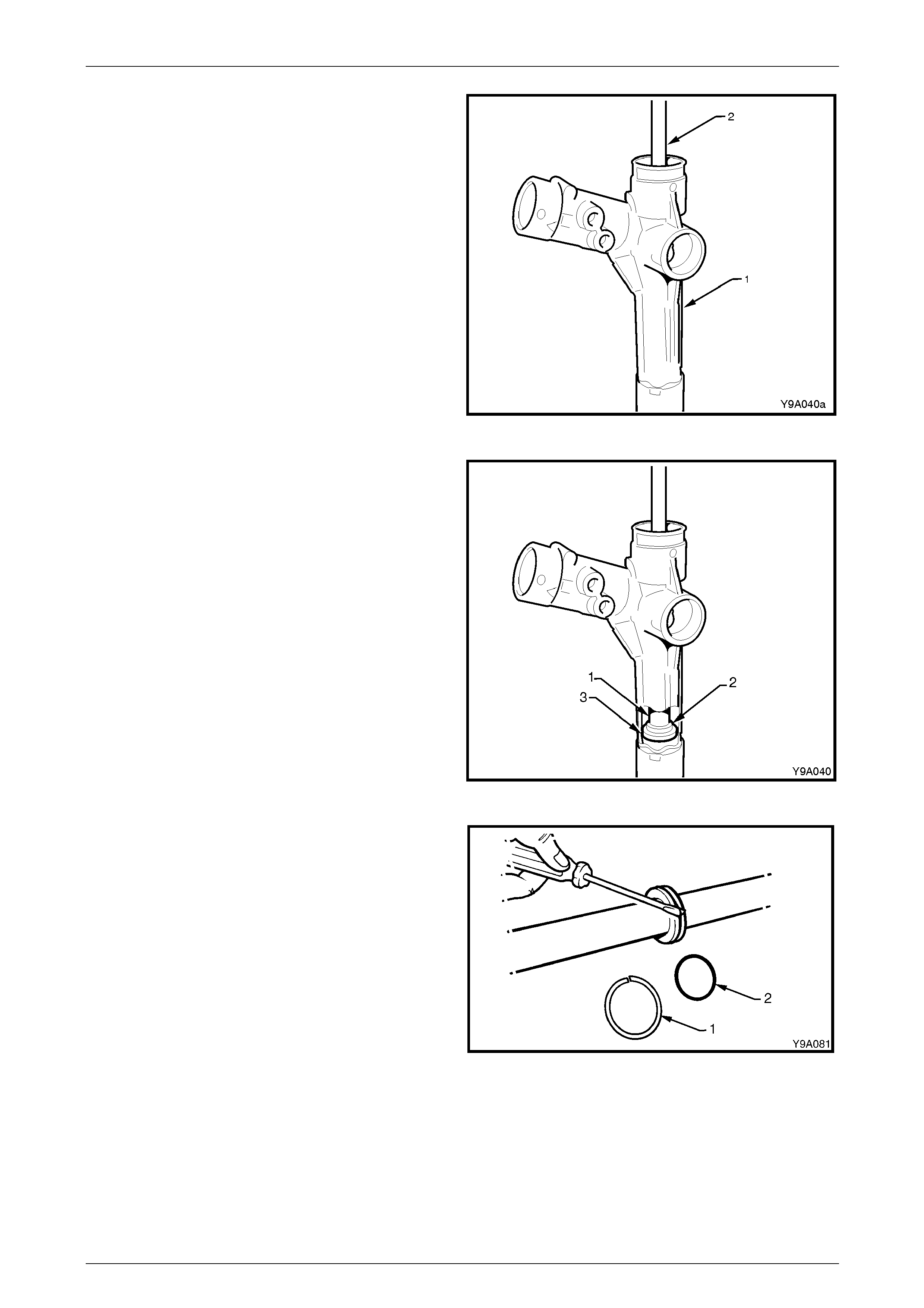
Steering Page 9–55
Page 9–55
29 Support the tube end of the rack housing (1) over
suitable press plates such as Tool No E6673 or
similar.
30 Remove the rack from the housing by inserting a
brass drift (2) into the right threaded end of the rack
and pressing the rack from the tube end of the rack
housing.
NOTE
As this action will remove the rack end bush and
the outer piston rod seal from the steering tube,
some resistance will be enc ountered. If re qu ired,
a suitable commercially available hydraulic
press may be used.
Figure 9 – 69
31 Insert a suitable length of tubing or mild steel stock
(1), 30 mm in diameter into the housing from the
pinion end, then use a hammer to drive the spacer (2)
and inner piston rod seal (3) from the rack housing.
Figure 9 – 70
32 Remove the rack piston seal (1) and O-ring (2) from
the rack piston.
NOTE
The seal can be more easily removed by cuttin g
diagonally with a sharp knife but take care not to
scratch the sides of the seal groove during this
procedure.
Figure 9 – 71

Steering Page 9–56
Page 9–56
33 Remove the pinion lower ball bearing using Tool
No. 211-259 and driv er handle AU355-A.
NOTE
As this operation will damage the bearing, the
bearing must be replaced when removed.
Figure 9 – 72
34 If required, remove the intermediate pinion roller
bearing and seal by usi ng a pin punch (1) and
hammer, working from opposite sides of the bearing
case until the bearing and seal are dislodged from the
housing.
NOTE
As this operation will damage the bearing, the
bearing must be replaced when removed.
Figure 9 – 73
Clean and Inspect
To avoid personal injury, always use the
appropriate gloves and safety glasses when
using cleaning fluids and compressed air.
1 Thoroughly wash all metal parts in a commercially av ailable cleaning fluid a nd blow dry using compressed air.
2 Inspect the rubber rack boot for damage or deterioration, re place as required.
3 Inspect the pinion bearings for signs of damage or wear.
NOTE
Pinion bearings when removed from the housing
will be damaged in the removal procedure and
must be replaced.
4 Inspect the pinion gear for signs of wear or damage on the teeth, bearing and seal surfaces.
5 Inspect the rack for signs of a bent rack, wear or damage to teeth, rack pad faces and rack bearing journal.
NOTE
A light polish on the teeth and the rack rear face
is normal and should not be confuse d with wear.
6 Inspect the housing for wear or damage in the pi nion bearing bores, the seal bores, the rack piston and the lock
stop faces.
7 Inspect the rack pad for damage or excess ive wear.
8 Inspect the major components of the rotary valve assembly (pinion, rotary valve, sleeve and torsion bar) for
damage or wear. These parts cannot be serviced individually as they are hydraulically balanced at the pinning
stage of assembly to equalise the steering efforts in right and left directions.
9 Inspect the right-hand mounting bracket and insulator for damage.
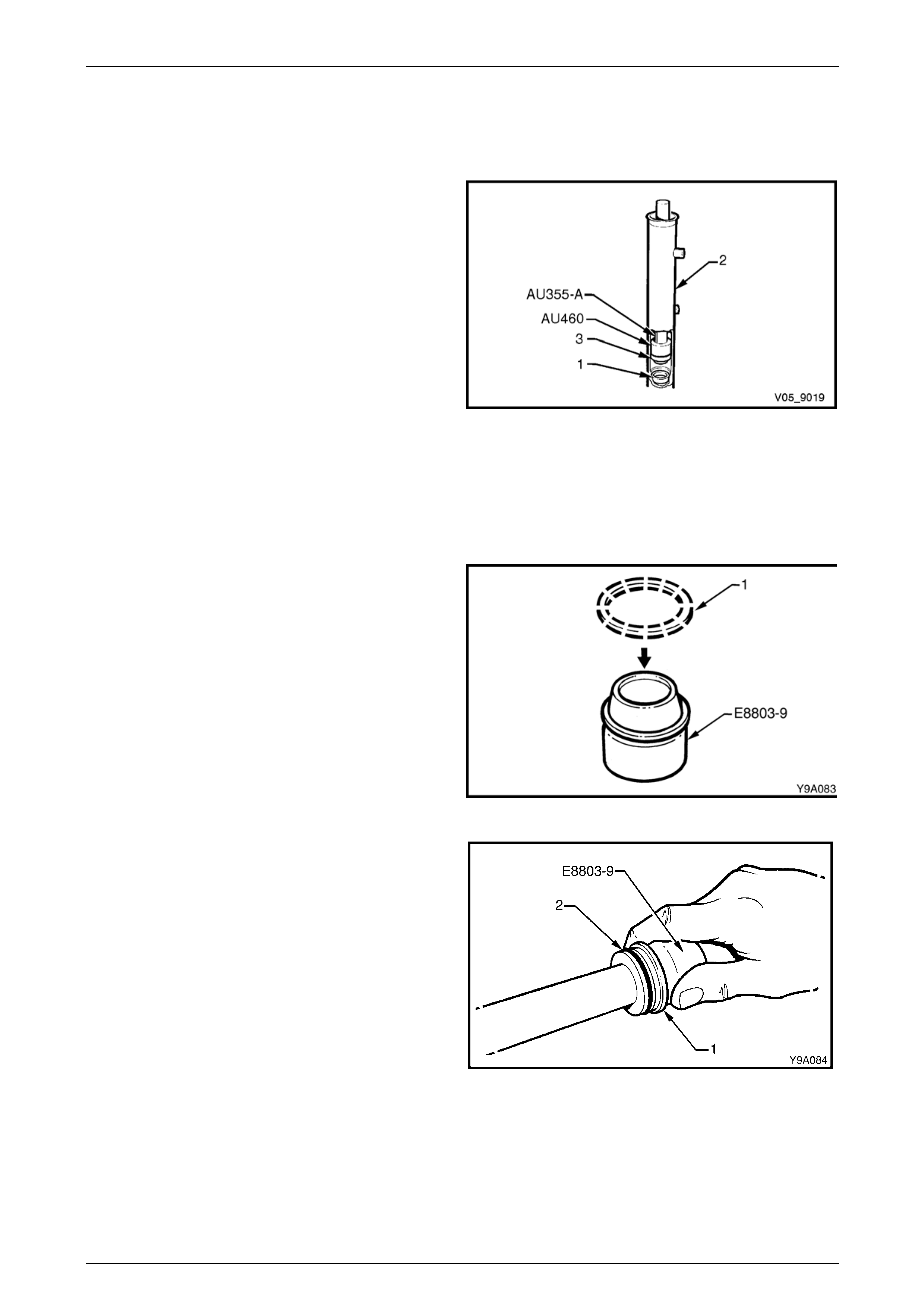
Steering Page 9–57
Page 9–57
Reassemble
1 Check that each of the rack seals have a circular plastic insert ring fitted in the opposite side to the spring loaded
seal lip and with the tapered edge of the insert facing toward the seal. Ensure the tapered ends of the rings seat
correctly.
2 Attach, Tool No. AU460 onto the driver handle Tool
No. AU355-A with the O-ring end facing out. Install the
inner seal spacer (1) onto Tool No. AU355-A, using
the O-ring to hold the spacer in place. Insert the tools
and spacer into the rack tube.
3 Using tool combination AU460/AU355-A, press the
seal spacer into the rack housing (2), until the end of
Tool No. AU355-A protrudes from the rack tube by
approximately 53 mm. This measurement will ensure
that the spacer has been fully install ed.
4 Reverse the fitment of Tool No. AU460 to the driver
handle Tool No. AU355-A.
5 Lubricate a new rack inner seal (3) with clean power
steering fluid. Install the seal over the spigot of Tool
No. AU460, ensuring that the spring loaded seali ng lip
is facing Tool No. AU460.
6 Press the seal into the rack housing on top of the
spacer. The seal will be fully installed when the end of
Tool No. AU355-A protrudes from the rack tube by
approximately 60 mm.
Figure 9 – 74
7 Install a new O-ring into the groove in the rack piston.
8 Lubricate a new Teflon seal ring (1) in clean power
steering fluid and install the seal ring over the
expander Tool No. E8803-9.
Figure 9 – 75
9 With the seal ring still installed on T ool No. E8803-9,
slide the assembly over the rack and up to the piston.
Slide the seal ring (1) off the expansion tool and into
the piston groove (2) over the O-ring.
Figure 9 – 76

Steering Page 9–58
Page 9–58
10 Ensure that the seal is seated correctly in the groove
by wrapping your fingers around the seal as shown.
Figure 9 – 77
11 Install the protector sleeve, Tool N o. AU45 6 over the
toothed end of the rack (1) and liberally apply clean
power steering fluid to the protector’s outer surface.
12 Liberally apply clean power steering fluid to the inner
surface of the rack tube and over the rack piston seal.
13 Carefully install the rack and protector into the rack
housing and through the inner seal, aligning the rack
teeth with the pinion bore. Continue installation until
the rack piston has entered the smaller, inne r tube
diameter.
14 Remove the seal protector, Tool No. AU456 from the
toothed end of the rack.
Figure 9 – 78
15 Install the seal protector, T ool No E8803-6 over the
end of the rack at the plain end.
a Liberally apply clean power steering fluid to the
lip surface of the outer rack seal (1) and then
install the seal over the protector and onto the
rack with the seal lips facing towards the rack
piston.
Figure 9 – 79
16 Lubricate the right-hand e nd bearing inner surface
with clean power steering fluid and then install the end
bearing into the rack tube, pushing it against the outer
rack seal.
NOTE
To assist with the installation of the bearing
retaining wire, align the hole in the bearing with
the opening in the steering housing tube.
17 Using a suitable diameter piece of tubing, tap the seal
and bearing into the rack tube until the retaining wire
groove in the bearing is aligned with the slot in the
rack housing tubing. Figure 9 – 80
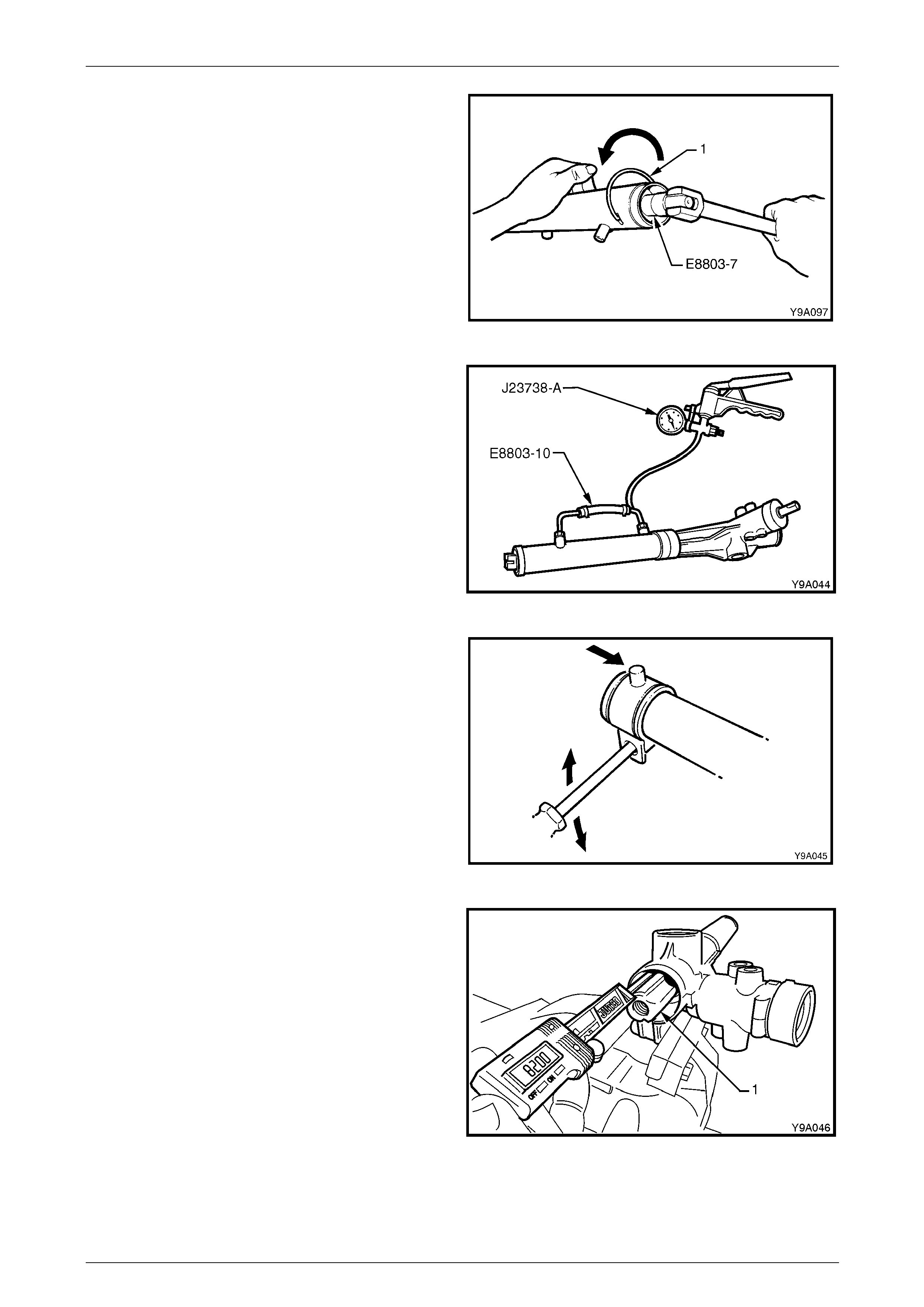
Steering Page 9–59
Page 9–59
18 If required, rotate the end bearing with Tool No.
E8803-7 until the hole in the wire groove ap pears in
the tube slot.
19 Install the bent end of the bearing retaini ng wire, into
the hole and continuing to us e Tool No. E8803-7,
rotate the bearing in an anti-cl ockwise direction until
the end of the wire disappears into the rack tubing.
Figure 9 – 81
20 Install the adapter Tool, No. E8803-10 on to the two
cylinder line fittings. Tighten the unio ns just sufficient
enough to affect an air tight seal.
21 Using a hand vacuum pump, such as, Tool No.
J-23738-A, apply a vacuum of 53.3 kPa (or 40 cm,
15.75 in. Hg), for approximately 30 seconds.
22 Check that no drop in the vacuum occurs during this
period. If a drop does occur, then the reason for the
drop must be found and corrected before proceeding
further.
Figure 9 – 82
23 Check the mounting bracket insulator for
serviceability. Appl y petroleum jelly to the inner
surface and then install the bracket and i nsu lator on to
the steering tube in the reverse order to removal,
aligning the marks made prior to removal.
Figure 9 – 83
24 Centralise the rack assembly by measuring 82 ± 1
mm from the lock stop (flange inside rack housing) to
the end of the toothed rack (1), as shown.
Figure 9 – 84
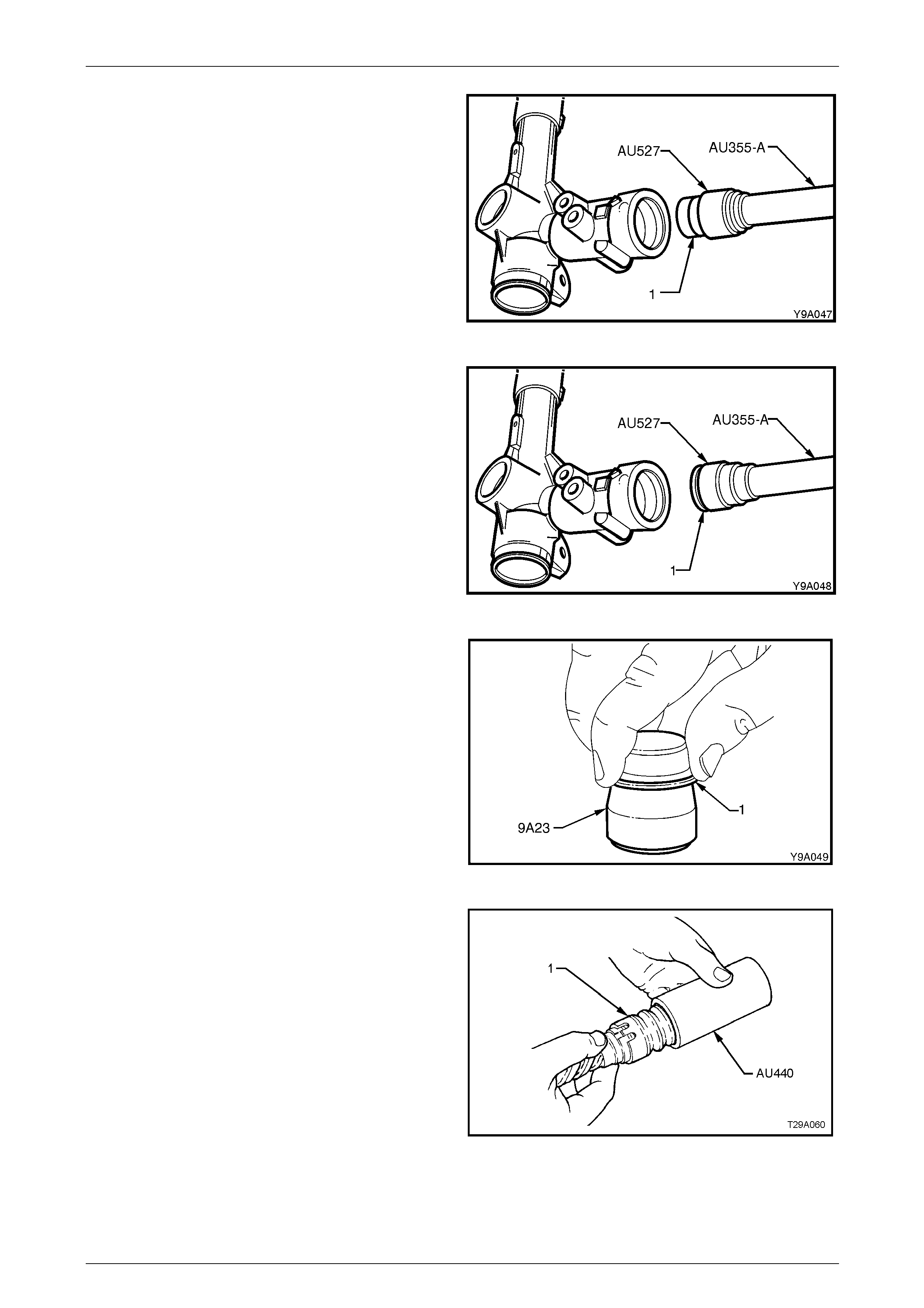
Steering Page 9–60
Page 9–60
25 Lubricate a new intermediate pinion roller bearing (1)
with clean automatic transmission fluid and install it on
the longer pilot of Tool AU527 that has the driver
handle AU355-A attached.
26 Press the bearing into the steering rack housing until
fully seated and then remove the installation tools.
Figure 9 – 85
27 Reverse Tool AU527 onto th e driver handle Tool
AU355-A and install a new intermediate seal (1) onto
the shorter pilot with the seal lips facing the tool
shoulder.
28 Press the seal into the steering housing until fully
seated and remove the installation tools.
Figure 9 – 86
29 To fit new PTFE seal rings (1) into the sleeve grooves,
first warm the seals in hot water and install each seal
ring in turn on to the expander Tool 9A23.
a Slide the expanding tool with the ring installed,
over the sleeve, then push the seal off and into
the sleeve groove.
b Repeat for the remaining three seals.
Figure 9 – 87
30 Push the seal compressor Tool AU440 over the
sealing rings and valve assembly (1) and leave in
place for 5 to 10 minutes to compress the rings back
to their normal size.
Figure 9 – 88
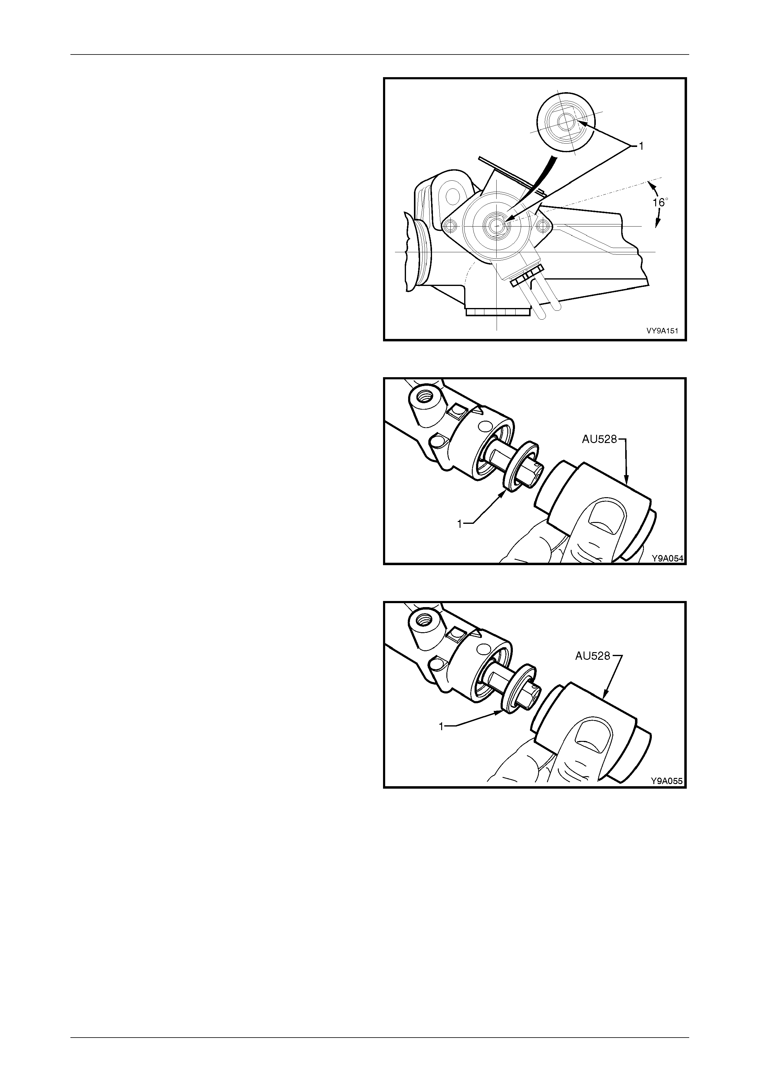
Steering Page 9–61
Page 9–61
31 While maintaining the rack in the centralised position,
insert the pinion so that the clamp bolt flat (1) of the
input shaft is positioned as shown, when the pinion is
fully located in the housing.
Figure 9 – 89
32 Lubricate a new upper pinion roller bearing with clean
power steering fluid and instal l the bearing over the
pinion shaft and into the housing.
33 Install the upper bearing into the steering gear
housing using the long end of installer Tool AU528
and a soft head hammer and gently tapping the
installer until the bearing is seated.
NOTE
Tool AU528 should be used with the longer
shank facing the bearing. When the shoulder
contacts the rack housing the bearing will have
been installed to the correct depth.
Figure 9 – 90
34 Lubricate a new pinion shaft upper seal (1) with clean
power steering fluid and instal l the seal over the
steering shaft with the lips of the seal facing the
steering gear.
35 Install the seal into the steering rack housing using the
shorter end of the installer Tool AU528 and a soft
head hammer, tap the installer in until it is se ated.
NOTE
Tool AU528 should be used with the shorter
shank facing the bearing. When the shoulder
contacts the rack housing the bearing will have
been installed to the correct depth.
Figure 9 – 91
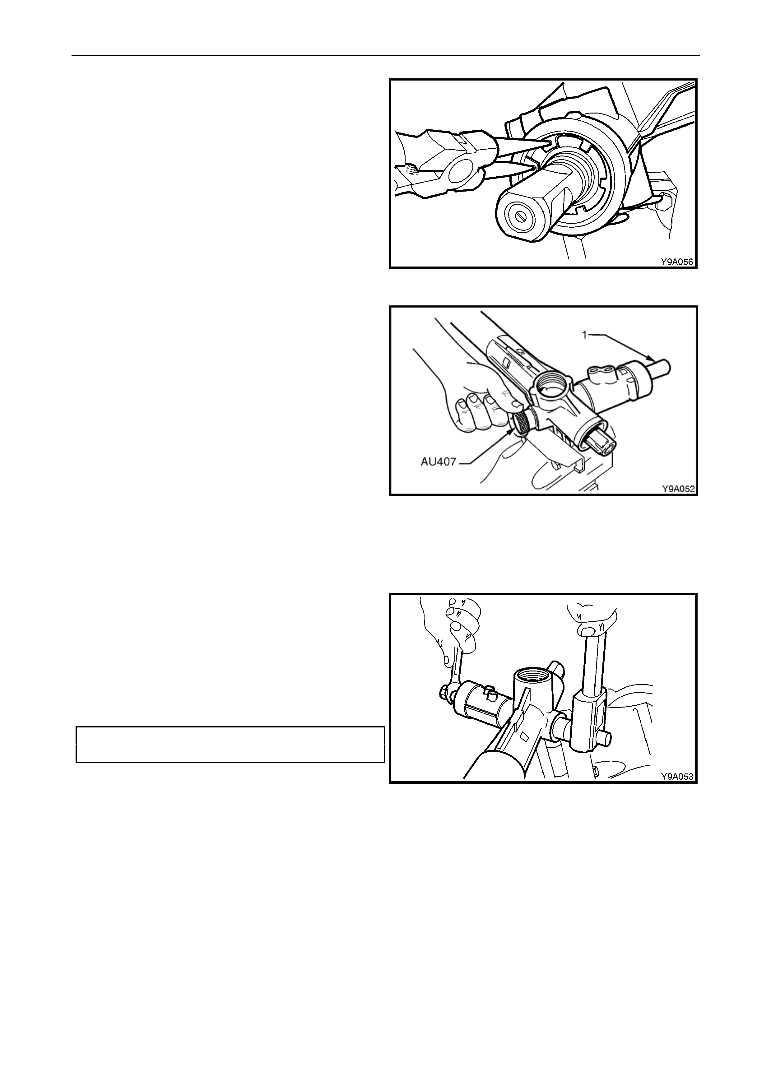
Steering Page 9–62
Page 9–62
36 Using suitable circlip pliers, install the pinion seal
retaining circlip over the top of the upper pinion seal,
ensuring that the circlip locates correctly in the
housing groove.
Figure 9 – 92
37 Pack a new pinion lower bearing with EP Semi Fluid
Lithium Base Grease and install the pinion lower
bearing using the following procedure:
a Install the new lubricated lower bearing over the
lower end of the pinion and thread the p inion
bearing installer T ool No. AU307 onto the pinion
end.
b While holding the knurled section as shown,
hold the flat section of the pinion (1) with a
15mm set spanner and turn the pinion back and
forth advancing the installation tool until the
bearing is fully seated.
NOTE
The pinion lower bearing is fully installed when
Tool AU307 cannot be screwed onto the pinion
any further. Remove the tool once the bearing is
fully installed.
Figure 9 – 93
NOTE
The pinion bearing retaining nut is a deformed
thread lock nut and may be reused once only.
However, it is recommended that a new nut be
installed at each overhaul.
38 Install a new pinion lower bea r ing retaining nut and
tighten to the correct torque specification.
Pinion lower bearing ret aining nut
torque specification ................................35.0 – 45.0 Nm
Figure 9 – 94
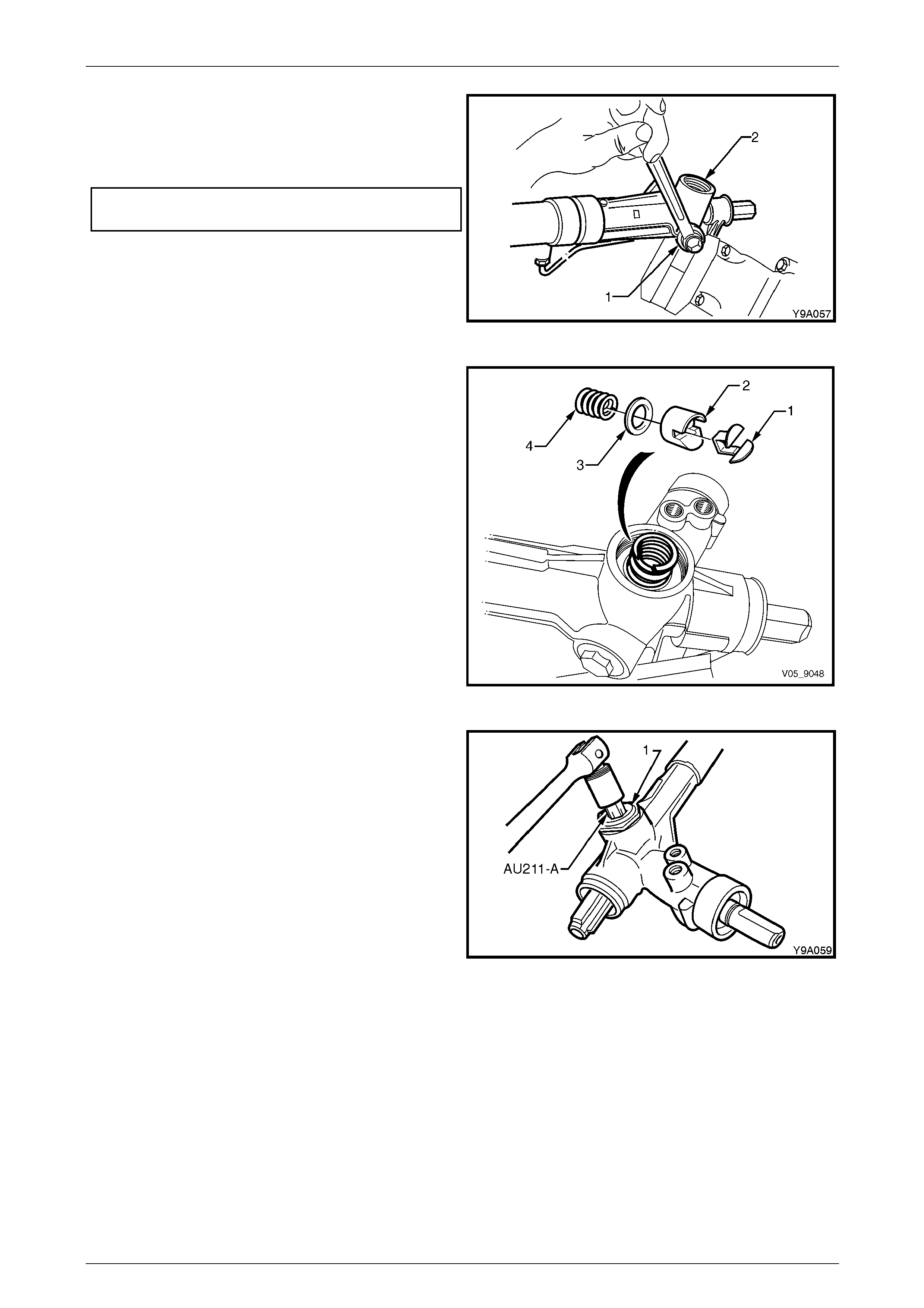
Steering Page 9–63
Page 9–63
39 Apply Loctite 242 thread seal ant or equivalent to the
cleaned threads of the pinion l ower screw plug (1).
Ensure the threads in the steering gear housing (2)
are clean and tighten the plug to the correct torqu e
specification.
Pinion lower bearing retai ning screw plug
torque specification ................................55.0 – 60.0 Nm
Figure 9 – 95
40 Install the rack pad insert (1) into the rack pad (2) and
the install the rack pad assembly into the steering
gear housing.
41 Install the plastic washer (3) and the rack p ad spring
(4).
Figure 9 – 96
42 Screw the lock nut (1) onto the adjusting screw. Install
the adjusting screw into the steering ge ar housing
using the pad adjusting screw Tool AU211-A
NOTE
Leave the adjuster screw lock nut loose at this
stage.
Figure 9 – 97
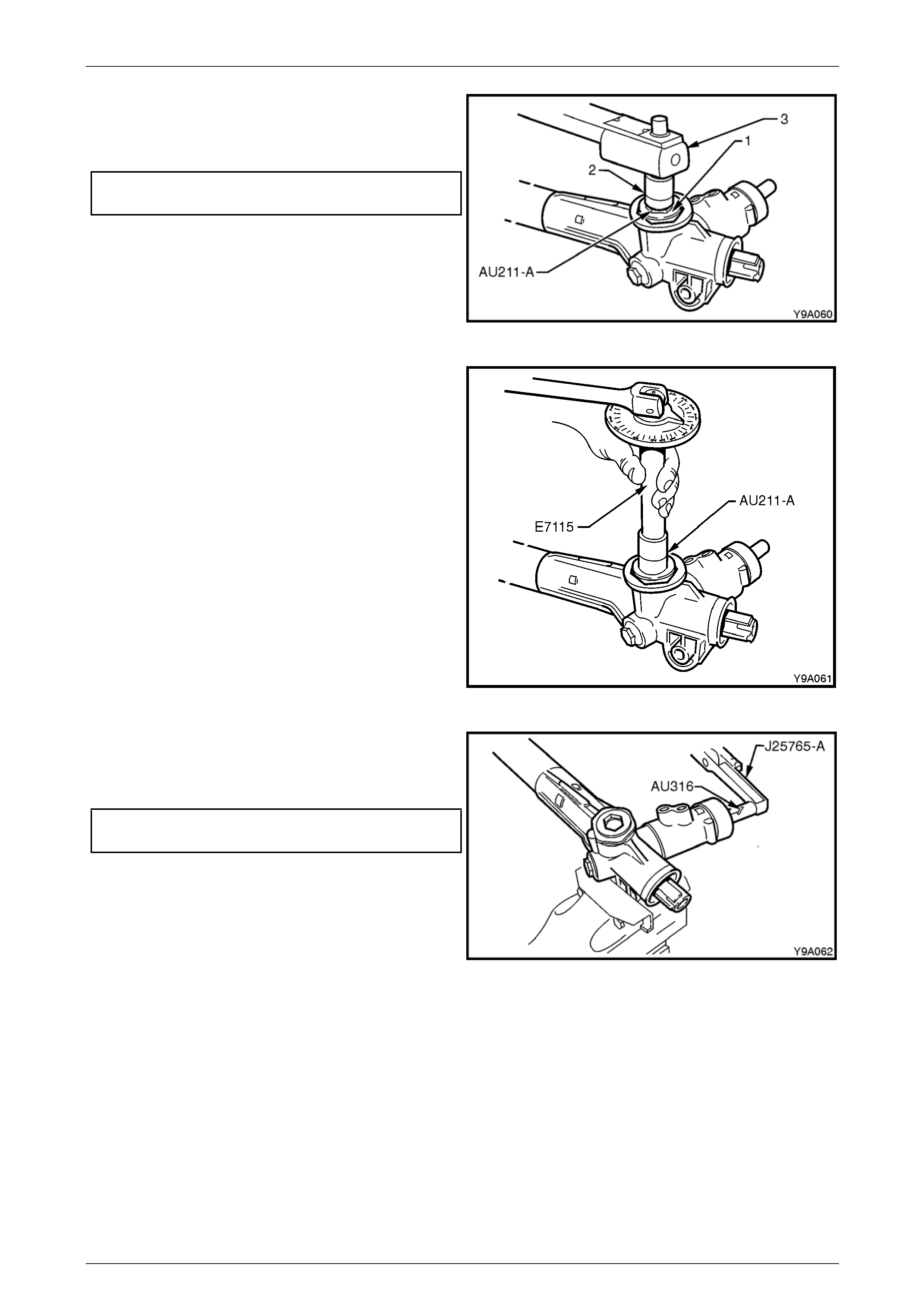
Steering Page 9–64
Page 9–64
43 With the steering rack in the centralised position, refer
to Figure 9 – 84, tighten the rack pad adjusting screw
(1) using Tool No. AU211-A to the correct torque
specification.
Rack pad adjusting screw
torque specification ................................10.0 – 12.0 Nm
Figure 9 – 98
44 Using angle wrench Tool No. E7115 and the rack pad
adjusting screw Tool AU211-A, turn the rack pad
adjusting screw back (counter-clock wise) 20° – 28°.
Figure 9 – 99
45 Install the preload adapter Tool AU316 onto the input
shaft and measure the rotating torque of the input
shaft using a dial type torque wrench such as
J25765-A, by cycling the steering gear back and forth.
Steering rack rotating torque
specification................................................ 0.8 – 2.5 Nm
Figure 9 – 100
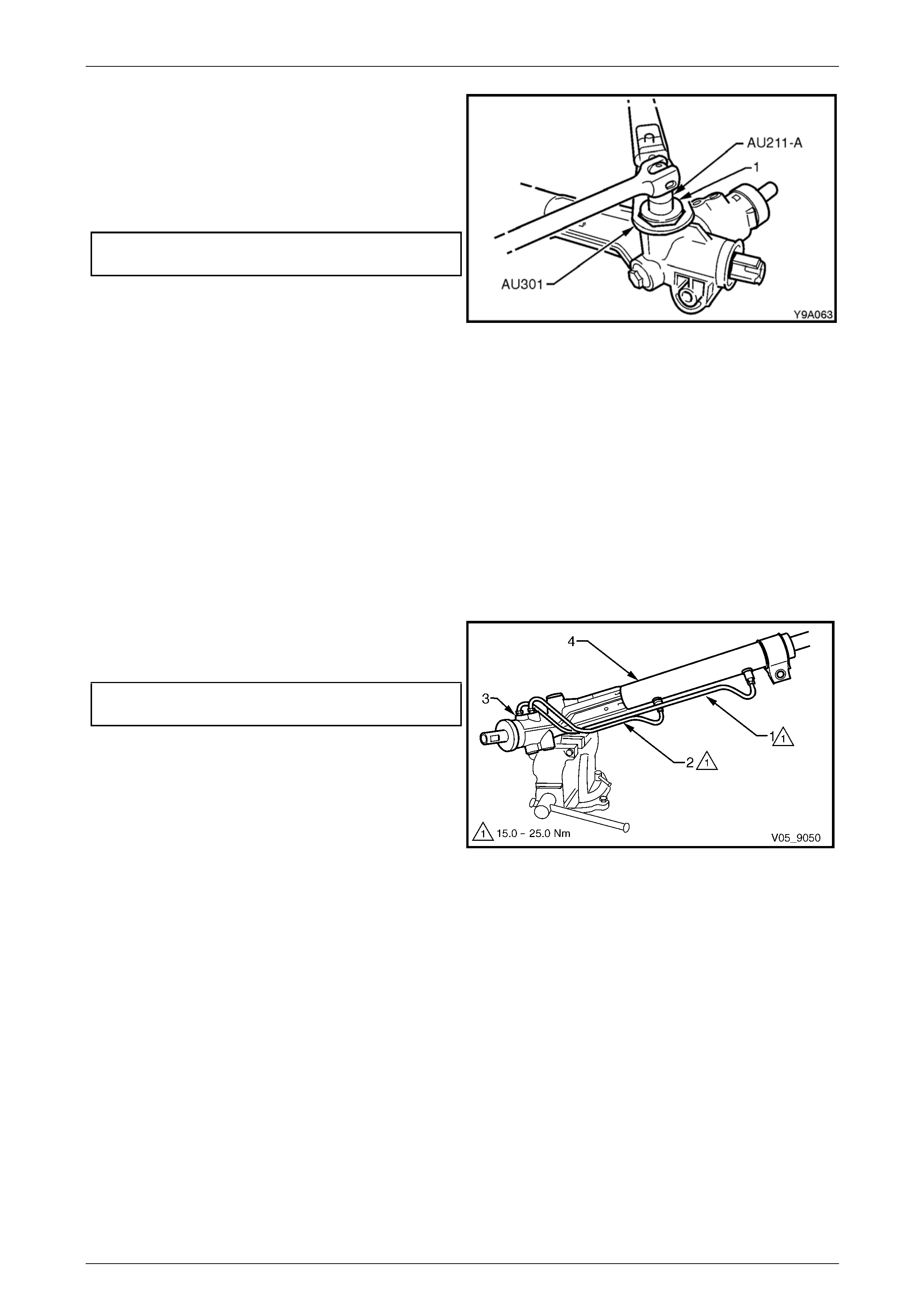
Steering Page 9–65
Page 9–65
46 Apply Loctite 242 thread seal ant or equivalent to the
cleaned threads of the rack pad adjuster l ock nut (1).
47 While holding the adjusting screw with Tool AU211-A
and a socket bar in the position set in steps 4 3 and
44, tighten the lock nut to the correct torque
specification using Tool AU301 and a suitable torque
wrench.
Rack pad adjusting screw lock nut
torque specification ................................55.0 – 65.0 Nm
NOTE
Once the rack pad adj ustment has been set and
the lock nut tightened to the correct torque
specification, the steering gear must be racked
from lock-to-lock to ensure localised wear has
not appreciably affected the setting. The gear
should not bind or appear tight over any part of
the total travel. Should the gear bind or appear
tight, recheck the rack pad adjustment. If this is
not the cause, strip the gear assembly and re-
examine the rack and pinion for wear or
bending. Replace as necessary.
48 Rotate the pinion shaft fully counter-clockwise (left
lock).
49 Remove the steering gear housing from the vice, and
grip the exposed toothed end of the rack in a vice with
soft jaws.
Figure 9 – 101
50 Reconnect the feed lines (1 and 2) to the val v e
housing (3) and steering gear tubing (4) and tighten
the line flare nuts to the correct torque specification.
Fluid feed line flare nut
torque specification ................................15.0 – 25.0 Nm
NOTE
The longer of the two lines is installed into the
upper location on the valve body housing, while
the shorter is installed into the lower location.
Figure 9 – 102
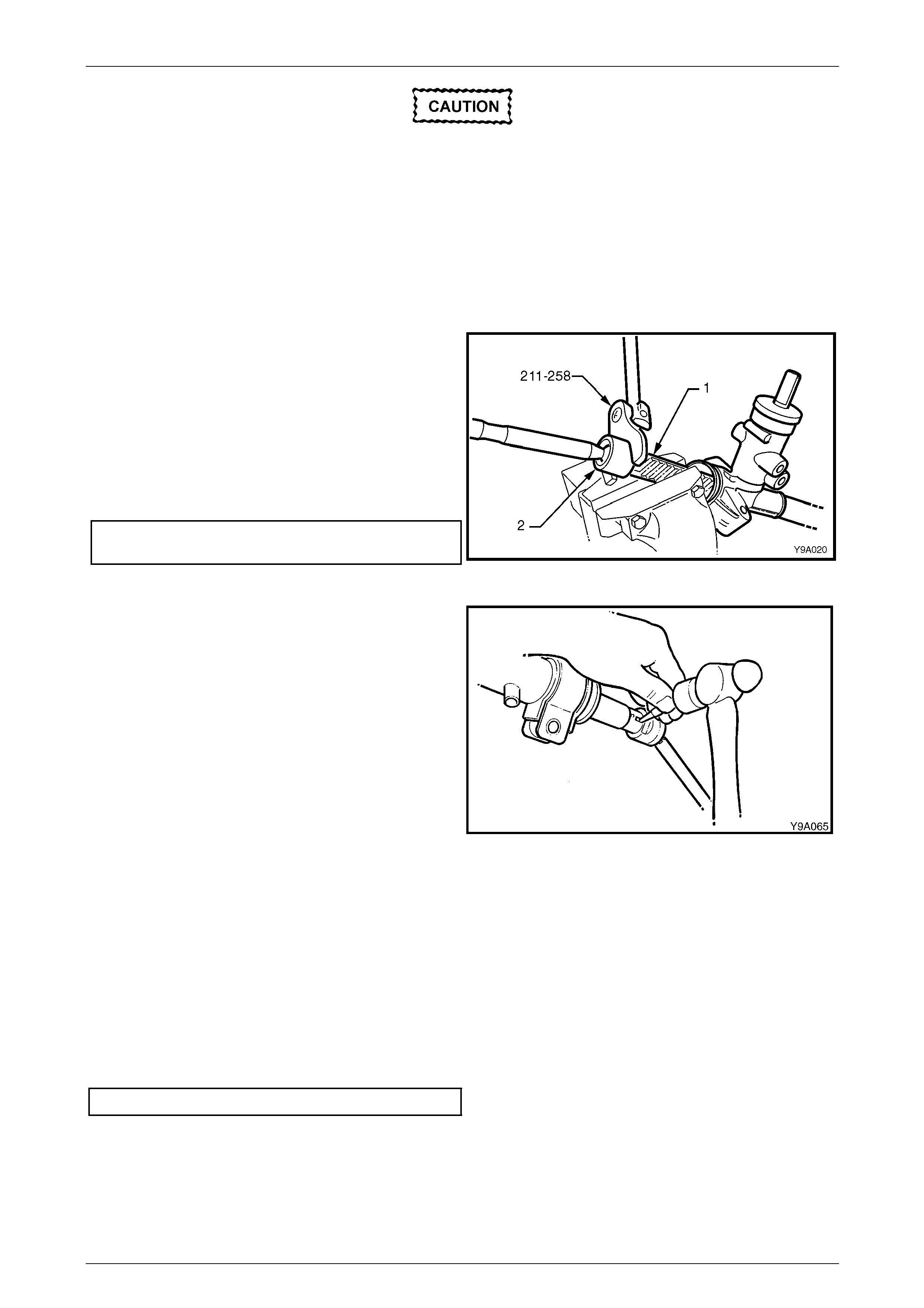
Steering Page 9–66
Page 9–66
During the manufacturing process, the
threaded ends o f the steering rack and piston
assembly are staked to the tie-rod inner
socket housing. Consequently, during
disassembly of the power steering gear,
damage to the threads on the end of the tie-
rod inner socket and the rack and piston
assembly may occur. Whenever damage to
the threads on the rack and piston assembly
or tie-rod occurs, the inner tie-rods and the
rack and piston assemb ly MUST be replaced.
51 Rotate the pinion input shaft fully clockwise (full right-
hand lock) and clamp the exposed toot h end of the
rack (1) in a vice.
NOTE
Use soft jaws to avoid damage to the steering
rack teeth.
52 Using tie-rod wrench Tool No. 211-258, tighten the
right-hand tie-rod to the correct torque specification.
Tie-rod to steering rack
torque specification .............................. 90.0 – 100.0 Nm
Figure 9 – 103
53 Using a centre punch and a hammer, stake the rack to
the tie-rod socket housing in two places inside the
key-way at the end of the rack. Ensure to stake the
rack in two places as close as possible to the tie-rod
inner socket either side of the keyway.
NOTE
The keyway at either end of the steering rack
has not been hardened, a nd i s the onl y ar ea that
is suitable for the staking procedure.
Figure 9 – 104
54 Remove the steering gear housing from the vice and rotate the pinion shaft slightly anti-clockwise, just enough to
expose the left-hand en d of the rack.
55 Clamp the exposed end of the rack in a vice.
NOTE
Use soft jaws to avoid damage to the steering
rack.
56 Using tie-rod wrench Tool No. 211-258, tighten the left-hand tie-rod to the correct torque specification, refer to
Figure 9 – 103.
Tie-rod torque specification...................90.0 – 100.0 Nm
57 Relocate the steering ge ar housing in the vice by gripping the right-hand mounti ng boss.
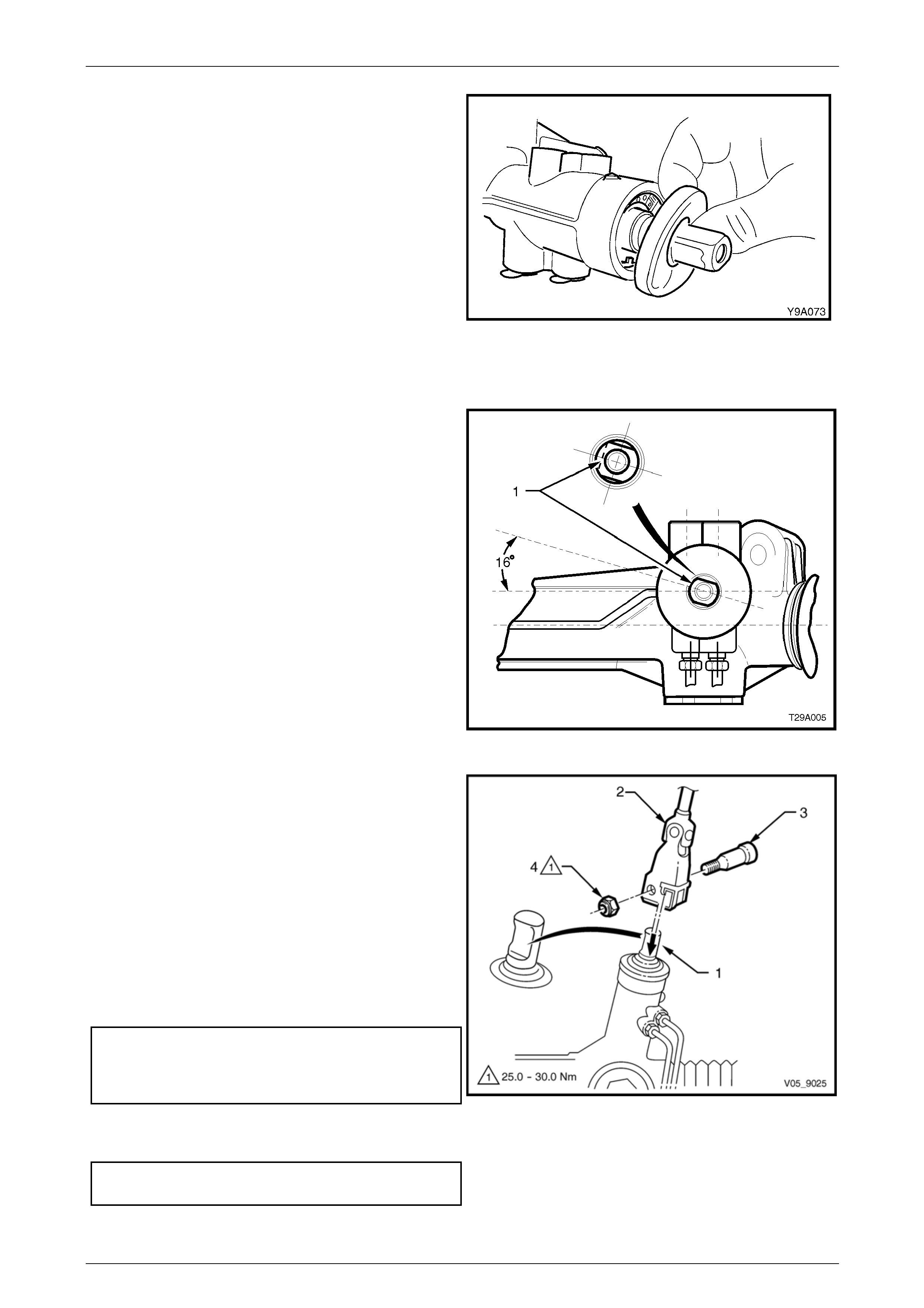
Steering Page 9–67
Page 9–67
58 Rotate the input shaft to the straight ahead positio n.
Install the dust cover onto the input shaft.
59 Fit the steering gear boot to the tie-rods and steering
gear housing. Install the retaining clips.
60 Fit the tie-rod socket lock nuts and the tie-rod sockets
to the tie-rods.
NOTE
Do not tighten the lock nuts, as a toe-in
adjustment must be performed when the
steering gear is reinstalled to the vehicle.
Figure 9 – 105
Reinstall
1 Ensure the steering gear is centralised. This is
achieved by rotating the pinion to the halfway position
of its total lock-to-lock rotation. When the rack is in the
straight ahead position, the flat on the pin ion shaft (1)
will be aligned as shown.
NOTE
Alternatively, remove both the inner boot
clamps, slide the boots back and measure the
exposed portion of each e nd of the rack from the
housing. When both measurements are equal,
the rack is centralised.
2 Ensure the steering wheel is in the straight ahead
position.
Figure 9 – 106
3 Slide the steering gear pinion shaft (1) into the
steering coupling lower flange (2) and then install the
lower cam bolt (3) and a new retaining crimp nut (4)
but do not tighten at this stage.
NOTE
The coupling cam bolt will only fit in the
recessed section of the pinion shaft.
4 Position the steering gear housing into the
crossmember mounting points. Install the mounti ng
bolts, washers and nuts and tighten the nuts to the
correct torque specification using an angle wrench
such as Tool E7115 or similar.
Steering gear housing to crossmember
mounting nut torque specificat ion
Stage 1..............................................................60.0 Nm
Stage 2...........................................40° – 50° turn angle.
5 Tighten the steering coupling cam bolt retaining nut to
the correct torque specification.
Steering coupling cam bolt retaining nut
torque specification ................................25.0 – 30.0 Nm
Figure 9 – 107

Steering Page 9–68
Page 9–68
6 Inspect the condition of the steering gear hydr aulic line O-rings and replace as required and install them to the
hydraulic lines.
7 Fit the hydraulic lines to the steering ge ar valve housing and tighten the flare nuts to the correct torque
specification.
Hydraulic line to valve housing flare nut
torque specification.................................30.0 – 42.0 Nm
NOTE
Ensure the plastic spacers are positioned on tie-
rod end ball studs and they are in go od condition
before fitting the studs into the steering arms.
Replace the spacers if damaged.
8 Install the tie-rod end ball studs into steering arms. Install the castellated nuts and tighten to the correct torque
specification.
Tie-rod socket stud castellated nut
torque specification.................................50.0 – 85.0 Nm
9 Install new split pins into the tie-rod ball studs.
10 Install the road wheels, refer to Section 10 Wheels and Tyres.
11 Lower the vehicle to the ground an d reconnect the battery ground lead.
12 Refill and bleed the hydraulic system, refer to 3.14 Hydraulic System Bleeding and Refilling.
13 Check the front wheel toe in adjustment and adjust as required, refer to Section 3A Front Suspension.
14 Tighten the tie-rod adjuster lo ck nut to the correct torque specifications.
Tie-rod adjuster lock nut
torque specification.................................40.0 – 60.0 Nm
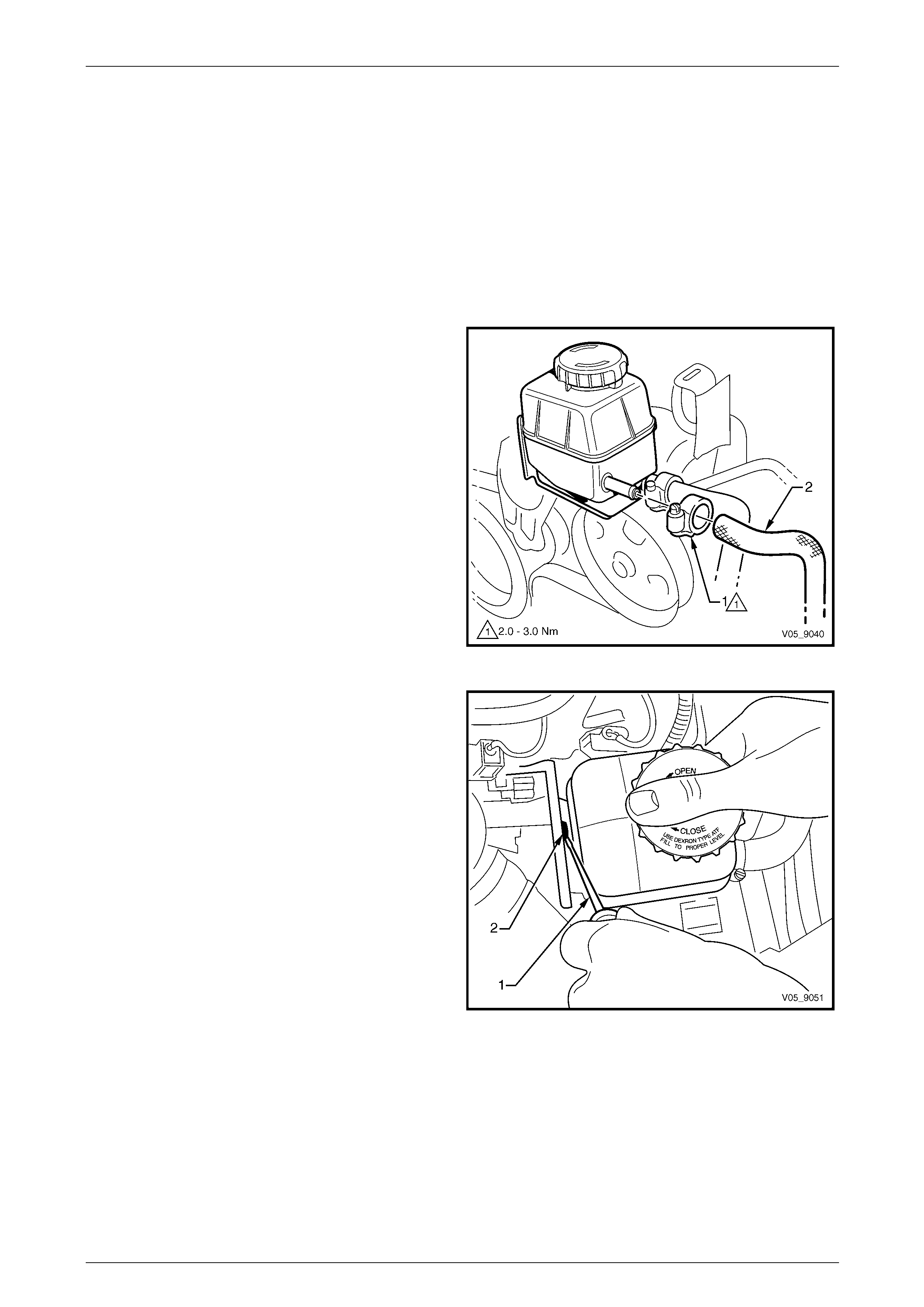
Steering Page 9–69
Page 9–69
3.11 Power Steering Fluid Reservoir
LT Section No. — 06–400
Remove
V6 Engine
1 Place a drain tray beneath the reservoir assembly to contain any fluid that may be spilt in the following operation.
2 Remove the air intake duct and the left-hand engine cover, refer to Section 6A1 Engine Mechanical – V6
3 Loosen the hose clamp (1) e nough to enable the hose
(2) to be removed from the reservoir and then repeat
for the other hose.
NOTE
Cover or tape the hose ends to prevent foreign
matter entry.
Figure 9 – 108
4 Using a suitable lever such as a screwdriver (1), from
above the reservoir, gently lever the locki ng tang (2)
back to clear the reservoir tab and lift the reservoir up
and out of the retaining bracket.
5 Reset the retaining bracket locking tang back into the
original position.
6 If required, remove the two bolts attaching the
reservoir bracket from the left-hand cylinder head.
Remove the bracket from the engine.
Figure 9 – 109
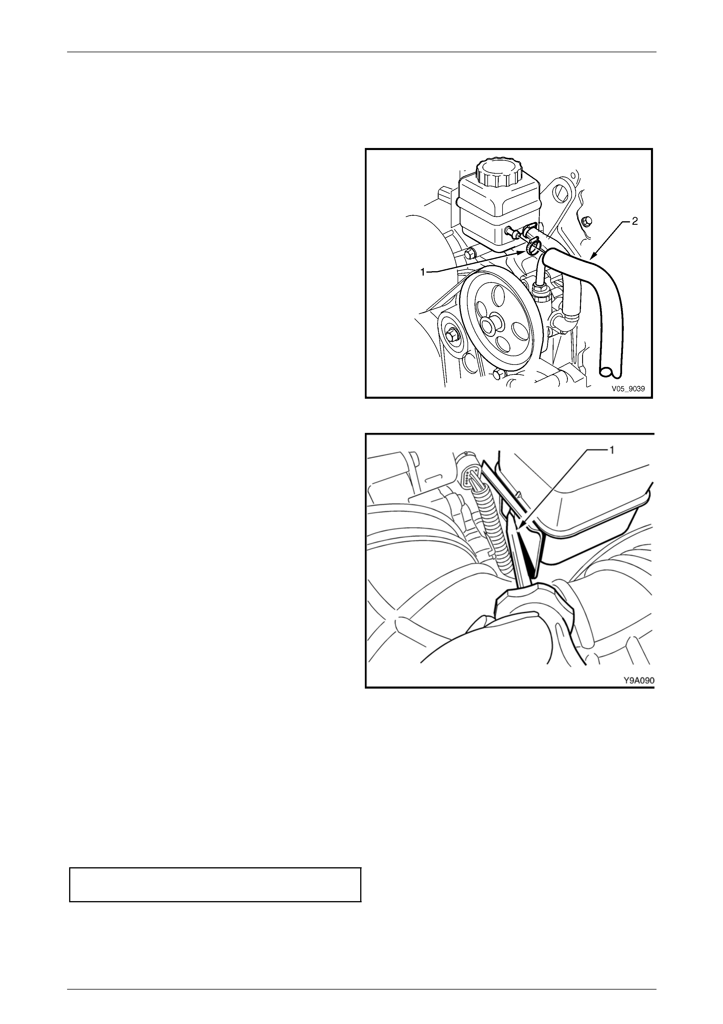
Steering Page 9–70
Page 9–70
GEN III V8 Engine
1 Place a drain tray beneath the reservoir assembly to contain any fluid that may be spilt in the following operation.
2 Remove the air intake duct and the engine dr ess cover, refer to Section 6A3 Engine Mechanical – GEN III V8.
3 Loosen the hose clamp (1) e nough to enable the hose
(2) to be removed from the reservoir and repeat for
the other hose.
NOTE
Cover or tape the hose ends to prevent any
foreign matter from entering the system.
Figure 9 – 110
4 Using a suitable lever such as a screwdriver (1),
gently lever the locking tang back to clear the
reservoir tab and lift the reservoir up and o ut of the
retaining bracket.
5 Reset the bracket locking tang back into the original
position.
6 If required, remove the two bolts attaching the
combination reservoir and engine lifting bracket from
the left-hand cylinder head. Remove the bracket from
the engine.
Figure 9 – 111
Reinstall
V6 and GEN III V8 Engine
Reinstallation of the power steering fluid reservoir is the reverse of the removal procedure, noting the following:
1 Ensure the locking tab on the bracket has been returned to the original position and the reservoir is secured
properly.
2 Tighten the reservoir hose clamps to the correct torque spe cification.
Power steering reservoir hose clamp
torque specification.....................................2.0 – 3.0 Nm
3 Refill and bleed the hydraulic system, refer to 3.14 Hydraulic System Bleeding and Refilling.
4 Start the engine and check for po wer steering fluid l eaks from the reservoir area.
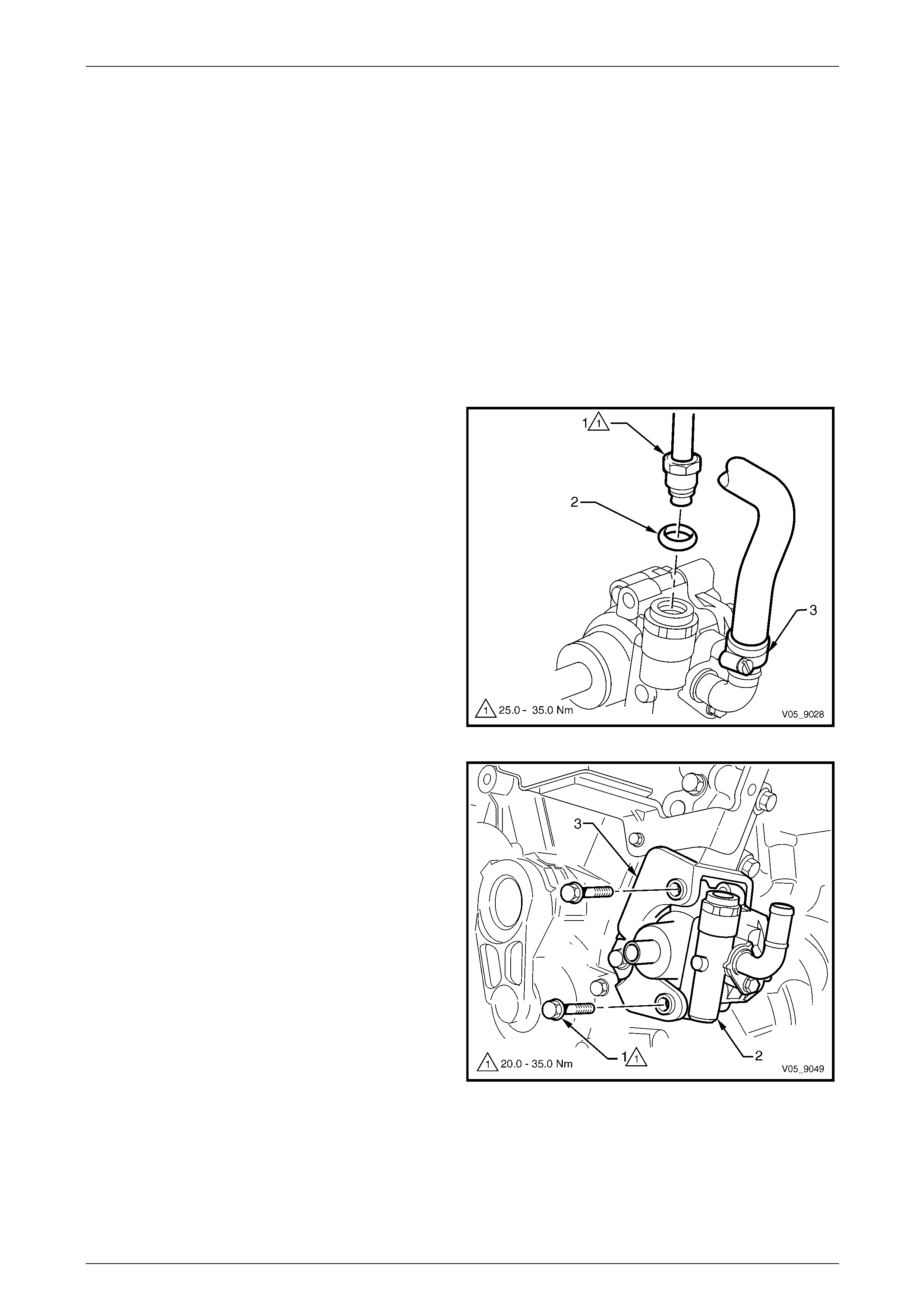
Steering Page 9–71
Page 9–71
3.12 Power Steering Pump
LT Section No. — 06–400
Remove
V6 Engine
1 Place a tray under the vehicle to contain any fluid that may be spilt in the following operation.
2 Refer to Section 6A1 Engine Mechanical – V6 and remove the follo wing:
• air intake duct,
• engine accessor y drive b elt, and
• left-hand engine dress cover.
3 If required, remove the power steering fluid reservo ir, refer to 3.11 Power Steering Fluid Reservoir.
4 Loosen and remove the high pressure line flare nut (1
and O-ring (2) from the pump outlet fitting.
5 Loosen the low pressure hose clamp (3) and remove
the hose from the pump inlet fitting.
NOTE
Cover or tape the pump and hose fittings to
prevent foreign matter from entering the system.
Figure 9 – 112
NOTE
• The pump is removed with the pulley
attached to the pump, however it is not
shown for clarity.
• Access to the two attaching bolts is be made
through the pulley holes, using a suitable
socket and extension.
6 From through the holes in the pulley, remove the two
bolts (1), attaching the power steering pump (2) to the
mounting bracket (3). Remove the pump from the
bracket by sliding it towards the left-hand side of the
car.
Figure 9 – 113
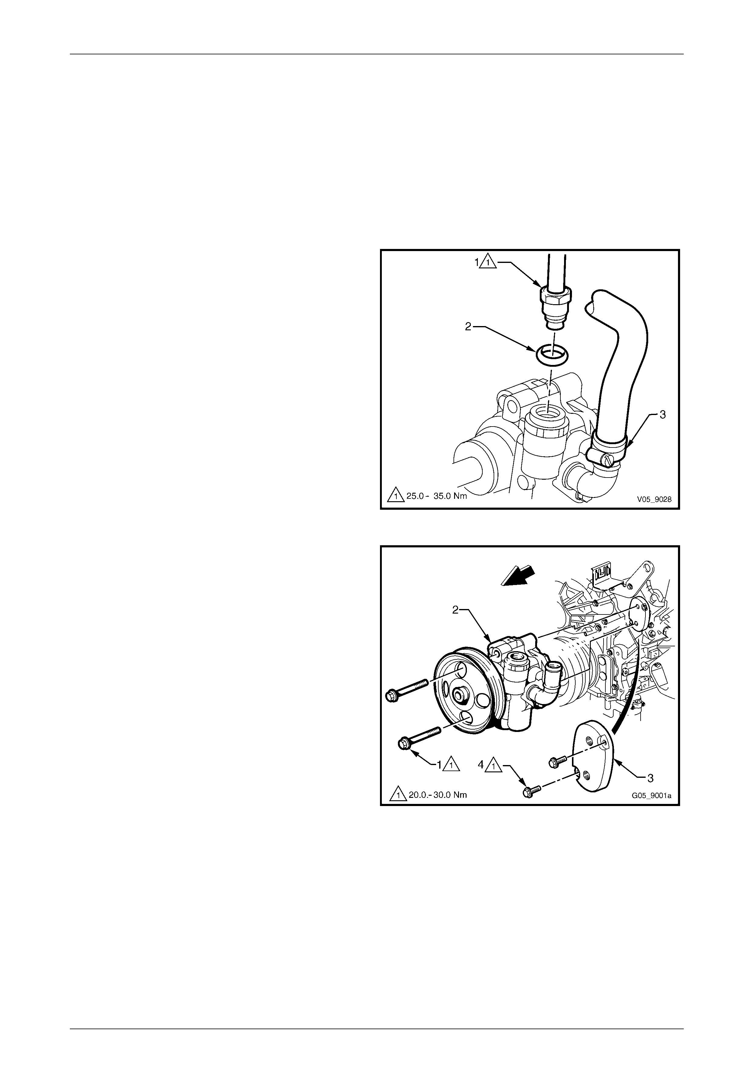
Steering Page 9–72
Page 9–72
GEN III V8 Engine
1 Place a suitable size tray under the vehicle to contain any fluid that may be spilt in the follo wing operation.
2 Refer to Section 6A3 Engine Mechanical – GEN III V8 and remove the follo wing:
• The engine cover
• Air intake duct
• The engine accessory drive belt
3 Remove the power steering fluid reservoir, refer to 3.11 Power Steering Fluid Reservoir.
4 Remove the high pressure lin e flare nut (1) a nd O-ring
(2) from the pump outlet fitting.
5 Loosen the low pressure hose clamp (3) and remove
the hose from the pump inlet fitting.
NOTE
Cover or tape the pump and hose fittings to
prevent foreign matter from entering the system.
Figure 9 – 114
6 From through the holes in the pulley, remove the two
bolts (1), attaching the power steering pump (2) to the
mounting plate (3).
7 Remove the pump from the mounting plate.
8 If required, remove the two bolts (4) attaching the
power steering pump mounting plate to the left-hand
cylinder head.
Figure 9 – 115
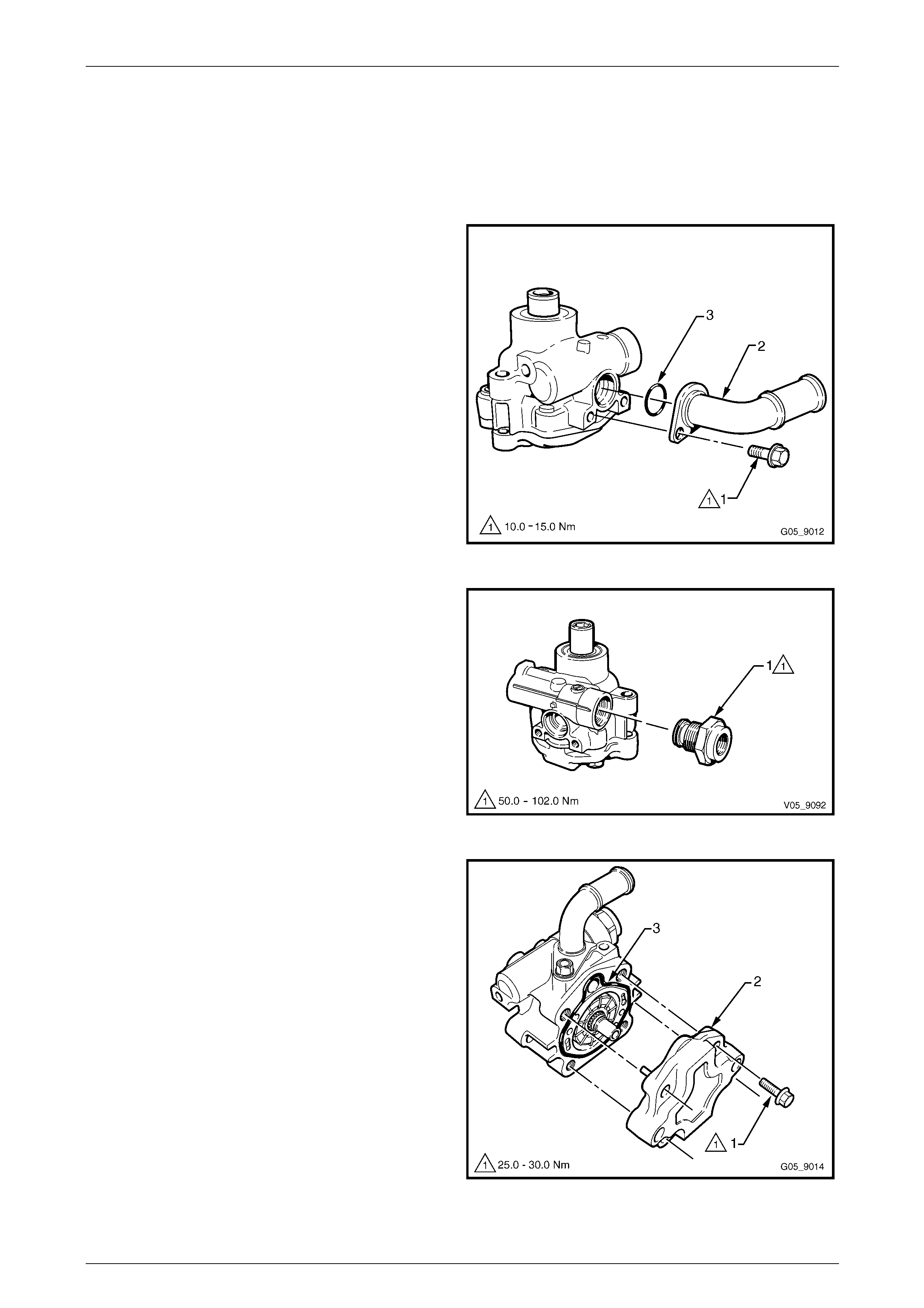
Steering Page 9–73
Page 9–73
Disassemble
1 Tilt the pump assembly up and allow the power steering fluid to drain from the pump.
2 Remove the power steering pump pulley, refer to 3.13 Power Steering Pump Pulley.
3 Clamp the pump in a vice fitted with soft jaws. Do not use excessive force or the pump body will be distorted.
4 Remove the bolt (1) attaching the low pressure inlet
pipe (2) and ensure the O-ring (3) is also removed.
NOTE
Take note of the rotation of the low pressure
inlet pipe as it can b e installed in two directions.
When installed correctly, the low pressure inlet
pipe should be facing the same direction as the
high pressure outlet.
Figure 9 – 116
5 Remove the high pressure outlet fitting (1).
Figure 9 – 117
6 Remove the bolt (1), four places, attaching the rear
endplate (2) to the pump hous ing and remove the rear
endplate.
7 Remove the rear endplate seal (3) from the pump
housing.
Figure 9 – 118
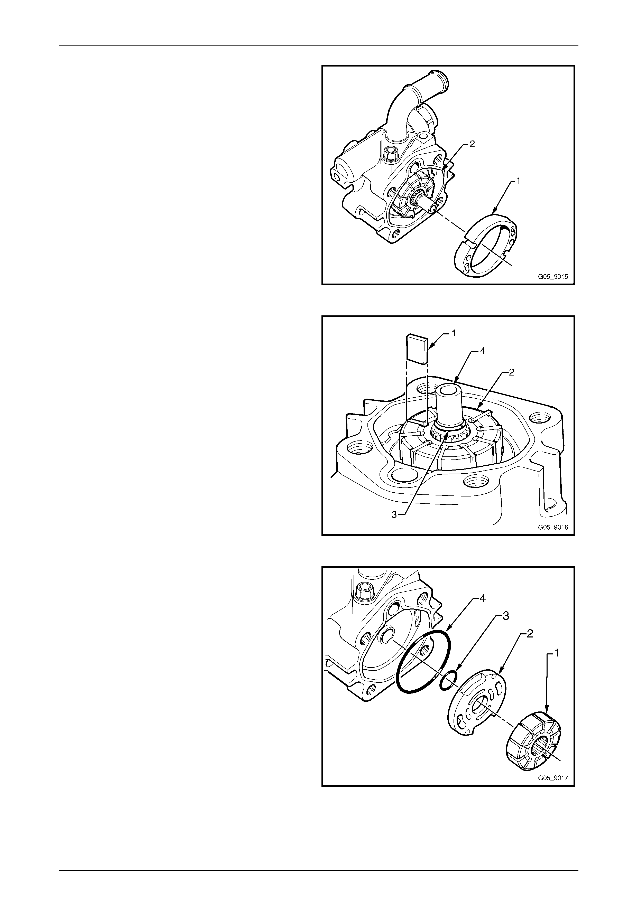
Steering Page 9–74
Page 9–74
8 Remove the pump ring (1) from the housing (2).
Figure 9 – 119
9 Remove the vane blade (1), 10 places, from the pump
rotor (2).
NOTE
If required, a small screwdriver can be used to
assist in removing the vanes.
10 Using a suitable set of circlip pliers, remove the full
circumference retainer ring (3) from the shaft (4).
Figure 9 – 120
11 Remove the rotor (1), thrust washer (2) and the two
O-rings (3 and 4) from the housing.
Figure 9 – 121
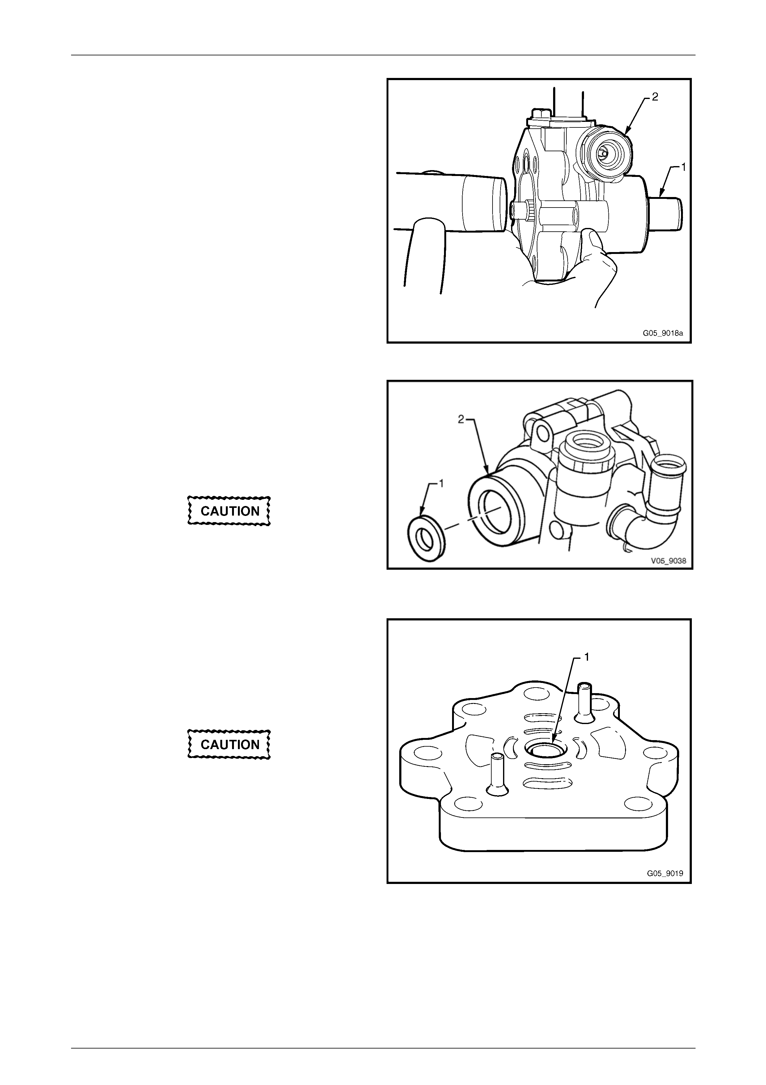
Steering Page 9–75
Page 9–75
12 Remove the pump shaft (1) from the housing (2). If
required, use a suitable soft faced hammer and tap
the pump shaft very lightly until the shaft can be
removed.
Figure 9 – 122
13 Prise the drive shaft seal (1) from the pump housi ng
(2) with a screwdriver and discard the seal.
NOTE
Take care not to damage the hous ing bore when
removing the seal.
The power steering pump bushes
should only be removed if replacement is
required. Prior to removing the bushes
inspect for wear, refer to Figure 9 – 130 and
Figure 9 – 131. Figure 9 – 123
14 If required, remove the rear endplate bush (1), by
either:
a Packing it with grease and using the drive shaft
inserted into the bush, tap the shaft with a soft
faced hammer to drive the bush out of the
housing.
Extreme care must be used when removing
the bush by drilling to avoid damage to the
housing. Any damage to the rear housing
will result in the housing requiring
replacement.
b Using an 11 mm drill bit and a pedestal drill,
carefully drill to a depth of 12 mm from the
surface of the rear endplate removing the
excess material of the bush, then use a
screwdriver to carefully prise out the remainder
of the bush.
Figure 9 – 124
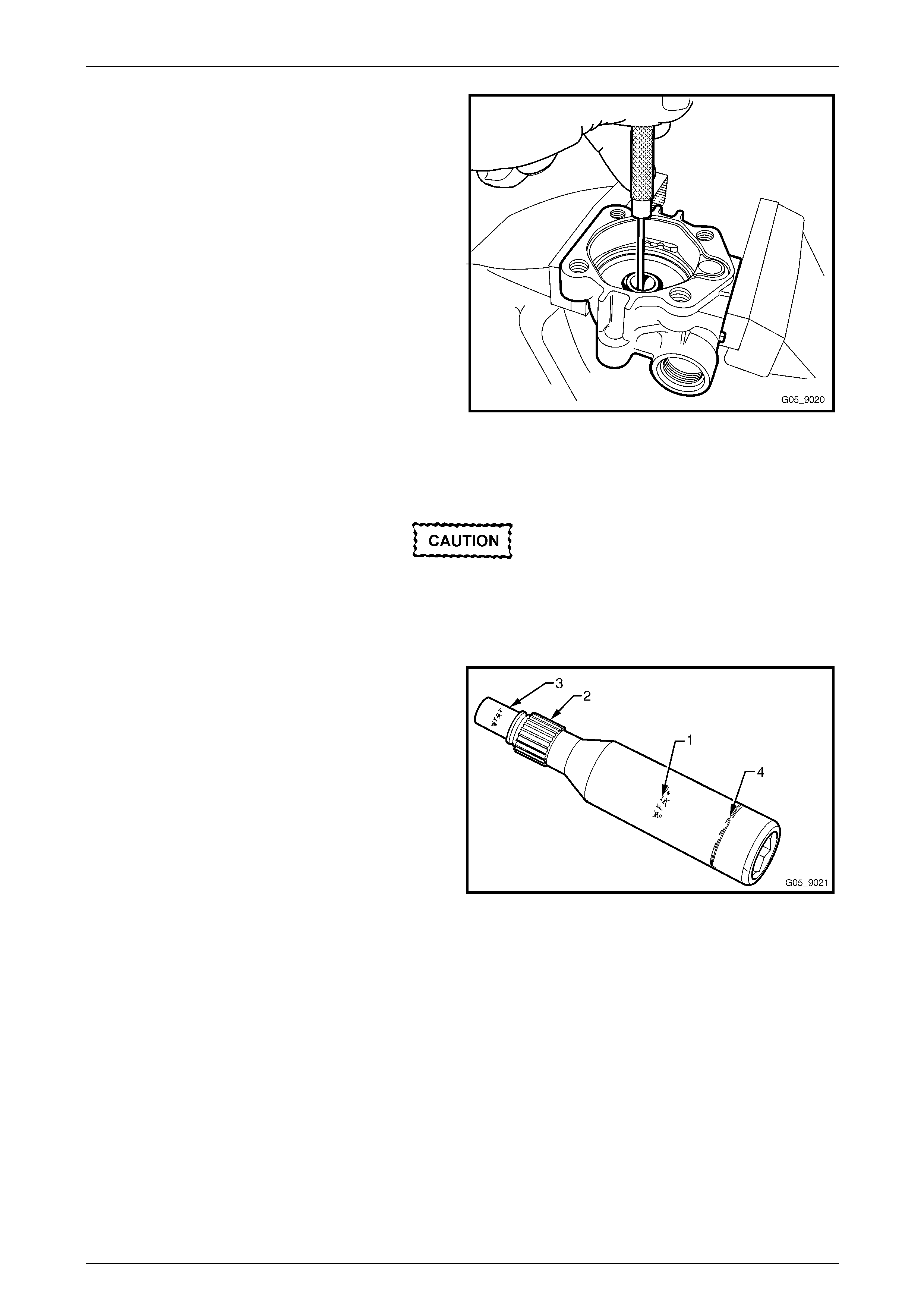
Steering Page 9–76
Page 9–76
15 Using a suitable size brass dri ft or similar, tap the front
housing bush evenl y on both sides until it is removed
from the housing.
Figure 9 – 125
Clean and Inspect
To avoid personal injury, always use the
appropriate gloves and safety glasses when
using cleaning fluids and compressed air.
1 Clean all metal parts in a commercially available cleaning fluid and allow to air dry.
2 Inspect the pump shaft for the following:
a Scouring, pitting or bush pick-up on the front
bush surfaces (1).
b Worn or damaged splines (2).
c Scoring, pitting or bush pick-up on the rear bush
surface (3).
d Excessive wear on the seal track (4).
Figure 9 – 126
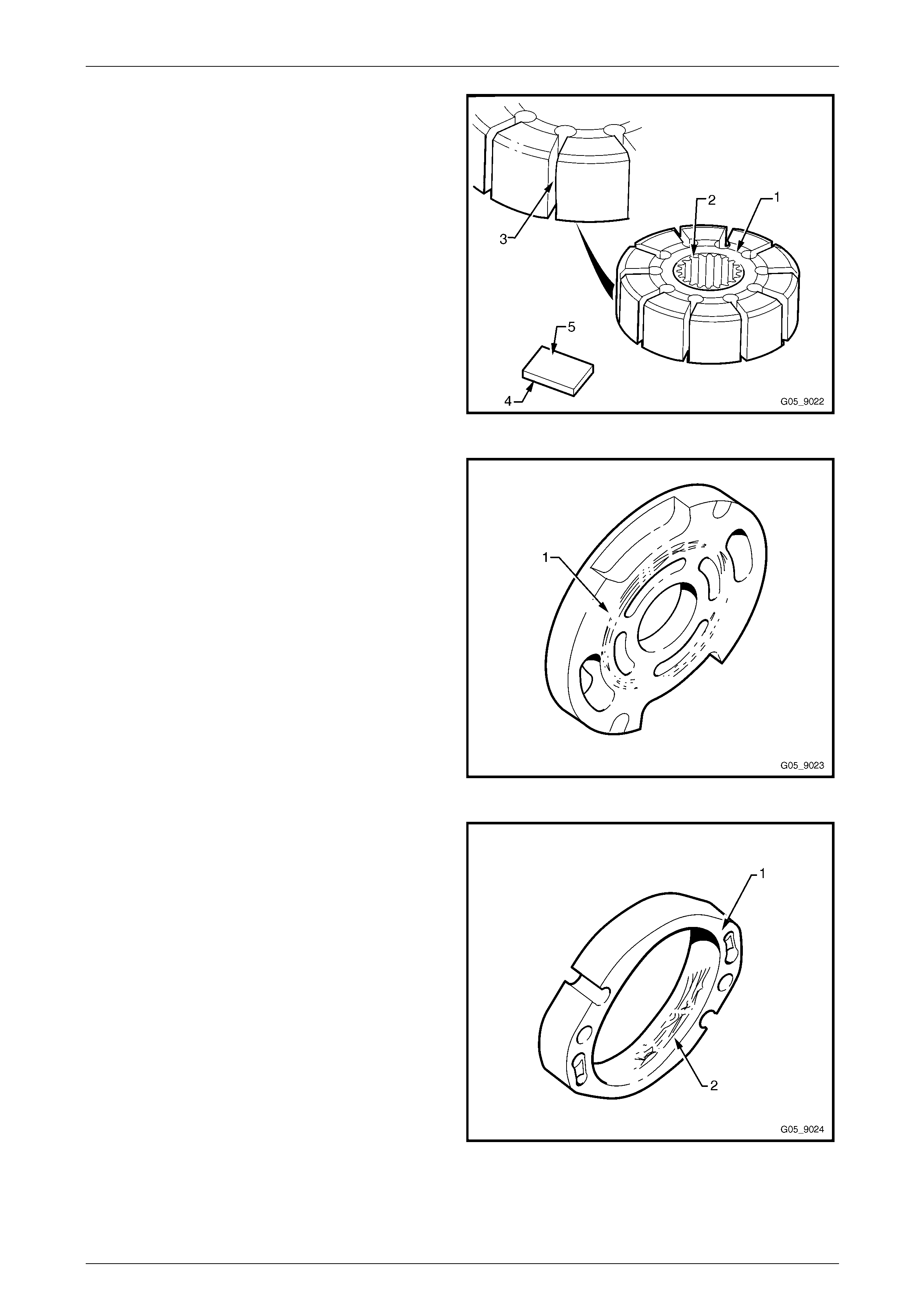
Steering Page 9–77
Page 9–77
3 Inspect the rotor for:
a Scoring on the thrust surfaces (1).
b Worn or damaged splines (2).
c Damage to the vane channels that ma y cause
the vanes to stick (3).
4 Inspect the vanes for:
a Excessive wear on the contact surface (4).
b Wear on the thrust faces of the vane (5).
c Ensure the vanes move freely in the rotor slots.
Figure 9 – 127
5 Inspect the thrust plate for wear and any scouring
marks (1).
Figure 9 – 128
6 Inspect the pump ring (1) for excessive wear and
scouring on the inner surface (1) and the sid e
faces (2).
NOTE
A high polish is al ways present on the surface of
the pump ring as a result of normal wear. Do not
confuse this with abnormal wear.
Figure 9 – 129
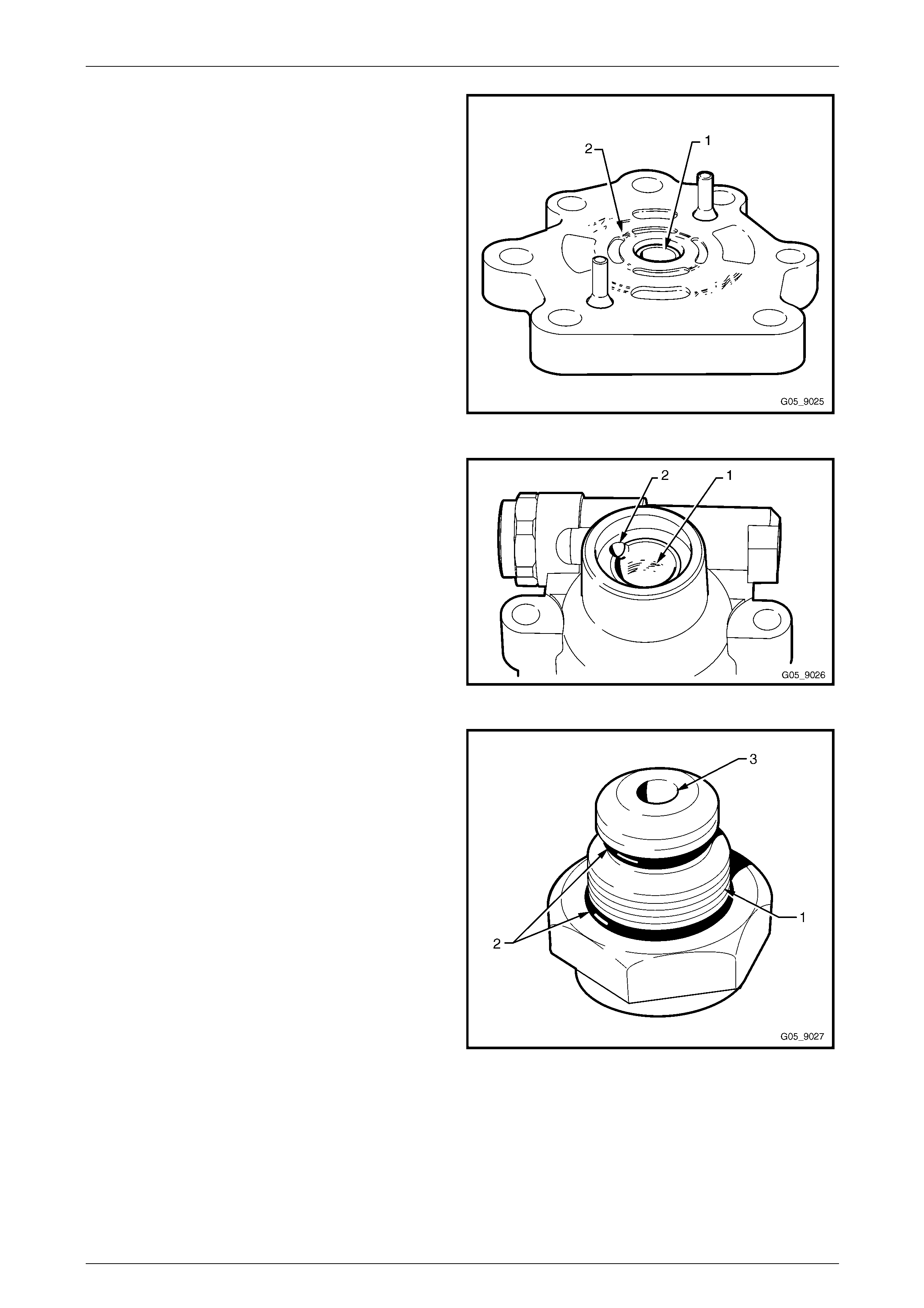
Steering Page 9–78
Page 9–78
7 Inspect the rear endplate:
a Bush (1) for excessive wear, signs of bush
material pick-up or pitting.
b Rear endplate for scouring and excessive wear
on the thrust face (2).
Figure 9 – 130
8 Inspect the front bush (1) for excessive wear, signs of
bush material pick-up or pitting.
9 Using a piece of wire, carefully probe through the front
bearing lubrication passage (2) to check for
blockages.
Figure 9 – 131
10 Inspect the high pressure outlet fitting for damage to
the threads (1), damaged O-rings (2) and res trictions
in the outlet orifice (3).
Figure 9 – 132
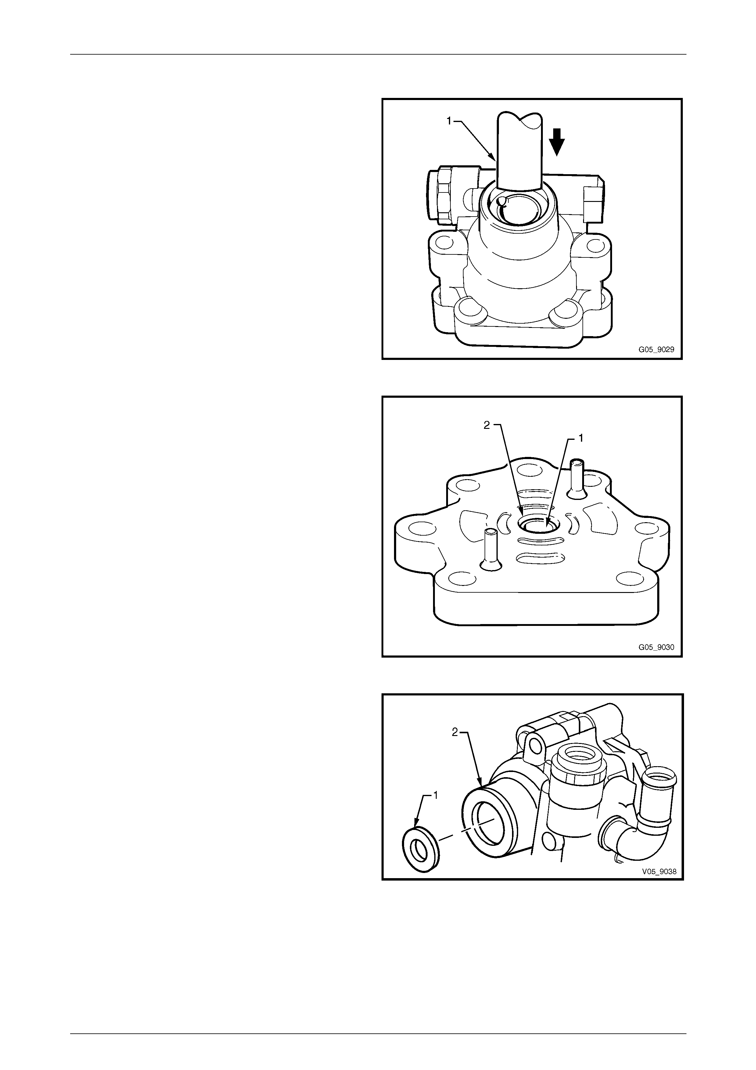
Steering Page 9–79
Page 9–79
Reassemble
1 If required, install a new bush into the front h ousing
using a suitable size brass drift (1) or similar.
2 Install the bush so that it is flush with the housing and
the notch in the bush is aligned with the relief hole in
the housing.
Figure 9 – 133
3 If required, install a new bush (1) into the rea r
endplate (2), using a suitable size brass drift or
similar. Ensure the bush is installed to 3.5 mm below
the surface of the rear endplate.
Figure 9 – 134
4 Lubricate a new driveshaft seal with clean power
steering fluid and install the seal (1) into the pump
housing (2) using Tool No. E1460-1 or 96A1.
Figure 9 – 135
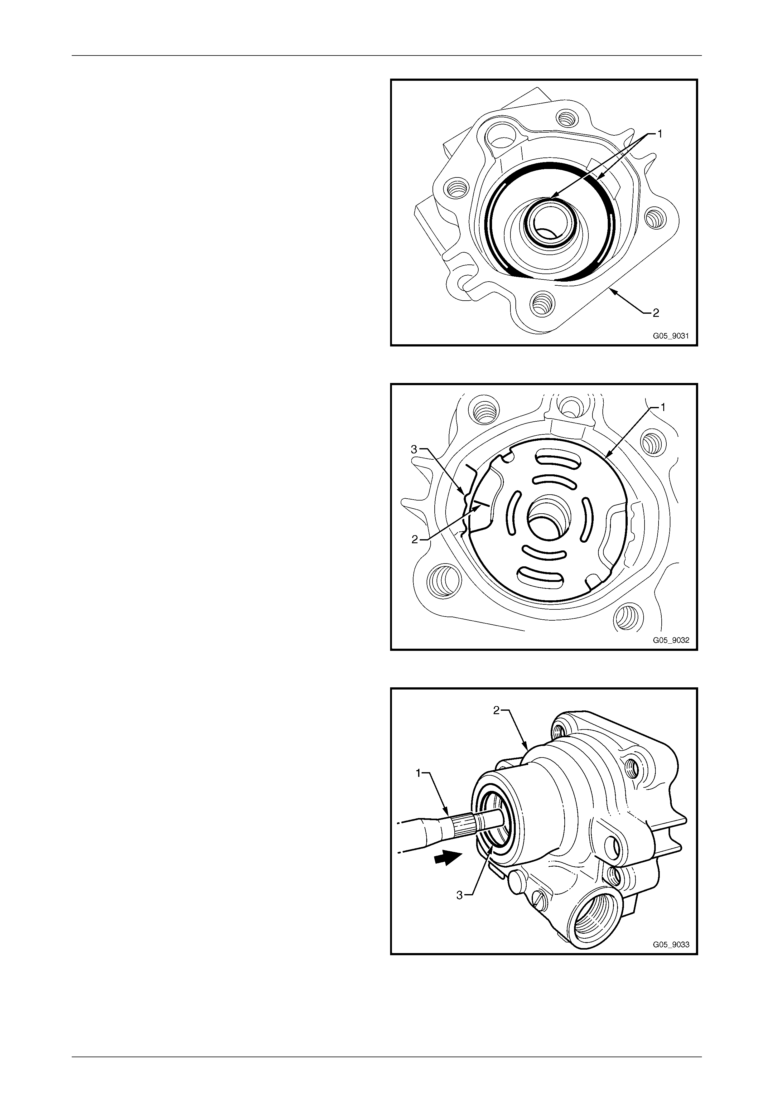
Steering Page 9–80
Page 9–80
5 Lubricate two ne w thrust plate O-rings (1) an d install
the O-rings into the housing (2).
NOTE
Ensure the O-rings are seated correctly in the
housing.
Figure 9 – 136
6 Install the thrust plate (1) with the flat side facing
upwards and align the small notch (2) in the plate to
the notch in the housing (3).
NOTE
Due to the asymmetric shape of the plate, it can
be install in either direction.
Figure 9 – 137
7 Install the drive shaft (1) into the housing (2) taking
care not to contact the seal lips (3) with the spline of
the shaft.
NOTE
Hold the thrust plate in place by hand to ensure
it is not dislodged from the housing.
Figure 9 – 138
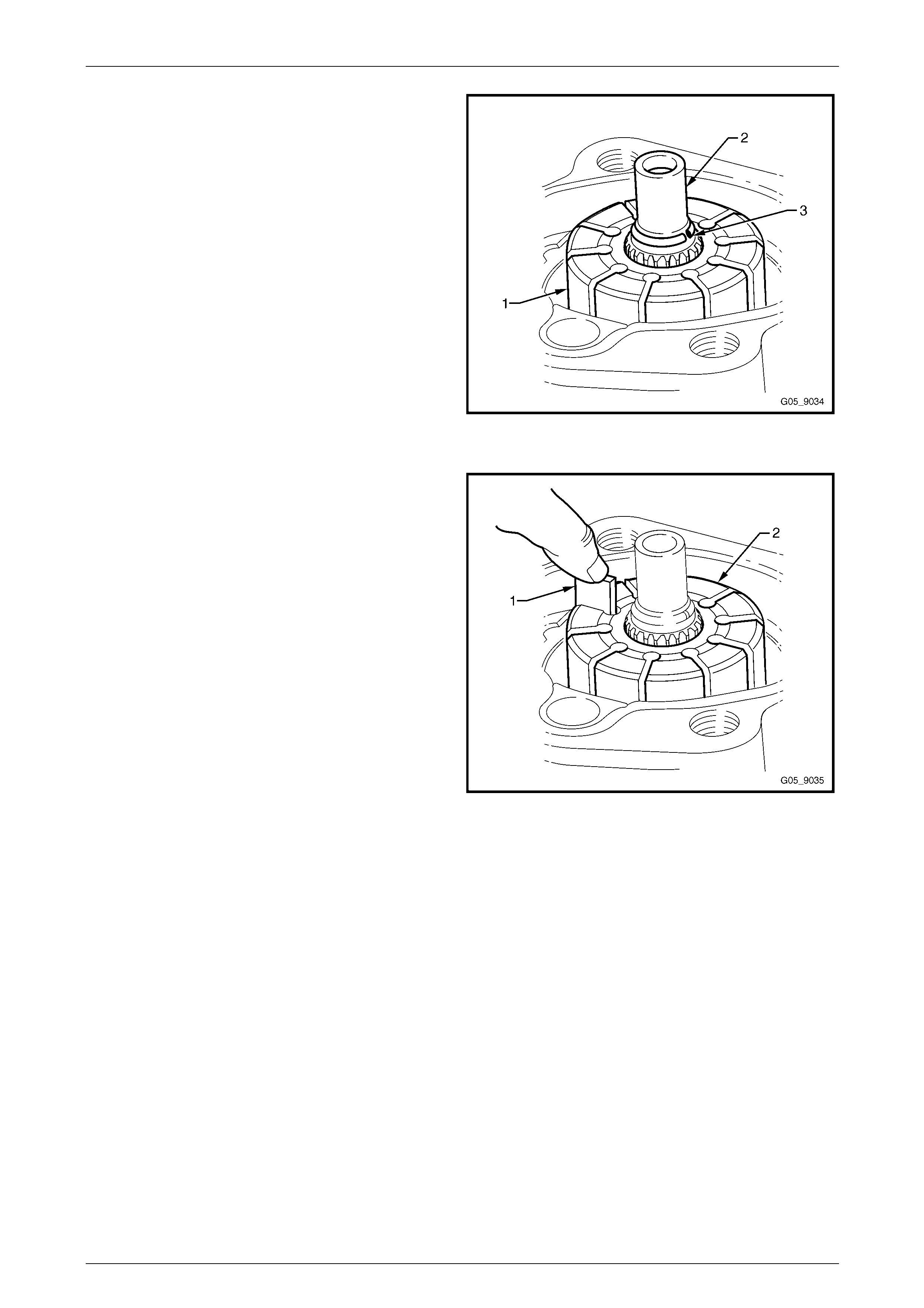
Steering Page 9–81
Page 9–81
8 Support the pump drive shaft by placing a small block
of wood under the drive shaft and clamp the pump in
a vice using soft jaws.
NOTE
Do not clamp with excessive force, as this will
distort the pump housing.
9 Install the rotor (1) onto the drive shaft (2).
10 Install the full circumference retainer ring (3) onto the
shaft. Place the ring on the shaft and using a soft
headed hammer and a deep 11 mm socket, tap the
ring into place. Ensure the ring is correctly seated in
the groove.
NOTE
If the full circumference retainer ri ng does not fit
firmly in the groove, replace with a new one. D o
not use a conventional Circlip or C-clip. Only use
a full circumference retainer ring. Figure 9 – 139
11 Install the vane (1), 10 places, into the rotor slots (2).
NOTE
If required, a small amount of petroleum j ell y can
be used to assist in holding the vanes in place.
Figure 9 – 140
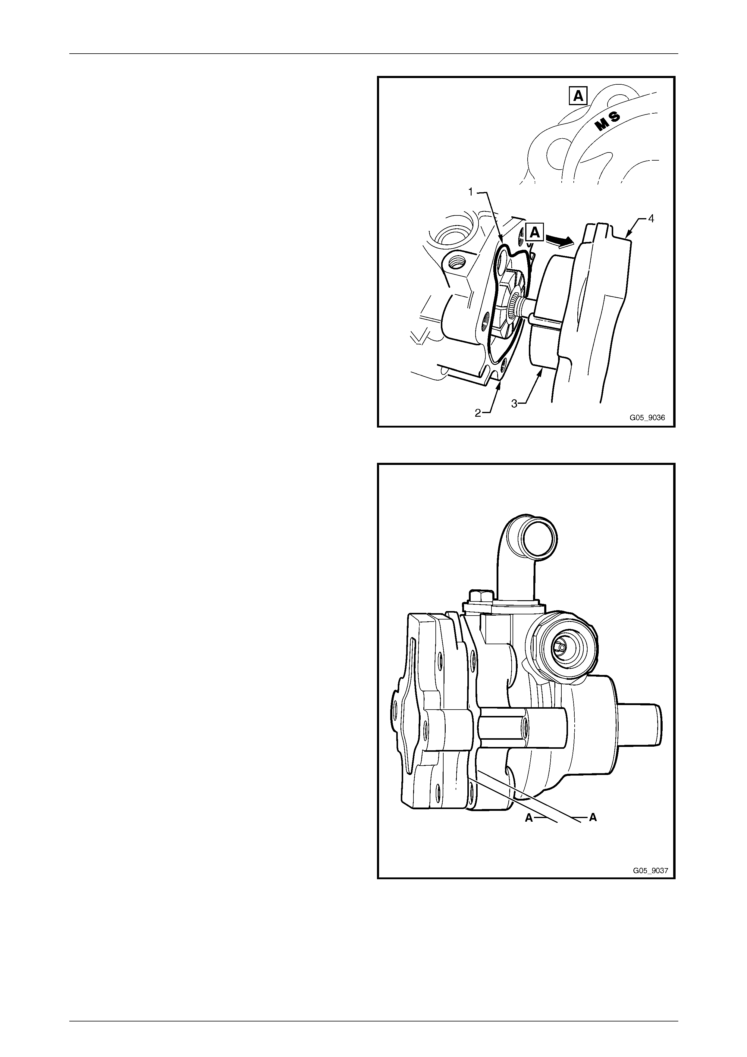
Steering Page 9–82
Page 9–82
12 Install a new rear endplate seal (1) into the groove in
the pump housing (2) and ligh tly smear the outer
surface of the seal with clean po wer steering fluid.
13 Install the pump ring (3) onto the dowel pins in the
rear endplate (4), noting the "MS" mark is to be facing
towards the front of the pump.
14 Hold the pump horizontally and reinstall the rear
endplate housing to the pump housing
15 Rotate the pump so the rear endplate is vertical.
Carefully remove the rear endplate and ensure all the
vanes are in place and man ipulate into position if
required. Reinstall the rear e ndplate.
Figure 9 – 141
NOTE
Ensure the rear endplate is sit ting within 1-2 mm
with the pump housing (A). If the rear en dplate is
raised more than 2 mm from the surface of the
pump housing, remove the rear endplate and
use a small screwdriver to realign the thrust
plate.
Figure 9 – 142
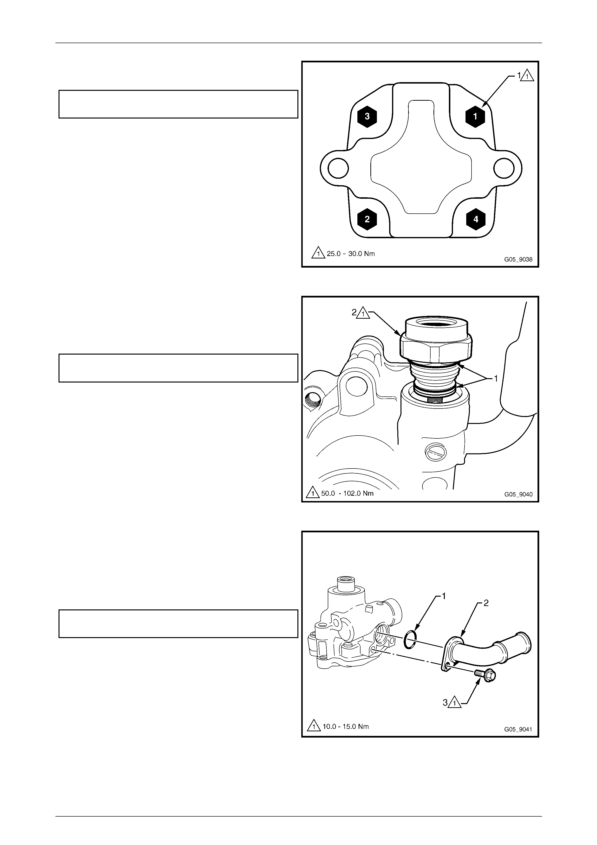
Steering Page 9–83
Page 9–83
16 Tighten the four attaching bolt s (1) in a cross pattern
to the correct torque specification.
Rear endplate housing attaching bolt
torque specification ................................25.0 – 30.0 Nm
Figure 9 – 143
17 Lubricate two ne w O-rings (1) and install them to the
high pressure outlet fitting (2).
18 Install the high pressure outlet fitting and tighten to the
correct torque specification.
High pressure outlet fitting
torque specification .............................. 50.0 – 102.0 Nm
Figure 9 – 144
19 Lubricate a new lo w pressure inlet O-ring (1) with
clean power steering fluid and install it onto the low
pressure inlet pipe (2).
20 Reinstall the inlet ensuring the correct rotation and
tighten the attaching bolt (3) to the correct torque
specification.
Low pressure inlet attaching bolt
torque specification. ............................... 10.0 – 15.0 Nm
NOTE
The outlet should be facing the same direction
as the high pressure outlet when installed
correctly.
21 Reinstall the power steering pump pulley, refer to
3.13 Power Steering Pump Pulley.
Figure 9 – 145
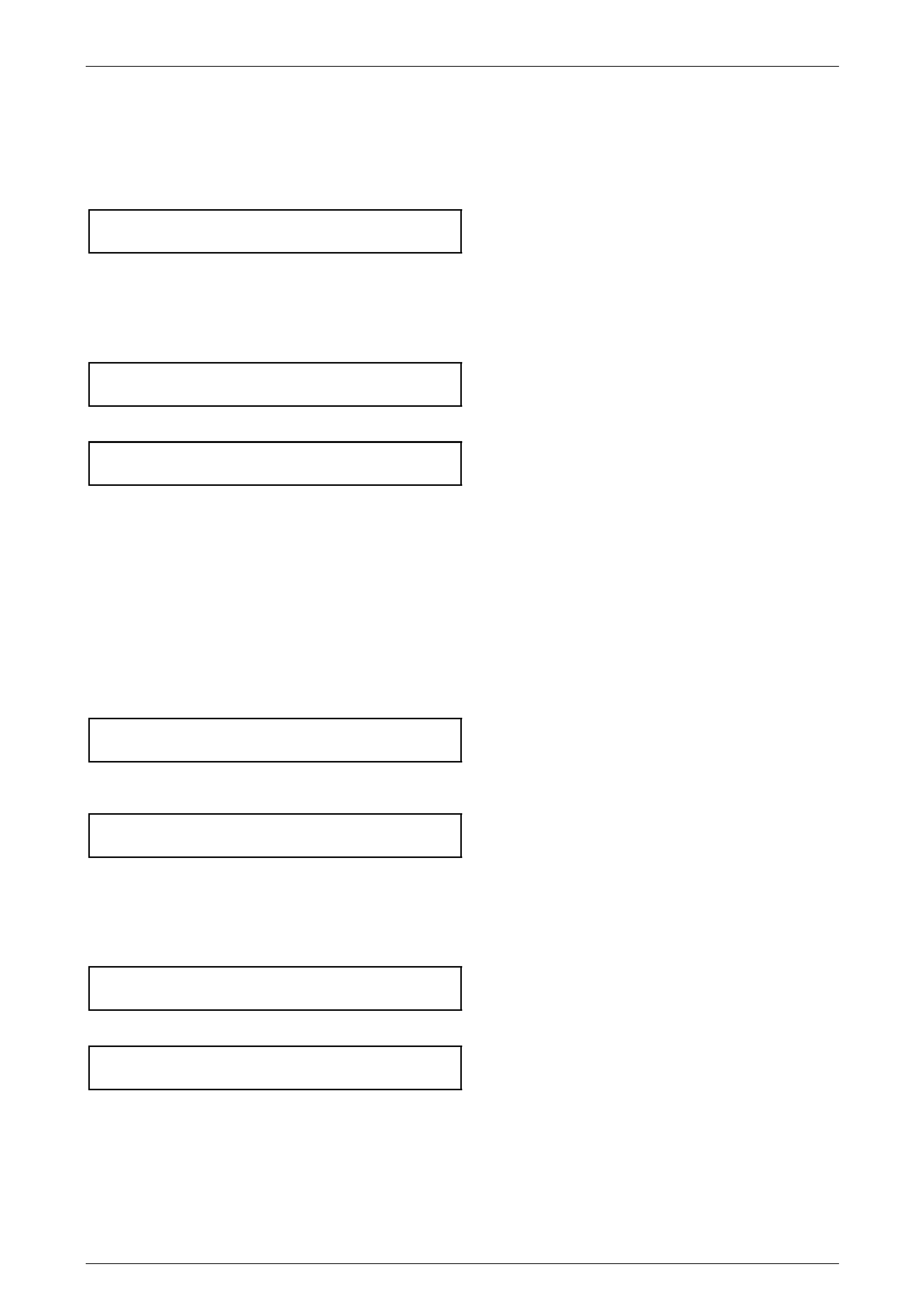
Steering Page 9–84
Page 9–84
Reinstall
V6 Engine
1 Position the power steering pump in the mounting bracket.
2 Reinstall and tighten the two power steering pump attaching bolts to the correct torque specification.
Power steering pump attaching bolt
torque specification.................................20.0 – 35.0 Nm
3 Lubricate a new high pressure line O-ring with clean power steering fluid and install it onto the high pressure line
connection. Install the pipe to the high pr essure outlet fitting, tightening by hand until the thread has started b y at
least two turns.
4 Tighten the high pressure line flare nut to the correct torque specification, using a back-up spanner on the outlet
fitting.
High pressure line flar e nut
torque specification.................................25.0 – 35.0 Nm
5 Reinstall and tighten all low pressure hose clamps to the correct torque specification.
Low pressure hose clamp
torque specification.....................................2.0 – 3.0 Nm
6 If required, reinstall the power steering fluid reservoir, refer to 3.11 Power Steering Fluid Reservoir.
7 Reinstall the engine acc essory drive belt, air intake duct and left-hand engine cover,
refer to Section 6A1 Engine Mechanical – V6.
8 Refill and bleed the hydraulic system, refer to 3.14 Hydraulic System Bleeding and Refilling.
9 Start the engine and check for power steering fluid leaks around the pump and reserv oir area.
10 Perform a pressure check, refer to 2.2 Hydraulic System Pressure Test.
GEN III V8 Engine
1 If required, reinstall the mounting plate to the cylinder head and tighten the attaching bolts to the correct torque
specification.
Power steering pump mounting plate
attaching bolt torque specification...........20.0 – 35.0 Nm
2 Position the power steering pump to the mounting plate and tighten the two pump attaching bolts to the correct
torque specification.
Power steering pump attaching bolt
torque specification.................................20.0 – 35.0 Nm
3 Lubricate a new high pressure pipe O-ring with clean power steering fluid and install the O-ring onto the pipe
connection. Install the pipe to the high pr essure outlet fitting, tightening by hand until the thread has started b y at
least two turns.
4 Tighten the high pressure line outlet fitting flare nut to the correct torque specification, using a back-up s panner on
the outlet fitting.
High pressure line flar e nut
torque specification.................................25.0 – 35.0 Nm
5 Reinstall and tighten all low pressure hose clamps to the correct torque specification.
Low pressure hose clamp
torque specification.....................................2.0 – 3.0 Nm
6 Reinstall the power steering fluid reservoir. Refer to 3.11 Power Steering Fluid Reservoir.
7 Reinstall the engine acc essory drive belt, air intake duct and left-hand engine cover,
refer to Section 6A3 Engine Mechanical – GEN III V8.
8 Refill and bleed the hydraulic system, refer to 3.14 Hydraulic System Bleeding and Refilling.
9 Start the engine and check for power steering fluid leaks around the pump and reserv oir area.
10 If required, perform a pressure check, refer to 2.2 Hydraulic System Pressure Test.
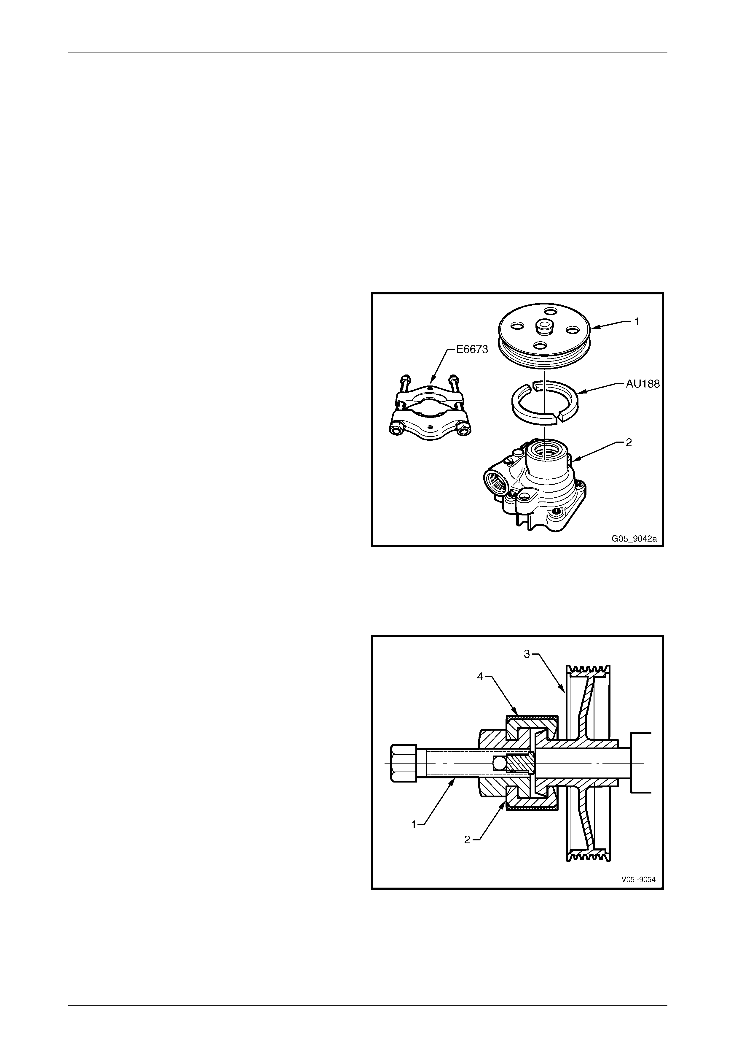
Steering Page 9–85
Page 9–85
3.13 Power Steering Pump Pulley
LT Section No. — 06–400
Remove
The power steering pump dri v e pulley can be removed and reinstalled by either of the following two methods:
• Method 1 uses tool numbers AU188, E923 9A and a commercially available hydraulic pr ess.
• Method 2 uses tool numbers 7185 and 7005.
Method 1
1 Remove the power steering pump, refer to 3.12 Power Steering Pump.
2 Install a set of suitable pulley press plates, such as
Tool No. E6673 under the power steering pump pulley
(1).
3 Position Tool No. AU188, between the pulley and the
press plates and then using a commercially available
hydraulic press, press the pulley from the pump
assembly (2) using a suitable sized drift at the pump
pulley shaft.
NOTE
Do not position the press plates on the edge of
the pulley as damage to the pulle y will occur.
Figure 9 – 146
Method 2
1 Remove the power steering pump, refer to 3.12 Power Steering Pump.
2 Lubricate the forcing screw (1) of Tool No. 7185 and
position the forcing screw against the pulley shaft.
3 Ensure the full diameter end of the half jaws (2) are
engaged with the pu lley (3) and the larger open end
diameter (has chamfer and relief profile) engages with
the pulley flange.
4 Slide the retainer sleeve (4) o v er the half jaws and
hand tighten the forcing screw. Ensure the forcing
screw is aligned with the pump axis.
5 Progressively tighten the forcing screw and remove
the pulley from the pump shaft.
NOTE
Do not use power tools or exceed a torque of
90.0 Nm. If the pulley cannot be removed within
this torque, remove the pulley using tool No.
AU188 & E9239. If still unsuccessful, replace the
complete pump assembly. Figure 9 – 147
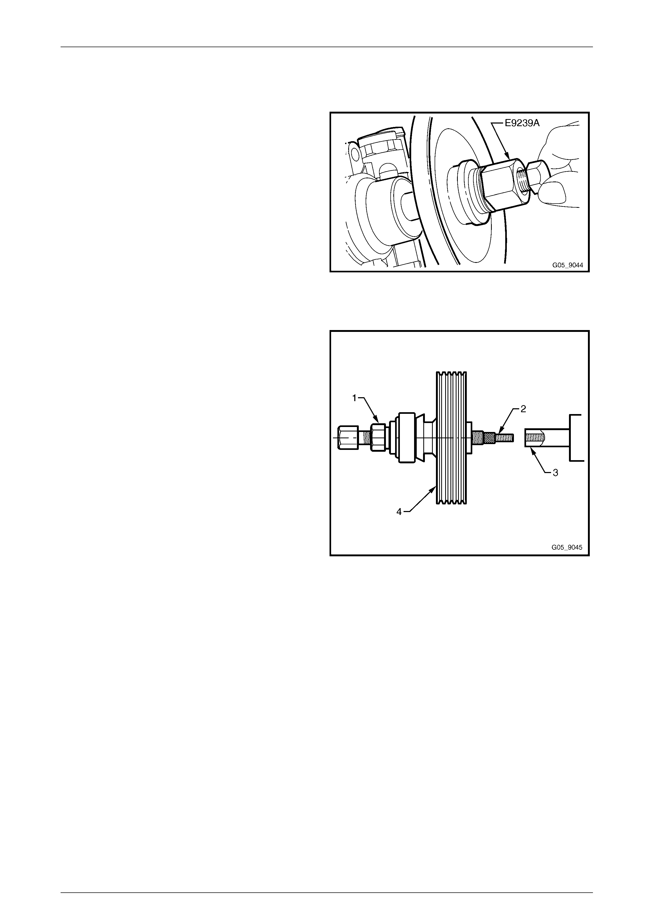
Steering Page 9–86
Page 9–86
Reinstall
Method 1
1 Ensure the pulley bore and th e pump pulley shaft are
free of burrs. Place pulley on end of pump shaft.
2 Install Tool No. E9239A by screwing the bolt fully into
the pump pulley shaft.
3 Install the pulley by holding the bolt he ad and turning
the large nut and bearing clockwise until the pulley is
flush with the end of the shaft.
4 Remove Tool No. E9239 (or J25033-B).
5 Install the power steering pump,
refer to 3.12 Power Steering Pump.
Figure 9 – 148
Method 2
1 Assemble the drive nut (1) and thread insert (2) into
the forcing screw of Tool 7005. Ensure that adequate
graphite grease is applied to the forcing screw and
nut.
2 Tighten the forcing screw assembly by hand onto the
pump shaft (3), until it bottoms out against the
shoulder.
NOTE
Do not use a spanner for this operation.
3 Turn the drive nut against the pulley (4) until the pulley
is at the correct installation depth.
NOTE
Do not allow the forcing screw to turn during this
operation. Do not use power tools or exceed a
torque of 90.0 Nm. If the pulley cannot be
installed within this torque, replac e the complete
pump assembly.
4 Once the pulley is installed, remove the forc ing screw
from the pump shaft.
5 Install the power steering pump,
refer to 3.12 Power Steering Pump.
Figure 9 – 149

Steering Page 9–87
Page 9–87
3.14 Hydraulic System Bleeding and Refilling
If the power steering fluid level is low in the po wer steering fl uid reservoir, air will be drawn in and mixed with the power
steering fluid in small bubbles (aeration). If the pump is allowed to continue operation, an increasing am ount of air will be
drawn into the system, causing the power steering fluid volume to increase to a point where the reserv oir could overflow.
Sudden releases in pressure that will occur when the steering is suddenly taken off a full lock condition will ca use
dramatic eruptions of power steering fluid from the reservoir. The separation of air entrapp ed under these conditions will
be extremely difficult to remove and may take several days.
If the steering gear assembly requires replacement, a large volume of air will be required to be purged, which means the
power steering reservoir fluid level will fall rapidly when the engine is started.
During bleeding, it is important the front wheels are clear of the ground and the steerin g is not held forcibly against the
steering stops.
Procedure
1 Raise the front of the vehicle and place on safety stands, refer to Section 0A General Information.
2 With the engine not running, add power steering fluid to the reservoir to the maximum mark (or greater, if it is
known the steering gear is empty).
3 Start the engine and allow to run for only 2-3 seconds. Do not turn the steering wheel at this point.
4 Repeat with Steps 2 and 3 until the power steering fluid level remains constant.
5 Start and run the engine at idle speed, turning the steerin g wheel slowly from lock to lock without holding it in the
full lock positions (this will build up hi gh pressures, atomising any entrapped air). Repeat this procedure six to eight
times.
6 Stop the engine, check the power steering fluid level and top up to the maximum level, as required.
7 Start and run the engine at idle speed. Again turn the steering wheel from lock to lock but now slowly build up the
pressure levels by holding against the full lock position from 1-2 seconds. Repeat this procedure four to six times.
8 Stop the engine and top up the power steering fluid level to the maximum mark, as required.
NOTE
While the majority of entrapped air will be
removed by the above procedure, a small amount
may remain, which can only be removed by
alternate circulation and settling of the power
steering fluid for a prolonged period. This is
usually achieved automatically after two to three
days with daily driving and settling overnight.
9 Turn the steering wheel to the straight ahead position, lower vehicle to the ground and turn the ignition off.

Steering Page 9–88
Page 9–88
4 Power Steering Hoses, Pipes
and Fluid Cooler
4.1 Power Steering Lines and Hoses Layout
LT Section No. — 06–400
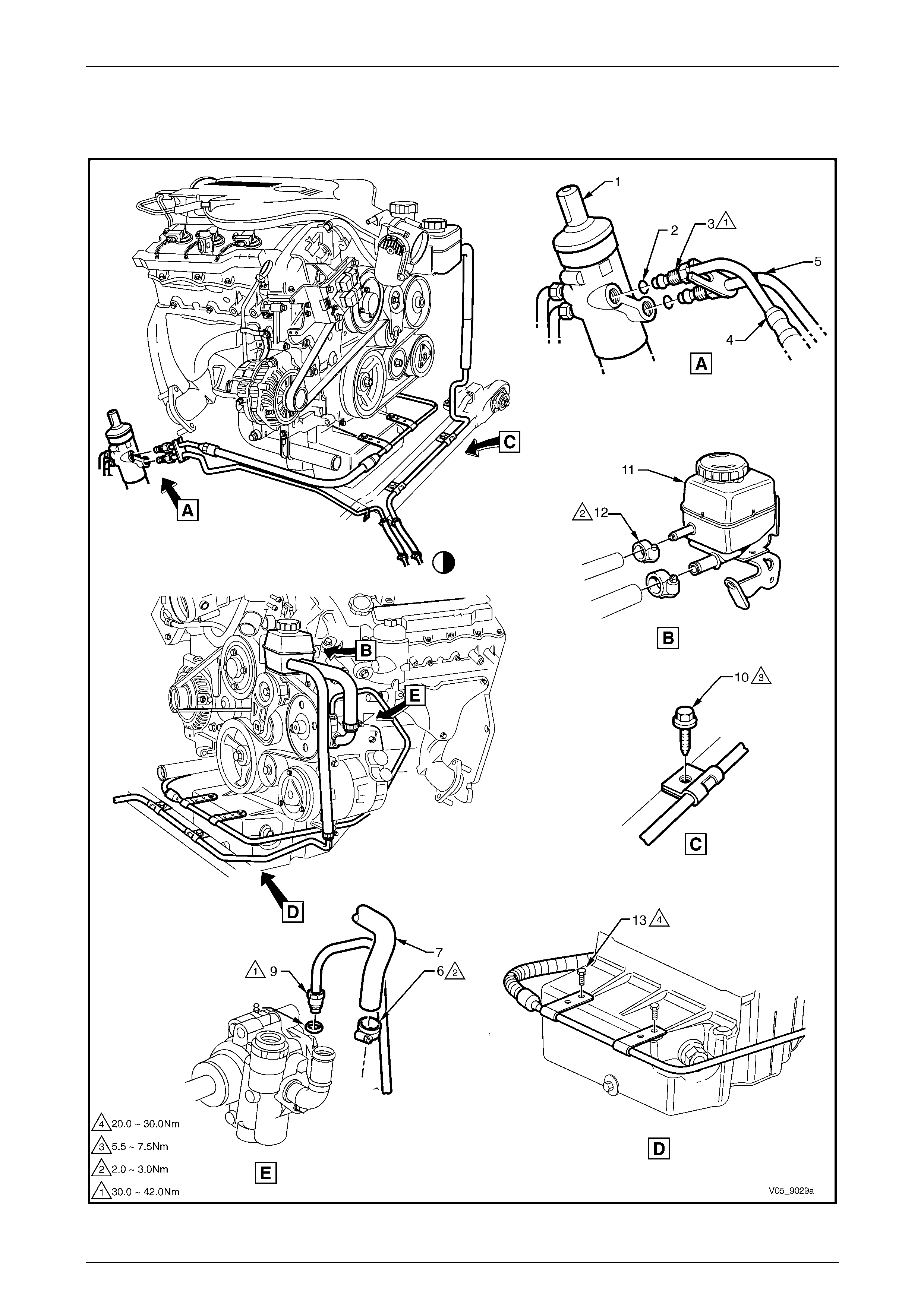
Steering Page 9–89
Page 9–89
Arrangement
V6 Engine
Figure 9 – 150

Steering Page 9–90
Page 9–90
Legend
1 Power Steering Gear Assembly
2 Fluid Line O-ring, 2 places
3 Fluid Line Flare Nut, 2 places
4 Steering Gear to Pump Line
5 Steering Gear to Cooler Line
6 Pump to Reservoir Inlet Hose Clamp
7 Pump to Reservoir Inlet Hose
8 High Pressure Fluid Line O-ring
9 High Pressure Fluid Line Flare Nut
10 Low Pressure Return Hose
11 Low Pressure Line Bracket Attaching Screw
12 Low Pressure Hose Clamp
13 Low Pressure Return line
14 Steering Gear Fluid Line Bracket Attaching Screw
15 Fluid Reservoir
16 Low Pressure Return Line Clamp
17 Fluid Line to Oil Pan Bracket Attaching Screw
To cooler, for continuation refer to Figure 9 – 154.

Steering Page 9–91
Page 9–91
GEN III V8 Engine
Figure 9 – 151
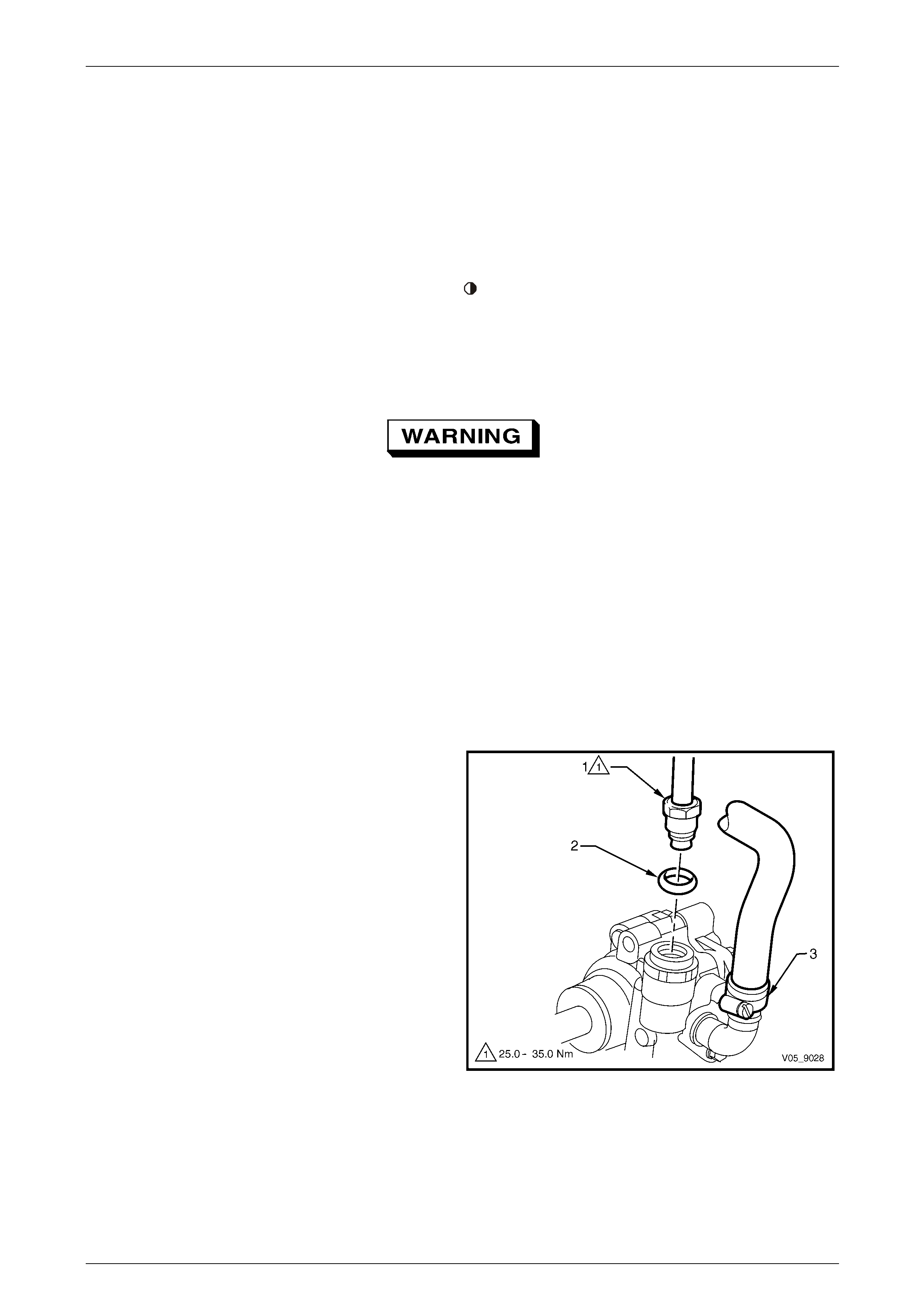
Steering Page 9–92
Page 9–92
Legend
1 Power Steering Gear Assembly
2 Fluid Line to Steering Gear O-ring, 2 places
3 Fluid Line Flare Nut, 2 places
4 Steering Gear to Cooler Line
5 Steering Gear to Pump Line
6 Low Pressure Hose Clamp
7 Low Pressure Pump to Reservoir Hose
8 Fluid Line to Pump O-ring
9 Fluid Line Flare Nut
10 Cooler to Reservoir Low Pressure Hose
11 Low Pressure Line Bracket Attaching Screw
12 Low Pressure Hose Clamp
13 Fluid Cooler to Reservoir Low Pressure Line
14 Low Pressure Line Bracket Attaching Screw
15 Fluid Reservoir
16 Low Pressure Hose Clamp, 2 places
17 High Pressure Line to Sump Bracket Attaching Bolt
To cooler, for continuation refer to. Figure 9 – 154
Remove
Power steering lines and hoses that are either , damaged, leaking, perished or show signs of wear cannot be repaired
and replacement of the complete hose is req uire d.
Power steering fluid can reach temperatures
of approximately 75° Celsius. When handling
power steering fluid or power steering
components that are hot, the technician must
wear the appropriate safety glasses, gloves
and clothing to protect against possible
burns.
NOTE
The following operation is best performed with
the vehicle raised on stands or a hoist.
Remove the power steering line/hose as re quired referring to the appropriate layo ut diagram, noting the following:
1 Place a suitable sized tray underneath the vehicle to contain any fluid that may be spilt in the following operation.
2 As required remove the following:
a Loosen and remove the high pressure line flare
nut (1) and O-ring (2) from the pump outlet
fitting.
b Loosen the reservoir to pump low pressure hose
clamp (3) and remove the hose from the pum p
inlet fitting.
NOTE
Cover or tape the pump and hose fittings to
prevent foreign matter from entering the system.
Figure 9 – 152
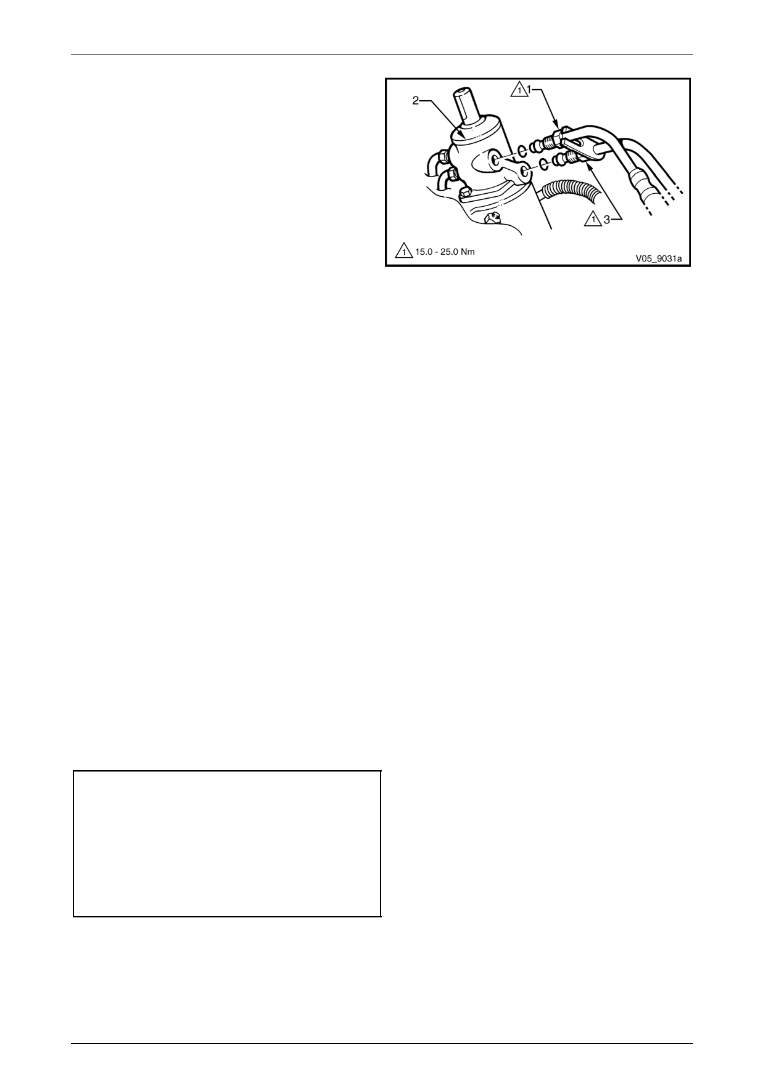
Steering Page 9–93
Page 9–93
3 As required remove the following:
a Loosen and remove the flare nut (1), attaching
the high pressure hydraulic line to the steering
gear valve housing (2) and remove the line.
b If removing the return line, loosen and remov e
the flare nut (1), attaching the high pressur e
hydraulic line to the steering gear valve housing
(2), then loosen and remove the flare nut (3),
attaching the return line to the steering gear
valve housing and remove.
NOTE
Ensure the O-rings are removed from the valve
housing when the lines are removed. Replace
the O-rings when reinstalling the lines.
4 Remove all fasteners attaching the appropriate power
steering hose to the chassis and/or body.
Refer to the following:
• V6 engine, refer to Figure 9 – 150.
• GEN III V8 engine, refer to Figure 9 – 151.
Figure 9 – 153
Inspect
Before removing power steering hoses, insp ect the hoses for the following:
• leakage,
• external damage,
• abrasions, and
• perished.
For further information on leak testing and diagnosis, refer to Section 00 Warnings, Cautions and Notes.
The outer jacket, steering shaft and instrument pan el mounting bracket are designed as energy absorbing units. Because
of the design of these components, it is essential the steering column assembly be handled with care when performing
any service operations. Avoid hammering, jarring, dropping, or leaning on any portion of the column.
Reinstall
Reinstallation of the power steering lines and hoses is the reverse of the removal procedure, noting the following:
1 Ensure all hoses and lines a free from interference and rubbing with other components.
2 Tighten all attaching screws and hose connections to the correct torque specification.
Power steering fluid line to chassis rail
attaching screw torque specification...........1.0 – 1.5 Nm
High pressure line flar e nut
torque specification.................................25.0 – 35.0 Nm
Hydraulic line to valve housing flare nut
torque specification.................................25.0 – 35.0 Nm
Low pressure hose clamp
torque specification.....................................2.0 – 3.0 Nm
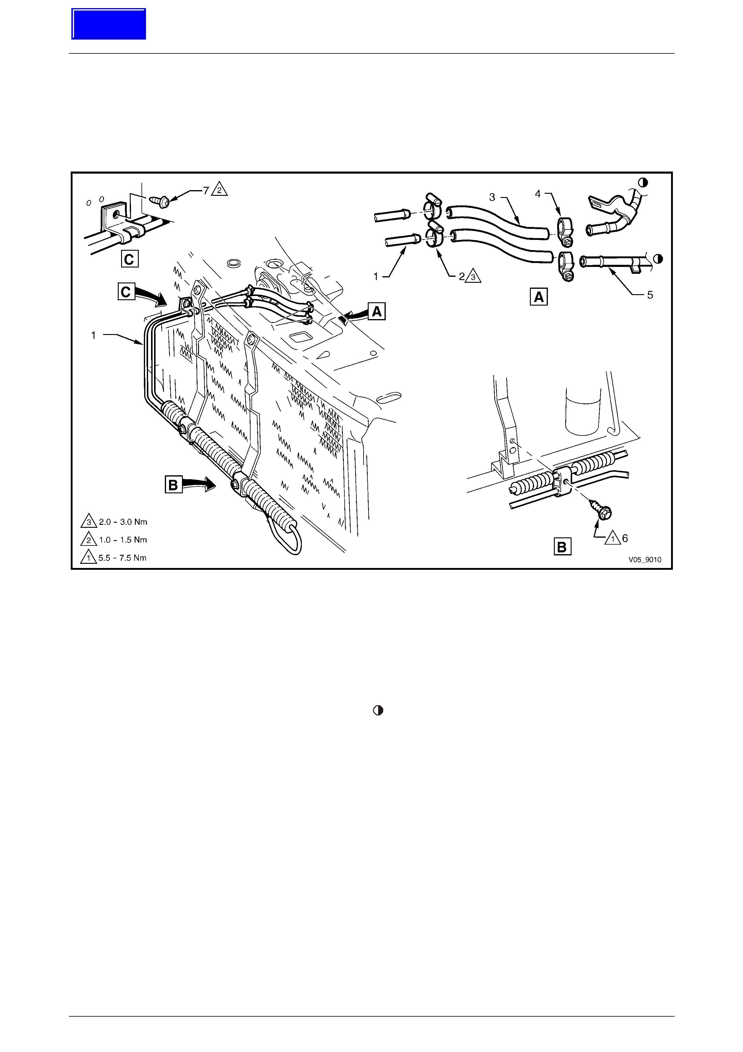
Steering Page 9–94
Page 9–94
4.2 Power Steering Fluid Cooler
LT Section No. — 06–400
Arrangement
Figure 9 – 154
Legend
1 Power Steering Fluid Cooler to Steering Gear Pipe
2 Cooler to Steering Gear Line Connecting Hose
3 Cooler to Reservoir Line Connector Hose
4 Hose Clamp, 4 places
5 Steering Gear to Cooler Pipe
6 Cooler Pipe to Body Rail Attaching Screw
7 Fluid Reservoir Line
8 Power Steering Fluid Cooler
9 Fluid Cooler Attaching Screw, 2 places
To power steering line, for continuation refer to
Figure 9 – 150 or Figure 9 – 151.
Techline
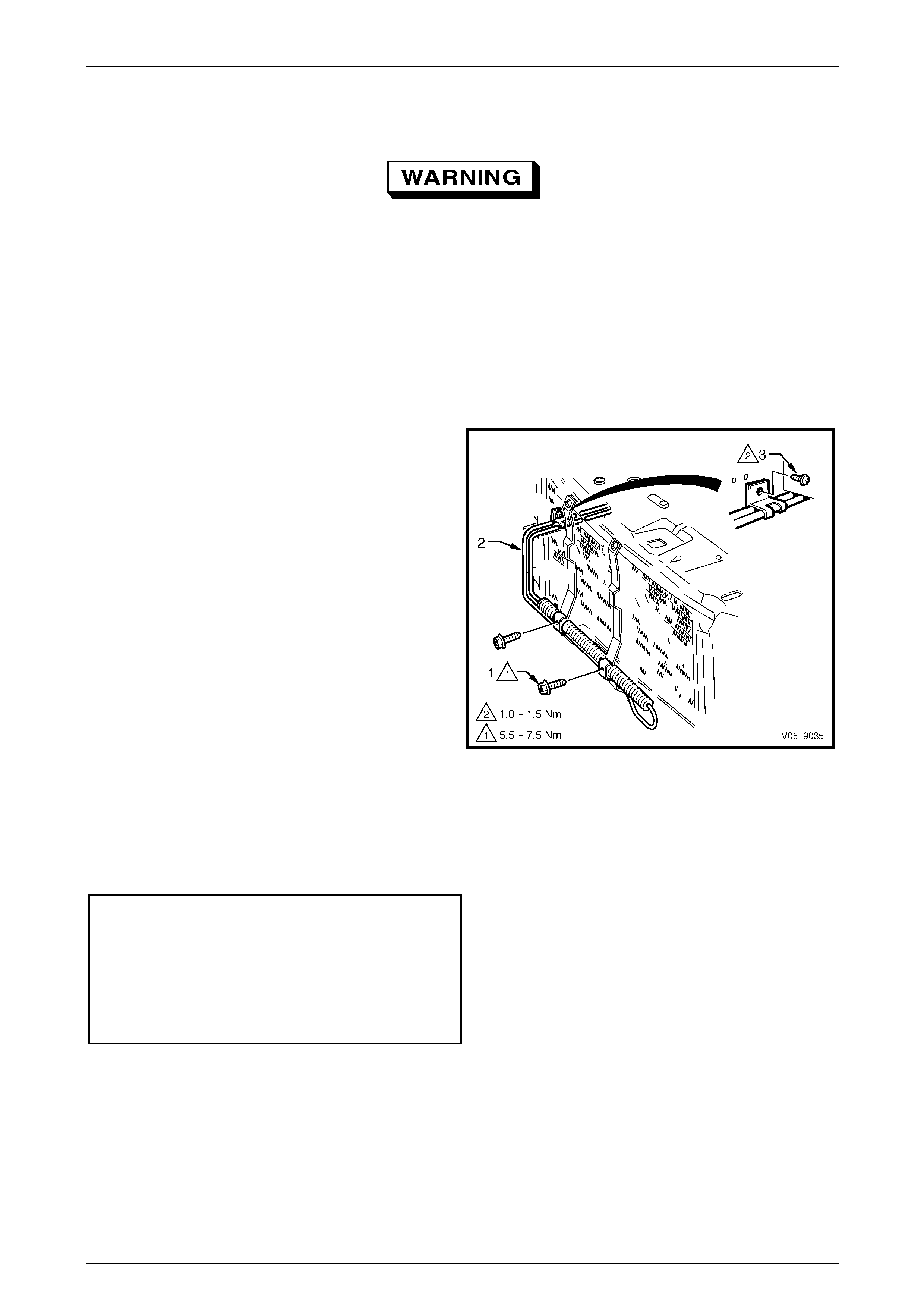
Steering Page 9–95
Page 9–95
Remove
Power steering fluid can reach temperatures
of approximately 75° Celsius. When handling
power steering fluid or power steering
components that are hot, the technician must
wear appropriate safety glasses, gloves and
clothing to protect again st p ossible burns.
1 Remove the front bumper fascia, refer to Section 1D Bumper Bars.
2 Place a suitable sized tray under the vehicl e to contain any fluid that may be spilt in the following operation.
3 Remove the hose clamp attaching the power steering cooler flexibl e hose to the power steering cooler line, refer to
View A in Figure 9 – 154. Repeat for the other cooler hose.
4 Remove the two screws (1), attaching the power
steering fluid cooler (2) to the front mounting bracket.
5 Remove the screw (3), attaching the power steering
fluid cooler line attaching bracket to the right-hand
body rail.
6 Remove the power steering fluid cooler from the
vehicle.
Figure 9 – 155
Reinstall
Reinstallation of the power steering fluid cooler is the reverse of the removal procedure, noting the following:
1 Tighten all attaching screws and hose clamps to the correct torque specification.
Power steering fluid cooler attaching screw
torque specification.....................................5.5 – 7.5 Nm
Power steering fluid cooler line to
chassis rail attaching screw
torque specification.....................................1.0 – 1.5 Nm
Power steering cooler flexible
hose clamp..................................................2.0 – 3.0 Nm
2 Refill the power steering system with the recommended flui d and bleed the hydraulic system,
refer to 3.14 Hydraulic System Bleeding and Refilling.
Steering Page 9–96
Page 9–96
5 Specifications
Steering Gear
Steering Gear Type Power Steering Rack and pin ion with integral power cylinder and
rotary valve mechanism – variable ratio.
Steering Gear Ratio
On-centre 17.2:1
Toward Lock 11.8:1
Number of Steering Wheel turns Lock to Loc k 2.7
Nominal Rack Travel Total 164 mm
Power Steering Pump
Make Kayaba
Type Vane type constant flow.
Pressure @ 1,000 engine rpm 7,580 – 8,270 kPa
Flow 8 L/pm.
Drive Pulley driven by the crankshaft via a drive belt
Drive Belt Tension Self Adjusting
Lubrication
Hydraulic Fluid Dexron® III Automatic Transmission Fluid
Power Steering Fluid Capac ity Approx. 650 ml
NOTE
Use the power steering fluid level indicator as a final
check to ensure the correct refill quantit y.
Specified Grease EP Semi Fluid Lithium Base O Grease
Sealant
Recommended Type Loctite 242 or equivalent
RTV T32 Silicone Sealant
Front Wheel Toe
Front Toe-in (degrees total)
Front Toe-in (degrees per wheel)
0° 10’ ± 0° 10’
0° 5’ ± 0° 5’

Steering Page 9–97
Page 9–97
6 Torque Wrench Specifications
ATTENTION
All steering fasteners are important attaching parts as they affect the performance of vital components and/or
could result in majo r repair expense. Where specified in this Section, fasteners MUST be rep laced with parts
of the same part number or a GM approved equivalent. Do not use fasteners of an inferior quality or
substitute design.
Torque values must be used as specified during reassembly to ensure proper retention of all steering
components.
Through out this Section, fastener torque wrench specifications may be accompanied with the following
Identification marks:
Fasteners must be repl aced after loosening.
Fasteners either have micro encapsulated sealant applied or incorporate a mechanical thread lock and
should only be re-used once. If in doubt, replacement is recommended.
If one of these identification marks is present alongside a fastener torque wrench specification, the
recommendation regarding that fastener must be adhered to.
High Pressure Pipe Flare Nut....................................................25.0 – 35.0 Nm
High Pressure Outlet Fitting ....................................................50.0 – 102.0 Nm
Rear Endplate Attaching Bolt ....................................................25.0 – 30.0 Nm
Active Select Shift Control Paddle Assembly Attaching Screw .....1.0 – 3.0 Nm
Horn Bar Stereo Control Switch Assembly Attaching Screw.........1.0 – 3.0 Nm
Rear Cover Attaching Screw.........................................................1.0 – 3.0 Nm
¡ Steering Wheel Attaching Bolt...............................................40.0 – 50.0 Nm
Steering Column Lower Cover Attaching Screw............................0.5 – 2.0 Nm
Steering Column Lower Housing Attaching Nut ........................15.0 – 30.0 Nm
Upper Steering Column Mount Attaching Nut............................15.0 – 30.0 Nm
Steering Coupling Cam Bolt Retaining Nut............................23.0 – 30.0 Nm
Tie-rod Socket Castellated Attaching Nut..................................50.0 – 85.0 Nm
Tie-rod End Adjuster Lock Nut .................................................40.0 – 60.0 Nm
Lower Pinion Bearing Retaining Nut......................................35.0 – 45.0 Nm
Pinion Sealing Plug ...................................................................55.0 – 60.0 Nm
Valve Housing Attaching Screw ....................................................5.0 – 6.0 Nm
Rack Pad Adjusting Screw
Stage 1.....................................................................................10.0 – 12.0 Nm,
Stage 2....................................................................................back off 20 – 28°
Rack Pad Adjusting Screw Lock Nut.........................................55.0 – 65.0 Nm
Tie-rod to Steering Rack..........................................................90.0 – 100.0 Nm

Steering Page 9–98
Page 9–98
Fluid Feed Pipe Flare Nut..........................................................15.0 – 25.0 Nm
Steering Gear Housing to Crossmember Mounti ng Nut
Stage 1.............................................................................................60.0.0 Nm,
Stage 2................................................................................40° - 50° turn angle
Hydraulic Line to Valve Housing Flare Nut................................30.0 – 42.0 Nm
Power Steering Reservoir Hose Clamp.........................................2.0 – 3.0 Nm
Low Pressure Inlet Attaching Bolt ..............................................10.0 – 15.0 Nm
Power Steering Pump Attaching Bolt ........................................20.0 – 35.0 Nm
High Pressure Line Flare Nut....................................................25.0 – 35.0 Nm
Low Pressure Hose Clamp............................................................2.0 – 3.0 Nm
Power Steering Fluid Line to Chassis Rail Attaching Screw..........1.0 – 1.5 Nm
Power Steering Fluid Cooler Attaching Screw...............................5.5 – 7.5 Nm
Power Steering Fluid Cooler Lin e to Chassis Rail Attaching
Screw ............................................................................................2.0 – 3.0 Nm
Power Steering Fluid Cooler Pipe Flexible Hose Clamp................2.0 – 3.0 Nm
GEN III V8 Engine Reservoir Bracket
Attaching Bolts .....................................................................................50.0 Nm
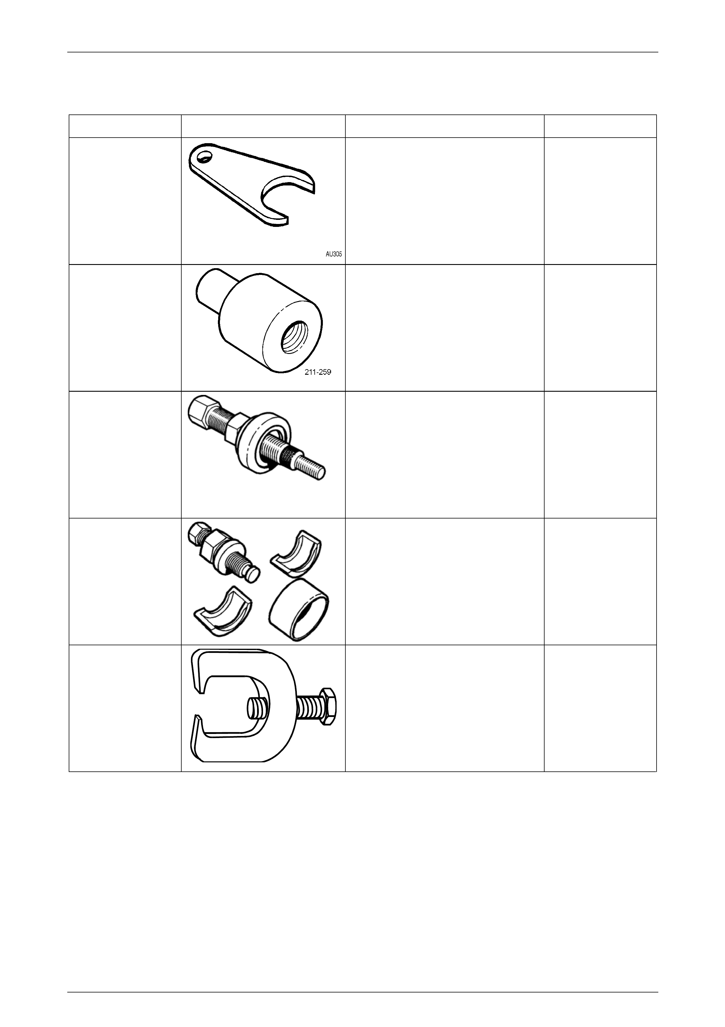
Steering Page 9–99
Page 9–99
7 Special Tools
Tool number Illustration Description Tool classification
211-258 Tie-rod Wrench
Previously released.
Unique
211-259
Lower Pinion Bearing Remover
Previously released.
Used in conjunction with Driver
Handle AU355-A.
Unique
7005 Power Steering Pump Pulley
Installer
Previously released.
Desirable
7185 Power Steering Pump Pulley
Remover
Previously released.
Desirable
9A10
Steering Linkage Ball Stud
Remover
Previously released.
Desirable
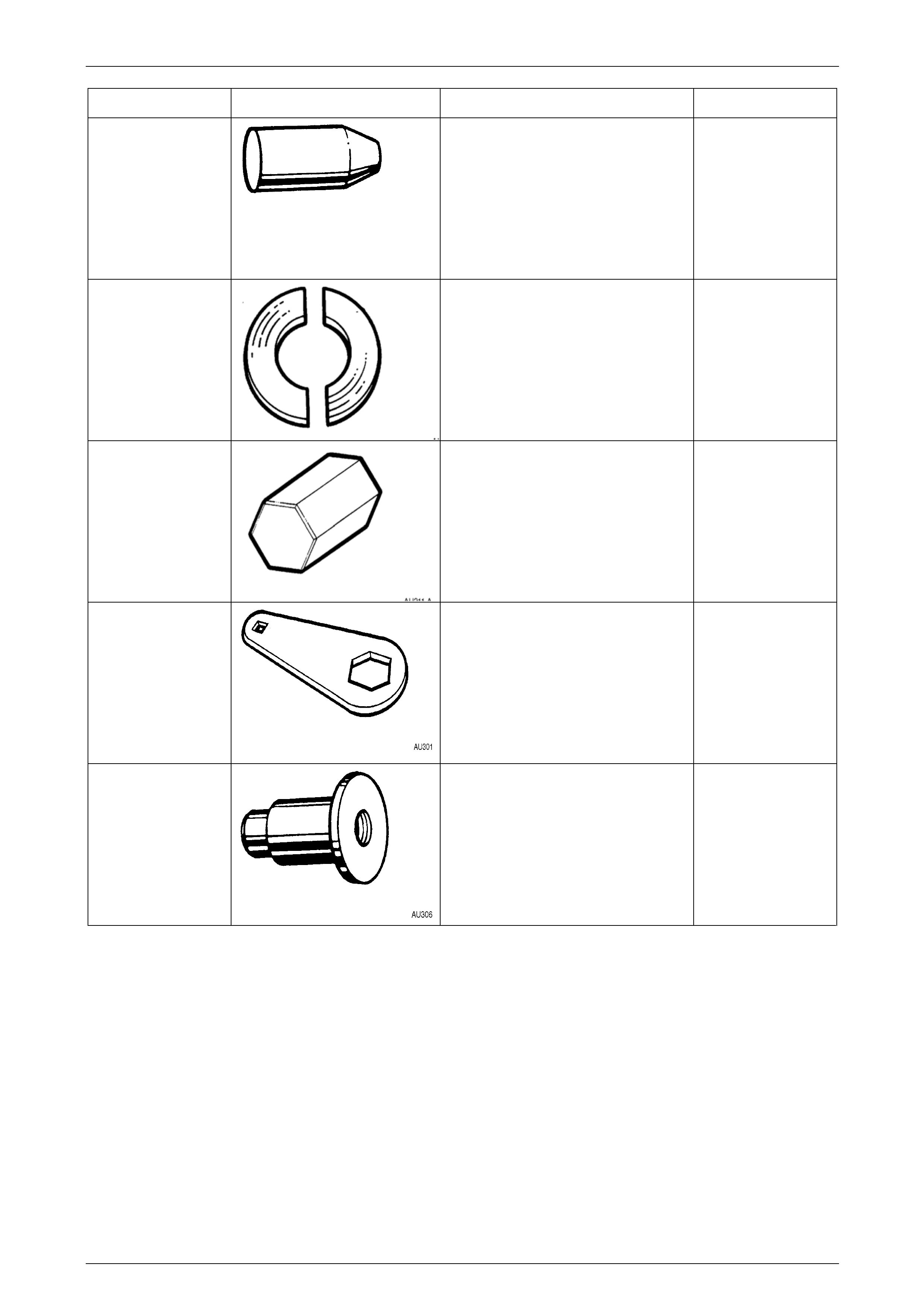
Steering Page 9–100
Page 9–100
Tool number Illustration Description Tool classification
9A23 Expander - Sleeve Seals Unique
AU188 Press Plates
Previously released.
Can also use E6673 that were
previously released as J22912-1
Unique
AU211-A Rack Pad Adjusting Screw Wrench
Previously released.
Desirable
AU301
Rack Pad Adjusting Screw Lock
Nut Wrench
Previously released.
Desirable
AU306
Lower Pinion Bearing Remover
Previously released.
Unique
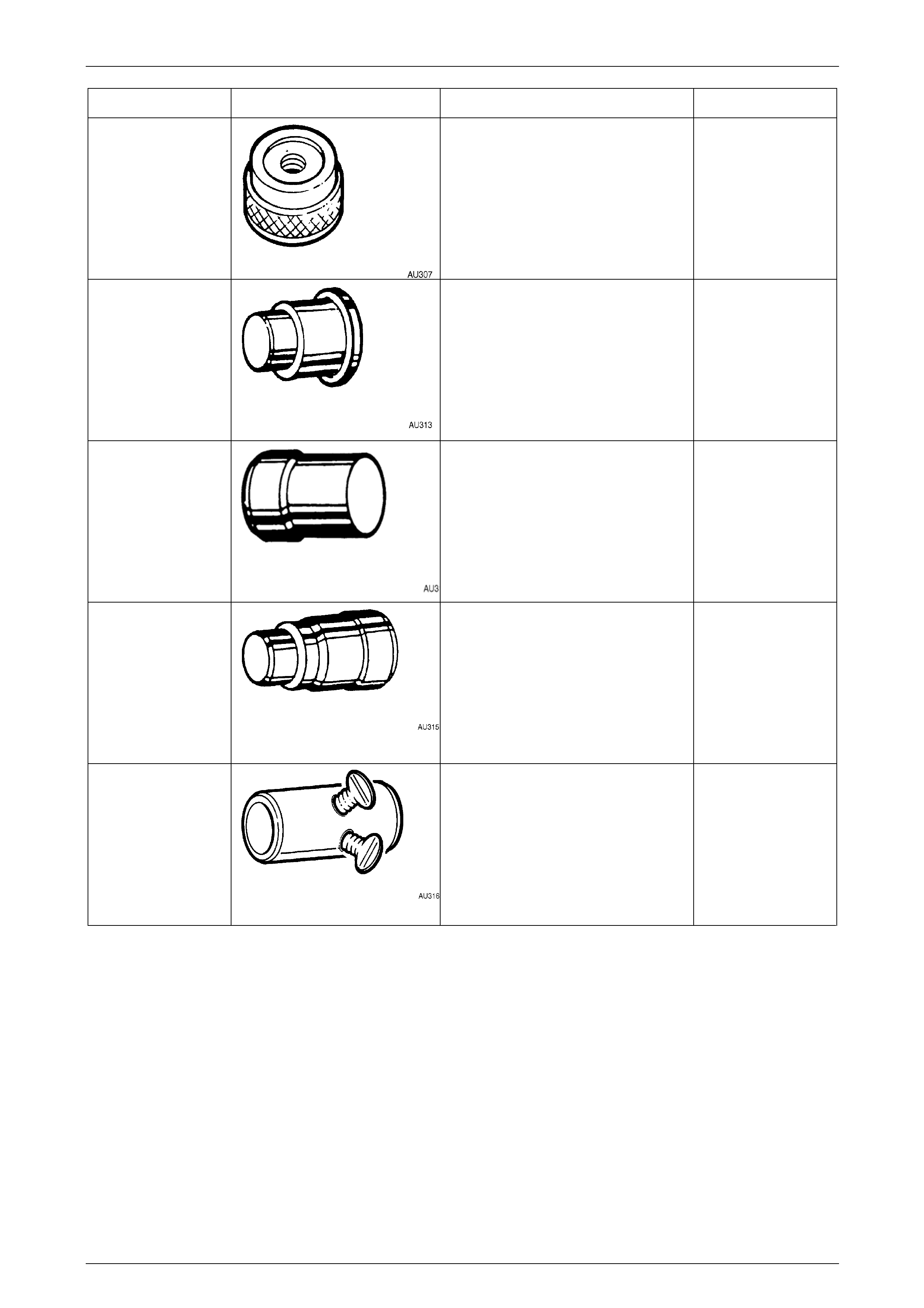
Steering Page 9–101
Page 9–101
Tool number Illustration Description Tool classification
AU307 Lower Pinion Bearing Installer Unique
AU313
Upper Pinion Power Steering Fluid
Seal Installer
Previously released.
Used to install the valve housing
bearing.
Unique
AU314 Valve Housing Seal And Bearing
Remover
Previously released.
Unique
AU315 Valve Housing Seal & Bearing
Installer
Previously released.
Unique
AU316 Pre-Load Adaptor
Previously released.
Used to connect a torque wrench to
the steering pinion gear, to enable the
rotating torque to be measured.
Unique
Steering Page 9–102
Page 9–102
Tool number Illustration Description Tool classification
AU355-A Driver Handle Unique
AU392 Pressure Hose Set
Previously released.
Comprises:
AU392-1, hose with male end fitting.
AU392-2, hose with female end fitting.
Mandatory
AU440 Compressor - Sleeve Seals
Previously released.
Unique
AU456 Rack Seal Protector – Long
Previously released.
Unique
AU460
Installer - Inner Rack Seal and
Spacer
Previously released.
Used in conjunction with Driver
Handle AU355-A.
Unique
Steering Page 9–103
Page 9–103
Tool number Illustration Description Tool classification
AU527
Intermediate Pinion Bearing And
Power Steering Fluid Seal Installer Unique
AU528 Upper Pinion Bearing and Power
Steering Fluid Seal Installer
Previously released.
Unique
E1408
Steering Wheel Puller Legs
Previously released.
Use in conjunction with steering
wheel puller, Tool No. J1859-A
Desirable
E1460-1 Power Steering Pump Shaft Seal
Installer
Previously released as 9A61.
Unique
E1461-1 Pressure Gauge Assembly
Previously released.
Mandatory
E6673
Press Plates
Previously released as J22912-1
Desirable
Steering Page 9–104
Page 9–104
Tool number Illustration Description Tool classification
E7115 Angle Wrench
Previously released.
Desirable
E8803-6 Rack Seal Protector – Short
Previously released.
Used to cover the steering rack while
installing the seals
Unique
E8803-7 Rack Piston Tool
Previously released.
Used to rotate the end bushing to
remove/install retaining wire clip.
Unique
E8803-9 Rack Piston Seal Expander
Previously released.
Used to expand the rack piston seal
prior to installation.
Unique
E8803-10 Rack Seal Pressure Test Adaptor
Previously released.
Used in conjunction with hand
vacuum pump to assess rack seal
serviceability.
Mandatory
E8803-11 Rack End Seal / Bush Installer
Previously released.
Used to install the rack end seal and
bush.
Unique
Steering Page 9–105
Page 9–105
Tool number Illustration Description Tool classification
E9239
Power Steering Pump Pulley
Installer
Previously released as J2503 3-B.
Desirable
ETX30H Torx Bit
Previously released.
Also commercially available as a
T30H Torx bit
Mandatory
J1859-A Steering Wheel Puller
Previously released.
Use in conjunction with steering
wheel puller legs, Tool No. E1408.
Unique
J23738-A Hand Vacuum Pump
Previously released or use
commercially available equivalent.
Mandatory
J25359-8 Torx Bit Holder
Previously released or commercially
available.
Used with ETX30H Torx bit.
Mandatory
J25765-A Dial Type Torque Wrench
Previously released or use
commercially available equivalent,
capable of measuring from
0.4 – 6.0 Nm.
Mandatory