
SECTION 6A2 - ENGINE MECHANICAL -
5.0 LITRE V8 ENGINE
CAUTION:
This vehicle will be equipped with a Supplemental Restraint System (SRS). A SRS will consist of either
seat belt pre-tensioners and a driver's air bag, seat belt pre-tensioners and a driver's and front
passenger's air b ags o r seat b elt p re-t ension ers, driv er’s an d f ron t p asseng er’s air bag and left and righ t
hand side air bags. Refer to SAFETY PRECAUTIONS, Section 12M Supplemental Restraint System
before performing any se rvice operation on, or around any S RS components, the steering mechanism or
wiring. Failure to follow the SAFETY PRECAUTIONS could result in SRS deployment, resulting in
possible personal injury or unnecessary SRS system repairs.
1. GENERAL INFORMATION
The 5.0 litre V8 engine, installed in VT Series I Models for vehicles with P.O. 9C1 is as detailed in
Section 6A2 ENGINE MECHANICAL – V8 ENGINE of the VT Series I Service Information, noting the following:
A high ambient temperature kit P.O. 5D2, was available for all national police vehicles. One of the major
components of this kit is a water cooled engine oil cooler. The kit is installed by Holden By Design (HBD).
2. SERVICE OPERATIONS
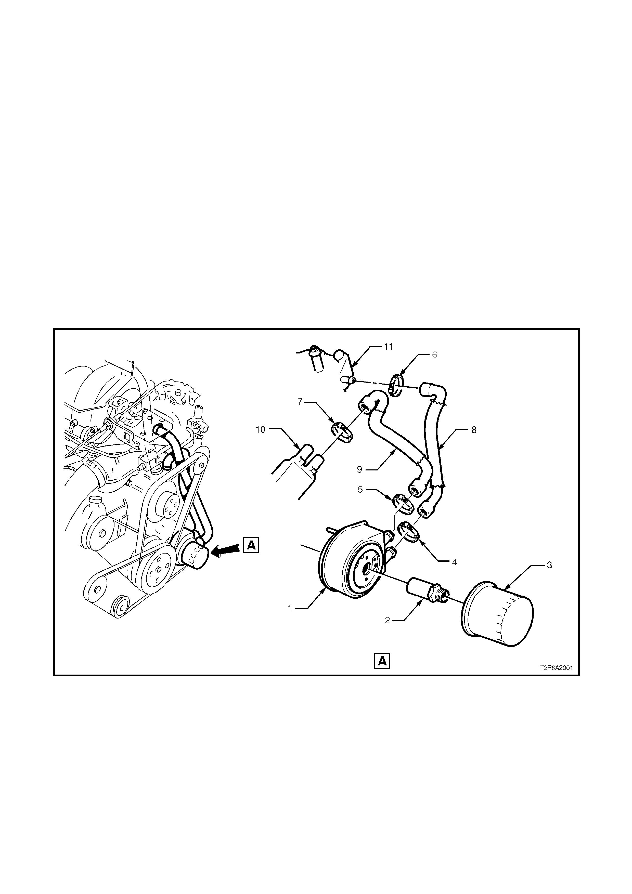
2.1 ENGINE OIL COOLER
REMOVE
CAUTION 1: To avoid the possibility of scalding, ensure the engine temperature is below 50°
°°
°C before
commencing this operation.
CAUTION 2: Always wear prot ective safety glasses wh en working w ith spring t ype hose clamps. Failure to
do so could result in eye injury.
1. Drain cooling system, refer to 2.1 SERVICE NOTES in Section 6B2 ENGINE COOLING – V8 ENGINE, of the
VT Series I Service Information.
2. Place a suitable container below the engine oil filter (3). Using a suitable oil filter removal spanner, loosen the oil
filter in a counter clockwise direction, then remove the oil filter.
3. Loosen the two hose clamps (4 & 5) securing the two coolant hoses (8 & 9) to the oil cooler assem bly (1) and
remove coolant hoses from assembly.
4. If complete removal of coolant hoses in necessary; remove engine trim covers, refer to 2.15 ENGINE TRIM
COVERS in Section 6A2 ENGINE MECHANICAL, of the VT Series I Service Information.
Loosen hose clam ps (6 & 7) s ecuring the coolant hoses to the inlet m anifold (1) and water pum p (10), r emove
hoses.
5. Loosen and remove the oil cooler adaptor (2), pull oil cooler assembly from the oil pump body.
Figure 6A2-1

REINSTALL
Reinstallation of the engine oil cooler assembly is the reverse of the removal procedure, noting the following:
1. Ens ure seals, oil cooler to oil pum p body and oil filter to oil cooler, are located c orrectly in r ecesses , then apply
a light film of engine oil to the seal surfaces.
2. Install oil filter by rotating the oil filter clockwise until the seal contacts the m ating surface, then tighten filter an
additional two thirds (2/3) of a turn.
3. Ensure coolant hose connections are thoroughly cleaned before installing.
4. Refill cooling system with the correct concentration of coolant and pressure test cooling system, refer to the
following operations in Section 6B2 ENGINE COOLING – V8 ENGINE of the VT Series I Service Information:
2.3 CHECKING AND FILLING COOLING SYSTEM
2.6 PRESSURE TESTING
5. Check and top up engine oil level as necessary.
6. Start engine and check for leaks.
7. Turn engine off and recheck engine oil level. Top up as necessary.