
SECTION 6A - ENGINE MECHANICAL
(C22NE MODELS)
GENERAL DESCRIPTION
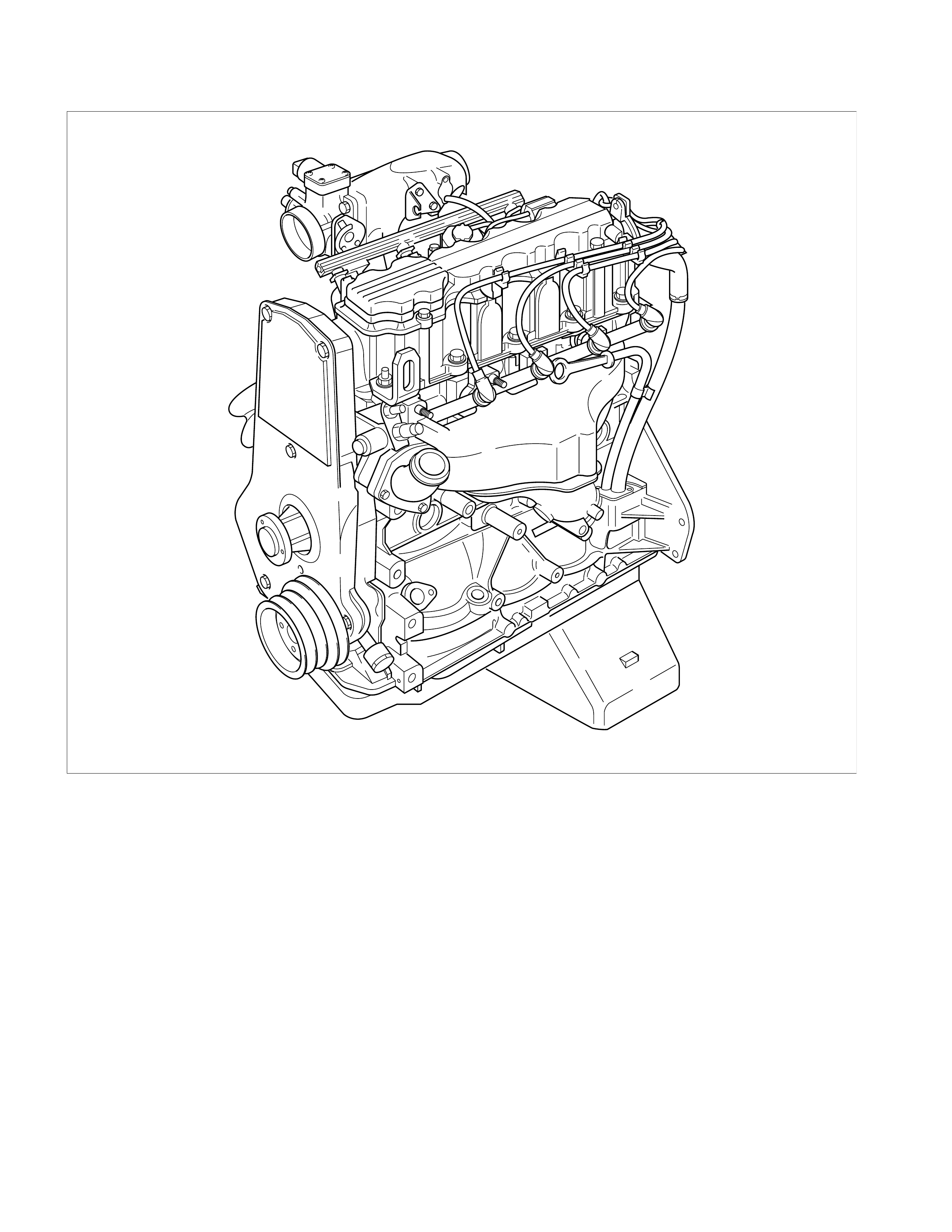
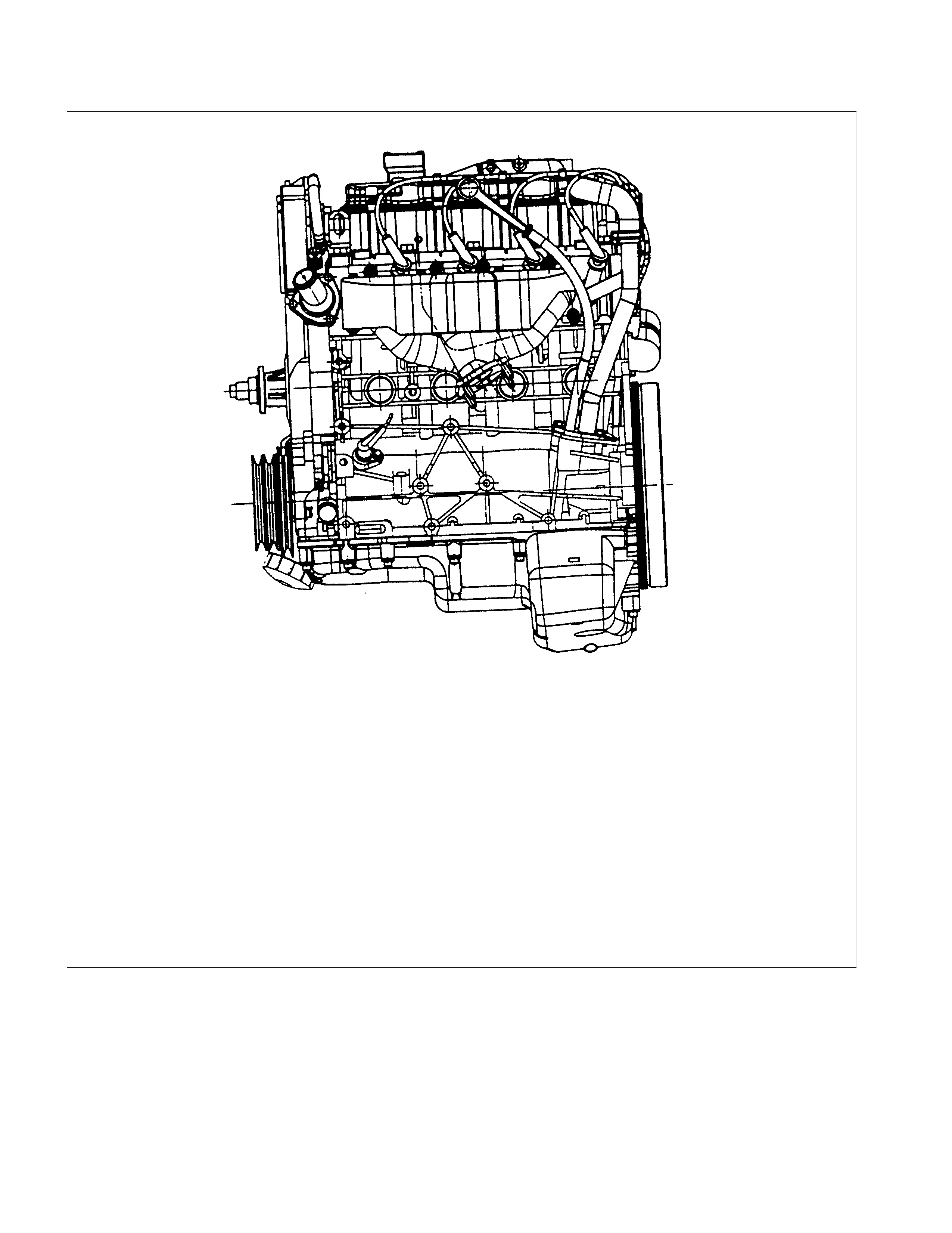
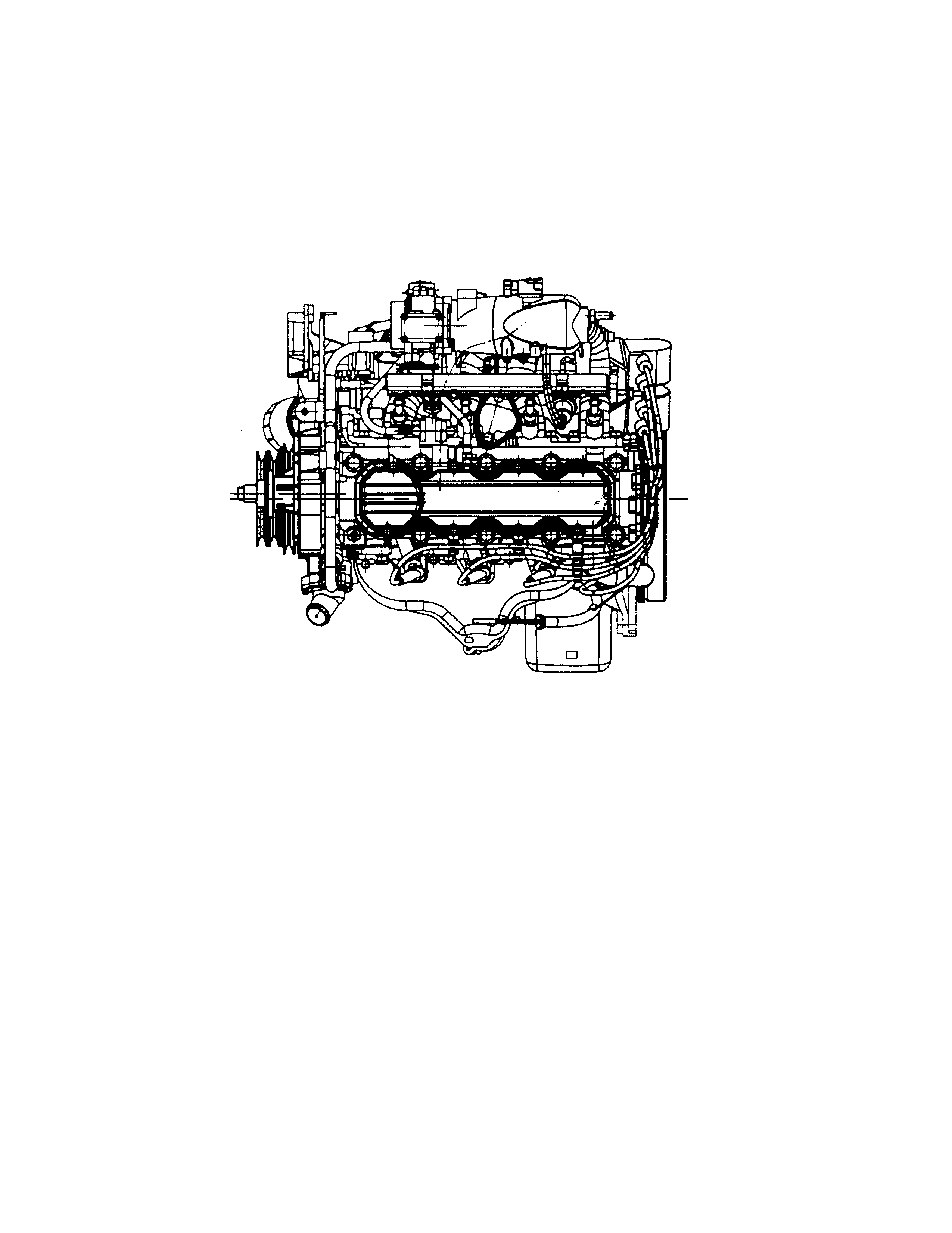
ENGINE PICTORIAL
FRONT VIEW
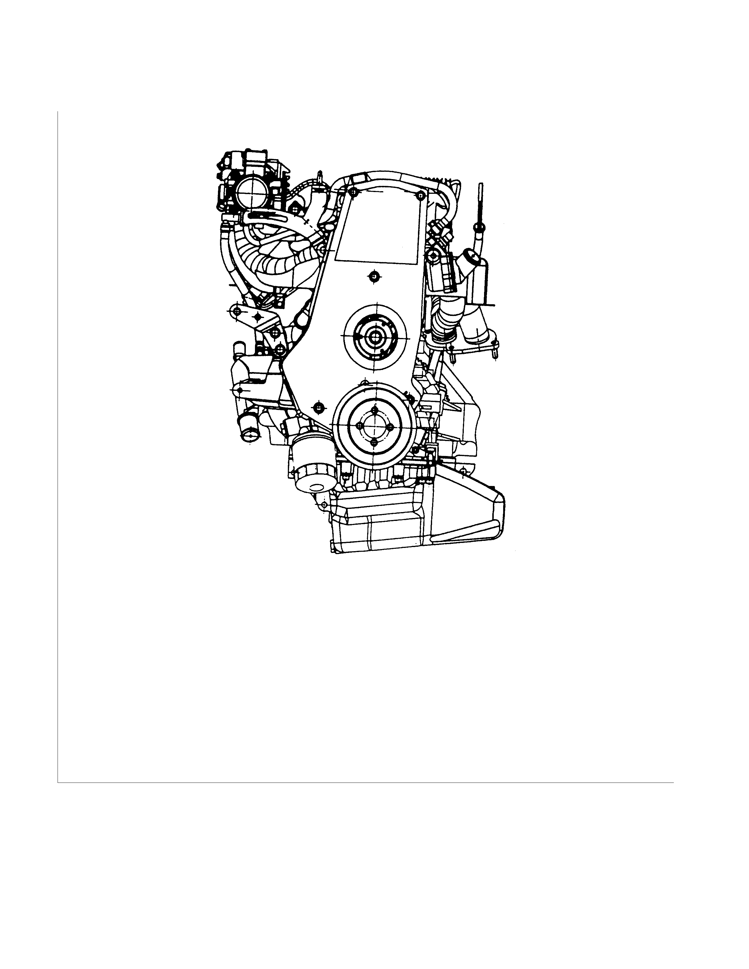
INLET SIDE VIEW
REAR VIEW
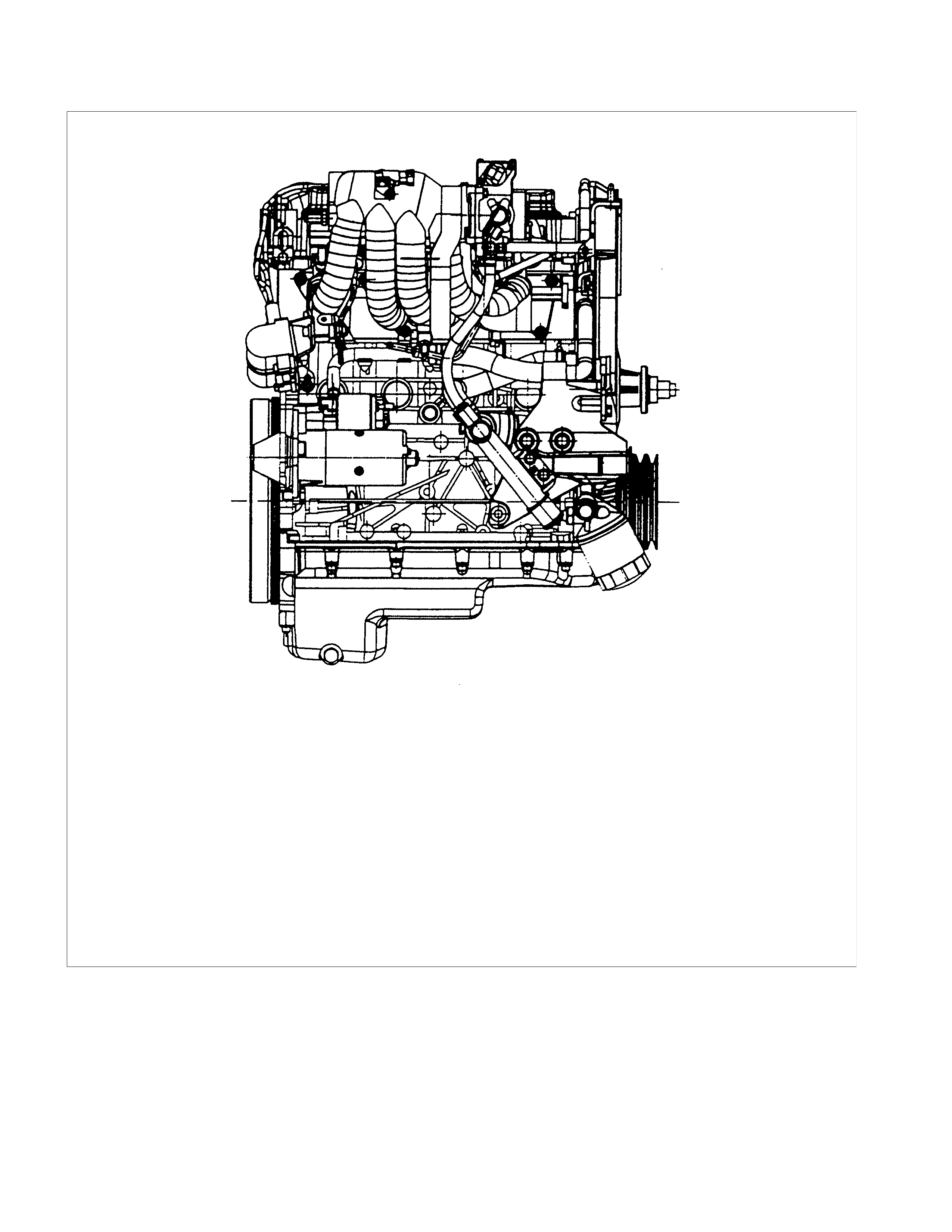
EXHAUST SIDE VIEW
TOP VIEW
MAIN DATA AND SPECIFICATION
ENGINE SPECIFICATION MATRIX FOR AUSTRALIA
CRANK CASE VENTILATION SYSTEM
ENGINE ASSEMBLY & LOOSE PARTS
OPERATIONS ON ENGINE AGGREGATES
ENGINE MOUNTS (ENGINE WITHOUT TRANSMISSION)
TOOTHED BELT TENSION, CHECK
TOOTHED BELT TENSION, ADJUST
TOOTHED BELT, REPLACE
OPERATIONS ON INSTALLED ENGINE
SEALING OPERATIONS
GASKE T, EXHAUST MANIFOLD, CYLINDER HEAD
GASKE T, INTAKE MANIFOLD, CYLINDER HEAD
SEAL RING, CAMSHAFT HOUSING, TIMING SIDE
SEAL RING, THERMOSTAT HOUSING, CYLINDER HEAD
SEAL RING - FRONT CAMS HAFT HOUSING, REPLACE
TOOTHED BELT REAR COVER
TOOTHED BELT TENSION ROLLER
COMPONENT PARTS
CYLINDER HEAD
HYDRAULIC V ALVE LIFTER
OPERATIONS ON CYLINDER HEAD AND CAMS HAFT HOUSING
CAMSHAFT
CAMSHAFT HOUSING REMOVAL AND INSTALLATION
CYLINDER HEAD
HYDRAULIC V ALVE LIFERS, REPLACE
CAMS HAFT HOUSING, REPLACE
CAMS HAFT HOUSING, CHECK FOR PLANE SURFACE
CYLINDER HEAD, REMOVAL AND INSTALLATION

CYLINDER HEAD, DISASSEMBLE AND ASSEMBLE
VALVE, GRIND
VALVE SEATING, MILL
CYLINDER HEAD, OVERHAUL
VAVLE GRIND
FLYWHEEL
STARTE R RING GE AR (MANUAL TRANSMISSION)
SEAL RING, CRANKSHAFT (OIL PUMP HOUSING)
SEAL RING, CRANKSHAFT REAR
GASKET, OIL PAN
OPERATIONS ON CRANKSHAFT
CON-ROD BEARING
PISTON WITH CON-ROD
CON-ROD
PISTON RINGS
OPERATIONS ON REMOVED ENGINE
CRANKSHAFT
BEARING FREE PLAY MEASUREMENT
1.PLASTIGAGE METHOD
2.MICROMETER AND GAUGE METHOD
BYPASS VALVE
OIL FILTER
OIL PUMP
OIL PUMP SAFETY VALVE
OIL PUMP (OVERHAUL)
OPERATIONS ON OIL CIRCULATION
CYLINDER HEAD SAFETY VALVE
OPERATIONS ON COOLING SYSTEM
COOLING SYSTEM, CHECK FOR LEAKS
COOLING SYSTEM, FILL UP AND BLEED
REFILL COOLANT
IGNITION TIMING, CHECK

ENGINE EXTERNAL PARTS
RADIATOR
THERMOSTAT
WATER PUMP
COATING SEALING SURFACES WITH SILICONE GREASE
ALTERNATOR
STARTER
V-BELT TENSION OF ALTERNATOR
V-BELT TENSION OF POWER STEERING PUMP
FUEL INJECTION SYSTEM
MAP SENSOR
PRESSURE REGULATOR
ECM (ENGINE CONTROL MODULE)
ECT
IDLE AIR CONTROL (IAC) VALVE
IGNITION COIL
CRANK POSITION SENSOR
FUEL INJECTOR
KNOCK SENSOR
OXYGEN SENSOR (IF APPLICABLE)
THROTTLE VALVE POSITION SENSOR
ACCE LERATOR P EDAL AND CABLE
AI R CLE ANER FILTER
SPARK PLUG THREAD
TECHNICAL DATA
SOHC GASOLINE ENGINE C22NE
OIL PUMP
COOLING SYSTEM
IDLE SPEEDS, CO CONTENT, IGNITION ADJUSTMENT
CYLINDER HEAD
CAMSHAFT
CRANKS HAFT, CYLINDER BLOCK
RECOMMENDED TORQUE V ALUES
SPECIAL SERVICE TOOL
GENERAL DESCRI PTION
ENGINE CLEANLINESS AND CARE
An automobile engine is a combination of many machined, honed, polished and lapped surfaces with tolerances that
are measured in the thousandths of a millimeter (ten thousandths of an inch). Accordingly, when any internal engine
parts are serviced, care and cleanliness are important. Throughout this section, it should be understood that proper
cleaning and protection of machined surfaces and friction areas is part of the repair procedure. This is considered
standard shop practice even if not specifically stated.
lA liberal coating of engine oil should be applied to all friction areas during assembly to protect and lubricate the
surfaces on initial operation.
lWhenever valve train components, pistons, piston rings, connecting rods, rod bearings, and crankshaft journal
bearings are removed for service, they should be retained in order.
lAt the time of installation, they should be installed in the same locations and with the same mating surfaced as
when removed.
lBattery cables should be disconnected before any major work is performed on the engine. Failure to disconnect
cables may result in damage to wire harness or other electrical parts.
lThe four cylinders of this engine are identified as 1, 2, 3 and 4, as counted from crankshaft pulley.

GENERAL INFORMATION ON ENGINE SERVICE
The following information on engine service should be noted carefully, as it is important in preventing damage and
contributing to reliable engine performance:
lWhen raising or supporting the engine for any reason, do not use a jack under the oil pan. Due to the small
clearance between the oil pan and the oil pump strainer, jacking against the oil pan may cause damage to the oil
pick up unit.
lThe 12-volt electrical system is capable of damaging circuits. When performing any work where electrical
terminals could possible be grounded, the ground cable of the battery should be disconnected at the battery.
lAny time the intake air duct or air cleaner is removed, the intake opening should be covered. This will protect
against accidental entrance of foreign material into the cylinder, which could cause extensive damage when the
engine is started.
CYLINDER BLOCK
The cylinder block is made of cast iron. The crankshaft is supported by five bearings. The bearing caps are made of
nodular cast iron.
CYLINDER HEAD
The cylinder head is made of aluminum alloy casting.
VALVE TRAIN
Valve system is a single over head camshaft.
Hydraulic valve lifters, no adjustment necessary.
INTAKE MANIFOLD
The intake manifold is made of aluminum alloy.
EXHAUST MANIFOLD
The exhaust manifold is made of high Si-Mo nodular iron.
PISTONS AND CONNECTING RODS
Aluminum pistons are used after selecting the grade that meets the cylinder bore diameter. Each piston has two
compression rings and one oil control ring. The piston pin is made of cast hardened steel. The connecting rod bearings
are made of modular cast iron. The connecting rod bearings are made of steel backed with tri-metal babbitt metal.
CRANKSHAFT AND BEARI NGS
The crankshaft is made of modular cast iron. Pins and journal are graded for correct size selection for their bearing.
ENGINE PICTORIAL
FRONT VIEW
INLET SIDE VIEW
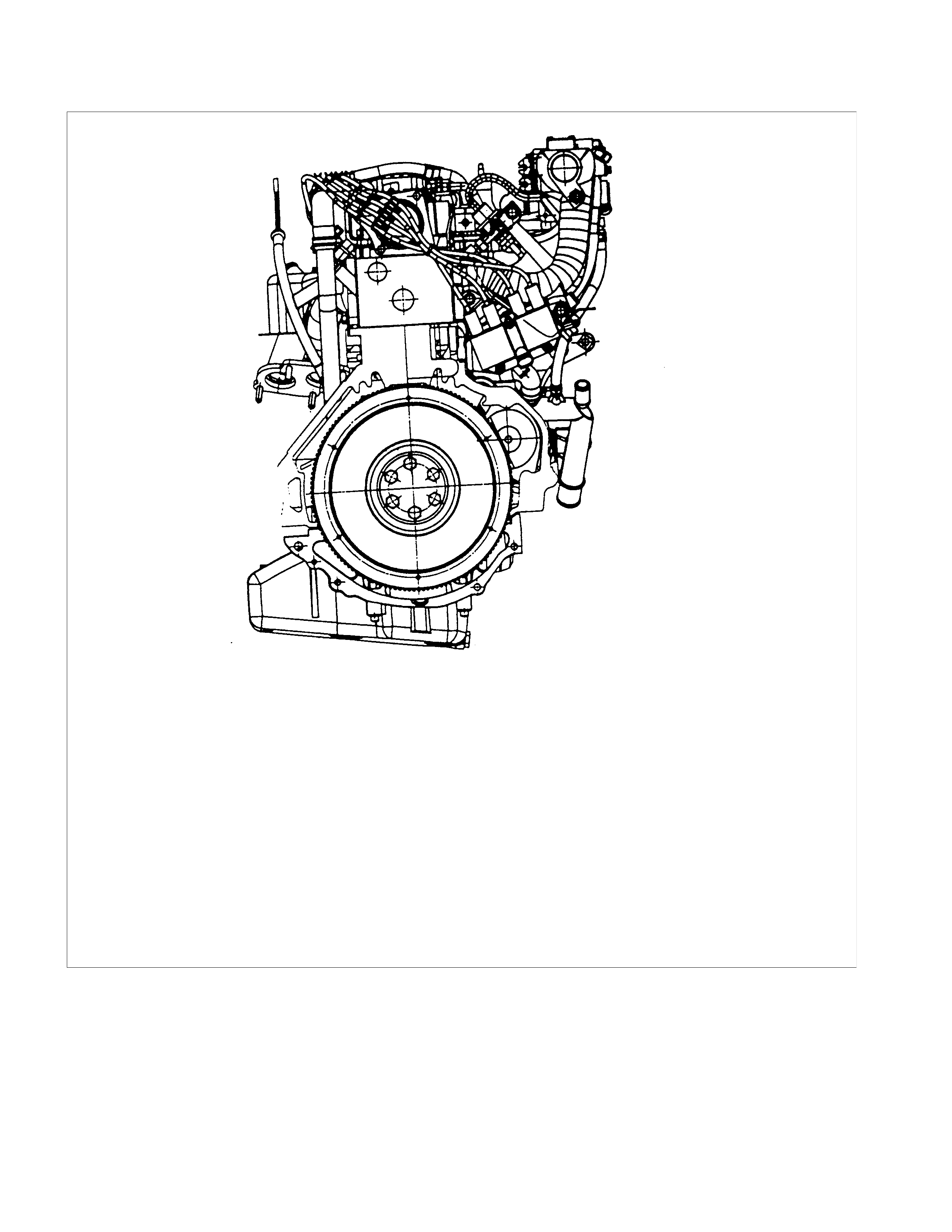
REAR VI EW
EXHAUST SIDE VI EW
TOP VIEW

MAIN DATA AND SPECIFICATIONS
Engine - General C22NE
Engine type Four-cycle, water cooled cross-flow with single over head camshaft
Micro-computer control, fuel injection
Combustion chamber type (Volume) Hemispherical (43.3cm3)
Timing train system Belt drive
No.of cylinders-bore × stroke mm (in) 4-86.0×94.6 (3.39×3.72)
Bore Spacing (C/L to C/L) 93.0 mm
Firing Order 1-3-4-2
Bore×Stroke 86.0×94.6mm
Total piston displacement cm3 (in3) 2,198 (134.39)
Combustion Chamber Volume 43.3 cm
No.of piston ring compression ring : 2 ,oil ring :1
Compression pressure kg/cm2 (psi/pa) 17.8 (253/1746)
Ignition timing (BTDC) No adjustment
Idling speed :rpm (WO/AC,W/AC)
Acoff 825
Valve clearances (At cold)
Intake mm (in) 0 (0) (Hydraulic valve lash adjustment)
Exhaust mm (in) 0 (0) (Hydraulic valve lash adjustment )
Intake valves
Open at (BTDC) deg 29
Close at (ABDC) deg 65
Exhaust valves
Open at (BBDC) deg 66
Close at (ATDC) deg 29
Ignition system Fully transistorized battery ignition
Distributor type Not applicable, Electronic Spark Timing control
Distributor advance type Not applicable, Electronic Spark Timing control
Spark plug type RN9YC4
Spark plug gap mm (in) 1.0--1.1 (0.039--0.043)
Lubrication system
Lubricating method Fully flow pressure circulation
Special engine oil (API grade) SE,SF,SG or SH grade
Oil pressure (psi/Pa) rpm (21.3/147)/825 (SAE 10W-30/API SE grade) engine oil after warm-
up
Oil pump type Gear
Oil filter type Cartridge full flow
Oil capacity lit. (US/UK gal.) with Oil Filter change 4.5litres
without Oil Filter change 4.25 (1.07/0.93) litres
Cooling system
Radiator type Corrugated fin with reserve tank
Coolant capacity lit. (US/UK gal.) 2.3 (0.66/0.55)
Water pump type Centrifugal
Thermostat Wax pellet with jiggle hole
Fuel system Electronically controlled Multi Port Fuel Injection System
Fuel pump ty pe Electric

Engine - General C22NE
Fuel pressure psi/Pa 48.4/334
Fuel filter type Cartridge paper element
Air cleaner type Dry paper element
Battery Type/V-Ax No. of units 50D20L 306 CCA
Alternator
Capacity V-A(W) 12-70 (840)
Starter
Output V-kW 12-1.4
Exhaust system CO Adjustment (1) Applicable to Open Loop System (Not equipped H2OS)
(2) Not applicable to Closed Loop System (Equipped H2OS)
Compression Ratio (with Tolerance) 9.2:1±0.3
Cylinder Head Material Aluminum Alloy (gravity cast)
Cylinder Block Material Cast Iron
No.of Mounting Points (including
trans.) 3
Engine Installation Angles-Longitudinal 3° 30'
-Lateral 7° 50' (towards exhaust side)
Overall Dimensions (L × W × H): 610×550×744 mm
Engine Weight 136kg
Camshaft Type SOHC
No.of Valves per Cylinder - Inlet
- Exhaust 1
1
Spark Plug Location Side
Port Arrangement Cross Flow
Valve System C22NE
Actuation Type Direct-acting Inverted Bucked Tappet
Valve Clearance Adjustment Hydraulic
Valve Rotor Type None
Inlet-Valve Material Chromium Alloyed Steel
-Seat Insert Material Sintered Iron
Exhaust-Valve Material Head:Cr-Mn-Ni Alloyed
Shaft:Cr-Si Alloyed&Cr plated
-Seat Insert Material Sintered Iron
Valve Spring Material GME 06 100-C1
Valve Guide Material QS 13 MR 00
Valve Seal Type Lip
Water Pump C22NE
Type Centrifugal
Drive-Material&Type HNBR Toothed-belt
Bearing Type Double Row Ball
Shaft Seal Type Mechanical Ceramic
Thermostat-Coolant C22NE
Type Bypass

Oil Pump & Filter C22NE
Type Gear Pump
Location Front of Engine
Drive Direct Crankshaft Driven
Filter Type Full Flow with Bypass for blocked filter
Oil&Oil Reservoir C22NE
Reservoir-Description&Location 1-piece below Engine
Reservoir Material Aluminium Alloy (pressure cast)
Replacement Oil Fill Volume
-With FIlter change 4.5L
-without Filter change 4.5L
Recommended Oil - Normal use API SG or SH Engine oil with a viscosity of 20W/50
Prolonged use in snow areas API SG or SH Engine oil with a viscosity of 15W/40
Ignition Components C22NE
Spark Plugs Conventional
Type Electronic Spark Control
No.of Coils&Type 2 Solid State
Coil Location Engine-mounted
Ignition Lead Type Inductive (hi-resistance)
Crankshaft C22NE
Material Nodular Cast Iron
Bearing subjected to End Thrust Guide Bearing NO.3
Main Bearing-Material&Type Steel Backed Tri-metal Babbitt
Front Seal-Diameter&Type 35.0mm Lip Seal
Rear seal-Diameter&Type 90.0mm Micro-lip Seal
Crankshaft Balancing Individually Balanced
No.of Counterweights 8
Camshaft C22NE
Location Overhead(Cylinder Head)
Material Chilled Cast Iron
Bearing Material Aluminium
No.of Bearings HNB 5
Pistons C22NE
Material Aluminium Alloy
Finish & Type Tin-coated Strut-less
Piston Rings C22NE
Function (top to bottom) -Ring 1 Compression Ring
-Ring 2 Compression Ring
-Ring 3 Oil Ring
Description-Ring 1 Rectangular
-Ring 2 Taper Face
-Ring 3 3-piece (2 Scrapers&1 Expander)
Material-Ring 1 Molybdenum Inlay Nodular Cast Iron
-Ring 2 Cast Iron (individually cast)
-Ring 3 Steel
Piston Pins C22NE
Material Case Hardened Steel
Retention Locked in Rod
Bearing Machined in Piston Pin Boss
Connecting Rod C22NE
Material Nodular Cast Iron
Bearing-Material&Type S teel Backed Tri-metal Babbitt
Inlet Manifold C22NE
Material Aluminium Alloy
Exhaust Manifold C22NE
Description Dual Take-down
Material High Si-Mo Nodular Iron

ENGINE SPECI FICATION MATRIX FOR AUSTRALIA
HEC FOR TF MODEL:
AUSTRALIA
VEHICLE MODE L TFR/S (141)
2.2L
VEHICLE TYPE 4×2
VEHICLE IDENT. CODE TA
ENGINE TYPE C22NE
FUEL CONTROL
SYSYTEM OPEN LOOP
COMPRESSION RATIO 9.2:1
FUEL OCTANE 91RON
FUEL TYPE UN-LEADED
OXYGEN SENSOR NO
EVAP CANISTER YES
PURGE CONTROL
SOLENOID YES
CHECK & RELIEF VALVE YES
ECM YES
EXHAUST SYSTEM
FRONT PIPE
MUFFLER
TWC YES
CO ADJUSTMENT YES
Refer to 6A-78
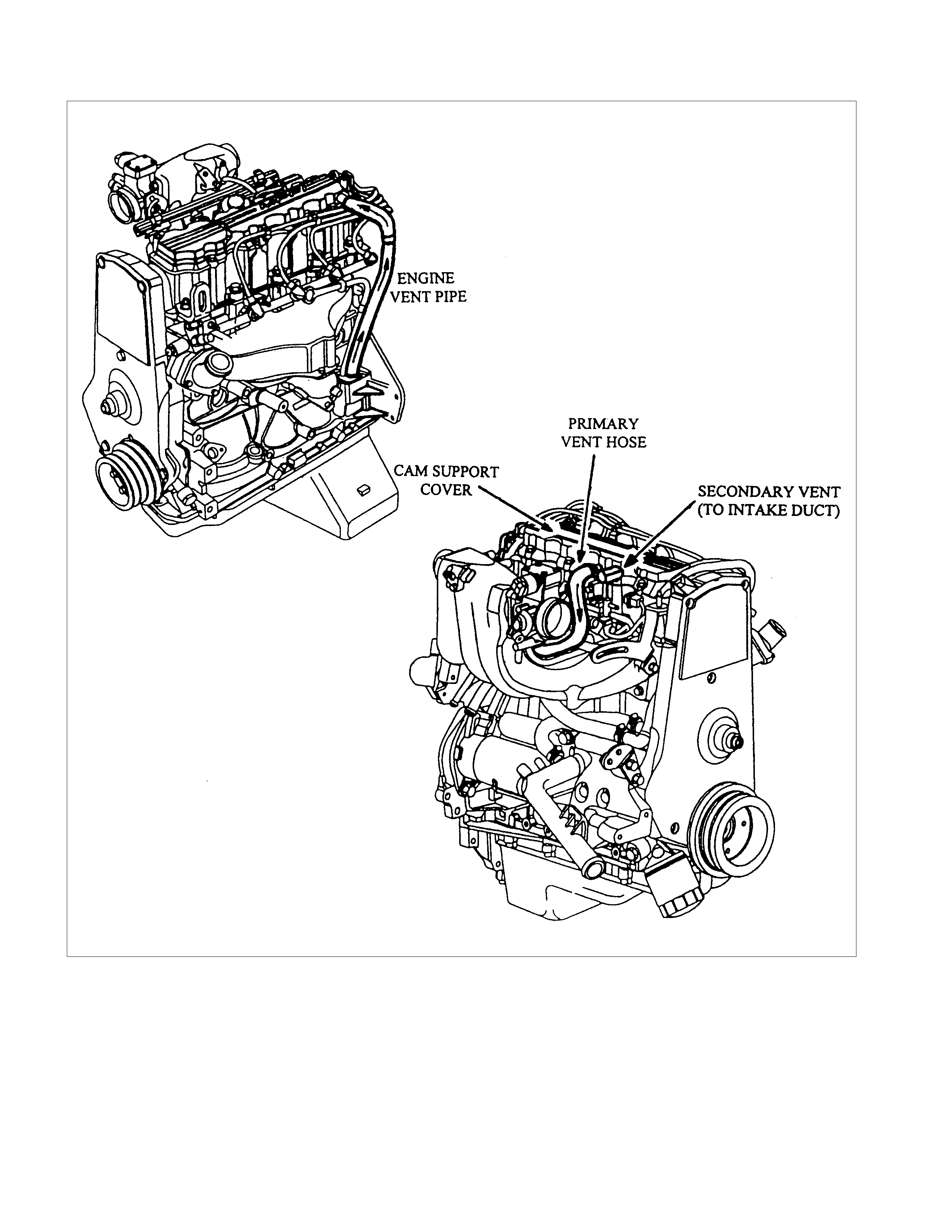
CRANKCASE VENTILATION SYSTEM
The Engine Ventilation System passes crankcase vapours, via the Engine Vent Pipe, to the Cam Support Cover, where
separation of oil and exhaust gases occurs. The oil drains into the Cylinder Head, via the Camshaft Support. The gases
pass through the Primary and Secondary Vent Hoses to the intake system, and are consumed during the combustion
process.
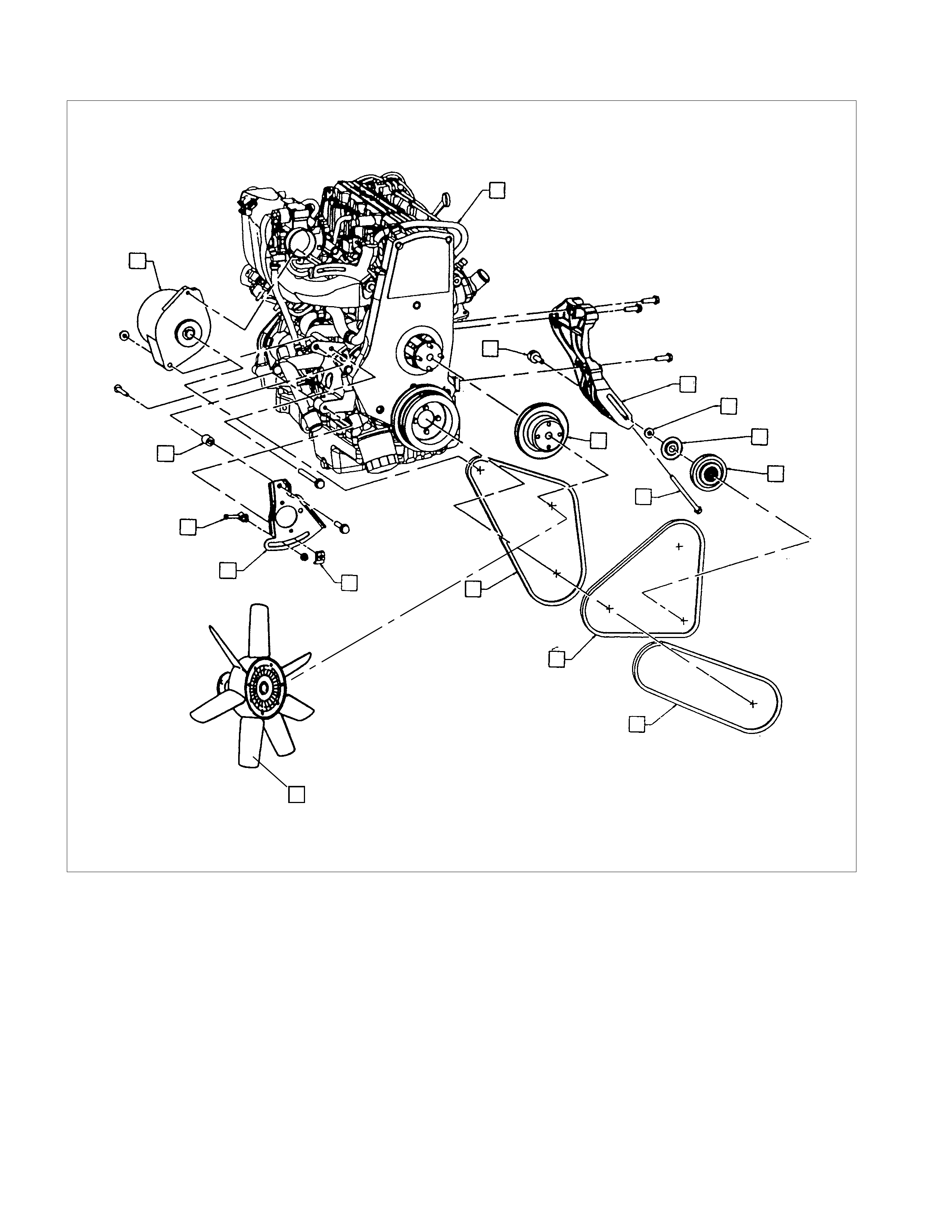
ENGINE ASSEMBLY & ACCESSORIES
1
2
3
4
56
7
8
16
10
11
12
13
9
15
14
20
ACCESSORIES
1 Alternator
2 P/S Pivot Spacer
3 P/S Adjusting Screw
4 P/S Adjusting Plate
5 P/S Adjusting Nut
6 Alternator & Fan Drive Belt
7 A/C Compressor Drive Belt
8 P/S Pump Drive Belt
9 TENSIONER Bolt
10 TENSIONER Pulley
11 Pulley Dust Shield Cover
12 Pulley Spacer
13 A/C Compressor Bracket
14 Pulley Bolt
15 Fan Pulley
16 Cooling Fan
ENGINE ASSEMBLY
20 C22NE
OPERATIONS ON ENGINE AGGREGATES
ENGINE MOUNTS (ENGINE WITHOUT TRANSMISSION)
REMOVAL
1. Remove bonnet.
2. Remove radiator.
3. Remove air inlet hose.
4. Remove power steering pump drive belt and power
steering pump from engine.
5. Remove all cable connections, hoses and lines from
engine.
6. Remove accelerator cable from inlet pipe.
7. Remove exhaust pipe from manifold.
8. Remove lower nine bolts and transmission from engine
block.
9. Remove clutch slave cylinder and allow to hang free.
10. Remove starter from engine block.
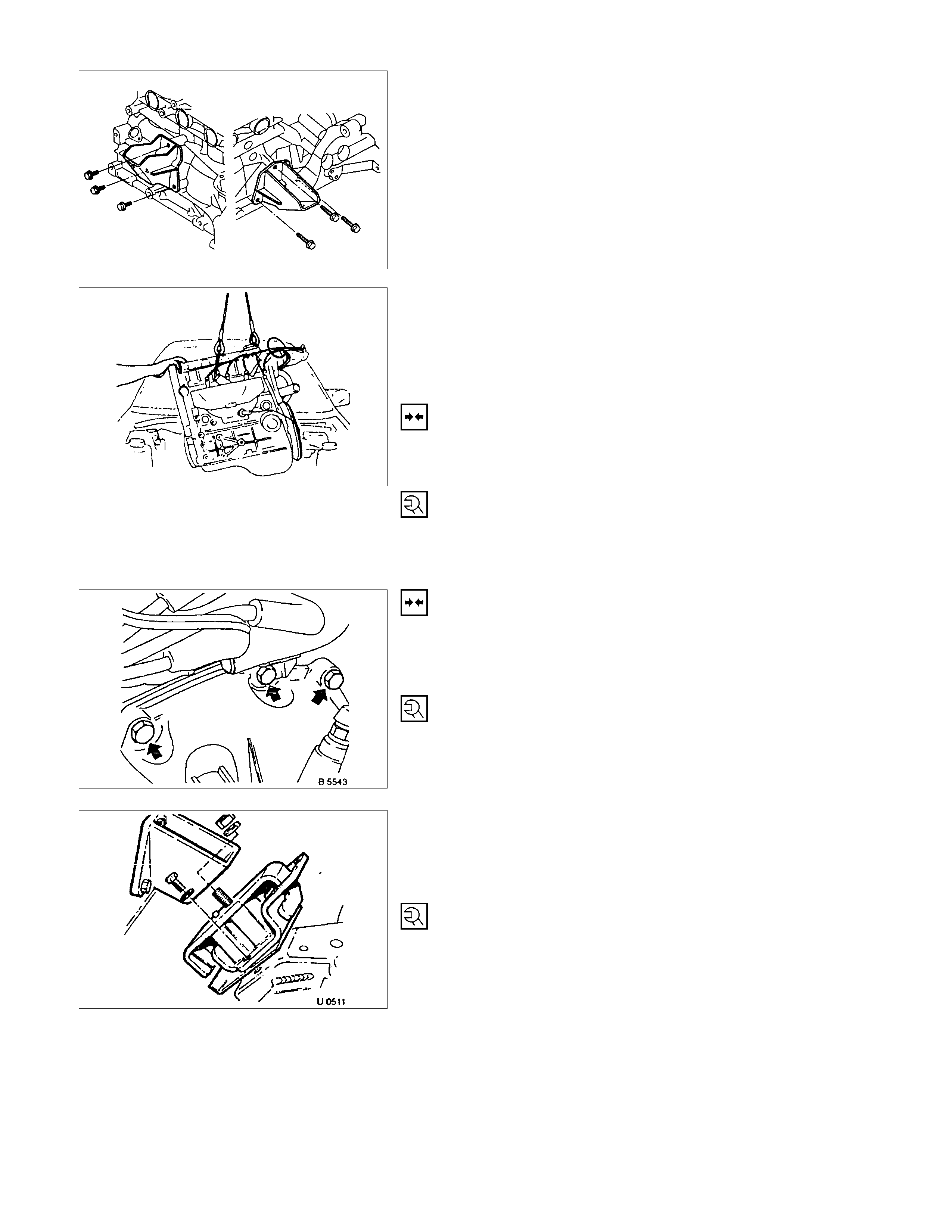
11. Remove upper bolts of left and right engine mounting
from damping blocks.
12. Raise engine slightly.
13. Remove lower bolts of left and right damping blocks.
14. Remove damping blocks.
Attach engine to cable, support transmission with car jack and
remove upper transmission fastening bolt.
Press off engine from transmission and lift out of engine
compartment.
INSTALLATION
Lower engine into engine compartment and insert guide
bushings on cylinder block into transmission.
TIGHTEN (TORQUE)
Transmission to cylinder block (M10) -45 N⋅m (4.6 kgf⋅m)
Transmission to cylinder block (M12) -60 N⋅m (6.1 kgf⋅m)
INSTALLATION
1. Install engine to vehicle and transmission.
2. Install clutch slave cylinder.
TIGHTEN (TORQUE)
Transmission to engine block bolts - 76 N⋅m (7.6 kgf⋅m)
3. Install left engine-mounting block to sidemember.
4. Install left and right engine damping blocks to engine
brackets.
TIGHTEN (TORQUE)
Engine damper block to sidemember - 52 N⋅m (5.3 kgf⋅m)
Engine damper block to engine bracket - 85 N⋅m (8.6 kgf⋅m)
5. Install exhaust pipe to manifold.
6. Install power steering pump and V-belt.
ADJUST
Adjust power steering pump V-belt tension according to the
corresponding operation.
INSTALLATION
7. Install radiator according to the corresponding operation.
8. Install air inlet hose.
9. Install all electrical cable connections, hoses and lines to
engine.
10. Install accelerator cable from inlet pipe.
11. Install bonnet.
INSPECTION
1. Check engine oil level.
2. Fill up cooling system and bleed according to the
corresponding operation.
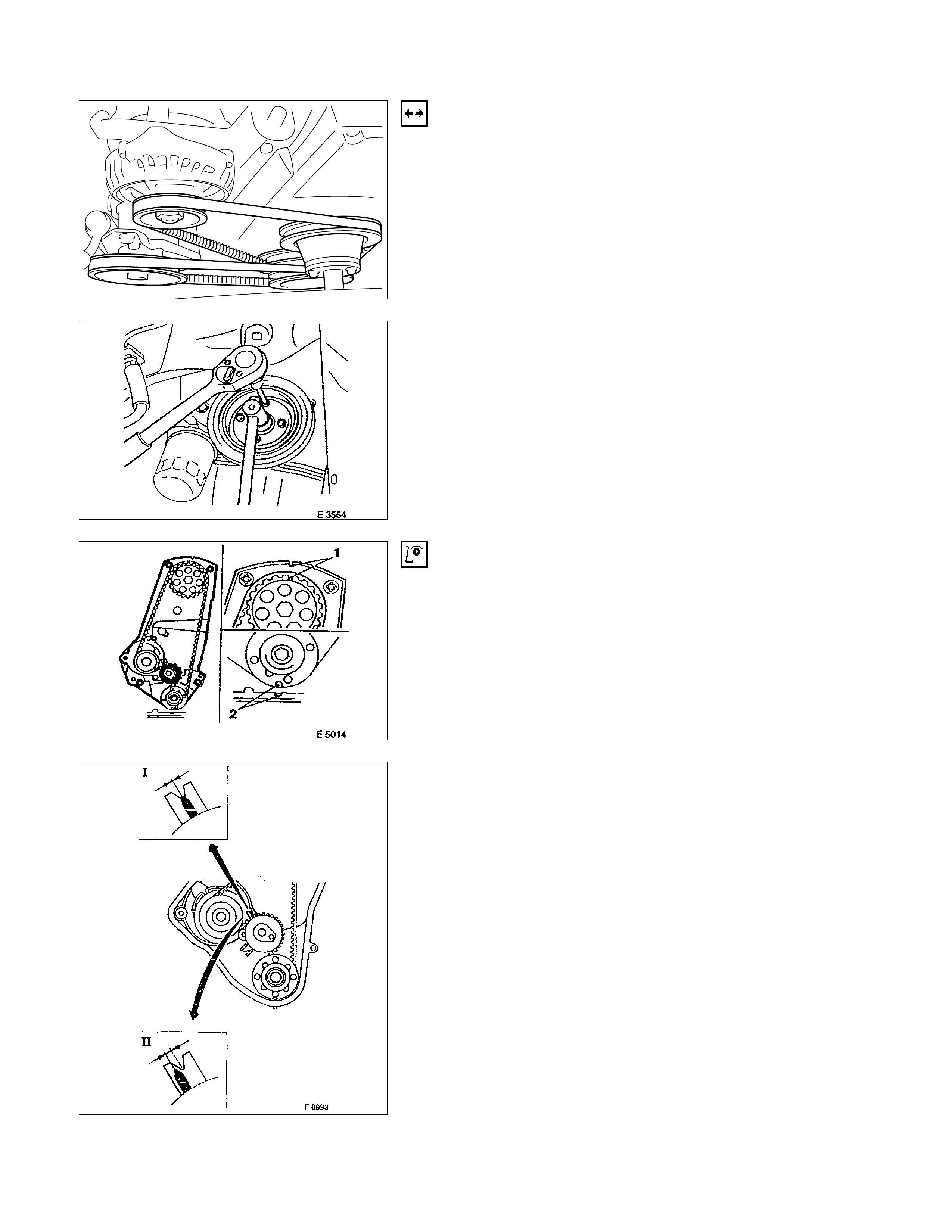
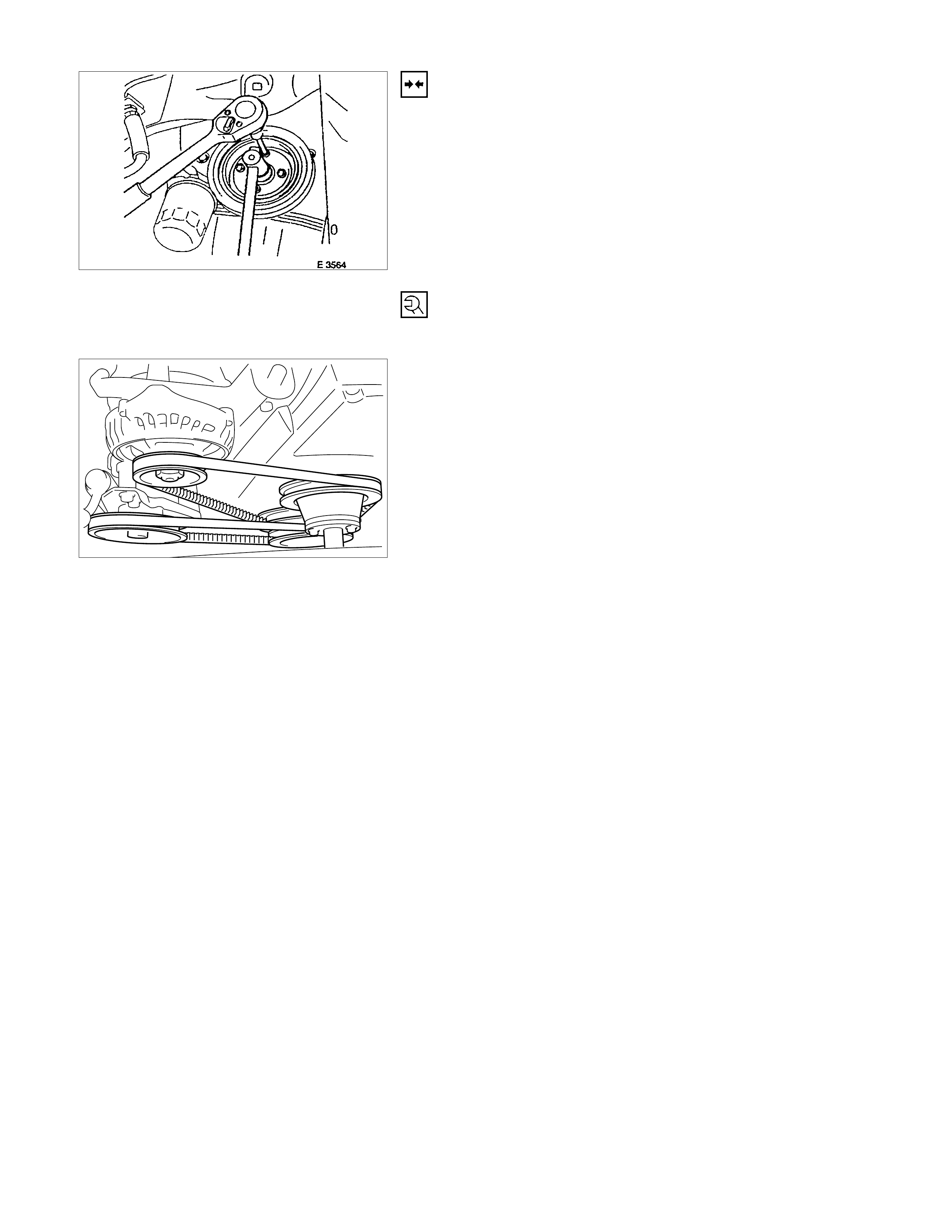
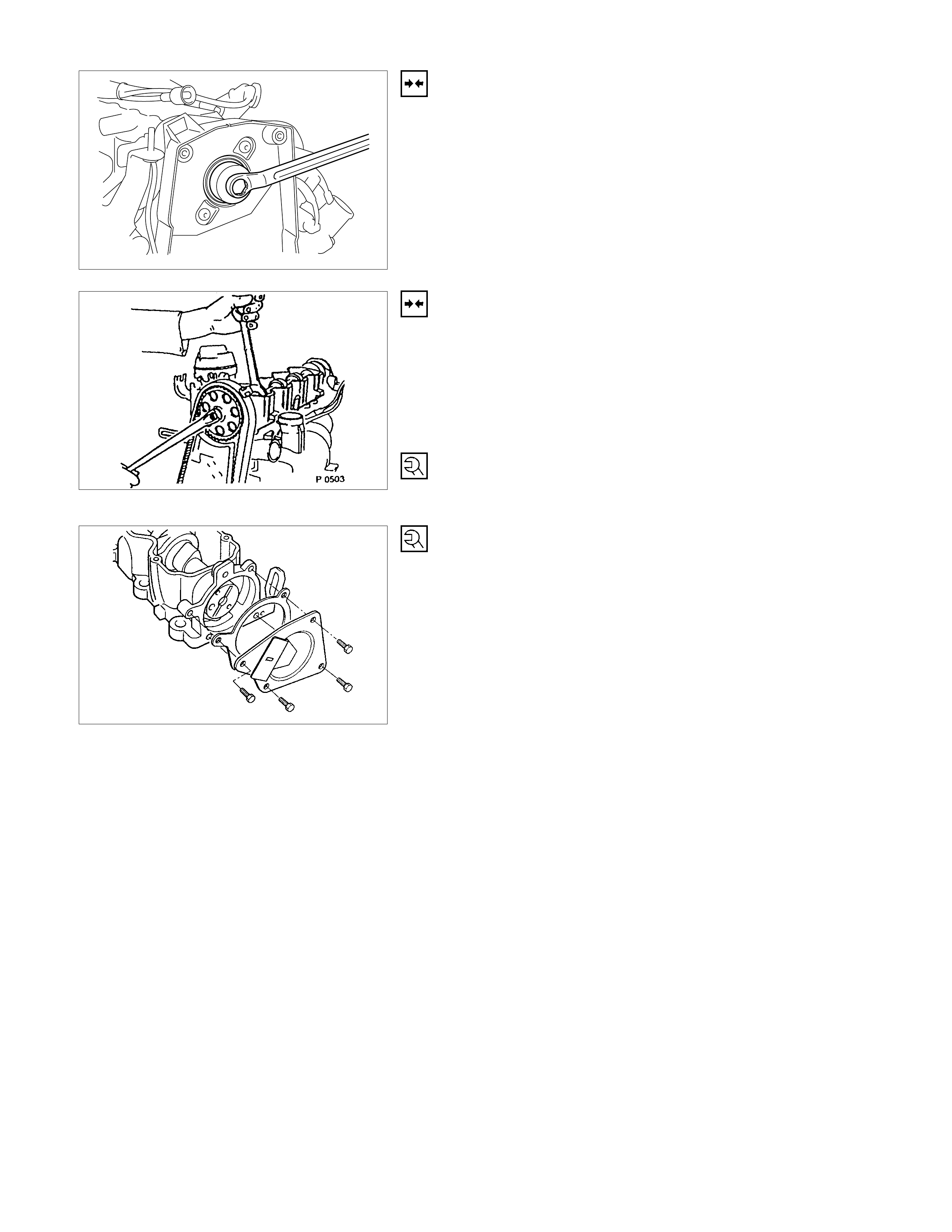
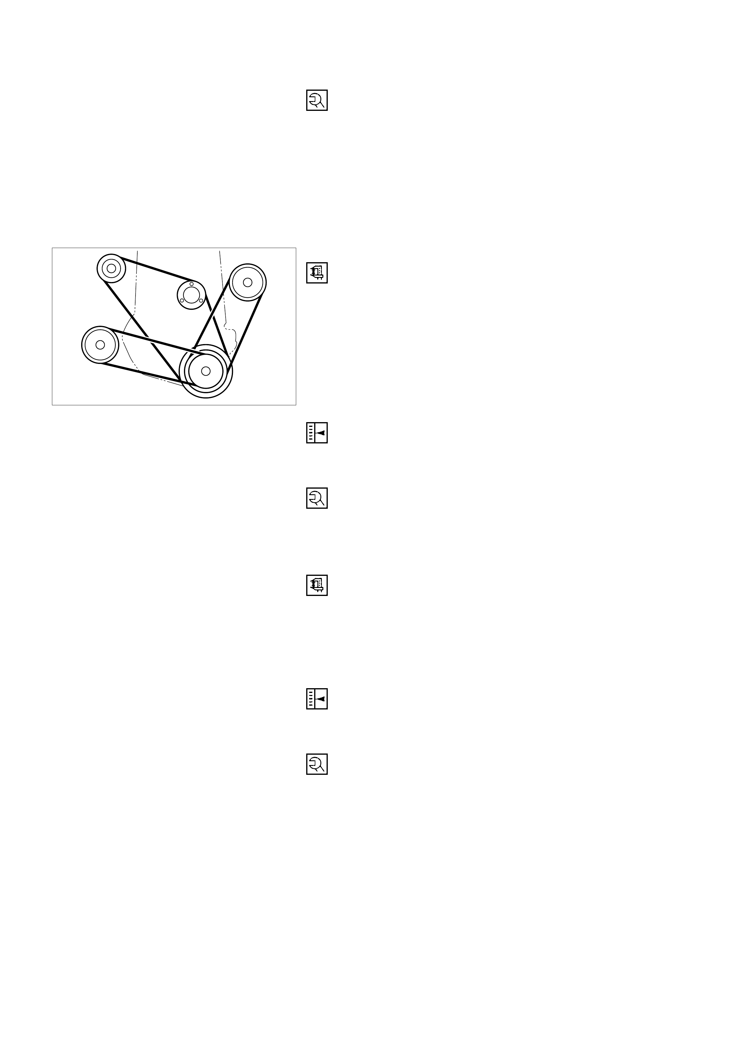
TOOTHED BELT AND TIMING CHECK
REMOVAL
1. Remove the belts on the bracket for alternator.
2. Remove the fan.
3. Remove the V-belt for power steering.
4. Remove the V-belt for A/C.
5. Remove the fan belt.
6. Remove the fan shroud.
7. Remove the crankshaft pulley while counterholding on
the fastening bolt of toothed belt drive gear.
8. Remove the toothed belt from cover.
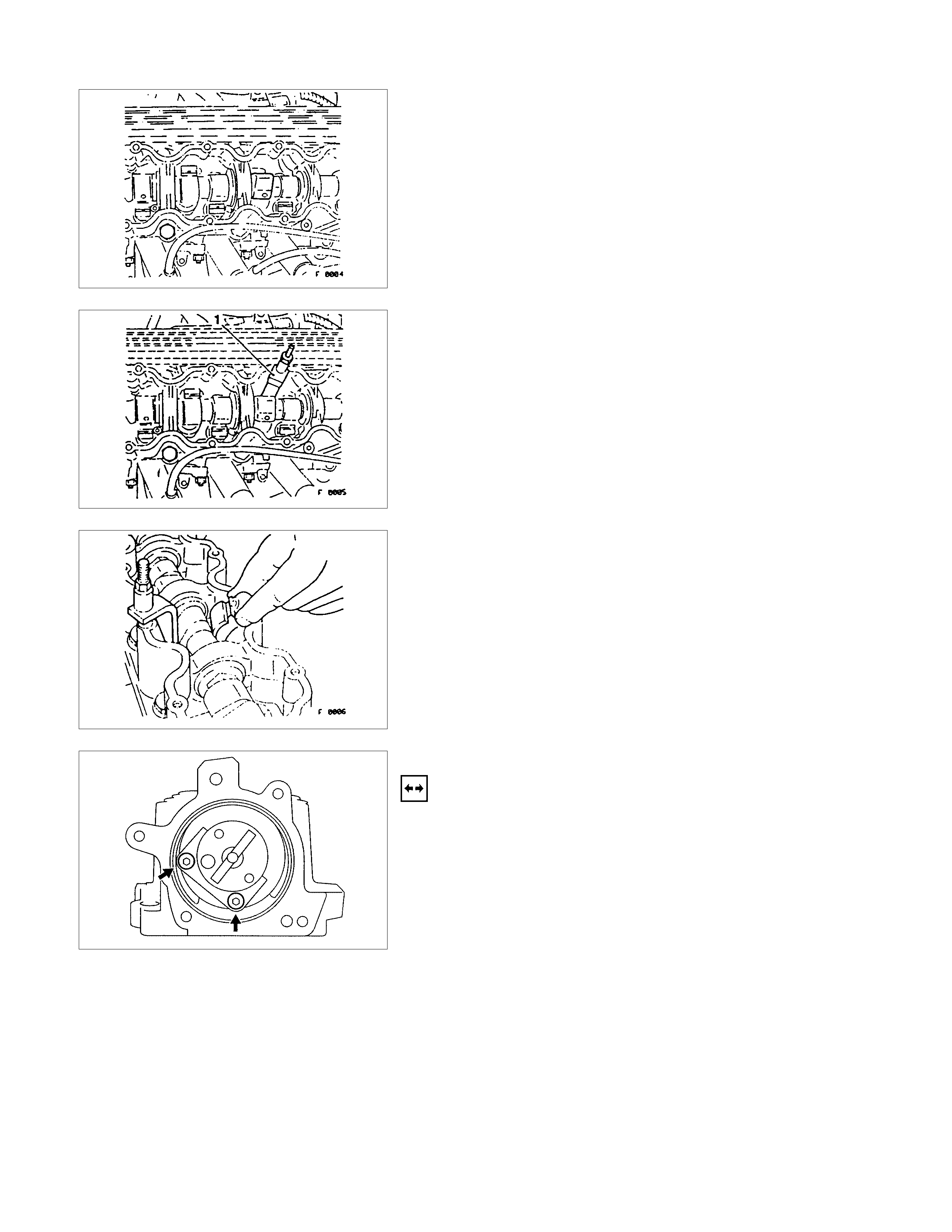
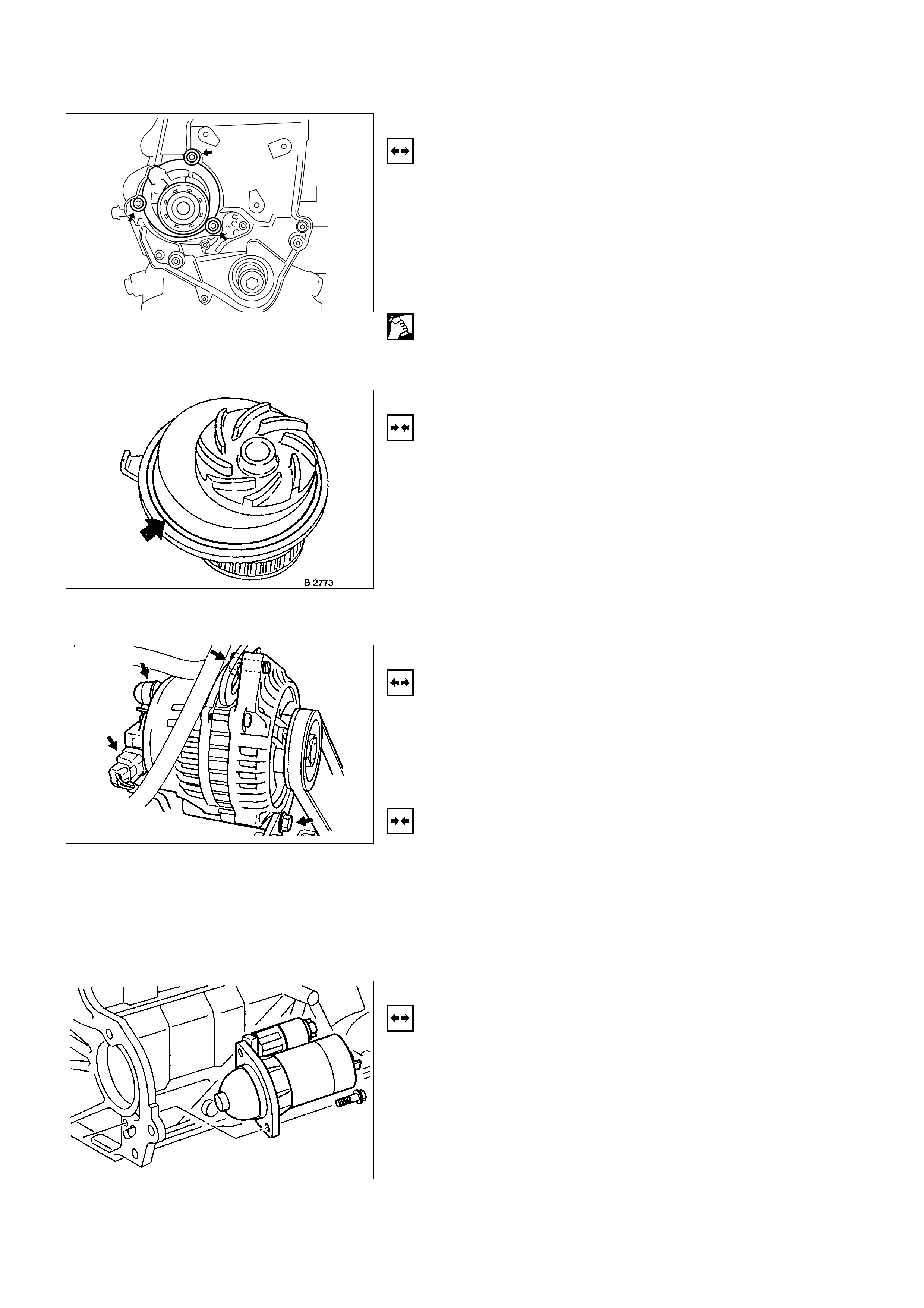
INSPECTION
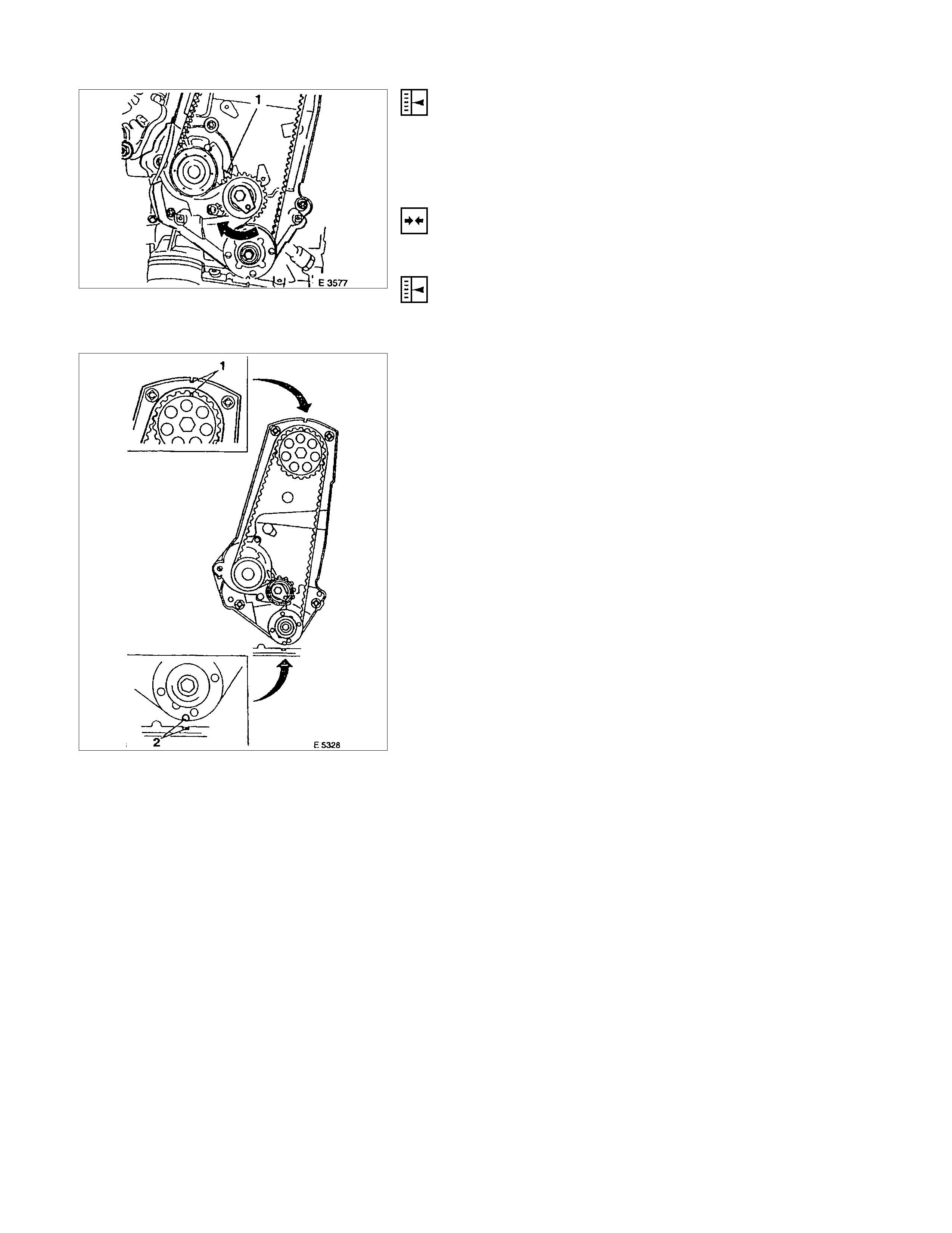
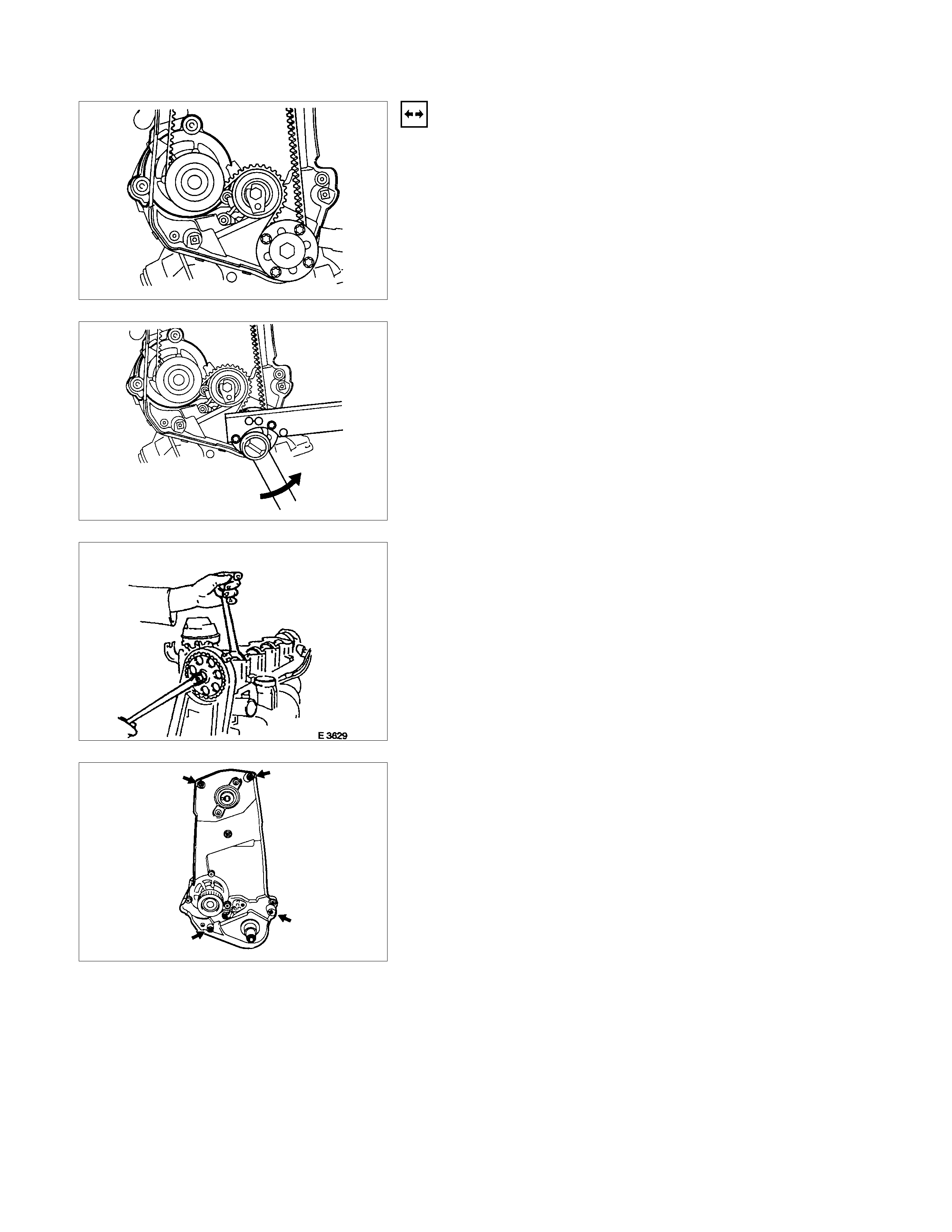
1. Turn the crankshaft in the engine rotational direction
mark (2) so that the notch (1) on the camshaft gear
aligns with the mark on toothed belt rear cover.
2. Check the timing belt for wear, cracks or oil adhesion.
3. Check that the cast on the water pump aligns with the
counterpart on cylinder block (arrowed).
4. The tension of a NEW toothed belt is correctly adjusted
when the pointer and the center of the notch are aligned
(I).
The tension of a RUN-IN toothed belt (regardless of
mileage covered) is correctly adjusted when the pointer
is positioned approx. 4mm (0.16 in.) to the left of the
center of the notch (2).
Check the condition of the run-in toothed belt for
suitability for reuse. Only toothed belts of the toothed
belt tension rollers must be replaced and the source of oil
contamination must be eliminated.
INSTALLATION
1. Install the toothed belt to the cover.
2. Install the crankshaft pulley while counterholding on the
fastening bolt of toothed belt drive gear.
3. Install the fan shroud.
TIGHTEN(TORQUE)
Crankshaft pulley bolts - 20 Nm (2.1 kgf.m)
4. Install the fan belt
5. Install the V-belt for A/C.
6. Install the V-belt for power steering.
7. Install the fan.
8. Install the belts on the bracket for alternator.
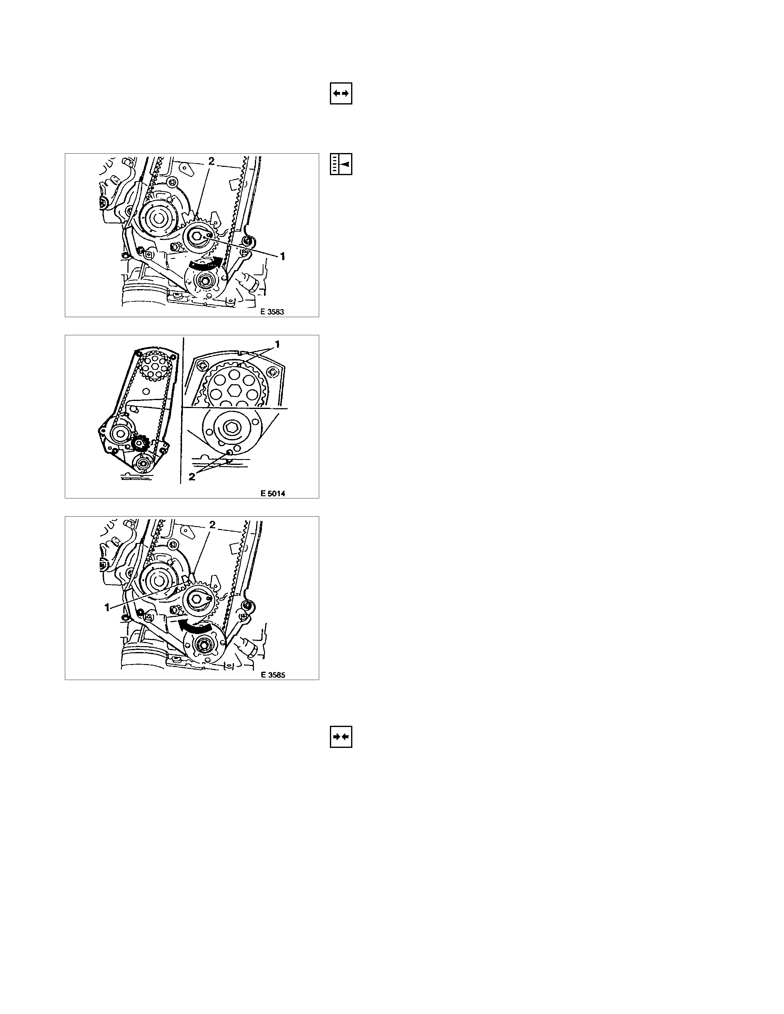
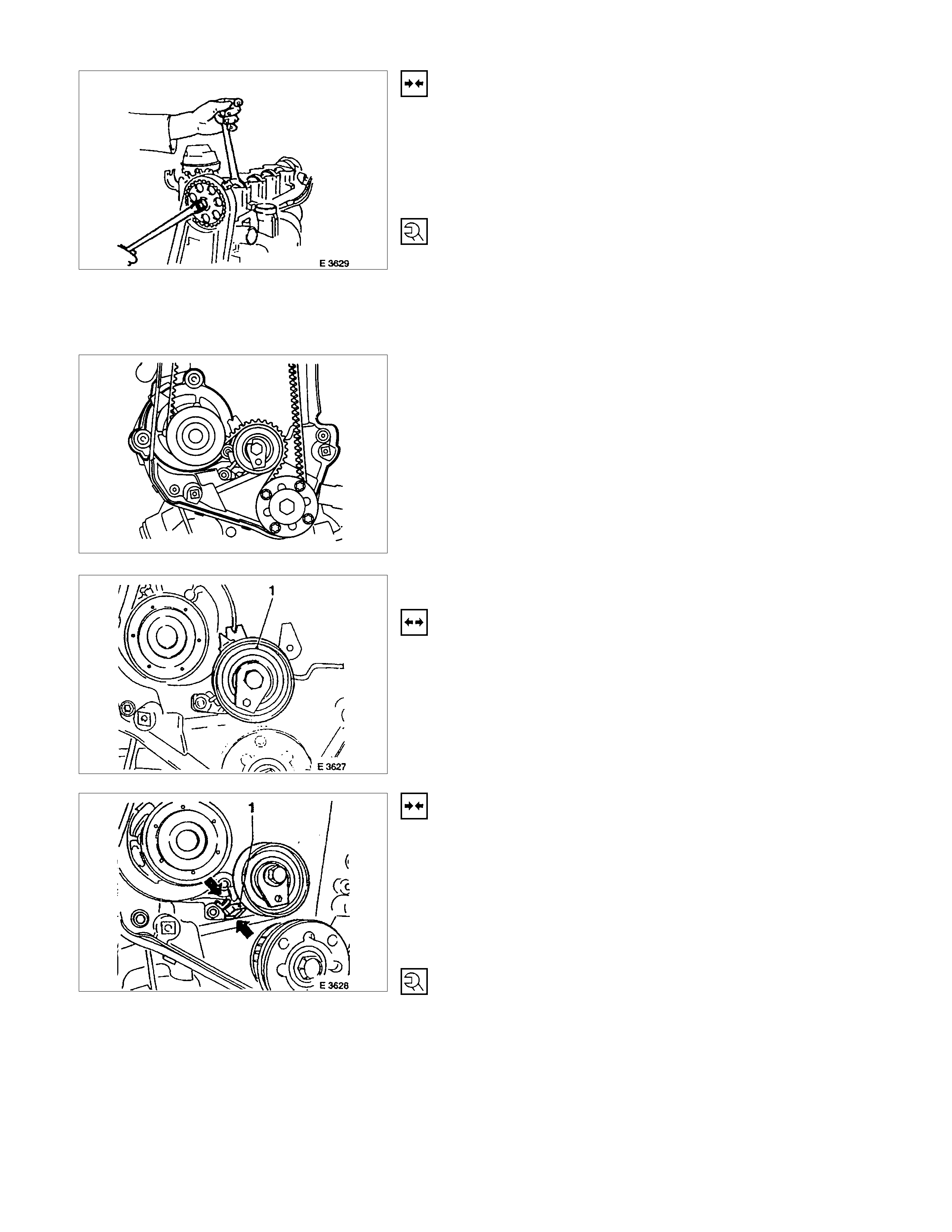
TOOTHED BELT TENSION, ADJUST (ENGINES WITH TOOTHED BELT TENSION ROLLER)
REMOVAL
Refer to 6A. Toothed Belt and Timing check and removal
steps.
ADJUST
1. Loosen the fastening bolt of the toothed belt tension
roller.
2. Turn the toothed belt tension roller at adjustment
eccentric (1) in the direction of arrow (counterclockwise),
until pointer (2) comes to the right stop.
3. If necessary tighten the fastening bolt of toothed belt
tension roller.
4. Rotate the crankshaft twice (720°) in the engine
rotational direction until marks (2) and (1) align again.
5. Turn the eccentric in the direction of arrow (clockwise)
until pointer (1) and notch (2) are positioned to suit age of
toothed belt. The tension of a NEW toothed belt is
correctly adjusted when the pointer and the centre of the
notch are aligned (I).
The tension of a RUN-IN toothed belt (regardless of
mileage covered) is correctly adjusted when the pointer
is positioned approx. 4mm (0.16 in.) to the left of the
centre of the notch (2).
6. Rotate the crankshaft twice (720°) in the engine
rotational direction again and correct adjustment if
necessary.
INSTALLATION
Refer to 6A Toothed Belt and Timing check and installation
steps.
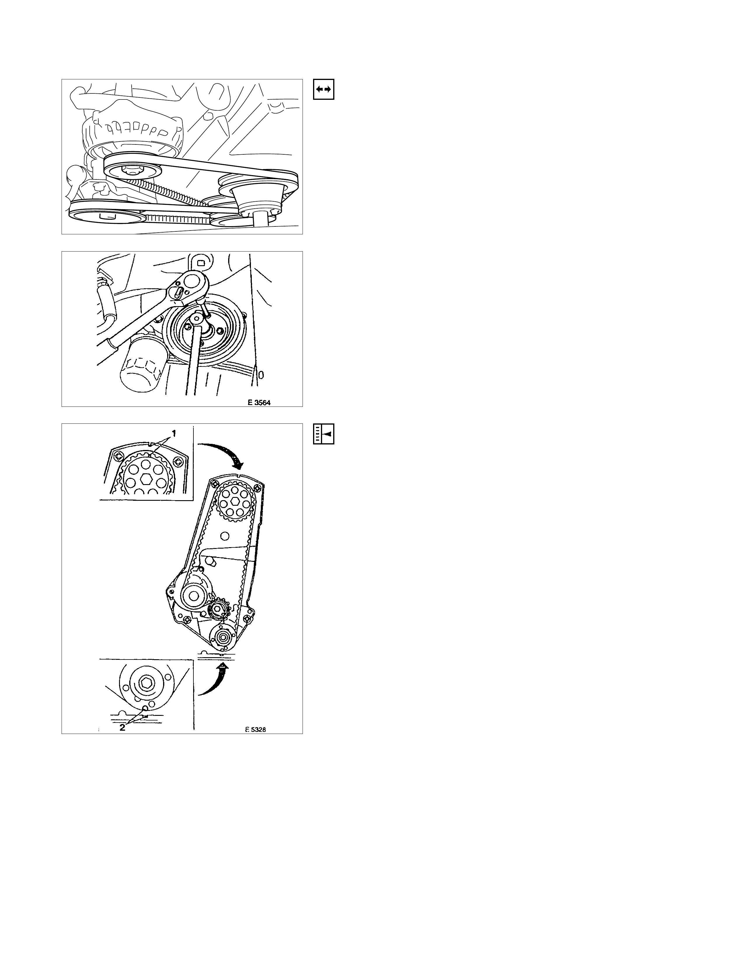
TOOTHED BELT, REPLACE ( ENGINE WI TH TOOTHED BELT TENSION ROLLER)
REMOVAL
1. Remove the belts on the bracket for alternator.
2. Remove the fan.
3. Remove the V-belt for power steering.
4. Remove the V-belt for A/C.
5. Remove the fan belt.
6. Remove the fan shroud.
7. Remove the crankshaft pulley while counterholding on
the fastening bolt of toothed belt drive gear.
8. Remove the toothed belt from cover.
ADJUST
Turn the crankshaft in the engine rotational direction to mark
(2).
Align markings on toothed belt and on toothed belt rear cover.
Simultaneously, notch (1) on camshaft gear must align with the
mark on toothed belt rear cover.
Turn the crankshaft slowly and smoothly.
ADJUST
Loosen the fastening bolt of the toothed belt tension roller and
turn the adjustment eccentric in the direction of arrow
(clockwise) until pointer (1) comes to the left stop.
Remove the toothed belt.
INSTALLATION
1. Install a new toothed belt while keeping tension side taut.
ADJUST
Toothed belt tension - see operation " Toothed Belt Tension".
2. Install the toothed belt to the cover.
3. Install the crankshaft pulley while counterholding on the
fastening bolt of toothed belt drive gear.
4. Install the fan shroud.
5. Install the fan belt.
6. Install the V-belt for A/C.
7. Install the V-belt for power steering.
8. Install the fan.
9. Install the belts to the bracket for alternator.
OPERATIONS ON INSTALLED ENGINE
SEALING OPERATIONS
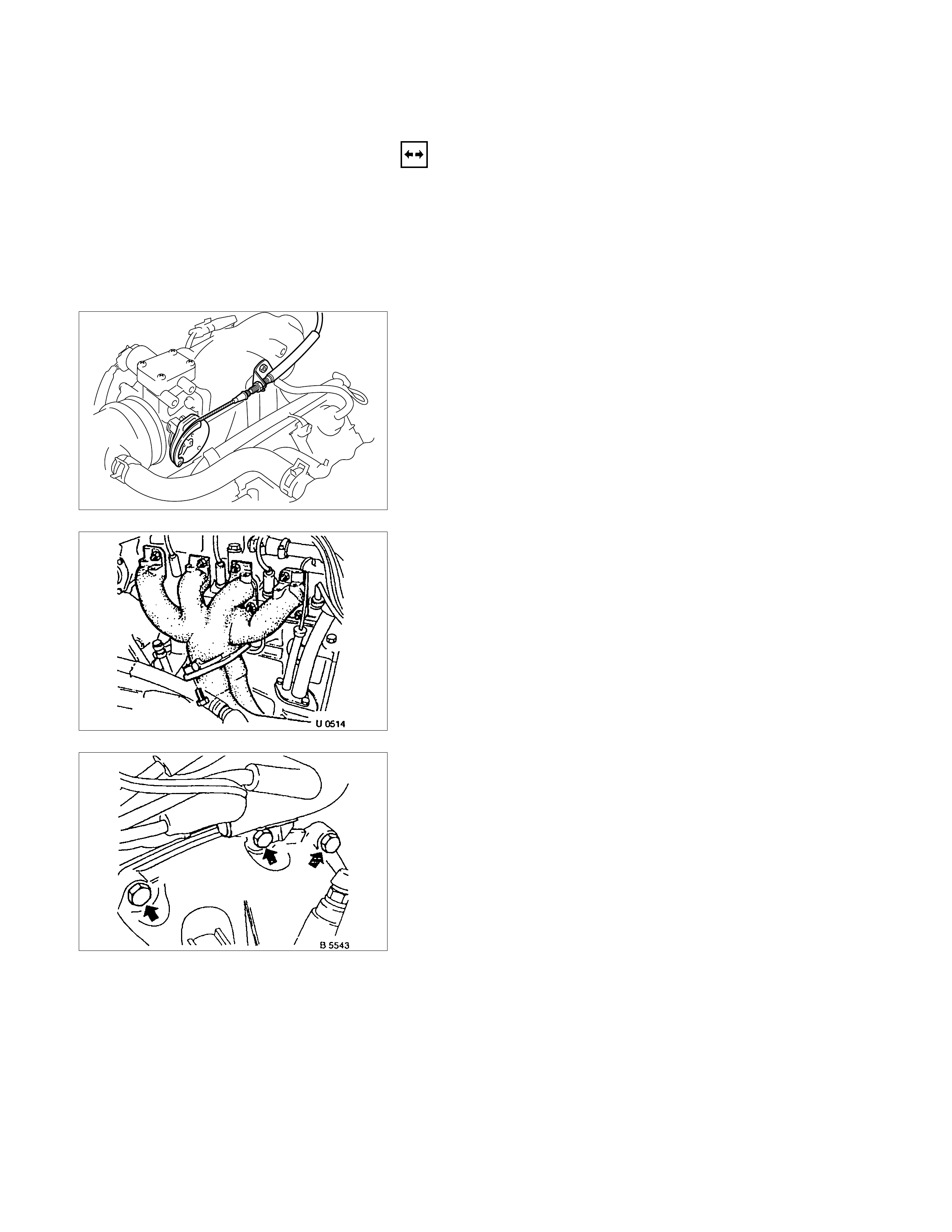
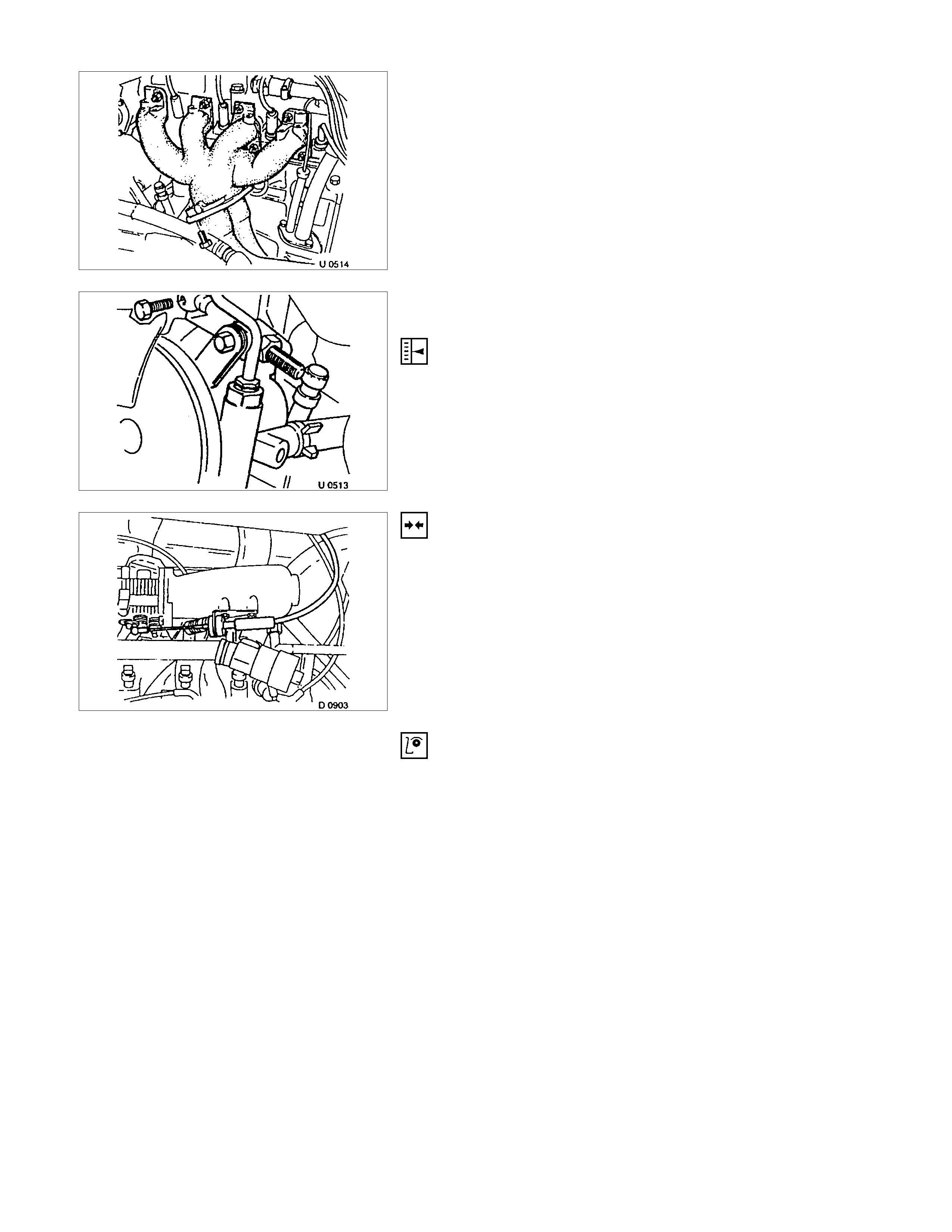
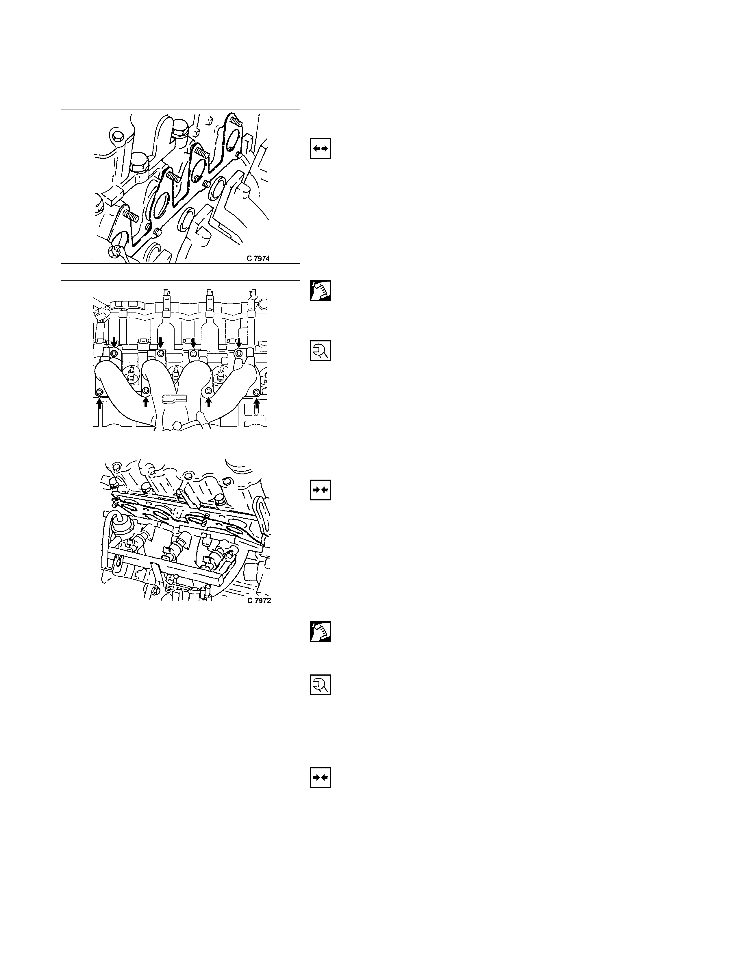
GASKET, EXHAUST MANIFOLD, CYLINDER HEAD
REMOVAL
1. Remove front exhaust pipe from exhaust manifold.
2. Remove exhaust manifold heat shield.
3. Remove exhaust manifold retaining nut.
4. Remove exhaust manifold from cylinder head.
CLEAN
Sealing surfaces.
TIGHTEN (TORQUE)
Exhaust manifold to cylinder head - 22 N⋅m (2.2 kgf⋅m)
Front exhaust pipe to exhaust manifold - 25 N⋅m (2.6 kgf⋅m)
GASKET, INTAKE MANIFOLD, CYLINDER HEAD
REMOVAL
1. Remove air intake hose.
2. Remove drives belt for alternator.
3. Remove bolt clamping bracket for alternator from intake
manifold.
4. Remove intake manifold from cylinder head.
CLEAN
Sealing surfaces
TIGHTEN (TORQUE)
Intake manifold to cylinder head - 22 N⋅m (2.2 kgf⋅m)
Clamping bracket for alternator to intake manifold - 25 N⋅m (2.5
kgf⋅m)
INSTALLATION
1. Install V-belt according to the corresponding operation.
2. Install air intake hose.
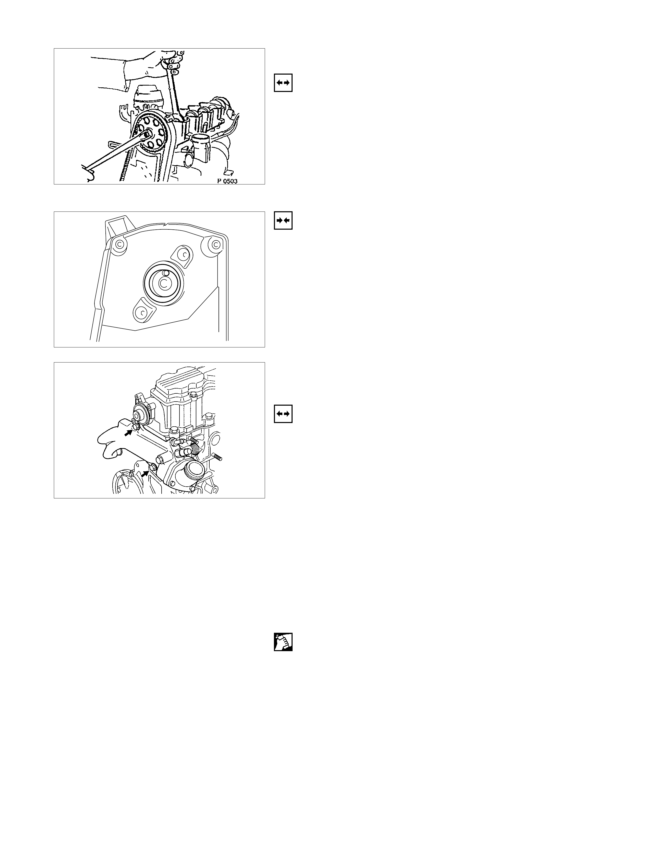
SEAL RING, CAMSHAFT HOUSI NG , TIMING SIDE
REMOVAL
1. Remove front toothed belt cover toothed belt from
camshaft timing gear according to the corresponding
operation.
2. Remove camshaft housing cover and camshaft timing
gear.
3. Remove sealing ring by making hole in middle of ring,
turning in self-tapping screw and edging out.
INSTALLATION
1. Install sealing ring by using 5-8840-0451-0 with camshaft
sprocket bolt and washer.
2. Install coat seal lips of shaft seal ring slightly.
SEAL RING, THERMO STAT HOUSING , CYLINDER
HEAD
REMOVAL
1. Open radiator drain tap and collect coolant.
2. Remove toothed belt rear cover and toothed belt
according to the corresponding operation.
3. Remove camshaft housing cover.
4. Remove camshaft timing gear by counterholding
camshaft with a flat spanner.
5. Remove cable from temperature sensor.
6. Remove upper inner hex bolts of rear toothed belt cover.
7. Turn rear toothed belt cover to one side.
8. Remove thermostat housing.
9. Remove sealing ring from cylinder head.
CLEAN
Sealing surfaces in cylinder head and thermostat housing.
INSTALLATION
1. Install sealing ring in recess of cylinder head.
2. Install cable to temperature sensor.
3. Install upper bolts of rear toothed belt rear cover.
4. Install camshaft timing gear then check timing according
to the corresponding operation.
5. Install camshaft housing cover.
6. Install toothed belt and front cover.
7. Fill up and bleed cooling system according to the
corresponding operation.
TIGHTEN (TORQUE)
Thermostat housing to cylinder head - 15 N⋅m/1.5 kgf⋅m.
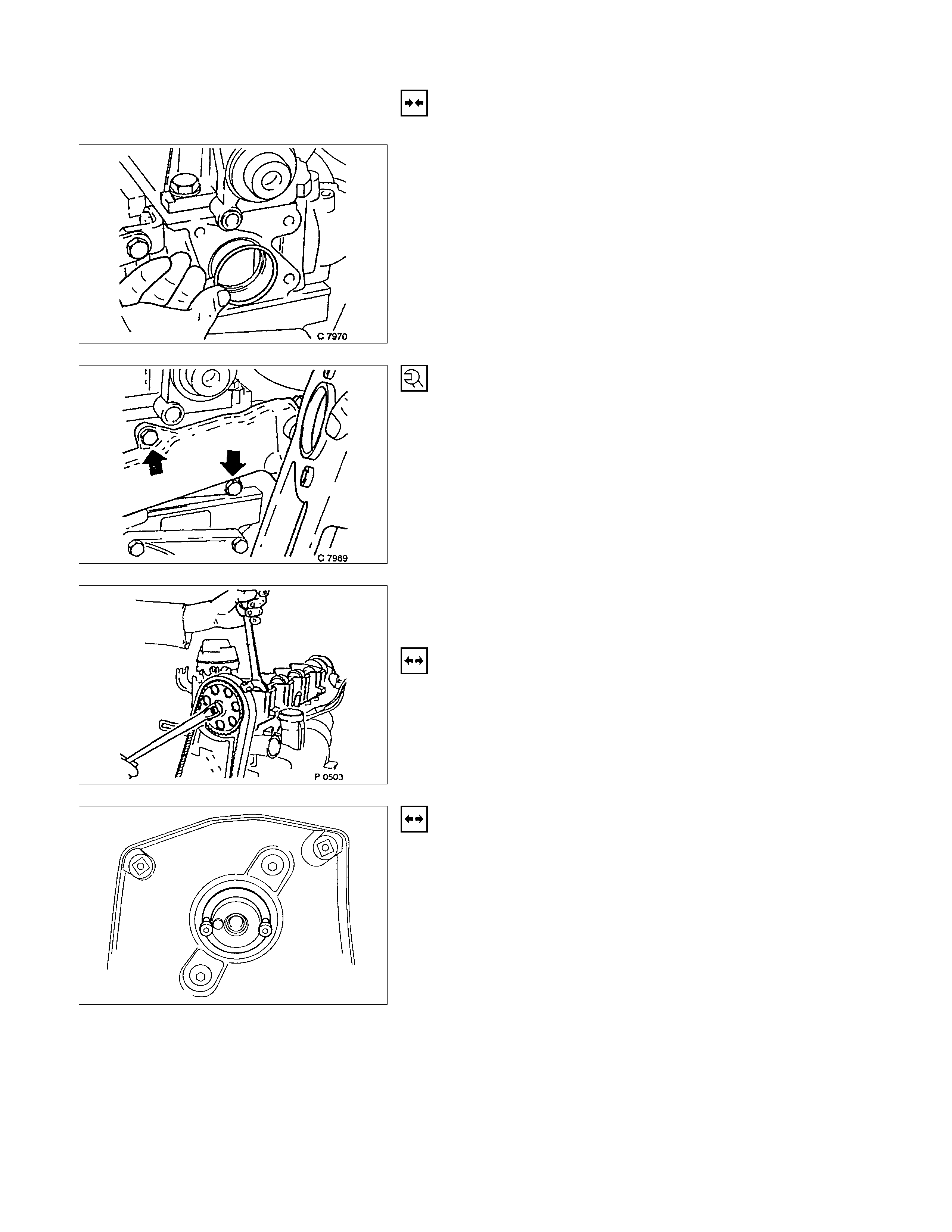
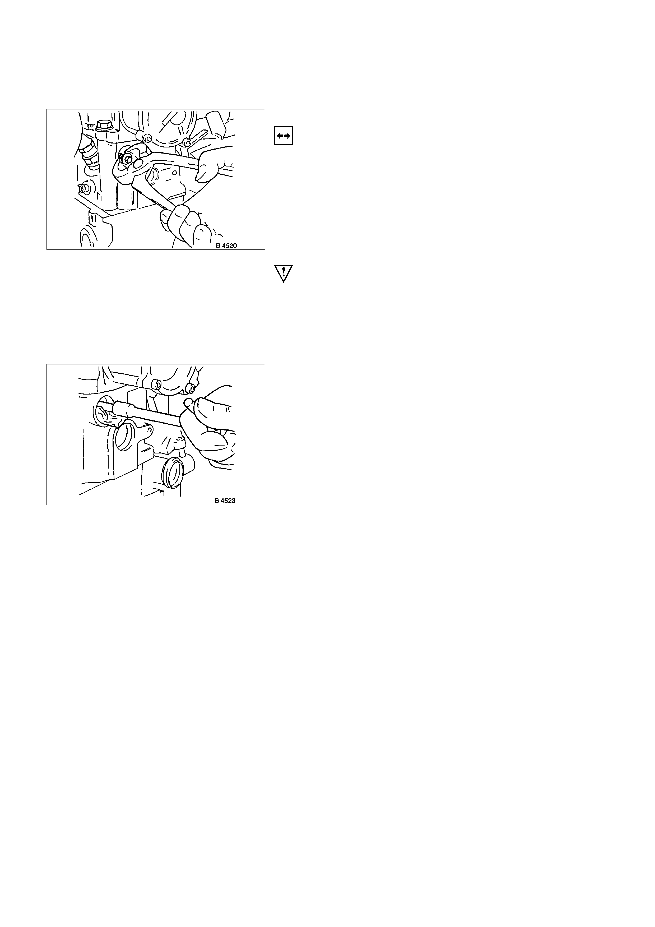
SEAL RING - FRONT CAMSHAFT HOUSING,
REPLACE
REMOVAL
Mark running direction of toothed belt.
Remove toothed belt-see operation “Toothed Belt, Replace”.
Camshaft housing cover, camshaft pulley-counterhold on hex
of camshaft.
REMOVAL
Screw self-tapping screw into seal ring.
Edge out seal ring.
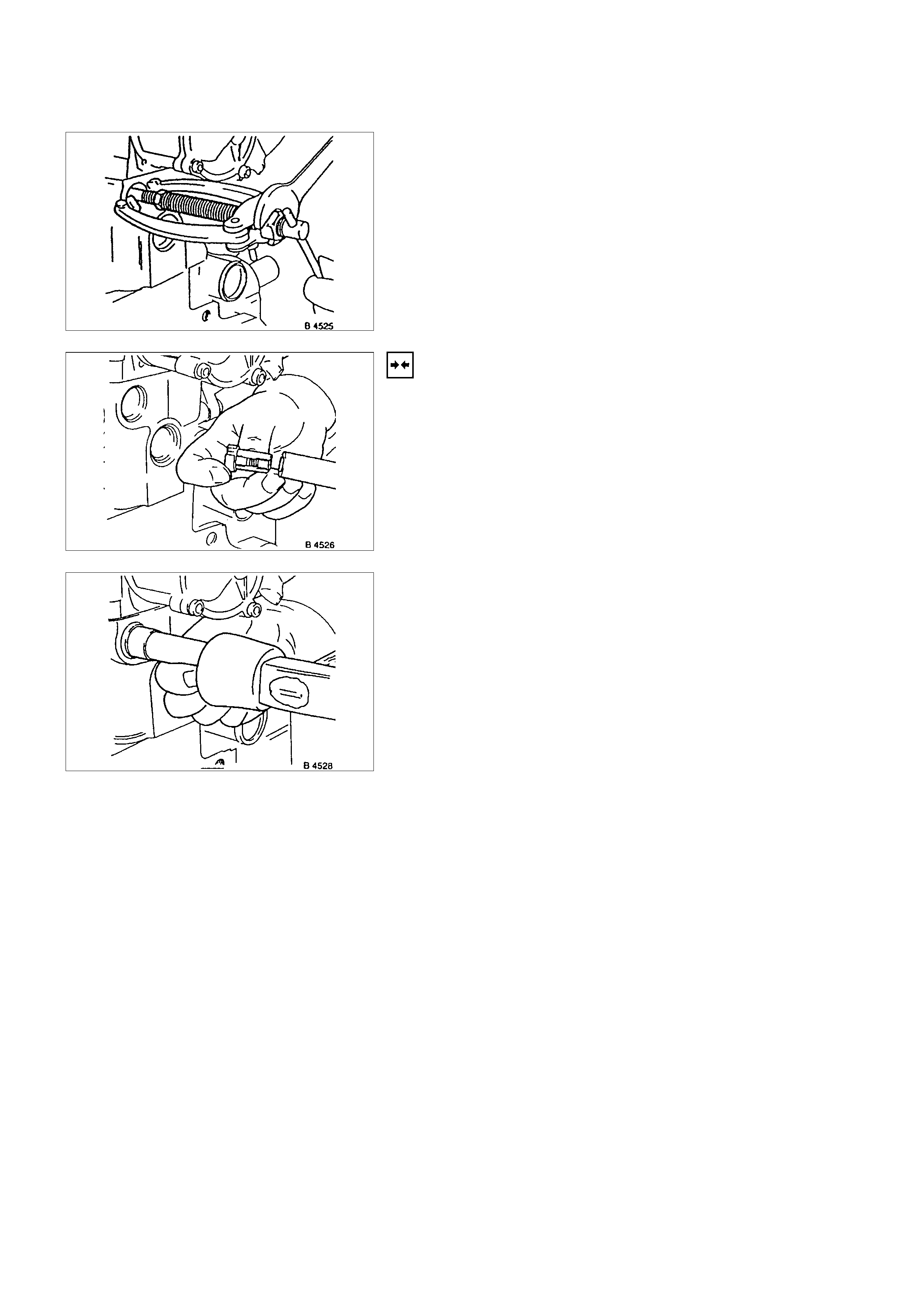
INSTALLATION
Lightly coat sealing lip of seal ring with protective grease.
Install seal ring with 5-8840-0451-0 into camshaft housing-use
screw and washer of camshaft pulley.
INSTALLATION
Camshaft pulley: counter-hold camshaft at hexagon, near
camshaft housing cover.
Toothed belt-see operation “Toothed Belt, Replace”.
Note operating direction of toothed belt.
TIGHTEN (TORQUE)
Camshaft pulley to camshaft-45 N⋅m (3.7 kgf⋅m)
TIGHTEN (TORQUE)
Camshaft housing cover to cover to housing-8 N⋅m (0.8 kgf⋅m)
TOOTHED BELT REAR COVER ( ENGINE WITH TOOTHED BELT TENSION ROLLER)
REMOVAL
1. Mark operating direction of toothed belt.
2. Remove toothed belt according to the operation "Toothed
Belt".
3. Remove toothed belt tension roller according to the
operation "Toothed Belt Tension Roller ".
4. Remove fastening bolt while counter-holding with 5-8840-
2598-0 (Holding wrench).
5. Remove toothed belt drive gear while counter-holding
with 5-8840-2598-0 (Holding wrench).
6. Remove camshaft housing cover.
7. Remove camshaft pulley while counter-holding camshaft
at hexagon.
8. Remove toothed belt rear cover (arrows) from oil pump
and camshaft housing.
INSTALLATION
1. Install toothed belt rear cover.
2. Install camshaft pulley while counter-holding at camshaft
hexagon.
3. Install camshaft housing cover.
TIGHTEN (TORQUE)
Toothed belt rear cover to oil pump and camshaft housing - 6
Nm/4 lb/ft.
Camshaft housing cover to housing - 6 N⋅m (0.6 kgf⋅m).
Camshaft pulley to camshaft - 45 N⋅m (4.6 kgf⋅m).
4. Install toothed belt drive gear to crankshaft - 130 N⋅m
(13.3 kgf⋅m).
5. Install toothed belt according to the operation "Toothed
Belt".
TOOTHED BELT TENSION ROLLER
REMOVAL
1. Mark operating direction of toothed belt.
2. Remove toothed belt according to the operation "Toothed
Belt”.
3. Remove toothed belt tension roller (1) from oil pump.
INSTALLATION
1. Install toothed belt tension roller and make sure that the
locking lever (1) engages in the guide lugs (arrowed) on
the oil pump housing.
2. Install toothed belt according to the operation "Toothed
Belt" with paying attention to the operating direction of
toothed belt.
TIGHTEN (TORQUE)
Toothed belt tension roller to oil pump - 25 N⋅m (2.5 kgf⋅m)
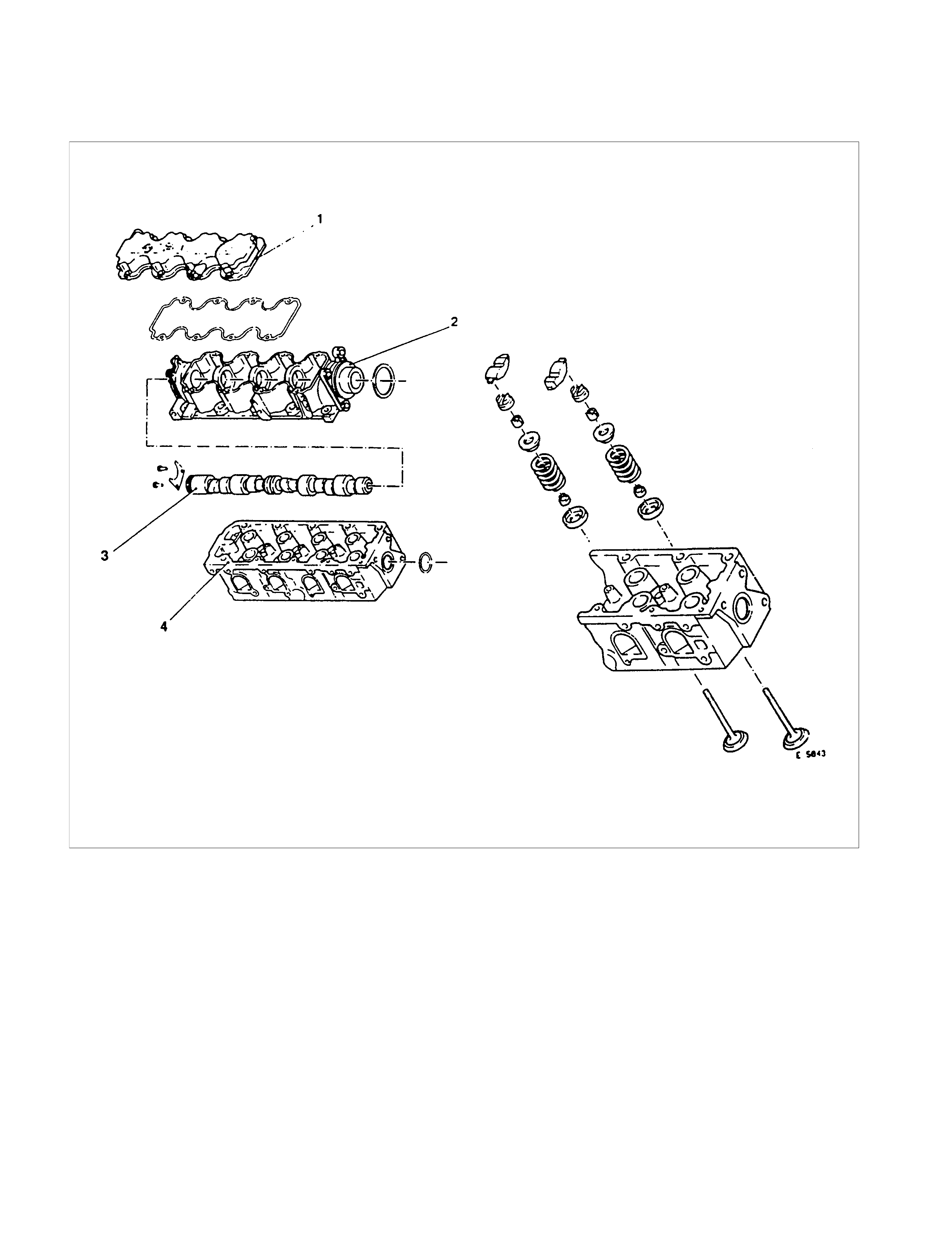
COMPONENT PARTS
CYLINDER HEAD
(A)
1. Camshaft Housing Cover
2. Camshaft Housing
3. Camshaft
4. Cylinder Head
(A) Valve Gear
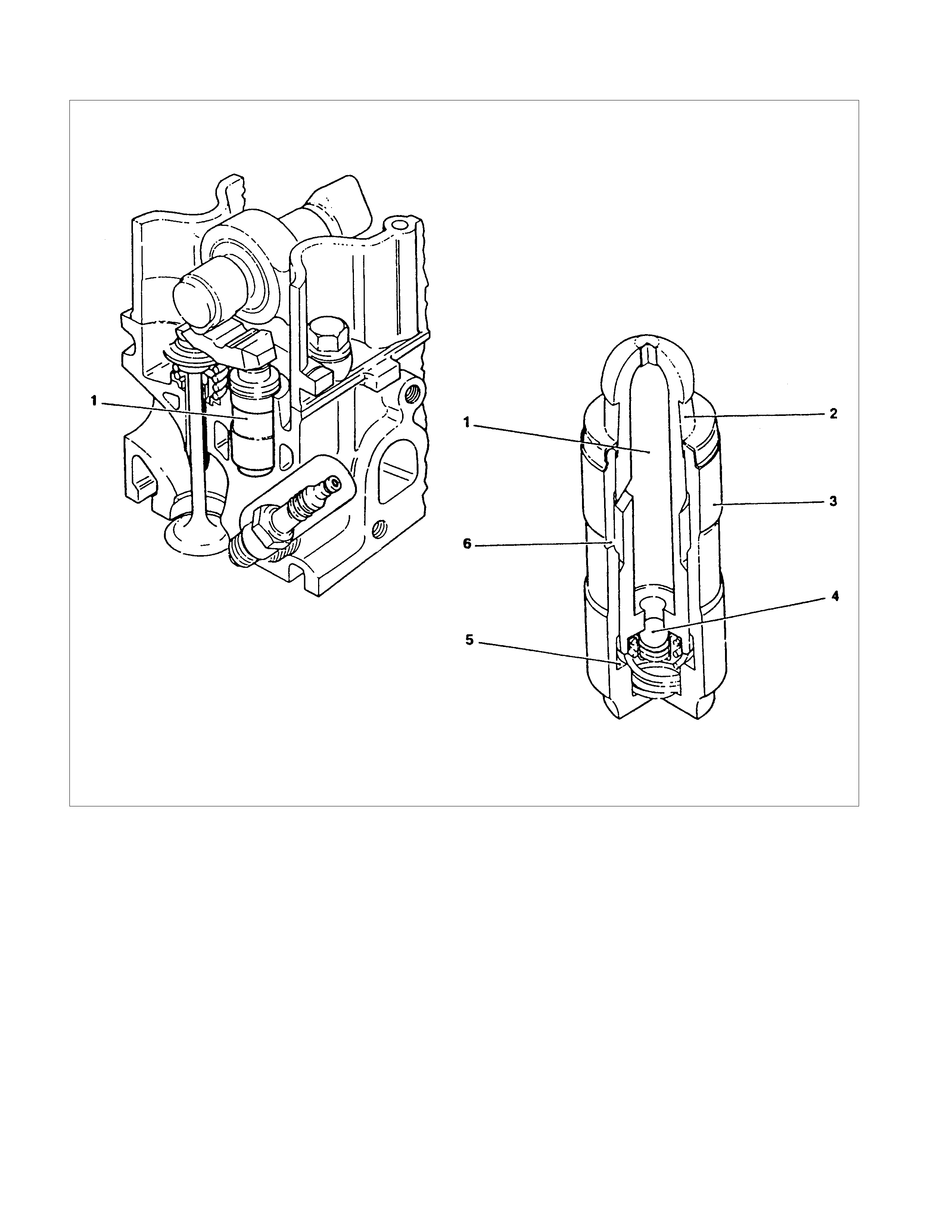
HYDRAULI C VALVE LIFTER
1. Hydraulic Valve Lifter 1. Oil reservoir
2. Piston with ball head (moving)
3. Pressure Cylinder (fixed)
4. Check ball
5. Pressure chamber
6. Oil feed
OPERATI O NS ON CYLINDER HEAD AND CAM SHAFT HOUSING
CAMSHAFT
REMOVAL
1. Remove cylinder head according to the corresponding
operation.
2. Remove camshaft housing from cylinder head and lay
housing on base provided
3. Remove rear sealing gasket and plate camshaft housing
with taking care not to damage housing.
4. Remove thrust plate.
5. Remove camshaft.
6. Remove front sealing gasket and plate from camshaft
housing with taking care not to damage housing.
INSPECTION
All parts.
INSTALLATION
1. Install camshaft.
2. Coat sliding surfaces with molybdenum disulphide
grease.
TIGHTEN (TORQUE)
Thrust plate for camshaft housing - 8 N⋅m (0.8 kgf⋅m)
CAM SHAFT HOUSING, REMOVAL AND INSTALLATION
See operation Camshaft
CYLINDER HEAD
IMPORTANT:
Remove cylinder head only from cold engine (room
temperature).
REMOVAL
1. Remove ground cable from battery.
2. Open radiator drain tap and collect coolant.
3. Remove air intake hose.
4. Remove all cable connections, hoses and lines to the
cylinder head.
5. Remove accelerator cable on the throttle valve.
6. Remove V-belt for alternator.
7. Remove front toothed belt cover according to the
corresponding operation.
8. Bring piston of 1st cylinder to TDC and mark the position.
9. Remove camshaft housing cover.
10. Remove camshaft timing gear after releasing tension on
toothed belt.
11. Remove upper bolts of rear toothed belt cover.
12. Remove exhaust pipe from exhaust manifold.
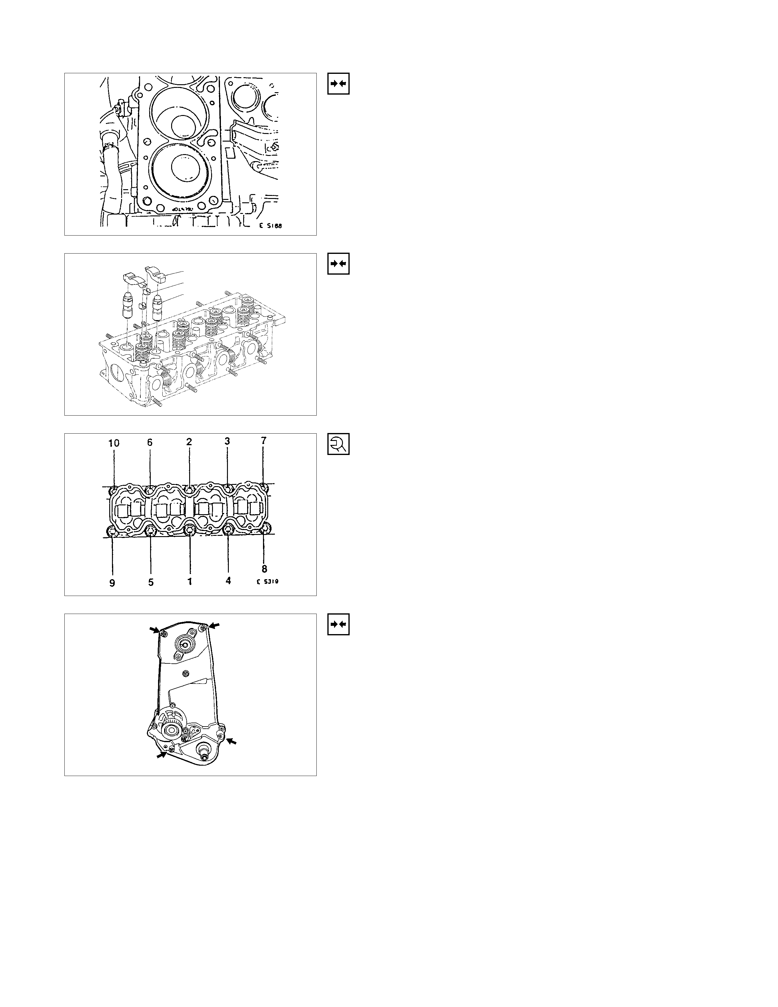
13. Remove cylinder head after loosening bolts from outside
inwards (at first quarter turn then half turn) in a spiral
pattern.
14. Remove camshaft housing from cylinder head.
15. Remove rocker arm, pressure parts and hydraulic valve
lifter adjuster.
CLEAN
All sealing surfaces, drill holes in cylinder head bolts.
Check cylinder block and cylinder head for plane surface
according to the corresponding operations.
INSTALLATION
1. Install cylinder head sealing with marking "OBEN/TOP"
facing upwards and to right side of engine.
2. Install cylinder head on cylinder block.
3. Install hydraulic valve lash adjuster, pressure parts and
rocker arm - molybdenum disulphate paste.
4. Install camshaft housing-Sealing Compound TB-1207C
or equivalent.
IMPORTANT:
Use new cylinder head bolts.
Screw in bolts until they rest on cover.
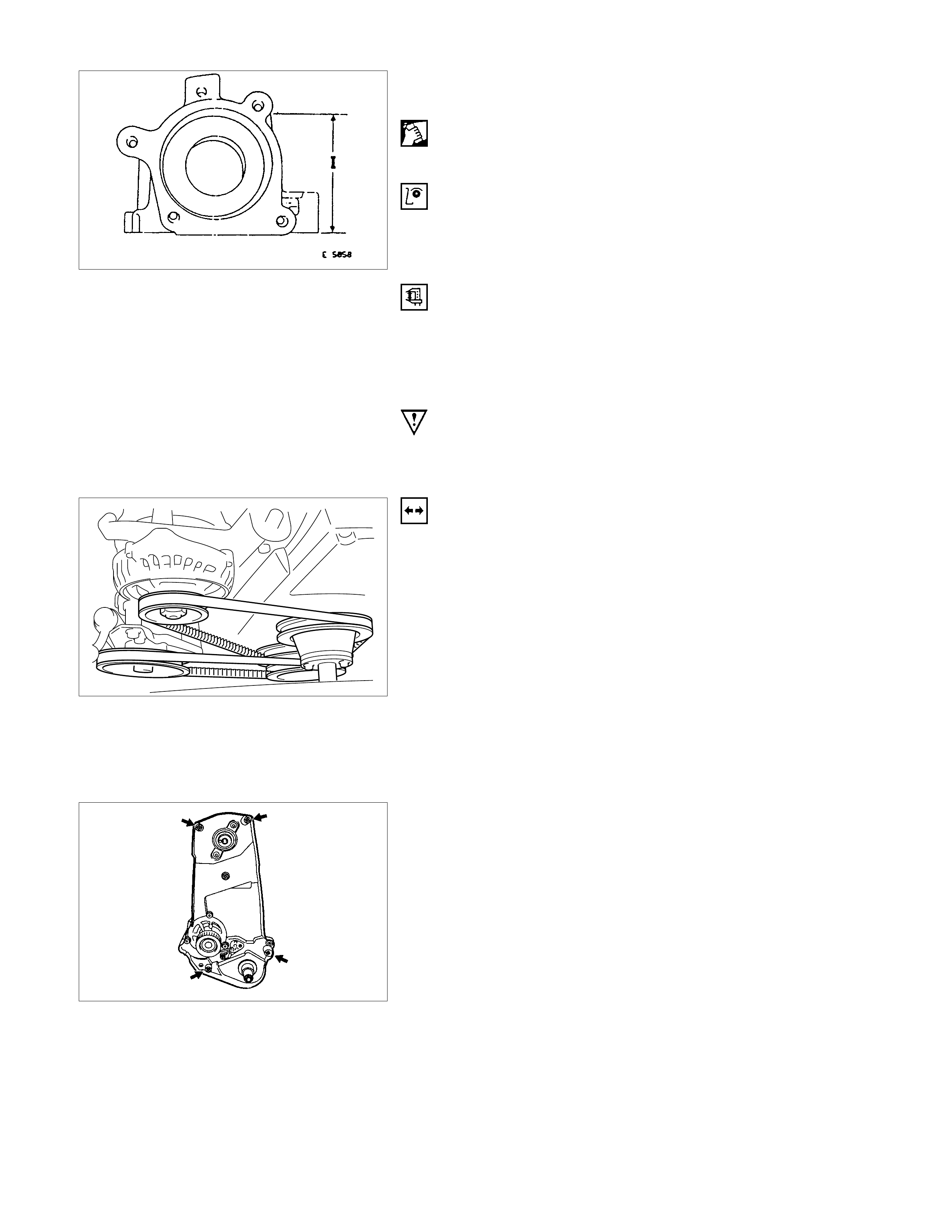
TORQUE - ANGLE METHOD
Cylinder head to cylinder block - 25 N⋅m (2.5 kgf⋅m)
Further turn angle 90°+90°+ 90°.
Tighten cylinder head bolts from inside outwards. In four
stages in a spiral pattern.
5. Install rear toothed belt cover onto camshaft housing.
6. Install toothed belt and apply tension according to the
corresponding operation.
TIGHTEN (TORQUE)
Camshaft timing gear to camshaft - 45 N⋅m (4.6 kgf⋅m)
7. Install camshaft housing cover and front toothed belt
cover.
8. Install cable connections, all hoses and lines onto
cylinder head.
9. Adjust accelerator cable for free of play.
10. Install V-belt according to the corresponding operation.
11. Install air intake hose.
12. Install front exhaust pipe.
13. Install ground cable onto battery.
14. Fill up cooling system and bleed according to the
corresponding operation.
HYDRAULI C VALVE LIFTERS, REPLACE
REMOVAL
1. Remove the spark plug connectors and spark plugs.
2. Remove the camshaft housing cover.
3. Turn the crankshaft at fastening bolt of toothed belt drive
gear in the direction of the engine rotation until the cam
of hydraulic valve lifter being replaced stands vertically.
4. Apply 5-8840-0457-0 to the camshaft housing, valve
spring cap and tension valve spring.
5. Remove the cam follower from camshaft housing.
Note thrust pieces.
6. Remove hydraulic valve lifter from camshaft housing.
CAM SHAFT HOUSING, REPLACE
REMOVAL
Cylinder head-see operation “Cylinder Head. Remove and
Install”.
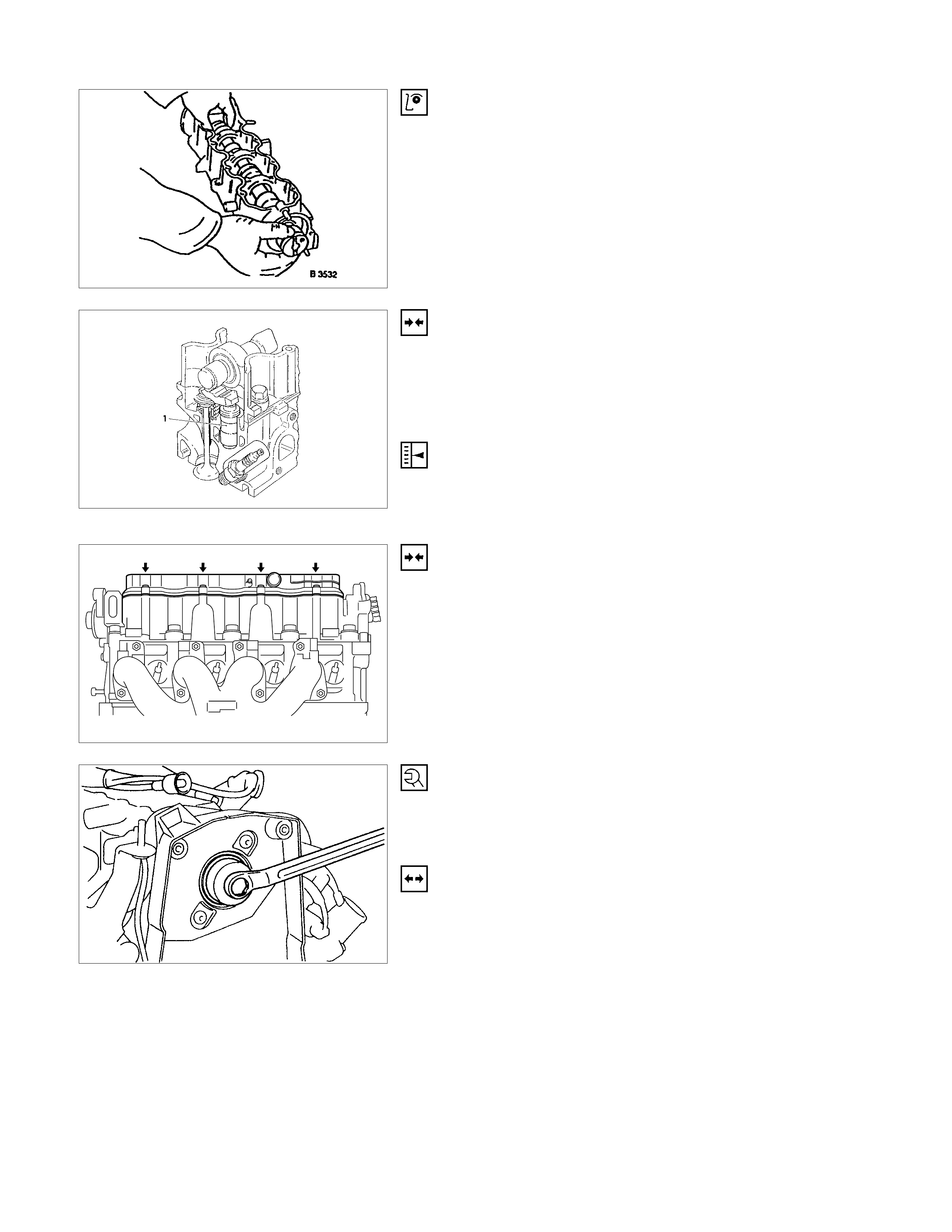
INSPECTION
All parts, if necessary replace.
When replacing camshaft, always replace all cam followers.
INSTALLATION
Insert hydraulic valve lifter (1) in camshaft housing.
Coat sliding surfaces of rocker arm with Molybdenum Grease
(HN1461 or equivalent) and insert in camshaft housing.
ADJUST
Adjustment of the hy draulic valve liters is not required.
Pretension is provided by the design.
INSTALLATION
1. Remove 5-8840-0457-0 and install the camshaft housing
cover.
2. Insert the spark plug connectors.
TIGHTEN (TORQUE)
Guide plate to camshaft housing.
Insert camshaft with MoS2 paste.
INSTALLATION
1. Install the front seal ring in camshaft housing with
5-8840-0451-0.
2. Install the camshaft housing rear cover.
3. Install the cylinder head.
CAM SHAFT HOUSING, CHECK FO R PLANE
SURFACE
CLEAN
Sealing surfaces.
INSPECTION
Check length and width of sealing surface for deformation and
diagnosis for warpage and use straight edge feeler gauge.
MEASURE
Height of camshaft housing (sealing surface to sealing
surface).
Dimension I: (74.0 mm)
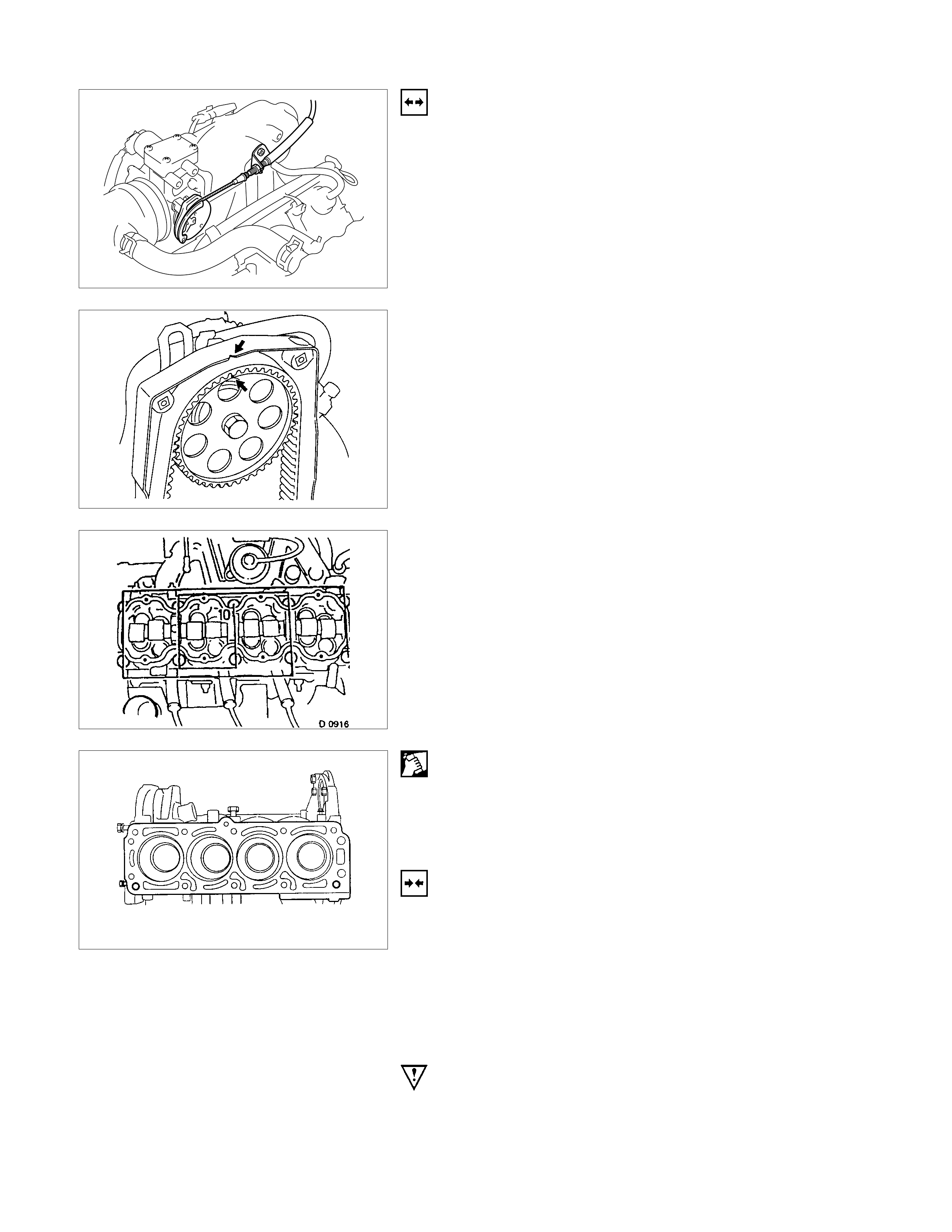
CYLINDER HEAD, REMO VAL AND INSTALLATIO N
IMPORTANT:
Only remove cylinder head with engine cold (room
temperature).
REMOVAL
1. Remove the alternator, power steering and V-belts.
2. Loosen the fastening bolts from alternator.
3. Loosen the lower alternator fastening bolt by swinging
the alternator to the rear.
4. Remove the front toothed belt cover.
5. Remove the toothed belt from camshaft pulley.
See operation "Timing Check and Adjust".
6. Remove the camshaft housing cover and camshaft
pulley by counter-holding at the hex head of camshaft.
7. Remove the fastening bolts from camshaft housing.
8. Remove the exhaust pipe from exhaust manifold.
9. Loosen the cylinder head bolts spirally from the outside
inwards (first 1/4, then 1/2 revolution).
REMOVAL
1. Remove the camshaft housing from cylinder head.
2. Remove the cam followers, thrust pieces and hydraulic
valve lifters.
Note the allocation.
3. Remove the cylinder head.
CLEAN
Sealing surfaces, bores and threads of cylinder head bolts.
INSPECTION
Check cylinder head and cylinder block for plane Surface-see
operations “Cylinder Head. Check for Plane Surface” and
“Cylinder Block, Check for Plane Surface.”
INSTALLATION
1. Install the cylinder head gasket.
Mark "OBEN/TOP" on top and turn it towards timing side
of engine.
2. Place cylinder head on cylinder block.
1
2
3
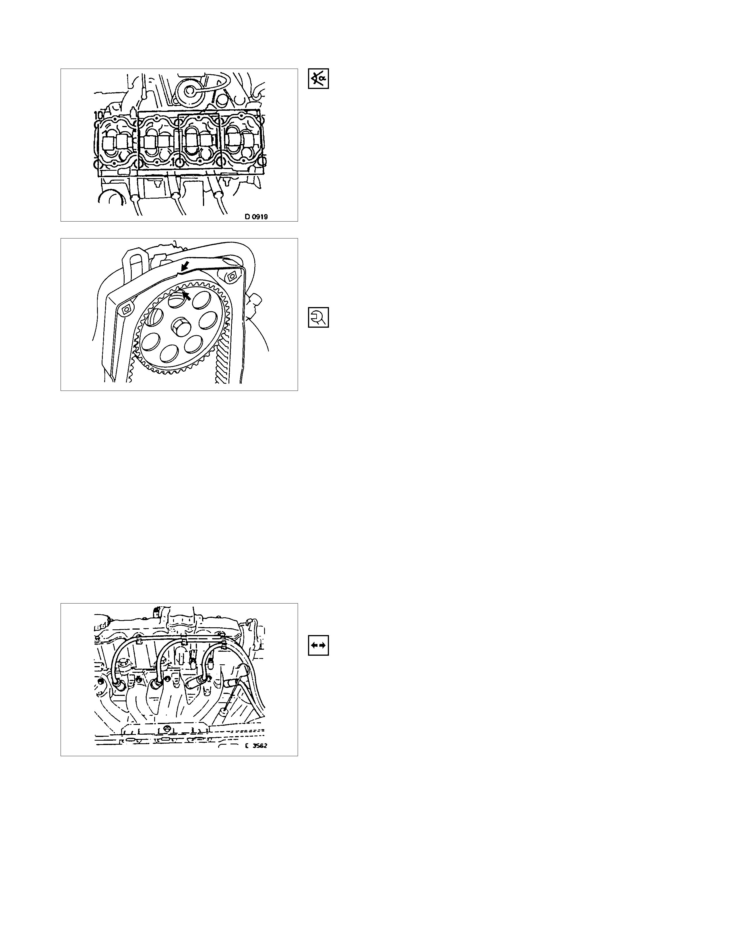
INSTALLATION
1. Insert the hydraulic valve lifters (3), thrust pieces (2) and
cam followers (1) with MoS2 paste.
Note allocation.
2. Apply a bead of Sealing Compound TB1207C to sealing
surface of cylinder head.
3. Install the camshaft housing on cylinder head.
TORQUE-ANGLE METHOD
Cylinder head and camshaft housing with new cylinder head
bolts to cylinder block.
Cylinder head bolts in sequence shown.
INSTALLATION
1. Install the rear toothed belt cover to camshaft housing.
2. Install the camshaft pulley to camshaft.
3. Install the camshaft housing cover to housing.
INSTALLATION
1. Install the toothed belt on camshaft pulley.
See operation "Timing Adjust".
2. Install the front toothed belt cover.
INSTALLATION
1. Install the fastening bolts.
2. Loosen the lower alternator fastening bolt.
3. Install the alternator, power steering and V-belts.
CYLINDER HEAD, DISASSEMBLE AND ASSEMBLE
REMOVAL
1. Remove the hydraulic valve lifters.
Lay aside in installation positions.
2. Remove the spark plugs, exhaust manifold and intake
manifold from cylinder head.
REMOVAL
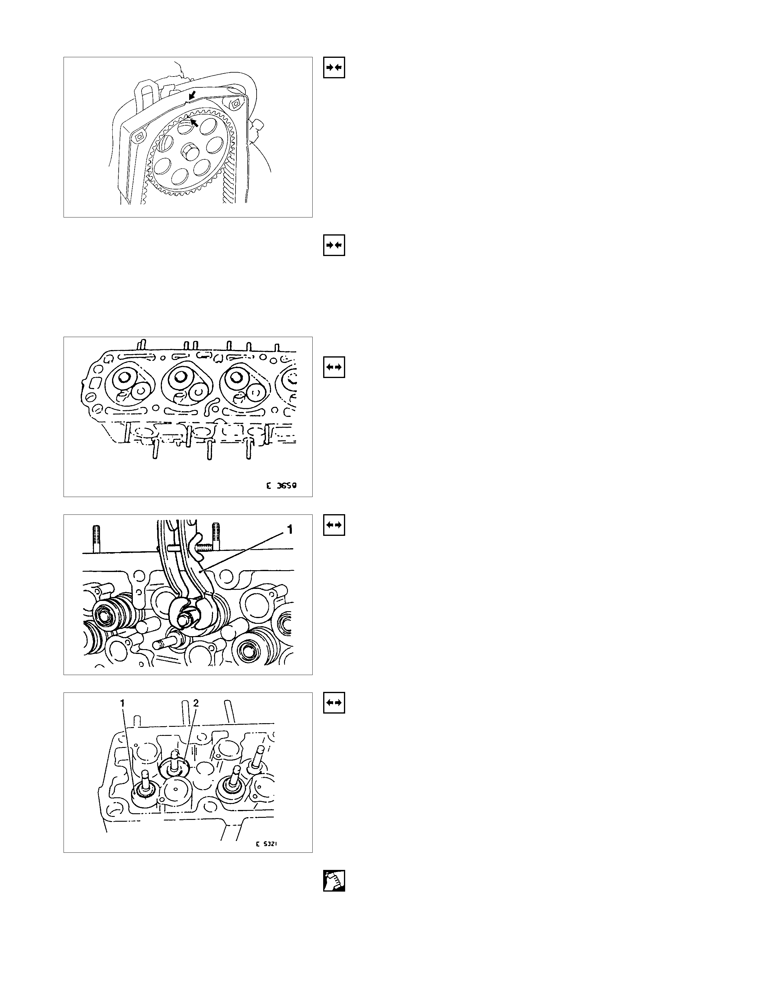
1. Mark valves.
2. Remove the tension valve springs with 5-8840-2594-0
(1).
3. Remove valve keepers, valve spring cap and valve
spring.
REMOVAL
1. Remove the valve and valve stem seal.
2. Remove the valve spacer ring (1-exhaust) and valve
spring seat (2-intake).
3. Remove valve from cylinder head.
CLEAN
Sealing surfaces.
INSPECTION
Sealing surfaces for plane surface, guides, sliding and bearing
points for wear-see operation “Cylinder Head. Overhaul”.
INSTALLATION
1. Coat the valves with engine oil and insert in cylinder
head.
2. Install the valve spacer ring or valve rotator (exhaust)
and valve spring seal (intake).
3. Push the accompanying assembly sleeve onto valve
stem and coat with engine oil.
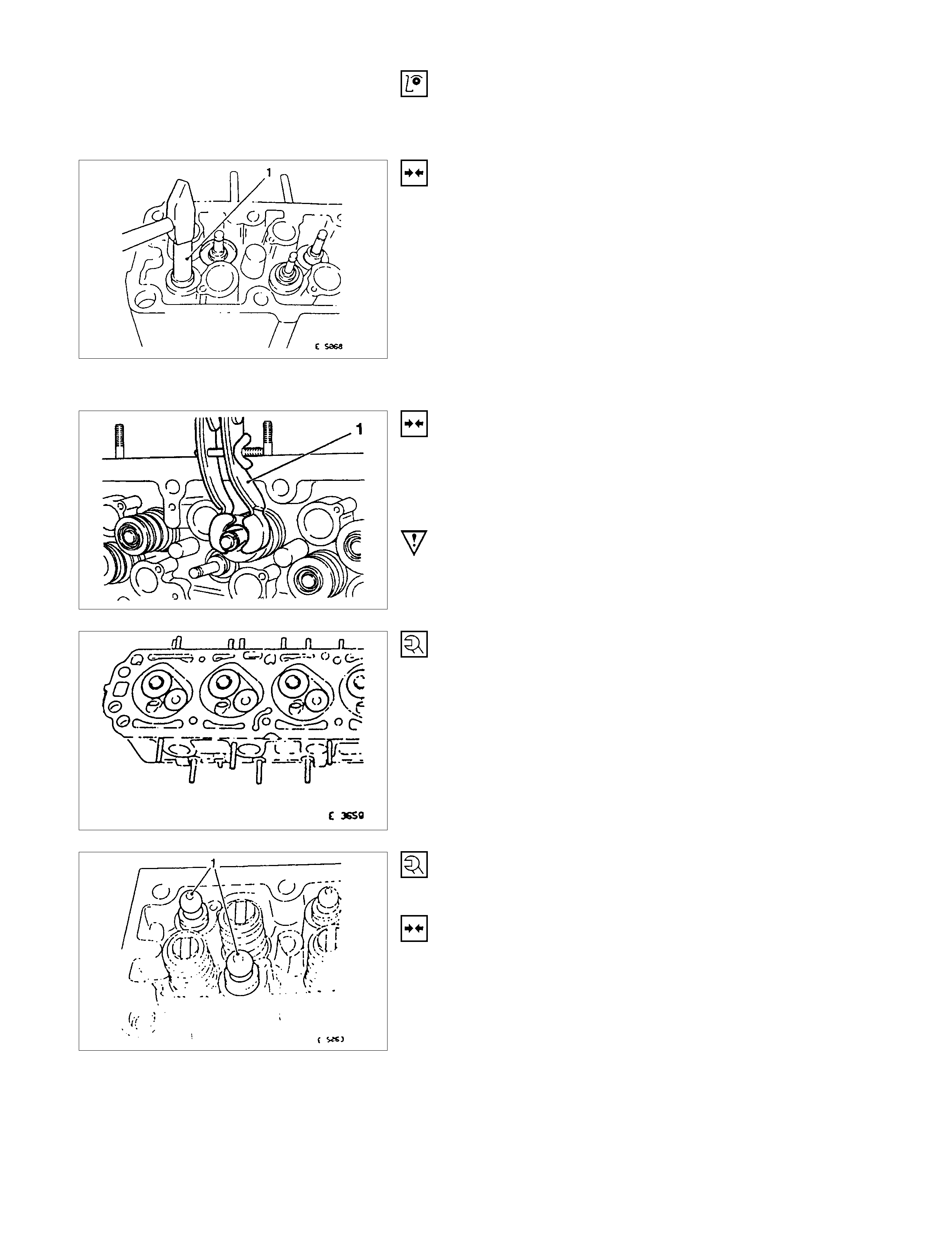
4. Insert a new valve stem seal with 5-8840-2601-0 (1).
5. Drive the valve stem seal carefully in to stop with light
hammer blow.
INSTALLATION
1. Install the valve springs and valve spring caps.
2. Install the tension valve springs with 5-8840-2594-0 (1),
valve keeper.
IMPORTANT:
Note markings made on valves.
TIGHTEN (TORQUE)
Exhaust manifold and intake manifold with new gaskets to
cylinder head.
Thermostat housing with new seal ring to cylinder head:
TIGHTEN (TORQUE)
Spark plugs with spark plug wrench to cylinder head.
INSTALLATION
1. Coat hydraulic valves lifters (1) with oil.
2. Insert them in cylinder head.
Note installation position.
VALVE, GRIND
Valves can be reused once or twice after regrinding-only if
there are no crater-like burns on the valve cone.
Excessive grinding can cause the upper valve head edge to
become too thin.
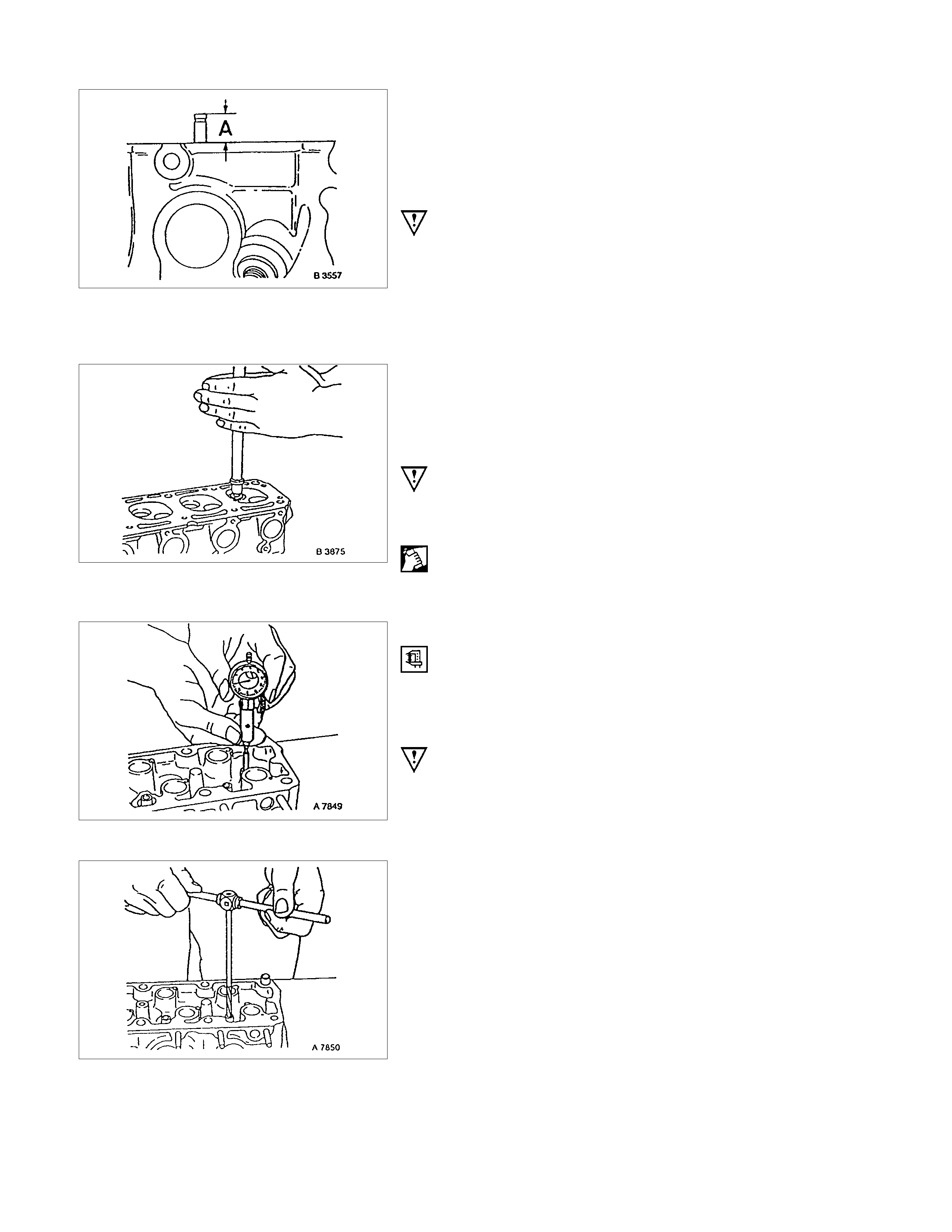
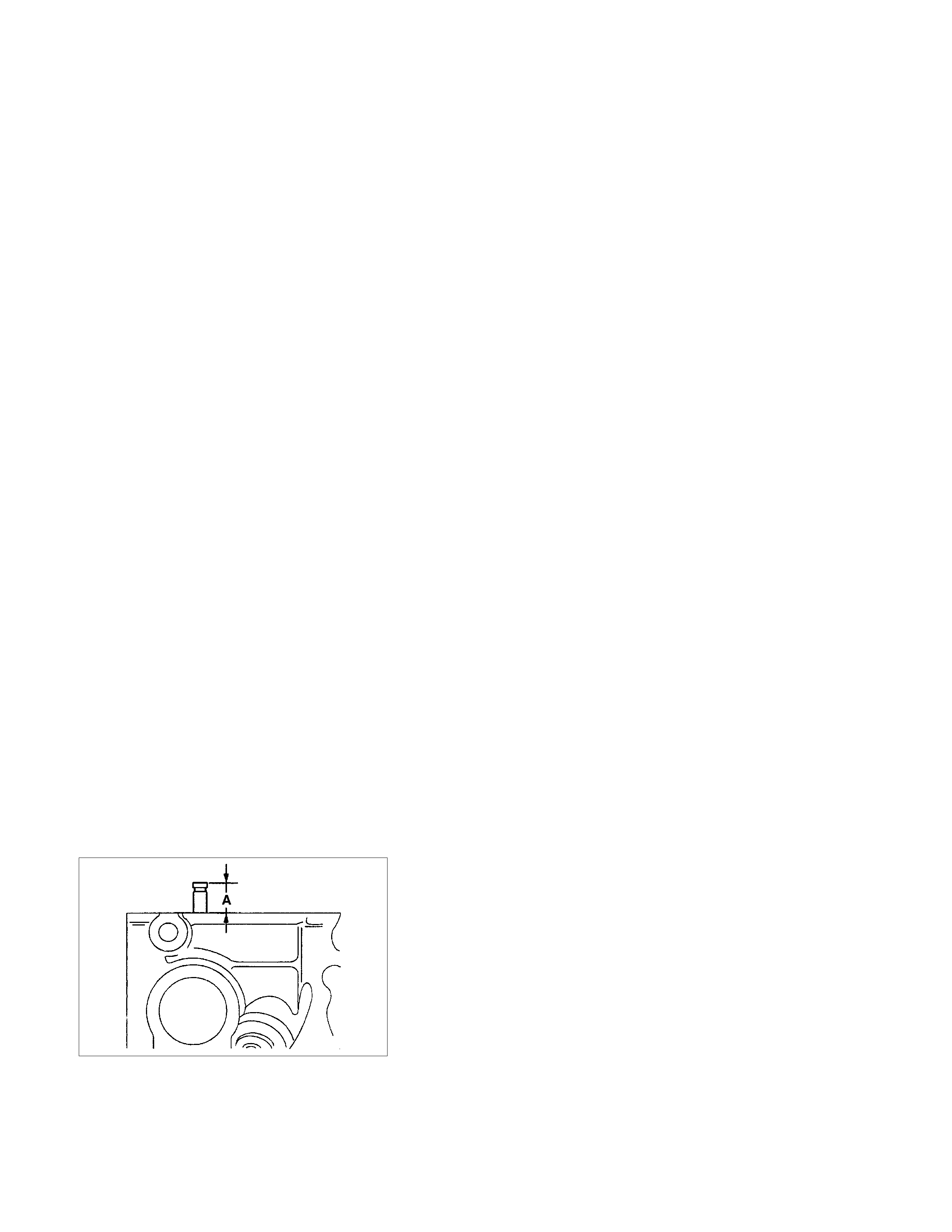
IMPORTANT:
Valve stem protection must not exceed dimension “A”-use 5-
8840-2596-0.
Do not regrind valve stem ends.
For all valve reworking note that angle of valve head is 44° and
the valve seat 45°-see also “Technical Data”.
VALVE, GRIND IN
Grind-In the valve to improve valve seating.
Grind-In by rhythmically lifting valves and turning uniformly.
Use commercially available grinding tool.
IMPORTANT:
Use only fine-grained pastes for grinding.
Lubricate valve stem before grinding in.
CLEAN
After grinding, carefully clean valve and valve seat.
VALVE GUIDE, REAM
MEASURE
Diameter of valve guide-dial gauge and internal measuring
instrument.
IMPORTANT:
Valve oversizes are available ex-works.
Oversize identification, on the valve guide and on the valve
stem end with the following specified identification
flgures/letters-see also “Technical Data”.
IDENTIFICATION MARK
Size Production Customer Service Reamer
Normal none K
0.075 mm 1 K1
0.150mm 2 K2
Ream valve guide from the upper side of the cylinder head to
the next oversize (use 5-8840-2599-0).
After reaming, cross out identification mark and stamp in new
identification mark.
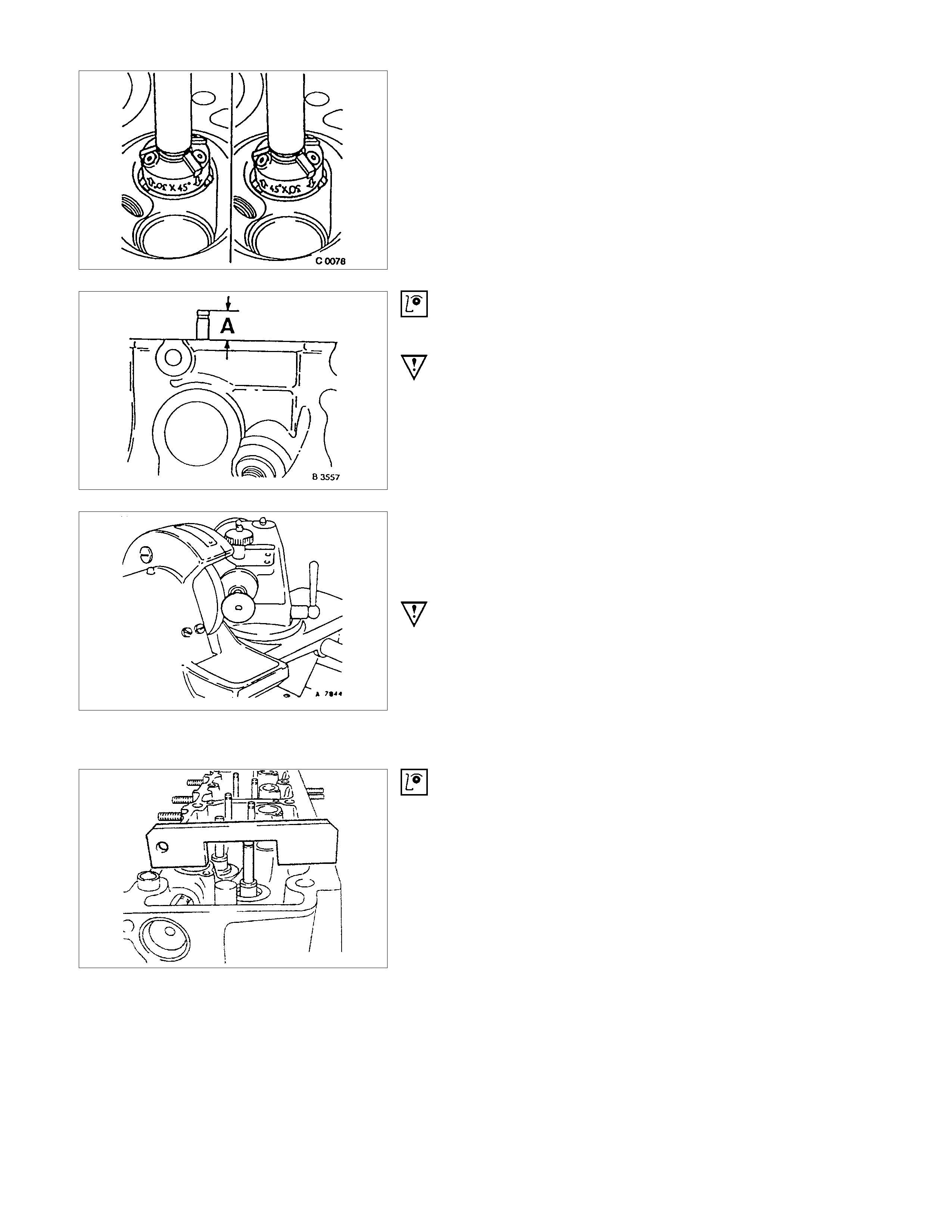
VALVE SEATING, MILL
Place cylinder head on block of wood.
Inlet and exhaust, Guide Drift and Valve Seat Cutter 5-8840-
2593-0.
Valve seat-45°, side face, upper correction-30°, side face
(arrows on cutter).
Valve seat width:
Inlet-1.0 to 1.5 mm/0.04 to 0.06 in.
Exhaust-1.7 to 2.2 mm/0.072 to 0.088 in.
INSPECTION
Valve stem projection-use 5-8840-2596-0.
IMPORTANT:
If dimension “A” is exceeded, use new valves.
Check valve stem projection again. If dimension “A” is
exceeded, replace cylinder head.
CYLINDER HEAD, OVERHAUL
Cylinder head disassembled.
VALVE, GRIND
IMPORTANT:
Ensure that there are no crater-like burns on the valve cone.
Regrinding possible once or twice.
Grinding of valve stem end is not permitted.
Angle at valve head-44°
INSPECTION
Check valve stem projection as shown 5-8840-2596-0
VALVE, LAP IN
Lubricate valve stem, use fine-graining grinding paste.
Lift up valve from seat rhythmically using valve grinding tool
(1)-for distribution of grinding paste.
INSPECTION
Check contact pattern (I) on valve seat and in cylinder head.
CLEAN
Valves, valve guides, cylinder head.
FLYWHEEL
REMOVAL
1. Remove transmission and clutch.
2. Remove flywheel while locking with 5-88400-446-0.
TORQUE - ANGLE METHOD
Flywheel to crankshaft - 65 Nm/6.5 kgf⋅m.+30° to 45°
IMPORTANT:
Use new bolts.
Do not apply grease to the thread.
INSTALLATION
1. Install clutch and transmission.
COMPONENT PARTS
Fly wheel and Ring gear. (Manual Transmission)
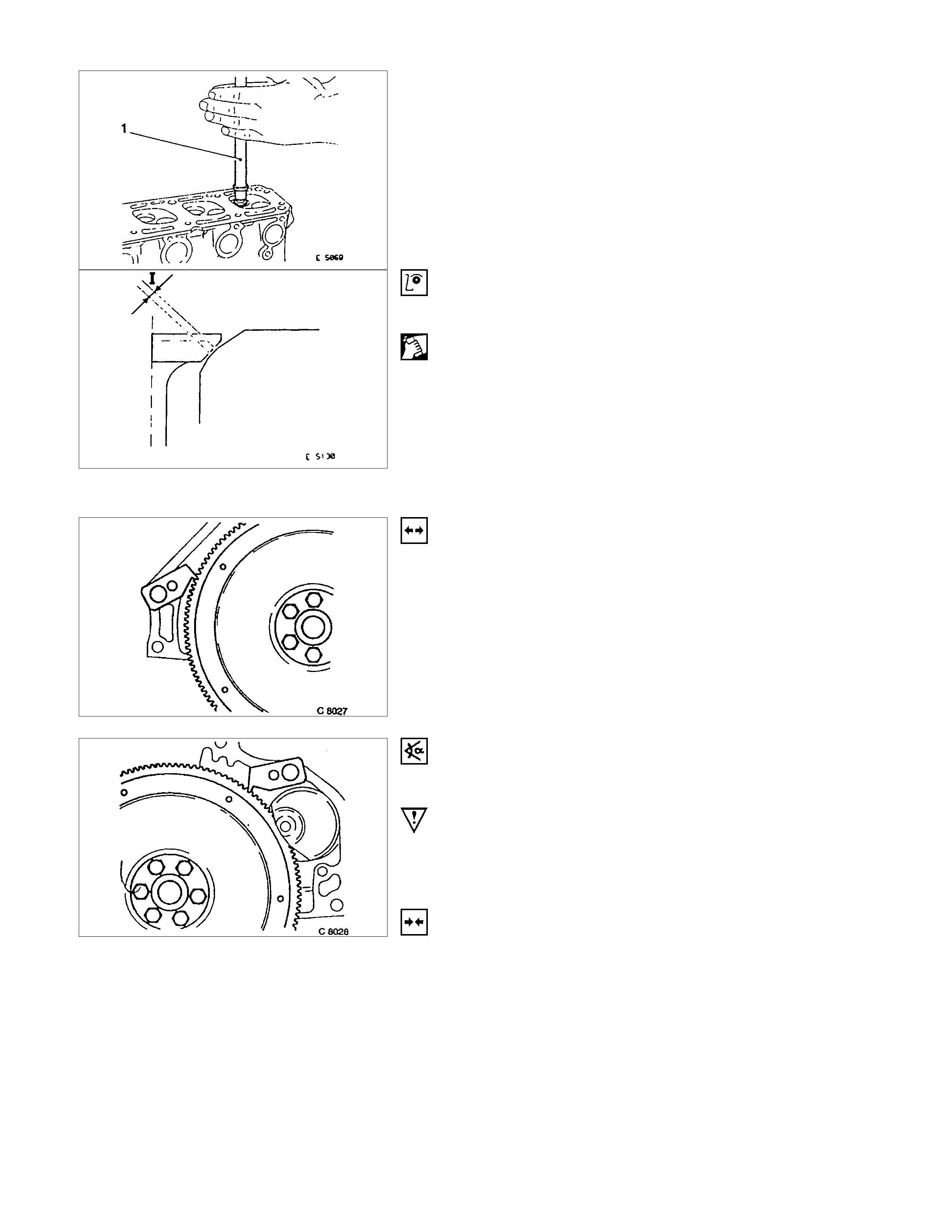
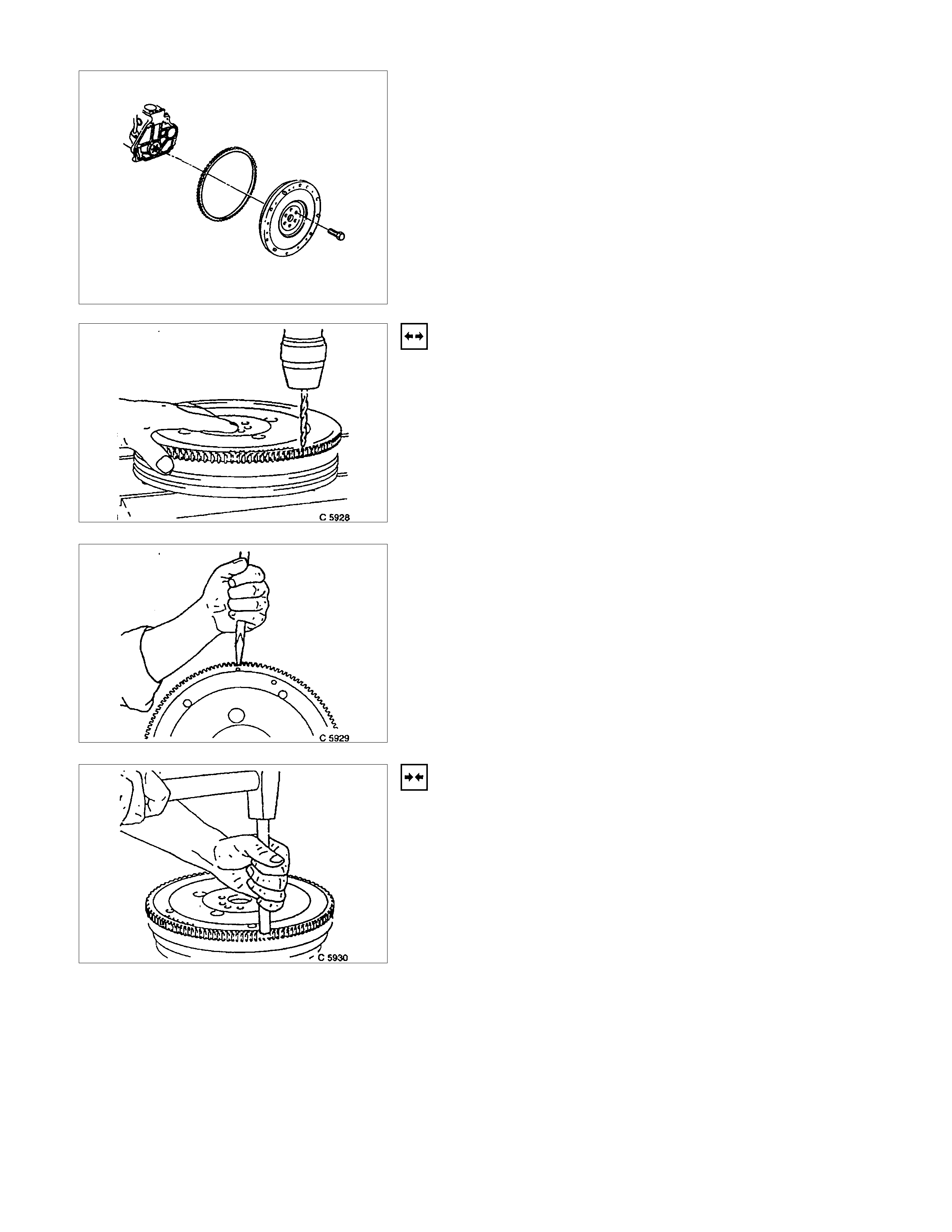
STARTER RING GEAR (MANUAL TRANSMI SSION)
REMOVAL
1. Remove flywheel according to the corresponding
operation.
2. Drill starter ring gear underneath tooth gap approx.
8mm/0.30in. deep with 8mm/0.25in. diameter drill.
3. Separate starter ring gear with chisel on the drilling point.
INSTALLATION
1. Install starter ring gear with inner chamfered edge to
flywheel.
2. Heat starter ring gear evenly to 180°C /356°F to 230°C
/446°F (yellow paint mark)
3. Install flywheel according to the corresponding operation.
INSPECTION
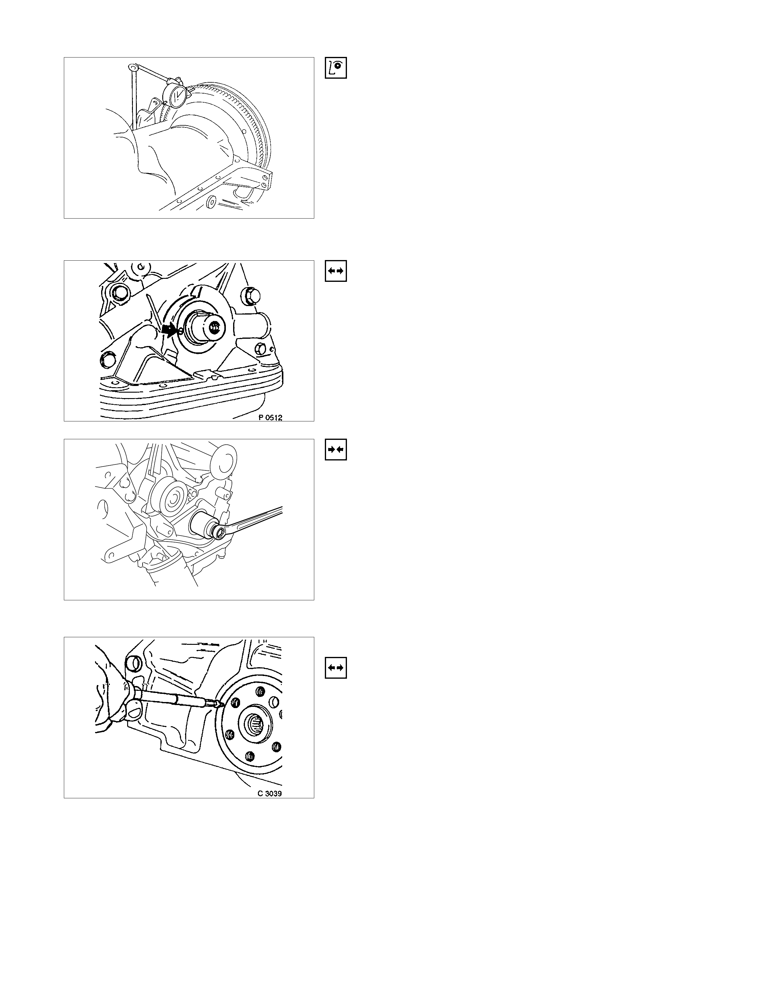
Lateral run-out of starter ring gear - max. 0.5mm/0.02in.
SEAL RING, CRANKSHAFT (OIL PUMP HOUSING)
REMOVAL
1. Remove toothed belt rear cover according to the
corresponding operation.
2. Remove sealing ring by making hole in middle of ring,
turning in self-tapping screw and edging out.
INSTALLATION
1 Install the protective sleeve to the crankshaft.
2. Coat the sealing lip with protective grease.
3. Install the sealing ring.
4. Install the sealing ring using 5-8840-0455-0.
5. Install the rear toothed belt cover and toothed belt
according to the corresponding operations.
6. Replace the sealing ring with a new one.
7. Tighten the belt to the crankshaft.
SEAL RING, CRANKSHAFT REAR
REMOVAL
1. Remove transmission and clutch.
2. Remove flywheel or flex plate according to the
corresponding operations.
3. Make hole in middle of sealing ring, turn in self-tapping
screw and edge out.
INSTALLATION
1. Install protective sleeve.
2. Coat sealing lip with Protective Grease.
3. Install sealing ring using 5-8840-0459-0 and 5-8840-
2597-0.
4. Install flywheel, clutch and transmission.
REASSEMBLY
Reassemble clutch assembly.
DISASSEMBLY
Disassemble clutch assembly to flywheel using 5-8840-2634-0
TORQUE ANGLE-METHOD
Clutch assembly to flywheel-17.6Nm/1.8 kgfm.
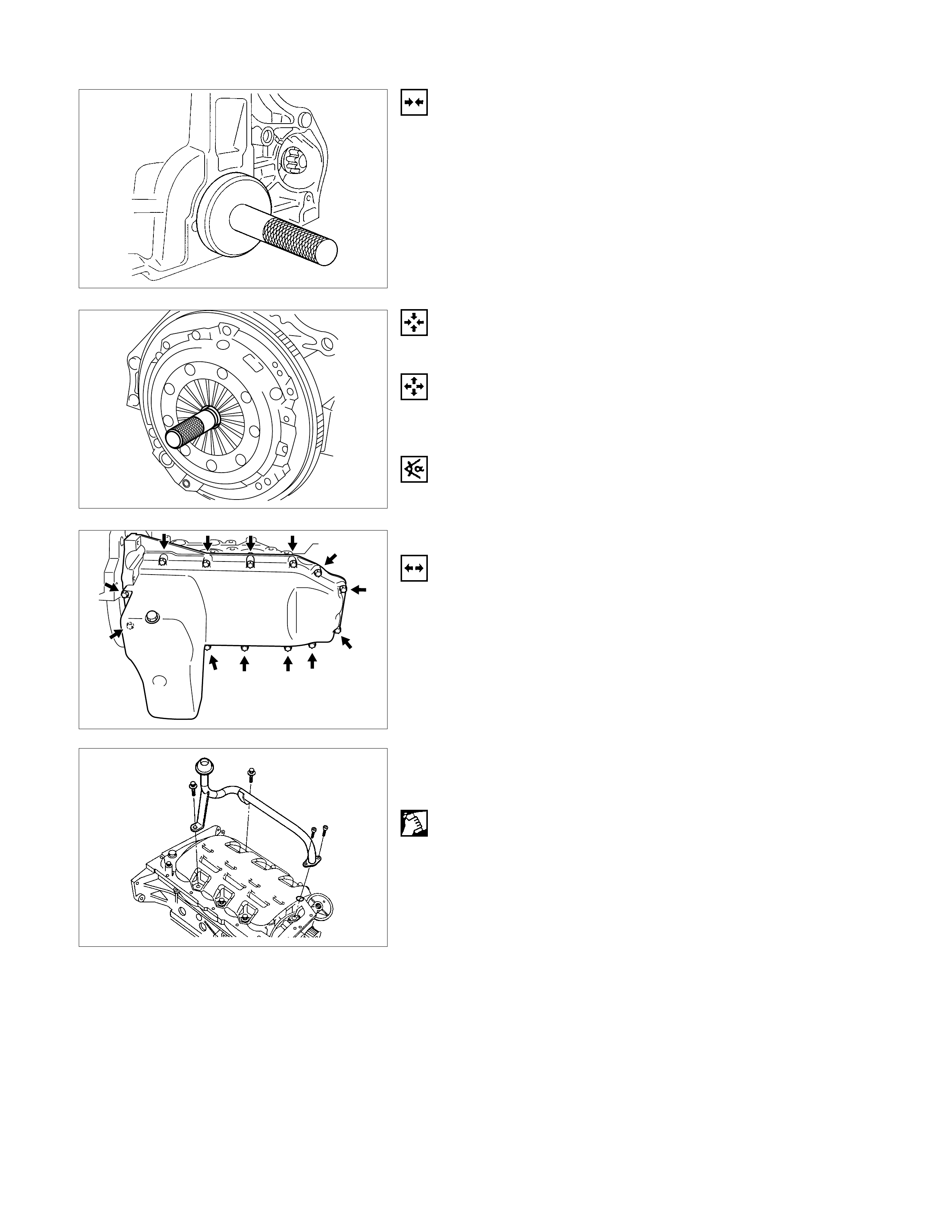
GASKET, OIL PAN
REMOVAL
1. Loosen fixing bolts.
2. Remove oil pan from oil pump and cylinder block.
3. Remove oil intake pipe, oil intake pipe bracket, and oil
baffle plate.
CLEAN
Sealing surfaces.
INSTALLATION
1. Apply a bead of Sealing Compound, TB120TC or
equivalent to joint of oil pump.
2. Install baffle plate, or reuse baffle plate with vulcanised
gasket.
CAUTION:
Baffle plates with vulcanised gasket can be retrofitted without
difficulty - replace baffle plate with gasket.
3. Install oil intake pipe to oil pump and oil intake pipe
bracket to cylinder block.
4. Install oil pan and new gasket to cylinder block and insert
bolts with Locking Compound 15 10 177 (90 167 347).
Maximum assembly time including torque check is 10
min.
TIGHTEN (TORQUE)
Oil intake pipe to oil pump -8N⋅m (0.8 kgf⋅m)
Oil intake pipe bracket to cylinder block - 6 N⋅m (0.6 kgf⋅m)
Oil pan to cylinder block - 8 N⋅m (0.8 kgf⋅m) with vulcanized
gasket - 15 N⋅m (1.5 kgf⋅m)
OPERATI O NS ON CRANKSHAFT
CON-ROD BEARING
REMOVAL
1. Remove oil pan according to the corresponding
operation.
2. Remove con-rod bearing cap and con-rod bearing after
marking both sides.
CLEAN
Con-rod journal, con-rod bearing cap
INSTALLATION
1. Install new bearing shafts lightly coated with engine oil.
2. Install con-rod bearing cap.
TORQUE-ANGLE METHOD
Con-rod bearing cap to con-rod - 35N⋅m (3.5 kgf⋅m) + 45° to
60°
IMPORTANT:
Use new bolts.
3. Install oil pan according to the corresponding operation.
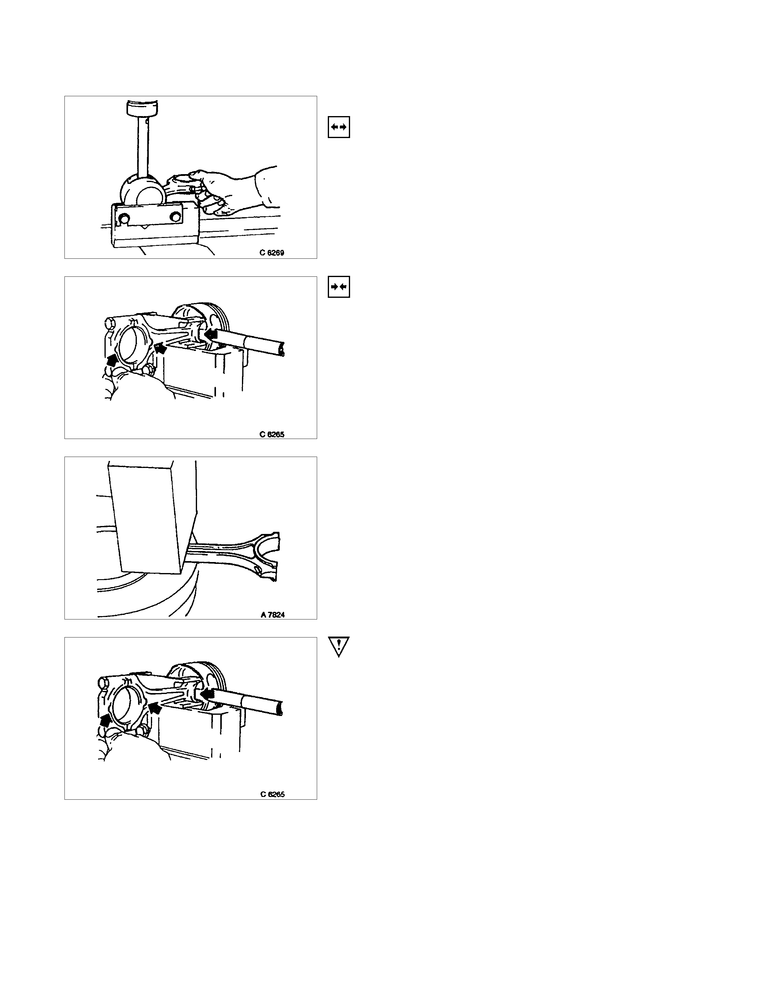
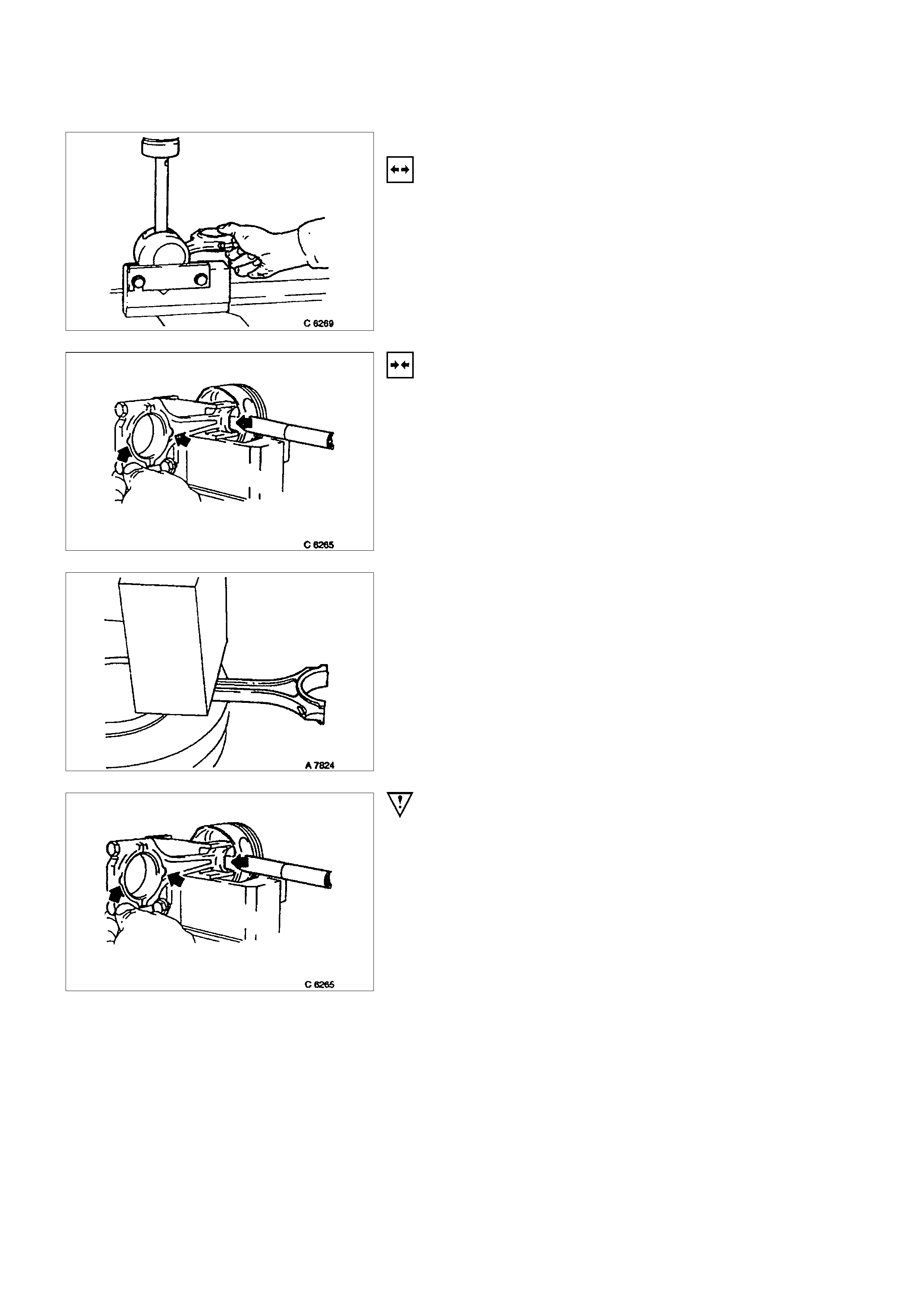
PISTON WI TH CON-ROD
REMOVAL
1. Remove cylinder head and oil pan according to the
corresponding operations.
2. Remove piston with con-rod after marking con-rod
bearing cap.
INSPECTION
Remove and install all parts, if applicable.
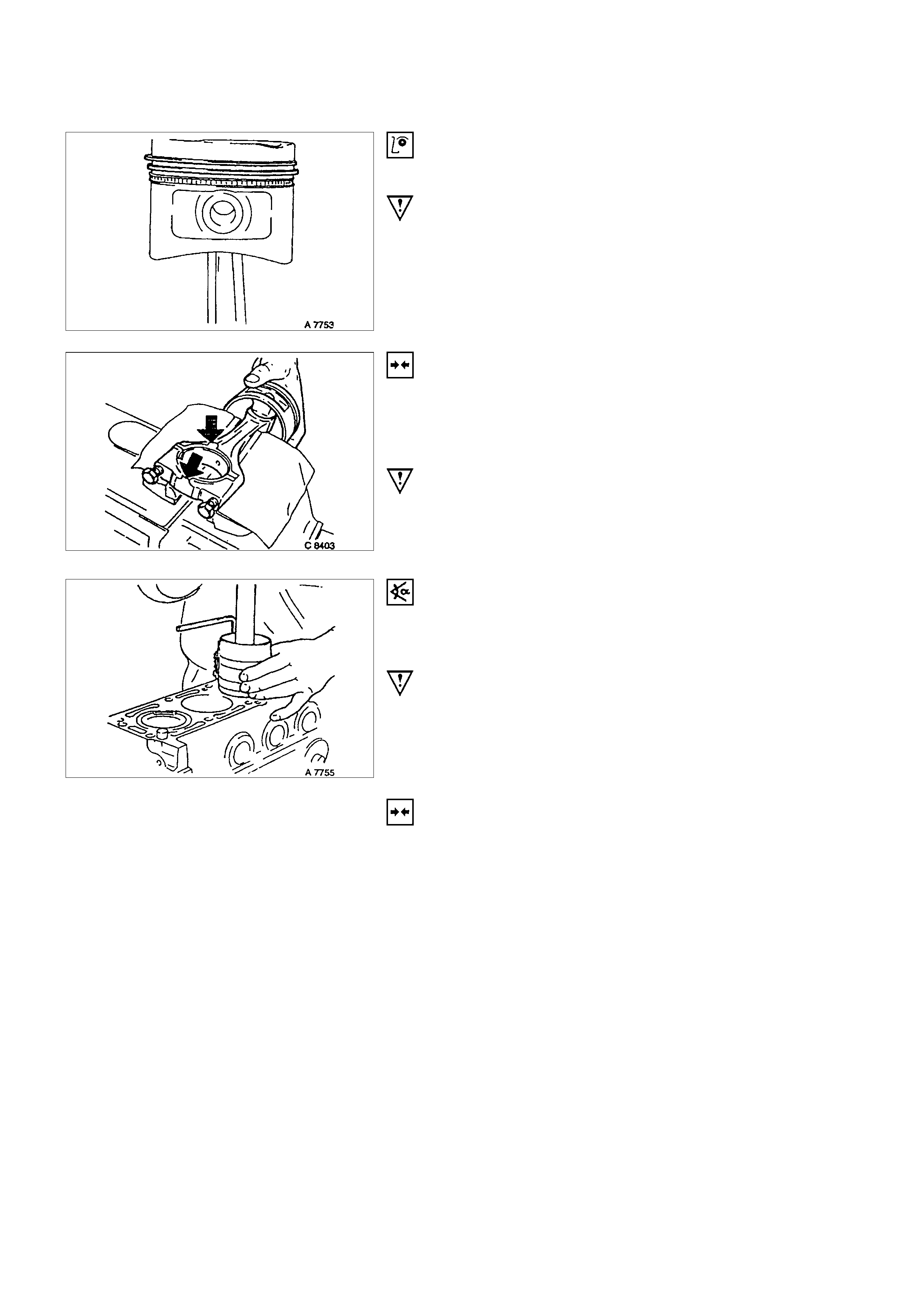
IMPORTANT:
Ring gap offset:
Piston rings - 180°.
Oil scraper rings - 25 to 50 mm/1 to 2 in. from gap of
intermediate ring to the left and to the right.
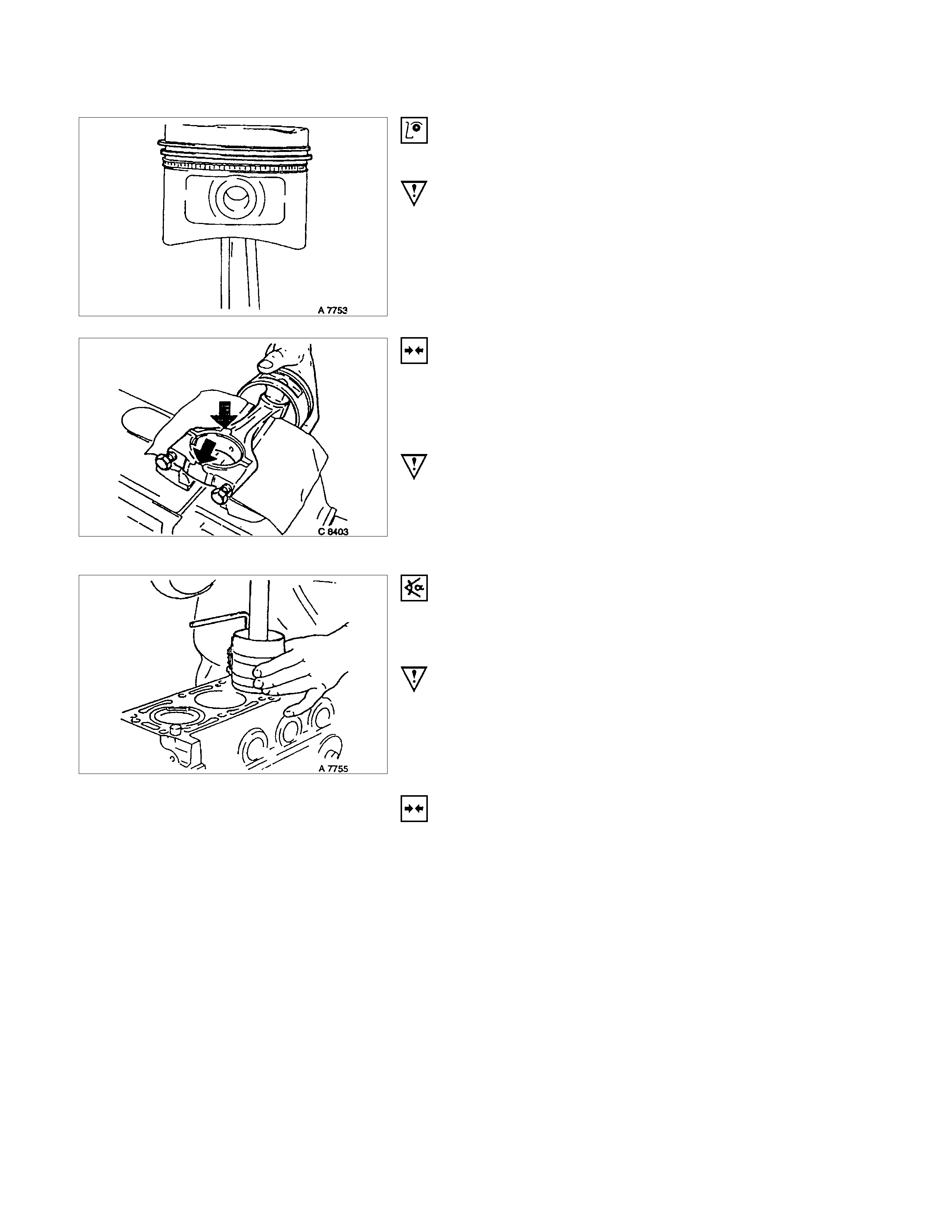
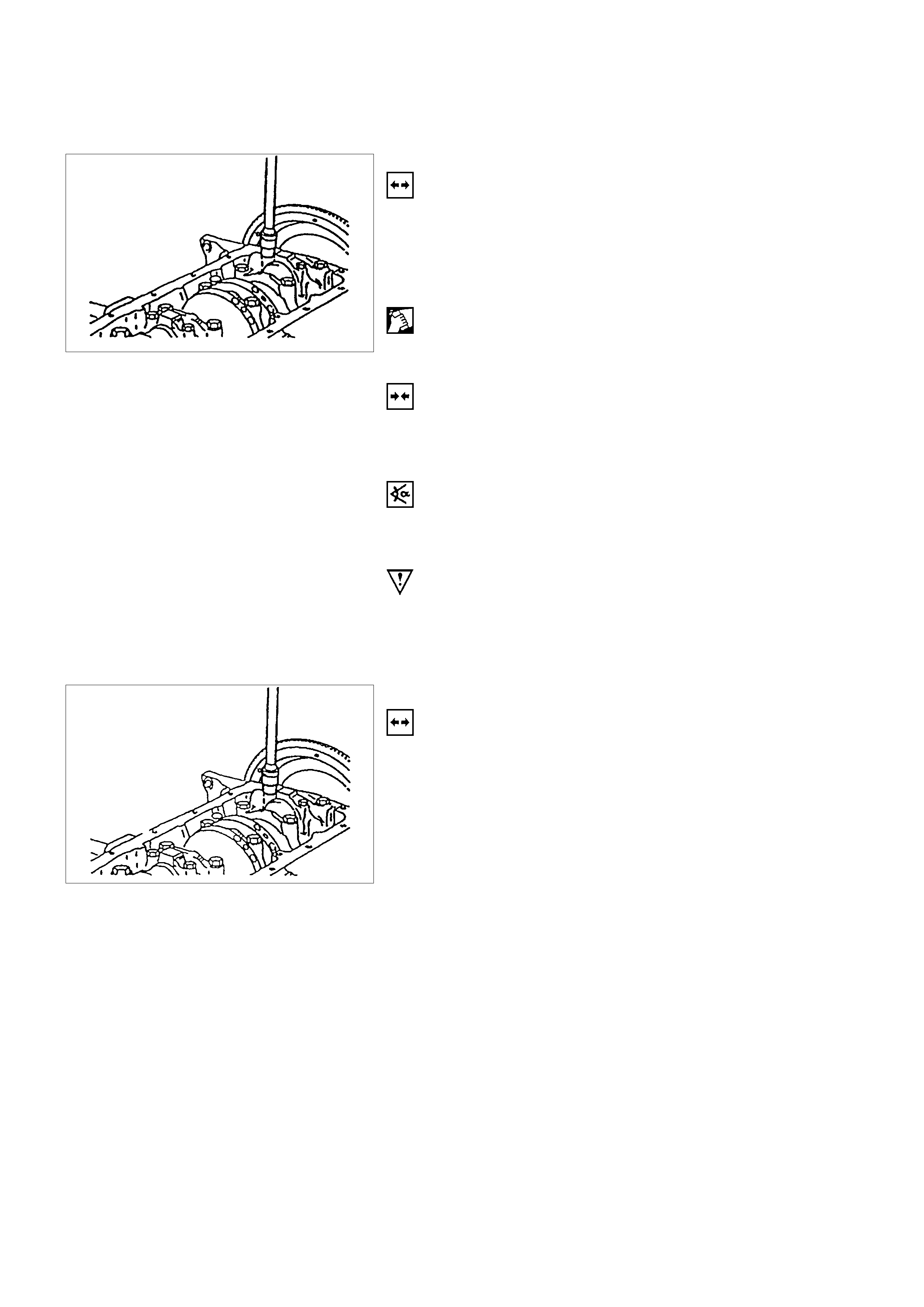
INSTALLATION
1. Install piston with con-rod by inserting with engine oil.
2. Coat piston rings with engine oil and compress with
piston ring compressor.
IMPORTANT:
Installation position:
Arrow / notch on piston head on timing side of engine
Beads on con-rod on clutch side
TORQUE-ANGLE METHOD
Piston to cylinder block.
Con-rod bearing cap to con-rod-35N⋅m (3.5 kgf⋅m) + 45° to 60°
IMPORTANT:
Use new bolts.
INSTALLATION
1. Install oil pan and cylinder head according to the
corresponding operations.
2. Install sealing Gasket or replace if damaged.
3. Install camshaft housing to cylinder head.
4. Install cylinder head according to the corresponding
operation.
CON-ROD
REMOVAL
1. Remove piston with con-rod according to the
corresponding operation.
2. Disassemble con-rod piston assembly by pressing out
piston pin, using 5-8840-0468-0.
INSTALLATION
1. Slide guide drift (5-8840-0468-0) in horizontal position
through piston and con-rod as far as side plate stops.
2. Tighten bolts evenly so that the piston rests flush on the
rear plate.
3. Remove centre piece from guide drift and insert piston
bolts (lubricated) into guide drift.
4. Heat a new con-rod to 280°C in the oil bath.
5. Install the con-rod to the piston and insert the piston pin.
IMPORTANT:
Since the con-rods have no weight balancing studs, re-working
is not possible.
Exchange con-rods in sets only.
Installation position, beads on con-rod point to the flattening on
the piston pin eye.
Firmly seated piston pin cannot be pushed in. Carry out
installation quickly.
OPERATI O NS ON CRANKSHAFT
CON-ROD BEARING
REMOVAL
1. Remove oil pan according to the corresponding
operation.
2. Remove con-rod bearing cap and con-rod bearing after
marking both sides.
CLEAN
Con-rod journal, con-rod bearing cap
INSTALLATION
1. Install new bearing shafts lightly coated with engine oil.
2. Install con-rod bearing cap.
TORQUE-ANGLE METHOD
Con-rod bearing cap to con-rod - 35N⋅m (3.5 kgf⋅m) + 45° to
60°
IMPORTANT:
Use new bolts.
3. Install oil pan according to the corresponding operation.
PISTON WITH CON-ROD
REMOVAL
1. Remove cylinder head and oil pan according to the
corresponding operations.
2. Remove piston with con-rod after marking con-rod
bearing cap.
INSPECTION
Remove and install all parts, if applicable.
IMPORTANT:
Ring gap offset:
Piston rings - 180°.
Oil scraper rings - 25 to 50 mm/1 to 2 in. from gap of
intermediate ring to the left and to the right.
INSTALLATION
1. Install piston with con-rod by inserting with engine oil.
2. Coat piston rings with engine oil and compress with
piston ring compressor.
IMPORTANT:
Installation position:
Arrow / notch on piston head on timing side of engine
Beads on con-rod on clutch side
TORQUE-ANGLE METHOD
Piston to cylinder block.
Con-rod bearing cap to con-rod-35N⋅m (3.5 kgf⋅m) + 45° to 60°
IMPORTANT:
Use new bolts.
INSTALLATION
1. Install oil pan and cylinder head according to the
corresponding operations.
2. Install sealing Gasket or replace if damaged.
3. Install camshaft housing to cylinder head.
4. Install cylinder head according to the corresponding
operation.
CON-ROD
REMOVAL
1. Remove piston with con-rod according to the
corresponding operation.
2. Disassemble con-rod piston assembly by pressing out
piston pin, using 5-8840-0468-0.
INSTALLATION
1. Slide guide drift (5-8840-0468-0) in horizontal position
through piston and con-rod as far as side plate stops.
2. Tighten bolts evenly so that the piston rests flush on the
rear plate.
3. Remove centre piece from guide drift and insert piston
bolts (lubricated) into guide drift.
4. Heat a new con-rod to 280°C in the oil bath.
5. Install the con-rod to the piston and insert the piston pin.
IMPORTANT:
Since the con-rods have no weight balancing studs, re-working
is not possible.
Exchange con-rods in sets only.
Installation position, beads on con-rod point to the flattening on
the piston pin eye.
Firmly seated piston pin cannot be pushed in. Carry out
installation quickly.
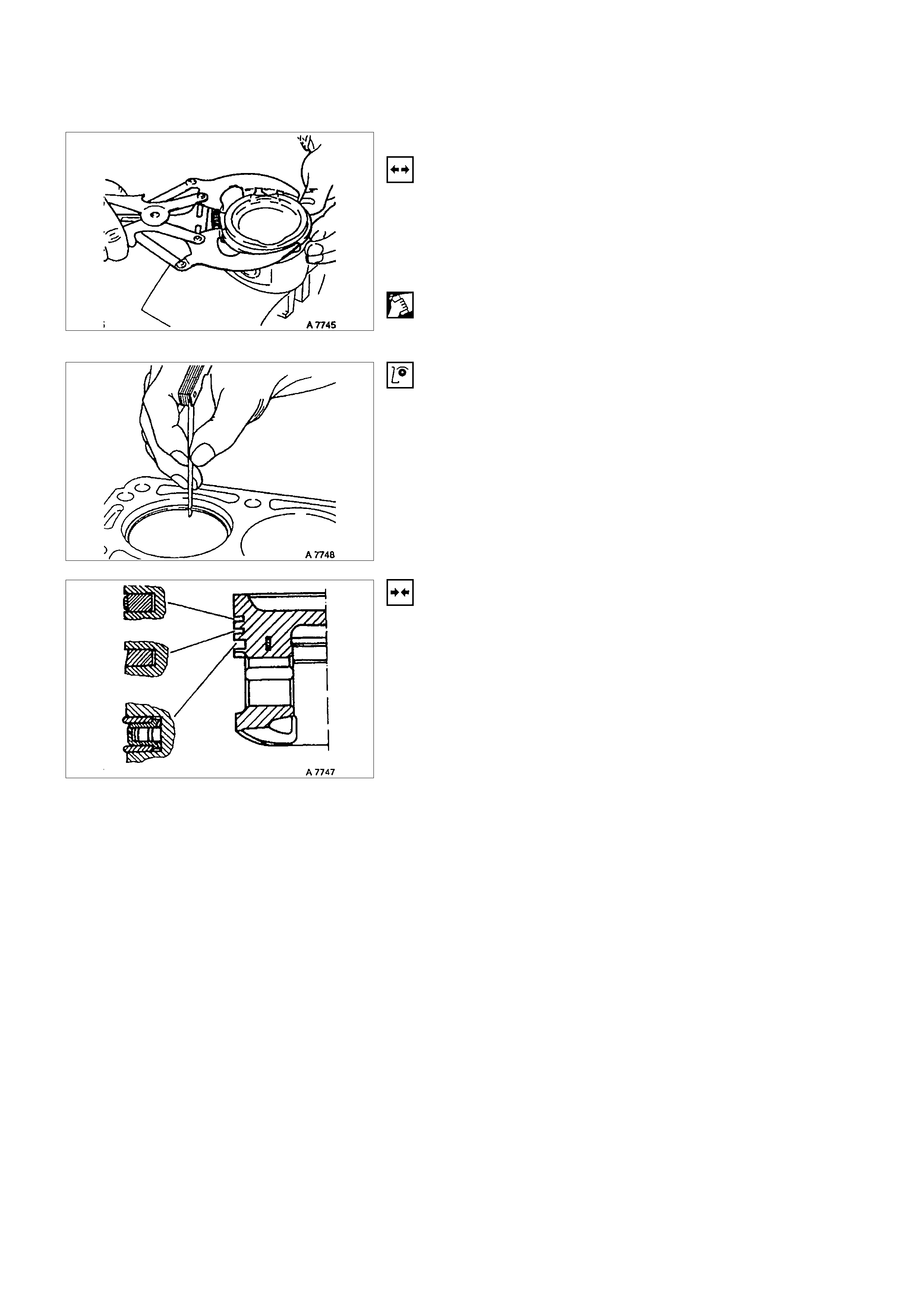
PISTON RINGS
REMOVAL
1. Remove piston with con-rod according to the
corresponding operation.
2. Remove piston rings using commercially available ring
installer or piston ring clamp pliers.
CLEAN
Piston ring grooves - ground piece of old piston ring
INSPECTION
Piston ring gap
For piston ring sizes, permissible piston ring gaps - see
"Technical Data"
INSTALLATION
1. Install oil scraper ring.
2. Offset ring gaps of steel band rings each 25 to 50 mm/1
to 2in. to the left or right of the intermediate ring gap.
3. Install piston rings.
4. Offset ring gaps by approx. 180°.
5. Install second piston ring with identification mark "TOP"
facing upwards.
6. Install piston with con-rod according to the corresponding
operation.
OPERATIONS ON REMOVED ENGINE
CRANKSHAFT
REMOVAL
1. Mount the engine on an engine overhaul stand with
appropriate adapters.
2. Remove the aggregates, flywheel/drive disc, oil pan, and
oil pump according to the corresponding operation.
3. Mark the con-rod bearing cover.
4. Remove the crankshaft bearing cover.
5. Remove the crankshaft from cylinder block.
INSPECTION
Remove and install all parts if necessary
Crankshaft pulse pickup sensor rotor inspection and repair.
Inspect the crankshaft pulse pickup sensor rotor for excessive
wear and damage.
Replace the crankshaft pulse pickup rotor if the inspection
results exceed wear and damage limits.
INSTALLATION
1. Install the crankshaft pulse pickup sensor.
Torque: 13N
m (1.3 kgf
m)
2. Install new bearing shells into the cylinder block and
bearing cover.
3. Coat the bearing shafts with engine oil.
For oversizes-see “Technical Data”
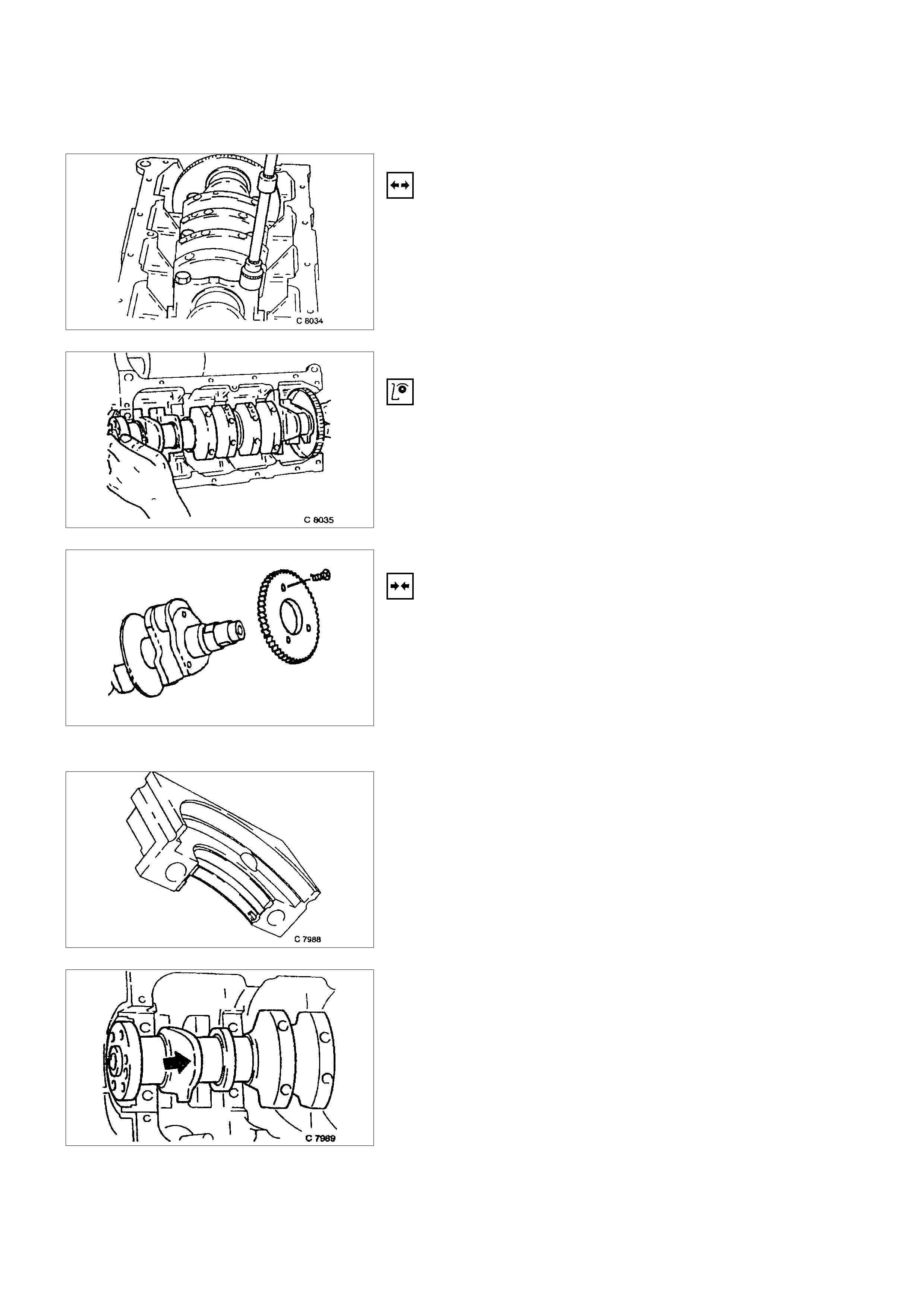
4. Install a new crankshaft into the cylinder block.
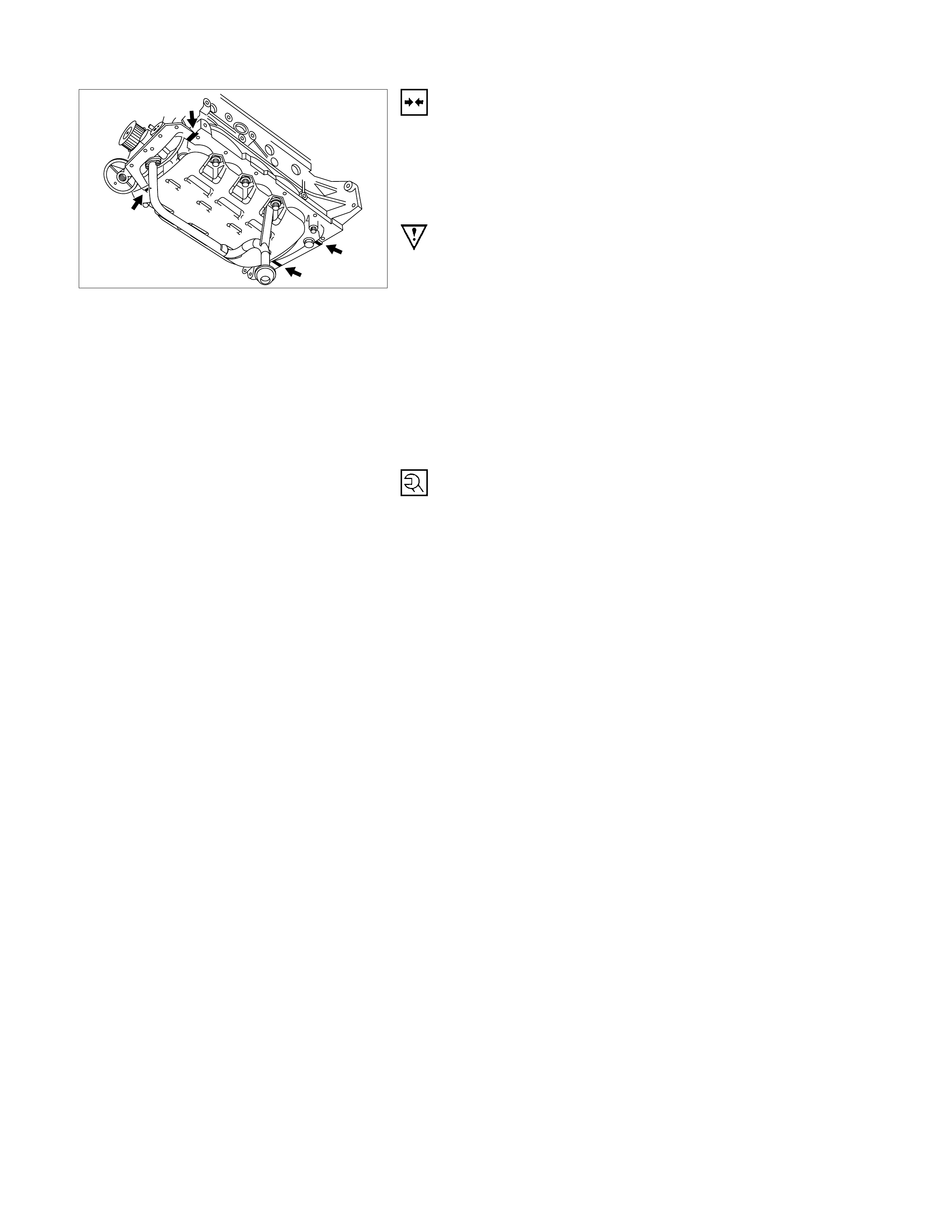
NOTE
The sealing of the crankshaft can be corrected with light
blows with a rubber hammer on the crank arm (arrowed).
5. Apply a bead of sealant (TB-1207C or equivalent) in the
grooves of both bearing shells
IMPORTANT:
After installation of bearing cover, press in sealing compound
again from above, until compound emerges at the joints.
TORQUE - ANGLE METHOD
Bearing cover to cylinder block - 50 N⋅m (5.1 kgf⋅m) +40° to
50°
Con-rod bearing cover to con-rod - 35 N⋅m (3.5 kgf⋅m) +45° to
60°
Use new bolts.
6. Install oil pump, oil pan, rear crankshaft sealing,
flywheel/drive plate, and aggregates according to the
corresponding operations.
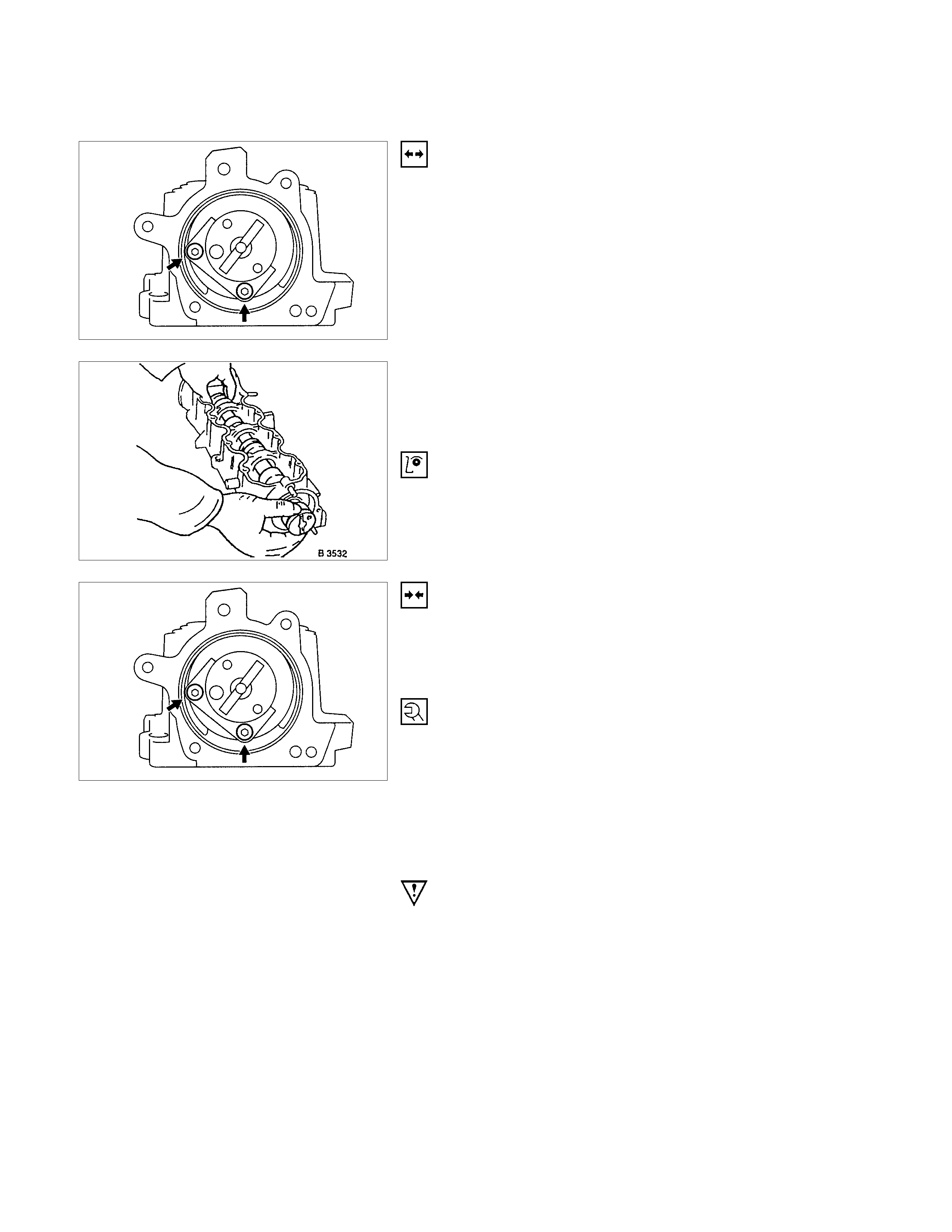
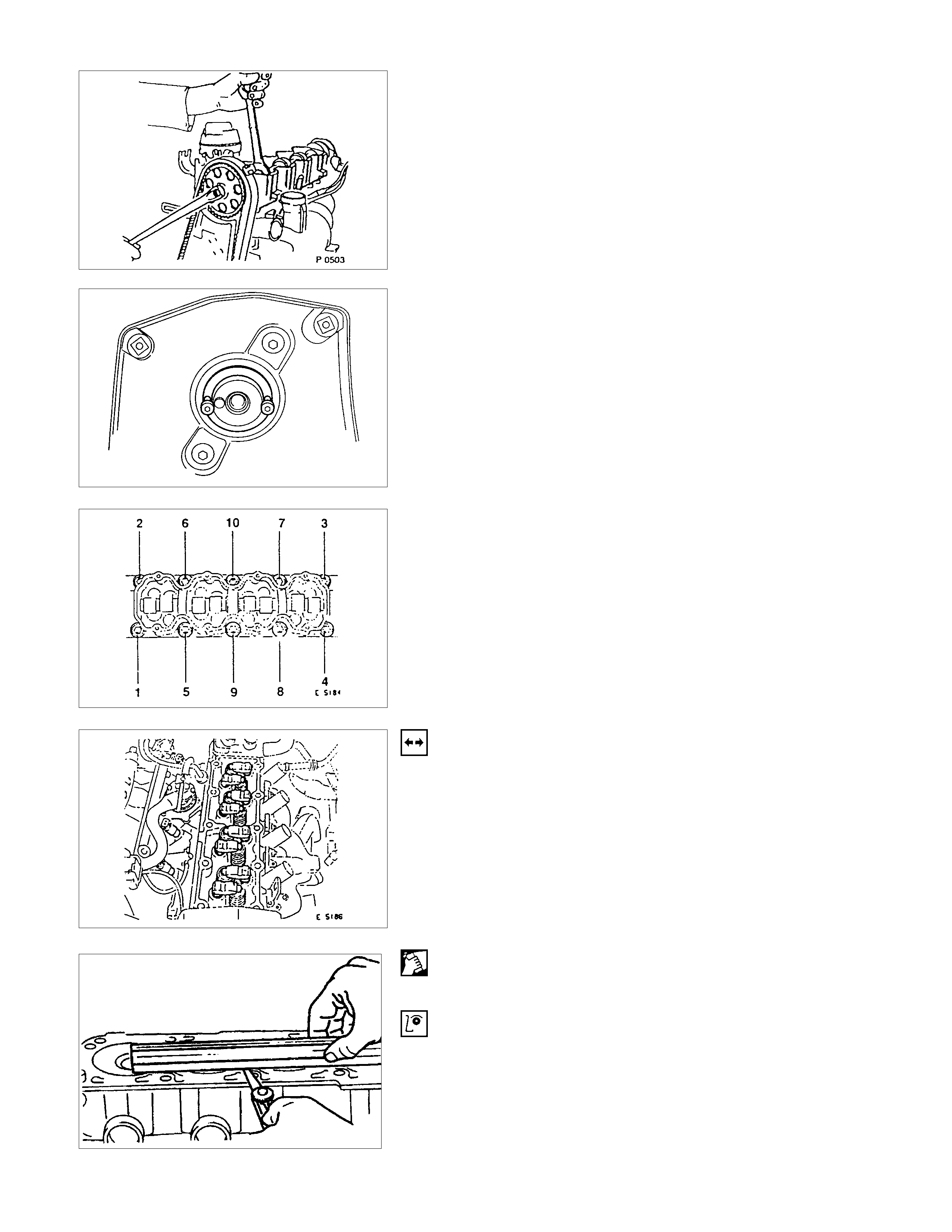
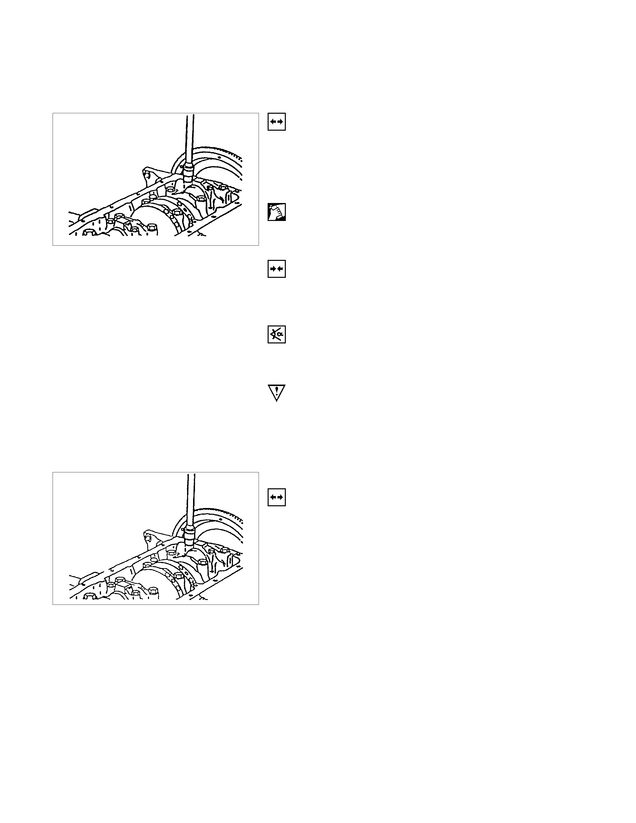
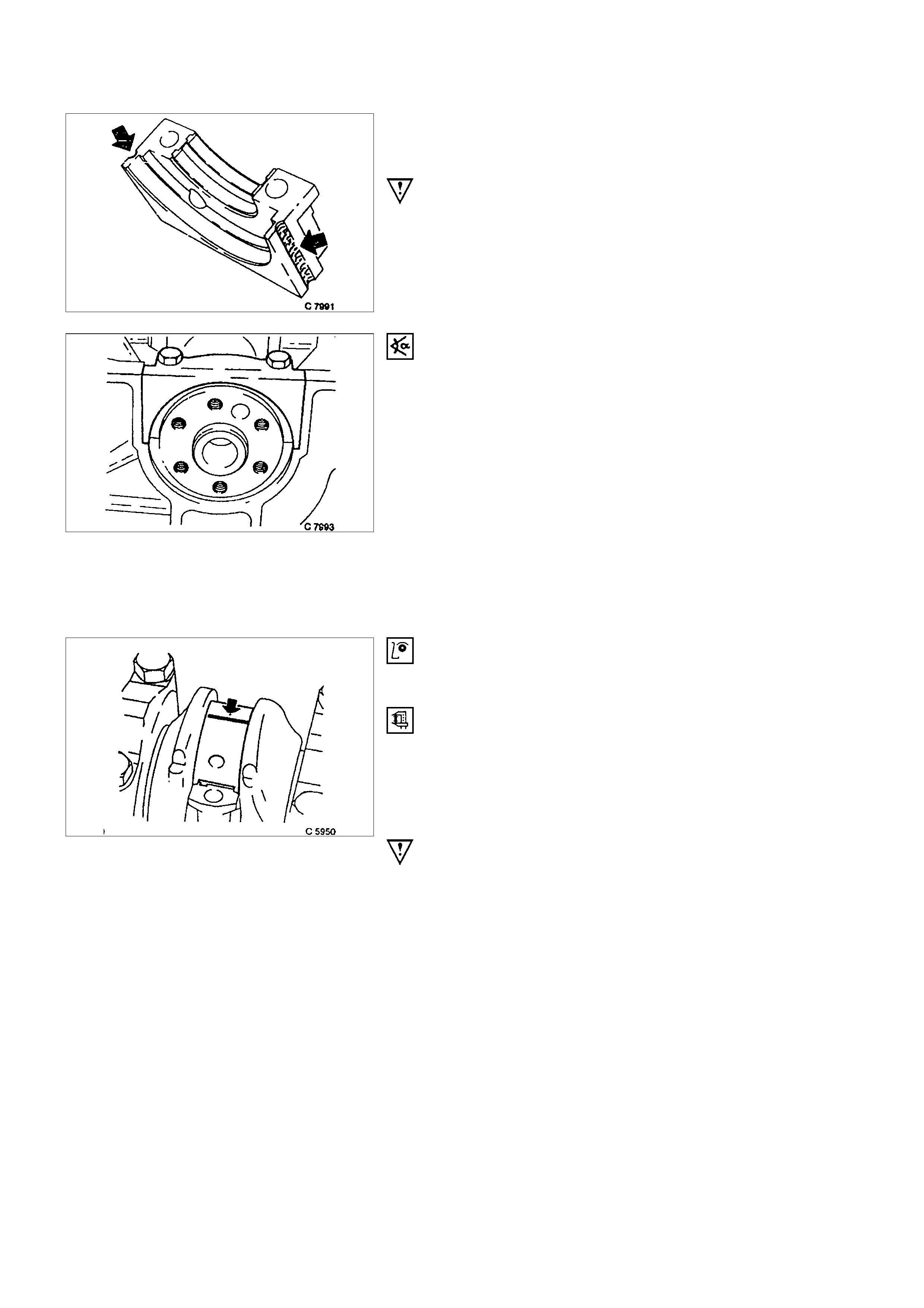
INSPECTION
Bearing play - bearing cover removed
MEASURE
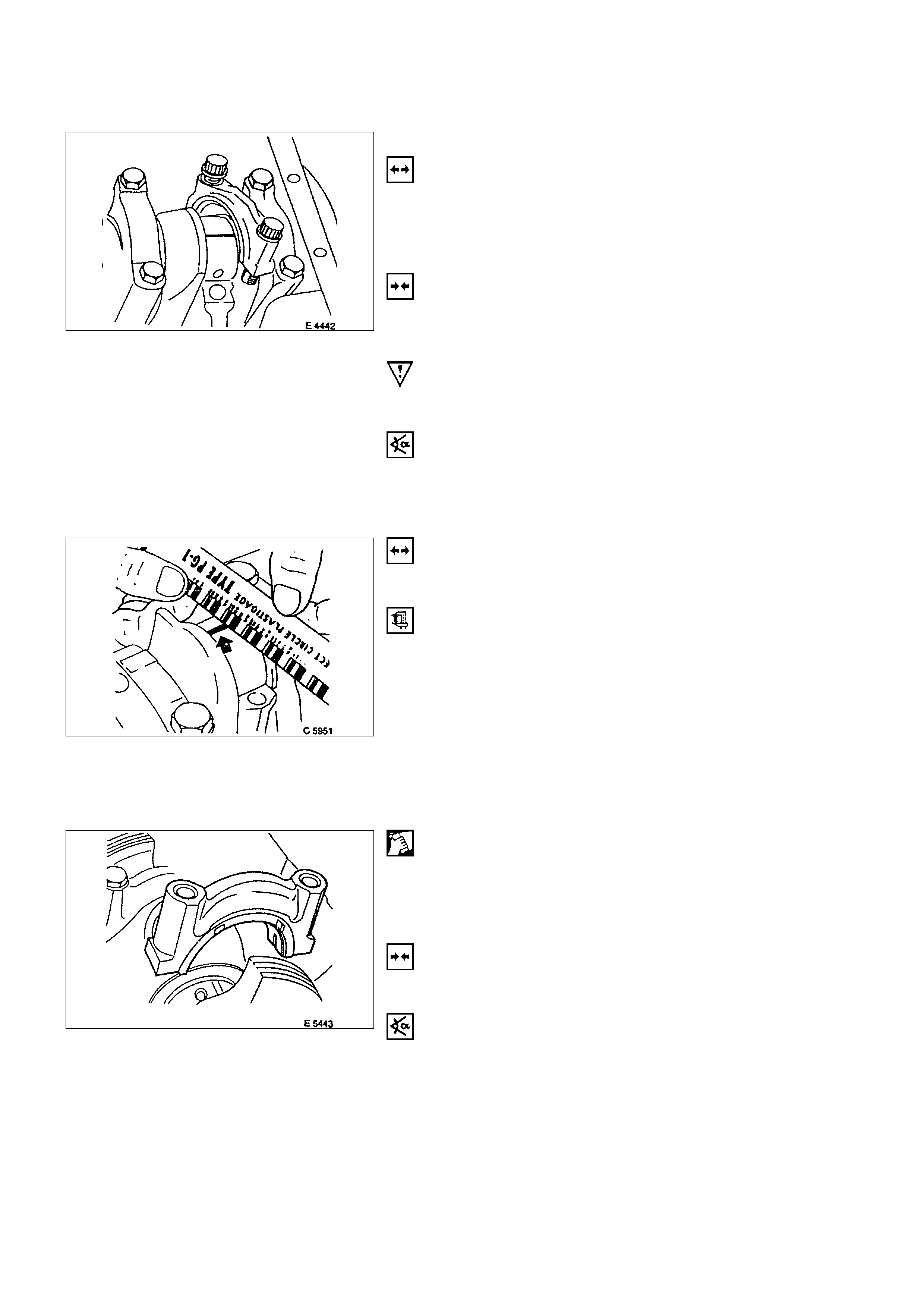
With "Plastigage" (ductile plastic threads)
Cut threads to length of bearing width and lay axially between
crankshaft journal and bearing shell (arrowed).
Install bearing cover with correct torque.
IMPORTANT:
Grease crankshaft journal and lubricate bearing shell slightly
so that the thread does not tear when the bearing cover is
moved
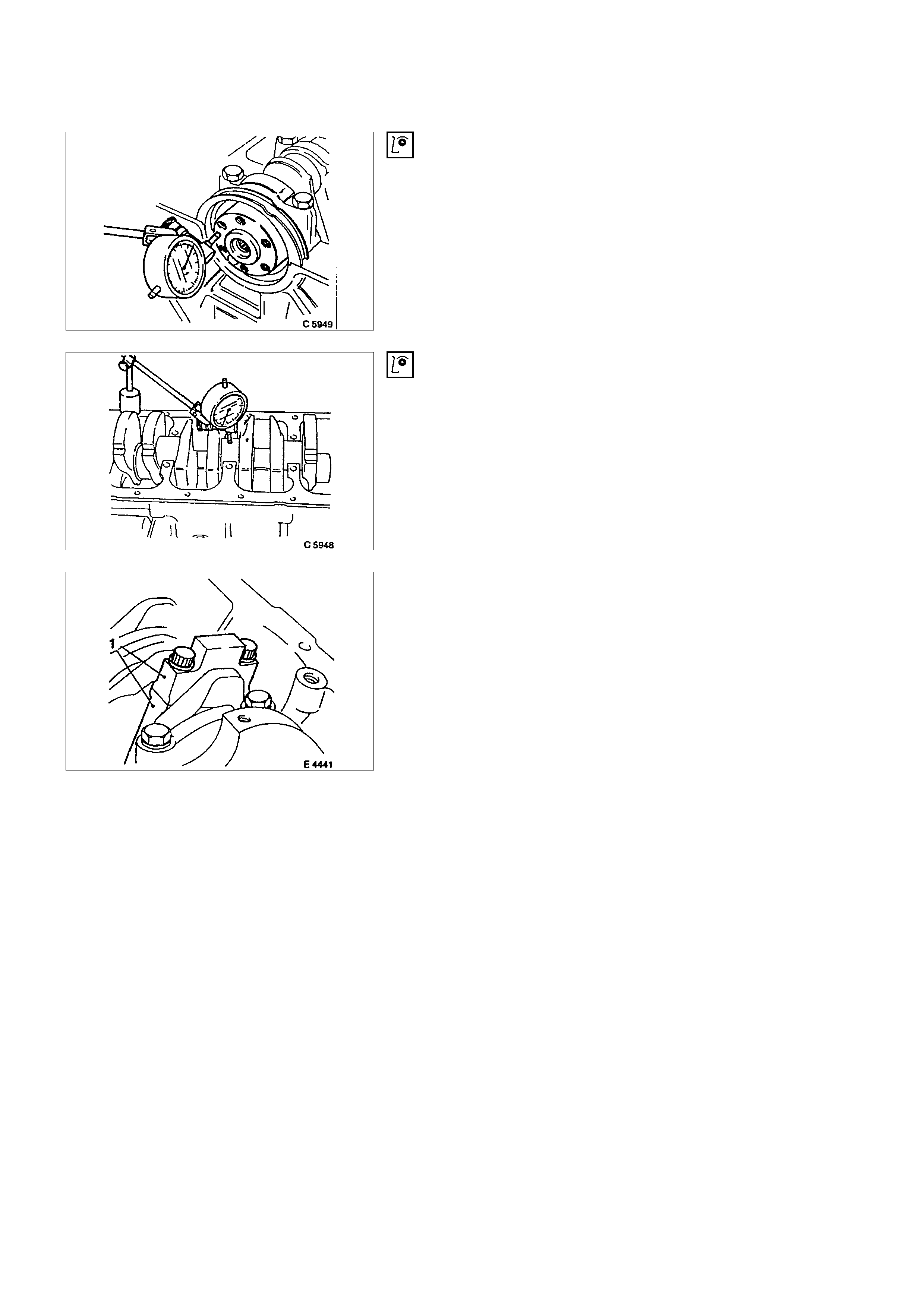
INSPECTION
End play when bearing shells are installed.
Front end contact surfaces of flywheel/flexible plate.
Permissible end play - see "Technical Data "
INSPECTION
Out-of-round (run-out)-middle bearing shell removed when
mounting on front and rear bearing.
Permissible out-of-round - see "Technical Data"
BEARING FREE PLAY MEASUREMENT
Two methods for measuring bearing free play are described -
1. Plastigage method and 2. micrometer and gauge method.
The two procedures are suitable for measuring both con-rod
and main bearing free play.
For both methods ensure con-rod and main bearing caps are
identified (1) prior to removal as they are machine matched.
1. PLASTIGAGE METHOD
REMOVAL
1. Remove bearing cap and shell.
2. Lightly coat journals and bearings with engine oil to
prevent Plastigage from tearing when cap is removed.
INSTALLATION
1. Lay a length of Plastigage across width of crank pin and
fit bearing cap and shell using old bolts at this stage.
IMPORTANT:
Do not allow crankshaft to rotate.
TORQUE – ANGLE METHOD
Main bearing cap bolt - 60 N⋅m (6.1 kgf⋅m) +40° + to 50°.
Con-rod bearing cap bolts - 35 N⋅m (3.6 kgf⋅m) +45°.
REMOVAL
1. Remove bearing cap and shell.
MEASURE
Width of Plastigage -use scale supplied with Plastigage.
If con-rod bearing clearance exceeds 0.031mm/0.001in or
main journal bearing clearance exceeds 0.04mm/0.02in. -
check crankshaft journal diameters - see corresponding
operation.
Replace bearing if crankshaft is within specification - see
"Technical Data"
CLEAN
Plastigage from journals.
Lightly coat journals and bearings with engine oil.
INSTALLATION
Install bearing cap and shell using new bolts.
TORQUE – ANGLE METHOD
Main bearing cap bolt - 60 N⋅m (6.1 kgf⋅m) +40° to 50°.
Con-rod bearing cap bolts - 35 N⋅m (3.9 kgf⋅m) +45°.
2. MICROMETER AND GAUGE METHOD.
Crankshaft removed.
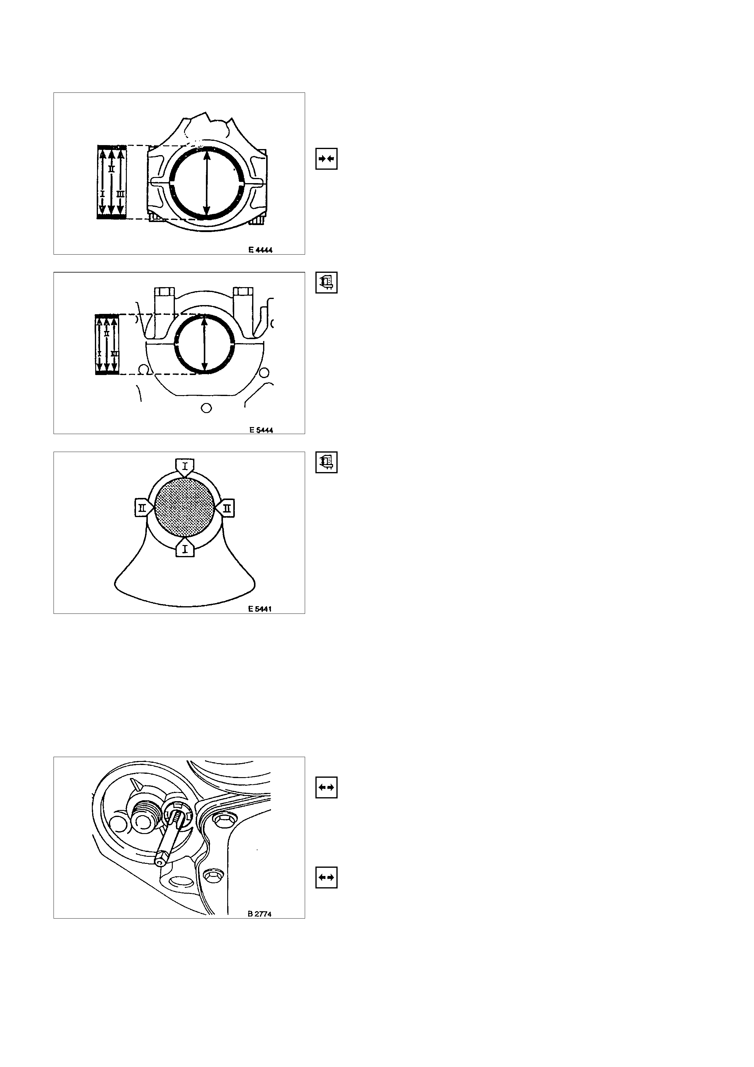
INSTALLATION
1. Install caps and bearing shells to con-rods and cylinder
block.
MEASURE
Con-rod and main bearing diameters at three points I, II, III
(arrowed).
Divide the sum of the three measurements by three to obtain a
mean diameter.
The top illustration shows con-rod measuring points.
The second illustration shows main bearing measuring points.
MEASURE
Crankshaft main and con-rod bearing journals at points II and
I. Divide the sum of both measurements to obtain a mean
diameter.
Crankshaft must be replaced if mean diameter of main or con-
rod journals is below specified limit - see "Technical Data".
If crankshaft is serviceable subtract crankshaft mean journal
diameters from corresponding shell bearing mean diameters to
determine bearing clearance.
Permissible main bearing clearance - 0.015 to 0.04mm/0.0006
to 0.002in.
Permissible con-rod bearing clearance - 0.006 to
0.031mm/0.002 to 0.001in.
BYPASS VALVE
REMOVAL
1. Remove oil filter.
2. Remove bypass valve by cutting thread in locking disc
with M 10 tap (3rd stage), turning in M 10 bolt and taking
out bypass valve from seating.
INSTALLATION
1. Install bypass valve using drift (diameter approx.
15mm/0.6in.).
OIL FILTER
REMOVAL
1. Remove oil filter using commercially available tool.
INSTALLATION
1. Install oil filter by hand and oil seal ring.
2. Fill up engine oil while preventing overflow.
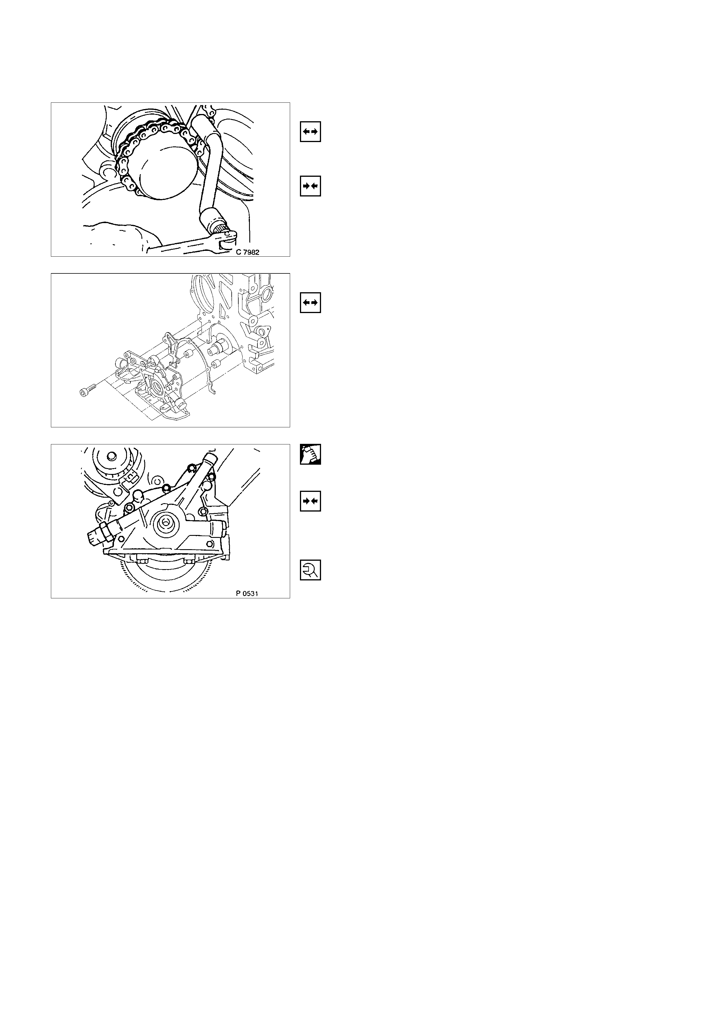
OIL PUMP
REMOVAL
1. Remove rear toothed belt cover, and oil pan according to
the corresponding operations.
2. Remove oil filter, wiring plug from oil pressure switch, oil
pump from cylinder block, and oil pressure switch from
oil pump.
CLEAN
Sealing surfaces
INSTALLATION
1. Install oil pressure switch to oil pump, oil pump to cylinde
r
block, oil pan, wiring plug, oil filter and toothed belt cover.
TIGHTEN (TORQUE)
Oil pressure switch to oil pump - 30 N⋅m (3.2 kgf⋅m)
Oil pump to cylinder block - 8 to 12 N⋅m (0.6 kgf⋅m)
Oil intake pipe to oil pump - 8 N⋅m (0.8 kgf⋅m)
Intake pipe bracket to cylinder block - 8 N⋅m (0.8 kgf⋅m)
*Insert bolts with Loctite (Refer to
General Description Recommended Liquid Gasket)
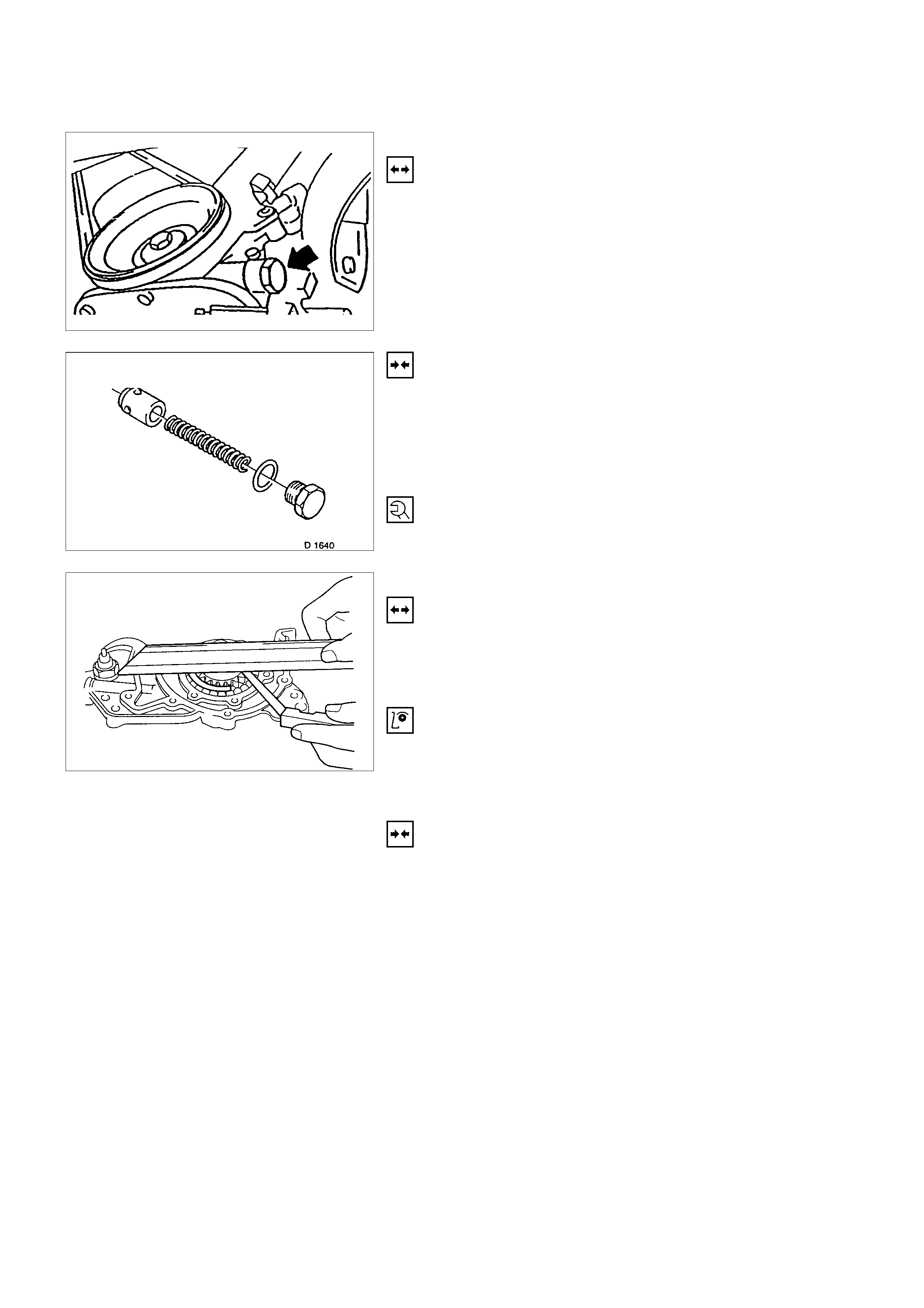
OIL PUMP SAFETY VALVE
REMOVAL
1. Remove closure plug.
2. Remove seal ring.
3. Remove spring.
4. Remove piston.
INSTALLATION
1. Install piston (observe installation position).
2. Install spring.
3. Install seal ring.
4. Install closure plug.
TIGHTEN (TORQUE)
Closure plug - 30 N⋅m (3.0 kgf⋅m)
OIL PUMP (OVERHAUL)
REMOVAL
1. Remove oil pump according to the corresponding
operation.
2. Remove oil cover and pressure control valve.
INSPECT
Clearance between gear pair and housing upper edge - see
“Technical Data”.
Check housing, cover and pressure control valve.
INSTALLATION
1. Install pump cover with Sealing Compound 15 03 166 (90
094 714).
2. Install oil pump safety valve according to the
corresponding operation.
3. Install oil pump according to the corresponding operation.
OPERATI ONS ON OIL CIRCUI T
CYLINDER HEAD SAFETY VALVE
REMOVAL
1. Remove cylinder head according to the corresponding
operation.
2. Make hole in core plugs with pointed drift, turn in self
tapping screw and edge out.
IMPORTANT:
Cover oil duct in cylinder head with piece of cloth.
3. Pull out valve retainer, using commercially available tool.
4. Remove ball and spring.
5. Cut three threads in the ball seating with M 10 tap (3rd
stage).
6. Coat tap with grease.
7. Remove ball seating from cy linder head with
commercially available tool.
Do not damage cylinder head.
INSTALLATION
1. Install new pressure valve into cylinder head - with
suitable pipe until stop.
2. Install core hole plugs into cylinder head - with suitable
pipe to end of chamfer.
OPERATIONS ON COOLING SYSTEM
CAUTION:
Before working with the cooling system, be sure to confirm that
the temperature of the engine is cooled down.
Failure to observe this may cause burn.
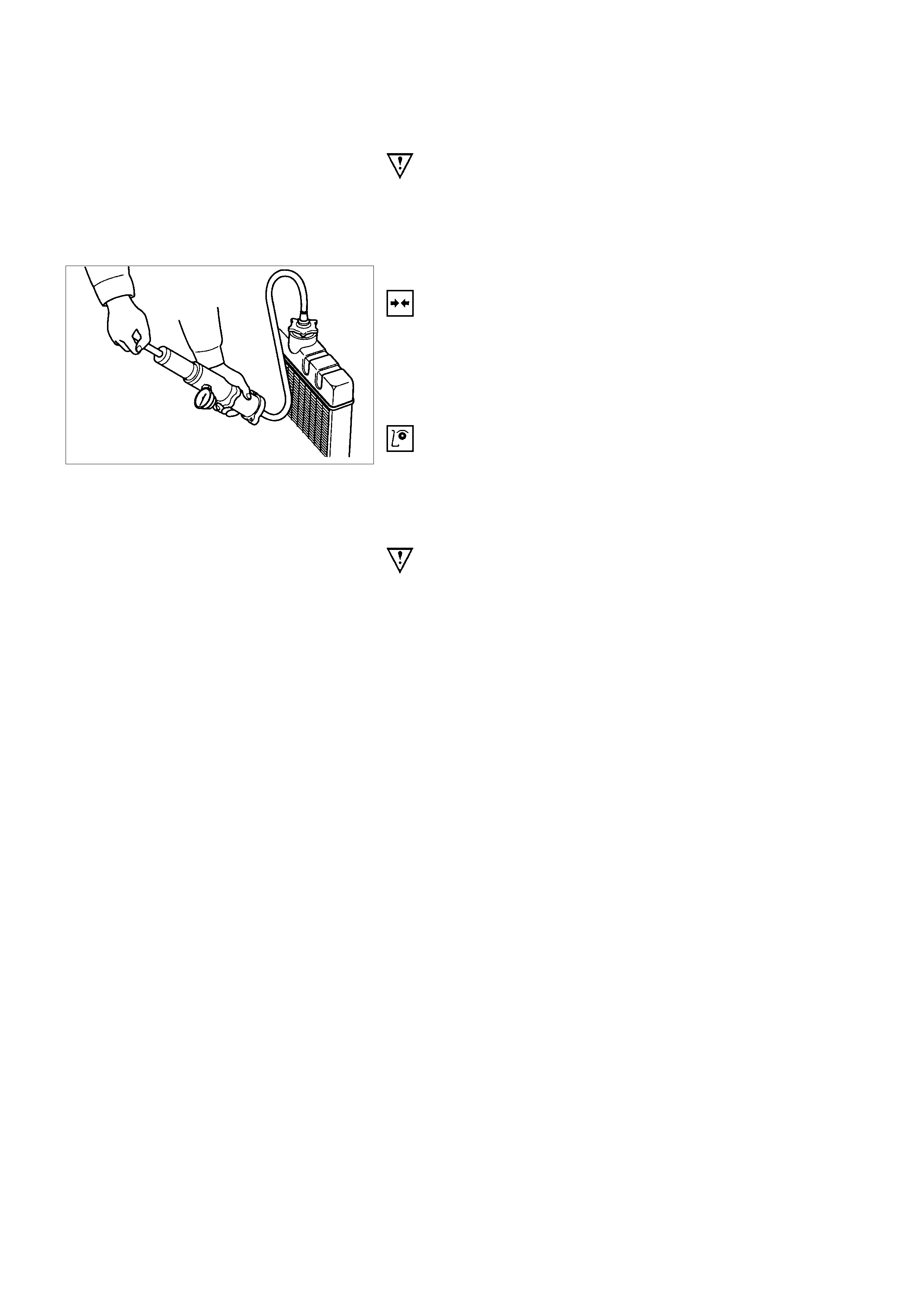
COOLING SYSTEM, CHECK FOR LEAKS
INSTALLATION
1. Install commercially available coolant checking
instrument onto compensation tank (Refer to
Section 6B; Engine cooling).
2. Check coolant level.
INSPECTION
Use 5-8840-0277-0 tester & 5-8840-2603-0 adaptor.
COOLING SYSTEM, FILL UP AND BLEED
IMPORTANT:
Radiator and heater core are made from aluminium.
To avoid corrosion, use only anti-freeze with corrosion
protection.
REPLACE CO OLANT
1. Confirm the engine is cold enough.
2. Open the radiator cap, pour coolant to the filler neck level
and close the cap.
3. Pour coolant into the reservoir until MAX line is reached.
4. Start the engine, run 2 ∼ 3 minutes at idling speed and
switch off the engine.
5. Refill coolant if the coolant level is lowered.

IMPORTANT:
Do not loosen or open the radiator cap when coolant is hot.
Doing so may cause hot water or steam to splash out, resulting
in burn. When opening the radiator cap, be sure to confirm the
coolant is cold. Cover a thick cloth over the cap and loosen it
slowly to reduce pressure, then open the cap.
6. Close the radiator cap firmly and run the engine at
approx. 2000 rpm. In addition, set the heater temperature
adjuster to the max position to circulate coolant in the
heater conduit system.
7. Confirm that the temperature gauge reads half or more
of full scale and that the thermostat is activated.
Then continue idling 5 minutes more and switch off the
engine, and allow it to cool.
8. After the engine cools down, check the coolant level and
refill it if necessary. When the level is lowered extremely,
check the coolant conduit system and reservoir hose for
leak.
9. Pour coolant into the reservoir to MAX level.
REFILL COOLANT
IMPORTANT:
After closing the cooling system, let engine run warm until
thermostat opens (coolant approx. 92°C/197.6F)
INSPECTION
Coolant level
Allow engine to cool. If necessary, refill coolant.
Check that cooling system self-bleeds during engine warming-
up phase.
IGNITION TIMING, CHECK
NO ADJUSTMENT
ENGINE EXTERNAL PARTS
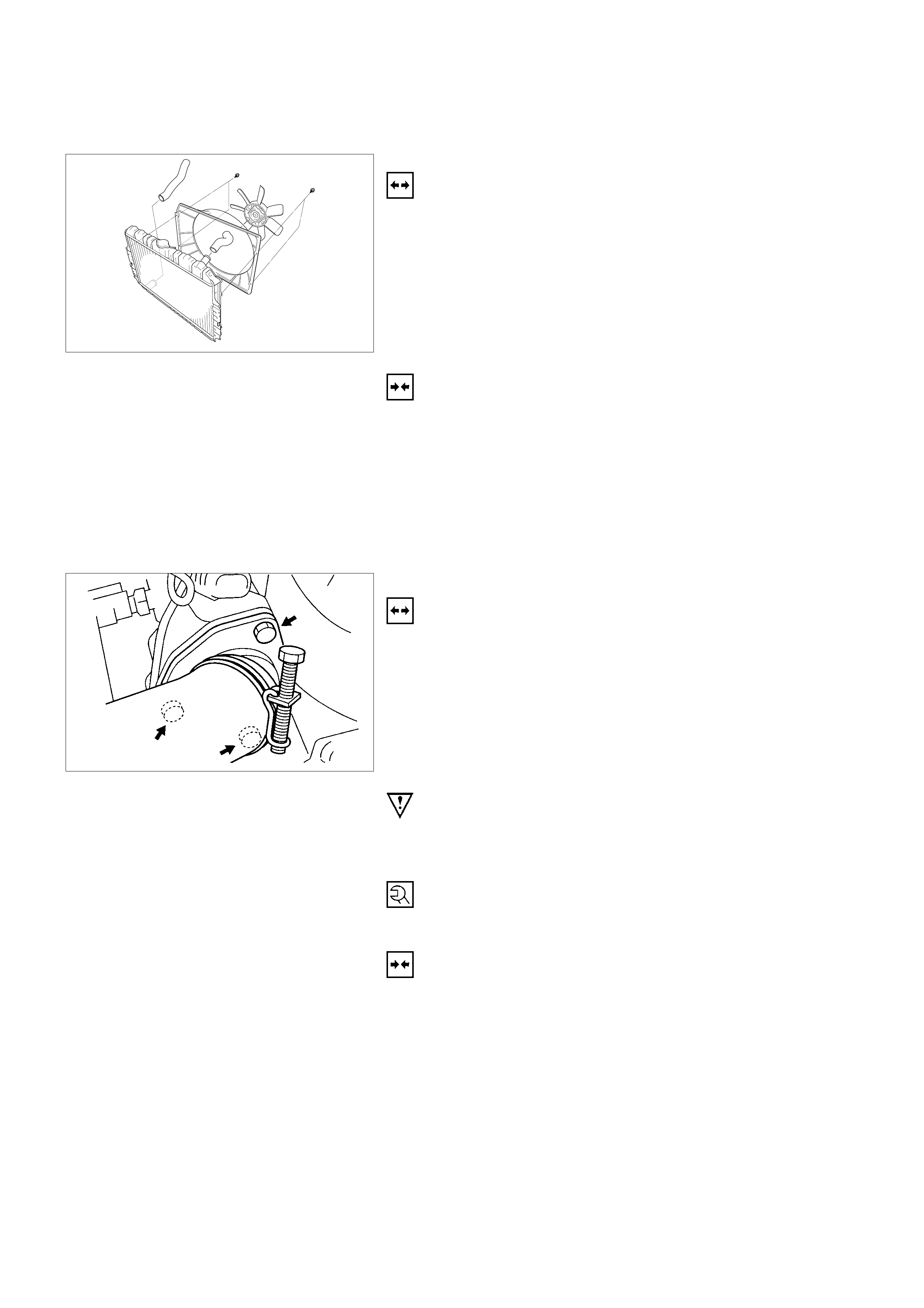
RADIATOR
REMOVAL
1. Remove the upper hose and lower hose.
2. Remove all V-belts.
3. Remove the cooling fan.
4. Remove the fan guide.
5. Remove the radiator.
INSTALLATION
1. Install the radiator.
2. Install the fan guide.
3. Install the cooling fan.
4. Install all V-belts.
5. Install the lower and upper hose.
THERMOSTAT
REMOVAL
1. Remove water outlet nozzles with thermostat from
thermostat housing.
2. Remove coolant hose and collect coolant.
IMPORTANT:
Remove and Install thermostat only together with water outlet
nozzles.
TIGHTEN (TORQUE)
Water outlet nozzles to thermostat housing - 8 N⋅m (0.8 kgf⋅m)
INSTALLATION
1. Install coolant hose.
2. Fill cooling system and bleed according to the
corresponding operation.
WATER PUMP
REMOVAL
1. Remove lower hose band from pipe band and collect
coolant.
2. Remove front toothed belt cover according to the
corresponding operation.
3. Remove water pump from cylinder block after releasing
tension on toothed belt.
CLEAN
Sealing surfaces
COATING SEALING SURFACES
WITH SILICONE GREASE
INSTALLATION
1. Install water pump to cylinder block with new rubber O-
ring.
2. Apply tension to toothed belt according to the
corresponding operation.
3. Install coolant hoses.
4. Fill cooling system and bleed according to the
corresponding operation.
ALTERNATOR
REMOVAL
1. Remove ground cable from battery.
2. Remove cable connection from alternator and V-belt.
3. Remove alternator from retaining strap and lower
fastening.
INSTALLATION
1. Install alternator by tightening firmly by hand.
2. Install V-belt and apply tension according to the
corresponding operation.
3. Install cable connections to alternator.
4. Install ground cable to battery.
STARTER
REMOVAL
1. Remove cable connections from starter.
2. Remove upper bolt of transmission side.
3. Remove lower bolt of engine side.
TIGHTEN (TORQUE)
Starter to cylinder block:
Engine side - 45 N⋅m (4.6 kgf⋅m)
Transmission side - 75 N⋅m (7.6 kgf⋅m)
Starter support to cylinder block - 25 N⋅m (2.5 kgf⋅m)
Re-connect cables.
V-BELT TENSION OF ALTERNATOR
MEASURE
Measure V-belt tension of alternator.
Permitted values for new V-belt are approx. 311-489N (31-50
kgf).
Note:
V-belt to deflection as loaded with 10kg : 8-12mm.
ADJUST
Adjust V-belt tension by loosening clamping bracket and lower
alternator bracket and moving alternator.
TIGHTEN (TORQUE)
Clamping bracket to alternator - 25 N⋅m (2.6 kgf⋅m)
Lower alternator bracket – 25 N⋅m (2.6 kgf⋅m)
V-BELT TENSION OF POWER STEERING PUMP
MEASURE
Measure V-belt tension of power steering pump. Permitted
values for new belt are approx. 578-712N (59-73 kgf) and 534-
667N (54-68 kgf) for used belt.
Note:
V-belt to deflection as loaded with 10kg : 8-12mm.
ADJUST
Adjust V-belt tension by loosening clamping bolt, lower pump
bracket, and adjusting nuts and moving steering pump.
TIGHTEN (TORQUE)
Adjusting nuts - 18 N⋅m (1.8 kgf⋅m)
Clamping bolt - 25 N⋅m (2.6 kgf⋅m)
Lower pump bracket - 26 N⋅m (2.6 kgf⋅m)
FUEL INJECTION SYSTEM
MAP SENSOR
REMOVAL
1. Disconnect the battery cable.
2. Disconnect the electrical connector from the sensor.
3. Remove the mounting bolts securing the sensor to the
manifold.
4. Remove the sensor from the intake manifold.
INSTALLATION
1. Push MAP sensor into the manifold.
2. Install the mounting bolts and tighten them.
3. Connect electrical connector.
4. Connect the battery cable.
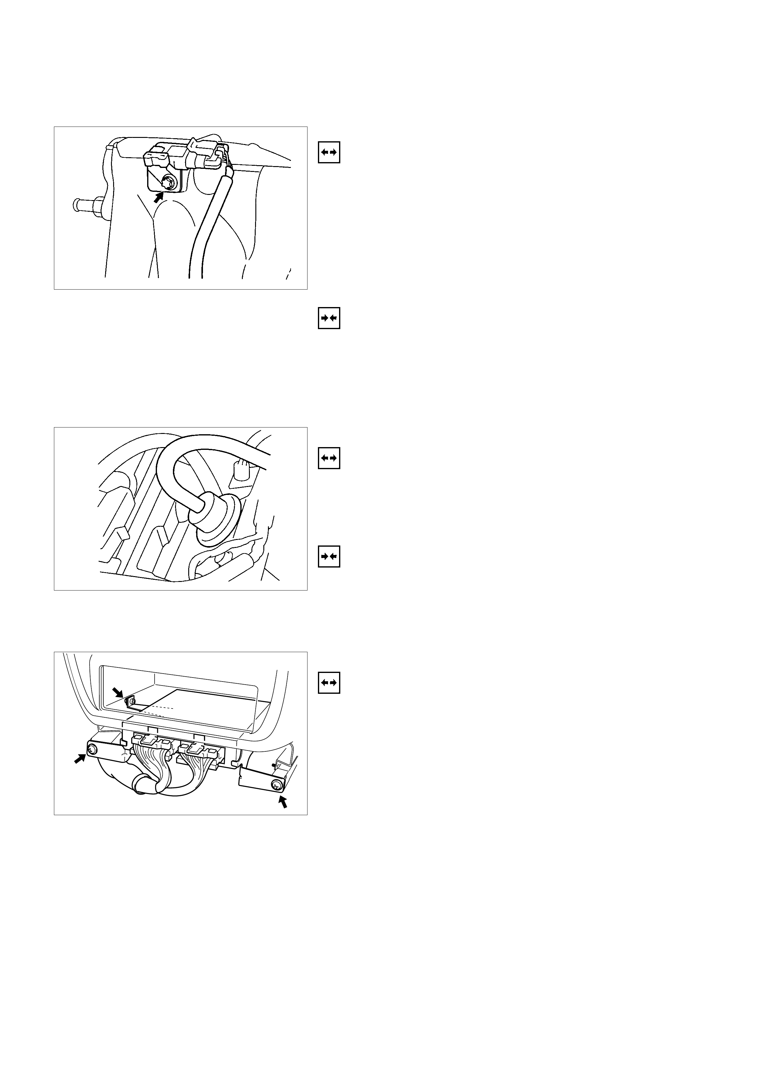
PRESSURE REGULATOR
REMOVAL
1. Remove vacuum hose.
2. Remove fuel hoses.
3. Remove pressure regulator.
INSTALLATION
1. Install pressure regulator.
2. Install fuel hoses.
3. Install vacuum hoses.
ECM (ENGINE CONTROL MODULE)
REMOVAL
1. Remove the center console assembly.
2. Remove the ECM cover.
3. Remove 3 screws for the bracket.
4. Pull ECM out.
5. Disconnect the connectors.
INSTALLATION
1. Connect the connectors.
2. Install ECM to the proper position.
3. Tighten 4 screws to the bracket.
4. Install the ECM cover.
5. Install the center console assembly.
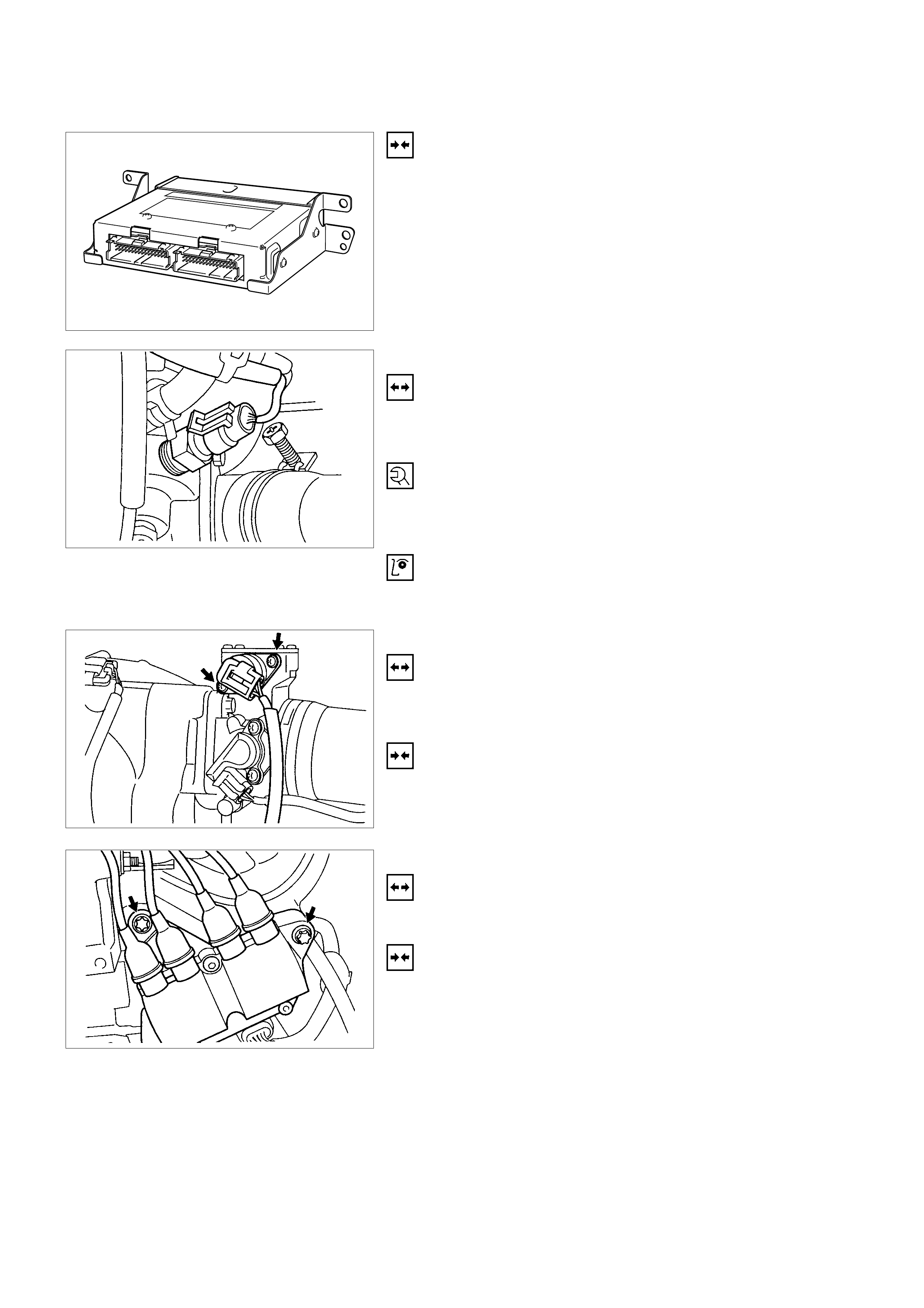
ECT
REMOVAL
1. Remove wiring harness plug and coolant temperature
sensor.
TIGHTEN (TORQUE)
Temperature sensor to intake pipe - 10 N⋅m (1.0 kgf⋅m)
Wiring harness plug to temperature sensor
INSPECTION
Coolant level
IDLE AIR CONTROL (IAC) VALVE
REMOVAL
1. Remove wiring harness plug, hose clamps and idle
speed adjuster.
INSTALLATION
1. Install idle speed adjuster, hose clamps and wiring
harness plug.
IGNITION COIL
REMOVAL
1. Remove 2 bolts, plug and ignition coil.
INSTALLATION
1. Install ignition coil, plug and bolts.
CRANK POSITION SENSOR
REMOVAL
1. Remove crank position sensor.
INSTALLATION
1. Install crank position sensor.
FUEL INJECTOR
REMOVAL
CAUTION: To reduce the risk of fire and personal injury, it
is necessary to relieve the fuel system pressure before
servicing the fuel system components.
CAUTION: After relieving the fuel system pressure, a small
amount of fuel may be released when servicing fuel lines
or connections. Reduce the chance of personal injury by
covering the fuel line fitting with a shop towel before
disconnecting the fittings. The towel will absorb any fuel
that may leak out. When the disconnect is completed,
place the towel in an approved container.
1. Depressurise the fuel system.
2. Disconnect the fuel inlet.
3. Disconnect the fuel return line.
4. Remove the fuel rail from the intake manifold.
5. Remove the fuel injector from the fuel rail by disengaging
claws.
INSTALLATION
1. Install the fuel injector to the fuel rail by engaging claws.
2. Install the fuel rail to the intake manifold.
3. Connect the fuel return line firmly.
4. Connect the fuel supply line firmly.
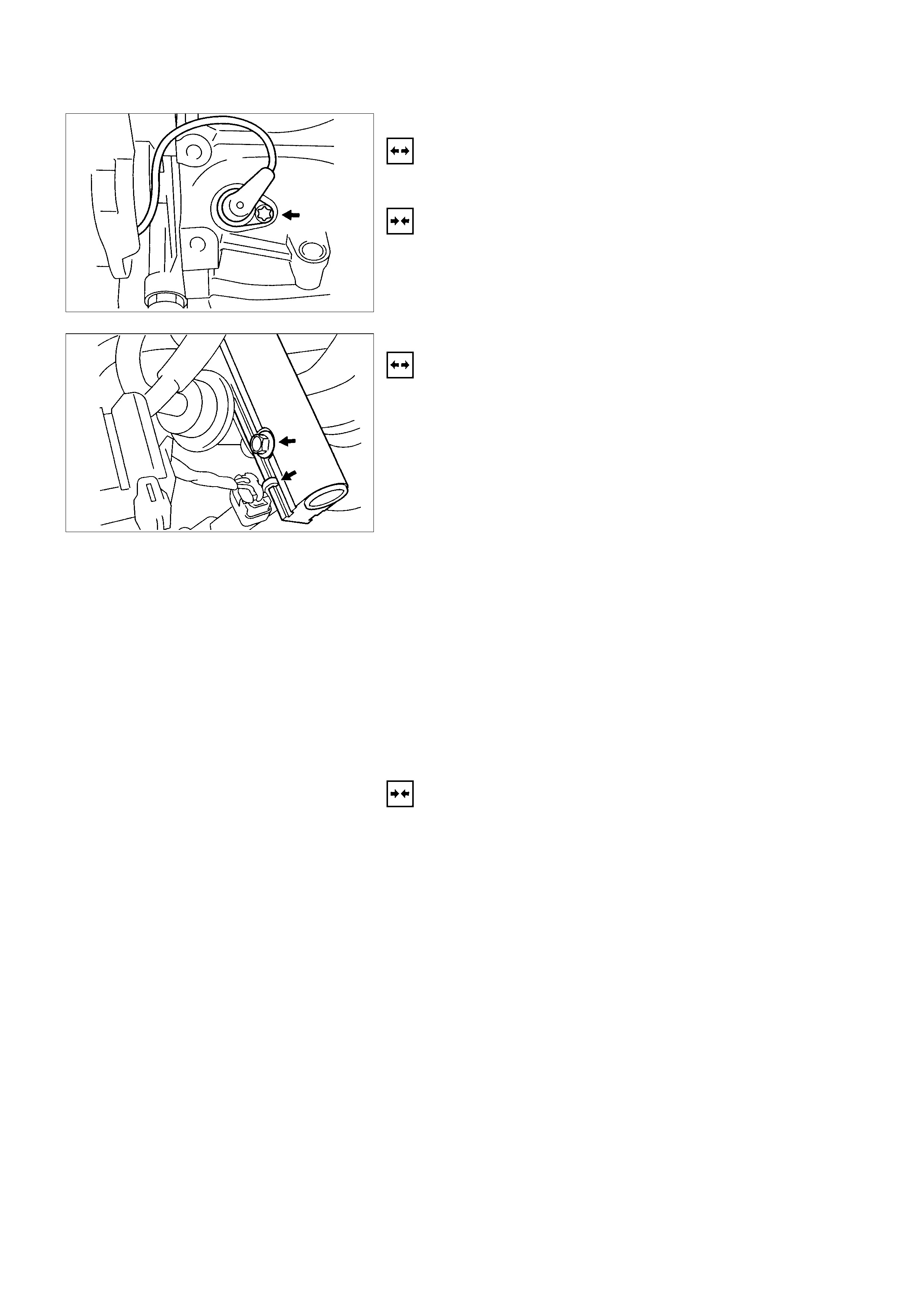
KNOCK SENSOR
REMOVAL
1. Remove fixing bolts.
2. Disconnect the connector at the other side.
TIGHTEN (TORQUE)
30N⋅m (3.2 kgf⋅m)
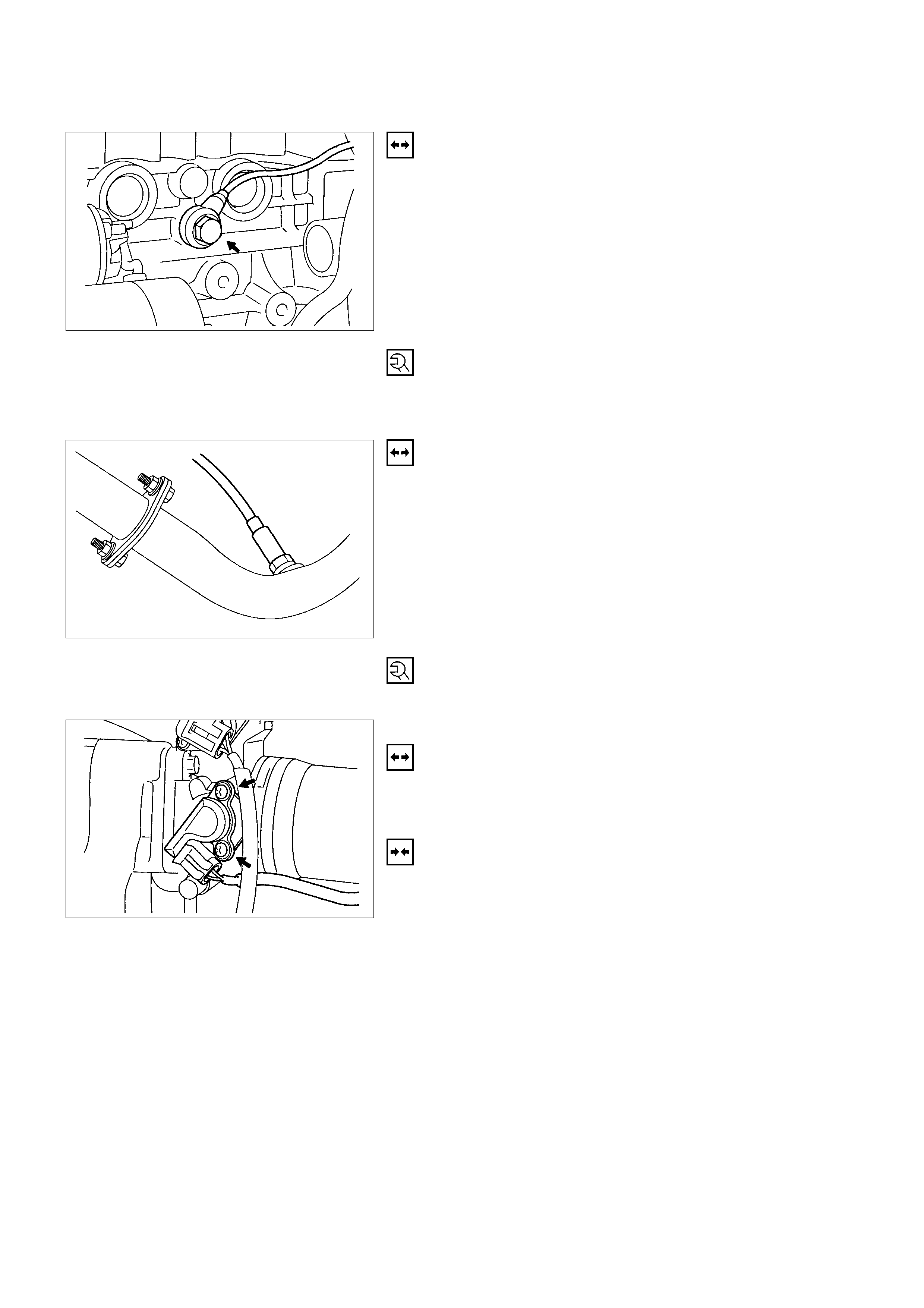
OXYGEN SENSOR (IF APPLICABLE)
REMOVAL
1. Remove wiring harness plug.
2. Remove oxygen sensor from the front exhaust pipe.
TIGHTEN (TORQUE)
Oxygen sensor in exhaust pipe - 30 N⋅m (3.1 kgf⋅m)
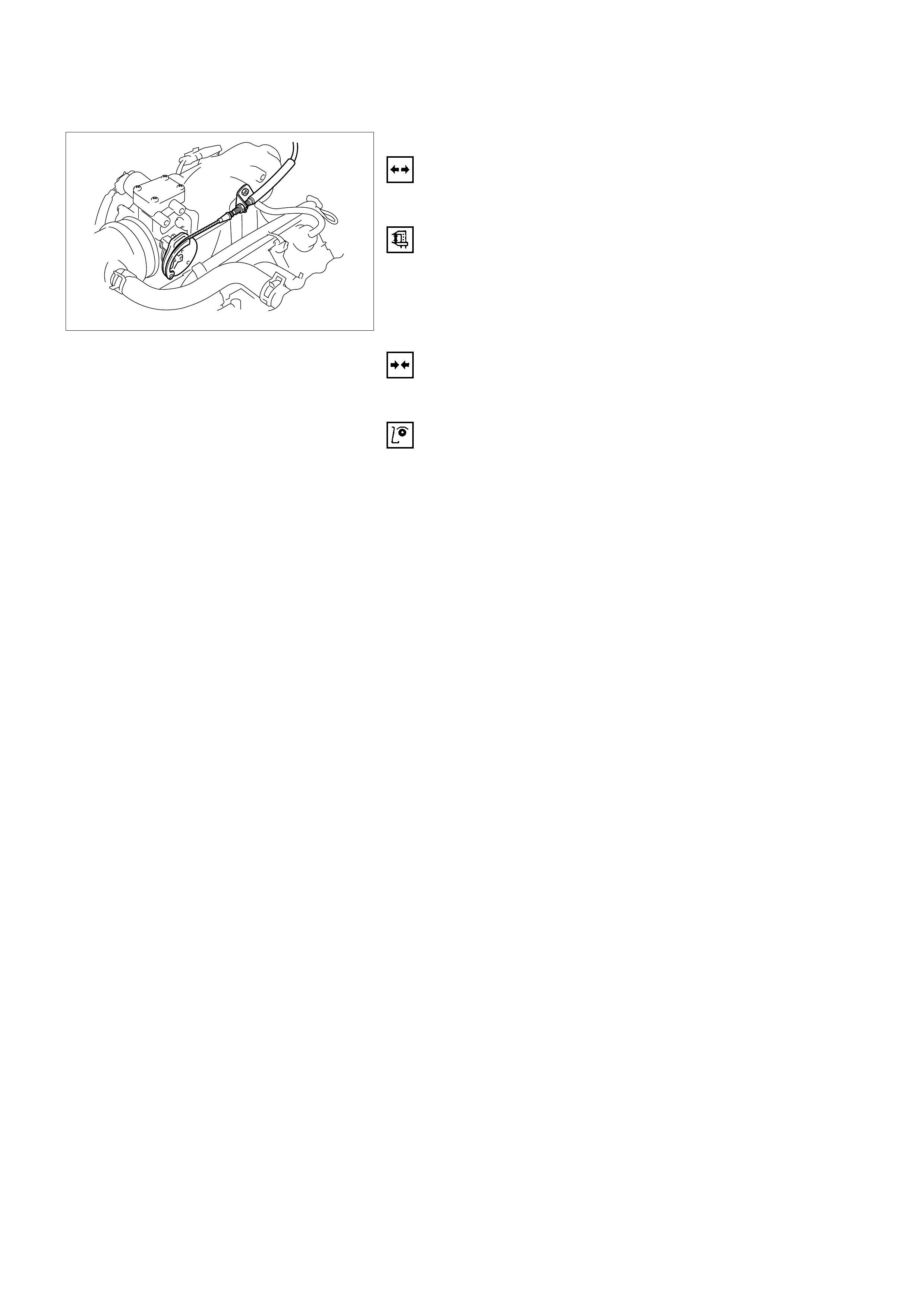
THROTTLE VALVE POSITION SENSOR
REMOVAL
1. Remove wiring harness connector.
2. Remove throttle valve position sensor.
INSTALLATION
1. Install throttle valve position sensor.
2. Install wiring harness connector.
ACCE LERATOR P EDAL AND CABLE
REMOVAL
1. Remove pad stopper from pedal stop bolt.
MEASURE
Dimension "A":
RD=15mm ± 0.5mm/0.59in. ± 0.02in.
LD=14mm ± 0.5mm/0.55in. ± 0.02in.
INSTALLATION
1. Install pad stopper.
INSPECTION
Ensure that accelerator pedal is fully in idle position and
accelerator level at engine is in closed position.
Pull outer sleeve of accelerator cable towards pedal and check
that clip on sleeve is in slot nearest to grommet.
Reposition clip if necessary, and check that full throttle and idle
positions are obtained at engine lever.
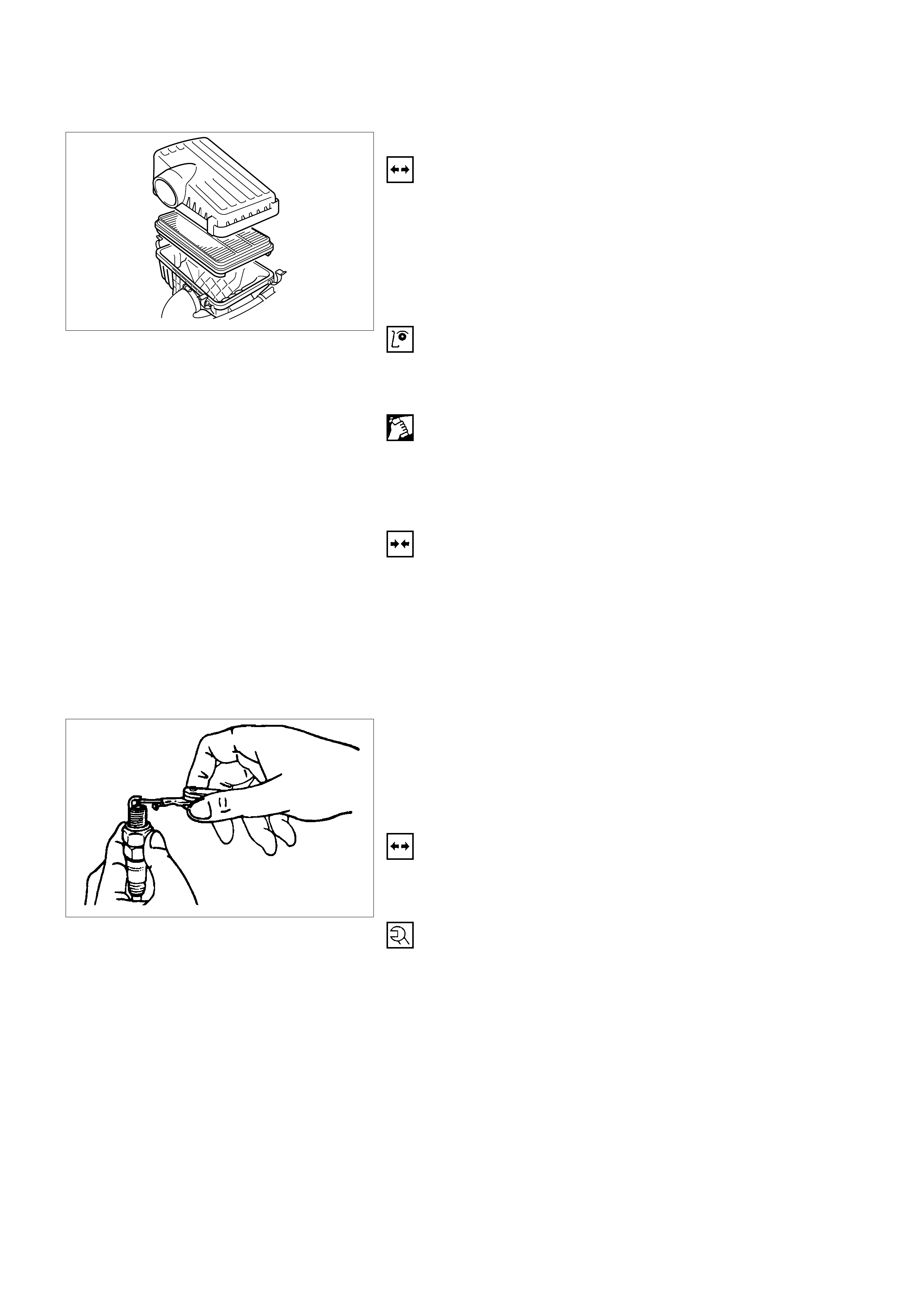
AI R CLE ANER FILTER
REMOVAL
1. Remove positive ventilation hose connector.
2. Remove intake air temperature sensor.
3. Remove mass air flow sensor.
4. Remove air cleaner duct assembly.
5. Remove air cleaner element.
INSPECTION
Check the air cleaner filter for damage or dust clogging.
Replace if it is damaged, or clean if it is clogged.
CLEANING METHOD
Tap the air cleaner filter gently so as not to damage the paper
filter, or clean the element by blowing with compressed air of
about 490 kPa (71 psi) from the clean side if it is extremely
dirty.
INSTALLATION
1. Install air cleaner element.
2. Attach the air cleaner duct cover to the body completely,
then clamp it with the clip.
3. Install mass air flow sensor.
4. Install mass air temperature sensor.
5. Install positive crankcase ventilation hose connector.
SPARK PLUG THREAD
RECONDITION
Ream thread and recut using commercially available spark
plug thread drill (observe manufacturer's instructions).
REMOVAL
Remove thread bush on spark plug. (Dimensions (A) =
17mm/0.67in.)
TIGHTEN (TORQUE)
Spark plug with thread bush into cylinder head - 25N⋅m (2.5
kgf⋅m) - use
TECHNICAL DATA
SOHC GASOLINE ENGINE C22NE
ENGINE OIL VISCOSITY
The following engine oils can be used:
A = single-grade oils
B = multigrade oils
C = easy run oils
Depending on the outside temperature.
ENGINE OIL QUALITY
It is important that the following API and CCMC classes are
used:
Engines Single and multigrade oils Easy run oils
Petrol API-SF/CC, SF/CD, SG/CC,
SG/CD, CCMC/G4 API-SF/CC, SF/CD, SG/CD
CCMC-G5/PD2
IMPORTANT:
CD engine oils designed by manufacturers especially for diesel
engines are not suitable for petrol engines, unless a sufficient
performance class for petrol engines (e.g. API-SF/CCMC-G4)
is also indicated.
DISPOSAL.
Observe the relevant national regulations when disposing of
used oil.
ENGINE OIL FILLING QUANTITIES
Initial filling
(litres) Filling quantity
with filter change*
(litres)
MIN to MAX
(litres)
4.25 4.5 1.00
*Up to mark "MAX" on oil dipstick
OIL PUMP
Backlash 0.1 to 0.2mm
Gaps in gears opposite housing 0.03 to 0.1mm
Oil pressure at idle speed Engine at operating
temperature (>70°C oil and
approx. 80°C coolant) 150
kPa/1.5 bar
Oil drain plug M14 × 1.5
COOLING SYSTEM
Radiator
Type: Cross-flow
Radiator core surface in cm2: 2000
Cooling system capacity (in litres): 7.2
COOLANT
50% HN2043 with wa ter
FAN
Type Visco Clutch Fan
Number of blades 5
Distribution of blades asymmetric
Diameter mm
RADIATOR CAP
Boiling point 123°C
Opening pressure kPa (bar) 120 to 135 (1.20 to 1.35)
THERMOSTAT
Start of opening 92°C
Fully opened 107°C
Type Bypassed
IDLE SPEEDS, CO CONTENT, IGNI TIO N
ADJUSTMENT
Appl i cabl e S yatem I dle speed in min -1 (rpm)
Manual CO content
in vol. % Ignition timing in CA BTDC (adjustment
ensues at able speed,
ignition marks must align) with TDC
sensor measuring instrum ent:
Closed Loop Syst em 825 *<0.4 *** 8 to 12
Open Loop System 825 **1.0+0.2
-0.5 *** 8 to 12
Note) * CO content adjustment not applicable.
** CO content adjustment refer to 6C1-93
*** Ignition timing adjustment not possible.
ADJUSTMENT VALUES/CHECKING VALUES
Valve clearance
Inlet Hydraulic valve lash adjustment
Outlet No adjustment necessary
Spark plugs - electrode gap 1.0 ∼ 1.1mm
Compression The difference in compression
between the individual cylinders
in the engine must not exceed
100 kPa (1 bar).
Pressure loss The pressure loss of an engine
in perfect condition per cylinder
is not more than max. 25%
CYLINDER HEAD
Cylinder Head Gasket
Thickness - installed mm 1.15 to 1.30
Valve seat width at cylinder head
inlet mm 1.0 to 1.5
outlet mm 1.7 to 2.2
Valve stem play inlet mm 0.018 to 0.052
outlet mm 0.038 to 0.072
Permissible valve stem to cone runout
inlet mm 0.03
outlet mm 0.33
Overall height of cylinder head
(Sealing surface to sealing surface) mm 96.00 ± 0.25
Installation height
inlet and
outlet valves mm 17.85 to 18.25
dimension "A" Distance Gauge
5-8840-2596-0
Installation height valve guide mm 83.50 to 83.80
Sealing surface peak-to-valley height mm max. 0.025
Valve System
Valve lifter valve play compensator
(hydraulic)
Valve rotators
(inlet or outlet) outlet
Valve play
(warm or cold) inlet mm 0
outlet mm 0
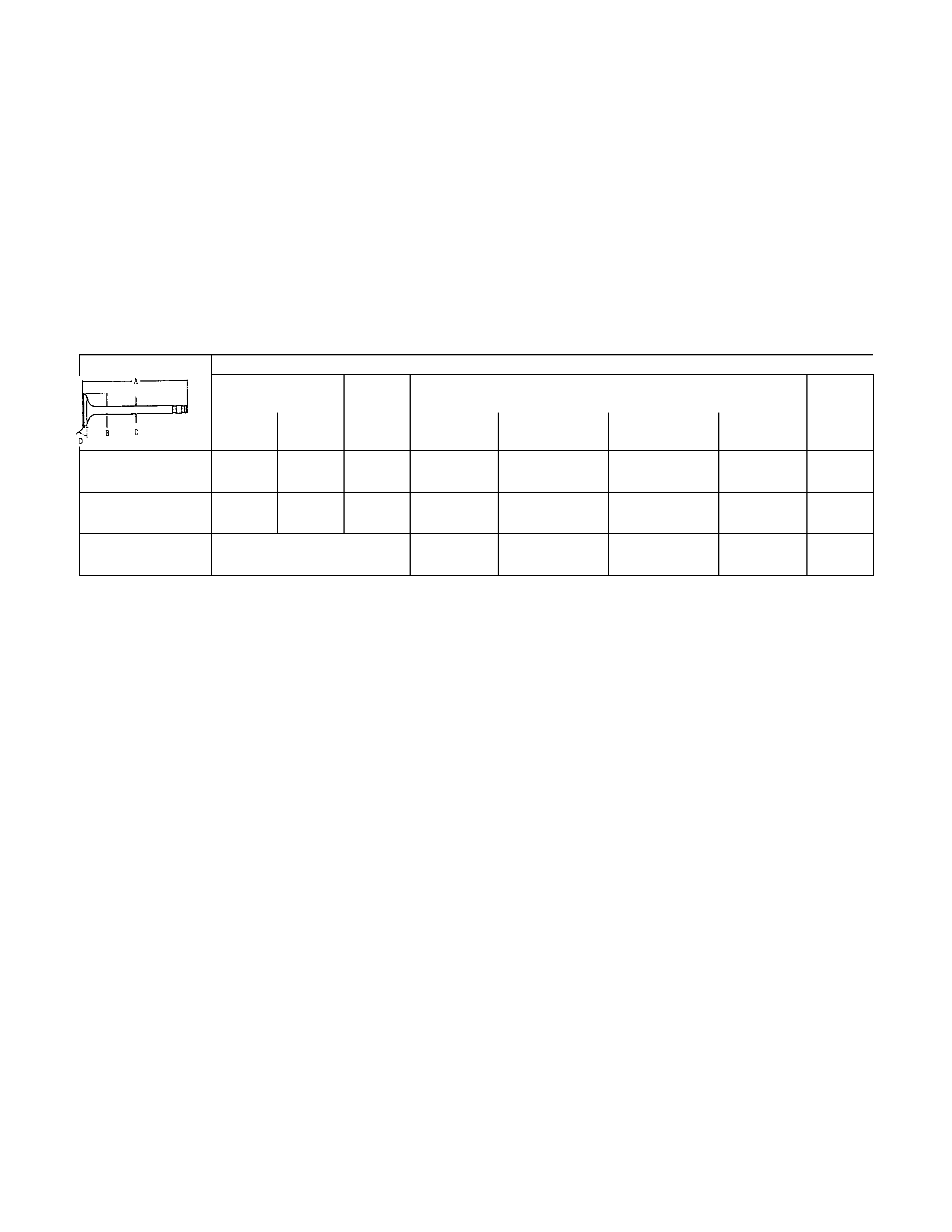
Valve Dimensions C 22 NE
A in mm B in
mm C(diameter in mm) and identification mark D
1) 2) Normal K Oversize K1
0.075 Oversize K2
0.150 Oversize A
0.250
Inlet valve 104.2 103.8 41.8 7.012
6.998 7.087
7.073 7.162
7.148 7.262
7.248 44°
Outlet valve 104.0 103.6 36.5 6.992
6.978 7.087
7.053 7.142
7.128 7.242
7.228 44°
Valve stem
bore - 7.050
7.030 7.125
7.105 7.200
7.180 7.300
7.280 -
1) Production
2) Customer service
The P and A department only supplies valves with a length of 103.8mm (inlet valve) and 103.6mm (outlet valve)
only
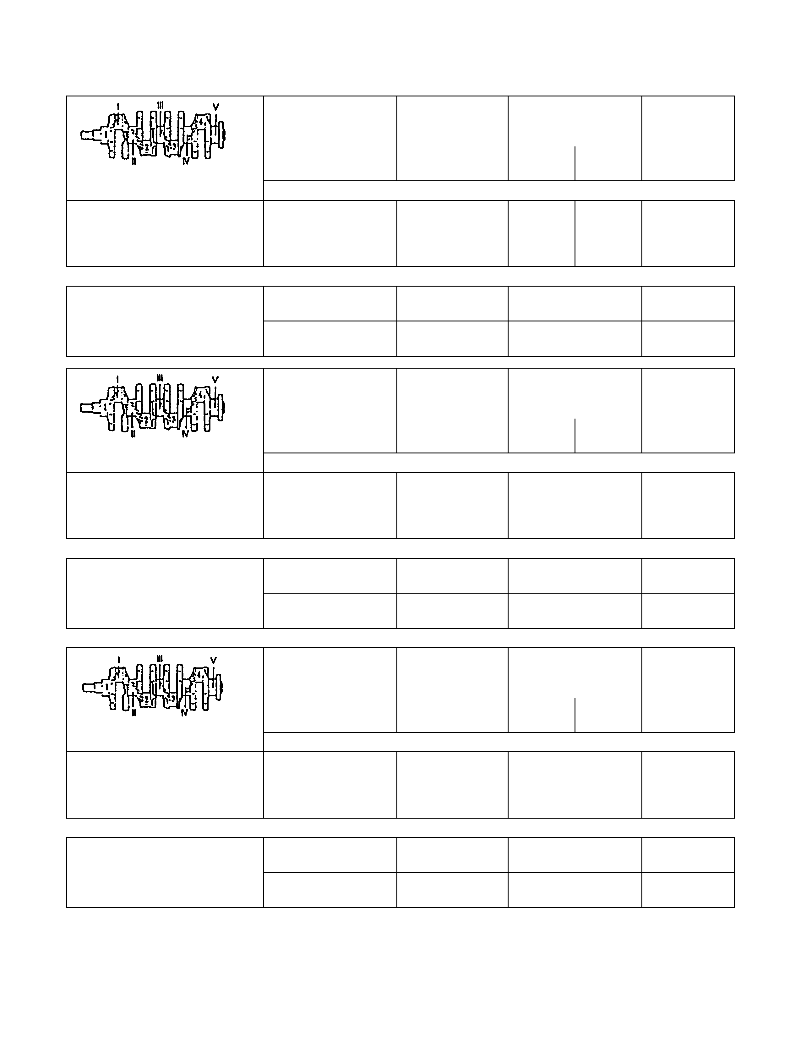
CAMSHAFT
Identification letter J
Colour code Normal size -
0.1mm undersize violet
Radial runout mm 0.03
End play mm 0.09 to 0.21
Cam lift Inlet and outlet valve mm 6.67
Grinding Dimension for Camshaft Bearing Position
Bearing Bearing journal
diameter in mm Diameter
in housing
normal -0.1mm normal -0.1mm
1 42.470
42.455 42.370
42.355 42.525
42.425 42.500
42.400
2 42.720
42.705 42.620
42.605 42.775
42.750 42.675
42.650
3 42.970
42.955 42.870
42.855 43.025
43.000 42.925
42.900
4 43.220
43.205 43.120
43.105 43.275
43.250 43.175
43.150
5 43.470
43.455 43.370
43.355 43.525
43.500 43.425
43.400
CRANKSHAFT, CYLINDER BLOCK
CYLINDER GRI NDING AND PISTON DIMENSIO NS
Cylinder Grinding and Piston Dimensions
Size Cylinde r bore dia. in mm Cylinder to Related pis ton dia. in mm Piston head
Crankshaft co- efficient
housing
co-efficient
over to over to
Production 1 85.97* 85.89 8 85.95 85.96 8
2 85.98
85.99
86.00
86.01
85.99
86.00
86.01
86.02
99
00
01
02
85.96
85.97
85.98
85.99
85.97
85.98
85.99
86.00
99
00
01
02
Customer
service Oversize
0.5mm 8.46 86.47 7+0.5 86.44 86.45 7+0.5
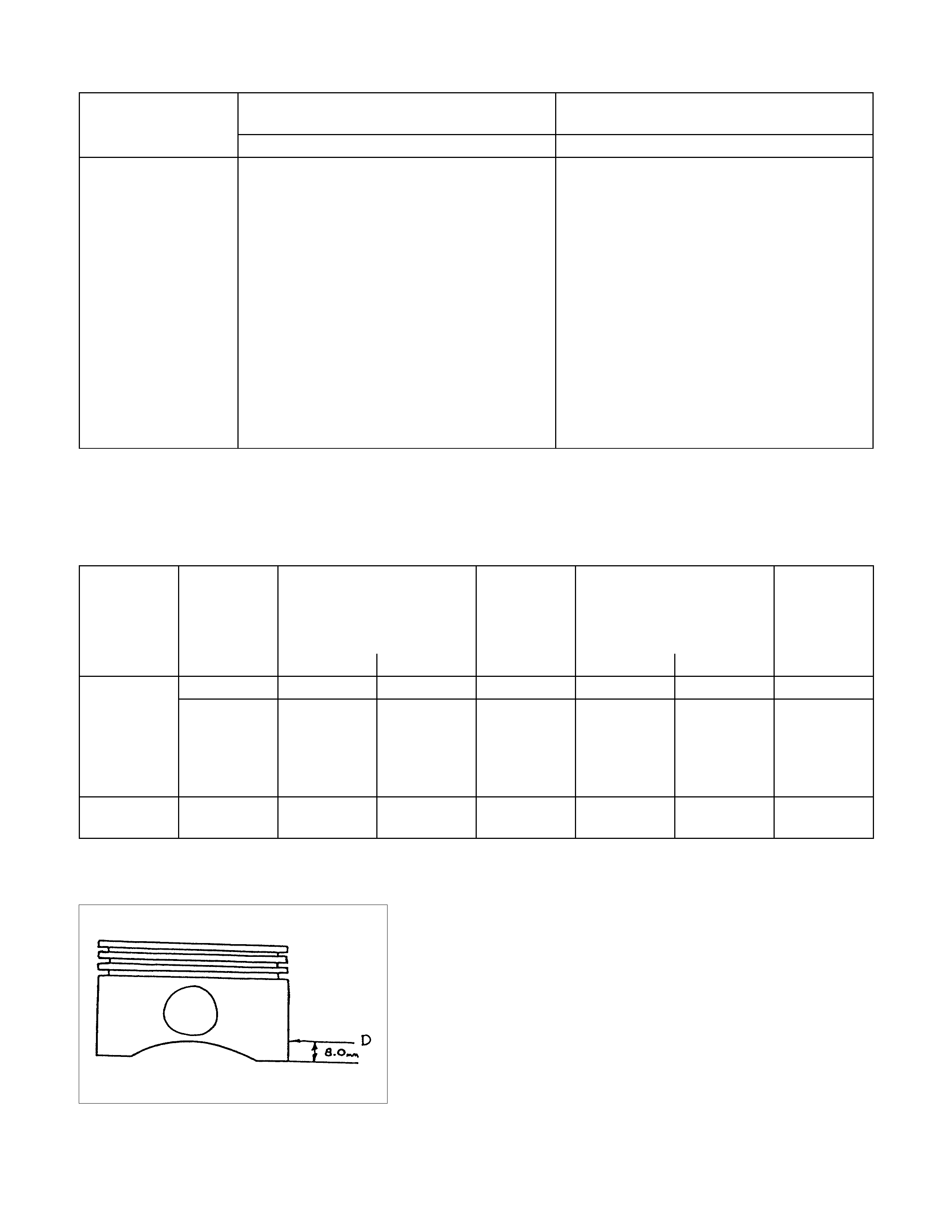
Piston diameter must be measured at the position "D".
*inclusive
CYLINDER BORE
Rebore cylinder Permissible oversize to 0.5mm (see parts
microfiche)
After reboring, invalidate original crankcase
housing coefficient and drive in new oversize
coefficient
Permissible out-of-round: 0.013mm
Permissible taper: 0.013mm
Measure out-of-round in bore at 4 different
heights

Piston projection above upper edge of cylinder block
0.40mm
Piston
Type Recessed pistons
Clearance For short-blocks and cylinder blocks with
complete pistons, the clearance is 0.02 to
0.04mm
For replacement (oversize), depending on
available pistons, a clearance of 0.02 to
0.04mm is permissible
PISTON RINGS
Square ring Height mm 1.5
Tapered ring Height mm 1.5
Oil scraper Height mm 3
Ring gap offset 180°
Note that the upper steel band ring gap is offset 25 to 50mm to
the left and the lower 25 to 50mm to the right opposite the
intermediate ring gap.
Piston Pin
Length mm 61.5
Diameter mm 21
Type Shrunk into con-rod
Play mm
in piston 0.011 to 0.014
in con-rod none
Installation When installing piston pins,
heat con-rods to approx.
280°C in oil bath. This
temperature should under no
circumstances be exceeded.
The permissible weight variation of con-rods without piston and
bearing shell inside an engine is 8 g.
As the con-rods do not have balancing studs, reworking is not
possible.
Con-rods can only be replaced in sets.
CRANKSHAFT GRINDING DI M E NSI ONS
Crankshaft
jounal
I, II, IV, V
Guide
bearing
III
Con-rod journal
1 to 4 Con-rod width
Diameter
mm Widtht
mm Diameter
mm Width
mm mm
Normal size
Bearing journal and colour code from 57.9820 green
to 57.9885
> 57.9885 brown
to 57.9950
25.900
25.850 48.988
48.970 26.580
26.460 26.390
26.338
Bearing shel l i dent i ficat i on mark
Colour code and embossed Crankshaft bearing
I, II, IV, V Guide bearing
III Con-rod bearing
1 to 4
Identif i cation mark brown-662N
green-663N brown-655N
green-658N
Crankshaft
jounal
I, II, IV, V
Guide
bearing
III
Con-rod journal
1 to 4 Con-rod width
Diameter
mm Widtht
mm Diameter
mm Width
mm mm
0.25m m Undersi ze f or Producti on and Custom er Service
Bearing journal and colour code from 57.7320 green/
to 57.7385 blue
> 57.7385 brown/
to 57.7450 blue
26.100
26.050 48.738
48.720 26.580
26.460
Bearing shel l i dent i ficat i on mark
Colour code and embossed Crankshaft bearing
I, II, IV, V Guide bearing
III Con-rod bearing
1 to 4
Identif i cation mark brown/blue-664 A
green/blue-655 A brown/ bl ue-657 A
green/blue-658 A
Crankshaft
jounal
I, II, IV, V
Guide
bearing
III
Con-rod journal
1 to 4 Con-rod width
Diameter
mm Widtht
mm Diameter
mm Width
mm mm
0.50m m Undersi ze Custom er Service
Bearing journal and colour code from 57.4820 green/
to 57.4885 blue
> 57.4885 brown/
to 57.4950 blue
26.300
26.250 48.488
48.470 26.580
26.460
Bearing shel l i dent i ficat i on mark
Colour code and embossed Crankshaft bearing
I, II, IV, V Guide bearing
III Con-rod bearing
1 to 4
Identif i cation mark brown/white-666 B
green/white-667 B brown/blue-659 B
green/blue-660 B
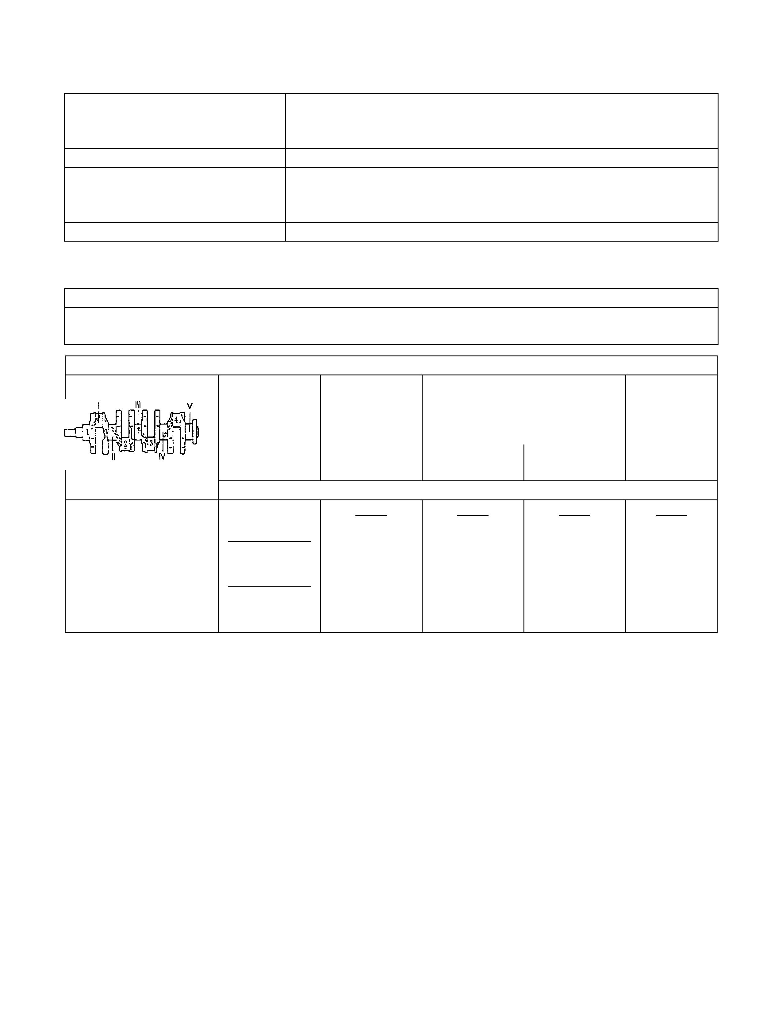
PISTON PINS
Dimensions
Length mm
Diameter mm 61.5
21
Type Shank-fit in con-rod
Clearance
In piston mm
In con-rod mm 0.011 to 0.014
0
Installation See operation “Con-rod, Replace”
CON-ROD
Permissible, weight variation of con-rods without pistons and bearing shells within an engine 8 g.
As the con-rods have no counterweights, re-working is not possible.
Con-rods must be replaced only as a set.
Crankshaft Grinding Dimensions
Crankshaft
bearing journals
I, II, III, IV, V
Guide bearings
III Con-Rod bearing journals
1 to 4 Con-rod
diameter in
mm/col our code width
in mm diameter
in mm
width
in mm width
in mm
Standard Si ze for Product i on and Service
from 57.974white
to 57.981
over 57.981
green
to 57.988
over 57.988
brown
to 57.995
26.002
25.950 48.988
48.970 26.580
26.450 26.390
26.338
Crankshaft and con-rod journal Permissible out-of-round:
0.04mm
Out-of-round Permissible variation of
middle crankshaft bearing
journal when seating shaft into
cylinder block: 0.03mm
Permissible end play 0.05 to 0.152mm
Permissible main bearing play Bearing I to V0.015 to
0.04mm
Permissible con-rod play 0.006 to 0.031mm
Permissible con-rod and play 0.07 to 0.24mm
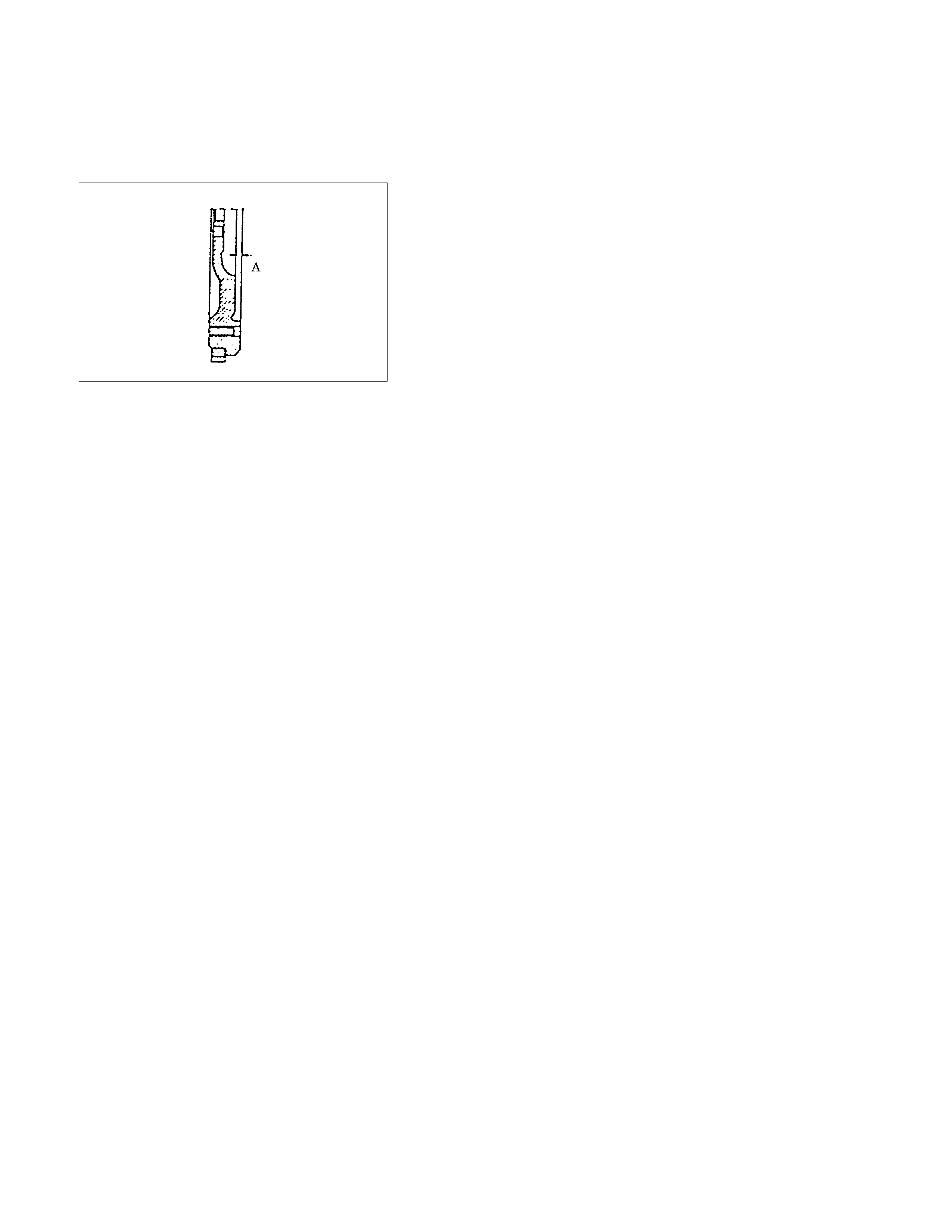
Flywheel
Starter ring gear Before fitting, heat ring gear to 180°C -
230°C
Lateral run-out Permissible lateral run-out of installed
starter ring gear to flywheel: 0.5mm
Precision turning Permissible removal of material in clutch
disc lining surface area: 0.3mm
In order to achieve the functional
relationship again after removal of material,
the same removal of material must take
place on the fore part of the flywheel
(contact for clutch assembly)
Dimension A: 2.1 to 2.2mm
RECOMM ENDED TORQUE VALUES N⋅m (kgf⋅m)
Bearing cover to cylinder block ....................................................................................... 60 1) 6.1 +40° to 50°
Bracket for alternator to cylinder block ............................................................................ 40 4.1
Bracket for engine damping block to transmission ......................................................... 60 2) 6.1
Bracket for engine damping block to engine block ......................................................... 60 6.1
Bracket for pump/compressor to engine block ................................................................ 40 4.1
Camshaft housing cover to housing ................................................................................ 8 0.8
Camshaft timing gear to camshaft .................................................................................. 45 4.6
Clamping bracket for alternator to intake manifold ......................................................... 25 2.5
Clamping bracket to alternator ........................................................................................ 25 2.5
Con-rod bearing cap to con-rod ...................................................................................... 35 1) 3.5 +45° to 60°
Crankshaft pulley bolts .................................................................................................... 20 2.0
Cylinder head to cylinder block ........................................................................................ 25 1)2) 2.5 +90° +90° +90°
Engine damping block to engine bracket ........................................................................ 8.5 8.7
Engine damping block to side member ........................................................................... 52 1) 5.3
Exhaust manifold to cylinder head .................................................................................. 22 2.2
1) Use new bolts
2) Use new locking plates

RECOMM ENDED TORQUE VALUES N⋅m (kgf⋅m)
Flywheel to crankshaft ..................................................................................................... 65 1) 6.6 +30° to 45°
Front exhaust pipe to exhaust manifold .......................................................................... 25 2.5
Guide sleeve for pressure bearing to transmission ......................................................... 22 2.2
Intake manifold to cy linder head ...................................................................................... 22 2.2
Lower alternator bracket .................................................................................................. 25 2.5
Oil drain plug to oil pan .................................................................................................... 454.6
Oil intake pipe bracket to cylinder block .......................................................................... 6 2) 0.6
Oil intake pipe to oil pump ............................................................................................... 8 0 .8
Oil pan to cylinder block .................................................................................................. 8 2)3) 0.8
Oil pan to cylinder block (vulcanized gasket) .................................................................. 15 2)3) 1.5
Oil pressure switch to oil pump ....................................................................................... 30 3.2
Pump for power steering (ribbed V-belt) to engine block ................................................ 30 3.2
Spark plugs in cylinder head ........................................................................................... 25 2.5
Starter support to cylinder block ...................................................................................... 25 2.5
Starter to cylinder block - engine side ............................................................................. 45 4.6
Starter to cylinder block - transmission side .................................................................... 75 7.6
Thermostat housing to cylinder head .............................................................................. 15 1.5
Toothed belt drive gear to crankshaft .............................................................................. 130 1) 13.3
Toothed belt front cover .................................................................................................. 4 0.4
Toothed belt rear cover ................................................................................................... 6 0.6
Toothed belt tension roller to oil pump ............................................................................ 25 2.5
(M10) ............................................................................ 45 4.6
Transmission to engine block ......................................................................................... 76 7.7
(M12) ............................................................................ 60 6.1
Water pump to cylinder block .......................................................................................... 25 2.5
1) Use new bolts
2) Use Locking Compound
3) Maximum installation time - 10 minutes
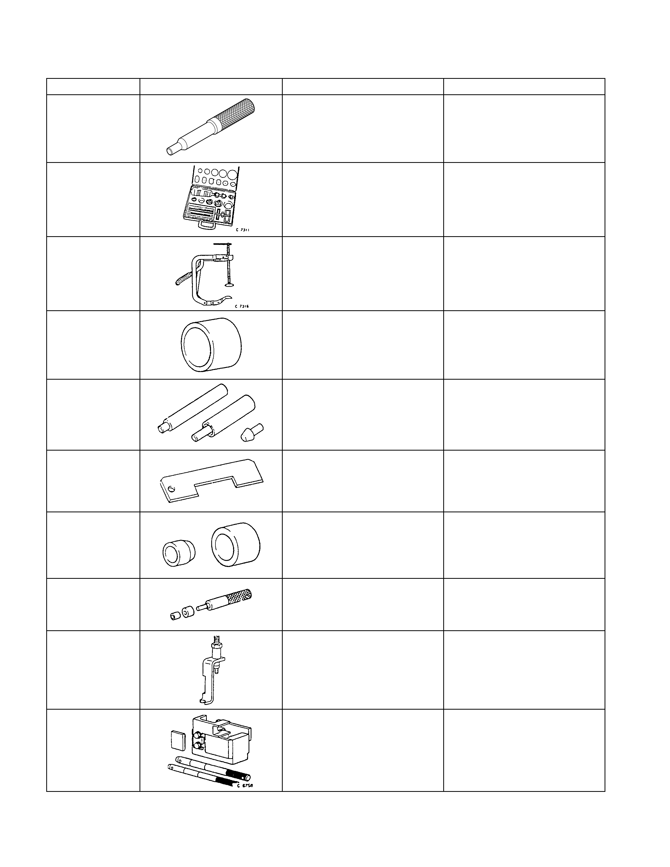
SPECIAL SERVICE TOOLS
ITEM NO. I LLUSTRATION PART NO. PART NA ME
5-8840-2634-0 Aligner
5-8840-2593-0 Cutter set
5-8840-2594-0 Spring Compressor
5-8840-0451-0 Installer
5-8840-0452-0 Remover / Installer
5-8840-2596-0 Distance Gauge
5-8840-0455-0 Assembly Sleeves
5-8840-2597-0 Installer
5-8840-0457-0 Remover / Installer
5-8840-0468-0 Remover / Installer
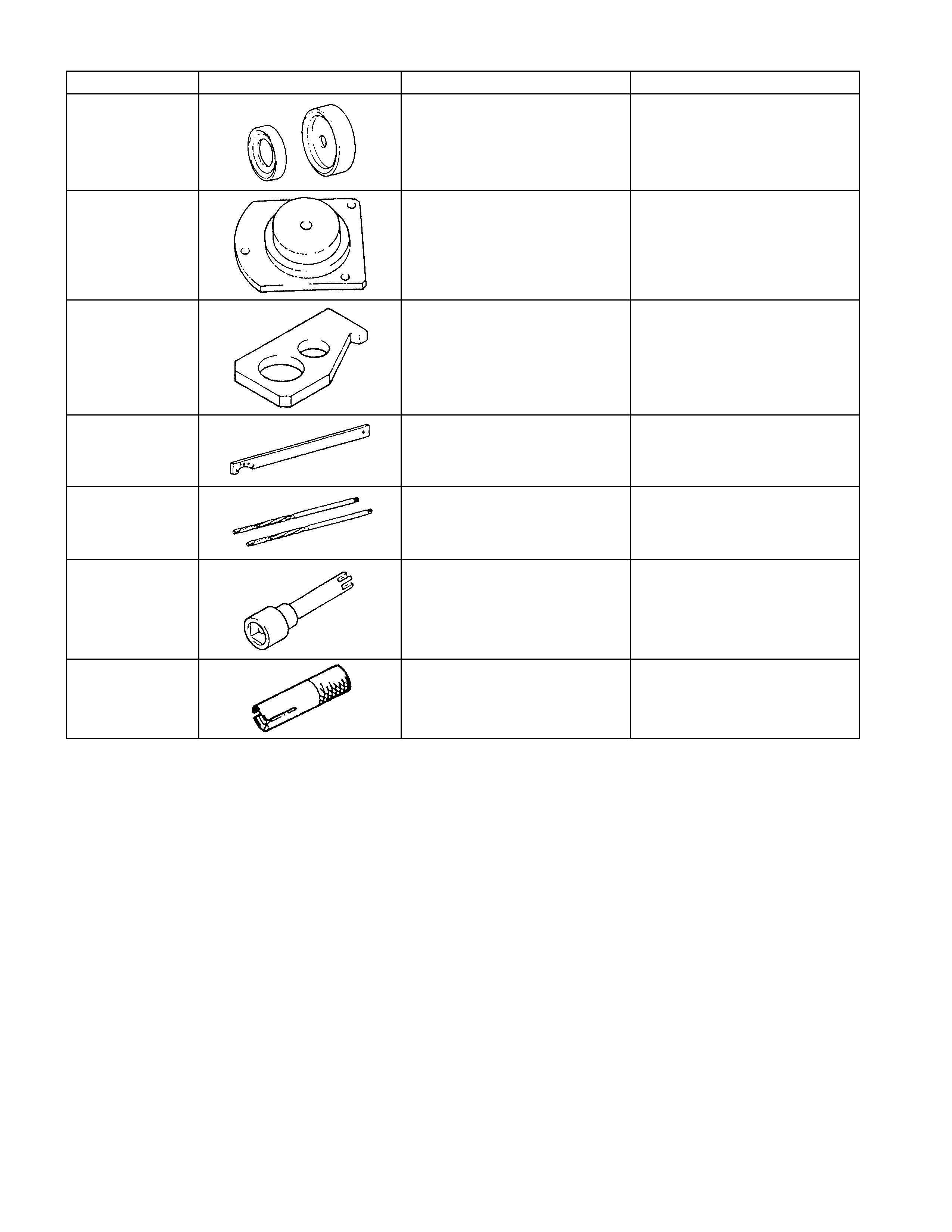
ITEM NO. I LLUSTRATION PART NO. PART NA ME
5-8840-0459-0 Installer
5-8840-0460-0 Installer
5-8840-0446-0 Flywheel Holder
5-8840-2598-0 Holding Wrench
5-8840-2599-0 Reamer Set
5-8840-2600-0 Socket Wrench
5-8840-2601-0 Installer