

GENERAL DESCRIPTION
The C22NE engine uses a waste-spark ignition system. The ignition module is mounted below the coil pack and is
controlled by the ECM.
Since the cylinder on exhaust stroke requires less energy to fire its spark plug, energy from the ignition coils can be
utilized to fire the mating cylinder on compression stroke.
A notch in the timing disc on the crankshaft activates the crank angle sensor which then sends information such as
firing order and starting timing of ignition coil to the ECM.
By receiving signals such as crank position, engine speed, water temperature and Manifold Absolute Pressure (MAP),
the ECM controls the ignition timing.

SERVICE PRECAUTION
CAUTION:
Always use the correct fastener in the proper location.
When you replace a fastener, use ONLY the exact part
number for that application. HOLDEN will call out those
fasteners that require a replacement after removal.
HOLDEN will also call out the fasteners that require thread
lockers or thread sealant. UNLESS OTHERWISE
SPECIFIED, do not use supplemental coatings (Paints,
greases, or other corrosion inhibitors) on threaded
fasteners or fastener joint interfaces. Generally, such
coatings adversely affect the fastener torque and the joint
clamping force, and may damage the fastener. When you
install fasteners, use the correct tightening sequence and
specifications. Following these instructions can help you
avoid damage to parts and sys tems.

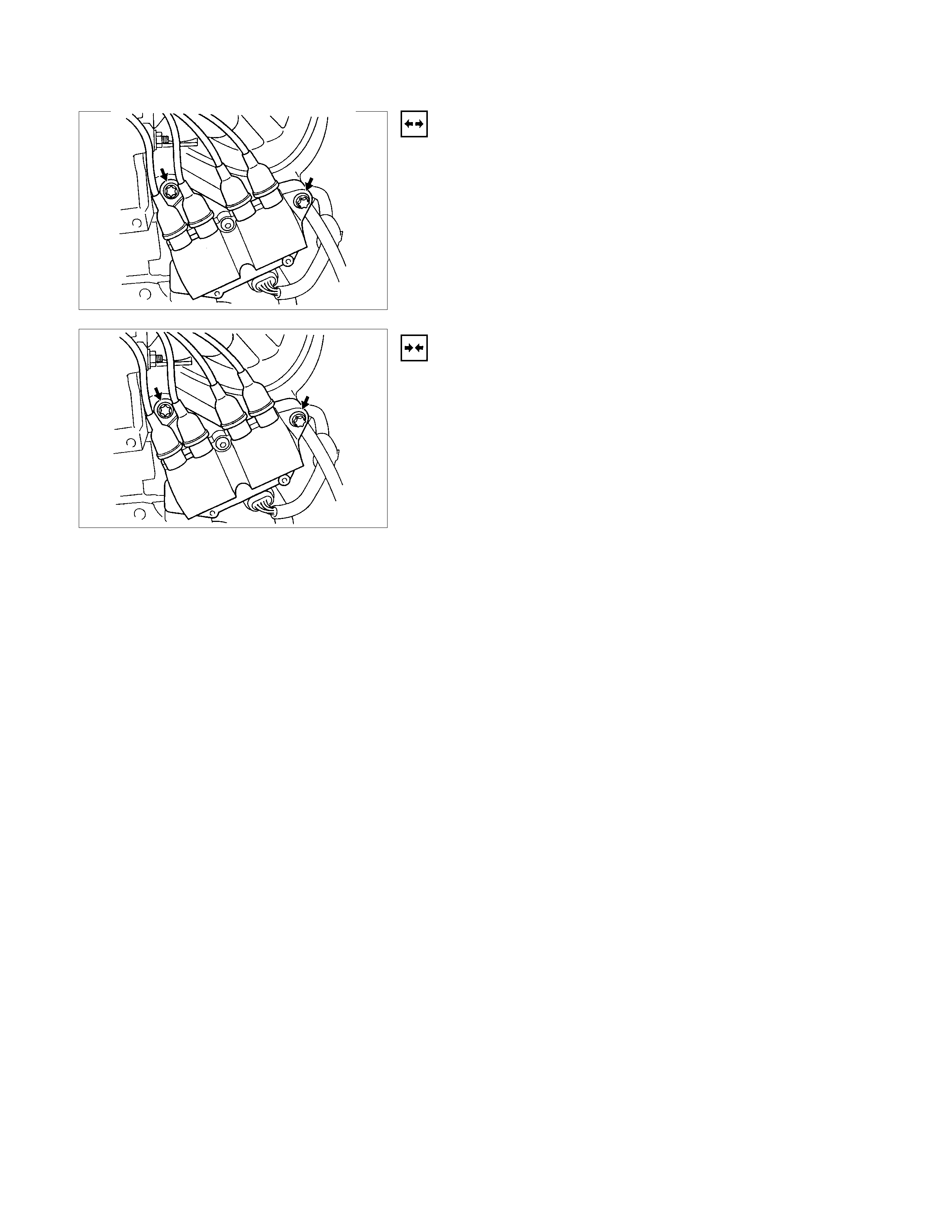
IGNITION COIL
REMOVAL
1. Disconnect battery ground cable.
2. Ignition coil connector.
3. Removal ignition coil.
INSTALLATION
1. Install the ignition coil.
Connect ignition coil connector and ignition coil, then tighten
bolt to the specified torque.
Torque: 20 N⋅
⋅⋅⋅m (2.0 kgf.m)
2. Connect battery ground cable.
SPARK PLUG
REMOVAL
1. Remove spark plugs.
INSPECTION AND REPAIR
The spark plug affects entire engine performance and
therefore its inspection is very important.
•Check electrode and insulator for presence of cracks, and
replace if any.
•Check electrode for wear, and replace if necessary.
•Check gasket for damage, and replace if necessary.
•Measure insulation resistance with an ohmmeter, and
replace if faulty.
•Adjust spark plug gap to 1.0 - 1.1 mm (0.027 in) - 0.8 mm
(0.031 in).
•Check fuel and electrical systems if spark plug is extremely
dirty.
•Use spark plugs having low heat value (hot type plug) if f uel
and electrical systems are normal.
•Use spark plugs having high heat value (cold type plug) i
f
insulator and electrode are extremely burned.
SOOTY SPARK PLUGS
Much deposit of carbon or oil on the electrode and insulator of
spark plug reduces the engine performance.
Possible causes:
•Too rich mixture
•Presence of oil in combustion chamber
•Incorrectly adjusted spark plug gap
BURNING ELECTRODES
This fault is characterized by scorched or heavily oxidized
electrode or blistered insulator nose.
Possible causes:
•Too lean mixture
•Improper heat value
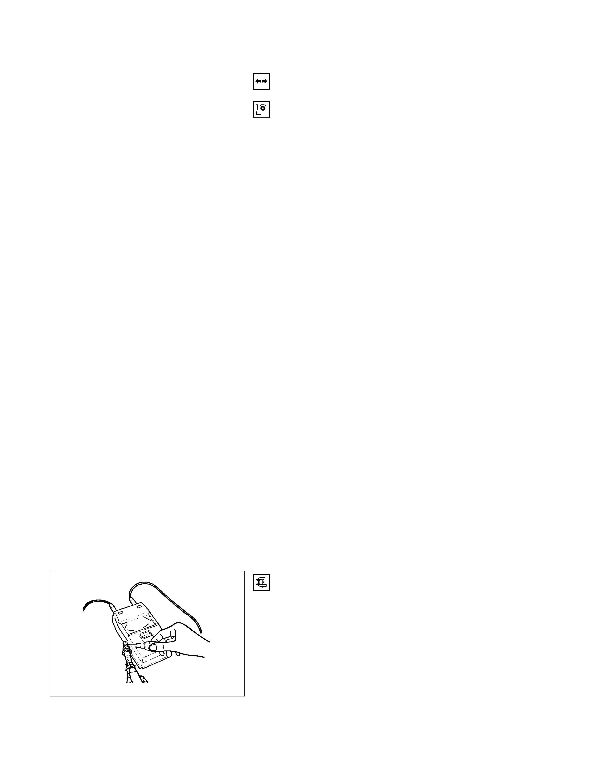
MEASURING INSULATION RESISTANCE
•Measure insulation resistance using a 500 volt megaohm
meter.
•Replace spark plugs if measured value is out of standard.
Insulation resistance: 50 MΩ
ΩΩ
Ω or more
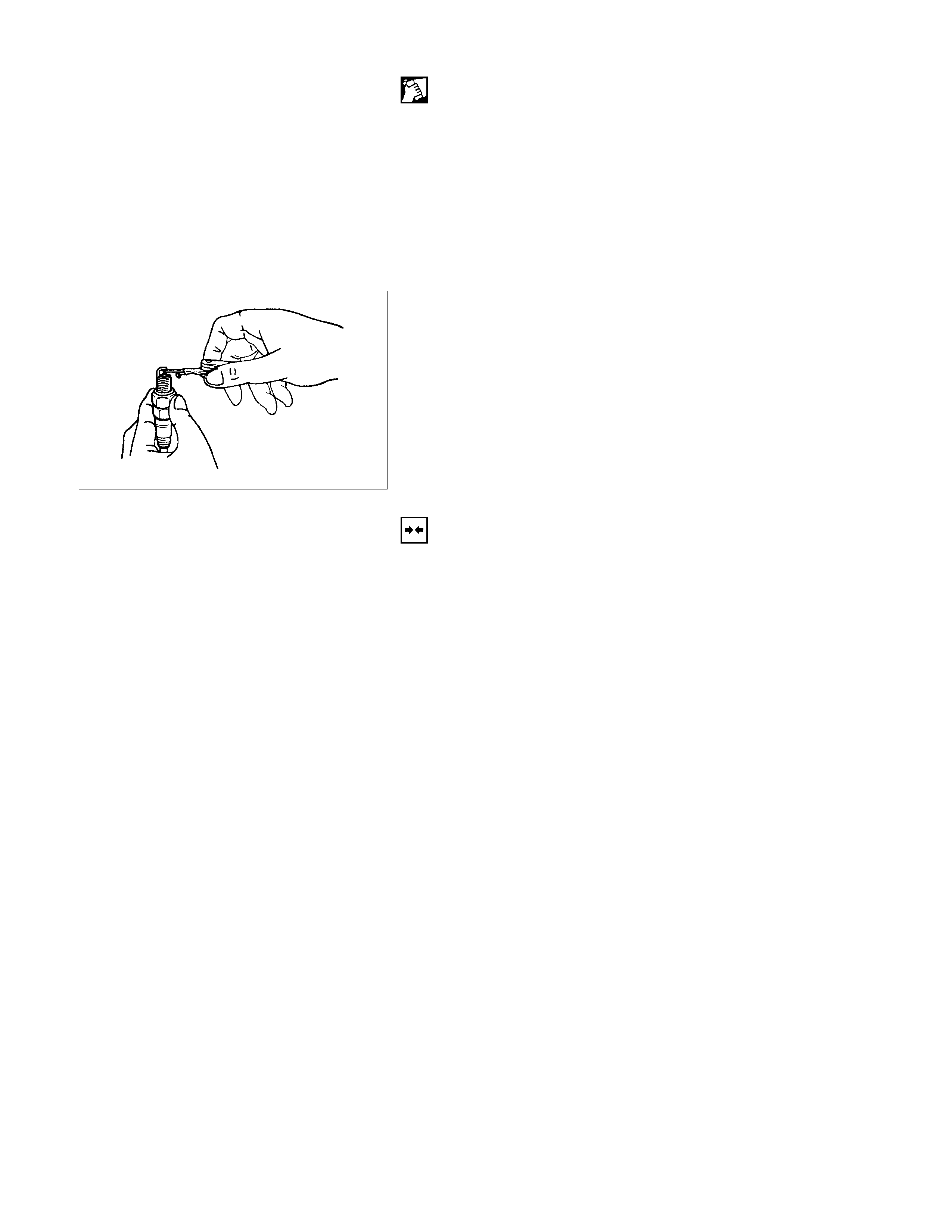
CLEANING SPARK PLUGS
•Clean spark plugs with a spark plug cleaner.
•Raise the ground electr ode to an angle of 45 to 60 degrees.
if electrode is wet, dry it gefore cleaning.
•
A
fter spark plug is thoroughly cleaned, check insulator fo
r
presence of cracks.
•Clean threads and metal body with a wire brush.
•File the electrode tip if electrode is extremely worn.
•Bend the ground electrode to adjust the spark plug gap.
INSTALLATION
1. Spark plugs
•Tighten spark plugs to the specified torque.
Torque: 25 N⋅
⋅⋅⋅m (2.5 kgf.m)
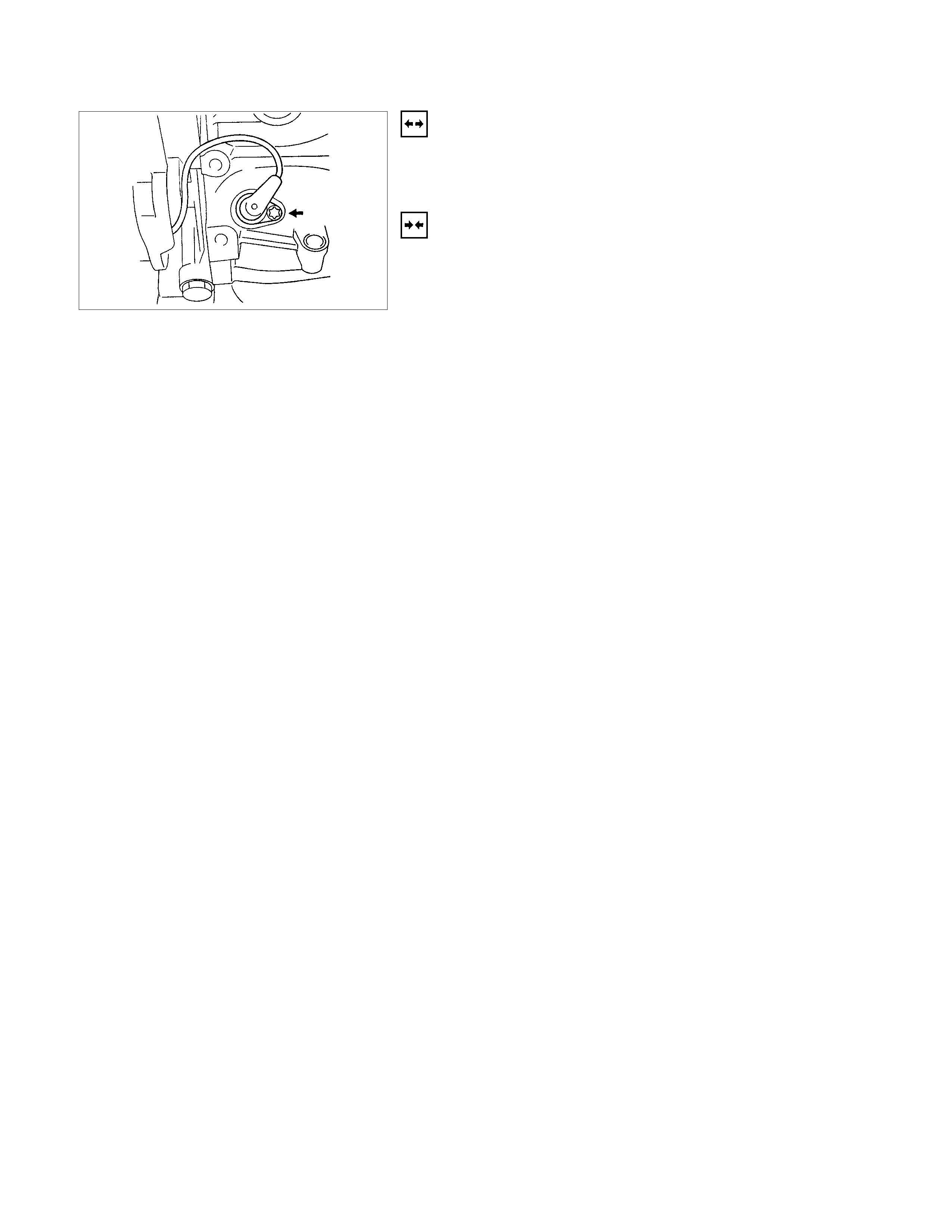
CRANKSHAFT ANGLE SENSOR
REMOVAL
1. Disconnect battery ground cable
2. Wiring connector from crankshaft angle sensor.
3. Remove crankshaft angle sensor from cylinder block.
INSTALLATION
1. Install crankshaft angle sensor into the cylinder block.
Before installation, apply small amount of engine oil to the
O-ring.
Torque: 6 N⋅
⋅⋅⋅m (0.6 kgf.m)
2. Reconnect wiring connector to crankshaft angle sensor.