
SECTION 6C - FUEL SYSTEM
Main Data and Specifications
General Description
Fuel Flow
Fuel Filter and Water Separator
Injection Pump
Injection Nozzle
Fuel Tank
Fuel Tank and Associated Parts
Removal
Installation
Fuel Gauge Unit
Fuel Gauge Unit and Associated Parts
Removal
Installation
Fuel Tube / Quick - Connector Fittings
Precautions
Cautions During Work
Removal
Reuse of Quick–Connector
Assembling Advice
Filler Neck
Removal
Installation
Fuel Filler Cap
General Description
Inspection
Injection Pump
Removal
Installation
Special Tools
Techline
MAIN DATA AND SPECIFICATIONS
Item Description
Injection pump type Bosch distributor VP44 type
Governor type Electronically controlled
Timer type Electronically controlled
Fuel feed pump type Vane with input shaft
Injection nozzle type Hole type
Number of injection nozzle orifices 5
Injection nozzle orifices
Inside diameter mm (in) 0.21 (0.0083)
Injection nozzle opening pressure
(nominal) MPa (kg/cm2) 1st 19.5 (199)
2nd 33.8 (331)
Main fuel filter type Disposable cartridge paper element
Precautions
When working on the fuel system, there are several things
to keep in mind:
• Any time the fuel system is being worked on,
disconnect the negative battery cable except for
those tests where battery voltage is required.
• Always keep a dry chemical (Class B) fire
extinguisher near the work area.
• Replace all pipes with the same pipe and fittings that
were removed.
• Clean and inspect “O" rings. Replace if required.
• Always reliev e the line pressure before servicing any
fuel system components.
• Do not attempt repairs on the fuel system until you
have read the instructions and checked the pictures
relating to that repair.
• Adhere to all Notices and Cautions.
GENERAL DESCRIPTION
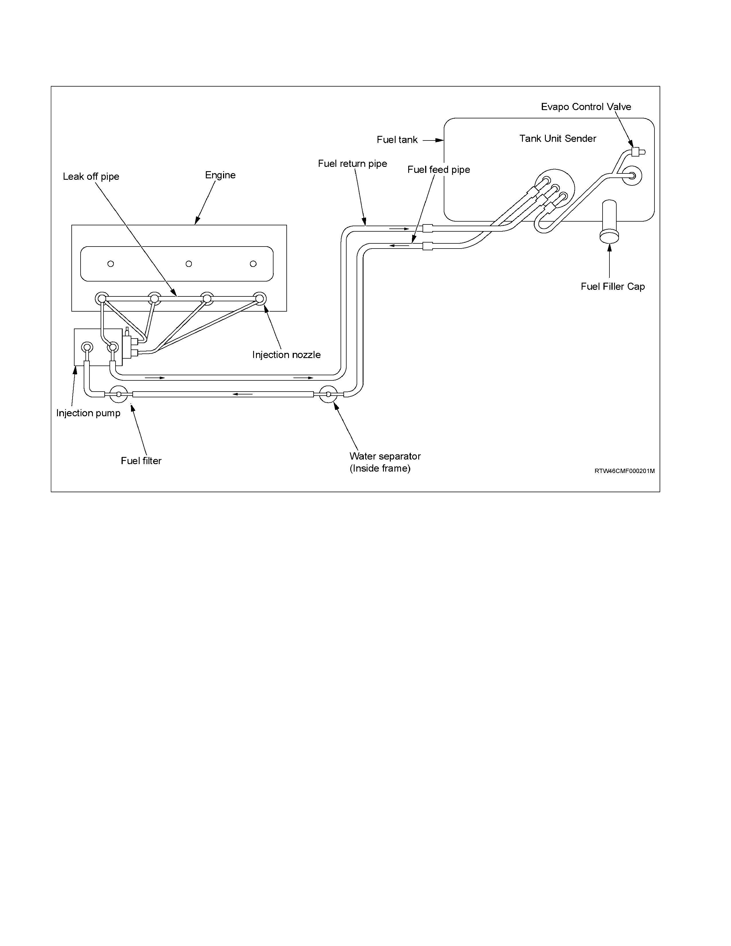
FUEL FLOW
The fuel system consists of the fuel tank, the fuel filter, the water separator, the injection pump, and the injection
nozzle.
The fuel from the fuel tank passes through the water separator and the fuel filter where water particles and other
foreign material are removed from the fuel.
Fuel, fed by the injection pump plunger, is delivered to the injection nozzle in the measured volume at the optimum
timing for efficient engine operation.
NOTE:
1 If abnormal injector operation is found, refer to Section 6E2 ENGINE DRIVEABILITY AND EMISSIONS.
2 Do not mix any additives with the fuel.
3 As neither the fuel injection pump nor injection nozzles are serviceable items, should any injection
pump or nozzle problems be experienced, contact Holden TAS for the latest information on replacing
or exchanging the fuel pump and/or injectors.
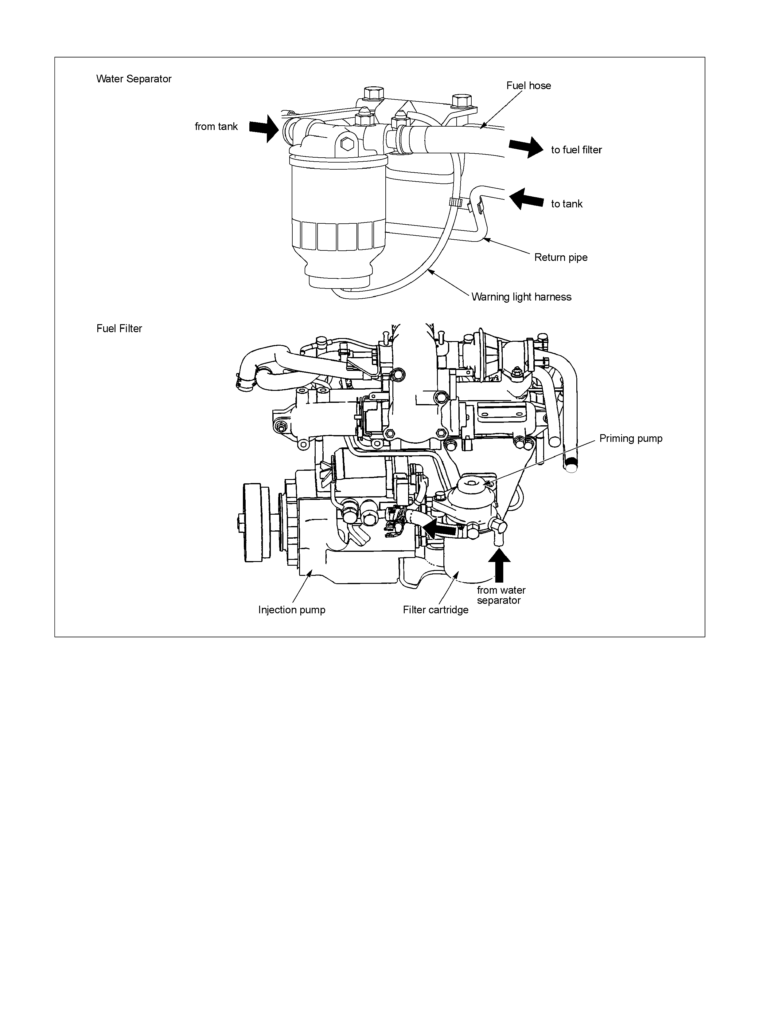
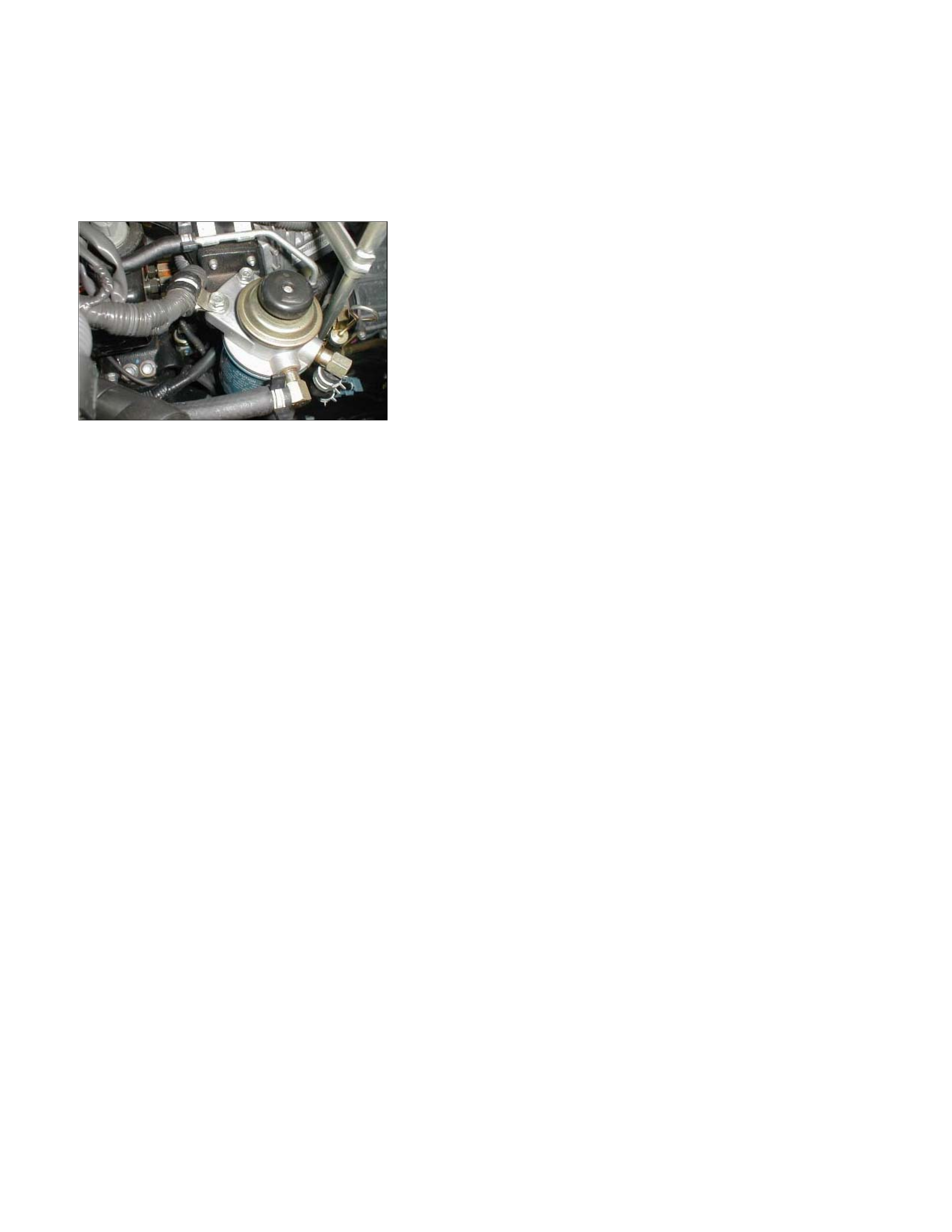
FUEL FILTER AND WATER SEPARATOR
RTW36CLF000701
As the inside of the injection pump is lubricated by the fuel which it is pumping, the fuel must be perfectly clean. The
fuel filter and the water separator remove water particles and other foreign material from the fuel before it reaches the
injection pump.
The water separator has an internal float. When the float reaches the specified level, a warning light comes on to
remind you to drain the water from the water separator.
A diaphragm type priming pump is installed at the top of the fuel filter. It is used during the air bleeding procedures.
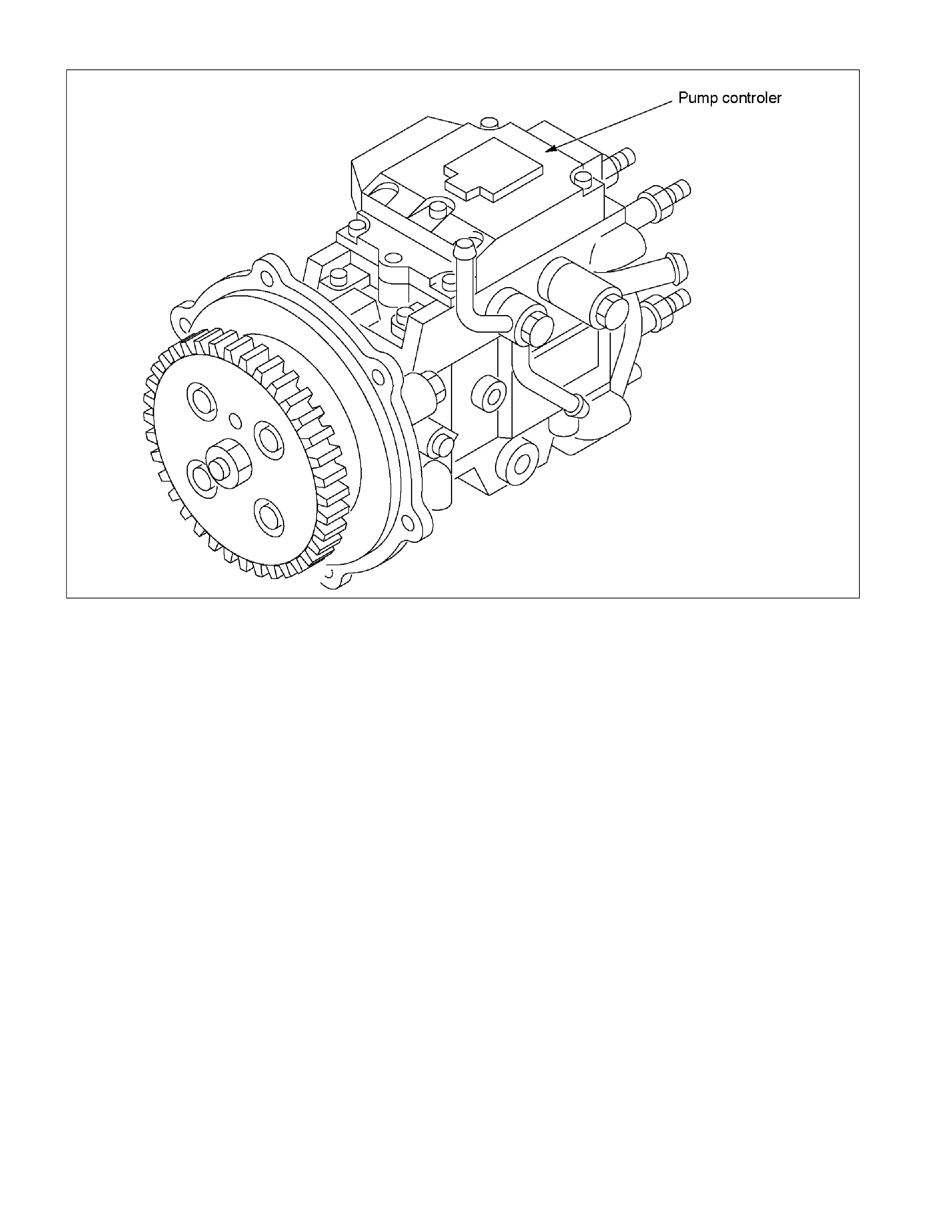
INJECTION PUMP
RTW36CMF000501
The Bosch VP44 injection pump is electronically controlled. The pump controller is mounted on the injection pump.
Signals from the pump controller are sent to the engine control module (ECM). In response to these signals, the ECM
selects the optimum fuel injection timing and volume for the existing driving conditions.
INJECTION NOZZLE
The injection nozzle is a hole type, with 5 orifices. It consists of the nozzle body and the needle valve assembly.
The injection nozzle assembly sprays pressurized fuel from the injection pump into the combustion chamber through
the nozzle body injection orifices.
As the fuel injector nozzles are not serviceable, should any injector problem be experienced, contact Holden TAS for
the latest information on replacing or exchanging the fuel pump and/or the injectors.
FUEL TANK
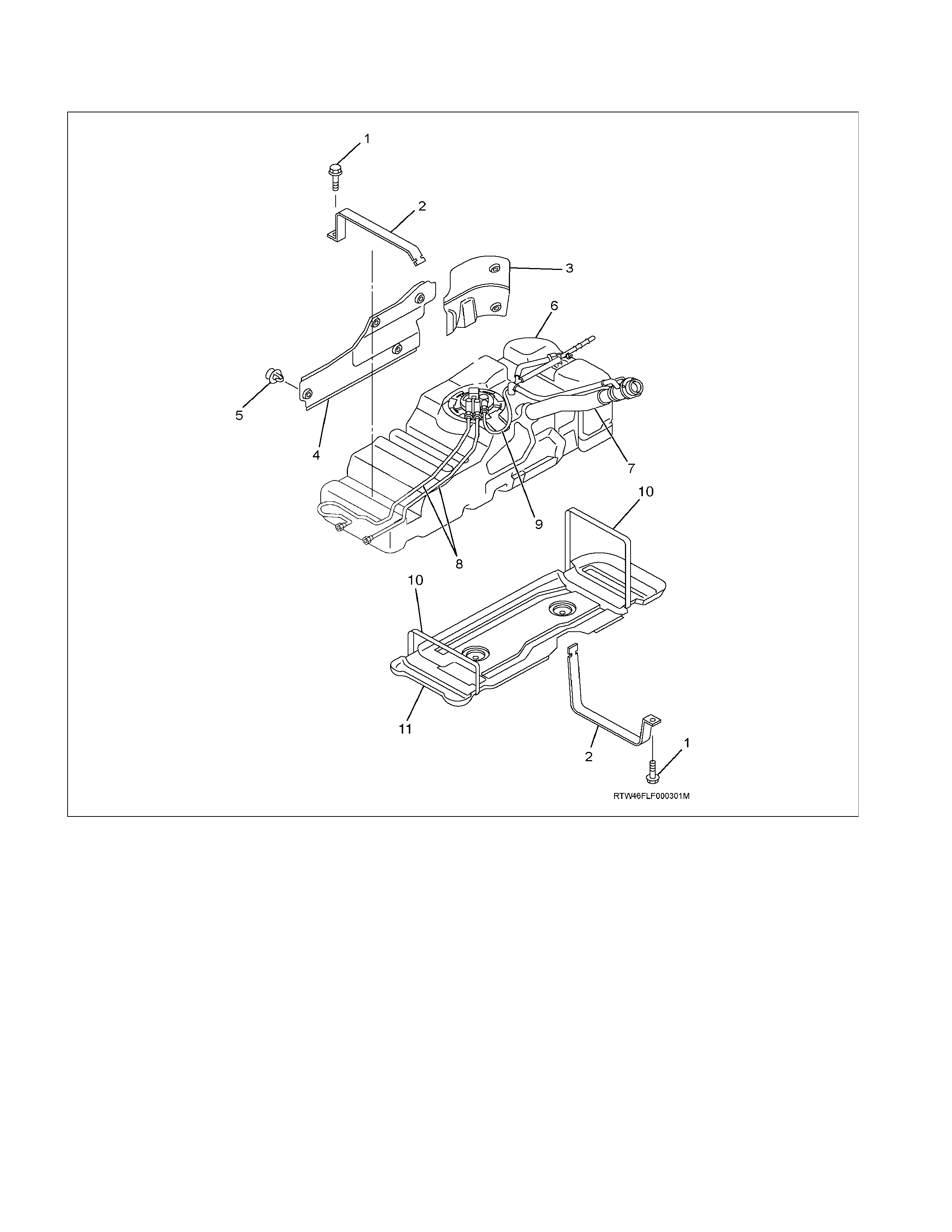
Fuel Tank and Associated Parts
Legend
1. Bolt; Fuel Tank
2. Fuel Tank Band
3. Rear Side Shield
4. Side Shield
5. Retainer
6. Fuel Tank
7. Fuel Filler Hose
8. Fuel Tube / Quick Connector
9. Evapo Tube / Quick Connector
10. Band; Under Shield
11. Under Shield

Removal
CAUTION: When repair to the fuel system has been
completed, start engine and check the fuel system for
loose connection or leakage. For the fuel system
diagnosis, see Section “Driveability and Emission".
1. Disconnect battery ground cable.
2. Slowly loosen the fuel filler cap.
NOTE:
Be careful of fuel spouting out due to a pressure change
in the fuel tank.
NOTE:
Cover the opening of the filler neck to prevent any dust
entering.
3. Jack up the vehicle.
4. Support underneath of the fuel tank with a lifter.
5. Remove the inner liner of the wheel house at rear left
side.
6. Remove fixing bolt of the filler neck from the body.
7. Disconnect the quick connectors joining the fuel and
evapo tubes (8) & (9) to the fuel and evapo pipes.
NOTE:
Cover the quick connector to prevent any dust entering
and fuel leakage.
NOTE:
Refer to “Fuel Tube/Quick Connector Fittings” in this
section when performing any repairs.
8. Remove fixing bolt (1) of the tank band and remove
the tank band (2).
9. Disconnect the fuel gauge sender connector from the
fuel gauge unit and remove the harness from the weld
clip on the fuel tank.
10. Carefully lower the fuel tank (6).
NOTE:
When lowering the fuel tank from the vehicle, be careful
not to scratch the hoses and tubes against any other
parts.
Installation
1. Lift the fuel tank into position.
NOTE:
When raising the fuel tank up to the vehicle, be careful not
to scratch the hoses and tubes against any other parts.
2. Connect the fuel gauge sender connector to the fuel
gauge unit and install the harness to the weld clip on
the tank.
NOTE:
Ensure the connector is firmly seated against stopper.
3. Install the tank band and fasten bolt.
Torque N·m (kg·m/lb·ft)
68 (6.9/50)
NOTE:
Ensure the anchor of the tank band is installed into the
guide hole on the frame.
4. Connect the quick connectors joining the fuel and
evapo tubes to the fuel and evapo pipes.
NOTE:
Remove coverings placed on the fuel pipes / connectors
before assembly.
NOTE:
Refer to “Fuel Tube/Quick Connector Fittings” in this
section when performing any repairs.
5. Install the filler neck to the body with bolt.
6. Install the inner liner of the wheel house at rear left
side.
7. Remove lifter from the fuel tank.
8. Lower the vehicle.
9. Tighten the filler cap until at least three clicks are
heard.
10. Connect the battery ground cable.
FUEL GAUGE UNIT
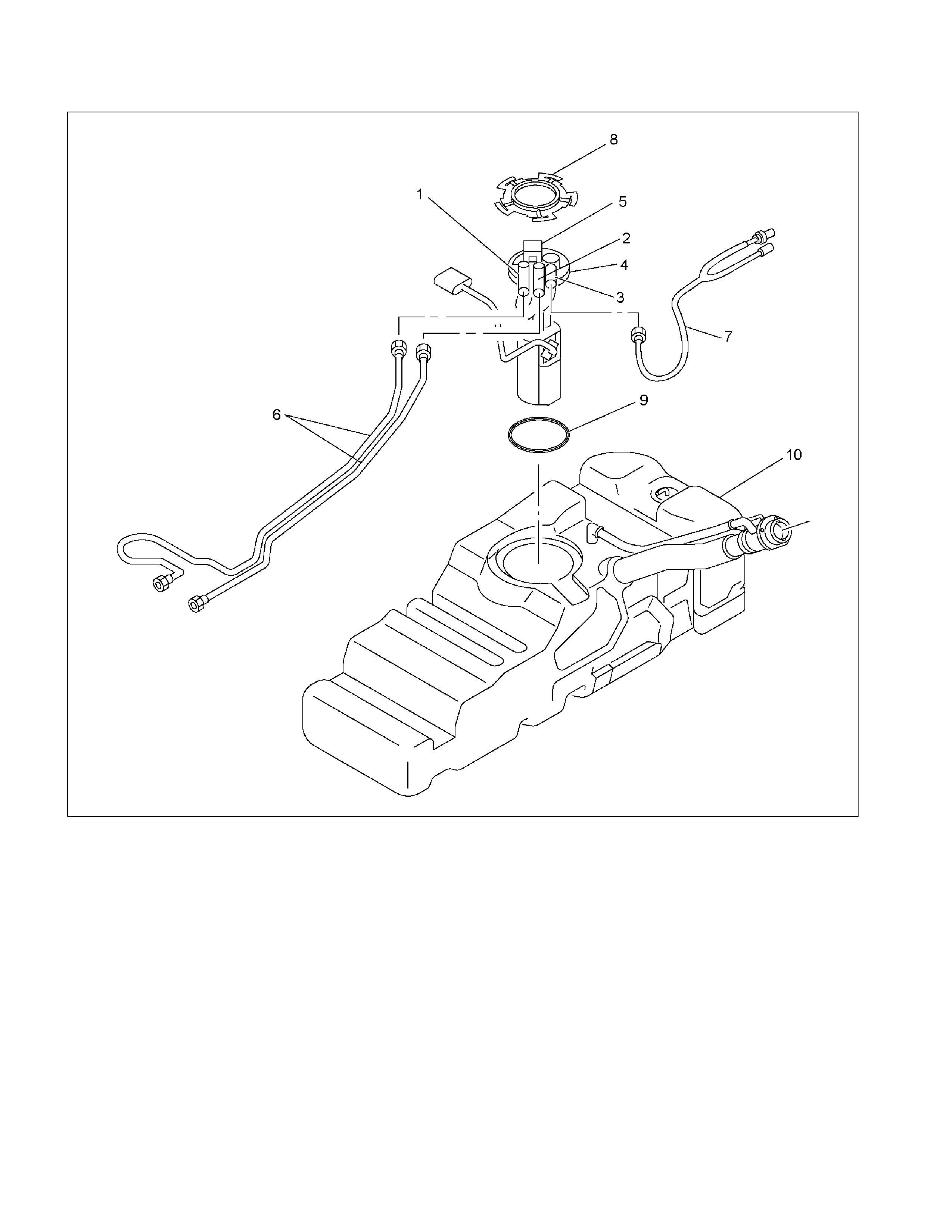
Fuel Gauge Unit and Associated Parts
RTW46CLF000501
Legend
1. Fuel Feed Port
2. Fuel Return Port
3. Fuel Emission Port
4. Fuel Gauge Unit and Sender Assembly
5. Connector; Fuel Gauge Unit
6. Fuel Tube / Quick Connector
7. Evapo Tube / Quick Connector
8. Retainer Ring (Fuel Gauge Unit Lock)
9. Seal; Fuel Gauge Unit
10. Fuel Tank Assembly
Removal
CAUTION: When repair to the fuel system has been
completed, start engine and check the fuel system for
loose connection or leakage. For the fuel system
diagnosis, see Section “Driveability and Emission".
1. Remove fuel tank assembly (10). Refer to “Fuel Tank
Removal" in this section.
2. Disconnect the quick connector of the fuel tube (6)
from fuel gauge unit.
3. Disconnect the quick connector of the evapo tube (7)
from fuel gauge unit.
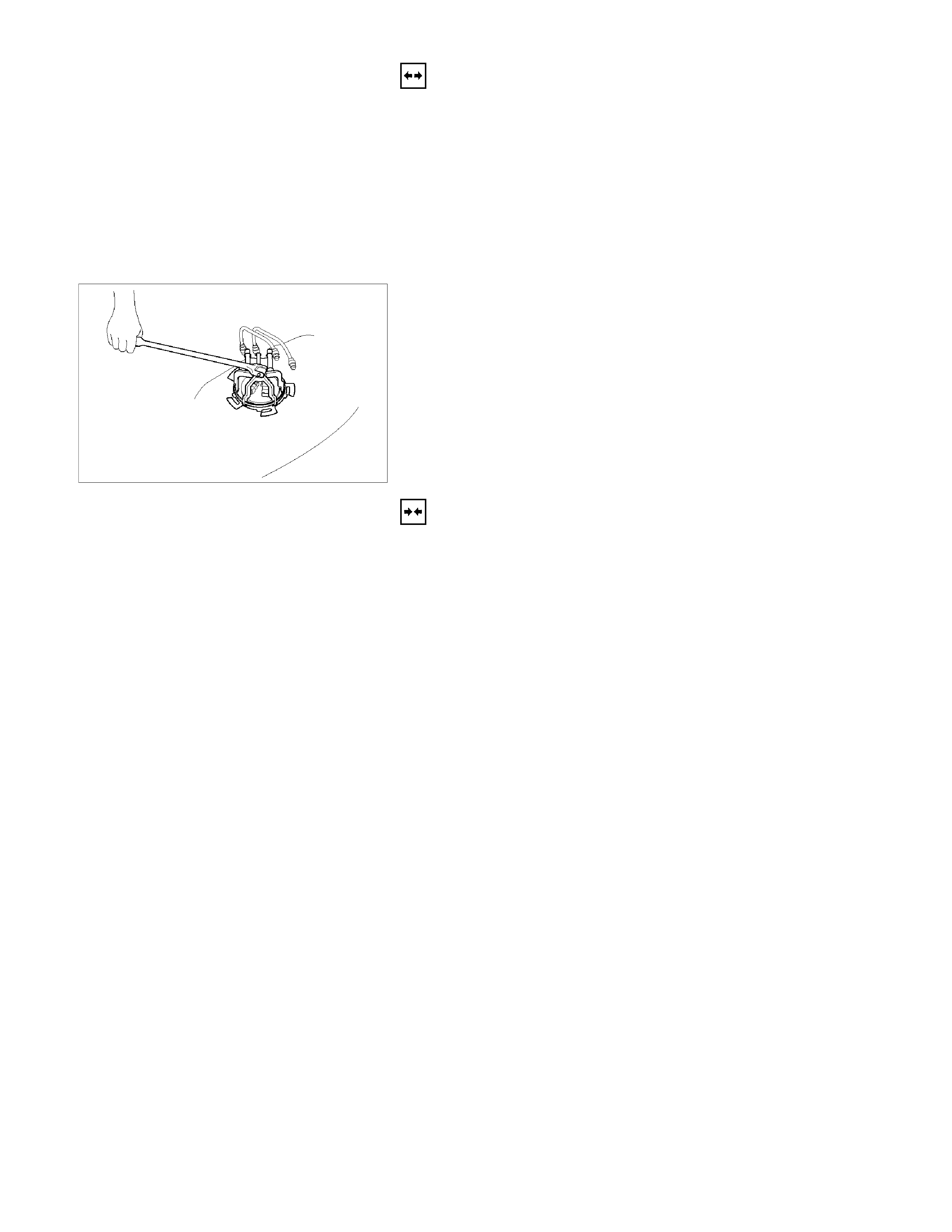
140R100035
4. Remove the retainer ring (8) from the fuel tank with
the removal tool 5-8840-2602-0.
5. Slowly remove the fuel gauge unit (4) from the fuel
tank, being careful not to bend the float arm.
NOTE:
Cover opening for the fuel gauge unit on fuel tank to
prevent any foreign matter from entering.
6. Discard fuel gauge unit seal (9) because it is not
reusable.
Installation
1. Clean the seal surface of the fuel tank and the fuel
gauge unit.
NOTE:
If there is foreign matter on the seal surface, it may cause
a fuel leak.
2. Install the new fuel gauge unit seal (9) to opening of
the fuel tank, fitting the seal along the groove.
3. Install the fuel gauge unit (4) into the fuel tank, being
careful not to bend the float arm.
4. Ensure that the flange on the fuel gauge unit is fitted
into the groove in the opening of the fuel tank and
seated firmly on the fuel gauge unit seal.
5. Carefully lock the retainer ring (8) to the fuel tank with
the remover tool 5-8840-2602-0.
6. Connect the quick connector of the evapo tube (7) to
the fuel gauge unit.
7. Connect the quick connector of the fuel tube (6) to the
fuel gauge unit.
NOTE:
Refer to “Fuel Tube/Quick Connector Fittings” in this
section when performing any repairs.

8. Check for leaks.
Method for leak checking.
(a) Plug the end of the fuel and evapo pipes (6 & 7).
Remove the breather hose from the fuel tank.
Tighten the fuel filler cap until at least one click is
heard.
(b) Apply soapy water around the fuel gauge unit seal
area.
(c) Apply air pressure to the fuel tank from the end of
the breather pipe at 5 psi (34.3 kPa/2.8 kgf/cm2)
over 15 seconds.
(d) Verify there are no bubbles forming around the
fuel gauge unit seal area.
(e) Remove the plugs from the end of the fuel and
evapo pipes, and refit the breather hose.
9. Install the fuel tank assembly (9).
NOTE:
Refer to “Fuel Tank” in this section.

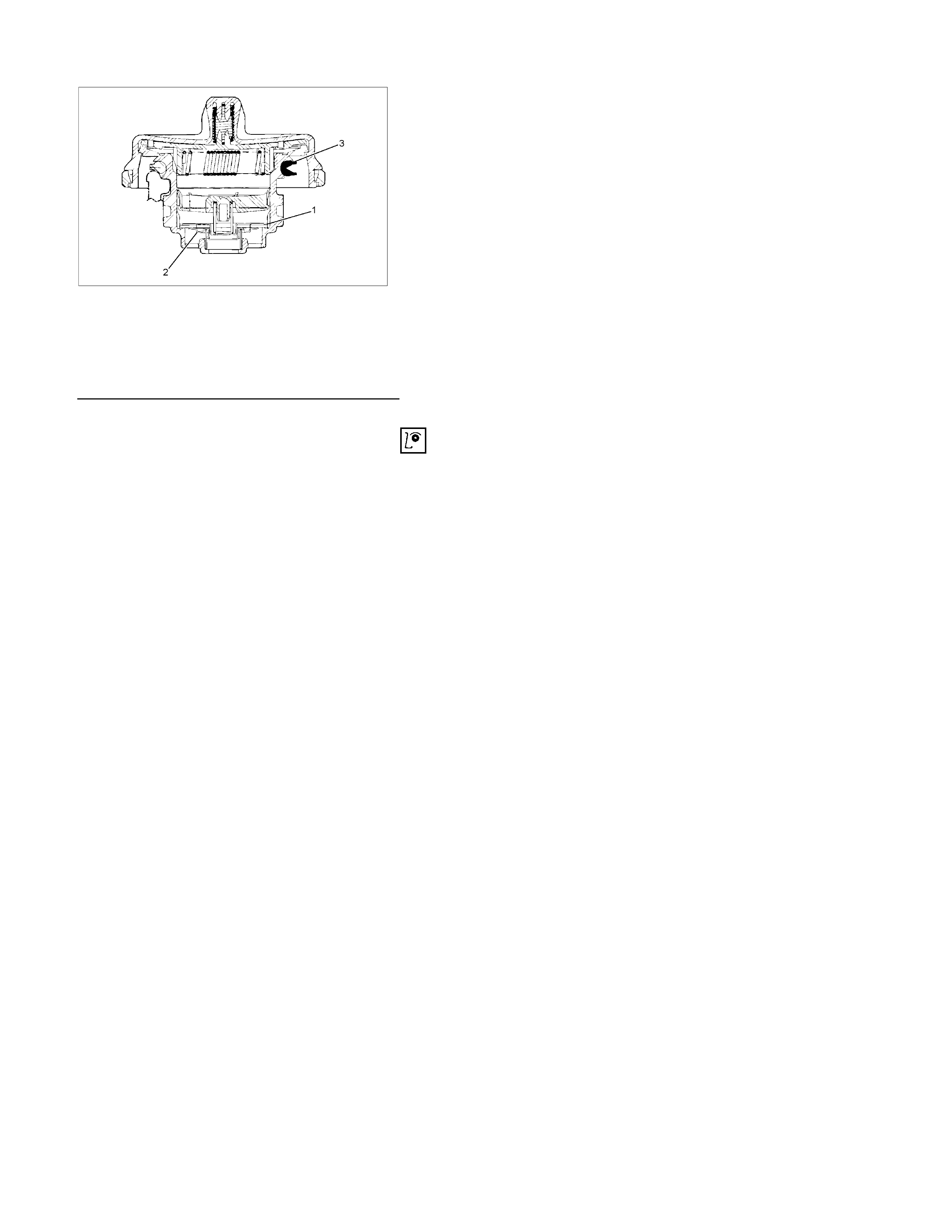
FUEL TUBE / QUICK – CONNECTOR FITTINGS
Precautions
• Do not light a match or create a flame.
• Keep flames away from your work area to prevent
flammable materials from catching fire.
• Disconnect battery ground cable to prevent electrical
shorts.
• Pre-treat piping system or associated parts from thermal
damage or from spattering when welding or simila
r
heat-generating work.
140R100032
Legend
(1) O-ring
(2) Port
(3) Connector
(4) Plastic Tube
Cautions During Work
Do not expose the assembly to battery electrolyte or do not
wipe the assembly with a cloth used to wipe off spilt battery
electrolyte.
Piping that has been splattered with battery electrolyte or
battery electrolyte soaked cloth that was wiped on the piping
cannot be used.
141R100002
Removal
1. Open the fuel cap to relieve the fuel pressure in the
tank.
NOTE:
Use compressed air to remove any dirt on the fuel quick
connect fittings prior to disconnecting the fittings.
NOTE:
When disconnecting the fuel pipe, cover the area with a
cloth to prevent fuel from splashing as the fuel pipe may
still have some pressure in it.
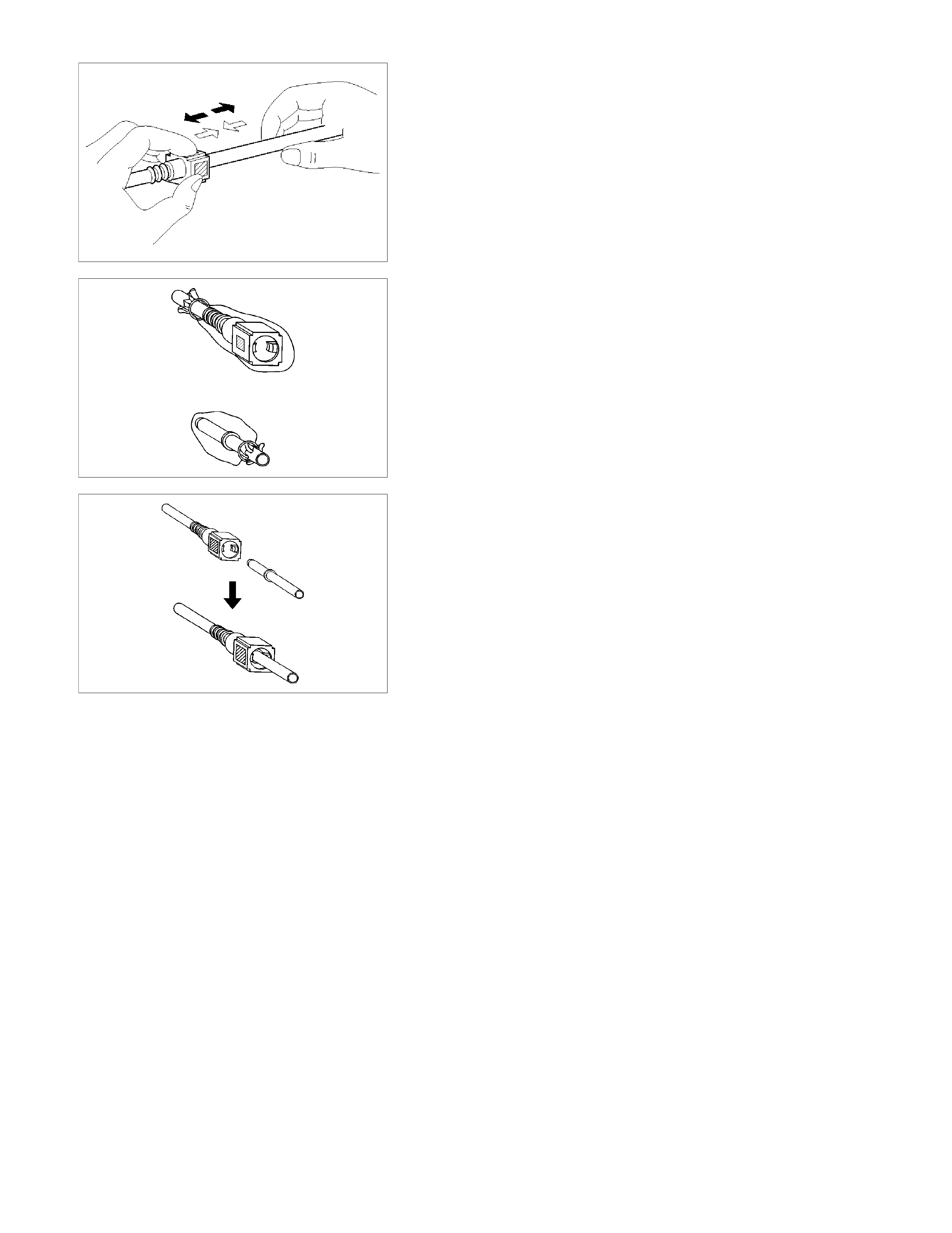
140R100037
3. For removal of the quick connector, hold the quick
connector in one hand, and pull out the connector with
the other hand while pressing the square relieve
button of the connector, as illustrated.
NOTE:
Do not use tools of any kind. Only use bare hands when
disconnecting the connector. Use a lubricant (light oil)
and/or push and pull the connector until the pipe is
disconnected.
140R100028
Cover the connectors that were removed with a plastic
bag, to prevent dust or rain water from entering.
140R100036
Reuse of Quick–Connector
• Replace the port and connector if scratch, dent or crack is
found.
• Remove any dirt build up on the port when installing the
connector. Replace the connector, if there is any forms o
f
rust, dent, scratch.
• After cleaning the port, insert it straight into the connecto
r
until it clicks. After it clicks, try pulling it out at 49 N (5 kgf)
to make sure that it is not drawn and is securely locked.
Assembling Advice
By applying engine oil or light oil to the pipe port makes
pipe assembly easier. The pipe assembly should take
place immediately after applying oil (to prevent dust from
sticking to the pipe surface – which may decrease sealing
ability).
Test/Inspection After Assembling
1. Reconnect the battery negative cable.
2. Start the engine and observe the engine idle speed.
The presence of dirt in the fuel system may affect the
fuel injection system.
3. Check for fuel leakage from the connector.

FILLER NECK
Removal
1. Remove the fuel tank.
NOTE:
Refer to "Fuel Tank" in this section.
2. Put a mark on the following points as the filler neck
assembly is restored.
• Each joint area of the hose (to restore axial
direction and insertion length of the hose)
• Each fasten area of the clamp (to restore axial
direction and position of the clamp)
• Each bolt in the clamp (to restore fasten length of
bolt in the clamp)
• The band clip (to restore position and fasten
length of the band clip)
NOTE:
Cover end of each hose and pipe to prevent any dust
entering.
Installation
1. Align each marking and restore the following point.
• Each joint area of the hose (Restore axial direction
and insertion length of the hose)
• Each fasten area of the clamp (Restore axial
direction and position of the clamp)
• Each bolt in the clamp (Restore fasten length of
bolt in the clamp)
Torque N·m (kg·m/lb·ft)
2.5 (0.25/21.7)
For filler neck side except flat deck model:
• The band clip (Restore position and fasten length
of the band clip)
2. Install the fuel tank.
NOTE:
Refer to "Fuel Tank" in this section.
FUEL FILLER CAP
RTW36CSH000401
Legend
(1) Pressure Valve
(2) Vacuum Valve
(3) Seal Ring
General Description
A vacuum valve and pressure valve are built into the fuel filler
cap which adjusts the fuel pressure in the fuel tank to prevent
fuel tank damage.
Inspection
The fuel filler cap must be inspected for seal condition.
The fuel filler cap must be replaced if found defective
CAUTION: A replacement fuel filler cap must be the same
as the original. The fuel filler cap valve was designed
primarily for this application and must be replaced with
the same type or decreased engine performance may
occur.

INJECTION PUMP
Read this Section carefully before performing any removal and installation procedure. This Section gives you important
points as well as the order of operation. Be sure that you understand everything in this Section before you begin.
Removal
1. Battery
Remove the battery from the battery tray.
6C-1
2. Drive Belt
1) Loosen the adjust bolt of the power steering pump
pulley.
2) Remove the drive belt.
3. Power Steering Pump Assembly
P1010003
4. Accelerator Control Cable
Disconnect the accelerator cable from the intake throttle.
5. Vacuum Hose
Disconnect the vacuum hose from the EGR valve and the
intake throttle.
6. Fan
7. Power Steering Pump Bracket
6C-4
8. Throttle Position Sensor Harness Connector
Disconnect the harness connector from the throttle
position sensor.
9. Oil Level Gauge
10. Fuel Pipe
1) Disconnect the fuel hoses from the fuel filter or
priming pump.
2) Disconnect the fuel hoses from the injection pump.
11. Fuel Filter Assembly
6C-5
12. Fuel Filter Bracket
13. Leak Off Hose
Disconnect the leak off hose at the injection pump.
14. Injection Pipe Clip
15. Injection Pipe
1) Loosen the injection pipe sleeve nuts at the delivery
valve side and the injection nozzle side.
NOTE:
Do not apply excessive force to the injection pipes.
2) Loosen the injection pipe clip.
3) Remove the injection pipes.
NOTE:
Plug the delivery holder ports with the caps to prevent the
entry of foreign material.
16. Intake Manifold
1) Remove the EGR valve from the intake manifold and
EGR pipe.
2) Loosen the intake rubber hoses clip.
3) Loosen the intake manifold bolts and nuts.
17. Injection Pump Cover
020L200017
RTW46CSH000201
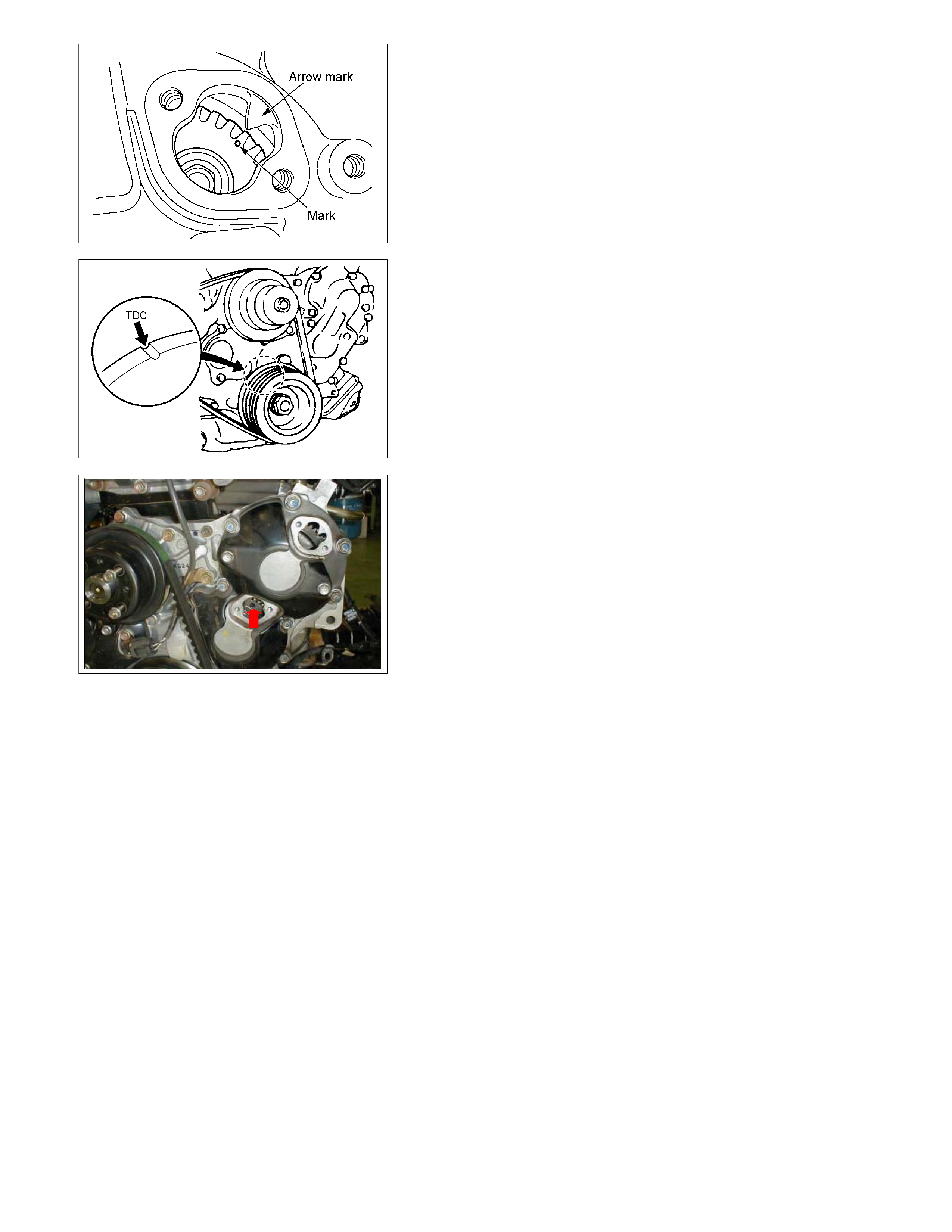
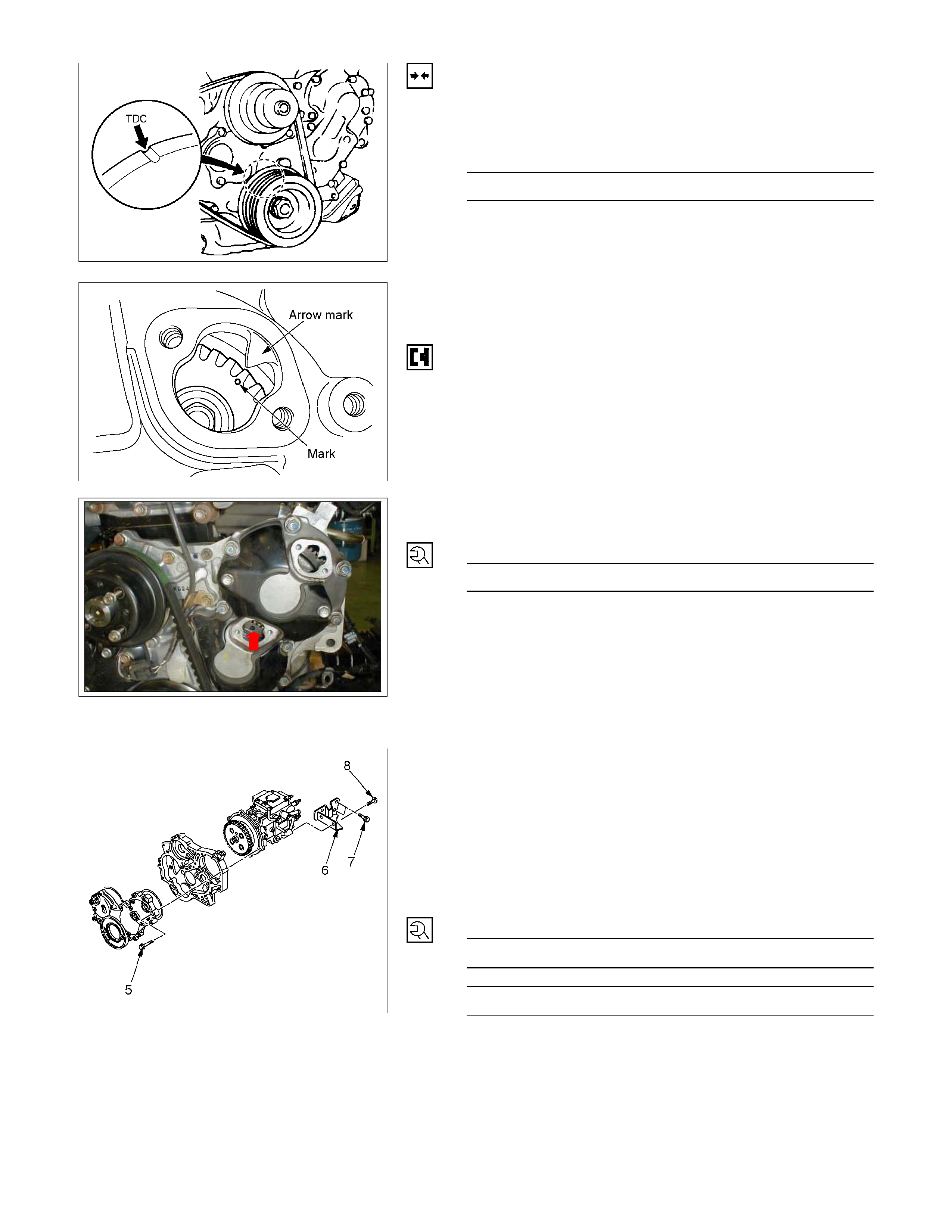
18. Timing Check Hole Cover
1) Remove the timing check hole cover.
2) For ease in reinstalling the injection pump, align the
timing mark on the timing gear case cover by turning
the crankshaft using a wrench.
• Turn the crankshaft until the crankshaft pulley
TDC line aligns with the timing mark. Ensure the
piston in the No.1 cylinder is at TDC on the
compression stroke.
NOTE:
If the check hole cover is reinstalled with the lock bolt still
in place, the crank pulley will not turn.
6C-7
3) Insert the lock bolt (M6 x 30) into the scissors gear
idle gear “B” fixing hole to prevent the scissors gear
from turning.
19. Injection Pump Bracket
20. Injection Pump
RTW46CSH000201
Installation
1. Injection Pump
1) Install the injection pump gear (When gear is
removed).
Injection Pump Gear Nut N⋅m (kg⋅m/lb⋅ft)
64 (6.5/47)
2) Turn the crankshaft until the crankshaft pulley TDC
line aligns with the timing mark. Ensure the piston in
the No.1 cylinder is at TDC on the compression
stroke.
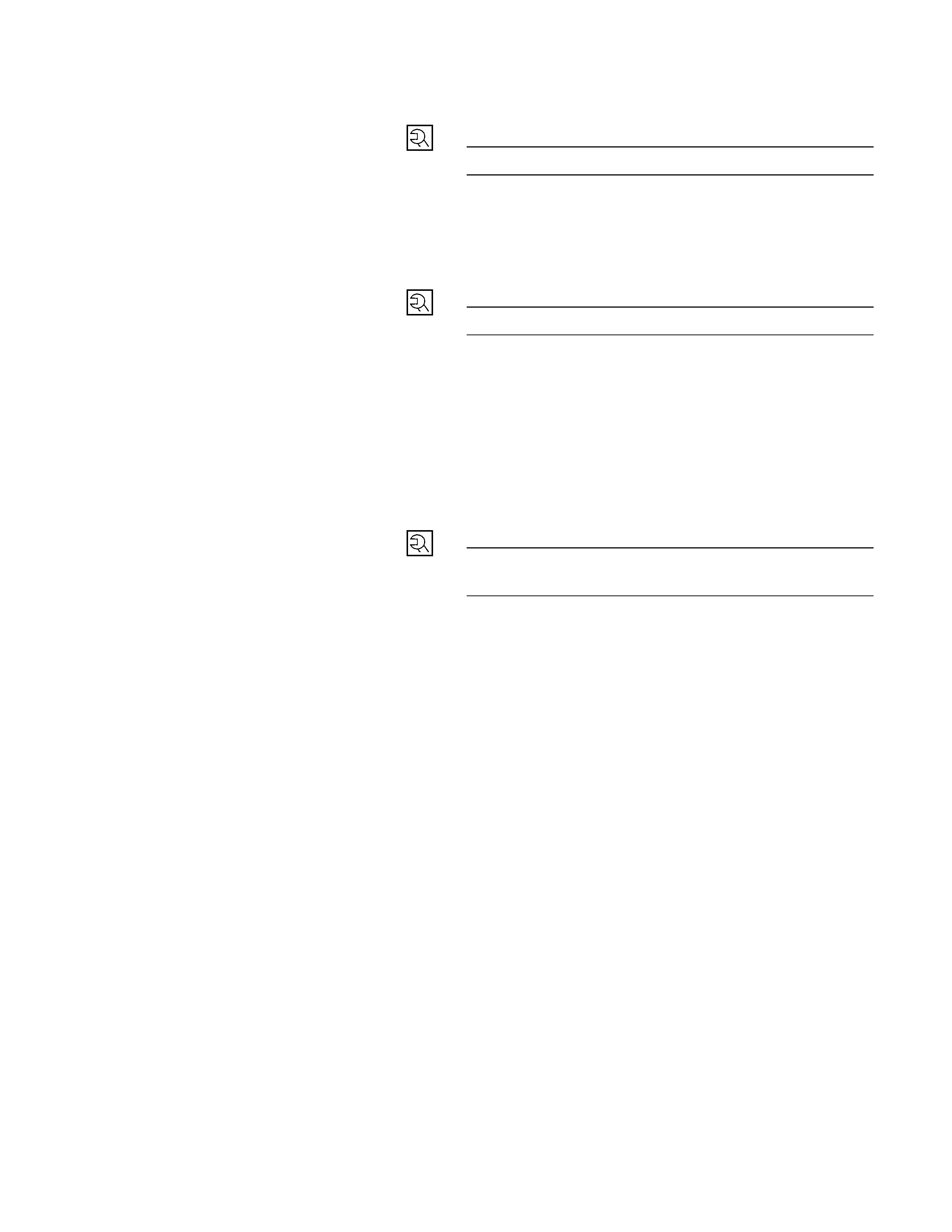
020L200017
3) Install the injection pump to the timing gear case with
align the timing mark on the pump gear to the arrow
mark on the timing gear case cover.
4) Check that the setting marks of the injection pump
gear and the idler gear B are aligned.
5) Remove the lock bolt (M6 × 30) from the idle gear “B”.
6C-7
6) Tighten the injection pump fixing bolts to the specified
torque.
Injection Pump Bolts Torque N·m (kg·m/lb·ft)
19 (1.9/14)
RTW36AMH000101
2. Injection Pump Bracket
1) Install the injection pump bracket (6) and the bracket
bolts (7) and (8) to the cylinder body. Temporarily
tighten the bracket bolts.
2) Tighten the bracket bolts (7) to the specified torque.
3) Tighten the bracket bolts (8) to the specified torque.
NOTE:
Tighten the bracket bolt (8) first.
Injection Pump Bracket Torque N·m (kg·m/lb·ft)
(8) 19 (1.9/14)
(7) 40 (4.1/30)

3. Timing Check Hole Cover
Install the timing check hole cover and tighten bolts to the
specified torque.
Timing Check Hole Cover Bolts
Torque N·m (kg·m/lb·in)
8 (0.8/69)
4. Injection Pump Cover
5. Intake Manifold
1) Install the intake manifold with gasket.
Intake Manifold Bolts
Torque N·m (kg·m/lb·ft)
19 (1.9/14)
Intake Manifold Nuts Torque N·m (kg·m/lb·ft)
24 (2.4/17)
2) Install the EGR valve to the intake manifold and EGR
pipe temporarily.
3) Tighten the nuts and bolts to the specified torque
Torque N⋅m (k g⋅m/lb⋅ft)
Nuts 24 (2.4/17)
Bolts 27 (2.8/20)
6. Injection Pipe
Install the injection pipe.
Injection Pipe Torque N·m (kg·m/lb·ft)
29 (3.0/22)
Nozzle Side N·m (kg·m/lb·ft)
29 (3.0/22)
Pump Side N·m (kg·m/lb·ft)
40 (4.1/30)
7. Injection Pipe Clip
Install the injection pipe clip.
NOTE:
Make absolutely sure that the clip is correctly positioned.
Injection Pipe Clip Torque N·m (kg·m/lb·in)
8 (0.8/69)
8. Leak Off Pipe and Leak Off Hose
Install the leak off pipe to injection nozzle and connect the
leak off hose to the injection pump.
9. Fuel Filter Bracket
Install the fuel filter bracket and tighten bolts to the
specified torque.
Fuel Filter Bracket Bolts Torque N·m (kg·m/lb·ft)
21 (2.1/15)
10. Fuel Filter Assembly
Install the fuel filter assembly to bracket and tighten bolts
to the specified torque.
Fuel Filter Assembly Bolts
Torque N·m (kg·m/lb·ft)
21 (2.1/15)
11. Fuel Pipe
1) Connect the fuel hoses to the fuel filter or priming
pump.
2) Connect the fuel hoses to the injection pump.
12. Oil Level Gauge
Install the oil level gauge and tighten bolts to the specified
torque.
Oil Level Gauge Bolts
Torque N·m (kg·m/lb·in)
M8: 19 (1.9 / 14)
M6: 8 (0.8/69)
13. Throttle Position Sensor Harness Connector
Reconnect the harness connector to the throttle position
sensor.
14. Power Steering Pump Bracket
15. Fan
16. Vacuum Hose
Connect the vacuum hose to the EGR valve and the
intake throttle.
17. Accelerator Control Cable
1) Connect the accelerator cable to the intake throttle.
18. Power Steering Pump Assembly
19. Drive Belt
Install the drive belt and adjust the belt tension.
20. Battery
SPECIAL TOOLS
ILLUSTRATION TOOL NUMBER TOOL NAME
5-8840-2602-0
(J-39765) Remover: fuel pump retainer ring