

MAIN DATA AND SPECIFICATIONS
Exhaust system
Pipe outside diameter × thickness
Front pipe mm (in)
Middle pipe (4 × 4) mm (in)
Silencer & Tail pipe
Type
Pipe outside diameter × thickness
Tail pipe mm (in)
Length mm (in)
Mounting
Number of suspension points
Type
50.8 × 1.6 (2.0 × 0.063)
50.8 × 1.6 (2.0 × 0.063)
Circular section-shell construction
of double skin and end plates,
internal construction of baffles
and perforated tubes.
50.8 × 1.6 (2.0 × 0.063)
Approximately 1335 (52.6)
4
Rubber
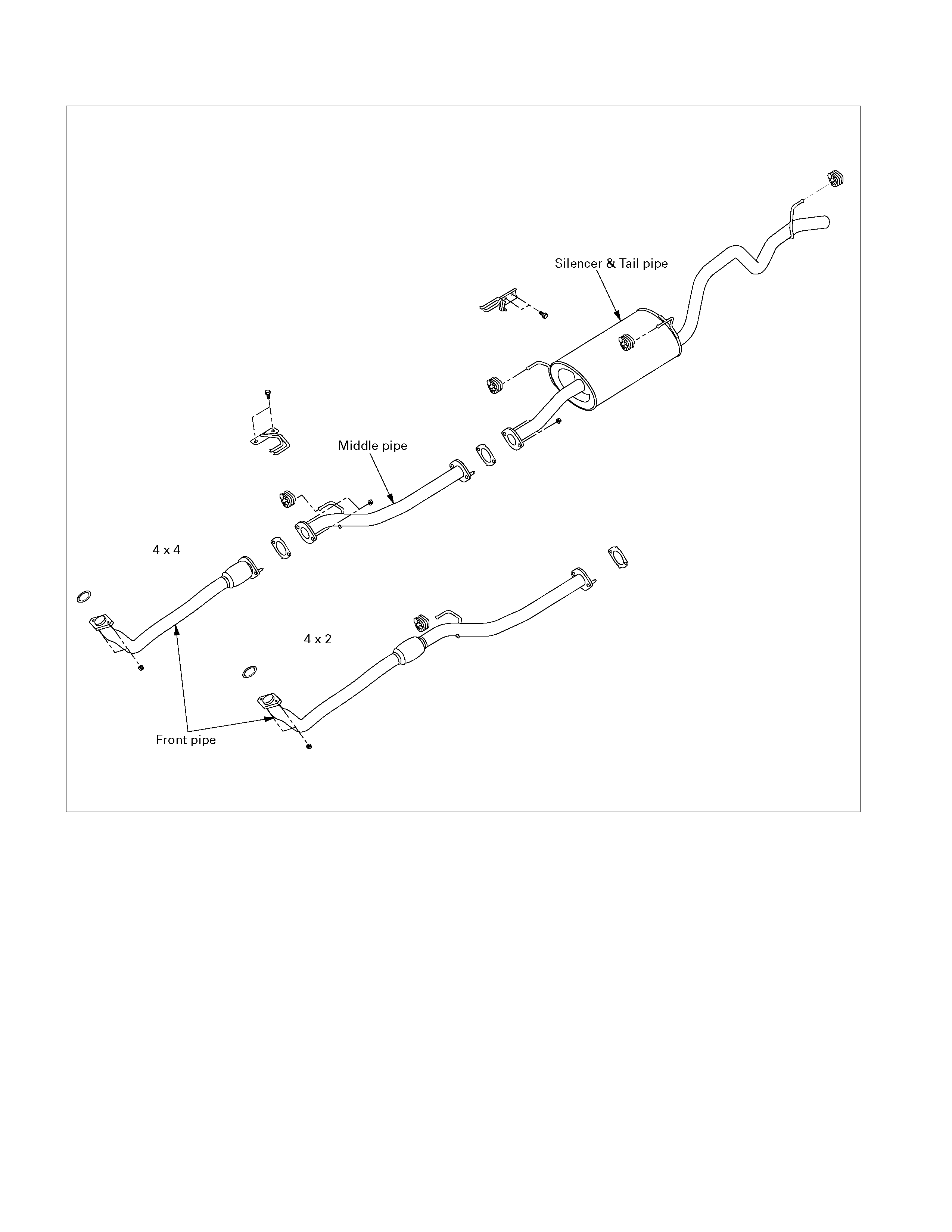
GENERAL DESCRIPTION
150R300002
The exhaust pipe layout is described in the above illustration.
The catalytic converter is installed between the turbocharger and the front pipe.
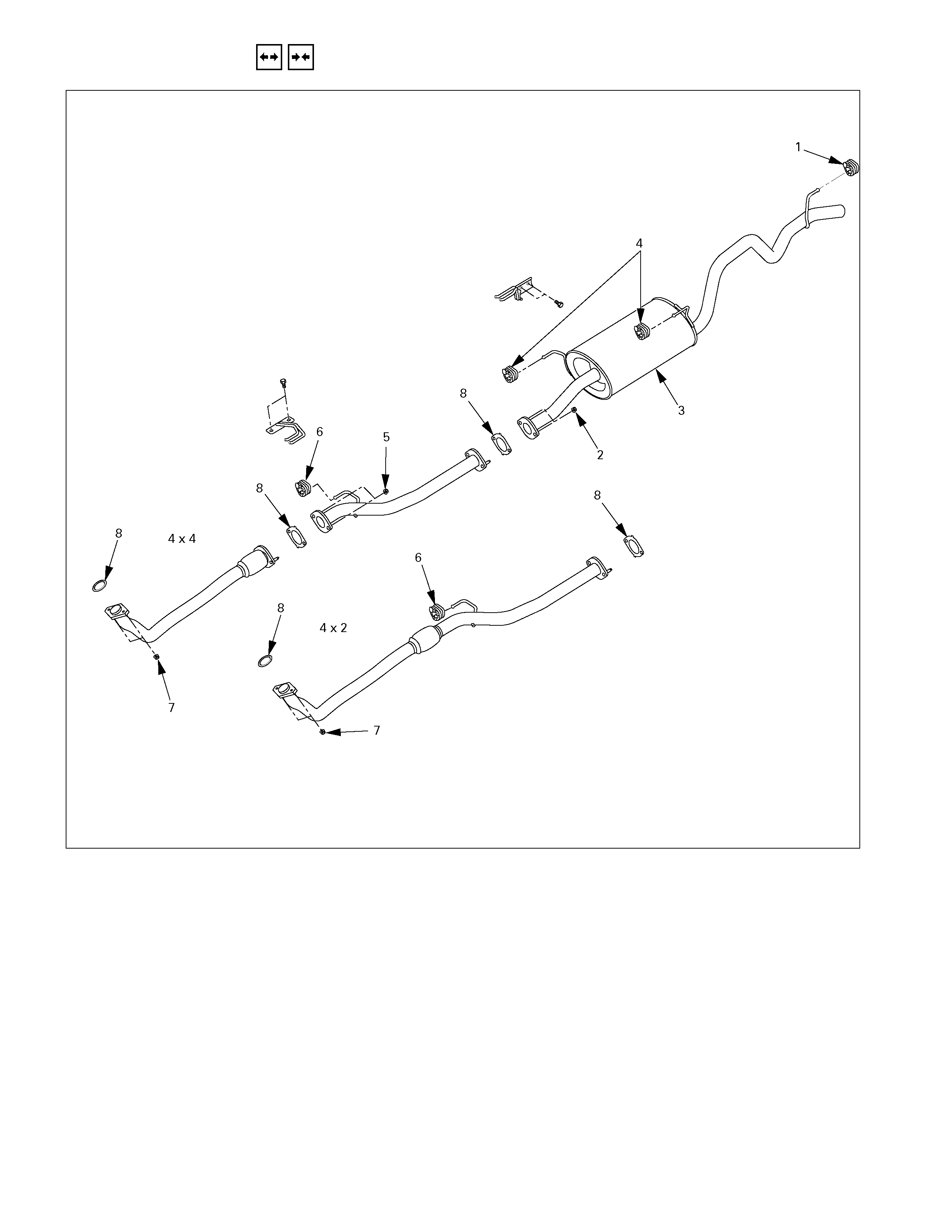
REMOVAL AND INSTALLATION
150L300001
Removal Steps
1. Rear hanger rubber
2. Silencer front nut
3. Exhaust silencer
4. Silencer hanger rubber
5. Middle pipe nut
6. Front hanger rubber
7. Front pipe nut
8. Exhaust pipe gasket
Important Operations – Installation
Follow the removal procedure in the reverse order to
perform the installation procedure. Pay careful attention to
the important points during the installation procedure.
1. Front Pipe Nut
Connect the exhaust pipe to the catalytic converter.
Torque N⋅m (kg⋅m/lb⋅ft)
67 (6.8/49)
2. Middle pipe Nut (4×4 only)
Connect the middle pipe to the front pipe.
Torque N⋅m (kg⋅m/lb⋅ft)
43 (4.4/32)
3. Silencer Front Nut
Connect the silencer to the front or middle pipe.
Torque N⋅m (kg⋅m/lb⋅ft)
43 (4.4/32)

INSPECTION AND REPAIR
Make the necessary adjustments, repairs, and part replacements if excessive wear or damage is discovered during
inspection.
Front Exhaust Pipe and Exhaust Silencer
Check the pipes for corrosion, cracking, damage or misalignment and repair as required.
Check the rubber rings for deterioration or damage and repair as required.
Catalytic Converter
1. Inspect outside the catalytic converter for any hitting mark.
2. Visual check inside the catalytic converter for crack or break converter element.
3. If find any problem during the inspection, replace the catalytic converter assembly.
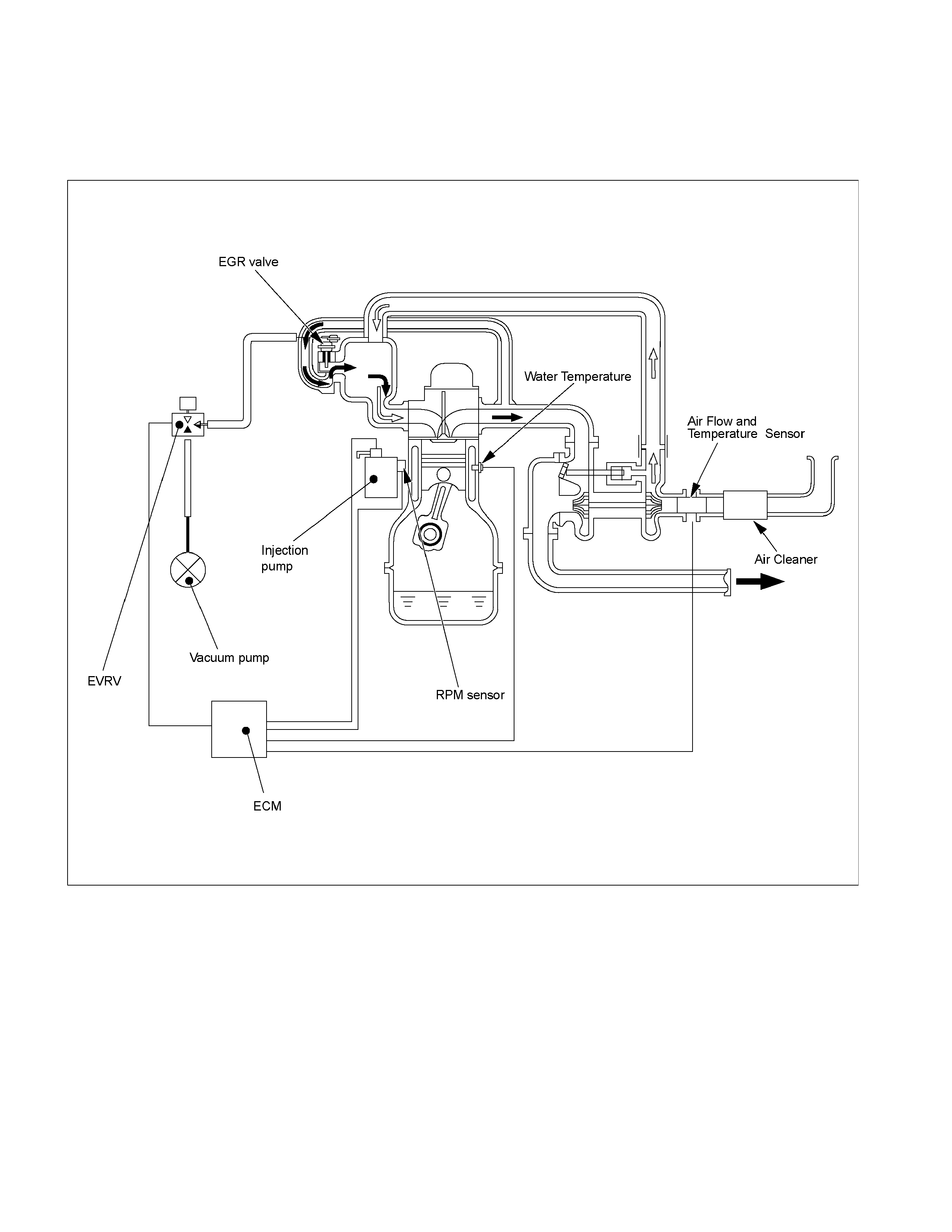
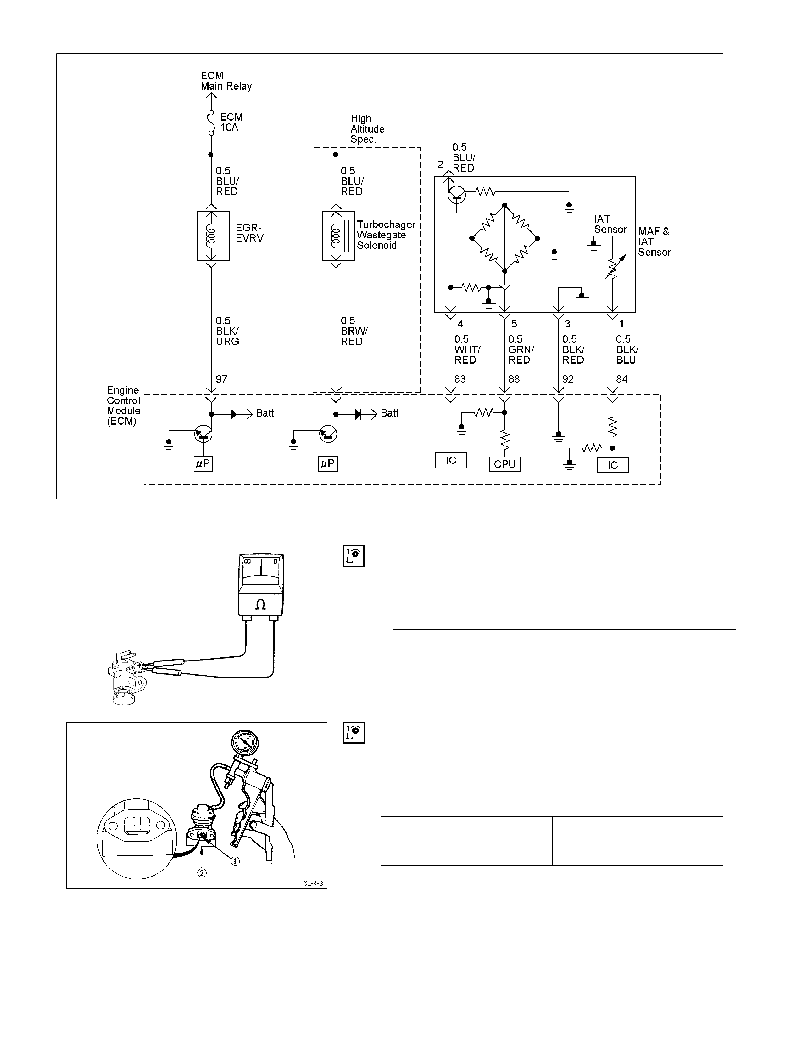
The EGR system is controlled by the ECM. Refer to “Engine Driveability and Emissions” section for details.
RTW46EMF000701
INSPECTION
RTW46ESH000301
EVRV
Use a circuit tester to measure the EVRV resistance.
EVRV Resistance Ω at 20°C
14
If the resistance is not within specification, replace the
EVRV.
EGR Valve
Apply vacuum to the EGR valve and check the valve
operation.
Negative Pressure
Less than 250 mm Hg No operation
More than 300 mm Hg Operation
TURBOCHARGER
MAIN DATA AND SPECIFICATI O NS
Engine Model 4JA1L 4JA1T, 4JB1T,
4JA1TC 4JG2T 4JH1TC
Turbocharger Model IHI RHF 4H IHI RHB 52W
or RHF5 RHF5H
Turbine Type Radial Inflow
Compressor Type Radial Outflow
Maximum Permissible Speed rpm – 180,000 172,000 180,000
Boost Set Value mmHg 440 – – –
Wastegate Opening Pressure mmHg – 189 – 887
Safety Valve Opening Pressure mmHg – 850 – 910
Weight kg (lb) 4.1 (9.0) 4.2 (9.3) 4.6 (10.1)
IHI: Ishikawajima Harima Heavy Industries., Ltd.
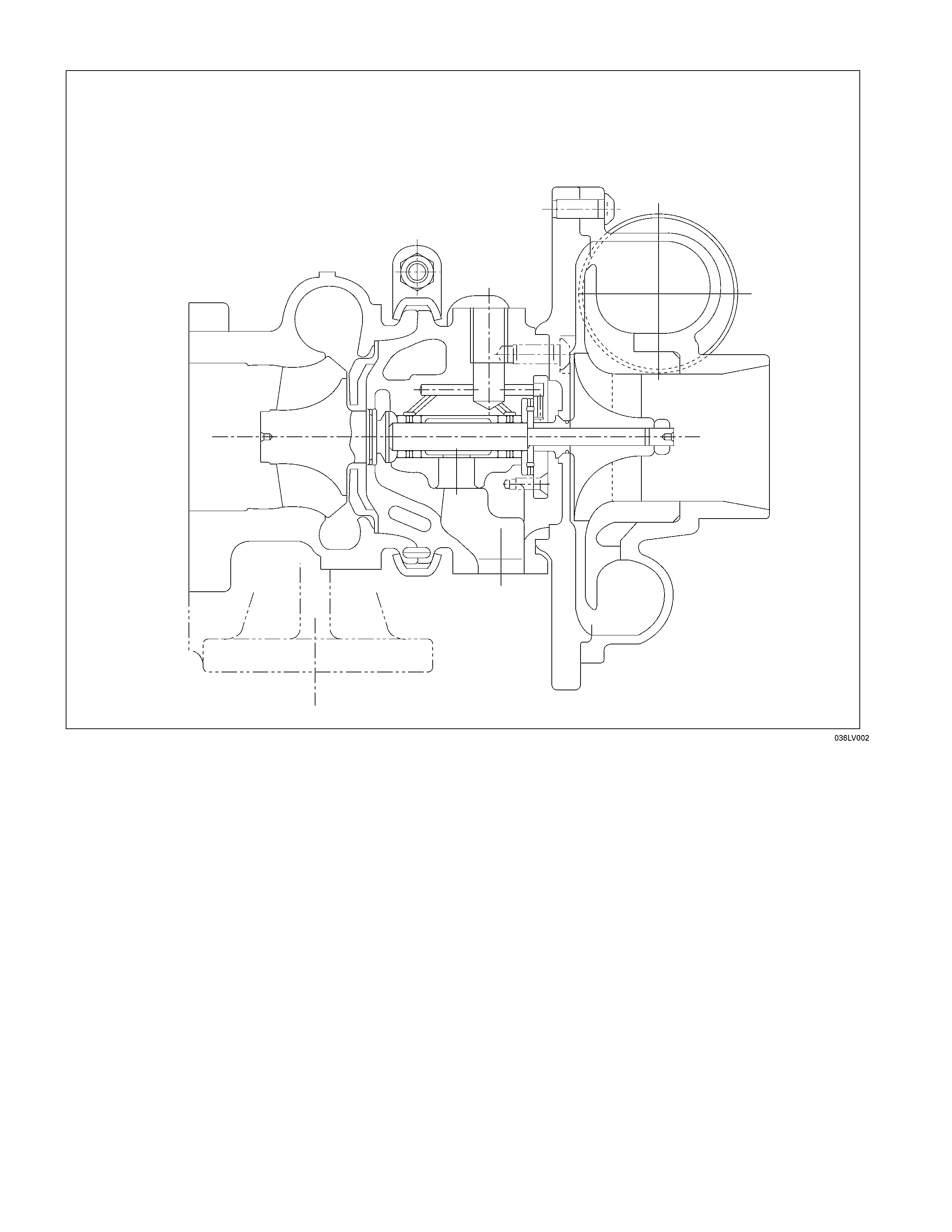
GENERAL DESCRIPTION
The turbocharger internal mechanism consists of the turbine wheel, the compressor wheel, and the radial bearings.
These parts are supported by the bearing housing.
The turbocharger external mechanism consists of the compressor housing air intake port and the turbine housing air
exhaust port.
The turbocharger increases air intake efficiency. This results in increased engine power, reduced fuel consumption,
and minimal engine noise.
The turbocharger operates at very high speeds and temperatures. Part materials have been carefully selected and
machined to extremely high precision.
Turbocharger servicing requires great care and expertise.
If reduced performance is noted, check the engine for damage or wear. If there is no apparent engine damage or wear,
trouble with the turbocharger is indicated.
INSPECTION AND REPAIR
Make the necessary adjustments, re pairs, and part replacements if excessive wear or damage is discovere d during
inspection. Note that the quoted pressures ar e Absolute Pressure.
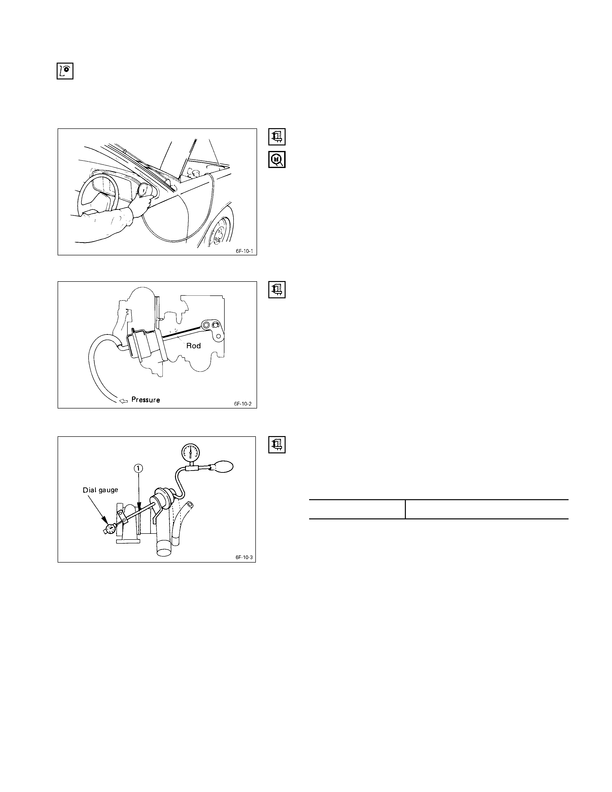
Turbocharger pressure check
(1) Remove the pressure switch conn ecting hose from
intake duct.
(2) Connect the pressure gau ge.
(3) Start the engine and gradually increase the engine
speed (the vehicle must be stationary with no load
applied to the engine).
(4) Check to see that turbocharger pressure rises to
approximately 141.3 kPa (1060 mmHg).
Pressure Gauge : 5-8840-0075-0
Waste gate operation check
(1) Remove the hose between the waste gate and the
intake pipe.
(2) Connect the pressure gau ge.
(3) Check to see that the rod begins to move when a
pressure of approximately 118 kPa (885 mm Hg) is
applied to the waste gate.
Note:
Do not apply a pressure greater than 150 kPa (1125
mm Hg) to the wastegate during this check.
Unit Inspection (Remove Turbo. from engine)
Check that the pressure required to stroke the control rod
c is at the correct value. kPa / mm Hg
4JH1-TC 134.8 / 1101
Contact the “ISUZU MOTORS LIMITED” Dealer service
department or “IHI SERVICE FACILITY” for major repairs
and maintenance.
Important wheel shaft end play and bearing clearance
standards and limits are included below for your
reference.
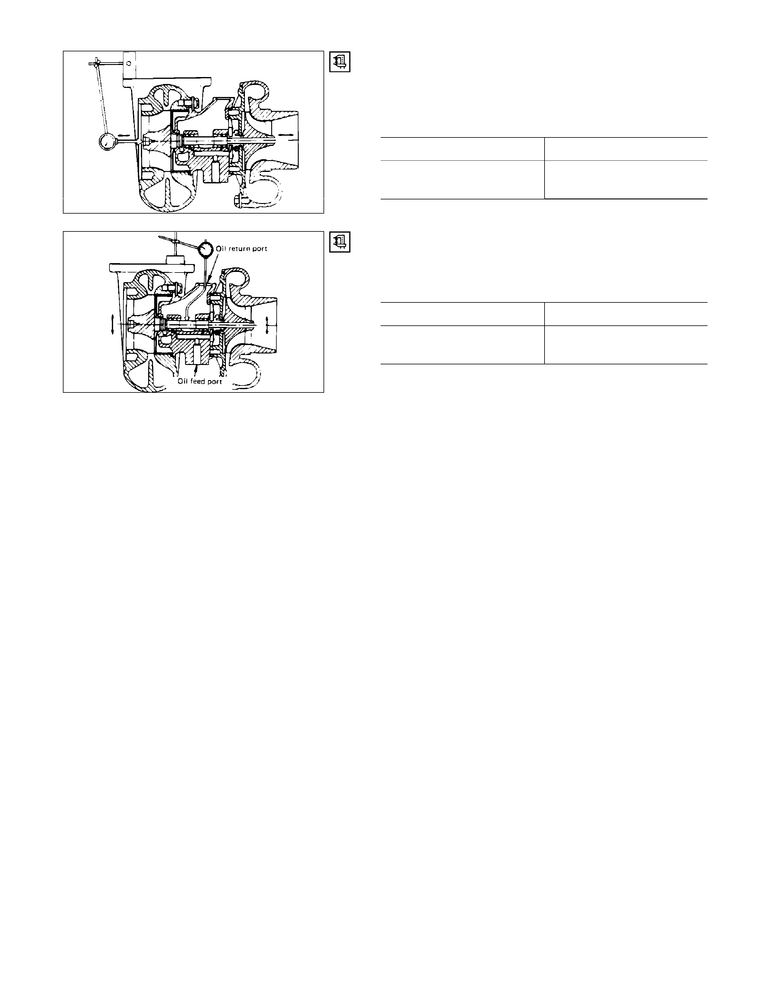
Wheel Shaft End Play
Use a dial indicator to measure the wheel shaft end play.
Apply a force of 11.8 N (1.2 kg/2.6 lb) alternately to the
compressor wheel end and the turbine wheel end.
Wheel Shaft End Play mm (in)
Standard Limit
0.03 - 0.06
(0.001 - 0.002) 0.09 (0.004)
150RY00034
Wheel Shaft and Bearing Clearance
Use a dial indicator to measure the wheel shaft and
bearing clearance.
Wheel Shaft and Bearing Clearance mm (in)
Standard Limit
0.056 - 0.127
(0.0022 - 0.0050) 0.127 (0.0050)
150RY00036

SPECIAL TOOLS
ILLUSTRATION TOOL NUMBER TOOL NAME
901RX00143
5-8840-0075-0 Pressure Gauge

IHI SERVICE NETWORK
For inquiries relating to turbochargers, please contact your ISUZU distributor or the nearest IHI Turbocharger Service
Facility.
HEADQUARTERS
ISHIKAWAJIMA HARIMA HEAVY INDUSTRIES CO., LTD.(IHI)
General Machinery Division
Tokyo Chuo Building 1-6-2 Marunouchi Chiyoda-ku
Tokyo 100-0005 JAPAN
TEL: 81-(3)-3286-2405 to 2407 (3 lines)
FAX: 81-(3)-3286-2430
CHINA
IHI BEIJING OFFICE
Room 705, China World Trade Centre, No. 1 Jian Guo Men Wai Avenue
Beijing, People’s Republic of CHINA
TEL: 86-(1)-505-4997, 0408
FAX: 86-(1)-505-4350
TLX: 210343 IHIPK CN
TAIWAN
IHI TAIPEI OFFICE
Room 1202, Chia Hsin Building, No. 96 Chung Shan
North Road, Section 2, Taipei, TAIWAN
TEL: 886-(2)-542-5520, 5521, 5523
FAX: 886-(2)-542-4362
TLX: 11320 IHICO
THAILAND
IHI BANGKOK OFFICE
8th Floor, Thaniya Building, 62 Silom Road, Bangkok, THAILAND
TEL: 66-(2)-236-3490, 7356, 9099
FAX: 66-(2)-236-7340
TLX: 82375 IHICO TH
MALAYSIA
IHI KUALA LUMPUR OFFICE
Letter Box No. 52, 22nd Floor, UBN Tower,
10 Jin. P. Ramlee 50250 Kuala Lumpur, MALAYSIA
TEL: 60-(3)-232-1255, 1271
FAX: 60-(3)-232-1418
TLX: IHI KLMA 20257
INDONESIA
IHI JAKARTA OFFICE
9th Floor, Skyline Building JI. M. H. Thamrin, No. 9, Jakarta, INDONESIA
TEL: 62-(21)-32-2147, 390-2211
FAX: 62-(21)-32-3273
TLX: 44175 IHIJKT