
SECTION 6E2 - C24SE ENGINE DRIVEABILITY AND
EMISSIONS
Abbreviations Charts
Component Locator
ECM Circuit Diagram
Ground Poi nt Chart
Location
Cable Harness & Connector Location
Connector List
Relay And Fuse
Relay & Fuse Box Location
Fuse & Relay Location
ECM Wiring Diagram
ECM Connector Pin Assignment & Output Signal
General Description For ECM And Sensors
Engine Control Module (ECM)
Manifold Absolute Pressure (MAP) Sensor
Throttle Position Sensor (TPS)
Idle Air Control (IAC) Valve
Crankshaft Position (CKP) Sensor
Engine Coolant Temperature (ECT) Sensor
Intake Air Temperature (IAT) Sensor
Vehic le Speed Sen so r (VSS )
Heated Oxygen (O2) Sensor
General Description For Fuel Metering
Battery Voltage Correction Mode
Clear Floo d Mode
Deceleration Fuel Cutoff (DFCO) Mode
Engine Speed/ Vehicle Speed/ Fuel Disable Mode
Acceleration Mode
Fuel Cutof f Mode
Starting Mod e
Run Mode
Fuel Mete ring System Components
Fuel Inj ect or
Fuel Pr essu re Regul ator
Fuel Rail
Fuel Pump Electrical Circuit
Thottle Body Unit
General Description For Electric Ignition System
Spark Plug
General Description For Evaporative Emission System
EVAP Emission Control System Purpose
EVAP Emission Control System Operation
System Fault Detection
Positive Crankcase Ventilation (PCV) System
Crank cas e Ven til ati on System Purpo se
A/C Clutch Diagnosis
A/C Clutch Circuit Operation
A/C Clutch Circuit Purpose
A/C Request Signal
Holden Strategy Based Diagnostics
Overview
Strategy Based Diagnostics Chart
Diagnostic Thought Process
1. Verify the Complaint
2. Perform Preliminary Checks
3. Check Bulletins and Troubleshooting Hints
4. Perform Service Manual Diagnostic Checks
5a and 5b. Perform Service Manual Diagnostic
Procedures
5c. Technician Self Diagnoses
5d. Intermittent Diagnosis
5e. Vehicle Operates as Designed
6. Re-examine the complaint
7. Repair and Verify Fix
General Service Information
Aftermarket Electrical and Vacuum Equipment
Electrostatic Discharge Damage
Visual/Physical Engine Compartment Inspection
Basic Knowledge of Tools Required
On-Board Diagnostic (OBD)
On-Board Diagnostic Tests
The Diagnostic Executive
Diagnostic Information
Malfunction Indicator Lamp
Data Link Connector (DLC)
Verifying Vehicle Repair
On-Board Diagnosis (Self-Dianosis)
Diagnosis With Tech 2 Scan Tool
Clearing Diagnostic Trouble Codes
Typical Scan Data & Definitions (Engine Data)
Typical Scan Data & Definitions (O2 Sensor Data)
Miscellaneous Test
Plotting Snapshot Graph
Plotting Graph Flow Chart (Plotting graph after
obtaining vehicle information)
Flow Chart for Snapshot Replay (Plotting Graph)
Snapshot Display With TIS2000
Service Programming System (SPS)
How To Use Breaker Box
On-Board Diagnostic (OBD) System Check
No Check Engine Lamp (MIL)
Check Engine Lamp (MIL) “On” Steady
Fuel Metering System Check
Fuel Injector Coil Test Procedure And Fuel Injector
Balance Test Procedure
Injector Coil Test Procedure (Steps 1-6) and
Injector Balance Test Procedure (Steps 7-11)
The Tech 2 Scan Tool
Techline
Techline
Techline

Fuel System Electrical Test
Fuel System Diagnosis
ECM Diagnostic Trouble Codes (DTC)
Diagnostic Trouble Code (DTC) P0107 Manifold
Absolute Pressure Circuit Low Input
Diagnostic Trouble Code (DTC) P0108 Manifold
Absolute Pressure Circuit High Input
Diagnostic Trouble Code (DTC) P0112 Intake Air
Temperature Sensor Low Input
Diagnostic Trouble Code (DTC) P0113 Intake
Air Temperature Sensor High Input
Diagnostic Trouble Code (DTC) P0117 Engine
Coolant Temp eratur e Sen sor Low Inpu t
Diagnostic Trouble Code (DTC) P0118 Engine
Coolant Temp eratur e Sen sor Hig h Input
Diagnostic Trouble Code (DTC) P0122 Throttle
Position Sensor Low Input
Diagnostic Trouble Code (DTC) P0123 Throttle
Position Sensor High Input
Diagnostic Trouble Code (DTC) P0131 O2 Sensor
Circuit Low Voltage (Bank 1 Sensor 1)
Diagnostic Trouble Code (DTC) P0132 O2 Sensor
Circuit High Voltage (Bank 1 Sensor 1)
Diagnostic Trouble Code (DTC) P0134 O2 Sensor
No Activity Defected Circuit (Bank 1 Sensor 1)
Diagnostic Trouble Code (DTC) P0135 O2 Sensor
Heater Circuit (Bank 1 Sensor 1)
Diagnostic Trouble Code (DTC) P0201
Injector 1 Control Circuit
Diagnostic Trouble Code (DTC) P0202
Injector 2 Control Circuit
Diagnostic Trouble Code (DTC) P0203
Injector 3 Control Circuit
Diagnostic Trouble Code (DTC) P0204
Injector 4 Control Circuit
Diagnostic Trouble Code (DTC) P0325
Knock Sensor (KS) Circuit Malfunction
Diagnostic Trouble Code (DTC) P0327
Knock Sensor (KS) Circuit Low Input
Diagnostic Trouble Code (DTC) P0336
Crankshaft Position (CKP) Sensor Circuit
Range/Per forma nc e ( 58x)
Diagnostic Trouble Code (DTC) P0337 Crankshaft
Position (CKP) Sensor Circuit Low Input (58x)
Diagnostic Trouble Code (DTC) P0351
Ignition 1 Control Circuit
Diagnostic Trouble Code (DTC) P0352
Ignition 2 Control Circuit
Diagnostic Trouble Code (DTC) P0443
Evaporative Emission (EVAP) Control
System Purge Control Valve Circuit Malfunction
Diagnostic Trouble Code (DTC) P0502
Vehicle Speed Sensor (VSS) Circuit Low Input
Diagnostic Trouble Code (DTC) P0562
System Voltage Low
Diagnostic Trouble Code (DTC) P0563
System Voltage High
Diagnostic Trouble Code (DTC) P0601
ECM Memory Checksum
Diagnostic Trouble Code (DTC) P0602
Programming Error
Diagnostic Trouble Code DTC P0650 Malfunction
Indicator Lamp (MIL) Contorol Circuit Malfunction
Diagnostic Trouble Code (DTC) P1167 Fuel Supply
System Rich During Deceleration Fuel Cut Off
Diagnostic Trouble Code (DTC) P1171 Fuel Supply
System Lean During Power Enrichment
Diagnostic Trouble Code (DTC) P1625
ECM System Reset
Diagnostic Trouble Code (DTC) P1626
Immobiliser No Signal
Diagnostic Trouble Code (DTC) P1631
Immobiliser Wrong Signal
Diagnostic Trouble Code (DTC) P1648
Wrong Security Code Entered
Diagnostic Trouble Code (DTC) P1649
Immobiliser Function Not Programmed
Diagnostic Trouble Code (DTC) P1693
Tachometer Output Low Voltage
Symptom Diagnosis
Preliminary Checks
Visual/physical Check
Intermittent
Engine Cranks But Will Not Run
Hard Start Symptom
Rough, Unstable, Or Incorrect Idle,
Stalling Symptom
Surges And/or Chugs Symptom
Hesitation, Sag, Stumble Symptom
Cuts Out, Misses Symptom
Lack Of Power, Sluggish Or Spongy Symptom
Detonation/spark Knock Symptom
Poor Fuel Economy Symptom
Excessive Exhaust Emissions Or Odors Symptom
Dieseling, Run-on Symptom
Backfire Symptom
On-vehicle Service Procedure
Engine Cont ro l Modu le (ECM)
Crankshaft Position (CKP) Sensor
Engine Coolant Temperature (ECT) Sensor
Intake Air Temperature (IAT) Sensor
Manifold Absolute Pressure (MAP) Sensor
Throttle Position Sensor (TPS)
Idle Ai r Contr o l (IA C ) Va lv e
Knock Sensor
Power Steering Pressure (PSP) Switch
Heated Oxygen Sensor (HO2S)
Evap Canister Purge Valve Solenoid
Fuel Pressure Relief
Fuel Rail Assembly
Fuel Injector
Fuel Pressure Regulator
Ignition Coil
Spark Plugs
Spark Plug Cables
Special Service Tools

Abbreviations Charts
Abbreviations Appellation
A/C Air Conditioner
A/T Automatic Transmission
ACC Accessory
BLK Black
BLU Blue
BRN Brown
CEL Check Engine Lamp
CKP Crankshaft Position
DLC Data Link Connector
DTC Diagnostic Trouble Code
DVM Digital Volt Meter
ECM Engine Control Module
ECT Engine Coolant Temperature
EEPROM Electrically Erasable & Programmable Read Only Memory
EVAP Evaporative Emission
EVRV Electric Vacuum Regulating Valve
EXH Exhaust
FT Fuel Temperature
GND Ground
GRY Gray
HOS2 Heated Oxygen Sensor
IAC Idel Air Control
IAT Intake Air Temperature
IG Ignition
ITP Intake Throttle Position
KS Knock Sensor
M/T Manual Transmission
MAP Manifold Absolute Pressure
MIL Malfunction Indicator Lamp
OBD On-Board Diagnostic
ORN Orange
OT Oil Temperature
PNK Pink
RED Red
SW Switch
TB Throttle Body
TEMP Temperature
TP Throttle Position
VSS Vehicle Speed Sensor
WHT White
YEL Yellow
Component Locator
EndOFCallout
21
1
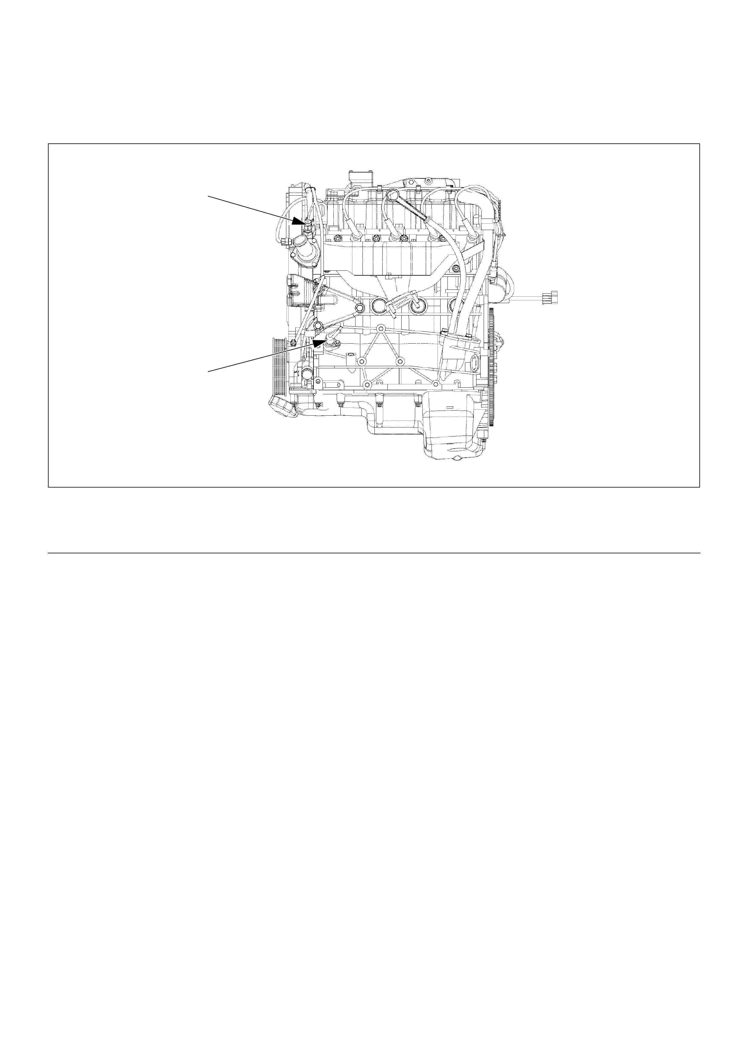
Legend
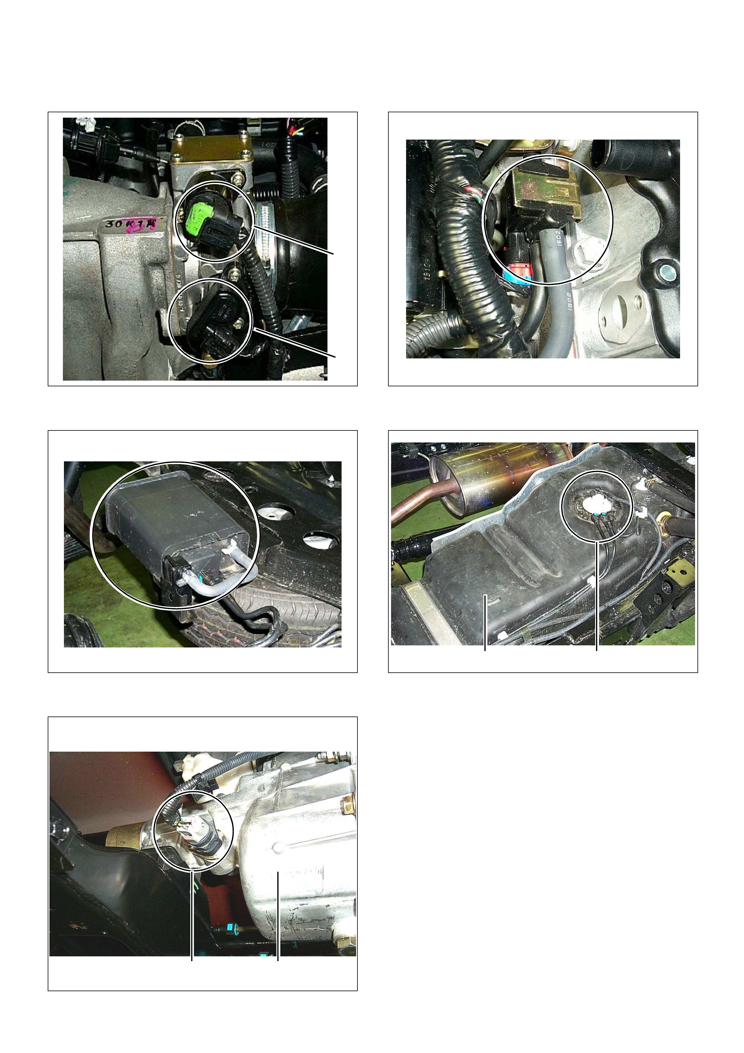
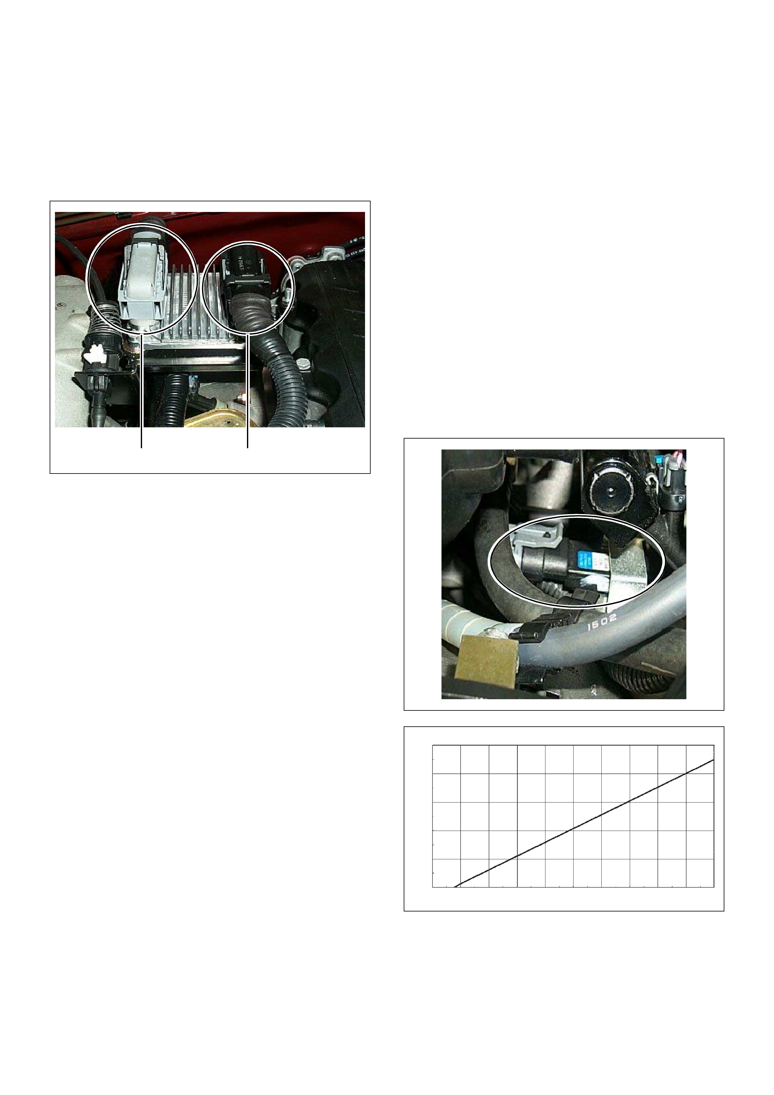
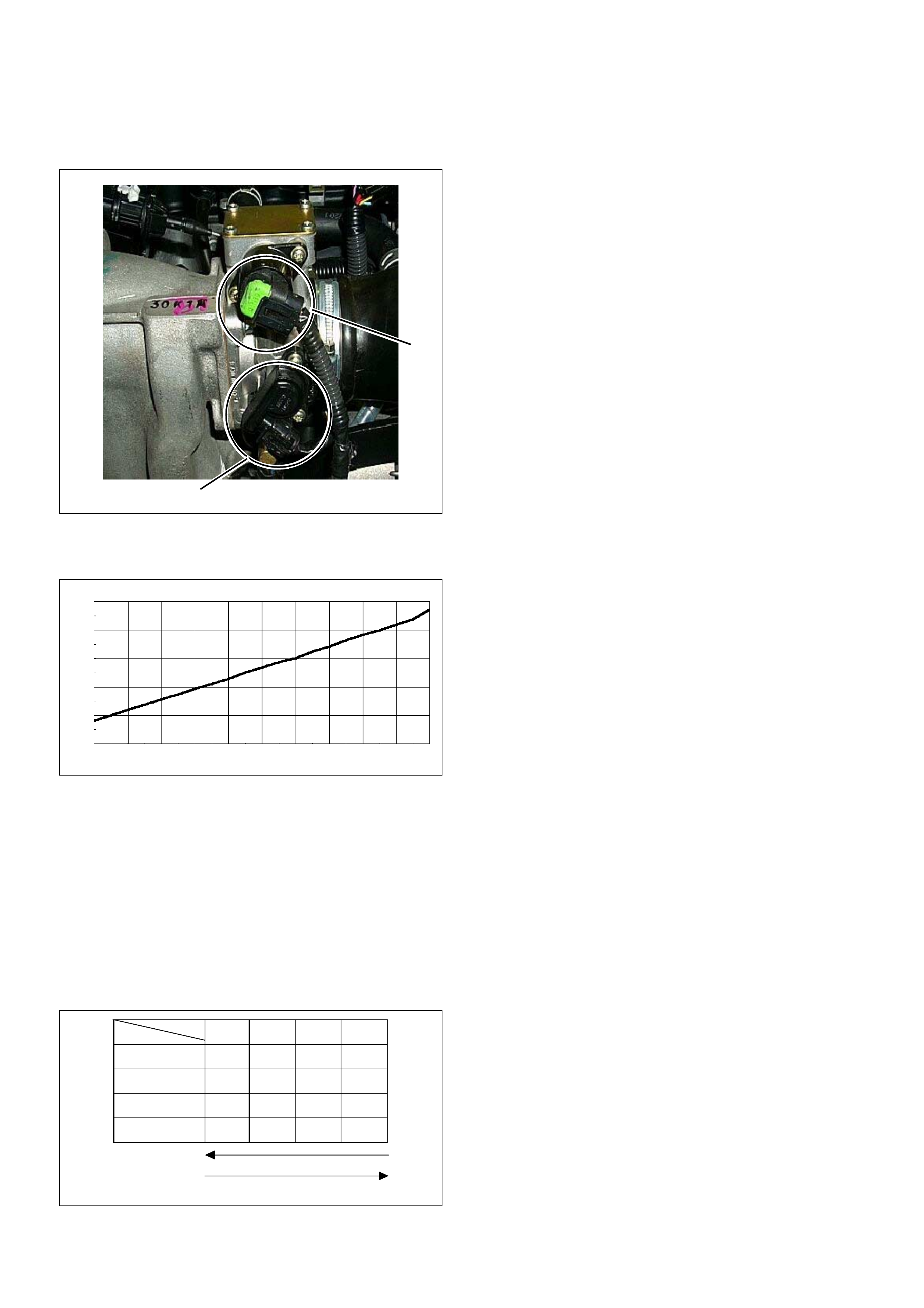
(1) Engine Coolant Temperature (ECT) Sensor
(2) Crankshaft Position (CKP) Sensor
ndOFCallout
1
1
2
3
4
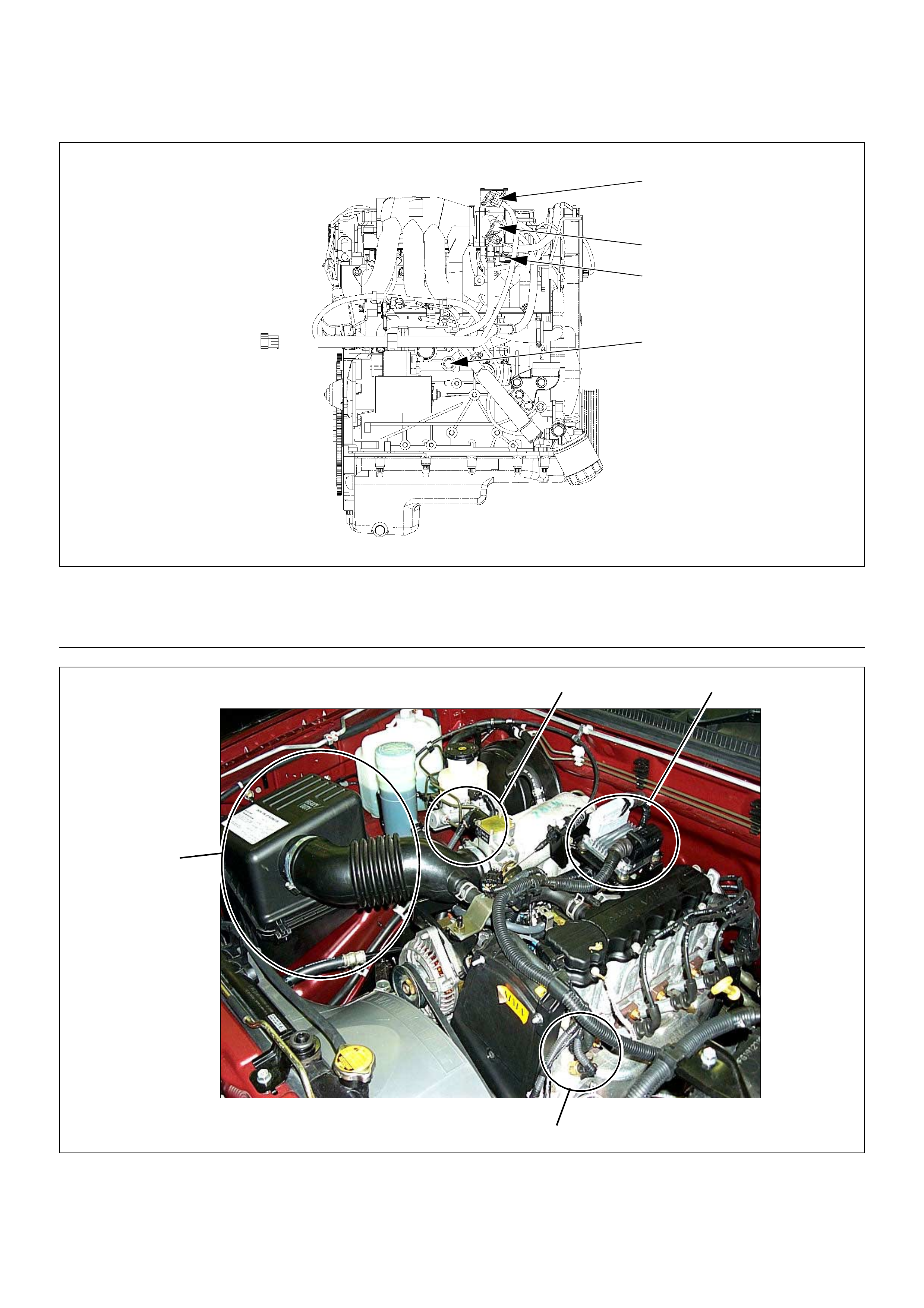
Legend
(1) Idle Air Control (IAC) Valve
(2) Throttle Position Sensor (TPS)
(3) K noc k Se nso r (KS)
(4) Manifol d Absolute Pressure (MAP) Sensor
1
2 4
3
(1)
(2) Air Cleaner
Idle Air Control (IAC) Valve (3)
(4) Engine Coolant Temperature (ECT) Sensor
Engine Control Module (ECM)
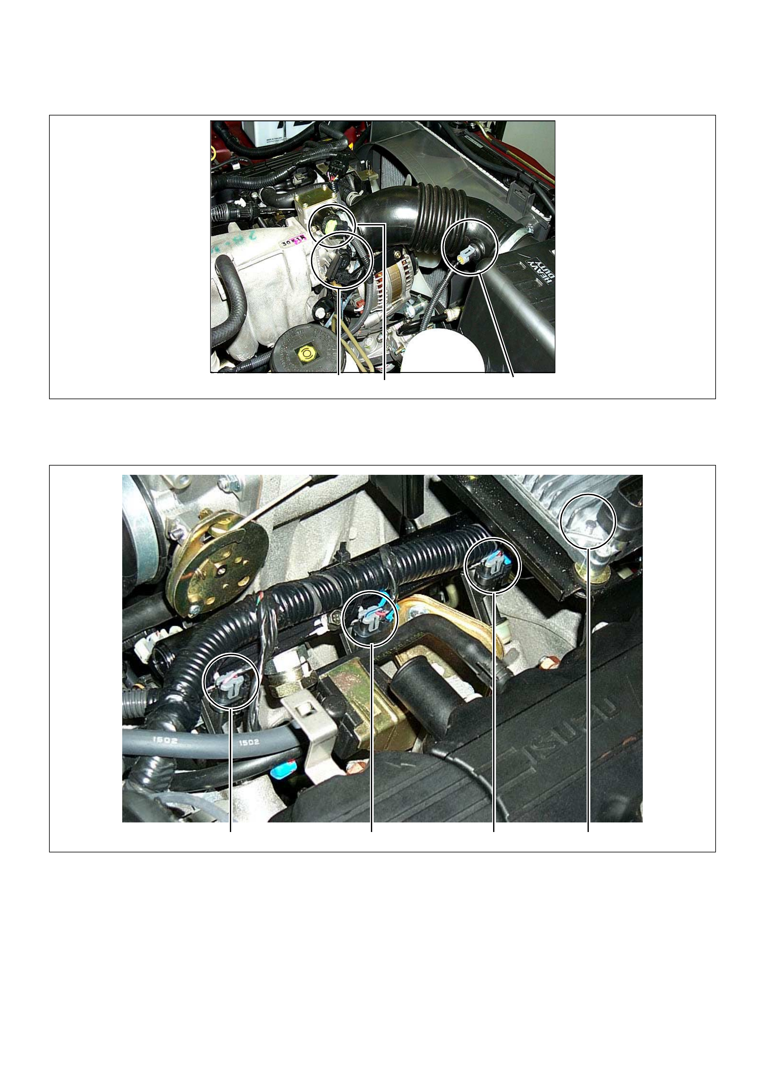
3 2 1
(1)
(2)
(3)
Intake Air Temperature (IAT) Sensor
Idle Air Control (IAC) Valve
Throttle Position Sensor (TPS)
1234
(1)
(2) Injector #1 Cylinder
Injector #2 Cylinder (3)
(4) Injector #3 Cylinder
Injector #4 Cylinder (Under the ECM)
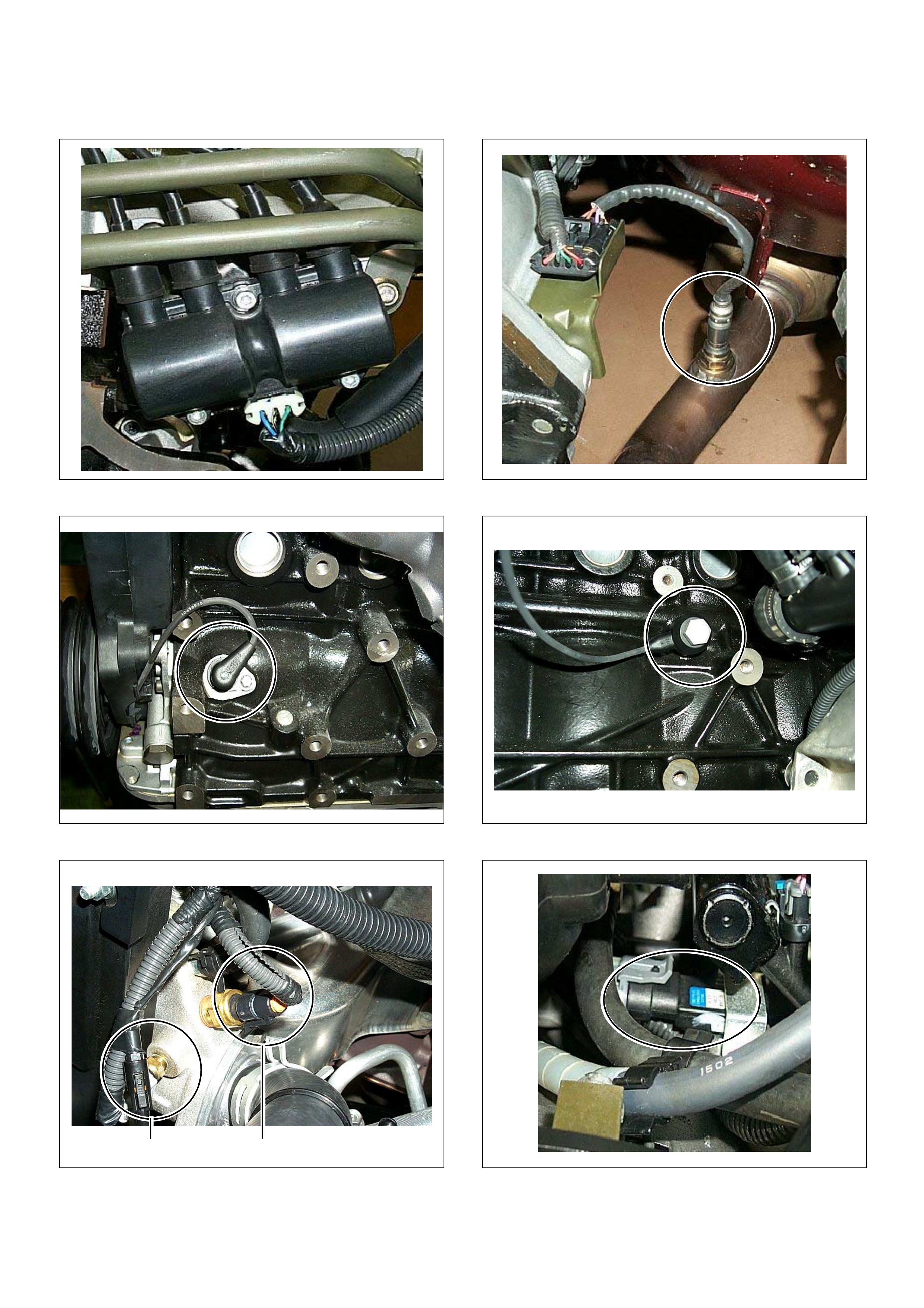
(1) Ignition Coil Module Assembly (1) Heated Oxygen Sensor
(1) Crankshaft Position (CKP) Sensor (1) K noc k Se nso r (KS)
(1)
(2) Engine Coolant Temperature (ECT) Sensor
Thermo Meter Sensor
2 1
(1) Manifol d Absolute Pressure (MAP) Sensor
(1)
(2) Throttle Position Sensor
Idle Air Control (IAC) Valve
2
1
(1) EVAP Purge Solenoid
(1) Canister (1)
(2) Fuel Tank
Fuel Pump
21
1 2
(1)
(2) Vehicle Speed Sensor (VSS)
Transmission Assembly
1 2
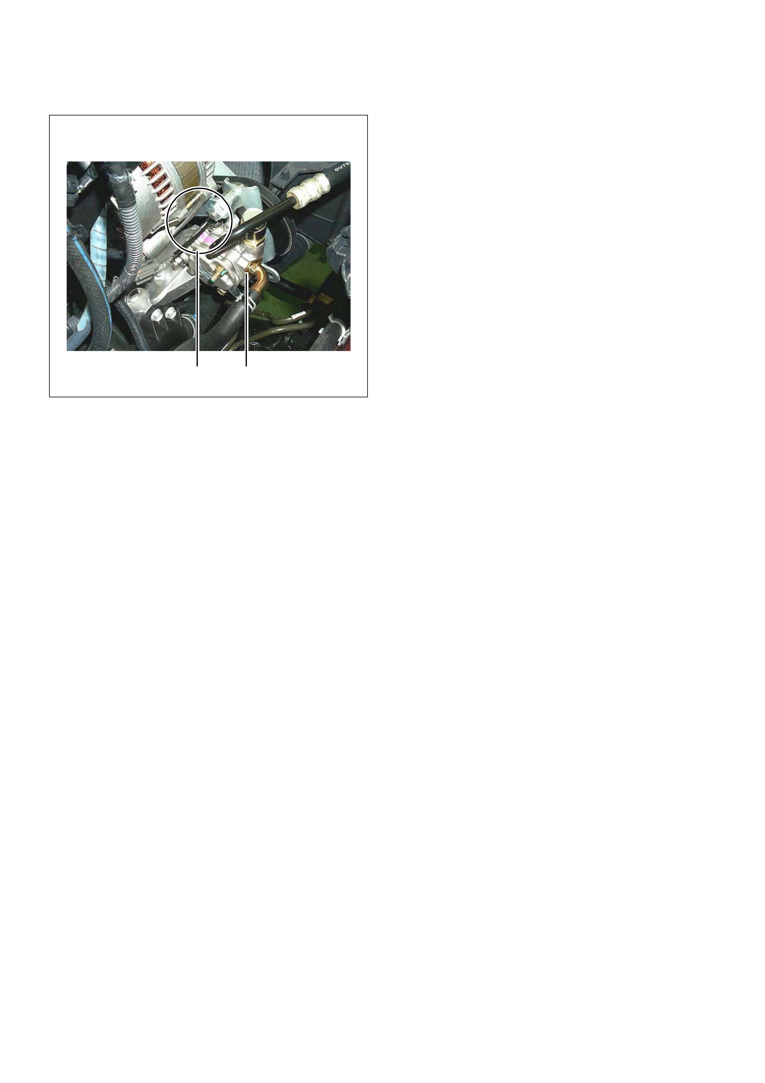
(1)
(2) Power Steering Pressure Switch
Power Steering Oil Pump Assem bl y
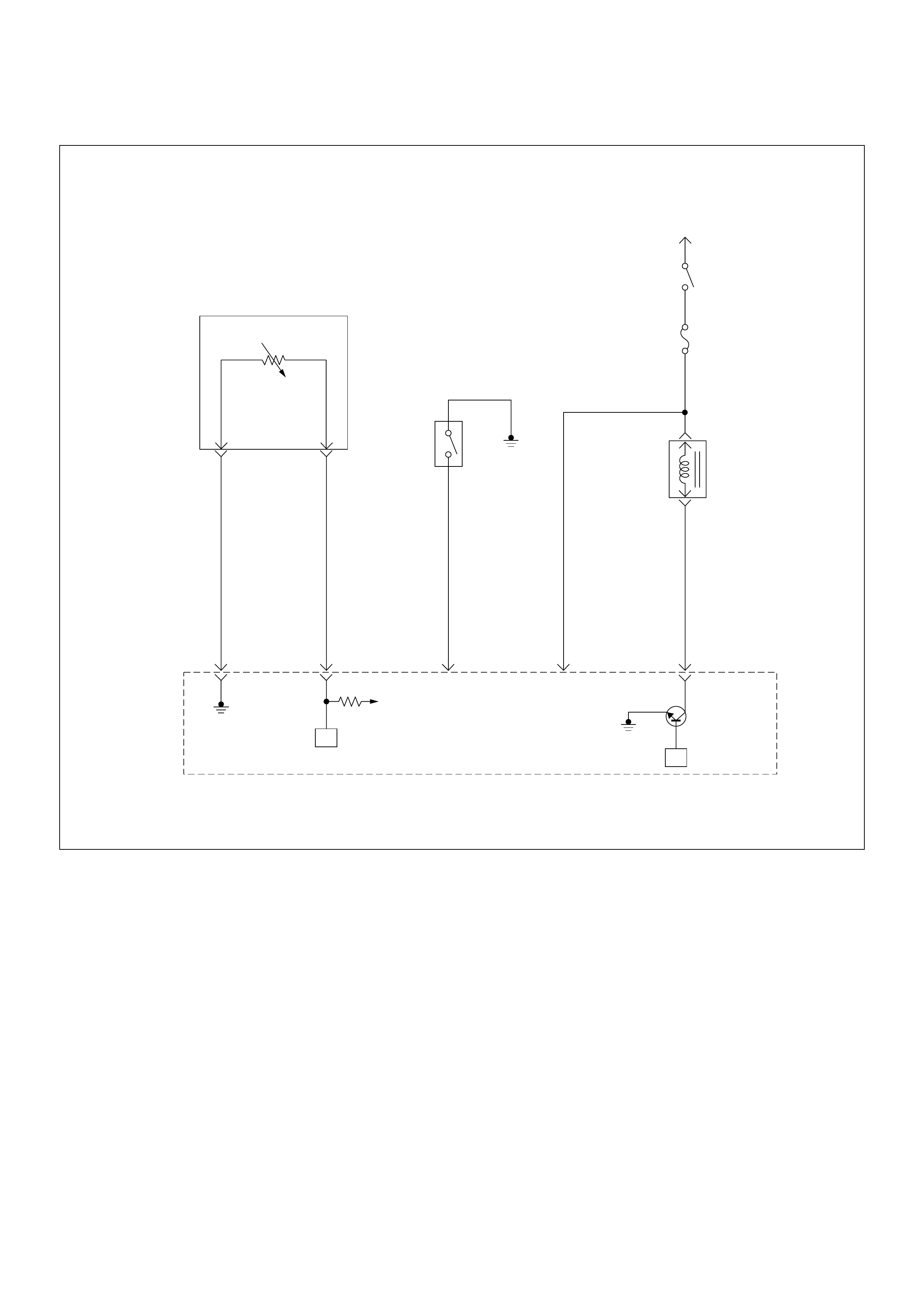
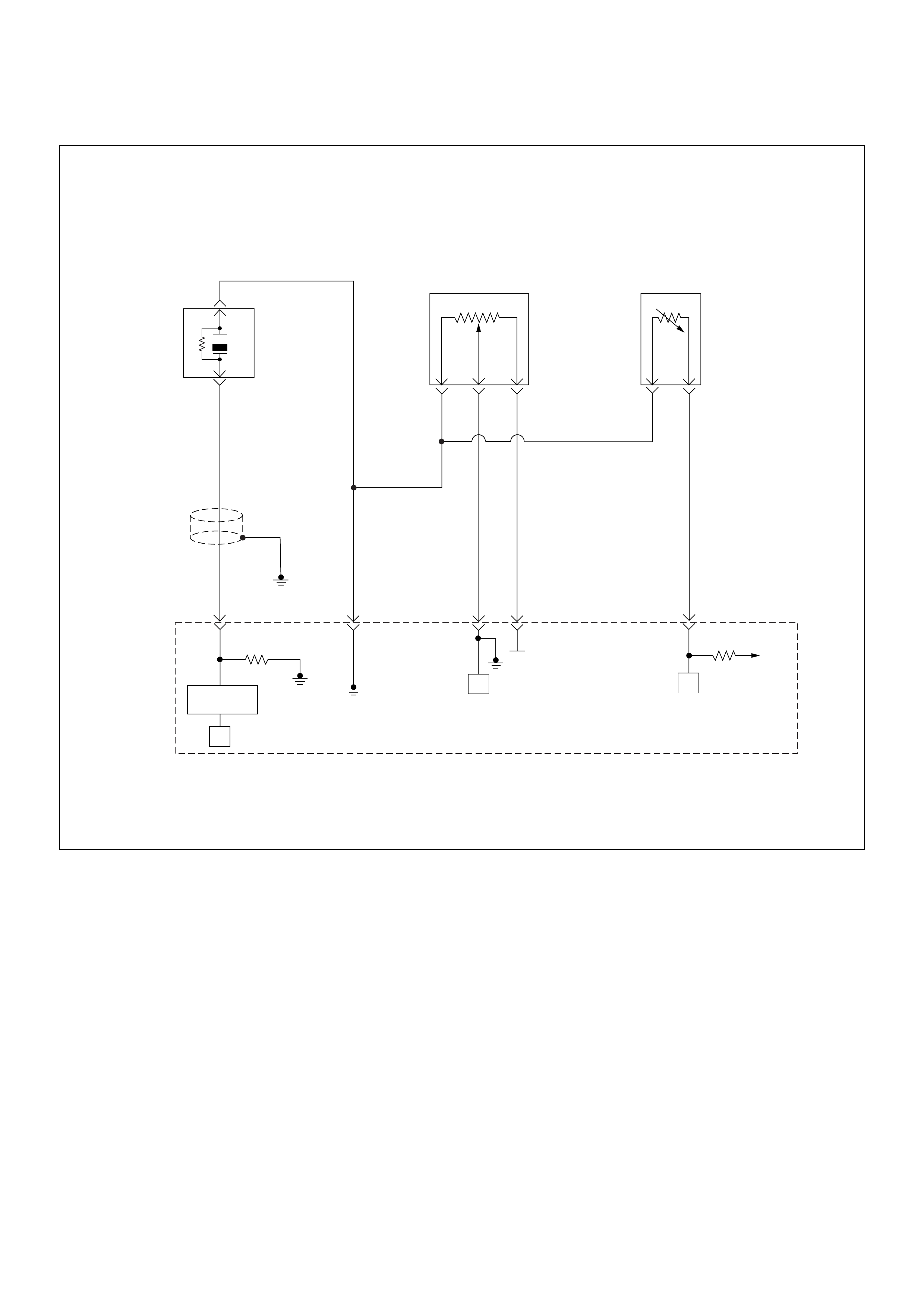
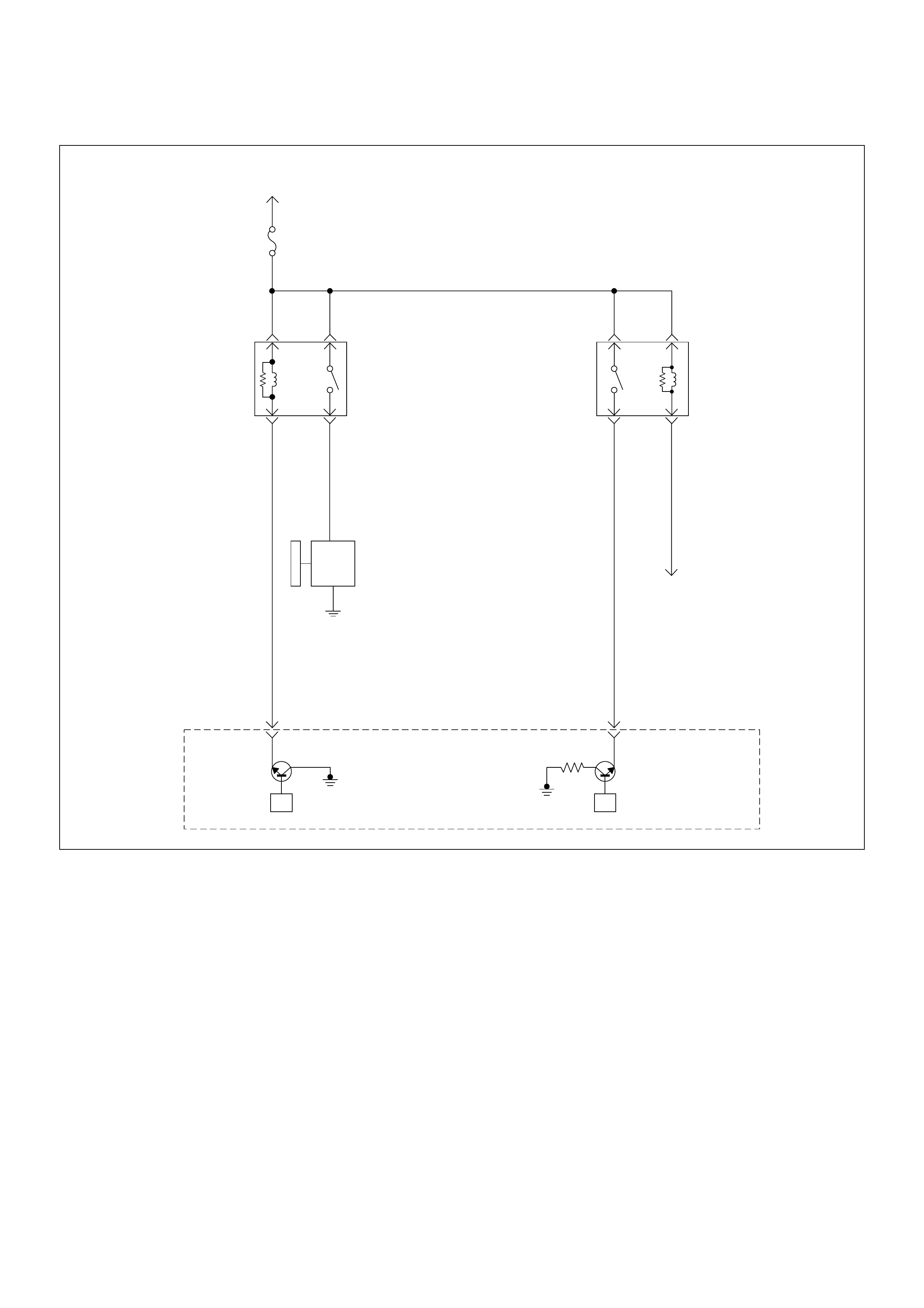
ECM Circuit Diagram
Ground Po int Chart
Ground Point Chart (1/4)
Ground Point Chart (2/4)

Ground Point Chart (3/4)
Ground Point Chart (4/4)

Location
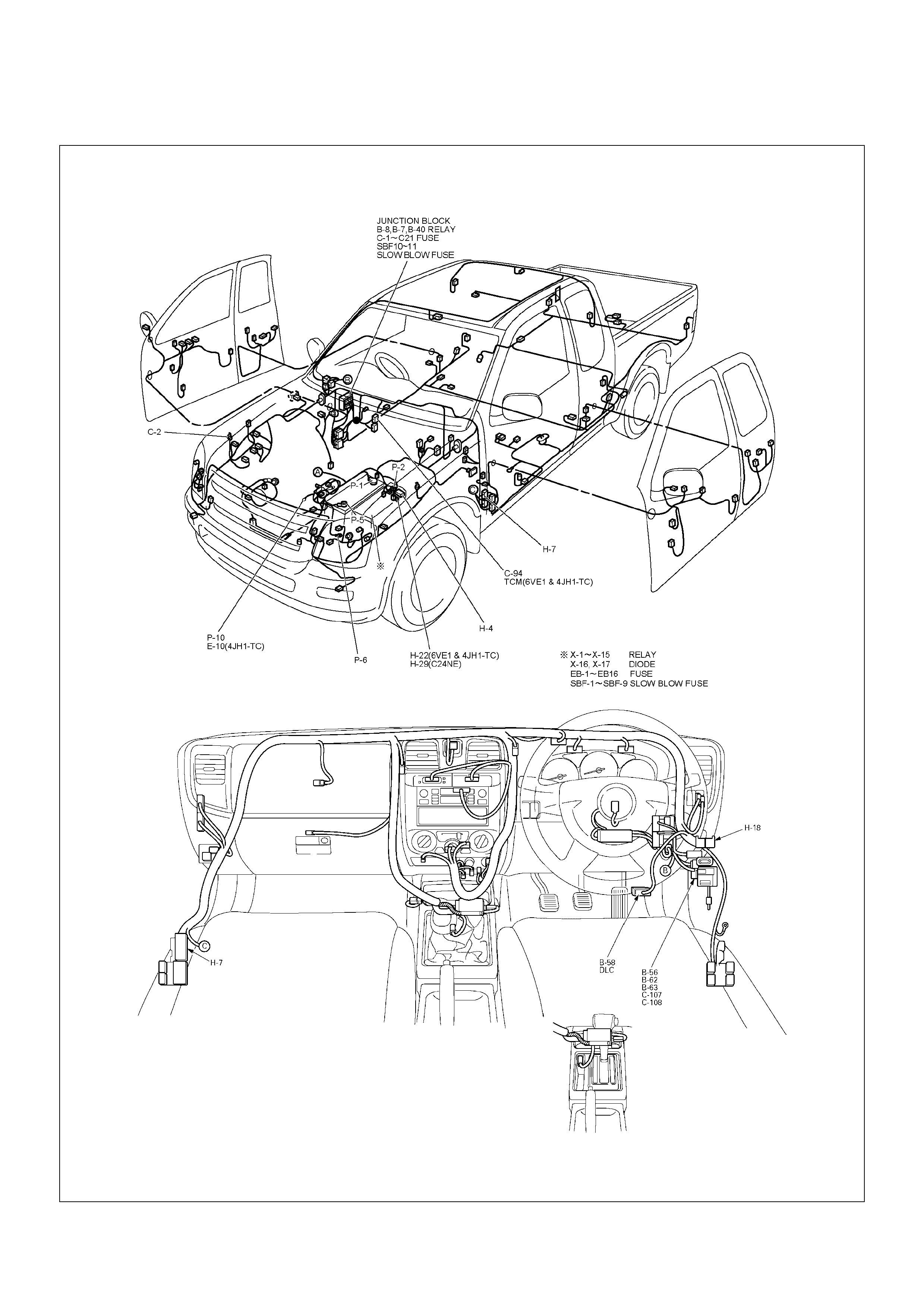
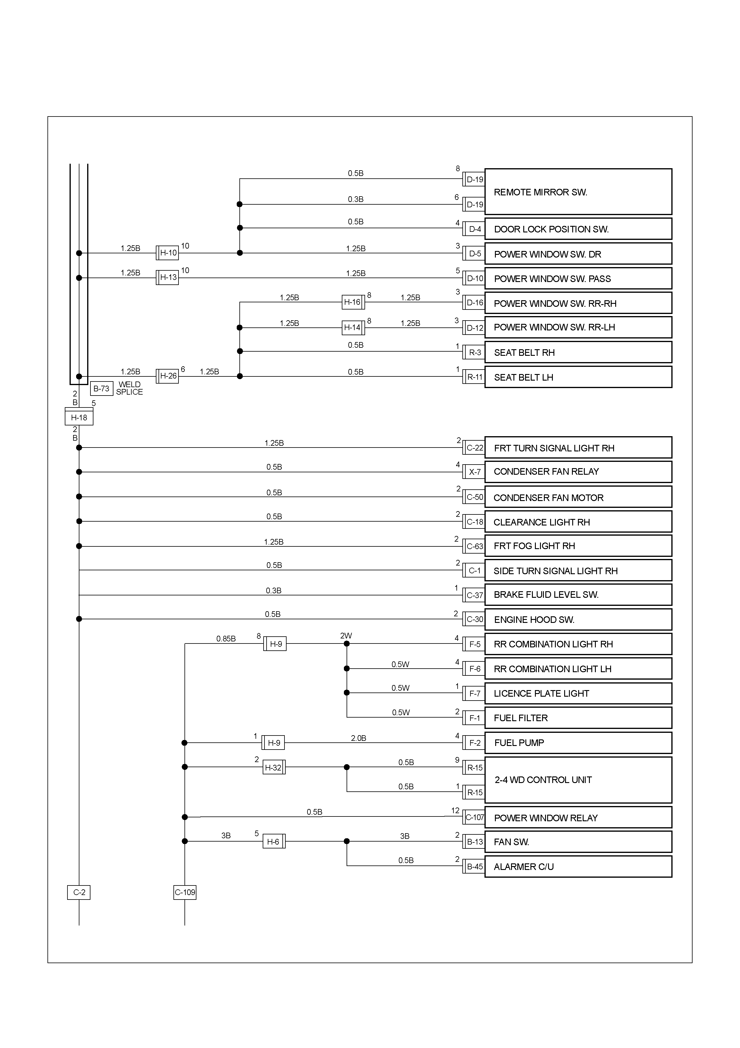
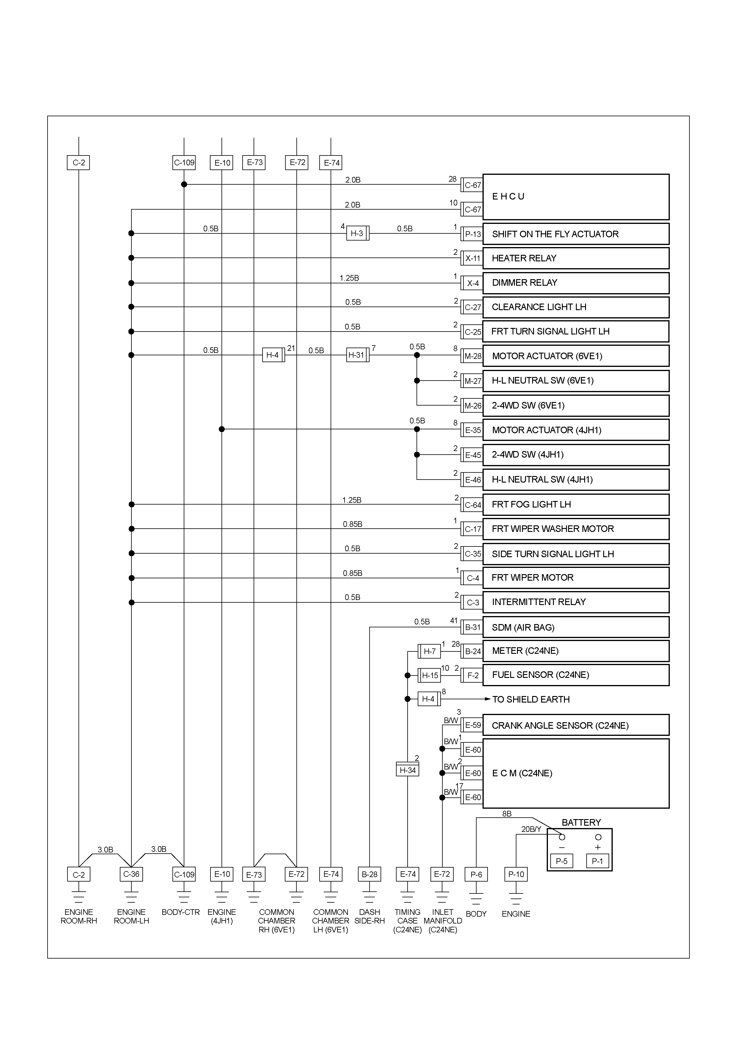
Cable Harness & Connector Location
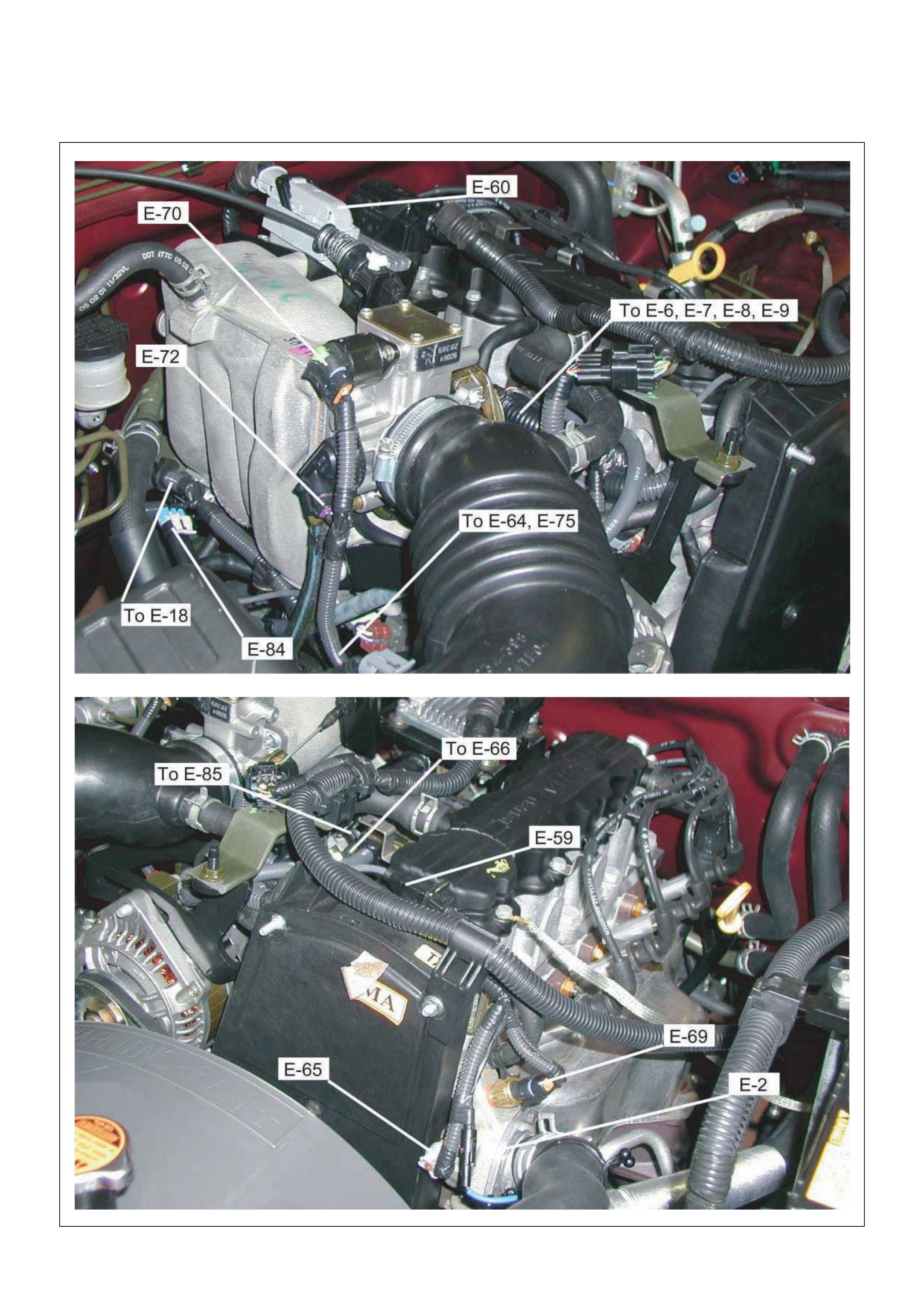
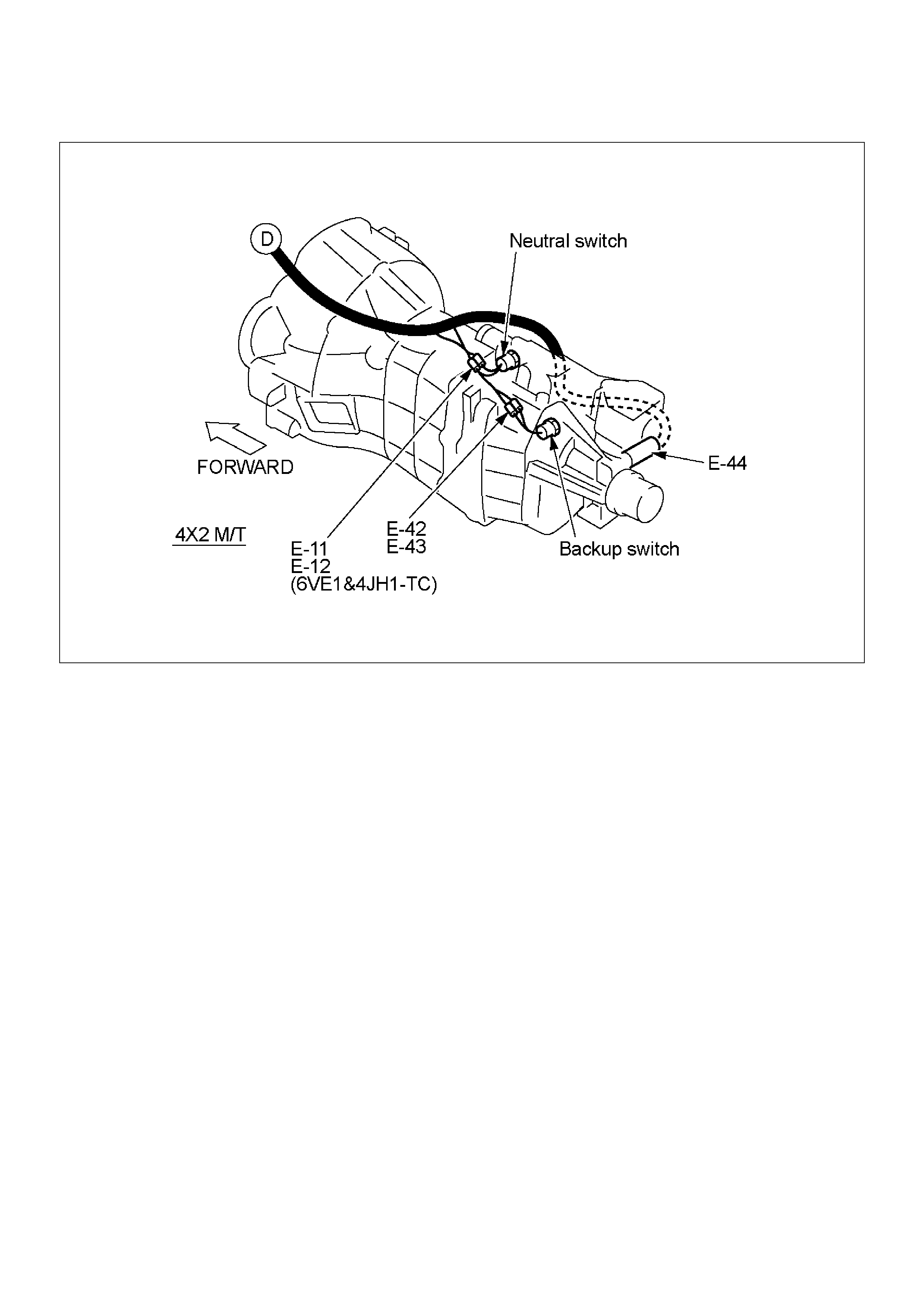
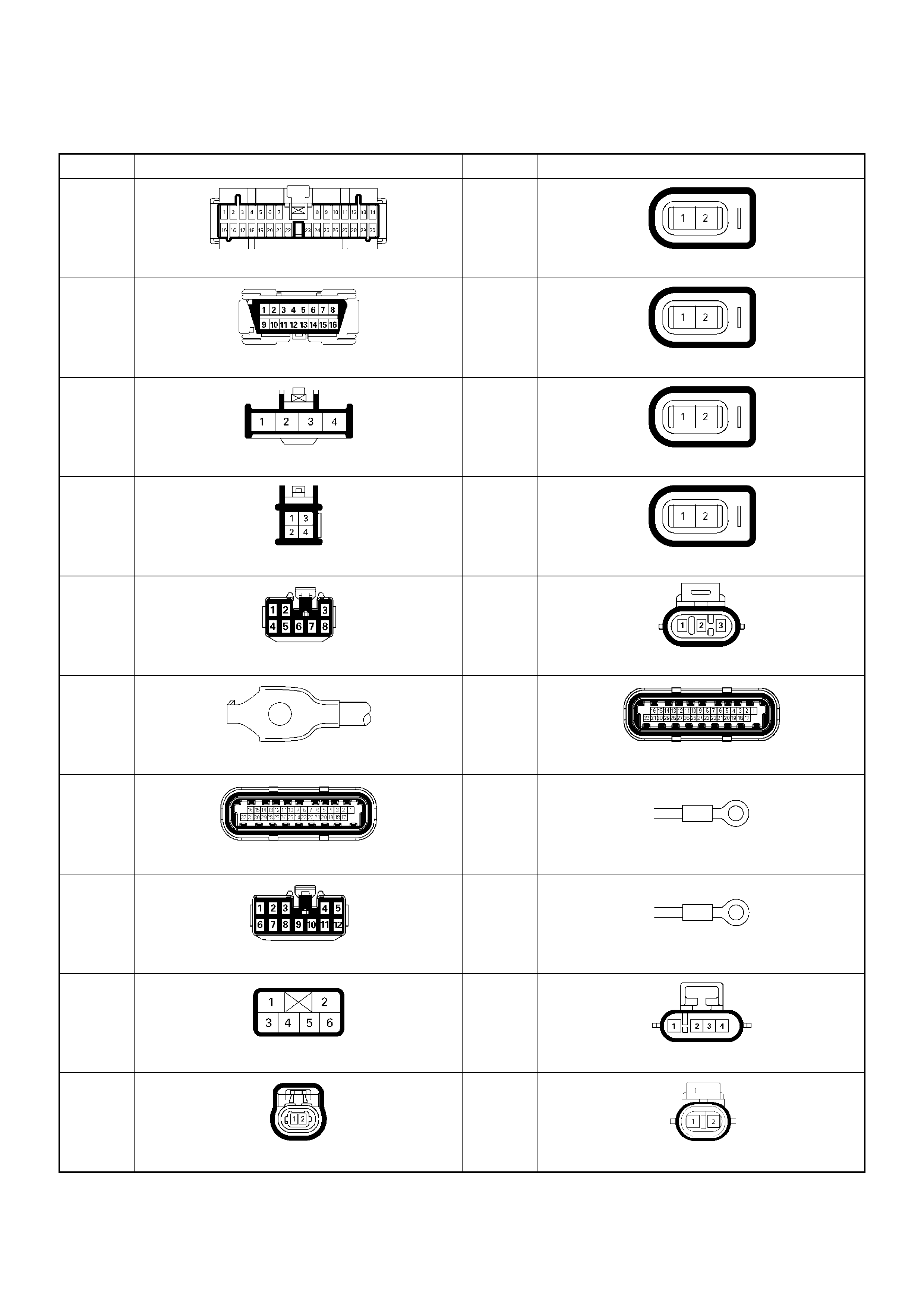
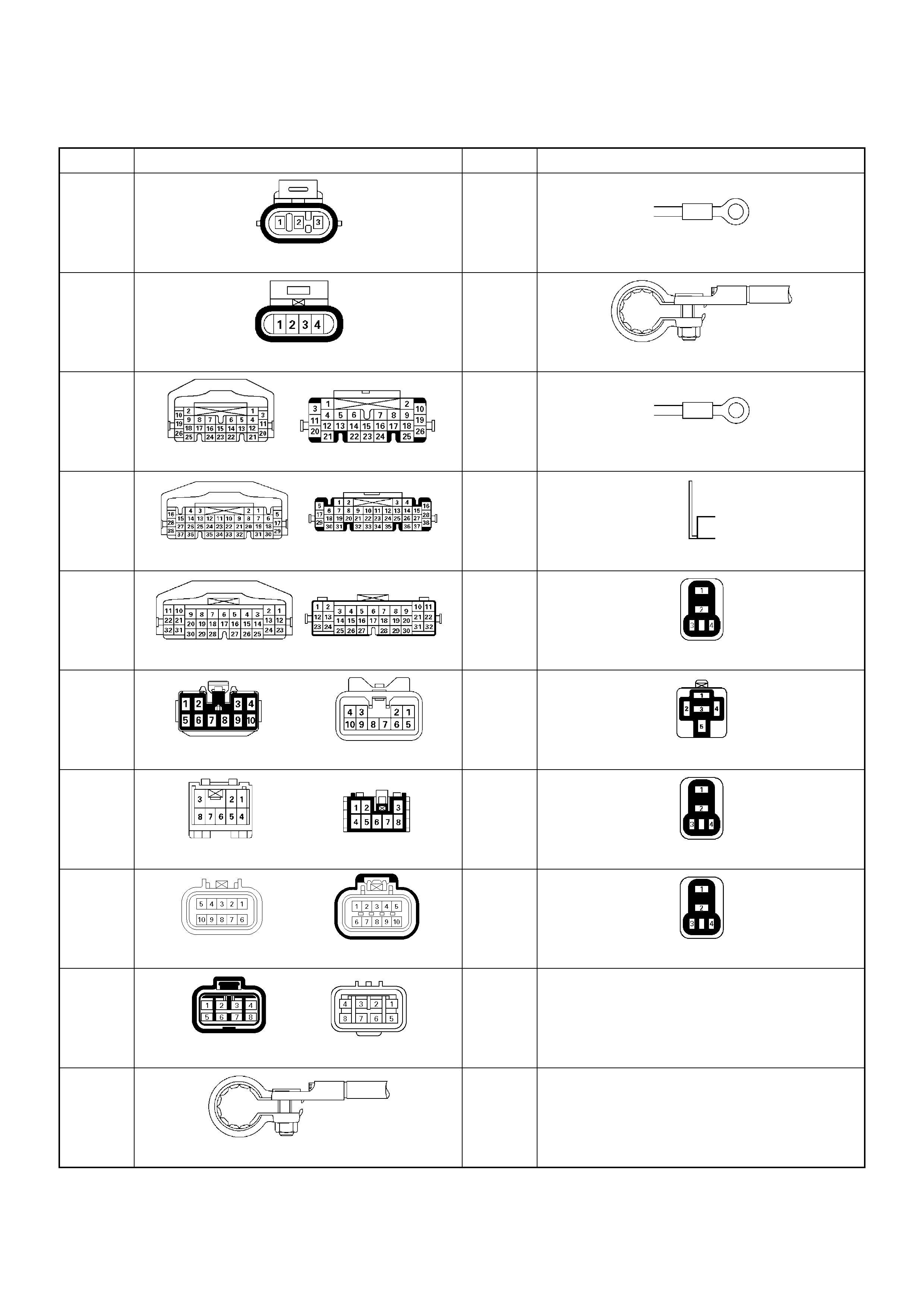
Connector List
No. Connector face No. Connector face
B-24
Green Meter-B
E-6
Injector pump
B-58
Black Check connector
E-7
Fuel injector
B-62
White Ignition switch (IGSUB : G1)
E-8
Fuel injector
B-63
White Ignition switch (IGSUB : G2)
E-9
Fuel injector
B-68
Immobiliser
E-18
Ignition coil
C-2
Silver Engine room-RH ground
E-60
ECM
C-56
ECM
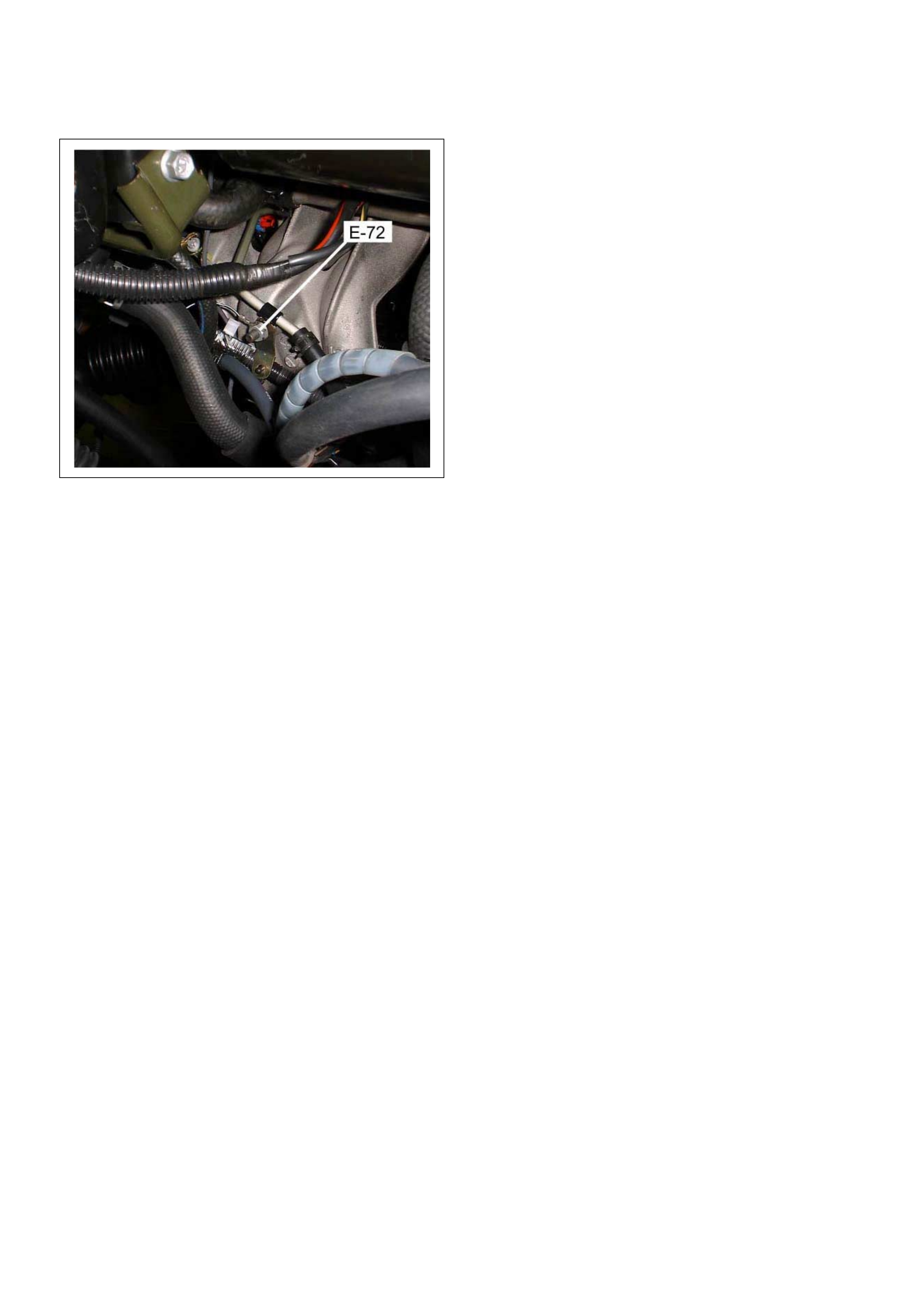
E-72
Engine earth-A
C-107
White J/B E2
E-74
Engine earth-B
C-108
White J/B E1
E-77
O
2
sensor
C-121
IAT sensor
E-84
Knock sensor
No. Connector face No. Connector face
E-85
MAP sensor
P-2
Silver Relay & Fuse box
F-2
White Fuel pump & sensor
P-5
Silver Batter y (-)
H-4
White Engine room ~ Mission
P-6
Silver Body earth (Ground)
H-6
White Engine room ~ INST
P-10
Silver Engine ground
H-7
White Engine room ~ INST
X-2
Black Rela y; Fuel pomp
H-9
Blue Engine room ~ Chassis
X-11
Black Relay; Heater
H-18
White Engine room ~ INST
X-14
Black Relay; A/C Compressor
H-31
Engine room ~ Mission
X-15
Black Relay; Thermo
H-34
Engine ~ Engine room
P-1
Silver Battery (+)
Relay & Fuse
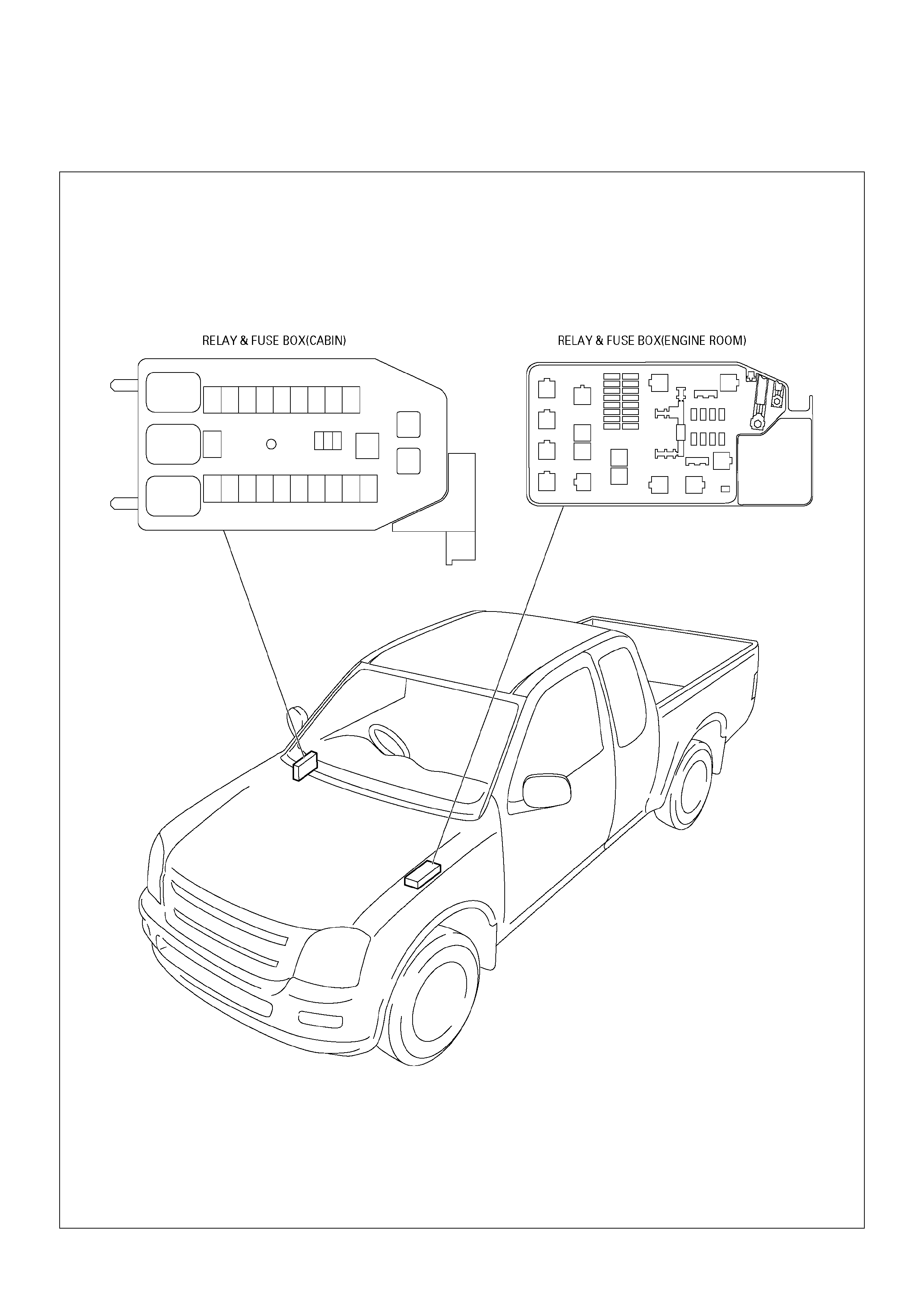
Relay & Fuse Box Location
Relay & Fuse Box Location
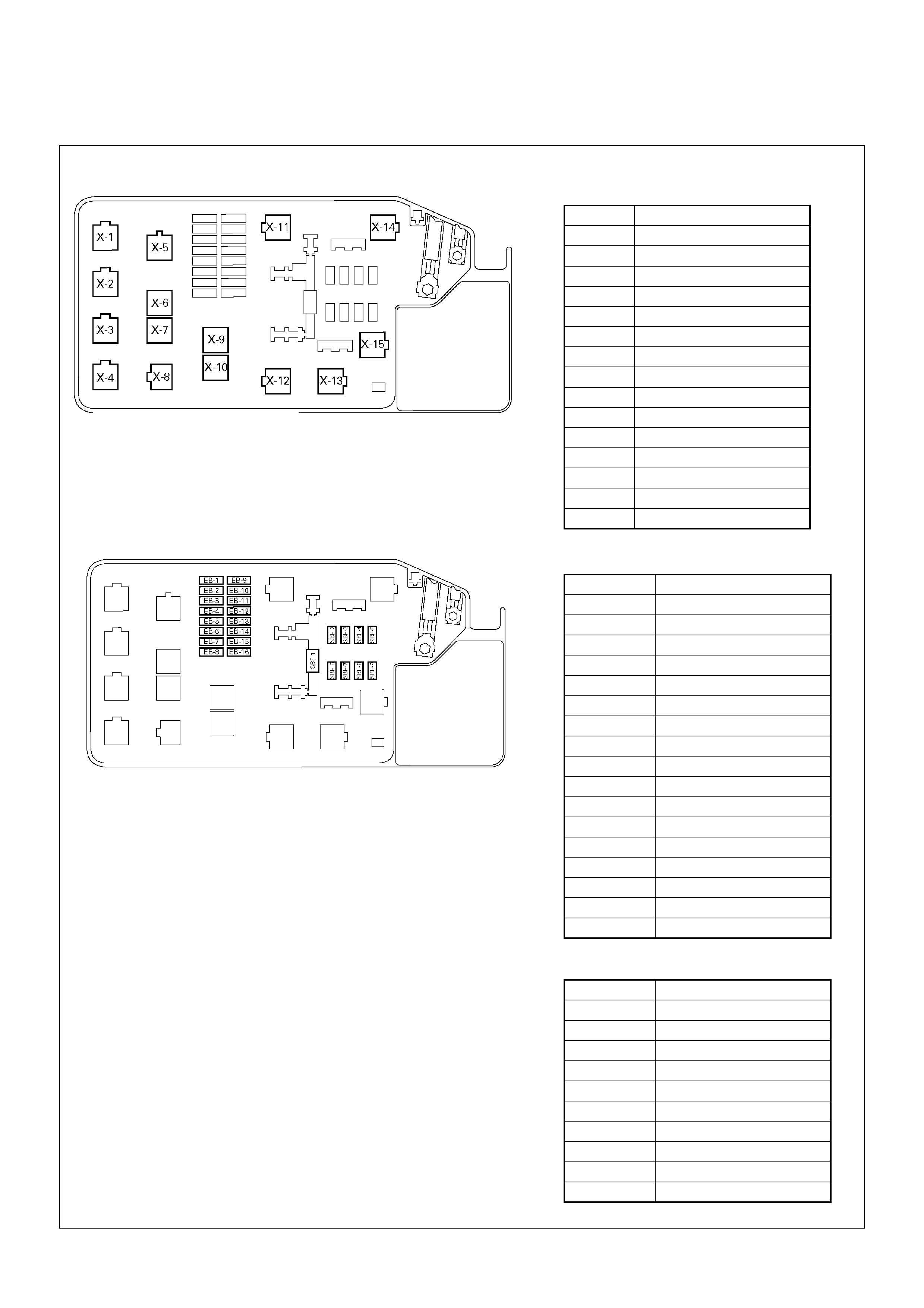
RELAY & FUSE BOX
RELAY
No. RELAY (C24SE)
X-1 RELAY; TAIL LIGHT
X-2 RELAY; FUEL PUMP
X-3 RELAY; HORN
X-4 RELAY; DIMMER
X-5 —
X-6 RELAY; STARTER
X-7 RELAY; COND, FAN
X-8 RELAY; —
X-9 —
X-10 —
X-11 RELAY; HEATER
X-12 RELAY; HEAD LIGHT
X-13 —
X-14 RELAY; A/C COMP
X-15 RELAY; THERMO
FUSE
SLOW BLOW FUSE
ENGINE MODEL
FUSE NO. C24SE
EB-1 15A ECM
EB-2 —
EB-3 —
EB-4 15A ACG (S)
EB-5 10A ILLUMI
EB-6 10A TAIL
EB-7 10A H/LIGHT-RH
EB-8 10A H/LIGHT-LH
EB-9 20A FUEL PUMP
EB-10 10A O
2
SENSOR
EB-11 —
EB-12 —
EB-13 10A A/C
EB-14 —
EB-15 10A HORN
EB-16 10A HAZARD
ENGINE MODEL
FUSE NO. C24SE
SBF-1 10 0A MA IN
SBF-2 —
SBF-3 —
SBF-4 20A COND, FAN
SBF-5 40A IG 1
SBF-6 —
SBF-7 —
SBF-8 30A BLOWER
SBF-9 50A IG 2
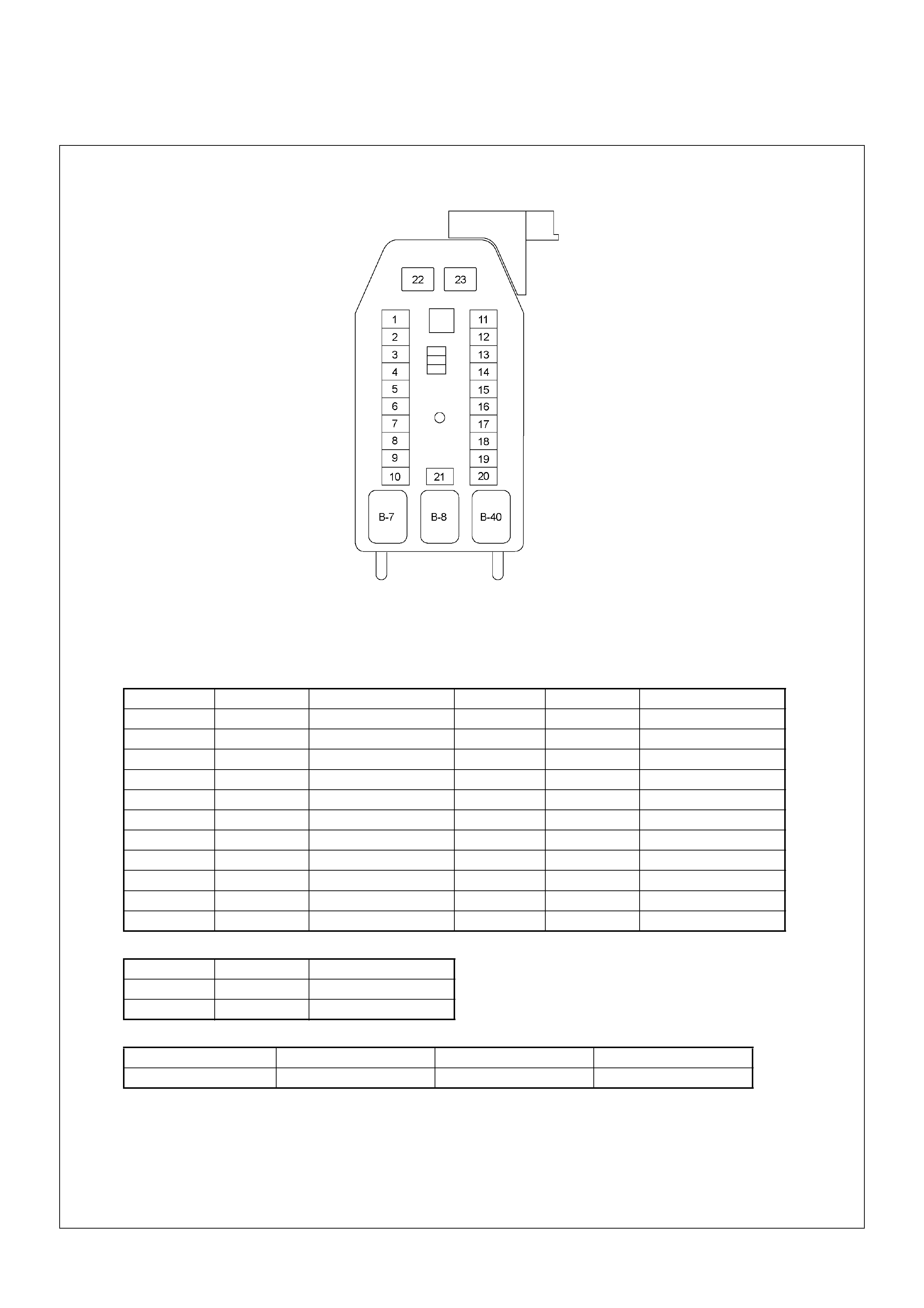
Fuse & Relay Location
FUSE
SLOW BL OW FUS E
RELAY
No. Capacity Indication on label No. Capacity Indication on label
1— — 1215ACIGER
2 10A ABS 13 15A AUDIO (+B)
3 — — 14 20A DOOR LOCK
4 15A BACK UP 15 10A METER (+B)
5 15A METER 16 10A ROOM
6 10A TURN 17 10A ANTI THEFT
7 15A ELEC.IG 18 15A STOP
8 15A ENGINE 19 15A ACC SOCKET
9 20A FRT WIPER 20 10A STARTER
10 15A EGR 21 10A SRS
11 10A AUDIO
No. Capacity Indication on label
22 20A RR DEF
23 20A POWER WINDOW
Connector No. B-7 B-8 B-40
C24SE REAR DEFOGGER POWER WINDOW ACC SOCKET
FUSE BOX
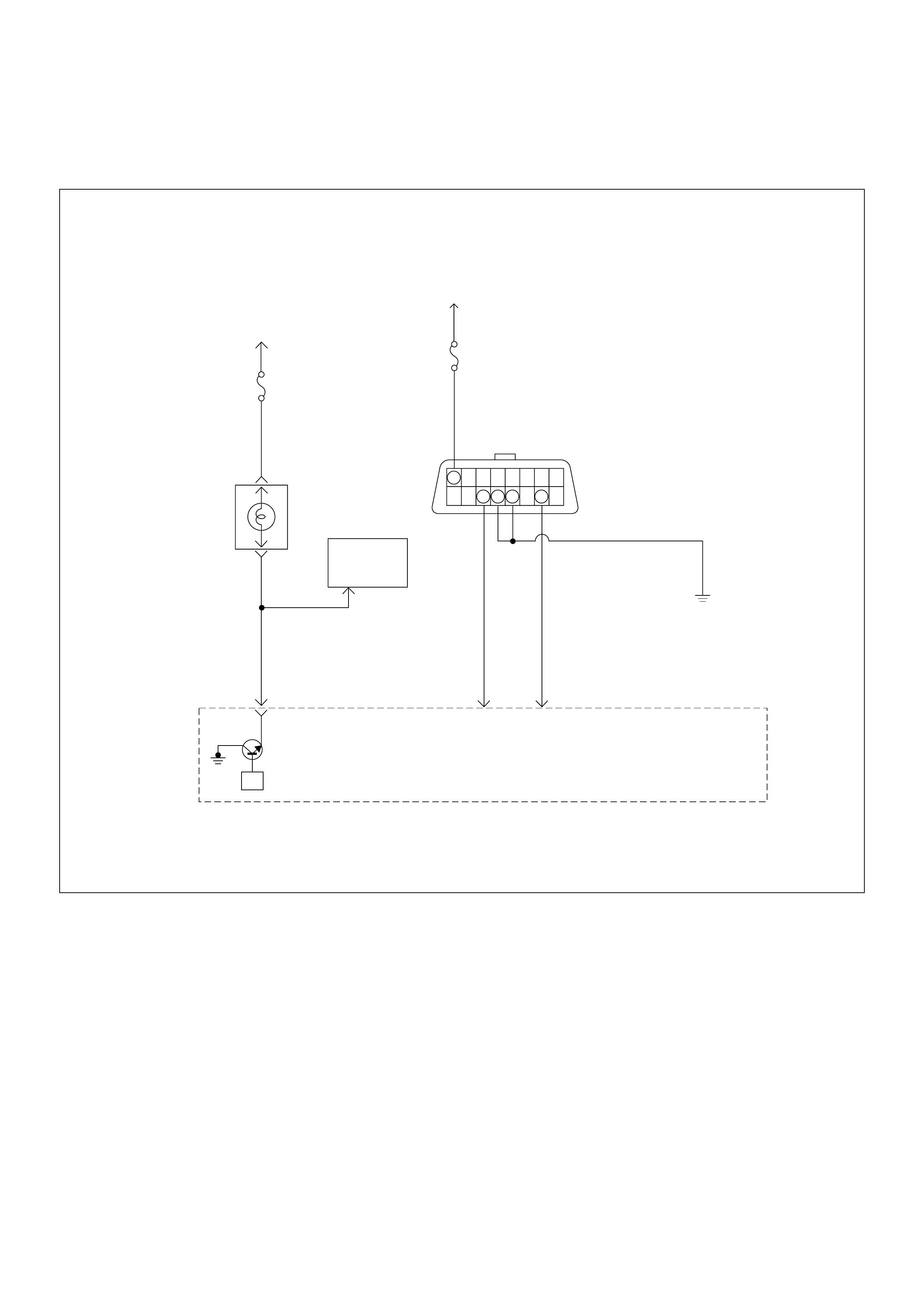
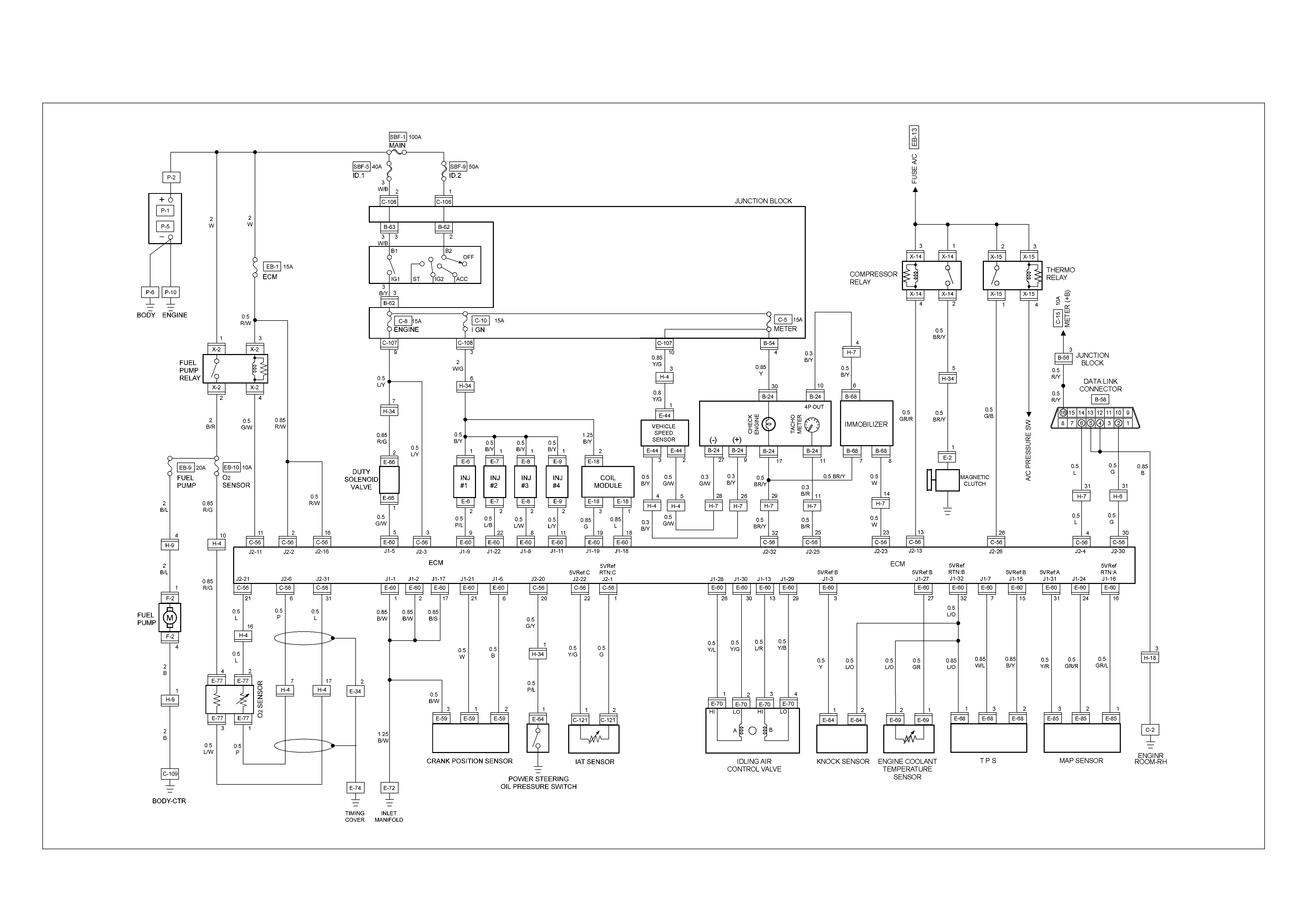
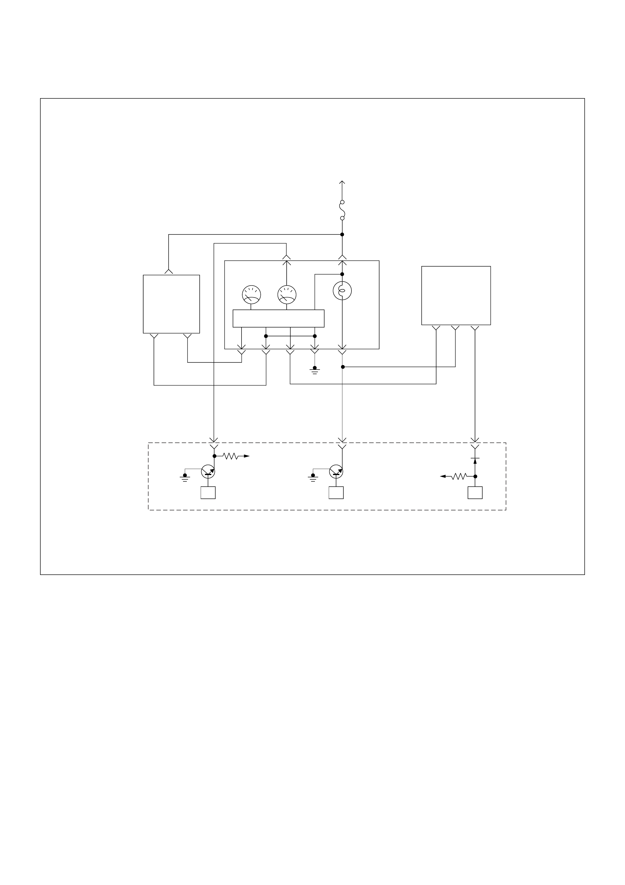
ECM Wiring Diagram
ECM Wiring Diagram (1/9)
Buttery
Voltage
0.5
RED/
YEL
Engine
Room-RH
µP
J2-32
7
0.5
BRN/
YEL
Engine
Control
Module
(ECM)
Check
Engine
Lamp
Imnobiliser
Control
Unit
METER
15A
Ignition
SW
0.5
BLU
J2-4
0.5
GRN
J2-30
Diag
SW Class 2
Serial
Data
0.85 BLK
Diagnostic
Comectar
16151413121110 9
87654321
METER
10A
ECM Wiring Diagram (2/9)
VIgn
Engine
Control
Module
(ECM)
Ignition
SW
µPµPµP
Meter
15A
VIgn
Check
Engine
Sped
Meter Tacho
Meter
0.85
YEL
0.8 YEL/GRN
0.5 BRN/YEL
CPU
0.5
WHT
J2-23J2-25
0.5
BRN/
YEL
(–) (+)
Vehicle
Speed
Sensor
J2-32
678
Imnobiliser
Control
Unit
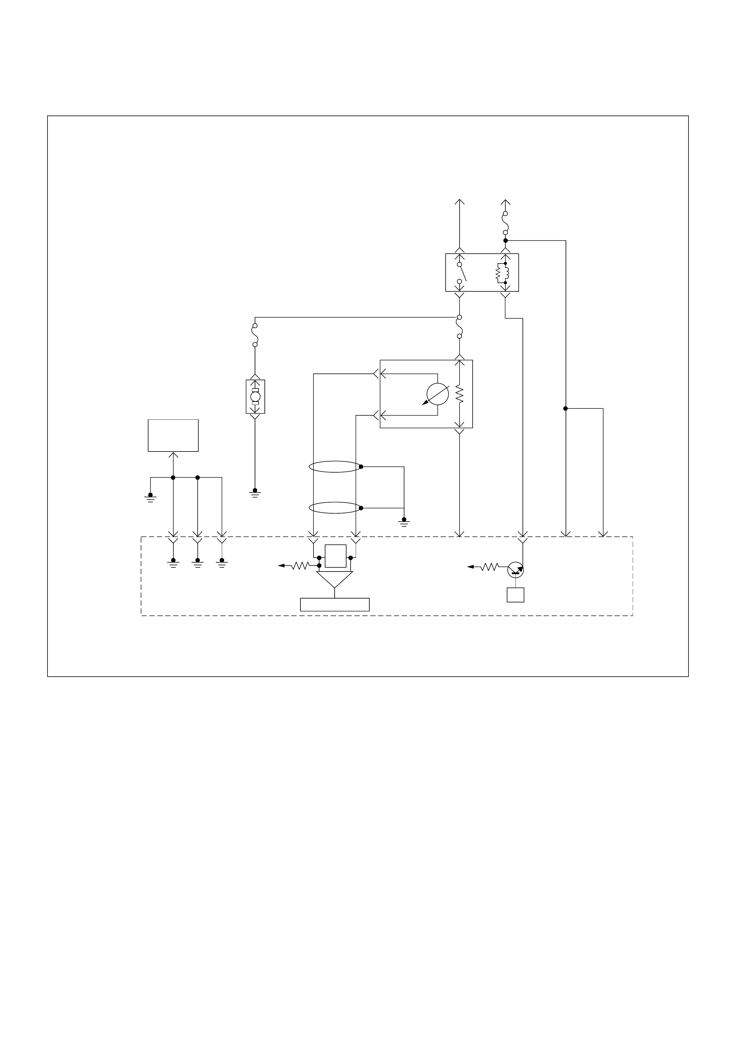
ECM Wiring Diagram (3/9)
µP
VIgn
-
+
Crankshaft
Position
Sensor
J1-1 J1-2 J1-17
Battery
Voltage
Battery
Voltage
2.0
WHT ECM
10A
450
mV
A/D Converter
Vcc
+5V -+
TIMING
COVER
J2-6 J2-21
Fuel
Pump
FUEL
PUMP
20A
2.0
BLK
2.0
BLK/
BLU
Fuel
Pump
Relay
O2
SENSOR
10A
Heated
O2
Sensor
0.85
RED/
WHT
0.5
GRN/
WHT
0.5
RED/
WHT
0.5
BLU/
WHT
0.5
BLU
0.5 PNK
J2-31 J2-11 J2-2 J2-18
M
Engine
Control
Module
(ECM)
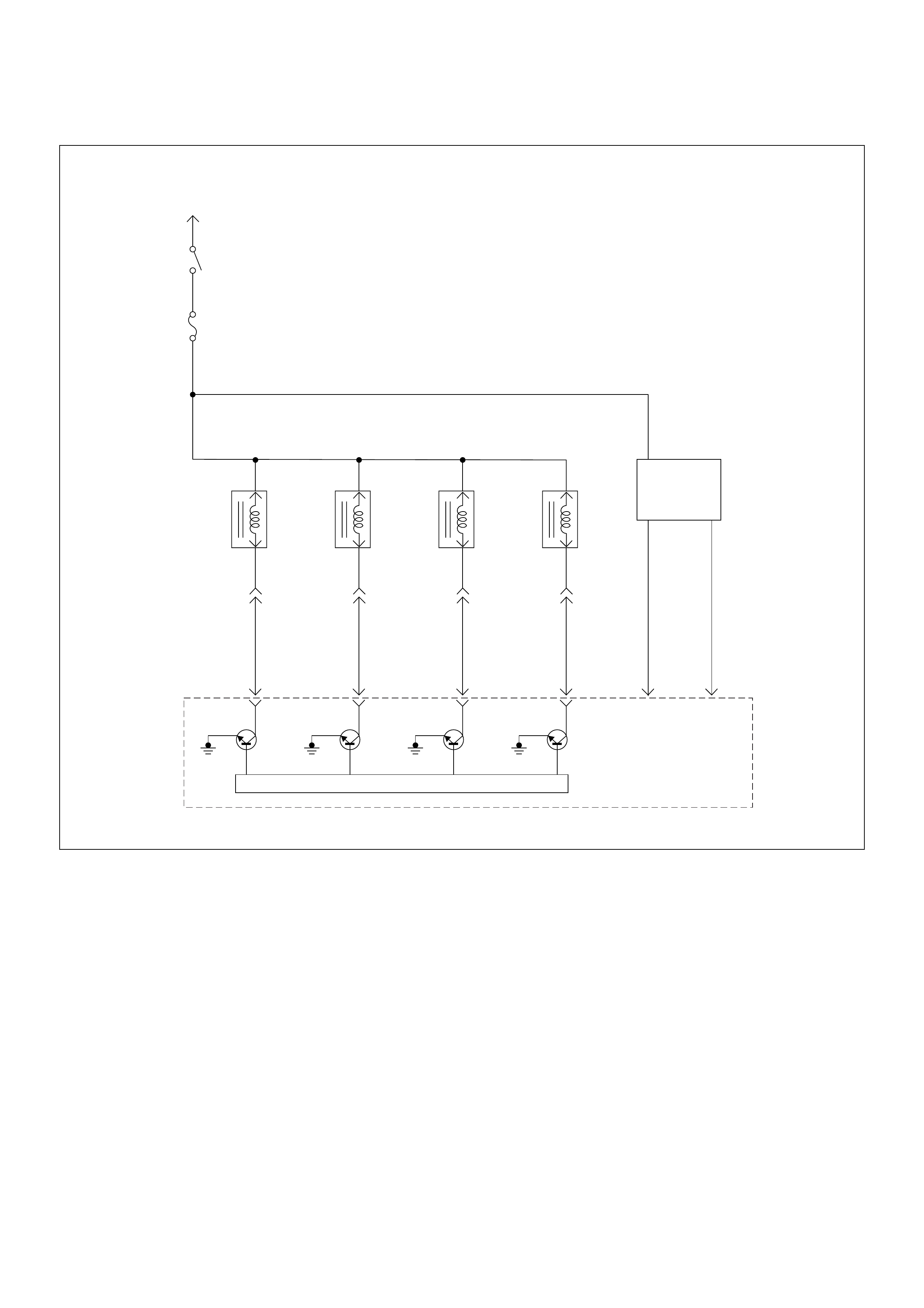
ECM Wiring Diagram (4/9)
Battery Voltage
PNK/
BLU
Injector
#1
Cylinder
Injector
#2
Cylinder
Injector
#3
Cylinder
Injector
#4
Cylinder
J1-9
BLU/
BLK
J1-22
BLU/
WHT
J1-8
COIL
MODULE
BLU/
YEL
J1-11
0.85
GRN
J1-19
0.85
BLU
J1-18
µP
IGN
Switch
IGN
Fuse
15A
Engine
Control
Module
(ECM)
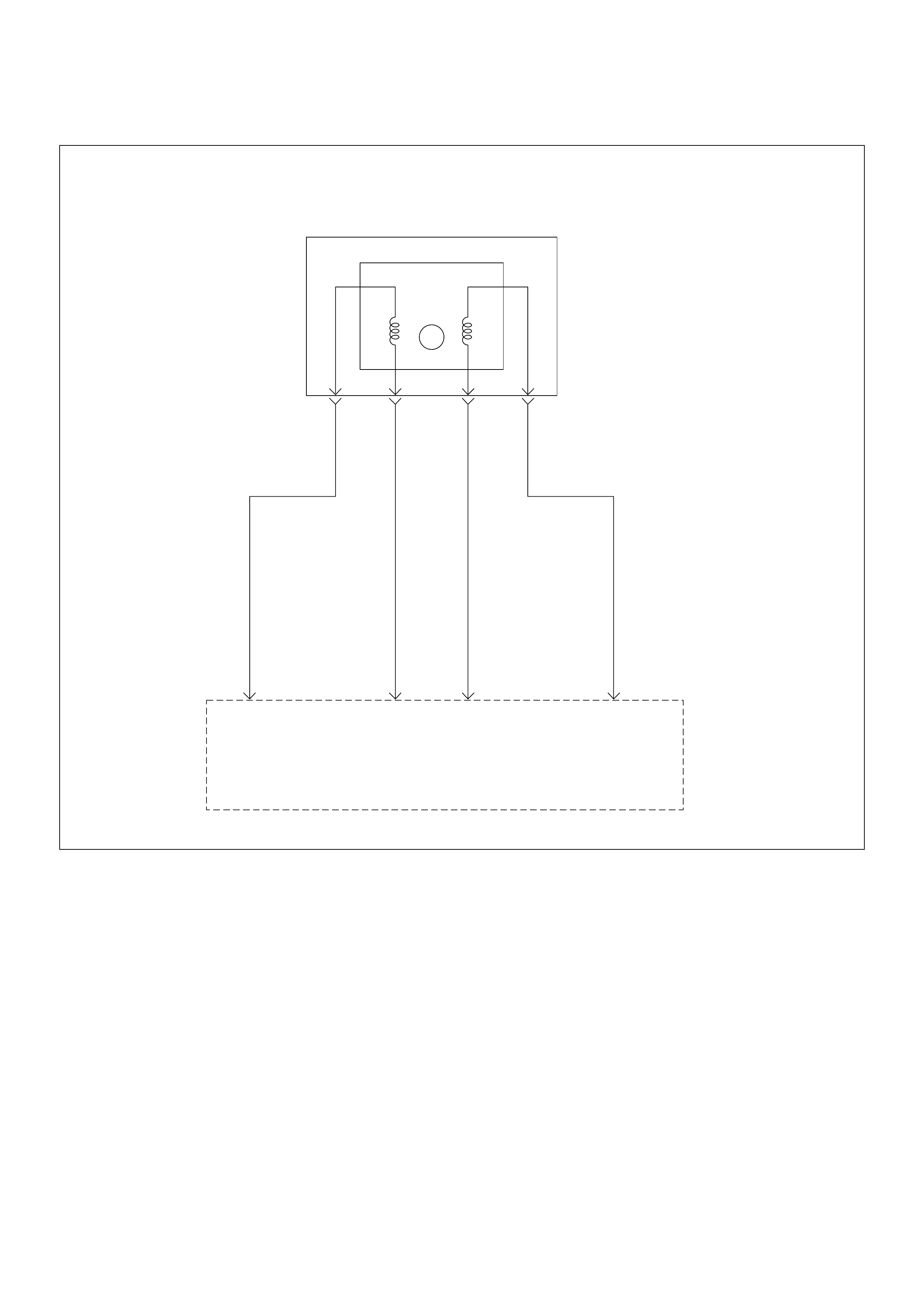
ECM Wiring Diagram (5/9)
Idle
Air
Control(IAC) Valve
HI
LO
LO
HI
AB
0.5
YEL/
BLU
J1-28
0.5
YEL/
GRN
J1-30
0.5
BLU/
RED
J1-13
0.5
YEL/
BLK
J1-29
Engine
Control
Module
(ECM)
ECM Wiring Diagram (6/9)
Intake
Air
Temperature(IAT)
Sensor
0.5
GRN
J2-1
0.5
YEL/
GRN
J2-22
0.5
GRN/
YEL
J2-20
0.5
BLU/
YEL
0.5
BLU/
YEL
Engine
15A
Ignition
SW
Battery V oltage
J2-3
0.5
GRN/
WHT
J1-5
+5V
µPµP
Power
Steering
Pressure
SW
Evaporativ
Emission(EVAP)
Canistor
Purge
Valve
Solenoid
Engine
Control
Module
(ECM)

ECM Wiring Diagram (7/9)
Manifold
Absolute
Pressure(MAP) Sensor
Crankshaft
Position(CKP)
Sensor
µP
0.5
GRY/
BLU
J1-16
0.5
GRY/
RED
J1-24
0.5
YEL/
RED
J1-31
0.5
BLK/
WHT
J1-1
0.5
BLK/
WHT
J1-2
0.5
BLK/
WHT
J1-17
0.5
BLK
J1-6
0.5
WHT
J1-21
INLET
MANIFOLD
5 V olts
Reference
Engine
Control
Module
(ECM)
ECM Wiring Diagram (8/9)
µP
0.5
GRY
J1-27
+5V
µP
µP
5Volts
Reference
Knock
Sensor
0.5
YEL
0.5
WHT/
BLU
J1-7
0.5
BLU/
PNK
J1-32
0.5
BLK/
YEL
J1-15J1-3
Engine
Coolant
Temperature(ECT)
Sensor
Throttle
Position Sensor
Knock Filter
Module
Engine
Control
Module
(ECM)
ECM Wiring Diagram (9/9)
Battery
Voltage
A/C
10A
COMPRESSOR
RELAY
0.5
BRN/
YEL
0.5
GRY/
RED
J2-13
0.5
GRN/
BLK
J2-26
MAGNETIC
CLUTCH
µP
A/C PRESSURE S/W
THERMO
RELAY
µP
Engine
Control
Module
(ECM)

ECM Connector Pin As signment & Output Signal
Connector J1 Port: View Looking Into ECM Case
1
17 16
32
PIN16PIN1
PIN17 PIN32
Pin
No. B/Box
No. Pin Function Wire
Color
Signal or Contin uity ECM
Connection
Tester Posi tion
Key SW
Off Key SW
On Engine
Idle Engine
2000rpm Range (+) (-)
J1-1 1 Ground BLK/WHT Continuity
with
ground
- - - Disconnect Ω1GND
J1-2 2 Ground BLK/WHT Continuity
with
ground
- - - Disconnect Ω2GND
J1-3 3 Knock Sensor Signal YEL - - - - - - - -
J1-4 4 No Connection - - - - - - - - -
J1-5 5 Canister Purge
Solenoid Valve GRN/
WHT Less than
1V Battery
voltage Wave form / b a ttery
voltage while solenoid
is not activated
Connect DC V 5 GND
J1-6 6 Crankshaft Position
(CKP) Senso r
(Ground)
BLK Continuity
with
ground
- - - Connect Ω6GND
J1-7 7 Throttle Position
Sensor (TPS) Output
Signal
WHT/BLU Approx. 6.0kΩ at idle /
Approx. 1.7kΩ at WO T
Approx. 2.3kΩ at idle /
Approx. 6.6kΩ at WOT
- - Disconnect Ω7 1 5 /
32
J1-8 8 No. 3 Injector BLU/WHT Less t han
1V Battery
voltage Wave form Connect DC V 8 GND
J1-9 9 No. 1 Injector PNK/BLU Less than
1V Battery
voltage Wave form Connect DC V 9 GND
J1-10 10 No Connection - - - - - - - - -
J1-11 11 No. 4 Injector BLU/YEL Less than
1V Battery
voltage Wave form Connect DC V 11 GND
J1-12 12 No Connection - - - - - - - - -
J1-13 13 Idle Air Control Valve
(I ACV) C oil B High YEL/BLU Less than
1V Less than 1V / Battery voltage Connect DC V 13 GND
J1-14 14 No Connection - - - - - - - - -
J1-15 15 Throttle Position
Sensor (TPS) Power
Supply
BLK/YEL Less than
1V Approx. 5V Connect DC V 15 32
J1-16 16 MAP Sensor Ground GRY/BLU Continuity
with
ground
- - - Connect Ω16 GND
J1-17 17 Ground BLK/W HT Continuity
with
ground
- - - Connect Ω17 GND
J1-18 18 Coil Module No. 1 &
No.4 BLU Less than
1V Battery
voltage Wave form Connect DC V 18 GND
J1-19 19 Coil Module No. 2 &
No. 3 GRN Less than
1V Battery
voltage Wave form Connect DC V 19 GND

J1-20 20 No Connection - - - - - - - - -
J1-21 21 Crankshaft Position
(CKP) Sensor Signal WHT - - Wave
form or
approx.
3.7V
Wave
form or
approx.
7.7V
Connect AC V 21 6
J1-22 22 No.2 Injector BLU/BLK Less than
1V Battery
voltage Wave form Connect DC V 22 GND
J1-23 23 No Connection - - - - - - - - -
J1-24 24 MAP Sensor Signal GRY/RED Less t han
1V Approx.
4.8V Approx.
1.3V Approx.
0.9V Connect DC V 24 16
J1-25 25 No Connection - - - - - - - - -
J1-26 26 No Connection - - - - - - - - -
J1-27 27 Engine Coolant Temp.
(ECT) Sensor Signal GRY Less than
1V Approx. 2.5V at ECT 80°C Connect DC V 27 32
J1-28 28 Idle Air Control Valve
(I ACV) C oil A High YEL/BLK Less than
1V Less than 1V / Battery voltage Connect DC V 28 GND
J1-29 29 Idle Air Control Valve
(I ACV) C oil B Low YEL/GRN Less than
1V Less than 1V / Battery voltage Connect DC V 29 GND
J1-30 30 Idle Air Control Valve
(I ACV) C oil A Low BLU/WHT Less than
1V Less than 1V / Battery voltage Connect DC V 30 GND
J1-31 31 MAP Sensor Power
Supply YEL/RED Less than
1V Approx.. 5V Connect DC V 31 16
J1-32 32 ECT Sensor, Knock
Sensor, Throttle
Position Sensor
Ground
BLU/PNK Continuity
with
ground
- - - Connect Ω32 GND
Pin
No. B/Box
No. Pin Function Wire
Color
Signal or Contin uity ECM
Connection
Tester Posi tion
Key SW
Off Key SW
On Engine
Idle Engine
2000rpm Range (+) (-)

Connector J2 Port: View Looking Into ECM Case
1
17 16
32
PIN32
PIN1
PIN17
PIN16
Pin
No. B/Box
No. Pin Function Wire
Color
Signal or Contin uity ECM
Connection
Tester Posi tion
Key SW
Off Key SW
On Engine
Idle Engine
2000rpm Range (+) (-)
J2-1 33 Intake Air Temp. (IAT )
Sensor Ground GRN Continuity
with
ground
- - - Disconnect Ω33 GND
J2-2 34 Battery Power Supply RED/
WHT Battery voltage Connect DC V 34 GND
J2-3 35 Ignition Power Supply BLU/YEL Less than
1V Battery voltage Connect DC V 35 GND
J2-4 36 To Data Link
Connector No. 6 BLU Less than
1V Approx. 5V Connect DC V 36 GND
J2-5 37 No Connection - - - - - - - - -
J2-6 38 Oxygen Sensor
(Ground) PNK Continuity
with
ground
- - - Connect Ω38 GND
J2-7 39 No Connection - - - - - - - - -
J2-8 40 No Connection - - - - - - - - -
J2-9 41 No Connection - - - - - - - - -
J2-10 42 No Connection - - - - - - - - -
J2 - 11 43 Fuel Pum p R elay GR N /
WHT Less than
1V Less than
1V /
Battery
voltage
while fuel
pump is
activated
Battery voltage Connect DC V 43 GND
J2-12 44 No Connection - - - - - - - - -
J2-13 45 A/C Compressor
Relay GRY/RED Less than
1V Battery
voltage Less than 1V Connect DC V 45 GND
J2-14 46 No Connection - - - - - - - - -
J2-15 47 No Connection - - - - - - - - -
J2-16 48 No Connection - - - - - - - - -
J2-17 49 No Connection - - - - - - - - -
J2-18 50 Battery Power Supply RED/
WHT Battery voltage Connect DC V 50 GND
J2-19 51 No Connection - - - - - - - - -
J2-20 52 Power Steering
Pressure Switch GRN/YEL Less than
1V Less than 1V when switch is turned
on / Battery voltage when switch is
turned off
Connect DC V 52 GND
J2-21 53 Oxygen Sensor BLU Less t han
1V Approx.
0.4V 0.1 - 0.9V Connect DC V 53 38
J2-22 54 Intake Air Tem p. (IAT )
Sensor (Signal) YEL/GRN Less than
1V Approx. 1.8V at IAT 30°C Connect DC V 54 33

J2-23 55 Vehicle Speed Signal
(Immobiliser Control
Unit Term inal B8)
WHT - - Approx. 16Hz by wave
form or approx. 4.8V at
20km/h
Connect AC V 55 G ND
J2-24 56 No Connection - - - - - - - - -
J2-25 57 Tachometer Output
Signal BLK/RED - W ave form - - - -
J2-26 58 Thermo Relay GRN/ BLK Less than
1V Battery voltage when A/C request is
activated Connect DC V 58 GND
J2-27 59 No Connection - - - - - - - - -
J2-28 60 No Connection - - - - - - - - -
J2-29 61 No Connection - - - - - - - - -
J2-30 62 To Data Link
Connector No. 2 GRN - - - - - - - -
J2-31 63 Oxygen Sensor Heater BLU/WHT Continuity
with
ground
- - - Connect Ω63 GND
J2-32 64 Check Engine Lamp
(Immobiliser Control
Unit Term inal B7)
BRN/YEL Less than
1V Less than
1V Battery voltage while
lamp is turned off Connect DC V 64 GND
Pin
No. B/Box
No. Pin Function Wire
Color
Signal or Contin uity ECM
Connection
Tester Posi tion
Key SW
Off Key SW
On Engine
Idle Engine
2000rpm Range (+) (-)
General Description For ECM And
Sensors
Engine Control Module (ECM)
The engine con tr ol mod ule (ECM ) is loca ted on the
intake manifold. The ECM controls the following.
• Fuel metering system
• Ignition timing
• On-board diagnostics for electrical functions.
The ECM constantly observes the information from vari-
ous sensors. The ECM controls the systems that affect
vehicle performance. And it performs the diagnostic
function of the system.
The function can recognize operational problems, and
warn to the driver through the check engine lamp, and
store diagn ostic trouble code (DTC). DTCs ide nti fy the
problem areas to aid the technician in marking repairs.
The input / output devices in the ECM include analog to
digital converts, signal buffers, counters and drivers.
The ECM controls most components with electronic
switches which complete a ground circuit when turned
on.
Inputs (Operatin g cond ition re ad):
• Battery voltage
• Electrical ignition
• Exhaust oxygen content
• Intake manifold pressure
• Intake air temperature
• Engine coola nt tempe ra ture
• Crankshaft position
• Knock signa l
• Throttle position
• Vehic le sp eed
• Power steering pressure
• Air conditioning request on or off
Outputs (Systems controlled):
• Ignition co ntrol
• Fuel control
• Idle air control
• Fuel pump
• EVAP canister purge
• Air conditioning
• Diagnostic s functi ons
Manifold Absolute Pressure (MAP) Sensor
The MAP sensor is a strain gage. A pressure strains the
resistance on the silicon base. At that time the
resistance value changes. And it changes voltage. In
other words it measures a pressure value. It is installed
to the intake manifold. Output voltage of the MAP
sensor is low as pressure is low.
(1) J1 Port
(2) J2 Port
1 2
Output V oltage (V)
0
0
0.5
1
1.5
2
2.5
3
3.5
4
4.5
5
10 20 305 1525354540 50 55
Pressure (KPa)
Characteristic of MAP Sensor (Reference)
60 65 7570 8580 90 95 100
Throttle Position Sensor (TPS)
The TPS is a potentiometer connected to throttle shaft
on the throttle body.
The engine control mo dule (ECM) monitors the voltage
on the signal line and calculates throttle position. As the
throttle valve angle is changed when accelerator pedal
moved. The TPS signal also changed at a moved
throttle valve. As the throttle valve opens, the output
increases so that the output voltage should be high.
Idle Air C ontrol (IAC ) Valve
The idle air control valve (IAC) valve is two directional
and giv es 2-way control. W ith power supply to the c oils
controlled steps by the engine control module (ECM),
the IAC valve's pintle is moved to adjust idle speed,
raising it for fast idle when cold or there is extra load
from the air conditioning or power steering.
By moving the pintle in (to decrease air flow) or out (to
increase air flow), a controlled amount of the air can
move around the throttle plate. If the engine speed is
too low, the engine control module (ECM) will retract the
IAC pin tle, res ulting in more air moving past the throttle
plate to increase the engine speed.
If the engine speed is too high, the engine control
module (ECM) will extend the IAC pintle, allowing less
air to move past the throttle plate, decreasing the
engine speed.
The IAC pintle valve moves in small step called counts.
During idle, the proper position of the IAC pintle is
calculated by the engine control module (ECM) based
on battery voltage, coolant temperature, engine load,
and engine speed .
If the engine speed drops below a specified value, and
the throttle plate is closed, the engine control module
(ECM) senses a near-stall condition. The engine control
module (ECM) will then calculate a new IAC pintle valve
position to prevent stalls.
If the IAC valve is disconnected and reconnected with
the engi ne runnin g, the idle spee d will be wrong . In this
case, the IAC must be reset. The IAC resets when the
key is cycled “On” then “Off”. When servic ing the IAC, it
should only be disconnected or connected with the
ignition “Off”.
The po sitio n of the IAC pin tle valv e affects engin e start-
up and the idle characteristic of the vehicle.
If the IAC pintle is fully open, too much air will be
allowed into the manifold. This results in high idle
speed, along with possible hard starting and lean air/
fuel ratio.
(1) Throttle Position Sensor
(2) Idle Air Control (IAC) Valve
1
2
Output V oltage (V)
0
0
0.5
1
1.5
2
2.5
3
3.5
4
4.5
5
10 20 305 1525354540 50 55
Throttle Angle (%)
Characteristic of TPS (Reference)
60 65 7570 8580 90 95 100
Ste
p
Coil ABCD
Coil A High
(ECM J 1-28 ) On On
Coil A Low
(ECM J 1-30 ) On On
Coil B High
(ECM J 1-13 ) On On
Coil B Low
(ECM J 1-29 ) On On
(IAC Valve Close Direction)
(IAC Valve Open Direction)
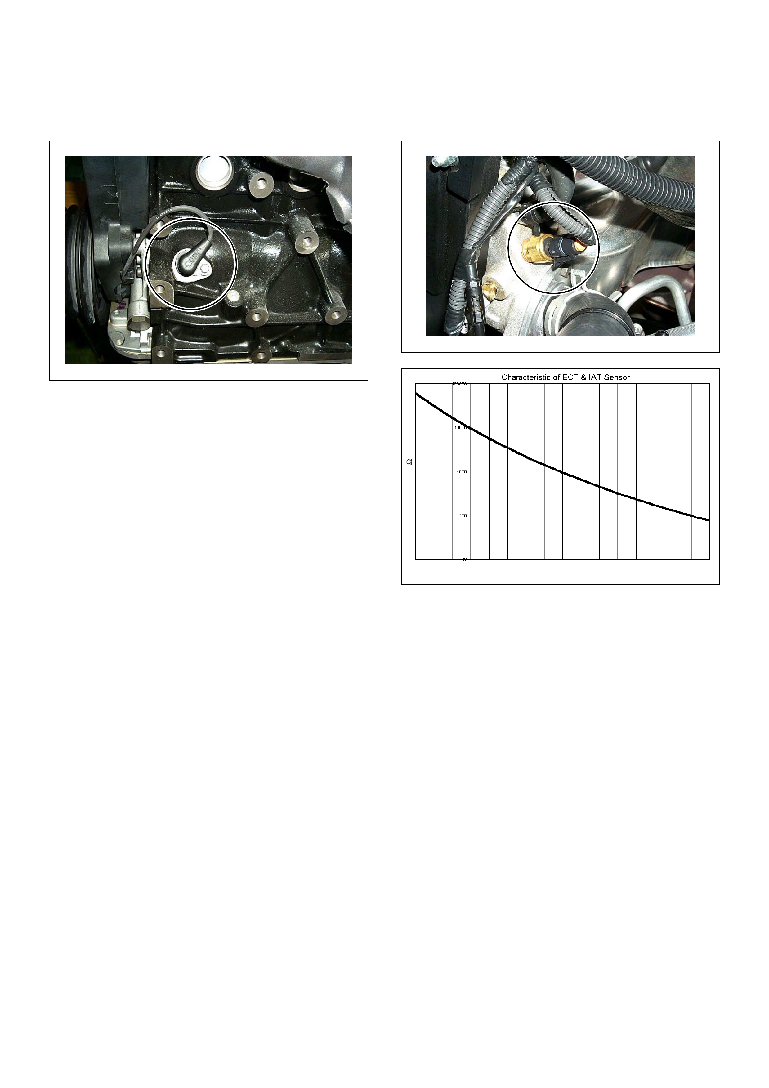
Crankshaft Position (CKP) Sensor
The crankshaft position (CKP) sensor, which sends a
signal necessary for deciding on injection timing to the
ECM, is mounted on the left-hand side of the cylinder
block just back of the A/C compressor.
The crank shaft has a 58 teeth pre ss- fit timing d isc, fr om
which the CKP sensor reads the position of the
crankshaft at all the times. It converts this to an
electrical signal, which it sends to the ECM.
Using the 58 X signals per rotation and the ti ming-mark
signal sent by the CKP sensor, the ECM is able to
accurately calculate engine speed and crank position.
The ECM conv erts the 58 X signa ls into squar e signa ls.
This conv erte d s ig nal is s ent fr om the ECM termi nal J 2-
25 to the tachometer.
Engine Coolant Temperature (ECT) Sensor
The ECT sensor is a thermistor. A temperature changes
the resistance value. And it changes voltage. In other
words it measures a temperature value. It is installed on
the coolant stream. Low coolant temperature produces
a high resistance.
The ECM supplies 5 volts signal to the ECT sensor
through resisters in the ECM and measures the voltage.
The signal voltage will be high when the engine
temperature is cold, and it will be low when the engine
temper atur e is hot.
-30
Resistance ( )
-20-100 1020304050
Temperature (ºC)
60 70 80 90 100 110 120 130
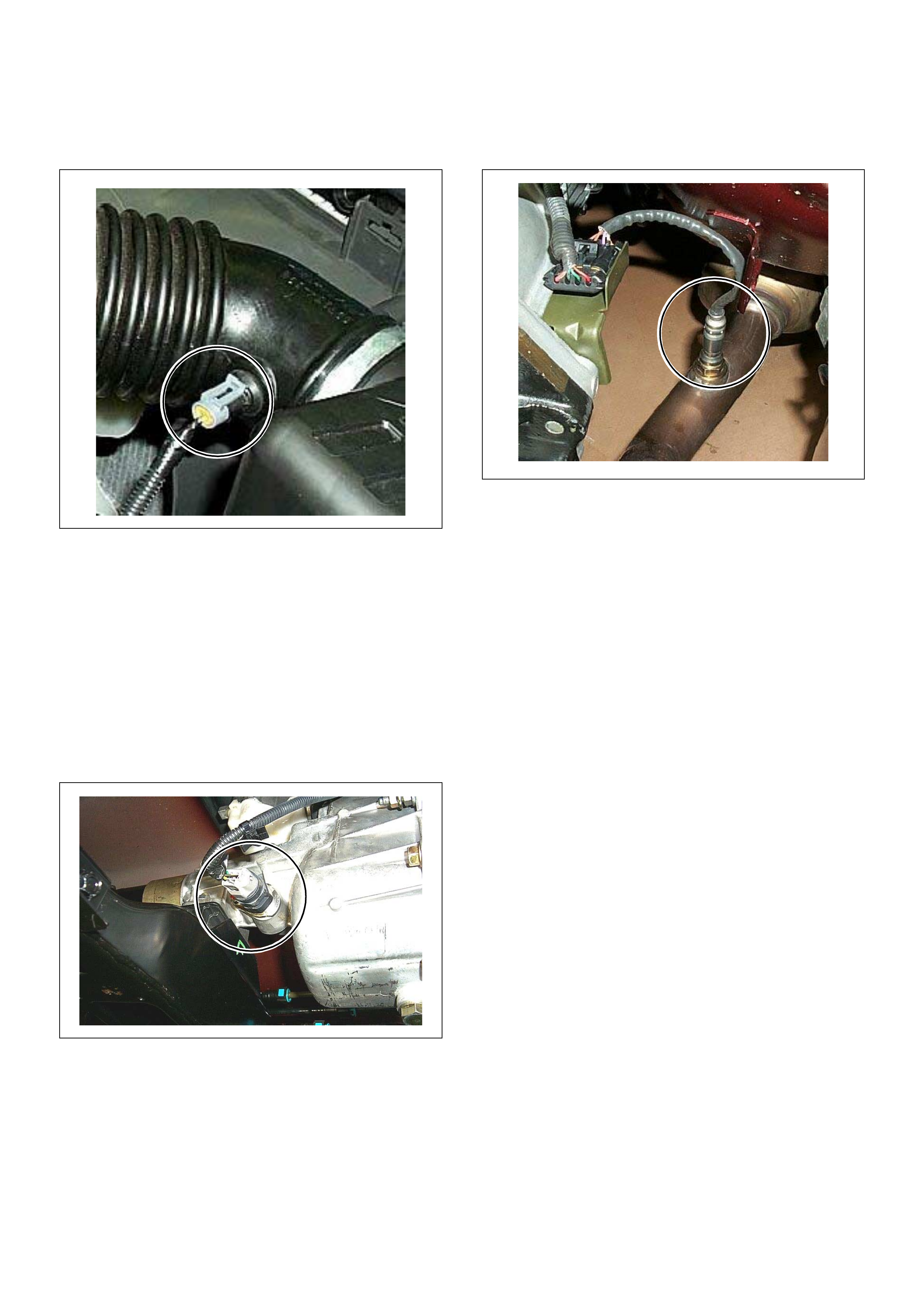
Intake Air Temper ature (IAT) Sensor
The IAT sensor is a thermistor. A temperature changes
the resistance value. And it changes voltage. In other
words it measures a temperature value. Low air
temperature produces a high resistance.
The ECM supplies 5 volts signal to the IAT sensor
through resisters in the ECM and measures the voltage.
The signal voltage will be high when the air temperature
is cold, and it will be low when the air temperature is
hot. The ECM uses to this value
Vehicle Speed Sensor (VSS)
The VSS is a magnet rotated by the transmission output
shaft. The VSS uses a hall ele ment. It in teracts with the
magnetic field treated by the r otating magnet. It out puts
pulse signal. The 12 volts operating supply from the
meter fuse.
Heated Oxy g en (O
2
) Sensor
The heated oxygen sensor consists of a 4-wire low
temperature activated zirconia oxygen analyzer element
with heater for operating temperature of 315°C, and
there is one mounted on each exhaust pipe.
A cons tant 450mi lliv olt is suppl ied by the ECM between
the two supply terminals, and oxygen concentration in
the exhaust gas is reported to the ECM as returned
signal voltage.
The oxygen present in the exhaust gas reacts with the
senso r to pr od uc e a vol tage o utpu t. T h is v ol tage s ho uld
constantly fluctuate from approximately 100mV to
1000mV and the ECM calculates the pulse width
commanded for the injectors to produce the proper
combustion chamber mixture.
Low oxygen sensor output voltage is a lean mixture
which will result in a rich commanded to compensate.
High oxygen sensor output voltage is a rich mixture
which result in a lean commanded to compensate.
When the engine is first started the system is in “Open
Loop” operation. In “Open Loop”, the ECM ignores the
signal from the oxygen sensors. When various
conditions (ECT, time from start, engine speed &
oxygen sensor output) are met, the system enters
“Closed Loop” operation. In “Closed Loop”, the ECM
calc ulates th e air fuel rat io based on the signa l from the
oxygen sensors.

General Description For Fuel
Metering
The fuel metering sys tem starts with the fu el in the fuel
tank. An electric fuel pump, located in the fuel tank,
pumps fuel to the fuel rail through an in-line fuel filter.
The pump is designed to provide fuel at a pressure
above the pressure needed by the injectors.
A fuel pressure regulator in the fuel rail keeps fuel
available to the fuel injectors at a constant pressure.
A return line delivers unused fuel back to the fuel tank.
The basic function of the air/fuel metering system is to
control the air/fuel delivery to the engine. Fuel is
delivered to the engine by individual fuel injectors
mounted in the intake manifold.
The main control sensor is the heated oxygen sensor
located in the exhaust system. The heated oxygen
sensor reports to the ECM how much oxygen is in the
exhaust gas. The ECM changes the air/fuel ratio to the
engine by controlling the amount of time that fuel
injector is “On”.
The best m ixture to minim ize exha ust emiss ions is 14.7
parts of air to 1 part of ga soli ne by w eight, w hich a llows
the catalytic converter to operate most efficiently.
Because of the cons tant measu ring and adjusti ng of the
air/fuel ratio, the fuel injection system is called a “closed
loop” system.
The ECM monitors signals from several sensors in
order to d etermine the fuel needs of the engine. F uel is
delivered under one of several conditions called “mode”.
All modes are controlled by the ECM.
Battery Voltage Correction Mode
When battery voltage is low, the ECM will compensate
for the weak spark by increasing the following:
• The amount of fuel delivered.
• The idle RPM.
Clear Flood Mode
Clear a flooded engine by pushing the accelerator pedal
down all the way. The ECM then de-energizes the fuel
injectors. The ECM holds the fuel injectors de-energized
as long as the throttle remains above 75% and the
engine speed is below 800 RPM. If the throttle position
becomes less than 75%, the ECM again begins to pulse
the injectors ON and OFF, allowing fuel into the
cylinders.
Deceleration Fuel Cutoff (DFCO) Mode
The ECM reduces the amount of fuel injected when it
detects a decrease in the throttle position and the air
flow. When deceleration is very fast, the ECM may cut
off fuel completely. Until enable conditions meet the
engine revolution less 1000 rpm or manifold absolute
pressure less than 10 kpa.
Engine Speed/ Vehicle Speed/ Fuel Disable
Mode
The ECM monitors engine speed. It turns off the fuel
injector s when t he engine speed inc reases ab ove 6000
RPM. The fuel injectors are turned back on when
engine speed decreases below 3500 RPM.
Acceleration Mode
The ECM provides extra fuel when it detects a rapid
increase in the throttle position and the air flow.
Fuel Cutoff Mode
No fuel is delivered by the fuel injectors when the
ignition is OFF. This prevents engine run-on. In addition,
the ECM suspends fuel delivery if no reference pulses
are detected (engine not running) to prevent engine
flooding.
Starting Mode
When th e i gni tio n is f irs t tur ne d ON , t he EC M ene rgiz es
the fuel pump relay for two seconds to allow the fuel
pump to build up pressure. The ECM then checks the
engine coolant temperature (ECT) sensor and the
throttle position sensor to determine the proper air/fuel
ratio for startin g.
The ECM controls the amount of fuel delivered in the
starting mode by adjusting how long the fuel injectors
are energized by pulsing the injectors for very short
times.
Run Mode
The run mode has the following two conditions:
• Open loop
• Closed loop
When the engine is first s tarted, the system is in “open
loop” operation. In “Open Loop,” the ECM ignores the
signal from the heated oxygen sensor (HO2S). It
calcula t es the a ir/fu el r at io b ased on inputs from th e T P,
ECT, and MAP sensors.
The system remains in “Open Loop” until the following
conditions are met:
• The HO2S has a v arying vol tage output sho wing tha t
it is hot enough to oper ate properly (thi s depends on
temperature).
• The ECT has reached a specified temperature.
• A specific amount of time has elapsed since starting
the engine.
• Engine speed has been greater than a specified RPM
since start-up .
The specific values for the above conditions vary with
different engines and are stored in the programmable
read o nly memory (PRO M). When t hese condition s are
met, the system enters “closed loop” operation. In
“closed loop,” the ECM calculates the air/fuel ratio
(injector on-time) based on the signal from the HO2S.
This allows the air/fuel ratio to stay very close to 14.7:1.

Fuel Metering System Components
The fuel metering system is made up of the following
parts.
• Fuel injector
• Throttle body
•Fuel rail
• Fuel pressure regulator
•ECM
• Crankshaft position (CKP) sensor
• Idle air control (IAC) valve
•Fuel pump
Fuel Injector
The group fuel injection fuel injector is a solenoid
operated device controlled by the ECM. The ECM
energizes the solenoid, which opens a valve to allow
fuel delivery.
The fuel is injected under pressure in a conical spray
pattern at the opening of the intake valve. Excess fuel
not used by the injectors passes through the fuel
pressure regulator before being returned to the fuel
tank.
Fuel Pressure Regulator
The fuel pressure regulator is a diaphragm-operated
relief valve mounted on the fuel rail with fuel pump
pressure on one side and manifold pressure on the
other side. The fuel pressure regulator maintains the
fuel pressure available to the injector at three times
barometric press ure adjus ted for engi ne loa d. It may b e
serviced separately.
If the pressure is too low or poor performance, DTC
P0131 or P1171 wi ll be the result. If the pr essure is too
high, DTC P0132 or P1167 will be the result. Refer to
Fuel System Diagnosis for information on diagnosing
fuel pressure conditions.
Fuel Rail
The fuel rail is mounted to the top of the engine and
distributes fuel to the individual injectors. Fuel is
delivered to the f uel inlet tub e of the fue l rail by the fuel
lines. The fuel goes through the fuel rail to the fuel
pressure regulator. The fuel pressure regulator
maintains a constant fuel pressure at the injectors.
Remaining fuel is then returned to the fuel tank.
Fuel Pump Elec trical Circ uit
When the k ey is first tur ne d ON, the ECM energi ze s the
fuel pump relay for two seconds to build up the fuel
pressure quickly. If the engine is not started within two
seconds, the ECM shuts the fuel pump off and waits
until the engi ne i s cr an ke d. W he n the en gin e i s cr ank ed
and the 58X crankshaft position signal has been
detecte d by the ECM, the E CM supplies 12 volts to the
fuel pump relay to energize the electric in-tank fuel
pump.
An inoperative fuel pump will cause a “no-start”
condition. A fuel pump which does not provide enough
pressure will result in poor performance.
Thottle Body Unit
The throttle body has a throttle plate to control the
amount of air delivered to the engine. The Thottle
position s ensor and IAC val ve are also mou nted on the
throttle body.
Vacuum ports located behind the throttle plate provide
the vacuum signals needed by various components.
Engine coolant is directed through a coolant cavity in
the throttle body to warm the throttle valve and to
prevent icing.
General Description For Electric
Ignition System
The engine use two ignition coils, one per two cylinders.
A two wire connector provides a battery voltage primary
supply through the ignition fuse.
The ignition control spark timing is the ECM’s method of
controlling the spark advance and the ignition dwell.
The ignition control spark advance and the ignition dwell
are calculated by the ECM using the following inputs.
• Engine speed
• Crankshaft position (CKP) sensor
• Engine coolant temperature (ECT) sensor
• Throttle position sensor
• Vehicle speed sensor
• ECM and ignition system supply voltage
Ignition coil works to generate only the secondary
voltage be receiving the primary voltage from ECM.
The primary voltage is generated at the coil driver
located in the ECM. The coil driver generate the primary
voltage based on the crankshaft position signal. In
accordance with the crankshaft position signal, ignition
coil driver determines the adequate ignition timing and
also cylinder number to ignite.
Ignition timing is determined the coolant temperature,
intake air temperature, engine speed, engine load,
knock sensor signal, etc.
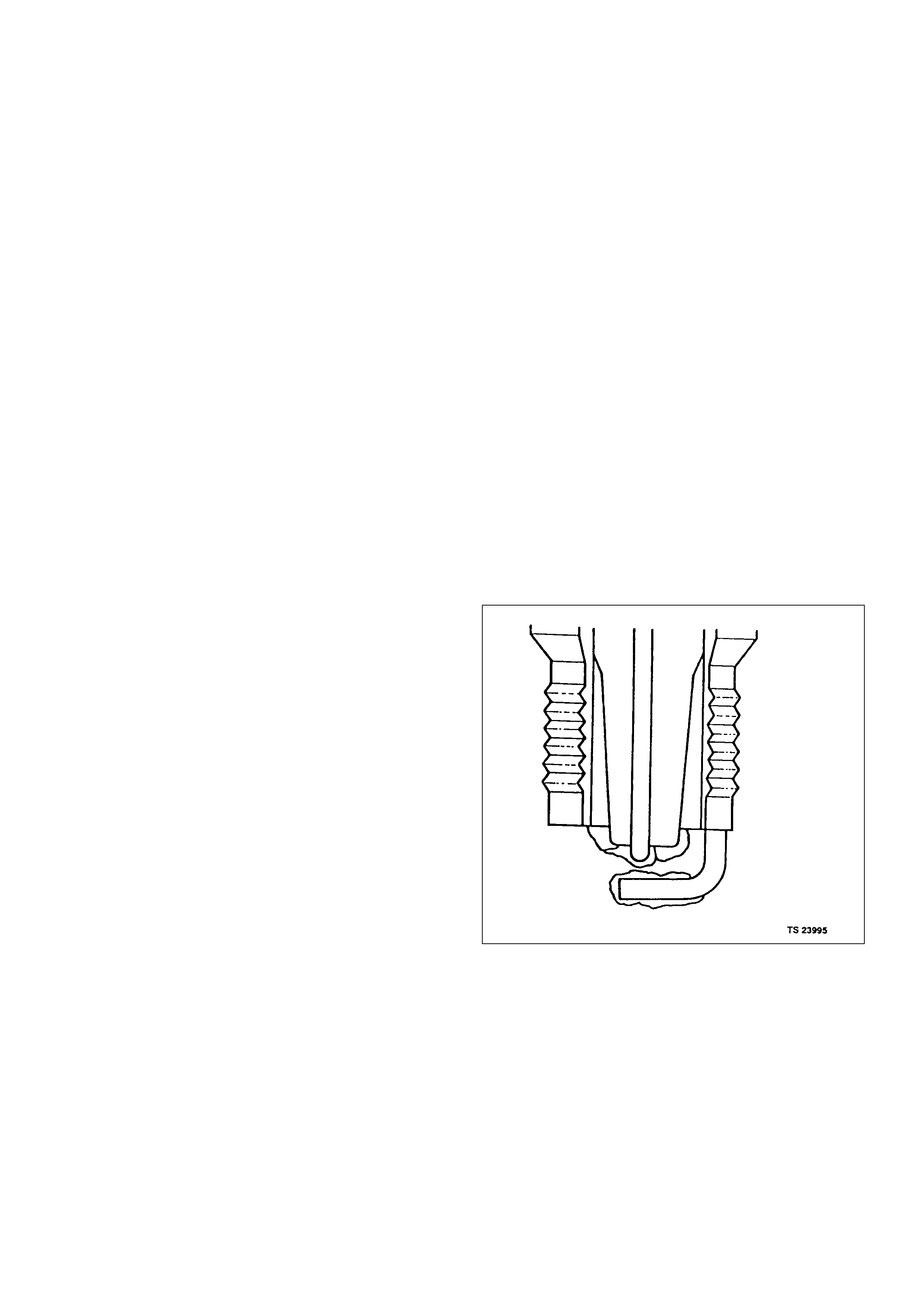
Spark Plug
Although worn or dirty spark plugs may give satisfactory
operation at idling speed, they frequently fail at higher
engine speeds. Faulty spark plugs may cause poor fuel
economy, power loss, loss of speed, hard starting and
generally poor engine performance. Follow the
scheduled maintenance service recommendations to
ensure satisfactory spark plug performance. Refer to
Maintenance and Lubrication.
Normal spark plug operation will result in brown to
grayish-tan deposits appearing on the insulator portion
of the spark plug. A small amount of red-brown, yellow,
and white powdery material may also be present on the
insulator tip around the center electrode. These
deposits are normal combustion by-products of fuels
and lubricating oils with additives. Some electrode wear
will also occur. Engines which are not running properly
are often referred to as “misfiring.” This means the
ignition spark is not igniting the air/fuel mixture at the
proper time. While other ignition and fuel system causes
must also be considered, possible causes include
ignition system conditions which allow the spark voltage
to reach ground in some other manner than by jumping
across the air gap at the tip of the spark plug, leaving
the air/fuel mixture unburned. Misfiring may also occur
when the tip of the spark plug becomes overheated and
ignites the mixture before the spark jumps. This is
referred to as “pre-ignition.”
Spark plugs may also misfire due to fouling, excessive
gap, or a cracked or broken insulator. If misfiring occurs
before the recommended replacement interval, locate
and correct the cause.
Carbon fouling of the spark plug is indicated by dry,
black carbon (soot) deposits on the portion of the spark
plug in the cylinder. Excessive idling and slow speeds
under light engine loads can keep the spark plug
temperatures so low that these deposits are not burned
off. Very rich fuel mixtures or poor ignition system output
may also be the cause. Refer to DTC P1167.
Oil fouling of the spark plug is indicated by wet oily
depo sits on the p ortio n o f the s park plug i n the c ylin der,
usua ll y wi th l i t tl e e lectrode we ar. T hi s ma y be c au s ed b y
oil d uring br eak-i n of n ew or newly o verhaul ed eng ines .
Deposit fouling of the spark plug occurs when the
normal red-brown, yellow or white deposits of
combustion by-products become sufficient to cause
misfiring. In some cases, these deposits may melt and
form a shiny glaze on the insulator around the center
electrode. If the fouling is found in only one or two
cylinders, valve stem clearances or intake valve seals
may be allowing excess lubricating oil to enter the
cylinder, particularly if the deposits are heavier on the
side of the spark plug facing the intake valve.
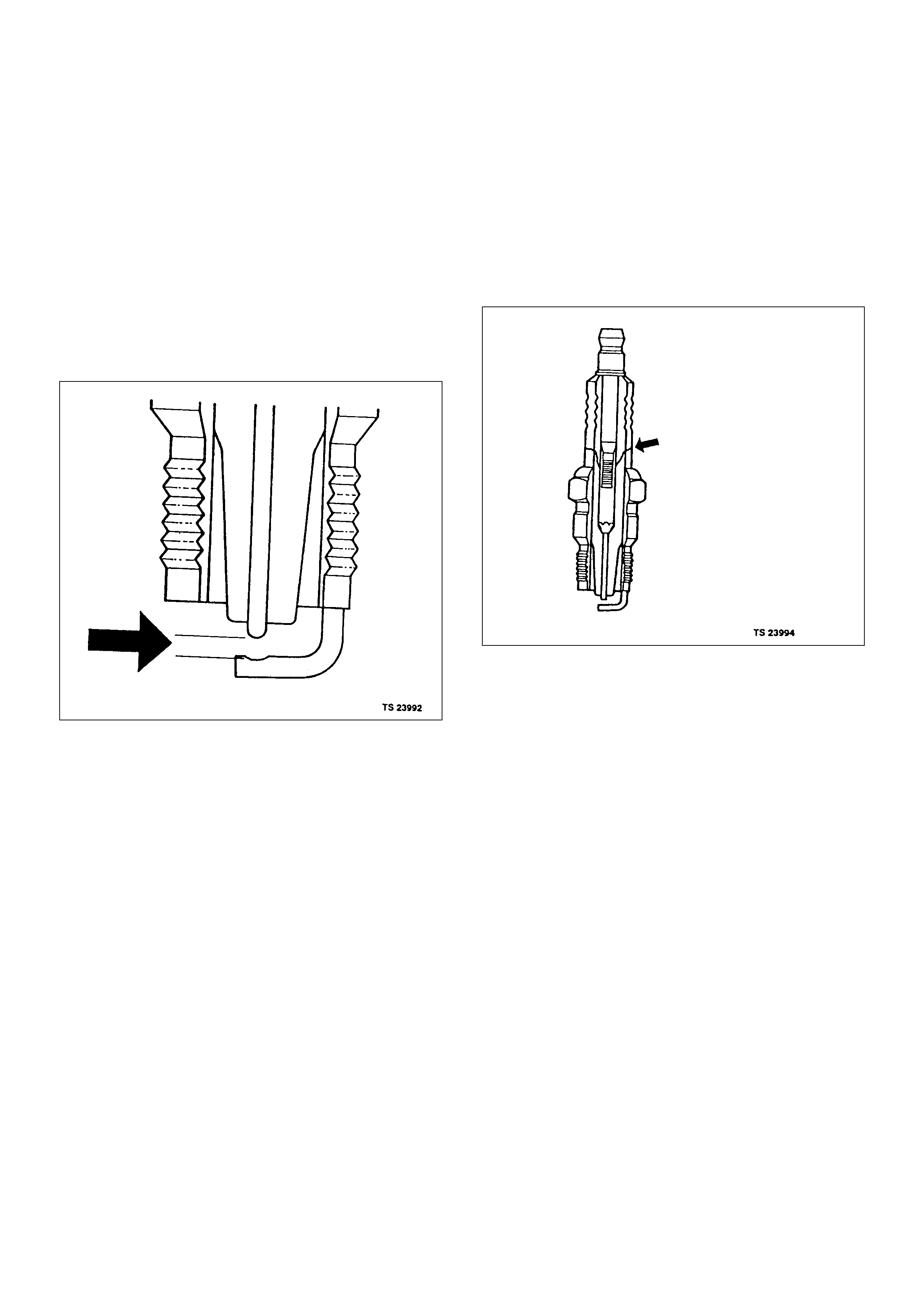
Excessive gap means that the air space between the
center and the side electrodes at the bottom of the
spark plug is too wide for consistent firing. This may be
due to improper gap adjustment or to excessive wear of
the electrode during use. A check of the gap size and
comparison to the gap specified for the vehicle in
Maintenance and Lubrication will tell if the gap is too
wide. A spark plug gap that is too small may cause an
unstable idle condition. Excessive gap wear can be an
indication of continuous operation at high speeds or
with engine loads, causing the spark to run too hot.
Another possible cause is an excessively lean fuel
mixture.
Low or high spark plug installation torque or improper
seating c an result in the spark pl ug runni ng too hot an d
can cause excessive center electrode wear. The plug
and the c ylind er he ad se ats must be i n good c ontact for
proper heat transfer and spark plug cooling. Dirty or
damaged threads in the head or on the spark plug can
keep it from seating even though the proper torque is
applied. Once spark plugs are properly seated, tighten
them to the torque shown in the Specifications Table.
Low torque may result in poor contact o f the seats due
to a loose spark plug. Over tightening may cause the
spark plug shell to be stretched and will result in poor
contact between the seats. In extreme cases, exhaust
blow-by and damage beyond simple gap wear may
occur.
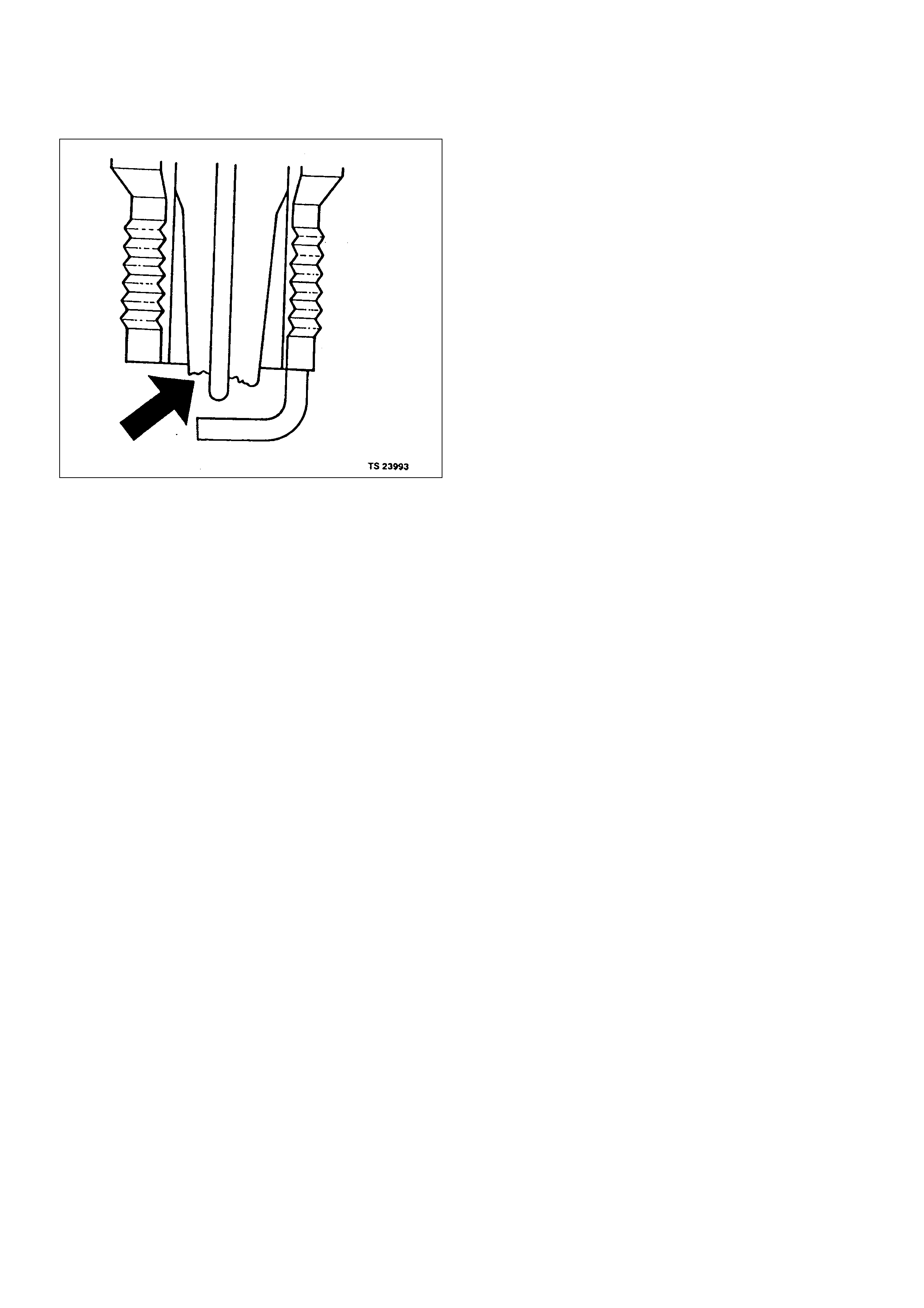
Cracked or broken insulators may be the result of
improper installation, damage during spark plug re-
gapping, or heat shock to the insulator material. Upper
insulators can be broken when a poorly fitting tool is
used during installation or removal, when the spark plug
is hit from the outside, or is dropped on a hard surface.
Cracks in the upper insulator may be inside the shell
and not visible. Also, the breakage may not cause
problems until oil or moisture penetrates the crack later.
A broken or cracked lower insulator tip (around the
center electrode) may result from damage during re-
gapping or from “heat shock” (spark plug suddenly
operating too hot).
• Damage during re-gapping can happen if the gapping
tool is pushed against the center electrode or the
insulator around it, causing the insulator to crack.
When re -gapping a s park plug, ma ke the adju stment
by bending only the ground side terminal, keeping the
tool clear of other parts.
• “Heat shock” breakage in the lower insulator tip
generally occurs during several engine operating
conditions (high speeds or heavy loading) and may
be caused by over-advanced timing or low grade
fuels. He at shock refers to a rapid increas e in the tip
temperature that causes the insulator material to
crack.
Spark plugs with les s t han th e reco mm ende d am ount of
service c an s om eti mes be c lea ned and re- ga ppe d, the n
returned to service. However , if there is any doubt about
the servic eab il ity of a spark plu g, repl ac e it . Spark plugs
with cracked or broken insulators should always be
replaced.
General Description For Evaporat ive
Emission System
EVAP Emission Control System Purpose
The bas ic e va porat iv e e mi ss io n con tr ol sys tem u sed o n
the charcoal canister storage method. The method
transfers fuel vapor from the fuel tank to an activated
carbon (charcoal) storage devise to hold the vapors
when the vehicle is not operating.
The canister is located on the rear axle housing by the
frame cross-member.
When the engine is running, the fuel vapor is purged
from the carbon element by intake air flow and
consumed in the normal combustion process.
EVAP Emission Control System Operation
The EVAP canister purge is controlled by a solenoid
valve that allows the manifold vacuum to purge the
canister. The engine control module (ECM) supplies a
ground to energize the solenoid valve (purge on). The
EVAP purge solenoid control is pulse-width modulated
(PWM ) (turned on and off several times a se cond). The
duty cycle (pulse width) is determined by engine
operating conditions including load, throttle position,
coolant temperature and ambient temperature. The duty
cycle is calculated by the ECM. the output is
commanded when the appropriate conditions have
been met. These conditions are:
• The engine is fully warmed up.
• The engine has been running for a specified time.
• The IAT reading is above 10°C (50°F).
• Purge/Vacuum Hoses. Made of rubber compounds,
these hoses route the gasoline fumes from their
sources to the canister and from the canister to the
intake air flow.
• EVAP Canister. Mounted on a bracket ahead of the
fuel tank, the canister stores fuel vapors until the
ECM determined that engine conditions are right for
them to be removed and burned.
Poor idle, stalling and Poor driveability can be caused
by:
• A malfunctioning purge solenoid.
• A damaged canister.
• Hoses that are split, cracked, or not connected
properly.
System Fau lt Detection
The EVAP leak detection strategy is based on applying
vacuum to the EVAP system and monitoring vacuum
decay. At an appropriate time, the EVAP purge solenoid
is turned “ON,” allowing the engine vacuum to draw a
small vacuum on the entire evaporative emission
system.
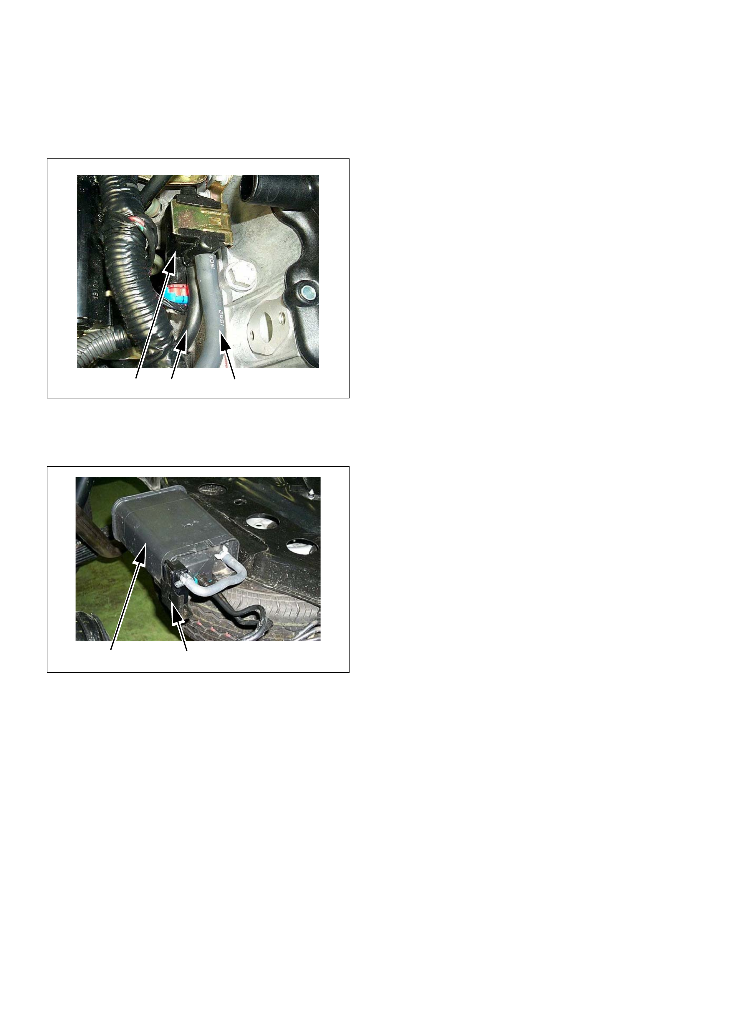
(1) Purge Sol en oid Valve
(2) From Canistor to Purge Solenoid
(3) From Purge Solenoid to Intake
(1) Canistor
(2) Air Separator
1 3 2
1 2

After the desired vacuum level has been achieved, the
EVAP purge solenoid is turned “OFF,” sealing the
system. A l ea k is dete ct ed b y moni tor i ng f or a d ec reas e
in vacuum level over a given time period, all other
variables remaining constant.
If the desired vacuum level cannot be achieved in the
test described above, a large leak or a faulty EVAP
purge control solenoid valve is indicated.
Leaks can be caused by the following conditions:
• Missing or faulty fuel cap
• Disconnected, damaged, pinched, or blocked EVAP
purge line
• Disconnected, damaged, pinched, or blocked fuel
tank vapor line
• Disconnected or faulty EVAP purge control solenoid
valve
• Open ignition feed circuit to the purge solenoid
• Damaged EVAP canister
• Leaking fuel sender assembly O-ring
• Leaking fuel tank or fuel filler neck
The ECM supplies a ground to energize the purge
control solenoid valve (purge “ON” ). Th e EVAP pu rge
control is turned “ON” and “OFF,” several times a
second. The duty cycle (pulse width) is determined by
engine operating conditions including load, throttle
position , c ool ant t emp eratur e a nd a mbi en t tem peratu re .
The duty cycle is c alculat ed by the EC M and the o utput
is commanded when the appropriate conditions have
been met.
The syste m checks for cond itions that cause the EVAP
system to purge continuously by commanding the EVAP
purge solenoid “OFF”, EVAP purge solenoid du ty ratio
“0%”. If fuel tank vacuum level increases during the test,
a contin uous purge flow co ndition is in dicated. Thi s can
be caused by the following conditions:
• EVAP purge solenoid leaking
• EVAP purge and engine vacuum lines switched at the
EVAP purge control solenoid valve
• EVAP purge control solenoid valve driver circuit
grounded
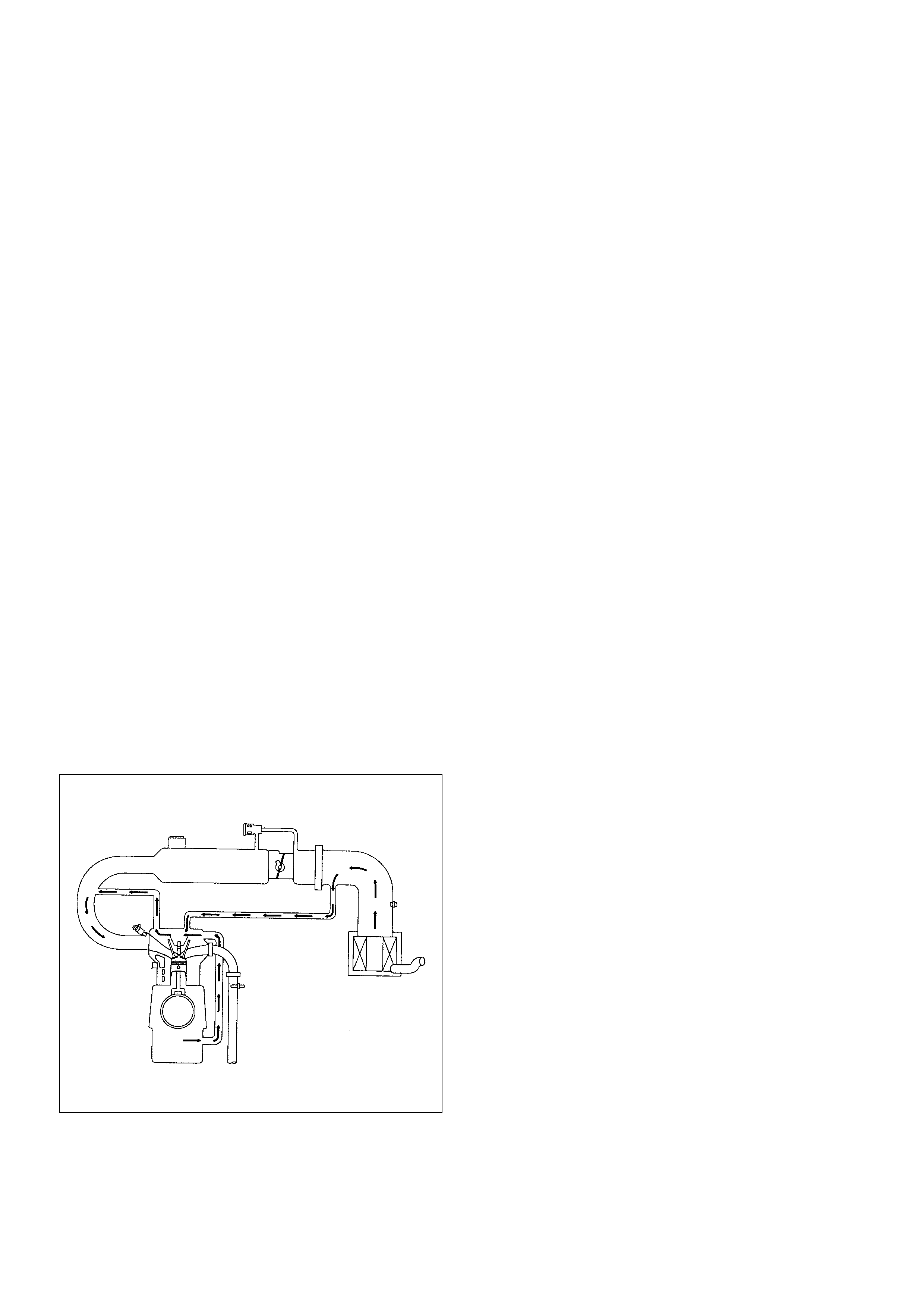
Positive Crankcase Ventilation (PCV)
System
Crankcase Ventilation System Purpose
The crankcase ventilation system is used to consume
crankc ase vapors i n the combus tion process instead of
venting them to the atmosphere. Fresh air from the
throttle body is supplied to the crankcase and mixed
wit h bl o w- by g a se s. T his mixtur e is t h en passed th r o u gh
the positive crankcase ventilation (PCV) port into the
intake manifold.
While the engine is running, exhaust gases and small
amounts of the fuel/air mixture escape past the piston
rings and enter the crankcase. these gases are mixed
with clean air entering through a tube from the air intake
duct.
During normal, part-throttle operation, the system is
designed to allow crankcase gases to flow through the
PCV hose into the intake manifold to be consumed by
normal combustion.
A plugged positive crankcase ventilation port or PCV
hose may cause the following conditions:
• Rough idle.
• Stalling or slow idle speed.
• Oil leaks.
• Sludge in the engine .
A leaking PCV hose would cause:
• Rough idle.
• Stalling.
• High idle speed.

A/C Clutch Diagnosis
A/C Clutch Circuit Operation
A 12-volt signal is supplied to the A/C request input of
the ECM when the A/C is selected through the A/C
control switch.
The A/C compressor clutch relay is controlled through
the ECM. This allows the ECM to modify the idle air
control position prior to the A/C clutch engagement for
better idl e qual ity. If the en gine oper ating condit ions are
within their specified calibrated acceptable ranges, the
ECM will en abl e the A/C c om pres so r relay. Th is is don e
by providing a ground path for the A/C relay coil within
the ECM. When the A/C compressor relay is enabled,
battery voltage is supplied to the compressor relay is
enabled, battery voltage is supplied to the compressor
clutch coil.
The ECM will enable the A/C compressor clutch
whenever the engine is running and the A/C has been
requested. The ECM will not enable the A/C
compressor clutch if any of the following conditions are
met:
• The engine speed is greater than 6000 RPM.
• The ECT is greater than 122°C (251°F).
• The throttle is more than 95% open.
A/C Clutch Circuit Purpose
The A/C compressor operation is controlled by the
engine control module (ECM) for the following reasons:
• It improves idle quality during compressor clutch
engagement.
• It improves wide open throttle (WOT) performance.
• It provides A/C com pressor pr otection fr om operatio n
with incorrect refrigerant pressures.
The A/C electrical system consists of the following
components:
• The A/C control switch.
• The A/C refrigerant pressure switches.
• The A/C compressor clutch.
• The A/C compressor clutch relay.
•The ECM.
A/C Request Signal
This signal tells the ECM when the A/C mode is
selected at the A/C control switch. The ECM uses this
input to adjust the idle speed before turn ing on the A /C
clutch. The A/C compressor will be inoperative if this
signal is not available to the ECM.
Refer to A/C Clutch Circuit Diagnosis for A/C wiring
diagrams and diagnosis for the A/C electrical system.

Holden Strategy Based Diagnostics
Overview
As a re tail serv ic e t ech ni cian, you ar e p art of the Hold en
service team. The team goal is FIX IT RIGHT THE
FIRST TIME for the satisfa ction of every custome r. Yo u
are a very important member of the team as you
diagnose and repair customer vehicles.
You have maximum efficiency in diagnosis when you
have an effective, organized plan for your work.
St rategy Based Diagnostic s (refer to F igure 1) provides
you with guidance as you create and follow a plan of
action for each specific diagnostic situation.
Strategy Based Diagnostics Chart

Diagnostic Thought Process
As you follow a diagnostic plan, every box on the
Strategy Based Diagnostics chart requires you to use
the diagnos tic thought pr ocess. Thi s method of think ing
optimize s your diagno sis in the following ways:
• Improves your understanding and definition of the
customer complaint
• Saves tim e b y avo idi ng testing and/o r repla ci ng goo d
parts
• Allows you to look at the problem from different
perspectives
• Guides yo u to determin e what level of understanding
about system operation is needed:
– Owner’s manual level
– Service manual level
– In-depth (engineering) level
– Owner’s manual leve l
– Service manual level
– In-depth (engineering) level
1. Verify the Complaint
What you should do
To verify the customer co mplaint, you ne ed to know the
correct (normal) operating behavior of the system and
verify that the customer complaint is a valid failure of the
system.
The following information will help you verify the
complaint:
• WHAT the vehicle model/options are
• WHAT aftermarket and dealer-installed accessories
exist
• WHAT related system(s) operate properly
• WHEN the problem occurs
• WHERE the problem occurs
• HOW the problem occurs
• HOW LONG the condition has existed (and if the
system ever worked correctly)
• HOW OFTEN the problem occurs
• Whether the severity of the problem has increased,
decreased or stayed the same
What resources you should use
Whenever possible, you should use the following
resources to assist you in verifying the complaint:
• Service manual Theory or Circuit Description
sections
• Service manual “System Performance Check”
• Owner manual operational description
• Technician experience
• Identical vehicle for comparison
• Circuit testing tools
• Vehic le road te sts
• Complaint check sheet
• Contact with the customer
2. Perform Preliminary Checks
NOTE: An estimated 10 percent of successful vehicle
repairs are diagnosed with this step!
What you should do
You perform preliminary checks for several reasons:
• To detect if the cause of the complaint is VISUALLY
OBVIOUS
• To identify parts of the system that work correctly
• To accumulate enough data to correctly and
accurately search for a Holden Service Bulletin on
Holden Web site.
The initial checks may vary depending on the
compl exity of the system and may in clude the follow ing
actions:
• Operate the suspect system
• Make a visual inspection of harness routing and
accessible/visible power and ground circuits
• Check for blown fuses
• Make a visual inspection for separated connectors
• Make a visual inspection of connectors (includes
checking terminals for damage and tightness)
• Check for any DTCs stored by the on-board
computers
• Sense unusual noises, smells, vibrations or
movements
• Investigate the vehicle service history (call other
dealerships, if appropriate)
What resources you should use
Whenever appropriate, you should use the following
resources for assistance in performing preliminary
checks:
• Tech II or other technical equipment for viewing DTCs
• Service manual information:
– Component locations
– Harness routing
– Wiring schem ati cs
– Procedures for viewing DTCs
• Dealership service history file
• Vehic le road te st
• Identical vehicle or system for comparison

3. Check Bulletins and Troubleshooting
Hints
NOTE: As estimated 30 percent of successful vehicle
repairs are diagnosed with this step!
What you should do
You should have enough information gained from
preliminary checks to accurately search for a bulletin
and other related service information. Some service
manual sections provide troubleshooting hints that
match symptoms with specific complaints.
What resources you should use
You should use the following resources for assistance in
checking for bulletins and troubleshooting hints:
• Printed bulletins
• Access Holden Bulletin W eb sit e,
https://www.einet.Holden.co.jp//
• Videotapes
• Service manual
4. Perform Service Manual Diagnostic
Checks
What you should do
The “System Checks” in most service manual sections
and in most cells of section 8A (electrical) provide you
with:
• A systematic approach to narrowing down the
possible causes of a system fault
• Direction to specific diagnostic procedures in the
service manual
• Assistance to identify what systems work correctly
What resources you should use
Whenever possible, you should use the following
resources to perform service manual checks:
• Service manual
• Technical equipment (for viewing DTCs and
analyzing data)
• Digital multimeter and circuit testing tools
• Other tools as needed
5a and 5b. Perform Service Manual
Diagnostic Procedures
NOTE: An estimated 40 percent of successful vehicle
repairs are diagnosed with these steps!
What you should do
When directed by service manual diagnostic checks,
you must then carefully and accurately perform the
steps of diagnostic procedures to locate the fault related
to the customer complaint.
What resources you should use
Whenever appropriate, you should use the following
resources to perform service manual diagnostic
procedures:
• Service manual
• Technical equipment (for analyzing diagnostic data)
• Digital multimeter and circuit testing tools
• Essential and special tools
5c. Technician Self Diagnoses
When there is no DTC stored and no matching
symptom for the condition identified in the service
manual , you must b egin with a thorough understanding
of how the system(s) operates. Efficient use of the
service manual combined with you experience and a
good process of elimination will result in accurate
diagnosis of the condition.
What you should do
Step 1: Identify and understand the suspect
circuit(s)
Having completed steps 1 through 4 of the Strategy
Based Diagnostics chart, you should have enough
information to identify the system(s) or sub-system(s)
involved. Using the service manual, you should
determine and investigate the following circuit
characteristics:
• Electrical:
– How is the circuit powered (power distribution
charts and/or fuse block details)?
– How is the circuit grounded (ground distribution
charts)?
– How is the circuit controlled or sensed (theory of
operation):
– If it is a switched circuit, is it normally open or
normally closed?
– Is the power switched or is the ground
switched?
– Is it a variable resistance circuit (ECT sensor
or TP sensor, for example)?
– Is it a signal ge nerati ng devi ce (MAF sens or of
VSS, for example)?
– Does it rely on some mechanical/vacuum
device to operate?

• Physical:
– Where are the circuit components (component
locators and wire harness routing diagrams):
– Are there areas where wires could be chafed
or pinched (brackets or frames)?
– Are there areas subjected to extreme
temperatures?
– Are there areas subjected to vibration or
movement (engine, transmission or
suspension)?
– Are there are as expos ed to moistu re, road s alt
or other corrosives (battery acid, oil or other
fluids)?
– Are there common mounting areas with other
systems/components?
– Have previous repairs been performed to wiring,
connectors, components or mounting areas
(causing pinched wires between panels and
drivetrain or suspension components without
causing and immediate problem)?
– Does the vehicle have aftermarket or dealer-
installed equipment (radios, telephone, etc.)
Step 2: Isolate the problem
At this point, you should have a good idea of what could
cause th e presen t cond ition, as well a s could not ca use
the condition. Actions to take include the following:
• Divide (and separate, where possible) the system or
circuit into smaller sections
• Confine the problem to a smaller area of the vehicle
(start with main harness connections while removing
panels and trim as necessary in order to eliminate
large vehicle sections fr om further investig ation)
• For two or more circuits that do not share a common
power or ground, concentrate on areas where
harnesses are routed together or connectors are
shared (refer to the following hints)
Hints
Though the symptoms may vary, basic electrical failures
are generally caused by:
• Loose connections:
– Open/high resistance in terminals, splices,
connectors or grounds
• Incorrect connector/harness routing (usually in new
vehicles or after a repair has been made):
– Open/high resistance in terminals, splices,
connectors of grounds
• Corrosion and wire damage:
– Open/high resistance in terminals, splices,
connectors of grounds
• Component failure:
– Opens/short and high resistance in relays,
modules, switches or loads
• Aftermarket equipment affecting normal operation of
other systems
You may isolate circuits by:
• Unplugging connectors or removing a fuse to
separate one part of the circuit from another part
• Operating shared circuits and eliminating those that
function normally from the suspect circuit
• If only one component fails to operate, begin testing
at the component
• If a number of components do no operate, begin tests
at the area of commonality (such as power sources,
ground circuits, switches or major connectors)
What resources you should use
Whenever appropriate, you should use the following
resources to assist in the diagnostic process:
• Service manual
• Technical equipment (for data analysis)
• Experience
• Technical Assistance
• Circuit testing tools
5d. Intermittent Diagnosis
By definition, an intermittent problem is one that does
not occur continuously and will occur when certain
conditions are met. All these conditions, however, may
not be obvious or currently known. Generally,
intermittents are caused by:
• Faulty electrical connections and wiring
• Malfunctioning components (such as sticking relays,
solenoids, etc.)
• EMI/RFI (Electromagnetic/radio frequency
interference)
• Aftermarket equipment
Intermittent diagnosis requires careful analysis of
suspected systems to help prevent replacing good
parts. This m ay i nvolve using cr eativity a nd i ngenui ty to
interpret customer complaints and simulating all
exter nal and internal system conditi ons to duplicat e the
problem.
What you should do
Step 1: Acquire information
A thorough and comprehensive customer check sheet
is critical to intermittent problem diagnosis. You should
require this, since it will dictate the diagnostic starting
point. The vehicle service history file is another
source for accumulating information about the
complaint.

Step 2: Analyze the intermittent problem
Analyze the customer check sheet and service history
file to determine conditions relevant to the suspect
system(s).
Using service manual information, you must identify,
trace and locate all electrical circuits related to the
malfunctioning system(s). If there is more than one
system failure, you should identify, trace and locate
areas of commonality shared by the suspect circuits.
Step 3: Simulate the symptom and isolate the
problem
Simulate the symptom and isolate the system by
reproducing all possible conditions suggested in Step 1
while monitoring suspected circuits/components/
systems to isolate the problem symptom. Begin with the
most logical circuit/component.
Isolate the circuit by dividing the suspect system into
simpler circuits. Next, confine the problem into a smaller
area of the system. Begin at the most logical point (or
point of easiest access) and thoroughly check the
isolated circuit for the fault, using basic circuit tests.
Hints
You can isolate a circuit by:
• Unplugging connectors or removing a fuse to
separate one part of the circuit from another
• If only component fails to operate, begin testing the
component
• If a number of components do not operate, begin test
at areas of commonality (such as power sources,
ground circuits, switches, main connectors or major
components)
• Substitute a known good part from the parts
department or the vehicle system
• Try the suspect part in a known good vehicle
See Symptom Simulation Tests on the next page for
problem simulation procedures. Refer to service manual
sections 6E and 8A for information about intermittent
diagnosis. Follow procedures for basic circuit testing in
service manual section 8A.
What resources you should use
Whenever appropriate, you should use the following
resources to assist in the diagnostic process:
• Service manual
• Bulletins
• Digital multimeter (with a MIN/MAX feature)
• Tech II and Tech II upload function
• Circuit testing tools (including connector kits/
harnesses and jumper wires)
• Experience
• Intermittent problem solving simulation methods
• Customer complaint check sheet
Symptom Simulation Tests
1. Vibration
This method is useful when the customer complaint
analysis indicates that the problem occurs when the
vehicle/system undergoes some form of vibration.
For connectors and wire harness, slightly shake
vertically and horizontally. Inspect the connector joint
and body for damage. Also, tapping lightly along a
suspected circuit may be helpful.
For parts and sensors, apply slight vibration to the part
with a light tap of the finger while monitoring the system
for a malfunction.
2. Heat
This method is important when the complaint suggests
that the problem occurs in a heated environment. Apply
moderate heat to the component with a hair drier or
similar tool while monitoring the system for a
malfunction.
CAUTION: Care must be take to avoid overheating
the compone nt.
3. Water and Moisture
This method may be used when the complaint suggests
that the malfunction occurs on a rainy day or under
conditions of high humidity . In this case, apply water in a
light spray on the vehicle to duplicate the problem.
CAUTION: Care must be take to avoid directly
exposing electrical connections to water.
4. Electrical loads
This method involves turning systems ON (such as the
blower, lights or rear windo w defogger) to create a load
on the vehicle electrical system at the same time you
are monitoring the suspect circuit/component.

5e. Vehicle Operates as Designed
This condition refers to instances where a system
operatin g as des igned i s perceiv ed to be unsatis factory
or undesirable. In general, this is due to:
• A lack of understanding by the customer
• A conflict between customer expectations and
vehicle des ig n inten t
• A system performance that is unacceptable to the
customer
What you should do
You can verify that a system is operating as designed
by:
• Reviewing service manual functional/diagnostic
checks
• Examinin g bulletins a nd other ser vice i nformation for
supplementary information
• Compare syst em opera tion to an identical vehicl e
If the condition is due to a customer misunderstanding
or a con flict between c ustomer expec tation an d system
operation, you should explain the system operation to
the custo mer.
If the complaint is due to a case of unsatisfactory
system performance, you should contact Technical
Assistance for the latest information.
What resources you should use
Whenever possible, you should use the following
resour ce s to faci li tate the diagno sti c pr oces s:
• Vehicle service information (service manual, etc.)
• Holden field support
• Experience
• Identical vehicle or system for comparison
6. Re-examine the complaint
When you do not successfully find/isolate the problem
after executing a diagnostic path, you should re-
examine the com pl ain t.
What you should do
In this case, you will need to backtrack and review
information accumulated from step 1 through 4 of
Strategy Based Diagnostics. You also should repeat any
procedures that require additional attention.
A previous path may be eliminated from consideration
only if you are certain that all steps were executed as
directed. You must then select another diagnostic path
(step 5a, 5b, 5 c or 5d ) . If al l po ss ible options have bee n
explored, you may call or seek Holden field support.
What resources you should use
Whenever possible, you should use the following
resources to facilitate the diagnostic process:
• Service manual
• Accumulated information form a previous diagnostic
path
• Service information and publications
• Holden field support
7. Repair and Verify Fix
What you should do
After you have located the cause of the problem, you
must execute a repair by following recommended
service manual procedures.
When the repair is completed, you should verify the fix
by performing the system checks under the conditions
listed in the customer complaint.
If applic able, you should ca rry out prev entive me asures
to avoid a repeat complaint.
What resources you should use
Whenever possible, you should use the following
resources to facilitate the repair process:
• Electrical repair procedures
• Service manual information and publications

General Service Information
Aftermar ket El ectrical and Vacuum
Equipment
Aftermarket (add-on) electrical and vacuum equipment
is defined as any equipment which connects to the
vehicle's electrical or vacuum systems that is installed
on a vehicle after it leaves the factory. No allowances
have been made in the vehicle design for this type of
equipment.
NOTE: No add -on vacu um equipme nt should be added
to this vehicle.
NOTE: Add-on electrical equipment must only be
connected to the vehicle's electrical system at the
battery (power and ground).
Add-on electrical equipment, even when installed to
these guidelines, may still cause the electric system to
malfunction. This may also include equipment not
connected to the vehicle electrical system such as
portable tele pho nes and radio s. Th erefo re , the fi rst ste p
in diagnosing any electric problem is to eliminate all
aftermarket electrical equipment from the vehicle. After
this is done, if the problem still exists, it may be
diagnosed in the normal manner.
Electrostatic Discharge Damage
Electronic components used in the ECM are often
designed to carry very low voltage. Electronic
components are susceptible to damage caused by
electrostatic discharge. Less than 100 volts of static
electricity can cause damage to some electronic
components. By comparison, it takes as much as 4000
volts for a person to feel even the zap of a static
discharge.
There are several ways for a person to become
statically charged. The most common methods of
charging are by friction and induction.
• An example of char ging by fric tion is a perso n slid ing
across a vehicle seat.
• Charge by induc tion o ccurs when a per son w ith well-
insulated shoes stands near a highly charged object
and momentarily touches ground. Charges of the
same polarity are drained off leaving the person
highly charged with the opposite polarity. Static
charges can cause damage, therefore it is important
to use care when handling and testing electronic
components.
Non-OEM Pa rts
All of the OBD diagnostics have been calibrated to run
with OEM parts. Accordingly, if commercially sold
sensor or switch is installed, it makes a wrong diagnosis
and turns on the check engi ne lam p.
Aftermarket electronics, such as cellular phones,
stereos, and anti-theft devices, may radiate EMI into the
control system if they are improperly installed. This may
cause a false sensor reading and turn on the check
engine lamp.
Poor Vehicle Maintenance
The se nsitivity of OBD dia gnostics will caus e the check
engine lamp to turn on if the vehicle is not maintained
properly. Restricted oil filters, fuel filters, and crankcase
deposits due to lack of oil changes or improper oil
viscosity can trigger actual vehicle faults that were not
previously monitored prior to OBD. Poor vehicle
maintenance can not be classified as a “non-vehicle
fault”, but with the sensitivity of OBD diagnostics,
vehicle maintenance schedules must be more closely
followed.
Related System Faults
Many of the OBD system diagnostics will not run if the
ECM detects a fault on a related system or component.
Visual/Physical Engine Compartment
Inspection
Perform a careful visual and physical engine
compartment inspection when performing any
diagnostic procedure or diagnosing the cause of an
emiss ion test fail ure. This can o ften lead to r epairing a
problem without further steps. Use the following
guidelines when performing a visual/physical
inspection:
• Inspect all vacuum hoses for punches, cuts,
disconnects, and correct routing.
• Inspect hoses that are difficult to see behind other
components.
• Inspect all wires in the engine compartment for
proper co nnection s, burned or chafed s pots, pinched
wires, contact with sharp edges or contact with hot
exhaust manifolds or pipes.
Basic Knowledge of Tools Required
NOTE: Lack of basic knowledge of this powertrain
when performing diagnostic procedures could result in
an incorrect diagnosis or damage to powertrain
components. Do not attempt to diagnose a powertrain
problem without this basic knowledge.
A basic understanding of hand tools is necessary to
effectively use this section of the Service Manual.
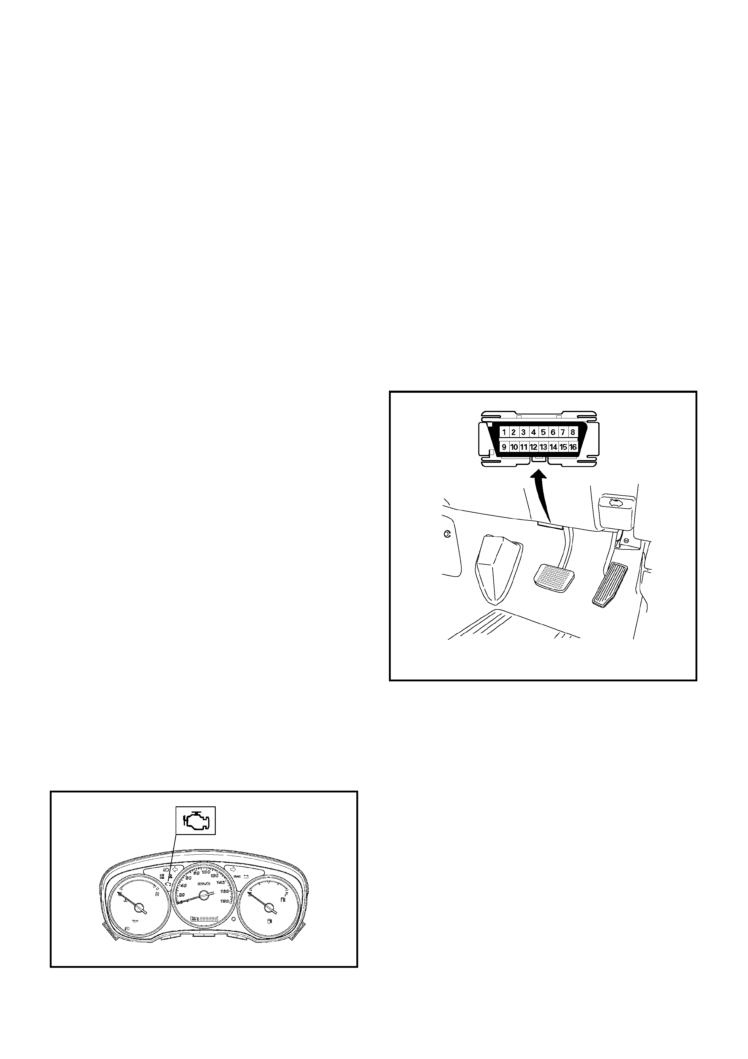
On-Board Diagnostic (OBD)
On-Board Diagnostic Tests
A diagnostic test is a series of steps, the result of which is a
pass or fail, reported to the diagnostic executive. When a
diagnostic test reports a pass result, the diagnostic executive
record s the fo llowing data :
• The diagnosti c test has been comp leted si nce the la st
ignition cycle.
• The diagnosti c test has passed during the cu rren t ignition
cycle .
• The fault iden tified by the diagn ostic te st is not curren tly
active.
When a diagnostic te st reports a fail resul t, the diagno stic
executive records the following data:
• The diagnosti c test has been comp leted si nce the la st
ignition cycle.
• The fault identified by the diagnostic test is currently active.
• The fault has been active during thi s ignition cycle.
• The operating conditions at the time of the failure.
The Diagnostic Executive
The Diagnostic Executive is a unique segment of software
which is designed to coordinate and prioritise the diagnostic
procedures as well as define the protocol for recording and
displaying their results. The main responsibilities of the
Diagnostic Executive are listed as follows:
• Commanding the check engine la mp on and off
• DTC logging and clea ring
• Current status information on each diagnostic
Diagnostic Information
The diagnostic charts and functional checks are designed to
locate a faulty circuit or component through a process of
logical decisions. The charts are prepared with the
requiremen t that the vehicl e fun cti oned corre ctly at th e ti me of
assembly and that there are not multiple faults present.
There is a continuous self-diagnosis on certain control
functions. This diagnostic ca pab ility is co mpl emented by the
diagnostic procedures co ntai ned in this ma nua l.
The langua ge of communica ting the source of the malfunction
is a system of di agnosti c trou ble codes. When a ma lfun ction is
detected by the con trol mo dul e, a diag nosti c tro uble code is
set and the check engine lamp is illuminated.
Malfunc tion Indica tor Lamp
The malfunction indicator lamp (MIL) is located in the
instrument pane l clus ter. The MIL will di splay the follow ing
symbol when commanded ‘ON’.
•
•
• The MIL remains illuminated after the engine is started, i
f
the engine control module (ECM) detects a fault.
A
diagnostic trouble code (DTC) is stored any time the ECM
illumina tes the MIL due to an emi ssion re lated fau l t.
Data Link Connector (DLC)
The provision fo r communi ca tion with the control mo dule i s the
Data Link Connector (DLC). It is located behind the lower front
instrument pane l. The DLC is used to connect to a Tech2 .
Some common uses of the Tech2 are listed below:
• Identifying stored Diagnosti c Trou ble Code s (DTCs).
• Clearing DTCs.
• Reading serial data.
Verifying Vehicle Repair
Verifica tion of ve hi cle rep ai r w ill be mo re comprehensi ve fo r
vehicles with OBD system diagnostic. Following a repair, the
technician shoul d perfo rm the following steps:
1. Review and record the Fail Records for the DTC which
has been diagnosed .
2. Clear DTC(s).
3. Operate the vehicle within conditions noted in the Fail
Records.
4. Monitor the DTC status information for the specific DTC
which has been diagnosed until the diagnostic test
associated with that DTC runs.
Following these steps is very impo rta nt in verifyin g repairs on
OBD systems. Failure to follow these steps could result in
unnecessary repai rs.
The MIL turns ’OFF’ after the engine is started, if a
diagnostic fault is n o t present.
The MIL illuminates when the ignition switch is turned
‘ON’, with the engine ‘OFF’. This is a bulb test to ensure
that the MIL is able to illumi na te.
The MIL indicates tha t an emission related faul t has occurred
and vehicle service is required. The following is a list of the
modes of operation for the MIL:
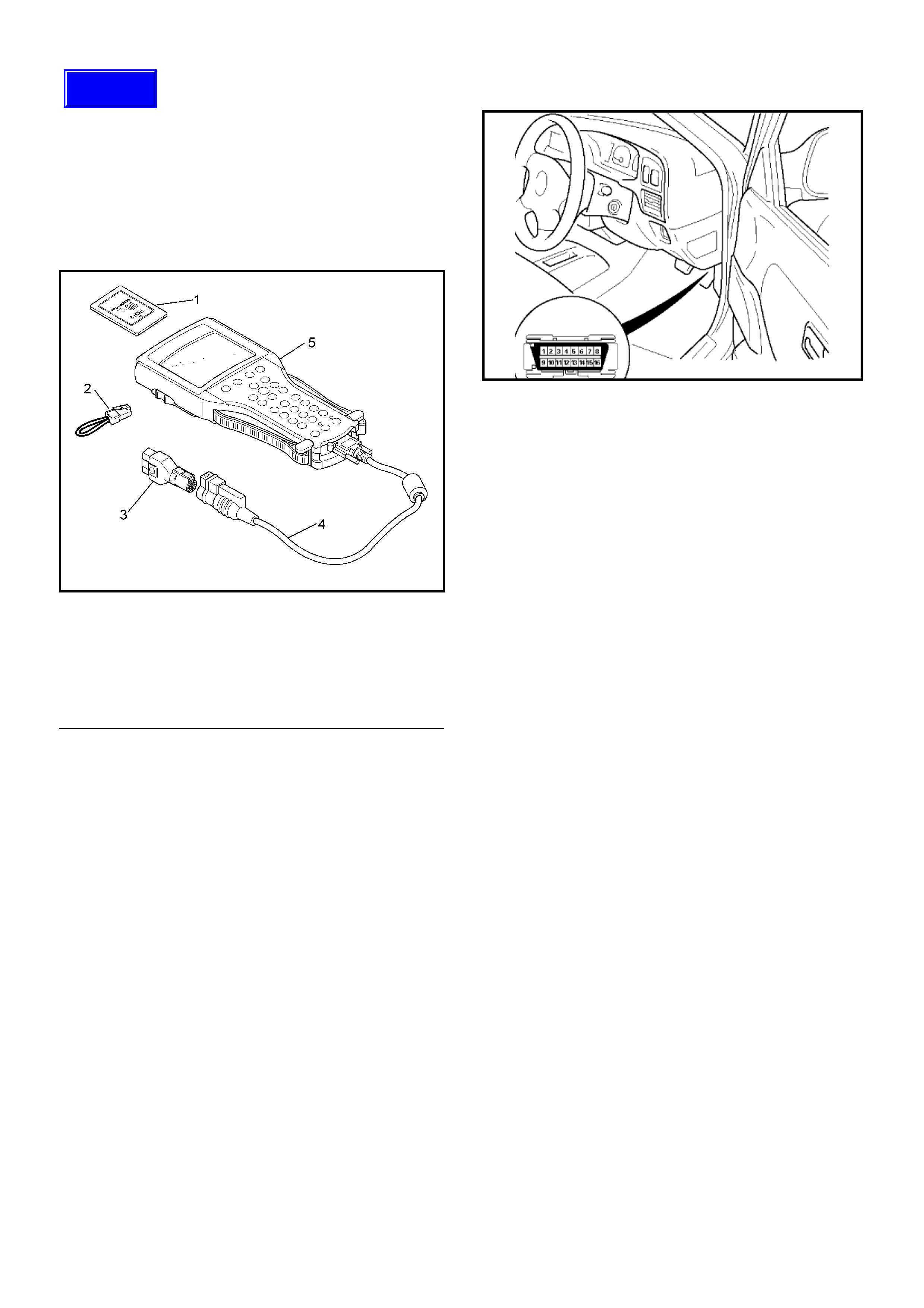
On-Board Diagnosis (Self-Diagnosis)
The Tech 2 Scan Tool
The Tech 2 scan tool is used to electrically diagnose and
check the vehicle electronic systems. The Tech 2 enhances
the diagnosis efficiency, even though the troubleshooting can
be done without the Tech 2.
Legend
(1) PCMCIA Card
(2) Loop Back Connecto r
(3) SAE 16/19 Pin Adaptor
(4) DLC Cable
(5) Tec h 2 S ca n To ol
1. Tech 2 Components:
• Tech 2 scan tool ki t (No . 70 00086), Tech 2 scan tool
(No. 7000057) a nd DLC cable (No . 3000095).
• SAE 16/19 adapter (No. 3000098) (3), RS232 loop
back connector (No. 3000112) (2) and PC MCIA card
(No. 3000117) (1).
2. Connecting Tech 2 to the Vehicle:
• Check the key switch is turn OFF.
• Insert the PCMCIA card (1) into th e Te ch 2 (5) . No te
that the PCMCIA card must be installed in the slot
closest to the Tech 2 screen.
NOTE: Check that power is not supplied to the Tech 2
when installing or remo vin g the PCMC IA card.
• Connect the SAE 16/19 adapter (3 ) to the data lin k
connector of the vehicle.
• Connect the DLC cable (4 ) to th e Tech 2 (5 ).
• Connect the SAE 16/19 adapter (3 ) to the data lin k
connector (DLC) of the vehicle.
• Turn the key switch of the vehicle ON and press the
"PWR" key of the Tech 2.
• Check the display of the Tech 2.
Diagnosis With Tech 2 Scan Tool
The preferred method for reading diagnostic trouble code(s) is
to use a Tech2 scan tool. When reading DTC(s), follo
w
instructions supplied by the Tech 2 manufacturer.
If No Codes are Set:
• R e fe r to Fl: Data D isplay and iden tify the ele ctri cal faul ts
that are not indicated by a troub le code .
• Refe r to "SYMPTOM DIAGNOSIS".
If codes are set:
1. Record all trouble codes displayed by Tech 2 and check i
f
the codes are intermittent.
2. Clear the codes.
3. Road test the vehicle to reproduce the faulty status.
4. Check trouble codes again using the Tech 2.
5. If no codes is displayed by test driving, the fault is
inte rmi t ten t. In this ca se , re fe r to "DIAGNOSIS AIDS".
6. If a code is present, refer to DTC Chart for diagnosis.
7. Check trouble codes again using the Tech 2.
Clearing Diagnostic Trouble Codes
To clear Diagnostic Trouble Codes (DTCs), use the Tech2
"clear DTCs" or "clear information" function. When clearing
DTCs follow instructions supplied by the Tech2 manufacturer.
Techline

TECH 2 Operating Flow Cart (Start Up)
Select “2.XL L4 HV240” in Vehicle Identification menu and the following table is shown in the Tech 2 screen.
Main Menu
F0: Diagnostic
F1: Service Programming System (SPS)
F2: View Capture Data
F3: Tool Option
F4: Download/ Upload Help
Press “ENTER” key.
Vehicle Identification
(3) 2003
(2) 2002
(1) 2001
(Y) 2000
(X) 1999
(W) 1998
Select “F0: Diagnostic”.
Select “(3) 2003” or later.
Press (ENTER) to Continue
System Selection Menu
F0: Powertrain
F1: Chassis
F3: Body
Select “(TF/UC)”.
Vehicle Identification
4JH1-TC Bosch
4JH1-T Denso
2.XL L4 HV240
3.5L V6 6VE1 Hitachi
AW30-40LE
AT JR405E
Select “F0: Powertrain”.
Select “2.XL L4 HV240”.
Vehicle Identification
(UB) Trooper, Bighorn
(UE) Rodeo,/Amigo, Wizard/Mu
(TF/UC) LUV, Frontier, LAO-Rodeo
(TBR)
(N*) ELF, NPR, NQR

F0: Diagnostic Trouble Code
The pur pose o f the “D iag nos tic Trouble Cod es” m ode is
to display stored trouble code in the ECM.
When “Clear DTC Information” is selected, a “Clear
DTC Information”, warning screen appears.
This screen informs you that by cleaning DTC's “all
stored DTC information in the ECM will be erased”.
After clearing codes, confirm system operation by test
driving the vehicle.
Use the “DTC Information” mode to search for a specific
type of stored DTC information.
History
This selection will display only DTCs that are stored in
the ECM's history memory. It will not display Type B
DTCs that have not requested the MIL (“Check Engine
Lamp”). It will display all type A and B DTCs that
requested the MIL and have failed within the last 40
warm- up c ycle s. In addi tio n, it will dis pla y al l type C and
D DTCs that have failed within the last 40 warm-up
cycles.
MIL SVC or Message Request
This selection will display only DTCs that are requesting
the M IL. Type C and Type D DTCs cann ot be di splay ed
using the MIL. Type C and D DTCs cannot be displayed
usin g this option.
This selec ti on wi ll rep or t typ e B DTCs onl y after the MIL
has been requested.
Last Test Failed
This selection will display only DTCs that have failed the
last ti me the test run . The last test m ay have run d uring
a previous ignition cycle of a type A or type B DTC is
display ed. For type C and type D DT Cs, the last failure
must have occurred during the current ignition cycle to
appear as last test fail.
Test Failed Since Code Cleared
The selection will display all active and history DTCs
that have reported a test failure since the last time
DTCs were cleared. DTCs that last failed more that 40
warm- up c ycle s be fore thi s op tio n is selec ted will not be
displayed.
Failed This Ignition
This selection will display all DTCs that have failed
during the present ignition cycle.
F1: Data Display
The purpose of the “Data Display” mode is to
continuously monitor data parameters.
The current actual values of all important sensors and
signals in the system are display through F1 mode.
See the “Typical Scan Data” section.
F2: Snapshot
“Snapsho t” allows you to focus on maki ng the condit ion
occur, rather than trying to view all of the data in
anticipation of the fault.
The snapshot will collect parameter information around
a trigger point that you select.
F3: Miscellaneous Test:
The purpose of “Miscellaneous Test” mode is to check
for correct operation of electronic system actuators.
F4: Programming (Factory Use Only)
The pu rpose o f “Prog rammi ng” is to progr am VI N in the
ECM and lock the programmed data.
F0: Diagnostic Trouble Code
F0: Read DTC Infor By Priority
F1: Clear DTC Information
F2: DTC Information
F0: History
F1: MIL SVS or Message Requested
F2: Last Test Failed
F3: Test Failed Since Code Cleared
F4: Not Run Since Code Cleared
F5: Failed This Ignition
F1: Data Display
F0: Engine Data
F1: O
2
Sensor Data
F2: Snapshot
F3: Misc ell an eou s Tes t
F0: Lamps
F0: Malfunction Indicator Lamps
F1: Relays
F0: Fuel Pump Relay
F1: A/C Clutch Relay
F2: EVAP
F0: Purge Solenoid
F3: IAC System
F0: IAC Control
F1: IAC Reset
F4: Injector Balance Test
F4: Program mi ng
F0: Program VIN

Typical Scan Data & Definitions (Engine Data)
Use the Typical Values Table only after the On-Board Diagnostic System Check has been completed, no DTC(s) were
noted, and you have determined that the on-board diagnostics are functioning properly. Tech 2 values from a
properly-running engine may be used for comparison with the engine you are diagnosing.
Condition : Vehicle st opp in g, en gin e runn ing, air con dit ioning off & after warm- up (Co ol ant te mpe ratur e a ppr oxim ately
80 deg.)
Tech 2 Parameter Units Idle 2000rpm Description
1 Engine Speed rpm 775 - 875 1950 - 2050 The actual engine speed is measured by ECM from the
CKP sensor 58X signal.
2 Desired Idle Speed rpm 825 800 - 850 The desired engine idle speed that the ECM
commanding. The ECM compens ates for various engine
loads.
3 Engine Coolant
Temperature °C or °F 80 - 90 80 - 90 The ECT is measured by ECM from ECT sensor output
voltage. When the engine is normally warm upped, this
data displays approximately 80 °C or more.
4 Start Up ECT (Engine
Coolant Tem perature) °C or °F Depends on engine
coolant temp. at
time of start-up
Depends on engine
coolant temp. at
time of start-up
Start-up ECT is measured by ECM from ECT sensor
output voltage when engine is started.
5Intake Ai r
Temperature °C or °F Depends on
ambient temp. Depends on
ambient temp. The IAT is measured by ECM from IAT sensor output
voltage. This data is changing by intake air temperature.
6 Start Up IAT (Intake
Air Temperature) °C or °F Depends on
ambient temp. at
start-up
Depends on
ambient temp. at
start-up
Start-up IAT is measured by ECM f rom IAT sens or output
voltage when engine is started.
7 Manifold Absolute
Pressure Kpa 33 - 38 26 - 30 The MAP (Kpa) is measured by ECM from MAP output
voltage. This data is changing by inlet manifold pressure.
8 Throttle Position % 02 - 5 Throttle position operating angle is measured by the
ECM from throttle position output voltage. This should
display 0% at idle and 99 - 100% at full throttle.
9 Barometric Pressure Kpa Depends on
altitude Depends on
altitude The barometric pressure is measured by ECM from the
MAP sensor output voltage monitored during key up and
wide open throttle. This data is changing by altitude.
10 Calculated Air Flow g/s 4.0 - 5.0 8.0 - 10.0
11 Air Fuel Ratio 14.6:1 14.6:1 This displays the ECM commanded value. In closed loop,
this should normally be displayed around 14.2:1 - 14.7:1.
12 S park Advance °CA 10 - 15 25 - 32 This displays the amount of spark advance being
commanded by the ECM.
13 Engine Load % 2 - 5 5 - 10 This displays is calculated by the ECM form engine
speed and MAF sensor reading. Engine load should
increase with an increase in engine speed or air flow
amount.
14 Injection Pulse Width ms 3.0 - 4.5 3.0 - 4.0 This displays the amount of time the ECM is
commanding each injector On during each engine cycle.
A longer injector pulse width will cause more fuel to be
delivered. Injector pulse width should increase with
increased engine load.
15 Fuel System Stat us Open Loop/
Close Loop Close Loop Close Loop When the engine is first started the system is in “Open
Loop” operation. In “Open Loop”, the ECM ignores the
signal from the oxygen sensors. When various conditions
(ECT, time from start, engine speed & oxygen sensor
output) are met, the system enters “Closed Loop”
operation. In “Closed Loop”, the ECM calculates the air
fuel ratio based on the signal from the oxygen sensors.
16 Knock Present Yes/No No No
17 Knock Counter - -
18 Knock Retard °CA 00 This displays the commanded ignition spark timing retard
timing based on the signal from the knock sensor.
19 A/C Clutch Relay On/Off Off Off This displays whether the ECM has commanded the A/C
compressor clutch “On” or “Off”.

20 A/C Request Yes/No Off Off This displays the air conditioner request signal. This
should display “On” when the air conditioner switch is
switched on.
21 EV AP Purge Solenoid
(Evaporative
Emission)
%0 - 10 0 - 10 This displays the duty signal from the ECM to control the
canister purge solenoid valve.
22 Deceleration Fuel
Cutoff Active/
Inactive Inactive Inactive The ECM reduces the amount of fuel injected when it
detects a decrease in the throttle position and the air
flow. When deceleration is very fast, the ECM may cut off
fuel completely. Until enable conditions meet the engine
revolution less than 1000rpm or MAP less than 10KPa.
23 Fuel Pump On/Off On On This displays operating status for the fuel pump main
relay. This should display “On” when the key switch is
turned on and while engine is running.
24 Idle Air Control Steps 20 - 30 65 - 75 This displays the ECM commanded position of the idle air
control valve pintle. A larger number means that more air
is being commanded through the idle air passage.
25 Idle Speed Variation rpm -25 - 0 1125 - 1225
26 Vehic le Speed km/h or
mph 00 This displays vehicle speed. The vehicle speed is
measured by ECM from the vehicle speed sensor.
27 Ignition Voltage V 11.0 - 14.5 11.0 - 14.5 This displays the system voltage measured by the ECM
at ignition feed.
28 Reference Voltage V 5.00 5.00
29 Malfunction Indicator
Lamp On/Off Off Off This displays operating status for the Check Engine
Lamp. This should display “On” w hen the Check Engine
Lamp is turned on.
30 Time From Start - - This displays the engine time elapsed since the engine
was started. If the engine is stopped, engine run t ime will
be reset to 00:00:00
Tech 2 Parameter Units Idle 2000rpm Description

Typical Scan Data & Definitions (O
2
Sensor Data)
Use the Typical Values Table only after the On-Board Diagnostic System Check has been completed, no DTC(s) were
noted, and you have determined that the on-board diagnostics are functioning properly. Tech 2 values from a
properly-running engine may be used for comparison with the engine you are diagnosing.
Condition : Vehicle st opp in g, en gin e runn ing, air con dit ioning off & after warm- up (Co ol ant te mpe ratur e a ppr oxim ately
80 deg.)
Tech 2 Parameter Units Idle 2000rpm Description
1 Engine Speed rpm 710 - 860 1950 - 2050 The actual engine speed is measured by ECM from the
CKP sensor 58X signal.
2 Desired Idle Speed rpm 800 - 850 800 - 850 The desired engine idle speed that the ECM
commanding. The ECM compens ates for various engine
loads.
3 Engine Coolant
Temperature °C or °F 80 - 90 80 - 90 The ECT is measured by ECM from ECT sensor output
voltage. When the engine is normally warm upped, this
data displays approximately 80 °C or more.
4 Start Up ECT (Engine
Coolant Tem perature) °C or °F Depends on engine
coolant temp. at
time of start-up
Depends on engine
coolant temp. at
time of start-up
Start-up ECT is measured by ECM from ECT sensor
output voltage when engine is started.
5Intake Ai r
Temperature °C or °F Depends on
ambient temp. Depends on
ambient temp. The IAT is measured by ECM from IAT sensor output
voltage. This data is changing by intake air temperature.
6 Start Up IAT (Intake
Air Temperature) °C or °F Depends on
ambient temp. at
start-up
Depends on
ambient temp. at
start-up
Start-up IAT is measured by ECM f rom IAT sens or output
voltage when engine is started.
7 Manifold Absolute
Pressure Kpa 33 - 38 26 - 30 The MAP (Kpa) is measured by ECM from MAP output
voltage. This data is changing by inlet manifold pressure.
8 Barometric Pressure Kpa Depends on
altitude Depends on
altitude The barometric pressure is measured by ECM from the
MAP sensor output voltage monitored during key up and
wide open throttle. This data is changing by altitude.
9 Throttle Position % 02 - 5 Throttle position operating angle is measured by the
ECM from throttle position output voltage. This should
display 0% at idle and 99 - 100% at full throttle.
10 Calculated Air Flow g/s 4.0 - 5.0 8.0 - 10.0 This displays intake air amount. The mass air flow is
measured by ECM from the MAF sensor output voltage.
11 Air Fuel Ratio 14.6:1 14.6:1 This displays the ECM commanded value. In closed loop,
this should normally be displayed around 14.2:1 - 14.7:1.
12 Fuel System Stat us Open Loop/
Close Loop Close Loop Close Loop When the engine is first started the system is in “Open
Loop” operation. In “Open Loop”, the ECM ignores the
signal from the oxygen sensors. When various conditions
(ECT, time from start, engine speed & oxygen sensor
output) are met, the system enters “Closed Loop”
operation. In “Closed Loop”, the ECM calculates the air
fuel ratio based on the signal from the oxygen sensors.
13 Engine Load % 2 - 5 5 - 10 This displays is calculated by the ECM form engine
speed and MAF sensor reading. Engine load should
increase with an increase in engine speed or air flow
amount.
14 B1 O
2
Sensor Ready
(Bank 1) Yes/No Yes Yes This displays the status of the exhaust oxygen sensor.
This display will indicate “Yes” when the ECM detects a
fluctuating oxygen sensor output voltage sufficient to
allow closed loop operation. This will not occur unless the
oxygen sensor is warmed up.
15 B1S1 S tatus
(Bank 1 Sensor 1) Rich / Lean Rich / Lean Rich / Lean This displays dependent on the exhaust oxygen sensor
output voltage. Should fluctuate constantly “Rich” and
“Lean” in closed loop.
16 Fuel Trim Learned Yes/No Yes Yes When conditions are appropriate for enabling long term
fuel trim corrections, fuel trim learn will display “Yes”. This
indicates that the long term fuel trim is respo nding to the
short term fuel trim. If the fuel trim lean displays “No”,
then long term fuel trim will not respond to changes in
sho r t te rm fue l tri m.

17 Fuel Trim Cell 15 - 20 1 T his displays dependent on eng ine speed and calculated
intake air flow reading. A plot of engine speed versus
intake air flow amount is divided into the cells. Fuel trim
cell indicates which cell is currently active.
18 B1S1 O
2
Sensor
(Bank1 Sensor 1) mV 50 - 950 50 -950 This disp lays the exhaust oxygen sensor output voltage.
Should fluctuate constantly within a range between 10mV
(lean exhaust) and 1000mV (rich exhaust) while
operating in closed loop.
19 B1 Short Term Fuel
Trim (Bank 1) %-3 - 0 -10 - 14 The short term fuel trim to a bank represents a short term
correction to the bank fuel delivery by the ECM in
response to the amount of time the bank fuel control
oxygen sensor voltage spends above or below the
450mV threshold. If the oxygen sensor voltage has
mainly remained less than 450mV, indicating a lean air/
fuel, short term fuel trim will increase into the positive
range above 0% and the ECM will pass fuel. If the
oxygen sensor voltage stays mainly above the threshold,
short term fuel trim will decrease below 0% into the
negative range while the ECM reduces fuel delivery to
compensate for the indicated rich condition. Under
certain conditions such as extended idle and high
ambient temperatures, canister purge may cause short
term fuel trim to read in the negative range during normal
operation. Fuel trim values at maximum authority may
indicate an excessively rich or lean system.
20 B1 Long Term Fuel
Trim (Bank 1) %-10 - 0 0 The long term fuel trim is delivered from the short term
fuel term values and represents a long term correction of
fuel delivery for bank in question. A value of 0% indicates
that fuel delivery requires no compensation to maintain
the ECM commanded air fuel ratio. A negative value
indicates that the fuel system is rich and fuel delivery is
being reduced (decreased injector pulse width). A
positive value indicates that a lean condition exists and
the ECM is com pensating by add fuel (increas ed injector
pulse width). Because long te rm fuel trim tends to follow
short term fuel trim, a value in the negative range due to
canister purge at idle should not be cons idered unusual.
Fuel trim values at maximum authority may indicate an
excessively rich or lean system.
21 Power Enrichment Yes/No No No The ECM provides the extra amount of fuel when it
detects a rapid increase in the throttle position and air
flow (Power Enrichment). Under this condition the ECM
should detect a “rich condition (high oxygen sensor
voltage).
22 Time From Start - - This displays the engine time elapsed since the engine
was started. If the engine is stopped, engine run t ime will
be reset to 00:00:00
Tech 2 Parameter Units Idle 2000rpm Description

Miscellaneous Test
The state of each circuit can be tested by using
miscellaneous test menus. Especially when DTC
cannot be detected, a faulty circuit can be diagnosed by
testing each circuit by means of these menus.
Even DTC has been detected, the circuit tests using
these menus could help discriminate between a
mechanical trouble and an electrical trouble.
Connect Tech 2 and select “Powertrain”, “2.XL L4
HV240” & “Miscellaneous Test”.
F0: Lamps
F0: Malfunction Indicator Lamp
When the Tech 2 is operated, “Malfunction Indicator
Lamp (Check Engine Lamp)” is turned on or off.
The circuit is normal if the “Malfunction Indicator Lamp
(Check E ngine Lamp)” in the i nstrume nt panel is turne d
on or off in accordance with this operation.
F1: Relays
F0: Fuel Pump Relay
When the Tech 2 is operated, fuel pump relay signal
turns ON or OFF.
The circuit i s normal if fuel p ump sound is gener ated in
accordance with this operation when key switch is
turned ON.
F1: A/C Clutch Relay
When the Tech 2 is operated, A/C clutch relay signal
turns ON or OFF.
The circuit is normal if A/C compressor clutch is
energized in accordance with this operation when the
engine is running.
F2: EVAP
F0: Purge Solenoid
When the Tech 2 i s operated, duty r atio of EVAP pu rge
solenoid is changed 10%-by-10%.
– Press “Increase” key.
Then, EVAP Purge Solenoid is increases 10%-by-
10%.
– Press “Quit” Key.
F3: IAC System
F0: IAC Control
When the Tech 2 is operated, “Idle Air Control”
increases or decreases 5steps-by-5steps up to
150steps.
The circuit is normal if idle engine speed is changed in
accordance with this operation.
– Press “Increase” key.
Then, Idle Air Control is increases 1osteps-by-
10steps up to 160steps. Engine speed is also
changed by this operation.
– Press “Quit” Key.
F1: IAC Reset
When the Tech 2 is operated, “Idle Air Control” resets.
The circuit is normal if idle engine speed is droped in
accordance with this operation.
– Press “Increase” key.
Then, Desired Idle speed is increases 50rpm-by-
50rpm up to 15 50rpm . E ngi ne s pe ed is a lso c han ged
by this operation.
– Press “Quit” Key.
Purge Solenoid
Engine Speed 800 RPM
Desired Idle Speed 762 RPM
Engine Coolant Temperature 80 °C
Start Up ECT 50 °C
Intake Air Temperature 30 °C
Start Up IAT 25 °C
Manifold Absolute Pressure 35KPa
EVAP Purge Solenoi d 30 %
IAC Control
Engine Speed 8 00 RPM
Desired Idle Speed 762 RPM
Engine Coolant Temperature 80 °C
Start Up ECT 50 °C
Intake Air Temperature 30 °C
Start Up IAT 25 °C
Manifold Absolute Pressure 35KPa
Idle Air Control 30 Steps
IAC Reset
Engine Speed 8 00 RPM
Desired Idle Speed 762 RPM
Engine Coolant Temperature 80 °C
Start Up ECT 50 °C
Intake Air Temperature 30 °C
Start Up IAT 25 °C
Manifold Absolute Pressure 35KPa
Idle Air Control 30 Steps

F4: Injector Balance Test
When the Tech 2 is operated, selected injector turns ON
or OFF.
The circuit is normal if engine vibration is changed at
selected cylinder in accordance with this operation
when engine is idling.
– Press “Injector Off” key.
Then, eng in e spe ed drops and vibrati on occurs when
a cylinder is selected.
– Press “Quit” Key.
Injector Balance Test
Engine Speed 800 RPM
Desired Idle Speed 762 RPM
Engine Coolant Temperature 80
Start Up ECT 50
Intake Air Temperature 30
Start Up IAT 25
Manifold Absolute Pressure 35KPa
Injector 1 On
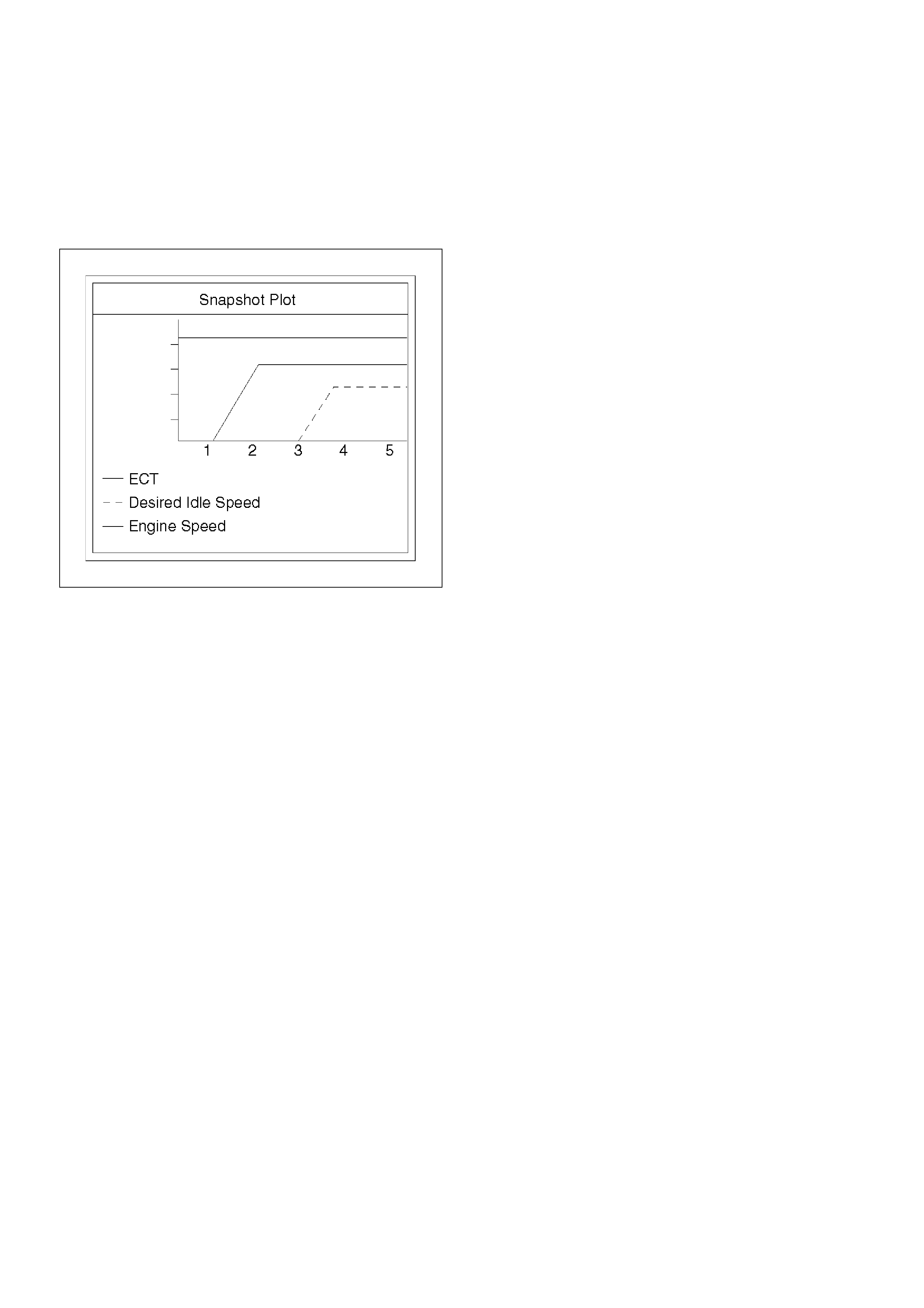
Plotting Snapshot Graph
This test selects several necessary items from the data
list to plot graphs and makes data comparison on a long
term basis. It is an effective test particularly in emission
related evaluations.
060RX037
For trouble diagnosis, you can collect graphic data
(snap shot) directly from the vehicle.
You can replay the snapshot data as needed. Therefore,
accura te diagno sis is possi ble, eve n though t he ve hicle
is not available.
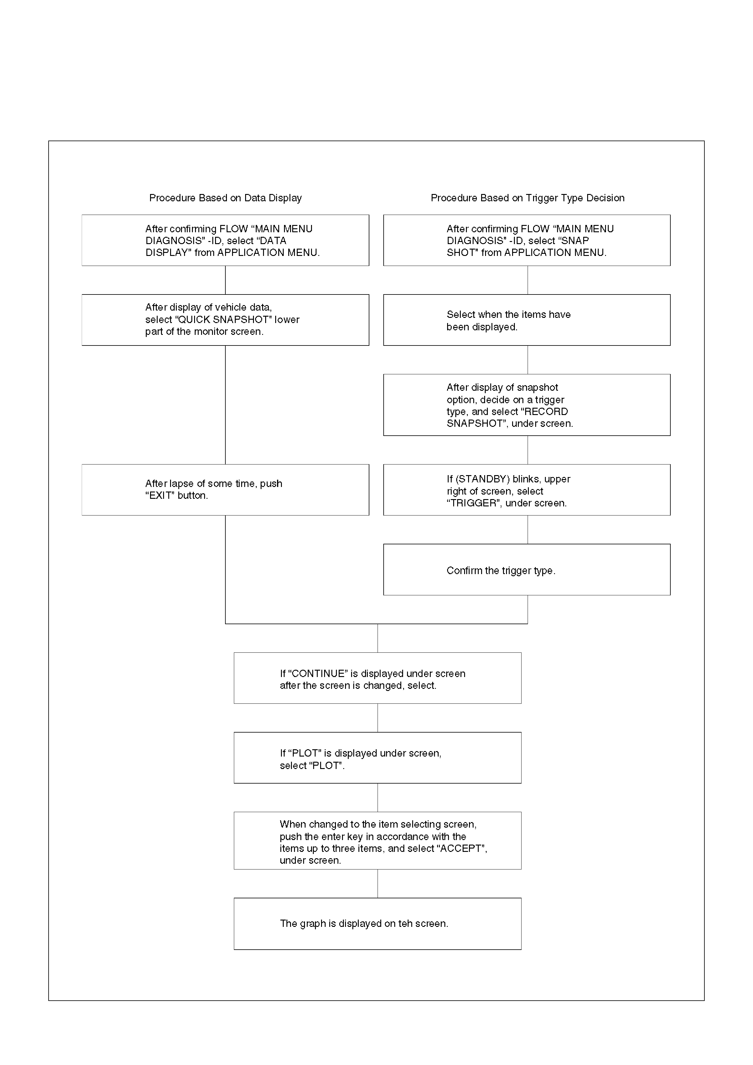
Plotting Graph Flow Chart (Plotting Graph After Obtaining Vehicle Information)
D06RY00167
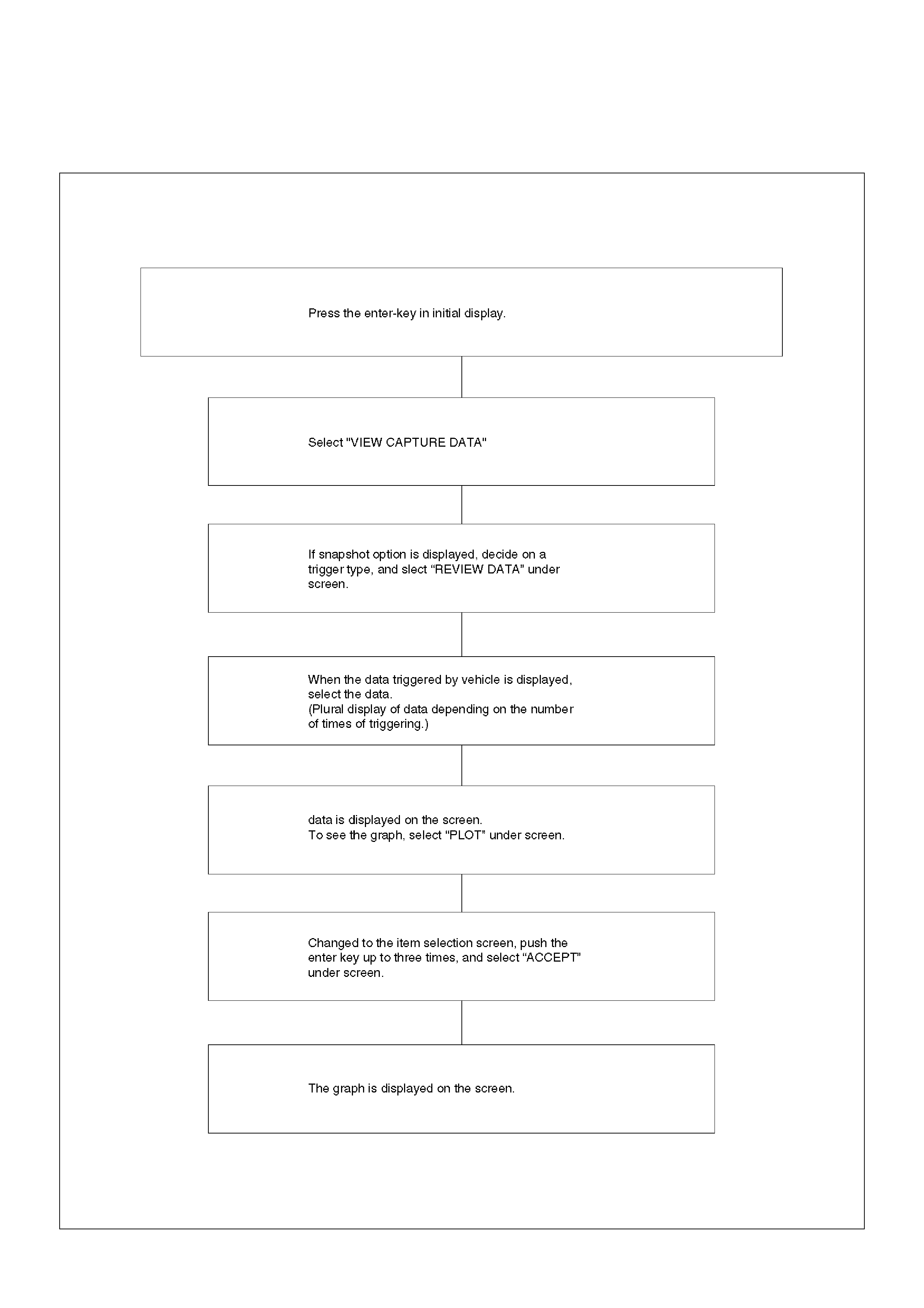
Flow Chart For Snapshot Replay (Plotting Graph)
060RX0-40
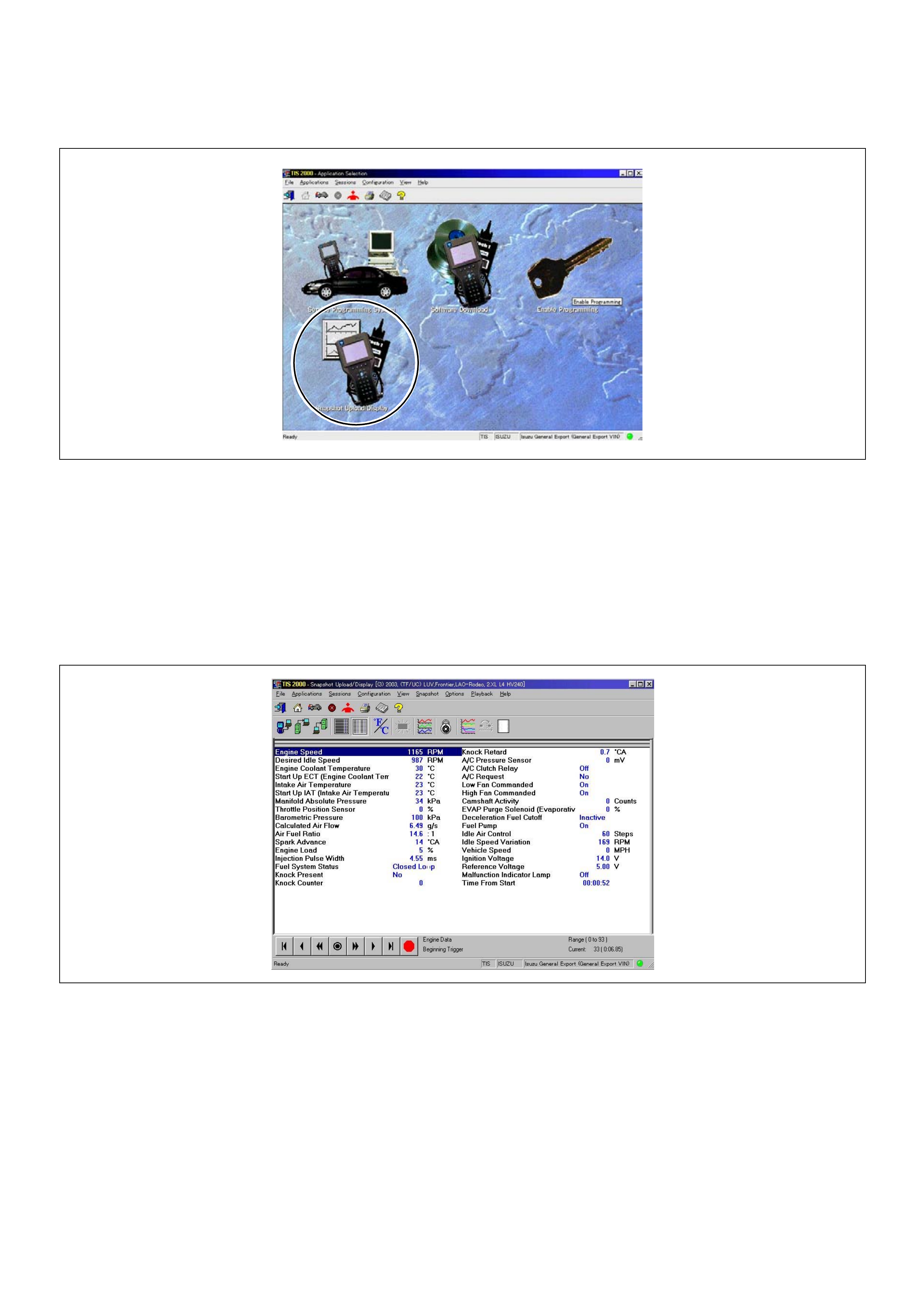
Snapshot Display With TIS2000
Procedures for transferring and displaying Tech2 snapshot data by using TIS2000 [Snapshot Upload] function is
described below.
Snapshot data can be displayed with [Snapshot Upload] function included in TIS2000.
By analyzing these data in various methods, trouble conditions can be checked.
Snapshot data is displaye d by executing the thr ee ste ps below sho wn:
1. Record the snapshot data, in Tech2.
2. Transfer the snapshot data to PC.
After recording the snapshot in Tech2, transfer the data from Tech2 to PC by the below procedures.
1. Start TIS2000.
2. Select [Snapshot Upload] on the TIS2000 start screen.
3. Select [Upload from trouble diagnosis tool (transfer from diagnosis teste r)] or click the corresponding icon of the
tool bar.
4. Select Tech2, and transfer the recorded snapshot information.
5. Select the transferred snapshot.
6. After ending transfer of the snapshot, data parameter list is displayed on the screen.
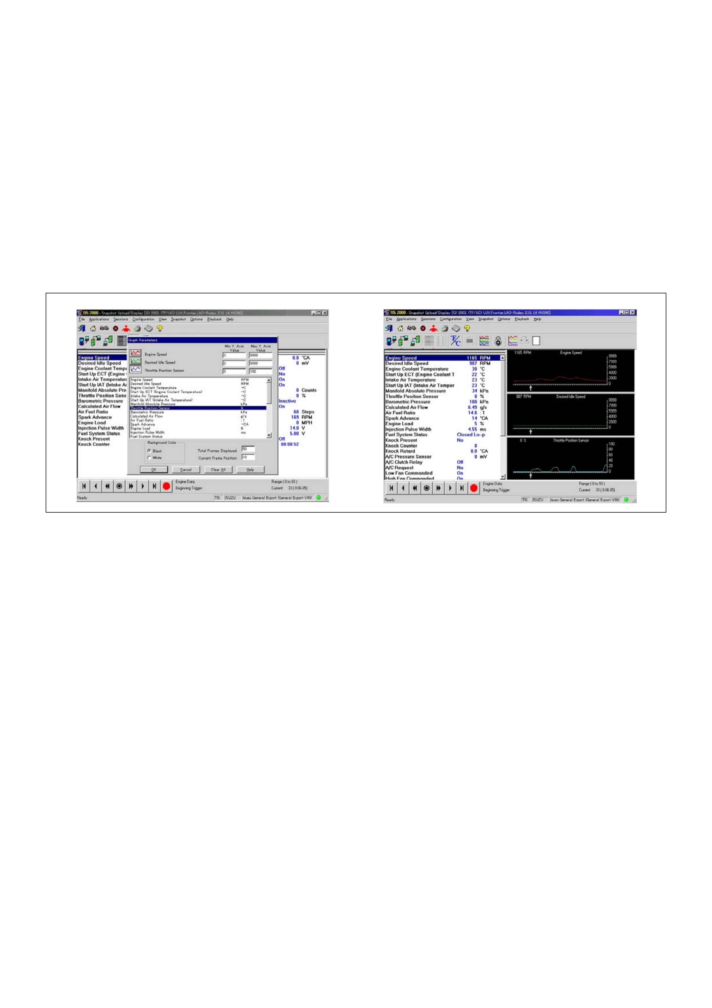
3. Snapshot data is displayed with TIS2000 [Snapshot Upload] function.
Snapshot is stored in the PC hard disk or floppy disk, and can be displayed any time.
Stored snapshot can be displayed by the below procedures.
1. Start TIS2000.
2. Select [Snapshot Upload] on the TIS2000 start screen.
3. Select [Open the existing files] or click the corresponding icon of the tool bar.
4. Select the transferred snapshot.
5. Open the snapshot, to display the data parameter list on the screen.
Graph Display Values And Graphs (Max. 3 Graphs):
1. Click the icon for graph display. [Graph Parameter] window opens.
2. Click the first graph icon of the window upper part, and select one parameter from the list of the window lower part.
Selected parameter is displayed nest to the graph icon. Graph division can be selected in the field on the
parameter right side.
3. Repeat the same procedures with the 2nd and 3rd icons.
4. After selecting all parameters to be displayed (Max. 3 parameters), click [OK] button.
5. Parameter selected is displayed in graph form on the right of the data parameter on the screen.
6. Graph display can be moved with the navigation icon.
7. For displaying another parameter by graph, click the parameter of the list, drug the mouse to the display screen
while pressing the mouse button and release the mouse button. New parameter is displayed at the position of the
previo us parameter. For displayin g the graph di splay scre en in full siz e, move the cur sor upward on the screen.
When the cursor is changed to the magnifying glass form, click the screen. Graph screen is displayed on the
whole screen.
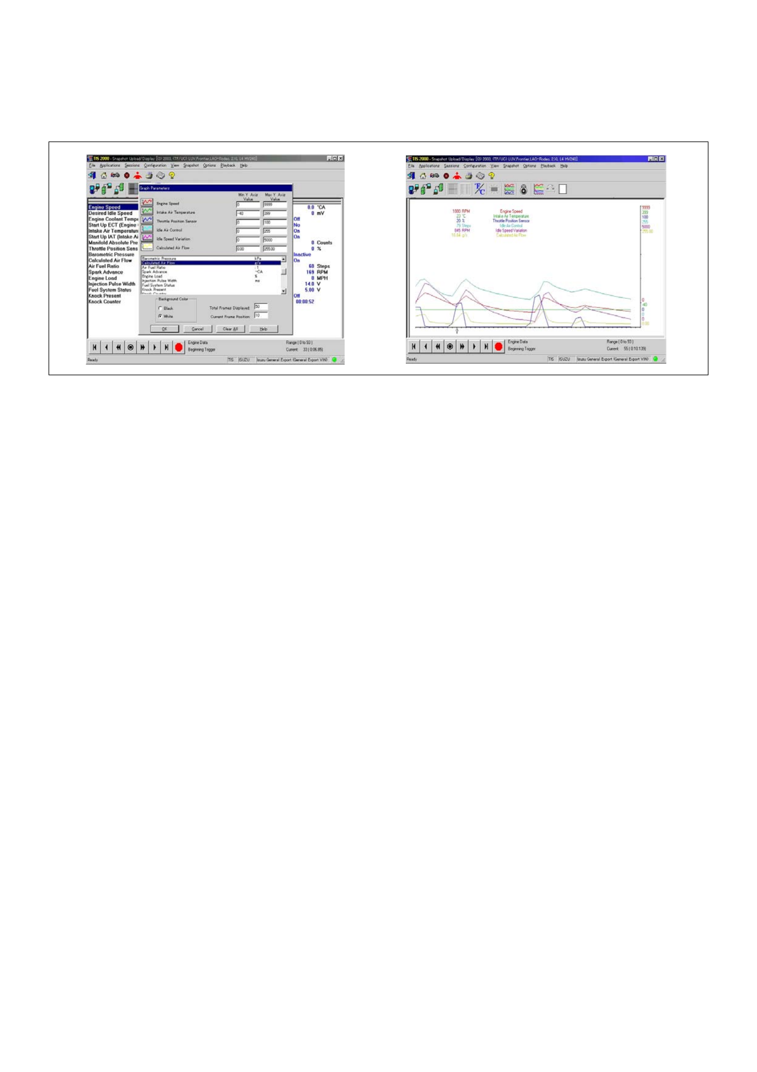
Display Of Graphs On One Screen (Max. 6 Graphs):
1. Click the 6 graph icon. [Graph Parameter] window opens.
2. Click the graph icon, select the parameter to be displayed from the list and change divisions according to
necessity.
3. Repeat the same procedures with the graph icons, from the 2nd to 6th.
4. Click the [OK] button to display.
5. In this case, parameters are displayed only in graph form. All parameters are displayed in one graph.
6. The graph display screen can be moved with the navigation icon.
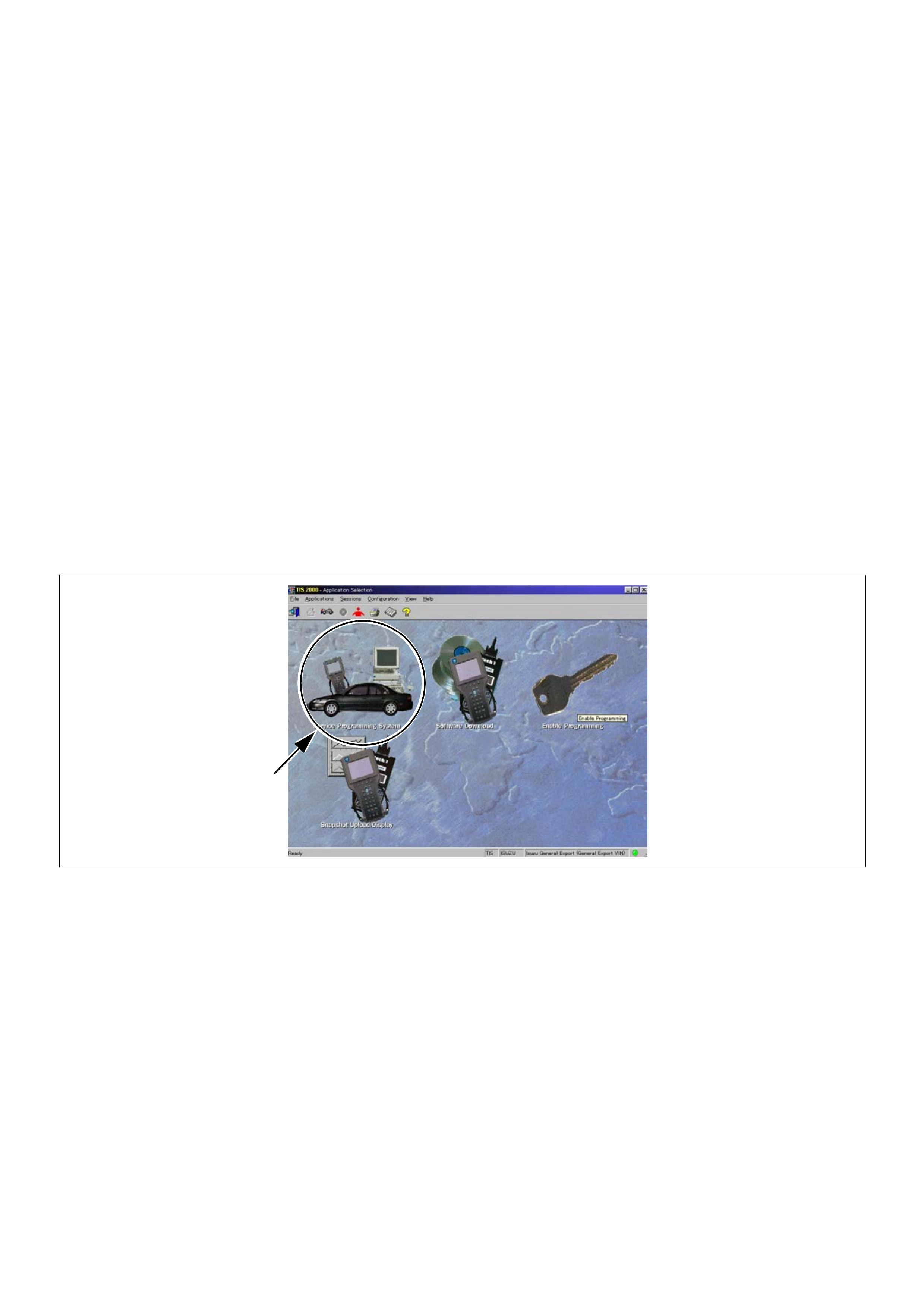
Service Programming System (SPS)
The procedure to program the control unit by using the Service Programming System (SPS) software contained in
TIS2000 is explained below.
NOTE:
• If the Engine Control Module (ECM) was programmed, the Immobiliser System must be linked to the ECM: Refer to
section 11 “Immobiliser System-ECM replacement” for the ECM/Immobiliser linking procedure.
Important: Perform the following checks before attempting to program the control unit:
• The Tech2 PCMCIA card is programmed with The latest software release.
• The latest release of TIS2000 is loaded on the PC.
• The vehicle battery is fully charged.
• The control unit to be programmed is connected to the vehicle.
1. Preparations of TIS 2000
1. Connect Tech 2 to P/C.
2. Check to see if Hardware Key is plugged into Port.
3. Activate TIS 2000 by P/C.
4. On the activating screen of TIS2000, choose “Service Programming System”
5. On the s creen of “Diagno st ic Test er and P roce ssing Prog ram S electi on”, ch oose the one th at will com ply wi th the
following.
• Diagnostic tester in use
• New programming by the existing module or new programming by the replaced/new module.
• Fixing position of the control unit.
6. Upon completion of the selection, push the button of “Continue”.
2. Demand of Data
1. Connect Tech-2 to the vehicle. When activated by turning on the power of Tech-2, push the “Enter” switch.
2. Turn on the ignition switch (without starting the engine)
3. In the main menu of Diagnostic Tester, push “F1: Service Programming System (SPS)”.
4. Push “F0: Request Info” of Tech-2.
5. Where vehicle data has been already saved in Tech 2, the existing data come on display. In this instance, as Tech-
2 starts asking wheth er to k eep the d ata or to co nti nue o btaining an ew da ta from the c on tro l un it, cho os e eithe r o f
them.

6. If you select “continue”, you have to select “Model Year”, “Vehicle Type”, “Controller Type (Engine)”.
7. After that. then push button and turn Ignition switch tuned on, off, on following Tech-2 display. Tech-2 will read
information from controller after this procedure.
8. During obtaining infor mation , Tech-2 i s rece iving infor matio n from the co ntrol uni t cho sen. In replac ing the contr ol
unit, plea se be sure to undertake “Ob taining Informatio n” from the new unit. Wi th VIN not being progr ammed into
the new control unit at the time of shipment, “obtaining information” is not complete (because the vehicle model,
engine model an d model year are specified from VIN). For the procedure get additio nal information on vehicles,
instruction will be provided in dialog form, when TIS2000 is in operation.
9. Following instructions by Tech-2, push the “Exit” switch of Tech-2, turn off the ignition of the vehicle and turn off the
power of Tech-2, thereby removing from the vehicle.
3. Data Exchange
1. Connect Tech-2 to P/C, turn on the power and click the “Next” button of P/C.
2. Check VIN of the vehi cle and ch oos e “Next” .
3. When a lack of data is asked from among the following menu, enter accordingly.
Select following Menu
• Model Year
• Model
• Engine type
• Transmission type
• Destination code (vehicles for general export)*1
• Immobiliser
* 1: How to read the destination code
Destination code can be read from ID Plate affixed on vehicles, while on VIN plate the destination code is described at
the right-hand edge of Body Type line. In Fig.-3, the destination code can be read as “EK4 (Europe)”.
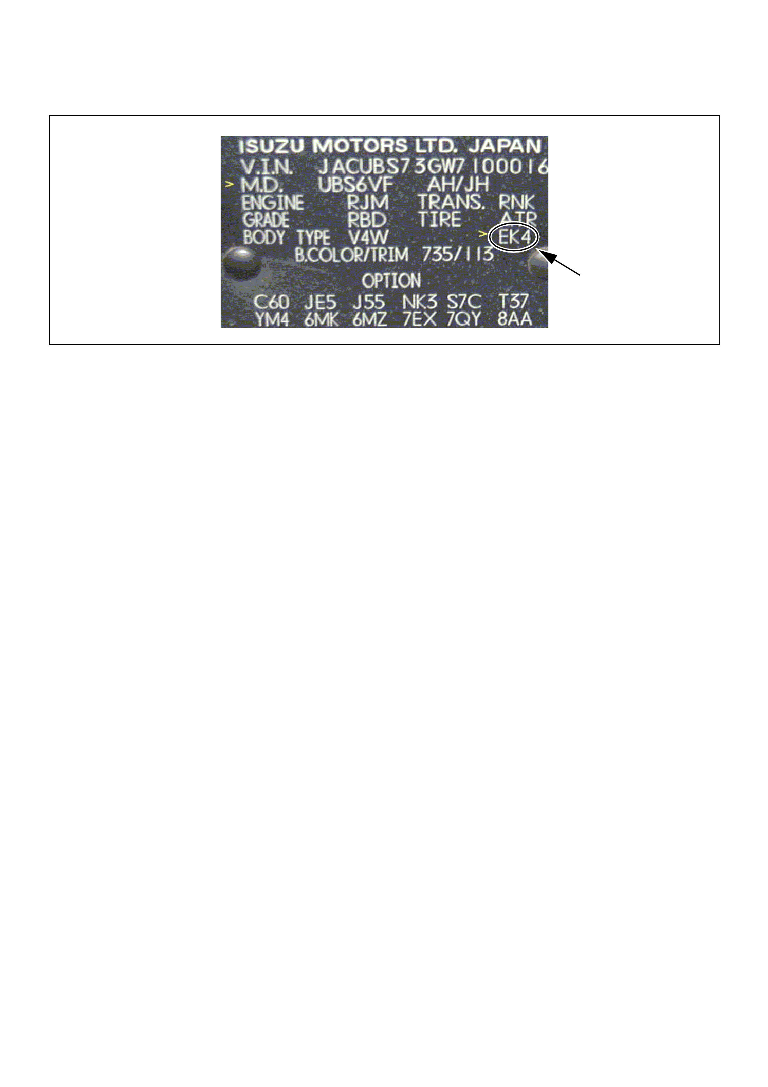
4. After choosing the data, click the “Next” button.
5. When all the necessary information is entered, the “details” of software within the database that match the entered
data will appear for confirmation. Click the “Program” switch and then download the new software onto Tech-2.
6. “Data Transf er” comes on displ ay. The progres s of down loading wi ll be dis played on the scree n in the for m of bar
graph.
7. Upon finishing the data transfer, turn off the power of Tech-2, removing from P/C.
4. Programming of ECM
1. Check to see if batteries are fully charged, while ABS connectors shall be removed from the vehicle.
2. Connect Tech-2 to Vehicle Diagnostic Connectors.
3. Turn on the power of Tech-2 and the title screen comes on display.
4. Turn on the ignition (without allowing the engine to start)
5. On the title screen of Tech-2, push the “Enter” button.
6. Choose “F: Service Programming System” on the main screen and then choose “Fl: Programming”.
7. While data is being transferred, “Downloading” will be displayed on the Tech-2 screen.
8. Upon finishing the data transfe r, Tech-2 w ill display “ Reprogramming Successful”. Push the “Ex it” button to bring
program to completion.
9. Foll owing “P rocedu re 2: D ema nd of Data”, try over again “Info rmation Obtaining” and check to c onfirm if t he data
has been correctly re-loaded.
10. Upon finishing confirmation, turn off the ignition of the vehicle and then turn off the power of Tech-2, removing from
the vehicle.
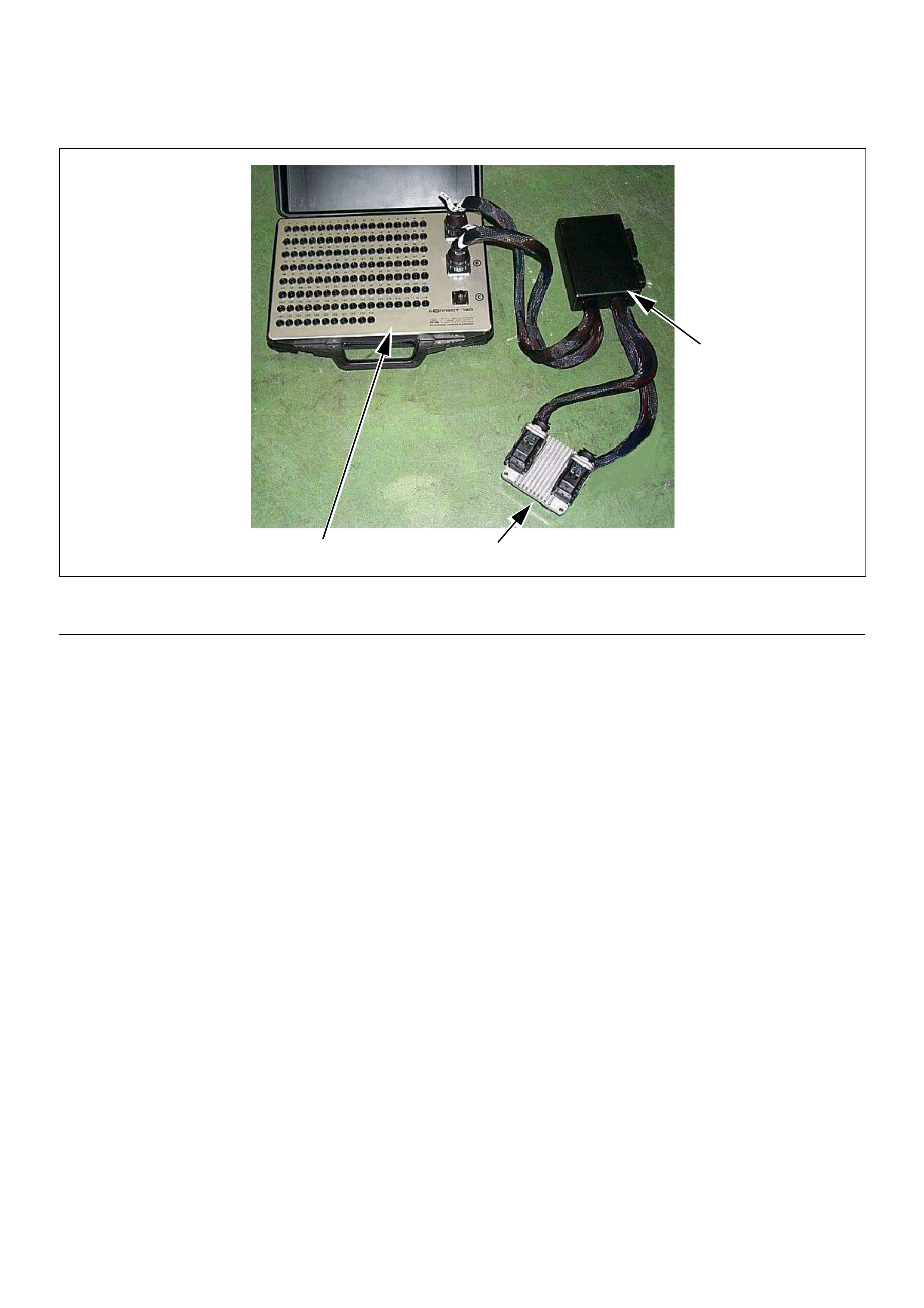
How To Use Breaker Box
The engine control module (ECM) and other connectors have water proof connector and special terminal. Water proof
terminal d oes not all ow to use back prove. In addition , the engine control mod ule (ECM) s pecial term inal can n ot let
regular digital voltage meter prove to access, because terminal shape is very fin pin type.
In order to preven t damage of fema le terminal and conne ctor itself, the breaker box and adapter is the most suitable
special tool.
3 1
2
(1) Engine Control Module (ECM)
(2) Harness Adapter (3) Breaker Box
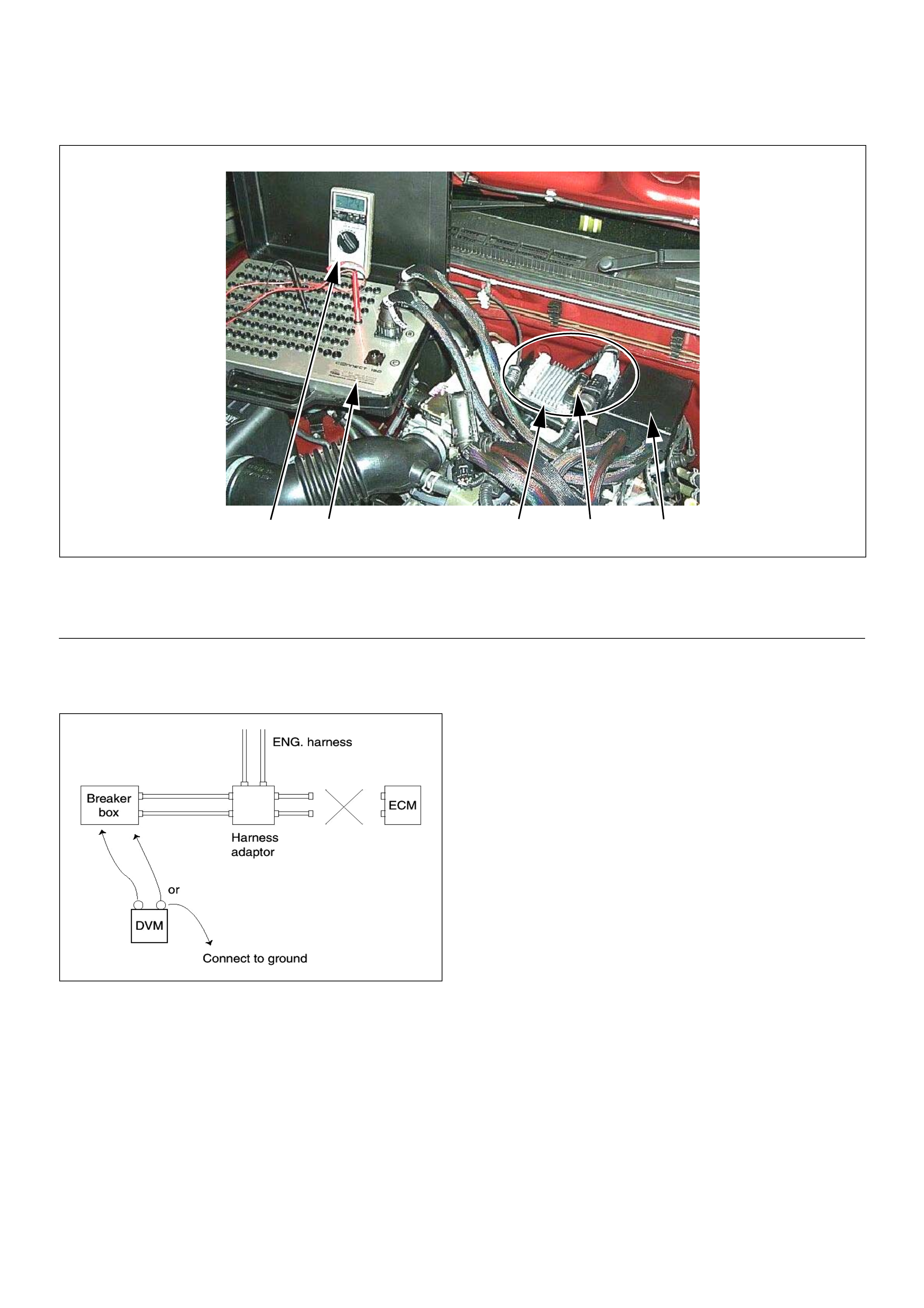
Breake r Box Con n ection Type A
Breake r box connect ion type A, c heck for “o pen circuit”
and “short to ground circuit”.
4 3 152
(1) Engine Control Module (ECM)
(2) Harness Adapter
(3) Breaker Box
(4) Digital Voltage Meter
(5) ECM - Harness Adapter Disconnection
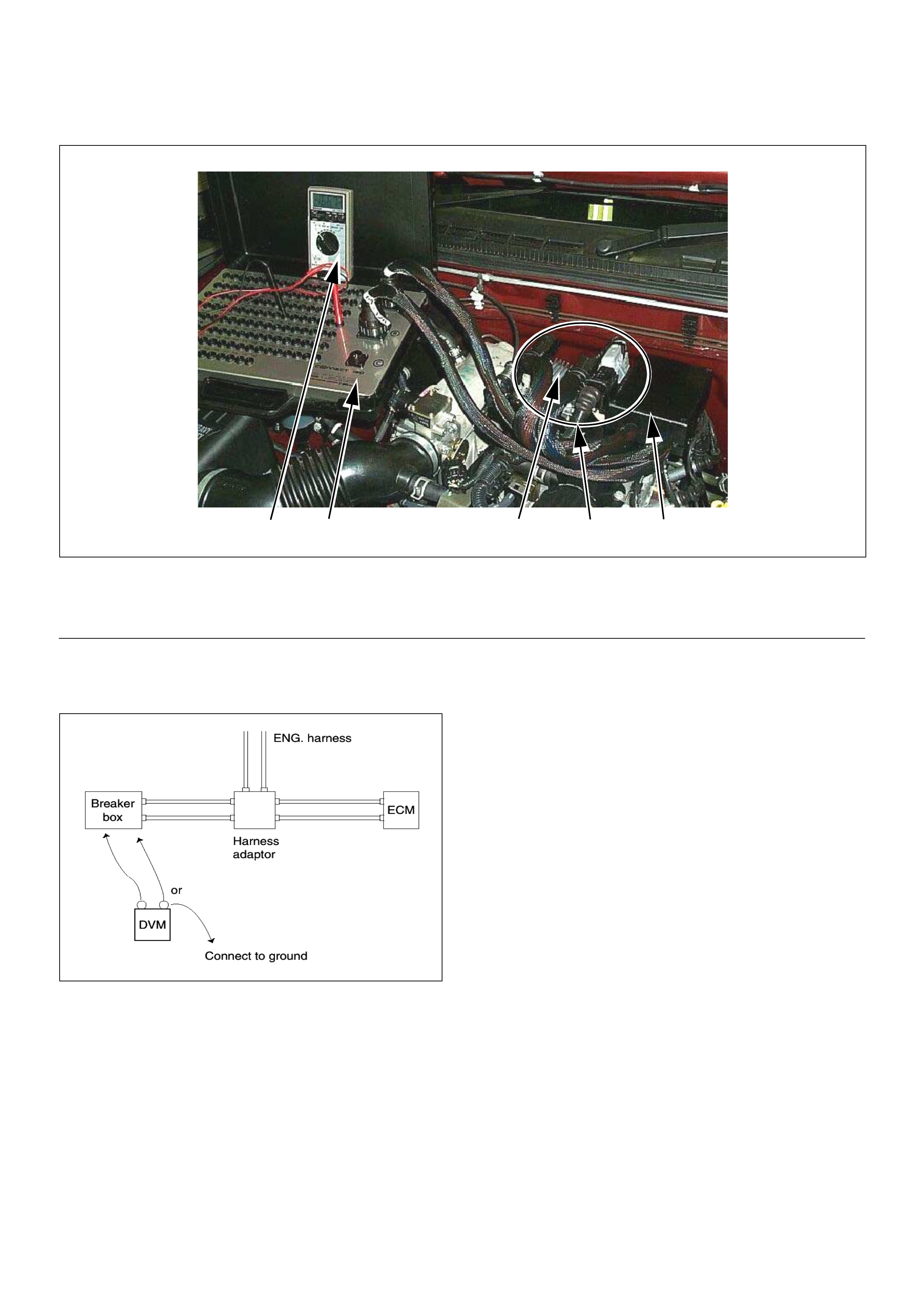
Breake r Box Con n ection Type B
Breaker box connection type B, check for “short to power supply circuit” and “power, signal voltage check” between the
engine control module (ECM) and electrical components.
4 3 152
(1) Engine Control Module (ECM)
(2) Harness Adapter
(3) Breaker Box
(4) Digital Voltage Meter
(5) ECM - Harness Adapter Connection

On-Board Diagnostic (OBD) System Check
Circuit Description
The on-board diagnostic system check is the starting
point for any driveability complaint diagnosis. Before
using this procedure, perform a careful visual/physical
check of the ECM and engine grounds for cleanliness
and tightness.
The on-board diagnostic system check is an organized
approach to identifying a problem created by an
electronic engine control system malfunction.
Diagnostic Aids
An intermittent may be caused by a poor connection,
rubbed-through wire insulation or a wire broken inside
the insulation. Check for poor connections or a
damaged harness. Inspect the ECM harness and
connector for improper mating, broken locks, improperly
formed or damaged terminals, poor terminal-to-wire
connection, and damaged harness.
Test Description
Number(s) below refer the step number(s) on the
Diagnostic Chart:
1. The Check Engi ne Lamp (MIL ) shoul d be ON stea dy
with the ignition “On”, engine “Off”. If not, “No Check
Engine Lamp (M IL)” chart s hould be used to is olate the
malfunction.
2. Che cks the Clas s 2 data circuit an d ensures that the
ECM is able to transmit serial data.
3. This test ensures that the ECM is capable of
controlling the Check Engine Lamp (MIL) and the Check
Engine Lamp (MIL) driver circuit is not shorted to
ground circuit.
4. If the engine will not start, “Engine Cranks But Will
Not Run” chart should be used to diagnose the fault.
6. Th e Tech2 parameter s which is not within the typical
range m ay help to iso late the area wh ich is c ausing the
problem.
12. Th is v ehicle i s equ ipped with EC M whic h util izes an
electrically erasable programmable read only memory
(EEPROM).
Buttery
Voltage
0.5
RED/
YEL
Engine
Room-RH
µP
J2-32
7
0.5
BRN/
YEL
Engine
Control
Module
(ECM)
Check
Engine
Lamp
Imnobiliser
Control
Unit
METER
15A
Ignition
SW
0.5
BLU
J2-4
0.5
GRN
J2-30
Diag
SW Class 2
Serial
Data
0.85 BLK
Diagnostic
Comectar
16151413121110 9
87654321
METER
10A
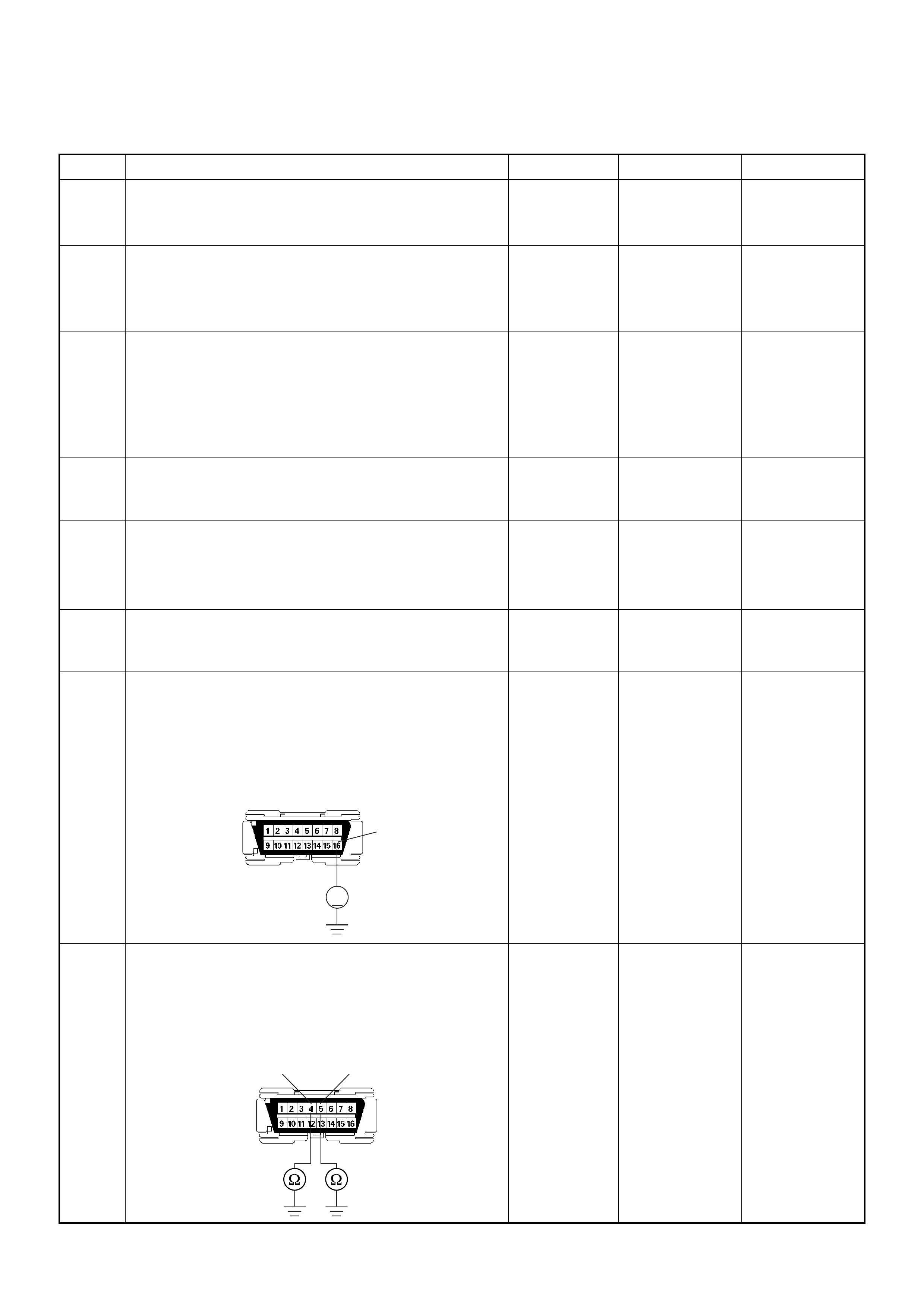
On-board Diagnostic (OBD) System Check
Step Action Value(s) Yes No
1 1. Ignition “On”, engine “Off”.
2. Check the “CHECK ENGINE” lamp (MIL).
Does the “CHECK ENGINE” lamp turn “On”? — Go to Step 2
Go to No
CHECK
ENGINE Lamp
2 1. Using the Tech 2, ignition “On” and engine “Off”.
2 . A t t e m p t t o d i s p l a y “ E n g i n e D a t a ” w i t h t h e Te c h 2 .
Does the Tech 2 display “Engine Data” and “O
2
Sensor Data”? — Go to Step 3 Go to Step 7
3 1. Using the Tech 2, ignition “On” and engine “Off”.
2. Select the “Miscellaneous Test” and perform the
“Malfunction Indicator Lamp” in “Lamps”.
3. Operate the Tech 2 in accordance with the Tech 2
instructions.
Does the “CHECK ENGINE” lamp turn “Off”? — Go to Step 4
Go to CHECK
ENGINE LAMP
On Steady
4 Attempt to start the engine.
Does the engine start and continue to “Run”?—Go to Step 5
Go to Engine
Cranks But Will
Not Run
5 1. Using the Tech 2, ignition “On” and engine “Off”.
2. Select the “Read DTC Infor By Priority” in
“Diagnostic Trouble Code”.
3. Are any DTCs stored? —Go to DTC
Chart Go to Step 6
6 Compare typical scan data values displayed on the
Tech 2 “Engine Data” and “O
2
Sensor Data”.
Are the displayed values within the range? —
Refer to
SYMPTOM
DIAGNOSIS
Refer to
TYPICAL
SCAN DATA
7 Using the DVM and check the data link connector
power supply circuit.
1. Ignition “Off”, engine “Off”.
2. Check the circuit for open circuit.
Was the problem found?
—
Repair faulty
harness and
verify repair Go to Step 8
8 Using the DVM and check the data link connector
ground circuit.
1. Ignition “Off”, engine “Off”.
2. Check the circuit for open circuit.
Was the problem found?
—
Repair faulty
harness and
verify repair Go to Step 9
V
16
B58
54 B58
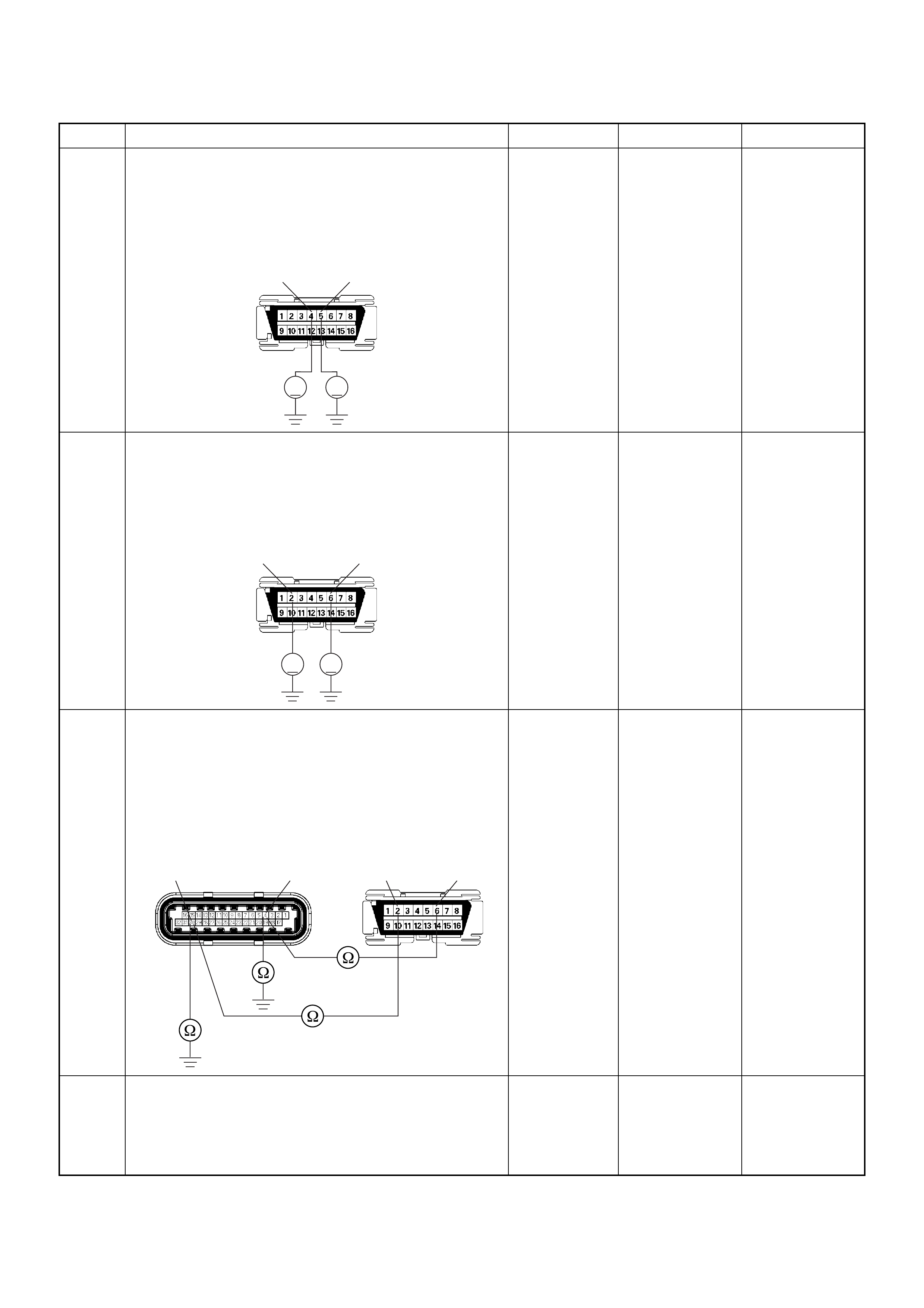
9 Using the DVM and check the data link connector
ground circuit.
1. Ignition “On”, engine “Off”.
2. Check the circuit for short to power supply circuit.
W as the DVM indicated specified value?
Less than 1V Go to Step 10
Repair faulty
harness and
verify repair
10 Using the DVM and check the data link connector
communicati on circ ui t.
1. Ignition “On”, engine “Off”.
2. Check the circuit for short to power supply circuit.
Was the DVM indicated battery voltage?
—
Repair faulty
harness and
verify repair Go to Step 11
11 Using the DVM and check the data link connector
communicati on circ ui t.
1. Ignition “Off”, engine “Off”.
2. Disconnect the ECM connector.
3. Check the circuit for open or short to ground
circuit.
Was the problem found?
—
Repair faulty
harness and
verify repair Go to Step 12
12 Is the ECM programmed with the latest software
release?
If not, download the latest software to the E CM using
the “SPS (Service Programming System)”.
W as the problem solved? — Verify repair Go to Step 13
Step Action Value(s) Yes No
V V
54 B58
V V
B58 62
B58
C56(J2) 430 62

13 Replace the ECM.
Is the action complete?
IMPORTANT: The replacement ECM must be
programmed. Refer to section of the Service
Programming System (SPS) in this manual.
Foll owing ECM pr ogramming, the immobi liser system
(if equipped) must be linked to the ECM. Refer to
section 11 “Immobiliser System-ECM replacement” for
the ECM/Immobiliser linking procedure. — Verify repair —
Step Action Value(s) Yes No
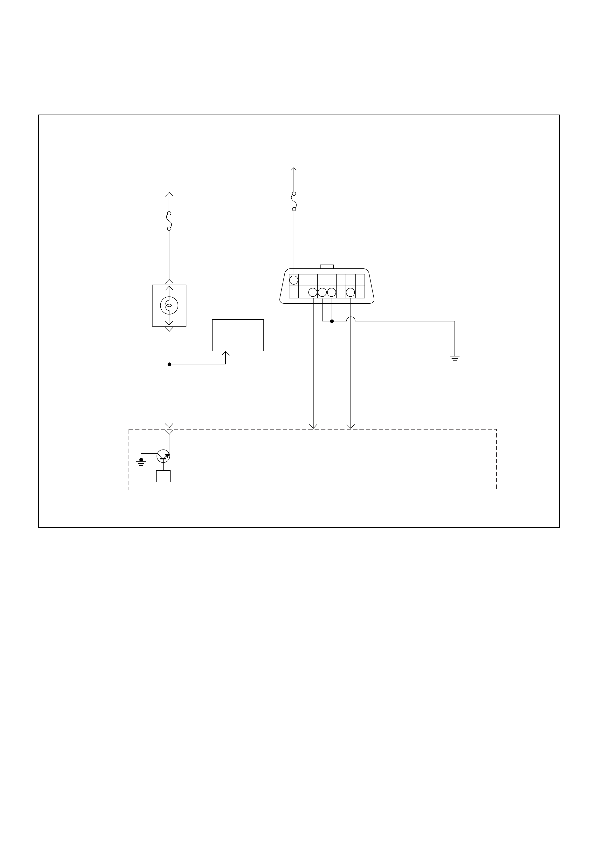
No Check Engine Lamp (MIL)
Circuit Description
The check engine lamp should be illuminated and
steady fo r abou t five seco nds wi th t he igni ti on “O N” an d
the engi ne s topped. Ig nition feed vol tage is s uppli ed t o
the check engine lamp bulb through the meter fuse.
The Engine Control Module (ECM) turns the check
engine lamp “ON” by grounding the check engine lamp
driver circuit.
Diagnostic Aids
An intermittent check engine lamp may be cased by a
poor connection, rubbed-through wire insulation, or a
wire broken inside the insulation. Check for the
followi ng ite ms :
• Inspect the ECM harness and connections for
improper mating, broken locks, improperly formed or
damaged terminals, poor terminal-to-wire connection,
and damaged harness.
• If the engine runs OK, check for a faulty light bulb, an
open in the check engine lamp driver circuit, or an
open in the instrument cluster ignition feed.
• If the engine cranks but will not run, check for an
open ECM i gnition or batt ery feed, or a poor ECM to
engine ground.
Buttery
Voltage
0.5
RED/
YEL
Engine
Room-RH
µP
J2-32
7
0.5
BRN/
YEL
Engine
Control
Module
(ECM)
Check
Engine
Lamp
Imnobiliser
Control
Unit
METER
15A
Ignition
SW
0.5
BLU
J2-4
0.5
GRN
J2-30
Diag
SW Class 2
Serial
Data
0.85 BLK
Diagnostic
Comectar
16151413121110 9
87654321
METER
10A
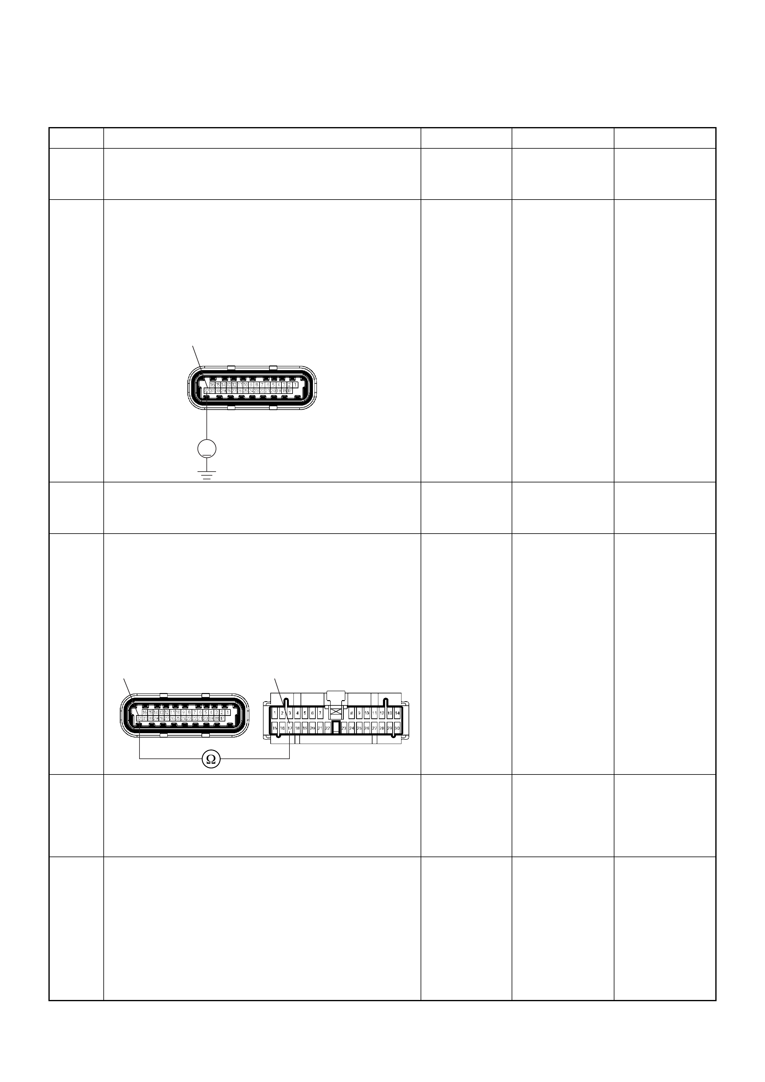
No Check Engine Lamp (MIL)
Step Action Value(s) Yes No
1 Check the “Meter” fuse (15A).
If the fuse is burnt out, repair as necessary.
Was the problem found? — Verify repair Go to Step 2
2 Using the DVM and check the “CHECK ENGINE”
lamp circuit.
1. Ignition “Off”, engine “Off”.
2. Disconnect the ECM connector.
3. Ignition “On”.
4. Check the circuit for open circuit.
Was the DVM indicated specified value?
Battery
voltage Go to Step 5 Go to Step 3
3 Check the “CHECK ENGINE” lamp bulb.
If the bulb is burnt out, repair as necessary.
Was the problem found? — Verify repair Go to Step 4
4 Using the DVM and check the “CHECK ENGINE”
lamp circuit.
1. Ignition “Off”, engine “Off”.
2. Disconnect the meter connector and ECM
connector.
3. Check the circuit for open circuit.
Was the problem found?
— Verify repair Go to Step 5
5 Is the ECM programmed with the latest software
release?
If not, download the latest software to the ECM using
the “SPS (Service Programming System)”.
Was the problem solved? — Verify repair Go to Step 6
6 Replace the ECM.
Is the action complete?
IMPORTANT: The replacement ECM must be
programmed. Refer to section of the Service
Programming System (SPS) in this manual.
Foll owing ECM pr ogramming, the immobi liser system
(if equipped) must be linked to the ECM. Refer to
section 11 “Immobiliser System-ECM replacement” for
the ECM/Immobiliser linking procedure. — Verify repair —
V
32 C56(J2)
32 17
C56(J2) B24

Check Engine Lamp (MIL) “On” Steady
Circuit Description
The check engine lamp should always be illuminated
and steady for about five seconds with ignition “ON” and
the engine stopped. Ignition feed voltage is supplied
directl y to the ch eck en gine lam p indic ator. The Engin e
Control Module (ECM) turns the check engine lamp
“ON” by grounding the check engine lamp driver circuit.
The check engine lamp should not remain “ON” with the
engine running and no DTC(s) set. A steady check
engine lamp with the engine running and no DTC(s)
suggests a short to ground in the check engine lamp
driver circuit.
Diagnostic Aids
An intermittent may be caused by a poor connection,
rubbed-through wire insulation, or a wire broken inside
the insulation. Check for the following items:
• Poor connection or damaged harness - Inspect the
ECM harness and connectors for improper mating,
broken locks, improperly formed or damaged
terminals, poor terminal-to-wire connection, and
damaged harness.
Buttery
Voltage
0.5
RED/
YEL
Engine
Room-RH
µP
J2-32
7
0.5
BRN/
YEL
Engine
Control
Module
(ECM)
Check
Engine
Lamp
Imnobiliser
Control
Unit
METER
15A
Ignition
SW
0.5
BLU
J2-4
0.5
GRN
J2-30
Diag
SW Class 2
Serial
Data
0.85 BLK
Diagnostic
Comectar
16151413121110 9
87654321
METER
10A
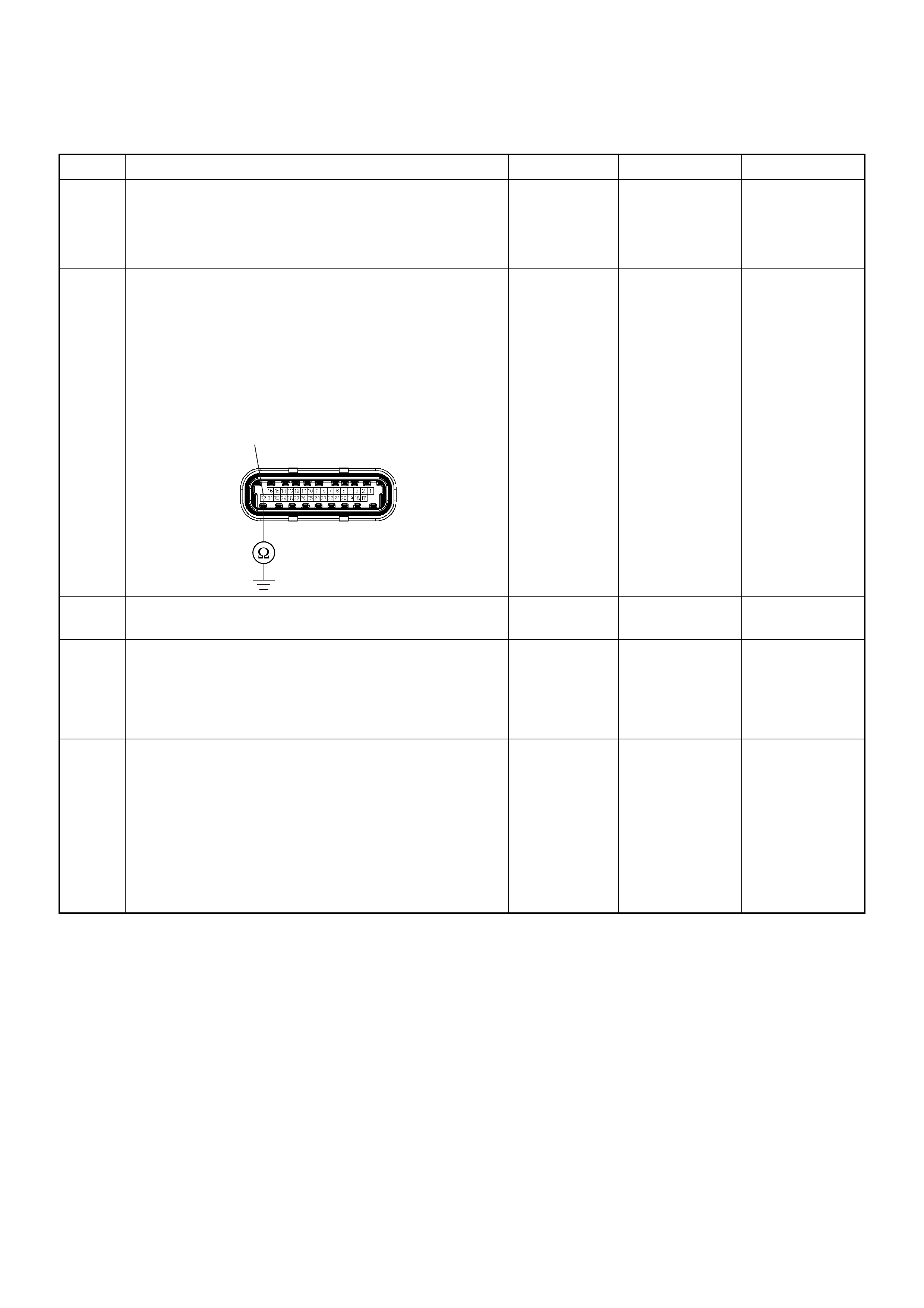
Check Engine Lamp (MIL) “ON” Steady
Step Action Value(s) Yes No
1 1. Ignition “Off”, engine “Off”.
2. Disconnect the ECM connector.
3. Ignition “On”.
Was the “CHECK ENGINE” lamp turned on? — Go to Step 2 Go to Step 4
2 Using the DVM and check the “CHECK ENGINE”
lamp circuit.
1. Ignition “Off”, engine “Off”.
2. Disconnect the meter connector and ECM
connector.
3. Check the circuit for short to ground circuit.
Was the problem found?
— Verify repair Go to Step 3
3 Replace the meter assembly.
Is the action complete? — Verify repair —
4 Is the ECM programmed with the latest software
release?
If not, download the latest software to the ECM using
the “SPS (Service Programming System)”.
Was the problem solved? — Verify repair Go to Step 5
5 Replace the ECM.
Is the action complete?
IMPORTANT: The replacement ECM must be
programmed. Refer to section of the Service
Programming System (SPS) in this manual.
Foll owing ECM pr ogramming, the immobi liser system
(if equipped) must be linked to the ECM. Refer to
section 11 “Immobiliser System-ECM replacement” for
the ECM/Immobiliser linking procedure. — Verify repair —
32 C56(J2)

Fuel Metering System Check
Some failures of the fuel metering system will result in an “Engine Cranks But Will Not Run” symptom. If this condition
exists, refer to the Cranks But Will Not Run chart. This chart will determine if the problem is caused by the ignition
system, the ECM, or the fuel pump electrical circuit.
Refer to Fuel System Electrical Test for the fuel system wiring schematic.
If there is a fuel delivery problem, refer to Fuel System Diagnosis, which diagnoses the fuel injectors, the fuel pressure
regulator, and the fuel pump.
Followings are applicable to the vehicles with closed Loop System:
If a malfunction occurs in the fuel metering system, it usually results in either a rich HO2S signal or a lean HO2S
signal. This condition is indicated by the HO2S voltage, which causes the ECM to change the fuel calculation (fuel
injector pulse width) based on the HO2S reading. Changes made to the fuel calculation will be indicated by a change
in the long term fuel trim values which can be monitored with a Scan Tool. Ideal long term fuel trim values are around
0%; for a lean HO2S signal, the ECM will add fuel, resulting in a fuel trim value above 0%. Some variations in fuel trim
values are normal because all engines are not exactly the same. If the evaporative emission canister purge is 02
status may be rich condition. 02 status indicates the lean condition, refer to DTC P1171 for items which can cause a
lean HO2S signal.
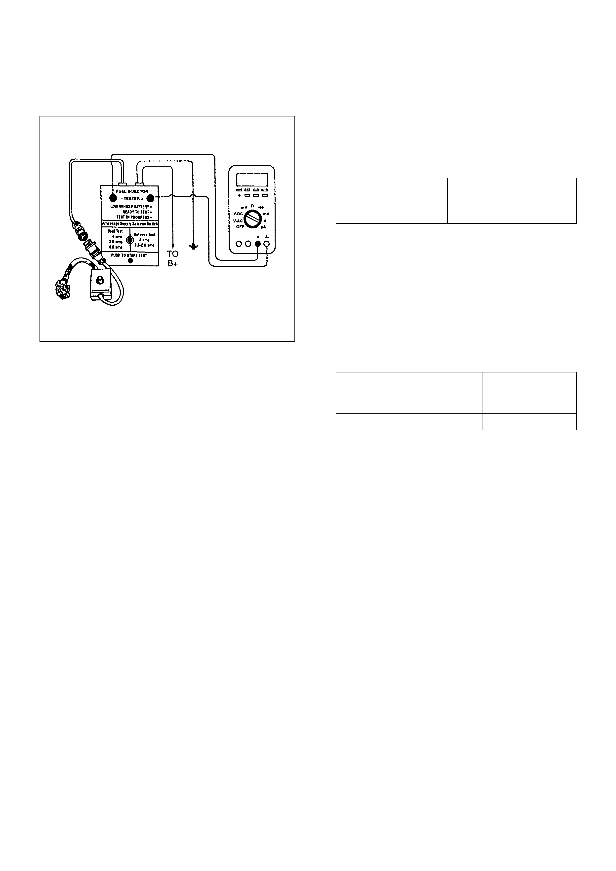
Fuel Injector Coil Test Procedure And Fuel Injector Balance Test Procedure
Test Description
Number(s) below refer to the step number(s) on the
Diagnostic Chart:
2. Relieve the fuel pressure by connecting 5-8840-
0378-0 T-Joint to the fuel pressure connection on the
fuel rail.
Caution: In order to reduce the risk of fire and
personal injury, wrap a shop towel around the fuel
pressure connection. The towel will absorb any fuel
leakage t hat o cc urs dur in g the co nne cti on o f the fuel
pressure gauge. Place the towel in an approved
container when the connection of the fuel pressure
gauge is complete.
Place the fuel pressure gauge bleed hose in an
approved gasoline container.
With the ignition switch OFF open the valve on the
fuel pressure gauge.
3. Record the lowest voltage displayed by the DVM
after the first second of the test. (During the first
second, voltage displayed by the DVM may be
inaccurate due to the initial current surge.)
Injector Specifications:
• The voltage displayed by the DVM should be
within the specified range.
• The voltage displayed by the DVM may increase
throughout the test as the fuel injector windings
warm and the resistance of the fuel injector
windings changes.
• An erratic voltage reading (large fluctuations in
voltage that do not stabilize) indicates an
intermittent connection within the fuel injector.
5. Injector Specifications:
7. The Fuel Injector Balance Test portion of this chart
(S tep 7 through S tep 11) checks the mechanical (fuel
delivery) portion of the fuel injector. An engine
coold own perio d of 10 min utes i s neces sar y in ord er
to avoid irregula r fuel pressure r eadings du e to “Hot
Soak” fuel boiling.
Resistance Ohms Voltage Specification at
10°C-35°C (50°F-95°F)
11.8-12.6 5.7-6.6
Highest Ac ce ptable Voltage
Reading Above/Below
35°C/10°C (95°F/50°F)
Acceptable
Subtracted Value
9.5Volts 0.6Volt
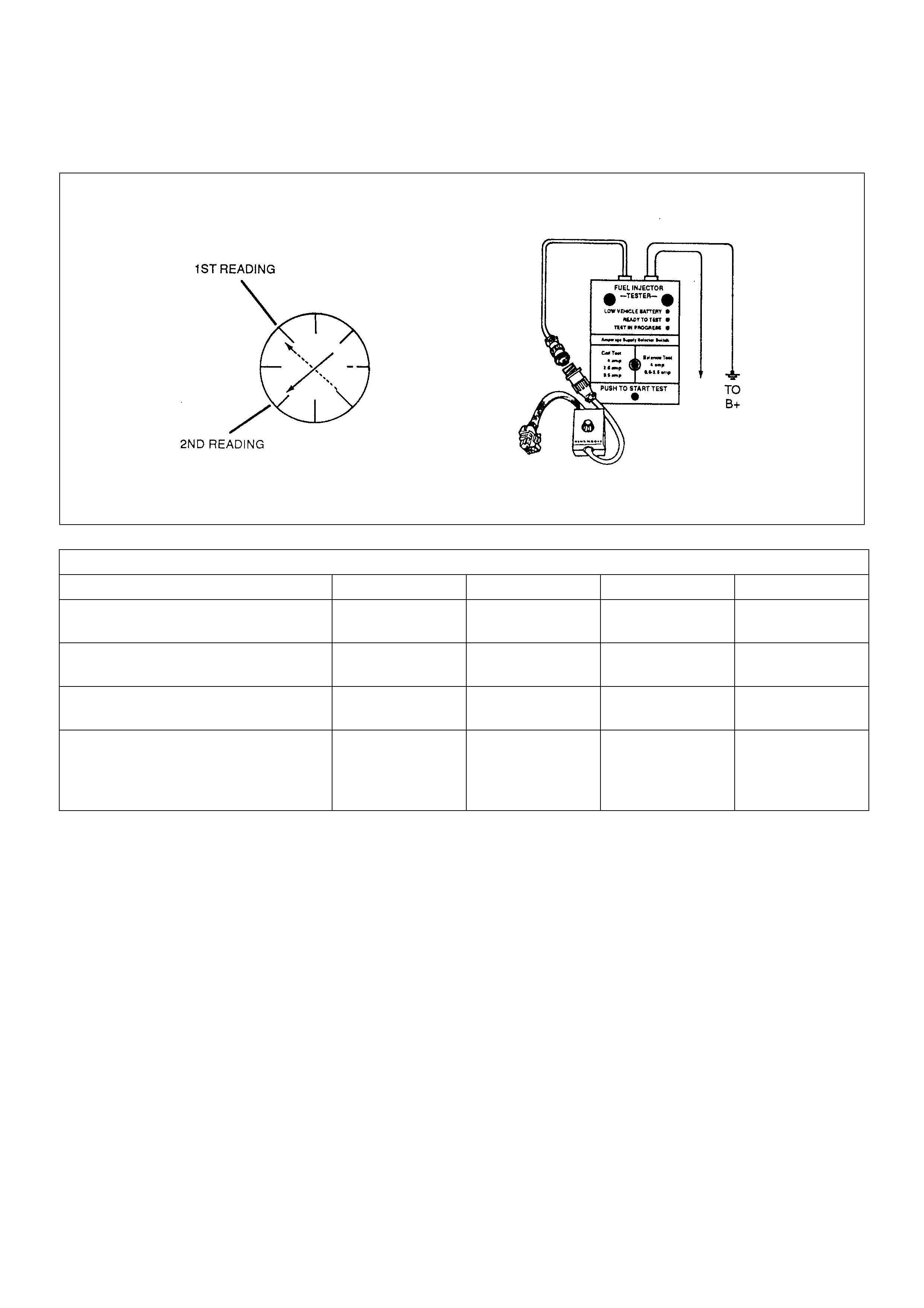
Injector Coil Test Procedure (Steps 1-6) and Injector Balance Test Procedure (Steps 7-11)
NOTE: These figures are examples only.
CYLINDER
1234
1st Reading (1) 296kPa
(43psi) 296kPa
(43psi) 296kPa
(43psi) 296kPa
(43psi)
2nd Reading (2) 205kPa
(29psi) 205kPa
(29psi) 196kPa
(28psi) 274kPa
(39psi)
Amount of Drop
(1st Reading-2nd Reading) 91kPa
(14psi) 91kPa
(14psi) 100kPa
(15psi) 22kPa
(4psi)
Av. Drop = 166kPa/24psi
±10kPa/1.5psi
= 156 - 176kPa or
22.5 - 25.5psi
Faulty, Lean
(Too Little Fuel
Drop)
Faulty, Lean
(Too Little Fuel
Drop)
Faulty, Lean
(Too Little Fuel
Drop)
Faulty, Lean
(Too Little Fuel
Drop)

Injector Coil Test Procedure (Steps 1-6) and Injector Balance Test Procedure (Steps 7-11)
Step Action Value(s) Yes No
1 Was the “On-Board Diagnostic (OBD) System Check”
performed? — Go to Step 2Go to OBD
System Check
2 1. Turn the engine OFF.
NOTE: In order to prevent flooding of a single cylinder
and possible engine damage, relieve the fuel pressure
before performing the fuel injector coil test procedure.
2. Relieve the fuel pressure. Refer to Test
Description Number 2.
3. Connect the 5-8840-2618-0 Fuel Injector Tester to
B+ and ground, and to the 5-8840-2589-0 Injector
Adapter Cable.
4. Remove the harness connector of the Fuel
Injector and connect the 5-8840-2589-0 Injector
Adapter Cable for F/I check.
5. Set the amperage supply selector switch on the
fuel injector tester to the “Coil Test” 0.5 amp
position.
6. Connect the leads from the 5-8840-2392-0 Digital
Voltmeter (DVM) to the fuel injector tester. Refer
to the illustrations associated with the test
description.
7. Set the DVM to the tenths scale (0.0).
8. Observe the engine coolant temperature.
Is the engine coolant temperature within the specified
values?
10°C (50°F)
to
35°C (95°F) Go to Step 3 Go to Step 5
3 1. Set the injector adapter cable to injector #1.
2. Press the “Push to Start Test” button on the fuel
injector tester.
3. Observe the voltage reading on the DVM.
Important: The voltage reading may rise during the
test.
4. Record the lowest voltage observed after the first
second of the test.
5. Set the injector adapter cable to the next injector
and repeat steps 2, 3, and 4.
Did any fuel injector have an erratic voltage reading
(large fluctuations in voltage that did not stabilize) or a
voltage reading outside of the specified values? 5.7-6.6V Go to Step 4 Go to Step 7
4 Replace the faulty fuel injector(S). Refer to Fuel
Injector.
Is the action complete? — Go to Step 7 —

5 1. Set the Injector Adapter Cable to injector #1.
2. Press the “Push to Start Test” button on the fuel
injector tester.
3. Observe the voltage reading on the DVM.
Important: The voltage reading may rise during the
test.
4. Record the lowest voltage observed after the first
second of the test.
5. Set the Injector Adapter Cable to the nex t injector
and repeat steps 2, 3, and 4.
Did any fuel injector have an erratic voltage reading
(large fluctuations in voltage that did not stabilize) or a
voltage reading above the specified value? 9.5V Go to Step 4 Go to Step 6
6 1. Identify the highest voltage reading recorded
(other than those above 9.5V).
2. Subtract t he voltage read ing of each injector from
the highest voltage selected in step 1. Repeat until
you have a subtracted value for each injector.
For any injector, is the subtracted value in step 2
greater than the specified value? 0.6V Go to Step 4 Go to Step 7
7 Caution: In order to reduce the risk of fire and
personal injury, wrap a shop towel around the fuel
pressure connection. The towel will absorb any fuel
leakage that occurs during the connection of the fuel
pressure gauge. Place the Towel in an approved
container when the connection of the fuel pressure
gauge is complete.
1. Connect th e 5-8840-037 8-0 Fuel Pres sure Gauge
to the fuel pressure test port.
2. Energize the fuel pump using the Scan Tool.
3. Place the bleed hose of the fuel pressure gauge
into an approved gasoline container.
4. Bleed the air out of the fuel pressure gauge.
5. With the fuel pump running, observe the reading
on the fuel pressure gauge.
Is the fuel pressure within the specified values?
296kPa-
376kPa
(43-55psi) Go to Step 8
Go to Fuel
System
Diagnosis
8 Turn the fuel pump OFF.
Does the fuel pressure remain constant? —Go to Step 9
Go to Fuel
System
Diagnosis
Step Action Value(s) Yes No

9 1. Connect the 5-8840-0378-0 Fuel Injector Tester
and 5-8840-2589-0 Injector Adapter Cable to the
fuel injector harness connector.
2. Set the amperage supply selector switch on the
fuel injector tester to the “Balance Test” 0.5-2.5
amp position.
3. Using the Scan Tool turn the fuel pump ON then
OFF in order to pressurize the fuel system.
4. Record the fuel pressure indicated by the fuel
pressure gauge after the fuel pressure stabilizes.
This is the first pressure reading.
5. Energize the f uel i nje cto r by d epr es sing th e “ P ush
to Start Test” button on the fuel injector tester.
6. Record the fuel pressure indicated by the fuel
pressure gauge after the fuel pressure gauge
needle has stopped moving. This is the second
pressure reading.
7. Repeat steps 1 through 6 for each fuel injector.
8. Subtract the second pressure reading from the
first pressure reading for one fuel injector. The
result is the pressure drop value.
9. Obtain a pressure drop value for each fuel injector .
10. Add all of the individual pressure drop values.
This is the total pressure drop.
11. Divide the total pressure drop by the number of
fuel injectors. This is the average pressure drop.
Does a ny fuel in je ct or ha ve a p re ssu re dr op va lu e t hat
is either higher than the average pressure drop or
lower tha n the aver age pres s ure dro p by the spec ifie d
value? 10kPa
(1.5psi) Go to Step 10 Go to OBD
System Check
10 Re-test any fuel injector that does not meet the
specification. Refer to the procedure in Step 11.
NOTE: Do not repeat any portion of this test before
running the engine in order to prevent the engine from
flooding.
Does any fue l injec tor still have a pre ssure dr op valu e
that is either higher than the average pressure drop or
lower tha n the aver age pres s ure dro p by the spec ifie d
value? 10kPa
(1.5psi) Go to Step 11 Go to
Symptoms
11 1. Replace the faulty fuel injector(s). Refer to Fuel
Injector.
2. Disconnect the 5-8840-2589-0 Injector Adapter
Cable for F/I che ck and re-connec t the original F/ I
check connector.
Is the action complete? — Verify repair —
Step Action Value(s) Yes No
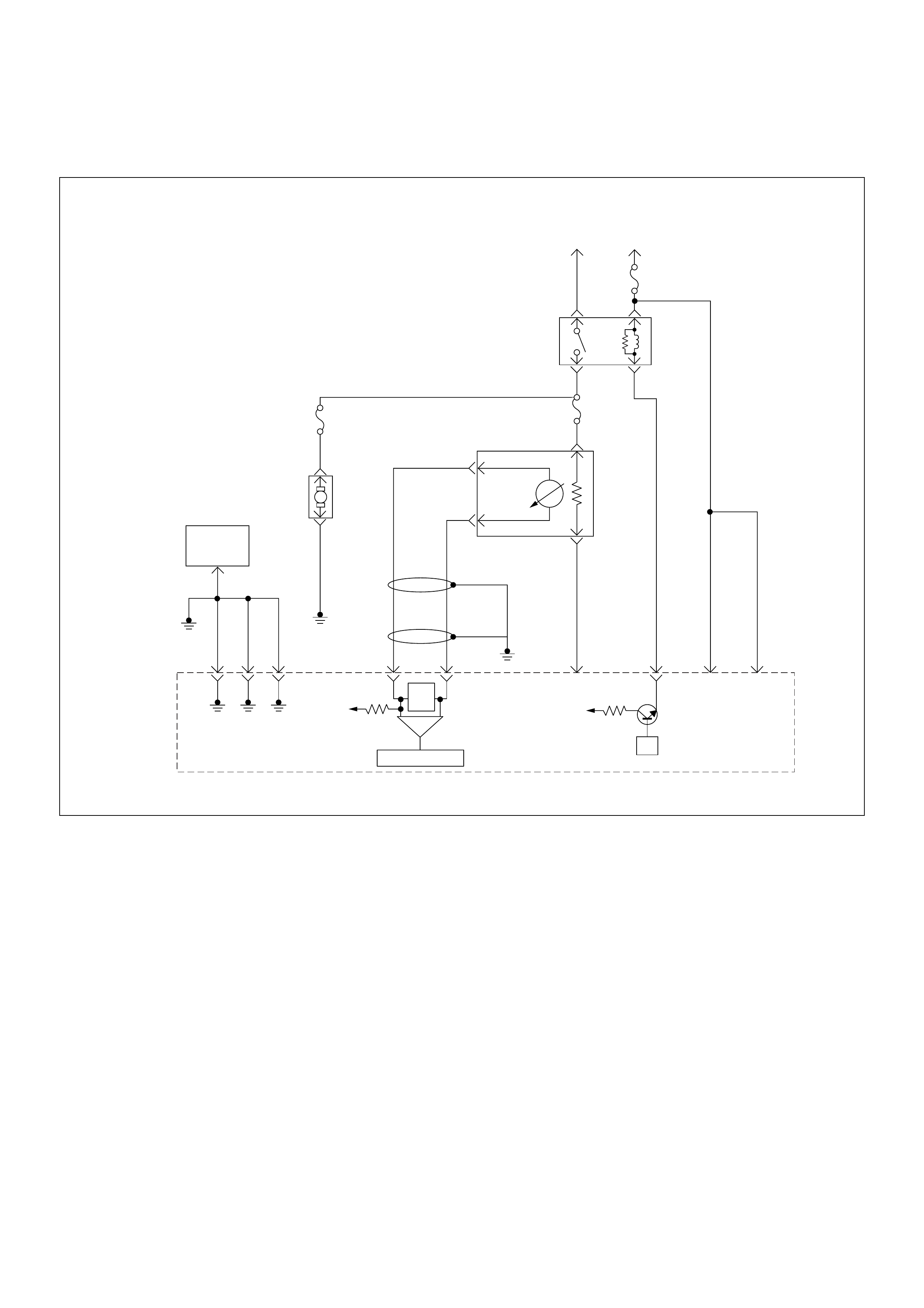
Fuel System Electrical Test
Circuit Description
When the ignition switch is first turned ON, the engine
control module (ECM) energizes the fuel pump relay
which applies power to the in-tank fuel pump. The fuel
pump relay will remain ON as long as the engine is
running or cranking and the ECM is receiving 58X
crankshaft position pulses. If no 58X crankshaft position
pulses are present, the ECM de-energizes the fuel
pump relay within 2 seconds after the ignition is turned
ON or the engine is stopped.
The fuel pump delivers fuel to the fuel rail and injectors,
then to the fuel pressure regulator. The fuel pressure
regulator controls fuel pressure by allowing excess fuel
to be returned to the fuel tank. With the engine stopped
and ignition ON, the fuel pump can be turned ON by
using a command by the scan tool.
Diagnostic Aids
An intermittent may be caused by a poor connection,
rubbed-through wire insulation, or a wire broken inside
the insulation. Check for the following items:
• Poor connection or damaged harness - Inspect the
ECM harness and connectors for improper mating,
broken locks, improperly formed or damaged
terminals, poor terminal-to-wire connection, and
damaged harness.
Caution: To reduce the risk of fire and personal
injury:
• It is necessary to relieve fuel system pressure
before connecting a fuel pressure gauge. Refer to
Fuel Pressure Relief Procedure, below.
• A small amount of fuel may be released when
disconnecting the fuel lines. Cover fuel line
fitting s wit h a shop towel bef or e d isco nne ct ing , to
catch any fuel tha t may leak out. Place the to wel
in an approved container when the disconnect is
completed.
µP
VIgn
-
+
Crankshaft
Position
Sensor
J1-1 J1-2 J1-17
Battery
Voltage
Battery
Voltage
2.0
WHT ECM
10A
450
mV
A/D Converter
Vcc
+5V -+
TIMING
COVER
J2-6 J2-21
Fuel
Pump
FUEL
PUMP
20A
2.0
BLK
2.0
BLK/
BLU
Fuel
Pump
Relay
O2
SENSOR
10A
Heated
O2
Sensor
0.85
RED/
WHT
0.5
GRN/
WHT
0.5
RED/
WHT
0.5
BLU/
WHT
0.5
BLU
0.5 PNK
J2-31 J2-11 J2-2 J2-18
M
Engine
Control
Module
(ECM)
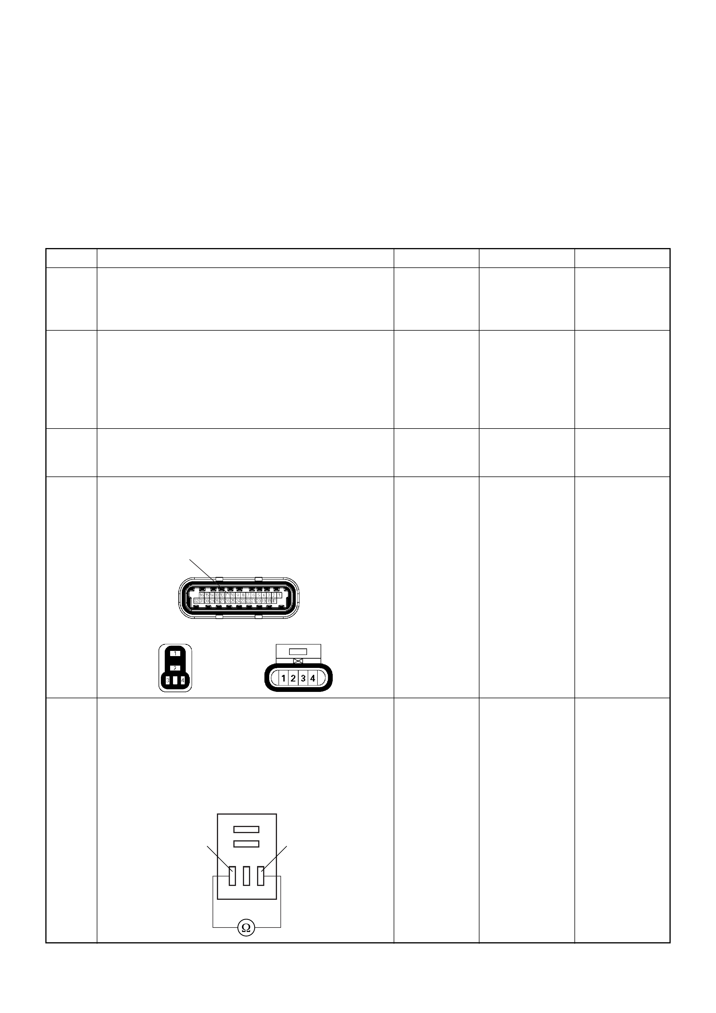
Fuel Pressure Relief Procedure
1. Remove the fuel cap.
2. Remove the fuel pump relay from the underhood
relay center.
3. Start the engine and alow it to stall.
4. Crank the engine for an additional 3 seconds.
Fuel Pressure Gauge Installation
1. Remove the fuel pressure fitting cap.
2. Install fuel pressure gauge 5-8840-0378-0 to the
fuel feed line located in front of and above the right
side valve cover.
3. Reinstall the fuel pump relay.
Fuel System Electrical Test
Step Action Value(s) Yes No
1 Was the “On-Board Diagnostic (OBD) System Check”
performed?
—Go to Step 2
Go to On Board
Diagnostic
(OBD) System
Check
2 1. Using the Tech 2, ignition “On” and engine “On”.
2. Select the “Miscellaneous Test” and perform the
“Fuel Pump Relay” in the “Relays”.
3. Operate the Tech 2 in accordance with procedure.
Was the fuel pump operated, when the Tech 2 is
operated? —
Go to Fuel
System
Diagnosis Go to Step 3
3 Check the “Fuel Pump” fuse (20A).
If the fuse is burnt out, repair as necessary.
Was the problem found? — Verify repair Go to Step 4
4 Check for poor/faulty connection at the fuel pump, fuel
pump relay or ECM connector. If a poor/faulty
connection is found, repair as necessary.
Was the problem found?
— Verify repair Go to Step 5
5 Using the DVM and check the fuel pump relay.
1. Ignition “Off”, engine “Off”.
2. Remove the fuel pump relay from the relay box.
3. Check the relay coil.
W as the DVM indicated specified value?
Continuity Go to Step 6
Replace fuel
pump relay and
verify repair
11 C56(J2)
F2X2
Fuel Pump Relay
34
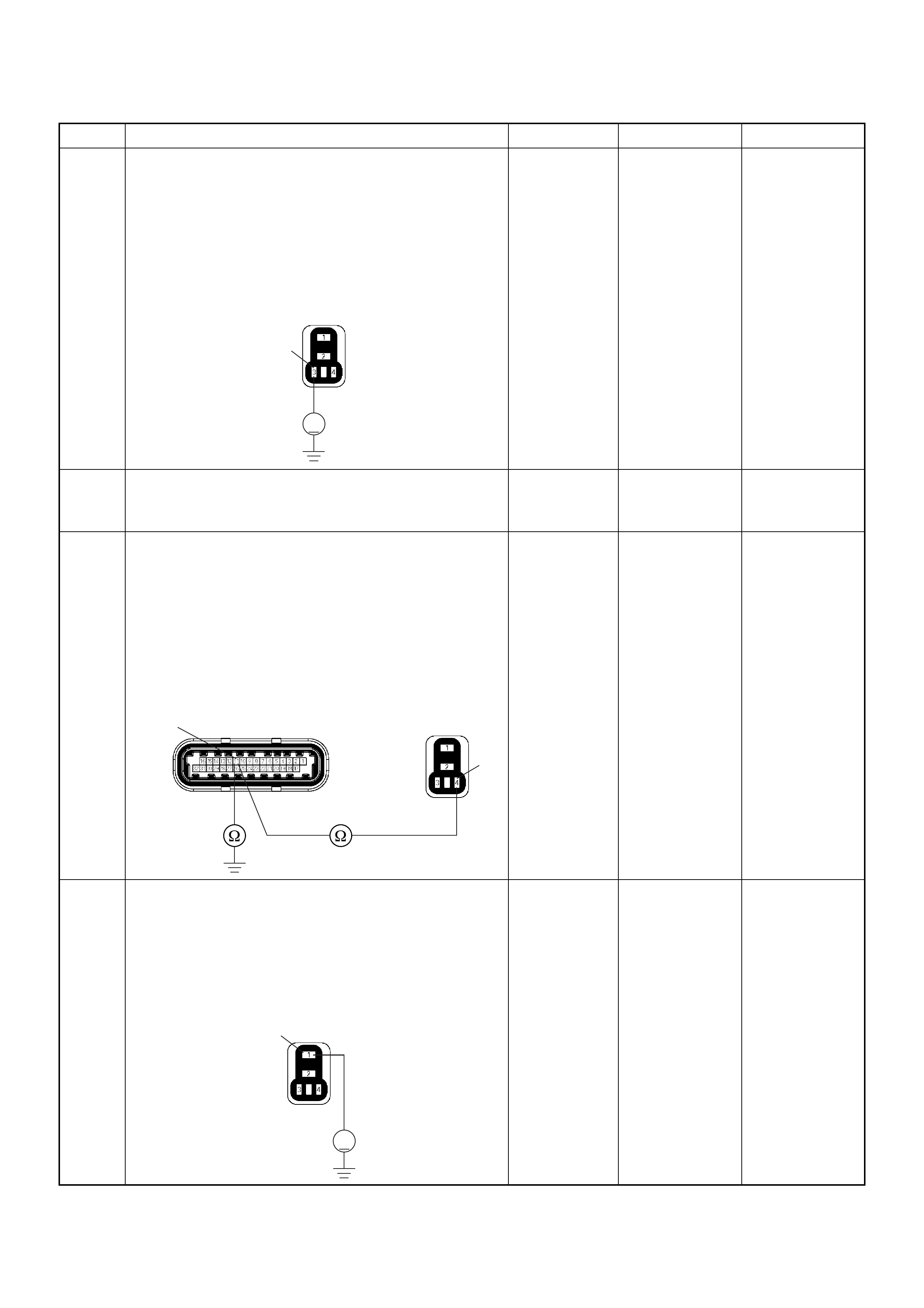
6 Using the DVM and check the fuel pump relay power
supply circuit.
1. Ignition “On”, engine “Off”.
2. Remove the fuel pump relay from the relay box.
3. Check the circuit for open or short to ground
circuit.
W as the DVM indicated specified value?
Battery
voltage Go to Step 8 Go to Step 7
7 Repair the open or short to ground circuit between the
“ECM” fuse (15A) and fuel pump relay.
Is the action complete? — Verify repair —
8 Usi ng the DVM and chec k the fuel pum p relay gr ound
circuit.
1. Ignition “Off”, engine “Off”.
2. Disconnect the ECM connector.
3. Remove the fuel pump relay from the relay box.
4. Check the circuit for open or short to ground
circuit.
Was the problem found?
—
Repair faulty
harness and
verify repair Go to Step 9
9 Using the DVM and check the fuel pump relay power
supply circuit.
1. Ignition “Off”, engine “Off”.
2. Remove the fuel pump relay from the relay box.
3. Check the circuit for open circuit.
W as the DVM indicated specified value?
Battery
voltage Go to Step 11 Go to Step 10
Step Action Value(s) Yes No
V
3
X2
4
11 C56(J2) X2
V
1X2
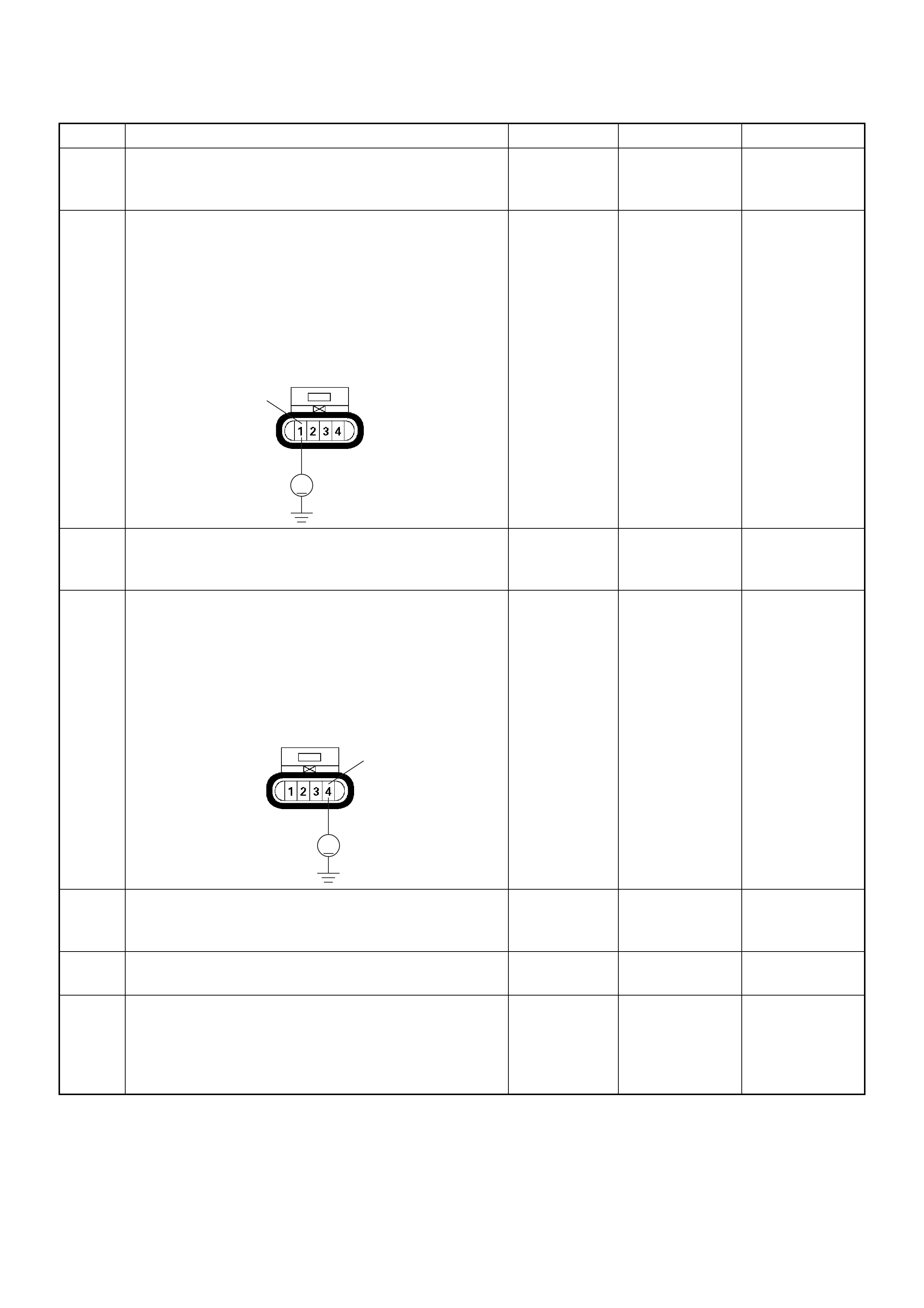
10 Repair the open circuit between the fuel pump relay
and battery.
Is the action complete? — Verify repair —
11 Using the DVM and check the fuel pump power supply
circuit.
1. Ignition “On”, engine “Off”.
2. Disconnect the fuel pump connector.
3. Check the circuit for open or short to ground
circuit.
W as the DVM indicated specified value?
Battery
voltage Go to Step 13 Go to Step 12
12 Repair the open or short to ground circuit between the
fuel pump relay and fuel pump.
Is the action complete? — Verify repair —
13 Using the DVM and check the fuel pump ground
circuit.
1. Ignition “Off”, engine “Off”.
2. Disconnect the fuel pump connector.
3. Check the circuit for open circuit.
W as the DVM indicated specified value?
Continuity Go to Step 15 Go to Step 14
14 Repair the open circuit between the fuel pump and
body ground.
Is the action complete? — Verify repair —
15 Replace the fuel pump.
W as the problem solved? — Verify repair Go to Step 16
16 Is the ECM programmed with the latest software
release?
If not, download the latest software to the E CM using
the “SPS (Service Programming System)”.
W as the problem solved? — Verify repair Go to Step 17
Step Action Value(s) Yes No
V
1F2
V
4
F2

17 Replace the ECM.
Is the action complete?
IMPORTANT: The replacement ECM must be
programmed. Refer to section of the Service
Programming System (SPS) in this manual.
Foll owing ECM pr ogramming, the immobi liser system
(if equipped) must be linked to the ECM. Refer to
section 11 “Immobiliser System-ECM replacement” for
the ECM/Immobiliser linking procedure. — Verify repair —
Step Action Value(s) Yes No

Fuel System Diagnosis
Circuit Description
When the ignition switch is turned ON, the engine
control module (ECM) will turn ON the in-tank fuel
pump. The in-tank fuel pum p will rema in ON as l ong as
the engine is cranking or running and the ECM is
receiv in g 58X cr an ks ha ft posit ion pul se s. If there ar e n o
58X crankshaft position pulses, the ECM will turn the in-
tank fuel pump OFF 2 seconds after the ignition switch
is turned ON or 2 seconds after the engine stops
running.
The in-tank fuel pump is an electric pump within an
integral reservoir. The in-tank fuel pump supplies fuel
through an in-line fuel filter to the fuel rail assembly. The
fuel pump is designed to provide fuel at a pressure
above the pressure needed by the fuel injectors. A fuel
pressure regulator, attached to the fuel rail, keeps the
fuel available to the fuel injectors at a regulated
pressure. Unused fuel is returned to the fuel tank by a
separate fuel return line.
Test Description
Number(s) below refer to the step number(s) on the
Diagnostic Chart.
2. Connect the fuel pressure gauge to the fuel feed line
as shown in the fuel system illustration. Wrap a shop
towel around the fuel pressure connection in order to
absorb any duel leakage that may occur when
installing the fuel pressure gauge. With the ignition
switch ON and the fuel pump running, the fuel
pressure indicated by the fuel pressure gauge
should b e 283-37 6 kPa ( 41-55 psi). T his pres sure is
controlled by the amount of pressure the spring
inside the fuel pressure regulator can provide.
µP
VIgn
-
+
Crankshaft
Position
Sensor
J1-1 J1-2 J1-17
Battery
Voltage
Battery
Voltage
2.0
WHT ECM
10A
450
mV
A/D Converter
Vcc
+5V -+
TIMING
COVER
J2-6 J2-21
Fuel
Pump
FUEL
PUMP
20A
2.0
BLK
2.0
BLK/
BLU
Fuel
Pump
Relay
O2
SENSOR
10A
Heated
O2
Sensor
0.85
RED/
WHT
0.5
GRN/
WHT
0.5
RED/
WHT
0.5
BLU/
WHT
0.5
BLU
0.5 PNK
J2-31 J2-11 J2-2 J2-18
M
Engine
Control
Module
(ECM)

3. A fuel system that cannot maintain a constant fuel
pressure has a leak in one or more of the following
areas:
• The fuel pump check valve.
• The fuel pump flex line.
• The valve or valve seat within the fuel pressure
regulator.
• The fuel injector(s).
4. Fuel pressure that drops off during acceleration,
cruise, or hard cornering may case a lean condition.
A lean condition can cause a loss of power, surging,
or misfire. A lean condition can be diagnosed using a
Tech 2 Scan Tool.
Following are applicable to the vehicle with
closed Loop System:
If an extremely lean condition occurs, the oxygen
sensor(s) will stop toggling. The oxygen sensor
output voltage(s) will drop below 500 mV. Also, the
fuel injector pulse width will increase.
Important: Make sure the fuel system is not
operating in the “Fuel Cut-Off Mode.”
When the engine is at idle, the manifold pressure is
low (high vacuum). This low pressure (high vacuum)
is applied to the fuel pressure regulator diaphragm.
The low pressure (high vacuum) will offset the
pressure being applied to the fuel pressure regulator
diaphragm by the spring inside the fuel pressure
regulator. When this happens, the result is lower fuel
pressure. The fuel pressure at idle will vary slightly
as the barometric pressure changes, but the fuel
pressure at idle should always be less than the fuel
pressure noted in step 2 with the engine OFF.
16.Check the spark plug associated with a particular
fuel injector for fouling or saturation in order to
determine if that particular fuel injector is leaking. If
checking the spark plug associated with a particular
fuel injector for fouling or saturation does not
determine that a particular fuel injector is leaking,
use the following procedure:
• Remove the fuel rail, but leave the fuel lines and
injectors connected to the fuel rail. Refer to Fuel
Rail Assembly in On-Vehicle Service.
• Lift the fuel rail just enough to leave the fuel
injector nozzles in the fuel injector ports.
Caution: In order to reduce the risk of fire and
personal injury that may result from fuel
spraying on the engine, verify that the fuel rail is
positioned over the fuel injector ports and verify
that the fuel injector retaining clips are intact.
• Pressurize the fuel system by connecting a 20
amp fused jumper between B+ and the fuel pump
relay connector.
• Visually and physically inspect the fuel injector
nozzles for leaks.
17.A rich condition may result from the fuel pressure
being above 376 kPa (55 psi). A rich condition may
cause a 45 to set. Driveability conditions associated
with rich conditions can include hard starting
(followed by black smoke) and a strong sulfur smell
in the exhaust.
20.This test determines if the high fuel pressure is due
to a restricted fuel return line or if the high fuel
pressure is due to a faulty fuel pressure regulator.
21.A lean condition may result from fuel pressure below
333 kPa (48 psi). A lean condition may cause a 44 to
set. Driveability conditions associated with lean
conditions can include hard starting (when the
engine is cold), hesitation, poor driveability, lack of
power, surging, and misfiring.
22.Restricting the fuel return line causes the fuel
pressure to rise above the regulated fuel pressure.
Command the fuel pump ON with the scan tool. The
fuel pressure should rise above 376 kPa (55 psi) as
the fuel return line becomes partially closed.
NOTE: Do not allow the fuel pressure to exceed 414
kPa (60 psi). Fuel pressure in excess of 414 kPa (60
psi) may damage the fuel pressure regulator.
Caution: To reduce the risk of fire and personal
injury:
• It is necessary to relieve fuel system pressure
before connecting a fuel pressure gauge. Refer to
Fuel Pressure Relief Procedure, below.
• A small amount of fuel may be released when
disconnecting the fuel lines. Cover fuel line
fitting s wit h a shop towel bef or e d isco nne ct ing , to
catch any fuel tha t may leak out. Place the to wel
in an approved container when the disconnect is
completed.
Fuel Pressure Relief Procedure
1. Remove the fuel cap.
2. Located on the intake manifold which is at the top
right part of the engine.
3. Start the engine and allow it to stall.
4. Crank the engine for an additional 3 seconds.
Fuel Pressure Gauge Installation
1. Remove the fuel pressure fitting cap.
2. Install fuel pressure gauge 5-8840-0378-0 to the
fuel feed line located on the upper right side of the
engine.
3. Reinstall the fuel pump relay.

Fuel System Diagnosis
Step Action Value(s) Yes No
1 Was the “On-Boa rd Diagnosti c (OBD) Sys tem Check”
performed? — Go to Step 2 Go to OBD
System Check
2 1. Turn the ignition OFF.
2. Turn the air conditioning system OFF.
3. Relieve fuel system pressure and install the fuel
pressure gauge.
4. Turn the ignition ON.
NOTE: The fuel pump will run for approximately 2
seconds. Use the Scan Tool to command the fuel
pump ON.
5. Observe the fuel pressure indicated by the fuel
pressure gauge with the fuel pump running.
Is the fuel pressure within the specified limits? 283-376 kPa
(41-55 psi) Go to Step 3 Go to Step 17
3 Does the fuel pressure indicated by the fuel pressure
gauge remain constant?
NOTE: The fuel pressure will drop when the fuel
pump stops running, then it should stabilize and
remain constant. — Go to Step 4 Go to Step 12
4 1. When the vehicle is at normal operating
temperature, turn the ignition ON to build fuel
pressure and observe the measurement on the
gauge.
2. Start the engine and observe the fuel pressure
gauge.
Did the rea din g drop by the amo unt sp ec ified after the
engine was started? 21-105 kPa
(3-15 psi) Go to Step 5 Go to Step 9
5 Is fuel pressure dropping off during acceleration,
cruise, or hard cornering? — Go to Step 6 Check for
improper fuel
6 Visually and physically inspect the following items for
a restriction:
• The in-line fuel filter.
• The fuel feed line.
Was a restriction found? — Verify repair Go to Step 7
7 Remove the fuel tank and visually and physically
inspect the following items:
• The fuel pump strainer for a restriction.
• The fuel line for a leak.
• Verify that the correct fuel pump is in the vehicle.
Was a problem found in any of these areas? — Verify repair Go to Step 8
8 Replace the fuel pump.
Is the action complete? — Verify repair —
9 1. Disconnect the vacuum hose from the fuel
pressure regulator.
2. With the engine idling, apply 12-14 inches of
vacuum to the fuel pressure regulator.
Does the fuel pressure indicated by the fuel pressure
gauge drop by the amount specified? 21-105 kPa
(3-15 psi) Go to Step 10 Go to Step 11
10 Locate and repair the loss of vacuum to the fuel
pressure regulator.
Is the action complete? — Verify repair —

11 Replace the fuel pressure regulator.
Is the action complete? — Verify repair —
12 1. Run the fuel pump with the Scan Tool.
2. After pressure has built up, turn off the pump and
clamp the supply hose shut with suitable locking
pliers.
Does the fuel pressure indicated by the fuel pressure
gauge remain constant? — Go to Step 13 Go to Step 15
13 Visually inspect the fuel supply line and repair any
leaks.
W as a problem found? — Verify repair Go to Step 14
14 Remove the fuel tank and inspect for leaky hose or in-
tank fuel line.
W as a problem found? — Verify repair Go to Step 8
15 1. If the pliers are still clamped to the fuel supply
hose, remove the locking pliers.
2. With suitable locking pliers, clamp the fuel return
line to prevent fuel from returning to the fuel tank.
3. Run the fuel pump with the Scan Tool.
4. After pressure has built up, remove power to the
pump.
Does the fuel pressure indicated by the fuel pressure
gauge remain constant? — Go to Step 11 Go to Step 16
16 Locate and replace any leaking fuel injector(s).
Is the action complete? — Verify repair —
17 Is the fuel pressure indicated by the fuel pressure
gauge above the specified limit? 376 kPa
(55 psi) Go to Step 18 Go to Step 21
18 1. Relieve the fuel pressure. Refer to the Fuel
Pressure Relief.
2. Disconnect the fuel return line from the fuel rail.
3. Attach a length of flexible hose to the fuel rail
return outlet passage.
4. Place the open end of the flexible hose into an
approved gasoline container.
5. Run the fuel pump with the Scan Tool.
6. Observe the fuel pressure indicated by the fuel
pressure gauge with the fuel pump running.
Is the fuel pressure within the specified limits? 290-376 kPa
(42-55 psi) Go to Step 19 Go to Step 20
19 Locate and correct the restriction in the fuel return
line.
Is the action complete? — Verify repair —
20 Visually and physically inspect the fuel rail outlet
passages for a restriction.
Was a restriction found? — Verify repair Go to Step 11
21 Is the fuel pressure indicated by the fuel pressure
gauge above the specified value? 0 kPa (0 psi) Go to Step 22 Go to Step 23
22 1. Command the fuel pump ON with the Scan Tool.
2. Using suitable pliers which will not damage the
fuel hose, gr adually apply pres sure with the pliers
to pinch the flexible fuel return hose closed. 376 kPa
(55 psi)
Step Action Value(s) Yes No

Does the fuel pressure indicated by the fuel pressure
gauge rise above the first specified value?
Caution: Do not let the fuel pressure exceed the
second specified value. 414 kPa
(60 psi) Go to Step 11 Go to Step 7
23 1. Command the fuel pump ON with the Scan Tool.
2. Remove th e fuel filler cap an d listen for the s ound
of the fuel pump running.
3. Turn the pump off.
Was the fuel pump running? — Go to Step 7
Go to Fuel
System
Electrical Test
Chart
Step Action Value(s) Yes No

ECM Diagnostic Trouble Codes (DTC)
Type A
•Emission related.
• Requests illumination of the MIL (Malfunction Indicator Lamp = Check Engine Lamp) of the first trip with a fail.
• Stores a history DTC on the first trip.
• Stores a freeze frame (If empty).
• Stores a fail record.
• Updates the fail record each time the diagnostic test fails.
Type B
•Emission related.
• “Armed” after one trip with fail.
• “Disarmed” after one trip with a pass.
• Requests illumination of the MIL on the second consecutive trip with a fail.
• Store a history DTC on the second consecutive trip with a fail. (The DTC will be armed after the first fail.)
• Stores a freeze frame on the second consecutive trip with a fail (If empty).
• Stores a fail record when the first test fails (not dependent on consecutive trip).
• Updates the fail record each time the diagnostic test fails.
Type D
• Non emission related.
• Does not request illumination of any lamp.
• Stores a history DTC on the first trip.
• Does not store a freeze frame.
• Stores fail record when test fails.
• Updates the fail record each time the diagnostic test fails.

Diagnostic Trouble Code (DTC) P0107 Manifold Absolute Pressure
Circuit Low Input
Manifold
Absolute
Pressure(MAP) Sensor
Crankshaft
Position(CKP)
Sensor
µP
0.5
GRY/
BLU
J1-16
0.5
GRY/
RED
J1-24
0.5
YEL/
RED
J1-31
0.5
BLK/
WHT
J1-1
0.5
BLK/
WHT
J1-2
0.5
BLK/
WHT
J1-17
0.5
BLK
J1-6
0.5
WHT
J1-21
INLET
MANIFOLD
5 V olts
Reference
Engine
Control
Module
(ECM)

Condition for setting the DTC and action ta ken when the DTC sets
Circuit Description
The manifold absolute pressure (MAP) sensor responds
to changes in intake manifold pressure. The MAP
sensor signal voltage to the engine control module
(ECM) varies from below 2 volts at idle (low manifold
pressure) to above 4 volts with the ignition ON, engine
not running or at wide-open throttle (high manifold
pressure).
A “speed den sity” method of determining e ngine load is
used on t he 2.4L eng in e. T hi s is c al cu lat ed u sing inputs
from the MAP sensor, the CKP Sensor, and the Intake
Air Temperature (IAT) sensor. The MAP sensor is the
main sensor used in this calculation, and measuring
engine load is its main function.
The ECM monitors the MAP signals for voltages outside
the normal range (10-104 kpa) of the MAP sensor. If the
ECM detects a MAP signal voltage that is excessively
low, Diagnostic Trouble Code P0107 will be set.
Diagnostic Aids
Check for the following conditions:
• Poor connection at ECM - Inspect harness
connectors for backed-out terminals, improper
mating, broken locks, improperly formed or damaged
terminals, and poor terminal-to-wire connection.
• If these codes are also set, it could indicate a
problem with the 5 Volt reference circuit.
• Damaged harness - Inspect the wiring harness for
damage, short to ground, short to battery positive,
and open circuit. If the harness appears to be OK,
obse rve the MAP disp lay on the Tech 2 while moving
connectors and wiring harnesses related to the
sensor. A change in the display will indicate the
location of the fault.
Diagnostic Trouble Code (DTC) P0107 Manifold Absolute Pressure Circuit Low Input
Code Type DTC Name DTC Setting Condition Fail-Safe (Back Up)
P0107 A Manifold Absolute Pressure Circuit
Low Input 1. No DTC rela ting to TPS.
2. Throttle position is more than 0% if engine
speed is below 1000rpm, or throttle posi-
tion more than 5% if engine speed is more
than 1000rpm.
3. MAP sensor output is below 12KPa.
The ECM uses default manifold absolute
pressure value based on engine speed
and throttle position.
Step Action Value(s) Yes No
1 Was the “On-Board Di agnostic (OBD) System Check”
performed?
—Go to Step 2
Go to On
Board
Diagnostic
(OBD) System
Check
2 1. Connect the Tech 2.
2. Review and record the failure information.
3. Select “F0: Read DTC Infor By Priority” in “F0:
Diagnostic Trouble Code”.
Is the DTC P0107 stored as “Present Failure”? — Go to Step 3
Refer to
Diagnostic Aids
and Go to Step
3
3 1. Using the Tech2, ignition “On” and engine “Off”.
2. Select “Cl ear D TC I nform ati on” w ith th e Tech2 and
clear the DTC information.
3. Operate the vehicle and monitor the “F5: Failed
This Ignition” in “F2: DTC Information”.
Was the DTC P0107 stored in this ignition cycle? — Go to Step 4
Refer to
Diagnostic Aids
and Go to Step
4
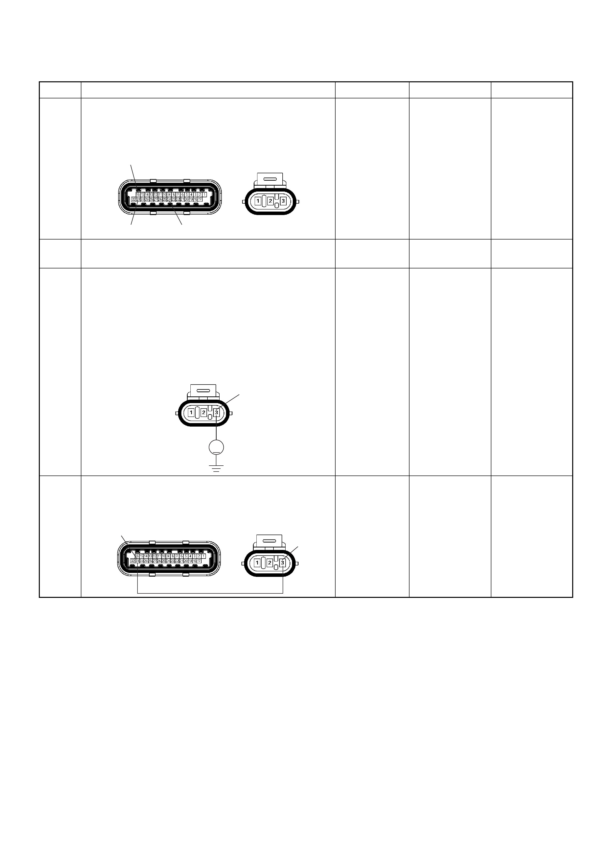
4 Check for poor/faulty connection at the MAP sensor or
ECM connector. If a poor/faulty connection is found,
repair as necessary.
Was the problem found?
— Verify repair Go to Step 5
5 Visually check the MAP.
Was the problem found? — Go to Step 9 Go to Step 6
6 Using the DVM and check the MAP sensor power
suppl y ci rcui t .
1. Ignition “On”, engine “Off”.
2. Disconnect the MAP sensor connector.
3. Check the circuit for open or short to ground
circuit.
Was the DVM indicated specified value?
Approximately
5.0V Go to Step 8 Go to Step 7
7 Repair the open or short to ground circuit between the
ECM and MAP sensor
Was the problem solved?
— Verify repair Go to Step 11
Step Action Value(s) Yes No
16
31 24
E85E60(J1)
V
E85 3
31 3
E85E60(J1)
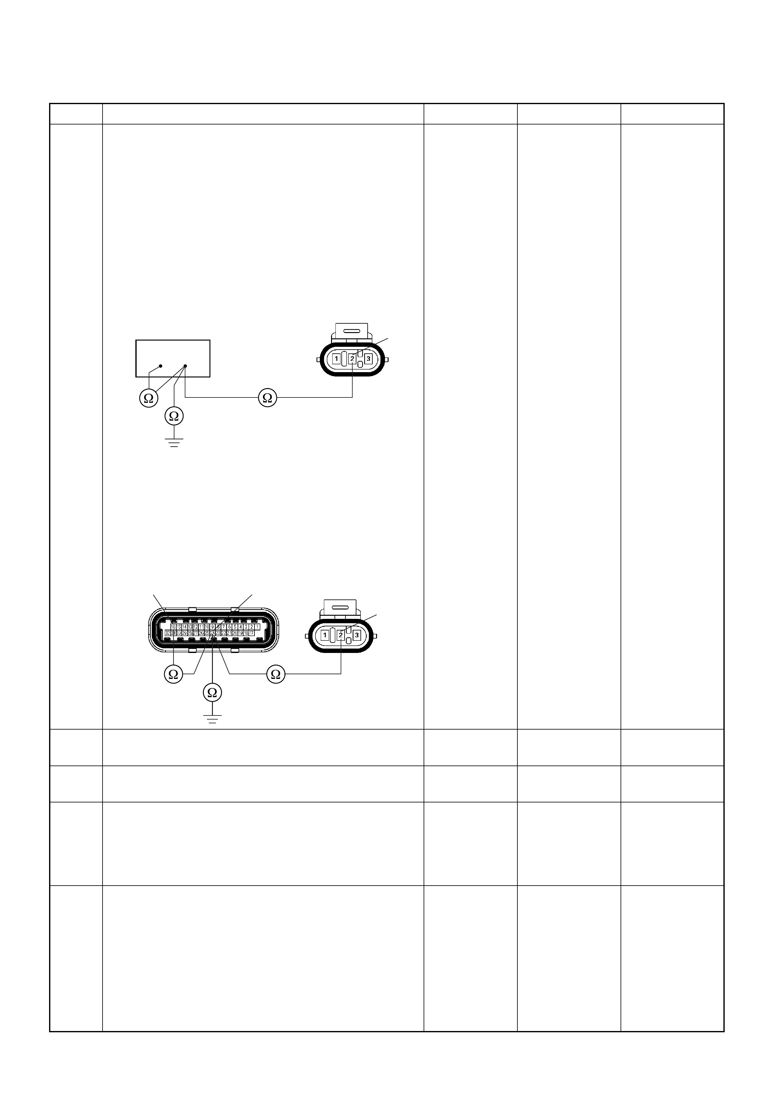
8 Using the DVM and check the MAP sensor signal
circuit.
Breaker box is available:
1. Ignition “Off”, engine “Off”.
2. Install the breaker box as type A. (ECM
disconnected) Ref. 6E-80.
3. Disconnect MAP sensor connector.
4. Check the circuit for open, sho rt to sensor gr ound
or shor t to ground circ uit.
Was the problem found?
Breaker box is not available:
1. Ignition “Off”, engine “Off”.
2. Disconnect the MAP sensor connector and ECM
connector.
3. Check the circuit for open, sho rt to sensor gr ound
or shor t to ground circ uit.
Was the problem found?
—
Repair faulty
harness and
verify repair Go to Step 9
9 Substitute a known good MAP sensor and recheck.
Was the problem solved ? — Go to Step 10 Go to Step 1 1
10 Replace the MAP sensor.
Is the action complete? — Verify repair —
11 Is the ECM programmed with the latest software
release?
If not, download the latest software to the ECM using
the “SPS (Service Programming System)”.
Was the problem solved? — Verify repair Go to Step 12
12 Replace the ECM.
Is the action complete?
IMPORTANT: The replacement ECM must be
programmed. Refer to section of the Service
Programming System (SPS) in this manual.
Following EC M programming, the immobiliser system
(if equipped) must be linked to the ECM. Refer to
section 11 “Immobiliser System-ECM replacement” for
the ECM/Immobiliser linking procedure. — Verify repair —
Step Action Value(s) Yes No
2
E85
16 24
16 24
2
E85E60(J1)
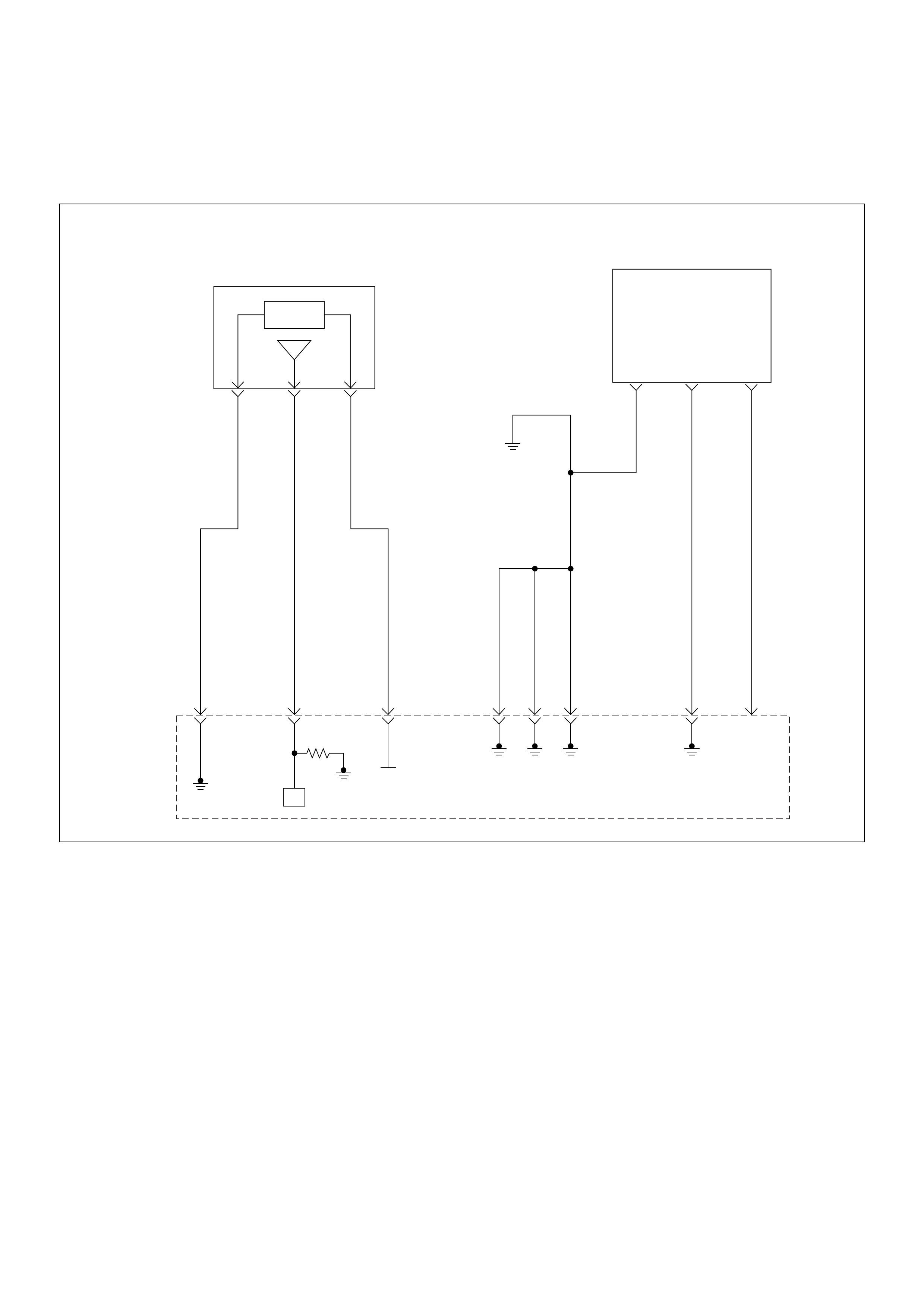
Diagnostic Trouble Code (DTC) P0108 Manifold Absolute Pressure
Circuit High Input
Manifold
Absolute
Pressure(MAP) Sensor
Crankshaft
Position(CKP)
Sensor
µP
0.5
GRY/
BLU
J1-16
0.5
GRY/
RED
J1-24
0.5
YEL/
RED
J1-31
0.5
BLK/
WHT
J1-1
0.5
BLK/
WHT
J1-2
0.5
BLK/
WHT
J1-17
0.5
BLK
J1-6
0.5
WHT
J1-21
INLET
MANIFOLD
5 V olts
Reference
Engine
Control
Module
(ECM)

Condition for setting the DTC and action ta ken when the DTC sets
Circuit Description
The manifold absolute pressure (MAP) sensor responds
to changes in intake manifold pressure. The MAP
sensor signal voltage to the engine control module
(ECM) varies from below 2 volts at idle (low manifold
pressure) to above 4 volts with the ignition ON, engine
not running or at wide-open throttle (high manifold
pressure).
A “speed den sity” method of determining e ngine load is
used on t he 2.4L eng in e. T hi s is c al cu lat ed u sing inputs
from the MAP sensor, RPM, CKP Sensor, and the
Intake Air Temperature (IAT) sensor. The MAP sensor is
the main senso r used in thi s cal culati on , and me as ur in g
engine load is its main function.
The ECM monitors the MAP signals for voltages outside
the normal range (10-104 kpa) of the MAP sensor. If the
ECM detects a MAP signal voltage that is excessively
high, Diagnostic Trouble Code P0108 will be set.
Diagnostic Aids
Check for the following conditions:
• Poor connection at ECM - Inspect harness
connectors for backed-out terminals, improper
mating, broken locks, improperly formed or damaged
terminals, and poor terminal-to-wire connection.
• If these codes are also set, it could indicate a
problem with the 5 Volt reference circuit.
• Damaged harness - Inspect the wiring harness for
damage; an open circuit, a short to ground, or a short
to voltage. If the har ness appears to be OK, obser ve
the MAP display on the Tech 2 while moving
connectors and wiring harnesses related to the
sensor. A change in the display will indicate the
location of the fault.
Diagnostic Trouble Code (DTC) P0108 Manifold Absolute Pressure Circuit High Input
Code Type DTC Name DTC Setting Condition Fail-Safe (Back Up)
P0108 A Manifold Absolute Pressure Circuit
High Input 1. No DTC rela ting to TPS.
2. Throttle position is below 15% if engine
speed is below 2500rpm, or throttle posi-
tion is below 35% if engine speed is more
than 2500rpm.
3. Engine run time is longer than 10 seconds.
4. MAP sensor output is more than 103KPa.
The ECM uses default manifold absolute
pressure value based on engine speed
and throttle position.
Step Action Value(s) Yes No
1 Was the “On-Boa rd Diagnosti c (OBD) Sys tem Check”
performed?
—Go to Step 2
Go to On
Board
Diagnostic
(OBD) System
Check
2 1. Connect the Tech 2.
2. Review and record the failure information.
3. Select “F0: Read DTC Infor By Priority” in “F0:
Diagnostic Trouble Code”.
Is the DTC P0108 stored as “Present Failure”? — Go to Step 3
Refer to
Diagnostic Aids
and Go to Step
3
3 1. Using the Tech2, ignition “On” and engine “Off”.
2. Select “Clear DTC Information” with the Tech2 and
clear the DTC information.
3. Operate the vehicle and monitor the “F5: Failed
This Ignition” in “F2: DTC Information”.
Was the DTC P0108 stored in this ignition cycle? — Go to Step 4
Refer to
Diagnostic Aids
and Go to Step
4
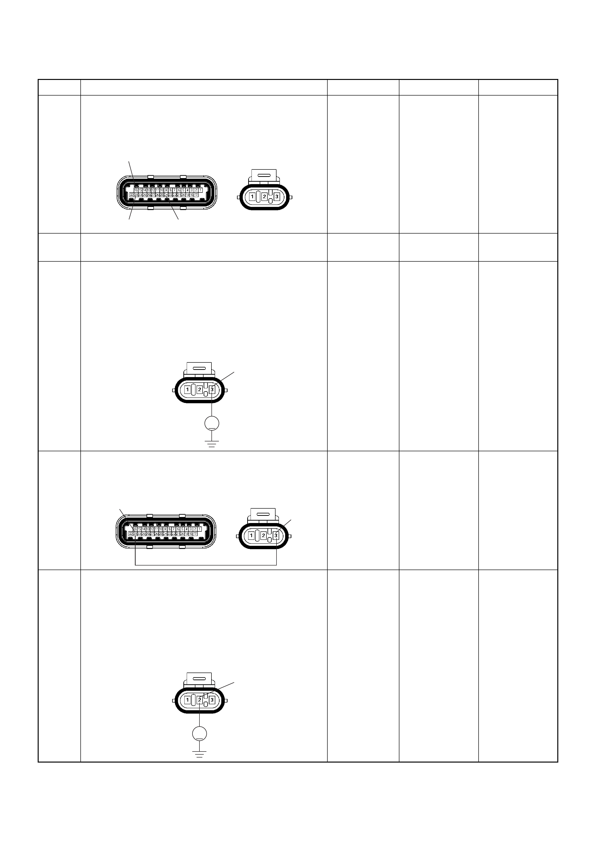
4 Check for poor/faulty connection at the MAP sensor or
ECM connector. If a poor/faulty connection is found,
repair as necessary.
Was the problem found?
— Verify repair Go to Step 5
5 Visually chec k the MAP sens or.
Was the problem found? — Go to Step 11 Go to Step 6
6 Using the DVM and check the MAP sensor power
supply circuit.
1. Ignition “On”, engine “Off”.
2. Disconnect the MAP sensor connector.
3. Check the circuit for short to voltage circuit.
W as the DVM indicated specified value?
Approximately
5.0V Go to Step 8 Go to Step 7
7 Repair the short to voltage circuit between the ECM
and MAP sensor.
Was the problem solved?
— Verify repair Go to Step 13
8 Using the DVM and check the MAP sensor signal
circuit.
1. Ignition “On”, engine “Off”.
2. Disconnect the MAP sensor connector.
3. Check the circuit for short to power supply circuit.
W as the DVM indicated specified value?
Less than 1V Go to Step 9
Repair faulty
harness and
verify repair
Step Action Value(s) Yes No
16
31 24
E85E60(J1)
V
E85 3
31 3
E85E60(J1)
V
E85 2
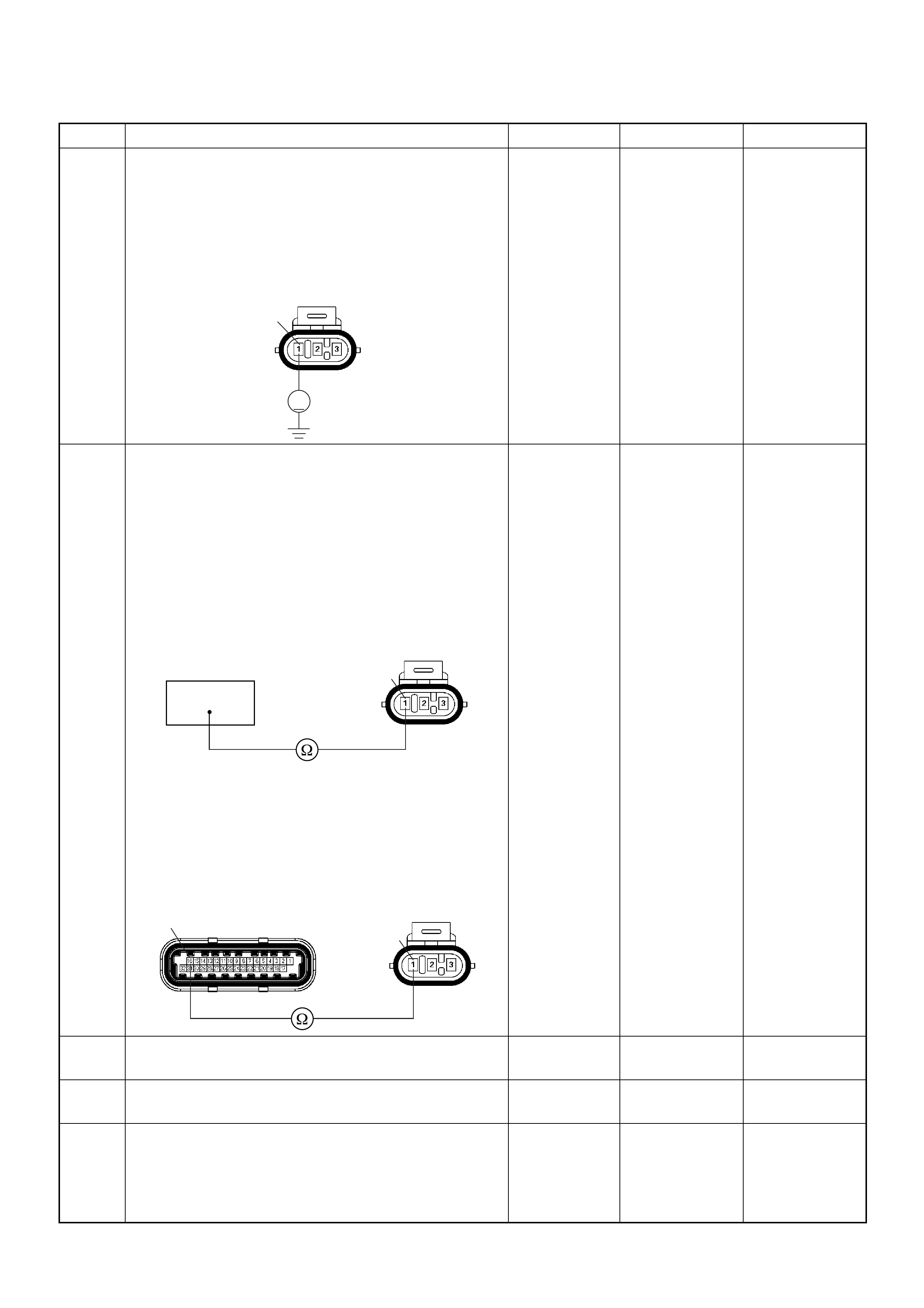
9 Using the DVM and check the MAP sensor ground
circuit.
1. Ignition “On”, engine “Off”.
2. Disconnect the MAP sensor connector .
3. Check the circuit for short to power supply circuit.
W as the DVM indicated specified value?
Less than 1V Go to Step 10
Repair faulty
harness and
verify repair
10 Using the DVM and check the MAP sensor ground
circuit.
Breaker box is available:
1. Ignition “Off”, engine “Off”.
2. Install the breaker box as type A. (ECM
disconnected) Ref. 6E-80.
3. Disconnect the MAP sensor connector.
4. Check the circuit for open circuit.
Was the problem found?
Breaker box is not available:
1. Ignition “Off”, engine “Off”.
2. Disconnect the MAP sensor connector and ECM
connector.
3. Check the circuit for open circuit.
Was the problem found?
—
Repair faulty
harnes s and
verify repair G o to Step 11
11 Substitute a known good MAP sensor and recheck.
Was the problem solved? — Go to Step 12 Go to Step 13
12 Replace the MAP sensor.
Is the action complete? — Verify repair —
13 Is the ECM programmed with the latest software
release?
If not, download the latest software to the E CM using
the “SPS (Service Programming System)”.
Was the problem solved? — Verify repair Go to Step 14
Step Action Value(s) Yes No
V
E85
1
1E85
16
1
16 E85E60(J1)

14 Replace the ECM.
Is the action complete?
IMPORTANT: The replacement ECM must be
programmed. Refer to section of the Service
Programming System (SPS) in this manual.
Foll owing ECM pr ogramming, the immobi liser system
(if equipped) must be linked to the ECM. Refer to
section 11 “Immobiliser System-ECM replacement” for
the ECM/Immobiliser linking procedure. — Verify repair —
Step Action Value(s) Yes No

Diagnostic Trouble Code (DTC) P0112 Intake Air Temperature
Sensor Low Input
Intake
Air
Temperature(IAT)
Sensor
0.5
GRN
J2-1
0.5
YEL/
GRN
J2-22
0.5
GRN/
YEL
J2-20
0.5
BLU/
YEL
0.5
BLU/
YEL
Engine
15A
Ignition
SW
Battery V oltage
J2-3
0.5
GRN/
WHT
J1-5
+5V
µPµP
Power
Steering
Pressure
SW
Evaporativ
Emission(EVAP)
Canistor
Purge
Valve
Solenoid
Engine
Control
Module
(ECM)

Condition for setting the DTC and action ta ken when the DTC sets
Circuit Description
The intake air temperature (IAT) sensor is a thermistor
which mea sures the t emperature of th e air entering th e
engine. The engine control module (ECM) applies 5
volts through a pull -up resisto r to the IAT s ensor. W hen
the intake air is cold, the sensor resistance is high and
the ECM will monitor a high signal voltage on the IAT
signal circuit. If the intake air is warm, the sensor
resistance is lower, causing the ECM to monitor a lower
voltage. Diagnostic Trouble Code P0112 will set when
the ECM detects an excessively low signal voltage
(short to ground) on the intake air temperature sensor
signal circuit.
Diagnostic Aids
Check for the following conditions:
• Poor connection at ECM - Inspect harness
connectors for backed-out terminals, improper
mating, broken locks, improperly formed or damaged
terminals, and poor terminal-to-wire connection.
• Damaged harness - Inspect the wiring harness for
damage, short to ground, short to battery and open
circuit. If the harness ap pears to be OK, observe the
IAT display on the Tech 2 while moving connectors
and wiring harnesses related to the IAT sensor. A
change in the IAT displa y will indicate the location of
the fault.
Diagnostic Trouble Code (DTC) P0112 Intake Air Temperature Sensor Low Input
Code Type DTC Name DTC Setting Condition Fail-Safe (Back Up)
P0112 A Intake Air Temperature Sensor Low
Input 1. No DTC relating to VSS.
2. Vehicle speed is more than 25km/h.
3. Engine run time is longer than 120 sec-
onds.
4. IAT sensor output is more than 149°C.
The ECM uses 20°C condition as substi-
tute.
Step Action Value(s) Yes No
1 Was the “On-Board Di agnostic (OBD) System Check”
performed?
—Go to Step 2
Go to On
Board
Diagnostic
(OBD) System
Check
2 1. Connect the Tech 2.
2. Review and record the failure information.
3. Select “F0: Read DTC Infor By Priority” in “F0:
Diagnostic Trouble Code”.
Is the DTC P0112 stored as “Present Failure”? — Go to Step 3
Refer to
Diagnostic Aids
and Go to Step
3
3 1. Using the Tech2, ignition “On” and engine “Off”.
2. Select “Cl ear D TC I nform ati on” w ith th e Tech2 and
clear the DTC information.
3. Operate the vehicle and monitor the “F5: Failed
This Ignition” in “F2: DTC Information”.
Was the DTC P0112 stored in this ignition cycle? — Go to Step 4
Refer to
Diagnostic Aids
and Go to Step
4
4 Check for poor/faulty connection at the IAT sensor or
ECM connector. If a poor/faulty connection is found,
repair as necessary.
Was the problem found?
— Verify repair Go to Step 5
5 Remove the IAT sensor and visually check.
Was the problem found? — Go to Step 8 Go to Step 6
C56(J2) C121
1
22
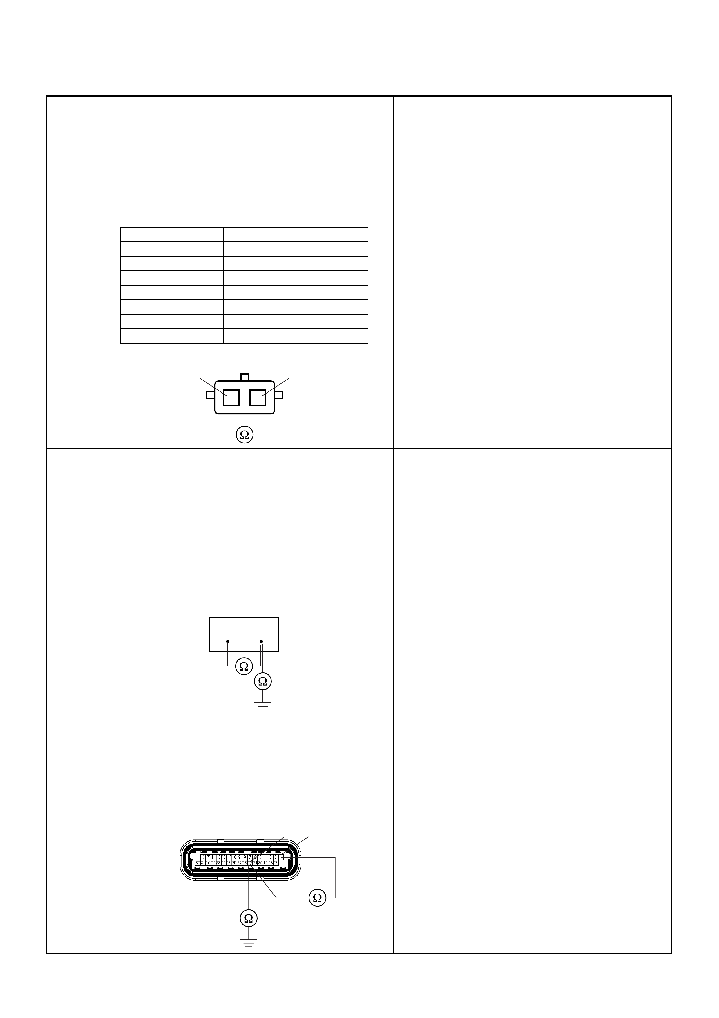
6 Using the DVM and check the IAT sensor.
1. Ignition “Off”, engine “Off”.
2. Disconnect IAT sensor connector.
3. Measure the resistance of IAT sensor.
Does the tester indicate standard resistance as shown
in the following table?
Standard
resistance Go to Step 7 Go to Step 8
7 Using the DVM and check the IAT sensor signal
circuit.
Breaker box is available:
1. Ignition “Off”, engine “Off”.
2. Install the breaker box as type A. (ECM
disconnected) Ref. 6E-80.
3. Disconnect the IAT sensor connector.
4. Check the circuit for short to sensor ground or
ground circuit.
Was the problem found?
Breaker box is not available:
1. Ignition “Off”, engine “Off”.
2. Disconnect the IAT sensor connector.
3. Check the circuit for short to sensor ground or
ground circuit.
Was the problem found?
—
Repair faulty
harness and
verify repair Go to Step 10
Step Action Value(s) Yes No
Temperature (°C) Resistance (Ω) (Approximately)
-20 32040
0 9788
20 3516
40 1439
60 656
80 327
100 175
IAT Sensor 1
1
2
2
33 54
C56(J2) 1
22

8 Substitute a known good IAT sensor assembly and
recheck.
Was the problem solved? — Go to Step 9 Go to Step 10
9 Replace the IAT sensor assembly.
Is the action complete? — Verify repair —
10 Is the ECM programmed with the latest software
release?
If not, download the latest software to the ECM using
the “SPS (Service Programming System)”.
Was the problem solved? — Verify repair Go to Step 1 1
11 Replace the ECM.
Is the action complete?
IMPORTANT: The replacement ECM must be
programmed. Refer to section of the Service
Programming System (SPS) in this manual.
Following EC M programming, the immobiliser system
(if equipped) must be linked to the ECM. Refer to
section 11 “Immobiliser System-ECM replacement” for
the ECM/Immobiliser linking procedure. — Verify repair —
Step Action Value(s) Yes No
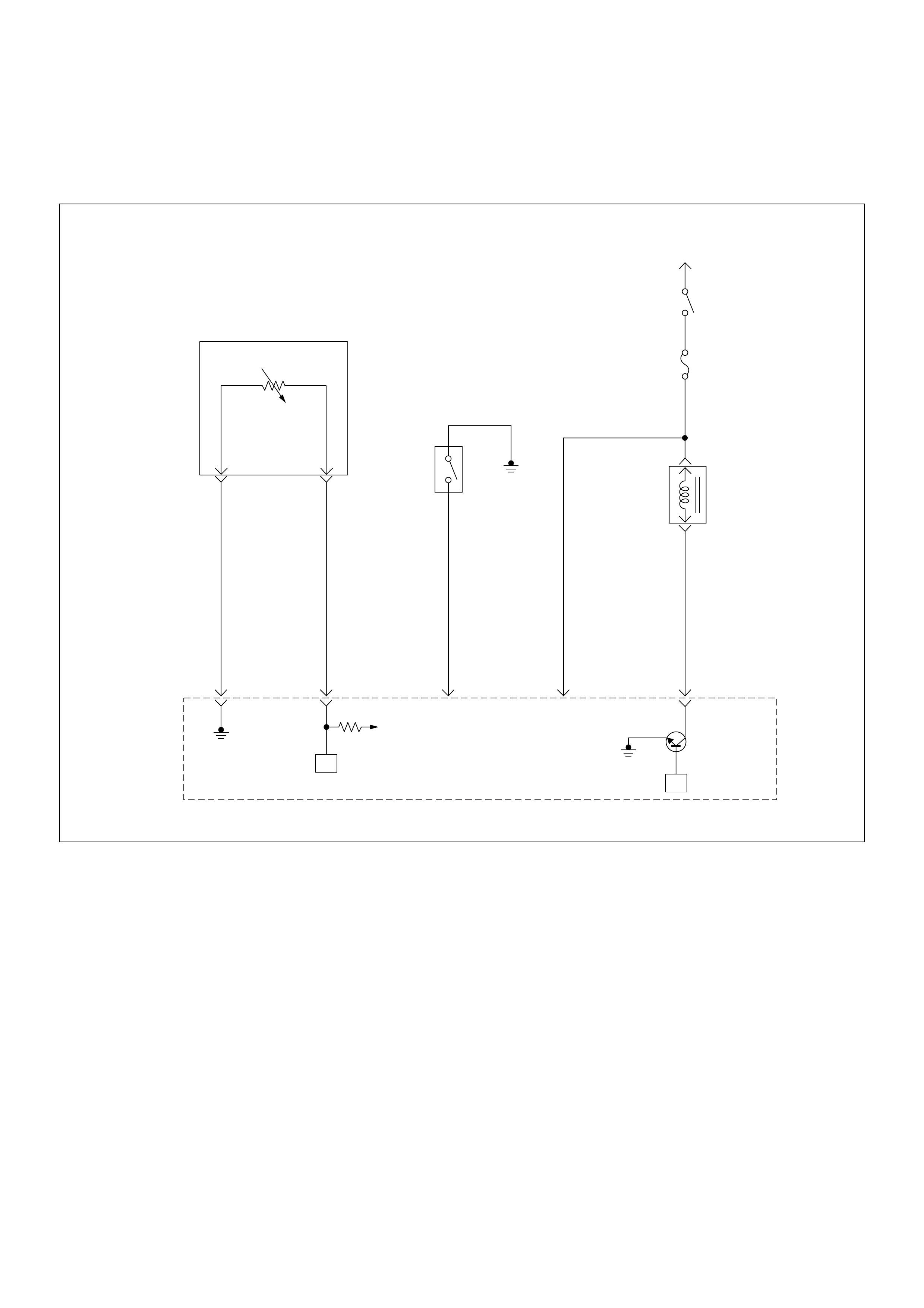
Diagnostic Trouble Code (DTC) P0113 Intake Air Temperature
Sensor High Input
Intake
Air
Temperature(IAT)
Sensor
0.5
GRN
J2-1
0.5
YEL/
GRN
J2-22
0.5
GRN/
YEL
J2-20
0.5
BLU/
YEL
0.5
BLU/
YEL
Engine
15A
Ignition
SW
Battery V oltage
J2-3
0.5
GRN/
WHT
J1-5
+5V
µPµP
Power
Steering
Pressure
SW
Evaporativ
Emission(EVAP)
Canistor
Purge
Valve
Solenoid
Engine
Control
Module
(ECM)

Condition for setting the DTC and action ta ken when the DTC sets
Circuit Description
The intake air temperature (IAT) sensor is a thermistor
which mea sures the t emperature of th e air entering th e
engine. The engine control module (ECM) applies 5
volts through a pull -up resisto r to the IAT s ensor. W hen
the intake air is cold, the sensor resistance is high and
the ECM will monitor a high signal voltage on the IAT
signal circuit. If the intake air is warm, the sensor
resistanc e is lo wer causing the EC M to moni tor a lo wer
voltage. Diagnostic Trouble Code P0113 will set when
the ECM detects an excessively high signal voltage on
the intake air temperature sensor signal circuit.
Diagnostic Aids
Check for the following conditions:
• Poor connection at ECM - Inspect harness
connectors for backed-out terminals, improper
mating, broken locks, improperly formed or damaged
terminals, and poor terminal-to-wire connection.
• Damaged harness - Inspect the wiring harness for
damage, short to ground, short to battery positive,
and open circuit. If the harness appears to be OK,
observe the IAT display on the Tech 2 while moving
connectors and wiring harnesses related to the IAT
sensor. A change in the IAT display will indicate the
location of the fault.
Diagnostic Trouble Code (DTC) P0113 Intake Air Temperature Sensor High Input
Code Type DTC Name DTC Setting Condition Fail-Safe (Back Up)
P0113 A Intake Air Temperature Sensor High
Input 1. No DTC relating to VSS & ECT sensor .
2. Vehicle speed is below 70km/h.
3. 3Engine coolant temperature is more than -
8°C.
4. Engine run time is longer than 120 sec-
onds.
5. Mass air flow is below 30g/s.
6. IAT sensor output is below -38°C.
The ECM uses 20°C condition as substi-
tute.
Step Action Value(s) Yes No
1 Was the “On-Board Di agnostic (OBD) System Check”
performed?
—Go to Step 2
Go to On
Board
Diagnostic
(OBD) System
Check
2 1. Connect the Tech 2.
2. Review and record the failure information.
3. Select “F0: Read DTC Infor By Priority” in “F0:
Diagnostic Trouble Code”.
Is the DTC P0113 stored as “Present Failure”? — Go to Step 3
Refer to
Diagnostic Aids
and Go to Step
3
3 1. Using the Tech2, ignition “On” and engine “Off”.
2. Select “Cl ear D TC I nform ati on” w ith th e Tech2 and
clear the DTC information.
3. Operate the vehicle and monitor the “F5: Failed
This Ignition” in “F2: DTC Information”.
Was the DTC P0113 stored in this ignition cycle? — Go to Step 4
Refer to
Diagnostic Aids
and Go to Step
4
4 Check for poor/faulty connection at the IAT sensor or
ECM connector. If a poor/faulty connection is found,
repair as necessary.
Was the problem found?
— Verify repair Go to Step 5
C56(J2) C121
1
22
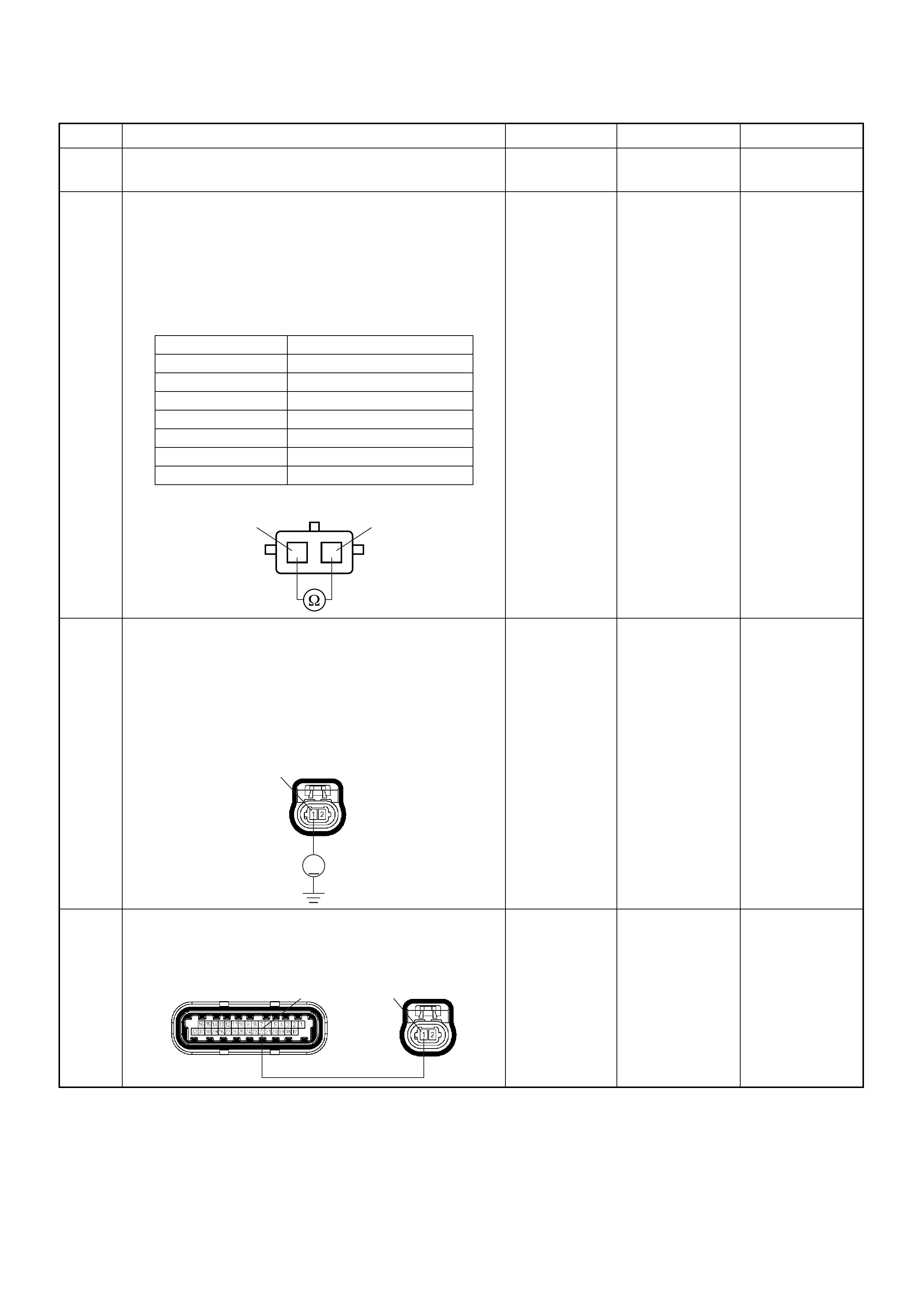
5 Visually check the IAT sensor.
Was the problem found? — Go to Step 12 Go to Step 6
6 Using the DVM and check the IAT sensor.
1. Ignition “Off”, engine “Off”.
2. Disconnect IAT sensor connector.
3. Measure the resistance of IAT sensor.
Does the tester indicate standard resistance as shown
in the following table?
Standard
resistance Go to Step 7 Go to Step 12
7 Using the DVM and check the IAT sensor signal
circuit.
1. Ignition “On”, engine “Off”.
2. Disconnect the IAT sensor connector.
3. Check the ci rcui t for open circuit.
Was the DVM indicated specified value?
Approximately
5.0V Go to Step 10
Less than 1V:
Go to Step 8
More than
specified value:
Go to Step 9
8 Repair the open circuit between the ECM and IAT
sensor.
Was the problem solved?
— Verify repair Go to Step 14
Step Action Value(s) Yes No
Temperature (°C) Resistance (Ω) (Approximately)
-20 32040
0 9788
20 3516
40 1439
60 656
80 327
100 175
IAT Sensor 1
1
2
2
V
C121
1
C56(J2) C121
1
22

9 Repair the short to voltage circuit between the ECM
and IAT sensor.
Was the problem solved?
— Verify repair Go to Step 14
10 Using the DVM and check the IAT sensor ground
circuit.
1. Ignition “On”, engine “Off”.
2. Disconnect the IAT sensor connector.
3. Check the circuit for short to power supply circuit.
Was the DVM indicated specified value?
Less than 1V Go to Step 11
Repair faulty
harness and
verify repair
11 Using the DVM and check the IAT sensor ground
circuit.
Breaker box is available:
1. Ignition “Off”, engine “Off”.
2. Install the breaker box as type A. (ECM
disconnected) Ref. 6E-80.
3. Disconnect the IAT sensor connector.
4. Check the ci rcui t for open circuit.
Was the problem found?
Breaker box is not available:
1. Ignition “Off”, engine “Off”.
2. Disconnect the IAT sensor connector.
3. Check the ci rcui t for open circuit.
Was the problem found?
—
Repair faulty
harness and
verify repair Go to Step 14
12 Substitute a known good IAT sensor assembly and
recheck.
Was the problem solved ? — Go to Step 13 Go to Step 14
Step Action Value(s) Yes No
C56(J2) C121
1
22
V
C121 2
33
C121 2
C56(J2) C121 2
1

13 Replace the IAT sensor assembly.
Is the action complete? — Verify repair —
14 Is the ECM programmed with the latest software
release?
If not, download the latest software to the ECM using
the “SPS (Service Programming System)”.
Was the problem solved? — Verify repair Go to Step 15
15 Replace the ECM.
Is the action complete?
IMPORTANT: The replacement ECM must be
programmed. Refer to section of the Service
Programming System (SPS) in this manual.
Following EC M programming, the immobiliser system
(if equipped) must be linked to the ECM. Refer to
section 11 “Immobiliser System-ECM replacement” for
the ECM/Immobiliser linking procedure. — Verify repair —
Step Action Value(s) Yes No
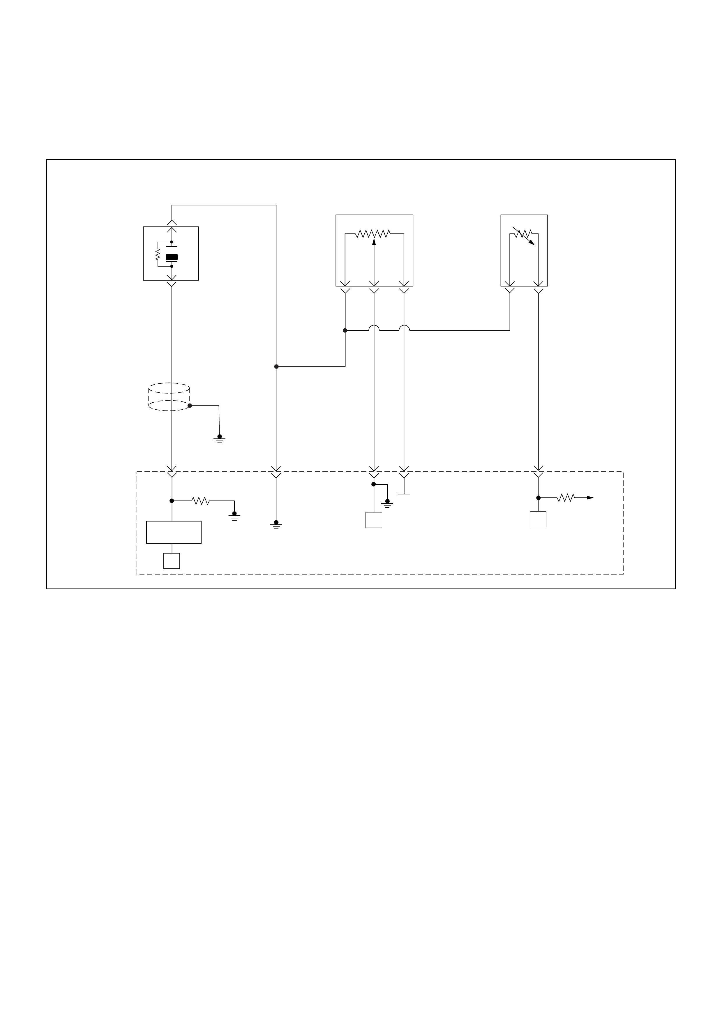
Diagnostic Trouble Code (DTC) P0117 Engine Coolant Temperature
Sensor Low Input
µP
0.5
GRY
J1-27
+5V
µP
µP
5Volts
Reference
Knock
Sensor
0.5
YEL
0.5
WHT/
BLU
J1-7
0.5
BLU/
PNK
J1-32
0.5
BLK/
YEL
J1-15J1-3
Engine
Coolant
Temperature(ECT)
Sensor
Throttle
Position Sensor
Knock Filter
Module
Engine
Control
Module
(ECM)

Condition for setting the DTC and action ta ken when the DTC sets
Circuit Description
The engine coolant temperature (ECT) sensor is a
thermistor mounted in the engine coolant stream. The
engine control module (ECM) applies a voltage (about 5
volts) through a pull-up resistor to the ECT signal circuit.
When the engine coolant is cold, the sensor (thermistor)
resistance is high, therefore the ECM will measure a
high signal voltage. As the engine coolant warms, the
sensor resistance becomes lower, and the ECT signal
voltage measured at the ECM drops. Diagnostic T rouble
code P0117 set when the ECM detects an excessively
low signal voltage on the engine coolant temperature
sensor signal circuit.
Diagnostic Aids
Check for the following conditions:
• Poor connection at ECM - Inspect harness
connectors for backed-out terminals, improper
mating, broken locks, improperly formed or damaged
terminals, and poor terminal-to-wire connection.
• Damaged harness - Inspect the wiring harness for
damage, short to ground, short to battery positive,
and open circuit. If the harness appears to be OK,
obse rve the ECT display on t he Tech 2 w hile mov ing
connectors and wiring harnesses related to the ECT
sensor. A chan ge in th e ECT display will indicate the
location of the fault.
Diagnostic Trouble Code (DTC) P0117 Engine Coolant Temperature Sensor Low Input
Code Type DTC Name DTC Setting Condition Fail-Safe (Back Up)
P0117 A Engine Coolant Temperature Sensor
Low Input 1. Engine run time is longer than 120 sec-
onds.
2. ECT sensor output is more than 149°C.
The ECM uses default engine coolant
temperature value based on intake air
temperature and engine run time.
Step Action Value(s) Yes No
1 Was the “On-Board Di agnostic (OBD) System Check”
performed?
—Go to Step 2
Go to On
Board
Diagnostic
(OBD) System
Check
2 1. Connect the Tech 2.
2. Review and record the failure information.
3. Select “F0: Read DTC Infor By Priority” in “F0:
Diagnostic Trouble Code”.
Is the DTC P0117 stored as “Present Failure”? — Go to Step 3
Refer to
Diagnostic Aids
and Go to Step
3
3 1. Using the Tech2, ignition “On” and engine “Off”.
2. Select “Cl ear D TC I nform ati on” w ith th e Tech2 and
clear the DTC information.
3. Operate the vehicle and monitor the “F5: Failed
This Ignition” in “F2: DTC Information”.
Was the DTC P0117 stored in this ignition cycle? — Go to Step 4
Refer to
Diagnostic Aids
and Go to Step
4
4 Check for po or/faul ty connec tio n at the ECT se nsor or
ECM connector. If a poor/faulty connection is found,
repair as necessary.
Was the problem found?
— Verify repair Go to Step 5
5 Visually check the ECT sensor.
Was the problem found? — Go to Step 8 Go to Step 6
E60(J1) E69
32 27
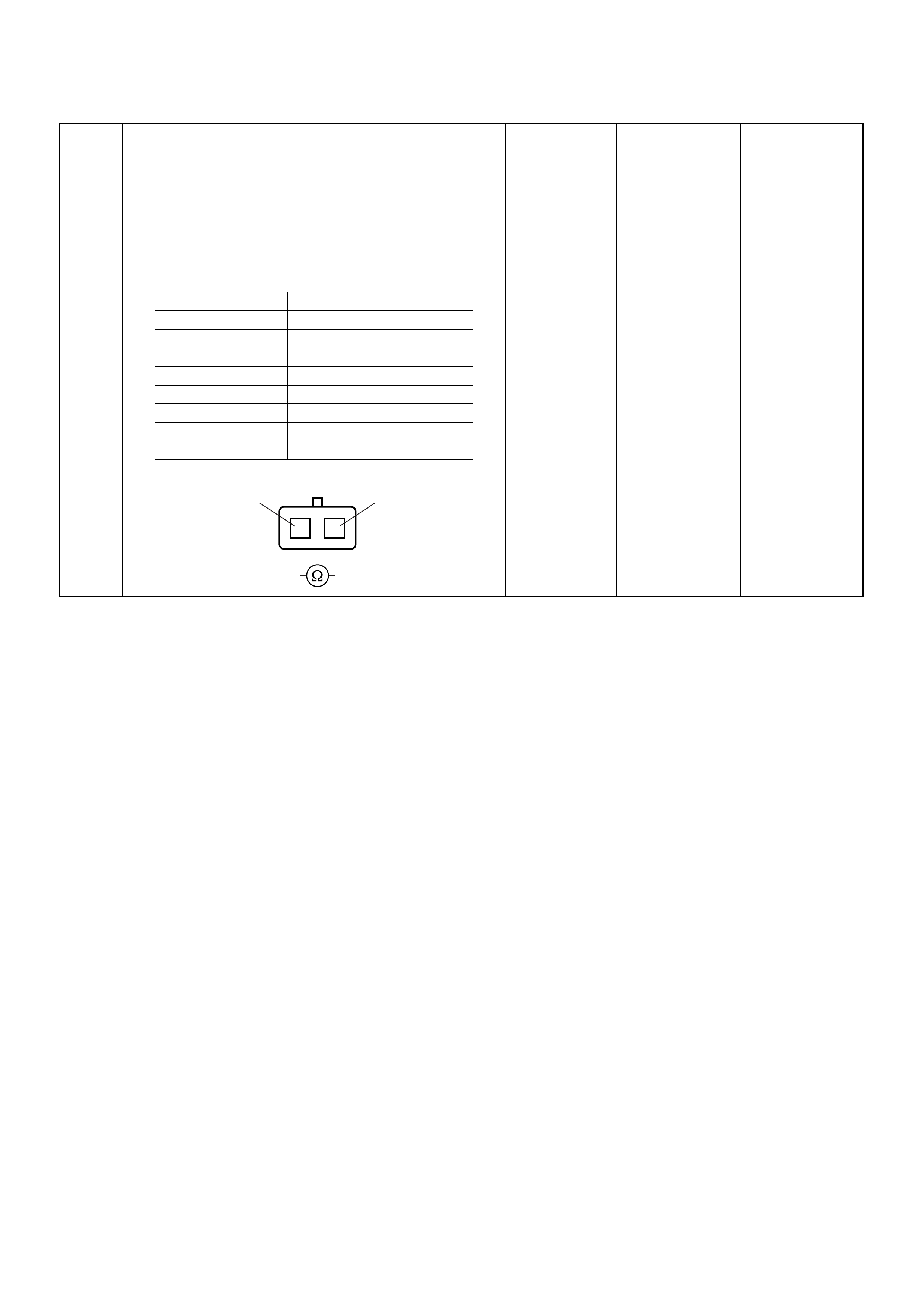
6 Using the DVM and check the ECT sensor.
1. Ignition “Off”, engine “Off”.
2. Disconnect ECT sensor connector.
3. Measure the resistance of ECT sensor.
Does the tester indicate standard resistance as shown
in the following table?
Standard
resistance Go to Step 7 Go to Step 8
Step Action Value(s) Yes No
Temperature (°C) Resistance (Ω) (Approximately)
-20 32040
0 9788
20 3516
40 1439
60 656
80 327
100 175
120 100
ECT Sensor 1
1
2
2
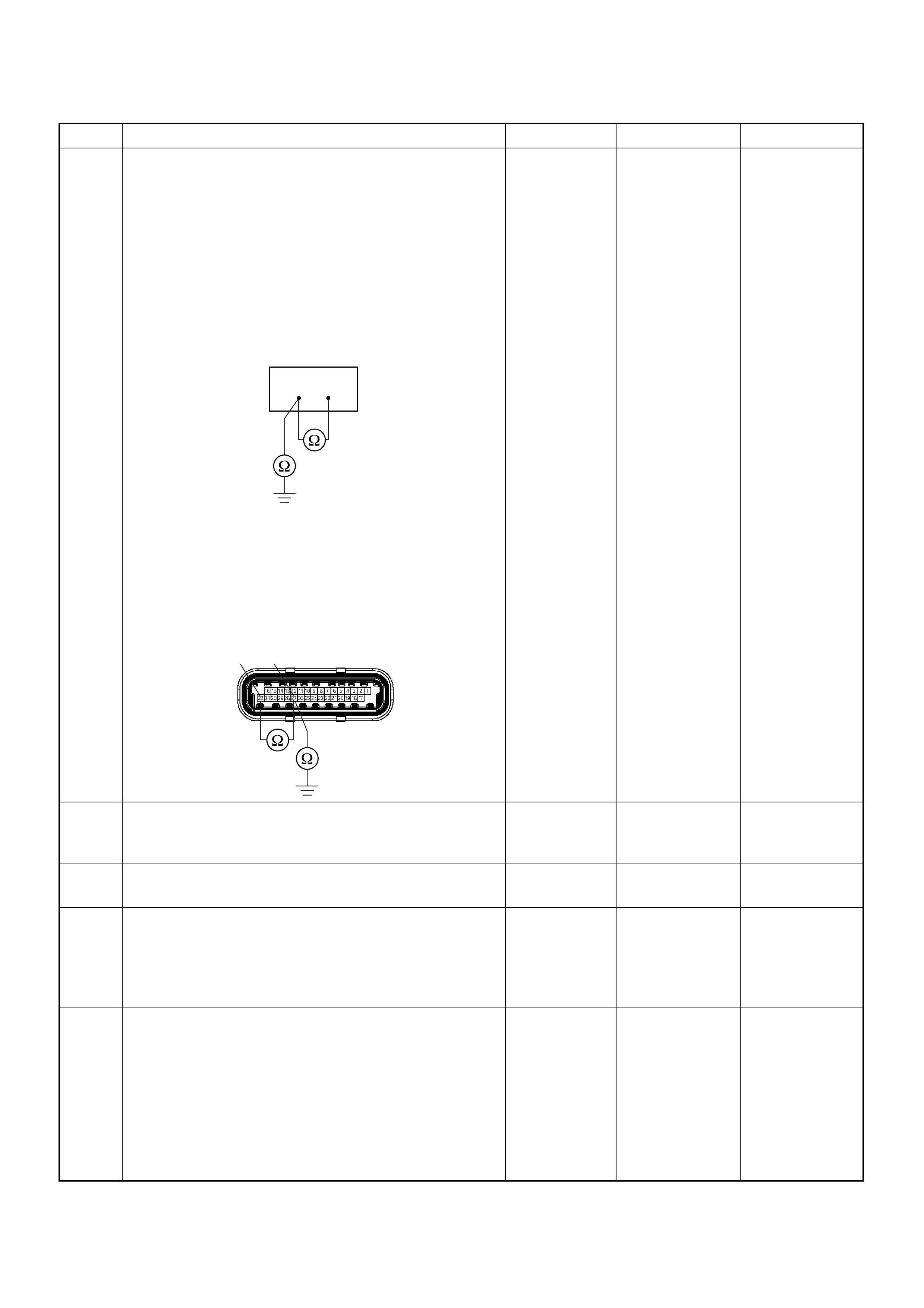
7 Using the DVM and check the ECT sensor signal
circuit.
Breaker box is available:
1. Ignition “Off”, engine “Off”.
2. Install the breaker box as type A. (ECM
disconnected) Ref. 6E-80.
3. Disconnect the ECT sensor connector.
4. Check the circuit for short to sensor ground or
ground circuit.
Was the problem found?
Breaker box is not available:
1. Ignition “Off”, engine “Off”.
2. Disconnect the ECT sensor connector.
3. Check the circuit for short to sensor ground or
ground circuit.
Was the problem found?
—
Repair faulty
harness and
verify repair Go to Step 10
8 Substitute a known good ECT sensor assembly and
recheck.
Was the problem solved? — Go to Step 9 Go to Step 10
9 Replace the ECT sensor.
Is the action complete? — Verify repair —
10 Is the ECM programmed with the latest software
release?
If not, download the latest software to the ECM using
the “SPS (Service Programming System)”.
Was the problem solved? — Verify repair Go to Step 1 1
11 Replace the ECM.
Is the action complete?
IMPORTANT: The replacement ECM must be
programmed. Refer to section of the Service
Programming System (SPS) in this manual.
Following EC M programming, the immobiliser system
(if equipped) must be linked to the ECM. Refer to
section 11 “Immobiliser System-ECM replacement” for
the ECM/Immobiliser linking procedure. — Verify repair —
Step Action Value(s) Yes No
27 32
E60(J1)
27
32
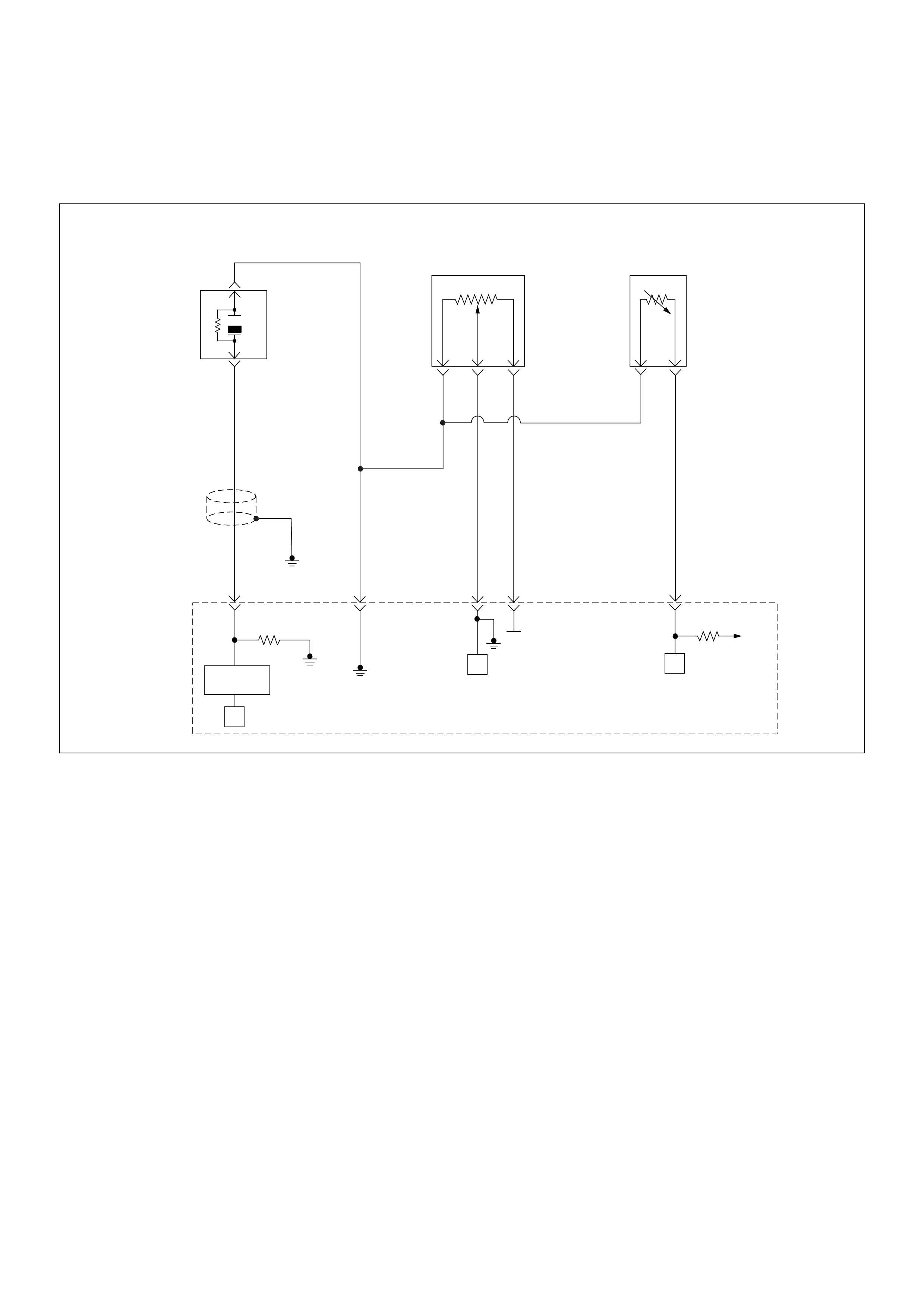
Diagnostic Trouble Code (DTC) P0118 Engine Coolant Temperature
Sensor High Input
µP
0.5
GRY
J1-27
+5V
µP
µP
5Volts
Reference
Knock
Sensor
0.5
YEL
0.5
WHT/
BLU
J1-7
0.5
BLU/
PNK
J1-32
0.5
BLK/
YEL
J1-15J1-3
Engine
Coolant
Temperature(ECT)
Sensor
Throttle
Position Sensor
Knock Filter
Module
Engine
Control
Module
(ECM)

Condition for setting the DTC and action ta ken when the DTC sets
Circuit Description
The engine coolant temperature (ECT) sensor is a
thermistor mounted in the engine coolant stream. The
engine control module (ECM) applies a voltage (about 5
volts) through a pull-up resistor to the ECT signal circuit.
When the engine coolant is cold, the sensor (thermistor)
resistance is high, therefore the ECM will measure a
high signal voltage. As the engine coolant warms, the
sensor resistance becomes less, and the ECT signal
voltage measured at the ECM drops. Diagnostic T rouble
code P0118 set when the ECM detects an excessively
high signal voltage on the engine coolant temperature
sensor signal circuit.
Diagnostic Aids
Check for the following conditions:
• Poor connection at ECM - Inspect harness
connectors for backed-out terminals, improper
mating, broken locks, improperly formed or damaged
terminals, and poor terminal-to-wire connection.
• Damaged harness - Inspect the wiring harness for
damage, short to ground, short to battery positive,
and open circuit. If the harness appears to be OK,
obse rve the ECT display on t he Tech 2 w hile mov ing
connectors and wiring harnesses related to the ECT
sensor. A chan ge in th e ECT display will indicate the
location of the fault.
Diagnostic Trouble Code (DTC) P0118 Engine Coolant Temperature Sensor High Input
Code Type DTC Name DTC Setting Condition Fail-Safe (Back Up)
P0118 A Engine Coolant Temperature Sensor
High Input 1. Engine run time is longer than 120 sec-
onds.
2. ECT sensor output is below -38°C.
The ECM uses default engine coolant
temperature value based on intake air
temperature and engine run time.
Step Action Value(s) Yes No
1 Was the “On-Board Di agnostic (OBD) System Check”
performed?
—Go to Step 2
Go to On
Board
Diagnostic
(OBD) System
Check
2 1. Connect the Tech 2.
2. Review and record the failure information.
3. Select “F0: Read DTC Infor By Priority” in “F0:
Diagnostic Trouble Code”.
Is the DTC P0118 stored as “Present Failure”? — Go to Step 3
Refer to
Diagnostic Aids
and Go to Step
3
3 1. Using the Tech2, ignition “On” and engine “Off”.
2. Select “Cl ear D TC I nform ati on” w ith th e Tech2 and
clear the DTC information.
3. Operate the vehicle and monitor the “F5: Failed
This Ignition” in “F2: DTC Information”.
Was the DTC P0118 stored in this ignition cycle? — Go to Step 4
Refer to
Diagnostic Aids
and Go to Step
4
4 Check for po or/faul ty connec tio n at the ECT se nsor or
ECM connector. If a poor/faulty connection is found,
repair as necessary.
Was the problem found?
— Verify repair Go to Step 5
5 Visually check the ECT sensor.
Was the problem found? — Go to Step 12 Go to Step 6
E60(J1) E69
32 27
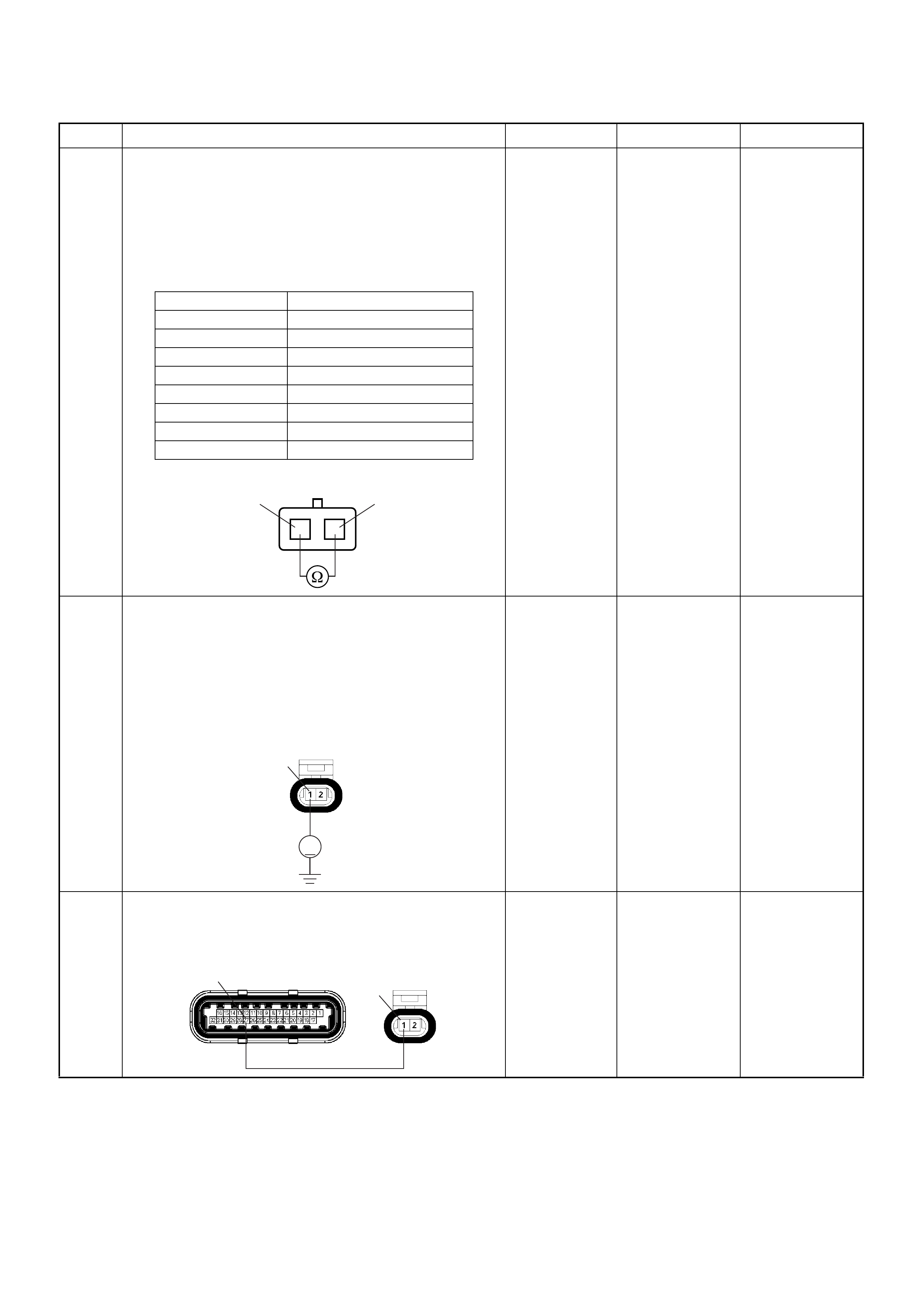
6 Using the DVM and check the ECT sensor.
1. Ignition “Off”, engine “Off”.
2. Disconnect ECT sensor connector.
3. Measure the resistance of ECT sensor.
Does the tester indicate standard resistance as shown
in the following table?
Standard
resistance Go to Step 7 Go to Step 12
7 Using the DVM and check the ECT sensor signal
circuit.
1. Ignition “On”, engine “Off”.
2. Disconnect the ECT sensor connector.
3. Check the ci rcui t for open circuit.
Was the DVM indicated specified value?
Approximately
5.0V Go to Step 10
Less than 1V:
Go to Step 8
More than
specified value:
Go to Step 9
8 Repair the open circuit between the ECM and ECT
sensor.
Was the problem solved?
— Verify repair Go to Step 14
Step Action Value(s) Yes No
Temperature (°C) Resistance (Ω) (Approximately)
-20 32040
0 9788
20 3516
40 1439
60 656
80 327
100 175
120 100
ECT Sensor 1
1
2
2
V
E69
1
E60(J1) E69
27 1
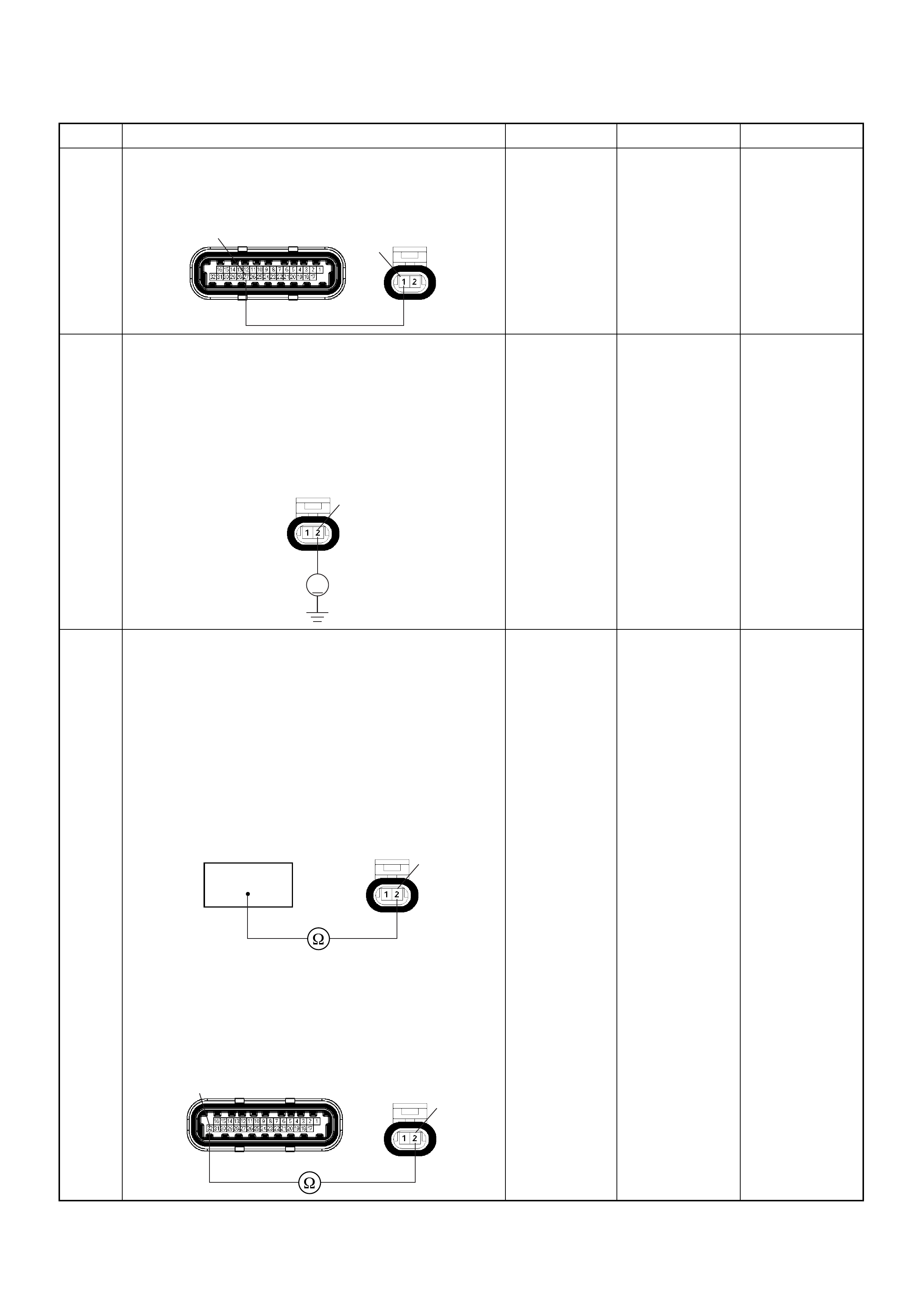
9 Repair the short to voltage circuit between the ECM
and ECT sensor.
Was the problem solved?
— Verify repair Go to Step 14
10 Using the DVM and check the ECT sensor ground
circuit.
1. Ignition “On”, engine “Off”.
2. Disconnect the ECT sensor connector.
3. Check the circuit for short to power supply circuit.
Was the DVM indicated specified value?
Less than 1V Go to Step 11
Repair faulty
harness and
verify repair
11 Using the DVM and check the ECT sensor ground
circuit.
Breaker box is available:
1. Ignition “Off”, engine “Off”.
2. Install the breaker box as type A. (ECM
disconnected) Ref. 6E-80.
3. Disconnect the ECT sensor connector.
4. Check the ci rcui t for open circuit.
Was the problem found?
Breaker box is not available:
1. Ignition “Off”, engine “Off”.
2. Disconnect the ECT sensor connector.
3. Check the ci rcui t for open circuit.
Was the problem found?
—
Repair faulty
harness and
verify repair Go to Step 14
Step Action Value(s) Yes No
E60(J1) E69
27 1
V
E69 2
32
E69 2
2
32 E60(J1) E69

12 Substitute a known good ECT sensor assembly and
recheck.
Was the problem solved ? — Go to Step 13 Go to Step 14
13 Replace the ECT sensor.
Is the action complete? — Verify repair —
14 Is the ECM programmed with the latest software
release?
If not, download the latest software to the ECM using
the “SPS (Service Programming System)”.
Was the problem solved? — Verify repair Go to Step 15
15 Replace the ECM.
Is the action complete?
IMPORTANT: The replacement ECM must be
programmed. Refer to section of the Service
Programming System (SPS) in this manual.
Following EC M programming, the immobiliser system
(if equipped) must be linked to the ECM. Refer to
section 11 “Immobiliser System-ECM replacement” for
the ECM/Immobiliser linking procedure. — Verify repair —
Step Action Value(s) Yes No
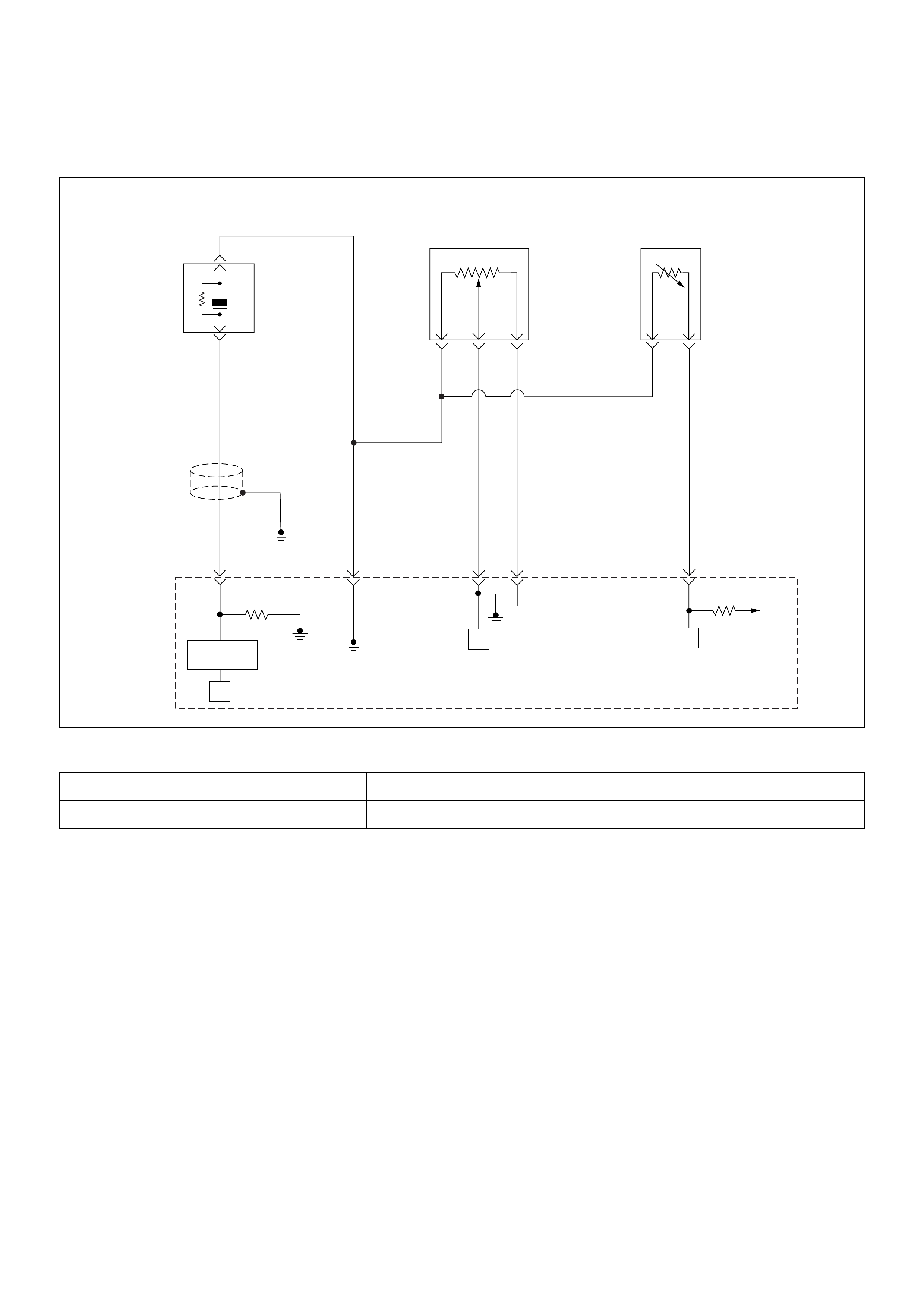
Diagnostic Trouble Code (DTC) P0122 Throttle Position Sensor Low Input
Condition for setting the DTC and action ta ken when the DTC sets
Circuit Description
The throttle position sensor circuit provides a signal
voltage that changes relative to throttle blade angle. The
signal voltage will vary from below 1 volt at closed
throttle to about 4 volts at wide open throttle (WOT).
The TPS signal is used by the engine control module
(ECM) for fuel control and most of the ECM-controlled
outputs. If the ECM de tect a co ntinuo us short to gr ound
in the TPS or circuit, then a code P0122 will set.
Diagnostic Aids
• Poor connection at ECM - Inspect harness
connectors for backed-out terminals, improper
mating, broken locks, improperly formed or damaged
terminals, and poor terminal-to-wire connection.
• Damaged harness - Inspect the wiring harness for
damage, short to ground, short to battery positive,
and open circuit. If the harness appears to be OK,
observe the throttle position display on the Tech 2
while moving connectors and wiring harnesses
related to the TPS. A change in the display will
indicate the location of the fault.
Code Type DTC Name DTC Setting Condition Fail-Safe (Back Up)
P0122 A Throttle Position Sensor Low Input TPS output voltage is below 0.14V. The ECM uses 0% condition as substitute.
µP
0.5
GRY
J1-27
+5V
µP
µP
5Volts
Reference
Knock
Sensor
0.5
YEL
0.5
WHT/
BLU
J1-7
0.5
BLU/
PNK
J1-32
0.5
BLK/
YEL
J1-15J1-3
Engine
Coolant
Temperature(ECT)
Sensor
Throttle
Position Sensor
Knock Filter
Module
Engine
Control
Module
(ECM)

Diagnostic Trouble Code (DTC) P0122 Throttle Position Sensor Low Input
Step Action Value(s) Yes No
1 Was the “On-Board Di agnostic (OBD) System Check”
performed?
—Go to Step 2
Go to On
Board
Diagnostic
(OBD) System
Check
2 1. Connect the Tech 2.
2. Review and record the failure information.
3. Select “F0: Read DTC Infor By Priority” in “F0:
Diagnostic Trouble Code”.
Is the DTC P0122 stored as “Present Failure”? — Go to Step 3
Refer to
Diagnostic Aids
and Go to Step
3
3 1. Using the Tech2, ignition “On” and engine “Off”.
2. Select “Cl ear D TC I nform ati on” w ith th e Tech2 and
clear the DTC information.
3. Operate the vehicle and monitor the “F5: Failed
This Ignition” in “F2: DTC Information”.
Was the DTC P0122 stored in this ignition cycle? — Go to Step 4
Refer to
Diagnostic Aids
and Go to Step
4
4 Check for poor/faulty connection at the TPS or ECM
connector. If a poor/faulty connection is found, repair
as necessary.
Was the problem found?
— Verify repair Go to Step 5
5 Visually check the TPS.
Was the problem found? — Go to Step 10 Go to Step 6
6 Using the DVM and check the TPS.
1. Ignition “Off”, engine “Off”.
2. Disco nne ct TP S co nne cto r.
3. Measur e the resi stanc e of TPS .
Does the tester indicate standard resistance as shown
in the following table?
Standard
resistance Go to Step 7 Go to Step 10
E60(J1) E68
32 15 7
Measurement
Terminal Resistance (Ω)
1 - 2 Approximately 5.6kΩ at idle position &
WOT
2 - 3 Approximately 6.0kΩ at idle position
Approximately 1.7kΩ at WOT
1 - 3 Approximately 2.3kΩ at idle position &
WOT
2 1
3
TPS
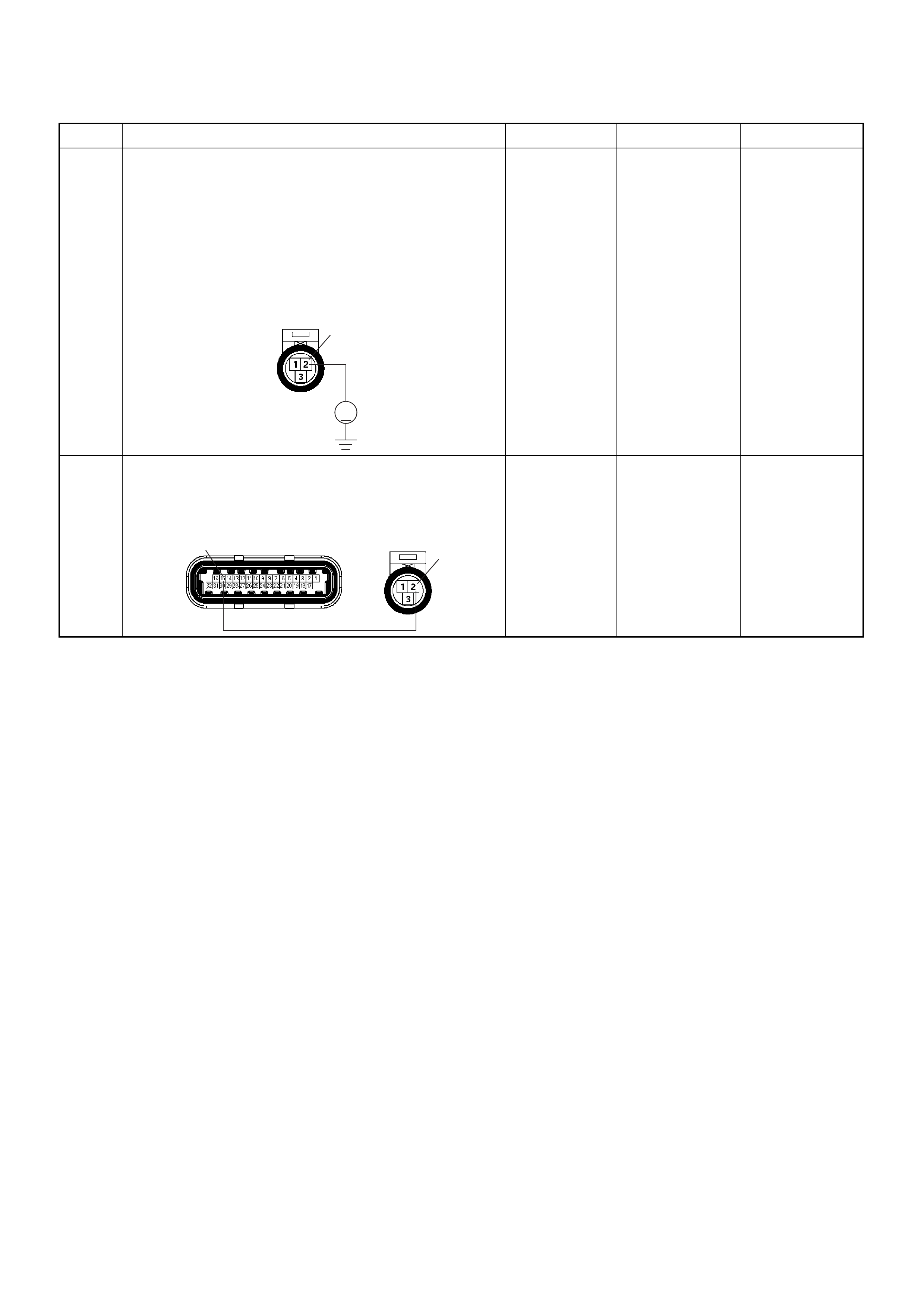
7 Using the DVM and check the TPS power supply
circuit.
1. Ignition “On”, engine “Off”.
2. Disco nne ct the TP S co nne cto r.
3. Check the circuit for open or short to ground
circuit.
Was the DVM indicated specified value?
Approximately
5.0V Go to Step 9 Go to Step 8
8 Repair the open or short to ground circuit between the
ECM and TPS.
Was the problem solved?
— Verify repair Go to Step 12
Step Action Value(s) Yes No
V
E68 2
2
E60(J1) E68
15
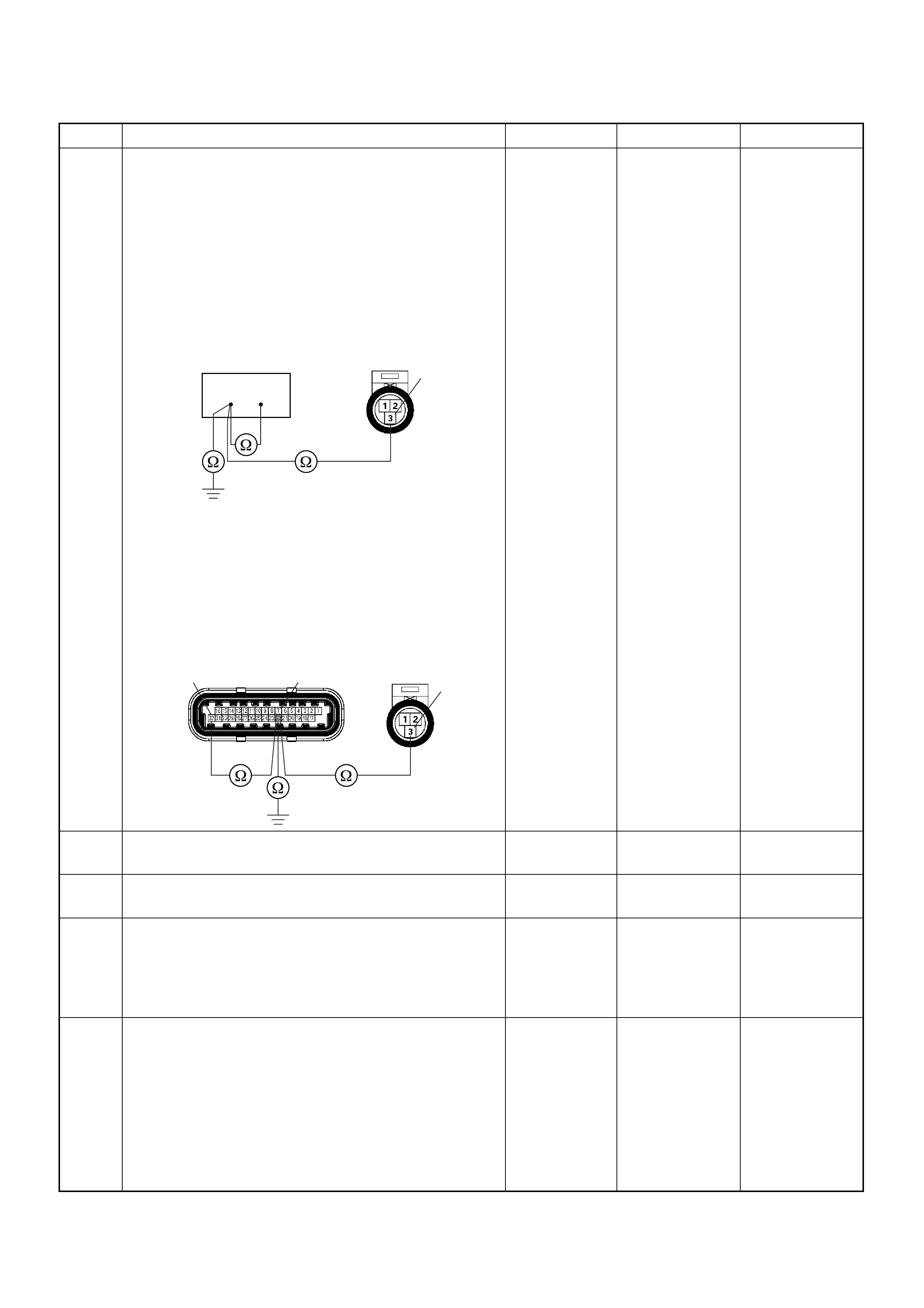
9 Using the DVM and check the TPS signal circuit.
Breaker box is available:
1. Ignition “Off”, engine “Off”.
2. Install the breaker box as type A. (ECM
disconnected) Ref. 6E-80.
3. Disco nne ct TP S co nne cto r.
4. Check the circuit for open, sho rt to sensor gr ound
or shor t to ground circ uit.
Was the problem found?
Breaker box is not available:
1. Ignition “Off”, engine “Off”.
2. Disconnect the TPS connector and ECM
connector.
3. Check the circuit for open, sho rt to sensor gr ound
or shor t to ground circ uit.
Was the problem found?
—
Repair faulty
harness and
verify repair Go to Step 12
10 Substitute a known good TPS and recheck.
Was the problem solved? — Go to Step 11 Go to Step 12
11 Replace the TPS.
Is the action complete? — Verify repair -
12 Is the ECM programmed with the latest software
release?
If not, download the latest software to the ECM using
the “SPS (Service Programming System)”.
Was the problem solved? — Verify repair Go to Step 12
13 Replace the ECM.
Is the action complete?
IMPORTANT: The replacement ECM must be
programmed. Refer to section of the Service
Programming System (SPS) in this manual.
Following EC M programming, the immobiliser system
(if equipped) must be linked to the ECM. Refer to
section 11 “Immobiliser System-ECM replacement” for
the ECM/Immobiliser linking procedure. — Verify repair —
Step Action Value(s) Yes No
732
3
E68
32 7 3
E60(J1) E68
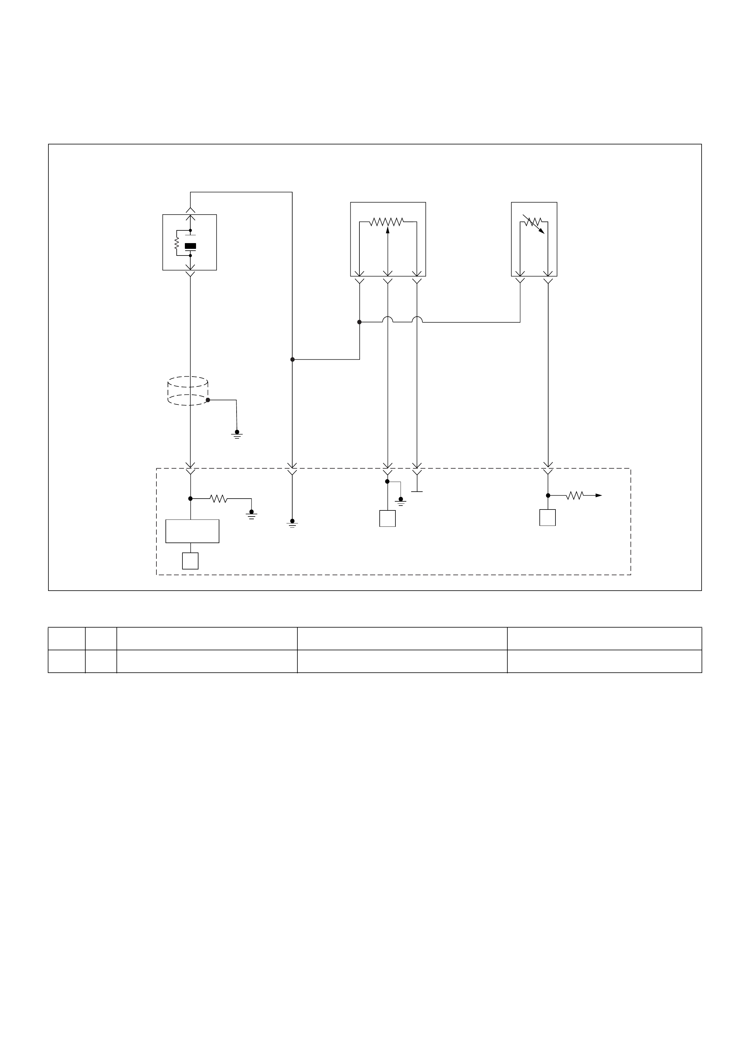
Diagnostic Trouble Code (DTC) P0123 Throttle Position Sensor High Input
Condition for setting the DTC and action ta ken when the DTC sets
Circuit Description
The throttle position sensor circuit provides a voltage
signal t hat changes r elative to thr ottle blade angl e. The
signal voltage will vary from below 1 volt at closed
throttle to about 4 volts at wide open throttle (WOT).
The TPS is used by the engine control module (ECM)
for fuel cont rol an d most of the ECM -co ntrolled outputs.
If the ECM de tect a con tin uou s s hort vo lta ge in the TPS
or circuit, then a code P0123 will set.
Diagnostic Aids
Check for the following conditions:
• Poor connection at ECM - Inspect harness
connectors for backed-out terminals, improper
mating, broken locks, improperly formed or damaged
terminals, and poor terminal-to-wire connection.
• If these codes are also set, it could indicate a
problem with the 5 Volt reference circuit or
components itself.
• Damaged harness - Inspect the wiring harness for
damage, short to ground, short to battery positive and
open circuit. If the harness appears to be OK,
observe the Throttle Position sensor display on the
Tech 2 while moving connectors and wiring
harnesses related to the TP sensor. A change in the
display will indicate the location of the fault.
Code Type DTC Name DTC Setting Condition Fail-Safe (Back Up)
P0123 A Throttle Position Sensor High Input TPS output voltage is more than 4.9V. The ECM uses 0% condition as substitute.
µP
0.5
GRY
J1-27
+5V
µP
µP
5Volts
Reference
Knock
Sensor
0.5
YEL
0.5
WHT/
BLU
J1-7
0.5
BLU/
PNK
J1-32
0.5
BLK/
YEL
J1-15J1-3
Engine
Coolant
Temperature(ECT)
Sensor
Throttle
Position Sensor
Knock Filter
Module
Engine
Control
Module
(ECM)
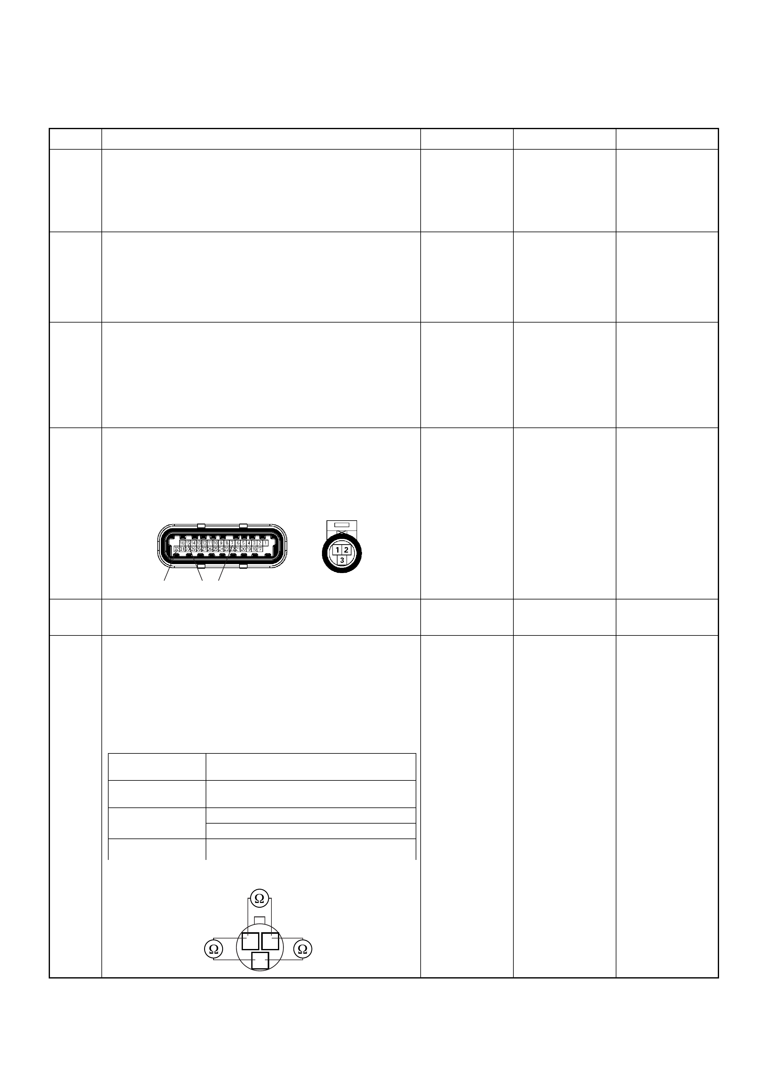
Diagnostic Trouble Code (DTC) P0123 Throttle Position Sensor High Input
Step Action Value(s) Yes No
1 Was the “On-Board Di agnostic (OBD) System Check”
performed?
—Go to Step 2
Go to On
Board
Diagnostic
(OBD) System
Check
2 1. Connect the Tech 2.
2. Review and record the failure information.
3. Select “F0: Read DTC Infor By Priority” in “F0:
Diagnostic Trouble Code”.
Is the DTC P0123 stored as “Present Failure”? — Go to Step 3
Refer to
Diagnostic Aids
and Go to Step
3
3 1. Using the Tech2, ignition “On” and engine “Off”.
2. Select “Cl ear D TC I nform ati on” w ith th e Tech2 and
clear the DTC information.
3. Operate the vehicle and monitor the “F5: Failed
This Ignition” in “F2: DTC Information”.
Was the DTC P0123 stored in this ignition cycle? — Go to Step 4
Refer to
Diagnostic Aids
and Go to Step
4
4 Check for poor/faulty connection at the TPS or ECM
connector. If a poor/faulty connection is found, repair
as necessary.
Was the problem found?
— Verify repair Go to Step 5
5 Visually check the TPS.
Was the problem found? — Go to Step 12 Go to Step 6
6 Using the DVM and check the TPS.
1. Ignition “Off”, engine “Off”.
2. Disco nne ct TP S co nne cto r.
3. Measur e the resi stanc e of TPS .
Does the tester indicate standard resistance as shown
in the following table?
Standard
resistance Go to Step 7 Go to Step 12
E60(J1) E68
32 15 7
Measurement
Terminal Resistance (Ω)
1 - 2 Approximately 5.6kΩ at idle position &
WOT
2 - 3 Approximately 6.0kΩ at idle position
Approximately 1.7kΩ at WOT
1 - 3 Approximately 2.3kΩ at idle position &
WOT
2 1
3
TPS
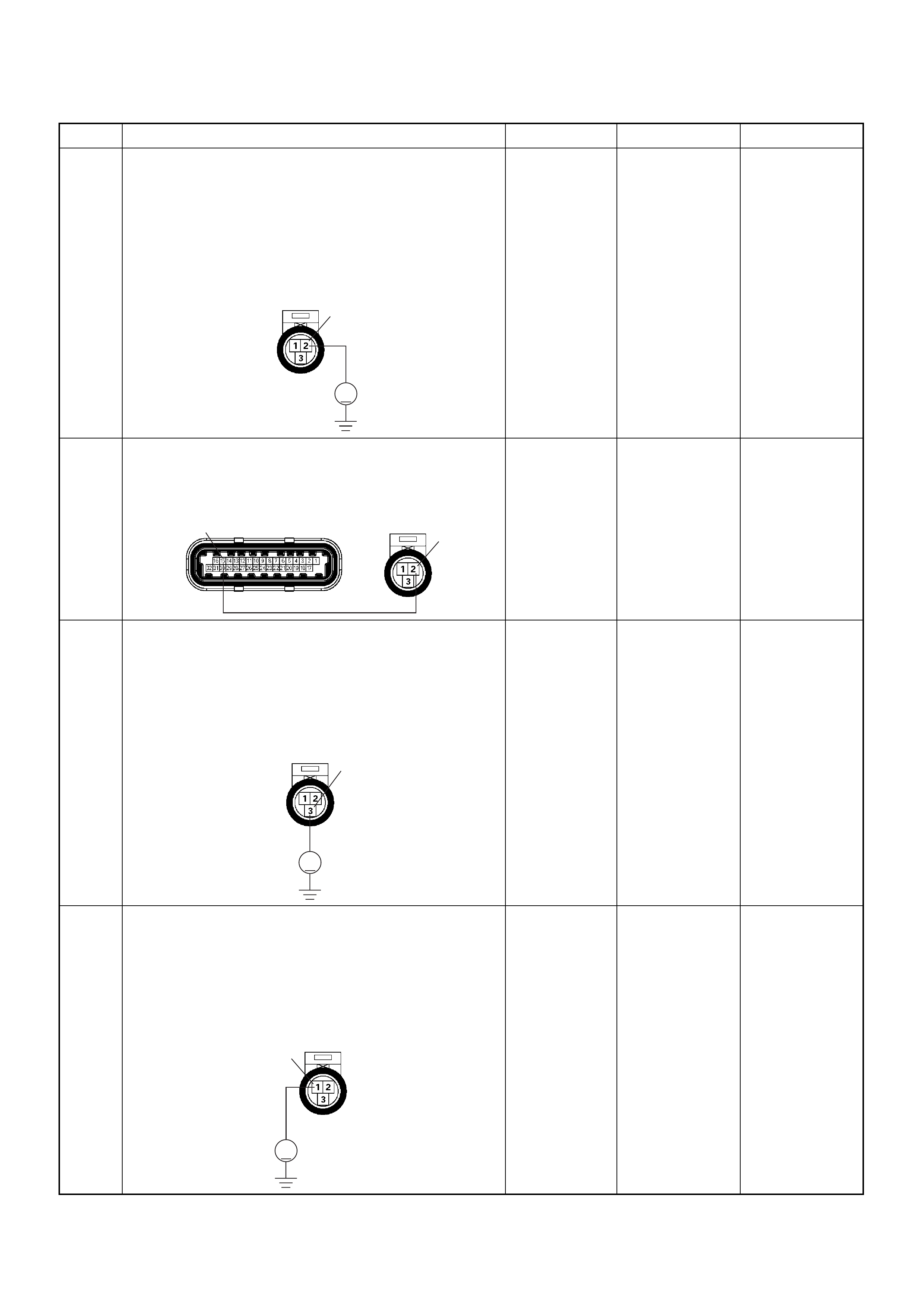
7 Using the DVM and check the TPS power supply
circuit.
1. Ignition “On”, engine “Off”.
2. Disco nne ct the TP S co nne cto r.
3. Check the circuit for short to voltage circuit.
Was the DVM indicated specified value?
Approximately
5.0V Go to Step 9 Go to Step 8
8 Repair the short to voltage circuit between the ECM
and TPS.
Was the problem solved?
— Verify repair Go to Step 14
9 Using the DVM and check the TPS signal circuit.
1. Ignition “On”, engine “Off”.
2. Disco nne ct the TP S co nne cto r.
3. Check the circuit for short to power supply circuit.
Was the DVM indicated specified value?
Less than 1V Go to Step 10
Repair faulty
harness and
verify repair
10 Using the DVM and check the TPS ground circuit.
1. Ignition “On”, engine “Off”.
2. Disco nne ct the TP S co nne cto r .
3. Check the circuit for short to power supply circuit.
Was the DVM indicated specified value?
Less than 1V Go to Step 11
Repair faulty
harness and
verify repair
Step Action Value(s) Yes No
V
E68 2
2
E60(J1) E68
15
3
V
E68
1
V
E68
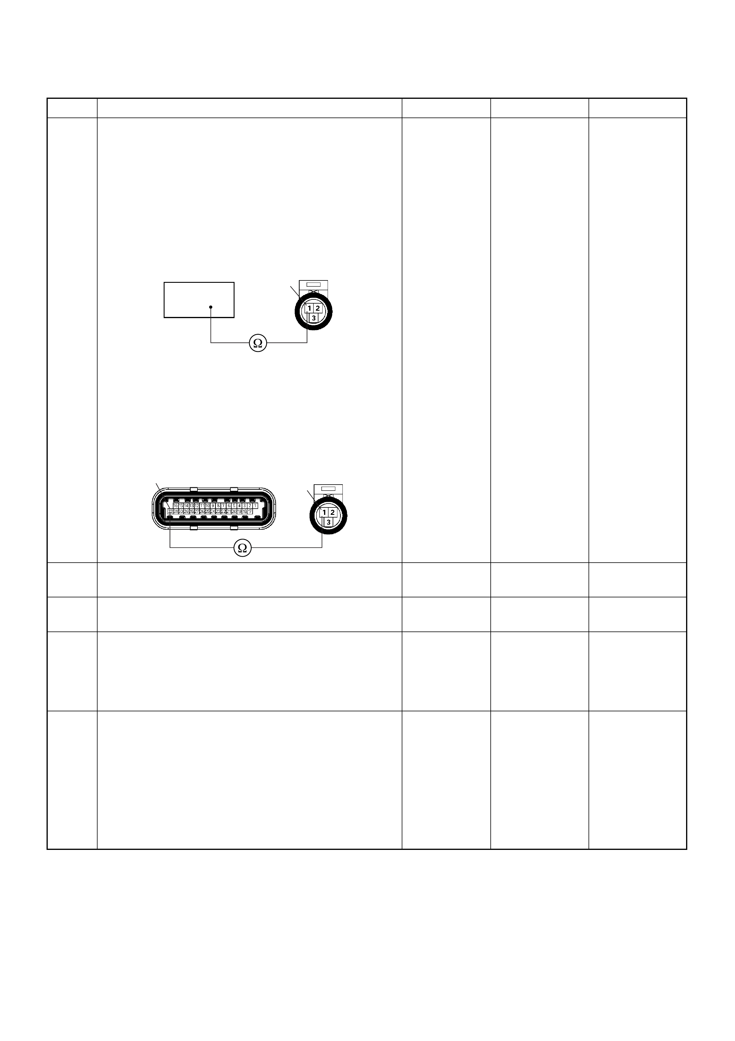
11 Using the DVM and check the TPS ground circuit.
Breaker box is available:
1. Ignition “Off”, engine “Off”.
2. Install the breaker box as type A. (ECM
disconnected) Ref. 6E-80.
3. Disco nne ct the TP S co nne cto r.
4. Check the ci rcui t for open circuit.
Was the problem found?
Breaker box is not available:
1. Ignition “Off”, engine “Off”.
2. Disconnect the TPS connector and ECM
connector.
3. Check the ci rcui t for open circuit.
Was the problem found?
—
Repair faulty
harness and
verify repair Go to Step 14
12 Substitute a known good TPS and recheck.
Was the problem solved ? — Go to Step 13 Go to Step 14
13 Replace the TPS.
Is the action complete? — Verify repair —
14 Is the ECM programmed with the latest software
release?
If not, download the latest software to the ECM using
the “SPS (Service Programming System)”.
Was the problem solved? — Verify repair Go to Step 14
15 Replace the ECM.
Is the action complete?
IMPORTANT: The replacement ECM must be
programmed. Refer to section of the Service
Programming System (SPS) in this manual.
Following EC M programming, the immobiliser system
(if equipped) must be linked to the ECM. Refer to
section 11 “Immobiliser System-ECM replacement” for
the ECM/Immobiliser linking procedure. — Verify repair —
Step Action Value(s) Yes No
32
1E68
32 1
E60(J1) E68

Diagnostic Trouble Code (DTC) P0131 O
2
Sensor Circuit Low Voltage
(Bank 1 Sensor 1)
µP
VIgn
-
+
Crankshaft
Position
Sensor
J1-1 J1-2 J1-17
Battery
Voltage
Battery
Voltage
2.0
WHT ECM
10A
450
mV
A/D Converter
Vcc
+5V -+
TIMING
COVER
J2-6 J2-21
Fuel
Pump
FUEL
PUMP
20A
2.0
BLK
2.0
BLK/
BLU
Fuel
Pump
Relay
O2
SENSOR
10A
Heated
O2
Sensor
0.85
RED/
WHT
0.5
GRN/
WHT
0.5
RED/
WHT
0.5
BLU/
WHT
0.5
BLU
0.5 PNK
J2-31 J2-11 J2-2 J2-18
M
Engine
Control
Module
(ECM)

Condition for setting the DTC and action taken when the DTC sets
Circuit Description
The engine control module (ECM) supplies a bias
voltage of about 450 mV between the heated oxygen
sensor (HO2S) signal and low circuits. The oxygen
sensor varies the voltage within a range of about 1000
mV when the exhaust is rich, down through about 10
mV when exhaust is lean. The ECM constantly monitors
the HO2S signal during “Closed Loop” operation and
compensates for a rich or lean condition by decreasing
or increasing injector pulse width as necessary. If the
Bank 1 HO2S 1 voltage remains excessively low for an
extended period of time, Diagnostic Trouble Code
P0131 will be set.
Diagnostic Aids
Check for the following conditions:
• Heated oxygen sensor wiring - The sensor pigtail
may be routed incorrectly and/or contacting the
exhaust system. Also, check for shorts to ground,
shorts to battery positive and open circuits.
• Poor ECM to engine block grounds.
• Fuel pressure - The system will go lean if pressure is
too low. The ECM can compensate for some
decrease. However, if fuel pressure is too low, a
Diagnostic Trouble Code P0131 may be set. Refer to
Fuel System Diagnosis.
• Lean injector(s) - Perform “Injector Balance Test.”
• Vacuum leaks - Check for disconnected or damaged
vacuum hoses and for vacuum leaks at the intake
manifold, throttle body, EGR system, and PCV
system.
• Exhaust leaks - An exhaust leak may cause outside
air to be pulled into the exhaust gas stream past the
HO2S, causing the system to appear lean. Check for
exhaust leaks that may cause a false lean condition
to be indicated.
• Fuel contamination - Water, even in small amounts,
can be delivered to the fuel injectors. The water can
cause a lean exhaust to be indicated. Excessive
alcohol in the fuel can also cause this condition. For
the procedure to check for fuel contamination, Refer
to Fuel System Diagnosis.
Diagnostic Trouble Code (DTC) P0131 O
2
Sensor Circuit Low Voltage (Bank 1 Sensor 1)
Code Type DTC Name DTC Setting Condition Fail-Safe (Back Up)
P0131 A O
2
SensorCircuit Low Voltage (Bank 1
Sensor 1) 1. No DTC relating to MAP sensor, TPS,
EVAP purge, ECT sensor, CKP sensor,
VSS, injector control circuit and ignition
control circuit.
2. Engine coolant temperature is more than
60°C.
3. O
2
sensor bank 1 output voltage is below
50mV in “Closed Loop” condition.
“Open Loop” fuel control.
Step Action Value(s) Yes No
1 Was the “On-Board Diagnostic (OBD) System Check”
performed?
—Go to Step 2
Go to On
Board
Diagnostic
(OBD) System
Check
2 1. Connect the Tech 2.
2. Review and record the failure information.
3. Select “F0: Read DTC Infor By Priority” in “F0:
Diagnostic Trouble Code”.
Is the DTC P0131 stored as “Present Failure”? — Go to Step 3
Refer to
Diagnostic Aids
and Go to Step
3
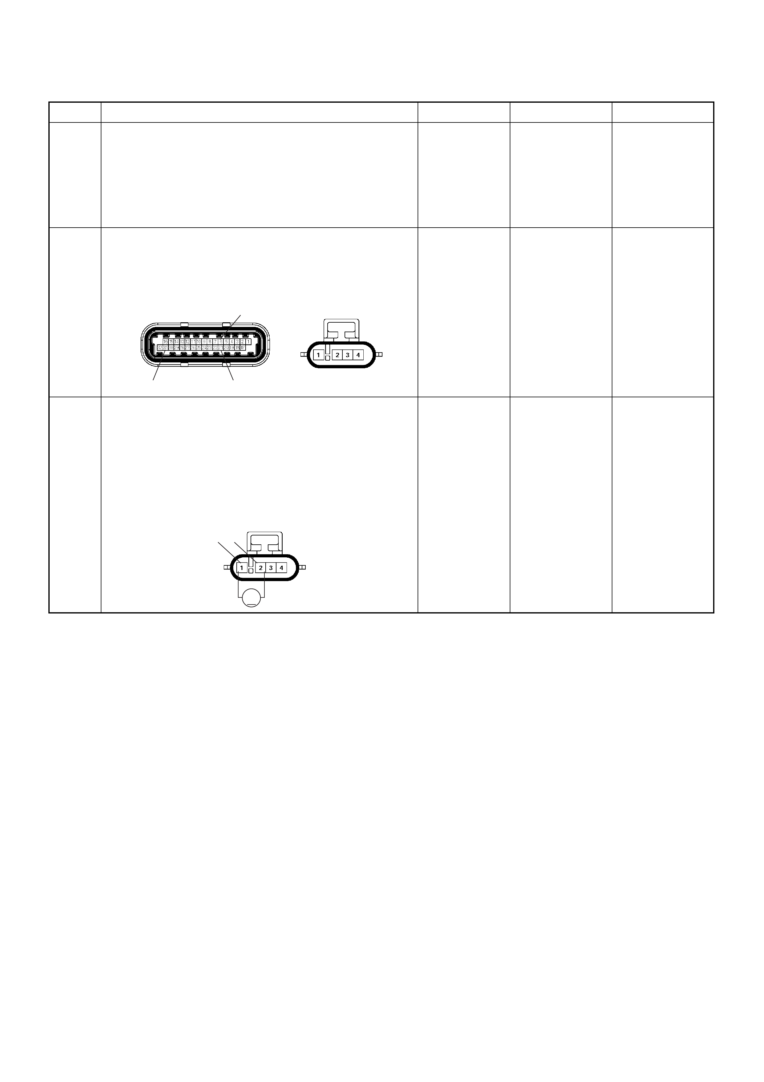
3 1. Using the Tech2, ignition “On” and engine “Off”.
2. Select “Cl ear D TC I nform ati on” w ith th e Tech2 and
clear the DTC information.
3. Operate the vehicle and monitor the “F5: Failed
This Ignition” in “F2: DTC Information”.
Was the DTC P0131 stored in this ignition cycle? — Go to Step 4
Refer to
Diagnostic Aids
and Go to Step
4
4 Check for poor/faulty connection at the O
2
sensor or
ECM connector. If a poor/faulty connection is found,
repair as necessary.
Was the problem found?
— Verify repair Go to Step 5
5 Using the DVM and check the O
2
sensor circu it.
1. Ignition “On”, engine “Off”.
2. Disco nne ct the O
2
sensor connector.
3. Check the circuit for short to heater ground or
ground circuit.
Was the DVM indicated specified value?
Approximatly
450mV Go to Step 7 Go to Step 6
Step Action Value(s) Yes No
C56(J2) E77
31 21
6
V
21 E77
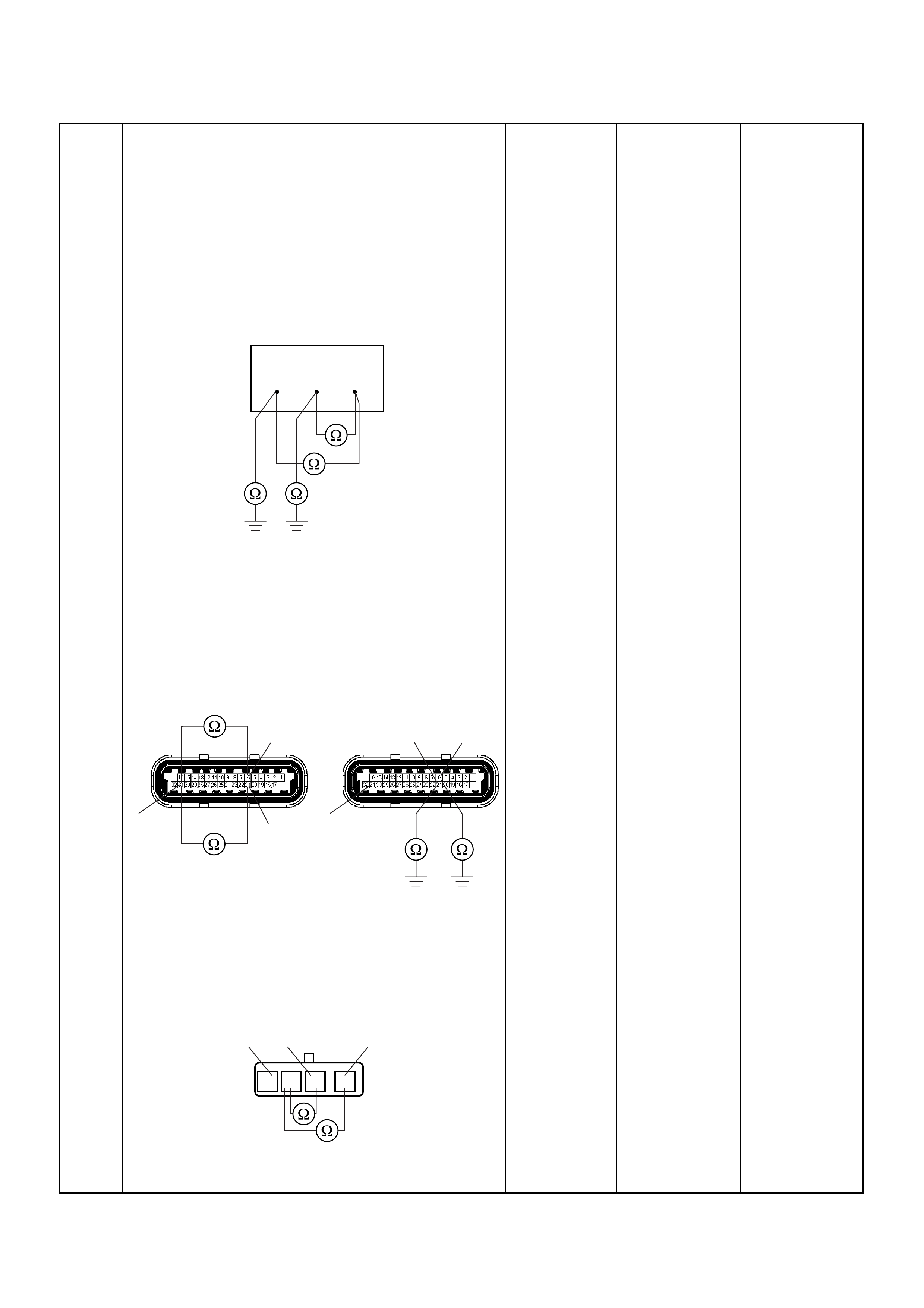
6 Using the DVM and check the O
2
sensor circu it.
Breaker box is available:
1. Ignition “Off”, engine “Off”.
2. Install the breaker box as type A. (ECM
disconnected) Ref. 6E-80.
3. Disco nne ct the O
2
sens or.
4. Check the circuit for short to heater ground or
short to ground circuit.
Was the problem found?
Breaker box is not available:
1. Ignition “Off”, engine “Off”.
2. Disconnect the O
2
sensor connector and ECM
connector.
3. Check the circuit for short to heater ground or
short to ground circuit.
Was the problem found?
—
Repair faulty
harness and
verify repair Go to Step 15
7 Using the DVM and check the O
2
sensor circu it.
1. Ignition “Off”, engine “Off”.
2. Disconnect the the O
2
sensor connector.
3. Check the circuit for short to heater ground circuit.
Was the DVM indicated specified value?
No continuity Go to Step 9 Go to Step 8
8 Repair the short to heater ground circuit.
Was the problem found? — Verify repair Go to Step 15
Step Action Value(s) Yes No
38 53 63
31 21
6
C56(J2)
31
21 6
C56(J2)
124
1234
O2 Sensor

9 1. Using the Tech 2, ignition “On” and engine “On”.
2. Monitor the “Manifold Absolute Pressure” in the
data display.
Does the Tech 2 indicate correct “Manifold Absolute
Pressure” in accordance with engine speed or
acceleration? — Go to Step 11 Go to Step 10
10 Remove the MAP sensor and check for the following
conditions.
• Objects blocking the air cleaner.
• Objects blocking the MAP sensor.
• Objects blocking the throttle valve.
• Vacuum leaking at intake duct.
• Vacuum leaking at throttle body.
If a problem is found, repair as neces sa ry.
Was the problem found? — Verify repair Go to Step 11
11 1. Using the Tech 2, ignition “On” and engine “On”.
2. Select the “Miscellaneous Test” and perform the
“IAC Control” in the “IAC System”.
3. Operate the Tech 2 in accordance with procedure.
Was the engine speed changed, when the IAC valve
is operating step by step? — Go to Step 13 Go to Step 12
12 Check for the following conditions.
• Objects blocking the IAC valve.
• Objects blocking the throttle valve.
• Vacuum leaking at throttle body.
If a problem is found, repair as neces sa ry.
Was the problem found? — Verify repair Go to Step 13
13 Check for injector for the affected bank.
Refer to “Injector Coil Test & Injector Balance Test
Procedure”.
Was the injector operation correct? —Go to Step 14
Refer to Injector
Coil Test &
Injector
Balance Test
Procedure
14 Check for fuel pressure.
Refer to “Fuel System Diagnosis”.
Was the fuel pressure correct? — Go to Step 15
Refer to Fuel
System
Diagnosis
15 Replace the O
2
sens or.
Was the problem solved? — Verify repair Go to Step 16
16 Is the ECM programmed with the latest software
release?
If not, download the latest software to the ECM using
the “SPS (Service Programming System)”.
Was the problem solved? — Verify repair Go to Step 17
17 Replace the ECM.
Is the action complete?
IMPORTANT: The replacement ECM must be
programmed. Refer to section of the Service
Programming System (SPS) in this manual.
Following EC M programming, the immobiliser system
(if equipped) must be linked to the ECM. Refer to
section 11 “Immobiliser System-ECM replacement” for
the ECM/Immobiliser linking procedure. — Verify repair —
Step Action Value(s) Yes No
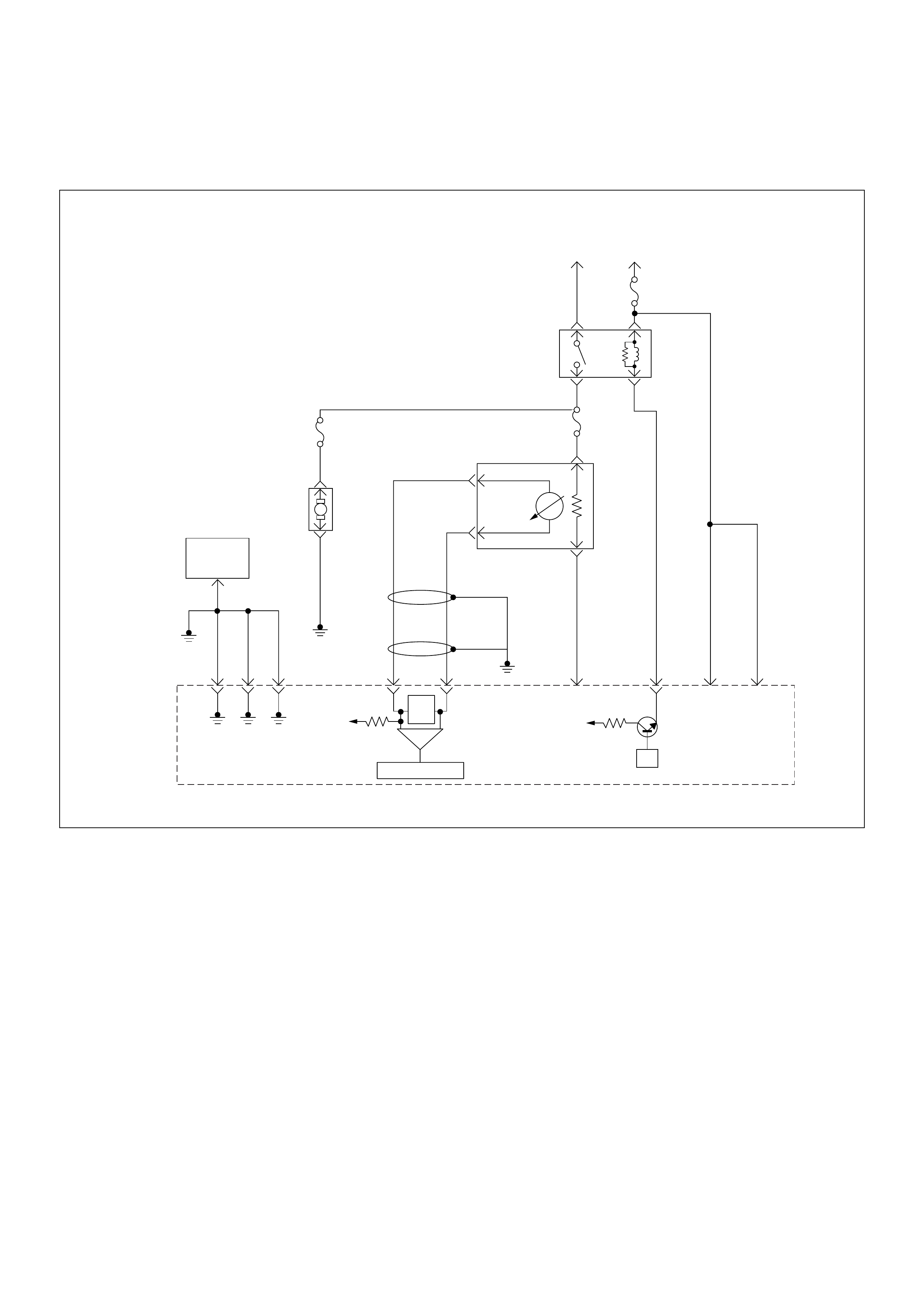
Diagnostic Tro uble Code (DTC) P0132 O
2
Sensor Circuit High
Voltage (Bank 1 Sensor 1)
µP
VIgn
-
+
Crankshaft
Position
Sensor
J1-1 J1-2 J1-17
Battery
Voltage
Battery
Voltage
2.0
WHT ECM
10A
450
mV
A/D Converter
Vcc
+5V -+
TIMING
COVER
J2-6 J2-21
Fuel
Pump
FUEL
PUMP
20A
2.0
BLK
2.0
BLK/
BLU
Fuel
Pump
Relay
O2
SENSOR
10A
Heated
O2
Sensor
0.85
RED/
WHT
0.5
GRN/
WHT
0.5
RED/
WHT
0.5
BLU/
WHT
0.5
BLU
0.5 PNK
J2-31 J2-11 J2-2 J2-18
M
Engine
Control
Module
(ECM)

Condition for setting the DTC and action taken when the DTC sets
Circuit Description
The engine control module (ECM) supplies a bias
voltage of about 450 mV between the heated oxygen
sensor (HO2S) signal and low circuits. The oxygen
sensor varies the voltage within a range of about 1000
mV when the exhaust is rich, down through about 10
mV when exhaust is lean. The ECM constantly monitors
the HO2S signal during “Closed Loop” operation and
compensates for a rich or lean condition by decreasing
or increasing injector pulse width as necessary. If the
Bank 1 HO2S 1 voltage remains excessively high for an
extended period of time, Diagnostic Trouble Code
P0132 will be set.
Diagnostic Aids
Check the following items:
• Fuel pressure - The system will go rich if pressure is
too high. The ECM can compensate for some
increase. However, if fuel pressure is too high, a
Diagnostic Trouble Code P0132 may be set. Refer to
Fuel System Diagnosis.
• Perform “Injector Balance Test” - Refer to Fuel
System Diagnosis.
• Check the EVAP canister for fuel saturation - If full of
fuel, check canister control and hoses. Refer to
Evaporative (EVAP) Emission Control System.
• Check for a leak in the fuel pressure regulator
diaphragm by checking the vacuum line to the
regulator for the presence of fuel.
• An intermittent TPS output will cause the system to
go rich due to a false indication of the engine
accelerating.
• Silicon contamination of the HO2S can also cause a
high HO2S voltage to be indicated. This condition is
indicated by a powdery white deposit on the portion
of the HO2S exposed to the exhaust stream. If
contamination is noticed, replace the affected HO2S.
Diagnostic Trouble Code (DTC) P0132 O
2
Sensor Circuit High Voltage (Bank 1 Sensor 1)
Code Type DTC Name DTC Setting Condition Fail-Safe (Back Up)
P0132 A O
2
Sensor Circuit High V oltage (Bank 1
Sensor 1) 1. No DTC relating to MAP sensor, TPS,
EVAP purge, ECT sensor, CKP sensor,
VSS, injector control circuit and ignition
control circuit.
2. Engine coolant temperature is more than
60°C.
3. O
2
sensor bank 1 output voltage is more
than 952mV in “Closed Loop” condition.
“Open Loop” fuel control.
Step Action Value(S) Yes No
1 Was the “On-Board Di agnostic (OBD) Syst em Check”
performed?
—Go to Step 2
Go to On
Board
Diagnostic
(OBD) System
Check
2 1. Connect the Tech 2.
2. Review and record the failure information.
3. Select “F0: Read DTC Infor By Priority” in “F0:
Diagnostic Trouble Code”.
Is the DTC P0132 stored as “Present Failure”? — Go to Step 3
Refer to
Diagnostic Aids
and Go to Step
3
3 1. Using the Tech2, ignition “On” and engine “Off”.
2. Select “Cl ear D TC I nform ati on” w ith th e Tech2 and
clear the DTC information.
3. Operate the vehicle and monitor the “F5: Failed
This Ignition” in “F2: DTC Information”.
Was the DTC P0132 stored in this ignition cycle? — Go to Step 4
Refer to
Diagnostic Aids
and Go to Step
4
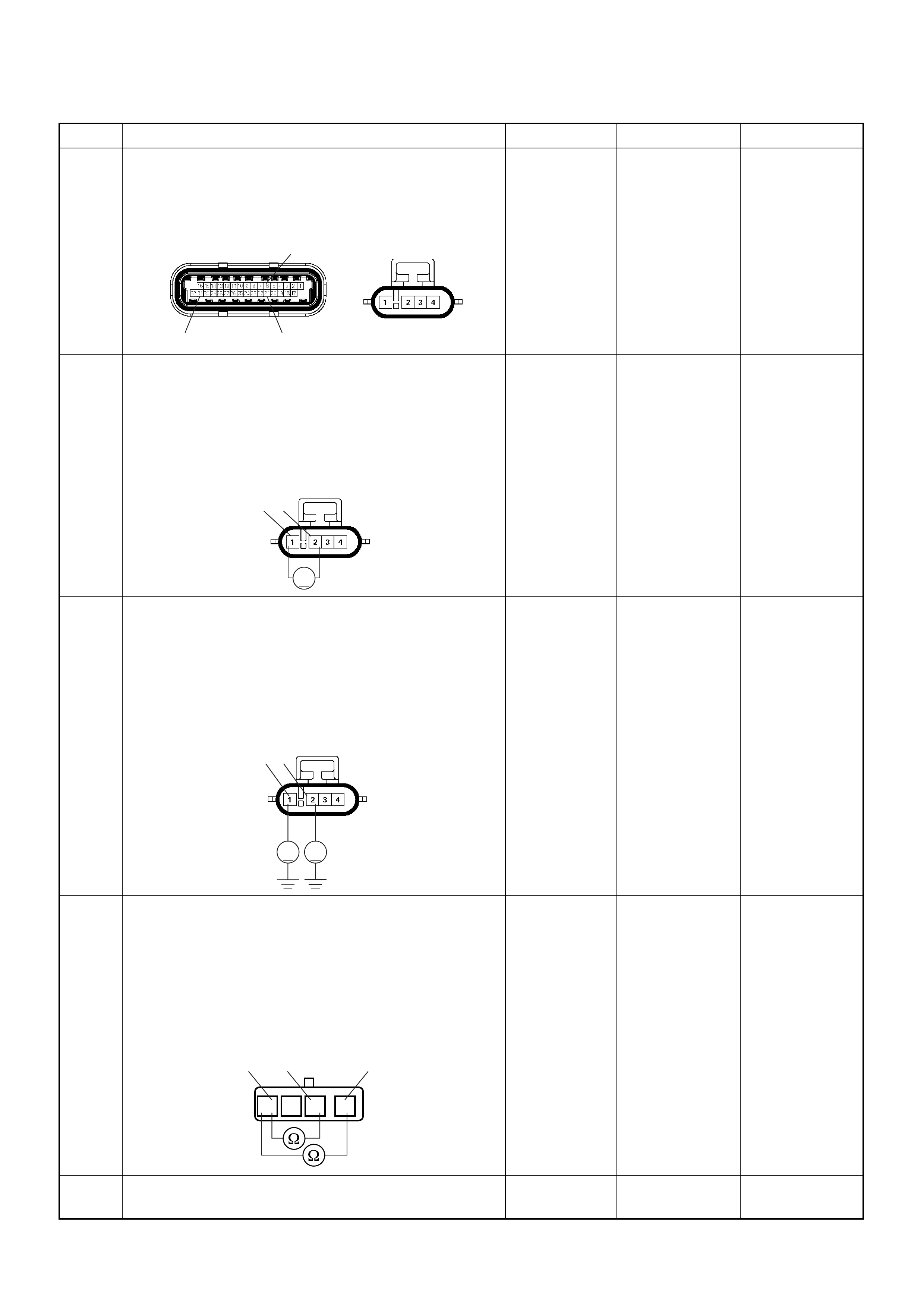
4 Check for poor/faulty connection at the O
2
sensor or
ECM connector. If a poor/faulty connection is found,
repair as necessary.
Was the problem found?
— Verify repair Go to Step 5
5 Using the DVM and check the O
2
sensor circu it.
1. Ignition “On”, engine “Off”.
2. Disconnect the the O
2
sensor connector.
3. Check the circuit for short to power supply circuit.
Was the DVM indicated specified value?
Approximatly
450mV Go to Step 7 Go to Step 6
6 Using the DVM and check the O
2
sensor circu it.
1. Ignition “On”, engine “Off”.
2. Disco nne ct the O
2
sensor connector.
3. Check the circuit for short to power supply circuit.
Was the DVM indicated specifed value?
Less than 1V Go to Step 15
Repair faulty
harness and
verify repair
7 Using the DVM and check the O
2
sensor circu it.
1. Ignition “Off”, engine “Off”.
2. Disconnect the the O
2
sensor connector.
3. Check the circuit for short to heater power supply
circuit.
Was the DVM indicated specified value?
No continuity Go to Step 9 Go to Step 8
8 Repair the short to heater power supply circuit.
Was the problem found? — Verify repair Go to Step 15
Step Action Value(S) Yes No
C56(J2) E77
31 21
6
V
21 E77
1 2
VV
E77
124
1234
O2 Sensor

9 1. Using the Tech 2, ignition “On” and engine “On”.
2. Monitor the “Manifold Absolute Pressure” in the
data display.
Does the Tech 2 indicate correct “Manifold Absolute
Pressure” in accordance with engine speed or
acceleration? — Go to Step 11 Go to Step 10
10 Remove the MAP sensor and check for the following
conditions.
• Objects blocking the air cleaner.
• Objects blocking the MAP sensor.
• Objects blocking the throttle valve.
• Vacuum leaking at intake duct.
• Vacuum leaking at throttle body.
If a problem is found, repair as neces sa ry.
Was the problem found? — Verify repair Go to Step 11
11 1. Using the Tech 2, ignition “On” and engine “On”.
2. Select the “Miscellaneous Test” and perform the
“IAC Control” in the “IAC System”.
3. Operate the Tech 2 in accordance with procedure.
Was the engine speed changed, when the IAC valve
is operating step by step? — Go to Step 13 Go to Step 12
12 Check for the following conditions.
• Objects blocking the IAC valve.
• Objects blocking the throttle valve.
• Vacuum leaking at throttle body.
If a problem is found, repair as neces sa ry.
Was the problem found? — Verify repair Go to Step 13
13 Check for injector for the affected bank.
Refer to “Injector Coil Test & Injector Balance Test
Procedure”.
Was the injector operation correct? —Go to Step 14
Refer to Injector
Coil Test &
Injector
Balance Test
Procedure
14 Check for fuel pressure.
Refer to “Fuel System Diagnosis”.
Was the fuel pressure correct? — Go to Step 15
Refer to Fuel
System
Diagnosis
15 Replace the O
2
sens or.
Was the problem solved? — Verify repair Go to Step 16
16 Is the ECM programmed with the latest software
release?
If not, download the latest software to the ECM using
the “SPS (Service Programming System)”.
Was the problem solved? — Verify repair Go to Step 17
17 Replace the ECM.
Is the action complete?
IMPORTANT: The replacement ECM must be
programmed. Refer to section of the Service
Programming System (SPS) in this manual.
Following EC M programming, the immobiliser system
(if equipped) must be linked to the ECM. Refer to
section 11 “Immobiliser System-ECM replacement” for
the ECM/Immobiliser linking procedure. — Verify repair —
Step Action Value(S) Yes No

Diagnostic Trouble Code (DTC) P0134 O
2
Sensor No Activity Defected Circuit
(Bank 1 Sensor 1)
µP
VIgn
-
+
Crankshaft
Position
Sensor
J1-1 J1-2 J1-17
Battery
Voltage
Battery
Voltage
2.0
WHT ECM
10A
450
mV
A/D Converter
Vcc
+5V -+
TIMING
COVER
J2-6 J2-21
Fuel
Pump
FUEL
PUMP
20A
2.0
BLK
2.0
BLK/
BLU
Fuel
Pump
Relay
O2
SENSOR
10A
Heated
O2
Sensor
0.85
RED/
WHT
0.5
GRN/
WHT
0.5
RED/
WHT
0.5
BLU/
WHT
0.5
BLU
0.5 PNK
J2-31 J2-11 J2-2 J2-18
M
Engine
Control
Module
(ECM)

Condition for setting the DTC and action ta ken when the DTC sets
Circuit Description
The engine control module (ECM) supplies a bias
voltage of about 450 mV between the heated oxygen
sensor (HO2S) high and low circuits. The oxygen
sensor varies the voltage within a range of about 1000
mV when the exhaust is rich, down through about 10
mV when exhaust is lean. The ECM constantly monitors
the HO2S signal during “Closed Loop” operation and
compensates for a rich or lean condition by decreasing
or increasing injector pulse width as necessary. If the
Bank 1 HO2S 1 voltage rem ains at or near the 450 mV
bias for an extended period of ti me, Diagnostic Trou ble
Code P0134 will be set, indicating an open sensor
signal or sensor low circuit.
Diagnostic Aids
Check for the following conditions:
• Poor connection or damaged harness - Inspect the
harness connectors for backed-out terminals,
improper mating, broken locks, improperly formed or
damaged terminals, poor terminal-to-wire connection,
and damaged harness.
Diagnostic Trouble Code (DTC) P0134 O
2
Sensor Circuit No
Activity Detected (Bank 1 Sensor 1)
Code Type DTC Name DTC Setting Condition Fail-Safe (Back Up)
P0134 A O
2
Sensor Circuit No Activity Detected
(Bank 1 Sensor 1) 1. No DTC relating to MAP sensor, TPS,
EVAP purge, ECT sensor, CKP sensor,
VSS, injector control circuit and ignition
control circuit.
2. Engine coolant temperature is more than
60°C.
3. Engine run time is longer than 40 seconds.
4. Mass air flow is more than 7g/s.
5. O
2
sensor bank 1 output voltage is
between 300mV and 600mV.
“Open Loop” fuel control.
Step Action Value(s) Yes No
1 Was the “On-Board Di agnostic (OBD) System Check”
performed?
—Go to Step 2
Go to On
Board
Diagnostic
(OBD) System
Check
2 1. Connect the Tech 2.
2. Review and record the failure information.
3. Select “F0: Read DTC Infor By Priority” in “F0:
Diagnostic Trouble Code”.
Is the DTC P0134 stored as “Present Failure”? — Go to Step 3
Refer to
Diagnostic Aids
and Go to Step
3
3 1. Using the Tech2, ignition “On” and engine “Off”.
2. Select “Cl ear D TC I nform ati on” w ith th e Tech2 and
clear the DTC information.
3. Operate the vehicle and monitor the “F5: Failed
This Ignition” in “F2: DTC Information”.
Was the DTC P0134 stored in this ignition cycle? — Go to Step 4
Refer to
Diagnostic Aids
and Go to Step
4
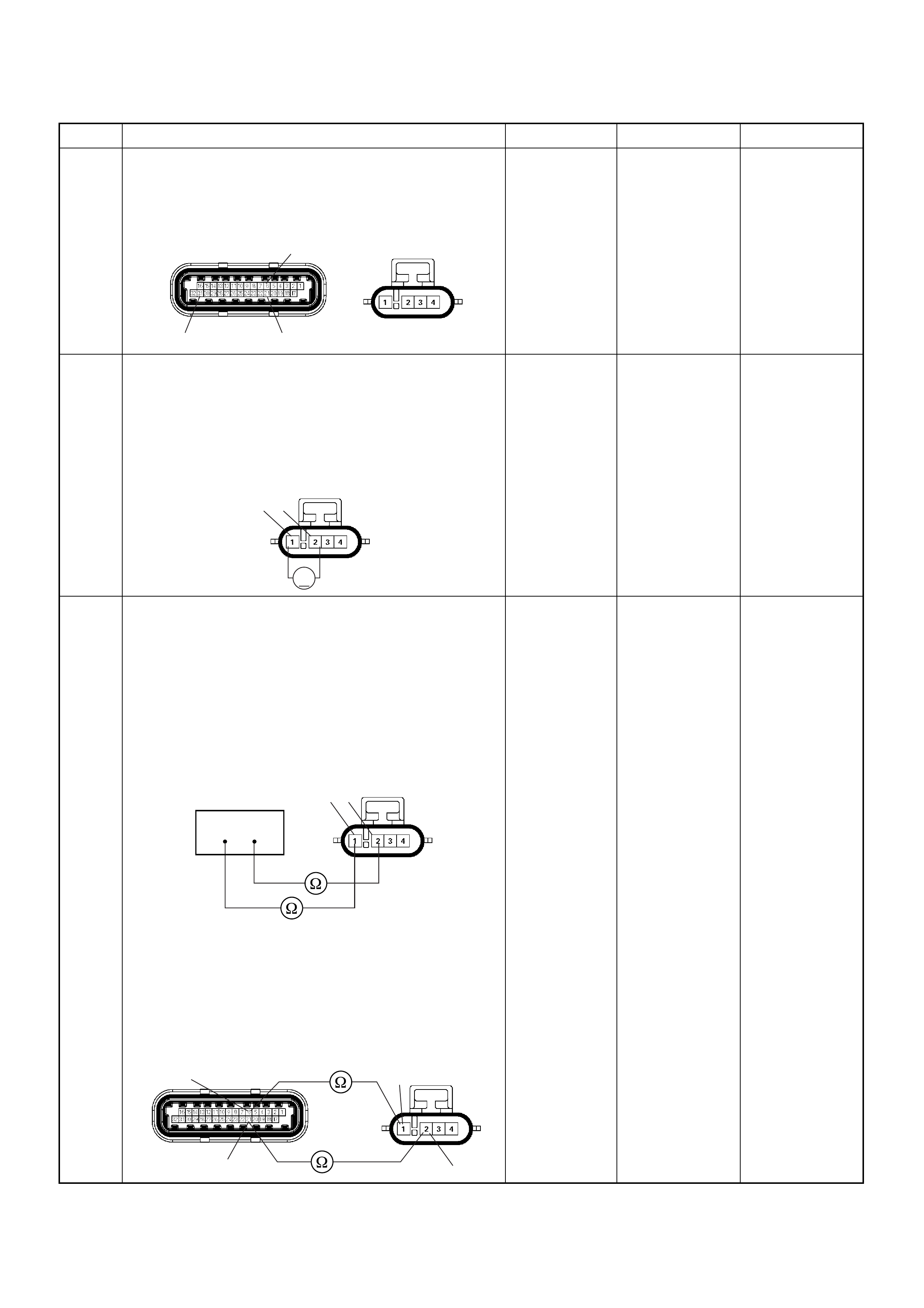
4 Check for poor/faulty connection at the O
2
sensor or
ECM connector. If a poor/faulty connection is found,
repair as necessary.
Was the problem found?
— Verify repair Go to Step 5
5 Using the DVM and check the O
2
sensor circu it.
1. Ignition “On”, engine “Off”.
2. Disco nne ct the O
2
sensor connector.
3. Check the ci rcui t for open circuit.
Was the DVM indicated specified value?
Approximatly
450mV Go to Step 7 Go to Step 6
6 Using the DVM and check the O
2
sensor circu it.
Breaker box is available:
1. Ignition “Off”, engine “Off”.
2. Install the breaker box as type A. (ECM
disconnected) Ref. 6E-80.
3. Disco nne ct the O
2
sens or.
4. Check the ci rcui t for open circuit.
Was the problem found?
Breaker box is not available:
1. Ignition “Off”, engine “Off”.
2. Disconnect the O
2
sensor connector and ECM
connector.
3. Check the ci rcui t for open circuit.
Was the problem found?
—
Repair faulty
harness and
verify repair Go to Step 13
Step Action Value(s) Yes No
C56(J2) E77
31 21
6
V
21 E77
1 2
38 53
E77
1
2
21
6C56(J2) E77

7 1. Using the Tech 2, ignition “On” and engine “On”.
2. Monitor the “Manifold Absolute Pressure” in the
data display.
Does the Tech 2 indicate correct “Manifold Absolute
Pressure” in accordance with engine speed or
acceleration? — Go to Step 9 Go to Step 8
8 Remove the MAP sensor and check for the following
conditions.
• Objects blocking the air cleaner.
• Objects blocking the MAP sensor.
• Objects blocking the throttle valve.
• Vacuum leaking at intake duct.
• Vacuum leaking at throttle body.
If a problem is found, repair as neces sa ry.
Was the problem found? — Verify repair Go to Step 9
9 1. Using the Tech 2, ignition “On” and engine “On”.
2. Select the “Miscellaneous Test” and perform the
“IAC Control” in the “IAC System”.
3. Operate the Tech 2 in accordance with procedure.
Was the engine speed changed, when the IAC valve
is operating step by step? — Go to Step 11 Go to Step 10
10 Check for the following conditions.
• Objects blocking the IAC valve.
• Objects blocking the throttle valve.
• Vacuum leaking at throttle body.
If a problem is found, repair as neces sa ry.
Was the problem found? — Verify repair Go to Step 11
11 Check for injector for the affected bank.
Refer to “Injector Coil Test & Injector Balance Test
Procedure”.
Was the injector operation correct? —Go to Step 12
Refer to Injector
Coil Test &
Injector
Balance Test
Procedure
12 Check for fuel pressure.
Refer to “Fuel System Diagnosis”.
Was the fuel pressure correct? — Go to Step 13
Refer to Fuel
System
Diagnosis
13 Replace the O
2
sens or.
Was the problem solved? — Verify repair Go to Step 14
14 Is the ECM programmed with the latest software
release?
If not, download the latest software to the ECM using
the “SPS (Service Programming System)”.
Was the problem solved? — Verify repair Go to Step 15
15 Replace the ECM.
Is the action complete?
IMPORTANT: The replacement ECM must be
programmed. Refer to section of the Service
Programming System (SPS) in this manual.
Following EC M programming, the immobiliser system
(if equipped) must be linked to the ECM. Refer to
section 11 “Immobiliser System-ECM replacement” for
the ECM/Immobiliser linking procedure. — Verify repair —
Step Action Value(s) Yes No

Diagnostic Trouble Code (DTC) P0135 O
2
Sensor Heater Circuit
(Bank 1 Sensor 1)
Condition for setting the DTC and action ta ken when the DTC sets
Code Type DTC Name DTC Setting Condition Fail-Safe (Back Up)
P0135 A O
2
SensorHeater Circuit (Bank 1 Sen-
sor 1 ) 1. No DTC relating to MAP sensor and ECT
sensor.
2. Engine coolant temperature is more than
60°C.
3. Engine run time is longer than 20 seconds.
4. MAP sensor output is more than 70KPa.
5. O
2
sensor bank 1 heater current more than
10mA.
No fail-s a fe fu n ction.
µP
VIgn
-
+
Crankshaft
Position
Sensor
J1-1 J1-2 J1-17
Battery
Voltage
Battery
Voltage
2.0
WHT ECM
10A
450
mV
A/D Converter
Vcc
+5V -+
TIMING
COVER
J2-6 J2-21
Fuel
Pump
FUEL
PUMP
20A
2.0
BLK
2.0
BLK/
BLU
Fuel
Pump
Relay
O2
SENSOR
10A
Heated
O2
Sensor
0.85
RED/
WHT
0.5
GRN/
WHT
0.5
RED/
WHT
0.5
BLU/
WHT
0.5
BLU
0.5 PNK
J2-31 J2-11 J2-2 J2-18
M
Engine
Control
Module
(ECM)

Circuit Description
Heated oxygen sensors are used to minimize the
amount of time required for “Closed Loop” fuel control
operation and to allow accurate catalyst monitoring. The
oxygen sensor heater greatly decreases the amount of
time requi red for fuel control se nsors Bank 1 HO2S 1 1
to become active. Oxygen sensor heaters are required
by catalys t monito r senso rs Bank 1 HO2S 2 to m ain tain
a sufficiently high temperature which allows accurate
exhaust oxygen content readings further from the
engine.
The engine control module (ECM) will run the heater
test only after a cold start (determined by engine coolant
and intake air temperature at the time of start-up) and
only once during an ignition cycle. When the engine is
started the ECM will monitor the HO2S voltage. When
the HO2S voltage indicates a sufficiently active sensor,
the ECM looks at how much time has elapsed since
start-up. If the EC M deter mines that too much ti me was
required for the Bank 1 HO2S 1 to become active, a
Diagnostic Trouble Code P0135 will set.
Diagnostic Aids
Check for the following conditions:
• Poor connection at ECM - Inspect harness
connectors for backed-out terminals, improper
mating, broken locks, improperly formed or damaged
terminals, and poor terminal-to-wire connection.
• Damaged harness - Inspect the wiring harness for
damage; shorts to ground, shorts to battery positive
and open circuits.
Diagnostic Trouble Code (DTC) P0135 O
2
Sensor Heater Circuit (Bank 1 Sensor 1)
Step Action Value(s) Yes No
1 Was the “On-Board Di agnostic (OBD) System Check”
performed?
—Go to Step 2
Go to On
Board
Diagnostic
(OBD) System
Check
2 1. Connect the Tech 2.
2. Review and record the failure information.
3. Select “F0: Read DTC Infor By Priority” in “F0:
Diagnostic Trouble Code”.
Is the DTC P0135 stored as “Present Failure”? — Go to Step 3
Refer to
Diagnostic Aids
and Go to Step
3
3 1. Using the Tech2, ignition “On” and engine “Off”.
2. Select “Cl ear D TC I nform ati on” w ith th e Tech2 and
clear the DTC information.
3. Operate the vehicle and monitor the “F5: Failed
This Ignition” in “F2: DTC Information”.
Was the DTC P0135 stored in this ignition cycle? — Go to Step 4
Refer to
Diagnostic Aids
and Go to Step
4
4 Check for poor/faulty connection at the O
2
sensor or
ECM connector. If a poor/faulty connection is found,
repair as necessary.
Was the problem found?
— Verify repair Go to Step 5
5 Visually check the O
2
sensor.
Was the problem found? — Go to Step 11 Go to Step 6
3 4
31
C56(J2) E77
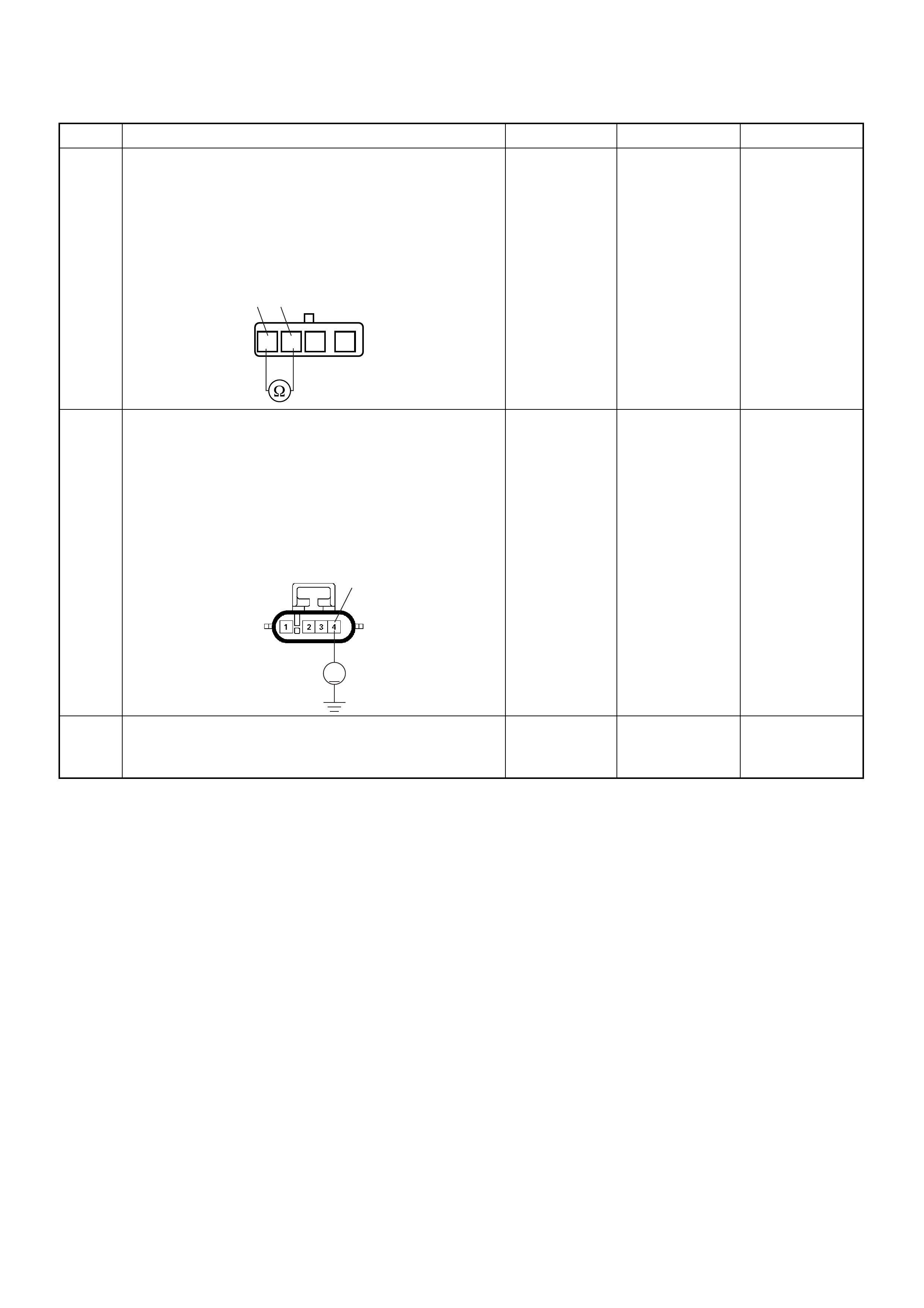
6 Using the DVM and check the O
2
sensor.
1. Ignition “Off”, engine “Off”.
2. Disconnect O
2
senso r conne ctor
3. Measur e the resi stanc e of heater.
Was the tester indicated specified value?
Approximately
12.5Ω at 20°C Go to Step 7 Go to Step 11
7 Using the DVM and check the heater power supply
circuit for the affected cylinder.
1. Ignition “On”, engine “Off”.
2. Disco nne ct the O
2
sensor connector.
3. Check the ci rcui t for open circuit.
Was the DVM indicated specified value?
Battery
voltage Go to Step 9 Go to Step 8
8 Repair the open or short to ground circuit between the
“O
2
Sensor” fuse (10A) and O
2
sensor.
Is the action complete? — Verify repair —
Step Action Value(s) Yes No
34
1234
O2 Sensor
4
V
E77
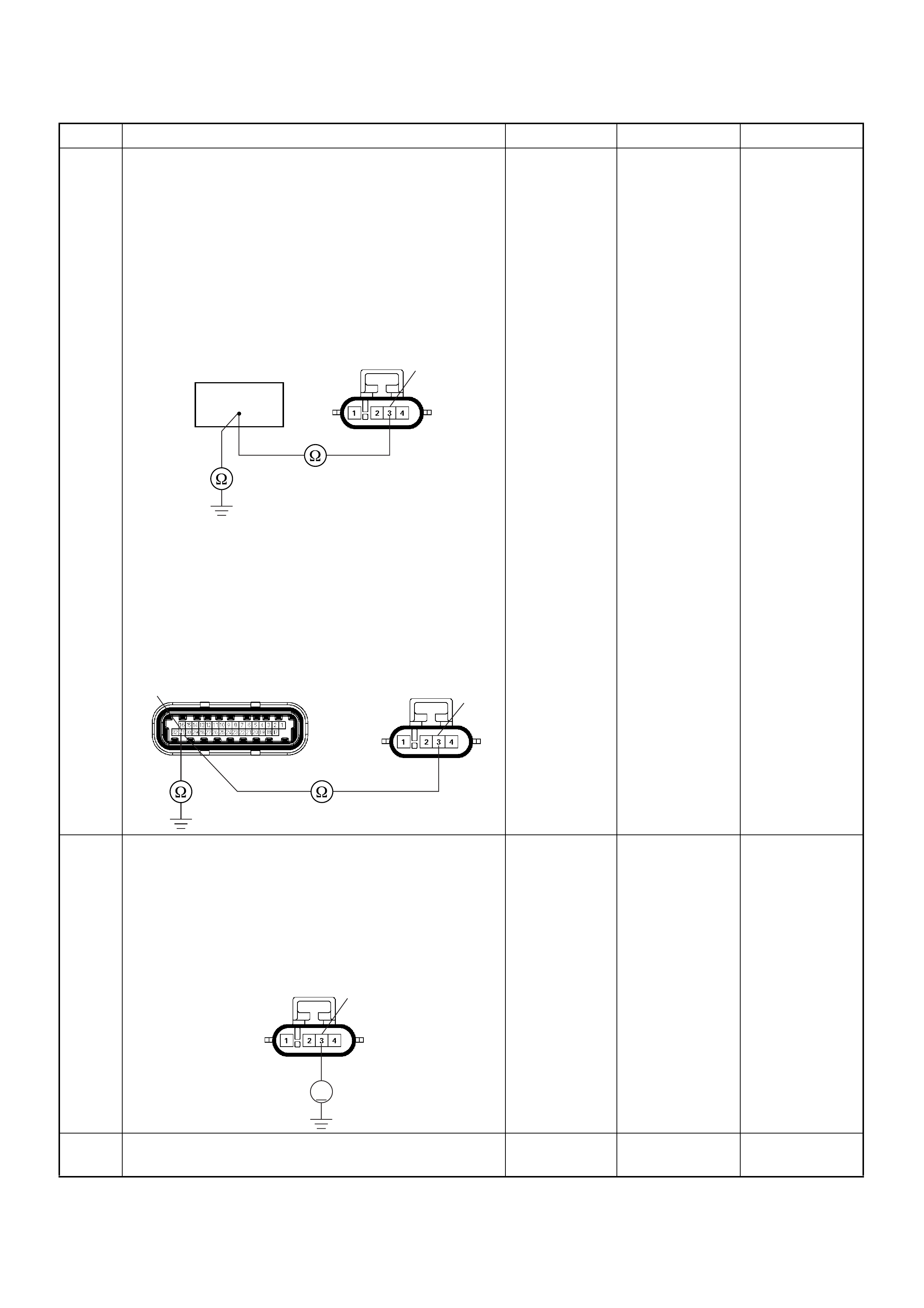
9 Using the DVM and check the heater ground circuit.
Breaker box is available:
1. Ignition “Off”, engine “Off”.
2. Install the breaker box as type A. (ECM
disconnected) Ref. 6E-80.
3. Disco nne ct the O
2
sensor connector.
4. Check the circuit for open or short to ground
circuit.
Was the problem found?
Breaker box is not available:
1. Ignition “Off”, engine “Off”.
2. Disconnect the O
2
sensor connector and ECM
connector.
3. Check the circuit for open or short to ground
circuit.
Was the problem found?
—
Repair faulty
harness and
verify repair Go to Step 10
10 Using the DVM and check the heater ground circuit.
1. Ignition “On”, engine “Off”.
2. Disco nne ct the O
2
sensor connector.
3. Check the circuit for short to battery voltage
circuit.
Was the DVM indicated voltage?
—
Repair faulty
harness and
verify repair Go to Step 12
11 Replace the O
2
sens or.
Was the problem solved? — Verify repair Go to Step 12
Step Action Value(s) Yes No
3
63
E77
3
31 E56(J2) E77
3
V
E77

12 Is the ECM programmed with the latest software
release?
If not, download the latest software to the ECM using
the “SPS (Service Programming System)”.
Was the problem solved? — Verify repair Go to Step 13
13 Replace the ECM.
Is the action complete?
IMPORTANT: The replacement ECM must be
programmed. Refer to section of the Service
Programming System (SPS) in this manual.
Following EC M programming, the immobiliser system
(if equipped) must be linked to the ECM. Refer to
section 11 “Immobiliser System-ECM replacement” for
the ECM/Immobiliser linking procedure. — Verify repair —
Step Action Value(s) Yes No
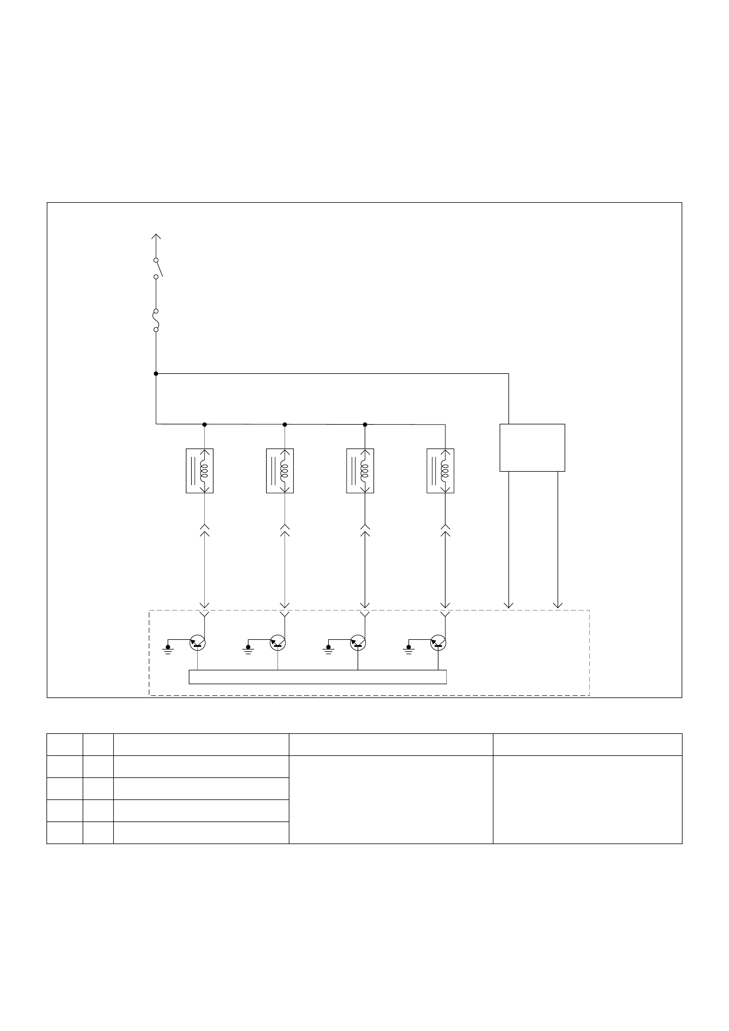
Diagnostic Trouble Code (DTC) P0201 Injector 1 Control Circuit
Diagnostic Trouble Code (DTC) P0202 Injector 2 Control Circuit
Diagnostic Trouble Code (DTC) P0203 Injector 3 Control Circuit
Diagnostic Trouble Code (DTC) P0204 Injector 4 Control Circuit
Condition for setting the DTC and action ta ken when the DTC sets
Code Type DTC Name DTC Setting Condition Fail-Safe (Back Up)
P0201 A Injector 1 Control Circuit 1. Engine is running.
2. Engine speed is more than 1000rpm.
3. Injector voltage does not meet to the bat-
tery voltage when the injector is com-
manded Off or does not meet to the 0V
when the injector is commanded On.
No fail-s a fe fu n ction.
P0202 A Injector 2 Control Circuit
P0203 A Injector 3 Control Circuit
P0204 A Injector 4 Control Circuit
Battery Voltage
PNK/
BLU
Injector
#1
Cylinder
Injector
#2
Cylinder
Injector
#3
Cylinder
Injector
#4
Cylinder
J1-9
BLU/
BLK
J1-22
BLU/
WHT
J1-8
COIL
MODULE
BLU/
YEL
J1-11
0.85
GRN
J1-19
0.85
BLU
J1-18
µP
IGN
Switch
IGN
Fuse
15A
Engine
Control
Module
(ECM)

Circuit Description
The engine control module (ECM) has four individual
injector driver circuits. Each controls an injector. When a
driver circuit is grounded by the ECM, the injector is
activated. The ECM monitors the current in each driver
circuit. The ECM measures a voltage drop through a
fixed r es istor an d controls i t. T h e v oltage on each dr iv er
is monitored to detect a fault. If the voltage is not what
the ECM e xpects to m onitor on th e circuit, a Diagnos tic
Trouble Code is set. This Diagnostic Trouble Code is
also set if an injector driver is shorted to voltage.
Diagnostic Aids
An injector driver circuit that is open or shorted to
voltage will cause a Diagnostic Trouble Code P0201 to
set. It will also cause a misfire due to an inoperative
injector. A misfire Diagnostic Trouble Code will also be
set indicating which cylinder is inoperative.
Long term and short term fuel trims that are excessively
high or low are a good indication that an injector is
faulty.
Use Fuel Injector Coil Test Procedure to check for faulty
injectors.
Diagnostic Trouble Code (DTC) P0201 Injector 1 Control Circuit
Diagnostic Trouble Code (DTC) P0202 Injector 2 Control Circuit
Diagnostic Trouble Code (DTC) P0203 Injector 3 Control Circuit
Diagnostic Trouble Code (DTC) P0204 Injector 4 Control Circuit
Step Action Value(s) Yes No
1 Was the “On-Board Di agnostic (OBD) System Check”
performed?
—Go to Step 2
Go to On
Board
Diagnostic
(OBD) System
Check
2 1. Connect the Tech 2.
2. Review and record the failure information.
3. Select “F0: Read DTC Infor By Priority” in “F0:
Diagnostic Trouble Code”.
Is the DTC P02 01, P0202, P 0203 or P020 4 stored a s
“Present F ailur e” ? — Go t o Step 3
Refer to
Diagnostic Aids
and Go to Step
3
3 1. Using the Tech2, ignition “On” and engine “Off”.
2. Select “Cl ear D TC I nform ati on” w ith th e Tech2 and
clear the DTC information.
3. Operate the vehicle and monitor the “F5: Failed
This Ignition” in “F2: DTC Information”.
Was the DTC P0201, P0202, P0203 or P0204 stored
in this ignition cycle? — Go to Step 4
Refer to
Diagnostic Aids
and Go to Step
4
4 Check for poor/faulty connection at the injector or
ECM connector. If a poor/faulty connection is found,
repair as necessary.
Was the problem found?
— Verify repair Go to Step 5
5 Visually check the injector for the affected cylinder.
Was the problem found? — Go to Step 11 Go to Step 6
22
8911 E-60(J1)
E-6/E-7/E-8/E-9

6 Using the DVM and check the injector coil for the
affected cylinder.
1. Ignition “Off”, engine “Off”.
2. Disconnect injector connector for the affected
cylinder.
3. Measure the resistance of injector coil.
Was the tester indicated specified value?
Approximately
12.5Ω at 20°C Go to Step 7 Go to Step 11
Step Action Value(s) Yes No
1
1
2
2
Injector
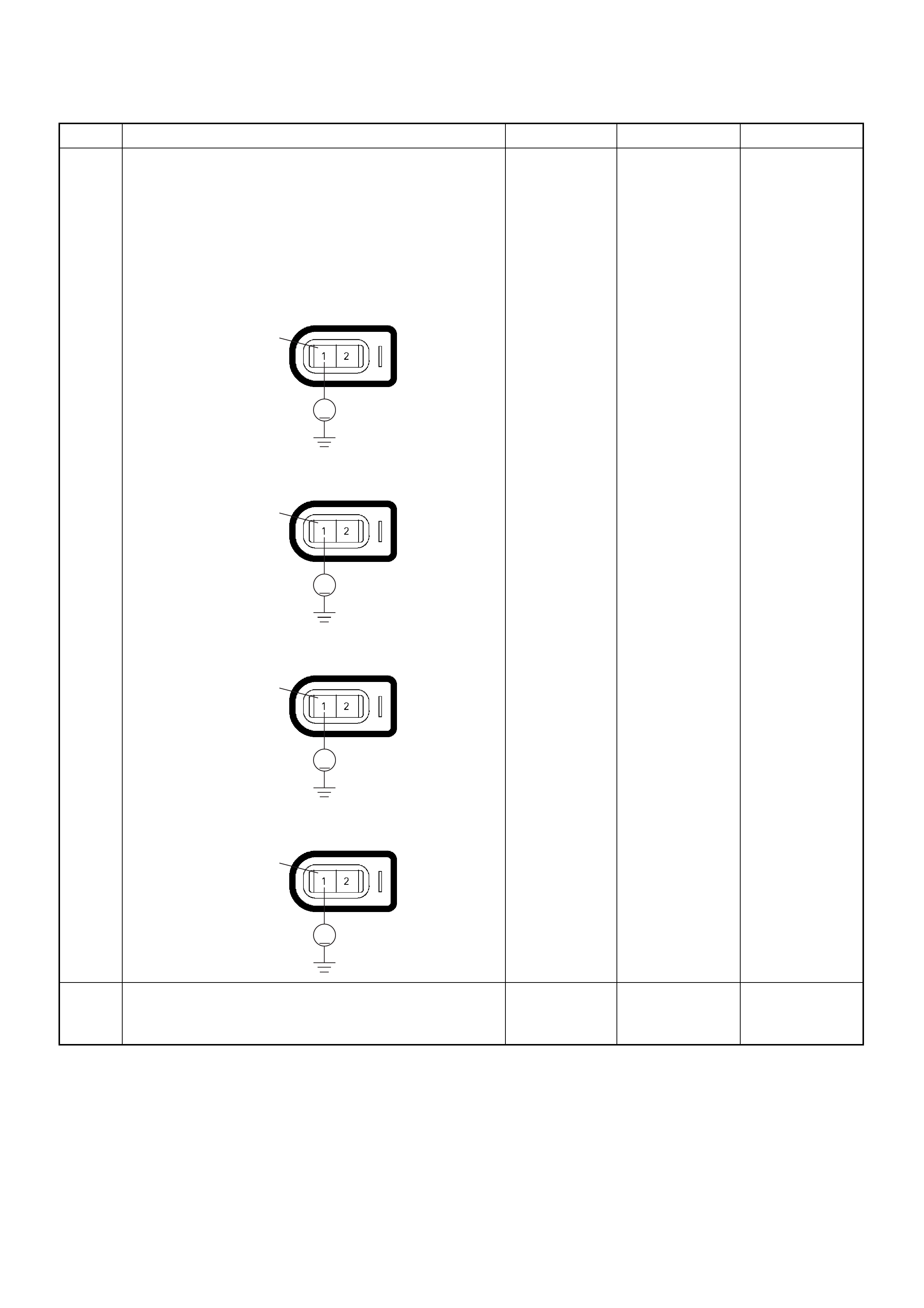
7 Using the DVM and check the injector power supply
circuit for the affected cylinder.
1. Ignition “On”, engine “Off”.
2. Disconnect the injector connector for the affected
cylinder.
3. Check the ci rcui t for open circuit.
Was the DVM indicated specified value?
Battery
voltage Go to Step 9 Go to Step 8
8 Repair the open or short to ground circuit between the
“IGN” fuse (15A) and injector for the affected cylinder.
Is the action complete? — Verify repair —
Step Action Value(s) Yes No
V
1E-6No.1 Cylinder
V
1E-7No.2 Cylinder
V
1E-8No.3 Cylinder
V
1E-9No.4 Cylinder
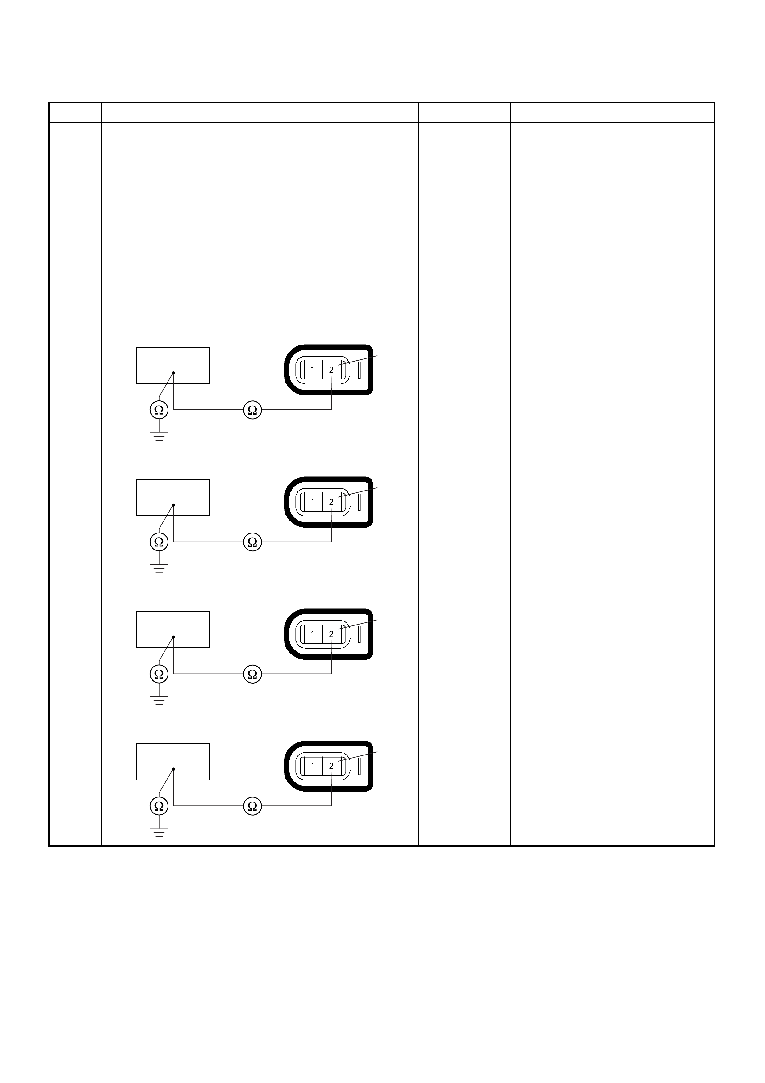
9 Using the DVM and check the injector signal circuit for
the affected cylind er.
Breaker box is available:
1. Ignition “Off”, engine “Off”.
2. Install the breaker box as type A. (ECM
disconnected) Ref. 6E-80.
3. Disconnect the injector connector for the affected
cylinder.
4. Check the circuit for open or short to ground
circuit.
Was the problem found?
—
Repair faulty
harness and
verify repair Go to Step 10
Step Action Value(s) Yes No
92
E-6
No.1 Cylinder
22 2
E-7
No.2 Cylinder
82
E-8
No.3 Cylinder
11 2
E-9
No.4 Cylinder
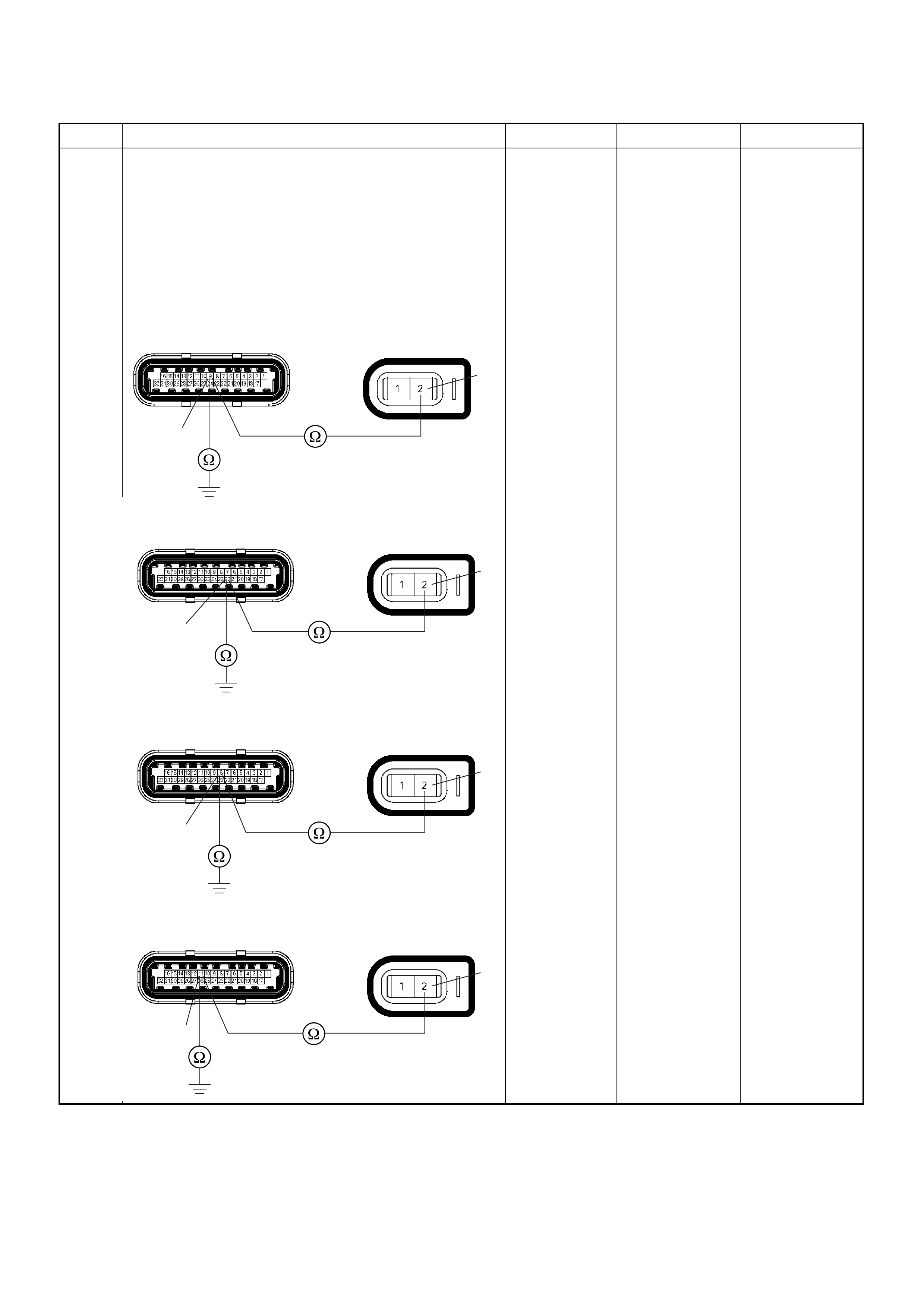
9Breaker box is not available:
1. Ignition “Off”, engine “Off”.
2. Disconnect the injector connector for the affected
cylinde r and ECM conne ct or.
3. Check the circuit for open or short to ground
circuit.
Was the problem found?
—
Repair faulty
harness and
verify repair Go to Step 10
Step Action Value(s) Yes No
E-60(J1) E-6
9
2
No.1 Cylinder
E-60(J1) E-7
22
2
No.2 Cylinder
E-60(J1) E-8
8
2
No.3 Cylinder
E-60(J1) E-9
11
2
No.4 Cylinder
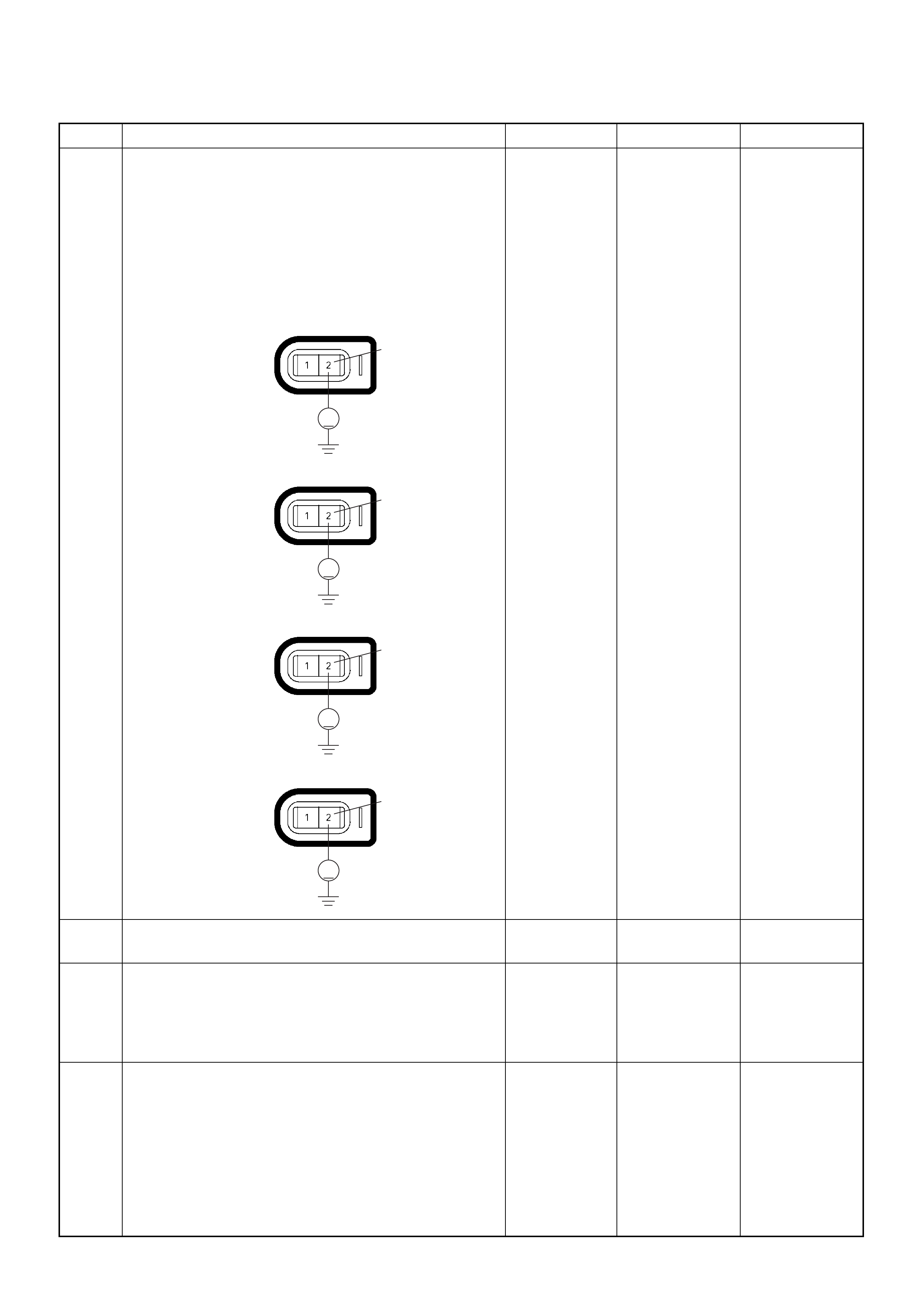
10 Using the DVM and check the injector signal circuit.
1. Ignition “On”, engine “Off”.
2. Disconnect the injector connector for the affected
cylinder.
3. Check the circuit for short to battery voltage
circuit.
Was the DVM indicated battery voltage?
—
Repair faulty
harness and
verify repair Go to Step 12
11 Replace the injector for the affected cylinder.
Was the problem solved? — Verify repair Go to Step 12
12 Is the ECM programmed with the latest software
release?
If not, download the latest software to the ECM using
the “SPS (Service Programming System)”.
Was the problem solved? — Verify repair Go to Step 13
13 Replace the ECM.
Is the action complete?
IMPORTANT: The replacement ECM must be
programmed. Refer to section of the Service
Programming System (SPS) in this manual.
Following EC M programming, the immobiliser system
(if equipped) must be linked to the ECM. Refer to
section 11 “Immobiliser System-ECM replacement” for
the ECM/Immobiliser linking procedure. — Verify repair —
Step Action Value(s) Yes No
V
2
E-6
No.1 Cylinder
V
2
E-7
No.2 Cylinder
V
2
E-8
No.3 Cylinder
V
2
E-9
No.4 Cylinder
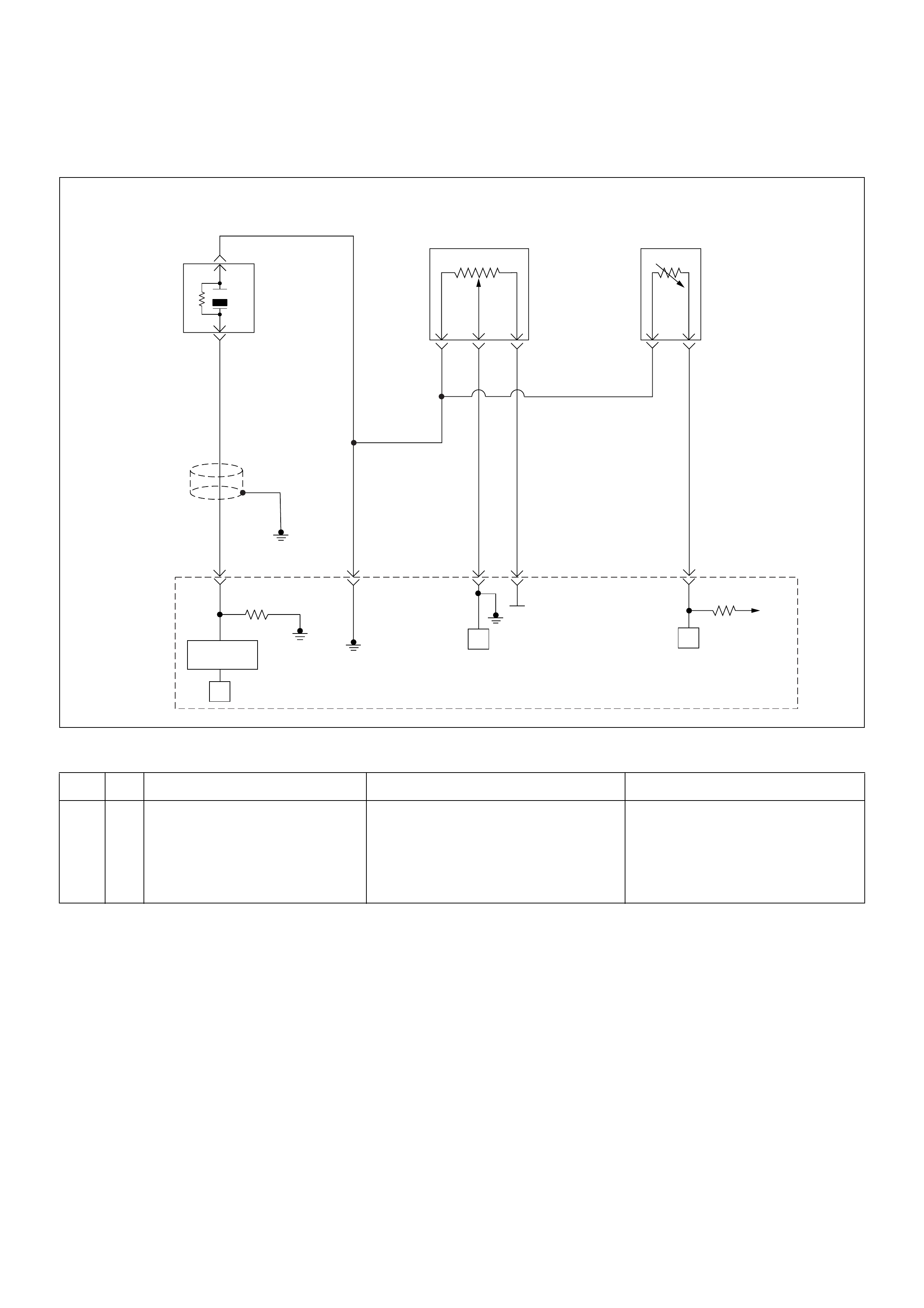
Diagnostic Trouble Code (DTC) P0325 Knock Sensor (KS) Circuit Malfunction
Condition for setting the DTC and action ta ken when the DTC sets
Circuit Description
The kno ck sens or (K S) sys tem is use d to det ect eng ine
detonation. The knock sensor produced an AC voltage
signal. T he knock se nsor sends this signal to the ECM .
The amplitude and the frequency of the AC voltage
signal depends upon the knock level being detected.
The ECM wil l then retard the spark timing based on the
signals from the Knock Sensor.
Diagnostic Aids
Correct any abnormal engine noise before using the
diagno sti c table.
Check for an open circuit.
Code Type DTC Name DTC Setting Condition Fail-Safe (Back Up)
P0325 B Knock Sensor Module Circuit 1. No DTC relating to MAP sensor.
2. Engine coolant temperature is more than
50°C.
3. Engine speed is more than 1600rpm.
4. Knock sensor filter module integrated cir-
cuit malfunction.
ECM retards ignition timing 4°C.
µP
0.5
GRY
J1-27
+5V
µP
µP
5Volts
Reference
Knock
Sensor
0.5
YEL
0.5
WHT/
BLU
J1-7
0.5
BLU/
PNK
J1-32
0.5
BLK/
YEL
J1-15J1-3
Engine
Coolant
Temperature(ECT)
Sensor
Throttle
Position Sensor
Knock Filter
Module
Engine
Control
Module
(ECM)
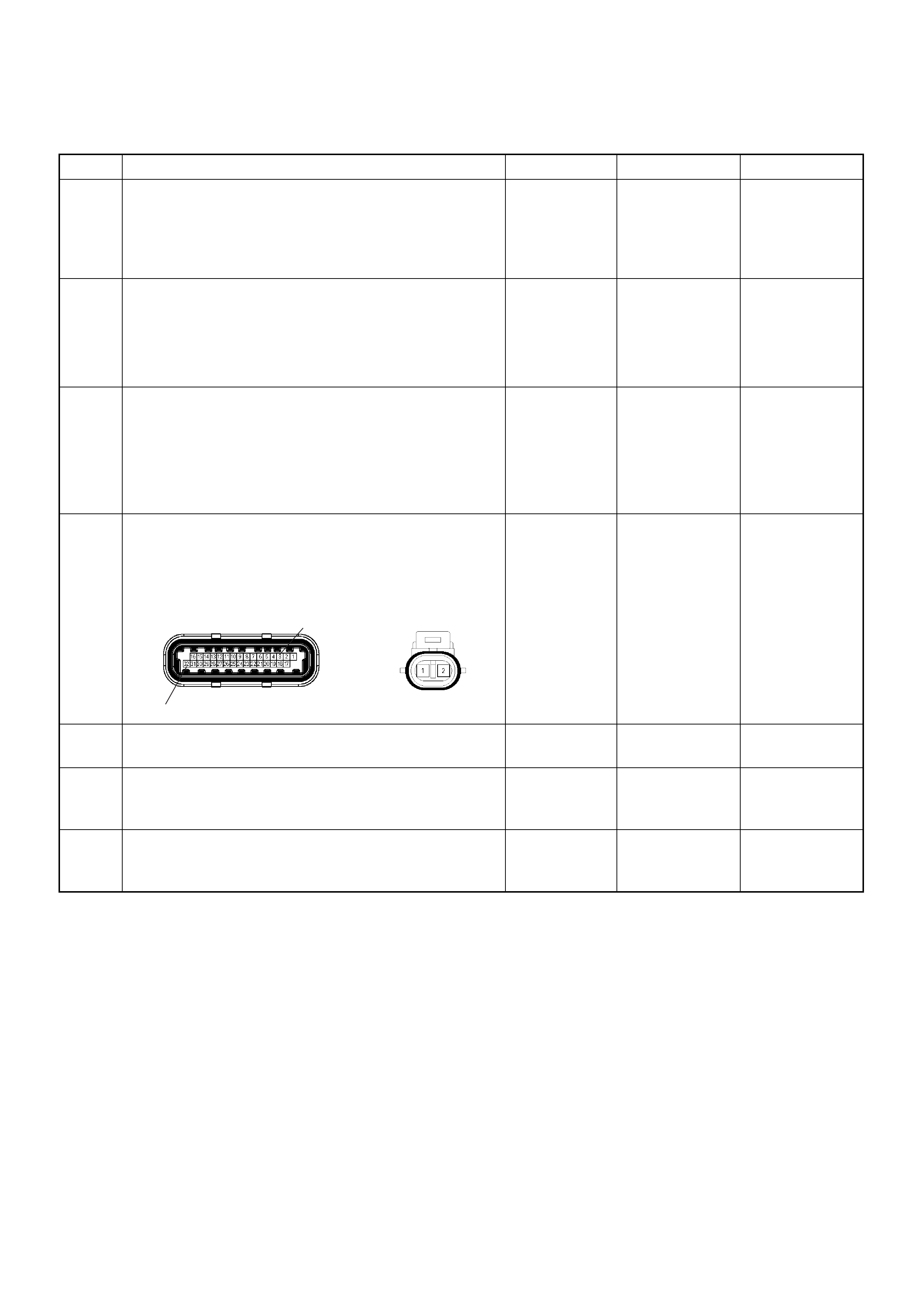
Diagnostic Trouble Code (DTC) P0325 Knock Sensor Module Circuit
Step Action Value(s) Yes No
1 Was the “On-Board Di agnostic (OBD) System Check”
performed?
—Go to Step 2
Go to On
Board
Diagnostic
(OBD) System
Check
2 1. Connect the Tech 2.
2. Review and record the failure information.
3. Select “F0: Read DTC Infor By Priority” in “F0:
Diagnostic Trouble Code”.
Is the DTC P0325 stored as “Present Failure”? — Go to Step 3
Refer to
Diagnostic Aids
and Go to Step
3
3 1. Using the Tech2, ignition “On” and engine “Off”.
2. Select “Cl ear D TC I nform ati on” w ith th e Tech2 and
clear the DTC information.
3. Operate the vehicle and monitor the “F5: Failed
This Ignition” in “F2: DTC Information”.
Was the DTC P0325 stored in this ignition cycle? — Go to Step 4
Refer to
Diagnostic Aids
and Go to Step
4
4 Check for poor/faulty connection at the knock sensor
or ECM connector . If a poor/faulty connection is found,
repair as necessary.
Was the problem found?
— Verify repair Go to Step 5
5 Visually check the knock sensor.
Was the problem found? — Go to Step 10 Go to Step 6
6 Listen to the engine noise while raising and lowering
the engine speed .
Is a knock or audible noise present? — Go to Step 7 Go to Step 8
7 Repair the mechanical engine problem or a loose
bracket or component.
Is the action complete? — Verify repair —
32
3
E-60(J1) E-84
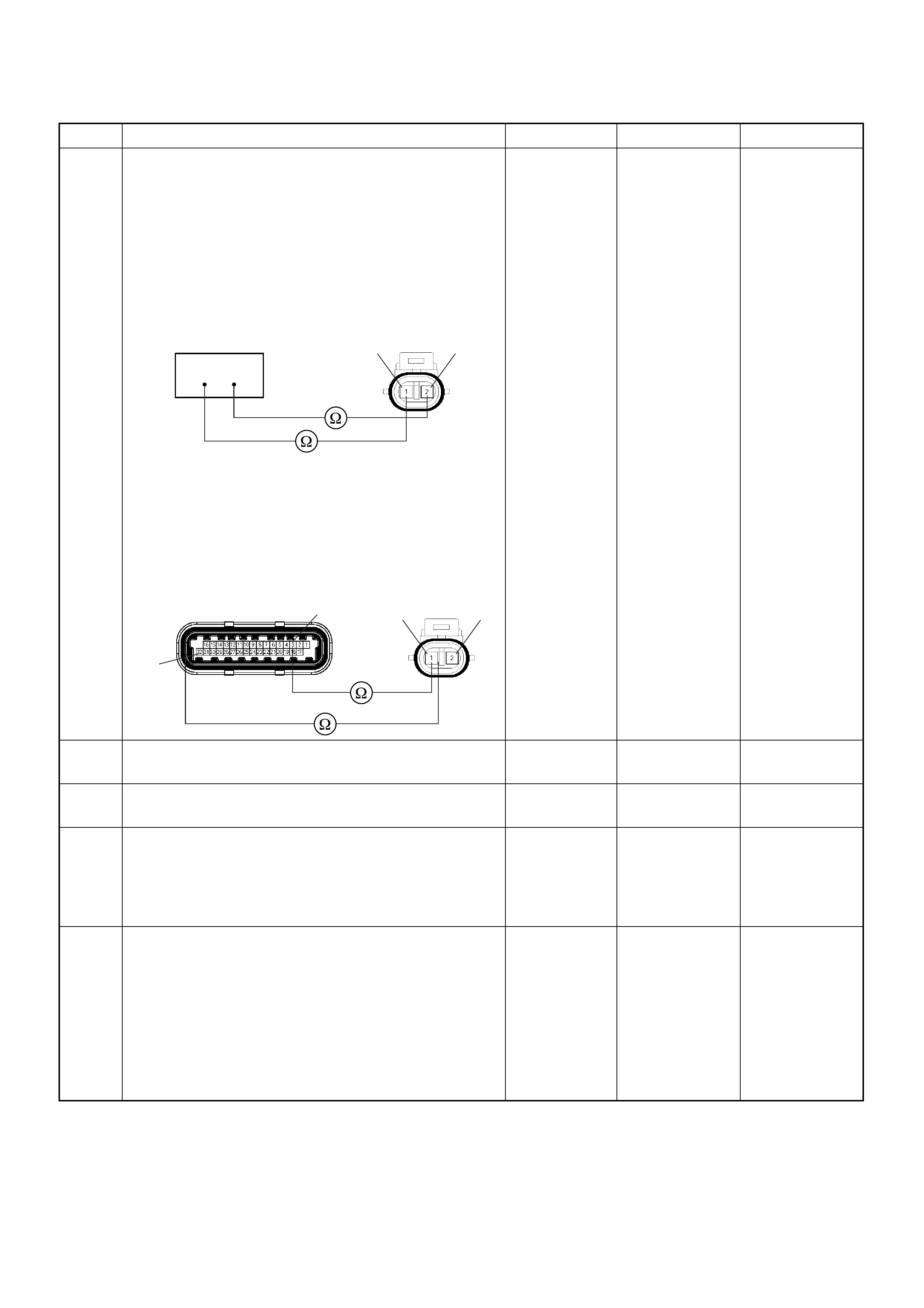
8 Using the DVM and check the knock sensor circuit.
Breaker box is available:
1. Ignition “Off”, engine “Off”.
2. Install the breaker box as type A. (ECM
disconnected) Ref. 6E-80.
3. Disconnect the knock sensor.
4. Check the ci rcui t for open circuit.
Was the problem found?
Breaker box is not available:
1. Ignition “Off”, engine “Off”.
2. Disco nnect the knoc k sensor co nnector and ECM
connector.
3. Check the ci rcui t for open circuit.
Was the problem found?
—
Repair faulty
harness and
verify repair Go to Step 9
9 Substitute a known good knock sensor and recheck.
Was the problem solved? — Go to Step 10 Go to Step 11
10 Replace the knock sensor.
Was the problem solved? — Verify repair Go to Step 1 1
11 Is the ECM programmed with the latest software
release?
If not, download the latest software to the ECM using
the “SPS (Service Programming System)”.
Was the problem solved? — Verify repair Go to Step 12
12 Replace the ECM.
Is the action complete?
IMPORTANT: The replacement ECM must be
programmed. Refer to section of the Service
Programming System (SPS) in this manual.
Following EC M programming, the immobiliser system
(if equipped) must be linked to the ECM. Refer to
section 11 “Immobiliser System-ECM replacement” for
the ECM/Immobiliser linking procedure. — Verify repair —
Step Action Value(s) Yes No
332
E-84 21
3
E-60(J1) E-84
32
21
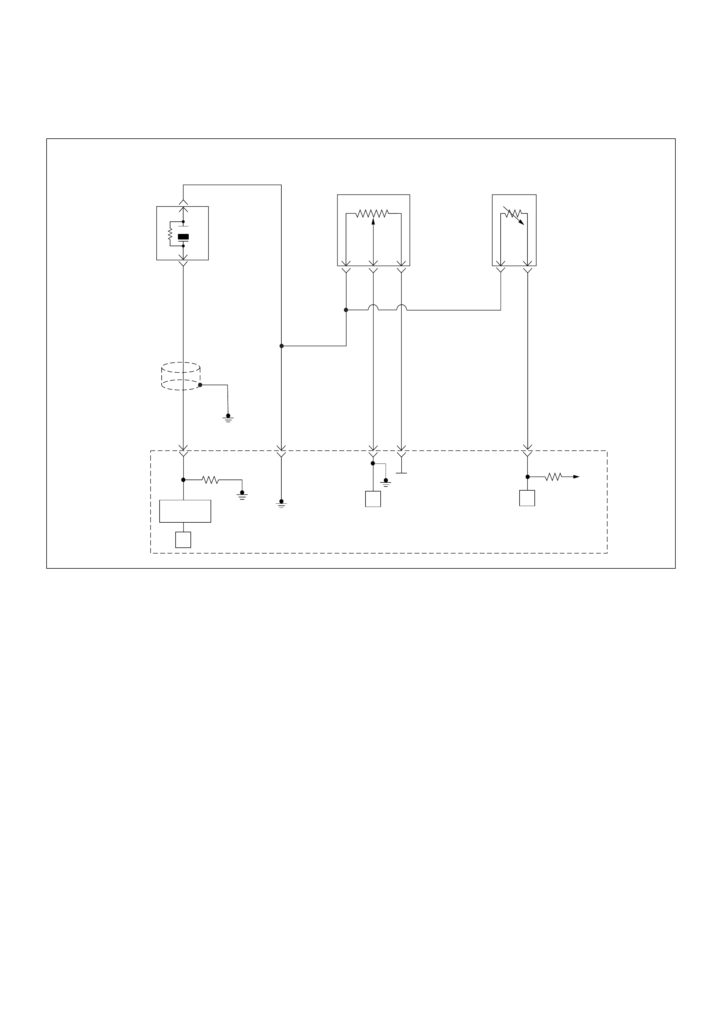
Diagnostic Trouble Code (DTC) P0327 Knock Sensor (KS) Circuit Low Input
µP
0.5
GRY
J1-27
+5V
µP
µP
5Volts
Reference
Knock
Sensor
0.5
YEL
0.5
WHT/
BLU
J1-7
0.5
BLU/
PNK
J1-32
0.5
BLK/
YEL
J1-15J1-3
Engine
Coolant
Temperature(ECT)
Sensor
Throttle
Position Sensor
Knock Filter
Module
Engine
Control
Module
(ECM)

Condition for setting the DTC and action ta ken when the DTC sets
Circuit Description
The ECM uses the Knock Sensor (KS) in order to detect
engine detonation. This allows the ECM to retard the
Ignition Control (IC) spark timing based on the KS signal
the ECM receives. The knock sensors produce an AC
signal that rides on the 1.3 volts DC. The signal’s
amplitude and frequency are dependent upon the
amount of the knock being experienced.
The ECM det er mi nes wh ether the kn ock is oc c urri ng by
comparing the signal level on the KS circuit with a
voltage level on the noise channel. The normal engine
noise varies depending on the engine speed and load.
Then the ECM determines that an abnormally high
noise channel voltage level is being experienced, a
Diagnostic Trouble Code P0327 sets.
Diagnostic Aids
Check for the following conditions:
A poor connection at the ECM. Inspect the knock
sensor and the ECM connectors for: , broken locks,
improperly formed or damaged terminals.
• Backed out terminals
• Broken locks
• Improperly formed or damaged terminals
Also, check the wiring harness for: shorts to ground,
shorts to battery positive, and open circuits.
• A misrouted harness. Inspect the knock sensor
harness in order to ensure that it is not routed too
close to high voltage wires such as spark plug leads.
Diagnostic Trouble Code (DTC) P0327 Knock Sensor Circuit
Code Type DTC Name DTC Setting Condition Fail-Safe (Back Up)
P0327 A Knock Sensor Circuit 1. No DTC relating to MAP sensor.
2. Engine coolant temperature is more than
50°C.
3. Engine speed is more than 1600rpm.
4. Knock sensor harness short to ground or
short to voltage circuit.
ECM retards ignition timing 4°C.
Step Action Value(s) Yes No
1 Was the “On-Board Di agnostic (OBD) System Check”
performed?
—Go to Step 2
Go to On
Board
Diagnostic
(OBD) System
Check
2 1. Connect the Tech 2.
2. Review and record the failure information.
3. Select “F0: Read DTC Infor By Priority” in “F0:
Diagnostic Trouble Code”.
Is the DTC P0327 stored as “Present Failure”? — Go to Step 3
Refer to
Diagnostic Aids
and Go to Step
3
3 1. Using the Tech2, ignition “On” and engine “Off”.
2. Select “Cl ear D TC I nform ati on” w ith th e Tech2 and
clear the DTC information.
3. Operate the vehicle and monitor the “F5: Failed
This Ignition” in “F2: DTC Information”.
Was the DTC P0327 stored in this ignition cycle? — Go to Step 4
Refer to
Diagnostic Aids
and Go to Step
4
4 Check for poor/faulty connection at the knock sensor
or ECM connector . If a poor/faulty connection is found,
repair as necessary.
Was the problem found?
— Verify repair Go to Step 5
32
3
E-60(J1) E-84
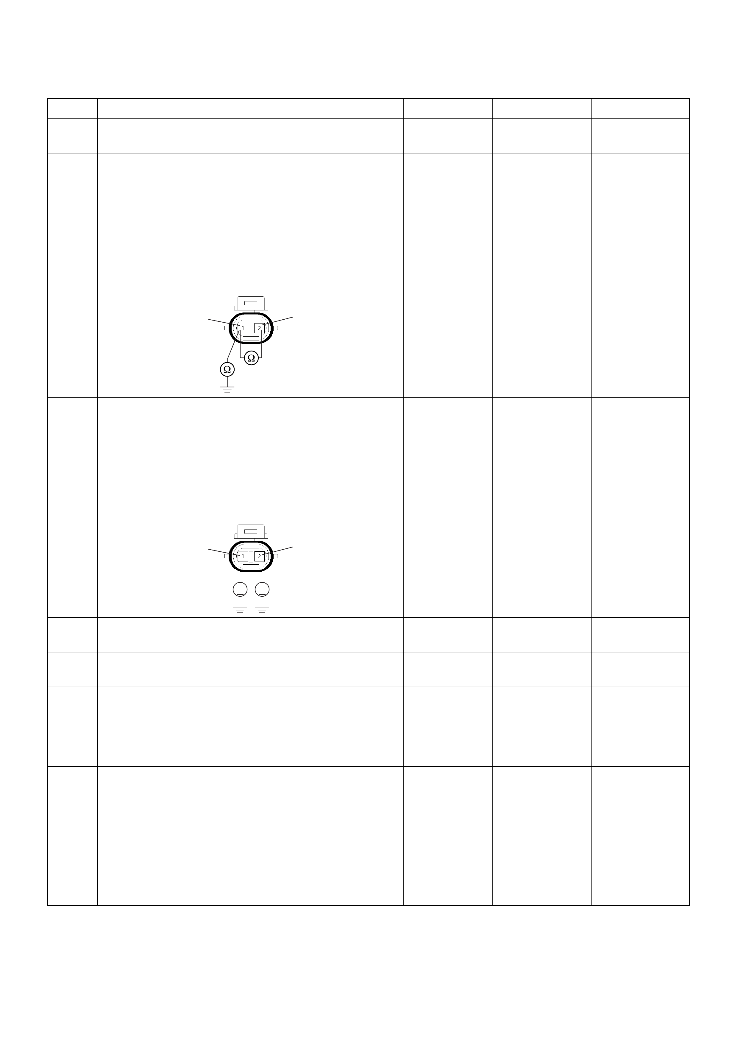
5 Visually check the knock sensor.
Was the problem found? — Go to Step 9 Go to Step 6
6 Using the DVM and check the knock sensor circuit.
1. Ignition “Off”, engine “Off”.
2. Disco nnect the knoc k sensor co nnector and ECM
connector.
3. Check the circuit for short to sensor ground or
ground circuit.
Was the problem found?
—
Repair faulty
harness and
verify repair Go to Step 7
7 Using the DVM and check the knock sensor circuit.
1. Ignition “On”, engine “Off”.
2. Disconnect the knock sensor connector.
3. Check the circuit for short to battery voltage
circuit.
Was the DVM indicated battery voltage?
—
Repair faulty
harness and
verify repair Go to Step 8
8 Substitute a known good knock sensor and recheck.
Was the problem solved? — Go to Step 9 Go to Step 10
9 Replace the knock sensor.
Was the problem solved? — Verify repair Go to Step 10
10 Is the ECM programmed with the latest software
release?
If not, download the latest software to the ECM using
the “SPS (Service Programming System)”.
Was the problem solved? — Verify repair Go to Step 1 1
11 Replace the ECM.
Is the action complete?
IMPORTANT: The replacement ECM must be
programmed. Refer to section of the Service
Programming System (SPS) in this manual.
Following EC M programming, the immobiliser system
(if equipped) must be linked to the ECM. Refer to
section 11 “Immobiliser System-ECM replacement” for
the ECM/Immobiliser linking procedure. — Verify repair —
Step Action Value(s) Yes No
E-84
2
1
VV
E-84
2
1
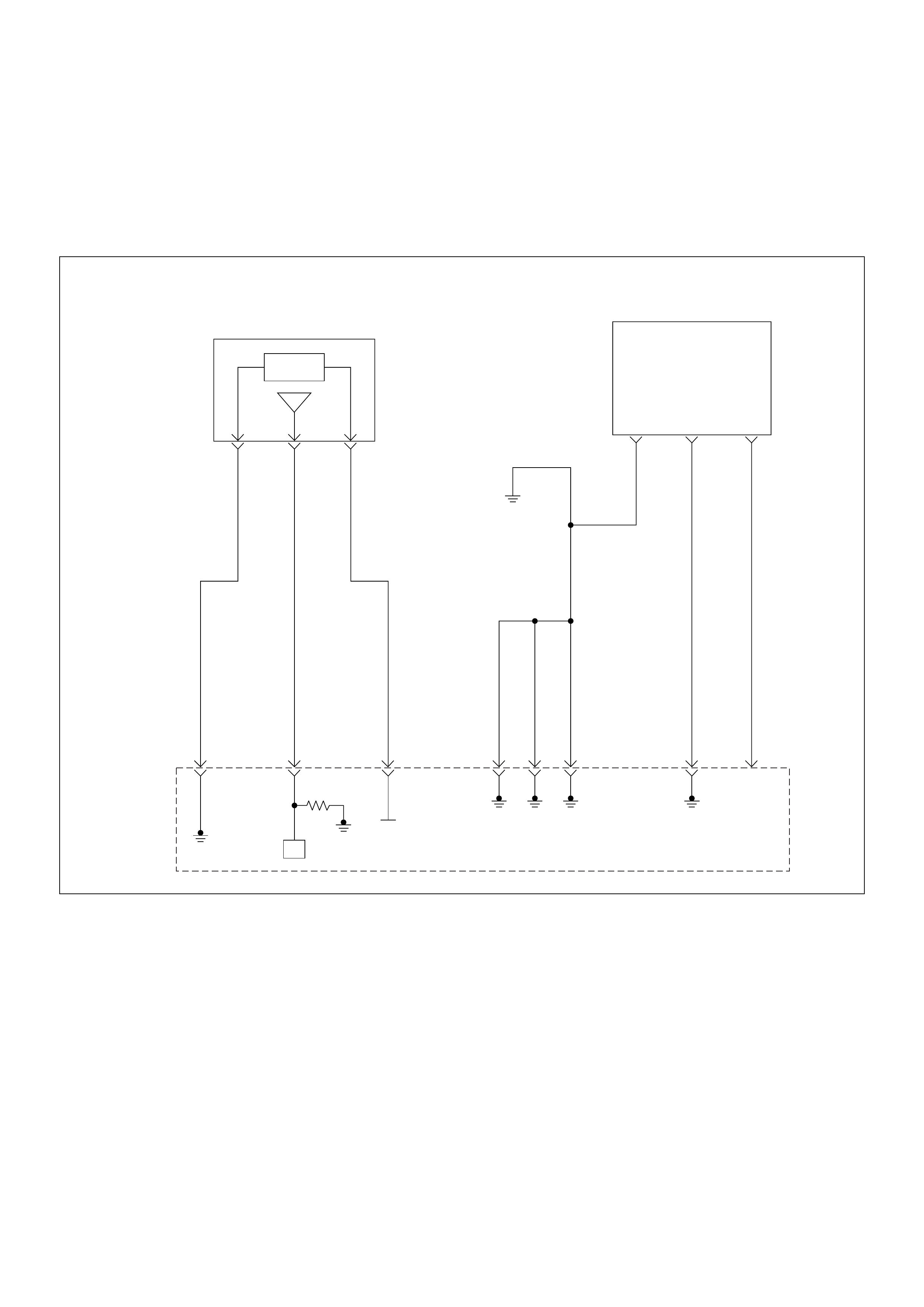
Diagnostic Trouble Code (DTC) P0336 Crankshaft Position (CKP)
Sensor Circuit Range/Performance (58X)
Diagnostic Trouble Code (DTC) P0337 Crankshaft Position (CKP)
Sensor Circuit Low Input (58X)
Manifold
Absolute
Pressure(MAP) Sensor
Crankshaft
Position(CKP)
Sensor
µP
0.5
GRY/
BLU
J1-16
0.5
GRY/
RED
J1-24
0.5
YEL/
RED
J1-31
0.5
BLK/
WHT
J1-1
0.5
BLK/
WHT
J1-2
0.5
BLK/
WHT
J1-17
0.5
BLK
J1-6
0.5
WHT
J1-21
INLET
MANIFOLD
5 V olts
Reference
Engine
Control
Module
(ECM)

Condition for setting the DTC and action ta ken when the DTC sets
Circuit Description
The 58X r eferenc e sig nal is pr oduce d by the cran ksha ft
position (CKP) sensor. During one crankshaft
revolution, 58 crankshaft pulses will be produced. The
engine control module (ECM) uses the 58X reference
signal to c alculate engine RP M and cra nkshaft posit ion.
The ECM constantly monitors the number of pulses on
the 58X reference circuit. If the ECM receives an
incorrec t number of pulses on the 58X refe rence circ uit,
Diagnostic Trouble Code P0336 will set. If the ECM
does not receive pluses on the 58X reference circuit,
Diagnostic Trouble Code P0337 will set.
Diagnostic Aids
An intermittent may be caused by a poor connection,
rubbed-through wire insulation or a wire broken inside
the insulation. Check for:
• Poor connection - Inspect the ECM harness and
connectors for improper mating, broken locks,
improperly formed or damaged terminals, and poor
terminal-to-wire connection.
• Damaged harness - Inspect the wiring harness for
damage; shorts to ground, shorts to battery positive
and open circuits. If the harness appears to be OK,
discon nect the ECM, turn the ign ition on and obs er ve
a voltmet er connecte d to the 58X refe rence ci rcuit at
the ECM harness connector while moving connectors
and wiring harnesses related to the ECM. A change
in voltage will indicate the location of the fault.
Diagnostic Trouble Code (DTC) P0336 Crankshaft Position Sensor
Circuit Range/Performance (58x)
Diagnostic Trouble Code (DTC) P0337 Crankshaft Position Sensor Circuit Low Input (58x)
Code Type DTC Name DTC Setting Condition Fail-Safe (Back Up)
P0336 B Crankshaft Position Sensor Circuit
Range/Performance (58X ) 1. Engine is running.
2. Extra or missing pulse is detected consecu-
tively.
No fail-s a fe fu n ction.
P0337 B Crankshaft Position Sensor Circuit Low
Input (58X) No pulse is detected during engine cranking.
Step Action Value(s) Yes No
1 Was the “On-Board Di agnostic (OBD) System Check”
performed?
—Go to Step 2
Go to On
Board
Diagnostic
(OBD) System
Check
2 1. Connect the Tech 2.
2. Review and record the failure information.
3. Select “F0: Read DTC Infor By Priority” in “F0:
Diagnostic Trouble Code”.
Is the DTC P0336 or P0337 stored as “Present
Failure”? — Go to Step 3
Refer to
Diagnostic Aids
and Go to Step
3
3 1. Using the Tech2, ignition “On” and engine “Off”.
2. Select “Cl ear D TC I nform ati on” w ith th e Tech2 and
clear the DTC information.
3. Operate the vehicle and monitor the “F5: Failed
This Ignition” in “F2: DTC Information”.
Was the DTC P0336 or P0337 stored in this ignition
cycle? — Go to Step 4
Refer to
Diagnostic Aids
and Go to Step
4
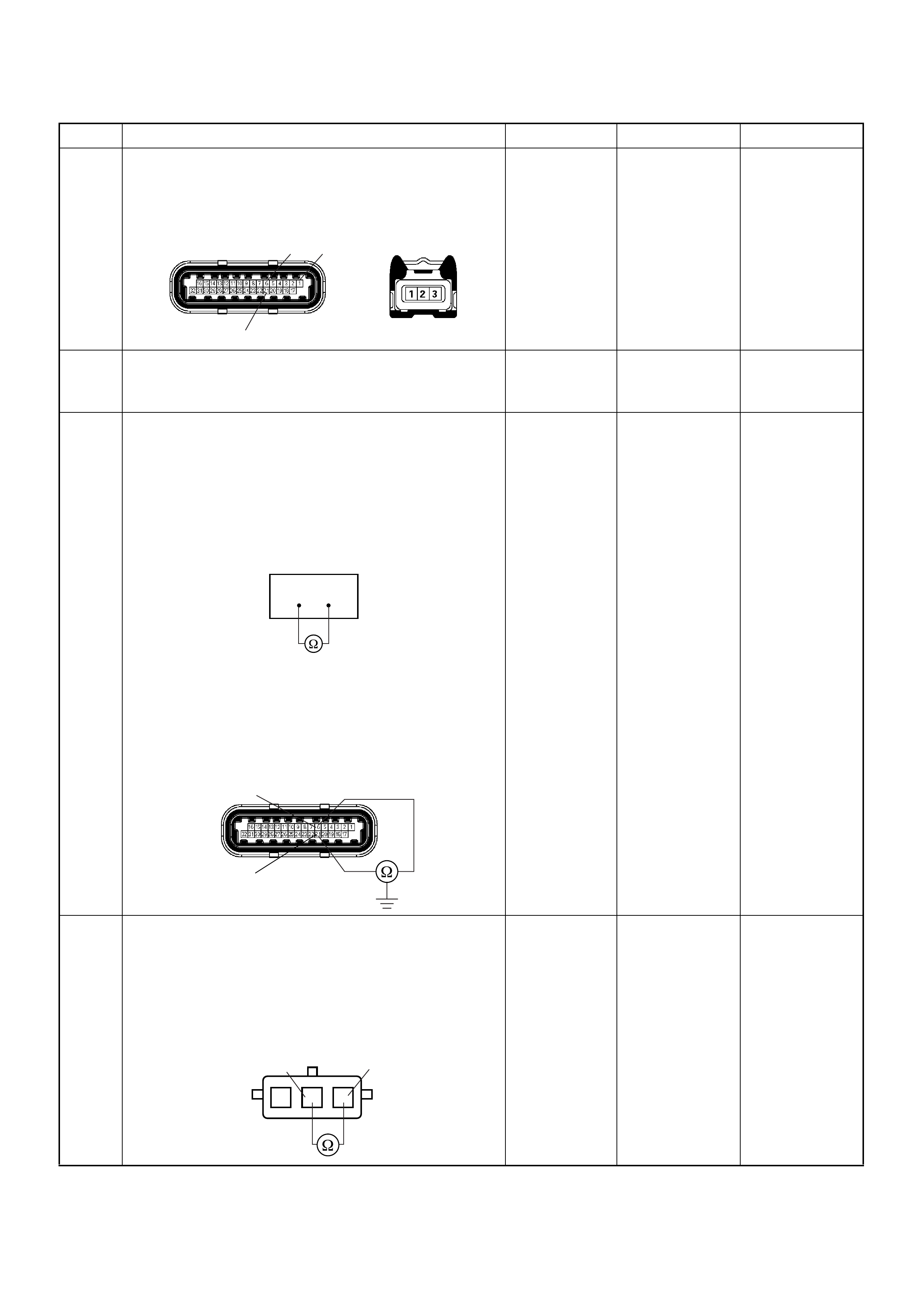
4 Check for poor/faulty connection at the CKP sensor or
ECM connector. If a poor/faulty connection is found,
repair the faulty terminal.
Was the problem found?
— Verify repair Go to Step 5
5 Visually check the CKP sensor. If a faulty installation
is found, repair as necessary.
Was the problem found? — Verify repair Go to Step 6
6 Using the DVM and check the CKP sensor circuit.
Breaker box is available:
1. Ignition “Off”, engine “Off”.
2. Install the breaker box as type A. (ECM
disconnected) Ref. 6E-80.
3. Check the resistance of the CKP sensor.
Was the DVM indicated specified value?
Breaker box is not available:
1. Ignition “Off”, engine “Off”.
2. Disconnect the ECM connector.
3. 3. Check the resistance of the CKP sensor.
Was the DVM indicated specified value?
Approximately
0.55kΩ at
20°C Go to Step 10 Go to Step 7
7 Using the DVM and check the CKP sensor circuit.
1. Ignition “Off”, engine “Off”.
2. Disconnect the CKP sensor connector.
3. Check the resistance of the CKP sensor.
Was the DVM indicated specified value?
Approximately
0.55kΩ at
20°C Go to Step 8 Go to Step 14
Step Action Value(s) Yes No
21
6 1
E-60(J1) E-59
621
6
21
E-60(J1)
1
23
CKP Sensor 1
2
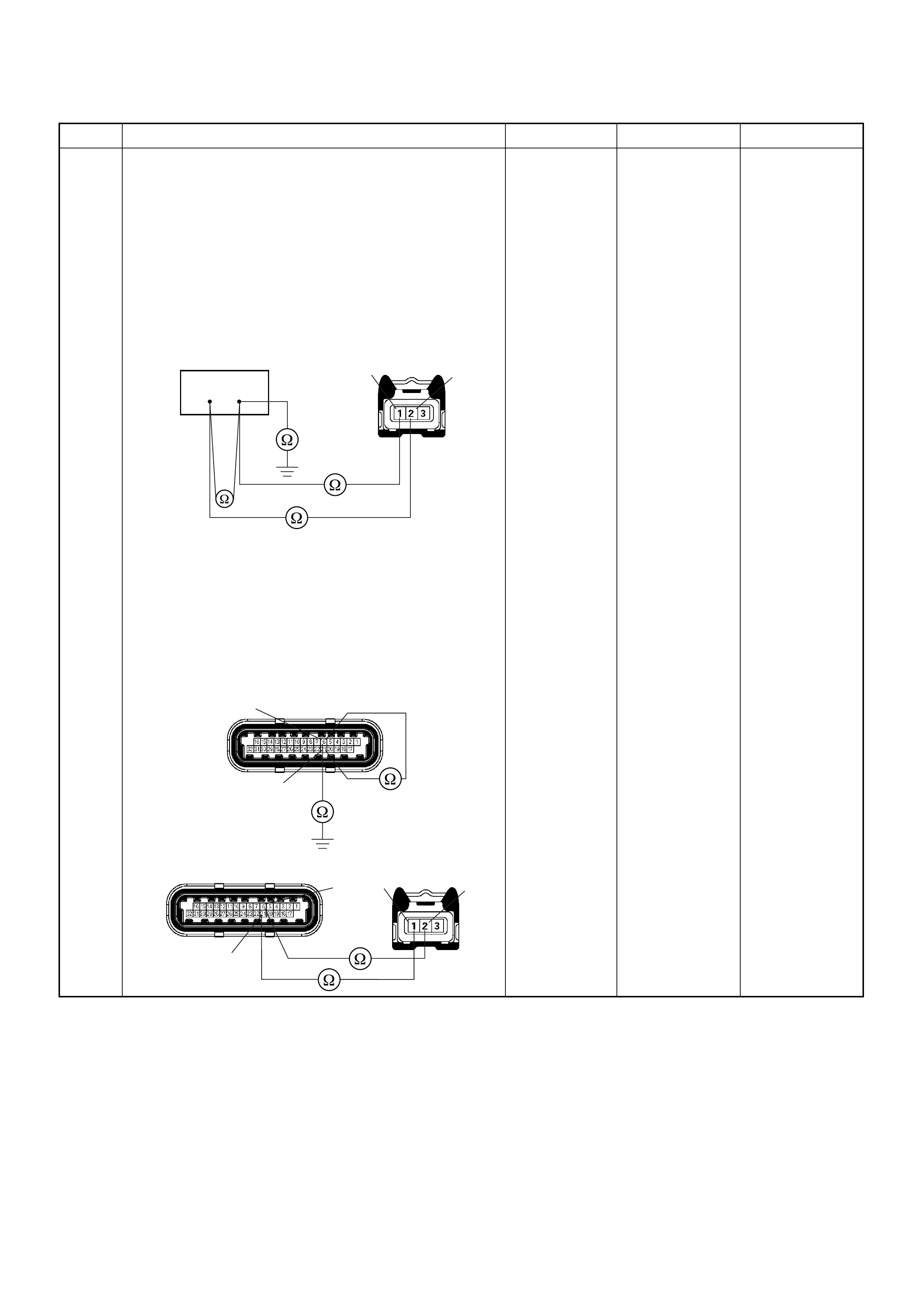
8 Using the DVM and check the CKP sensor circuit.
Breaker box is available:
1. Ignition “Off”, engine “Off”.
2. Install the breaker box as type A. (ECM
disconnected) Ref. 6E-80.
3. Disconnect the CKP sensor connector.
4. Check th e circuit for op en, short to sensor wire o r
short to ground circuit.
Was the problem found?
Breaker box is not available:
1. Ignition “Off”, engine “Off”.
2. Disconnect the ECM connector.
3. Disconnect the CKP sensor connector.
4. Check th e circuit for op en, short to sensor wire o r
short to ground circuit.
Was the problem found?
—
Repair faulty
harness and
verify repair Go to Step 9
Step Action Value(s) Yes No
621
E-59 21
6E-60(J1)
21
E-59
E-60(J1) 6
21
21
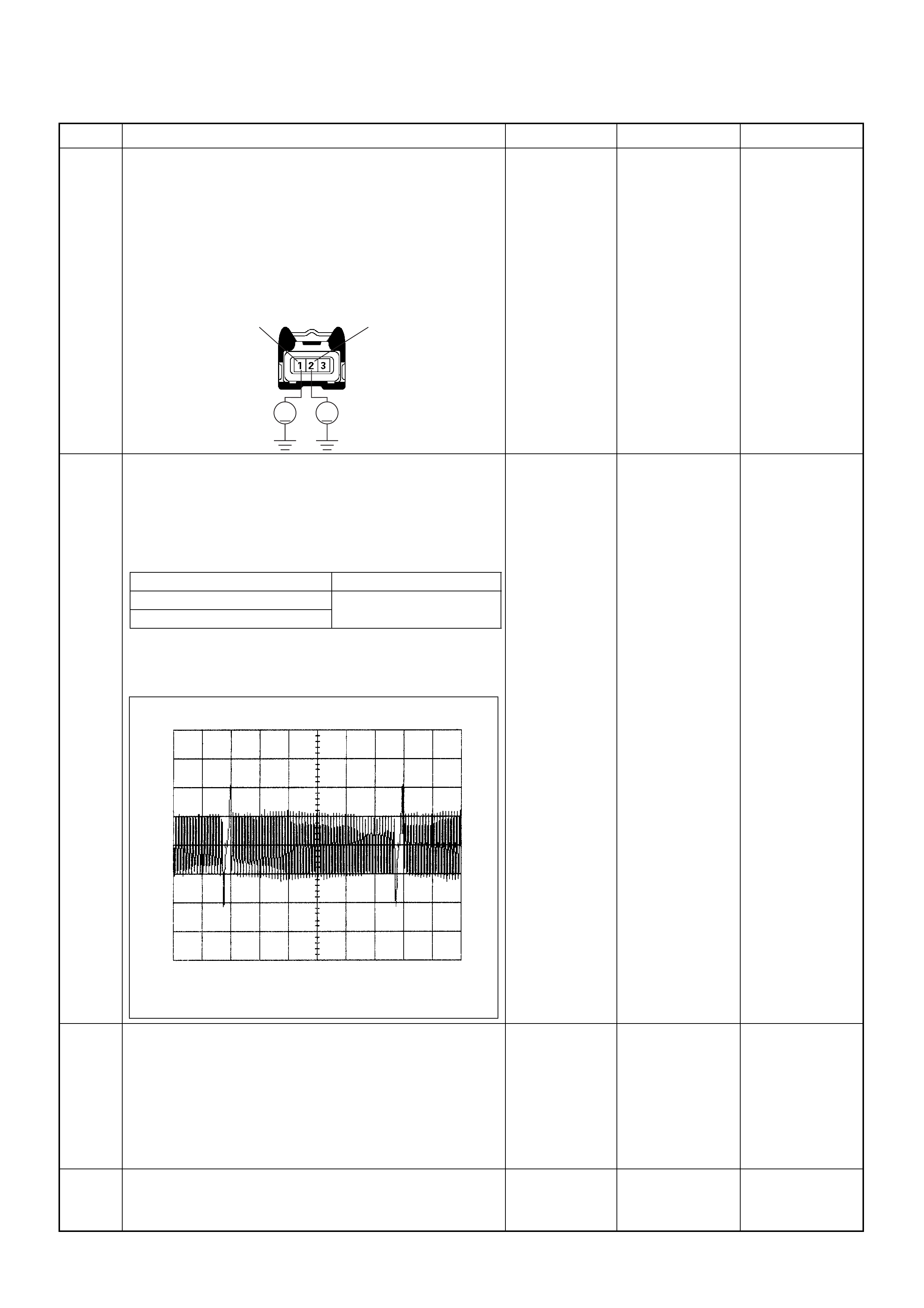
9 Using the DVM and check the CKP sensor circuit.
1. Ignition “On”, engine “Off”.
2. Disconnect the CKP sensor connector.
3. Check the circuit for short to power supply circuit.
If the DVM indicated out of specified value, repair
faulty harness and verify repair.
Is the action complete?
Less than 1V Verify repair —
10 Using the DVM and check the CKP sensor signal.
1. Ignition “On”, engine “On”.
2. Measure the CKP output voltage at the sensor
and ECM.
Does the tester indicate standard voltage?
If a oscilloscope is available, monitor the CKP sensor
signal. Does the oscilloscope indicate correct wave
form?
Go to Step 13 Go to Step 11
11 Remove the CKP sensor from the flywheel housing
and visually check.
Check for the following conditions.
• Objects sticking the CKP sensor.
• Objects sticking the CKP sensor pulser.
If a problem is found, repair as neces sa ry.
Was the problem found? — Verify repair Go to Step 12
12 Check the CKP sensor shield wire for open or short
circuit.
Was the problem found? —
Repair faulty
harness and
verify repair Go to Step 13
Step Action Value(s) Yes No
V V
E-59 2
1
Measurement Point V oltage (V) (AC Range)
At CKP sensor terminal 1 & 2 Approx. 3.7V in engine idle
Approx. 7.7V at 2000rpm
At ECM E60 (J1) connector 21 & 6
CKP Sensor Signal Reference Wave Form
0V→
Measurement Terminal: J1-21 (+) J1-6 (-)
Measurement Scale: 10V/div 5.0ms/div
Measurement Condition: Engine speed at 2000rpm

13 Check any accessory parts which may cause electric
interference or magnetic interference.
Was the problem found? —
Remove the
accessory parts
and verify repair Go to Step 14
14 Substitute a known good CKP sensor and recheck.
Was the problem solved ? — Go to Step 15 Go to Step 16
15 Replace the CKP sensor.
Was the problem solved? — Verify repair Go to Step 16
16 Is the ECM programmed with the latest software
release?
If not, download the latest software to the ECM using
the “SPS (Service Programming System)”.
Was the problem solved? — Verify repair Go to Step 17
17 Replace the ECM.
Is the action complete?
IMPORTANT: The replacement ECM must be
programmed. Refer to section of the Service
Programming System (SPS) in this manual.
Following EC M programming, the immobiliser system
(if equipped) must be linked to the ECM. Refer to
section 11 “Immobiliser System-ECM replacement” for
the ECM/Immobiliser linking procedure. — Verify repair —
Step Action Value(s) Yes No
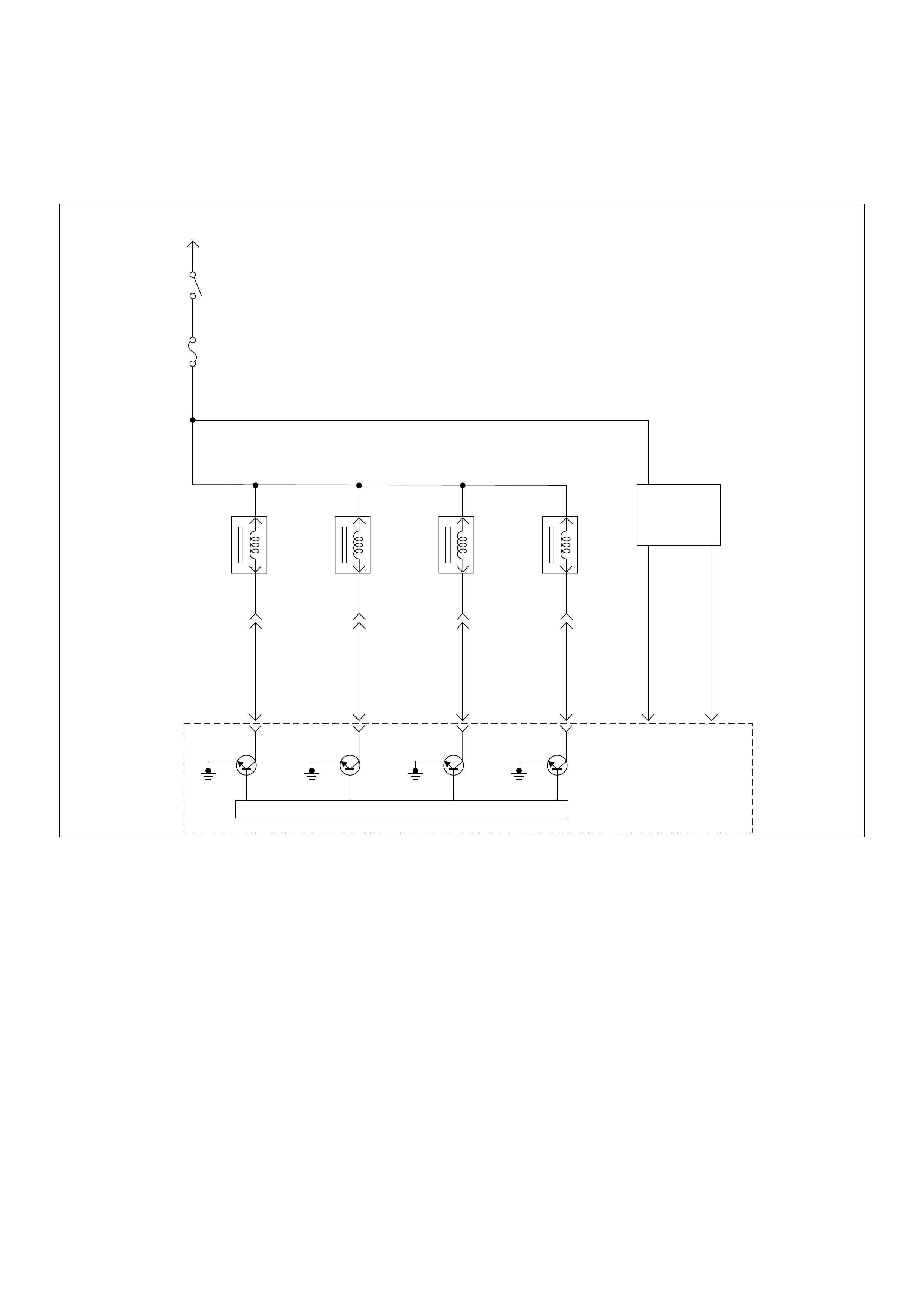
Diagnostic Trouble Code (DTC) P0351 Ignition 1 Control Circuit
Diagnostic Trouble Code (DTC) P0352 Ignition 2 Control Circuit
Battery Voltage
PNK/
BLU
Injector
#1
Cylinder
Injector
#2
Cylinder
Injector
#3
Cylinder
Injector
#4
Cylinder
J1-9
BLU/
BLK
J1-22
BLU/
WHT
J1-8
COIL
MODULE
BLU/
YEL
J1-11
0.85
GRN
J1-19
0.85
BLU
J1-18
µP
IGN
Switch
IGN
Fuse
15A
Engine
Control
Module
(ECM)

Condition for setting the DTC and action ta ken when the DTC sets
Circuit Description
The ignition control circuit provides a zero volt or a 5 volt
signal to the ignition control module. The normal circuit
voltage is zero volts. When the module receives the 5
volt signal from the ECM, it provides a ground path for
the B+ voltage supplied to the ignition primary coil.
When the ECM turns off the 5 volts to the module, the
module will remove the ground path of the ignition
primary coils; causing the magnetic field produces a
voltage in the secondary coils which fires the spark
plug.
The circuit between the ECM and the ignition control
module is monitored for an open circuit, short to voltage,
and shor t to ground. W hen the ECM detects a problem
in the ignition control circuit, it will set DTC P0351 or
P0352.
Diagnostic Aids
Check for the following conditions:
• Poor connection at the ECM - Inspect the harness
connectors for backed-out terminals, improper
mating, broken locks, improperly formed or damaged
terminals, and poor terminal-to-wire connections.
• Damaged harness - Inspect the wiring harness for
damage ; Open circuits, sh orts to ground, or shor ts to
Voltage. If the harness appears to be OK, observe
the Tech 2 display related to DTC P0351 or P0352
while moving the connector and wiring related to the
ignition system. A change in the display will indicate
the location of the fault.
Diagnostic Trouble Code (DTC) P0351 Ignition 1 Control Circuit
Diagnostic Trouble Code (DTC) P0352 Ignition 2 Control Circuit
Code Type DTC Name DTC Setting Condition Fail-Safe (Back Up)
P0351 A Ignition 1 Control Circuit #2 or #3cylinder ignition signals are not
detected consecutively. No fail- safe func tion.
P0352 A Ignition 2 Control Circuit #1 or #4 cylinder ignition signals are not
detected consecutively.
Step Action Value(s) Yes No
1 Was the “On-Board Di agnostic (OBD) System Check”
performed?
—Go to Step 2
Go to On
Board
Diagnostic
(OBD) System
Check
2 1. Connect the Tech 2.
2. Review and record the failure information.
3. Select “F0: Read DTC Infor By Priority” in “F0:
Diagnostic Trouble Code”.
Is the DTC P0351 or P0352 stored as “Present
Failure”? — Go to Step 3
Refer to
Diagnostic Aids
and Go to Step
3
3 1. Using the Tech2, ignition “On” and engine “Off”.
2. Select “Cl ear D TC I nform ati on” w ith th e Tech2 and
clear the DTC information.
3. Operate the vehicle and monitor the “F5: Failed
This Ignition” in “F2: DTC Information”.
Was the DTC P0351 or P0352 stored in this ignition
cycle? — Go to Step 4
Refer to
Diagnostic Aids
and Go to Step
4
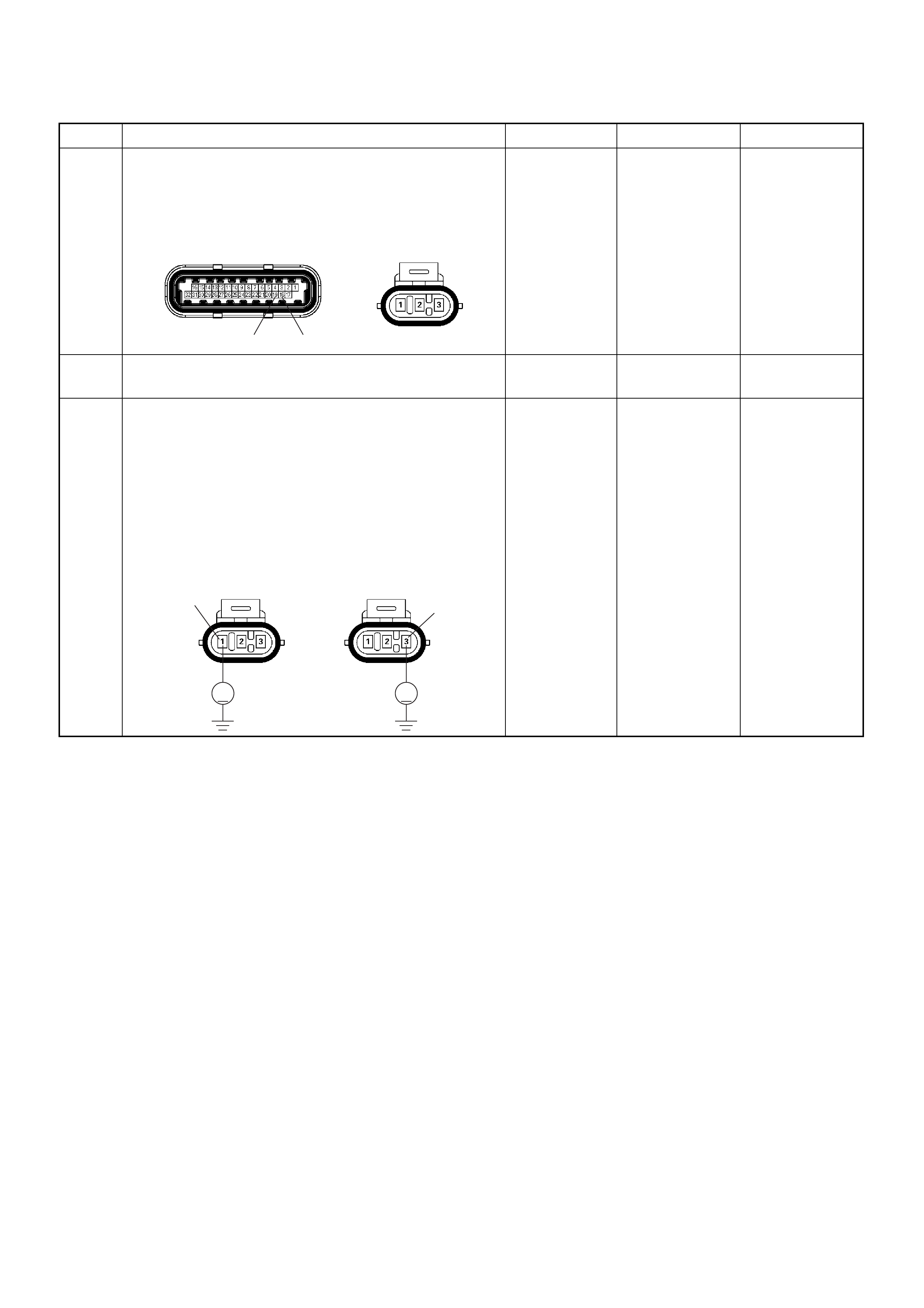
4 Check for poor/faulty connection at the ignition coil
module or ECM connector. If a poo r/faulty connec tion
is found, repair as necessary.
Was the problem found?
— Verify repair Go to Step 5
5 Visually check the ignition coil module.
Was the problem found? — Go to Step 12 Go to Step 6
6 Using the DVM and check the ignition coil module
signal circuit for the affected coil.
1. Ignition “On”, engine “Off”.
2. Disco nne ct the ign ition coi l mod ule conne ct or.
3. Check the circuit for short to battery voltage circuit
for the affected coil.
Was the DVM indicated battery voltage?
—
Repair faulty
harness and
verify repair Go to Step 7
Step Action Value(s) Yes No
19 18
E-60(J1) E-18
V
E-18
Coil 1
1
V
E-18 3
Coil 2
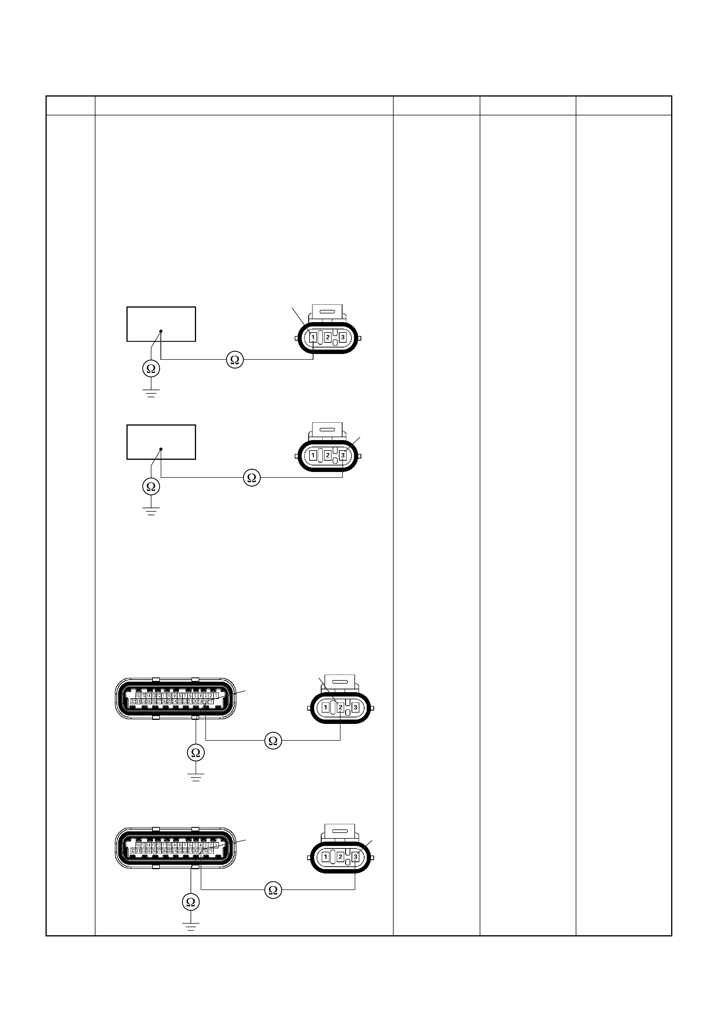
7 Using the DVM and check the ignition coil signal
circuit for the affected coil.
Breaker box is available:
1. Ignition “Off”, engine “Off”.
2. Install the breaker box as type A. (ECM
disconnected) Ref. 6E-80.
3. Disco nne ct the ign ition coi l mod ule conne ct or.
4. Check the circuit for open or short to ground circuit
for the affected coil.
Was the problem found?
Breaker box is not available:
1. Ignition “Off”, engine “Off”.
2. Disco nnect the i gnition coil module conn ector a nd
ECM connector.
3. Check the circuit for open or short to ground circuit
for the affected coil.
Was the problem found?
—
Repair faulty
harness and
verify repair Go to Step 8
Step Action Value(s) Yes No
18
E-18
1
Coil 1
19
E-18
3
Coil 2
E-18E-60(J1)
18 2
Coil 1
E-18E-60(J1)
19 3
Coil 2

8 Using the DVM and check the ignition coil module
power supply circuit.
1. Ignition “On”, engine “Off”.
2. Disco nne ct the ign ition coi l mod ule conne ct or.
3. Check the ci rcui t for open circuit.
Was the DVM indicated specified value?
Battery
voltage Go to Step 10 Go to Step 9
9 Repair the open or short to ground circuit between the
“IGN. Coil” fuse (15A) and ignition coil module.
Is the action complete? — Verify repair —
10 Replace the ignition coil module.
Was the problem solved? — Verify repair Go to Step 1 1
11 Is the ECM programmed with the latest software
release?
If not, download the latest software to the ECM using
the “SPS (Service Programming System)”.
Was the problem solved? — Verify repair Go to Step 12
12 Replace the ECM.
Is the action complete?
IMPORTANT: The replacement ECM must be
programmed. Refer to section of the Service
Programming System (SPS) in this manual.
Following EC M programming, the immobiliser system
(if equipped) must be linked to the ECM. Refer to
section 11 “Immobiliser System-ECM replacement” for
the ECM/Immobiliser linking procedure. — Verify repair —
Step Action Value(s) Yes No
V
E-18
2
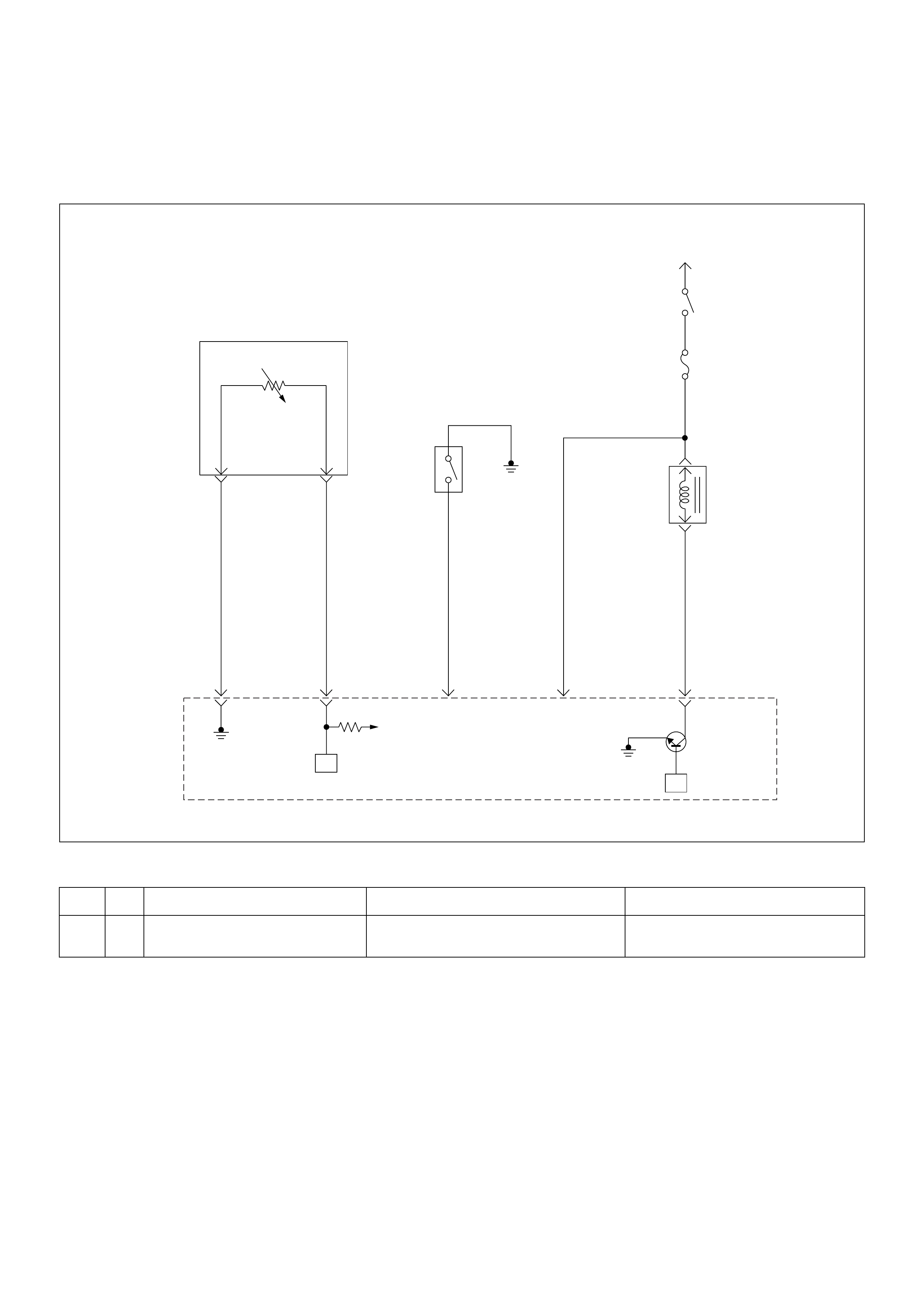
Diagnostic Trouble Code (DTC) P0443 Evaporative Emission (EVAP) Control
System Purge Control Valve Circuit Malfunction
Condition for setting the DTC and action ta ken when the DTC sets
Circuit Description
The Engine Control Module (ECM) controls the
Evaporative Emission (EVAP) Canister Purge Solenoid
Valve thr oug h the u se of a contr ol (g rou nd) cir cuit. If th e
ECM commands the Purge solenoid to maximum duty
cycle (100%) but the voltage remains High (12 Volts);
or, if the ECM commands the Purge solenoid to
minimum duty cycle (0%) but the voltage remains Low
(0 volts), then DTC P0443 will set.
Diagnostic Aids
• Poor connections, or a damaged harness - Inspect
the harness connectors for: backed-out terminals,
improper mating or damaged terminals. Also check
for open circuits, shorts to ground, and shorts to
voltage.
Code Type DTC Name DTC Setting Condition Fail-Safe (Back Up)
P0443 B EVAP Em ission Control System Purge
Control Circuit EVAP purge solenoid circuit open, short to
ground or short to voltage circuit. No fail -safe fun ction.
Intake
Air
Temperature(IAT)
Sensor
0.5
GRN
J2-1
0.5
YEL/
GRN
J2-22
0.5
GRN/
YEL
J2-20
0.5
BLU/
YEL
0.5
BLU/
YEL
Engine
15A
Ignition
SW
Battery V oltage
J2-3
0.5
GRN/
WHT
J1-5
+5V
µPµP
Power
Steering
Pressure
SW
Evaporativ
Emission(EVAP)
Canistor
Purge
Valve
Solenoid
Engine
Control
Module
(ECM)
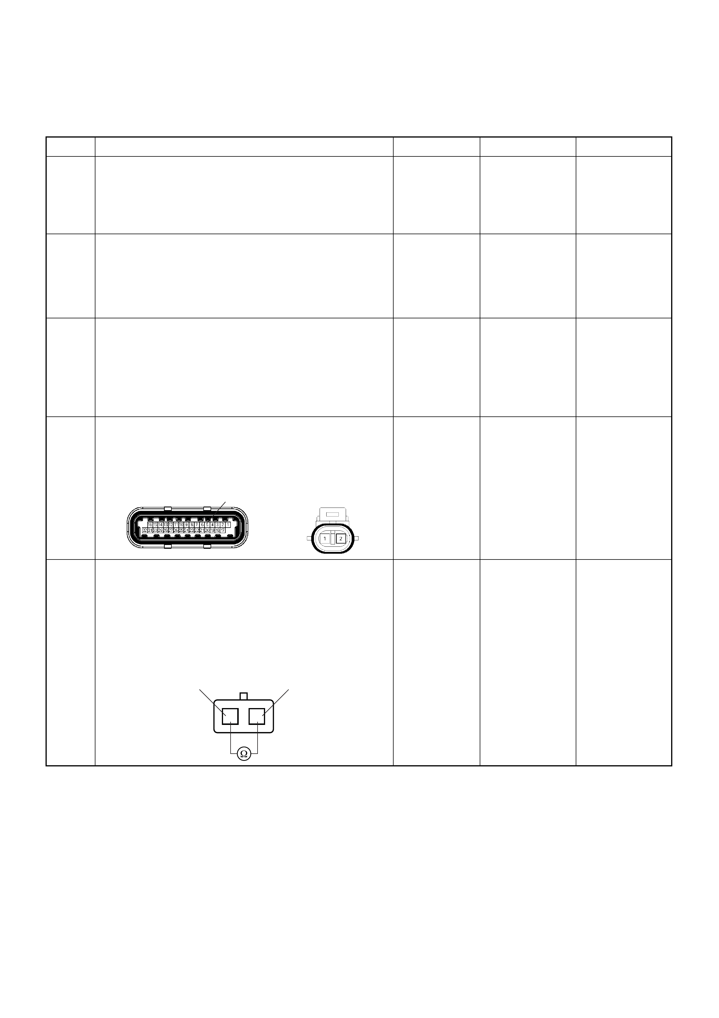
Diagnostic Trouble Code (DTC) P0443 EVAP Emission Control
System Purge Control Circuit
Step Action Value(s) Yes No
1 Was the “On-Board Di agnostic (OBD) System Check”
performed?
—Go to Step 2
Go to On
Board
Diagnostic
(OBD) System
Check
2 1. Connect the Tech 2.
2. Review and record the failure information.
3. Select “F0: Read DTC Infor By Priority” in “F0:
Diagnostic Trouble Code”.
Is the DTC P0443 stored as “Present Failure”? — Go to Step 3
Refer to
Diagnostic Aids
and Go to Step
3
3 1. Using the Tech2, ignition “On” and engine “Off”.
2. Select “Cl ear D TC I nform ati on” w ith th e Tech2 and
clear the DTC information.
3. Operate the vehicle and monitor the “F5: Failed
This Ignition” in “F2: DTC Information”.
Was the DTC P0443 stored in this ignition cycle? — Go to Step 4
Refer to
Diagnostic Aids
and Go to Step
4
4 Check for poor/faulty connection at the purge solenoid
valve or ECM connecto r. If a poor /faulty connec tion is
found, repair as necessary.
Was the problem found?
— Verify repair Go to Step 5
5 Using the DVM and check the purge solenoid valve.
1. Ignition “Off”, engine “Off”.
2. Disconnect purge solenoid valve connector.
3. Measure the resistance of purge solenoid valve
coil.
Does the tester indicate standard resistance?
25 - 30Ω at
20°C Go to Step 6 Go to Step 9
5
E-60(J1) E-66
12
EVAP Purge Solenoid
12

6 Using the DVM and check the purge solenoid valve
power supply circuit.
1. Ignition “On”, engine “Off”.
2. Disco nne ct the pur ge so len oid valv e con nec to r.
3. Check the ci rcui t for open circuit.
Was the DVM indicated specified value?
Battery
voltage Go to Step 8 Go to Step 7
7 Repair the open or short to ground circuit between the
“Engine” fuse (15A) and purge solenoid valve.
Is the action complete? — Verify repair -
8 Using the DVM and check the purge solenoid valve
solenoid signal circuit.
Breaker box is available:
1. Ignition “Off”, engine “Off”.
2. Install the breaker box as type A. (ECM
disconnected) Ref. 6E-80.
3. Disco nne ct the pur ge so len oid valv e con nec to r.
4. Check the circuit for open or short to ground
circuit.
Was the problem found?
Breaker box is not available:
1. Ignition “Off”, engine “Off”.
2. Disconnect the purge solenoid valve connector
and ECM conne cto r.
3. Check the circuit for open or short to ground
circuit.
Was the problem found?
—
Repair faulty
harness and
verify repair Go to Step 9
Step Action Value(s) Yes No
V
E-66 2
5
E-66
1
E-66
E-60(J1) 51

9 Using the DVM and check the purge solenoid valve
signal circuit.
1. Ignition “On”, engine “Off”.
2. Disco nne ct the pur ge so len oid valv e con nec to r.
3. Check the circuit for short to battery voltage
circuit.
Was the DVM indicated battery voltage?
—
Repair faulty
harness and
verify repair Go to Step 10
10 Substitute a known good purge solenoid valve and
recheck.
Was the problem solved? — Go to Step 11 Go to Step 12
11 Replace the purge solenoid valve.
Was the problem solved? — Verify repair Go to Step 12
12 Is the ECM programmed with the latest software
release?
If not, download the latest software to the ECM using
the “SPS (Service Programming System)”.
Was the problem solved? — Verify repair Go to Step 13
13 Replace the ECM.
Is the action complete?
IMPORTANT: The replacement ECM must be
programmed. Refer to section of the Service
Programming System (SPS) in this manual.
Following EC M programming, the immobiliser system
(if equipped) must be linked to the ECM. Refer to
section 11 “Immobiliser System-ECM replacement” for
the ECM/Immobiliser linking procedure. — Verify repair —
Step Action Value(s) Yes No
V
E-66
1
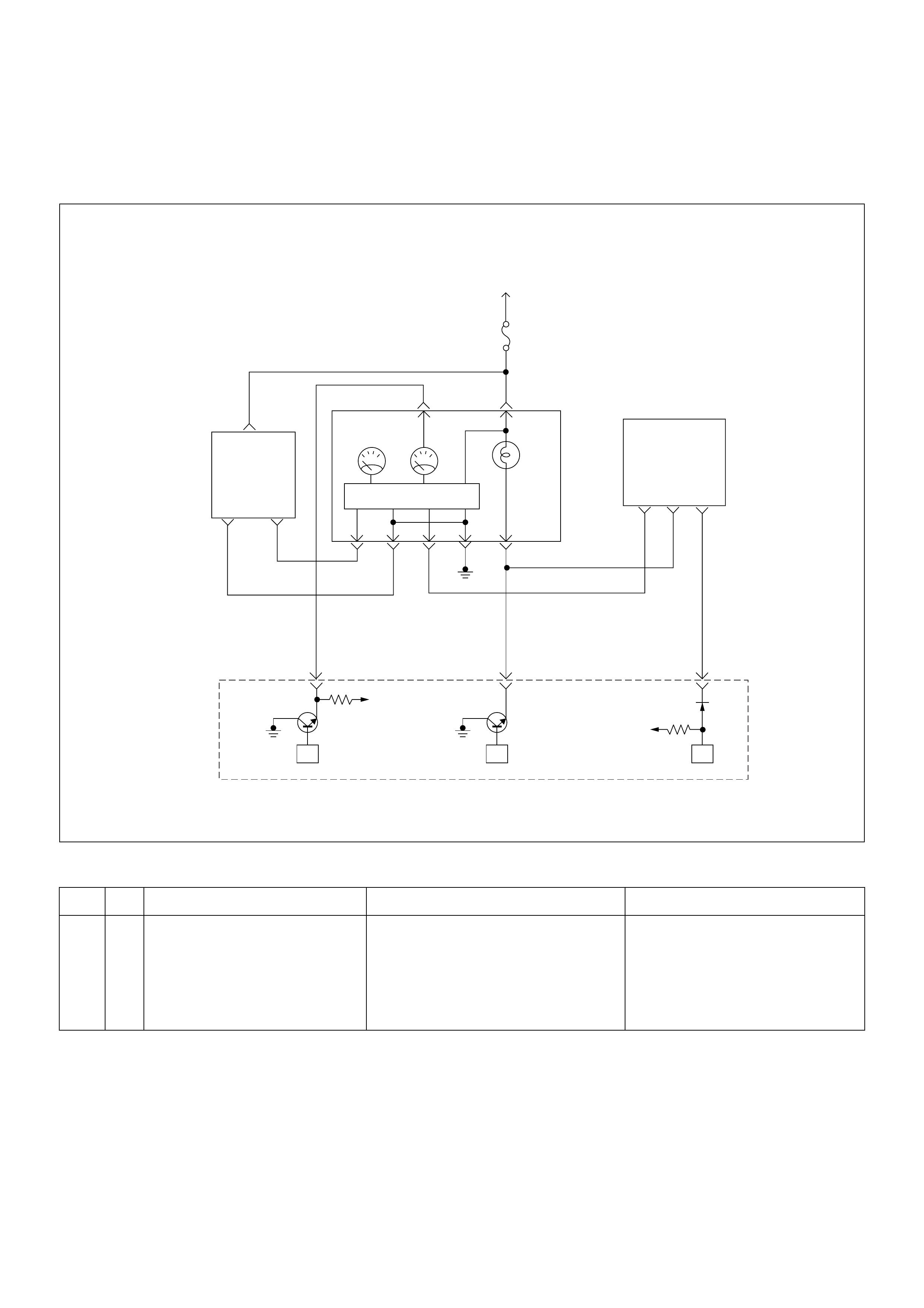
Diagnostic Trouble Code (DTC) P0502 Vehicle Speed Sensor (VSS)
Circuit Low Input
Condition for setting the DTC and action ta ken when the DTC sets
Circuit Description
The vehicle speed sensor has a magnet rotated by the
transmission output shaft. Attached to the sensor is a
hall effect circuit that interacts with the magnetic field
created by the rotating magnet. A 12-volt operating
supply fo r the speed sensor hall circuit is suppli ed from
the meter fuse.
Diagnostic Aids
• Poor connection at ECM: Inspect harness connectors
for backed out terminals, improper mating, broken
locks, improperly formed or damaged terminals, and
poor terminal to wire connection.
Code Type DTC Name DTC Setting Condition Fail-Safe (Back Up)
P0502 B Vehicle Speed Sensor Circuit Low
Input 1. No DTC relating to MAP sensor, TPS, ECT
sensor, injector control circuit and ignition
control circuit.
2. Engine is running.
3. V ehicle speed is below 3km/h in power
condition or 2km/h in deceleration condi-
tion.
ECM uses 0km/h condition as substitute.
VIgn
Engine
Control
Module
(ECM)
Ignition
SW
µPµPµP
Meter
15A
VIgn
Check
Engine
Sped
Meter Tacho
Meter
0.85
YEL
0.8 YEL/GRN
0.5 BRN/YEL
CPU
0.5
WHT
J2-23J2-25
0.5
BRN/
YEL
(–) (+)
Vehicle
Speed
Sensor
J2-32
678
Imnobiliser
Control
Unit
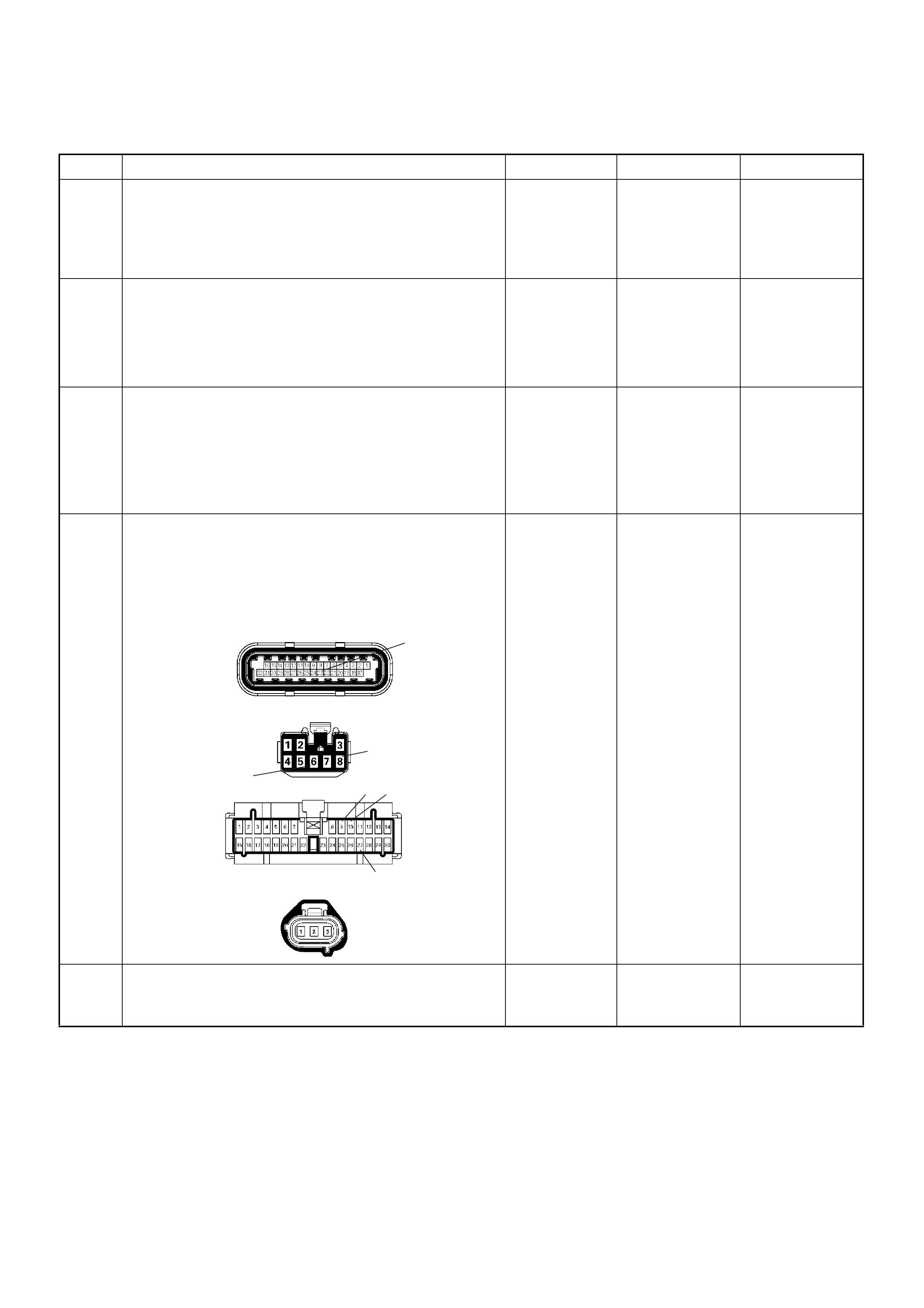
Diagnostic Trouble Code (DTC) P0502 Vehicle Speed Sensor Circuit Low Input
Step Action Value(s) Yes No
1 Was the “On-Board Di agnostic (OBD) System Check”
performed?
—Go to Step 2
Go to On
Board
Diagnostic
(OBD) System
Check
2 1. Connect the Tech 2.
2. Review and record the failure information.
3. Select “F0: Read DTC Infor By Priority” in “F0:
Diagnostic Trouble Code”.
Is the DTC P0502 stored as “Present Failure”? — Go to Step 3
Refer to
Diagnostic Aids
and Go to Step
3
3 1. Using the Tech2, ignition “On” and engine “Off”.
2. Select “Cl ear D TC I nform ati on” w ith th e Tech2 and
clear the DTC information.
3. Operate the vehicle and monitor the “F5: Failed
This Ignition” in “F2: DTC Information”.
Was the DTC P0502 stored in this ignition cycle? — Go to Step 4
Refer to
Diagnostic Aids
and Go to Step
4
4 Check for poor/faulty connection at the VSS, meter,
immobiliser control unit (if equipped), ECM and other
connecto rs . If a poo r /faulty c onn ectio n i s foun d, re pair
the faulty termina l.
Was the problem found?
— Verify repair Go to Step 5
5 Remove the VSS from the housing case and visually
check.
Was the problem found? — Go to Step 19 Go to Step 6
6
8
23
27
910
C-56(J2)
B-68
B-24
E-44
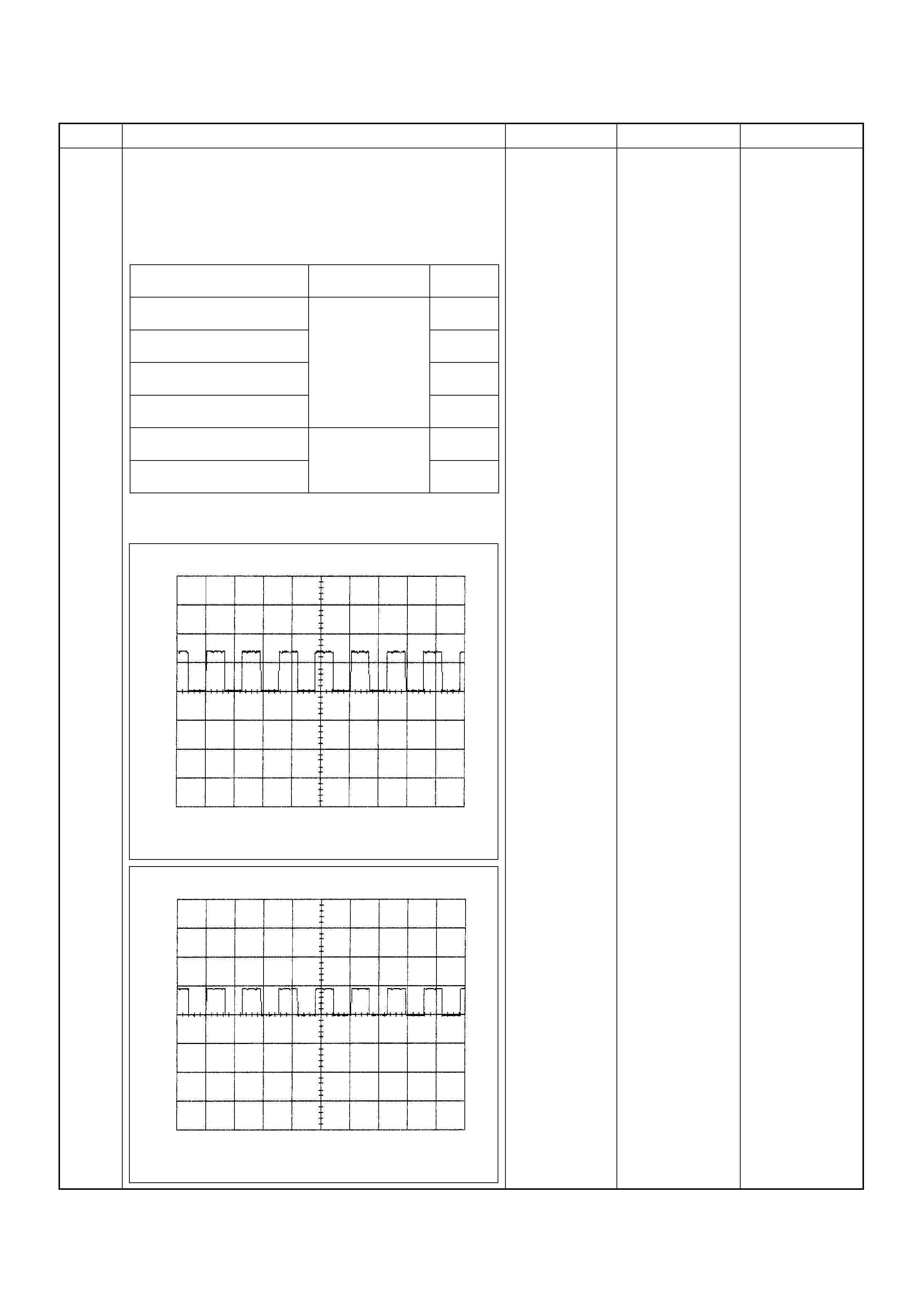
6 Using the DVM and check the VSS signal.
1. Ignition “On”, vehicle “Run (lift up)”.
2. Measur e the VSS outp ut voltag e at sensor, meter,
immobiliser control unit (if equipped) and ECM.
Does the tester indicate specified value?
If a oscilloscope is available, monitor the VSS signal.
Does the oscilloscope indicate correct wave form?
Refer to
Diagnostic Aids
and Go to Step
21 Refer the table
Step Action Value(s) Yes No
Measurement Position Voltage (V)
(AC Range) If No
Good
VSS terminal 3 & GND Approximately
7.0 V at 20km/h Go to
Step 7
Meter B24 connector 9 &
GND Go to
Step 11
Meter B24 connector 10 &
GND Go to
Step 13
Immobiliser control unit B68
connector 6 & GND Go to
Step 14
Immobiliser control unit B68
connector 8 & GND Approximately
4.8 V at 20km/h Go to
Step 16
ECM C56 (J2) connector 23 &
GND Go to
Step 17
Vehicle Speed Sensor Reference Wave Form
0V→
Measurement Scale: 10V/div 50ms/div
Measurement Condition: Vehicle speed 20km/h
Measurement Terminal: At Vehicle Speed Sens or
Vehicle Speed Sensor Reference Wave Form
0V→
Measurement Scale: 10V/div 50ms/div
Measurement Condition: Vehicle speed 20km/h
Measurement Terminal: At Engine Control Module
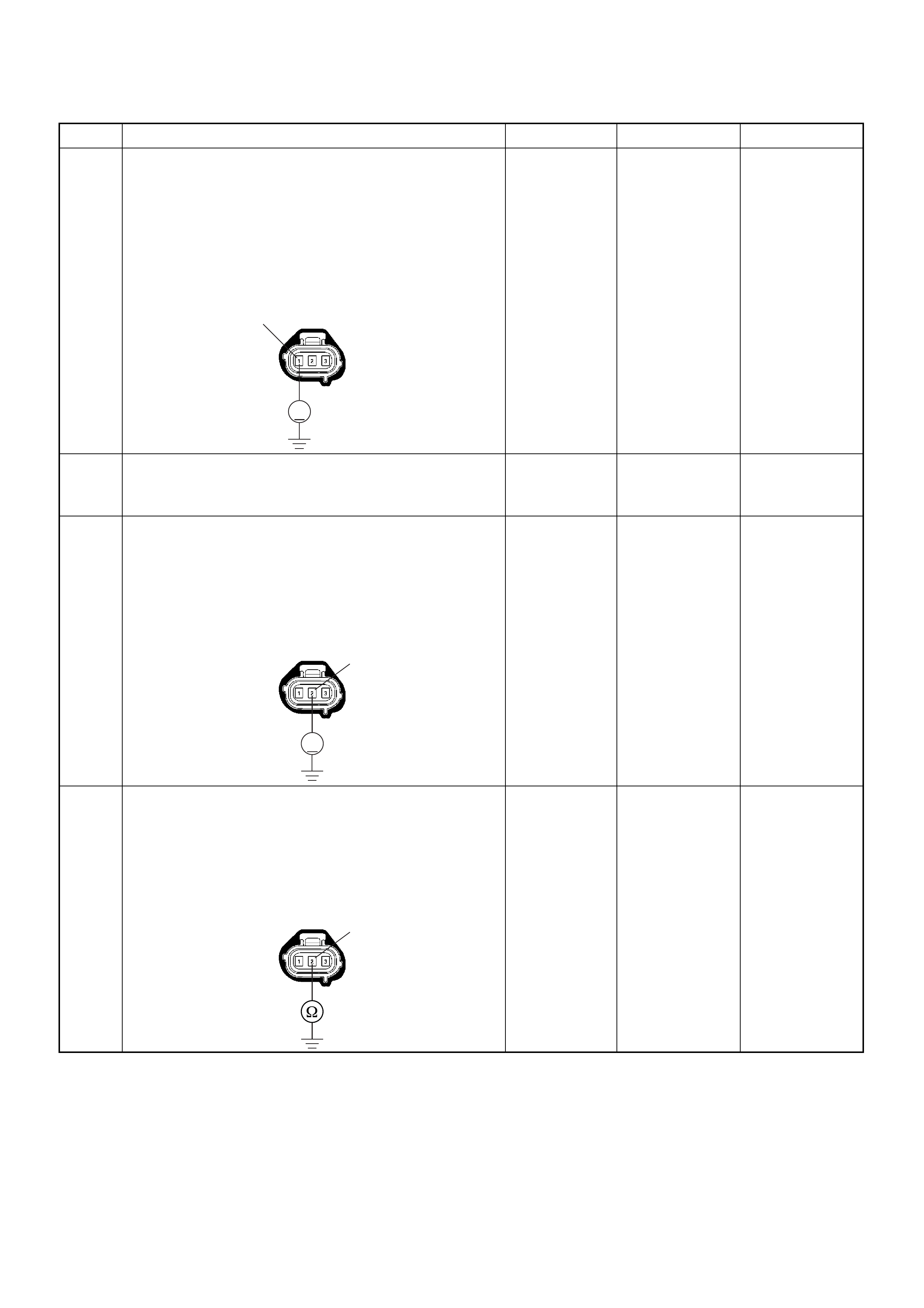
7 Using the DVM and check the VSS power supply
circuit.
1. Ignition “On”, engine “Off”.
2. Disconnect the VSS connector.
3. Check the circuit for open or short to ground
circuit.
Was the DVM indicated specified value?
Battery
voltage Go to Step 9 Go to Step 8
8 Repair the open circuit between the VSS and meter
fuse.
Is the action complete? — Verify repair —
9 Using the DVM and check the VSS ground circuit.
1. Ignition “On”, engine “Off”.
2. Disconnect the VSS connector.
3. Check the circuit for short to power supply circuit.
Was the DVM indicated specified value?
Less than 1V Go to Step 10
Repair faulty
harness and
verify repair
10 Using the DVM and check the VSS ground circuit.
1. Ignition “Off”, engine “Off”.
2. Disconnect the VSS connector.
3. Check the ci rcui t for open circuit.
Was the problem found?
—
Repair faulty
harness and
verify repair Go to Step 19
Step Action Value(s) Yes No
V
E-44
1
V
E-44 2
E-44 2
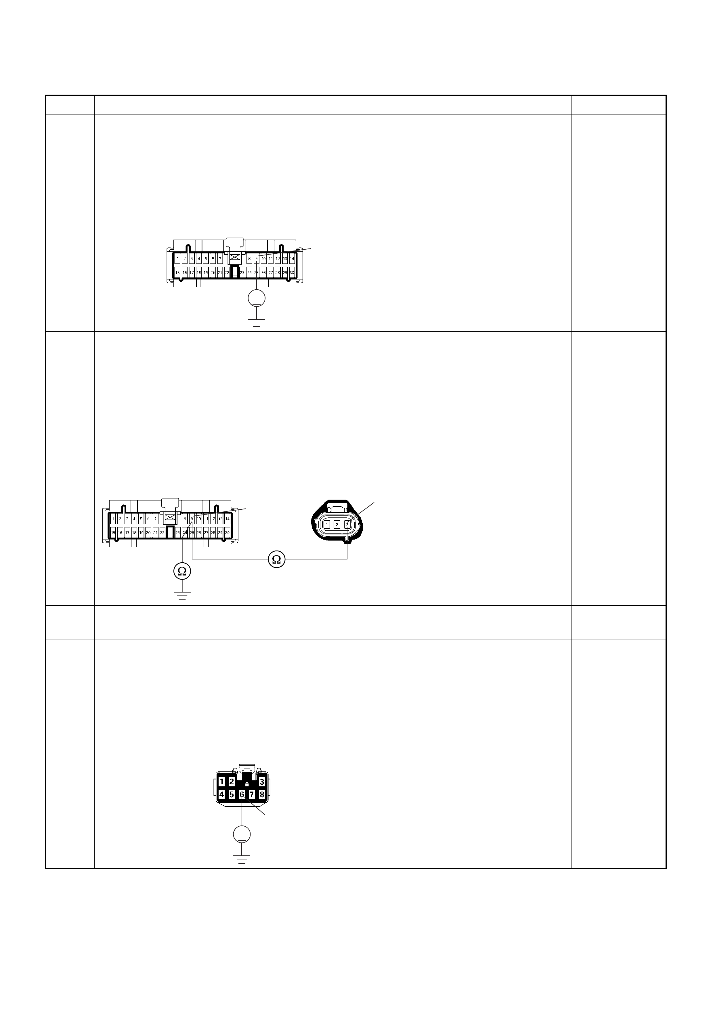
11 Using the DVM and check the VSS signal circuit.
1. Ignition “On”, engine “Off”.
2. Disconnect the VSS connector and meter
connector.
3. Check the circuit for short to power supply circuit.
Was the DVM indicated specified value?
Less than 1V Go to Step 12
Repair faulty
harness and
verify repair
12 Using the DVM and check the VSS signal circuit.
1. Ignition “Off”, engine “Off”.
2. Disconnect the VSS connector and meter
connector.
3. Check the circuit for open or short to ground
circuit.
If a open or short to g round circui t is found, re pair the
faulty harness and verify repair.
Is the action complete?
— Verify repair —
13 Replace the speed meter.
Is the action complete? — Verify repair —
14 Using the DVM and check the VSS signal circuit.
1. Ignition “On”, engine “Off”.
2. Disconnect the meter connector and immobiliser
control unit connector (if equipped).
3. Check the circuit for short to power supply circuit.
Was the DVM indicated specified value?
Less than 1V Go to Step 15
Repair faulty
harness and
verify repair
Step Action Value(s) Yes No
V
B-24
9
B-24
9
E-44 3
V
B-68
6
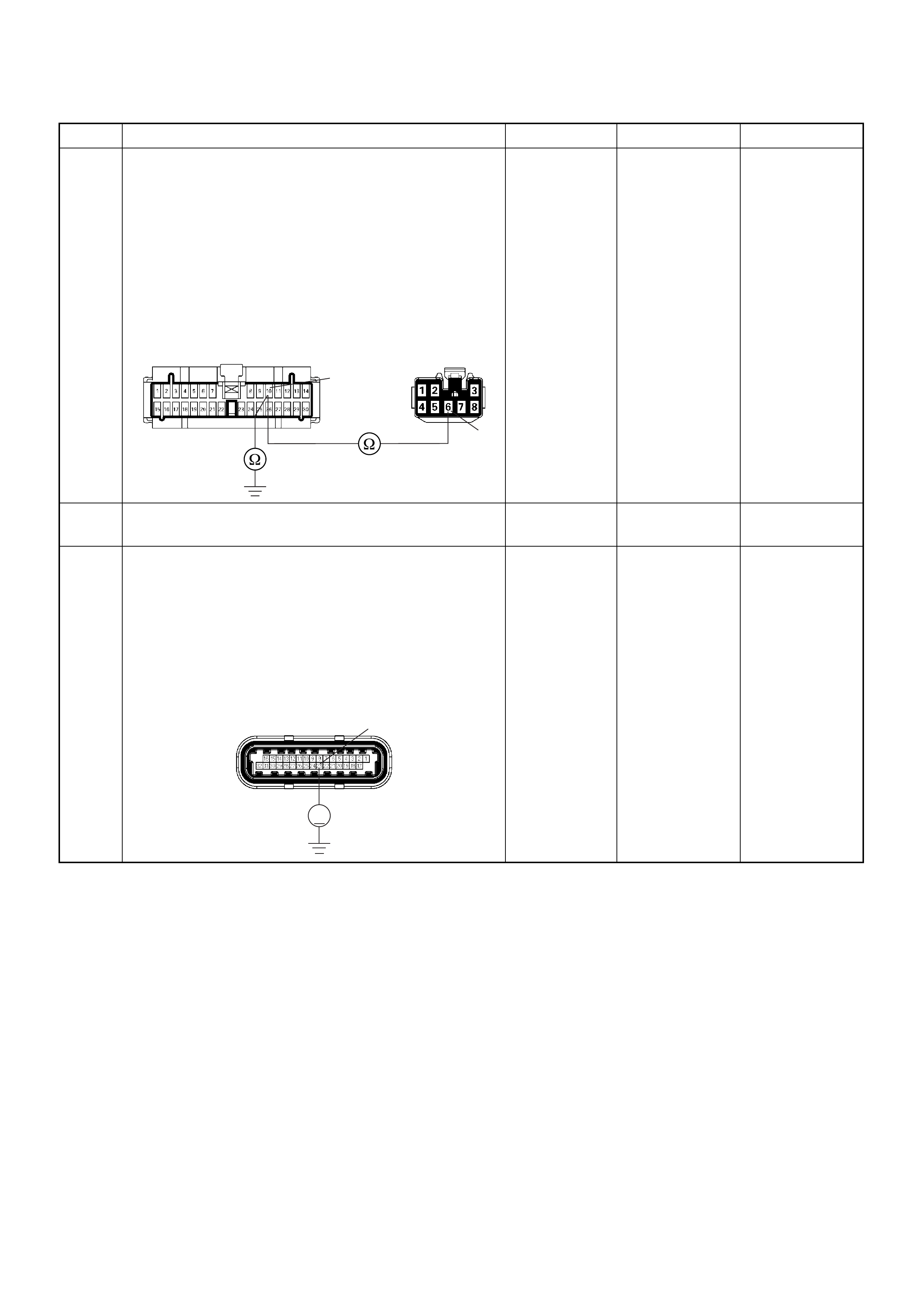
15 Using the DVM and check the VSS signal circuit.
1. Ignition “Off”, engine “Off”.
2. Disconnect the meter connector and immobiliser
control unit connector (if equipped).
3. Check the circuit for open or short to ground
circuit.
If a open or short to g round circui t is found, re pair the
faulty harness and verify repair.
Is the action complete?
— Verify repair —
16 Replace the immobiliser control unit (if equipped).
Is the action complete? — Verify repair —
17 Using the DVM and check the VSS signal circuit.
1. Ignition “Off”, engine “Off”.
2. Disconnect the immobiliser control unit connector
(if equip ped ) and ECM conne ct or.
3. Ignition “On”.
4. Check the circuit for short to power supply circuit.
Was the DVM indicated specified value?
Less than 1V Go to Step 18
Repair faulty
harness and
verify repair
Step Action Value(s) Yes No
B-24
10
B-68
6
V
C-56(J2) 23

18 Using the DVM and check the VSS signal circuit.
Breaker box is available:
1. Ignition “Off”, engine “Off”.
2. Install the breaker box as type A. (ECM
disconnected) Ref. 6E-80.
3. Disconnect the immobiliser control unit connector
(if equipped).
4. Check the circuit for open or shot to ground circuit.
Was the problem found?
Breaker box is not available:
1. Ignition “Off”, engine “Off”.
2. Disconnect the immobiliser control unit connector
(if equip ped ) and ECM conne ct or.
3. Check the circuit for open or short to ground
circuit.
Was the problem found?
—
Repair faulty
harness and
verify repair Go to Step 21
19 Substitute a known good VSS and recheck.
Was the problem solved ? — Go to Step 20 Go to Step 21
20 Replace the VSS.
Was the problem solved? — Verify repair Go to Step 21
21 Is the ECM programmed with the latest software
release?
If not, download the latest software to the ECM using
the “SPS (Service Programming System)”.
Was the problem solved? — Verify repair Go to Step 22
22 Replace the ECM.
Is the action complete?
IMPORTANT: The replacement ECM must be
programmed. Refer to section of the Service
Programming System (SPS) in this manual.
Following EC M programming, the immobiliser system
(if equipped) must be linked to the ECM. Refer to
section 11 “Immobiliser System-ECM replacement” for
the ECM/Immobiliser linking procedure. — Verify repair —
Step Action Value(s) Yes No
55
B-68 8
B-68C-56(J2) 23
8
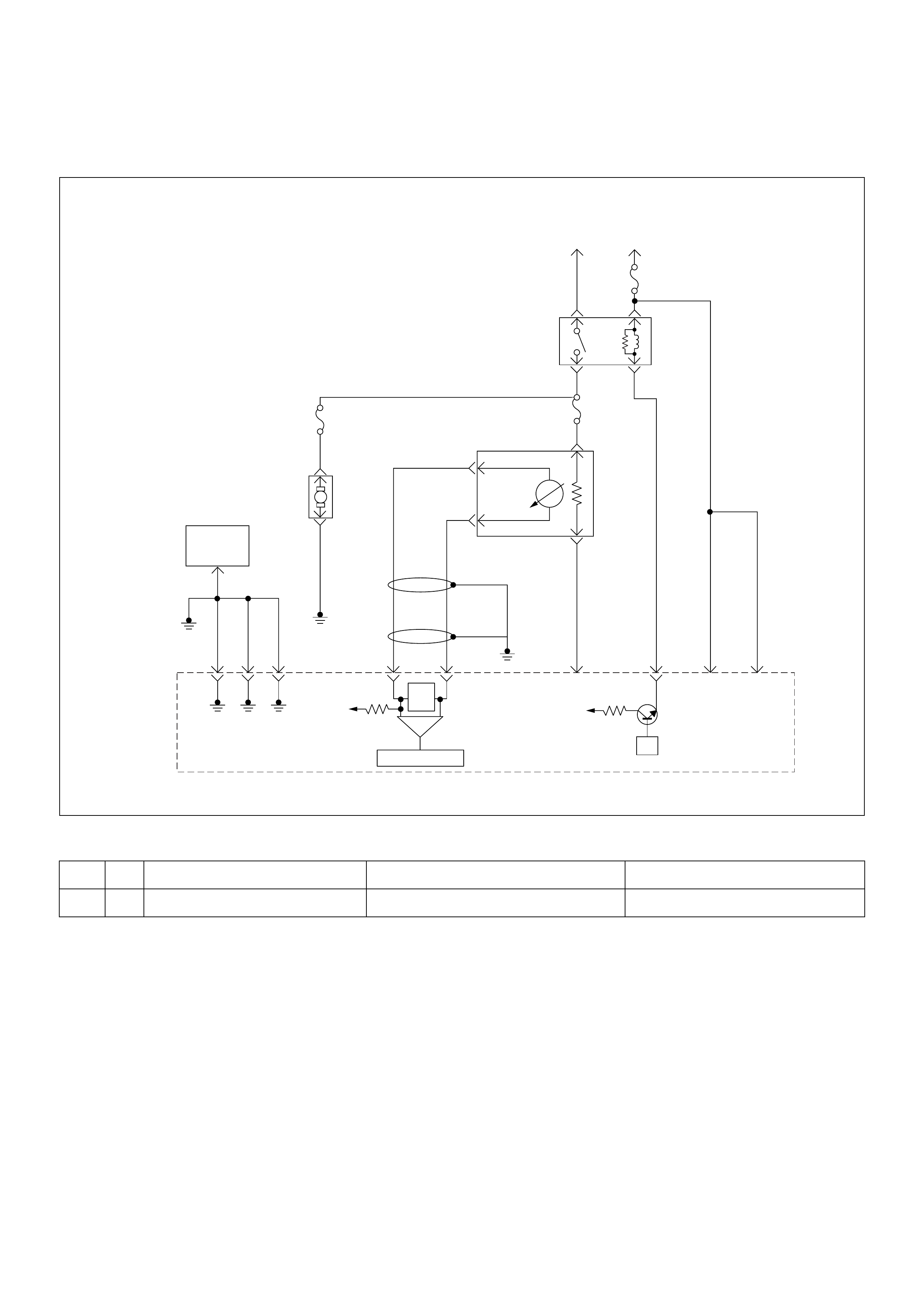
Diagnostic Trouble Code (DTC) P0562 System Voltage Low
Condition for setting the DTC and action ta ken when the DTC sets
Circuit Description
The engine cont rol module (EC M) monitors the system
voltage on the ignition feed terminal to the ECM. A
system voltage Diagnostic Trouble Code will set
whenever the voltage is below a calibrated value.
Diagnostic Aids
• If the Diagnostic Trouble Code sets when an
accessory is operated, check for a poor connection or
excessive current draw.
• Check for open circuits or shorts to ground on the
ECM’s battery or ignition inputs.
Code Type DTC Name DTC Setting Condition Fail-Safe (Back Up)
P0562 D S yst em Voltage Low Battery voltage is below 11V. No fail-safe function.
µP
VIgn
-
+
Crankshaft
Position
Sensor
J1-1 J1-2 J1-17
Battery
Voltage
Battery
Voltage
2.0
WHT ECM
10A
450
mV
A/D Converter
Vcc
+5V -+
TIMING
COVER
J2-6 J2-21
Fuel
Pump
FUEL
PUMP
20A
2.0
BLK
2.0
BLK/
BLU
Fuel
Pump
Relay
O2
SENSOR
10A
Heated
O2
Sensor
0.85
RED/
WHT
0.5
GRN/
WHT
0.5
RED/
WHT
0.5
BLU/
WHT
0.5
BLU
0.5 PNK
J2-31 J2-11 J2-2 J2-18
M
Engine
Control
Module
(ECM)
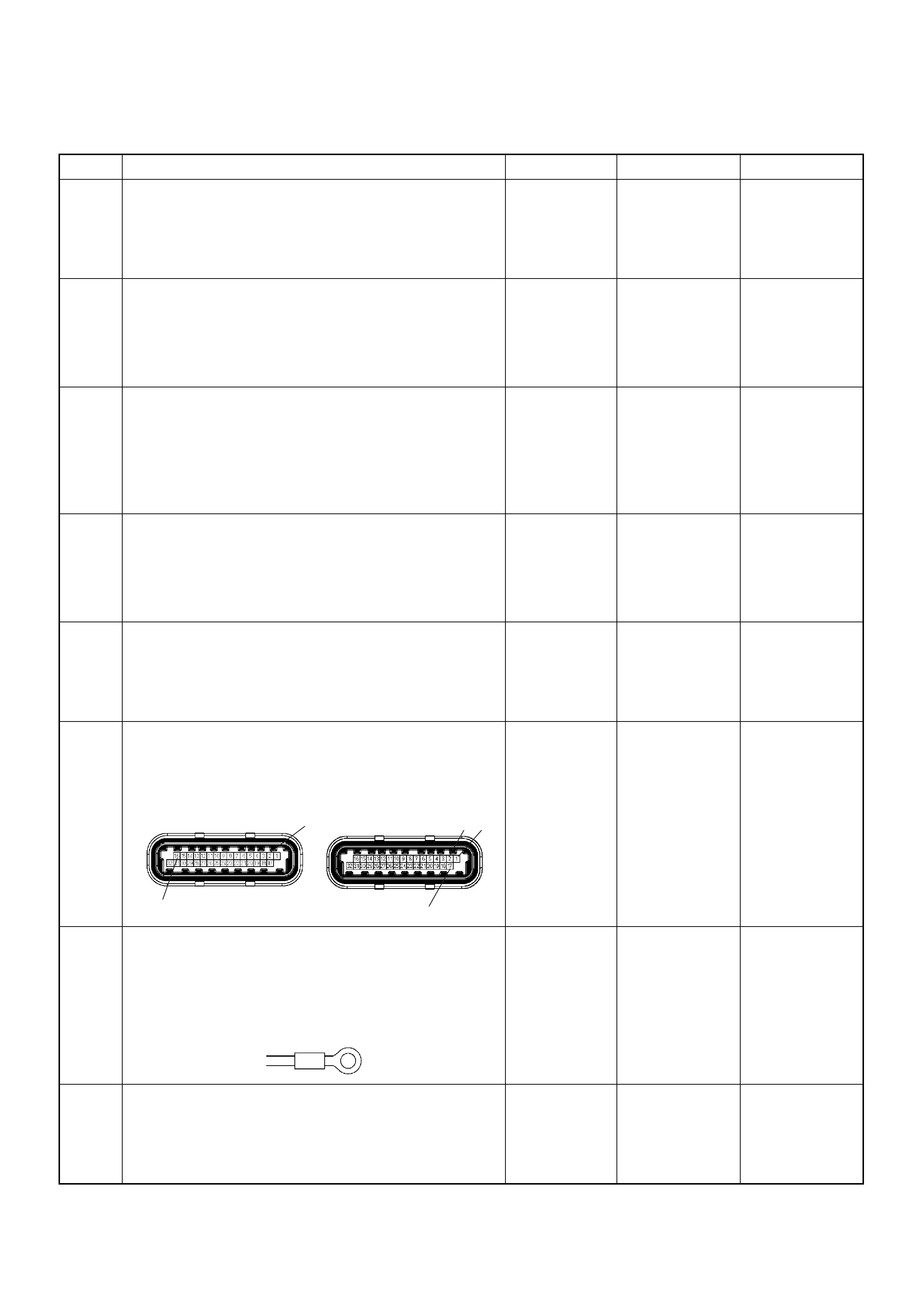
Diagnostic Trouble Code (DTC) P0562 System Voltage Low
Step Action Value(s) Yes No
1 Was the “On-Board Di agnostic (OBD) System Check”
performed?
—Go to Step 2
Go to On
Board
Diagnostic
(OBD) System
Check
2 1. Connect the Tech 2.
2. Review and record the failure information.
3. Select “F0: Read DTC Infor By Priority” in “F0:
Diagnostic Trouble Code”.
Is the DTC P0562 stored as “Present Failure”? — Go to Step 3
Refer to
Diagnostic Aids
and Go to Step
3
3 1. Using the Tech2, ignition “On” and engine “Off”.
2. Select “Cl ear D TC I nform ati on” w ith th e Tech2 and
clear the DTC information.
3. Operate the vehicle and monitor the “F5: Failed
This Ignition” in “F2: DTC Information”.
Was the DTC P0562 stored in this ignition cycle? — Go to Step 4
Refer to
Diagnostic Aids
and Go to Step
4
4 1. Using the Tech 2, ignition “On” and engine “On”.
2. Monitor the “Ignition Voltage” in the data display.
3. Load the electrical system by turning on the
headlights, etc..
Does the Tech 2 indicate enough ignition voltage? 10 - 14V Go to Step 6 Go to Step 5
5 Using the DVM and check the battery voltage at the
battery terminal.
Does the tester indicate enough battery voltage?
10 - 14V Go to Step 6
Check the
charging
system, charge
or replace the
battery
6 Check for poor/faulty connection at the ECM
connector. If a poor/faulty connection is found, repair
as necessary.
Was the problem found?
— Verify repair Go to Step 7
7 Check for poor/faulty connection of the ECM ground
at the inlet manifold. If a poor/faulty connection is
found, repair as necessary.
Was the problem found?
— Verify repair Go to Step 8
8 Is the ECM programmed with the latest software
release?
If not, download the latest software to the ECM using
the “SPS (Service Programming System)”.
Was the problem solved? — Verify repair Go to Step 9
16
2
17
12
C-56(J2) E-60(J1)
E-72

9 Replace the ECM.
Is the action complete?
IMPORTANT: The replacement ECM must be
programmed. Refer to section of the Service
Programming System (SPS) in this manual.
Following EC M programming, the immobiliser system
(if equipped) must be linked to the ECM. Refer to
section 11 “Immobiliser System-ECM replacement” for
the ECM/Immobiliser linking procedure. — Verify repair —
Step Action Value(s) Yes No

Diagnostic Trouble Code (DTC) P0563 System Voltage High
Condition for setting the DTC and action ta ken when the DTC sets
Circuit Description
The engine cont rol module (EC M) monitors the system
voltage on the ignition feed terminals to the ECM. A
system voltage Diagnostic Trouble Code will set
whenever the voltage is above a calibrated value.
Diagnostic Aids
Check for a faulty charging system components.
Code Type DTC Name DTC Setting Condition Fail-Safe (Back Up)
P0563 A System Voltage High Battery voltage is above 16V. No fail-safe function.
µP
VIgn
-
+
Crankshaft
Position
Sensor
J1-1 J1-2 J1-17
Battery
Voltage
Battery
Voltage
2.0
WHT ECM
10A
450
mV
A/D Converter
Vcc
+5V -+
TIMING
COVER
J2-6 J2-21
Fuel
Pump
FUEL
PUMP
20A
2.0
BLK
2.0
BLK/
BLU
Fuel
Pump
Relay
O2
SENSOR
10A
Heated
O2
Sensor
0.85
RED/
WHT
0.5
GRN/
WHT
0.5
RED/
WHT
0.5
BLU/
WHT
0.5
BLU
0.5 PNK
J2-31 J2-11 J2-2 J2-18
M
Engine
Control
Module
(ECM)

Diagnostic Trouble Code (DTC) P0563 System Voltage High
Step Action Value(s) Yes No
1 Was the “On-Board Di agnostic (OBD) System Check”
performed?
—Go to Step 2
Go to On
Board
Diagnostic
(OBD) System
Check
2 1. Connect the Tech 2.
2. Review and record the failure information.
3. Select “F0: Read DTC Infor By Priority” in “F0:
Diagnostic Trouble Code”.
Is the DTC P0563 stored as “Present Failure”? — Go to Step 3
Refer to
Diagnostic Aids
and Go to Step
3
3 1. Using the Tech2, ignition “On” and engine “Off”.
2. Select “Cl ear D TC I nform ati on” w ith th e Tech2 and
clear the DTC information.
3. Operate the vehicle and monitor the “F5: Failed
This Ignition” in “F2: DTC Information”.
Was the DTC P0563 stored in this ignition cycle? — Go to Step 4
Refer to
Diagnostic Aids
and Go to Step
4
4 1. Using the Tech 2, ignition “On” and engine “On”.
2. Monitor the “Ignition Voltage” in the data display.
3. Load the electrical system by turning on the
headlights, etc..
Does the Tech 2 indicate correct ignition voltage? 10 - 14V Go to Step 5
Check the
charging
system and Go
to Step 5
5 Is the battery jamp start cable incorrectly connecting? —Verify
procedure Go to Step 6
6 Is the ECM programmed with the latest software
release?
If not, download the latest software to the ECM using
the “SPS (Service Programming System)”.
Was the problem solved? — Verify repair Go to Step 7
7 Replace the ECM.
Is the action complete?
IMPORTANT: The replacement ECM must be
programmed. Refer to section of the Service
Programming System (SPS) in this manual.
Following EC M programming, the immobiliser system
(if equipped) must be linked to the ECM. Refer to
section 11 “Immobiliser System-ECM replacement” for
the ECM/Immobiliser linking procedure. — Verify repair —

Diagnostic Trouble Code (DTC) P0601 ECM Memory Checksum
Condition for setting the DTC and action ta ken when the DTC sets
Circuit Description
The engine control module (ECM) used in this vehicle
utilizes an electrically erasable programmable read-only
memory (EEPROM). The EEPROM contains program
information and the calibrations required for engine,
transmission, and powertrain diagnostics operation.
Unlike the PROM used in past applications, the
EEPROM is not replaceable. When the ECM is
replaced or a calibration update is required, the ECM
must be programmed using a Tech 2.
Diagnostic Aids
• Diagnostic Trouble Code P0601 indicates that the
contents of the EEPROM have changed since the
ECM was programmed. The only possible repair is
ECM reprogramming or replacement. Check service
bulletins to program the replacement ECM with the
correct software an d calibration for the vehicle.
Diagnostic Trouble Code (DTC) P0601 ECM Memory Checksum
Code Type DTC Name DTC Setting Condition Fail-Safe (Back Up)
P0601 A ECM Memory Check sum ECM mem ory area error. Engine control disabled.
Step Action Value(s) Yes No
1 Was the “On-Board Di agnostic (OBD) System Check”
performed?
—Go to Step 2
Go to On
Board
Diagnostic
(OBD) System
Check
2 1. Connect the Tech 2.
2. Review and record the failure information.
3. Select “F0: Read DTC Infor By Priority” in “F0:
Diagnostic Trouble Code”.
Is the DTC P0601 stored as “Present Failure”? — Go to Step 3
Refer to
Diagnostic Aids
and Go to Step
3
3 1. Using the Tech2, ignition “On” and engine “Off”.
2. Select “Cl ear D TC I nform ati on” w ith th e Tech2 and
clear the DTC information.
3. Operate the vehicle and monitor the “F5: Failed
This Ignition” in “F2: DTC Information”.
Was the DTC P0601 stored in this ignition cycle? — Go to Step 4 Refer to
Diagnostic Aids
4 Is the ECM programmed with the latest software
release?
If not, download the latest software to the ECM using
the “SPS (Service Programming System)”.
Was the problem solved? — Verify repair Go to Step 5
5 Replace the ECM.
Is the action complete?
IMPORTANT: The replacement ECM must be
programmed. Refer to section of the Service
Programming System (SPS) in this manual.
Following EC M programming, the immobiliser system
(if equipped) must be linked to the ECM. Refer to
section 11 “Immobiliser System-ECM replacement” for
the ECM/Immobiliser linking procedure. — Verify repair —

Diagnostic Trouble Code (DTC) P0602 Programming Error
Condition for setting the DTC and action ta ken when the DTC sets
Circuit Description
The engine control module (ECM) used in this vehicle
utilizes an electrically erasable programmable read-only
memory (EEPROM). The EEPROM contains program
information and the calibrations required for engine,
transmission, and powertrain diagnostics operation.
Unlike the PROM used in past applications, the
EEPROM is not replaceable. When the ECM is
replaced or a calibration update is required, the ECM
must be programmed using a Tech 2.
Diagnostic Aids
• Diagnostic Trouble Code P0602 indicates when non
programmed ECM is used without service
programming system (SPS). The replacement ECM
must be programmed.
Diagnostic Trouble Code (DTC) P0602 Programming Error
Code Type DTC Name DTC Setting Condition Fail-Safe (Back Up)
P0602 - Programming Error ECM memory area error. Engine control disabled.
Step Action Value(s) Yes No
1Was the “On-B oard Diagno stic (OBD ) System C heck”
performed?
—Go to Step 2
Go to On
Board
Diagnostic
(OBD) System
Check
21. Connect the Tech 2.
2. Review and record the failure information.
3. Select “F0: Read DTC Infor By Priority” in “F0:
Diagnostic Trouble Code”.
Is the DTC P0602 stored as “Present Failure”? — Go to Step 3 Refer to
Diagnostic Aids
3Download the latest software to the ECM using the
“SPS (Service Programming System)”.
Is the action complete? — Verify repair —
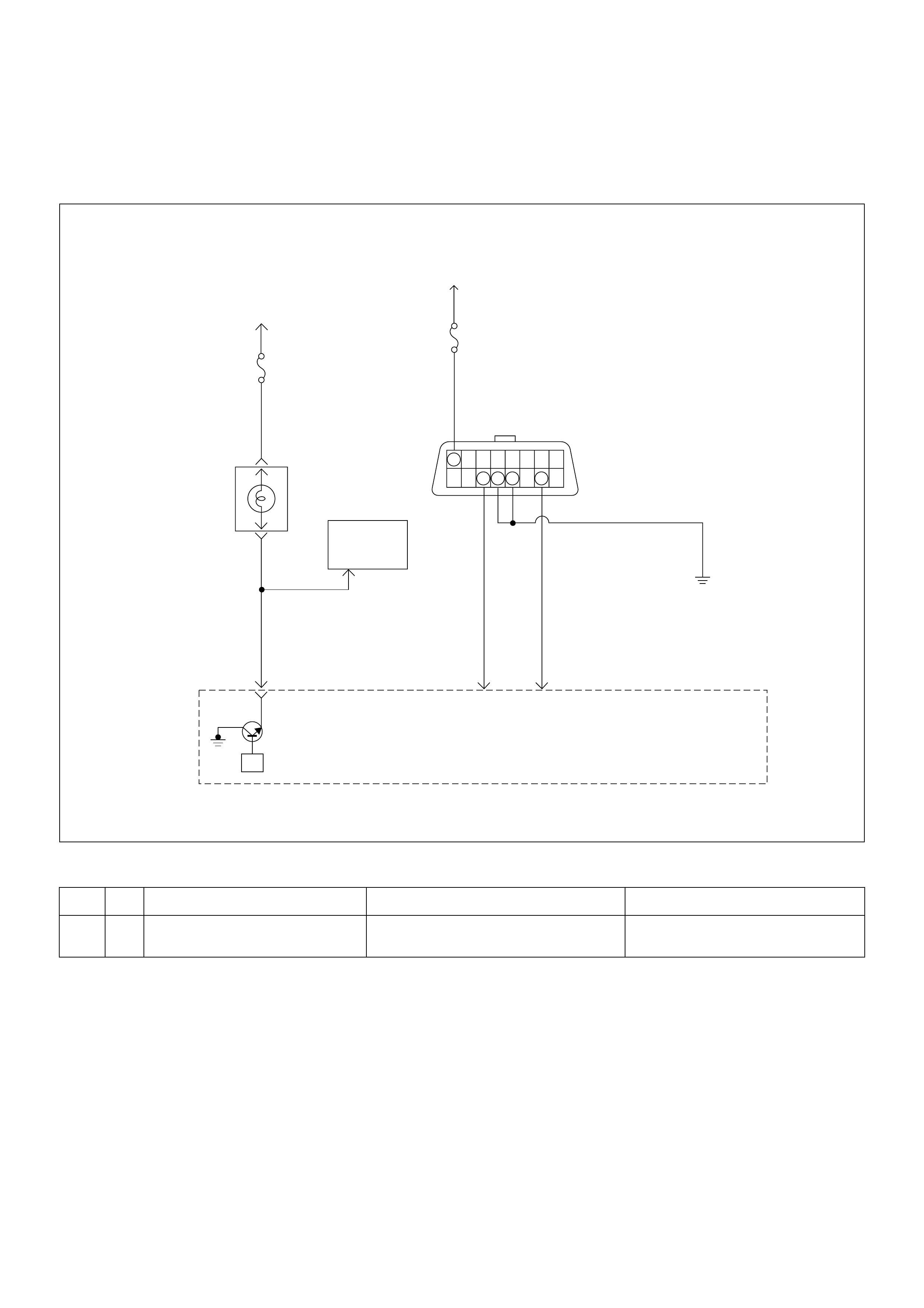
Diagnostic Trouble Code (DTC) P0650 Malfunction Indicator Lamp (MIL)
Contorol Circuit Malfunction
Condition for setting the DTC and action ta ken when the DTC sets
Circuit Description
The check engine lamp should always be illuminated
and steady with ignition “ON” and the engine stopped.
Ignition feed voltage is supplied directly to the check
engine lamp indicator. The Engine Control Module
(ECM) turns the check engine lamp “ON” by grounding
the check engine lamp driver circuit. The check engine
lamp should not remain “ON” with the engine running
and no DTC(s) set. A steady check engine lamp with
the engine running and no DTC(s) suggests a short to
ground in the check engine lamp driver circuit.
Diagnostic Aids
An intermittent may be caused by a poor connection,
rubbed-through wire insulation, or a wire broken inside
the insulation. Check for the following items:
• Poor connection or damaged harness - Inspect the
ECM harness and connectors for improper mating,
broken locks, improperly formed or damaged
terminals, poor terminal-to-wire connection, and
damaged harness.
Code Type DTC Name DTC Setting Condition Fail-Safe (Back Up)
P0650 A Malfunction Indicator Lamp (MIL) Con-
trol Circuit Malfunction Chec k engine lamp circuit open, short to
ground or short to voltage circuit. No fail -safe fun ction.
Buttery
Voltage
0.5
RED/
YEL
Engine
Room-RH
µP
J2-32
7
0.5
BRN/
YEL
Engine
Control
Module
(ECM)
Check
Engine
Lamp
Imnobiliser
Control
Unit
METER
15A
Ignition
SW
0.5
BLU
J2-4
0.5
GRN
J2-30
Diag
SW Class 2
Serial
Data
0.85 BLK
Diagnostic
Comectar
16151413121110 9
87654321
METER
10A
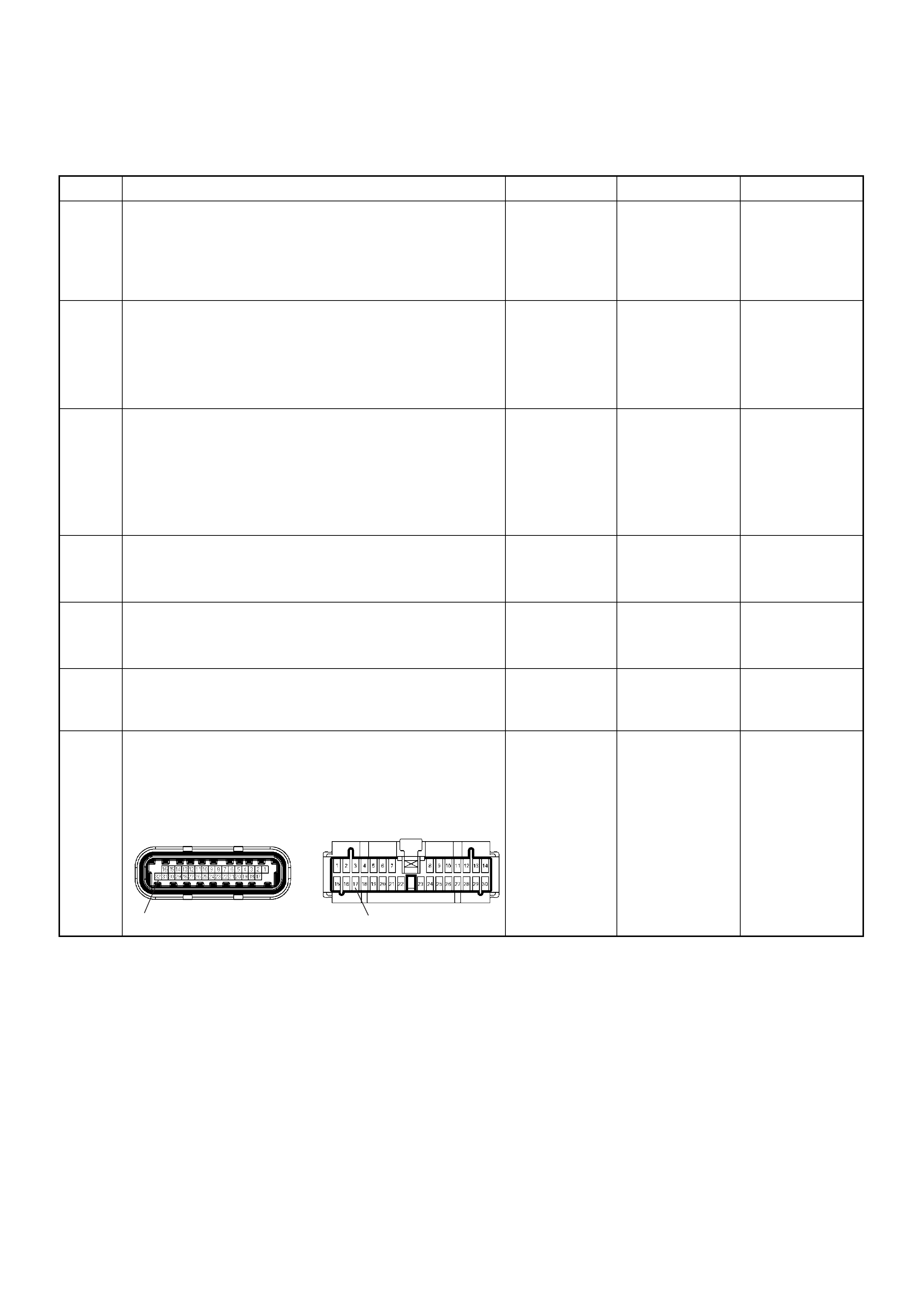
Diagnostic Trouble Code (DTC) P0650 Malfunction Indicator Lamp (MIL)
Control Circuit Malfunction
Step Action Value(s) Yes No
1 Was the “On-Board Di agnostic (OBD) System Check”
performed?
—Go to Step 2
Go to On
Board
Diagnostic
(OBD) System
Check
2 1. Connect the Tech 2.
2. Review and record the failure information.
3. Select “F0: Read DTC Infor By Priority” in “F0:
Diagnostic Trouble Code”.
Is the DTC P0650 stored as “Present Failure”? — Go to Step 3
Refer to
Diagnostic Aids
and Go to Step
3
3 1. Using the Tech2, ignition “On” and engine “Off”.
2. Select “Cl ear D TC I nform ati on” w ith th e Tech2 and
clear the DTC information.
3. Operate the vehicle and monitor the “F5: Failed
This Ignition” in “F2: DTC Information”.
Was the DTC P0650 stored in this ignition cycle? — Go to Step 4
Refer to
Diagnostic Aids
and Go to Step
4
4 1. Ignition “On”, engine “Off”.
2. Check the “Ch ec k Eng ine ” lamp .
Does the lamp turn “On”? — Go to Step 5 Go to Step 6
5 1. Ignition “On”, engine “Off”.
2. Check the “Ch ec k Eng ine ” lamp .
Does the lamp turn “Off”? — Go to Step 9 Go to Step 7
6 Check the “Check Engine” lamp bulb.
If the bulb is burnt out, repair as necessary.
Was the problem found? — Verify repair Go to Step 7
7 Check for poor/faulty connection at the meter
connector and ECM connector. If a poor/faulty
connection is found, repair as necessary.
Was the problem found?
— Verify repair Go to Step 8
32 17
C-56(J2) B-24
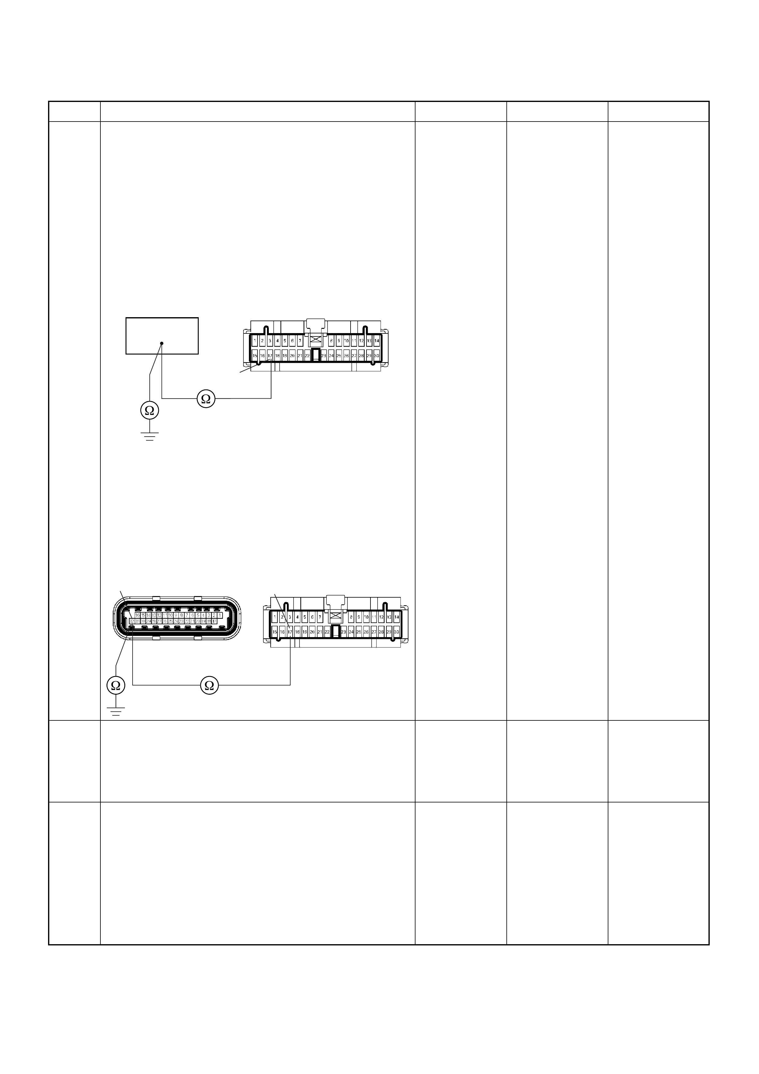
8 Using the DVM and check the “Check Engine” lamp
circuit.
Breaker box is available:
1. Ignition “Off”, engine “Off”.
2. Install the breaker box as type A. (ECM
disconnected) Ref. 6E-80.
3. Remove the meter connector.
4. Check the circuit for open or short to ground
circuit.
Was the problem found?
Breaker box is not available:
1. Ignition “Off”, engine “Off”.
2. Disconnect the ECM connector.
3. Remove the meter connector.
4. Check the circuit for open or short to ground
circuit.
Was the problem found?
—
Repair faulty
harness and
verify repair Go to Step 9
9 Is the ECM programmed with the latest software
release?
If not, download the latest software to the ECM using
the “SPS (Service Programming System)”.
Was the problem solved? — Verify repair Go to Step 10
10 Replace the ECM.
Is the action complete?
IMPORTANT: The replacement ECM must be
programmed. Refer to section of the Service
Programming System (SPS) in this manual.
Following EC M programming, the immobiliser system
(if equipped) must be linked to the ECM. Refer to
section 11 “Immobiliser System-ECM replacement” for
the ECM/Immobiliser linking procedure. — Verify repair —
Step Action Value(s) Yes No
64
17
B-24
C-56(J2) B-24
32 17
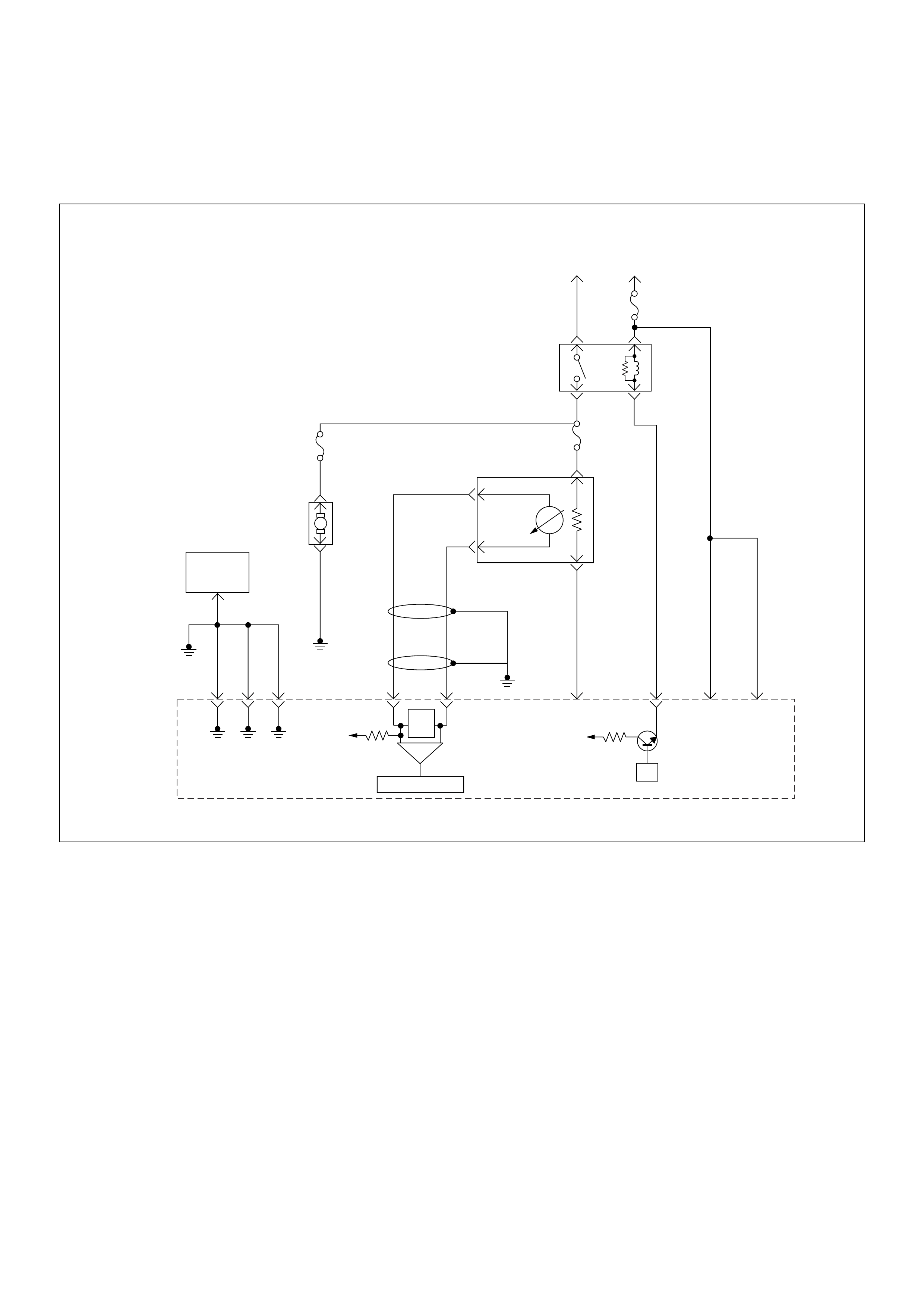
Diagnostic Trouble Code (DTC) P1167 Fuel Supply System Rich
During Deceleration Fuel Cut Off
µP
VIgn
-
+
Crankshaft
Position
Sensor
J1-1 J1-2 J1-17
Battery
Voltage
Battery
Voltage
2.0
WHT ECM
10A
450
mV
A/D Converter
Vcc
+5V -+
TIMING
COVER
J2-6 J2-21
Fuel
Pump
FUEL
PUMP
20A
2.0
BLK
2.0
BLK/
BLU
Fuel
Pump
Relay
O2
SENSOR
10A
Heated
O2
Sensor
0.85
RED/
WHT
0.5
GRN/
WHT
0.5
RED/
WHT
0.5
BLU/
WHT
0.5
BLU
0.5 PNK
J2-31 J2-11 J2-2 J2-18
M
Engine
Control
Module
(ECM)

Condition for setting the DTC and action ta ken when the DTC sets
Circuit Description
The engine control module (ECM) internal circuitry can
identify if the vehicle fuel system is capable of supplying
adequate amounts of fuel during deceleration (fuel cut
off). The ECM monitors the voltage of the oxygen
sensor during fuel cut off. When a fuel cut off mode of
operation is requested during “Closed Loop” operation
(by dec eleration), t he ECM wil l provide more fuel t o the
engine. Under these conditions the ECM should detect
a “lean” condition (low oxygen sensor voltage). If this
“lean” exh aust is not detected at this tim e, a Diagnostic
Trouble Code P1167 will set.
Diagnostic Aids
Check the following items:
• Fuel pressure - The system will go rich if pressure is
too high. The ECM can compensate for some
increase. However, if fuel pressure is too high, a
Diagnost ic Trouble Code P1167 may be set. Re fer to
Fuel System Diagnosis.
• Perform “Injector Balance Test” - Refer to Fuel
System Diagnosis.
• Check t he EVAP canist er fo r fuel satur ation - If f ull o f
fuel, check canister control and hoses. Refer to
Evaporative (EVAP) Emission Control System.
• Check for a leak in the fuel pressure regulator
diaphragm by checking the vacuum line to toe
regulator for the presence of fuel.
• An intermittent TP sensor output will cause the
system to go rich due to a false indication of the
engine accelerating.
• Silicon contamination of the HO2S can also cause a
high HO2S voltage to be indicated. This condition is
indicated by a powdery white deposit on the portion
of the HO2S exposed to the exhaust stream. If
contamination is noticed, replace the affected HO2S.
Diagnostic Trouble Code (DTC) P1167 Fuel Supply System Rich During
Deceleration Fuel Cutoff
Code Type DTC Name DTC Setting Condition Fail-Safe (Back Up)
P1167 D Fuel Supply System Rich During
Deceleration Fuel Cutoff 1.No DTC relating to MAP sensor, TPS,
EVAP purge, ECT sensor, CKP sensor,
VSS, injector control circuit and ignition
control circuit.
2. O
2
sensor bank 1 output voltage is more
than 550mV in deceleration fuel cutoff
mode.
No fail-s a fe fu n ction.
Step Action Value(s) Yes No
1 Was the “On-Board Di agnostic (OBD) Syst em Check”
performed?
—Go to Step 2
Go to On
Board
Diagnostic
(OBD) System
Check
2 1. Connect the Tech 2.
2. Review and record the failure information.
3. Select “F0: Read DTC Infor By Priority” in “F0:
Diagnostic Trouble Code”.
Is the DTC P1167 stored as “Present Failure”? — Go to Step 3
Refer to
Diagnostic Aids
and Go to Step
3
3 1. Using the Tech2, ignition “On” and engine “Off”.
2. Select “Cl ear D TC I nform ati on” w ith th e Tech2 and
clear the DTC information.
3. Operate the vehicle and monitor the “F5: Failed
This Ignition” in “F2: DTC Information”.
Was the DTC P1167 stored in this ignition cycle? — Go to Step 4
Refer to
Diagnostic Aids
and Go to Step
4

4 1. Using the Tech 2, ignition “On” and engine “Off”.
2. Monitor the “Thrott le Posit ion ” in the data display.
Does the Te ch 2 indica te correct “Thr ottle Position ” in
accordance with accelerator pedal operation? — Go to Step 6 Go to Step 5
5 Check for the following conditions.
• Objects blocking the throttle valve.
• Incorrectly installed.
If a problem is found, repair as neces sa ry.
Was the problem found? — Verify repair Go to Step 12
6 1. Using the Tech 2, ignition “On” and engine “On”.
2. Monitor the “Manifold Absolute Pressure” in the
data display.
Does the Tech 2 indicate correct “Manifold Absolute
Pressure” in accordance with engine speed or
acceleration? — Go to Step 8 Go to Step 7
7 Remove the MAP sensor and check for the following
conditions.
• Objects blocking the air cleaner.
• Objects blocking the MAP sensor.
• Objects blocking the throttle valve.
• Vacuum leaking at intake duct.
• Vacuum leaking at throttle body.
If a problem is found, repair as neces sa ry.
Was the problem found? — Verify repair Go to Step 13
8 1. Using the Tech 2, ignition “On” and engine “On”.
2. Select the “Miscellaneous Test” and perform the
“IAC Control” in the “IAC System”.
3. Operate the Tech 2 in accordance with procedure.
Was the engine speed changed, when the IAC valve
is operating step by step? — Go to Step 10 Go to Step 9
9 Check for the following conditions.
• Objects blocking the IAC valve.
• Objects blocking the throttle valve.
• Vacuum leaking at throttle body.
If a problem is found, repair as neces sa ry.
Was the problem found? — Verify repair Go to Step 14
10 Check for injector for the affected bank.
Refer to “Injector Coil Test & Injector Balance Test
Procedure”.
Was the injector operation correct? —Go to Step 11
Refer to Injector
Coil Test &
Injector
Balance Test
Procedure
11 Check for fuel pressure.
Refer to “Fuel System Diagnosis”.
Was the fuel pressure correct? — Go to Step 15
Refer to Fuel
System
Diagnosis
12 Replace the TPS.
Is the action complete? — Verify repair —
13 Replace the MAP sensor.
Is the action complete? — Verify repair —
14 Replace the IAC valve.
Is the action complete? — Verify repair —
Step Action Value(s) Yes No

15 Replace the O
2
sens or.
Was the problem solved? — Verify repair Go to Step 16
16 Is the ECM programmed with the latest software
release?
If not, download the latest software to the ECM using
the “SPS (Service Programming System)”.
Was the problem solved? — Verify repair Go to Step 17
17 Replace the ECM.
Is the action complete?
IMPORTANT: The replacement ECM must be
programmed. Refer to section of the Service
Programming System (SPS) in this manual.
Following EC M programming, the immobiliser system
(if equipped) must be linked to the ECM. Refer to
section 11 “Immobiliser System-ECM replacement” for
the ECM/Immobiliser linking procedure. — Verify repair —
Step Action Value(s) Yes No
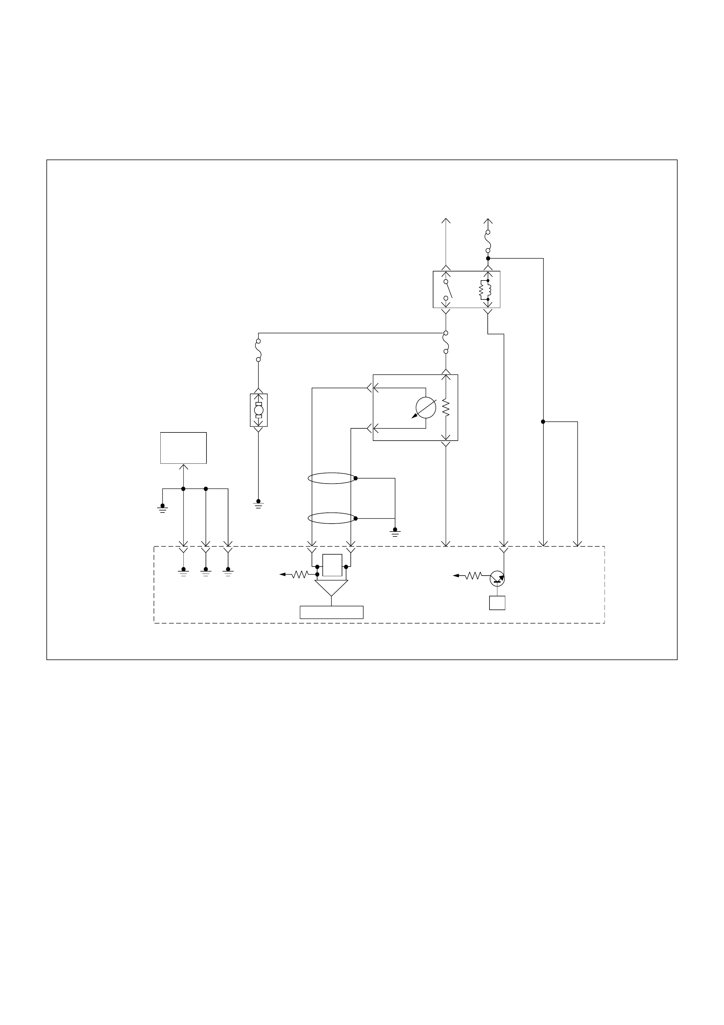
Diagnostic Trouble Code (DTC) P1171 Fuel Supply System
Lean During Power Enrichment
µP
V
Ign
-
+
Crankshaft
Position
Sensor
J1-1 J1-2 J1-17
Battery
Voltage
Battery
Voltage
2.0
WHT ECM
10A
450
mV
A/D Converter
Vcc
+5V -+
TIMING
COVER
J2-6 J2-21
Fuel
Pump
FUEL
PUMP
20A
2.0
BLK
2.0
BLK/
BLU
Fuel
Pump
Relay
O
2
SENSOR
10A
Heated
O
2
Sensor
0.85
RED/
WHT
0.5
GRN/
WHT
0.5
RED/
WHT
0.5
BLU/
WHT
0.5
BLU
0.5 PNK
J2-31 J2-11 J2-2 J2-18
M
Engine
Control
Module
(ECM)

Condition for setting the DTC and action taken when the DTC sets
Circuit Description
The engine control module (ECM) internal circuitry can
identify if the vehicle fuel system is capable of supplying
adequate amounts of fuel during heavy acceleration
(power enrichment). The ECM monitors the voltage of
the oxygen sensor during power enrichment. When a
power enrichment mode of operation is requested
during “Closed Loop” operation (by heavy acceleration),
the ECM will provide more fuel to the engine. Under
these conditions the ECM should detect a “rich”
condition (high oxygen sensor voltage). If this “rich”
exhaust is not detected at this time, a Diagnostic
Trouble Code P1171 will set. A plugged fuel filter or
restricted fuel line can prevent adequate amounts of fuel
from being supplied during power enrichment mode.
Diagnostic Aids
Check for the following conditions:
• Heated oxygen sensor wiring - The sensor pigtail
may be routed incorrectly and contacting the exhaust
system.
• Poor ECM to engine block ground.
• Fuel pressure - The system will go lean if pressure is
too low. The ECM can compensate for some
decrease. However, if fuel pressure is too low, a
diagnostic Trouble Code P1171 may be set. Refer to
Fuel System Diagnosis.
• Lean injector(s) - Perform “Injector Balance Test.”
• Vacuum leaks - Check for disconnected or damaged
vacuum hoses and for vacuum leaks at the intake
manifold, throttle body, and PCV system.
• Exhaust leaks - An exhaust leak may cause outside
air to be pulled into the exhaust gas stream past the
HO2S, causing the system to appear lean. Check for
exhaust leaks that may cause a false lean condition
to be indicated.
• Fuel contamination - Water, even in small amounts,
can be delivered to the fuel injectors. The water can
cause a lean exhaust to be indicated, Excessive
alcohol in the fuel can also cause this condition.
Refer to Fuel System Diagnosis for the procedure to
check for fuel contam ination.
Code Type DTC Name DTC Setting Condition Fail-Safe (Back Up)
P1171 D Fuel Supply System Lean During
Power Enrichm ent 1. No DTC relating to MAP sensor, TPS,
EVAP purge, ECT sensor, CKP sensor,
VSS, injector control circuit and ignition
control circuit.
2. Engine coolant temperature is more than
60°C.
3. Mass air flow is below 13.5m/s.
4. O
2
sensor bank 1 output voltage is below
350mV in power enrichment mode.
No fail-s a fe fu n ction.

Diagnostic Trouble Code (DTC) P1171 Fuel Supply System Lean During Power Enrichment
Step Action Value(s) Yes No
1 Was the “On-Board Di agnostic (OBD) System Check”
performed?
—Go to Step 2
Go to On
Board
Diagnostic
(OBD) System
Check
2 1. Connect the Tech 2.
2. Review and record the failure information.
3. Select “F0: Read DTC Infor By Priority” in “F0:
Diagnostic Trouble Code”.
Is the DTC P1171 stored as “Present Failure”? — Go to Step 3
Refer to
Diagnostic Aids
and Go to Step
3
3 1. Using the Tech2, ignition “On” and engine “Off”.
2. Select “Cl ear D TC I nform ati on” w ith th e Tech2 and
clear the DTC information.
3. Operate the vehicle and monitor the “F5: Failed
This Ignition” in “F2: DTC Information”.
Was the DTC P1171 stored in this ignition cycle? — Go to Step 4
Refer to
Diagnostic Aids
and Go to Step
4
4 1. Using the Tech 2, ignition “On” and engine “Off”.
2. Monitor the “Thrott le Posit ion ” in the data display.
Does the Te ch 2 indica te correct “Thr ottle Position ” in
accordance with accelerator pedal operation? — Go to Step 6 Go to Step 5
5 Check for the following conditions.
• Objects blocking the throttle valve.
• Incorrectly installed.
If a problem is found, repair as neces sa ry.
Was the problem found? — Verify repair Go to Step 12
6 1. Using the Tech 2, ignition “On” and engine “On”.
2. Monitor the “Manifold Absolute Pressure” in the
data display.
Does the Tech 2 indicate correct “Manifold Absolute
Pressure” in accordance with engine speed or
acceleration? — Go to Step 8 Go to Step 7
7 Remove the MAP sensor and check for the following
conditions.
• Objects blocking the air cleaner.
• Objects blocking the MAP sensor.
• Objects blocking the throttle valve.
• Vacuum leaking at intake duct.
• Vacuum leaking at throttle body.
If a problem is found, repair as neces sa ry.
Was the problem found? — Verify repair Go to Step 13
8 1. Using the Tech 2, ignition “On” and engine “On”.
2. Select the “Miscellaneous Test” and perform the
“IAC Control” in the “IAC System”.
3. Operate the Tech 2 in accordance with procedure.
Was the engine speed changed, when the IAC valve
is operating step by step? — Go to Step 10 Go to Step 9

9 Check for the following conditions.
• Objects blocking the IAC valve.
• Objects blocking the throttle valve.
• Vacuum leaking at throttle body.
If a problem is found, repair as neces sa ry.
Was the problem found? — Verify repair Go to Step 14
10 Check for injector for the affected bank.
Refer to “Injector Coil Test & Injector Balance Test
Procedure”.
Was the injector operation correct? —Go to Step 11
Refer to Injector
Coil Test &
Injector
Balance Test
Procedure
11 Check for fuel pressure.
Refer to “Fuel System Diagnosis”.
Was the fuel pressure correct? — Go to Step 15
Refer to Fuel
System
Diagnosis
12 Replace the TPS.
Is the action complete? — Verify repair —
13 Replace the MAP sensor.
Is the action complete? — Verify repair —
14 Replace the IAC valve.
Is the action complete? — Verify repair —
15 Replace the O
2
sens or.
Was the problem solved? — Verify repair Go to Step 16
16 Is the ECM programmed with the latest software
release?
If not, download the latest software to the ECM using
the “SPS (Service Programming System)”.
Was the problem solved? — Verify repair Go to Step 17
17 Replace the ECM.
Is the action complete?
IMPORTANT: The replacement ECM must be
programmed. Refer to section of the Service
Programming System (SPS) in this manual.
Following EC M programming, the immobiliser system
(if equipped) must be linked to the ECM. Refer to
section 11 “Immobiliser System-ECM replacement” for
the ECM/Immobiliser linking procedure. — Verify repair —
Step Action Value(s) Yes No

Diagnostic Trouble Code (DTC) P1625 ECM System Reset
Condition for setting the DTC and action ta ken when the DTC sets
Circuit Description
The powertrain control module (ECM) monitors
unexpected ECM reset. This will not turn on MIL light
on, only records code DTC P1625.
Diagnostic Aids
Check for the follwing conditions:
• P1625 alone stored does not need diagnosis. Clear
DTC code.
NOTE: DTC P1625 is a DTC to record a ECM reset
history. If DTC P1625 is not reset and no engine
abnormality occurs after learing the DTC, no farther
diagnostic procedures are required.
Diagnostic Trouble Code (DTC) P1625 ECM System Reset
Code Type DTC Name DTC Setting Condition Fail-Safe (Back Up)
P1625 B ECM
System Reset ECM reset has occurred other than “On”. Engine control disabled.
Step Action Value(s) Yes No
1 Was the “On-Board Di agnostic (OBD) System Check”
performed?
—Go to Step 2
Go to On
Board
Diagnostic
(OBD) System
Check
2 1. Connect the Tech 2.
2. Review and record the failure information.
3. Select “F0: Read DTC Infor By Priority” in “F0:
Diagnostic Trouble Code”.
Is the DTC P1625 stored as “Present Failure”? — Go to Step 3
Refer to
Diagnostic Aids
and Go to Step
3
3 1. Using the Tech2, ignition “On” and engine “Off”.
2. Select “Cl ear D TC I nform ati on” w ith th e Tech2 and
clear the DTC information.
3. Operate the vehicle and monitor the “F5: Failed
This Ignition” in “F2: DTC Information”.
Was the DTC P1625 stored in this ignition cycle? — Go to Step 4
Refer to
Diagnostic Aids
and Go to Step
4
4 Check any accessory parts which may cause electric
interference or magnetic interference.
Was the problem found? —
Remove the
accessory parts
and verify repair Go to Step 5
5 Is the ECM programmed with the latest software
release?
If not, download the latest software to the ECM using
the “SPS (Service Programming System)”.
Was the problem solved? — Verify repair Go to Step 6
6 Replace the ECM.
Is the action complete?
IMPORTANT: The replacement ECM must be
programmed. Refer to section of the Service
Programming System (SPS) in this manual.
Following EC M programming, the immobiliser system
(if equipped) must be linked to the ECM. Refer to
section 11 “Immobiliser System-ECM replacement” for
the ECM/Immobiliser linking procedure. — Verify repair —
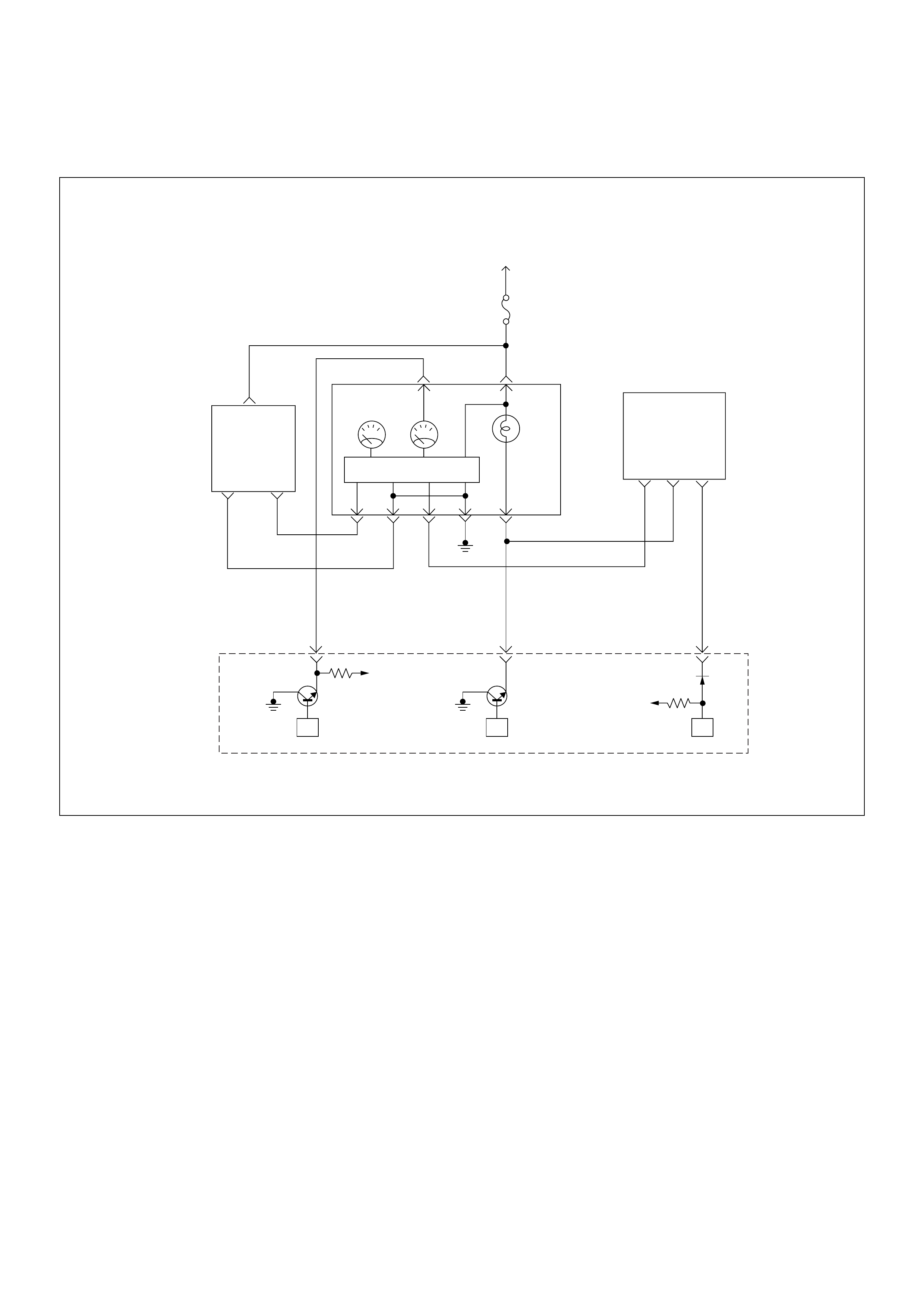
Diagnostic Trouble Code (DTC) P1626 Immobiliser No Signal
VIgn
Engine
Control
Module
(ECM)
Ignition
SW
µPµPµP
Meter
15A
VIgn
Check
Engine
Sped
Meter Tacho
Meter
0.85
YEL
0.8 YEL/GRN
0.5 BRN/YEL
CPU
0.5
WHT
J2-23J2-25
0.5
BRN/
YEL
(–) (+)
Vehicle
Speed
Sensor
J2-32
678
Imnobiliser
Control
Unit

Condition for setting the DTC and action ta ken when the DTC sets
Circuit Description
The ECM decides whether that is an abnomality in the
immobiliser control system. DTC P1626 is recorded by
the ECM when no response from immobiliser.
Diagnostic Aids
Check for the following conditions:
• Poor connection at ECM and Immobiliser-Inspect
harness connectors for backed out terminals,
improper mating, broken locks, improperly formed or
damaged terminals, and poor terminal to wire
connection.
• Damaged harness Inspect the wiring harness for
damage, If the harness appears to be OK, disconnect
the ECM and Immobiliser, turn the ignition “ON” and
observe a voltmeter connected to the suspect driver
circuit at the ECM and Immobiliser harnass connector
while moving connectors and wiring harnesses
relates to the MIL. A change in voltage will indicate
the location of the fault.
Diagnostic Trouble Code (DTC) P1626 Immobiliser No Signal
Code Type DTC Name DTC Setting Condition Fail-Safe (Back Up)
P1626 - Immobiliser No Signal No response from immobiliser control unit. 1. Engine does not start.
2. Check engine lamp flash.
Step Action Value(s) Yes No
1 Was the “On-Board Di agnostic (OBD) System Check”
performed?
—Go to Step 2
Go to On
Board
Diagnostic
(OBD) System
Check
2 1. Connect the Tech 2.
2. Review and record the failure information.
3. Select “F0: Read DTC Infor By Priority” in “F0:
Diagnostic Trouble Code”.
Is the DTC P1626 stored as “Present Failure”? — Go to Step 3
Refer to
Diagnostic Aids
and Go to Step
3
3 1. Using the Tech2, ignition “On” and engine “Off”.
2. Select “Cl ear D TC I nform ati on” w ith th e Tech2 and
clear the DTC information.
3. Operate the vehicle and monitor the “F5: Failed
This Ignition” in “F2: DTC Information”.
Was the DTC P1626 stored in this ignition cycle? — Go to Step 4
Refer to
Diagnostic Aids
and Go to Step
4
4 1. Using the Tech 2, ignition “On” and engine “Off”.
2. Sele ct “Im mob ilis er” i n the syst em se lecti on me nu
“Body”.
3. Select “Read DTC Info Ordered By Priority” in the
“Diagn ositi c Trouble Code” .
Was the any DTC's B**** stored in this ignition cycle? —
Refer to
“Immobiliser
Workshop
Manual” & Go
to DTC Chart
B**** Go to Step 5
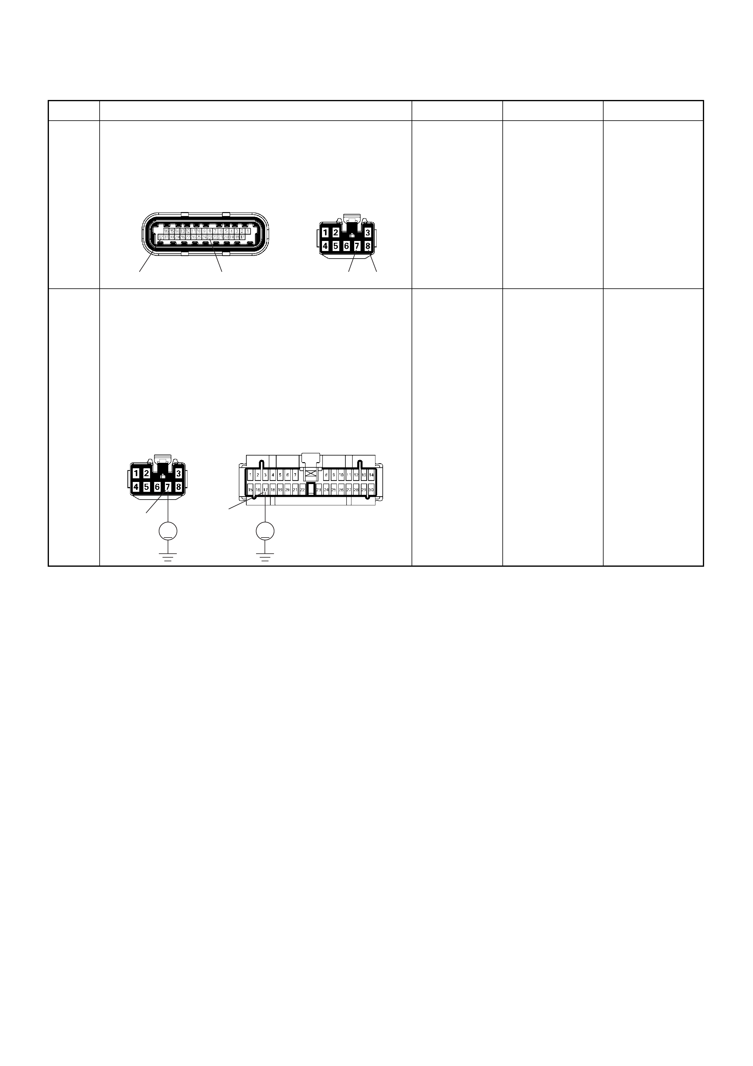
5 Check for poor/faulty connection at the immobiliser
control unit connector or ECM connector. If a poor/
faulty connection is found, repair as necessary.
Was the problem found?
— Verify repair Go to Step 6
6 Using the DVM and check the “CHECK ENGINE”
lamp circuit.
1. Ignition “Off”, engine “Off”.
2. Disconnect the meter connector and immobiliser
contr ol uni t connec tor.
3. Ignition “On”.
4. Check the circuit for short to power supply circuit.
Was the problem found?
—
Repair faulty
harness and
verify repair Go to Step 7
Step Action Value(s) Yes No
32 23 7 8
C-56(J2) B-68
V V
B-24
B-68
17
7
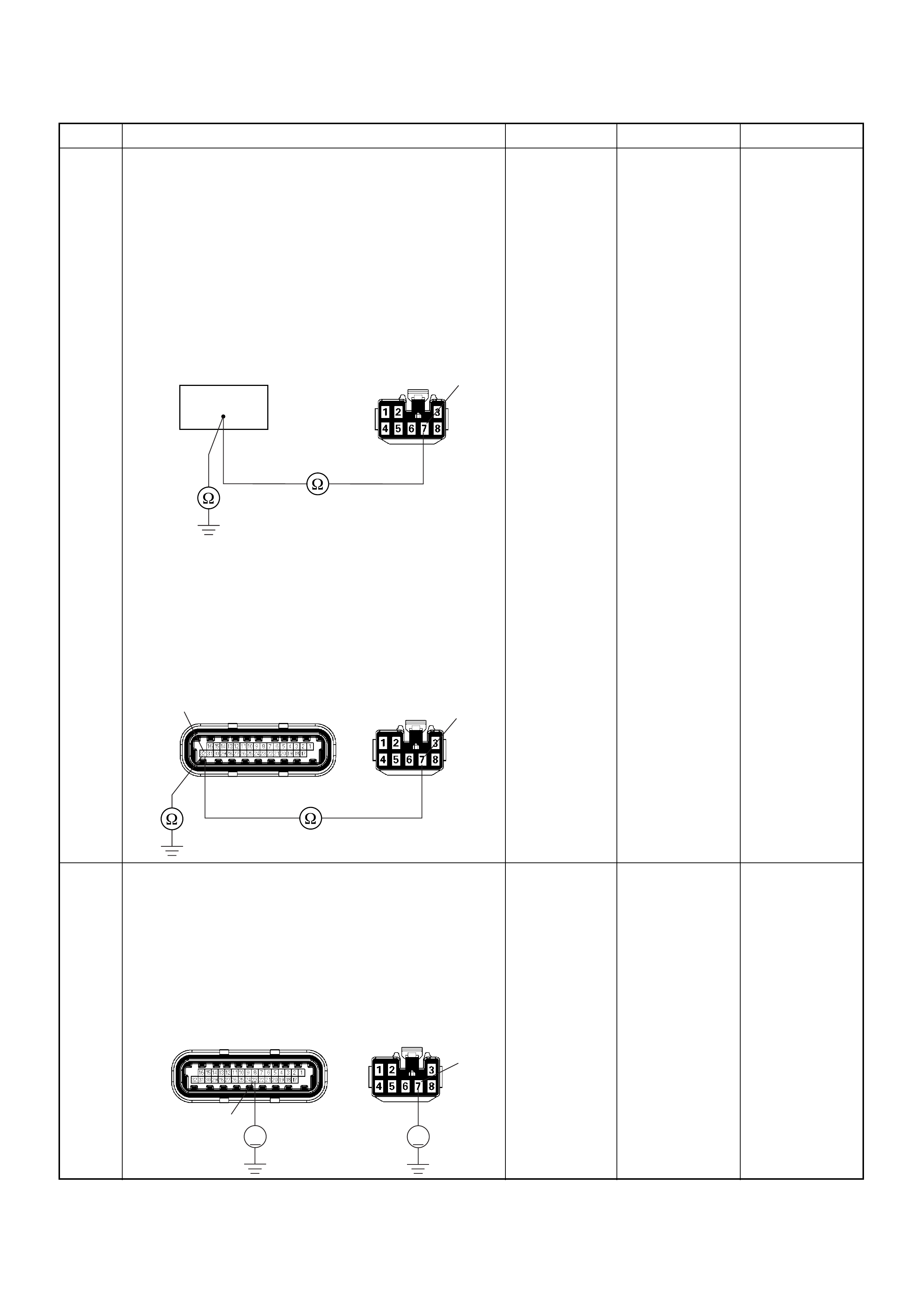
7 Using the DVM and check the “CHECK ENGINE”
lamp circuit.
Breaker box is available:
1. Ignition “Off”, engine “Off”.
2. Install the breaker box as type A. (ECM
disconnected) Ref. 6E-80.
3. Disconnect the immobiliser control unit connector.
4. Check the circuit for open or short to ground
circuit.
Was the problem found?
Breaker box is not available:
1. Ignition “Off”, engine “Off”.
2. Disconnect the the immobiliser control unit
connector and ECM connector.
3. Check the circuit for open or short to ground
circuit.
Was the problem found?
—
Repair faulty
harness and
verify repair Go to Step 8
8 Using the DVM and check the VSS signal circuit.
1. Ignition “Off”, engine “Off”.
2. Disconnect the immobiliser control unit connector
and ECM conne cto r.
3. Ignition “On”.
4. Check the circuit for short to power supply circuit.
Was the problem found?
—
Repair faulty
harness and
verify repair Go to Step 9
Step Action Value(s) Yes No
64
B-68 7
C-56(J2)
32 7
B-68
VV
C-56(J2)
23
7
B-68

9 Using the DVM and check the VSS signal circuit.
Breaker box is available:
1. Ignition “Off”, engine “Off”.
2. Install the breaker box as type A. (ECM
disconnected) Ref. 6E-80.
3. Disconnect the immobiliser control unit connector.
4. Check the circuit for open or shot to ground circuit.
Was the problem found?
Breaker box is not available:
1. Ignition “Off”, engine “Off”.
2. Disconnect the immobiliser control unit connector
and ECM conne cto r.
3. Check the circuit for open or short to ground
circuit.
Was the problem found?
—
Repair faulty
harness and
verify repair Go to Srtep 10
10 Is the ECM programmed with the latest software
release?
If not, download the latest software to the ECM using
the “SPS (Service Programming System)”.
Was the problem solved? — Verify repair Go to Step 1 1
11 Replace the ECM.
Is the action complete?
IMPORTANT: The replacement ECM must be
programmed. Refer to section of the Service
Programming System (SPS) in this manual.
Following EC M programming, the immobiliser system
(if equipped) must be linked to the ECM. Refer to
section 11 “Immobiliser System-ECM replacement” for
the ECM/Immobiliser linking procedure. — Verify repair —
Step Action Value(s) Yes No
55
B-68 8
23 B-68
C-56(J2) 8

Diagnostic Trouble Code (DTC) P1631 Immobiliser Wrong Signal
Condition for setting the DTC and action ta ken when the DTC sets
Circuit Description
The ECM decides whether that is an abnomality in the
immobiliser control system. DTC P1631 is recorded by
the ECM when received response was not correct.
Diagnostic Aids
Check for the following conditions:
• Poor connection at ECM and Immobiliser-Inspect
harness connectors for backed out terminals,
improper mating, broken locks, improperly formed or
damaged terminals, and poor terminal to wire
connection.
• Damaged harness-Inspect the wiring harness for
damage, If the harness appears to be OK, disconnect
the ECM and Immobiliser, turn the ignition “ON” and
observe a voltmeter connected to the suspect driver
circuit at the ECM and Immobiliser harnass connector
while moving connectors and wiring harnesses
relates to the MIL. A change in voltage will indicate
the location of the fault.
Code Type DTC Name DTC Setting Condition Fail-Safe (Back Up)
P1631 - Immobiliser Wrong Signal Rece ived response is not correct. 1. Engine does not start.
2. Check engine lamp flash.
VIgn
Engine
Control
Module
(ECM)
Ignition
SW
µPµPµP
Meter
15A
VIgn
Check
Engine
Sped
Meter Tacho
Meter
0.85
YEL
0.8 YEL/GRN
0.5 BRN/YEL
CPU
0.5
WHT
J2-23J2-25
0.5
BRN/
YEL
(–) (+)
Vehicle
Speed
Sensor
J2-32
678
Imnobiliser
Control
Unit

Diagnostic Trouble Code (DTC) P1631 Immobiliser Wrong Signal
Step Action Value(s) Yes No
1 Was the “On-Board Di agnostic (OBD) System Check”
performed?
—Go to Step 2
Go to On
Board
Diagnostic
(OBD) System
Check
2 1. Connect the Tech 2.
2. Review and record the failure information.
3. Select “F0: Read DTC Infor By Priority” in “F0:
Diagnostic Trouble Code”.
Is the DTC P1631 stored as “Present Failure”? — Go to Step 3
Refer to
Diagnostic Aids
and Go to Step
3
3 1. Using the Tech2, ignition “On” and engine “Off”.
2. Select “Cl ear D TC I nform ati on” w ith th e Tech2 and
clear the DTC information.
3. Operate the vehicle and monitor the “F5: Failed
This Ignition” in “F2: DTC Information”.
Was the DTC P1631 stored in this ignition cycle? — Go to Step 4
Refer to
Diagnostic Aids
and Go to Step
4
4 1. Using the Tech 2, ignition “On” and engine “Off”.
2. Sele ct “Im mob ilis er” i n the syst em se lecti on me nu
“Body”.
3. Select “Read DTC Info Ordered By Priority” in the
“Diagn ositi c Trouble Code” .
Was the any DTC's B**** stored in this ignition cycle? —
Refer to
“Immobiliser
Workshop
Manual” & Go
to DTC Chart
B**** Go to Step 5
5 Is the ECM programmed with the latest software
release?
If not, download the latest software to the ECM using
the “SPS (Service Programming System)”.
Was the problem solved? — Verify repair Go to Step 6
6 Replace the ECM.
Is the action complete?
IMPORTANT: The replacement ECM must be
programmed. Refer to section of the Service
Programming System (SPS) in this manual.
Following EC M programming, the immobiliser system
(if equipped) must be linked to the ECM. Refer to
section 11 “Immobiliser System-ECM replacement” for
the ECM/Immobiliser linking procedure. — Verify repair —
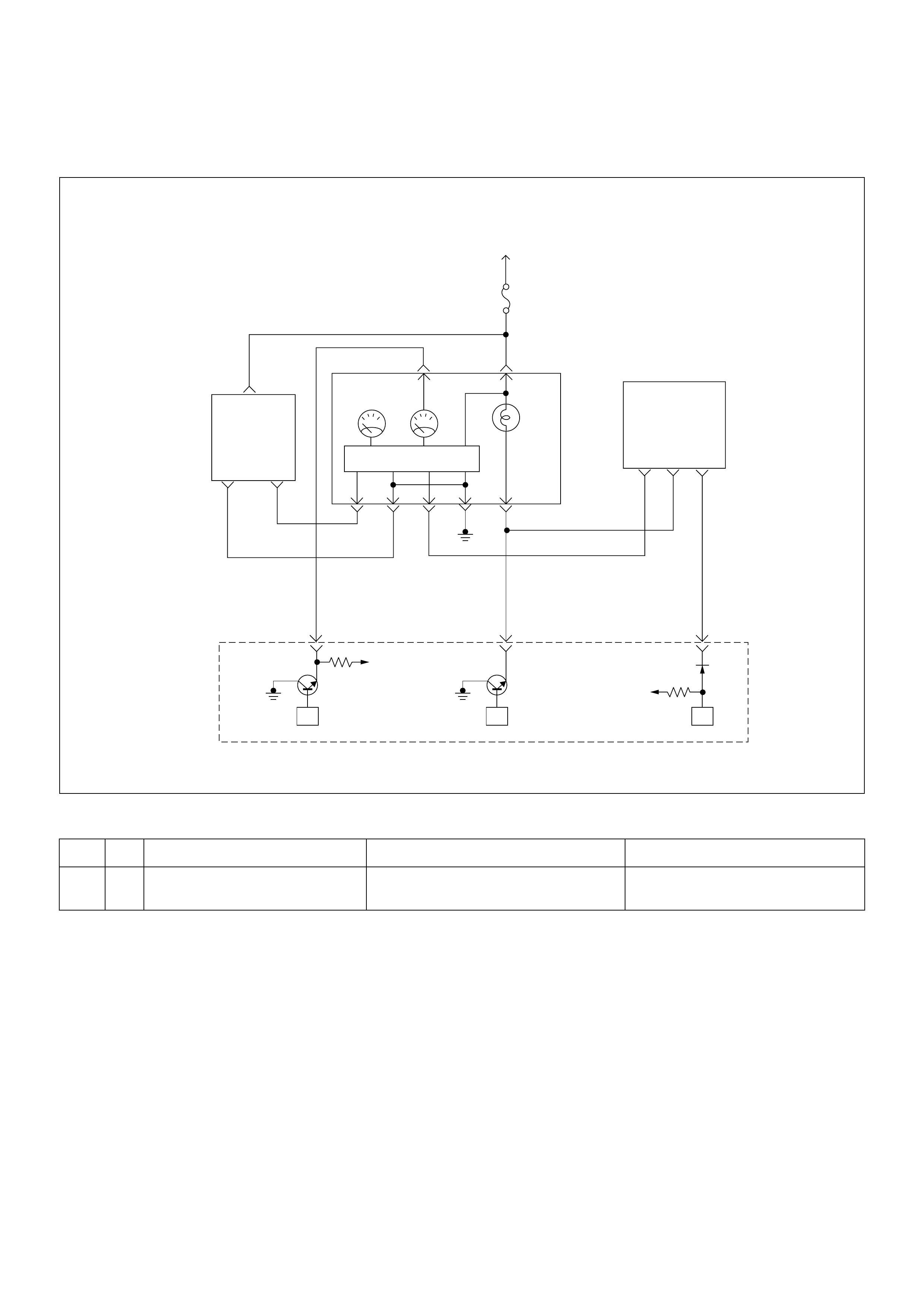
Diagnostic Trouble Code (DTC) P1648 Wrong Security Code Entered
Condition for setting the DTC and action ta ken when the DTC sets
Circuit Description
The ECM decides whether that is an abnomality in the
immobiliser control system. DTC P1648 is recorded by
the ECM when received incorrect security code.
Diagnostic Aids
Check for the following conditions:
• Poor connection at ECM and Immobiliser-Inspect
harness connectors for backed out terminals,
improper mating, broken locks, improperly formed or
damaged terminals, and poor terminal to wire
connection.
• Damaged harness Inspect the wiring harness for
damage, If the harness appears to be OK, disconnect
the ECM and Immobiliser, turn the ignition “ON” and
observe a voltmeter connected to the suspect driver
circuit at the ECM and Immobiliser harnass connector
while moving connectors and wiring harnesses
relates to the MIL. A change in voltage will indicate
the location of the fault.
Code Type DTC Name DTC Setting Condition Fail-Safe (Back Up)
P1648 - Wrong Security Code Entered Received incorrect securit y code. 1. Engine does not start.
2. Check engine lamp flash.
VIgn
Engine
Control
Module
(ECM)
Ignition
SW
µPµPµP
Meter
15A
VIgn
Check
Engine
Sped
Meter Tacho
Meter
0.85
YEL
0.8 YEL/GRN
0.5 BRN/YEL
CPU
0.5
WHT
J2-23J2-25
0.5
BRN/
YEL
(–) (+)
Vehicle
Speed
Sensor
J2-32
678
Imnobiliser
Control
Unit

Diagnostic Trouble Code (DTC) P1648 Wrong Security Code Entered
Step Action Value(s) Yes No
1 Was the “On-Board Di agnostic (OBD) System Check”
performed?
—Go to Step 2
Go to On
Board
Diagnostic
(OBD) System
Check
2 1. Connect the Tech 2.
2. Review and record the failure information.
3. Select “F0: Read DTC Infor By Priority” in “F0:
Diagnostic Trouble Code”.
Is the DTC P1648 stored as “Present Failure”? — Go to Step 3
Refer to
Diagnostic Aids
and Go to Step
3
3 1. Using the Tech2, ignition “On” and engine “Off”.
2. Select “Cl ear D TC I nform ati on” w ith th e Tech2 and
clear the DTC information.
3. Operate the vehicle and monitor the “F5: Failed
This Ignition” in “F2: DTC Information”.
Was the DTC P1648 stored in this ignition cycle? — Go to Step 4
Refer to
Diagnostic Aids
and Go to Step
4
4 1. Using the Tech 2, ignition “On” and engine “Off”.
2. Sele ct “Im mob ilis er” i n the syst em se lecti on me nu
“Body”.
3. Select “Read DTC Info Ordered By Priority” in the
“Diagn ositi c Trouble Code” .
Was the any DTC's B**** stored in this ignition cycle? —
Refer to
“Immobiliser
Workshop
Manual” & Go
to DTC Chart
B**** Go to Step 5
5 Is the ECM programmed with the latest software
release?
If not, download the latest software to the ECM using
the “SPS (Service Programming System)”.
Was the problem solved? — Verify repair Go to Step 6
6 Replace the ECM.
Is the action complete?
IMPORTANT: The replacement ECM must be
programmed. Refer to section of the Service
Programming System (SPS) in this manual.
Following EC M programming, the immobiliser system
(if equipped) must be linked to the ECM. Refer to
section 11 “Immobiliser System-ECM replacement” for
the ECM/Immobiliser linking procedure. — Verify repair —

Diagnostic Trouble Code (DTC) P1649 Immobiliser Function Not Programmed
Condition for setting the DTC and action ta ken when the DTC sets
Circuit Description
The ECM decides whether that is an abnomality in the
immobiliser control system. DTC P1649 is recorded by
the ECM when security code & secret key not
programmed.
Diagnostic Aids
Check for the following conditions:
• Poor connection at ECM and Immobiliser-Inspect
harness connectors for backed out terminals,
improper mating, broken locks, improperly formed or
damaged terminals, and poor terminal to wire
connection.
• Damaged harness Inspect the wiring harness for
damage, If the harness appears to be OK, disconnect
the ECM and Immobiliser, turn the ignition “ON” and
observe a voltmeter connected to the suspect driver
circuit at the ECM and Immobiliser harnass connector
while moving connectors and wiring harnesses
relates to the MIL. A change in voltage will indicate
the location of the fault.
Code Type DTC Name DTC Setting Condition Fail-Safe (Back Up)
P1649 - Immobiliser Function Not Programmed Immobiliser function is not programmed in the
ECM. 1.Engine does not start.
2. Check engine lamp flash.
VIgn
Engine
Control
Module
(ECM)
Ignition
SW
µPµPµP
Meter
15A
VIgn
Check
Engine
Sped
Meter Tacho
Meter
0.85
YEL
0.8 YEL/GRN
0.5 BRN/YEL
CPU
0.5
WHT
J2-23J2-25
0.5
BRN/
YEL
(–) (+)
Vehicle
Speed
Sensor
J2-32
678
Imnobiliser
Control
Unit

Diagnostic Trouble Code (DTC) P1649 Immobiliser Function Not Programmed
Step Action Value(s) Yes No
1 Was the “On-Board Di agnostic (OBD) System Check”
performed?
—Go to Step 2
Go to On
Board
Diagnostic
(OBD) System
Check
2 1. Connect the Tech 2.
2. Review and record the failure information.
3. Select “F0: Read DTC Infor By Priority” in “F0:
Diagnostic Trouble Code”.
Is the DTC P1649 stored as “Present Failure”? — Go to Step 3
Refer to
Diagnostic Aids
and Go to Step
3
3 1. Using the Tech2, ignition “On” and engine “Off”.
2. Select “Cl ear D TC I nform ati on” w ith th e Tech2 and
clear the DTC information.
3. Operate the vehicle and monitor the “F5: Failed
This Ignition” in “F2: DTC Information”.
Was the DTC P1649 stored in this ignition cycle? — Go to Step 4
Refer to
Diagnostic Aids
and Go to Step
4
4 1. Using the Tech 2, ignition “On” and engine “Off”.
2. Sele ct “Im mob ilis er” i n the syst em se lecti on me nu
“Body”.
3. Select “Read DTC Info Ordered By Priority” in the
“Diagn ositi c Trouble Code” .
Was the any DTC's B**** stored in this ignition cycle? —
Refer to
“Immobiliser
Workshop
Manual” & Go
to DTC Chart
B**** Go to Step 5
5 Is the ECM programmed with the latest software
release?
If not, download the latest software to the ECM using
the “SPS (Service Programming System)”.
Was the problem solved? — Verify repair Go to Step 6
6 Replace the ECM.
Is the action complete?
IMPORTANT: The replacement ECM must be
programmed. Refer to section of the Service
Programming System (SPS) in this manual.
Following EC M programming, the immobiliser system
(if equipped) must be linked to the ECM. Refer to
section 11 “Immobiliser System-ECM replacement” for
the ECM/Immobiliser linking procedure. — Verify repair —
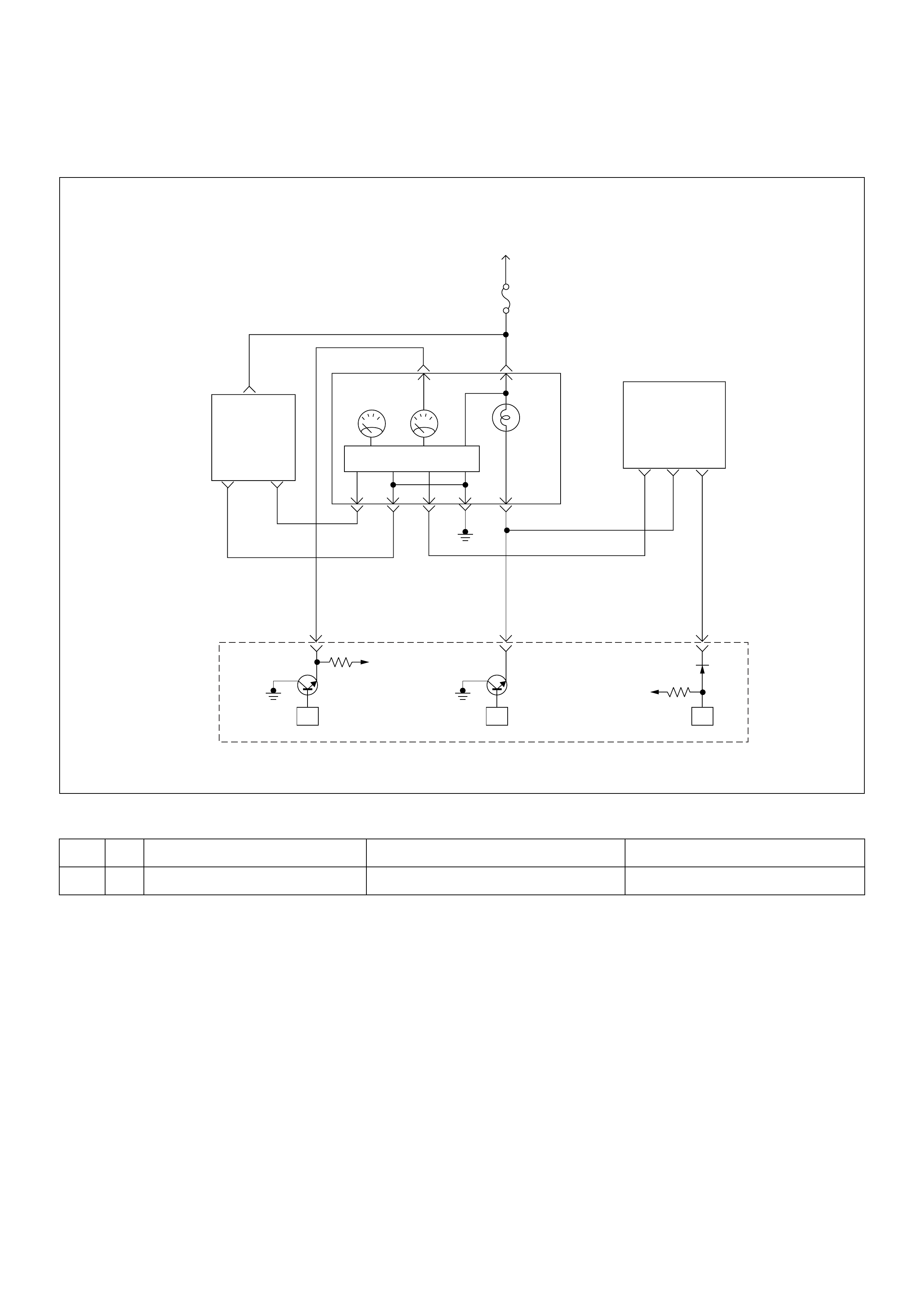
Diagnostic Trouble Code (DTC) P1693 Tachometer Output Low Voltage
Condition for setting the DTC and action ta ken when the DTC sets
Circuit Description
Based on the information from the Crank Position
Sensor (CKP), X58 reference signal is generated at
each rotation of the crankshaft.
Engine Control Module (ECM) converts X58 reference
signal into the square wave signal which is used to drive
the pulse generator of the tachometer.
When the wave length of the output signal is long, the
tacho meter indic ates the engine speed is low, and vi se
versa.
This malfunction detects a low impedance short to
ground or open contact on the Tacho output, the
Diagnostic Trouble Code P1693 will be set.
Diagnostic Aids
• Poor connections or a damaged harness - Inspect
the harness connections for: backed out terminals,
imprope, mating or damaged terminals. Also check
for open circuit, short to ground, and short to voltage.
• This malfunction detects a low impedance short to
ground or open contact on the ECM out put circuit.
Code Type DTC Name DTC Setting Condition Fail-Safe (Back Up)
P1693 B Tachometer Output Low Voltage Tacho output circuit short to ground circuit. No fail-safe function.
VIgn
Engine
Control
Module
(ECM)
Ignition
SW
µPµPµP
Meter
15A
VIgn
Check
Engine
Sped
Meter Tacho
Meter
0.85
YEL
0.8 YEL/GRN
0.5 BRN/YEL
CPU
0.5
WHT
J2-23J2-25
0.5
BRN/
YEL
(–) (+)
Vehicle
Speed
Sensor
J2-32
678
Imnobiliser
Control
Unit

Diagnostic Trouble Code (DTC) P1693 Tachometer Output Low Voltage
Step Action Value(s) Yes No
1 Was the “On-Board Di agnostic (OBD) System Check”
performed?
—Go to Step 2
Go to On
Board
Diagnostic
(OBD) System
Check
2 1. Connect the Tech 2.
2. Review and record the failure information.
3. Select “F0: Read DTC Infor By Priority” in “F0:
Diagnostic Trouble Code”.
Is the DTC P1693 stored as “Present Failure”? — Go to Step 3
Refer to
Diagnostic Aids
and Go to Step
3
3 1. Using the Tech2, ignition “On” and engine “Off”.
2. Select “Cl ear D TC I nform ati on” w ith th e Tech2 and
clear the DTC information.
3. Operate the vehicle and monitor the “F5: Failed
This Ignition” in “F2: DTC Information”.
Was the DTC P1693 stored in this ignition cycle? — Go to Step 4
Refer to
Diagnostic Aids
and Go to Step
4
4 Check for poor/faul ty connectio n at the ECM or meter
connector. If a poor/faulty connection is found, repair
the faulty termina l.
Was the problem found?
— Verify repair Go to Step 5
5 If a oscilloscope is available, monitor the Tachometer
output signal. Does the oscilloscope indicate correct
wave form?
—Go to Step 10
Not available:
Go to Step 6
Fixed at low:
Go to Step 6
Fixed at High:
Go to Step 7
25
C-56(J2) B-24 11
Tachometer Output Signal Reference Wave Form
0V→
Measurement Terminal: J2-25 (+) J1-1 (-)
Measurement Scale: 10V/div 5.0ms/div
Measurement Condition: Engine Speed at 2000rpm
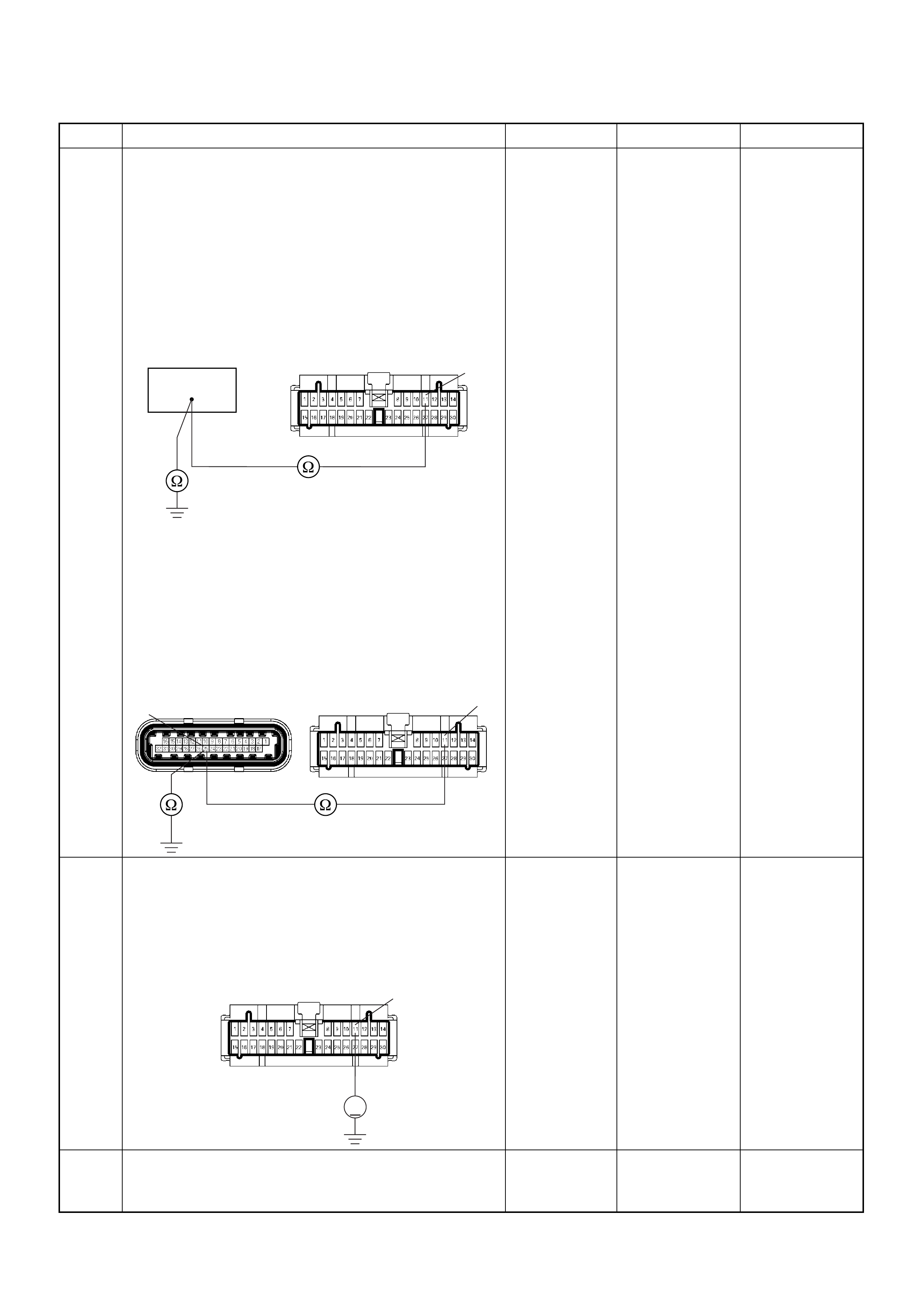
6 Using the DVM and check the Tacho output circuit.
Breaker box is available:
1. Ignition “Off”, engine “Off”.
2. Install the breaker box as type A. (ECM
disconnected) Ref. 6E-80.
3. Disco nne ct the mete r connec to r.
4. Check the circuit for open or short to ground
circuit.
Was the problem found?
Breaker box is not available:
1. Ignition “Off”, engine “Off”.
2. Disconnect the ECM connector.
3. Disco nne ct the mete r connec to r.
4. Check the circuit for open or short to ground
circuit.
Was the problem found?
—
Repair faulty
harness and
verify repair Go to Step 7
7 Using the DVM and check the Tacho output circuit.
1. Ignition “On”, engine “Off”.
2. Disco nne ct the mete r connec to r.
3. Check the circuit for short to power supply circuit.
Was the DVM indicated specified value?
Less than 1V Go to Step 8
Repair faulty
harness and
verify repair
8 Check any accessory parts which may cause electric
interference or magnetic interference.
Was the problem found? —
Remove the
accessory parts
and verify repair Go to Step 9
Step Action Value(s) Yes No
57
B-24 11
11
25 C-56(J2) B-24
V
B-24 11

9 Replace the Tacho meter.
Was the problem solved? — Verify repair Go to Step 10
10 Is the ECM programmed with the latest software
release?
If not, download the latest software to the ECM using
the “SPS (Service Programming System)”.
Was the problem solved? — Verify repair Go to Step 1 1
11 Replace the ECM.
Is the action complete?
IMPORTANT: The replacement ECM must be
programmed. Refer to section of the Service
Programming System (SPS) in this manual.
Following EC M programming, the immobiliser system
(if equipped) must be linked to the ECM. Refer to
section 11 “Immobiliser System-ECM replacement” for
the ECM/Immobiliser linking procedure. — Verify repair —
Step Action Value(s) Yes No

Symptom Diagnosis
Preliminary Checks
Before using this section, perform the “On-Board
Diagnostic (OBD) System Check” and verify all of the
following items:
• The engine control module (ECM) and malfunction
indicator lamp (MIL = Check Engine Lamp) are
operating correctly.
• There are no Diagnostic Trouble Code(s) stored.
• Tech 2 data is within normal operating range. Refer to
Typical Scan Data Values.
• Verify the customer complaint and locate the correct
symptom in the table of contents. Perform the
procedure included in the symptom chart.
Visual/Physical Check
Several of the symptom procedures call for a careful
visual/physical check. This can lead to correcting a
problem without further checks and can save valuable
time. This check should include the following items:
• ECM grounds for cleanliness, tightness and proper
location.
• Vacuum hoses for splits, kinks, and proper
connection, shown on the “Emission Control System
Schematics”. Check thoroughly for any type of leak or
restriction.
• Air intake ducts for collapsed or damaged areas.
• Air leaks at throttle body mounting area, manifold
absolute pressure (MAP) sensor and intake manifold
sealing surfaces.
• Ignition wires for cracking, harness, and carbon
tracking.
• Wiring for proper connections, pinches and cuts.
Intermittent
Important: An intermittent problem may or may not turn
on the malfunction indicator lamp (MIL) or store a
Diagnostic Trouble Code. Do NOT use the Diagnostic
Trouble Code (DTC) charts for intermittent problems.
The fault must be present to locate the problem.
Most intermittent problems are cased by faulty electrical
connections or wiring. Perform a careful visual/physical
check for the following conditions.
• Poor mating of the connector halves or a terminal not
fully seated in the connector (backed out).
• Improperly formed or damaged terminal.
• All connector terminals in the problem circuit should
be carefully checked for proper contact tension.
• Poor terminal-to-wire connection. This requires
removing the terminal form the connector body to
check.
• Ignition coils shorted to ground and arcing at ignition
wires or plugs.
• MIL (Check Engine Lamp) wire to ECM shorted to
ground.
• Poor ECM grounds. Refer to the ECM wiring
diagrams.
Road test the vehicle with a Digital Multimeter
connected to a suspected circuit. An abnormal voltage
when the malfunction occurs is a good indication that
there is a fault in the circuit being monitored.
Using Tech 2 to help detect intermittent conditions. The
Tech 2 has several features that can be used to located
an intermittent condition.
An intermittent MIL (Check Engine Lamp) with no stored
Diagnostic Trouble Code may be caused by the
following:
• Ignition coil shorted to ground and arcing at ignition
wires or plugs.
• MIL (Check Engine Lamp) wire to ECM short to
ground.
• Poor ECM grounds. Refer to the ECM wiring
diagrams.
Check for improper installation of electrical options such
as light, cellular phones, etc. Check all wires from ECM
to the ignition control module for poor connections.
Check for an open diode across the A/C compressor
clutch and check for other open diodes (refer to wiring
diagrams in Electrical Diagnosis).
If problem has not been found, refer to ECM connector
symptom tables.
• Check the “Broadcast Code” of the ECM, and
compare it with the la test Isuzu servic e bulletin s and/
or Isuzu EEPROM reprogramming equipment to
determine if an update to the ECM’s reprogrammable
memory has been released.
To check the “Broadcast Code”, connect the Tech 2,
then look for “ID info.” then select “Broadcast Code”.
This sh oul d di sp lay a 4 char ac te r code , su ch as “XBYA”
(example only).
This identifies the contents of the reprogrammable
software and calibration contained in the ECM.
If the “Broadcast Code” is not the most current
available, it is advisable to reprogram the ECM’s
EEPROM memory, which may either help identify a
hard-to find problem or may fix the problem.
The Service Programming System (SPS) will not allow
incorrect software programming or incorrect calibration
changes.
Techline

Engine Cranks But Will Not Run
DEFINITIONS: Engine cranks, but will not run. (The engine never start.)
NOTE: The replacement ECM must be programmed. Refer to section of the Service Programming System (SPS) in
this manual. Following ECM programming, the immobiliser system (if equipped) must be linked to the ECM.
Refer to section 11 “Immobiliser System-ECM replacement” for the ECM/Immobiliser linking procedure.
NOTE: The vehicle with immobiliser system, this system may be activated. Check the immobiliser system diagosis.
Step Action Value(s) Yes No
1 Was the “On-Boar d Diagnostic ( OBD) Syst em Check”
performed? — Go to Step 2 Go to OBD
System Check
2 1. Perform a bulletin search.
2. If a bulletin that addresses the symptom is found,
correct the condition as instructed in the bulletin.
W as a bulletin found that addresses the symptom? — Verify repair Go to Step 3
3 Was a visually/physical check performed? —Go to Step 4 Go to Visual /
physical Check.
4 Check the “Ignition coil” fuse (15A) and “ECM” fuse
(15A).
W as a fuse blown? — Verify repair Go to Step 5
5 1. Ignition ON
2. Use a DVM to verify that battery voltage at the
ignition coil fuse, and the ECM fuse.
Was battery voltage presented at the fuses? — Go to Step 6 Verify & repair
6 1. Visually/physically inspect for the following
conditions:
• Restriction of air intake system. Check for a
restricted air filter element, or foreign objects
blocking the air intake system.
• Check for objects blocking the IAC passage or
throttle bore, excessive deposits in the throttle
bore and on the throttle plate.
• Check for a condition that causes a large
vacuu m lea k, such as an inc or r ect ly i ns talled or
faulty cra nkcase venti lation hose/br ake booster
hose.
W as a problem found? — Verify repair Go to Step 7
7 1. Usin g a Te ch 2, displ ay the IAC va lue .
2. Check for a faulty, plugged, or sticking IAC
operation.
Was the problem found? — Verify repair Go to Step 8
8 1. Usin g a Tech 2, dis pl ay the MAP sensor val ue.
2. Check for a fault y, pl ugged, or incorre ctly ins talled
MAP sensor.
Was the problem found? — Verify repair Go to Step 9
9 If oscilloscope is available, check the wave form of the
CKP signal.
Was the correct wave form found? — Go to Step 12 Go to Step 10
10 Check the CKP sensor wire for open or short circuit.
W as a problem found? — Verify repair Go to Step 11
11 Replace CKP sensor.
Is there still problem? — Replace pulsar
ring. Verify repair

12 Visually/physically inspect the secondary ignition
wires. Check for the following conditions:
• Verify that all ignition wire resistance are less than
the specified value.
• Verify that ignition wires are correctly routed to
eliminate cross-fitting.
• Verify that ignition wires are not arcing to ground.
Spraying the secondary ignition wires with a light
mist of water may help locate an intermittent
problem.
Was a problem found?
#1 cyl. 4.4kΩ
#2 cyl. 3.6kΩ
#3 cyl. 3.1kΩ
#4 cyl. 2.8kΩVerify repair Go to Step 13
13 1. Disc on nec t the spark pl ug hig h ten si on cab le fr om
No.1 spark plug.
2. Install a spark tester at the end of the
disconnected ignition coil.
3. Clip the spark tester to a good ground.
4. Observe the spark tester while the engine is
cranking.
Was a crisp blue spark observed? (Only one or two
sparks followed by no result is considered the same
as “No Spark”.) — Go to Step 21 Go to Step 14
14 1. Disconnect the ignition coil harness connector.
2. Check for an open or short circuit between the
ignition coil and the ECM.
W as a problem found? — Verify repair Go to Step 15
15 1. Ignition “On”.
2. Using a Di gi tal Vo ltm eter ( DV M) ch eck th e ignitio n
wire coil at the ignition coil harness connector.
Was the voltage equal t o the specified value? Battery
voltage Go to Step 16 Verify repair
16 1. Ignition “Off”.
2. With DVM, check for an open in the ground wire at
the ignition coil harness connector.
Was the ground wire OK? — Go to Step 17 Verify repair
17 Replace the ignition coil, verify the repair.
Attempt to start the engine.
Is there still a problem? — Go to Step 18 Verify repair
18 Use an ohmmeter to check the ignition coil primary
winding resistance.
Was the primary winding resistance approximately
equal to the specified value? 0.8-18kΩGo to Step 19 Go to Step 20
19 Use an ohmmeter to check the ignition c oil se condary
winding resistance.
Was the primary winding resistance hear around the
to the specified value? 2.5kΩGo to Step 21 Go to Step 20
20 Replace the ignition coil. — Verify repair —
21 1. Remove the spark plugs from all cylinders.
2. Visually inspect the spark plug electrodes.
3. Replace any spark plugs with loose or missing
electrodes or cracked insulators.
Did your inspection reveal any spark plugs exhibiting
excessive fouling? —
Correct the
fouling
conditi on G o to Step 22
Step Action Value(s) Yes No

22 Perform the procedure in Fuel System Pressure Test
to determine if there is a problem with fuel delivery.
Was a problem found? — Verify repair Go to Step 23
23 Refer to Fuel System Diagnosis to determine if there
is a problem with fuel delivery.
Was a problem found? — Verify repair Go to Step 24
24 Check for the following engine mechanical problems
(refer to Engine Mechanical):
• Low compression
• Leaking cylinder head gaskets
• Worn camshaft
• Camshaft drive belt slipped or stripped
Was a problem found? — Verify repair Go to Step 25
25 1. Review all diagnostic procedures within this table.
2. If all procedures have been completed and no
malfunctions have been found, review/inspect the
following:
• Visual/physical inspection
• Tech 2 data
• All electrical connections within a suspected
circuit and/or system
Was a problem found? — Verify repair Go to Step 26
26 Is the ECM programmed with the latest software
release?
If not, download the latest software to the ECM using
the “SPS (Service Programming System)”.
Was the problem solved? — Verify repair Go to Step 27
27 Replace the ECM.
Is the action complete?
IMPORTANT: The replacement ECM must be
programmed. Refer to section of the Service
Programming System (SPS) in this manual.
Foll owing ECM pr ogramming, the immobi liser system
(if equipped) must be linked to the ECM. Refer to
section 11 “Immobiliser System-ECM replacement” for
the ECM/Immobiliser linking procedure. — Verify Repair —
Step Action Value(s) Yes No

Hard Star t Symptom
DEFINITIONS: Engine cranks, but does not start for a long time. Does eventually start, of may start and then
immediately stall.
Step Action Value(s) Yes No
1 Was the “On-Boar d Diagnostic ( OBD) Syst em Check”
performed? — Go to Step 2 Go to OBD
System Check
2 1. Perform a bulletin search.
2. If a bulletin that addresses the symptom is found,
correct the condition as instructed in the bulletin.
W as a bulletin found that addresses the symptom? — Verify repair Go to Step 3
3 Was a visually/physical check performed? —Go to Step 4 Go to Visual /
physical Check.
4 1. Visually/physically inspect for the following
conditions:
• Restriction of air intake system. Check for a
restricted air filter element, or foreign objects
blocking the air intake system
• Check for objects blocking the IAC passage or
throttle bore, excessive deposits in the throttle
bore and on the throttle plate
• Check for a condition that causes a large
vacuu m lea k, such as an inc or r ect ly i ns talled or
faulty cra nkcase venti lation hose/br ake booster
hose.
W as a problem found? — Verify repair Go to Step 5
5 1. Usin g a Te ch 2, displ ay the IAC va lue .
2. Check for a faulty, plugged, or sticking IAC
operation.
Was the problem found? — Verify repair Go to Step 6
6 Check engine coolant temperature (ECT) sensor for
shift in value.
1. After 8 hours with hood up and the engine not
running, connect the Tech 2.
2. Ignition On, engine not running.
3. Using Tech 2, compare Engine Coolant
Temperature to Intake Air Temperature.
Are ECT and IAT within the specified value of each
other? ±5°C Go to Step 8 Go to Step 7

7 1. Using a Tech 2, display the engine coolant
temperature and note the value.
2. Check the resistance of the engine coolant
temperature sensor.
Is the actual resistance near the resistance value in
the chart for the temperature that was noted?
—Go to Step 8
Replace the
ECT sensor.
Verify repair
8 1. Using a Tech 2, display the MAP sensor value in
comparison with atmosphere temperature.
2. Check for a fault y, pl ugged, or incorre ctly ins talled
MAP sensor.
Was the problem found? — Verify repair Go to Step 9
9 Visually/physically inspect all spark plug high-tension
cables. Check for the following conditions:
• Verify that the resistance of all spark plug high-
tension cables are less than the specified value.
• Verify that the all spark plug high-tension cables are
correctly fitted to eliminate cross-fitting.
• Verify that the all spark plug high-tension cables are
not arcing to ground.
Spraying the spark plug high-tension cables with a
light mist of water may help locate an intermittent
problem.
Was a problem found?
#1 cyl. 4.4kΩ
#2 cyl. 3.6kΩ
#3 cyl. 3.1kΩ
#4 cyl. 2.8kΩVerify repair Go to Step 10
10 Check for proper ignition voltage output with a spark
tester.
W as the problem found? — Verify repair Go to Step 11
11 1. Remove the spark plugs and check for gas or oil
fouling cracks, wear, improper gap, burned
electrodes, heavy deposits, or improper heat
range.
2. If spark plugs are fouled, the cause of fouling must
be determined before replacing the spark plugs.
W as a problem found? — Verify repair Go to Step 12
12 Check for a loose ignition control module ground.
W as a problem found? — Verify repair Go to Step 13
13 1. Check the ignition coil secondary resistance.
2. Replace the coil if it is greater than the specified
resistance.
Did the coil require replacement? 2.5kΩVerify repair Go to Step 14
Step Action Value(s) Yes No
Temperature (°C) Resistance (Ω) (Approximately)
-20 32040
0 9788
20 3516
40 1439
60 656
80 327
100 175
120 100

14 Drain sample fuel, visual inspection.
Any suspecion about the fuel, such as discoloration,
particle, contamination, water, unusual smell, then
drain the fuel from fuel tank.
Replace the fuel from know vehicle source.
If any suspicion of alcohol contamination, completely
drain the fuel, replace by fuel from known vehicle
source. — Verify repair Go to Step 15
15 Perform the procedure in Fuel System Pressure Test
to determine if there is a problem with fuel delivery.
Was a problem found? — Verify repair Go to Step 16
16 1. Check the injector connectors.
2. If any of the connectors are connected at an
improper cylinder, connect as necessary.
Was a problem found? — Verify repair Go to Step 17
17 Check for the following engine mechanical problems
(refer to Engine Mechanical):
• Low compression
• Leaking cylinder head gaskets
• Worn camshaft
• Camshaft drive belt slipped or stripped
Was a problem found? — Verify repair Go to Step 18
18 1. Review all diagnostic procedures within this table.
2. If all procedures have been completed and no
malfunctions have been found, review/inspect the
following:
• Visual/physical inspection
• Tech 2 data
• All electrical connections within a suspected
circuit and/or system
Was a problem found? — Verify repair Go to Step 19
19 Is the ECM programmed with the latest software
release?
If not, download the latest software to the ECM using
the “SPS (Service Programming System)”.
Was the problem solved? — Verify repair Go to Step 20
20 Replace the ECM.
Is the action complete?
IMPORTANT: The replacement ECM must be
programmed. Refer to section of the Service
Programming System (SPS) in this manual.
Foll owing ECM pr ogramming, the immobi liser system
(if equipped) must be linked to the ECM. Refer to
section 11 “Immobiliser System-ECM replacement” for
the ECM/Immobiliser linking procedure. — Verify Repair —
Step Action Value(s) Yes No

Rough, Unstable, Or Incorrect Idle, Stalling Symptom
DEFINITIONS: Engine runs unevenly at idle. If severe,
the engine or vehicle may shake. Engine idle speed
may vary in RPM. Either condition may be severe
enough to stall the engine.
Step Action Value(s) Yes No
1 Was the “On-Boar d Diagnostic ( OBD) Syst em Check”
performed? — Go to Step 2 Go to OBD
System Check
2 1. Perform a bulletin search.
2. If a bulletin that addresses the symptom is found,
correct the condition as instructed in the bulletin.
W as a bulletin found that addresses the symptom? — Verify repair Go to Step 3
3 Was a visual/physical check performed? —Go to Step 4 Go to Visual /
physical Check.
4 1. Check for faulty, plugged or incorrectly installed
PCV va lve.
2. Verify that the PCV system is not plugged.
W as a problem found? — Verify repair Go to Step 5
5 1. Check for incorrect idle speed. Ensure that the
following conditions are present.
• Engine fully warm
• Accessories are “Off”
2. Using a Tech 2, monitor IAC position.
Is the IAC position within the specified values? 20-30 Steps Go to Step 7 Go to Step 6
6 1. Visually/physically inspect for the following
conditions:
• Restrictio n of the ai r intake sys tem . Che ck fo r a
restricted air filter element, or foreign objects
blocking the air intake system.
• Check for objects blocking the IAC passage or
throttle bore, excessive deposits in the throttle
bore and on the throttle plate.
• Check for a condition that causes a large
vacuu m lea k, such as an inc or r ect ly i ns talled or
faulty cra nkcase venti lation hose/br ake booster
hose.
W as a problem found? — Verify repair Go to Step 7

7 1. Using a Tech 2, display the engine coolant
temperature and note the value.
2. Check the resistance of the engine coolant
temperature sensor.
Is the actual resistance near the resistance value in
the chart for the temperature that was noted?
—Go to Step 8
Replace the
ECT sensor.
Verify repair
8 1. Using a Tech 2, display the MAP sensor value in
comparison with atmosphere temperature.
2. Check for a fault y, pl ugged, or incorre ctly ins talled
MAP sensor.
Was the problem found? — Verify repair Go to Step 9
9 U sing Tech 2, m onitor thro ttle po sitio n with the eng ine
idling.
Is the throttle position at the specified value and
steady?
0% Go to Step 10
Refer to
Diagnostic
Trouble Code
P0123 for
further
diagnosis
10 Check for proper ignition voltage output with the spark
tester.
W as a problem found? — Verify repair Go to Step 11
11 1. Remove the spark plugs and check for gas or oil
fouling cracks, wear, improper gap, burned
electrodes, heavy deposits, or improper heat
range.
2. If spark plugs are fouled, the cause of fouling must
be determined before replacing the spark plugs.
W as a problem found? — Verify repair Go to Step 12
12 Check for a loose ignition control module ground.
W as a problem found? — Verify repair Go to Step 13
13 Check items that can cause the engine to run rich.
Refer to DTC P1167 “Fuel Supply System Rich During
Deceleration Fuel Cut Off”.
W as a problem found? — Verify repair Go to Step 14
14 Check items that can cause the engine to run lean.
Refer to DTC P1171 “Fuel Supply System Lean
During Power Enrichment”.
W as a problem found? — Verify repair Go to Step 15
15 Check the injector connectors, if any of the injectors
are connected any incorrect cylinder, correct as
necessary.
W as a problem found? — Verify repair Go to Step 16
16 1. Check for faulty engine mounts.
2. If a problem is found, repair as necessary.
W as a problem found? — Verify repair Go to Step 17
Step Action Value(s) Yes No
Temperature (°C) Resistance (Ω) (Approximately)
-20 32040
0 9788
20 3516
40 1439
60 656
80 327
100 175
120 100

17 Perform the procedure in Fuel System Pressure Test
to determine if there is a problem with fuel delivery.
Was a problem found? — Verify repair Go to Step 18
18 Check for the following engine mechanical problems
(refer to Engine Mechanical):
• Low compression
• Leaking cylinder head gaskets
• Worn camshaft
• Sticking or leaking valves
• Valve timing
• Broken valve springs
• Camshaft drive belt slipped or stripped
Was a problem found? — Verify repair Go to Step 19
19 1. Review all diagnostic procedures within this table.
2. If all procedures have been completed and no
malfunctions have been found, review/inspect the
following:
• Visual/physical inspection
• Tech 2 data
• All electrical connections within a suspected
circuit and/or system
Was a problem found? — Verify repair Go to Step 20
20 Is the ECM programmed with the latest software
release?
If not, download the latest software to the ECM using
the “SPS (Service Programming System)”.
Was the problem solved? — Verify repair Go to Step 21
21 Replace the ECM.
Is the action complete?
IMPORTANT: The replacement ECM must be
programmed. Refer to section of the Service
Programming System (SPS) in this manual.
Foll owing ECM pr ogramming, the immobi liser system
(if equipped) must be linked to the ECM. Refer to
section 11 “Immobiliser System-ECM replacement” for
the ECM/Immobiliser linking procedure. — Verify Repair —
Step Action Value(s) Yes No

Surges And/or Chugs Symptom
DEFINITIONS: See the ill ustration be low. Feel s like the
vehicle speeds up and slows down with no charge in the
accelerator pedal.
Step Action Value(s) Yes No
1 Was the “On-Boar d Diagnostic ( OBD) Syst em Check”
performed? — Go to Step 2 Go to OBD
System Check
2 1. Perform a bulletin search.
2. If a bulletin that addresses the symptom is found,
correct the condition as instructed in the bulletin.
W as a bulletin found that addresses the symptom? — Verify repair Go to Step 3
3 Was a visual/physical check performed? —Go to Step 4 Go to Visual /
physical Check.
4 Be sure that the driver understands A/C compressor
operation as explained in the owner ’s manual. Inform
the customer how the A/C clutch operate.
Is the customer experiencing a normal condition? — System OK Go to Step 5
5 1. Using a Tech 2, display the MAP sensor value in
comparison with atmosphere temperature.
2. Check for a fault y, pl ugged, or incorre ctly ins talled
MAP sensor.
Was the problem found? — Verify repair Go to Step 6
6 Observe the throttle position display on the Tech 2
while slowly increasing throttle pedal.
Is the throttle position at the specified value and
steady in any position?
—Go to Step 7
Refer to
Diagnostic
Trouble Code
P0123 for
further
diagnosis
7 Check the knock sensor wire, shield wire, or
installation condition.
W as a problem found? — Verify repair Go to Step 8
8 Run Engine.
Check the fuel control Heated Oxygen Sensor
(HO2S). When monitored on the Tech 2, the HO2S
should res po nd qu ic kl y to differen t thr ottl e po si tio ns . If
it does n’t check for s ilicon or other contaminates from
fuel or use of improper sealant. The sensors may
have a white powdery coating. Silicon contamination
sends a rich exhaust signa l which causes the ECM to
command an excessively lean air/fuel mixture.
W as a problem found? — Verify repair Go to Step 9

9 Check the fuel pressure. Refer to Fuel System
Diagnosis.
W as a problem found? — Verify repair Go to Step 10
10 Moni tor “B1S1 (B ank 1 Sensor 1) Status” on the Tec h
2.
Is the “B1S1 (Bank 1 Sensor 1) Status” in the rich
condition? — Verify repair Go to Step 11
11 Check items that can cause the engine to run rich.
Refer to DTC P1167 “Fuel Supply System Rich During
Deceleration Fuel Cut Off”.
W as a problem found? — Verify repair Go to Step 12
12 Check items that can cause the engine to run lean.
Refer to DTC P1171 “Fuel Supply System Lean
During Power Enrichment”.
W as a problem found? — Verify repair Go to Step 13
13 Check for proper ignition voltage output with the spark
tester.
W as a problem found? — Verify repair Go to Step 14
14 Check for a loose ignition control module ground.
W as a problem found? — Verify repair Go to Step 15
15 Visually/physically inspect all spark plug high-tension
cables. Check for the following conditions:
• Verify that the resistance of all spark plug high-
tension cables are less than the specified value.
• Verify that the all spark plug high-tension cables are
correctly fitted to eliminate cross-fitting.
• Verify that the all spark plug high-tension cables are
not arcing to ground.
Spraying the spark plug high-tension cables with a
light mist of water may help locate an intermittent
problem.
Was a problem found?
#1 cyl. 4.4kΩ
#2 cyl. 3.6kΩ
#3 cyl. 3.1kΩ
#4 cyl. 2.8kΩVerify repair Go to Step 16
16 1. Check the ignition coil secondary resistance.
2. Replace the coil if it is greater than the specified
resistance.
Did the coil require replacement? 2.5kΩVerify repair Go to Step 17
17 1. Remove the spark plugs and check for gas or oil
fouling cracks, wear, improper gap, burned
electrodes, heavy deposits, or improper heat
range.
2. If spark plugs are fouled, the cause of fouling must
be determined before replacing the spark plugs.
W as a problem found? — Verify repair Go to Step 18
18 1. Check the injector connectors.
2. If any of the connectors are connected at an
improper cylinder, connect as necessary.
W as a problem found? — Verify repair Go to Step 19
19 Check the ECM grounds to verify that they are clean
and tight. Refer to the ECM wiring diagrams.
W as a problem found? — Verify repair Go to Step 20
20 Visually/physically check the vacuum hose for splits,
kinks and proper connections and routing.
W as a problem found? — Verify repair Go to Step 21
Step Action Value(s) Yes No

21 Check the exhaust system for a possible restriction:
• Damaged or collapsed pipes
• Internal muffler failure
Was a problem found? — Verify repair Go to Step 22
22 1. Review all diagnostic procedures within this table.
2. If all procedures have been completed and no
malfunctions have been found, review/inspect the
following:
• Visual/physical inspection
• Tech 2 data
• All electrical connections within a suspected
circuit and/or system
Was a problem found? — Verify repair Go to Step 23
23 Is the ECM programmed with the latest software
release?
If not, download the latest software to the ECM using
the “SPS (Service Programming System)”.
Was the problem solved? — Verify repair Go to Step 24
24 Replace the ECM.
Is the action complete?
IMPORTANT: The replacement ECM must be
programmed. Refer to section of the Service
Programming System (SPS) in this manual.
Foll owing ECM pr ogramming, the immobi liser system
(if equipped) must be linked to the ECM. Refer to
section 11 “Immobiliser System-ECM replacement” for
the ECM/Immobiliser linking procedure. — Verify Repair —
Step Action Value(s) Yes No

Hesitation, Sag, Stumble Symptom
DEFINITIONS: Momentary lack of response as the
accelerator is pushed down. Can occur at any vehicle
speed. Usually most pronounced when first trying to
make the vehicle move, as from a stop sign. May cause
the engine to stall if severe enough.
Step Action Value(s) Yes No
1 Was the “On-Boar d Diagnostic ( OBD) Syst em Check”
performed? — Go to Step 2 Go to OBD
System Check
2 1. Perform a bulletin search.
2. If a bulletin that addresses the symptom is found,
correct the condition as instructed in the bulletin.
W as a bulletin found that addresses the symptom? — Verify repair Go to Step 3
3 Was a visual/physical check performed? —Go to Step 4 Go to Visual /
physical Check.
4 Check the fuel quality.
Is the customer using improper fuel or degraded fuel? — Replace fuel Go to Step 5
5 1. Using a Tech 2, display the MAP sensor value in
comparison with atmosphere temperature.
2. Check for a fault y, pl ugged, or incorre ctly ins talled
MAP sensor.
Was the problem found? — Verify repair Go to Step 6
6 Observe the throttle position display on the Tech 2
while slowly increasing throttle pedal.
Does the throttle position increase steady with
increasing smoothly?
—Go to Step 7
Refer to
Diagnostic
Trouble Code
P0123 for
further
diagnosis
7 Check the knock sensor wire, shield wire, or
installation condition.
W as a problem found? — Verify repair Go to Step 8
8 Run Engine.
Check the fuel control Heated Oxygen Sensor
(HO2S). When monitored on the Tech 2, the HO2S
should res po nd qu ic kl y to differen t thr ottl e po si tio ns . If
it does n’t check for s ilicon or other contaminates from
fuel or use of improper sealant. The sensors may
have a white powdery coating. Silicon contamination
sends a rich exhaust signa l which causes the ECM to
command and excessively lean air/fuel mixture.
W as a problem found? — Verify repair Go to Step 9
9 Check the fuel pressure. Refer to Fuel System
Diagnosis.
W as a problem found? — Verify repair Go to Step 10

10 Moni tor “B1S1 (B ank 1 Sensor 1) Status” on the Tec h
2.
Is the “B1S1 (Bank 1 Sensor 1) Status” in the rich
condition? — Go to Step 11 Go to Step 12
11 Check items that can cause the engine to run rich.
Refer to DTC P1167 “Fuel Supply System Rich During
Deceleration Fuel Cut Off”.
W as a problem found? — Verify repair Go to Step 12
12 Check items that can cause the engine to run lean.
Refer to DTC P1171 “Fuel Supply System Lean
During Power Enrichment”.
W as a problem found? — Verify repair Go to Step 13
13 Check for proper ignition voltage output with the spark
tester.
W as a problem found? — Verify repair Go to Step 14
14 Check for a loose ignition control module ground.
W as a problem found? — Verify repair Go to Step 15
15 Visually/physically inspect all spark plug high-tension
cables. Check for the following conditions:
• Verify that the resistance of all spark plug high-
tension cables are less than the specified value.
• Verify that the all spark plug high-tension cables are
correctly fitted to eliminate cross-fitting.
• Verify that the all spark plug high-tension cables are
not arcing to ground.
Spraying the spark plug high-tension cables with a
light mist of water may help locate an intermittent
problem.
Was a problem found?
#1 cyl. 4.4kΩ
#2 cyl. 3.6kΩ
#3 cyl. 3.1kΩ
#4 cyl. 2.8kΩVerify repair Go to Step 16
16 1. Check the ignition coil secondary resistance.
2. Replace the coil if it is greater than the specified
resistance.
Did the coil require replacement? 2.5kΩVerify repair Go to Step 17
17 1. Remove the spark plugs and check for gas or oil
fouling cracks, wear, improper gap, burned
electrodes, heavy deposits, or improper heat
range.
2. If spark plugs are fouled, the cause of fouling must
be determined before replacing the spark plugs.
W as a problem found? — Verify repair Go to Step 18
18 Check the ECM grounds to verify that they are clean
and tight. Refer to the ECM wiring diagrams.
W as a problem found? — Verify repair Go to Step 19
19 Visually/physically check the vacuum hose for splits,
kinks and proper connections and routing.
W as a problem found? — Verify repair Go to Step 20
Step Action Value(s) Yes No

20 1. Review all diagnostic procedures within this table.
2. If all procedures have been completed and no
malfunctions have been found, review/inspect the
following:
• Visual/physical inspection
• Tech 2 data
• All electrical connections within a suspected
circuit and/or system
Was a problem found? — Verify repair Go to Step 21
21 Is the ECM programmed with the latest software
release?
If not, download the latest software to the ECM using
the “SPS (Service Programming System)”.
Was the problem solved? — Verify repair Go to Step 22
22 Replace the ECM.
Is the action complete?
IMPORTANT: The replacement ECM must be
programmed. Refer to section of the Service
Programming System (SPS) in this manual.
Foll owing ECM pr ogramming, the immobi liser system
(if equipped) must be linked to the ECM. Refer to
section 11 “Immobiliser System-ECM replacement” for
the ECM/Immobiliser linking procedure. — Verify Repair —
Step Action Value(s) Yes No

Cuts Out, Miss es Sympt om
DEFINITIONS: Steady pulsation or jerking that follows
engine s pee d; us ual ly m ore p ro nou nc ed as en gin e lo a d
increases.
Step Action Value(s) Yes No
1 Was the “On-Boar d Diagnostic ( OBD) Syst em Check”
performed? — Go to Step 2 Go to OBD
System Check
2 1. Perform a bulletin search.
2. If a bulletin that addresses the symptom is found,
correct the condition as instructed in the bulletin.
W as a bulletin found that addresses the symptom? — Verify repair Go to Step 3
3 Was a visual/physical check performed? —Go to Step 4 Go to Visual /
physical Check.
4 Check the ECM grounds to verify that they are clean
and tight. Refer to the ECM wiring diagrams in
Electrical Diagnosis.
W as a problem found? — Verify repair Go to Step 5
5 Check for a loose or short circuit of ignition coil
modu le vo ltage feed.
W as a problem found? — Verify repair Go to Step 6
6 Check for a loose or short circuit of ignition coil
modu le groun d.
W as a problem found? — Verify repair Go to Step 7
7 Visually/physically inspect all spark plug high-tension
cables. Check for the following conditions:
• Verify that the resistance of all spark plug high-
tension cables are less than the specified value.
• Verify that the all spark plug high-tension cables are
correctly fitted to eliminate cross-fitting.
• Verify that the all spark plug high-tension cables are
not arcing to ground.
Spraying the spark plug high-tension cables with a
light mist of water may help locate an intermittent
problem.
Was a problem found?
#1 cyl. 4.4kΩ
#2 cyl. 3.6kΩ
#3 cyl. 3.1kΩ
#4 cyl. 2.8kΩVerify repair Go to Step 7
8 Check the CKP sensor wire, shield wire, or installation
condition.
W as a problem found? — Verify repair Go to Step 9
9 M onitor “B1S1 ( Bank 1 Sens or 1) Status” on the Tech
2.
Is the “B1S1 (Bank 1 Sensor 1) Status” in the rich
condition? — Go to Step 10 Go to Step 11

10 Check items that can cause the engine to run rich.
Refer to DTC P1167 “Fuel Supply System Rich During
Deceleration Fuel Cut Off”.
W as a problem found? — Verify repair Go to Step 11
11 Monitor “B1S1 (Bank 1 S ensor 1) Status” on the Tec h
2.
Is the “B1S1 (Bank 1 Sensor 1) Status” in the lean
condition? — Go to Step 12 Go to Step 13
12 Check items that can cause the engine to run lean.
Refer to DTC P1171 “Fuel Supply System Lean
During Power Enrichment”.
W as a problem found? — Verify repair Go to Step 13
13 1. Visually/physically inspect for the following
conditions:
• Restriction of air intake system. Check for a
restricted air filter element, or foreign objects
blocking the air intake system.
• Check for objects blocking the IAC passage or
throttle bore, excessive deposits in the throttle
bore and on the throttle plate.
• Check for a condition that causes a large
vacuu m lea k, such as an inc or r ect ly i ns talled or
faulty cra nkcase venti lation hose/br ake booster
hose.
W as a problem found? — Verify repair Go to Step 14
14 Check the injector connectors, if any of the injectors
are connected an incorrect cylinder, correct as
necessary.
W as a problem found? — Verify repair Go to Step 15
15 Perform the Injector Coil/Balance Test.
W as a problem found. — Verify repair Go to Step 16
16 1. Check for fuel in the pressure regulator vacuum
hose.
2. If fuel is present, replace the fuel pressure
regulator assembly.
W as a problem found? — Verify repair Go to Step 17
17 Check for proper ignition voltage output with the spark
tester.
W as a problem found? — Verify repair Go to Step 18
18 1. Remove the spark plugs and check for gas or oil
fouling cracks, wear, improper gap, burned
electrodes, heavy deposits, or improper heat
range.
2. If spark plugs are fouled, the cause of fouling must
be determined before replacing the spark plugs.
W as a problem found? — Verify repair Go to Step 19
Step Action Value(s) Yes No

19 Check for the following engine mechanical problems
(refer to Engine Mechanical):
• Low compression
• Leaking cylinder head gaskets
• Worn camshaft
• Sticking or leaking valves
• Valve timing
• Broken valve springs
• Camshaft drive belt slipped or stripped
Was a problem found? — Verify repair Go to Step 20
20 1. Check for faulty engine mounts.
2. If a problem is found, repair as necessary.
Was a problem found? — Verify repair Go to Step 21
21 1. Review all diagnostic procedures within this table.
2. If all procedures have been completed and no
malfunctions have been found, review/inspect the
following:
• Visual/physical inspection
• Tech 2 data
• All electrical connections within a suspected
circuit and/or system
Was a problem found? — Verify repair Go to Step 22
22 Is the ECM programmed with the latest software
release?
If not, download the latest software to the ECM using
the “SPS (Service Programming System)”.
Was the problem solved? — Verify repair Go to Step 23
23 Replace the ECM.
Is the action complete?
IMPORTANT: The replacement ECM must be
programmed. Refer to section of the Service
Programming System (SPS) in this manual.
Foll owing ECM pr ogramming, the immobi liser system
(if equipped) must be linked to the ECM. Refer to
section 11 “Immobiliser System-ECM replacement” for
the ECM/Immobiliser linking procedure. — Verify Repair —
Step Action Value(s) Yes No

Lack Of Power, Sluggish Or Spongy Symptom
DEFINITIONS: Engine delivers less than expected power. Attempting part-throttle acceleration results in little or no
increase in vehicle speed .
Step Action Value(s) Yes No
1 Was the “On-Boar d Diagnostic ( OBD) Syst em Check”
performed? — Go to Step 2 Go to OBD
System Check
2 1. Perform a bulletin search.
2. If a bulletin that addresses the symptom is found,
correct the condition as instructed in the bulletin.
W as a bulletin found that addresses the symptom? — Verify repair Go to Step 3
3 Was a visual/physical check performed? —Go to Step 4 Go to Visual /
physical Check.
4 1. Re move and check the air filter ele ment for dirt or
restrictions.
2. Replace the air filter element if necessary.
Was a repair required? — Verify repair Go to Step 5
5 Check the ECM grounds to verify that they are clean
and tight. Refer to the ECM wiring diagrams.
W as a problem found? — Verify repair Go to Step 6
6 1. Using a Tech 2, display the MAP sensor value in
comparison with atmosphere temperature.
2. Check for a fault y, pl ugged, or incorre ctly ins talled
MAP sensor.
Was the problem found? — Verify repair Go to Step 7
7 1. Using a Tech 2, display the ECT sensor and IAT
sensor value and warm up condition compared
with the typical data.
2. Check the specified value or wire.
Was the problem found? — Verify repair Go to Step 8
8 Observe the throttle position display on the Tech 2
while slowly increasing throttle pedal.
Does the throttle position increase steady with
increasing smoothly?
—Go to Step 9
Refer to
Diagnostic
Trouble Code
P0123 for
further
diagnosis
9 Check the knock sensor wire, shield wire, or
installation condition.
W as a problem found? — Verify repair Go to Step 10
10 Run Engine.
Check the fuel control Heated Oxygen Sensor
(HO2S). When monitored on the Tech 2, the HO2S
should res po nd qu ic kl y to differen t thr ottl e po si tio ns . If
it does n’t check for s ilicon or other contaminates from
fuel or use of improper sealant. The sensors may
have a white powdery coating. Silicon contamination
sends a rich exhaust signa l which causes the ECM to
command and excessively lean air/fuel mixture.
W as a problem found? — Verify repair Go to Step 11
11 Check the fuel pressure. Refer to Fuel System
Diagnosis.
W as a problem found? — Verify repair Go to Step 12

12 Moni tor “B1S1 (B ank 1 Sensor 1) Status” on the Tec h
2.
Is the “B1S1 (Bank 1 Sensor 1) Status” in the rich
condition? — Verify repair Go to Step 13
13 Check items that can cause the engine to run rich.
Refer to DTC P1167 “Fuel Supply System Rich During
Deceleration Fuel Cut Off”.
W as a problem found? — Verify repair Go to Step 14
14 Check items that can cause the engine to run lean.
Refer to DTC P1171 “Fuel Supply System Lean
During Power Enrichment”.
W as a problem found? — Verify repair Go to Step 15
15 Check for proper ignition voltage output with a spark
tester.
W as the problem found? — Verify repair Go to Step 16
16 1. Remove the spark plugs and check for gas or oil
fouling cracks, wear, improper gap, burned
electrodes, heavy deposits, or improper heat
range.
2. If spark plugs are fouled, the cause of fouling must
be determined before replacing the spark plugs.
W as a problem found? — Verify repair Go to Step 17
17 Drain sample fuel, visual inspection.
Any suspecion about the fuel, such as discoloration,
particle, contamination, water, unusual smell, then
drain the fuel from fuel tank.
Replace the fuel from know vehicle source.
If any suspencion of alcohol contamination,
completely drain the fuel, replace by fuel from known
vehicle source. — Verify repair Go to Step 18
18 Check the exhaust system for a possible restriction:
• Damaged or collapsed pipes
• Inter nal muffler f ailure
W as a problem found? — Verify repair Go to Step 19
19 Check for the following engine mechanical problems
(refer to Engine Mechan ic al ):
• Low compression
• Leaking cylinder head gaskets
• Worn camshaft
• Loose timing belt
W as a problem found? — Verify repair Go to Step 20
20 1. Review all diagnostic procedures within this table.
2. If all procedures have been completed and no
malfunctions have been foun d, review/inspect the
following:
• Visual/physical inspection
• Te ch 2 data
• All electrical connections within a suspected
circuit and/or system
W as a problem found? — Verify repair Go to Step 21
Step Action Value(s) Yes No

21 Is the ECM programmed with the latest software
release?
If not, download the latest software to the ECM using
the “SPS (Service Programming System)”.
Was the problem solved? — Verify repair Go to Step 22
22 Replace the ECM.
Is the action complete?
IMPORTANT: The replacement ECM must be
programmed. Refer to section of the Service
Programming System (SPS) in this manual.
Foll owing ECM pr ogramming, the immobi liser system
(if equipped) must be linked to the ECM. Refer to
section 11 “Immobiliser System-ECM replacement” for
the ECM/Immobiliser linking procedure. — Verify Repair —
Step Action Value(s) Yes No

Detonation/spark Knock Symptom
DEFINITIONS: A mil d to s ev ere p in g, u su all y wors e u nde r acce ler at ion . T he en gine makes a shar p metall ic knoc k ing
sound that changes with throttle opening. Prolonged detonation may lead to complete engine tailure.
Step Action Value(s) Yes No
1 Was the “On-Boar d Diagnostic ( OBD) Syst em Check”
performed? — Go to Step 2 Go to OBD
System Check
2 1. Perform a bulletin search.
2. If a bulletin that addresses the symptom is found,
correct the condition as instructed in the bulletin.
W as a bulletin found that addresses the symptom? — Verify repair Go to Step 3
3 Was a visual/physical check performed? —Go to Step 4 Go to Visual /
physical Check.
4 1. If Tech 2 readings are normal (refer to Typical
Scan Data Values) and there are no engine
mechanical faults, fill the fuel tank with a known
quality gasoline.
2. Re-evaluate the vehicle performance.
Is detonation present? — Go to Step 5 Verify repair
5 1. Check for obvious overheating problems:
• Low engine coolant
• Restricted air flow to radiato r
• Incorrect coolant solution
2. If a problem is found, repair as necessary.
W as a problem found? — Verify repair Go to Step 6
6 Check the fuel pressure. Refer to Fuel System
Diagnosis.
W as a problem found? — Verify repair Go to Step 7
7 1. Using a Tech 2, display the MAP sensor value in
comparison with atmosphere temperature.
2. Check for a fault y, pl ugged, or incorre ctly ins talled
MAP sensor.
Was the problem found? — Verify repair Go to Step 8
8 1. Using a Tech 2, display the ECT sensor and IAT
sensor value and warm up condition compared
with the typical data.
2. Check the specified value or wire.
Was the problem found? — Verify repair Go to Step 9
9 Observe the throttle position display on the Tech 2
while slowly increasing throttle pedal.
Does the throttle position increase steady with
increasing smoothly?
—Go to Step 10
Refer to
Diagnostic
Trouble Code
P0123 for
further
diagnosis
10 Check the knock sensor wire, shield wire, or
installation condition.
W as a problem found? — Verify repair Go to Step 11
11 Check items that can cause the engine to run lean.
Refer to DTC P1171 “Fuel Supply System Lean
During Power Enrichment”.
W as a problem found? — Verify repair Go to Step 12

12 Check spark plugs for proper heat range.
Were incorrect spark plugs installed? — Verify repair Go to Step 13
13 1. Remove excessive carbon buildup with a top
engine cleaner.
2. Re-evaluate vehicle performance.
Is detonation still present? — Verify repair Go to Step 14
14 Check for an engine mechanical problem. Perform a
cylinder compression check. Refer to Engine
Mechanical.
Was a problem found? — Verify repair Go to Step 15
15 1. Review all diagnostic procedures within this table.
2. If all procedures have been completed and no
malfunctions have been found, review/inspect the
following:
• Visual/physical inspection
• Tech 2 data
• All electrical connections within a suspected
circuit and/or system
Was a problem found? — Verify repair Go to Step 16
16 Is the ECM programmed with the latest software
release?
If not, download the latest software to the ECM using
the “SPS (Service Programming System)”.
Was the problem solved? — Verify repair Go to Step 17
17 Replace the ECM.
Is the action complete?
IMPORTANT: The replacement ECM must be
programmed. Refer to section of the Service
Programming System (SPS) in this manual.
Foll owing ECM pr ogramming, the immobi liser system
(if equipped) must be linked to the ECM. Refer to
section 11 “Immobiliser System-ECM replacement” for
the ECM/Immobiliser linking procedure. — Verify Repair —
Step Action Value(s) Yes No

Poor Fuel Economy Symptom
DEFINITIONS: Fuel economy, as m eas ured by an a ctu al ro ad te st , is no tic ea bly lower th an e xp ec ted. Al so , economy
is noticeably lower than it was on this vehicle at one time, as previously shown by an actual road test.
Step Action Value(s) Yes No
1 Was the “On-Boar d Diagnostic ( OBD) Syst em Check”
performed? — Go to Step 2 Go to OBD
System Check
2 1. Perform a bulletin search.
2. If a bulletin that addresses the symptom is found,
correct the condition as instructed in the bulletin.
W as a bulletin found that addresses the symptom? — Verify repair Go to Step 3
3 Was a visual/physical check performed? —Go to Step 4 Go to Visual /
physical Check.
4 Check owner’s driving habits.
• Is the A/C On full time (defroster mode On)?
• Are tires at the correct pressure?
• Are excessively heavy loads being carried?
• Is acceleration too much, too often? — Go to Step 5 Go to Step 6
5 Review the items in Step 4 with the customer and
advise as necessary.
Is the action complete? — System OK —
6 Visually/physically check: Vacuum hoses for splits,
kinks, and improper connections and routing as
shown on the “Emission Control System Schematics”.
W as a problem found? — Verify repair Go to Step 7
7 Check for low engine coolant level.
W as a problem found? — Verify repair Go to Step 8
8 Ch eck for incorrect or faulty engine thermostat. Refer
to Engine Cooling.
W as a problem found? — Verify repair Go to Step 9
9 Re move and check the air filter element for dirt or for
restrictions.
W as a problem found? — Verify repair Go to Step 10
10 1. Using a Tech 2, display the MAP sensor value in
comparison with atmosphere temperature.
2. Check for a fault y, pl ugged, or incorre ctly ins talled
MAP sensor.
W as the problem found? — Verify repair Go to Step 11
11 1. Using a Tech 2, display the ECT sensor and IAT
sensor value and warm up condition compared
with the typical data.
2. Check the specified value or wire.
W as the problem found? — Verify repair Go to Step 12
12 Check the knock sensor wire, shield wire, or
installation condition.
W as a problem found? — Verify repair Go to Step 13
13 Check the fuel pressure. Refer to Fuel System
Diagnosis.
W as a problem found? — Verify repair Go to Step 14

14 Moni tor “B1S1 (B ank 1 Sensor 1) Status” on the Tec h
2.
Is the “B1S1 (Bank 1 Sensor 1) Status” in the rich
condition? — Verify repair Go to Step 15
15 Check items that can cause the engine to run rich.
Refer to DTC P1167 “Fuel Supply System Rich During
Deceleration Fuel Cut Off”.
W as a problem found? — Verify repair Go to Step 16
16 1. Remove the spark plugs and check for gas or oil
fouling cracks, wear, improper gap, burned
electrodes, heavy deposits, or improper heat
range.
2. If spark plugs are fouled, the cause of fouling must
be determined before replacing the spark plugs.
W as a problem found? — Verify repair Go to Step 17
17 Check for proper calibration of the speedometer.
Does the s peed indicated on the speed meter closely
match the vehicle speed displayed on the Tech 2? — Go to Step 19 Go to Step 18
17B Check the vehicle speed on accurate chassisi dynamo
on check number of pulse fun speed sensor. See
typic al data below.
18 Diagnose and repair the inaccurate speedometer
condition as necessary. Refer to Vehicle Speed
Sensor in Electrical Diagnosis. — Verify Repair —
19 Check for proper calibration of the fuel gauge.
W as a problem found? — Verify repair Go to Step 20
20 Check for the following engine mechanical problems
(refer to Engine Mechan ic al ):
• Low compression
• Worn camshaft
• Sticking or leaking valves
• Valve timing
W as a problem found? — Verify repair Go to Step 21
21 1. Review all diagnostic procedures within this table.
2. If all procedures have been completed and no
malfunctions have been foun d, review/inspect the
following:
• Visual/physical inspection
• Te ch 2 data
• All electrical connections within a suspected
circuit and/or system
W as a problem found? — Verify repair Go to Step 22
22 Is the ECM programmed with the latest software
release?
If not, download the latest software to the E CM using
the “SPS (Service Programming System)”.
W as the problem solved? — Verify repair Go to Step 23
Step Action Value(s) Yes No

23 Replace the ECM.
Is the action complete?
IMPORTANT: The replacement ECM must be
programmed. Refer to section of the Service
Programming System (SPS) in this manual.
Foll owing ECM pr ogramming, the immobi liser system
(if equipped) must be linked to the ECM. Refer to
section 11 “Immobiliser System-ECM replacement” for
the ECM/Immobiliser linking procedure. — Verify Repair —
Step Action Value(s) Yes No

Excessive Exhaust Emissions Or Odors Symptom
DEFINITIONS: Vehicle fails an emission test. There is excessive “rotten egg” smell. (Excessive odors do not
necessarily ind i cate excessive emissions.)
Step Action Value(s) Yes No
1 Was the “On-Boar d Diagnostic ( OBD) Syst em Check”
performed? — Go to Step 2 Go to OBD
System Check
2 1. Perform a bulletin search.
2. If a bulletin that addresses the symptom is found,
correct the condition as instructed in the bulletin.
W as a bulletin found that addresses the symptom? — Verify repair Go to Step 3
3 Was a visual/physical check performed? —Go to Step 4 Go to Visual /
physical Check.
4 D o es the cus tomer con tin ual accelerat e On /O ff durin g
cold condition? — System OK Go to Step 5
5 Is the customer using the incorrect fuel type? —Replace with
unleaded fuel Go to Step 6
6 Check for vacuum leaks (vacuum lines, intake
manifold, throttle body, etc.)
Were any vacuum leaks found? — Go to Step 17 Go to Step 7
7 1. Check fuel cap for proper installation.
2. Secure the fuel cap if necessary.
Was a problem found? — Go to Step 17 Go to Step 8
8 Check the fuel pressure. Refer to Fuel System
Pressure Test.
Was a problem found? — Go to Step 17 Go to Step 9
9 1. Check for faulty, plugged or incorrectly installed
PCV va lve.
2. Verify that the PCV system is not plugged.
Was a problem found? — Go to Step 17 Go to Step 10
10 Check the injector connectors, if any of the injectors
are connected to an incorrect cylinder, correct as
necessary.
Was a problem found? — Go to Step 17 Go to Step 11
11 Perform the Injector Coil/Balance Test.
Was a problem found. — Go to Step 17 Go to Step 12
12 Check for a problem with the engine cooling system.
Was a problem found? — Go to Step 17 Go to Step 13
13 Check EVAP canister for fuel loading. Refer to
Evaporative Emission Control System.
Was a problem found? — Go to Step 17 Go to Step 14
14 Check the EVAP purge solenoid valve operation.
Is the valve operated normally? — Go to Step 17 Verify repair &
Go to Step 15
15 Check the exhaust system for a possible restriction:
• Damaged or collapsed pipes
• Internal catalytic converter failure
Was a problem found? — Verify repair &
Go to Step 16 Go to Step 17
16 1. Remove excessive carbon buildup with a top
engine cleaner . Refer to the instructions on the top
engine cleaner can.
2. Perform the exhaust emission test.
Does the vehicle pass the test? — System OK Go to Step 18

17 Perform the exhaust emission test.
Does the vehicle pass the test? — System OK Go to Step 18
18 Run Engine.
Check the fuel control Heated Oxygen Sensor
(HO2S). When monitored on the Tech 2, the HO2S
should res po nd qu ic kl y to differen t thr ottl e po si tio ns . If
it does n’t check for s ilicon or other contaminates from
fuel or use of improper sealant. The sensors may
have a white powdery coating. Silicon contamination
sends a rich exhaust signa l which causes the ECM to
command and excessively lean air/fuel mixture.
W as a problem found? — Verify repair Go to Step 19
19 Moni tor “B1S1 (B ank 1 Sensor 1) Status” on the Tec h
2.
Is the “B1S1 (Bank 1 Sensor 1) Status” in the rich
condition? — Go to Step 20 Go to Step 21
20 1. Check items that can cause the engine to run rich.
Refer to Diagnostic Aids in DTC P1167 “Fuel
Supply Sy st em Ri ch Durin g Dec el erati on F u el Cu t
Off”. Make any necessary repairs.
2. Perform the exhaust emission test.
Does the vehicle pass the test? — System OK Go to Step 22
21 1. Check items that can cause the engine to run
lean. Refer to Diagnostic Aids in DTC P1171 “Fuel
Supply System Lean During Power Enrichment”.
Make any necessary repairs.
2. Perform the exhaust emission test.
Does the vehicle pass the test? — System OK Go to Step 22
22 Check for the following engine mechanical problems
(refer to Engine Mechan ic al ):
• Low compression
• Leaking cylinder head gaskets
• Worn camshaft
• Sticking or leaking valves
• Valve timing
• Broken valve springs
W as a problem found? — Verify repair Go to Step 23
23 1. Review all diagnostic procedures within this table.
2. If all procedures have been completed and no
malfunctions have been foun d, review/inspect the
following:
• Visual/physical inspection
• Te ch 2 data
• All electrical connections within a suspected
circuit and/or system
W as a problem found? — Verify repair Go to Step 24
24 Is the ECM programmed with the latest software
release?
If not, download the latest software to the E CM using
the “SPS (Service Programming System)”.
W as the problem solved? — Verify repair Go to Step 25
Step Action Value(s) Yes No

25 Replace the ECM.
Is the action complete?
IMPORTANT: The replacement ECM must be
programmed. Refer to section of the Service
Programming System (SPS) in this manual.
Foll owing ECM pr ogramming, the immobi liser system
(if equipped) must be linked to the ECM. Refer to
section 11 “Immobiliser System-ECM replacement” for
the ECM/Immobiliser linking procedure. — Verify Repair —
Step Action Value(s) Yes No

Dieseling, Run-on Symptom
DEFINITIONS: Engine continues to run after key is turned OFF, but runs very rough. If engine runs smoothly, check
the ignition switch and adjustment.
Step Action Value(s) Yes No
1 Was the “On-Board Diagnostic (OBD) System Check”
performed? — Go to Step 2Go to OBD
System Check
2 1. Perform a bulletin search.
2. If a bulletin that addresses the symptom is found,
correct the condition as instructed in the bulletin.
Was a bulletin found that addresses the symptom? — Verify repair Go to Step 3
3 Was a visual/physical check performed?—Go to Step 4Go to Visual /
physical Check.
4 Check for a short between battery voltage and the
ignition feed circuit.
Was a problem found? — Verify repair Go to Step 5
5 Check the fuel leaking from injector. Refer to Fuel
System Diagnostic.
Was the problem found? — Verify repair Go to Step 6
6 1. Review all diagnostic procedures within this table.
2. If all procedures have been completed and no
malfunctions have been found, review/inspect the
following:
• Visual/physical inspection
• Tech 2 data
• All electrical connections within a suspected
circuit and/or system
Was a problem found? — Verify repair Go to Step 7
7 Is the ECM programmed with the latest software
release?
If not, download the latest software to the ECM using
the “SPS (Service Programming System)”.
Was the problem solved? — Verify repair Go to Step 8
8 Replace the ECM.
Is the action complete?
IMPORTANT: The replacement ECM must be
programmed. Refer to section of the Service
Programming System (SPS) in this manual.
Foll owing ECM pr ogramming, the immobi liser system
(if equipped) must be linked to the ECM. Refer to
section 11 “Immobiliser System-ECM replacement” for
the ECM/Immobiliser linking procedure. — Verify repair —

Backfire Symptom
DEFINITIONS: Fuel ignites in the intake manifold, or in the exhaust system, making a loud popping noise.
Step Action Value(s) Yes No
1 Was the “On-Boar d Diagnostic ( OBD) Syst em Check”
performed? — Go to Step 2 Go to OBD
System Check
2 1. Perform a bulletin search.
2. If a bulletin that addresses the symptom is found,
correct the condition as instructed in the bulletin.
W as a bulletin found that addresses the symptom? — Verify repair Go to Step 3
3 Was a visual/physical check performed? —Go to Step 4 Go to Visual /
physical Check.
4 Check for proper ignition voltage output with the spark
tester.
W as a problem found? — Verify repair Go to Step 5
5 1. Remove the spark plugs and check for gas or oil
fouling cracks, wear, improper gap, burned
electrodes, heavy deposits, or improper heat
range.
2. If spark plugs are fouled, the cause of fouling must
be determined before replacing the spark plugs.
W as a problem found? — Verify repair Go to Step 6
6 Visually/physically inspect all spark plug high-tension
cables. Check for the following conditions:
• Verify that the resistance of all spark plug high-
tension cables are less than the specified value.
• Verify that the all spark plug high-tension cables are
correctly fitted to eliminate cross-fitting.
• Verify that the all spark plug high-tension cables are
not arcing to ground.
Spraying the spark plug high-tension cables with a
light mist of water may help locate an intermittent
problem.
Was a problem found?
#1 cyl. 4.4kΩ
#2 cyl. 3.6kΩ
#3 cyl. 3.1kΩ
#4 cyl. 2.8kΩVerify repair Go to Step 7
7 Check the fuel pressure. Refer to Fuel System
Pressure Test.
W as a problem found? — Verify repair Go to Step 8
8 Check for an intermittent ignition system malfunction:
• Intermittent CKP 58X signal
• Intermittent ignition feed circuit or sensor ground
circuit to the crankshaft position sensor.
W as a problem found? — Verify repair Go to Step 9
9Refer to Fuel System Diagnosis to determine if there
is a problem with fuel delivery.
W as a problem found? — Verify repair Go to Step 10

10 Check for the following engine mechanical problems
(refer to Engine Mechanical):
• Low compression
• Leaking cylinder head gaskets
• Worn camshaft
• Sticking or leaking valves
• Valve timing
• Broken valve springs
• Camshaft drive belt slipped or stripped
Was a problem found? — Verify repair Go to Step 11
11 Check leakage at exhaust system.
Check the intake and exhaust manifold for casting
flash. Refer to Engine Mechanical.
Was a problem found? — Verify repair Go to Step 12
12 1. Review all diagnostic procedures within this table.
2. If all procedures have been completed and no
malfunctions have been found, review/inspect the
following:
• Visual/physical inspection
• Tech 2 data
• All electrical connections within a suspected
circuit and/or system
Was a problem found? — Verify repair Go to Step 13
13 Is the ECM programmed with the latest software
release?
If not, download the latest software to the ECM using
the “SPS (Service Programming System)”.
Was the problem solved? — Verify repair Go to Step 14
14 Replace the ECM.
Is the action complete?
IMPORTANT: The replacement ECM must be
programmed. Refer to section of the Service
Programming System (SPS) in this manual.
Foll owing ECM pr ogramming, the immobi liser system
(if equipped) must be linked to the ECM. Refer to
section 11 “Immobiliser System-ECM replacement” for
the ECM/Immobiliser linking procedure. — Verify repair —
Step Action Value(s) Yes No
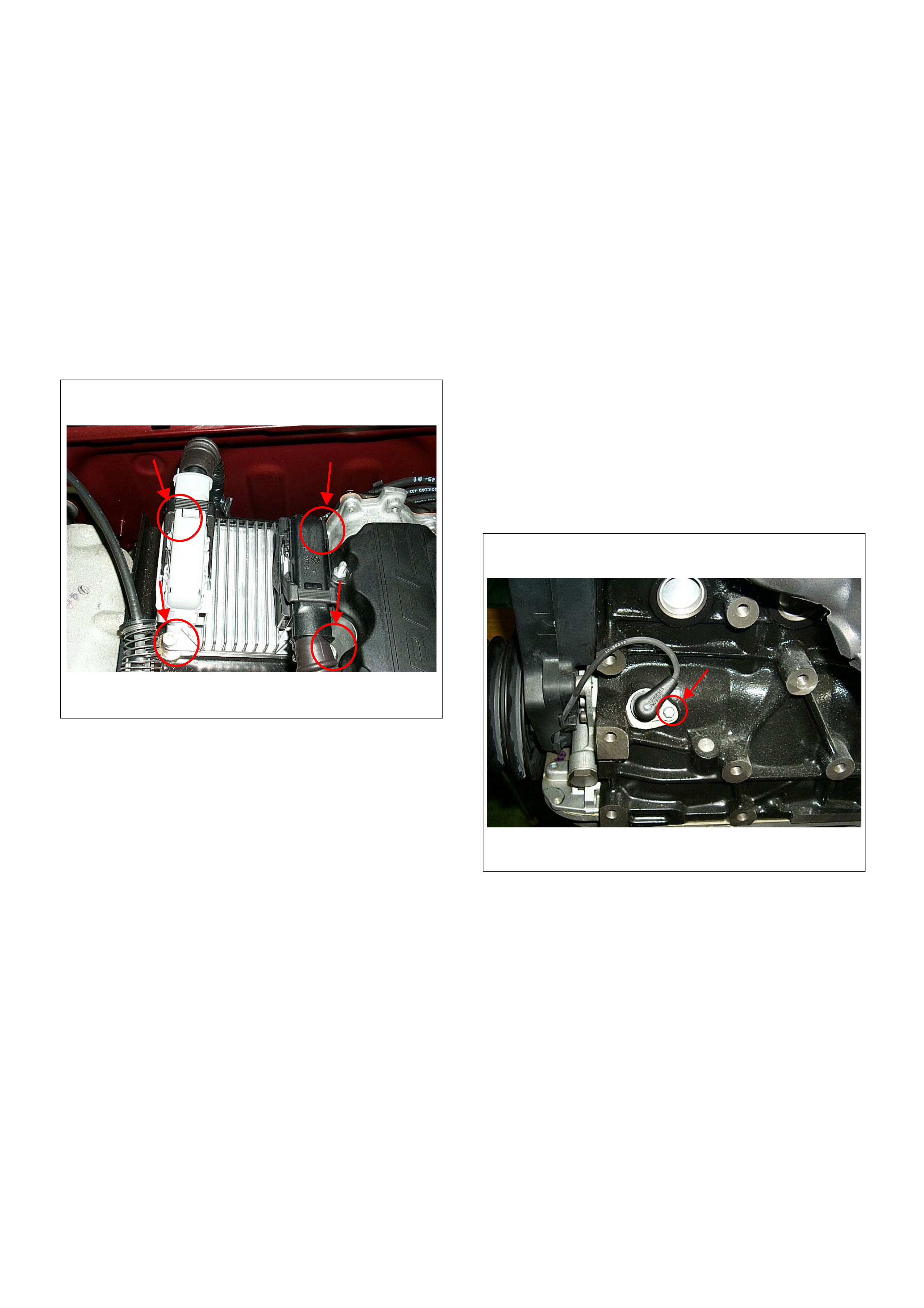
On-Vehicle Service Procedure
Engine Control Module (ECM)
Location
On the intake manifold.
Removal Procedure
1. Disconnect the negative battery cable.
2. Disconnect the two connectors from the ECM.
3. Remove four bolts.
4. Remo ve the ECM from bracket.
Installation Procedure
1. Put on the ECM to the bracket.
2. Tighten the ECM by four bolts with specified
tightening torque.
Tightening torque
• Bolts: 8.0 - 12.0 N·m (0.8 - 1.2 kgf·m)
3. Connect the two connectors to the ECM.
4. Connect the negative battery cable.
NOTE: Verify any DTCs (diagnosis Trouble Code) are
not stored after replacement.
Crankshaft Position (CKP) Sensor
Location
Left-hand side of the cylinder block. (Back of the A/C
compressor)
Removal Procedure
1. Disconnect the negative battery cable.
2. Remove the drive belt. Refer to Engine Me chanical
Section.
3. Remove the A/C compressor from engine. Refer to
Engine Mechanical Section.
4. Disconnect connector from the CKP sensor.
5. Loos en a bol t and rem ove the CKP sens or from the
cylinder block.
NOTE: Use caution to avoid any hot oil that might drip
out.
Installation Procedure
1. Install the CKP sensor to the cylinder block.
2. Tighten CKP sensor by a bolt with specified
tighteni ng torque .
Tightening Torque
• Bolt: 6N·m (0.6kgf·m)
3. Reinstall the A/C compressor to the engine.
4. Reins tall the acc ess or y driv e belt.
5. Connect the negative battery cable.
NOTE: Verify any DTCs (diagnosis Trouble Code) are
not stored after replacement.
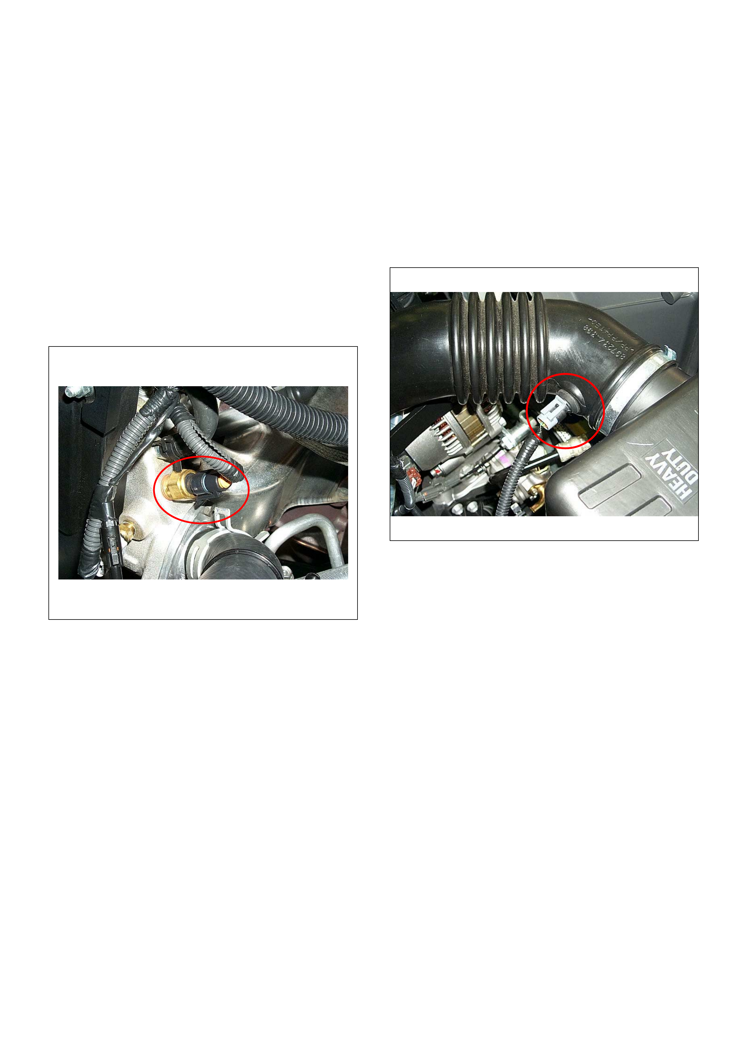
Engine Coolant Temperature (ECT) Sensor
Location
Installed to the thermostat housing.
Removal Procedure
1. Disconnect the negative battery cable.
2. Drain enough engine coolant so that the coolant
level will be below the ECT sensor.
3. Disconnect connector from the ECT sensor.
4. Loosen and remove the ECT sensor from the
thermostat housing.
NOTE: Cool down the en gine before abo ve procedur es
are carried out.
Installation Procedure
1. Apply sealer to threads of screw at the ECT sensor.
2. Tighten the ECT sensor with specified tightening
torque.
Tightening Torque
• Bolt: 13N·m (1.3kgf·m)
3. Connect a ECT sensor connector to the ECT
sensor.
4. Fill the engine coolant.
5. Connect the negative battery cable.
NOTE: Verify any DTCs (diagnosis Trouble Code) are
not stored after replacement.
Verify no engine coolant leaking from the sensor
threads after replac em ent .
Intake Air Temperature (IAT) Sensor
Location
Installed to the intake duct housing.
Removal Procedure
1. Disconnect the negative battery cable.
2. Disconnect a IAT sensor connector from the IAT
sensor.
3. Remove the IAT sensor from the intake duct.
Installation Procedure
1. Install the IAT sensor into intake air duct.
2. Connect a IAT sensor connector to the IAT sensor.
3. Connect the negative battery cable.
NOTE: Verify any DTCs (diagnosis Trouble Code) are
not stored after replacement.
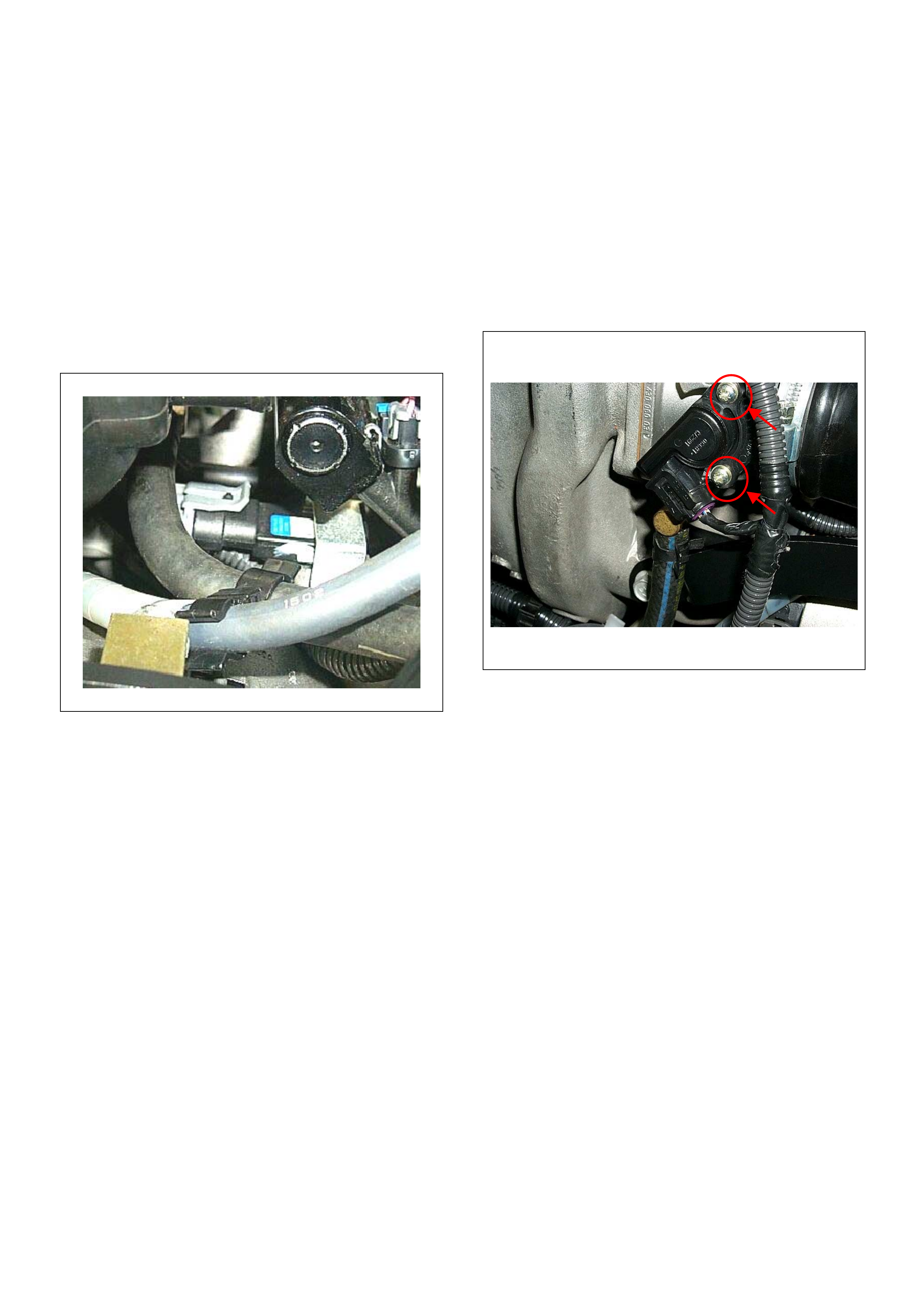
Manifold Absolute Pressure (MAP) Sensor
Location
Installed on the intake manifo ld.
Removal Procedure
1. Disconenct the negative battery cable.
2. Disconnect a MAP sensor connector from the MAP
sensor.
3. Loosen a bol t and remov e the MAP s ens or fr om th e
intake manifold.
4. Remove the MAP sensor from the bracket.
Installation Procedure
1. Tighten the MAP sensor by a bolt with specified
tightening torque.
Tightening Torque
• Bolt: 8N·m (0.8kgf·m)
2. Connect a MAP sensor connector to the MAP
sensor.
3. Connect the negative battery cable.
NOTE: Verify any DTCs (diagnosis Trouble Code) are
not stored after replacement.
Throttle Position Sensor (TPS)
Location
Installed on the throttle body.
Removal Procedure
1. Disconnect the negative battery cable.
2. Disconnect the TPS connector .
3. Loosen two screws and remove TPS from the
throttle body.
Installation Procedure
1. Temporary tighten the TPS by two screws.
2. Connect a TPS connectors to the TPS.
3. Connect the Tech2 to the vehicle.
4. Connect the negative battery cable.
5. Select "Data Display" with the Tech2.
6. Check the throttle position data and adjust the TPS
position.
7. Tighten two screws.
NOTE: Verify any DTCs (diagnosis Trouble Code) are
not stored after replacement.
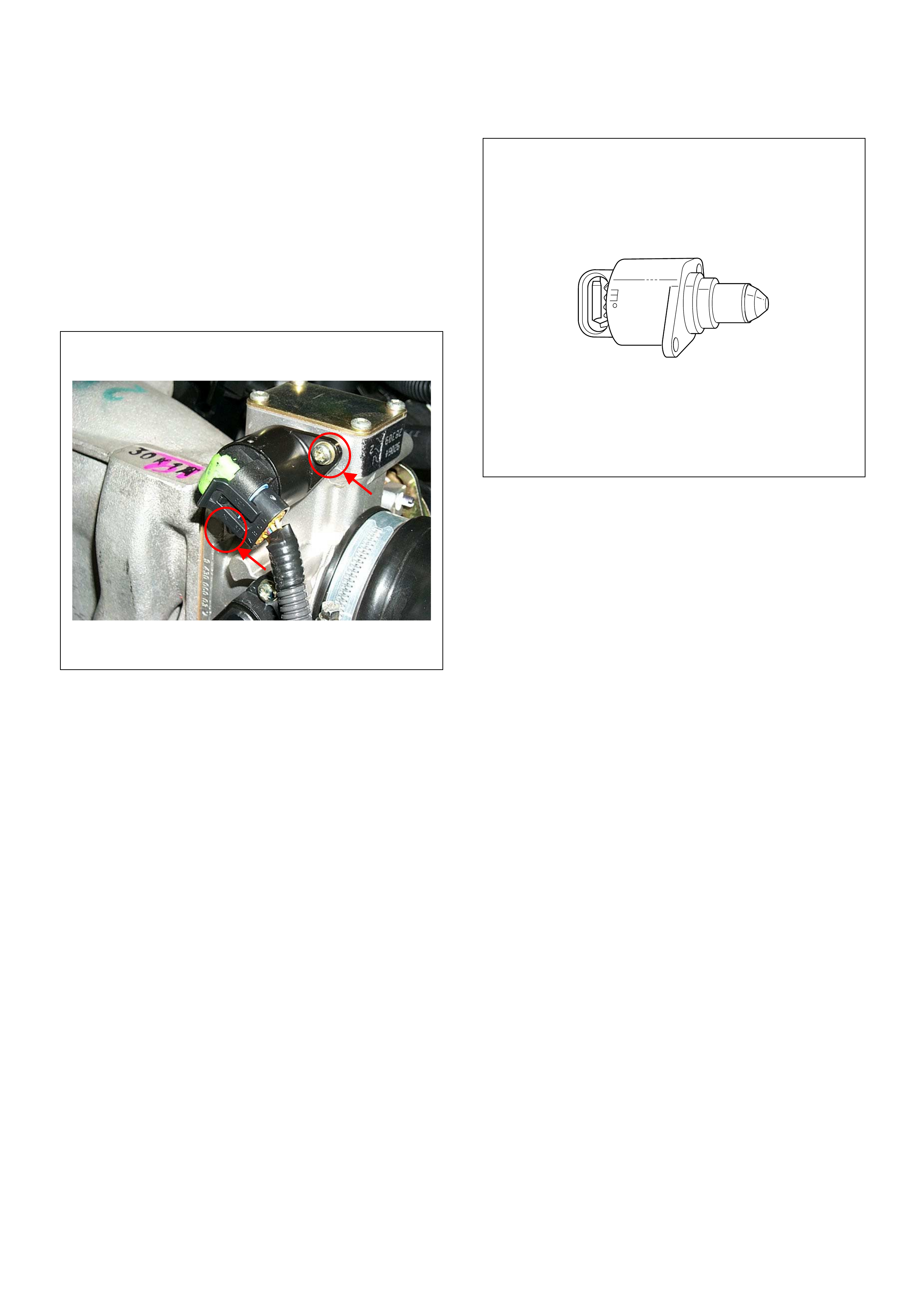
Idle Air Con trol (IAC) Valve
Location
Installed on the throttle body.
Removal Procedure
1. Disconnect the negative battery cable.
2. Disconnect the IAC valve connector.
3. Loosen two screws and remove IAC v alve from the
throttle body.
Cleaning and Inspecti on
1. Clean the IAC valve O-ring sealing surface, pintle
valve seat and air passag e.
2. Use carburetor cleaner and a parts cleaning brush
to remove carbon deposit.
Do not use a cleaner that contain methyl ethyl
ketone. This is an extremely strong solvent and not
necessary for this type of deposit.
3. Shiny spots on the pintle are normal and do not
indicate misalignment or a bent pintle shaft.
4. Inspect the IAC valve O-ring for cuts, cracks or
distortion.
Measurement
• Clean the IAC valve O-ring sealing surface, pintle
valve seat and air passage.
• Use carbureto r cleaner and a parts clea ning brush to
remove carbon deposit. Do not use a cleaner that
contain methyl ethyl ketone. This is an extremely
strong solvent and not necessary for this type of
deposit.
• Shiny spots on the pintle are normal and do not
indicate misalignment or a bent pintle shaft.
• Inspect the IAC valve O-ring for cuts, cracks or
distortion. Replace the O-ring if damaged.
Installation Procedure
1. Tighten the IAC valve by two screws.
2. Connect a IAC valve connector to the MAP sensor.
3. Connect the negative battery cable.
NOTE: Verify any DTCs (diagnosis Trouble Code) are
not stored after replacement.
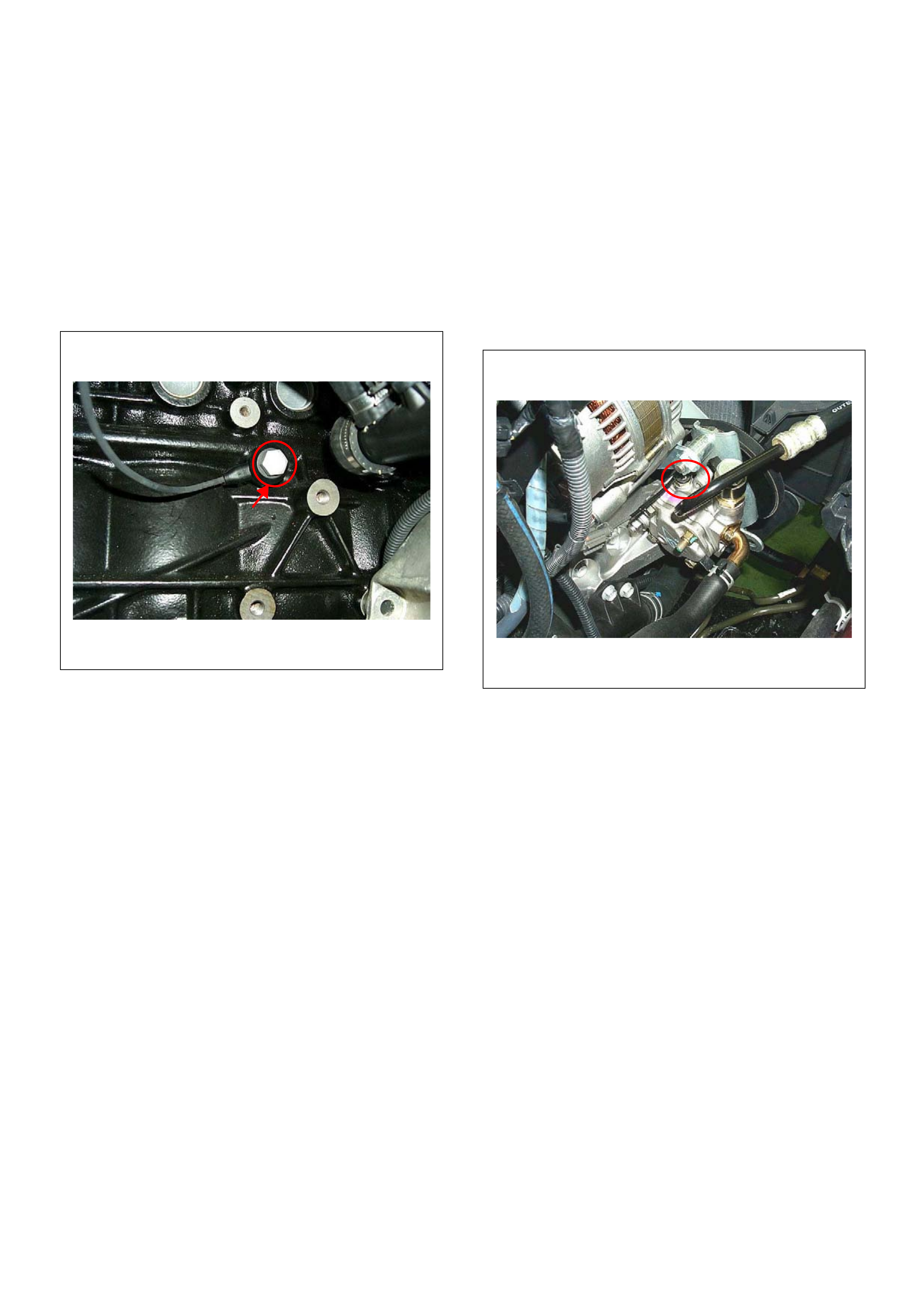
Knock Sensor
Location
Right-hand side of the cylinder block.
Removal Procedure
1. Disconnect the negative battery cable.
2. Disconnect the knock sensor connector.
3. Loosen a bolt and remove knock sensor from the
cylinder block.
Installation Procedure
1. Tighten the knock sensor by a bolt with specified
tightening torque.
Tightening Torque
• Bolt: 20N·m (2.0kgf·m)
2. Connect a knock sensor connector to the knock
sensor.
3. Connect the negative battery cable.
NOTE: Verify any DTCs (diagnosis Trouble Code) are
not stored after replacement.
Power Steering Pressure (PSP) Switch
Location
Installed on the power steering pump assembly.
Removal Procedure
1. Disconnect the negative battery cable.
2. Disconnect the power steering pressure switch
connector.
3. Loosen and remove the power steering pressure
switch from the power steering pump.
Installation Procedure
1. Install the power steering pressure switch to the
power steering pump.
2. Tighten the power steering pressure switch.
3. Connect a connector to the power steering pressure
switch.
4. Connect the negative battery cable.
NOTE: Verify any DTCs (diagnosis Trouble Code) are
not stored after replacement.
Verify no power steering fluid leaking from the sensor
threads after replacement.
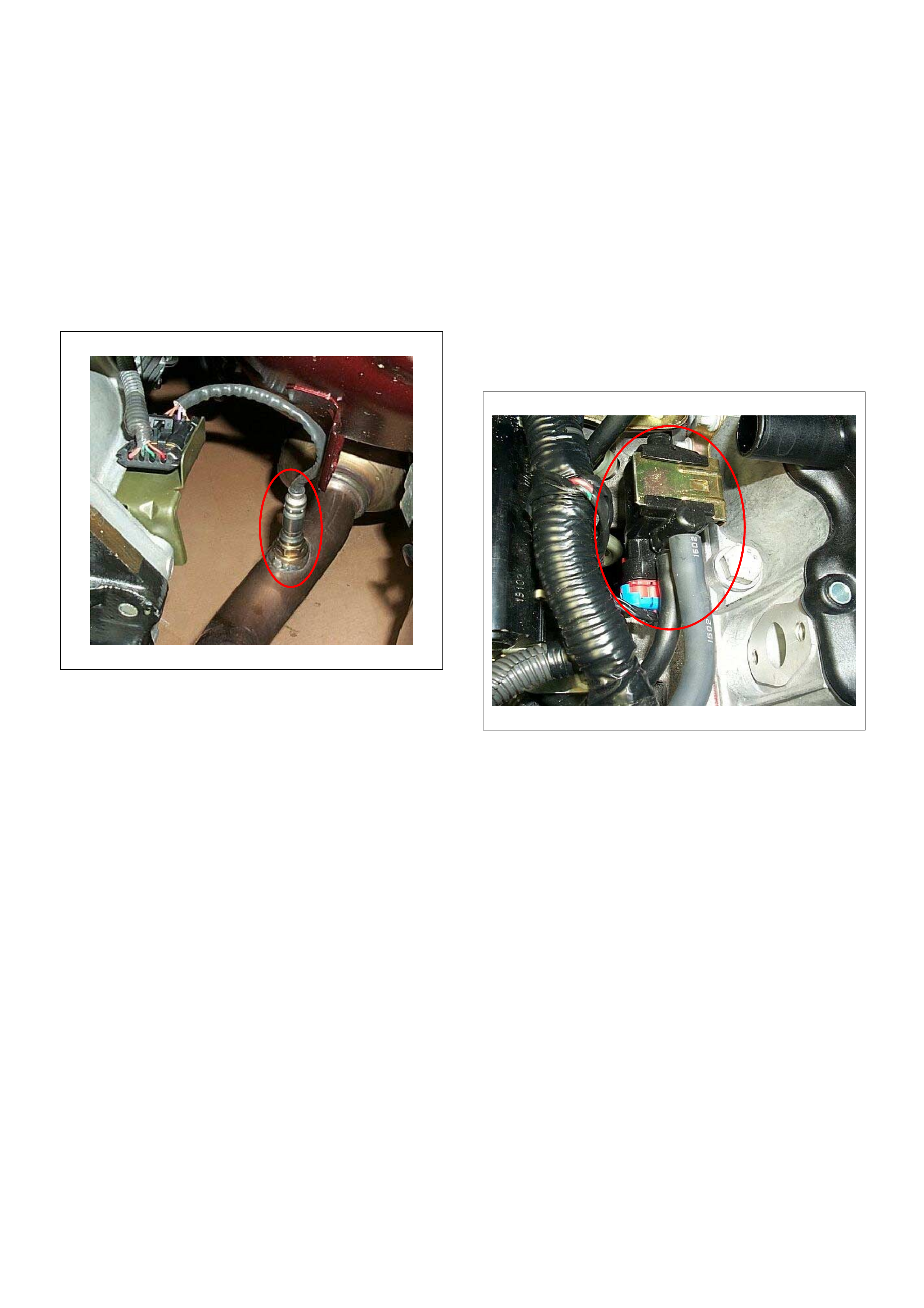
Heated Oxygen Sensor (HO2S)
Location
Installed on the exhaus t pipe.
Removal Procedure
1. Disconnect the negative battery cable.
2. Disco nne ct the O
2
sensor connector.
3. Loosen and remove the O
2
sensor from the exhaust
pipe.
Inspection
Inspect the louvered end of the sensor for grease, dirt,
excessive carbon build up or other contamination.
Installation Procedure
1. Install the O
2
sensor to the exhaust pipe.
2. Tighten the O
2
sensor with specified tightening
torque.
Tightening Torque
• Bolt: 42N·m (4.3kgf·m)
3. Connect a O
2
sensor connector to the O
2
sensor.
4. Connect the negative battery cable.
NOTE: Verify any DTCs (diagnosis Trouble Code) are
not stored after replacement.
Verify no exhaust gas leaking from the sensor threads
after replacement.
EVAP Canister Purge Valve Solenoid
Location
On the intake manifold.
Removal Procedure
1. Disconenct the negative battery cable.
2. Disconnect a purge solenoid connector from the
purge solenoid.
3. Disconnect two hoses from the purge solenoid
valve.
4. Slide from the bracket and remove the purge
solenoid.
Installation Procedure
1. Insert EVAP purge solenoid valve onto the bracket.
2. Connect two hoses to the purge solenoid valve.
3. Connect a purge solenoid connector to the purge
solenoid.
4. Connect the negative battery cable.
NOTE: Verify any DTCs (diagnosis Trouble Code) are
not stored after replacement.
Verify proper connection of two hoses.
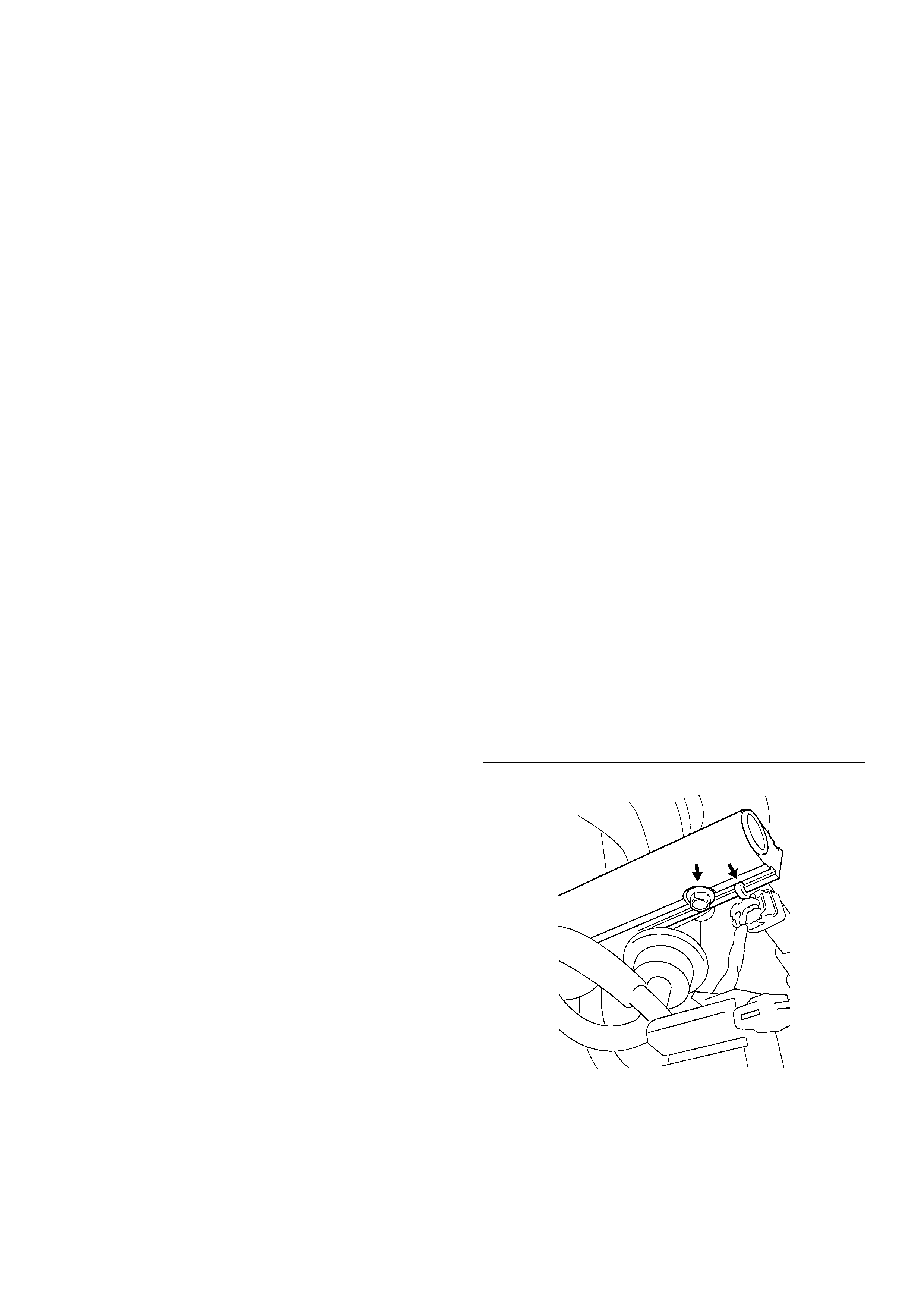
Fuel Pressure Relief
Caution: To reduce the risk of fire and personal
injury, it is necessary to relieve the fuel system
pressure before servicing the fuel system
components.
Caution: After relieving the fuel system pressure, a
small amount of fuel may be released when
servicing fuel lines or connections. Reduce the
chance of personal injury by covering the fuel line
fitting with a short towel before disconnecting the
fittings. The towel will absorb any fuel that may leak
out. When the disconnect is completed, place the
towel in an approved container.
1. Remo ve the fuel filler cap.
2. Remove the fuel pump relay from the underhood
relay box.
3. Start the engine and allow it to stall.
4. Crank the engine for about 30 seconds.
5. Disconnect the negative battery cable.
Fuel Rail Assembly
Removal Procedure
NOTE:
• Use care when removing the fuel rail assembly in
order to prevent damage to the injector al connector
terminal and the injector spray tips.
• Fitting should be capped and holes plugged during
servicing to prevent dir t and other con taminants from
entering open lines and passage.
Important: An eight-digit identification number is
stamped on side of the fuel injector. Refer to this
number when you service the fuel rail or when a
replacement part is required.
1. Disconnect 4 injector connectors.
2. Lift side-clip up on the fuel rail.
3. Disconnect fuel pressure regulator hose.
4. Disconnect wiring harness from the bands on the
fuel rail .
5. Remove the intake pipe.
6. Loos en fla re nut.
A. Lift up the injectors carefully to separate them
from intake manifold.
B. Lift up the fuel rail with injectors as assembly.
Do not separate the fuel injectors from fuel rail.
C. If an injector become separated from fuel rail,
injector backup O-ring and injector retainer clip
must be repla ced.
D. Drain residual fuel from fuel rail into an
approved container.
7. If removal of fuel pressure regulator is necessary,
Refer to Fuel Pressure Regulator Removal
Procedure.
8. If removal of fuel injector is necessary, Refer to Fuel
Injecto rs Remova l Procedu re.
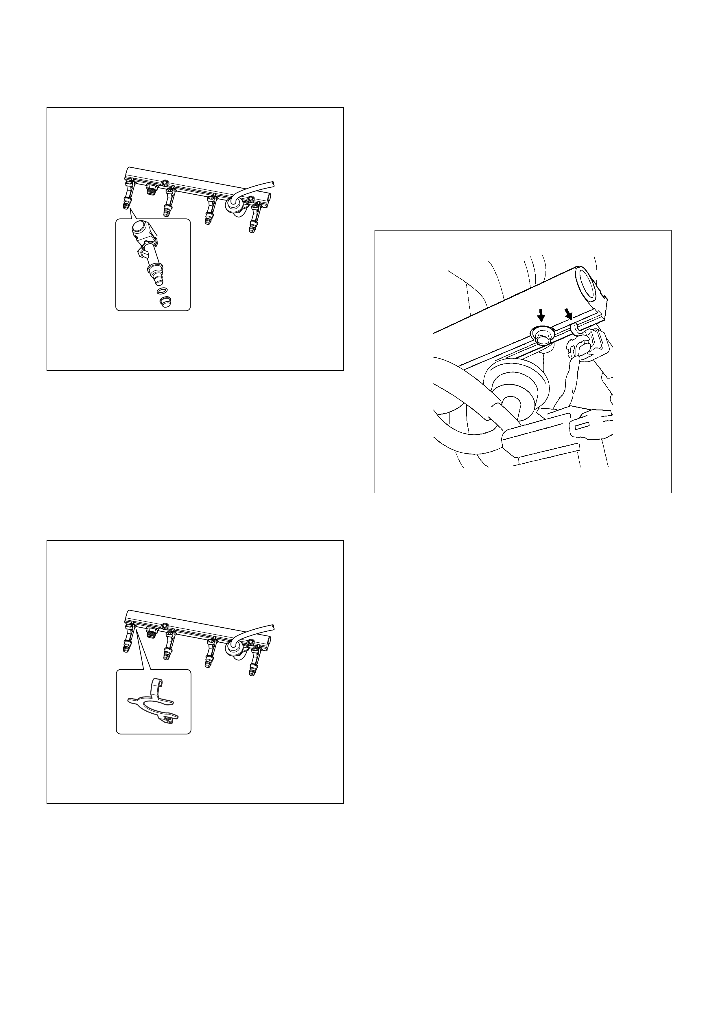
Installation Procedure
1. Install the fuel injectors if necessary. Refer to Fuel
Injector Installation Procedure.
2. Install the fuel pressure regulator if necessary. Refer
to Fuel Pressure Regulator Installation
Procedure.
3. Place the fuel inje ctor ra il asse mbly on the ma nifol d
and insert the injectors into each port by pushing
fuel rail.
4. Install two fuel rail retaining bolts. Tighten fuel rail
retaining bolt to 19 N·m (1.9kgf·m)
5. Place wiring harness in its place and secure it with
two nuts.
6. Connect all connector to each fuel injector.
7. Connect the fuel supply line securely. Do not over
tighten.
8. Connect the fuel return line securely. Do not over
tighten.
9. Connect the negative battery cable.
10. Cran k the engin e until it starts. Crank ing the eng ine
may take l on ger th an us ual du e to trap ped ai r in the
fuel sy stem. Ch eck for l eak. If fuel l eak is obse rved,
stop engine immediately. Before correcting fuel
leak, be sure to depressurize system again.
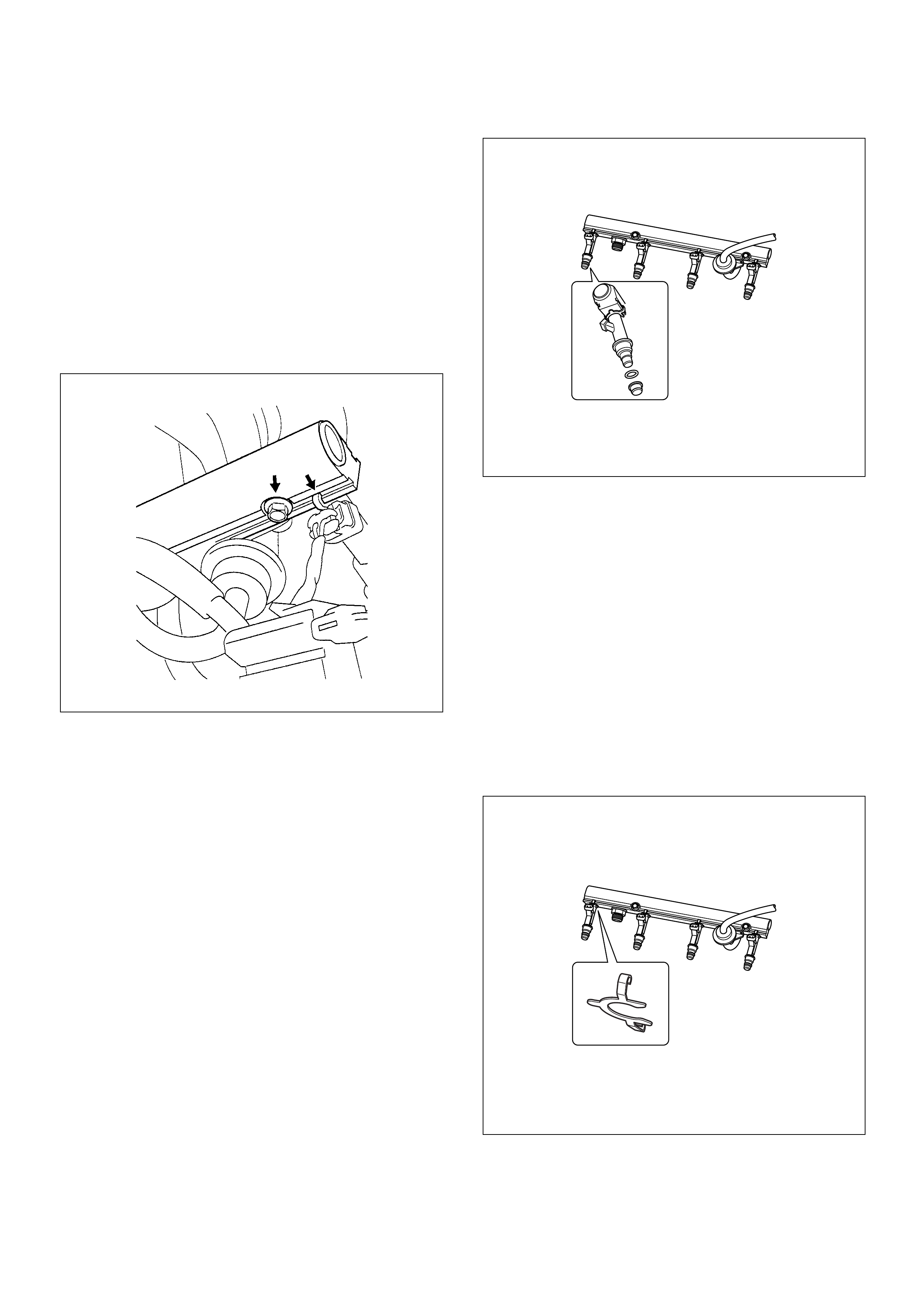
Fuel Injector
Removal Procedure
NOTE: If the fuel injectors are leaking, the engine oil
may be contaminated with fuel. Check the oil for signs
of contamination and change the oil and filter if
necessary.
NOTE: Use care in removing the fuel injector in order to
prevent damage to the fuel injector al connector pins or
fuel injector nozzles. The fuel injector is an al
component and should not be immersed in any type of
cleaner as this may damage the fuel injector.
Important: Fuel injectors are serviced as complete
assembl y onl y.
1. Disconnect the negative battery cable.
2. Disconnect al connector from fuel injector.
3. Remove the fuel rail. Refer to Fuel Rail Removal
Procedure.
4. Remo ve the fuel inje cto r retain er cli p.
5. Remo ve the fuel inje cto r assembly fro m fuel rail .
6. Remove O-ring from the fuel injector.
7. Remove O-ring backup from fuel injector.
Inspection
1. Inspect O-ring for crack, damage or leaks.
2. Replace worn or damaged O-ring.
3. Lubricate the new O-rings with engine oil before
installation.
Installation Procedure
1. Lubricate the new O-ring with engine oil.
2. Install the O-ring backup on the fuel injector.
3. Inst all new O-ring on the fuel injector.
4. Install all four injector on the fuel rail.
5. Use new injector retainer clip to retain the injetor to
the fuel rail.
6. Coat the end of the fuel injector with engine oil.
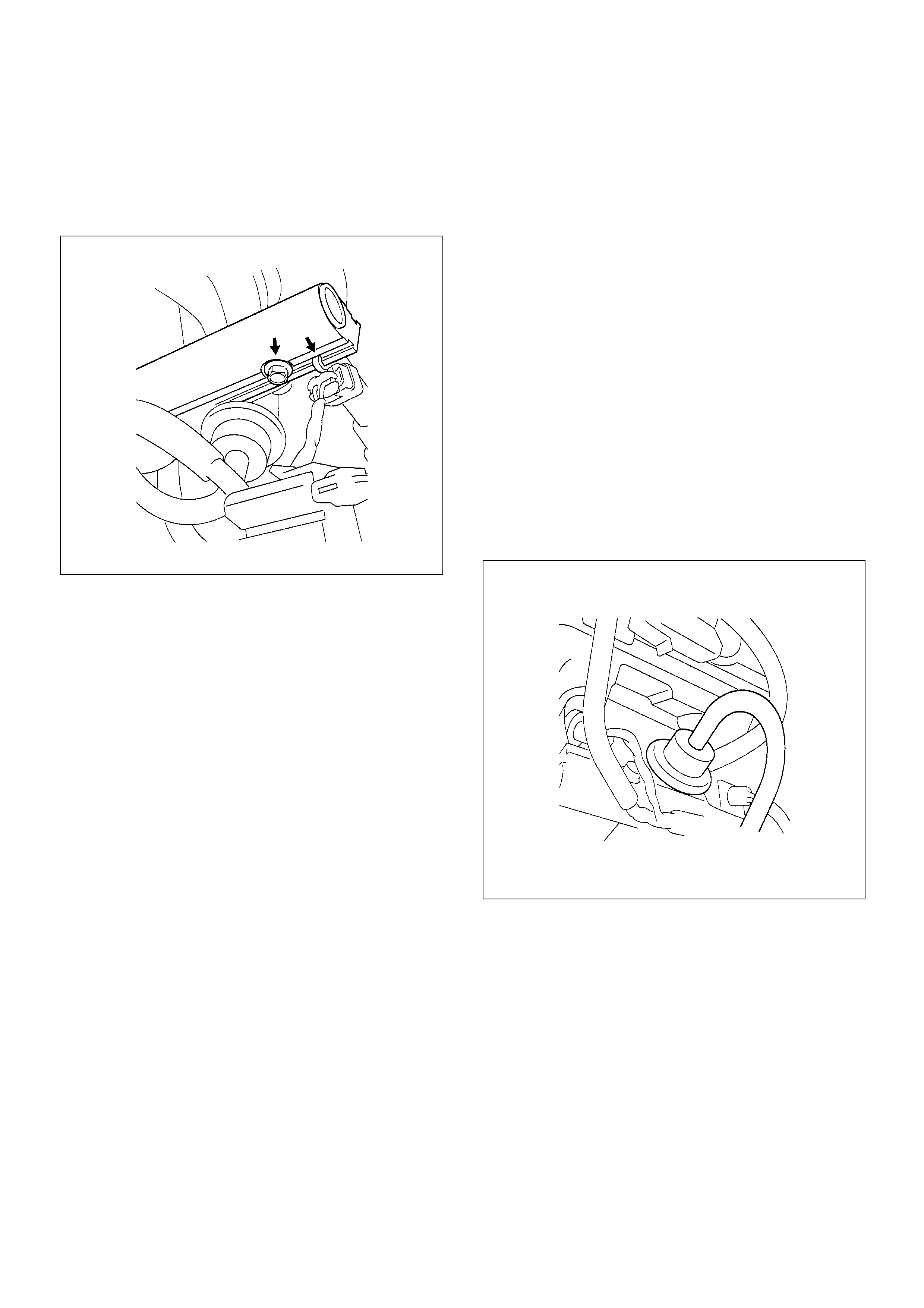
7. Install fuel rail assembly. Tighten the nuts to 19 N·m
(1.9 kgf·m). Refer to Fuel Rail Installation
Procedure.
Tighten the flare nut to 27 - 33 N·m (2.8 - 3.4 kgf·m).
8. Connect the negative battery cable.
Fuel Pressure Regulator
Removal Procedure
Caution: To reduce the risk of fire and personal
injury, it is necessary to relieve the fuel system
pressure before servicing the fuel system
components.
Caution: After relieving the fuel system pressure, a
small amount of fuel may be released when
servicing fuel lines or connections. Reduce the
chance of personal injury by covering the fuel line
fitting with a shop towel before disconnecting the
fittings. The towel will absorb any fuel that may leak
out. When the disconnect is completed, place the
towel in an approved container.
NOTE: Compressed air must never be used to test or
clean a fuel pressure regulator, as damage to the fuel
pressure regulator may occur.
NOTE: To prevent damage to the fuel pressure
regulator, do not immerse the pressure regulator in
solvent.
Removal Procedure
1. Depressurize the fuel system. Refer to
Fuel Pressure Relief Procedure.
2. Disconnect the negative battery cable.
3. Remove the fuel pump relay.
4. Disconnect the vacuum line form fuel pressure
regulator.
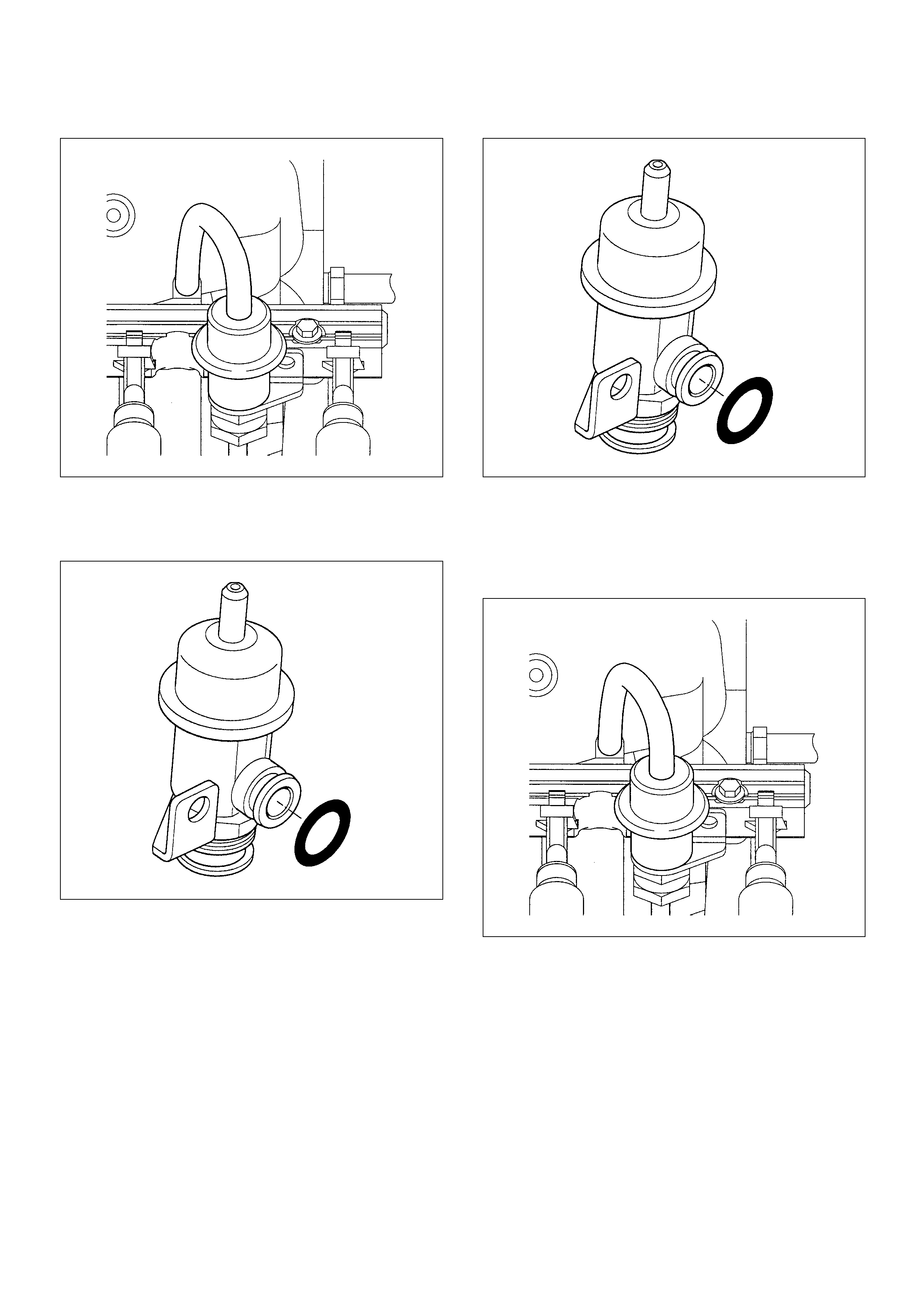
5. Remove the fuel pressure regulator retaining screw.
6. Remove the fuel pressure regulator from fuel rail.
Installation Procedure
1. Insert the fuel pressure regulator into the fuel rail.
2. Install the fuel pressure regulator retaining bracket
and tighten with a screw.
3. Connect vacuum line onto the fuel pressure
regulator.
4. Install the fuel pump relay.
5. Connect the negative battery cable.
6. Cran k the engin e until it starts. Crank ing the eng ine
may take l on ger th an us ual du e to trap ped ai r in the
fuel line.
7. Tighten the flare nut to 27 - 33 N·m (2.8 - 3.4 kgf·m).
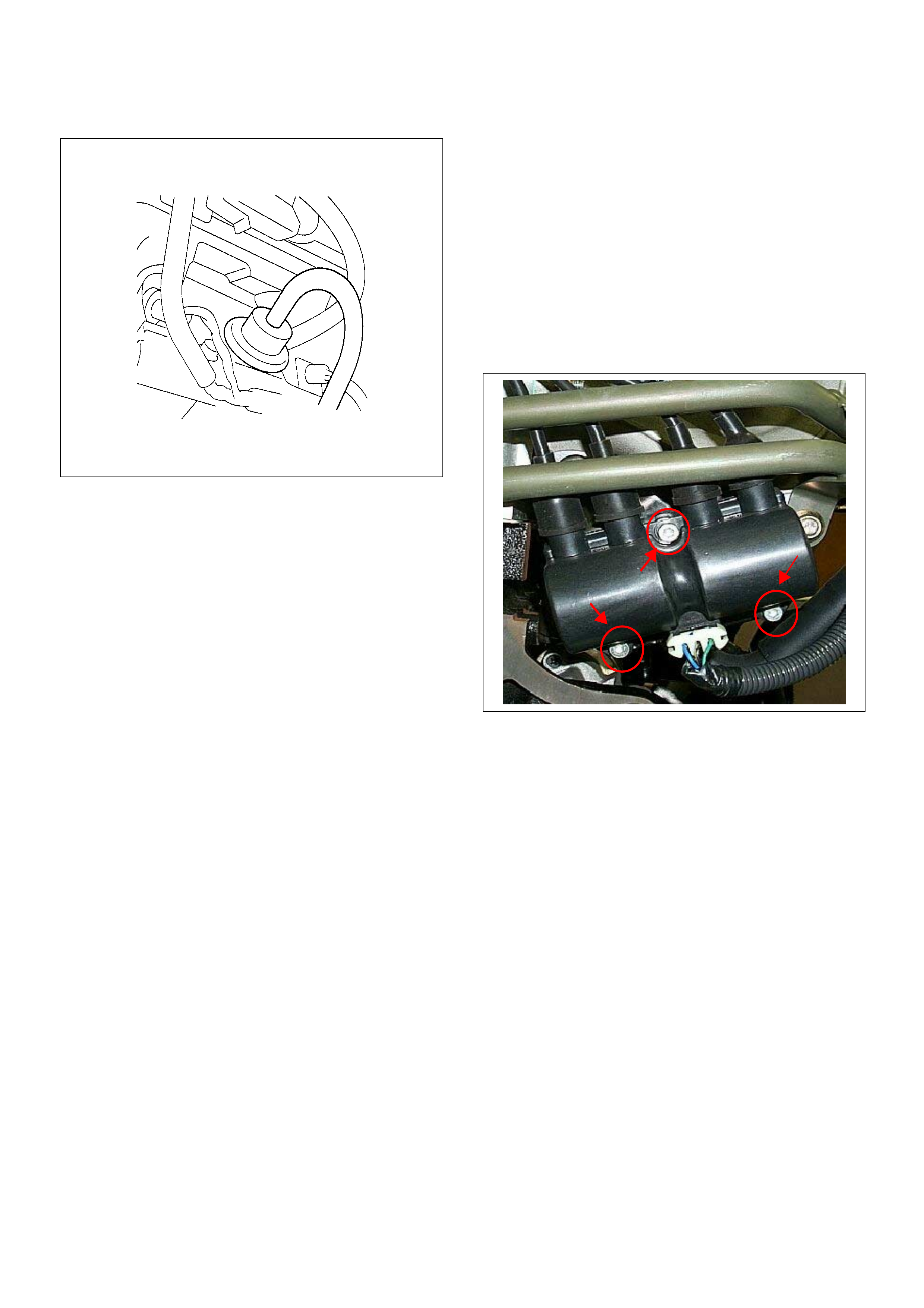
Ignition Coil
Location
Back of the engine right-hand side.
Removal Procedure
1. Disconnect the negative battery cable.
2. Disconnect the ignition coil connector.
3. Disconnect four spark plug cables from the ignition
coil.
4. Loosen three bolts and remove ignition coil from the
bracket.
Installation Procedure
1. Tighten the ignition coil by three bolts.
2. Connect four spark plug cables to the ignition coil.
3. Connect a ignition coil connector to the ignition coil.
4. Connect the negative battery cable.
NOTE: Verify any DTCs (diagnosis Trouble Code) are
not stored after replacement.
Verify proper connection of spark plug cables for each
cylinders.
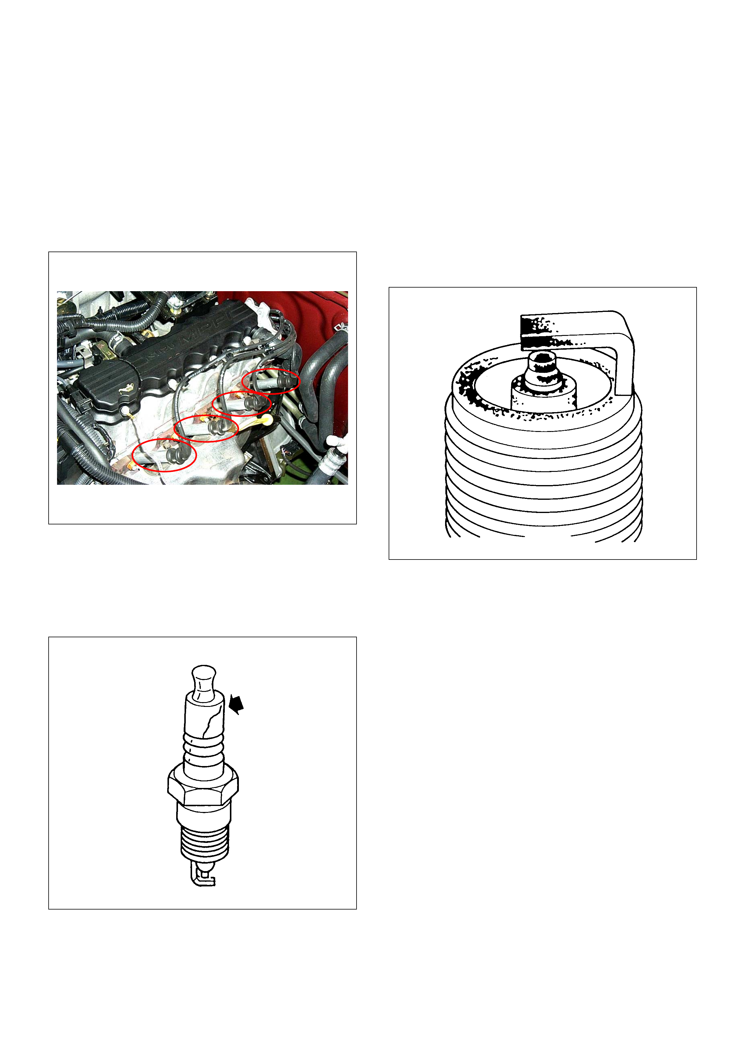
Spark Plugs
Location
Installed on the left-hand side of cyl inder head.
Removal Procedure
1. Disconnect the negative battery cable
2. Remo ve the spark plug cabl e.
3. Remove the spark plug.
Inspection
1. Check the insulator for cracks. Replace the spark
plug if cracks are present.
2. Check the electrode condition and replace the spark
plug if necessary.
If the spark plug electrodes and insulators are fouled
with carbon or oil, the engine will not operate efficiently.
There are a number of possible causes:
• Fuel mixture is too rich.
• Oil in the combustion chamber.
• The spark plug gap is not set correctly.
If spark plug fouling is excessive, check the fuel and al
system for possible causes of trouble. If fuel and al
system are normal, install spark plugs of a higher heat
range which have the s ame physic al di mensions as the
original equipment spark plugs.
The following symptoms are characteristics of spark
plugs that are running too hot:
• Fuel mixture is too lean.
• Heat range is incorrect.
If vehicle usage does not conform to normal driving
conditions, a more suitable spark plug may be
substituted.
If fuel and al system are normal, in most cases of this
sort, the problem can be corrected by using a colder
type spark plug with the same physical dimensions as
the original equipment spark plug.
3. Check the gaskets for damage and replace if
necessary.
4. Measure the spark plug gap. The specification is 1.0
to 1.1mm (0.039 to 0.043").
5. Adjust the spark gap by bending the grounded
electrode.
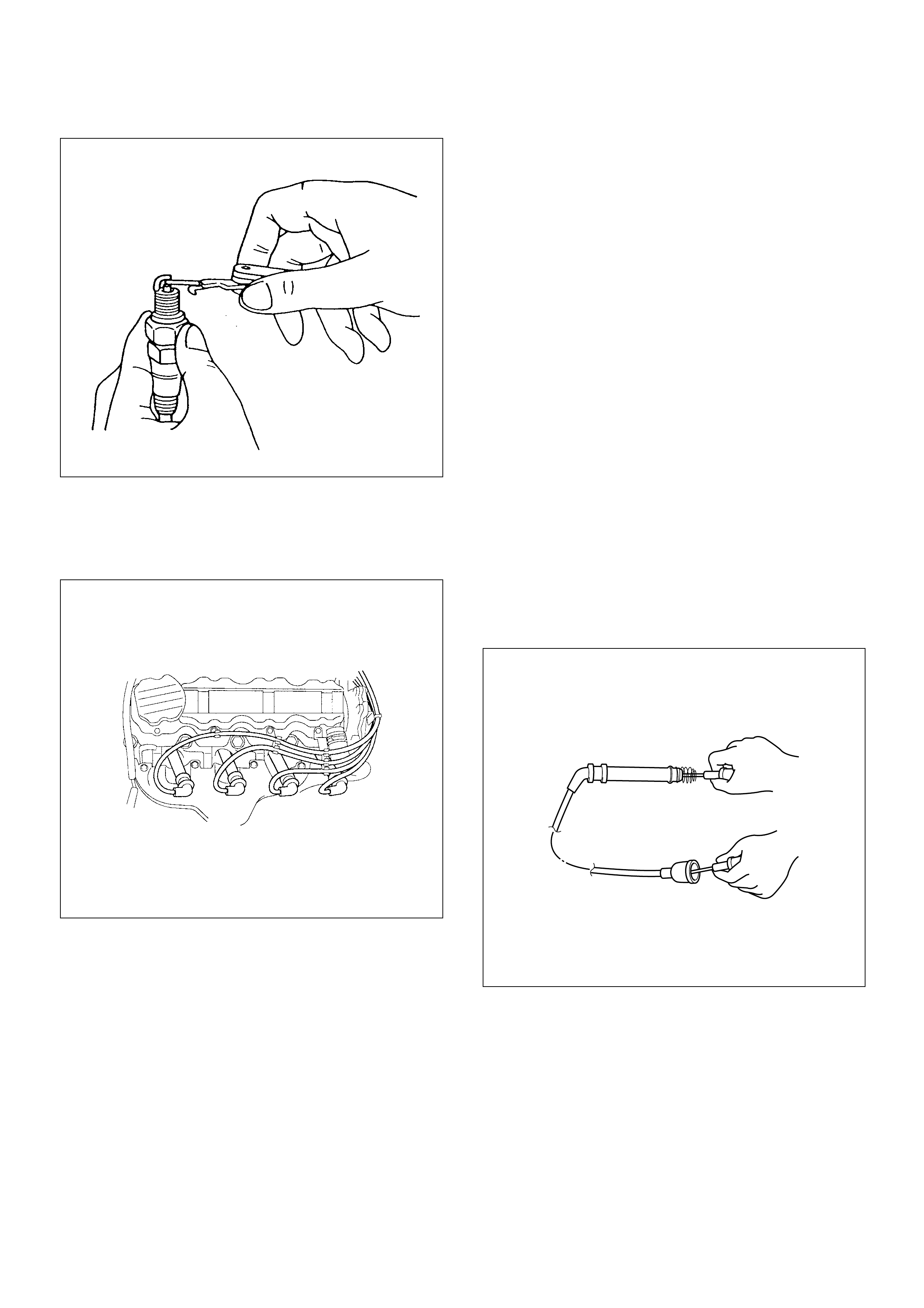
Installation
1. Tighten the spark plug to the 25N·m (2.5kgf·m).
2. Push the spark plug cable in until it snaps in.
Installation Procedure
1. Install the spark plug to the cylinder head.
2. Tighten the spark plug with specified tightening
torque.
Tightening Torque
• Bolt: 25N·m (2.5kgf·m)
3. Connect the spark plug cable to the spark plug.
4. Connect the negative battery cable.
NOTE: Verify any DTCs (diagnosis Trouble Code) are
not stored after replacement.
Verify proper connection of spark plug cables for each
cylinders.
Spark Plug Cables
The cable contains a synthetic conductor which is easily
damaged. Never stretch or kink the cable. Disconnect
the cable fr om spark plug and the igniti on co il .
The original equipment cables and the ignition coil are
marked to show correct location of the cables. If spark
plug cables or the ignition coil are replaced previously,
before cables are removed from the ignition coil, mark
the cables and the coil so they can be reconnected in
the same position.
Inspection
NOTE: Never pun cture the spa r k plu g ca ble’s insulation
with a needle or the pointed end of a probe into the
cable. An increase in resistance would be created which
would cause the cable to become defective.
1. If the cable has broken or cracked insulation, it must
be replaced.
2. If the terminals are corroded or loose, the cable
must be replaced.
3. Check that the cable resistance does not exceed
specified value.
#1 cylinder: 3.50kΩ - 5.24kΩ
#2 cylinder: 2.89kΩ - 4.33kΩ
#3 cylinder: 2.49kΩ - 3.73kΩ
#4 cylinder: 2.22kΩ - 3.32kΩ
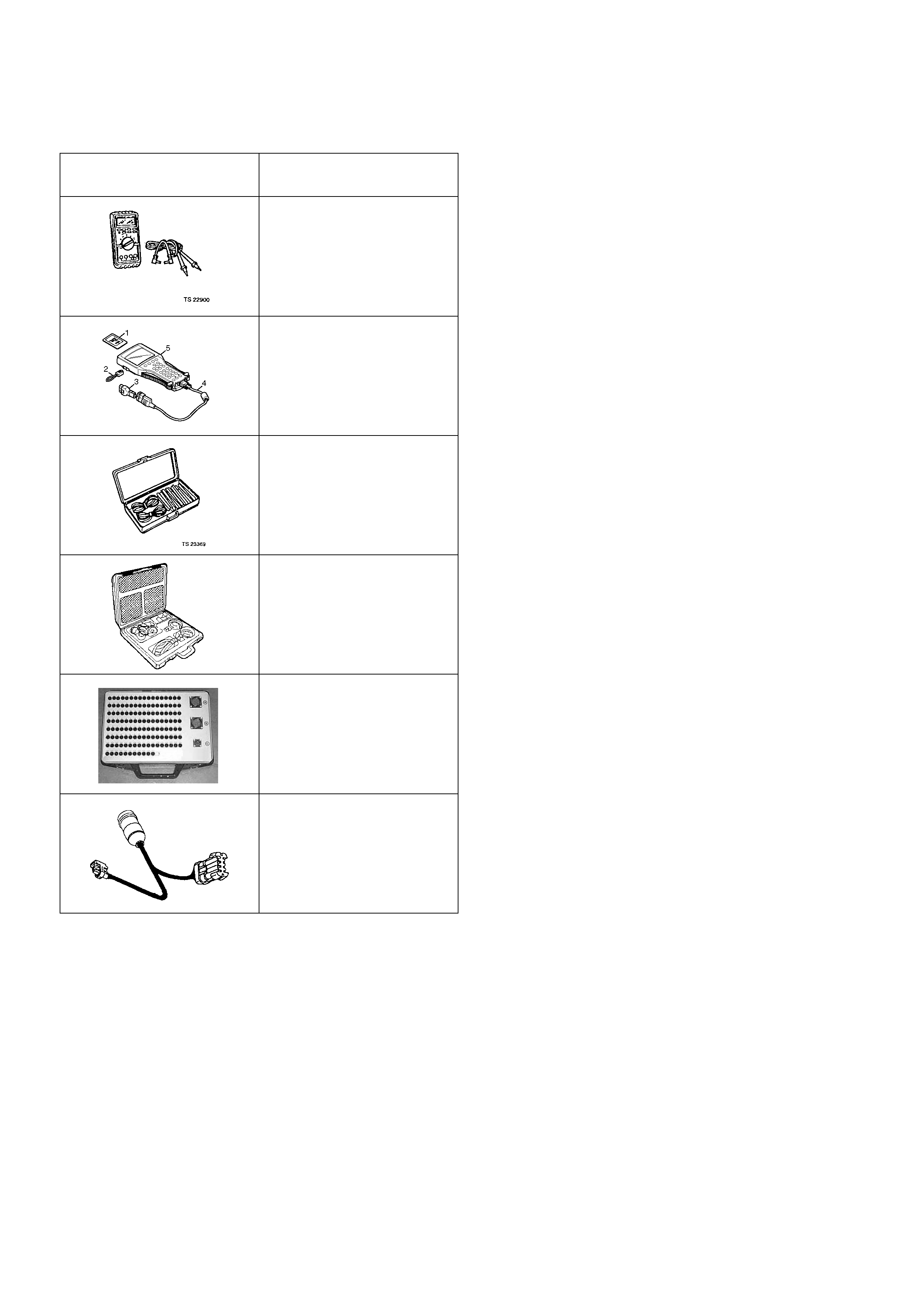
Special Service Tools
ILLUSTRATION TOOL NO.
TOLL NAME
5-8840-0285-0
(J 39200)
High Impedance
Multimeter
(Digital Voltmeter -DVM)
(1) PCMCIA Card
(2) RS232 Loop Back
Connector
(3) SAE 16/19 Adapter
(4) DLC Cable
(5) TECH 2
5-8840-0385-0
(J 35616-A/BT-8637)
Connector Test Adapter Kit
5-8840-0378-0
(J34730-E)
Port Fuel Injection
Diagnostic Kit
Breaker Box
5-8840-2589-0
Injector Adapter Cable