
SECTION 2B - HEATING & AIR CONDITIONING –
REMOVAL & INSTALLATION
IMPORTANT
Before performing any Service Operation or other procedure described in this Section, refer to Section
00 CAUTIONS AND NOTES for correct workshop practices with regard to safety and/or property damage.
1. GENERAL INFORMATION
1.1 AIR-CONDITIONING HOSE LAYOUTS
V6 SUPERCHARGED ENGINE
GEN III V8 ENGINE
2. SERVICE OPERATIONS
2.1 CONDENSER – V6 SUPERCHARGED ENGINE
REMOVE
REINSTALL
2.2 CONDENSER – GEN III V8 ENGINE
REMOVE
REINSTALL
2.3 FILTER DRIER RECEIVER
REMOVE
REINSTALL
3. TORQUE WRENCH SPECIFICATIONS
Techline
Techline
Techline
Techline
Techline
Techline

1. GENERAL I NFORMATI O N
The r emoval and ins tallation pr ocedur es f or the heating and air c onditioning s ystems as f itted to V2 Series Models
carries over from the information provided for VT Series Models, noting the following:
• A new condenser, radiator and fan module (CRFM) was introduced with the MY2003 V2 Series Update
Models during August 2002.
The information provided in this Section only applies to MY2003 V2 Series Update Models fitted with the revised
CRFM. For information regarding either the earlier type CRFM or the unchanged portion of the heating and air-
conditioning system, refer to Section 2B – HEATING AND AIR CONDITIONING – REMOVAL AND
INSTALLATION in the VT Series I and VT Series II Service Information.
NOTE: Information in these two Sections should be read in conjunction with each other.
1.1 AIR-CONDITIONING HOSE LAYOUTS
Due to the introduction of a revised CRFM, several air-conditioning hoses and the position of the filter drier
receiver ( FDR) have als o been r evised. F igures 2B- 1 and 2B-2 s how the air c onditioning hose layouts for MY2003
V2 Series Update Models fitted with the revised CRFM.
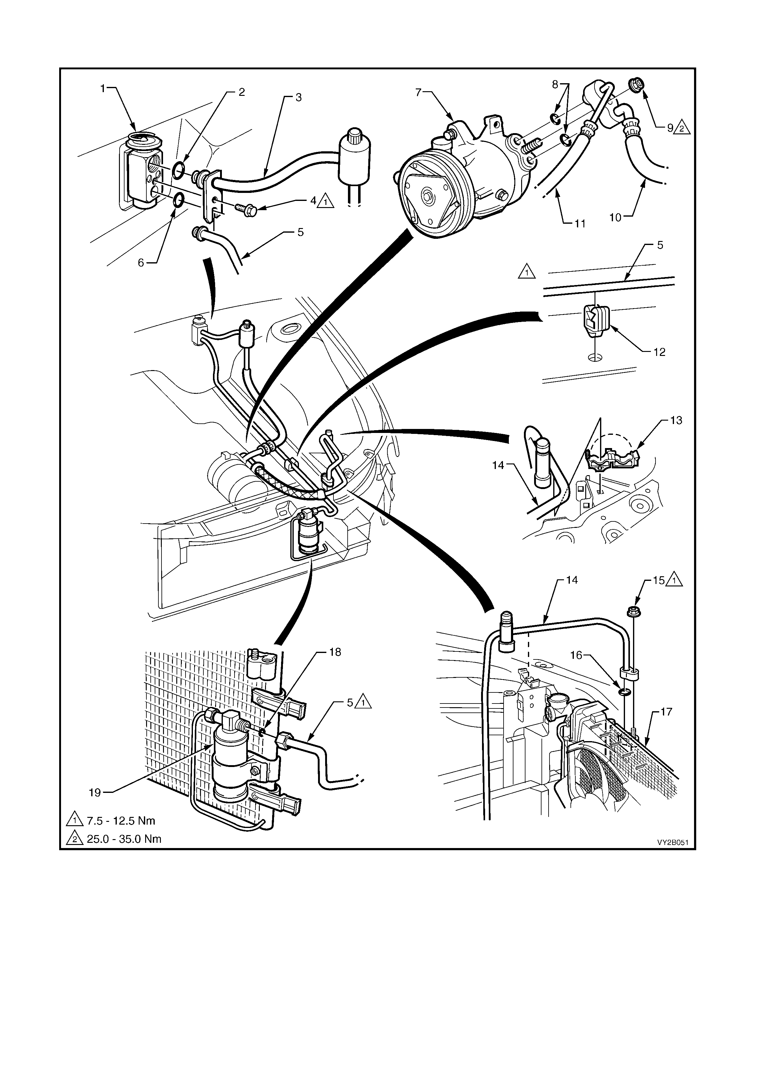
V6 SUPERCHARGED ENGINE
Figure 2B-1
Legend
1. Thermal Expansion Valve
2. O-ring
3. Suction Tube
4. Screw
5. Liquid Tube
6. O-ring
7. Compressor
8. Bonded Sealing Washer
9. Nut
10. Suction Hose
11. Discharge Hose
12. Liquid Tube Clip
13. Discharge Tube Clip
14. Discharge Tube
15. Nut
16. O-ring
17. Condenser
18. O-ring
19. Filter Drier Receiver (FDR)
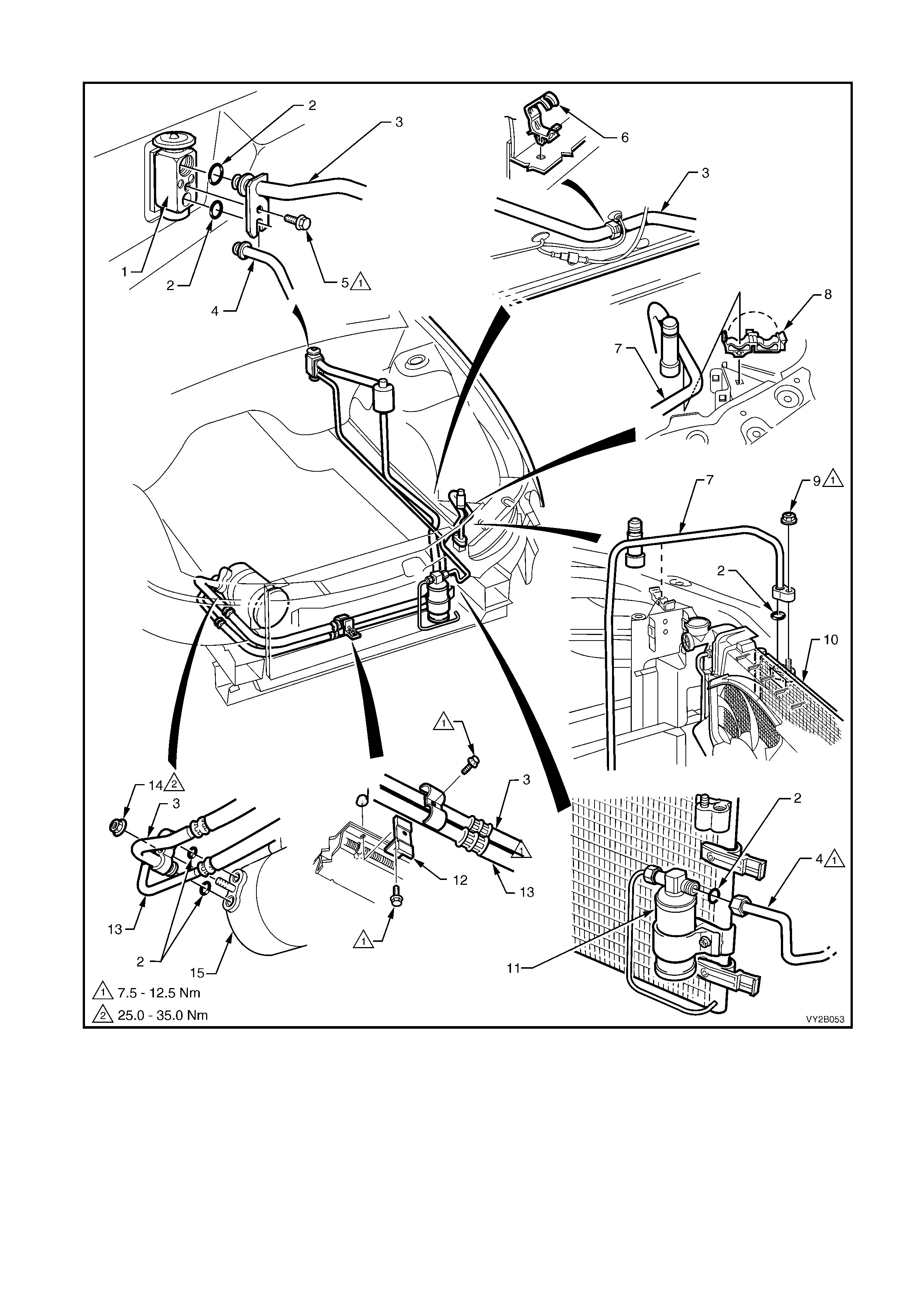
GEN III V8 ENGINE
Figure 2B-2
Legend
1. Thermal Expansion Valve
2. O-ring
3. Suction Tube
4. Liquid Tube
5. Retaining Screw
6. Suction Tube Retaining Clip
7. Discharge Tube
8. Discharge Tube Retaining Clip
9. Discharge Tube Retaining Nut
10. Condenser
11. Filter Drier Receiver (FDR)
12. Retaining Clamp
13. Discharge Hose/Tube
14. Retaining Nut
15. Compressor
2. SERVICE OPERATIONS
2.1. CONDENSER – V6 SUPERCHARGED ENGINE
REMOVE
1. Recover the refrigerant from the A/C system,
refer to 2.1 SYSTEM CHARGING AND
EVACUATION in Section 2C HEATING AND
AIR CONDITIONING – SERVICING AND
DIAGNOSIS in the VT Series I Service
Information.
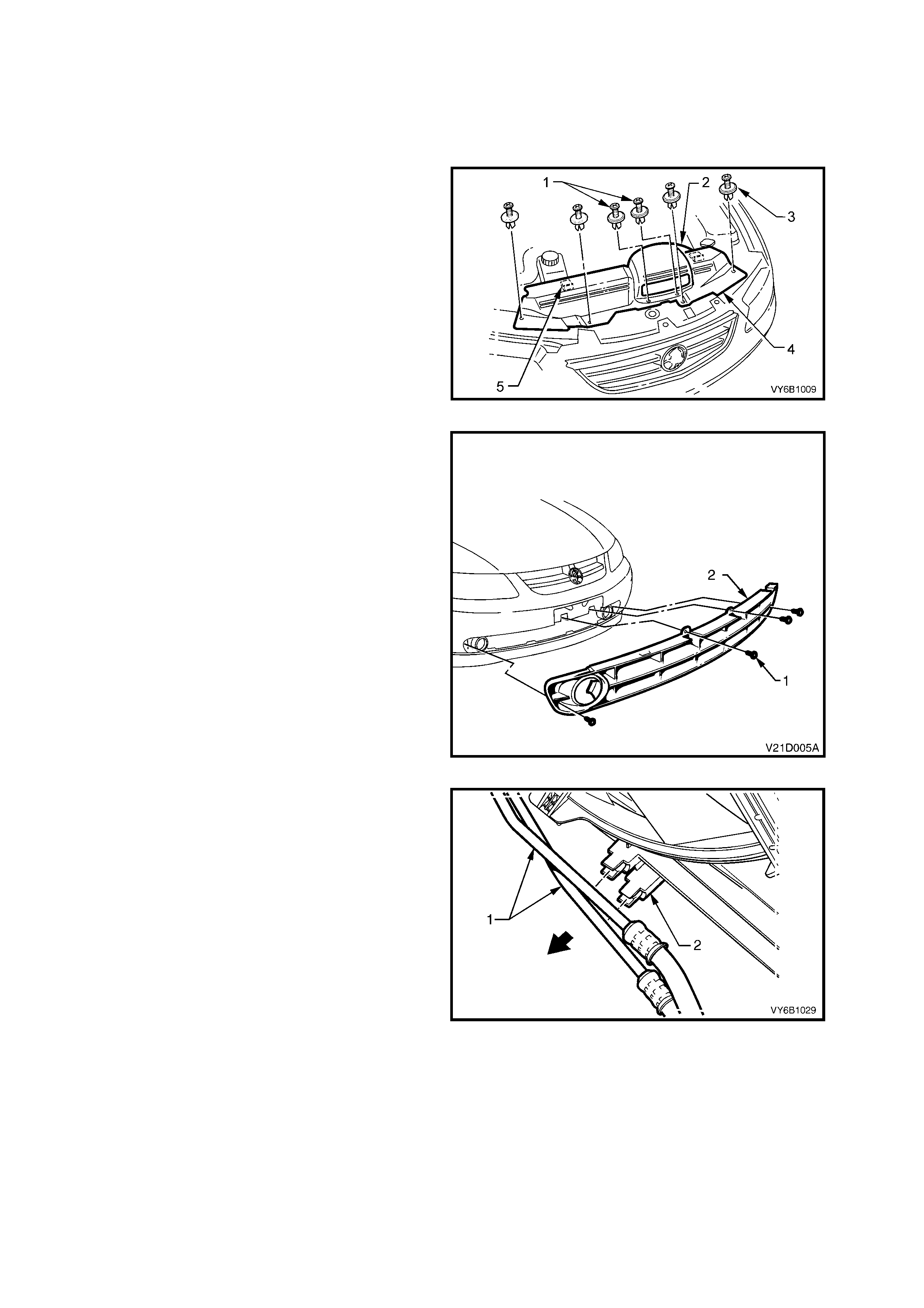
2. Remove the cold air intake duct and radiator
upper shroud retainers (1 and 3). Remove the
cold air intake duct (2), then disengage the
shroud locating tabs (5) by pulling the shroud
(4) towards front of vehicle, prior to removal.
Figure 2B-3
3. Remove the vehicle licence plate.
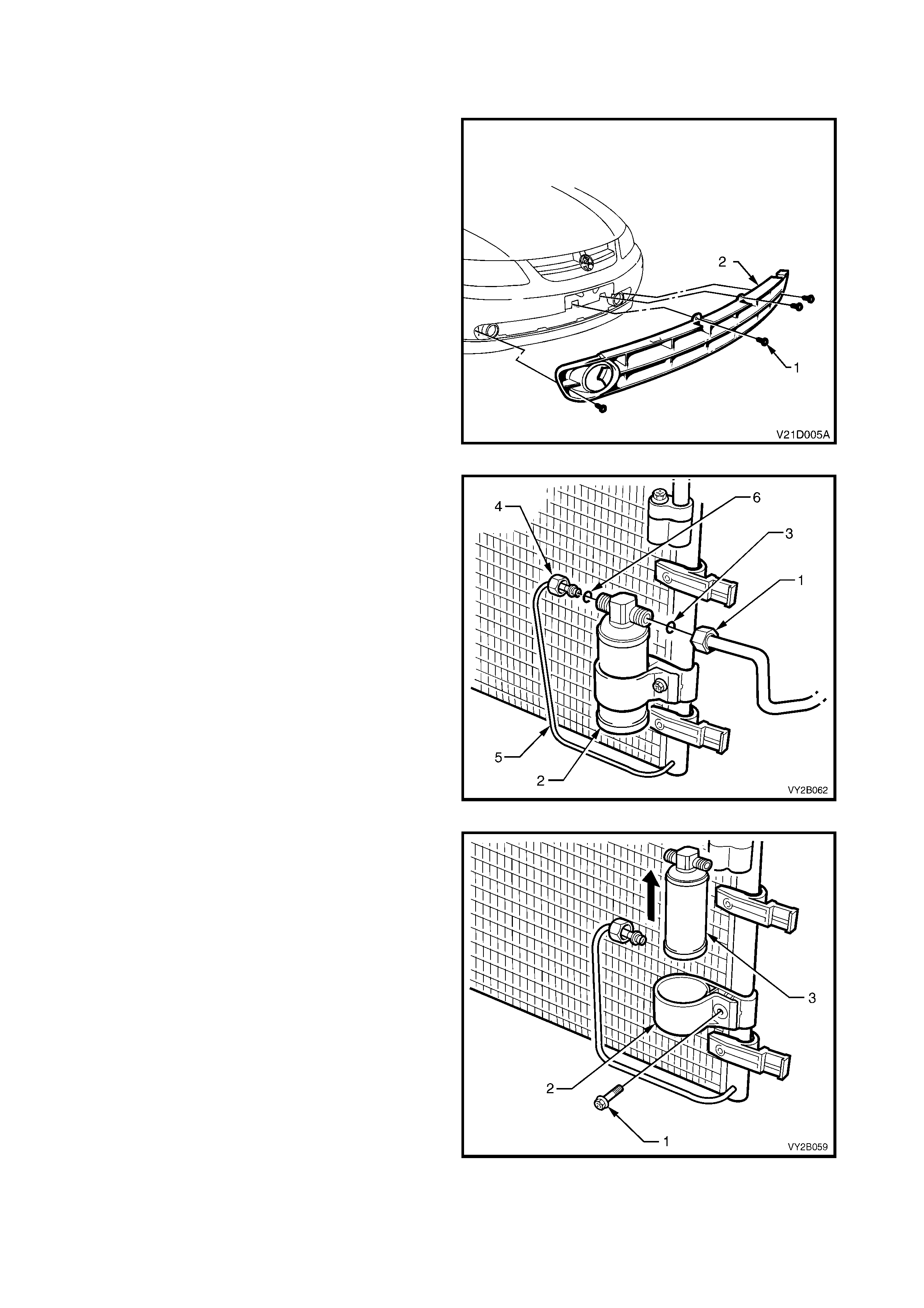
4. Remove the four sc rews (1) retaining the lower
air intake grille (2) to the front facia.
5. Flex the upper edge of the lower air intake grille
to disengage the four retaining tabs and four
locating tabs from the front bumper bar facia.
6. F lex the lower edge of the lower air intak e grille
to disengage the four retaining tabs and five
locating tabs from the front bumper bar facia.
7. Remove the lower air intake grille from the
vehicle.
Figure 2B-4
8. Release each of the automatic transmission
cooling pipes (if fitted) (1) from the integral clips
(2) on the fan shroud.
Figure 2B-5
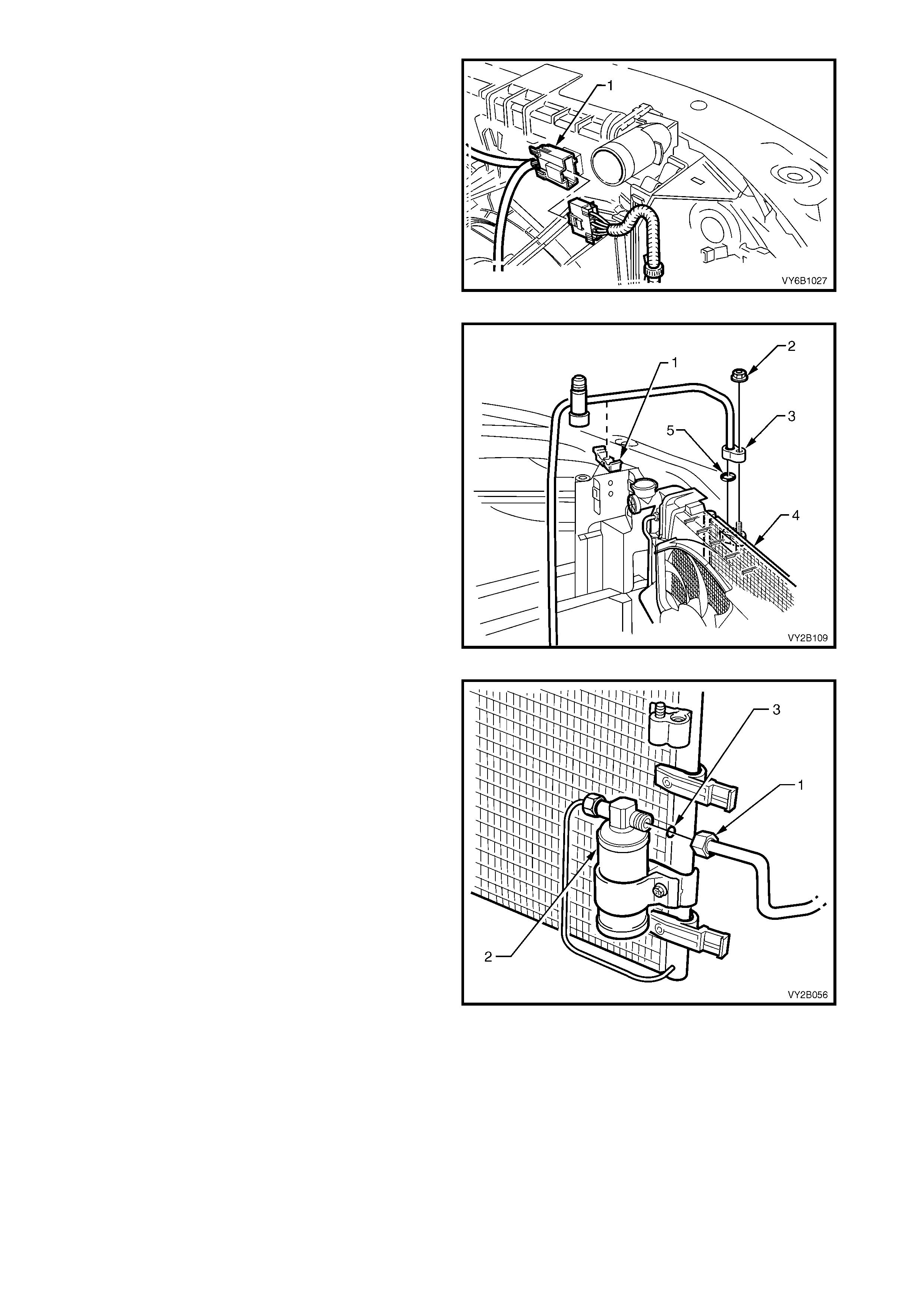
9. Depress tang on main wiring harness to cooling
fan motor wiring harness connector (1) and
separate connector.
Figure 2B-6
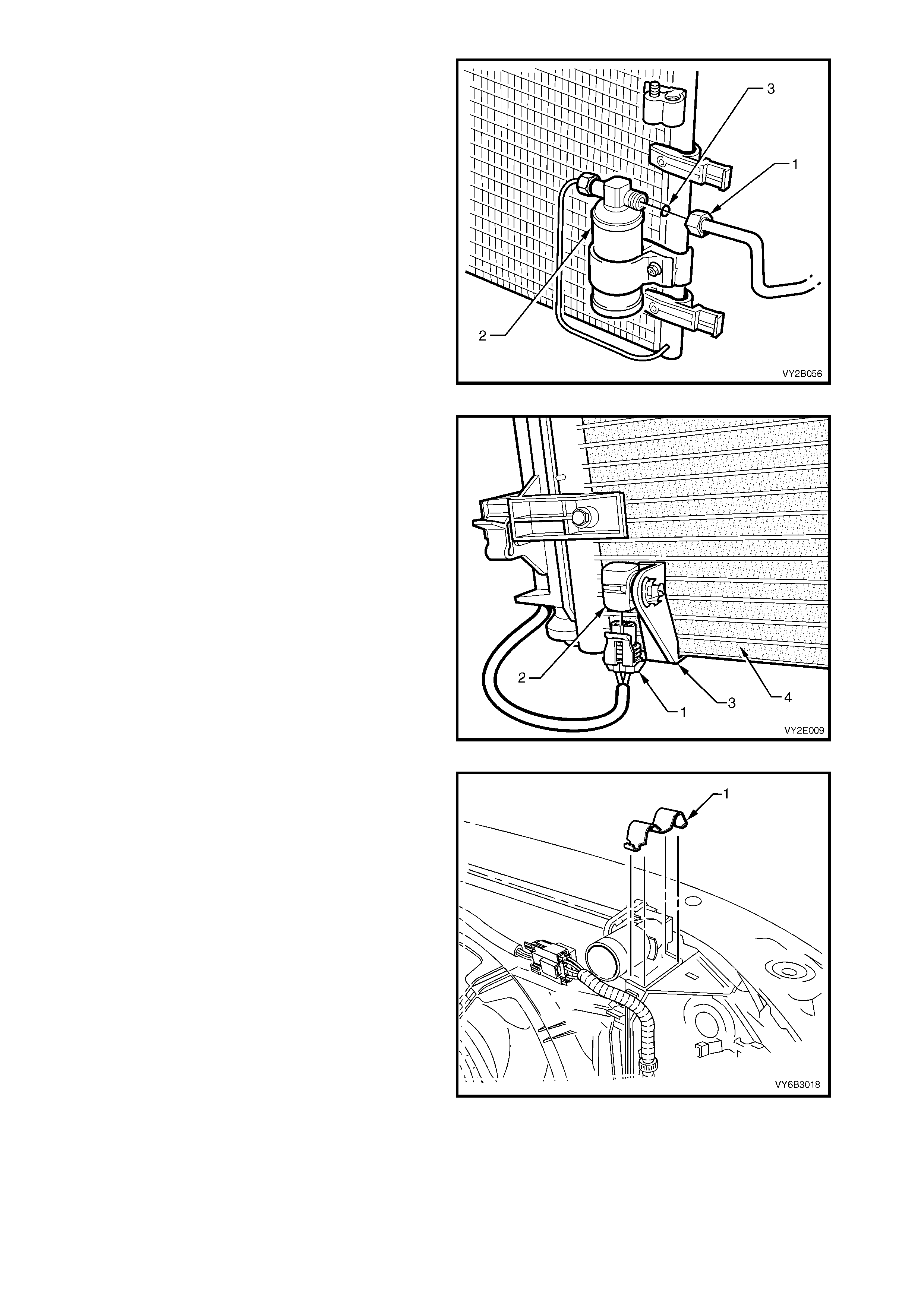
10. Release the discharge tube retaining clip (1).
11. Remove the nut (2) retaining the discharge
hose pad fitting (3) to the condenser (4).
12. Cap all open tubes/hoses to avoid moisture
from entering the system.
13. Discard the O-ring (5).
Figure 2B-7
14. Remove the liquid tube union (1) from the filter
drier receiver (2) and discard the O-ring (3).
Figure 2B-8
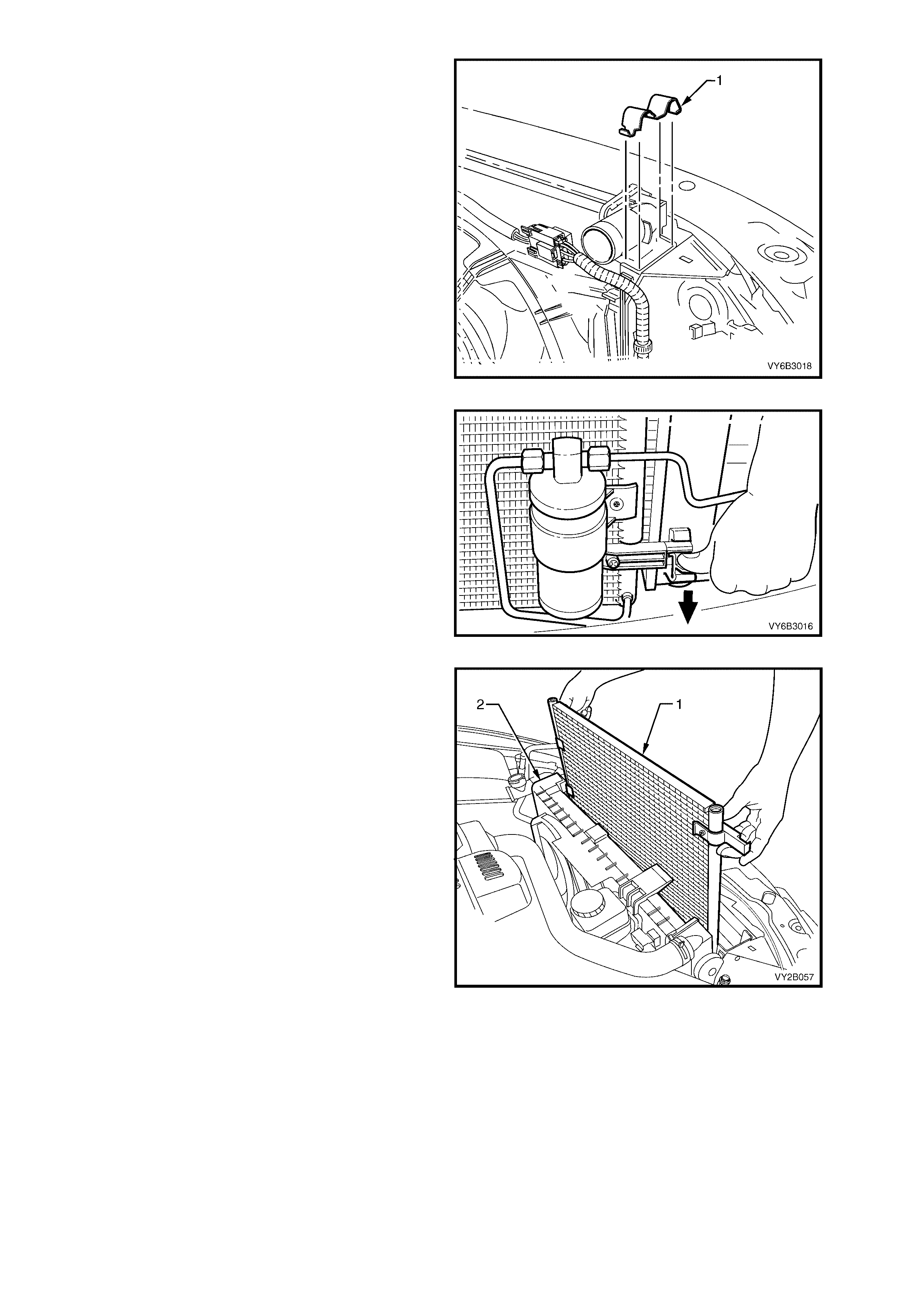
15. Using a screwdriver, compress and lever out
radiator retaining clips (1) from radiator upper
mounting brackets.
IMPORTANT: Do not lift the radiator assembly by
lifting on the fan rings as this will bend the fan
motor shaft and create an unnecessary vibration.
16. Lift radiator assembly upwards out of lower
insulators. Slant the upper section of the
assembly behind the radiator support sheet
metal work and allow it to remain there.
Figure 2B-9
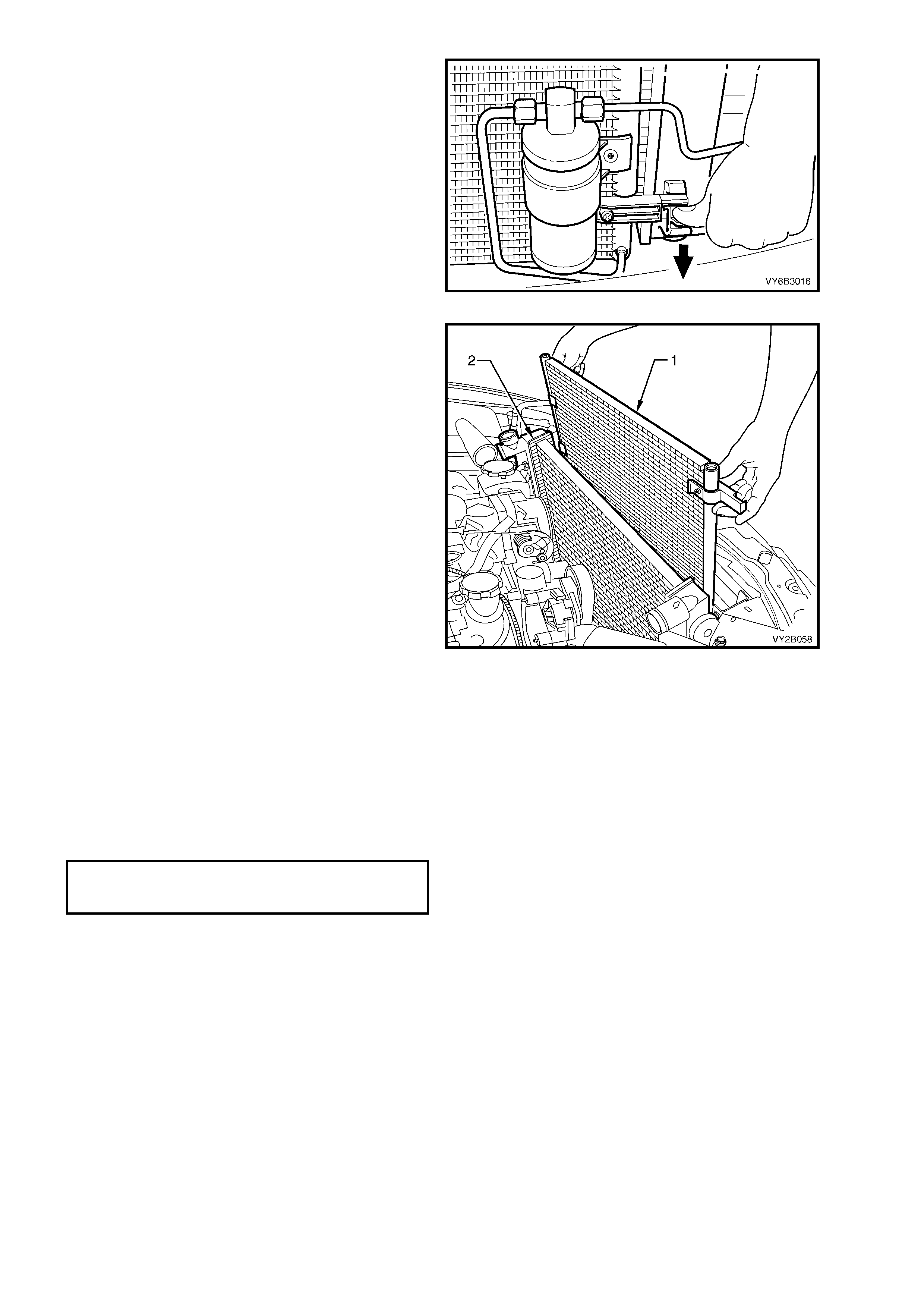
17. Release one of the clips securing the
condenser to the radiator (bold arrow) by
pressing down on the locking retainer while
lifting the condenser assembly with the other.
Repeat for the other side.
Figure 2B-10
18. Lift the condenser assembly (1) upwards
suff ic iently to clear the mounts moulded to f r ont
of the radiator (2). Rem ove the condenser from
engine bay with the FDR attached.
NOTE: If the FDR is to be removed from the
condenser mark the mounting position of the FDR
in relation to the mounting bracket for correct
positioning when installing, and note the IN mar king
on the filter head for the correct flow direction. For
FDR installation information, refer to 2.3 FILTER
DRIER RECEIVER in this Section.
Figure 2B-11

REINSTALL
Installation of the condenser is the reverse of removal procedures, noting the following points:
1. Before installing the radiator , inspect the cor e to ensure that there is no for eign matter in the cor e fins. Clean
out between the core fins with compressed air, blowing from the rear to the front.
2. Ensure that the radiator lower mounting insulators are correctly located in the radiator support panel.
3. Ensure that the upper insulators are installed on each of the upper mounting pins and the radiator retainers
are correctly installed on each side of the radiator by checking that the clips engage on both sides of the
channel support bracket
4. If rem oved ins tall the FDR, ens ur ing that the union thread with the word IN is connec ted to the c ondenser s ide
of the FDR. Tighten the FDR unions and the FDR mounting bracket screw.
5. Install the liquid tube and the discharge hose using new lubricated O-rings to the condenser. Torque the
unions to specification.
FILTER DRIER
RECEIVER TUBE UNION
TORQUE SPECIFICATION...................... 7.5 - 12.5 Nm
6. Evacuate and charge the A/C system with 775 – 825 g of R134a refrigerant, refer to 2.1 SYSTEM
CHARGING AND EVACUATION in Section 2C HEATING AND AIR CONDITIONING – SERVICING AND
DIAGNOSIS in the VT Series I Service Information.
7. Ensur e that fan and shroud ass embly to radiator attaching clips are all f ully engaged and that the two lock ing
tangs on the upper clips are securing the shroud correctly.
8. Check cooling fan operation and direction of rotation.
2.2 CONDENSER – GEN III V8 ENGINE
REMOVE
1. Allow engine to cool to ambient temperature
(less than 50°C), slowly loosen screw-on
pressure cap at the coolant surge tank to
relieve any residual coolant pressure, then
remove.
CAUTION: Do not remove the screw-on
pressure cap while the engine coolant
temperature is above 50°
°°
°C, as personal injury
will most likely occur.
2. Disconnect battery ground lead.
IMPORTANT: Disconnection of the battery affects
certain vehicle electronic systems. Refer to
BATTERY DISCONNECT CAUTION in Section 00
CAUTIONS AND NOTES in the VX Series II Service
Information before disconnecting the battery.
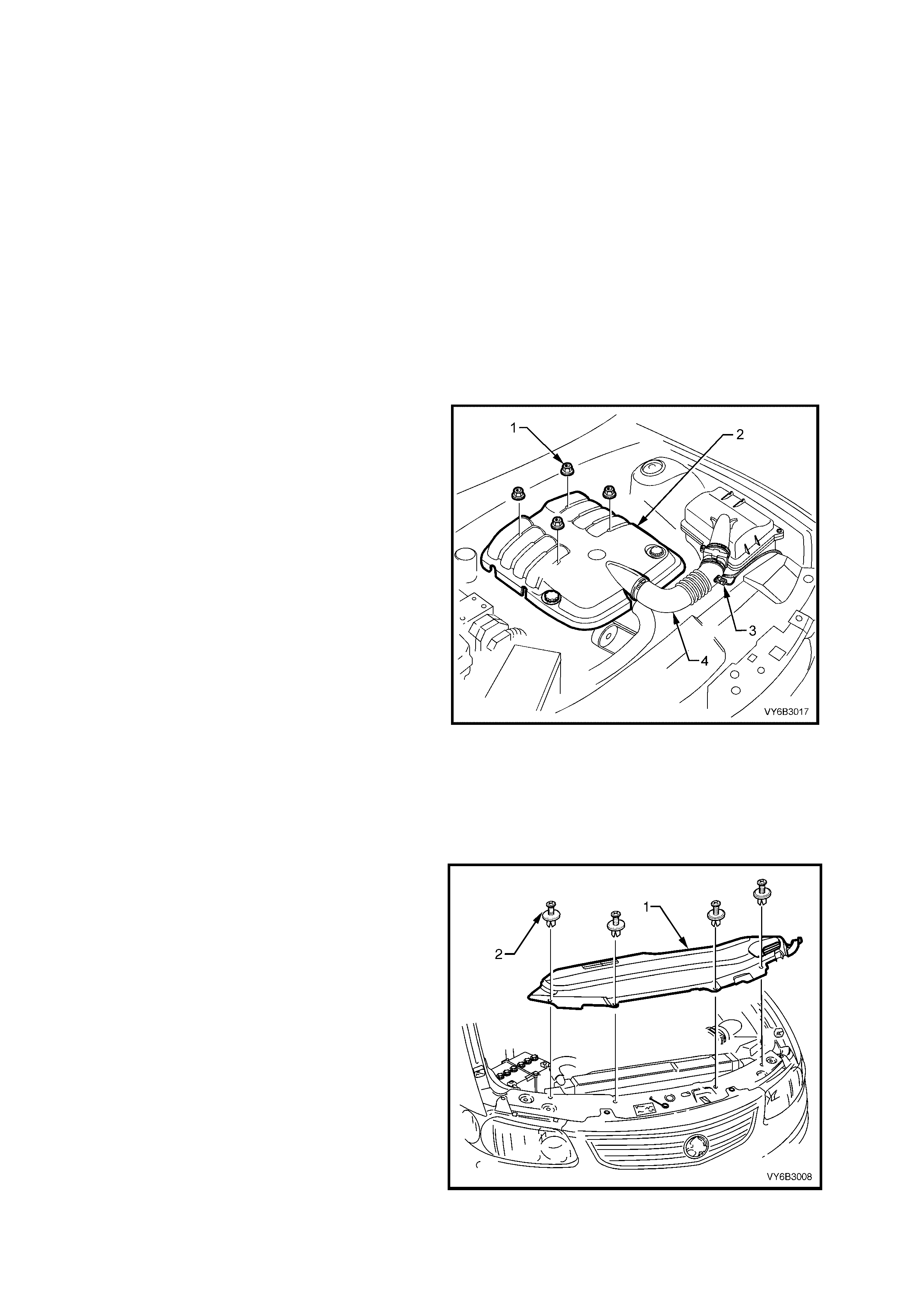
3. Remove engine dress cover decorative nuts
(1), then remove the cover (2).
4. Lift the locking lever on the Intake Air
Temperature (IAT) sensor wiring harness
connector (3), then remove the connector.
5. Lift the locking lever on the Mass Air Flow
(MAF) sensor, then remove the connector.
6. Loosen the two intake duct clamps, one at the
throttle body and the other at the MAF sensor
to air c leaner c onnection. Remove the duc t and
MAF sensor as an assembly and carefully set
to one side.
7. Drain engine coolant into a suitable, clean
container. Refer to 2.3 DRAINING AND
FILLING COOLING SYST EM in Sect ion 6B3 –
ENGINE COOLING – GEN III V8 ENGINE in
the VT Series II Service Information.
8. Release the vapour hose from the radiator fan
shroud clips, remove the clamp securing the
hose to the radiator, remove the hose and
route to one side.
9. Remove the c lamp sec uring the vapour hose to
surge tank at the radiator end. Remove the
hose and route to one side.
Figure 2B-12
10. Remove the f our retainers (2) from the radiator
upper shroud by carefully lifting the inner stud
with a small screwdriver. Lift the upper shroud
(1), on the right side first, to allow release of the
locating tab on the left-hand end.
Figure 2B-13
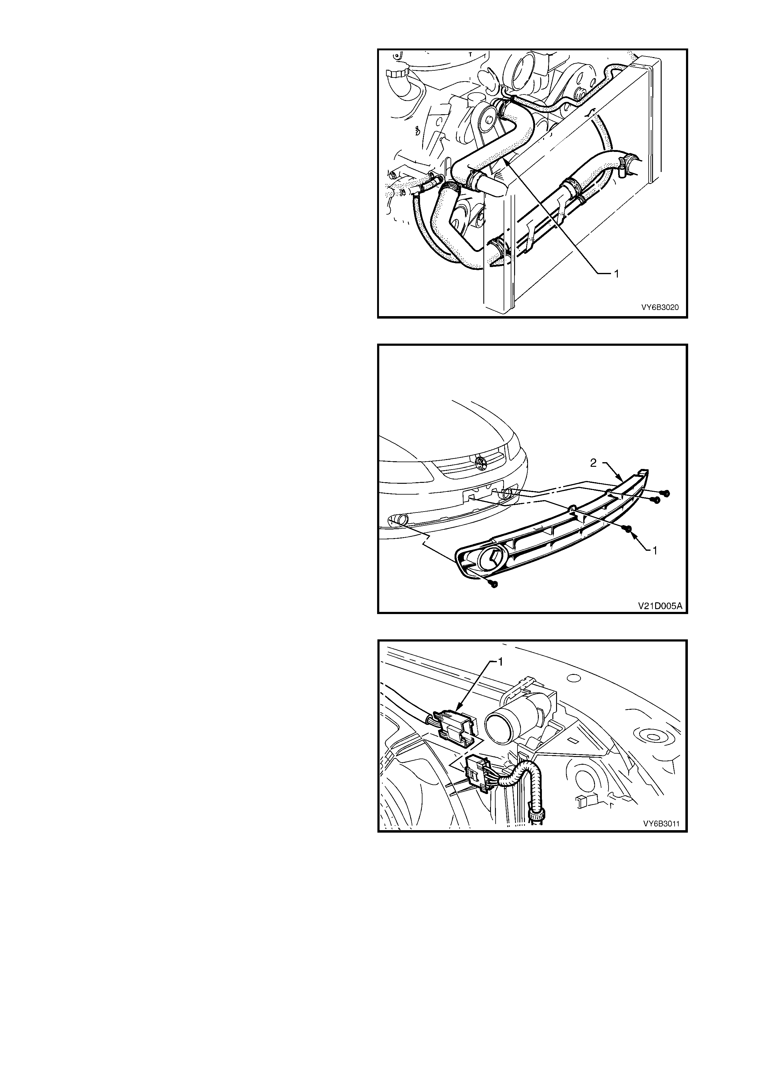
11. Remove the upper radiator hose clamps, then
remove the hose (1) and set to one side.
CAUTION: Wear eye protection when working
with spring type hose clamps.
Figure 2B-14
12. Remove the vehicle licence plate.
13. Remove the four sc rews (1) retaining the lower
air intake grille (2) to the front facia.
14. Flex the upper edge of the lower air intake grille
to disengage the four retaining tabs and four
locating tabs from the front bumper bar facia.
15. F lex the lower edge of the lower air intak e grille
to disengage the four retaining tabs and five
locating tabs from the front bumper bar facia.
16. Remove the lower air intake grille from the
vehicle.
Figure 2B-15
17. Press the retaining tang on wiring harness-to-
cooling fan m otor wiring harness connector (1),
then separate the connector halves.
Figure 2B-16
18. While holding the shroud locking tang in the
release position, lift the shroud and fan
assembly upwards. Repeat for the second side.
NOTE: While the automatic transmission fluid
cooling pipe is shown removed, this is not a
mandatory requirement for shroud removal. Pipe
has been shown rem oved to m ore clearly show the
shroud release method.
Figure 2B-17
19. Lif t the shr oud and fan as sem bly clear from the
engine bay, grasping the motor mounting
brackets.
IMPORTANT: Do not lift the assembly clear by
lifting on the fan rings as this will bend the fan
motor shaft and create an unnecessary vibration.
Figure 2B-18
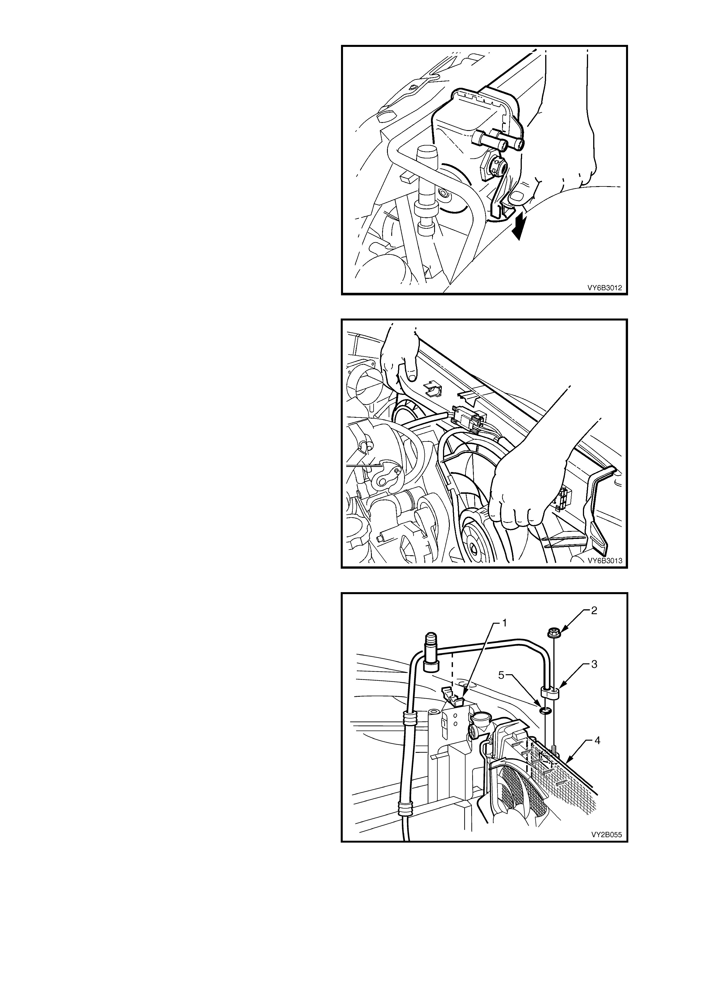
20. Release the discharge tube retaining clip (1).
21. Remove the nut (2) retaining the discharge
hose pad fitting (3) to the condenser (4).
22. Cap all open tubes/hoses to avoid moisture
from entering the system.
23. Discard the O-ring (5).
Figure 2B-19
24. Remove the liquid tube union (1) from the
FDR (2) and discard the O-ring (3).
Figure 2B-20
25. Disconnect the harness connector (1) from the
ambient temperature sensor (2). Do not
attempt to remove the bracket (3) from the
condenser (4).
Figure 2B-21
26. Using a screwdriver, compress and lever out
the radiator retaining clips (1) from the radiator
upper mounting brackets.
IMPORTANT: Do not lift the radiator assembly by
lifting on the fan rings as this will bend the fan
motor shaft and create an unnecessary vibration.
27. Lift the radiator assembly upwards out of the
lower insulators. Slant the upper section of the
assembly behind the radiator support sheet
metal work and allow it to remain there.
Figure 2B-22
28. Release one of the clips securing the
condenser to the radiator (bold arrow) by
pressing down on the locking retainer, while
lifting the condenser assembly. Repeat for the
other side.
Figure 2B-23
29. Lift the condenser assembly (1) upwards
suff ic iently to clear the mounts moulded to f r ont
of the radiator (2).
30. Remove the condenser from engine bay with
the FDR attached.
NOTE 1: If the FDR is to be removed from the
condenser mark the mounting position of the FDR
in relation to the mounting bracket for correct
positioning when installing, and note the IN mar king
on the filter head for the correct flow direction. For
FDR installation information, refer to 2.3 FILTER
DRIER RECEIVER in this Section.
Figure 2B-24
REINSTALL
Installation of the condenser is the reverse of removal procedures, noting the following points:
1. Bef ore installing the radiator, inspect the cor e to ensure that there is no for eign matter in the cor e fins. Clean
out between the core fins with compressed air, blowing from the rear to the front.
2. If rem oved ins tall the FDR, ens ur ing that the union thread with the word IN is connec ted to the c ondenser s ide
of the FDR. Tighten the FDR unions and the FDR mounting bracket screw.
3. Install the liquid tube and the discharge hose using new lubricated O-rings to the condenser.
4. Torque the unions to specification.
FILTER DRIER
REVIEVER TUBE UNION
TORQUE SPECIFICATION ......................7.5 - 12.5 Nm
5. Evacuate and charge the A/C system with 775 – 825 g of R134a refrigerant, refer to 2.1 SYSTEM
CHARGING AND EVACUATION in Section 2C HEATING AND AIR CONDITIONING – SERVICING AND
DIAGNOSIS in the VT Series I Service Information.
6. Ensure that the fan and shroud assembly-to-radiator attaching clips are all fully engaged and that the two
locking tangs on the upper clips are securing the shroud correctly.
7. Refill the cooling system and test the concentration levels. Refer to 2.3 DRAINING AND FILLING COOLING
SYSTEM in Section 6B3 – ENGINE COOLING – GEN III V8 ENGINE in the VT Series II Service Inform ation
and TESTING COOLANT CONCENTRATION, 2.2 COOLANT MAINTENANCE in Section 6B3 – ENGINE
COOLING – GEN III V8 ENGINE in the VT Series II Service Information.
8. Check the cooling fan operation and direction of rotation.
2.3 FILTER DRIER RE CEIVER
REMOVE
1. Recover the refrigerant from the A/C system,
refer to 2.1 SYSTEM CHARGING AND
EVACUATION in Section 2C HEATING AND
AIR CONDITIONING – SERVICING AND
DIAGNOSIS in the VT Series I Service
Information.
2. Remove the vehicle licence plate.
3. Remove the four sc rews (1) retaining the lower
air intake grille (2) to the front facia.
4. Flex the upper edge of the lower air intake grille
to disengage the four retaining tabs and four
locating tabs from the front bumper bar facia.
5. F lex the lower edge of the lower air intak e grille
to disengage the four retaining tabs and five
locating tabs from the front bumper bar facia.
6. Remove the lower air intake grille from the
vehicle.
Figure 2B-25
7. Remove the liquid tube union (1) from the filter
drier receiver (2) and discard the O-ring (3).
8. Remove the discharge pipe union (4) from the
filter drier receiver and carefully flex the
discharge pipe (5) to the left clear of the FDR.
Discard the O-ring (6).
Figure 2B-26
9. Remove the screw (1) on the FDR mounting
bracket (2).
10. Cap all open tubes/hoses to avoid moisture
from entering the system.
11. Expand the bracket and remove the FDR (3) by
lifting it upwards clear of the bracket.
12. Remove the FDR through the lower air intake
grille aperture.
Figure 2B-27
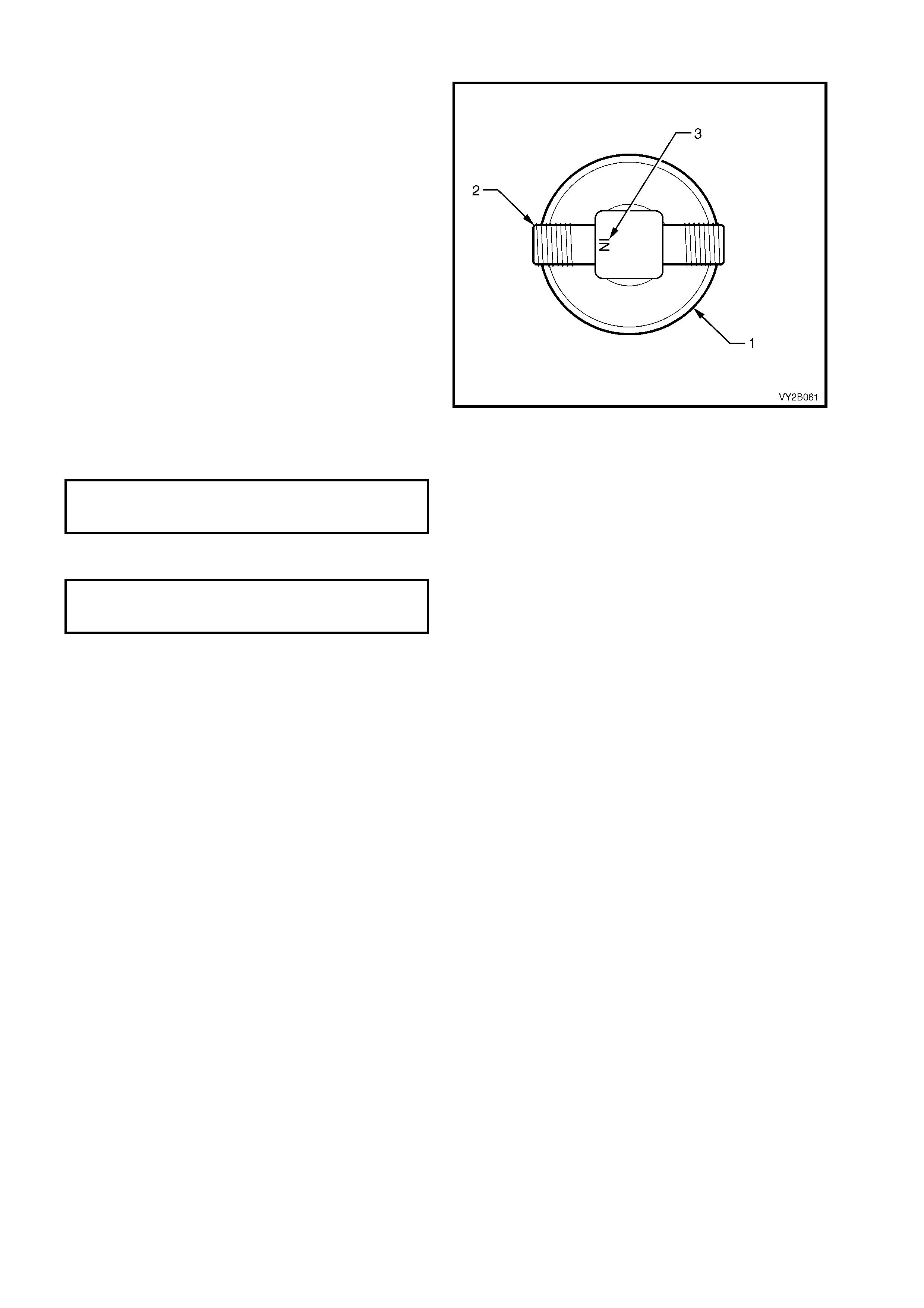
REINSTALL
Installation of the filter drier receiver is the reverse
of removal procedures, noting the following points:
1. Install the FDR (1), ensuring that the condenser
union is connected to the thread (2) adjacent to
the word IN (3) stamped on the head of the
FDR.
2. Install the liquid tube and the discharge hose
together with new lubricated O-rings, onto the
condenser.
Figure 2B-28
3. Torque the filter drier receiver mounting screw
to specification.
FILTER DRIER RECEIVER
MOUNTING SCREW
TORQUE SPECIFICATION ...................7.5 – 12.5 Nm
4. Torque the filter drier receiver tube nuts to
specification.
FILTER DRIER
RECEIVER TUBE NUTS
TORQUE SPECIFICATION ...................7.5 – 12.5 Nm
5. Evacuate and charge the A/C system with
775 – 825 g of R134a refrigerant, refer to
2.1 SYSTEM CHARGING AND EVACUATION
in Section 2C HEATING AND AIR
CONDITIONING – SERVICING AND
DIAGNOSIS in the VT Series I Service
Information.

3. TORQUE WRENCH SPECIFICATIONS
Nm
Suction And Discharge Hose Assembly Retaining Nut...................7.5 – 12.5
Filter Drier Reveiver Tube Nuts.......................................................7.5 – 12.5
Filter Drier Reveiver Mounting Screw..............................................7.5 – 12.5
Condenser Discharge Pad Retaining Nut .......................................7.5 – 12.5
Condenser Inlet Pad Fitting Nut ......................................................7.5 – 12.5