
SECTION 6B3 - COOLING SYSTEM -
GEN III V8 ENGINE
IMPORTANT
Before performing any Service Operation or other procedure described in this Section, refer to Section
00 CAUTIONS AND NOTES for correct workshop practices with regard to safety and/or property damage.
1. GENERAL INFORMATION
2. GENERAL DESCRIPTION
2.1 RADIATOR
2.2 COOLING FANS
OPERATION
3. SERVICE OPERATIONS
3.1 SERVICE NOTES
3.2 COOLANT HOSES
3.3 RADIATOR
REMOVE
REINSTALL
3.4 COOLING FANS AND SHROUD ASSEMBLY
REMOVE
DISASSEMBLE
REASSEMBLE
REINSTALL
4. SPECIFICATIONS
5. TORQUE WRENCH SPECIFICATIONS
6. SPECIAL TOOLS
Techline
Techline
Techline
Techline

1. GENERAL I NFORMATI O N
The engine cooling system for V2 Series CV8 Models carries over from VX Series I Models, noting the following:
• A new condenser, radiator and f an m odule (CRFM) was introduced with the MY2003 V2 Series Update Models
during October 2002.
The information provided in this Section only applies to MY2003 V2 Series Update CV8 Models fitted with the
revised cooling s ystem. For infor m ation regarding either the ear lier type cooling sys tem or the unchanged portion of
the revised cooling system, refer to Section 6B3 ENGINE COOLING – GEN III V8 ENGINE in the VX Series I
Service Inf ormation, in c onjunction with Section 6B3 ENGINE COOL ING – GEN III V8 ENGINE in the VT Series II
Service Information
The cooling system for MY2003 V2 Series Update vehic les with the G EN III V8 engine, consists of two, two-speed
electric cooling fans mounted behind the radiator. Fan operation is dependent on engine coolant temperature,
vehicle speed, A/C request (where fitted) and A/C system pressure.

2. GENERAL DESCRI PTI O N
2.1 RADIATOR
The radiator (1) is of the crossflow design and consists of an aluminium core with plastic side tanks attached to
each end of the c ore. For vehicles with automatic trans mission, a trans mission oil c ooler is located in the left- hand
side tank.
Pegs are attached to the lower frame and the upper area of each side tank. These pegs are used to support the
radiator in four rubber mounts. The assembly is held in position by two spring clips at the upper mounting locations.
The radiator core side tanks and/or trans mission oil cooler CANNOT be replac ed separately. If there is a fault with
any of these components, the radiator assembly must be replaced. Small core repairs can be made using an
Aluminised Silicon based liquid repair agent.
2.2 COOLING FANS
The cooling system for the GEN III V8 engine, includes two, twin speed, engine cooling fan motors, both of which,
drive fans with five, asym m etrical blades, to r educe air noise. T he right fan is 342 m m in diam eter and has a motor
rated at 220 Watts, while the left fan is 293 mm in diameter with a motor power rating of 180 Watts.
With 12 volts applied and the fans mounted onto the radiator with a condenser fitted, the operating speeds are:
Stage 1 Stage 2
Large Fan 2,350 ± 150
rpm 2,750 ± 150
rpm
Small Fan 2,050 ± 150
rpm 2,300 ± 150
rpm
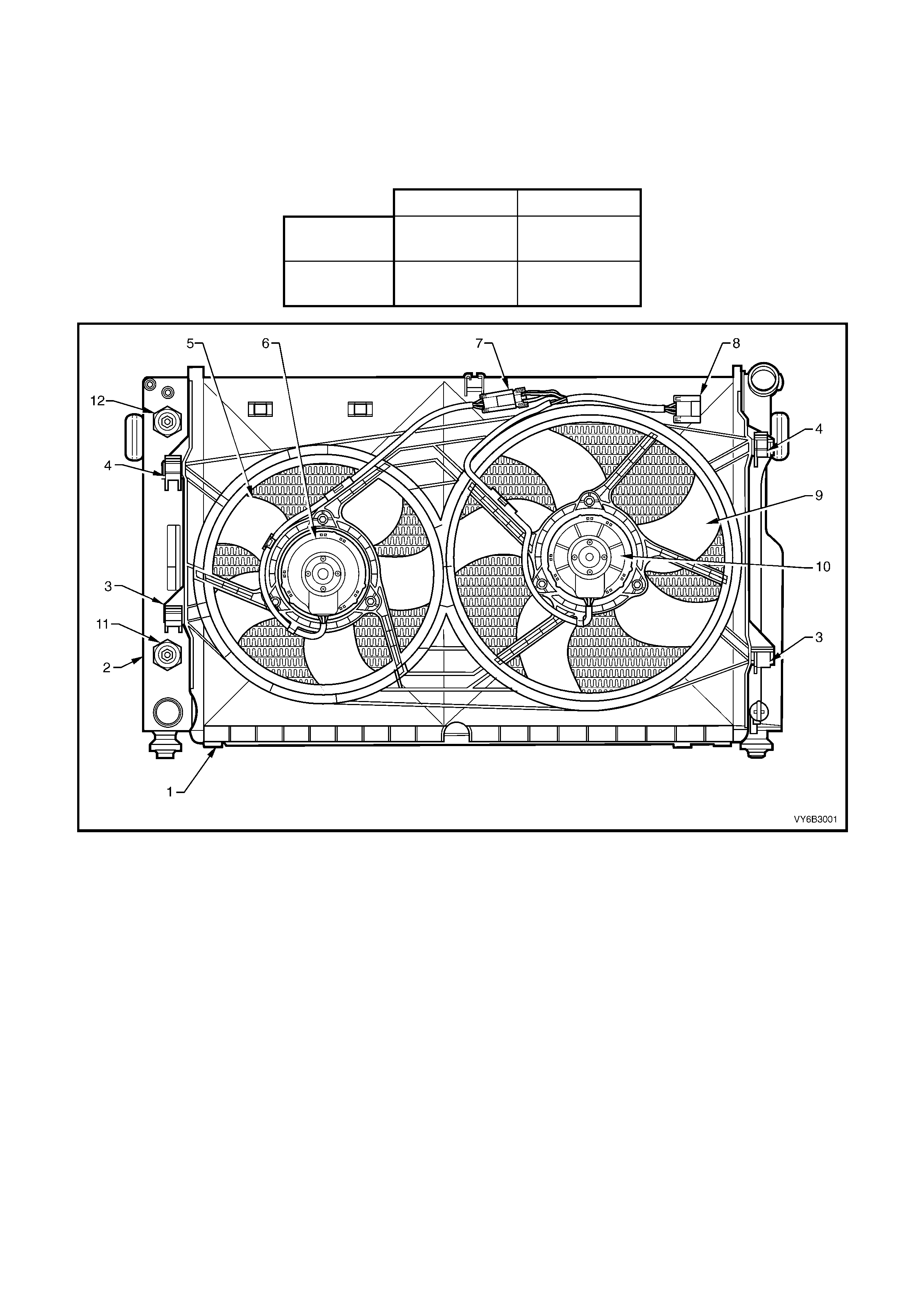
Figure 6B3-1
Legend
1. Fan Shroud
2. Radiator
3. Fan Shroud Lower Support
4. Fan Shroud Upper Support/Locking Retainer
5. Left Fan – 5 Blade, 293 mm Diameter
6. Left Fan Motor – 180 Watt, Twin Speed
7. Left Fan Motor Harness Connector (3 terminal)
8. Left and Right Fan Motor Main Harness Connector
9. Right Fan – 5 Blade, 342 mm Diameter
10. Right Fan Motor – 220 Wa tt, Twin Speed
11. Oil Cooler, lower quick connect fitting (Auto. Only)
12. Oil Cooler, upper quick connect fitting (Auto. Only)
OPERATION
To achieve the dual speed requirement, the electrical circuitry for the GEN III V8 cooling fans have two negative and
one positive terminal. T o reduce the heat burden on the electrical connectors, the current draw is directed through
separate negative term inals at the joint connector (‘8’ in Figure 6B3-1), for each fan m otor, when operating on low
speed. When operating at high speed, only one negative terminal is required.
The positive terminals are permanently connected
to battery voltage, via fusible links F101 (left fan)
and F107 (right fan).
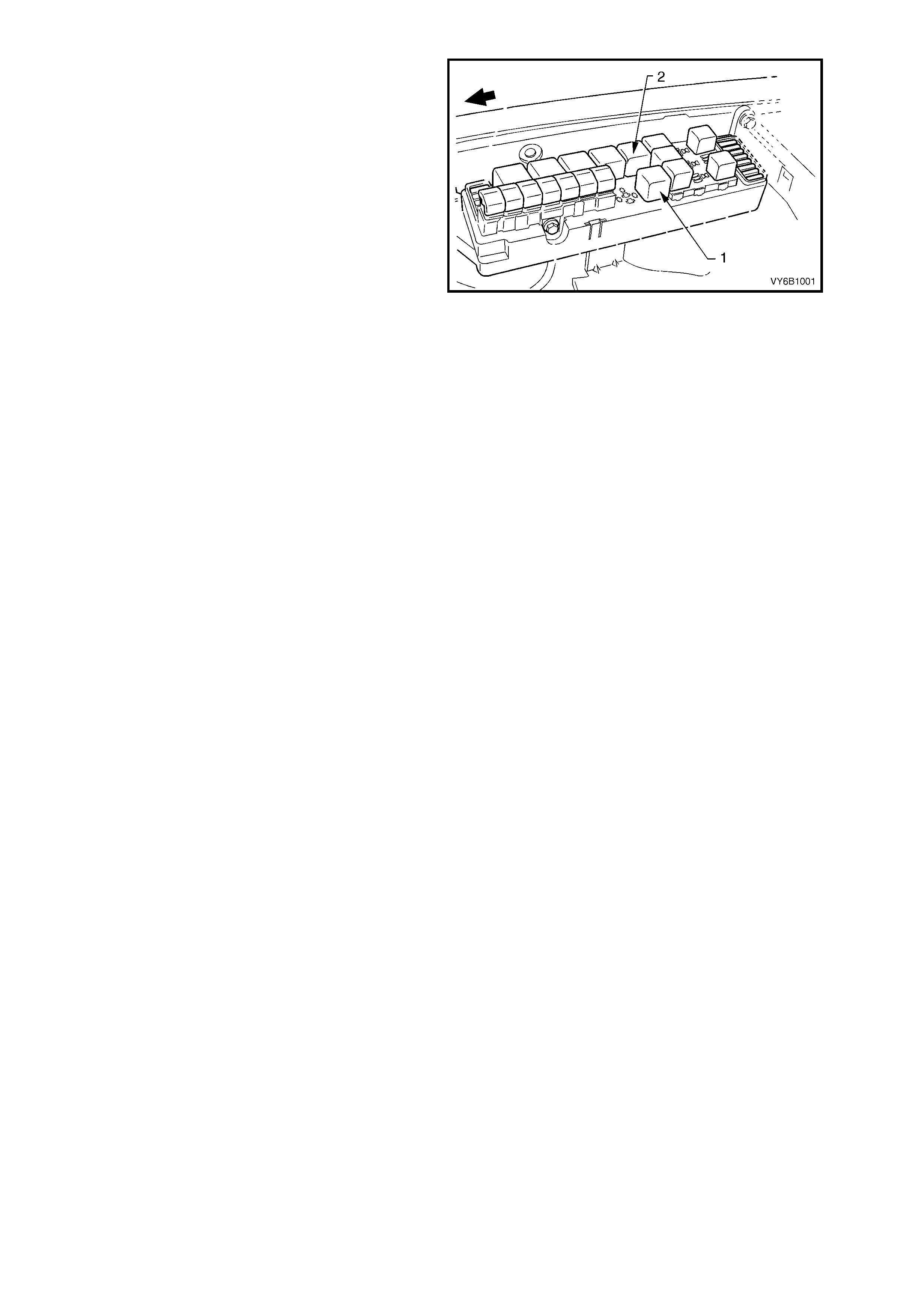
The engine cooling fan Low Speed Relay (1) is
energised by the BCM. W hen the PCM determ ines
that the low speed fan relay should be enabled, the
PCM will send a message on the Class 2 serial
data circuit to the PIM. The PIM will then convert
the PCM Class 2 message to a UART message
and supply this UART message to the BCM, via a
serial data Normal Mode Message to the BCM on
circuit 800 (Red/Black wire). This message will
request the BCM to supply the needed ground
signal for the Low Speed Relay to operate.
After the BCM provides the ground signal for the
Low Speed Relay, the BCM will send a message
back to the PIM confirming that the ground signal
was commanded.
A failure in this BCM response communication, will
cause a PIM DTC B2002 to set.
Figure 6B3-2
The PCM determines when to enable stage 1, based on inputs from the A/C request signal, Engine Coolant
Temperature (ECT) sensor and the Vehicle Speed Sensor (VSS).
There are also suppression capacitors incorporated into the fan motor, located on the brush holders. These
suppression capacitors help eliminate fan motor noise through the radio speakers. As these capacitors are not
serviced separately, should a problem occur with either capacitor, then the motor assembly must be replaced.
STAGE ONE FAN OPERATION
The cooling fan low speed relay will be turned ON when:
• The A/C request indicated (YES) and either:
• the vehicle speed is less than 30 km/h.
or
• A/C pressure is greater than 1500 kPa
or
• The coolant temperature is greater than 98°C.
or
• If the coolant tem per ature is gr eater than 113°C, when the ignition is switched of f, the r elay is energised for
approximately four minutes, this is known as Low Fan Run On.
or
• If an engine coolant temperatur e s ensor f ault is detec ted and a DT C s uch as DTC P0117, P0118, P1114 or
P1115 is set.
The cooling fan low speed relay will be turned OFF when any of the following conditions have been met:
• An A/C request is not indicated (NO) and the coolant temperature is less than 95°C.
or
• An A/C request is indicated (YES) and the vehicle speed is greater than 50 km/h and A/C pressure is less
than
1170 kPa and the coolant temperature is less than 98°C.
NOTE: THE LOW SPEED COOLING FAN HAS A MINIMUM, RUN-ON TIM E OF 30 SECONDS.
STAGE TWO FAN OPERATION
The engine cooling fan relay 2 (R5) is controlled by the PCM. The PCM will only activate stage 2 fan operation, if the
engine cooling fan relay 1 has been ON for two seconds and the following conditions are satisfied.
• There is a BCM message response fault which will cause a PIM DTC B2002.
• An engine coolant temperature sensor fault is detected and a DTC such as DTC P0117, P0118, P1114 or
P1115 is set.
• Coolant temperature greater than 108°C.
• The A/C refrigerant pressure is greater than 2400 kPa.

If the low speed fan was OFF when the criteria was met to turn the high speed fan ON, the high speed fan will come
ON 5 seconds after the low speed fan is turned ON. If both engine cooling fan relays are ON, the PCM will turn OFF
the high speed relay when:
• The engine coolant temperature is less than 102°C.
• A/C request not indicated (NO).
• A/C request indicated (YES) and A/C pressure is less than 1900 kPa.
NOTE: All cooling fans will be turned off if the vehicle speed is greater than 104 km/h.
The PCM determines operation of the two, two-speed engine cooling fans based on A/C request, A/C system
pressure (where fitted), engine coolant temperature and vehicle speed signal inputs. For further details of the
engine cooling fan operation and diagnosis of the system, refer to Section 6C3 POW ERT RAIN M ANAGEM ENT –
GEN III V8 ENGINE in the VT Series II Service Information.

3. SERVICE OPERATIONS
The service operations for the GEN III V8 cooling system carry over from those described in
Section 6B3 COOLING SYSTEM – GEN III V8 ENGINE in the VT Series II Service Information, except for those
service oper ations desc r ibed in this Sec tion. F or inf ormation r egarding the s er vice oper ations for the cooling s ystem
as fitted to V2 Ser ies CV8 Models not provided in this Sec tion, refer to Section 6B3 COOLING SY STEM – G EN III
V8 ENGINE in the VT Series II Service Information.
NOTE: The service operations described below only applies to MY2003 V2 Series Update Models.
3.1 SERVICE NOTES
SAFETY
Before removing the surge tank cap, allow the engine to cool, then place a shop rag over the surge tank cap and
then slowly turn the c ap anti- cloc kwise, to loosen. DO NOT SPIN THE CAP OFF! If there is any residual pressure in
the cooling system, it can then be released into the dam under the cap and out through the drain hose onto the
ground. When all pressure has been dispersed in this way, the cap can then be fully removed.
CAUTION: To av oid serious p ersonal injury, never remov e the screw -on surge t ank cap wh en the engine is
hot, even if the cooling system should require filling. Sudden release of cooling system pressure is very
dangerous.
The vehic le is fitted with twin r adiator electric cooling f ans. W hen working ar ound the engine com partm ent with the
engine running or with the ignition on, keep clear of the fan as it may start operating without warning.
PERIODIC SERVICING
The cooling system requires little care except for maintaining the coolant to the correct level in the coolant surge
tank and periodic servicing at the time or distance intervals as outlined in the Owner's Handbook.
Periodic servicing includes:
1. Checking coolant level, refer to 2.3 DRAINING AND FILLING COOLING SYSTEM in Section 6B3 – ENGINE
COOLING – GEN III V8 ENGINE in the VT Series II Service Information.
2. Checking coolant concentration, refer to TESTING COOLANT CONCENTRATION, 2.2 COOLANT
MAINTENANCE in Section 6B3 – ENGINE COOLING – GEN III V8 ENGINE in the VT Series II Service
Information.
3. Pressure test cooling system and radiator cap, refer to 2.8 PRESSURE TESTING in Section 6B3 – ENGINE
COOLING – GEN III V8 ENGINE in the VT Series II Service Information.
4. Check/tighten hose clamps and inspect all hoses, refer to 3.2 COOLANT HOSES in this Section. Replace
hoses if swollen or deteriorated.
CAUTION: Always wear protective safety glasses when working with spring type hose clamps. Failure to do
so could result in eye injury.
5. Clean out cooling system, refer to COOLING SYSTEM REVERSE FLUSH, 2.5 CLEANING COOLING
SYSTEM, in Section 6B3 – ENGINE COOLING – GEN III V8 ENGINE in the VT Series II Service Information
and ref ill cooling system, r efer to 2.3 DRAINING AND FILLING COOLING SYSTEM in Section 6B3 – ENG INE
COOLING – GEN III V8 ENGINE in the VT Series II Service Information.
ENVIRONMENTAL ISSUES
To reduc e the impact on the envir onment and the maintenance cos t, whenever the c oolant is dr ained f r om the GEN
III V8 engine, the service rec ords are to be check ed to determine when the coolant was last changed. If more than
six months life is left before the next coolant change, then the following procedure is to be adhered to:
1. W hen draining the coolant f rom the engine, use a clean container of at least 15 litres capac ity and ensure that
the coolant is not contaminated in the draining process.
2. After repairs have been completed, refill the engine cooling system with the drained coolant.
3. Top up as required, using a 50% mixture of DEX-COOL® to GM Specification 6277M to 50% clean, good
quality water. Refer to 2.2 COOLANT MAINTENANCE in Section 6B3 – COOLING SYSTEM – GEN III V8
ENGINE in the VT Series II Service Information and 2.3 DRAINING AND FILLING COOLING SYSTEM in
Section 6B3 – ENGINE COOLING – GEN III V8 ENGINE in the VT Series II Service Information for the
necessary procedures and further information.
Techline
3.2 COOLANT HOSES
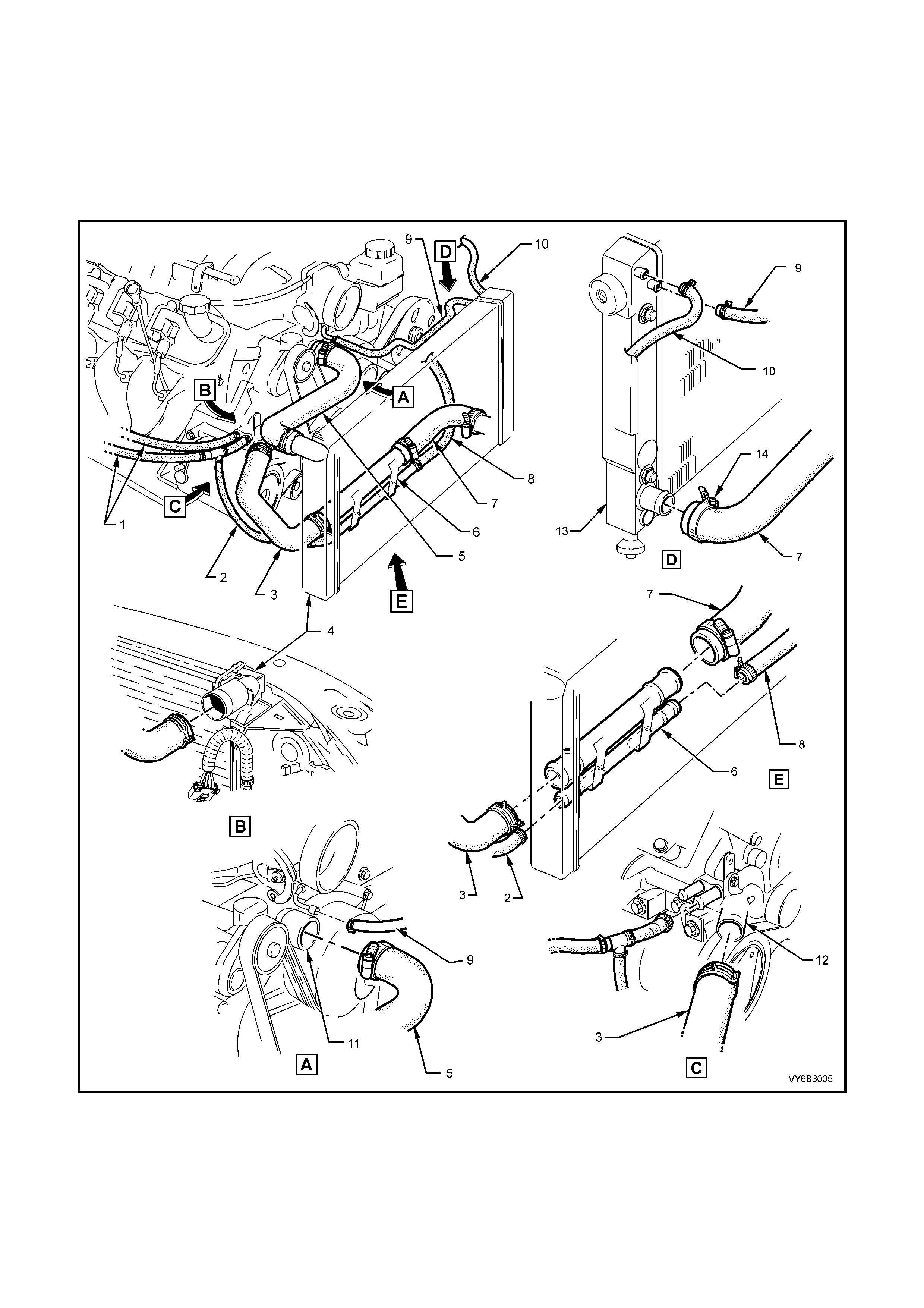
Coolant hoses are installed as shown in the following illustrations.
Hose connections should be thoroughly cleaned before installing any new hose.
NOTE: Because of the production m ethod of inst alling the spring type hos e clamps , access to the clam p ends may
not be pos sible. Partic ularly for the c lamps s ecuring the hoses to the lower br idging piece of the coolant intak e and
coolant surge tank hoses, it may be necessary to remove the complete hose assembly from the vehicle.
ENGINE COOLING SYSTEM HOSES
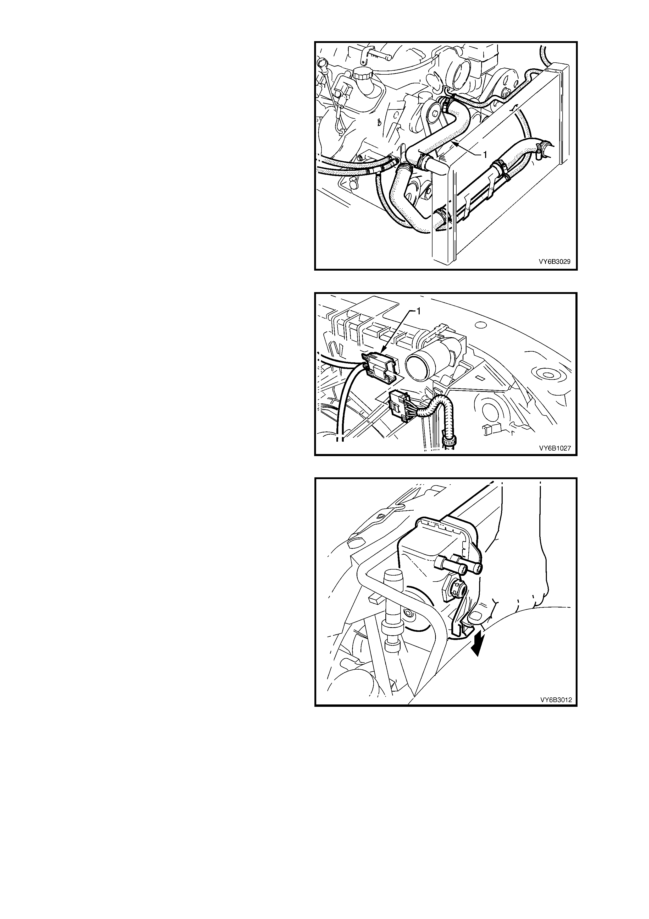
Figure 6B3-3
Legend
1. Hoses – Heater
2. Hose – To Coolant Surge Tank 1 of 2
3. Hose – Radiator Lower 1 of 2
4. Radiator
5. Hose – Radiator Upper
6. Bridging Pipe – Radiator Hoses
7. Hose – Radiator Lower 2 of 2
8. Hose – To Coolant Surge Tank 2 of 2
9. Hose – Vapour to Radiator
10. Hose – Vapour to Surge tank
11. Pump Coolant
12. Housing – Thermostat

HEATER HOSES
Figure 6B3-4
Legend
1. Coolant Valve
2. Coolant Valve Actuator
3. Heater Hose from Interior Heater Core
4. Heater Hose to Interior Heater Core
5. Vacuum Hose – HVAC Supply
6. One-Way Check Valve
7. Vacuum Hose to Intake Manifold
8. Heater Hose to Engine
9. Hose to Coolant Surge Tank
10. Heater Hose T-piece
11. Heater Hose to T-piece
12. Heater Hose from Engine
13. Vacuum Hose to Interior Control Valve
14. Heater Hose Clamps (2 places)
15. Vacuum Hose to Coolant Valve Actuator
16. Brake Booster
17. Steering Shaft
18. Brake Lines
19. Coolant Valve Hose Clamps (4 places)
20. Right Side Wheelhouse
21. Clip - Coolant Flow Control Valve
22. Heater Hose Clamps to Engine (2 places)
23. T-piece Hose Clamps - Spring Band Type (3 places)
24 T-piece Hose Clamp - Worm Type (1 place)
NOTE: Heater and vacuum hoses to be routed under Brake Pipes – refer View B
3.3 RADIATOR
REMOVE
1. Allow the engine to cool to ambient
temperature (less than 50°C), slowly loosen the
screw-on pressure cap at the coolant surge
tank to relieve any residual coolant pressure,
then remove.
CAUTION: Do not remove the screw-on
pressure cap while the engine coolant
temperature is above 50°
°°
°C, as personal injury
will most likely occur.
2. Disconnect the battery ground lead.
IMPORTANT: Disconnection of the battery affects
certain vehicle electronic systems. Refer to
BATTERY DISCONNECT CAUTION in Section 00
CAUTIONS AND NOTES in the VX Series II
Service Information before disconnecting the
battery.
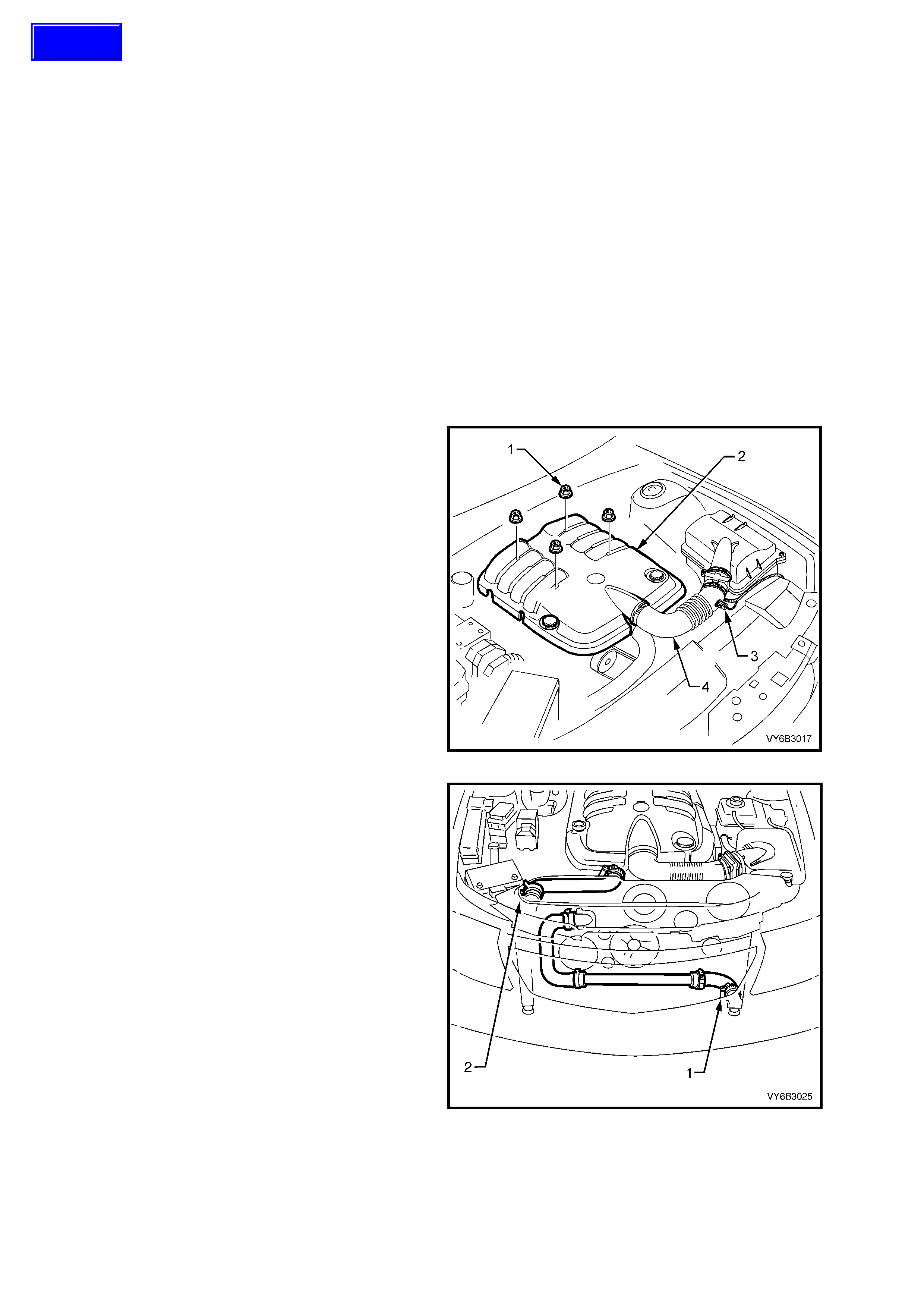
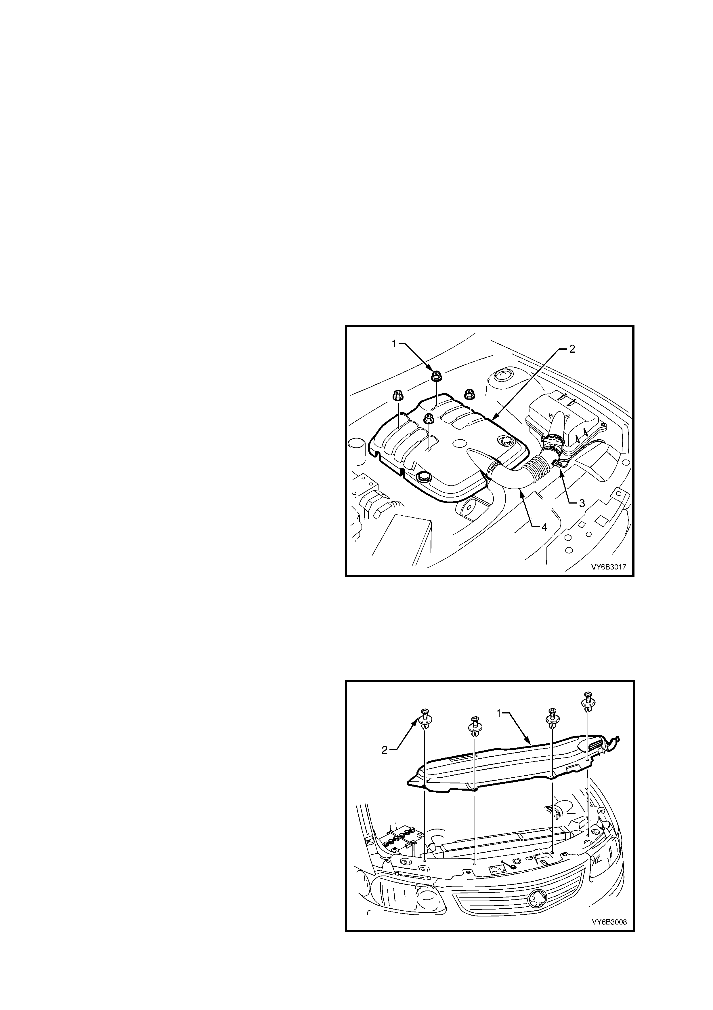
3. Remove the engine dress cover decorative
nuts (1), then remove the cover (2).
4. Lift the locking lever on the Intake Air
Temperature (IAT) sensor wiring harness
connector (3), then remove the connector.
5. Lift the locking lever on the Mass Air Flow
(MAF) sensor, then remove the connector.
6. Loosen the two intake duct clamps, one at the
throttle body and the other at the MAF sensor
to air c leaner c onnection. Remove the duc t and
MAF sensor as an assembly.
Figure 6B3-5
7. Loosen the radiator lower hose worm drive
clamp from the radiator connection (1).
8. Rem ove the hose and dr ain engine coolant into
a suitable, clean container. Refer to
2.3 DRAINING AND FILLING COOLING
SYSTEM in Section 6B3 – ENGINE COOLING
– GEN III V8 ENGINE in the VT Series II
Service Information.
9. Remove the radiator upper hose from the
radiator (2), after releasing the spring type hose
clamp, using suitable pliers.
CAUTION: Always wear protective safety
glasses when working with spring type hose
clamps. Failure to do so could result in eye
injury.
10. Remove the fan and shroud assembly, refer to
3.4 COOLING FAN AND SHROUD
ASSEMBLY, in this Section.
NOTE: The fan and shroud assembly must be
removed separate from the radiator, to provide the
required space.
Figure 6B3-6
Techline
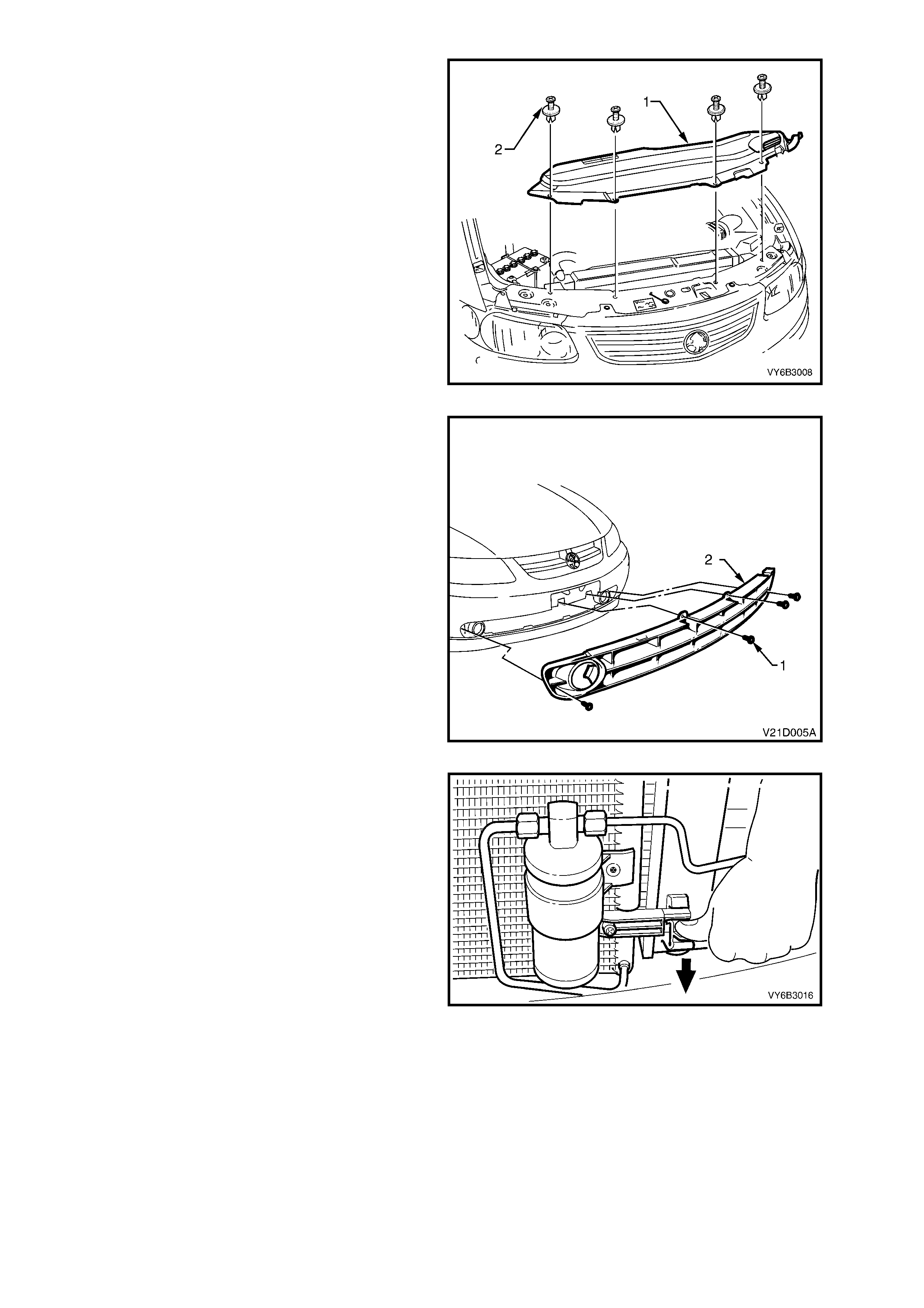
11. Remove the four retainers (2) securing the
upper shroud to the radiator by carefully lifting
the inner stud with a small screwdriver. Lift the
upper shroud, on the driver’s side first to
release the locating tab on the left hand side.
12. Release the clip sec uring the refr igerant pipe to
the receiver drier, at the left side of the radiator.
Figure 6B3-7
NOTE: The condens er m us t be separated f rom the
radiator ass embly. This ac tion will allow the radiator
removal without having to open any refrigerant
lines.
13. Remove the vehicle licence plate.
14. Rem ove the four s crews (1) retaining the lower
air intake grille (2) to the front facia.
15. Flex the upper edge of the lower air intake grille
to disengage the four retaining tabs and four
locating tabs from the front bumper bar facia.
16. Flex the lower edge of the lower air intak e grille
to disengage the four retaining tabs and five
locating tabs from the front bumper bar facia.
17. Remove the lower air intake grille from the
vehicle.
Figure 6B3-8
18. Working through the lower air intake grille
opening, release one of the clips securing the
condenser to the radiator. Do this by pressing
down on the lug with the fingers of one hand,
while lifting the condenser assembly with the
other. Repeat for the other side.
NOTE: It is not necessary to remove the receiver
drier, nor disturb the air conditioning refrigerant
system (where fitted), for this operation. The
condenser can be lifted against the spring of the
attached refrigerant pipes.
19. Once released, pull the condenser assembly
forward to clear the radiator mounting lugs.
Figure 6B3-9
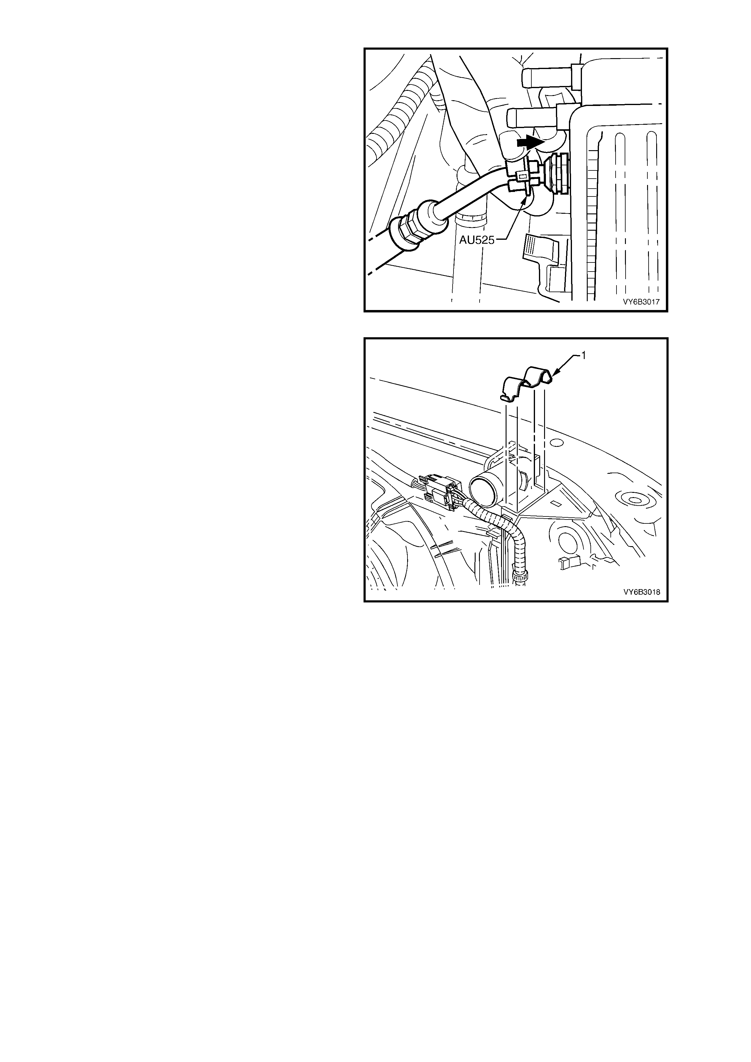
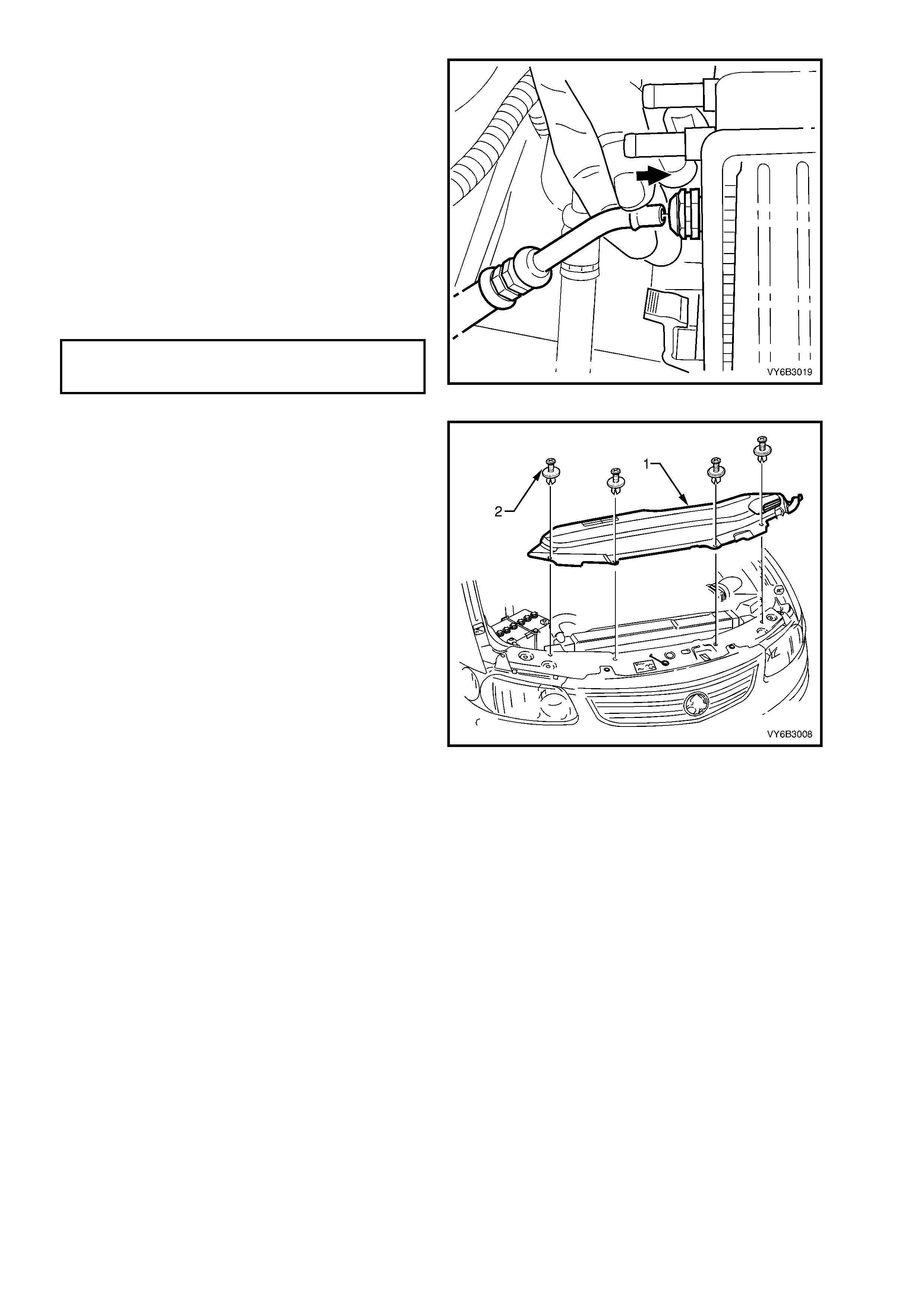
20. If the vehicle is equipped with an automatic
transmission, disconnect the transmission oil
cooler line quick connect fittings, using Tool
No. AU525.
a. Open the release tool AU525, then close
and clip around the pipe to be
disconnected.
b. While holding the flexible hose with one
hand, push the tool into the connection, to
release, then pull back on the pipe.
NOTE: If Tool No. AU525 is not available, the
cooler pipes can be disconnected from the cooler,
in the lef t side radiator tank , by removing the quick
connect fitting, using conventional tools. Do not
lose the sealing washer.
c. Plug all openings to minim ise fluid loss and
prevent dirt entry.
Figure 6B3-10
21. Using a screwdriver, compress and lever out
the radiator retaining clip (1) from the radiator
upper mounting bracket, on each side.
22. Lift the radiator upwards out of the lower
insulators. To remove the radiator assembly
from the vehicle, after clearing the top
insulators, move the radiator rearward on the
left side, then across to the left, to allow the
right side to clear the mounting brackets.
Remove the upper insulators from the radiator
upper mounting pins.
Figure 6B3-11
REINSTALL
Installation of the radiator is the rever se of rem oval
procedures, noting the following points:
1. Before installing the radiator, inspect the core
to ensure that there is no foreign matter such
as insects in the core fins. Clean out between
the core fins with compressed air, working from
the engine side and blowing forwards.
2. Ensure that the radiator lower mounting pins
are correctly located in the lower insulators.
3. Ensure that the upper insulators are installed
on each of the upper mounting pins and the
radiator retainers are correctly installed on
each side of the radiator by checking that the
clips engage on both sides of the channel
support bracket.
4. Install the lower radiator hose, securing the
hose with the worm drive hose clamp.
5. If the vehicle is fitted with an automatic
transmission, remove the plugs from the pipe
ends and the two quick connect fittings.
6. After wiping the cooler pipe ends and smearing
with clean automatic transmission fluid, push
the pipes into the quick connect fittings to
engage. As a s ec urity check , tug f irmly on each
pipe to ensure cor rect engagem ent of the quick
connect fitting.
NOTE: If the quick connect fittings were removed
from the left-hand radiator tank, inspect the sealing
washer for serviceability before installation.
Replace the sealing washer/s as required. Tighten
the quick connect fittings to the correct torque
specification.
QUICK CONNECT FITTINGS TO
TRANSMISSION FLUID COOLER
TORQUE SPECIFICATION 25 Nm
Figure 6B3-12
7. After installing the condenser assembly onto
the four retaining clips, ensure that the two
lower clips have fully engaged.
8. Install the lower air intake grille and the four
retaining screws. Do not over-tighten.
9. Secure the compressor discharge air
conditioning pipe by closing the plastic clip at
the top left-hand of the radiator, engaging the
locking tang.
10. Install the upper radiator shroud (1), by first
engaging the lug on the left side, before
installing the four retainers (2).
11. Install the following hoses;
a. Vapour hos e to the radiator fitting, securing
with the spr ing clam p. Clip the vapour hose
into the clips on the radiator fan shroud.
b. The surge tank hose to the radiator and
secure with the spring clamp.
c. The upper radiator hose, securing with the
two securing hose clamps.
12. Refill the cooling system, refer to
2.3 DRAINING AND FILLING COOLING
SYSTEM in Section 6B3 – ENGINE COOLING
– GEN III V8 ENGINE in the VT Series II
Service Information.
13. Check for coolant leaks, refer to
2.8 PRESSURE TESTING in Section 6B3 –
ENGINE COOLING – GEN III V8 ENGINE in
the VT Series II Service Information.
14. Check the cooling fan operation and direction
of rotation.
Figure 6B3-13
3.4 COOLING FANS AND SHROUD ASSEMBLY
REMOVE
1. Allow the engine to cool to ambient
temperature (less than 50°C), slowly loosen the
screw-on pressure cap at the coolant surge
tank to relieve any residual coolant pressure,
then remove.
CAUTION: Do not remove the screw-on
pressure cap while the engine coolant
temperature is above 50°
°°
°C, as personal injury
will most likely occur.
2. Disconnect the battery ground lead.
IMPORTANT: Disconnection of the battery affects
certain vehicle electronic systems. Refer to
BATTERY DISCONNECT CAUTION in Section 00
CAUTIONS AND NOTES in the VX Series II
Service Information before disconnecting the
battery.
3. Remove the engine dress cover decorative
nuts (1), then remove the cover (2).
4. Lift the locking lever on the Intake Air
Temperature (IAT) sensor wiring harness
connector (3), then remove the connector.
5. Lift the locking lever on the Mass Air Flow
(MAF) sensor, then remove the connector.
6. Loosen the two intake duct clamps, one at the
throttle body and the other at the MAF sensor
to air c leaner c onnection. Remove the duc t and
MAF sensor as an assembly and carefully set
to one side.
7. Drain the engine coolant into a suitable, clean
container. Refer to 2.3 DRAINING AND
FILLING COOLING SYST EM in Sect ion 6B3 –
ENGINE COOLING – GEN III V8 ENGINE in
the VT Series II Service Information.
8. Release the vapour hose from the radiator fan
shroud clips, remove the clamp securing the
hose to the radiator, remove the hose and
route to one side.
9. Remove the c lamp secur ing the vapour hos e to
surge tank at the radiator end. Remove the
hose and route to one side.
Figure 6B3-14
10. Remove the four retainers (2) securing the
upper shroud to the radiator by carefully lifting
the inner stud with a small screwdriver. Lift the
upper shroud ( 1), on the right side f irst, to allow
release of the locating tab on the left hand end.
Figure 6B3-15
11. Remove the upper radiator hose clamps, then
remove the hose (1) and set to one side.
CAUTION: Wear eye protection when working
with spring type hose clamps.
Figure 6B3-16
12. Press the retaining tang on wiring harness-to-
cooling fan m otor wiring harness connector (1),
then separate the connector halves.
Figure 6B3-17
13. While holding the shroud locking tang in the
release position, lift the shroud and fan
assembly upwards. Repeat for the other side.
NOTE: While the automatic transmission fluid
cooling pipe is shown removed, this is not a
mandatory requirement for shroud removal. The
pipe has been shown removed to clearly show the
shroud release method.
Figure 6B3-18
14. Grasping the motor mounting brackets, lift the
shroud and f an as sem bly clear from the engine
bay.
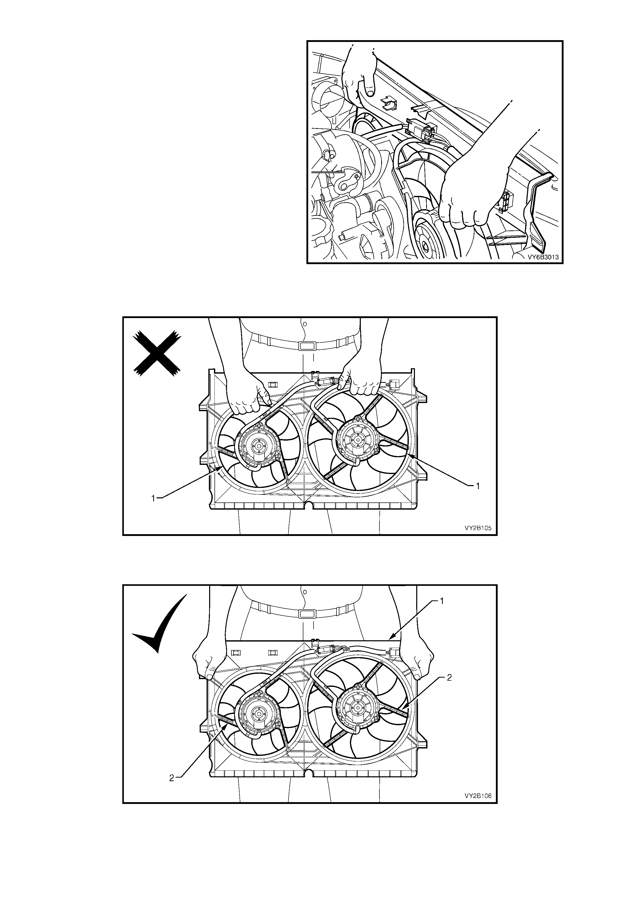
Figure 6B3-19
IMPORTANT: When rem oving, tr ansporting or installing the f an assem b ly, do not gr asp the ass em bly by the fan
rings (1) as this may bend the fan motor shafts and cause fan vibrations.
Figure 6B3-20
When handling the fan assembly, always hold the assembly at the fan shroud (1) or fan motor mounting
struts (2).
Figure 6B3-21
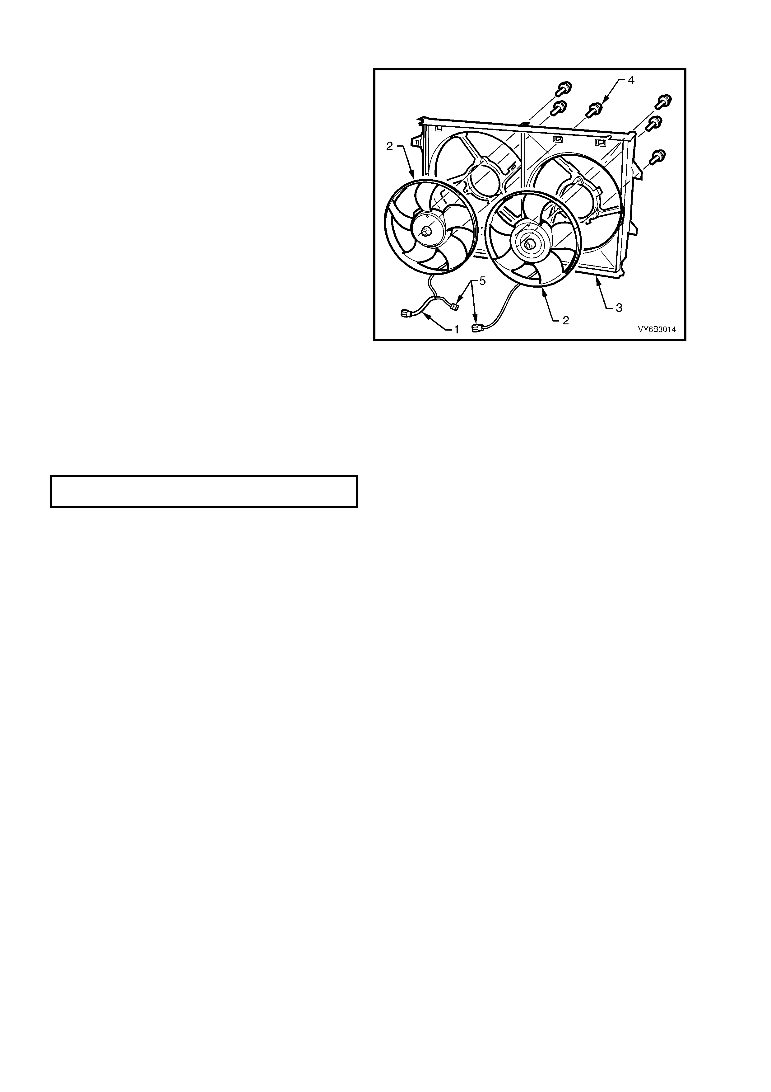
DISASSEMBLE
IMPORTANT: The fans are not to be separated
from the fan motor. The assembly is carefully
balanced during manufacture and duplication of
this balance is not possible, on reassembly.
1. Separate the intermediate wiring harness
connectors (5) and remove motor assembly
wiring harness (1) from the integral clips that
form a part of the shroud (3).
2. Remove screws (4) attaching the motor and
fan assemblies (2) to the shroud, then remove
the motor, fan and wiring from the shroud.
3. Repeat for the s econd fan, motor and harness,
as required.
Figure 6B3-22
REASSEMBLE
Reassembly is the reverse of disassembly
procedures, noting the following points:
1. Tighten the motor-to-shroud attaching screws
to the c orrec t torque spec ific ation. Do not over-
tighten.
FAN MOTOR TO SHROUD SCREW
TORQUE SPECIFICATION 4.0 – 5.0 Nm
2. Ensure that all wiring is secured under the
shroud clips.
REINSTALL
Installation of the cooling fan and shr oud assembly
is the reverse of removal procedures, noting the
following points:
1. Ensure that the fan and shroud assembly-to-
radiator attaching clips are all fully engaged
and that the two locking tangs on the upper
clips are securing the shroud correctly.
2. Refill the cooling system and test the
concentration levels. Refer to 2.3 DRAINING
AND FILLING COOLING SYSTEM in Section
6B3 – ENGINE COOLING – GEN III V8
ENGINE in the VT Series II Service Information
and TESTING COOLANT CONCENTRATION,
2.2 COOLANT M AINTENANCE in Section 6B3
– ENGINE COOLING – GEN III V8 ENGINE in
the VT Series II Service Information.
3. Check cooling fan operation, and cooling fan
rotation direction.

4. SPECIFICATIONS
General
Radiator Cap Pressure Rating ................................ 96.5 to 124 kPa
Cooling System Capacity........................................ 14.3 Litres
Coolant Corrosion Inhibitor...................................... DEX-COOL® to GM Specification 6277M, approx. 7.0
litres required when changing coolant.
Thermostat
Type ........................................................................ Power element (wax pellet)
Start to open at........................................................ 86° C
Fully open at............................................................ 100° C
Coolant Pump
Type ........................................................................ Centrifugal
Drive........................................................................ Multi-ribbed, Serpentine V-belt
Bearing Type........................................................... Double-row ball bearing
Radiator
Core type................................................................. Aluminium crossflow core
Overall Width........................................................... 826 mm
Overall Height.......................................................... 495 mm
Core Width.............................................................. 674 mm
Core Height............................................................. 427 mm
Core Thickness....................................................... 35 mm
Plastic tanks............................................................ Nylon 6,6 (30% glass filled)
Radiator Hoses
Lower – Number and type....................................... Two, Moulded
Upper – Number and type....................................... One, Moulded
Engine Cooling Fan – LHS
Fan – Design.............................................................. Asymmetrically spaced, curved blades with outer ring
Material Nylon 6,6 (25% glass filled), with zinc coated metal
hub insert
Number of Blades ................................................... 5
Diameter.................................................................. 293 mm
Fan Motor – Type ...................................................... Twin speed, 4 brush with 4 permanent magnets
Housing................................................................... Semi-sealed, zinc coated steel with drain hole
Direction of Rotation................................................ Counter-clockwise (as viewed from motor side)
Power...................................................................... 180 Watts (nominal)
Rotational Speed with 12 volts applied, Radiator
and Condenser Installed:
Stage 1............................................................... 2,050 ± 150 rpm
Stage 2............................................................... 2,300 ± 150 rpm
Engine Cooling Fan – RHS
Fan – Design.............................................................. Asymmetrically spaced, curved blades with outer ring
Material Nylon 6,6 (25% glass filled), with zinc coated metal
hub insert
Number of Blades ................................................... 5
Diameter.................................................................. 342 mm
Fan Motor – Type ...................................................... Twin speed, 4 brush with 4 permanent magnets
Housing................................................................... Semi-sealed, zinc coated steel with drain hole
Direction of Rotation................................................ Counter-clockwise (as viewed from motor side)
Power...................................................................... 220 Watts (nominal)
Rotational Speed with 12 volts applied, Radiator
and Condenser Installed:
Stage 1............................................................... 2,350 ± 150 rpm
Stage 2............................................................... 2,750 ± 150 rpm
Techline

5. TORQUE WRENCH SPECIFICATIONS
Nm
Fan Motor to Shroud Screw.................................................. 4 - 5
Quick Connect Fitting to Transmission Fluid Cooler............. 25
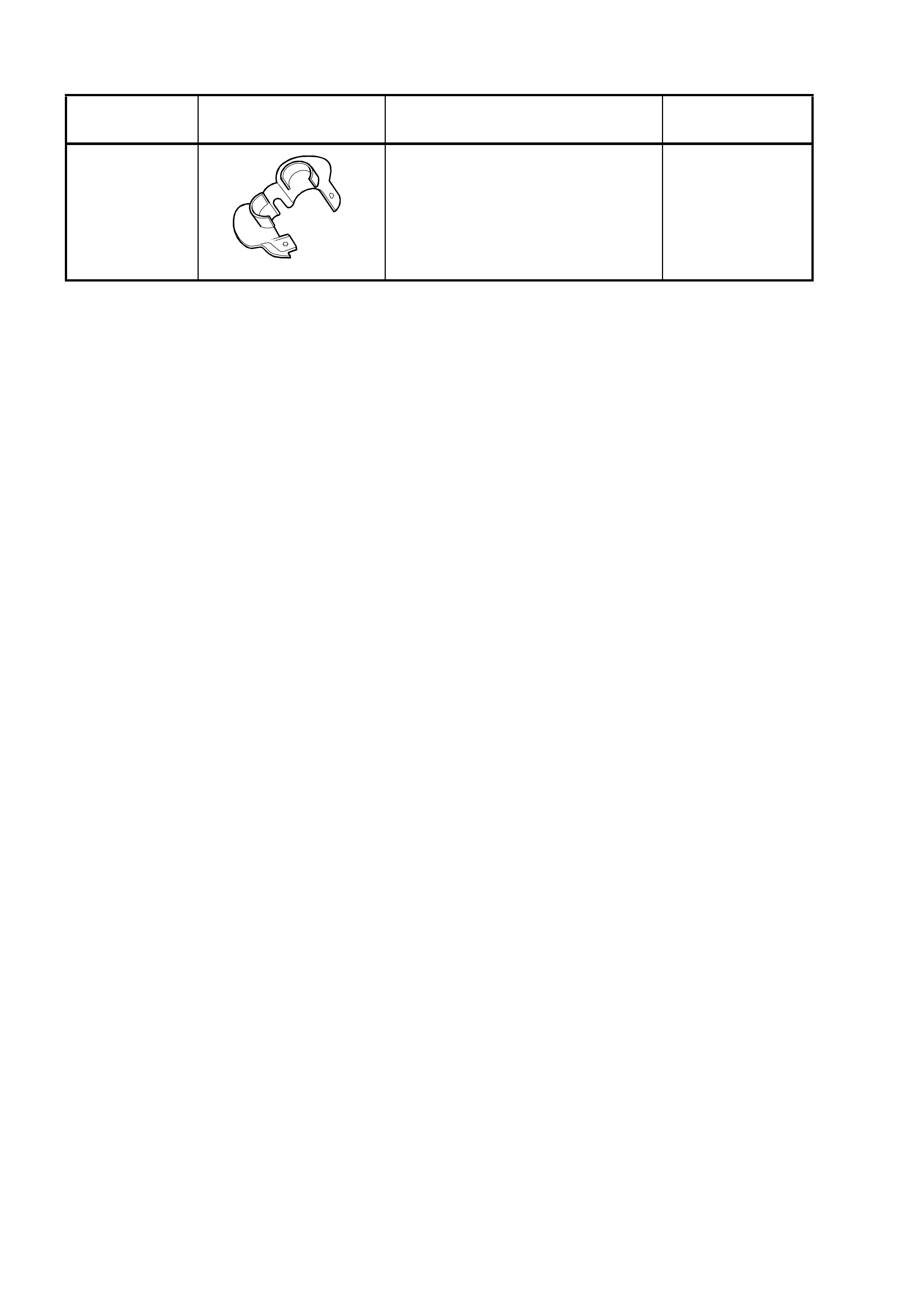
6. SPECIAL TOOLS
TOOL
NUMBER ILLUSTRATION DESCRIPTION CLASSIFICATION
AU525
A
U525
QUICK CONNECT RELEASE TOOL
Use to release the quick connect
fittings on the automatic transmission
fluid cooler lines at the radiator end,
when the vehicle is so equipped.
Previously released.
Mandatory