SECTION 1 – PRINCIPLES OF OPERATION
CAUTION:
This vehicle will be equipped with a Supplemental Restraint System (SRS). A SRS will
consist of either seat belt pre-tensioners and a driver's side air b ag, or seat belt pre-
tensioners and a driver's and front passenger's side air bags. Refer to CAUTIONS,
Section 12M, before performing any service operation on, or around any SRS
components, the steering mechanism or wiring. Failure to follow the CAUTIONS
could result in SRS d eployment, result ing in po ssible person al injury or unnecessary
SRS system repairs.
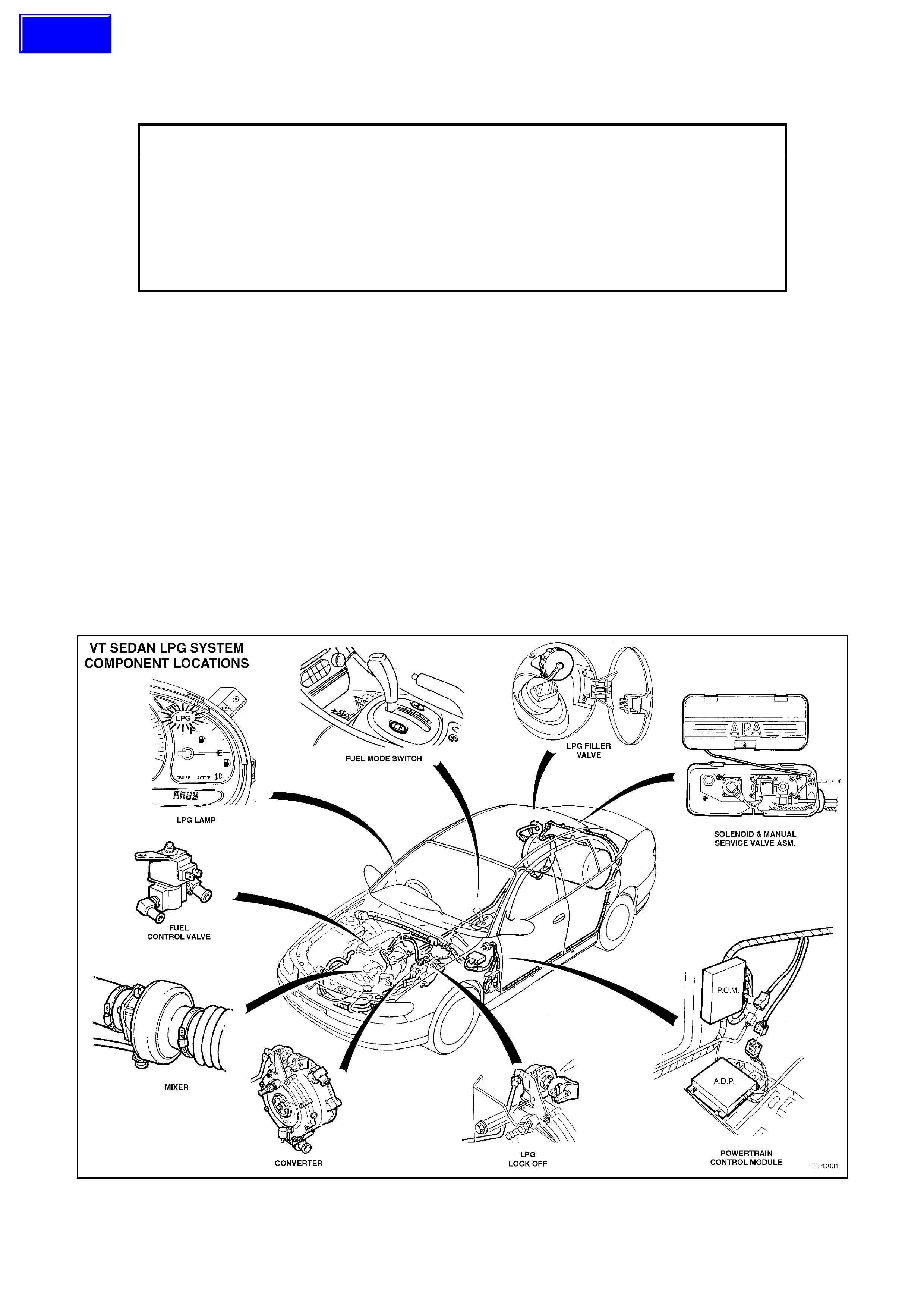
1. GENERAL INFORMATION
Liquefied Petroleum Gas (LPG) option KL7 is available for all VT Series sedans with V6 engine and automatic
transmissions, without FE2 suspension or Electronic Traction Control.
The LPG system is a f ully integrated system and has been des igned so that it is not pos s ible to switch between f uel
modes unless the vehicle has stopped. Secondly, under certain high load drive conditions, the LPG system injects
petrol into the engine while it is running on LPG to aid in engine valve lubrication.
Automotive LPG is a hydrocarbon fuel and consists predominantly of propane (60% - 90%) and butane (40% -
10%). The propane to butane mix varies depending on the source and manufacturing location. This gives LPG an
octane rating of approximately 110 RON.
Pure LPG is c olourless, odourles s and tasteless, however com m ercial LPG has a pungent odour to enable LPG to
be detected by a human. This pungent odour is achieved by adding a chemical to the LPG to enable a human to
detect the LPG at concentrations of LESS than 0.5% by volume in air.
LPG boils at approximately - 40°C at atmospheric pressure, this means that the LPG must be pressurised to
approximately 750 kPa to maintain it in a liquid state.
Figure 1
-
1
Techline

1.1 SAFETY PRECAUTIONS
Any servicing or testing of the 'High Pressure" area of the LPG system must be performed by trained and/or
licensed LPG inst allers or f itters in a "Spec ialis t G as Work s hop" in acc or danc e with Australian Standar ds AS 2746 -
1985 and AS 1425 - 1989.
Norm al vehic le maintenance s ervic e and any servicing of the LPG system not af f ec ting the high pr es sur e area (filler
line, LPG cylinder, service line, LPG lockoff and converter) may be performed by dealership technicians who are not
accredited installers or fitters.
DO NOT smoke or allow naked flames, or any ignition source near the vehicle.
LPG m us t NEVER be allowed to come in contac t with any part of the body. Due to the very low boiling point of LPG,
it readily absorbs heat from its surroundings, or any surface it comes in contact with when released into the
atmosphere. LPG can cause severe frost bite if it is allowed to come into contact with the human body.
W hen work ing on the LPG system, suitable protective clothing including gloves and s afety goggles MUST be worn
to prevent personal injury.
LPG in the vapour form is highly inflamm able and in the interests of safety, the LPG system should be leak tested
and isolated by turning 'OFF' the manual service valve and draining service lines of LPG before ANY service work is
carried out on the vehicle.
During servicing, the manual service valve m ust be turned 'OFF' at all times and the service lines drained of LPG
(refer 2.1 DRAINING THE SERVICE LINES), except when gas is SPECIFICALLY required to be available for
servicing or testing of the LPG system.
Whenever any service operation is performed on the high pressure area of the system (filler line, LPG cylinder,
service line, LPG lockoff and converter), a leak test MUST be performed on the complete LPG system (refer
2.3 LEAK TESTING).
Whenever any service oper ation is per f or med on the LPG c ylinder that involves the removal of any component fr om
the LPG cylinder, the LPG cylinder MUST be emptied of LPG (refer 2.2 LPG CYLINDER UNLOADING
PROCEDURE) BEFORE any component is removed from the LPG cylinder.
Whenever any service operation is performed on the LPG cylinder that involves the removal and replacement of any
com ponent f rom the LPG cylinder, the LPG cylinder MUST be safety tested in accordanc e with Australian Standard
AS2030.1 according to the laws of the state in which the vehicle is registered and a leak test MUST be performed
on the complete LPG system before the LPG cylinder is returned to service in the vehicle.
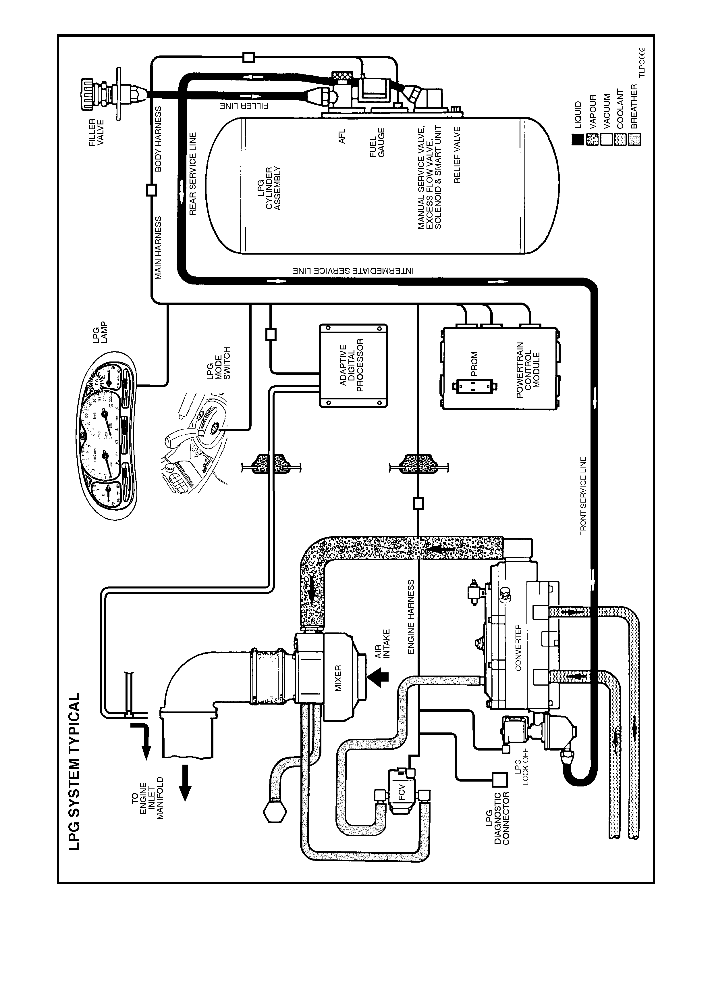
Figure 1-2
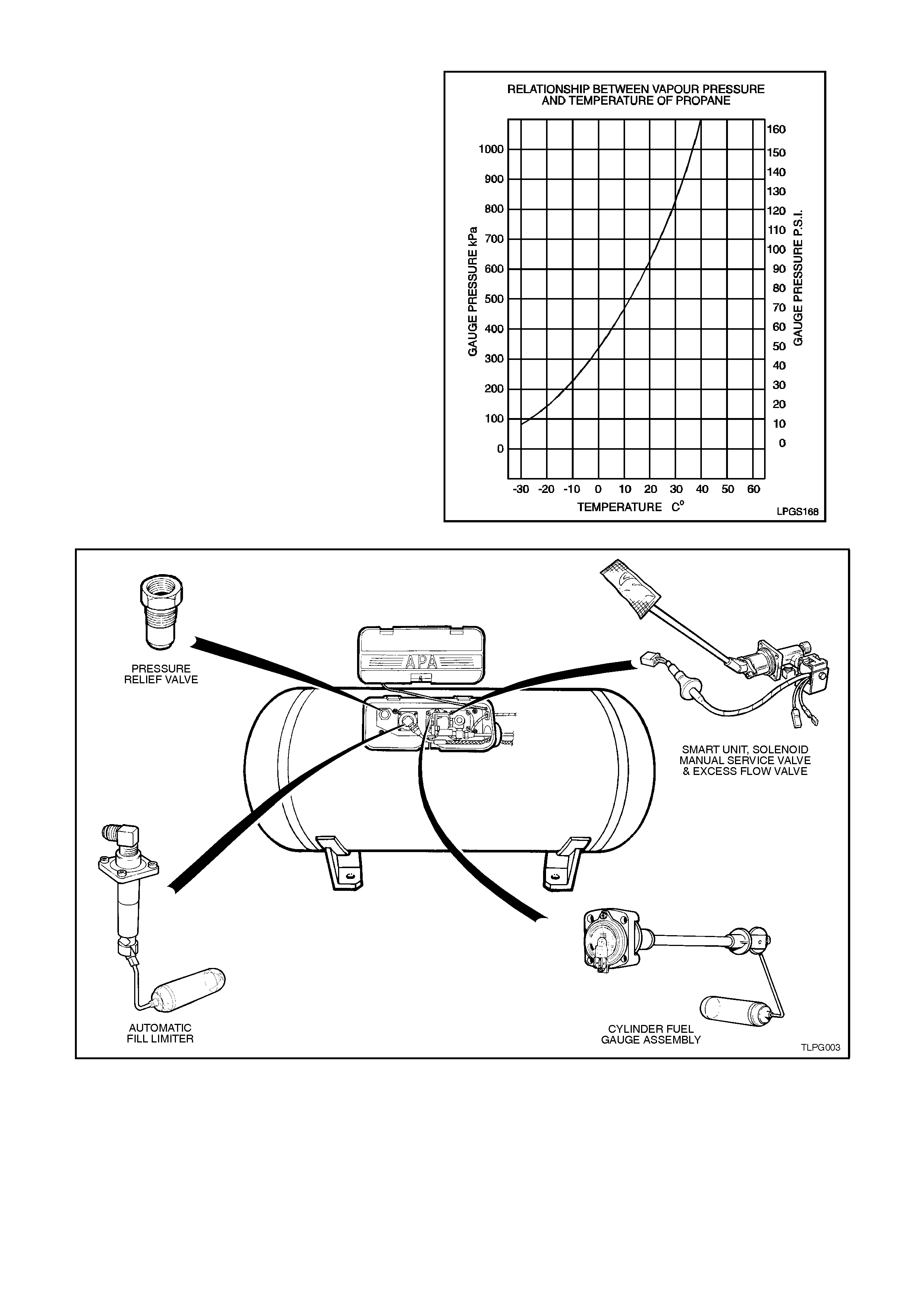
1.2 LPG CYLINDE R
The LPG cylinder is fitted in the rear com partment.
Cylinders are made of carbon steel and
manufactured to stringent safety standards. LPG
must be stored at approximately 750 kPa at 20°C
to remain a liquid. The vapour pressure inside the
LPG cylinder will vary with ambient tem perature, as
the ambient temperature rises so does the vapour
pressure, refer Fig. 1-3.
The LPG cylinder is heat treated during
manuf acture and MUST NOT be heated or welded
in any way.
The LPG cylinder has a gas tight compartment
(valve box), which contains the following
components: (refer Fig. 1-4) Automatic Fill Limiter
(AFL), Cylinder Fuel Gauge Assembly, Smart Unit,
Solenoid and Manual Service Valve Assembly and
a Pressure Relief Valve. These components are
screwed either into or onto the LPG cylinder. As the
LPG cylinder is located in the luggage
compartment, if any of these components were to
leak, or there was an excess pressure discharge,
the LPG would be vented to atmos phere via a vent
hose and will not vent into the vehicle.
Figure 1-3
Figure 1-4
1.3 FILLER VALVE
The filler valve is located at the remote filling point
in the fuel f iller pock et. The valve has a double non
return valve and a filling connection which will
shear off in the event of the vehicle being driven
away during filling. The filler valve is connected to
the LPG cylinder AFL inlet elbow by a filler line.
Figure 1-5
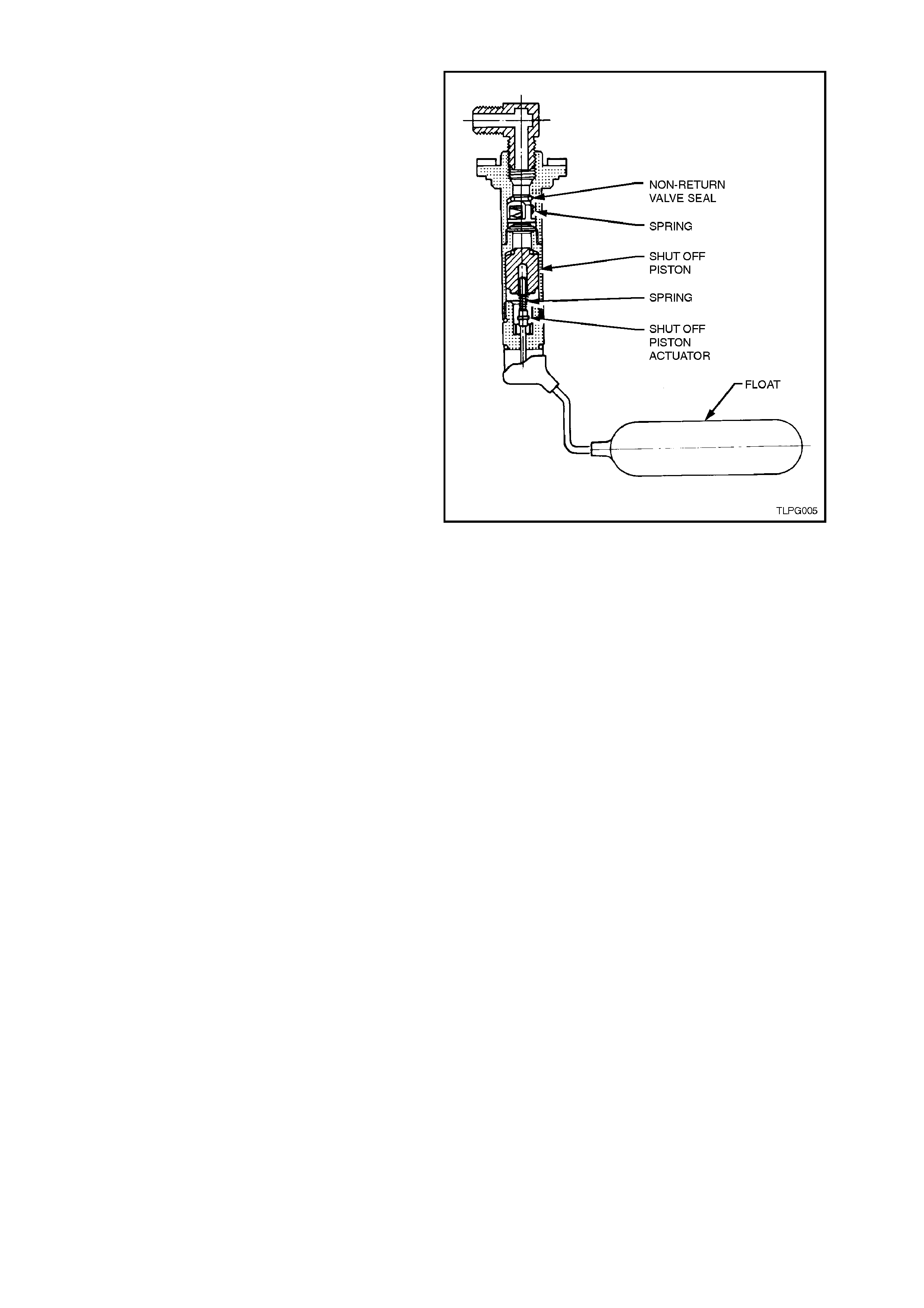
1.4 AUTOMATIC FILL LIMITER
The Automatic Fill Limiter (AFL) is screwed onto
the LPG cylinder with the filler line connected to the
inlet elbow of the AFL. When the tank is being f illed
with liquid LPG, the AFL float ris es with the liquid in
the LPG cylinder and shuts off the valve when the
cylinder is 80% full. The remaining 20% of the
cylinder volume is nec ess ary vapour space to allow
for the expansion of the liquid that occurs as the
temperature of the liquid increases.
Figure 1-6
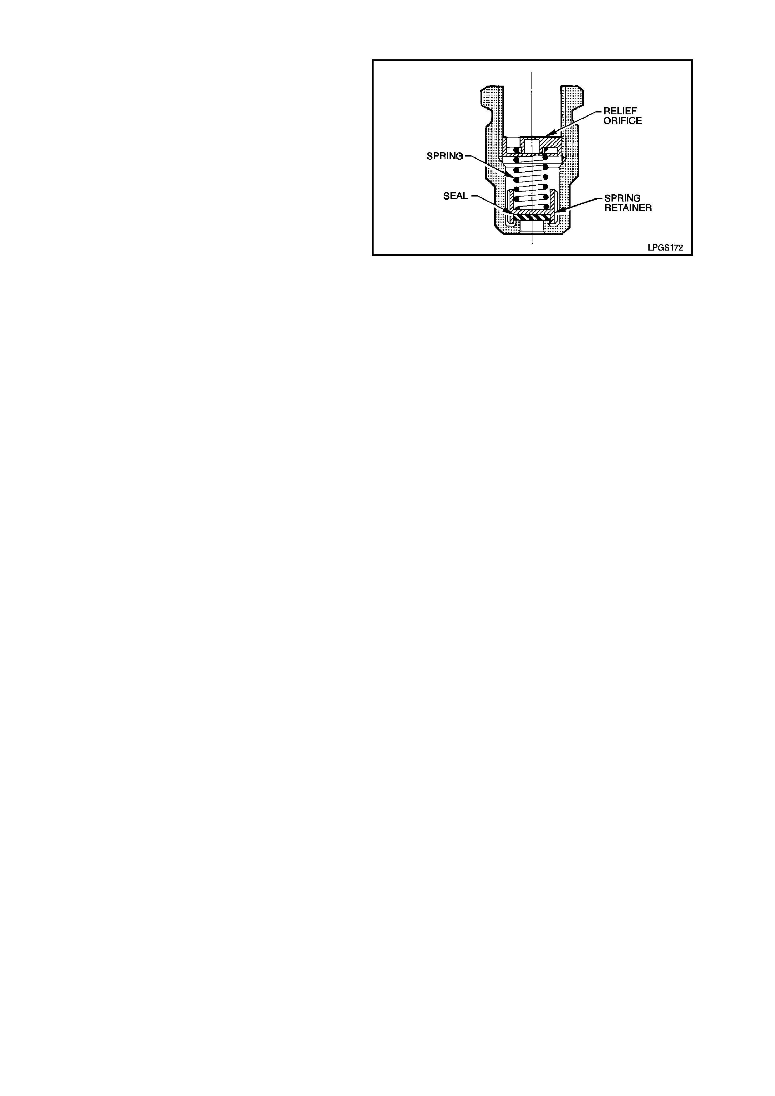
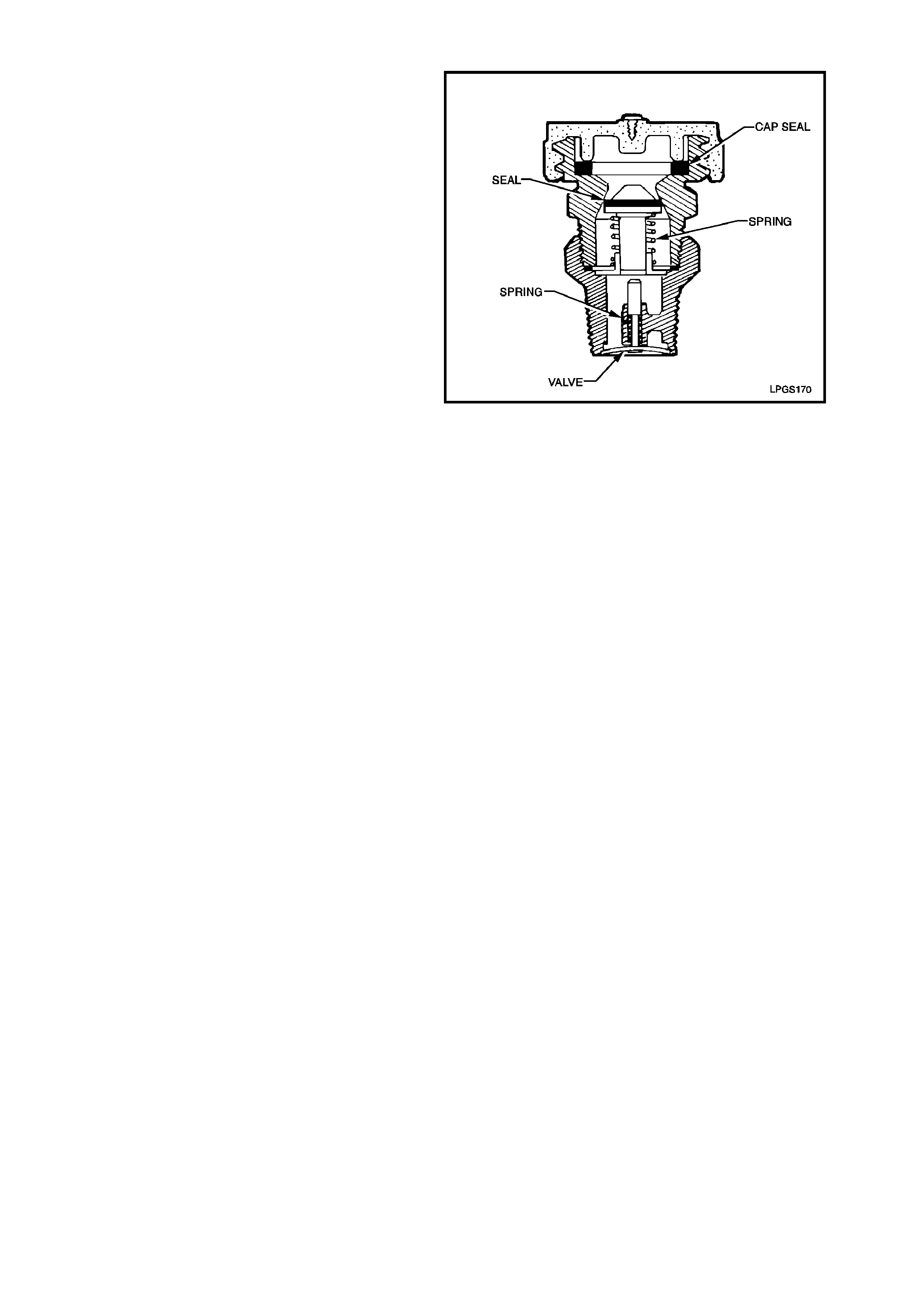
1.5 PRESSURE RELIEF VALVE
The pr essur e relief valve is housed ins ide the valve
box and is screwed into the LPG cylinder. If the
pressure in the LPG cylinder was to exceed
approximately 2,550 kPa, the pressure relief valve
will open and the excess pressure will be vented
into the valve box and then to atmosphere via the
vent hose. The valve will continue to vent the LPG
cylinder until the pressure drops below 2,550 kPa
and the pressure relief valve will then close. Dur ing
normal operating conditions the pressure relief
valve should not operate.
Figure 1-7
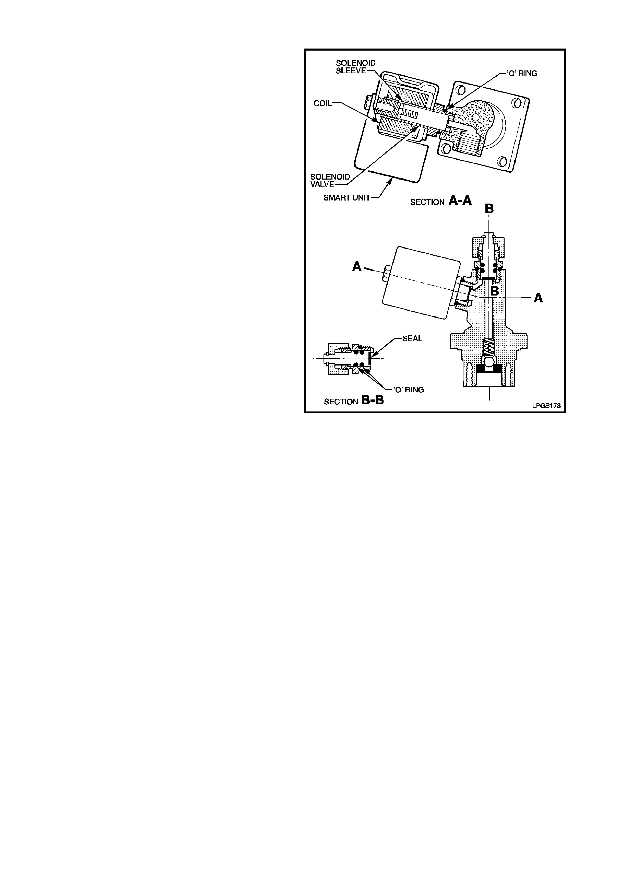
1.6 SOLENOID AND MANUAL SERVICE VALVE ASSEMBLY
The m anual servic e valve is screwed onto the LPG
cylinder and is three valves in one; a manual shut
off valve, an electrically operated solenoid valve
and an excess flow valve.
MANUAL SHUT OFF VALVE
The manual shut of f valve allows the s upply of LPG
to be manually shut off for servicing, or if a leak in
the system develops, or in the event of a vehicle
accident.
SOLENOID VALVE
The solenoid valve is an electrically operated valve
which allows the flow of LPG from the cylinder into
the service line when energised. The solenoid valve
is energised by the smart unit for three seconds
when the ignition key is first turned on, when the
engine is being crank ed or is running. The solenoid
valve is energised by the smart unit.
The solenoid valve will shut off the LPG flow when
the ignition is switched off and/or the engine stops
running.
EXCESS FLOW VALVE
The ex cess f low valve will close automatic ally if the
flow of liquid LPG is excessive, shutting off the
supply of liquid LPG. The valve will automatically
reopen when the excess flow condition has ceased.
The excess f low valve is designed to shut off if the
flow exceeds a specified am ount, as would occur if
the service line was severed or opened. Figure 1-8
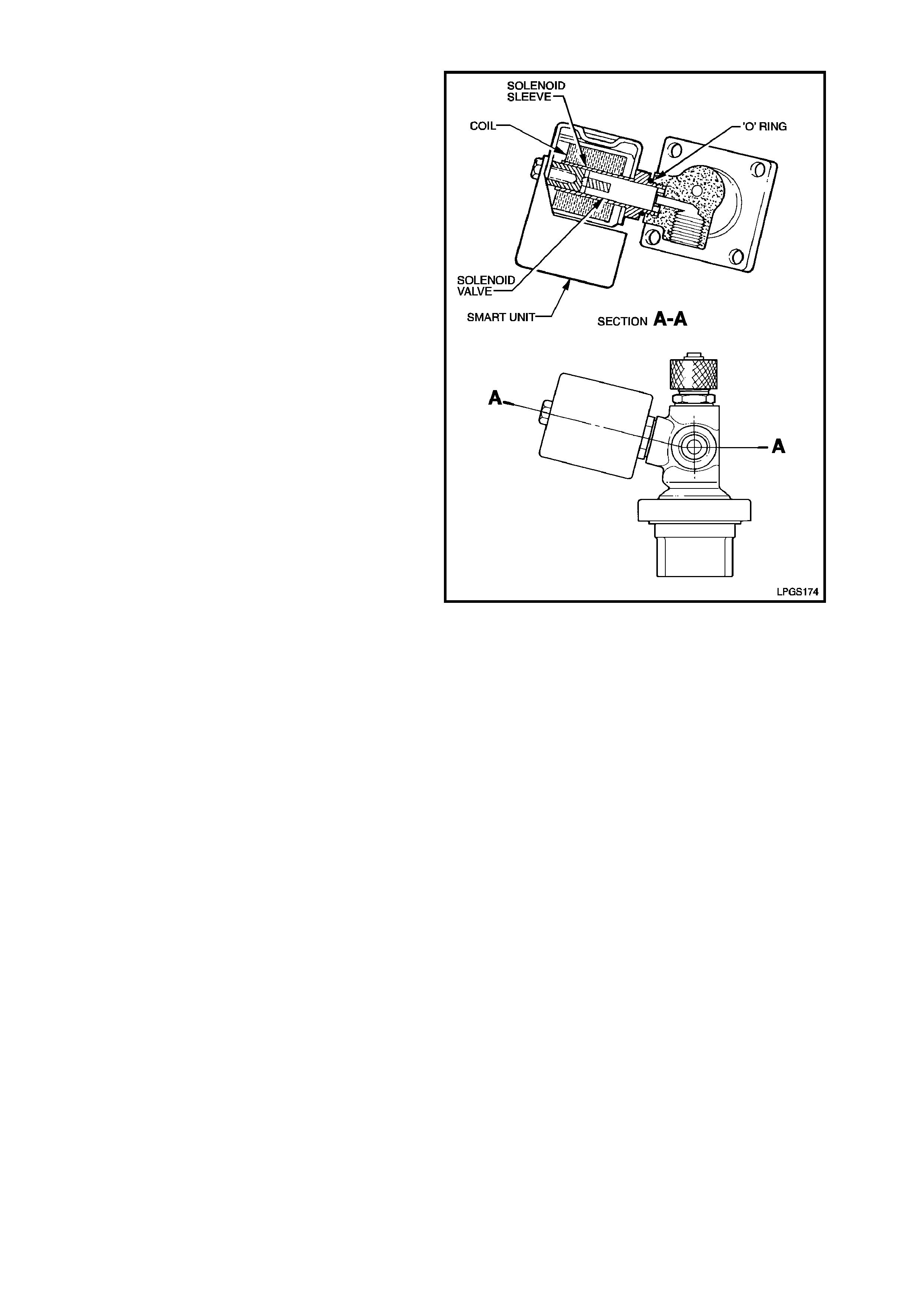
1.7 SMART UNIT
The smart unit is attached to the solenoid and
manual service valve and controls the operation of
the solenoid valve and the LPG lockoff. When the
smart unit receives a signal from the PCM, it will
energise the solenoid valve and LPG lock of f. When
operating in the LPG Mode the PCM will signal the
smart unit to energise the solenoid valve and LPG
lock of f f o r thr ee se conds when the ignition s witch is
first tur ned on, or when the engine is being cr anked
and while the engine is running.
If the engine stops running, the PCM will stop
sending the signal to the smart unit, the smart unit
will de-energise the solenoid valve and the LPG
lockoff and the flow of LPG will stop.
Figure 1-9
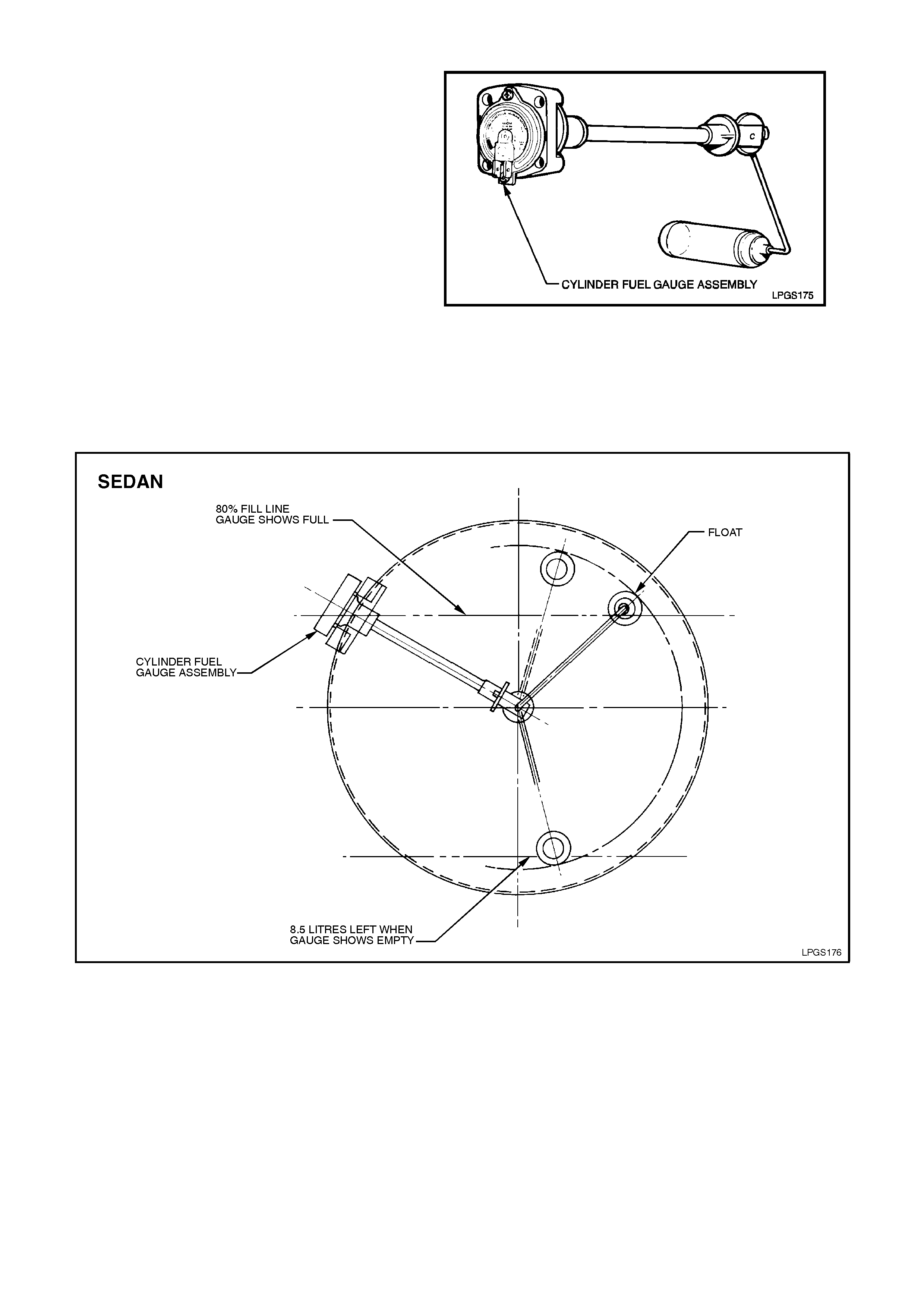
1.8 CYLINDER FUEL GAUGE ASSEMBLY
The cylinder fuel gauge assembly has a float
similar to a petrol gauge sender unit, as the liquid
level in the LPG cylinder rises so to does the float.
The float is connected to a magnet within the
assembly. Any change in the position of the liquid
level is transmitted to the fuel contents gauge via
the float and magnet. The magnetic field produced
by the magnet causes the fuel contents gauge
mounted on the exterior of the cylinder to move in
relation to the magnet's position.
The fuel contents gauge will show full when the
liquid level in the cylinder is at 80%. The fuel gauge
sender unit within the fuel contents gauge has a
variable resistor which will vary its resistance from
approximately 40 ohms when the tank is empty to
approximately 255 ohms when the tank is full. This
change in resistance is sensed by the instrument
fuel gauge. The instrument fuel gauge will display
the contents of the LPG cylinder when operating on
LPG and the contents of the petrol fuel tank when
operating on petrol.
Figure 1-10
Figure 1-11
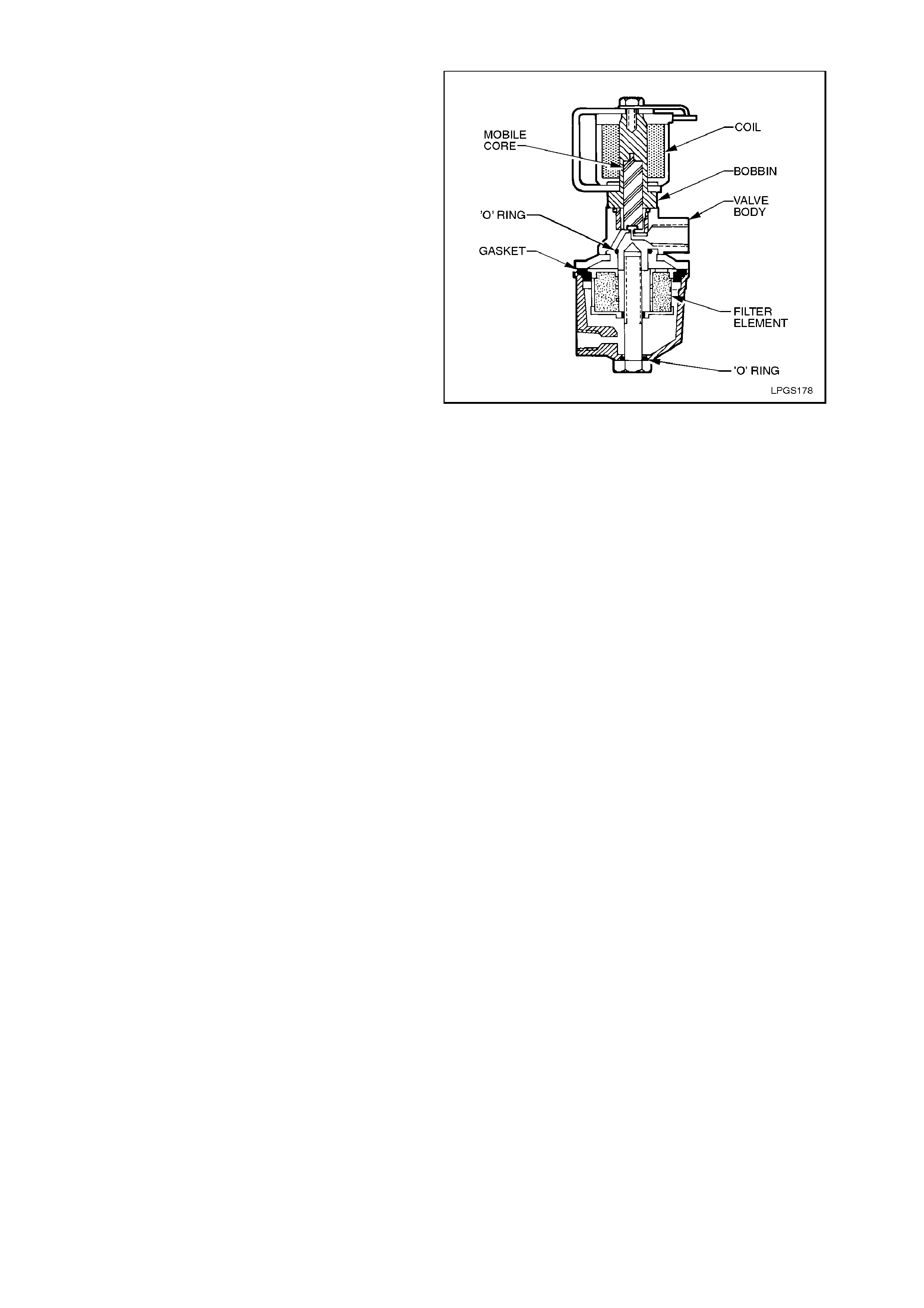
1.9 LPG LOCKOFF
The LPG lock off is an elec trically operated solenoid
valve which is designed to allow or prevent the f low
of LPG to the converter. When energised by the
smart unit the LPG lockoff opens and allows LPG
from the cylinder to flow through a fuel filter in the
LPG lockoff and then to the converter. The LPG
lockoff is energised by the smart unit for three
seconds when the ignition is tur ned on, or when the
engine is being crank ed or is running. Any time the
engine stops running, (ignition "ON" or "OFF") or
the ignition is turned OFF the smart unit de-
energises the LPG lock of f and the s upply of LPG is
shut off.
Figure 1-12
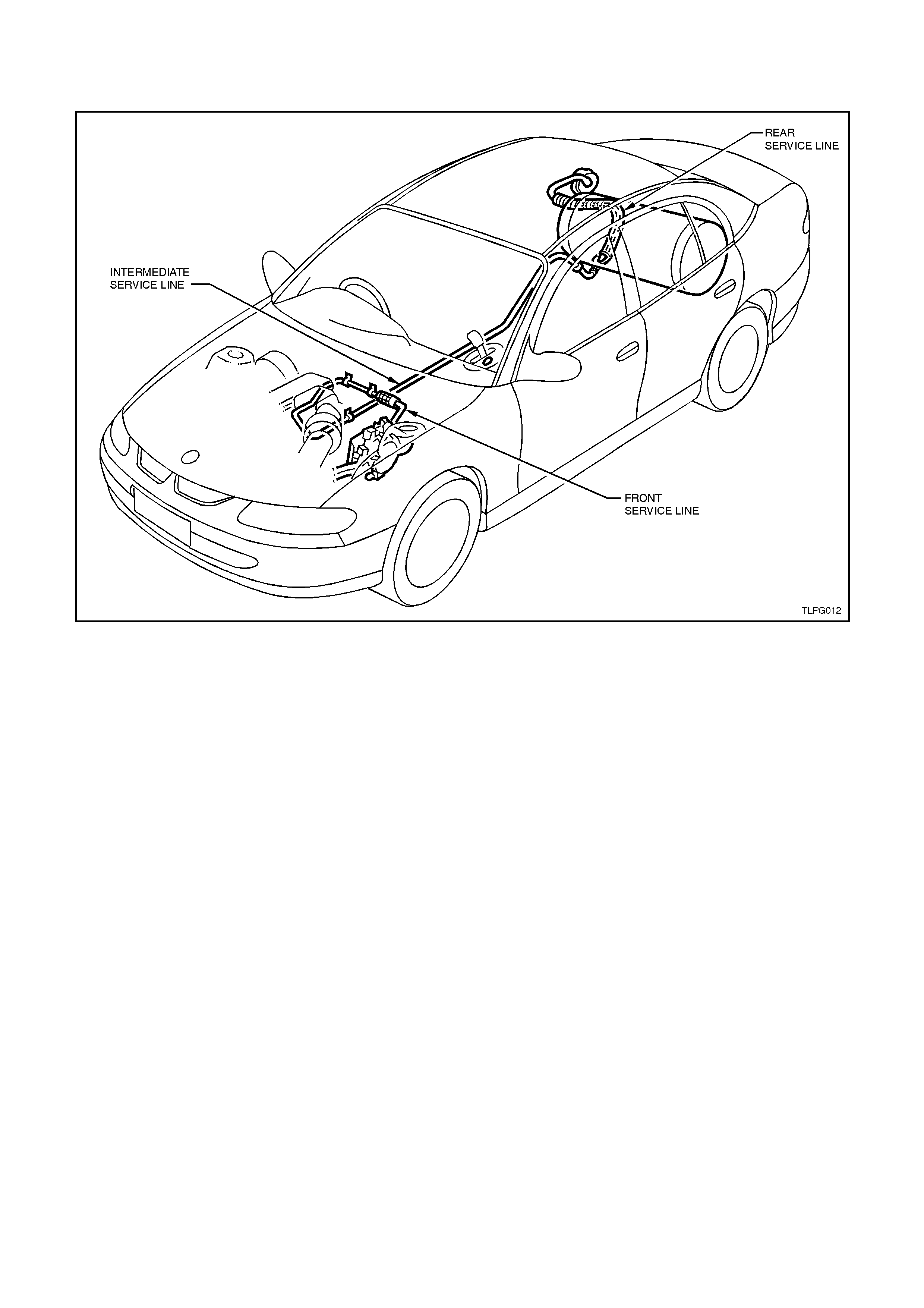
1.10 SERVICE LINE
The service line carries the liquid LPG from the solenoid and manual service valve to the LPG lockoff. The service
line consists of three major components; the front, intermediate and rear service lines.
Figure 1-13
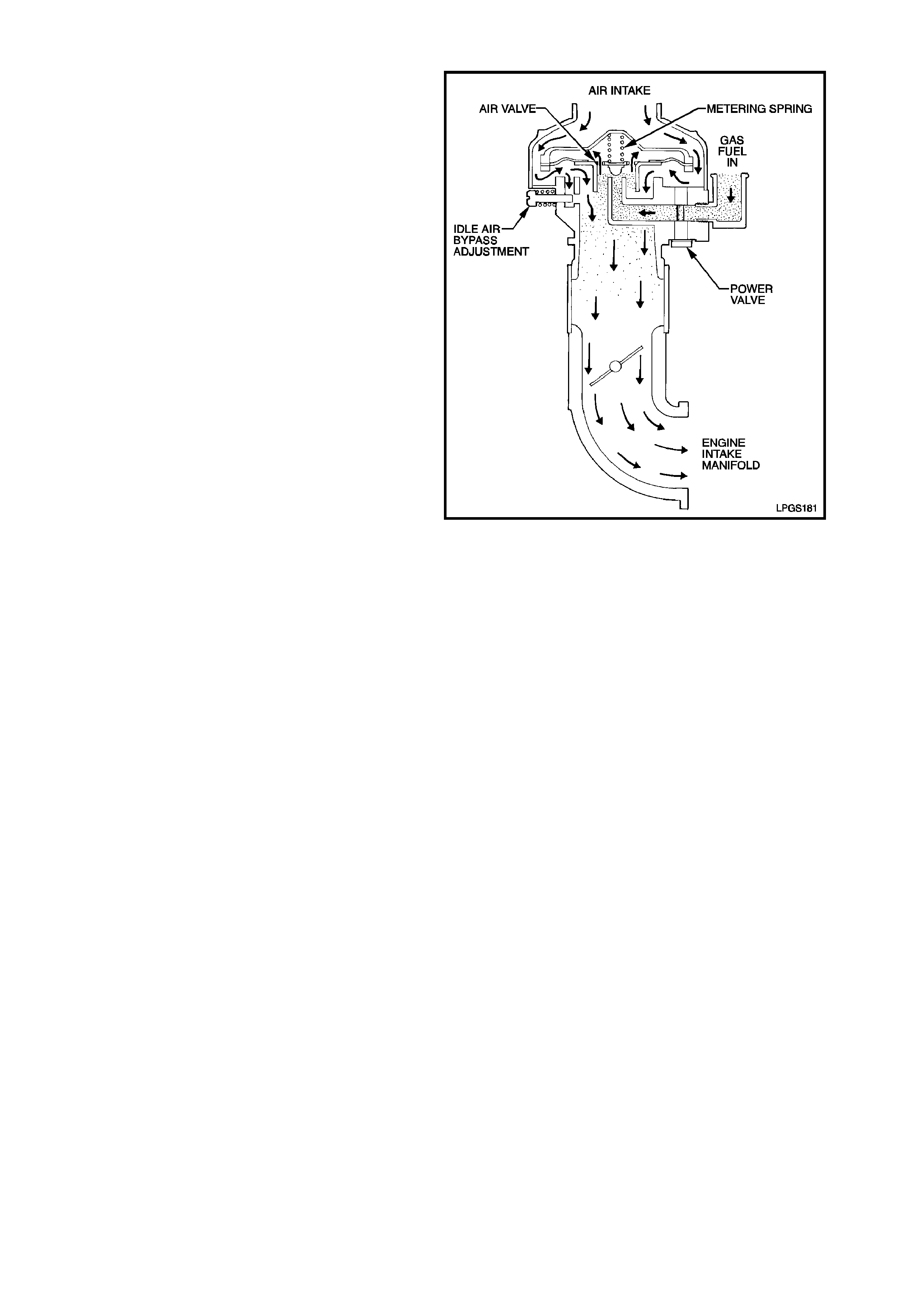
1.11 MIXER
When the engine is cranked or running, manifold
vacuum is transmitted through vacuum ports in the
air valve to the upper side of mixer diaphragm. As a
result, atmospheric pressure pushing upwards on
the underneath side of the diaphragm, lifts it
against the downward force of the metering valve
spring.
The pressure applied to the upper side of the
diaphragm varies with engine speed and throttle
position. The pressure difference between
atmospheric pressure acting on the underneath
side of the diaphragm and the pressure acting on
the upper side of the diaphragm determines the
metering valve position.
The position and the shape of the metering valve
determines the amount of LPG delivered to the
engine.
Maximum fuel delivery is determined by the power
valve, which limits the maximum fuel flow. The
power valve is pre-calibrated in the factory and is
not adjustable in service.
Figure 1-14
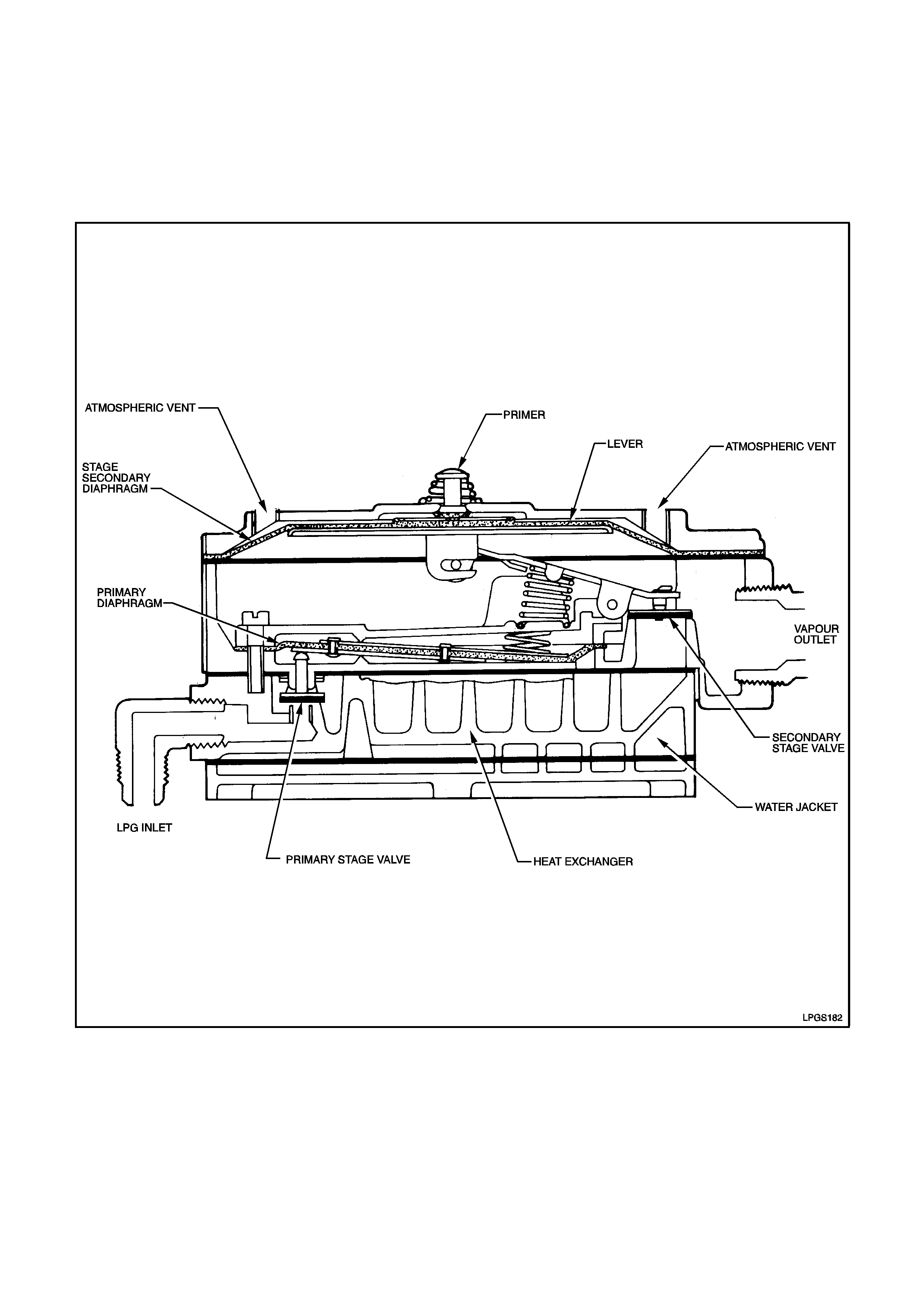
1.12 CONVERTER
The converter is a combined two - stage regulator and vaporiser. It receives LPG at cylinder pressure from the LPG
lockoff and reduces that pressure in two stages to slightly less than atmospheric. When the engine is cranked or
running, a partial vacuum is created in the vapour line from the mixer, which opens the converter permitting LPG to
flow to the mixer.
In the process of reducing the pressure from approximately 1260 kPa in the tank to atmospheric pressure, the LPG
expands to become a vapour, causing refrigeration. To compensate for this and to assist in vaporisation, coolant
from the engine cooling system circulates through a heat exchanger. The converter seals off LPG flow when the
engine is stopped.
Figure 1-15
PRIMARY REGULATION
The prim ary regulator spring, acting on the upper side
of the primary diaphragm, pushes the primary
diaphragm down. This opens the primary valve and
allows LPG to enter the converter which then flows
through the heat exchanger where the LPG changes
state from a liquid to a gas. The pressure of the LPG
acting on the underneath side of the diaphragm
causes the diaphr agm to m ove upward, closing off the
primary regulator valve.
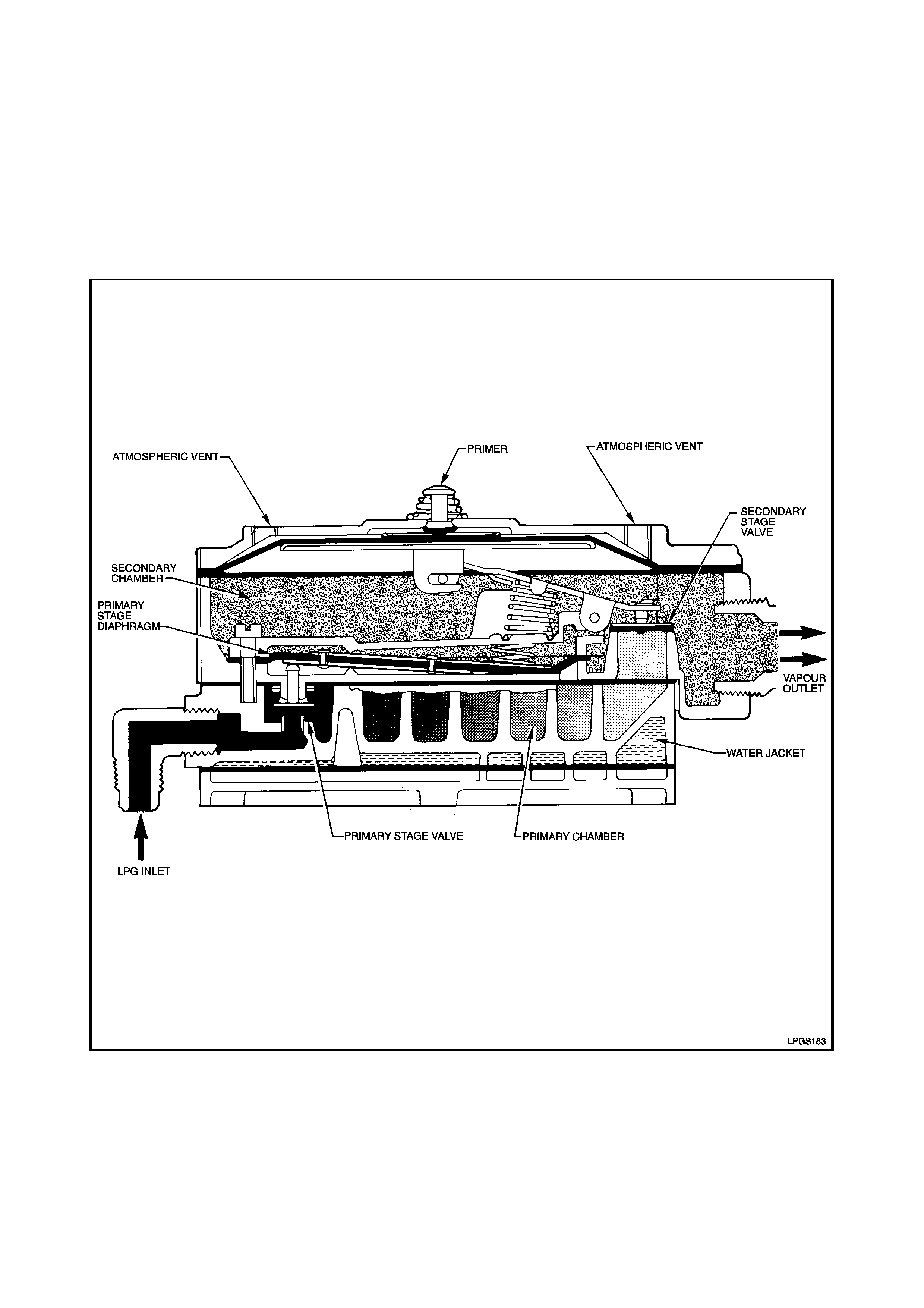
SECONDARY REGULATION
When the engine is cranked or running, a negative
pressure is created by the mixer in the secondary
chamber. This negative pressure (slightly below
atmospheric) acting on the underneath of the
secondary diaphragm, overcomes the secondary
spring force, allowing LPG as a vapour to enter the
secondary chamber. This increases the pressure
acting on the underneath side of the diaphragm,
overcoming the secondary spring force, causing the
diaphragm to move upward closing off the secondary
valve.
Figure 1-16
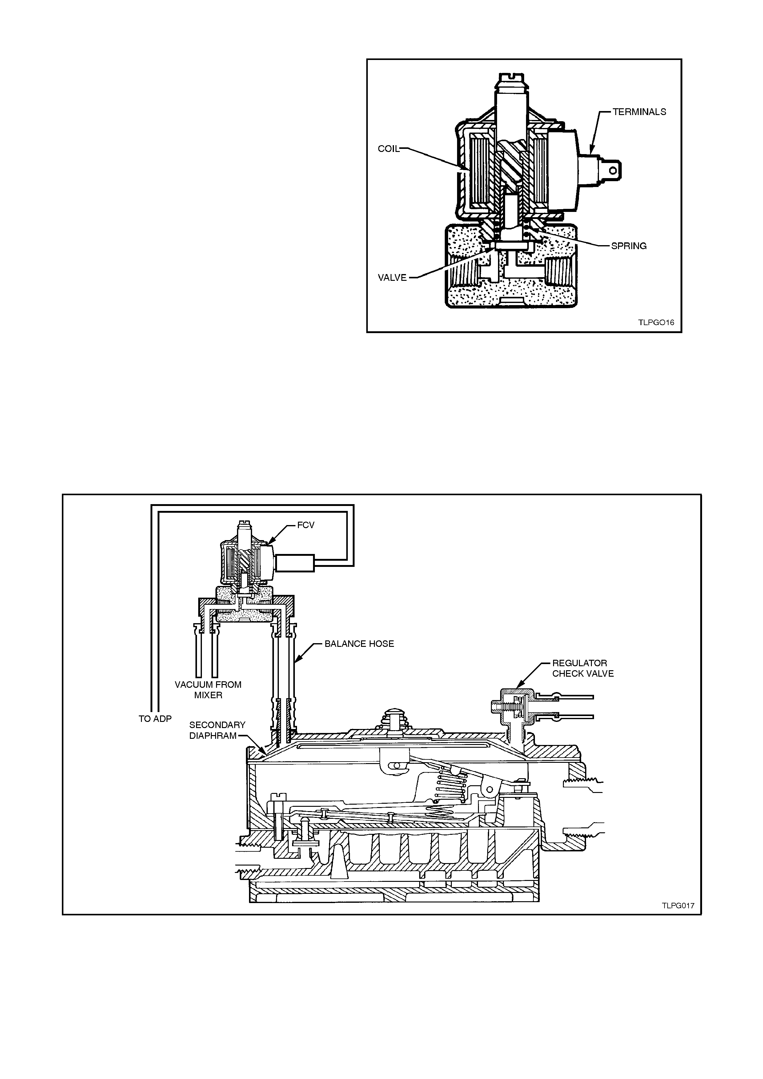
1.13 FUEL CONTROL V ALVE
The Fuel Control Valve (FCV) is used to control
fuel delivery. Because the diaphragm of the
converter is very large, little movement is required
to control the amount of LPG delivered. The fuel
control valve is connected into the balance line
between the atmospheric vent of the converter
secondary diaphragm and the air valve venturi of
the mixer. This applies a very low vacuum to the
atmospheric side of the converter secondary
diaphragm. Any pressure less than atmospheric
results in a reduction in LPG delivery. This ass ures
extremely accurate LPG delivery and rapid
response time.
With the exhaust gas oxygen sensor at operating
temperature and the Adaptive Digital Processor
(ADP) operating in closed loop, there is a wide
range of control. This permits the ADP to optimise
the air/fuel mixture to varying engine requirements.
The FCV is controlled by the ADP. To open the
FCV and decrease the pressure acting on the
secondary diaphragm of the converter, the ADP
pulses the FCV on and off at a frequency of 10Hz.
The ratio between the on and off time is called the
duty cycle. To open the F CV the ADP inc reas es the
duty cycle, which decreases the pressure applied to
the secondary diaphragm. The amount of time the
FCV is on will determ ine the press ure ac ting on the
converter secondary diaphragm. In this way, the
ADP can control the air/fuel ratio.
Figure 1-17
Figure 1-18
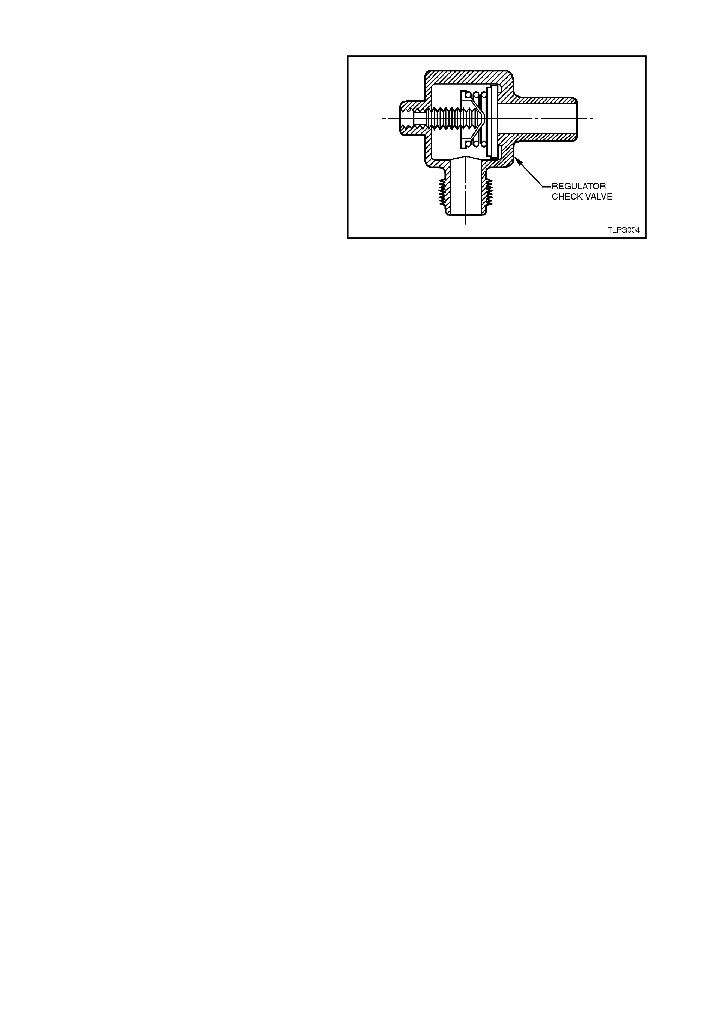
1.14 REGULATOR CHECK VALVE
To maintain correct control during normal driving
the pressure above the secondary diaphragm is
influenced by the air valve vacuum but is finally
controlled by the FCV.
However, when the accelerator is depressed
quickly, the pressure in the air valve chamber will
rise very quickly, far above it’s normal working
value. This is because the movement of the mixer
diaphragm and air-gas valve will lag behind the
movement of the throttle valve. This will
momentarily subject the air valve chamber to a high
vacuum. Because the FCV duty cycle has been
controlling the air fuel ratio with a steady vacuum
value this sudden increase in vac uum will delay the
movement of the converter diaphragm at precisely
the time it needs to move freely. This would cause
a lean air/fuel ratio.
Whenever the vacuum above the diaphragm
exceeds 16” W C ie. when the diaphragm needs to
move down quickly as the accelerator is suddenly
depressed the Regulator Check Valve (RCV) it will
open and allow atmospheric pressure to act on the
secondary diaphragm.
Figure 1-19
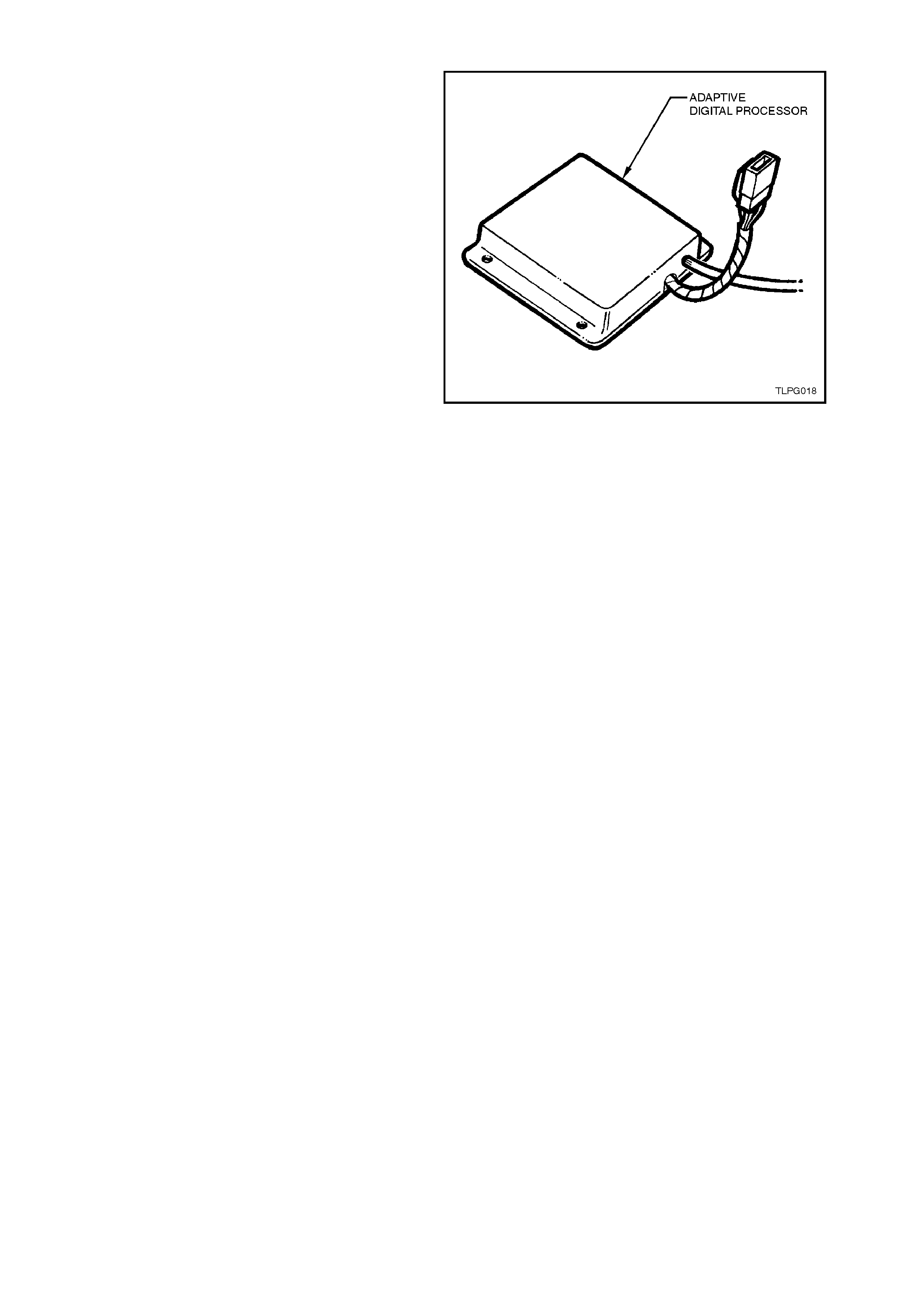
1.15 ADAPTIVE DIGITAL PROCESSOR
The Adaptive Digital Processor (ADP) controls the
operation of the Fuel Control Valve (FCV). The
FCV controls the mixture by varying the pressure
above the secondary diaphragm of the converter.
The ADP receives a vacuum signal from the
engine, a RPM signal from the DIS module and a
signal from the exhaust gas oxygen sensor.
The ADP uses the RPM and vacuum signals to
determine the operating conditions (load) of the
engine. The ADP has two operating modes; open
and closed loop. In the open loop mode, the ADP
ignores the exhaust gas oxygen sensor signal. In
the closed loop mode the ADP uses the exhaust
gas oxygen sensor signal to maintain the air fuel
ratio at 15.0:1.
When atmospheric pressure is applied to the
chamber above the secondary diaphragm of the
converter, the LPG system will deliver a rich
mixture. When mixer vacuum is applied to the
chamber above the secondary diaphragm of the
converter, the LPG system will deliver a lean
mixture. This enables the ADP to control the air/fuel
ratio by varying the FCV duty cycle.
Increasing the duty cycle causes the balance line
from the mixer to the converter to be opened for a
longer period. This decreases the pressure above
the secondary diaphragm, causing less LPG to be
delivered for a given mixer vacuum.
Decreasing the duty cycle causes the balance line
from the mixer to the converter to be opened for a
shorter period. This increases the pressure above
the secondary diaphragm, caus ing more LPG to be
delivered for a given mixer vacuum.
Figure 1-20
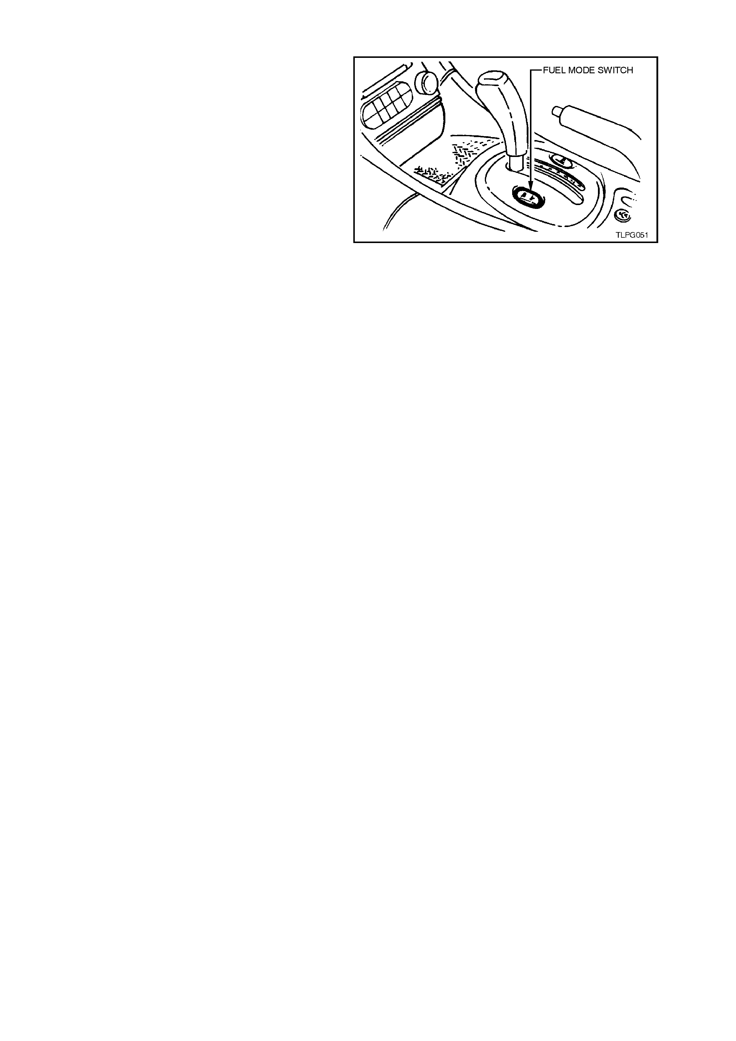
1.16 FUEL MODE SWITCH
The fuel mode switch is mounted in the centre
console and is a momentary type switch. When
pressed the switch supplies 12 volts to PCM
terminal A9. The PCM sees this voltage as a
request to change over from Petrol to LPG or from
LPG to petrol.
The PCM will only allow the changeover from Petrol
to LPG mode or LPG to petrol mode if the vehicle
speed is less than 3 km/h.
With each press the PCM toggles between Petrol
and LPG mode.
The m ode that the PCM is operating in is stored in
the memory of the PCM so that the engine s tarts in
the same mode on the next ignition cycle. Figure 1-21
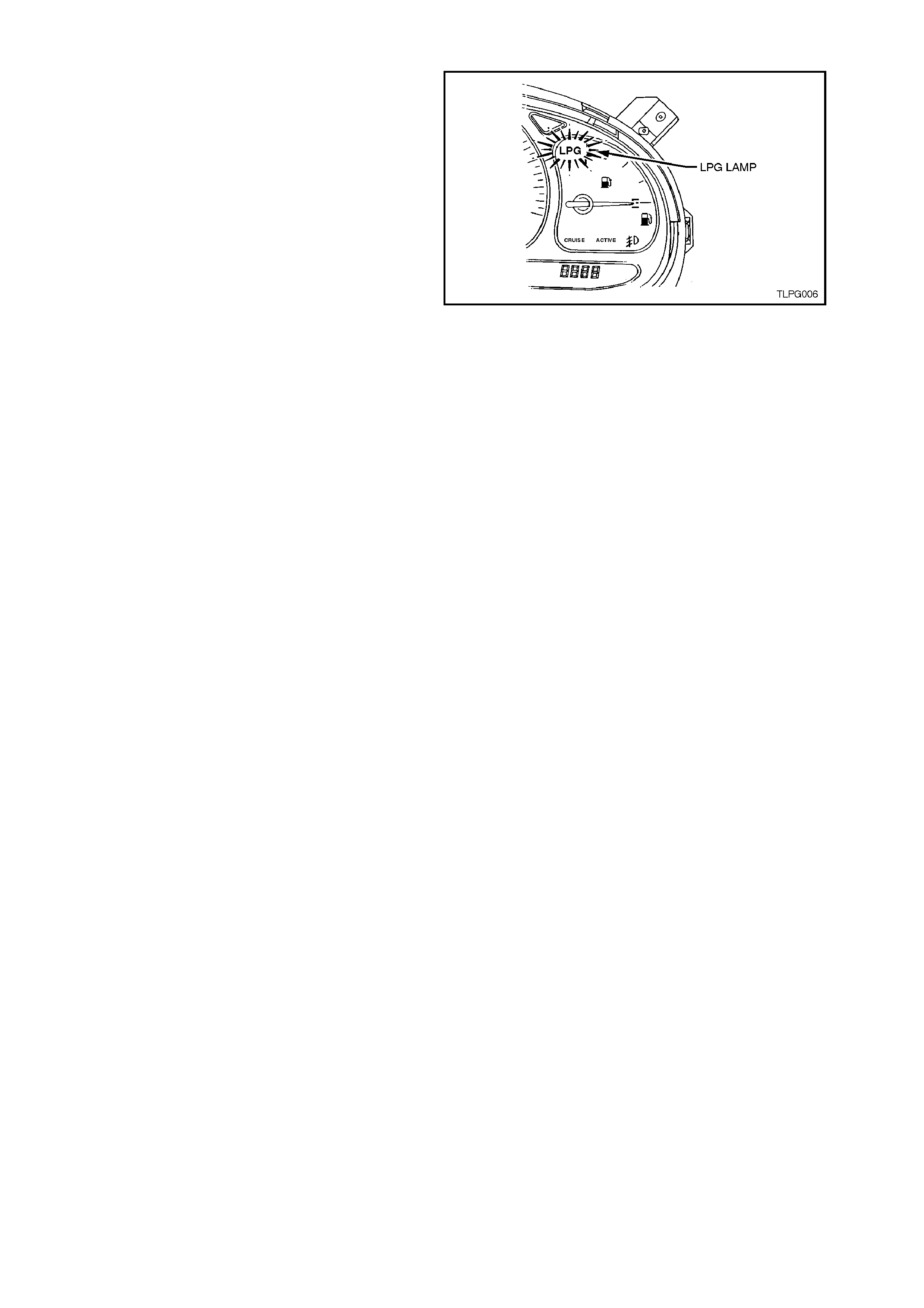
1.17 LPG LAMP
Whenever the PCM is operating in the LPG mode
the LPG lamp will be illuminated. If the PCM is
operating in the petrol mode the LPG lamp will be
off.
When the PCM switches to the LPG mode the
PCM will command the instruments to turn on the
LPG lamp, via the serial data line normal mode
message.
Figure 1-22
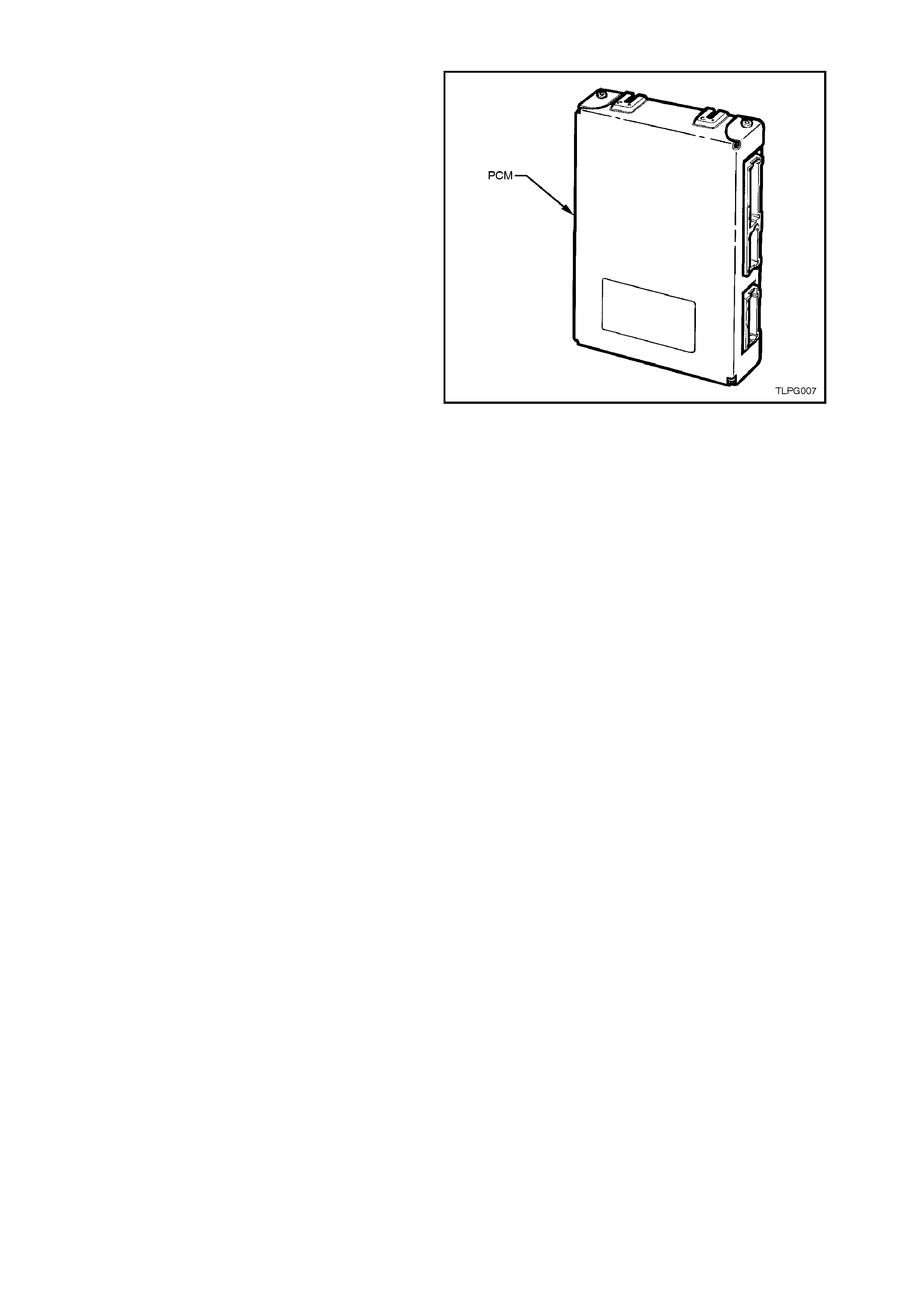
1.18 POWERTRAIN CONTROL MODULE
The Powertrain Control Module (PCM) when fitted
with the correct LPG PROM is c apable of operating
in either of two operating m odes, PETRO L or LPG.
The m ode that the PCM is operating in is stored in
the memory of the PCM so that the engine s tarts in
the same mode on the next ignition cycle.
PETROL MODE
When operating in the petrol mode, the LPG
system is turned off and the vehicle will operate on
petrol, with full engine management control in the
same manner as a vehicle that is not fitted with
LPG. In this mode, the instrument cluster fuel
gauge will show the amount of petrol in the petrol
fuel tank.
LPG MODE
When operating in the LPG mode, the engine
managem ent system is switched to the LPG mode,
and the LPG system is turned on, enabling the
vehicle to operate on LPG. When the PCM
switches to the LPG mode it energises the LPG
relay. The LPG relay supplies power to the ADP
and the smart unit via fuse F9.
In this mode the LPG lamp will be turned on and
the instrument cluster fuel gauge will show the
amount of LPG in the LPG cylinder.
The PCM controls the flow of LPG, by sending a
signal to the sm art unit via circuit 937 W /G wire on
receiving this signal the smart unit energises the
solenoid valve. The smart unit also energises the
LPG lockoff via circuit 965 BLU/O wire.
Figure 1-23
In the LPG m ode, the f ollowing c hanges have been
made so the engine can operate on LPG.
NOTE:
These changes only effect the operation of the
PCM when operating in LPG mode.
Injector Pulse Width
The injector pulse width is set to zero in all LPG
operating modes, except during engine cranking
or, on when the vehicle runs in “engine valve
recession protection mode”.
During engine cranking the amount of petrol
delivered is determined by the engine coolant
temperature and the engine crank time. The
injection of petrol during engine cranking is to aid
engine starting.
when operating in the LPG mode, and under
conditions of high speed / high load, a small
amount of petrol is injected into the engine to
protect the engine from engine valve seat
recession. When petrol is injected under these
conditions, it is refer red to as the engine valve seat
recession protection mode.

Fuel Pump
To provide petrol when starting in the LPG mode,
the fuel pump will run for 2 seconds when the
ignition is turned to the ON position and c ontinue to
run when the engine is being cranked, but will be
turned off 5 seconds after the engine has started.
The fuel pump will also operate under high load
conditions. This allows for petrol to be injected into
the engine when the vehicle goes into the engine
valve recession protection mode.
As a protection devise to the fuel pump, the PCM
will switch off the fuel pum p and disable the engine
valve seat recession protection mode, if there is
less than 6 litres of fuel in the petr ol tank. T he PCM
monitors the serial data normal mode message to
determine the amount of fuel in the petrol tank.
Electronic Spark Timing
A specific Electronic Spark Timing (EST) map is
used when in the LPG mode, the PROM has been
programmed to provide optimum EST for LPG
operation.
If the engine speed drops below 300 RPM, the
PCM prevents the spar k plugs f rom f iring by setting
the ignition dwell to zero.
Fuel Usage Signal Output
The PCM fuel usage output signal is used by the
trip computer to determine the fuel consumption
display and is recalibrated to suit LPG.
Engine Cranking
The PCM will prevent the engine from cranking
when operating in the LPG mode if the throttle is
open. The PCM will only energise the starter relay
if the throttle is open less than 7%.