SECTION 2A - SERVICE OPERATIONS - VT WAGON
CAUTION:
This vehicle will be equipped with a Supplemental Restraint System (SRS). A SRS will
consist of either seat belt pre-tensioners and a driver's side air bag, or seat belt pre-
tensioners and a driver's and front passenger's side air bags. Refer to CAUTIONS,
Section 12M, before performing any service operation on, or around any SRS
components, the steering mechanism or wiring. Failure to follow the CAUTIONS
could result in SRS deployment, resu lting in possible perso nal in jury or u nnecessary
SRS system repairs.
IMPORTANT:
When any LPG system component has been replaced or overhauled, or when the engine assembly has
been replaced or overhauled, the adaptive learn drive cycle procedures must be carried out as described in
2.23, ADAPT IVE DIGITAL PROCESSOR SET - UP PRO CEDURE under VT Sedan With Production LPG, of the
VT Series Service Information CD. This is because the values stored in the Adaptive Digital Processor
operational cells apply only to the previous condition of the engine or components.
2.1 DRAINING THE SERVICE LINES
The procedure f or draining the ser vice lines on VT
Series Wagon is the same as VT Series Sedans
with exception to the location of the m anual service
valve. Theref ore when draining the service lines on
VT Series Wagon, refer to 2.1 DRAINING THE
SERVICE LINES under VT Sedan W ith Production
LPG of the VT Series Service Information CD,
noting the location of the manual service valve for
VT Series wagons.
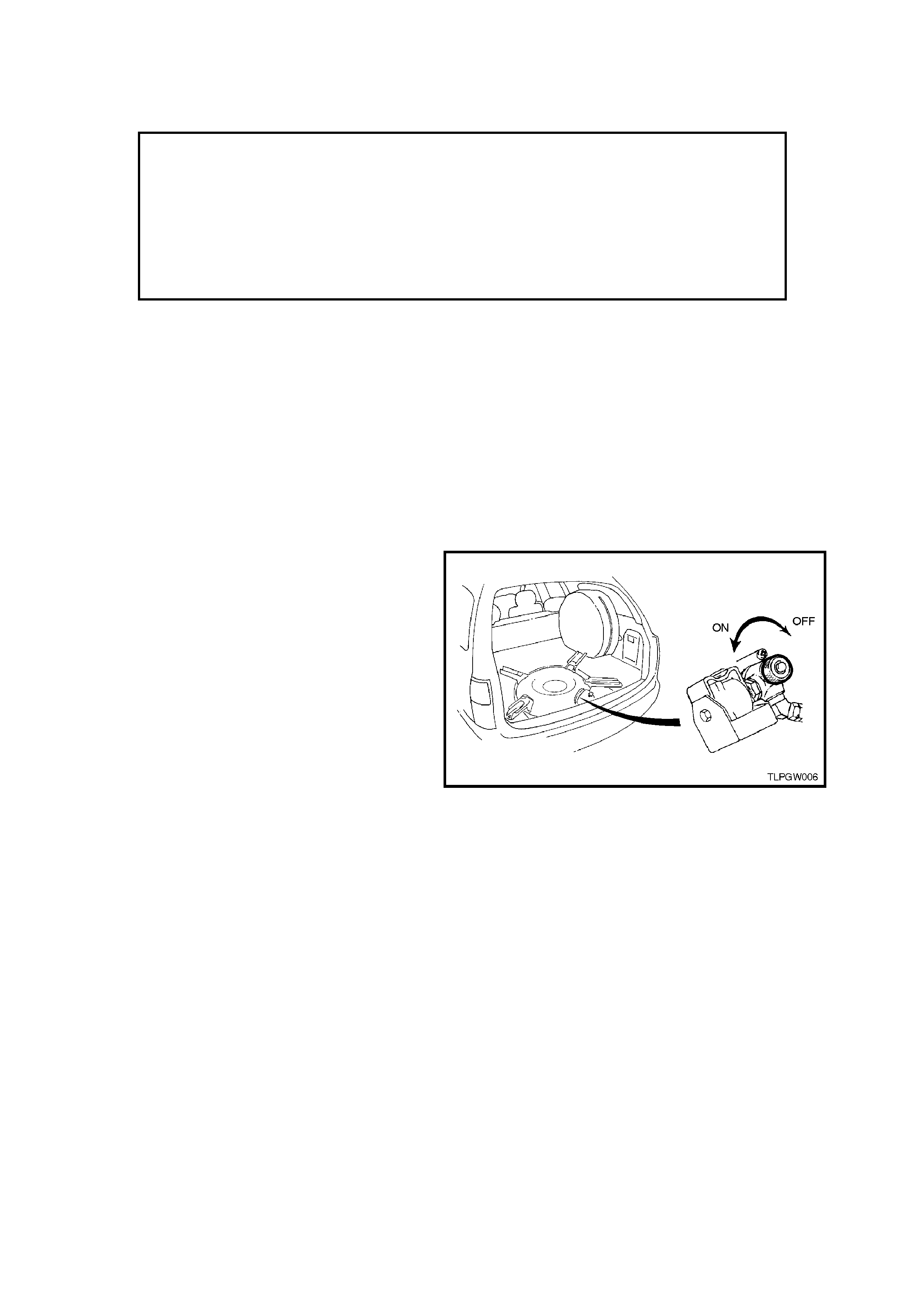
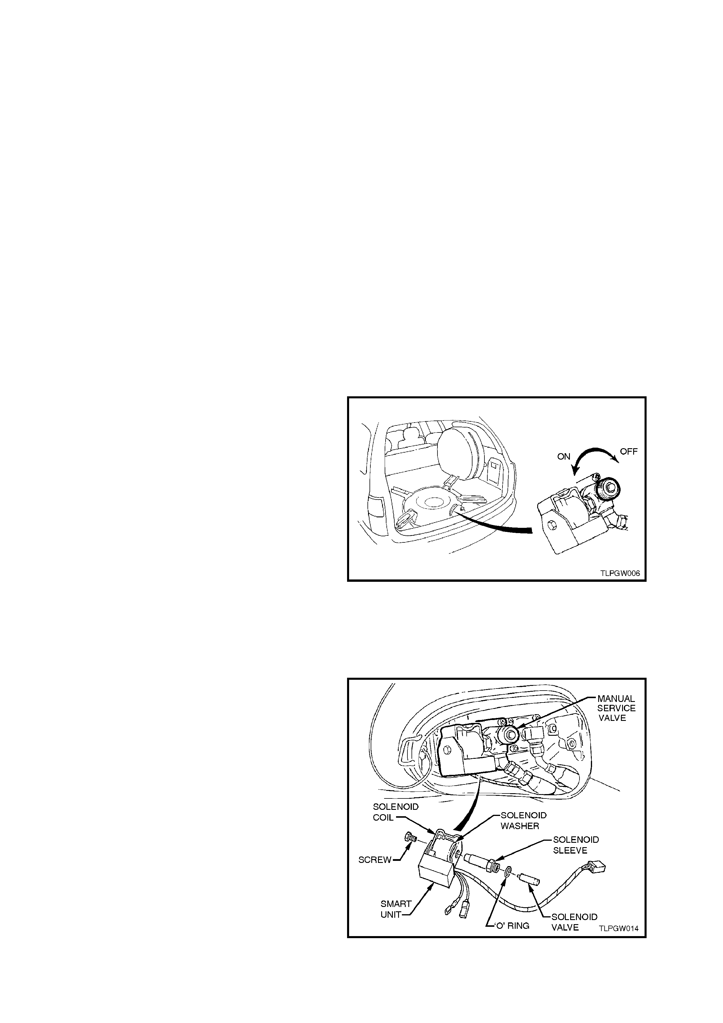
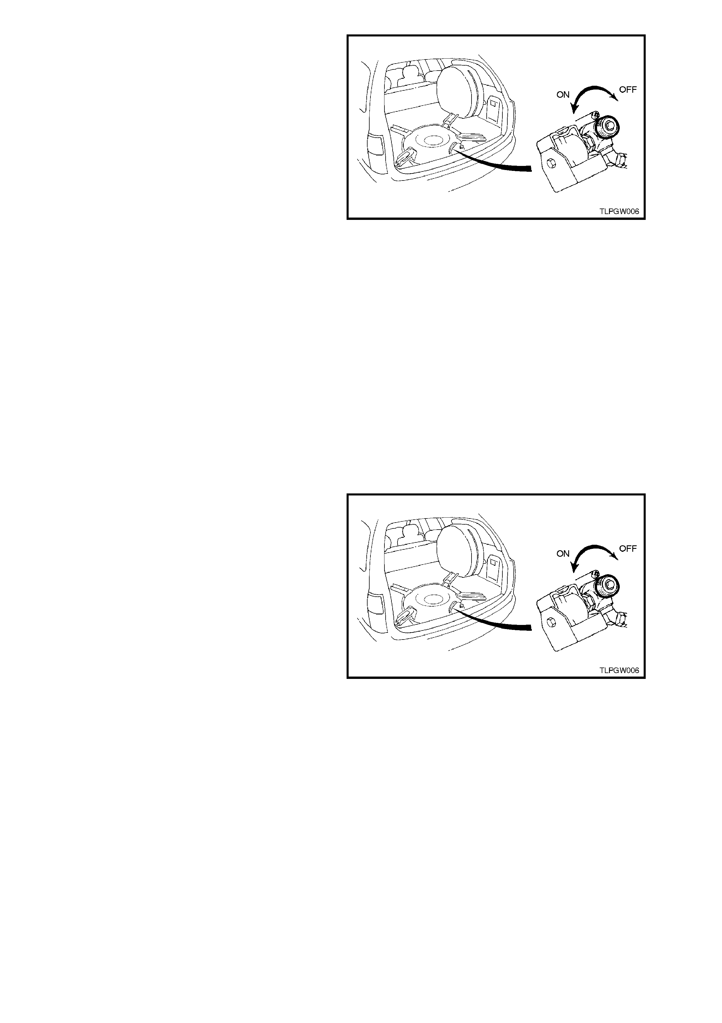
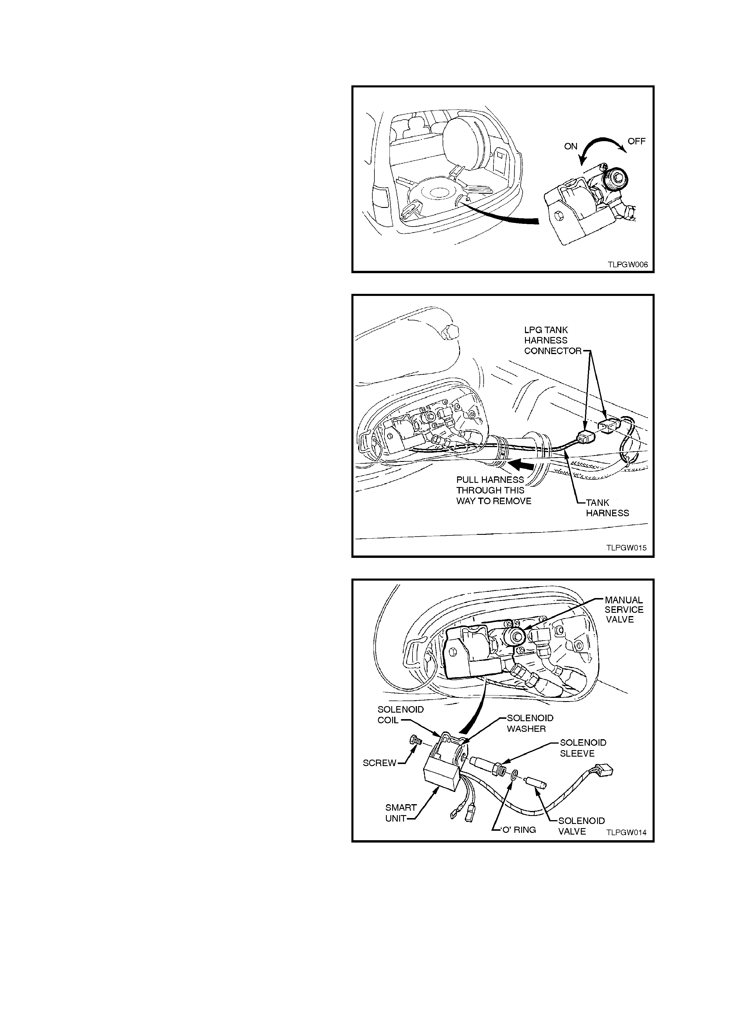
The manual service valve is located on the upper
rear of the LPG tank which is m ounted in the spare
wheel compartment, refer Fig. 2A-1.
Figure 2A-1
2.2 LPG TANK UNLOADING PROCEDURE
The procedure for unloading the LPG tank on VT
Series wagons is essentially the same as the VT
Series Sedan, therefore refer to
2.2 LPG TANK UNLOADING PROCEDURE under
VT Sedan With Production LPG of the VT Series
Service Information CD, noting the following:
Due to a flexible rear s ervic e line (hos e) being used
on Wagon Models , it is not neces s ary to com pletely
remove the rear service line. Therefore, only
disconnect the rear service line at the manual
service valve.
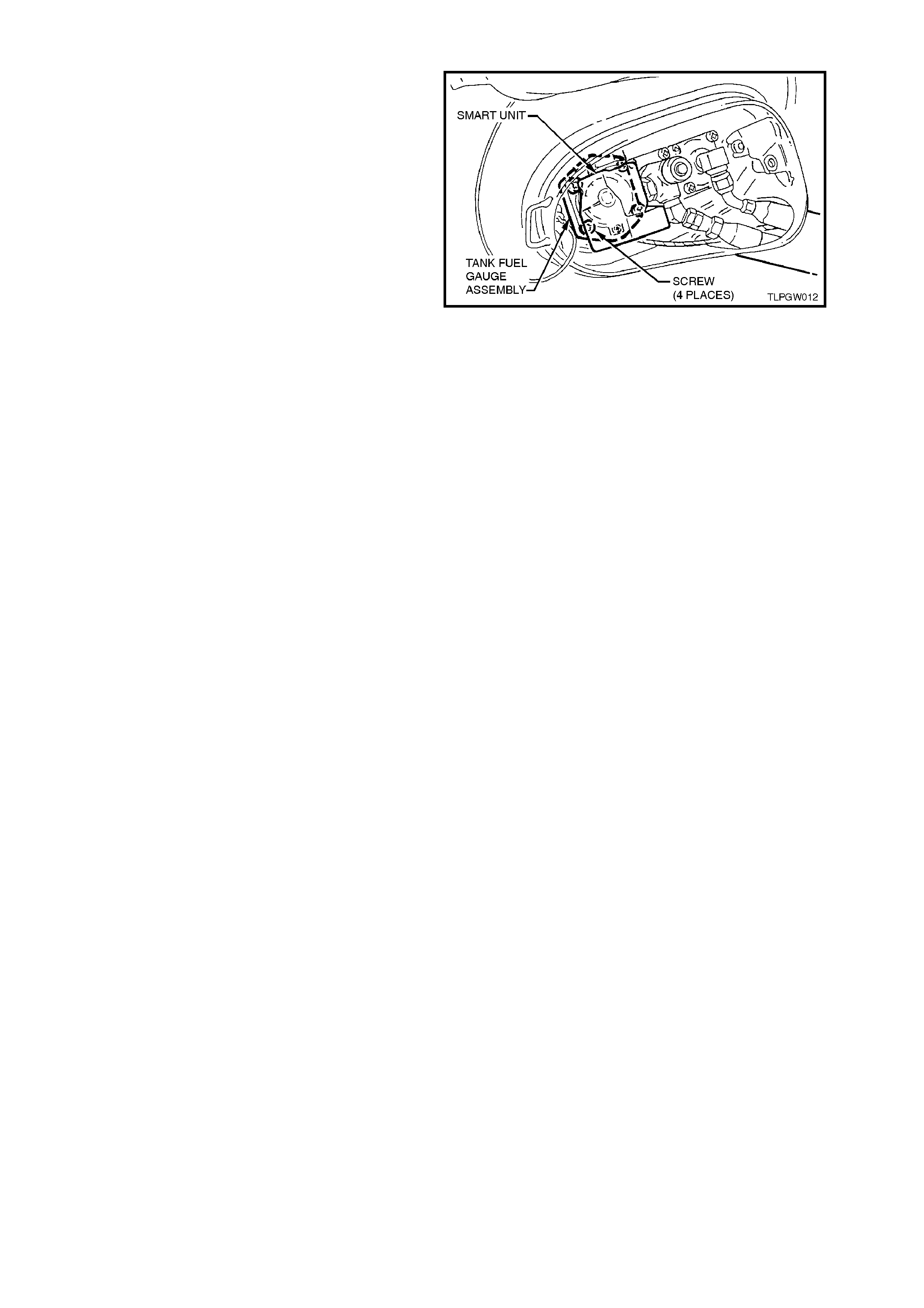
To remove the tank fuel gauge, it will be necessary
to remove the smart unit and solenoid sleeve to
gain access to the four tank fuel gauge retaining
screws. Refer to 2.8 SMART UNIT AND
SOLENOID VALVE in this Section.
CAUTION:
AFTER ANY VALVE OR COMPONENT HAS
BEEN REMOVED AND REINSTALLED TO THE
LPG TANK, THE LPG TANK MUST BE
PRESSURE AND LEAK TESTED IN
ACCORDANCE WITH THE CURRENT
AUSTRALIAN STANDARD AS2030.1 BEFORE
THE LPG T ANK IS PUT BACK INTO SERVICE IN
THE VEHICLE.
Figure 2A-2
2.3 LEAK TESTING
The following leak test procedure is to be carried
out on the LPG system high pressure components
and is to be performed as part of the LPG After
Installation Check as well as each normal
maintenance service.
The leak test is to be carried out in the open air in a
well-ventilated area, away from any ignition source
and PRIOR to bringing the vehicle into the
workshop.
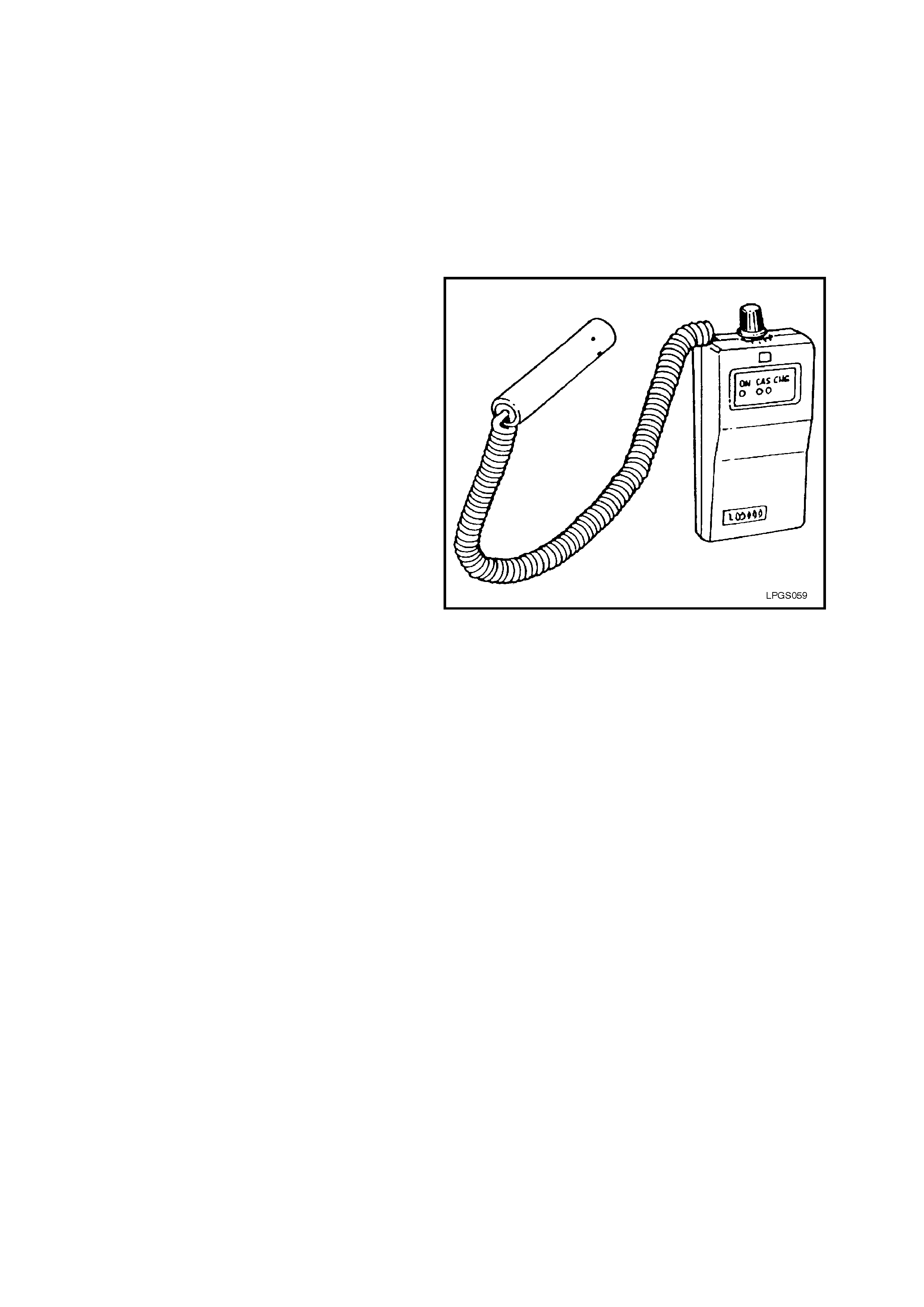
COMBUSTIBLE GAS DETECTORS
If a com bustible gas detector is to be used for leak
testing of the LPG system, the combustible gas
detector should be capable of detecting 25 parts
per million (P.P.M.) of LPG in air. A detector such
as a LD-9001 LP Gas Leak Detector or equivalent
is recommended.
Whichever leak detector is used, it is important to
follow the manufacturer's instructions in regard to
adjustment and setting the instrument prior to
conducting the leak test.
Care in interpretation is necessary, as the detector
can respond to the presence of any of several
vapours that are combustible, some of which may
not be LPG, such as oil smears, joining
compounds, etc. They may also detect residual
LPG vapours that are present for reasons other
than leakage, and which must be cleared before a
valid test for leakage can be made.
If a leak is present, a detector will signal its
existence but not its size, and will indicate its
general location, but may not be able to locate it
exactly. So, a proving or follow up check with foam
is often desirable.
Figure 2A-3
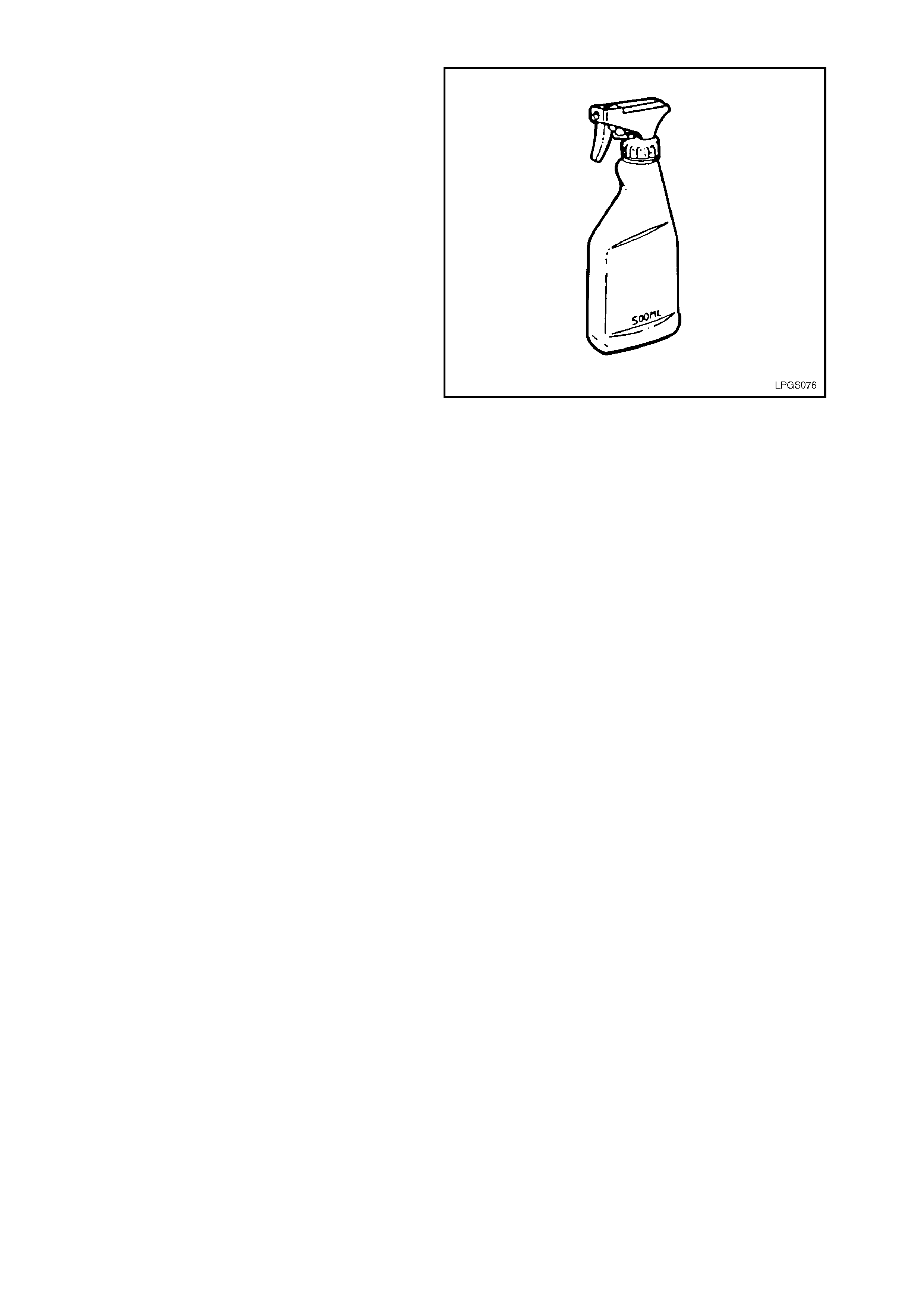
FOAM
If foam is to be used, the f oaming agent should be
a propriety leak test solution, f or mulated spec if ic ally
for the purpose, s uch as G am eco Leak Check TM or
a similar solution. T he solution should be fresh and
the whole of the area to be tested should be
coated, and time allowed for bubbles to form. All
areas under test must be able to be observed
during the leak test.
W hichever foaming agent is used, it is impor tant to
follow the manufacturer's instructions.
Foam testing is more effective for small leaks.
Large leak s tend to blow the solution away from the
leak without forming a bubble, so care in
application is necessary.
The leak test is performed by directing a spray of
solution at each of the possible leak points in the
high pressure side of the system.
After applying the solution, look c ar ef ully for no les s
than 15 seconds.
A leak is indicated by the presence of gas bubbles
(foaming) in the solution at the leak source.
NOTE:
LPG IS HEAVIER THAN AIR SO TEST
THOROUGHLY BELOW ALL COMPONENTS
AND FITTINGS.
If a leak is detected at a joint, the relevant
component/s must be rem oved as described in the
appropriate component service operation in this
Section, all mating threads thoroughly cleaned,
then resealed using the specified sealant and
tightened to the correct torque specification. Once
installed, thoroughly leak test the component/s
again.
At the completion of each test, dry the leak test
area of the foaming agent with low pressure
compressed air or shop cloths and spray
imm ediate area with a water dispersing agent such
as WD40 or RP7, etc.
Figure 2A-4

LEAK TEST PROCEDURE
With at least 3 litres of LPG in the LPG tank, leak test the complete LPG system following the instructions below
1. Park the vehicle in a dry, well ventilated area.
DO NOT SMOKE OR ALLOW NAKED FLAMES OR ANY IGNITION SOURCE NEAR THE VEHICLE DURING THE
TESTING OPERATIONS.
2. Ensure the vehicle is operating on LPG and run the engine for at least 30 seconds to fully pressurise the
system, then stop the engine.
3. The recommended sequence of testing is as follows:
A. Referring to Figure 2A-5, View A, lift the rear part of the floor trim in the luggage compar tment to acc es s the
valve box, remove the valve box cover and leak test at and around the:
Pressure relief v alve (1).
AFL to LPG tank (2).
AFL inlet elbow to AFL (3).
Rear service line to AFL inlet elbow connection (4).
Solenoid and manual service valve assembly (5).
Solenoid and manual service valve assembly to LPG tank (6).
Rear service line to solenoid and manual service valve assembly connection (7).
Tank fuel gauge assembly (8).
B. Referring to Figure 2A-5, View B: remove the right hand rear wheelhouse liner to gain access to the inner
side of the f iller valve as s embly, refer to Section 1A1 BODY of the VT Series Servic e Manual. Leak tes t at
and around the filler valve connecting pipe to filler line hose (10).
Open filler box door and leak tes t at and around the filler valve c heck ball (11) and f iller line c onnec ting pipe
to the filler valve connection (9).
C. Referring to Figure 2A-5, View C, raise rear of vehicle and support on safety stands, refer to Section 0A
GENERAL INFORMATION of the VT Series Servic e Inform ation CD f or the loc ation of jac k ing points. Leak
test at and around the:
Rear service line (hose) to intermediate service line joiner connection (12).
Intermediate service line to rear service line joiner connector (13).
D. Referring to Figure 2A-5, View D, leak test in the engine compartment at and around the:
Intermediate service line to front service line joiner connection (14).
Front service line to intermediate service line joiner connection (15).
E. Referring to Figure 2A-5, View E, leak test in the engine compartment at and around the:
Front service line to lockoff inlet connection (16).
Lockoff inlet connection to lockoff (17).
Lockoff to lockoff outlet connection (18).
Lockoff outlet connection to converter (19).
Lockoff (20, 21, 22).
Converter mounting faces (23).
At the completion of the leak test, close the manual service valve, start the engine and run the engine until all the
LPG in the service line is exhausted. W ith the engine stopped, switch to ‘petrol’ and start the engine. The vehicle
can now be driven into the workshop.
NOTE:
The vehic le cannot be oper ated on LPG in the workshop unles s the work s hop is a “Spec ialis t Gas Work s hop” , refer
to Australian Standard AS 2746 - 1985.
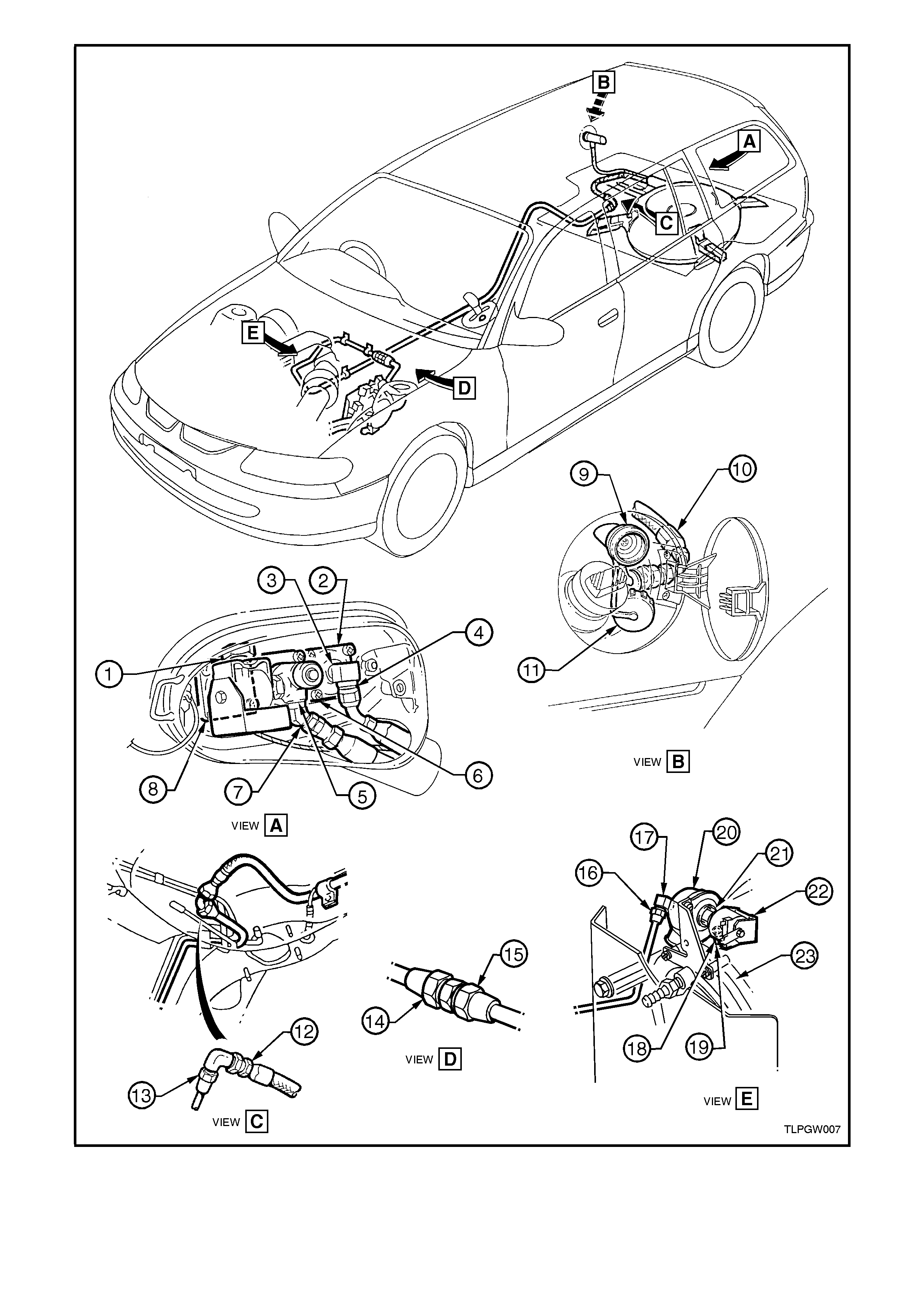
Figure 2A-5
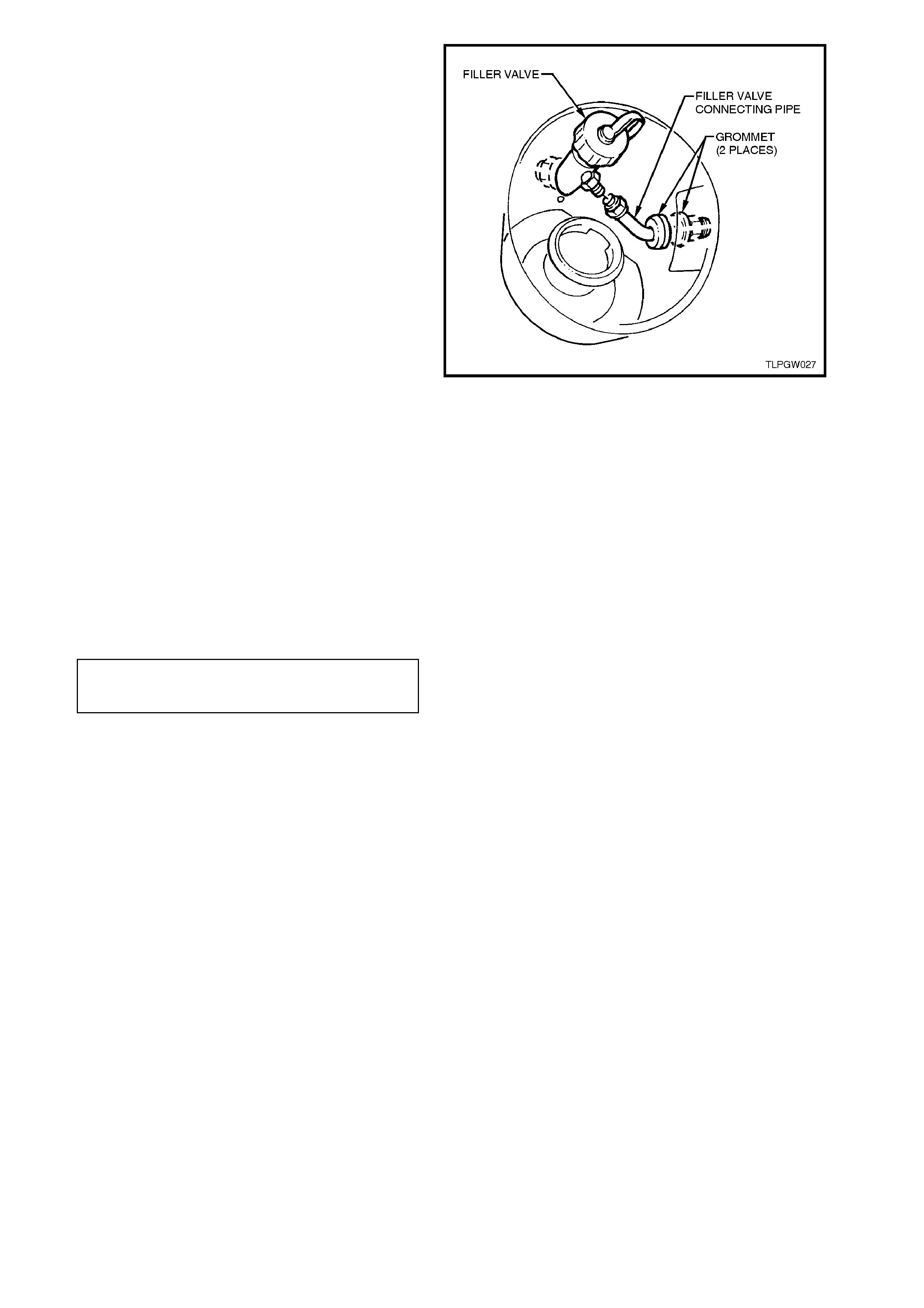
2.4 FILLER VALVE
REMOVE
1. Park the vehic le in a well ventilated area, away
from any ignition source.
2. Drain the LPG service lines, refer
2.1 DRAINING THE SERVICE LINES in this
Section.
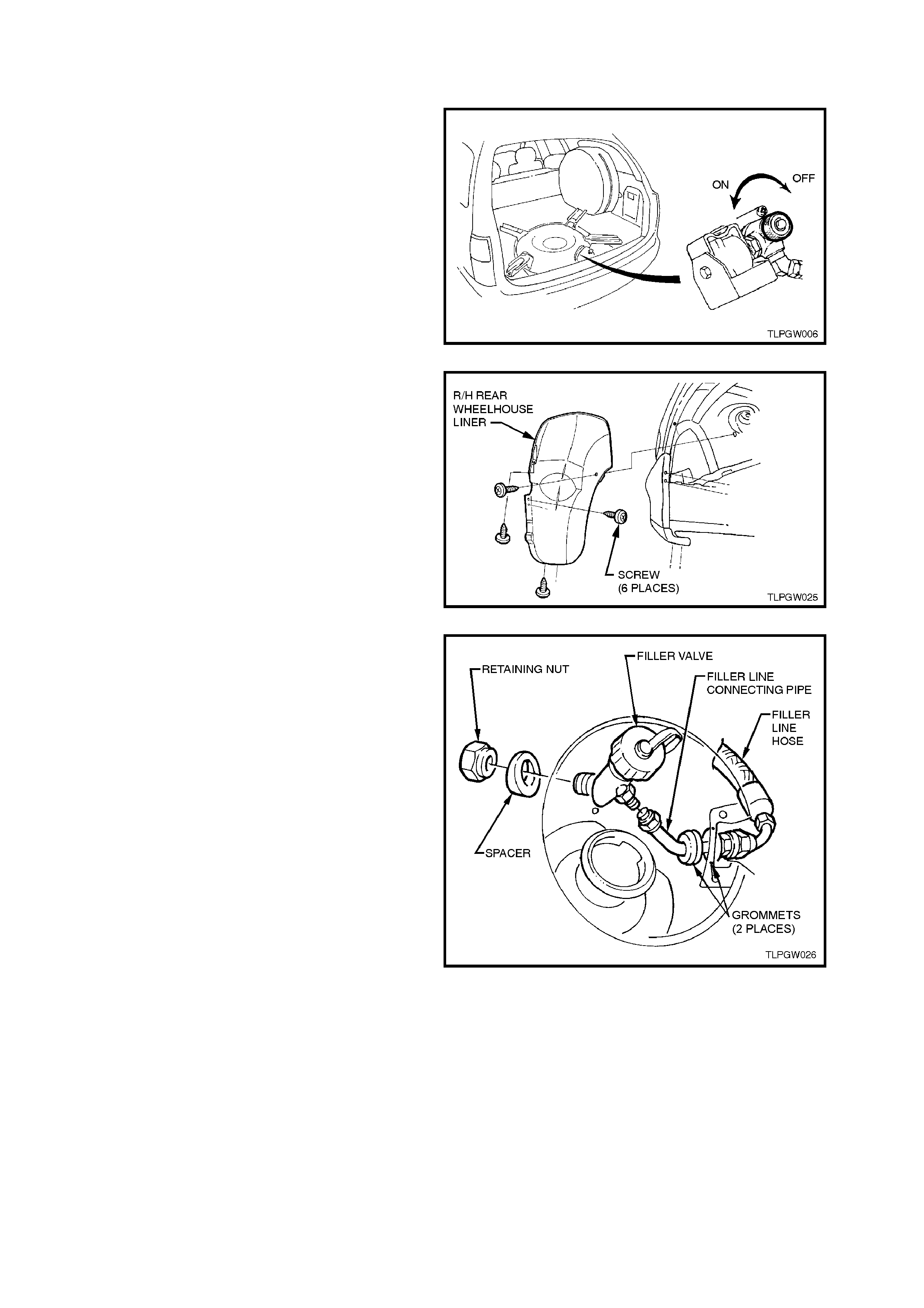
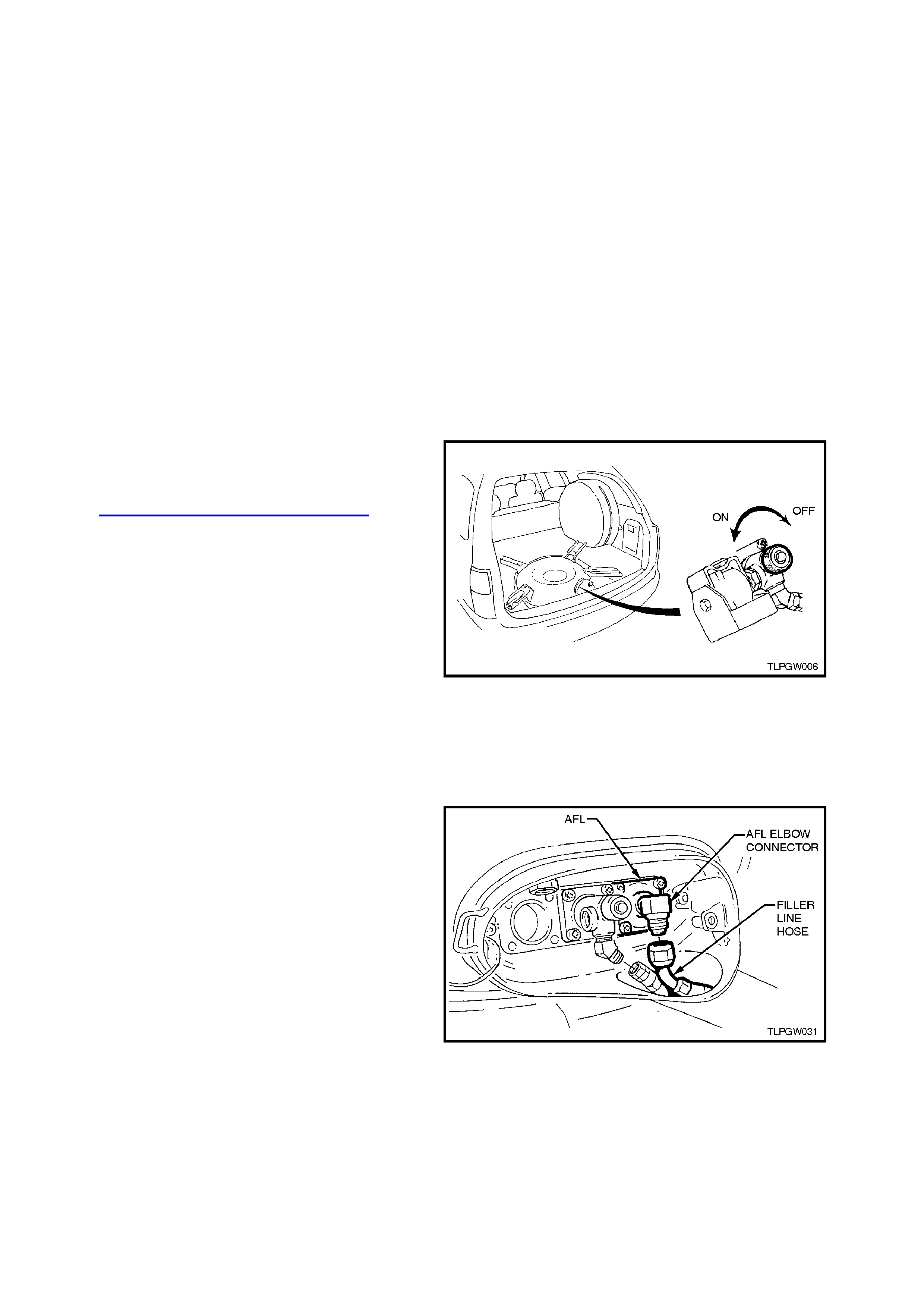
3. Ensure the manual service valve is turned
'OFF' and the battery earth lead is
disconnected.
Figure 2A-6
4. Remove the right hand rear wheelhouse liner.
Figure 2A-7
5. Crack open the filler line connecting pipe at
the filler valve and allow the residual gas to
escape.
CAUTION:
The filler line will contain LPG under pressure.
6. Unscrew the filler line connecting pipe from the
filler valve and m ove is away fr om contac t with
the filler valve.
7. From inside the right hand rear wheelhouse,
loosen and remove the f iller valve retaining nut
and spacer.
8. Remove the filler valve.
NOTE:
During installation of the LPG system, silicone
adhesive is applied to the vehicle body m ating face
of the filler valve.
Figure 2A-8
REINSTALL
1. Clean filler valve and f iller line c onnecting pipe
mating threads.
2. Apply silcone sealer, to Holden Specification
HN1886, to the filler valve mating surface
(between vehicle body and filler valve). Install
filler valve, spacer and retaining nut and
tighten to the correct torque specification.
FILLER VALVE
RETAINING NUT
TORQUE SPECIFICATION 50.0 - 60.0 Nm
3. Connect filler line connecting pipe to filler
valve and tighten to the correct torque
specification.
FILLER LINE
CONNECTING PIPE
TORQUE SPECIFICATION 12.0 - 18.0 Nm
4. Reconnect battery earth lead.
5. Carry out LPG system leak test, refer
2.3 LEAK TESTING in this Section.
6. Ensure the two filler line connecting pipe
grommets are installed correctly.
7. Reinstall right hand rear wheelhouse liner.
2.5 FILLER LINE
REMOVE
1. Park the vehic le in a well ventilated area, away
from any ignition source.
2. Drain the LPG service lines, refer
2.1 DRAINING THE SERVICE LINES in this
Section.
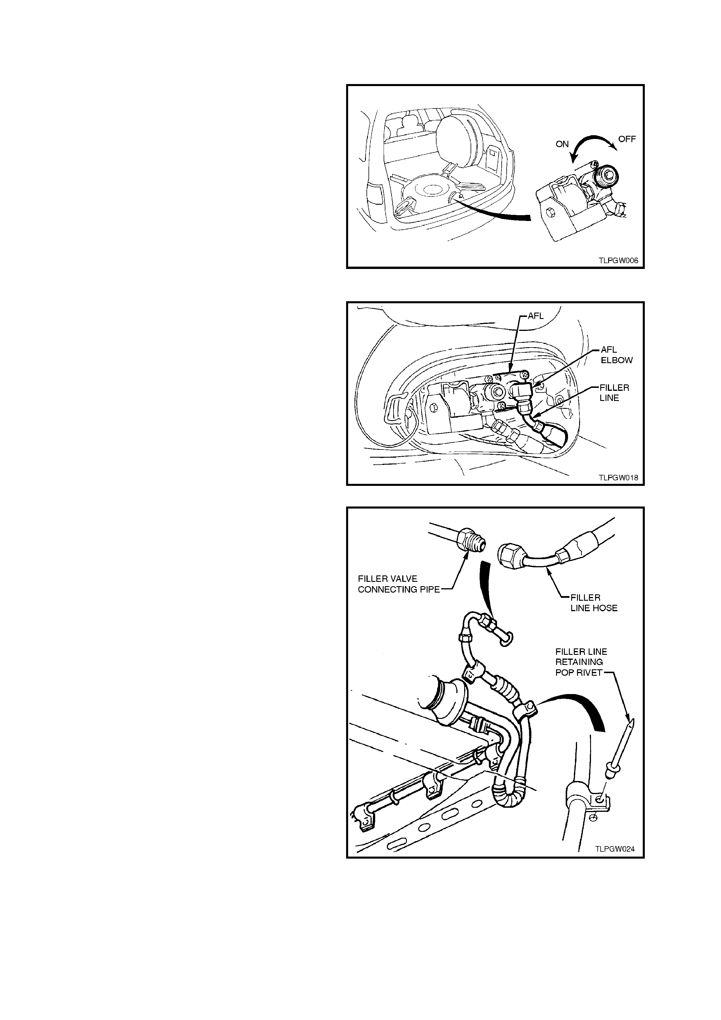
3. Ensure the manual service valve is turned
'OFF'.
4. De-pressur ise the fuel (petrol) system , refer to
Section 6C1 POWERTRAIN MANAGEMENT
of the VT Series Service Information CD.
5. Ensure the battery earth lead is disconnected.
6. Remove the fuel (petrol) tank assembly, refer
to Section 8A FUEL TANK of the VT Series
Service Information CD. Figure 2A-9
7. From inside the LPG tank valve box, while
holding AFL elbow, crack open filler line hose
to AFL elbow connector and allow residual
LPG to escape.
CAUTION:
The filler line will contain LPG under pressure.
Once all the LPG in the line has dispersed,
unscrew filler line hose connector completely
from AFL elbow.
Figure 2A-10
8. From under vehicle, while holding the filler
valve connecting pipe f r om turning, loos en and
unscrew the filler line hose, refer Fig 2A-11.
9. Using a suitable sized drill bit, drill into the
head of the two filler line hose retaining pop
rivets, refer Fig. 2A-11, and remove the filler
line hose .
10. Using a suitable size pin punch and hammer,
knock out remains of the filler line hose
retaining pop rivets from vehicle underbody.
Figure 2A-11
11. From inside fuel filler box, while holding the
filler valve connection f rom turning, loos en and
unscrew the filler line connecting pipe, refer
Fig. 2A-12.
12. Using a suitable screwdriver, push/lever the
two grommets into the fuel filler box and
rem ove the filler valve c onnecting pipe thr ough
the filler box opening.
Figure 2A-12
REINSTALL
Reinstallation of the filler line is the reverse of the
removal procedure, noting the following:
1. Clean filler line mating threads on filler valve,
filler valve c onnecting pipe, filler line hos e and
AFL.
2. Ensuring that flared surfaces are free of
sealant and contaminants, tighten filler line
connections to the correct torque
specifications.
FILLER LINE
CONNECTORS
TORQUE SPECIFICATION 12.0 - 18.0 Nm
3. Secure filler line hose using a new pop rivets
before the fuel (petrol) tank is reinstalled.
4. Ensure the two filler line connecting pipe
grommets are installed correctly.
5. Before starting vehicle or opening the manual
service valve, carry out a fuel (petrol) system
leak test as detailed in
Section 6C1 POWERTRAIN MANAGEMENT
- V6 ENGINE of the VT Series Service
Information CD.
6. Carry out LPG system leak test, refer
2.3 LEAK TESTING in this Section.
2.6 LPG TANK
CAUTION:
AFTER ANY VALVE OR COMPONENT HAS
BEEN REMOVED AND REINSTALLED TO THE
LPG TANK, THE LPG TANK MUST BE
PRESSURE AND LEAK TESTED IN
ACCORDANCE WITH CURRENT AUSTRALIAN
STANDARD AS2030.1 BEFORE THE LPG TANK
IS REFI TTED TO THE VEHICLE.
NOTE:
THE LPG TANK MUST BE PRESSURE AND
LEAK TESTED ACCORDING TO THE LAWS OF
THE STATE IN WHICH THE VEHICLE IS
REGISTERED. THIS TESTING MUST ONLY BE
DONE BY A LICENSED INSTALLER OR
TESTING STATION.
REMOVE
1. Park the vehic le in a well ventilated area, away
from any ignition source.
2. Drain the LPG service lines, refer
2.1 DRAINING THE SERVICE LINES in this
Section.
3. Ensure the manual service valve is turned
‘OFF’ and the battery earth lead is
disconnected.
4. Remove the luggage com partm ent f loor cover,
refer 2.15 LUGGAGE COMPARTMENT
FLOOR COVER in this Section.
5. Unload the LPG tank of LPG. Refer to notes in
operation 2.2 LPG TANK UNLOADING
PROCEDURE in this Section, then follow the
cylinder unloading procedure, steps 4 - 10
only, in operation 2.2 LPG CYLINDER
UNLOADING PROCEDURE in VT Sedan
W ith Pr oduction LPG of the VT Series Ser vice
Information CD.
Figure 2A-13
6. From inside the LPG tank valve box, while
holding the AFL elbow, crack open filler line
hose to AFL elbow connector and allow
residual LPG to escape.
CAUTION:
The filler line will contain LPG under pressure.
7. Once all the LPG in the line has dispersed,
unscrew filler line hose connector completely
from AFL elbow.
Figure 2A-14
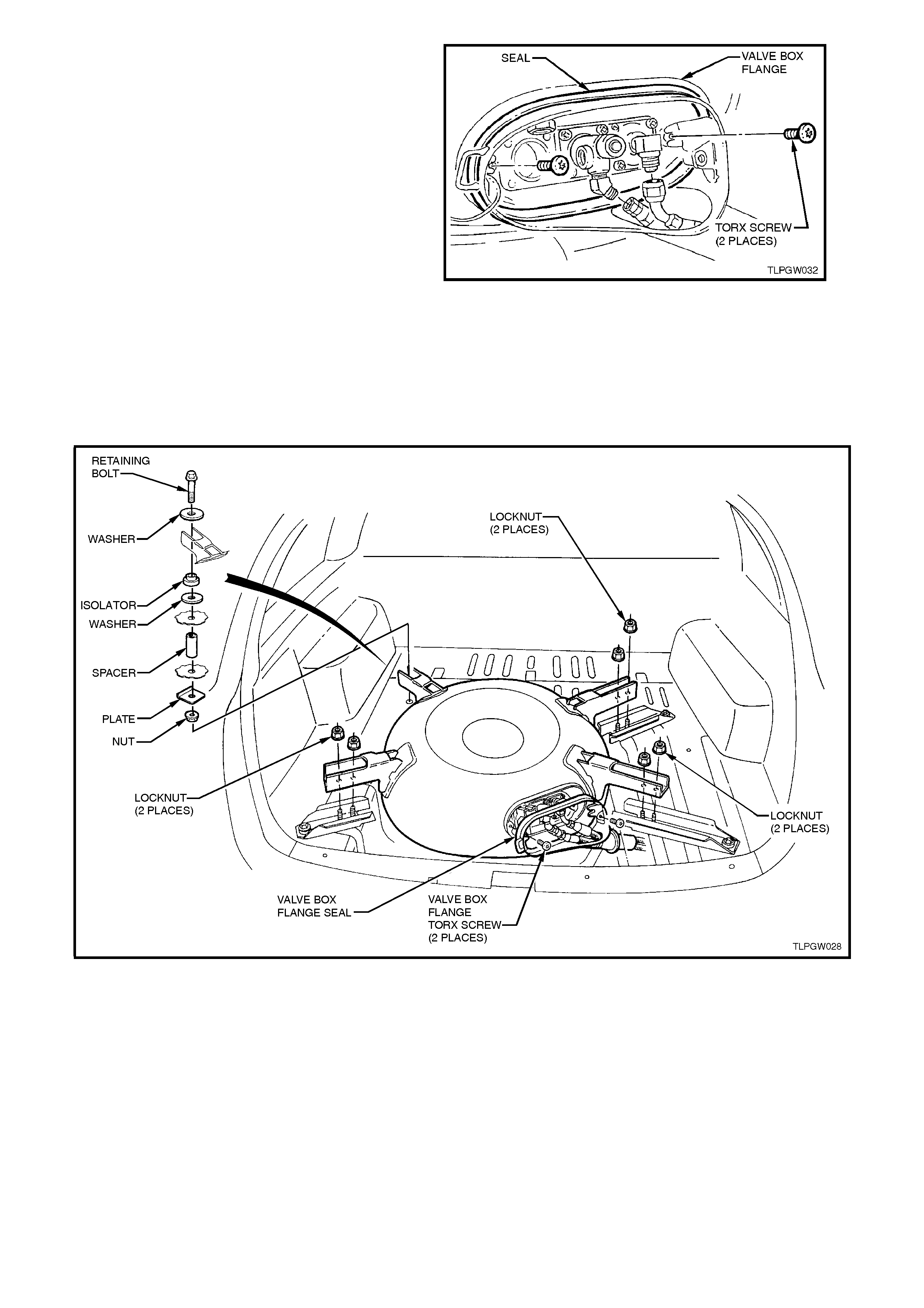
8. Loosen and remove the two torx screws
retaining the valve box flange to the LPG tank.
9. Pull valve box flange and s eal away from LPG
tank so that there is sufficient clearance to
remove the LPG tank.
Figure 2A-15
10. With the aid of an assistant, loosen and
remove the left hand front LPG tank retaining
bolt and nut, refer Fig. 2A-16.
11. Loosen and remove the six locknuts retaining
the LPG tank to the rem aining three LPG tank
brackets, refer Fig. 2A-16.
12. Lift the LPG tank up and remove.
Figure 2A-16
REINSTALL
1. If the LPG tank fuel gauge has not already
been reinstalled, reinstall LPG tank fuel gauge
assembly, refer 2.12 TANK FUEL GAUGE
ASSEMBLY in this Section.
2. Seat tank onto the LPG tank bracket studs
(six places).
3. With the aid of an assistant, install the left
hand front retaining bolt and nut, ensuring
spacers, isolators, washers and reinforcement
plates are installed correctly, refer
Fig. 2A-16. While holding the retaining bolt,
tighten retaining nut to the correct torque
specification.
LPG TANK
RETAINING NUT
TORQUE SPECIFICATION 40 - 50 Nm
4. Install the six locknuts retaining the LPG tank
to the LPG tank brackets and tighten locknuts
to the correct torque specification.
LPG TANK
RETAINING LOCKNUT
TORQUE SPECIFICATION 40 - 50 Nm
5. Install the valve box f lange, ensuring the valve
box seal is seated correctly. Tighten the two
valve box flange retaining torx screws to the
correct torque specification.
VALVE BOX FLANGE
RETAINING TORX SCREW
TORQUE SPECIFICATION 7.0 Nm
6. Reinstall the smart unit and solenoid valve,
refer 2.8 SMART UNIT AND SOLENOID
VALVE in this Section.
7. Clean rear service line mating threads on
solenoid and manual service valve assembly
and the filler line hose mating surface on the
AFL elbow.
8. Ensuring the flared surfaces are free of
sealant and contaminants, tighten filler line
hose and service line connections to the
correct torque specification.
FILLER LINE HOSE
CONNECTION TO AFL ELBOW
TORQUE SPECIFICATION 12.0 - 18.0 Nm
SERVICE LINE CONNECTION
TO MANUAL SERVICE VALVE
TORQUE SPECIFICATION 12.0 - 18.0 Nm
10. If the LPG tank has not alr eady been pressure
tested, pressure and leak test LPG tank in
accordance with the current Australian
Standard AS2030.1
11. Carry out system leak testing, refer
2.3 LEAK TESTING in this Section.
12. Reinstall valve box cover.
13. Reinstall the luggage compartment floor cover,
refer 2.15 LUGGAGE COMPARTMENT
FLOOR COVER in this Section
2.7 SOLENOID AND MANUAL SERVICE VALVE ASSEMBLY
CAUTION:
If at any time the manual service valve
becomes stuck, no service operations on the
system will be possible. Should for any reason
the valve stick, the LPG tank will have to be
returned to the tank manufacturer (APA) to
arrange a replacement tank.
Contact: APA Industries
190 Colchester Road
Kilsyth
Victoria 3137
Phone - (03) 9720 2855
Fax - (03) 9761 4495
NOTE:
The m anual service valve is three valves in one. A
manual shut off valve, an electrically operated
solenoid valve and an excess flow valve.
EXCESS-FLOW VALVE TEST
CAUTION:
ENSURE THERE ARE NO NAKED FLAMES OR
OTHER SOURCES OF IGNITION IN THE
VICINITY.
ENSURE ALL SAFETY PRECAUTIONS LISTED
AT THE FRONT OF THIS MANUAL ARE
ADHERED TO WHILE PERFORMING THIS
TEST.
DO NOT PERFORM THIS TEST ON A VEHICLE
WITH A HOT ENGINE.
1. Park the vehic le in a well ventilated area, away
from any ignition source.
2. Drain the service lines of LPG, refer
2.1 DRAINING THE SERVICE LINES in this
Section.
3. Ensure the manual service valve is turned
'OFF' and the battery earth lead is
disconnected.
Figure 2A-17
4. Remove the smart unit and solenoid
assembly, including the solenoid valve, r ef er to
2.8 SMART UNIT AND SOLENOID VALVE in
the Section.
NOTE:
It is not necessary to completely remove the smart
unit from the vehicle, ie. leave the harness routed
through the valve box vent tube.
5. Reinstall the solenoid sleeve (with O-ring)
WITHOUT the solenoid valve.
6. Disconnect the front service line at the lockoff
valve to allow LPG to flow from this line when
the manual service valve is opened, refer to
operation 2.13 SERVICE LINES under VT
Sedan With Production LPG of the VT Series
Service Information CD.
Figure 2A-18
7. Quickly open the manual service valve and
listen for the sound of the excess-flow valve
operating.
8. If the excess flow valve is operating correctly,
it can be heard to click shut when the manual
service valve is opened quickly.
CAUTION:
TO ENSURE THAT THE LEAST AMOUNT OF
LPG ESCAPES INTO TH E ATMO SPHERE, O NLY
OPEN THE M ANUAL SERVICE VALVE FOR T HE
MINIMAL TIME POSSIBLE TO PERFORM THIS
TEST.
Figure 2A-19
9. Reinstall the front service line to the lockoff
valve as per the reinstallation procedure
detailed in operation 2.13 SERVICE LINES
under VT Sedan With Production LPG of the
VT Series Service Information CD.
10. Remove the solenoid sleeve from the manual
service valve. Reinstall the solenoid valve,
solenoid sleeve and smart unit as per the
reinstallation procedure in
2.8 SMART UNIT AND SOLENOID VALVE in
this Section.
11. Leak test LPG system, refer
2.3 LEAK TESTING in this Section.
12. Once installed, check vehicle operation on
LPG and petrol.
REPLACE
1. Park the vehic le in a well ventilated area, away
from any ignition source.
2. Drain the LPG service lines, refer
2.1 DRAINING THE SERVICE LINES in this
Section.
3. Ensure the manual service valve is turned
'OFF' and the battery earth lead is
disconnected.
4. Unload the LPG tank of LPG. Refer to notes in
operation 2.2 LPG TANK UNLOADING
PROCEDURE in this Section, then follow the
cylinder unloading procedure, steps 4 - 10
only, in operation 2.2 LPG CYLINDER
UNLOADING PROCEDURE under VT Sedan
W ith Pr oduction LPG of the VT Series Ser vice
Information CD.
Figure 2A-20
5. Pull the rear service line thr ough the valve box
vent tube.
6. Loosen and remove the two screws securing
the valve box vent tube to the LPG tank.
Loosen the hose clam p securing the grommet
to the valve box vent tube.
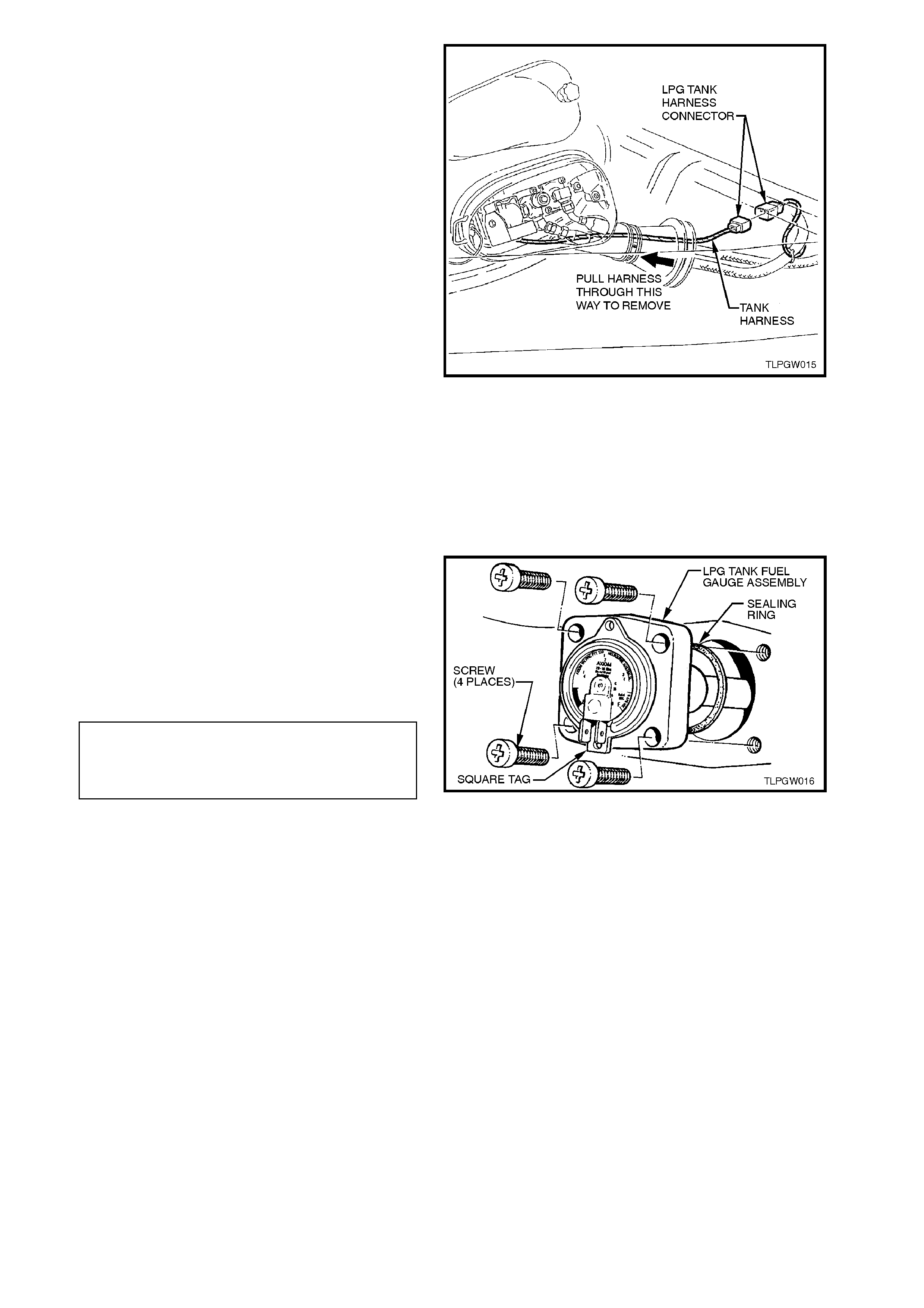
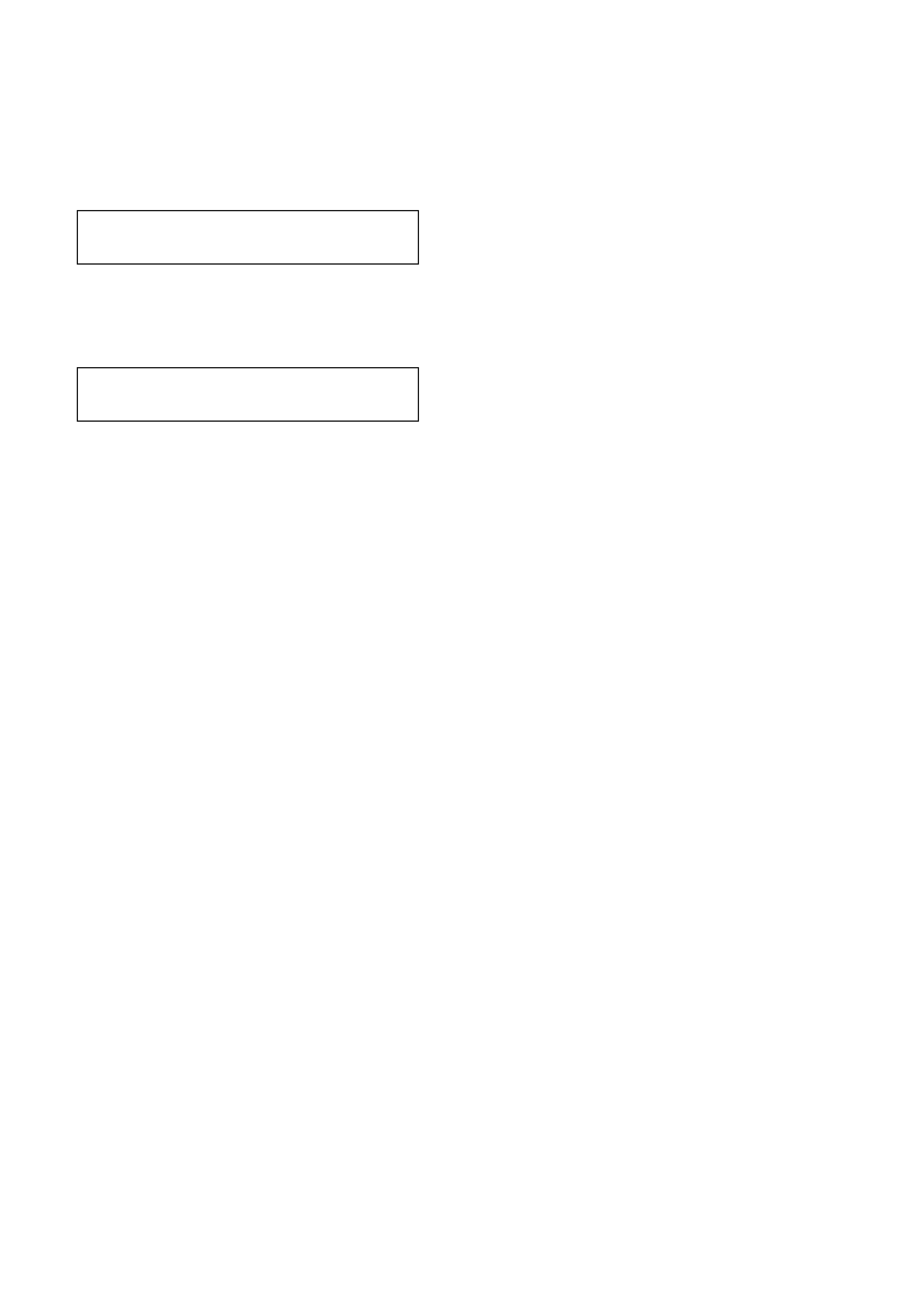
7. From under the vehicle, disconnect LPG body
harness connector from LPG tank harness
connector, refer to Fig 2A-21.
From inside the luggage compartment, gently
pull LPG tank harness through the valve box
vent tube towards the LPG tank, refer to Fig
2A-21.
Figure 2A-21
8. If not already removed, r em ove sm art unit and
solenoid valve assembly from the manual
valve, refer 2.8 SMART UNIT AND
SOLENOID VALVE in this Section.
9. Unscrew the four manual service valve
attaching screws and remove the manual
service valve from LPG tank, refer to Fig. 2A-
23.
10. Install new LPG tank fuel gauge assembly to
LPG tank sealing ring, install LPG tank fuel
gauge assembly taking care to install
assembly with gauge up the right way. Install
and tighten LPG tank fuel gauge assembly
attaching screws to the correct torque
specification. Reconnect wiring harness
connectors to gauge terminals.
LPG TANK FUEL GAUGE
ASSEMBLY TO LPG TANK 5.0 - 7.0
ATTACHING SCREW Nm
TORQUE SPECIFICATION
Figure 2A-22
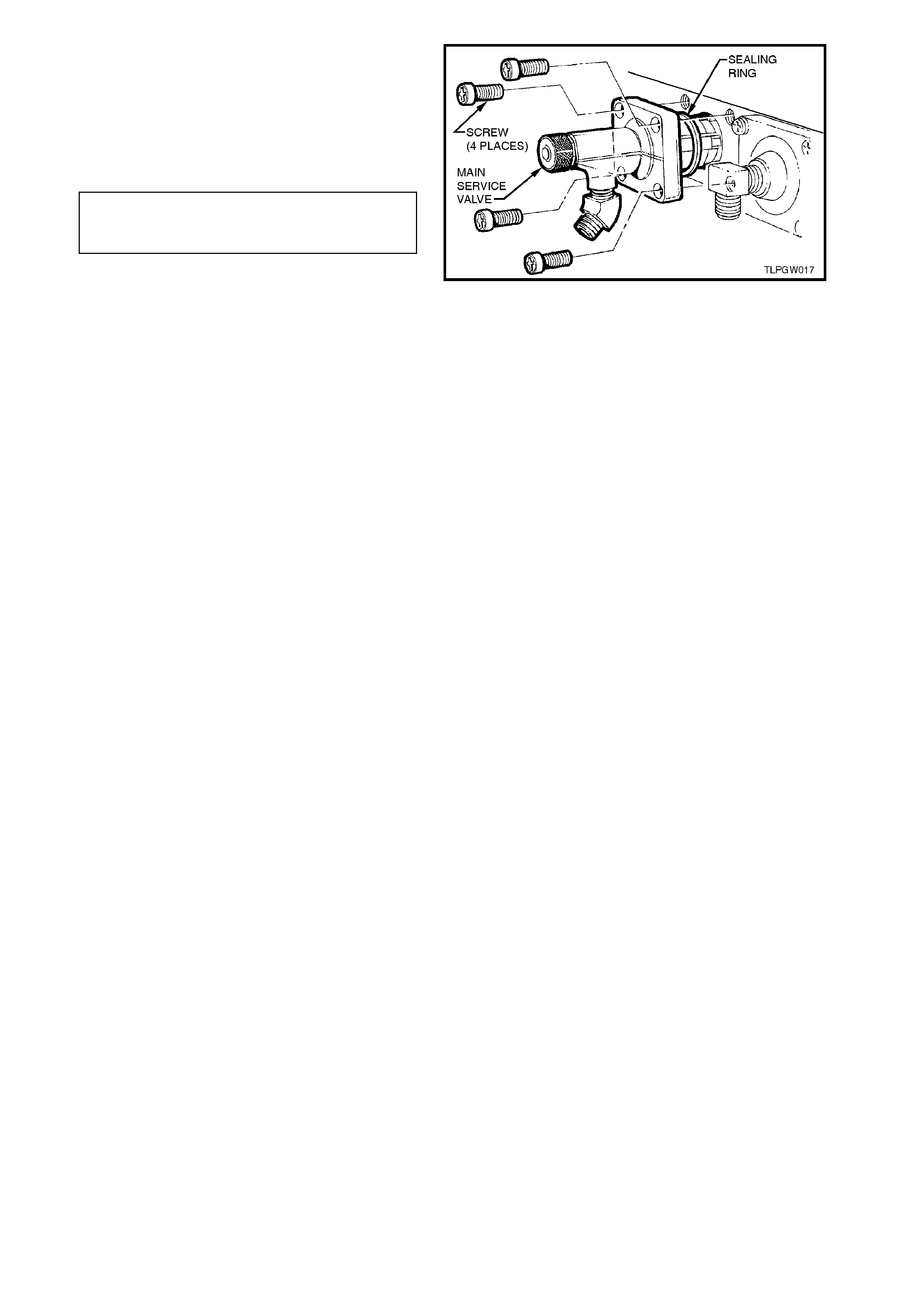
11. Install new manual service valve to LPG tank
sealing ring and the new manual s ervice valve
assembly. Take care to install the valve so that
the valve elbow for the service line connection
is pointing In the correct direction. Install and
tighten the four m anual ser vice valve attaching
screws to the correct torque specification.
MANUAL SERVICE VALVE TO
LPG TANK ATTACHING SCREW 5.0 - 7.0 Nm
TORQUE SPECIFICATION
12. Reinstall the smart unit and solenoid valve,
refer 2.8 SMART UNIT AND SOLENOID
VALVE in this Section.
13. Reconnect LPG body wiring harness
connector to LPG tank harness connector.
14. Reconnect rear service line to manual service
valve and tighten to the correct torque
specification, refer 2.13 SERVICE LINES in
this Section.
15. Tighten valve box vent tube retaining screws
and hose clamp.
16. Pressure and leak test LPG tank in
accordance with the current Australian
Standard AS2030.1
17. Carry out system leak testing, refer
2.3 LEAK TESTING in this Section.
Figure 2A-23
2.8 SMART UNIT AND SOLENOID VALVE
REMOVE
1. Park the vehic le in a well ventilated area, away
from any ignition source.
2. Drain the LPG service lines, refer
2.1 DRAINING THE SERVICE LINES in this
Section.
3. Ensure the manual service valve is turned
'OFF' and the battery earth lead is
disconnected.
Figure 2A-24
4. Disconnect the rear service line to the tank
and pull rear ser vic e line through the valve box
vent tube.
5. Loosen and remove the two screws securing
the valve box vent tube to the LPG tank.
Loosen the hose clam p securing the grommet
to the valve box vent tube.
6. From under the vehicle, disconnect LPG body
harness connector from LPG tank harness
connector 2A-25.
From inside the luggage compartment, gently
pull LPG tank harness through the valve box
vent tube towards the tank valves.
Figure 2A-25
7. Remove smart unit retaining screw from end
of the assembly.
8. Slide the smart unit and solenoid coil from the
solenoid sleeve and manual service valve.
9. Loosen and remove solenoid sleeve from
manual service valve, ensuring that solenoid
valve is also removed.
Separate solenoid valve from the sleeve.
Discard the solenoid sleeve to m anual service
valve 'O' ring.
10. Disconnect LPG tank harness connectors
from tank fuel contents gauge terminals.
Figure 2A-26
REINSTALL
Reinstallation of the smart unit and solenoid coil to
the manual service valve is the reverse of removal
procedures, noting the following points:
1. Ensure new 'O' ring is fitted to solenoid sleeve.
2. Tighten solenoid sleeve to the manual service
valve to the correct torque specification.
SOLENOID SLEEVE TO
MANUAL SERVICE VALVE
TORQUE SPECIFICATION 15 - 18 Nm
3. Once installed, ensure that the smart unit
retaining screw is tightened to the correct
torque specification.
SMART UNIT
RETAINING SCREW
TORQUE SPECIFICATION 1 - 3 Nm
4. Reconnect rear service line to manual service
valve and tighten to the correct torque
specification, refer 2.13 SERVICE LINES in
this Section.
5. Leak test LPG system, refer to
2.3 LEAK TESTING in this Section.
6. Once installed, check vehicle operation on
LPG and petrol.
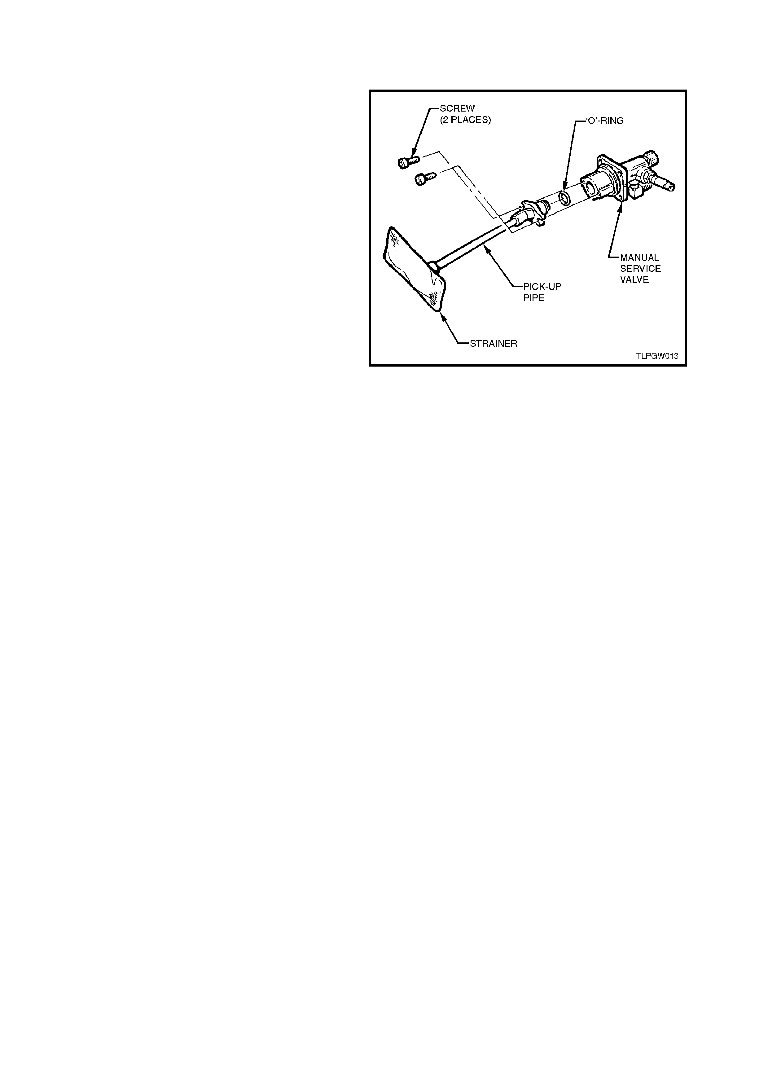
2.9 PICK-UP PIPE AND STRAINER
REMOVE
Remove the solenoid and manual service valve,
refer 2.7 SOLENOID AND MANUAL SERVICE
VALVE ASSEMBLY in this Section.
Remove the two screws retaining the LPG pick-up
pipe and strainer to the manual valve ass embly and
twist the pick -up pipe and strainer out from the rear
of the manual service valve.
REINSTALL
Reinstallation of the LPG pick-up pipe and strainer
is the reverse of the rem oval procedure, noting the
following point:
Ensure the O-r ing on the end of the pick -up pipe is
installed correctly.
Figure 2A-27
2.10 AUTOMATIC FILL LIMITER
TEST
The proc edure for testing the Autom atic Fill Limiter
(AFL) on VT Wagon Models is the same as the
procedure detailed in oper ation 2.10 AUTOM AT IC
FILL LIMITER under VT Sedan With Production
LPG of the VT Series Service Information CD,
noting the following:
The LPG tank ‘fillable’ capacity for VT Wagon
Models is 60 litres ± 2 litres.
REPLACE
The automatic fill limiter should only be replaced if
it proves to be faulty.
1. Park the vehic le in a well ventilated area, away
from any ignition source.
2. Drain the LPG service lines, refer
2.1 DRAINING THE SERVICE LINES in this
Section.
3. Ensure the manual service valve is turned
'OFF' and the battery earth lead is
disconnected.
Figure 2A-28
4. Unload the LPG tank of LPG, refer
2.2 LPG TANK UNLOADING PROCEDURE
in this Section.
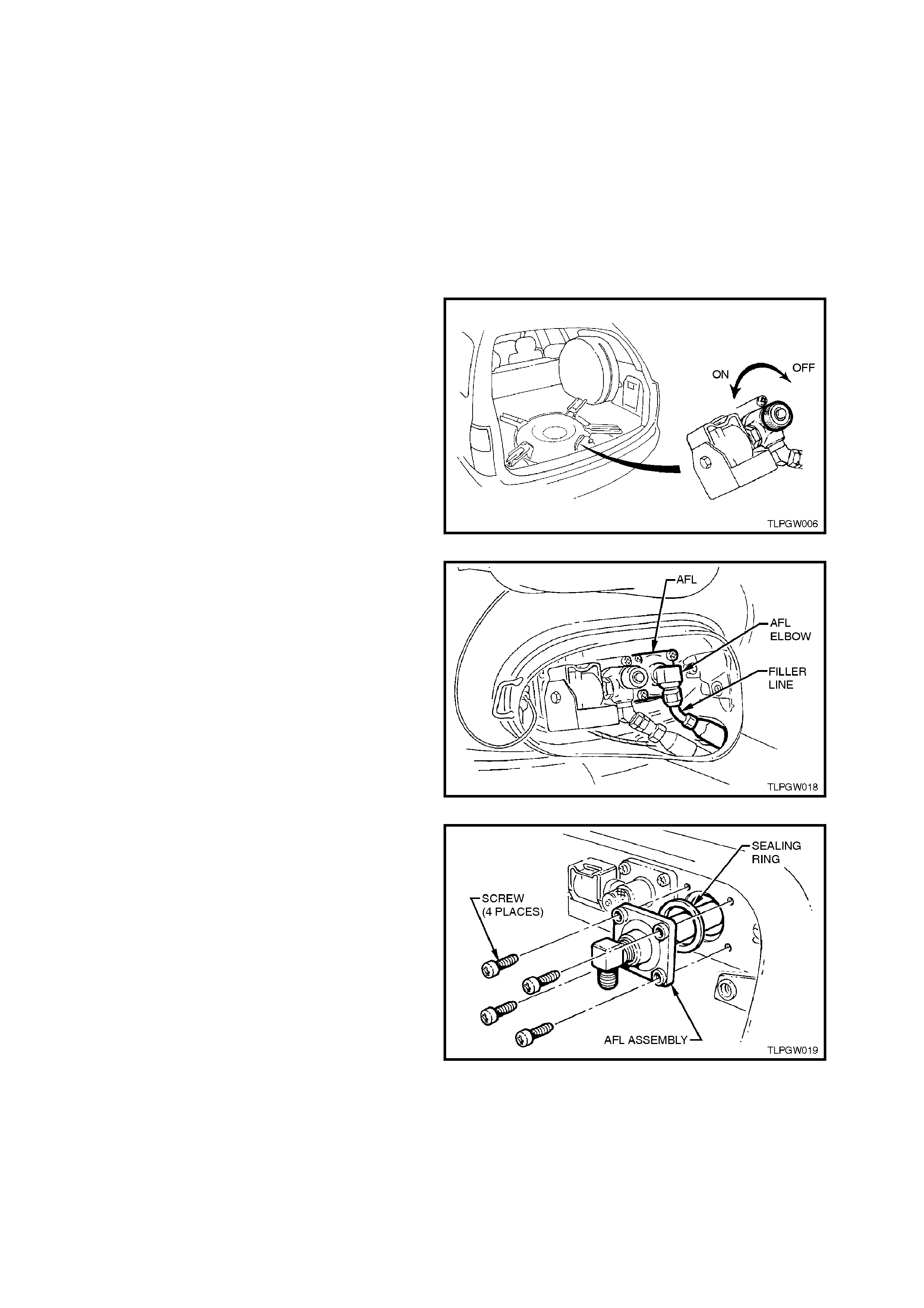
5. From inside the LPG tank valve box, while
holding AFL elbow, crack open filler line hose
to AFL elbow connector and allow residual
LPG to escape.
CAUTION:
The filler line will contain LPG under pressure.
Once all the LPG in the line has dispersed,
unscrew filler line hose connector completely
from the AFL elbow.
Figure 2A-29
6. Unscr ew the four autom atic fill lim iter retaining
screws and remove automatic fill limiter from
the LPG tank.
Figure 2A-30
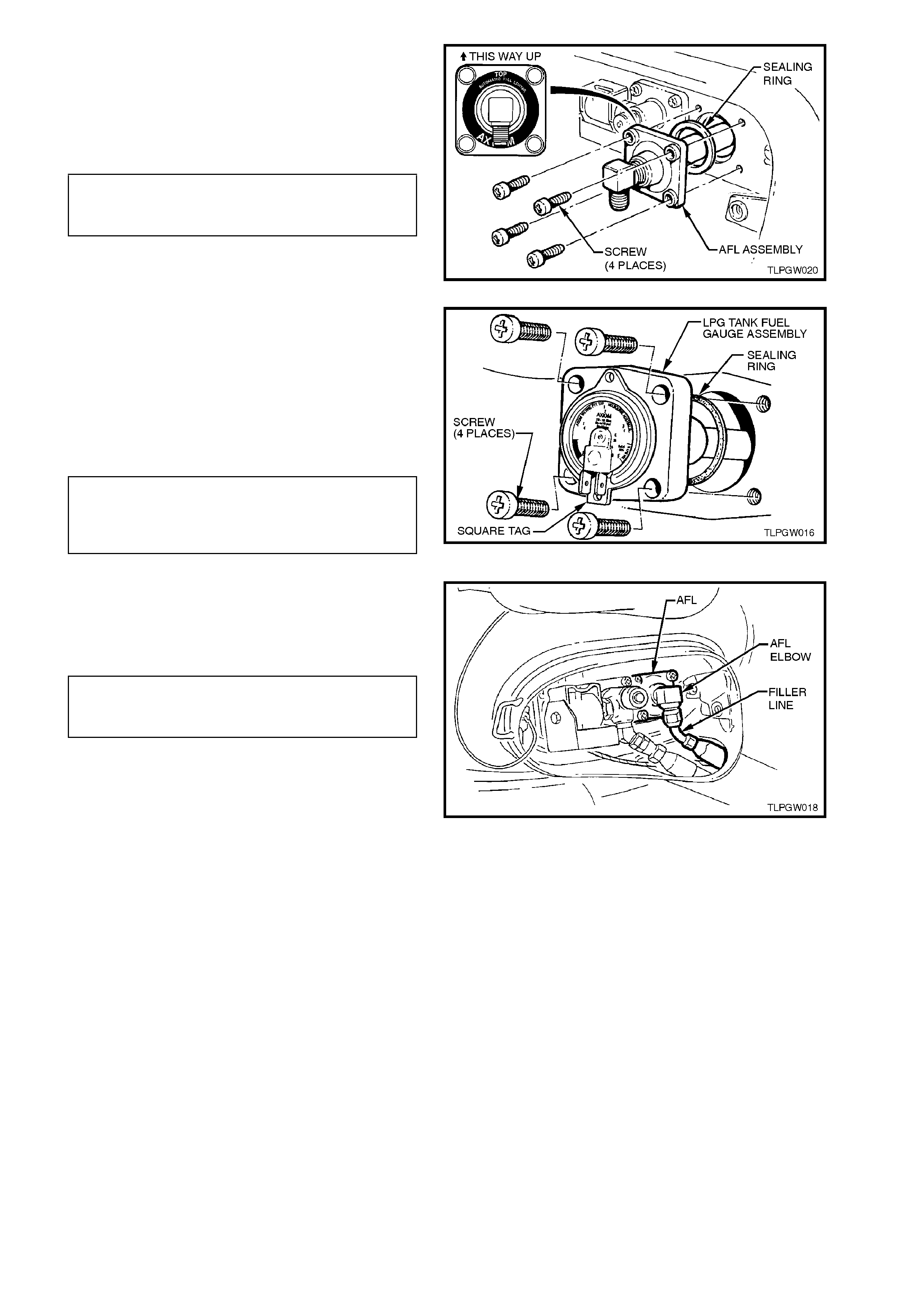
7. Install new automatic fill limiter to LPG tank
sealing ring and the autom atic fill limiter. Take
care to install the automatic fill lim iter the right
way up. Install and tighten the four automatic
fill limiter attaching screws to the correct
torque specification.
AUTOMATIC FIL L LIMITER TO
LPG TANK ATTACHING SCREW 5.0 - 7.0 Nm
TORQUE SPECIFICATION
Figure 2A-31
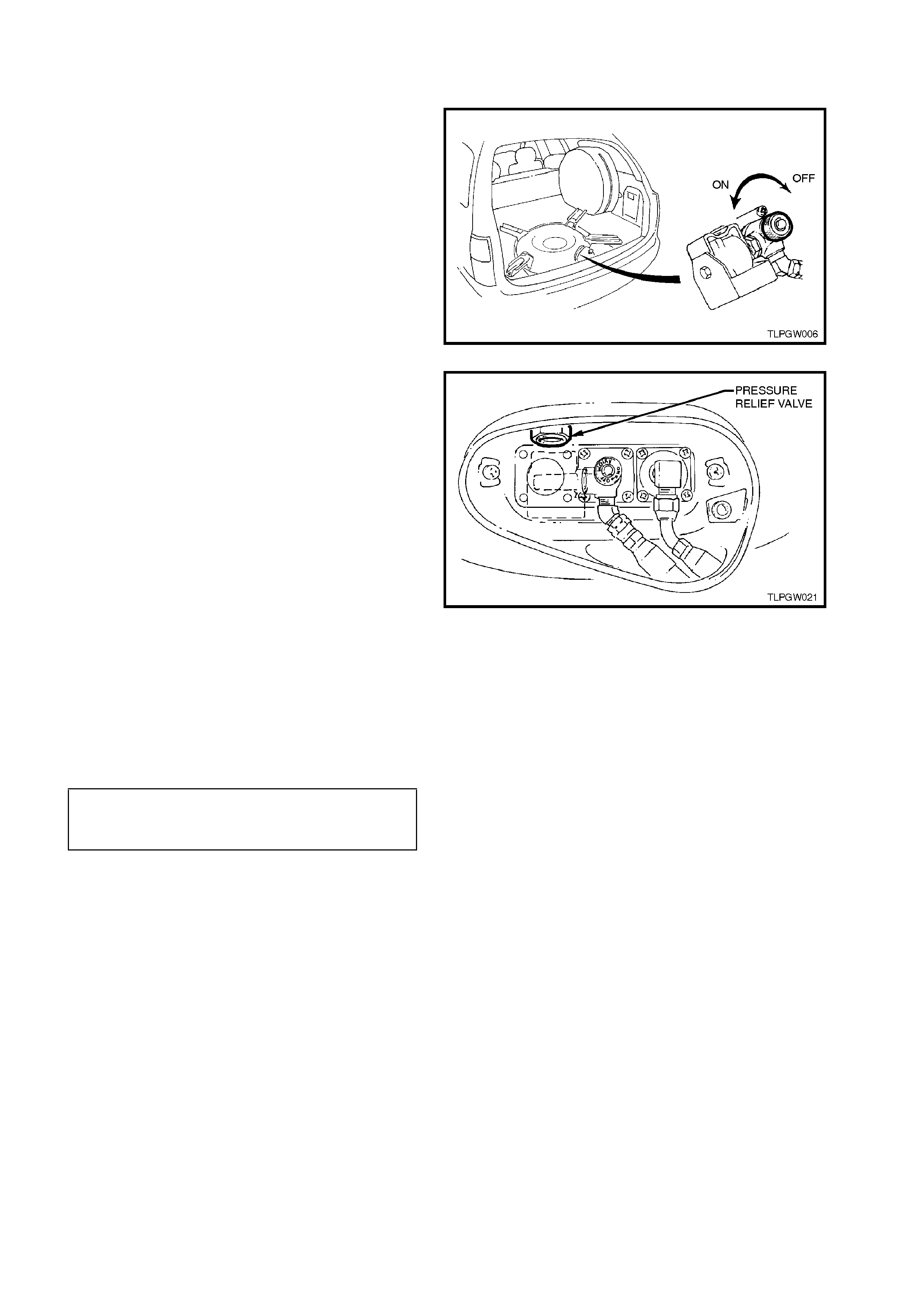
8. Install new LPG tank fuel gauge assembly to
LPG tank sealing ring, install LPG tank fuel
gauge assembly taking care to install
assembly with gauge up the right way. Install
and tighten LPG tank fuel gauge assembly
attaching screws to the correct torque
specification. Reconnect wiring harness
connectors to gauge terminals.
LPG TANK FUEL GAUGE
ASSEMBLY TO LPG 5.0 - 7.0
TANK ATTACHING SCREW Nm
TORQUE SPECIFICATION
Figure 2A-32
9. Ensuring that flared surfaces are free of
sealant and contaminants, connect filler line
hose to AFL elbow and tighten to the correct
torque specification.
FILLER LINE HOSE CONNECTOR
TO AFL ELBOW SCREW 12.0 - 18.0 Nm
TORQUE SPECIFICATION
10. Pressure and leak test LPG tank in
accordance with the current Australian
Standard AS2030.1.
11. Carry out system leak testing, refer
2.3 LEAK TESTING in this Section. Figure 2A-33
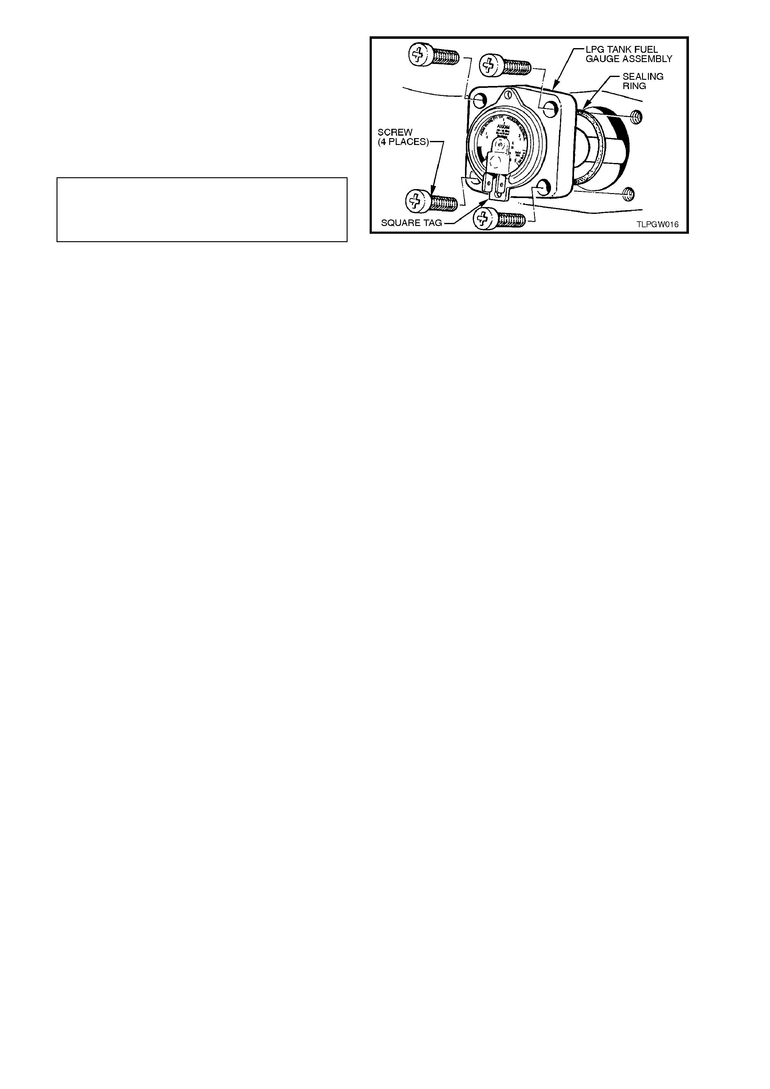
2.11 PRESSURE RELIEF VALVE
REPLACE
NOTE:
The pr essure re lief valve should only be r eplaced if
it proves to be leaking.
1. Park the vehic le in a well ventilated area, away
from any ignition source.
2. Drain the LPG service lines, refer
2.1 DRAINING THE SERVICE LINES in this
Section.
3. Ensure the manual service valve is turned
'OFF' and the battery earth lead is
disconnected.
Figure 2A-34
4. Unload the LPG tank of LPG, refer
2.2 LPG TANK UNLOADING PROCEDURE
in this Section.
NOTE:
The smart unit and solenoid valve is removed
during the unloading procedure.
5. Using a 1 1/16 inch socket and breaker bar,
loosen and remove the pressure relief valve
from the LPG tank.
NOTE:
It may be necessary to install a tube over the end of
the breaker bar to enable greater leverage to be
applied for loosening the valve.
6. Ensure that new relief valve and LPG tank
mating threads are clean.
Apply Loctite 577 sealant to the valve threads
and a small amount to the tank mating
threads.
7. Tighten pressure relief valve to the correct
torque specification.
PRESSURE RELIEF VALVE
TO LPG TANK 60 Nm
TORQUE SPECIFICATION
Figure 2A-35
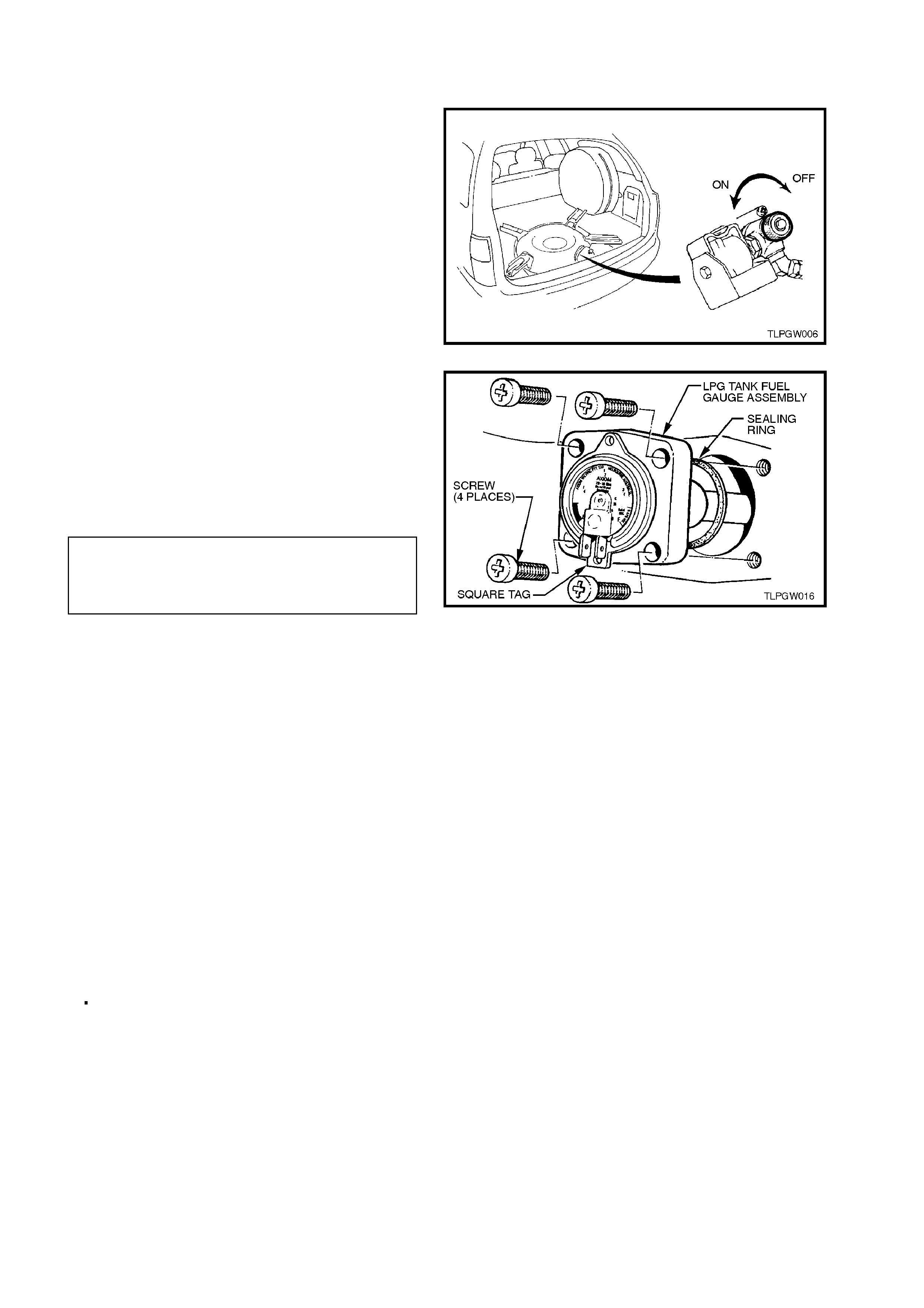
8. Install new LPG tank fuel gauge assembly to
LPG tank sealing ring, install LPG tank fuel
gauge assembly taking care to install
assembly with gauge up the right way. Install
and tighten LPG tank fuel gauge assembly
attaching screws to the correct torque
specification. Reconnect wiring harness
connectors to gauge terminals.
LPG TANK FUEL GAUGE
ASSEMBLY TO LPG 5.0 - 7.0
TANK ATTACHING SCREW Nm
TORQUE SPECIFICATION
9. Reinstall the smart unit and solenoid valve,
refer 2.8 SMART UNIT AND SOLENOID
VALVE in this Section.
10. Pressure and leak test LPG tank in
accordance with the current Australian
Standard AS2030.1
11. Carry out system leak testing, refer
2.3 LEAK TESTING in this Section.
Figure 2A-36
2.12 TANK FUEL GAUGE ASSEMBLY
REPLACE
1. Park the vehic le in a well ventilated area, away
from any ignition source.
2. Drain the LPG service lines, refer
2.1 DRAINING THE SERVICE LINES in this
Section.
3. Ensure the manual service valve is turned
'OFF' and the battery earth lead is
disconnected.
4. Unload the LPG tank of LPG, refer
2.2 LPG TANK UNLOADING PROCEDURE
in this section.
Figure 2A-37
5. Install new LPG tank fuel gauge assembly to
LPG tank sealing ring, install LPG tank fuel
gauge assembly taking care to install
assembly with gauge up the right way. Install
and tighten LPG tank fuel gauge assembly
attaching screws to the correct torque
specification. Reconnect wiring harness
connectors to gauge terminals.
LPG TANK FUEL GAUGE
ASSEMBLY TO LPG 5.0 - 7.0
TANK ATTACHING SCREW Nm
TORQUE SPECIFICATION
6. Reinstall the smart unit and solenoid valve,
refer 2.8 SMART UNIT AND SOLENOID
VALVE in this Section.
7. Pressure and leak test LPG tank in
accordance with the current Australian
Standard AS2030.1
8. Carry out system leak testing, refer
2.3 LEAK TESTING in this Section.
Figure 2A-38
CONTENTS GAUGE
The procedure for removing, testing and
reinstalling the LPG contents gauge is as detailed
in Section 2.12 CYLINDER FUEL GAUGE
ASSEMBLY under VT Sedan With Production LPG
of the VT Series Service Information CD, noting the
following:
To r einstall the smar t unit and solenoid valve, refer
to 2.8 SMART UNIT AND SOLENOID VALVE in
this Section.

2.13 SERVICE LINES
FRONT SERVICE LINE
The procedure for removing and reinstalling the
front s er vice line on VT Wagon Models is the s ame
as the procedure published for VT Sedan Models.
Theref ore, ref er to Section 2.13 SERVICE L INES
- FRONT SERVICE LINE under VT Sedan With
Production LPG of the VT Series Service
Information CD.
INTERMEDIATE SERVICE LINE
The intermediate service line is incorporated into
the fuel and brake pipe harness assembly and,
therefore, not serviced separately. For additional
information, refer to Section 8A FUEL TANK of
the VT Series Service Information CD.
NOTE:
Ensure heat protective shield is installed over
intermediate service line near the exhaust
manifold.
REAR SERVICE LINE
REMOVE
1. Park the vehic le in a well ventilated area, away
from any ignition source.
2. Drain the LPG service lines, refer
2.1 DRAINING THE SERVICE LINES in this
Section.
3. Ensure the manual service valve is turned
'OFF'.
4. De-pressur ise the fuel (petrol) system , refer to
Section 6C1 POWERTRAIN MANAGEMENT
of the VT Series Service Information CD.
5. Ensure the battery earth lead is disconnected.
6. Remove the fuel (petrol) tank assembly, refer
to Section 8A FUEL TANK of the VT Series
Service Information CD. Figure 2A-39
7. From inside the LPG tank valve box, loosen
and unscrew the rear service line connector
from solenoid and manual service valve
assembly, refer to Fig. 2A-40.
Figure 2A-40
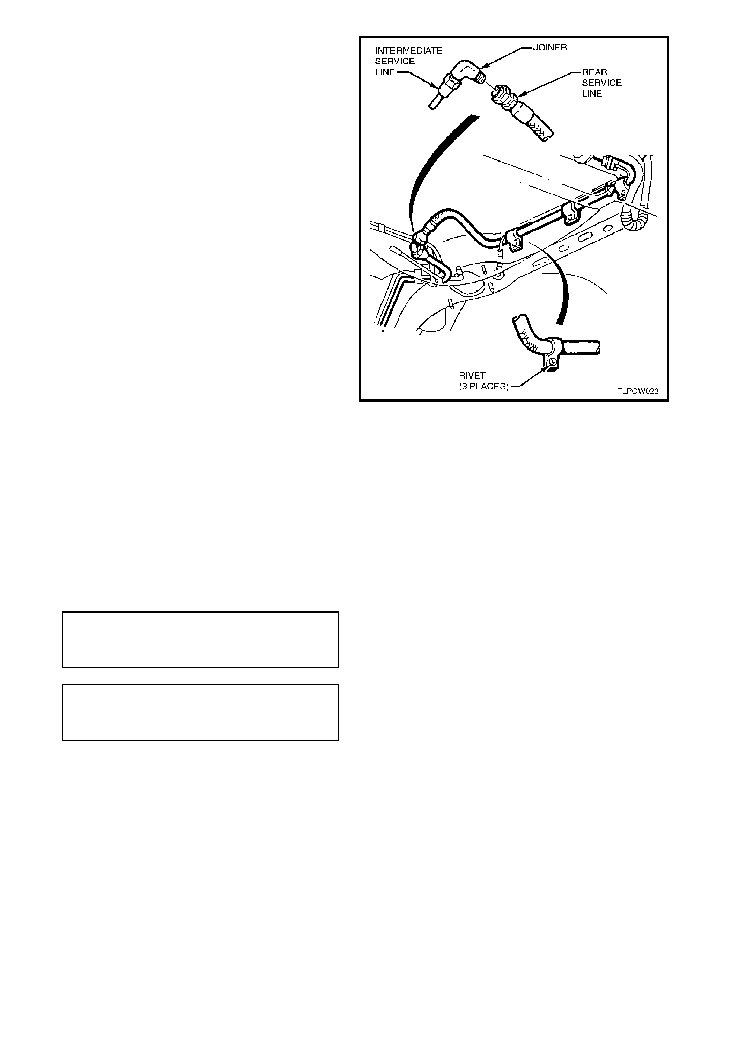
8. From under vehicle, while holding the
intermediate to rear service line joiner from
turning, loosen and unscrew the rear service
connector fr om the s ervic e line joiner , r ef er Fig
2A-41.
9. Using a suitable sized drill bit, drill into the
heads of the rear service line retaining pop
rivets (refer Fig. 2A-41) and remove the rear
service line.
10. Using a suitable size pin punch and hammer,
knock out remains of the rear service line
securing pop rivets from vehicle underbody.
Figure 2A-41
REINSTALL
Reinstallation of the r ear service line is the reverse
of the removal procedure, noting the following:
1. Clean rear service line mating threads on
solenoid and manual service valve assembly,
intermediate to rear service line joiner, and
both rear service line connectors.
2. Ensuring that flared surfaces are free of
sealant and contam inants, tighten rear service
line connections to the correct torque
specifications.
REAR SERVICE LINE
CONNECTION TO SERVICE
LINE JOINER VALVE
TORQUE SPECIFICATION
12.0 - 15.0
Nm
REAR SERVICE LINE
CONNECTION TO SOLENOID
AND MANUAL SERVICE VALVE
TORQUE SPECIFICATION
12.0 - 18.0
Nm
3. Secure rear service line using new pop rivets
before fuel (petrol) tank is reinstalled.
4. Before starting vehicle or opening the manual
service valve, carry out a fuel (petrol) system
leak test as detailed in
Section 6C1 POWERTRAIN MANAGEMENT
- V6 ENGINE of the VT Series Service
Information CD.
5. Carry out LPG system leak test, refer
2.3 LEAK TESTING in this Section.
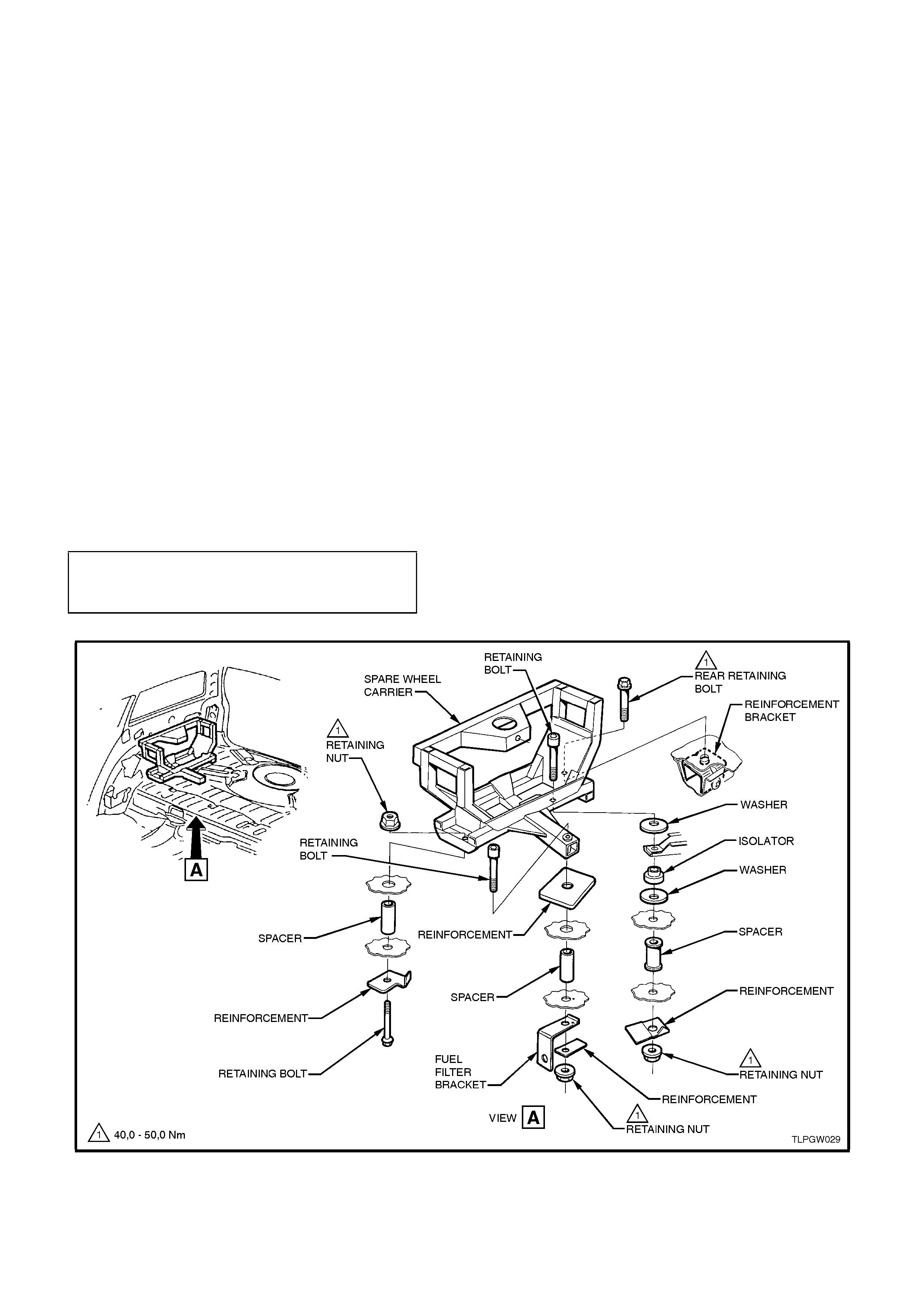
2.14 SPARE WHEEL CARRIER
REMOVE
1. Remove spare wheel cover and spare wheel
from the spare wheel carrier.
2. Remove the luggage com partm ent f loor cover,
refer 2.15 LUGGAGE COMPARTMENT
FLOOR COVER in this Section.
3. With the aid of an assistant, loosen and
remove the four bolts and three nuts securing
the spare wheel carrier to the rear
compartment floor, refer Fig. 2A-42.
NOTE:
The rear spare wheel carrier retaining bolt screws
into a reinforcement bracket with a captive nut.
REINSTALL
Reinstallation of the spare wheel carrier is the
reverse of the removal procedure, noting the
following:
1. Ensure spacer, isolator and reinforcement
plates are installed correctly, refer Fig. 2A-42.
2. Ensure all fasteners are tightened to the
correct torque specification.
SPARE WHEEL CARRIER
RETAINING BOLT AND NUT 40.0 - 50.0 Nm
TORQUE SPECIFICATION
Figure 2A-42
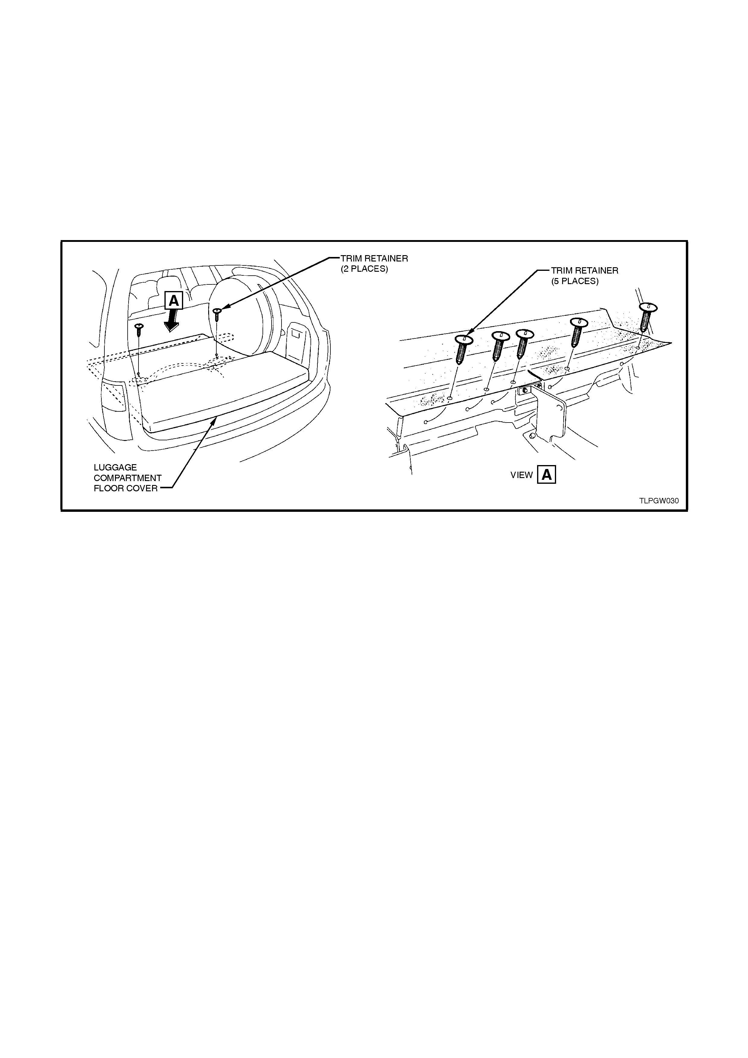
2.15 LUGGAGE COMPARTMENT FLOOR COVER
REMOVE
1. Lower the rear seat back assemblies.
2. Remove the five trim retainers from the rear of the luggage compartment floor cover.
3. Remove the two trim retainers from the centre of the luggage compartment floor cover.
4. Lifting the left hand side of the luggage compartment floor cover up 45°, remove the floor cover from the
luggage compartment.
REINSTALL
Reinstallation of the luggage compartment floor cover is the reverse of the removal procedure.
Figure 2A-43

2.16 AFTER INSTALLATION CHECK (FOR PRODUCTION FITTED LPG SYSTEMS ONLY)
GENERAL INFORMATION
At the 1,500 km (or 1 month) first service, it is a requirement of Holden Ltd. A.B.N. 84 006 893 232 that the following
‘After Installation Check’ be performed.
All items in this check list must be checked to ensure they have been adjusted or installed as outlined in this Service
Information CD.
UNDERBODY (Tick the appropriate boxes)
CHECK OK REPAIR
1. Rear service line and intermediate service line
connected to union (under vehicle) and
connectors tightened to the correct torque
specification.
!!!
2. Service lines correctly routed and retaining clips
installed. !!!
3. LPG tank/cylinder correctly installed and
attaching nuts tightened to the correct torque
specification.
!!!
REAR COMPARTMENT (Tick the appropriate boxes)
CHECK OK REPAIR
1. Floor flange installed and silicone sealer applied.
(Sedan Only) !!!
2. Service line vent tube installed to floor flange and
retaining clamps tightened. (Sedan Only) !!!
3. Service line vent tube installed to joiner and
retaining clamp tightened (Sedan Only).
Ensure vent tube grommet is installed correctly
in its location. (Wagon Only).
!!!
4. Filler line connected to joiner and LPG
tank/cylinder high pressure inlet elbow and filler
line connectors tightened to the correct torque
specification.
!!!
5. Filler installed correctly and retaining cap screws
tightened to the correct torque specification.
(Sedan Only)
Filler installed correctly and retaining nut
tightened to correct torque specification (Wagon
Only).
!!!
6. Filler lid operates without binding and shuts
flush, AFL sticker is affixed to inside of filler lid. !!!
7. Rear service line connected to solenoid and
manual service valve assembly and connector
tightened to the correct torque specification.
!!!
8. LPG tank/cylinder level sender and smart unit
harness connector is connected to LPG body
harness connector (YR50).
!!!
9. Rear compartment carpet and quarter trim
carpet have been reinstalled and are positioned
correctly.
!!!
10. Check spare wheel retainer is hand tight (Wagon
Only). !!!
11. Check spare wheel carrier is correctly installed &
nuts tightened to the correct torque specification
(Wagon Only).
!!!

UNDER BONNET (Tick the appropriate boxes)
CHECK OK REPAIR
1. The vapour line to mixer and vapour line to
converter retaining clamps are installed and
tightened.
!!!
2. The vapour line and vacuum hoses are
connected and routed correctly. !!!
3. Converter and converter bracket installed and
retaining bolts are tightened to the correct torque
specification.
!!!
4. Coolant pipe hose clamps fitted and tightened.
Coolant and vapour hoses correctly routed to
avoid contact with engine or body parts.
!!!
5. Fuel control valve (FCV) installed and FCV
retaining bolt tightened to the correct torque
specification.
!!!
6. Air intake tube installed, clamps and mounting
screw tightened to the correct torque
specification.
!!!
7. Air cleaner assembly and MAF sensor installed. !!!
8. Intermediate LPG line P clamps installed on
cockpit module and tightened to the correct
torque specification.
!!!
LEAK CHECK
With at least 3 litres of LPG in the cylinder/tank, leak test the complete LPG system as outlined in 2.3 LEAK
TESTING in this Service Information CD.(Tick the appropriate boxes)
Note: The following points must be tested. CHECK OK REPAIR
1. Pressure relief valve. !!!
2. Solenoid and manual service valve assembly to
LPG tank/cylinder. !!!
3. Solenoid and manual service valve assembly. !!!
4. Rear service line to solenoid and manual service
valve assembly connector. !!!
5. LPG tank/cylinder fuel gauge assembly. !!!
6. AFL inlet elbow to LPG tank/cylinder. !!!
7. Rear service line to AFL inlet elbow connector. !!!
8. AFL to LPG tank/cylinder. !!!
9. Filler valve to filler line and on Wagon Models,
filler line connector to filler line hose. !!!
10. Filler valve check ball. !!!
11. Rear service line to intermediate service line
joiner connection. !!!
12. Intermediate service line to rear service line
joiner connection. !!!
13. Intermediate service line to front service line
joiner connection. !!!
14. Front service line to intermediate service line
joiner connection. !!!
15. Front service line to LPG lockoff inlet connection. !!!
16. LPG lockoff inlet connection to LPG lockoff. !!!
17. LPG lockoff. !!!
18. LPG lockoff to LPG lockoff outlet connection. !!!
19. LPG lockoff outlet connection to converter. !!!