SECTION 2B - SERVICE OPERATIONS - VT SEDAN
WITH ACCESSORY FITTED LPG
CAUTION:
This vehicle will be equipped with a Supplemental Restraint System (SRS). A SRS will
consist of either seat belt pre-tensioners and a driver's side air bag, or seat belt pre-
tensioners and a driver's and front passenger's side air bags. Refer to CAUTIONS,
Section 12M, before performing any service operation on, or around any SRS
components, the steering mechanism or wiring. Failure to follow the CAUTIONS
could result in SRS deployment, resu lting in possible perso nal in jury or u nnecessary
SRS system repairs.
IMPORTANT:
When any LPG system component has been replaced or overhauled, or when the engine assembly has
been replaced or overhauled, the adaptive learn drive cycle procedures must be carried out as described in
2.23, ADAPT IVE DIGITAL PROCESSOR SET -UP PROCEDURE under VT Sedan With Production LPG of the
VT Series Service Information CD. This is because the values stored in the Adaptive Digital Processor
operational cells apply only to the previous condition of the engine or components.
2.1 LEAK TESTING
The procedure for leak testing the LPG system high pressure components on VT Series Model Sedans with
Accessory fitted LPG is the same as detailed in Section 2.3 LEAK TESTING under VT Sedan With Production
LPG of the VT Series Service Information CD, noting the following.
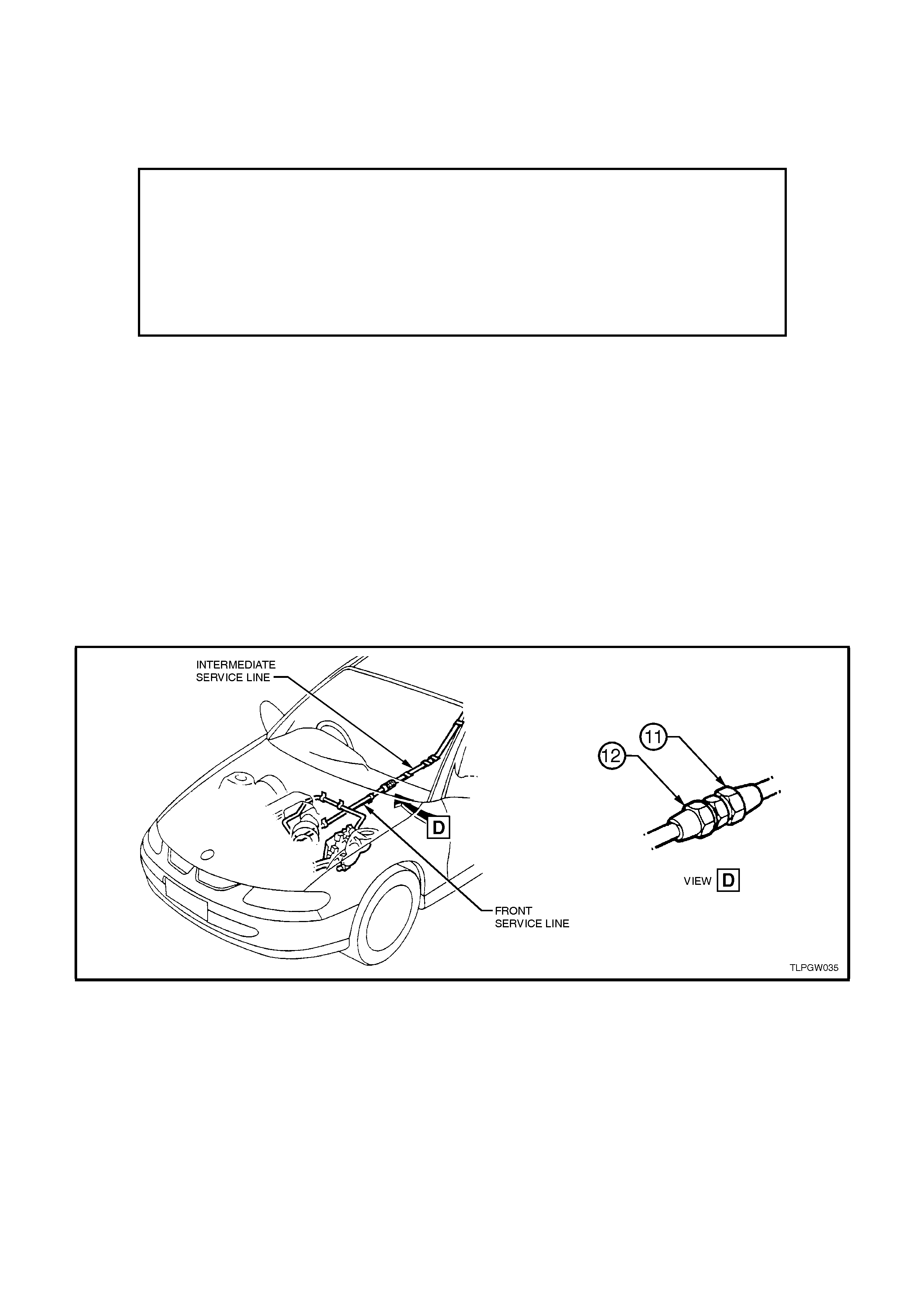
The front and intermediate service line joiner is located on the underbody on VT Sedans with accessory LPG.
Figure 2B-1
2.2 SERVICE LINES
FRONT SERVICE LINE
REMOVE
1. Park the vehic le in a well ventilated area, away
from any ignition source.
2. Drain the service lines of LPG, refer
2.1 DRAINING THE SERVICE LINES under
VT Sedan With Production LPG of the VT
Series Service Information CD.
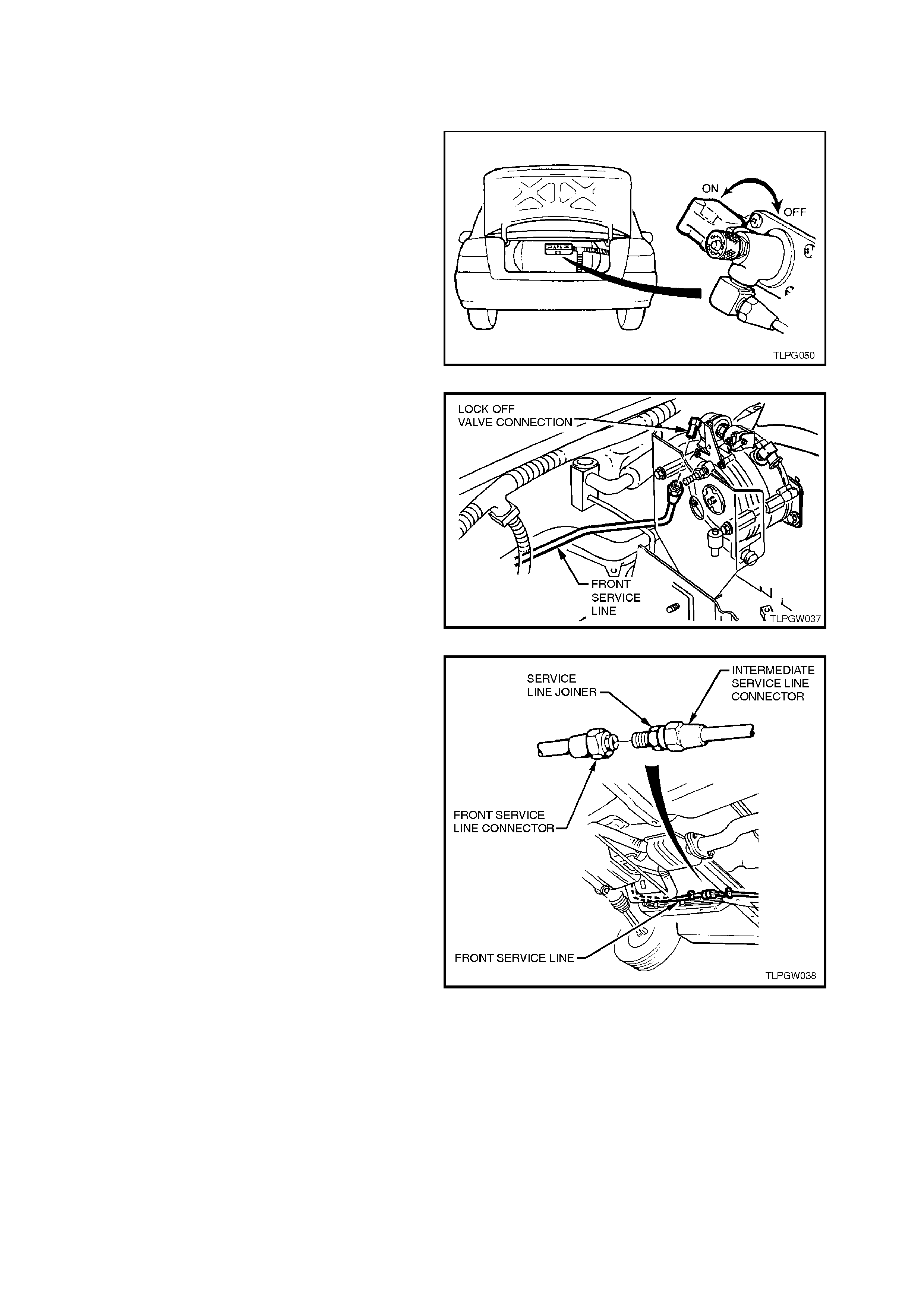
3. Ensure the manual service valve is turned
'OFF' and the battery earth lead is
disconnected.
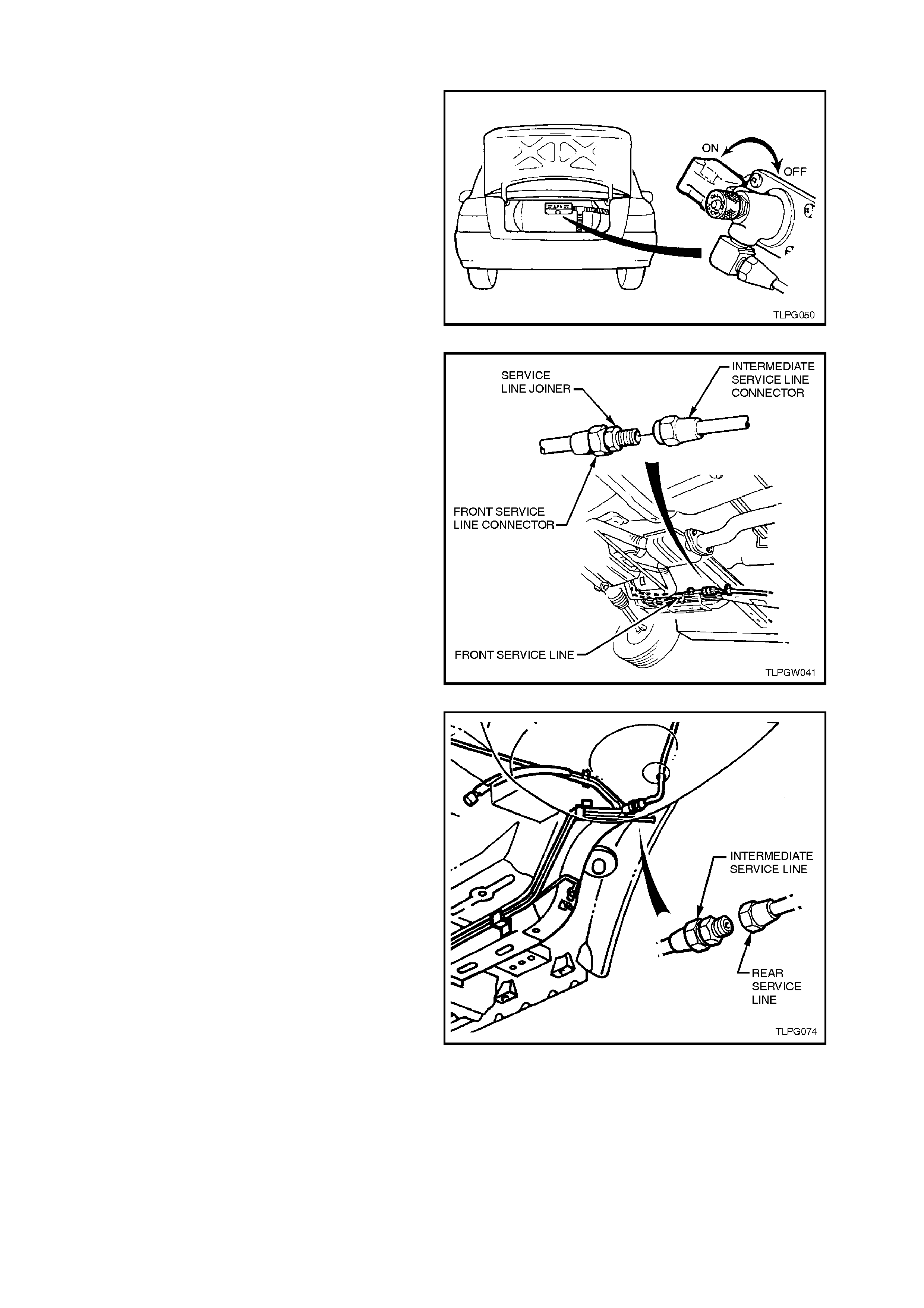
Figure 2B-2
4. Loosen and disconnect front service line
connector from LPG lockoff connection.
Figure 2B-3
5. W hile holding f ront to inter mediate service line
joiner from turning, loosen and disconnect
front service line connector from joiner and
remove front service line.
Figure 2B-4
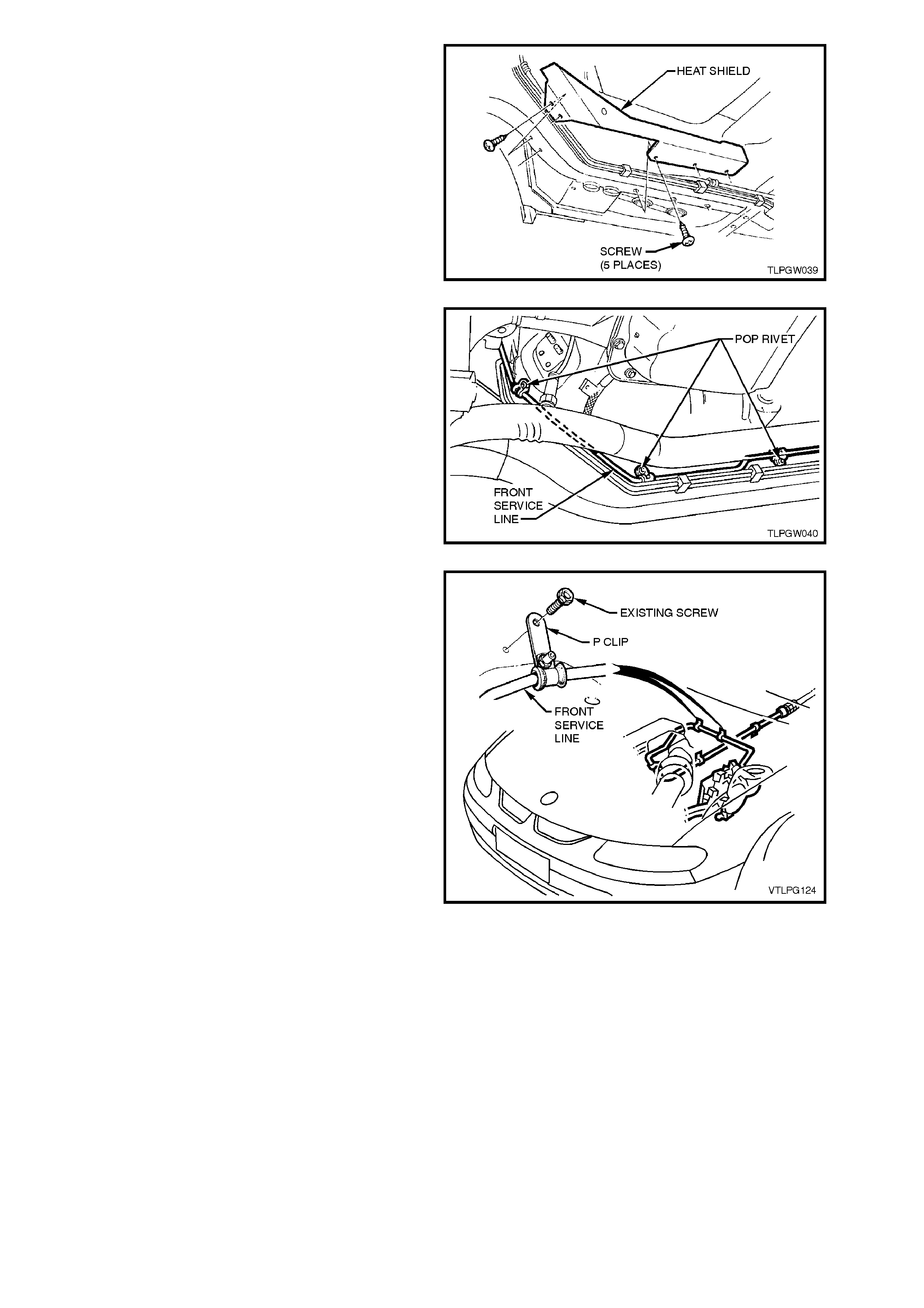
6. Remove the five screws securing the front
service line heat shield to the underbody and
remove heat shield.
7. Remove the longitudinal to front floor brace,
refer Section 1A1 BODY of the VT Series
Service Information CD.
Figure 2B-5
8. From under the vehicle, and using a suitable
sized drill bit, drill into the heads of the three
front service line retaining pop rivets.
9. Using a suitable size pin punch and hammer,
knock out remains of the three front service
line retaining pop rivets.
Figure 2B-6
10. From inside the engine compartment, remove
the two screws securing the front service line
to the cockpit module.
11. Remove the front service line from beneath
the vehicle.
Figure 2B-7
REINSTALL
1. Clean mating threads of front service line,
LPG lockoff connection and front to
intermediate service line joiner connector.
2. From under vehicle, feed the f ront service line
into the engine compartment.
3. From above, position the front service line
across the engine compartment to the LPG
lockoff.
4. Ensuring that flared surfaces are free of
sealant and contaminants, assemble front
service line connectors to LPG lockoff
connection and service line joiner and tighten
to the correct torque specification.
FRONT SERVICE LINE
TO LOCKOFF CONNECTOR
AND JOINER
TORQUE SPECIFICATION
12.0 - 15.0
Nm
5. Using new pop rivets and existing clamps,
secure the front service line to the underbody.
6. Reinstall the two screws securing the front
service line to cockpit module.
7. Reinstall the longitudinal to front floor brace
and tighten the four nuts to the correct torque
specification.
LONGITUDINAL TO FRONT
FLOOR BRACE NUT
TORQUE SPECIFICATION 25.0 - 35.0 Nm
8. Assemble the front service line heat shield to
the underbody and install securing screws.
9. Leak test LPG system, refer
2.1 LEAK TESTING in this Section.
INTERMEDIATE SERVICE LINE
MOVE
1. Park the vehic le in a well ventilated area, away
from any ignition source.
2. Drain the service lines of LPG, refer
2.1 DRAINING THE SERVICE LINES under
VT Sedan With Production LPG of the VT
Series Service Information CD.
3. Ensure the manual service valve is turned
'OFF' and the battery earth lead is
disconnected.
Figure 2B-8
4. W hile holding f ront to inter mediate service line
joiner from turning, loosen and disconnect
intermediate service line connector from
joiner.
Figure 2B-9
5. While holding the intermediate to rear service
line joiner from turning, loosen and unscrew
the rear service connector from the service
line joiner.
6. From under the vehicle, and using a suitable
sized drill bit, drill into the heads of the six
intermediate service line retaining pop rivets.
7. Remove the intermediate service line, by
feeding the service line towards the front of the
vehicle.
8. Using a suitable size pin punch and hammer,
knock out remains of the six intermediate
service line retaining pop rivets.
Figure 2B-10
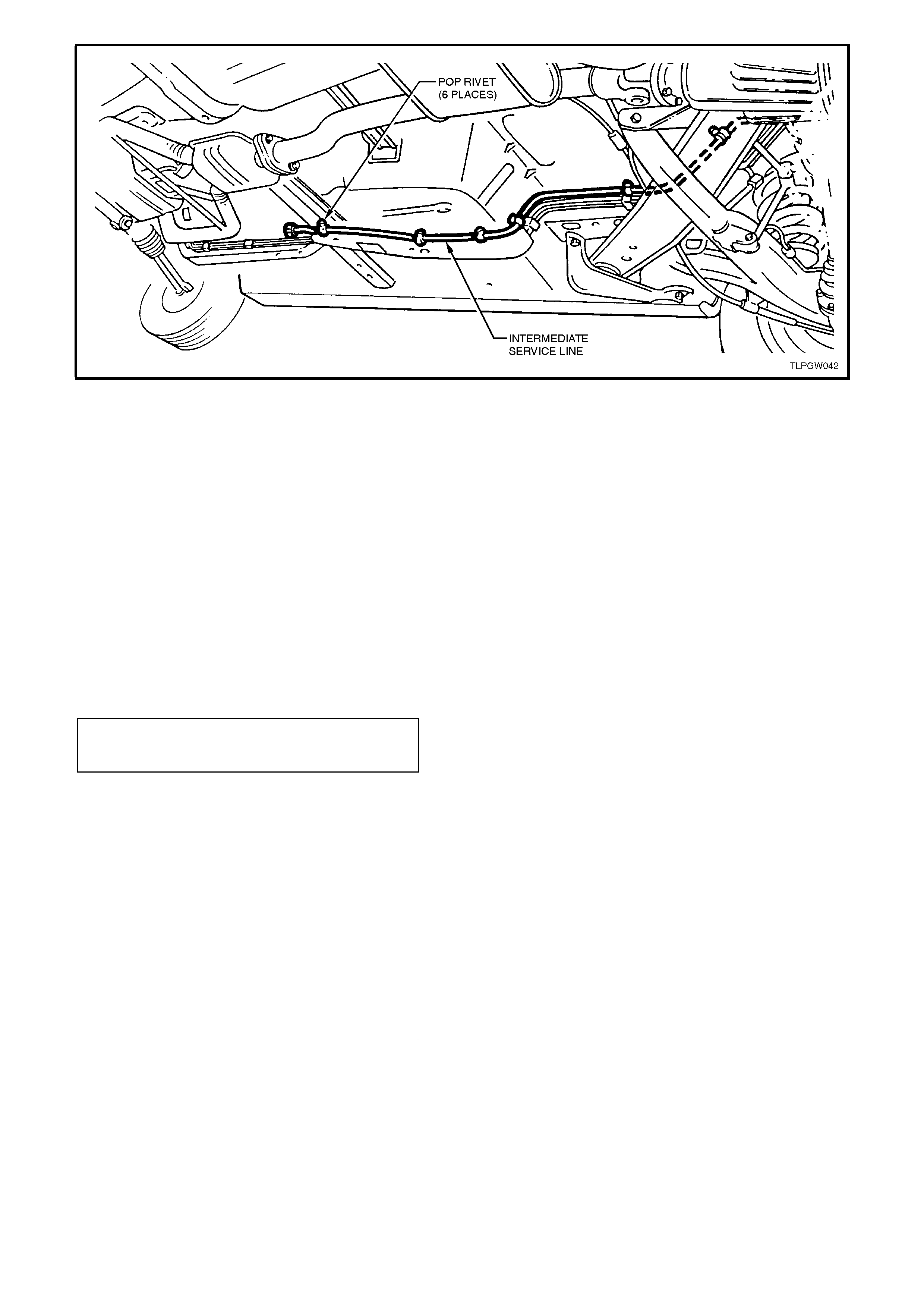
Figure 2B-11
REINSTALL
1. Clean mating threads of front to intermediate
and intermediate to rear service line joiner
connectors.
2. From under vehicle, place the intermediate
service line in position, by feeding the line
from the front of the vehicle, over the
handbrake cable, rear suspension and axle
components.
3. Ensuring that flared surfaces are free of
sealant and contaminants, assemble front to
intermediate and intermediate to rear service
line joiner connectors and tighten to the
correct torque specification.
INTERMEDIATE SERVICE
LINE CONNECTION
TORQUE SPECIFICATION 12.0 - 15.0 Nm
4. Using new pop rivets and existing clamps,
secure the intermediate service line to the
underbody (6 places), refer Fig. 2B-11.
5. Leak test LPG system, refer 2.1 LEAK
TESTING in this Section.
REAR SERVICE LINE
The procedure for removing and reinstalling the
rear service line on VT Series Sedan Models with
accessory LPG systems is the same as the
procedure published for VT Sedan Models with
production fitted LPG system s. Therefore, refer to
Section 2.13 SERVICE LINES - REAR SERVICE
LINE under VT Sedan W ith Production LPG of the
VT Series Service Information CD.

2.3 LPG RELAY
REMOVE
1. Disconnect battery earth lead.
2. Remove left hand front shroud panel lower
trim (cowl panel trim), refer
Section 1A2 UNDERBODY of the VT Series
Service Information CD.
3. Disconnect LPG interior patch harness from
LPG relay.
4. Remove LPG relay retaining screw, remove
relay.
REINSTALL
Reinstallation of the LPG relay is the reverse of the
removal procedure. Figure 2B-12
2.4 FUEL MODE SWITCH
REMOVE
1. Disconnect the battery earth lead.
2. Remove instrument panel facia far enough to
gain access to switch connectors (fuel mode,
headlamp, fog lam p, trip computer and hazard
switches) attached to instrument panel facia,
refer Section 1A3 INSTRUMENT PANEL
AND CONSOLE of the VT Series Service
Information CD.
3. Disconnect wiring harness connectors from
instrument panel facia and remove facia.
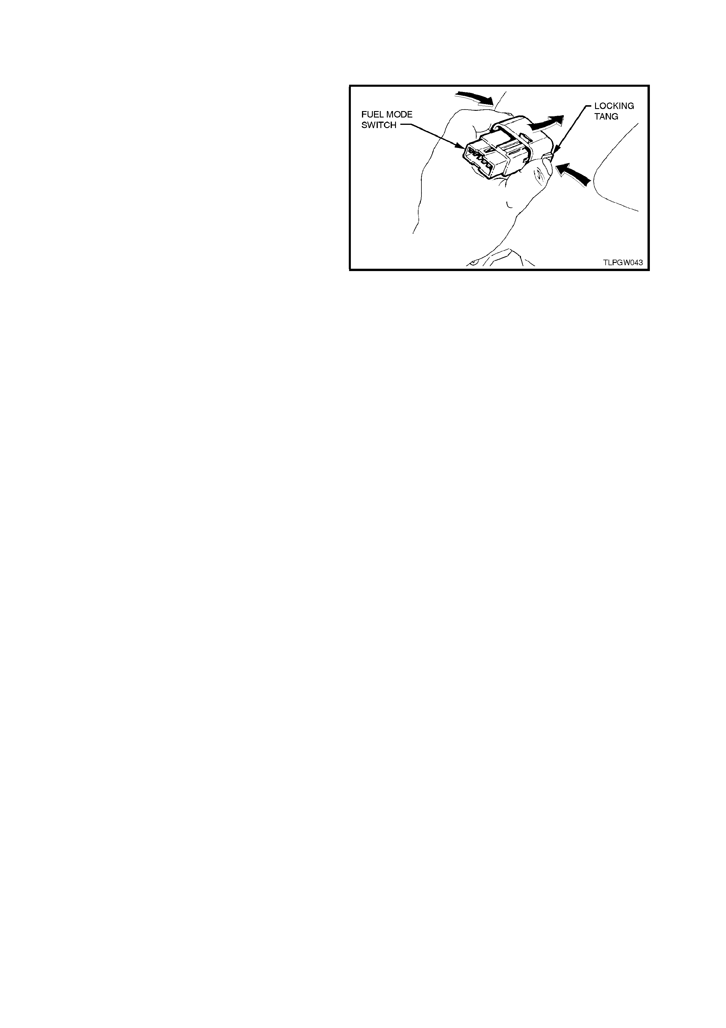
4. From behind instrument panel facia, squeeze
together fuel mode switch to instrument panel
facia retaining tangs and push switch out from
facia.
TEST
The procedure for testing the f uel mode switch on
VT Series Models with accessory fitted LPG is the
same as the procedure detailed for VT Series
Sedans with production fitted LPG systems.
Therefore, refer to operation 2.22 FUEL MODE
SWITCH under VT Sedan With Production LPG of
the VT Series Service Information CD.
Figure 2B-13
REINSTALL
Reinstallation of the fuel mode switch is the reverse
of the removal procedure.

2.16 AFTER INSTALLATION CHECK (FOR ACCESSORY FITTED LPG SYSTEMS ONLY)
GENERAL INFORMATION
On completion of the LPG installation and at the 1,500 km (or 1 month) first service, it is a requirement of Holden
Ltd. A.B.N. 84 006 893 232 that a copy of the following ‘After Installation Check’ list be completed and filled out by the
fitting dealer to ensure a high quality installation standard. Be advised that Holden Ltd. reserves the right at any time
to audit any ‘After Installation Check’ list sheet.
All items in this check list must be checked to ensure they have been installed, adjusted or reinstalled as outlined in
the Fitting Instructions, or applicable Service Manual.
DATE: ____________________________________ VEHICLE: _____________________________________
VIN No. REGISTRATION No. ______________________ REGISTRATION No. ________________________
Kit No. _____________________________________________________________________________________
AUTHORISED DEALER: _______________________________ LICENCE No: _________________________
FITTER: ____________________________________________ LICENCE No. _________________________
UNDERBODY (Tick the appropriate boxes)
CHECK OK REPAIR
1. Rear service line and intermediate service line
connected to joiner (near grommet in rear
longitudinal) and connectors tightened to the
correct torque specification.
!!!
2. Front and intermediate service lines connected
to joiner, just forward of brake/fuel pipe harness
cover, and connectors tightened to the correct
torque specification.
!!!
3. Front and intermediate service lines are not
chafing or in contact with brake, petrol or
evaporative lines, body or any other component.
!!!
4. Front and intermediate service lines correctly
routed and retaining clips installed. !!!
5. LPG cylinder correctly installed and attaching
nuts tightened to the correct torque specification. !!!
6. Rear springs installed and rear shock absorber
mounting bolts tightened to the correct torque
specification.
!!!
7. Drive shafts and constant velocity joint to
trunnion flange attaching bolts are tightened to
the correct torque specification.
!!!

VEHICLE INTERIOR (Tick the appropriate boxes)
CHECK OK REPAIR
1. All the following LPG body harness connections
are installed. !!!
a. LPG body harness fuel mode switch
connector to fuel mode switch. !!!
b. 3 Amp fast blow fuse installed in LPG main
wiring harness (under RHF lower instrument
panel).
!!!
c. LPG body harness 10 pin connector to LPG
engine harness connector. !!!
d. LPG body harness 9 pin ADP connector to
ADP. !!!
e. LPG body harness single lead PCM terminals
are inserted to PCM connector as follows:
Violet lead into cavity A9 of connector 2,
YB188.
Pink/Black lead into cavity E1, White/Green
lead into cavity E5 and Pink/Blue lead into
cavity E11 of connector 3, YB194.
Anti-backout combs reinstalled.
!!!
2. LPG body harness routed along rocker panel
from RHF shroud lower trim (kick panel) and tie
strapped to existing wiring harness.
!!!
3. Rear seat cushion and RHR seat back
reinstalled. !!!
4. RH rocker panel cover installed. !!!
5. RHF instrument panel lower trim assembly and
instrument panel facia reinstalled with fuel mode
switch installed and connected to LPG main
harness.
!!!
6. LPG body harness routing not impairing heater
valve.
Operate heater controls to ensure the harness
routing does effect their operation.
!!!
7. ADP installed and retaining screws tightened to
the correct torque specification. ADP vacuum
supply hose is connected to ADP without any
kinks in the vacuum hose.
!!!
8. PCM connectors are installed correctly. !!!
9. LH shroud lower trim (kick panel) assembly and
rocker panel cover installed. !!!
10. All instrument panel controls function correctly. !!!

REAR COMPARTMENT (Tick the appropriate boxes)
CHECK OK REPAIR
1. Floor flange installed and silicone sealer applied. !!!
2. Service line vent tube installed to floor flange and
retaining clamps tightened. !!!
3. Service line vent tube joiner installed and
retaining clamp tightened. !!!
4. Filler line connected to joiner and LPG cylinder
high pressure inlet elbow and filler line
connectors tightened to the correct torque
specification.
!!!
5. Filler valve flange installed correctly and retaining
cap screws tightened to the correct torque
specification.
!!!
6. Filler lid operates without binding and shuts
flush, AFL sticker is affixed to inside of filler lid. !!!
7. Rear service line connected to solenoid and
manual service valve assembly and connector
tightened to the correct torque specification.
!!!
8. LPG cylinder level sender and smart unit
harness connector is connected to LPG body
harness connector.
!!!
9. Rear compartment carpet and quarter trim
carpet have been reinstalled and are positioned
correctly.
!!!

UNDER BONNET (Tick the appropriate boxes)
CHECK OK REPAIR
1. All the following LPG engine harness
connections are installed. !!!
a. LPG engine harness 8 pin connectors are
connected to main harness and engine harness
connectors (YE112) located near RH strut tower.
!!!
b. Earth lead is installed to rear of LH cylinder head
and retaining bolt is tightened to the correct
torque specification.
!!!
c. LPG engine harness oxygen sensor connectors
are connected to vehicle engine harness and
oxygen sensor connectors (YE97).
!!!
d. LPG engine harness lockoff connector is
connected to LPG lockoff. !!!
e. LPG engine harness fuel control valve connector
connected to fuel control terminals. !!!
2. Oxygen sensor wiring correctly routed and cable
tie installed. !!!
3. The vapour line to mixer and vapour line to
converter retaining clamps are installed and
tightened.
!!!
4. The vapour line and vacuum hoses are
connected and routed correctly. !!!
5. Converter and converter bracket installed and
retaining bolts are tightened to the correct torque
specification.
!!!
6. Coolant pipe hose clamps fitted and tightened.
Coolant and vapour hoses correctly routed to
avoid contact with engine or body parts.
!!!
7. Fuel control valve (FCV) installed and FCV
retaining bolt tightened to the correct torque
specification.
!!!
8. Air intake tube installed, clamps and mounting
screw tightened to the correct torque
specification.
!!!
9. Air cleaner assembly and MAF sensor installed. !!!
10. Front service line P clamps installed on cockpit
module and tightened to the correct torque
specification.
!!!

LEAK CHECK
With at least 3 litres of LPG in the cylinder/tank, leak test the complete LPG system, refer 2.1 LEAK TESTING in
this Service Information CD.
Note:
The following points must be tested. (Tick the appropriate boxes)
CHECK OK REPAIR
1. Pressure relief valve. !!!
2. Solenoid and manual service valve assembly to
LPG tank/cylinder. !!!
3. Solenoid and manual service valve assembly. !!!
4. Rear service line to solenoid and manual service
valve assembly connector. !!!
5. LPG tank/cylinder fuel gauge assembly. !!!
6. AFL inlet elbow to LPG tank/cylinder. !!!
7. Rear service line to AFL inlet elbow connector. !!!
8. AFL to LPG tank/cylinder. !!!
9. Filler valve to filler line. !!!
10. Filler valve check ball. !!!
11. Rear service line to intermediate service line
joiner connection. !!!
12. Intermediate service line to rear service line
joiner connection. !!!
13. Intermediate service line to front service line
joiner connection. !!!
14. Front service line to intermediate service line
joiner connection. !!!
15. Front service line to LPG lockoff inlet connection. !!!
16. LPG lockoff inlet connection to LPG lockoff. !!!
17. LPG lockoff. !!!
18. LPG lockoff to LPG lockoff outlet connection. !!!
19. LPG lockoff outlet connection to converter. !!!

FILLING
After the leak test has been completed and there are NO LEAKS, fill the LPG cylinder and record the number of
litres taken.
NOTE:
Don't forget the three litres you put into the LPG cylinder to conduct the Leak Test.
The LPG cylinder capacity of 74 litres is the 'fallible' capacity .
Automatic Fill Limiter (AFL) operation.
Total Litres Taken: __________________________________ Litres.
COMMISSIONING OF VEHICLE (Tick the appropriate boxes)
CHECK OK REPAIR
1. ADP fuel adjustment. Confirm with fuel system
analyser. !!!
2. Glove box installed, key and lock operate
correctly. !!!
3. Vehicle's fuel changeover operation. !!!
4. Number plate LPG stickers affixed. !!!
5. LPG compliance plate affixed. !!!
6. Windscreen label affixed. !!!
7. Owners handbook LPG supplement. !!!
8. Road test vehicle. !!!
9. Warranty card filled out. !!!