SECTION 10 - WHEELS AND TYRES
CAUTION:
This vehicle will be equipped with a Supplemental Restraint System (SRS). An SRS
will consist of either seat belt pre-tensioners and a driver's side air bag, or seat belt
pre-tensioners and a driver's and front passenger's side air bags. Refer to
CAUTIONS, Section 12M, before performing any service operation on or around any
SRS components, the steering mechanism or wiring. Failure to follow the CAUTIONS
could result in SRS deplo yment, resulting in possible p ersonal injury or unnecessary
SRS system repairs.
CAUTION:
Whenever any component that forms part of the ABS or ABS/ETC (if fitted), is
disturbed during Service Operations, it is vital that the complete ABS or ABS/ETC
system is checked, using the procedure as detailed in 4. DIAGNOSIS, ABS or
ABS/ETC FUNCTION CHECK, in Section 12L ABS & A BS/ETC.
1. GENERAL INFORMATION
New wheels and wheel covers have been
introduced for VT Series vehicles.
The Executive VT Series Model with V6 engine
features 6.0J x 15 steel wheels with P205/65 R15
92H tubeless tyres and revised wheel covers.
Berlina models feature 6.0J x 15 alloy wheels with
P205/65 R15 92H tubeless tyres.
VT Series Calais have newly designed 7.0J x 16
alloy wheels and P215/60 R16 92H size tubeless
tyres.
VT ‘S' Models use the 7.0J x 16 alloy wheels
previously used on VS, ‘SS’ pack vehicles and
fitted with P225/50 R16 92V tyres.
VT ‘SS' Models have newly designed 8.0J x 17
alloy wheels and P235/45 R17 92V tyres.
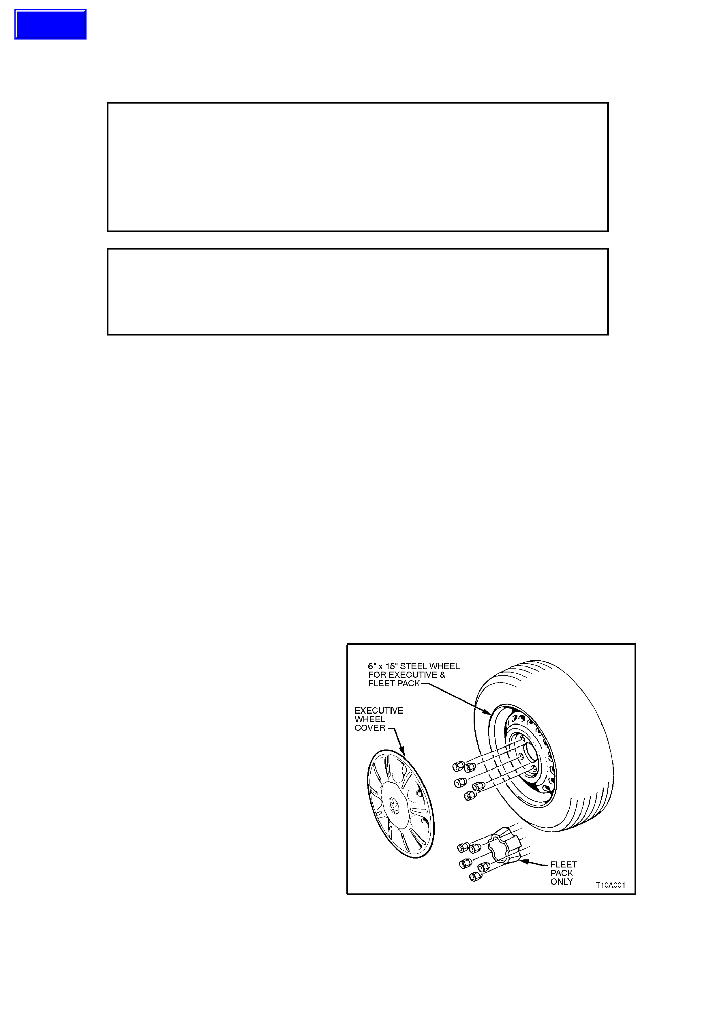
Figure 10-1 illustrates the wheel and wheel
cover/cap for Executive and Fleet pack models.
Figure 10-1
Techline
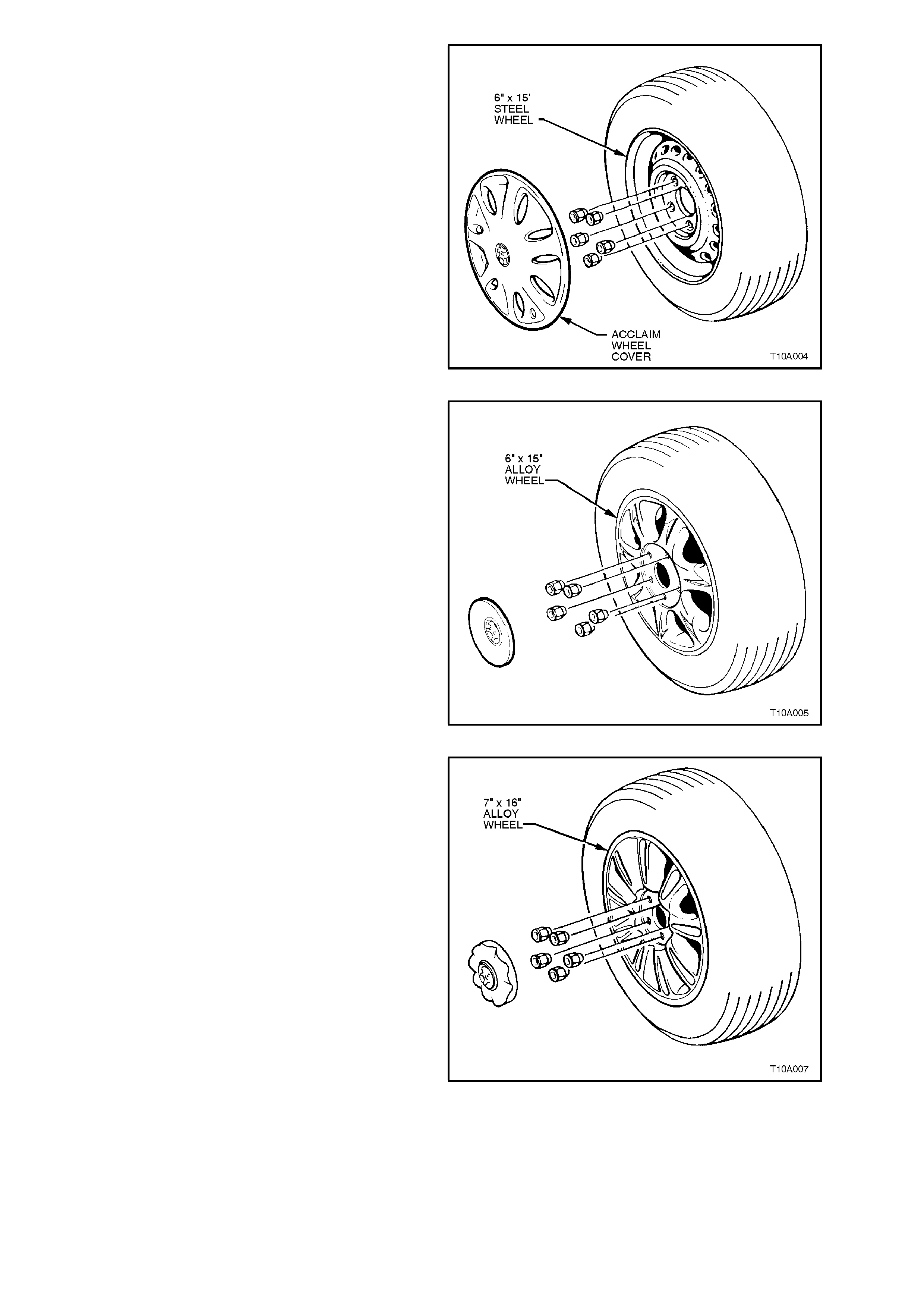
Figure 10-2 illustrates the wheel and wheel cover
fitted to Acclaim models.
Figure 10-2
Figure 10-3 illustrates the Berlina road wheel and
cover.
Figure 10-3
Figure 10-4 illus trates the Calais m odel alloy wheel
and cover.
Figure 10-4
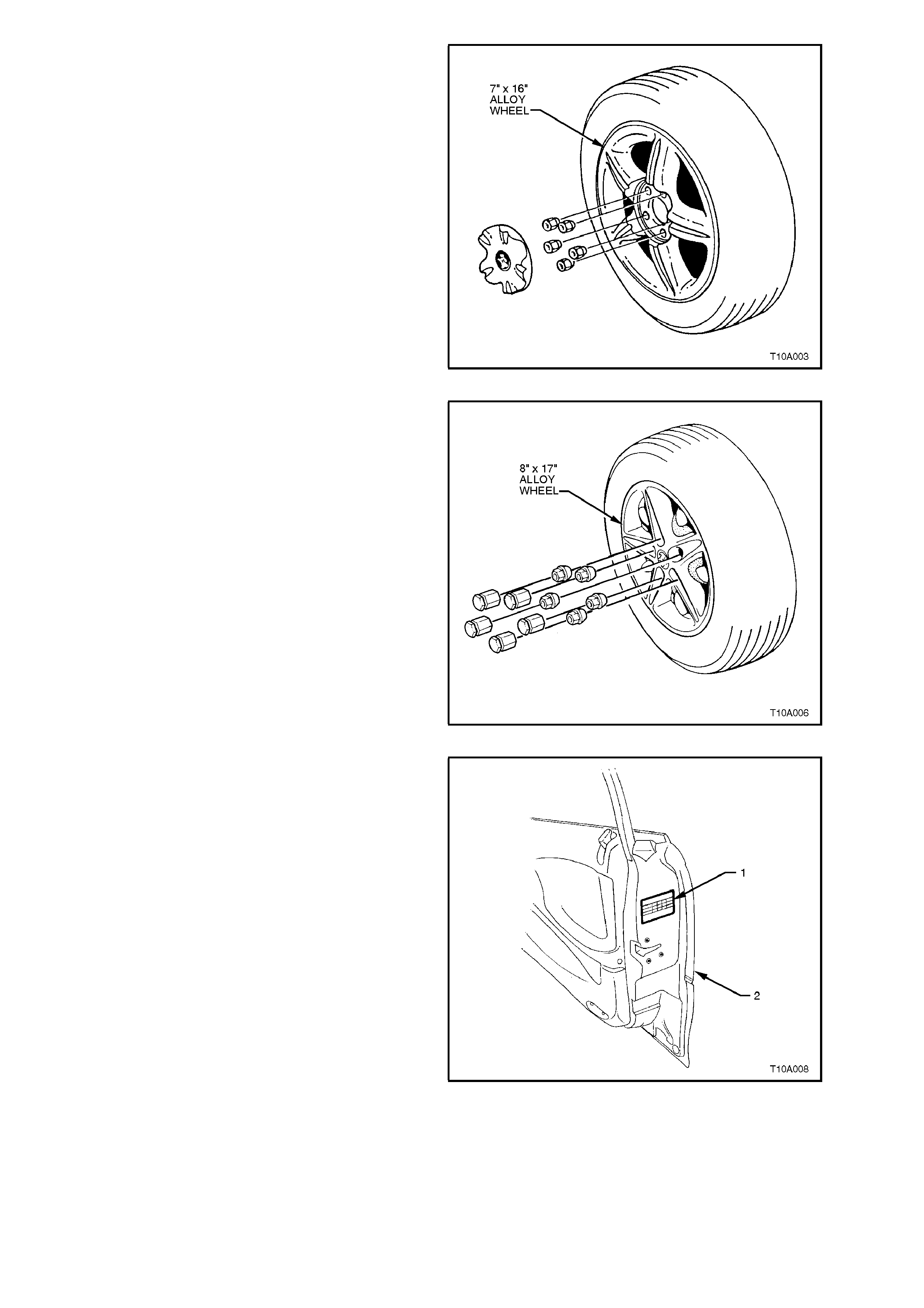
Figure 10-5 illustrates the alloy wheel and wheel
cap fitted to the ‘S’ pac k , m odel vehic le. T his wheel
was previously fitted to VS Series, ‘SS’ pack
vehicles.
Figure 10-5
Fig. 10-6 illustrates the alloy wheel fitted to ‘SS’
pack, VT vehicles.
Figure 10-6
Wheel and tyre sizes, inflation pressures and load
capacity are specified on a tyre placard (1) located
on the end surface of the right-hand front door (2),
as shown.
Correct sizes and pressures are the subject of an
Australian Design Rule (ADR) and must be
observed at all times.
Figure 10-7
All models are equipped with a spare wheel/tyre
assembly and tools necessary for a wheel change,
refer Figure 10-8 and Figure 10-9.
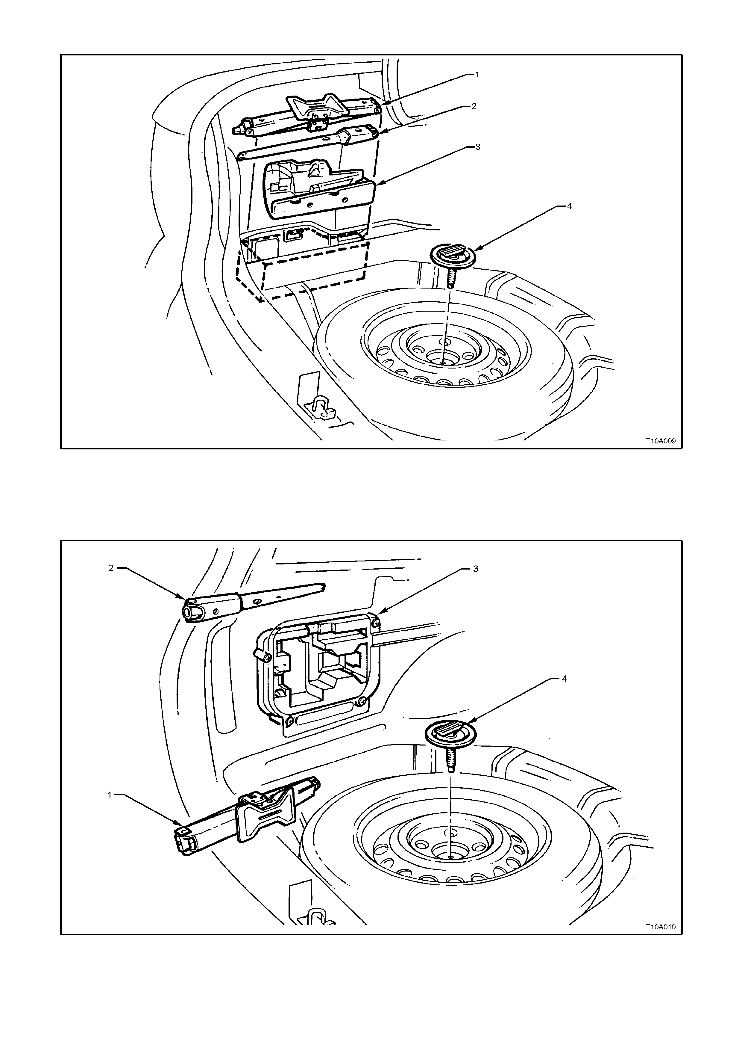
SEDAN SPARE WHEEL AND JACK STOWAGE
1 Jack 3 Stowage Compartment
2 Jack/Wheel Nut Wrench 4 Spare Wheel Retaining Stud and Plate
Figure 10-8 Sedan Spare Wheel and Jack Stowage
STATION WAGON SPARE WHEEL AND JACK STOWAGE
1 Jack 3 Stowage Compartment
2 Jack/Wheel Nut Wrench 4 Spare Wheel Retaining Stud and Plate
Figure 10-9 Station Wagon Spare Wheel and Jack Stowage
2. SERVICE OPERATIONS
2.1 REPLACEMENT OF WHEELS AND TYRES
Wheels must be replaced if they are bent, dented
or have excessive lateral or radial run-out. W heels
with greater than specified run-out may cause
objectionable vibration through the vehicle.
Replacement wheels must be equivalent to the
original equipment wheels in load capacity,
diameter, rim width, profile, offset and mounting
configur ation. A wheel of incor rect s ize or type m ay
affect wheel and bearing life, brake cooling,
speedometer/odometer calibration, vehicle to
ground clearance or tyre to body or chassis
clearance.
The s election of replacem ent tyres r equires caref ul
consideration if vehicle handling, braking, steering
response and ride comfort are to be preserved.
In the course of vehicle development, all of the
factors influencing handling and ride comfort are
considered and particular emphasis is placed on
the role of tyres in order to achieve optimum
standards in vehicle performance.
W hen selecting replacement tyres, consult the tyre
placard to determine appropriate tyre sizes. It is
essential that replacements be of the same size,
type and speed/load rating in order to maintain
intended ride, handling and braking. This also
ensures compatibility of new tyres with existing
tyres and the spare tyre.
NOTE:
Do not mix different types of tyres on the same
vehicle except in emergencies, because vehicle
handling may be seriously affected and may result
in loss of control.
It is recommended that new tyres be installed in
pairs on the same axle. If necessary to replace only
one tyre, it should be paired with the tyre having the
most tread, to equalise braking traction.
TYRE MARKINGS
The tyre sidewall has a coded marking system
which gives various information about the tyre.
NOTE:
The effective load capacity for the rear tyres fitted
to VT Series , is 95% of specif ied load capacity due
to the effect of the rear suspension negative
camber.
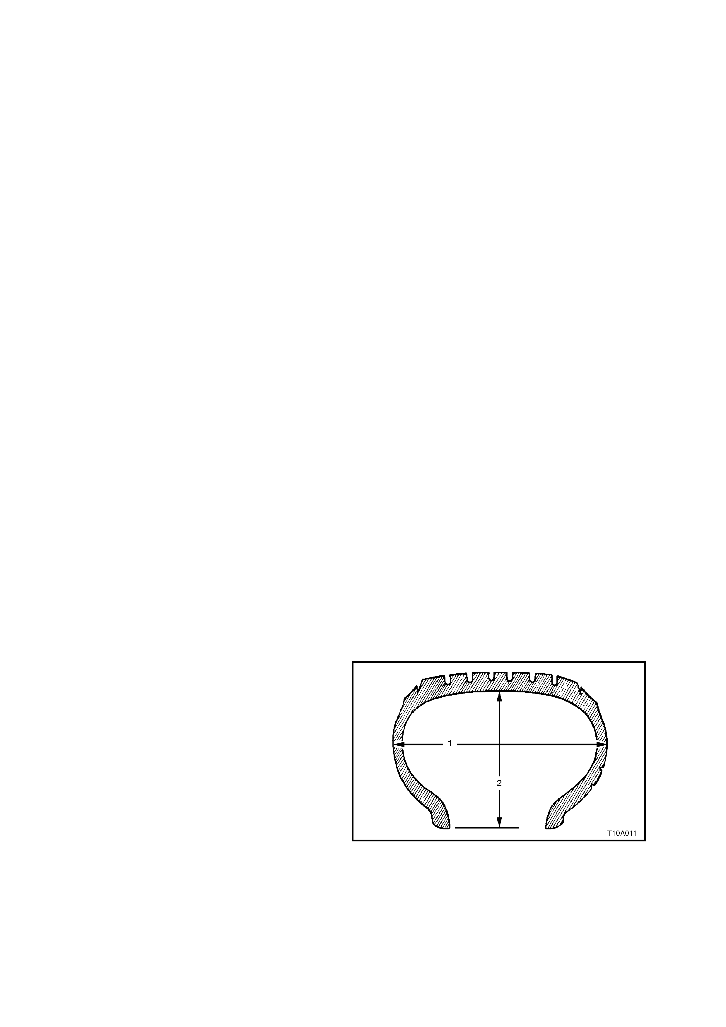
Tyre Marking Example:
P 205 65 R 15 92 H
P= Passenger Tyre Type
205 = Section Width (‘1’) - mm (‘205’ mm)
65 = Aspect Ratio % (Section Height ‘2’ to
Section Width (‘1’) (‘65’ = 65%)
R= Tyre Construction (‘R’ - Radial)
15 = Rim Diameter - inches (‘15’ = 15”)
92 = Load Index - kg (‘92’ = 630 kg max. load)
(‘94’ = 670 kg max. load)
(‘95’ = 690 kg max. load)
H= Speed Rating (‘H’ = 210 km/h)
(‘V’ = 240 km/h)
Figure 10-10

2.2 TYRE INFLATION AND INSPECTION
The pressure recommended for any model is carefully calculated to give satisfactory ride, stability, steering, tread
wear, tyre life and resistance to wheel/tyre damage.
Tyre pressures, with COLD tyres (after vehicle has stood for three hours or more, or driven less than 2 kilometres)
should be checked weekly or before any extended trip, and set to the specifications on the tyre placard located on
the end surface of the right-hand front door, as shown in Figure 10-7.
When checking tyre pressure, visually inspect tyres for excessive wear, sharp objects embedded in the tyre or
damage to sidewalls.
NOTE 1:
Clean valve exterior, prior to apply ing air pressure nozzle when inflating tyre.
NOTE 2:
Always reinstall valve caps to keep out dust and water.
PRESSURE ADJUSTMENTS TO SUIT OPERATING CONDITIONS
For continuous high speed operation, increase pressures as recommended on the tyre placard.
Tyre pressure can increase as much as 40 kPa when hot. DO NOT REDUCE PRESSURES TO OFFSET THIS
BUILD UP.
For operation on unsealed rough roads, increase COLD tyre pressures 28 kPa above that shown on the tyre
placard.
NOTE:
Tyre pressures are not to be increased for unsealed rough road condition if tyre pressures have already been
increased for high speed operation.
2.3 WHEEL REMOVAL AND INSTALLATION
IMPORTANT:
Before removing any wheel, mark the relationship
of the wheel to the mounting flange or brake
disc/hub.
Difficulty in wheel removal can be caused by either
corrosion or a tight fit between the wheel centre
and the mounting or brake disc/hub flange.
NOTE:
If tightness is caused by corrosion, do not use heat
or heavy impact.
If a wheel is tight, proceed as follows;
1. Tighten and loosen each road wheel attaching
nut a maximum of two turns.
2. Lower vehicle to ground and allow weight of
the vehicle to rest on the wheel.
3. Drive the vehicle approximately 2 metres in a
forward and reverse direction. Apply quick,
hard jabs on the brake pedal to loosen the
wheel.
4. Raise the vehicle and remove road wheel
attaching nuts and remove wheel.
Should a removed road wheel show signs of
corrosion, then all deposits should be removed
from the hub spigot and mating bore of the alloy
wheel, using fine emery paper.
Wash down with mineral spirit, dry and apply a light
coating of a lubricant such as Omega 929 or
equivalent to the hub spigot, using a small brush.
Remove any excess with mineral spirit and allow
the product to dry before installing the road wheel.
NOTE:
Installing wheels without good metal to metal
contact at the mounting surfaces can result in
wheel nuts coming loose. Wheel nuts must be
carefully tightened to the correct torque
specification and in the order shown.
ROAD WHEEL ATTACHING NUT 110 - 140
TORQUE SPECIFICATION Nm
Figure 10-11
2.4 TYRE ROTATION
For VT Series Models, it is recommended that tyre
rotation be carried out when brake inspections are
performed, as per the service schedule outlined in
the VT Owner's Handbook, or when:
1. Difference in tread depth between front and
rear tyres is 1.5 mm.
2. When any unusual tyre wear pattern develops.
If uneven tyre wear is evident, the reason for it
should be corrected if at all possible.
If the tyres are rotated, it is rec omm ended that the
tyre and wheel assembly balance be checked at
the same time, refer to 2.8 WHEEL AND TYRE
BALANCING in this Section.
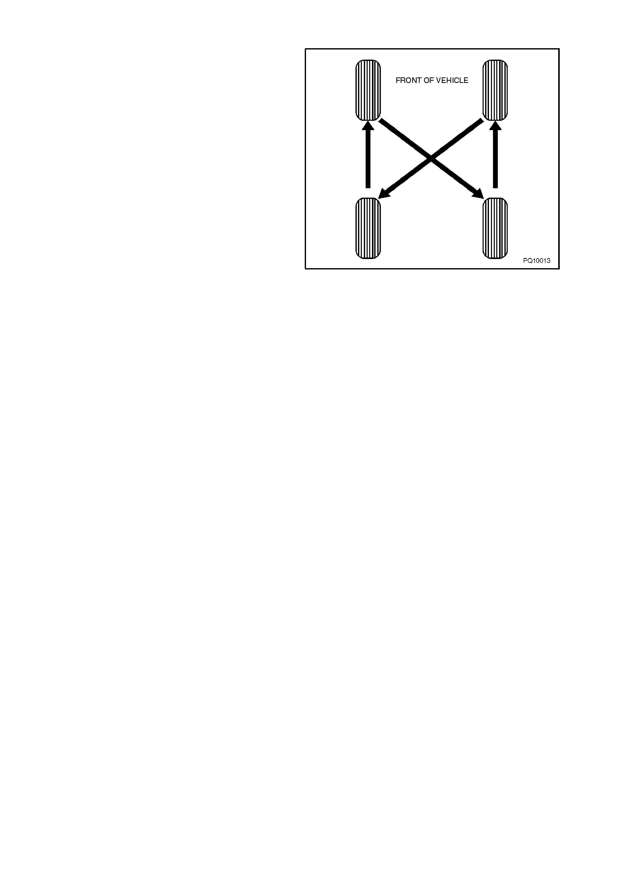
Tyre rotation in accordance with Fig. 10-12 will
assist in obtaining maximum tyre life.
Figure 10-12

2.5 CHECKING TYRE/WHEEL ASSEMBLY RUN-OUT
Because the run-out of a tyre/wheel assembly will
directly affect the amount of imbalance and radial
force variation, it should be corrected first. The
smaller the amount of run-out, the less imbalance
and force variation. Radial and lateral run-out can
be corrected at the same time. There are two
methods to measure run-out of the tyre/wheel
assemblies:
•On the vehicle (mounted to the hub - wheel
bearing must be in good condition)
•Off the vehicle (mounted on a spin-type
wheel balancer).
NOTE:
Initial on-car inspection should be made prior to off-
car run-out checks.
Measuring the tyre/wheel run-out off the vehicle is
easiest. It is usually easier to m ount a dial indic ator
in the correct location, and the chances of water,
dirt, or slush getting on the dial indicator are
decreased. Once the run-out has been measured
and corrected off the vehicle, a quick visual check
of run-out on the vehicle will indicate if any further
problems exist.
If there is a large difference in the run-out
measurements from on-vehicle to off-vehicle, then
the run-out problem is due to either stud pattern
run-out, hub flange run-out, or a m ounting problem
between the wheel and the vehicle.
Before measuring or attempting to correct
excessive run-out, carefully check the tyre for
an unev en b ead seat . T he distanc e fr om the edge
of the ring to the conc entr ic r im loc ating r ing s hould
be equal around the entire circumference. If the
beads are not seated properly, the tyre should be
remounted. Otherwise, excessive run-out and
imbalance will result.
Important:
If the vehicle has been sitting in one place for a
long time, flat spots may exist at the point where
the tyres were resting on the ground. These flat
spots will aff ect the run-out readings and should be
eliminated by driving the vehicle long enough to
warm up the tyres prior to conducting any run-out
measurements.
PROCEDURE
1. Lift the vehicle on a hoist or suppor t with jack -
stands.
2. In order to get an initial indication of how much
run-out exists, spin each tyre and wheel on the
vehicle by hand (or at a slow speed using the
engine to run the drive wheels). Vis ually check
the amount of run-out from the front or rear.
3. Mark the location of each tyre/wheel assembly
in relation to the wheel studs and to their
position on the vehicle (right front, left rear,
etc.) for future reference.
4. Remove tyre/wheel assemblies one at a time
and mount on a spin-type wheel balancer.
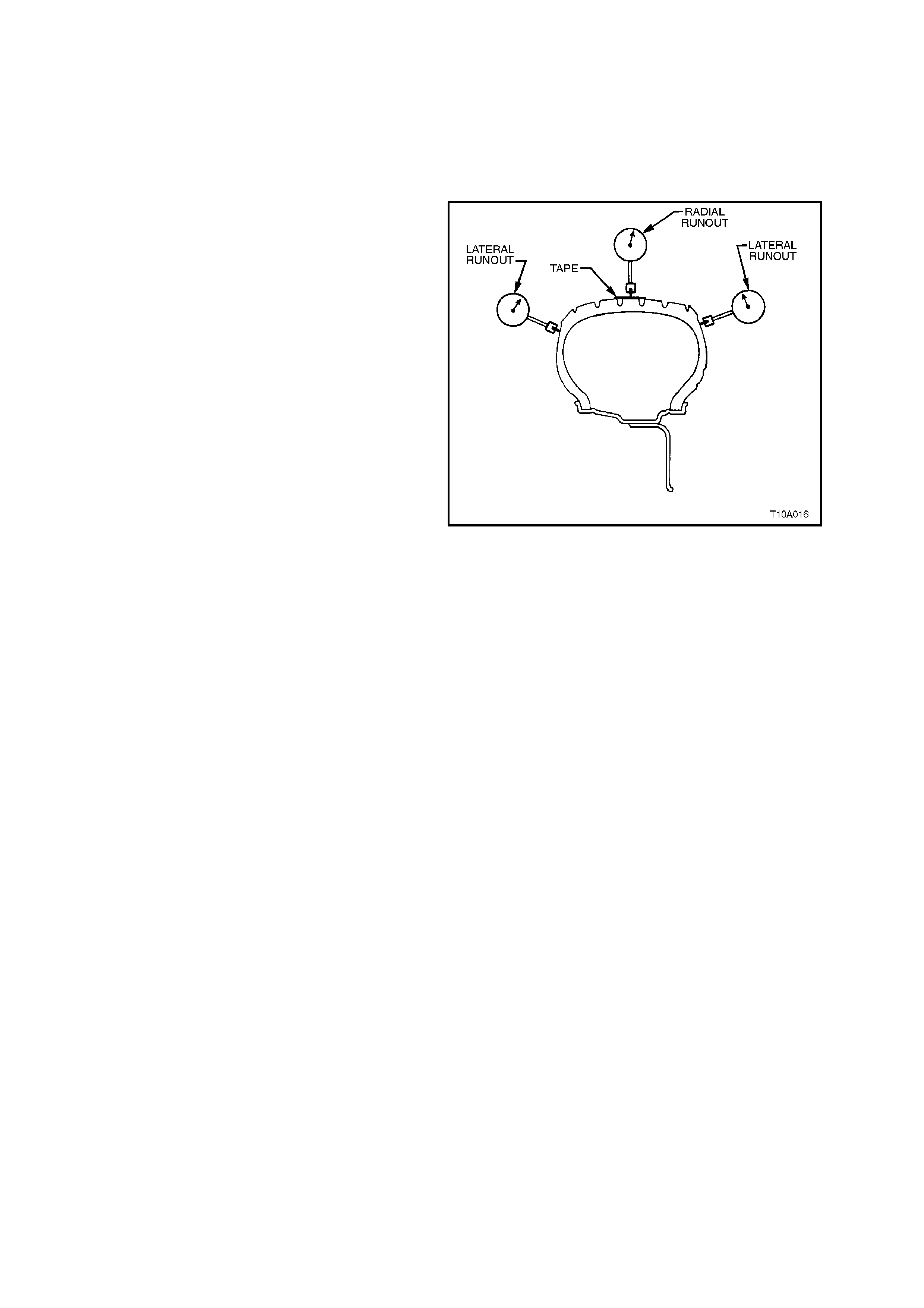
5. Measure the tyre/wheel assembly radial and
lateral run-outs, using a dial indicator fitted
with a roller.
NOTE 1:
With tyres that use an aggressive tread pattern, it
will be necessary to wrap the outer circumference
with tape (as indicated) when measuring radial run-
out, to provide a smooth surface for a more
accurate measurement.
NOTE 2:
Lateral run-out should be measured on a smooth
area of the sidewall, as close to the tread as
possible. Any jumps or dips due to sidewall splices
should be ignored and an average amount of run-
out attained.
1. Slowly rotate the assembly one complete
revolution and zero the dial indicator on the
low spot.
2. Rotate the assembly one more complete
revolution and note the total amount of run-out
indicated.
As a guide, the tyre/wheel assembly, radial and
lateral run-out should be no more than 1.5 mm
when measured off the vehicle.
Figure 10-13
MATCH MOUNTING
NOTE:
W hile this operation is not norm ally necessary with
original equipment tyres, when replaced, match
mounting is recommended to obtain optimum
vehicle handling and performance.
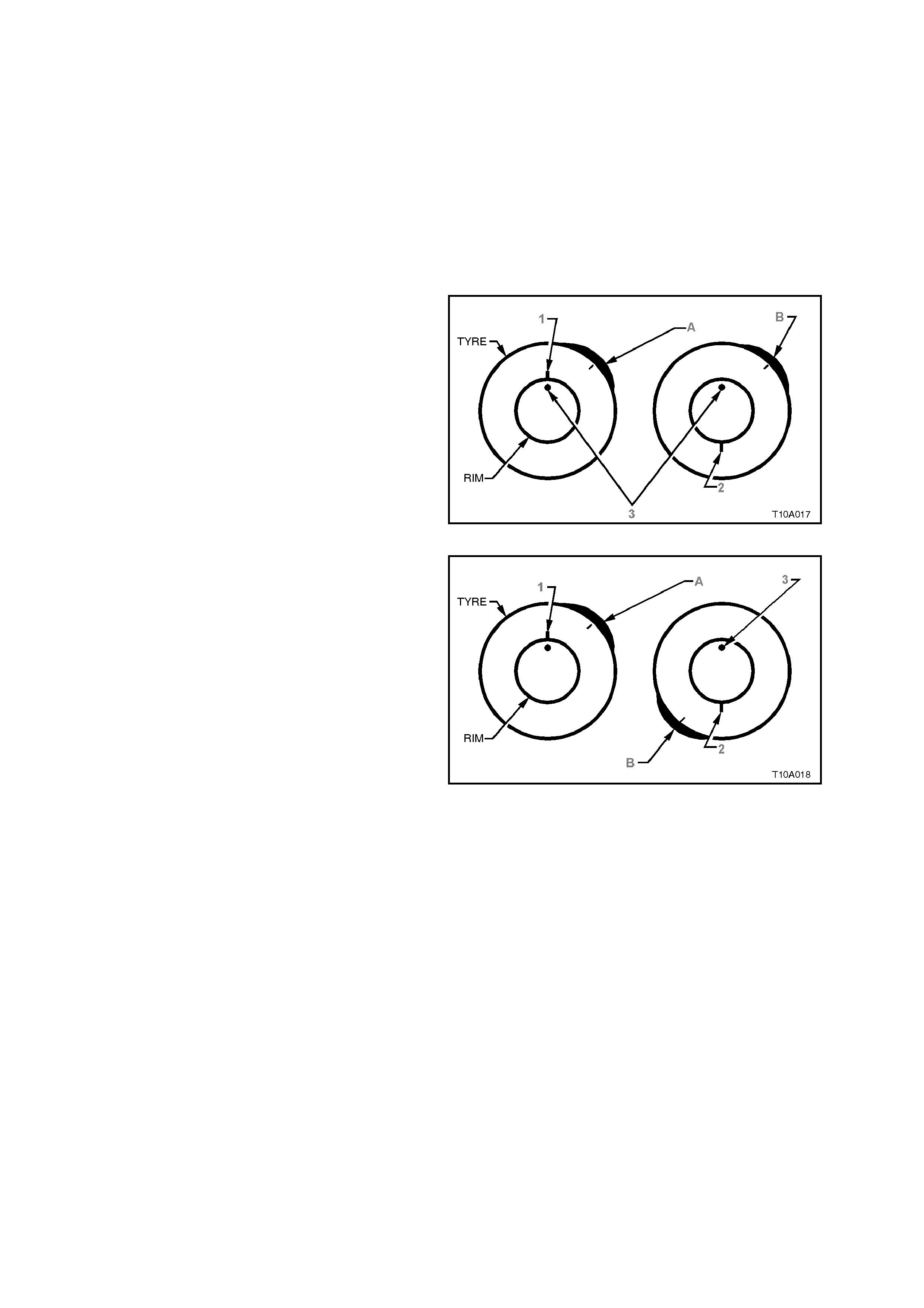
If tyre/wheel assembly run-out is excessive, mark
the location of the high and low spot on the tyre
and the wheel. The next st ep will be to deter m ine if
the run-out problem exists in the tyre, wheel, or a
combination of both, then to correct it. The
procedure us ed to accom plish this is called m atch-
mounting or system matching.
1. Place a mark on the tyre sidewall (1) at the
location of the valve stem (3). This will be
referred to as the 12:00 o’clock position. The
location of the high spot (A) will always be
referred to in relation to its clock position on
the wheel.
2. Mount the tyre wheel assembly on a tyre
machine and break down the bead. Do not
dismount the tyre from the wheel at this time.
3. Rotate the tyre 180° on the rim so the valve
stem referenc e m ark (2) is now at 6:00 o’clock
in relation to the valve stem itself. Inflate the
tyre and make sure the bead is seated
properly. You may have to lube the bead to
easily rotate the tyre on the wheel.
4. Install the assembly on the tyre balancer and
again measure the run-out. Mark the new
location of the run-out high point (B) on the
tyre.
If the run-out is now within tolerance, no further
steps are necessary. The tyre may be balanced
and installed on the vehicle.
Alternatively, if the clock location of the high spot
(B) remained at or near the clock location of the
original high spot (A) (as in Figure 10-14), the
wheel is the major contributor to the run-out
problem. It should be measured for excessive run-
out, as detailed in 2.6 CHECKING WHEEL RUN-
OUT and replaced if found to exceed specification.
If the high spot is now at or near a position 180°
(6.00 o’clock ) f rom the or iginal high spot, the tyre is
the major contributor (as in Figure 10-15) and
should be replaced.
Always remeas ure the tyr e/wheel as sembly run-out
after replacing the tyre and make sure the run-out
is within tolerance befor e continuing. In the m ajority
of cases, the first 180° rotation of the tyre will either
correct the run-out problem or indicate which
component to replace.
If the high spot is between the two extremes, then
both the tyre and wheel are contributing to the run-
out. Try rotating the tyre an additional 90° in both
the clockwise (9.00 o’clock) and anti-clockwise (3
o’clock) directions, measuring the run-out after
each rotation.
Figure 10-14 Wheel is the Major Contributing Factor
Figure 10-15 Tyre is the Major Contributing Factor
If run-out cannot be corrected by match-mounting,
then the tyre must be removed and the wheel run-
out measured, as detailed in the next Operation.
Once run-out has been brought within the
tolerance, the tyre/wheel assembly should be
balanced.

2.6 CHECKING WHEEL RUN-OUT
Wheel run -out should be measured on the inside
bead area of the wheel. Measure the run -out in the
same fashion as tyre run-out. Ignore any jumps or
dips due to paint drips, chips, or welds, measure
both inboard and outboard.
If the run-out of the wheel is within tolerance, and
the tyre/wheel assembly run -out cannot be reduced
to an acceptable level by using the match-mounting
technique, the tyre must be replaced. Always
measure assembly run
-out after replacing the
tyre.
If there is a large difference in the run-out
measurements from on-vehicle to off -vehicle, then
the run-out problem is due to either stud pattern
run-out, hub flange run-out, or a mounting problem
between the wheel and the vehicle.
The tolerances listed are to serve as guidelines.
If run-out measurements are within tolerance but
are marginal, some sensitive vehicles may still be
affected. It is always advisable to reduce run -out to
as little as possible in order to attain optimum
results under all conditions.
PROCEDURE
NOTE:
This measuring procedure can be used equally well
on either steel or alloy road wheels.
1. Raise vehicle and support on safety stands.
2. Remove wheel cover (steel wheels) or centre
cap (alloy wheels).
3. Mark relationship of wheel to mounting flange
or brake disc/hub. Remove wheel attaching
nuts and remove wheel.
4. Mark relationship of tyre to wheel rim and then
remove tyre from rim.
5. Check that the wheel and mounting flange or
brake disc/hub mating surfaces are clean and
free from burrs etc.
6. Install the wheel onto the mounting flange or
brake disc/hub and install wheel attaching
nuts. Tighten nuts to the correct torque
specification.
ROAD WHEEL ATTACHING NUT 110 - 140
TORQUE SPECIFICATION Nm
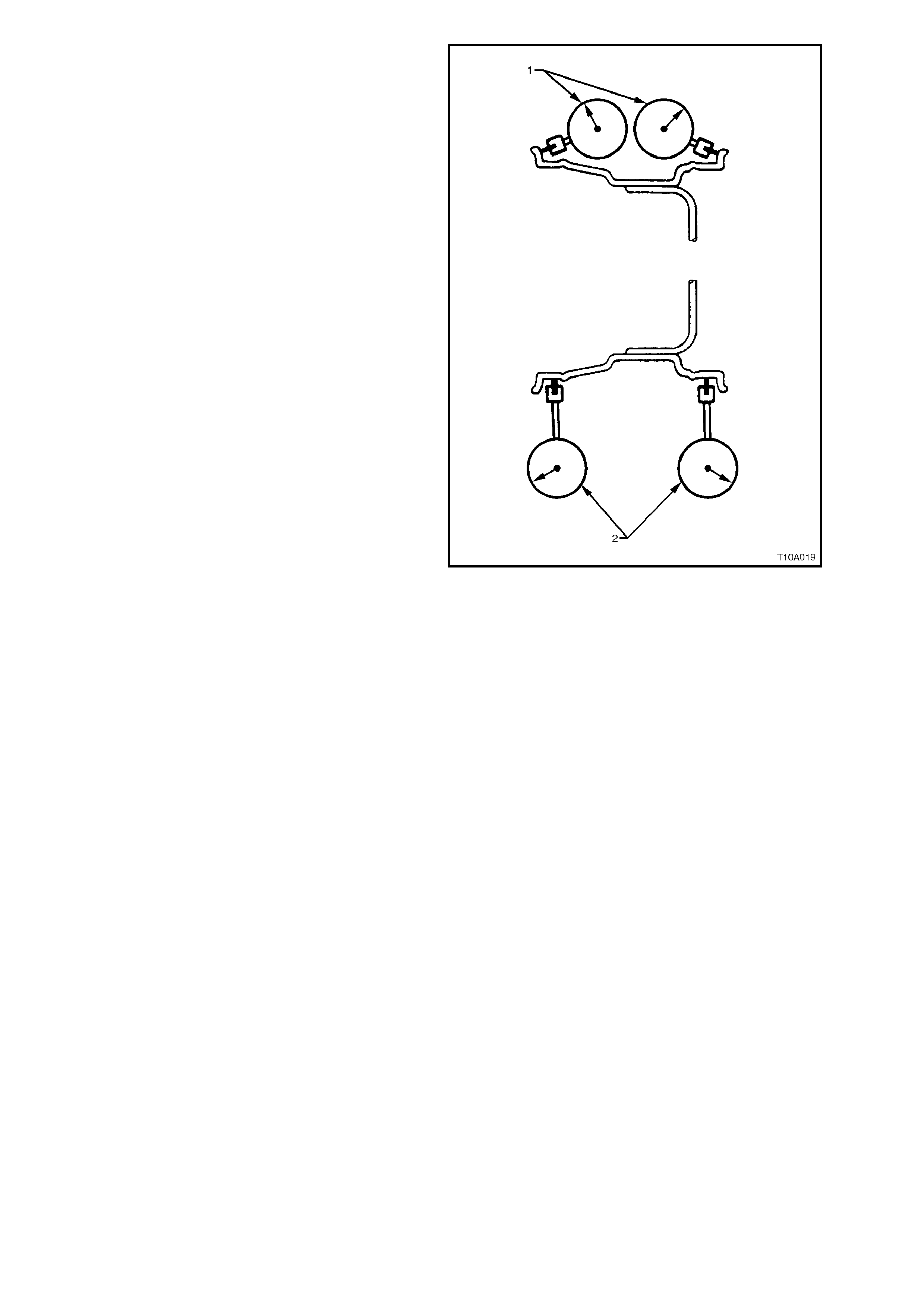
7. Using a dial indicator with a roller fitted to the
probe, secure the base to a fixed point. Then,
slowly rotate the road wheel and measure
wheel run-out at the points shown.
1 = Lateral Run-out.
2 = Radial Run-out.
Wheel run-out should be within the specified
values listed in 4. SPECIFICATIONS in this
Section.
If not within specification, replace wheel.
NOTE:
Always measure the run-out of new wheels when
replacing old ones. Do not assume that a new
wheel is automatically a known good component.
Figure 10-16

2.7 TYRE REMOVAL AND INSTALLATION
Whenever possible, tyre rem oval and installation s hould be carried out on a tyre changing m achine. T he use of tyre
levers and mallets is likely to damage tyre carcasses and wheel rims.
Minor dents and burr s on steel rim s can be r epaired by f iling, but alloy rim s m ust always be r eplaced if significantly
damaged.
CAUTION:
Wheels must not be welded, brazed, peened or treated in any manner which could weaken them.
The bead seat of the rim must be clean and smooth; rust, rubber etc. may be removed with a wire brush or steel
wool.
Before r emoving or ins talling a tyre, or installing a valve stem , apply tyre lubricant (Holden's Specific ation HN1162)
to the tyre bead and rim flanges.
Install valve stem and tyre before lubricant dries.
Initially, inflate tyre to 280 kPa to ensure that the tyre beads seat correctly in the rim flanges.
If the tyre beads fail to seal at this pressure, def late the tyre, lubric ate the tyr e beads and wheel rim again and then
inflate.
WARNING:
Exercise care to avoid personal injury when the tyre bead snaps over the wheel rim safety humps.
NOTE:
When fitting a tyre to a rim, it is important to ensure that the tyre is correctly indexed to the rim, i.e. the first
harmonic high point of the tyre should be fitted so that it is matching the first harmonic low point of the rim. This
matching minimises force variations inherent with tyre and rim manufacture. (Refer to 3. DIAGNOSIS in this
Section for more information on harmonics.)
As different origins of tyres have different standards regarding the first harmonic point, refer to the following as a
guide to the correct ty re fitting position.
Australian manufactured tyres have a red dot indicating the first harmonic high point.
European manufactured tyres have a white dot indicating the first harmonic low point.
Some J apanese m anuf actured tyres have a red dot indicating the f irst har m onic high point and a yellow dot (which
should be ignored) which indicates a static balance point.
As independent rear suspension vehicles are more sensitive to a wheel/tyre imbalance condition than other
suspension designs, particular care should be given to correct fitment of tyres to all VT vehicles.
AUSTRALIAN MFD. TYRES
(Red dot on s/wall)
Align RED dot on tyre to mark on outer
flange of wheel, or if there is no mark on the wheel,
align RED dot to low spot of wheel as measured
with dial indicator.
EUROPEAN MFD. TYRES
(White dot on s/wall)
Align WHITE dot on tyre 180° from the mark on
outer flange of wheel, or if there is no mark on the
wheel, align WHITE dot 180° from the low spot of
wheel as measured with dial indicator.
JAPANESE MFD. TYRES
If there is a YELLOW dot but not a red dot use the
rule for Australian tyres. If there is a YELLOW and a
RED dot, ignore the yellow dot and use the red dot
as per rule for Australian tyres.
TYRE REPAIRS
There are many different materials and techniques available to repair tyres. It is suggested that details of materials
and procedures for the repair of tyres should be obtained from the tyre manufacturer.
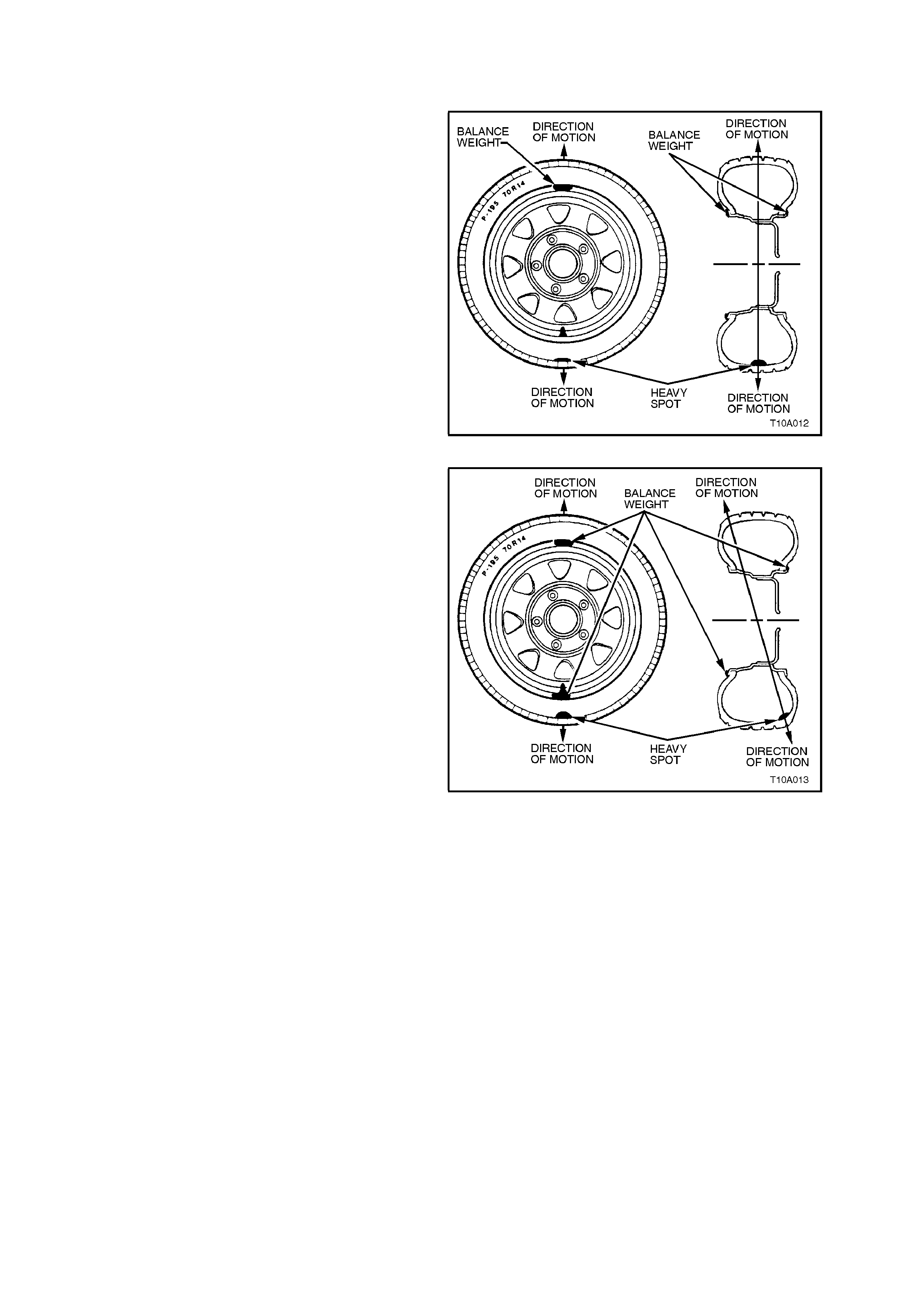
2.8 W HE EL AND TYRE BALANCING
There are two types of wheel and tyre balance;
Static and Dynamic.
STATIC balance is the equal distribution of weight
around the wheel.
Vibrations caused by static imbalance will cause a
vertical or bouncing motion of the tyre.
Figure 10-17
DYNAMIC balance aff ects the distr ibution of weight
on each side of the tyre/wheel centreline.
Dynam ic imbalanc e results in a side-to-side m otion
of the tyre, sometimes referred to as shimmy.
Figure 10-18
OFF-VEHICLE BALANCING
When wheel and tyre assemblies require
balancing, they should be removed from the
vehicle and balanced on a machine capable of
ensuring correct static and dynamic balance.
Balancing should be car ried out in accordanc e with
the machine manufacturer's instructions to obtain
the results as outlined under BALANCE LIMITS.
Although hub/brake discs do not contribute
significantly to an out of balance condition, it is
desirable to fit wheels to the same position on the
vehicle after balancing. Accordingly, it is good
practice to mar k the r elations hip of the wheel to the
axle flange or brake hub/disc, prior to wheel
removal.
Before balancing, remove all accumulated mud
from the wheel and any embedded stones f rom the
tyre treads. If using on-vehicle balancing
equipment, observe the LIMITED SLIP
DIFFERENTIAL PRECAUTIONS as outlined in
Section 4B FINAL DRIVE AND DRIVE SHAFTS.
ON-VEHICLE BALANCING
If checking and/or correcting a tyre/wheel
imbalance condition off the vehicle and it is not
possible or does not corr ect the vibration, it m ay be
necessary to balance the assembly/ies while
mounted on the vehicle, using an on-vehicle, high-
speed spin balancer. This will balance the hubs,
rotors, and wheel trim s sim ultaneously. Also, it can
compensate for any amount of residual run-out
encountered as a r esult of m ounting the tyre/wheel
assembly on the vehicle, as opposed to the
balance that was achieved on the off-vehicle
balance.
Always follow the on-vehicle balancer manuf ac ture r
Operator's Manual for specific instructions.
NOTE 1:
Do not remove the off-vehicle balance weights.
The purpose of on-vehicle balance is to "fine tune"
the assembly balance already achieved, not to
begin again.
NOTE 2:
Leave all wheel trims installed where possible.
Some wire wheel covers have been known to
induce static imbalance. If you suspect a wheel trim
of causing the vibration, it can be eliminated by
road testing the vehicle with the wheel trim
removed.
NOTE 3:
If the on-vehicle balance calls for more than 10
grams of additional weight, split the weight between
the inboard and outboard flanges of the wheel, to
avoid disturbing the dynamic balance of the
assembly, achieved in the off-vehicle balance
procedure.
NOTE 4:
Evaluate the condition following the on-vehicle
balance to determine if the vibration has been
eliminated.
BALANCE LIMITS
Maximum allowable out of balance is 8 grams per
side of rim. Total balance weights are not to exceed
120 grams per wheel with a max imum of 80 gram s
per wheel flange. If a wheel assembly requires
more than these limits, fit another tyre to the wheel
and re-balance.
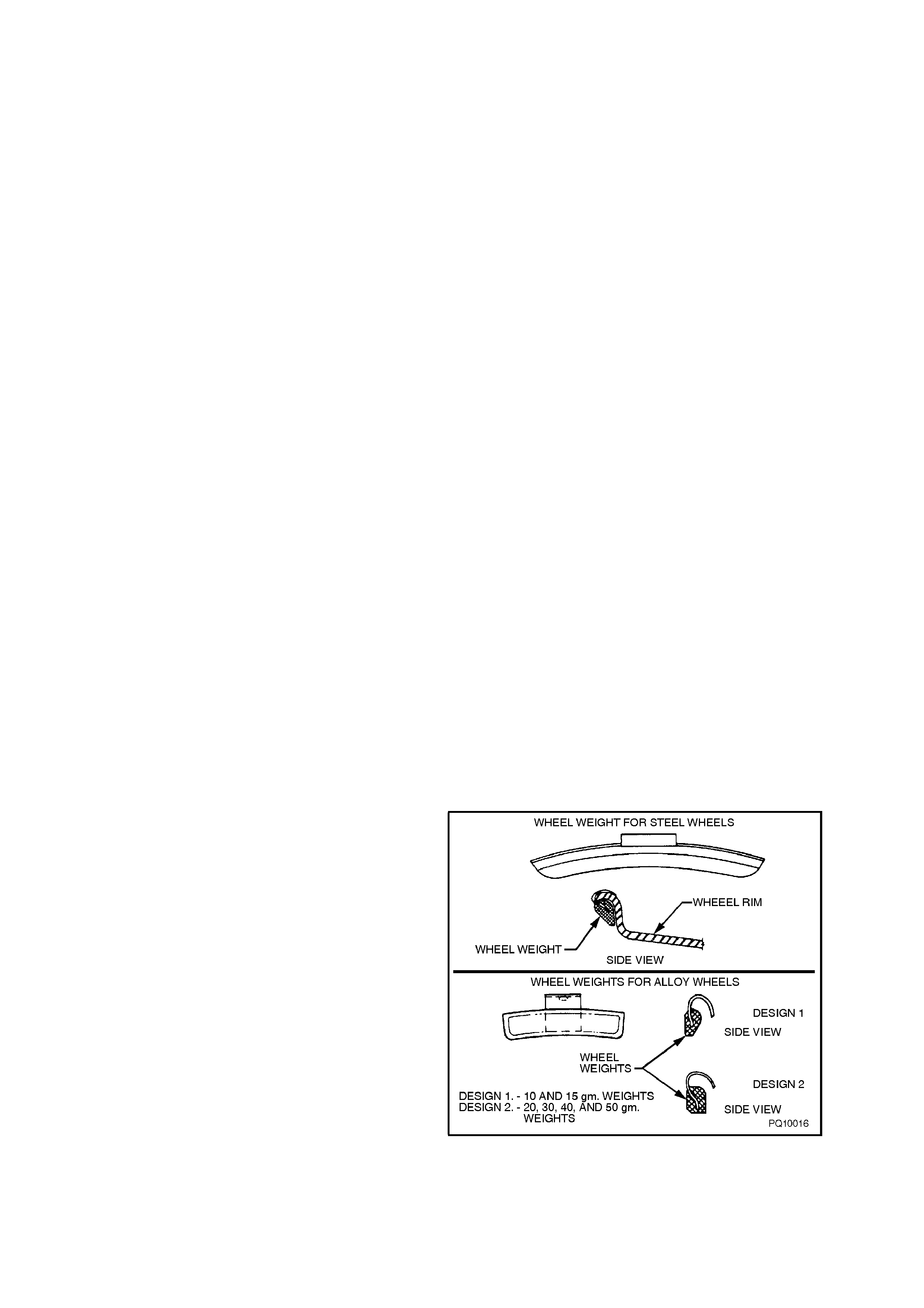
NOTE:
Specific wheel weights for each design of wheel are
used. This is due to the differences in wheel rim
profile.
Figure 10-19
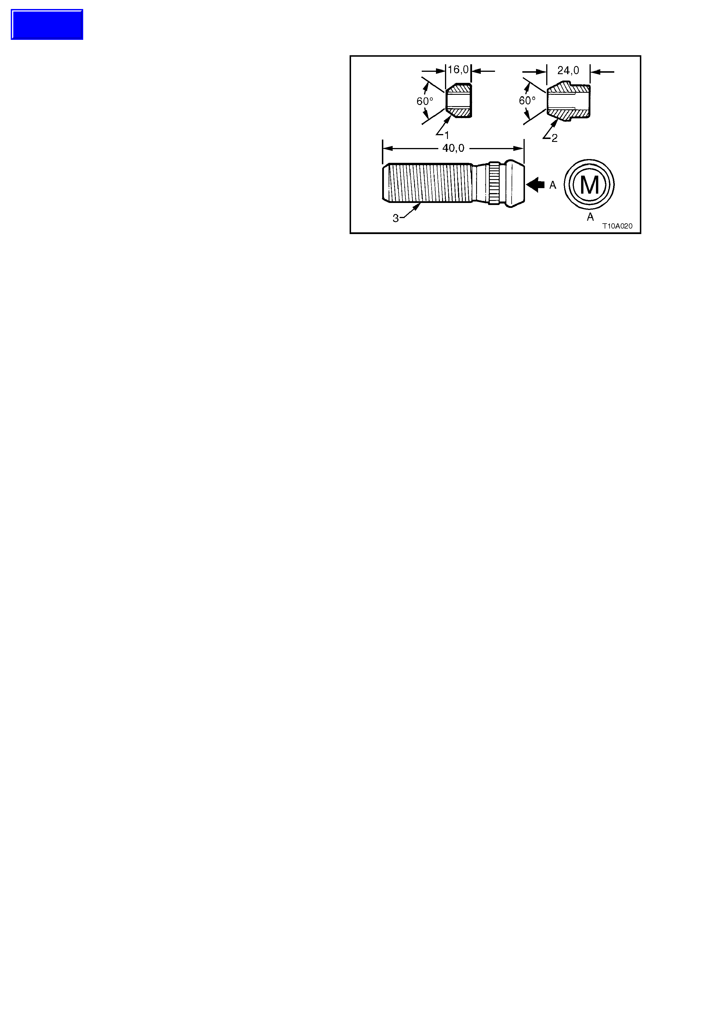
2.9 WHE EL ATTACHING NUTS/STUDS
Important:
W hen alloy wheels are fitted to VT series vehicles,
special attaching wheel nuts (2) are also used. If
VT alloy wheels are to be fitted to a vehicle
normally equipped with steel wheels, then the
original nuts (1) MUST be discarded and revised
design attaching nuts used on the replacement
wheels.
For removal and installation instructions for the
wheel attaching studs (3), either refer to
Section 3 FRONT SUSPENSION or
Section 4B FINAL DRIVE AND DRIVE SHAFTS.
All models use metric (M12 x 1.5) wheel attaching
studs and nuts (refer to A, in Figure 10-20). Figure 10-20
Techline

3. DIAGNOSIS
3.1 WEAR
Analysis of tyre wear conditions is adequately
covered in tyre company literature.

3.2 ROAD TESTING
Because there are many reasons for a vibration condition to be present in a vehicle, it is vital that a thorough road
test be conducted, to eliminate other possible causes for a vibration condition being present.
TYRE AND WHEEL INSPECTION
This visual inspection should be conducted for all vibration complaints unless the disturbance only occurs with the
vehicle at a standstill.
The tyres should be inspected for unusual wear, including cupping, flat spots and heel-and-toe wear. These
conditions can cause tyre growl, howl, slapping noises, and vibrations throughout the vehicle.
Establish that all tyres are inflated to the correct pressures prior to any road test.
Check for bulge’s in the sidewalls.
Check all wheels for bent rim flanges. Many times, hub caps or trim rings that appear dented, can indicate a bent
wheel underneath.
SLOW ACCELERATION TEST
This test is to identify engine or vehicle speed related conditions. It will be necessary to perform additional tests in
order to determine in which category the vibration belongs.
1. On a smooth, level road, slowly accelerate up to highway speed.
2. Look for disturbances that match the customer's description.
3. Note the vehicle speed (km/h) and engine speed (rpm) where the disturbance occurs.
Follow this test with the neutral coast-down test, and the downshift test.
NEUTRAL COAST-DOWN TEST
1. On a smooth, level road, accelerate to a speed slightly higher than the speed at which the vibration occurs.
2. Shift the vehicle into NEUTRAL and coast down through the vibration range. Note if the vibration is present in
NEUTRAL.
If the vibration still occurs in NEUTRAL, it is definitely vehicle-speed sensitive. At this point, the engine and
torque converter have been eliminated as a cause. Depending on the symptoms or frequency, the repair will
concentrate on either the tyres and wheels or the propshaft and rear axle.
DOWNSHIFT TEST
1. On a smooth, level road, accelerate to the speed at which the complaint vibration occurs. Note the engine rpm.
2. Next, decelerate and safely downshift to the next lower gear (from overdrive to drive, or from drive to second,
etc.).
3. Operate the vehicle at the previous engine rpm.
If the vibration returns at the same rpm, the engine or torque converter are the most probable causes. To
confirm these results, repeat this test in still lower gears, and in NEUTRAL.
STEERING INPUT TEST
This test is intended to determine how much wheel bearings and other suspension components contribute to a
vibration, especially those relating to noises, howl or growl, grinding and roaring.
With the vehicle at the vibration speed (km/h), drive through slow, sweeping turns - first in one direction, then the
other.
If the vibration is either worse or goes away, the wheel bearings, hubs, tyre tread wear (etc.) are all possible causes.
STANDING START ACCELERATION
The purpose of this test is to duplicate a vibration called “Take Off Shudder”. In some cases, a powertrain mount or
the exhaust contacting the body may also be suspect, depending on the symptoms.
1. With the vehicle at a complete stop and in gear, remove your foot from the brake.
2. Accelerate to 60 or 70 km/h while checking for vibrations that match the customer's description.
Shudder in the seat or steering wheel under these conditions usually results from improper driveline angles. Worn,
tight or failed universal joints may also be a cause, and should be inspected first.
Grunting or groaning noises along with a buzzing or roughness in the floor usually points to the vibration being
conducted through the engine or transmission mounts, or through exhaust mounts and hangers that have
“GROUNDED OUT”. Refer to the respective Sections for rectification procedures.
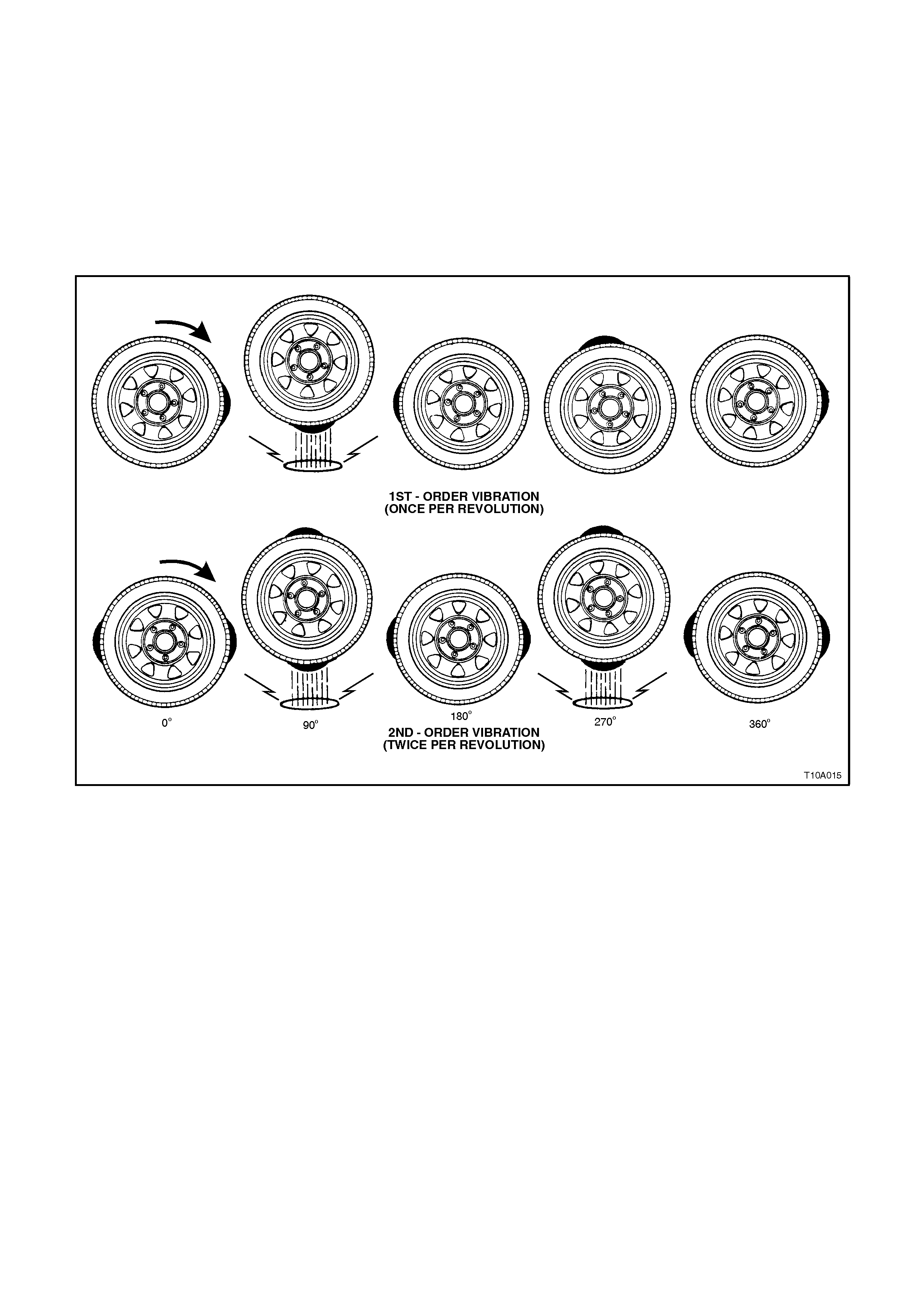
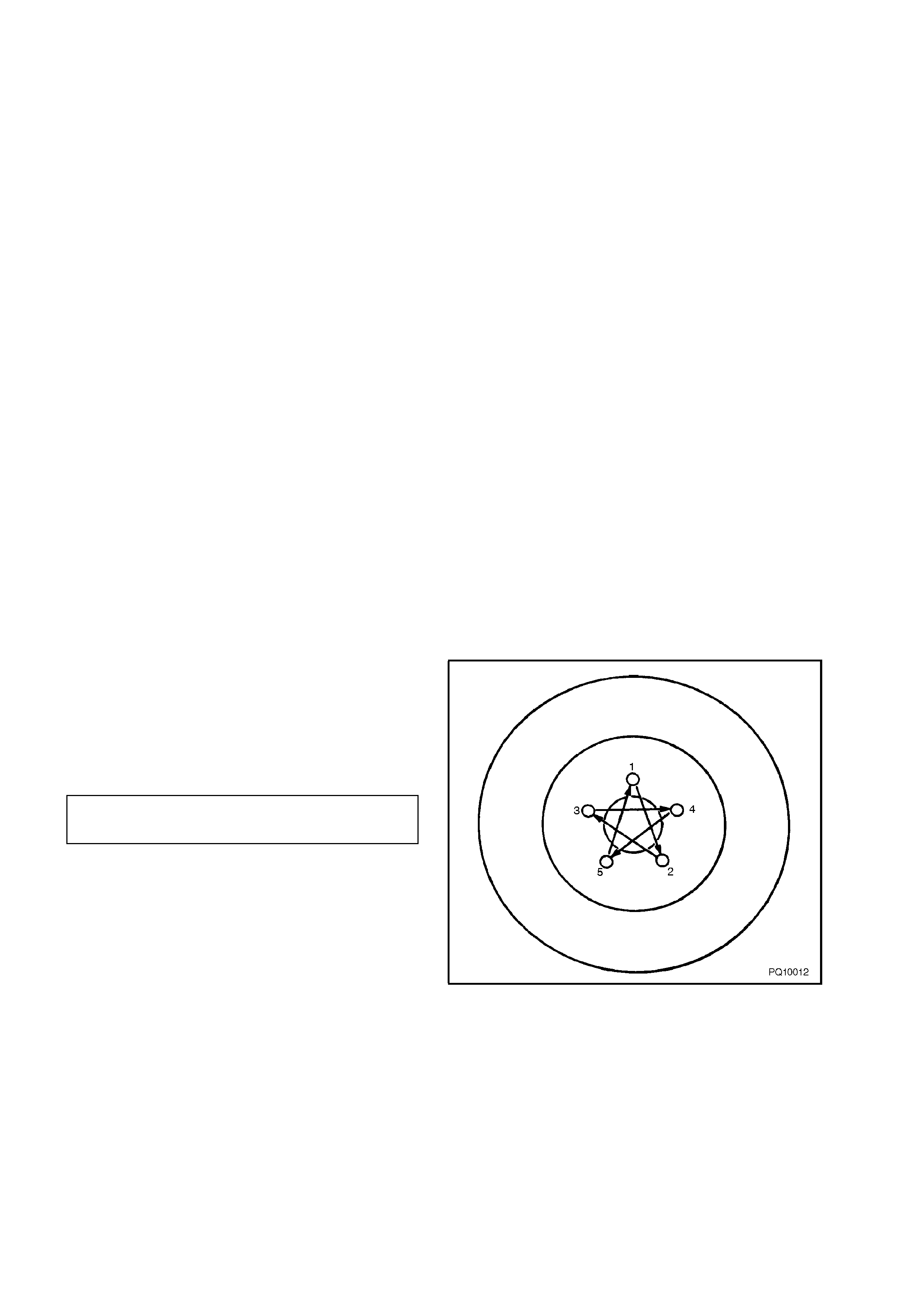
3.3 VIBRATION
To determine the cause of a vibration condition that is suspected of being tyre/wheel related, a key aspect is to
understand the nature of first and second order vibrations (or harmonics).
As shown in Figure 10-21, a tyre with one high spot would create a disturbance once every complete revolution.
This is called first-order.
An oval shaped tyre with two high spots would create a disturbance twice per revolution. This is called second-
order.
Three high spots would be third order, and so on.
Two first-order vibrations m ay add to or subtract from the overall amplitude of the disturbance, but that is all. Two
first-order vibrations do not equal a second-order. Due to centrifugal force, an imbalanced component (tyres,
propshafts, engine) will always create a first-order vibration.
Figure 10-21
If wheel and tyre assemblies are balanced to the degree required and vibration is still evident, then tyre run-out or
‘Force Variation' could be responsible.
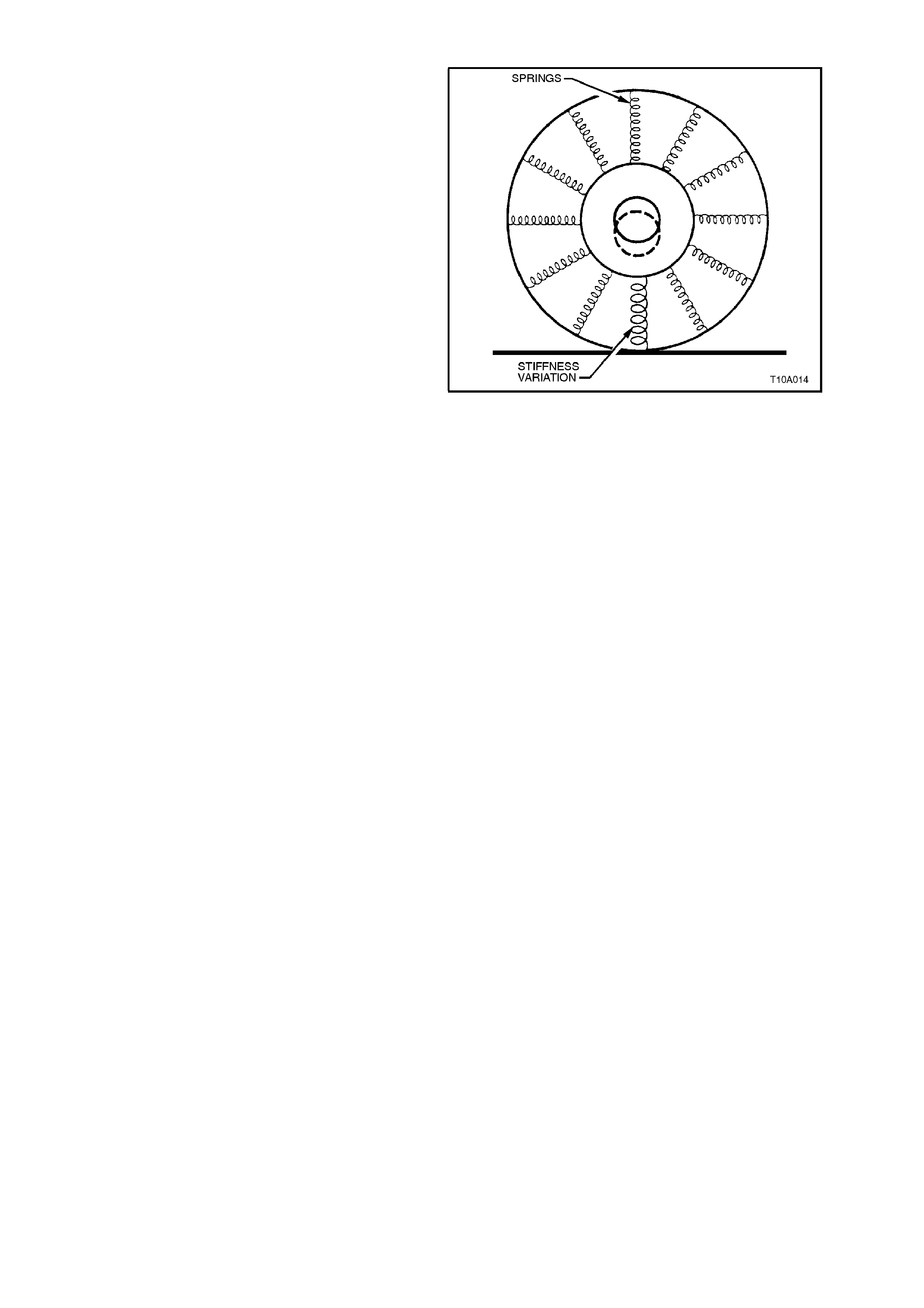
RADIAL FORCE VARIATION
Radial force variation refers to a difference in the
stiff nes s of a tyre sidewall as it rotates and contacts
the road. Tyre/wheel assem blies have som e of this
due to splices in the different plies of the tyre, but
they do not cause a problem unless the force
variation is excessive. These stiff spots in the
sidewall can deflect the tyre/wheel assembly
upward as they contact the road.
If there is only one stiff spot in the sidewall, it will
deflect the spindle once per each revolution of the
tyre/wheel assembly, causing a first order
tyre/wheel vibration.
If there are two stif f spots , they can cause a sec ond
order vibration.
First and second order tyre/wheel vibrations are the
most common to occur as a result of radial force
variation. Higher orders (third, fourth, etc.) are
possible, but quite rare. The most effective way to
minimise the possibility of force variation as a factor
in tyre/wheel vibration is to ensure that the
tyre/wheel assembly run-out is at an absolute
minimum.
Some tyre/wheel assemblies may exhibit vibration
causing amounts of force variation even though
they are within run-out and balance tolerances. Due
to tighter tolerances and higher standards in
manuf acturing, these instances are becom ing rare.
If force variation is suspected as being a factor,
substitute one or more known good tyre/wheel
assemblies for the suspect assemblies. If this
rectifies the problem replace the offending tyre.
Figure 10-22
LATERAL FORCE VARIATION
This is based on the same concept as radial force
variation, except that later al forc e variation tends to
deflect the vehicle sideways or laterally, as the
name implies. It can be caused by a ‘snaky’ belt
inside the tyre. Tyre replacement using the
substitution method may be necessary.
This condition is very rare and again, the best way
to eliminate it as a factor is to ensure that the
lateral run-out of the tyre/wheel assemblies is at an
absolute minimum.
In most cases where excessive lateral force
variation exists, the vehicle will display a ‘wobble’ or
‘waddle’ at low speeds (8 to 40 km /h) on a s mooth
road surface. The condition will usually be related
to a first order vibration of ty re/wheel rotation.
Tyre run-out will always be pr esent to som e degr ee
due to dimensional tolerances in both the tyre and
wheel and can often be r educ ed by rotating the tyre
on the wheel to cancel out the overall effect. The
same problem can be caused by ‘Force Variation'
which is, in effect, a variation in stiffness around
the tyre which res ults in a varying loaded radius as
the tyre rotates.
All of these factors have so far been considered to
act radially. However lateral run-out and lateral
force variation can also be translated into vehicle
vibration ranging from low speed ‘waddle' to
relatively high speed shake or vibrations similar to
those obtained with tyre imbalance. The following
diagnosis procedure indicates the process of test
and logic required to deter mine the cause of wheel
and tyre induced vibration.

3.4 LEAD
‘Lead' is the deviation of the vehicle from a straight path on a level road (no camber) with no load on the steering
wheel and is usually caused by alignment, brake drag etc., but can sometimes be caused by tyres.
The way in which a tyre is built can produc e lead in a vehicle. An exam ple of this is placem ent of the belt in a r adial
tyre. Off centre belts can cause the tyre to develop a side force while rolling straight down the road.
If one side of the tyre is a little larger in diameter than the other, the tyre will tend ‘to roll up' to one side. This will
develop a side force which can produce vehicle lead. Before attempting to find a faulty tyre, wheel alignment,
brakes, steering components etc., should be thoroughly checked.
The following diagnostic chart can be used to confirm vehicle lead.
DIAGNOSING VEHICLE LEAD
STEP ACTION YES NO
1Inflate tyres to the correct pressures.
Road test vehicle in opposite directions, on a level,
uncrowned road with no wind.
Does vehicle ‘lead’ to the same side in both directions?
Go to Step 2. Go to Step 8.
2Swap front tyres from one side to the other and road test,
again in opposite directions.
Does vehicle ‘lead’ to the same side as in Step 1?
Put tyres back in
original positions.
Go to Step 8.
Go to Step 3.
3Does the vehicle now lead to the opposite side to that in
Step 1? Go to Step 5. Go to Step 4.
4Has the lead condition been corrected? Leave tyres as is. If
roughness develops,
replace front tyres.
Go to Step 5.
5Install a known good tyre to replace one front tyre and road
test again.
Is the lead condition corrected?
Lead condition has
been isolated.
Replace tyre.
Go to Step 6.
6Check test tyre on a known good vehicle.
Has the lead condition been corrected?
Test tyre is faulty -
replace.
Go to Step 5.
Go to Step 7.
7Install a known good tyre to replace remaining front tyre.
Has the lead condition been corrected?
Lead condition has
been isolated.
Replace tyre.
Go to Step 8.
8Check/correct vehicle wheel alignment and mal-adjusted or
binding steering.
Road test again. Has the lead condition been corrected?
Vehicle is now
operating to
specification.
Swap tyres, front
to rear.
Go to Step 4.
4. SPECIFICATIONS
STEEL WHEEL
Rim Width Code 6.0J
Diameter Code 15
Maximum Permissible Radial Run-out 0.6 mm
Maximum Permissible Lateral Run-out 0.8 mm
Offset 43 mm (positive)
ALLOY WHEELS
Rim Width Code 6.0J 7.0J 8.0J
Diameter Code 15 16 17
Maximum Permissible Radial Run-out
Berlina 0.25 mm
‘S’ 0.25 mm
‘SS’ 0.25 mm
Calais 0.25 mm
Maximum Permissible Lateral Run-out
All models 0.3 mm
OffsetBerlina 43 mm (pos)
‘S’ 43 mm (pos)
‘SS’ 48 mm (pos)
Calais 48 mm (pos)
TYRES
Dynamic Balancing - All
Maximum Permissible Wheel/Tyre Out of Balance 150 g
Maximum Permissible Tyre Radial
1st Harmonic Force Variation (tyre only) 65 N
Maximum Load Rating (per tyre) *
92H 630 kg
Refer to 2. SERVICE OPERATIONS - TYRE MARKINGS, in this Section.
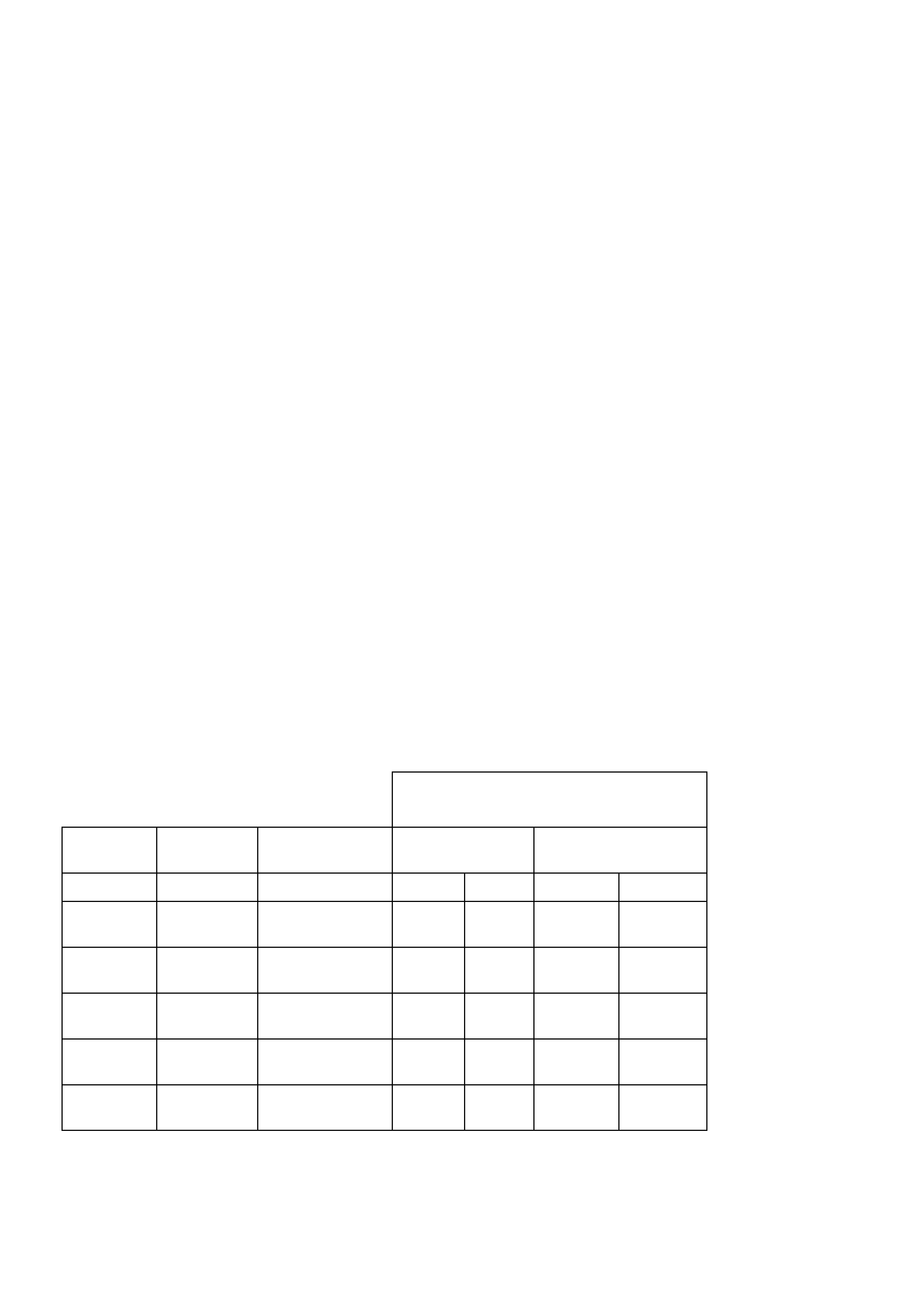
RECOMMENDED COLD INFLATION
kPa
MODEL WHEEL TYRE
DESIGNATION Up to 3
Passengers Up to
Maximum Load
Front Rear Front Rear
Executive 6.0J x 15
Steel P205/65
R15 92H 200 200 240
270 (1) 240
300 (1)
Berlina 6.0J x 15
Alloy P205/65
R15 92H 200 200 240
270 (1) 240
300 (1)
S 7.0J x 16
Alloy P225/50
R16 92V 200 200 240
270 (1) 240
310 (1)
SS 8.0J x 17 P235/45
R17 92V 200 200 240
270 (1) 240
310 (1)
Calais 7.0J x 16
Alloy P215/60
R16 92H 180 180 240
240 (1) 250
280 (1)
(1) Where vehicle is used for consistent speed in excess of 140 km/h,
required cold inflation pressures are to be as indicated.

5. TORQUE WRENCH SPECIFI CATIONS
ROAD WHEEL ATTACHING NUTS Nm
Steel Wheel 110-140
Alloy Wheel 110-140