SECTION 1E - COCKPIT MODULE
CAUTION:
This vehicle will be equipped with a Supplemental Restraint System (SRS). A SRS will
consist of either seat belt pre-tensio ners and a driver’s side air bag, o r seat belt pre-
tensioners and a driver’s and front passenger’s side air bags. Refer to CAUTIONS,
Section 12M, before performing any service operation on or around SRS
components, the steering mechanism or wiring. Failure to follow the CAUTIONS
could result in SRS deployment, resu lting in possible perso nal in jury or u nnecessary
SRS system repairs.
CAUTION:
This vehicle may be equipped with LPG (Liquefied Petroleum Gas). In the interests of
safety, the LPG fuel system should be isolated by turning 'OFF' the manual service
valve and then draining the L PG service lines, before any service w ork is carried out
on the vehicle. Refer to the LPG leaflet included with the Owner's Handbook for
details or LPG Section 2 for more specific servicing information.
1. GENERAL INFORMATION
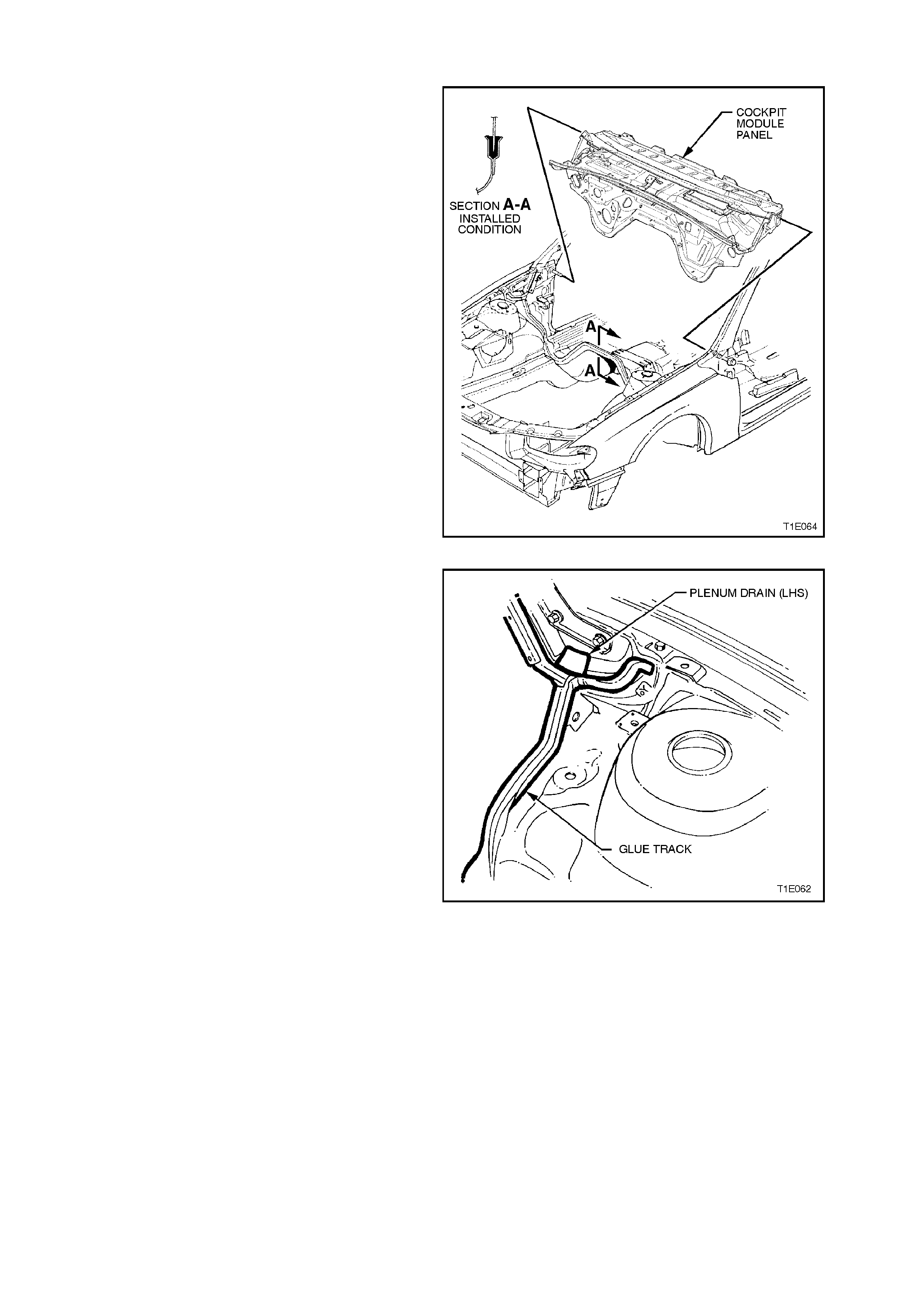
The cockpit module panel is clearly visible in the engine bay, the panel is painted gloss black and the glue track is
apparent where the panel joins to the floor and A-pillars.
The module consists of a sub-assembly comprising the dashboard, air conditioner (where fitted), radio, pedals,
steering column, instruments etc. After completion of the-sub assembly, the operation of the electrical components
is tested before fitting to the vehicle.
The sub-assembly is retained in a channel (glue track) filled with a Special Silicone Adhesive in the front floor
extension and inner shroud panels of the body shell. Refer to 1.2 GENERAL PRECAUTIONS, as under repair
conditions the glue track must be free of refinishing paint.
The module locates on self-centering dimples, two bolts, installed through the A-pillar, and two bolts, installed in the
plenum area. These points maintain the location until the adhesive cures. After installation and when the adhesive is
fully cured, the module becomes an integral part of the body structure.
Prior to removal of the module, the vehicle should be mounted in a jigging system to ensure that the body structure
is fully supported and cannot move.
The upper section of the module forms the base for the front windshield, which is bonded to the module using a
urethane adhesive.
The Vehicle Identification Number (VIN) plate is secured to the left side of the module by unique rosette headed
rivets. As a theft deterrent, the VIN number is visible through the front windshield.
The Silicone Adhesive in the glue track is suited for the high temperature conditions generated in the engine
compartment. The silicone also has excellent bonding, sealing and longevity characteristics.

1.2 GENERAL PRECAUTIONS
Unless repairing a crack or tear in the glue track, only two part silicone adhesive should be used when refitting the
cockpit module.
NOTE:
Remove as much of the old adhesive as possible from the glue track before installing the cockpit module.
As the cockpit module panel forms part of the vehicle structure, where the module panel has any damage or cracks
in the sheet metal, or if fire damage has occurred, the module must be removed and replaced.
Tears, separation or splitting in the adhesive exceeding 300 mm in length require removal and complete reglueing
of the module.
The Silicone Adhesive, Part Number M39998 used in the glue track must not be replaced with any other type of
adhesive or sealant other than that which is recommended by GMHAL; urethanes, epoxies, acrylic etc. are not
suitable for use in this application. Failure to correctly seal the cockpit module panel to the vehicle may allow
exhaust, fuel or other fumes to enter the passenger compartment.
INSTALLATION PRECAUTIONS
IMPORTANT:
To obtain a satisfactory bond between the two parts, the following procedures must be observed.
1. Remove as much of the remaining adhesive as possible from the glue track prior to reinstallation of the panel.
2. After repairing the sheet metal work, if all the remaining adhesive has been thoroughly removed, apply a coat
of primer inside the glue track. Do not apply primer over any remaining adhesive.
NOTE:
The finish on the front floor extension and shroud panel service parts will not require priming before applying the
adhesive to the glue track.
3. When reinstalling a module after a repair, ensure that no refinishing paint or overspray is in the glue track or on
the remaining adhesive.
Apply a layer of masking tape to the track before painting, and install the module after oven baking the paint
(where appropriate).
4. Do not use an adhesive other than that which is recommended by GMHAL.
5. Body shell assemblies are available (at the time of publication) in white enamel finish with or without the cockpit
module installed.
6. Before commencing installation of the module, thoroughly read 2.1 COCKPIT MODULE - MIXING SILICONE
ADHESIVE in this Section.
7. Although the cockpit module is installed as an assembly on the production line, this method is not practical for
repairing the vehicle. Service Operation 2.1 COCKPIT MODULE in this Section describes the cockpit module
disassembly and reassembly in the vehicle.
SAFETY PRECAUTIONS
The Silicone Adhesive used in the glue track, once cured requires no special precautions. However, when mixing
the adhesive compound with the catalyst, the Precautions listed below should be observed.
1. Do not swallow–the catalyst is a Toxic substance, keep away from children.
2. Safety glasses should be worn to avoid contact with eyes. If eye contact occurs, wash the area in clean water
only, and seek immediate medical advice.
3. Wear protective gloves when handing the adhesive and catalyst, as they may cause skin irritation. If irritation
occurs, wipe the adhesive/catalyst off with a clean cloth and wash the affected area thoroughly in clean water.
4. Vapour produced by the adhesive and catalyst may cause breathing difficulties, use only in a well ventilated
area.
5. The catalyst is combustible, keep away from sparks and flame.
2. SERVICE OPERATIONS
2.1 COCKPIT MODULE
REMOVE
CAUTION:
Disable the SRS (Air Bag). Refer to DISABLING
THE SRS, Section 12M SRS.
NOTE:
This procedure describes the minimum
disassembly required to remove the components
attached to the cockpit module. Where replacement
of individual parts is necessary refer to appropriate
Section.
IMPORTANT:
As a theft deterrent, VT series vehicles are fitted
with a security coded audio system. Af ter the power
supply is interrupted, the radio will remain
inoperative after reinstallation until the pin number
is entered into the system. The procedure is
described in the glove box literature accompanying
the Owner’s Handbook.
1. Disconnect the negative and positive cables
from the battery to isolate the electrical
equipment, and prevent damage to the
components.
2. Drain cooling system, refer to
Section 6B1-1 ENGINE COOLING - V6
ENGINE or 6B1-2 ENGINE COOLING - V6
SUPERCHARGED or 6B2 ENGINE COOLING
- V8 ENGINE.
3. Where fitted discharge the air conditioning
system, refer to
Section 2C AIR CONDITIONING -
SERVICING AND DIAGNOSIS .
4. Depressurise the fuel system as described in
Section 6C1 POWERTRAIN MANAGEMENT
- V6 ENGINE or 6C2 POWERTRAIN
MANAGEMENT - V8 ENGINE.
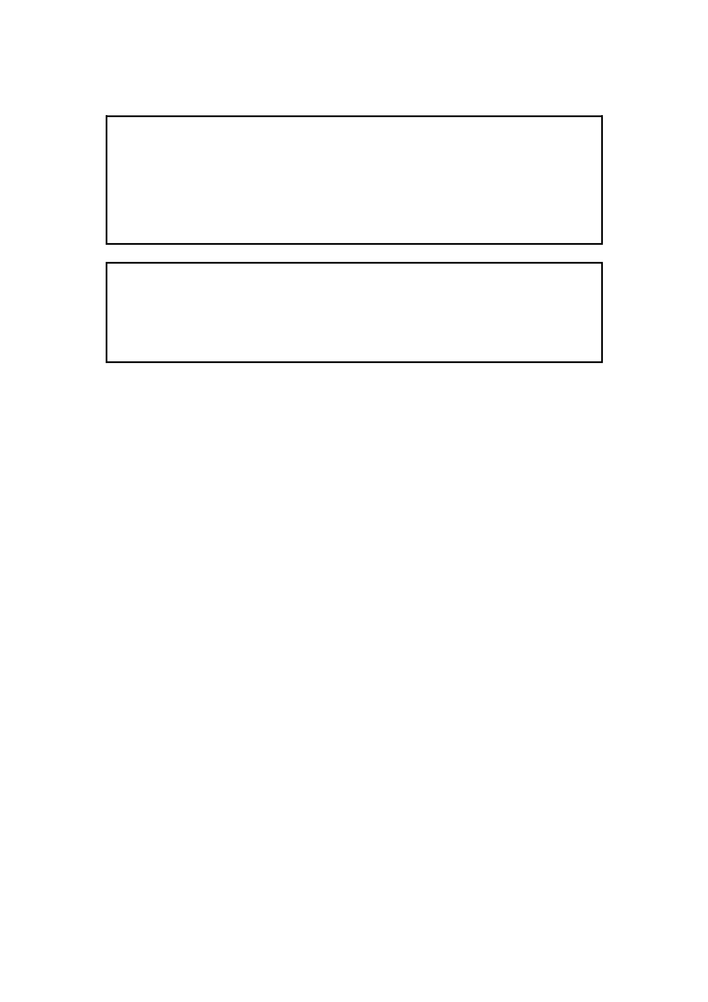
5. Locate powertrain control module in the
passenger footwell.
Figure 1E-1
6. Unclip duct cover flap on right hand side of
footwell upper closing panel left side and
disengage locating lugs to passenger side
shroud lower. Grasp closing panel firmly and
detach by pulling left side down first, then
disengage right side clip and remove panel.
Figure 1E-2
7. Remove passenger side shroud lower trim
assembly, refer to Section 1A2 BODY
DIMENSIONS.
Techline
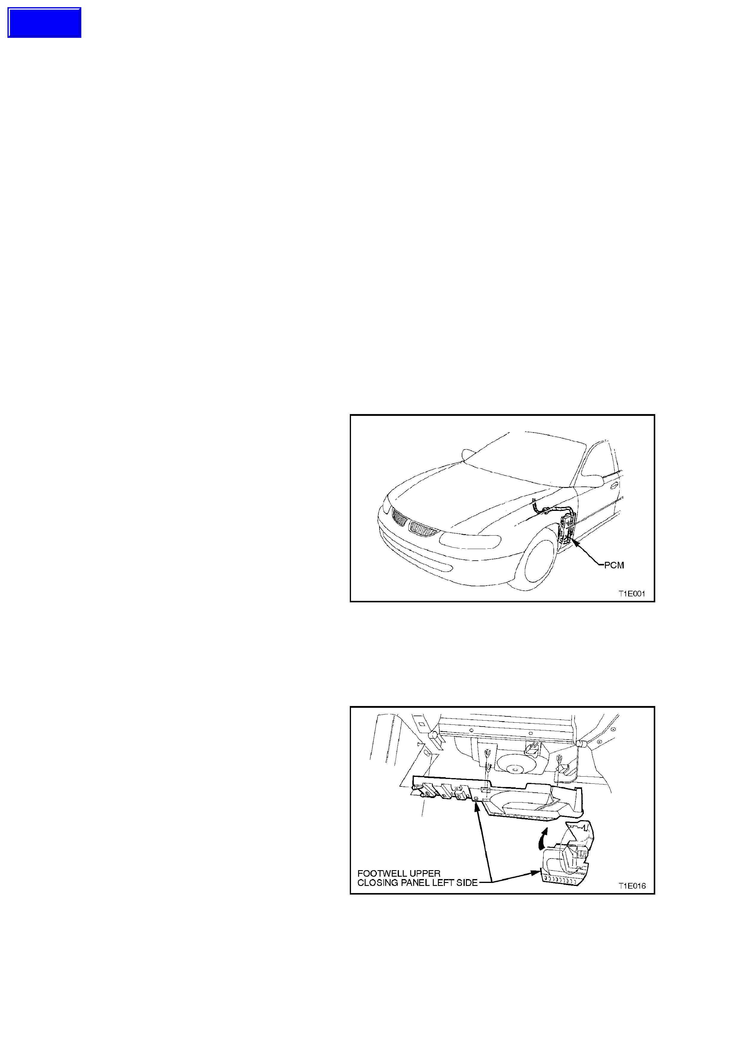
8. Disconnect the harness from the powertrain
control module, refer to Section 6C1
POWERTRAIN MANAGEMENT - V6 ENGINE
or 6C2 POWERTRAIN MANAGEMENT - V8
ENGINE. The module should be removed from
the vehicle to prevent damage occurring.
Figure 1E-3
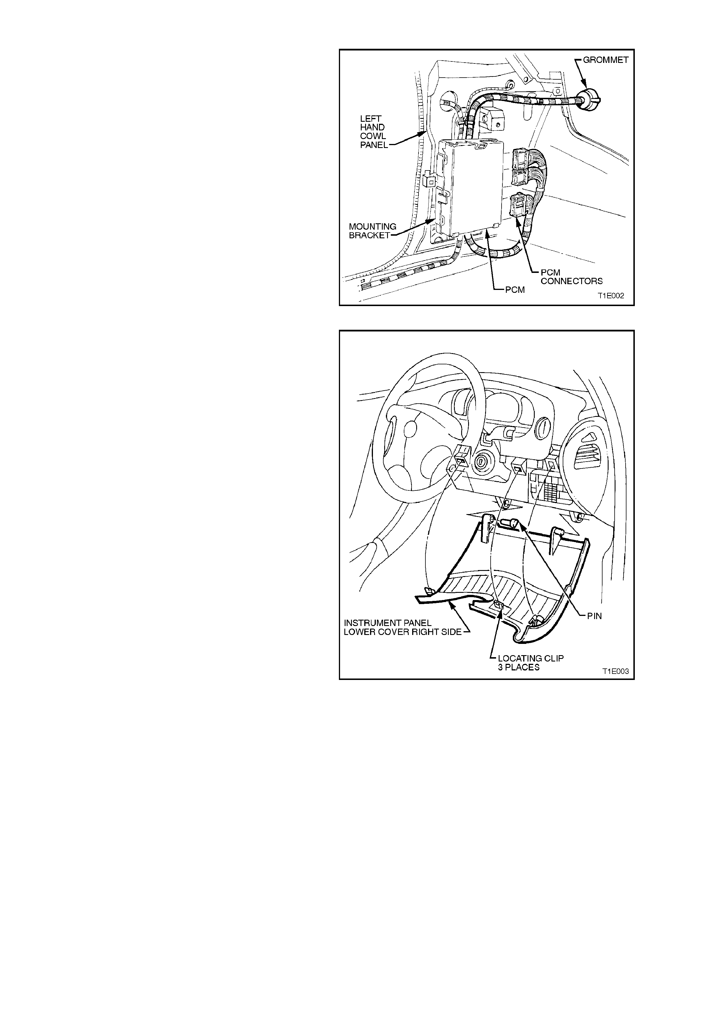
9. Adjust steering wheel to upper most position.
Grasp right hand side of lower cover panel
right side firmly and pull towards rear of
vehicle. Repeat procedure f or left hand side of
cover. Prise out the left hand hinge pin using a
flat blade screwdriver.
Tilt the cover down on the left side and
disengage the right hand hinge pin and
remove panel.
Figure 1E-4
10. Adjust steering column to lower most position.
Remove steering column to facia screen.
Remove single screw from the lower steering
column shroud and remove upper and lower
steering column shroud.
Figure 1E-5
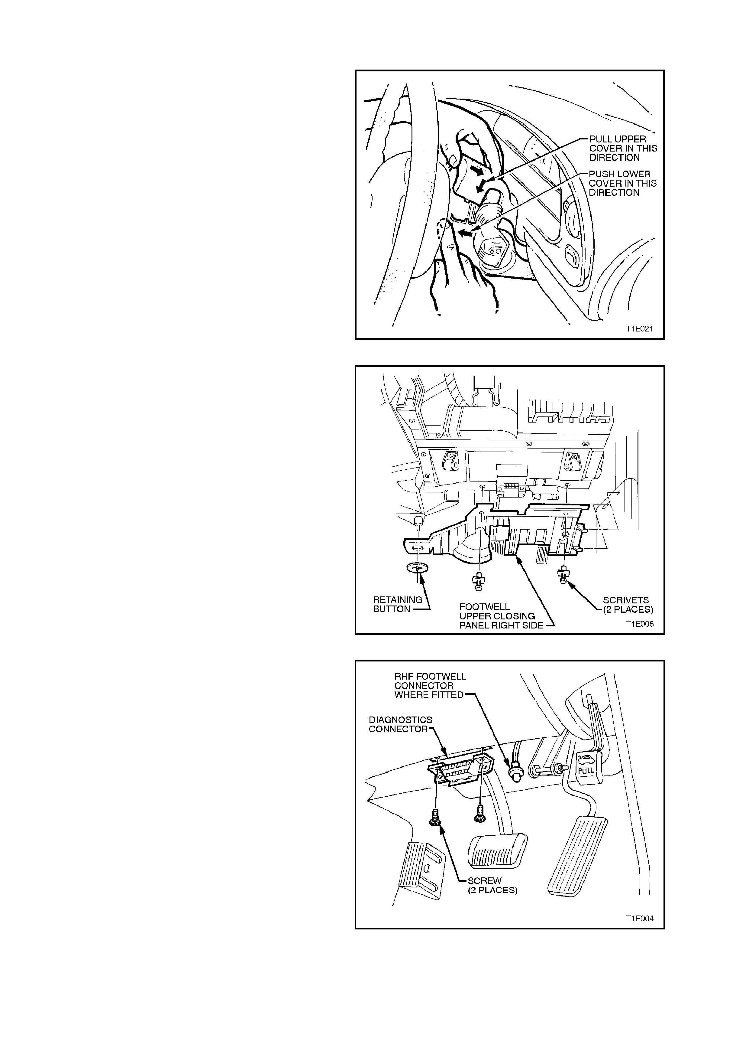
11. Remove two scrivets and on vehicles fitted
with automatic transm ission, prise off retaining
button and detach the footwell upper closing
panel right side.
Where fitted disconnect front footwell lamp
from footwell upper closing panel, refer to
Section 12B LIGHTING SYSTEM.
Figure 1E-6
12. Remove two screws securing the diagnostic
connector to instrument panel lower trim right
side assembly.
Figure 1E-7
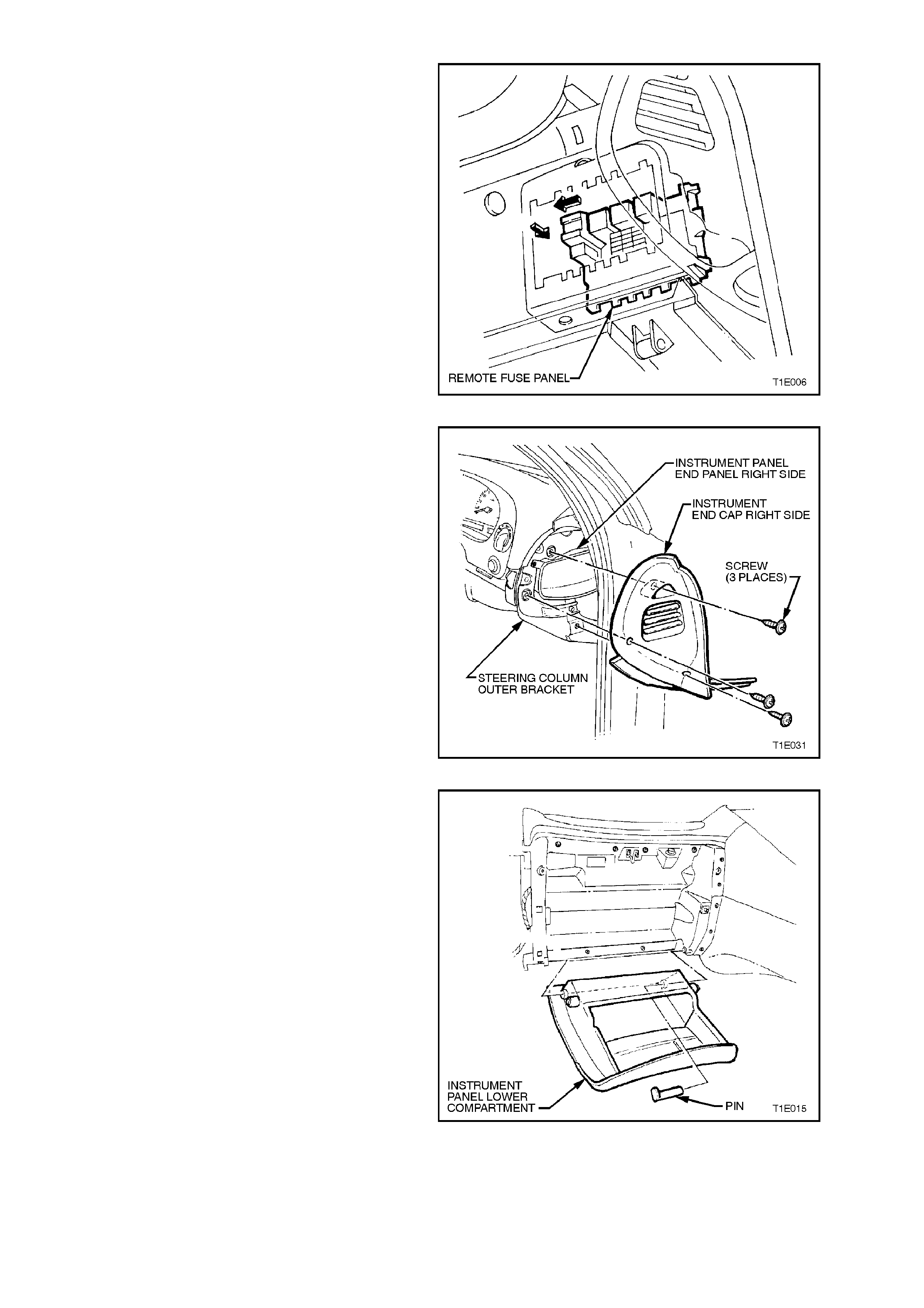
13. Slide the passenger compartment relay and
fuse block to the left, push through support
panel and withdraw towards front of vehicle.
Figure 1E-8
14. Remove the three screws and remove
instrument panel end cap cover right hand
side.
Figure 1E-9
15. Open the instrument panel lower
com partment, and lever the hinge pin f rom the
right side. Lower compartment and withdraw
the pin. Disengage right hand travel limiting
peg from slot in instrument panel roof by
deforming plastic tang..
Figure 1E-10
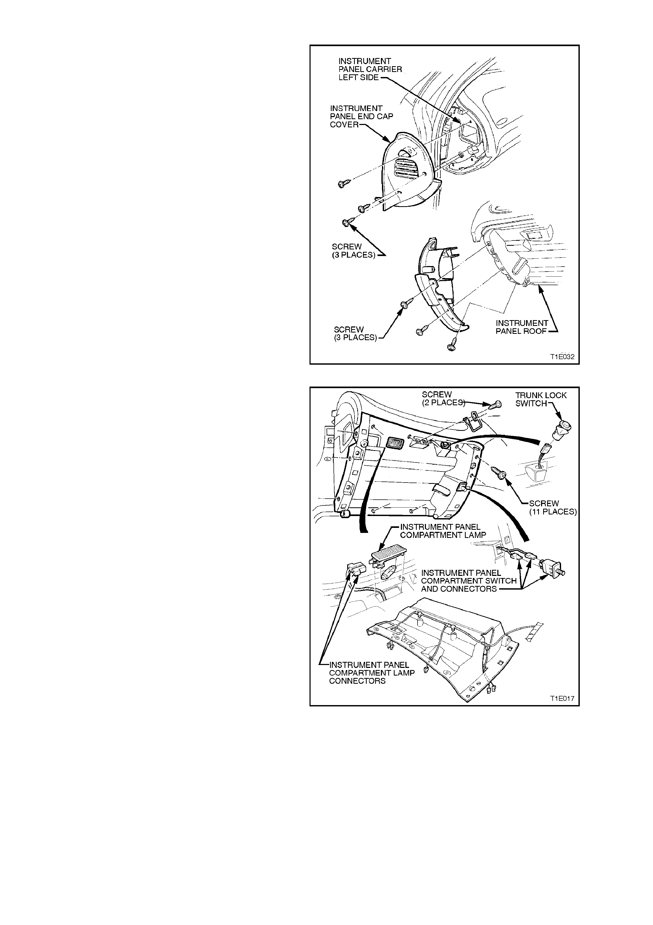
16. Remove the six retaining screws for instrument
panel end cap cover left hand side.
Figure 1E-11
17. Remove 11 retaining screws from instrument
compartment roof, disconnect glove box lamp
connectors, trunk lock switch connector, glove
box switch connectors and unclip glove box
wiring harness.
Figure 1E-12
18. Remove driver’s side shroud lower trim
assembly, refer to Section 1A2 BODY
DIMENSIONS.
Figure 1E-13
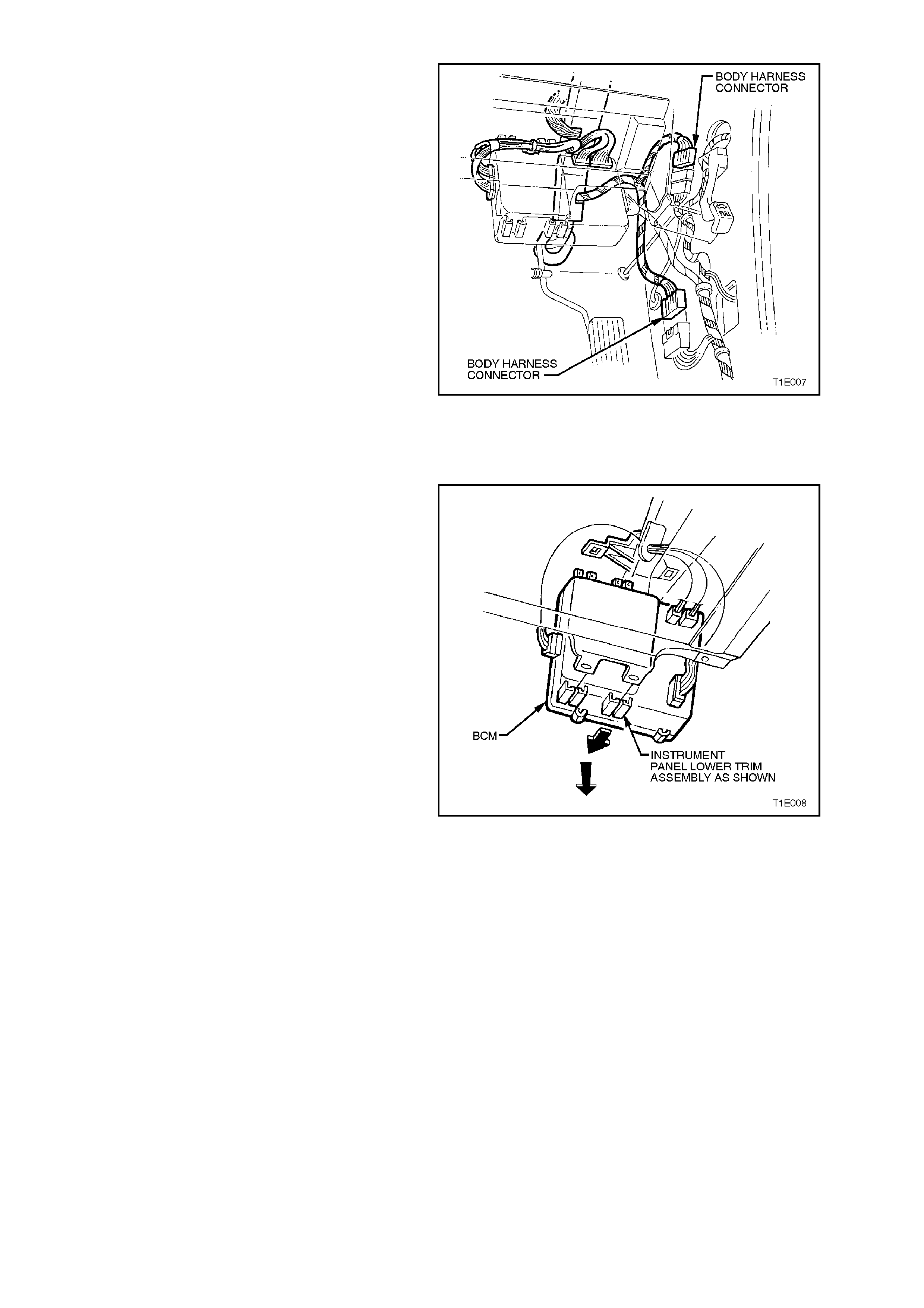
19. Disconnect body harness to main wiring
harness connectors at the right hand cowl
panel.
20. Remove Body Control Module (BCM) from
mounting brackets by pushing the bottom of
the BCM towards the front of the vehicle until
the BCM disengages from the lower mounting
bracket.
NOTE:
The wiring harnesses are still connected.
Then grasp the BCM, and gently pull the BCM
down disengaging it from the upper mounting
bracket.
Figure 1E-14
21. Remove the transmission console and detach
console wiring harness, refer to
Section 1A3 INSTRUMENT PANEL &
CONSOLE.
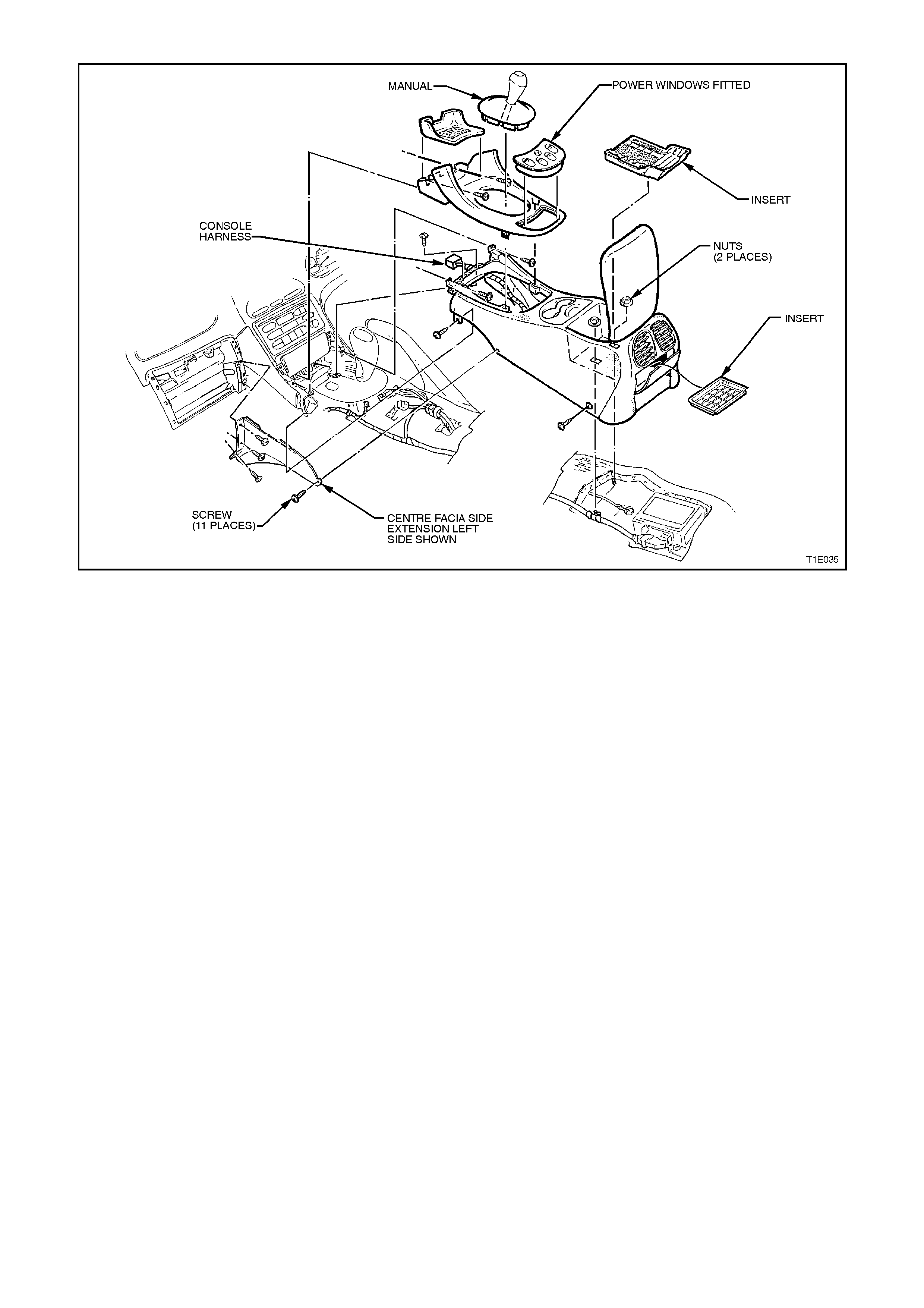
Figure 1E-15
22. Remove retaining screw from the demist
nozzle right-hand and remove.
23. Remove retaining screw from the demist
nozzle left-hand and remove.
NOTE:
On all vehicles, care must be taken to avoid
damage to the solar sensor.
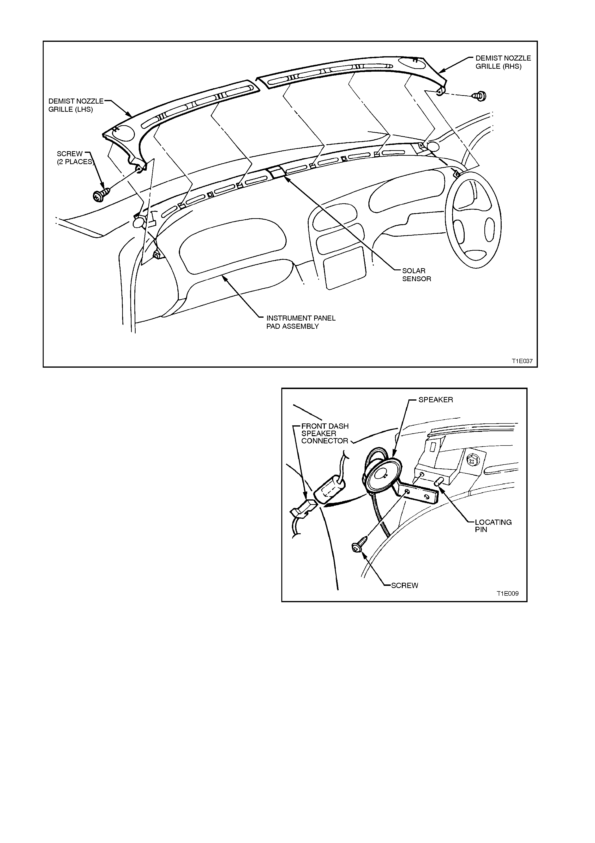
Figure 1E-16
24. Disconnect left and right front dash speaker
harness connectors. Using a Phillips screw
driver, remove screw attaching front dash
speakers and remove both speakers.
Figure 1E-17
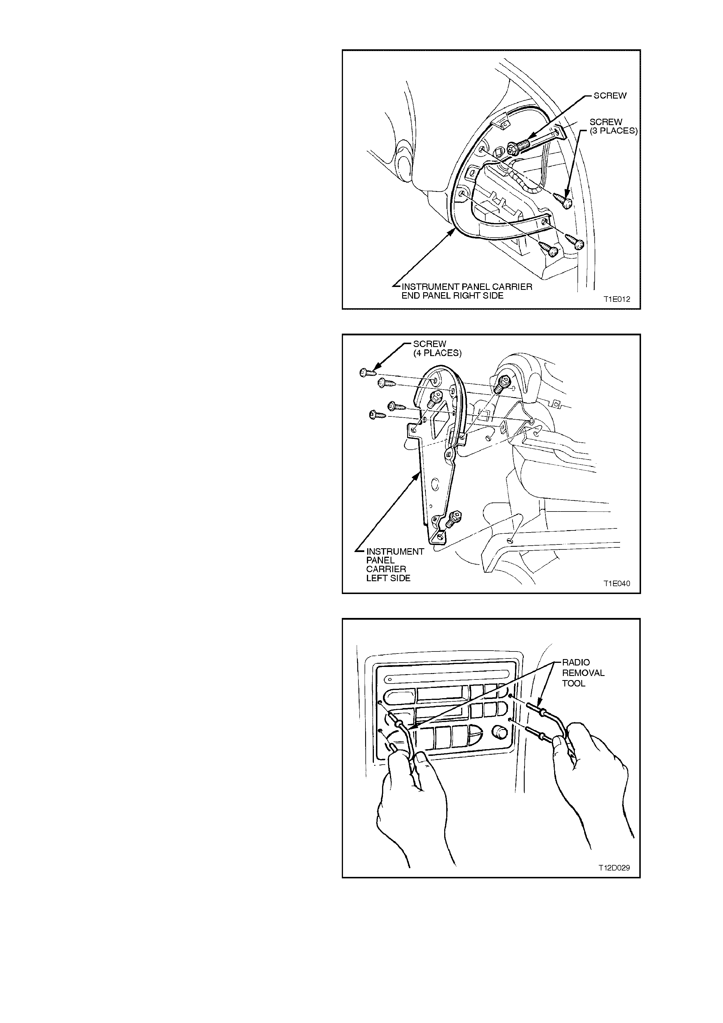
25. Remove the four retaining screws from
instrument panel carrier end panel right side
and remove panel.
Figure 1E-18
26. Remove four attaching screws securing
instrument panel carrier end panel left side
and three bolts attaching passenger airbag
support rail, lower left side rail, and remove
panel.
Figure 1E-19
27. Remove radio/cassette/CD from instrument
panel, use service tool 179 1308 000 to assist
in removal. Refer to Section 12D AUDIO
SYSTEMS.
Figure 1E-20
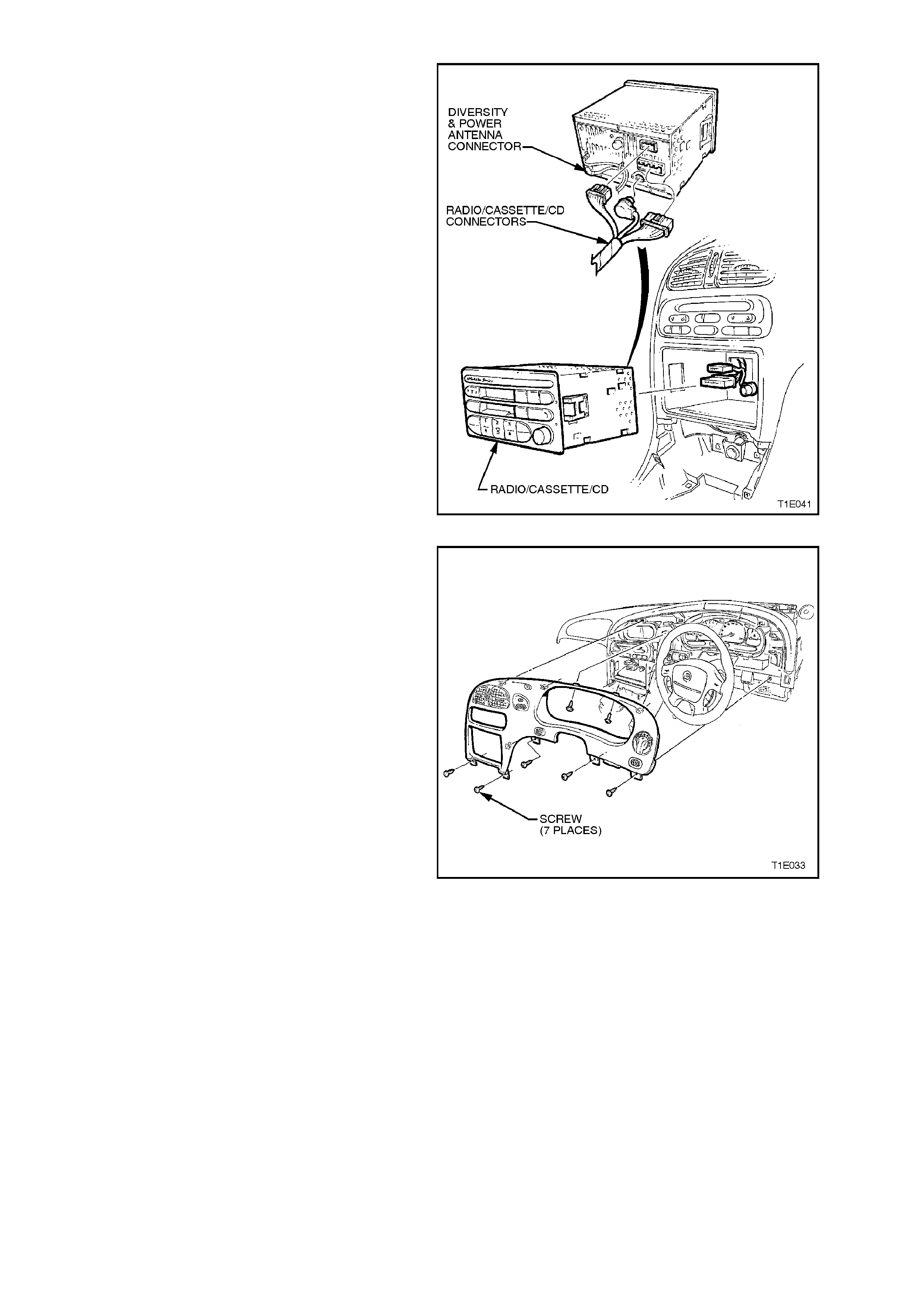
28. Disconnect radio/cassette harness and if fitted
CD connector. Disconnect antenna and if fitted
diversity and power antenna.
Figure 1E-21
29. Remove the seven screws retaining the
instrument facia assembly, and pull facia from
retaining clips (5 clips).
NOTE:
Care must be taken to disconnect the headlamp
switch connector, fog lamp switch connector (if
fitted), trip computer switch connector (if fitted),
hazard switch connector from main wiring harness.
Figure 1E-22
30. Remove the two attaching screws securing in-
car sensor (if fitted) and disconnect harness
connector, refer to Section 2E AIR
CONDITIONING.
31. Remove the 13 screws securing centre facia
assembly, refer to
Section 1A3 INSTRUMENT PANEL &
CONSOLE.
Figure 1E-23
NOTE:
The steering column is designed as an energy
absorbing unit. Avoid hammering, jarring dropping
or applying force to any portion of the steering
column.
IMPORTANT:
TO MAINTAIN SAFETY STANDARDS DO NOT
REUSE DAMAGED COMPONENTS OR
REPLACEMENT PARTS OF LESSER QUALITY
OR SUBSTITUTE DESIGN.
32. Disconnect the wiring harness connectors
from the ignition switch, horn, turn signal
switch and ignition key reader and lamp.
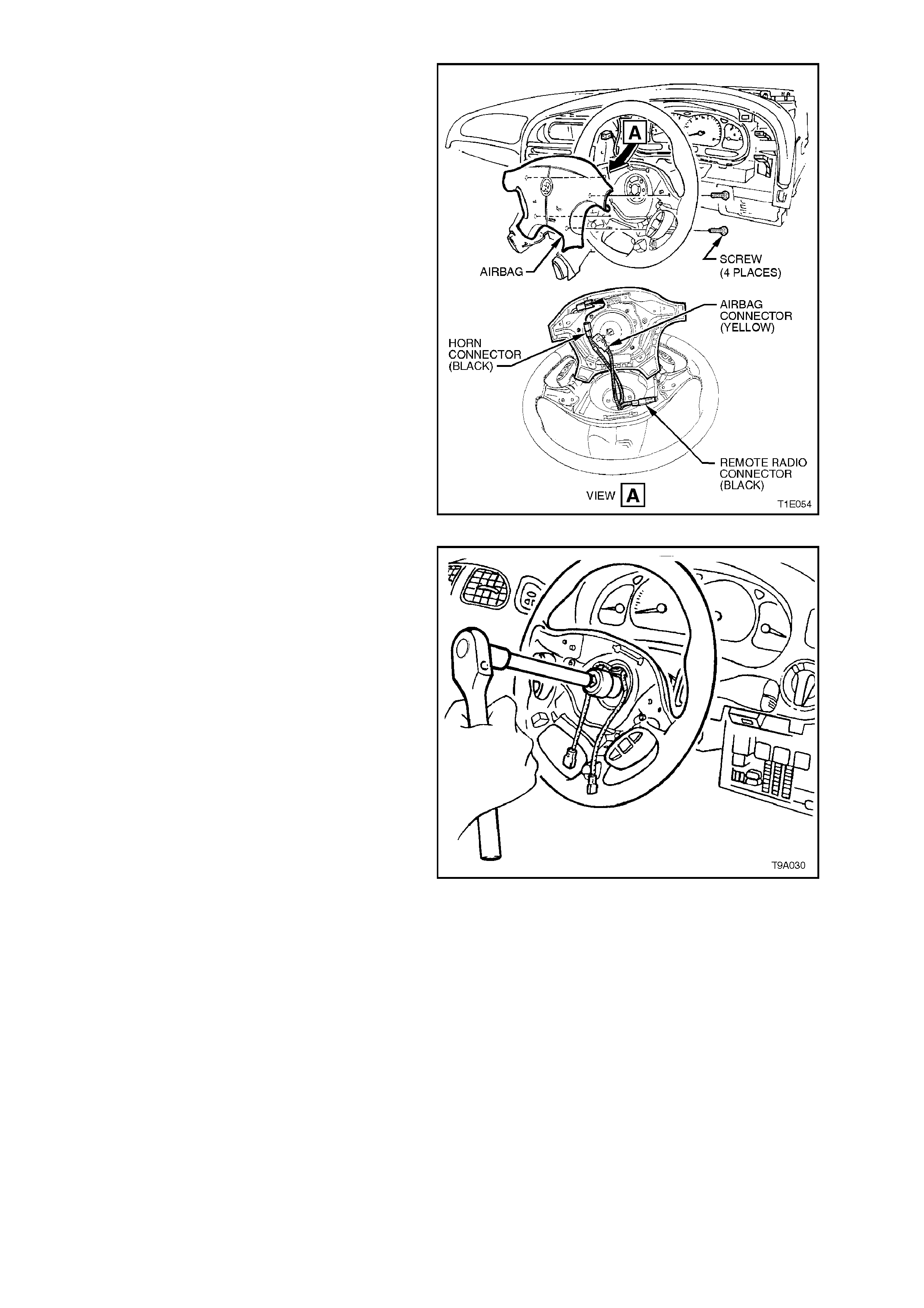
33. Remove four retaining screws securing Airbag
and disconnect horn connector, airbag
connector and if fitted remote radio connector.
Figure 1E-24
34. Use Torx driver to remove single screw
securing steering wheel to steering column,
and remove steering wheel.
Figure 1E-25
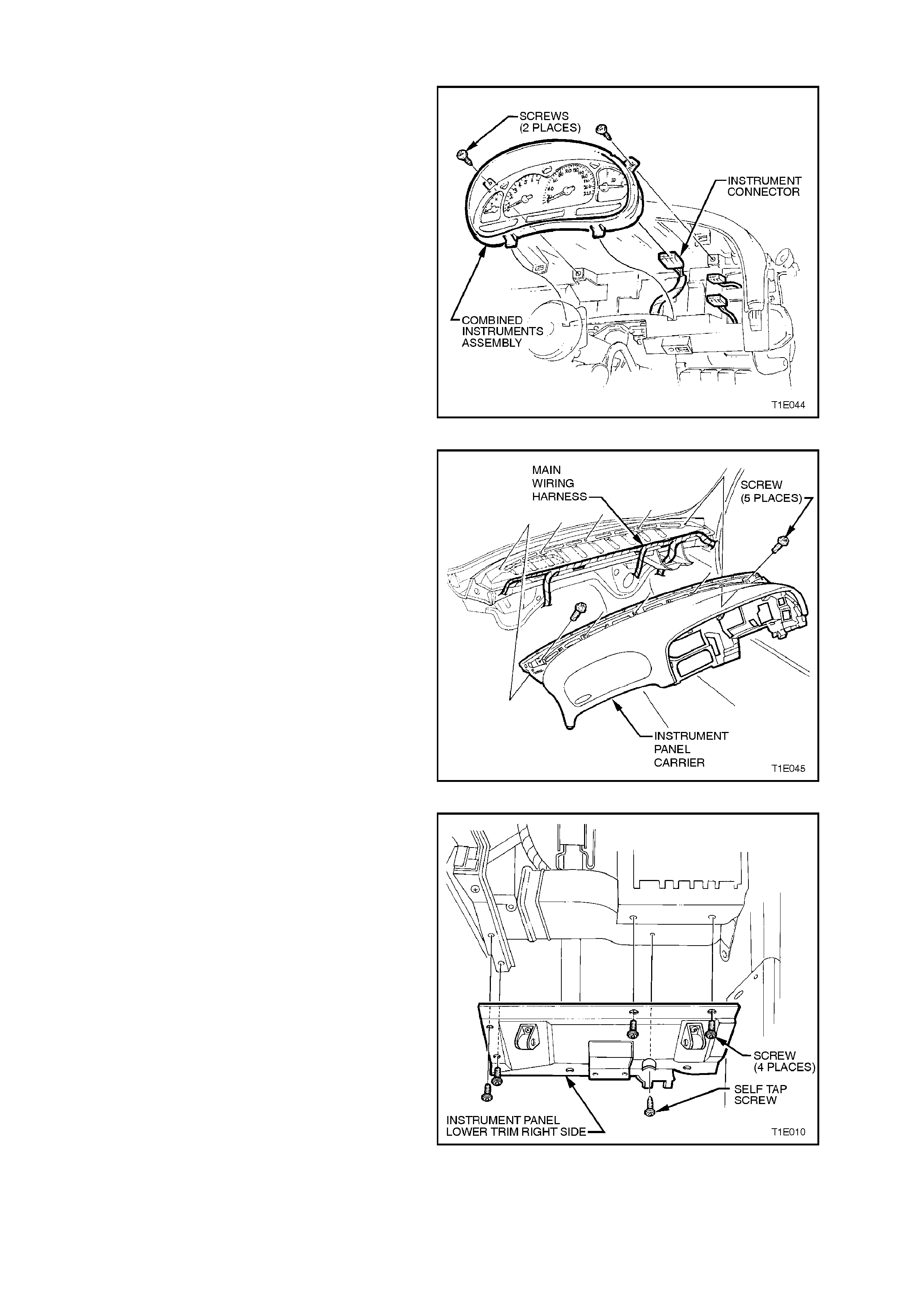
35. Remove the screws securing the heater and
air conditioning controls and disconnect the
electrical connections.
36. Remove the screws securing the combined
instruments assembly and disconnect
instrument connector.
Figure 1E-26
37. Remove the five retaining screws along top
edge of instrument panel carrier.
Figure 1E-27
38. Remove the five screws and withdraw
instrument panel lower trim right side rail
assembly.
39. Remove HVAC unit to door outer right hand
side and HVAC unit to door vent inner right
hand side. Refer to
Section 2B AIR CONDITIONING - REMOVAL
AND INSTALLATION .
Figure 1E-28
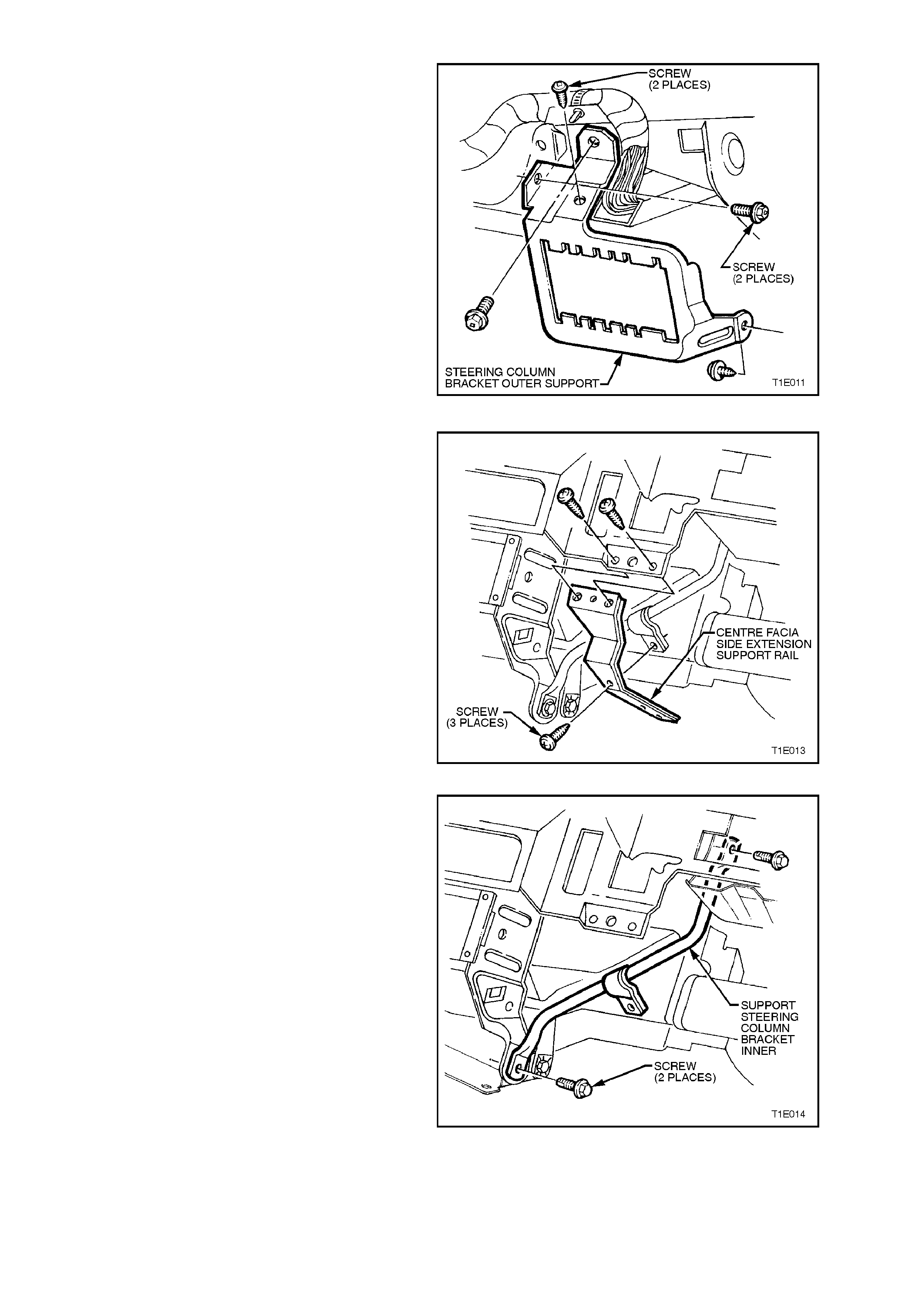
40. Remove four screws securing the steering
column bracket outer support and remove.
Figure 1E-29
41. Remove centre facia side extension support
rail (3 screws).
Figure 1E-30
42. Remove the two screws and remove support
steering column bracket inner.
Figure 1E-31
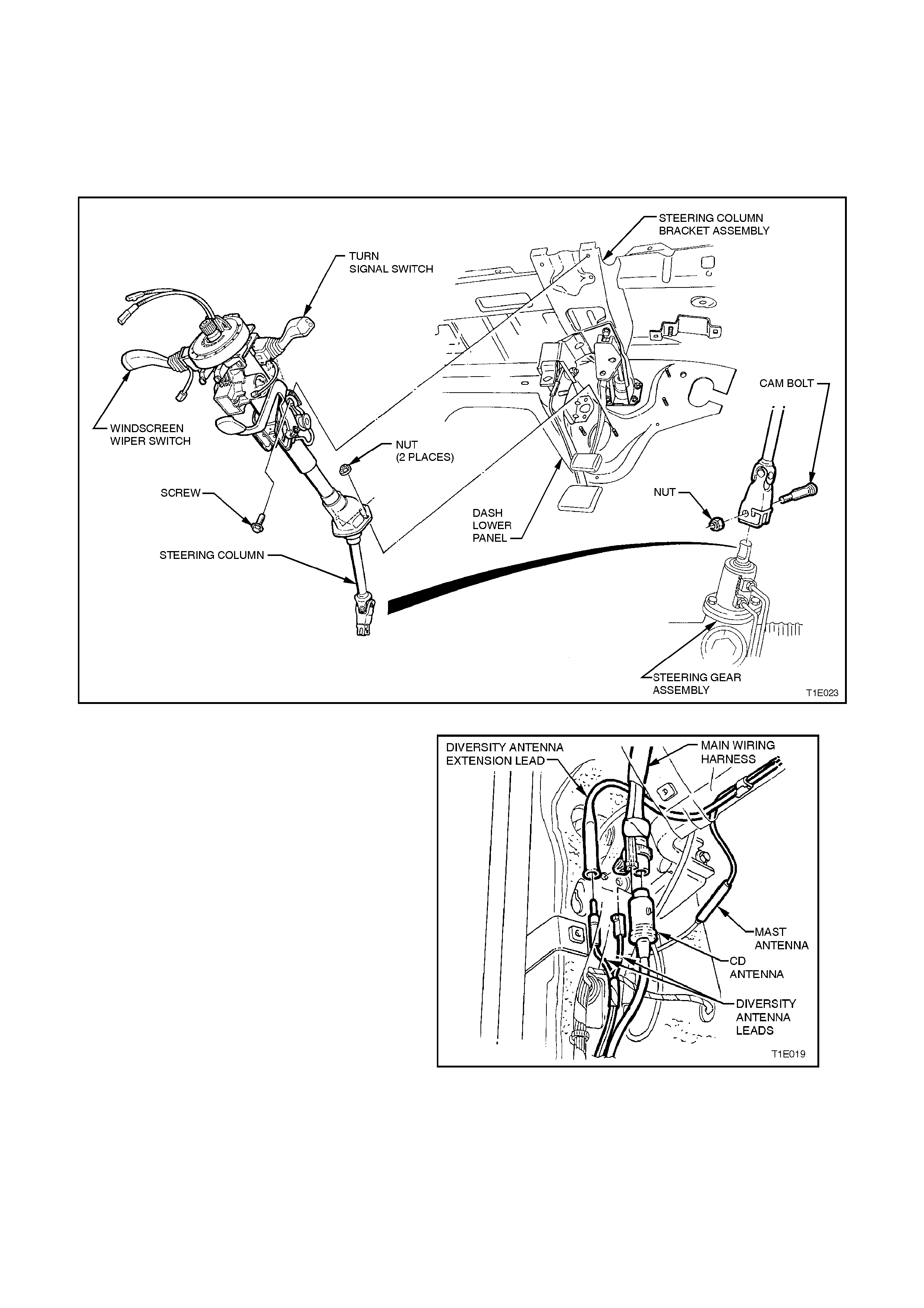
43. Remove cam bolt and nut from steering
column clevis located at the steering rack.
From inside vehicle remove two nuts at base
of steering column, remove two upper
mounting screws, and carefully remove
steering column assembly from vehicle.
Figure 1E-32
44. Disconnect the main wiring harness from the
antenna, power, and where fitted CD
connector located on the left side of
passenger footwell.
Figure 1E-33
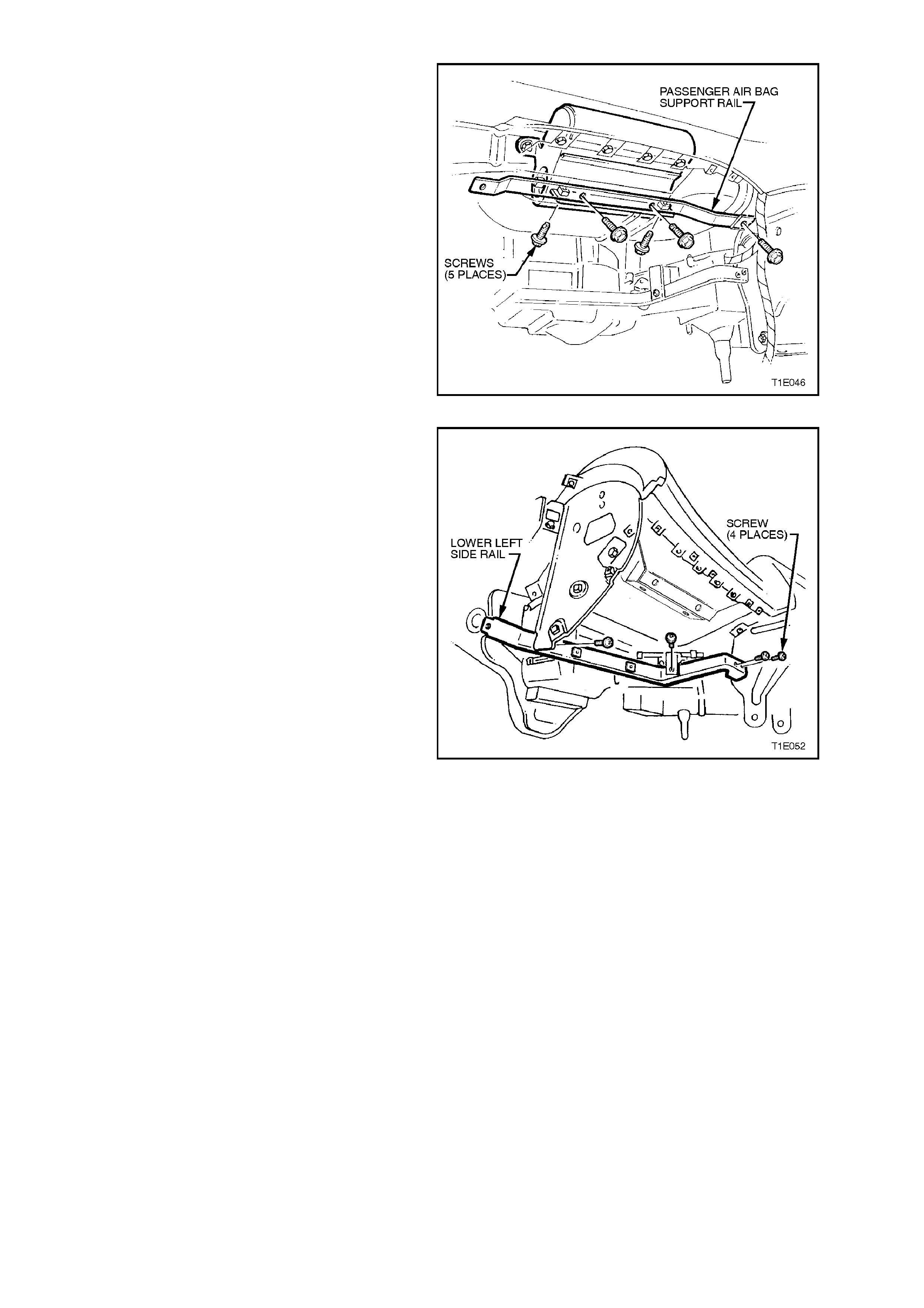
45. Remove five screws securing passenger
airbag support rail assembly left side and
remove rail.
Figure 1E-34
46. Rem ove two screws connecting lower lef t side
rail to instrument panel carrier rail assembly.
Remove single screw connecting lower left
side rail to instrument panel carrier end panel
left side. Remove single screw connecting
lower left side rail to body mount.
Figure 1E-35
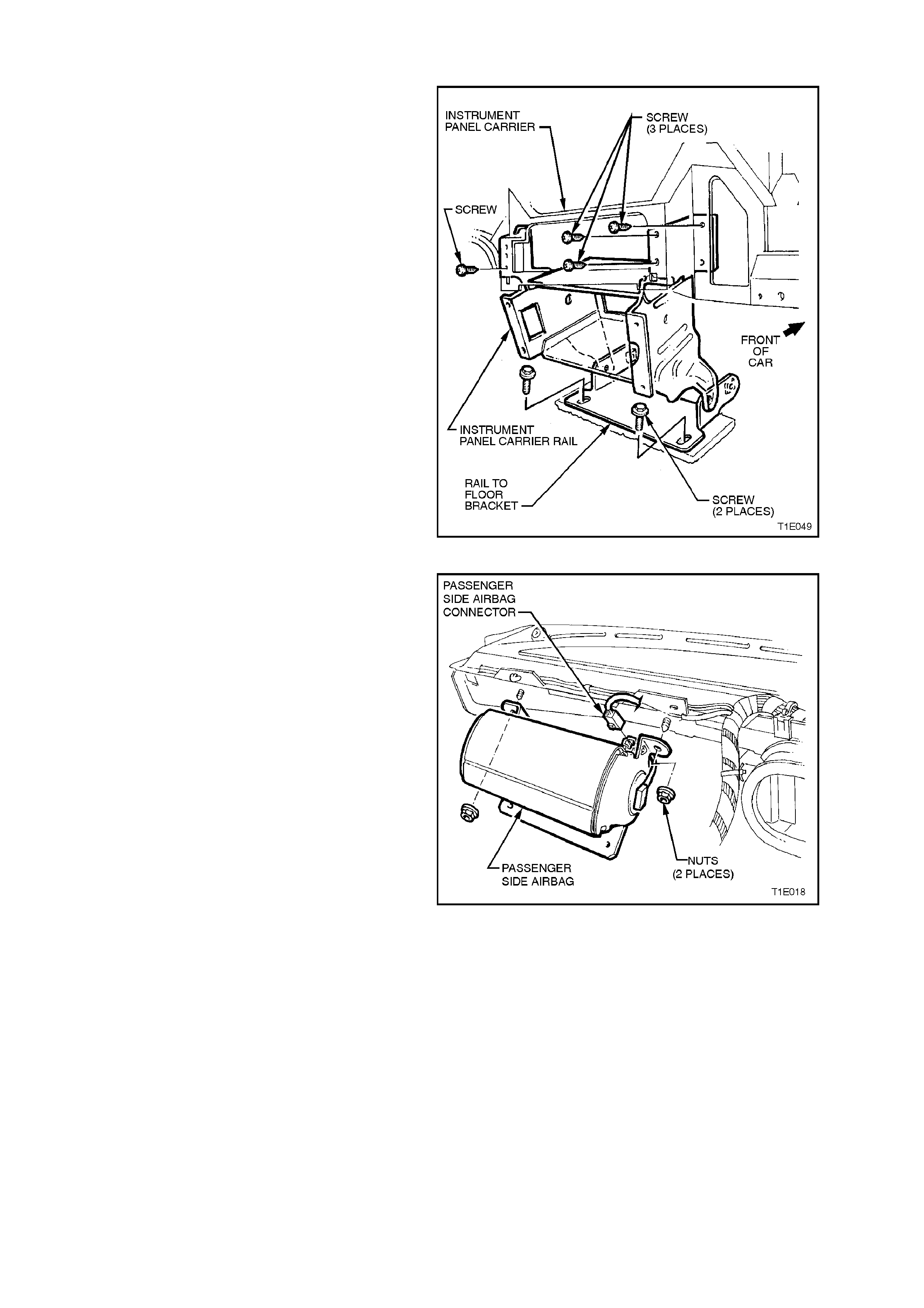
47. Remove instrument panel carrier rail
assembly.
Figure 1E-36
48. Where fitted remove passenger side airbag
connector located on the right hand side of
airbag. Remove two nuts attaching airbag to
dash lower panel assembly
Figure 1E-37
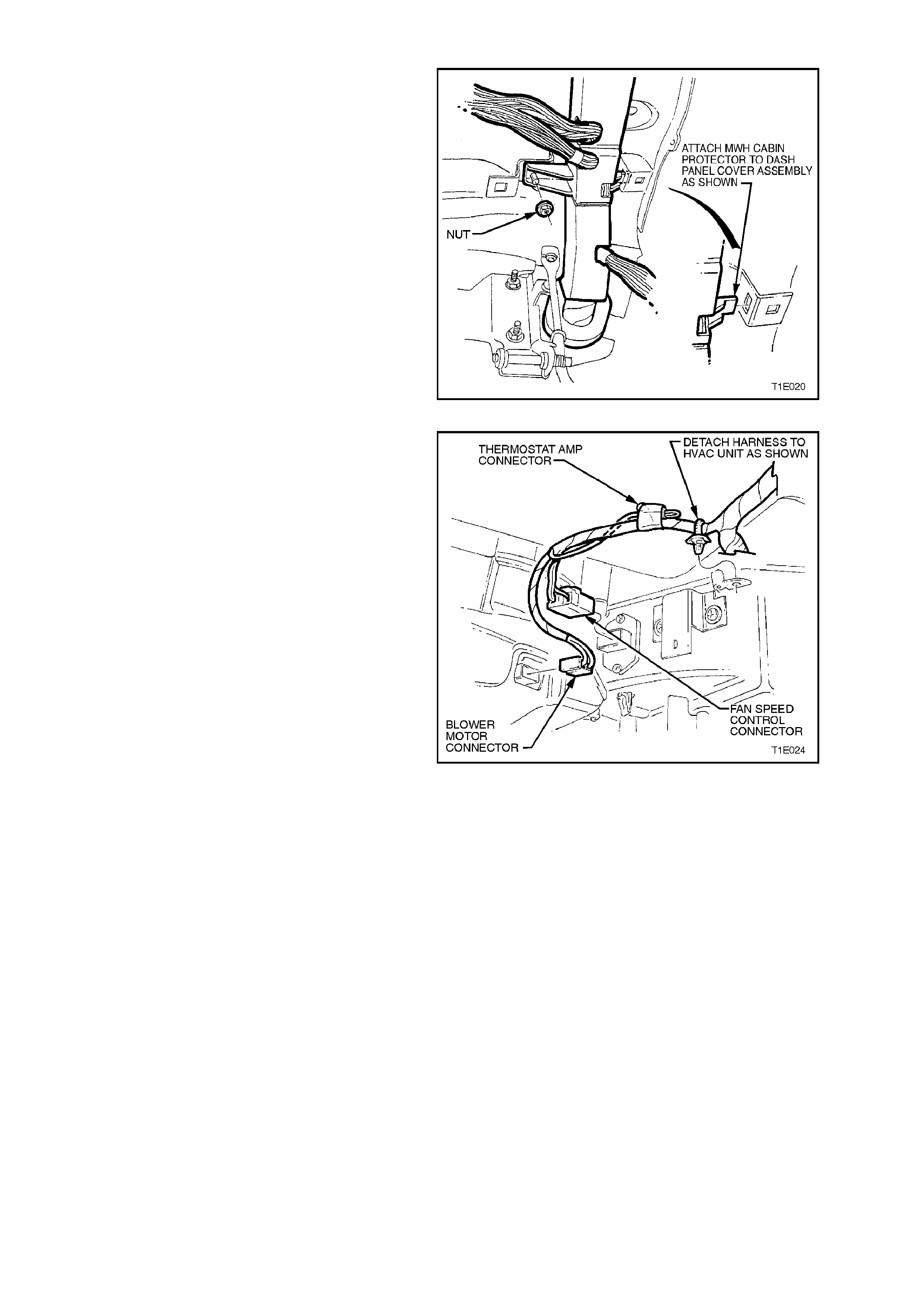
49. Remove main wiring harness former
retaining screw accessed from above and
single nut accessed from underneath.
Unclip main wiring harness former from
upper retaining bracket.
50. Disconnect the throttle cable from the
accelerator pedal and throttle body lever,
then remove the cable from the vehicle.
NOTE: Throttle cable remove is described in
Section 6C1 POWERTRAIN MANAGEM ENT – V6
Engine or 6C2 POWERTRAIN MANAGEMENT –
V8 Engine in the VT Series I Service Information.
Figure 1E-38
51. Disconnect the blower motor connector and
fan speed control connector from the HVAC
unit and detach harness.
Figure 1E-39
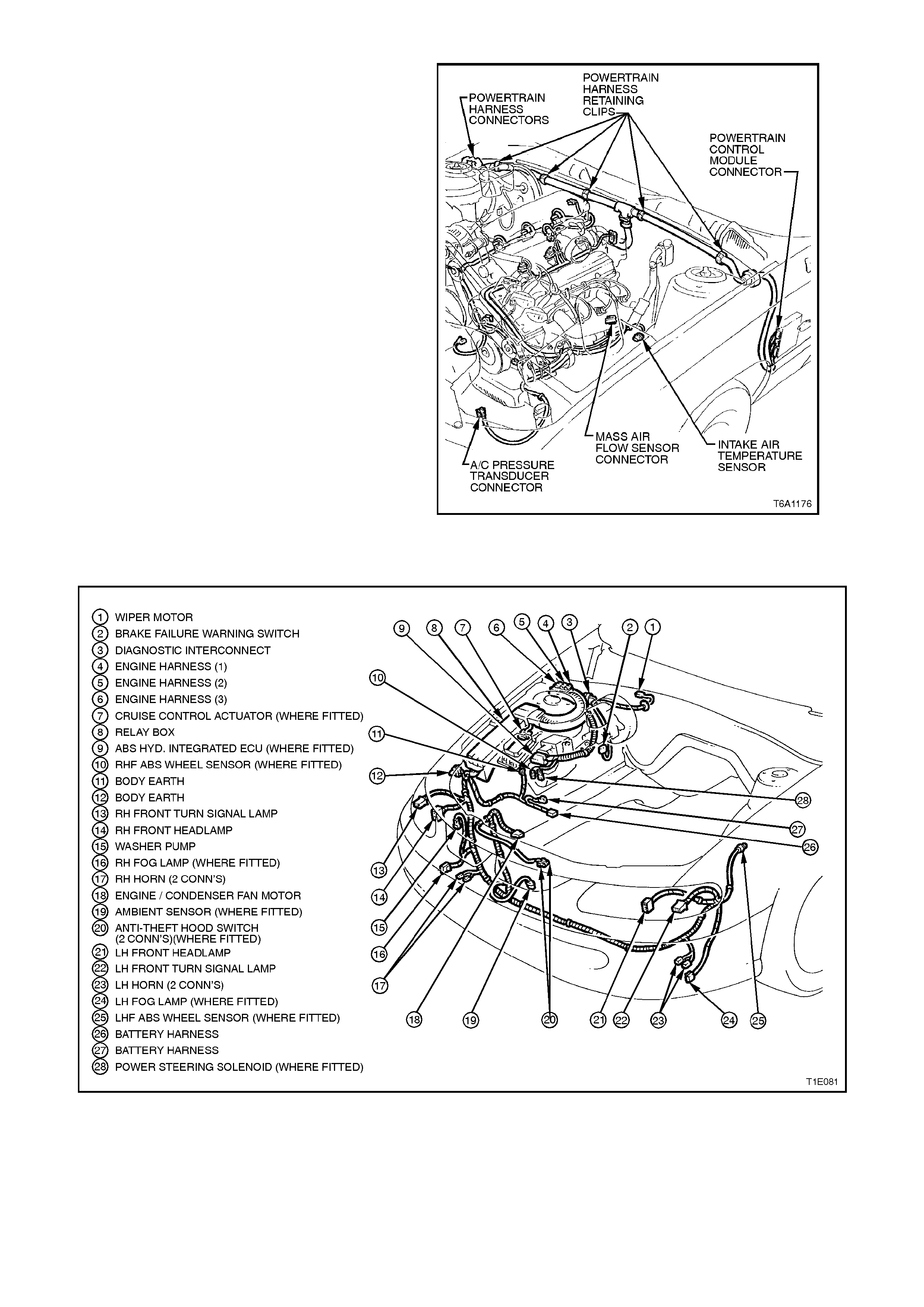
52. From engine compartment release powertrain
harness to dash panel retaining clips.
Disconnect mass air flow sensor, idle air
control motor connector, powertrain control
module connector. Disconnect intake air
temperature sensor at air cleaner and air
conditioning pressure transducer connector at
air conditioning condenser, lay wiring harness
on top of engine.
Figure 1E-40
53. Disconnect the main wiring harness from the
engine compartment electrical equipment.
Figure 1E-41
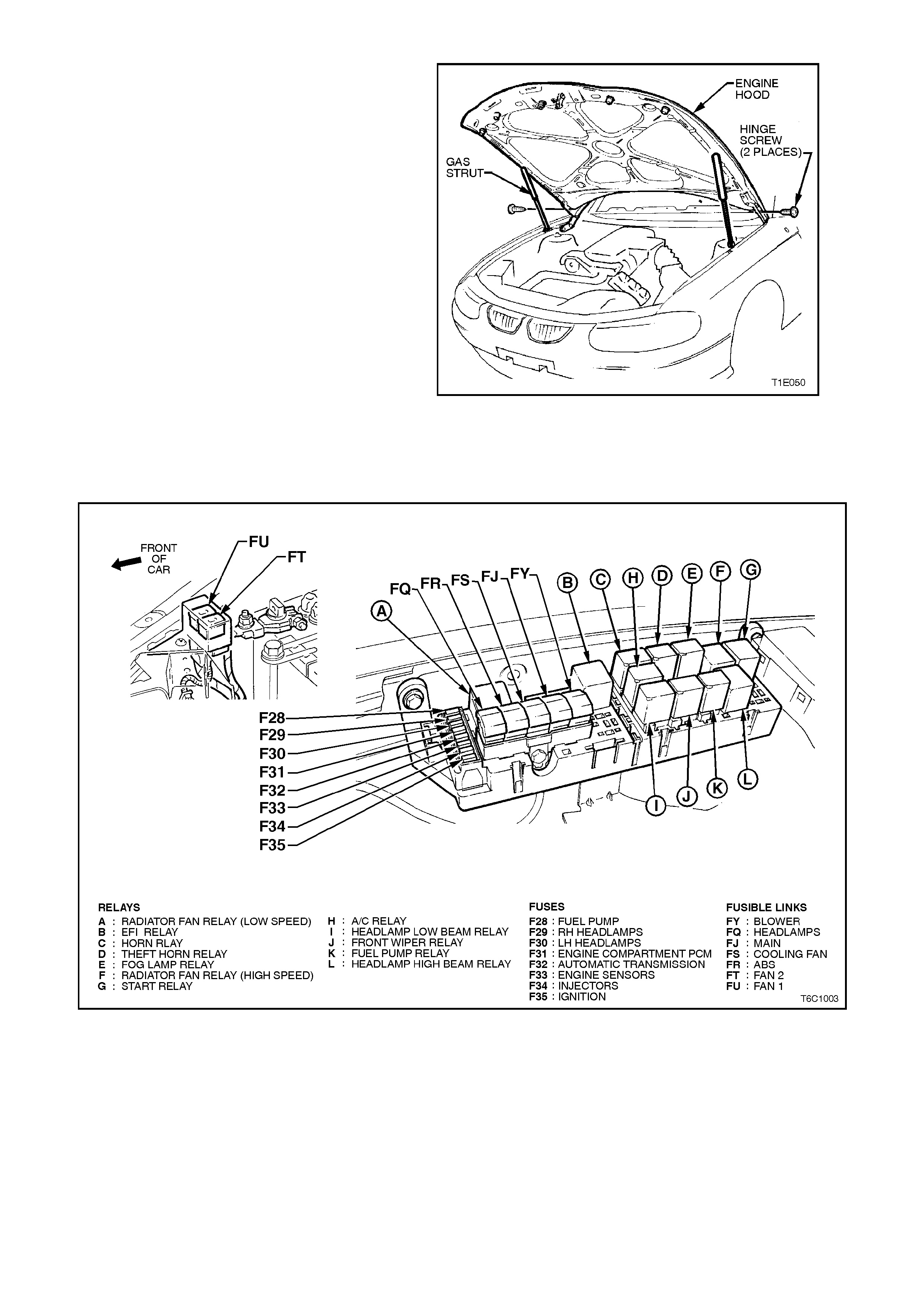
54. With engine hood adequately supported,
remove clips securing upper end of struts to
hood pivots. Disengage struts from hood
pivots and lay strut down on fender inner
panel.
With the aid of an assistant hold hood
assembly, remove engine hood bracket to
hinge attaching screws, and remove hood.
Figure 1E-42
55. Tag and remove all relays, fusible links, and
fuses from the relay housing in the engine
compartment. If fitted, disconnect Cruise
Control Actuator Connector.
Figure 1E-43
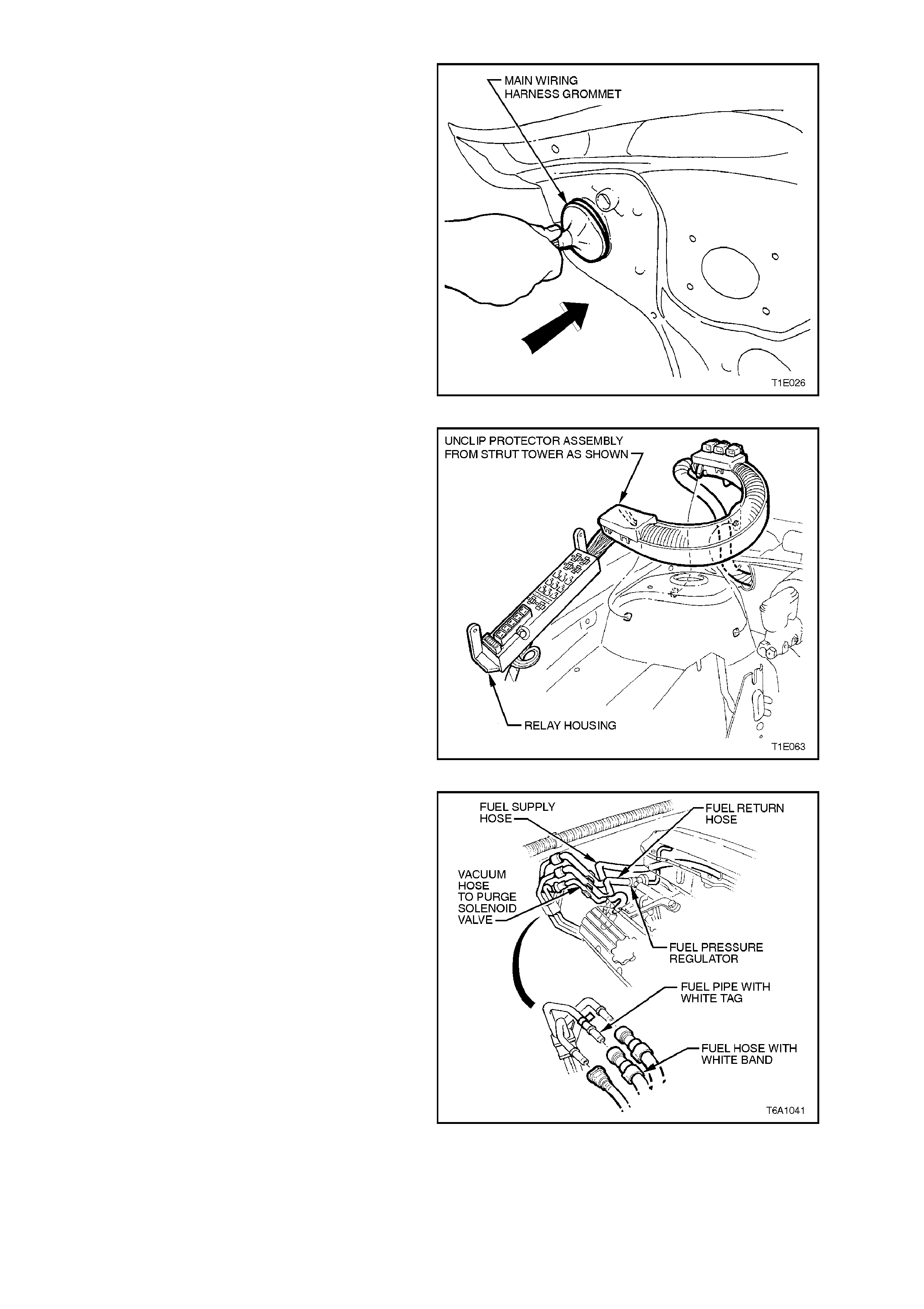
56. Release engine compartment harness tie
down clips, then push the main wiring harness
grommet into the cabin.
Figure 1E-44
57. Pass engine compartment relay block and
harness through cockpit module panel
opening.
CAUTION:
This operation is extremely difficult and should
be carried out with the utmost care, as damage
to wiring harness may occur.
Figure 1E-45
58. Disconnect the fuel feed and return hoses at
quick connects. Plug all openings to prevent
foreign matter entry.
NOTE:
Do not attempt to remove hoses from fuel rail
connections. Once removed from fuel rail
connection hoses require replacement.
Figure 1E-46
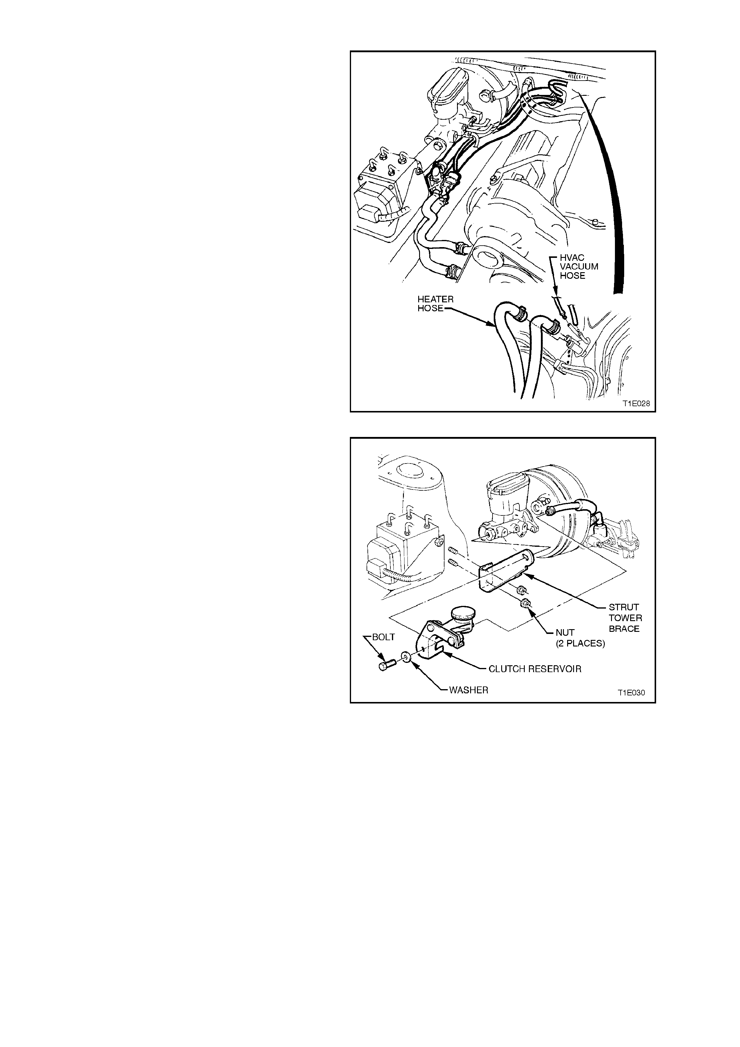
59. Tag and disconnect the heater hoses and
vacuum lines.
60. Remove the bolt retaining the fuel pipe clip to
the module panel.
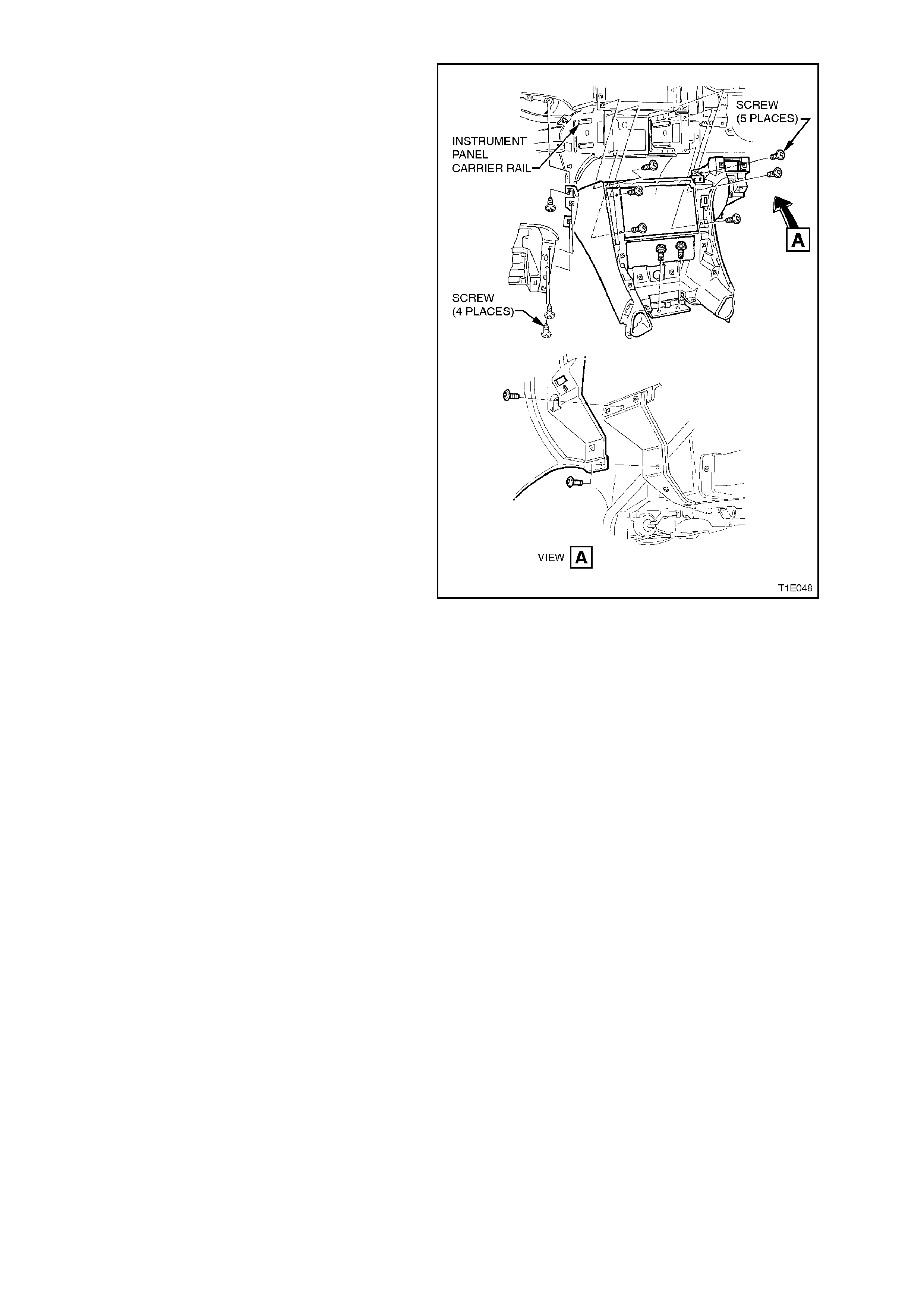
Figure 1E-47
61. Where f itted, disconnec t fluid hose f rom clutch
ma ster c ylinder and using a suitable container,
collect fluid.
62. Remove retaining screw from the clutch fluid
reservoir located at the brake master cylinder.
63. Remove the master cylinder to strut tower
brace.
Figure 1E-48
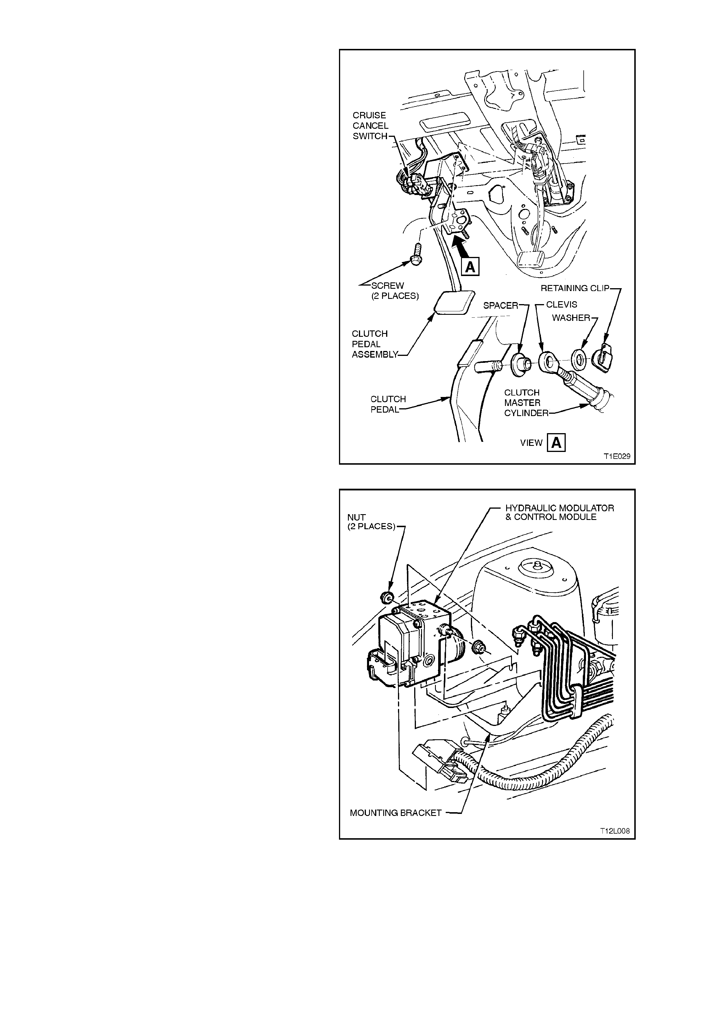
64. Rem ove two retaining nuts from clutch master
cylinder, and from inside vehicle, remove
clevis from clutch pedal assembly.
65. From inside vehicle, remove the two retaining
screws attaching clutch pedal assembly to
cockpit module panel and remove pedal
assembly from vehicle.
66. If fitted, remove the cruise control electrical
release harness connector from brake pedal
electrical release switch.
Figure 1E-49
67. Tag and disconnect the brake lines, vacuum
hose and electrical harness from the brake
booster, ABS modulator (where fitted) and
master cylinder assembly. Seal all apertures
with suitable plastic plugs.
68. On vehicles with automatic transmission
remove the nuts from the blanking plate
adjacent to the brake booster.
69. Tag and disconnect the vacuum control hose
at the throttle body (V6) or inlet manifold (V8).
Figure 1E-50
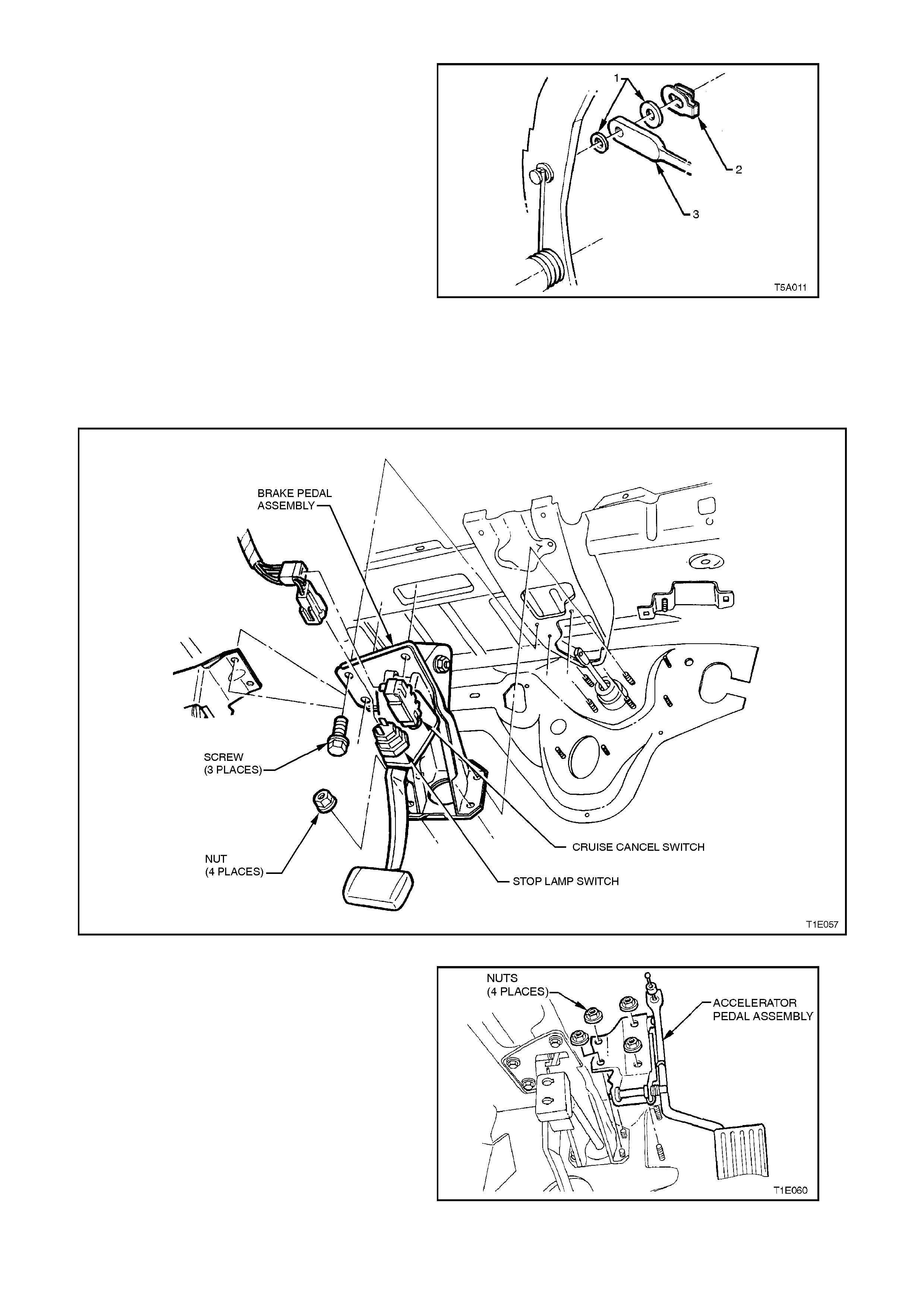
70. Rem ove the retaining clip (2), washers ( 1) and
brake booster pushrod (3) from the brake
pedal.
Figure 1E-51
71. Remove stop lamp switch harness connector
and if fitted, cruise control cancel switch
harness connector.
72. Remove the three screws securing the brake
pedal assembly to the module.
Figure 1E-52
73. Remove the four nuts secur ing the accelerator
pedal bracket, then remove the assembly,
refer to Fig. 1E-53.
74. Remove the remaining two nuts from brake
pedal assembly and remove assembly from
vehicle.
Figure 1E-53
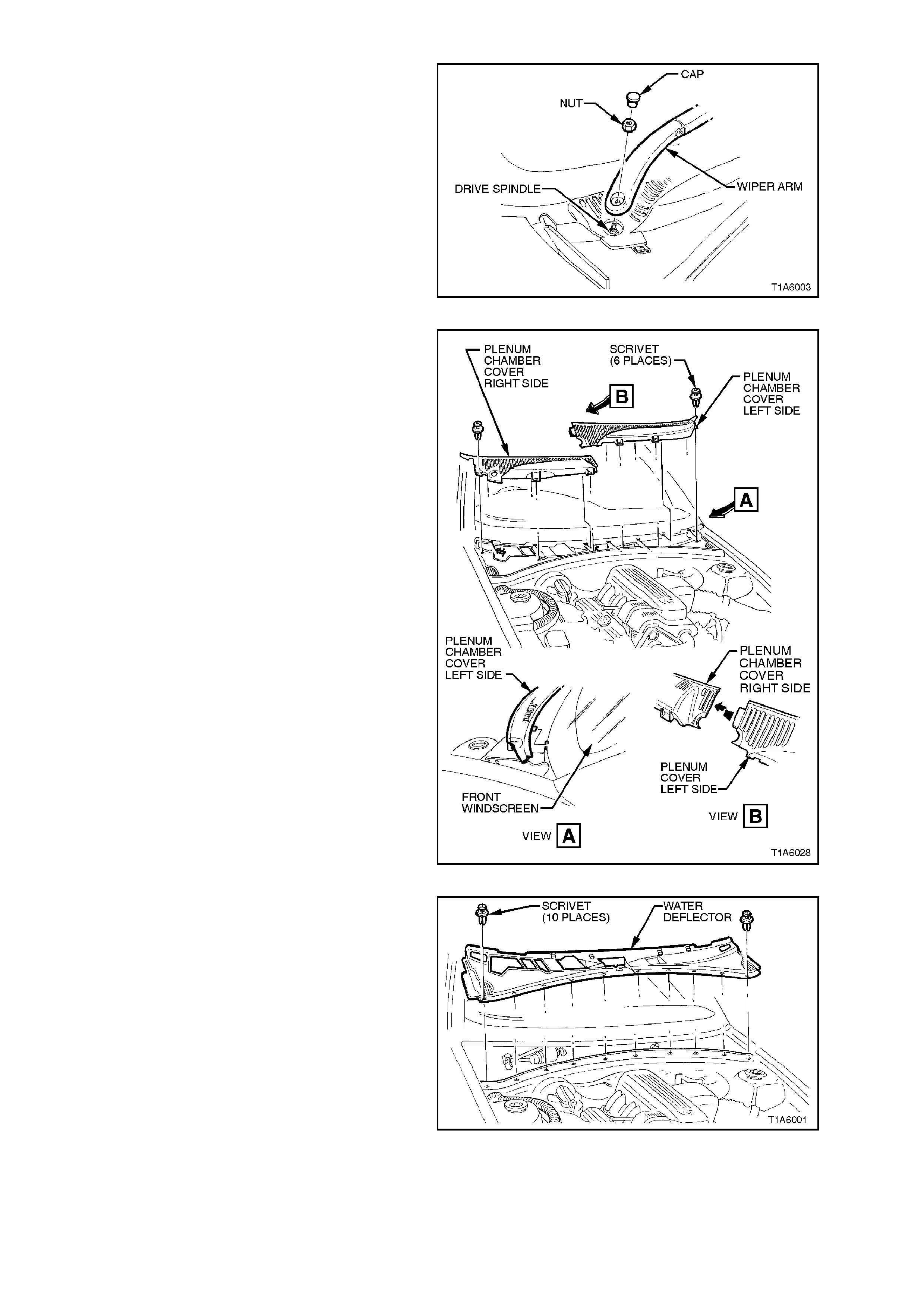
75. Remove the windscreen wiper arm and blade
assemblies. For further information refer to
Section 12C INSTRUMENTS, WIPERS,
WASHERS & HORN .
Figure 1E-54
76. Unscrew scrivets at six locations and remove
plenum chamber cover left and right side.
Figure 1E-55
77. Unscrew scrivets at ten locations and remove
plenum chamber water deflector.
Figure 1E-56
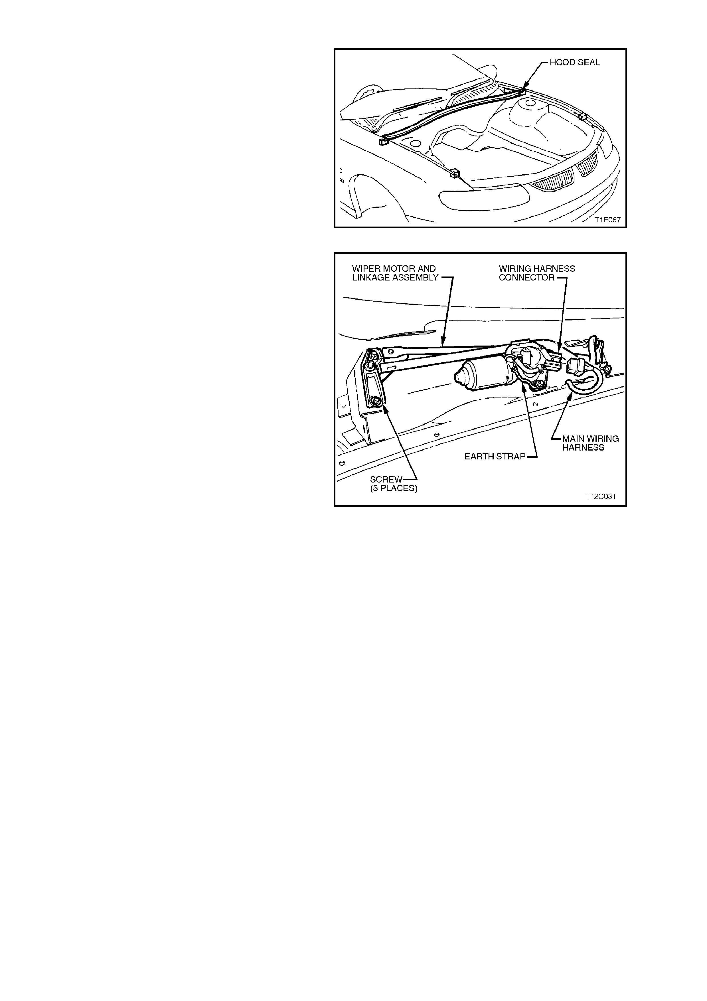
78. Remove Hood Seal.
Figure 1E-57
79. Disconnect wiper motor wiring harness and
push back through hole, then remove the five
mounting bolts and earth strap from the
windshield wiper assembly, and remove
assembly from vehicle.
Figure 1E-58
80. Where fitted, disconnect the air conditioning
lines at the evaporator bloc k valve, then cap or
plug connections.
81. Disconnect the evapor ator to c ondens er line at
the condenser, plug the f ittings then unclip the
line and remove.
82. Remove the compressor to evaporator line
and hose, then plug the fittings, refer to Fig.
1E-59 (V6 Engines) and Fig. 1E-60 (V8
Engines).
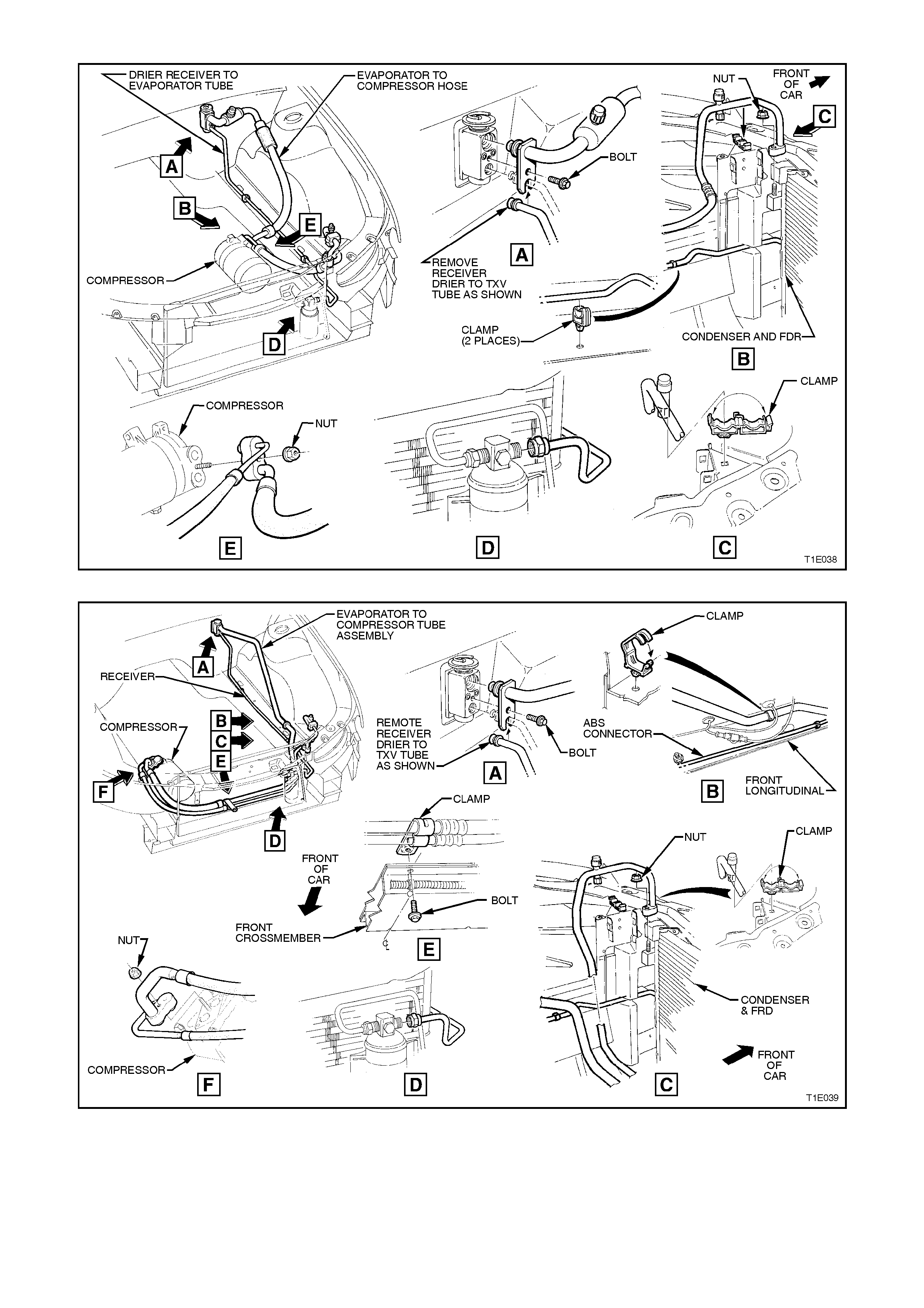
Figure 1E-59
Figure 1E-60
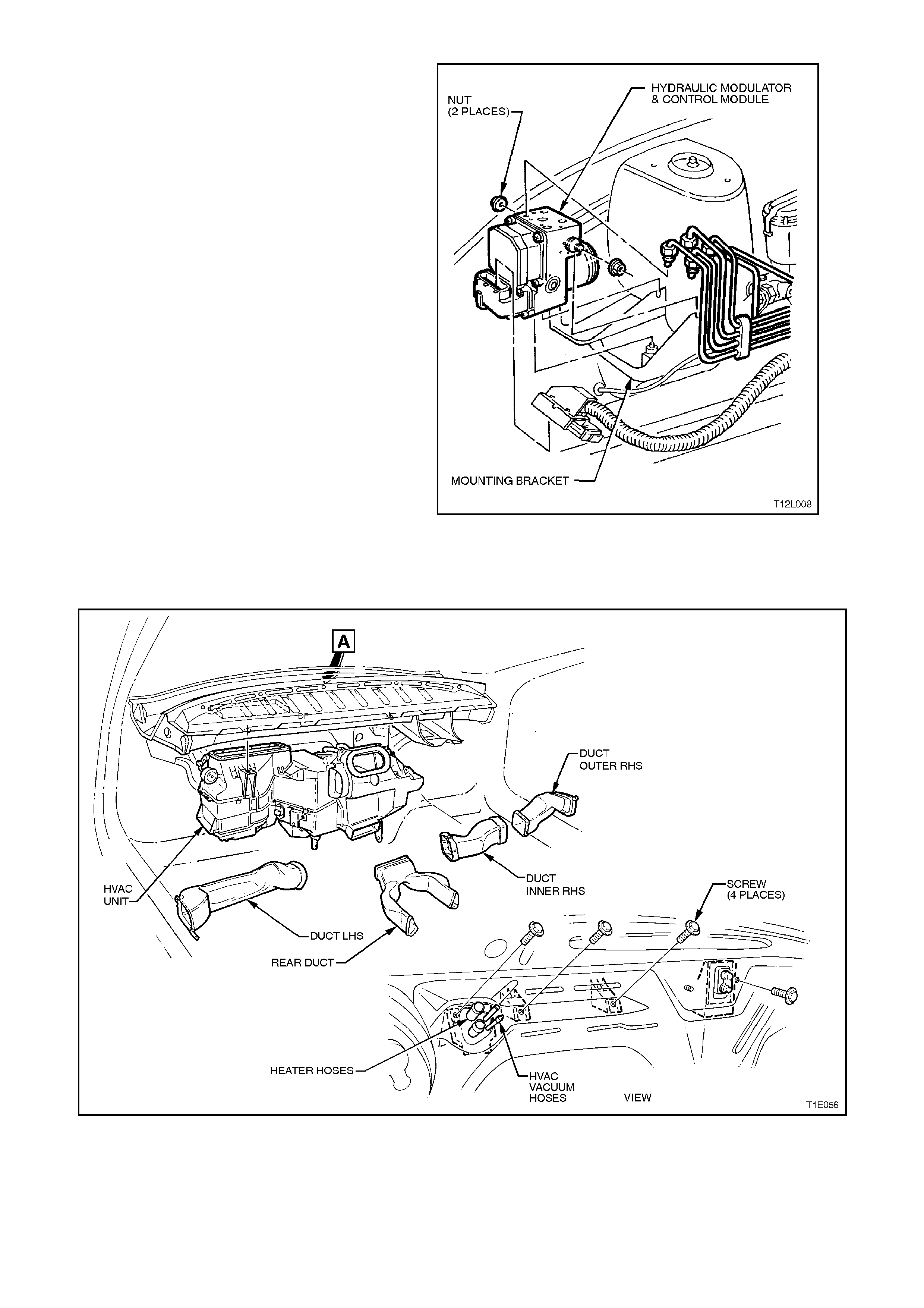
83. Remove the brake booster and master
cylinder assembly. If fitted, remove ABS
hydraulic modulator and control module, refer
to Section 12L ANTI-LOCK BRAKING
SYSTEM/TRACTION CONTROL .
Figure 1E-61
84. Disconnect the front and rear door harnesses.
85. Remove the screws securing the heater case
assembly to the module panel.
Figure 1E-62

86. Remove the case from the vehicle by
disengaging the drain grommet and easing the
assembly from the vehicle taking care not to
strain the heater core tubes.
Figure 1E-63
87. Remove the grommets and insulation panels.
88. Remove the front windshield, refer to
Section 1A6 STATIONARY GLASS.
89. The cockpit module should be disassembled
prior to removing the panel, the procedure is
described in 2.1 COCKPIT MODULE in this
Section.
90. Remove the front doors, refer to
Section 1A5 FRONT AND REAR DOOR
ASSEMBLIES.
91. Remove engine, refer to
Section 6A1-1 ENGINE MECHANICAL - V6
ENGINE or 6A1-2 ENGINE MECHANICAL -
V6 SUPERCHARGED or 6A2 ENGINE
MECHANICAL - V8 ENGINE.
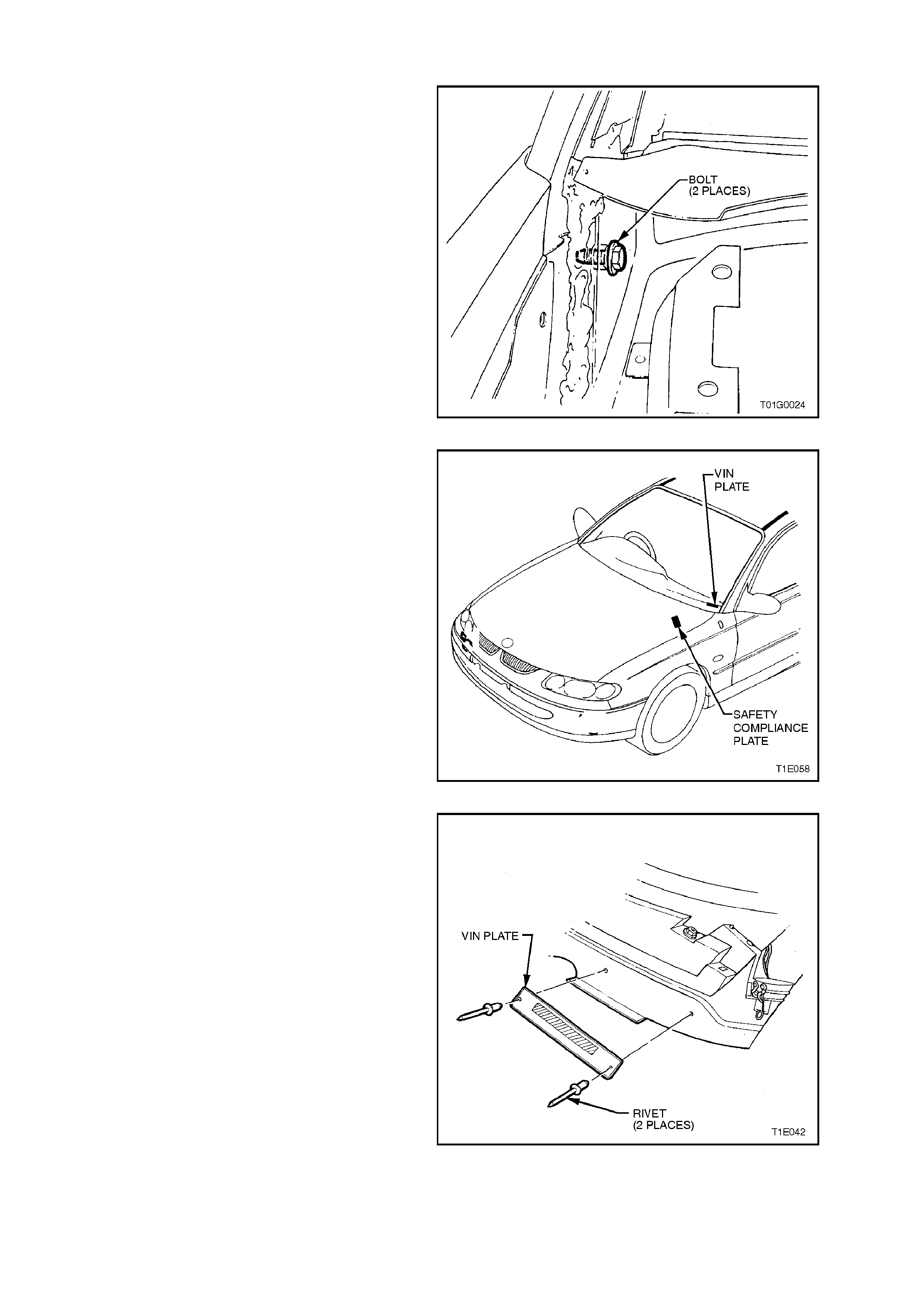
92. Remove module retaining bolts: Two from the
A-pillar area (1 bolt each side).
Figure 1E-64
93. Remove module retaining bolts: Two from the
plenum area (1 bolt each side).
Figure 1E-65
94. Locate VIN plate and compliance plate on
passenger side of cockpit module panel, and
using a drill and suitable drill bit, drill out
retaining rivets.
Figure 1E-66
95. Transfer VIN plate onto new cockpit panel.
Using commercially available hand rivet tool
and new rosette headed rivets (two off each
plate) secure to new cockpit module panel.
Figure 1E-67
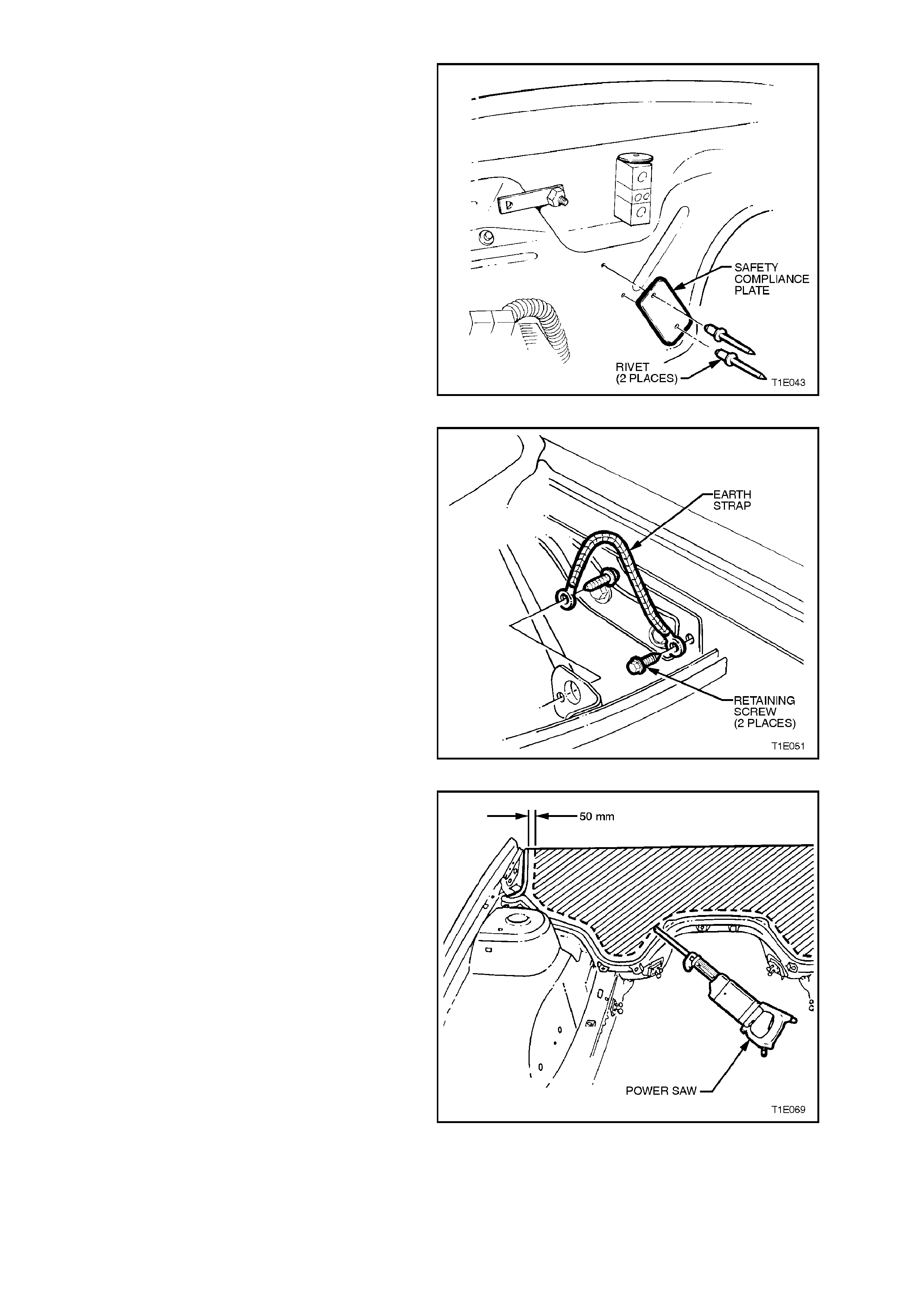
96. Transfer compliance plate onto new cockpit
panel. Using com merc ially available hand rivet
tool and new rosette headed rivets (two off
each plate) secure to new cockpit module
panel.
Figure 1E-68
97. Remove the two screws retaining cockpit
module to body earth strap and remove from
vehicle.
Figure 1E-69
98. Using a power saw, cut the module panel
approximately 50 mm above the glue track.
CAUTION:
Sparks may ignite petrol in the fuel or emission
control lines if due precautions are not taken.
Figure 1E-70
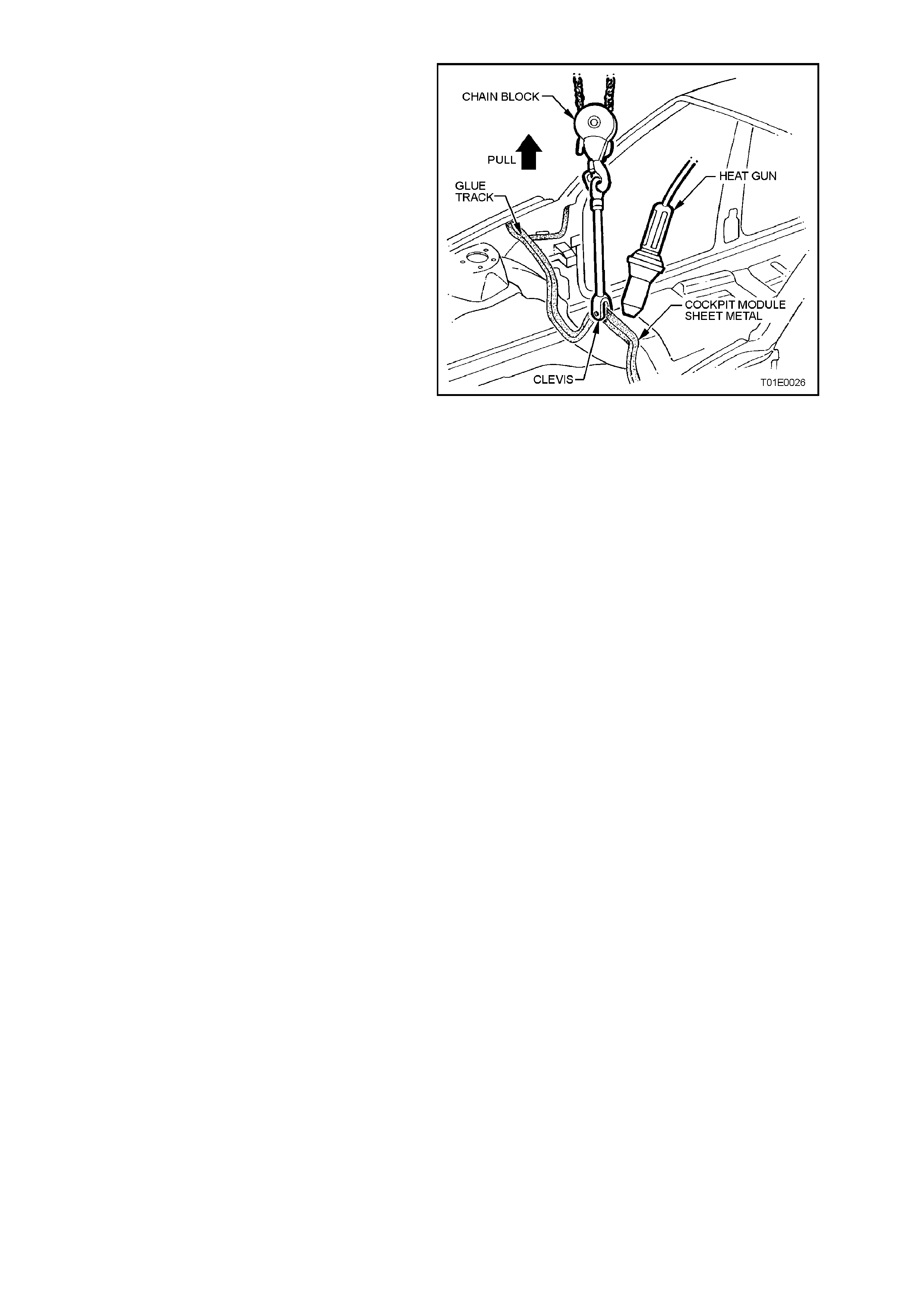
99. Drill a hole in the flange above the
transmission tunnel, and attach a chain block
and a clevis.
100.Apply and maintain a light tension to the
module. Heat the adhesive using a heat gun
and pull the panel from the glue track.
Alternatively cut the adhesive with a hot knife.
101.Clean the excess adhesive f rom the glue tr ack
using a hot knife or a heat gun and tool.
CAUTION:
To avoid fire, Do NOT attempt to burn the
remaining adhesive from the glue track using an
“oxy” torch.
Figure 1E-71
MIXING SILICONE ADHESIVE
Surface Preparation
Clean any remaining adhesive from the glue track
using a hot knife or heat gun and tool if necessary.
The vehicle should be painted before installation of
the cock pit module. Bef ore painting the vehicle apply
masking tape to prevent paint entering the glue track.
The adhesive will not properly adhere to paint,
overspray, oils, grease etc. The glue track must be
free of dirt, dust, grease, oils and paint or over spray.
Wipe the glue track with a suitable cleaning agent
such as “Prepsol”, then clean any residue from the
area with a clean, dry, lint free cloth.
Avoid fitment problems by temporarily installing the
cockpit module panel, prior to mixing the adhesive,
rectify any faults found, then remove the panel from
the vehicle.
Before mixing the adhesive it is necessary to have
the application gun available. All par ts m ust be clean
of any previous adhesive.
Refer to the VT Series Parts Inf orm ation, Section 12-
430 for details of where to obtain an applicator gun.

Mixing Adhesive and Catalyst
IMPORTANT:
This is a two-part mix, fast cure adhesive, ensure
that the panel is ready for installation before mixing
the adhesive. The working time is less than 20
minutes.
Part A:
The Adhesive compound, yellow in colour and
supplied in a 1.4 kilogram container.
Part B:
The Catalyst, used to accelerate the “Cure” time of
the of the adhesive compound and is supplied in a
120 gram tube.
The contents of the Adhesive Kit, Part Number
M39998 is sufficient to install the module panel in a
vehicle.
CAUTION:
The vapour from the adhesive may cause
breathing difficulties, use only in a well ventilated
area. In case of eye contact, flush immediately
with clean water.
Combustible – keep away from spark and flame.
Refer to Safety Precautions in
1.2 GENERAL PRECAUTIONS in this Section.
1. Remove the lid from the Adhesive Compound
container.
2. Remove the cap from the Catalyst and pierce
the end of the tube, then squeeze the entire
contents of the tube into the Adhesive
Compound container.
3. Hold the container sec urely, and mix the catalyst
into the adhesive using a paint mixer or a flat
clean wooden utensil.
4. Continue to mix until the adhesive is a
consistent grey colour without any streaks.
5. Place the follower plate supplied with the
applicator gun into the adhesive container.
6. Remove the front end cap and disposable
nozzle from the applicator gun.
7. Cut the tip from the nozzle.
8. Place the applicator gun front end over the hole
in the follower plate.

NOTE:
The easiest method of drawing the adhesive into the
gun is to proceed slowly, allow the downward
pressure on the plate and the suction of the gun to
draw the compound.
9. Simultaneous ly push down on the gun and plate
with maximum pressure, press the gun’s release
plate inward and slowly pull the T-bar (piston)
outwards. This procedure will slowly suck the
mixed adhesive into the applicator gun.
10. Wipe any excess adhesive from the applicator
gun, screw the end cap onto the applicator gun,
then reinstall the nozzle.
11. Proceed immediately with installing the panel.
IMPORTANT:
After mixing the silicone adhesive, installation of the
cockpit module panel should be completed within 15
- 20 minutes. Under normal conditions, the adhesive
will begin to cure in about 25 - 30 minutes. After
installation, the module panel should not be moved or
disturbed until the adhesive is fully cured (about 3
hours).
Check List
Before m ixing the adhesive and installing the cockpit
module the following items should be checked:
• Familiarise yourself with the precautions in
1.2 GENERAL PRECAUTIONS in this Section.
• Ensure the adhesive being used is the material
recommended by GMHAL.
• The vehicle surface should be finished and the
paint fully dry.
• Clean any overspray, grease, oil, dirt, etc. from
the glue track using Prepsol and A CLEAN,
DRY, LINT FREE CLOTH.
• Test fit the module panel in the glue track
BEFORE MIXING THE ADHESIVE.
• Is the adhesive applicator gun clean and ready
for use?
• Install the main wiring harness plate in position
on the module panel.
• Are the cockpit module bolts readily accessible?
MODULE PANEL INSTALLATION
1. Clean any remaining adhesive from the glue
track using a hot knife or heat gun and tool if
necessary.
2. Temporarily install the cockpit module without
adhesive to check fit. Panel should sit in the
centre of the glue track. Rectify any faults
found, then remove from vehicle.
3. Install the harness side plate onto the right
hand side of the module panel.
4. Check each item in the Check List in
MIXING SILICONE ADHESIVE in this Section.
5. Mix the silicone adhesive and f ill the applicator
gun as described in ‘Mixing Silicone Adhesive’
in this Section.
6. Begin filling the glue track from the lowest
points to prevent air bubbles forming in the
adhesive. Completely fill the channel in a
continuous bead.
7. Apply a patch of adhesive approximately
50 mm diameter to the base or the windshield
pillar.
Figure 1E-72
IMPORTANT:
The glue track or any adhesive remaining within,
must be thoroughly clean and free of grease, dirt,
dust, paint overspray or other foreign material.
NOTE:
Do not attempt to install a fully built-up cockpit
module assembly.
8 Have an assistant help install the cockpit
module panel.
9. Push the panel firmly into the glue track
channel until mounting bolt holes align. Check
to ensure that the section above the main
wiring harness hole is correctly installed.
10. Replace 2 bolts into plenum area (torque
setting 15,0 - 35,0 Nm). Replace 2 bolts into
A-pillar area (torque setting 35,0 - 65,0 Nm)
11. Wipe any excess adhesive from the plenum
drain holes and shroud panel areas (LHS
plenum drain shown).
12. After installing the cockpit module panel,
immediately wipe the excess adhesive from
the applicator gun and follower plate.
Figure 1E-73

REINSTALL
Reverse removal operations noting the following.
IMPORTANT:
If vehicle is equipped with SRS (Air Bag),
enable the system. Refer to ENABLING THE
SRS, Section 12M SRS.
NOTE:
Use new O - rings when installing air conditioning
components.
1. Install the rubber grommets and insulation
materials onto the module panel.
2. Ensure that air conditioner drain tube is
correctly installed.
3. Ensure that all wiring is correctly clipped in
location.
4. Charge air conditioning system and leak test,
refer to Section 2C AIR CONDITIONING -
SERVICING AND DIAGNOSIS.

3. TORQUE WRENCH SPECIFI CATIONS
Nm
Lower steering column shroud screw 0.5 - 2.0
Diagnostics connector attaching screws 1.0 - 2.0
Instrument panel end cap cover attaching screws 1.0 - 3.0
Instrument panel compartment attaching screws 1.0 - 3.0
Instrument panel compartment lock striker attaching
screws 1.0 - 3.0
Centre console securing screws 1.0 - 3.0
Centre console bin retaining nuts 1.0 - 3.0
Transmission console retaining screws 1.0 - 3.0
Storage compartment securing screws 1.0 - 3.0
Demist nozzle retaining screws 1.0 - 3.0
Front dash speaker connecting screws 1.0 - 2.0
Instrument panel carrier end panel attachment
screws 1.0 - 3.0
Instrument panel carrier end panel attaching bolts 3.0 - 5.0
Instrument facia assembly retaining screws 1.0 - 3.0
Cent re facia assembly securing screws 1.0 - 3.0
Airbag securing screws 8.0 - 11.3
Steering wheel securing screw 40.0 - 50.0
Heater and air conditioning controls securing screws 1.0 - 3.0
Combined instruments assembly securing screws 1.0 - 3.0
Instrument panel carrier retaining screws 7.0 - 12.0
Instrument panel lower trim right side rail assembly
retaining screws 1.0 - 3.0
Steering column bracket outer support securing
screws 3.0- 5.0
Centre facia side extension support rail attaching
screws 1.0 - 3.0
Support steering column bracket inner securing
screws 3.0 - 5.0
Steering column clevis cam bolt 23.0 - 30.0
Steering column upper mounting screws 15.0 - 30.0
Nuts at base of steering column 15.0 - 30.0
Passenger air bag support rail securing screws 2.5 - 5.0
Lower left side rail connecting screws 1.0 - 3.0
Instrument panel carrier rail assembly securing
screws 1.0 - 3.0
Passenger side air bag securing nuts 15 - 25.0
Main wiring harness cabin protector securing nut
Engine hood bracket retaining screws 6.0 - 14.0
Fuel pipe clip retaining bolt 10.0 - 25.0
Clutch fluid reservoir attachment screw
Strut tower brace attachment nuts 15.0 - 20.0
Clutch master cylinder retaining nuts
Clutch pedal assembly retaining screws 20.0 - 30.0
Blanking plate securing nuts 20.0 - 30.0
Brake pedal assembly securing screws
Brake pedal assembly securing nuts 20.0 - 30.0
Accelerator pedal bracket securing nuts 20.0 - 30.0
Windshield wiper assembly mounting bolts 20.0 - 30.0
Receiver drier to TXV connecting bolt - V6 4.0 - 6.0
Hose to condenser and FRD connecting nut V6/V8 7.5 - 12.5
Hose to compressor connecting nut V6/V8 7.5 - 12.5
Front crossmember securing bolt - V8 7.5 - 12.5
ABS hydraulic modulator and control module
securing nuts 7.5 - 12.5
Heater case assembly securing screws 5.0 - 12.0
A-pillar area module retaining bolts 6.0 - 14.0
Module retaining bolts from the plenum area 35.0 - 65.0
Retaining earth strap screw to cockpit module 15.0 - 35.0
2.0 - 4.0
4. SPECIAL TOOLS
TOOL NO. REF IN TEXT TOOL DESCRIPTION COMMENTS
179 1308 0000 RADIO REMOVAL TOOL