
SECTION 2B - AIR CONDITIONING - REMOVAL AND
INSTALLATION
CAUTION:
This vehicle will be equipped with a Supplemental Restraint System (SRS). A SRS will
consist of either seat belt pre-tension ers and a driver’s side air bag, o r seat belt pre-
tensioners and a driver’s and front passenger’s side air bags. Refer to CAUTIONS,
Section 12M, before performing any service operation on or around SRS
components, the steering mechanism or wiring. Failure to follow the CAUTIONS
could result in SRS d eployment, result ing in po ssible person al injury or unnecessary
SRS system repairs.
CAUTION:
This vehicle may be equipped with LPG (Liquefied Petroleum Gas). In the interests of
safety, the LPG fuel system should be isolated by turning 'OFF' the manual service
valve an d then draining the LPG service lines, bef ore any service work is carried out
on the vehicle. Refer to the LPG leaflet included with the Owner's Handbook for
details or LPG Section 2 for more specific servicing information.
CAUTION:
Whenever any component that forms part of the ABS or ABS/ETC (if fitted), is disturbed during
Service Operations, it is vital that the complete ABS or ABS/ETC system is checked, using the
procedure as detailed in 4 DIAGNOSIS, ABS or ABS/ETC FUNCTION CHECK, in Section 12L
ABS & ABS/ETC.
Techline
Techline
1. HEATING, VENTILATION AND AIR CONDI TIONING (HVAC) UNIT
REMOVE
CAUTION:
Disable the SRS (Air Bag). Refer to DISABLING
THE SRS, Section 12M SRS.
IMPORTANT:
As a theft deterrent, VT Series vehicles are fitted
with a security coded audio system. Af ter the power
supply is interrupted, the radio will remain
inoperative after reinstallation until the PIN number
is entered into the system. The procedure is
described in the glove box literature accompanying
the owner’s handbook.
1. Disconnect the negative and positive cables
from the battery to isolate the electrical
equipment, and prevent damage to the
components.
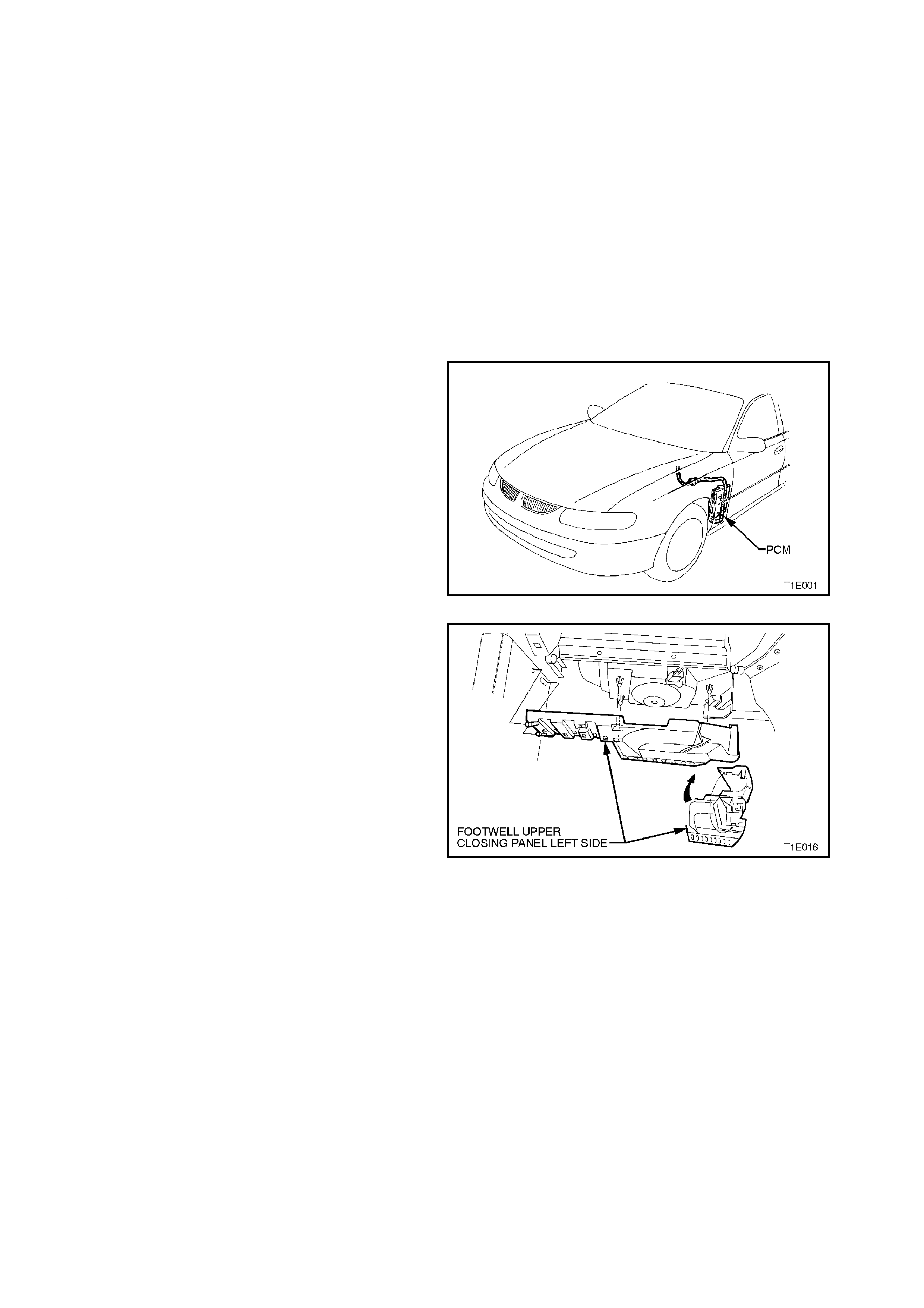
2. Locate powertrain control module in the
passenger footwell.
Figure 2B-1
3. Unclip duct cover flap on right hand side of
footwell upper closing panel left side.
Disengage locating lugs to passenger side
shroud lower, grasp closing panel firmly and
detach by pulling left side down first, then
disengage right side clip and remove panel.
Figure 2B-2
4. Remove passenger side shroud lower trim
assembly, refer to Section 1A1 BODY.
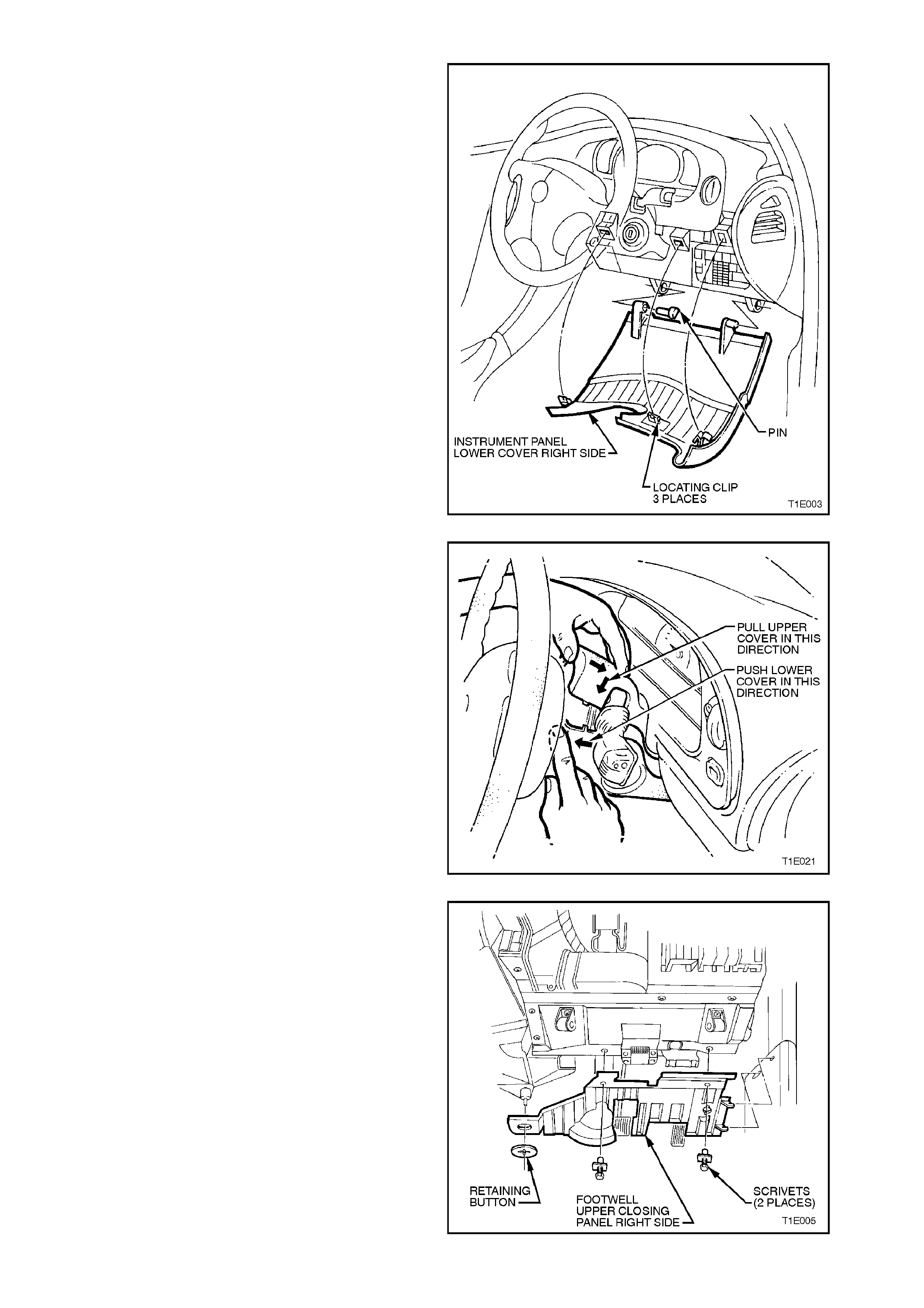
5. Adjust steering wheel to upper most position.
Grasp right-hand side of lower cover panel
right side firmly and pull towards rear of
vehicle. Repeat procedure f or left-hand side of
cover. Pr ise out the lef t-hand hinge pin using a
flat blade screwdriver.
Tilt the cover down on the left side and
disengage the right-hand hinge pin and
remove panel.
Figure 2B-3
6. Adjust steering column to lower most position.
Remove steering column to facia screen.
Remove single screw from the lower steering
column shroud and remove upper and lower
steering column shroud.
Figure 2B-4
7. Remove two scrivets and on vehicles fitted
with automatic transm ission, prise off retaining
button and detach the footwell upper closing
panel right side.
Where fitted disconnect front footwell lamp
from footwell upper closing panel, refer to
Section 12B LIGHTING SYSTEM.
Figure 2B-5
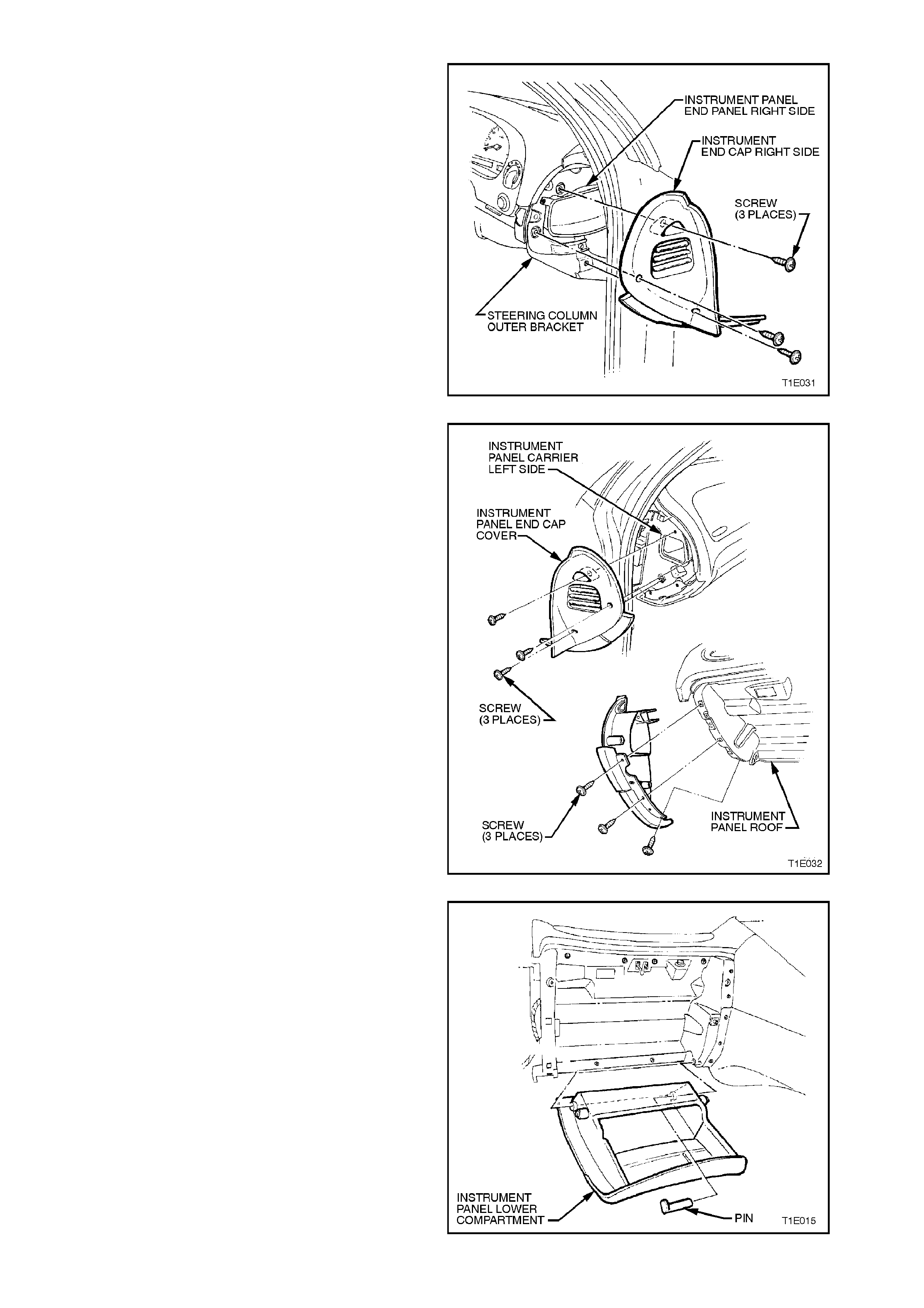
8. Remove the three screws and remove
instrument panel end cap cover right-hand
side.
Figure 2B-6
9. Remove the six retaining screws for instrument
panel end cap cover left hand side.
Figure 2B-7
10. Open the instrument panel lower
com partment, and lever the hinge pin f rom the
right side. Lower compartment and withdraw
the pin. Disengage travel lim iting pegs by tilting
instrument panel lower compartment.
Figure 2B-8
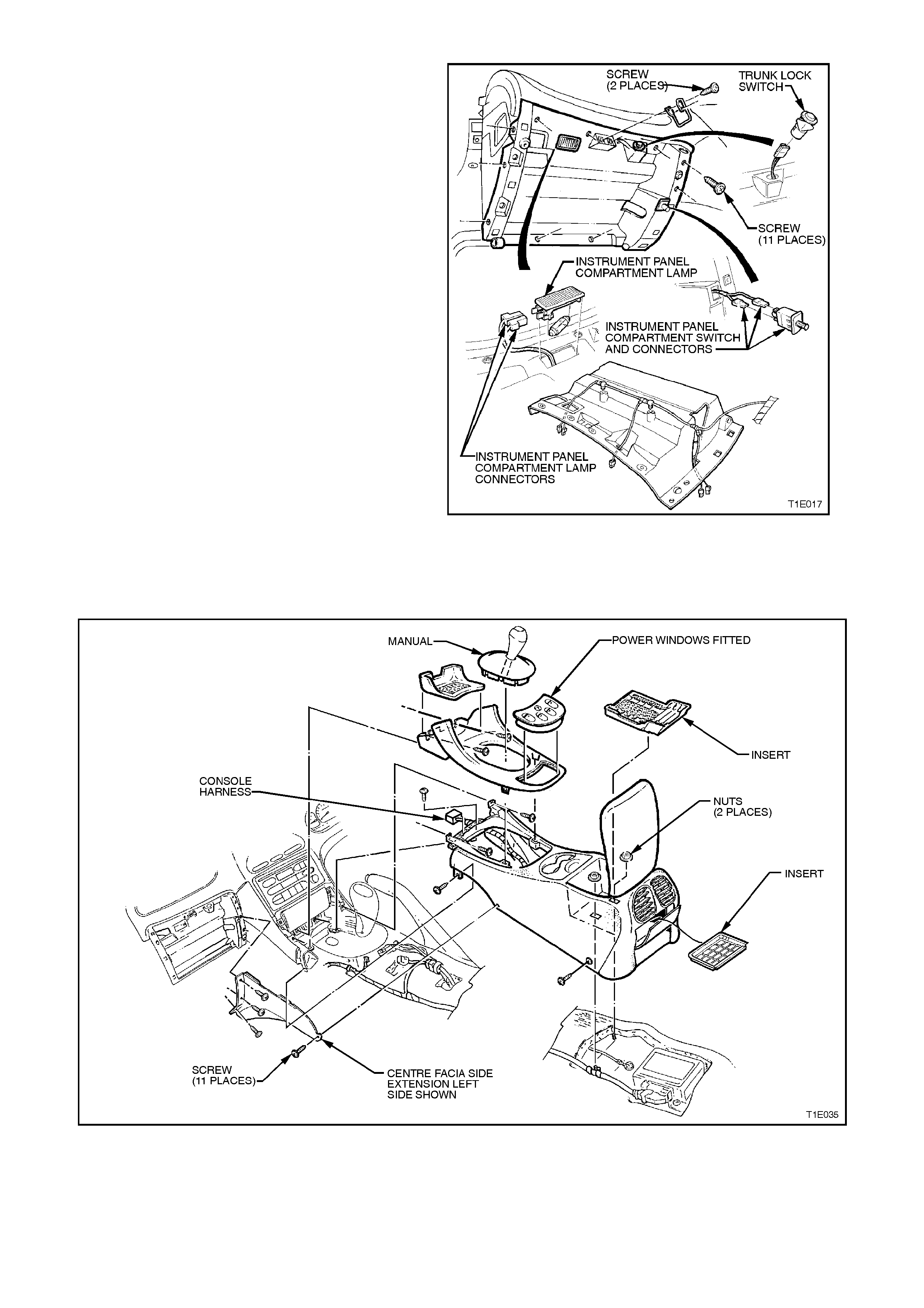
11. Remove 11 retaining screws from instrument
compartment roof. Disconnect glove box lamp
connectors, trunk lock switch connector, glove
box switch connectors and unclip glove box
wiring harness.
Figure 2B-9
12. Remove the transmission console and detach
console wiring harness, refer to
Section 1A3 INSTRUMENT PANEL &
CONSOLE.
Figure 2B-10
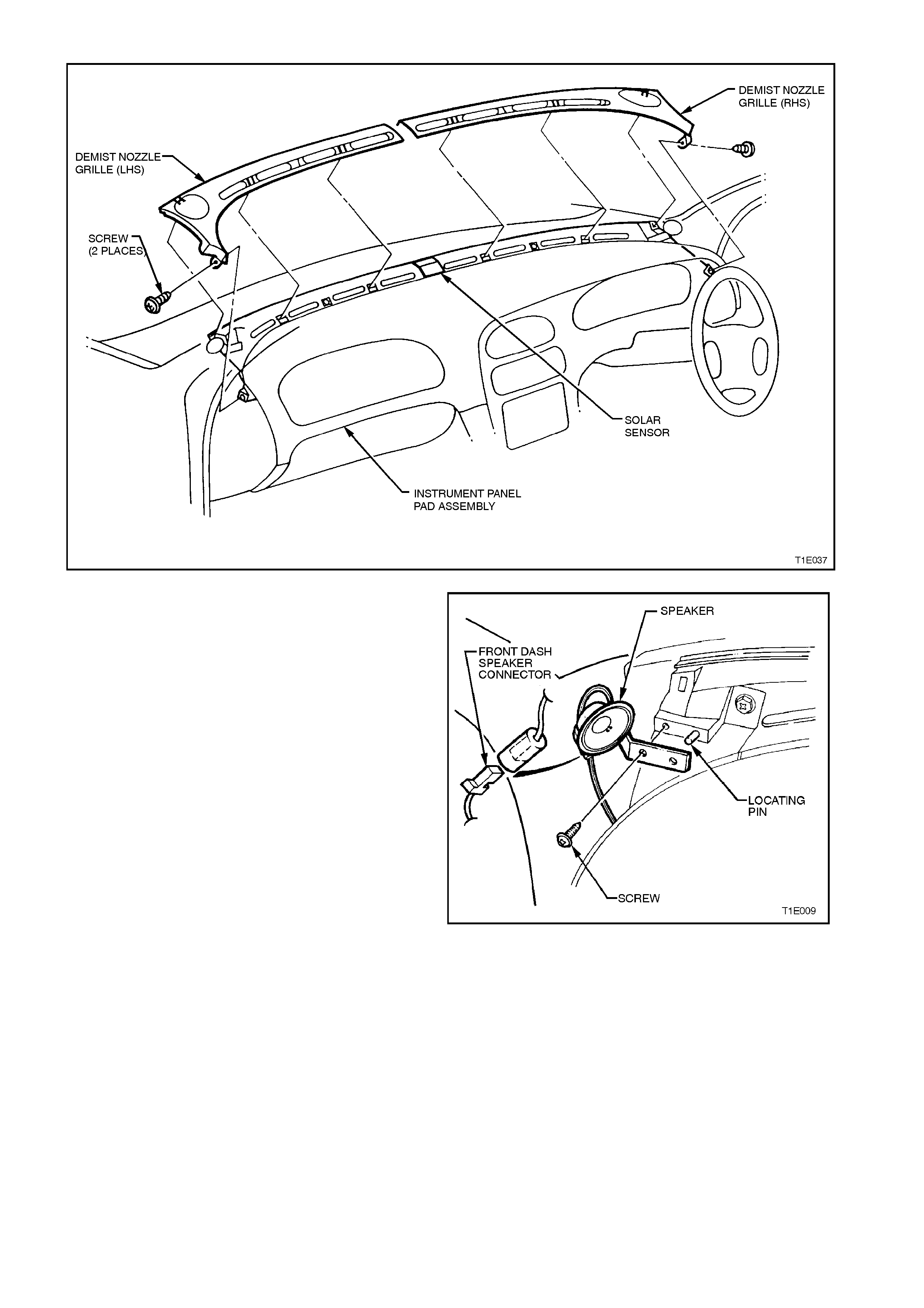
Figure 2B-11
15. Disconnect left and right front dash speker
harness connectors. Using a Phillips head
screw driver, remove screw attaching front
dash speakers and remove both speakers.
Figure 2B-12
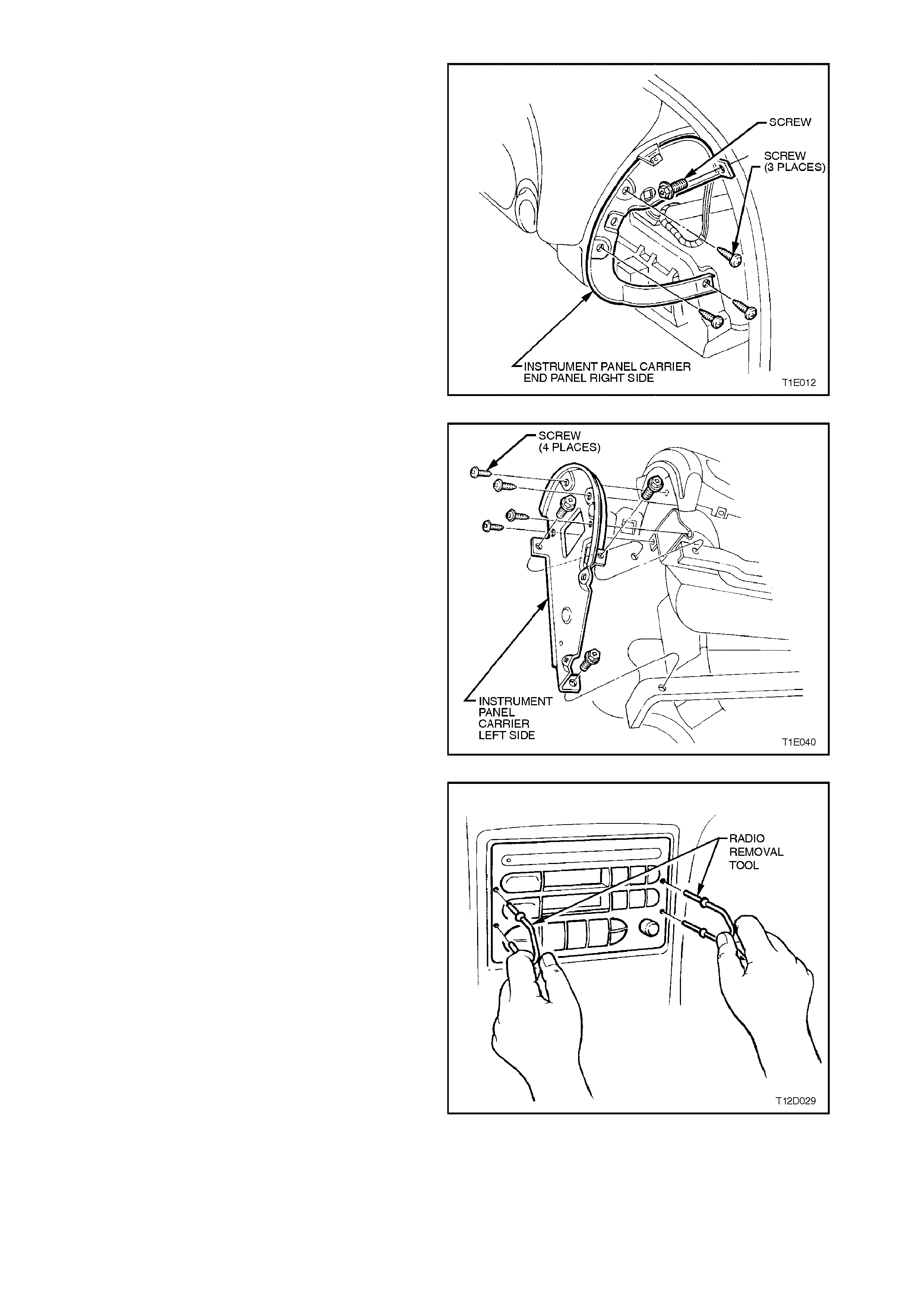
16. Remove the four retaining screws from
instrument panel carrier end panel right side
and remove panel.
Figure 2B-13
17. Remove four attaching screws securing
instrument panel carrier end panel left side.
Remove three bolts attaching carrier to
passenger airbag support rail and lower left
side rail, and remove panel.
Figure 2B-14
18. Remove radio/cassette/CD from instrument
panel, using service tool 179 1308 0000 to
assist in removal. Refer to
Section 12D RADIO/CASSETTE PLAYER.
Figure 2B-15
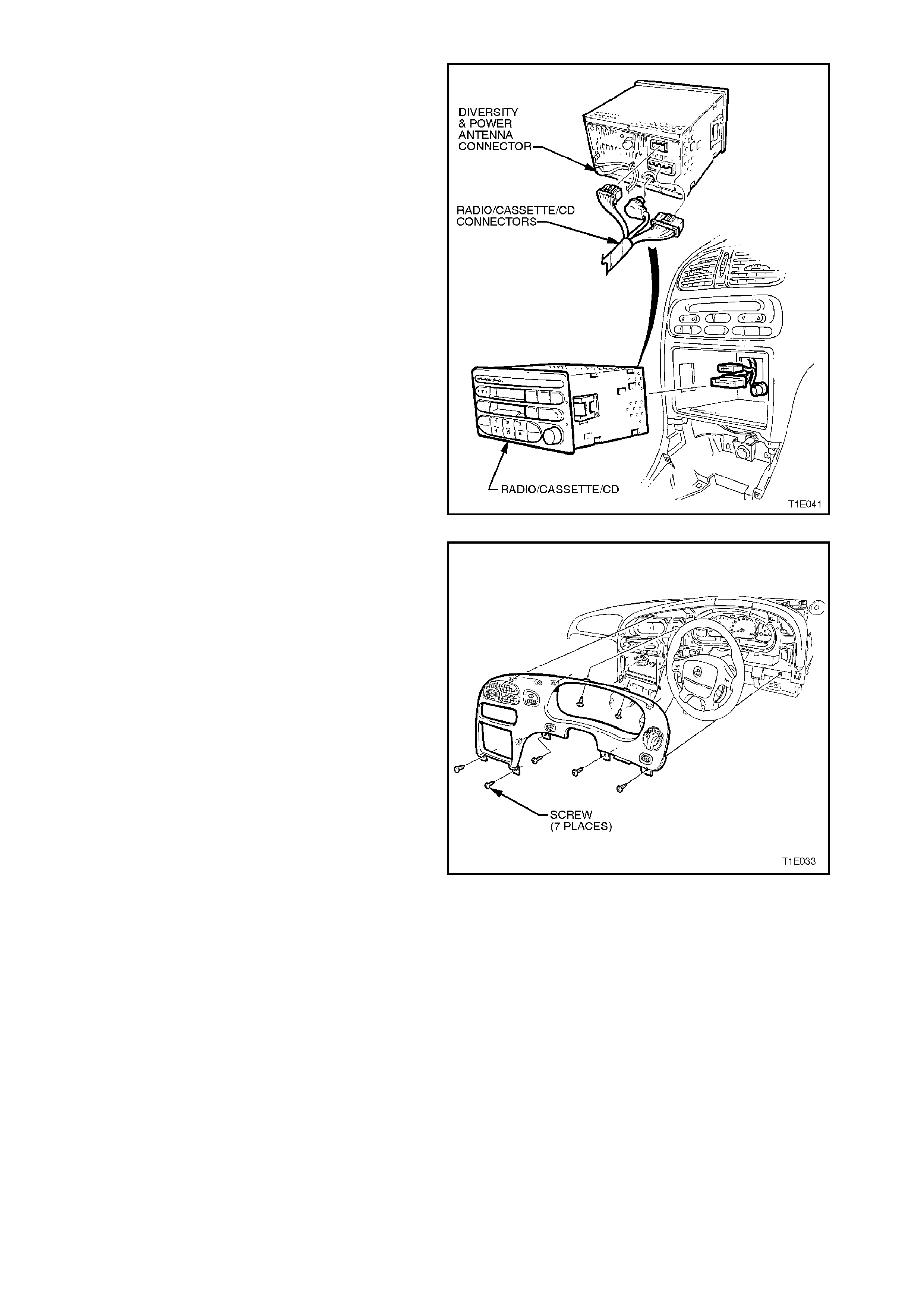
19. Disconnect radio/cassette harness and if fitted
CD connector. Disc onnect antenna and if f itted
diversity and power antenna.
Figure 2B-16
20. Remove the seven screws retaining the
instrument facia assembly, and pull facia from
retaining clips (5 clips).
NOTE:
Care must be taken to disconnect the headlamp
switch connector, fog lamp switch connector (if
fitted), trip computer switch connector (if fitted) and
hazard switch connector from main wiring harness.
Figure 2B-17
21. Remove the two attaching screws securing in-
car temperature sensor (if fitted) and
disconnect harness connector, refer to
Section 2E AIR CONDITIONING - ECC -
REMOVAL AND INSTALLATION.
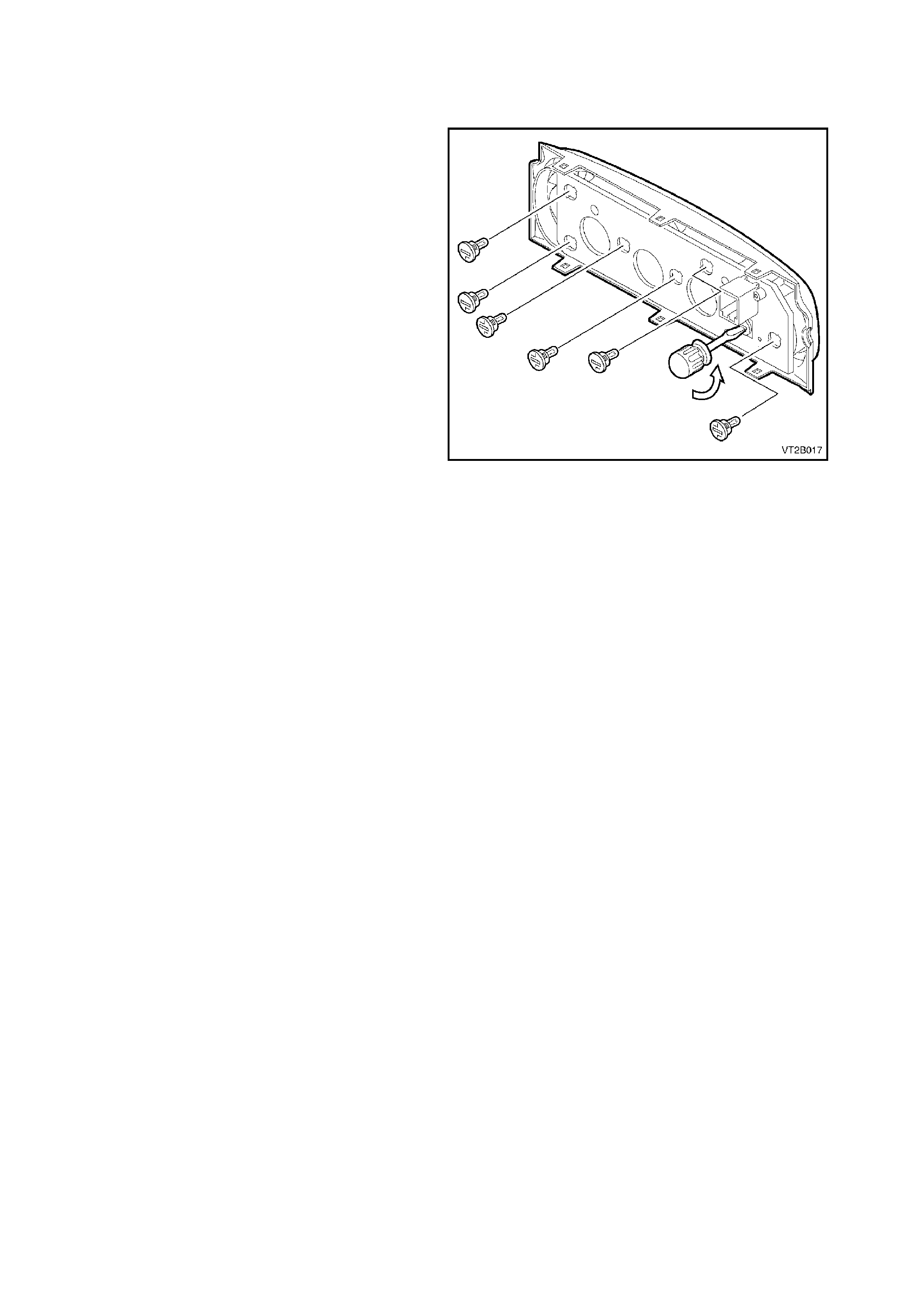
22. Remove the 13 screws securing centre facia
assembly.
Figure 2B-18
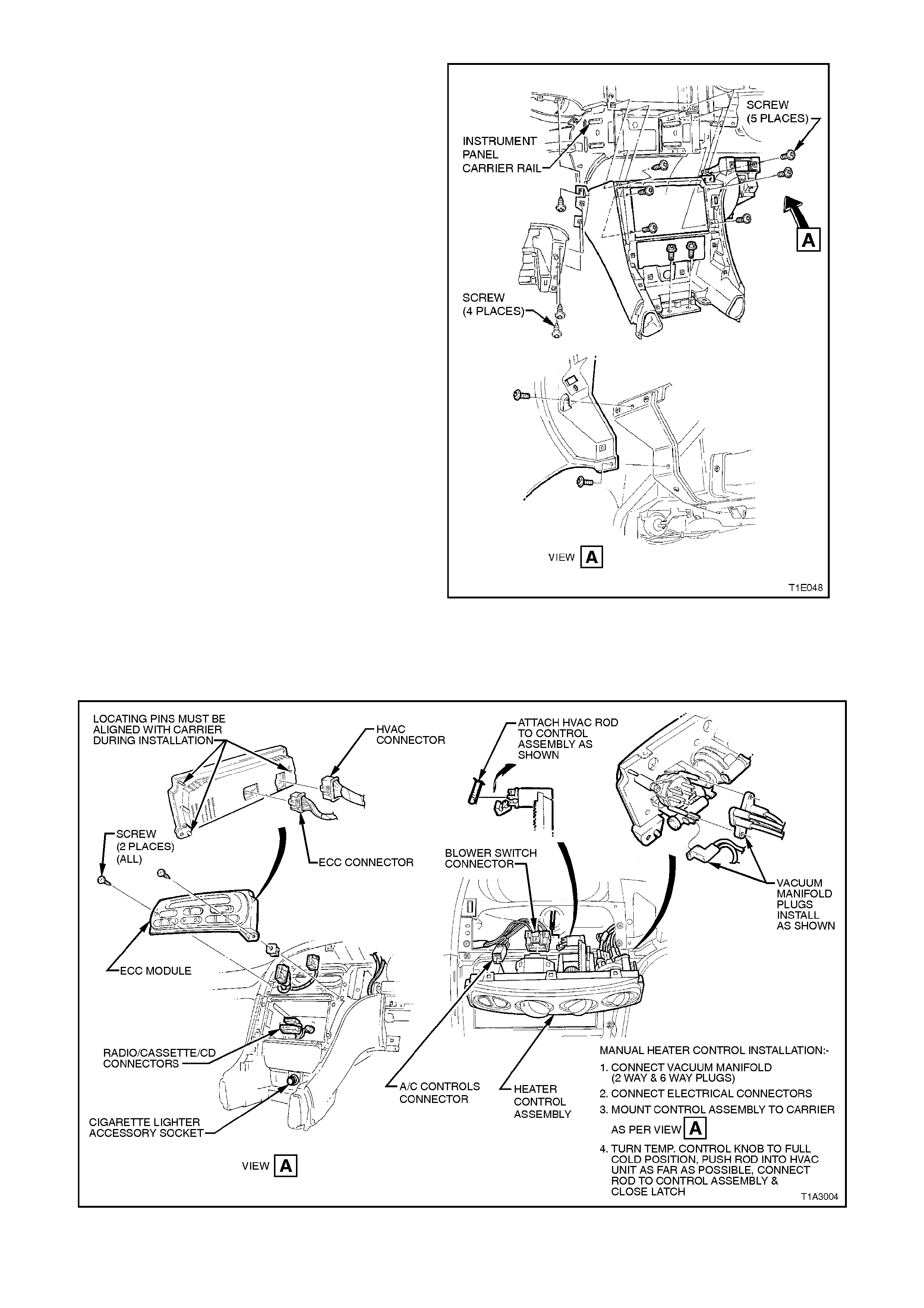
23. Remove the screws securing the heater and
air conditioning controls and disconnect the
electrical connections. Remove heater control
assembly or ECC Module, where fitted.
Figure 2B-19

24. Remove the screws securing the combined
instruments assembly and disconnect
instrument connector.
Figure 2B-20
25. Remove the five retaining screws along top
edge of instrument panel carrier.
Figure 2B-21
26. Remove the five screws and withdraw
instrument panel lower trim right side rail
assembly.
Figure 2B-22
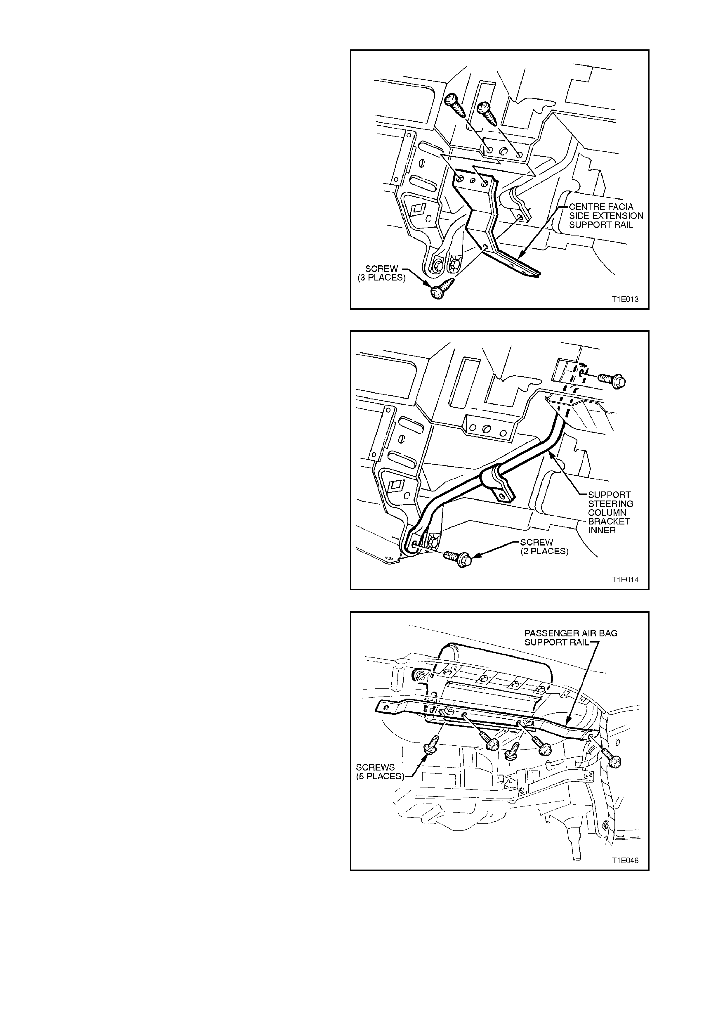
27. Remove centre facia side extension support
rail.
Figure 2B-23
28. Remove the two screws and remove support-
steering column bracket inner.
Figure 2B-24
29. Remove five screws securing passenger
airbag support rail assembly left side and
remove rail.
Figure 2B-25
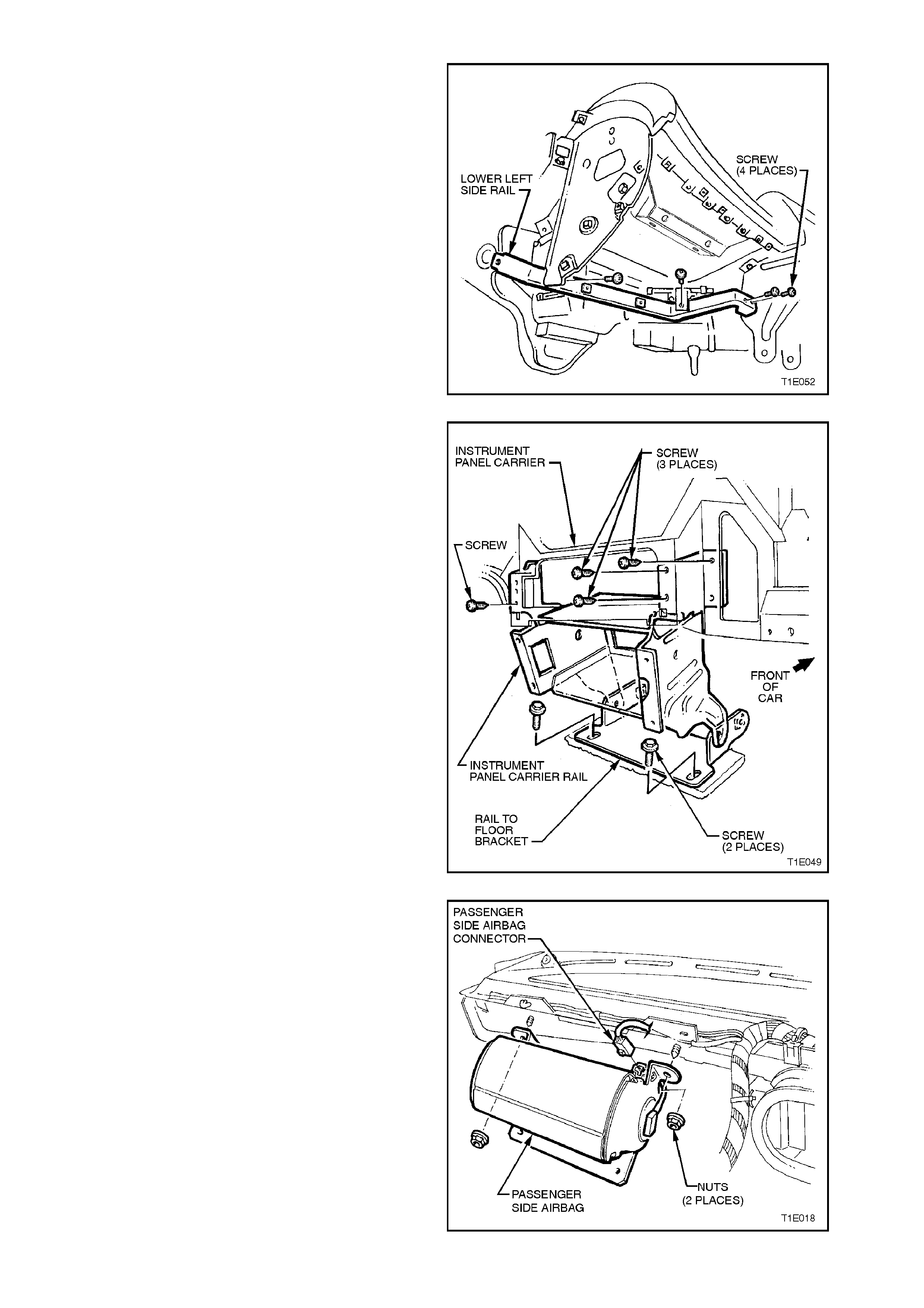
30. Remove two sc rews connecting lower left side
rail to instrument panel carrier rail assembly.
Remove single screw connecting lower left
side rail to instrument panel carrier end panel
left side. Remove single screw connecting
lower left side rail to body mount.
Figure 2B-26
31. Remove instrument panel carrier rail
assembly.
Figure 2B-27
32. Remove passenger side airbag connector
located on the right-hand side of airbag.
Remove two nuts attaching airbag to dash
lower panel assembly.
Figure 2B-28
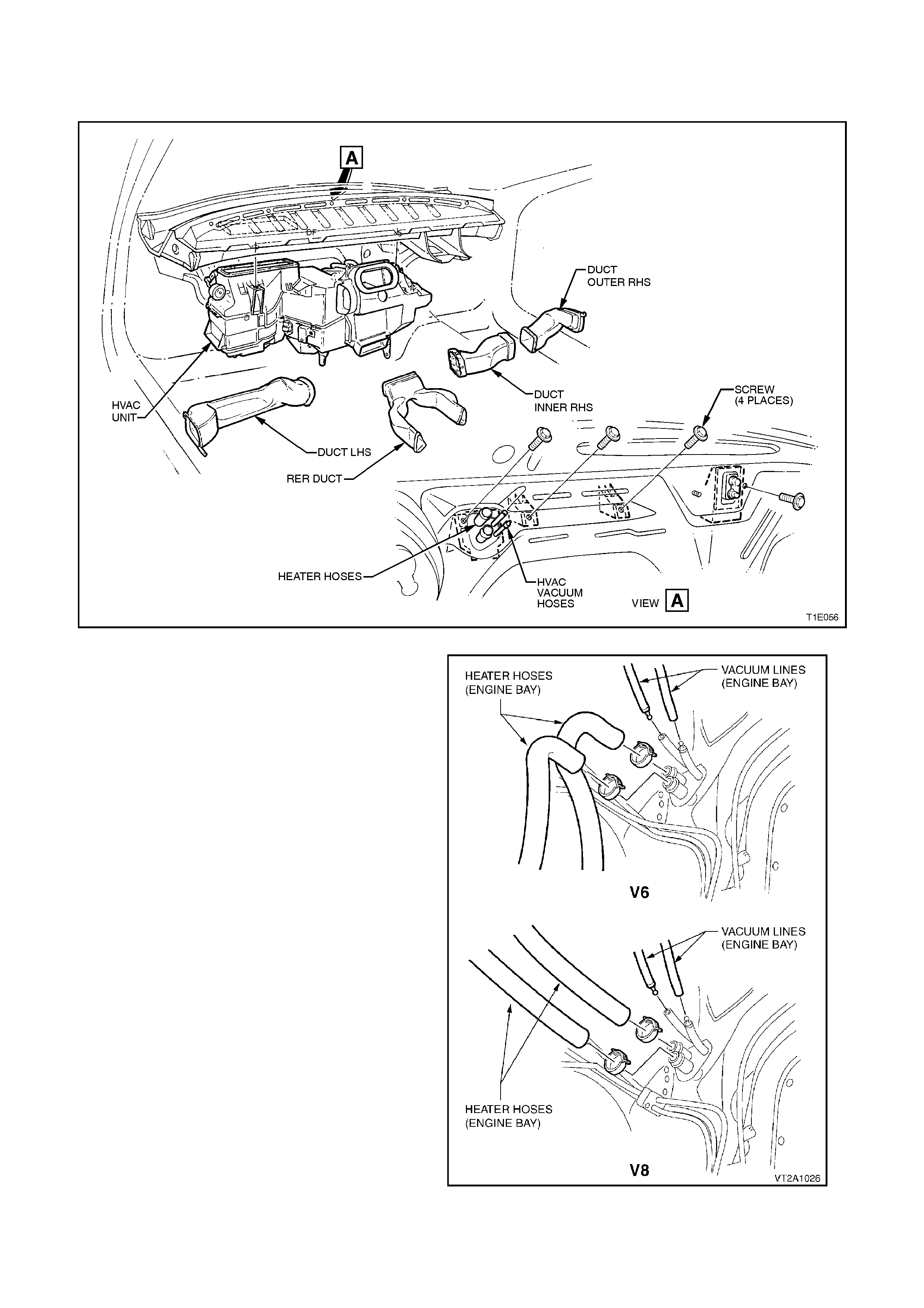
33. Disconnect the r ight side air duc ts , the lef t s ide
air duct, and the rear air duct from the HVAC
unit.
Figure 2B-29
34. Disconnect heater hoses in the engine bay as
shown (mark hoses for correct replacement
position).
35. Disconnect vacuum hoses in the engine bay
as shown.
36. Remove the suction and liquid tubes (1 bolt)
and the thermal expansion valve (2
capscrews) (refer to Fig. 2B-65 in this
Section).
37. Remove the screws retaining the HVAC unit
from the passenger compartment (as shown in
Figures 2B-29 and 2B-32 in this Section).
38. Remove the screws retaining the HVAC unit
from the engine bay (as shown in Fig. 2B-32 in
this Section).
39. Carefully lift the HVAC unit away from the
firewall.
Figure 2B-30
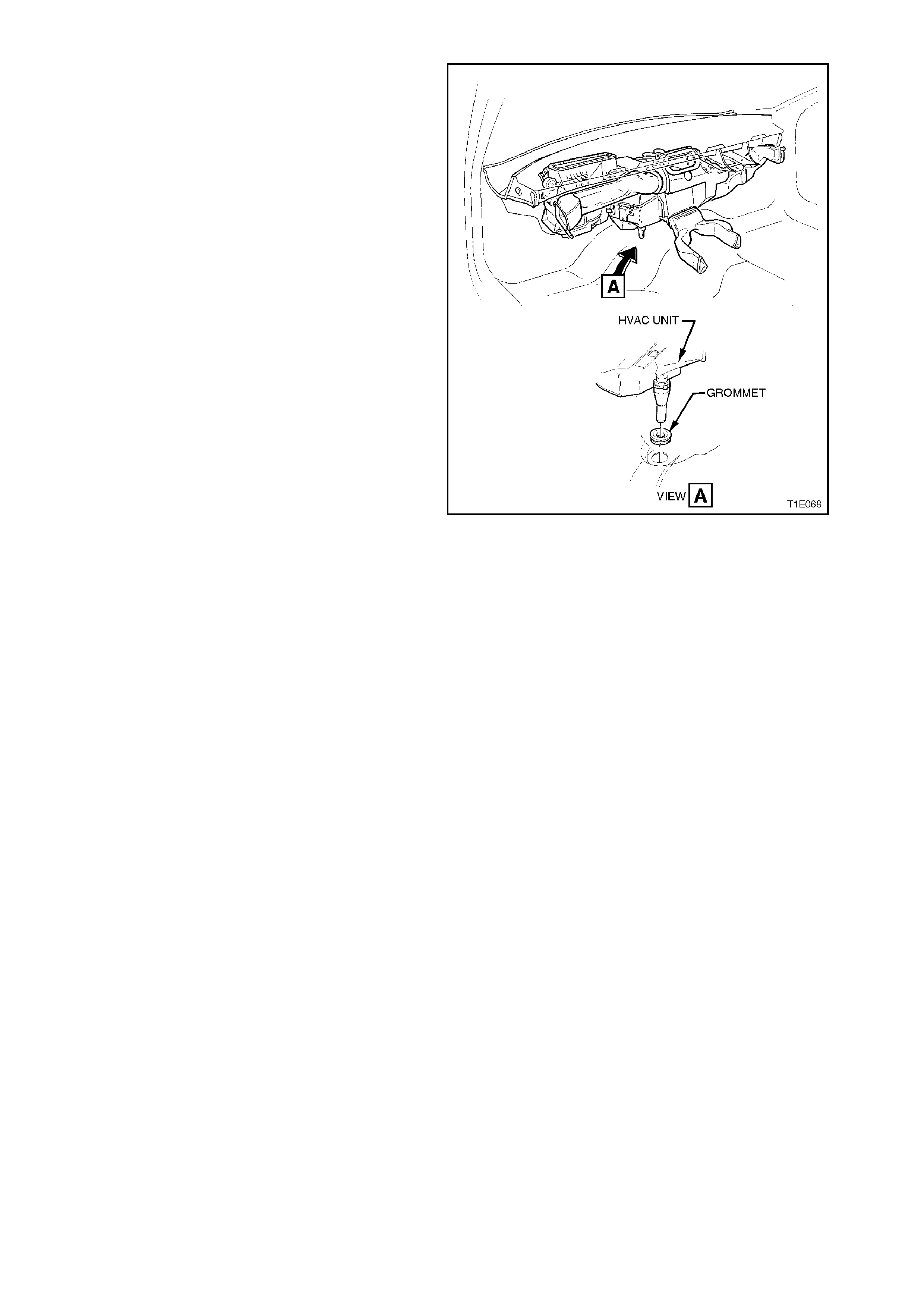
NOTE:
Remove the case from the vehicle by disengaging
the drain grommet and easing the unit from the
vehicle taking care not to strain the heater core
tubes, refer to Fig. 2B-31.
Figure 2B-31
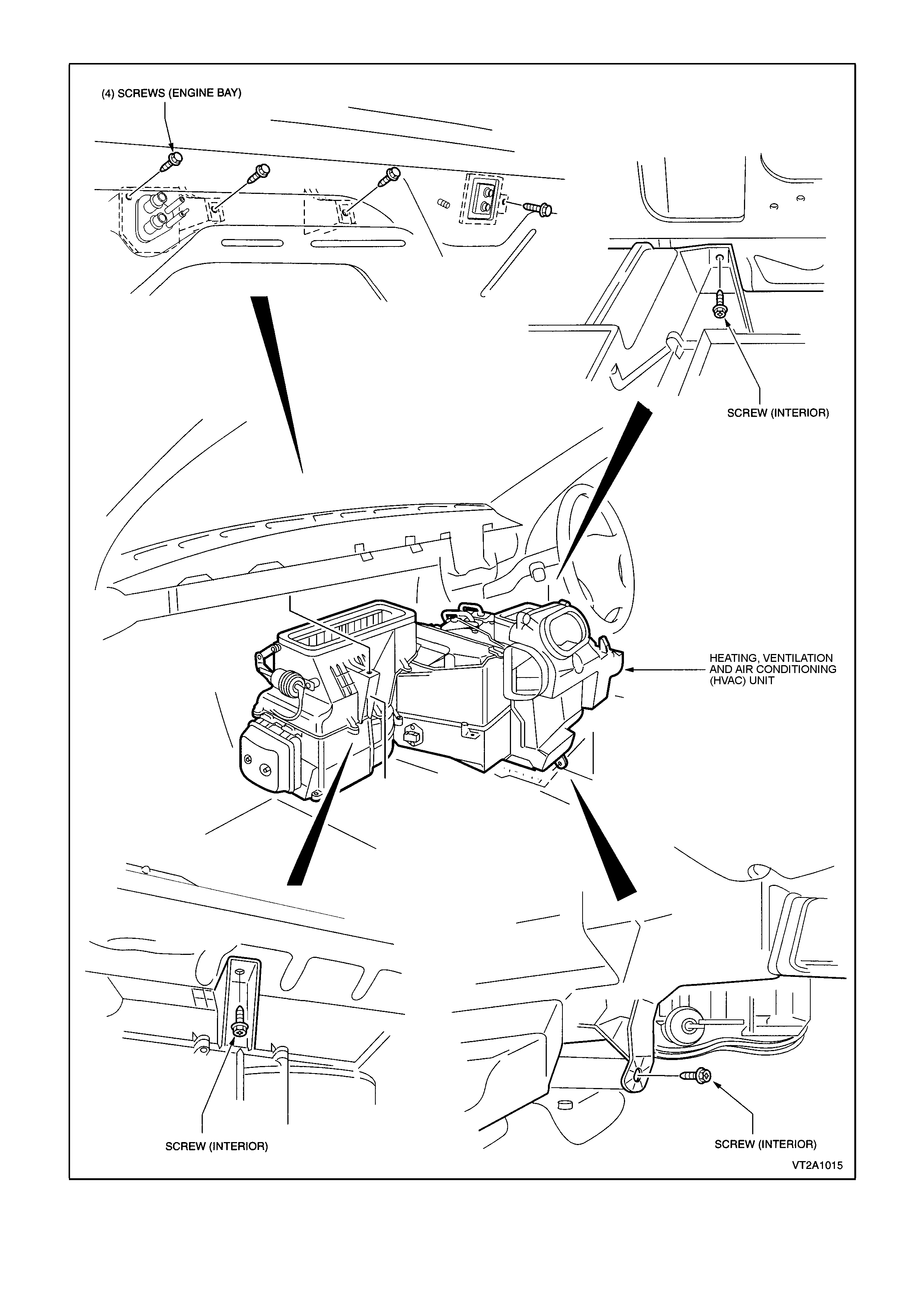
Figure 2B- 32

2. MANUAL CONTROL
2.1 HEATER VALVE VACUUM SWITCH
REMOVE
1. Remove the heater and A/C control assembly
(refer to Fig. 2B-19 in this Section).
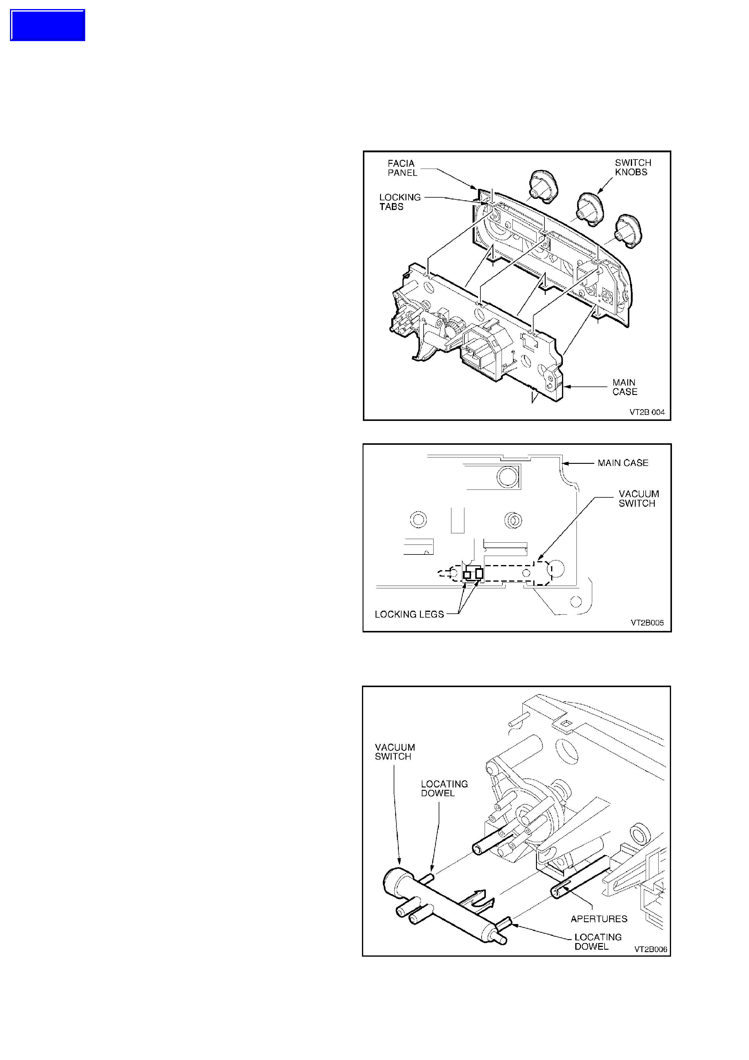
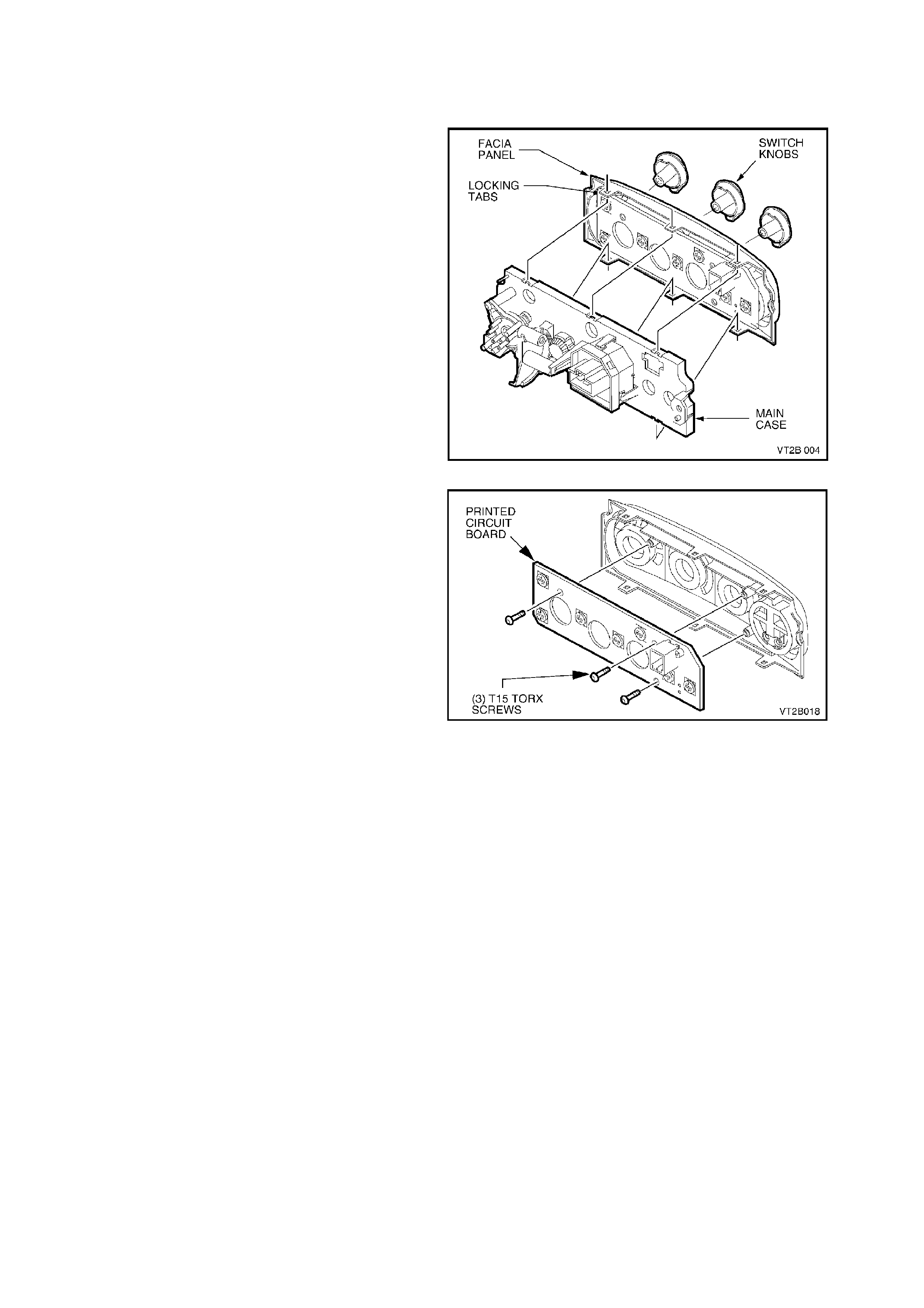
2. Withdraw the three switch knobs by grasping
and gently pulling the knobs from their switch
shafts.
3. Using a small flat screwdriver carefully
dislodge the facia panel six locking tabs from
the main case.
4. Withdraw the fac ia panel from the main control
case (as shown).
Figure 2B-33
5. From the front of the control main case locate
the black plastic vacuum switch locking legs
(as shown).
6. Gently push the locking legs together using
your fingers then push through the locking leg
hole.
7. Remove the vacuum switch.
Figure 2B-34
REINSTALL
1. Insert the vacuum switch locking legs through
the main case ensuring the plastic locating
dowels are sliding into the two apertures.
2. Push the vacuum switch into position ens uring
the lock ing legs are lock ed into position on the
main case.
3. Installation of the c ontrol occurs in the reverse
order of the removal.
Figure 2B-35
Techline
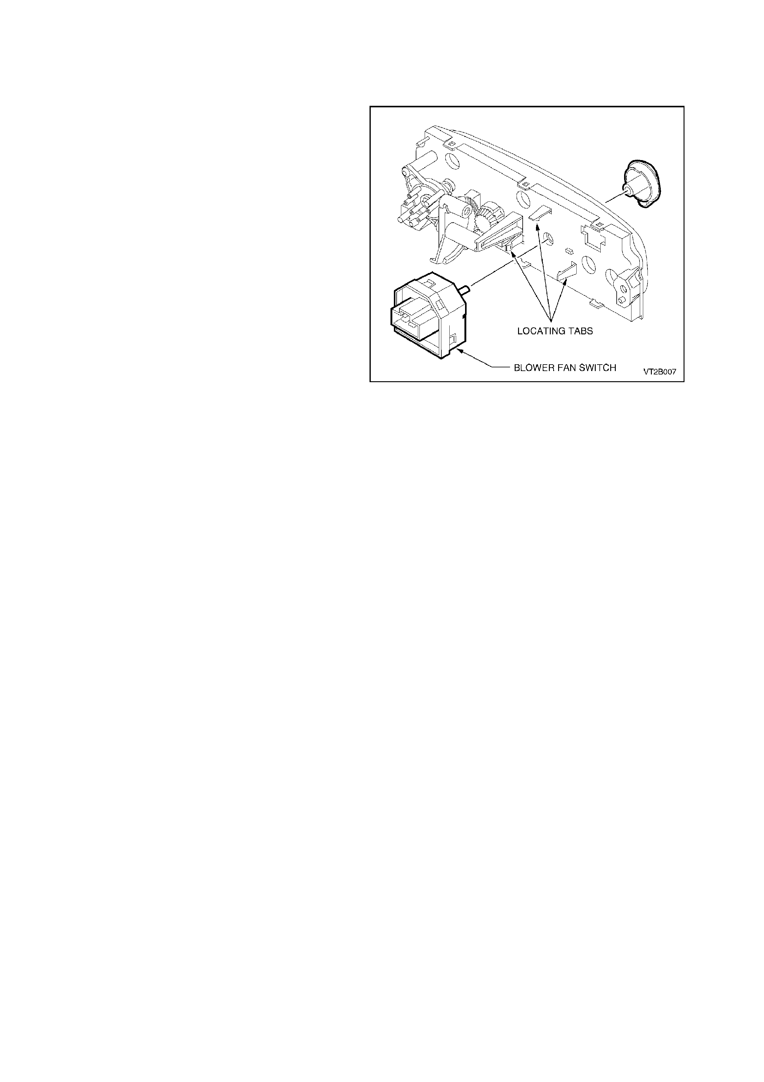
2.2 BLOWE R FAN SWITCH
REMOVE
1. Remove the heater and A/C control assembly
(refer to Fig. 2B-19 in this Section).
2. Withdraw the blower fan switch knob by
grasping and gently pulling the knob from the
switch shaft.
3. Using a sm all flat blade sc rewdriver pus h back
the three blower fan switch locking tabs from
the main body.
4. Remove the blower fan switch from the main
body of the control.
REINSTALL
Installation of the control occurs in the reverse
order of removal.
Figure 2B-36
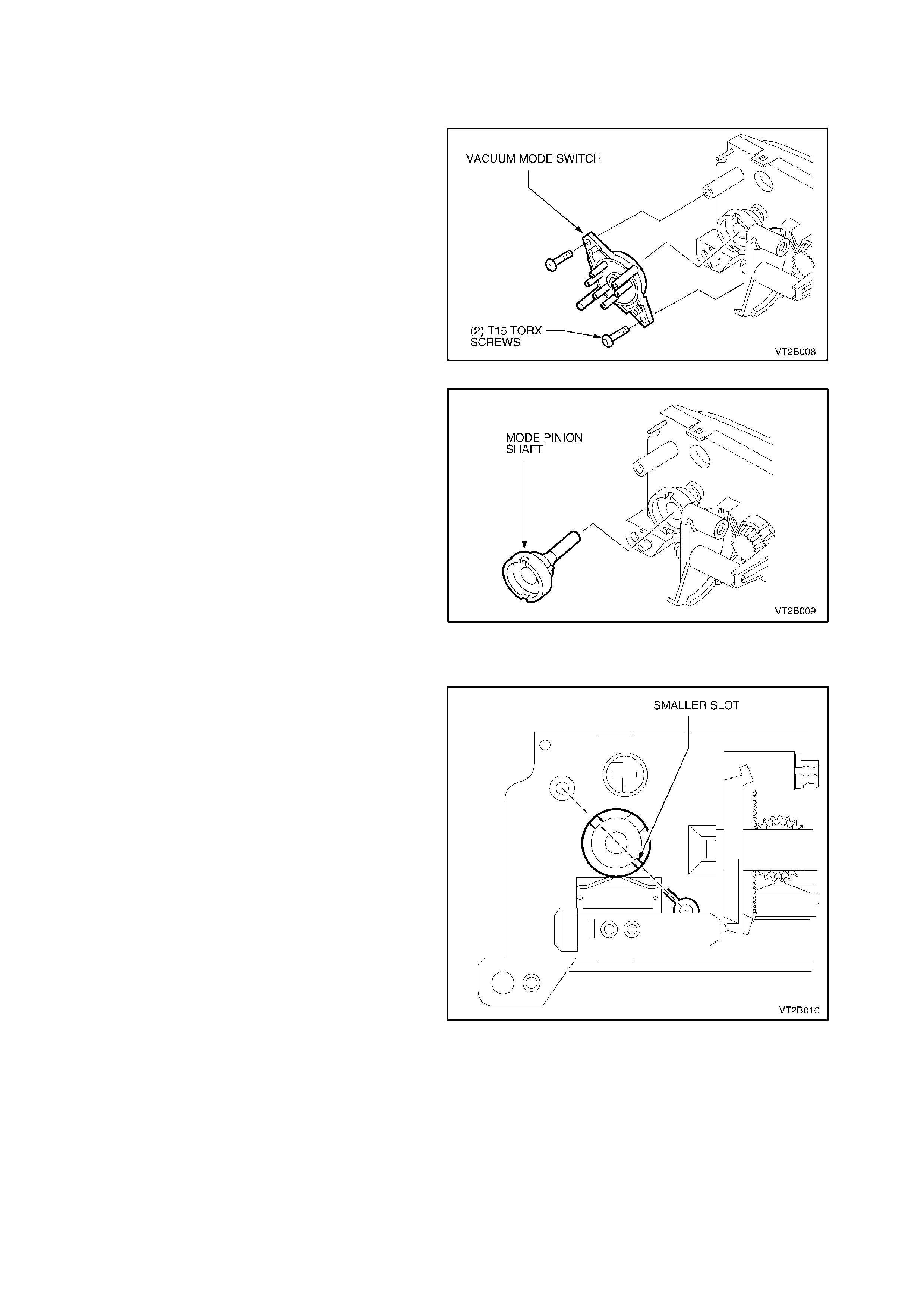
2.3 ROTARY VACUUM MODE SW ITCH ASSEMBLY
REMOVE
1. Remove the heater and A/C control assembly
(refer to Fig. 2B-19 in this Section).
2. Withdraw the mode switch knob by grasping
and gently pulling the knob from the switch
shaft.
3. Unscrew the two mounting T15 Torx screws
from the rotary vacuum switch. Detach the
rotary vacuum switch from the main case.
Figure 2B-37
4. W ithdr aw the mode pinion shaf t from the main
case.
Figure 2B-38
REINSTALL
1. Insert the mode pinion shaft through the main
case with the vacuum switch locater smaller
slot aligned with the lower vacuum switch
mount (as shown).
Figure 2B-39
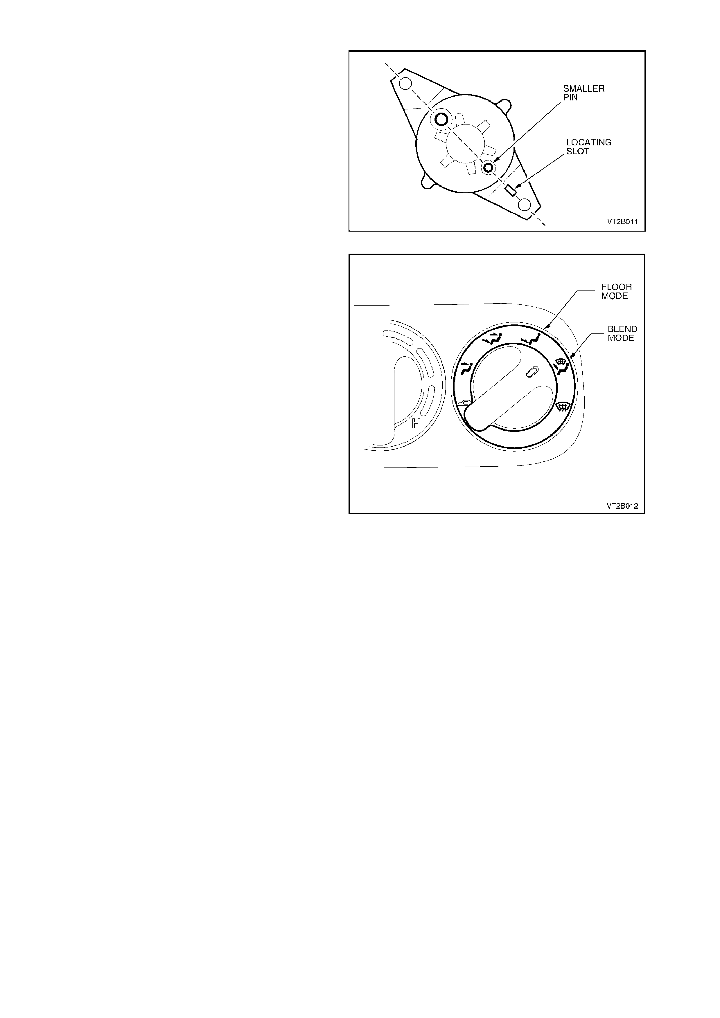
2. Co-ordinate the back section of the vacuum
mode s witch (as s hown) with the sm aller sized
pin aligned with the locating slot.
3. Fit the aligned vacuum switch to the pr eviously
aligned mode pinion shaft.
4. Secure the rotary vacuum switch to the main
case mounts using two T15 Torx screws.
Figure 2B-40
5. Fit the mode knob. Ensure it is aligned with the
locating sect ion of the shaft. If the alignment of
the vacuum valve and pinion shaft is correct
the mode knob white indicator should be
positioned between the blend and floor mode
(as shown).
6. Turn the mode knob to ensure that the white
indicator aligns with all mode settings.
Figure 2B-41
2.4 TEMP E RATURE CONTROL -TEMPERATURE QUADRANT
REMOVE
1. Rem ove the heater and A/C control assembly,
refer to Fig. 2B-19 in this Section.
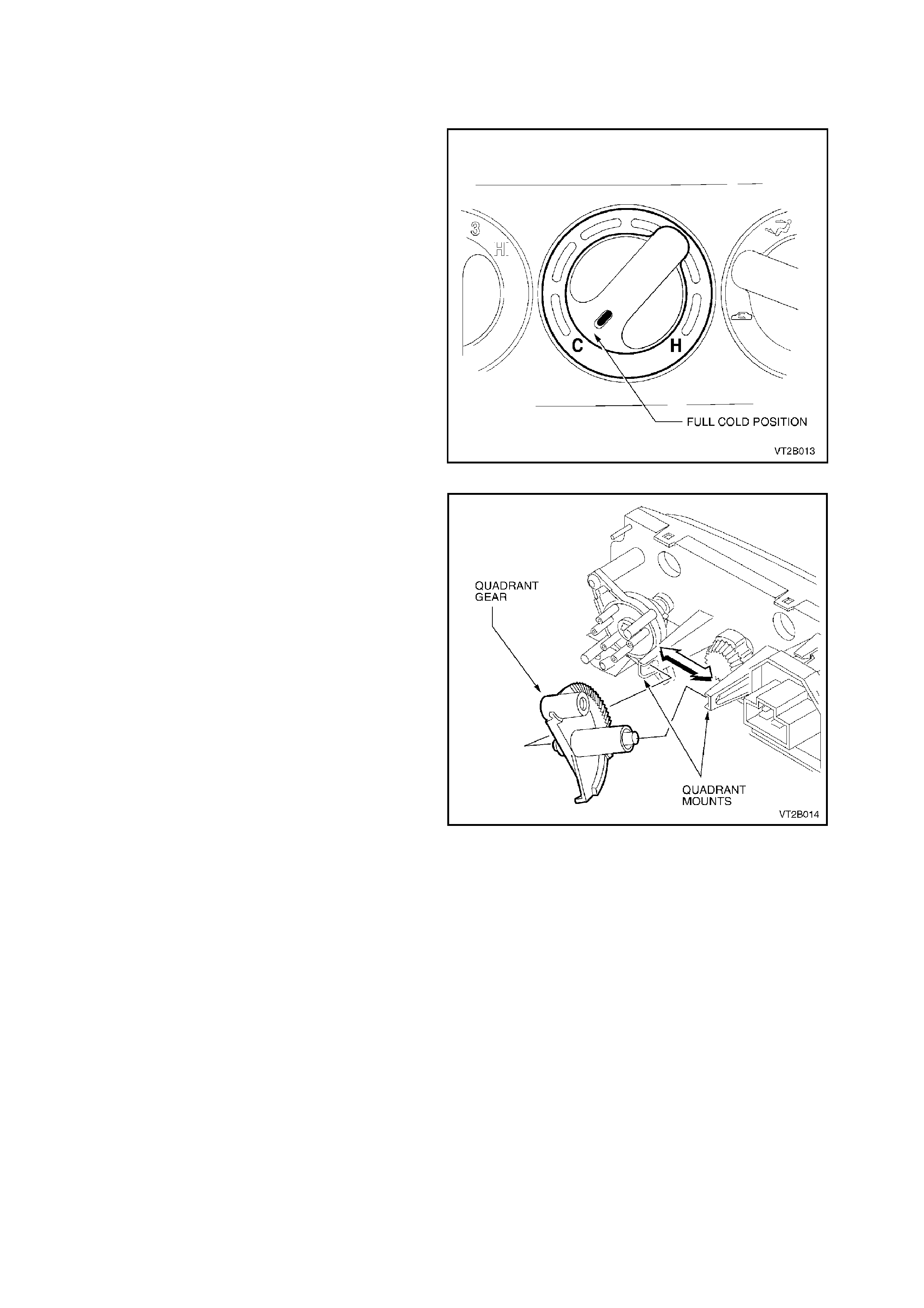
2. Turn the temperature control knob to the full
cold position.
Figure 2B-42
3. Withdraw the temperature control knob by
grasping and gently pulling the knob from
pinion shaft.
4. From the rear of the control gently separate
the two quadrant mounts from the quadrant
gear pivots. Remove the quadrant gear (as
shown).
Figure 2B-43
REINSTALL
1. Installation takes place in reverse order of
removal.
2. Ensure that the mode knob is still set at the full
cold position.
3. Gently separate the two quadrant gear pinion
mounts. Insert the quadrant gear pivots into
the mountings (refer to Fig. 2B-43).
4. Correct timing of the gears is achieved when
the quadrant ramp has depressed the heater
valve vacuum switch plunger with the mode
knob in full cold position (as shown).
5. Install the heater and A/C control assembly
(refer to Fig. 2B-19).
6. Turn the temperature control knob to ensure
full travel in either direction. In the full cold
position the heater water valve must be off.
2.5 PINION SHAFT
REMOVE
1. Remove the heater and A/C control assembly
(refer to Fig. 2B-19 in this Section).
2. Withdraw the temperature control knob by
grasping and gently pulling the knob from the
pinion shaft.
3. Remove the temperature quadrant gear (refer
to Fig. 2B-43).
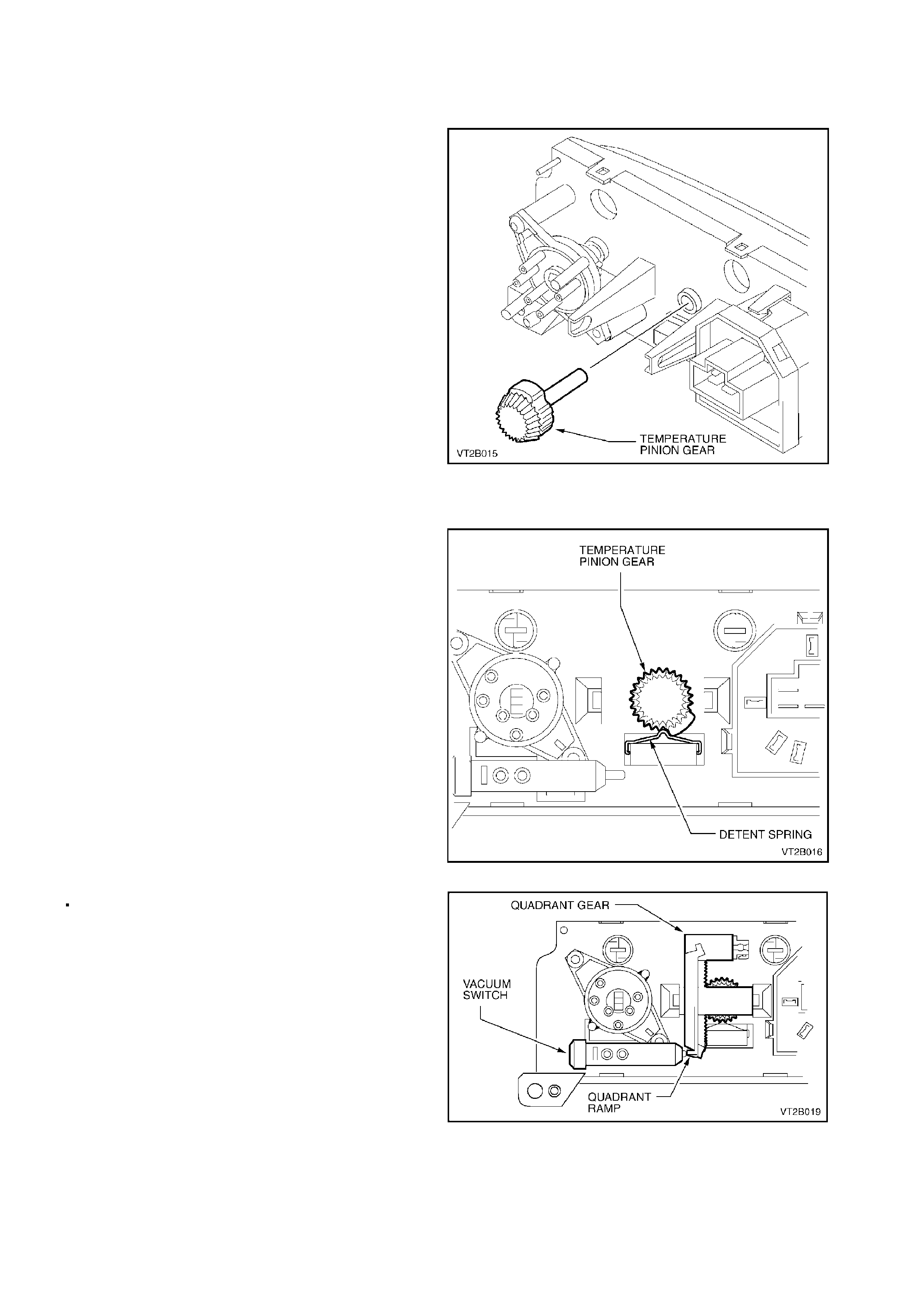
4. Push the temperatur e pinion shaf t out from the
main case.
Figure 2B-44
REINSTALL
1. Reassembly takes place in reverse order of
disassembly.
2. Insert the temperature pinion shaft into the
main case in the full cold position. Lock the
pinion into the detent spring (as shown). This
will ensure the full cold position is selected.
Figure 2B-45
3. Fit the quadrant gear (refer to Fig. 2B-43)
ensuring that the quadrant ramp is pushing the
vacuum switch plunger.
4. Install the heater and A/C control assembly
(refer to Fig. 2B-19).
Figure 2B-46
2.6 PRINTED CIRCUIT BOARD
REMOVE
NOTE:
A/C switch and heated rear window switch are
integrated on the printed circuit board.
1. Remove the heater and A/C control assembly
(refer to Fig. 2B-19 in this Section).
2. Withdraw the three switch knobs by grasping
and gently pulling the knob from the pinion
shaft.
3. Using a small flat blade screwdriver carefully
dislodge the facia panel six locking tabs from
the main case (as shown).
4. Withdraw the facia panel from the main case
(as shown).
Figure 2B-47
5. Unscrew the three T15 Torx screws
retaining the printed circuit board to the facia
panel. Carefully remove the circuit board from
the facia panel.
REINSTALL
1. Install printed circuit board in reverse order of
removal.
2. Install heater and A/C control assembly (refer
to Fig. 2B-19).
Figure 2B-48
2.7 CONTROL ILLUMINATION
GLOBES - REMOVE
1. Remove the heater and A/C control assembly
(refer to Fig. 2B-19 in this Section).
2. Remove the facia panel (refer to
2.6 PRINTED CIRCUIT BOARD in this
Section).
3. Insert a flat blade screwdriver in the plastic
globe holder slot (as shown) then twist anti-
clockwise until the holder stops. Gently ease
globe holder out of housing.
NOTE:
The A/C and rear demist switch globes are non
replaceable. The printed circuit board will have to
be replaced (refer to 2.6 PRINTED CIRCUIT
BOARD in this Section).
GLOBES - REINSTALL
1. Install globes in reverse order of removal.
2. Install heater and A/C control assembly
(refer to Fig 2B-19).
Figure 2B-49
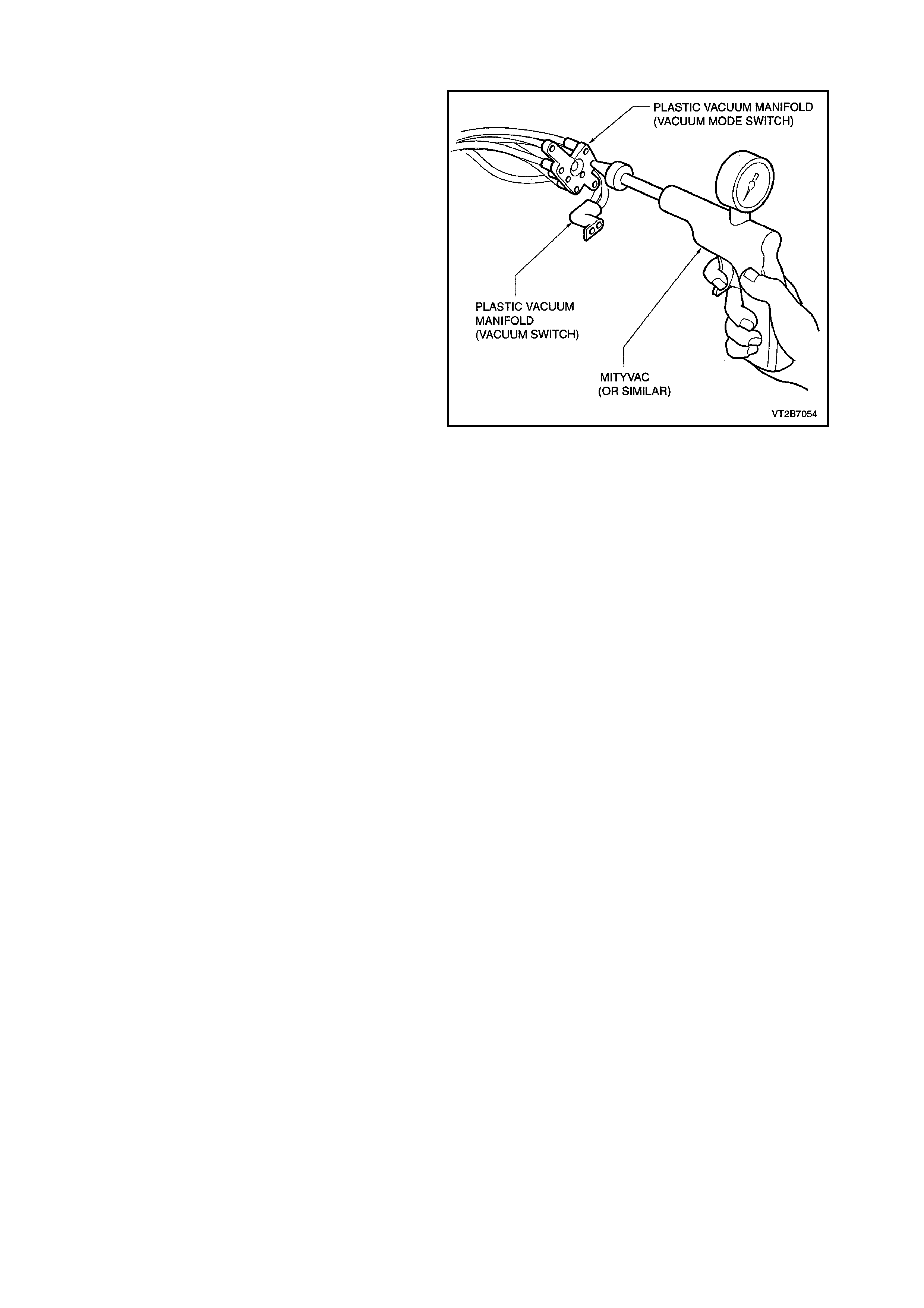
2.8 VACUUM LINE CHECK
1. Remove the heater and A/C control assembly,
refer to Fig. 2B-19 in this Section.
2. Disconnect the vacuum mode switch vacuum
manifold or the heater valve vacuum manifold
(depending on the problem).
3. Using the schematic drawing (refer to Section
2A A/C COMPONENTS, Fig. 2A-19) locate
the appropriate coloured vacuum tube.
4. Insert a vacuum checking device such as a
Mityvac into the appropriate tube and create a
vacuum check to see if both vacuum actuator
or tube hold vacuum.
5. If a vacuum leak is found, check the manifold,
tubing and component for leaks and replace
parts as necessary.
Figure 2B-50
3. EVAPORATOR CORE
REMOVE
1. Recover refrigerant, refer to
Section 2C AIR CONDITIONING -
SERVICING AND DIAGNOSIS.
2. Drain cooling system, refer to
Section 0B LUBRICATION AND SERVICE.
3. Remove the instrument panel carrier, refer to
1. HEATING, VENTILATION AND AIR
CONDITIONING (HVAC) UNIT in this
Section.
4. Remove the heating, ventilation and air
conditioning (HVAC) unit, refer to 1. HEATING ,
VENTILATION AND AIR CONDITIONING
(HVAC) UNIT in this Section.
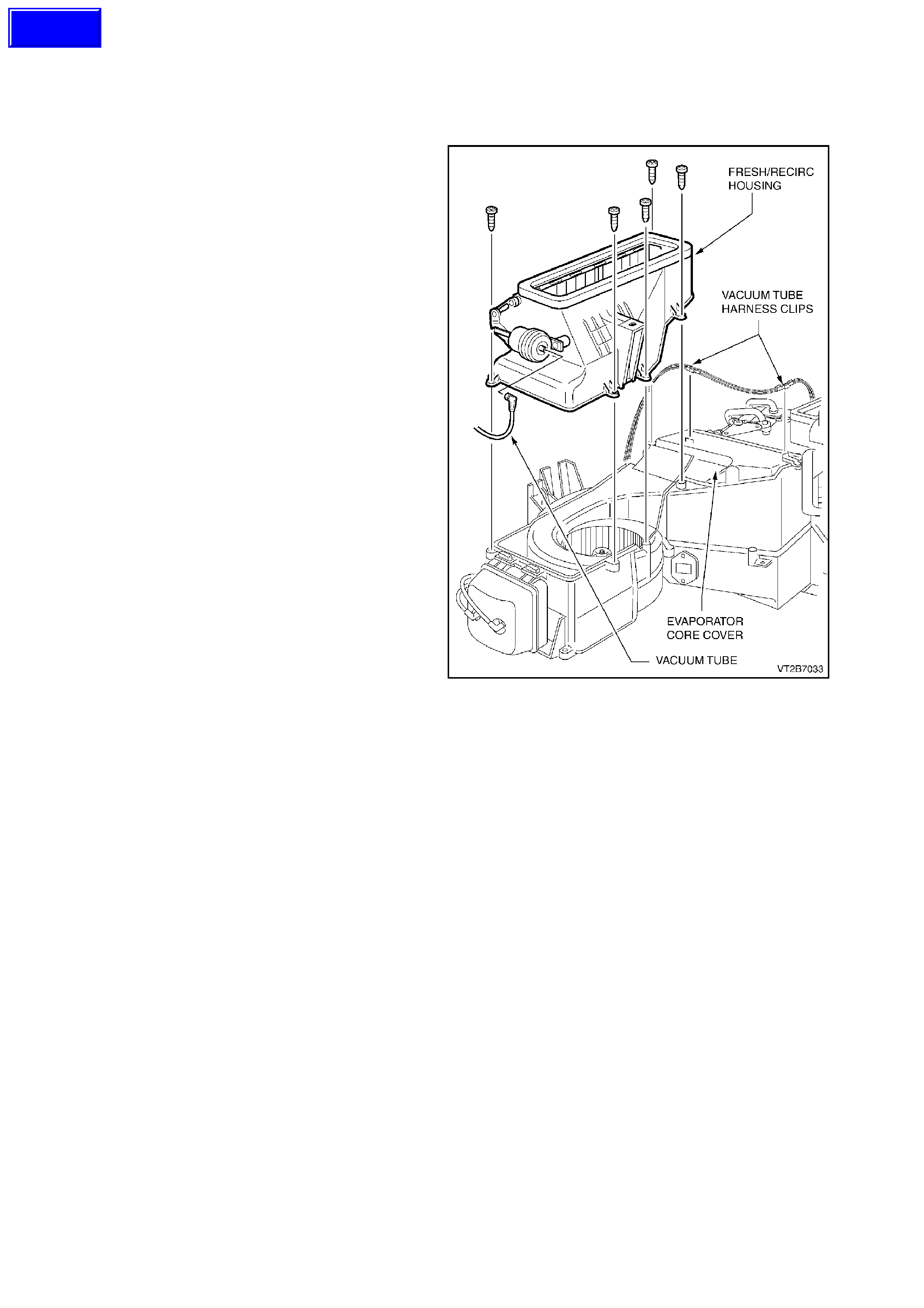
5. Disconnect the vacuum hose from the fresh/
recirculation actuator.
6. Remove the fresh/recirculation housing five
self tapping screws. Remove
fresh/recirculation housing.
Figure 2B-51
Techline
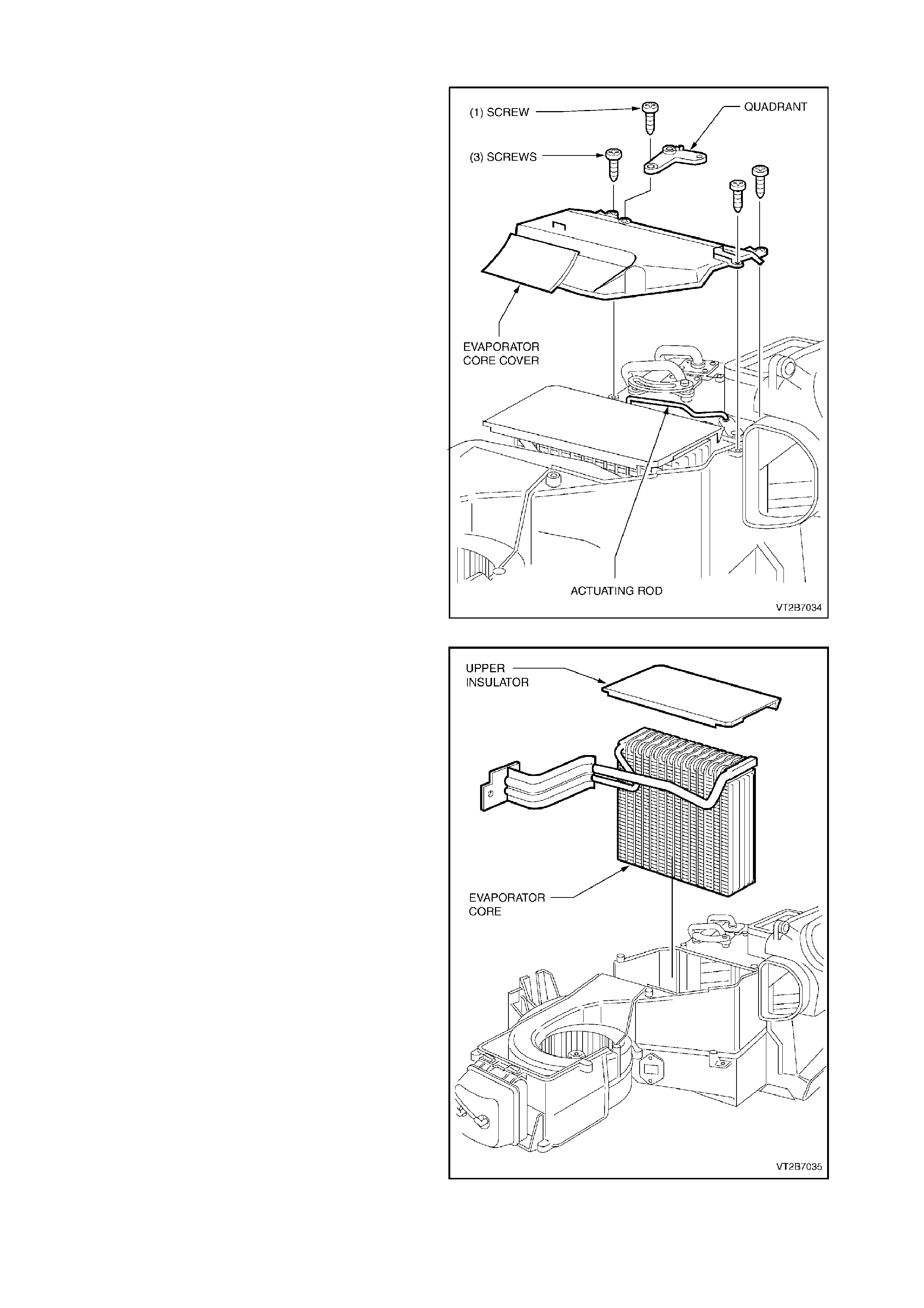
7. Disconnect the vac uum tube harness retaining
clips above the evaporator core cover.
8. MANUAL ONLY: Disconnect the air mix door
actuator rod and quadrant screw.
9. ECC ONLY: Remove the aspirator tube and
evaporator air sensor electrical connector.
10. Remove the four evaporator core cover self
tapping screws.
Figure 2B-52
11. Gently lift out the evaporator core ensuring no
damage occurs to the foam liners.
Figure 2B-53

REINSTALL
1. Install the evaporator core in the reverse order of removal.
2. Reinstall the HVAC unit and instrument panel carrier as described in 1. HEATING, VENTILA TION AND AIR
CONDITIONING (HVAC) UNIT in this Section.
3. Evacuate and charge the system with 775 - 825 g of R134a refrigerant, refer to
Section 2C AIR CONDITIONING - SERVICING AND DIAGNOSIS.
Techline
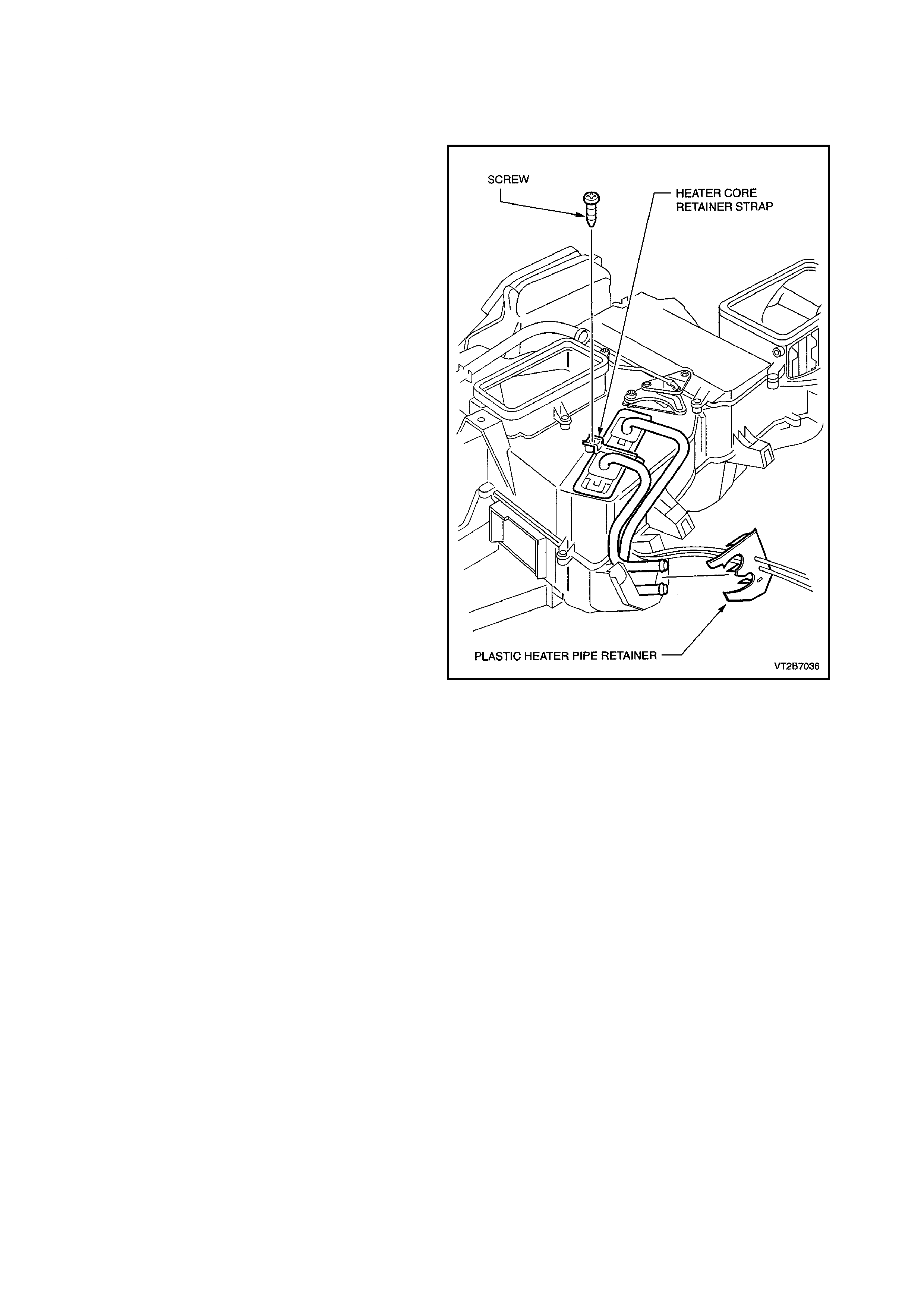
4. HEATER CORE
REMOVE
1. Recover refrigerant, refer to
Section 2C AIR CONDITIONING -
SERVICING AND DIAGNOSIS.
2. Drain cooling system, refer to
Section 0B LUBRICATION AND SERVICE.
3. Remove instrument panel carrier, refer to
1. HEATING, VENTILATION AND AIR
CONDITIONING (HVAC) UNIT in this Section.
4. Remove HVAC unit, refer to
1. HEATING, VENTILATION AND AIR
CONDITIONING (HVAC) UNIT in this Section.
5. Unclip and remove plastic heater pipe retainer
from rear of the HVAC unit.
6. Unscrew the self tapping screw from the
plastic heater core retaining strap and remove
strap.
7. Gently lift out the heater core assembly.
Figure 2B-54
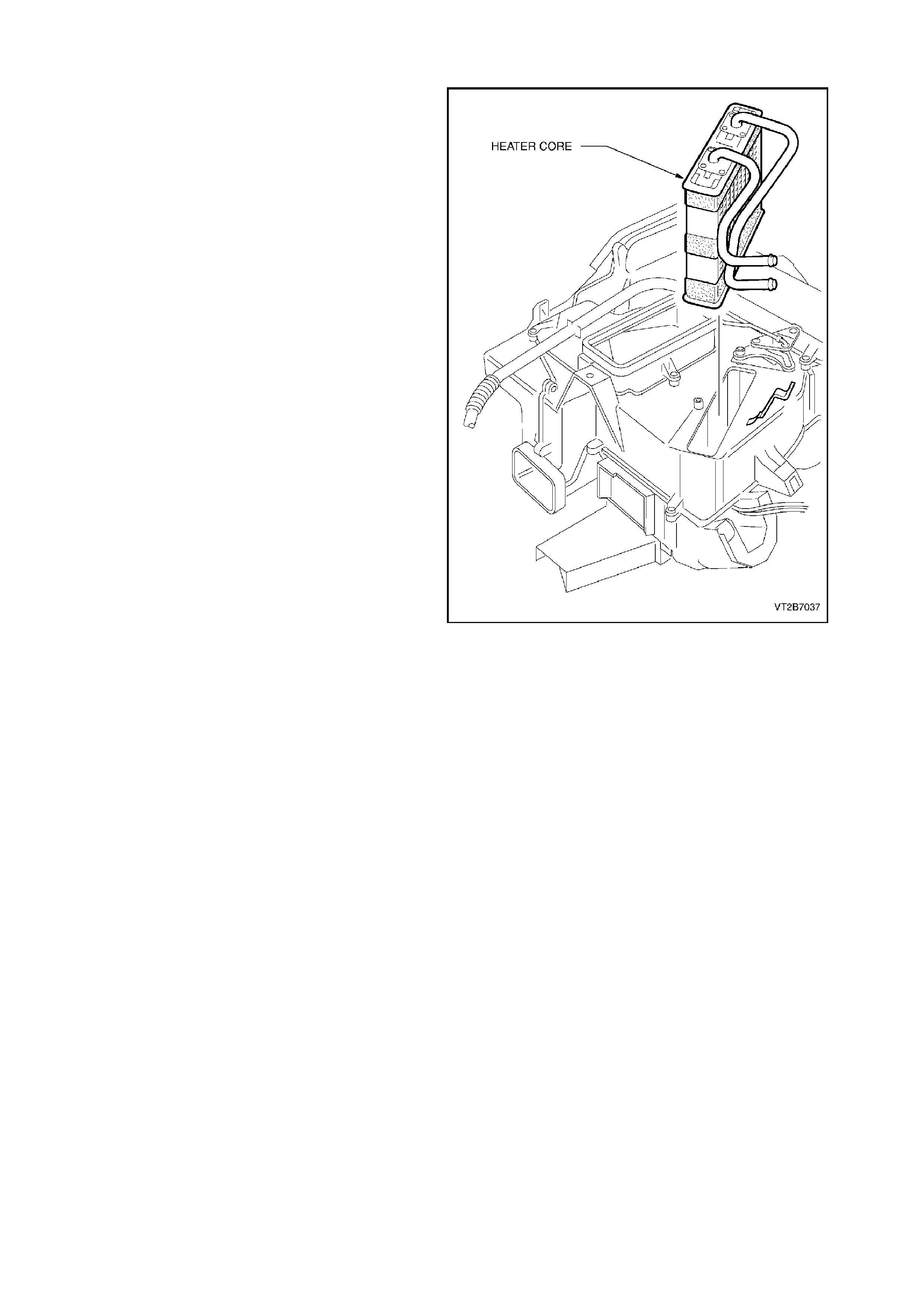
REINSTALL
1. Slide the heater core into the aperture
provided in the HVAC unit.
NOTE:
Ensure the foam seals are not damaged when
inserting heater core.
2. Fit the heater core plastic retaining str ap. Slide
one side under the HVAC unit case and
secure with one self tapping screw.
3. Fit the heater core pipe plastic retainer located
at the rear of the case.
4. Fit the HVAC unit, refer to
1. HEATING, VENTILATION AND AIR
CONDITIONING (HVAC) UNIT in this Section.
5. Install the instrument panel carrier.
6. Install the cooling system and bleed.
7. Evacuate and charge the system with 775 -
825g of R134a refrigerant.
Figure 2B-55
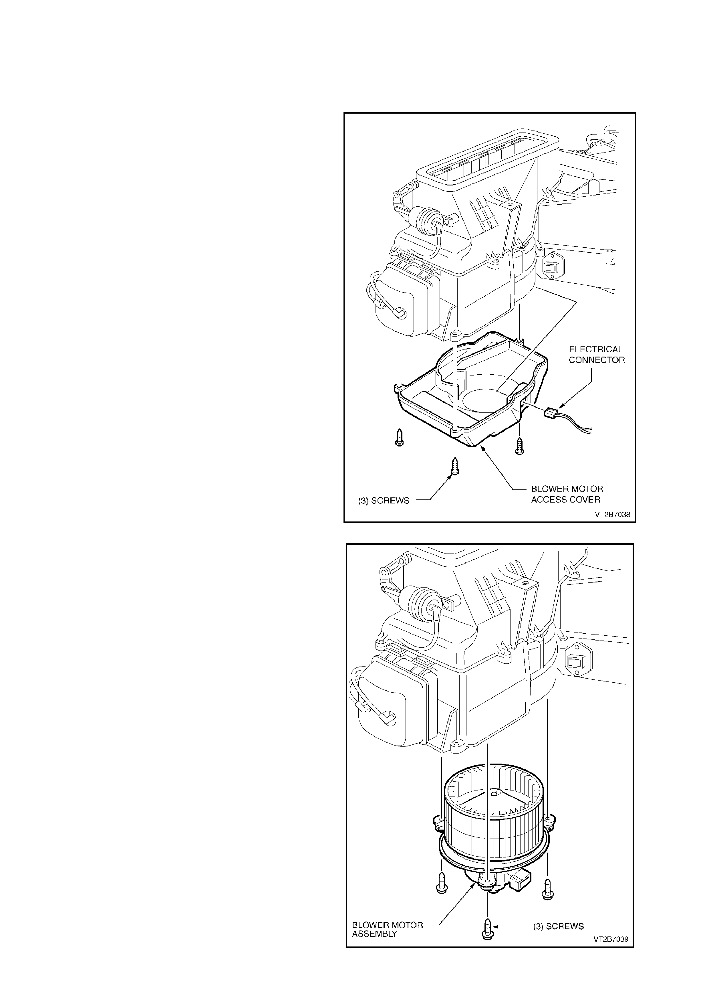
5. BLOWER MOTOR
REMOVE
1. Remove the footwell upper closing panel left
side (unclip.
2. Disconnect the blower motor electrical
connector.
3. Unscrew the blower motor access cover three
self tapping screws.
Figure 2B-56
4. Locate the three blower motor retaining screws
and remove.
5. Gently remove the blower motor assembly
NOTE: Ensure the blower motor wheel balancing
clips are not dislodged during removal.
REINSTALL
1. Install the blower motor using three self
tapping screws.
NOTE: When installing the blower motor ensure
that the balance clips have not been dislodged from
the blower motor wheel.
1. Install the blower motor access cover using the
three self tapping screws.
1. Connect the blower m otor electrical plug to the
blower motor.
1. Install the footwell cover upper closing panel
let side.
Figure 2B-57
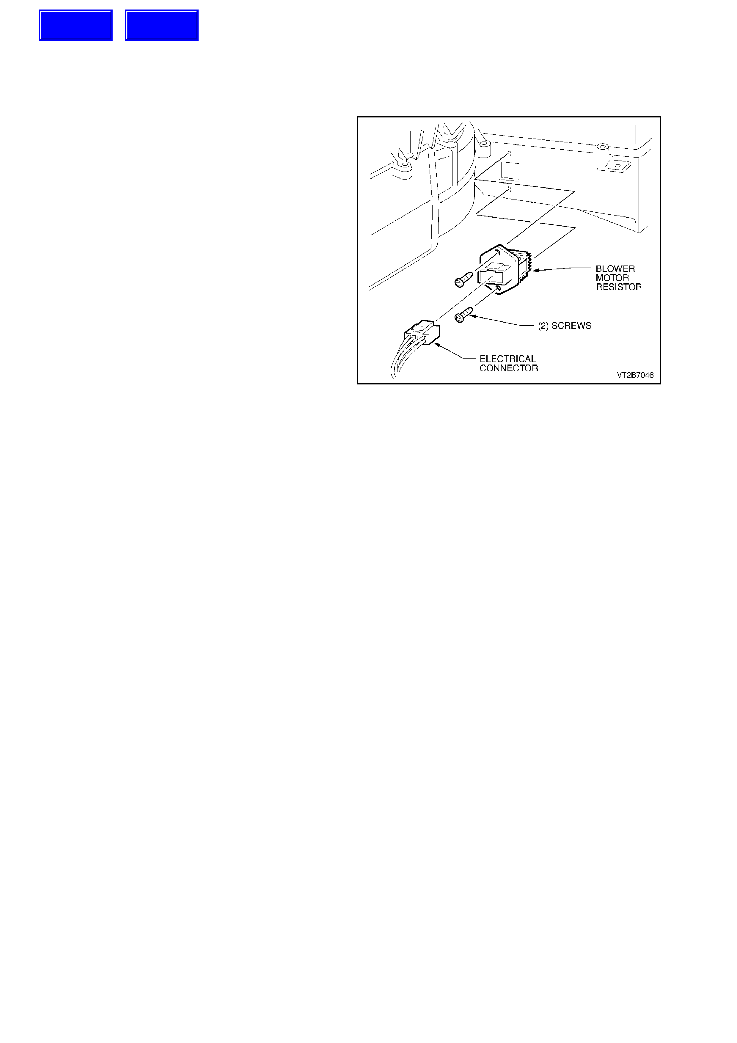
6. BLOWER MOTOR RESISTOR
REMOVE
1. Remove the instrument panel lower
compartment, the instrument panel end cap
cover left-hand side and the instrument
compartment roof (refer to
1. HEATING, VENTILATION AND AIR
CONDITIONING (HVAC) UNIT in this
Section).
2. Detach the electrical connector and two self
tappers retaining the blower motor resistor.
3. Remove the resistor assembly
REINSTALL
1. Install the blower motor resistor using the
original two self tapping screws.
2. Reconnect the electrical connector.
3. Replace the instrument compartment roof
using original screws.
4. Install the instrument panel end cap cover left
side using original screws.
5. Reinstall the instrument panel lower
compartment using original pins.
Figure 2B-58
Techline
Techline
7. VACUUM SUPPLY AND VACUUM ACTUATORS
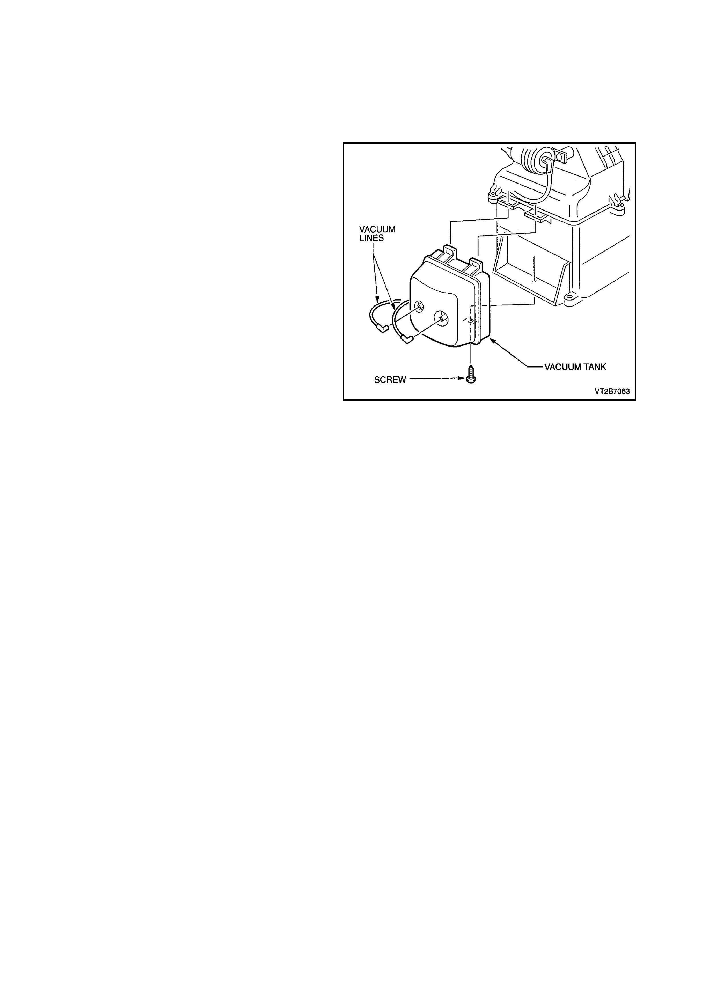
7.1 VACUUM TANK
REMOVE
1. Remove instrument facia assembly, refer to
1. HEATING, VENTILATION AND AIR
CONDITIONING (HVAC) UNIT in this Section.
2. Disconnect the two vacuum c onnections at the
vacuum tank.
3. Unscrew the one self tapping screw from the
lower section of the tank.
4. Move vacuum tank outwards and down to
dislodge the retaining tangs.
REINSTALL
Install the vacuum tank in the reverse order of
removal.
Figure 2B-59
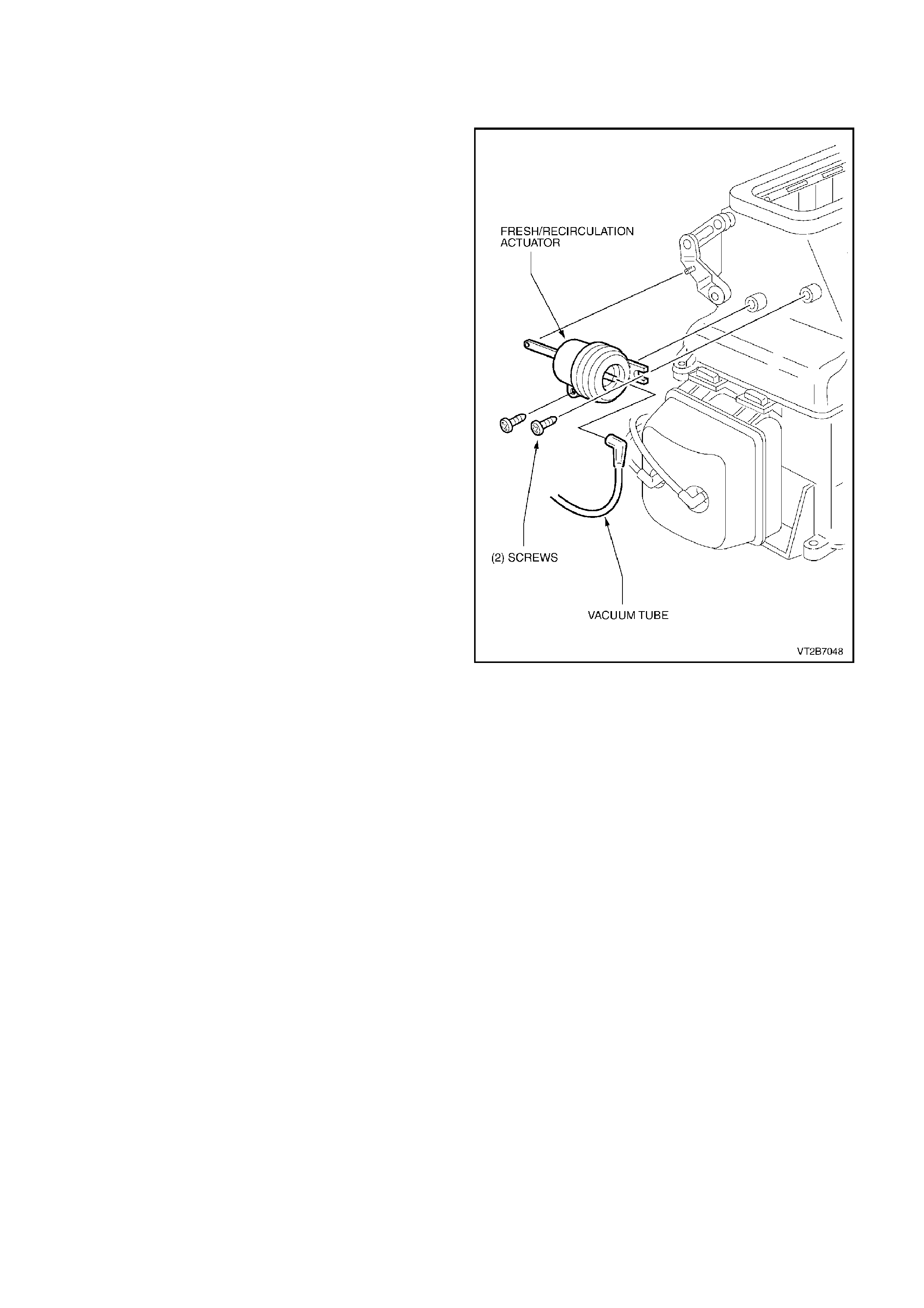
7.2 FRESH/RECIRCULATION ACTUATOR
REMOVE
1. Remove the instrument panel lower compartment,
the instrument panel end cap cover left side and the
footwell upper closing panel left side (refer to
1. HEATING, VENTILA TION AND AIR
CONDITIONING (HVAC) UNIT in this Section).
2. Disconnect the vacuum actuator rod from the
fresh/recirculation lever.
3. Remove the vacuum actuator using a stubby
Phillip’s head screwdriver two self tapping screws.
REINSTALL
Reassembly takes place in the reverse order of removal.
Figure 2B-60
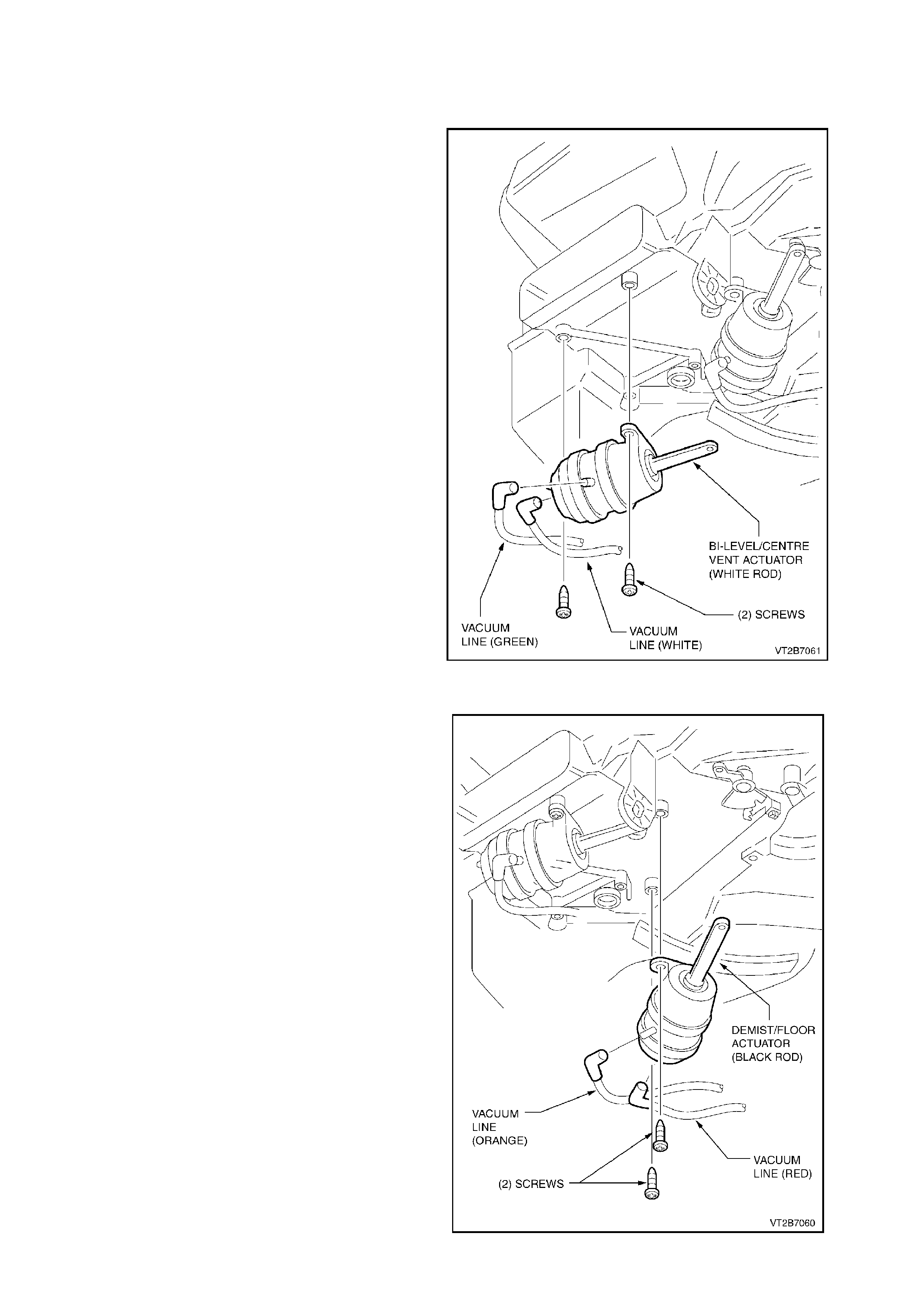
7.3 BI-LEVEL/CENTRE VENT AND DEMIST/FOOT ACTUATOR
REMOVE
1. Remove instrument panel carrier, refer to
1. HEATING, VENTILATION AND AIR
CONDITIONING (HVAC) UNIT in this Section.
2. Remove the HVAC unit (refer to
1. HEATING, VENTILATION AND AIR
CONDITIONING (HVAC) in this Section.
3. From the underside of the HVAC unit, locate
the vacuum actuator for removal.
4. Gently unclip the vacuum actuator rod from
the door lever. Remove the coloured vacuum
tubing from the ports.
NOTE:
Take note of the positions.
5. Detach the vacuum actuator two self tapping
screws.
REINSTALL
Install the vacuum actuator in the reverse order of
removal.
NOTE:
If in doubt about the correct colour coding of the
vacuum tubes to the vacuum actuator’s ports refer
to Section 2A - A/C COMPONENTS, Fig. 2A-19.
NOTE:
Vacuum Actuator with WHITE rod - connect to
WHITE coloured levers.
Vacuum actuator with BLACK rod - connect to
BLACK coloured gears.
Figure 2B-61
Figure 2B-62
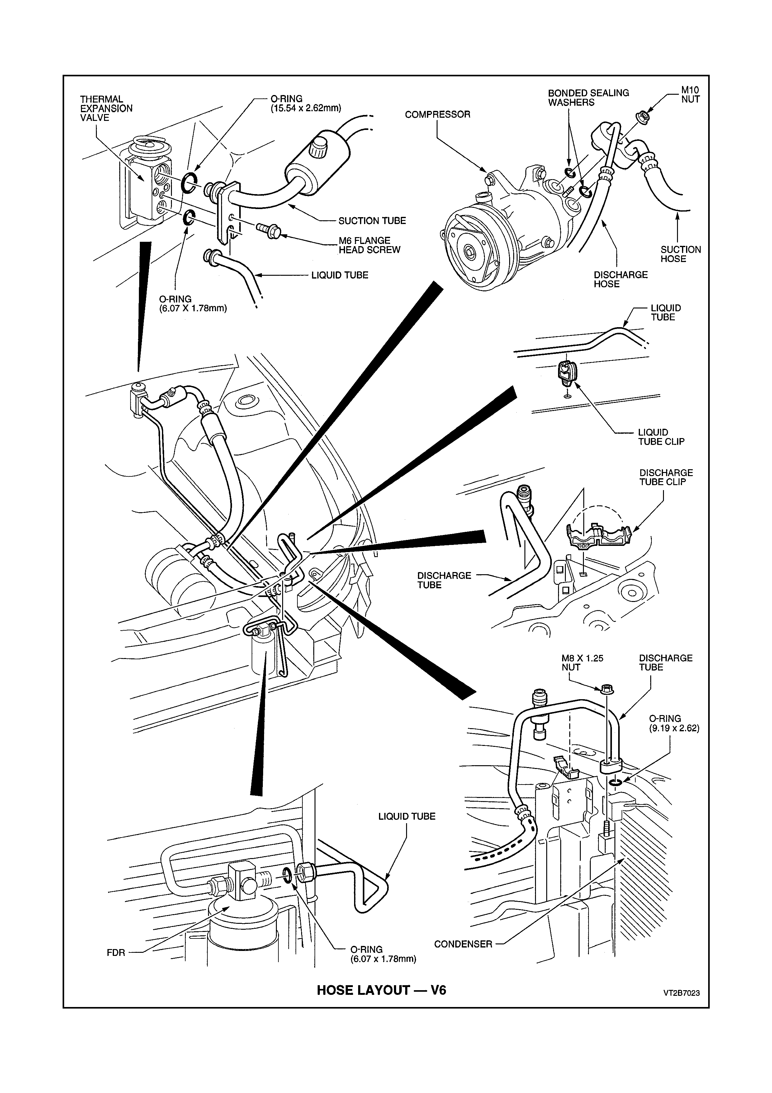
7.4 HOSE LAYOUT - V6
Figure 2B-63
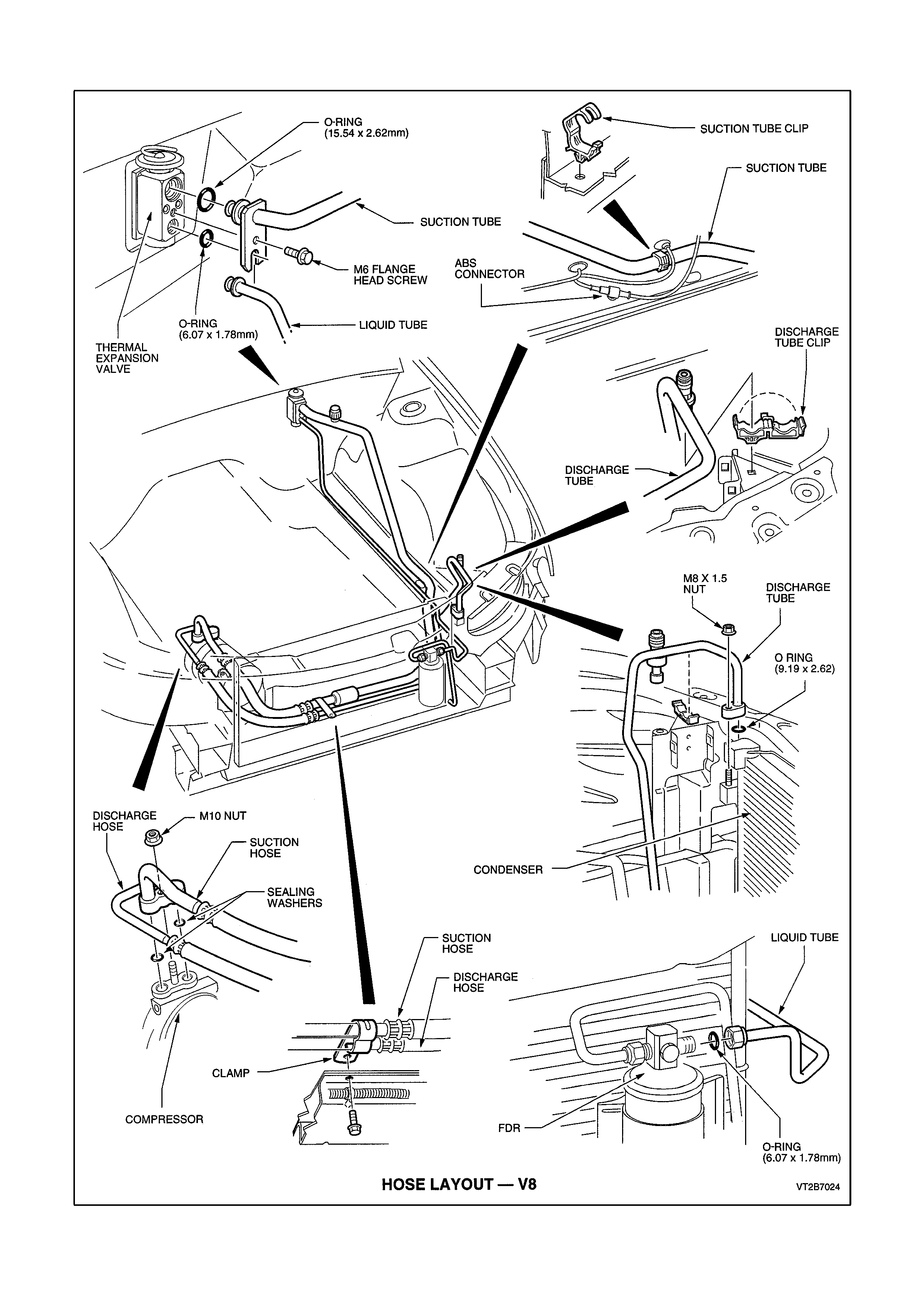
7.5 HOSE LAYOUT - V8
Figure 2B-64
8. THERMAL EXPANSION VALVE (TXV)
REMOVE
1. Recover refrigerant, refer to
Section 2C AIR CONDITIONING -
SERVICING AND DIAGNOSIS.
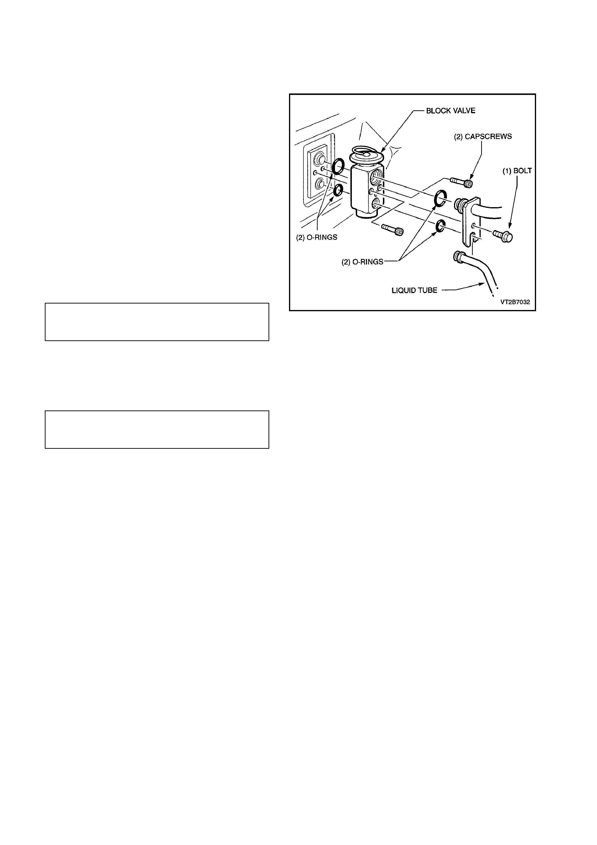
2. Remove the washer faced bolt retaining the
tube plate to the TXV.
3. Discard two O - rings.
4. Unscrew the two capscrews and remove TXV.
REINSTALL
1. Lubricate and fit two new O - rings to the
evaporator tubes.
2. Insert the TXV (diaphragm facing upwards)
onto the evaporator tubes.
3. 3. Secure the TXV to the evaporator tube
plate using the two cap screws.
EVAPORATOR TUBE PLATE
SECURING SCREWS 4.0 - 4.5 Nm
TORQUE SPECIFICATION
4. Fit two new lubricated O - rings to the liquid
and suction tubes.
5. Insert the liquid and suction tubes and
retaining plate onto the TXV.
6. 6. Secure using original bolt.
WASHER FACED TUBE PLATE
RETAINING BOLT 7.5 - 12.5 Nm
TORQUE SPECIFICATION
7. Evacuate and charge the A/C system with
775 - 825 g of refrigerant, refer to
2C AIR CONDITIONING - SERVICING AND
DIAGNOSIS.
Figure 2B-65
9. CONDENSER - V6 & V8
REMOVE
1. Rec over refrigerant from the A/C system , refer
to Section 2C AIR CONDITIONING -
SERVICING AND DIAGNOSIS.
2. Remove the radiator assembly, refer to
Section 6B1 ENGINE COOLING - V6
ENGINE or 6B2 ENGINE COOLING - V8
ENGINE.
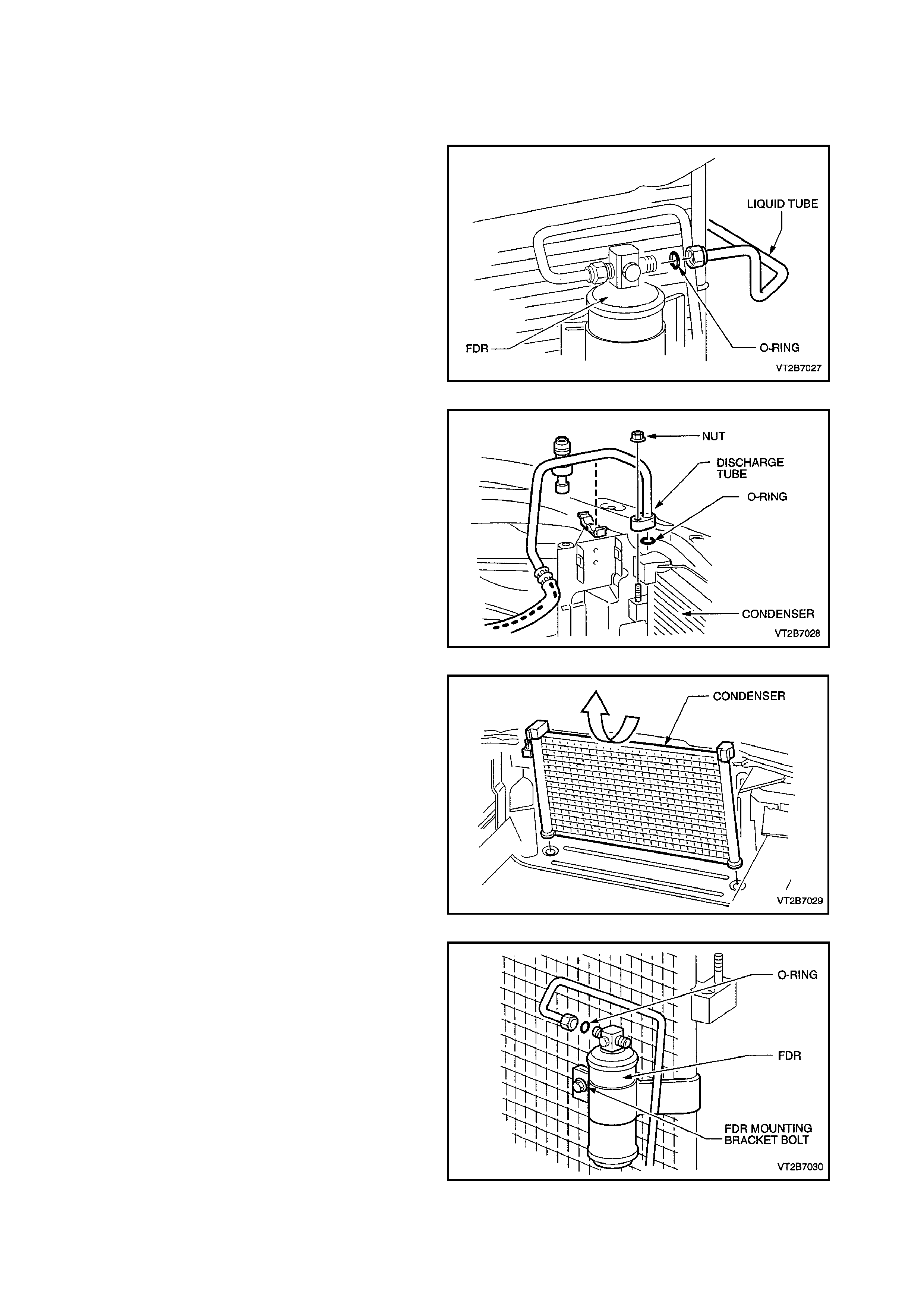
3. Through the front bumper bar opening,
unscrew the liquid tube fitting from the Filter
Drier Receiver (FDR) outlet.
Figure 2B-66
4. Remove one nut retaining the discharge hose
pad fitting to the condenser.
5. Cap all open tubes/hoses to avoid moisture
from entering the system.
6. Discard O - rings.
Figure 2B-67
7. ECC VEHICLES ONLY
Disconnect the ambient temperature sensor
electrical connector from the front right hand
side of the condenser.
8. Tilt the condenser towards engine and lift
upwards.
Figure 2B-68
9. Unscrew the FDR inlet fitting, loosen the FDR
mounting bracket bolt and remove the FDR.
NOTE:
Mark mounting position of FDR for correct
repositioning.
Figure 2B-69
REINSTALL
1. Replace the FDR, ensure the fitting with the
word IN is connected to the inlet side of the
FDR, tighten the FDR inlet fitting and the FDR
mounting bracket bolt.
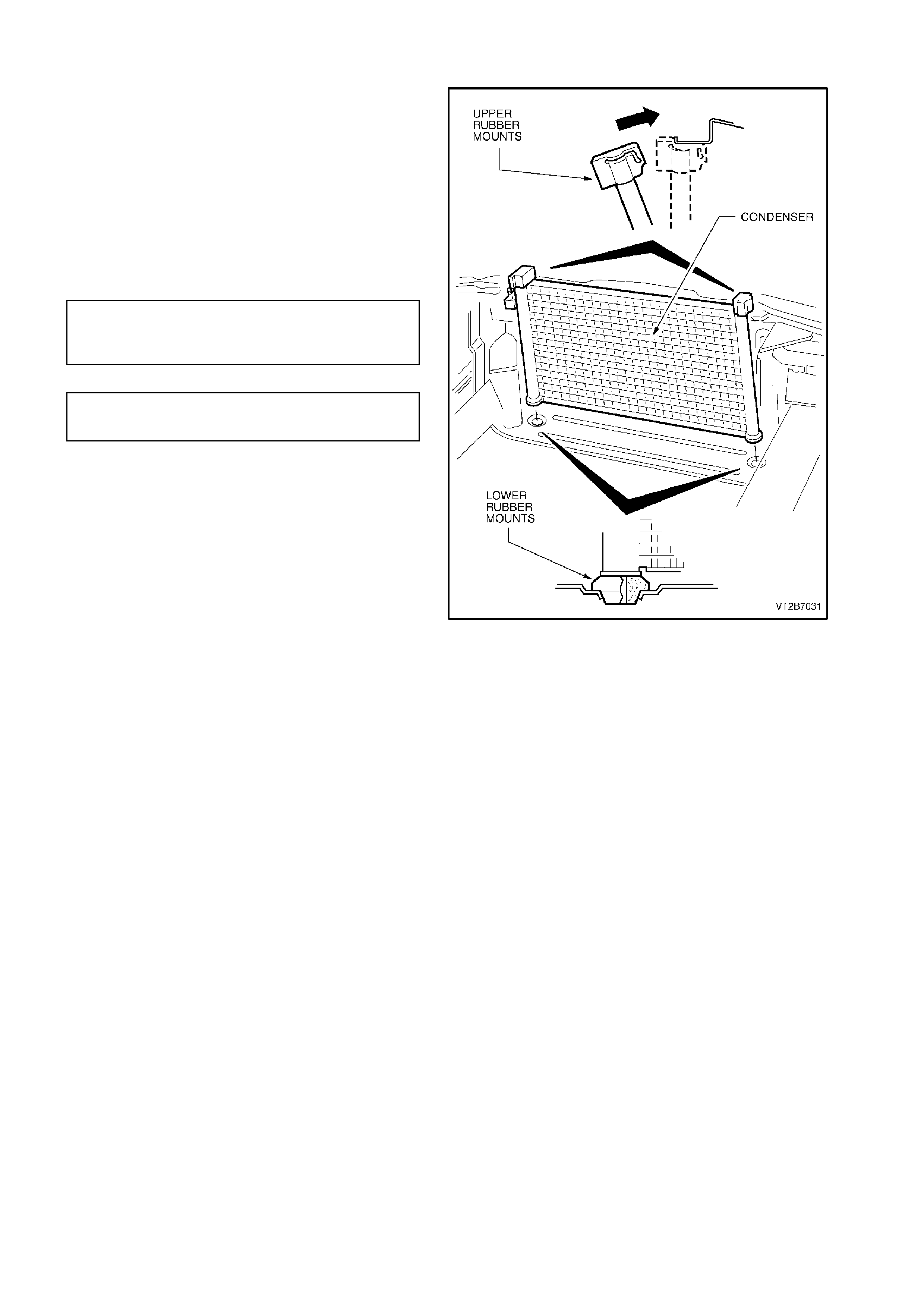
2. Fit upper and lower rubber mounts to
condenser.
3. Insert condenser into location holes in lower
radiator panel.
4. Install liquid tube and discharge hose using
new lubricated O - rings to the condenser.
Torque fittings to specifications;
CONDENSER INLET PAD
FITTING NUT 7.5 - 12.5 Nm
TORQUE SPECIFICATION
FDR TUBE NUTS 7.5 - 12.5
TORQUE SPECIFICATION Nm
5. Evacuate and charge the A/C system with
775 - 825g of R134a refrigerant, refer to
Section 2C AIR CONDITIONING -
SERVICING AND DIAGNOSIS.
Figure 2B-70
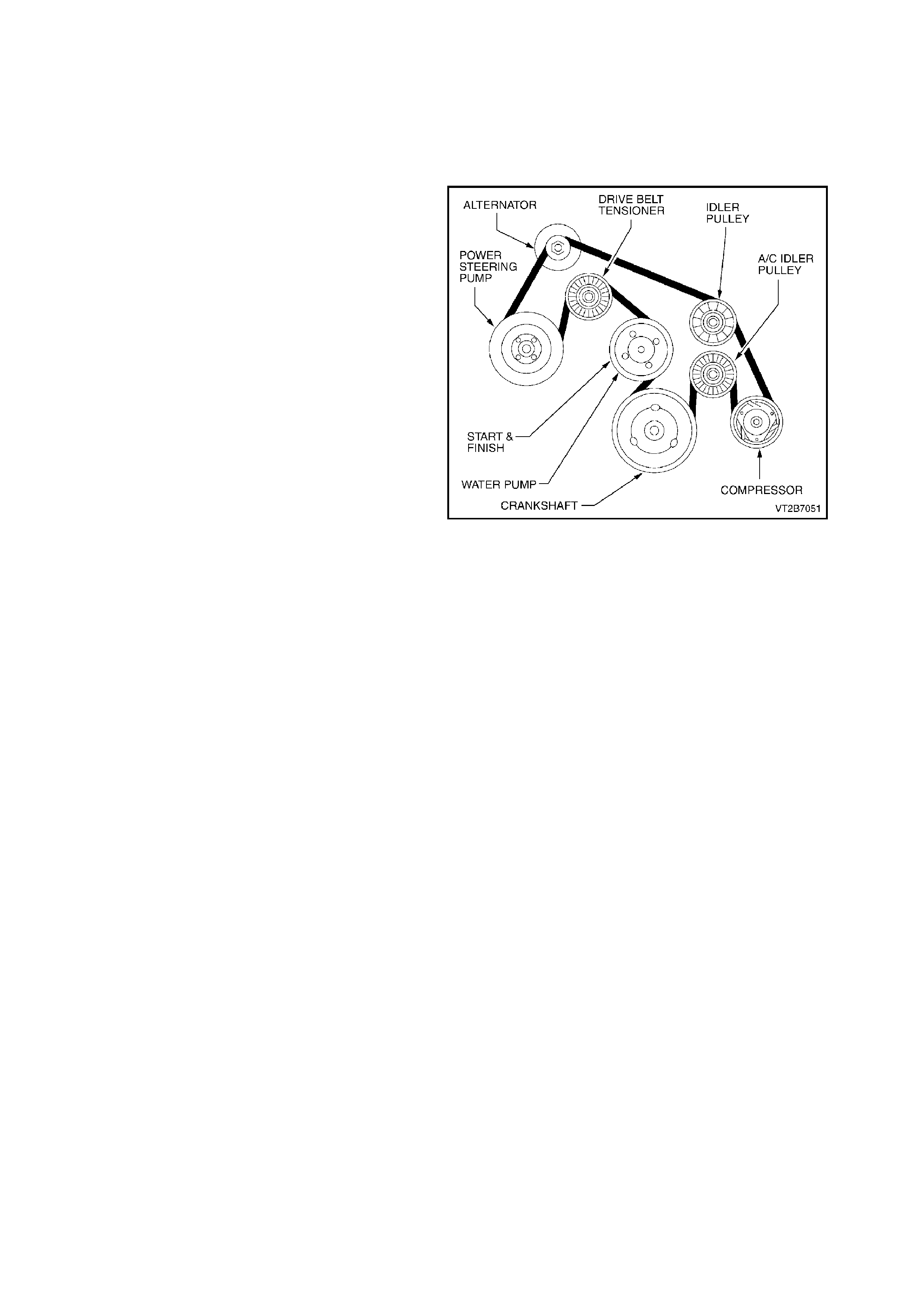
10. A/C DRI VE BELT
10.1 V6 ENGINE
REMOVE
1. Using a 17mm ring spanner on the drive belt
tensioner pulley retaining bolt, release the belt
tension.
2. Starting at the water pump pulley remove the
drive belt.
REINSTALL
1. Using the diagram in Fig. 2B-71 fit the drive
belt starting at the water pump pulley.
2. Ensure the vee grooves of the drive belt align
with the grooves in the pulley s.
Figure 2B-71
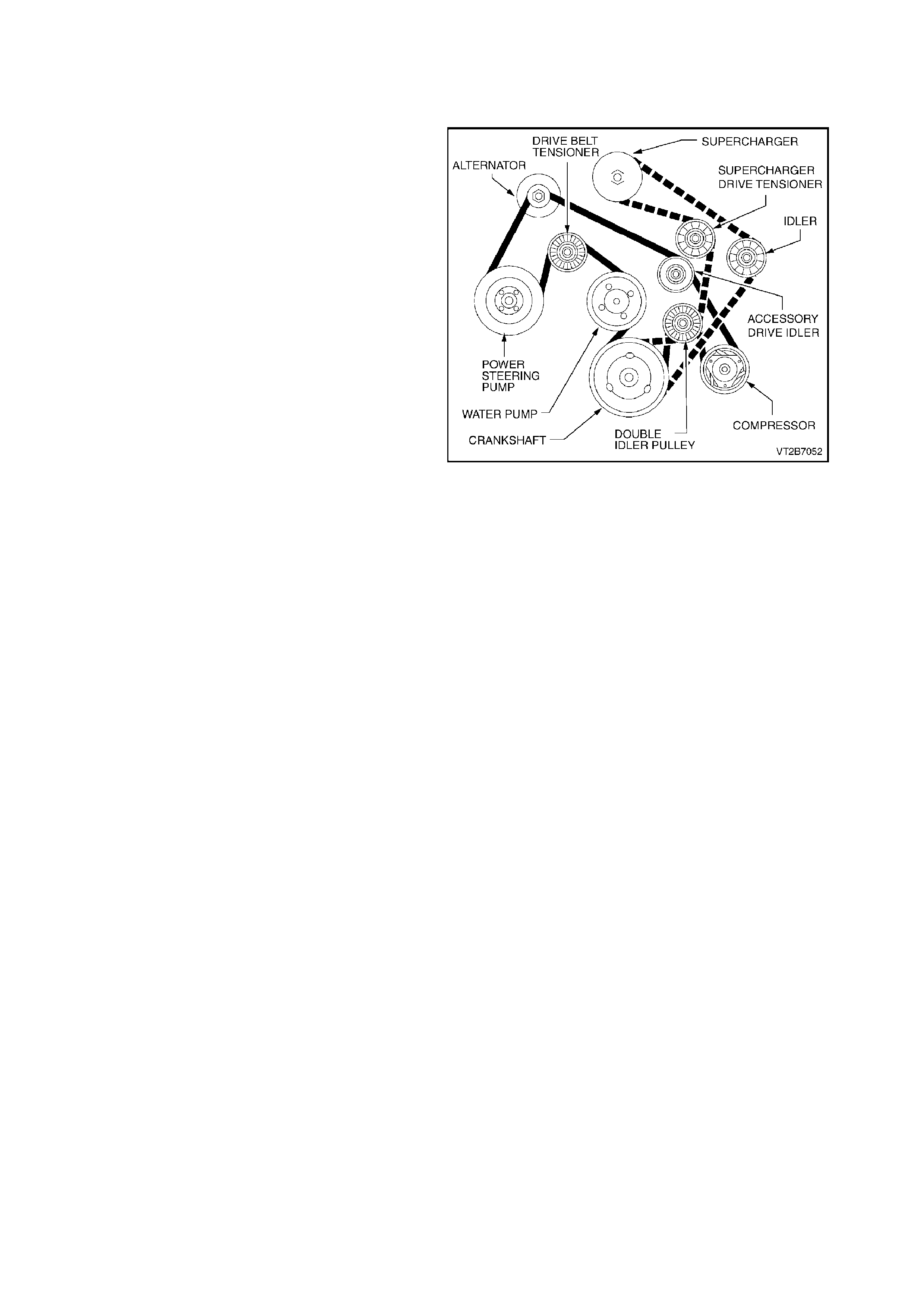
10.2 V6 S UP E RCHARGED ENGINE
REMOVE
1. Using a 17mm ring spanner on the
supercharger drive belt tensioner, release the
supercharger drive belt tension.
2. Remove the s uperchar ger drive belt s tarting at
the double idler pulley.
3. Using a 17mm ring spanner on the m ain drive
belt tensioner pulley retaining bolt, release the
belt tension.
4. Starting at the water pump pulley remove the
drive belt.
REINSTALL
1. Using the diagram in Fig. 2B-72 fit the drive
belt then the supercharger belt starting at the
water pump pulley (drive belt) and double idler
pulley (supercharger drive belt).
2. Ensure that the vee grooves of both dr ive belts
align with the pulley grooves. Figure 2B-72
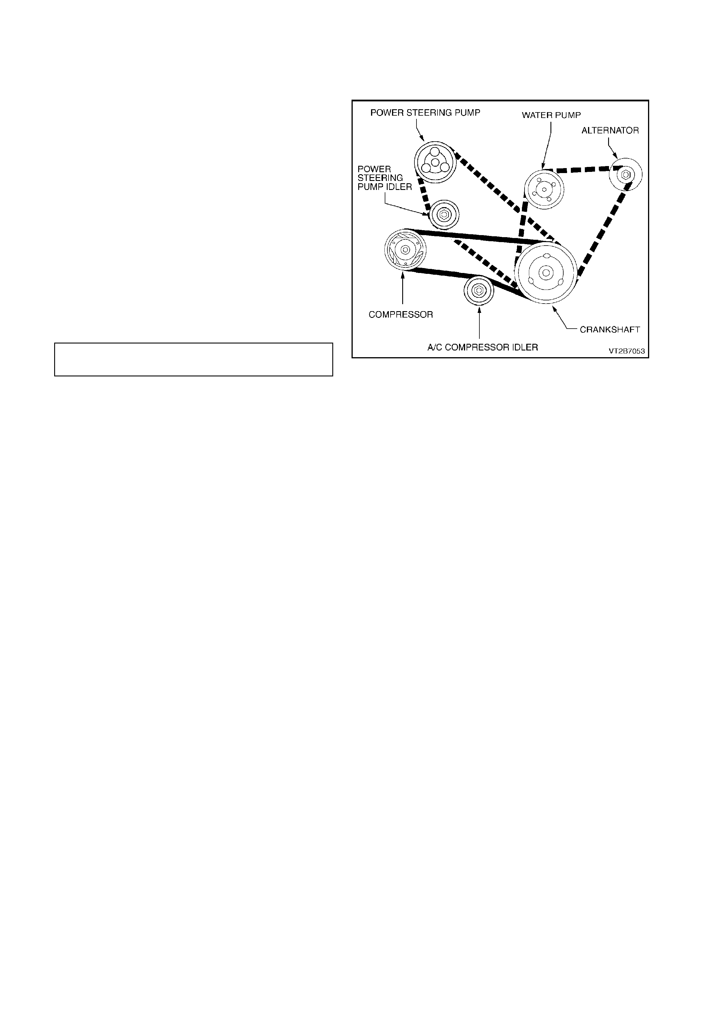
10.3 V8 ENGINE
REMOVE
1. Remove the power steering drive belt, refer to
Section 9A STEERING.
2. Remove alternator drive belt, refer to Section
6A2 ENGINE MECHANICAL - V8.
3. Loosen the nut retaining the A/C idler pulley.
4. Unscrew the A/C idler pulley adjusting bolt to
reduce tension on the A/C belt.
5. Remove the A/C belt.
REINSTALL
1. Fit the A/C drive belt as shown in Fig. 2B-73.
2. Using the A/C idler pulley adjusting bolt, adjust
the A/C belt until a tension of 50kg is achieved.
3. Tension the A/C idler pulley nut.
A/C IDLER PULLEY RETAINING 40 - 60
NUT TORQUE SPECIFICATION Nm
4. Fit the alternator drive belt, refer to
Section 6A2 ENGINE MECHANICAL - V8.
5. Fit the power steering drive belt, refer to
Section 9A STEERING.
Figure 2B-73
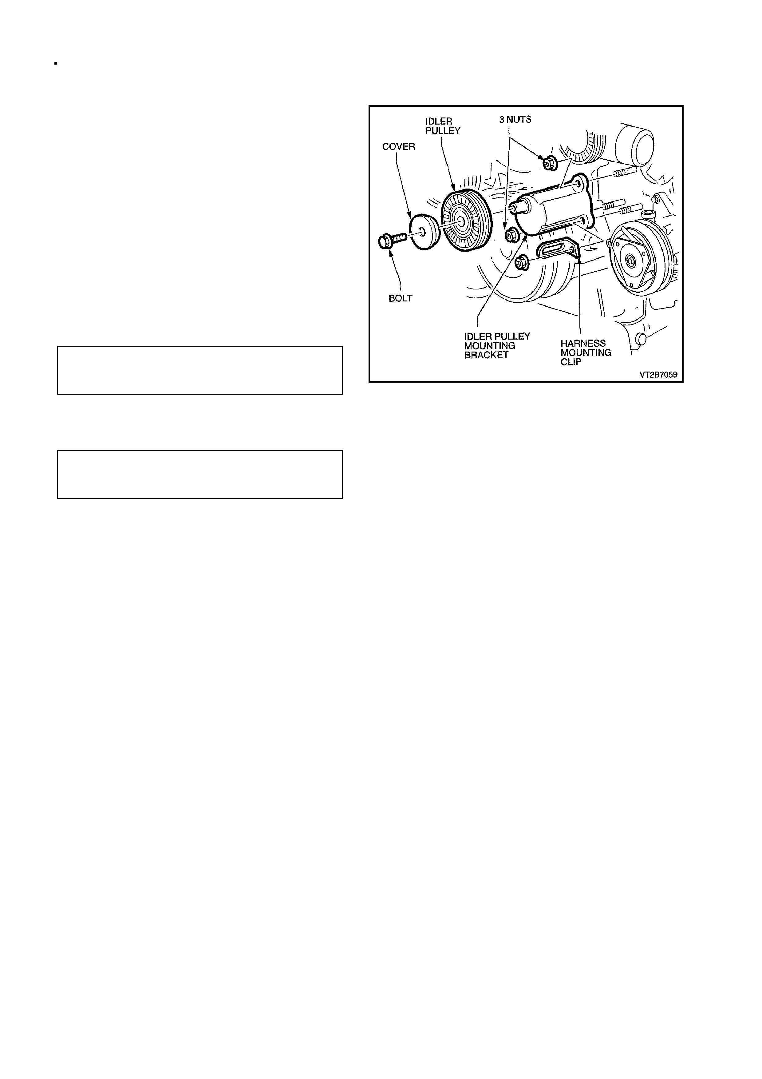
10.4 V6 IDLER PULLEY ASSEMBLY
REMOVE
1. Remove drive belt, refer to 10.1 or 10.2 A/C
DRIVE BELT in this Section.
2. Unscrew the idler pulley retaining bolt.
3. Remove bolt, washer and pulley.
4. Unscrew and remove the three mounting
bracket nuts.
5. 5. Detach the idler mounting bracket from
engine
REINSTALL
1. Fit the idler mounting bracket to engine.
2. Install the harness clip as shown.
3. Install the three nuts.
MOUNTING BRACKET
RETAINING NUTS 20 - 30 Nm
TORQUE SPECIFICATION
4. Replace the pulley, washer and bolt onto the
idler pulley bracket.
5. Tighten the idler pulley retaining bolt.
IDLER PULLEY
RETAINING BOLT 45 - 50 Nm
TORQUE SPECIFICATION
6. Replace the drive belt, refer to 10.1 or 10.2
A/C DRIVE BELT in this Section.
Figure 2B-74
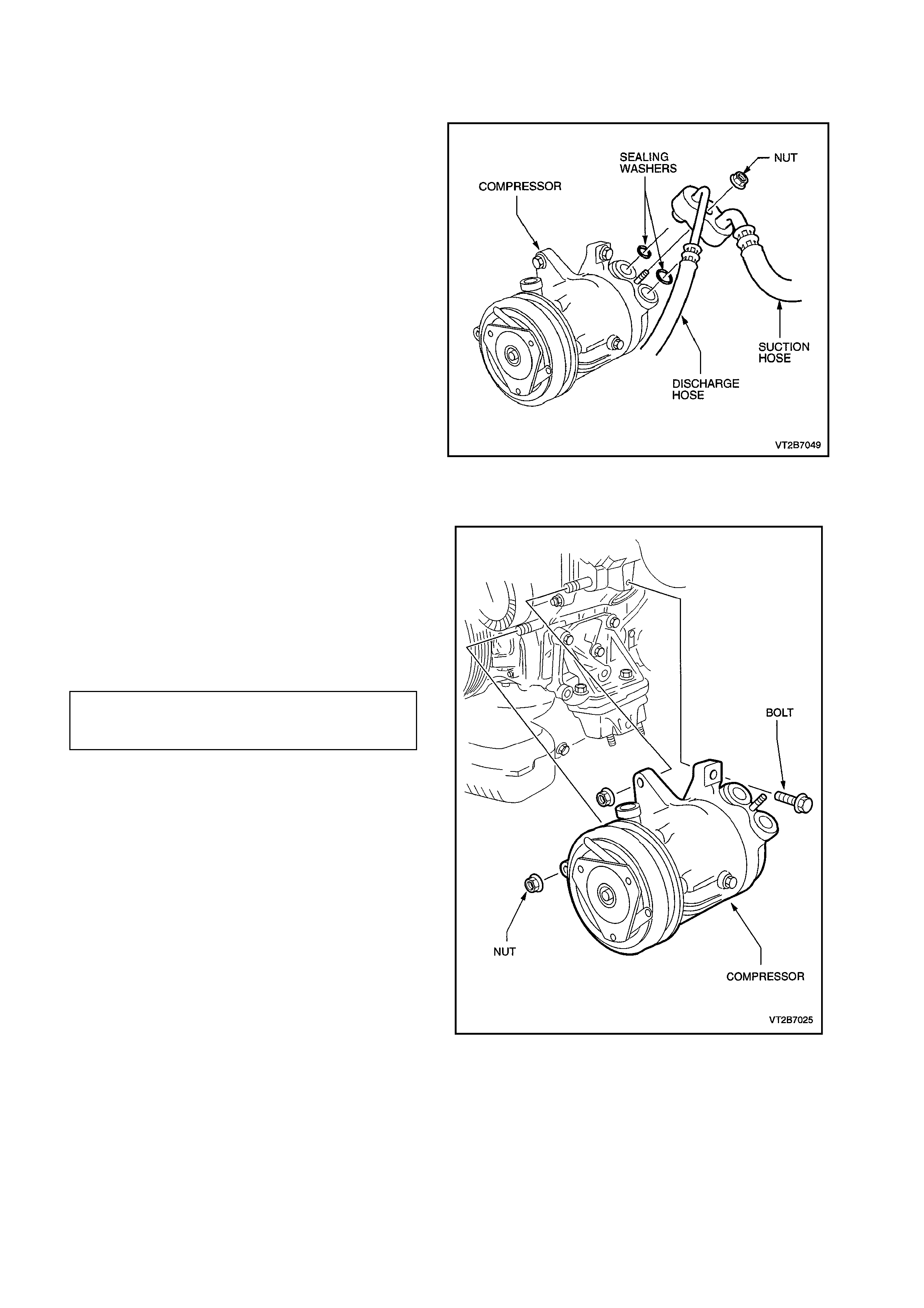
10.5 COMPRESSOR - V6 ENGINE
REMOVE
1. Disconnect the battery ground cable.
2. Recover refrigerant charge, refer to
Section 2C AIR CONDITIONING -
SERVICING AND DIAGNOSIS.
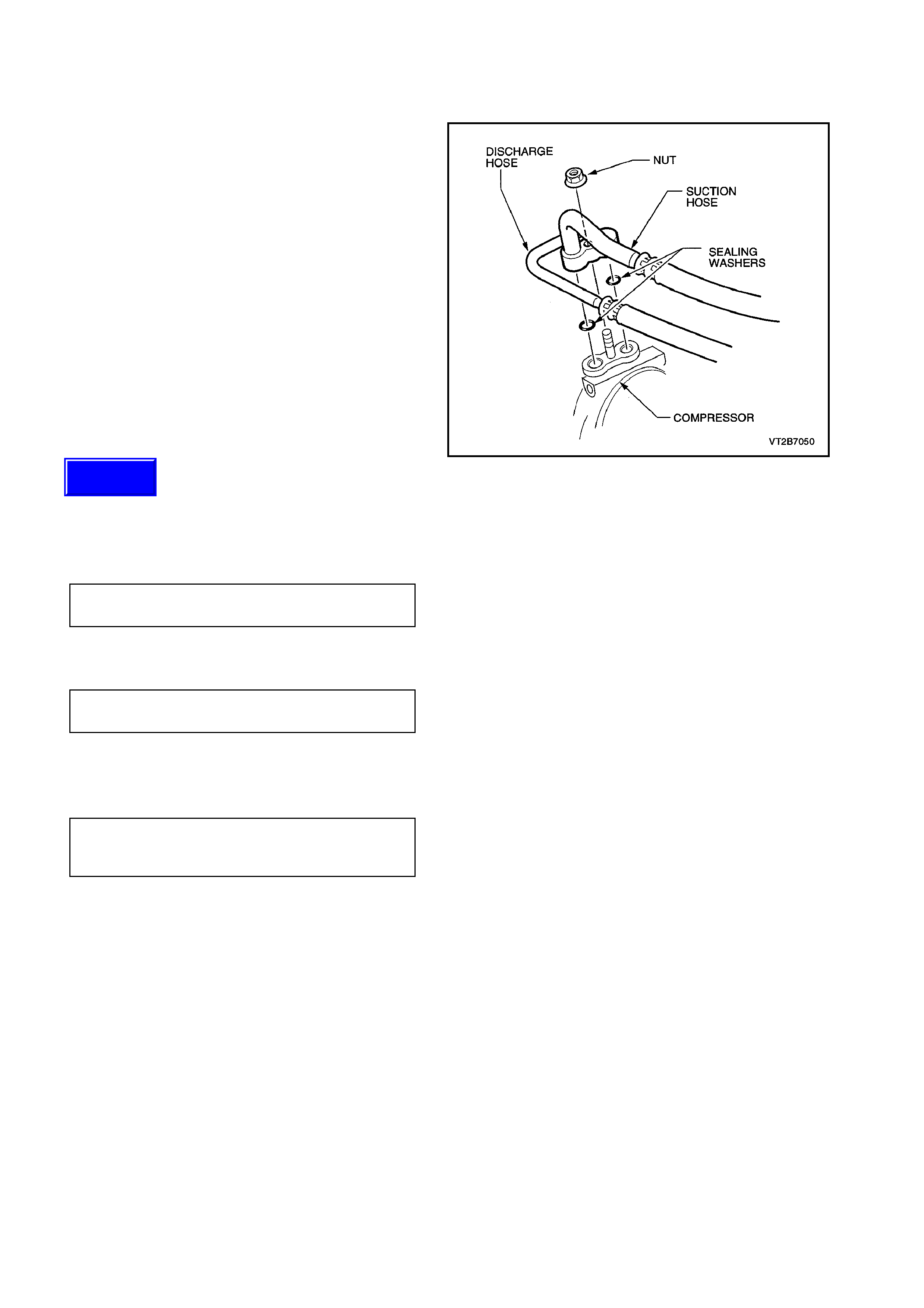
3. Remove the suction/discharge hose pad fitting
nut from the compressor.
4. Cap or plug disconnected hoses and ports
immediately to prevent absorption of moisture
from the atmosphere.
5. Remove the A/C drive belt.
6. Jack up the vehicle and place the vehicle on
jack stands.
7. Disconnect the compressor clutch electrical
connector.
8. Remove the two nuts and one bolt retaining
the compressor to the engine block.
Figure 2B-75
REINSTALL
1. Fit the compressor to the engine using the
original two nuts and bolt. Torque to
specifications.
2. Fit the A/C drive belt.
3. Remove the compressor port protection caps.
4. Fit two new port sealing washers.
5. Secure the suction/discharge hose assembly
to the compressor with original nut.
SUCTION/DISCHARGE HOSE
ASSEMBLY SECURING NUT 7.5 - 12.5 Nm
TORQUE SPECIFICATION
6. Evacuate and charge the A/C system with
775 - 825 g of R134a refrigerant, refer to
2C AIR CONDITIONING - SERVICING AND
DIAGNOSIS.
NOTE:
If replacing with a new compressor, refer to
Section 2C AIR CONDITIONING - SERVICING
AND DIAGNOSIS for lubrication requirements.
Figure 2B-76
10.6 COMPRESSOR - V8 ENGINE
REMOVE
1. Disconnect the battery ground cable.
2. Recover refrigerant charge, refer to
Section 2C AIR CONDITIONING -
SERVICING AND DIAGNOSIS.
3. Loosen the locking nut retaining the A/C idler
pulley .
4. Uns crew the A/C idler pulley adjusting bolt and
remove the A/C belt.
5. Remove the A/C hose pad fitting from the
compressor (1 nut).
6. Cap or plug the ports immediately to prevent
entry of moisture from the atmosphere.
7. Disconnect the compressor clutch electrical
connector.
8. Remove the three bolts retaining the
compressor to the mounting bracket.
Figure 2B-77
REINSTALL
1. Fit the compressor to the compressor
mounting bracket using the three original
bolts.
COMPRESSOR RETAINING BOLTS 40 - 60
TORQUESPECIFICATION Nm
2. Install the A/C belt and adjust tension to 50kg
using the idler pulley adjusting bolt, tighten
idler pulley locking nut.
IDLER PULLEY LOCKING NUT 40 - 60
TORQUE SPECIFICATION Nm
3. Remove caps from compressor ports and
install new sealing washers.
4. Fit the A/C hose pad fitting and secure with
original nut.
A/C HOSE PAD FITTING
RETAINING NUT 28 - 42 Nm
TORQUE SPECIFICATION
5. Evacuate and charge the A/C system to 775 -
825 g.
NOTE:
If replacing with a new compressor refer to
Section 2C AIR CONDITIONING - SERVICING
AND DIAGNOSIS for lubrication requirements.
Techline
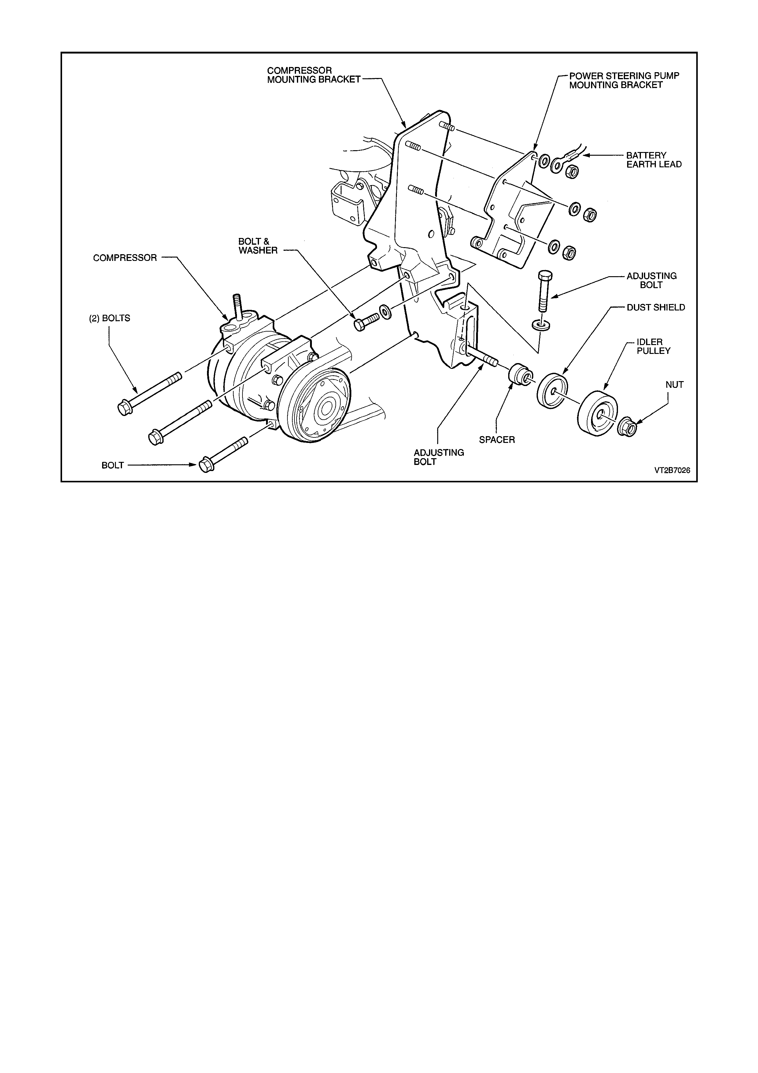
Figure 2B-78
11. M INOR COMP RESSOR REPAIR PROCEDURES
Illustrations used in the following procedures show
the compressor removed from the vehicle for
easier viewing. When servicing the compressor,
remove only the parts that preliminary diagnosis
shows are in need of service.
Removal and installation of external compressor
parts and disassembly/assembly of internal parts
must be performed on a clean workbench. The
work area, tools and parts must be clean at all
times.
NOTE:
The only components that can be serviced are:-
Control Valve
Port Sealing Washers
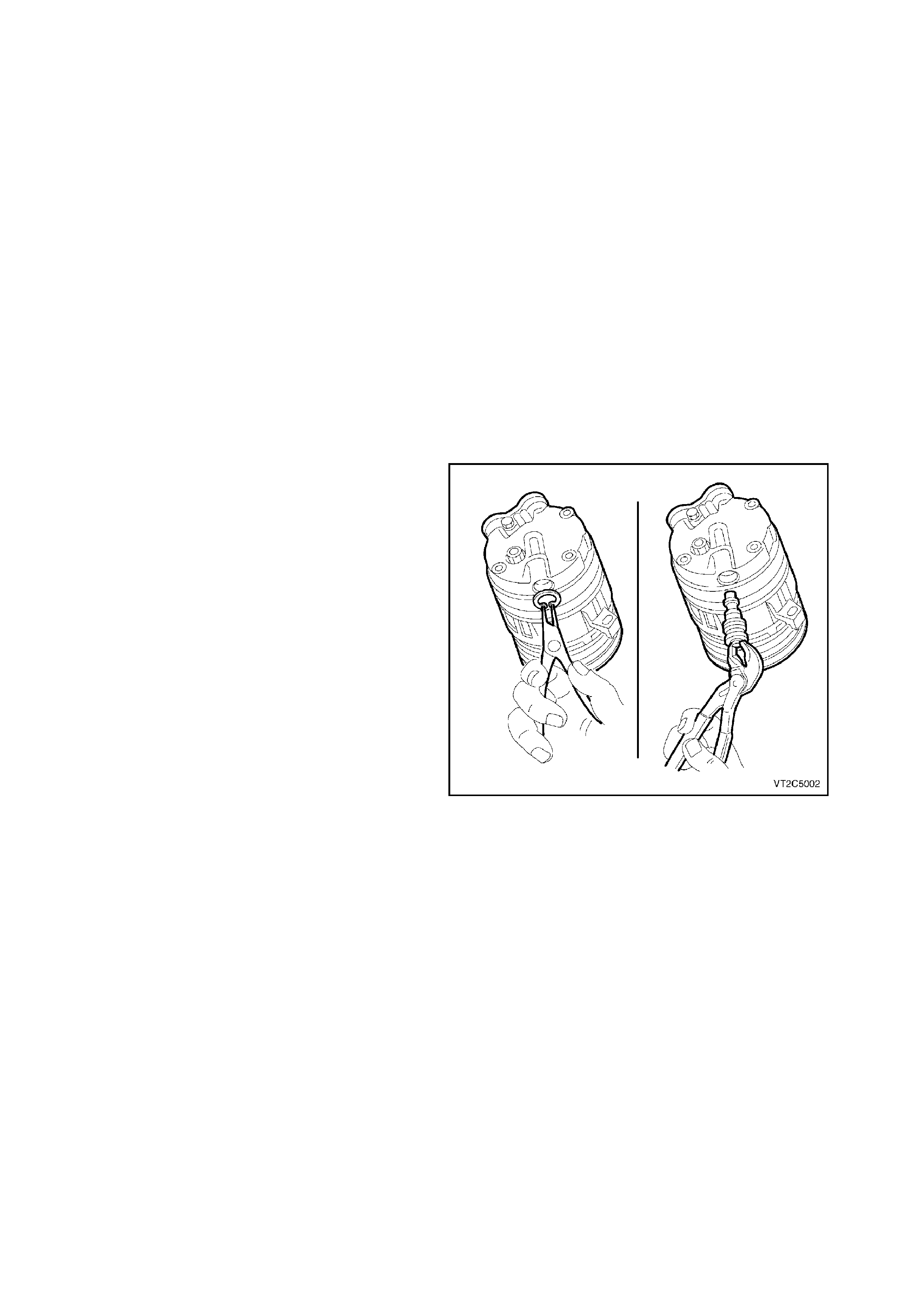
11.1 COMPRESSOR CONTROL VALVE
REMOVE
1. Recover the refrigerant, refer to
Section 2C AIR CONDITIONING -
SERVICING AND DIAGNOSIS.
2. Jack vehicle up and place on jack stands.
3. From beneath the vehicle remove the circlip
securing the control valve to the compressor.
4. Using a pair of suitable circlip pliers remove
the control valve from the compressor by
pulling downwards. Quickly insert replacement
control valve (this will avoid any minor oil loss).
REINSTALL
1 Lubricate the control valve O - rings and
carefully push control valve into the
compressor.
NOTE:
V6 and V8 control valves have different control
settings. Ensure that the correct valve is installed.
2. Inspect original c ontrol valve r etaining circ lip, if
undamaged us e to secure valve, if not replac e
with new circlip. Ensure circlip is FULLY
seated.
3. Add to the compressor through the suction
port any new lubricating oil required, if oil had
been lost during control valve removal.
4. Evacuate and charge the A/C system with
775 - 825 g of R134a refrigerant, refer to
2C AIR CONDITIONING - SERVICING AND
DIAGNOSIS.
Figure 2B-79
11.2 CLUTCH DRIVE PLATE AND HUB ASSEMBLY
REMOVE
1. Recover the refrigerant, refer to Section 2C
AIR CONDITIONING - SERVICING AND
DIAGNOSIS.
2. Remove the compressor from the vehicle as
described in this section.
3. Place the compressor on a clean work bench.
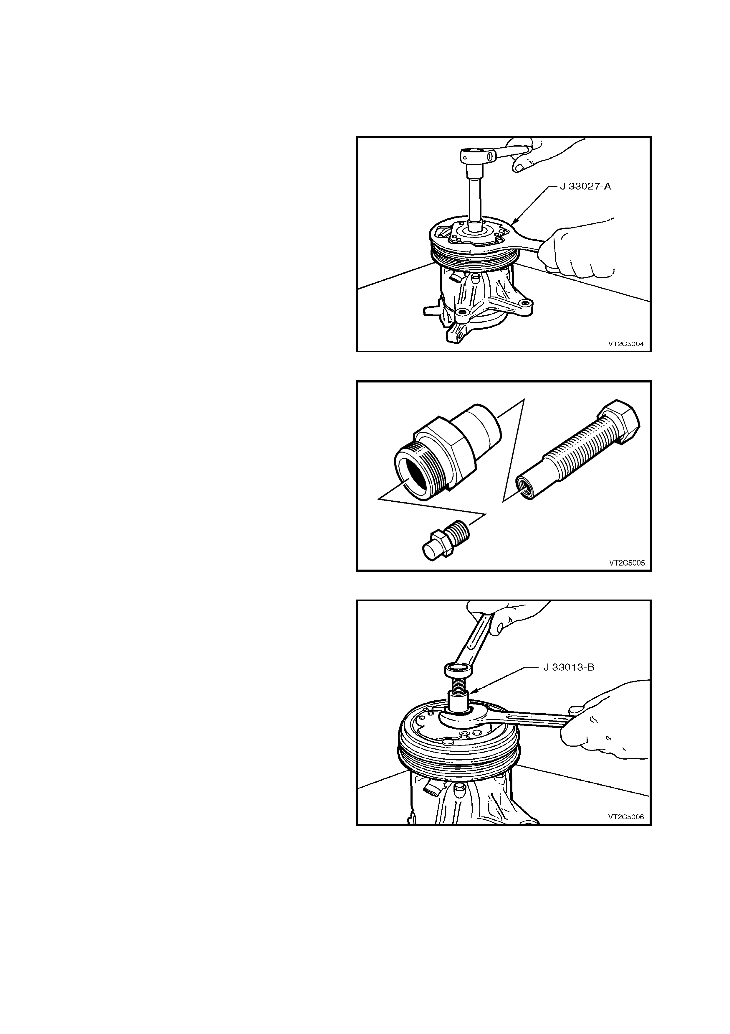
4. Using the Clutch Hub Holding Tool (J-33027-
A), keep the hub assembly from turning while
removing the shaft nut as shown in Fig. 2B-80.
5. Assemble the Hub and Drive Plate Remover
and Installer tool (J33013-B) as shown in Fig.
2B-81
6. Thread the body of the tool into the hub. Hold
the body of the tool with a wrench and turn the
centre screw of the tool to remove the clutch
drive plate and hub assembly as shown in Fig.
2B-82.
Remove the shaft key and retain for
reassembly.
Figure 2B-80
Figure 2B-81
Figure 2B-82
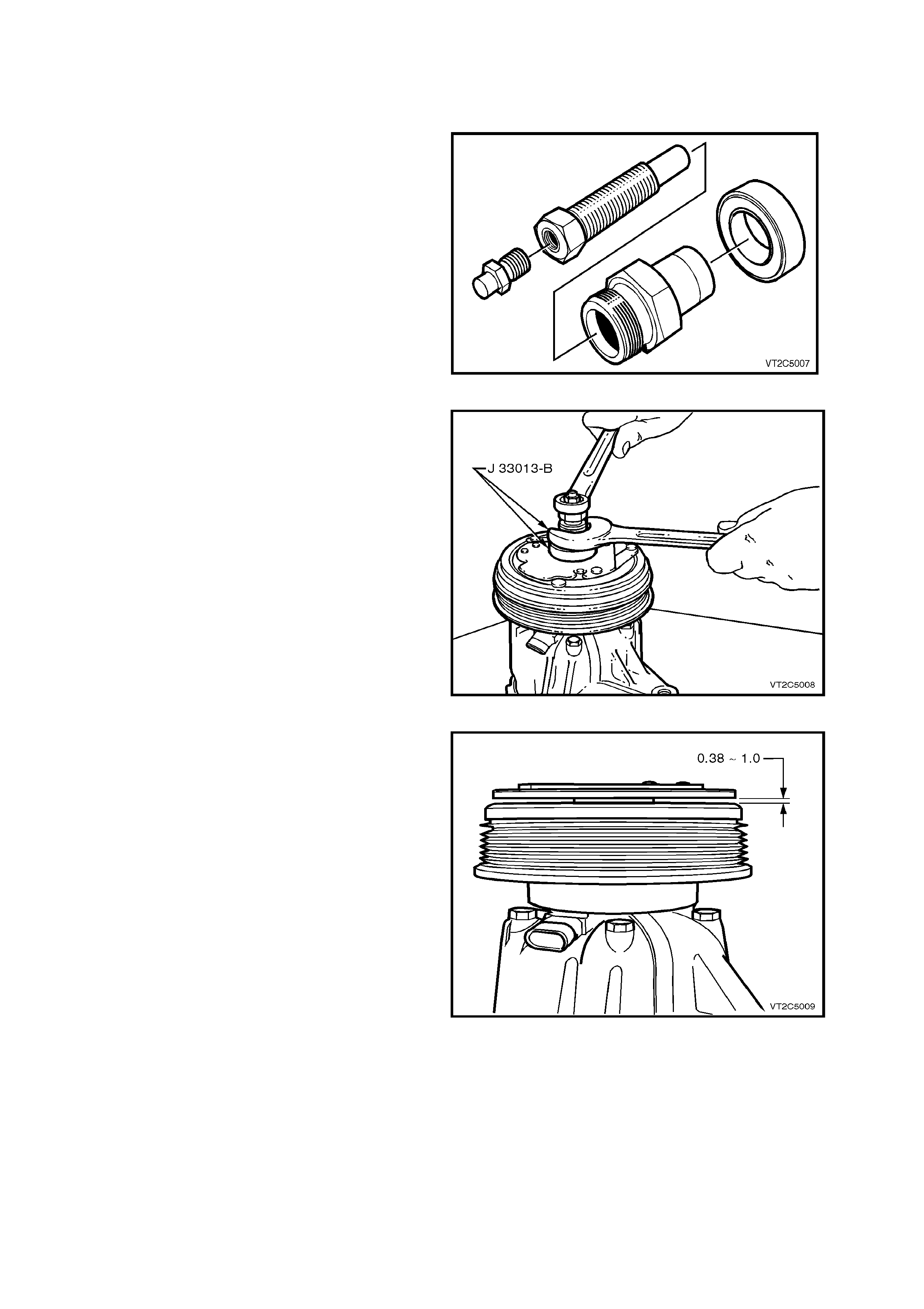
REINSTALL
1. Install the shaft key in the hub key groove,
allowing the key to protrude about 3mm out of the
keyway. The shaft key is curved slightly to provide
an interference fit in the hub key groove.
NOTE: Be sure the frictional surface of the rotor
and clutch plate are clean before installing the
Clutch Plate and Hub Assembly.
2. Align the shaft keyway and place the Clutch
Plate and Hub Assembly onto the compressor
shaft.
3. Assemble the Hub and Drive Plate Remover
and Installer tool (J33013-B) as shown in Fig
2B-83.
4. Thread the c entre screw about 3 turns onto the
end of the compressor shaft
5. Hold the centre screw with a wrench and
tighten the hex portion of the J-33013-B tool to
press the hub on the shaft.
CAUTION: If the c entre s c r ew is threaded fully onto
the end of the compressor shaft, or if the body of
the installer is held and the centre screw rotated,
the key will wedge in the keyway and break the
clutch hub.
6. Tighten the body several turns, remove the
installer and check that the shaft key is still in
place in the keyway before installing the Clutc h
Plate and Hub Assembly to it’s final position.
NOTE: The air gap between the frictional surfaces
of the clutch plate and the clutch rotor should be
0.38 – 1.0 mm. This clearance should be checked
using a non-magnetic feeler strip.
7. Remove the J-33013-B tool and check for
proper positioning of the s haf t key (even with or
slightly above, the clutch hub).
8. Install the shaft nut, and holding the hub
assembly with the Clutch Hub Holding Tool (J-
33027-A), tighten the nut to 11 – 22 Nm torque.
9. Re-check the air gap and spin the pulley rotor
by hand, check ing that the rotor is not touching
the drive plate.
10. Reinstall the compressor on the vehicle as
described in this Section
11. Evacuate and charge the A/C system with
775 - 825 g of R134a refrigerant, refer to 2C
AIR CONDITIONING - SERVICING AND
DIAGNOSIS in this section.
Figure 2B-83
Figure 2B-84
Figure 2B-85
11.3 CLUTCH ROTOR AND BEARING ASSEMBLY
REMOVE
1. Remove the clutch drive plate and hub
assembly as described in 11.2 Clutch Drive
Plate And Hub Assembly
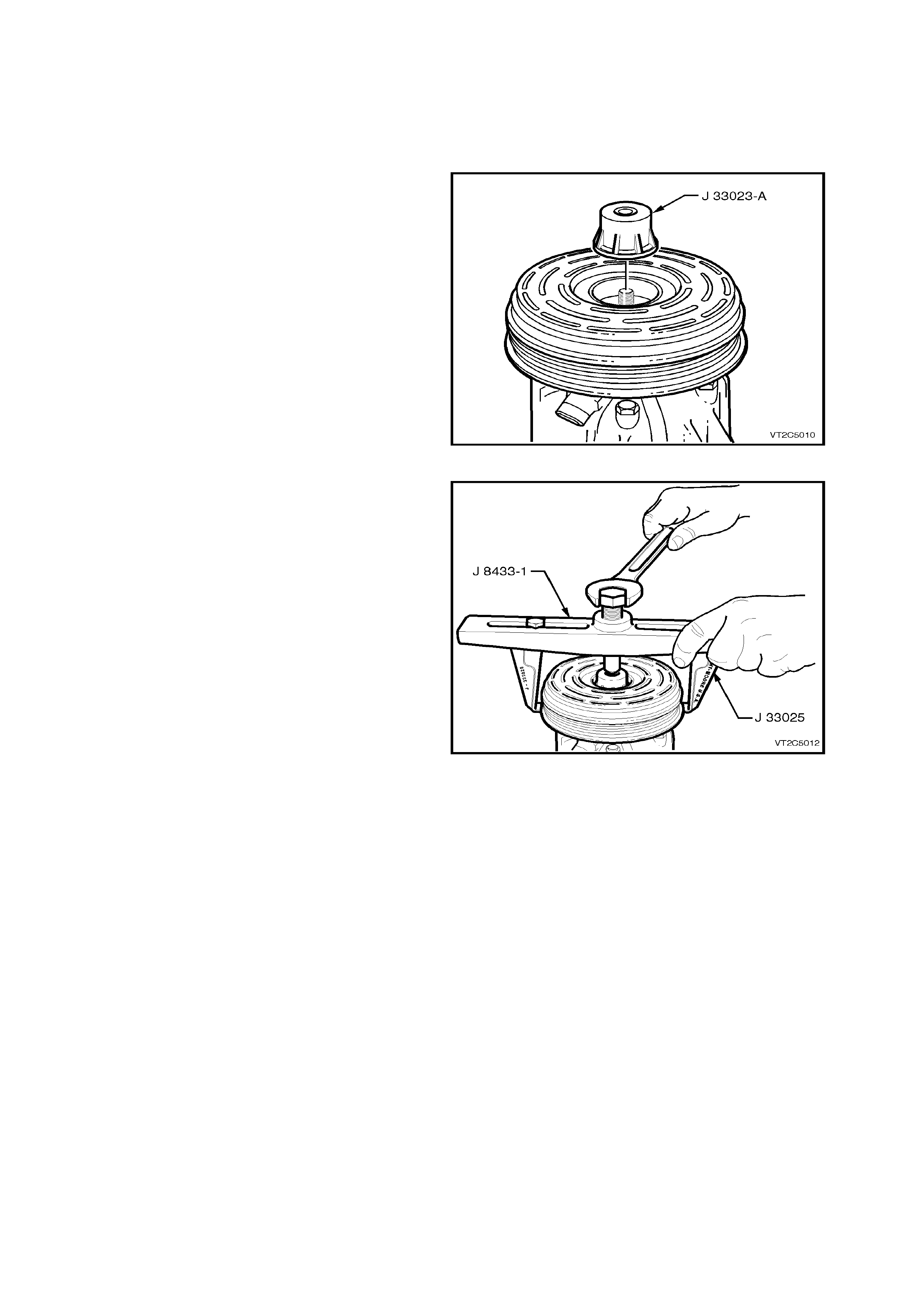
2. Install the J-33023-A Puller Pilot on to the end
of the compressor shaft
3. Attach J-333025 Puller Legs to the J-8433-1
Puller Bar. Centre the forcing screw of the
Puller Bar in the countersink hole of the J-
33023-A Puller Pilot. Engage the Puller Leg
tangs under the clutch rotor as shown in Fig.
2B-87
4. Turn the forcing screw of the J-8433-1 Puller
Bar to draw the clutch rotor and bearing
assembly from the compressor shaft.
Figure 2B-86
Figure 2B-87
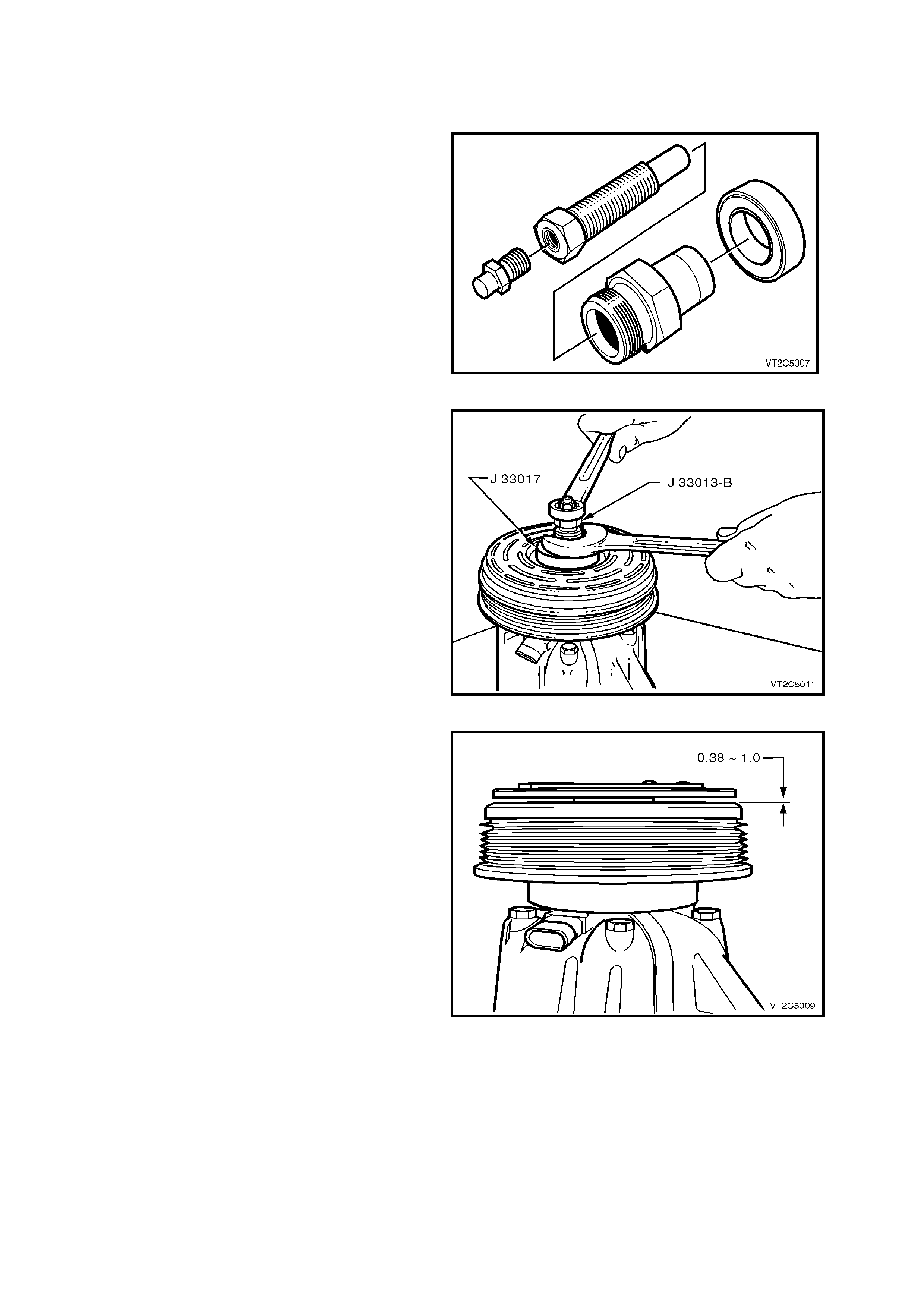
REINSTALL
1. Position the Clutch Rotor and Bearing
Assembly on the co mpressor shaft
2. Assemble the Hub and Drive Plate Remover
and Installer tool (J33013-B) as shown in Fig.
2B-88.
3. Position the Pulley and Bearing Assembly
Installer (J-33017) on the hub centre. Thread
the centre screw onto the end of the
compressor shaft
4. Hold the centre screw with a wrench and
tighten the hex portion of the J-33013-B tool to
press the hub on the shaft.
5. Install the Clutch Drive Plate and Hub as
described in 11.2.
NOTE: The air gap between the frictional surfaces
of the clutch plate and the clutch rotor should be
0.38 – 1.0 mm. This clearance should be checked
using a non-magnetic feeler strip
6. Install the shaft nut, and holding the hub
assembly with the Clutch Hub Holding Tool (J-
33027-A), tighten the nut to 11 – 22 Nm torque.
7. Re-check the air gap and spin the pulley rotor
by hand, check ing that the rotor is not touching
the drive plate.
8. Reinstall the compressor on the vehicle as
described in this Section
9. Evacuate and charge the A/C system with
775 - 825 g of R134a refrigerant, refer to 2C
AIR CONDITIONING - SERVICING AND
DIAGNOSIS in this Section.
Figure 2B-88
Figure 2B-89
Figure 2B-90

12. TORQUE WRENCH SPECIFICATIONS
Nm
Lower steering column shroud screw................................... 0.5 - 2
Instrument panel end cap cover attaching screws ............... 1 - 3
Instrument panel compartment attaching screws................. 1 - 3
Instrument panel compartment lock striker attaching screws 1 - 3
Centre console securing screws........................................... 1 - 3
Centre console bin retaining nuts......................................... 1 - 3
Transmission console retaining screws................................ 1 - 3
Centre console storage compartment securing screws ....... 1 - 3
Demist nozzle retaining screws............................................ 1 - 3
Front dash speaker retaining screws.................................... 1 - 2
Instrument panel carrier end panel attachment screws........ 1 - 3
Instrument facia assembly retaining screws......................... 1 - 3
Centre facia assembly securing screws............................... 1 - 3
Heater and air conditioning controls securing screws.......... 1 - 3
Combined instruments assembly securing screws .............. 1 - 3
Instrument panel carrier retaining screws............................. 7 - 12
Instrument panel lower trim right side rail assembly
retaining screws.................................................................... 1 - 3
Centre facia side extension support rail attaching screws.... 1 - 3
Support steering column bracket inner securing screws...... 3 - 5
Passenger air bag support rail securing screws................... 2.5 - 5
Lower left side rail connecting screws.................................. 1 - 3
Instrument panel carrier rail assembly securing screws....... 1 - 3
Passenger side air bag securing nuts .................................. 15 - 25
TXV attaching cap screws.................................................... 4 - 4.5
Heating, ventilation and air conditioning unit attachment
screws to the passenger compartment ................................ 6 - 14
Heating, ventilation and air conditioning unit attachment
screws to the engine bay...................................................... 2 - 5
Evaporator tube plate securing screws ................................ 4.0 - 4.5
Washer faced tube plate retaining bolt................................. 7.5 - 12.5
TXV Pipe bracket retaining bolt........................................... 7.5 - 12.5
Compressor suction and discharge hose retaining nut ........ 7.5 - 12.5
FDR pipe flange nut.............................................................. 7.5 - 12.5
Condensor discharge pad retaining nut................................ 7.5 - 12.5
Condensor inlet pad fitting nut.............................................. 7.5 - 12.5
Compressor retaining bolts (V8)........................................... 40 - 60
A/C idler pulley retaining nut (V8)......................................... 40 - 60
A/C hose pad fitting retaining nut (V8).................................. 26 - 42
Idler pulley mounting bracket retaining nut (V6)................... 20 - 30
Idler pulley retaining bolt....................................................... 40 - 50
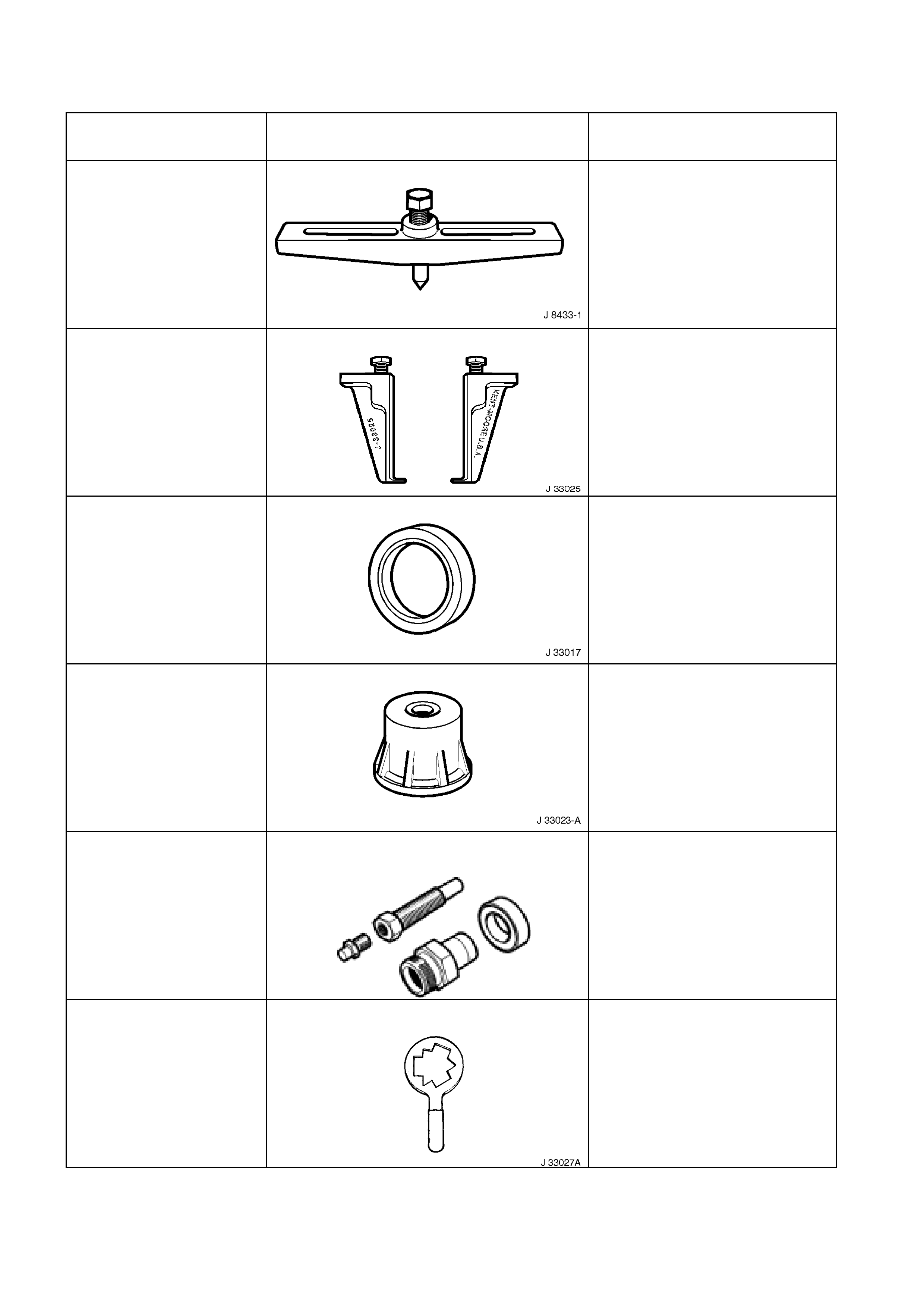
13. SPECIAL TOOLS
TOOL NO. REF
IN TEXT TOOL DESCRIPTION COMMENTS
J 8433-1 PULLER BAR
J 33025 CLUTCH COIL PULLER LEGS
J 33017 PULLEY & BEARING ASSEMBLY TOOL
J 33023-A PULLER PILOT
J 33013B HUB & DRIVE PLATE
REMOVER/INSTALLER
J 33027A
CLUTCH HUB HOLDING TOOL