SECTION 2F - ELECTRONIC CLIMATE CONTROL -
DIAGNOSTICS
CAUTION:
This vehicle will be equipped with a Supplemental Restraint System (SRS). A SRS will
consist of either seat belt pre-tensio ners and a driver’s side air bag, o r seat belt pre-
tensioners and a driver’s and front passenger’s side air bags. Refer to CAUTIONS,
Section 12M, before performing any service operation on or around SRS
components, the steering mechanism or wiring. Failure to follow the CAUTIONS
could result in SRS deployment, resu lting in possible perso nal in jury or u nnecessary
SRS system repairs.
CAUTION:
This vehicle may be equipped with LPG (Liquefied Petroleum Gas). In the interests of
safety, the LPG fuel system should be isolated by turning 'OFF' the manual service
valve and then draining the L PG service lines, before any service w ork is carried out
on the vehicle. Refer to the LPG leaflet included with the Owner's Handbook for
details or LPG Section 2 for more specific servicing information.
1. DIAGNOSTICS
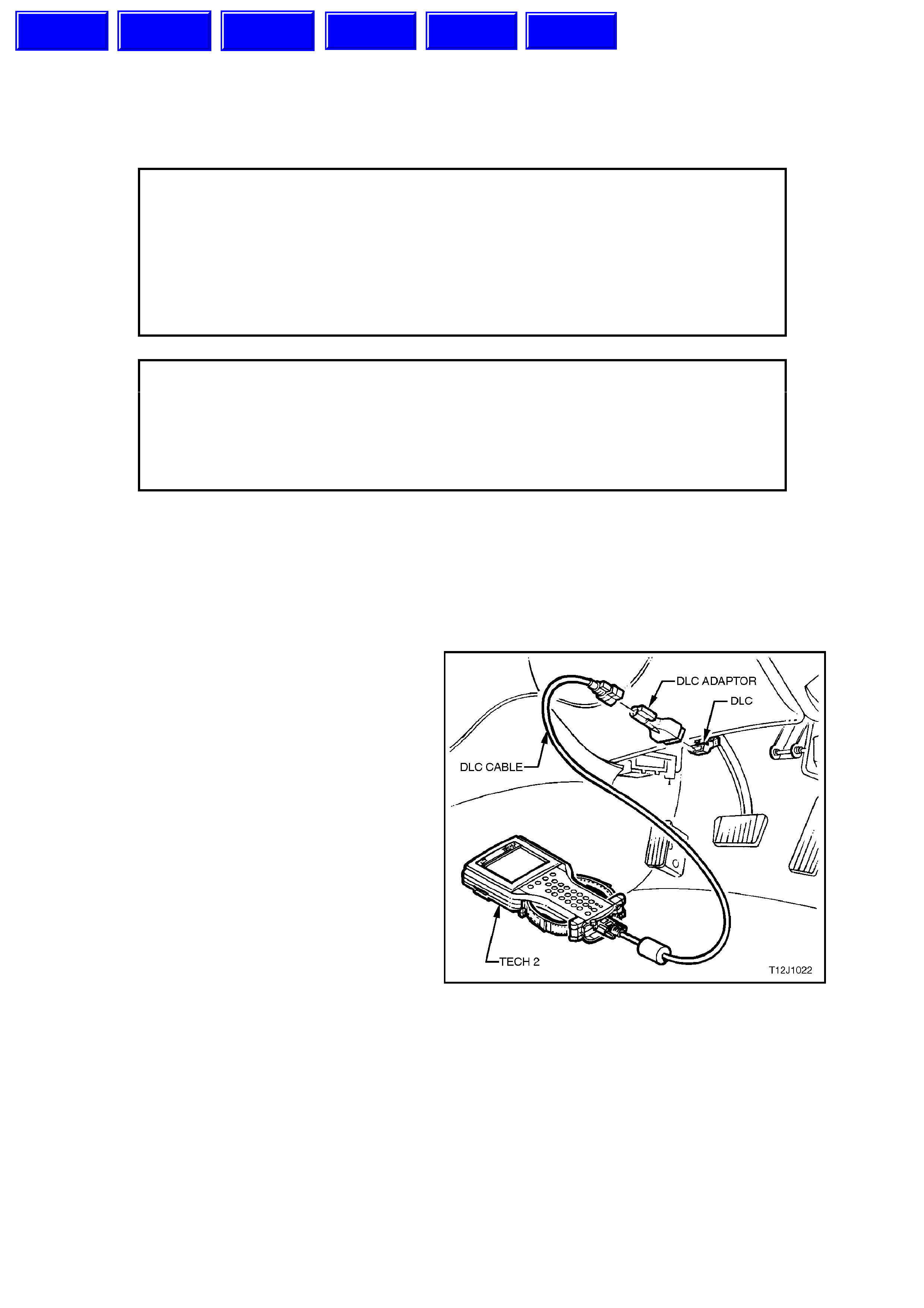
1.1 TECH 2 DIAGNOSTICS
TECH 2, with the appropriate software, cables and
adaptors, when connected to the Data Link
Connector (DLC) is capable of reading ECC serial
data. The DLC is connected to the instrument panel
lower right hand trim, to the right of the steering
column.
For additional general information on connecting
and operating TECH 2 , refer to
Section 0C TECH 2.
Figure 2F-1
Techline
Techline
Techline
Techline
Techline
Techline
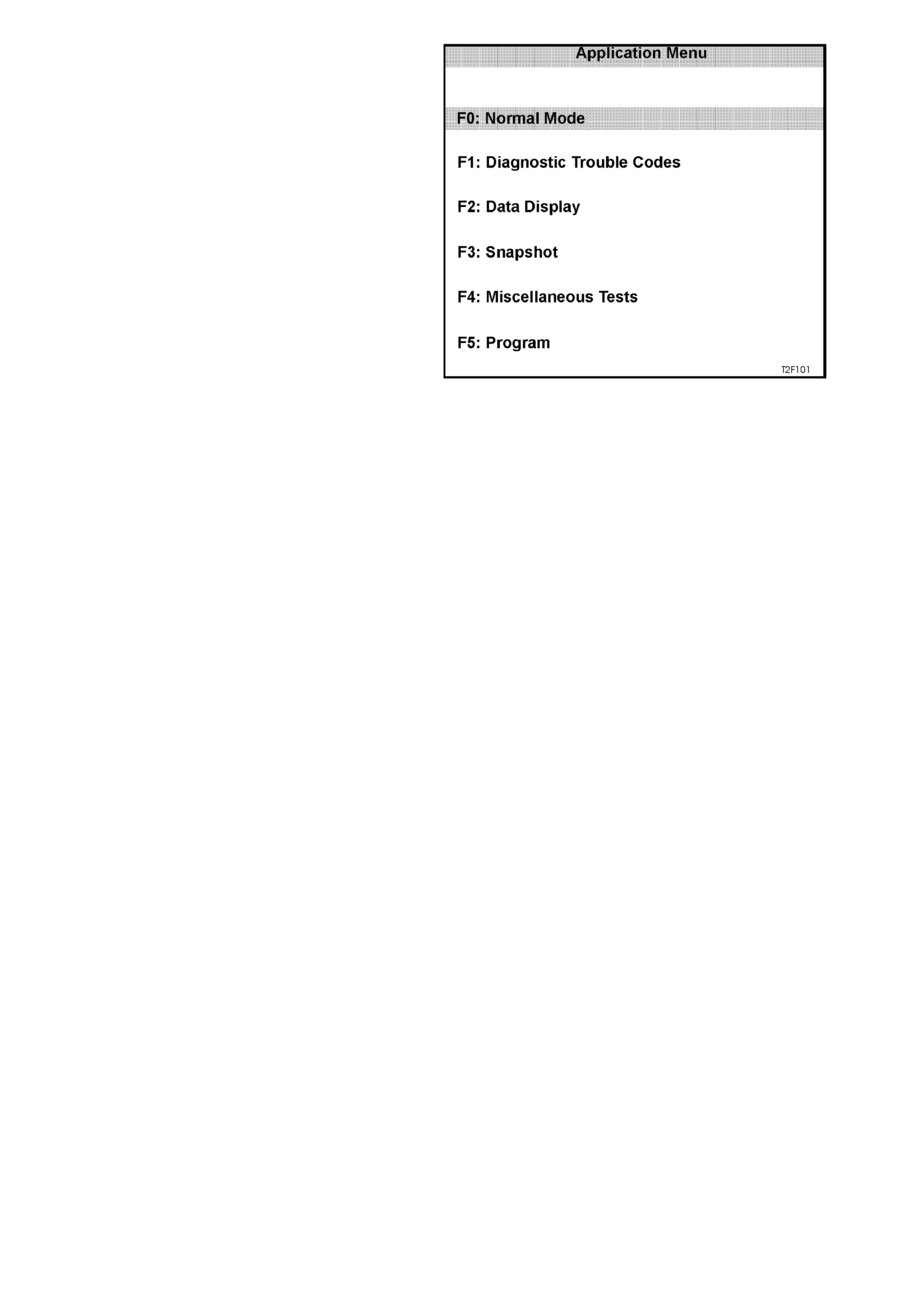
TECH 2 has six tes t modes f or diagnos ing the ECC
The six test modes are as follows:
Mode F0: Normal Mode
In this mode, the TECH 2 monitors the
communication between control modules on the
serial data line. The information displayed on the
TECH 2 screen in this mode is what the ECC is
communicating to the other modules via the serial
data line.
Mode F1: Diagnostic Trouble Codes (DTC)
In this test mode, the operator of TECH 2 has the
option of reading current and history DTC’s or
clearing stored DTC’s from the control modules
memory.
Mode F2: Data Display
In this test mode, TECH 2 displays the status of
inputs and outputs of the ECC.
Mode F3: Snapshot
In this test mode, the TECH 2 captures ECC data
before and after a forced manual trigger.
Mode F4: Miscellaneous Tests
In this test mode, the TECH 2 performs system
functional tests to assist in pr oblem isolation during
troubleshooting.
Each test mode has specific diagnosis capabilities
that depend upon various function key entry on the
TECH 2.
Mode F5: Program
In this test m ode, TECH 2 allows the programming
of various ECC features (ie. calibration of driver’s
air mix door.
Figure 2F-2
1.2 TECH 2 TEST MODES AND DISPLAYS FOR ECC DIAGNOSIS
A prerequisite to this diagnostic section is for the
user to be familiar with the proper use of TECH 2.
The following pages illustrate only the major TECH
2 screen displays and provide a brief explanation of
their function for diagnosing the ECC. If additional
information is required on the operation of TECH 2,
reference should be made to either
Section 0C TECH 2, or the TECH 2 OPERATOR’S
MANUAL.
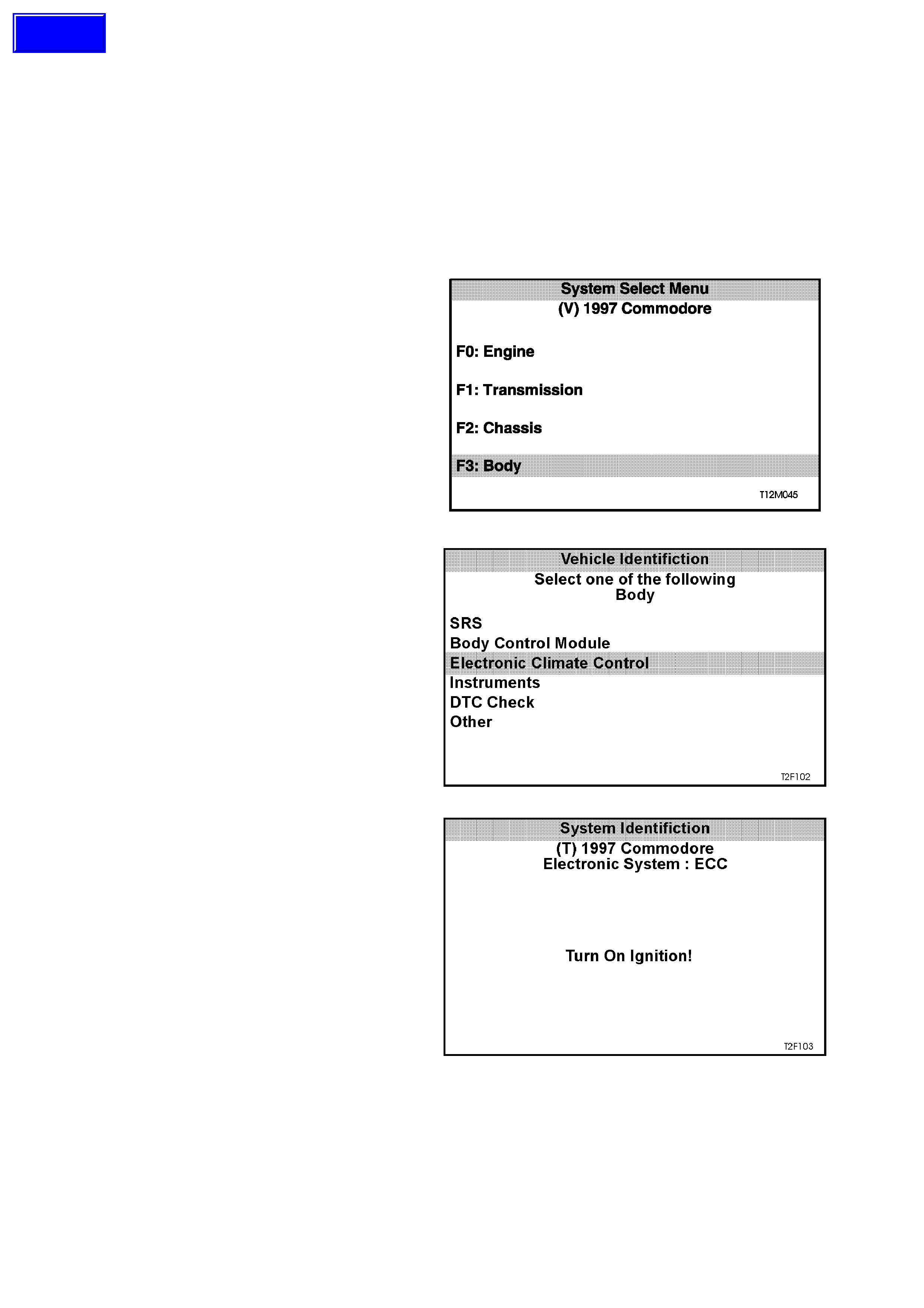
System Select Menu
With TECH 2 connected to the DLC, the F0:
Diagnostics selected from the Main Menu, the
correct Model Year and Vehicle Type must be
selected for access to the System Select Menu.
Select F3: Body.
This mode contains all functions to test, diagnose,
monitor and program the vehicles body systems
including the ECC as well as providing the
opportunity to check all DTC’s that may be set in
the vehicle.
Figure 2F-3
Body Applica tion Menu
Once F3: Body has been selected f rom the System
Select Menu, ECC can be selected.
Select ECC.
NOTE: If information regarding DTC’s set for the
vehicle is required, select DTC Check and press
enter to continue. To return to the ECC mode
option from the DTC Check mode option screen
display, simply press the EXIT key on TECH 2.
Once the ECC has been s elec ted, the f ollowing two
System Identification screens will appear which
require action.
Figure 2F-4
System Identification
Turn the ignition ON (as requested) and press
CONFIRM soft key to continue.
Figure 2F-5
Techline
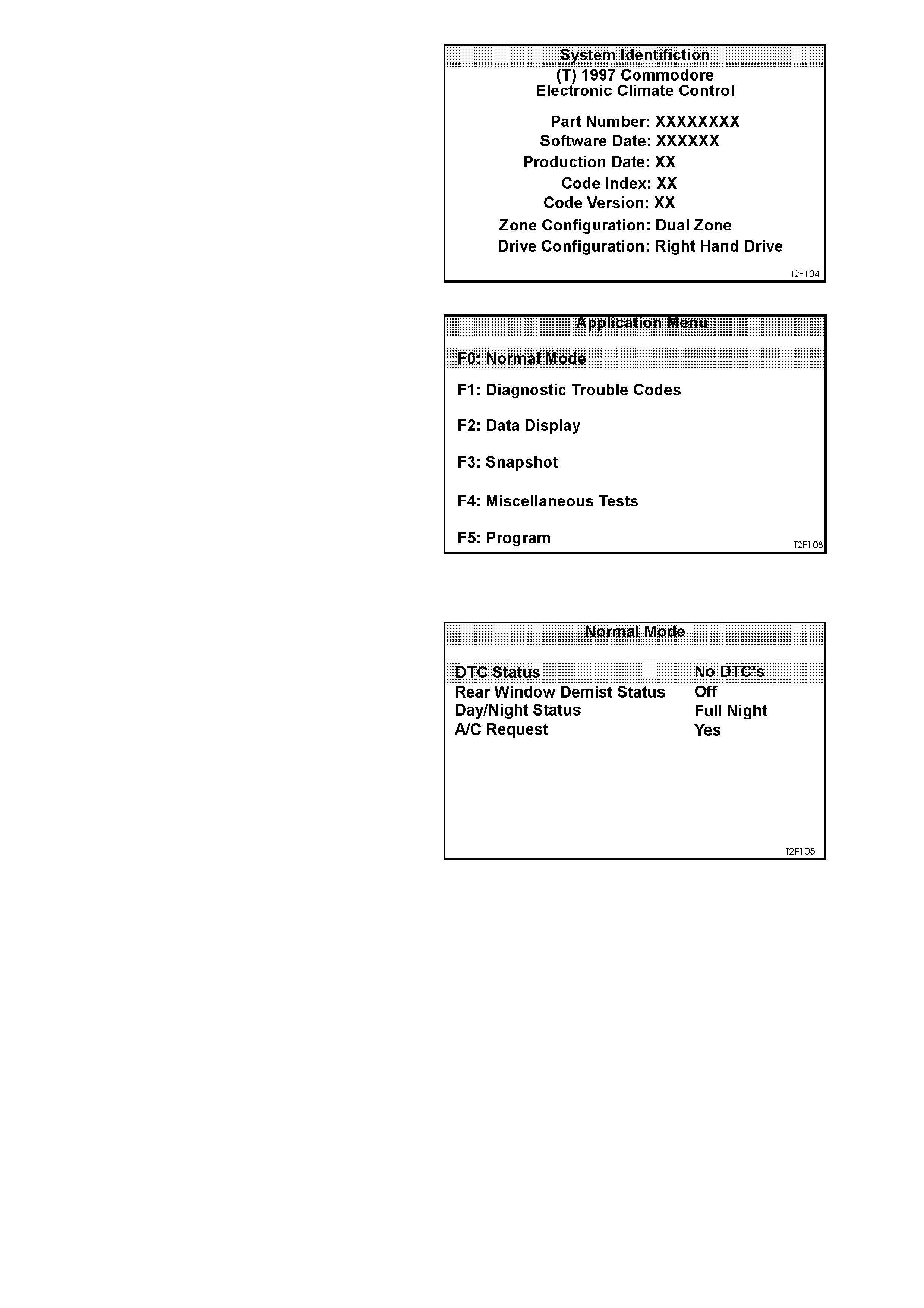
The System Identification screen will then display
ECC control module identification data. Press the
CONFIRM soft key to continue to the ECC
Application Menu.
Figure 2F-6
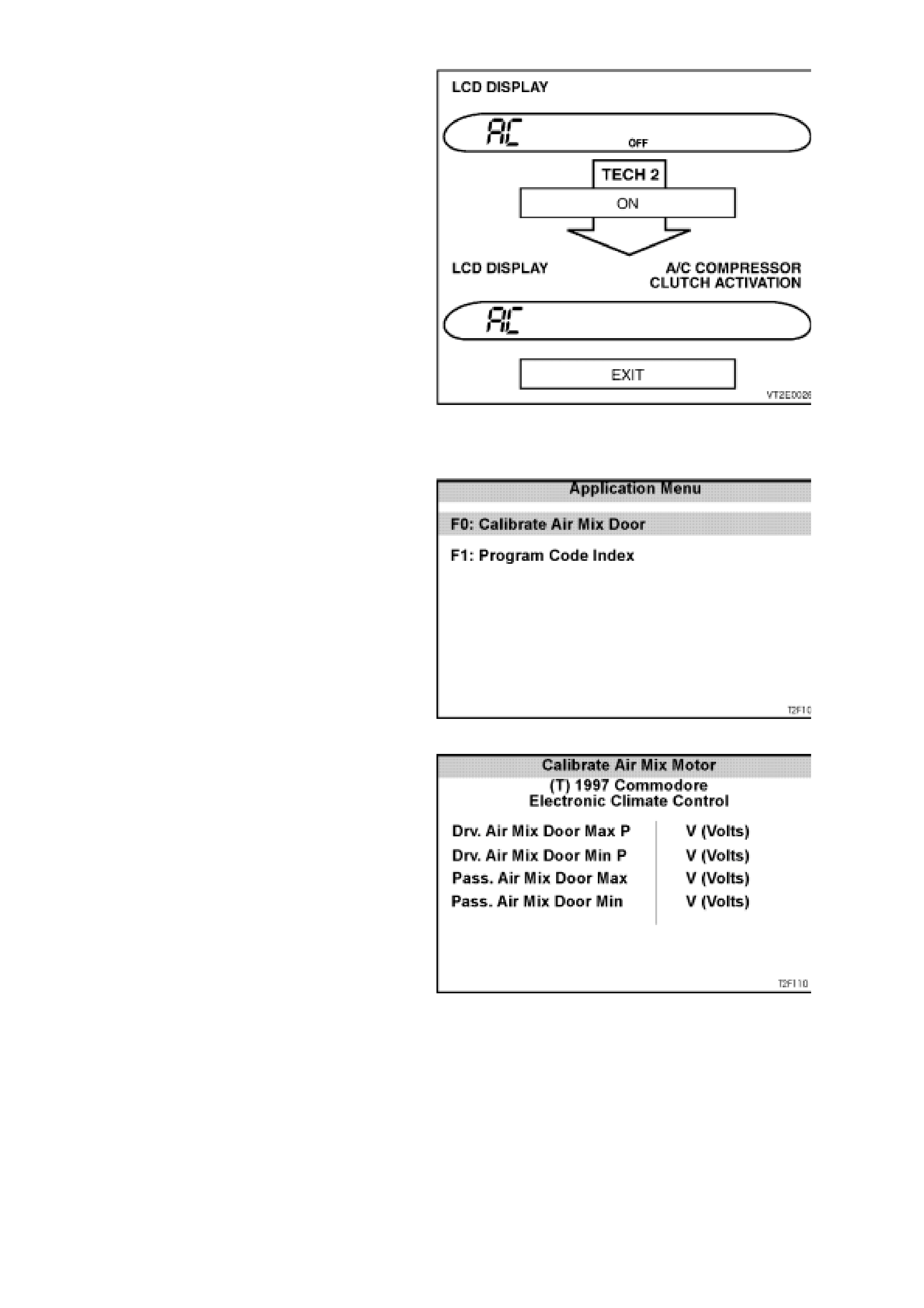
Application Menu
The following functions will now be available:
F0: Normal Mode
F1: Diagnostic Trouble Codes
F2: Data Display
F3: Snapshot
F4: Miscellaneous Tests
F5: Program
Figure 2F-7
F0: NORMAL MODE
In the F0: Normal Mode, information that the ECC
control module is communicating to other control
modules, via the serial data line, is displayed.
For example: As displayed opposite, the A/C
request status is YES. This m eans the ECC control
module is com m unic ating with the BCM, requesting
the air conditioning compressor to be turned on.
Figure 2F-8
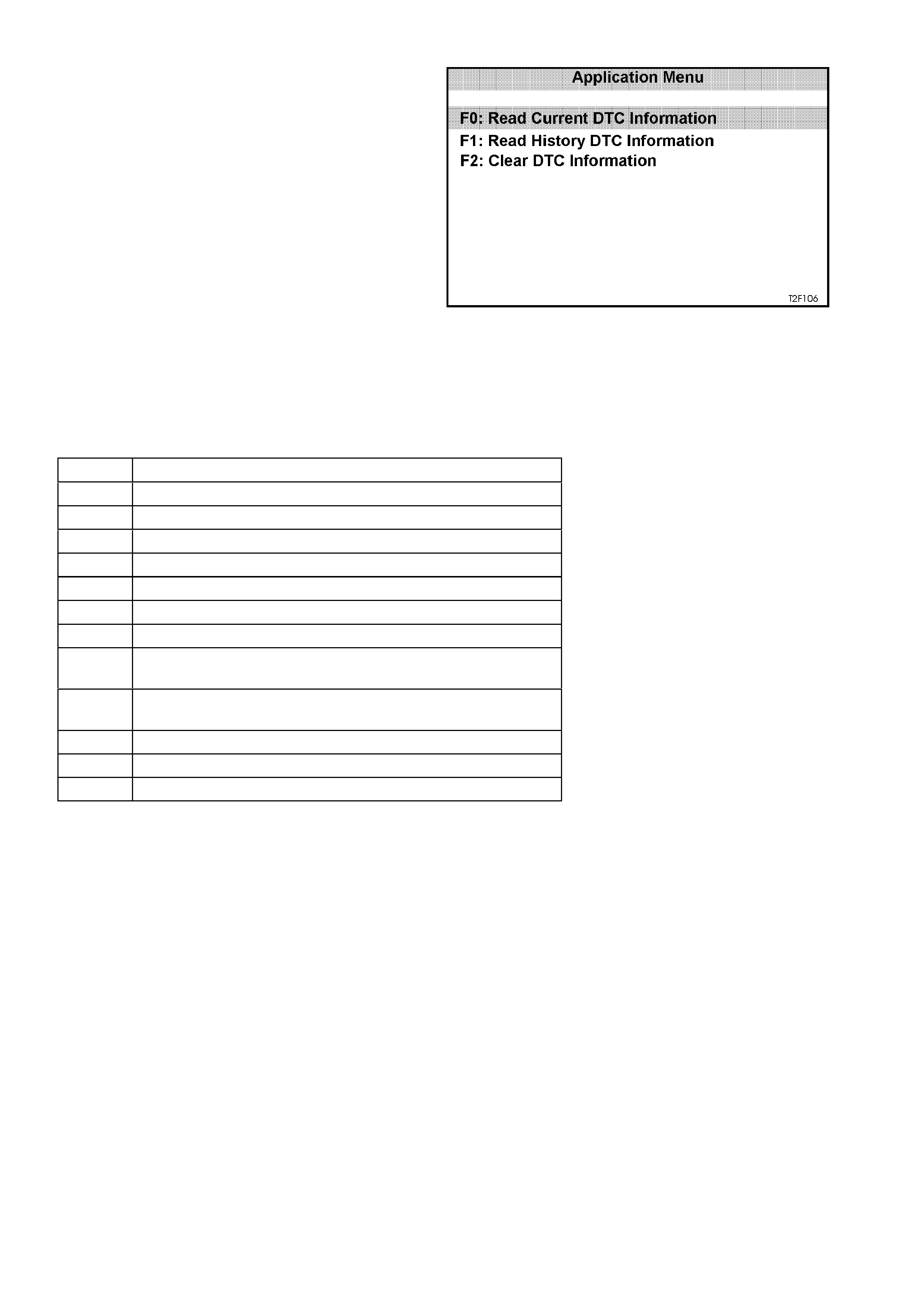
F1: DIAGNOSTIC TROUBLE CODES (DTC)
If F1: Diagnostic Trouble Codes is selected, a
selection list is displayed which contains:
F0: Read Current DTC Information: In this m ode,
a listing of all (if any) current DTC numbers,
together with a brief description of the DT C, will be
displayed.
F1: Read History DTC Information: In this mode,
a listing of the last two stored DTC’s will be
displayed, together with a brief description of the
DTC and the number of ignition cycles since the
DTC occurred.
NOTE: If any DTC’s are set, reference should be
made to the relevant diagnostic charts in this
Section.
F2: Clear DTC Information: In this mode, DTC’s
can be cleared by simply selecting F2: Clear DTC
Information and pressing the enter key on TECH 2.
The following table sets out all the possible
diagnostic trouble codes as indicated by TECH 2.
Figure 2F-9
DTC CODE DESCRIPTION
13 Ambient temperature sensor out of range - high
14 Ambient temperature sensor out of range - low
15 In car temperature sensor out of range - high
16 In car temperature sensor out of range - low
17 Evaporator air temperature sensor out of range - high
18 Evaporator air temperature sensor out of range - low
19 Sun load sensor fault
21 Air mix motor drivers side - dual & single zone
(motor & PBR test)
24 Air mix motor passenger’s side - dual zone only
(motor & PBR test)
36 Serial data communication error
37 ECC control module - Internal failure
38 EEPROM failure (ECC control module)
NOTE:
For diagnosis of pressure transducers, refer to
Section 6C1 POWERTRAIN CONTROL M ODULE
- V6 ENGINE or 6C2 POWERTRAIN CONTROL
MODULE - V8 ENGINE.
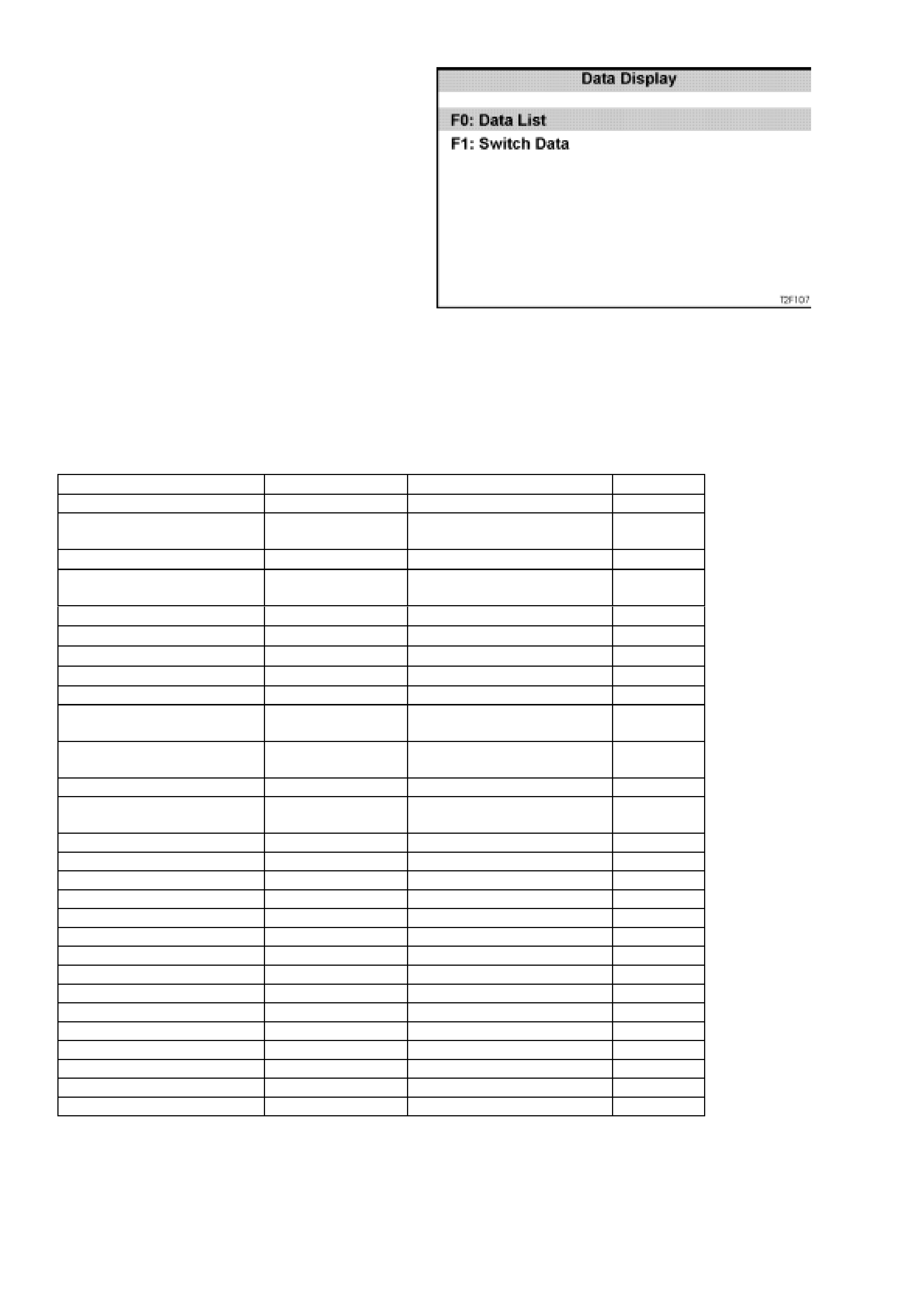
F2: DATA DISPLAY
If the F2: Data Display mode is selected, an
additional menu will appear giving the operator the
option of selec ting the ECC data list or ECC switch
data.
F0: Data list - The data list displays inputs and
outputs of the ECC.
F1: Switch Data - In this mode, the operator is
able to test the function of each ECC module
button and switch.
To test the ECC buttons and switches in this m ode;
activate each button and switch on the ECC
module and view the TECH 2 screen to see if
display changes status from OFF to ON.
NOTE:
The ECC module buttons will need to be held down
when carrying out this test due to a slight delay in
information transfer.
The following table lists each item in the data list
and the switch data together with expected
readings:
Figure 2F-10
DATA LIST READING SWITCH DATA READING
System status On/Off Right Set Temperature Up On/Off
In car Temperature Sensor 0 - 3.5 ± 0.2 V Right Set Temperature
Down On/Off
In car Temperature Degrees °CRear Demist Switch On/Off
Ambient Temperature
Sensor 0 - 3.5 ± 0.2 V Front Demist Switch On/Off
Ambient Temperature Degrees °CRecirculation Switch On/Off
Evap Temperature Sensor 0 - 3.5 ± 0.2 V Fan Up Switch On/Off
Evap Temperature Degrees °CFan Down Switch On/Off
Coolant Temperature Degrees °CAir Conditioning Switch On/Off
Battery Voltage Approx 13.5 V Mode Switch On/Off
Drivers Air Mix Door 0 - 3.5 ± 0.2 V Outside Temperature
Switch On/Off
Passengers Air Mix Door 0 - 3.5 ± 0.2 V Left Side Temperature
Switch On/Off
Outlet Setting Auto/Manual (Dual Zone Only)
Outlet Mode Face/Floor/
Blend/Foot Left Side Temperature Up On/Off
Inlet Setting Auto/Manual (Dual Zone Only)
Inlet Mode Fresh/Recirc Auto Switch On/Off
Air Conditioning Setting Auto/Manual Off Switch On/Off
Air Conditioning Request Yes/No
Blower Fan Setting Auto/Manual
Blower Fan Speed 1234/Auto
Cold Start 22 - 99%
Maximum Fan Relay Yes/No
Rear Demist Relay On/Off
Face 1 Solenoid On/Off
Face 2 Solenoid On/Off
Foot 1 Solenoid On/Off
Foot 2 Solenoid On/Off
Recirculation Solenoid On/Off
Water Valve On/Off
F3: SNAPSHOT
In this test mode, the TECH 2 captures ECC data
before and after a forced manual trigger.
F4: MISCELLANEOUS TEST
In the Miscellaneous Test mode, functional tests
are available on the ECC systems that will help
identify proper operation. In this mode, error
conditions can be further identified by testing and
observing the results.
In the Miscellaneous T est m ode, the f ollowing tests
can be performed:
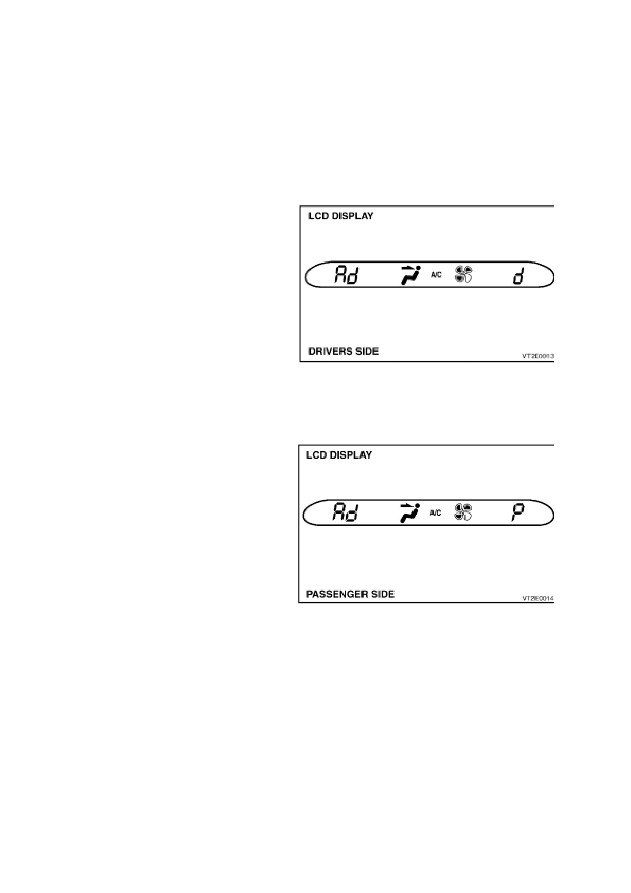
Drivers Side Air Mix Door
Purpose of test: Monitor the face vent to verify that
a temperature change takes place when opening
and closing the air m ix door, indicating both air m ix
motor and door movement.
Pre-conditions: Engine running at operating
temperature.
Procedure: Insert a thermometer into the centre
face vent (dual zone, right side centre vent). With
TECH 2 connec ted to DLC, s elect Body / Elec tronic
Climate Control / Drivers Side Air Mix Door.
Conduct Drivers Side Air Mix Door test by using the
increase/decrease soft keys on TECH 2 open and
close the air mix door.
W hen the door is open (increase), the temperature
at the centre vent should increase.
When the door is closed (decrease), the
temperature at the centre vent should decrease.
Figure 2F-11
Passenger Side Air Mix Door
Purpose of test: Monitor the face vent to verify that
a temperature change takes place when opening
and closing the air m ix door, indicating both air m ix
motor and door movement.
Pre-conditions: Engine running at operating
temperature.
Procedure: Insert a thermometer into the left side
of the centre face vent. W ith TECH 2 connected to
DLC, select Body / Electronic Climate Control /
Passengers Side Air Mix Door. Conduct Pass enger
Side Air Mix Door test by using the
increase/decrease soft keys on TECH 2 open and
close the air mix door.
W hen the door is open (increase), the temperature
at the centre vent should increase.
When the door is closed (decrease), the
temperature at the centre vent should decrease.
Figure 2F-12
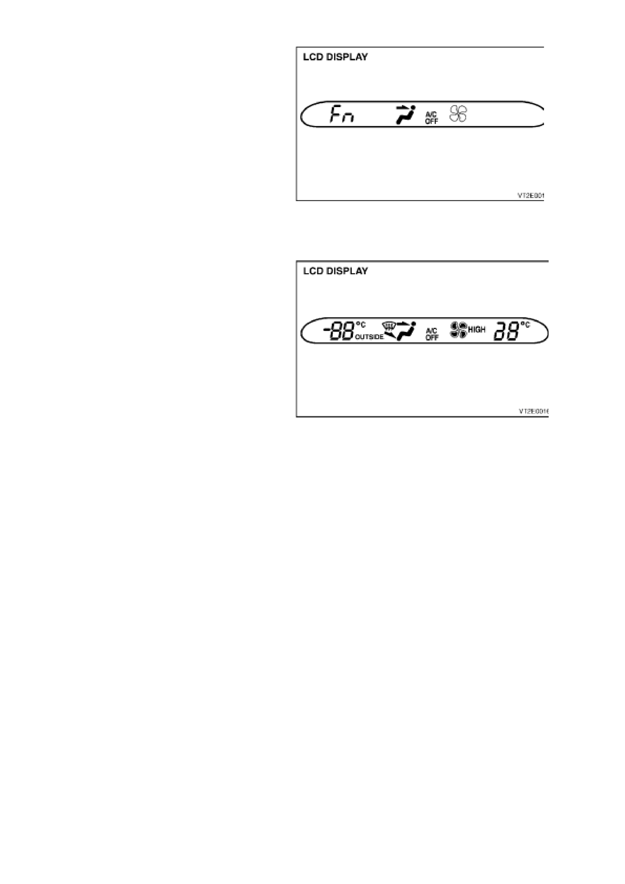
Blower Speed
Purpose of test: To ensure that all blower speeds
are preset and the blower motor circuit is
functional.
Pre-condition: Engine running
Procedure: With T ECH 2 connected to DLC, s elect
Body / Electronic Climate Control / Miscellaneous
Tests / Blower Speed. Using the increase soft key
on TECH 2, command the blower fan to maximum
(approx. 95 - 99%).
Using the decreas e soft k ey on TECH 2, com m and
the blower fan to minimum (approximately 22 -
26%).
NOTE:
Percentage values (%) are dependant on vehicle
battery voltage.
Figure 2F-13
LCD Display Test
Purpose of test: To ensure all segments are
displayed on the ECC module LCD screen.
Pre-condition: Engine not running.
Procedure: With T ECH 2 connected to DLC, s elect
Body / Electronic Climate Control / Miscellaneous
Tests / LCD Display Test. Using the On/Off soft
keys on TECH 2, activate and deactivate the LCD
full segment display.
Figure 2F-14
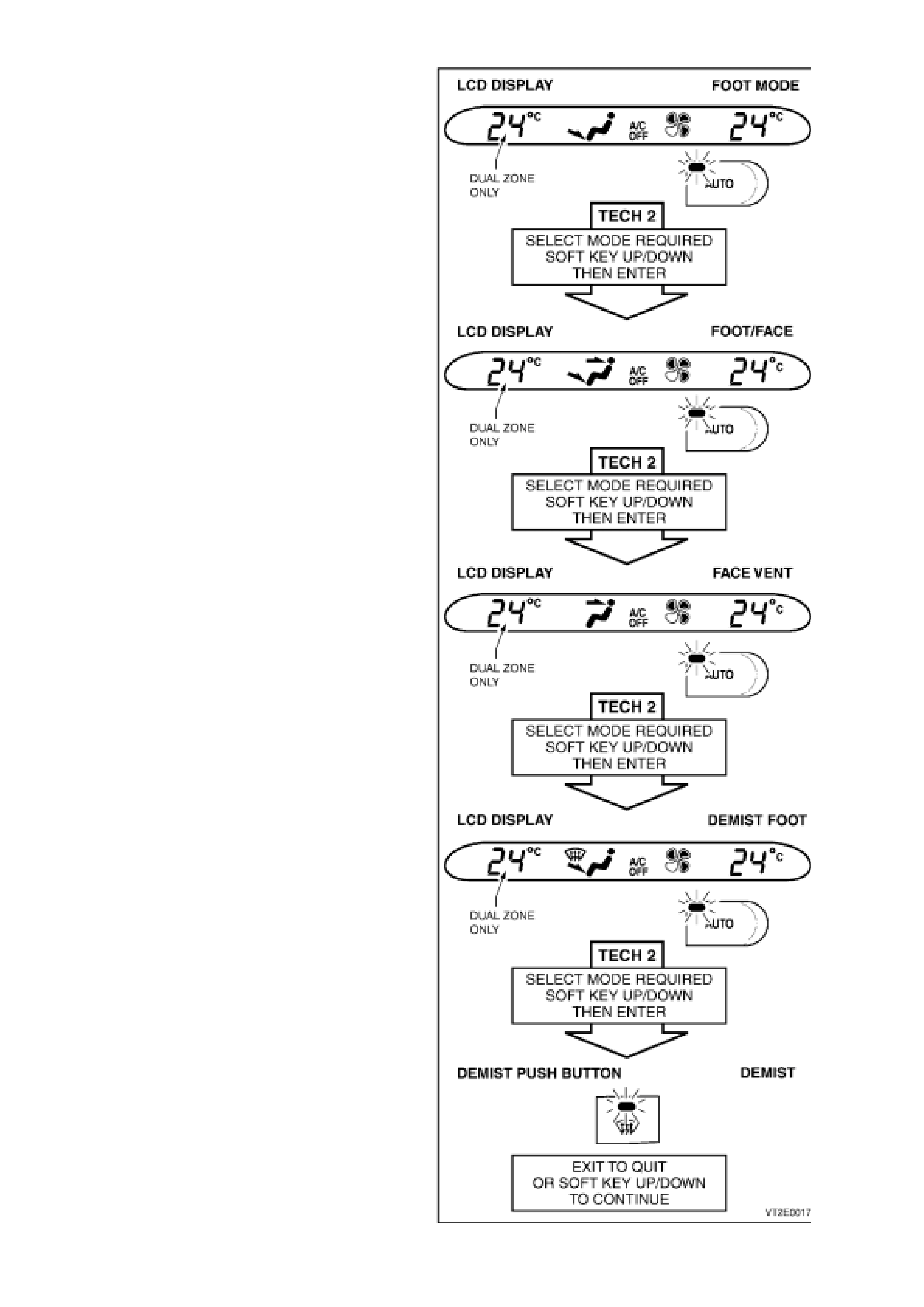
Outlet Mode
Purpose of test: To ensure that vacuum solenoids,
vacuum supply and mode doors are functional.
Pre-condition - Engine running.
Procedure: With T ECH 2 connected to DLC, s elect
Body / Electronic Climate Control / Miscellaneous
Tests / Outlet Mode. Conduct Outlet Mode test by
using the up/down soft keys on TECH 2 and
scrolling through each mode position; Foot,
Foot/Face, Face, Demist/Foot and Demist (only).
The ECC Module LCD indicates the position
(arrow) air will be directed to, in each mode the
third blower fan speed will automatically be
selected and the Auto button will be illuminated.
Feel for air movement at the direction indicated by
the arrow on the ECC Module LCD screen.
NOTE 1:
When the Foot Mode is selected, air is distributed
from the floor.
NOTE 2:
On dual zone systems, when the Face Vent Mode
is selected, air will be distributed from left and right
or the centre face vent.
NOTE 3:
When the Demist/Foot Mode is selected, air is
distributed from demist ducts and the floor.
NOTE 4:
When the Demist Mode is selected, air is
distributed from demist ducts only.
Figure 2F-15
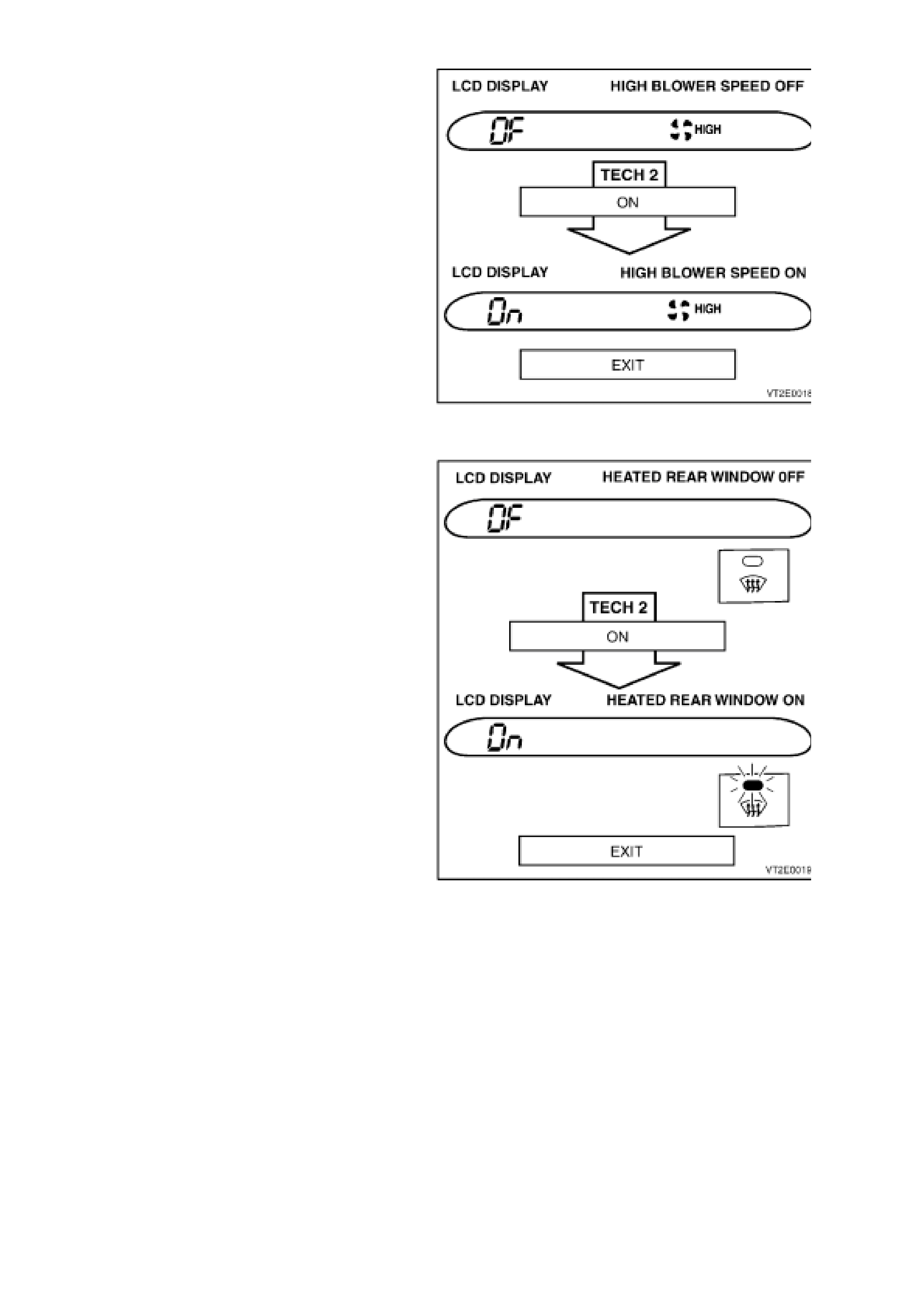
Maximum Fan Relay
Purpose of test: To ensure a circuit exists between
the ECC module, the relay and the blower fan.
Pre-condition: Engine running.
Procedure: With T ECH 2 connected to DLC, s elect
Body / Electronic Climate Control / Miscellaneous
Tests / Maximum Fan Relay. Conduct Maximum
Fan Relay test by using the On soft key to activate
the relay and maximum fan speed and the Off soft
key to deactivate relay and turn blower speed off.
Figure 2F-16
Rear Demist Relay
Purpose of test: To check operation of circuit from
ECC control to relay.
Pre-condition: Engine not running.
Procedure: With T ECH 2 connected to DLC, s elect
Body / Electronic Climate Control / Miscellaneous
Tests / Rear Demist Relay. Conduct Rear Demist
Relay test by pressing the On soft key to activate
heated rear window relay; the rear demist button
will illuminate and ON will be dis played on the LCD
display. Use the Off s of t key to deactivate r elay; the
rear demist button illumination will go out and OFF
will be displayed on the LCD.
Figure 2F-17
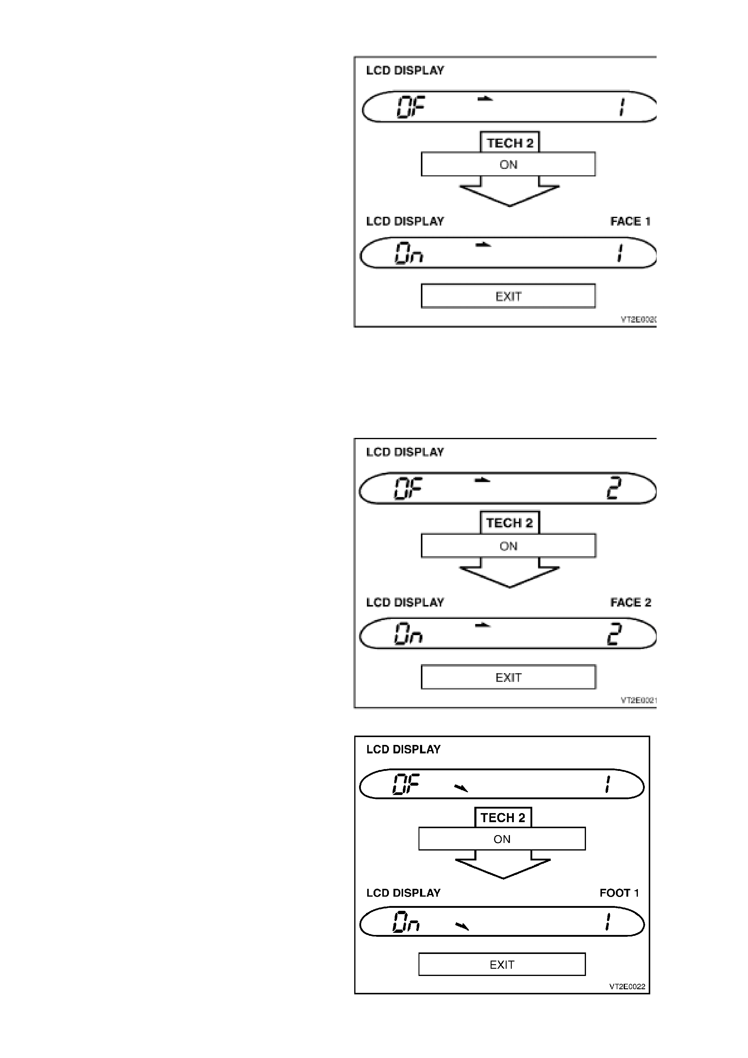
Solenoids
NOTE:
If the TECH 2 Outlet Mode test was carried out and
passed this test need not be carried out.
Purpose of test: To ensure the ECC Module,
electrical circuit is OK.
Pre-condition: Engine not running.
Procedure: Remove the left side footwell upper
closing panel, locate the vacuum solenoid pack
(rear of blower housing). With TECH 2 connected
to DLC, select Body / Electronic Climate Control /
Miscellaneous Tests / Solenoids. Conduct
Solenoids test by Using the On soft key activate
one solenoid at a time.
Listen or feel for the solenoids activating (clicking).
Use the Off soft key to deactivate solenoids and
likewise listen or feel for solenoids activating
(clicking).
Figure 2F-18 shows the screen display for: solenoid
one, face level.
NOTE:
Refer to. Error! Reference source not found. to
understand which solenoid should be activated in
each mode.
Figure 2F-18
Figure 2F-19 shows the screen display for: solenoid
two, face level.
Figure 2F-19
Figure 2F-20 shows the screen display for: solenoid
one, foot level.
Figure 2F-20
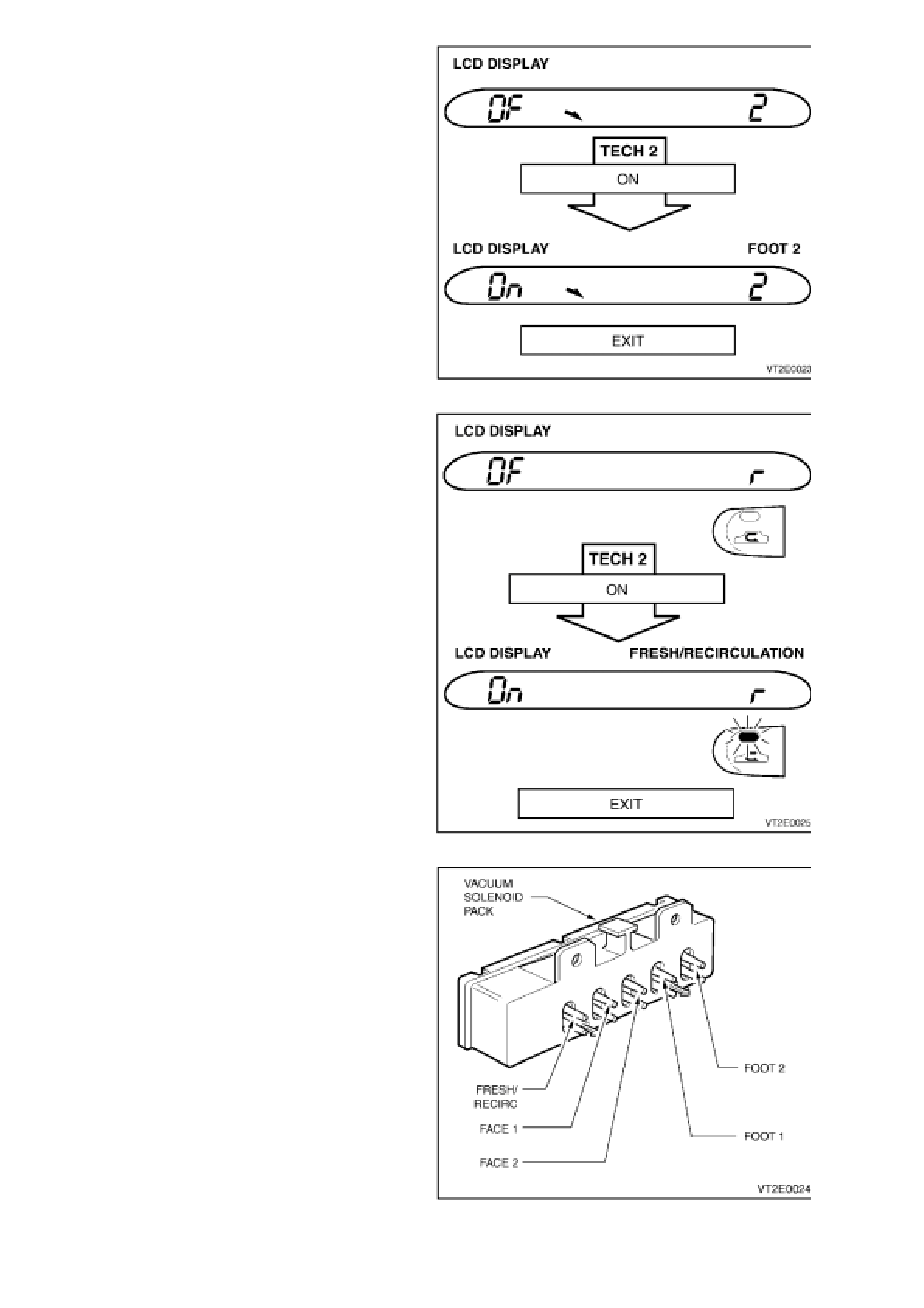
Figure 2F-21 shows the screen display for: solenoid
two, foot level.
Figure 2F-21
Figure 2F-22 shows the screen display for the
fresh/recirculation solenoid.
Figure 2F-22
Figure 2F-23
A/C Request
Purpose of test: To ensure ECC Module, wiring,
compressor relay and compressor clutch are
functional.
Pre-condition: Engine running.
Procedure: With T ECH 2 connected to DLC, s elect
Body / Electronic Climate Control / Miscellaneous
Tests / A/C Request. Conduct A/C Request test by
using the On soft key to engage the compressor
clutch and the Off soft key to disengage the
compressor. Listen for clutch engagement noise.
NOTE:
In this test a blower fan speed is automatically
selected.
NOTE:
A three second delay until compressor clutch
engagement will occur, this is normal.
Figure 2F-24
F5: PROGRAM
In this mode, TECH 2 allows the programming of
the ECC control module.
W hen the Program option is selec ted, the following
two choices will be available:
Figure 2F-25
F0: Calibrate Air Mix Door – In this mode, the air
mix door(s) may be re-calibrated/programmed so
they dive to the full hot and full cold stops.
The calibration mode looks at the full movement in
either direction of the air mix doors/motors and
compares the actual voltage values to known base
values. If they are different, the ECC software will
compensate.
To calibrate the air mix door; connect TECH 2 to
DLC, select Body / Electronic Climate Control /
Program / Calibrate Air Mix Door and pres
Calibrate soft key on Tech 2.
When the air mix doors are re-calibrated TECH 2
will display the percentage of variation between the
base value and the pre-calibration value. If this
variation is greater than 5%, a noticeable dif f er enc e
should be felt and could have contributed to a
customer complaint.
NOTE: If programming is unsuccessful repeat the
program again, as th system may have crashed
during this process.
NOTE: During programm ing, a DTC 21 or 24 could
be set. If either of these codes are set, with TECH
2 connected, select Body / Electronic Climate /
Diagnostic Trouble Codes / Clear DTC Information
and clear DTC’s.
Figure 2F-26
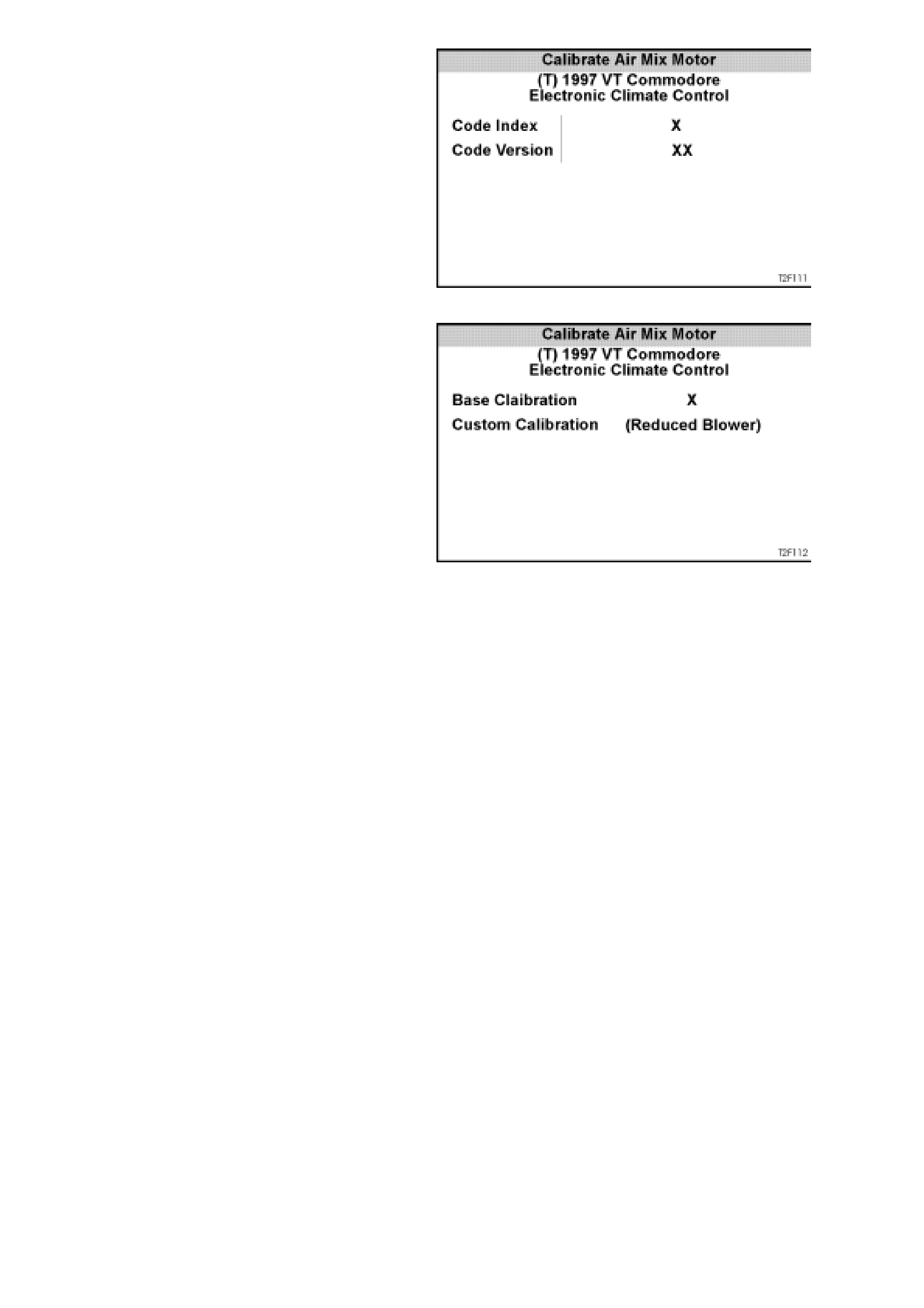
F1: Program Code Index – In this mode, the code
index and program m ed c ode version ar e dis played,
as well as provide the operator the option of
reprogramming the code version.
Code Index:1 = Single Zone (SZ) Right Hand Drive.
2. = Dual Zone (DZ) Right Hand Drive.
Code Version:
The code version identifies the progrmmed level
ECC calibration. A Higher number indicates the
latest version of calibration and can be update
using TECH 2.
Figure 2F-27
There are two Options available in the calibration
mode:
1. Base Calibration – brings the ECC operating
parameters to the latest level.
NOTE: Although ECC Control modules are
supplied with a pre-programmed code version, in
some cases the TECH 2 software version maybe
latter, therefore, all new ECC control modules
should be reprogrammed using TECH 2. If the
ECC software version is latter than the TECH 2
base calibration version, TECH 2 will display
“TECH 2 does not include data f or this code index ”,
indicating that programming will not be necessary.
2. Custom Calibration – In this mode, the ECC
system programming function can be re-
calibrated to suit specific customers
complaints. (ie. Reduced Blower calibration
will re-program the blower motor to operate at
a slower speed to reduce airflow or blower
noise).
NOTE: Additional custom calibrations will be
available once established.
To calibrate the ECC control module, either Base
or Customer, connect TECH 2 to the DLC and
select Body / Electronic Climate Control / Pr ogram /
Program Code Index and press Modify soft key on
TECH 2. Select the appropriate calibration version
and press the Enter key.
NOTE: If programming is unsuccessful, repeat the
program again, as the system may have crashed
during this process
Figure 2F-28
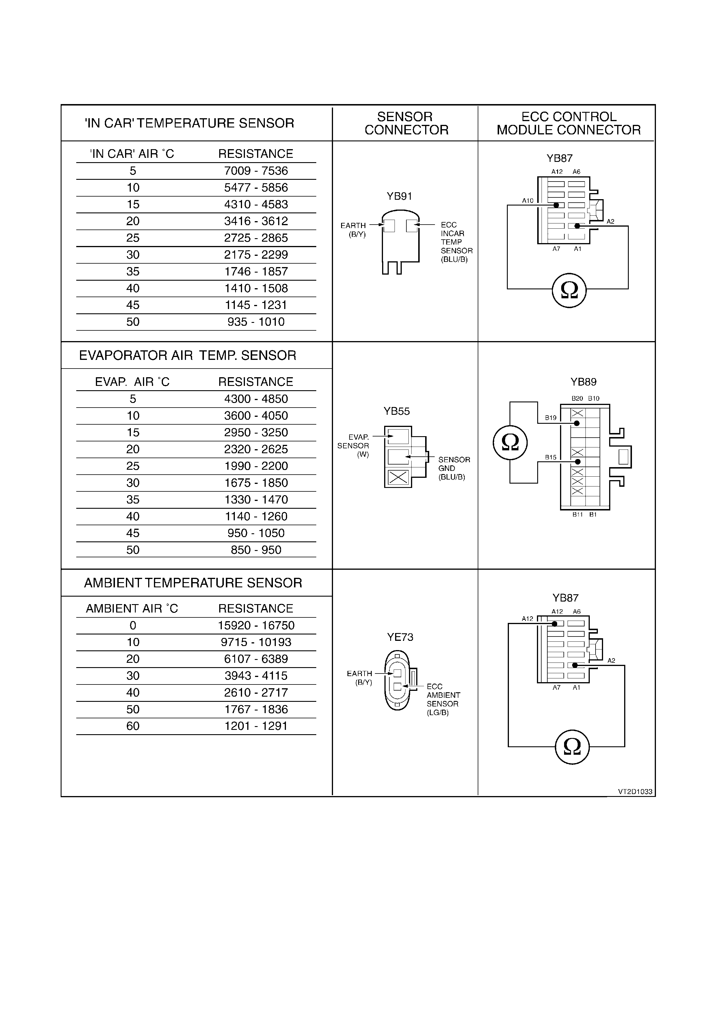
1.3. S ENSOR ACCURACY TES T ING
When testing how accurate a sensor is relaying information, you will be required to probe onto the terminals of
either the sensor itself or the terminals of the ECC Module connector within that circuit using an ohmmeter.
For accurate temperature to ohms comparison readings use a digital multimeter placed close to the sensor itself.

1.4 DIAGNOSTIC CHARTS
INTRODUCTION
The following diagnostic charts are designed to provide fast and efficient fault location of the ECC system. Each
diagnostic chart consists of: a ‘diagnostic chart’ and pertinent information including Diagnostic Trouble Code (DTC)
setting parameters and, in most charts, circuit diagrams.
The following figures illustrate the terminal layout for the various connectors used in the ECC system. These figures
should be used in conjunction with the diagnostic chart circuit diagrams when checking circuit faults.
When carrying out wiring checks as directed to by the diagnostic charts, rather than probe terminals and connectors
with incorrect sized multimeter connections, use the adaptors contained in connector test adaptor kit KM-609. This
will prevent any possibility of spreading or damaging wiring harness terminals.
Ensure that at the completion of any diagnostic procedure, all diagnostic tools are removed and all ECC
components are correctly connected.
Techline
Techline
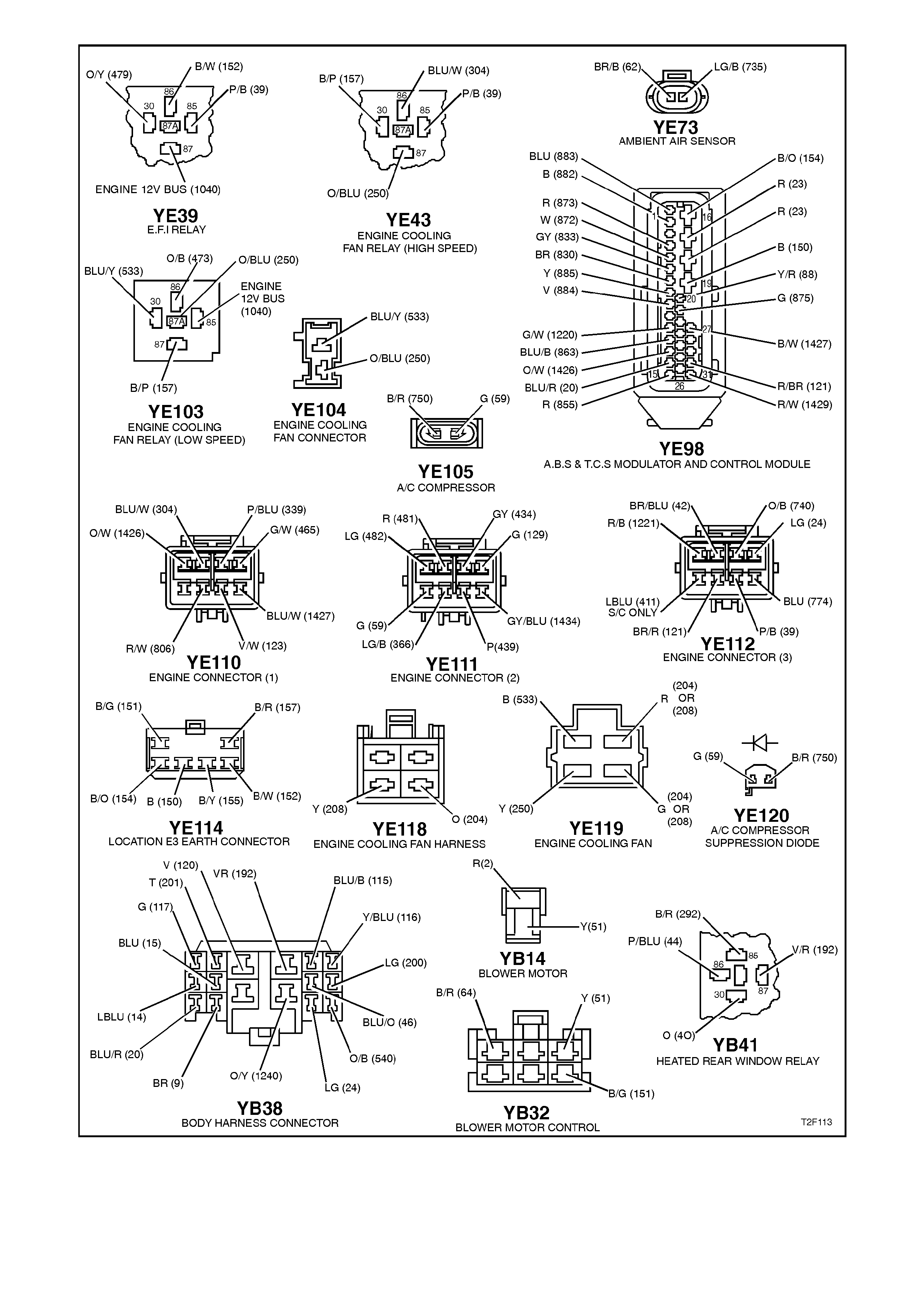
Figure 2F-29
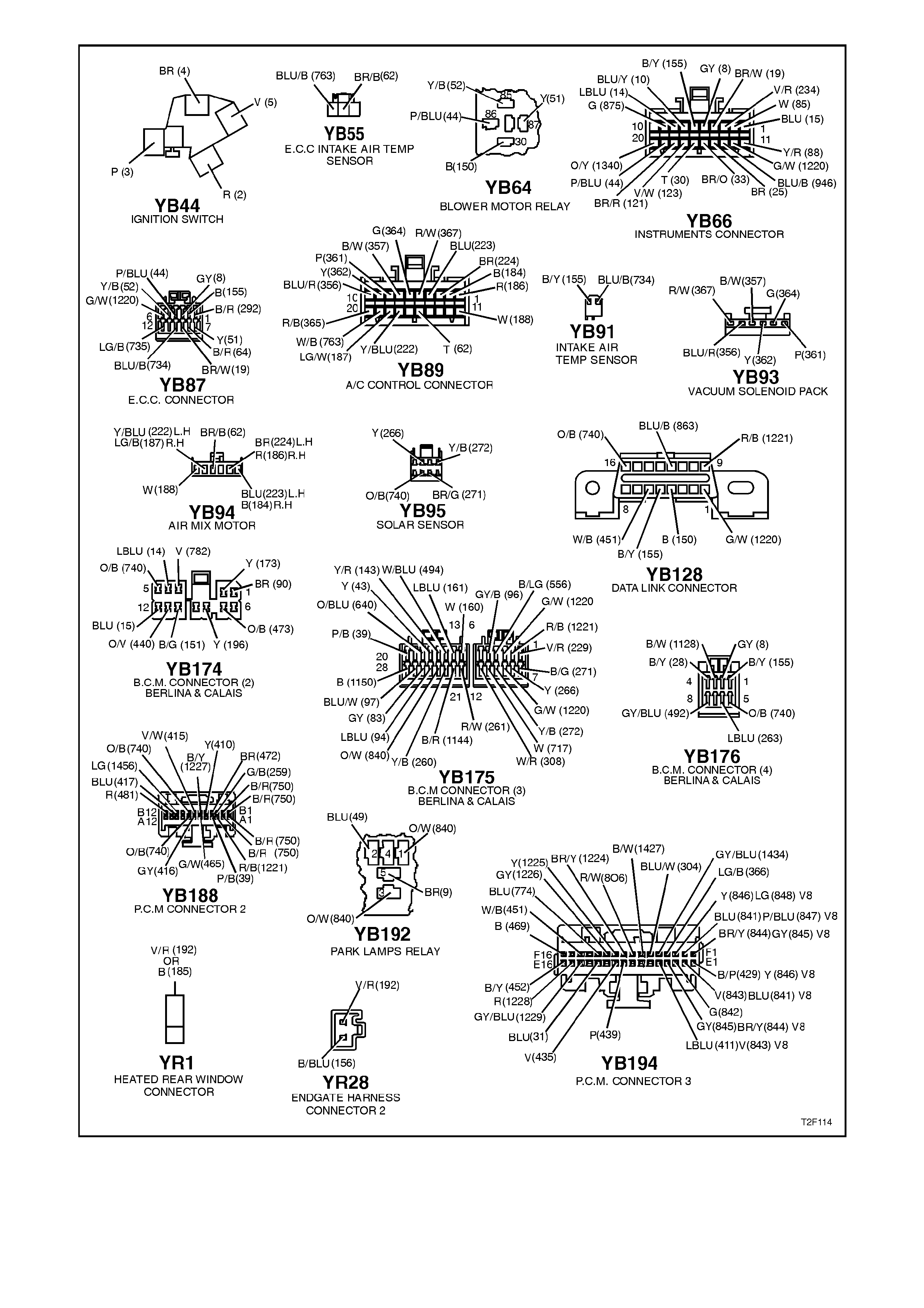
Figure 2F-25

INTERMITTENTS
Definition: Problems may or may not turn the ξ symbol on in the ECC control module display or store a DTC,
indicating an intermittent problem. DO NOT use the diagnostic code charts for intermittent problems. When using
the code charts the fault must be present to locate the problem. If a fault is intermittent, use of diagnostic trouble
code charts may result in replacement of good parts.
• Most intermittent problems are caused by faulty electrical connections or wiring. Perform careful visual/physical
checks of the applicable circuit.
Check for:
1. Poor mating of the connector halves or terminal not fully seated in the connector body (backed out).
2. Improperly formed or damaged terminal. All connector terminals in the suspect circuit should be carefully
reformed or replaced to insure proper contact tension.
3. Poor terminal to wire connection. This requires removing the terminal from the connector body to check as
outlined in service operations.
4. ECC earth circuit terminals being loose.
• If a visual/physical check does not find the cause of the problem, the car can be driven with a voltmeter
connected to a suspected circuit. A scan tool (TECH 2) can also be used to help detect intermittent conditions.
An abnormal voltage, or scan tool reading, when the problem occurs, indicates the problem may be in that
circuit. If the wiring and connectors check OK, and a diagnostic trouble code was stored for a circuit having a
sensor, substitute a known good sensor and recheck.
• Loss of diagnostic code memory. To check, disconnect Ambient Air Temperature sensor and turn the ignition
on until the ξ symbol on in the ECC control module display comes on. DTC 13 should be stored, and kept in
memory when ignition is turned "OFF." If not, the ECC is faulty.
• Check for an electrical system interference caused by a defective relay, ECC driven solenoid, or switch. They
can cause a sharp electrical surge. Normally, the problem will occur when the faulty component is operated.
• Check for improper installation of non-factory installed electrical options such as lights, 2 way radios, etc.
• If problem has not been found, refer to the proper sy mptom and perform all checks listed there.

CHART A - DIAGNOSTIC CIRCUIT CHECK
CIRCUIT DESCRIPTION
When investigating any complaint of an ECC
problem or malfunction, always begin diagnosis
with the following diagnostic circuit check. This
check is a preliminary procedure that checks to
ensure the ECC is communicating on the serial
data line as well as helping to identify a problem or
malfunction and directing the reader to the
appropriate diagnostic chart in this Section.
With TECH 2 connected to the DLC and the
ignition switched on, TECH 2 should display serial
data communication. If TECH 2 does not display
serial data, the serial data circuit maybe open of
shorted.
There are several other control modules that are
connected to the serial data line (PCM, BCM,
ABS/ASR, ECC, instruments and SDM). Any one
of these control m odules c ould cause a f ault on the
serial data line. This fault could result in TECH 2
not being able to display serial data.
Test Description:
The numbers below refer to step numbers in
diagnostic chart ‘A’
1. This test checks if the ECC control module is
being powered up.
2. This test checks if the ECC control module has
detected and stored a current Diagnostic
Trouble Code.
3. This test determines if TECH is being powered
up.
4. This test checks if tech can communicate with
the ECC control module. If tech 2 cannot
communicate with the ECC control module, you
will not be able to determine which DTC has
been stored in the control module’s memory.
5. Determines which DTC has been stored in the
control module’s memory.
6. This test determines if a DTC was current and
has rectified. An intermittent problem has
caused this DTC to be stored.
7. During this test the ECC control module re-
calibrates the air mix doors, an incorrectly
calibrated air mix door will cause incorrect
operation of the ECC system.
8. Checks accuracy of ECC sensors.
9. During this test the operation of the air
conditioning section of the ECC system is
checked.
Notes on Diagnostic Chart:
1. Refer to 1.1 TECH 2 DIAGNOSTICS in this
Section for connecting and using TECH 2.
2. Refer to 1.2 TECH 2 TEST MODES AND
DISPLAYS FOR ECC DIAGNOSIS in this
Section for further information on programming
of the ECC.
3. ECC sensors can be checked using the
following procedure and should als o be check ed
in the order as listed:
In car temperature sensor - connect TECH 2 to
DLC, select Body / Electronic Climate Control /
Data Display / Data List and scroll to In Car
Temperature Sensor. Using a digital

thermometer, placed as close to the in car
temperature sensor as possible, compare
thermometer reading with TECH 2 reading
(should be within ± 3°C). If values do not
correlate with each other, refer to
1.3 SENSOR ACCURACY TESTING in this
Section for a more accurate evaluation of the
sensor accuracy.
Ambient temperature sensor - connect TECH 2
to DLC, select Body / Electronic Clim ate Control
/ Data Display / Data List and scroll to Ambient
Temperature Sensor. Using a digital
thermometer, placed as close to the ambient
temperature sensor as possible, compare
thermometer reading with TECH 2 reading
(should be within ± 3°C). If values do not
correlate with each other, refer to
1.3 SENSOR ACCURACY TESTING in this
Section for a more accurate evaluation of the
sensor accuracy.
Sun sensor (sun sensor/remote receiver) refer
to DTC 19 diagnostic chart in this Section for a
procedure on checking this sensor.
Evaporator sensor - connect TECH 2 to DLC,
select Body / Electronic Climate Control / Data
Display / Data List and scroll to Evap
Temperature Sensor. Insert a digital
thermometer into the centre vent, start engine,
set A/C controls to full cold, fan speed 2 and
face level. Compare thermometer reading with
TECH 2 reading (thermometer reading should
be about 2 - 8°C higher than TECH 2 reading). If
values do not correlate with each other, refer to
1.3 SENSOR ACCURACY TESTING in this
Section for a more accurate evaluation of the
sensor accuracy.
STEP ACTION VALUE YES NO
1. • Turn ignition on.
• Turn on ECC system.
• Does ECC system
display activate?
Go to step 2. Go to Chart B -
ECC SYSTEM
DOES NOT
POWER UP is this
Section.
2. • Is there an X in the
bottom RH corner of the
ECC display?
Go to step 3. Go to step 6.
3. • Connect TECH 2 to the
DLC (refer Note 1).
• Turn ignition on.
• Push power button on
TECH 2.
• Does TECH 2 power up
(screen will illuminate
display TECH 2)?
Go to Step 4. Go to TECH 2
diagnosis, refer to
Section 0C -
TECH2.

STEP ACTION VALUE YES NO
4. • At the TECH 2 title
screen press the Enter
key.
• Select: Diagnostics
\1997 \ VT Commodore
\ Body \ Electronic
Climate Control.
• Turn on ignition and
press the confirm soft
key.
• Does TECH 2 display
ECC System
Identification Screen
information (ie. part
number etc.)?
Go to step 5. Go to DTC 39
SERIAL DATA
INTERFACE
FAULT in this
Section.
5. • With TECH 2 still
connected, ignition on
and ECC system
selected.
• Select: Diagnostic
Trouble Codes \ Read
Current DTC
Information.
• Does TECH 2 display
any DTC’s?
Go to applicable
DTC Chart in this
Section.
Go to step 6.
6. • With TECH 2 still
connected, ignition ON,
• Select Diagnostic
Trouble Codes \ Read
History DTC
Information.
• Does Tech 2 display
any History DTC’s?
DTC is intermittent.
Refer to
INTERMITTENTS
in this Section.
Go to step 7.
7. • With TECH 2 still
connected, ignition on
and ECC system
selected.
• Select Program \
Calibrate Air Mix Door \
Calibrate.
• Is the Air Mix Door
Position Difference
greater than specified
value (refer Note 2)?
5 % ECC Air Mix Doors
have been re-
calibrated.
Verify Repair.
Go to step 8.
8. • Check the accuracy of
the ECC sensors (refer
Note 3)
• Are ECC sensors OK?
Go to Step 9 Replace faulty ECC
sensor, refer to
Section 2E AIR
CONDITIONING -
ECC - REMOVAL
& INSTALL.
9. • Perform HARRISON V5
COMPRESSOR TXV
SYSTEM DIAGNOSIS
refer to Section 2C.
• Does system pass
Diagnosis Test?
No fault found with
ECC system.
System Code
Index may need to
be Programmed
refer to
Programming
Code Index in this
Section.
Carry out repair
procedure as
detailed in Harrison
V5 Compressor
TXV System
Diagnosis,
refer to
Section 2C.
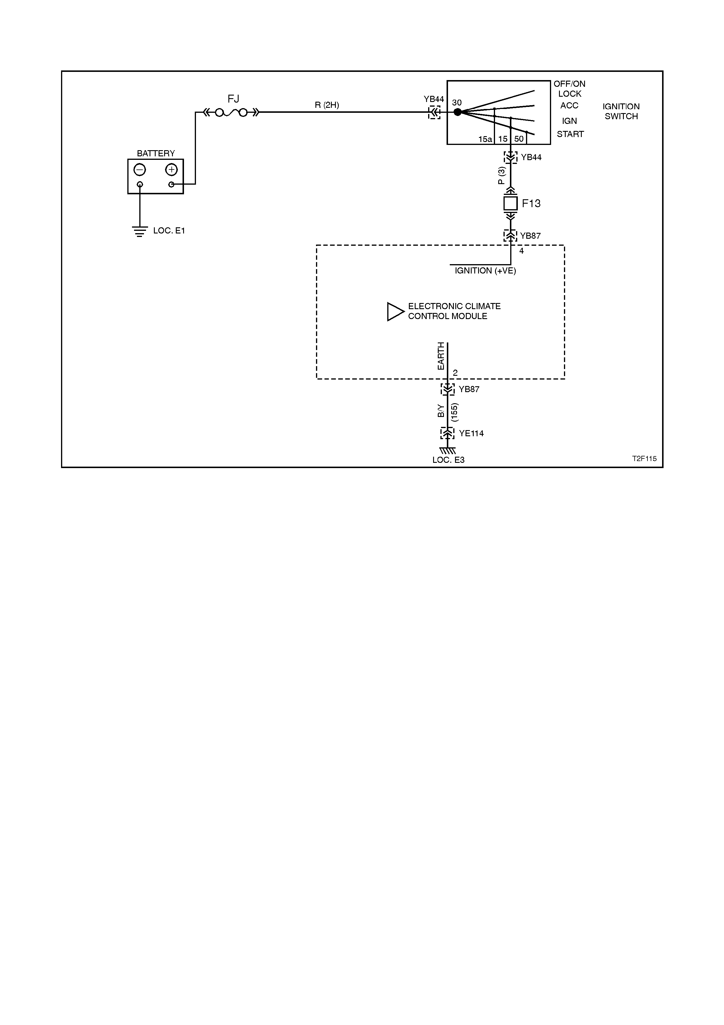
CHART B - ECC SYSTEM DOES NOT POWER UP
Figure 2F-26
CIRCUIT DESCRIPTION
Battery power is supplied to the ECC control module, terminal 4, with the ignition switch in the IGN or START
positions through fuse F13 (located in the passenger compartment fuse panel).
TEST DESCRIPTION:
The numbers below refer to step numbers in diagnostic chart ‘B’
1. The diagnostic circuit test is the beginning of all diagnostic and should be performed whenever diagnosing an
ECC system complaint.
2. This test checks if the fuse F13 is OK.
3. This test determines if power is being supplied to fuse F13.
4. This test determines if the ECC control has a power supply and an earth. If the control module has power and
earth and the module is not being activated when the ignition and the ECC system is turned on.
5. If battery voltage was not available during step 4, this test determines if the power supply circuit 44 to the ECC
control module has continuity.
6. If battery voltage was not available during step 4, this test determines if the earth circuit 155 to the ECC control
module has continuity.
NOTES ON DIAGNOSTIC CHART:
1. Refer to Section 12P WIRING DIAGRAMS for procedures on checking wiring faults.

STEP ACTION VALUE YES NO
1. • Has Diagnostic Circuit
Check been performed? Go to step 2 Go to Chart A -
DIAGNSOTIC
CIRCUIT CHECK
in this Section.
2. • Check Fuse F13.
• Is fuse F13 OK? Go to step 3. Replace fuse and
check for cause of
blown fuse.
Recheck and verify
repair.
3. • Turn Ignition on.
• Using a DVM check for
voltage at fuse F13
circuit 3 (Pink wi re)
(refer Note 1).
• Is voltage at specified
value?
B+ Go to step 4. Repair open in
circuit 3 pink wire.
Recheck and verify
repair..
4. • Remove ECC control
module (refer Section
2E ECC REMOVAL
AND INSTALLATION).
• Turn Ignition on.
• Using a DVM check for
voltage between ECC
Control module
connector YB87
terminal 4 circuit 44
(Pink / Blue wire) and
YB87 terminal 2 circuit
155 (Black / Yellow
wire) (refer Note 1).
• Is voltage at specified
value?
B+ Replace ECC
Control Module,
refer to Section
2E AIR
CONDITIONING -
ECC - REMOVE &
INSTALL.
Go to step 5.
5. • Ignition off.
• Using an ohmmeter
check continuity of
circuit 44 (Pink / Blue
wire) between ECC
module connector
YB87, terminal 4 and
fuse F13 (refer
Note 1).
• Is there continuity ?
Go to step 6. Repair open in
circuit 44 (Pink /
Blue wire) between
ECC control
module connector
YB87 and fuse
F13. Recheck and
verify repair.
6. • Ignition off.
• Using an ohmmeter
check continuity of
circuit 155 (Black /
Yellow wire) between
ECC module connector
YB87 and known good
earth (refer Note 1).
• Is there continuity ?
Check for
intermittent
connection at ECC
module connector
YB87. Check sizing
of connector YB87
terminals.
Repair open in
circuit 155 (Black /
Yellow wire)
between ECC
module connector
YB87 and earth
LOC. 3. Recheck
and verify repair.

DTC 13 - AMBIENT AIR TEMPERATURE SENSOR (ATS) - SIGNAL VOLTAGE HIGH
Figure 2F-27
CIRCUIT DESCRIPTION:
The Ambient Temperature Sensor (ATS) uses a thermistor to control the signal voltage to the ECC Module. The
ECC Module applies a voltage of 3.2 ±0.2 volts to the sensor when the air is cold, the ATS resistance is high
therefore the ECC Module will sense a high signal voltage. If the ambient air is warm, the ATS resistance is low
therefore the ECC Module will sense a low signal voltage.
DTC 13 will set if: the ATS sensor signal voltage is more than 3.5 ±0.2 volts or, if the ATS sensor, wiring harness
(circuit 735) or connectors are open circuited.

TEST DESCRIPTION:
Number(s) below refer to step numbers in the
following Diagnostic Chart
1. Ensures the Diagnostic Circuit Check has been
performed.
2. Checks that the conditions for setting the DTC
are present or if fault is intermittent.
3. Checks integrity of circuit 735.
4. Checks if sensor is okay by testing resistance
across ATS.
5. Checks for an intermittent connection at ATS.
6. Checks for an open in circuit 155.
7. Checks for an open in circuit 735.
8. Checks for short to voltage in circuit 735.
DIAGNOSTIC AIDS:
The default temperature for an open circuit is 22.5°C.
If the vehicle is left idling for an extended period, the
ambient temperature readings will rise owing to heat
radiated by the A/C Condenser and lack of airflow.
When using the temperature/resistance chart below,
place a thermometer as close as possible to the
sensor being tested, com pare this temperature figure
taken to the resistance value.
Notes on Diagnostic Chart:
1. Refer to Section 12P WIRING DIAGRAMS for
procedures on checking wiring faults.
2. Refer to 1.1 TECH 2 DIAGNOSTICS in this
Section for connecting and using TECH 2.
TEMPERATURE RESISTANCE CHART
AMBIENT°
°°
°CRESISTANCE AMBIENT°
°°
°CRESISTANCE
0 15920 - 16750 40 2610 - 2717
10 9715 - 10193 50 1767 - 1836
20 6107 - 6389 60 1201 - 1291
30 3943 - 4115

STEP ACTION VALUE YES NO
1• Was the Diagnostic
Circuit Check
performed?
Go to Step 2. Go to Chart A -
DIAGNOSTIC
CIRCUIT CHECK
in this Section.
2• Connect TECH 2 to
DLC (refer to Note 2).
• Select Body / Electronic
Climate Control / Data
Display / Data List and
scroll to Ambient Air
Temperature Sensor.
• Does TECH 2 display
Ambient Air
Temperature Sensor
above specified value?
3.4 Volts Go to Step 3. DTC 13
intermittent. If no
additional DTCs
were stored,
refer to
INTERMITTENT
in this section
3• With TECH 2 still
connected and Ambient
Air Temperature Sensor
displayed, disconnect
ambient air temperature
sensor wiring harness
connector YE73.
• Place a jumper wire
between the two
terminals of connector
YE73.
• Does TECH 2 display
ambient air temperature
sensor below the
specified value?
0.4 Volts Go to Step 4. Go to Step 6
4• With the ambient air
temperature sensor
wiring harness
connector YE73
disconnected, check
resistance across
ambient air sensor
terminals (refer to
Note 1).
• Is value as specified?
Refer to
Temp.
Resistance
Chart.
Go to Step 5. Replace faulty
ambient air
temperature
sensor, refer to
Section 2E AIR
CONDITIONING -
ECC - REMOVAL
&
INSTALLATION.

STEP ACTION VALUE YES NO
5• Inspect ambient air
temperature sensor
wiring harness
connector YE73 for an
intermittent or loose
terminal.
• Is connector YE73
okay?
Repair connector
as necessary.
Recheck and
verify repair
Go to Step 8
6• With TECH 2 still
connected and Ambient
Air Temperature Sensor
displayed, connect a
jumper lead between
circuit 735 (Light Green
/ Blue wire) and chassis
ground.
• Does TECH 2 display
ambient air temperature
sensor below the
specified value?
0.4 Volts Check and repair
open in circuit
155 (ATS earth).
Recheck and
verify repair.
Go to Step7
7• Check continuity of
circuit 735 (Light Green
/ Blue wire) between
connectors YE73 and
YB87 (including
connectors) (refer to
Note 1).
• Does continuity exist
and is connection okay?
Check and repair
circuit 735 as
necessary.
Recheck and
verify repair.
Go to Step 8
8• Turn ignition OFF.
• Disconnect ECC wiring
harness connectors
YB87 & YB89.
• Remove jumper lead
from ambient air
temperature sensor
connector YE73.
• Turn ignition ON.
• Check Voltage between
circuit 735 (Light Green
/ Blue wire) and chassis
ground at ambient air
temperature sensor
wiring harness
connector YE73.
• Was voltage below
specified value?
0.4 Volts Replace faulty
ECC control
module, refer to
Section 2E AIR
CONDITIONING -
ECC - REMOVAL
&
INSTALLATION.
Check and repair
short to voltage in
circuit 735.
Recheck and
verify repair.

DTC 14 - AMBIENT AIR TEMPERATURE SENSOR (ATS) - SIGNAL VOLTAGE LOW
Figure 2F-28
CIRCUIT DESCRIPTION:
The ambient air temperature sensor (ATS) uses a
thermistor to control the signal voltage to the ECC
Module. The ECC Module applies a voltage of 3.5
±0.2 volts to the sensor when the air is cold, the
ATS resistance is high therefore the ECC Module
will sense a high signal voltage. If the air is warm,
the ATS resistance is low therefore the ECC
Module will sense a low signal voltage.
DTC 14 will set if: the AT S sensor signal voltage is
less than 0.3 volts or, if the ATS sensor, wiring
harness (circuit 735) or connectors are short
circuited.
TEST DESCRIPTION:
Number(s) below refer to step numbers in the
following Diagnostic Chart
1. Ensures the Diagnostic Circuit Check has been
performed.
2. This test checks that the conditions that would
set the DTC are present.
3. This test checks if the sensor is causing the
short circuit.
4. This test checks if sensor is functioning okay.
5. Checks for intermittent connection at sensor.
6. Checks for a shor t c irc uit of sens or signal wire to
earth.
DIAGNOSTIC AIDS:
The default temperature for a short circuit is 22.5°C.
If the vehicle is left idling for an extended period, the
ambient temperature readings will rise owing to heat
radiated by the A/C Condenser and lack of airflow.
When using the temperature/resistance chart below,
place a thermometer as close as possible to the
sensor being tested, com pare this temperature figure
taken to the resistance value.
NOTES ON DIAGNOSTIC CHART:
1. Refer to Section 12P WIRING DIAGRAMS for
procedures on checking wiring faults.
2. Refer to 1.1 TECH 2 DIAGNOSTICS in this
Section for connecting and using TECH 2.

TEMPERATURE RESISTANCE CHART
AMBIENT°
°°
°CRESISTANCE AMBIENT°
°°
°CRESISTANCE
0 15920 - 16750 40 2610 - 2717
10 9715 - 10193 50 1767 - 1836
20 6107 - 6389 60 1201 - 1291
30 3943 - 4115
STEP ACTION VALUE YES NO
1• Was the Diagnostic
Circuit Check
performed?
Go to Step 2. Go to Chart A -
DIAGNOSTIC
CIRCUIT CHECK
in this Section.
2• Connect TECH 2 to DLC
(refer to Note 2).
• Select Body / Electronic
Climate Control / Data
Display / Data List and
scroll to Ambient Air
Temperature Sensor.
• Does TECH 2 display
Ambient Air
Temperature Sensor
less than specified
value?
0.4 Volts Go to Step 3. DTC 14
intermittent. If no
additional DTCs
were stored,
refer to
INTERMITTENTS
in this section.
3• With TECH 2 still
connected and Ambient
Air Temperature Sensor
displayed, disconnect
ambient air temperature
sensor wiring harness
connector YE73.
• Does TECH 2 display
ambient air temperature
sensor above the
specified value?
3.4 Volts Go to Step 4. Go to Step 6.
4• With the ambient air
temperature sensor
wiring harness connector
YE73 disconnected,
check resistance
across ambient air
sensor terminals (refer
to Note 1).
• Is value as specified?
Refer to
Temp.
Resistance
Chart.
Go to Step 5. Replace faulty
ambient air
temperature
sensor, refer to
Section 2E AIR
CONDITIONING -
ECC - REMOVAL
& INSTALLATION.
5• Check for intermittent
short to ground in
ambient air temperature
sensor circuit 735 (Light
Green / Blue wire)
including connectors
YE73 or YB87 (refer to
Note 1 on previous
chart).
• Was a problem found?
Repair fault as
necessary.
Recheck and
verify repair.
Replace faulty
ECC control
module, refer to
Section 2E AIR
CONDITIONING -
ECC - REMOVAL
& INSTALLATION.
6• Check circuit 735 (Light
Green / Blue wire) for
short to earth (refer to
Note 1 on previous
chart).
• Was a problem found?
Repair fault as
necessary.
Recheck and
verify repair.
Replace faulty
ECC control
module, refer to
Section 2E AIR
CONDITIONING -
ECC - REMOVAL
& INSTALLATION.
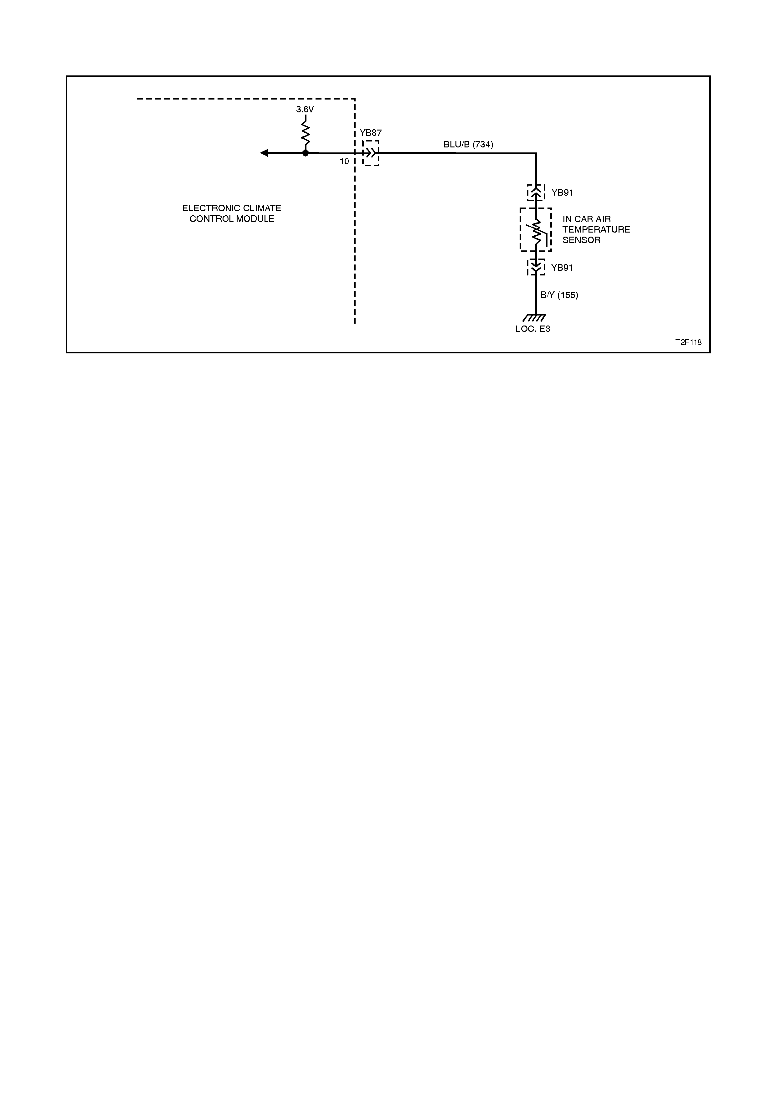
DTC 15 - IN-CAR TEMPERATURE SENSOR (ITS) - SIGNAL VOLTAGE HIGH
Figure 2F-29
CIRCUIT DESCRIPTION:
The In-car Temperature Sensor (ITS) is a
thermistor used to vary voltage signals to the
control the signal voltage to the ECC Module. The
ECC Module applies a voltage of 3.5 ±0.2 volts to
the sensor, via circuit 734. When the vehicle
interior air is cold, the ITS resistance is high
therefore the ECC Module will sense a high signal
voltage. If the air is warm, the ITS resistance is low,
therefore the ECC Module will sense a low signal
voltage.
DTC 15 will set: if the ITS signal voltage is more
than 3.5 ±0.2 volts or, if the ITS sensor, wiring
harness (circuit 734) or connectors are open
circuited
TEST DESCRIPTION:
Number(s) below refer to step numbers in the
following Diagnostic Chart
1. Ensures the Diagnostic Circuit Check has been
performed.
2. Checks that the conditions for setting the DTC
are present or if fault is intermittent.
3. Checks integrity of circuit 734.
4. Checks if sensor is okay by testing resistance
across ITS.
5. Checks for an intermittent connection at ITS.
6. Checks for an open in circuit 155.
7. Checks for an open in circuit 734.
8. Checks for short to voltage in circuit 734.
DIAGNOSTIC AIDS:
The default temperature for an open circuit is 22.5°C.
When using the temperature/resistance chart below,
place a thermometer as close as possible to the
sensor being tested, com pare this temperature figure
taken to the resistance value.
Notes on Diagnostic Chart:
1. Refer to Section 12P WIRING DIAGRAMS for
procedures on checking wiring faults.
2. Refer to 1.1 TECH 2 DIAGNOSTICS in this
Section for connecting and using TECH 2.

TEMPERATURE RESISTANCE CHART
AMBIENT°
°°
°CRESISTANCE AMBIENT°
°°
°CRESISTANCE
5 7009 - 7536 30 2175 - 2299
10 5477 - 5856 35 1746 - 1857
15 4310 - 4583 40 1410 - 1508
20 3416 - 3612 45 1145 - 1231
25 2725 - 2865 50 935 - 1010
STEP ACTION VALUE YES NO
1• Was the Diagnostic
Circuit Check
performed?
Go to Step 2. Go to Chart A -
DIAGNOSTIC
CIRCUIT CHECK
in this Section.
2• Connect TECH 2 to
DLC (refer to Note 2).
• Select Body / Electronic
Climate Control / Data
Display / Data List and
scroll to In-car
Temperature Sensor.
• Does TECH 2 display
In-car Temperature
Sensor above specified
value?
3.4 Volts Go to Step 3. DTC 15
intermittent. If no
additional DTCs
were stored,
refer to
INTERMITTENT
in this section
3• With TECH 2 still
connected and In-car
Temperature Sensor
displayed, disconnect
in-car temperature
sensor wiring harness
connector YB91.
• Place a jumper wire
between the two
terminals of connector
YB91.
• Does TECH 2 display
In-car temperature
sensor below the
specified value?
0.4 Volts Go to Step 4. Go to Step 6
4• With the in-car
temperature sensor
wiring harness
connector YB91
disconnected, check
resistance across in-car
temperature sensor
terminals (refer to Note
1).
• Is value as specified?
Refer to
Temp.
Resistance
Chart.
Go to Step 5. Replace faulty in-
car temperature
sensor, refer to
Section 2E AIR
CONDITIONING -
ECC - REMOVAL
&
INSTALLATION.

STEP ACTION VALUE YES NO
5• Inspect in-car
temperature sensor
wiring harness
connector YB91 for an
intermittent or loose
terminal.
• Is connector YB91
okay?
Repair connector
as necessary.
Recheck and
verify repair
Go to Step 8
6• With TECH 2 still
connected and In-car
Temperature Sensor
displayed, connect a
jumper lead between
circuit 734 (Blue/Black
wire) and chassis
ground.
• Does TECH 2 display
In-car Temperature
Sensor below the
specified value?
0.4 Volts Check and repair
open in circuit
155 (ITS earth).
Recheck and
verify repair.
Go to Step7
7• Check continuity of
circuit 734 (Blue/Black
wire) between
connectors YB91 and
YB87 (including
connectors) (refer to
Note 1).
• Does continuity exist
and is connection okay?
Go to Step 8. Check and repair
circuit 734 as
necessary.
Recheck and
verify repair.
8• Turn ignition OFF.
• Disconnect ECC wiring
harness connectors
YB87 & YB89.
• Remove jumper lead
from i n-car temperature
sensor connector YB91.
• Turn ignition ON.
• Check Voltage between
circuit 734 (Blue/Black
wire) and chassis
ground at in-car
temperature sensor
wiring harness
connector YB91.
• Was voltage below
specified value?
0.4 Volts Replace faulty
ECC control
module, refer to
Section 2E AIR
CONDITIONING -
ECC - REMOVAL
&
INSTALLATION.
Check and repair
short to voltage in
circuit 734.
Recheck and
verify repair.

DTC 16 - IN-CAR TEMPERATURE SENSOR (IAT) - SIGNAL VOLTAGE LOW
Figure 2F-30
CIRCUIT DESCRIPTION:
The in-c ar tem perature s ensor ( ITS) is a therm istor
used to vary voltage signals to the ECC Module.
The ECC Module applies a voltage of 3.5 ±0.2 volts
to the sensor. W hen the vehicle interior air is cold,
the ITS resistance is high therefore the ECC
Module will sense a high signal voltage. If the air is
warm, the IT S resistanc e is low, therefore the ECC
Module will sense a low signal voltage.
DTC 16 will set: if the ITS signal voltage is less
than 0.3 volts or, if the ITS sensor, wiring harness
(circuit 734) or connectors are short circuited
TEST DESCRIPTION:
Number(s) below refer to step numbers in the
following Diagnostic Chart
1. Ensures the Diagnostic Circuit Check has been
performed.
2. This test checks that the conditions that would
set the DTC are present.
3. This test checks if the sensor is causing the
short circuit.
4. This test checks if sensor is functioning okay.
5. Checks for intermittent connection at sensor.
6. Checks for a shor t c irc uit of sens or signal wire to
earth.
DIAGNOSTIC AIDS:
The default temperature for a short circuit is 22.5°C.
When using the temperature/resistance chart below,
place a thermometer as close as possible to the
sensor being tested, com pare this temperature figure
taken to the resistance value.
NOTES ON DIAGNOSTIC CHART:
1. Refer to Section 12P WIRING DIAGRAMS for
procedures on checking wiring faults.
2. Refer to 1.1 TECH 2 DIAGNOSTICS in this
Section for connecting and using TECH 2.

TEMPERATURE RESISTANCE CHART
AMBIENT°
°°
°CRESISTANCE AMBIENT°
°°
°CRESISTANCE
5 7009-7536 30 2175-2299
10 5477-5856 35 1746-1857
15 4310-4583 40 1410-1508
20 3416-3612 45 1145-1231
25 2725-2865 50 935-1010
STEP ACTION VALUE YES NO
1• Was the Diagnostic
Circuit Check
performed?
Go to Step 2. Go to Chart A -
DIAGNOSTIC
CIRCUIT CHECK
in this Section.
2• Connect TECH 2 to
DLC (refer to Note 2).
• Select Body / Electronic
Climate Control / Data
Display / Data List and
scroll to In-car
Temperature Sensor.
• Does TECH 2 display
In-car Temperature
Sensor less than
specified value?
0.4 Volts Go to Step 3. DTC 16
intermittent. If no
additional DTCs
were stored,
refer to
INTERMITTENTS
in this section.
3• With TECH 2 still
connected and In-car
Temperature Sensor
displayed, disconnect
in-car temperature
sensor wiring harness
connector YB91.
• Does TECH 2 display
In-car Temperature
Sensor above the
specified value?
3.4 Volts Go to Step 4. Go to Step 6.
4• With the in-car
temperature sensor
wiring harness
connector YB91
disconnected, check
resistance across in-car
sensor terminals (refer
to Note 1).
• Is value as specified?
Refer to
Temp.
Resistance
Chart.
Go to Step 5. Replace faulty in-
car temperature
sensor, refer to
Section 2E AIR
CONDITIONING -
ECC -
REMOVAL &
INSTALLATION.
5• Check for intermittent
short to ground in in-car
temperature sensor
circuit 734 (Blue / Black
wire) including
connectors YB91 or
YB87 (refer to Note 1).
• Was a problem found?
Repair fault as
necessary.
Recheck and
verify repair.
Replace faulty
ECC control
module, refer to
Section 2E AIR
CONDITIONING -
ECC - REMOVAL
&
INSTALLATION.
6• Check circuit 734 (Blue
/ Black wire) for sho rt to
earth (refer to Note 1).
• Was a problem found?
Repair fault as
necessary.
Recheck and
verify repair.
Replace faulty
ECC control
module, refer to
Section 2E AIR
CONDITIONING -
ECC - REMOVAL
&
INSTALLATION.

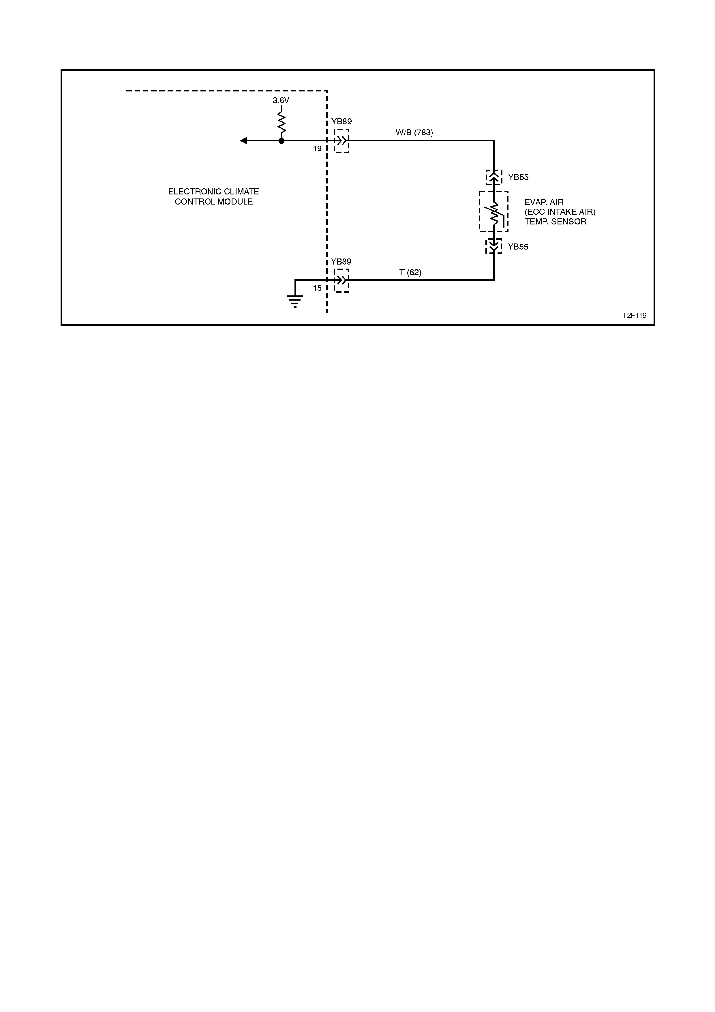
DTC 17 - EVAPORATOR AIR TEMPERATURE SENSOR (ETS) - SIGNAL VOLTAGE HIGH
Figure 2F-31
CIRCUIT DESCRIPTION:
The Evaporator Tem perature Sensor (ETS) uses a
thermistor to vary voltage signals to the ECC
Module. The ECC Module applies a voltage of 3.6
±0.18 volts to the sensor. W hen the air is cold, the
ETS resistance is high, therefore the ECC Module
will sense a high signal voltage. If the air is warm
the resistance is low, therefore the ECC Module
will sense a low signal voltage .
DTC 17 will set: if the ETS signal voltage is more
than 3.4 volts or, if the ETS sensor, wiring har ness
(circuit 783) or connectors are open circuited
TEST DESCRIPTION:
Number(s) below refer to step numbers in the
following Diagnostic Chart
1. Ensures the Diagnostic Circuit Check has been
performed.
2. This test checks that the conditions that would
set the DTC are present
3. This test checks if the wiring or sensor is open
circuit
4. This test checks if wiring is shorted to the ignition
feed in the ECC harness.
5. This test checks if wiring is shorted to the 3.5 V
feed in the ECC harness.
6. This test checks if wiring is shorted to a voltage
in the main wiring harness.
7. Check for intermittent connection at ECC.
8. This test checks if sensor is functioning okay.
9. Check for intermittent connection at sensor
10. This test checks for an open circuit sensor ear th
wire.
This test checks for an open circuit sensor signal
wire.

DIAGNOSTIC AIDS:
The default temperature for an open circuit is 5°C.
When using the temperature/resistance chart below,
place a thermometer in the centre vent, set
temperature to full cold and manual fan speed to 2.
This will give an approximate evaporator air
temperature. Compare this figure taken to the chart
below.
NOTES ON DIAGNOSTIC CHART:
1. Refer to Section 12P WIRING DIAGRAMS for
procedures on checking wiring faults.
2. Refer to 1.1 TECH 2 DIAGNOSTICS in this
Section for connecting and using TECH 2.
TEMPERATURE RESISTANCE CHART
AMBIENT°
°°
°CRESISTANCE AMBIENT°
°°
°CRESISTANCE
5 4300 - 4850 30 1675 - 1850
10 3600 - 4050 35 1330 - 1470
15 2950 - 3250 40 1140 - 1260
20 2320 - 2625 45 950 - 1050
25 1990 - 2200 50 850 - 950

STEP ACTION VALUE YES NO
1• Was the Diagnostic
Circuit Check
performed?
Go to Step 2. Go to Chart A -
DIAGNOSTIC
CIRCUIT CHECK
in this Section.
2• Connect TECH 2 to
DLC (refer to Note 2).
• Select Body / Electronic
Climate Control / Data
Display / Data List and
scroll to Evap
Temperature Sensor.
• Does TECH 2 display
Evap Temperature
Sensor above specified
value?
3.4 Volts Go to Step 3. DTC 17
intermittent. If no
additional DTCs
were stored,
refer to
INTERMITTENT
in this section
3• Disconnect ECC
connector YB89
• Check resistance
across evap air
temperature sensor
terminals at ECC
connector YB89 pins 19
& 15 (refer to Note 1).
• Is value as specified?
Refer to
Temp.
Resistance
Chart.
Go to Step 4. Go to Step 8.
4• With ECC connector
YB89 disconnected,
measure the resistance
between ECC harness
connector YB89
terminals 5 & 19
(circuits 367 & 763).
• Does a short exist?
NOTE:
Any resistance measured
here qualifies as a short
Ohms Repair short in
circuits 367 and
763. Recheck and
verify repair.
Go to Step 5.
5• With ECC connector
YB89 disconnected,
measure the resistance
between ECC harness
connector YB89
terminals 11 & B19
(circuits 188 & 763).
• Is the resistance less
than specified value?
4 K Ohms Repair short in
circuits 188 and
763. Recheck and
verify repair.
Go to Step 6.
6• Turn ignition ON.
• Check voltage across
circuit 763 to chassis
ground at ECC harness
connector YB89.
• Was voltage below
specified value?
0.4 Volts Go to Step 7. Repair short to
voltage in circuit
763. Recheck and
verify repair.
7• Inspect ECC harness
connector YB89 for an
intermittent or loose
terminal.
• Is connector YB89
okay?
Repair connector
as necessary.
Recheck and
verify repair.
Replace faulty
ECC control
module, refer to
Section 2E AIR
CONDITIONING -
ECC - REMOVAL
&
INSTALLATION.

STEP ACTION VALUE YES NO
8• Disconnect ETS
connector YB55.
• Check resistance
across evap air
temperature sensor
terminals (refer to
Note 1).
• Is value as specified?
Refer to
Temp.
Resistance
Chart.
Go to Step 9. Replace faulty in-
evap temperature
sensor, refer to
Section 2E AIR
CONDITIONING -
ECC - REMOVAL
&
INSTALLATION.
9• Inspect evap air
temperature sensor
harness connector
YB55 for an intermittent
or loose terminal.
• Is connector YB55
okay?
Repair connector
as necessary.
Recheck and
verify repair.
Go to Step 10.
10 • Check continuity of
circuit 62 (Tan wire)
between connectors
YB55 and YB89
(including connectors)
(refer to Note 1).
• Does continuity exist
and is connection okay?
•
Go to Step 11. Check and repair
circuit 62 as
necessary.
Recheck and
verify repair.
11 • Check continuity of
circuit 763 (White/Black
wire) between
connectors YB55 and
YB89 (including
connectors) (refer to
Note 1).
• Does continuity exist
and is connection okay?
Reconnect evap
air temp sensor
harness
connector YB55
and go to
step 4.
Check and repair
circuit 763 as
necessary.
Recheck and
verify repair.
DTC 18 - EVAPORATOR AIR TEMPERATURE SENSOR (ETS) - SIGNAL VOLTAGE LOW
Figure 2F-32
CIRCUIT DESCRIPTION:
The evaporator temperature sensor (ETS) uses a
thermistor to control the signal voltage to the ECC
Module. The ECC Module applies a voltage of 3.6
±0.18 volts to the sensor when the air off the
evaporator cor e is c old, the ETS r esistanc e is high,
therefore the ECC Module will sense a high signal
voltage. If the air is warm, the ETS resistance is
low, therefore the ECC Module will sense a low
signal voltage.
DTC 18 will set: if the ETS signal voltage is less
than 0.3 volts or, if the ETS sensor, wiring har ness
(circuit 783) or connectors are short circuited.
TEST DESCRIPTION:
Number(s) below refer to step numbers in the
following Diagnostic Chart
1. Ensures the Diagnostic Circuit Check has been
performed.
2. This test checks that the conditions that would
set the DTC are present
3. This test checks if the sensor or wiring is
causing the short circuit
4. This test checks if sensor & wiring is functioning
okay.
5. Check for intermittent connection at sensor
6. This test checks for a short circuit of the sensor
signal wire to earth.
7. This test determines if the sensor is shorted or
the wire is shorted.
.

DIAGNOSTIC AIDS:
The default temperature for a short circuit is 5°C.
When using the temperature/resistance chart below,
place a thermometer in the centre vent, set
temperature to full cold and manual fan speed to 2.
This will give an approximate evaporator air
temperature. Compare this figure taken to the chart
below.
Notes on Diagnostic Chart:
1. Refer to Section 12P WIRING DIAGRAMS for
procedures on checking wiring faults.
2. Refer to 1.1 TECH 2 DIAGNOSTICS in this
Section for connecting and using TECH 2.
TEMPERATURE RESISTANCE CHART
AMBIENT°
°°
°CRESISTANCE AMBIENT°
°°
°CRESISTANCE
5 4300 - 4850 30 1675 - 1850
10 3600 - 4050 35 1330 - 1470
15 2950 - 3250 40 1140 - 1260
20 2320 - 2625 45 950 - 1050
25 1990 - 2200 50 850 - 950

STEP ACTION VALUE YES NO
1• Was the Diagnostic
Circuit Check
performed?
Go to Step 2. Go to Chart A -
DIAGNOSTIC
CIRCUIT CHECK
in this Section.
2• Connect TECH 2 to
DLC (refer to Note 2).
• Select Body / Electronic
Climate Control / Data
Display / Data List and
scroll to Evap
Temperature Sensor.
• Does TECH 2 display
Evap Temperature
Sensor less specified
value?
0.4 Volts Go to Step 3. DTC 18
intermittent. If no
additional DTCs
were stored,
refer to
INTERMITTENTS
in this section
3• With TECH 2 connected
and Evap Temperature
Sensor displayed,
disconnect ECC wiring
harness YB89.
• Does TECH 2 display
Evap Temperature
Sensor above specified
value?
3.4 Volts Go to Step 4. Replace faulty
ECC control
module, refer to
Section 2E AIR
CONDITIONING -
ECC - REMOVAL
& INSTALLATION.
4• Disconnect ECC
connector YB89
• Check resistance
across evap air
temperature sensor
terminals at ECC
connector YB89 pins 19
& 15 (refer to Note 1).
• Is value as specified?
Refer to
Temp.
Resistance
Chart.
Go to Step 5. Wiring or Sensor
Faulty
Go to Step 7

STEP ACTION VALUE YES NO
5• With ECC connector
YB89 disconnected,
measure the resistance
between ECC harness
connector YB89
terminal 19 (circuit 763)
and ground.
• Does a short exist?
NOTE:
Any resistance measured
here qualifies as a short
Ohms Repair short in
circuit 763.
Recheck and
verify repair.
Go to Step 6
6• Inspect ECC and evap
air temperature sensor
wiring harness
connectors YB55 and
YB89 for an intermittent
short in harness or
connectors.
• Are connectors YB55 an
YB89 okay?
Repair connector
as necessary.
Recheck and
verify repair.
Replace faulty
ECC control
module, refer to
Section 2E AIR
CONDITIONING -
ECC - REMOVAL
& INSTALLATION.
7• Disconnect ETS sensor
plug YB55
• Connect YB87 & YB89
connectors to ECC
• Connect TECH 2 to
DLC.
• Select Body / Electronic
Climate Control / Data
Display / Data List and
scroll to Evap
Temperature Sensor.
• Does TECH 2 display
Evap Temperature
Sensor above specified
value?
3.4 Volts Replace faulty in-
evap
temperature
sensor, refer to
Section 2E AIR
CONDITIONING
- ECC -
REMOVAL &
INSTALLATION.
Repair short to
ground in circuit
763. Recheck and
verify repair.
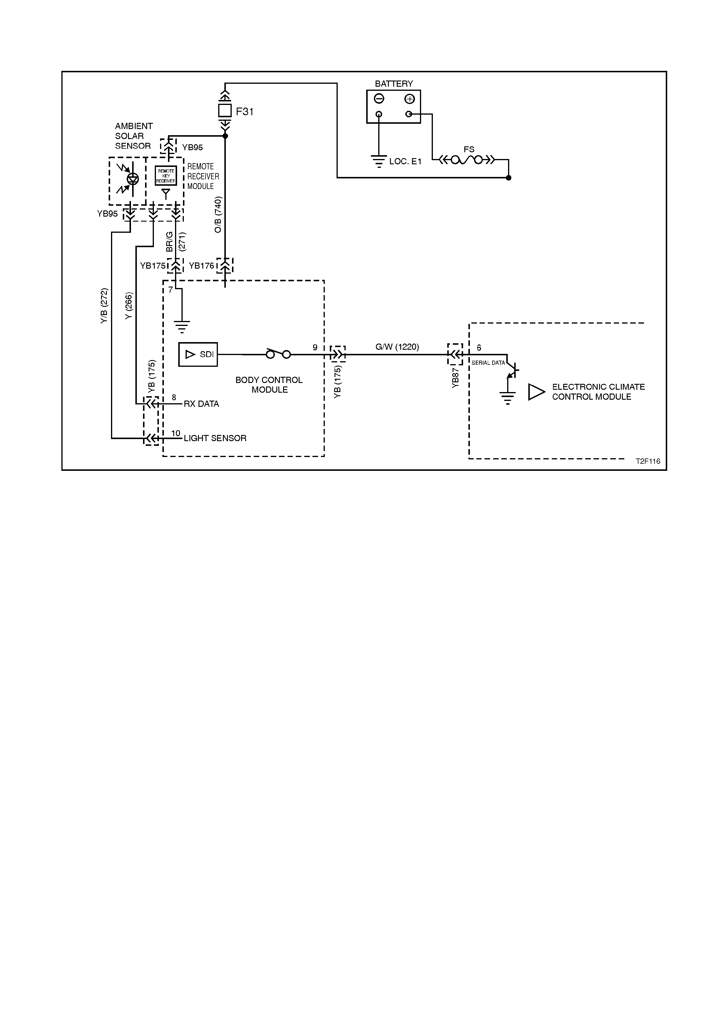
DTC 19 - SUN LOAD SENSOR FAULT
Figure 2F-33
CIRCUIT DESCRIPTION:
The sun load sensor is mounted in the instrument
panel pad between the demist duc ts to monitor the
amount of sun load and am bient light in f ront of the
vehicle. The am bient light m onitored is us ed by the
BCM for Auto Lights O n operation ( twilight s entinel)
and the sun load monitored is used by the ECC
control module. The BCM monitors the voltage
from this sensor via circuit 272 and converts this
voltage signal into steps which it s ends to the ECC
control module via the auxiliary serial data line,
circuit 1220. T he m es sage sent will vary between 0
and 254 steps depending on the amount of sun
load (0 = no sun load, 254 = maximum sun load).
DTC 19 will set if the BCM sends a sun load sensor
value of 255 steps to the ECC c ontrol m odule. T he
BCM will send this value if it detects a high sun
load and a low twilight level.

TEST DESCRIPTION:
Number(s) below refer to step numbers in the
following Diagnostic Chart
1. Ensures the Diagnostic Circuit Check has been
performed.
2 & 3. Uses TECH 2 to check ambient light level
data on the auxiliary serial data bus.
4 & 5. Uses TECH 2 to check ambient light level
signal at microprocessor of BCM.
6. Determines if the sun sensor / remote receiver
module has power and earth by checking
operation of the remote coded key reader.
7 & 8. Checks ambient light level signal at input to
BCM.
9. Checks integrity of circuit 272 (open, short to
earth or short to B+).
10. Checks battery voltage supply at sun sensor /
remote receiver module.
11. Checks integrity of circuit 271 (open, short to
earth or short to B+).
NOTES ON DIAGNOSTIC CHART:
1. Refer to Section 12P WIRING DIAGRAMS for
procedures on checking wiring faults.
2. Refer to 1.1 TECH 2 DIAGNOSTICS in this
Section for connecting and using TECH 2.

STEP ACTION VALUE YES NO
1• Was the Diagnostic
Circuit Check
performed?
Go to Step 2. Go to Chart A -
DIAGNOSTIC
CIRCUIT CHECK
in this Section.
2• Connect TECH 2 to
DLC (refer to Note 2).
• Select Body / Body
Control Module / Normal
Mode and scroll to
Ambient Light Level.
• Cover the sun load
sensor / remote receiver
module assembly.
• Does TECH 2 display 1
Step
Go to Step 3. Go to Step 4.
3• With TECH 2 connected
and Ambient Light Level
displayed, shine a torch
directly on the sun load
sensor / remote receiver
module assembly.
• Does TECH 2 display
254 Step
Fault not found, if
no other DTCs are
stored, refer to
INTERMITTENTS
in this section.
Go to Step 4.
4• With TECH 2
connected, select Body
/ Body Control Module /
Data Display / Datal List
and scroll to Ambient
Light Sensor display
• Cover the sun load
sensor / remote receiver
module assembly.
• Is TECH 2 screen
display value as
specified?
Less than
0.5 volts Replace BCM,
refer to Section
12J-2 HIGH
SERIES BCM.
Go to Step 5.

STEP ACTION VALUE YES NO
5• With TECH 2
connected, and Ambient
Light Sensor displayed
• Shine a torch on the sun
load sensor / remote
receiver module
assembly.
• Is TECH 2 screen
display value as
specified?
Approx.
5 volts Replace BCM,
refer to Section
12J-2 HIGH
SERIES BCM.
Go to Step 6.
6• Check operation of the
remote coded key
receiver by locking and
unlocking the doors
using the remote coded
key Lock and Unlock
button.
• Does remote coded key
receiver operate?
Go to Step 7 Go to Step 10.
7• Back probe BCM
connector YB175,
terminal E10, circuit 272
(Yellow/Black wire) with
a voltmeter to earth
(referNOTE 1).
• Turn ignition ON.
• Cover the sun load
sensor / remote receiver
module assembly.
• Is voltage as specified?
Less than
0.5 volts Replace BCM,
refer to Section
12J-2 HIGH
SERIES BCM.
Go to Step 8.

STEP ACTION VALUE YES NO
8• Back probe BCM
connector YB175,
terminal E10, circuit 272
(Yellow/Black wire) with
a voltmeter to earth
(refer NOTE 1).
• Turn ignition ON.
• Shine a torch on the sun
load sensor / remote
receiver module
assembly.
• Is voltage as specified?
Approx.
5 volts Replace BCM,
refer to Section
12J-2 HIGH
SERIES BCM.
Go to Step 9.
9• Check integrity of circuit
272 (Yellow/Brown wire)
(refer NOTE 1).
• Is circuit 272 okay?
Replace sun
sensor / remote
receiver module,
refer to Section
12J-2 HIGH
SERIES BCM
Check and repair
circuit 272 as
necessary.
Recheck and verify
repair.
10 • Back probe sun sensor /
remote receiver module
connector YB95, circuit
740 (Orange/Black wire)
with a voltmeter to earth
(refer NOTE 1).
• Is voltage as specified?
12 volts Go to Step 11. Check and repair
circuit 740.
Recheck and verify
repair.
11 • Check integrity of circuit
271 (Brown/Green wire)
(refer NOTE 1).
• Is circuit 271 okay?
Go to Step 7. Check and repair
circuit 271.
Recheck and verify
repair.
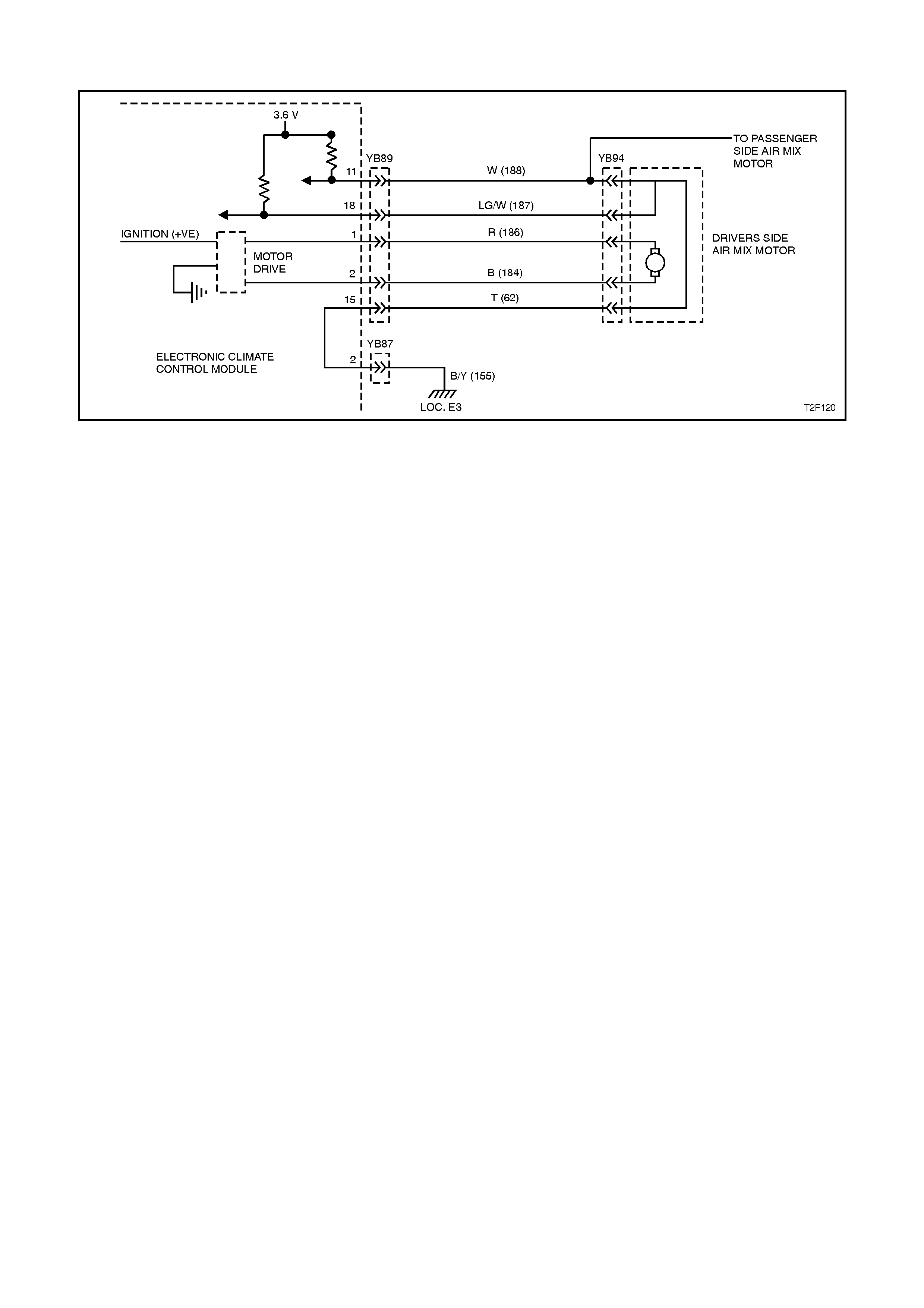
DTC 21 - AIR MIX MOTOR DRIVERS SIDE (SZ/DZ)
Figure 2F-39
CIRCUIT DESCRIPTION:
The air m ix motor is actually an electric m otor used
to operate the air m ixing door. T he electr ic m otor is
sent a voltage signal of 12.5 volts from the ECC
control module which causes the motor to turn,
which moves the air mix door towards or away
from the heater core, the direction change takes
place by reversing the polarity of this motor.
A potentiometer (PBR) is housed in the air mix
motor circuit which feeds signals (3.6 ± 0.18 volts)
back to the ECC control module as to the
positioning of the motor and consequently the air
mix door.
DTC 21 will set: if the dr iver’s PBR feedbac k signal
fails to r each the requested value. T his will occur if
the PBR or motor is open or short circuited, or if
the air mix door is jammed or sticking.
TEST DESCRIPTION:
Number(s) below refer to step numbers in the
following Diagnostic Chart
1. Ensures the Diagnostic Circuit Check has been
performed.
2. This test checks that the DTC is current.
3. This test checks if the motor is moving
4. This test checks that the m otor is stopping within
the correct range @ full cold.
5. This test checks that the m otor is stopping within
the correct range @ full hot.
6. Attempts to re-calibrate & check DTC is still
current
7. Determines if a motor fault is more likely than a
PBR fault to be the cause of the problem.
8. Checks fault has been rectified.
NOTES ON DIAGNOSTIC CHART:
1. Refer to Section 12P WIRING DIAGRAMS for
procedures on checking wiring faults.
2. Refer to 1.1 TECH 2 DIAGNOSTICS in this
Section for connecting and using TECH 2.

DIAGNOSTIC AIDS:
An air mix motor or door problem will always be
associated with non-regulated or incorrect
temperatures from mode positions.
The ECC control module, during calibration, sets a
minimum and a maximum PBR value for the air mix
motor in it’s memory. It is these values which
determine the operating range of the air mix motor
and against which all movements of the air mix
adjustm ent are scaled. Any PBR signal value outside
the minimum or maximum vale are considered a
motor fault.
The ECC c ontrol module m onitors the rate of change
of PBR signal during air mix motor movement. If this
rate of change falls to 0 (such as a broken air mix
motor wire or physical jam b), the ECC contr ol m odule
will recognise the stoppage and set the fault code.
If DTC 21 was present before turning the ignition off,
when the ignition is turned on again, the ECC control
m odule will autom atically try to re-c alibrate the air m ix
door. This takes approxim ately 15 seconds. If the re-
calibration fails, then DTC 21 will be set again.

DTC 21 - AIR MIX MOTOR DRIVERS SIDE
STEP ACTION VALUE YES NO
1• Was the Diagnostic
Circuit Check
performed?
Go to Step 2. Go to Chart A -
DIAGNOSTIC
CIRCUIT CHECK
in this Section.
2• Turn ignition OFF.
• Connect TECH 2 to
DLC.
• Turn ignition ON when
instructed by TECH 2.
• Select Body / Electronic
Climate Control /
Diagnostic Trouble
Codes / Read Current
DTC Information.
• Is DTC 21 displayed as
a current DTC?
Go to Step 3. Go to Step 8.
3• With TECH 2 still
connected, select Body
/ Electronic Climate
Control / Miscellaneous
Tests / Drivers S ide A ir
Mix Motor - Door
Movement and increase
to maximum then
decrease to minimum.
• Does the Drivers Air Mix
Door feedback (voltage)
on TECH 2 change?
Go to Step 4. Go to Step 7.
4• With Driver’s Side Air
Mix Motor - Door
Movement test still
selected, decrease air
mix door to minimum.
• Does Tech 2 display
Drivers Air Mix Door
feedback within the
specified range?
0.6 to 0.9
Volts Go to Step 5. Go to following
chart DRIVER
MOTOR TEST in
this Section.

STEP ACTION VALUE YES NO
5• With Driver’s Side Air
Mix Motor - Door
Movement test still
selected increase air
mix door to maximum.
• Does Tech 2 display
Drivers Air Mix Door
feedback within the
specified range?
2.6 to 2.9
Volts Go to Step 6. Go to following
chart DRIVER
MOTOR TEST in
this Section.
6• With TECH 2 still
connected, select Body
/ Electronic Climate
Control / Program /
Calibrate Air Mix Door
and reprogram air mix
doors.
• Turn ignition OFF.
• Turn ignition ON.
• Is DTC-21 set as a
current DTC?.
Go to following
chart DRIVER
MOTOR TEST in
this Section.
Go to Step 8.
7. • In Step 3, did TECH 2
display Drivers Air mix
door feedback within the
specified range?
0.3 to 3.4
volts Go to following
chart DRIVER
MOTOR TEST in
this Section.
Go to following
chart PBR TEST in
this Section.
8• With TECH 2 still
connected, select Body
/ Electronic Climate
Control / Miscellaneous
Tests / Drivers S ide A ir
Mix Motor- Door
Movement and increase
to maximum then
decrease to minimum.
• Is DTC-21 set as a
current DTC?.
Go to Step 3. Re-calibration of
Air mix door may
have corrected
fault or DTC 21 is
intermittent.
(Carry out air mix
door calibration if
not already done
so, refer to 1.2
TECH 2 TEST
MODES AND
DISPLAYS FOR
ECC DIAGNOSIS
and/or refer to
INTERMITTEN T in
this section.

DRIVER MOTOR TEST
STEP ACTION VALUE YES NO
1• Disconnect ECC wiring
harness connector
YB89.
• Connect TECH 2 to
DLC.
• Select Body / Electronic
Climate Control / Data
Display / Data List and
scroll to Drivers Air Mix
Door Feedback.
• Does Tech 2 display
Drivers Air Mix Door
Feedback above the
specified value?
3.4 Volts Go to step 2. Replace ECC
control module,
refer to Section
2E AIR
CONDITIONING -
ECC - REMOVAL
& INSTALLATION.
2• With ECC connector
YB89 disconnected,
measure the resistance
between harness
terminals 1 & 2 (circuits
184 & 186) on
connector YB89.
• Is resistance less than
specified value ?
80 Ohms Go to Step 3. Go to step 8.
3• In step 2, was
resistance less than
specified value between
terminals 1 & 2 (circuits
184 & 186) on
connector YB89?
70 Ohms Go to step 7. Go to Step 4.
4• With ECC connector
YB89 disconnected,
measure the resistance
between terminal 1
(circuit 186) on
connector YB89 and
chassis ground.
• Does the meter indicate
a short to ground ?
NOTE: (Any resistance
measured here qualifies
as a short)
Ohms Repair short in
circuit 186.
Recheck and verify
repair.
Go to Step 4.
5• With ECC connector
YB89 disconnected,
measure the resistance
between terminals 1 &
15 (circuits 186 & 62) on
connector YB89.
• Does the meter indicate
a short?
NOTE: (Any resistance
measured here qualifies
as a short)
Ohms Repair short in
circuits 186 and/or
62. Recheck and
verify repair.
Go to Step 5.

STEP ACTION VALUE YES NO
6• With ECC connector
YB89 disconnected,
measure the resistance
between terminals 1 & 5
(circuits 186 & 367) on
connector YB89.
• Does the meter indicate
a short?
NOTE: (Any resistance
measured here qualifies
as a short)
Ohms Repair short in
circuits 186 and/or
367. Recheck and
verify repair.
Go to Step 10.
7• Disconnect drivers air
mix door motor
connector YB94.
• With ECC connector
YB89 disconnected,
measure the resistance
between terminals 1 & 2
(circuits 184 & 186) on
connector YB89.
• Does the meter indicate
a short ?
NOTE: (Any resistance
measured here qualifies
as a short)
Ohms Repair short in
circuits 184 and/or
186. Recheck and
verify repair.
Replace drivers air
mix door motor,
refer to Section
2E AIR
CONDITIONING -
ECC - REMOVAL
& INSTALLATION.
8• Inspect wiring harness
connectors YB89 and
YB94 for an intermittent
or loose terminal.
• Are connectors okay?
Go to Step 9. Repair connectors
as necessary.
Recheck and verify
repair.
9• Check for open in
circuits 184 & 186.
• Was an open or faulty
connection found?
Repair circuits 184
and/or 186.
Recheck and verify
repair.
Replace air mix
door motor, refer to
Section 2E AIR
CONDITIONING -
ECC - REMOVAL
& INSTALLATION.

STEP ACTION VALUE YES NO
10 • Inspect wiring harness
connectors YB89 and
YB94 for an intermittent
or loose terminal, or for
terminals shorted
together.
• Are connectors okay?
Go to Step 11. Repair connectors
as necessary.
Recheck and verify
repair.
11 • Has the DRIVER PBR
TEST been performed ? Go to Step 12 Go to following
chart PBR TEST in
this Section.
12 • Remove drivers air mix
motor assembly, refer to
Section 2E AIR
CONDITIONING - ECC
- REMOVAL &
INSTALLATION.
• Move Air mix door by
hand
• Is door physically
jammed or broken
Repair air mix door
as necessary.
Recheck and verify
repair.
Go to 13.
13 • Replace air mix motor
assembly, refer to
Section 2E AIR
CONDITIONING - ECC
- REMOVAL &
INSTALLATION.
• Did new Motor fix the
problem ?
System okay. Replace ECC
control module,
refer to Section
2E AIR
CONDITIONING -
ECC - REMOVAL
& INSTALLATION.

DRIVER PBR TEST
STEP ACTION VALUE YES NO
1• Disconnect ECC wiring
harness connector
YB89.
• Connect TECH 2 to
DLC.
• Select Body / Electronic
Climate Control / Data
Display / Data List and
scroll to Drivers Air Mix
Door Feedback.
• Does Tech 2 display
Drivers Air Mix Door
Feedback above the
specified value?
3.4 Volts Go to step 2. Replace ECC
control module,
refer to Section
2E AIR
CONDITIONING -
ECC - REMOVAL
& INSTALLATION.
2• Re-connect drivers air
mix motor (if
disconnected from
Motor Testing).
• With ECC connector
YB89 disconnected,
measure the resistance
between terminal 11
(circuit 188) on
connector YB89 and
chassis ground.
• Does the meter indicate
a short to ground ?
NOTE: (Any resistance
measured here qualifies as
a short).
Ohms Repair short in
circuit 188.
Recheck and verify
repair.
Go to Step 3.
3• With ECC connector
YB89 disconnected,
measure the resistance
between terminals 1 &
11 (circuits 186 & 188)
on connector YB89.
• Does the meter indicate
a short ?
NOTE: (Any resistance
measured here qualifies as
a short).
Ohms Repair short in
circuit 186 and/or
188. Recheck and
verify repair.
Go to Step 4.
4• With ECC connector
YB89 disconnected,
measure the resistance
between terminals 5 &
11 (circuits 367 & 188)
on connector YB89.
• Does the meter indicate
a short ?
NOTE: (Any resistance
measured here qualifies as
a short).
Ohms Repair short in
circuit 367 and/or
188. Recheck and
verify repair.
Go to Step 5.

STEP ACTION VALUE YES NO
5• Disconnect passengers
air mix motor connector
YB94 (if fitted).
• With ECC connector
YB89 disconnected,
measure the resistance
between terminals 11 &
15 (circuits 188 & 62) on
connector YB89.
• Is resistance less than
specified values ?
<12K
Ohms Go to Step 6. Go to Step 14.
6• In Step 5, was the
measured resistance at
terminals 11 & 15
(circuits 62 & 188)
above the specified
value?
>8K
Ohms Go to Step 7. Go to Step 11.
7• With ECC connector
YB89 disconnected,
measure the resistance
between terminals 11 &
18 (circuits 188 & 187)
on connector YB89
• Is resistance less than
specified value?
<8.5K
Ohms Go to Step 8. Go to Step 14.
8• In Step 7, was the
measured resistance at
terminals 11 & 18
(circuits 187 & 188)
above the specified
value?
>1.5K
Ohms Go to Step 9. Go to Step 11.
9• Inspect ECC wiring
harness connector
YB89 or air mix motor
connector YB94 for an
intermittent or loose
terminal.
• Are connectors okay?
Repair connectors
as necessary.
Recheck and verify
repair.
Go to Step10.
10 • Re-connect ECC
connectors YB89 &
YB87 to ECC control
module.
• Disconnect drivers air
mix motor connector
YB94.
• Turn ignition ON
• Measure voltage at
driver’s air mix motor
connector YB94
between circuits 62
(Tan wire) & 188 (White
wire).
• Is the voltage as
specified?
3.4 volts
to 3.8
volts
Go to Step 16. Replace ECC
control module,
refer to Section
2E AIR
CONDITIONING -
ECC - REMOVAL
& INSTALLATION.

STEP ACTION VALUE YES NO
11 • Disconnect air mix
motor connectors YB94
(both if fitted).
• With ECC connector
YB89 disconnected,
measure the resistance
between terminals 11 &
15 (circuits 188 & 62 )
on connector YB89.
• Does the meter indicate
a short ?
NOTE: (Any resistance
measured here qualifies as
a short).
Ohms Repair short in
circuit 62 and/or
188. Recheck and
verify repair.
Go to Step 12.
12 • With ECC connectors
YB89 and YB94
disconnected, measure
the resistance between
terminals 15 & 18
(circuits 62 & 187) on
connector YB89.
• Does the meter indicate
a short ?
NOTE: (Any resistance
measured here qualifies as
a short).
Ohms Repair short in
circuit 62 and/or
187. Recheck and
verify repair.
Go to step 13.
13 • With ECC connectors
YB89 and YB94
disconnected, measure
the resistance between
terminals 11 & 18
(circuits 188 & 187) on
connector YB89.
• Does the meter indicate
a short ?
NOTE: (Any resistance
measured here qualifies as
a short).
Ohms Repair short in
circuit 187 and/or
188. Recheck and
verify repair.
Replace air mix
door motor, refer to
Section 2E AIR
CONDITIONING -
ECC - REMOVAL
& INSTALLATION.
14 • Inspect wiring harness
connectors YB89 and
YB94 for an intermittent
or loose terminal.
• Are connectors okay?
Go to Step 15 Repair connectors
as necessary.
Recheck and verify
repair.

STEP ACTION VALUE YES NO
15 • Check for open in
circuits 62, 187 & 188.
• Was an open or faulty
connection found?
Repair circuits as
necessary.
Recheck and verify
repair.
Replace air mix
door motor, refer to
Section 2E AIR
CONDITIONING -
ECC - REMOVAL
& INSTALLATION.
16 • Has the DRIVER
MOTOR TEST been
performed ?
Go to Step 17. Go to previous
chart DRIVERS
MOTOR TEST in
this Section.
17 • Remove drivers air mix
motor assembly, refer to
Section 2E AIR
CONDITIONING - ECC
- REMOVAL &
INSTALLATION.
• Move Air mix door by
hand
• Is door physically
jammed or broken
Repair air mix door
as necessary.
Recheck and verify
repair.
Go to Step 18.
18 • Replace air mix motor
assembly, refer to
Section 2E AIR
CONDITIONING - ECC
- REMOVAL &
INSTALLATION.
• Did new Motor fix the
problem ?
System okay. Replace ECC
control module,
refer to Section
2E AIR
CONDITIONING -
ECC - REMOVAL
& INSTALLATION.
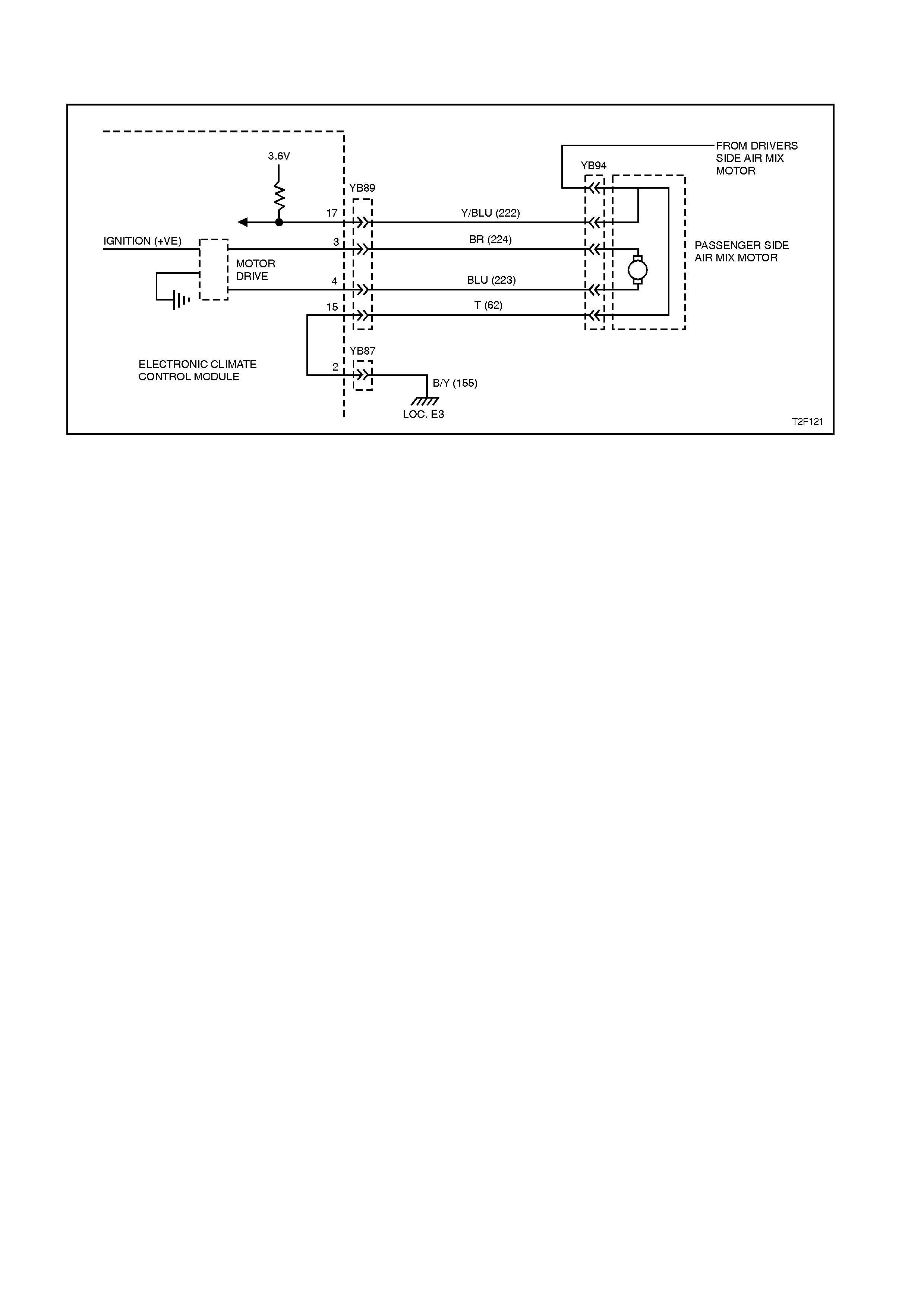
DTC 24 - AIR MIX MOTOR PASSENGER SIDE (DZ)
Figure 2F-34
CIRCUIT DESCRIPTION:
The air m ix motor is actually an electric m otor used
to operate the air m ixing door. T he electr ic m otor is
sent a voltage signal of 12.5 volts from the ECC
control module which causes the motor to turn,
which moves the air mix door towards or away
from the heater core, the direction change takes
place by reversing the polarity of this motor.
A potentiometer (PBR) is housed in the air mix
motor circuit which feeds signals (3.6 ± 0.18 volts)
back to the ECC control module as to the
positioning of the motor and consequently the air
mix door.
DTC 24 will set: if the passenger’s PBR feedback
signal fails to reach the requested value. This will
occur if the PBR or motor is open or shor t c irc uited,
or it the air mix door is jammed or sticking.
TEST DESCRIPTION:
Number(s) below refer to step numbers in the
following Diagnostic Chart
1. Ensures the Diagnostic Circuit Check has been
performed.
2. This test checks that the DTC is current.
3. This test checks if the motor is moving
4. This test checks that the m otor is stopping within
the correct range @ full cold.
5. This test checks that the m otor is stopping within
the correct range @ full hot.
6. Attempts to re-calibrate & check DTC is still
current
7. Determines if a if a m otor fault is m ore likely the
a PBR fault to be the cause of the fault.
8. Checks fault has been rectified.
NOTES ON DIAGNOSTIC CHART:
1. Refer to Section 12P WIRING DIAGRAMS for
procedures on checking wiring faults.
2. Refer to 1.1 TECH 2 DIAGNOSTICS in this
Section for connecting and using TECH 2.

DIAGNOSTIC AIDS:
An air mix motor or door problem will always be
associated with non-regulated or incorrect
temperatures from mode positions.
The ECC control module, during calibration, sets a
minimum and a maximum PBR value for the air mix
motor in it’s memory. It is these values which
determine the operating range of the air mix motor
and against which all movements of the air mix
adjustm ent are scaled. Any PBR signal value outside
the minimum or maximum vale are considered a
motor fault.
The ECC c ontrol module m onitors the rate of change
of PBR signal during air mix motor movement. If this
rate of change falls to 0 (such as a broken air mix
motor wire or physical jam b), the ECC contr ol m odule
will recognise the stoppage and set the fault code.
If DTC 24 was present before turning the ignition off,
when the ignition is turned on again, the ECC control
m odule will autom atically try to re-c alibrate the air m ix
door. This takes approxim ately 15 seconds. If the re-
calibration fails, then DTC 24 will be set again.

DTC 24 - AIR MIX MOTOR PASSENGER’S SIDE
STEP ACTION VALUE YES NO
1• Was the Diagnostic
Circuit Check
performed?
Go to Step 2. Go to Chart A -
DIAGNOSTIC
CIRCUIT CHECK
in this Section.
2• Turn ignition OFF.
• Connect TECH 2 to
DLC.
• Turn ignition ON when
instructed by TECH 2.
• Select Body /
Electronic Climate
Control / Diagnostic
Trouble Codes / Read
Current DTC
Information.
• Is DTC 24 displayed as
a current DTC?
Go to Step 3. Go to Step 8.
3• With TECH 2 still
connected, select Body
/ Electronic Climate
Control /
Miscellaneous Tests /
Passenger Side Air
Mix Motor - Door
Movement and
increase to maximum
then decrease to
minimum.
• Does the Passenger
Air Mix Door feedback
(voltage) on TECH 2
change?
Go to Step 4. Go to Step 7.
4• With Passengers Side
Air Mix Motor - Door
Movement test still
selected, decrease air
mix door to minimum.
• Does Tech 2 display
Drivers Air Mix Door
feedback within the
specified range?
0.6 to
0.9 Volts Go to Step 5. Go to following
chart
PASSENGER
MOTOR TEST in
this Section.

STEP ACTION VALUE YES NO
5• With Passengers Side
Air Mix Motor - Door
Movement test still
selected increase air
mix door to maximum.
• Does Tech 2 display
Passengers Air Mix
Door feedback within
the specified range?
2.6 to
2.9 Volts Go to Step 6. Go to following
chart
PASSENGER
MOTOR TEST in
this Section.
6• With TECH 2 still
connected, select Body
/ Electronic Climate
Control / Program /
Calibrate Air Mix Door
and reprogram air mix
doors.
• Turn ignition OFF.
• Turn ignition ON.
• Is DTC-24 set as a
current DTC?.
Go to following
chart
PASSENGER
MOTOR TEST in
this Section.
Go to Step 8.
7. • In Step 3, did TECH 2
display Passengers Air
mix door feedback
within the specified
range?
0.3 to
3.4 volts Go to following
chart
PASSENGER
MOTOR TEST in
this Section.
Go to following
chart
PASSENGER
PBR TEST in this
Section.
8• With TECH 2 still
connected, select Body
/ Electronic Climate
Control /
Miscellaneous Tests /
Passengers Side Air
Mix Motor- Door
Movement and
increase to maximum
then decrease to
minimum.
• Is DTC-24 set as a
current DTC?.
Go to Step 3. Re-calibration of
Air mix door may
have corrected
fault or DTC 24 is
intermittent.
(Carry out air mix
door calibration if
not already done
so, refer to 1.2
TECH 2 TEST
MODES AND
DISPLAYS FOR
ECC DIAGNOSIS
and/or refer to
INTERMITTENT
in this section.

PASSENGER’S MOTOR TEST
STEP ACTION VALUE YES NO
1• Disconnect ECC wiring
harness connector
YB89.
• Connect TECH 2 to
DLC.
• Select Body /
Electronic Climate
Control / Data Display /
Data List and scroll to
Passengers Air Mix
Door Feedback.
• Does Tech 2 display
Passengers Air Mix
Door Feedback above
the specified value?
3.4 Volts Go to step 2. Replace ECC
control module,
refer to Section
2E AIR
CONDITIONING -
ECC -
REMOVAL &
INSTALLATION.
2• With ECC connector
YB89 disconnected,
measure the
resistance between
harness terminals 3 &
4 (circuits 223 & 224)
on connector YB89.
• Is resistance less than
specified value ?
80
Ohms Go to Step 3. Go to step 8.
3• In step 2, was
resistance less than
specified value
between terminals 3 &
4 (circuits 223 & 224)
on connector YB89?
70
Ohms Go to step 7. Go to Step 4.
4• With ECC connector
YB89 disconnected,
measure the
resistance between
terminal 3 (circuit 224)
on connector YB89
and chassis ground.
• Does the meter
indicate a short to
ground ?
NOTE: (Any resistance
measured here
qualifies as a short)
Ohms Repair short in
circuit 186.
Recheck and
verify repair.
Go to Step 4.
5• With ECC connector
YB89 disconnected,
measure the
resistance between
terminals 3 & 15
(circuits 224 & 62) on
connector YB89.
• Does the meter
indicate a short?
NOTE: (Any resistance
measured here
qualifies as a short)
Ohms Repair short in
circuits 186 and/or
62. Recheck and
verify repair.
Go to Step 5.

STEP ACTION VALUE YES NO
6• With ECC connector
YB89 disconnected,
measure the
resistance between
terminals 3 & 5
(circuits 224 & 367) on
connector YB89.
• Does the meter
indicate a short?
NOTE:(Any resistance
measured here
qualifies as a short)
Ohms Repair short in
circuits 186 and/or
367. Recheck and
verify repair.
Go to Step 10.
7• Disconnect passenger
air mix door motor
connector YB94.
• With ECC connector
YB89 disconnected,
measure the
resistance between
terminals 3 & 4
(circuits 224 & 223) on
connector YB89.
• Does the meter
indicate a short ?
NOTE: (Any resistance
measured here
qualifies as a short)
Ohms Repair short in
circuits 184 and/or
186. Recheck and
verify repair.
Replace
passenger air mix
door motor, refer
to Section 2E AIR
CONDITIONING -
ECC -
REMOVAL &
INSTALLATION.
8• Inspect wiring harness
connectors YB89 and
YB94 for an
intermittent or loose
terminal.
• Are connectors okay?
Go to Step 9. Repair connectors
as necessary.
Recheck and
verify repair.
9• Check for open in
circuits 223 & 224.
• Was an open or faulty
connection found?
Repair circuits
184 and/or 186.
Recheck and
verify repair.
Replace air mix
door motor, refer
to Section 2E AIR
CONDITIONING -
ECC -
REMOVAL &
INSTALLATION.

STEP ACTION VALUE YES NO
10 • Inspect wiring harness
connectors YB89 and
YB94 for an
intermittent or loose
terminal, or for
terminals shorted
together.
• Are connectors okay?
Go to Step 11. Repair connectors
as necessary.
Recheck and
verify repair.
11 • Has the PASSENGER
PBR TEST been
performed ?
Go to Step 12 Go to following
chart PBR TEST
in this Section.
12 • Remove passenger’s
air mix motor
assembly, refer to
Section 2E AIR
CONDITIONING -
ECC - REMOVAL &
INSTALLATION.
• Move Air mix door by
hand
• Is door physically
jammed or broken
Repair air mix
door as
necessary.
Recheck and
verify repair.
Go to 13.
13 • Replace air mix motor
assembly, refer to
Section 2E AIR
CONDITIONING -
ECC - REMOVAL &
INSTALLATION.
• Did new Motor fix the
problem ?
System okay. Replace ECC
control module,
refer to Section
2E AIR
CONDITIONING -
ECC -
REMOVAL &
INSTALLATION.

PASSENGER’S PBR TEST
STEP ACTION VALUE YES NO
1• Disconnect ECC wiring
harness connector
YB89.
• Connect TECH 2 to
DLC.
• Select Body /
Electronic Climate
Control / Data Display /
Data List and scroll to
Passengers Air Mix
Door Feedback.
• Does Tech 2 display
Air Mix Door Feedback
above the specified
value?
3.4 Volts Go to step 2. Replace ECC
control module,
refer to Section
2E AIR
CONDITIONING -
ECC -
REMOVAL &
INSTALLATION.
2• Re-connect drivers air
mix motor (if
disconnected from
Motor Testing).
• With ECC connector
YB89 disconnected,
measure the
resistance between
terminal 11 (circuit
188) on connector
YB89 and chassis
ground.
• Does the meter
indicate a short to
ground ?
NOTE: (Any resistance
measured here qualifies
as a short).
Ohms Repair short in
circuit 188.
Recheck and
verify repair.
Go to Step 3.
3• With ECC connector
YB89 disconnected,
measure the
resistance between
terminals 1 & 3
(circuits 186 & 224) on
connector YB89.
• Does the meter
indicate a short ?
NOTE: (Any resistance
measured here qualifies
as a short).
Ohms Repair short in
circuit 186 and/or
188. Recheck and
verify repair.
Go to Step 4.
4• With ECC connector
YB89 disconnected,
measure the
resistance between
terminals 5 & 11
(circuits 367 & 188) on
connector YB89.
• Does the meter
indicate a short ?
NOTE: (Any resistance
measured here qualifies
as a short).
Ohms Repair short in
circuit 367 and/or
188. Recheck and
verify repair.
Go to Step 5.

STEP ACTION VALUE YES NO
5• Disconnect
passengers air mix
motor connector YB94.
• With ECC connector
YB89 disconnected,
measure the
resistance between
terminals 11 & 15
(circuits 188 & 62) on
connector YB89.
• Is resistance less than
specified values ?
<12K
Ohms Go to Step 6. Go to Step 14.
6• In Step 5, was the
measured resistance
at terminals 11 & 15
(circuits 62 & 188)
above the specified
value?
>8K
Ohms Go to Step 7. Go to Step 11.
7• With ECC connector
YB89 disconnected,
measure the
resistance between
terminals 11 & 17
(circuits 188 & 222) on
connector YB89
• Is resistance less than
specified value?
<8.5K
Ohms Go to Step 8. Go to Step 14.
8• In Step 7, was the
measured resistance
at terminals 11 & 17
(circuits 222 & 188)
above the specified
value?
>1.5K
Ohms Go to Step 9. Go to Step 11.
9• Inspect ECC wiring
harness connector
YB89 or air mix motor
connector YB94 for an
intermittent or loose
terminal.
• Are connectors okay?
Repair connectors
as necessary.
Recheck and
verify repair.
Go to Step10.
10 • Re-connect ECC
connectors YB89 &
YB87 to ECC control
module.
• Disconnect drivers air
mix motor connector
YB94.
• Turn ignition ON
• Measure voltage at
driver’s air mix motor
connector YB94
between circuits 62
(Tan wire) & 188
(White wire).
• Is the voltage as
specified?
3.4 volts
to 3.8
volts
Go to Step 16. Replace ECC
control module,
refer to Section
2E AIR
CONDITIONING -
ECC -
REMOVAL &
INSTALLATION.

STEP ACTION VALUE YES NO
11 • Disconnect air mix
motor connectors
YB94 (both if fitted).
• With ECC connector
YB89 disconnected,
measure the
resistance between
terminals 11 & 15
(circuits 188 & 62 ) on
connector YB89.
• Does the meter
indicate a short ?
NOTE: (Any resistance
measured here qualifies
as a short).
Ohms Repair short in
circuit 62 and/or
188. Recheck and
verify repair.
Go to Step 12.
12 • With ECC connectors
YB89 and YB94
disconnected,
measure the
resistance between
terminals 15 & 17
(circuits 62 & 222) on
connector YB89.
• Does the meter
indicate a short ?
NOTE: (Any resistance
measured here qualifies
as a short).
Ohms Repair short in
circuit 62 and/or
187. Recheck and
verify repair.
Go to step 13.
13 • With ECC connectors
YB89 and YB94
disconnected,
measure the
resistance between
terminals 11 & 17
(circuits 188 & 222) on
connector YB89.
• Does the meter
indicate a short ?
NOTE: (Any resistance
measured here qualifies
as a short).
Ohms Repair short in
circuit 187 and/or
188. Recheck and
verify repair.
Replace air mix
door motor, refer
to Section 2E AIR
CONDITIONING -
ECC -
REMOVAL &
INSTALLATION.

STEP ACTION VALUE YES NO
14 • Inspect wiring harness
connectors YB89 and
YB94 for an
intermittent or loose
terminal.
• Are connectors okay?
Go to Step 15 Repair connectors
as necessary.
Recheck and
verify repair.
15 • Check for open in
circuits 62, 222 & 188.
• Was an open or faulty
connection found?
Repair circuits as
necessary.
Recheck and
verify repair.
Replace air mix
door motor, refer
to Section 2E AIR
CONDITIONING -
ECC -
REMOVAL &
INSTALLATION.
16 • Has the
PASSENGER’S
MOTOR TEST been
performed ?
Go to Step 17. Go to previous
chart
PASSENGER’S
MOTOR TEST
in this Section.
17 • Remove passenger’s
air mix motor
assembly, refer to
Section 2E AIR
CONDITIONING -
ECC - REMOVAL &
INSTALLATION.
• Move Air mix door by
hand
• Is door physically
jammed or broken
Repair air mix
door as
necessary.
Recheck and
verify repair.
Go to Step 18.
18 • Replace air mix motor
assembly, refer to
Section 2E AIR
CONDITIONING -
ECC - REMOVAL &
INSTALLATION.
• Did new Motor fix the
problem ?
System okay. Replace ECC
control module,
refer to Section
2E AIR
CONDITIONING -
ECC -
REMOVAL &
INSTALLATION.
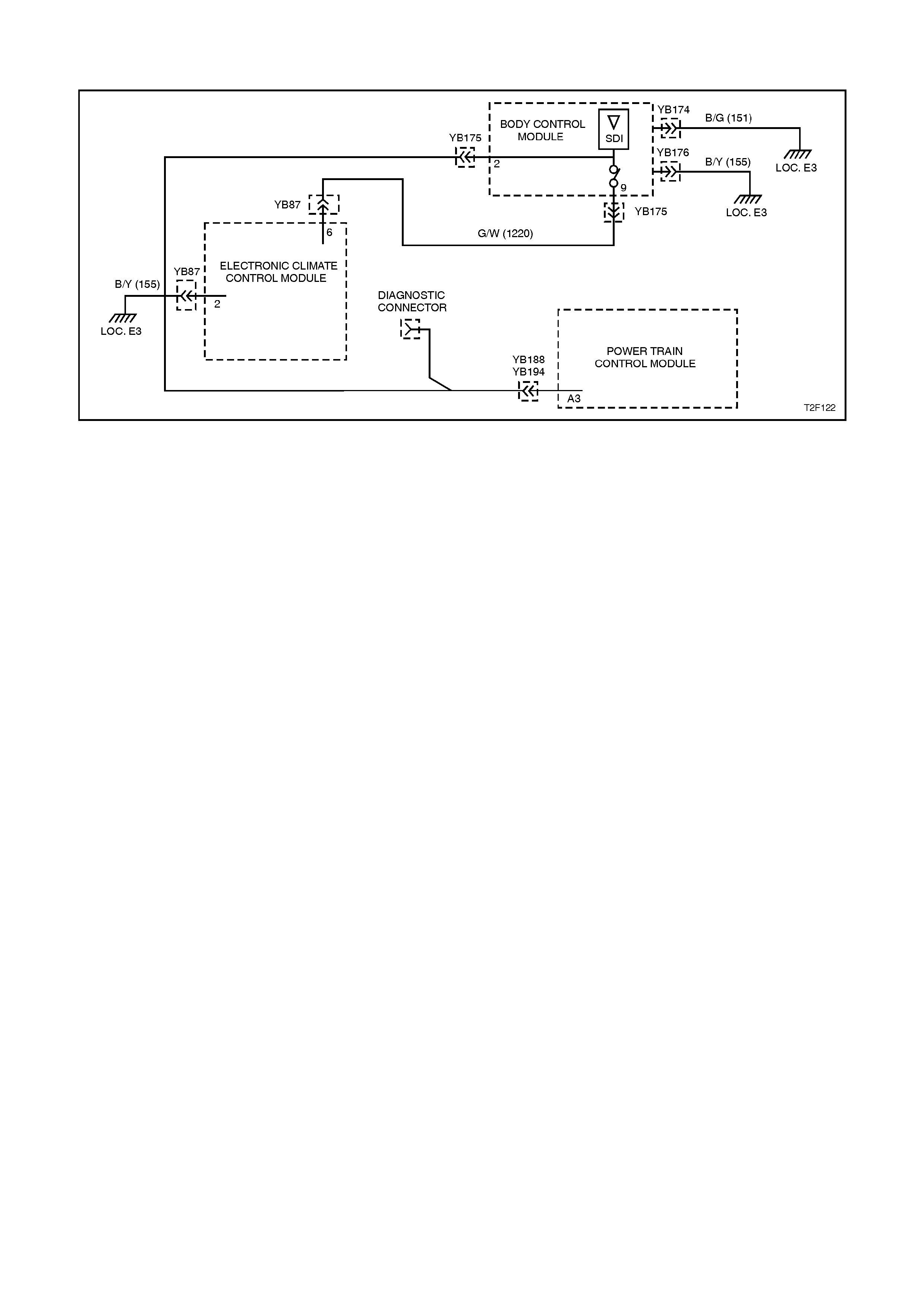
DTC 36 - SERIAL DATA COMMUNICATIONS ERROR
Figure 2F-41
CIRCUIT DESCRIPTION:
When investigating any complaint of an ECC
problem or malfunction, always begin diagnosis
with the following diagnostic circuit check. This
check is a preliminary procedure that checks to
ensure the SDM is communicating on the serial
data line as well as helping to identify a problem or
malfunction and directing the reader to the
appropriate diagnostic chart in this section.
With TECH 2 connected to the DLC and ignition
switched on, TECH 2 should display serial data
communication.
If TECH 2 does not display serial data, the serial
data circuit maybe open or shorted.
There are several other control modules that are
connected to the serial data line (PCM, BCM,
ABS/ASR, instruments and SDM. Any of these
control modules could cause a fault on the serial
data line. This fault could result in TECH 2 not
being able to display serial data.
DTC will set if set if the serial data line (circuits
1220 or 1221) are interrupted and the ECC does
not receive data from the PCM or BCM for 10
seconds.

TEST DESCRIPTION:
Number(s) below refer to step numbers in the
following Diagnostic Chart
1. Ensures the Diagnostic Circuit Check has been
performed.
2. Determines if there is a fault in the serial data
circuit (1221) between the BCM and PCM by
starting the engine. If serial data was lost while
the engine was running, the engine will restart
but there will be a one second delay.
3. Checks if fault is common with other control
modules connected to the serial data circuit.
4. Checks internal switch in BCM for open circuit.
5. Checks circuit 1220 and determines if fault is in
wiring or a control module.
6. Checks circuit 1220 for open circuit.
7. Checks integrity of earth circuits for the BCM,
PCM and ECC control module
DIAGNOSTIC AIDS:
A fault with the serial data circ uit could be caused by
one or more of the several control modules
connected to this serial data circuit. Isolate the fault
by disconnecting each control module, one at a time
until serial data communication is restored.
NOTES ON DIAGNOSTIC CHART:
1. Refer to Section 12P WIRING DIAGRAMS for
procedures on checking wiring faults.
2. Refer to 1.1 TECH 2 DIAGNOSTICS in this
Section for connecting and using TECH 2.
3. To check the integrity of the ECC control module
earth circuit; turn ignition and ECC system ON
and check for a voltage drop across circuit 155
(Black/Yellow wire), between ECC control
module connector YB87, terminal 2, and earth
point E3.
To check the integrity of the BCM earth circuit;
turn ignition ON and check for a voltage drop
across circuit 155 (Black/Yellow wire), between
BCM connector YB176, terminal A1 and earth
point E3
To check the integrity of the PCM earth circuit,
refer to Earth Credibility Check in Section 6C1
POWERTRAIN MANAGEMENT - V6 ENGINE
or Section 6C2 POWERTRAIN
MANAGEMENT - V8 ENGINE.

STEP ACTION VALUE YES NO
1• Was the Diagnostic
Circuit Check
performed?
Go to Step 2. Go to Chart A -
DIAGNOSTIC
CIRCUIT CHECK
in this Section.
2• Connect TECH 2 to
the DLC.
• Select Body / DTC
Check / DTC Check.
• Can TECH 2
communicate with the
BCM and PCM?
NOTE: If “No Data” is
displayed next to the BCM
or PCM, then there is no
communication between
TECH and these control
modules.
Go to Step 3. Go to BCM
Serial Data
Communication
diagnostics in
Section 12J-2
HIGH SERIES
BCM.
3• In Step 2, was TECH
able to communicate
with all the other
control modules,
except the ECC control
module, fitted to the
vehicle (ABS,
instruments, SRS)?
NOTE: If “No Data” is
displayed next to a control
module, then there is no
communication between
TECH and that control
module.
Go to Step 6. Go to Step 4.
4• Using an ohmmeter,
check continuity of
circuits 1220
(Green/White wire)
and 1221 (Red/Black
wire) between BCM
connector YB175,
terminals 2 and 9
(refer NOTE 1).
• Does continuity exist?
Go to Step 5. Replace BCM,
refer to Section
12J-2 HIGH
SERIES BCM.

STEP ACTION VALUE YES NO
5• Check circuit 1220 for
open, short to earth or
short to voltage
between BCM and
individual control
modules (refer
NOTE 1).
• Is circuit 1220 okay?
NOTE: Disconnect each
control module in circuit
1220 one at a time to
isolate the fault in the
circuit or to identify the
control module causing
the fault.
Replace faulty
control module as
necessary, refer
to relevant
Section. Recheck
and verify repair.
Repair circuit
1220 as
necessary.
Recheck and
verify repair.
6• Using an ohmmeter,
check for continuity
between BCM
connector YB175,
terminal 9 and ECC
control module
connector YB87,
terminal 6
(Green/White wire)
(refer NOTE 1).
• Does continuity exist?
•
Go to Step 7. Repair open in
circuit 1220.
Recheck and
verify repair.
7• Check the integrity of
the ECC control
module, BCM and
PCM earth circuits by
performing a voltage
drop on each circuit
(refer NOTE 3)
• Are voltage less than
the specified value?
0.15
Volts Replace ECC
control module,
refer to Section
2E AIR
CONDITIONING -
ECC -
REMOVAL &
INSTALLATION.
Repair earth
circuit as
necessary.
Recheck and
verify repair
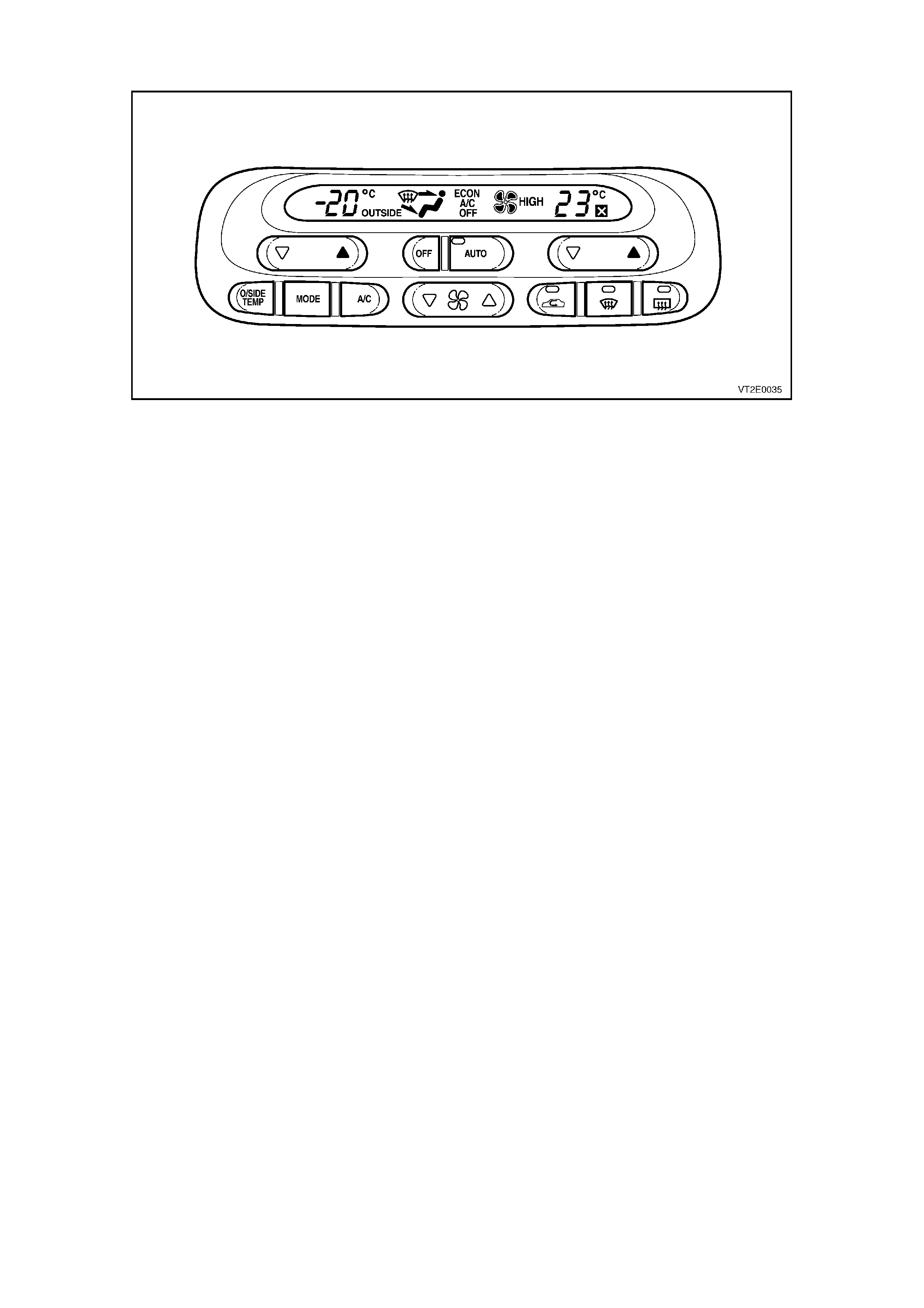
DTC 37 - ECC CONTROL MODULE - INTERNAL FAILURE
Figure 2F-42
CIRCUIT DESCRIPTION:
When this diagnostic trouble code (DTC) is set, it indicates a failure attributed to the processor within the ECC
Module itself.
If DTC 37 sets, replace the ECC control module. Refer to Section 2E-2 AIR CONDITIONING - ECC - REMOVAL
AND INSTALLATION.
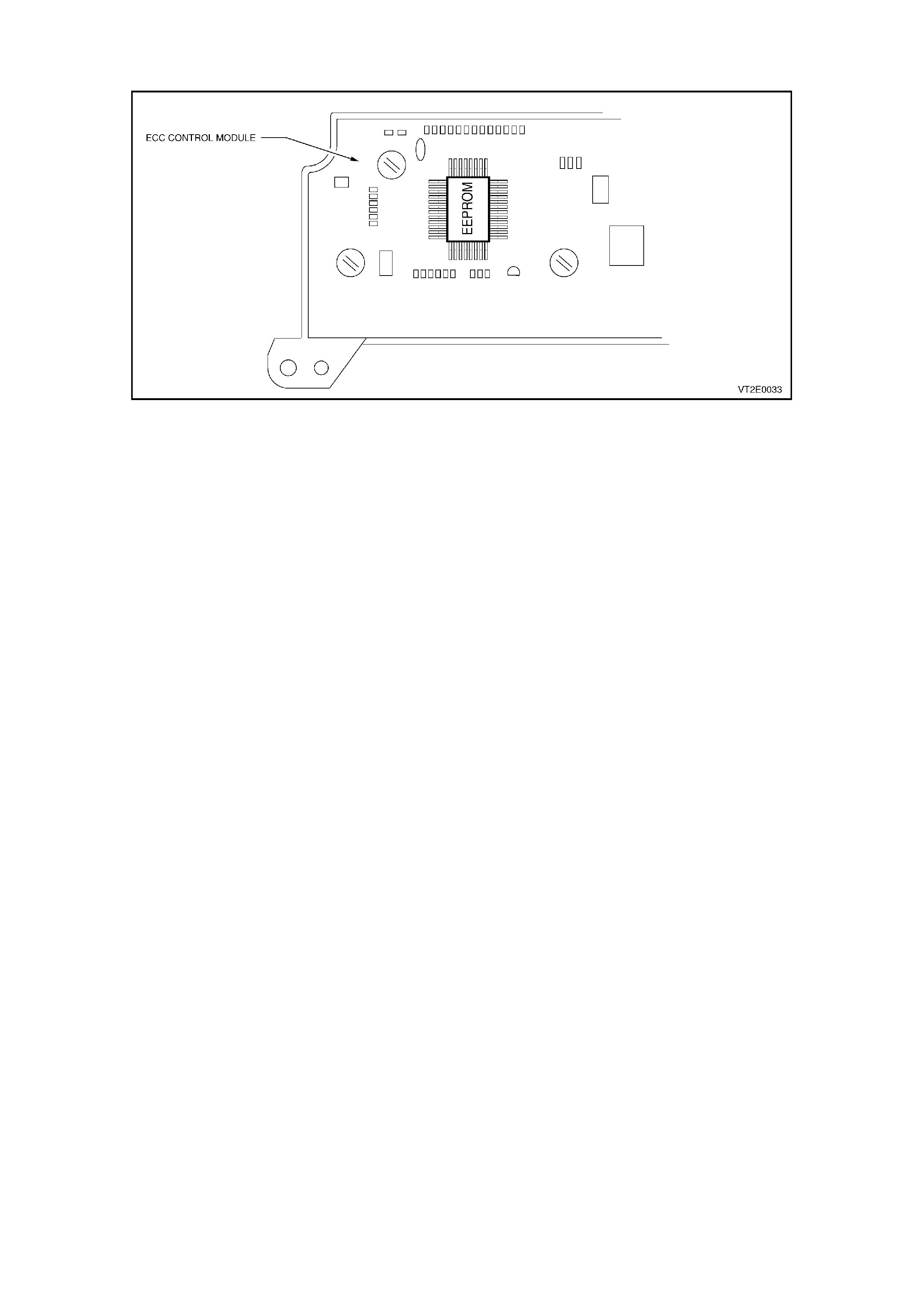
DTC 38 - EEPROM CHECKSUM FAILURE
Figure 2F-43
CIRCUIT DESCRIPTION:
The EEPROM (expandable, erasable program,
read only, memory) is part of the PCB (Printed
Circuit Board) housed within the ECC Module.
The function of the EEPROM is to store data used
to control operating parameters of the ECC
system.
When this DTC is set, it indicates that the
EEPROM has been corrupted or has altered.
DTC 38 will set: if the ECC system calibration is
corrupted or the EEPROM in the ECC control
module fails.
TEST DESCRIPTION:
Number(s) below refer to step numbers in the
following Diagnostic Chart.
1. Determines if ECC control module is faulty by
re-programming the ECC control module.
2. Determines if ECC control module is faulty.
NOTES ON DIAGNOSTIC CHART:
1. Refer to 1.1 TECH 2 DIAGNOSTICS in this
Section for connecting and using TECH 2.
DIAGNOSTIC AIDS:
If the ECC system programming is corrupted, re-
calibration can be carried out via TECH 2. To
calibrate the system refer to 1.2 TECH 2 TEST
MODES AND SCREEN DISPLAYS in this Section.

STEP ACTION VALUE YES NO
1• Reprogram ECC
control module Code
Version using TECH 2,
refer 1.2 TECH 2
TEST MODES AND
SCREEN DISPLAYS
FOR ECC
DIAGNOSIS in this
Section.
• Was programming
successful?
NOTE: If programming is
unsuccessful, repeat the
program at least twice, as
the system may have
crashed during this
process.
Go to Step 2. Replace ECC
control module,
refer to Section
2E AIR
CONDITIONING -
ECC -
REMOVAL &
INSTALLATION.
2• Connect TECH 2 to
DLC (refer NOTE 1
above).
• Select Body /
Electronic Control
Module / Diagnostic
Trouble Codes / Clear
DTC Information and
clear DTC’s.
• Were all DTC’s
cleared?
System okay. Replace ECC
control module,
refer to Section
2E AIR
CONDITIONING -
ECC -
REMOVAL &
INSTALLATION.