
SECTION 4B - FINAL DRIVE AND DRIVE SHAFTS
Click on the button for more information. CAUTION:
This vehicle will be equipped with a Supplemental Restraint System (SRS). An SRS
will consist of either seat belt pre-tensioners and a driver's side air bag, or seat belt
pre-tensioners and a driver's and front passenger's side air bags. Refer to
CAUTIONS, Section 12M, before performing any service operation on or around any
SRS components, the steering mechanism or wiring. Failure to follow the CAUTIONS
could result in SRS d eployment, result ing in po ssible person al injury or unnecessary
SRS system repairs.
CAUTION:
This vehicle may be equipped with LPG (Liquefied Petroleum Gas. In the interests of
safety, the LPG fuel system should be isolated by turning OFF the manual service
valve an d then draining the LPG service lines, bef ore any service work is carried out
on the vehicle. Refer to the LPG leaflet included with the Owner's Handbook for
details or LPG Section 2 for more specific servicing information.
CAUTION:
Whenever any component that forms part of the ABS or ABS/ETC (if fitted), is
disturbed during Service Operations, it is vital that the complete ABS or ABS/ETC
system is checked, using the procedure as detailed in 4. DIAGNOSIS, ABS or
ABS/ETC FUNCTION CHECK, in Section 12L ABS & ABS/ETC.
1. GENERAL DESCRIPTION
Independent rear sus pension is fitted as s tandard equipment on all VT Series vehicles and all are fitted with a final
drive assembly, production option GU4. This assembly has a four pinion type rear differential assembly. The ring
gear diam eter for V6 engined m odels, is 190.5 m m and for V8 and V6 supercharged, engined m odels, is 205 mm .
The final drive ratio for V6 engined models is 3.08:1 and for V8 and V6 supercharged, engined models, is 3.07:1.
Production option G80, Limited Slip Differential (LSD), (also referred to as Spin Resistant Differential - SRD) is
available on all models . While the m ajority of illustrations shown in this Sec tion relate to vehicles fitted with the ABS
braking system, service procedures are the same for vehicles equipped with standard brakes, unless noted.
The final drive assem bly is m ounted directly to a crossm ember which is rubber mounted to the vehicle underbody.
The differential case and drive pinion are m ounted in opposed taper roller bearings in the carrier. Differential case
side bearing pre-load adjustm ent is pr ovided by s crew adjusters in the sides of the c ase. Pinion bearing pre-load is
provided by a collapsible spacer. Torque is transferred from the propeller shaft to the final drive assembly via the
pinion flange which is splined to the hypoid pinion. The torque is then transferred from the pinion through the ring
gear, differential case, differential pinion cross shafts, differential pinions, side gears and then via splines, to the
inner axle shafts and drive shafts.
The Limited Slip Differential performs the same functions as the conventional type differential but in addition,
transfers driving force to the wheel with traction, should the opposite wheel begin to spin.
The differential case houses two cone type clutches behind the side gears that, with V6 models, are splined to the
inner axle shafts and their tapered faces contact corresponding faces in the differential case.
The cones for V8 and V6 supercharged models however, form an integral part of the side gears. The four pinion
type Limited Slip Dif fer ential has three pr e-load springs enc los ed in the centr e of the pinion c r oss s haf t. T he Limited
Slip Diff erential directs the m ajor driving f orce to the wheel with the greater amount of traction, but will not interf ere
with steering characteristic s or dif ferential action. T he partial locking ac tion, due to the spring load on the cones, is
automatically increased by the inherent separating forces between the side gears and pinions, which progressively
increases the resistance in the differential as applied torque is increased.
Techline
Techline
Techline
Techline
Techline
Techline
W hen the rear wheels ar e under extr emely unbalanced conditions, s uch as a wheel on a dry r oad and the other in
mud or ic e, with the standard differ ential, wheel spin eas ily occurs if over-acceleration is attempted. However, with a
Limited Slip Differential, when the tendency for wheel spin occurs, the friction generated inside the case, transfers
the major driving force to the non-spinning wheel. In the event of continued spinning, a whirring sound from the
over-running cones is produced but this condition/sound does not indicate failure of the unit.
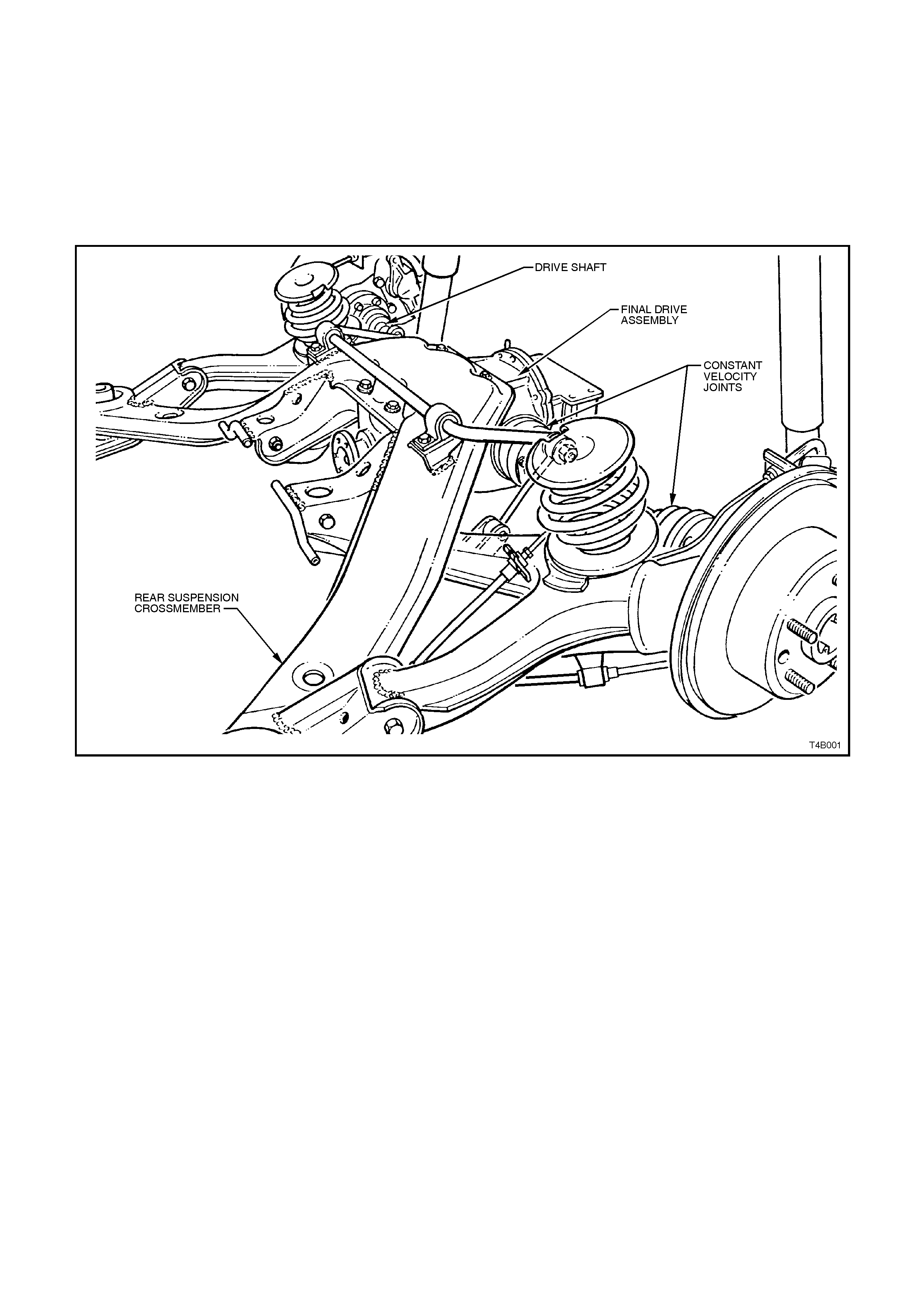
The f inal drive ass em bly should be removed f rom the vehic le for all service operations other than for the removal of
the inner axle shafts, inner axle shaft oil seals, pinion oil seal or the rear cover. Two drive shaft assemblies are
used, each consisting of a shaft which is splined at each end into a ball type constant velocity joint. The inner
constant velocity joint is bolted to the inner axle shaft flange at the differential carrier, with the outer joint bolted to
the trunnion flange at the rear trailing arm.
Figure 4B
-
1
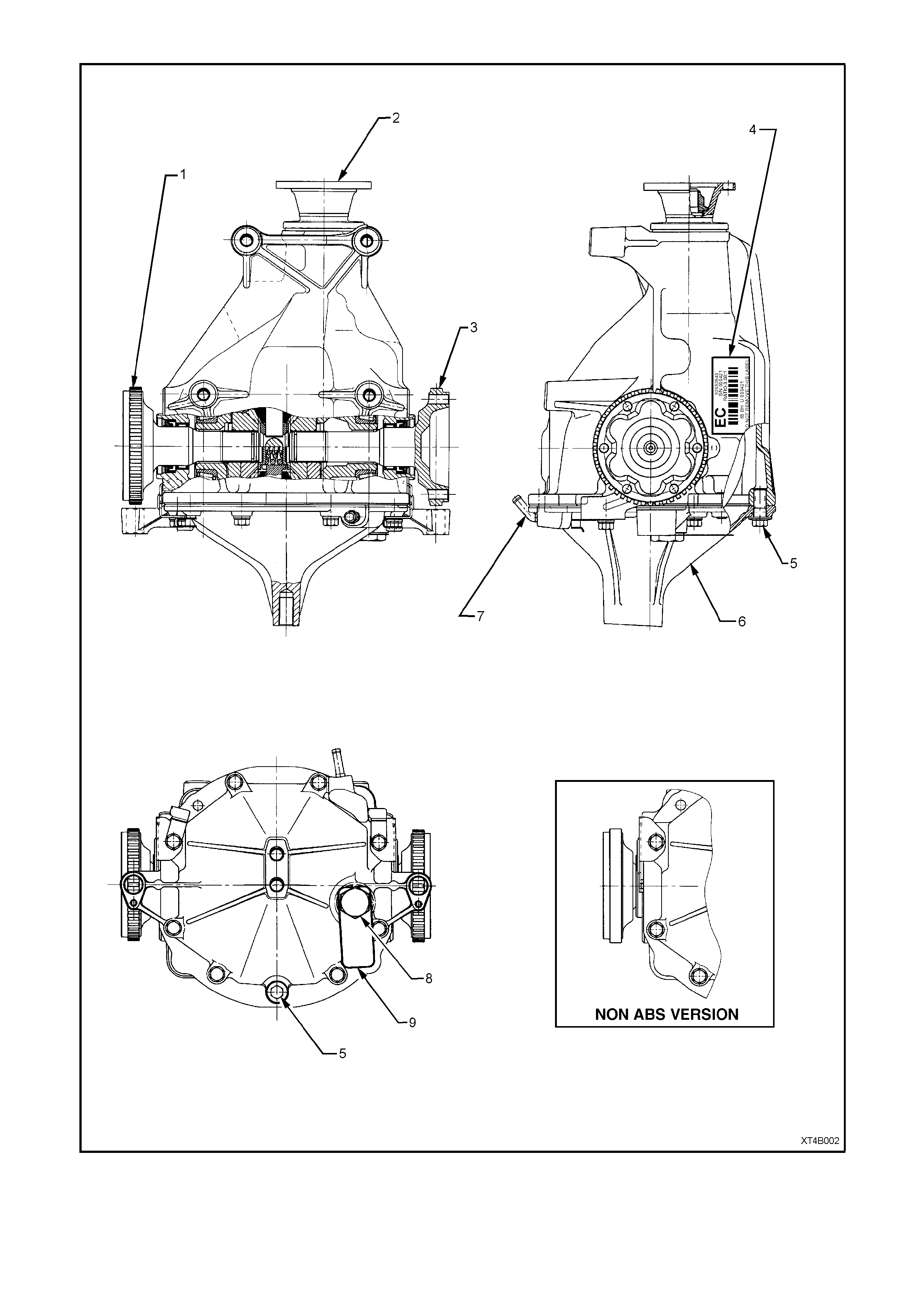
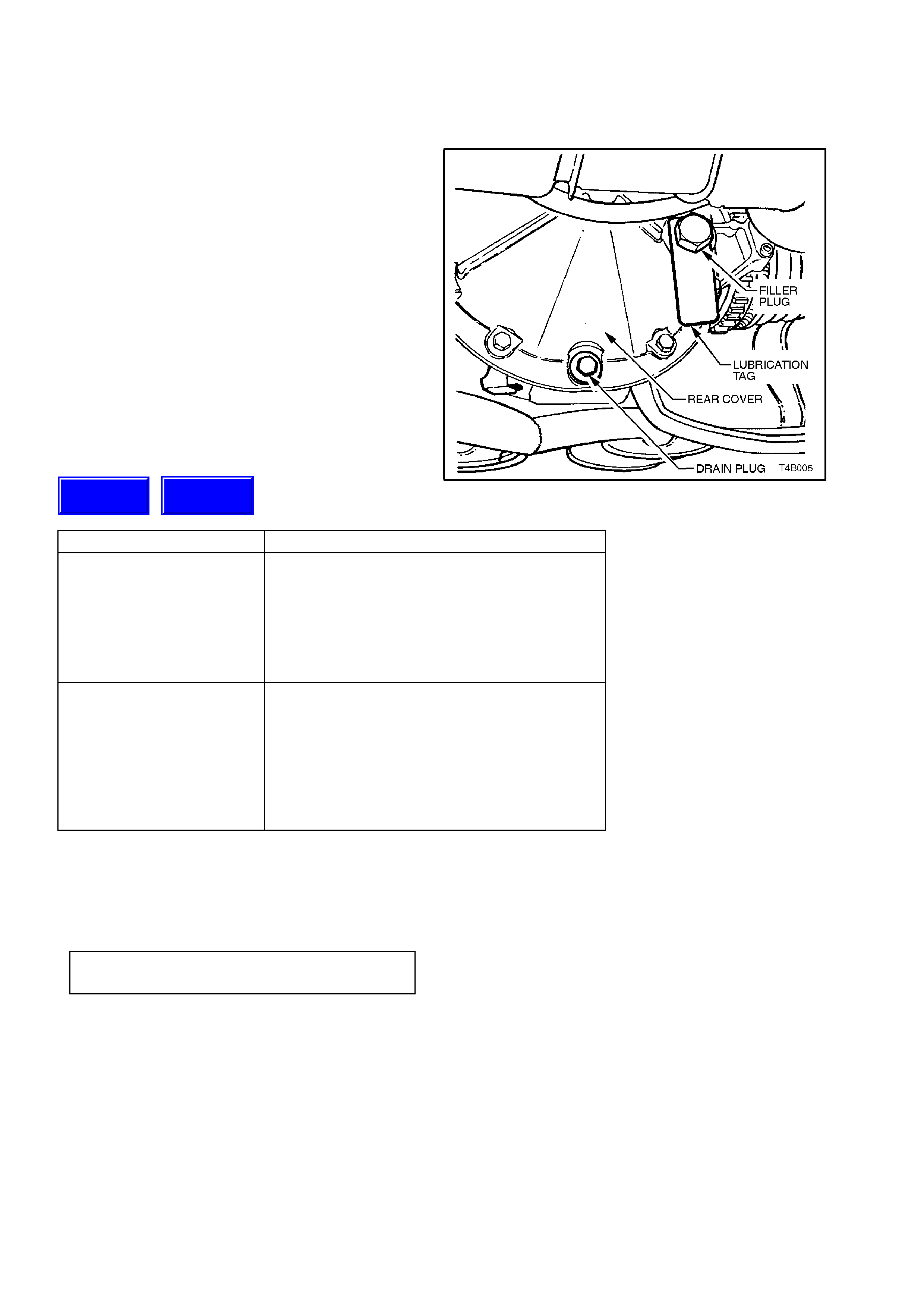
1. LH Inner Axle Shaft 4. Identification Label 7. Breather
2.. Pinion Flange 5. Frain Plug 8. Filler Plug
3. RH Inner Axle Shaft 6. Rear Cover 9. Lubrication Tag
Figure 4B-2
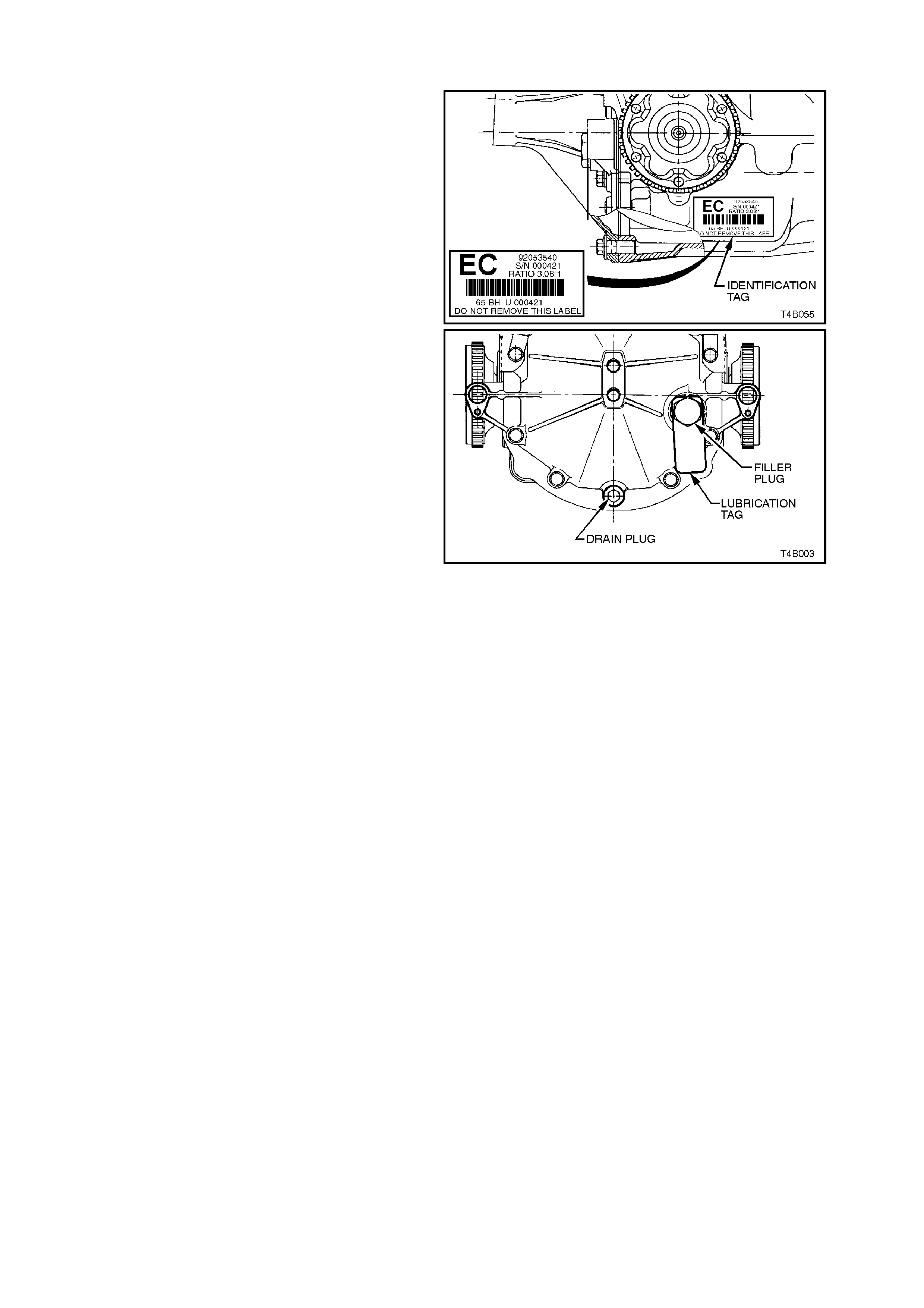
1. 1 FINAL DRIVE ASSEMBLY IDENTIFICATION
The type of differential fitted to this final drive
assem bly can be identified by referr ing to either the
identification label attached to the RHS of the
carrier housing and from the lubrication tag under
the filler plug on the rear cover.
The location of the label and tag are as shown, in
Figure 4B-2. The identification tag carries the
Holden's part number for the final drive assembly,
final drive ratio and the serial number of the
assembly.
The code number and bar code is used for
production identification of the final drive assembly.
CODE TAG LETTERING FINAL DRIVE ASS’Y TYPE
STD. BRAKES ABS
EF EC CONVENTIONAL - V6
ED EE LSD - V6
EA EJ CONVENTIONAL - V8
V6 Supercharged and
Wagon with
manual transmission
EB EH LSD - V8,
V6 Supercharged and
Wagon with
manual transmission
When fitted, the information on the lubrication tag
under the filler plug, (see Figure 4B-3), will be;
With V6 and LSD; “SPIN RESISTANT DIFF. USE
APPROVED LUBRICANT ONLY”
With V8 (or V6 supercharged) and conventional
differential; “HIGH PERFORMANCE. USE
APPROVED LUBRICANT ONLY”
With V8 (or V6 supercharged) and LSD; “LSD -
HIGH PERFORMANCE. USE APPROVED
LUBRICANT ONLY”
Figure 4B-3
1. 2 FINAL DRIVE ASSEMBLY MAINTENANCE
MAINTENANCE
Drive Shaft Bearings and Constant Velocity
Joints
The drive shaft outer bearings and constant
velocity joints are lubricated for life and therefore
require no periodic maintenance.
The constant velocity joint boots are to be
inspected at every maintenance service. If there is
any evidence of damage to boots, remove drive
shaft and inspect constant velocity joints, refer to
2.6 DRIVE SHAFT ASSEMBLY and to
2.7 DRIVE SHAFT AND/OR CONSTANT
VELOCITY JOINTS in this Section.
Differential Carrier Assembly
Check for lubricant leaks at every maintenance
service. If ther e is evidence of leak age, co rr ec t leak
and add lubricant as necessary. (Refer to
2 MINOR SERVICE OPERATIONS in this Section).
At the time or distance interval specified in the VT
Series Owner's Handbook, check to ensure that the
lubricant level is to the bottom of the filler plug hole
when the differential carrier assembly is COLD.
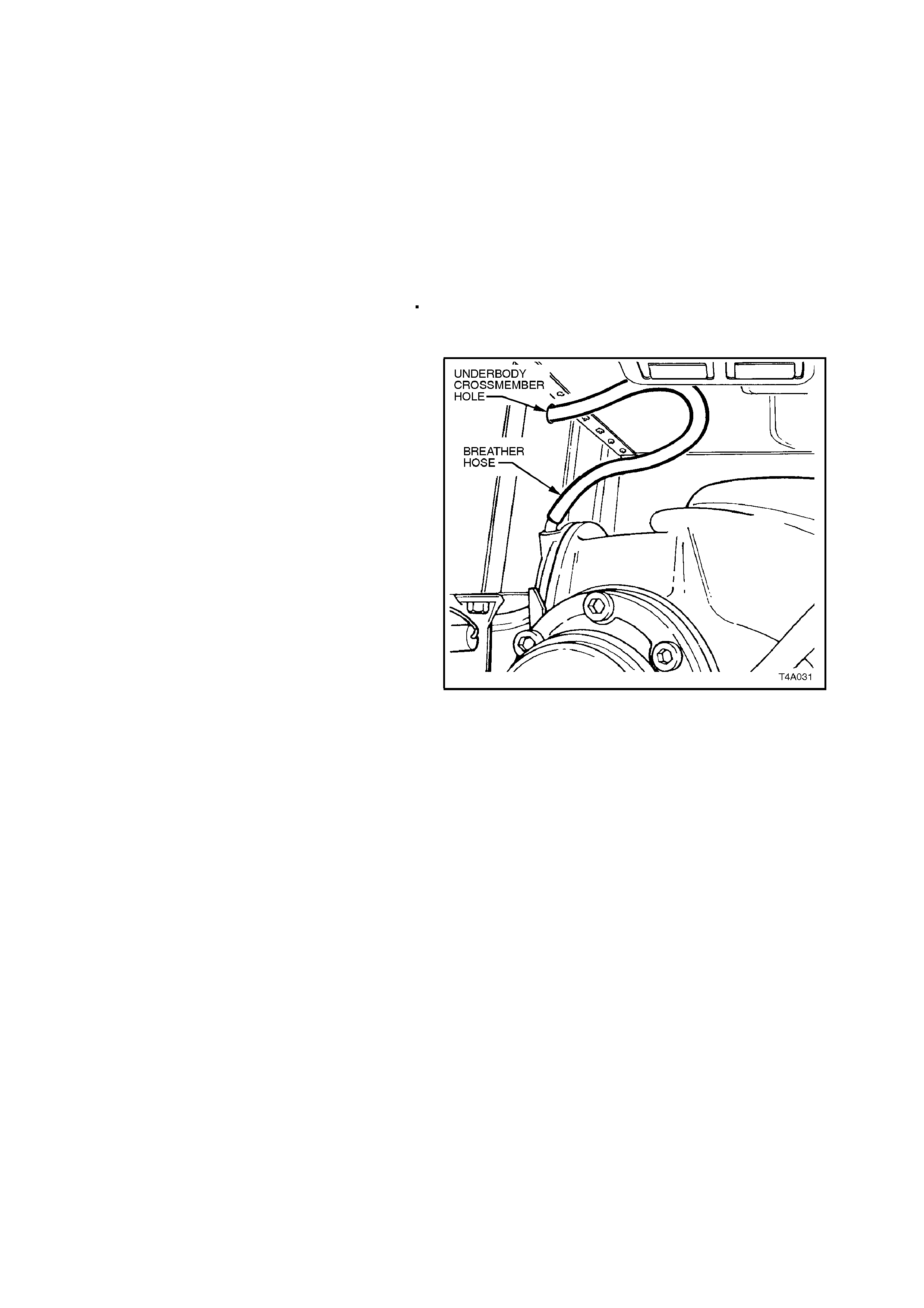
Final Drive Assembly Breather
The breather hose should be checked regularly to
ensure that it is correctly routed and not kinked.
The top end of the breather hose should be
inserted at least 25 mm into the vehicle underbody
crossmember hole.
Figure 4B-4
LIMITED SLIP DIFFERENTIAL PRECAUTIONS
CAUTION:
When servicing a vehicle fitted with a Limited
Slip Differential, never run the engine with the
transmission in gear and one w heel raised. T he
driving force to the wheel on the ground may
cause the vehicle to move.
NOTE:
'On Car' type wheel balancers are not
recommended for use on the rear wheels of cars
equipped with a Limited Slip Differential. One rear
wheel will drive if in contact with the ground when
the opposite wheel is raised and rotated.
This type of balancer may be used by rem oving the
road wheel opposite to the one being spun, the
vehicle raised and supported on safety stands.
Refit wheel nuts, reversed, to retain brake disc.

LUBRICATION
The lubricant level s hould be check ed and topped up, if required at the tim e or dis tance intervals outlined in the VT
Series Owner's Handbook with the differential carrier COLD; refer to 2.1 CHECKING DIFFERENTIAL CARRIER
LUBRICANT LEVEL in this Section. At this temperature, the lubricant should be level with the bottom of the filler
plug hole. Operation 2.1 also details the recommended lubricants for all final drives fitted to VT Series vehicles.
NEVER USE ANY OTHER THAN THE RECOMMENDED LUBRICANT.
NOTE 1:
The lubricant for vehicles with the V6 engine and either the standard or Lim ited Slip Dif fer ential (LSD) dif fer ential, is
a mineral based oil. W ith LSD final drives however, an approved LSD com patible lubricant MUST be used. Using a
straight run mineral oil in an LSD final drive assembly, will cause ‘stick-slip’ chatter to occur when turning corners.
Alternatively, if a synthetic type lubricant is used in any rear axle of a V6 engined, VT Series vehicle, oil seal
deterioration with the possibility of lubricant leakage may occur.
NOTE 2:
The lubric ant used in the rear ax les of all V8 and V6 super charged engined vehicles, is a synthetic product. T he oil
seals of the V8 type rear axle assemblies have been specially formulated to tolerate this lubricant. It m ust also be
noted that, using a mineral type lubricant in any final drive fitted to a V8 or V6 supercharged engined vehicle, may
cause gear set and/or bearing damage under high load driving conditions.
NOTE 3:
If the incor rect lubricant is ac cidentally used in the r ear axle of any VT Series vehic le, then the rear axle should be
drained, flushed (with the recommended lubricant) and then refilled with the correct lubricant.
The procedure for this operation is detailed in 2.2 CHANGING/FLUSHING REAR AXLE LUBRICANT, in this
Section.
2. MI NOR SERVICE OPERATIONS
2.1 CHECKING DIFFERENTIAL CARRIER LUBRICANT LEVEL
1. Ensure vehicle is level.
2. Clean area around filler plug.
3. Remove filler plug from right hand side of
differential carrier (do not lose the lubrication
tag from the plug, if fitted).
4. The lubricant level is to be maintained at the
bottom edge of the filler plug hole, WHEN
COLD. Use only the recommended lubricant.
Figure 4B-5
ENGINE & AXLE TYPE RECOMMENDED LUBRICANT
All V6 excluding
V6 Wagon with manual
Transmission &
V6 Supercharged
Vehicles
Mineral Hypoid Gear Oil, such as
AMPOL Gearlube SRD90, BP Limslip 90,
CALTEX Gear Oil LSD, CASTROL LSX90
MOBIL Lubrite LS90, SHELL XD90LS
VALVOLINE HP Gear Oil LS90
or equivalent lubricant to
Holden Specification HN 1561
All V8,
V6 Wagon
with Manual
Transmission &
V6 Supercharged
Vehicles
Synthetic Hypoid Gear Oil, such as
AMPOL Synthetic Gear Oil 80W/140
CALTEX Synstar GL 80W-140
CASTROL SAF-XA
MOBIL Mobilube SHC 80W-140 ID
VALVOLINE Synthetic Gear 75W-140
or equivalent lubricant to
Holden’s Specification HN 2040
5. Inspect filler plug for damage, if OK, refit in
carrier (including the lubrication tag). If
damaged, replace plug.
6. Tighten filler plug to the correct torque
specification.
FILLER PLUG 23 - 31
TORQUE SPECIFICATION Nm
Techline
Techline

2.2 CHANGING/FLUSHING REAR AXLE LUBRICANT
To drain lubricant from differential carrier
assembly, remove filler and drain plugs (see
Figure 4B-5) and allow (preferably warm) lubricant
to drain into a suitable container.
If flushing is required, use an undiluted quantity of
the recommended lubricant for the operation.
When the draining and flushing (if required),
operation is completed, apply thread sealing tape to
rear cover drain plug thread. Install and tighten
attaching plug to the correct torque specification.
REAR AXLE DRAIN PLUG 23 - 31
TORQUE SPECIFICATION Nm
Fill the final drive assembly with 1.65 litres of the
recommended lubricant, install the filler plug and
lubrication tag (if fitted) and tighten to the correct
torque specification.
REAR AXLE FILLER PLUG 23 - 31
TORQUE SPECIFICATION Nm
Techline
2.3 TRAILING ARM TRUNNION ASSEMBLY HUB
CHECK FOR RUN-OUT
1. Using a floor jack under centre of differential
carrier, jack up rear of vehicle, then place
safety stands under trailing arms to support
weight of vehicle.
2. Remove rear wheel cover (steel wheels) or
centre cap (alloy wheels) on that side of the
vehicle where the trunnion is to be checked.
3. Mark relationship of wheel to m ounting f lange.
Remove road wheel attaching nuts and
remove wheel.
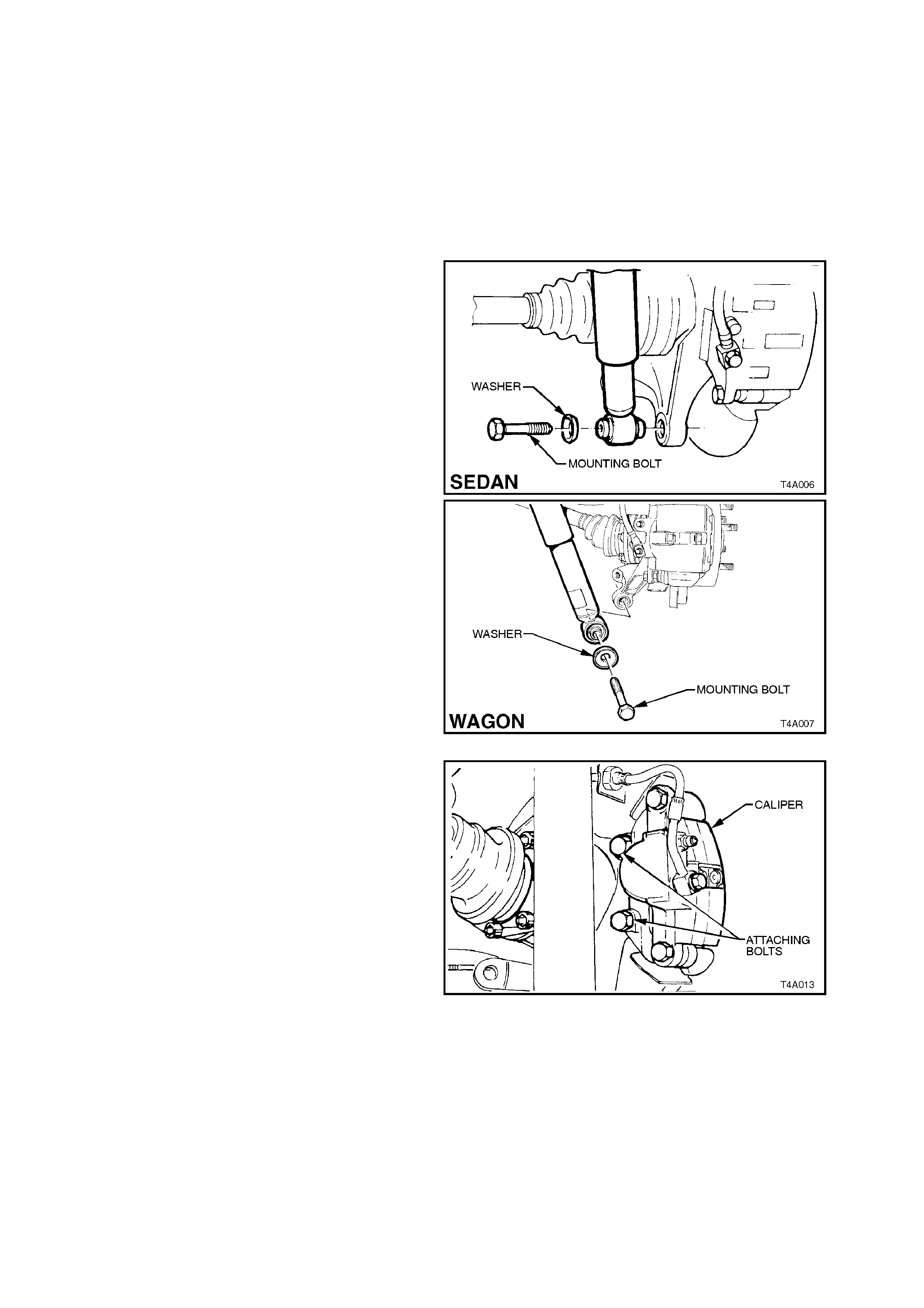
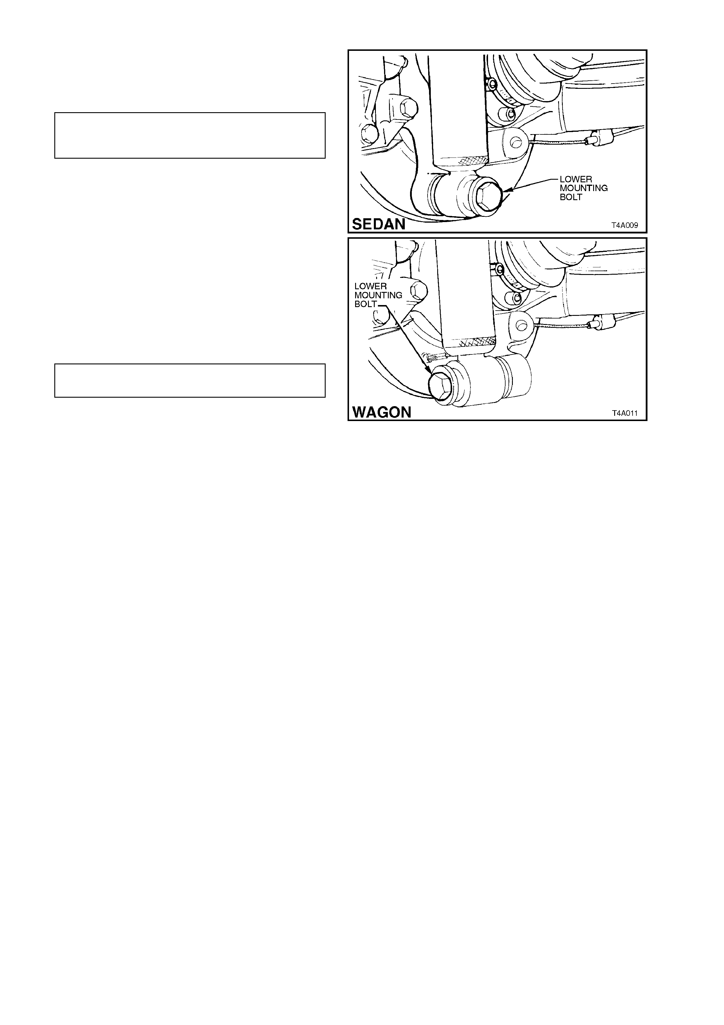
4. Disconnect rear shock absorber lower
mounting bolt from trailing arm, and pull lower
end of shock absorber from trailing arm.
Figure 4B-6
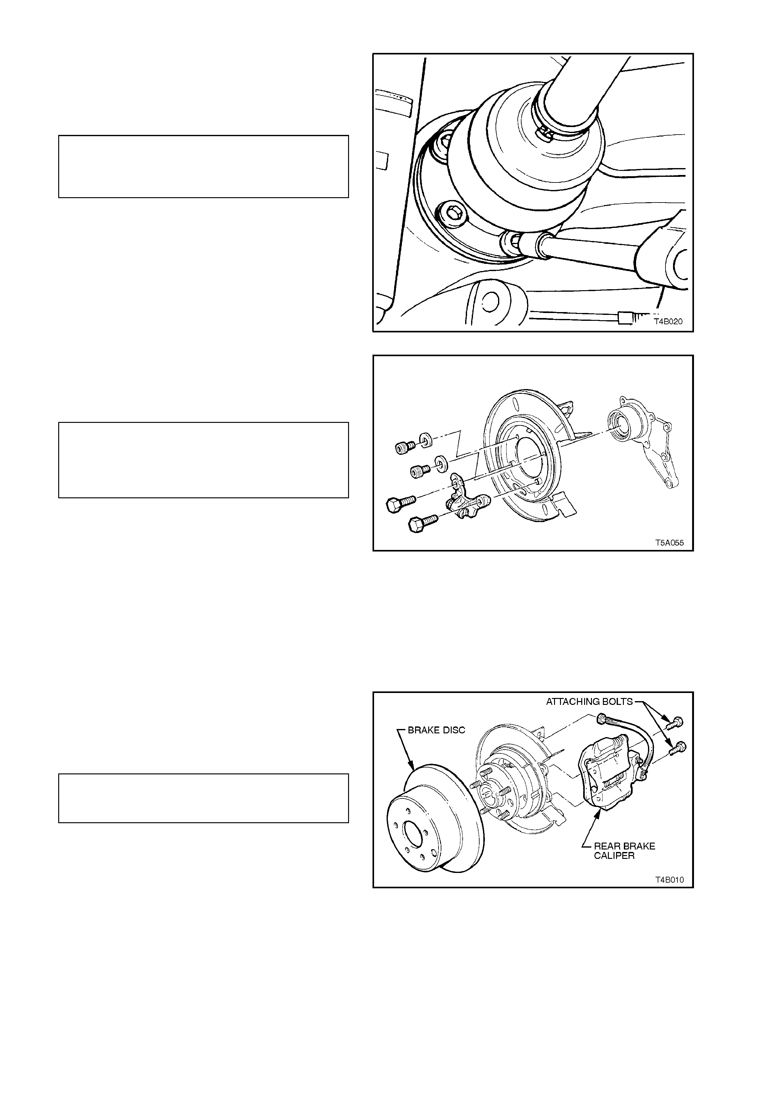
5. Remove brake caliper anchor plate to trailing
arm attaching bolts, remove caliper from disc.
Using wire, tie up caliper to lower end of s hock
absorber upper mounting. DO NOT ALLOW
CALIPER TO HANG BY BRAKE HOSE.
6. Remove brake disc.
Figure 4B-7
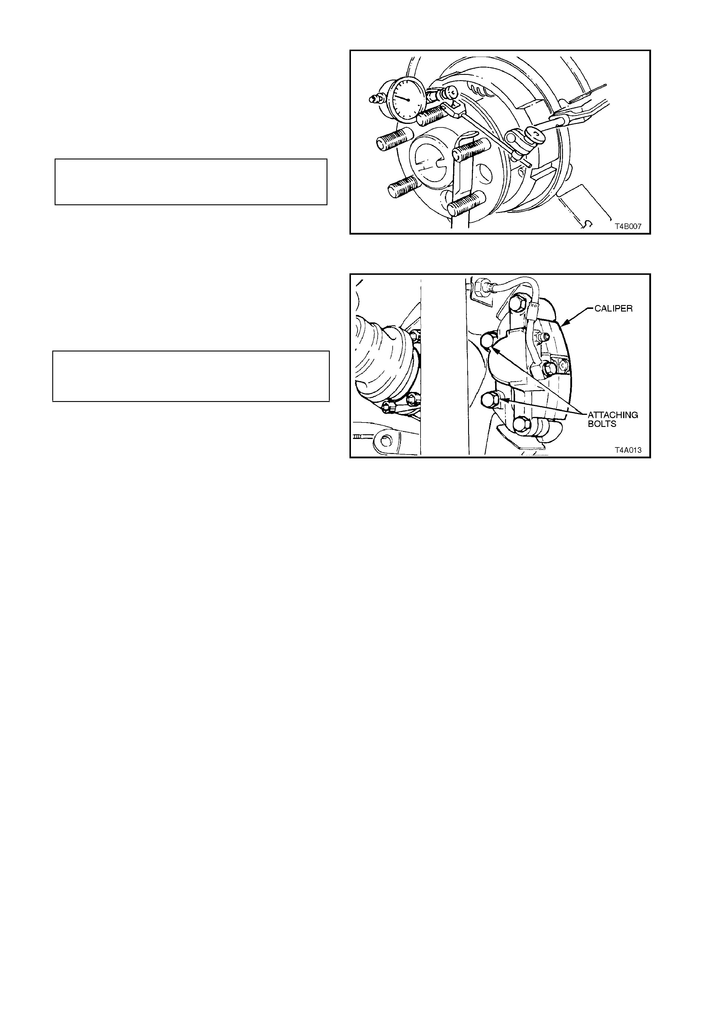
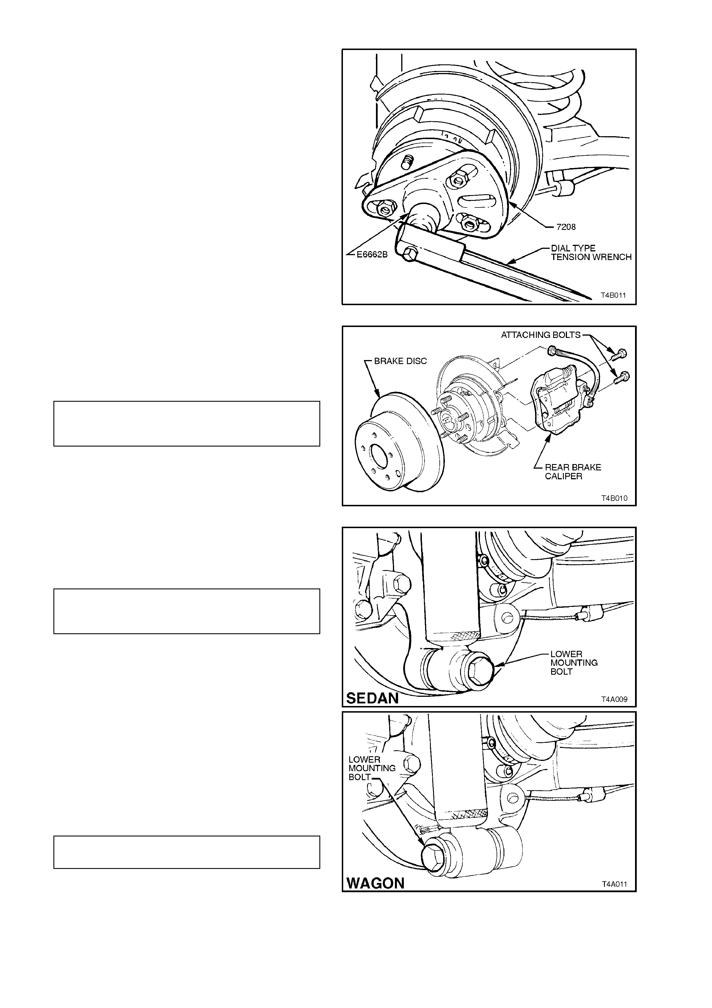
7. Mount a dial indicator with magnetic base to
rear brake backing plate, and stylus of gauge
perpendicular to outside of trunnion assembly
hub flange.
8. Rotate trunnion assem bly hub and read later al
run-out.
TRUNNION ASSEMBLY HUB,
TOTAL INDICATED 0.060 mm
RUN-OUT SPECIFICATION
Figure 4B-8
If Run-out is Within Specification:
9. Install brake disc and brake caliper. Install
brake caliper anchor plate to trailing arm
attaching bolts and tighten to the correct torque
specification.
BRAKE CALIPER ANCHOR PLATE
TO TRAILING ARM ATTACHING 70 - 100 Nm
BOLT TORQUE SPECIFICATION
Figure 4B-9

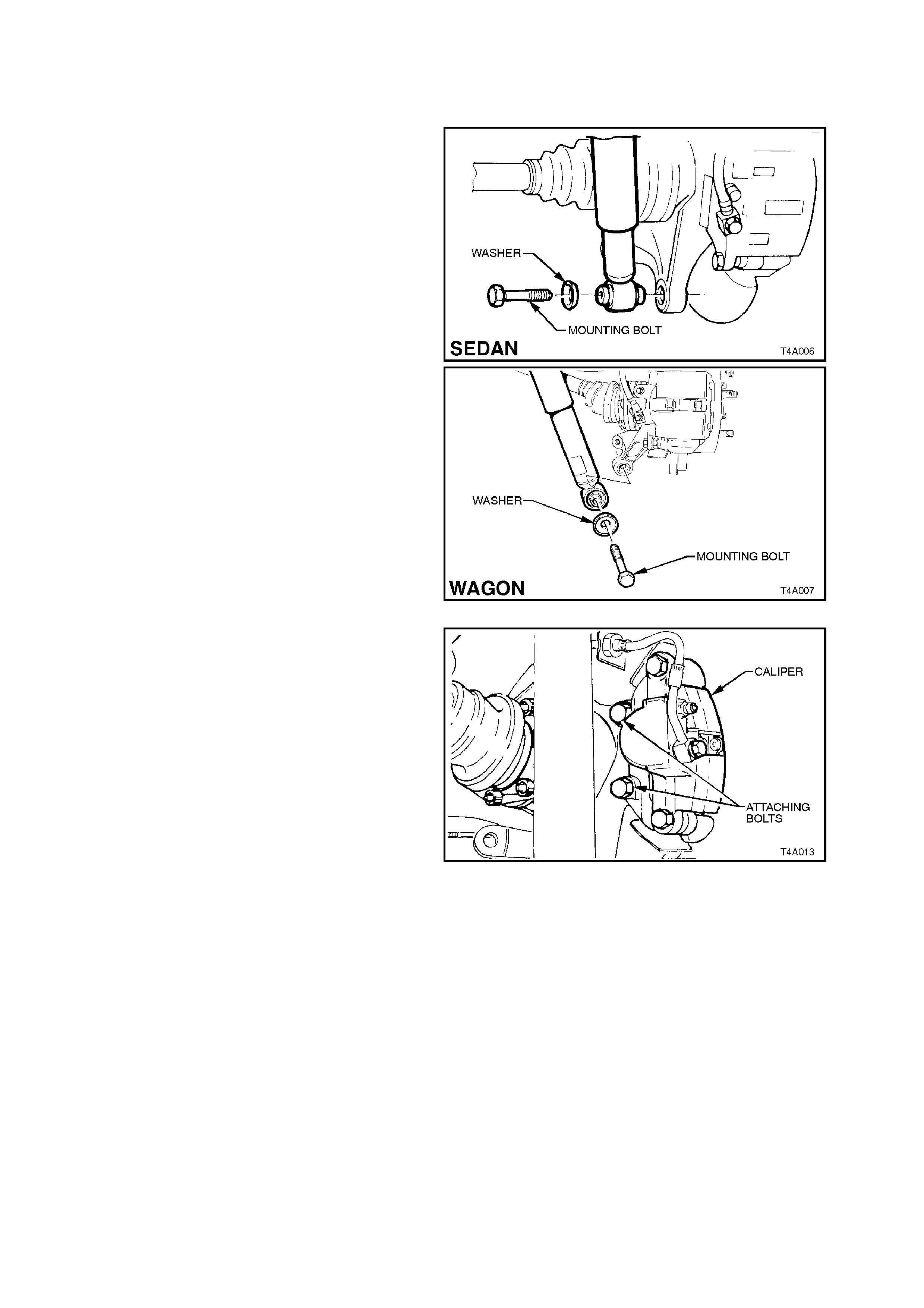
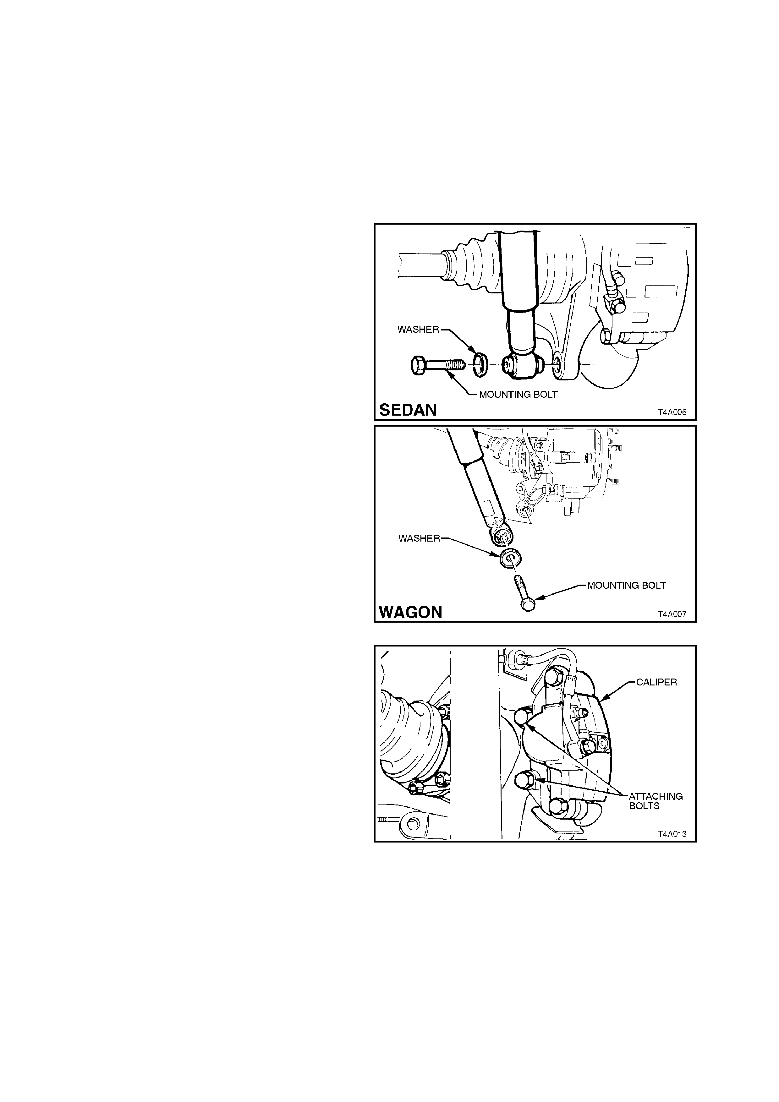
10. Install shock absorber to trailing arm, fit
washer to the lower mounting bolt, install bolt
and tighten to the correct torque specification.
SHOCK ABSORBER LOWER
MOUNTING BOLT 105 - 125 Nm
TORQUE SPECIFICATION
NOTE:
Vehicle must be at curb weight and on all four
wheels before this torque is applied.
11. Install road wheel and tighten attaching nuts.
NOTE:
When installing the wheel, align the marks made
prior to removal.
12. Remove safety stand and lower vehicle.
13. Tighten road wheel attaching nuts to the
correct torque specification.
ROAD WHEEL ATTACHING NUT 110 - 140
TORQUE SPECIFICATION Nm
14. Refit wheel cover/centre cap.
If the Run-out Check, Exceeds Specification:
15. The trunnion assembly must be replaced, refer
to 3.1 TRAILING ARM TRUNNION FLANGE,
TRUNNION ASSEMBLY AND/OR WHEEL
BEARING in this Section.
NOTE:
The trunnion shaft for VT Series vehicles is 1 mm
shorter than previous models and is identified by a
circumferential groove on the outside diameter of
the flange (see Figure 4B-8).
Figure 4B-10
2.4 TRAILING ARM TRUNNION ASSEMBLY HUB STUDS
REPLACE
1. Using a floor jack under centre of differential
carrier, jack up rear of vehicle, then place
safety stands under trailing arms to support
weight of vehicle.
2. Remove rear wheel cover (steel wheels) or
centre cap (alloy wheels) on that side of the
vehicle where the stud/s are to be replaced.
3. Mark relationship of wheel to m ounting f lange.
Remove road wheel attaching nuts and
remove wheel.
4. Disconnect rear shock absorber lower
mounting bolt from trailing arm and pull lower
end of shock absorber from trailing arm.
Figure 4B-11
5. Remove brake caliper anchor plate to trailing
arm attaching bolts and remove caliper from
disc.
Using wire, tie up caliper to lower end of s hock
absorber upper mounting. DO NOT ALLOW
CALIPER TO HANG BY BRAKE HOSE.
6. Remove brake disc.
Figure 4B-12
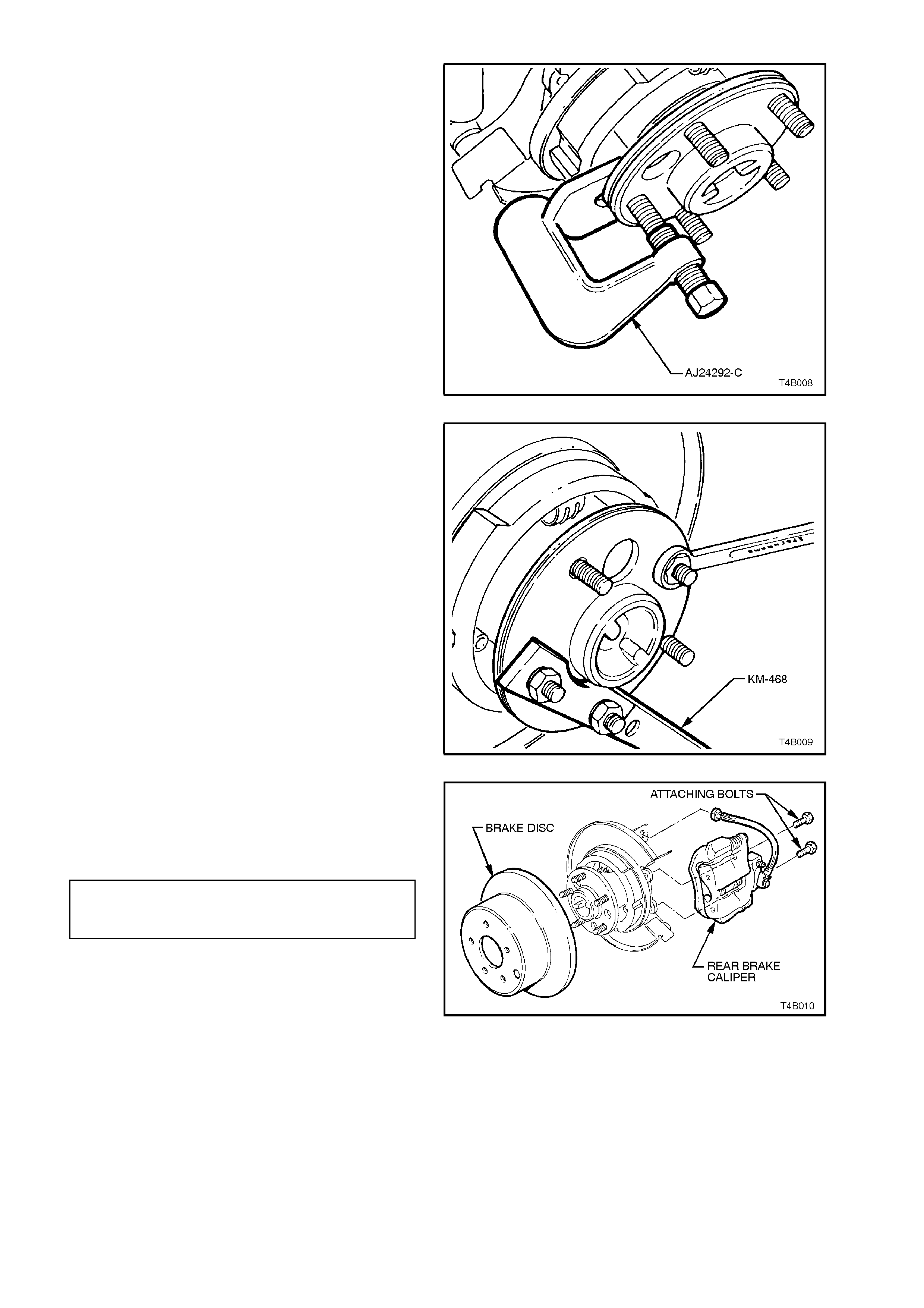
7. Using Tool No. AJ24292-C or equivalent,
press stud/s from hub.
Figure 4B-13
8. Install Tool No. KM-468 holding bar, with two
wheel nuts to the trunnion assembly hub
studs. Install new stud into hub. Assemble
some suitable size washers and a reversed
wheel nut, onto stud. Tighten wheel nut to
draw in stud. When stud is fully installed,
remove wheel nut and washers.
Install any remaining studs in the same
manner.
9. Remove Tool No. KM468.
Figure 4B-14
10. Install brake disc and brake caliper. Install
brake caliper anchor plate to trailing arm
attaching bolts and tighten to the correct
torgue specification.
BRAKE CALIPER ANCHOR PLATE
TO TRAILING ARM ATTACHING 70 - 100 Nm
TORQUE SPECIFICATION
Figure 4B-15
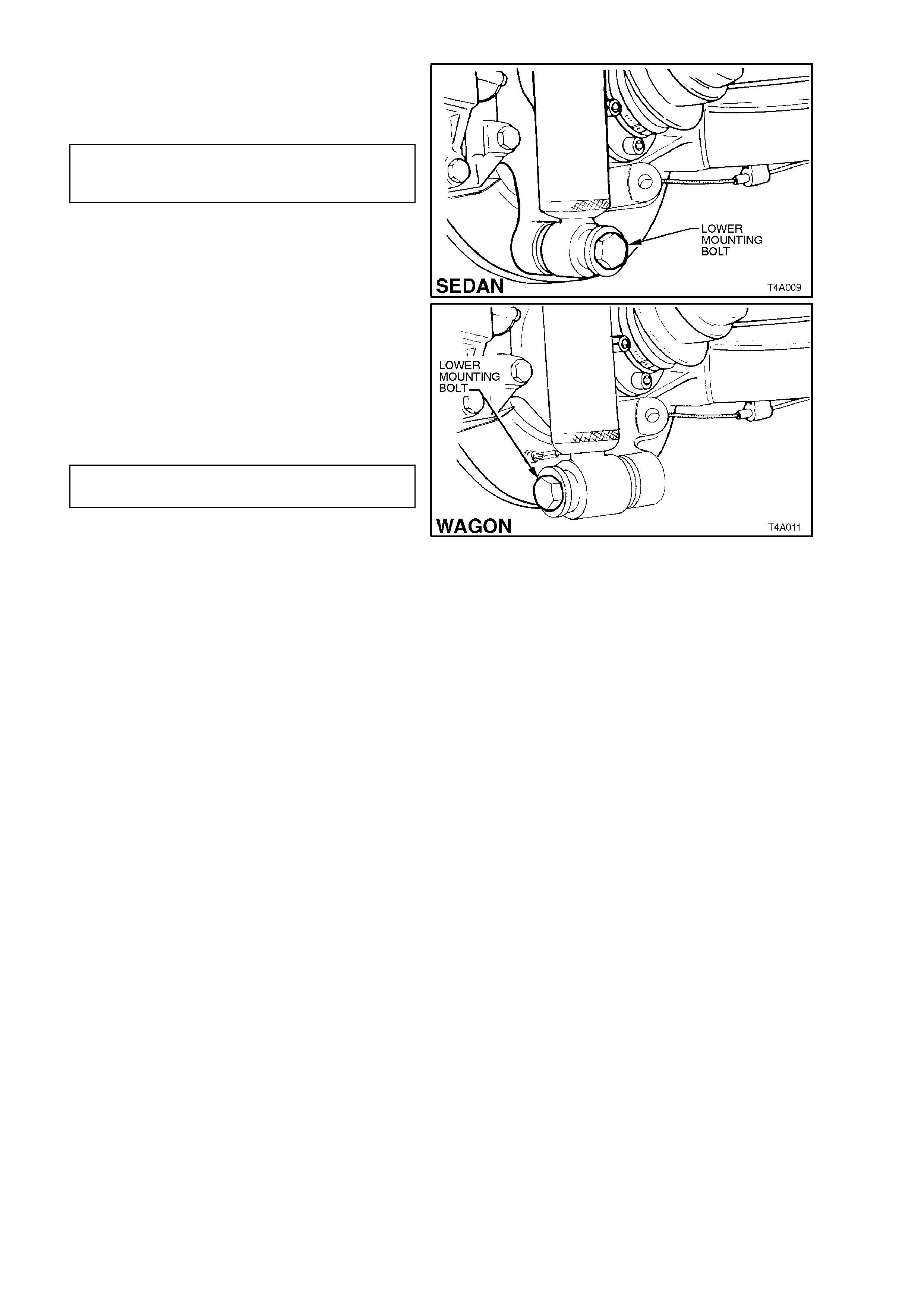
11. Install shock absorber to trailing arm, install
and tighten lower mounting bolt to the c orrect
torque specification.
SHOCK ABSORBER
LOWER MOUNTING BOLT 105 - 125 Nm
TORQUE SPECIFICATION
NOTE:
Vehicle must be at curb weight and on all four
wheels before this torque is applied.
12. Install road wheel and tighten attaching nuts.
NOTE:
When installing the wheel, align the marks made
prior to removal .
13. Remove safety stand and lower vehicle.
14. Tighten road wheel attaching nuts to the
correct torque specification.
ROAD WHEEL ATTACHING NUT 110 - 140
TORQUE SPECIFICATION Nm
15. Refit wheel cover/centre cap. Figure 4B-16
2.5 LIMITED SLIP DIFFE RENTIAL
TORQUE CHECK
1. Place transmission in neutral with engine
turned OFF.
2. Jack up one rear wheel and support trailing
arm on a safety stand. Release park brake
lever to fully OFF position.
3. Remove wheel cover (steel wheels) or centre
cap (alloy wheels).
4. Mark relationship of road wheel to mounting
flange. Remove road wheel attaching nuts and
remove wheel.
5. Disconnect rear shock absorber lower
mounting bolt from trailing arm, and pull lower
end of shock absorber from trailing arm.
Figure 4B-17
6. Remove brake caliper anchor plate to trailing
arm attaching bolts, remove caliper from disc.
Using wire, tie up caliper to lower end of s hock
absorber upper mounting. DO NOT ALLOW
CALIPER TO HANG BY BRAKE HOSE.
7. Remove brake disc.
Figure 4B-18
8. Using a torque wrench in conjunction with
adaptor, Tool No. 7208, and torque wrench
adaptor E6662B, rotate trunnion as sem bly in a
forward direction. If the unit is operating
satisfactorily, a torque reading of
approximately 70 Nm should be obtained while
turning the trunnion assembly, with the
opposite wheel remaining stationary.
If a torque reading of less than 45 Nm is
obtained, remove differential case and inspect
case internal components and repair as
necessary, refer to
3.4 LIMITED SLIP DIFFERENTIAL in this
Section.
Figure 4B-19
9. Install brake disc and brake caliper. Install
brake caliper anchor plate to trailing arm
attaching bolts and tighten to the correct
torque specification.
BRAKE CALIPER ANCHOR PLATE
TO TRAILING ARM ATTACHING 70 - 100 Nm
BOLT TORQUE SPECIFICATION
Figure 4B-20
10. Install shock absorber to trailing arm, install
and tighten lower mounting bolt to the correct
torque specification.
SHOCK ABSORBER
LOWER MOUNTING BOLT 105 - 125 Nm
TORQUE SPECIFICATION
NOTE:
Vehicle must be at curb weight and on all four
wheels before this torque is applied.
11. Install road wheel and tighten attaching nuts.
NOTE:
When installing the wheel, align the marks made
prior to removal.
12. Remove safety stand and lower vehicle.
13. Tighten road wheel attaching nuts to the
correct torque specification.
ROAD WHEEL ATTACHING NUT 110 - 140
TORQUE SPECIFICATION Nm
14. Refit wheel cover/centre cap. Figure 4B 21
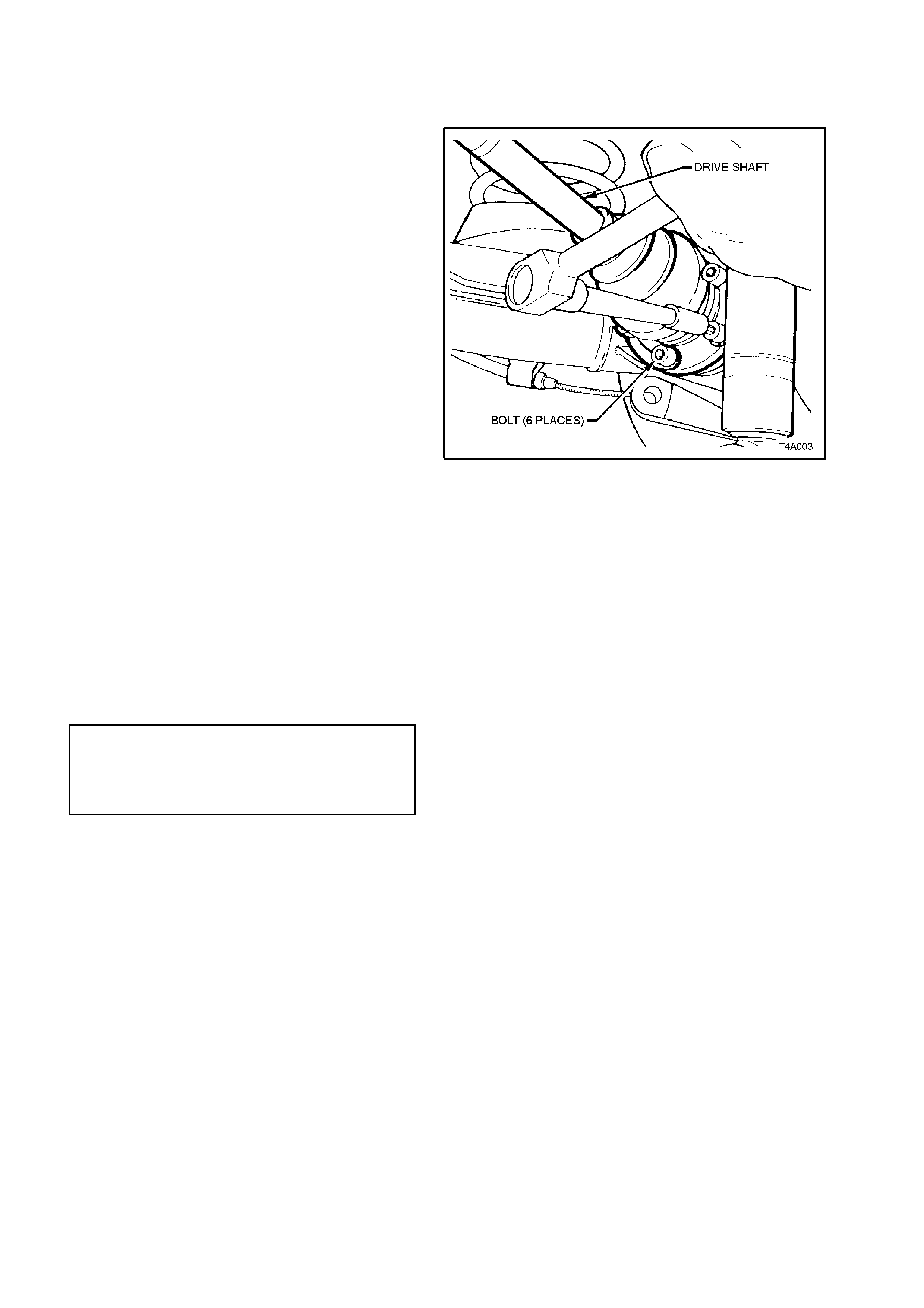
2.6 DRIVE SHAFT ASSEMBLY
REMOVE
1. Using a floor jack under centre of differential
carrier, jack up rear of vehicle then place
safety stands under trailing arms.
2. Using an 8 m m Allen key socket, r emove dr ive
shaft inner constant velocity joint to inner axle
shaft and outer constant velocity joint to
trunnion flange attaching bolts and plates,
remove drive shaft.
NOTE 1:
As it is only the inner, constant velocity joint that is
a plunge joint, it is important that which end is
which, is remembered for correct installation.
NOTE 2:
During drive shaft removal and installation, keep
drive shaft supported so that it does not hang on
one end because drive shaft joint deflection must
be kept to within the angular movement of an
installed drive shaft. Figure 4B-22
REINSTALL
Installation of the drive shaft is reversal of the
removal procedure, noting the following points.
NOTE:
The outer CV joint is marked with two grooves,
while the inner, plunge joint has only one groove. It
is important that the drive shaft is installed
correctly.
1. Tighten drive shaft to trunnion flange and
inner axle shaft attaching bolts to the correct
torque specification.
DRIVE SHAFT CONSTANT
VELOCITY JOINT TO TRUNNION 50 Nm, then
FLANGE AND INNER AXLE 60° - 75°
SHAFT ATTACHING BOLT turn angle
TORQUE SPECIFICATION
2.7 DRIVE SHAFT AND/OR CONSTANT VELOCITY JOINTS
There are three repair kits available for drive shaft
constant velocity joint repairs.
The first kit is a BOOT KIT, which consists of a
boot, boot clamps, snap ring and two tubes of
grease.
The sec ond k it is a CONST ANT VELOCIT Y JO INT
KIT, which contains the same items as the BOOT
KIT plus the inner, constant velocity joint.
The Third kit is a CONSTANT VELOCITY JOINT
KIT, which contains the same items as the BOOT
KIT plus the outer, constant velocity joint.
DISASSEMBLE
1. Remove drive shaft assembly, refer to
2.6 DRIVE SHAFT ASSEMBLY in this
Section.
2. Clean outside of assembly with a suitable
solvent before disassembling.
3. Clamp as sem bly, by drive s haft, in a vic e fitted
with soft metal jaws.
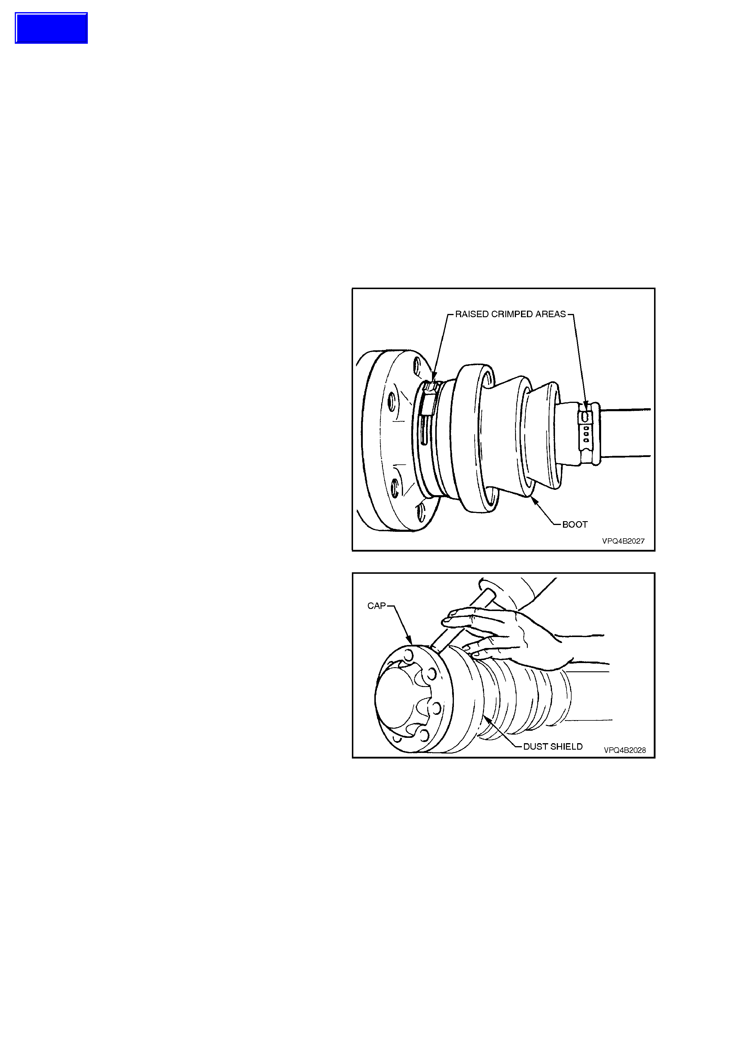
4. Using tin snips or other suitable cutting tool,
cut boot clamps in raised crimped area and
remove clamps.
Figure 4B-23
5. Using a suitable drift and hammer, tap dust
shields and caps from both sides of constant
velocity joints.
Figure 4B-24
Techline
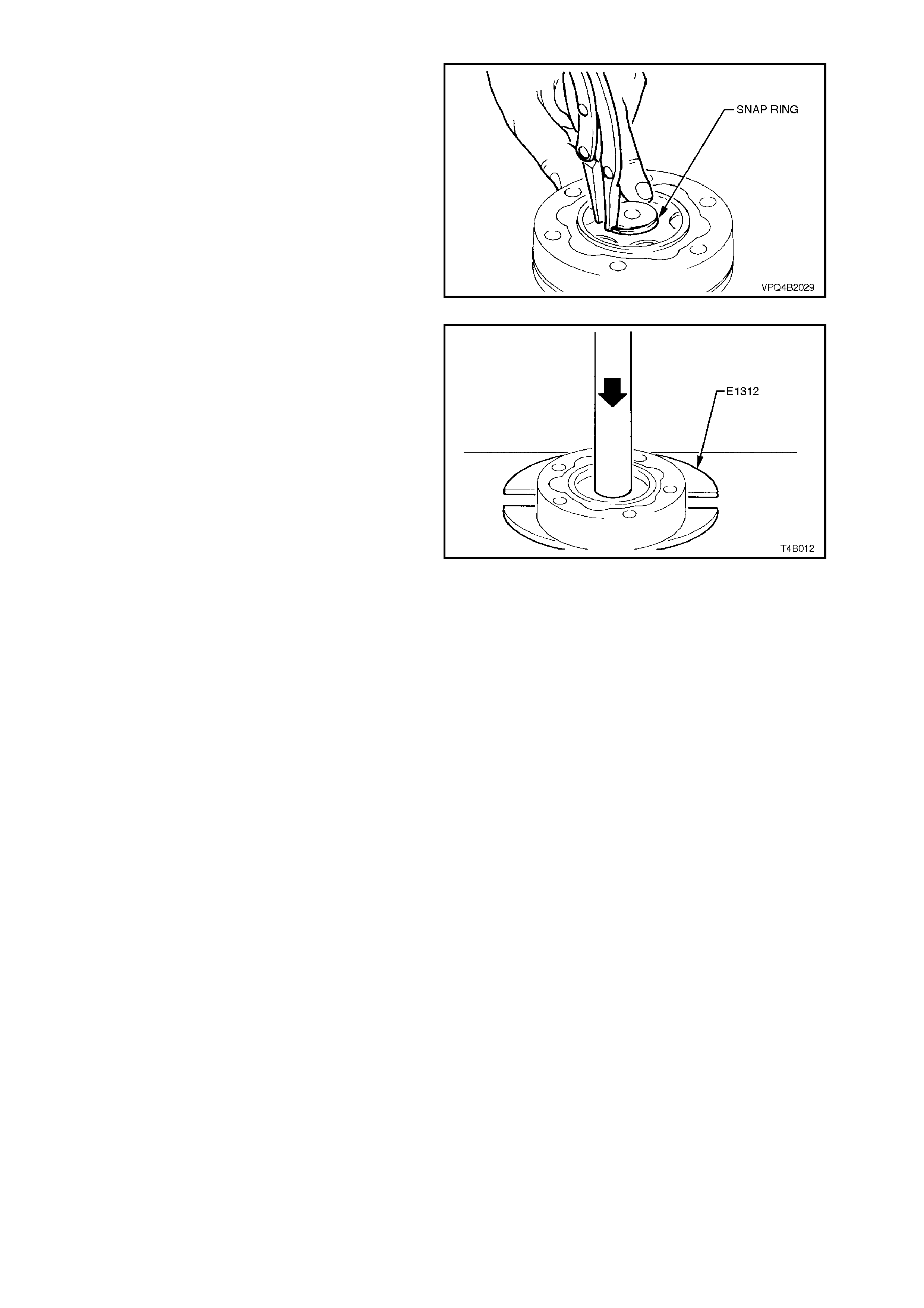
6. Remove snap rings from each end of drive
shaft and discard.
NOTE:
Do not use snap rings once they have been
removed. Always use new snap rings on
reassembly.
7. Remo ve assembly from vice. Slide dus t shield
and boots towards centre of shaft.
Figure 4B-25
8. Using suitable press plates (such as Tool No.
E1312), supporting inner race, press drive
shaft from constant velocity joint.
Repeat process to re move rem aining constant
velocity joint.
9. Remove boots and dust shields from drive
shaft, ensuring boots are not damaged on
edges of shaft.
Figure 4B-26
INSPECT
Drive Shaft and Boots
1. Clean shaft and boots in a suitable cleaning
solvent.
2. Inspect drive shaft for twisting, cracking or
excessive spline wear.
NOTE:
Because the drive shaft is not serviced separately,
if the drive shaft is found to be defective, then it
must be replaced as an assembly.
3. Inspect boots and replace if split, fatigued,
cracked or worn.
Constant Velocity Joints
NOTE:
Complete disassembly of the constant velocity
joints is not recommended. The internal
components are a precision fit and develop their
own characteristic wear patterns. Intermixing
components could result in looseness, binding
and/or premature failure of the joint.
1. Inspect grease in joint, and if obviously
contaminated with and/or been subjected to
dirt ingress, the joint has in all likelihood
suffered damage and should be replaced.
If inspec tion reveals that the j oint has not been
contaminated, clean joint by soaking in a
suitable cleaning solvent.
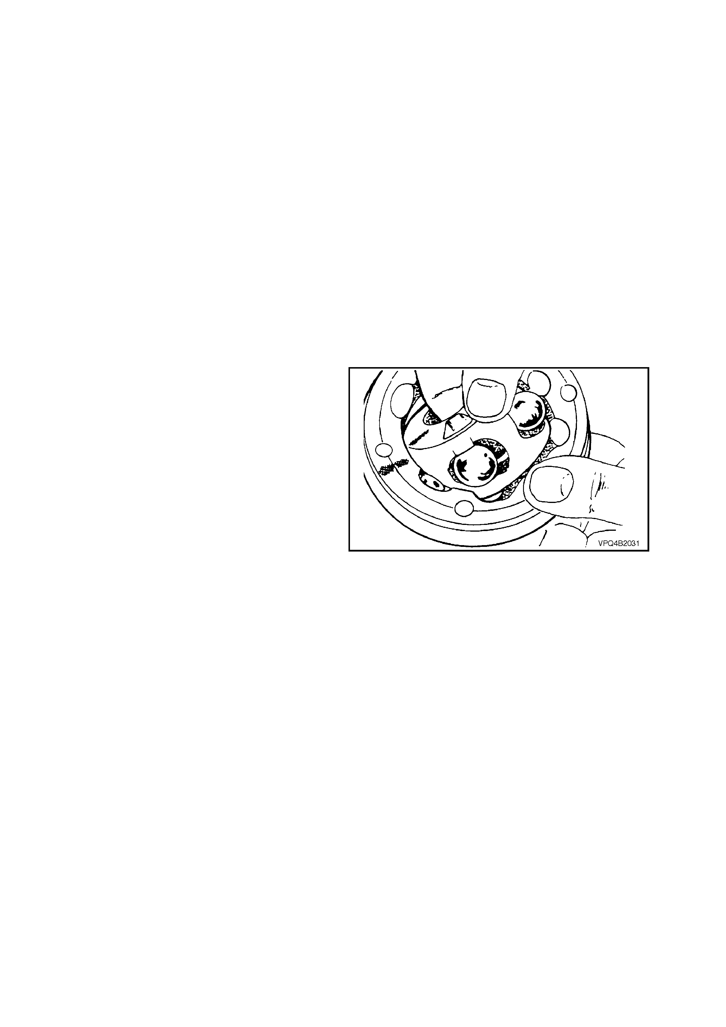
2. Once grease has been removed, inspect
internal components by tilting inner race to one
side to expose each ball.
Replace joint assembly if there is severe
pitting, galling, play between balls and the
cage windows, any cracking or damage to
cage, pitting or galling or chips in raceways. Figure 4B-27
REASSEMBLE
Constant Velocity Joints
NOTE 1:
During the removal, cleaning, inspection or
replacement of a constant velocity joint, it is
possible for the joint to become disassembled.
Should an inadvertent disassembly of a constant
velocity (CV) joint occur, and notwithstanding the
earlier recommendation, it is possible to
reassemble the CV joint, provided the following
procedure is followed EXACTLY.
NOTE 2:
Ideally, the inner race and cage, together with the
individual balls, should be maintained in their
original locations to minimise the creation of a noisy
joint.
NOTE 3:
Under no circumstances are components from one
constant velocity joint to be mixed with components
from another CV joint.
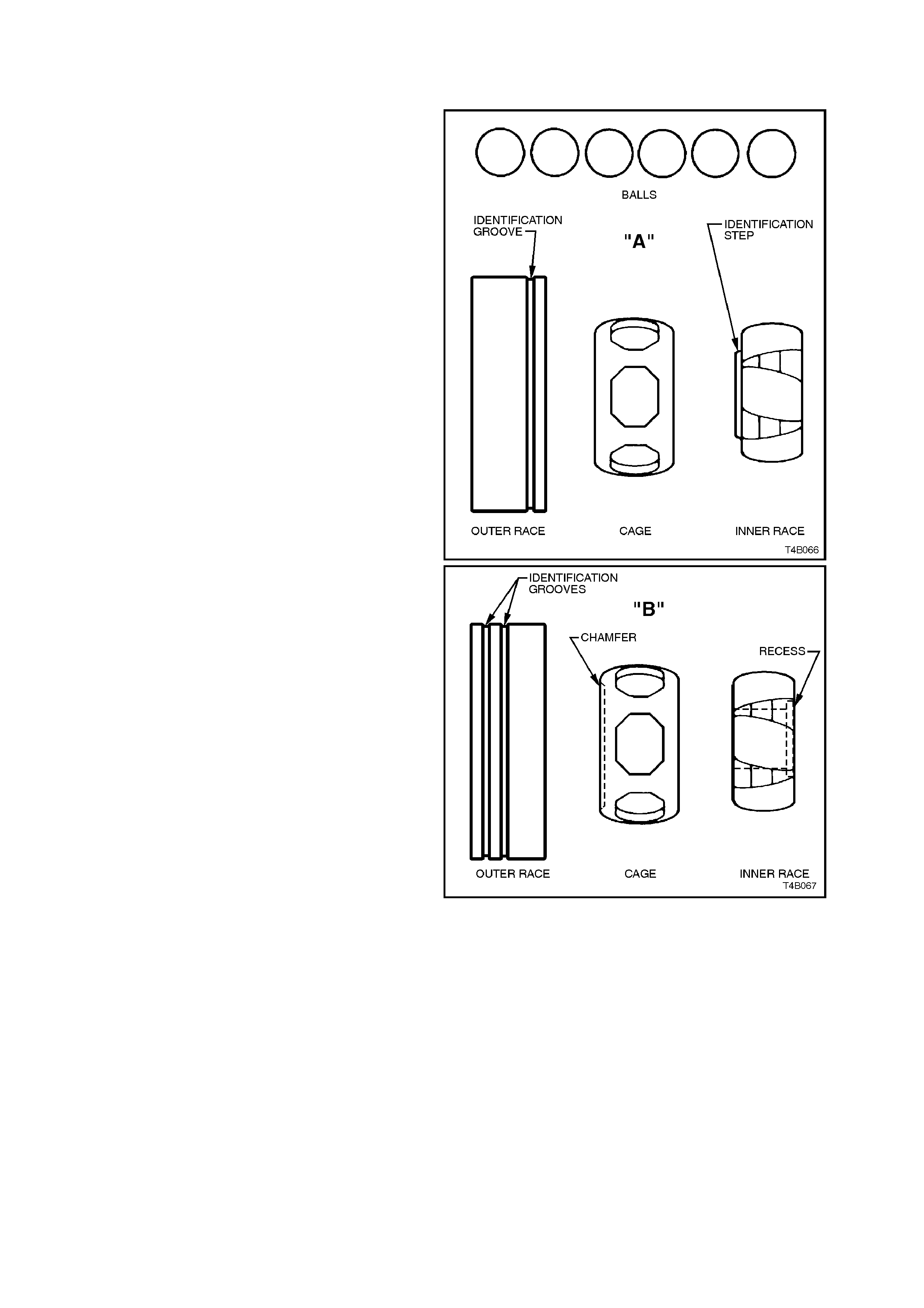
Shown are exploded views of each constant
velocity joint; view “A” is the inner joint, while view
“B” shows the outer. Note the single identification
groove on the outer race and the identification step
on the inner race for the inner joint and the two
grooves and recess on the outer joint.
Figure 4B-28
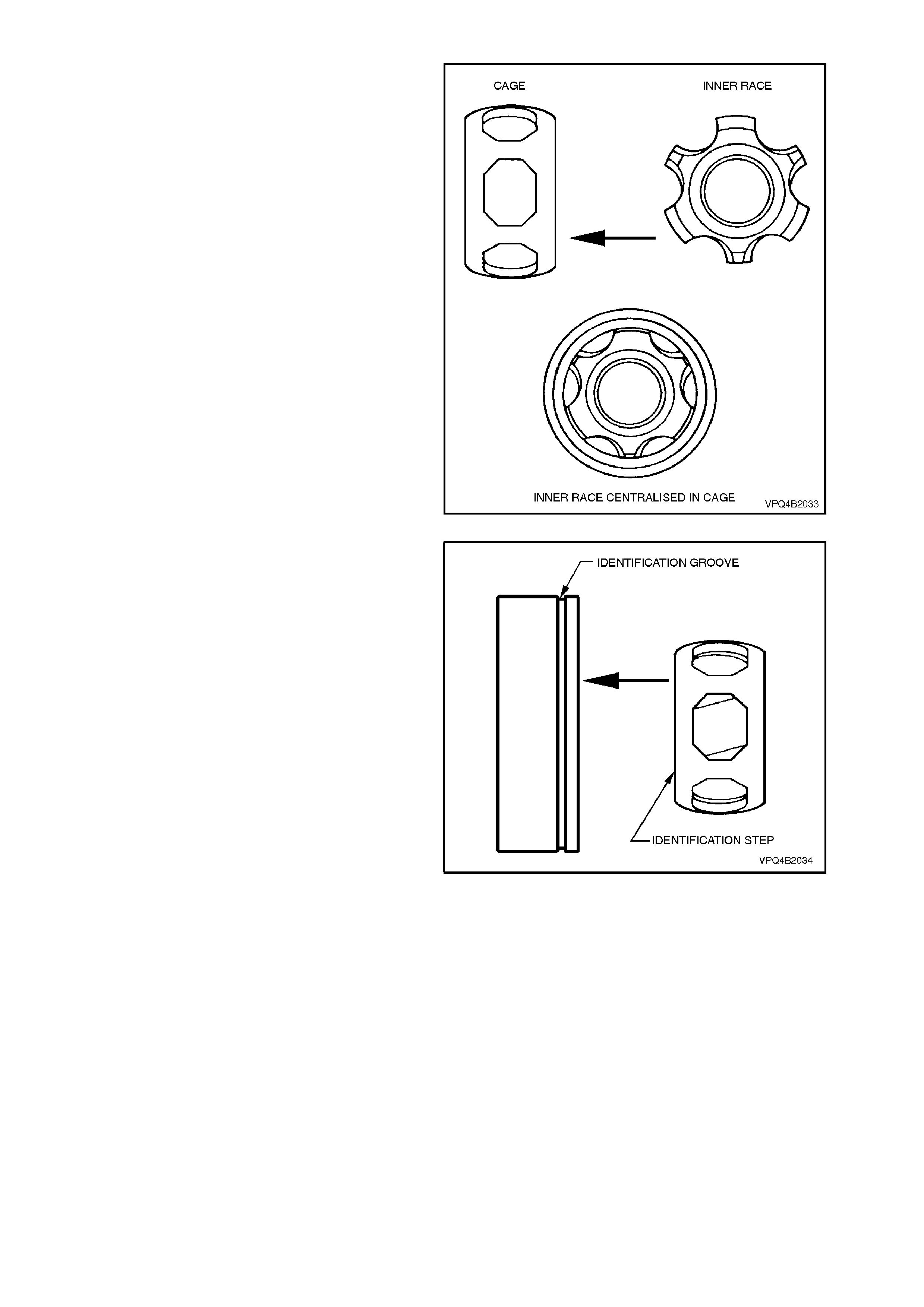
1. Place the inner race into the cage and position
centrally within the cage.
Figure 4B-29
2. Place the inner race and cage into the outer
race. Make sure that the identification
markings on both the inner and outer races
are on opposite sides of the assembly, as
shown.
Figure 4B-30
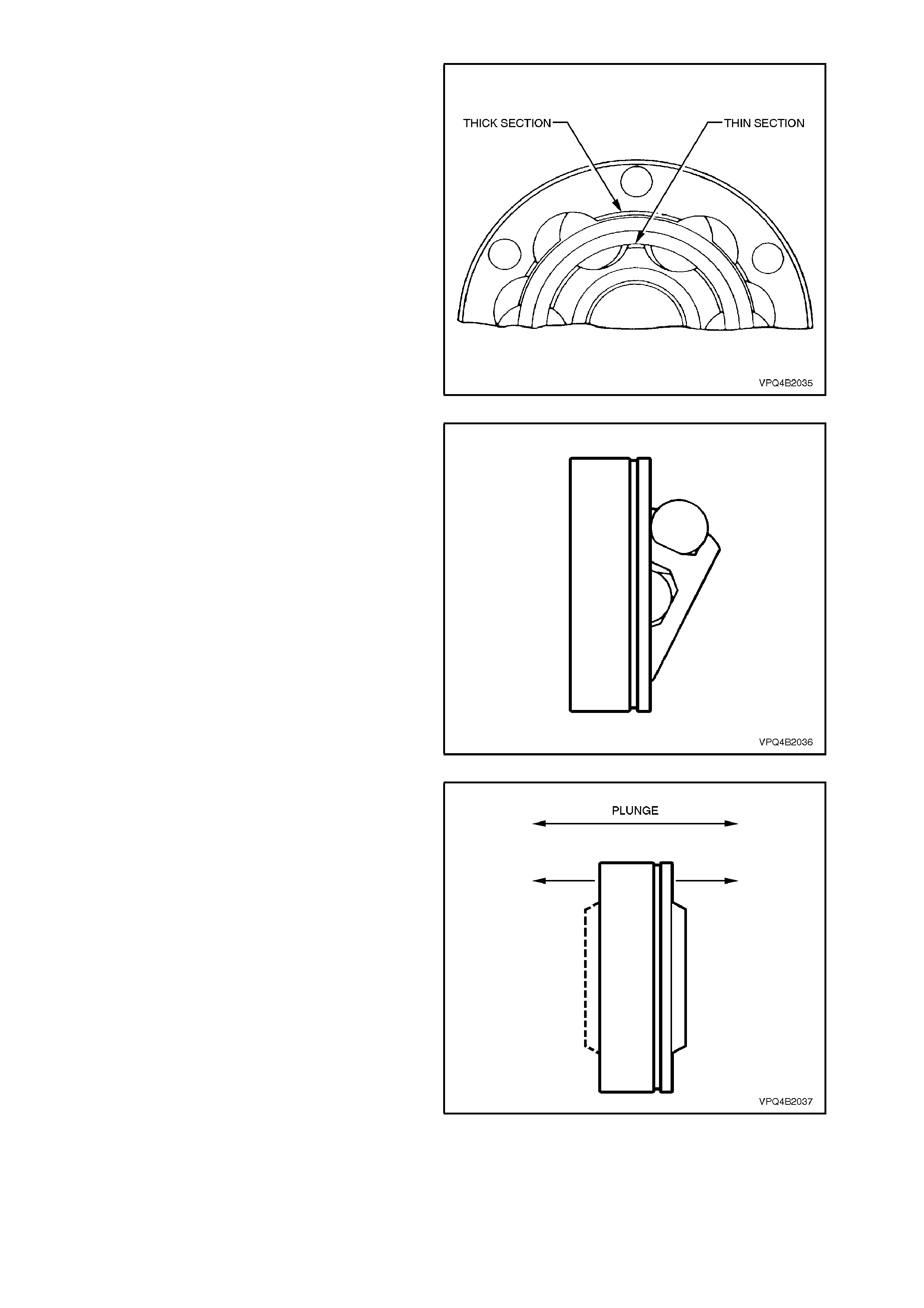
3. Align the thick sections on the outer race, with
the narrow ones on the inner race.
Figure 4B-31
4. Tilt the cage and inner race, as shown and fit
one ball.
Repeat this process for the remaining five
balls.
Figure 4B-32
5. When assembly of the CV joint is complete,
check for plunge movement as shown. If NO
plunge movement can be achieved, then
the constant velocity joint has been
incorrectly assembled.
If such a situation occurs, the CV joint must be
disassembled and the assembly process
repeated until such time that the required
plunge movement is achieved.
NOTE:
This check only applies to the inner plunge joint.
The outer CV joint should have no plunge
movement.
Figure 4B-33
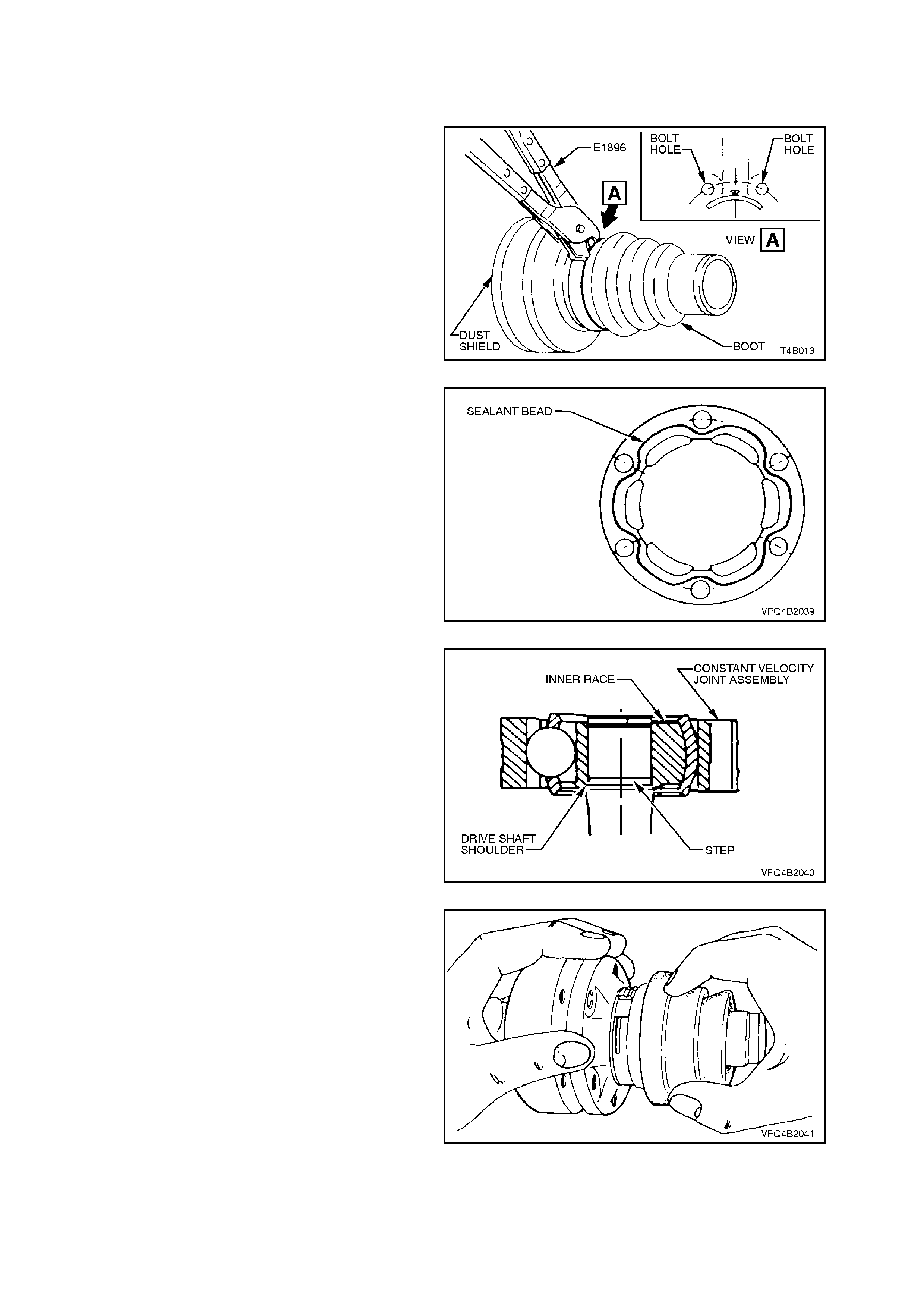
Drive Shaft and Boots
1. Remove old sealing bead of silicon from dust
shields, dust caps and constant velocity joints.
2. Position new large boot clamp over boot and
place boot over dust shield. Using Tool No.
E1896, securely crimp boot clamp, ensuring
crimp is in correct location.
Figure 4B-34
3. Apply a 2 mm diameter bead of RTV 732
sealant (Holden's Specification HN1373) to
dust caps/shields as shown and allow
approximately one hour to cure.
4. Place new small boot clamps onto drive shaft.
5. Place both dust shield and boot assemblies
onto drive shafts, ensuring that boots are not
damaged by sharp edges on each end of
shaft.
Figure 4B-35
6. Install inner, constant velocity joint onto shaft
with step on the inner race facing toward the
shoulder on the shaft, as shown.
NOTE:
The recess on the inner race of the outer CV joint,
also faces the drive shaft.
7. Press constant velocity joints onto shaft and
install NEW circlips.
NOTE:
When pressing joints onto shaft, ensure that the
joint inner races take the press load.
Figure 4B-36
8. Pack inside section of joint and boot with one
tube of grease (40 grams) and pack half tube
(20 grams) to outside section of joint.
9. Position dust caps and dust shields onto
constant velocity joints, ensuring that all bolt
holes align.
10. Using a suitable punch and ham m er, tap caps
and shields into place.
Figure 4B-37
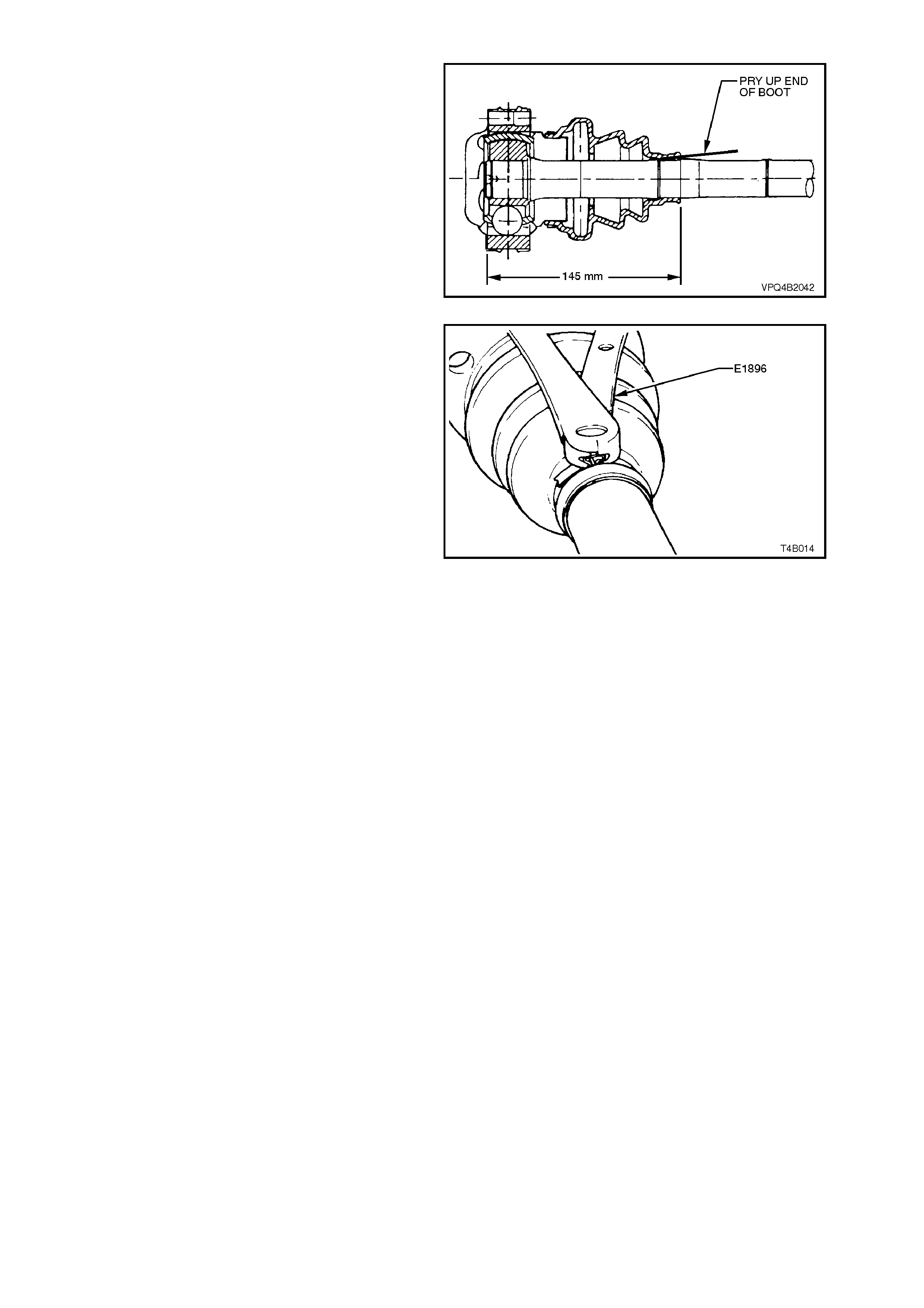
11. Locate small ends of boots into boot grooves
on drive shafts, ensuring that boots are not
twisted.
With both joint, pry up small ends of boots
from shaft to equalise air pressure inside and
outside of boots and work out any dimples
before applying new small clamps.
IMPORTANT:
The location distance shown, ONLY applies to the
inner, plunge joint and should be set before
applying the small clamp.
Figure 4B-38
12. Position small clamps over ends of boots and
using Tool No. E1896, crimp ends of clamps.
13. Reinstall drive shaft, refer
2.6 DRIVE SHAFT ASSEMBLY - REINST ALL
in this Section.
Figure 4B-39
2.8 INNER AXLE SHAFT SEAL
REPLACE
1. Using a floor jack under centre of differential
carrier, jack up rear of vehicle then place
safety stands under body rear jacking points.
Refer to Section 0A GENERAL
INFORMATION for location of jacking points.
2. Remo ve drive shaft f rom side of vehicle which
seal is to be replaced, refer to
2.6 DRIVE SHAFT ASSEMBLY in this
Section.
NOTE 1:
During drive shaft removal, keep drive shaft
supported so that it does not hang on one end.
NOTE 2:
Drive shaft joint deflection should be kept to a
minimum.
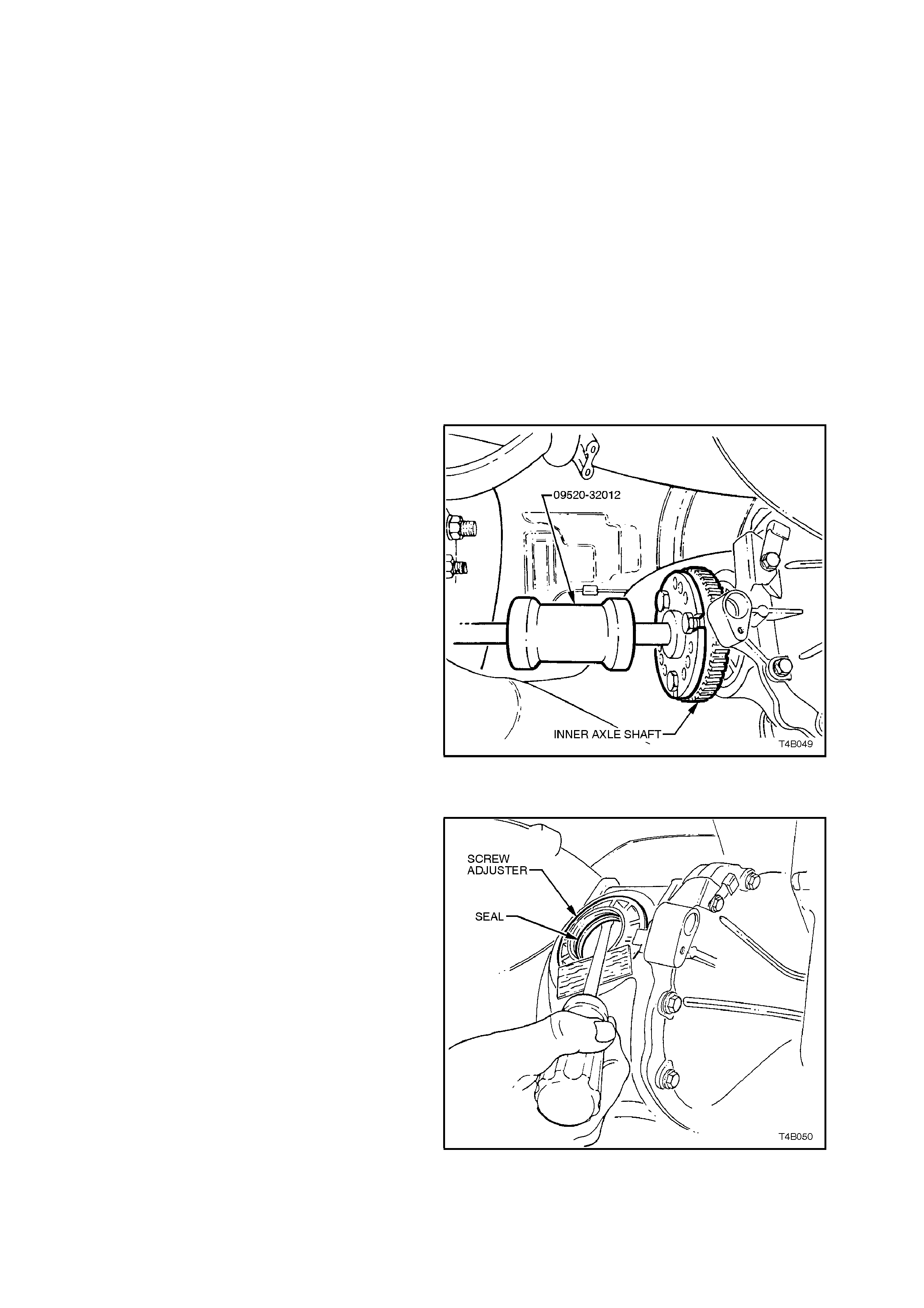
3. Remove inner axle shaft by installing a slide
hammer, Tool No. 09520-32012 with three
suitable size bolts to axle flange. Use slide
hammer to release axle shaft spring clip.
As the axle shaft is removed, a small amount
of lubricant may leak from differential carrier.
CAUTION:
If V6 engined vehicle is fitted with LSD, do not
rotate the opposite axle shaft, as side gear and
clutch cone splines will become misaligned.
Then the axle shaft cannot be reinstalled
without removing differential case, dismantling
and realigning gear and cone splines.
NOTE:
The above ‘Caution’ does not apply to the V8 or V6
superchar ged engine final drives, because the side
gear and LSD cone is an integrated component.
4. Clean around seal bore and housing area to
make sure that no foreign matter enters axle
shaft needle bearing in the screw adjuster.
Figure 4B-40
5. Using a suitable screwdriver and a block of
wood, lever seal from screw adjuster bore.
NOTE:
Take care not to damage the screw adjuster's
aluminium housing with the screwdriver blade, as
this could cause oil leaks to occur, after a new oil
seal was fitted.
Figure 4B-41
6. Before installation of new seal, examine seal
surface of inner axle shaft and remove any
nicks or burrs. Should this inspection show
that the surface is marked, a new inner axle
shaft should be fitted.
NOTE 1:
The left hand inner axle shaft is shorter in length
than the right hand shaft.
NOTE 2:
If vehicle is equipped with ABS, the inner axle
shafts are unique for this application.
NOTE 3:
Check spring clip in end of axle s haf t to ens ure that
it is not damaged and moves freely in groove.
Replace spring clip if necessary, by expanding
ends of clip and removing f rom shaft. Only expand
the ends of a new clip sufficiently to allow
installation into shaft groove.
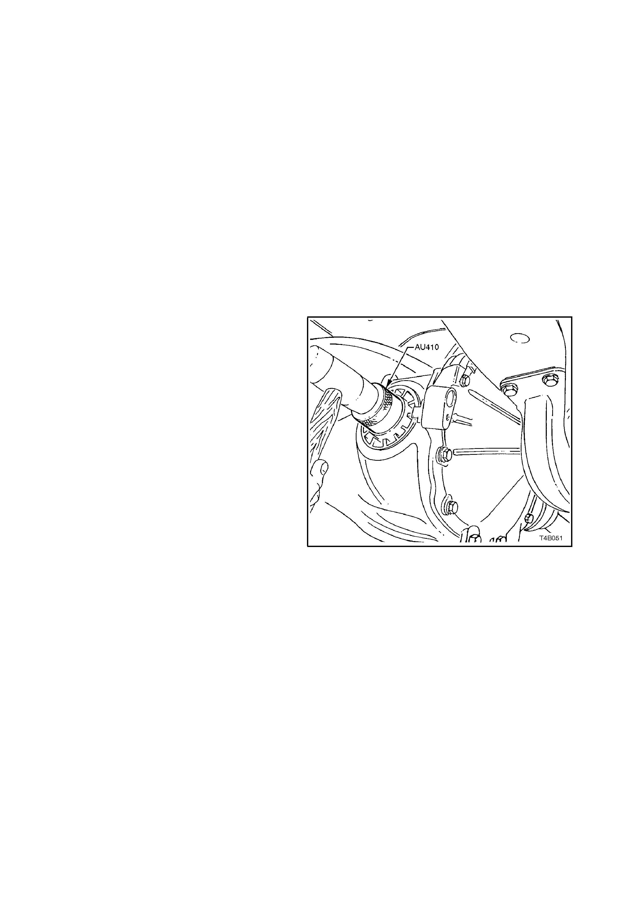
7. Examine seal bore in screw adjuster and
remove any nicks or burrs.
8. Lubricate seal lips and outside diameter with
lithium soap grease (Holden's Specification
HN1147). Install seal using Tool No. AU410,
until seal bottoms in bore.
Figure 4B-42

9. Install inner axle shaft, aligning splines with
clutch cone (if fitted with a Limited Slip
Differential) and side gear.
NOTE:
To avoid premature seal failure, ensure axle shaft
splines or s ecuring c lip do not scor e or dam age the
seal lips during installation.
10. Lightly hit on end of axle shaft flange with a
soft faced hammer to compress spring clip on
shaft into clutch cone and side gear splines.
Fully engage shaft until clip snaps into side
gear groove.
Figure 4B-43
11. Reinstall drive shaft, refer to
2.6 DRIVE SHAFT ASSEMBLY in this
Section.
12. Remove safety stands and low r vehicle.
13. Check and fill differential carrier to correct
level with specified lubricant. Refer to
2.1 CHECKING DIFFERENTIAL CARRIER
LUBRICANT LEVEL in this Section.
2.9 PINION OIL SEAL
REPLACE
1. Using a floor jack under centre of differential
carrier, jack up rear of vehicle then place
safety stands under trailing arms.
2. Mark the position of the propeller shaft rear
flange to pinion flange then remove propeller
shaft, refer to Section 4C PROPELLER
SHAFT AND UNIVERSAL JOINTS. This
operation will also mean that the exhaust
system has to be removed.
NOTE:
If the paint alignment marks on the rear universal
joint and pinion flanges are not visible, then lightly
scribe a mark on both flanges so they can be
installed in their original positions during
reassembly.
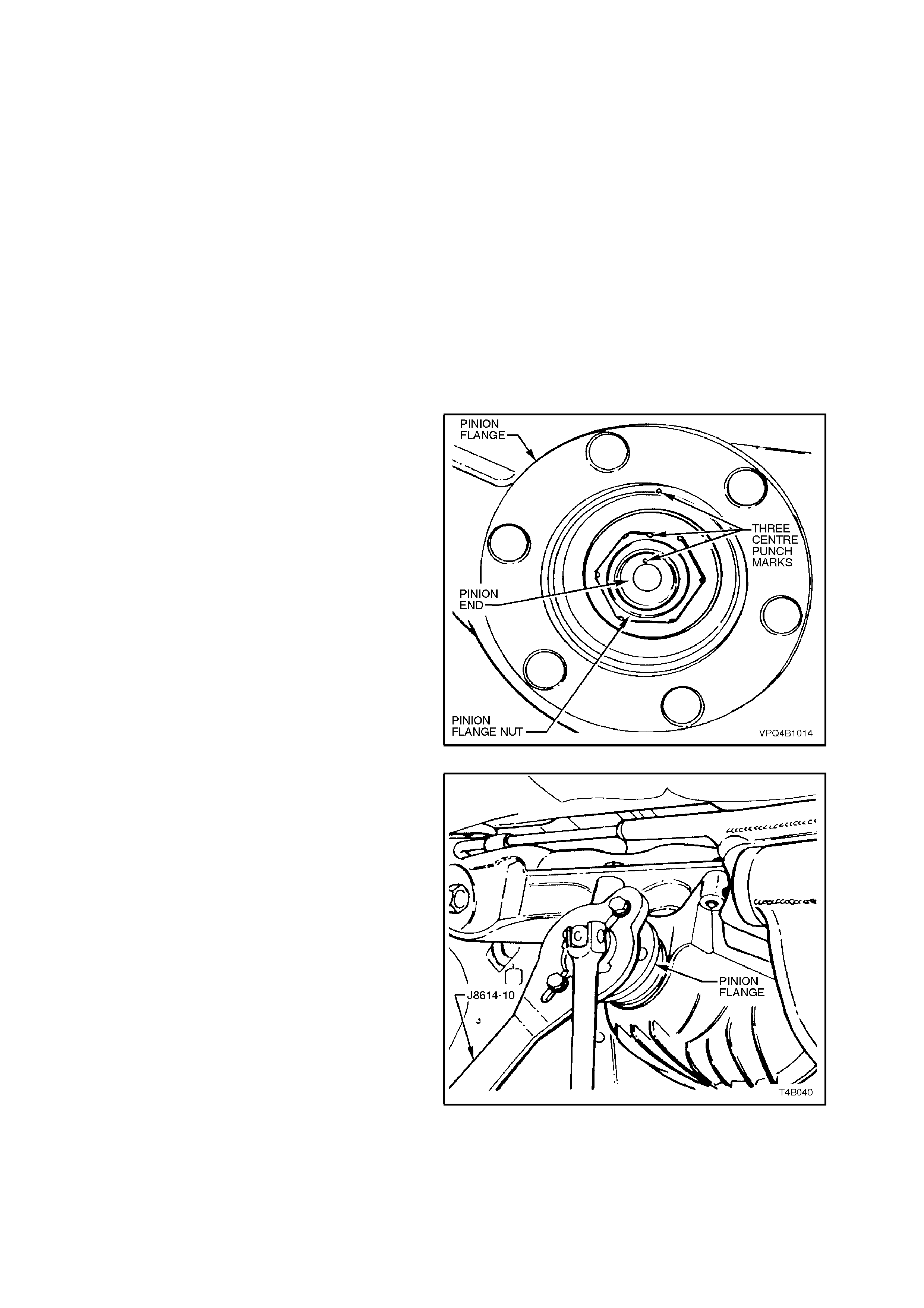
3. Lightly centre-punch alignment marks on the
pinion flange nut, pinion flange and pinion end
as an aid for reassembly.
By reassembling in the original position, the
flange run-out will be m inim ised and the pinion
bearing preload will be maintained.
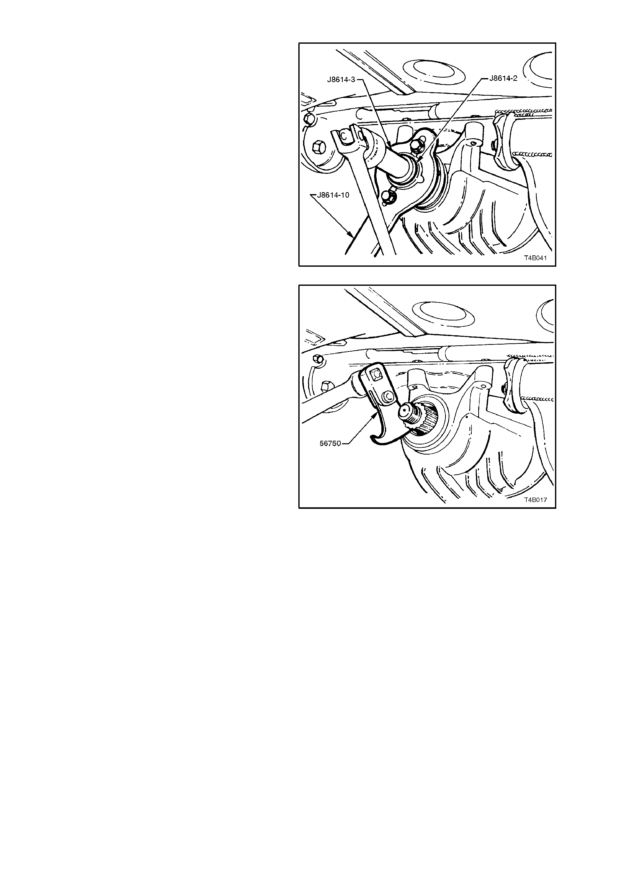
Figure 4B-44
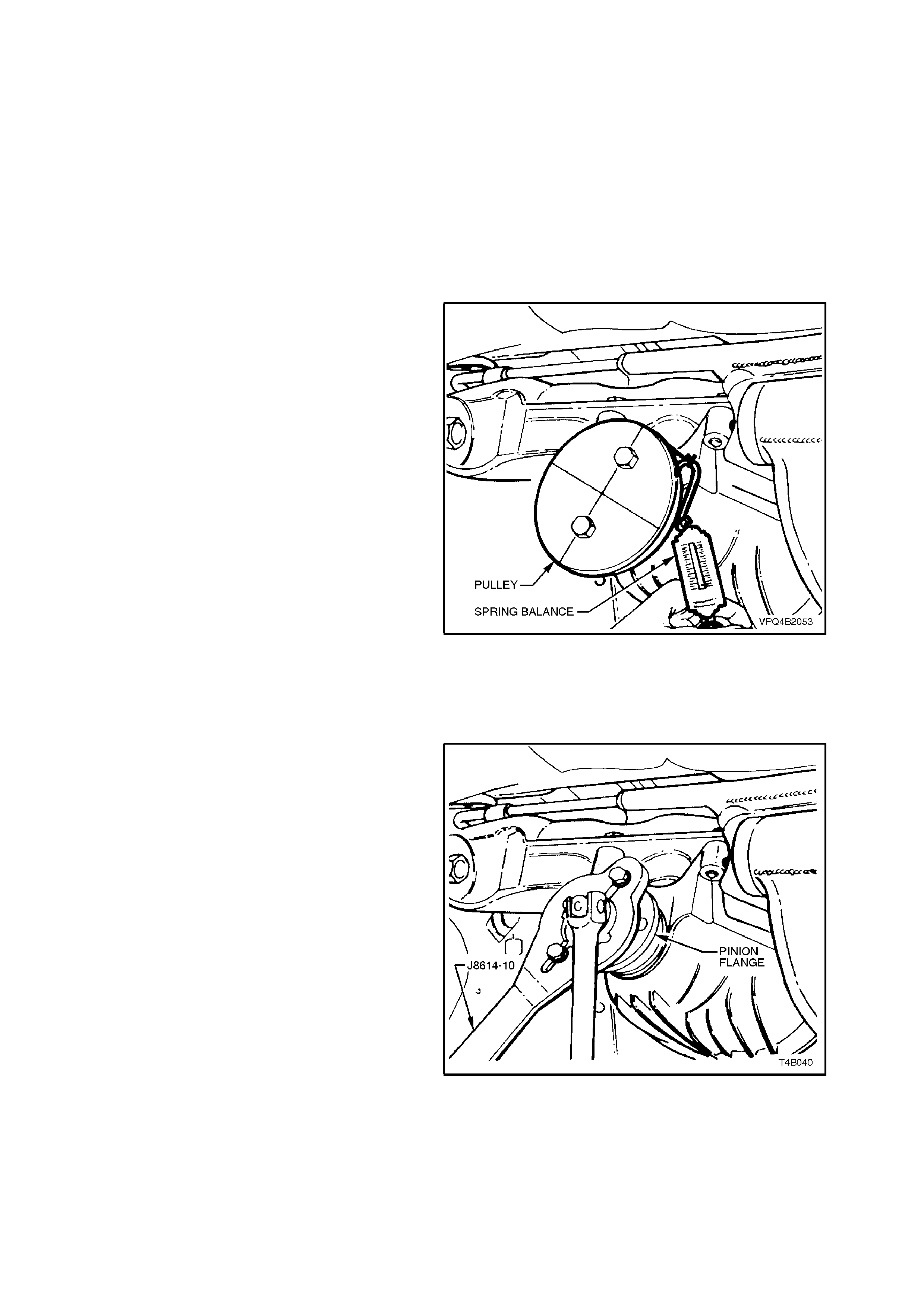
4. Using Tool No. J8614-10 with two suitable
bolts and nuts to hold pinion flange, remove
flange retaining nut.
Figure 4B-45
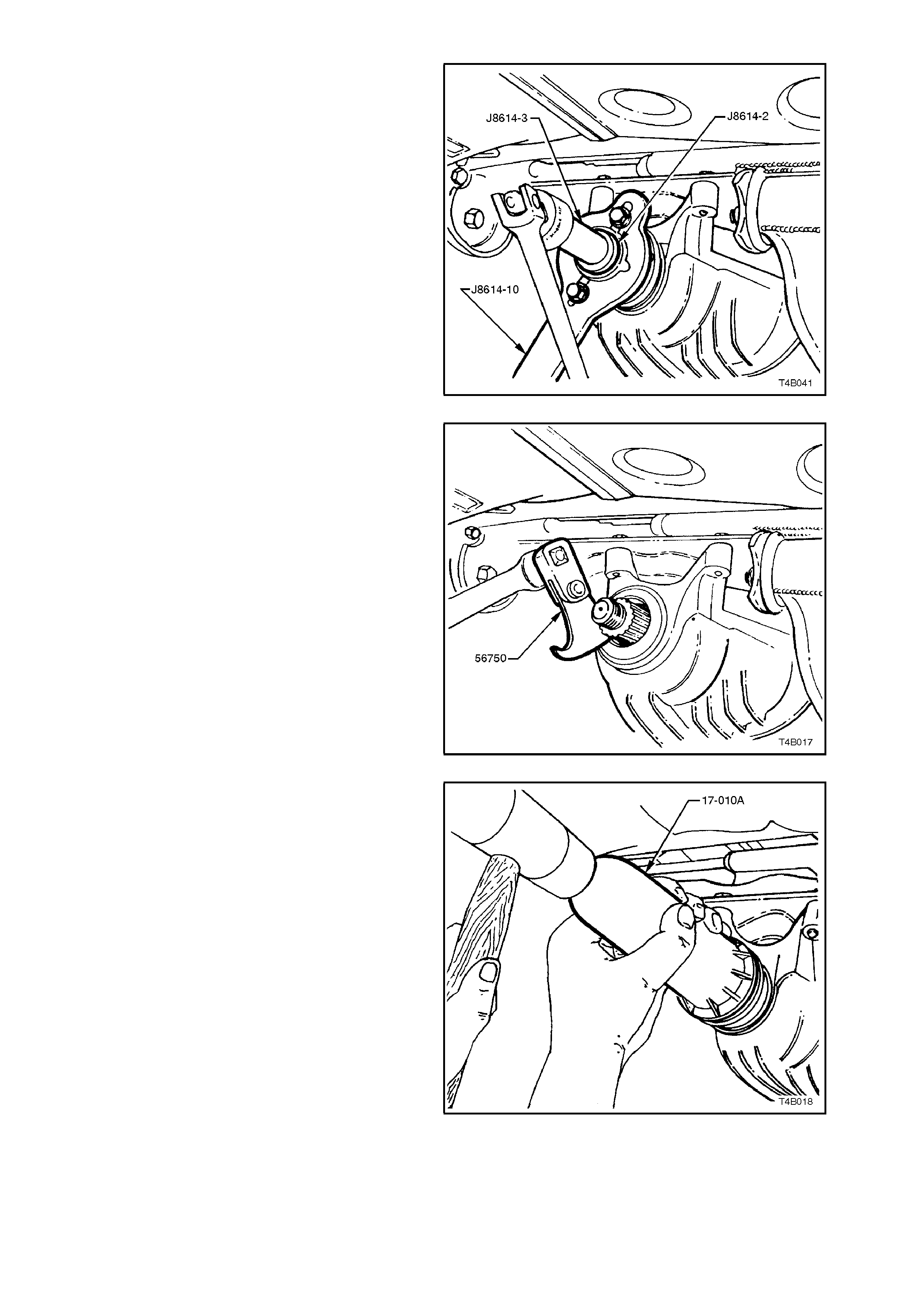
5. Withdraw pinion flange using the three
component parts of Tool No. J8614-01,
assembled as shown. Place a drain tray
beneath differential carrier housing.
Figure 4B-46
6. Prise pinion oil seal from carrier bore using
Tool No. 56750 or a universal seal removing
tool.
7. Lubricate new pinion oil seal lips with the
recommended rear axle lubricant. Lightly coat
the outside of the replacement seal with a non-
hardening gasket cement.
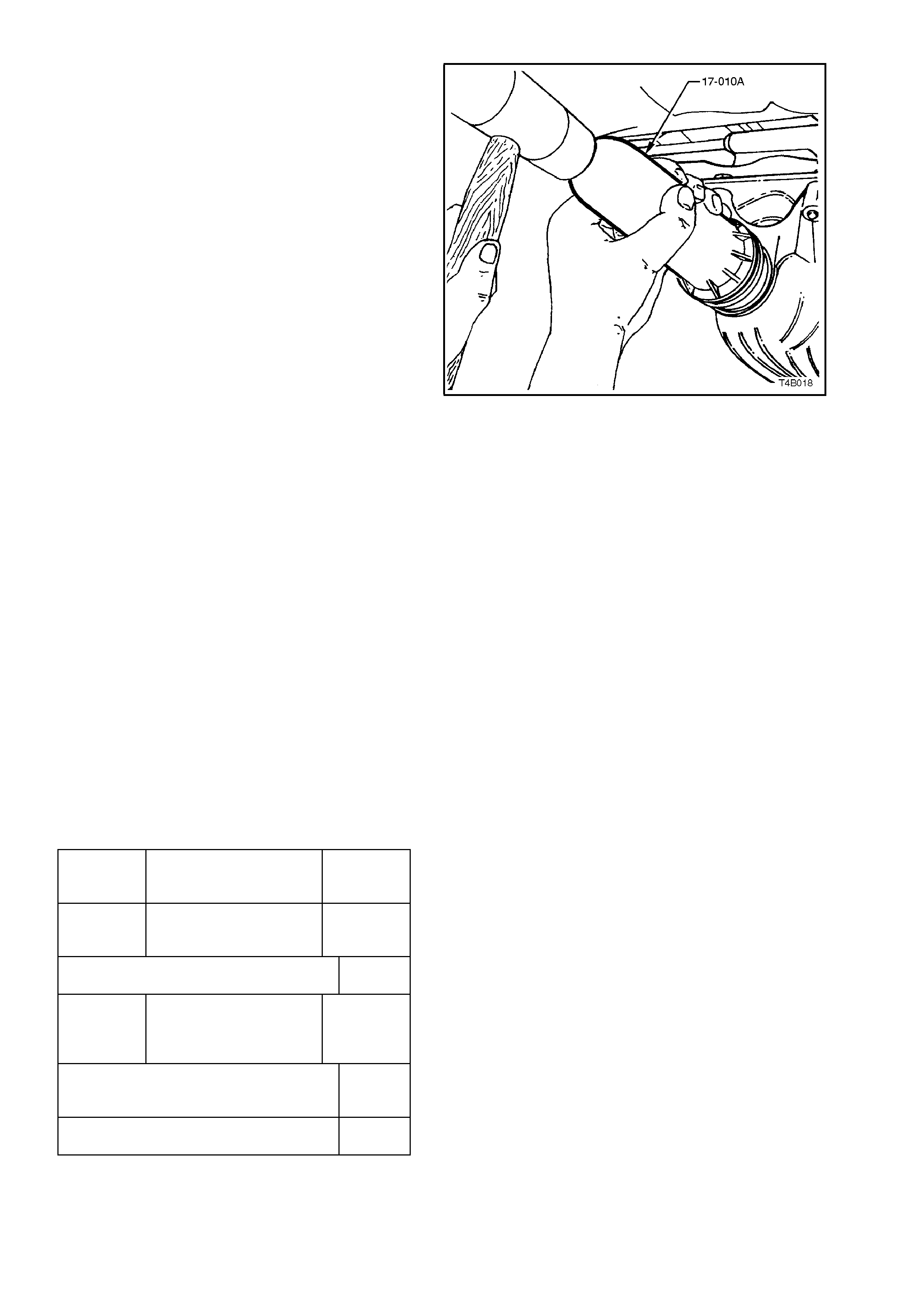
Figure 4B-47
8. Start oil seal into differential carrier housing
and drive seal squarely into position using Tool
No. 17-010A. Seal fits f lush to 0.25 m m below
carrier housing surface.
Figure 4B-48
9. Ensure that pinion shaf t is fr ee from burrs and
that flange oil seal surface is free from
damage.

10. Coat splines and seal surface of pinion f lange
with differential gear lubricant, and install
flange onto pinion shaft splines. Ensure that
centre-punch marks align.
11. Install flange retaining nut and tighten nut until
centre-punch marks align, then tighten nut
carefully to a position not more than 5° past
aligned setting.
NOTE:
The pinion flange is an interference fit on pinion
shaft splines and should only be pulled into place
by tightening retaining nut. DO NOT, UNDER ANY
CIRCUMSTANCES, USE FORCE OR HAMMER
FLANGE DURING INSTALLAT ION ONTO PINION
FLANGE.
CAUTION:
Should the retaining nut be overtightened and
pre-load exceeded, it will be necessary to
remove the pinion from the carrier and install a
new collapsible spacer. Under no
circumstances must the retaining nut be
backed off to decrease the pre-load reading.
12. Reconnect propeller shaft rear universal joint
flange to pinion flange, refer
Section 4C PROPELLER SHAFT AND
UNIVERSAL JOINTS.
13. If removed previously, reconnect exhaust
system, in the reverse to the removal
procedure. Refer to
3.2 FINAL DRIVE ASSEMBLY, in this
Section, for details.
14. Remove safety stands and lower vehicle.
15. Check lubricant level and top up as
necessary. Refer to
2.1 CHECKING DIFFERENTIAL CARRIER
LUBRICANT LEVEL in this Section, for
details.
16. Start vehicle and check for exhaust leaks.
2.10 PINION FLANGE
REPLACE (USING OLD OIL SEAL)
NOTE 1:
Due to production tolerances in the length of the
pinion flange, it is essential that the following
method be used when installing a new pinion
flange and/or pinion nut.
NOTE 2:
For this oper ation, new dual muff ler support to rear
crossmember retainers must be used on
reassembly.
1. Using a floor jack under centre of differential
carrier, jack up rear of vehicle then place
safety stands under trailing arms.
2. Remove propeller shaft, refer to
2.1 PROPELLER SHAFT in Section 4C
PROPELLER SHAFT AND UNIVERSAL
JOINTS.
3. Remove both drive shafts, refer
2.6 DRIVE SHAFTS in this Section.
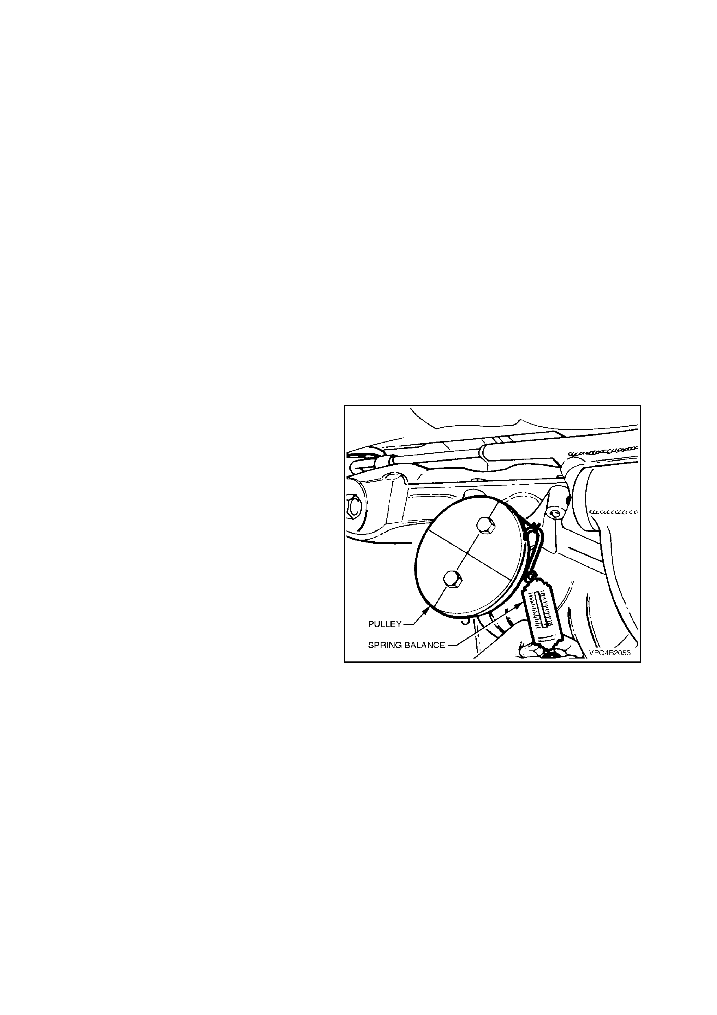
4. Check and record pre-load at pinion flange as
follows:
a. Fit a pulley to pinion flange and attach a
cord around pulley and to a spring scale.
NOTE:
For pulley details, refer to 7 SPECIAL TOOLS at
end of this Section.
b. Start rotation of pulley and whilst in
motion (approximately 50-60 rpm) note
and record reading of spring balance.
This pre-load reading includes pinion
bearings, side bearings, m es hing ef f ec t of
gear set and pinion oil seal.
To determine pre-load, multiply reading
on spring balance by radius of pulley.
EXAMPLE:
W ith a pulley diameter of 152 m m, the radius is 76
mm, which equals 0.076 m. W ith a spring balance
reading of 25 N, the pre-load equals 0.076 m x 25
N = 1.9 Nm.
5. Remove pulley from pinion flange. Figure 4B-49
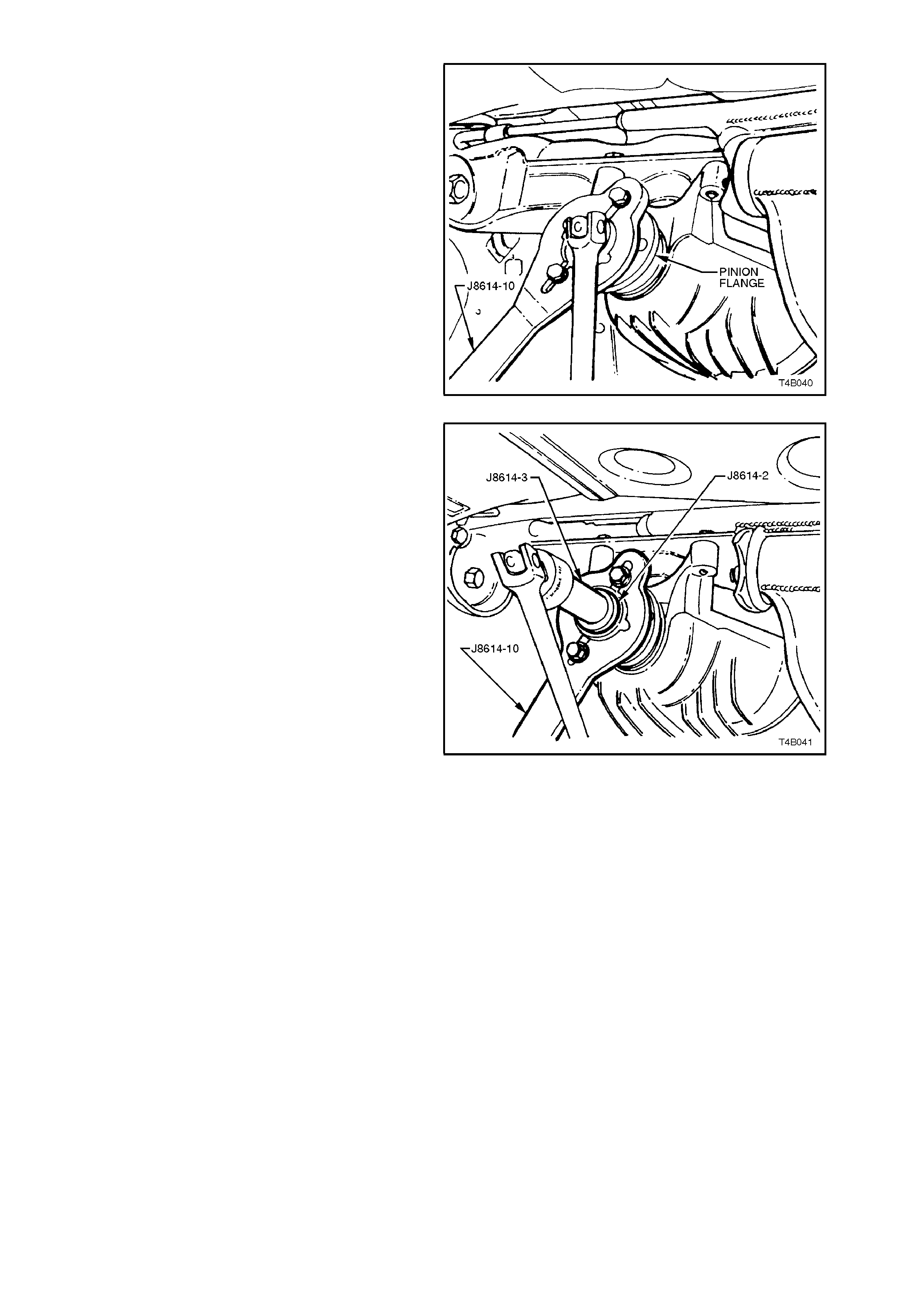
6. Using Tool No. J8614-10 with two suitable
bolts and nuts, hold pinion flange and remove
flange retaining nut.
Figure 4B-50
7. Place drain tray beneath differential carrier.
8. Remove holder from pinion flange and
assemble the three component parts of Tool
No. J8614-01, as shown. Install assembly to
pinion flange using two suitable bolts and nuts.
With the holder J8614-10 secured, tighten
screw J8614-3 and remove the pinion flange.
Figure 4B-51
9. Ensure that pinion shaft thread is free from
burrs, then coat splines and seal surface of
pinion flange with the recomm ended rear axle
lubricant.
10. Install pinion flange and retaining nut.
NOTE:
The new flange will be an interference fit on pinion
shaft splines and should only be pulled into place
by tightening retaining nut. DO NOT, UNDER ANY
CIRCUMSTANCES, USE FORCE OR HAMMER
FLANGE DURING INSTALLAT ION ONTO PINION
FLANGE.
11. Tighten flange retaining nut gradually until
pinion shaft end play is reduced to
approximately 0.50 mm.

12. Attach pulley to pinion flange and us ing spring
balance, check pre-load. Continue tightening
nut while alternatively turning pinion to seat
bearings, until the pre-load figure recorded
previously (Step 4b) is reached. Further
increase this original pre-load reading by 0.5
Nm.
ROTATE PINION AN EXTRA 30-40 TURNS
AND RE-CHECK THE PRE-LOAD TO
ENSURE THAT NO CHANGE HAS
OCCURRED.
CAUTION:
Should the retaining nut be overtightened and
the pre-load exceeded, it will be necessary to
remove the differential carrier assembly and
install a new collapsible spacer. Under no
circumstances must the retaining nut be
backed off to decrease the pre-load setting.
13. Reinstall drive shafts, refer to
2.6 DRIVE SHAFTS in this Section.
14. Reinstall propeller shaft, refer to
Section 4C PROPELLER SHAFT AND
UNIVERSAL JOINTS.
15. If removed previously, reconnect exhaust
system, in reverse to the removal procedure.
16. Remove safety stands and lower vehicle.
17. Check lubricant level and top up as necessary
with the recommended lubricant, refer to
2.1 CHECKING DIFFERENTIAL CARRIER
LUBRICANT LEVEL in this Section.
18. Start vehicle and check for exhaust leaks.
REPLACE (USING NEW OIL SEAL)
For this oper ation, new dual muff ler support to rear
crossmember retainers must be used on
reassembly.
1. Using a floor jack under centre of differential
carrier, jack up rear of vehicle then place
safety stands under trailing arms.
2. Remove propeller shaft, refer to
Section 4C PROPELLER SHAFT AND
UNIVERSAL JOINTS.
3. Remove both drive shafts, refer to
2.6 DRIVE SHAFTS in this Section.
4. Check and record pre-load at pinion flange as
follows:
a. Fit a pulley to pinion flange and attach a
cord around pulley and to a spring
balance.
NOTE:
For pulley details, refer to 7 SPECIAL TOOLS at
end of this Section.
b. Start rotation of pulley and whilst in
motion (approximately 50-60 rpm), note
and record the spring balance reading.
This pre-load reading includes pinion
bearings, side bearings, m es hing ef f ec t of
gear set and pinion oil seal.
To determine pre-load, multiply reading
on spring balance by radius of pulley.
EXAMPLE:
W ith a pulley diameter of 152 m m, the radius is 76
mm which equals 0.076 m. With a spring balance
reading of 25 N, the pre-load equals 0.076 m x 26
N = 1.9 Nm.
5. Remove pulley from pinion flange.
Figure 4B-52
6. Using Tool No. J8614-10 with two suitable
bolts and nuts, hold pinion flange and slacken
flange retaining nut until end play can be f elt in
pinion shaft. Check oil seal and differential
side bearing pre-load, using spring scale as
outlined in steps 4a and 4b and record oil seal
and side bearing pre-load for later use.
Figure 4B-53
7. Place drain tray beneath differential carrier
housing.
8. Withdraw pinion flange using the three
component parts of Tool No. J8614-01, as
shown.
Figure 4B-54
9. Prise pinion oil seal from carrier bore using
Tool No. 56750 or a universal seal removing
tool.
Figure 4B-55
10. Examine carrier seal bore and remove any
nicks or burrs.
11. Lubricate new pinion oil seal lips with the
recommended rear axle lubricant. Lightly coat
outside of seal shell with a non-hardening
gasket cement.
12. Start oil seal in differential carrier and drive
seal squarely into position using Tool No. 17-
010A. Seal fits flush to 0.25 mm below carrier
seal bore leading surface.
13. Ensure that pinion shaft threads are free from
burrs, then coat splines and seal surface of
pinion flange with differential gear lubricant.
14. Coat splines and sealing surface of the pinion
flange with the recommended lubricant and
install flange on pinion shaft splines.
NOTE:
The new flange will be an interference fit on pinion
shaft splines and should only be pulled into place
by tightening the retaining nut. DO NOT, UNDER
ANY CIRCUMSTANCES, USE FORCE OR
HAMMER FLANGE DURING INSTALLATION
ONTO PINION FLANGE.
15. Tighten flange retaining nut gradually until
pinion shaft end play is reduced to
approximately 0.5 mm.
Figure 4B-56
16. Check new oil seal and differential assembly
pre-load using spring balance as previously
outlined in steps 4a and 4b. Record pre-load
for reassembly reference.
17. The pre-load reading for differential assembly
obtained in step 6, is s ubtracted f rom pre-load
reading obtained in step 16. The difference
between these figures represents extra lip
tension of new seal expressed as a Nm pre-
load figure. The difference between the pre-
load readings obtained in step 6 and 16 must
be added to pre-load reading obtained in step
4b to obtain a total pre-load reading.
THEORETICAL EXAMPLE
STEP 16 NEW OIL SEAL AND
SIDE BEARING PRE-
LOAD SETTING 1.47 Nm
STEP 6 OLD OIL SEAL AND
SIDE BEARING PRE-
LOAD READING 1.02 Nm
SUBTRACT STEP 6
FROM STEP 16 0.45 Nm
STEP 4b COMPLETE
DIFFERENTIAL
ASSEMBLY PRE-LOAD
READING
1.47 Nm
THE PRE-LOAD READING
COMBINATION WILL BE
THE SUM OF:-
1.47 Nm
plus
0.45 Nm
WHICH GIVES A TOTAL
PRE-LOAD READING OF:-1.92 Nm

CAUTION:
Should the retaining nut be overtightened and
the pre-load exceeded, it will be necessary to
remove the differential carrier assembly and
install a new collapsible spacer. Under no
circumstances must the retaining nut be
backed off to decrease the pre-load setting.
18. Continue tightening retaining nut while
alternately turning pinion to seat bearings until
total pre-load figure obtained in step 17 is
achieved, then increase this pre-load reading
by 0.11 to 0.34 Nm. Further rotate pinion an
extra 30-40 turns and recheck pre-load to
ensure that no change has occurred.
NOTE:
It mus t be realised that the pr e-load readings in the
example are only theoretical. In practice, the
figures could differ greatly, so the readings
obtained when performing the actual operations,
are the ones to use.
19. Reinstall drive shafts, refer to
2.6 DRIVE SHAFTS in this Section.
20. Reinstall propeller shaft, refer to
Section 4C PROPELLER SHAFT AND
UNIVERSAL JOINTS.
21. If removed previously, reconnect exhaust
system, reverse of the removal procedure.
22. Remove safety stands and lower vehicle.
23. Check lubricant level and top up as
necessary, refer to
2.1 CHECKING DIFFERENTIAL CARRIER
LUBRICANT LEVEL in this Section.
24. Start vehicle and check for exhaust leaks.
3. MAJOR SERVICE OPERATIONS
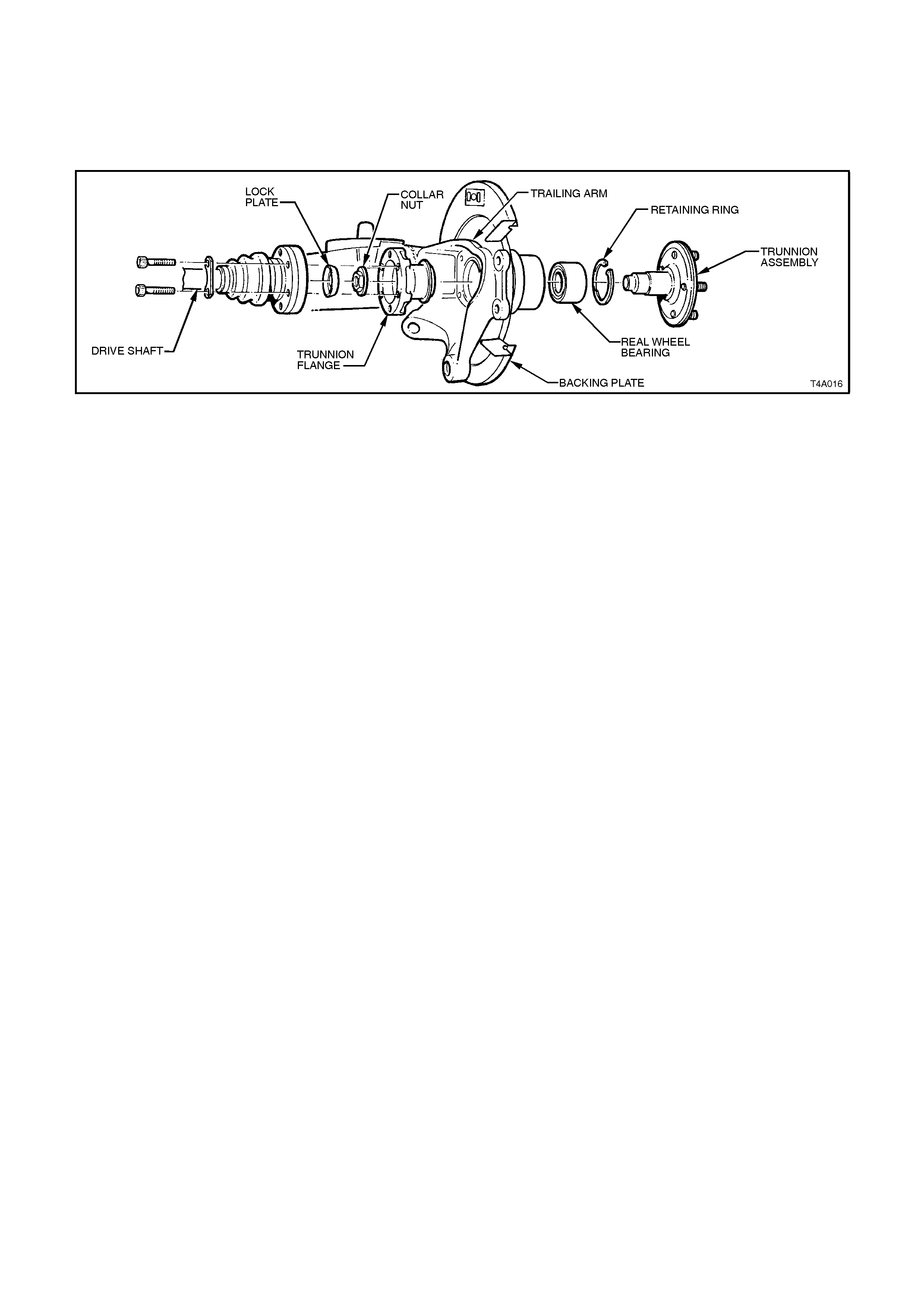
3.1 TRAILING ARM TRUNNION FLANGE, TRUNNION ASSEMBLY AND/OR
WHEEL BEARING
Figure 4B-57
The following procedure involves the removal of the trunnion flange, trunnion and/or wheel bearing with the trailing
arm installed on the vehicle. A similar procedure is included in Section 4A REAR SUSPENSION, involving the
trailing arm removed from the vehicle.
For this operation, a new lock plate and collar nut must be used on reassembly.
NOTE 1:
The rear wheel bearing should only be removed if it is faulty, or if the trunnion assembly is removed.
NOTE 2:
The trunnion assembly for VT Series vehicles is 1 mm shorter than previous models and is identified by a
circumferential groove on the outside diameter of the flange.

REMOVE
1. Using a floor jack under centre of differential
carrier, jack up rear of vehicle then place
safety stands under trailing arms.
2. Remove wheel cover (steel wheels) or centre
cap (alloy wheels) from side of vehicle which
component/s are to be removed.
3. Mark relationship of wheel to m ounting f lange.
Remove road wheel attaching nuts and
remove wheel.
4. Using holding bar, Tool No. KM468 to hold
trunnion assembly from rotating, loosen and
remove drive shaft constant velocity joints to
inner axle shaft and trunnion flange attaching
bolts and plates, remove drive shaft.
Figure 4B-58
5. Remove rear shock absorber lower mounting
bolt from trailing arm, and pull shock absorber
from trailing arm.
Figure 4B-59
6. Remove rear brake caliper anchor plate to
trailing arm attaching bolts, remove caliper
from disc.
Using wire, tie up caliper to lower end of s hock
absorber upper mounting. DO NOT ALLOW
CALIPER TO HANG BY BRAKE HOSE.
7. Remove rear brake disc.
Figure 4B-60
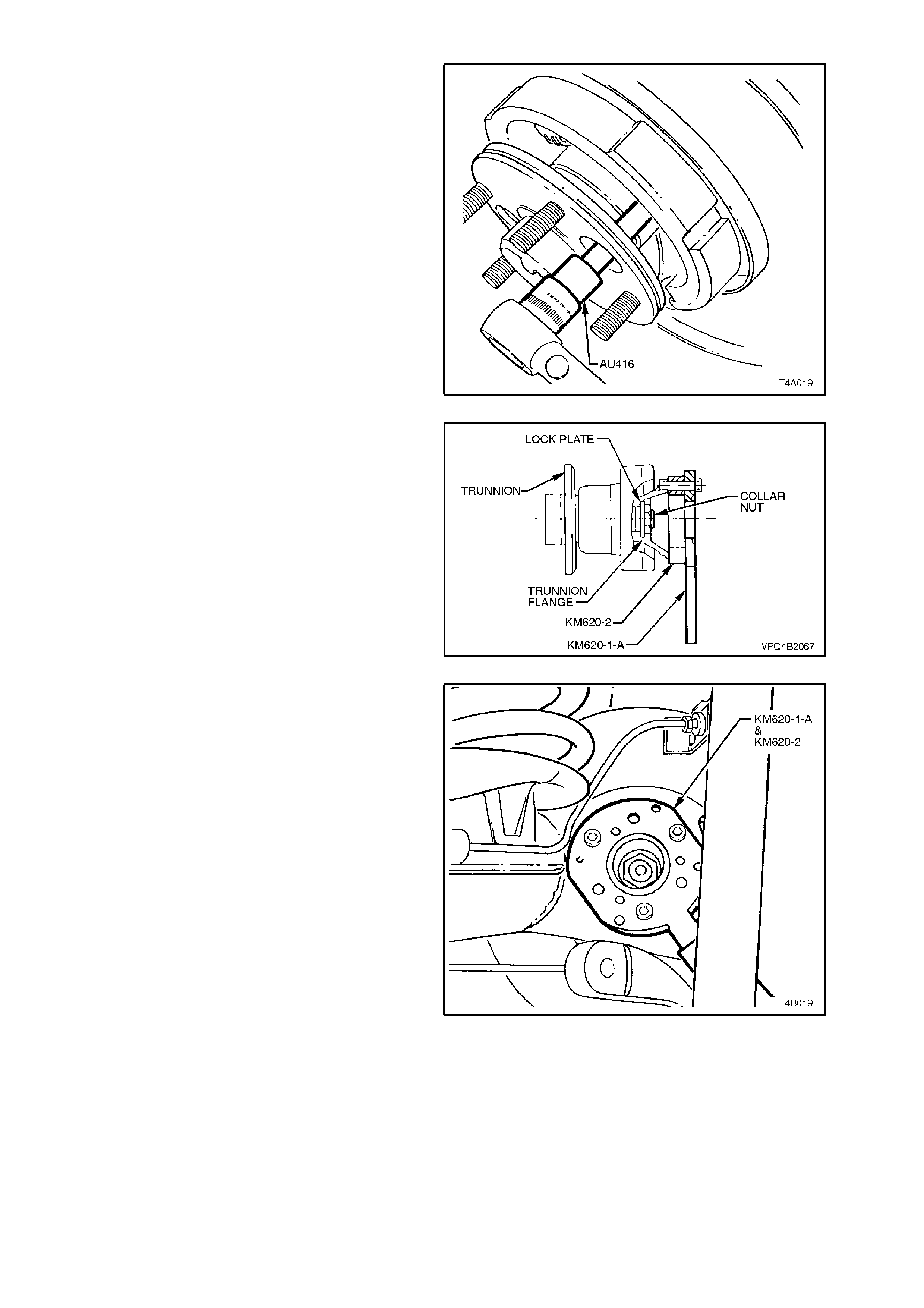
8. Using Torx bit socket, Tool No. AU416,
rem ove brake back ing plate to trailing arm two
upper rear bolts. Then remove the longer,
hexagon headed, lower bolts
Figure 4B-61
9. Secure Tool Nos . KM620-1-A and KM620-2 to
trunnion flange with three drive shaft constant
velocity joint to trunnion flange attaching bolts.
Figure 4B-62
NOTE:
Align holes marked 'B' on KM620-1-A and KM620-2
with holes in trunnion flange before installing bolts.
Figure 4B-63
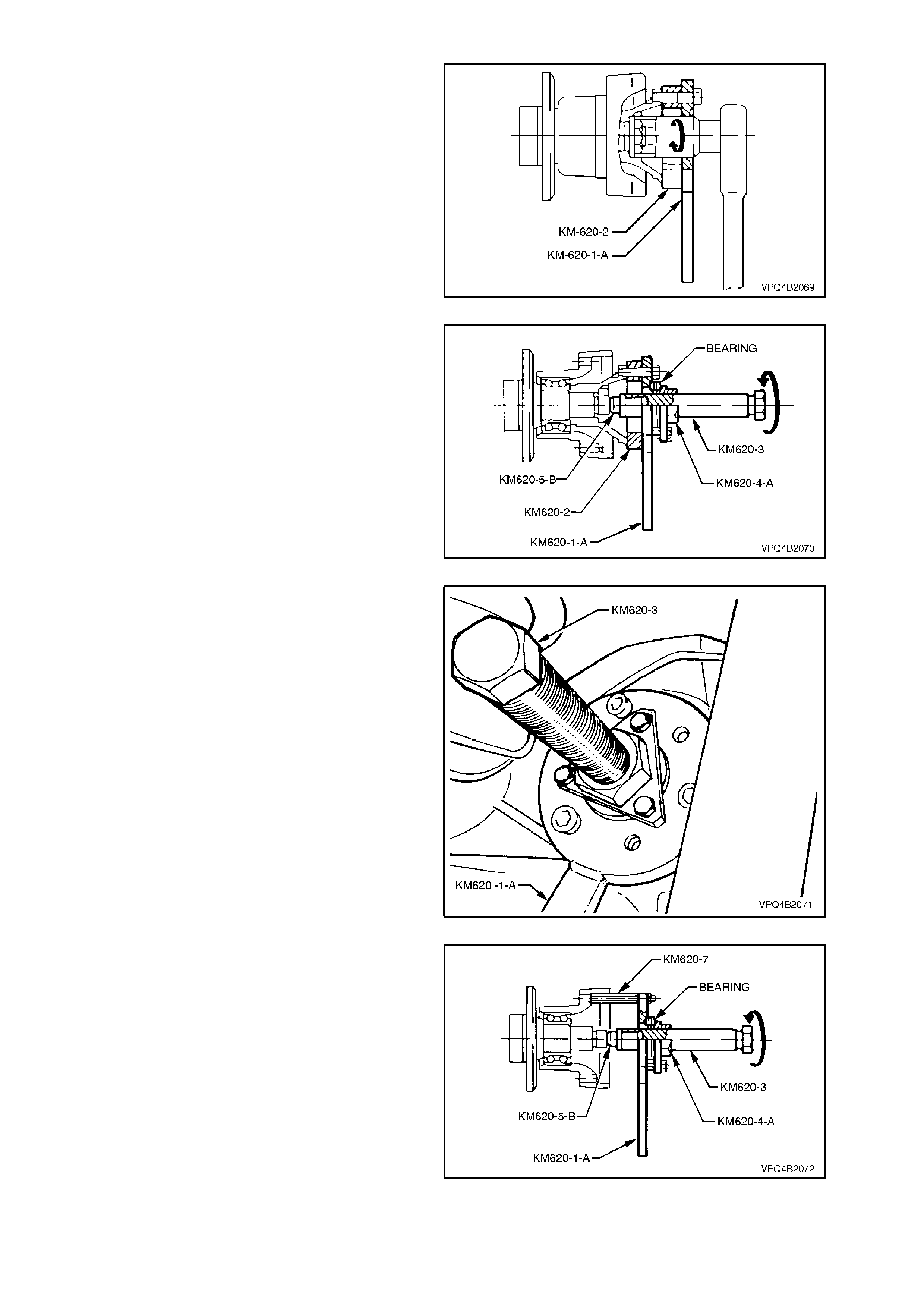
10. Install a suitable length and diameter steel
tube over handle of KM620-1-A, and while
holding KM620-1-A from rotating, loosen and
remove collar nut and lock plate.
NOTE:
Once c ollar nut and lock plate have been rem oved,
they m ust be discarded as they are only to be us ed
once.
Figure 4B-64
11. Apply grease to ball of Tool No. KM620-5-B.
Assemble KM620-3 to KM620-4-A and install
KM620-5-B into KM620-3. Assemble bearing
assembly (part of KM620-A) to KM620-4 and
install KM620-4 to KM620-1-A using three
bolts (part of KM620-A).
Secure the assembled tool and spacer ring,
Tool No. KM620-2, to the trunnion assembly,
using three drive shaft constant velocity joint to
trunnion flange attaching bolts.
Figure 4B-65
12. While holding KM620-1-A from rotating, turn
the screw KM620-3, forcing the flange free
from the trunnion.
Separate components from flange once it has
been removed.
Figure 4B-66
13. Working from the rear of the backing plate,
install the three distance pieces, KM620-7, to
the backing plate to trailing arm bolt holes.
Assemble KM620-4-A, KM620-3 and KM620-
5-B with three bolts to KM620-1-A (as in step
10). Install and tighten attaching nuts (part
KM620-A), to KM620-7.
Figure 4B-67
14. While holding KM620-1-A from rotating, turn
the screw KM620-3 to press trunnion from rear
wheel bearing.
Once trunnion has been removed, remove
nuts holding KM620-1-A assembly to the
distance pieces, KM620-7. Rem ove KM620-1-
A, and remove KM620-5-B from KM620-3.
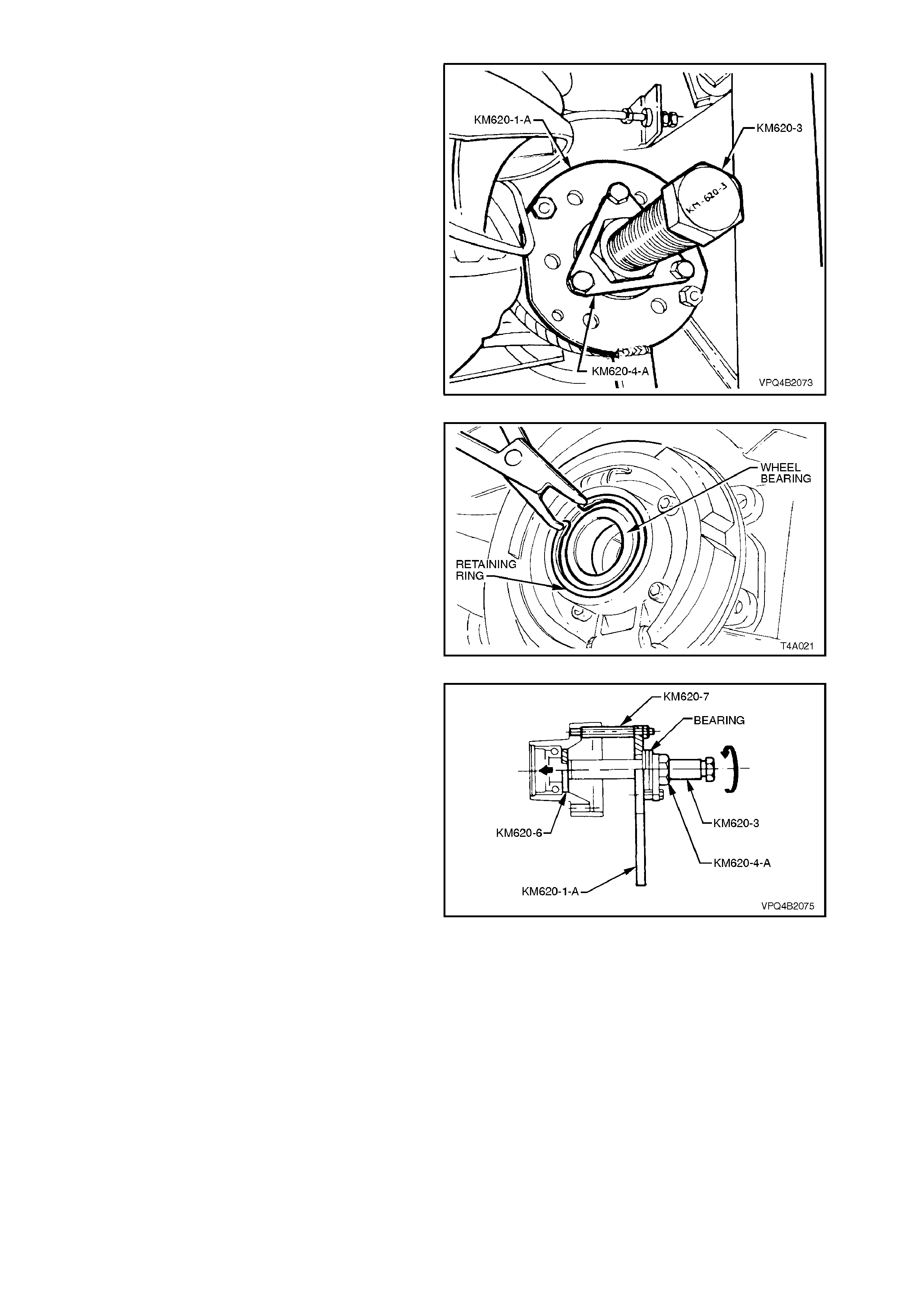
Figure 4B-68
15. Remove wheel bearing retaining ring from
trailing arm.
Figure 4B-69
16. Install KM620-6 to rear of bearing. Install
KM620-1-A assembly and install attaching
nuts, as shown.
17. While holding KM620-1-A, turn the screw
KM620-3, to press wheel bearing from trailing
arm.
Figure 4B-70
REINSTALL
To install new bearing:
1. Ensure that bearing bore of trailing arm is
clean and free of any foreign matter.
2. Coat outside diameter of new wheel bearing
and bore of trailing arm with lubricant meeting
Holden's Specification HN1326 (Molybond
HE50, or equivalent).
3. Remove KM620-1-A from distance pieces
KM620-7. Install sleeve KM620-9-A over
KM620-3, with the stepped end facing away
from the trunnion bearing.
Install KM620-8-A to new bearing and insert
into the bore of the trailing arm. Screw the
threads of KM620-8-A and KM620-3 together.
Reinstall KM620-1-A to KM620-7, tightening
the attaching nuts. Then, while holding
KM620-3 and KM620-1-A from turning, rotate
KM620-4-A to draw bearing into position.
When the bearing is fully installed, remove
KM620-8-A and fit retaining ring into trailing
arm, ensuring that it is seated correctly. Figure 4B-71
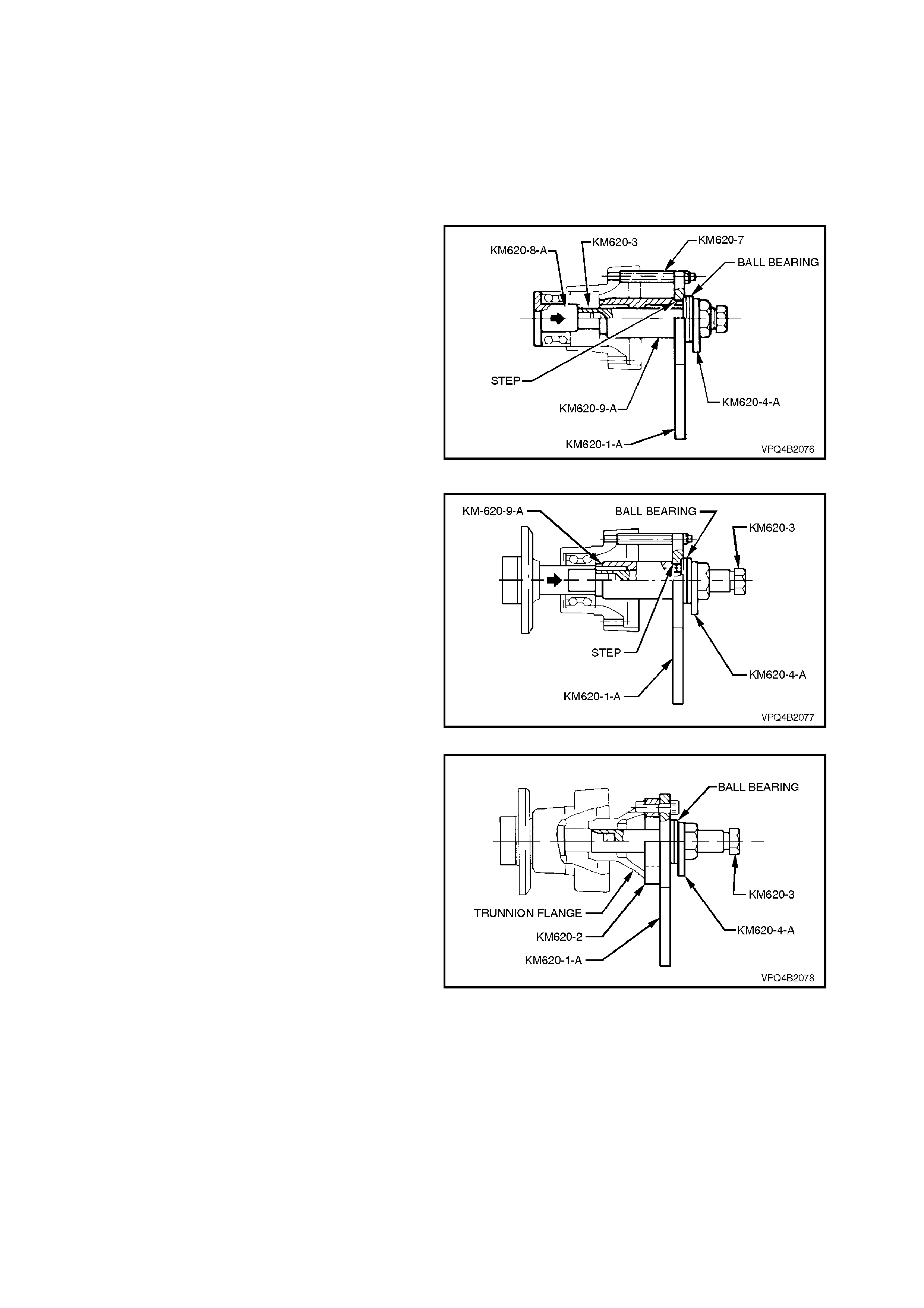
To reinstall trunnion:
1. Remove KM620-1-A from distance pieces,
KM620-7. Install KM620-9-A over KM620-3,
with the stepped shoulder facing away from
the trunnion bearing. Reinstall KM620-1-A to
KM620-7, tightening the attaching nuts.
2. Screw the threaded end of the trunnion into
KM620-3. While holding KM620- 3 and KM620-
1-A from turning, rotate KM620-4-A to draw
trunnion into wheel bearing.
3. Remove KM620-3 from trunnion and remove
the three distance pieces of KM620-7 from
trailing arm. Figure 4B-72
4. Assemble KM620-2 and KM620-1-A to
trunnion flange using three drive shaft
constant velocity joint to flange bolts.
5. Lubricate trunnion flange splines and trunnion
threads with the recommended differential
carrier lubricant.
6. With KM620-4-A, ball bearing assembly and
KM620-3 assembled to KM620-1-A, screw
thread of KM620-3 onto trunnion assembly.
Figure 4B-73
7. While holding KM620-3 from turning, rotate
KM620-4-A to draw trunnion flange onto
trunnion.
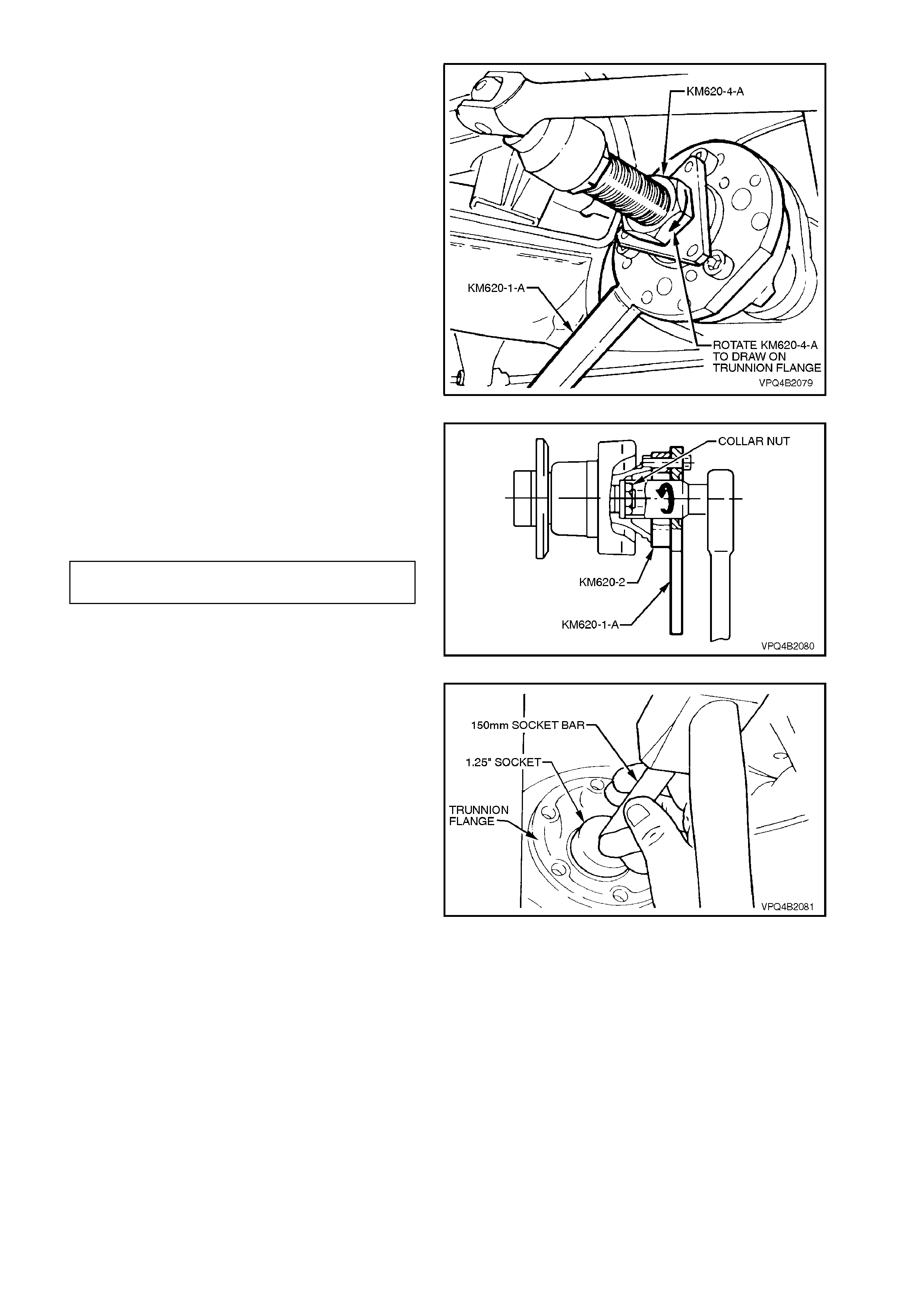
Figure 4B-74
8. Remove the components of KM620-A from
trunnion and trunnion flange.
9. Install NEW collar nut to trunnion assembly
and, using KM620-1-A and KM620-2 to hold
trunnion assembly from turning, tighten collar
nut to the correct torque specification.
COLLAR NUT TO TRUNNION ASSY 295 - 305
TORQUE SPECIFICATION Nm
Figure 4B-75
10. Using a 1.25 inch socket, 150 mm socket bar
and a soft faced hammer, install new lock
plate over collar nut.
Figure 4B2-76
11. Assemble drive shaft outer constant velocity
joint to trunnion flange, aligning bolt holes.
Install attaching bolts with plates and tighten
bolts to the correct torque specification.
DRIVE SHAFT CONSTANT
VELOCITY JOINT TO TRUNNION 50 Nm, then
FLANGE ATTACHING BOLT 60° - 75
TORQUE SPECIFICATION turn angle
Figure 4B-77
12. Install rear disc brake shield to trailing arm
bolts and tighten to the correct torque
specification.
REAR DISC
BRAKE SHIELD TO Upper: 70 - 80 Nm
TRAILING ARM
ATTACHING BOLT Lower: 85 - 90 Nm
TORQUE SPECIFICATION
NOTE 1:
The two upper bolts have washers. The washers
are installed with the cut-out surface facing around
the trailing arm hub outer surface.
NOTE 2:
Apply Loctite 242 thread sealant or equivalent (to
Holden's Specification HN1256, Class 2 Type 1) to
the threads of the two longer, lower hexagon
headed bolts, before installation.
Figure 4B-78
13. Install brake disc and brake caliper. Install
brake caliper anchor plate to trailing arm
attaching bolts and tighten to the correct
torque specification.
BRAKE CALIPER ANCHOR PLATE
TO TRAILING ARM ATTACHING 70 - 100 Nm
BOLT TORQUE SPECIFICATION
Figure 4B-79
14. Install shock absorber to trailing arm, install
and tighten lower mounting bolt to the correct
torque specification.
SHOCK ABSORBER LOWER
MOUNTING BOLT 105 - 125 Nm
TORQUE SPECIFICATION
NOTE:
Vehicle must be at curb weight and on all four
wheels before this torque is applied.
15. Install road wheel and tighten attaching nuts.
NOTE:
When installing the wheel, align the marks made
prior to removal.
16. Remove safety stands and lower vehicle.
17. Tighten road wheel attaching nuts to the
correct torque specification.
ROAD WHEEL ATTACHING NUT 110 - 140
TORQUE SPECIFICATION Nm
18. Refit wheel cover/centre cap. Figure 4B-80

3.2 FINAL DRIVE ASSEMBLY
IMPORTANT:
Before disturbing the rear suspension crossmember mounting bolts, an alignment procedure is required on
installation and a special tool is required for this purpose. If this tool is not available, then the crossmember cannot
be correctly aligned and steering and/or handling abnormalities will result.
CAUTION :
Whenever any component that forms part of the ABS (if fitted) is disturbed during Service Operations, it is
vital that the complete ABS system be checked, using the procedure as detailed in DIAGNOSIS, ABS
FUNCTION CHECK, in Section 12L ABS/Traction Control.
NOTE 1:
For this operation, NEW rear crossmember rear mount to vehicle underbody attaching bolts, differential carrier to
crossmember attaching bolts and intermediate muffler support to rear crossmember retainers must be used on
reassembly.
NOTE 2:
If rear mount is removed from rear cover, NEW bolts must also be installed on reassembly.
REMOVE
1. Using a floor jack under centre of differential
carrier, jack up rear of vehicle then place
safety stands under body rear jacking points.
Refer to Section 0A GENERAL
INFORMATION for location of jacking points.
2. Remove rear wheel covers (steel wheels) or
centre caps (alloy wheels).
3. Mark relationship of wheels to mounting
flange. Remove road wheel attaching nuts and
remove wheel.
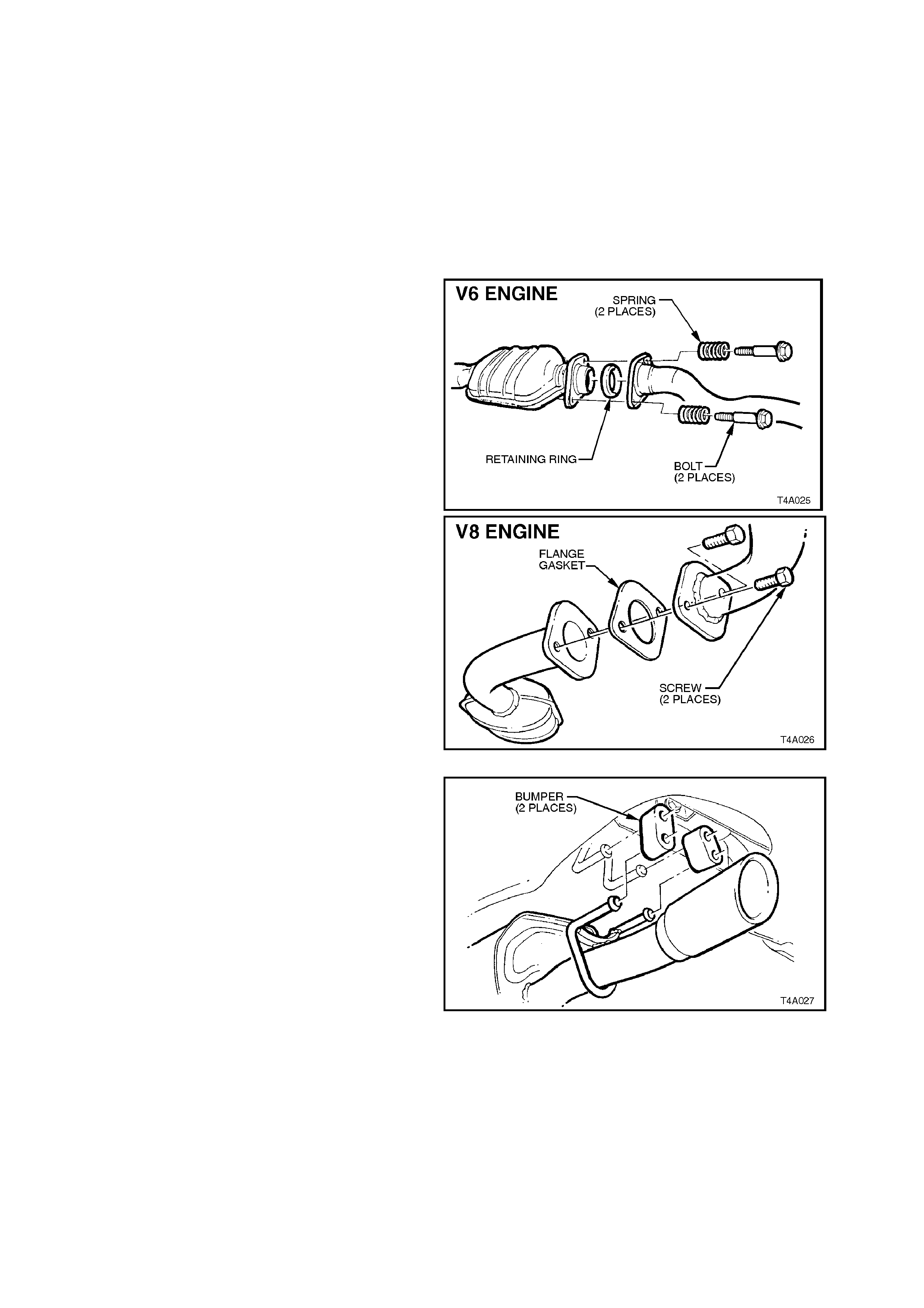
4. Disconnect exhaust system from rear of
catalytic converter (V6) or converters (V6
Supercharged and V8).
NOTE:
Only one side of the V6 Supercharged/V8
arrangement is shown.
Figure 4B-81
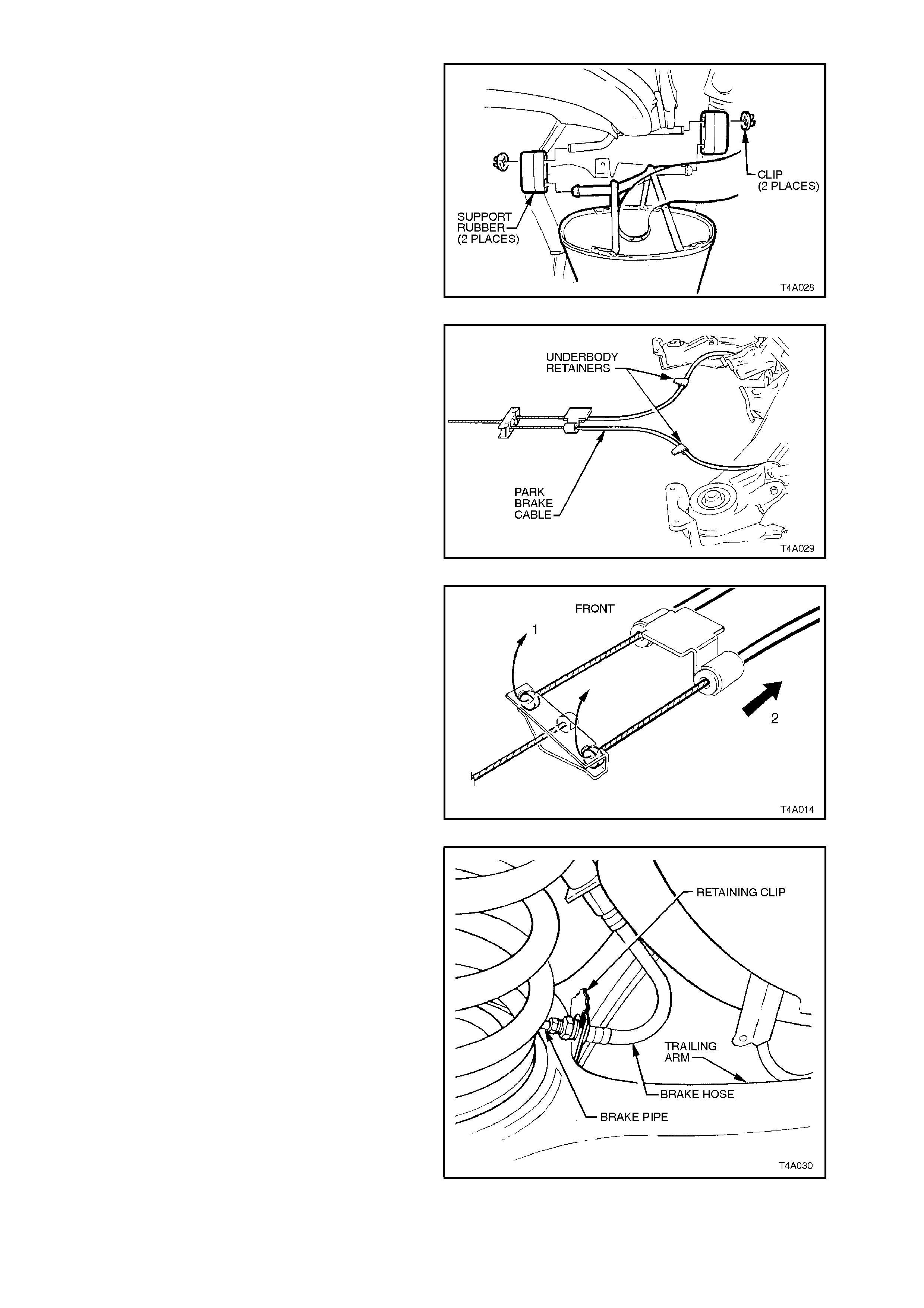
5. Remove the two retainers from the top posts
and discard. Disconnect exhaust system
support rings from the rear hanger of the rear
muf fler. Both V6 and V8 arrangem ents are the
same.
Figure 4B-82
6. Remove muffler support to rear crossmember
hanger retainers (2 places - V6, 4 places - V6
Supercharged and V8) and discard.
7. Lift up intermediate section of exhaust system
and remove intermediate muffler support
rubbers. Remove intermediate and rear
sections of exhaust system from vehicle.
Figure 4B-83
8. Remove propeller shaft, refer to
Section 4C PROPELLER SHAFT AND
UNIVERSAL JOINTS.
9. Set park brake in fully released position.
10. Release each of the underbody to park brake
cable retaining clips and free cables.
Figure 4B-84
11. Remove park brake outer cable retaining
bracket bolt from the vehicle underbody.
12. Pull each park brake inner cable forward and
up, (1) out of the cable retainer. Pull the cable
rearwards (2) to remove from the retaining
bracket.
Figure 4B-85
13. Disconnect brake pipes from brake hoses at
trailing arm brackets and remove brake hose
retaining clips.
Remove brake hoses from brackets.
Cap ends of brake pipes to prevent the entry
of foreign matter.
Figure 4B-86
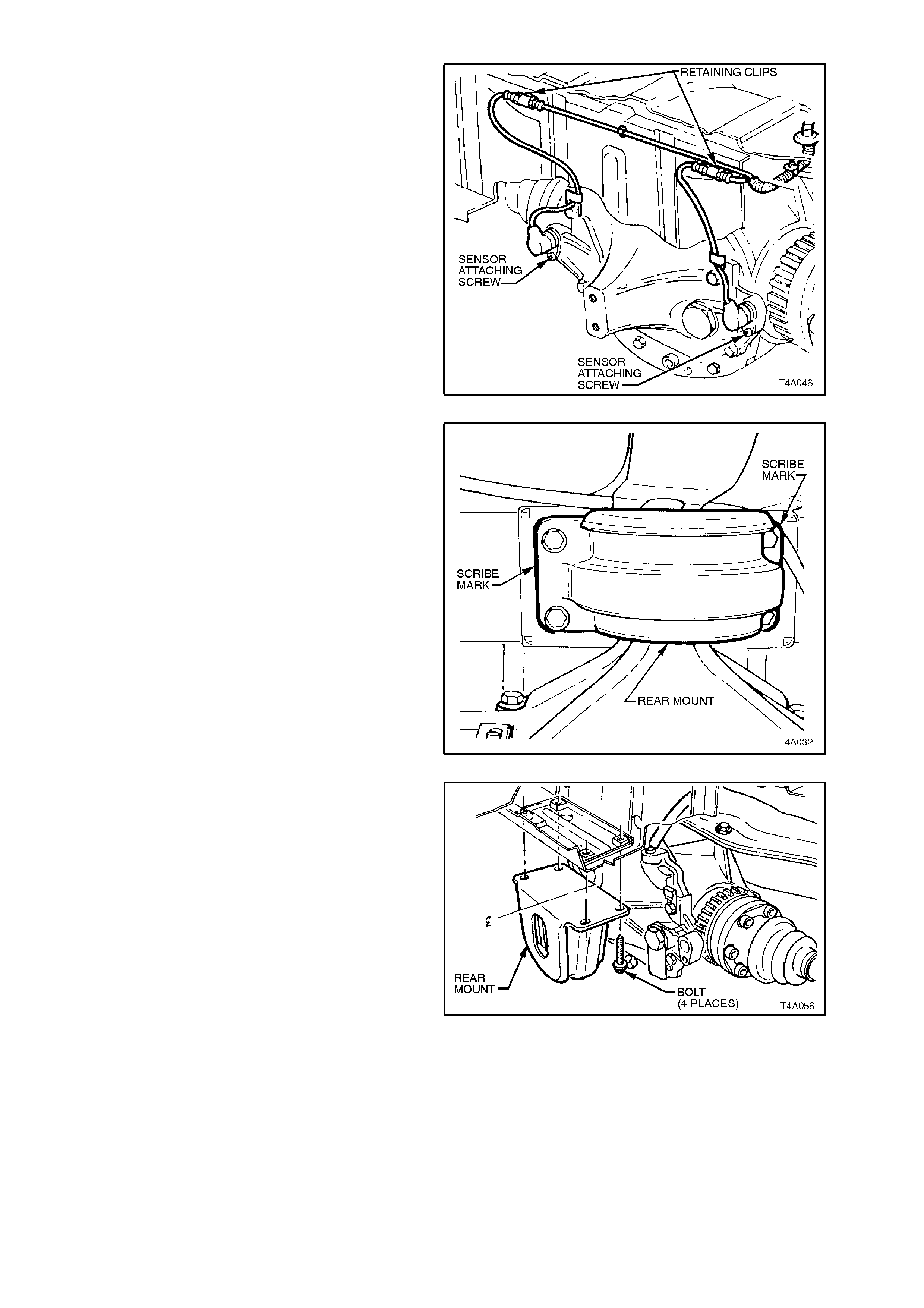
14. Pull differential carrier breather hose from
underbody crossmember hole.
15. If equipped with ABS, disconnect both sensor
electrical connectors, as shown.
Figure 4B-87
16. Using a scriber, mark rear mount to vehicle
under body location. This will aid in rear
crossmember reinstallation and to ensure that
rear end 'toe' setting is maintained.
Figure 4B-88
17. Support weight of differential carrier with floor
jack.
18. Remove rear mount to vehicle underbody
attaching bolts and discard.
Lower rear of differential carrier and rear
crossmember assembly at least 60 mm.
Figure 4B-89
19. Position a second floor jack under left and
right trailing arm s in turn and raise jac k slightly
to take spring load off trailing arms.
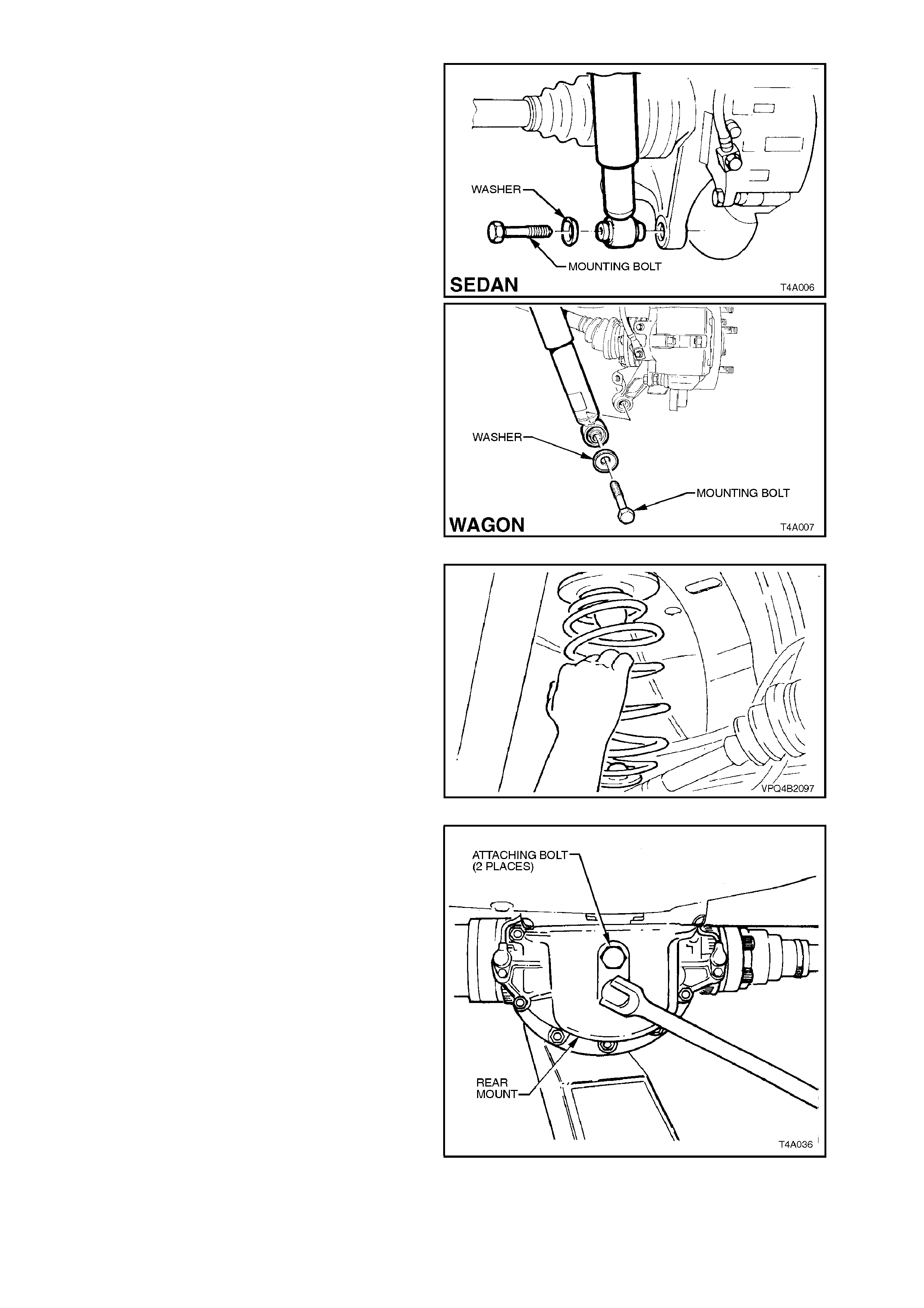
Disconnect rear shock absorber lower
mounting bolts from trailing arms, and pull
shock absorber lower ends from lower trailing
arms.
NOTE:
Bruising to the inside of the drive shaft constant
velocity joint boots will occur if the shock absorber
is disconnected from the trailing arm before the
rear of the differential carrier and crossmember
assembly has been lowered by at least 60 mm.
This bruising will lead to premature failure of the
boots and eventual failure of the joints if left
unchecked.
Figure 4B-90
20. Remove rear springs and insulators from
vehicle underbody and trailing arms.
Figure 4B-91
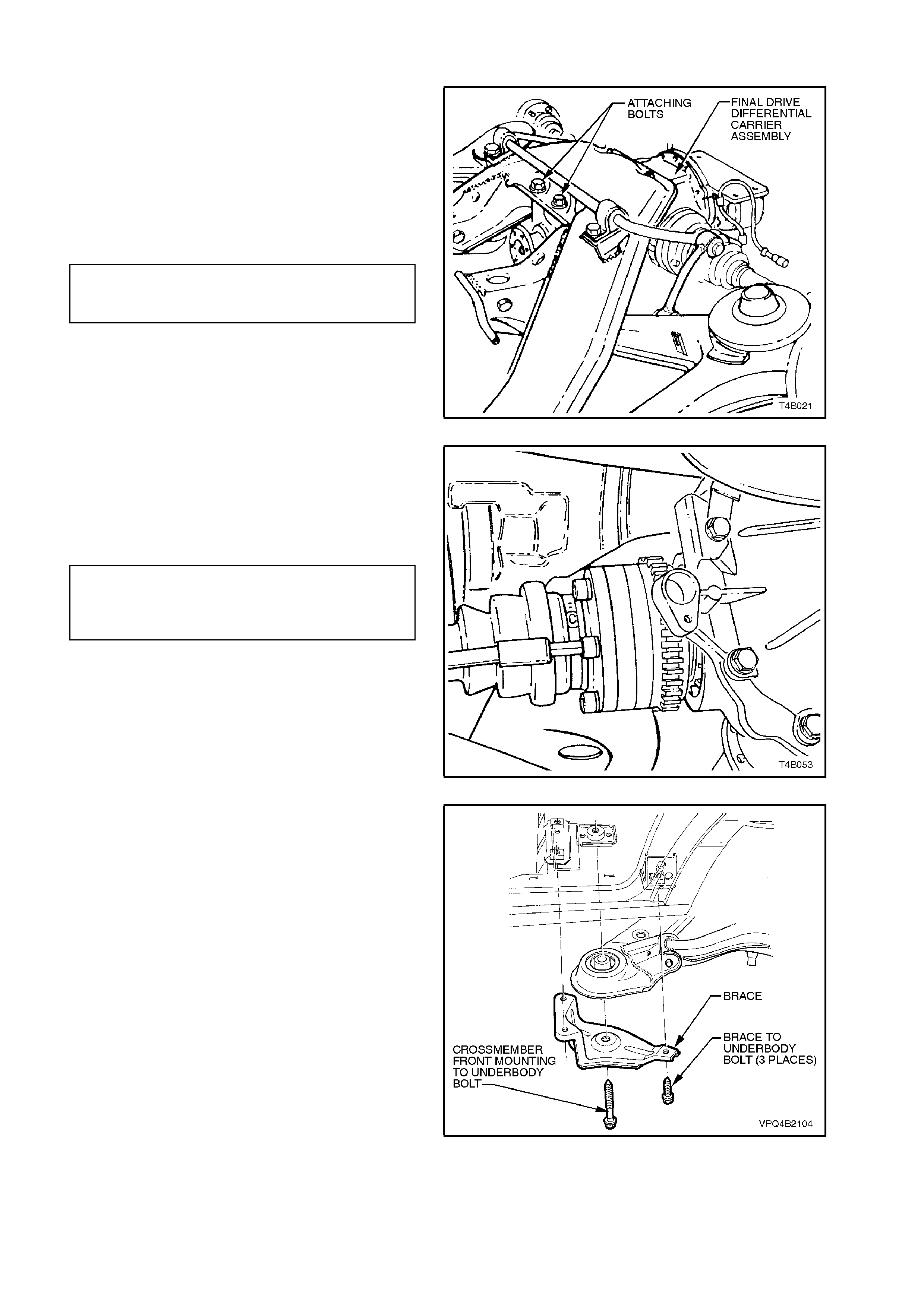
21. If replacing differential carrier assembly, rear
cover or rear m ount, loosen rear m ount to rear
cover attaching bolts.
Figure 4B-92
22. Raise differential carrier and rear
crossmember on floor jack until rear mount
contacts underbody.
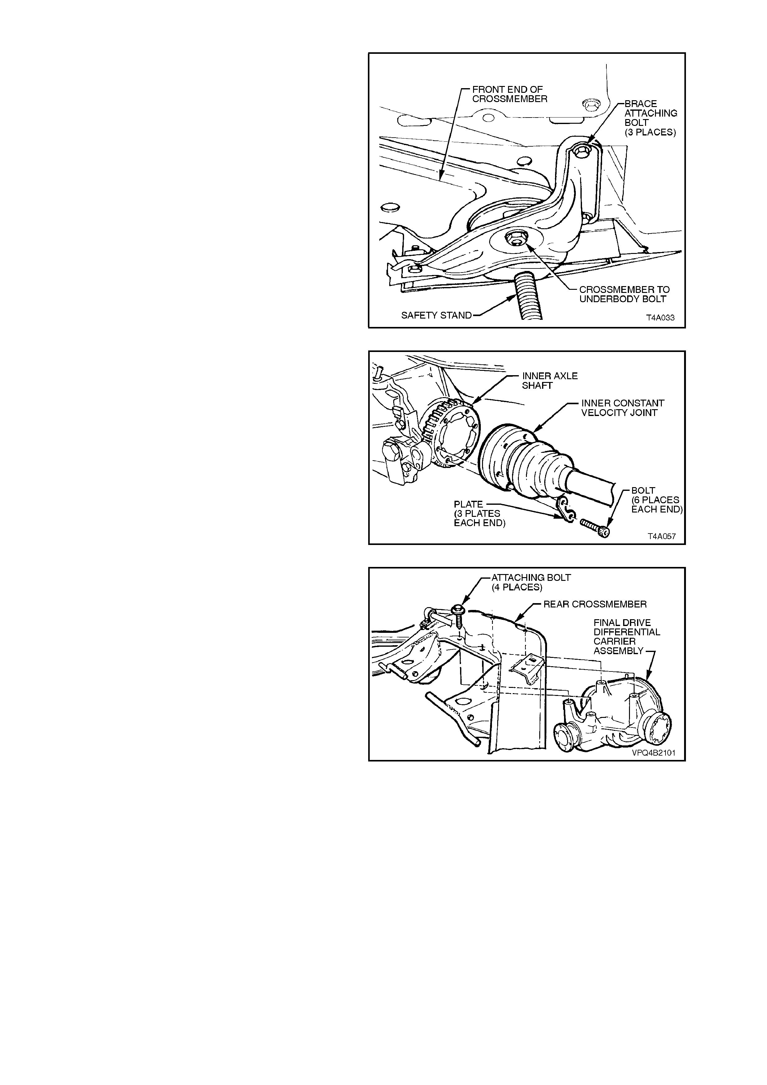
23. Remove brace to vehicle underbody attaching
bolts.
24. With the aid of an assistant, remove rear
crossmember to underbody bolts and braces.
25. With assistant supporting front end of rear
crossmember, lower assembly on jack and
remove from beneath vehicle.
Figure 4B-93
26. Using an 8 m m Allen key socket, r emove dr ive
shaft inner constant velocity joint to inner axle
shaft attaching bolts and plates.
Disconnect joints from inner axle shafts.
NOTE:
Support drive shafts so that they do not hang on
one end. Drive shaft joint def lection should be kept
to within the angular movement of an ins talled dr ive
shaft.
Figure 4B-94
27. Remove differential carrier to rear
crossmember attaching bolts, remove rear
crossmember assembly from differential
carrier and discard attaching bolts.
28. If not carried out in step 21, remove rear
mount to rear cover attaching bolts, remove
mount and discard attaching bolts.
Figure 4B-95
REINSTALL
Installation is the reverse of removal procedure with
attention to the following points:
1. If necessary, install NEW rear mount to rear
cover but leave bolts finger tight at this stage.
2. Line up mounting holes in differential carrier
and rear crossmember. Install new attaching
bolts and tighten to the correct torque
specification.
DIFFERENTIAL CARRIER TO REAR 90 Nm, then
CROSSMEMBER ATTACHING 30° - 45°
BOLT TORQUE SPECIFICATION turn angle
Figure 4B-96
3. Inspect drive shaf t constant veloc ity joint boots
for damage, replace as necessary.
4. Tighten drive s haft inner c onstant veloc ity j oint
to inner axle shaft attaching bolts to the
correct torque specification.
DRIVE SHAFT CONSTANT
VELOCITY JOINT TO TRUNNION 50 Nm, then
FLANGE ATTACHING BOLT 60° - 75°
TORQUE SPECIFICATION turn angle
Figure 4B-97
5. With the aid of two assistants, place the
differential carrier and rear crossmember
assembly onto a floor jack.
Position assembly under vehicle, and raise up
assembly on jack with assistants guiding
crossmember front mounting points into
location.
NOTE:
When raising assembly, take care that the rear
mount does not foul on fuel tank or fuel hose from
sender unit.
6. Install crossmember front mounting braces
and bolts but do not tighten bolts at this
stage.
Figure 4B-98
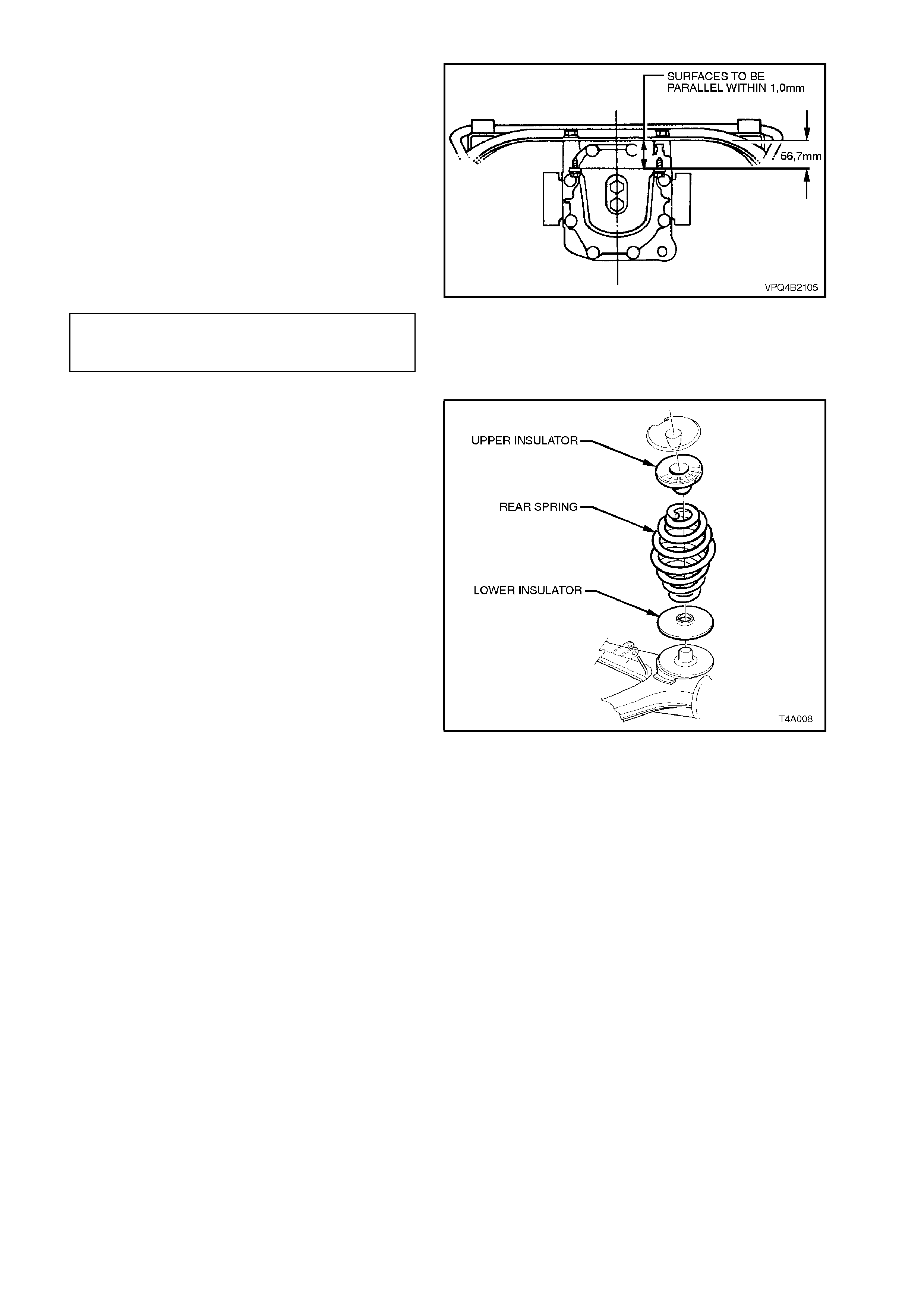
7. Lower rear of as s embly to allow access to r ear
mount-to-rear cover attaching bolts. Tighten
NEW attaching bolts to the correct torque
specification. At the same time, ensure that
the mount does not twist (mount to vehicle
underbody mating surface should be parallel
to rear crossmember, as shown in Figure 4B-
105).
NOTE:
Use a spirit level on rear mount to underbody and
top surface of crossmember to ensure that both
surfaces are parallel.
REAR MOUNT TO REAR COVER
ATTACHING BOLT 85 - 105 Nm
TORQUE SPECIFICATION
Figure 4B-99
8. Lower differential carrier and rear
crossmember assembly on floor jack and
safety stands. Install rear springs and
insulators.
NOTE:
During this operation, the differential carrier and
rear crossmember assembly rear mount must be
lowered at least 60 mm from the vehicle
underbody, or else damage to the drive shaft
constant velocity joint boots will occur.
Figure 4B-100
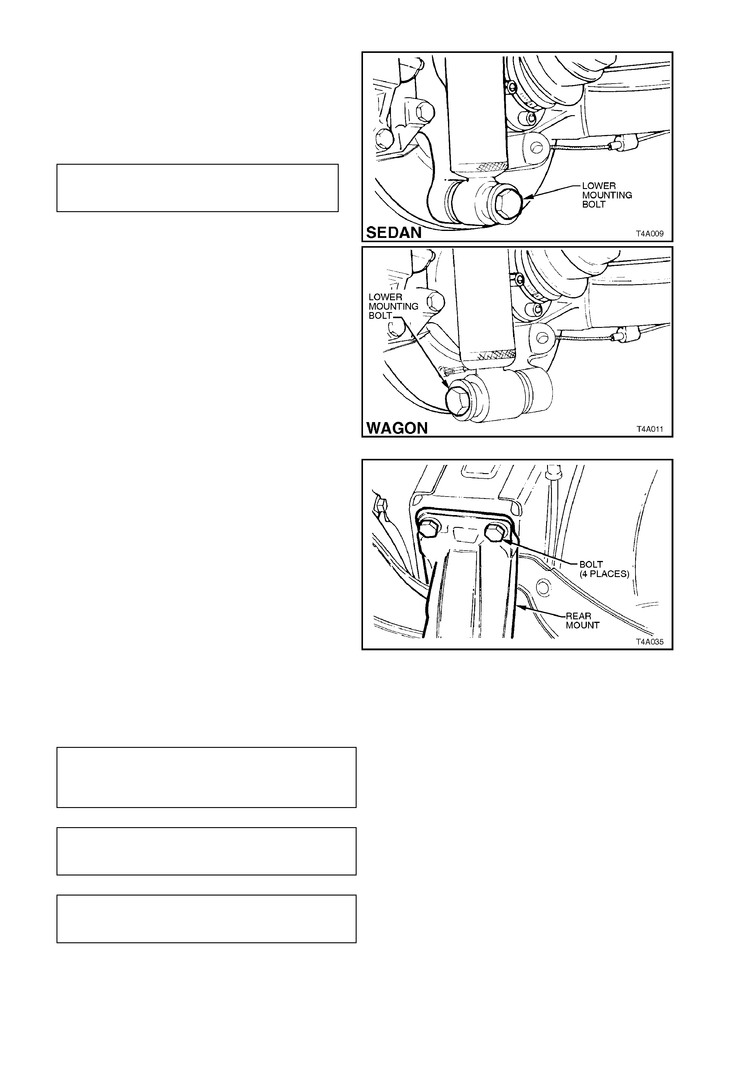
9. Use a second floor jack to raise each trailing
arm up far enough to allow shock absorber
lower mounting to be installed.
Install bolts and washers to shock absorber
lower mounts and trailing arms. Tighten bolts
to the correct torque specification.
SHOCK ABSORBER LOWER
MOUNTING BOLT 105 - 125 Nm
TORQUE SPECIFICATION
NOTE 1:
Vehicle must be at curb weight and on all four
wheels before this torque is applied.
NOTE 2:
Sedan and station wagon torque specifications are
the same.
Figure 4B-101
10. Raise differential carrier and rear
crossmember assembly until rear mount
contacts vehicle underbody.
11. Align mount with marks on underbody, made
on disassembly, and install and tighten new
attaching bolts but do not fully tighten at
this stage.
12. The rear crossmember MUST now be aligned
to the vehicle centreline, us ing the special tool
and procedure, as detailed in
Section 1A2 BODY DIMENSIONS.
IMPORTANT:
Failure to correctly align the rear crossmember
to the centreline of the vehicle will result in
steering abnormalities and uneven tyre wear!
Figure 4B-102
14. Tighten all crossmember mounting fasteners
to the correct torque specifications.
REAR MOUNT TO
VEHICLE UNDERBODY 30 Nm, then
ATTACHING BOLT 60° turn angle
TORQUE SPECIFICATION
REAR CROSSMEMBER FRONT 125 Nm, then
MOUNTING BOLT 30° - 45°
TORQUE SPECIFICATION turn angle
CROSSMEMBER FRONT
MOUNTING BOLT 60 - 70 Nm
TORQUE SPECIFICATION
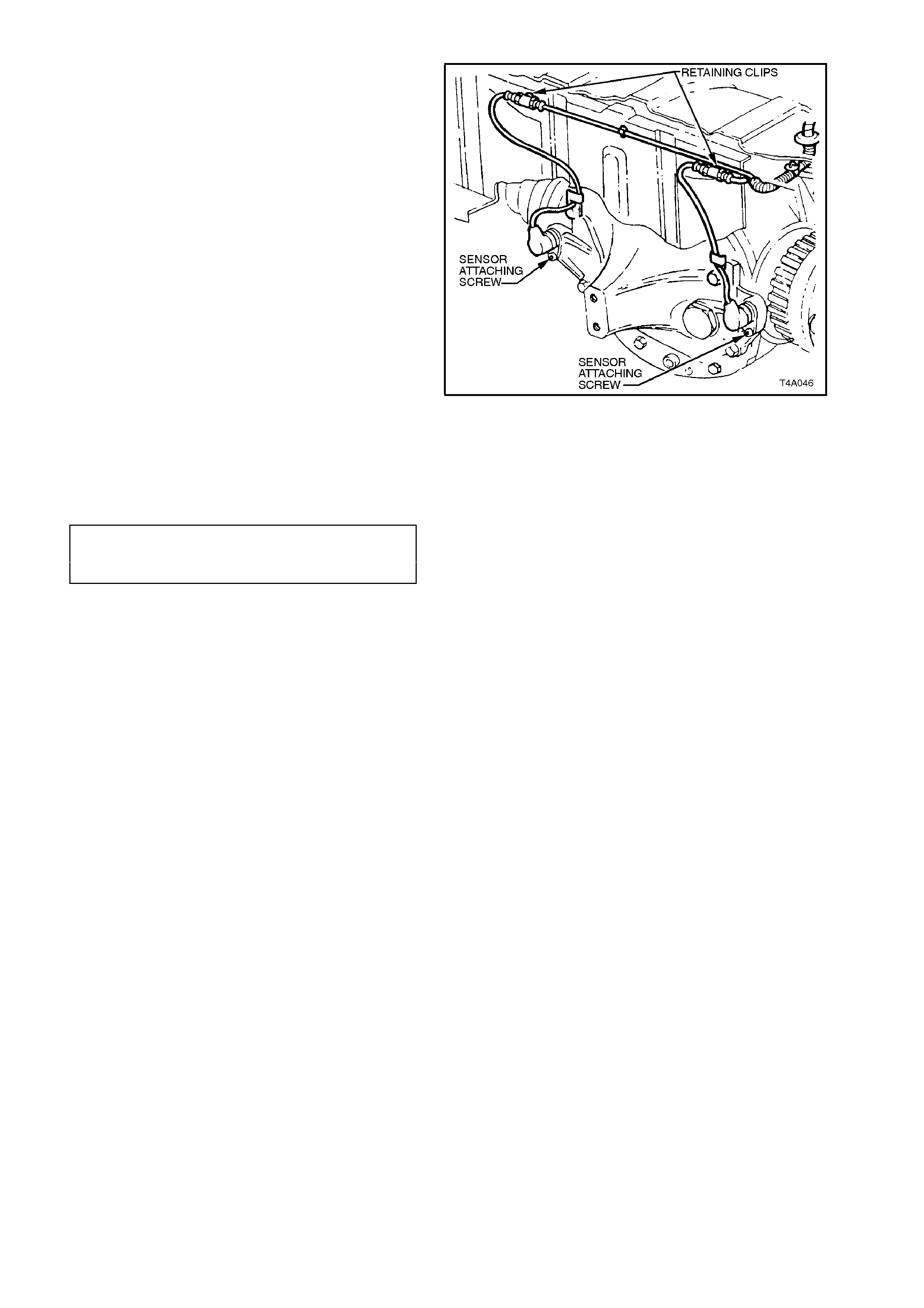
14. If vehicle is equipped with ABS, reconnect
sensor wiring harness connectors.
15. Reinstall park brake inner cables to the front
retainer, install and secure outer cables in the
underbody retainers, then install the outer
cable retaining bracket bolt to the vehicle
underbody.
16. Check and fill differential carrier to correct level
with specified lubricant, refer to
2.1 CHECKING DIFFERENTIAL CARRIER
LUBRICANT LEVEL in this Section.
17. Chec k park brak e adjustment and bleed br ake
hydraulic system, refer to
Section 5A, STANDARD BRAKES.
18. Reinstall propeller shaft. Refer to
Section 4C PROPELLER SHAFT AND
UNIVERSAL JOINTS.
19. Reconnect exhaust system, in reverse to the
removal procedure, ensuring that a new
intermediate exhaust pipe to catalytic
converter gasket is installed on V8 powered
vehicles. Tighten the retaining bolts to the
correct torque specification.
INTERMEDIATE EXHAUST PIPE All Engines
TO CATALYTIC CON VERTER 40 - 50 Nm
BOLT TORQUE SPECIFICATION
20. Check exhaust clearances as detailed in
Section 8B EXHAUST SYSTEM.
21. Start vehicle and check for exhaust leaks,
repair as necessary.
Figure 4B-103
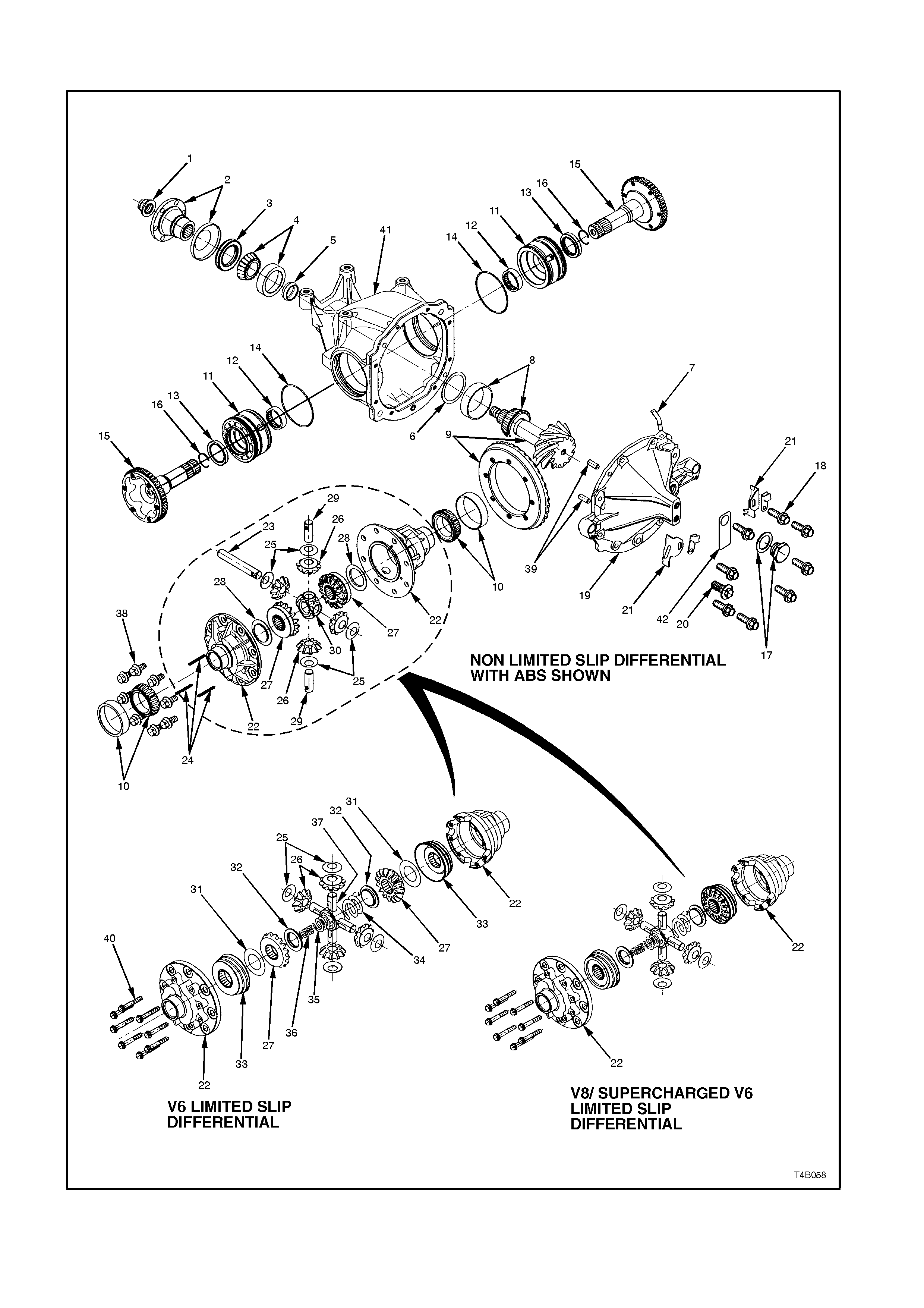
3.3 REMOVED FINAL DRIVE ASSEMBLY
Figure 4B-104
REF. No. PART NAME REF No. PART NAME
1 NUT - Pinion flange retaining
2 FLANGE ASSEMBLY - Differential pinion
3 SEAL - Rear axle pinion oil
4 BEARING ASSEMBLY - Pinion front
5 SPACER - Pinion bearing
6SHIM - Pinion position adjusting
7 BREATHER ASSEMBLY - Rear axle
8 BEARING ASSEMBLY - Pinion Rear
9 RING GEAR AND PINION
10 BEARING ASSEMBLY - Differential side
11 SCREW - Differential side bearing
adjusting
12 BEARING ASSEMBLY - Inner axle shaft
13 SEAL - Inner axle shaft
14 'O' RING - Screw adjuster
15 SHAFT - Inner axle
16 CLIP - Inner axle shaft
17 SCREW PLUG & WASHER - Rear axle
filler
18 BOLT - Rear cover attaching
19 COVER - Rear axle housing
20 PLUG - Drain
21 PLATE - Lock
22 CASE - Differential
23 SHAFT - Differential pinion gear - long
24 LOCK PIN - Differential pinion shaft
25 WASHER - Differential pinion gear
thrust
26 GEAR - Differential pinion
27 GEAR - Differential side
28 WASHER - Differential side gear thrust
29 SHAFT - Differential pinion gear - short
30 BLOCK - Thrust
31 SHIM - Differential side gear (LSD, V6
only)
32 PLATE - Thrust spring (LSD only)
33 CONE - Clutch (LSD, V6 only)
34 SPRING - Differential pre-load - outer
(LSD only)
35 SPRING - Differential pre-load -middle
(LSD only)
36 SPRING - Differential pre-load -inner
(LSD only)
37 SHAFT - Cross (LSD only)
38 BOLT - Ring gear to case
39 PIN - Dowel
40 BOLT - Case cap to cover
41 CARRIER
42 TAG - Lubrication
43 LABEL - Rear axle identification (Not
shown. See Figure 4B-2)
DISASSEMBLE
1. Remove differential carrier assembly. Refer to
3.2 FINAL DRIVE ASSEMBLY in this
Section.
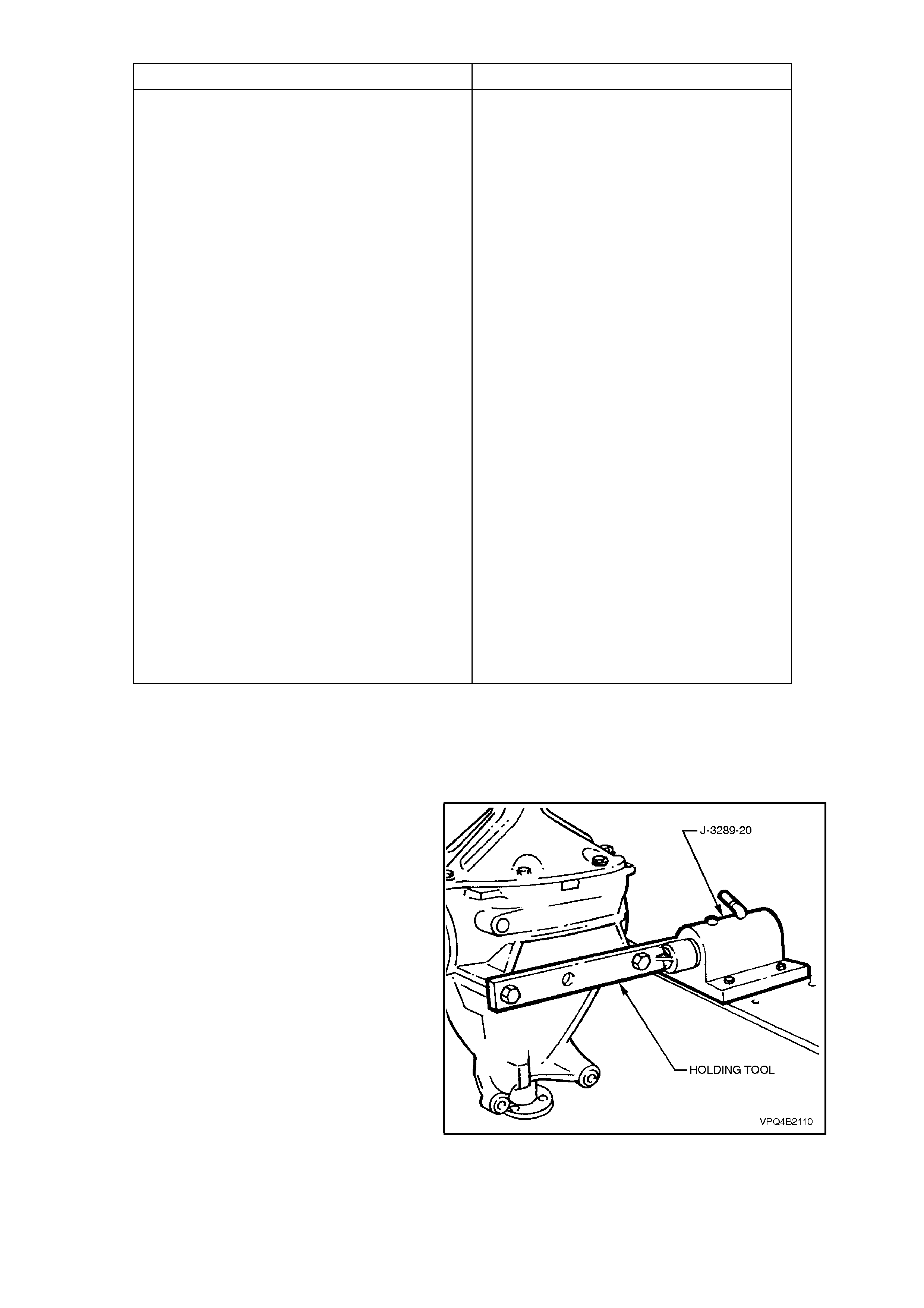
2. Secure holding tool (either fabricated or Tool
No. KM480) to differential carrier using two of
the discarded differential carrier to rear
crossmember attaching bolts.
For details of holding tool, refer to
7 SPECIAL TOOLS at the end of this Section.
3. Install holding tool into bench mounted fixture
base, Tool No. J-3289-20.
Figure 4B-105
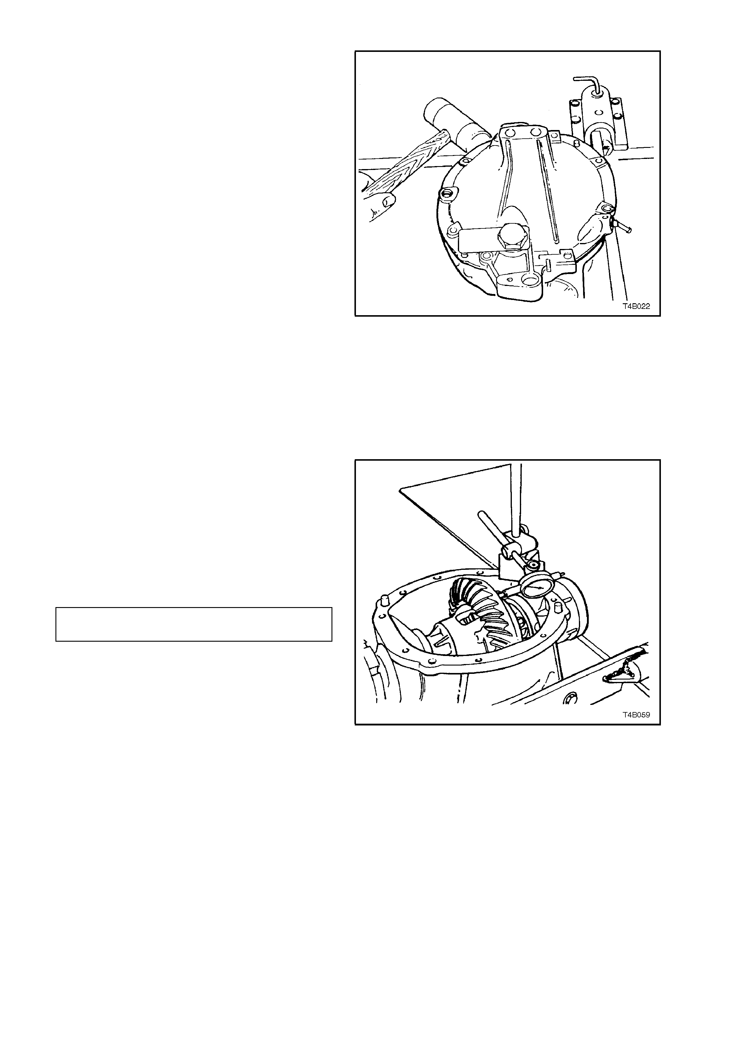
4. Remove rear cover to differential carrier
attaching bolts and sc rew adjuster loc k plates.
Using a soft faced hammer, tap rear cover at
rear mount area to break rear cover to
differential carrier seal. Remove rear cover
and allow differential lubricant to drain into a
suitable container.
Figure 4B-106
5. Before removing differential case assembly
and drive pinion from differential carrier, the
following inspection procedures should be
adopted. These inspections can help find the
cause of final drive assembly noise and
determine corrections needed.
a. Visually inspect the moving parts for
chipped or scuffed surfaces.
b. Check the torque of the ring gear bolts
and the pinion flange nut.
NOTE:
Ring gear bolts have a left hand thread.
c. Mount a dial indicator to read from the
rear face of the ring gear, then rotate the
differential case through several turns to
measure ring gear run-out.
RING GEAR FACE 0.13 mm
RUN-OUT SPECIFICATION maximum
d. Leave the dial indicator set up and push
the ring gear hard one way, then hard the
opposite way to m easur e side play. There
should be no side play present.
Check to ensure that there is no pinion
end play.
If end play is evident, then special
attention should be made to the bearing
inspection process, after disassembly.
Figure 4B-107
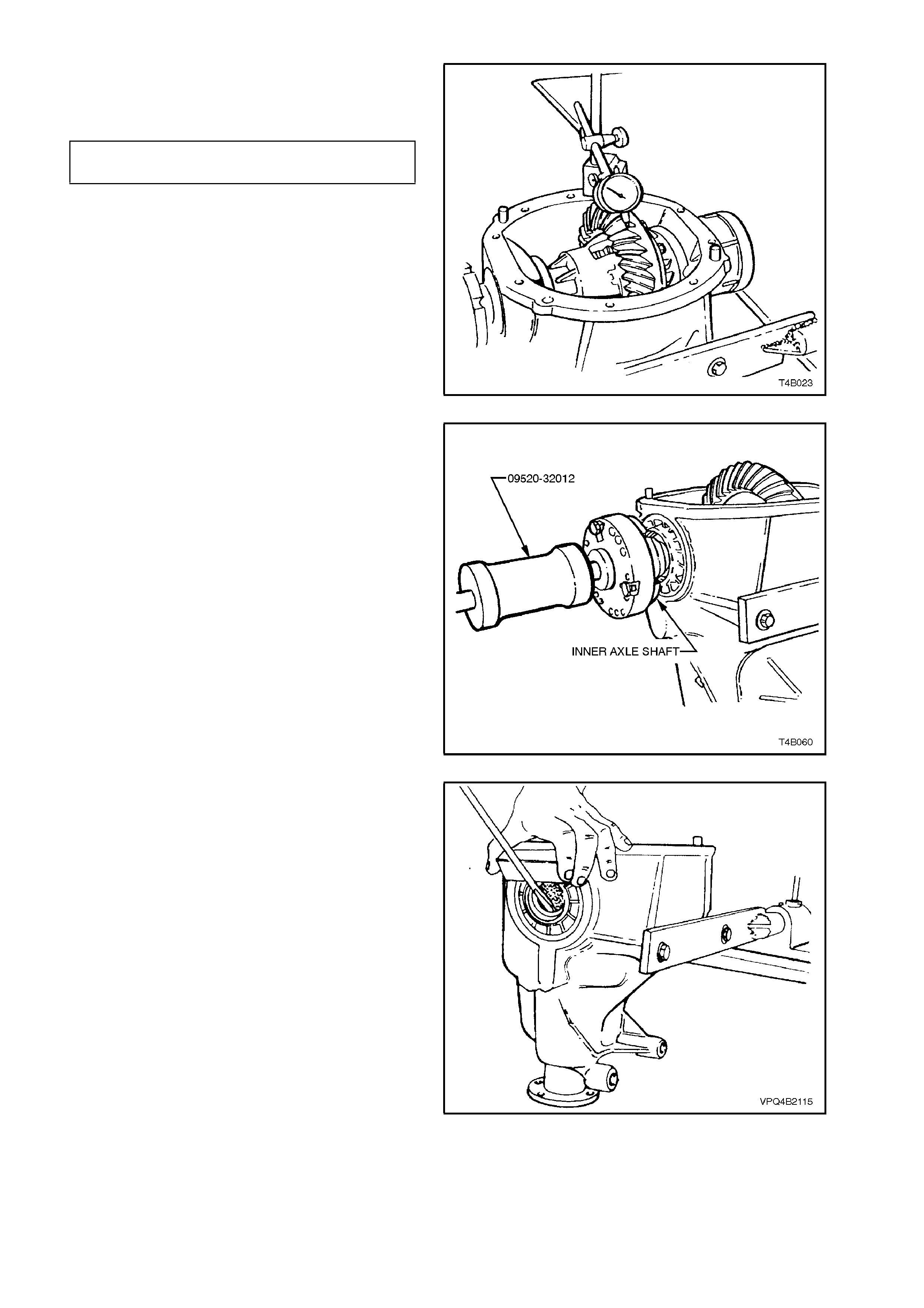
e. Set up the dial indicator to measure ring
gear backlash at three equally spaced
positions.
BACKLASH 0.10 - 0.18 mm, at
SPECIFICATION the tightest point
f. If no obvious faults are found, check the
gear tooth contact pattern. Refer to Ring
Gear and Pinion Contact Pattern in this
Section.
Figure 4B-108
6. Remove inner axle shafts by installing a slide
hammer, Tool No. 09520-32012 and three
suitable size bolts to each axle flange. Use
slide hammer to release axle shaft spring
clips.
NOTE:
The left hand inner axle shaft is shorter in length
than the right hand shaft.
Figure 4B-109
7. If new screw adjuster seals are to be installed,
use a suitable screwdriver and a block of wood
to lever out seals from screw adjusters.
NOTE:
Take care not to damage the screw adjuster's
aluminium housing with the screwdriver blade, as
this could cause oil leaks to occur, after a new oil
seal is fitted.
Figure 4B-110
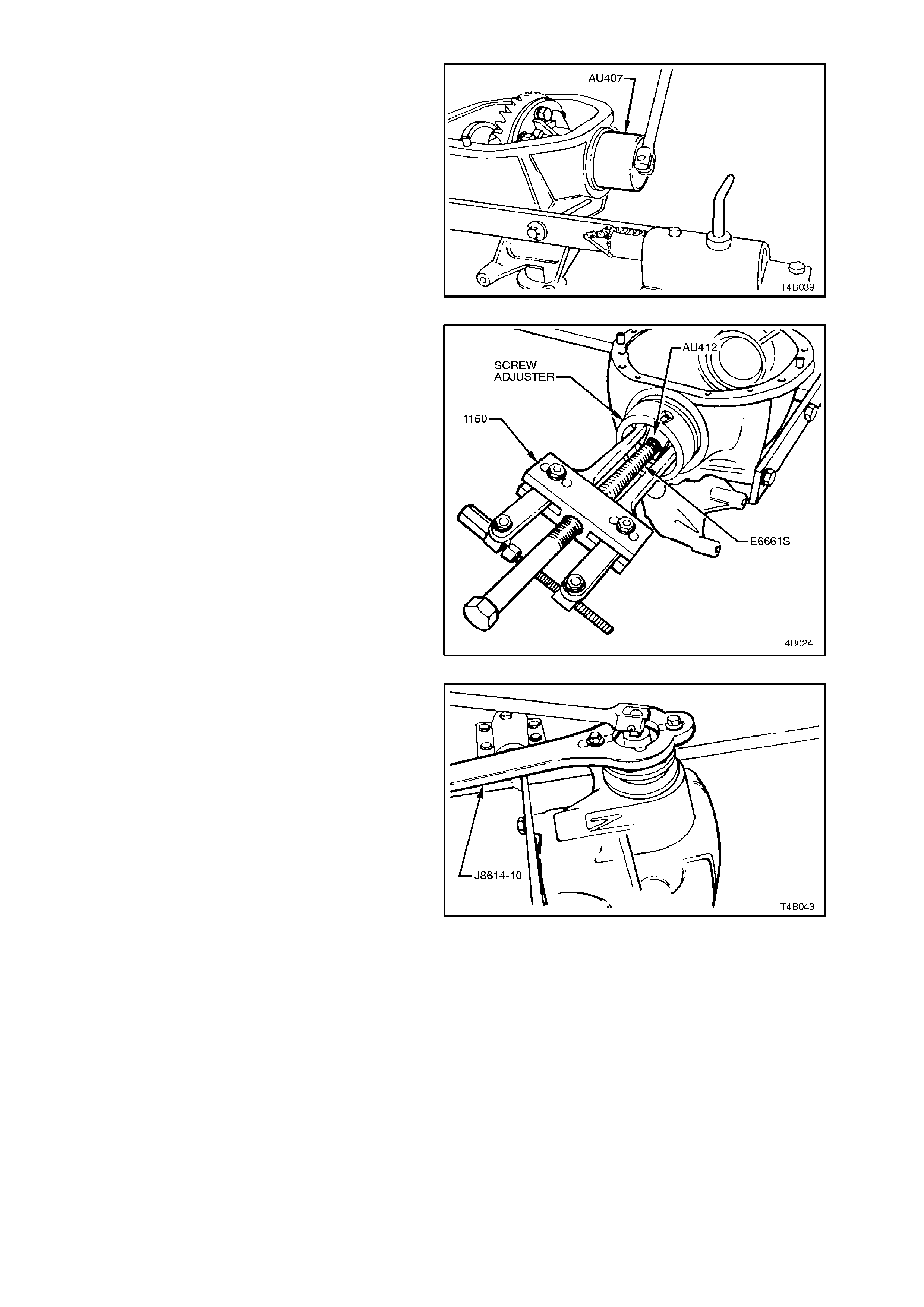
8. Remove screw adjusters from housing using
Tool No. AU407.
9. Remove differential case assembly from
carrier housing.
Figure 4B-111
10. To remove side bearing cups from screw
adjusters, install screw adjusters, reversed,
into differential carrier. Install adaptor, Tool
No. AU412 onto screw adjuster. Using puller,
Tool No. 1150, and forcing screw Tool No.
E6661S, pull side bearing cups from screw
adjusters and discard.
NOTE:
Side bearing cups are only to be removed if side
bearing assemblies are to be replaced.
Figure 4B-112
11. Install Tool No. 4A39/1 to the pinion flange
using two suitable bolts and nuts. While
holding 4A39/1, loosen and remove pinion
flange retaining nut.
Figure 4B-113
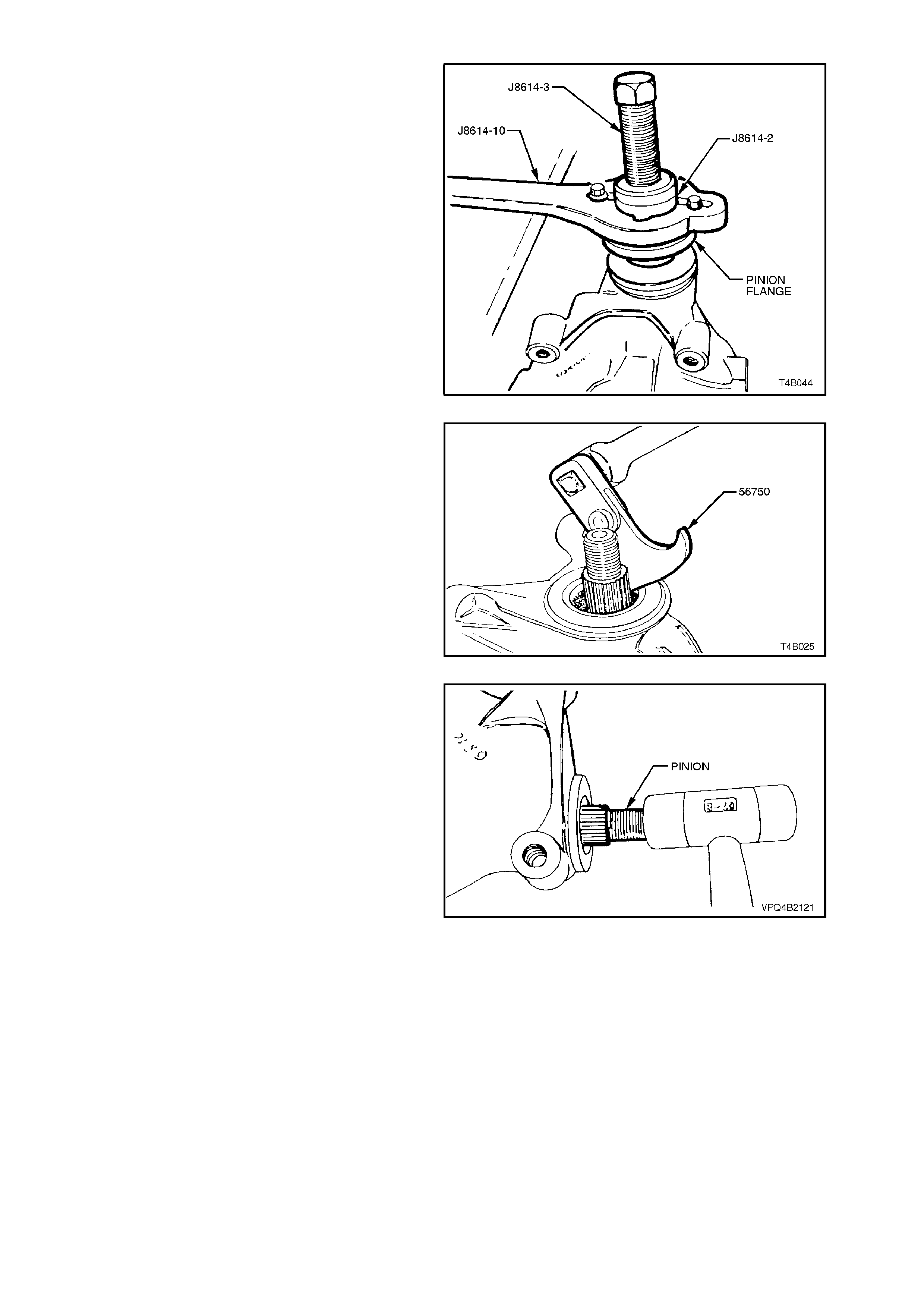
12. Remove holder from pinion flange and
assemble nut 4A39/2 and screw 4A39/3 to
holder, 4A39/1. Install assembly to pinion
flange using two suitable bolts and nuts. While
holding 4A39/1, tighten screw 4A39/3 to
remove pinion flange.
Figure 4B-114
13. Pry pinion oil seal out of carrier bore using
Tool No. 56750 or a suitable seal extraction
tool.
Figure 4B-115
14. Remove pinion by tapping on front end with a
soft faced hammer and withdrawing it through
rear of carrier. Remove pinion front bearing
from carrier bore. Remove and discard pinion
bearing spacer.
Figure 4B-116
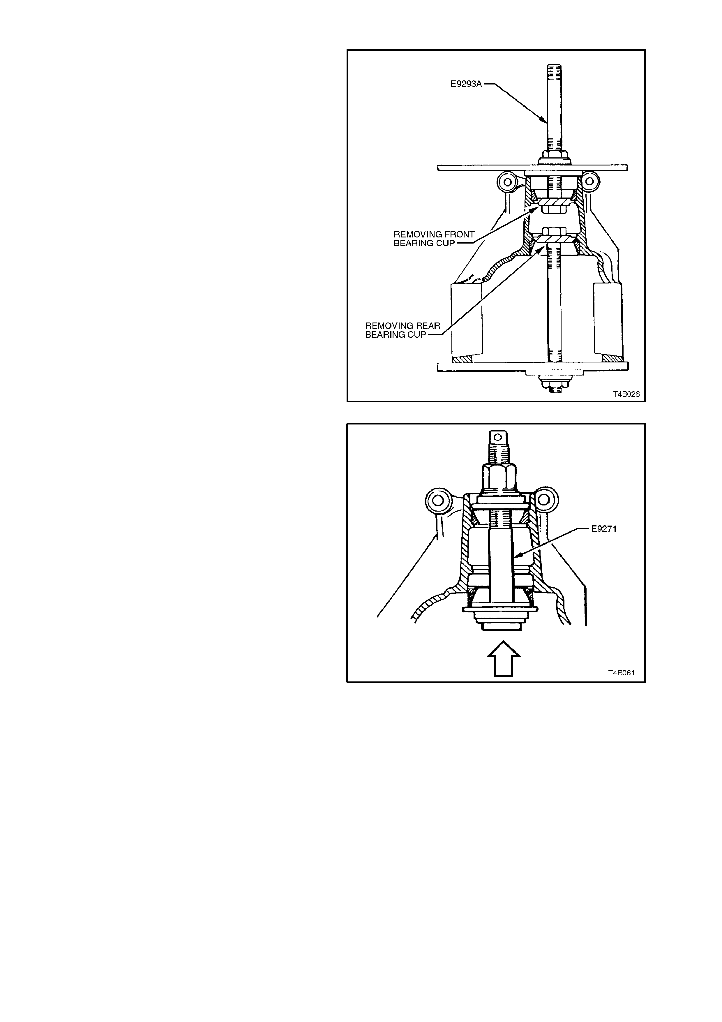
15. If pinion bearings are to be replaced, remove
bearing cups using Tool No. E9293. As shown
in Figure 4B-123, Tool No. E9271 is used for
installing new bearing cups.
Figures 4B-122 and 4B-123 illustrate both the
removal and installation of bearing cups.
Figure 4B-117
NOTE:
It is essential to only replace one bearing cup at a
time, as Tool No. E9271 relies on the remaining
bearing cup as a guide.
Figure 4B-118
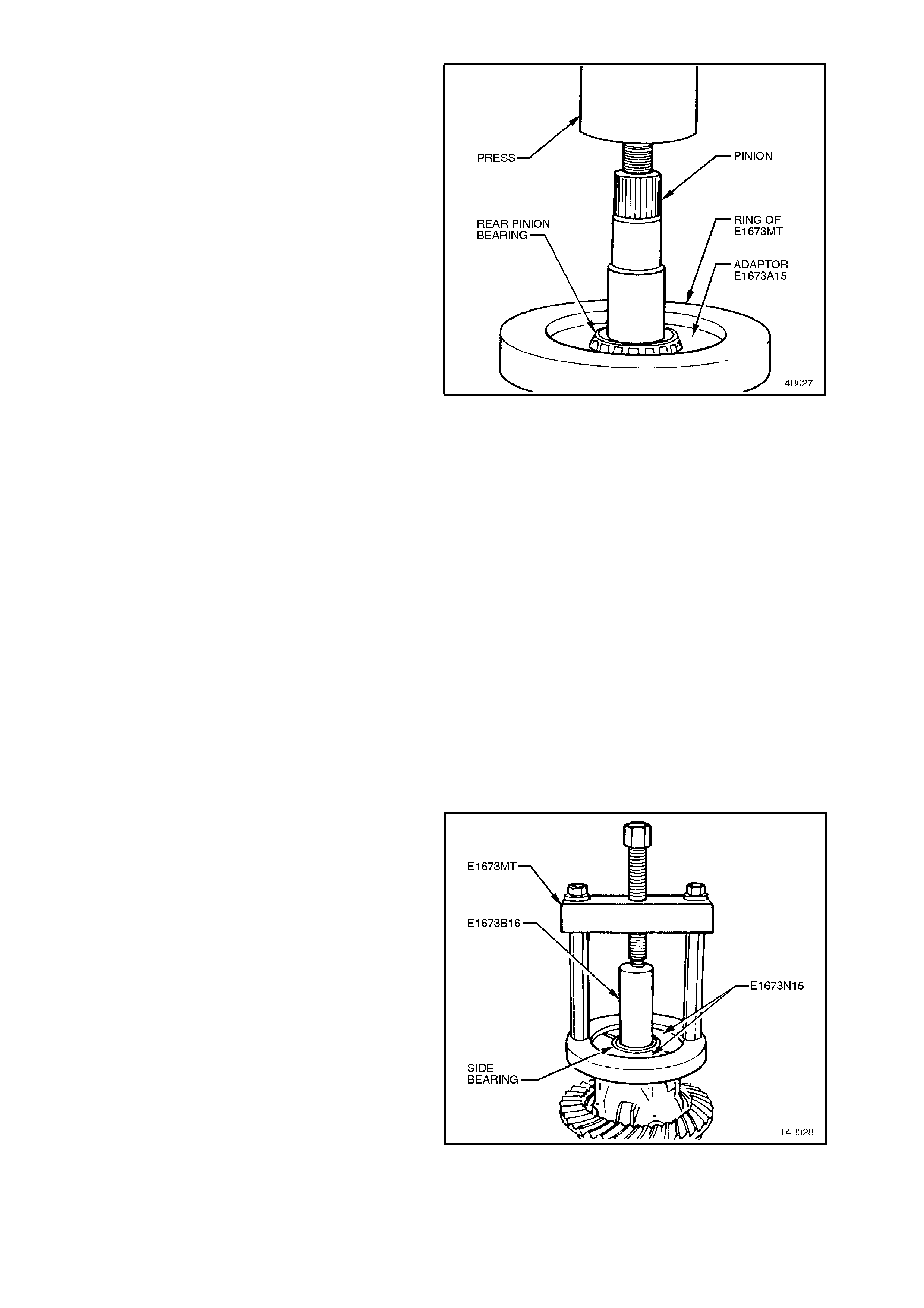
16. To remove rear bearing from pinion, remove
legs from the ring of Tool No. E1673MT.
Place ring on suitable press plates. Install
pinion and adaptors E1673A15 into ring. Pr ess
pinion from bearing.
Figure 4B-119
Differential Case
The following procedures describe the standard
type differential case assembly. For Limited Slip
Differential case assembly, refer to
3.4 LIMITED SLIP DIFFERENTIAL in this Section.
NOTE:
The differential for V8 and V6 supercharged
engined vehicles is unique and parts are not
interchangeable with the V6 engined unit. The
general overhaul procedures however, remain the
same for both types. The unique components for
the V8 and V6 super charged, are; dif ferential c ase,
differential pinions, side gears and thrust block.
1. Before disas s embling dif f er ential ca se, ins pec t
differential side bearings for any signs of
damage.
NOTE:
Both side bearings and their cups are matched
pairs. If either bearing is to be replaced, its
matching cup must also be replaced.
2. If necessar y, us e Tool No. E1673MT , adaptors
E1673N15 and stepped plug E1673B16 to
remove side bearings from differential case, as
shown.
Discard side bearings once they are removed.
To remove side bearing cups, refer to
3.3 REMOVED FINAL DRIVE ASSEMBLY -
DISASSEMBLE step 10.
Figure 4B-120
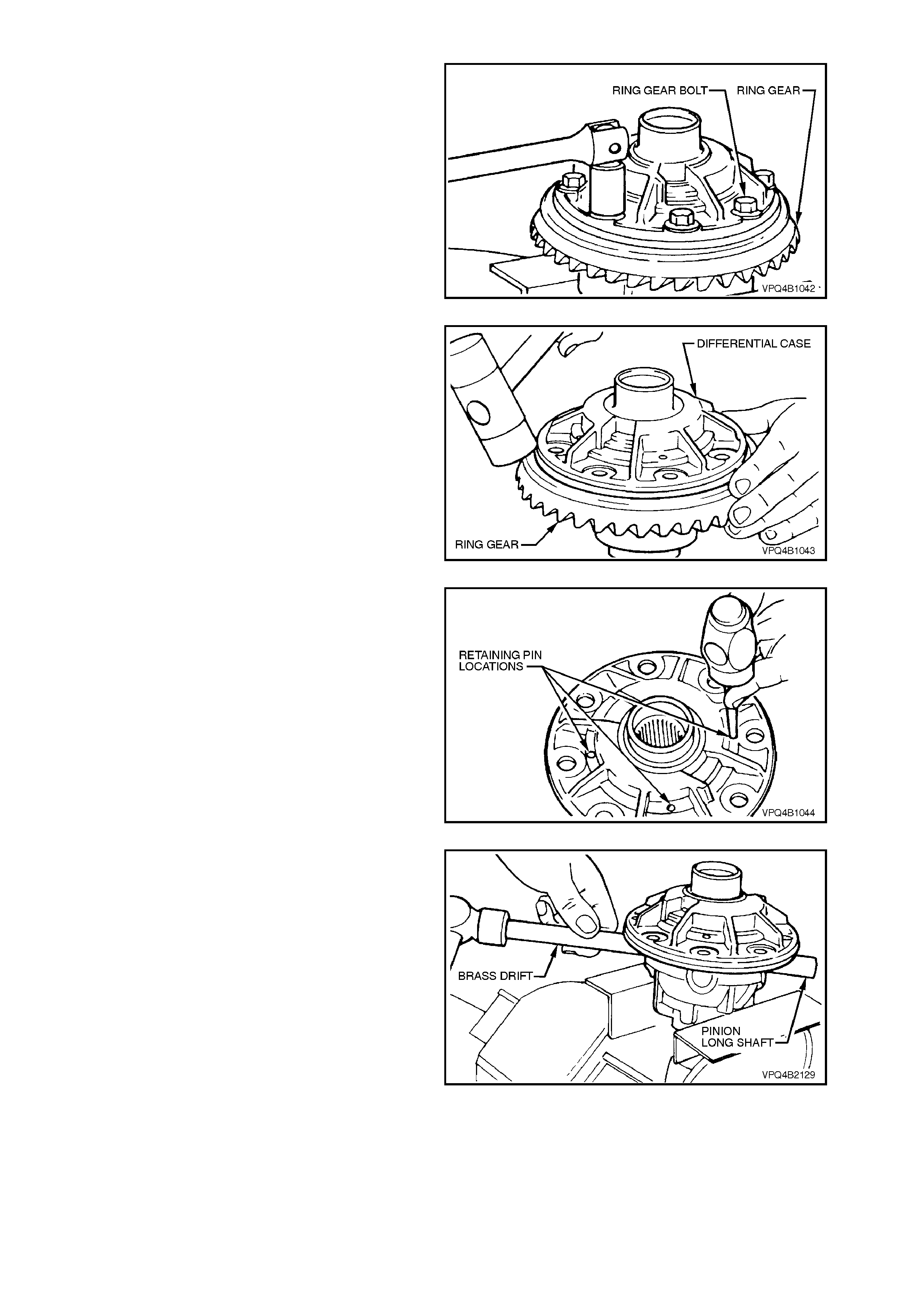
3. Grip the differential case in a vice with soft
jaws.
4. Remove ring gear attaching bolts.
NOTE:
Ring gear attaching bolts use a left hand thread and
are identified by an 'L' on the bolt head.
5. Remove differential case from vice.
Figure 4B-121
6. Using a soft faced hammer, remove ring gear
from differential case by hitting down on ring
gear. Support ring gear during this operation
so that it does not strik e bench top as it com es
free of case.
NOTE:
Do not use a screwdriver to pry between ring gear
and case.
Figure 4B-122
7. Drive out differ ential pinion gear long shaf t and
short shafts retaining pins from differential
case, using a suitable size pin punch and
hammer.
Figure 4B-123
8. Re-mount the differential case in vice with soft
jaws. Using a brass drift and hammer, drive
out pinion long shaft from differential case.
Figure 4B-124
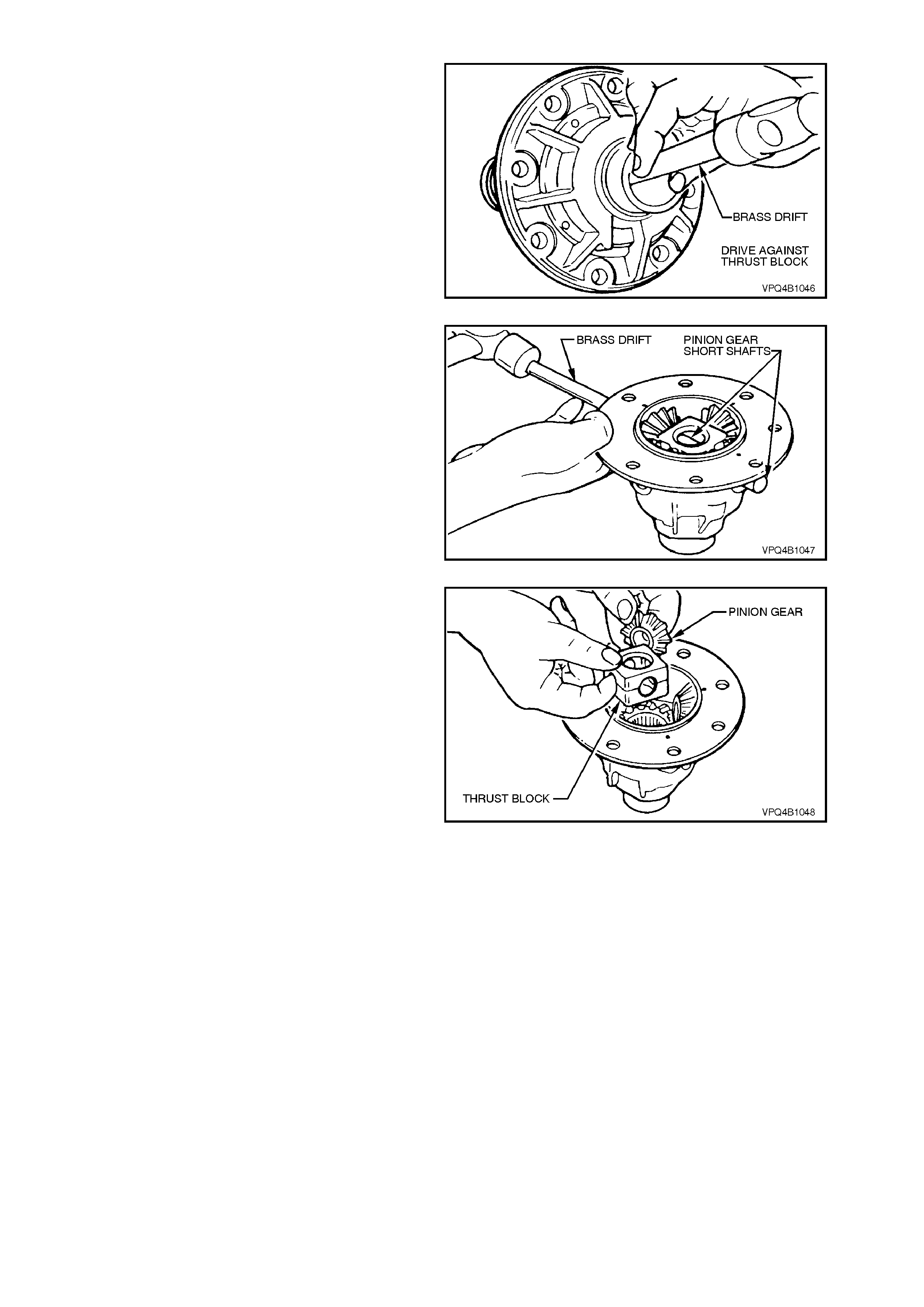
9. Remove differential case from vice. Using a
brass drift and hammer, separate two
differential case halves by driving against
thrust block.
NOTE:
Do not use a screwdriver to prise the differential
case halves apart.
Figure 4B-125
10. Using a brass drift and hammer, drive out
pinion gear short shafts from differential case.
Figure 4B-126
11. Lift out pinion gears, thrust washers and thr ust
block from differential case.
Remove differential side gears and thrust
washers from differential case halves.
NOTE 1:
When removing the thrust block from a V8 or V6
supercharged differential, note that the pinion
shafts are angled at 96° and not 90° as is usual.
NOTE 2:
Keep the gears with their r espective thrust washers
in pairs so they can be reinstalled in their original
position. Figure 4B-127
INSPECT
All components should be thoroughly cleaned and
dried, then inspected.
Differential Case
Check case for general soundness and pay
particular attention to the following points;
1. If differential case side bearings have been
rem oved, check case j ournals f or damage and
that bearing seating surf ac es ar e f r ee f rom dir t
and burrs.
2. The ring gear spigot and mounting face should
be clean and free from dirt and burrs.
3. The mating surfaces for differential case
halves should be clean and free from burrs.
4. The thrust surfaces for differential side gears
and pinions should be ex am ined f or exces sive
wear.
5. The differential side gear journal bores should
be clean and free from scoring.
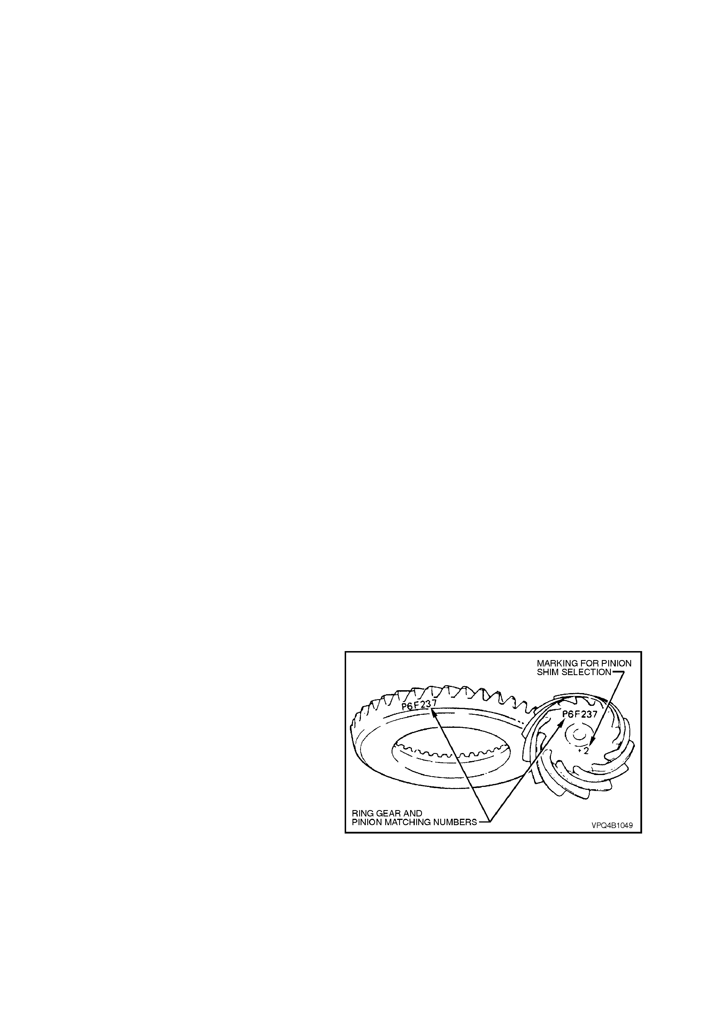
6. The case bores for differential pinion gear
shafts should be checked for ovality.
Differential Side Gears and Pinion Gears
1. Examine all gear teeth for cracks and hard
contact marks.
2. The differential side gear splines should be
checked for excessive wear. W ear on splines
can contribute to excessive driveline backlash.
3. Check differential side gear journals and back
faces for scoring.
4. Check fit of differential side gears in
differential case cap and cover. Wear on side
gear hubs or in the case bores can cause a
"clunking" noise in rear axle assembly when
vehicle is driven at low speeds.
5. Inspect differential pinion bores and thrust
surfaces for scoring. Also check differential
pinion gear shafts are not bent and that
surfaces where pinions run are not worn or
scored.
6. Check thrust washers. They should be free
from cracks, nicks and burrs. Excessive wear
of thrust washers or pinion gear thrust
surfaces can also contribute to excessive
driveline backlash.
7. Check thrust block pinion gear shaft bores for
ovality.
Ring Gear and Pinion
1. Inspect gear teeth for scoring or damage.
Scoring of gear teeth is usually caused by
excessive shock loading, use of incorrect
lubricant or ins uf ficient "run in" bef or e towing a
heavy load. (Refer VT Series Owner's
Handbook). Scored gears must be replaced.
2. The ring gear bore and back face should be
clean and free from burrs.
3. The rear bearing seating s urf ace on the pinion
should be clean and free from burrs.
4. Inspect pinion splines and flange splines for
evidence of wear.
5. Inspect thread and bearing journals of pinion
for damage.
6. If on reassembly, a new gear set is to be
installed, ensure that the same matching
number appears on both the pinion and ring
gear, as shown.
7. On ring gear bolts, clean Durlok serrations
under bolt flange.
Figure 4B-128
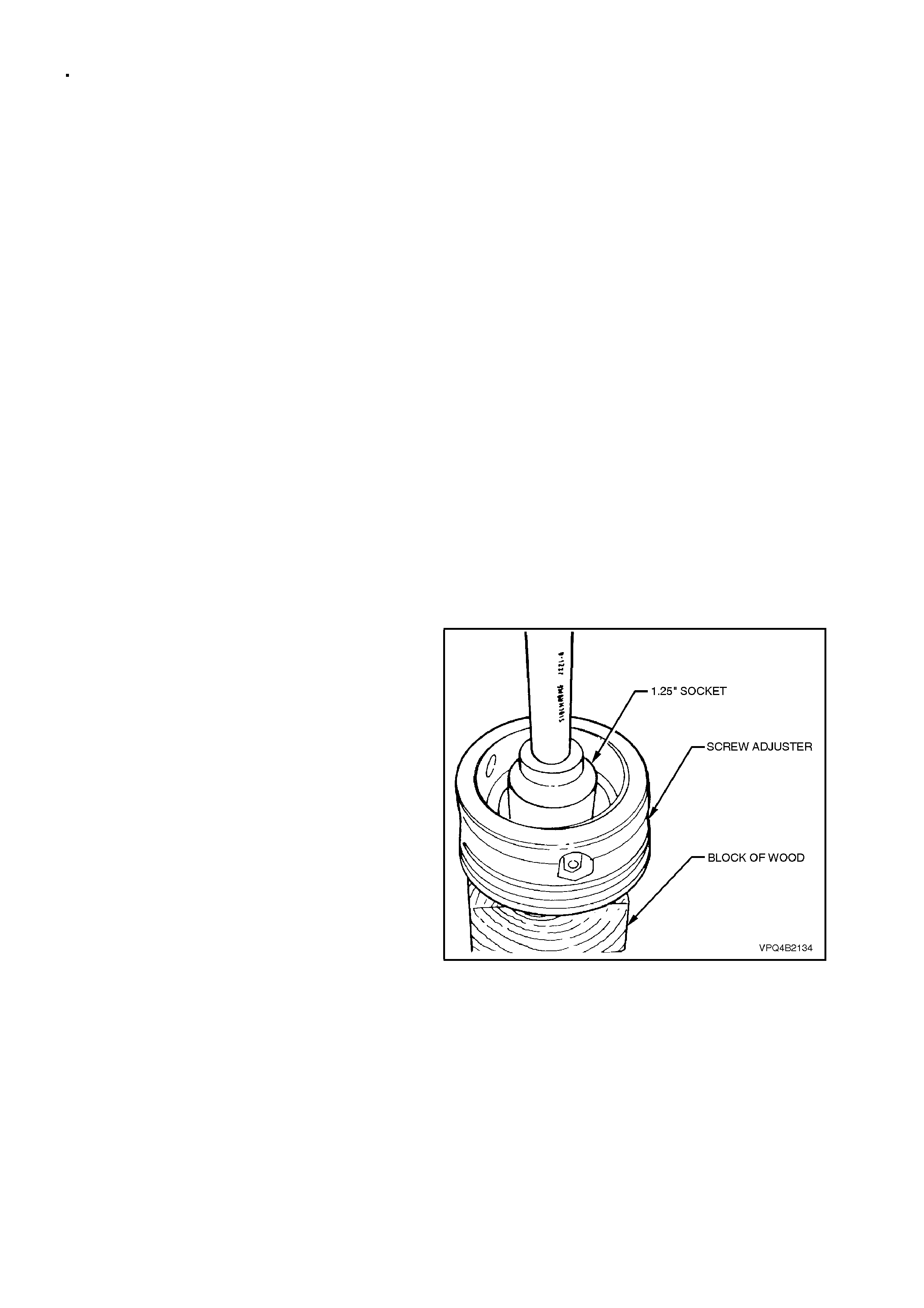
Bearings
1. Bearing cups should have an even wear
pattern and must be free from flaking or
pitting. Ensure that seating surf aces are clean
and free from burrs or raised metal.
2. The bearing assemblies should feel smooth
when turned in their cups.
3. The assembly should be free from loose
particles.
4. No cracks should be present in roller cages,
and bores should show no evidence of flaking
or pitting.
Refer to 4.4 FINAL DRIVE BEARING
DIAGNOSIS in this Section, for identification
of bearing failures.
Differential Carrier
1. Check casting all over for general soundness.
2. Examine oil passages and ensure they are
free from obstructions and loose particles.
3. The bore f or the pinion oil seal should be free
from burrs.
4. Inspect rear cover face and bolt holes for
damage.
5. Check rear cover seating surface for scoring
or other damage.
Screw Adjusters and Inner Axle Shafts
1. Inspect inner ax le s haf t needle bearings ins ide
screw adjusters for wear or damage.
2. If inner axle shaft needle bearings are to be
replaced, reinstall screw adjusters into
differential carrier and remove inner axle shaf t
seals, as detailed in steps 6 and 7 of
3.3 REMOVED FINAL DRIVE ASSEMBLY -
DISASSEMBLE.
Remove screw adjusters from carrier and
position each onto a block of wood. Then,
using a 1.25 inch socket and bar or a 73 mm
diameter tube, press the bearing from each of
the screw adjusters.
3. Remove and discard O-rings from screw
adjusters.
4. Examine adjuster seal bores for burrs, nicks or
other damage. Examine oil passages and
ensure they are free from obstructions and
loose particles.
Adjuster thread and bearing bores should be
clean and free from burrs or other damage. Figure 4B-129
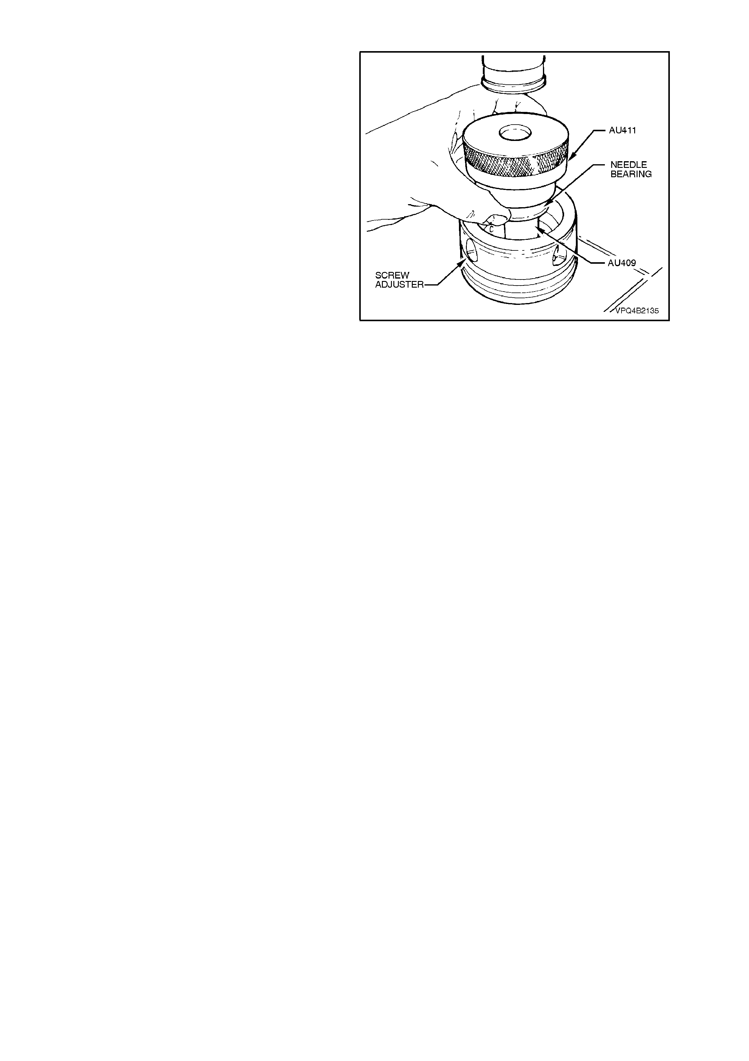
5. To ins tall new screw adjuster needle bearings,
place screw adjuster onto Tool No. AU409 and
press needle bearing into adjuster using Tool
No. AU411. Repeat procedure for opposite
screw adjuster.
NOTE 1:
Side bearing cups must be installed into screw
adjusters before installing needle bearings. This is
to ensure that needle bearings ar e located c or rec tly
into screw adjuster bores.
NOTE 2:
To install side bearing cups, refer to step 1,
Differential Case Side Bearing Pre-Load Setting in
this Section.
Figure 4B-130
6. Examine seal surface of inner axle shafts and
carefully remove any nicks or burrs.
Should this surface be irreparable on either
axle shaft, a new axle shaft must be fitted.
7. Check spring clip in end of inner ax le shaf ts to
ensure that they are not damaged and move
freely in grooves. Replace spring clips if
necessary, by expanding ends of each clip
and removing from inner axle shafts. Expand
ends of new clips sufficiently to allow
installation into axle shaft grooves.
Rear Cover
1. Clean sealant from rear cover sealing surface.
2. Inspect rear cover for cracks or damaged
sealing surface.
3. Ensure breather passage is clean and free of
obstructions.
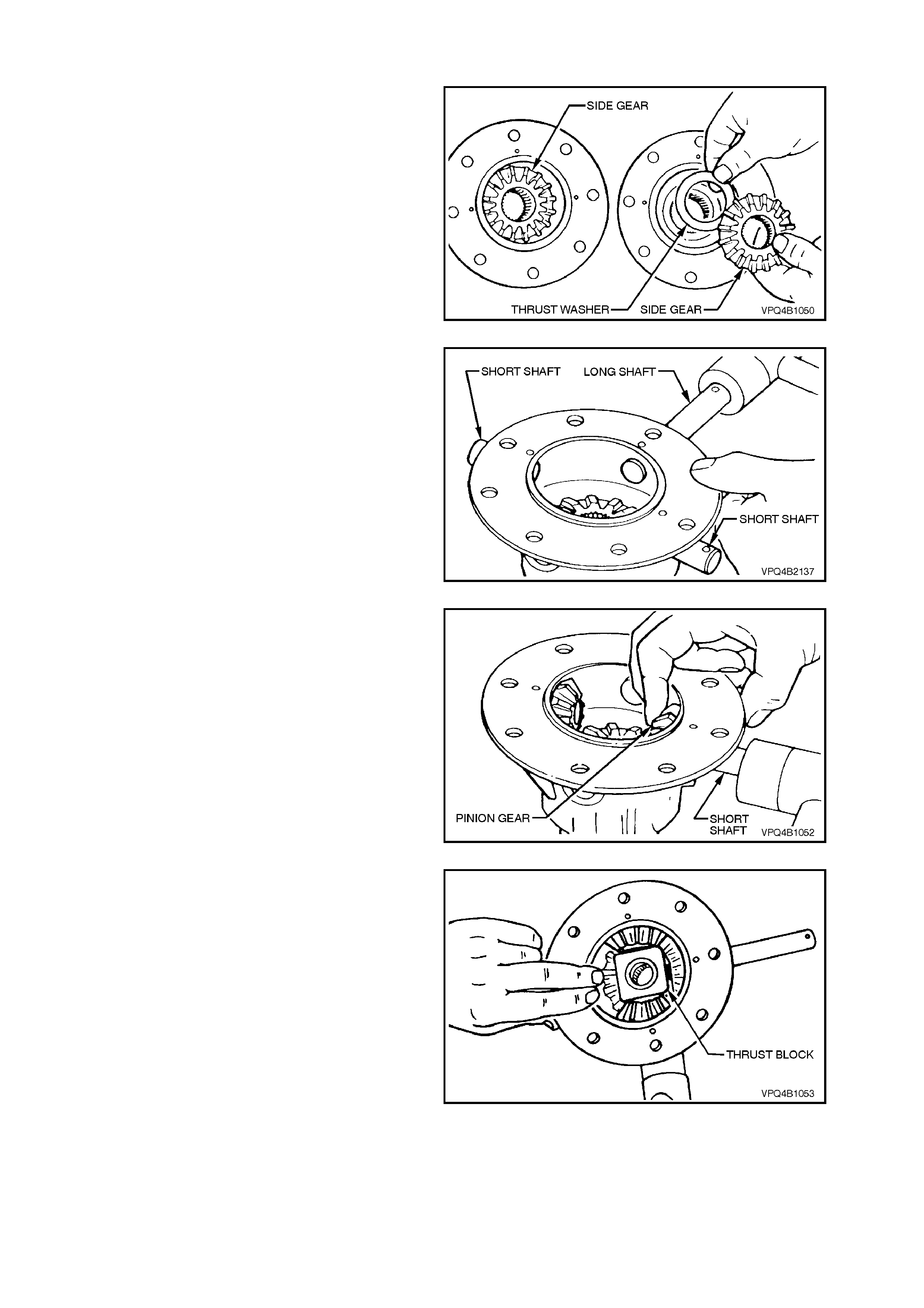
REASSEMBLE
Differential Case
1. Lubricate all differ ential gears, bearings, thrus t
washers and differential pinion gear shafts
with the recommended rear axle lubricant
before assembly.
2. Position differential side gears with their thrust
washers into differential case halves.
Figure 4B-131
3. Using a soft faced hammer, install pinion gear
short shafts and long shaft into differential
case, j ust enough to allow a pinion gear thrust
washer to sit on the end of each shaft.
NOTE:
Ensure that the retaining pin holes in the dif ferential
case and pinion gear shafts are in alignment and
with the cham fered edge of the holes in each shaft
facing up.
Figure 4B-132
4. Install one of the pinion gear thrust washers
over inside end of one of the short shafts.
5. Position appropriate pinion gear next to thrust
washer and knock short shaft in until it com es
through centre of the gear.
6. Carry out steps 4 and 5 for sec ond pinion gear
short shaft.
Figure 4B-133
7. Install thrust block between two installed
pinion gears. Knock the two pinion gear short
shafts into position, ensuring that retaining pin
holes in the shafts line up with holes in
differential case.
Figure 4B-134
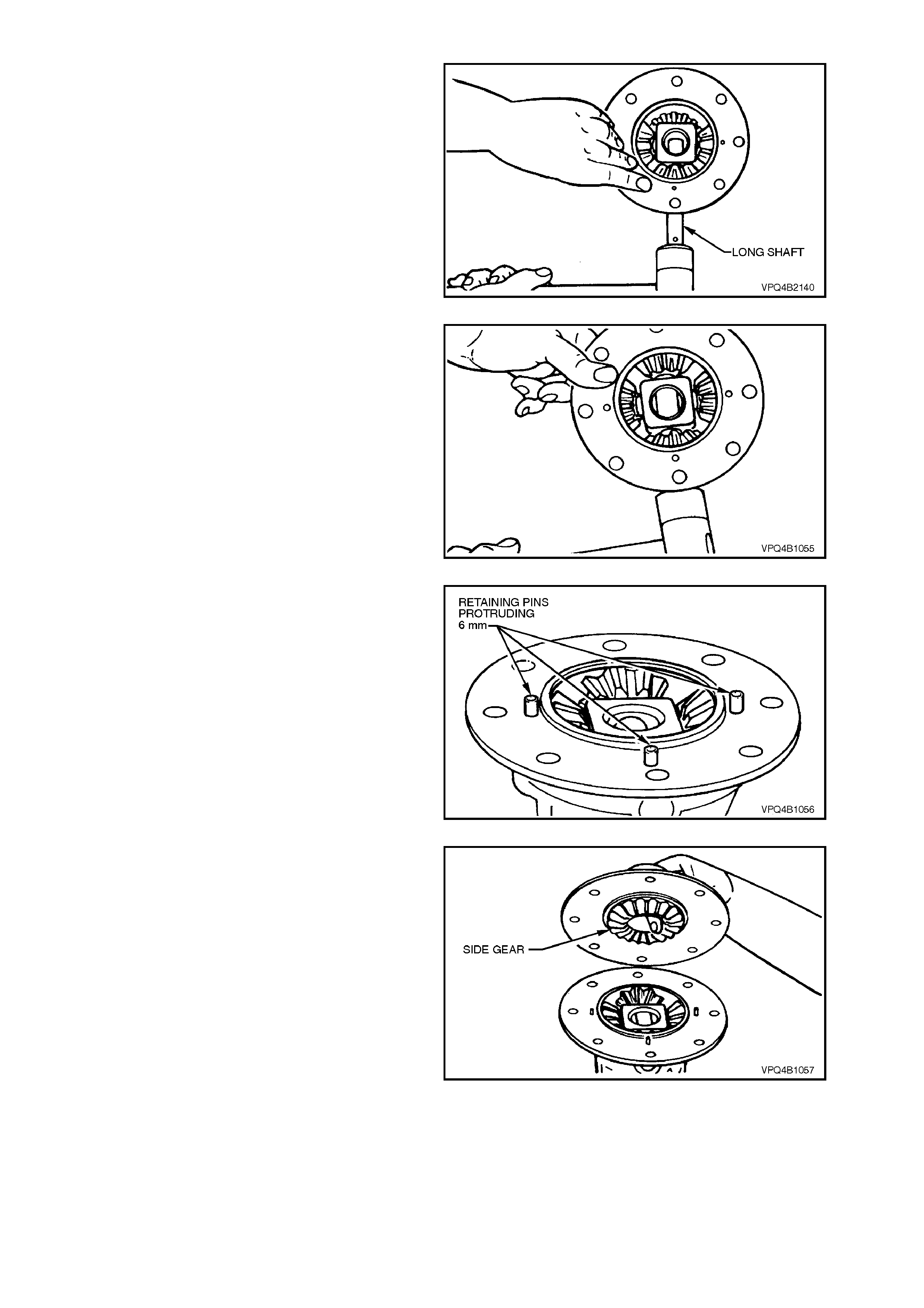
8. Install pinion gear thrust washer and gear to
long shaft. Knock cross shaft through gear and
thrust block.
Figure 4B-135
9. Install remaining pinion gear and thrust
washer. Knock long shaft through pinion gear,
ensuring that thrust washer aligns with cross
shaft. Knock cross shaft into differential case
until retaining pin hole in shaft aligns with hole
in differential case.
Figure 4B-136
10. Install pinion gear long shaft and short shaft
retaining pins. Ensure that ends of retaining
pins protrude 6 mm from differential case cap
to cover mating surface. This is necessary to
provide a positive location for the differential
case cover to case cap.
Figure 4B-137
11. Holding differential side gear in position with a
finger through differential case cover bore as
shown, push the two differential case halves
together, locating on the protruding retaining
pins.
Figure 4B-138
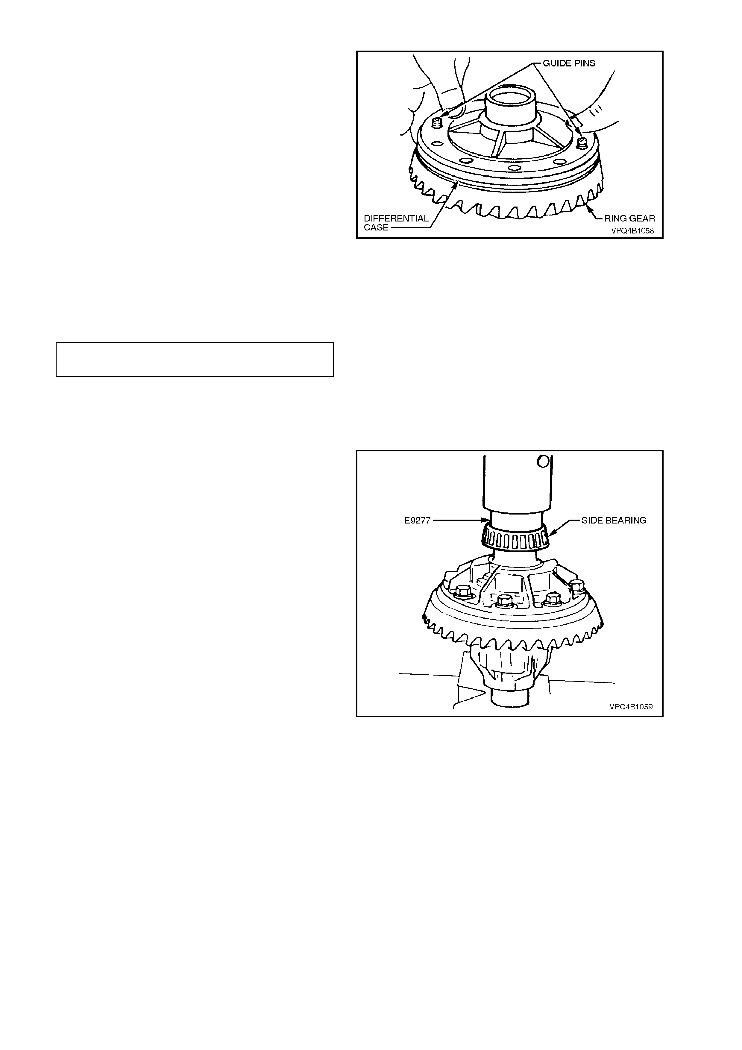
12. Place ring gear into position on differential
case cap and install ring gear attaching bolts.
NOTE 1:
For ease of assem bly, it m ay be necessary to heat
the ring gear on a hot plate until it is hot to the
hand, prior to installing onto the differential case
cap.
NOTE 2:
On no account must a flame be used to heat the
ring gear.
NOTE 3:
Use left hand threaded guide pins to pilot the ring
gear over the differential case spigot.
13. Install and gradually tighten NEW ring gear
attaching bolts evenly, until gear face is flush
with differential cas e s pigot. T ighten all bolts to
the correct torque specification.
DIFFERENTIAL RING GEAR 125 - 150
BOLTS TORQUE SPECIFICATION Nm
NOTE:
Ring gear attaching bolts use a left hand thread
and are identified by an 'L' on the bolt head.
Figure 4B-139
14. If installing new side bearings, use Tool No.
E9277 to press on side bearings to differential
case journals.
Figure 4B-140
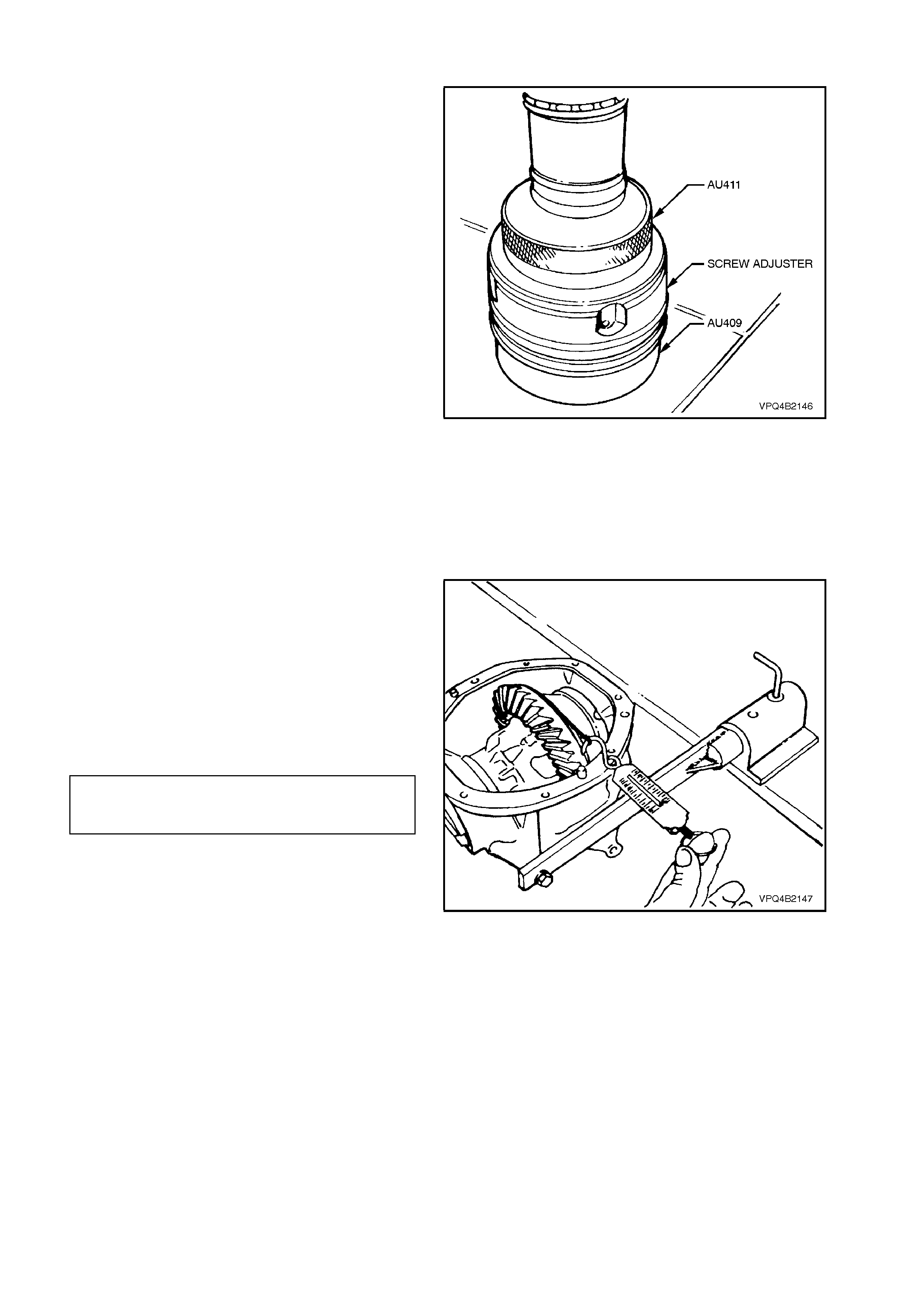
Differential Case Side Bearing Pre-Load Setting
1. If removed during disassembly, press new
bearing cups into screw adjusters firmly to the
shoulder by positioning screw adjuster onto
Tool No. AU409 and using Tool No. AU411 to
press new cup into place. Repeat procedure
for remaining screw adjuster.
NOTE 1:
Ensure that bearing side and cup matching is
maintained.
NOTE 2:
The screw adjuster used on the V8 and V6
supercharged engine final drives is 1.9 mm deeper
than the one used for V6. The deeper screw
adjuster can be identified by a groove on the inner
edge.
This depth change is necessary to accommodate
the greater side bearing span used with the V8 and
V6 supercharged axle assemblies. Figure 4B-141
2. Install new O-rings to screw adjusters and
apply a lubricant such as rubber grease to
each.
3. Holding differential case in carrier, fit screw
adjusters to both sides of carrier. Continue
tightening adjusters until case assembly is
supported by side bearings.
4. Rotate differential case several times to
ensure that side bearings are correctly seated.
5. W r ap a piece of st ring around diff erential case
flange and check side bearing pre-load by
pulling on end of string with a spring balance.
Spring balance reading must be within
specification.
Tighten or loosen one of the screw adjusters
until the correct pre-load is obtained.
SIDE BEARING
PRE-LOAD 15 - 35 N (New Bearings)
SPECIFICATION 8 - 18 N (Used Bearings)
Figure 4B-142
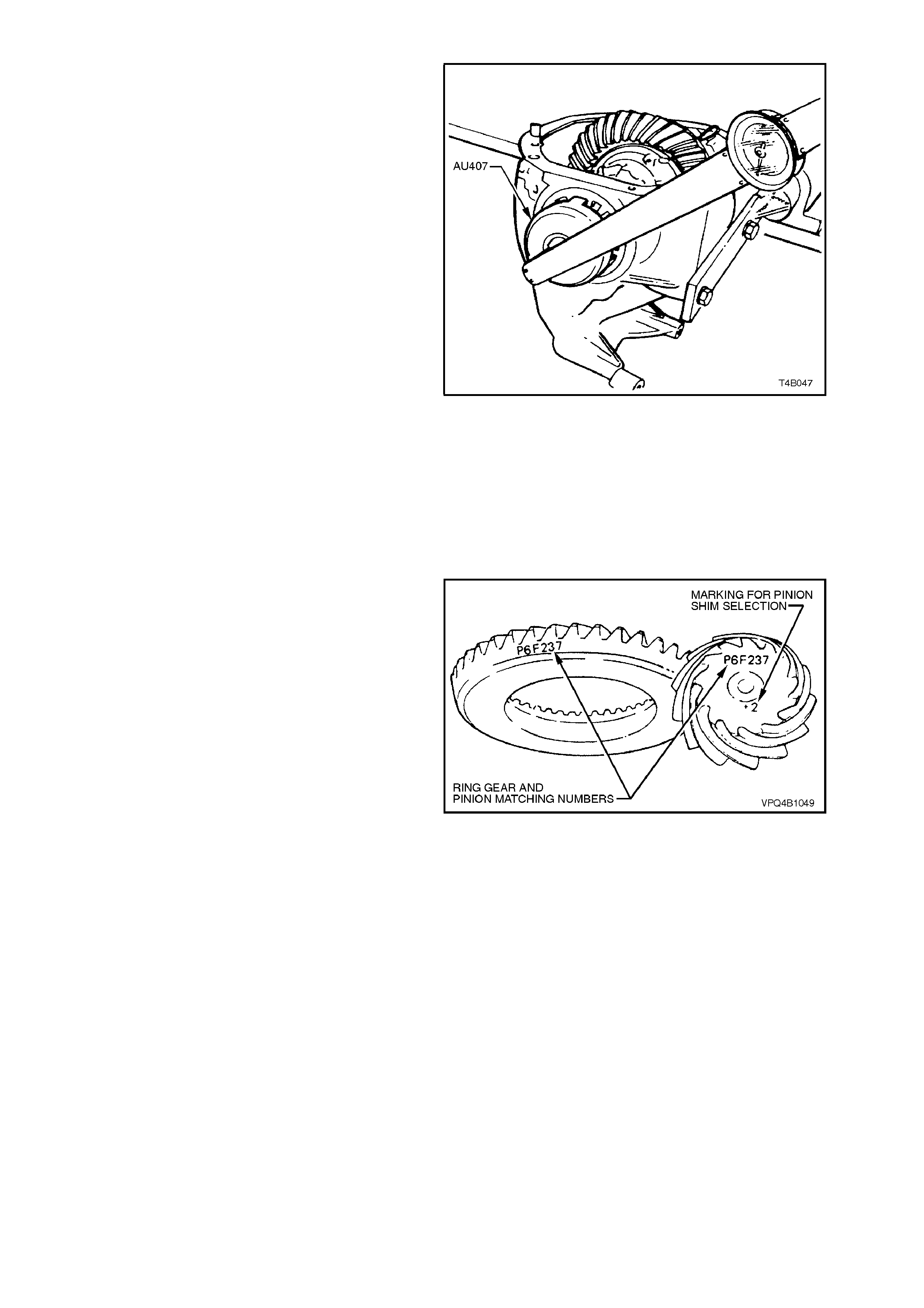
6. Using Tool No. AU407 and a torque wrench,
measure tightening torque of each screw
adjuster (usually within the range of 50-60 Nm)
and record.
These torque readings will be used to set
bearing pre-load on final assembly.
7. Using Tool No. AU407, loosen and remove
screw adjusters, remove differential case
assembly.
Figure 4B-143
Hypoid Pinion Positioning Shim Selection
The pinion positioning shim is located between
pinion rear bearing cup and carrier housing.
If the ring gear and pinion or the pinion rear bearing
assembly are replaced, pinion depth must be
rechecked with pinion setting gauge, Tool No.
E9300A (previously released as E9300) and
dummy arbor Tool No. AU408.
The gauge and arbor provide a nominal or 'zero'
pinion as a gauging reference.
NOTE 1:
If a new gear set is to be installed, ensure that the
sam e matc hing number appear s on both the pinion
and the ring gear.
NOTE 2:
The V6 and V8/V6 supercharged pinions have
different mounting distances (94.49 and 102.50
mm respectively). Also, as the V6 and V8/V6
superchar ged assem blies have dif f erent rear pinion
bearings, gear set sizes, differential case
assemblies and screw adjusters, none of these
parts are to be mixed. Figure 4B-144
1. Inspect pinion bearing cups/cones for nicks
and burrs. Replace if damaged (refer to Step
16 of 3.3 REMOVED FINAL DRIVE
ASSEMBLY - DISASSEMBLE).
2. Lubricate pinion front and rear bearings with
the recom mended dif ferential car rier lubricant.
Do not use engine or other oils, as a
misleading rotating torque can be obtained.
V6 Vehicles with the 3.08:1 Ratio Axle
Assembly:
3a. Install the rear bearing onto dummy pinion
after first installing the distance spacer Tool
No. E9300-1 (part of Tool No. E9300A).
NOTE:
The spacer is not required when using E9300.
V8/V6 Supercharged Vehicles with the 3.07:1
Ratio Axle Assembly:
3b. Install the rear pinion bearing onto the dum my
pinion, supplied as part of E9300A.
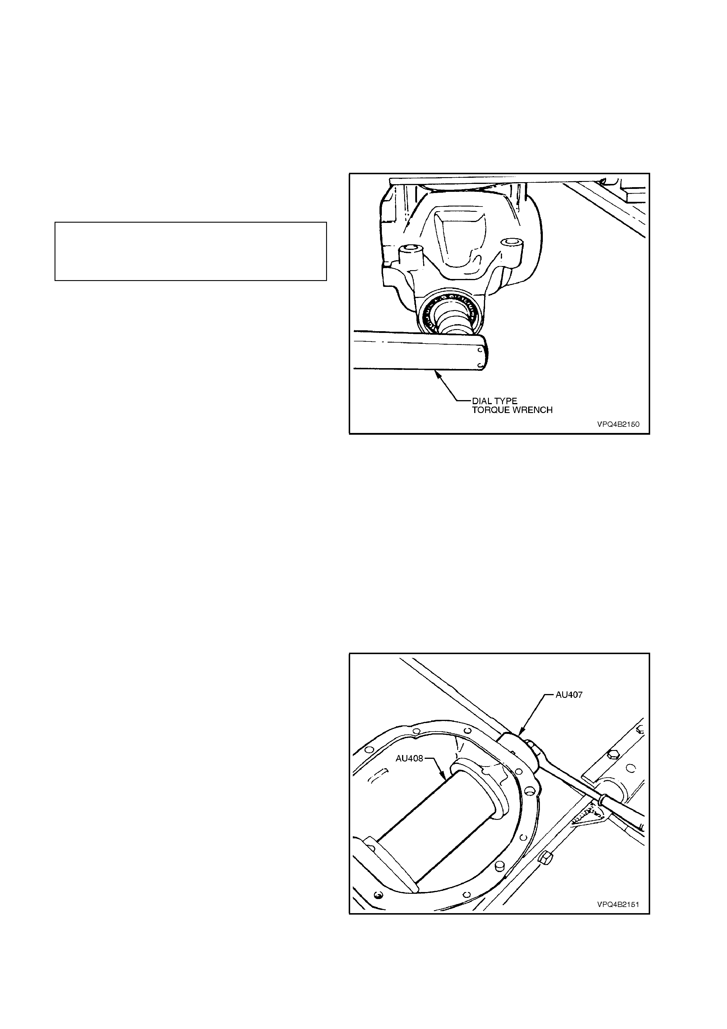
4. Install dummy pinion and rear bearing into
carrier housing. Fit front bearing to dummy
pinion and then install dummy pinion thrust
collar and nut.
NOTE:
Ensure that the rear pinion bearing that will be used
for final reassembly of the pinion is used on the
dummy pinion.
5. Tighten nut on end of dummy pinion until
specified rotational torque is obtained.
DUMMY PINION, 1.4 - 2.0 Nm
ROTATIONAL (New Bearings)
TORQUE 0.7 - 1.0 Nm
SPECIFICATION (Used Bearings)
6. Rotate dummy pinion back and forth during
tightening to ensure that bearings settle in
their cups.
NOTE 1:
Pinion bearing pre-load is very important bec ause it
retains pinion in its correct relationship to ring gear.
NOTE 2:
Bearings that are installed with insufficient or no
pre-load, will, after a comparatively short period of
running, develop end play, causing noisy operation
on overrun and could be r esponsible for s cuffing of
ring gear and pinion teeth.
NOTE 3:
Bearings that have too much pre-load, may
become pitted or flaked and result in ultimate
failure.
NOTE 4:
It is therefore essential to ensure that bearings are
pre-loaded to specified torque specification.
NOTE 5:
Rotate dummy pinion back and forth during
tightening to ensure bearings settle.
Figure 4B-145
7. Position arbor Tool No. AU408 in carrier
assem bly and install screw adjusters with side
bearing cups. Adjust screw adjusters to lightly
clamp arbor, using Tool No. AU407.
NOTE:
Ensure that arbor is free of bur rs that may damage
bearing cups.
Figure 4B-146
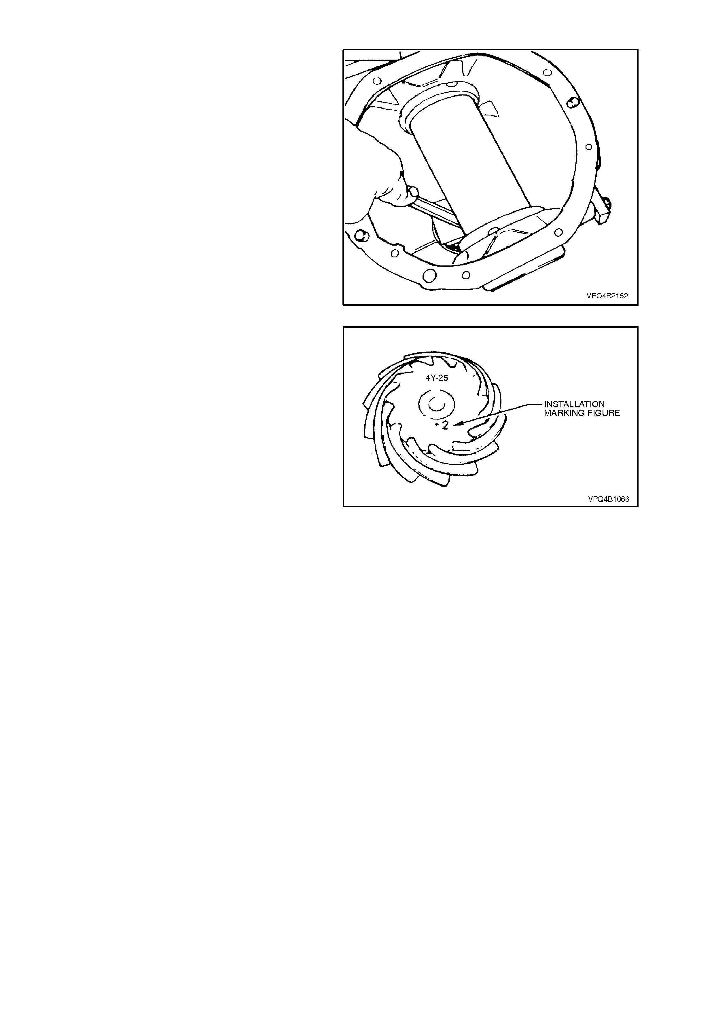
8. Check clearance between arbor and head of
dummy pinion with a feeler gauge. Record this
dimension.
Figure 4B-147
9. On the end of the pinion, a drive pinion
installation marking figure is etched. A zero
marking ('0') indicates that shim size equal to
the dimension measured in Step 7 is the
correct size for this carrier/pinion combination.
A positive marking, e.g. +3, means that a
thickness measurement equivalent to this
numerical marking must be subtracted from
shim size measured in Step 7, refer to the
following chart.
A negative marking, e.g. -3, means that a
thickness measurement equivalent to this
num erical m ar king mus t be added to the shim
size measured in Step 7. Refer to the f o llowing
chart for specific details.
PINION SHIM THICKNE S S
MARKING REQUIRED
–4 Add 0.10 mm t o measurement of step 7.
–3 Add 0.075 mm t o measurement of step 7.
–2 Add 0.050 mm t o measurement of step 7.
–1 Add 0.025 mm t o measurement of step 7.
0 Size as measured in s tep 7.
+1 Subtract 0. 025 mm from measurement of s tep 7.
+2 Subtract 0. 050 mm from measurement of s tep 7.
+3 Subtract 0. 075 mm from measurement of s tep 7.
+4 Subtract 0. 10 mm from measurement of s tep 7.
NOTE:
Pinion positioning shims are serviced in
thicknesses of 0.2 - to 0.75 mm in 0.25 mm
increments. They are also dimensioned differently,
depending on the pinion bearing used.
Figure 4B-148
10. Remove dummy pinion and arbor from carrier
assembly.
Pinion Installation
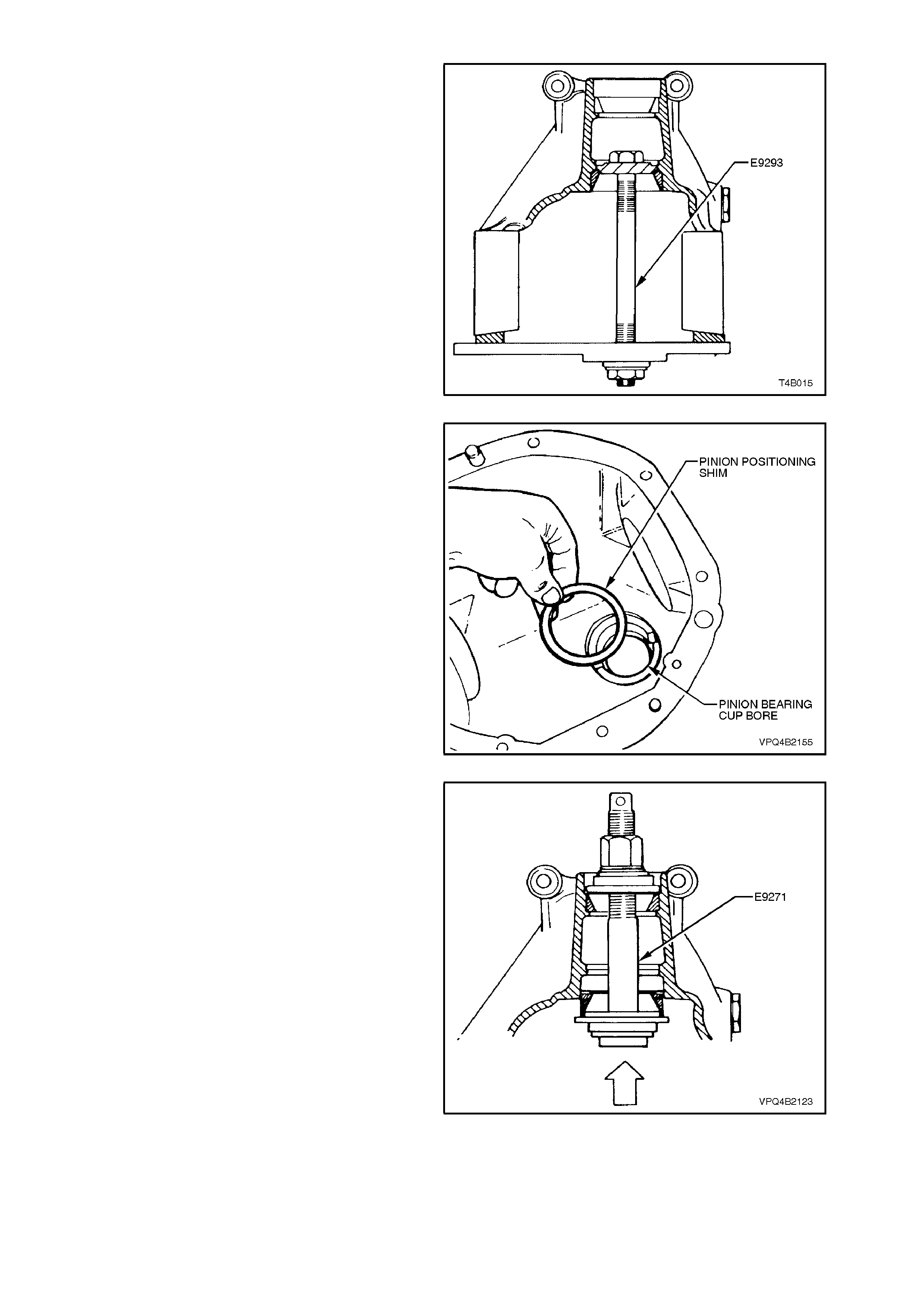
1. Select pinion positioning shim stack as
determined in the Operation, Hypoid Pinion
Positioning Shim Selection, in this Section.
2. Remove pinion rear bearing cup, using Tool
No. E9293.
Figure 4B-149
3. Install pinion positioning s him/s into pinion r ear
bearing cup bore.
Figure 4B-150
4. Reinstall pinion rear bearing cup using Tool
No. E9271. Ensure that cup is seated squar ely
in bore.
Figure 4B-151
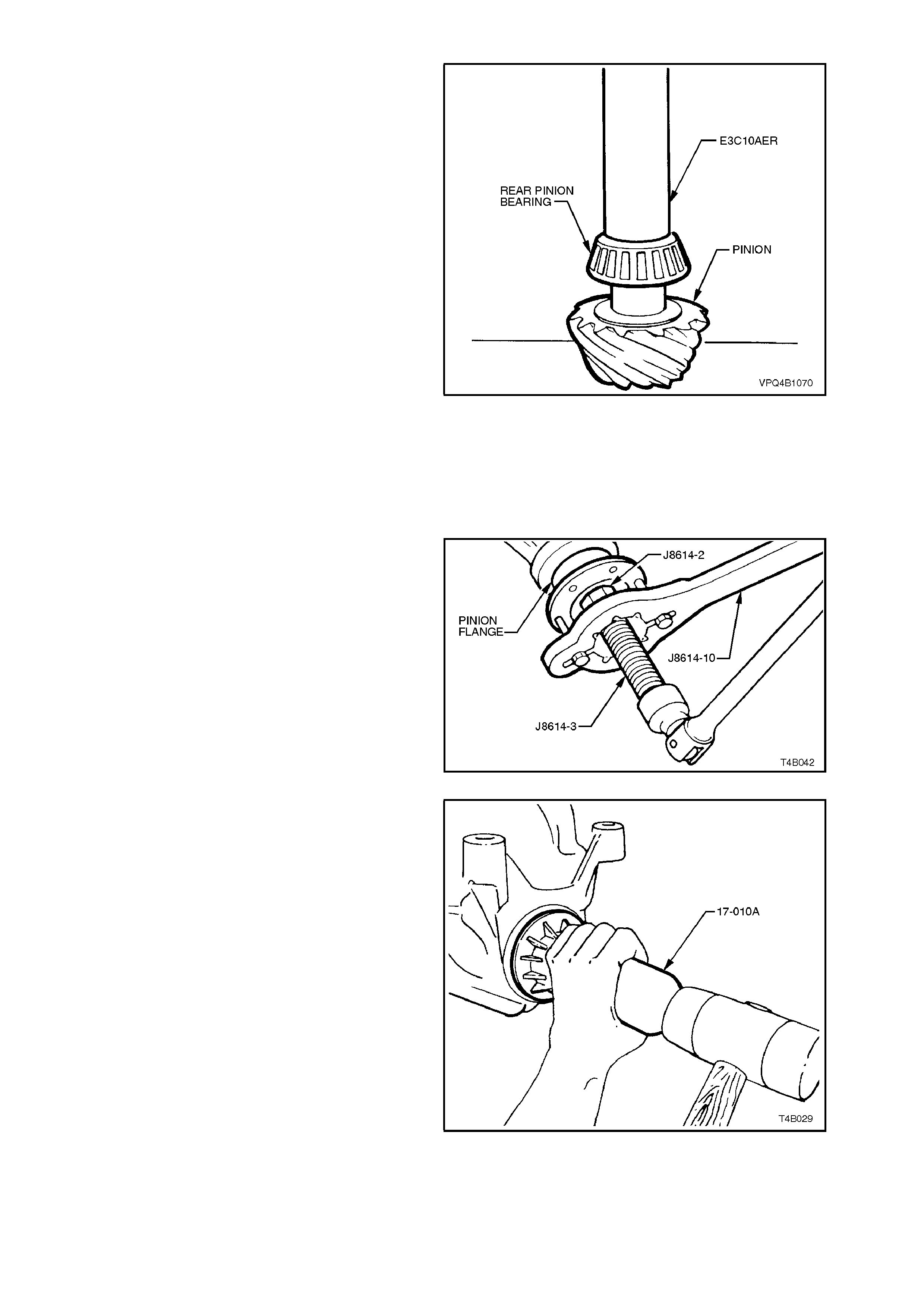
5. Press rear bearing inner race against the
shoulder of the pinion, using Tool No.
E3C10AER.
NOTE 1:
To avoid possible damage to the pinion gear teeth
when pressing the bearing on, ensure that the
press plates are perfectly flat, free of burrs and
foreign matter prior to installing the rear bearing.
NOTE 2:
Locate bearing inner race squarely on the pinion
and press only on inner race surface.
NOTE 3:
Only lubricate the bearing with the recommended
differential carrier lubricant.
Figure 4B-152
6. Place the pinion in the carrier.
7. Lubricate pinion front bearing with the
recom mended dif ferential carr ier lubricant and
assemble the collapsible pinion bearing
spacer and front bearing onto pinion, while
supporting pinion head.
8. Install pinion flange and the original pinion
flange retaining nut.
9. Using Tool No. J 8614-10 to hold pinion flange,
tighten retaining nut until pinion front bearing
starts on pinion shaft.
10. Remove pinion flange retaining nut and, using
the three components of Tool No. J8614-01,
assembled as shown, remove pinion flange.
Figure 4B-153
11. Lubricate pinion oil seal lips with differential
carrier lubricant. Lightly c oat differential c arrier
seal bore with differential carrier lubricant to
assist in seal installation. Install oil seal into
carrier bore using Tool No. 17-010A. Seal fits
flush to 0.25 mm below carrier housing
surface.
Figure 4B-154
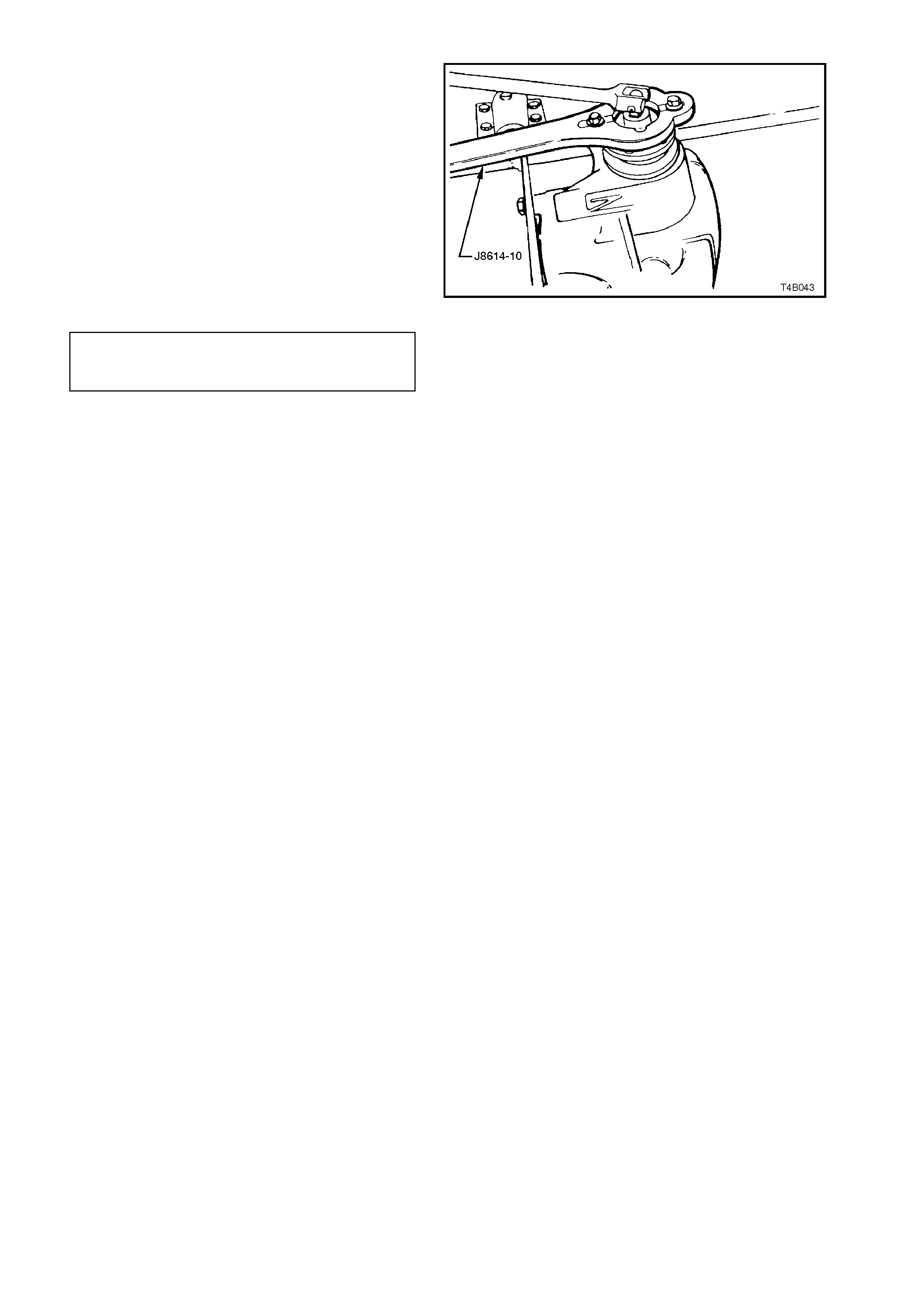
12. Reinstall pinion flange and f it a NEW retaining
nut. Hold pinion flange using Tool No. J8614-
10 and gradually tighten retaining nut while
rotating pinion in both directions to seat
bearings.
13. Check bearing pre-load frequently by
removing flange holding tool and installing a
pulley to pinion flange. Refer to
7 SPECIAL TOOLS at the end of this Section
for pulley details.
14. Using a spring scale, measure rotational
torque.
15. Tighten nut until specified torque is achieved.
PINION BEARING 1.4 - 2.4 Nm (New Bearings)
PRE-LOAD
SPECIFICATION 0.7 - 1.2 Nm (Used Bearings)
The torque figure is calculated by multiplying the
radius of the pulley by the spring balance reading.
EXAMPLE:
If the pulley diameter is 152 mm, the radius is 76
mm which equals 0.076 m. The spring balance
reading is 25 N. Therefore, the pre-load equals
0.076 m x 25 N = 1.9 Nm.
Figure 4B-155
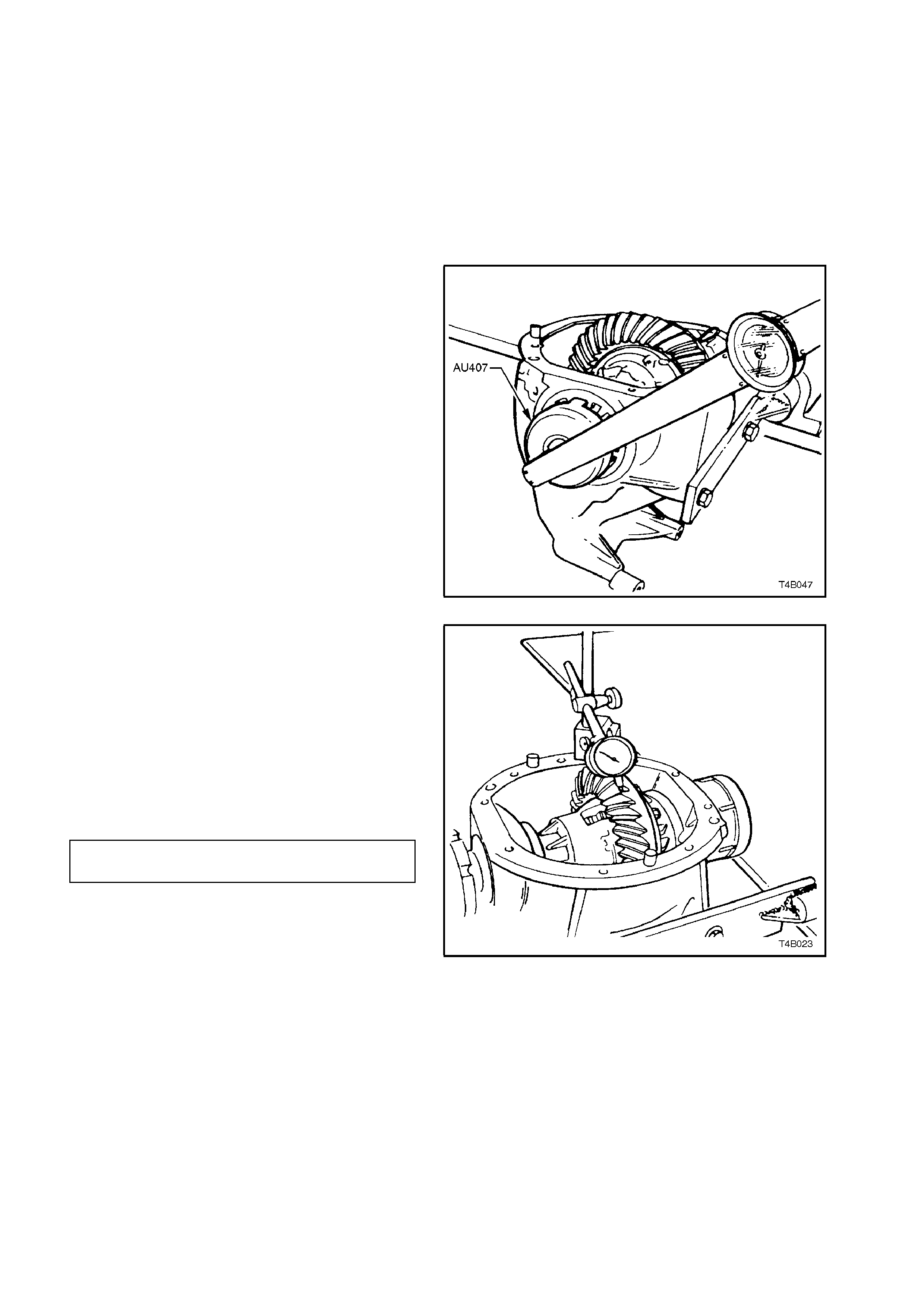
CAUTION:
Should the retaining nut be overtightened and
pre-load exceeded, it will be necessary to
remove the pinion from the carrier and install a
new collapsible spacer. Under no
circumstances must the retaining nut be
backed off to decrease the pre-load reading.
Differential Backlash Setting
1. Check threads of screw adjusters and ensure
that they are free of damage.
2. Holding differential case in carrier, with ring
gear in mesh with pinion, fit screw adjusters
and side bearing cup as sem blies to both sides
of carrier. Using Tool No. AU407, continue
tightening adjusters until case assembly is
supported by side bearings.
3. Rotate differential case several times, to
ensure that side bearings are correctly seated.
4. Tighten screw adjusters to the torque setting
recorded in step 6, ‘Differential Case Side
Bearing - Pre-load Setting’, in this Section.
Figure 4B-156
5. Mount a dial indicator on carrier and check
gear backlash between the ring gear and
pinion. Back lash should be within the following
specification.
Check readings at four equally spaced
positions around ring gear.
NOTE:
Position the dial indicator so that the indicator
stylus is perpendicular to the ring gear tooth and in
line with gear rotation.
BACKLASH 0.10 - 0.18 mm at the
SPECIFICATION tightest point
6. If backlash is excessive or insufficient, adjust
by slackening off screw adjuster on the side
that the ring gear (differential case) needs to
move towards. Re-tighten opposite screw
adjuster and tighten both as per step 4.
7. With backlash correctly set, check gear
contact pattern as detailed in the following
instructions.
Figure 4B-157

Ring Gear and Pinion Contact Pattern
1. Thoroughly clean ring gear and pinion teeth.
2. Paint ring gear teeth lightly and evenly with
gear marking compound of a suitable
consistency to produce a contact pattern.
3. Rotate pinion through several revolutions in
both directions while lightly loading gear set.
To load gear set, use a suitable bar to lever
between ring gear outer diameter and
differential carrier.
NOTE:
When rotating pinion, ensure that no metal swarf
from contact with rotating ring gear and bar is
allowed to enter gear teeth.
4. Inspect contact pattern produced by above
procedure.
5. After a satisfactory contact pattern is
produced, clean the ring gear and pinion gear
teeth and pour a liberal quantity of the correct
rear axle lubricant onto the gears and
bearings. Turn the gear set to work the
lubricant into all surfaces.
Tooth marking Nomenclature
The large end of the tooth is called the 'HEEL' and
the small end the 'TOE', also the top of the tooth
which is above the pitch line is called the 'FACE'
while the area below the pitch line is called the
'FLANK'. The clearance between the pinion and
ring gear teeth is referred to as 'BACKLASH'.
Figure 4B-158 illustrates correct and incorrect
contact patterns.
Contact pattern 'A' provides the ideal marking for
quietness and long life. If the pattern shows a toe
contact 'B', it indicates not enough backlash. To
correct, move the ring gear away from the pinion by
increasing the s ize of the shim on the pinion s ide of
the ring gear and decreasing the ring gear side
shim by an equal amount.
If the pattern shows a heel contact 'C', it indicates
too muc h backlash. T o correct, m ove the ring gear
towards the pinion by increasing the size of the
shim on the ring gear side and decreasing the size
of the shim on the pinion side of the ring gear by an
equal amount.
NOTE:
Make adjustment, increasing and decreasing shim
thickness by 0.04 mm at a time. Check contact with
gear marking compound and continue adjustment
until tooth contact appears as in 'A'. Back lash m ust
remain within specified limits.
To correct a pattern such as 'D', it will be necessary
to install a thicker pinion positioning shim as
described under HYPOID PINION POSITIONING
SHIM SELECTION in this Section. A 0.025 mm
thicker shim is recommended as a starting point.
Continued changes may be necessary to obtain the
correct setting. If the pattern shows a flank contact
'E', it indicates that the pinion is in too far. To
correct, replace the pinion shim with a 0.025 mm
thinner shim and recheck contact pattern.

In making pinion position adjustments, be sure
backlash is correct before testing contact pattern.
Moving the pinion 'IN' reduces backlash and
moving pinion 'OUT' increases backlash.
Figure 4B-158

IDEAL CONTACT
Figure 4B-159
Drive Side
A central toe contact marking, lengthwise in position and slightly low contact in the profile position.
Total length approximately 5/8 ths of the gear face width.
There should be clearance of about 1 mm between the contact marking and the toe and along the top face angle
line.
Coast Side
A centrally located marking, lengthwise in position and slightly high in the profile position.
Total length approximately 5/8 ths of the gear face width.
There should be clearance between the contact and the face angle line of the gear.
ACCEPTABLE HEEL CONTACTS
Figure 4B-160
Drive Side
A central face contact marking, lengthwise in position, is shown in Figure 4B-160. This represents the limit of
acceptability of the contact marking towards the heel.
The marking should fade out at least 5 mm before the heel end.
A central profile marking position is shown and is acceptable, although low contact marking is preferred.
Coast Side
The centre of the contact marking is located at 5/8 ths of the face width from the toe and it does not approach the
heel end by less than 5 mm.
A high contact marking, as shown in Figure 4B-160, is preferred for coast side contacts which tend to be toward the
heel.
A central profile marking position is acceptable, providing the pinion face angle edge lines do not appear low on the
gear.
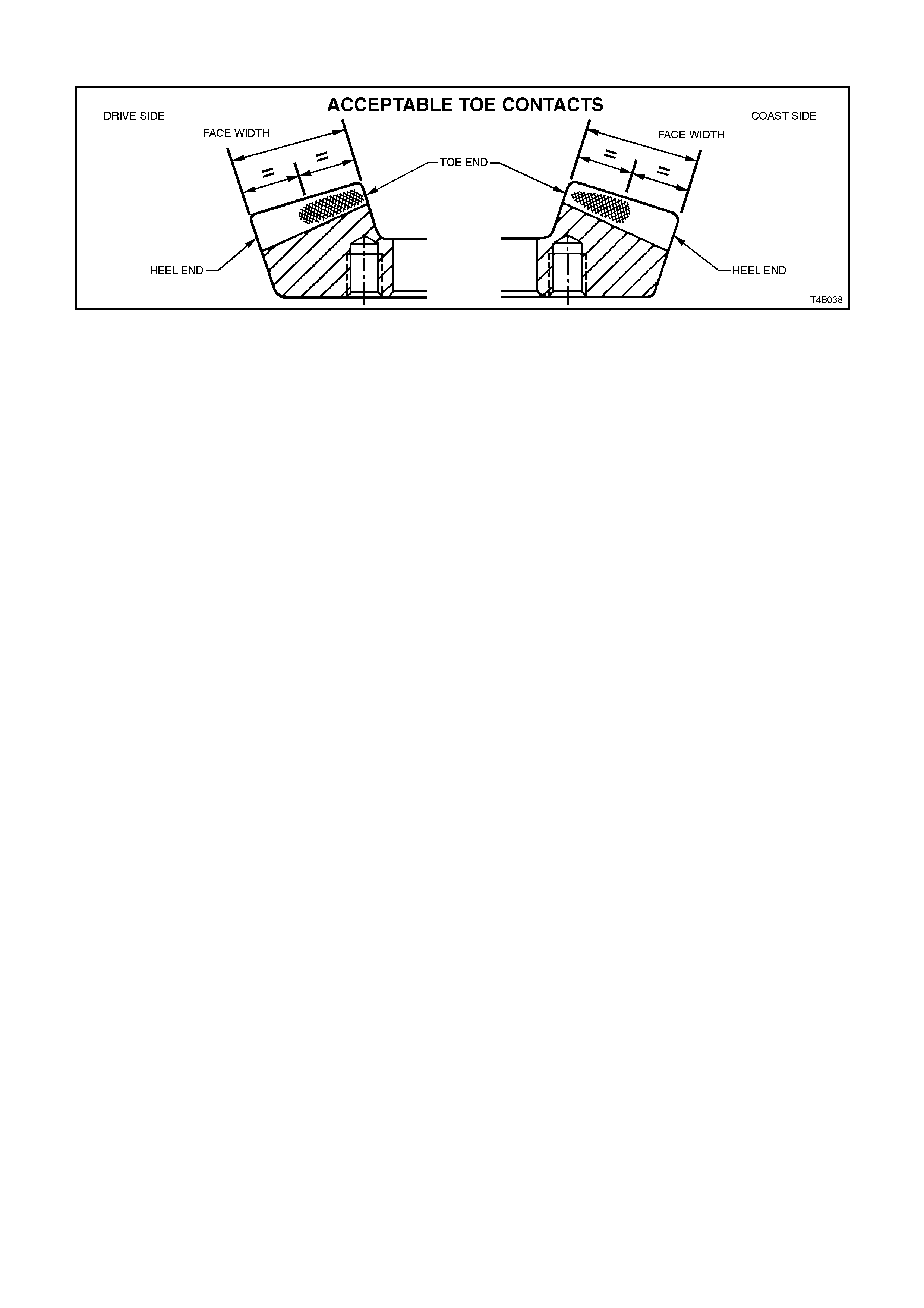
ACCEPTABLE TOE CONTACTS
Figure 4B-161
Drive Side
The contact markings begin almost at the toe end face and extend in length by approximately half the face width.
A slightly low contact marking is shown in Figure 4B-161. This is preferable although a centrally located profile
position is acceptable.
Coast Side
The contact marking being almost at the toe end face and may appear pointed as shown in Figure 4B-161. A
square end is equally acceptable.
The total length of the contact marking is approximately 1/2 of the face width.
A high profile marking position is desirable, although a central profile is acceptable.

3.4 LIMITED SLIP DIFFE RE NTIAL
The overhaul procedures, ring gear and pinion
positioning and tooth markings for the limited slip
diff erential ar e the same as f or the s tandar d type of
rear axle assembly, except for the servicing of the
internal components of the limited slip differential
assembly.
NOTE:
The differential for V8 and V6 supercharged
engined vehicles is unique and parts are not
interchangeable with the V6 engined unit. The
general overhaul procedures however, remain the
same for both types. The unique components for
the V8 and V6 super charged, are; dif ferential c ase,
differential pinions, side gears and thrust block.
DISASSEMBLE
1. Before disas s embling dif f er ential ca se, ins pec t
differential side bearings for any signs of
damage.
NOTE:
Both side bearings and their cups are matched
parts. If either bearing is to be replaced, its
matching cup must also be replaced.
2. If replacing side bearings, use Tool No.
E1673MT, adaptors E1673N15 and stepped
plug E1673B16 to remove side bearings from
differential case.
Discard side bearings once they are removed.
To remove side bearing cups, refer to
3.3 REMOVED FINAL DRIVE ASSEMBLY -
DISASSEMBLE, step 10 in this Section.
Figure 4B-162
3. Grip differential case in a vice with soft jaws.
4. Remove ring gear attaching bolts.
NOTE:
Ring gear attaching bolts use a left hand thread
and are identified by an 'L' on the bolt head.
5. Remove differential case from vice.
Figure 4B-163
Techline

6. Using a soft faced hammer, remove ring gear
from differential case by hitting down on ring
gear. Support ring gear during this operation
so that it does not str ik e benc h top as it c omes
free of case.
NOTE:
Do not use a screwdriver to pry between ring gear
and case.
7. Place differential case in a vice equipped with
soft jaws.
Figure 4B-164
8. Loosen and remove differential case cap to
cover attac hing bolts evenly. Lift of f dif ferential
case cover. If necessary, remove clutch cup
from cover (some-times the cone will remain
inside the cover).
Figure 4B-165
9. Remove clutch cone, shim (if fitted), side gear
and thrust spring plate from pinion cross shaft.
NOTE:
V8 and V6 supercharged vehicle clutch cone and
side gears are an integral unit and must stay
assembled to each other.
Figure 4B-166
NOTE:
To ensure that the clutch cones are not
interchanged during reassembly, mark the cone
and corres ponding side of the diff erential case with
a daub of paint. If shims are present, they must
also be marked so that they can be reassembled
into the correct case half.
Figure 4B-167
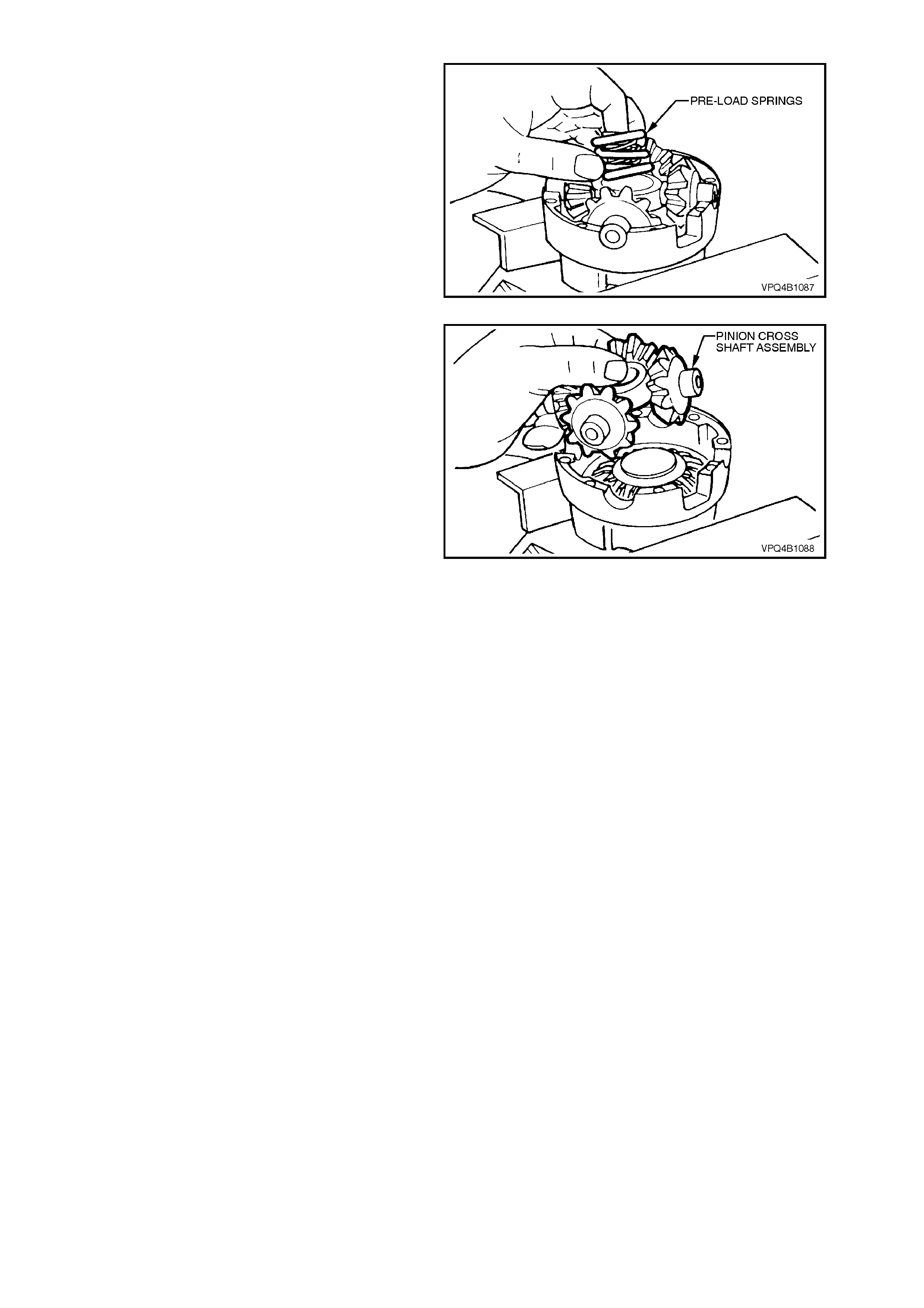
10. Remove three concentric differential pre-load
springs from centre of pinion cross shaft.
Figure 4B-168
11. Lift pinion cross shaft, pinion gears and thrust
washers from case. Rem ove pinion gears and
thrust washers from cross shaft.
NOTE:
Keep the pinion gears with their respective thrust
washers in sets so they can be reinstalled in their
original position.
12. Remove remaining thrust spring plate, side
gear, shim (if fitted) and clutch cone from
differential case cap.
Figure 4B-169
INSPECT
All components should be thoroughly cleaned and
dried, then inspected.
Differential Case
Check the case for general soundness and pay
particular attention to the following points:
1. If differential case side bearings have been
rem oved, check case j ournals f or damage and
that seating surfaces are free from dirt and
burrs.
2. The ring gear spigot and mounting face should
be clean and free from dirt and burrs.
3. The mating surfaces for differential case
halves should be clean and free from burrs.
4. The thrust surfaces for the differential pinions
should be examined for excessive wear.
5. The clutch cone seats in two housing halves
should be smooth and free from any
excessive scoring. Slight grooves and
scratches are permissible and normal.
The land surface of the heavy spirals on clutch
cones will duplicate the housing surface
condition. Excessive wear or damage on
clutch cone sur face will neces sitate renewal of
both clutch cones (V6 only) or the clutch
cone/side gear assemblies (V8 and V6
supercharged models) and the housing
6. Inspect axle splines of the clutch cones for
excessive wear.
7. Check thrust spring plates for excessive wear
or damage.
8. If fitted, inspect side gear shims for damage.
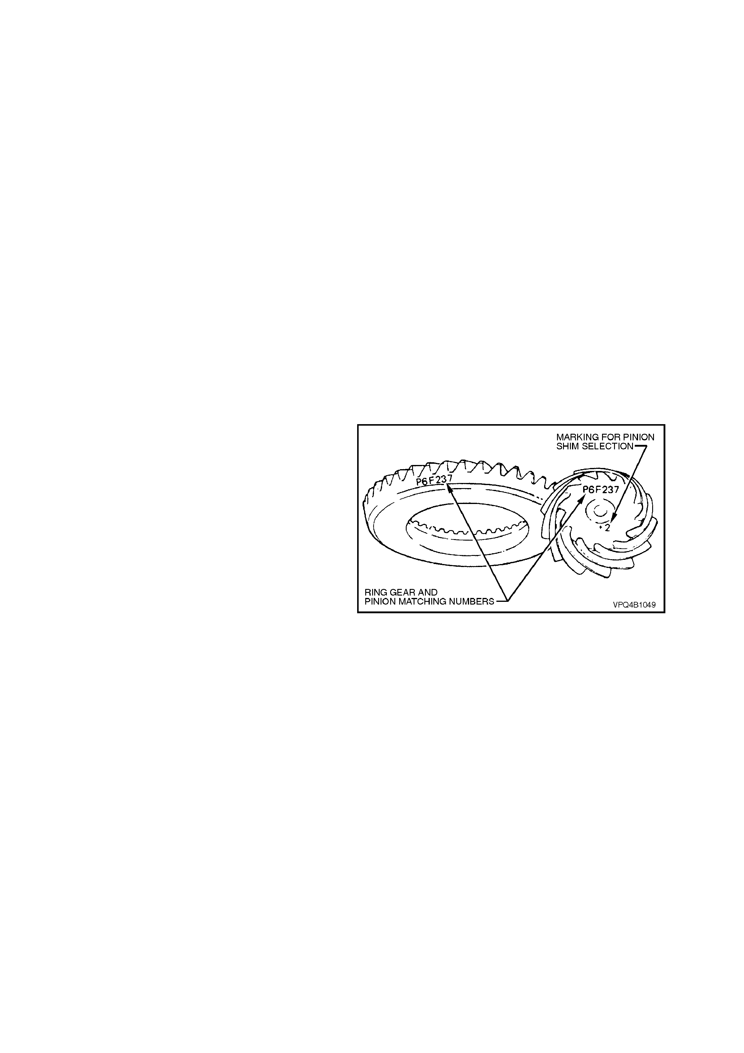
9. Inspect pinion gear cross shaft bores for
ovality.
Differential Side Gears and Pinion Gear s
1. Examine all gear teeth for cracks or hard
contact marks.
2. The differential side gear splines should be
checked for excessive wear. W ear on splines
can contribute to excessive driveline backlash.
3. The differential pinion bores and thrust
surfaces should be smooth and free from
scores. Inspect all thrust washers for cracks,
nicks or burrs. Wear of thrust washers or
thrust surfaces on gears can contribute to
excessive driveline backlash.
4. Check that pinion gear cross shaft is not bent
and that surfaces on which pinions run, are
not scored or worn.
Ring Gear and Pinion
1. Inspect gear teeth for scoring or damage.
Scoring of the gear teeth is usually caused by
excessive shock loading, use of the incorrect
lubricant or ins uf ficient "run in" bef or e towing a
heavy load. (Refer VT Series Owner's
Handbook). Scored gears must be replaced.
2. If on reassembly, a new gear set is to be
installed, ensure that the same matching
number appears on both the pinion and ring
gear.
Figure 4B-170
3. On ring gear bolts, clean Durlok serrations
under bolt flange.
Bearings
1. Bearing cups should have an even wear
pattern and be free from flaking or pitting.
Ensure the seating surfaces are clean and
free from burrs or raised metal.
2. The bearing assemblies should feel smooth
when turned in the cups.
3. The assembly should be free from loose
particles.
4. There should be no cracks present in the
roller cages and the bores should show no
evidence of flaking or pitting.
Refer to 4.4 FINAL DRIVE BEARING
DIAGNOSIS in this Section, for identification
of bearing failures.
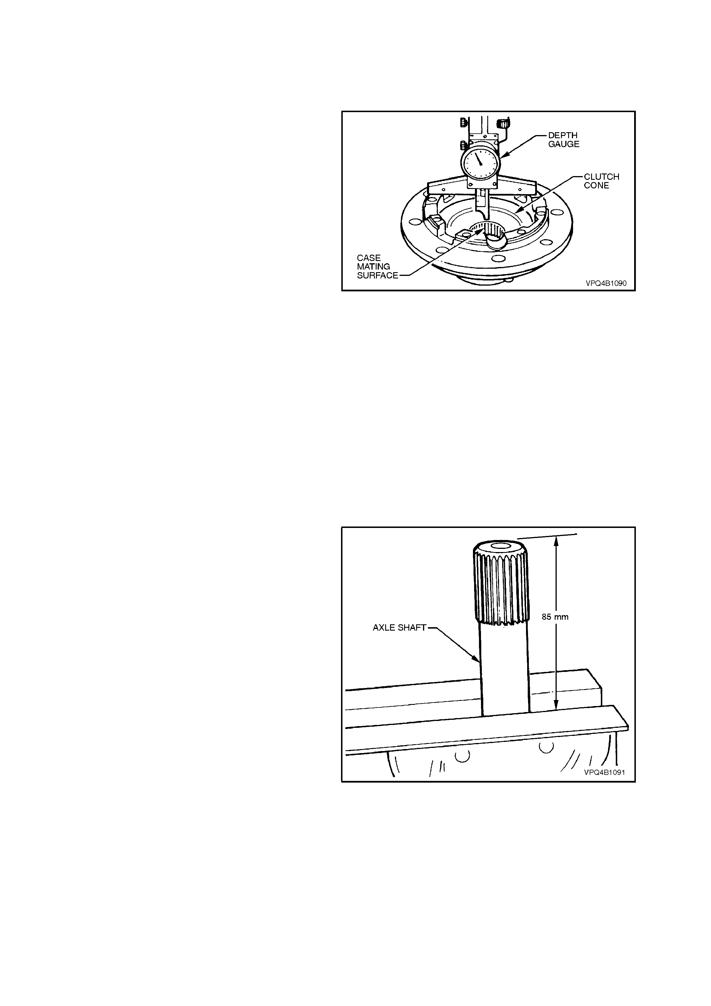
REASSEMBLE
1. Lubricate all gears, bearings, thrust washers
and pinion gear cross shaft with rear axle
lubricant before assembly.
2. With V6 engined models, install respective
clutch cones and shims (if fitted) into
differential case halves.
To check if shims are required:
a. Measure the distance from the case
mating surface to the flat surface of the
tightly seated clutch cone. Record this
dimension.
b. This measurement will indicate what size
side gear positioning shim is required.
Each case half and clutch cone must be
measured for its own respective shim.
c. With the measurement from "a", above,
select the correct shim size as indicated
by the following chart.
DISTANCE MEASURED SHIM SIZE REQUIRED
32.0 - 31.84 mm No shim required
32.14 - 32.04 mm 0.13 mm shim required
32.27 - 32.17 mm 0.25 mm shim required
Figure 4B-171
3. Remove clutch cones and shims from
differential case halves.
NOTE:
With V8 and V6 supercharged models, shimming is
not required, as the side gear and cone are an
integrated, single assembly.
4. If available, use an axle shaft from a VS
Series vehicle, 5 link rear axle assembly and
clamp it in a vice using soft jaws, allowing
approximately 85 mm to extend above vice
jaws.
Figure 4B-172
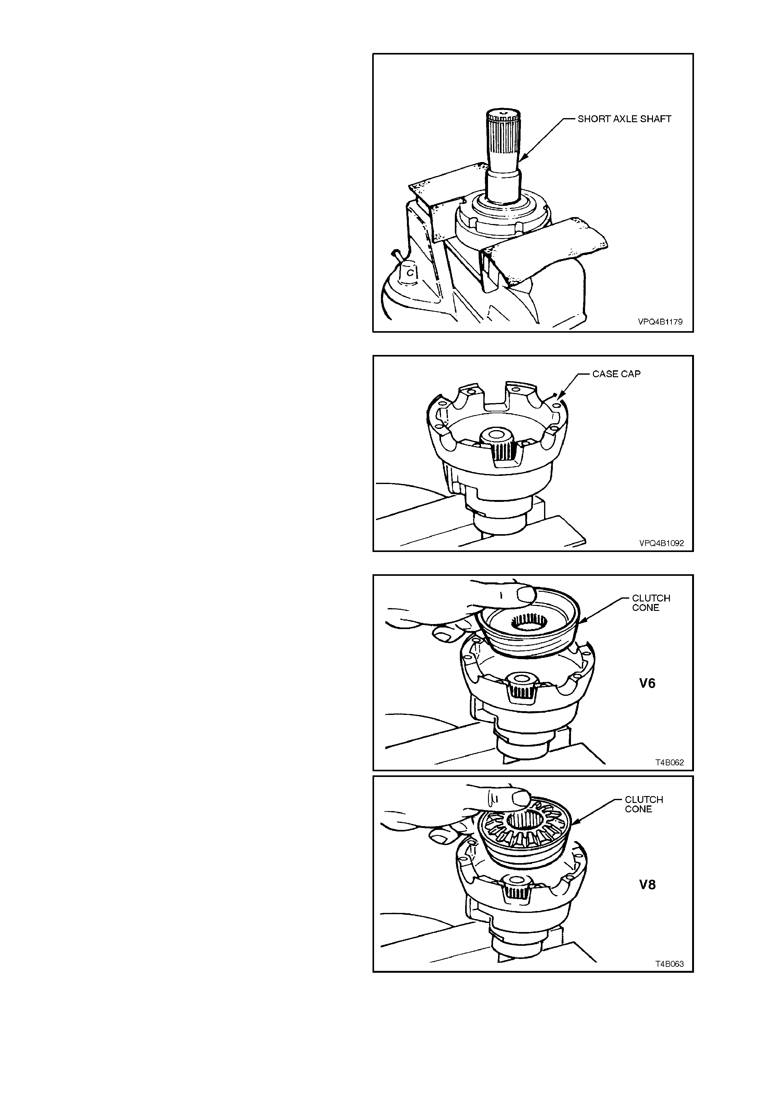
If an axle shaft from a VS Series vehic le, 5 link
rear axle assembly is not available, clamp the
left hand inner axle shaft in a vice equipped
with soft jaws.
NOTE:
The axle shaft (or inner axle shaft) is used as a
mounting tool with V6 differentials, to ensure
correc t side gear and clutch cone s pline alignment.
Failure to follow this procedure will prevent
installation of the inner axle shafts at final
assembly.
Figure 4B-173
5. Place differential case cap over axle shaft
mounted in vice with interior of the housing
facing upwards.
6. Paint a mixture of Molybdenum Disulphide
grease and the recommended differential
carrier lubricant onto faces of side gears and
clutch cone surfaces.
Figure 4B-174
7. For V6 differentials, install clutch cone over
axle splines, seating it in position in housing
followed by a shim (if required, refer Step 2)
and side gear.
With V8 and V6 supercharged differentials,
install the clutch cone/side gear assembly to
the housing.
Figure 4B-175
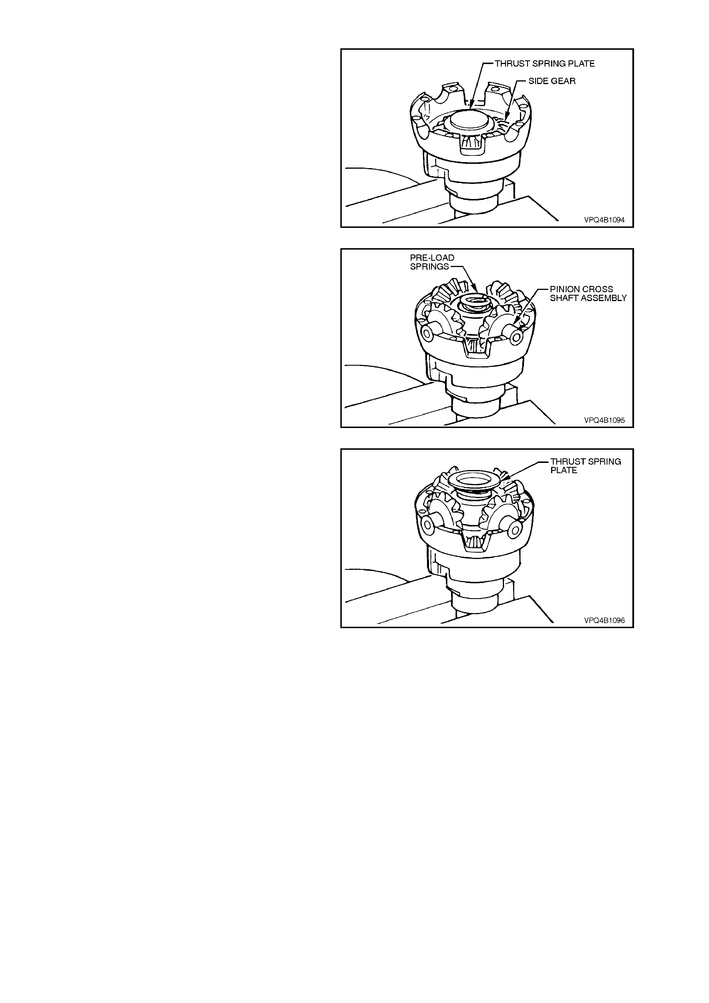
8. Place a thrust spr ing plate, stepped side up on
side gear.
9. Assemble the four pinions and thrust washers
onto pinion cross shaft.
10. Install pinions and cross shaft assembly to
case cap, ensuring that pinions m es h with side
gear.
Figure 4B-176
11. Install three new concentric differential pre-
load springs into centre of the pinion cross
shaft.
NOTE:
NEW pre-load springs must always be installed on
reassembly, DO NOT RE-USE OLD SPRINGS.
Figure 4B-177
12. Assemble second thrust spring plate, stepped
side onto pre-load springs.
Figure 4B-178
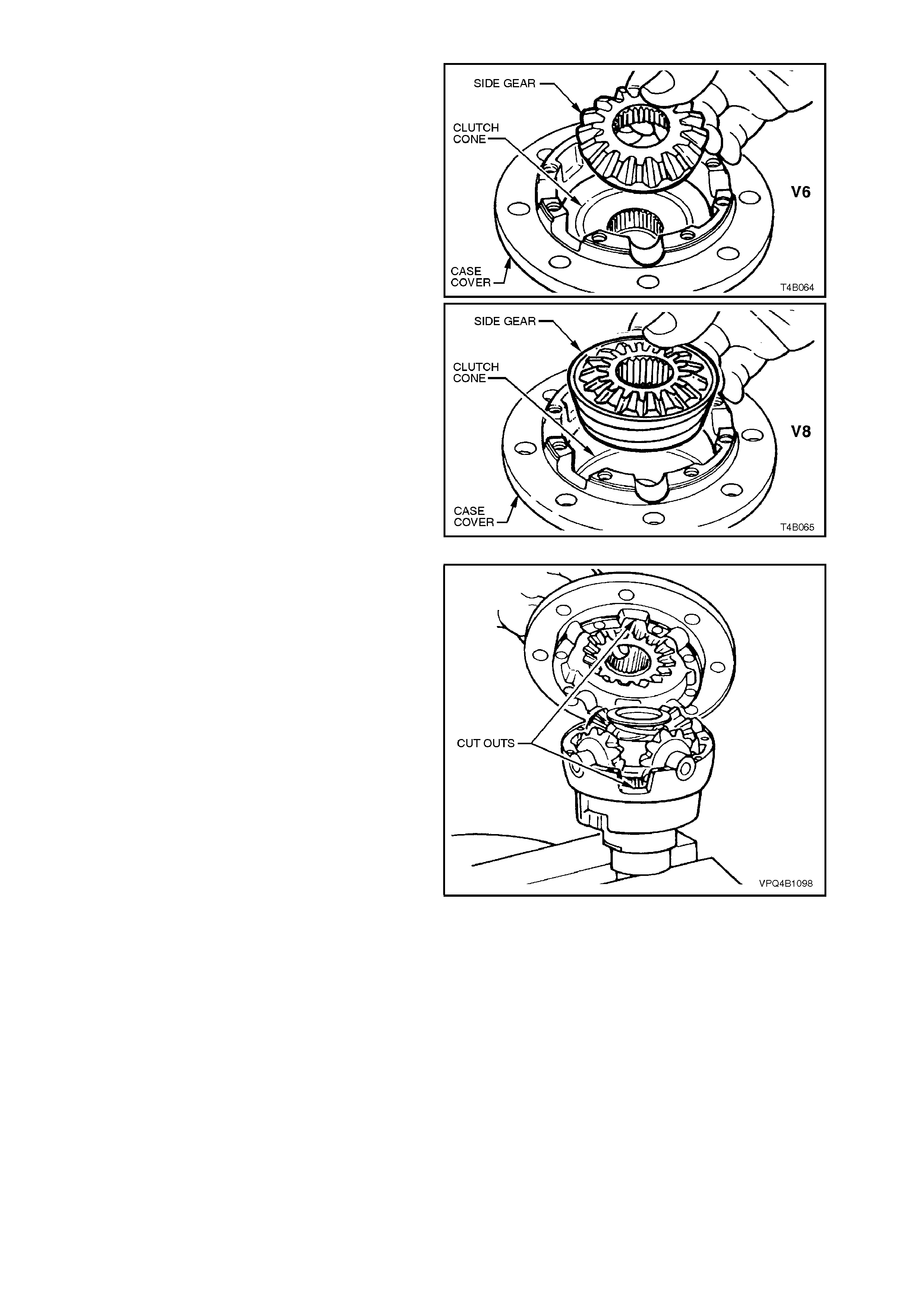
13. For V6 diff er entials , inst all clutc h c one, s him (if
required) and side gear to case cover.
With V8 and V6 supercharged differentials,
install the clutch cone/side gear assembly to
the housing.
Figure 4B-179
14. Install case cover onto case cap.
NOTE:
Ensure that the cut out on each side of the case
cover and cap align.
Figure 4B-180
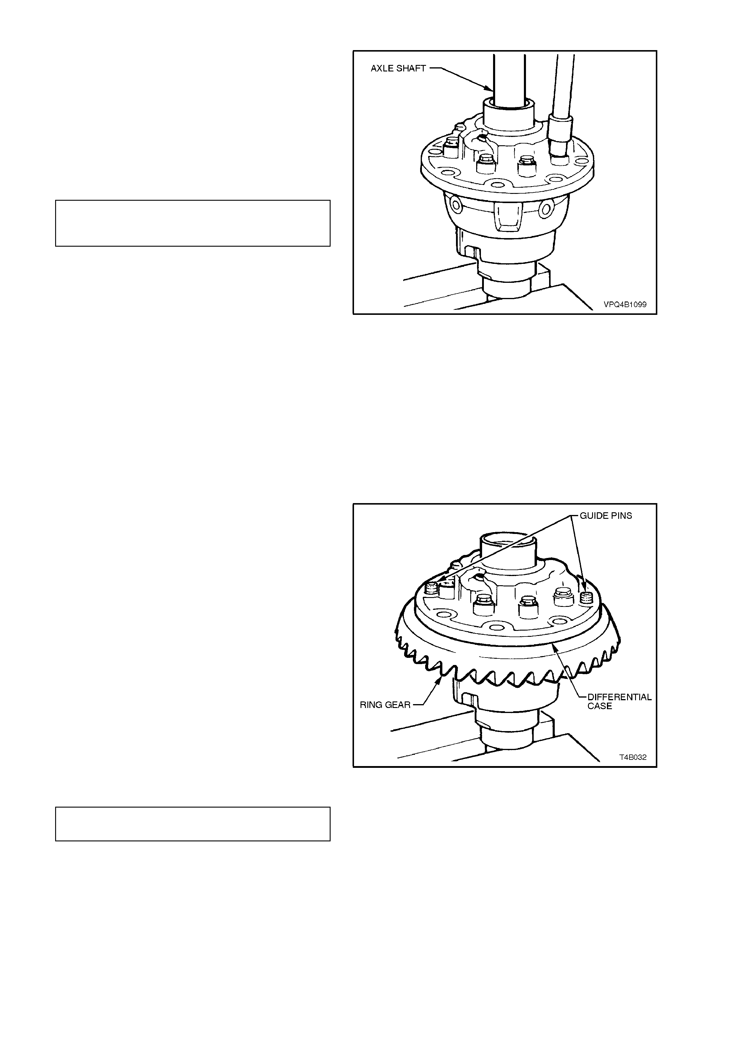
15. Install two NEW differential case cap-to-cover
attaching bolts in opposite bolt holes and
finger tighten.
16. Install other axle shaft through case cover,
rotating axle shaft to engage clutch cone
splines and then side gear splines. Leave axle
shaft in this position. Install remaining, NEW,
cap-to-cover attaching bolts and tighten evenly
to the correct torque specification.
DIFFERENTIAL CASE CAP
TO COVER ATTACHING BOLT 35 - 45 Nm
TORQUE SPECIFICATION
17. With V6 engined models, remove axle shafts
from differential case assembly.
NOTE 1:
If the shafts bind on the clutch cone and side gear
splines, a light tap with a soft metal hammer may
be necessary to remove the axle shafts.
NOTE 2:
At no time mus t the side gear s and c lutc h cones be
rotated until the inner axle shafts are fully installed.
Failure to observe this condition will result in side
gear and clutch cone spline misalignment, thus
preventing inner axle shaft installation.
Should splines become misaligned, loosen case
cap to cover bolts and repeat steps 4, 5, 15 and 16
of REASSEMBLE procedure.
Figure 4B-181
18. Place ring gear into position on differential
case cap and install ring gear attaching bolts.
NOTE:
For ease of assem bly, it m ay be necessary to heat
the ring gear on a hot plate until it is hot to the
hand, prior to installing onto the differential case
cap.
NOTE
On no account must a flame be used to heat the
ring gear.
NOTE:
Use left hand threaded guide pins to pilot ring gear
over differential case spigot.
19. Install NEW ring gear attaching bolts evenly
until gear face is flush with differential case
spigot.
Tighten bolts to the correct torque
specification.
DIFFERENTIAL RING GEAR 125 - 150
BOLTS TORQUE SPECIFICATION Nm
NOTE:
Ring gear attaching bolts use a left hand thread
and are identified by an 'L' on the bolt head.
Figure 4B-182
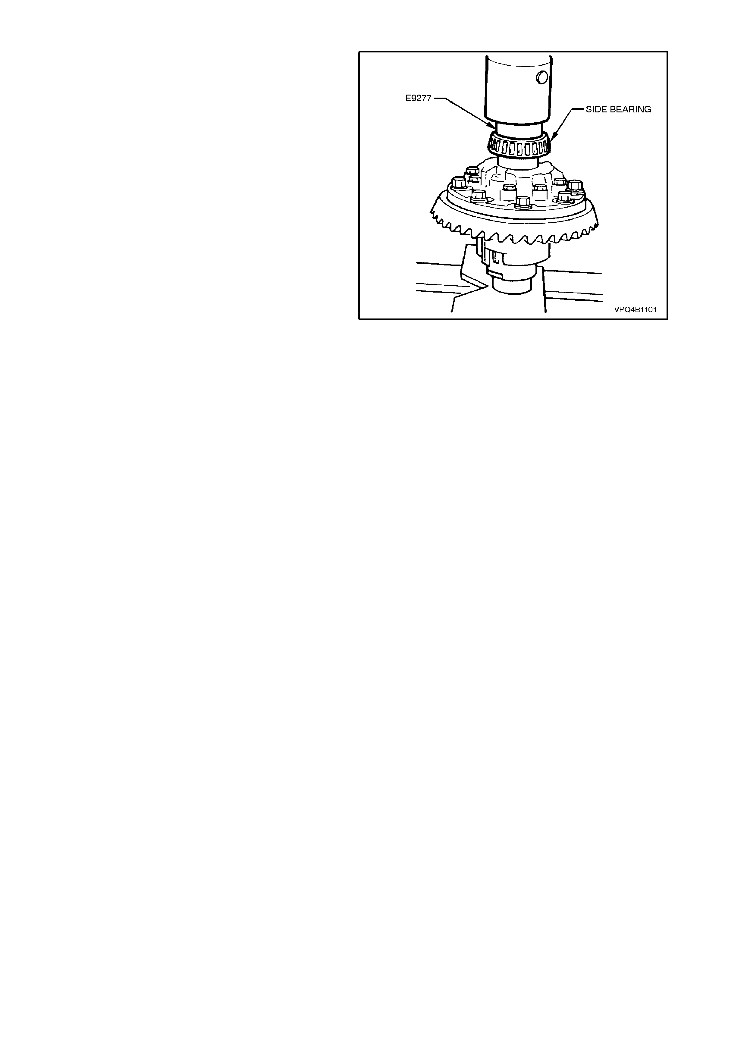
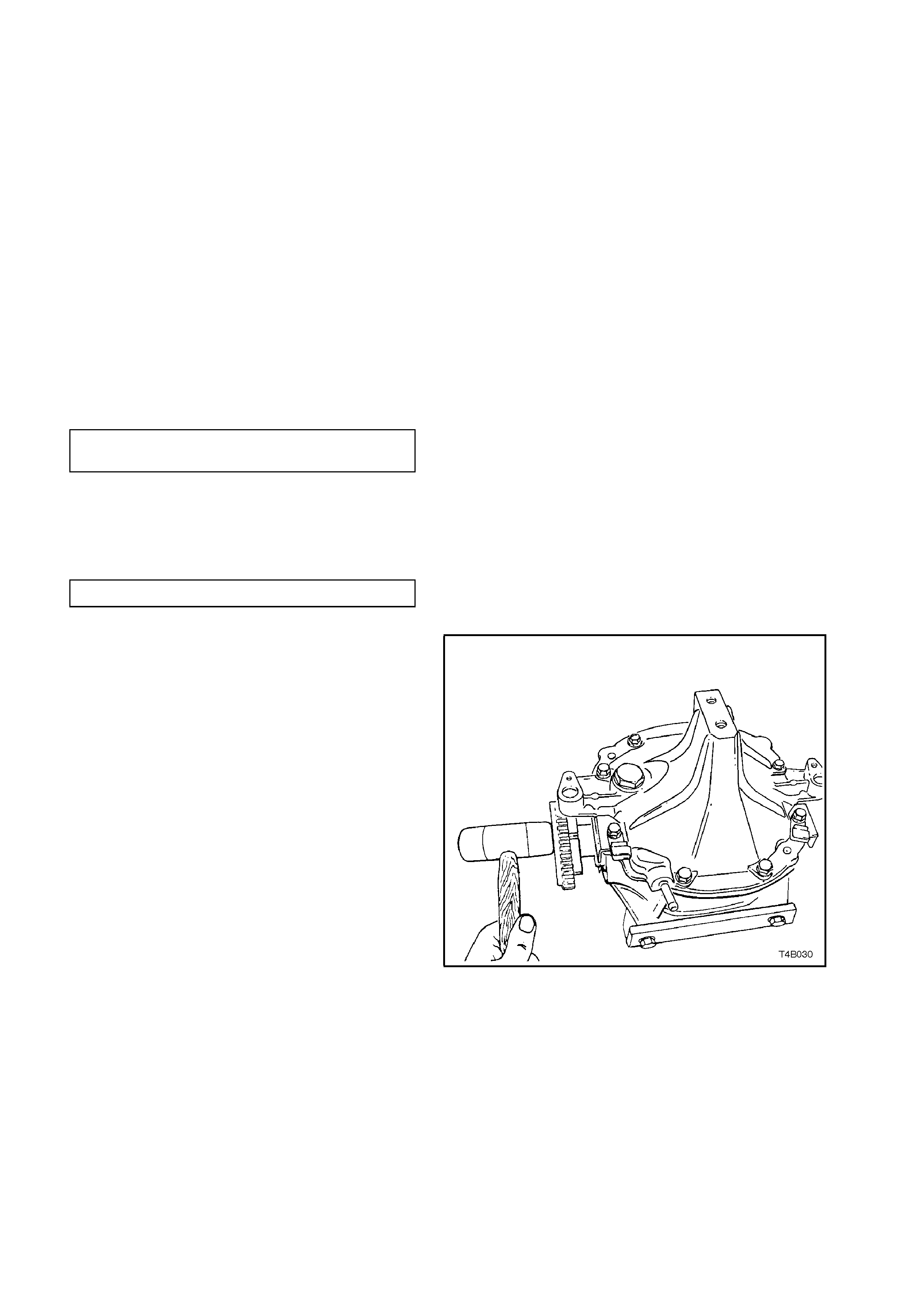
3.5 REAR AXLE
Reassemble
1. Apply a 1.5 - 2.0 mm diameter continuous
bead of sealant, such as Loctite 587 (‘Ultra
Blue’) or equivalent (Holden's Specification
HN1973) to inside edge of r ear cover and bolt
holes and completely around drain plug hole.
2. Install rear c over to dif f er ential c ar rier housing.
Fit screw adjuster lock plates to rear cover,
ensuring that lock plates fit over ribs or
between ribs on screw adjusters.
If equipped with ABS, install both sensors,
ensuring that sensor wiring is securely held in
the harness clip and that no chafing of the
wire is possible. Install and tighten rear cover
attaching bolts to the correct torque
specification.
REAR COVER ATTACHING 23 - 31
BOLT TORQUE SPECIFICATION Nm
3. If equipped with ABS, check that sensor to
toothed inner axle shafts air gap is to
specification.
ABS SENSOR AIR GAP 0.4 - 1.5 mm
4. Install inner axle shafts, aligning splines with
clutch cones (if a V6 and equipped with an
LSD) and side gears.
NOTE 1:
To avoid premature seal failure, ensure axle shaft
splines or s ecuring c lip do not scor e or dam age the
seal lips during installation.
NOTE 2:
With V6, LSD type differential assemblies, ensure
that both inner axle shafts are installed fully before
rotating either shaft. If rotation of one shaft occurs
before both are fully installed, misalignment of
opposite side gear and clutch cone will occur, thus
preventing assembly of remaining shaft.
NOTE 3:
For vehicles equipped with ABS, the inner axle
shafts are unique for this application.
5. Lightly hit on end of each shaft flange with a
soft faced hammer to compress spring clip on
shaft into clutch cup and side gear splines.
Fully engage both shafts until clips snap into
side gear grooves.
6. Reinstall dif ferential carr ier assem bly. Ref er to
3.2 FINAL DRIVE ASSEMBLY in this Section.
Figure 4B-184

4. DIAGNOSIS
4.1 GENERAL INFORMATION
Very often, final drive assemblies are considered as noisy, when in reality, the noise is emanating from some other
source, such as tyres, front wheel bearings, rear wheel bearings, manual transmission rear bearings, engine noises,
muffler roar, automatic transmission or power steering pumps.
All final drive assemblies have some slight humming noise. This will vary with the type of body construction, load
and tyre pressure.
Noise which emanates from any one of these can quite easily be confused with a final drive assembly noise and
unless a series of elimination tests are carried out to definitely confirm the real source of the noise, differential
assemblies may be, and often are, dismantled unnecessarily.
Although not infallible, the following diagnosis guide will assist in locating and defining the different characteristics of
the components which could be responsible for a noise.
Road Test
Ensure that the final drive assembly lubricant is correct and at the correct level. Drive at low speed until thoroughly
familiar with vehicle noises by which time the final drive assembly should have warmed up. Accelerate gradually
from the lowest practical speed in a direct ratio gear (1:1) to 100 km/h, noting any noises and the speeds at which
they occur. Release the accelerator and without using the brakes, allow the vehicle to lose speed. Next, allow the
vehicle to coast to rest from 100 km/h with the transmission in neutral position. Any noises common to earlier tests
may be eliminated as final drive assembly gear noise, as the final drive assembly is not under load under these
conditions. Engine noise is gauged by gradually accelerating the engine with the vehicle at rest.
NOTE:
Only drive at high speeds when it is legal and safe to do so.
Tyre Noise
Tyre noise can easily be mistaken for final drive assembly noise even though the noisy tyres may be operating on
the front wheels. Tyre noise changes with different road conditions, but final drive assembly noise does not. Final
drive assembly noise usually ceases when coasting with the transmission in neutral at speeds under 50 km/h. Tyre
noise continues, but with a lower tone as vehicle speed is reduced.
Tyre noise naturally should be first eliminated; driving on a grass surface is ideal to check against this condition. It
should be noted though, that dry grass can impose a fire hazard with the heat emanating from the catalytic
converter and wet grass can cause excessive wheel spin. Inflating tyres temporarily to high pressures will change
the contact with the road and assist in reducing tyre noise. Pressures up to 276 kPa may be used temporarily.
Tyres which have the surface of the non-skid divisions worn with one end higher than the other (saw-tooth wear) are
usually noisy. Interchanging tyres can prove effective in reducing noise.
Front Wheel Bearings
Worn, brinelled, chipped or incorrectly adjusted front wheel bearings will cause a noise, very similar to tyre noise. It
is a constant noise, does not vary on 'drive' or 'coast' and still persists when coasting with the transmission in
neutral. This noise does not noticeably change on differing road surfaces to the same degree as does tyre noise.
Although not so pronounced, front wheel bearing noise can also be compared to a road surface noise, which is
produced when the vehicle is travelling over a surface such as penetrated bitumen type road.
Techline
Techline

Transmission Rear Bearing (Manual Transmission)
A rough or pitted rear transmission bearing, usually produces a very definite bearing noise and sets up a distinct
'whirring' condition, which is most audible when accelerating from slow speed under a high throttle opening and
tends to diminish as vehicle speed increases.
This noise is also prominent under a constant throttle opening, but disappears on over-run when coasting with the
transmission in neutral.
When driven in second gear, noise can be amplified by lightly accelerating.
Backlash Clunk
Excessive clunk with acceleration and deceleration may be caused by worn differential pinion shafts, excessive
clearance between inner axle shaft and side gear splines, drive shaft companion flange and wheel spindle flange
splines, excessive clearance between side gear hub and counterbore in case, worn pinion and side gear teeth, worn
thrust washers and excessive drive pinion and ring gear backlash. Remove worn parts and replace as required,
selecting close fitting parts when possible. Adjust pinion and ring gear backlash.
Drive-Line Snap
A snap on sudden start, either forward or reverse, may be caused by a loose pinion flange. If loose, replace nut or
flange as outlined under 2.10 PINION FLANGE in this Section.
This condition may also be caused by incorrect lubricant in an LSD Drain and refill with correct lubricant.
Engine and Other Contributing Factors
Noises which emanate from the engine, transmission or muffler are occasionally confused with final drive assembly
noises.
To isolate these noises, first carefully note the approximate vehicle speed and conditions where the supposed final
drive assembly noise is most pronounced, then with the vehicle stationary and in a quiet place to avoid interfering
noises (depress the clutch pedal on vehicles with manual transmission), run the engine up and down slowly through
the engine speeds that correspond to the vehicle speeds at which the noise was prominent and observe whether
there is any similarity to a final drive assembly noise.
For vehicles with manual transmission: With transmission still in neutral, again run the engine at similar speed while
slowly letting the clutch engage, and listen for noises from the transmission.
Muffler noises are usually readily identified, possibly an exception being when a muffler emits a high-pitched
periodic whistling noise, which could be confused with a bearing noise.

4.2 FINAL DRIVE ASSEMBLY NOISE
Final drive assembly noises fall into two categories:
a. Gear related noises.
b. Bearing related noises.
Before testing for final drive assembly noise, ensure that the lubricant is the correct type and at the correct level.
GEAR RELATED NOISE
Ring Gear and Pinion Noise
Noise produced by the ring gear and pinion set is of a cyclic nature and generally shows up as a 'drive noise', 'coast
noise', or 'float noise'.
1. Drive noise is most pronounced on constant acceleration through the speed range of 50 to 90 km/h.
2. Coast noise is most pronounced when the vehicle is allowed to coast through the speed range from 90 to 50
km/h.
3. Float noise is most pronounced while the vehicle is kept at constant speed for periods between 50 to 90 km/h.
Final drive assembly noise will always change when comparing 'drive' and 'coast' and will usually cease when
coasting with transmission in neutral at speeds under 50 km/h.
Differential Side Gear and Pinion Noise
Noise produced by these gears occurs when there is excessive wear between the side gear hubs and the
differential case bores. This can cause a 'clunking' noise when the vehicle is driven at low speeds.
Noise produced due to excessive wear between the gear teeth will be most pronounced on turns.
Common Causes of Gear Related Noises
1. Low lubricant level or incorrect lubricant used.
2. Incorrect meshing of gear teeth (i.e. incorrect pinion positioning shim or backlash setting shims).
3. Scored gear teeth:- usually the result of incorrect lubricant type or level.
4. End play in bearings.
5. Bruised or chipped teeth.
6. Excessive runout of pinion head or ring gear backlash.
7. Ring gear creeping on differential case resulting from ring gear bolts loosening - noise from this source usually
appears as a sharp metallic sound when shifting from reverse to first gear.

BEARING RELATED NOISE
Differential Pinion Gear Bear ings
Worn, rough or loose bearings will tend to aggravate and magnify drive, float and coast noise, and result in heavy,
irregular drive noise on constant acceleration and float, and also an irregular noise on deceleration.
Pinion bearings, if rough or brinelled, will produce a continuous whine, which will persist when coasting with
transmission in neutral even to a low speed.
End play in the pinion bearings, even from natural wear, which permits the pinion to feed back into the ring gear, will
cause a noise on over-run.
Drive Shaft Bearings
Drive shaft bearings that are rough or pitted can be responsible for a growling noise which on first impression could
be likened to a final drive noise.
The noise, however, does not vary on 'drive' or 'coast' and still persists when coasting with transmission in neutral.
Frequently this noise can be readily identified by the sound being conveyed in an eccentric form. It can also be
intermittent as the noise may fade for a short period.
To confirm the diagnosis of a drive shaft bearing noise:
1. Support the rear of the vehicle on safety stands and remove both rear wheels and brake discs.
2. Start the engine and, with top gear engaged, speed engine up to a fast idle.
3. If a stethoscope is available, it is ideal to compare the noise of one bearing against the other. To obtain the
best results with a stethoscope, keep the volume adjustment down low.
4. A difference in the noise of the drive shaft bearings can also be discerned by placing a steel-shafted
screwdriver to the ear and in close proximity to each bearing in turn.
With practice, a noticeable difference in noise can, at most times, be observed between a good and not so good
bearing.
Differential Si de Bearings
Side bearings will produce a constant grinding noise of a slower nature than pinion bearings (side bearing noise
cannot be determined by the diagnosis procedure for drive shaft bearing noise), but will be in the same frequency
as drive shaft bearings.
Common Causes of Bearing Related Noises
1. Low lubricant level or incorrect lubricant used.
2. Foreign matter in the lubricant.
3. Incorrect pre-load setting.
4. Bearings incorrectly mounted e.g. dirt trapped behind abutment faces during assembly.

4.3 LSD NOISE
If LSD stick-slip chatter is diagnosed, the differential carrier lubricant should be drained immediately after a run to
warm up the lubricant. This is to remove as much old lubricant and wear debris as possible. Refill carrier with the
specified lubricant and re-evaluate LSD operation for a minimum of 20 km. Chatter will usually disappear within this
time.
Should chatter still occur, remove carrier and overhaul LSD. Refer to 3.4 LIMITED SLIP DIFFERENTIAL in this
Section.
Techline
Techline
Techline
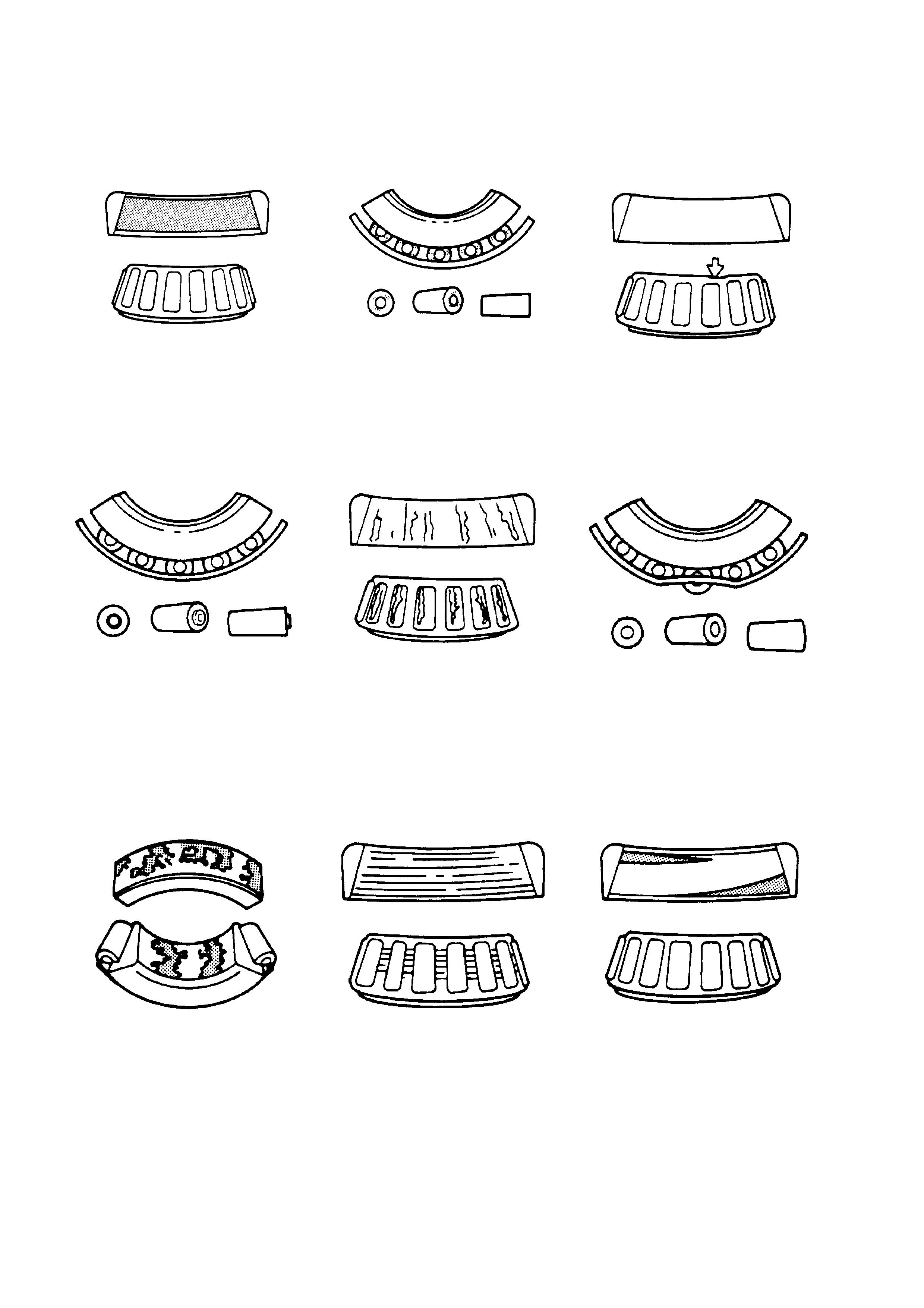
4.4 FINAL DRIVE BEARING DIAGNOSIS
CONSIDER THE FOLLOWING FACTORS WHEN DIAGNOSING BEARING CONDITION:
1. GENERAL CONDITION OF ALL PARTS DURING DISASSEMBLY AND INSPECTION.
2. CLASSIFY THE FAILURE WITH THE AID OF THE FOLLOWING ILLUSTRATIONS.
3. DETERMINE THE CAUSE.
4. MAKE ALL REPAIRS FOLLOWING RECOMMENDED PROCEDURES.
ABRASIVE ROLLER WEAR
PATT E RN ON RACES A ND ROLLE RS
CAUSED BY FINE ABRASIVES.
CLEAN ALL PARTS AND HOUSINGS.
CHECK SEALS AND BEARINGS,
REPLACING IF LEAKING, ROUGH OR
NOISY.
GALLING
METAL SMEARS ON ROLLER ENDS
DUE TO OVERHEATING, LUBRICANT
FAILURE OR OVERLOAD.
REPLACE BEARING. CHECK SEALS
AND CHECK F OR PROPER
LUBRICATION.
BENT CAGE
CAGE DAMAGE DUE TO IMPROPER
HANDLING OR TOOL USE .
REPLACE BEARING.
ABRASIVE STEP WEAR
PATT E RN ON ROLLER ENDS CAUSED
BY FINE ABRASIVES.
CLEAN ALL PARTS AND HOUSING.
CHECK SEALS AND BEARINGS AND
REPLACE IF LEAKING, ROUGH OR
NOISY.
ETCHING
BEARING SURFACES APPEAR GREY
OR GREYISH BLACK IN COLOUR WITH
RELATE D E T CHING AWAY OF
MATERIA L , USUALLY AT ROLLER
SPACING.
REPLACE BEARINGS. CHECK SEALS
AND CHECK F OR PROPER
LUBRICATION.
BENT CAGE
CAGE DAMAGE DUE TO IMPROPER
HANDLING OR TOOL USE .
REPLACE BEARING.
INDENTATIONS
SURFACE DEPRESSIONS ON RACE
AND ROLLERS CAUSED B Y HARD
PARTI CLES OF FORE IGN MATERI AL.
CLEAN ALL PARTS AND HOUSING.
CHECK SEALS AND REPLACE
BEARI NGS IF ROUGH AND NOIS Y.
CAGE WEAR
W E AR AROUND OUTSIDE DI AMETER
OF CAGE A ND ROLLE R POCKETS
CAUSED BY ABRASIVE MATERIALS
AND INEFFICIENT LUBRICATION.
REPLACE BEARINGS. CHECK SEALS
AND CHECK F OR PROPER
LUBRICATION.
MISALIGNMENT
OUTER RACE MI SALIGNME NT DUE TO
FOREIG N OB JECT.
CLEAN RELATED PARTS AND REPLACE
BEARING. MAKE SURE RACES ARE
PROPERLY SEATED.
Figure 4B-185
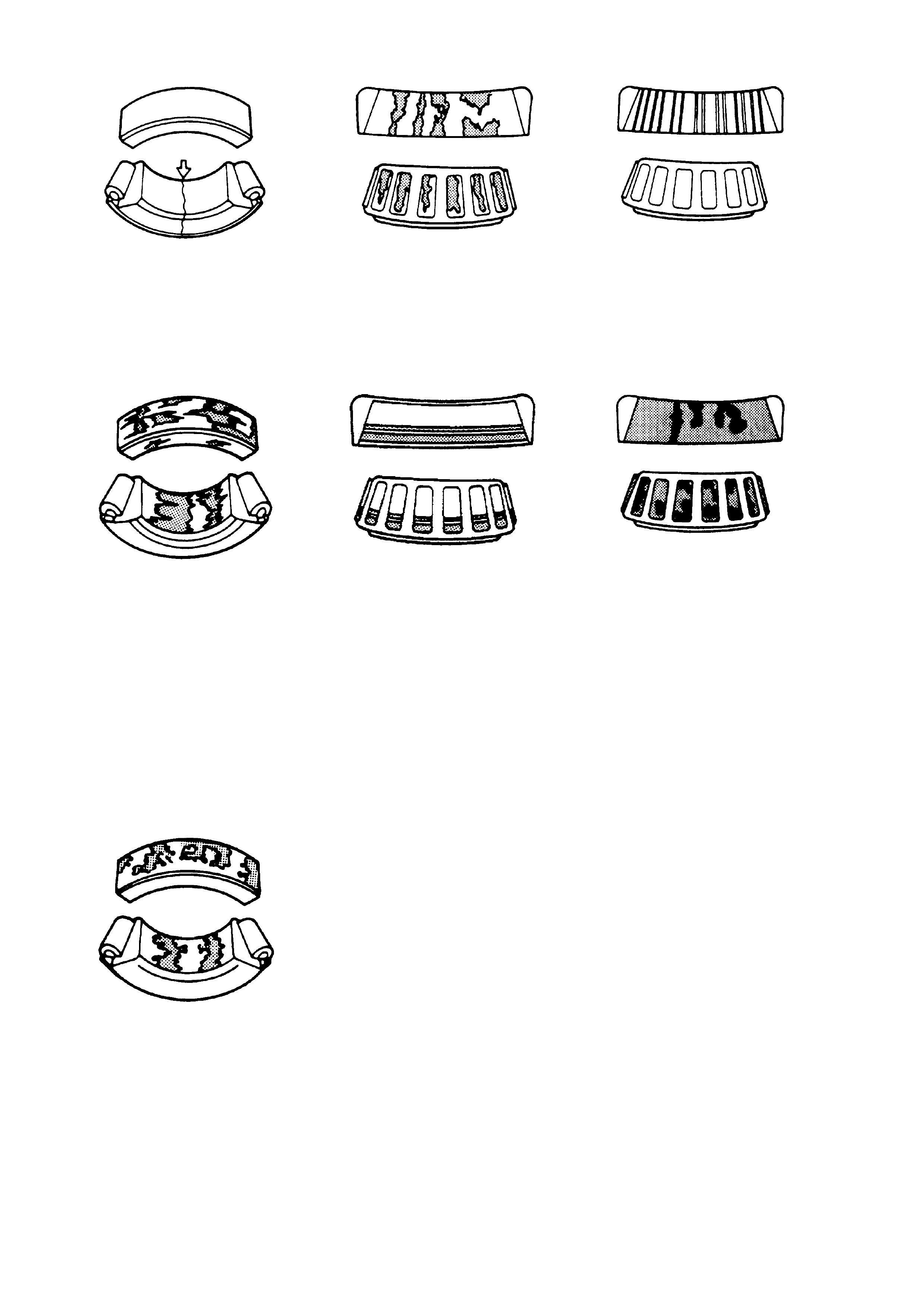
CRACKED INNER RACE
RACE CRACKED DUE TO IMPROPER
FIT, COCKI NG OR POOR B EARING
SEATS.
REPLACE BEARING AND CORRECT
BEARING SEATS.
FATIGUE SPALLING
FLAKING OF SURFACE METAL
RESULTING FROM FATIGUE.
REPLACE BEARING, CLEAN ALL
RELATE D PARTS.
BRINELLING
SURFACE INDENTATIONS IN RACEWAY
CAUSED BY ROLLERS E ITHER UNDER
IMPACT, LOADING OR VIBRATION
W HILE THE BEARING IS NOT
ROTATING.
REPLACE BEARING IF ROUGH OR
NOISY
FRETTAGE
CORROSION S E T UP BY RELATIVE
MOVEMENT OF PARTS WITH NO
LUBRICATION.
REPLACE BEARING. CLEAN RELATED
PARTS. CHECK SEALS AND CHECK
FOR PROPER LUBRICATION.
STAIN DISCOLOURATION
DISCOLOURAT ION CAN RANGE F ROM
LIGHT BROW N TO BLACK, CAUSED BY
INCORRECT LUBRICATION OR
MOISTURE.
RE-USE BEARING IF STAINS CAN BE
REMOVED BY LIGHT POLISHING OR IF
NO EVIDENCE OF OVERHEATING IS
OBSERVED.
CHECK SEALS AND RELATED PARTS
FOR DAMAGE.
HEAT DISCOLOURATION
HEAT DI SCOLOURATION CAN RANGE
FROM FAINT YELLOW TO DARK BLUE,
RESULTING FROM OVERLOAD OR
IMPROPER LUBRICANT.
EXCESSIVE HEAT CAN CAUSE
SOFTE NI NG OF RACES OR ROLLERS.
TO CHECK FOR LOSS OF TEMPER ON
RACES OR ROLLERS, A SIMPLE FILE
TEST MAY BE MADE. A FILE DRAWN
OVER A TEMPERED PART W ILL GRAB
AND CUT METAL, WHEREAS A FILE
DRAWN OVER A HARD PART WILL
GLIDE READILY WITH NO METAL
CUTTING ACTION.
REPLACE BEARING IF OVERHEATING
DAMAGE I S INDICATED. CHECK SEALS
AND OTHER P ARTS.
SMEARS
SMEARING OF METAL DUE TO
SLIPPAGE THAT CAN BE CAUSED BY
POOR FITS, LUBRICATION,
OVERHEATING, OVERLOADS OR
HANDLING DAMAGE.
REPLACE BEARINGS. CLEAN RELATED
PARTS AND CHECK FO R PROPER FI T
AND LUBRICATION.Figure 4B-186

5. SPECIFICATIONS
V6 Engine V8 & V6
Supercharged
Engine
GENERAL
Rear Axle Assembly BTRE - 76 Series BTRE - 80 Series
Axle Type Independent Housing
STANDARD AND LSD AXLES
Gear Type Hypoid
Gear Ratio 3.08:1. 3.07:1
See I.D. tag attached to the carrier
No. of Teeth:
Ring Gear 37 43
Drive Pinion Gear 12 14
LUBRICANT
Capacity 1.65 litres
Type:
With/Without LSD Mineral Hypoid Gear
Oil to Holden's
Specification
HN1561. Refer
2.1 CHECKING
DIFFERENTIAL
CARRIER
LUBRICANT LEVEL
for recommendations
Synthetic Hypoid Gear
Oil to Holden's
Specification HN2040.
Refer
2.1 CHECKING
DIFFERENTIAL
CARRIER
LUBRICANT LEVEL
for recommendations
NOTE:
Use Synthetic Hypoid Gear Oil to Holden’s
Specification HN2040 for V6 Wagon with
Manual Transmission, refer 2.1 CHECKING
DIFFERENTIAL CARRIER LUBRICANT
LEVEL
DIFFERENTIAL GEARS
Type Straight Bevel
No. Teeth: Pinion Gears 10 10
Side Gears 16 15
FINAL DRIVE PINION GEAR BEARINGS
Bearing Type Adjustable Taper Roller
Bearing Adjustment Collapsible Spacer
Bearing Pre-Load:
Dummy pinion - New bearings 1.4 - 2.0 Nm
Dummy pinion - Used bearings 0.7 - 1.0 Nm
New with oil seal 1.4 - 2.4 Nm
New without oil seal 1.4 - 2.0 Nm
Used with oil seal 0.7 - 1.2 Nm
Used without oil seal 0.7 - 1.2 Nm

DIFFERENTIAL CARRIER SIDE
BEARINGS
Type Adjustable Taper Roller
Adjustment Screw adjusters on each side of the carrier.
Bearing Pre-Load
New Bearings 15 - 35 N Torque measured at the differential
case, without inner axle shafts
Used Bearings 8 - 18 N or final drive pinion installed.
RUN-OUT SPECIFICATIONS
Trunnion Assembly Hub 0.060 mm Total Indicated Run-out
Case Assembly (without ring gear
attached) 0.05 mm (maximum)
Ring Gear Rear Face (assembled
onto case assembly) 0.13 mm (maximum)
BACKLASH SPECIFICATIONS
Ring Gear to Drive Pinion 0.10 - 0.18 mm (at the tightest point)
LSD TORQUE CHECK
Torque Check Specification 45 Nm (minimum)
ABS SENSOR
Air Gap (non-adjustable) 0.4 - 1.5 mm
SEALANTS
Drive Shaft Dust Caps/Shield RTV 732 Sealant, to Holden’s Specification
HN1373
Rear Cover to Carrier Housing Loctite 587 (‘Ultra Blue’) or equivalent, to
Holden’s Specification HN1973
As Required Loctite 242 or equivalent, to Holden’s
Specification HN1256, Class 2, Type 1
LUBRICANTS
As Specified in Text Molybond HE50 or equivalent, to Holden’s
Specification HN1326
As Specified in Text Lithium Soap Based Grease to Holden’s
Specification HN1147

6. TORQUE WRENCH SPECIFICATIONS
Nm
Rear cover attaching bolts 23 - 31
Filler plug 23 - 31
Drain plug 23 - 31
!
Final drive ring gear bolts 125 - 150
!
LSD case cap to cover attaching bolts 35 - 45
!
Collar nut to trunnion assembly 295 - 305
Drive shaft constant velocity joint to trunnion
flange/inner axle shaft flange bolts 50 Nm, then
60 ° - 75° turn angle
Road wheel attaching nut 110 - 140
Brake caliper anchor plate to trailing arm bolts 70 - 100
Rear disc brake shield to trailing arm. Upper bolts 70 - 80
Lower bolts 85 - 90
!Differential carrier to rear crossmember
attaching bolts 90 Nm, then
30° - 45° turn angle
!Rear mount to vehicle underbody attaching bolts 30 Nm, then
60° turn angle
!Rear mount to differential carrier rear cover
attaching bolts 85 - 105
Shock absorber lower mounting bolt 105 - 125
Crossmember front mounting brace to
underbody bolts 60 - 70
Crossmember front mounting bolt 125 Nm, then
30° - 45° turn angle
Intermediate exhaust pipe to catalytic converter
attaching bolts 40 - 50
!New bolts and/or nuts MUST be used on
reassembly.
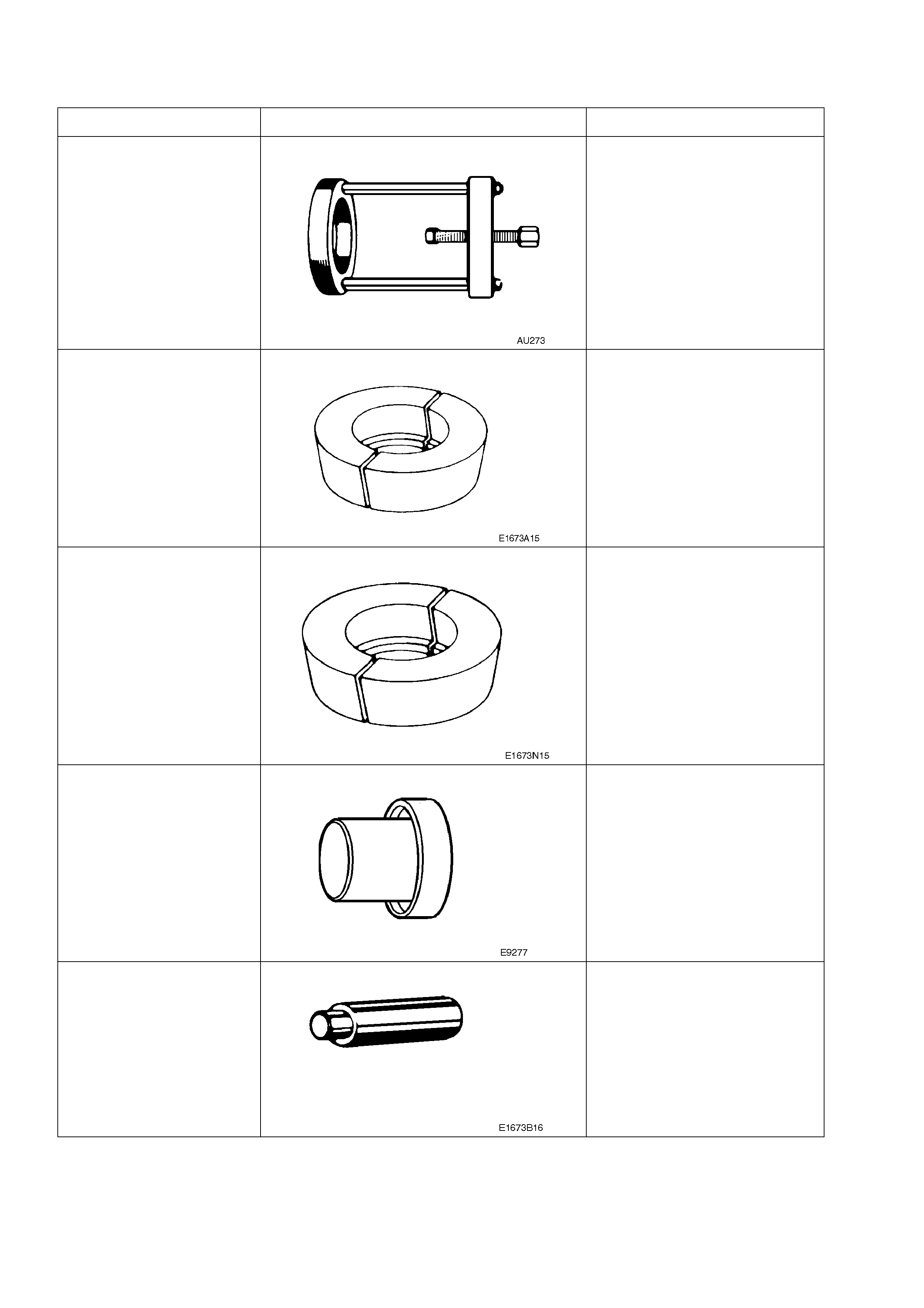
7. SPECIAL TOOLS
TOOL NO. REF IN TEXT TOOL DESCRIPTION COMMENTS
E1673MT BASIC PULLER PREVIOUSLY RELEASED
FOR "V" CAR.
E1673A15 ADAPTOR PREVIOUSLY RELEASED
FOR "V" CAR.
USED WITH E1673MT.
E1673N15 ADAPTOR PREVIOUSLY RELEASED
FOR "V" CAR.
USED WITH E1673MT.
E9277 SIDE BEARING INSTALLER PREVIOUSLY RELEASED
FOR "V" CAR.
E1673B16 STEPPED PLUG PREVIOUSLY RELEASED
FOR "V" CAR.
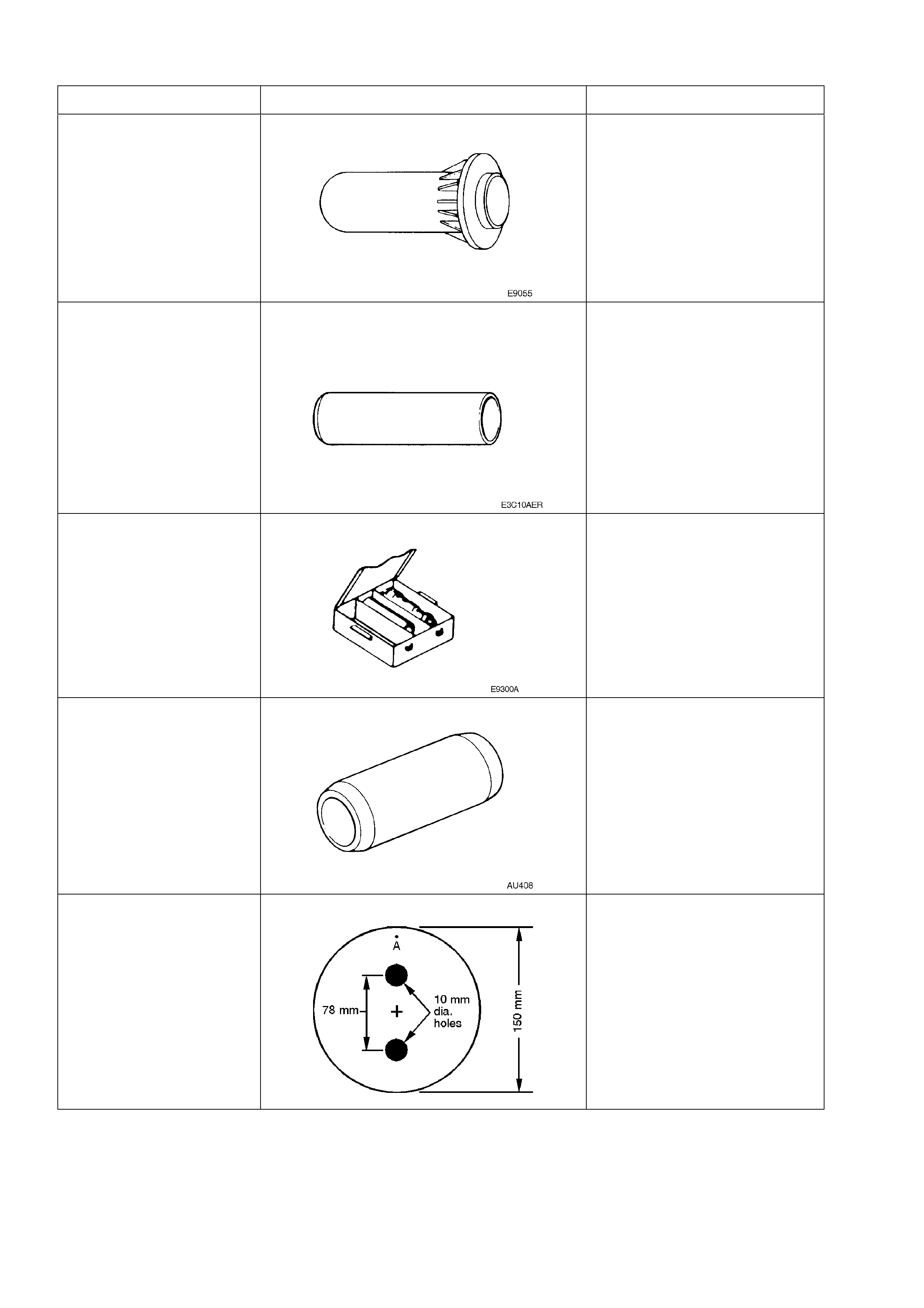
TOOL NO. REF IN TEXT TOOL DESCRIPTION COMMENTS
17-010A PINION OIL SEAL INSTALLER PREVIOUSLY RELEASED
FOR "V" CAR.
E3C10AER PINION REAR BEARING CONE
REPLACER PREVIOUSLY RELEASED
FOR "V" CAR.
E9300A PINION HEIGHT SETTING GAUGE SET PREVIOUSLY RELEASED AS
E9300, FOR "V" CAR.
THIS SET NOW HAS AN
ADDITIONAL SPACER FOR
THE DRIVE PINION USED ON
THE V8 AND V6
SUPERCHARGED FINAL
DRIVE ASSEMBLIES.
AU408 DUMMY ARBOR USED WITH DUMMY PINION
FROM E9300A
PINION FLANGE PULLEY DETAILS DEALER FABRICATED:
1. MADE FROM A 13 MM
THICK PIECE OF WOOD.
2. DRILL A SMALL HOLE AT
'A' AND ATTACH A ONE
METRE LENGTH OF
STRING AT THIS POINT.
3. DRILL TWO 10 MM
HOLES AS SHOWN IN
THE FIGURE.
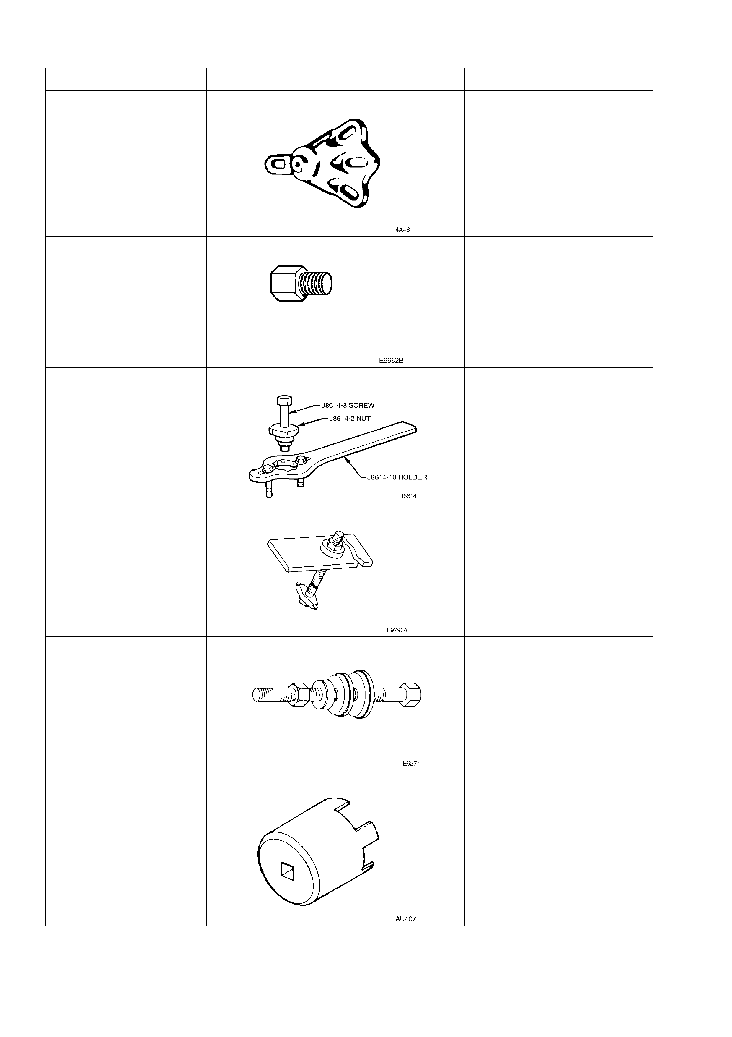
TOOL NO. REF IN TEXT TOOL DESCRIPTION COMMENTS
7208 REAR AXLE REMOVAL ADAPTOR PREVIOUSLY RELEASED
FOR "V" CAR.
USED WITH E6662B FOR LSD
TORQUE CHECK.
E6662B TORQUE WRENCH ADAPTOR PREVIOUSLY RELEASED
FOR "V" CAR.
USED WITH 7208
J8614-01 PINION FLANGE HOLDER AND REMOVER PREVIOUSLY RELEASED
FOR "V" CAR.
E9293 PINION BEARING CUP REMOVER PREVIOUSLY RELEASED
FOR "V" CAR.
E9271 PINION BEARING CUP INSTALLER PREVIOUSLY RELEASED
FOR "V" CAR.
AU407 SCREW ADJUSTER SOCKET USED FOR CHECKING AND
ADJUSTING SCREW
ADJUSTERS.
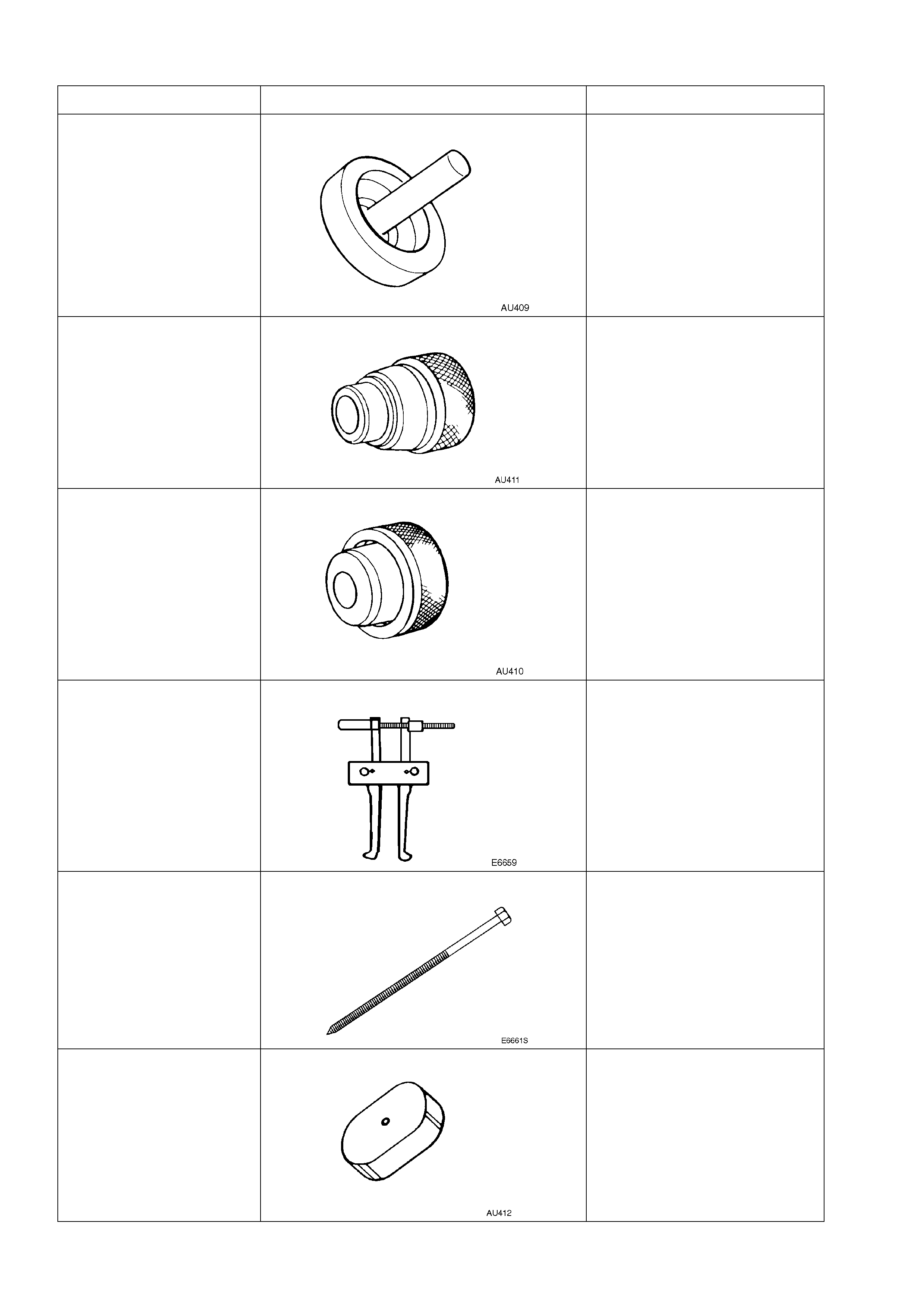
TOOL NO. REF IN TEXT TOOL DESCRIPTION COMMENTS
AU409 PRESS FIXTURE USED FOR INSTALLING
NEEDLE BEARINGS AND
SIDE BEARING CUP INTO
SCREW ADJUSTERS.
USED WITH AU411
AU411 BEARING AND CUP REMOVER AS ABOVE.
AU410 SEAL INSTALLER USED FOR INSTALLING SEAL
INTO SCREW ADJUSTERS.
1150 PULLER USED WITH FORCING
SCREW E6661S AND
ADAPTOR AU412 TO
REMOVE SIDE BEARING
CUPS FROM SCREW
ADJUSTERS.
E6661S FORCING SCREW PREVIOUSLY RELEASED.
AU412 ADAPTOR PREVIOUSLY RELEASED.
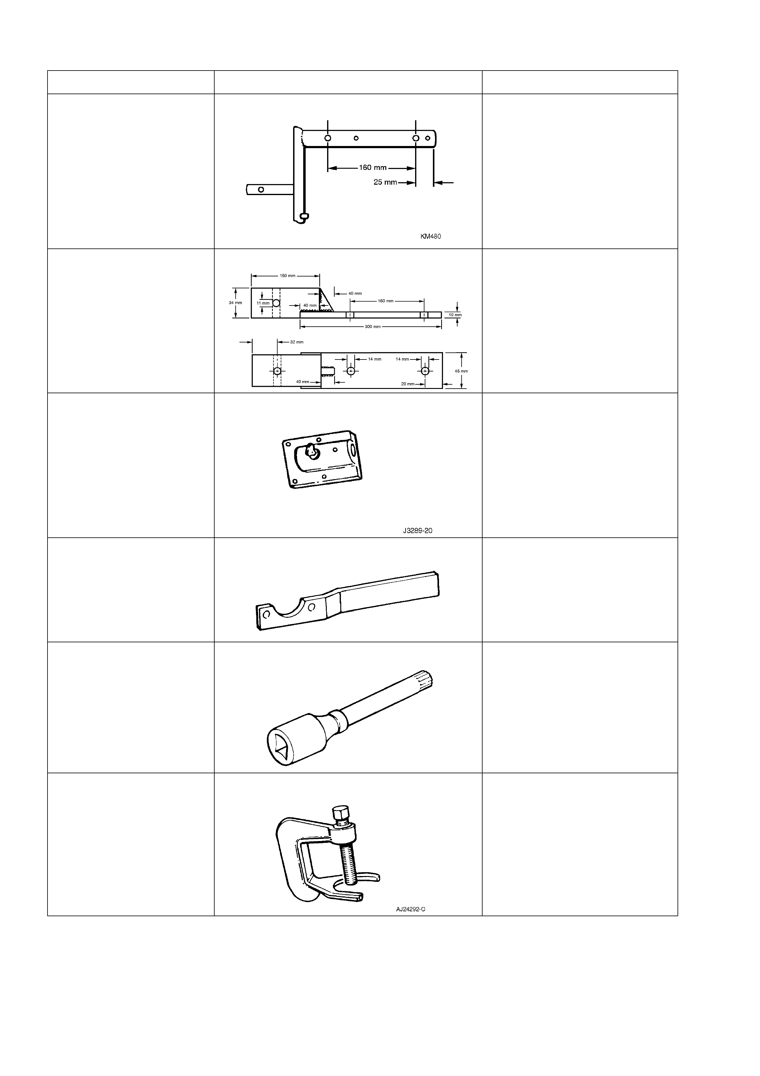
TOOL NO. REF IN TEXT TOOL DESCRIPTION COMMENTS
KM480 HOLDING FIXTURE PREVIOUSLY RELEASED
FOR THM 125 AUTOMATIC
TRANSAXLE.
MODIFY BY DRILLING TWO
14 MM HOLES AS SHOWN IN
THE ILLUSTRATION.
USED FOR HOLDING
DIFFERENTIAL CARRIER
ASSEMBLY.
N/A DIFFERENTIAL CARRIER HOLDING FIXTURE IF KM480 IS NOT AVAILABLE,
FABRICATE A HOLDING
FIXTURE AS SHOWN
J3289-20 HOLDING FIXTURE BASE PREVIOUSLY RELEASED
FOR "V" AND "J" CARS.
KM468 HOLDING BAR PREVIOUSLY RELEASED
FOR "J" CAR.
USED TO HOLD TRUNNION
ASSEMBLY FROM
ROTATING.
AU416 TORX BIT USED TO REMOVE AND
INSTALL REAR BRAKE
BACKING PLATE TO
TRAILING ARM ATTACHING
BOLTS.
AJ24292-C PRESS TOOL USED FOR REMOVING REAR
WHEEL STUDS FROM
TRUNNION ASSEMBLY
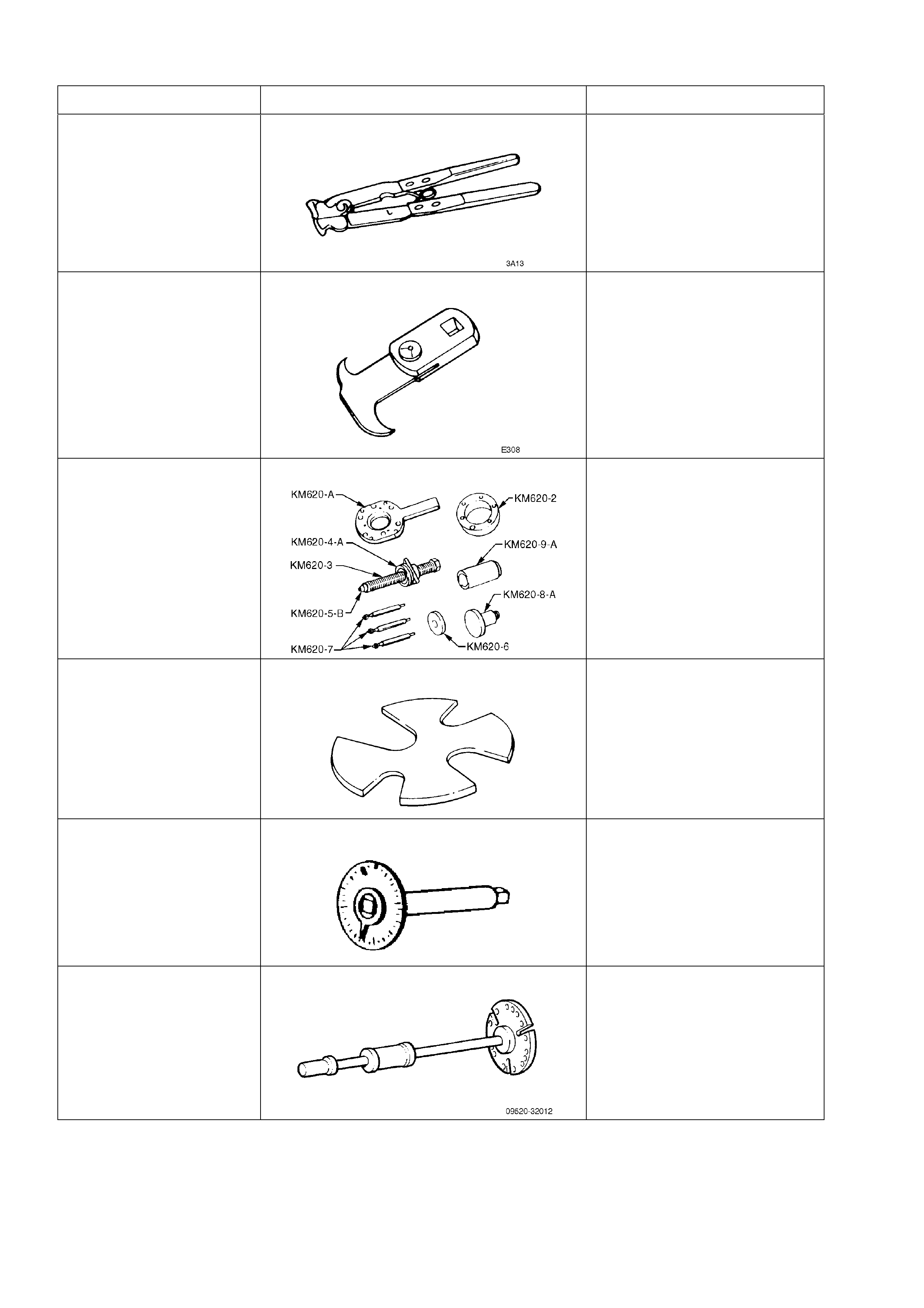
TOOL NO. REF IN TEXT TOOL DESCRIPTION COMMENTS
E1896 CLAMP PLIERS PREVIOUSLY RELEASED
FOR "J" CAR.
USED FOR SECURING DRIVE
SHAFT CONSTANT
VELOCITY JOINT BOOT
CLAMPS.
56750 SEAL REMOVER PREVIOUSLY RELEASED
FOR "V" CAR.
KM620-A REMOVER/INSTALLER PREVIOUSLY RELEASED
FOR "VQ".
USED FOR REMOVING AND
INSTALLING TRUNNION
FLANGE, REAR WHEEL
BEARING AND TRUNNION
ASSEMBLY.
E1312 PRESS PLATES PREVIOUSLY RELEASED.
E7115 ANGLE WRENCH PREVIOUSLY RELEASED
FOR "J" AND "V" CARS AS
TOOL NO. 394.
USED TO TIGHTEN
COMPONENT FASTENERS
WHEN ANGLE TORQUE IS
REQUIRED.
09520-32012 SLIDE HAMMER PREVIOUSLY RELEASED
FOR "JK" APOLLO.
USED TO REMOVE INNER
AXLE SHAFTS FROM THE
FINAL DRIVE ASSEMBLY.