SECTION 6B1-1 - ENGINE COOLING - V6 ENGINE
CAUTION:
This vehicle will be equipped with a Supplemental Restraint System (SRS). A SRS will
consist of either seat belt pre-tensio ners and a driver’s side air bag, o r seat belt pre-
tensioners and a driver’s and front passenger’s side air bags. Refer to CAUTIONS,
Section 12M, before performing any service operation on or around SRS
components, the steering mechanism or wiring. Failure to follow the CAUTIONS
could result in SRS deployment, resu lting in possible perso nal in jury or u nnecessary
SRS system repairs.
CAUTION:
This vehicle may be equipped with LPG (Liquefied Petroleum Gas). In the interests of
safety, the LPG fuel system should be isolated by turning 'OFF' the manual service
valve and then draining the L PG service lines, before any service w ork is carried out
on the vehicle. Refer to the LPG leaflet included with the Owner's Handbook for
details or LPG Section 2 for more specific servicing information.
1. GENERAL DESCRIPTI ON
The cooling system for VT Series Models with V6
engine carries over from VS Series Models with
minor changes.
A two speed electric c ooling fan is m ounted behind
the radiator. The fan operation is dependent on
engine coolant temperature, vehicle speed, A/C
request (where fitted) and A/C system pressure.
Refer to Section 6C1-1 POWERTRAIN
MANAGEMENT - V6 ENGINE for further
information.
1.1 GENERAL INFORMATION
The radiator utilises an aluminium core and is of
the crossflow design, with a radiator cap situated
on the left hand side tank. Plastic side tanks are
attached to the core by the use of clinch tabs. The
clinch tabs are formed as part of the core
assembly.
A high temperature rubber seal is used to seal the
mating surface between the core and each side
tank. The seal(s) must be replaced any time the
side tank is removed from the core.
For vehicles with automatic transmission,
transmission oil coolers are located in both left
hand and right hand side tanks.
Pegs are attached to the lower frame and the upper
area of each side tank. These pegs are used to
support the radiator in four rubber mounts. The
assembly is held in position by two spring clips at
the upper mounting locations. Figure 6B1-1-1
Techline
Techline
Techline
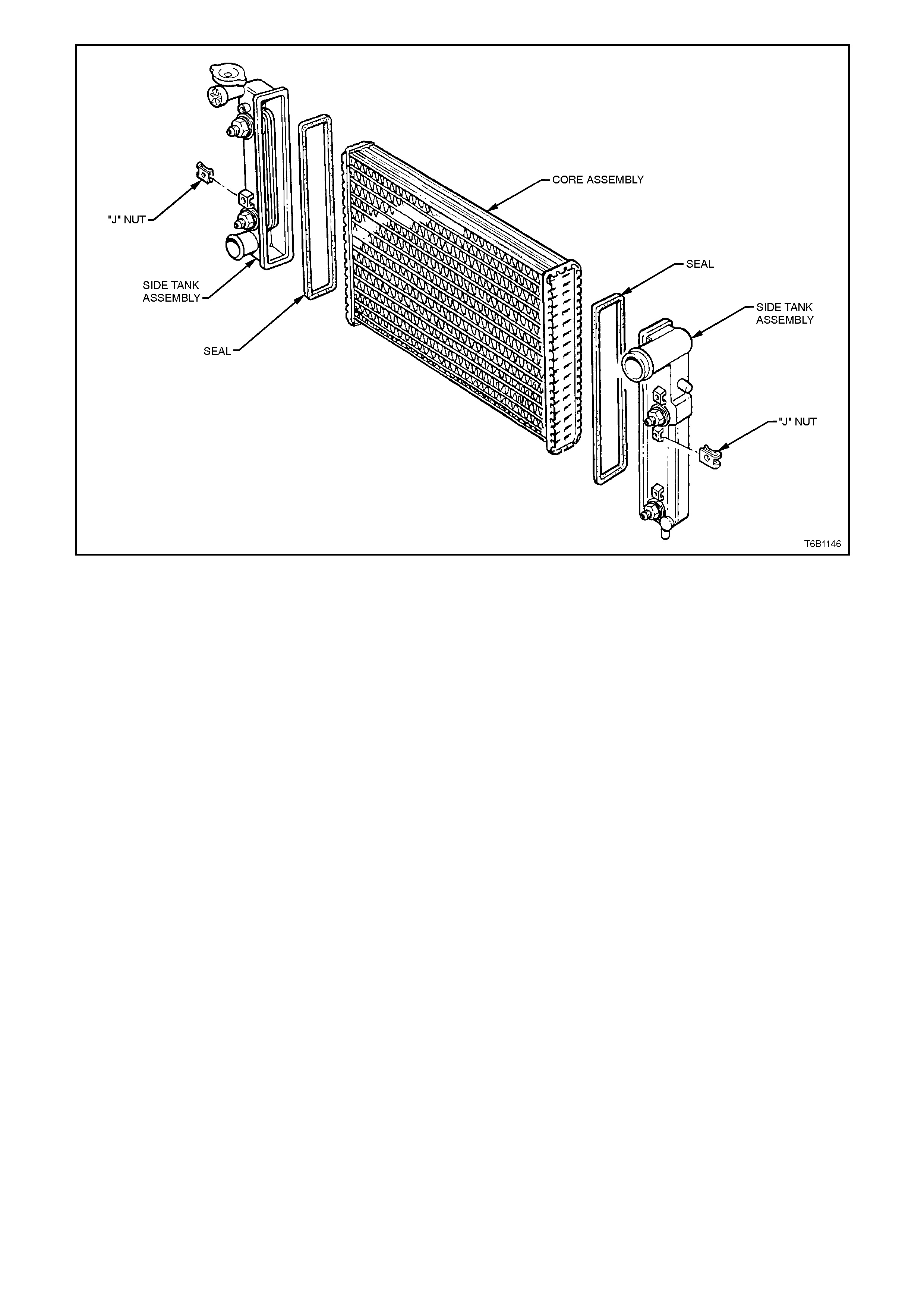
Figure 6B1-1-2
The radiator core side tanks or transmission oil cooler CANNOT be replaced separately. If there is a fault with any
of these c om ponents, the r adiator ass em bly must be replac ed. Sm all c ore r epairs can be m ade using a Alum inis ed
Silicon based liquid repair agent, refer to 2.13 RADIATOR - Radiator Repair Procedure in this Section.
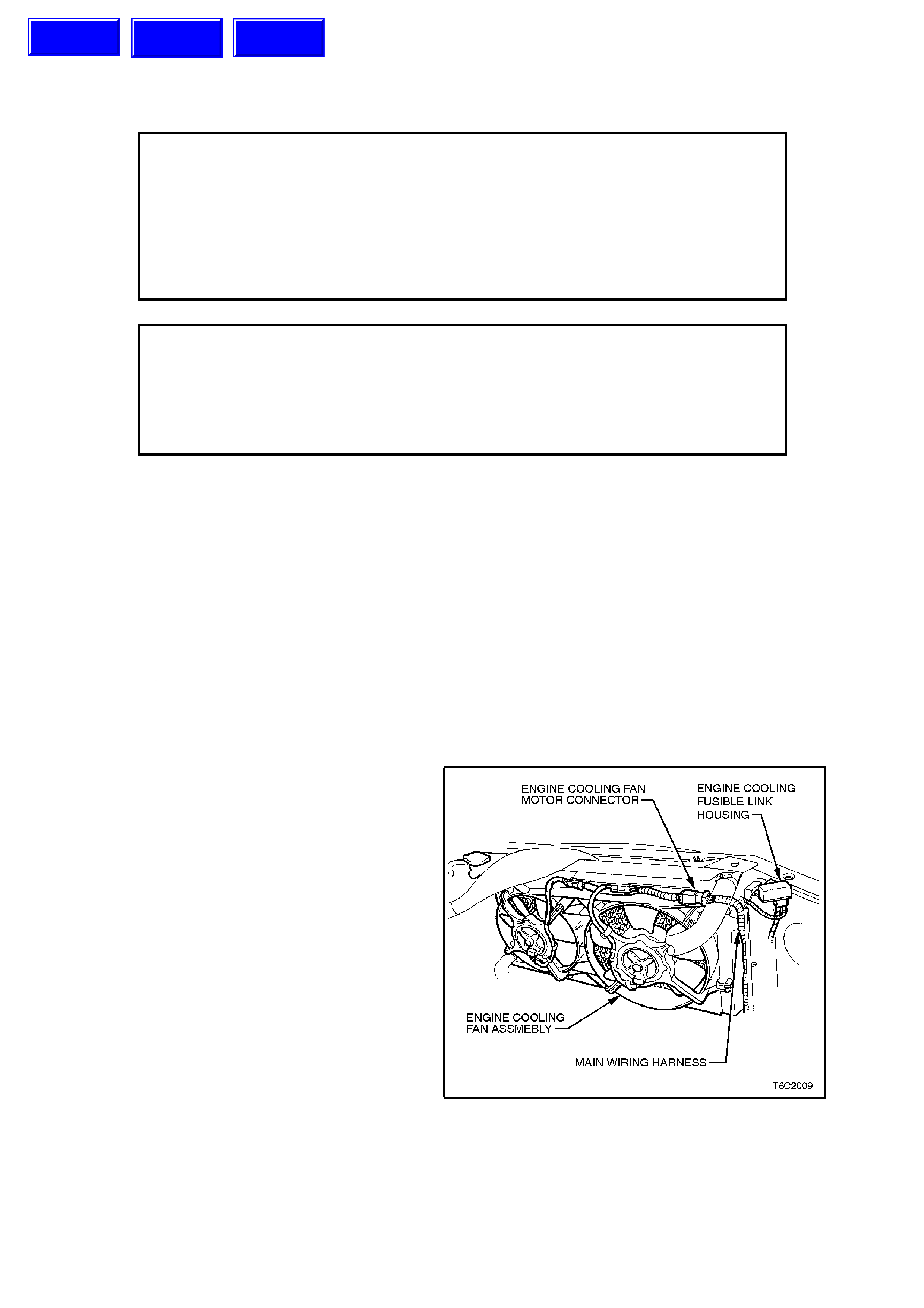
The cooling fan and electric motor assembly is supported in a polypropylene mounting bracket. The mounting
bracket and fan shroud are moulded as a one piece assembly. The mounting bracket is attached to the radiator
side tanks.
ENGINE COOLING FAN LOW SPEED
The PCM determines operation of the two speed engine cooling fan based on A/C request, A/C system pressure
(where fitted), engine coolant temperature and vehicle speed signal inputs.
The engine cooling fan low speed relay is energised by the BCM. The PCM. determines when to enable the low
speed fan based on inputs from the A/C request signal, Engine Coolant Tem per ature (ECT ) sens or and the Vehicle
Speed Sensor (VSS). The cooling fan speed relay will be turned "ON" when:
•The A/C request indicated (YES) and either
•The vehicle speed is less than 30 km/h.
or
•A/C pressure is greater than 1500 kPa
or.
•The coolant temperature is greater than 104 degrees C.
•If the coolant temperature is greater than 117 degrees C when the ignition is switched off, the relay is
energised for up to approx. 4 minutes.
If an engine coolant temperature sensor fault is detected, such as DTC 14, 15, 16, 17 or 91.
The cooling fan low speed relay will be turned "OFF" when the following conditions have been met:
•A/C request not indicated (NO).
•The A/C request is indicated (YES) and the vehicle speed is greater than 50 km/h and A/C pressure is less
than 1170 kPa.
ENGINE COOLING FAN HIGH SPEED
The engine cooling fan high speed relay is
controlled by the PCM based on input from the
Engine Coolant Temperature (ECT) sensor. The
PCM will only turn "ON" the engine cooling f an high
speed relay if the engine cooling fan low speed
relay has been "ON" for 2 seconds and the
following conditions are satisfied.
•There is a BCM message response fault
which will cause a DTC 92.
•An engine coolant temperature sensor failure
is detected such as DTC 14, 15, 16, or 17.
•Coolant temperature greater than
104 degrees C.
The engine cooling fan high speed relay can also
be enabled by the A/C Refrigerant Pressure
Sensor. When the A/C Refrigerant Pressure
Sensor determines the A/C system pressure is to
high, greater than 2600 kPa, and this will instruct
the PCM to enable the high speed fan.
If the low speed fan was “OFF” when the criteria
was met to turn the high speed fan “ON”, the high
speed fan will come “ON” 5 seconds after the low
speed fan is turned “ O N”. If both the engine c ooling
fan relays are “ON”, the PCM will turn “OFF” the
high speed relay when:
•The engine coolant temperature is less than
99 degrees C.
•A/C request not indicated (NO).
•A/C request indicated ( YES) and A/C pr es sur e
is less than 2300 kPa.
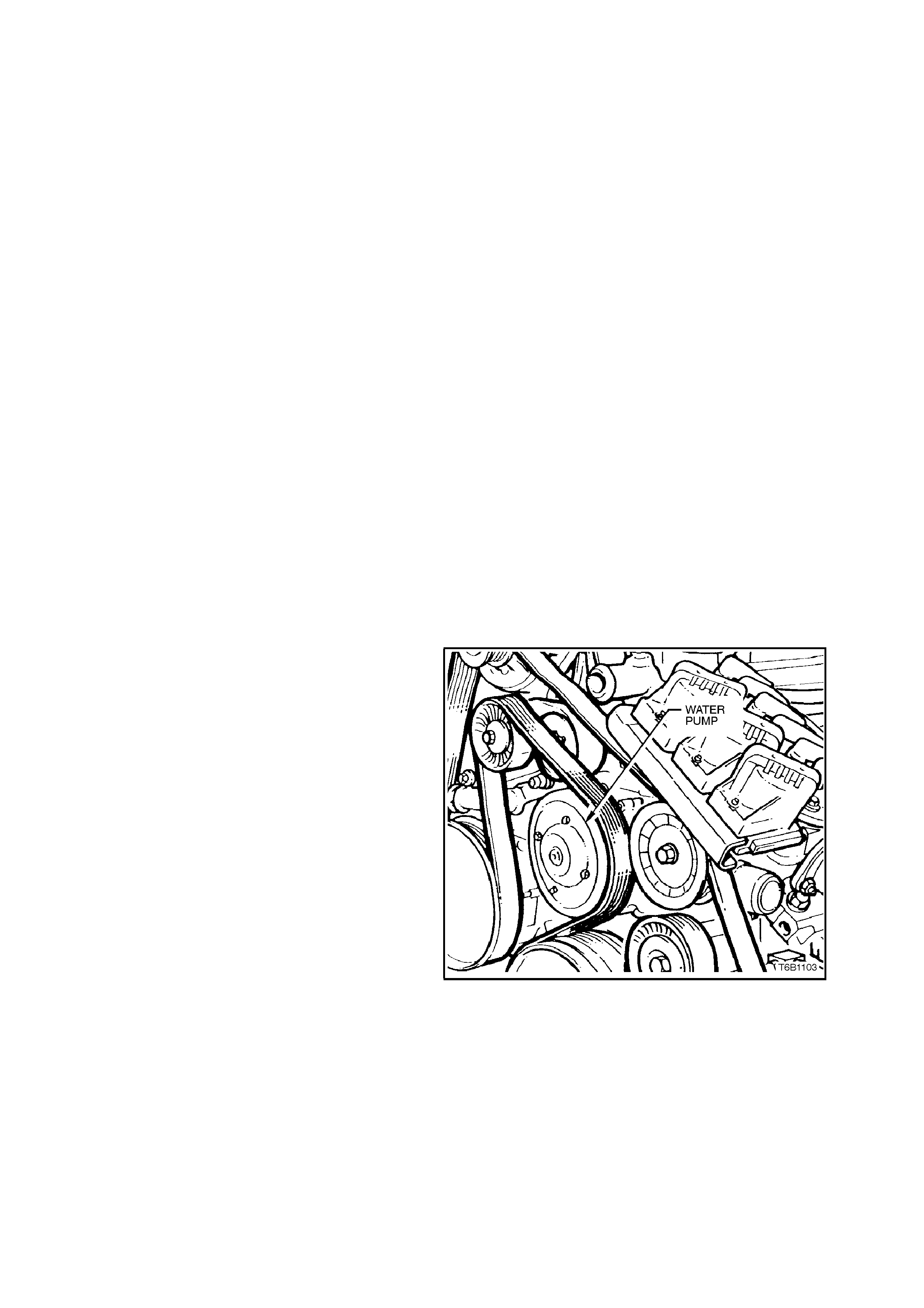
The water pump is mounted to the engine front
cover and is driven by the serpentine drive belt.
Coolant passes through the engine from the water
pump inlet at the engine front cover and exits via
the therm ostat and coolant outlet at the front of the
inlet manifold.
Figure 6B1-1-3
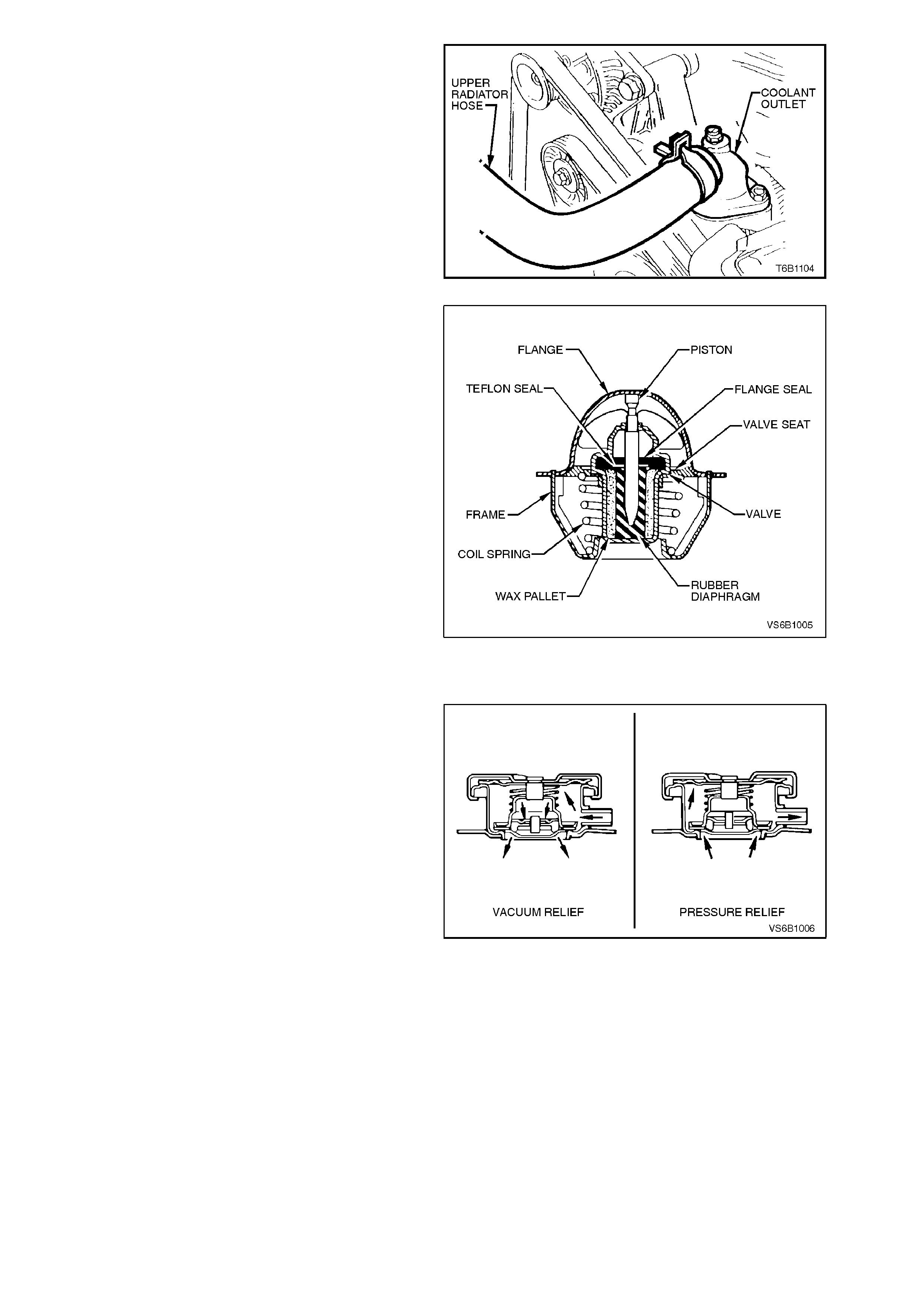
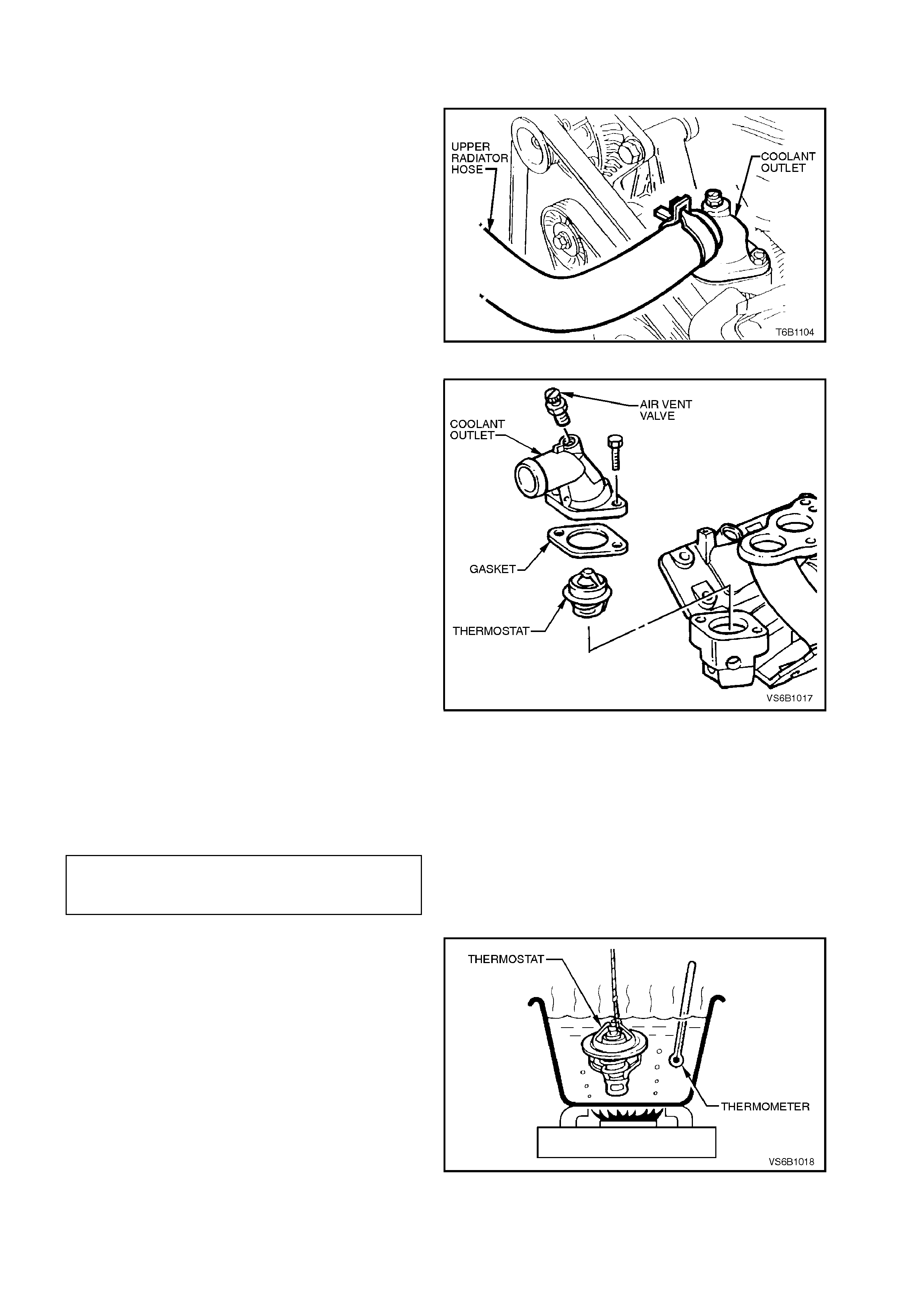
The c oolant outlet is located at the front of the inlet
manifold.
The thermostat is housed between the coolant
outlet and the inlet manifold.
Figure 6B1-1-4
A wax pellet type thermostat is used in the coolant
outlet passage to control the flow of coolant,
providing fast engine warm up and regulating
coolant temperature. The wax pellet or power
element in the thermostat, expands when heated
and contracts when cooled. The wax pellet is
connected through a piston to a valve and when the
pellet is heated, pressure is exerted against a metal
valve which is forced to open. As the pellet is
cooled, the contraction allows a spring to close the
valve. Thus, the valve remains closed while the
coolant is cold, preventing circulation of coolant
through the radiator, but allowing the coolant to
circulate throughout the engine to warm it quickly
and evenly.
As the engine becomes warm, the pellet expands
and the therm ostat opens, perm itting the coolant to
flow through the radiator where heat is passed
through the radiator walls. This opening and c los ing
of the thermostat valve permits enough coolant to
enter the radiator to keep the engine within
specified temperature limits.
Figure 6B1-1-5
A radiator cap, fitted to the radiator filler neck,
causes the cooling system to operate at higher
than atmospheric pressure. The higher pressure,
raises the boiling point of the coolant, resulting in
increased engine cooling efficiency.
The radiator cap contains a pressure valve and a
vacuum (atm ospheric) valve. T he pressure valve is
held against its seat by a spring, which determines
the maximum operating pressure of the cooling
system (135 kPa for V6 engine) The vacuum valve
is held against its seat by a light spring. The
vacuum created during cool down over-comes the
spring force and opens the valve, preventing the
radiator hoses from collapsing. Figure 6B1-1-6
NOTE:
Due to the cooling system pressure on vehicles
with V6 engine being greater than vehicles with V8
engine, a specific radiator cap is used on vehicles
fitted with V6 engines and will not fit onto the V8
type radiator neck.
The radiator cap for V6 is stamped with a 135 kPa
pressure rating.
The coolant is maintained at the ideal level in the
radiator by the radiator cap and the coolant
recovery reservoir, resulting in increased cooling
efficiency.
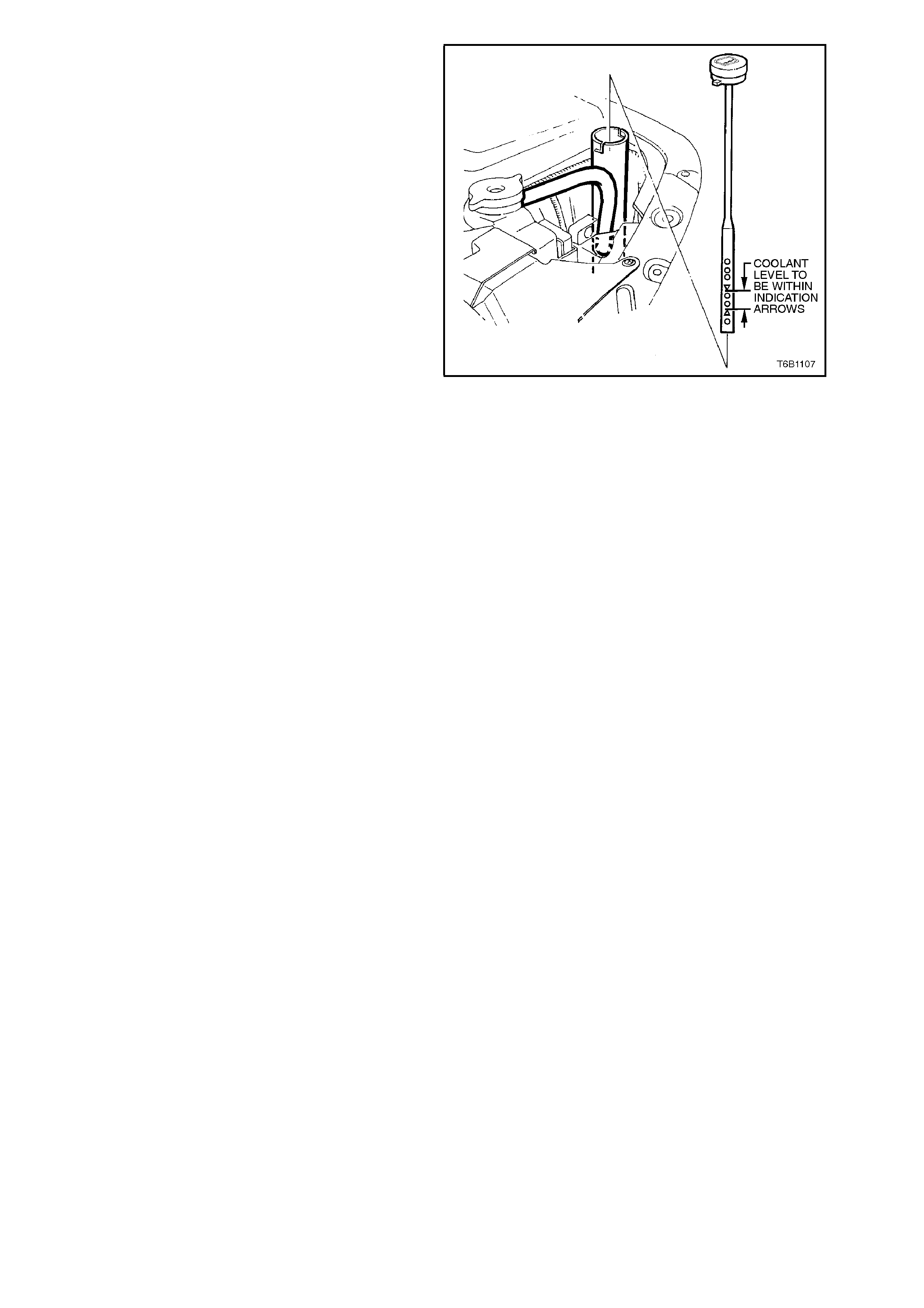
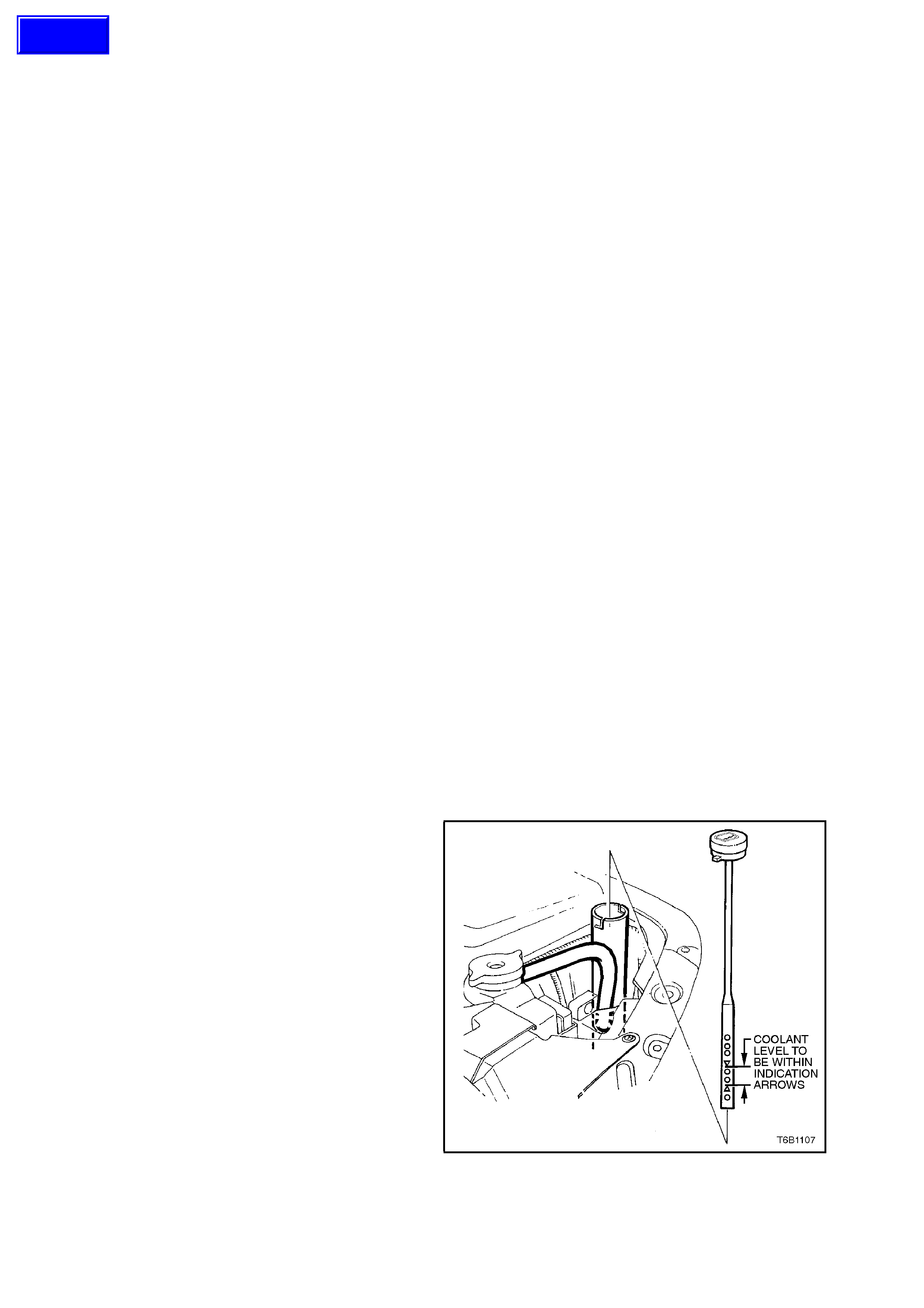
The c oolant recover y reservoir is located on the lef t
hand front of the engine com partm ent, between the
radiator support panel and air cleaner assembly.
The coolant recovery reservoir is connected to the
radiator overflow connection by a hose.
As the engine temperature rises, the coolant is
heated and expands. The fluid displaced by
expansion flows from the radiator into the recovery
reservoir. When the engine is turned 'OFF', the
coolant contracts as it cools. Coolant is then drawn
back into the radiator through the radiator cap
atmospheric valve.
Coolant level should be maintained between
indicator arrows on the coolant recovery reservoir
dipstick when the engine is cold. Figure 6B1-1-7
The cooling system is designed to use a coolant (a
mixture of ethylene glycol antifreeze with inbuilt
corrosion inhibitors and water), rather than plain
water to maintain the integrity of the cooling
system, and to prevent oxidation occurring within
the engine.
An air baffle and side chutes are fitted to the front
end of the vehicle to direct and promote air flow
through the radiator to provide maximum cooling.
The purpose of the air baffle is to create a low
pressure area behind the radiator whilst the vehicle
is at speed.
This enables additional air flow through the radiator
core to maintain the desired engine cooling.
The air baffle or side chutes should never be
removed unless for service work. If either the air
baffle or side chutes are damaged, this will reduce
the cooling system efficiency , and therefore they
must be replaced.
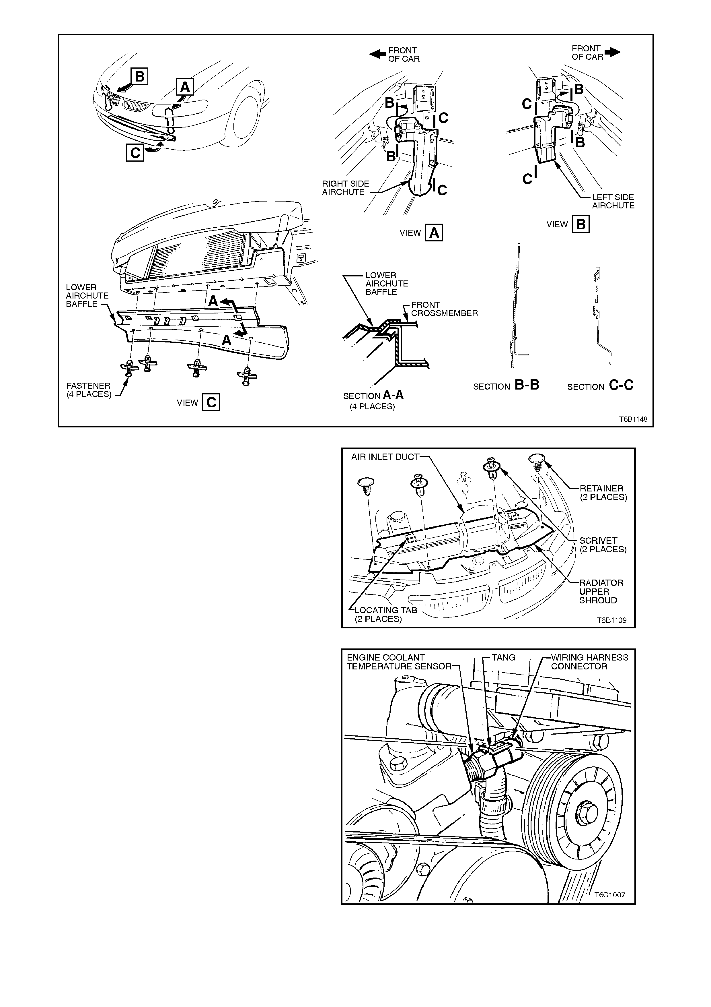
Figure 6B1-1-8
A radiator shroud is fitted between the upper
radiator support panel and the radiator assembly, to
minim is e the recirc ulation of hot air from the r ear of
the radiator back over the core.
Figure 6B1-1-9
A coolant temperature sensor is mounted in the
front of the inlet manifold. T he coolant temperature
sensor is used in conjunction with the instrument
panel temperature gauge. T he coolant temperatur e
sensor generates a signal which is used by the
engine management PCM/BCM for calculation of
the various engine management functions.
Figure 6B1-1-10

2. SERVICE OPERATIONS
2.1 SERVICE NOTES
WARNING:
To avoid serious personal injury, never remove the r adiator cap or open the air vent valve on the coolant
outlet when the engine is hot, even if the cooling system should require filling. Sudden release of cooling
system pressure is very dangerous.
Before removing the radiator cap, allow the engine to cool, then place a shop rag over the radiator cap and then
slowly turn the cap anti-clockwise, without pressing down until the cap reaches the first 'stop'. This is the pressure
relief stop, which will allow any remaining pressure within the system to escape. Then press down on cap and
continue to rotate it anti-clockwise until it can be removed.
The vehicle is fitted with a radiator electric cooling fan. When working around the engine compartment with the
engine running or with the ignition 'ON', keep clear of the fan as it may start operating without warning.
The cooling system requires little care except for maintaining the coolant to the correct level in the recovery
reservoir and periodic servicing at the time or distance intervals as outlined in the VT Owner's Handbook.
Periodic servicing includes
1. Checking coolant level, refer 2.3 CHECKING AND FILLING COOLING SYSTEM this Section.
2. Checking coolant concentration, refer 2.2 GLYCOL COOLANT MAINTENANCE - Testing Coolant
Concentration this Section.
3. Pressure test cooling system and radiator cap, refer 2.7 PRESSURE TESTING in this Section.
4. Tighten hose clamps and inspect all hoses, refer 2.6 COOLANT HOSES in this Section. Replace hoses if
swollen or deteriorated.
CAUTION:
Always wear protective safety glasses when working with spring type hose clamps. Failure to do so could
result in eye injury.
5. Clean out cooling system, refer 2.4 CLEANING COOLING SYSTEM - COOLING SYSTEM FLUSH, in this
Section and refill cooling system, refer 2.3 CHECKING AND FILLING COOLING SYSTEM this Section.
Techline
2.2 GLYCOL COOLANT MAINTENANCE
The c ooling system is designed to us e a coolant (a
mixture of ethylene glycol antifreeze with inbuilt
corrosion inhibitors, and water), rather than plain
water.
The use of glycol also raises the boiling point and
increases the cooling system efficiency.
For this reason, it is of the utmost importance to
ma intain the correct c oncentration level of ethylene
glycol in the cooling system.
Addition of plain water into the cooling system
when 'topping-up' may dilute the coolant m ixture to
a point where the antifreeze/anti-boil and corrosion
inhibitor properties of ethylene glycol become
ineffective.
The coolant should comprise of a mixture 50%
ethylene glycol antifreeze/inhibitor (Holden
Specification HN 2043) with 50% clear, clean
water.
Ethylene glycol conforming to Holden Specification
HN 2043 is named 'New Formula Long Life All
Seasons Coolant', and is available in the following
quantities:
1 litre, P/N M40236
5 litre, P/N M40307
20 litre, P/N M40238
NOTE:
Do not mix different types of anti-freeze or
corros ion inhibitors as they m ay be incompatible. If
a different type has been used in the cooling
system, flush the system with clean water, refer
2.4 CLEANING COOLING SYSTEM - COOLING
SYSTEM FLUSH in this Section and refill cooling
system with the correct coolant, refer 2.3
CHECKING AND FILLING COOLING SYSTEM in
this Section.
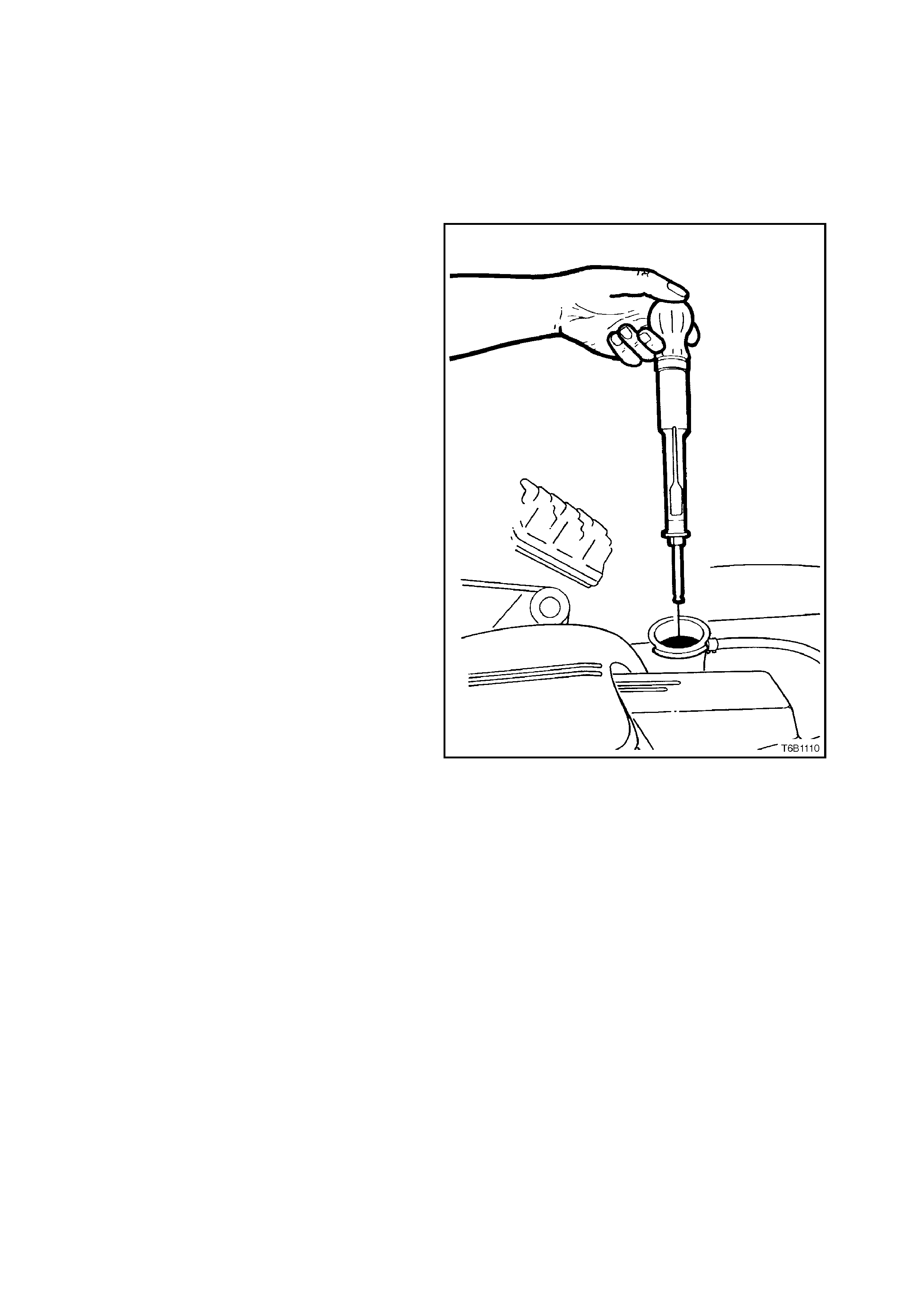
TOPPING UP THE COOLING SYSTEM
Under normal operating conditions, the cooling
system should not be topped up at the radiator
filler. The level can be checked at the coolant
recovery reservoir, and coolant (in the correct
concentration with clear, clean water) added as
necessary to bring the level to between the
indicator arrows on the coolant recovery reservoir
dipstick when the engine is cold .
Figure 6B1-1-11
Techline
TESTING COOLANT CONCENTRATION
To ensure the specified ethylene glycol
concentration is maintained in the engine coolant,
the coolant concentration must be checked at the
time or distance intervals outlined in the VT
Owner's Handbook.
Check coolant concentration as follows:
1. Cooling system should be at or close to
ambient temperature.
2. Remove radiator cap and insert nozzle of
coolant tester, Tool No. AU435 into coolant,
and by squeezing the rubber bulb, draw
sufficient coolant into the tester to float
hydrometer bulb freely.
NOTE:
The coolant recovery reservoir is not part of the
dynamic coolant system and therefore coolant
concentration m eas ur ements mus t not be made via
the recovery reservoir.
3. Hold tester at eye level and read scale on
hydrometer bulb at coolant level.
The reading shows the perc entage of ethylene
glycol antifreeze contained in the engine
coolant.
4. The hydrometer reading should show 50% if
the coolant concentration is correct.
If a reading of less than 50% is achieved, the
cooling system requires topping up with
ethylene glycol antifreeze to Holden
Specification HN 2043.
Refer to the following chart to determine how
much ethylene glycol antifreeze is required to
add to the cooling system to bring the coolant
to the specified concentration.
Figure 6B1-1-12

HYDRO-
METER
READING %
LITRES OF ANTIFREEZE TO BE
ADDED FOR CORRESPONDING
HYDROMETER READING
06.0
55.7
10 5.3
15 4.9
20 4.5
25 4.0
30 3.4
35 2.8
40 2.0
45 1.1
50 0
5. Drain sufficient quantity of coolant from
cooling system to allow top-up with ethylene
glycol antifreeze.
6. Add required amount of ethylene glycol
antifreeze to radiator and reinstall radiator cap.

2.3 CHECKING AND FILLING COOLING SYSTEM
During any service operation that requires the
cooling system to be partly or completely drained,
the following instructions must be followed when
refilling the cooling system so as to ensure that all
air is bleed from system.
FILLING COOLING SYSTEM WITH TOOL AU425
The following procedure requires the use of Tool
No. AU425 to fill the cooling s yst em. An alternative
procedure for filling the cooling system is also
given should Tool No. AU425 not be available.
1. Set heater control to maximum.
2. Mix a coolant m ixtur e consis ting 50% ethylene
glycol antifreeze/inhibitor (Holden Specification
HN 2043) with 50% clear, clean water.
Ethylene glycol conforming to Holden Specification
HN 2043 is named 'New Formula Long Life All
Seasons Coolant', and is available in the following
quantities:
1 litre, P/N M40236
5 litre, P/N M40307
20 litre, P/N M40238
NOTE:
Do not mix different types of anti-freeze or
corros ion inhibitors as they m ay be incompatible. If
a different type has been used in the cooling
system, flush the system with clean water, refer
2.4 CLEANING COOLING SYSTEM - COOLING
SYSTEM FLUSH in this Section.
3. If cooling s yst em was com pletely dr ained, add
a pack of pellets (three pellets), P/N M40124
to cooling system by disconnecting radiator
upper hose from engine coolant outlet and
placing pellets inside radiator hose. If cooling
system was only partially drained, add one
pellet for every four litres of coolant replaced.
CAUTION:
Always wear protective safety glasses when
working with spring type hose clamps. Failure
to do so could result in eye injury.
Refit hose to coolant outlet and tighten hose
clamp.
4. Remove radiator cap and install Tool No.
AU425 to radiator filler neck.
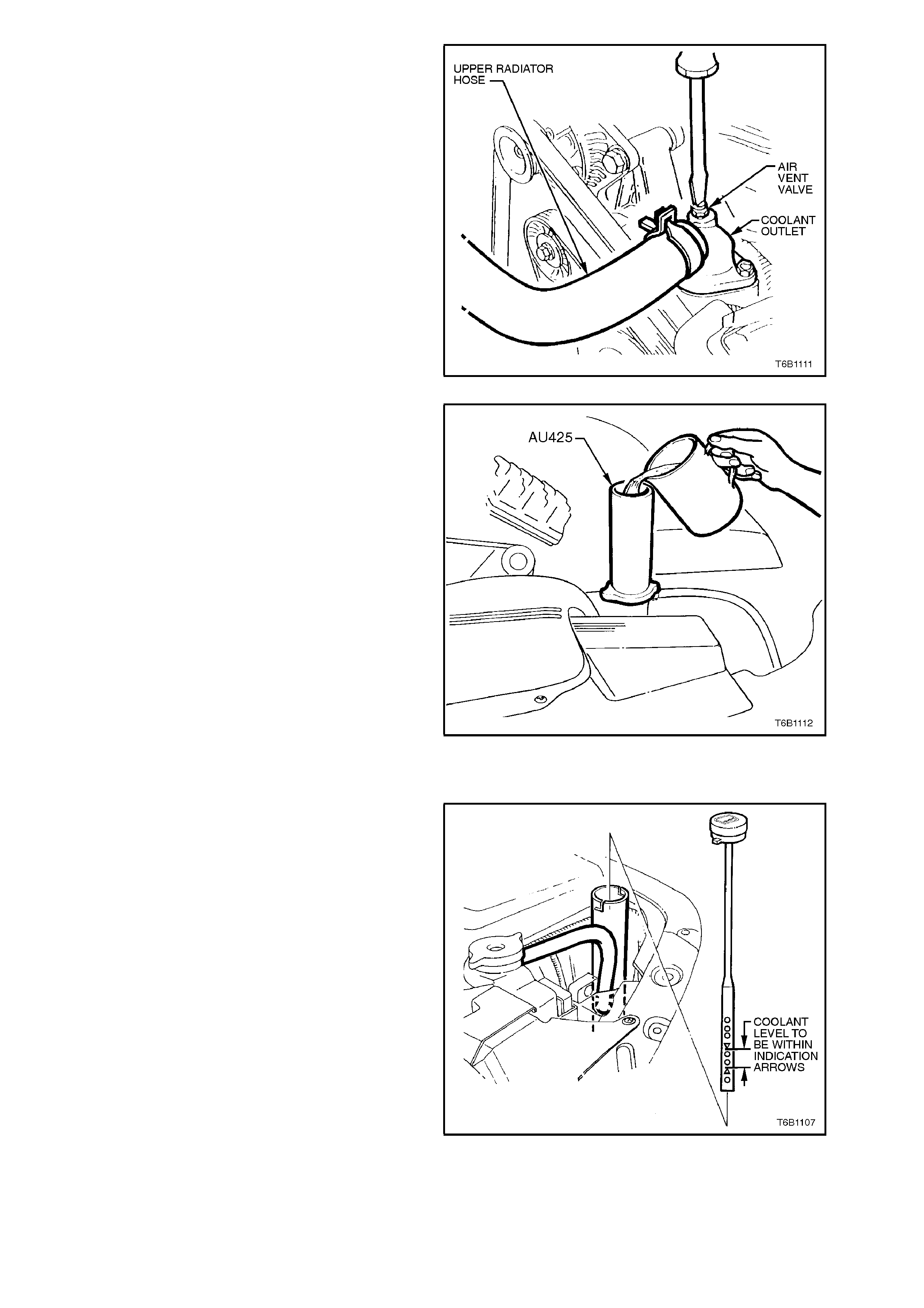
5. Using a screwdriver, open air vent valve at
coolant outlet.
Figure 6B1-1-13
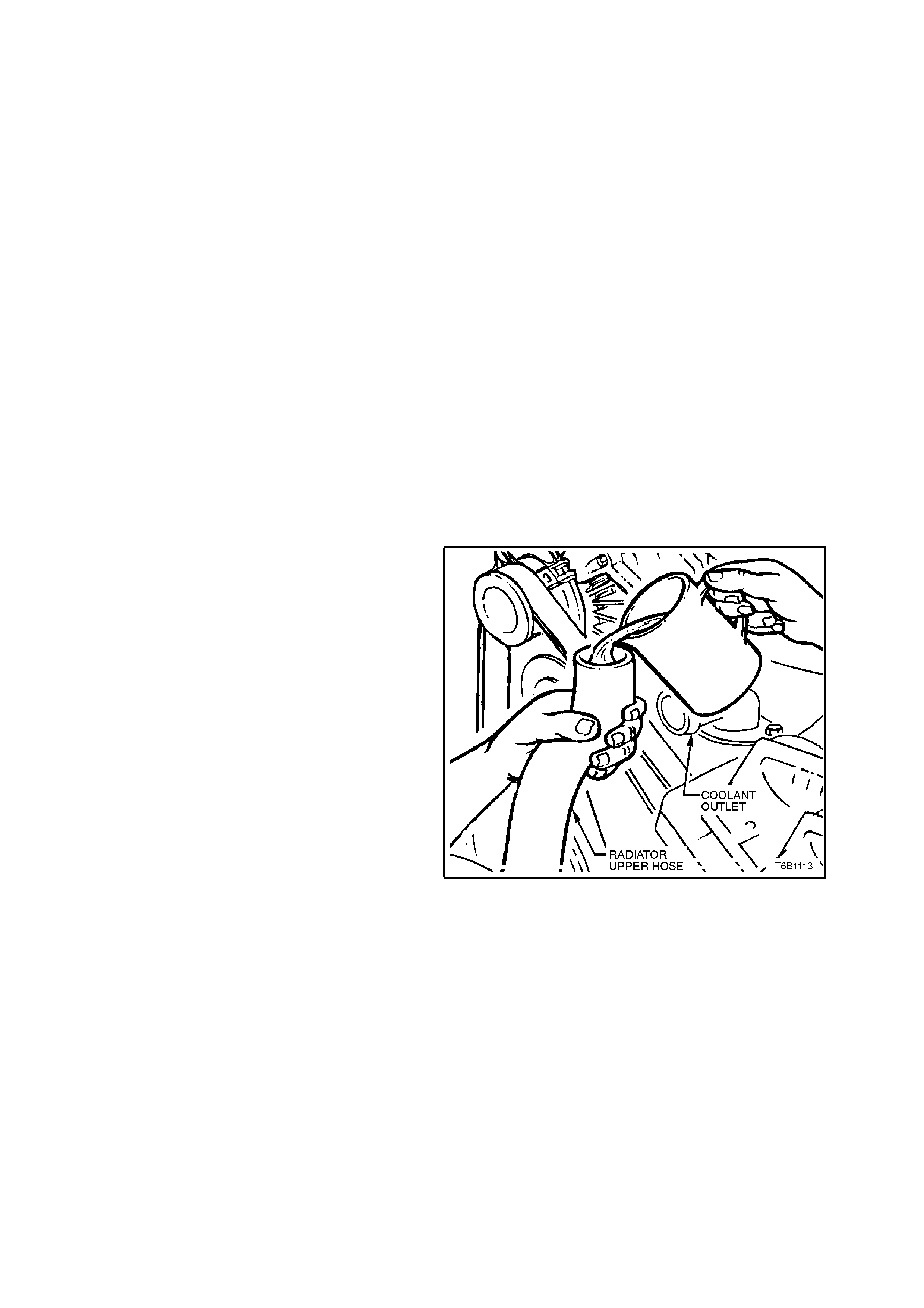
6. Fill cooling system using coolant mixture via
Tool No. AU425 until coolant flows from air
vent opening and all air is expelled.
Figure 6B1-1-14
7. Close air vent valve and remove AU425 from
radiator.
8. If necessary, remove cap from coolant
recovery reservoir and fill to between the
indicator arrows on the coolant recovery
reservoir dipstick when the engine is cold.
Figure 6B1-1-15
9. Pressure test cooling system, refer
2.7 PRESSURE TESTING in this Section.
10. Refit radiator cap.
FILLING COOLING SYSTEM WITHOUT TOOL AU425
As an alternative to filling the cooling system
should Tool No. AU425 not be available, perform
the following procedure.
1. Set heater control to maximum.
2. Mix a coolant m ixtur e consis ting 50% ethylene
glycol antifreeze/inhibitor (Holden Specification
HN 2043) with 50% clear, clean water.
Ethylene glycol conforming to Holden Specification
HN 2043 is named New Formula Long Life All
Seasons Coolant, and is available in the following
quantities:
1 litre, P/N M40236
5 litre, P/N M40307
20 litre, P/N M40238
NOTE:
Do not mix different types of anti-freeze or
corros ion inhibitors as they m ay be incompatible. If
a different type has been used in the cooling
system, flush the system with clean water, refer to
2.4 CLEANING COOLING SYSTEM - COOLING
SYSTEM FLUSH in this Section.
3. Remove radiator cap and fill cooling system
with as much coolant mixture as possible.
4. Replace radiator cap.
5. Loosen radiator upper hose clamp at coolant
outlet and remove hose from engine coolant
outlet.
CAUTION:
Always wear protective safety glasses when
working with spring type hose clamps. Failure
to do so could result in eye injury.
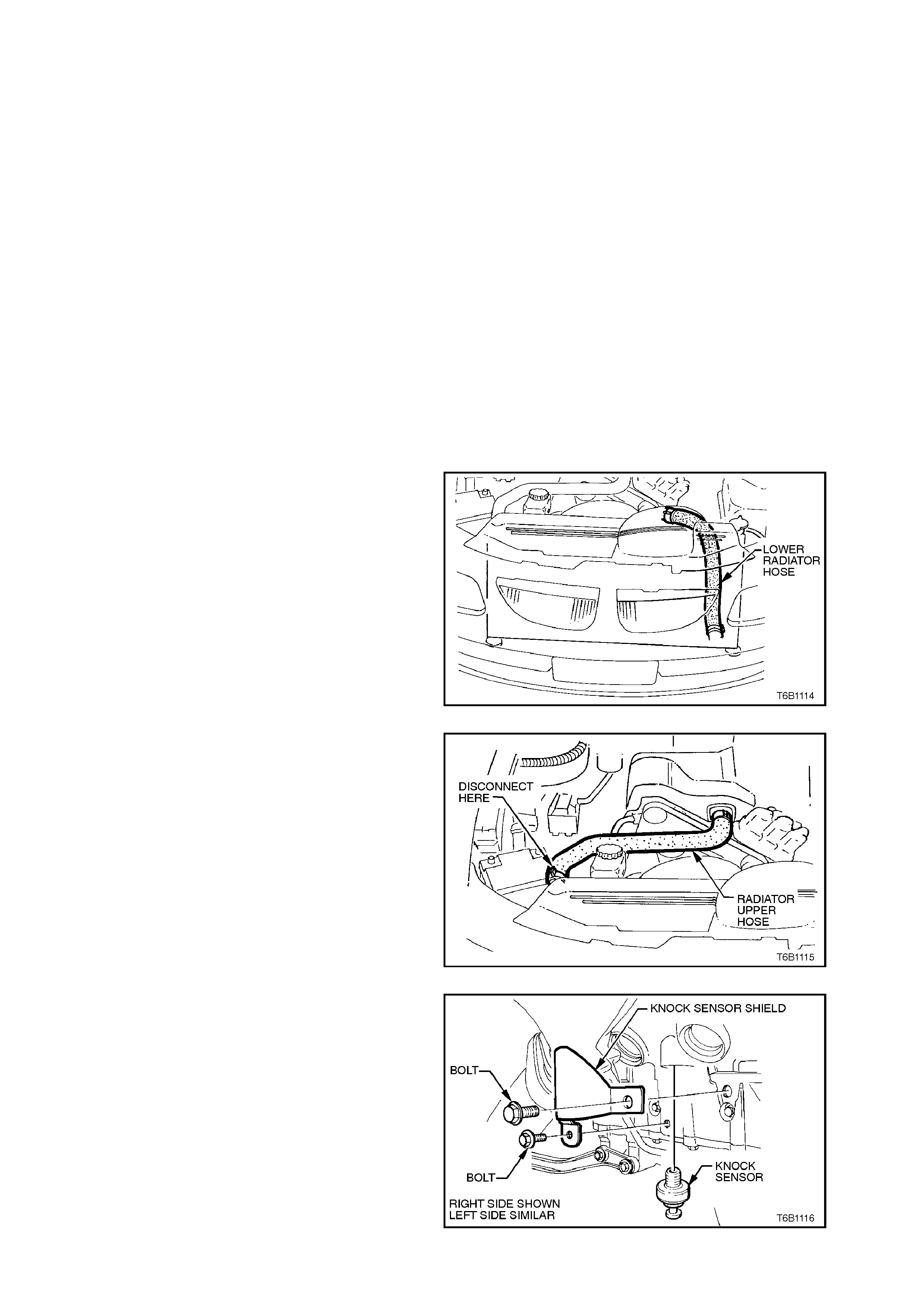
6. Holding disconnected end of radiator upper
hose upward, fill cooling system using coolant
mixture via open end of radiator upper hose
until coolant starts to flow from coolant outlet.
Figure 6B1-1-16

7. If cooling s yst em was com pletely dr ained, add
a pack of pellets (three pellets), P/N M40124
by placing pellets inside radiator hose. If
cooling system was only partially drained, add
one pellet for every four litres of coolant
replaced.
8. Quick ly install r adiator upper hos e onto engine
coolant outlet, trying not to allow pellets or a
large amount of coolant to spill from hose.
Install hose clamp at coolant outlet
connection.
9. Pressure test cooling system, refer to
2.7 PRESSURE TESTING in this Section.
10. Remove cap from recovery reservoir and fill
with coolant to a level approximately 25 mm
ABOVE the indicator arrows on the coolant
recovery reservoir dipstick, refit dipstick.
NOTE:
This condition only applies when the cooling
system is first being filled, after a major loss of
coolant.
The level of coolant will subsequently drop in the
reservoir and the level should then be kept at the
correct level.
Figure 6B1-1-17
2.4 CLEANING COOLING SYSTEM
A cleaning solution should be used to loosen the
rust and scale before performing a cooling system
flush.
Use radiator cleaner, Holden Part No. M39304
(500 ml). Follow the instructions on the container.
COOLING SYSTEM FLUSH
This operation should only be carried out when the
engine and radiator are at ambient temperature.
When using specialised cooling system flushing
equipment, connect in accordance with the
manufactures recommendations.
CAUTION:
Apply air pressure gradually as the rad iator w ill
only withstand 150 kPa pressure.
1. Place drain tray beneath vehicle.
2. Remove coolant outlet and thermostat from
front of inlet manifold, refer to
2.8 THERMOSTAT - REMOVE in this Section.
Refit coolant outlet (without thermostat).
3. Remove radiator lower hose at engine front
cover connection.
CAUTION:
Always wear protective safety glasses when
working with spring type hose clamps. Failure
to do so could result in eye injury.
Figure 6B1-1-18
4. Remove radiator upper hose at radiator
connection.
Figure 6B1-1-19
5. Remove knock sensors from both sides of
cylinder block.
Figure 6B1-1-20

6. Place water hose into radiator upper hose,
turn on water pressure and flush until water
coming from radiator lower hose connection
(front cover) is clear.
7. Place water hose into front cover radiator
lower hose connection and flush, until water
coming from upper hose is clear.
8. Place water hose into radiator lower hose and
flush out radiator in reverse direction of normal
coolant flow, until water coming from radiator
upper hose connection is clear.
9. Remove coolant recovery reservoir, refer to
2.9 COOLANT RECOVERY RESERVOIR -
REMOVE in this Section. Flush out reservoir
with clean water.
10. With cooling system flushed clean, refit all
cooling system c om ponents. F or installation of
thermostat and coolant outlet housing, refer to
2.8 THERMOSTAT - REINSTALL in this
Section.
NOTE:
a. If reinstalling original knock sensor,
inspect sealant on sensor threads. If
worn away, apply a light coating of Loctite
242 sealant or equivalent (Holden
Specification HN 1256, Class 2 Type 2)
to the threads of the knock sensors and
tighten to the correct torque specification.
b. On a new sensor, do not apply sealant to
threads as threads are coated with a
sealant during manufacture. Applying
additional sealant will affect the sensor's
ability to detect engine knock.
KNOCK SENSOR
TORQUE SPECIFICATION 16- 22
Nm
11. Fill cooling system with coolant to the correct
concentration level, refer to
2.3 CHECKING AND FILLING COOLING
SYSTEM and pressure test system, refer to
2.7 PRESSURE TESTING in this Section

2.5 DRIVE BE LT TENSION
Drive belt tension is provided by a tensioner
assem bly. The tensioner is an idler pulley mounted
on a spring-loaded arm that maintains the dr ive belt
at the proper tension, without imposing undue loads
on the various components.
Throughout its functional travel, the tensioner
mechanism will maintain this tension while
compensating for increases in belt wear and
stretch.
When the indicator pointer on the tensioner has
reached m inimum tension range, the tensioner has
reached the full extent of its travel and belt
replacement is necessary.
Drive belt tension can be checked using Tool No.
BT3373-F, refer to Section 6A1-1 ENGINE
MECHANICAL - V6 ENGINE.
Figure 6B1-1-21

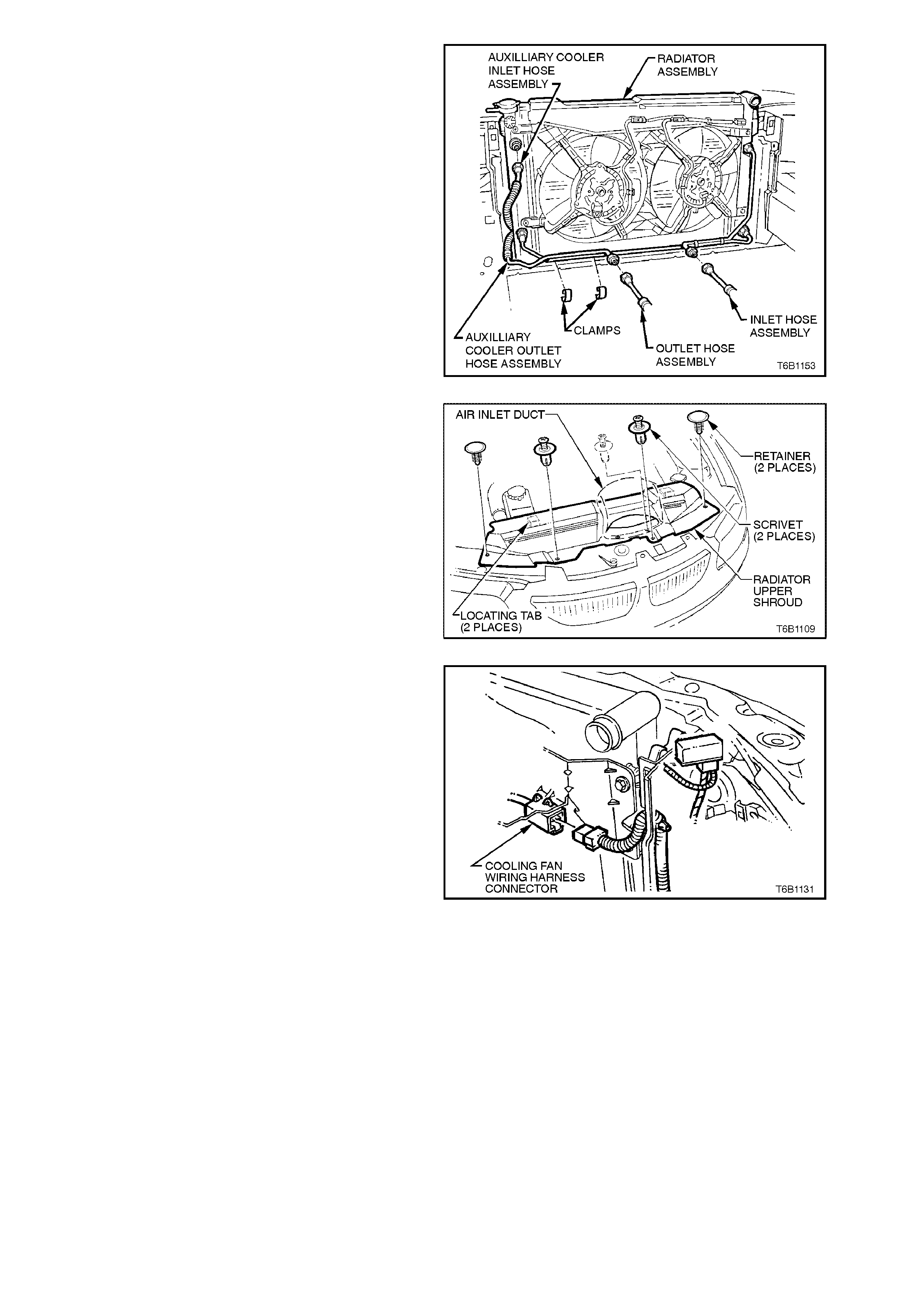
2.6 COOLANT HOSES
Coolant hoses are installed as shown in the following illustrations.
Hose connections should be thoroughly cleaned before installing any new hose.
After hose is fitted, always refill the cooling system with correct concentration of coolant, refer to 2.3 CHECKING
AND FILLING COOLING SYSTEM and pressure test cooling system, refer to 2.7 PRESSURE TESTING in this
Section.
CAUTION:
Always wear protective safety glasses when working with spring type hose clamps. Failure to do so could
result in eye injury.
Techline
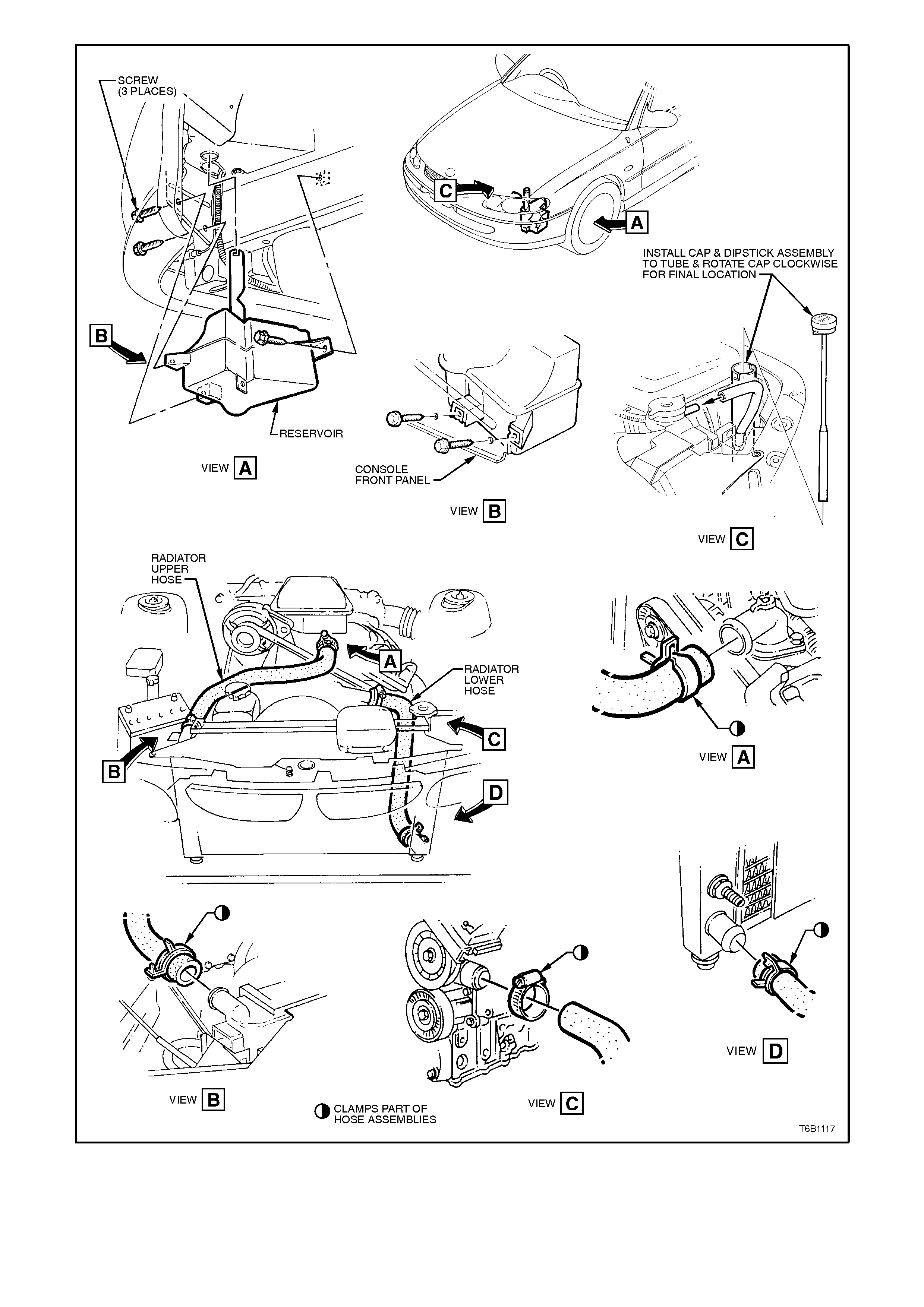
Figure 6B1-1-22
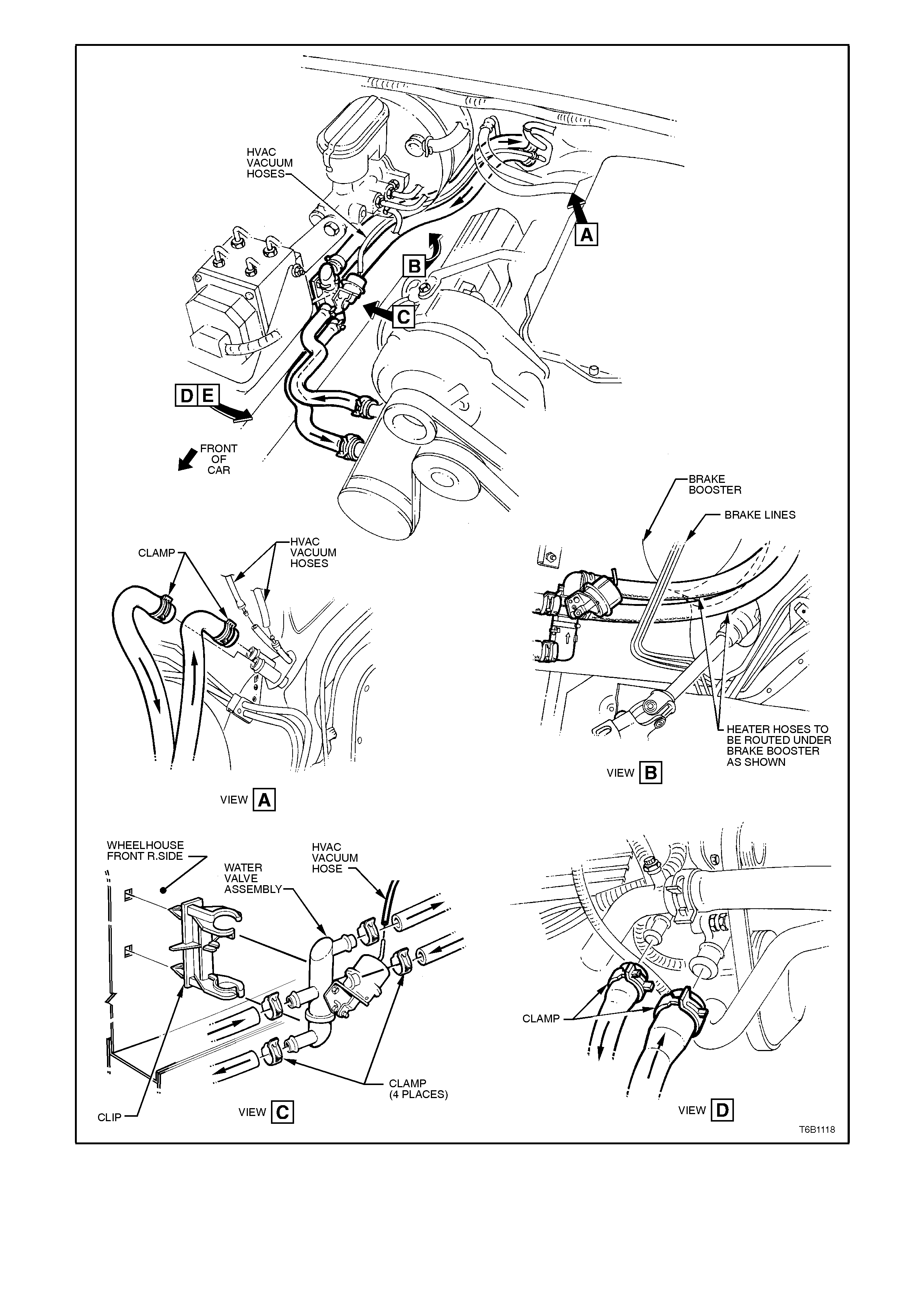
Figure 6B1-1-23
2.7 PRESSURE TESTING
RADIATOR CAP TESTING
1. Allow engine to cool to ambient temperature
(less than 50°C), then remove radiator cap.
CAUTION:
Do not remove radiator cap while the engine
coolant t emperature is above 50°
°°
°C, as personal
injury may result.
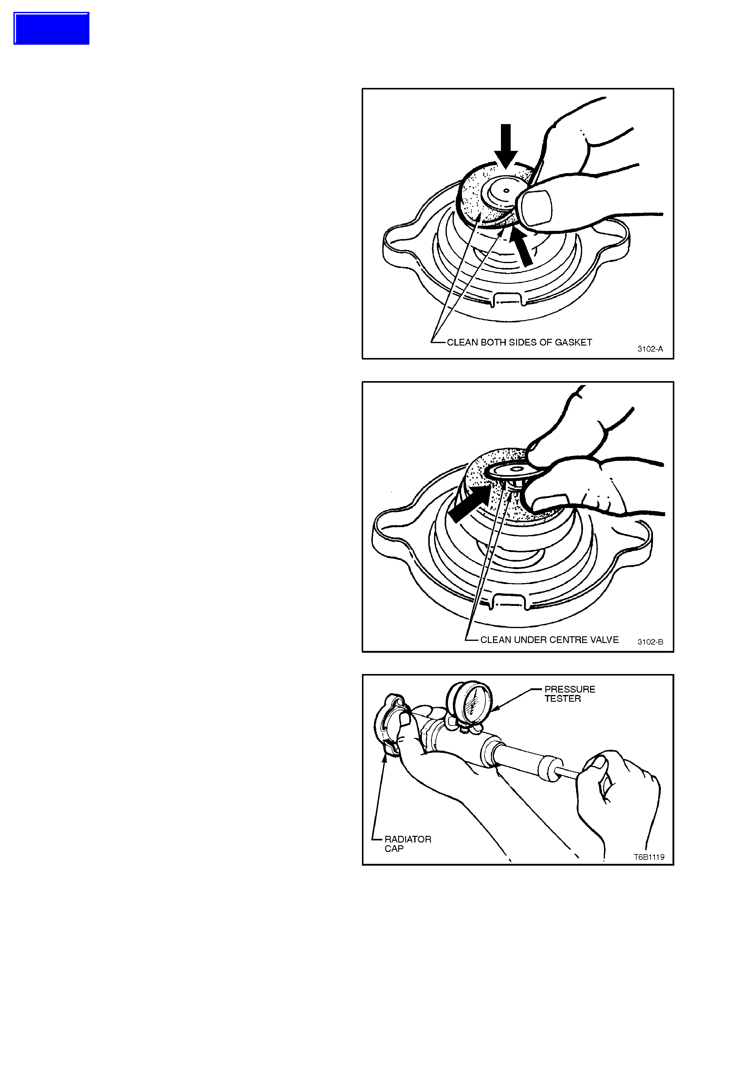
2. Clean both sides of radiator cap gasket with a
wet cloth.
NOTE: Use only water to wet cleaning cloth.
Figure 6B1-1-24
3. Lift centre valve and clean gasket area under
valve.
Figure 6A1-1-25
4. Attach radiator c ap to a c ommerc ially available
cooling system pressure tester. Slowly
pressurise cap to 120-150 kPa. The cap is
serviceable if it unloads slightly above this
pressure range and holds pressure at 120
kPa. Should cap fail to reach or hold the
specified pressure, replace cap.
Figure 6B1-1-26
Techline
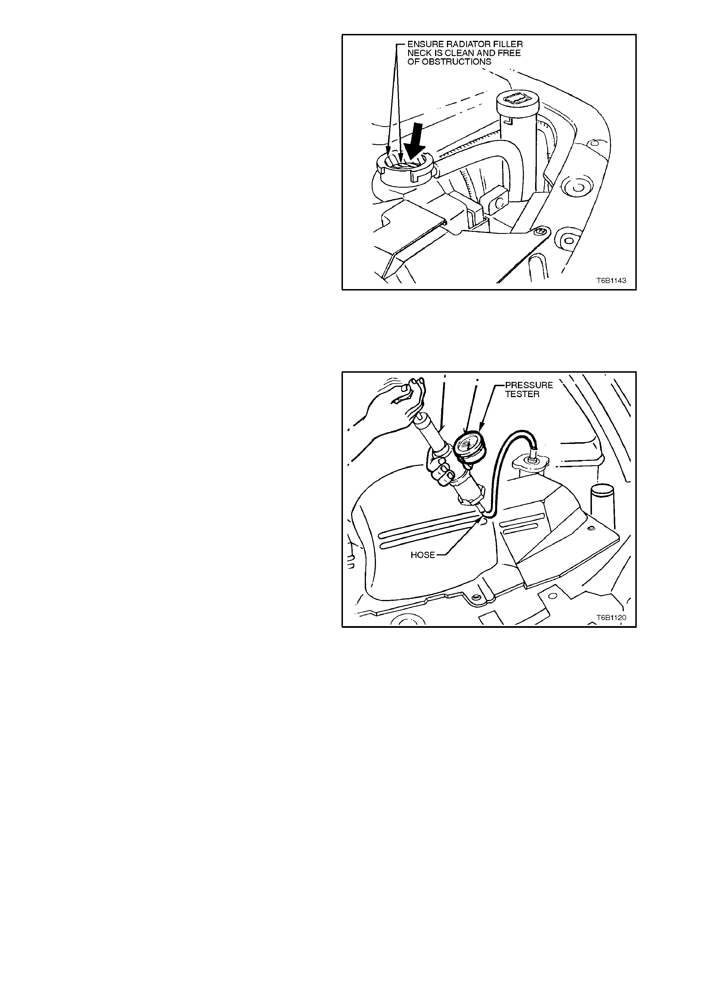
5. Prior to reinstalling radiator cap ensure
radiator f iller neck cap s eating sur face is clean
and free from obstruction.
Figure 6A1-1-27
COOLING SYSTEM PRESSURE TESTING
1. Allow engine to cool to ambient temperature
(less than 50°C), then remove radiator cap.
CAUTION:
Do not remove radiator cap while the engine
coolant t emperature is above 50°
°°
°C, as personal
injury may result.
2. Ensure coolant level is correct.
3. Connect a commercially available cooling
system pressure tester to radiator filler neck
and using compressed air, blow dry any
residual coolant around radiator filler neck.
Pressur ise c ooling s ystem to 120-150 kPa and
check for leaks at the following points;
a. All hoses and hose connections.
b. Overflow hose connection at radiator.
c. Radiator seams and core.
d. Corroded or faulty engine welsh plugs or
drain plugs.
e. Water pump and gasket.
f. Vehicle heater system.
g. Check engine oil dipstick for evidence of
engine oil contamination with coolant.
Figure 6B1-1-28
4. If pressure will not hold, there is a leak in the
cooling system. Repair as necessary.
2.8 THERMOSTAT
REMOVE
1. Allow7 engine to cool to ambient temperature
(less than 50°C), then remove radiator cap.
CAUTION:
Do not remove radiator cap while the engine
coolant t emperature is above 50°
°°
°C, as personal
injury may result.
2. Remove engine manifold cover.
3. Disconnect radiator upper hose from coolant
outlet at front of inlet manifold.
CAUTION:
Always wear protective safety glasses when
working with spring type hose clamps. Failure
to do so could result in eye injury. Figure 6B1-1-29
4. Remove coolant outlet to inlet manifold
attaching bolts.
5. Pull coolant outlet from inlet manifold, remove
and discard gasket.
6. Remove thermostat from inlet manifold.
Figure 6B1-1-30
TEST
1. Suspend thermostat and a suitable
thermometer in a container of 50/50
glycol/water.
THERMOSTAT OPENING
TEMPERATURE 89° - 93 °C
THERMOSTAT FULLY OPEN 106 °C
2. Heat container until thermostat begins to open.
Agitate solution to ensure uniform
temperature. Note temperature and ensure
thermostat opens within specified tem perature
range.
3. Replace thermostat if it does not meet these
operating conditions.
Figure 6B1-1-31

NOTE:
Neither the thermostat or thermometer should rest
on the bottom of the container because of uneven
concentration of heat at this point when the
container is heated.
REINSTALL
1. Install thermostat, new gasket and coolant
outlet into inlet manifold.
2. Install coolant outlet to inlet m anifold attaching
bolts and tighten to the correct torque
specification.
COOLANT OUTLET TO INLE T
MANIFOLD ATTACHING BOLT
TORQUE SPECIFICATION 20 - 34 Nm
3. Refit radiator upper hose and clamp to outlet
housing.
4. Refill cooling system, refer to
2.3 CHECKING AND FILLING COOLING
SYSTEM in this Section.
5. Check for cooling system leaks, refer to
2.7 PRESSURE TESTING in this Section.
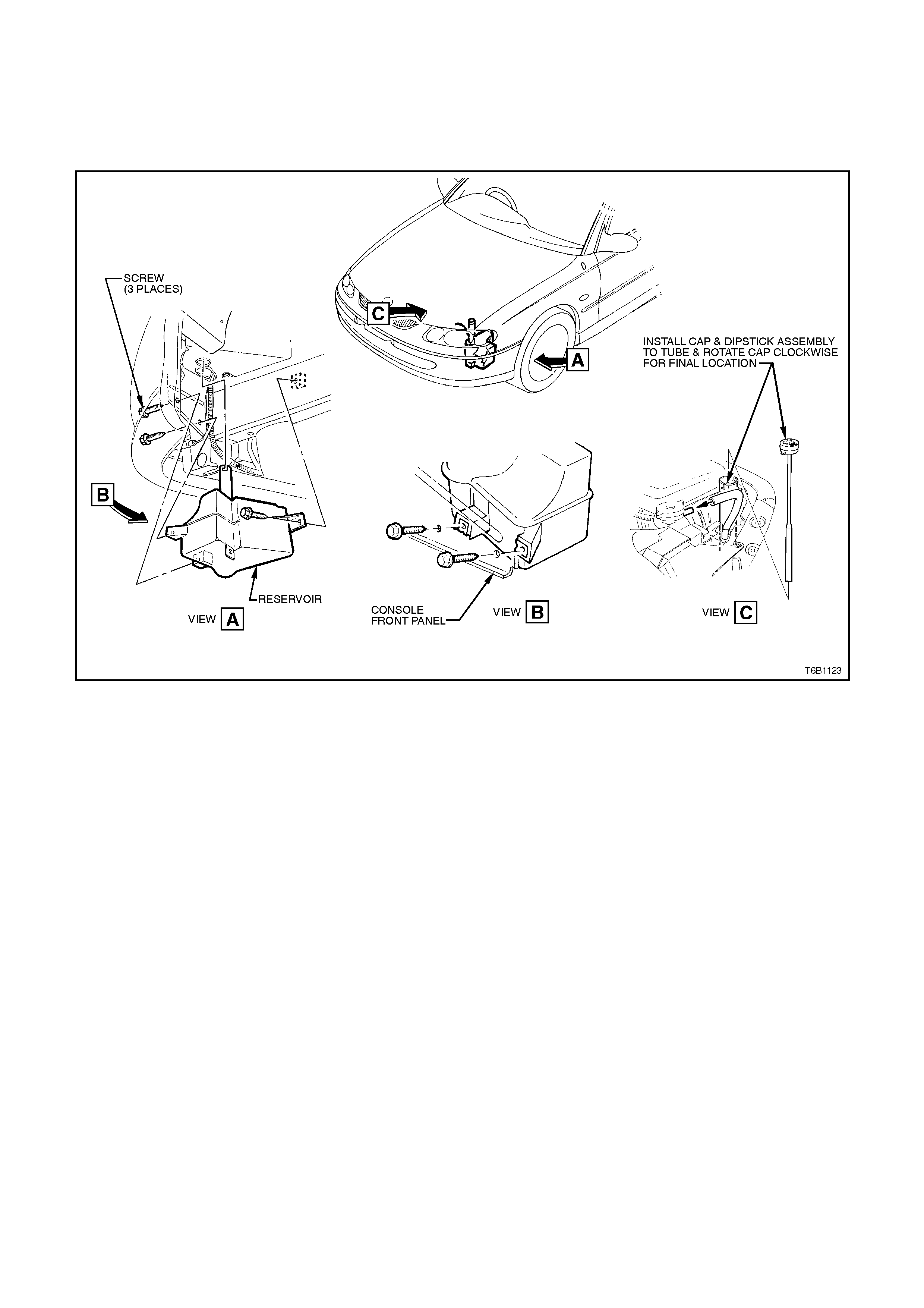
2.9 COOLANT RECOVERY RESERVOIR
REMOVE
1. Remove the radiator overflow hose from the radiator assembly neck and remove the reservoir tube from the
reservoir body assembly.
2. Remove reservoir assembly attaching screws, remove reservoir a ssembly.
Figure 6B1-1-32
INSPECT
1. Drain contents from reservoir assembly.
2. Clean reservoir assembly with water and dry using compressed air.
3. Check reservoir and assembly for damage, e.g. abrasions, cracks, or distortion. Replace if required.
REINSTALL
Reinstallation of the reservoir assembly is the reverse of removal procedures, noting the following points:
1. Refill cooling recovery reservoir and cooling system with the correct concentration of coolant, refer to
2.3 CHECKING AND FILLING COOLING SYSTEM in this Section.
2. Check cooling system for leaks.
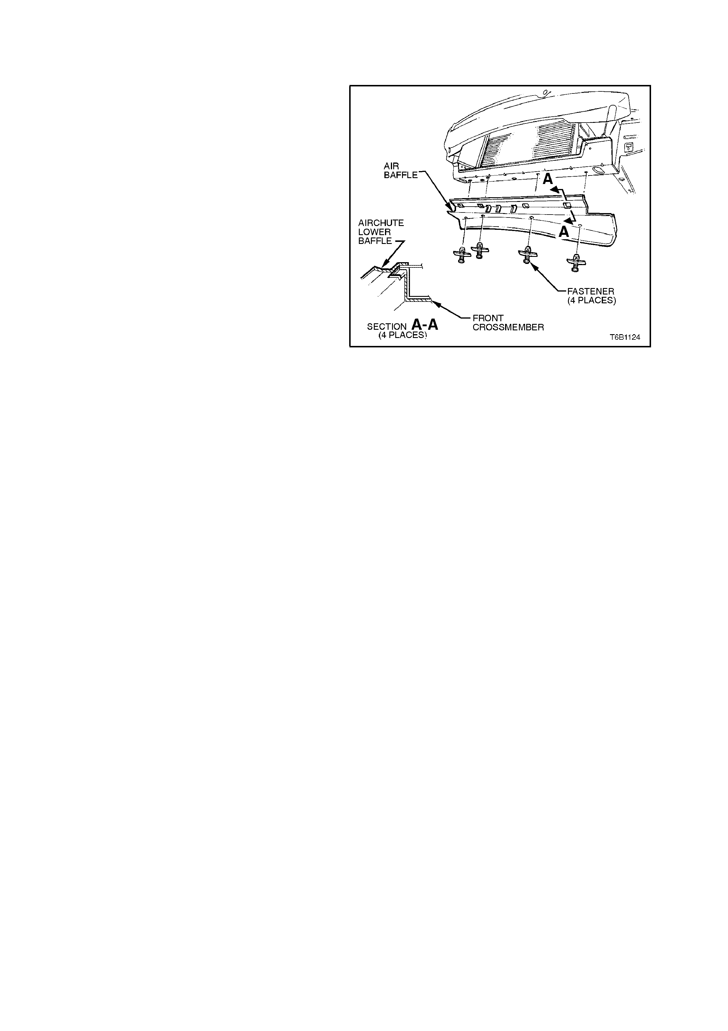
2.10 AIR BAFFLE
REMOVE
1. Jack up front of vehicle and place on safety
stands. Refer to Section OA GENERAL
INFORMATION for location of jacking points.
2. Remove air baffle to radiator support panel
fasteners and remove baffle.
Figure 6B1-1-33
REINSTALL
Reinstallation of the air baffle is the reverse of
removal procedures.
2.11 WATER PUMP
NOTE:
Water pump cannot be disassembled and
therefore can only be replaced as an assembly.
REMOVE
1. Allow engine to cool to ambient temperature
(less than 50°C), then remove radiator cap.
CAUTION:
Do not remove radiator cap while the engine
coolant t emperature is abov e 50°
°°
°C, as personal
injury may result.
2. Disconnect battery earth lead.
3. Loosen water pump pulley to hub bolts.
Figure 6B1-1-34
4. Using an 18mm ring spanner on drive belt
tensioner pulley pivot bolt, rotate tensioner
pulley assembly anti-clockwise and remove
drive belt from water pump pulley.
Figure 6B1-1-35
5. Remove radiator lower hose clamp at engine
front cover connection, disconnect hose from
front cover and allow coolant to drain into a
suitable splash tray.
CAUTION:
Always wear protective safety glasses when
working with spring type hose clamps. Failure
to do so could result in eye injury.
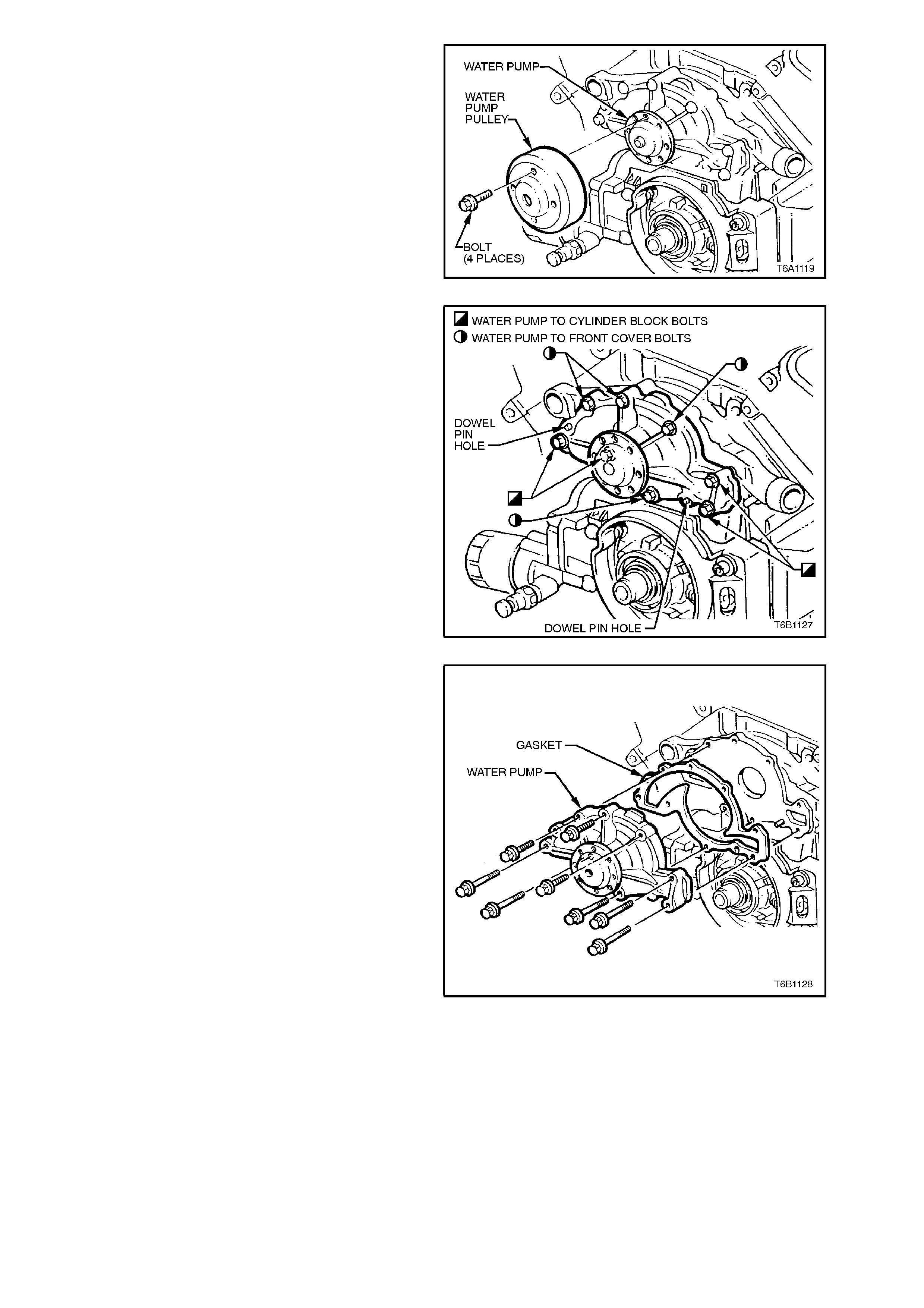
6. Remove water pump pulley to hub attaching
bolts, remove pulley
Figure 6B1-1-36
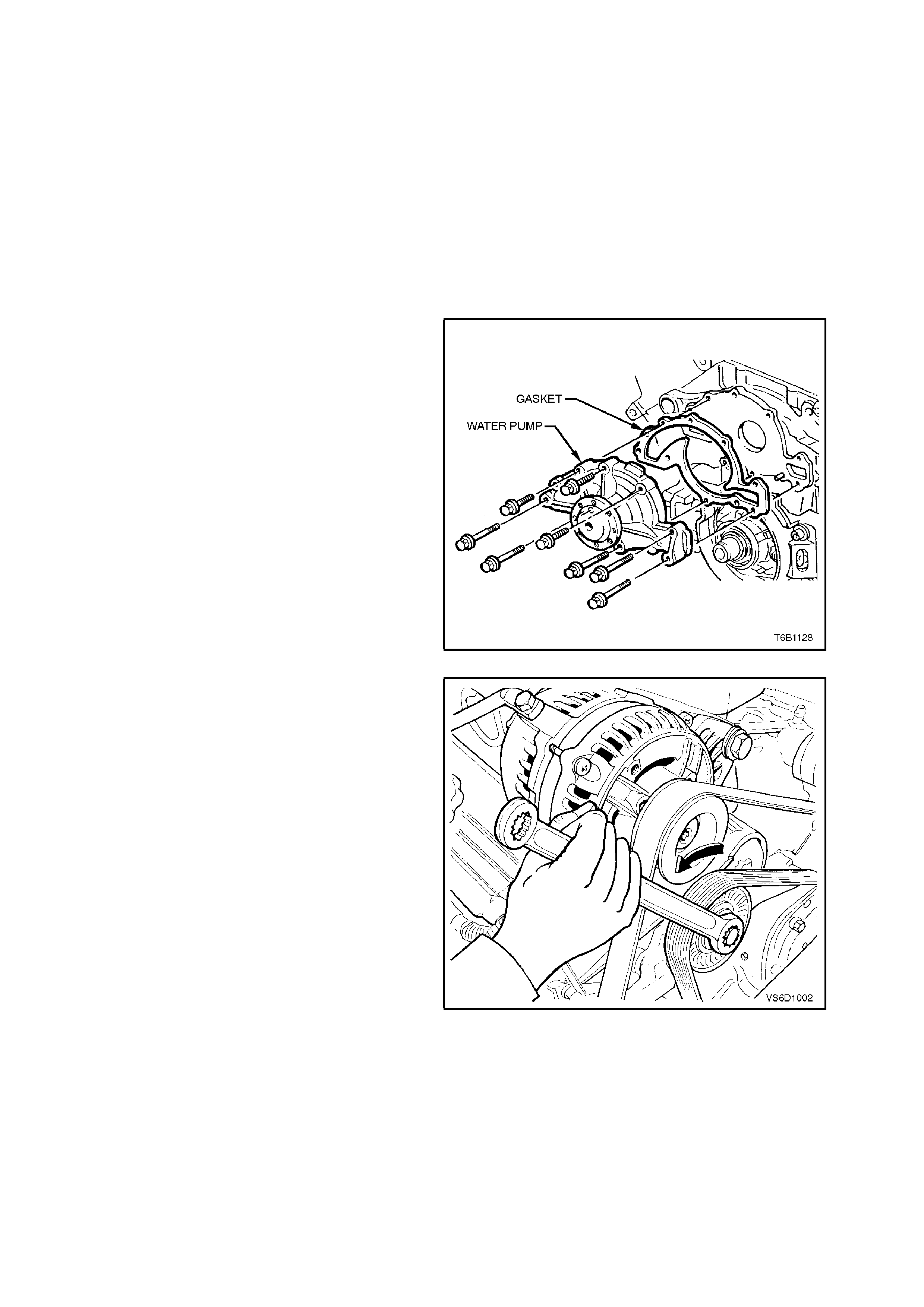
7. Remove water pump to front cover and
cylinder block attaching bolts.
Figure 6B1-1-37
8. Using a soft faced hammer, lightly tap water
pump housing to separate it from front cover.
9. Remove water pum p to f ront c over gask et and
discard.
Figure 6B1-1-38
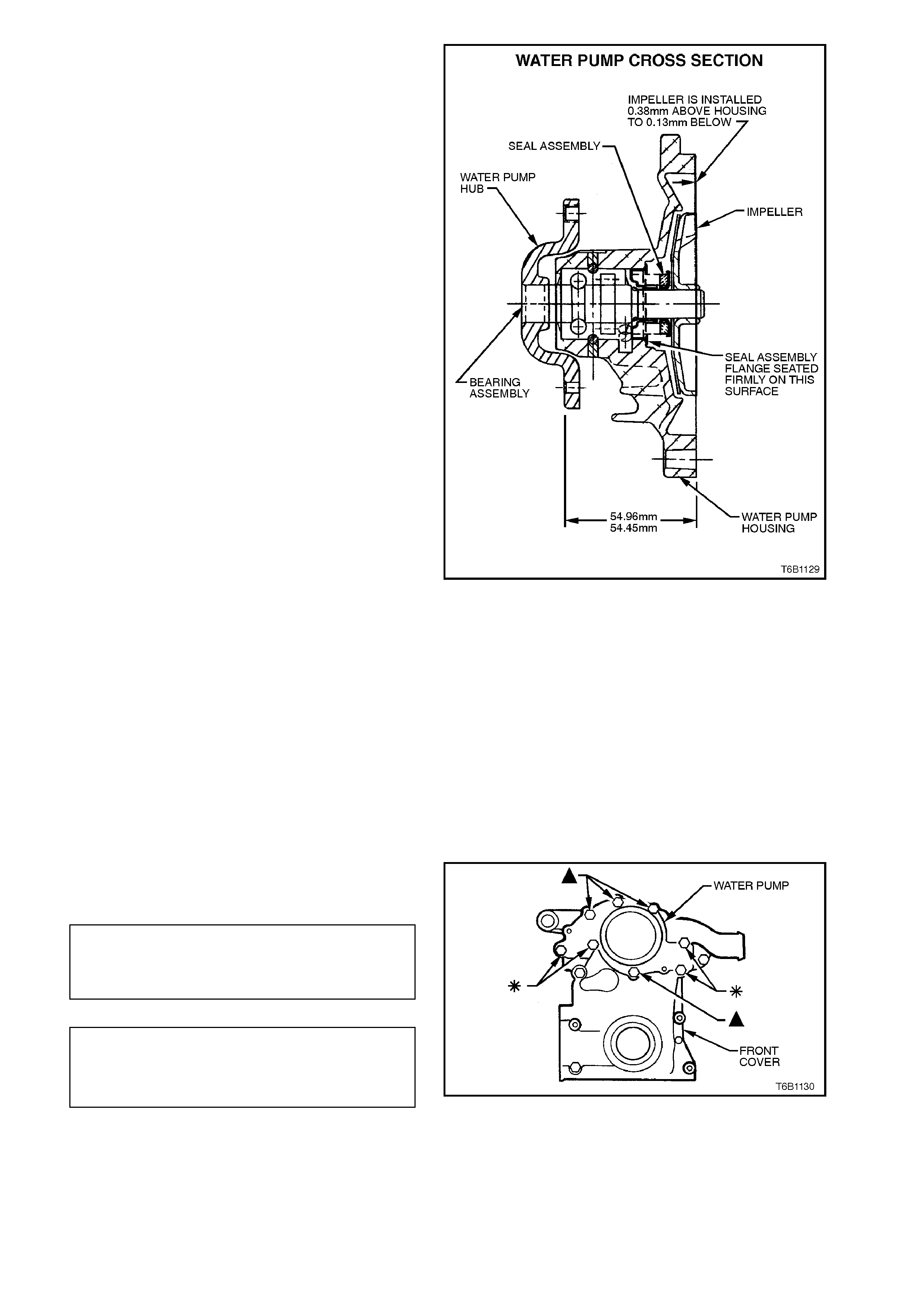
10. Check water pump bearing for excessive end-
play, or rough operation by rotating bearing
pulley hub. Replace water pump if faulty.
Figure 6B1-1-39
REINSTALL
1. Ensure that water pump and front cover
mating surfaces are clean and dry.
2. Install new gasket to front cover dowel pins.
3. Clean threads of water pump to front cover
and cylinder block attaching bolts. Coat
threads of bolts with Loctite 242 sealant or
equivalent (Holden Specification HN 1256
Class 2, Type 2).
NOTE:
Do not apply sealant to the f irs t 1-2 thr eads of each
bolt.
4. Install water pum p and attac hing bolts. Tighten
all bolts to the correct torque specification.
WATER PUMP TO FRONT
COVER ATTACHING BOLT 14 - 18
TORQUE SPECIFICATION - Nm
BOLTS !
WA TER PUMP TO CYLINDER
BLOCK ATTACHING BOLT 20 - 30
TORQUE SPECIFICATION - Nm
BOLTS !Figure 6B1-1-40

5. Install water pump pulley and attaching bolts.
6. Install drive belt (reverse to removal
procedures) and ensure that drive belt is
aligned with all accessory pulleys and
crankshaft balancer drive belt grooves.
7. Tighten water pump pulley attaching bolts to
the correct torque specification.
WA TER PUMP PULLEY TO HUB
ATTACHING BOLT
TORQUE SPECIFICATION 10 - 16 Nm
8. Refit radiator lower hose and clamp to front
cover connection.
9. Refill cooling system, refer to
2.3 CHECKING AND FILLING COOLING
SYSTEM in this Section.
10. Check for coolant leaks, refer to
2.7 PRESSURE TESTING in this Section.
11. Reconnect battery earth lead.
2.12 COOLING FAN AND SHROUD ASSEMBLY
REMOVE
1. Disconnect battery earth lead.
2. Remove the power steering pump reservoir,
refer to Section 9A STEERING.
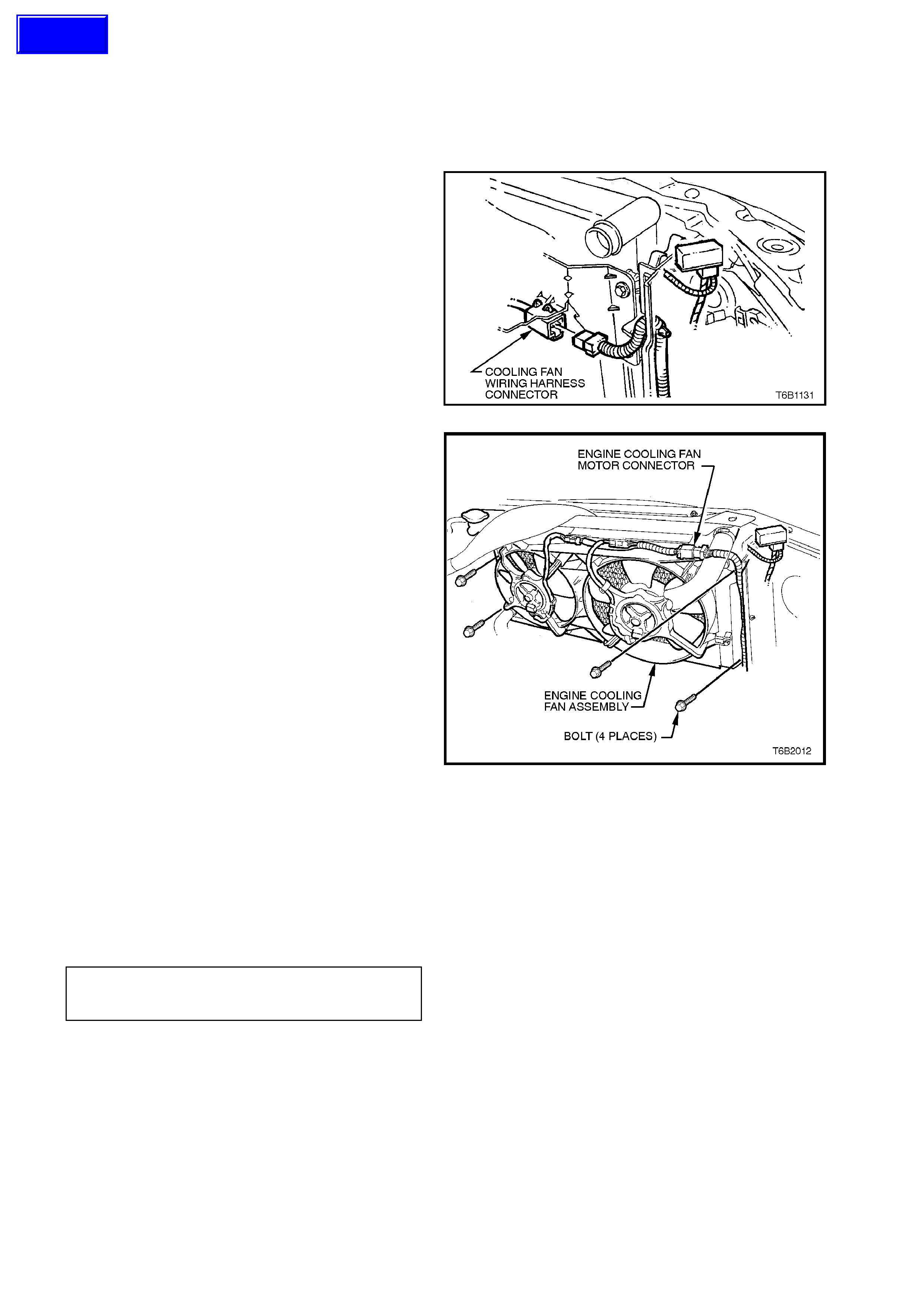
3. Depress tang on main wiring harness to
cooling fan motor wiring harness connector
and separate connector.
Figure 6B1-1-41
4. Remove cooling fan and shroud to radiator
attaching bolts, remove fan and shroud
assembly from engine compartment.
Figure 6B1-1-42
REINSTALL
Reinstallation of the cooling fan and shroud
assembly is the reverse of removal procedures,
noting the following points:
1. Ensure that fan and shroud assembly to
radiator attaching bolts are tightened to the
correct torque specification.
COOLING FAN AND SHROUD TO
RADIATOR ATTACHING BOLT
TORQUE SPECIFICATION 3 - 4.5 Nm
2. Check cooling fan operation, refer to
Section 6C1 POWERTRAIN - V6 ENGINE.
Check rotation direction of cooling fan.
Techline
DISASSEMBLE
1. Remove cooling fan and shroud assembly as
previously described.
2. Holding fan blade assembly, remove fan to
motor shaft attaching nut and remove fan.
NOTE:
If the fan blade assembly is a tight fit on motor
shaft, reinstall attaching nut and leave loose.
Holding fan blade assembly up, tap on end of
motor shaft with a soft faced hammer. Remove
attaching nut and fan blade assembly.
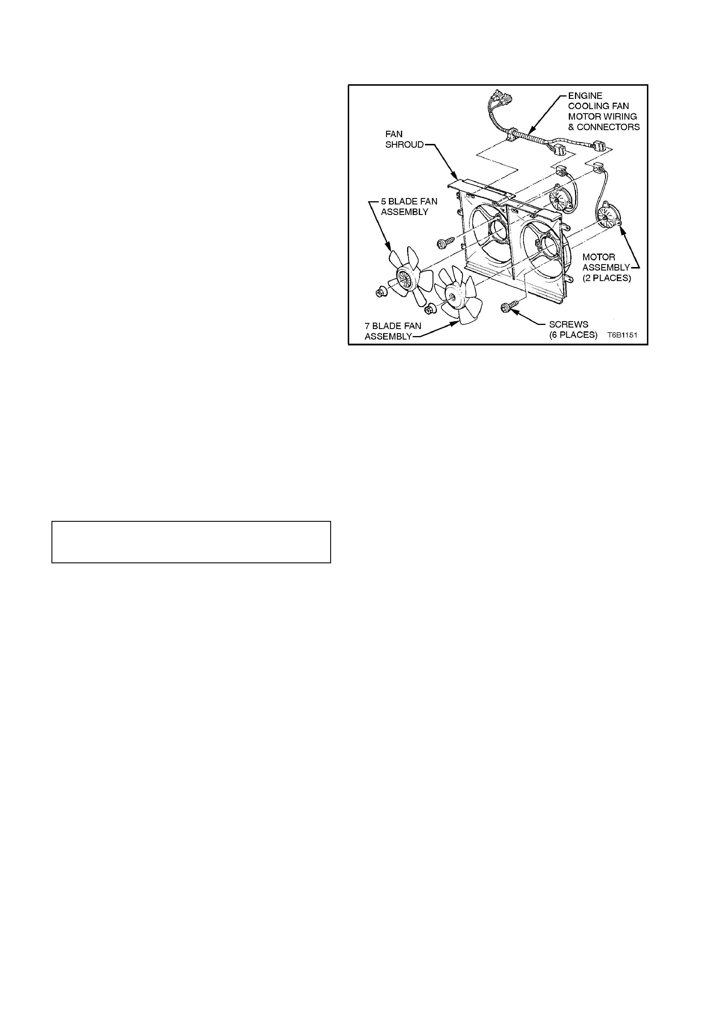
3. Remove motor assembly wiring harness to
shroud attaching straps
4. Remove motor assembly to shroud attaching
screws, remove motor.
Figure 6B1-1-43
REASSEMBLE
Reassembly is the reverse of disassembly
procedures, noting the following points:
1. Tighten motor to shroud attaching screws
securely.
2. Install fan blade assembly to motor shaft and
tighten attaching nut to the correct torque
specification.
FAN TO MOTOR SHAFT
ATTACHING NUT
TORQUE SPECIFICATION 1.5 - 2.5 Nm
3. Install new motor wiring harness to shroud
attaching straps.
4. Reinstall cooling fan and shroud assembly as
previously described.
2.13 RADIATOR
REMOVE
1. Allow engine to cool to ambient temperature
(less than 50°C), then remove radiator cap.
CAUTION:
Do not remove radiator cap while the engine
coolant t emperature is abov e 50°
°°
°C, as personal
injury may result.
2. Disconnect battery earth lead.
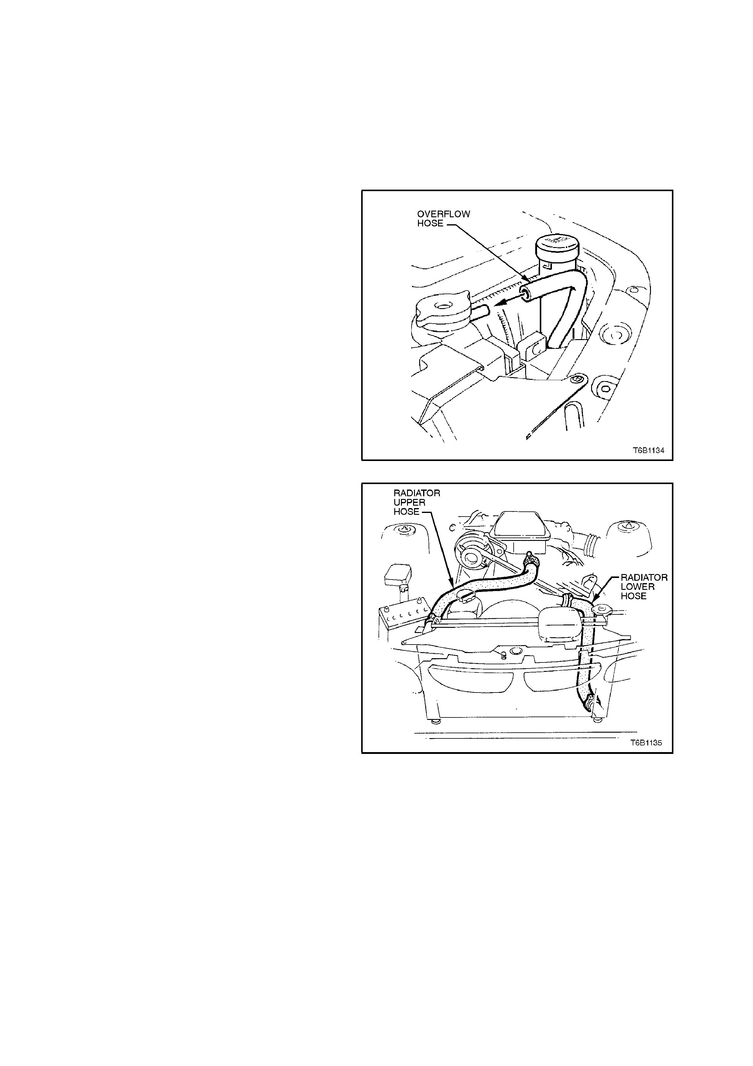
3. Remove coolant overflow hose from radiator
filler neck connection.
Figure 6B1-1-44
4. Remove radiator lower hose from radiator
connection and allow coolant to drain into a
suitable splash tray.
CAUTION:
Always wear protective safety glasses when
working with spring type hose clamps. Failure
to do so could result in eye injury.
5. Remove radiator upper hose from radiator.
Figure 6B1-1-45
6. Remove the cold air intake duct and radiator
shroud retainers, disengage locating tabs by
pulling shroud towards front of vehicle prior to
removing the shroud.
Figure 6A1-1-46
7. If vehicle is equipped with automatic
transmission, loosen transmission oil cooler
line hose clamps and disconnect hoses from
radiator oil cooler unions.
Plug hoses and oil cooler unions to prevent
foreign matter entry.
8. Remove the power steering pump reservoir,
refer to Section 9A STEERING.
Figure 6B1-1-47
9. Depress tang on main wiring harness to
cooling fan motor wiring harness connector
and separate connector.
Figure 6B1-1-48
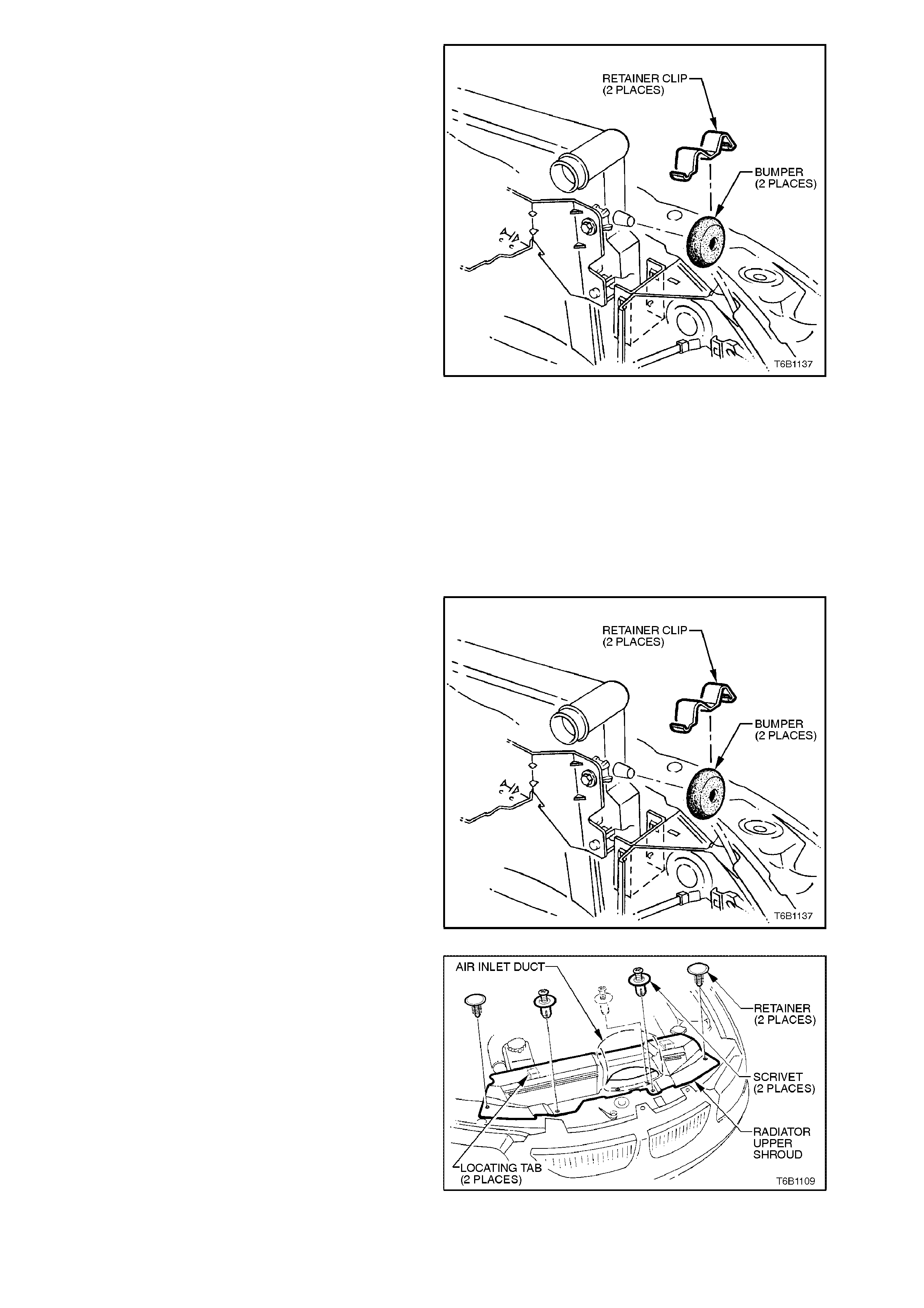
10. Using a screwdriver, compress and lever out
radiator retaining clips from radiator upper
mounting brackets.
11. Lift radiator upwards out of lower insulators
and remove radiator from vehicle.
Remove upper insulators from radiator upper
mounting pins.
Figure 6B1-1-49
REINSTALL
Reinstallation of the radiator is the reverse of
removal procedures, noting the following points:
1. Before installing radiator, inspect core to
ensure that there is no foreign matter in core
fins. Clean out between core fins with
compressed air.
2. Ensure that radiator lower mounting pins are
correctly located in lower insulators.
3. Ensure that upper insulators are installed on
upper m ounting pins and radiator retainer s are
installed.
Figure 6B1-1-51
4. Reinstall cold air intake duct and front end
panel radiator shroud.
Figure 6B1-1-52
5. If removed, tighten cooling fan and shroud
assembly to radiator attaching bolts to the
correct torque specification.
COOLING FAN AND SHROUD TO
RADIATOR ATTACHING BOLT
TORQUE SPECIFICATION 3 - 4.5 Nm
6. Refill cooling system, refer to
2.3 CHECKING AND FILLING COOLING
SYSTEM in this Section.
7. Check for coolant leaks, refer to
2.7 PRESSURE TESTING in this Section.
8. Check cooling fan operation, refer to
Section 6C1 POWERTRAIN MANAGEMENT
- V6 ENGINE.
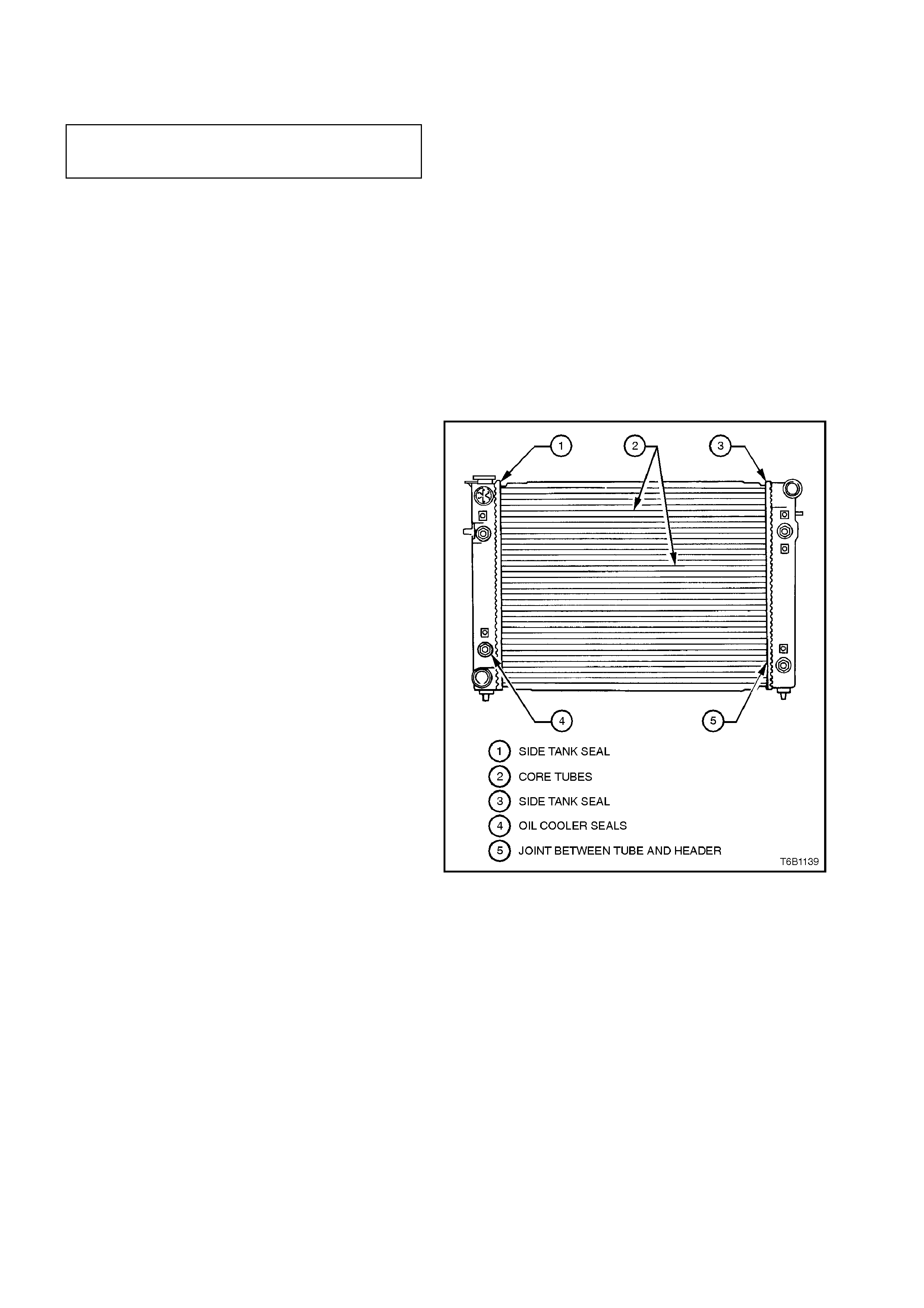
RADIATOR REPAIR PROCEDURE
REPAIRABLE LEAKS
There are two types of leaks that can be repaired
on the aluminium-plastic radiator; core leaks and
automatic transmission oil cooler seal leaks. Leak s
in the plastic tanks or the seals between the side
tanks and the headers cannot be repaired,
therefore the radiator must be replaced.
Core leaks may occur in a tube or in the joints
between the tubes and the headers. Seal leaks
may occur in the joints between the plastic tanks
and the headers or in the joints between the oil
cooler fittings and the tank (vehic les with autom atic
transmission).
Some leaks can be repaired while the radiator is
installed in the vehicle, however f or best r esults it is
recommended to remove the radiator from the
vehicle.
Figure 6B1-1-53
NOTE:
Minor damage to tubes, or tube to header joint
(holes up to 1m m diameter m ax.) can be repaired.
Core replacement is necessary if damage is any
greater.
REPAIR METHOD
Repairs to the aluminium radiator core should only
be made using the recommended 'Aluminised
Silicon' based liquid repair agent, in accordance
with the recommended procedure outlined in
General Core Repair in this Section. Refer to VT
Parts Information for Alum inised Silicon base liquid
part number.
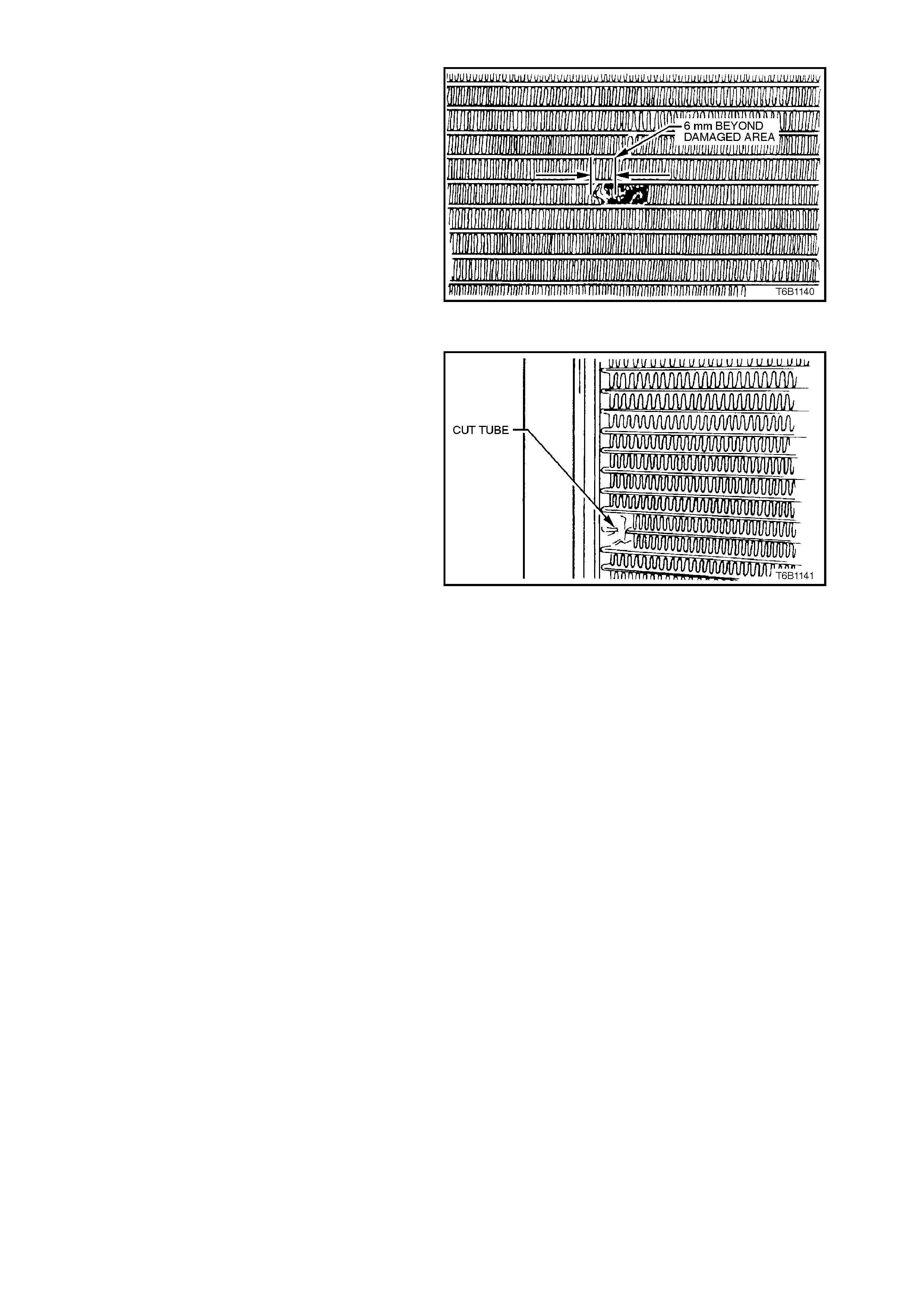
For damaged areas that are between the cooling
fins, it may be necessary to remove some of the
fins. Do not remove more fins than is necessary.
Usually 6mm beyond the leak or damage area, up
to a maximum of 25mm of total fin material, is
enough to make an effective repair. Figure 6B1-1-54
TUBE BLOCKING
If a tube is severely damaged, it can be blocked off.
NOTE:
Do not block off more than two tubes in a radiator.
Blocking off more than two tubes will reduce the
cooling capacity of the system.
The tube should be cut off 6 mm from the header
and pinched shut before it is cleaned and sealed,
refer GENERAL CORE REPAIR in this Section.
Figure 6B1-1-55
HEADER REPAIR
If the header or a tube near the header requires a
repair, the side tank does not have to be removed.

GENERAL CORE REPAIR
The need for careful preparation of the surface in
the repair area cannot be over-emphasised. If the
leak area surface is not clean, the repair material
will not adhere to the surface.
1. Remove and drain radiator, refer to
2.13 RADIATOR - REMOVE in this Section.
2. If neces sary, caref ully cut away fins to expose
the damaged area.
NOTE:
Do not cut away more than 25 mm total fin
material.
3. Clean away dirt etc. with water. Dry the
affected area using hot air from a hair drier.
NOTE:
Do not apply flame to dry damaged area.
4. Clean affected area with petrol to remove any
traces of oil.
5. Thoroughly stir contents of repair agent.
In cases of extended shelf life, the silicon in
solution may separate from the thinner base.
Should this occur, mix contents well until
agent is again homogeneous.
6. Apply repair agent s paringly to dam aged area.
Do not apply excessive amount, as this will
cause blockage of the radiator tube.
Use a clean, dry wooden applicator to 'DRIP'
agent onto damaged area of radiator.
7. Allow radiator to stand in a clean, dry area for
a minimum of 3 hours (at ambient
temperature of 20 - 30°C) with adequate
ventilation.
NOTE:
Do not apply heat or flame to promote drying.
8. Refit radiator, refer to 2.13 RADIATOR -
REINSTALL in this Section.
TRANSMISSION OIL COOLER LEAK TEST
If the transmission oil cooler is suspected of
leaking oil, test it before removal as follows:
1. Disconnect oil cooler lines from radiator
connections.
2. Plug one of the connections and attach an air
supply to the other connection.
3. Remove radiator cap.
4. APPLY AIR PRESSURE GRADUALLY,
increasing it up to a maximum of 1030 kPa.
If bubbles appear in radiator neck , oil cooler is
leaking and the radiator assembly must be
replaced.
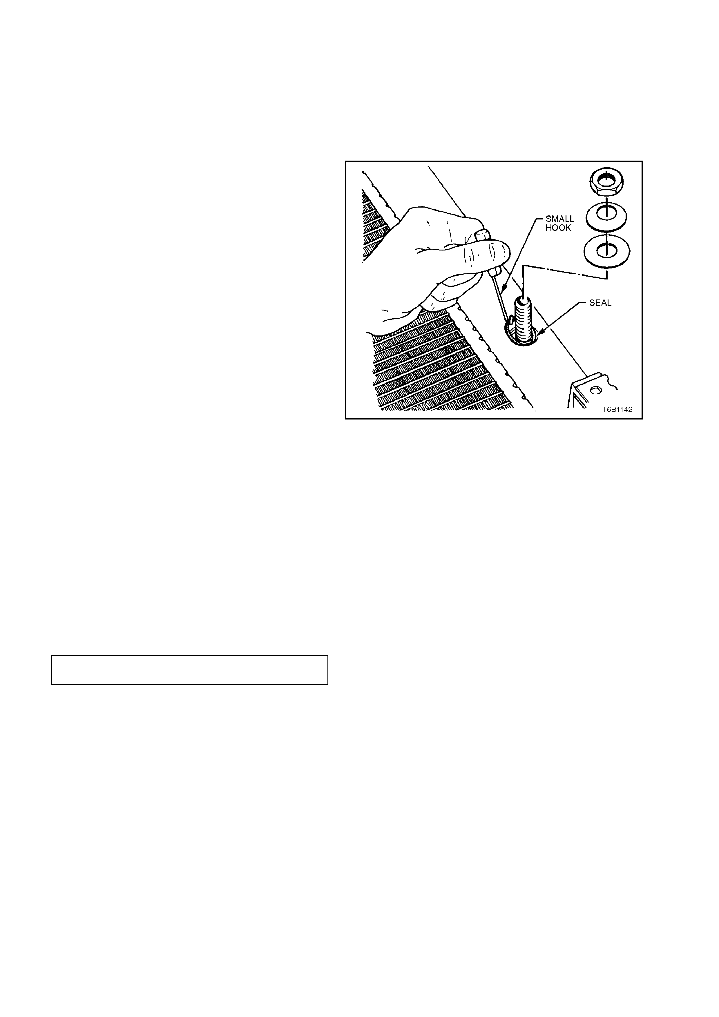
TRANSMISSION OIL COOLER SEAL REPLACEMENT.
The oil cooler seal can be replaced without
removing the side tank.
1. Remove radiator, refer to 2.13 RADIATOR -
REMOVE in this Sect ion, and lay radiator on a
flat surface.
2. Remove oil cooler to side tank nuts and
washers.
3. Press oil cooler into the side tank and remove
seal using a small wire hook.
Figure 6B1-1-56
4. Blow dry all surfaces on side tank and oil
cooler.
5. Install new seals WITHOUT ANY
LUBRICANT. Be sure they are seated
correctly on the flanges of the oil cooler
connections.
6. Pull oil cooler into position against side tank
and assemble washers and nuts to oil cooler
connections. Tighten oil cooler to side tank
nuts to the correct torque specification.
NOTE:
Do not over tighten, as damage to the seals could
result.
OIL COOLER TO SIDE TANK NUT
TORQUE SPECIFICATION 20 Nm
7. Reinstall radiator, refer to
2.13 RADIATOR - REINST ALL, and pressure
test, refer to 2.7 PRESSURE T ESTING in this
Section.

3. ENGINE COOLING SYSTEM DIAGNOSIS
Little or no heat coming from the heater, especially at idle, could be an indication of a cooling system problem.
As the coolant level begins to get lower than normal, air enters the system to replace the missing coolant. The
heater core is one of the highest parts of the cooling system and therefore, the first area to lose coolant.
At first, with a small amount of coolant loss, lack of heat will be most noticeable at idle. As driving speed increases,
the engine pumps more coolant and more heat is now able to pass through the heater core.
If coolant level drops even lower, heater operation will become less effective, even during normal driving. Cooling
and engine systems can be adversely affected if problem is not corrected.
The combustion gases can also force coolant out of the system and into the coolant recovery reservoir.
Air bubbles in the coolant or an overflow condition of the recovery reservoir are indications of a cylinder head gasket
leak.
To avoid needless time and cost in diagnosing cooling system complaints, the customer should be questioned
about driving conditions that place abnormal loads on the cooling system.
1. IS OVERHEATING OCCURRING AFTER PROLONGED IDLE, IN GEAR, AIR CONDITIONING SYSTEM
OPERATING?
If answer is YES - instruct owner on driving techniques that would avoid overheating such as:-
a. Idle in neutral as much as possible - increase engine rpm to get higher air flow (due to increase in voltage
to the fan) and water flow through radiator.
b. Turn air conditioning system off during extended idling periods if overheating is indicated on temperature
gauge. Further diagnostic checks should not be required.
2. IS OVERHEATING OCCURRING AFTER PROLONGED DRIVING IN SLOW CITY TRAFFIC, TRAFFIC
JAMS, PARADES, ETC?
If answer is YES - instruct owner on driving technique that would avoid overheating - same as for prolonged
idle - No.1. Further diagnostic checks should not be required.
If none of the above conditions apply, refer to the following Diagnosis Chart.
To effectively use this chart, question the customer to determine which of the following three categories apply to the
complaint:-
A. Hot indication on temperature gauge.
B. Boiling.
C. Coolant loss.
A. IF COMPLAINT IS HOT INDICATION ON TEMPERATURE GAUGE.
Was temperature reading accompanied by boiling? If answer is YES, go to overheating on diagnosis chart. If
answer is NO, check temperature gauge and sender.
B. IF COMPLAINT IS BOILING - go to overheating on diagnosis chart.
C. IF COMPLAINT IS COOLANT LOSS.
Determine if customer is filling the system correctly.
If incorrect filling is not the problem, go to coolant loss in the diagnosis chart.
WARNING:
The cooling system is designed to operate at 120-150 kpa and temperatures not exceeding 130°
°°
°c.
Refer to the WARNING in 2.1 SERVICE NOTES in this Section before removing the radiator cap or servicing the
system.
Techline

COOLING SYSTEM DIAGNOSIS
STEP ACTION RESULT IF YES IF NO
1. Check Temperature
gauge reading High Temp.
Low Temp. Go to Step 3
Go to Step 6
2. Check drive belt Belt Present Go to Step 3
3. Check coolant Boiling Go to Step 4 Go to Step 5
4. Check coolant level Low Go to Step 10 Go to Step 6
5. Check Radiator cap.
Refer to 2.7 in this Section OK? Go to Step 8 Replace
Radiator cap
6. Check thermostat. Refer
to 2.8 in this Section OK? Go to Step 9 Go to Step 13
7. Check Temperature
Gauge Faulty Replace Go to Step 12
8. Check cooling fan
operation. Refer Section
6C1 POWERTRAIN V6.
Operational Go to Step 10 Repair
9. Check for collapsed upper
or lower radiator hose. Collapsed Replace Go to Step 13
10. Visual system check Leaks Go to Step 13 Go to Step 11
11. Check Antifreeze /Antiboil
protection To
Specification Go to Step 12 Add Antifreeze
/Antiboil
12. Check radiator core for
bent fins, dirt, bugs or
other obstructions.
Obstructed Clean or
straighten Go to Step 14
13. Pressure Test cooling
system, Refer 2.7 in this
section.
Leaks Repair System OK
14. If none of the above
require repair, the
problem is out of ordinary
or of a major nature.
Listed below are two
groups of problem areas
that should be checked in
the order as shown.
PROBLEMS NOT REQUIRING DISASSEMBLY OF COOLING SYSTEM
1. Large obstructions blocking radiator or condenser airflow.
a. Auxiliary oil coolers.
b. License plate.
c. Obstruction of radiator grille, i.e. mud.
2. Loose, damaged or missing air chute side panels.
3. Missing or damaged air baffle.
4. Cracked or loose coolant recovery system hose.

PROBLEMS REQUIRING DISASSEMBLY OF COOLING SYSTEM
1. Damaged cooling fan or faulty motor operation.
2. Pressure test cooling system.
3. Defective water pump.
a. Eroded or broken impeller vanes.
b. Failed bearing or seal - check for shaft or bearing end play.
4. Internally blocked radiator core.
5. Obstruction of coolant recovery system.
6. Internal system leaks.
a. Head gaskets.
b. Cracked cylinder block.
c. Engine front cover.
d. Intake manifold gaskets.
7. Blocked coolant passages in cylinder heads or block - remove cylinder heads and check.
BLACK LIGHT AND DYE LEAK DIAGNOSIS METHOD
Holden strongly recommends the use of the black light and dye method to diagnose fluid leaks. This method of leak
detection is a proven, reliable method that identifies the specific leak source and/or location. The black light kit can
be used for various types of leak detection, when used with the appropriate tracer dye and it can be used for
detecting water leaks, engine and transmission fluid leaks, R12 & R134A leaks and coolant leaks. The following is a
summary of the steps involved in detecting a cooling system fluid leak using black light and dye.
1. Pour specified amount of dye into the radiator.
2. Road test the vehicle under normal operating conditions.
3. Direct the light towards the suspect area. The fluid leak will appear as a brightly coloured path leading to the
source.
4. Repair fluid leak and recheck to ensure that leak has been rectified.
5. Refer to the manufacturer’s directions when using this method.

4. SPECIFICATIONS
GENERAL
Radiator Cap Pressure Rating 135 kPa
Cooling System Capacity 12 Litres
Coolant Corrosion Inhibitor HN2043, approx. 6.0 litres
required when changing coolant.
THERMOSTAT
Type Power element (wax pellet)
Start to open at 89° - 93° C
Fully open at 106° C max.
WATER PUMP
Type Centrifugal
Drive V-belt
Bearing Type Double Row Ball Bearing
RADIATOR
Core type Aluminium crossflow core
Overall width 663 mm
Core width 546 mm
Overall height 462 mm
Core height 418 mm
Core thickness 25 mm
Plastic tanks Nylon 6,6
RADIATOR HOSES
Lower
Number and ty pe One, Moulded
Inside diameter 38.5 mm
Upper
Number and ty pe One, Moulded
Inside diameter 34.0 mm
ENGINE COOLI NG FAN 1
Number of blades 5
Spacing Uneven
Material Polypropylene (20% glass filled)
Diameter 340 mm
Electric motor drive 200 watts (nominal)
ENGINE COOLI NG FAN 2
Number of blades 7
Spacing Uneven
Material Polypropylene (20% glass filled)
Diameter 300 mm
Electric motor drive 160 watts (nominal)

5. TORQUE WRENCH SPECIFI CATIONS
Nm
Cylinder Block Drain Plugs 27 - 35
Coolant Outlet To Inlet Manifold Attaching Bolts 20 - 34
Water Pump To Front Cover Bolts 14 - 18
Water Pump To Cylinder Block Bolts 20 - 30
Water Pump Pulley Attaching Bolts 10 - 16
Cooling Fan And Shroud To Radiator Attaching Bolts 3 - 4.5
Fan To Motor Shaft Attaching Nut 1.5 - 2.5
Oil Cooler To Side Tank Nuts 20
Knock Sensor 16 - 22
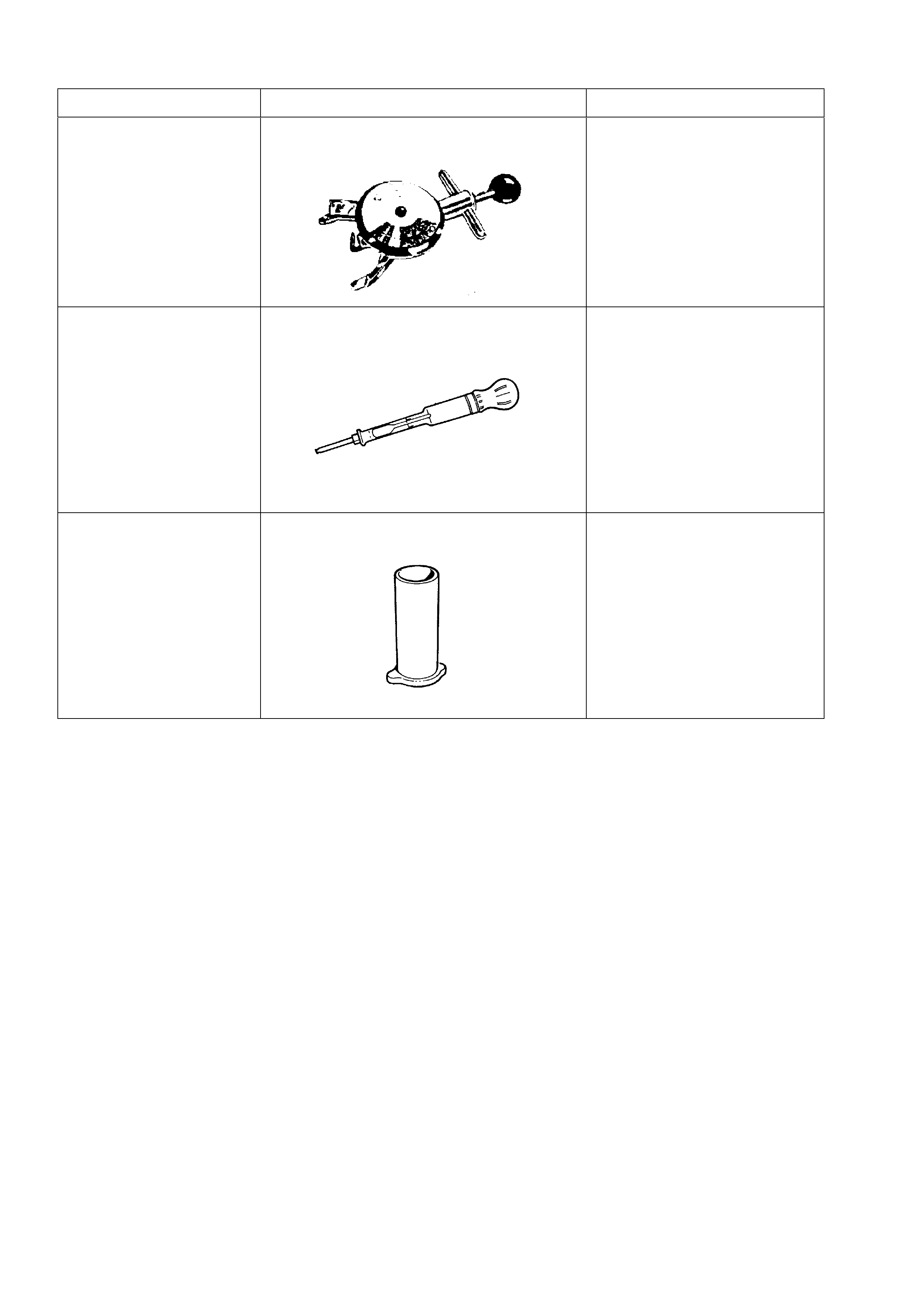
6. SPECIAL TOOLS
TOOL NO. REF IN TEXT TOOL DESCRIPTION COMMENTS
BT3373-F BELT TENSION GAUGE
AU435 COOLANT TESTER
AU425 COOLING SYSTEM FILLER TUBE