SECTION 6B1-2 - ENGINE COOLING - V6
SUPERCHARGED ENGINE
CAUTION:
This vehicle will be equipped with a Supplemental Restraint System (SRS). A SRS will
consist of either seat belt pre-tensio ners and a driver’s side air bag , or seat belt pre-
tensioners and a driver’s and front passenger’s side air bags. Refer to CAUTIONS,
Section 12M, before performing any service operation on or around SRS
components, the steering mechanism or wiring. Failure to follow the CAUTIONS
could result in SRS deplo yment, resulting in possible p ersonal injury or unnecessary
SRS system repairs.
1. GENERAL INFORMATION
The cooling system for VT V6 Supercharged engine differs from normally aspirated V6 engines with revised
plumbing and additional bleeder points.
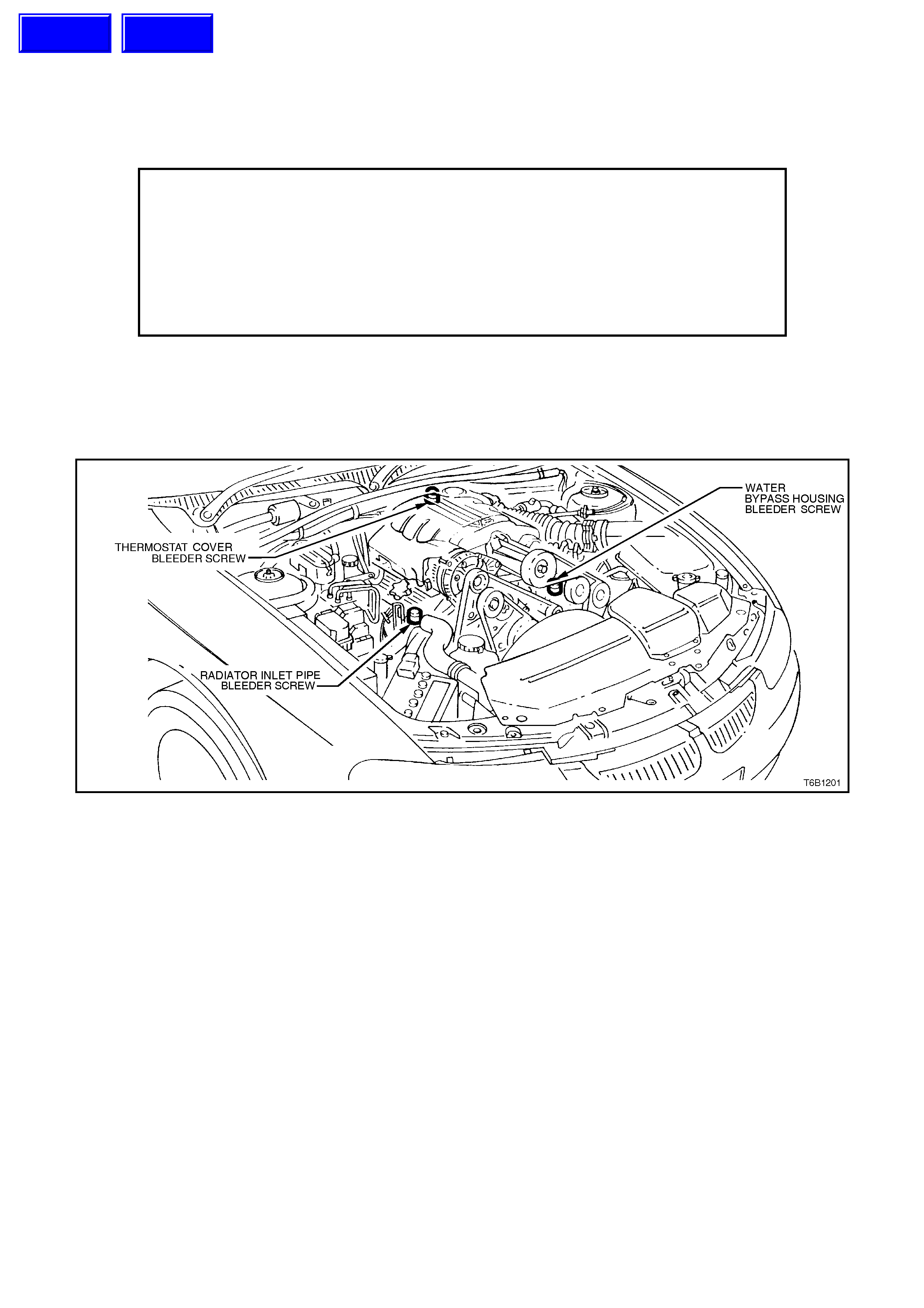
Figure 6B1-2-1
Techline
Techline

2. SERVICE OPERATIONS
Cooling system service operations carry over in general from those described in Section 6B1-1 ENGINE
COOLING - V6 ENGINE, except for the following operations.
2.1 SERVICE NOTES
WARNING:
To avoid serious personal injury, never remove the r adiator cap or open the air vent bleeder on the coolant
outlet when the engine is hot, even if the cooling system should require filling. Sudden release of cooling
system pressure is very dangerous.
When removing radiator cap allow engine to cool, place a shop rag over the radiator cap and slowly turn the cap
anti-clockwise (without pressing down) until the cap reaches the first ‘stop’. This is the pressure relief stop, which
will allow any remaining pressure within the system to escape. Press down on cap and continue to rotate anti-
clockwise until cap can be removed.
The vehicle is fitted with a radiator electric cooling fan. When working around the engine compartment with the
engine running or with the ignition ‘ON’, keep clear of the fan as it may start operating without warning.
The cooling system requires little care except for maintaining the coolant to the correct level in the cooling recovery
tank. Periodic servicing of the cooling system is required at the time or distance intervals as outlined in the VT
Series Owner’s Handbook.
Techline
2.2 CHECKING AND FILLING COOLING SYSTEM
During any service operation that requires the
cooling system to be partly or completely drained,
the following instructions must be followed when
refilling the cooling system to ensure that all air is
bled from system.
The following procedure requires the use of Tool
No. AU 425 to fill the cooling system.
1. Set heater control to maximum.
2. Mix a coolant m ixtur e consis ting 50% ethylene
glycol antifreeze/inhibitor (Specification HN
2043) with 50% clear, clean water.
Ethylene glycol conforming to Holden Specification
HN 2043 is named New Formula Long Life All
Seasons Coolant, and is available in the following
quantities:
1 litre, P/N M40236
5 litre, P/N M40307
20 litre, P/N M40238
NOTE:
Do not mix different types of anti-freeze or
corros ion inhibitors as they m ay be incom patible. If
a different type has been used in the cooling
system, flush the system with clean water, refer to
Section 6B1 ENGINE COOLING - V6 ENGINE -
2.4 CLEANING COOLING SYSTEM.
3. If cooling s ystem was com pletely drained, add
a pack of pellets (thr ee pellets) P/N M40124 to
cooling system by disconnecting radiator
upper hose from engine coolant outlet and
placing pellets inside radiator hose.
Refit hose to coolant outlet and tighten hose clamp.
4. Remove radiator cap and install Tool No. AU
425 to radiator filler neck.
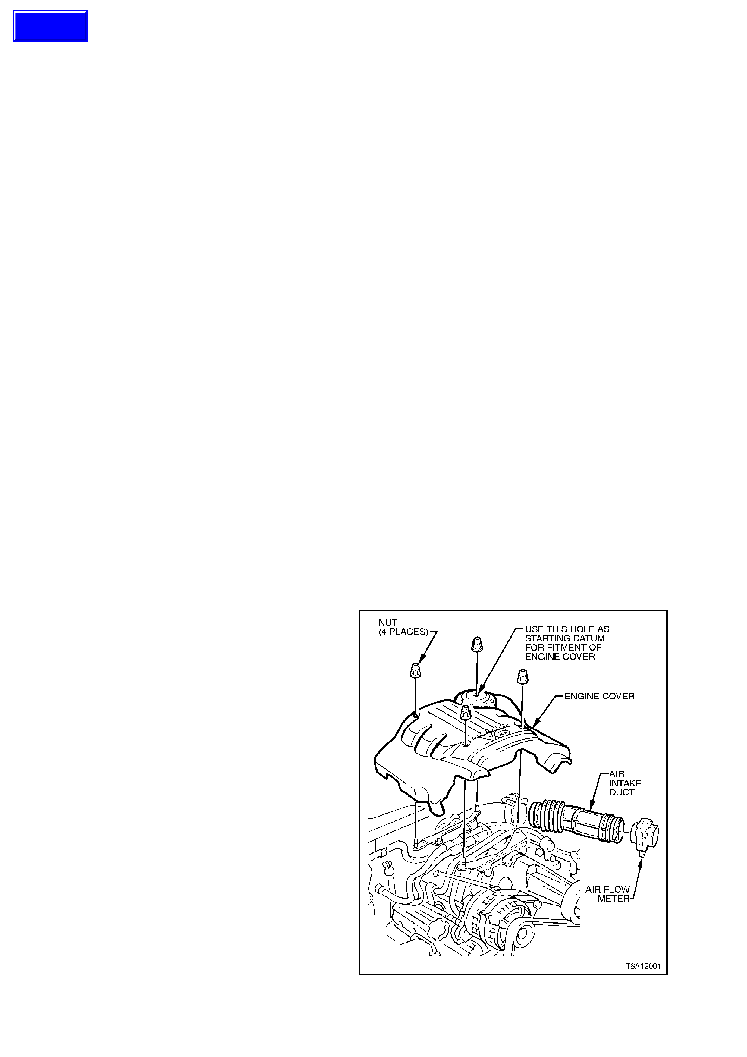
5. Remove the four engine dress cover dome
nuts and remove the cover.
Figure 6B1-2
Techline
NOTE:
Commence bleeding the cooling system using the
air vent bleeder screw located in the water bypass
housing.
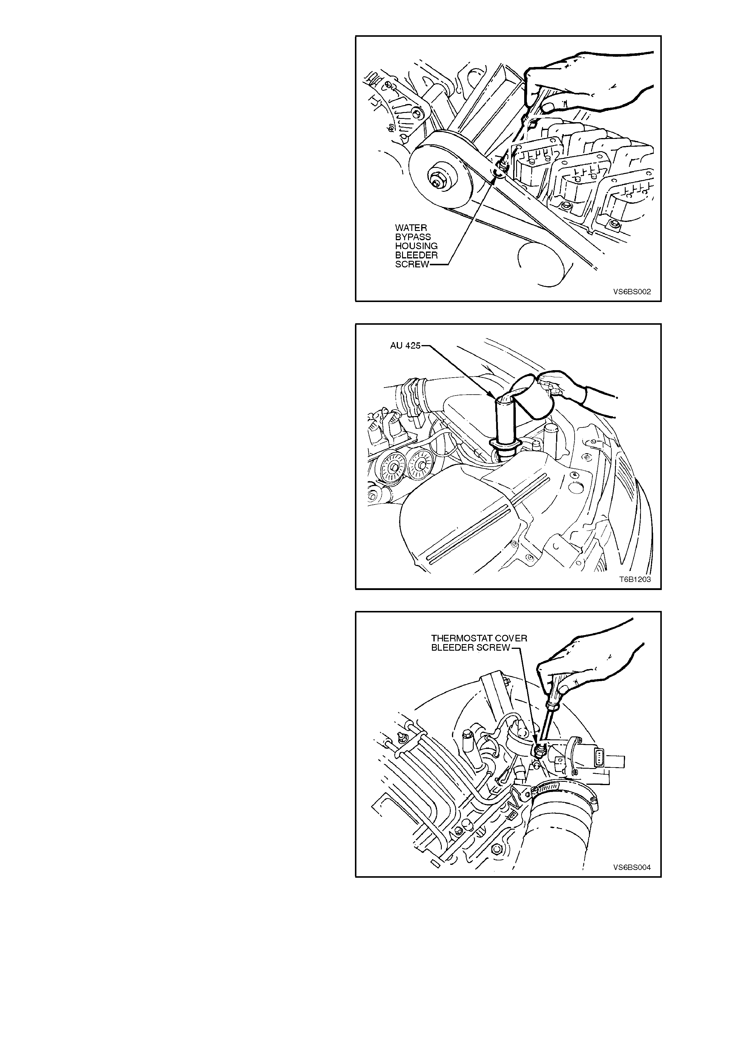
6. Using a screwdriver, open air vent bleeder
screw at water bypass housing.
Figure 6B1-2-3
7. Fill cooling system using coolant mixture via
Tool No. AU 425 until coolant flows from air
vent bleeder screw at water bypass housing
and all air is expelled. Close air vent bleeder
screw.
Figure 6B1-2-4
8. Continue bleeding cooling system from air
vent bleeder screw located in thermostat
housing cover until indications of air stop.
Close air vent bleeder screw.
Figure 6B1-2-5
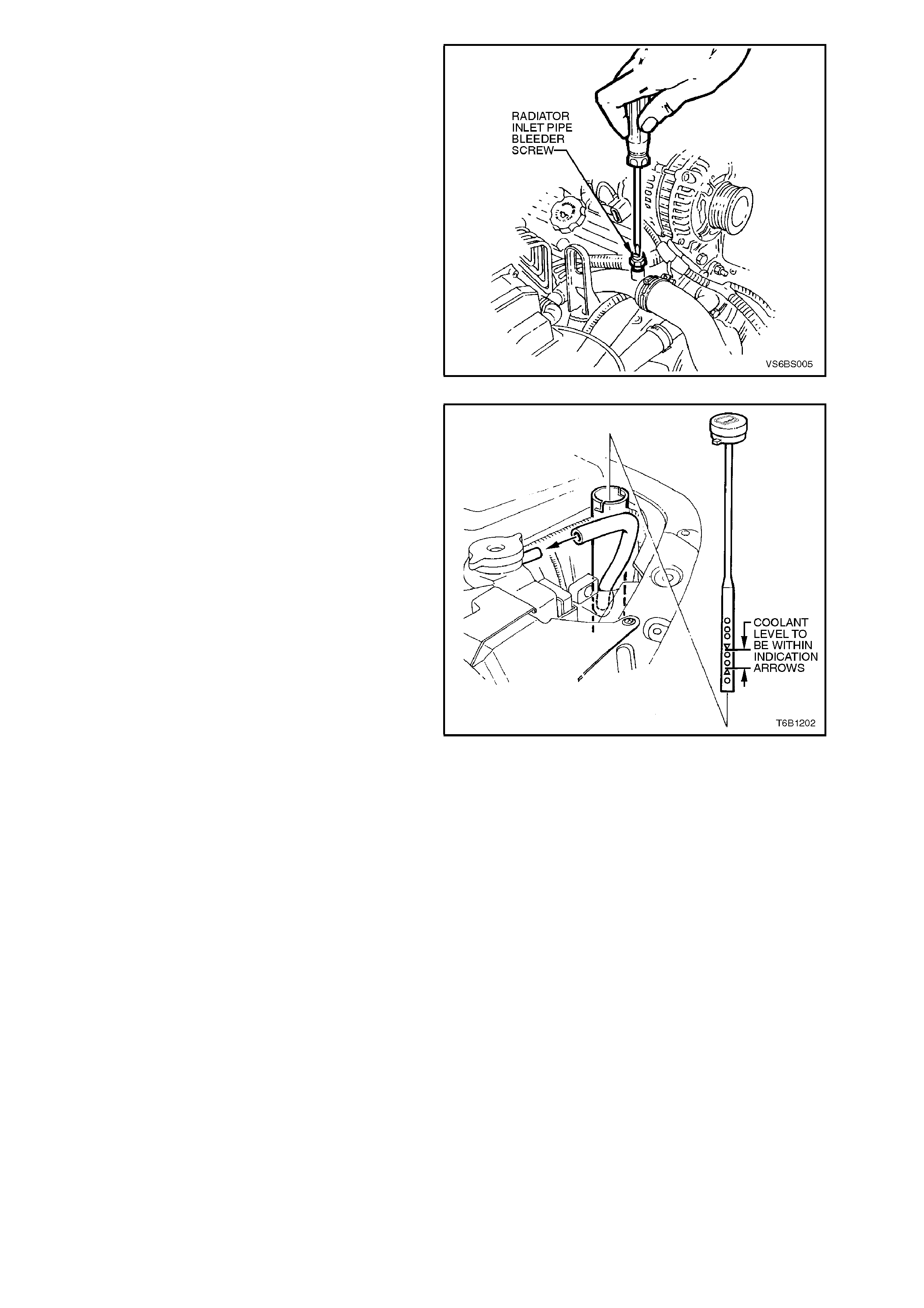
9. Commence bleeding system from radiator inlet
pipe air vent bleeder screw until indications of
air stop. Close air vent bleeder screw.
Repeat operations 6 to 9 until all air is exhausted
from cooling system.
Figure 6B1-2-6
10. Ensure air vent bleeder scr ews are closed and
remove AU 425 from radiator.
11. If necessary, remove coolant dipstick from
recovery tank and fill tank to between the
indicator arrows, re fit recovery tank dipstick.
12. Pressure test cooling system, refer to Section
6B1 ENGINE COOLING - V6 ENGINE -
2.7 PRESSURE TESTING.
13. Refit radiator cap.
14. Start engine and run at idle until operating
temperature is reached (thermostat is open).
15. Repeat bleeding procedure as outlined in
steps 6- 9 until all air is ex hausted from cooling
system.
16. Top up cooling system using coolant mixture
as described in step 2 and refit radiator cap.
Figure 6B1-2-7
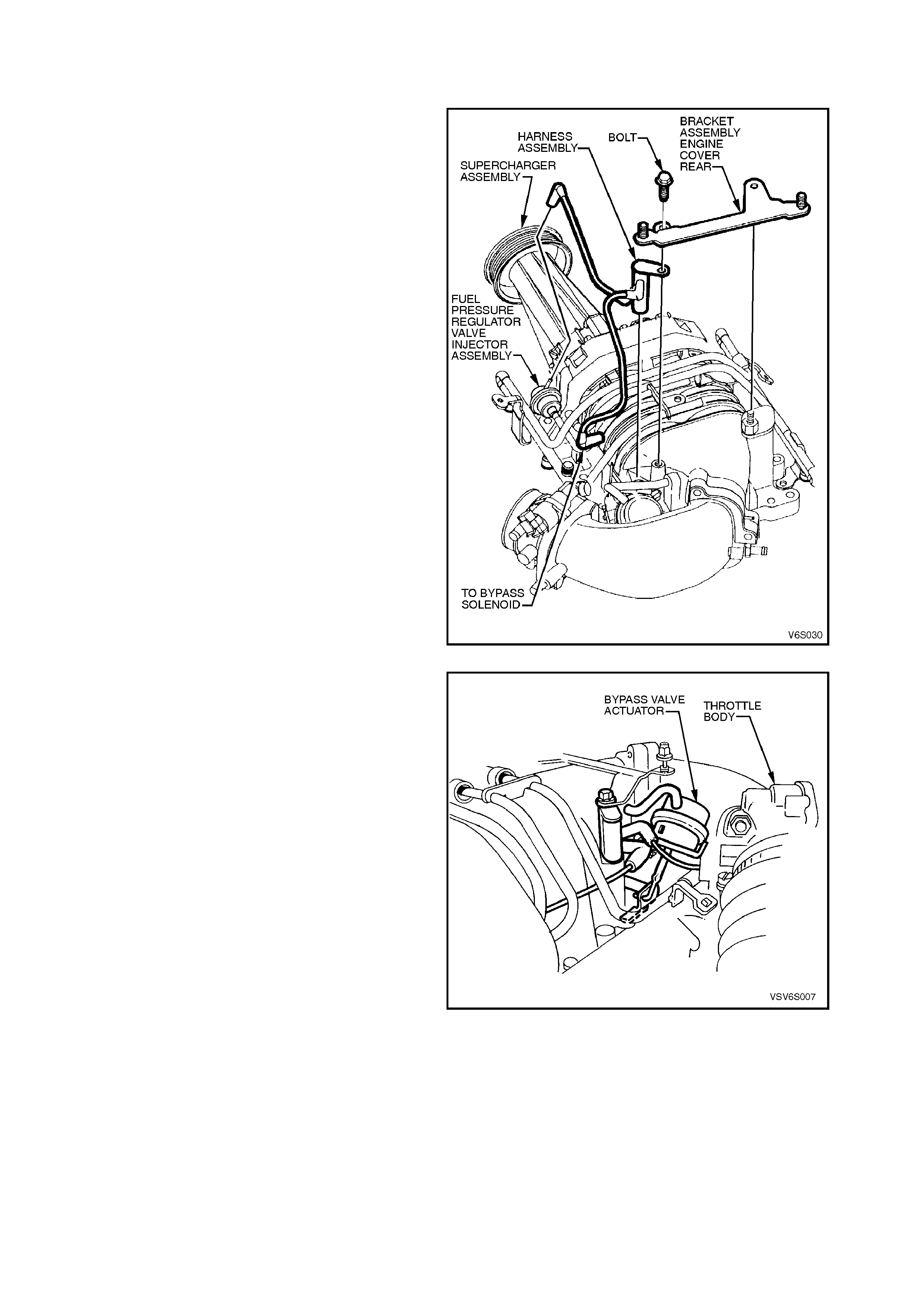
2.3 THERMOSTAT
REMOVE
1. Remove the four engine dress cover dome
nuts and remove the cover.
2. Remove 2 bolts securing rear engine cover
bracket assembly and remove bracket.
3. Tag and dis connect vacuum connections from
fuel pressure regulator and bypass solenoid,
lift out harness assembly.
Figure 6B1-2-8
4. Remove bolts attaching bypass valve actuator
and swing actuator to one side to gain access
to thermostat front bolt refer to Figure 6B-12-9.
6. Remove air intake duct, throttle body and
throttle cable mounting bracket, refer to
Section 6A1-2 ENGINE MECHANICAL - V6
SUPERCHARGED ENGINE.
7. Remove the water outlet hose from the
thermostat housing cover.
Figure 6B1-2-9
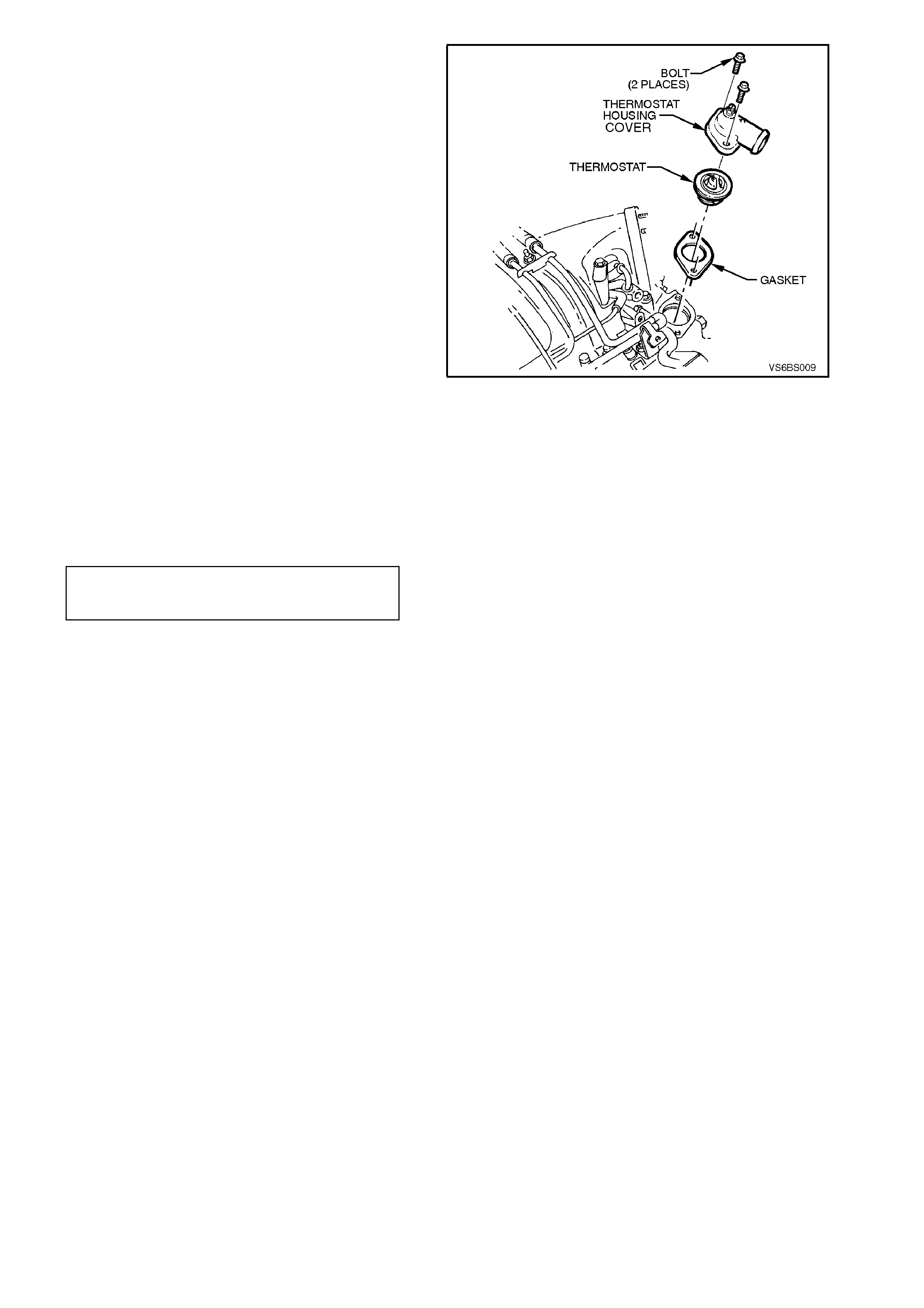
8. Remove the two bolts securing the thermostat
housing cover, remove cover, thermostat and
gasket. The rear bolt can be removed by
reaching around from behind supercharger
(using short open-ended spanner) and the
front bolt removed by using a socket ratchet
with extension. W iring harnes s located in fr ont
of the rear firewall may need to be temporar ily
shifted in order to gain access to rear bolt.
Figure 6B1-2-10
REINSTALL
Reinstallation of the thermostat is the reverse of
removal procedures noting the following.
1. Ensure all gasket surfaces are clean.
2. Tighten thermostat housing cover screws to
correct torque specification.
THERMOSTAT HOUSING
COVER SCREWS
TORQUE SPECIFICATION 20-34 Nm
3. Ensure the cooling system is bled correctly,
refer to 2.2 CHECKING AND FILLING
COOLING SYSTEM in this Section.
4. If the wiring harness was moved during
removal, reposition to original location.
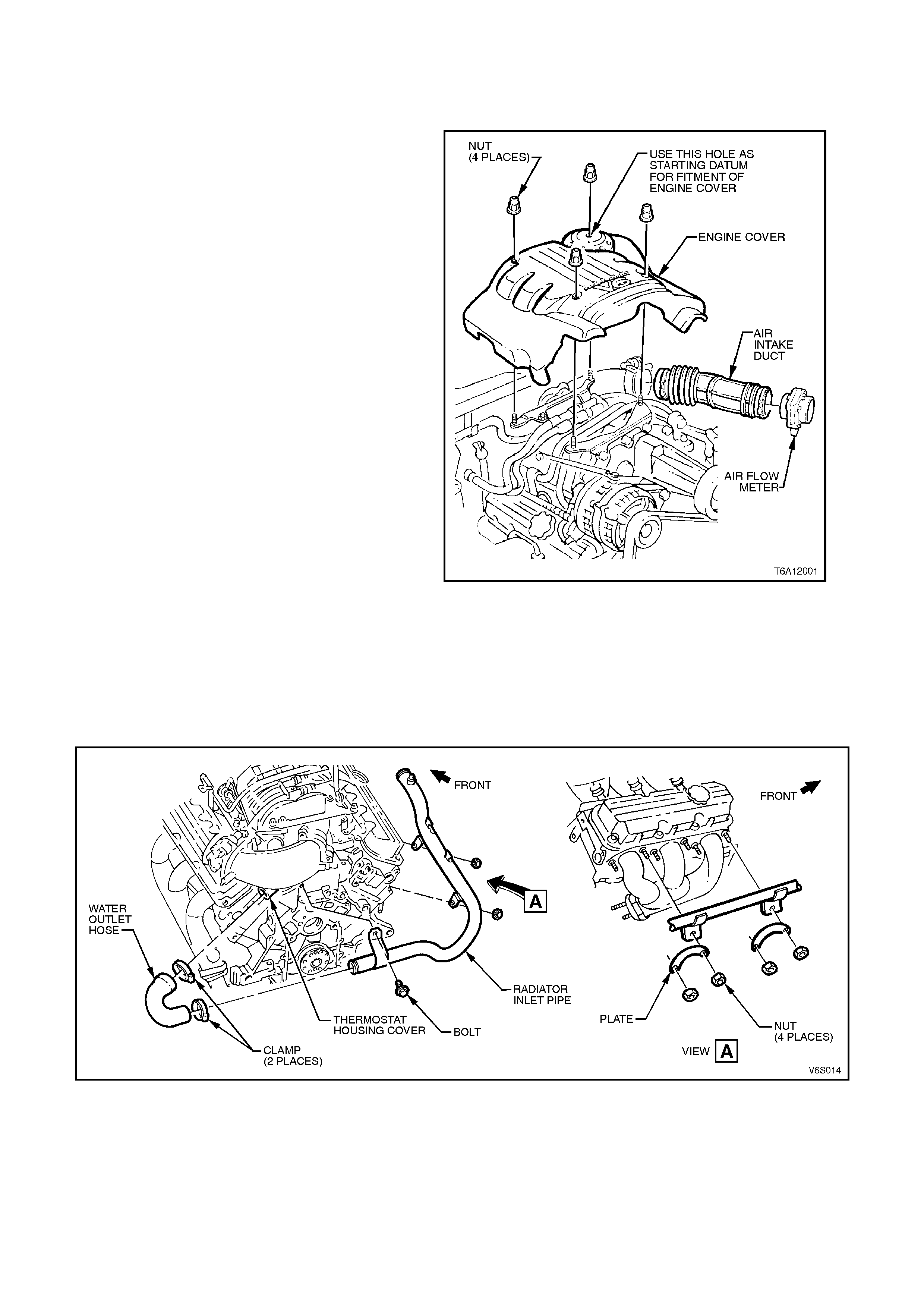
2.4 RADIATOR INLET PIPE
REMOVE
1. Disconnect the negative cable from the
battery.
2. Remove the lower radiator hose and drain the
cooling system.
3. Remove the four engine dress cover dome
nuts and remove the cover.
Figure 6B1-11
4. Remove the water outlet hose from the
radiator inlet pipe.
5. Disconnect the wiring harness from the
retainer brackets on the radiator inlet pipe.
6. Remove the screws securing the radiator inlet
pipe to the engine assembly removing the
pipe.
Figure 6B1-2-12
REINSTALL
Reinstallation of the radiator inlet pipe is the
reverse of removal operations noting the following
points.
1. Ensure the cooling system is bled correctly,
refer to 2.2 CHECKING AND FILLING
COOLING SYSTEM in this Section.

3. SPECIFICATIONS
GENERAL
Radiator cap pressure rating 135 kPa
Cooling system capacity 12 Litres
Coolant corrosion inhibitor HN 2043, approx. 6.0 litres
required for service fill.
THERMOSTAT
Type Power element (wax pellet)
Start to open 89° - 93° C
Fully open at 106° C max
WATER PUMP
Type Centrifugal
Drive V-belt
Bearing type Double Row Ball Bearing
RADIATOR
Core type Aluminium crossflow core
Overall width 663 mm
Core width 546 mm
Overall height 462 mm
Core height 418 mm
Core thickness 25 mm
Plastic tanks Nylon 6,6
RADIATOR HOSES
Lower
Number and ty pe One, Moulded
Inside diameter 38.5 mm
Upper
Number and ty pe One, Moulded
Inside diameter 34.0
ENGINE COOLI NG FAN 1
Number of blades 5
Spacing Uneven
Material Polypropylene (20% glass
filled)
Diameter 340 mm
Electric motor drive 200 watts (nominal)
ENGINE COOLI NG FAN 2
Number of blades 7
Spacing Uneven
Material Polypropylene (20% glass
filled)
Diameter 300 mm
Electric motor drive 160 watts (nominal)

4. TORQUE WRENCH SPECIFI CATIONS
Nm
Thermostat housing cover retaining bolts 20-34
Radiator inlet pipe retaining bolts 20-27
Water Outlet Hose 2-5
Engine dress cover attaching nut 4-6
Rear engine cover bracket assembly securing bolts 15 - 20
5. SPECIAL TOOLS
TOOL NO. REF IN TEXT TOOL DESCRIPTION COMMENTS
AU 425 COOLING SYSTEM FILLER TUBE