
SECTION 6C1-1 GENERAL INFORMATION
CAUTION
This vehicle will be equipped with a Supplemental Restraint System (SRS). A SRS
will consist of either seat belt pre-ten sioners and a driv er’s side air bag, or seat belt
pre-tensioners and a driver’s and front passenger’s side air bags. Refer to
CAUTIONS, Section 12M, before performing any service operation on or around SRS
components, the steering mechanism or wiring. Failure to follow the CAUTIONS
could result in SRS deployment, resulting in possible personal injury or
unnecessary SRS system repairs.
CAUTION
This vehicle may be equipped with LPG (Liquefied Petroleum Gas). In the interests
of safety, the LPG fuel system should be isolated by turning 'OFF' the manual
service valve and then draining the LPG service lines, before any service work is
carried out on the vehicle. Refer to the LPG leaflet included with the Owner's
Handbook for details or LPG Section 2 for more specific servicing information.
1. GENERAL DESCRIPTI ON
The engines used in this vehicle uses a Powertrain Control Module (PCM) with both an automatic transmission and a
manual transmission to control exhaust emissions while maintaining excellent driveability and fuel economy. The PCM
maintains a desired air/fuel ratio of precisely 14.7 to 1 by monitoring electrical signals from dual oxygen sensors
mounted in the exhaust stream and optimising the amount of fuel flow from the injectors. This method of "feed back"
fuel control is called CLOSED LOOP.
In addition to fuel control, the PCM also controls ignition dwell and timing, idle speed, EGR, electric engine cooling fan,
electric fuel pump, instrument panel "Check Powertrain" lamp and on vehicles so equipped, the A/C compressor clutch.
The PCM also controls the automatic transmission functions. The PCM also interfaces through the serial data line with
other vehicle control or information modules, such as the trip computer, Body Control Module (BCM), ABS/ETC module,
ECC module, SRS module, and theft deterrent system. Figures 6C1-1-1 through 6C1-1-4 contain a list of the various
operating conditions sensed by the PCM on the left, and the various systems controlled on the right. Details of basic
operation, diagnosis, and service are covered in this and other relevent Sections.
The PCM has a built-in diagnostic system that recognises and identifies possible operational problems and alerts the
driver by illuminating the "Check Powertrain" lamp/Malfunction Indicator Lamp (MIL) on the instrument panel. If the
lamp comes "ON" while driving, it does not mean that the engine should be stopped immediately, but the cause of the
lamp coming "ON" should be checked as soon as is reasonably possible. The PCM has built-in backup systems that in
all but the most severe failures will allow the vehicle to operate in a near normal manner until repairs can be made.
Below the instrument panel to the left of the steering column is a Data Link Connector (DLC) which is used by the
assembly plant for a computer "check-out" of the system. This connector is used in service along with a scan tool to
help diagnose the system. Refer to Section 6C1-2, DIAGNOSIS for further details.
The locations of the Engine Management System (EMS) components of the system are shown in the following
Figures 6C1-1-5 through 6C1-1-13.
For the Transmission Management System components and their locations, refer to Figure 6C1-1-60 in this Section.
Techline
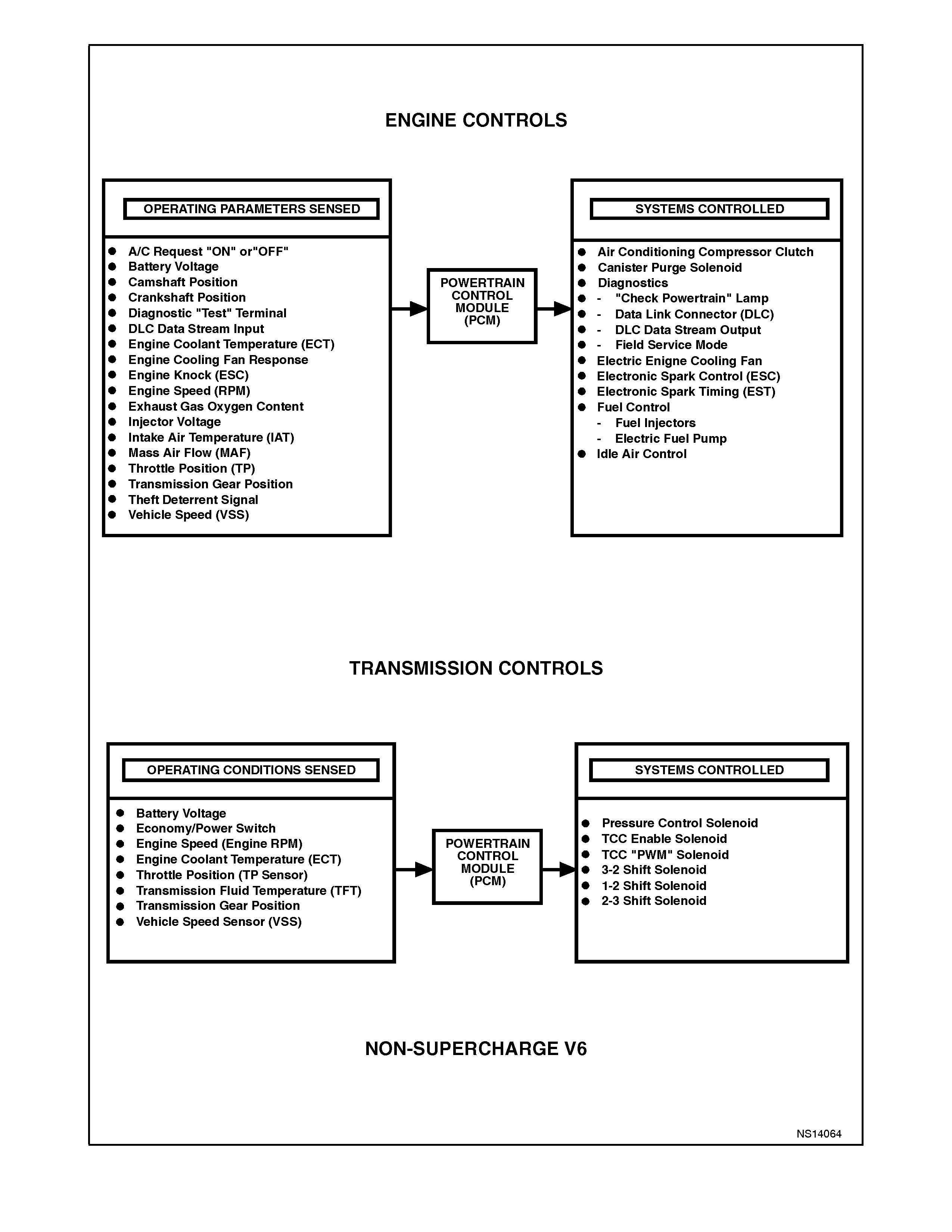
Figure 6C1-1-1 Non-Supercharged Engine Powertrain Control Module Systems
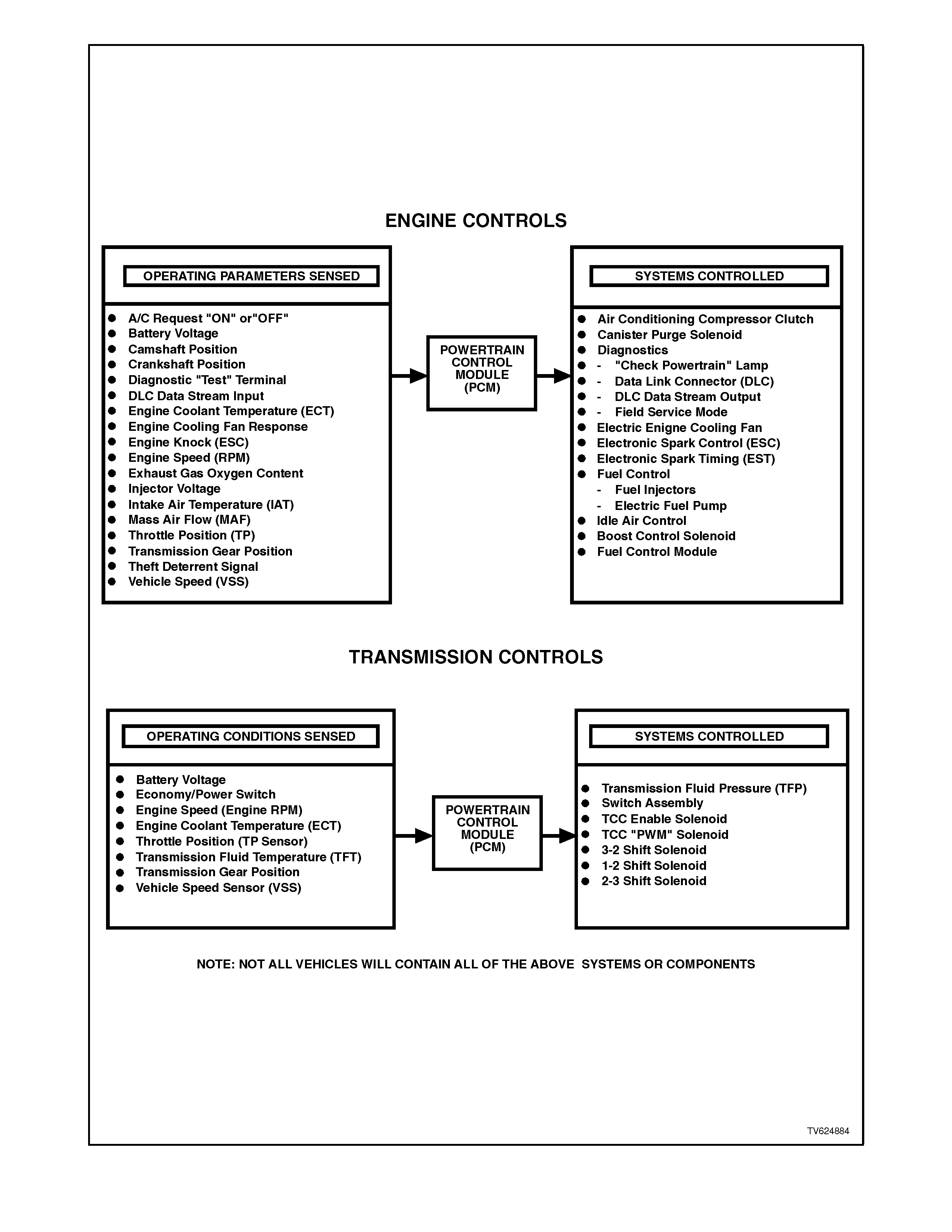
Figure 6C1-1-2 Supercharged Engine Powertrain Control Module Systems
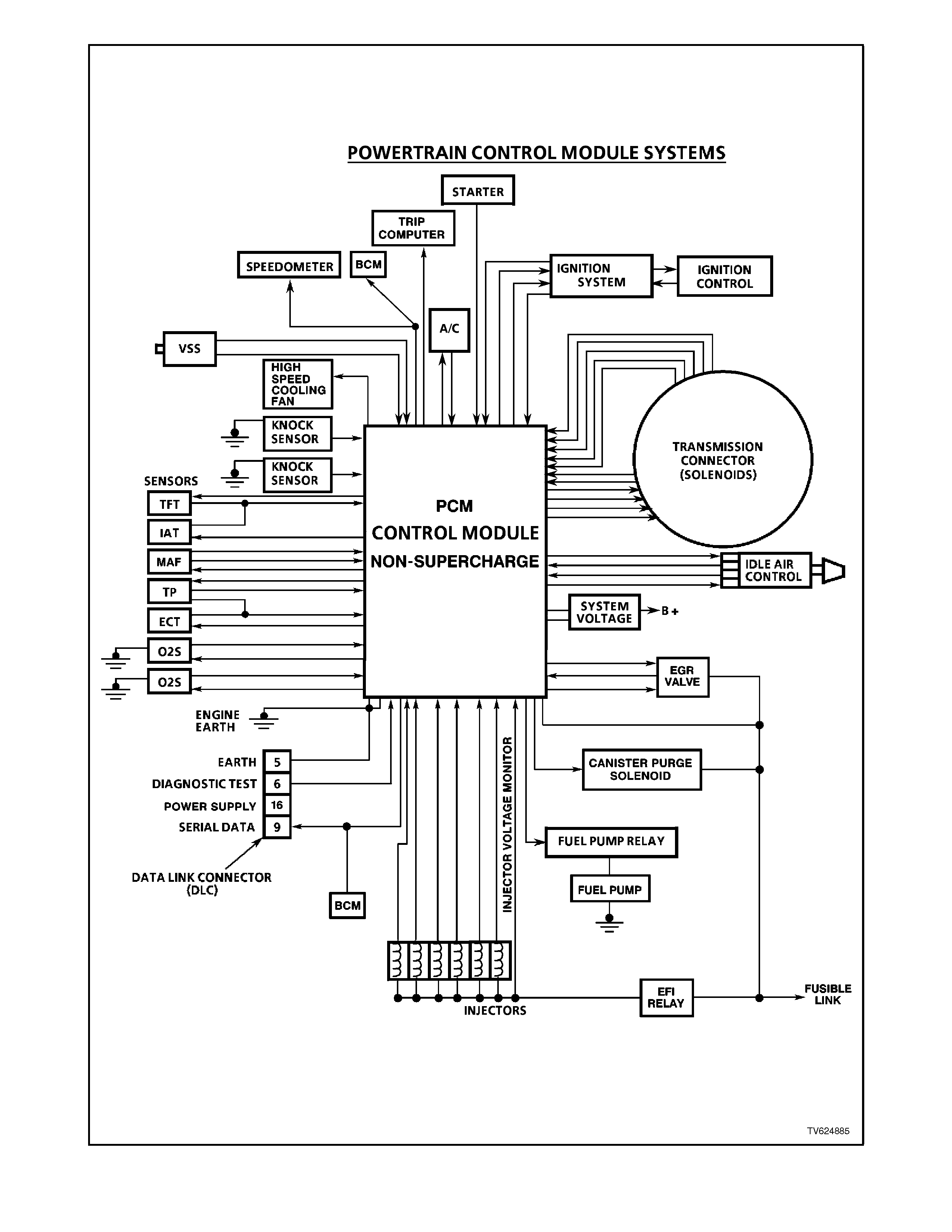
Figure 6C1-1-3 Non-Supercharged Engine Powertrain Control Module Systems
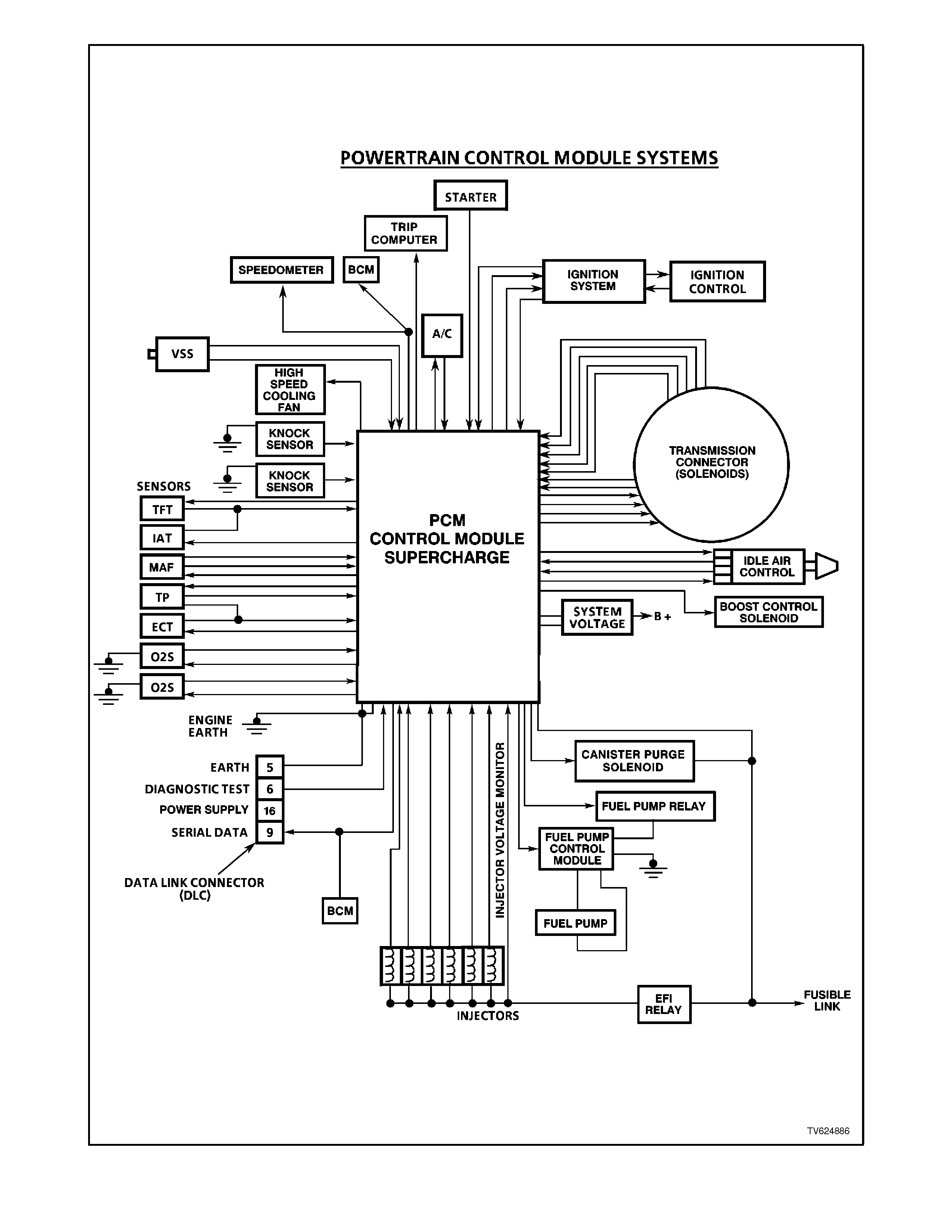
Figure 6C1-1-4 Supercharged Engine Powertrain Control Module Systems
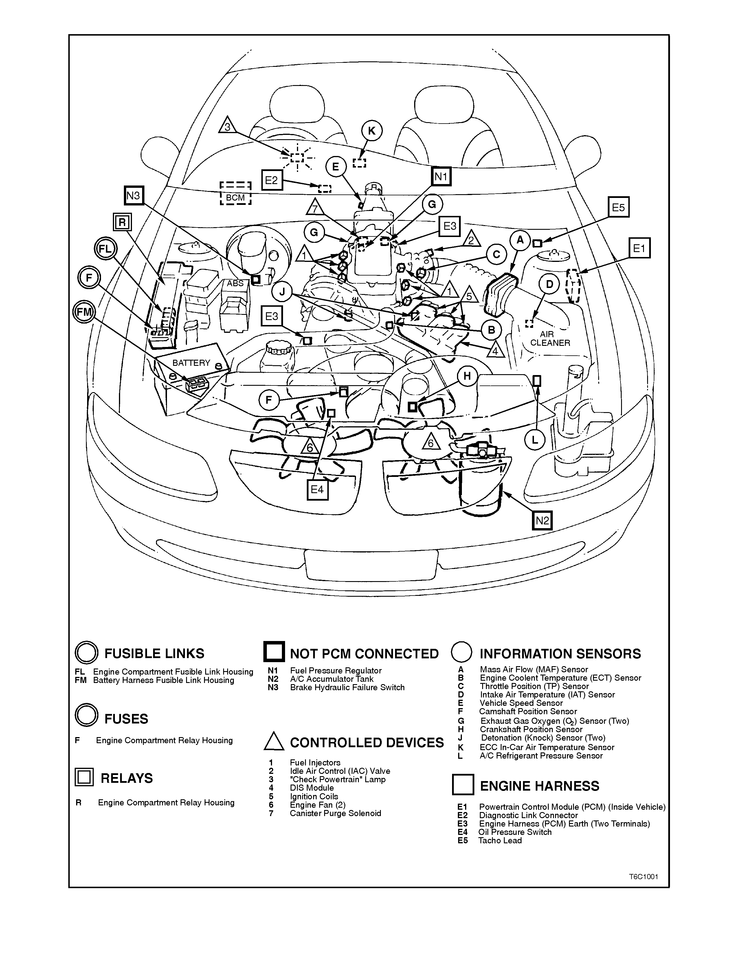
Figure 6C1-1-5 Non-Supercharged Engine Compartment Component Locations
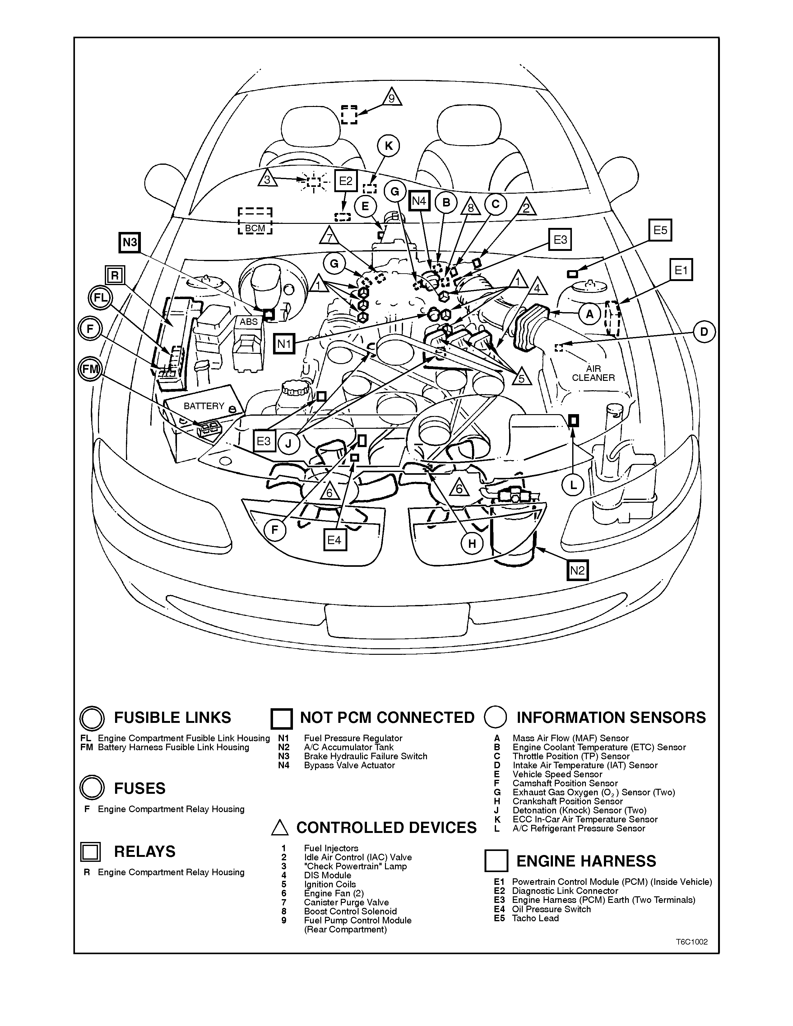
Figure 6C1-1-6 Supercharged Engine Compartment Component Locations
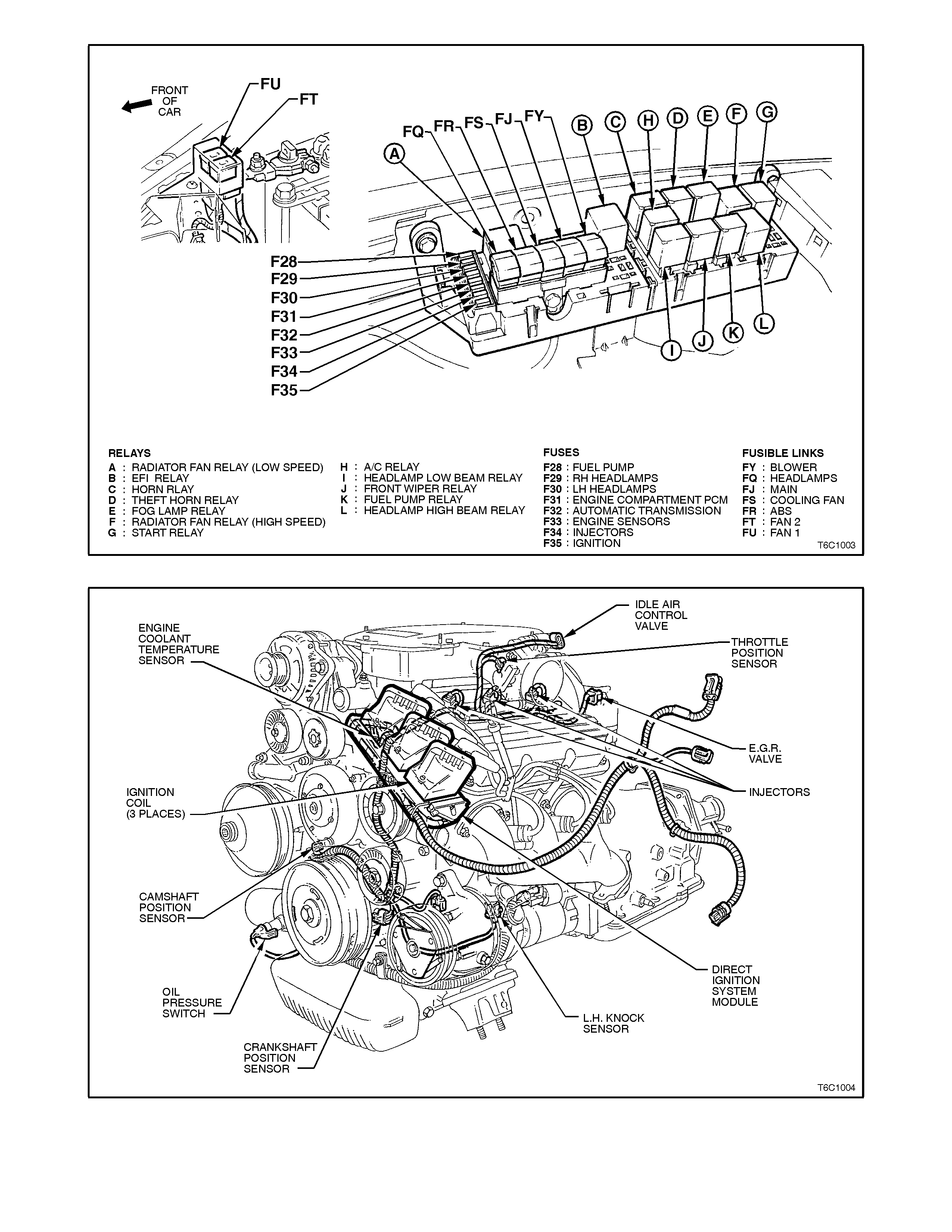
Figure 6C1-1-7 Engine Compartment Relay Locations
Figure 6C1-1-8 Non-Supercharged Engine Component Locations
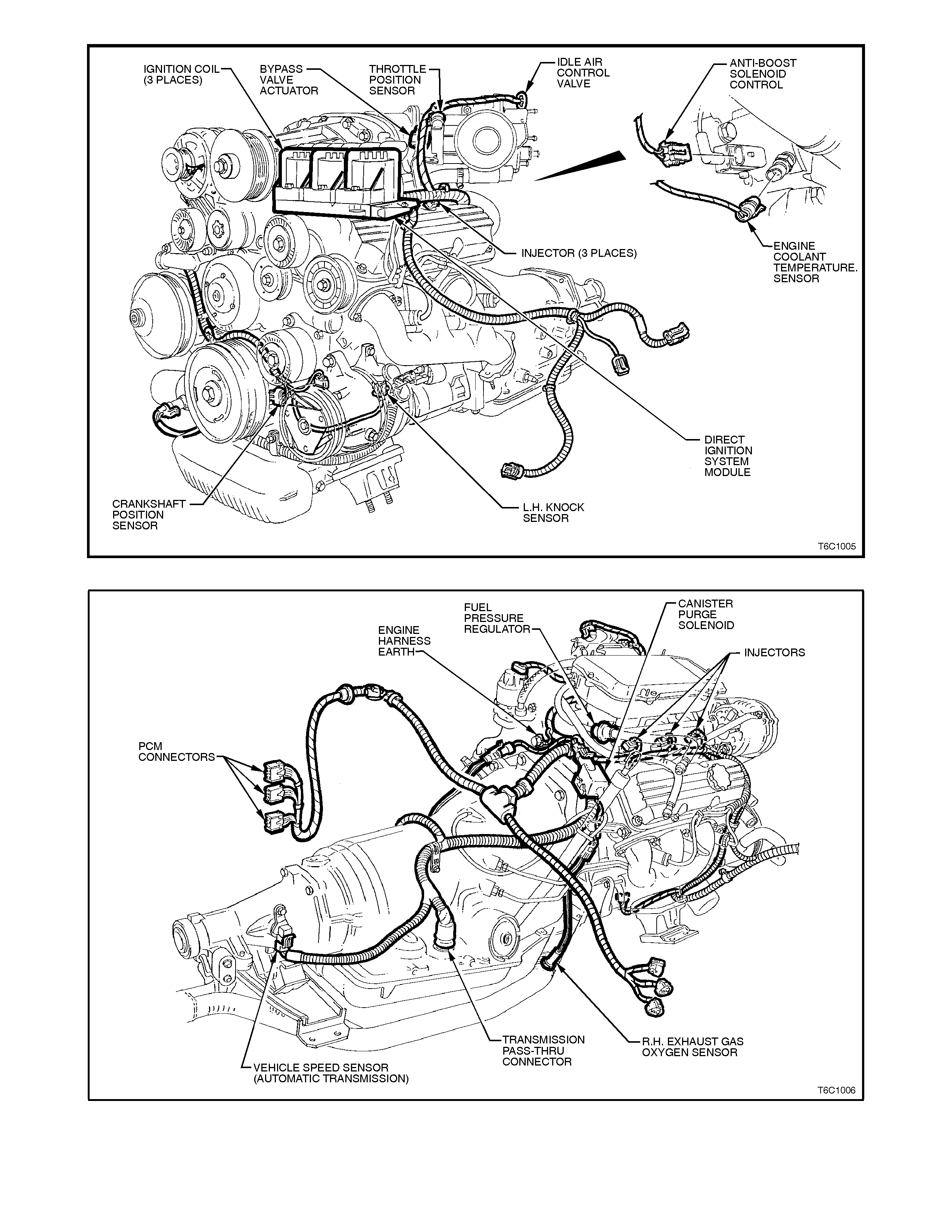
Figure 6C1-1-9 Supercharged Engine Component Locations
Figure 6C1-1-10 Non-Supercharged Engine Component Locations
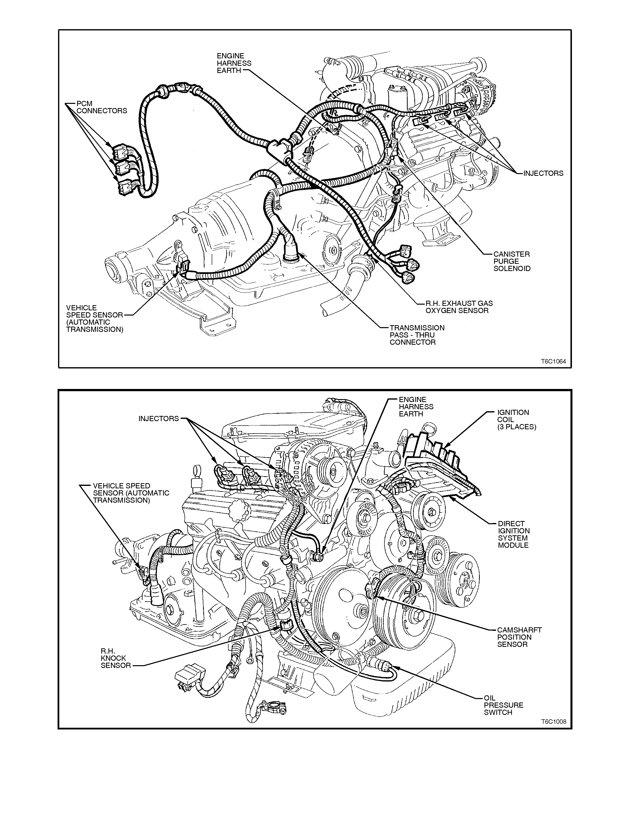
Figure 6C1-1-11-Supercharged Engine Component Locations
Figure 6C1-1-12 Non-Supercharged Engine Component Locations
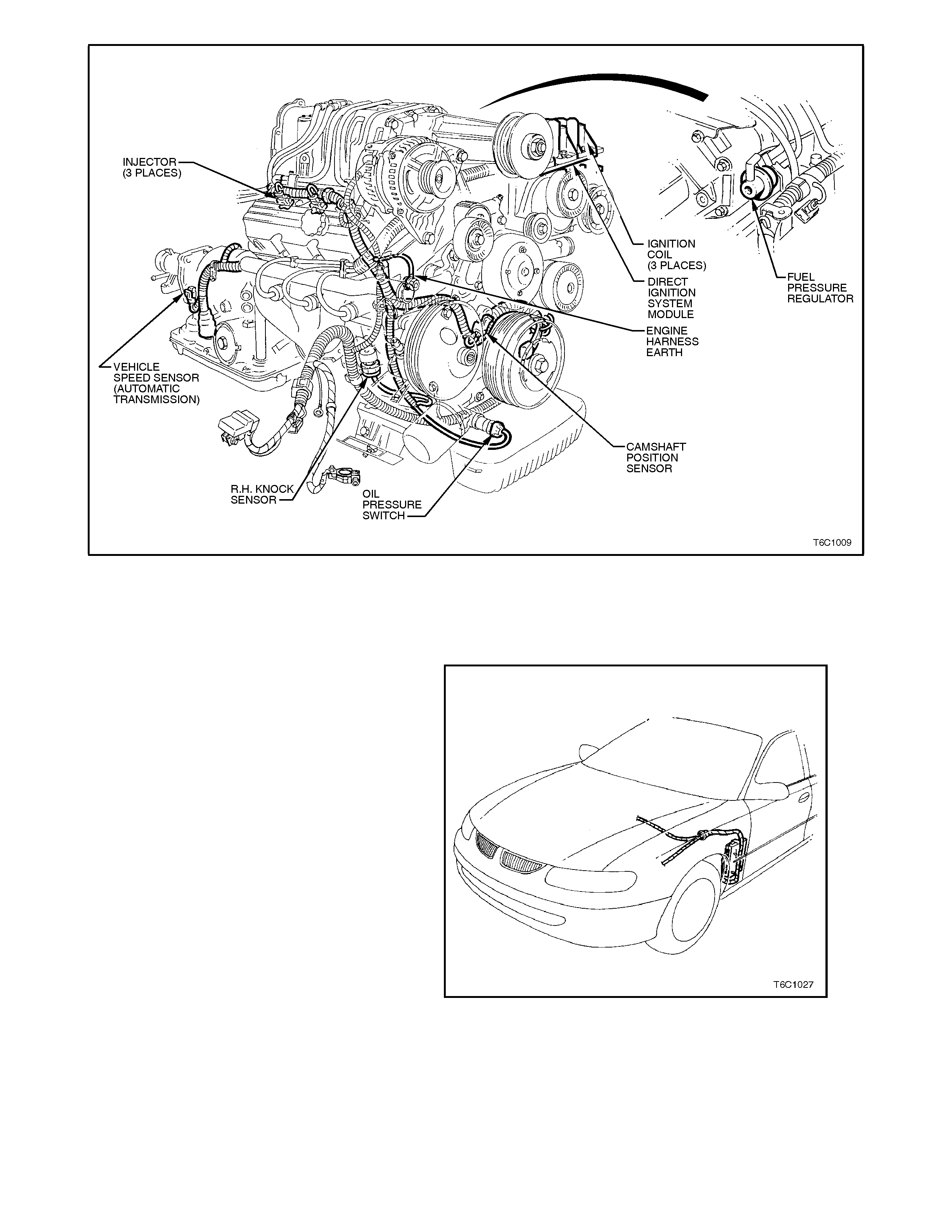
Figure 6C1-1-13 Supercharged Engine Component Locations
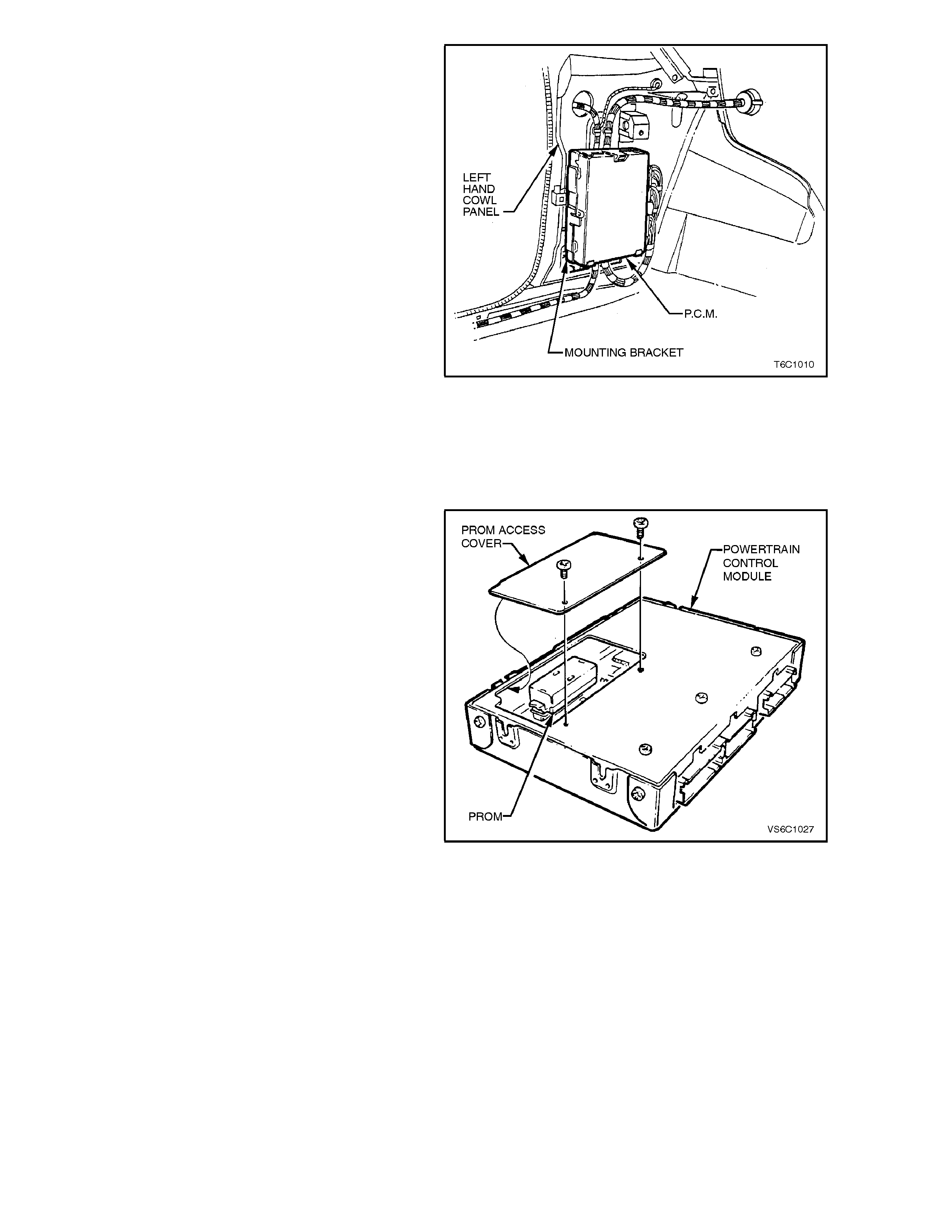
1.1 POWERTRAIN CONTROL MODULE (PCM)
POWERTRAIN CONTROL MODULE (PCM)
The Powertrain Control Module (PCM), located
behind the front left hand cowl trim panel, and is
the control center of the fuel injection and
transmission management systems. It constantly
monitors information from various sensors, and
controls the systems that affect exhaust emissions
and vehicle performance. The PCM performs the
diagnostic function of the system. It can recognise
operational problems, alert the driver through a
Malfunction Indicator Lamp (MIL) "Check
Powertrain" lamp and store a diagnostic code(s)
that will identify problem areas to aid the technician
in making repairs. Refer to Section 6C1-2
DIAGNOSIS for more information on using the
diagnostic functions of the PCM.
The PCM s upplies either a buf fer ed 5 or 12 volts to
power various sensors or switches. This is done
through resistance's in the PCM which are so high
in value that a test light will not light when
connected to the circuit. In some cases, even an
ordinary voltmeter will not give an ac curate reading
because the meter's internal resistance is too low.
Figure 6C1-1-14 Powertrain Control Module Location
A 10 Megaohm input impedance digital voltmeter is
required to assure accurate voltage readings.
The PCM controls output circuits such as the
injectors, IAC, and various relays, etc. by
controlling the earth circuit through transistors or a
device called a "Q uad-Driver" m odule (QDM) in the
PCM. The two exceptions to this are the fuel pump
relay control circuit and the autom atic transmission
Pressure Control Solenoid (PCS). The fuel pump
relay is the only PCM controlled circuit where the
PCM controls the +12 volts sent to the coil of the
relay. The earth side of the fuel pump relay coil is
connected to engine earth. The PCM supplies
current to the PCS and m onitors how m uch curr ent
returns to the PCM on a separate terminal.
PCM SECURITY LINK
Once the PCM and or BCM have been replaced,
the new PCM and or BCM must be security linked
to each other. If this procedure is not performed,
the vehicle will not crank.
There are two different types of procedures that
may be perform ed to ac com plish this tas k. Ref er to
Section 6C1-3 SERVICE OPERATIONS for this
procedure.
Figure 6C1-1-15 PCM Mounting
PROM
To allow one model of PCM to be used for many
diff erent vehicles, a device called a PROM is used.
The PROM is located inside the PCM and has
information on the vehicle's weight, engine,
transmission, axle ratio and several other factors.
While one PCM part number m ay be used by m any
different vehicles, a PROM is specific. For this
reason, it is very important to chec k the latest par ts
catalogue and Technical Information Bulletins for
the correct part number when replacing a PROM.
A replacement PCM (called a controller) is
supplied without a PROM. The PROM from the old
PCM must be carefully removed and installed in the
new PCM. For details refer Section 6C1-3
SERVICE OPERATIONS.
Figure 6C1-1-16 PROM Location

PCM MEMORY FUNCTIONS
There ar e three types of mem ory storage within the
PCM: RAM, EPROM and EEPROM.
RAM
Random Access Memory (RAM) is the
microprocessor "scratch pad." The processor can
write into, or read from this memory as needed.
This memory is volatile and needs a constant
supply of voltage to be retained. If the voltage is
lost, the memory is lost.
EPROM
Erasable Programmable Read Only Memory
(EPROM) is the portion of the PCM which means
that the program can be erased. This is also the
portion of the PCM that contains software and the
different engine and transmission calibration
information that is specific to year, model and
emis sions. T his m emor y is erased by exposing it to
high intensity ultra violet radiation for several
minutes.
The service Programmable Read Only Memory
(PROM) which is used by technicians in the field to
update calibrations in the PCM is actually an
EPROM. T he service PROM is r emovable fr om the
PCM. The PROM should be retained with the
vehicle following PCM replacement.
EEPROM
Electronically Erasable Programmable Read Only
Memory (EEPROM) is the portion of the PCM that
means the program can only be erased
electronically. This type of memory cannot be
erased by disconnecting the vehicle's battery. The
only way to erase this type of memory is by a
special electronic tool, such as the Tech 2 scan
tool. This type of memory is used to store the
Diagnostic Trouble Codes (DTC). DTC history data
is stored in EEPROM and will be saved even after
the vehicle's battery has been disconnected. For
this reason, the only way that the DTC history data
can be cleared is with the Tech 2 scan tool.

1.2 ENGINE INFORMATION SENSORS AND SIGNALS
CAMSHAFT POSITION SENSOR
The camshaft position sensor is located in the
engine front cover, behind and below the water
pump, near the camshaft sprocket.
As the camshaf t spr ock et turns, a m agnet m ounted
on it activates the Hall Ef f ec t s witch in the c ams haf t
position sensor. When the Hall Effect switch is
activated, it earth's the signal line to the DIS
module, pulling the camshaft position signal line's
applied voltage low. This is interpreted as a
camshaft position signal (Synchronisation Pulse).
Because of the way the signal is created by the
camshaft position sensor, the signal circuit is
always either at a high or low voltage (square wave
signal).
While the camshaft sprocket continues to turn, the
Hall Eff ect switch turns "OFF" as the m agnetic f ield
passes the camshaft position sensor, resulting in
one signal each time the camshaft makes one
revolution.
The camshaft position signal, which actually
represents camshaft position due to the sensor's
mounting location, is used by the PCM to properly
time its sequential fuel injection operation.
Figure 6C1-1-17 Camshaft Position Sensor
Figure 6C1-1-18 Camshaft And Crankshaft Position Sensor Locations
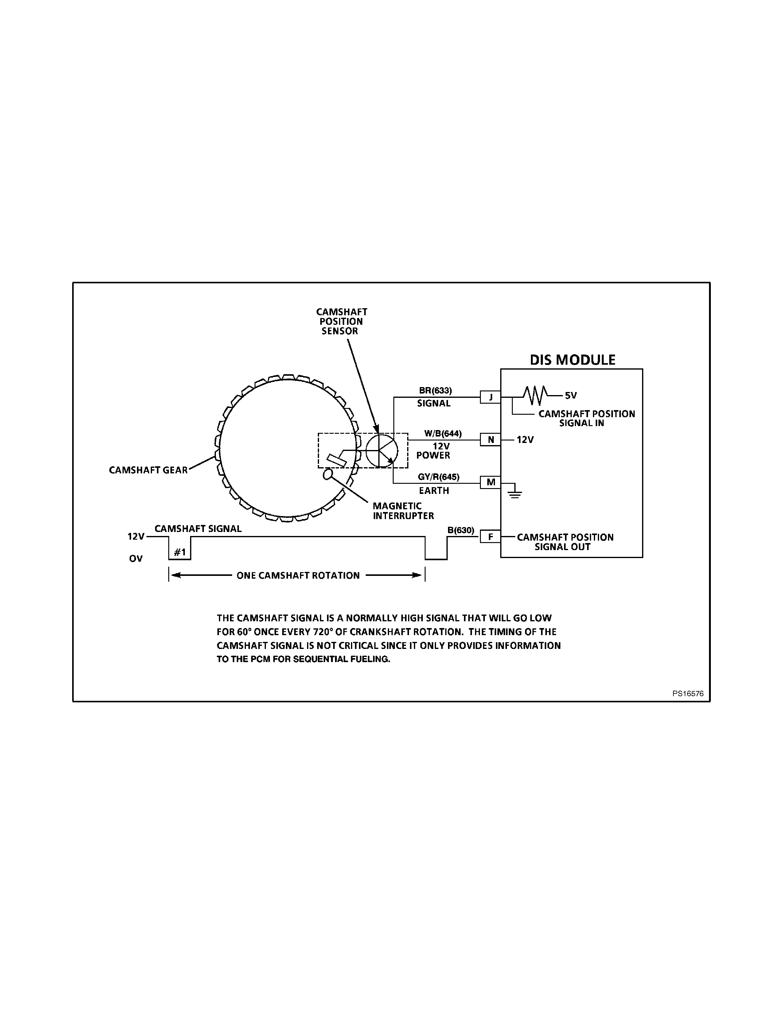
CAMSHAFT POSITION SIGNAL
The PCM uses the camshaft position signal to
determine the position of the No. 1 piston on its
power stroke. This signal is used by the PCM to
calculate sequential fuel injection operation. If the
camshaft position signal is lost while the engine is
running, the fuel injection mode will be based on
the last fuel injection pulse, and the engine will
continue to run. The engine can be restarted and
will run in the synchronous (all six inj ectors inject at
once) mode as long as the fault is present.
When the camshaft position signal is not received
by the PCM, a DTC 48 will be set. An intermittent
camshaft position signal will set a DTC 49. If either
of these DTC's are set, the fuel system will not be
in sequential fuel injection mode.
Figure 6C1-1-19 Camshaft Position Signal
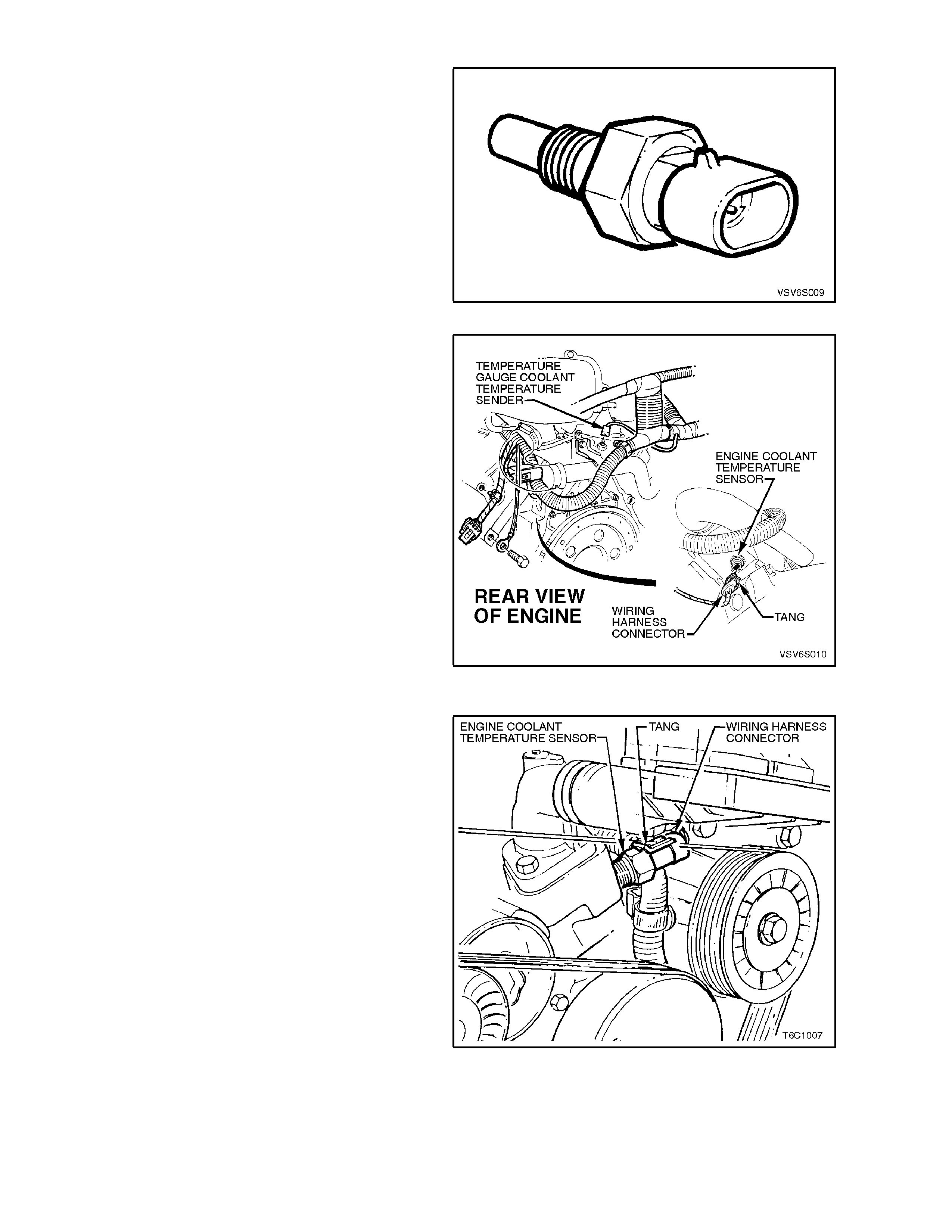
ENGINE COOLANT TEMPERATURE (ECT) SENSOR
The Engine Coolant Temperature (ECT) sensor is a
thermistor (a resistor that changes value based on
temperature) mounted in the engine coolant stream
and is specifically for the PCM. A different sensor is
used for instrument panel functions. Low coolant
engine temperature produces a high sensor
resistanc e (28,939 ohms at - 20 degrees C) while high
engine coolant temperature causes low sensor
resistance (180 ohms at 100 degrees C).
Figure 6C1-1-20 ECT Sensor
The location of the sensor for the Supercharged
application is at the rear of the engine. Both sensor
application are located near the thermostat housing.
Figure 6C1-1-21 ECT Sensor Location (Supercharged
Engine)
The Engine Coolant Temperature location on the
Non-Supercharged application is at the front of the
engine
Figure 6C1-1-22-A ECT Sensor Location (Non-
Supercharged Engine)
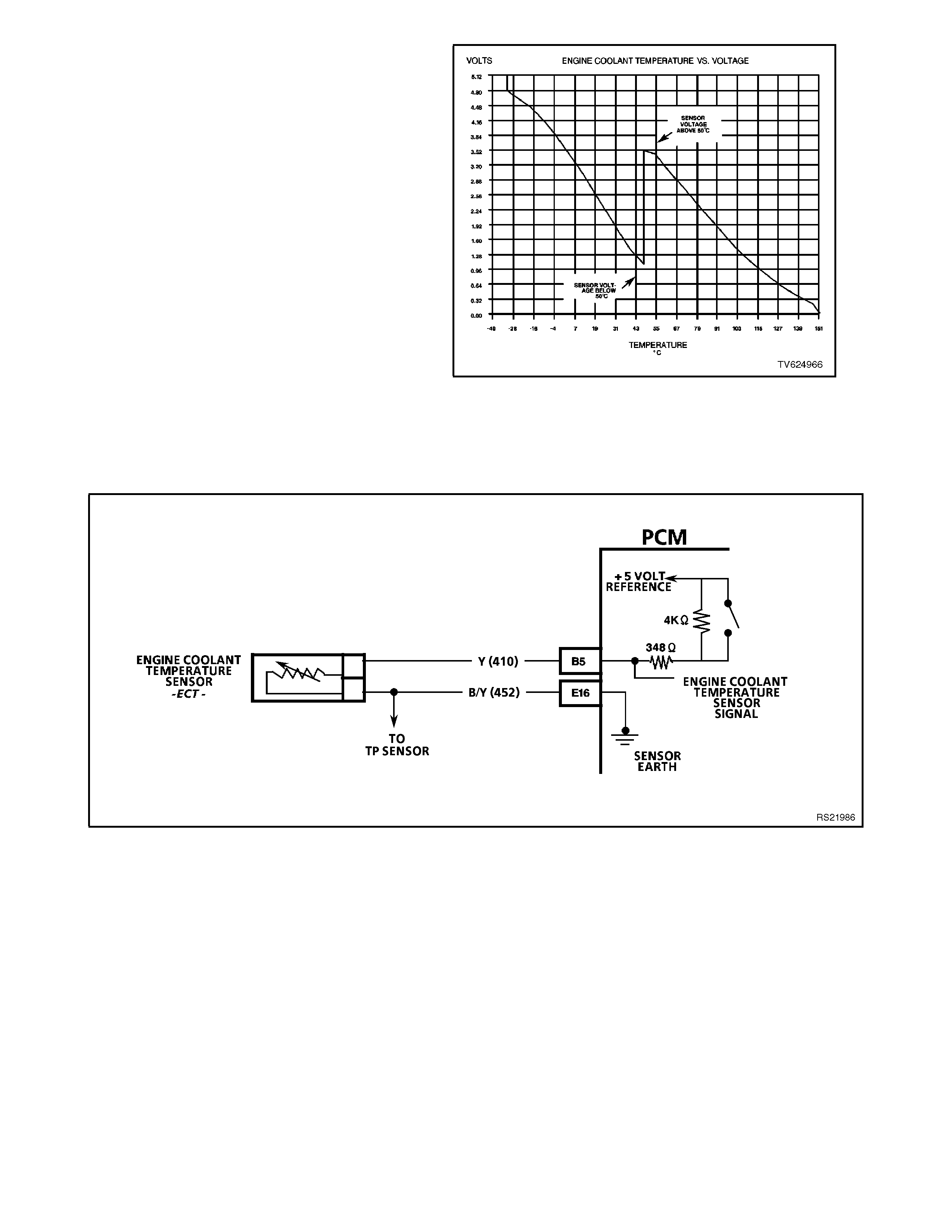
The PCM:
1. Supplies a 5 volt signal voltage to the sensor
through a resistor in the PCM, and
2. Monitors the circuit voltage, which will change
when connected to the sensor.
The circuit voltage will vary depending on the
resistance of the engine coolant temperature sensor.
The circuit voltage will be close to the 5 volt level
when the sensor is cold, and will decrease as the
sensor warms. Engine coolant temperature affects
most systems controlled by the PCM.
A failure in the engine coolant temperature sensor
circuit should set either a Diagnostic Trouble Code
(DTC) 14 or DTC 15. An intermittent open or a short
failure s hould set DTC 16. T he PCM supplies a 5 volt
signal to the engine coolant temperature sensor
through one of two resistors in the PCM. When the
engine coolant is cold the PCM will operate on one
resistor then switch over to another resistor at
approximately 50 degrees C. The circuit voltage will
change at this time but the Tech 2 scan tool will still
read the correct temperature value and will not
suddenly jump. A f ailure in one of these two resistor s
will set DTC 17.
Figure 6C1-1-23 ECT Temperature vs Voltage
Figure 6C1-1-24 ECT Sensor Circuit
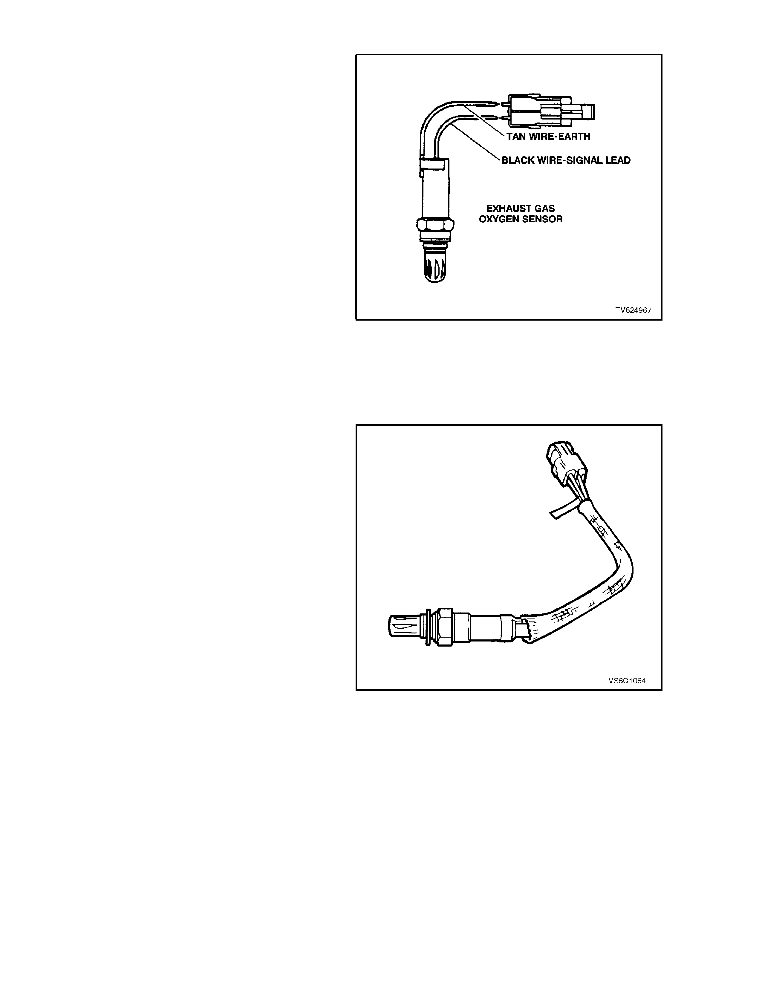
EXHAUST GAS OXYGEN SENSOR
The exhaust gas oxygen sensors are the key to
closed-loop f uel contr ol. The PCM us es inform ation
from the oxygen sensors to precisely fine-tune its
fuel injector pulse width calculations, based on the
unused, "left-over" oxygen content in the exhaust.
The Non-Supercharged V6 engine use two
unheated oxygen sensors, one oxygen sensor is
located in each exhaust pipe. This is done so that
the PCM can better control the engine's fuelling
requirements. By monitoring the exhaust oxygen
content of each bank of cylinders, the PCM can
better control the fuel injector pulse width to the
individual fuel injectors on each bank.
The Supercharged V6 engine uses two heated
oxygen sensors. These heated oxygen sensors
have a internal heater element that is used to heat
the Zirconia element faster inside the sensors,
thereby decreasing the amount of time the fuel
control system can begin running in closed loop
fuel control.
Both type of oxygen sensors have a zirconia
element that, when heated to temperatures above
360 degrees C, produce voltages based on the
amount of oxygen content surrounding the tip, as
compared to oxygen in the atmosphere.
Figure 6C1-1-25 Two Wire Oxygen Sensor
The sensor is mounted in the exhaus t pipe with the
sensing portion exposed to the exhaust gas
stream. When the sensor has reached an operating
temper ature of m ore than 360 degrees C, it ac ts as
a voltage generator, producing a rapidly changing
voltage of between 10 - 1000 millivolts. This voltage
output is dependent upon the oxygen content in the
exhaust gas, as compared to the sensor's
atmospheric oxygen reference cavity. This
reference cavity is exposed to the atmosphere
through the air that passes between the wire
strands and insulation.
When the sensor is cold, it produces either no
voltage, or an unusable, slowly changing one. Also
when cold, its internal electrical resistance is
extremely high - many million ohms. The PCM
always supplies a steady 450 millivolt, very low
current called "bias" voltage to the oxygen sensor
circuit. W hen the sensor is cold and not producing
any voltage, the PCM "detects" only this steady
bias voltage. As the sensor begins heating, its
internal resistance decreases and it begins
producing a rapidly changing voltage that will
overshadow the PCM's supplied steady bias
voltage.
Figure 6C1-1-26 Four Wire Heated Oxygen Sensor

When the PCM "detects" the changing voltage, it
knows the oxygen sensor is hot and its output
voltage can be used for the "fine-tuning" the fuel
injector pulse width. T he PCM monitors the oxygen
sensor's "changing voltage" for going above and
below a mid-range voltage band (approximately
300 - 600 millivolts), to help dec ide when to operate
in the closed-loop mode. (refer "READY TEST,"
Figure 6C1-1-29.)
W hen the fuel system is correctly operating in the
closed-loop mode, the oxygen sensor voltage
output is rapidly changing several times per
second, going above and below a rich/lean band.
The PCM monitors the changing voltage, and
decides the needed fuel mixture correction. (refer
"NORMAL, CLOSED-LOOP OPERATION,"
Figure 6C1-29).
An open sensor signal circuit or earth circuit, or a
defective, contaminated, or cold sensor could
cause the voltage to stay within a 350-550 millivolt
band too long, keeping the fuel control system in
open-loop and setting a DTC 13 or DTC 63. (refer
"DTC 13 or DTC 63", Figure 6C1-28).
Figure 6C1-1-27 Oxygen Sensor Zirconia Element
If the PCM monitors a low voltage for too long
(indicating a "lean" exhaust), a DTC 44 or DTC 64
will store in memory. If the PCM monitors a high
oxygen sensor circuit voltage for too long
(indicating a "rich" exhaust), a DTC 45 or DTC 65
will store in m e mory (refer "DTC 44 or DTC 64" and
"DTC 45 or DTC 65", Figure 6C1-28).
RESPONSE TIME
Not only is it necessary for the oxygen sensor to
produce a voltage signal for rich or lean exhaust, it
is also important to respond quickly to changes.
The PCM senses the response times and displays
this on the Tech 2 scan tool as the "rich-lean
status" and as "cross counts" If the oxygen sensor
responds slowly, the customer may complain of
poor fuel economy, rough idle or lack of
performance. It may also set false PCM DTCs
because the PCM uses oxygen sensor voltages for
system checks.
OXYGEN SENSOR CONTAMINANTS
CARBON
Black carbon or soot deposits result from over-rich
air/fuel mixtures. However, carbon does not harm
an oxygen sensor. Deposits can be burned off in
the vehicle by running it at least part thr ottle for two
minutes.
SILICA
Certain RTV silicone gasket materials give off
vapour as they cure that may contaminate the
oxygen sensor. This contamination is usually
caused by the vapours being pulled from the PCV
system, into the combustion chamber and passed
on to the exhaust system. The sand like particles
from the RTV silica embed in the molecules of the
oxygen sensor element and plug up the surface.
With the outside of the oxygen sensor element not
able to sense all of the oxygen in the exhaust
system it results in "lazy" oxygen sensor response

and engine control. The oxygen sensor will have a
whitish appearance on the outside if it has been
contaminated.
There is also a possibility of silica contamination
caused by silicone in the fuel. Some oil companies
have used silic one to rais e the oc tane rating of their
fuel. Careless fuel handling practices with transport
containers can result in unacceptable
concentrations of silicone in the fuel at the pump.
There is also a possibility of silica contamination
caused by silicon in lubricants used to install
vacuum hoses on fittings. Do not use silicone
sealers on gaskets or exhaust joints.
LEAD
Lead glazing of the sensors can be introduced
when regular, or leaded fuel is burned. Fuel
containing large amounts of methanol will also
result in lead contamination.
The methanol dissolves the terne coating of the fuel
tank, which introduces lead into the fuel system,
and into the exhaust after combustion. It is difficult
to detect lead contamination by visual inspection.
OTHER SUBSTANCES
Oil deposits will ultimately prevent oxygen sensor
operation. The sensor will have a dark brown
appearance. Causes of high oil consumption
should be checked.
The additives in ethylene glycol can also affect
oxygen sensor performance. This produces a
whitish appearance. If antif reeze enters the ex haus t
system, you will likely encounter other, more
obvious, symptoms of cooling system trouble. If for
example the engine had a head gasket failure
where coolant did enter the combustion chamber it
would be a good idea to check the oxygen sensor
operation after the head gasket was repaired.
MULTIPLE FAILURES
Leaded fuel, silica contamination from uncured,
low-grade (unapproved) RTV sealant, and high oil
consumption are possible.
A problem in the oxygen sensor circuit or fuel
system should set a DTC 13 or DTC 63 (open
circuit), DTC 44 or DTC 64 (lean indication), or
DTC 45 or DTC 65 (rich indication). Refer to
applicable diagnostic chart if any of these DTCs
were stored in memory.
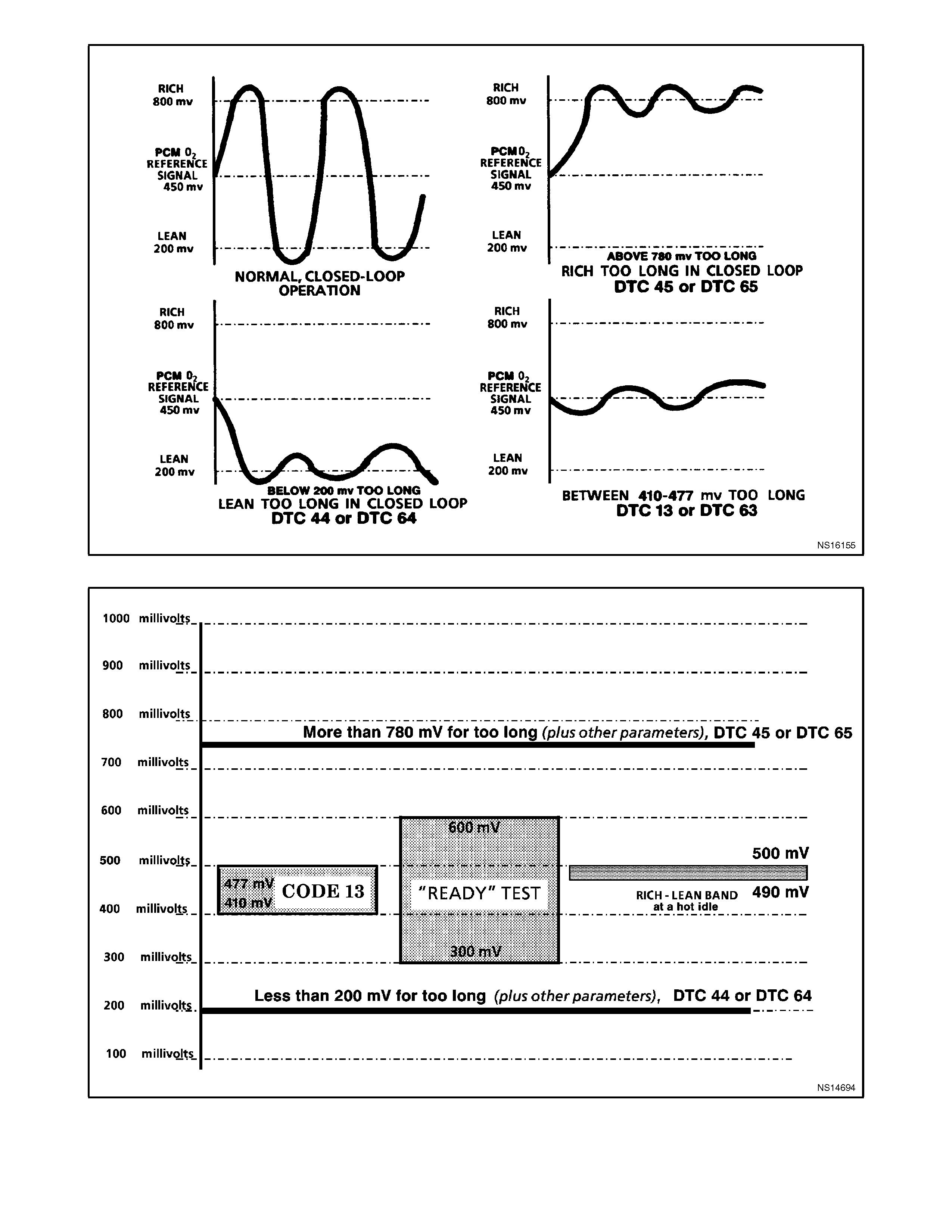
Figure 6C1-1-28 Oxygen Sensor Voltage Curves
Figure 6C1-1-29 Normal Oxygen Sensor Voltages, and Abnormal Trends
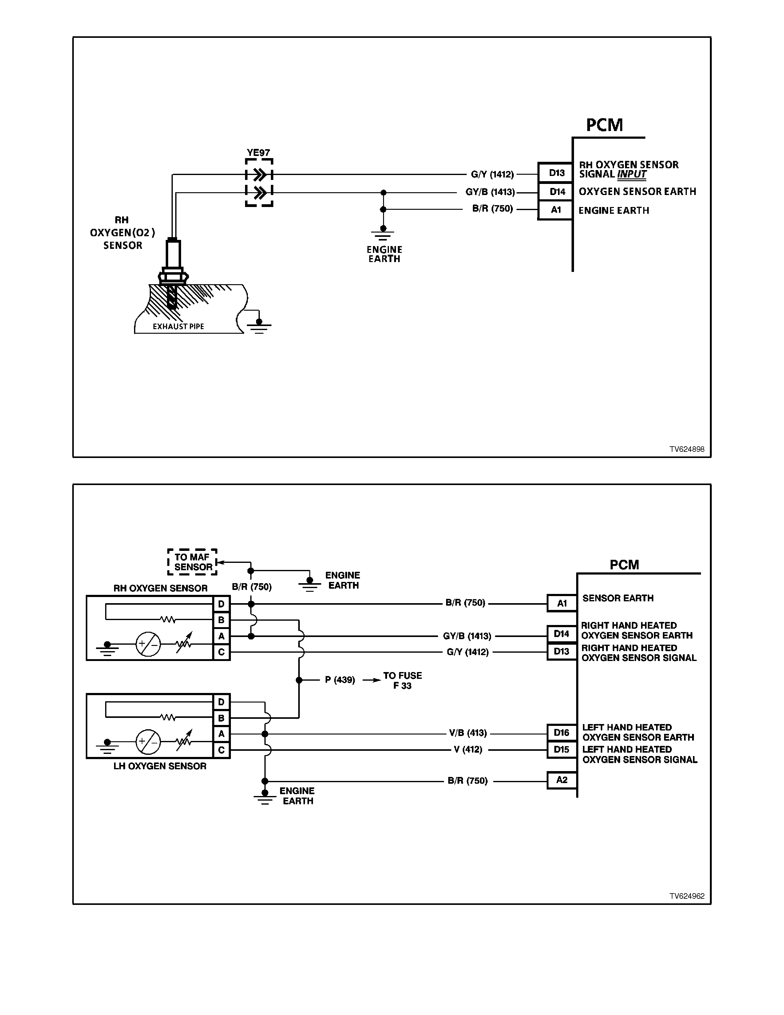
Figure 6C1-1-30 Two Wire Oxygen Sensor Circuit
Figure 6C1-1-31 Four Wire Heated Oxygen Sensor Circuit
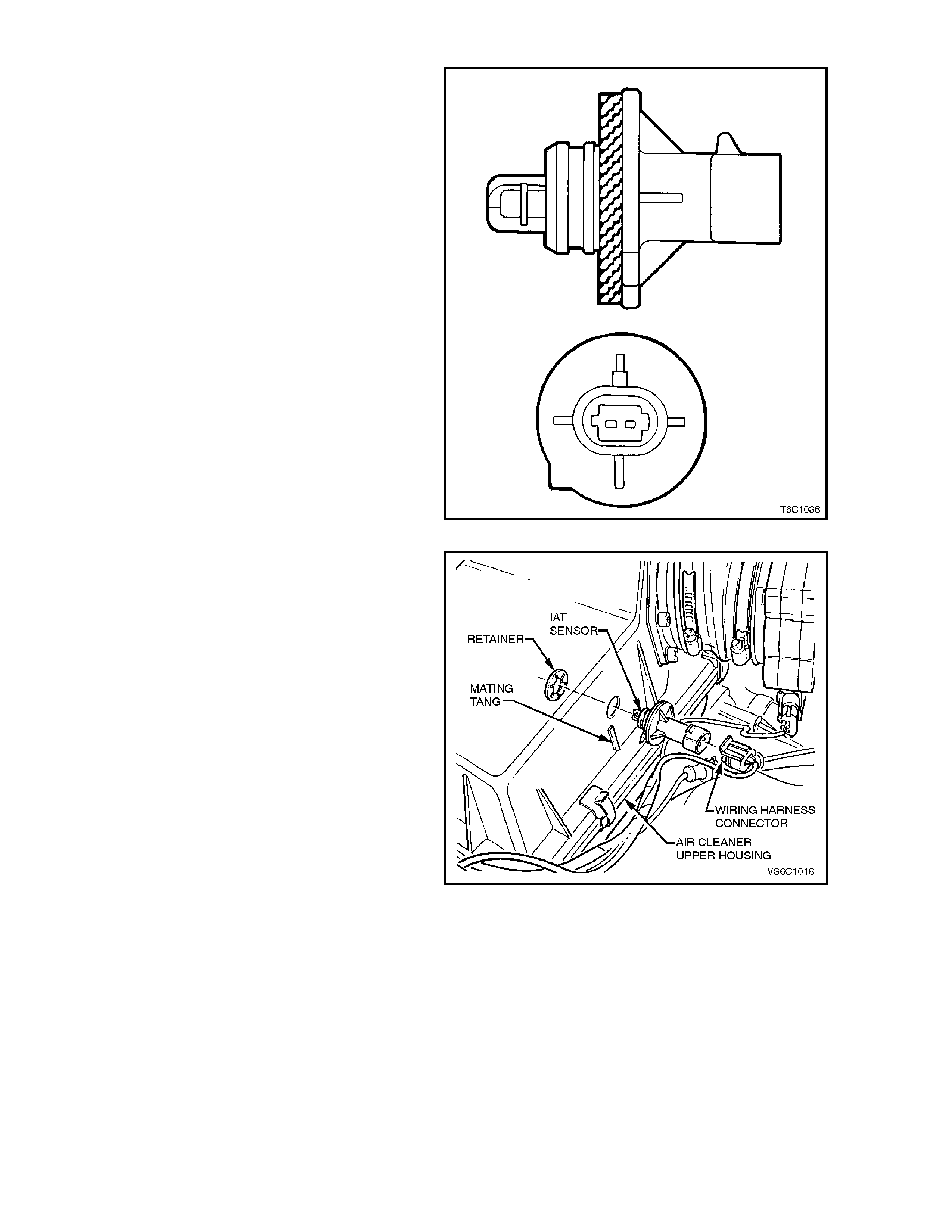
INTAKE AIR TEMPERATURE (IA T) SENSOR
The Intake Air Temperature (IAT) sensor is a
thermistor (a resistor that changes resistance with
changes in tem perature) mounted in an air cleaner
housing of the intake system. Low intake air
temper atur e produces high res istanc e in the sens or
(100,866 ohm s at -40 degr ees C), while high intak e
air temperature causes low sensor resistance (78
ohms at 130 degrees C).
The PCM:
1. Supplies a 5 volt signal voltage to the sensor
through a resistor in the PCM, and
2. Monitors the intake air temperature circuit
voltage, which will change when connected to
the intake air temperature sensor.
The circuit voltage will vary depending on the
resistance of the IAT sensor. The voltage will be
close to the 5 volt level when the sensor is cold,
and will decrease as the sensor warms.
The input intake air temperature signal voltage is
used by the PCM to assist in calculating the fuel
injector pulse width.
A failure in the IAT sensor circuit should set either a
Diagnostic Trouble Code (DTC) 23 or DTC 25. An
intermittent failure in the IAT sensor circuit should
set DTC 26. Figure 6C1-1-32 IAT Sensor
Figure 6C1-1-33 IAT Sensor Location
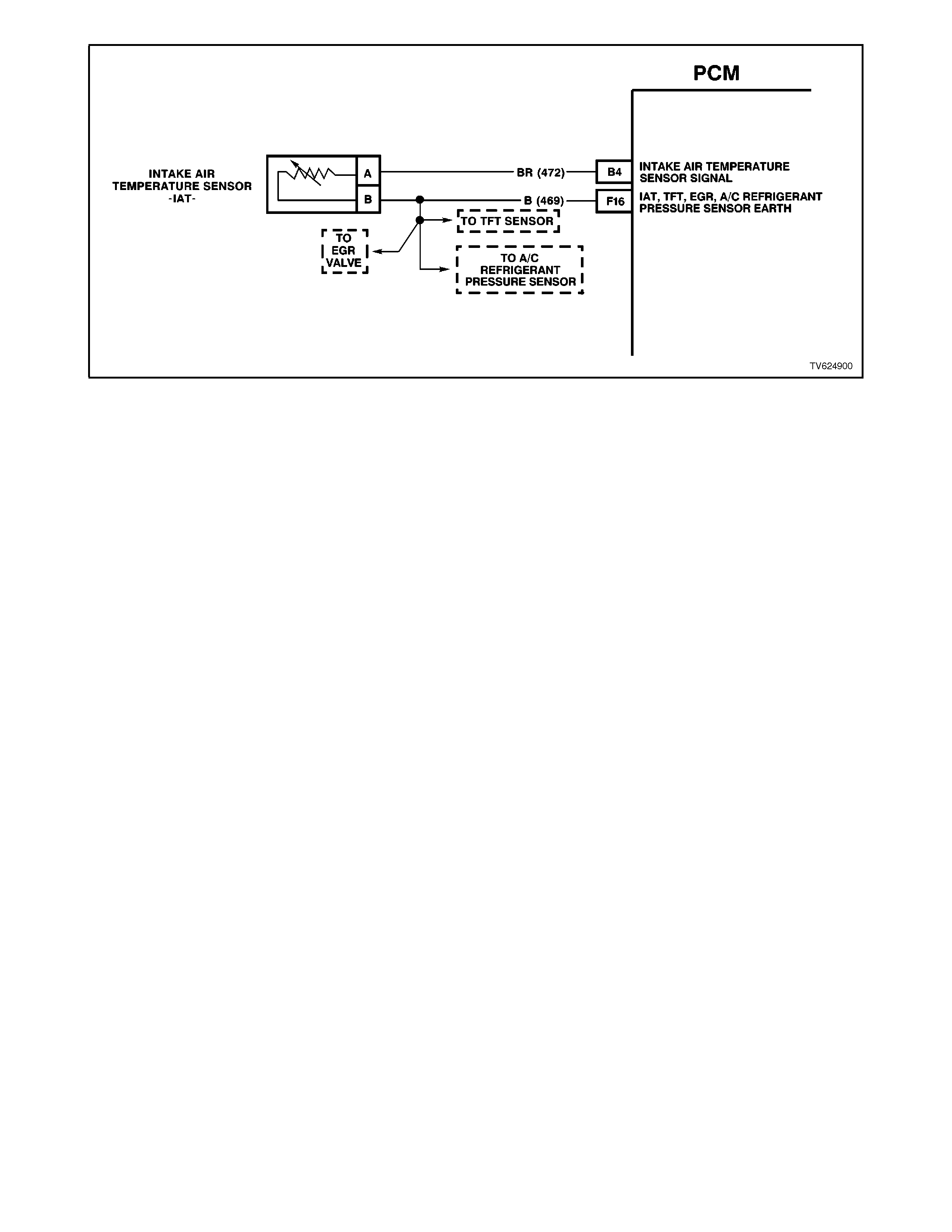
Figure 6C1-1-34 IAT Sensor Circuit
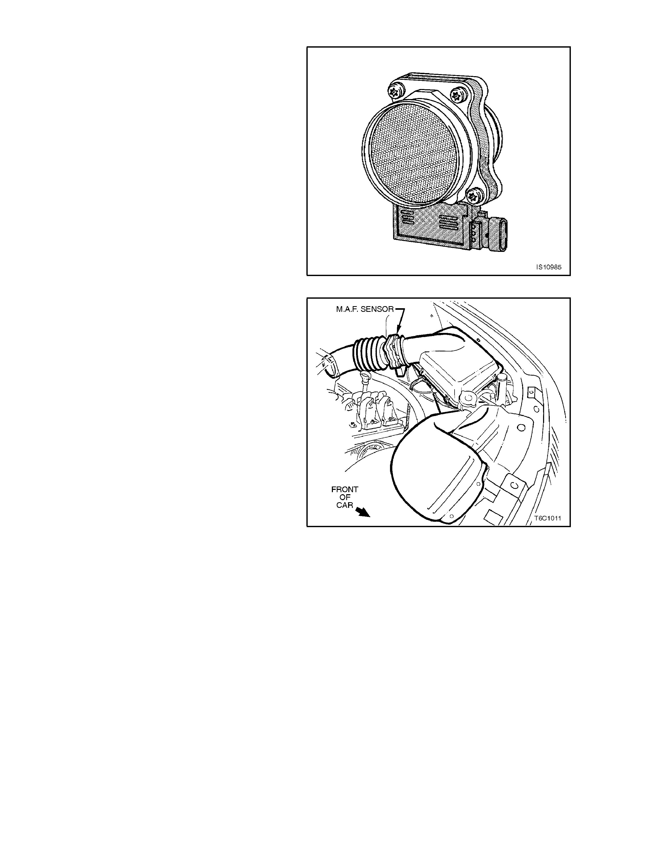
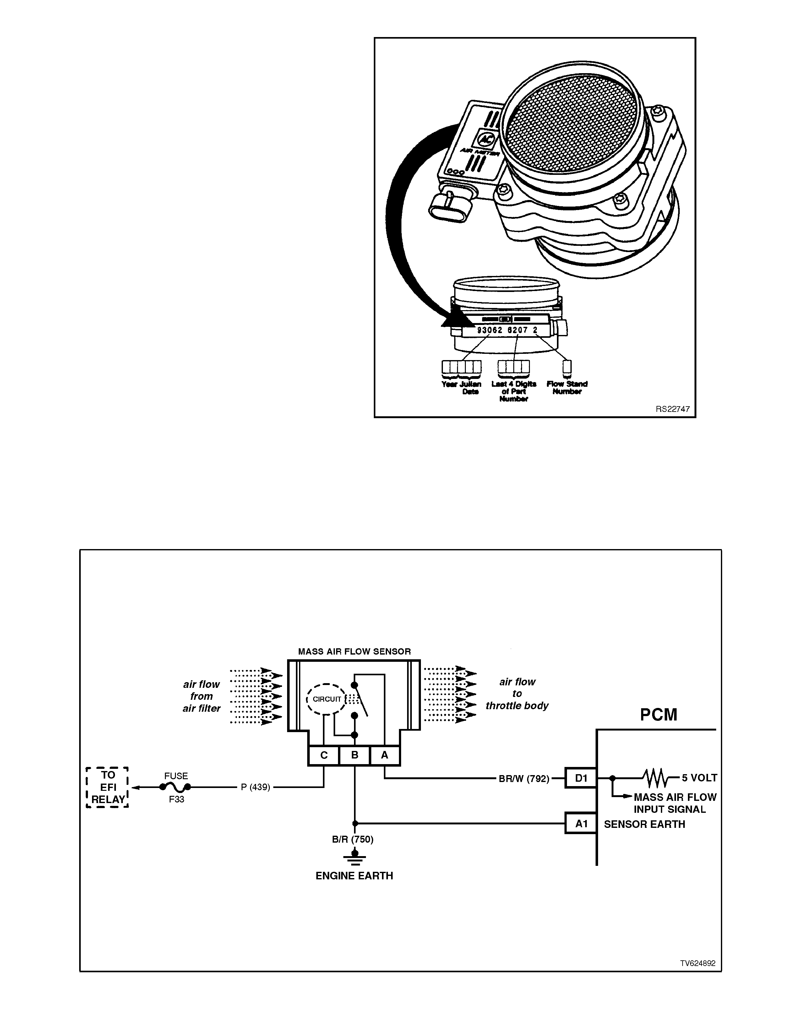
MASS AIR FLOW (MAF) SENSOR
The Mass Air Flow (MAF) sensor used on these
engines utilises a heated element type of operation.
A heated element in the MAF is placed in the air
flow stream of the engine intake system. The
heating element is maintained at a constant
temperature differential above the air temperature.
The am ount of elec trical power r equired to m aintain
the heated element at the proper temperature is a
direct function of the mass flow rate of the air past
the heated element.
Figure 6C1-1-35 Mass Air Flow Sensor
Figure 6C1-1-36 MAF Sensor Location
Non-Supercharged Engine
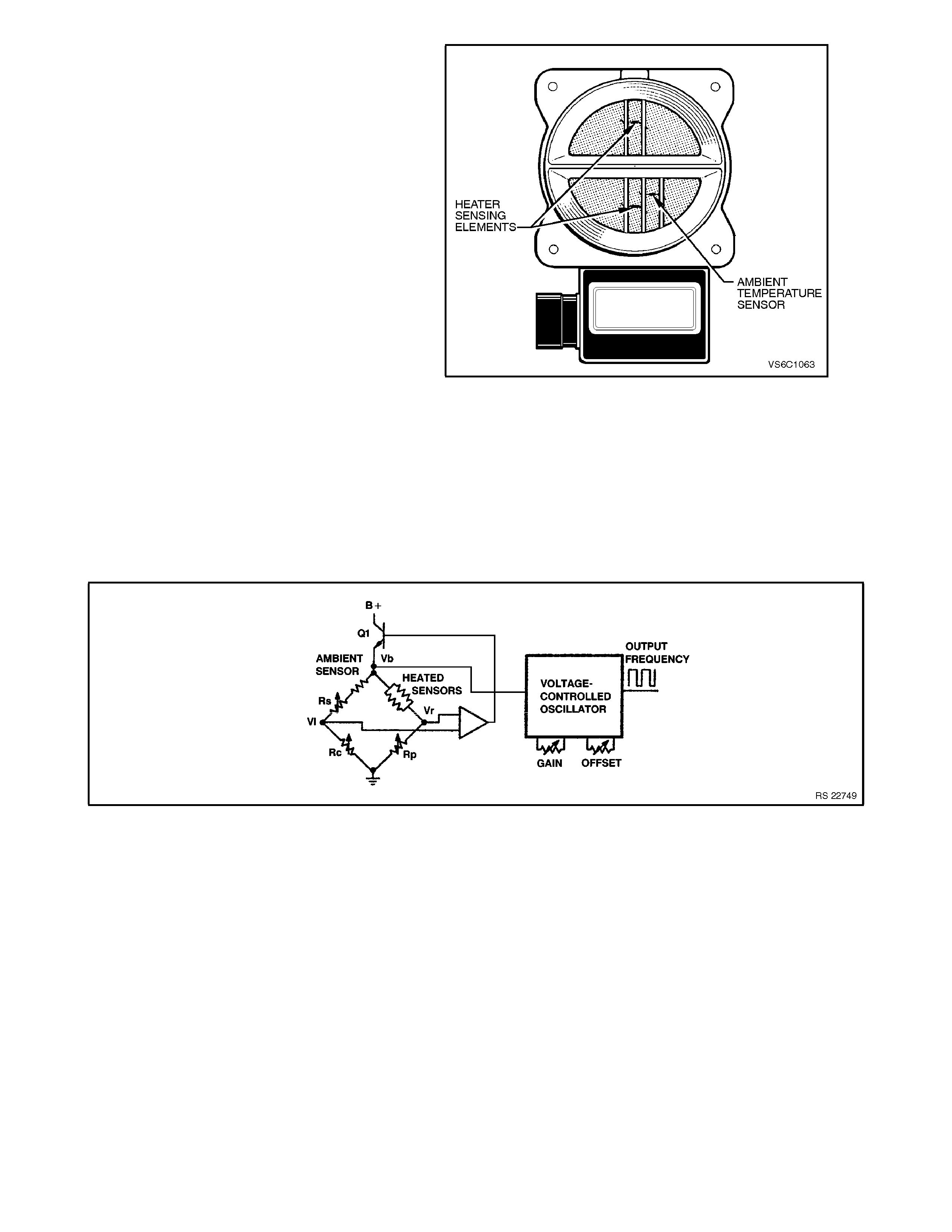
Three sensing elements are used in this system.
One senses ambient air temperature and uses two
calibratable resistors to establish a voltage that is
always a function of ambient temperature. This
ambient sensor is mounted in the lower half of the
sensor housing. The other two sensing elements
are heated to a predetermined temperature that is
significantly above ambient air temperature. The
two heated elements are connected electrically in
parallel and mounted directly in the air flow stream
of the sensor housing. O ne sensor is in the top and
one sensor is in the bottom of the sensor housing.
This is done so that the air meter is less sensitive to
upstream ducting configurations that could skew
the flow of air through the housing.
As air passes over the heated elements during
engine operation they begin to cool. By measuring
the amount of electrical power required to m aintain
the heated elements at the predetermined
temperature above ambient temperature the mass
air flow rate can be determined.
Once the mass air flow sensor has developed an
internal signal related to the mass air flow rate, it
must send this information to the PCM. In order to
preserve the accuracy and resolution of the small
voltage signal in the mass air flow sensor, it is
converted to a frequency signal by a voltage
oscillator and sent to the PCM.
Figure 6C1-1-37 Sensing Elements
Figure 6C1-1-38 MAF Sensor Simplified Schematic
The signal that is sent from the mass air flow
sensor is sent in the form of a frequency output. A
large quantity of air passing through the sensor
(such as when accelerating) will be indicated as a
high frequency output. A small quantity of air
passing through the sensor will be indicated as a
low frequency output (such as when decelerating or
at idle). The T ech 2 scan tool displays MAF sens or
information in frequency, and in grams per second
and calculated in mg per cylinder. At idle the
readings should be low and increase with engine
RPM.
As the PCM receives this f requency signal from the
Mass Air Flow sensor, it searches its pre-
program med tables of inform ation to determine the
pulse width of the fuel injectors required to match
the Mass Air Flow signal.
If a problem occurs in the Mass Air Flow sensor
circuit, after a period of time, the PCM will store a
DTC in its memory. The PCM will turn "ON" the
"Check Powertrain" lamp Malfunction indicator
Lamp (MIL) indicating there is a problem. If this
occurs, the PCM will calculate a "substitute" Mass
Air Flow signal based on engine speed and Throttle
Position (TP) sensor signal.
No field service adjustment is necessary or
possible with this Mass Air Flow sensor.
A failure in the Mass Air Flow sensor circuit should
set a DTC 32. Remember, this code indicates a
failure in the circuit, so pr oper use of the diagnos tic
chart will lead to either repairing a wiring problem or
replacing the MAF Sensor, to properly repair a
problem.
Figure 6C1-1-39 Mass Air Flow Sensor Identification
Figure 6C1-1-40 MAF Sensor Circuit
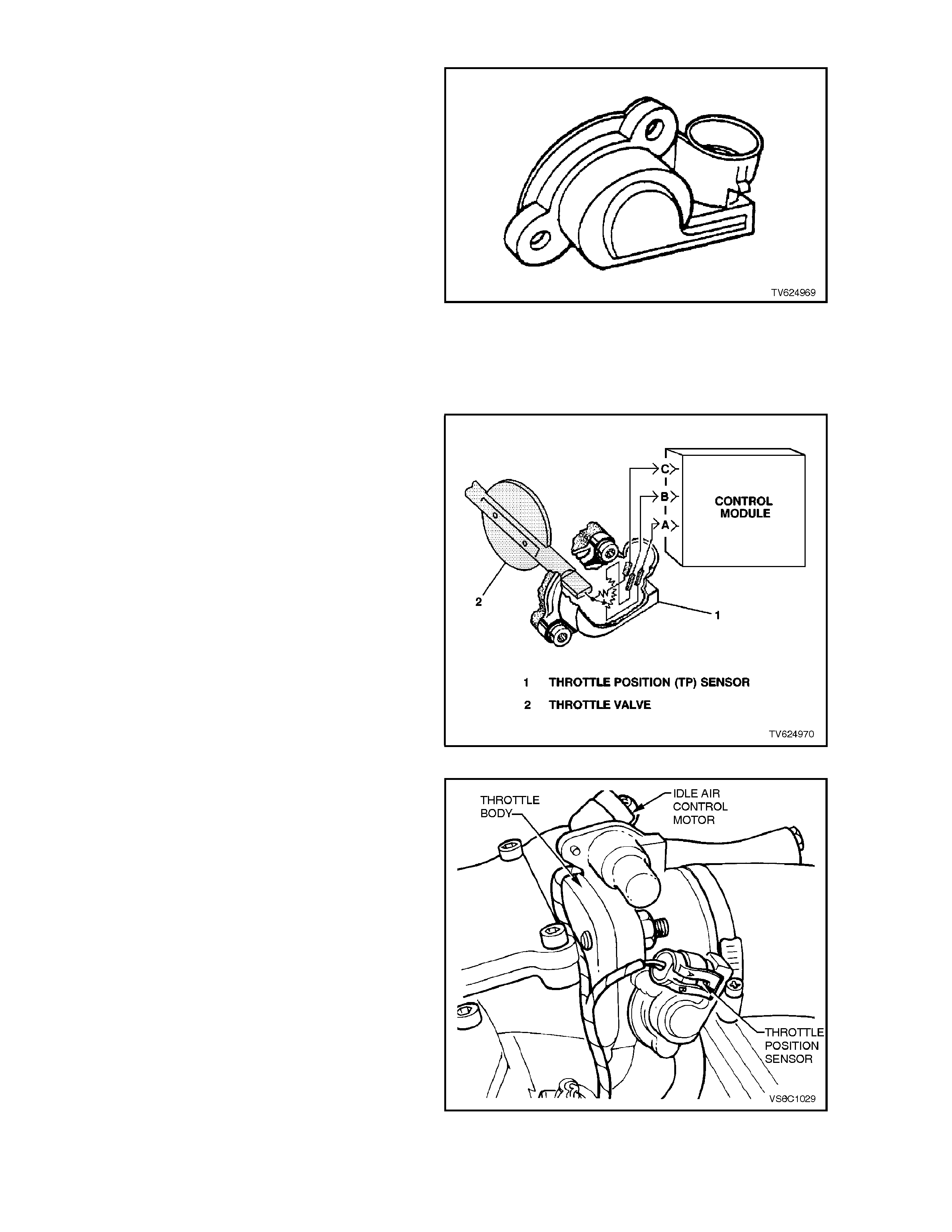
THROTTLE POSITION (TP) SENSOR
The Throttle Position (TP) sensor is connected to
the throttle shaft on the throttle body unit. It is a
potentiometer with one end connected to 5 volts
from the PCM and the other end to PCM earth. A
third wire connects from a sliding contact in the TP
sensor to the PCM allowing the PCM to measure
the voltage from the TP sensor. As the throttle is
moved ( acceler ator pedal m oved), the output of the
TP sensor changes. At a closed throttle position,
the output of the TP sensor is below 1.25V. As the
throttle valve opens, the output increases so that, at
wide-open throttle (WOT), the output voltage
should be about 4 volts.
By monitoring the output voltage from the TP
sensor, the PCM can determ ine fuel delivery based
on throttle valve angle (driver demand). A broken or
loose TP sensor can cause intermittent bursts of
fuel from the injectors, and an unstable idle,
because the PCM interprets the throttle is moving.
Figure 6C1-1-41 TP Sensor
The TP sensor is not adjustable and there is not a
set value for voltage at closed throttle because the
actual voltage at closed throttle can vary from
vehicle to vehicle due to tolerances. The PCM has
a special progr am built into it that can adjus t for the
tolerances in the T P sensor voltage reading at idle.
The PCM uses the reading at clos ed throttle idle for
the zero reading (0% throttle) so no adjustment is
necessary. Even if the TP sensor voltage reading
was to be change by: tampering, throttle body
coking, sticking cable or any other reason, the TP
sensor will still be 0%. The PCM will learn what the
closed throttle value is every time the throttle
comes back to closed throttle. The new closed
throttle value will be used by the PCM and no
driveability complaint will be present because the
PCM learned a new setting.
A failure in the TP sensor circuit problem will set
DTC 21 or DTC 22. If the internal spring in the TP
sensor should fail, the T P sensor will be stuck high.
A sticking TP sensor should set DTC 19. Figure 6C1-1-42 TP Sensor - Typical
Figure 6C1-1-43 TP Sensor Location
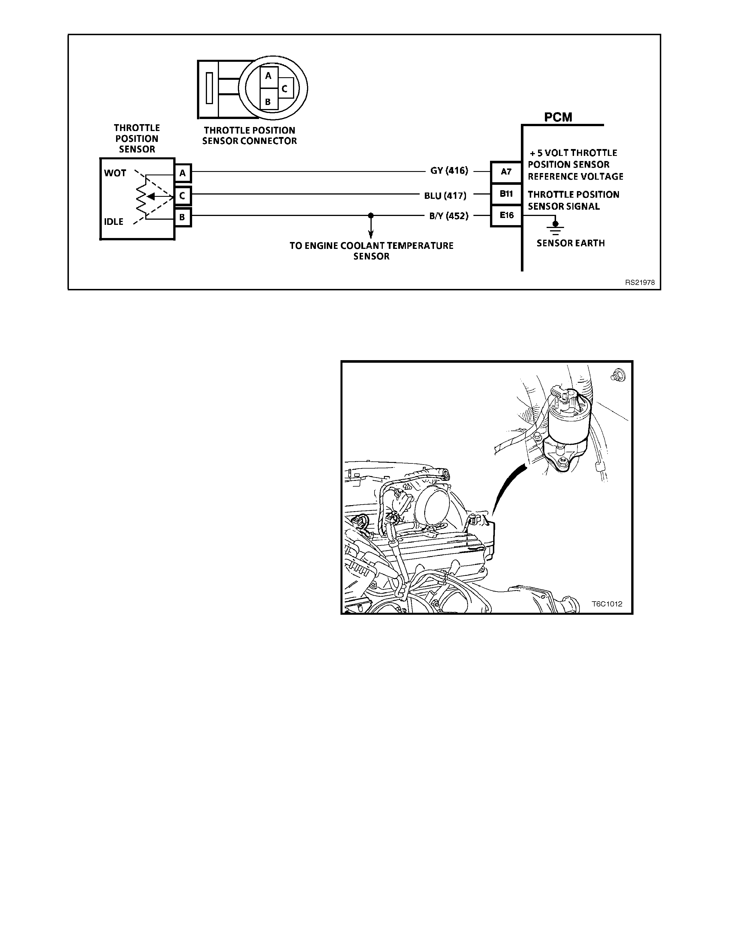
Figure 6C1-1-44 TP Sensor Circuit
EXHAUST GAS RECIRCULATION (EGR) SYSTEM
NON-SUPERCHARGED ENGINE APPLICATION ONLY
PURPOSE
The Exhaust Gas Recirculation (EGR) system is
used to lower Oxides of Nitrogen (NOx) emission
levels caused by high combustion temperatures. It
does this by decreasing combustion temperature.
The main element of the system is the linear EGR
valve. The EGR valve feeds small amounts of
exhaust gas back into the compression chamber.
With the air/fuel mixture thus diluted, combustion
temperatures are reduced.
Figure 6C1-1-45 Linear EGR Valve Location

OPERATION
The linear EGR valve is designed to accurately
supply EGR to an engine independent of intake
manifold vacuum. The valve controls EGR flow
from the exhaust to the intake m anifold through an
orifice with a PCM controlled pintle. During
operation, the PCM controls pintle position by
monitoring the pintle position feedback signal. The
feedback signal can be monitored with a scan tool
as "EGR POS. FEEDBACK". "EGR POS.
FEEDBACK" should always be near the
commanded EGR position ("EGR POS.
COMMANDED"). If a problem with the EGR system
will not allow the PCM to control pintle position
properly, DTC 29 should set. The PCM also tests
for EGR flow; if incorrect flow is detected, DTC 18
should set. If DTC 29 and/or DTC 18 are
encountered, refer to appropriate DTC chart in
section.
The Linear EGR valve is usually activated under
the following conditions:
• Warm engine operation
• Above idle engine speed
• Vehicle not in Park or Neutral
• Fuel Control Is In Closed Loop Mode
LINEAR EGR CONTROL
The PCM monitors EGR feedback position and
adjust pintle position accordingly. The PCM uses
information from the following sensors to control
the pintle position:
• Engine Coolant Temperature (ECT) sensor.
• Mass Air Flow (MAF).
• Engine RPM.
RESULTS OF INCORRECT EGR SYSTEM
OPERATION
Too much EGR flow at idle, cruise, or cold
operation may cause any of the following conditions
to occur:
• Engine stalls after cold start.
• Engine stalls at idle after deceleration.
• Vehicle surge during cruise.
• Rough idle.
• Misfire.
Too little or no EGR flow may allow combustion
temperatures to get too high. This could cause:
• Spark knock (detonation).
• Engine overheating.
• High emissions.
• Poor fuel economy.
• DTC 18.
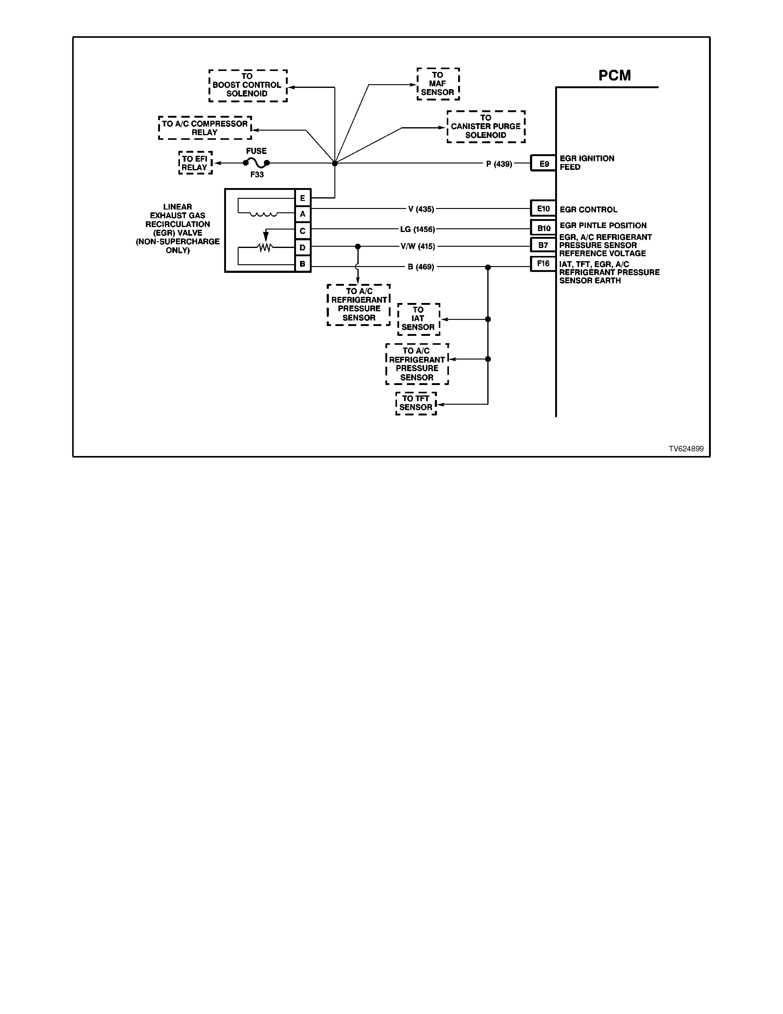
Figure 6C1-1-46 Linear EGR Valve Circuit
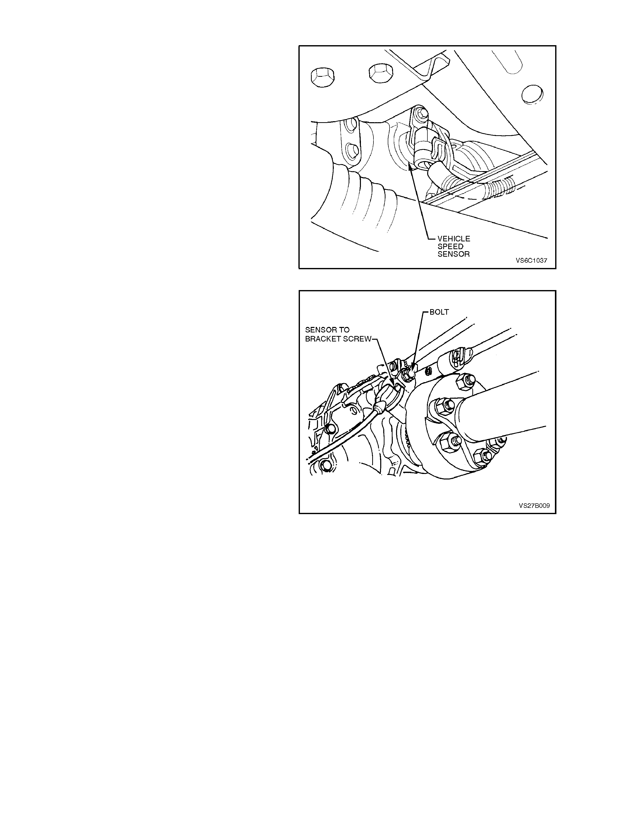
VEHICLE SPEED SENSOR (VSS)
The Vehicle Speed Sensor (VSS) is located on the
transm iss ion. Refer to Figure 6C1-1- 47 for the VSS
Location - Automatic Transmission and 6C1-1-48
for the VSS Location - Manual Transmission.
The VSS provides an indication of road speed to
the PCM. The sensor is mounted to the
transmission where it is gear driven by the
transmission output shaft. The sensor is an
electronic Hall effect switch that pulses to earth a
voltage signal com ing from the PCM. T hese pulses
occur 10 tim es per sensor revolution, and ar e used
by the speedometer for driver information.
The PCM also uses information from the VSS for
IAC valve operation and some of the engine fuelling
modes. If the PCM receives no pulses on the
vehicle speed sensor input while certain conditions
exist, a DTC 24 (Automatic Transmission) or DTC
94 (Manual Transmission) will be set.
Diagnostic Trouble Code (DTC) 24 or 94 will set if a
fault exis ts in the vehicle s peed sensor circ uit when
the vehicle is decelerated, and the VSS signal is
constant, or not pulsing. DTC 24 or 94 will set and
a default value will be substituted by the PCM. As
long as the fault r emains and the diagnostic trouble
code is set. If the fault is removed, normal
operation will resume after the next ignition cycle
Figure 6C1-1-47 VSS Location - Automatic Transmission
Figure 6C1-1-48 VSS Location - Manual Transmission
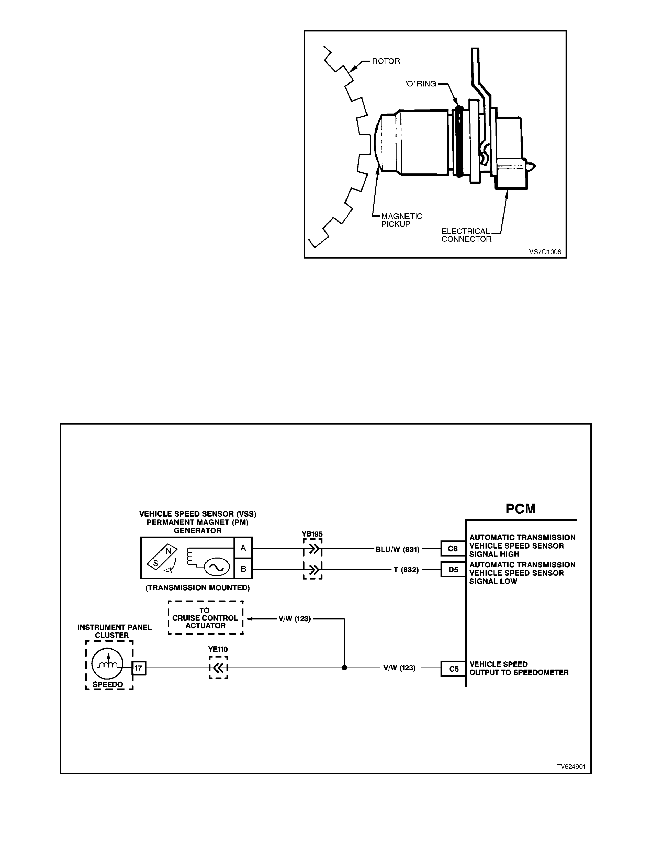
The vehicle speed sensor contains a coil that has
continuous magnetic field. A voltage signal is
induced in the vehicle speed s ens or by teeth on the
output shaft that rotate past the sensor and break
the magnetic field. Eac h break in the field s ends an
electrical pulse to the PCM. T his voltage output will
vary with transmission output shaft speed from a
minim um of 0.5 volts AC at 100 RPM to more than
100 volts AC at 8000 RPM with no load on the
circuit on the vehicle, with the engine at 4,000 RPM
in fourth gear the voltage will be approximately 10-
12 Volts AC.
The PCM uses speed information from this sensor
to determine the following:
• Vehicle speed.
• Control shift points (Auto Trans).
• Calculate transmission slip (Auto Trans).
• Engine fuelling modes.
Diagnostic Trouble Code (DTC) 24 or 94 will set if a
fault exists in the vehicle speed sensor circuit
indicating the vehicle is not moving. For the
automatic transmission, as the vehicle is
accelerated the PCM shifts the transmission to
second gear at approximately 50 km/h. If the
vehicle speed signal is still not present while in
second gear, DTC 24 is set, the transmission will
have maximum line pressure, 2 ND gear only and
have no TCC and a def ault value will be s ubs tituted
by the PCM.
Figure 6C1-1-49 VSS
Figure 6C1-1-50 VSS Circuit

A/C REQUEST SIGNAL
When A/C is requested from the dash master A/C switch, the A/C request signal is sent to the BCM. The BCM will then
send a command via the serial data line to the PCM. The PCM will then supply a earth signal to the A/C compressor
relay, to energise the A/C compressor.
The PCM uses this BCM serial data command to:
1. Adjust the Idle Air Control (IAC) position to compensate for the additional load placed on the engine by the air
conditioning compressor, and then
2. Energises the A/C compressor relay, to operate the A/C compressor.
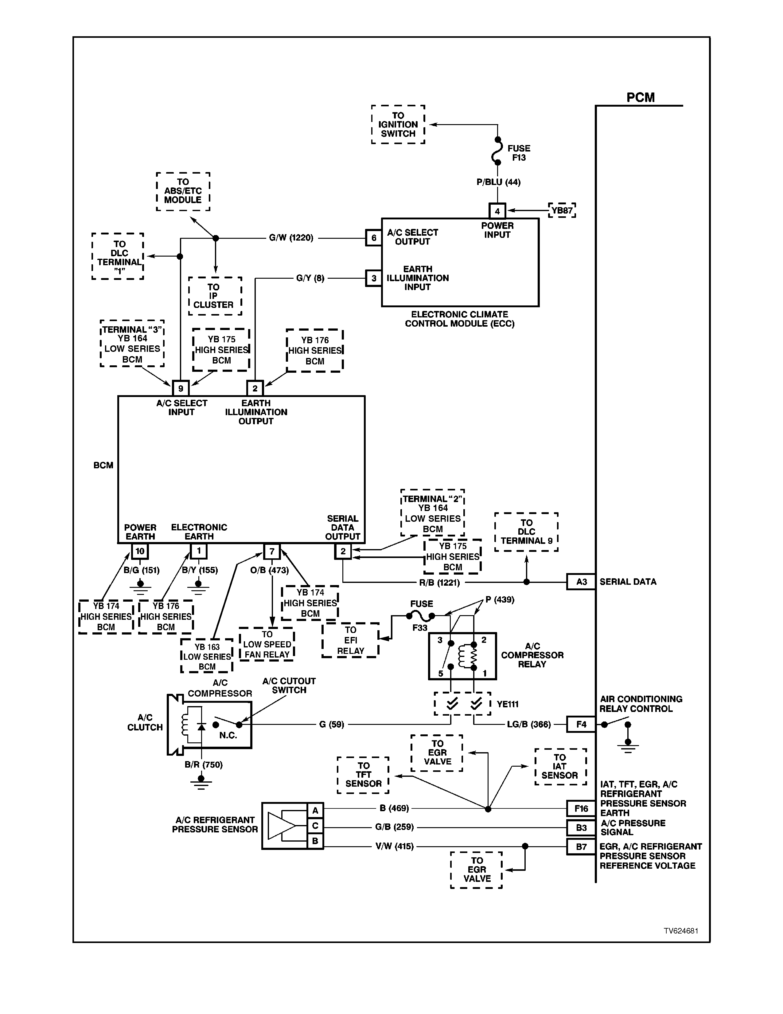
Figure 6C1-1-51 A/C Request Signal Circuit With ECC
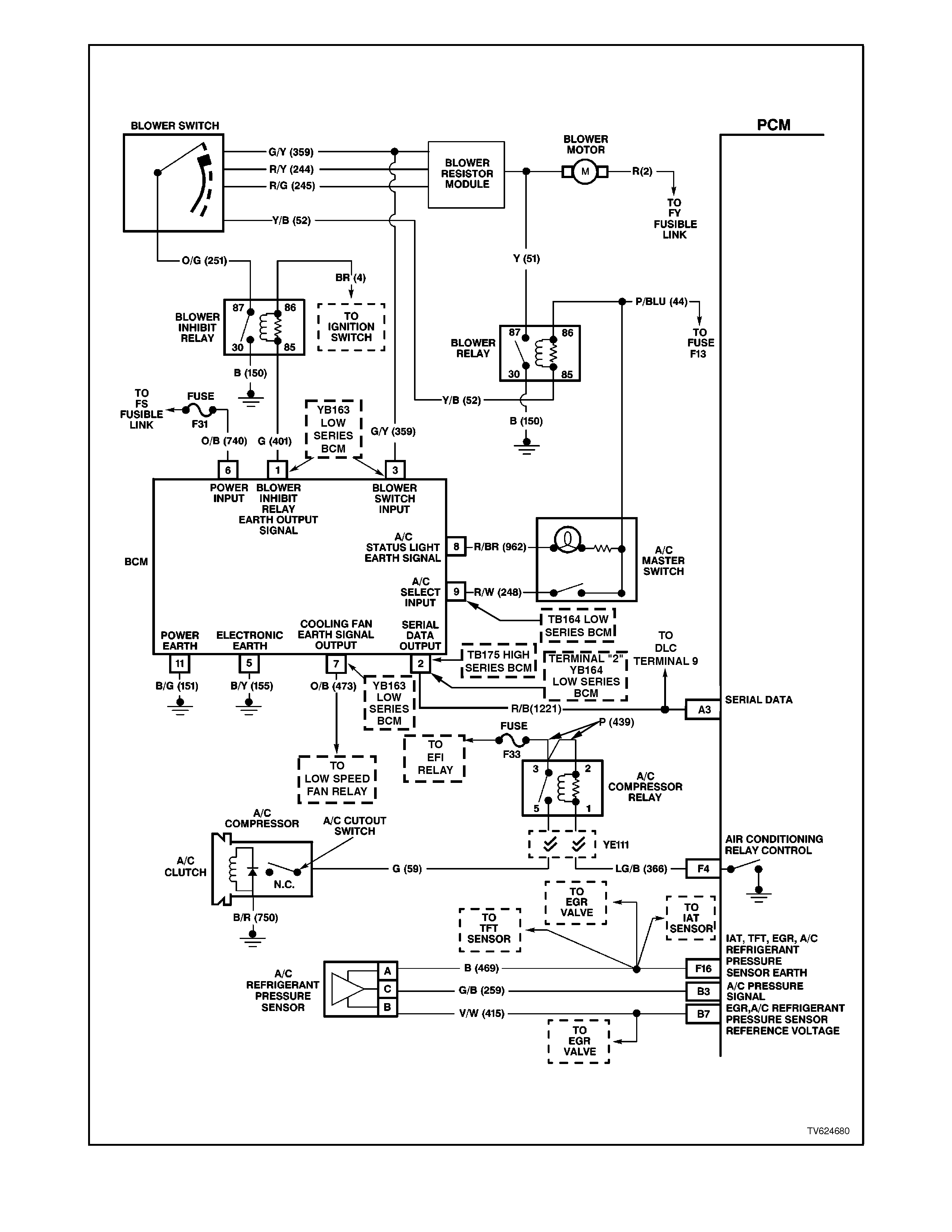
Figure 6C1-1-52 A/C Request Signal Circuit Without ECC
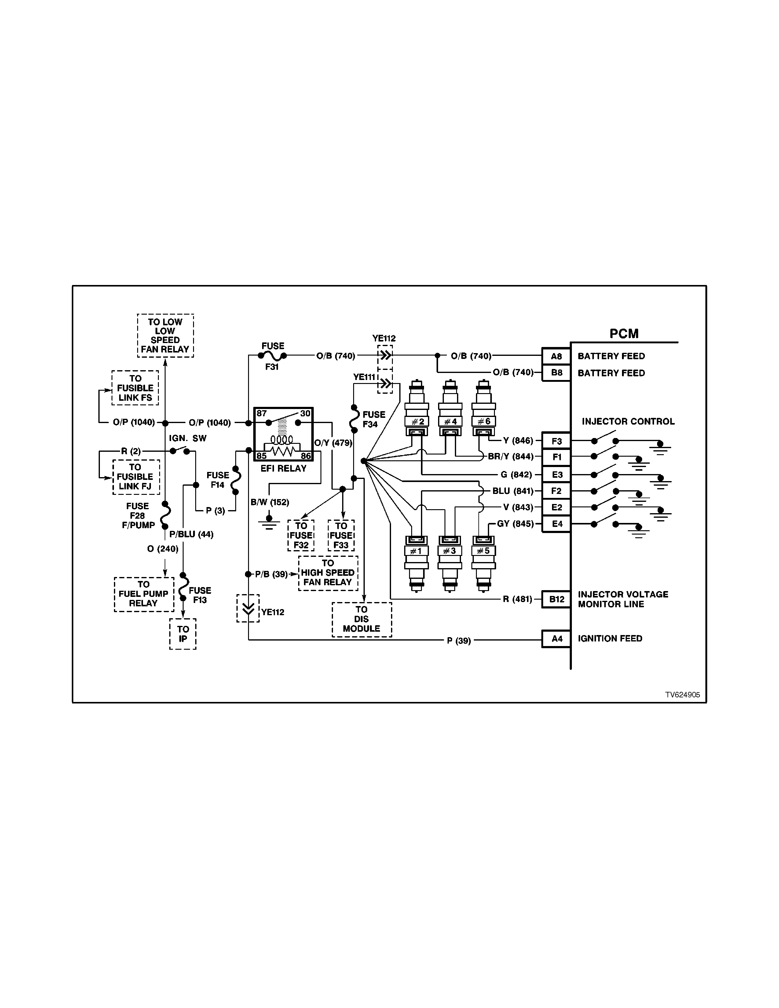
BATTERY VOLTAGE
The PCM continually monitor s battery voltage. W hen the battery voltage is low, the ignition system may deliver a weak
spark and the injector mechanical movement takes longer to open the injector. The Powertrain Control Module will
compensate by:
1. Increasing the ignition coil dwell time if the battery voltage is less than 12 volts.
2. Increasing the engine idle RPM if battery voltage drops below 10 volts.
3. Increasing the injector pulse width if the battery voltage drops below 10 volts.
On vehicles equipped with automatic transmissions, Diagnostic Trouble Code (DTC) 53 will set when the ignition is
"ON'' and PCM terminal "A4'' voltage is more than 19.5 volts for about 2 seconds.
Diagnostic Trouble Code (DTC) 54 will set when the ignition is "ON'' and PCM terminal "A4'' voltage changed more than
2.5 volts in 100 milliseconds.
Diagnostic Trouble Code (DTC) 75 will set when the ignition is "ON'' and PCM terminal "A4'' voltage is less than 8.6
volts for about 4 seconds. Minimum voltage allowed for Diagnostic Trouble Code 75 to set is on a graduated scale and
will change with the temperature. Minimum voltage at -40 degrees C is 7.3 volts, minimum voltage at 90 degrees C is
8.6 volts., minimum voltage at 152 degrees C is 11.4 volts.
Figure 6C1-1-53 PCM Battery Feed
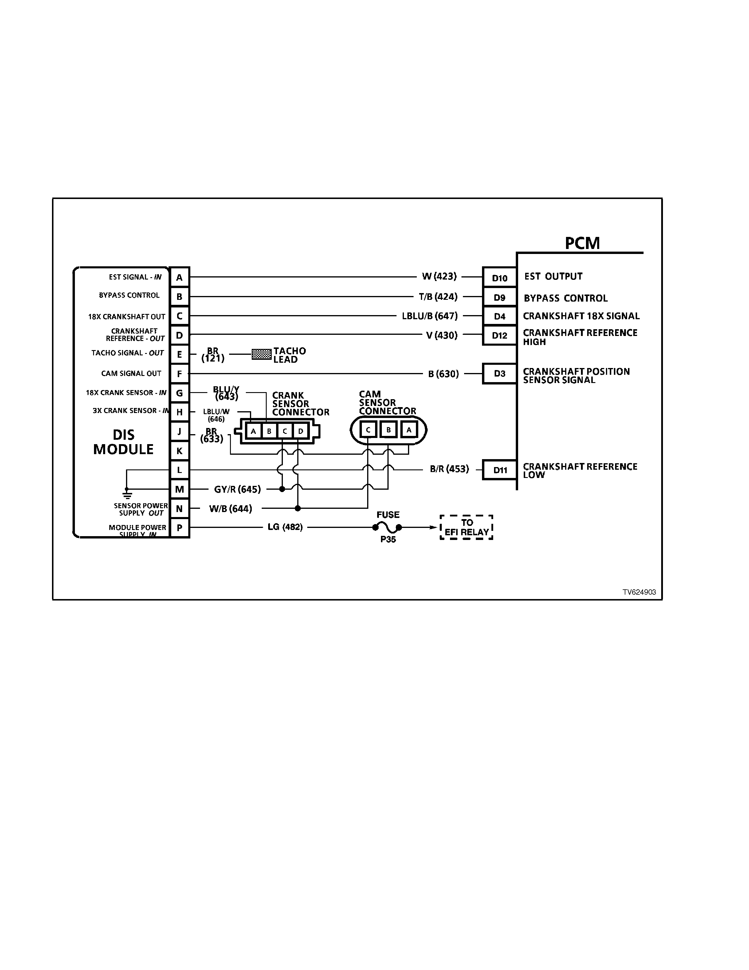
CRANKSHAFT REFERENCE SIGNAL
This also uses the camshaft position sensor signal to synchronise the fuel injector circuits for sequntial fuel injection.
The PCM also uses these reference pulses for Electronic Spark Timing (EST) operation.
For a full description of the ignition system operation refer to Section 1.7 DIRECT IGNITION SYSTEM (DIS) in this
Section.
The Direct Ignition System (DIS) sends this signal to the PCM to tell it engine RPM and crankshaft position. This signal
is a repeating series of low voltage electrical pulses generated by the ignition module. The PCM initiates fuel injector
pulses based upon receiving these crankshaft reference signal pulses.
Figure 6C1-1-54 Crankshaft Reference Signal
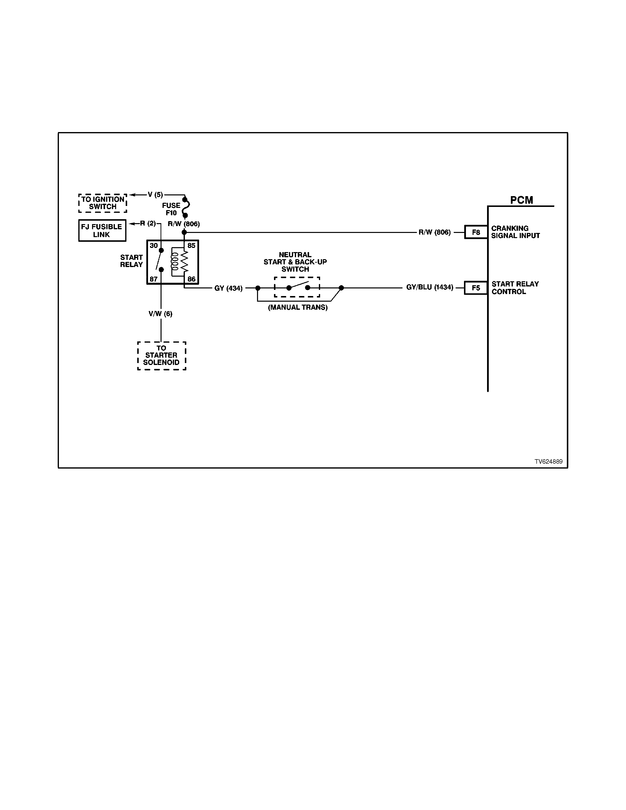
CRANKING SIGNAL
The cranking circuit provides an input for enabling fuel cut off during a possible backfire situation. During an engine
start, when the ignition switch is r eleas ed f r om the cr ank position bef or e the engine is running, the engine may back fire.
The Powertrain Control Module stops all injection pulses when the engine speed is less than 450 RPM, coolant
temperature is greater than -4 degrees C, a cranking signal is not received, but was received with the previous 12.5
milliseconds.
The Powertrain Control Module monitors the voltage on the cranking signal input terminal. This terminal is a voltage
sensing input.
Figure 6C1-1-55 Cranking Signal Circuit
ENGINE COOLI NG FAN SIGNAL
(LOW SPEED RESPONSE)
The V6 engine has two (2), two speed electric cooling fans which provides the primary means of moving air through the
engine radiator. These fan are placed between the radiator and the engine and has its own shroud. These fans are
used on all vehicles whether or not it is equipped with air conditioning. There is no fan in front of the A/C condenser.
The two (2), two speed electric fan's low speed can only be enabled when the engine cooling fan low speed relay is
energised by the BCM. The PCM will request low speed fan enable and disable via the serial data communication to the
BCM. After the PCM requests a change in the engine cooling fan low speed relay , the BCM will send a serial data
response message back to the PCM confirming it received the message. A failure in this response communication will
set a DTC 92. There are also four (4) suppression capacitors incorporated into the fan motor wiring circuits. These
suppression capacitors help eliminate fan motor noise through the radio speakers. If these capacitors are open, then
noise will be present through the radio speakers. If shorted to earth, the fan motors could continuously run, or the fuse
or fusible link could fail.
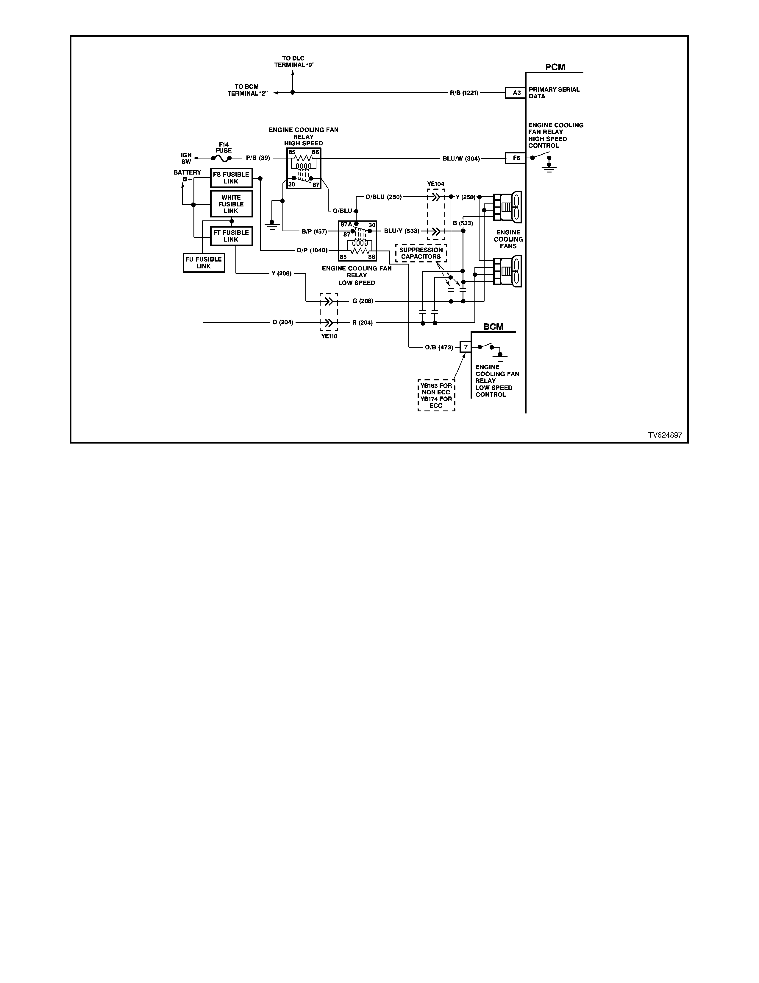
Figure 6C1-1-56 Engine Cooling Fan Signal
ENGINE COOLING FAN HIGH SPEED
The engine cooling fan high speed is controlled by the PCM based on input from the Engine Coolant Temperature
Sensor (ECT). The PCM will only turn "ON" the engine cooling fan high speed if the engine cooling low speed fans have
been "ON" for 2 seconds and the following conditions are satisfied.
• There is a BCM message response fault which will cause a DTC 92.
• An engine coolant temperature sensor failure is detected, such as DTC 14,15,16,17.
• Coolant temperature greater than 109 degrees C.
If the fan low speed was "OFF" when the criteria was met to turn the fan high speed "ON", the fan high speed will come
"ON" 5 seconds after the fan low speed is turned "ON". The high speed engine cooling fan relay can also be enable by
the A/C Refrigerant Pressure Sensor. The A/C Refrigerant Pressure Sensor will enable high speed cooling fan, if the
A/C system pressure becomes to high.
If a failure occurs in the PCM Engine Cooling Fan Relay High Speed Control circuit, a DTC 91 will set.
There are also four (4) suppression capacitors incorporated into the fan motor wiring circuits. These suppression
capacitors help eliminate fan motor noise through the radio speakers. If these capacitors are open, then noise will be
present through the radio speakers. Is shorted to earth, the fan motors could continuously run, or the fuse or fusible link
could fail.
TRANSMISSION FLUID PRESSURE (TFP) SWITCH ASSEMBLY
The Transmission Fluid Pressure Switch Assembly (TFP) is used by the PCM to sense what gear range has been
selected by the vehicle operator. The TFP is located on the transmission valve body and consists of five pressure
switches, 2 normally closed fluid pressure switches and 3 normally open fluid pressure switches combined into one unit.
The Transmission Fluid Pressure Switch Assembly is one of the inputs used by the PCM to control:
• Idle Air Control (IAC) and,
• Transmission Operation.
A failure in the TFP circuits will set a DTC 28 (Transmission Fluid Pressure Switch Assembly (TFP) circuit fault) if:
• The PCM detects an "illegal" TFP combination for five seconds.
For a full description of the TFP operation refer to
Section 1.3 TRANSMISSION INFORMATION INPUT SENSORS AND SIGNALS .
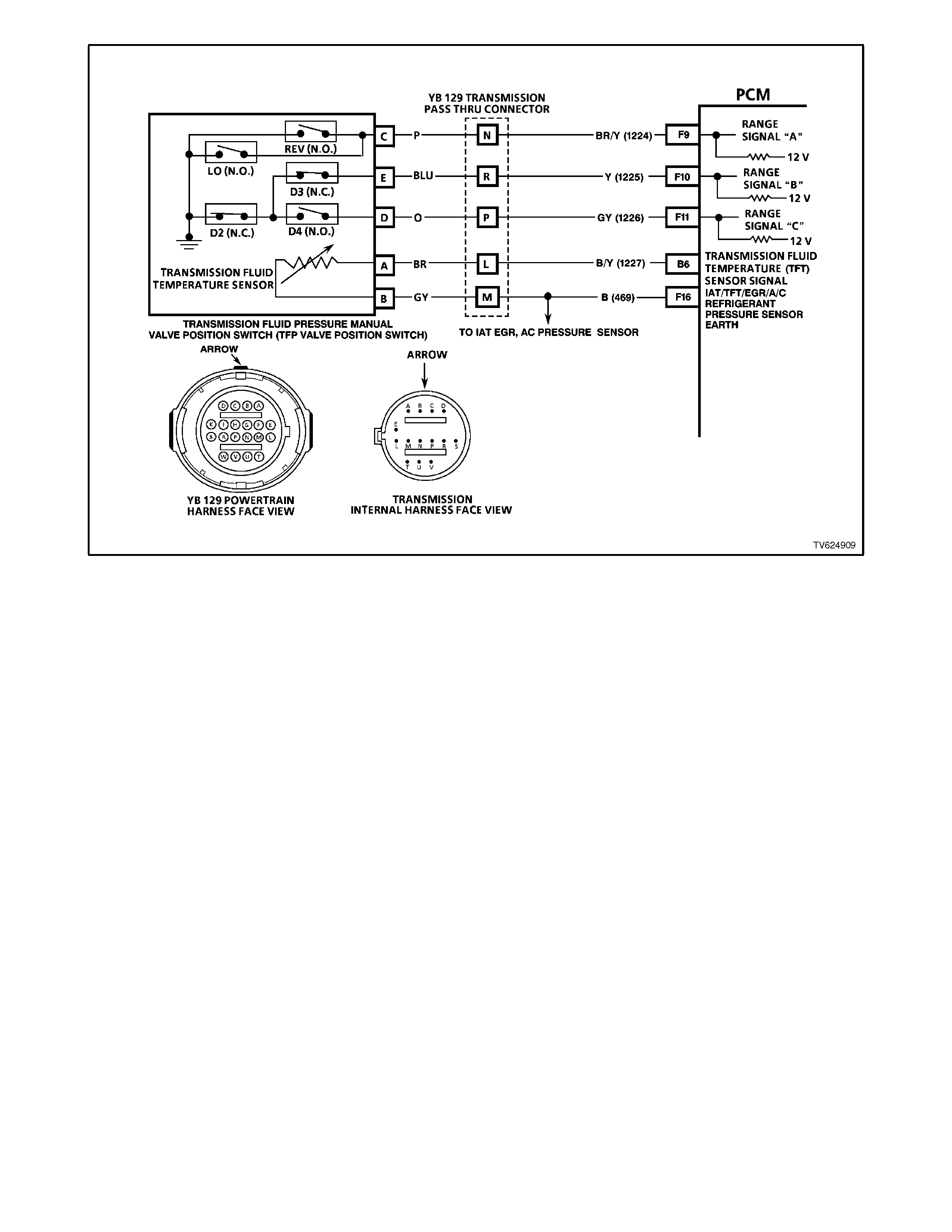
Figure 6C1-1-57 Transmission Fluid Pressure Switch Assembly Circuit
THEFT DETERRENT INPUT
When the ignition switch is turned to the “ON” position, the BCM polls the PCM and sends an encrypted BCM / key
security code. The security code is received by the BCM, via the remote key reader (slip ring) or via the remote receiver
in the event of no slip ring communication.
The PCM compares the received security code with its stored security code and if matched, the PCM will continue to
enable injector fuelling and engine crank.
The PCM will return a Valid Code message (OK TO START), which tells the BCM to jump to the short loop mode to the
long loop mode.
When the ignition switch is turned from the OFF position to the ON position, the BCM will communicate with the PCM
for antitheft purposes. If the BCM does not receive the message OK TO START from the PCM within 0.5 seconds of
the ignition being switched on, the auxiliary bus is isolated via switching within the BCM.
The isolation of the auxiliary data bus during this period eliminates the possibility of a device failure other than the BCM
or PCM causing a problem on the bus and inhibiting antitheft communications.
This period is known as “Short Loop Time”, and continues until the PCM responds with an acknowledgment or a
maximum of 5 seconds, after which the BCM will switch to the standard poling sequence.
Following successful antitheft communications, the BCM begins sequential poling of devices on the bus and normal
system operation is established.
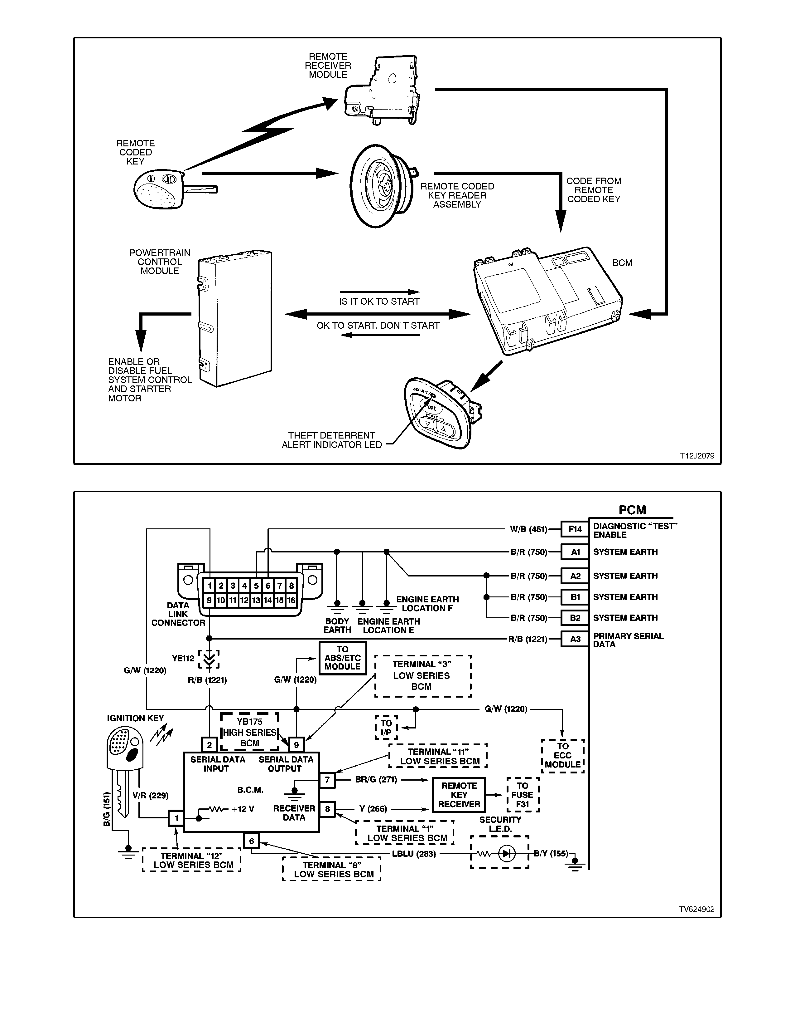
Figure 6C1-1-58 Theft Deterrent System
Figure 6C1-1-59 Theft Deterrent Serial Data Circuit

1.3 TRANSMISSION INFORMATION INPUT SENSORS AND SIGNALS
The computer used with Sequential Fuel Injected (SFI) petrol engine is called a Powertrain Control Module (PCM) and
controls a number of engine functions such as: fuel control, and ignition timing, in addition to the transmission functions.
The diagnosis of this transmission requires the availability of a Tech 2 scan tool to interface with the Powertrain Control
Module (PCM).
The transmission control system of the electronic control module has software and hardware that monitors a number of
engine and vehicle functions then uses the data to control the following operations:
• Transmission Converter Clutch (TCC) engagement.
• Upshift pattern.
• Downshift pattern.
•Line pressure to control shift quality.
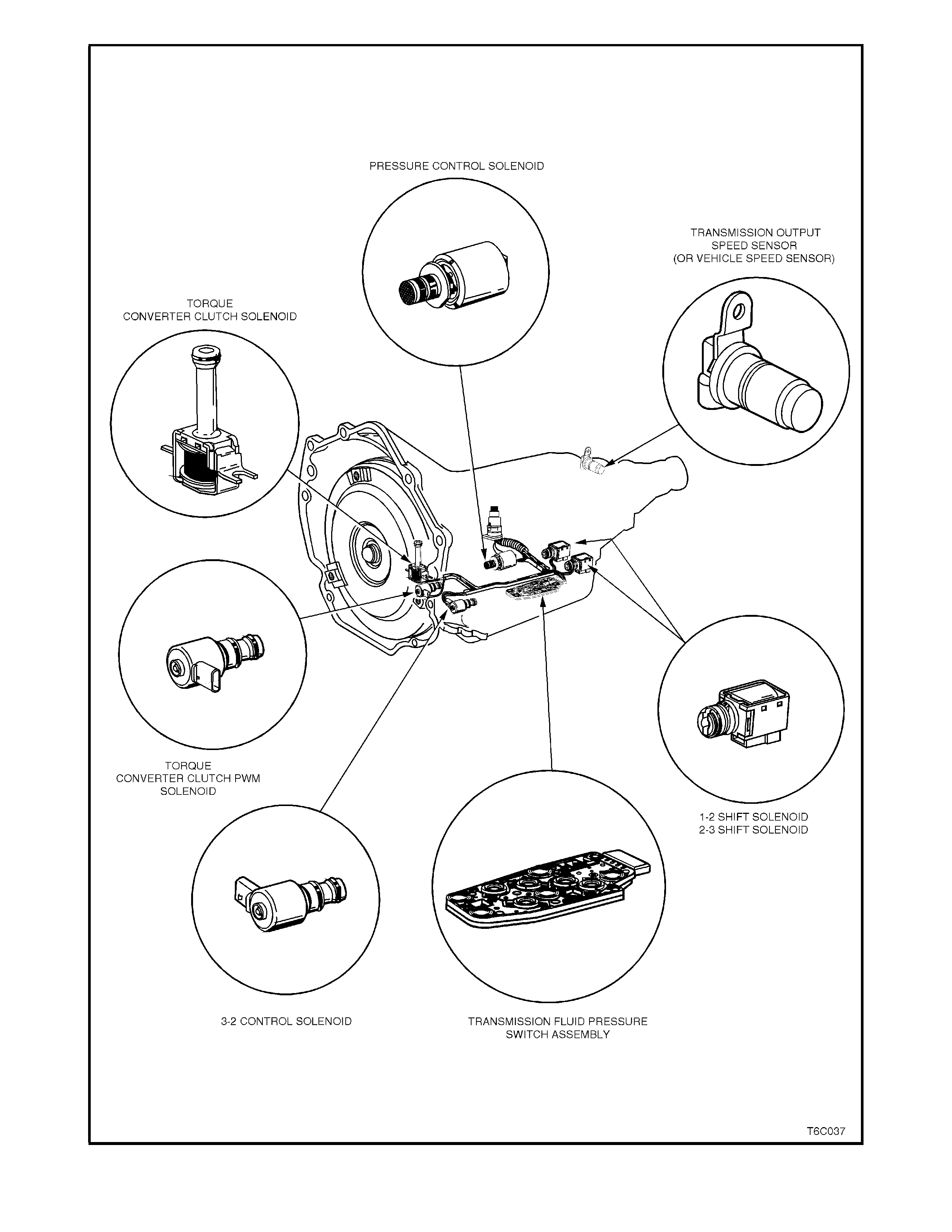
Figure 6C1-1-60 Transmission Electronic Component Location View
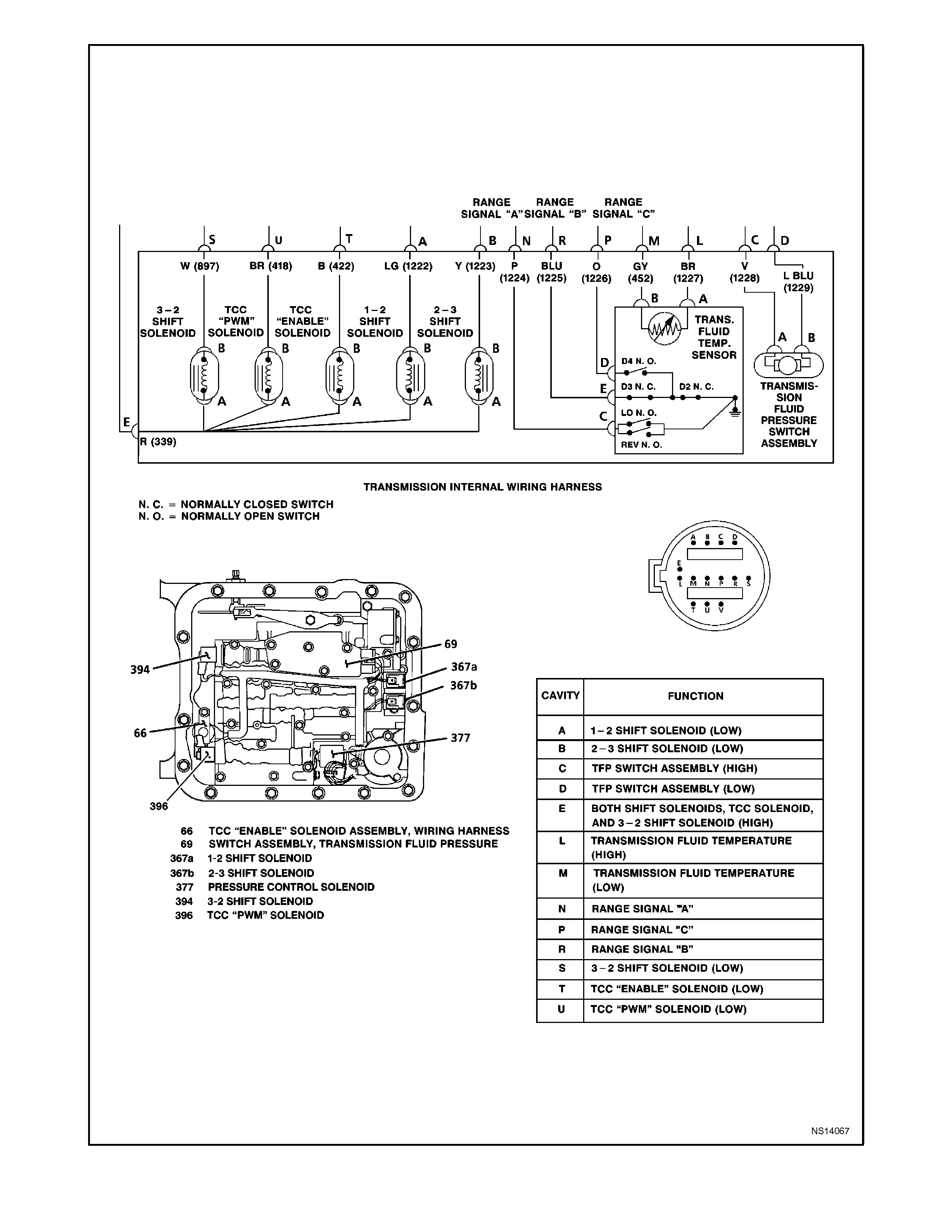
Figure 6C1-1-61 Transmission Wiring
INFORMATION SENSORS
The PCM uses the following information sensors and switches to gather data for electronically controlling transmission
functions.
• Engine Coolant Temperature (ECT) sensor.
• Engine Speed.
• Fluid Pressure Switch Assembly.
• Throttle Position (TP) Sensor.
• Transmission Fluid Temperature (TFT) sensor.
• Transmission Economy/Power Switch.
•Vehicle Speed Sensor (VSS).
ENGINE COOLANT TEMPERATURE (ECT) SENSOR
ECT sensor information is also used for engine functions as well as for the transmission management system. For ECT
details, refer to 1.2 ENGINE INFORMATION SENSORS AND SIGNALS in this Section.
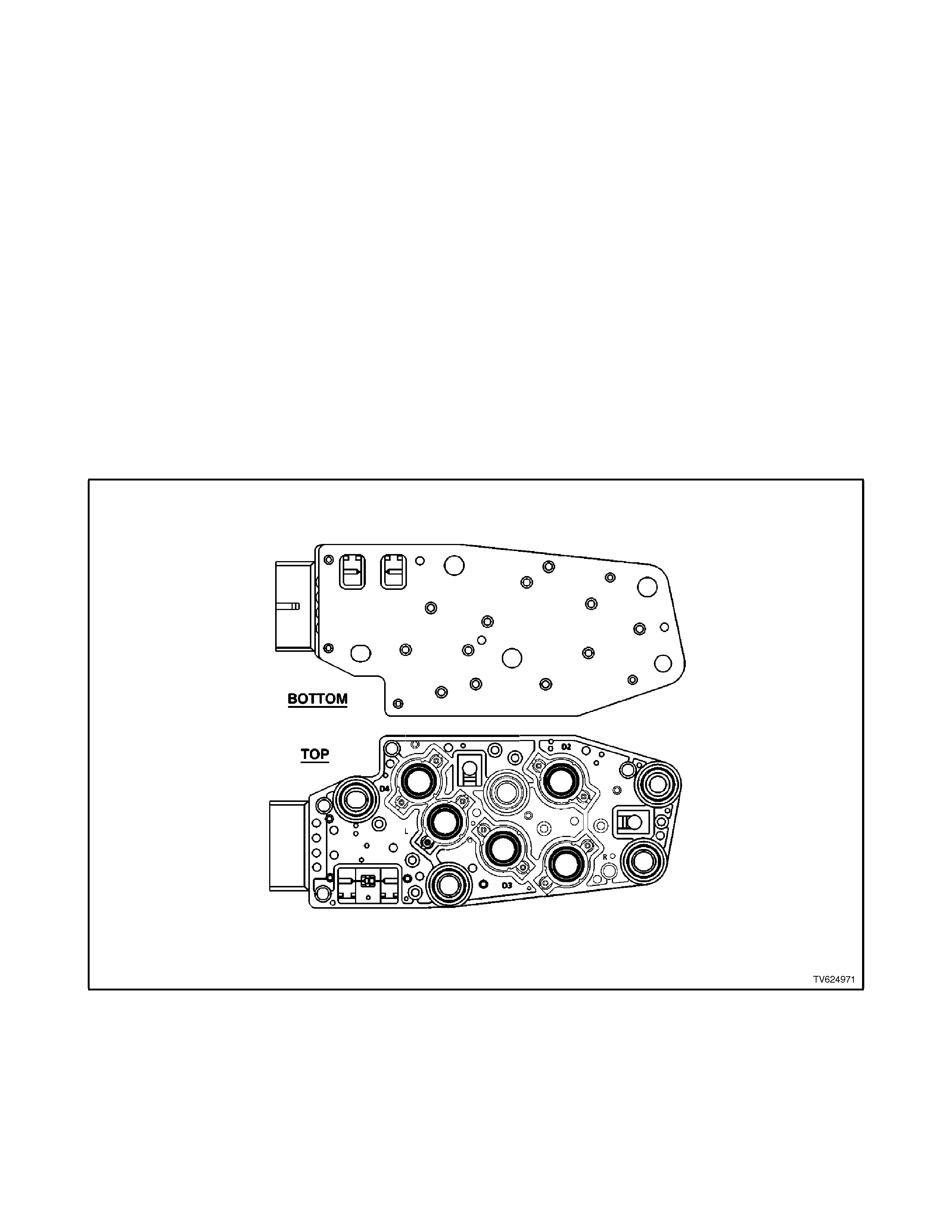
TRANSMISSION FLUID PRESSURE (TFP) SWITCH ASSEMBLY
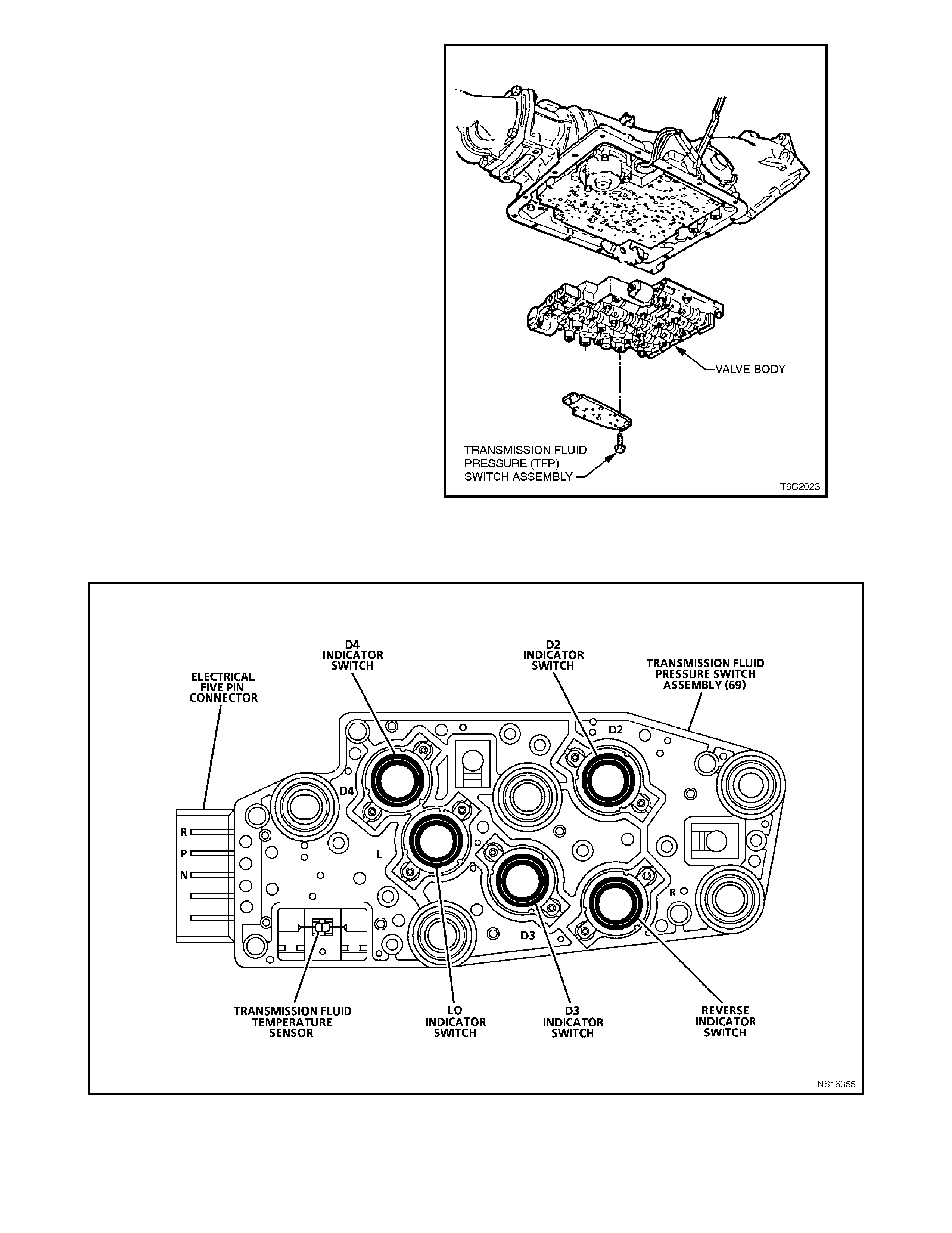
Figure 6C1-1-62 Transmission Fluid Pressure Switch Assembly (TFP) and Transmission Fluid Temperature Sensor
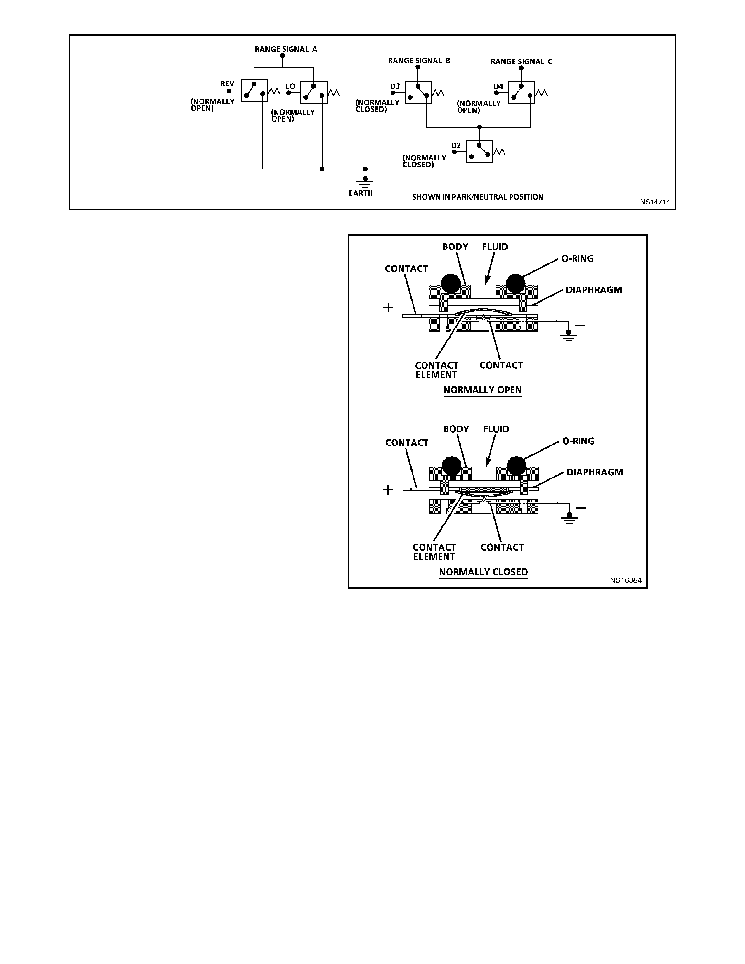
Figure 6C1-1-63 Transmission Fluid Pressure Switch Assembly (TFP) Switches
This gear range sensing device called a
Transmission Fluid Pressure Switch Assembly
(TFP) is used by the PCM to sense what gear
range has been selected by the vehicle operator.
The T FP is located on the valve body and consists
of five pressure switches, 2 normally closed and 3
normally open, combined into one unit.
The normally open fluid pressure switches are the
"D4", "LO" and "Reverse" fluid pressure switches.
They are normally open and electrical current is
stopped at these switches when no fluid pressure is
present. Fluid pressure moves the diaphragm and
contact element until the contact element touches
both the positive contact and the earth contact.
This creates a closed circuit and allows current to
flow from the positive contact, through the switch
and to earth. The normally closed fluid pressure
switches are the "D2" and "D3" fluid pressure
switches. They are normally closed and electrical
current is free to flow from the positive contact to
the earth contact when no f luid pressur e is pres ent.
Fluid pressure moves the diaphragm to disconnect
the positive and earth contacts. This opens the
switch and stops current from flowing through the
switch.
The PCM applies system voltage to the TFP on
three separate wires. An open circuit measures 12
volts while an earthed circ uit m easures 0 volts. T he
switches are opened or closed by fluid pressure.
The combination of which switches are open and
closed is used by the PCM to determine actual
manual valve position. The TFP however cannot
distinguish between park and neutral because the
monitored valve body pressures are identical in
both cases.
L -This switch will have hydraulic pressure
applied to it in m anual 1st gear only and will be
closed.
R -This switch will have hydraulic pressure
applied to it in reverse only and will be closed.
Figure 6C1-1-64 Transmission Fluid Pressure Switch
Assembly (TFP)
D2 -This switch will have hydraulic pressure
applied to it in manual 1st and 2nd gear and
will be open.
D3 -This switch will have hydraulic pressure
applied to it in manual 1st, 2nd and 3r
d
gear
and will be open.
D4 -This switch will have hydraulic pressure
applied to it in all drive gears except reverse
and will be closed.
TFP assembly signal voltage can be measured with
a high impedance digital volt ohmmeter by back
probing the PCM then taking measurements from
each terminal to earth, and comparing it to the
combination chart. On the transmission wiring
harness, pin N is "Range Signal A", pin R is "Range
Signal B", and pin P is "Range Signal C". With the
wiring harness connected and engine operating, a
voltage measurement of these three lines will
indicate a "high" reading (near 12 volts) when a
circuit is open, and a low (zero volts) when the
circuit is switched to earth.
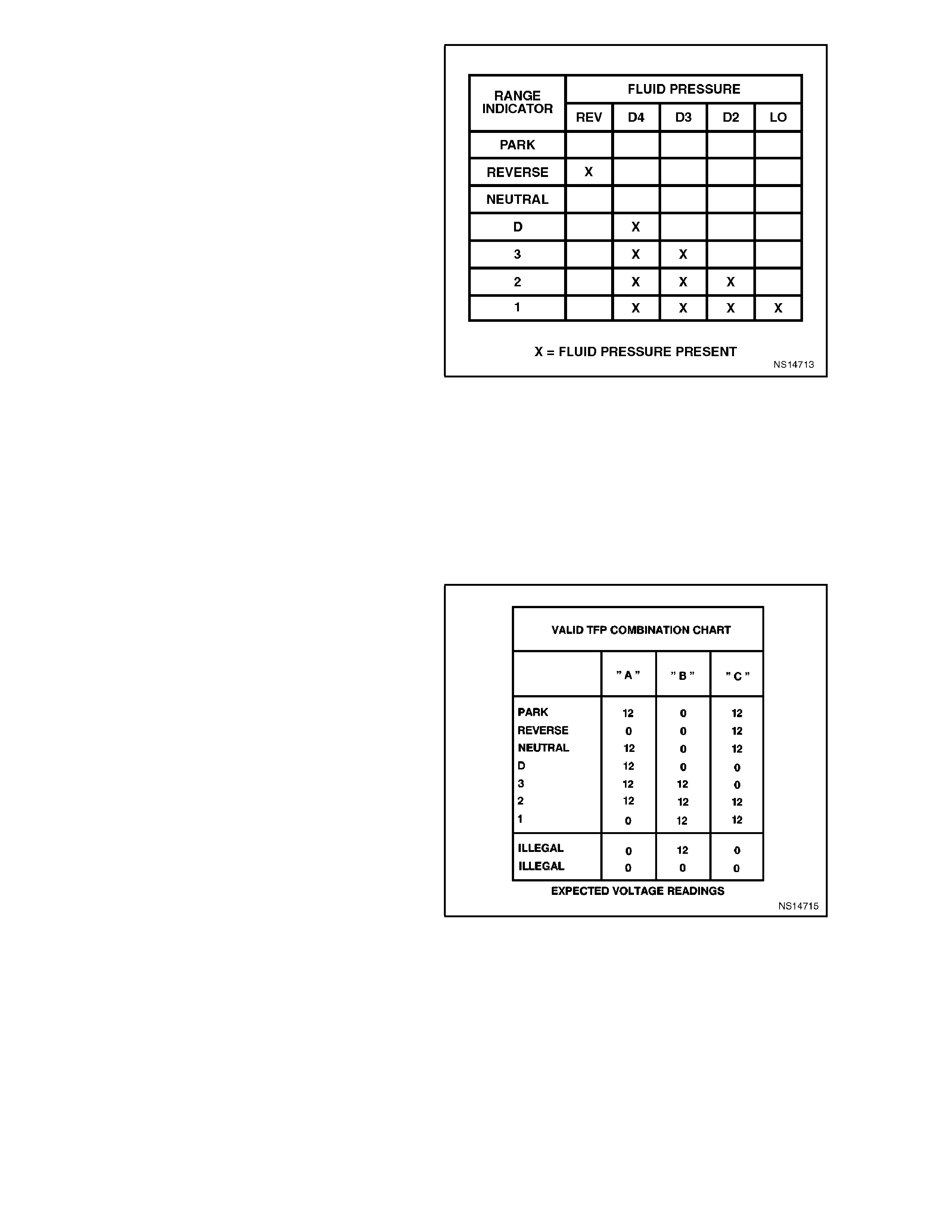
These TFP inputs are used to help control line
pressure, torque converter clutch apply and shift
solenoid operation. To monitor TFP assembly
operation, the PCM compares the actual voltage
combination of the switches to a TFP combination
chart stored in its mem ory. If the PCM detects one
of two "illegal" voltage combinations a Diagnostic
Trouble Code 28 will result.
Figure 6C1-1-65 Pressure Applied to TFP Switches
There are two possible combinations of the
switches within the pressure switch assembly that
do not represent an actual gear range. If either of
these combinations are detected by the PCM for 5
seconds or longer, Diagnostic Trouble Code 28 will
set. Diagnostic Trouble Code 28 will also set if a
valid gear range combination appears at the wrong
time.
While Diagnostic Trouble Code 28 is present, the
PCM will take the following action:
1. Assume D4 for shift pattern control.
2. Use D2 pressure table.
3. Inhibit 4th gear operation in hot mode only.
4. Inhibit TCC operation.
If the TFP resumes normal functioning, the
transm ission will resum e norm al operation after the
next ignition cycle.
DTC 28 will not detect an open circuit in either
range signal "B" or "C". An open circuit in either of
these signals will not be an illegal T FP com bination
but a legal TFP combination at the wrong time, so
that the PCM interprets wrong information.
Figure 6C1-1-66 TFP Chart
There ar e two failures in the T FP that will cause an
unusual complaint. If the range signal "B" is open
the PCM will interpret this PRNDL select as "2"
gear in park or neutral with the ignition "ON" or
engine idling. The customer will probably complain
that when "D" range is selected the transmission
never shif ts into 4th gear. T his is becaus e the PCM
only controls shif ts in "D" range, but because of the
open circuit in range signal "B" the PCM interprets
this as "3" gear and the tr ans miss ion will never s hif t
to fourth gear because this "3" gear input is a
normal condition.
The other condition to cause an unusual complaint
is an open in the range signal "C". When the dr iver
selects "3" gear range, the PCM will interpret this
PRNDL select as "2" gear and will provide 1st and
2nd gears only. If the driver selects "D" range, the
transmission will have all gears and TCC, but the
Tech 2 scan tool will read P-N all the time.
Figure 6C1-1-67 Transmission Fluid Pressure Switch
Assembly (TFP) Location
TRANSMISSION FLUID TEMPERATURE (TFT) SENSOR
Figure 6C1-1-68 Transmission Fluid Pressure Switch Assembly (TFP) and Transmission Fluid Temperature Sensor
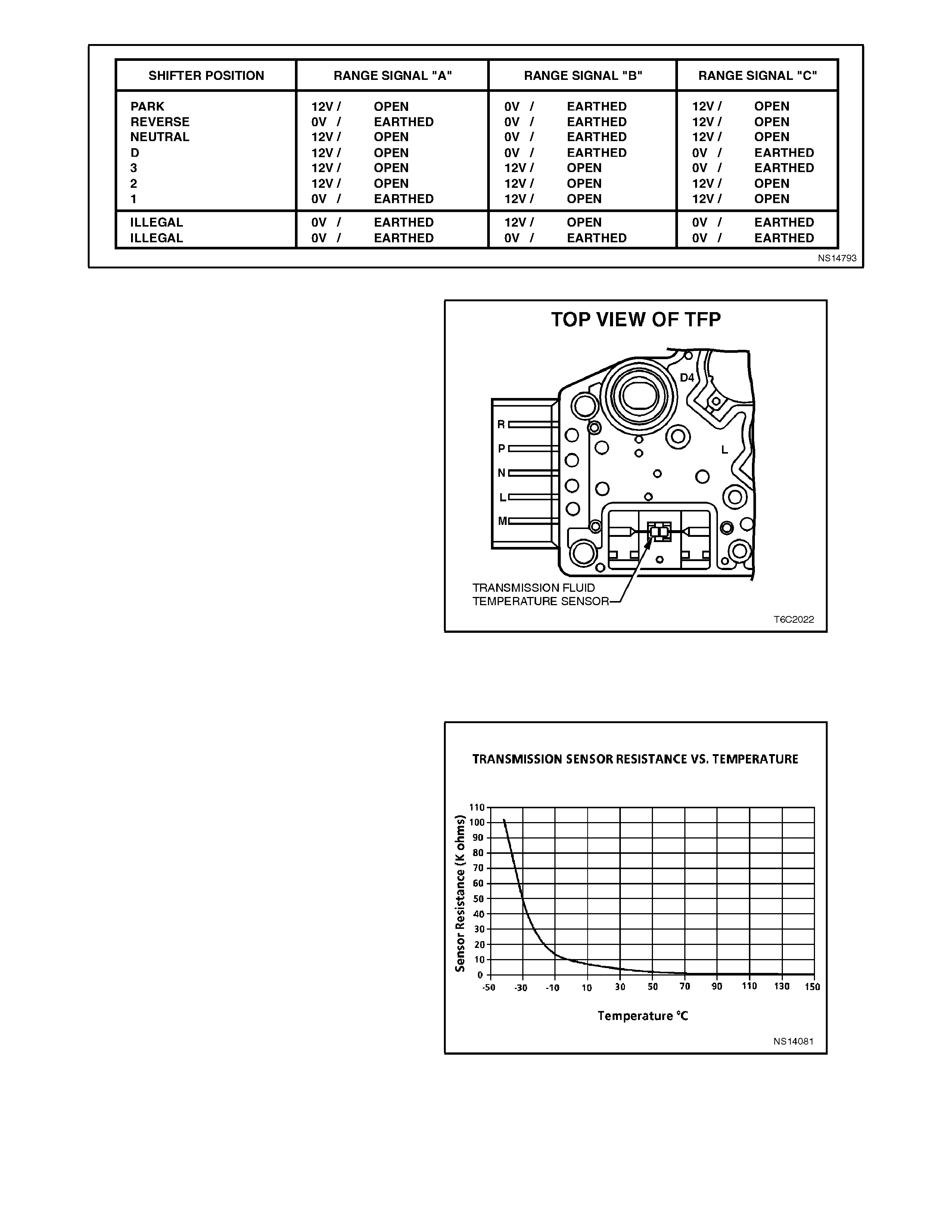
Figure 6C1-1-69 Transmission Fluid Pressure Switch Assembly (TFP) Switch Voltages
The Transm ission Fluid Temperature (T FT) sensor
is a thermistor (a res istor that changes value based
temperature) that is part of the transmission fluid
Pressure Switch Assembly (TFP). Low
transmission fluid temperature produces high
resistance and high transmission fluid temperature
produces low resistance. The PCM supplies a 5
volt signal to the Transmission Fluid Temperature
(TFT) sensor through an internal resistor then
measures the voltage drop in the circuit. Voltage
will be high when the transmission fluid is cold and
low when the transmission fluid is hot.
The PCM uses the Transmission Fluid
Temperature (TFT) Sensor to regulate torque
converter clutch apply, as well as shift quality.
Diagnostic T rouble Code 58 and 59 indic ate a fault
in the Transmission Fluid Temperature (TFT)
sensor circuit. The Tech 2 scan tool will display
transmission fluid temperature in degrees Celsius.
After the vehicle has been started, transmission
fluid temperature should rise steadily and stabilize
between 82 and 94 degrees Celsius, depending on
load.
Figure 6C1-1-70 Transmission Fluid Temperature Sensor
Both diagnostic trouble codes will cause the PCM
to use a default value of 130 degrees Celsius thus
reacting as if the transmission were hot in either
case. W hen Diagnostic Trouble Code 58 or 59 are
set the torque converter clutch is enabled in
second, third and forth and will apply early. Some
driveability symptoms will be noticed especially
when cold.
DTC 79 is used to identify if the transmission fluid
has been overheated to the point that the f luid is no
longer useable for the transmission. DTC 79 will set
if the transmission fluid temperature exceeds 146
degrees C and does not go lower than 137 degrees
C for 30 minutes.
The PCM m onitors the TFT sensor for determ ining
DTC 79. An electrical failure in the TFT sensor
circuit will not set a DTC 79. DTC 79 will only be set
if the fluid actually did exceed the temperature or if
the TFT sensor is skewed high or stuck above the
temperature threshold.
Temperature to Resistance specification chart
found at DTC 58 and DTC 59.
Figure 6C1-1-71 TFT Sensor Temperature to Resistance
Relationship

THROTTLE POSITION (TP) SENSOR
TP sensor information is also used for engine
functions as well as for the transmission
management system. For TP details, refer to
1.2 ENGINE INFORMATION SENSORS AND
SIGNALS in this Section.
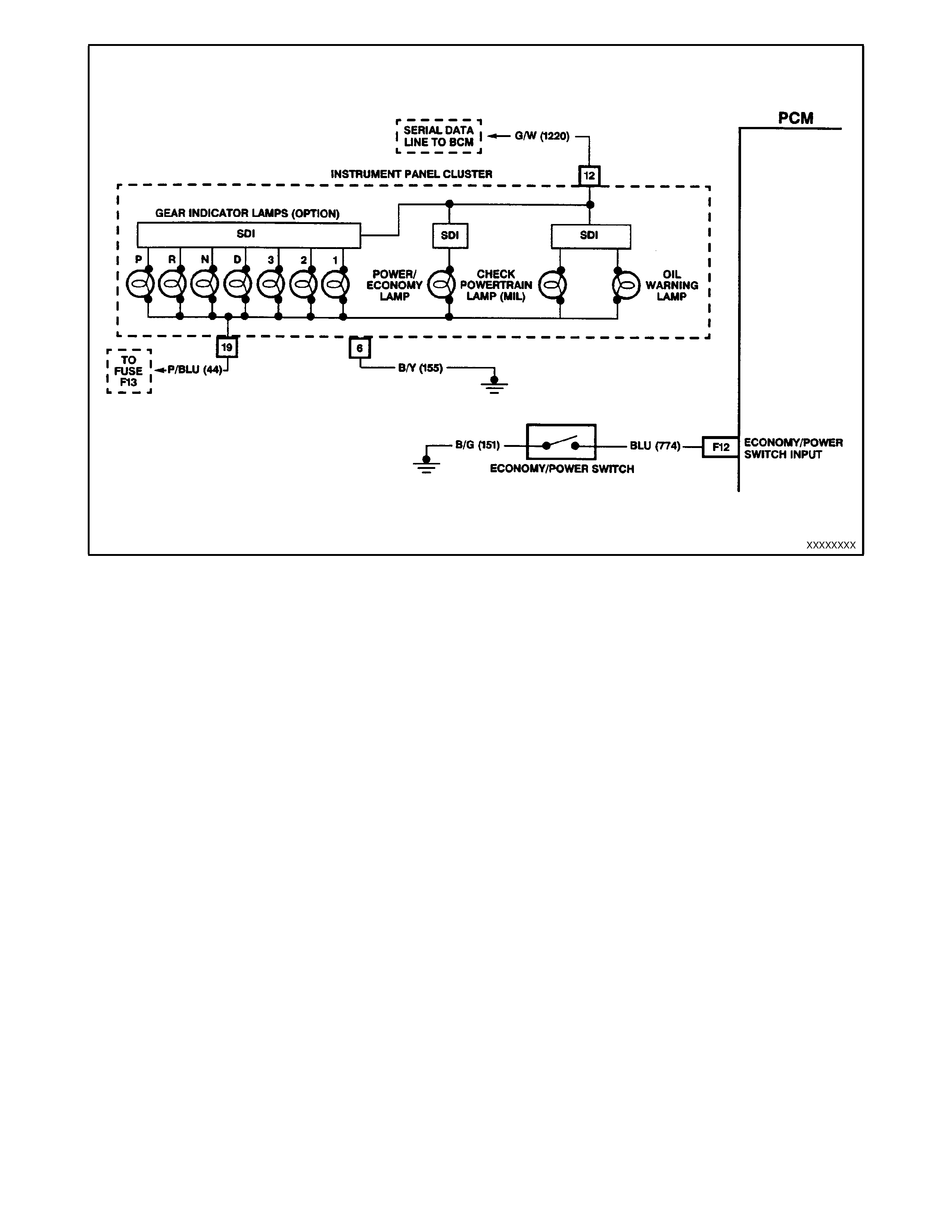
TRANSMISSION ECONOMY/POWER SWITCH
The economy/power switch is used to modify
upshifts and shift times slightly. The driver can
select two transmission modes, "Economy" or
"Power" with a dash or centre console mounted
switch. The "OUT" position enables the "Power"
mode. A green indicator lamp of 1.2 watts at 12
volts is located on the right side of the instrument
cluster and displays "PWR" when illuminated to
inform the driver that the "Power" mode is now
enabled.
The PCM sends out a voltage signal, about 12
volts, and monitors the status of this circuit. In the
"Economy" position, the switch is open and the
PCM voltage status signal remains high, about 12
volts. The PCM does not allow shift point changes
in the economy mode. When the transmission
switch is pressed to "Power" position the switch is
closed and the PCM voltage status signal is pulled
low, about 0.5 volts. The PCM senses this voltage
drop and enables "power" mode (alternate shift
pattern "tables" to be utilised).
In the "Power" mode, TCC can be applied in 3rd
and 4th gears. W hen TCC is applied in 3rd gear it
will stay applied until the normal 4th gear upshift
criteria are met, when the 3-4 upshift occurs the
TCC will not be released momentarily. Also, in the
"Power" mode, while in "D" gear select position the
PCM will delay the 1-2 and 2-3 shift while under
light throttle. The shift patterns will be the same in
the "Economy" and "Power" modes if the TP sensor
is between 94% - 100%. The "Power" m ode should
be used when towing as applying the TCC in 3rd
and 4th gear reduces slippage in the T CC and thus
heat build up.
Figure 6C1-1-72 Transmission Economy/Power Switch
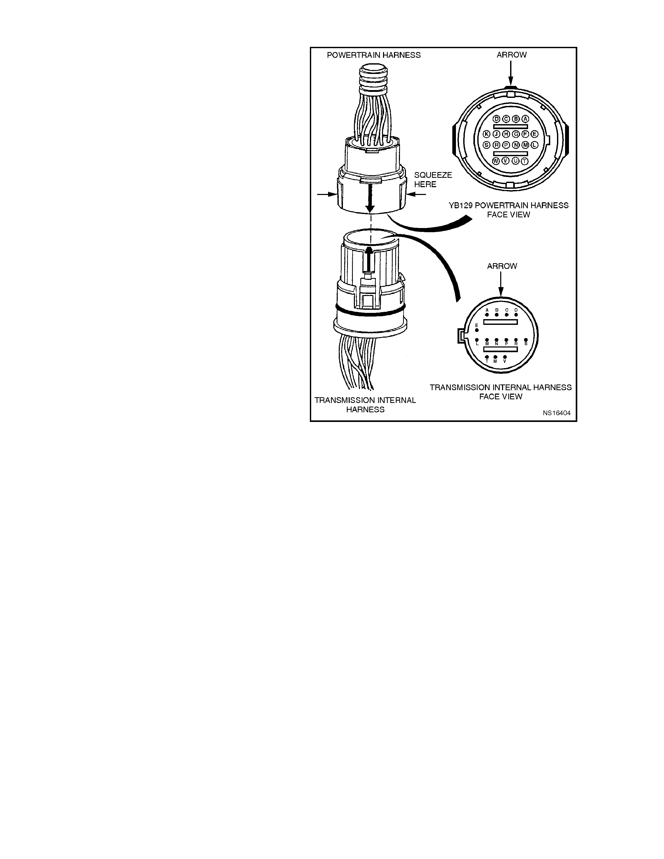
TRANSMISSION PASS-THRU CONNECTOR
The transmission electrical pass-thru connector is a
very important part of the HYDRA-MATIC 4L60-E
operating system.
A wiring harness electrically connects the PCM to
various sensors, solenoids, and relays within the
transmission management system. Many of the
connectors used are environmentally protected
because of the systems low voltages and low
current levels. Anything that interferes with the
electrical connec tion can cause the transm ission to
set diagnostic trouble codes and/or operate
incorrectly.
The following items can affect the electrical
connection:
• Bent pins in the connector from rough handling
during connection and disconnection.
• Wires backing away from the pins or coming
uncrimped (in either the transmission or
powertrain wiring harness).
• Dirt contamination entering the connector when
it is disconnected.
• Pins in the connector backing out of the
connector or pushed out during connection.
• Excessive transmission fluid leaking into the
connector, wicking up into the powertrain wiring
harness and degrading the wire insulation.
• Water/moisture intrusion in the connector.
• Low pin retention from excessive connection
and disconnection of the wiring harness.
• Pin corrosion from contamination.
The presence of transmission fluid in the
transmission connector is not harmful.
The fluid only affects the vehicle harness wiring
insulation if the fluid wicks up that far.
Points to remember when working with the
transmission electrical connector:
• To rem ove the connector, squeeze the two tabs
towards each other and pull straight up.
• Carefully limit twisting or wiggling the connector
during removal. This can bend pins.
• DO NOT pry the connector off with a
screwdriver or other tool.
• To install the connector, first orient the pins by
lining up the arrows on each half of the
connector. Push the connector straight down
into the transmission without twisting or angling
the mating parts.
• The connector should click into place with a
positive feel and/or noise.
• Whenever the trans mis sion pass thru connec tor
is disconnected from the transmission and the
ignition is switched "ON" or the engine is
started, numerous DTC's will be set.
Figure 6C1-1-74 YB129 Powertrain Harness Connector
1.4 TRANSMISSION OUTP UTS CONTROLLED BY THE PCM
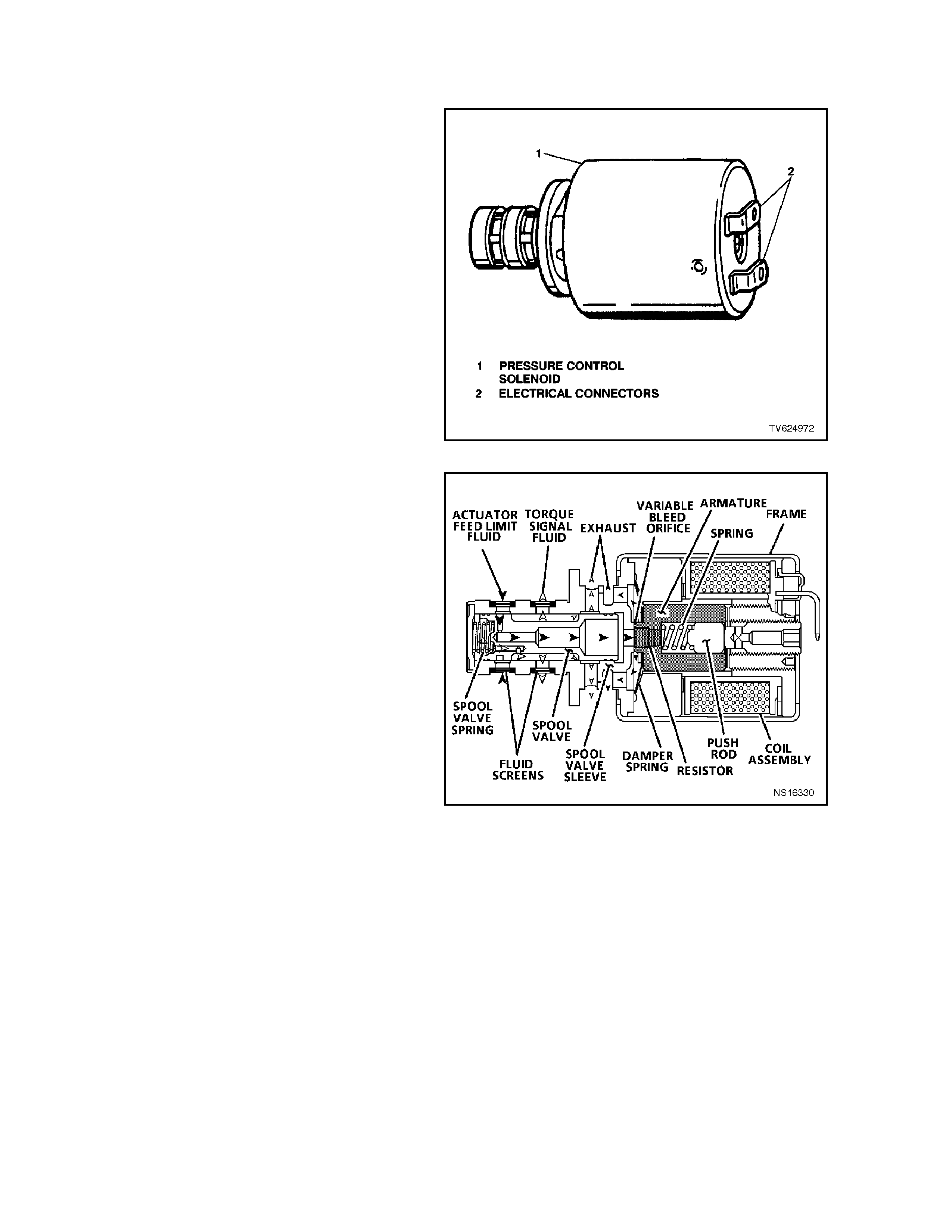
PRESSURE CONTROL SOLENOID
The transmission Pressure Control Solenoid (PC
SOL) is an electronic pressure regulator that
controls pressure based on current flow through its
coil winding. The magnetic field produced by the
coil moves the solenoid's internal valve that varies
pressure to the pressure regulator valve.
The pressure control solenoid takes the place of
the throttle valve used on past model 4L60
transmissions, used in previous "V" car models.
The PCM varies line pressure based on engine
load. Engine load is calculated from various inputs
including the TP and MAF sensors. The
transmission line pressure is actually varied by the
PCM's control of the pressure control solenoid and
its ability to change the amperage applied to the
pressure control solenoid from 0 amps (high line
pressure) to 1.1 amps (low line pressure). This
changes the duty cycle of the solenoid, which can
range between 0% and 100%. Figure 6C1-1-75 Pressure Control Solenoid
There is one Diagnostic Trouble Code associated
with the pressure control solenoid Diagnostic
Trouble Code (DTC) 73. Diagnostic Trouble Code
73 will set when the PCM detects a difference of
0.16 amp or more between the amperage
commanded and actual amperage. While the
Diagnostic Trouble Code 73 is set, the pressure
control solenoid will be turned "OFF" creating
maximum line pressure. Recovery can occur after
the next ignition cycle. Diagnostic Trouble Code 73
will not sense a stuck valve.
Figure 6C1-1-76 Pressure Control Solenoid Cutawa y View
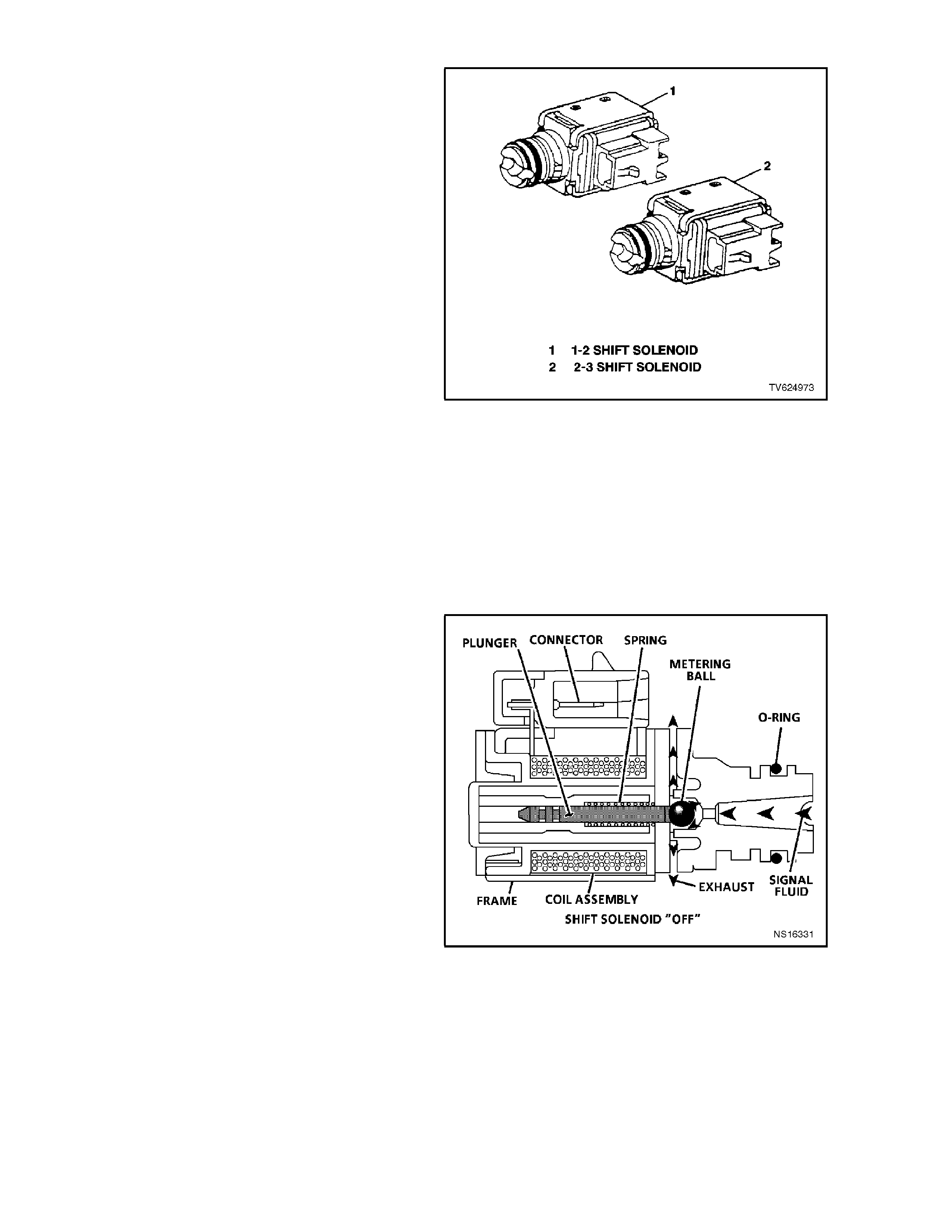
SHIFT SOLENOIDS
The 1-2 Shift Solenoid and 2-3 Shift Solenoid are
identical in operation solenoid devices that control
the movement of the 1-2 and 2-3 shift valves (the
3-4 shift valve is not directly controlled by a shift
solenoid). The solenoids are normally open
exhaust valves that work in four combinations to
shift the transmission into different gears. PCM
controlled shift solenoids eliminate the need for
Throttle Valve (TV) and governor pressures to
control shift valve operation.
IMPORTANT:
The PCM does NOT have total control of shifting
the transmission. The manual valve can
hydraulically override the shift solenoids. Only in
"D" are the PCM and shift solenoids totally
determ ining what gear the transm ission is in. In the
manual positions "3", "2", and "1", the transm ission
manual valve position will change fluid direction in
the valve body. The transmission will shift on its
own hydraulically, the PCM will have limited control
and will respond to the hydraulic changes of the
manual valve. The PCM will change the shift
solenoids when the pressure switch assembly
(TFP), throttle position and vehicle speeds fall into
the correct ranges for PCM control. In other words
the PCM "catches up" to what happened
hydraulically. This is impor tant to rem ember , as the
Tech 2 scan tool will only display the commanded
state of the shift solenoids not the actual gear the
transmission is in.
Figure 6C1-1-77 Shift Solenoids
1-2 SHIFT SOLENOID
The 1-2 shift s olenoid is attached to the valve body
and is a normally open exhaust valve. The PCM
activates the solenoid by earthing it through an
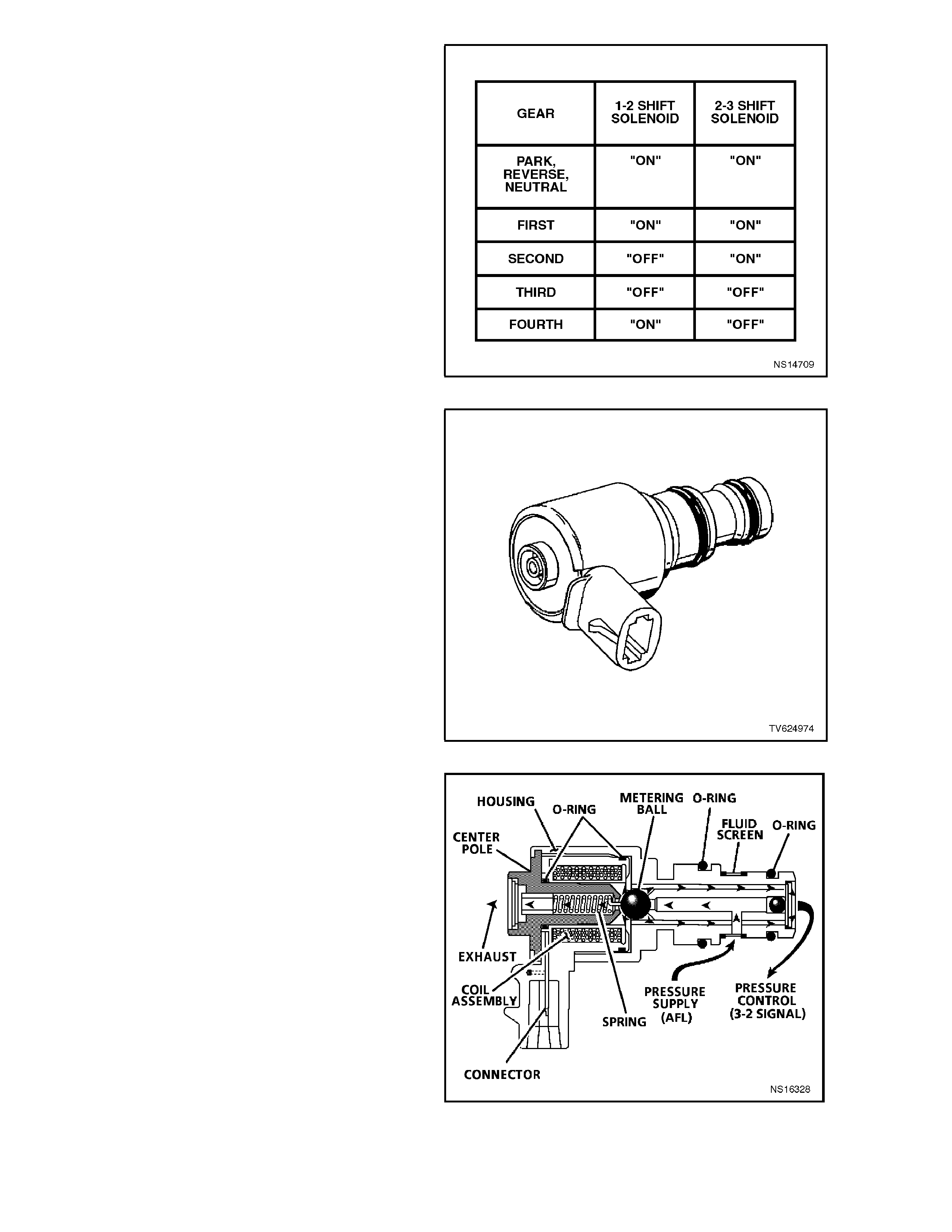
internal Quad Driver Module (QDM). The 1-2 shift
solenoid is "ON" in 1st and 4th gear, and "OFF" in
2nd and 3rd gears. When "ON," the solenoid
redirects fluid to act on the shift valves.
There is one Diagnostic Trouble Code associated
with the 1-2 shift Solenoid, Diagnostic Trouble
Code 82. The PCM continually monitors the 1-2
shift solenoid circuit for expected voltage ("OFF"
high "ON" low). If the voltage r eading is not what is
expected on the circuit, Diagnostic Trouble Code
82 will set. While Diagnostic Trouble Code 82 is
present, high line pressure will be set and the
vehicle will have 2nd or 3rd gear only or 1st and 4th
gears only. When the fault is removed, recovery will
occur on the next ignition cycle. Figure 6C1-1-78 Shift Solenoid Cutaway View
2-3 SHIFT SOLENOID
The 2-3 shift s olenoid is attached to the valve body
and is a normally open exhaust valve. The PCM
activates the solenoid by earthling it through an
internal Quad Driver Module (QDM). The 2-3 shift
solenoid is "ON" in 1st and 2nd gear and "OFF" in
3rd and 4th gear. When "ON," the shift solenoid
redirects fluid to act on the shift valves.
There is one Diagnostic Trouble Code (DTC)
associated with the 2-3 shift Solenoid, DT C 81. 2-3
shift solenoid circuit fault. The PCM continually
monitors the 2-3 shift solenoid circuit for expected
voltage ("OFF" high "ON" low). If the voltage
reading is not what is expected, DTC 81 will set.
While DTC 81 is present, TCC operation will be
inhibited, line pressure will be high and the
transmission will have 2nd or 3rd gear only. When
the fault is r emoved, rec overy will occur at the nex t
ignition cycle. Figure 6C1-1-79 Solenoid Status
3-2 SHIFT SOLENOID VALVES
The 3-2 shift solenoid is either "ON" or "OFF" and
is used to improve the 3-2 downshift. The 3-2 shift
solenoid uses "ON" or "O FF" to contr ol press ure so
that the release of the 3-4 clutch and the apply of
the 2-4 band are smooth. The 3-2 shift solenoid is
normally "OFF" in first gear and "ON" in all other
drive gears, except during a 3-2 downshift when the
solenoid is "OFF". The amount of "OFF" time is
determined by throttle position, vehicle speed, and
the commanded gear.
There is one Diagnostic Trouble Code (DTC)
associated with the 3-2 Shift Solenoid, DTC 66.
DTC 66 will set when the PCM detects either high
voltage when the 3-2 Shift Solenoid is com manded
"ON" or if low voltage exists on the feed back line
when the solenoid is com m anded "OFF". While the
3-2 Shift Solenoid DTC 66 is set, the solenoid will
be "OFF", When DTC 66 is set, the transmission
will have a soft landing into 3rd gear, high line
pressure and 3rd gear. W hen the fault is removed
recovery can occur after the next ignition cycle.
Figure 6C1-1-80 3-2 Shift Solenoid
Figure 6C1-1-81 3-2 Shift Solenoid Cutaway View
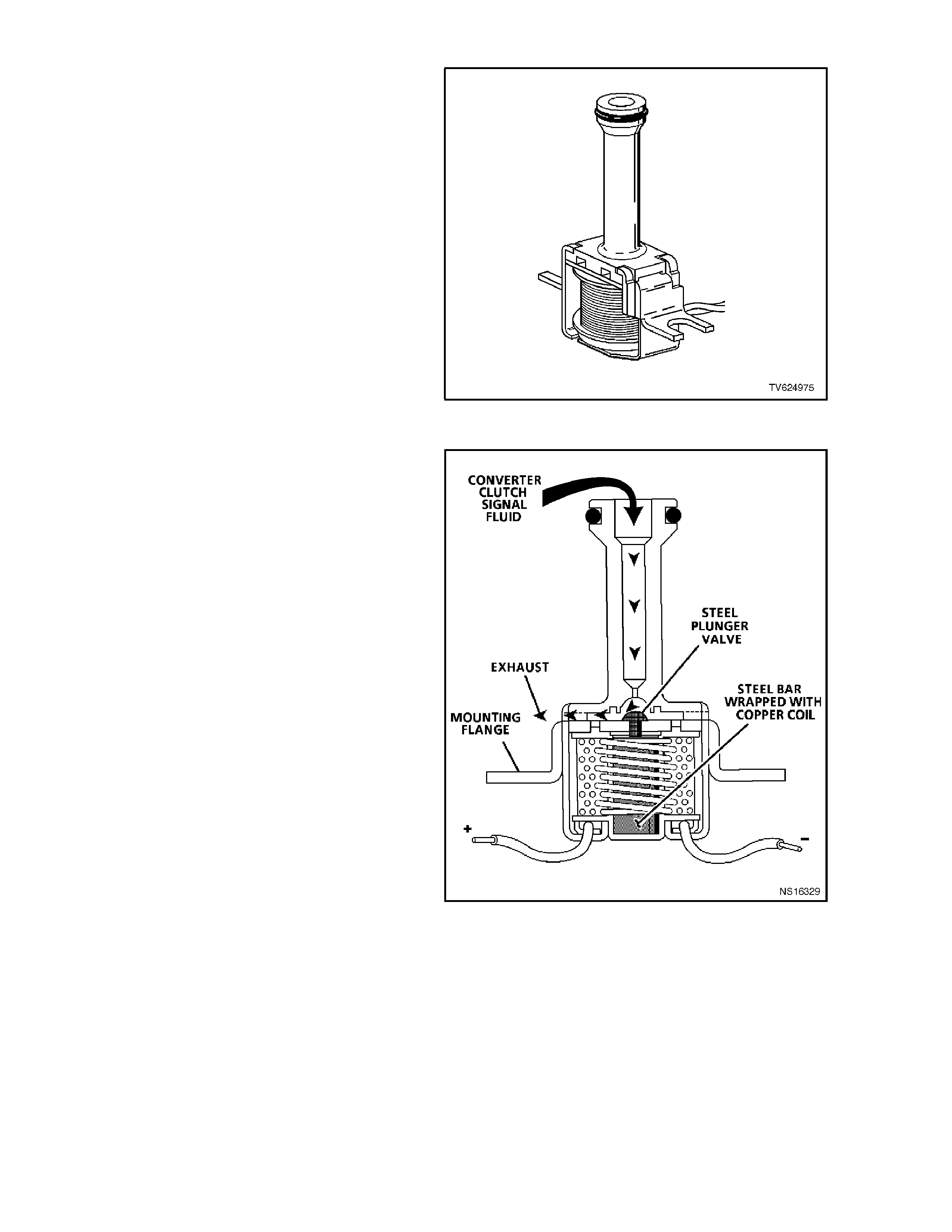
TORQUE CONVERTER CLUTCH (TCC) SOLENOIDS
This transmission uses two Torque Converter
Clutch (TCC) solenoids valves that are used to
control torque converter clutch apply and release.
The TCC enable solenoid has priority in applying
and releasing the torque converter clutch. "The
Torque Converter Clutch enable solenoid is a
normally open exhaust valves that is commanded
either "ON" or "OFF" by the PCM. When earthed
(energised "ON"), by the PCM, the TCC solenoid
stops converter feed from exhausting. This causes
converter feed pressure to increase and shift the
TCC valve into the apply position. This pressure
allows the TCC to couple the transm ission with the
engine for a near 100% engagement.
There are two Diagnostic Trouble Codes (DTC's)
associated with the TCC enable solenoid. The first
DTC is 67, T CC enable Solenoid Cir cuit F ault. DT C
67 is designed to detect a fault in the TCC enable
solenoid electrical circuit. While DTC 67 is set the
PCM will inhibit 4th gear if the trans miss ion is in the
hot mode, and no TCC operation. Figure 6C1-1-82 Torque Converter Clutch (TCC) Enable
Solenoid
The second DTC associated with the TCC enable
solenoid is DTC 69, TCC stuck "ON". DTC 69 is
designed to detect TCC enable solenoid that does
not disengage. It does this by monitoring engine
RPM when the TCC solenoid is com manded "ON."
If the engine speed does not rise when the TCC
solenoid is disengaged the DTC 69 is set. While
DTC 69 is set the TCC will be "ON" in all gears or
2nd, 3rd, and 4th depending upon the failure, and
the transmission will have an early shift pattern.
When the fault is removed recovery will occur on
the next ignition cycle.
Figure 6C1-1-83 TCC Solenoid Cutaway View
The Torque Converter Clutch "Pulse Width
Modulated" (PWM) solenoid is used to control the
fluid acting on the converter clutch control valve,
which then controls the TCC apply and release.
This solenoid is attached to the control valve body
assem bly within the transmiss ion. The T CC "PWM"
solenoid does not have total control over TCC
engagement. The TCC "PW M" solenoid is used as
a supplement to the TCC enable solenoid. The
TCC "PWM" solenoid is used to provide smooth
engagement of the torque converter clutch by
operating on a negative duty percent of "ON" time,
which means that the earth (negative or low) side
of the solenoid circuit is controlled by the PCM.
Therefore, the TCC "PWM" solenoid is constantly
fed approximately 12 volts to the high (positive)
side and the PCM controls the length of time the
electrical circuit path to earth is closed (i.e. duty
cycle).
When the PCM closes the solenoid earth circuit,
current flows through the TCC "PWM" solenoid,
and the earth circuit (or negative side) is at low
voltage state (0 volts and solenoid energised).
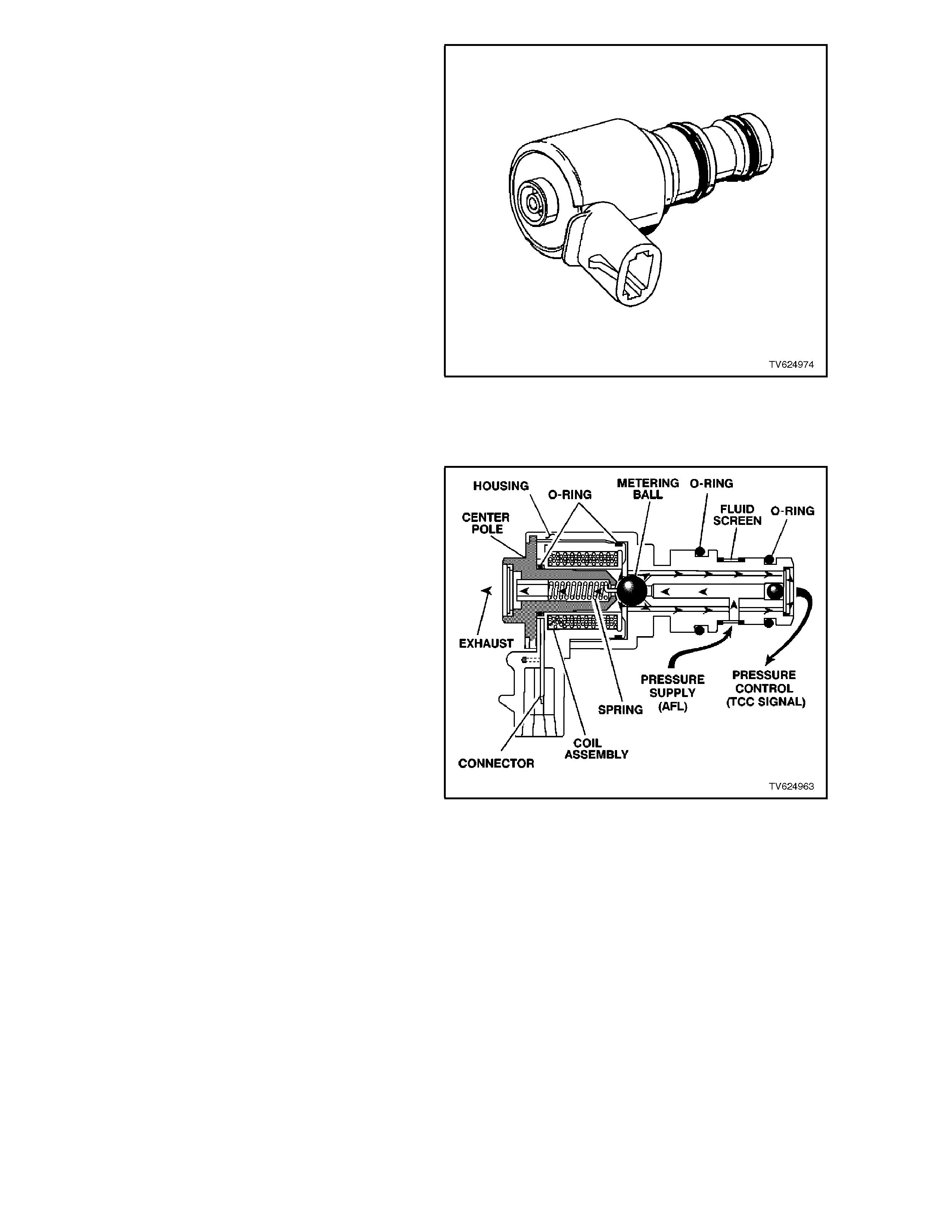
Figure 6C1-1-84 Torque Converter Clutch (TCC) "PWM"
Solenoid
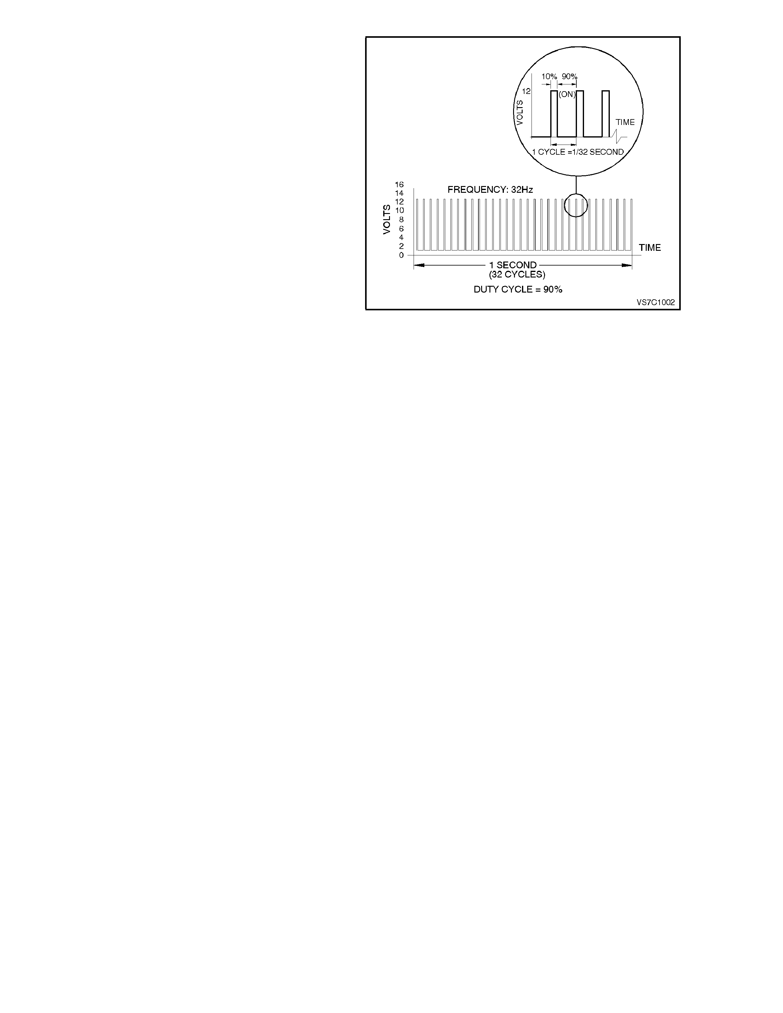
Fig. 6C1-1-86 illustrates an example of the TCC
"PWM" solenoid operating with a 90% negative
duty cycle at a constant operating frequency of 32
Hz (cycles per second). The frequency means that
the solenoid is puls ed (energised) with current fr om
the PCM 32 times per second. The 90% negative
duty cycle means that during each of these 32
cycles the solenoid is energis ed (ON) and 0 volts is
measured on the low (negative) side of the circuit,
90 % of the time.
At road speeds below approximately 13 km/h, the
negative duty cycle will be 0%, which means that
no current will flow through the TCC "PWM"
solenoid, deactivating it. When in this condition,
spring force will move the plunger seating the
metering ball and blocking the filtered Actuator
Feed Limit (AFL) fluid from entering the Converter
Clutch Signal (CC SIGNAL) circuit. This action
opens the Converter Clutch Signal fluid circuit to
exhaust through the solenoid.
Above road speed of approximately 13 km/h, the
TCC "PWM" solenoid will be operating at about a
90% duty cycle. T his action will cause the m etering
ball to close off the path to exhaust, most of the
time and allow AFL fluid to flow past the metering
ball and into the CC SIGNAL circuit, in readiness
for the apply of the torque converter clutch.
Figure 6C1-1-85 Torque Converter Clutch (TCC) "PWM"
Solenoid Cutaway View
When the PCM signals TCC apply, the TCC
"PWM" solenoid operates with a variable, negative
duty cycle, ranging from 90% to 0%, with an
operating fr equency of 32 Hz. This allows the PCM
to control the current flow through the solenoid coil
according to the duty cycle it sets. This has the
effect of creating a variable magnetic field, that
magnetises the solenoid core, attracting the
metering ball to seat against spring force. A high
percentage duty cycle keeps the metering ball
seated more often, thereby creating higher TCC
signal fluid pressures.
Figure 6C1-1-86 Torque Converter Clutch (TCC) "PWM"
Solenoid Duty Cycle
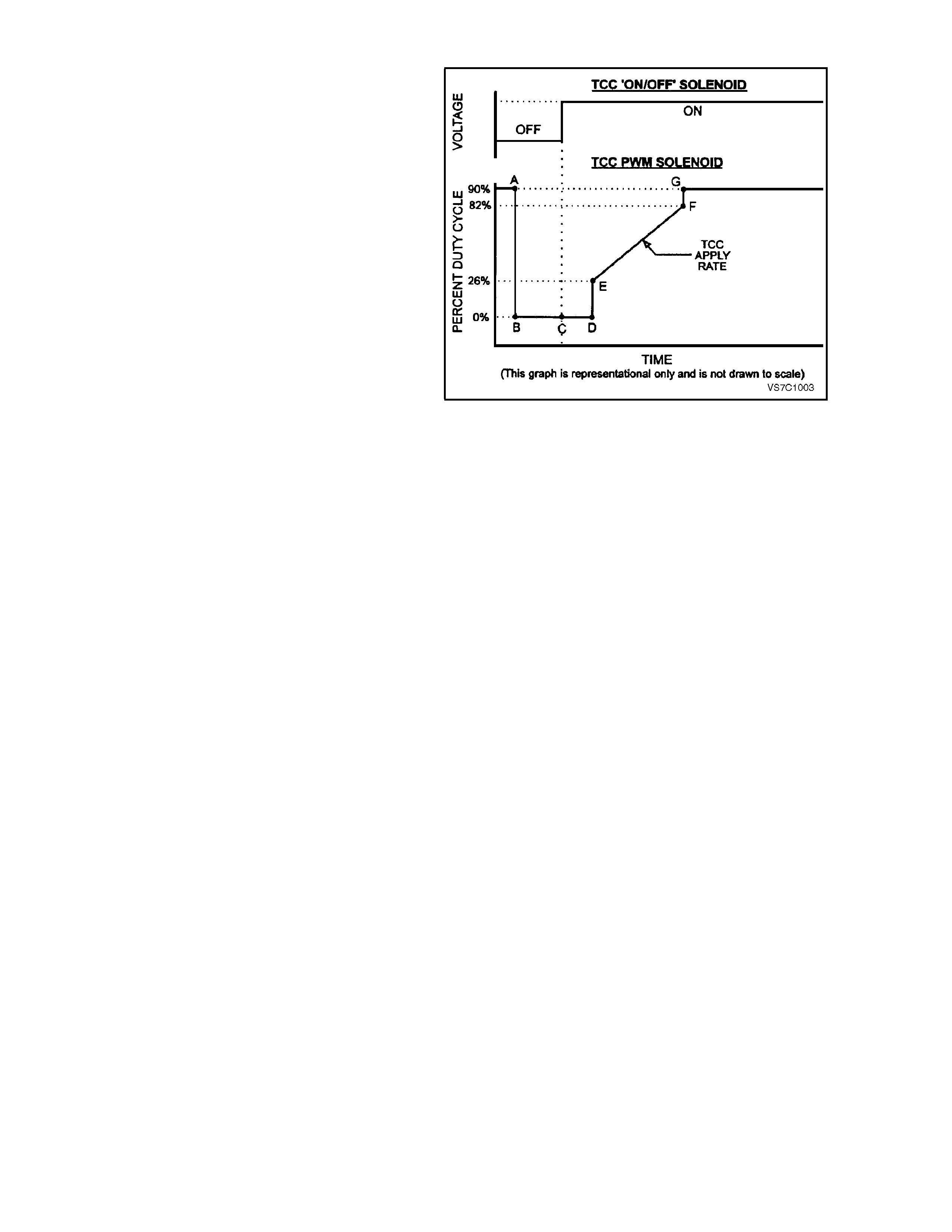
TCC "PWM" SOLENOID OPERATION
When vehicle road speed rises above about 13
km/h, the PCM causes the TCC "PWM" solenoid
duty cycle to change from 0% to 90% (point "A"), in
readiness for an apply of the torque converter.
To apply the torque converter clutch, the process
the PCM adopts, is as follows;
The duty cycle is dropped to 0% (point "B") and a
measurable amount of time is allowed for the TCC
enable solenoid to turn "ON". This is shown as the
time between points "B" and "C" in Fig. 6C1-1-84
Note that, at point "C", the TCC enable solenoid is
activated.
The time from point "C" to "D" is used to allow
converter (CONV FD) f luid to build in pressure and
move the Converter Clutch Valve into the apply
position.
At this point, with the TCC enable solenoid applied,
the PCM then increases the duty cycle to about
26% (point "E"). From this point, the duty cycle is
'ramped' to around the 82% point ("E" to "F"). The
rate at which the duty cycle is increased over this
period of tim e, determ ines how quickly the value of
the regulated apply fluid increases and therefore,
how quickly the torque converter clutch is applied.
This rate of change also affects the converter
clutch apply 'feel'.
As soon as the duty cycle reaches the 82% value, it
is then immediately increased to the maximum of
90%, to achieve full apply pressur e in the regulated
apply fluid circuit (point "G").
NOTE:
that the duty cycle and apply pressure will
continually vary, depending on vehicle specif ication
and operating conditions.
The two TCC solenoids work together so that TCC
apply or releas e rate can be calibrated f or a variety
of situations.
If a fault is detected by the PCM, in the TCC
"PW M" solenoid electrical circuit, a DTC 83 will be
set. When DTC 83 is set, the PCM will inhibit 4th
gear and TCC operation if in hot mode.
Figure 6C1-1-87 Torque Converter Clutch Solenoid
Operation

1.5 FUEL CONTROL SYSTEM
PURPOSE
The purpose of closed loop fuel control is to control tailpipe emissions consisting of hydrocarbons (HC), Carbon
Monoxide (CO), and Oxides of Nitrogen (NOx). At the sam e time, the system m ust achieve good engine perform ance
and good fuel economy.
The closed loop system regulates exhaust emissions by controlling the air/fuel ratio at an optimum level during various
driving conditions. The most efficient air/fuel ratio to minimise exhaust emissions is 14.7 to 1, this allows the 3-way
catalytic converter to operate at maximum efficiency to control exhaust pollutants. Because of the constant measuring
of the exhaust gases by the oxygen sensors, and adjusting of the fuel injector pulse width by the PCM, the fuel injection
system is called a "closed-loop" control system.
FUNCTION
The f uel supply system delivers fuel at a r egulated pressur e to the fuel rail. T he fuel injec tors, located dir ectly ahead of
each inlet port of the cylinder head, act as fuel flow control valves, "spraying" atomised fuel into the inlet ports when
they are electrically "pulsed" by the PCM. On this engine, all injectors are wired individually so they are pulsed
individually. This type of fuel injection is referred to as sequential injection because pulsation of the injectors are
individually controlled and in a specific order.
The PCM controls the amount of fuel injected into the engine by controlling the length of time the injectors are held
open. This "length-of-time" is called PULSE WIDTH. To increase the amount of fuel injected, the pulse width is
lengthened, and vice versa. The pulse width is calibratable and varies between 0 - 11 milliseconds with the engine
running at idle, and injection pulses normally occur once every crankshaft revolution.
MASS AIR FLOW SYSTEM
The Holden/Delco Fuel Injection system is a Mass Air Flow system. The system is based upon an Air Meter that
measures the mass air flow rate of the engine directly.
Advantages of Mass Air Flow:
• Base engine components can be changed.
• Automatically compensates for engine aging.
• No air measurement lag time.
• Excellent idle stability.
Two spec ific data s ensors provide the PCM with the basic inf orm ation for the fuel m anagem ent por tion of its operation.
That is, two specific signals; cr ankshaf t reference signal f rom the ignition s ystem , and the Mass Air Flow (MAF) sensor
signal. Both of these signals to the PCM establish the engine speed and m ass of air ingested by the engine. Due to the
additional temperature compensation sensor in the MAF sensor, this system does not require a manifold absolute
pressure sensor.
The engine speed signal comes from the ignition module to the PCM on the crankshaft reference signal input circuit.
The PCM uses RPM information to calculate the best fuel injector pulse width and spark timing for a given operating
RPM band.
The mass of air ingested by the engine is sent as a signal from the mass air flow sensor to the PCM.
When the engine is started, the PCM will immediately look at the Engine Coolant Temperature sensor to determine how
much fuel is required to start the engine. After the engine is started, the PCM will constantly monitor the MAF sensor
values to determine both the spar k advanc e and engine f uelling r equirements . The Mass Air Flow s ens or meas ures the
mass of air ingested into the engine. The PCM then calculates how much fuel that must be injected to maintain an
air/fuel ratio of 14.7 to 1. An engine started in cold weather will require more fuel and spark advance than an engine
started hot, which requires less fuel and less spark advance.

One sensor is used to m easur e the density fac tor, the Mass Air F low (MAF) sensor. T he m ass air f low sensor used on
this engine utilises a heated element type of operation. Three sensing elements are used in this system.
As air passes over the heated elements during engine operation they begin to cool. By measuring the amount of
electrical power required to maintain the heated elements at the predetermined temperature above ambient
temperature mass air flow rate can be determined.
As the PCM receives this frequency signal from the mass air flow sensor, it searches its pre-programmed tables of
information to determine the pulse width of the fuel injectors required to match the mass air flow signals.
The signal that is sent from the mass air flow sensor is sent in the form of a frequency output. A large quantity of air
passing through the sensor (such as when accelerating) will be indicated as a high frequency output. A small quantity of
air passing thr ough the sensor will be indicated as a low frequenc y output ( such as deceleration or at idle. The Tech 2
scan tool displays MAF sensor information in frequency, grams per second. A "normal" reading is approximately 4 - 9
grams per second at idle and increases with engine RPM.
The remaining sensors and switches provide electrical inputs to the PCM which are used for modification of the air/fuel
mixture as well as for other PCM control functions, such as Idle Air Control (IAC).
MODES OF OPERATION
The PCM looks at voltage signals from several sensors to determine how much fuel to give the engine, and when to
operate in the open-loop or clos ed-loop m odes. The f uel delivery is controlled in one of s everal possible m odes. All the
modes are controlled by the PCM, and are described in the following paragraphs.
STARTING MODE
W hen the ignition key is first turned "ON," the PCM will energise the fuel pump relay, and the fuel pump will build up
pressure to the fuel rail. The PCM then checks the engine coolant temperature sensor and determines the proper
injector pulse width for starting the engine.
When cranking begins, the PCM will operate in the Starting Mode until engine RPM is more than about 400, -or- the
"Clear Flood" m ode is enabled. After the ignition is turned "ON" and the firs t refer ence signal is received, the PCM will
pulse all of the fuel injectors. After the first prime pulse has been injected, the PCM will wait until the PCM receives a
good camshaft position signal. When the PCM receives a good camshaft position signal, the PCM operates the fuel
injectors in Sequential mode. Pulse width during the Starting Mode is between approximately 4 - 26 milliseconds,
depending upon engine coolant temperature.
CLEAR FLOOD MODE
If the engine floods, it can be started by pushing the accelerator pedal down all the way to the floor while cranking the
engine. The PCM then pulses the injectors with zero millisecond pulse width, which should "clear" a flooded engine.
The PCM holds this pulse width as long as the throttle position sensor input indicates the throttle is above 80% and
RPM is below 400.
If the throttle is held wide-open w hile attempting to make a normal start w ith a non-flooded engine, the engine
will not start.
NORMAL OPEN LOOP MODE
After the engine is running ( RPM mor e than 400), the PCM will operate the f uel c ontr ol s ystem in the O pen Loop mode.
In open loop, the PCM ignores the signal f rom the O xygen Sensor (O2S) , and calc ulates the air/f uel r atio inj ector pulse
width based on inputs from the crankshaft reference signal (RPM input) and these sensors: MAF, IAT, ECT, and TP
sensor.
The system will stay in the Open Loop m ode until all the Closed Loop m ode criteria have been m et, or not at idle, ref er
Open Loop Idle Mode description.
In open loop, the calculated pulse width may give an air/fuel ratio other than 14.7 to 1. An example of this would be
when the engine is cold, because a richer mixture is needed to ensure good driveability.
The normal open loop mode is not ac tive when adverse or abnor mal vehicle oper ating c onditions ar e oc cu rr ing advers e
conditions include engine overheating due to high vehicle speed or high ambient temperature.

OPEN LOOP IDLE MODE
The reason for the Idle Mode is to allow a slightly richer mixture at idle f or better idle quality. Idle Mode air/fuel ratio is
about 14.0 to 1. This is an open loop mode, meaning the O2 sensor signal is ignored.
The Open Loop Idle Mode is in effect when the throttle is closed (TP Sensor), and vehicle speed is below 5 km/h (VSS).
In the case where the vehicle rolls to a stop while operating in the Closed Loop mode, Idle Mode will be delayed for
about 20-30 seconds. During this time, the PCM will "learn" a fuel correction factor for a 14.7 to 1 air/fuel ratio before
switching to the Idle Mode.
CLOSED LOOP MODE
In Closed Loop mode, the PCM initially calculates injector pulse width based on the same sensors used in open loop.
The difference is that in closed loop, the PCM uses the Exhaust Gas Oxygen Sensor (O2S) signal to modify and
precisely fine tune the fuel pulse width calculations in order to precisely maintain the 14.7 to 1 air/fuel ratio that allows
the catalytic converter to operate at it's maximum conversion efficiency.
DELTA TPS ACCELERATION MODE
The PCM looks at rapid changes in throttle position (TP sensor) to increase engine power, and provides extra fuel by
increasing the injector pulse width. If the increased fuel requirements are great enough, the PCM may add extra fuel
injection pulses between the injector pulses that normally occur once per crankshaft revolution.
LEAN CRUISE AIR/FUEL MODE
During steady state cruising, the air/fuel ratio is made lower in order to increase fuel economy.
The engine will operate in Lean Cruise when:
• ECT is greater than 80 degrees C.
• VSS is greater than 70 km/h.
• Engine has been running longer than 2 minutes and 30 seconds.
• Calculated A/F ratio is 14.8 to 1
• Engine is not in power enrichment mode.
If all the criteria ar e met, the PCM will lean out the A/F ratio by 0.1 ratio every 0.2 second until it r eaches its m aximum
total enleanment.
DECELERATION MODE
When deceleration occurs, the fuel remaining in the intake manifold can cause excessive emissions and possibly
back firing. Again, the PCM looks at changes in throttle position (T P sensor) and engine RPM and r educes the am ount
of fuel by decreasing the pulse width, but does not completely shut off the fuel.
DECEL FUEL CUTOFF MODE
Decel fuel cutoff disables fuel delivery during a deceleration to reduce emissions and to improve fuel economy .
When deceleration from road speed occurs, the PCM can cut off fuel pulses completely for short periods. The decel
fuel cutoff mode occurs when all these conditions are met:
1. Coolant temperature above 63 degrees C.
2. Engine RPM has dropped more than 200 RPM.
3. Vehicle speed above 42 km/h.
4. Throttle is less than 2 %.
When the decel fuel cutoff is in effect, any one of these can cause the injection pulses to restart.
1. Engine RPM has not dropped more than 200 RPM.
2. Vehicle speed is less than 42 km/h.
3. Throttle is open at least 2%.

PARK/NEUTRAL TO DRIVE ACCELERATION ENRICHMENT MODE
The PCM will deliver additional fuel to the engine to reduce the RPM droop associated with a transmission shift from
park/neutral to a drive shift. This mode will only add fuel based on the first 32 reference pulses after a shift has been
detected.
POWER ENRICHMENT (PE) MODE
The Power Enrichment (PE) mode delivers a rich mixture to the cylinders during a large throttle position change
command from the driver. During PE, the PCM will not make fuelling changes based on the oxygen sensor signal.
BATTERY VOLTAGE CORRECTION MODE
At low battery voltages, the ignition system may deliver a weak spark, and the injector mechanical movement takes
longer to "open." The PCM will compensate by:
• Increasing ignition coil dwell time if voltage is less than 12 volts.
• Increasing idle RPM if voltage drops below 10 volts.
• Increasing injector pulse width if voltage drops below 10 volts.
FUEL CUTOFF MODE
No fuel is delivered by the injectors when the ignition is (OFF). This prevents dieseling. Also, fuel pulses are not
delivered if the PCM receives no distributor reference pulses from the ignition module, which means the engine is not
running.
The Fuel Cutoff Mode is also enabled at:
• High engine RPM, as an overspeed protection for the engine. When cutoff is in effect due to high RPM, injection
pulses will resume after engine RPM drops slightly.
• High vehicle speed. W hen the vehicle speed exceeds a calibratable value the fuel base pulse width is set equal to
zero. Normal fuel operation will return when the vehicle speed falls below a calibratable value.
SEQUENTIAL FUEL INJECTION MODE
When the engine is first cranked over, all injectors will be energised simultaneously. After the engine has been started
and a good camshaft signal has been processed, the PCM will energise each individual injector in the normal firing
order. This mode of operation helps to stabilize idle, reduce emissions and reduce fluctuations in fuel pressure.
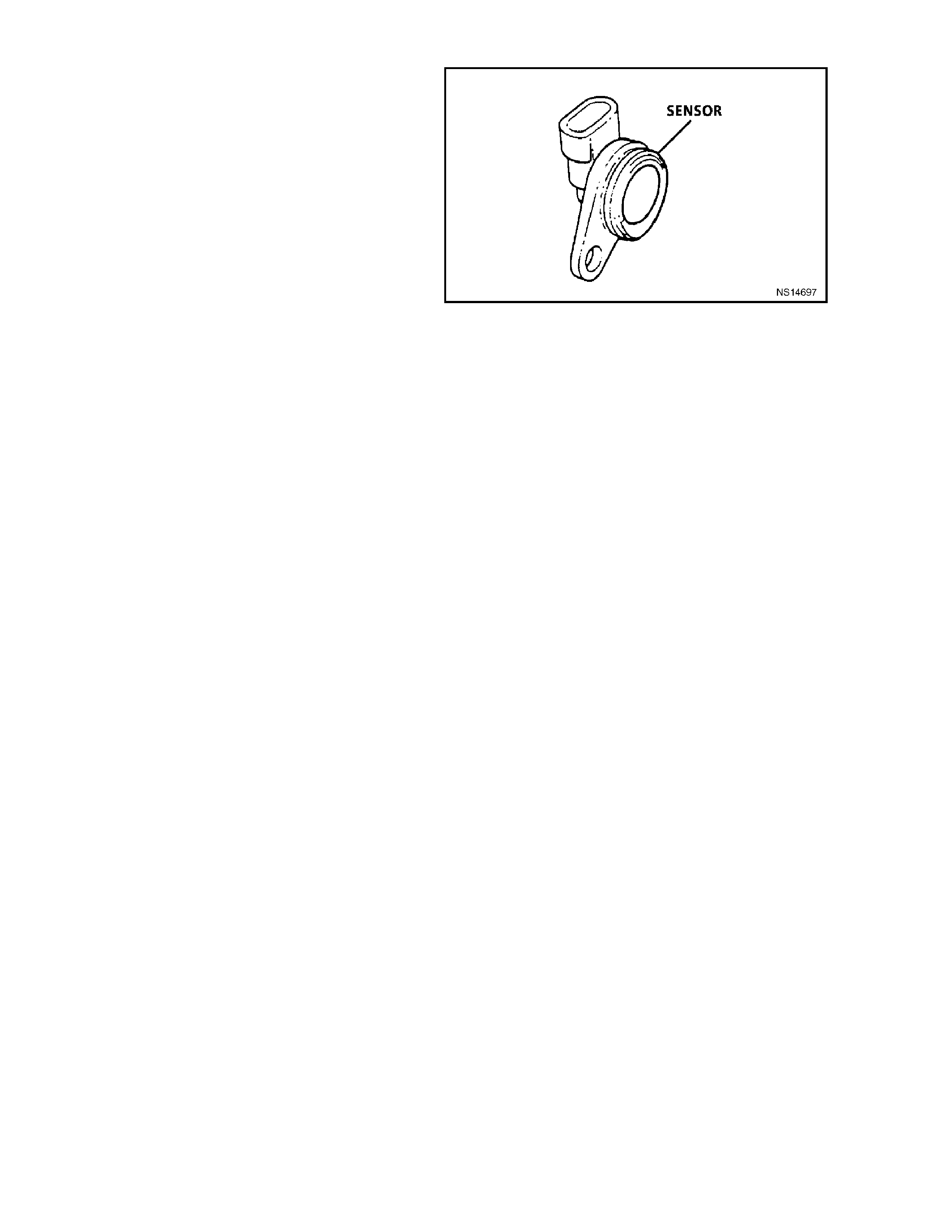
CAMSHAFT POSITION SENSOR
The Camshaft Position Sensor is located in the
engine front cover, behind and below the water
pump, near the camshaft sprocket.
As the camshaf t spr ock et turns, a m agnet m ounted
on it activates the Hall Ef f ec t s witch in the c amshaft
position sensor. When the Hall Effect switch is
activated, it earth's the signal line to the DIS
module, pulling the camshaft position signal line's
applied voltage low. This is interpreted as a
camshaft position signal (Synchronisation Pulse).
Because of the way the signal is created by the
camshaft position sensor, the signal circuit is
always either at a high or low voltage (square wave
signal).
While the camshaft sprocket continues to turn, the
Hall Eff ect switch turns "OFF" as the m agnetic f ield
passes the camshaft position sensor, resulting in
one signal each time the camshaft makes one
revolution.
The camshaft position signal, which actually
represents camshaft position due to the sensor's
mounting location, is used by the PCM to properly
time its sequential fuel injection operation.
Refer to Figs. 6C-1-1-18 and 6C1-1-19 in this
Section for camshaft position sensor location and
camshaft position signal details.
When the camshaft position signal is not received
by the PCM, a DTC 48 will be set. An intermittent
cam shaft position signal will set a DT C 49. If either
of these DTC's are set, the fuel system will not be
in sequential fuel injection mode.
Figure 6C1-1-88 Camshaft Position Sensor
ADAPTIVE LEARNING
Adaptive learning is the ability of the on-board
computer to determine and remember its most
recent operating experience. The PCM uses this
rem ember ed inform ation to "learn f rom experienc e"
and to make adjustments with respect to what it
learnt. If the engine were to develop a restricted
fuel filter, the PCM will change the fuel injector
pulse width richer to compensate for this condition
and will reme m ber to k eep this f uel inj ector pulse in
memory until the restriction is corrected. After the
restriction has been fixed, the PCM will eventually
go back to the original pre-programmed fuel injector
pulse.
Adaptive learning is an on-going process that
continues throughout the life of the engine. A new
engine with good compression will have good
vacuum. As the engine wears and compression
decreases, a slight decrease in engine vacuum will
be noticed, which translates into a slightly lower
MAF grams per second at idle, which will decrease
injector pulse width to compensate for this
condition.

SHORT TERM FUEL TRIM
Short Term Fuel Trim (STFT) represents short term corrections to the fuel injector pulse width calculations, based on
the oxygen sensor input signal to the PCM.
When the engine is started cold, in "Open Loop," the PCM will control the fuel injection pulse width based upon various
sensor inputs such as RPM, ECT, MAF and TP sensor until the oxygen sensors become hot enough (approximately
315 degrees C) to operate properly. During this "Open Loop" period, both Short Term Fuel Trim (STFT) and Long Term
Fuel Trim (LTFT) are disabled and will read 0% on a Tech 2 scan tool.
When the oxygen sensor has come up to its normal operating temperature (approximately 600 degrees C or above), it
will produce a varying voltage to the PCM and provide a good indication of what has happened in the combustion
chambers.
At this time the PCM will switch from "Open Loop" to "Closed Loop" and the STFT will start to constantly monitor the
oxygen sensor signal, so that the PCM can modify fuel injector pulse width with greater accuracy than in "Open Loop".
STFT monitors the oxygen sensor signal so that it can adjust the fuel injector pulse width to maintain an air/fuel ratio of
14.7 to 1 for maximum catalytic converter efficiency. An STFT value of 0% is equivalent to an air/fuel ratio of 14.7 to 1
and an average oxygen sensor signal voltage of 450 mV.
The normal position for Short Term Fuel Trim is 0%, any change from this value indicates the Short Term Fuel Trim is
changing the fuel injector pulse width. The amount of pulse width change depends upon how far the STFT value is from
0%. If the STFT value is above 0%, the fuel injector pulse width is being increased, thus adding more fuel. If the STFT
value is below 0%, the fuel injector pulse width is being decreased, thus removing fuel. The normal operating range of
STFT is considered to be between -22% and +25% ; any value out of this range is usually caused by a malfunction.
If an engine has a restricted fuel filter, the low fuel pressure will result in less fuel being injected and allows more air into
the air charge than is needed to ignite the amount of fuel the fuel injector has injected, therefore, a lean air/fuel ratio
exists in the combustion chamber. After combustion has taken place, the exhaust gases still contain more oxygen
content than normal and the oxygen sensor reads this as low voltage, say 200 mV. The STFT detects that the oxygen
sensor signal is low and will increase the value to richen up the air/fuel mixture. On a Tech 2 scan tool it will display
STFT as a value above 0%. This STFT change will increase the injector pulse width allowing the fuel injectors to stay
open longer and inject more fuel.
If the additional fuel was injected and the oxygen sensor signal voltage is still low, the STFT will continue to increase its
value until the oxygen sensor signal voltage goes above 450 mV. If the STFT continues to detect a low oxygen sensor
signal voltage it will continue to try and compensate for the lean exhaust condition until it runs out of its authority in the
particular Long Term Fuel Trim (LTFT) cell it's operating in. At this point, the PCM will reset STFT to 0% and go through
this procedure again until it can control the system.
If after a specified amount of resets have been tried and failed, the PCM knows that it cannot control for the failure and
the STFT will remain at its maximum value.
STFT values are based on the oxygen sensor signal voltage reading, therefore, STFT is used by the PCM to make
quick changes to the fuel injector pulse width over a short period of time.
LONG TERM FUEL TRIM
Long Term Fuel Trim is used to adjust for engine to engine variation and to adjust for engine aging. LTFT is a portion of
the PCM memory used to adjust fuel delivery across all operating conditions of the engine. The PCM monitors the
STFT and will adjust the long term trend of the fuel injector pulse width if the STFT has been at a value for a certain
period of time. LTFT is used to change the long term fuel injector pulse width and is only operational w hen the fuel
control system is in "Closed Loop." A normal LTFT value is 0% and should follow the STFT value.
If an engine has a restricted fuel filter, the low fuel pressure will result in less fuel being injected and will cause the
STFT value to go higher than 0%, say 2%. If this STFT value change does not compensate for the restricted fuel filter,
the PCM will continue to increase the STFT value. The STFT may climb as high as its maximum calibrated value if
there is a severe restriction. The PCM will continue to monitor STFT as it climbs, but it will not make any changes to the
fuel injector pulse width for a specific period of time. After a specific period of time has elapsed and the STFT value has
remained above say +8%, the LTFT will move up to say 4% and wait again to detect if the STFT has dropped back
down to 0%. If not, the STFT will gradually move toward its maximum calibrated value limit until it gains control of the
fuel injection system. If STFT and LTFT are both set at their maximum value limit, the fuel control system is "out of the
limits of control" and will set either a Diagnostic Trouble Code (DTC) 44, or DTC 64 (lean exhaust) or DTC 45, or DTC
65 (rich exhaust) and go into "open loop" operation. Under the conditions of power enrichment, (Wide Open Throttle,
WOT), the PCM sets the STFT to 0% and freezes it there until power enrichment is no longer in effect. This is done so
that LTFT will not try to correct for the commanded richness of power enrichment.
The PCM will keep the latest LTFT values stored in its LTFT memory cells. MAF sensor readings and engine RPM are
used by the LTFT to determine what cell to read. LTFT values are stored in the PCM's long term memory, for use each
time the engine's RPM and load matches one of the LTFT cells. All LTFT values are reset to 0% when the PCM's "long
term memory power supply" is disconnected, as when diagnostic trouble codes are cleared. The Tech 2 scan tool also
has the ability to reset LTFT to 0% with a special command.
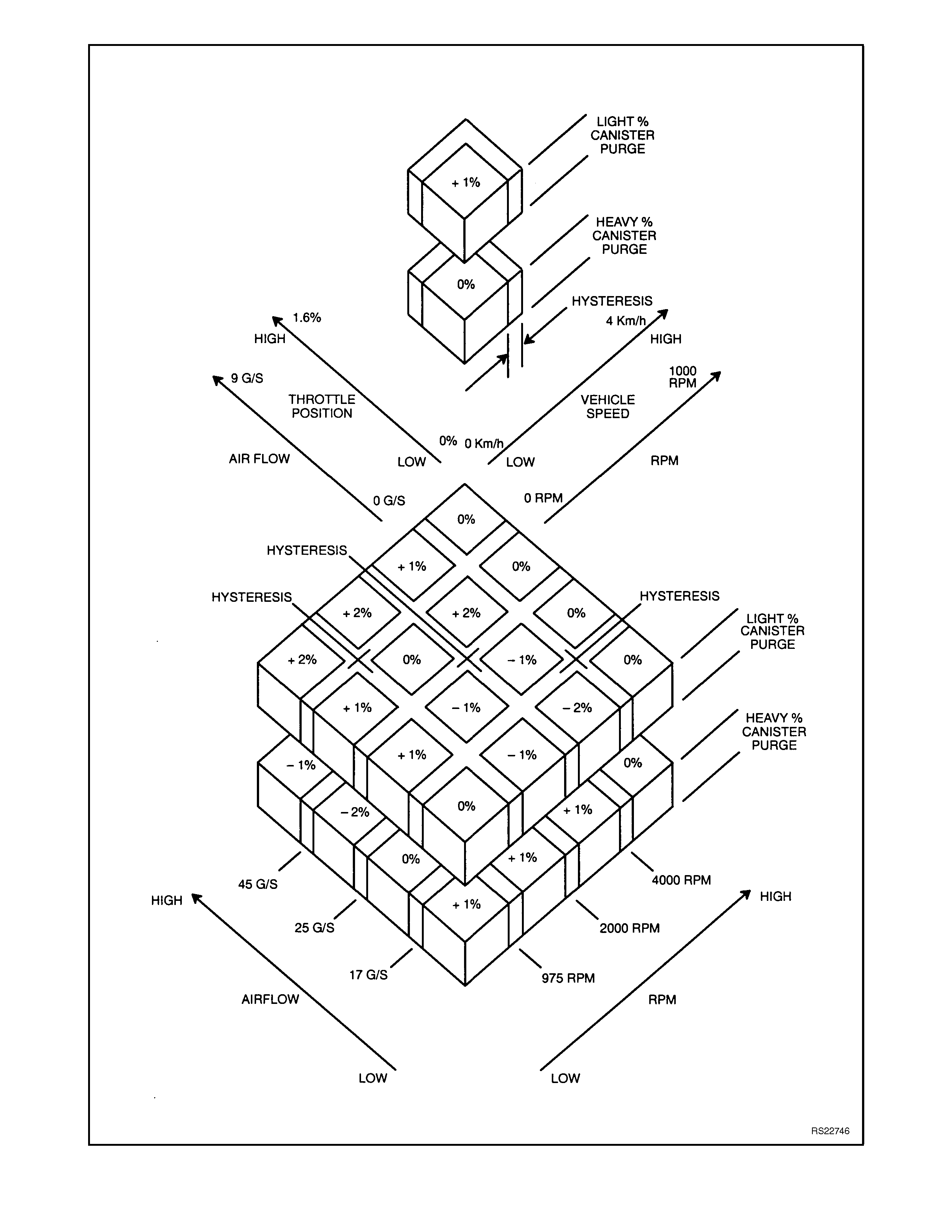
Figure 6C1-1-89 Long Term Fuel Trim Values

LONG TERM FUEL TRIM CELLS
The Long Term Fuel Trim function of the PCM is divided up into cells arranged by a Mass Air Flow (MAF) and Engine
Speed (RPM). Each cell corresponds to a region on a MAF vs RPM table. Each region is calibrated to a LTFT value of
0%. A value of 0% in a given block indicates no fuel adjustment is needed for that engine load condition. A higher
number, say + 4%, indicates that the PCM has detected a lean exhaust indication under those conditions, and is adding
fuel (increasing fuel injector pulse width) to compensate. Conversely, a lower number, say -6%, indicates that the PCM
has detected a rich exhaust indication under those load conditions, and is subtracting fuel (decreasing fuel injector
pulse width) to compensate.
As the vehicle is driven from a standing start and accelerated or decelerated from various engine speeds, the engine's
LTFT calibration will change from one cell to another cell. As the LTFT changes cell so does STFT, however, STFT will
only make short term corrections in whatever LTFT cell the engine is operating in. When the engine is idling, it can be in
one of two cells. On a vehicle with automatic transmission, depending upon canister purge, the engine will idle in cell 0
or 17. If the engine was running at idle and the canister purge was "ON", we would be in cell number 0 on an automatic
transmission equipped vehicle. Cells 16 and 33 are used for idle on vehicles with manual transmission only. Whatever
cell the engine is operating in, the PCM will read that cell's particular LTFT value and electronically adjust the fuel
injector base pulse width to compensate for a rich or lean condition in the engine. If an engine has a restricted fuel filter
and the customer has driven the vehicle like this for quite some time, the STFT value would be high, and the PCM
would be compensating for this condition by adding more fuel. Because the STFT value is above 0%, LTFT will also be
greater than 0% in most of the cells to compensate for the lean exhaust. If you suspect a driveability problem
associated with an over rich or over lean condition, then use the STFT value to detect what the fuel control system is
doing at the present time. Use the LTFT to identify what the system has "learned" over a greater period of time to
compensate for the condition.
Use the LTFT cells to determine if the fuel control system is commanding rich or lean throughout the operating range. If
it is only rich or lean at idle or part throttle, look for components that would cause problems in these areas.
All LTFT cell values are reset to 0% when long term memory power to the PCM is removed, such as when clearing
DTC's.
The Tech 2 scan tool has the ability to reset all LTFT cells to 0% with a special command.
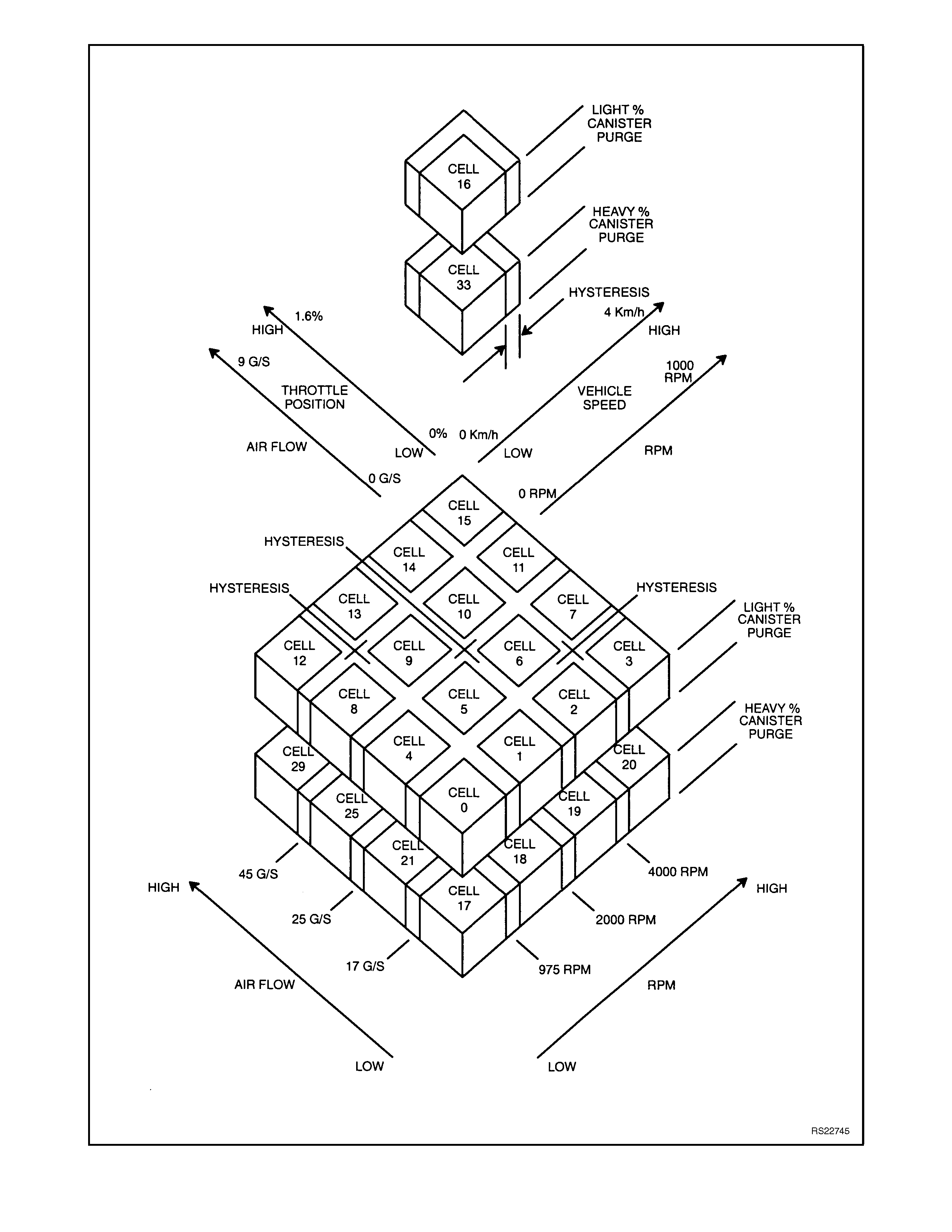
Figure 6C1-1-90 Long Term Fuel Trim Cell Matrix

BASIC FUEL SYSTEM OPERATION
The fuel control system starts with the fuel in the fuel tank. A single in-tank high pressure fuel pump (located inside a
modular sender unit) is used. From the high pressure pump, fuel flows through a fuel filter, then on to the engine fuel
rail through the fuel pressure supply line.
The high pressure in-tank single pump is capable of providing fuel at more than 414 kPa. A pressure regulator connects
between the fuel rail and the return fuel line, and keeps fuel available to the injectors at a regulated pressure between
270 and 350 kPa for the Non-Supercharged Engine, and 290 and 410 kPa for the Supercharged Engine application.
The regulated pressure will vary , depending on intake manifold pressure. The pressure regulator senses manifold
pressure through a small hose connecting it to the throttle body adapter. When throttle body adapter pressure is low
(closed-throttle), the regulated pressure is at its lowest. When the throttle is wide open, intake manifold pressure is high
and the fuel pressure also is at its highest.
Fuel in excess of injector needs is returned to the fuel tank by the separate return line connected to the outlet of the
pressure regulator.
The injectors, located in each runner of the intake manifold just ahead of the inlet ports to the cylinder head, are
controlled by the PCM. They deliver fuel in one of several modes, as described previously.
The fuel pump is energised by the PCM via the fuel pump relay. Refer to Diagnosis CHA RT A 4.1 for Non-
Supercharged Engine and Chart A 4.1-1 for Supercharged Engine for further diagnosis of the fuel pump electrical
system.
SYSTEM COMPONENTS
The Fuel Control System is made up of the following components:
• PCM
• Fuel pressure supply line
• Fuel pump relay
• Fuel Pump Control Module (Supercharged Engine Only)
• Fuel rail
• Injectors
• Modular Fuel Sender Assembly
• Fuel Pump
• Fuel pressure regulator
• Fuel filter
• Fuel return line
• Swirl pot
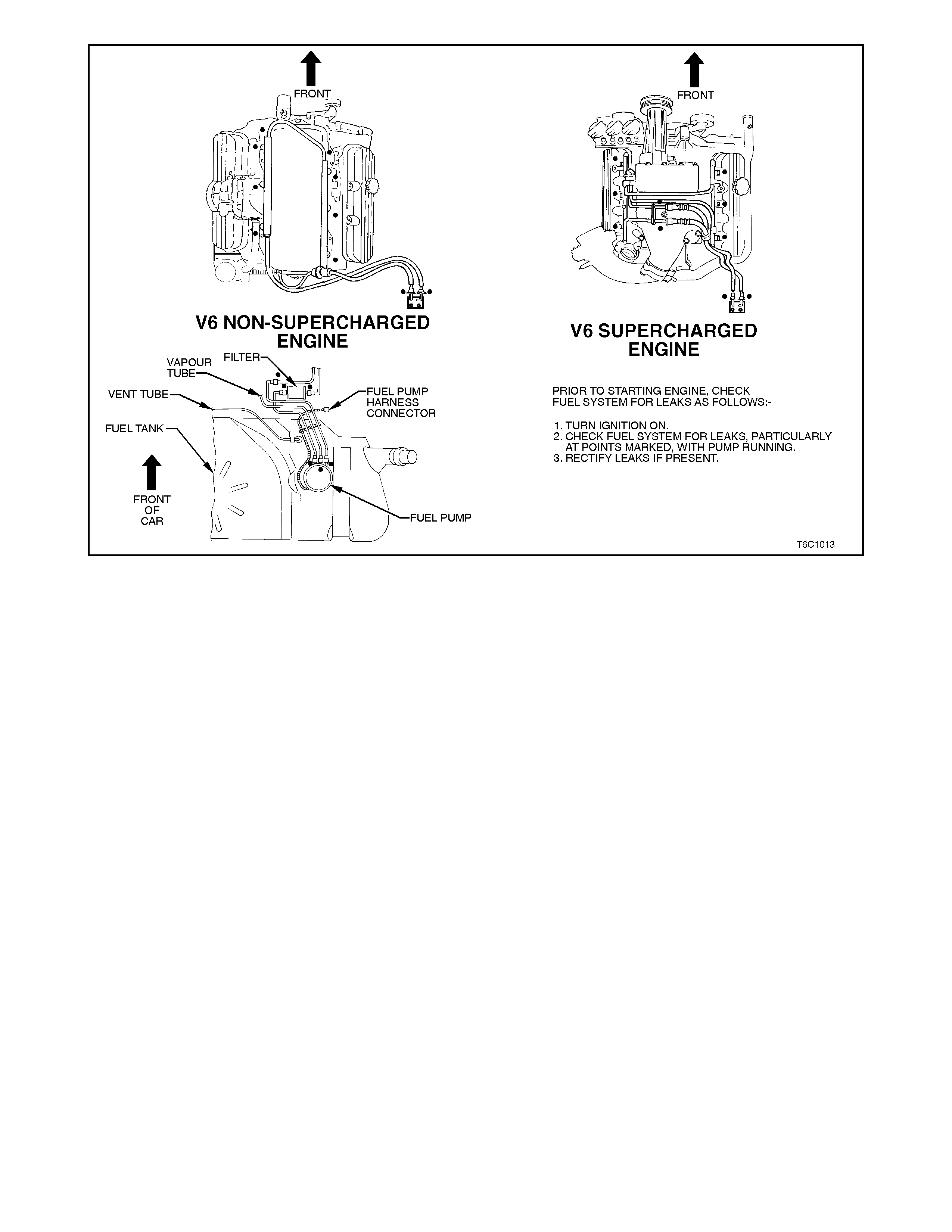
Figure 6C1-1-91 Fuel Delivery System
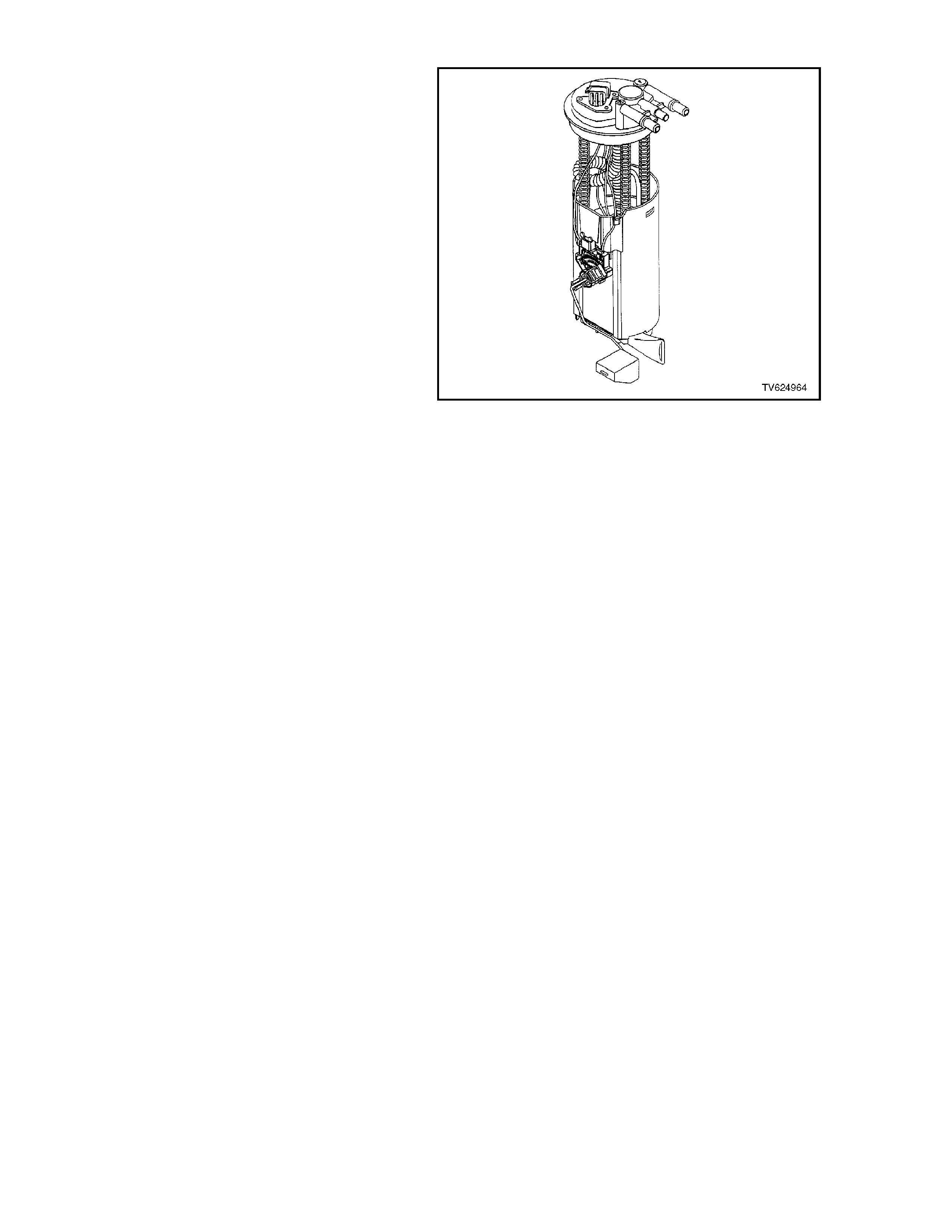
MODULAR FUEL SENDER ASSEMBLY
The modular fuel sender assembly is attached to
the top of the f uel tank , and ex tends f r om the top of
the fuel tank to the bottom.
The modular fuel sender assembly consists of the
following major components:
• A Fuel Sender Cover
• Fuel Pipes (above cover)
• A Fuel Pump
• A Fuel Pump Strainer
• A Fuel Pump Reservoir
• A Fuel Sender Strainer
• A filter to reduce radio fr equency interferenc e on
Supercharged Engine models
• A Ceramic Fuel Level Sensor Assembly
The fuel level sender assembly consists of the
following:
• A Float
• The Wire Float Arm
• A Rheostat
The fuel level is sensed by the position of the float
and float arm, position changes, the amount of
current passing through the rheostat varies, thus
changing the fuel gauge reading on the instrument
panel.
The V6 Non-Superc harged Engine applic ation uses
a GEN. III TURBINE fuel pump, and can be
serviced separately from the sender unit assembly.
The V6 Supercharged Engine application uses a
ROLLERVANE fuel pum p. This fuel pump c an only
be serviced as a complete unit with the sender unit
assembly.
Figure 6C1-1-92 Modular Sender Assembly
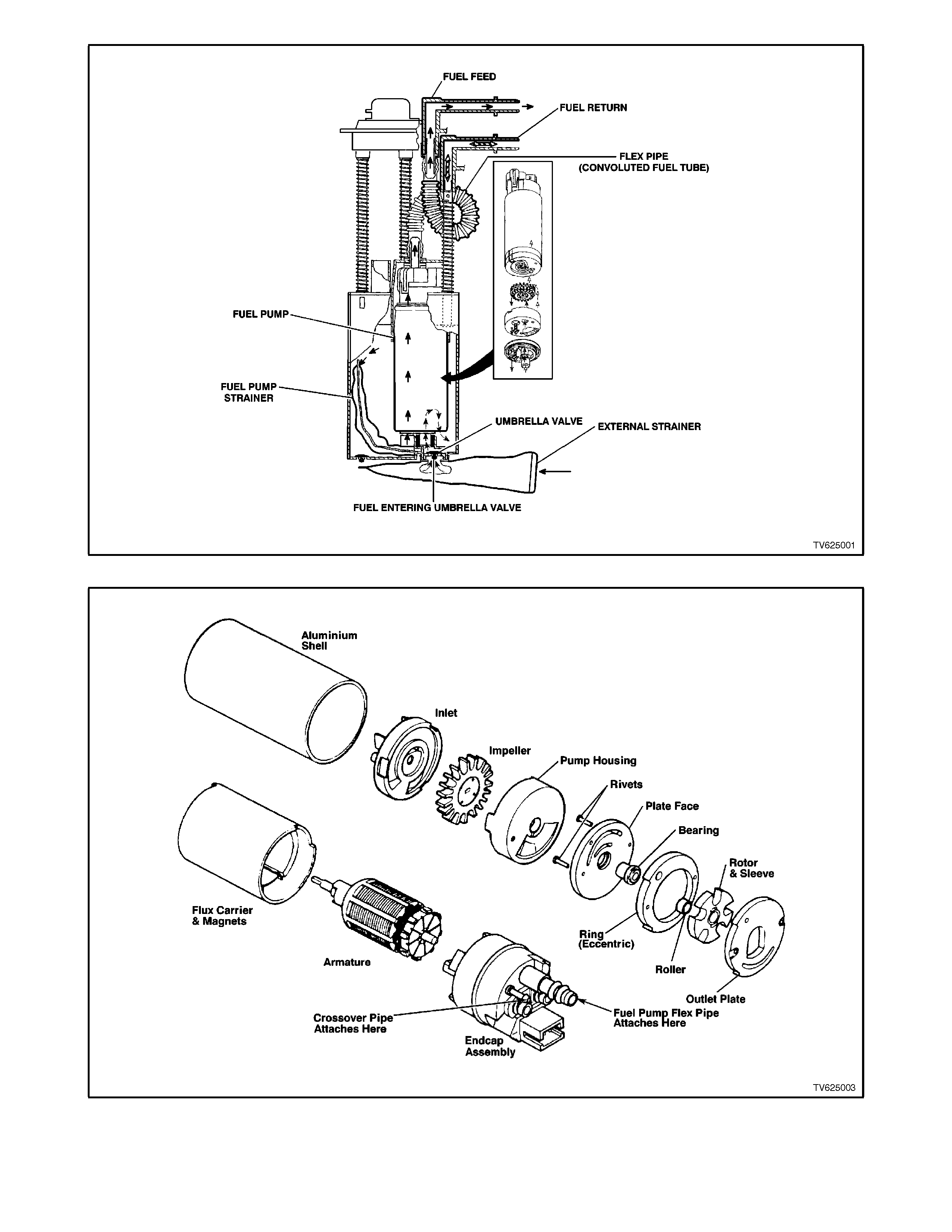
Figure 6C1-1-93 Fuel Pump/Sender Assembly
Figure 6C1-1-94-A Supercharged Engine Rollervane Fuel Pump Assembly
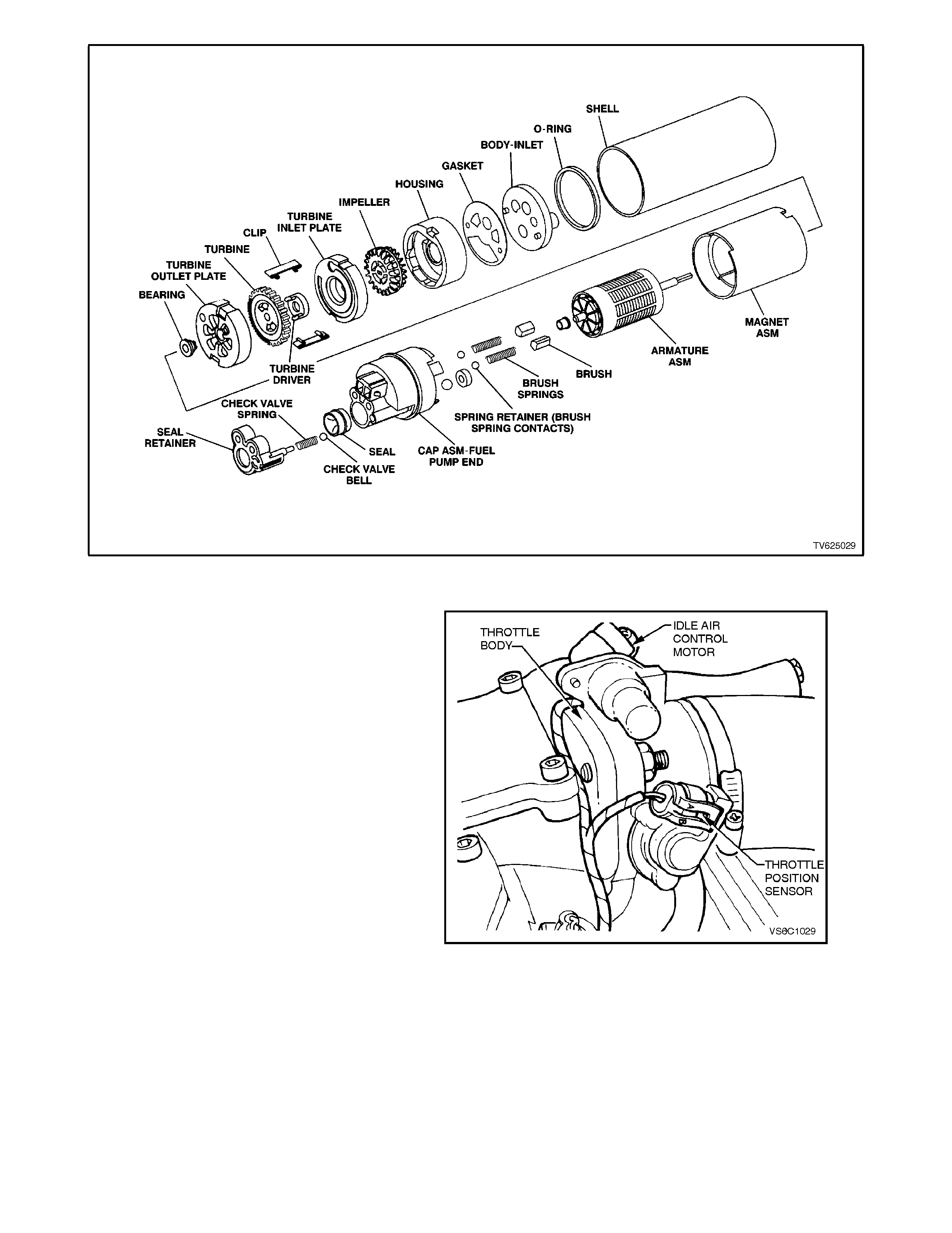
Figure 6C1-1-95 Non-Supercharged Engine GEN. III Turbine Fuel Pump Assembly
THROTTLE BODY UNIT
The throttle body unit is made up of one casting
assembly, with two electrical components
connected to it. They are:
1. An Idle Air Control (IAC) valve to control air
flow bypassing around the throttle blade. This
"bypass" airflow provides the air requirements
for the engine when the throttle is closed.
More "bypass" air gives the engine the ability
of a higher idle speed, while lower flow rates of
this "bypass" air give lower idle speeds. The
IAC acts as an PCM-controlled bypass air
valve, allowing the PCM to control idle speed.
2. A Throttle Position Sensor, which gives the
PCM information about current throttle
position, and if the throttle is moving (opening
or closing). The PCM can also determine how
quickly the throttle is opening or closing with
this signal.
The throttle body contains 2 vacuum ports. The
small port provides manifold vacuum to the
evaporative emission's canister purge solenoid.
The larger port is for the positive crankcase
ventilation system.
Figure 6C1-1-96 Throttle Body with TPS and IAC
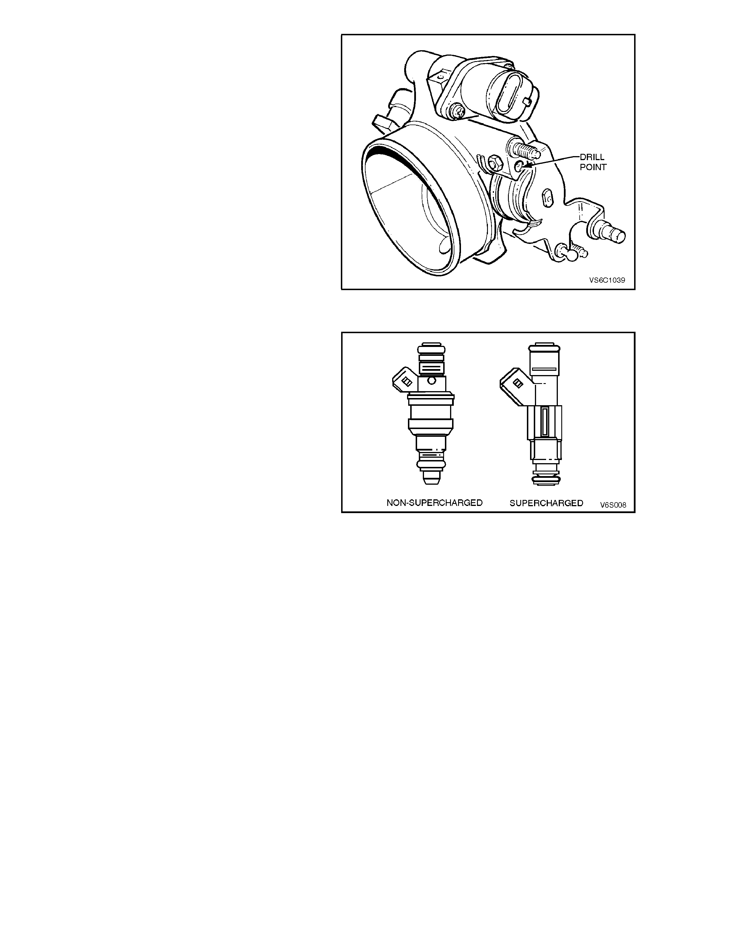
There are specific throttle body assemblies for
vehicles with automatic and manual transmission.
Identification is by a drill point marking on the
throttle used for vehicles with manual transmission.
Figure 6C1-1-97 Throttle Body Identification
FUEL INJECTORS
The fuel injectors are electrically operated fuel flow
control valves. They are supplied with +12 volts
through a Fuse and EFI relay, both located in the
engine compartment fuse and relay housing. The
injectors are controlled by the PCM providing the
earth circuit. The PCM energises the injectors to
"open" the flow of f uel. The injector s are never fully
energised "ON," as that would flood the engine with
too much fuel. The PCM supplies the earth circuit
in short pulses. The longer the
duration of the puls e (pulse width), the m ore fuel is
injected into the engine. Inside, the injector s have a
coil of electrical wire that becomes an
electromagnet when energised. The resistance of
these windings is im portant for the PCM to operate
correctly. The injector electrical resistance is
approximately 12.2 ohms at 20 C. If
measurement with an accurate ohmmeter
shows less than 11.8 ohms or more than 12.8
ohms, replace the injector.
(Acceptable: 11.8-12.8 ohms)
A fuel injector that does not open causes a misfire
condition. An injector which is stuck partly open
could caus e dieseling because som e fuel would be
delivered to the engine after the ignition key is
turned "OFF."
Figure 6C1-1-98 Fuel Injector
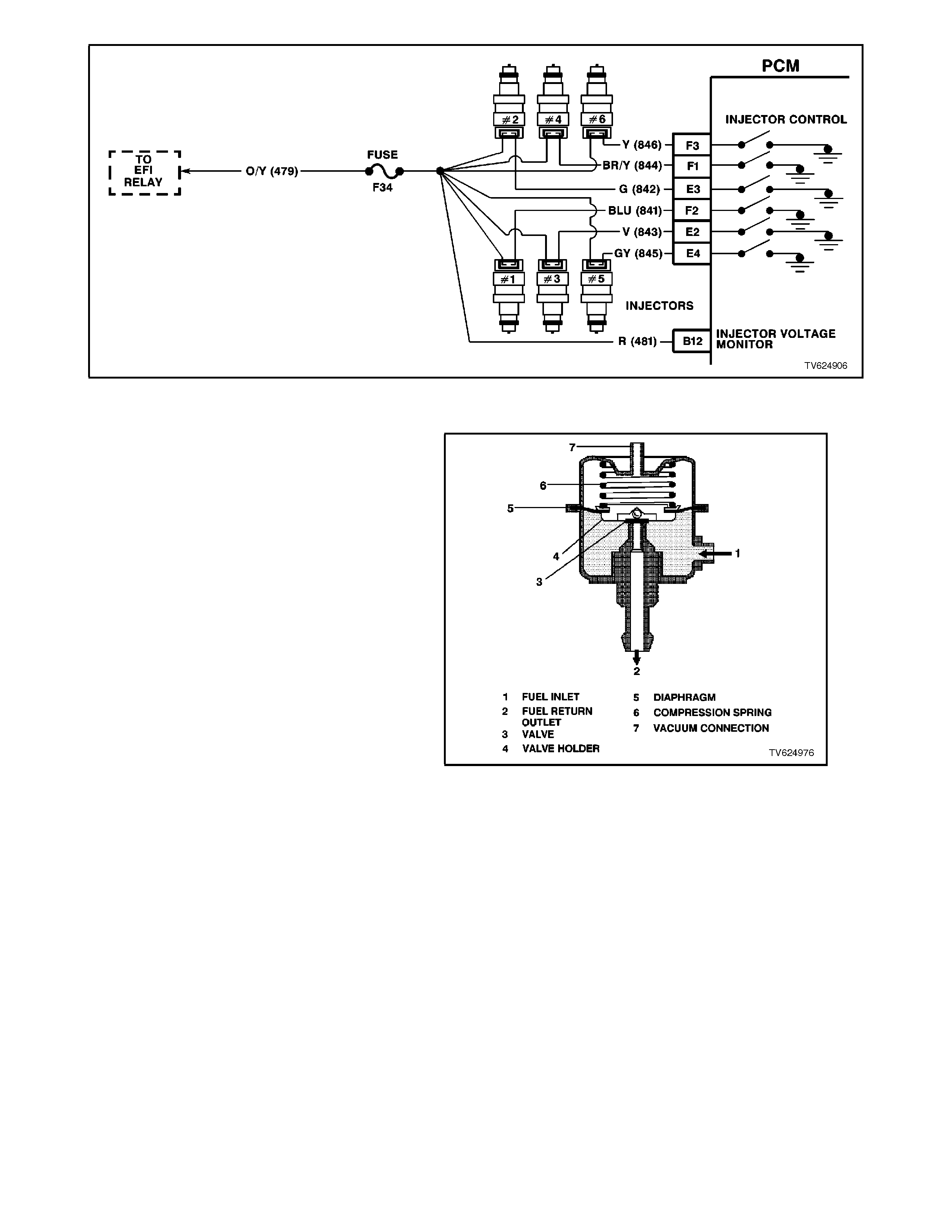
Figure 6C1-1-99 Injector Circuit
FUEL PRESSURE REGULATOR
The fuel pressure regulator is a diaphragm-
operated relief valve with fuel pump pressure on
one side and intake manifold pressure (engine
vacuum) combined with mechanical spring
pressur e on the other. The func tion of the regulator
is to maintain a regulated pressure at the injectors
at all times by controlling the flow into the return
line.
The fuel pressure regulator is mounted on the fuel
rail and may be serviced separately.
If the fuel pressure is too low, poor performance
and a DTC 44, or 64 could set. If the pressure is
too high, excessive odour and a DTC 45, or 65 may
result. Refer to Chart A-4.1 (Non-Supercharged
Engine) or Chart A-4.1-1 (Supercharged Engine)
for information on diagnosing fuel pressure
conditions.
Figure 6C1-1-100-Typical Fuel Pressure Regulator
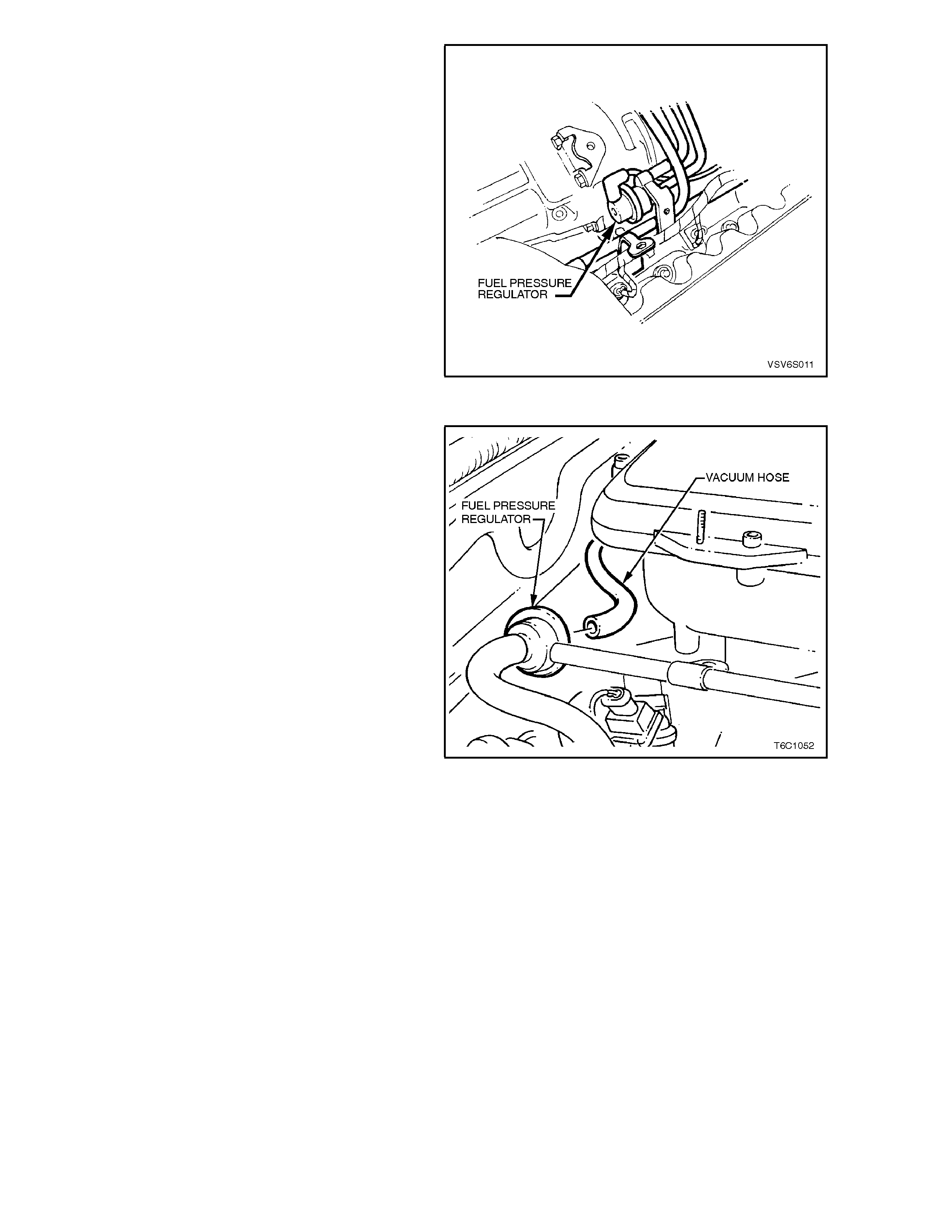
Figure 6C1-1-101 Fuel Pressure Regulator Location
Supercharged Engine
Figure 6C1-1-102 Fuel Pressure Regulator Location
Non-Supercharged Engine
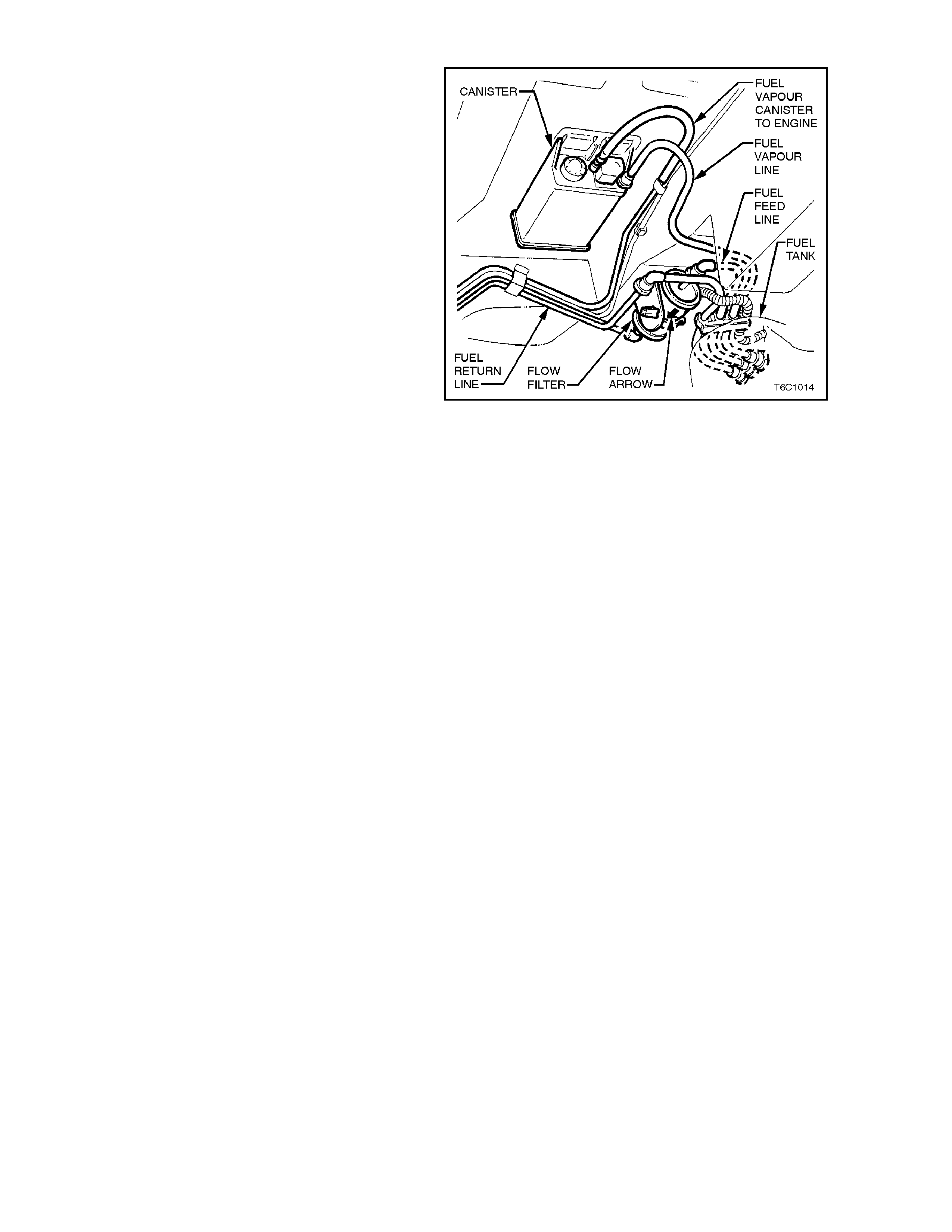
FUEL FILTER
The f uel f ilter is located under the vehic le by the left
hand rear side frame, forward of the fuel tank.
The fuel filter is mounted in place by a plastic
retaining strap attac hed to the rear fr am e. Both fuel
pressure hoses at the filter are quick connects to
the filter. T hese quick connections can be rem oved
by squeezing the oval shaped connections at the
filter.
For removal of the fuel filter, refer to
Section 6C1-3 SERVICE OPERATIONS in this
Section.
Figure 6C1-1-103 Fuel Filter Location
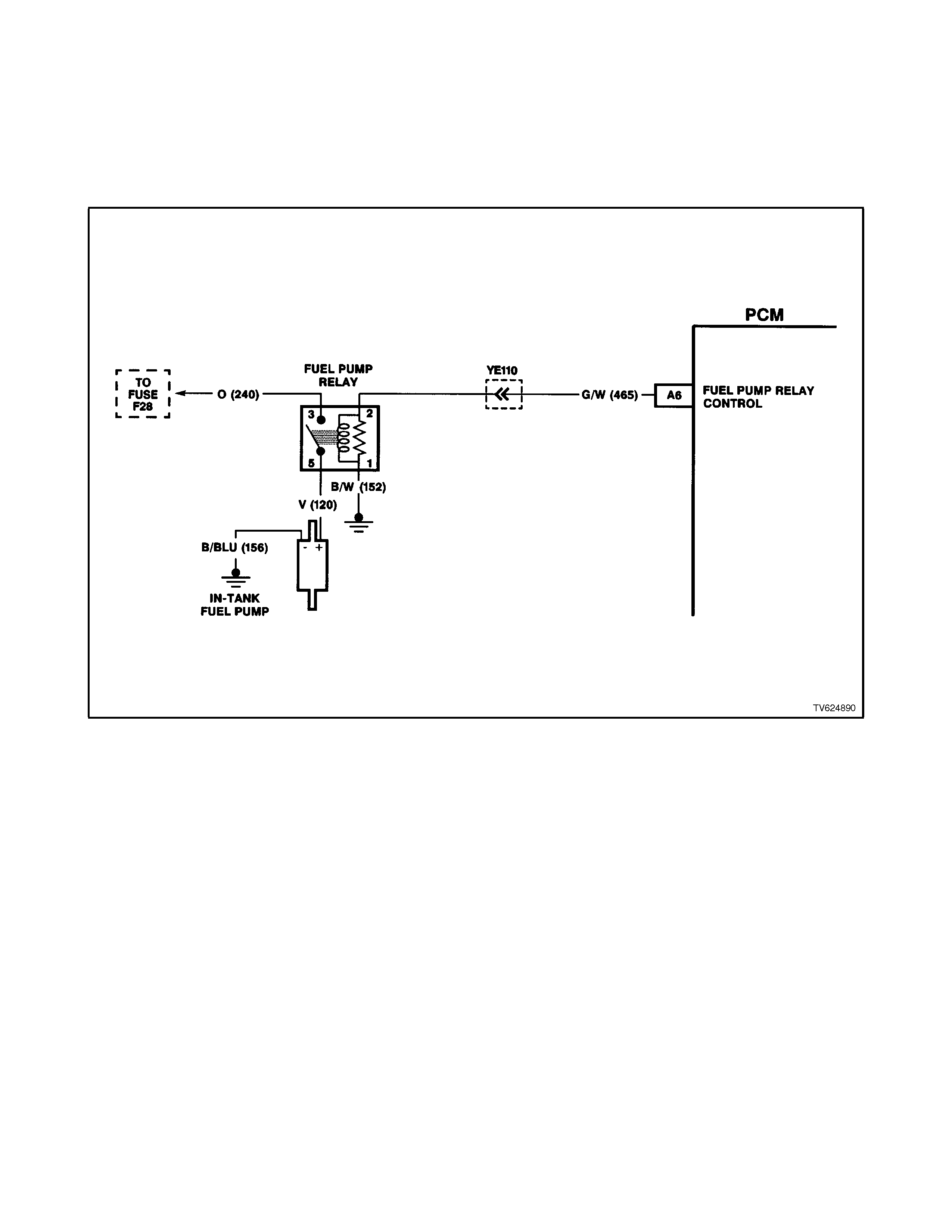
FUEL PUMP ELECTRICA L CIRCUITS (NON-SUPERCHARGED ENGINE)
When the ignition switch is turned to "ON" or 'crank' after having been "OFF" for at least 10 seconds, the PCM will
immediately energise the fuel pump relay to operate the fuel pump. This builds up the fuel pressure quickly. If the
engine is not cranked within two seconds, the PCM will shut the fuel pump relay "OFF" and wait until the engine is
crank ed. As soon as the engine begins c ranking, the PCM will sense the engine turning f rom the cranks haft ref erence
input, and turn the relay "ON" again to run the fuel pump.
A failed fuel pump relay circuit will cause a no start condition. Refer to Figure 6C1-1-106 for fuel pump relay location.
Figure 6C1-1-104 Fuel Pump Electrical Circuits Non-Supercharged Engine
FUEL PUMP ELECTRICAL CIRCUITS (SUPERCHARGED ENGINE)
When the ignition switch is turned to "ON" or 'crank' after having been "OFF" for at least 10 seconds, the PCM will
immediately energise the fuel pum p relay which will then activate the Fuel Pump Contr ol Module (Figure 6C1- 1-107) to
operate the fuel pump. This builds up the fuel pressure quickly. If the engine is not cranked within two seconds, the
PCM will shut the fuel pum p relay "OFF" and wait until the engine is cranked. As soon as the engine begins cranking,
the PCM will sense the engine turning from the c rank shaf t refer ence input, and turn the r elay "ON" again to run the fuel
pump.
A failed fuel pump relay circuit will cause a no start condition. Refer to Figure 6C1-1-106 for fuel pump relay location.
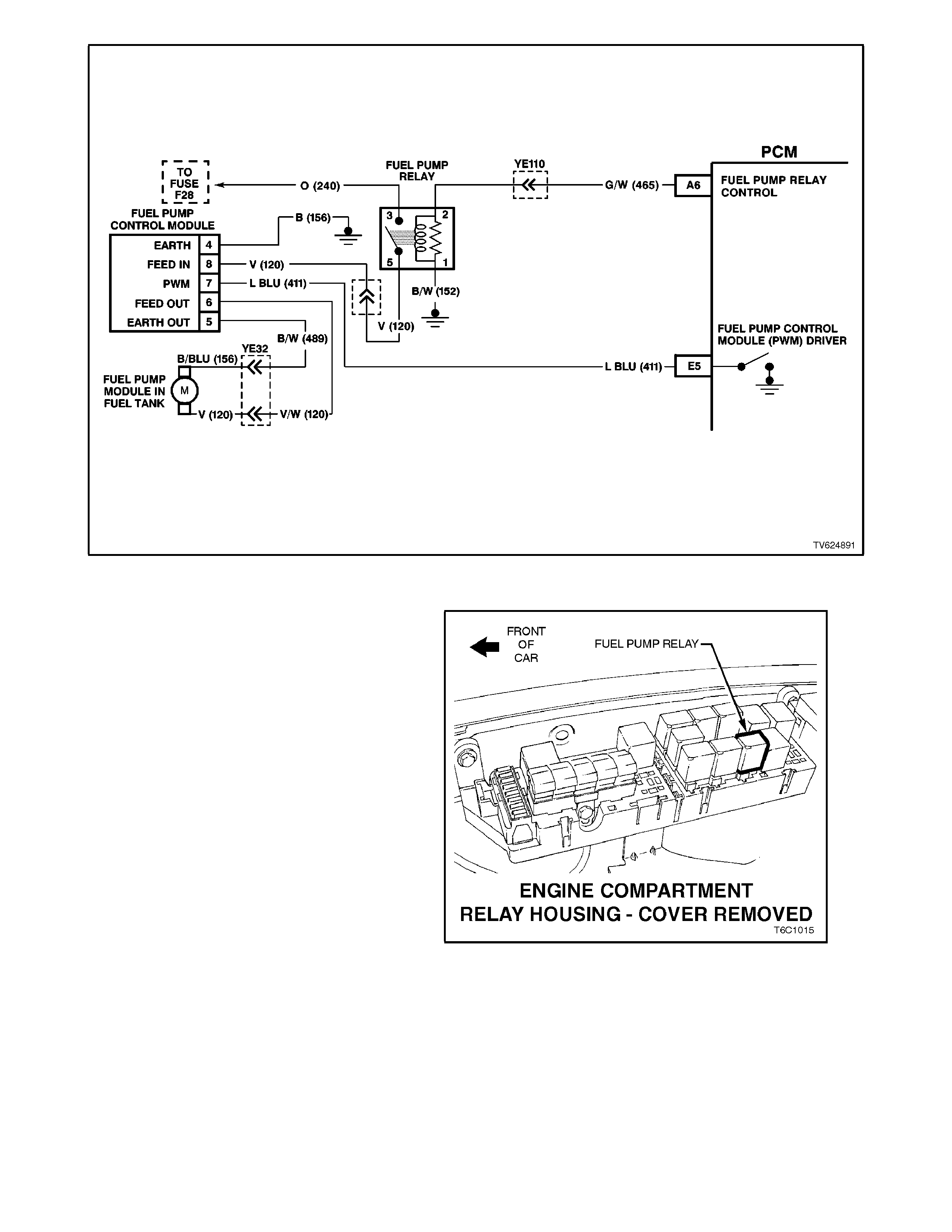
Figure 6C1-1-105 Fuel Pump Electrical Circuits Supercharged Engine
FUEL PUMP (SUPERCHARGED ENGINE)
A specific fuel pump is used for vehicles with V6
Supercharged engine. This fuel pump is a
ROLLERVANE type pump whereas the fuel pump
used for Non-Supercharged vehicles is a turbine
(GEN. III Turbine) type pump.
Identification of the fuel pum p for the superchar ged
engine over the pump used for non-supercharged
vehicles is by referring to the overall diameter of the
pump body. For supercharged applications the
pump body overall diameter is approximately 37
mm, with the fuel pump for the non-supercharged
engine application being approximately 44 mm.
The fuel pump relay is located in the engine
compartment relay housing.
Figure 6C1-1-106 Fuel Pump Relay Location
FUEL PUMP CONTROL MODULE
The V6 Supercharged engine utilises a two speed
Fuel Pump and a Fuel Pump Control module. The
Fuel Pump Control Module is located in the boot.
The Fuel Pump Control Module can vary the fuel
pump output depending on the required engine
load. When the ignition is first turned "ON", the
PCM energises the fuel pump relay which applies
power to the Fuel Pump Control Module. The fuel
pump will then pressurise the fuel system.
The purpose for the Fuel Pump Control Module is
that this Supercharged system requires more fuel
volume under heavy engine load conditions then
the non-superchar ged system . The f uel pum p used
in the non-superchar ged system m ay be capable of
supplying the required fuel volume for the
supercharged system, but with the increased fuel
volume required, the non-supercharged fuel pump
would eventually fail f rom r unning at the higher fuel
volume.
The PCM controls the current flow through the fuel
pump with a Pulsed Width Modulation (PWM)
signal at 128 Hertz (Hz) to the fuel pump control
module. T he fuel pum p control m odule controls the
current flow through the fuel pump depending on
the PWM signal received from the PCM.
Under normal driving conditions the required fuel
volume is less, so the f uel pum p operates at a duty
cycle of 67% "ON", that is the PCM controls the fuel
pump circuit, via the fuel pump control module at
67% "ON" and 33% "OFF", at a frequency of 128
Hz.
When the engine load is increased, as measured
by the Mass Air Flow sensor, the fuel pum p control
module will switch from the normal duty cycle
(67%) to a higher duty cycle (100%) based on the
com mand f r om the PCM. This higher duty cycle will
increase the current supply through the fuel pump,
increasing the fuel volume delivered by the fuel
pump.
Another feature of this Fuel Pump Control Module
is that when the fuel pump is running at the lower
duty cycle, (norm al driving conditions ), the returned
fuel to the fuel tank (from the fuel pressure
regulator) is less. This lower volume of returned
fuel to the fuel tank will result in lower emissions
(fuel tank vapours).
Also with the fuel pump running at a lower duty
cycle (normal dr iving conditions) , the voltage output
required to run the pump is lower. This will require
less generator output and will decrease overall
vehicle fuel usage.
Refer to Chart A-4.1-1 for diagnosis of the fuel
pump electrical circuit.
Figure 6C1-1-107 Fuel Pump Control Module Location
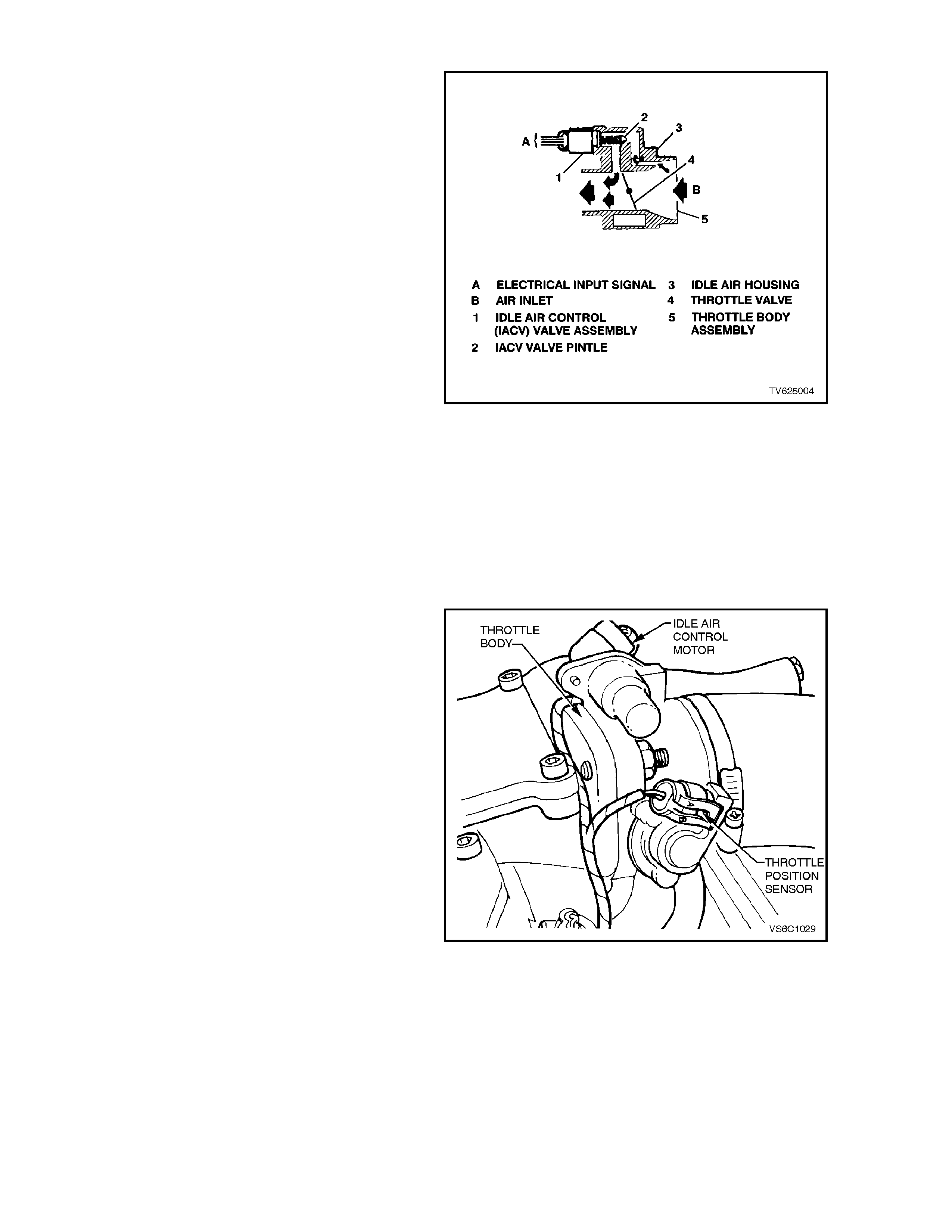
1.6 IDLE AIR CONTROL (IAC) VALVE
The purpose of the Idle Air Control (IAC) valve, is
to control engine idle speed, and prevent stalls due
to changes in engine load at idle.
The IAC valve, mounted in the throttle body,
controls bypass air around the throttle valve. By
extending the pintle (to decrease air flow) or
retracting the pintle (to increase air flow), a
controlled amount of air can move around the
throttle valve. If RPM is too low, more air is
bypassed around the throttle valve to increase
RPM. If RPM is too high, less air is bypassed
around the throttle valve to decrease RPM.
The IAC Valve moves in small steps numbered
from 0 (extended pintle, bypass air passage fully
shut) to 255 (retracted pintle, maximum bypass
airflow) as commanded by the PCM.
At idle, the desired position of the IAC valve is
calculated by the PCM based on coolant
temperature, actual engine RPM, engine load, and
battery voltage.
If the IAC Valve is disconnected or reconnected
with the engine running, the PCM can "lose track"
of the actual position of the IAC. T his also happens
when PCM's keep alive memory voltage, i.e., PCM
connectors, ENGINE fuse F31, or battery cables,
are disconnected. If this happens, the PCM will
"reset" the IAC. After the engine has been run for at
least 5 seconds, then upon ignition "OFF" the IAC
will be reset.
Figure 6C1-1-108 IAC Valve
The "reset" procedure is as follows:
The PCM commands the IAC to shut the idle air
passageway in the throttle body. It does so by
issuing enough "extend" pulses to move the IAC
pintle fully shut in the bore, regar dless of where the
actual position was. Then, the PCM calculates the
IAC is at a fully shut position, and calls that position
"0 steps." Next, the PCM issues "retract" steps to
properly position the pintle.
The IAC can also be reset with the engine running
by a special command on the Tech 2 scan tool.
The IAC valve affects only the idle RPM of the
engine. If it is open fully, too much air will be
allowed into the manif old and idle speed will be too
high. If it is stuc k closed, too little air will be allowed
into the intake manifold, and idle speed will be too
low.
Figure 6C1-1-109 IAC Valve Location

Figure 6C1-1-110 IAC Valve Circuit
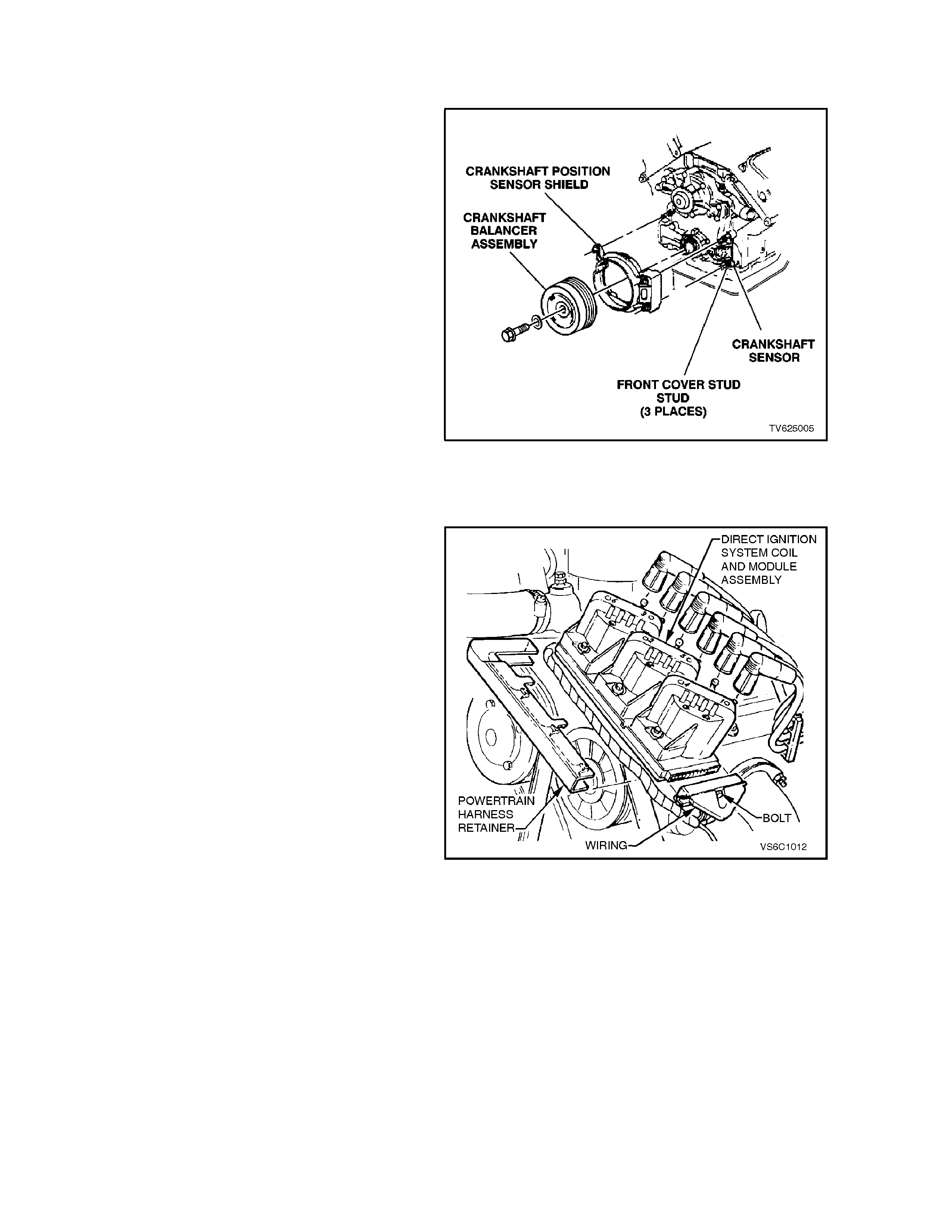
1.7 DIRECT IGNITION SYSTEM (DIS)
PURPOSE
The Direct Ignition System (DIS) system controls
fuel combustion by providing a spark to ignite the
compressed air/fuel mixture at the correct time. To
provide optimum engine performance, fuel
economy, and control of exhaust emissions, the
PCM controls spark advance with the DIS system.
DIS has several advantages over a mechanical
distributor system:
• No moving parts
• Less maintenance
• Remote mounting capability
• No mechanical load on the engine
• More coil cool down time between firing events
• Elimination of mechanical timing adjustments
• Increased available ignition coil saturation time
Figure 6C1-1-111 Crankshaft Sensor & Crankshaft
Balancer
OPERATION
The Direct Ignition System (DIS) is an ignition
system that does not use a conventional distributor
and ignition coil. The DIS ignition system consists
of; 3 ignition coils, a DIS m odule, a dual Hall-effect
crankshaft position sensor, an engine crankshaft
balancer with crankshaft sensor interrupter rings
attached to the rear, related connecting wires, and
the EST (electronic spark timing) portion of the
PCM. The PCM controls only the ignition timing and
dwell only. The DIS coils do the actual firing of the
spark plugs.
Conventional ignition coils have one end of the
secondary winding connected to earth. In the Direct
Ignition System, neither end of the secondary
winding is earthed. Instead, each end of a coil's
secondary winding is attached to a spark plug.
Thes e two plugs are on "c ompanion" c ylinders, i.e.,
on top dead centre at the same time.
When the coil discharges, both plugs fire at the
same time to complete the series circuit. The
cylinder on compression is said to be the `event'
cylinder and the one on exhaust is the `waste'
cylinder. The cylinder on the exhaust stroke
requires ver y little of the available energy to fir e the
spark plug at idle. The remaining energy will be
used as required by the cylinder on the
compression stroke. This method of ignition is
called "waste spark" ignition.
Since the polarity of the ignition coil primary and
secondary windings is f ixed, one spark plug always
fires with a forward current flow and it's
`companion' plug fires with a reverse current flow.
This is dif fer ent fr om a conventional ignition system
that fires all the plugs with the same direction of
current flow.
Figure 6C1-1-112 DIS Module And Coils
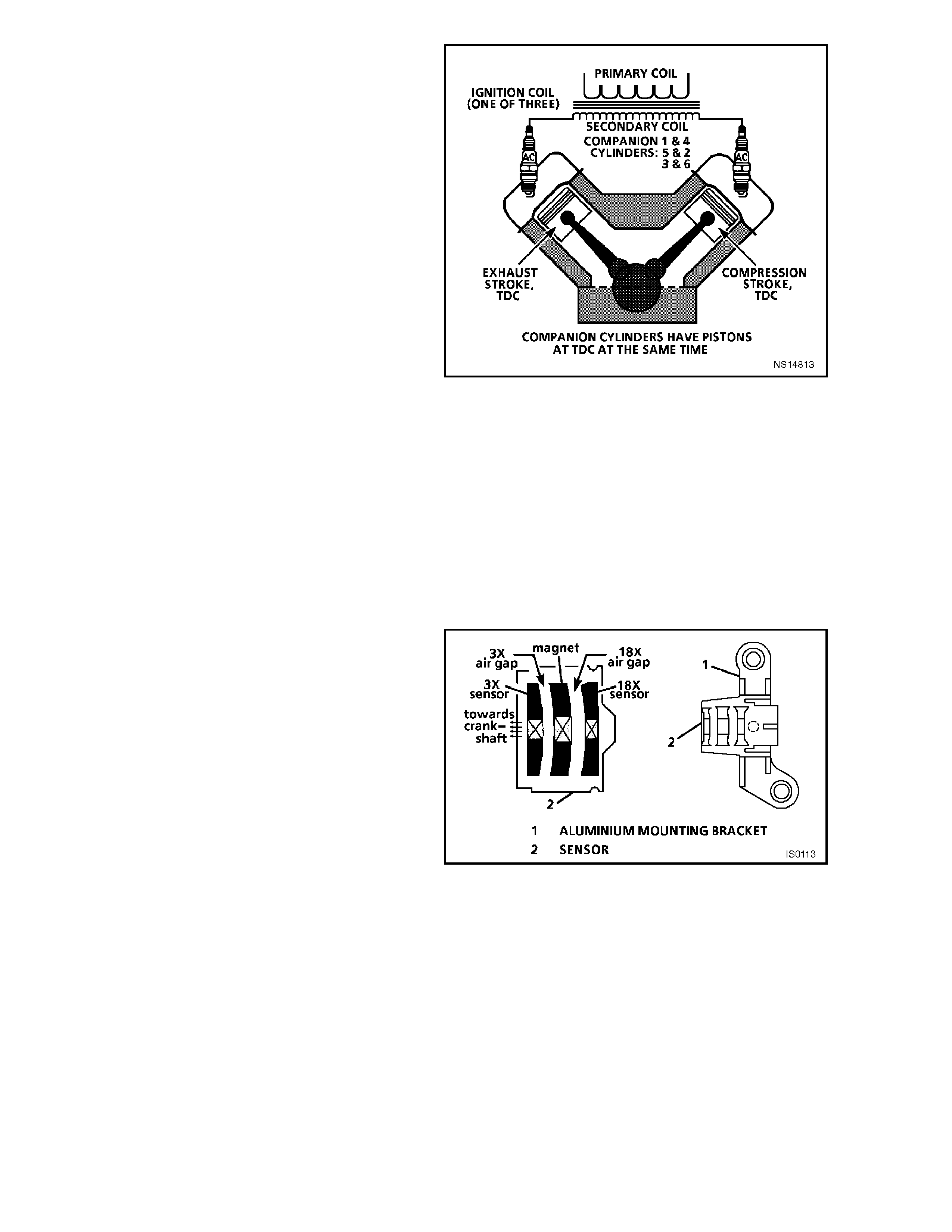
Since it requires approximately 30% more voltage
to fire a spark plug with reverse current flow, the
ignition coil design is im proved, with saturation tim e
and primary current flow increased. This redesign
of the system allows higher secondary voltage to
be available from the ignition c oils - greater than 40
kilovolts (40,000 volts) at any engine RPM. The
voltage required by each spark plug is determined
by the polarity and the cylinder pressure. The
cylinder on compression requires more voltage to
fire the spark plug (approximately 8 kilovolts) than
the one on exhaust (approximately 3 kilovolts).
It is possible f or one spark plug to fire even though
a plug wire fed by the same coil may be
disconnected from it's 'companion' spark plug. The
disconnected plug wire acts as one plate of a
capacitor, with the engine being the other plate.
These two 'capacitor plates' are charged as a spark
jumps across the gap of the still-connected spark
plug. The `plates' are then discharged as the
secondary energy is dissipated in an oscillating
current across the gap of the still-connected spark
plug. Secondary voltage requirements ar e very high
with an 'open' spark plug or wire. The ignition coil
has enough reserve energy to fire the still-
connected plug at idle, but possibly not under high
engine load. A more noticeable misfire may be
evident under load; both spark plugs may be
misfiring.
Figure 6C1-1-113 Waste Spark Ignition, Companion
Cylinders
SYSTEM COMPONENTS
CRANKSHAFT SENSOR CRANKSHAFT BALANCER INTERRUPTER RINGS
The dual crankshaft sensor, secured in an
aluminium mounting brack et and bolted to the front
left side of the engine timing c hain c over, is par tially
behind the crankshaft balancer. A 4-wire electrical
harness connector plugs into the sensor,
connecting it to the DIS module.
The DIS dual crankshaft sensor contains two Hall-
effect switches with one shared magnet mounted
between them. The magnet and each Hall switch
are separated by an air gap.
A Hall switch reacts like a solid-state switch,
earthing a low-current signal voltage when a
magnetic field is present. When the magnetic field
is shielded from the switch by a piece of steel
placed in the air gap between the magnet and the
switch, the signal voltage is not earthed. If the piece
of steel (called an interrupter) is repeatedly moved
in and out of the air gap, the signal voltage will
appear to go "ON-OFF-ON-OFF-ON-OFF."
Compar ed to a c onventional mec hanical dis tr ibutor,
this "ON-OFF" signal is similar to the signal that a
set of breaker points in the distributor would
generate as the distributor shaft turned and the
points opened & closed.
Figure 6C1-1-114 Crankshaft Sensor
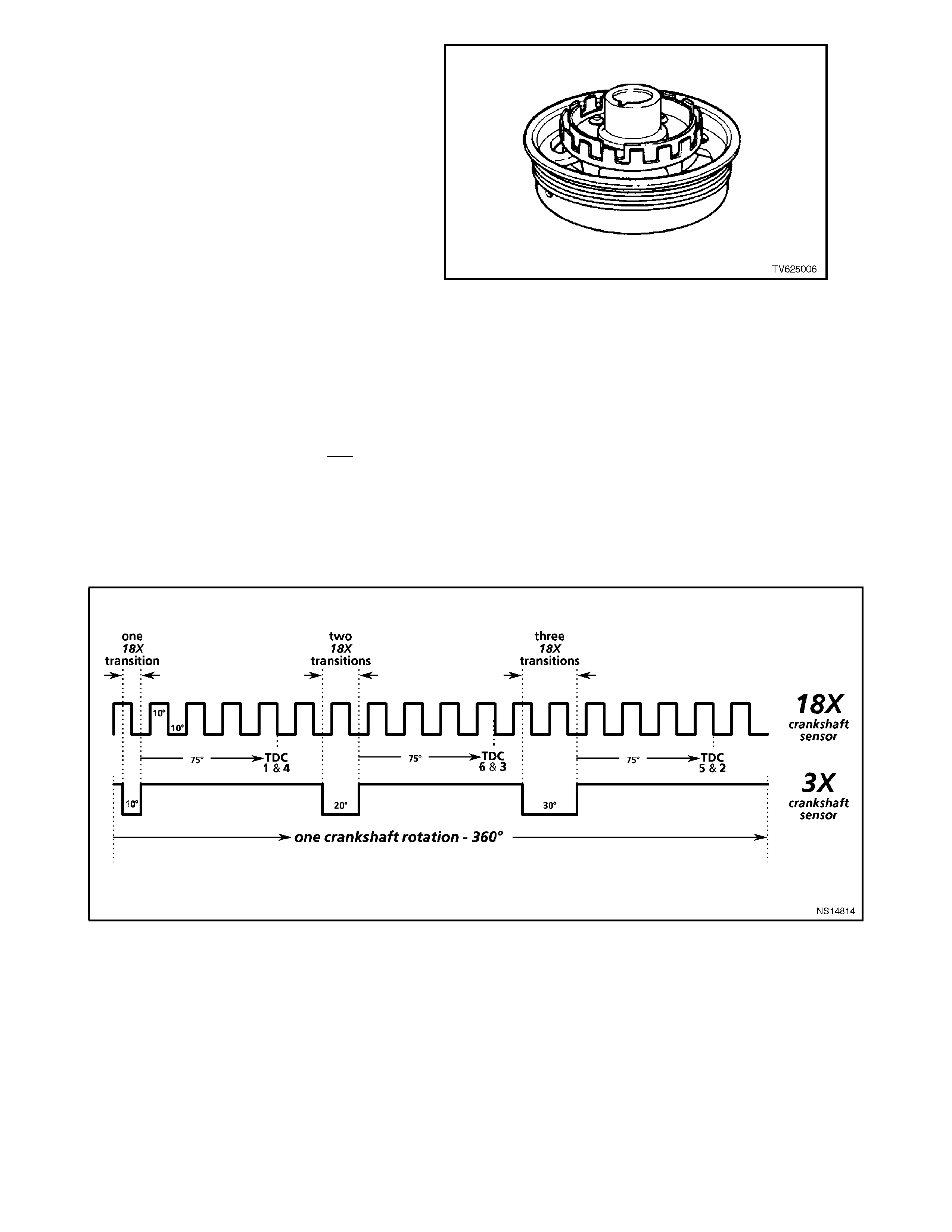
In the case of the DIS system, the piece of steel is
two concentric interr upter rings m ounted to the rear
of the crankshaft balancer. Each interrupter ring
has blades and windows that, with crankshaft
rotation, either block the magnetic f ield or allow it to
reach one of the Hall switches. The outer Hall
switch is called the 18X crankshaft sensor,
because the outer interrupter ring has 18 evenly
spaced same-width blades and windows. The 18X
crankshaft sensor produces 18 "ON-OFF" earth
pulses per crankshaft revolution. The Hall switch
closest to the c rankshaf t, the 3X crank s haft sens or,
is so called because the inside interrupter ring has
3 unevenly-spaced, different-width blades and
windows. The 3X crankshaft sensor produces 3
different length "ON-OFF" earth pulses per
crankshaft revolution.
W hen a 3X inter rupter ring 'window' is between the
magnet and inner switch, the magnetic field will
cause the 3X Hall switch to earth the 3X c rank shaf t
signal voltage supplied from the DIS module. The
18X interrupter ring and Hall switch react similarly.
The DIS module interprets the 18X and 3X "ON-
OFF" signals as an indication of crankshaft
position, and must have both signals to "fire" the
correct ignition coil. The DIS module determines
crankshaft position for correct ignition coil
sequencing by counting how many 18X signal
transitions occur, i.e. "ON-OFF" or "OFF-ON,"
during a 3X pulse.
Figure 6C1-1-115 Crankshaft Balancer with Interrupter
Rings
Figure 6C1-1-116 18X and 3X Crankshaft Sensor Pulses for One Crankshaft Revolution
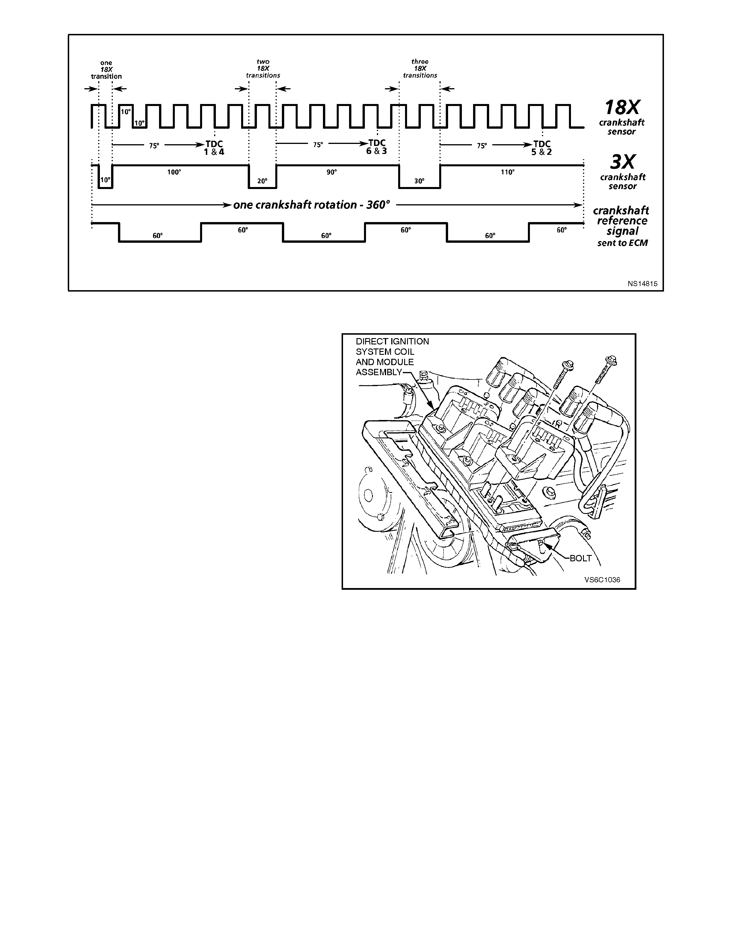
Figure 6C1-1-117 18X & 3X Crankshaft Sensor Pulses AND Crankshaft Reference Signal sent to the PCM
IGNITION COILS
Three twin-tower ignition coils are individually
mounted to the DIS module, with six screw type
fasteners. Each coil provides the spark for two
spark plugs simultaneously (waste spark
distribution), and all three coils can be replaced
individually. Spade type electrical term inals c onnect
each coil to the DIS module. Three of the six
terminals are connected together by a circuit in the
DIS module, supplying +12 volts to the primary
windings of all three coils. The other three terminals
are individually connected to the DIS module, so
that the DIS module can control only one coil firing
at a time, in the correct order, by removing the
primary circuit earth path at the proper time.
Figure 6C1-1-118 Ignition Coils & Ignition Module
DIS IGNITION MODULE
The DIS module serves several functions:
• It powers the dual crankshaft sensor internal
circuits.
• It supplies the 3X and 18X voltage signals that
each respective Hall switch pulses to earth to
generate the 3X and 18X crankshaft sensor
pulses.
• It determines the correct ignition coil firing
sequence, based on how many 18X transitions
occur during a 3X pulse. This coil sequencing
occurs at start-up. After the engine is running,
the module remembers the sequence, and
triggers the proper ignition coil.
• It sends a "crankshaft reference" signal to the
PCM. The PCM interpr ets engine RPM f rom this
signal. It is also used by the PCM to determine
crankshaft position for EST spark advance
calculations. (The falling edge of each

crankshaft reference signal pulse occurs 75
degrees before TDC of any cylinder.) The
crankshaft reference signal sent to the PCM by
the DIS module is an "on-off" pulse occurring 3
times per crankshaft revolution. This is neither
the 3X nor the 18X crank shaft sensor pulse, but
both of these are required by the DIS module to
generate the crankshaft reference signal.
• The DIS module generates the crankshaft
reference signal by an internal "divide-by-6"
circuit. This divider circuit divides the 18X
crankshaft sensor pulses by 6. The divider
circuit is enabled, or r eady to begin dividing, only
after it receives 3X crankshaft sensor pulses.
After it receives the first 3X crankshaft sensor
signal, the divider circuit does not need the 3X
pulses to continue operating. If either the 18X or
3X pulses are missing, the divider cannot
generate any crank shaft ref erence signal pulses
(sent to the PCM), and no fuel injector pulses
will occur.
• Below 450 engine RPM (or anytime the PCM
does not apply 5 volts to the DIS module
'bypass ' c irc uit), the DIS module c ontr ols ignition
by triggering eac h of the thr ee coils in the pr oper
sequence at a predetermined dwell, with spark
advance fixed at 10 degrees BTDC. This is
called bypass mode ignition. The DIS module
provides proper ignition coil sequencing during
both the module and EST modes.
• Above 450 RPM, the PCM applies 5 volts to the
DIS module 'bypass' circuit, signalling the
module to allow the PCM to control the dwell
and spark timing. This is EST mode ignition.
During EST mode, the PCM adjusts spark dwell
and timing advance for all driving conditions.
Again, the DIS module is responsible for proper
ignition coil sequencing during both the module
and EST modes.
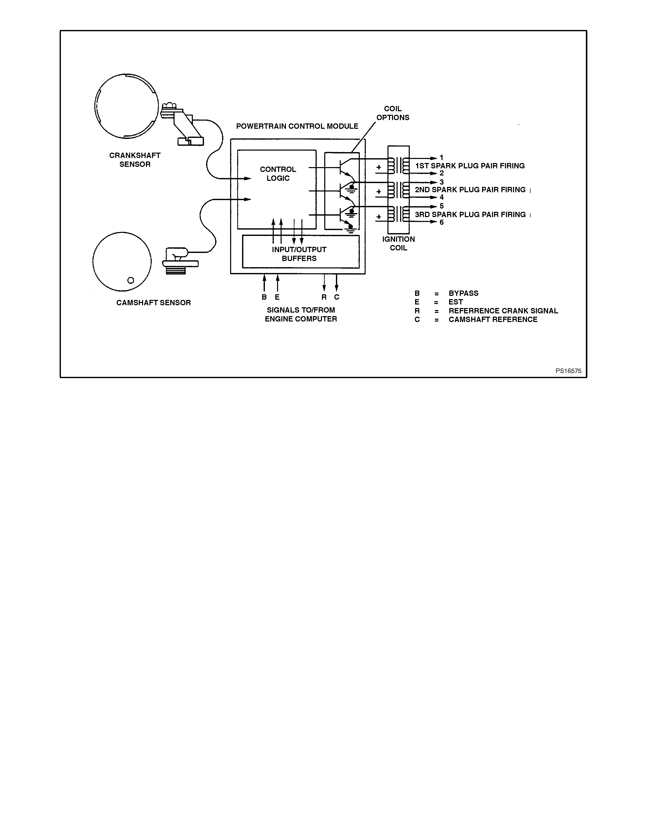
Figure 6C1-1-119 Computer Controlled Coil Ignition

DIRECT IGNITION SYSTEM (DIS) NOTEWORTHY INFORMATION
There are important considerations to point out
when servicing the Direct Ignition System. This
"Noteworthy Information" will list some of these, to
help the technician in servicing the DIS system.
A. The ignition coils secondary voltage output
capabilities are very high - more than 40,000
volts. Avoid body contact with DIS high
voltage secondary components when the
engine is running, or personal injury may
result!
B. The dual Hall-effect 18X - 3X crankshaft
sensor is the most critical part of the DIS
system. If the crankshaft sensor is damaged
so that the 18X or 3X crankshaft sensor pulses
are not generated, the engine will not start!
C. There are 4 circuit wires connecting the dual
crankshaft sensor to the DIS module. If there
is a problem with any of the four, the engine
will not start (No s park and no inj ector pulses ).
The circuits are:
• +10-to-12 volt operating power supply for
the Hall switches from the DIS module.
• 18X sensor pulse signal to the DIS module.
• 3X sensor pulse signal to the DIS module.
• Earth circuit for both Hall switches.
• Equally important (for the engine to run) is
the crankshaft reference signal generated
by the DIS module, sent to the PCM. If the
PCM does not receive this signal, it will not
pulse the fuel injectors.
D. If the 3X c rank shaf t sensor pulses ceas e while
the engine is running, the engine will stop
running and will not restart.
E. If the 18X crankshaft sensor pulses cease
while the engine is running, the engine will stop
running and will not restart.
F. The crankshaft sensor is not adjustable in its
aluminium mounting bracket.
G. Ignition timing is not adjustable. Clearance
of the crankshaft sensor is only for proper
clearance of the r otating interr upter r ings in the
sensor air gap, and does not affect ignition
timing. There are no timing marks on the
crankshaft balancer or timing chain cover.
H If crank s haft s ensor replac em ent is nec essary,
the crank shaf t balancer m us t be rem oved firs t.
The balancer is a press fit onto the crank shaft
and must be removed with a special tool;
removing the serpentine accessory drive belt,
balancer and crankshaft sensor shield will
allow access to replacing the crankshaft
sensor. When reinstalled, the proper torquing
of the balancer attachment bolt is critical to
ensure the balancer stays attached to the
crankshaft.
IIf a crankshaft sensor assembly is
replaced, 2 items are very important:
1. Check the crankshaft balancer interrupter

rings for any blades being bent (runout and
concentric ity). If this is not checked c losely and
a bent blade exists, a new crankshaft sensor
can be destroyed by the bent blade with only
one revolution of the crankshaft!
2. The proper crankshaft sensor replacement
procedure must be followed. Refer to
Section 6C1-3 SERVICE OPERATIONS for
proper replacem ent proc edure. T his proc edure
will position the interrupter rings in the centre
of the sensor air gaps.
J. Neither side of the ignition coil primary or
secondary windings is connected to engine
earth.
K. Be careful not to damage the high tension
leads or boots (dust caps) when servicing the
ignition system. Rotate each boot to dis lodge it
from the plug or coil tower before pulling it
from either a spark plug or the ignition coil.
Never pierce a high tension lead or boot for
any testing purposes! Future problems are
guaranteed if pinpoints or test lights are
pushed through the insulation for testing.
L The DIS m odule is earthed to the engine bloc k
through 2 mounting studs used to secure the
module to it's mounting bracket. If servicing is
required, ensure that good electrical contact is
made between the module and its mounting
bracket, including proper hardware & torque.
M A conventional tachometer used to check RPM
on a primary ignition 'tacho lead' will not work
on DIS. To check RPM, use one of the
following methods:
• A tachometer designed with an inductive
pickup, used on the secondary side of an
ignition system.
• These tachometers are identified by a
'clamp' that goes around a spark plug wire.
Set the tacho to '2-cycle' operation. The
reason for 2- cycle? Spark plugs on this
engine fire every time the piston is at the
top of it's stroke. If a '2 cycle' selection is
not available, divide the indicated 4 cycle
reading by 2.
• Tech 2 scan tool. Use "Engine Speed"
display to read actual RPM.

1.8 ELECTRONIC SPARK TIMING (EST)
The V6 Direct Ignition System uses the same four
ignition module to PCM circuits as do all other
Delco engine management systems. They are:
• Crankshaft Reference PCM Input
• Crankshaft Reference Earth
• Bypass Control
• EST Output
Electronic Spark Timing is the PCM's method of
controlling spark advance and ignitions dwell, when
the ignition system is operating in the EST mode.
There are two "modes" of ignition system operation:
• Bypass mode
• EST mode
In the bypass mode, the ignition system operates
independently of the PCM, with bypass mode s park
advance always at 10 degrees BTDC. The bypass
mode is in effect when cranking the engine. The
PCM has no control of the ignition system when in
this mode. In fact, the PCM could be disconnected
and removed from the car and the ignition system
would still fire the spark plugs while cranking, as
long as the other ignition system com ponents were
functioning! (This would provide spark but no fuel
injector pulses, and a no-start.)
After the engine starts (RPM greater than 450), the
PCM will cause the ignition system to change over
to the EST mode. On ce the c hange is made to EST
mode, it will stay in effect until either:
1. The ignition key is turned "OFF",
2. The engine quits running, or
3. An EST fault is detected.
If an EST fault is detected while the engine is
running, the ignition system will switch back to the
bypass m ode. The engine m ay quit running, but will
restart and stay in the bypass mode.
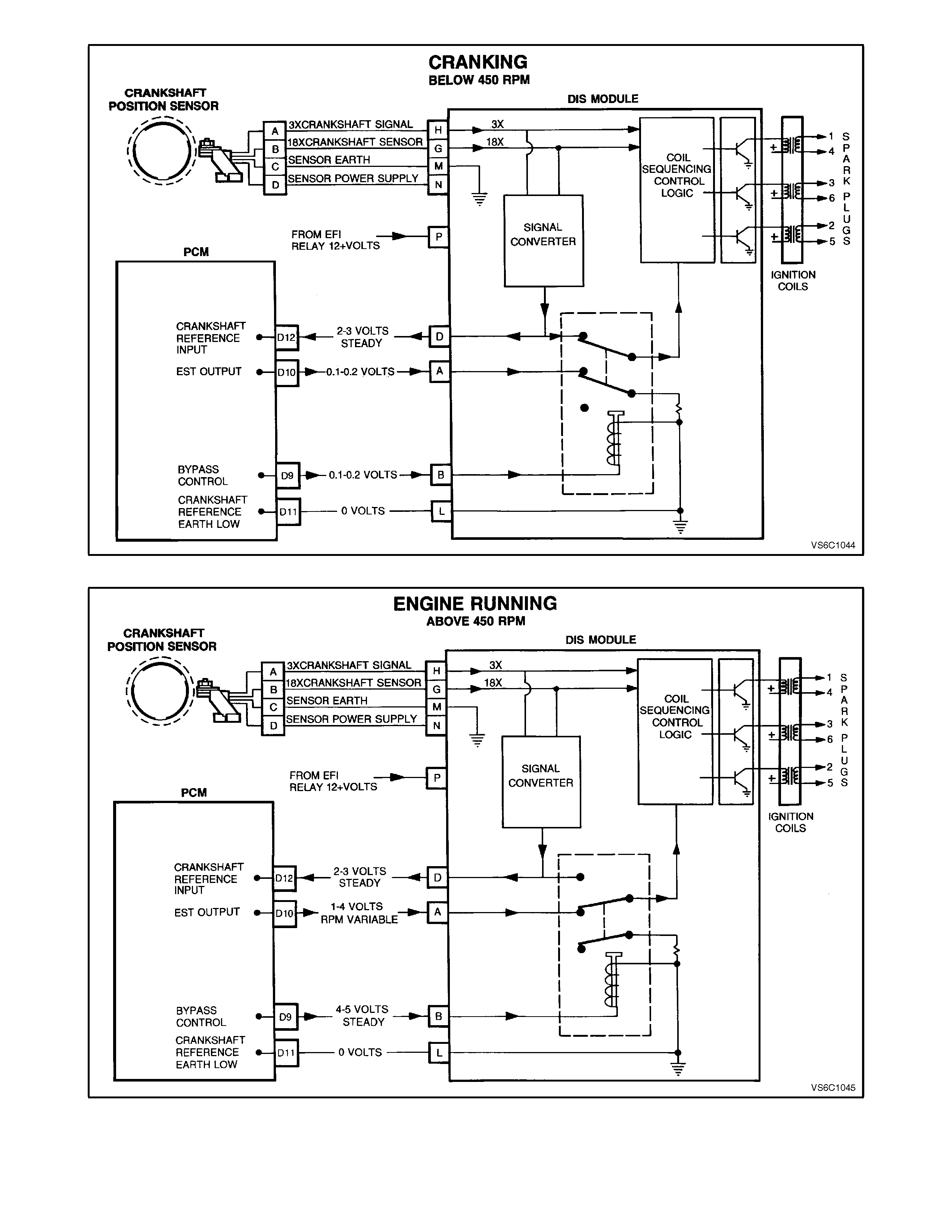
Figure 6C1-1-120 Cranking Below 450 RPM
Figure 6C1-1-121 Engine Running Above 450 RPM
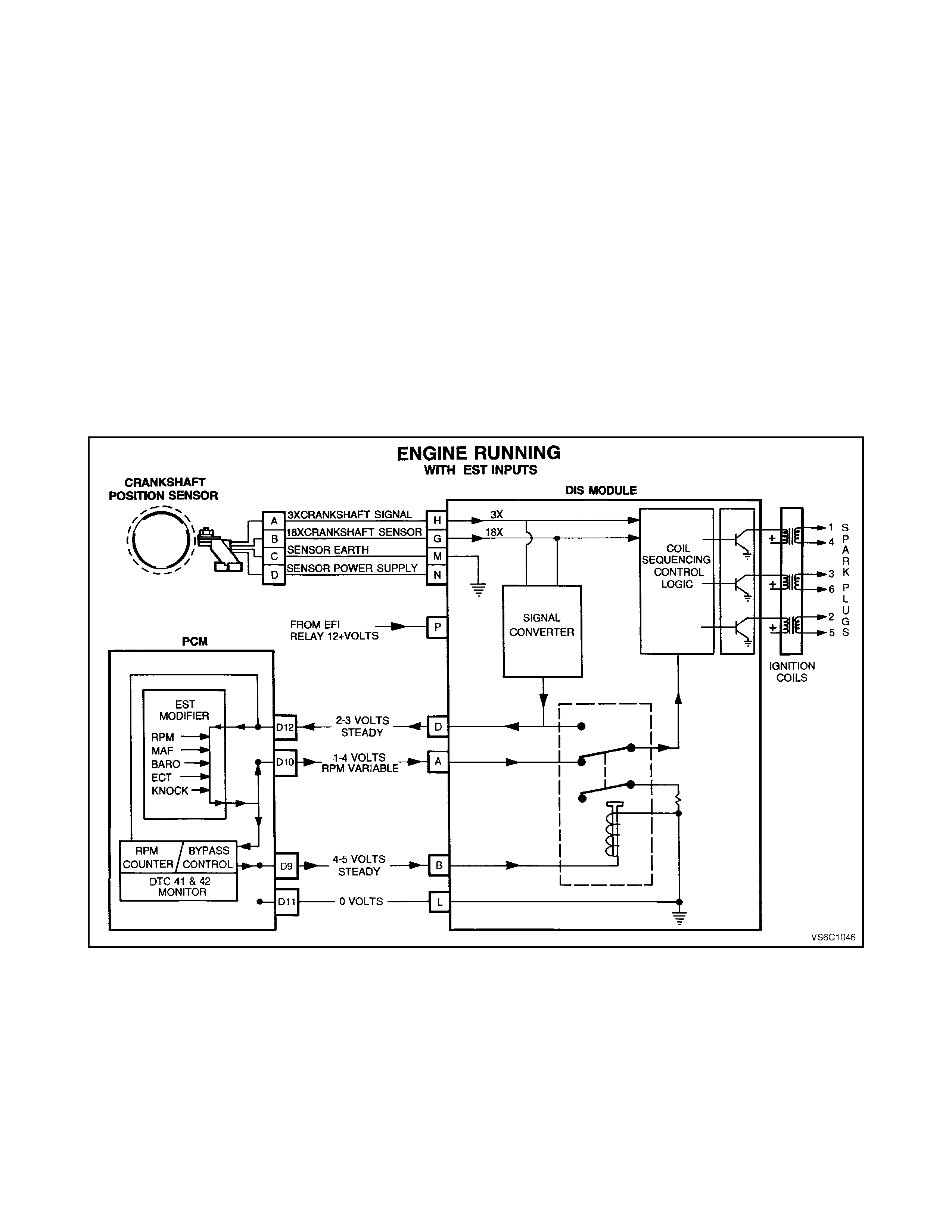
In the EST mode, the ignition spark timing and
ignition dwell time is fully controlled by the PCM.
EST spark advance and ignition dwell is calculated
by the PCM using the following inputs:
• Engine speed (crankshaft reference)
• Crankshaft position (crankshaft reference)
• Engine load (MAF)
• Engine coolant temperature (ECT)
• Throttle position (TP sensor)
• Park/neutral (TFP)
• Detonation (Knock sensor)
• Vehicle speed (VSS)
• Diagnostic request input - (DLC diagnostic test"
terminal)
• PCM supply voltage
The following describes the four PCM-to-ignition
module circuits.
Figure 6C1-1-122 Engine Running with EST Inputs
CRANKSHAFT REFERENCE PCM INPUT
From the ignition module, the PCM uses this signal to calculate engine RPM and crankshaft position. The PCM
compares pulses on this circuit to any that are on earth crankshaft reference low circuit. The PCM also uses the pulses
on this circuit to initiate injector pulses. If the PCM receives no pulses on this circuit, no fuel injection pulses will occur,
the engine will not run, and DTC 46 will set when attempting to start the engine.

CRANKSHAFT REFERENCE EARTH
This is an earth circuit for the digital RPM counter inside the PCM, but the wire is connected to engine earth only
through the ignition module. Although this circuit is electrically connected to the PCM, it is not connected to earth at or
through the PCM. The PCM compares voltage pulses on the reference input circuit to any on this circuit. If the circuit is
open, or connected to earth at the PCM, it may cause poor engine performance and possibly a "Check Powertrain"
Lamp with no DTC.
BYPASS CONTROL
The PCM either allows the ignition module to keep the spark advance at "bypass mode" 10 degrees BTDC, or the PCM
signals the ignition module that the PCM is going to control the spark advance (EST mode). The ignition module
switches between the two modes by the level of voltage that the PCM sends to the ignition module on the bypass
control circuit. The PCM provides 5 volts to the ignition module if the PCM is going to control spark timing (EST mode).
If the PCM does not turn "ON" the 5 volts, or if the ignition module doesn't receive it, then the module will keep control
of spark timing (bypass mode). An open or earthed bypass control circuit will set a DTC 42 and the ignition system will
stay in 'bypass mode'. If the bypass control circuit is shorted to voltage then DTC 41 will set.
EST OUTPUT
The EST output circuitry of the PCM sends out timing pulses to the ignition module on this circuit. When in the "bypass
mode," the ignition module earths these pulses. When in the EST mode, these pulses are the ignition timing pulses
used by the ignition module to energise the ignition coil. If the EST output circuit is open when the engine is started, a
DTC 41 will set and the ignition system will stay in the bypass mode. If this circuit becomes shorted to voltage or
earthed during EST mode operation above 1600 RPM, then DTC 42 will set.
HOW DTC 41 AND DTC 42 ARE DETERMINED
The EST output circuitry in the PCM issues EST output pulses anytime crankshaft reference signal input pulses are
being received. When the ignition system is operating in the bypass mode (no voltage on the bypass control circuit), the
ignition module earths the EST pulses sent from the PCM. The ignition module will remove the earth path for the EST
pulses only after switching to the EST mode. (The PCM commands the switching between bypass & EST modes, via
applying 5 volts on the bypass control circuit to the ignition module.)
The PCM has voltage monitors on the EST output line and the bypass control line. The PCM monitors it's EST output,
and expects to detect no EST pulses on the EST circuit when it has not supplied the 5 volts on the bypass control
circuit. When the RPM for EST operation is reached (approximately 450 RPM), the PCM applies 5 volts to the bypass
control circuit, and the EST pulses should no longer be earthed by the ignition module. The PCM constantly monitors
it's EST output, and should 'detect' the high EST pulses only when in the 'EST mode.'
If EST output circuit is open, the PCM will detect EST output pulses while attempting to start the engine (in the
bypass mode) due to the ignition module not being able to earth the EST pulses. The PCM will check for this condition
during engine cranking. Three things will occur: 1. A DTC 41 will set, 2. The PCM will not apply 5 volts to the bypass
control circuit, and 3. The engine will start and run in the bypass mode.
If EST output circuit is e arthed or shorted to voltage, the PCM would not detect a problem until the change to EST
mode happens. When the PCM applies 5 volts to the bypass control circuit, the ignition module will switch to the EST
mode. With EST circuit earthed or shorted to voltage, there would be no EST pulses for the ignition module to trigger
the ignition coil with, and the engine may falter. The PCM will quickly revert back to the bypass mode (turn "OFF" the 5
volts on the bypass control circuit), DTC 42 will set, after the engine speed exceeds 1600 RPM. The ignition system will
operate in the bypass mode until the fault is corrected and the engine is stopped and restarted.
If bypass control circuit is open OR earthed, the ignition module can not switch to the EST mode. In this case, the
EST pulses will stay earthed by the ignition module, and DTC 42 will be set after the engine speed exceeds 1600 RPM.
The engine will start and run in the bypass mode.
If bypass control circuit is shorted to voltage, the ignition module will be switched to the EST mode all the time. In
this case, the PCM would detect voltage on the bypass circuit only with the engine cranking and set DTC 41. The
engine would start and run in the EST mode.

RESULTS OF INCORRECT OPERATION
An open or earth in the EST or bypass circuit will set a DTC 41 or DTC 42. If a fault occurs in the EST output circuit
when the engine is running, the engine may falter or quit running but will restart and run in the bypass mode. A fault in
either circuit will force the ignition system to operate on bypass mode timing (10 degrees BTDC), which will result in
reduced performance and fuel economy.
The PCM uses information from the MAF and coolant temperature sensors in addition to RPM to calculate the main
spark advance values as follows:
High RPM = more advance
Low MAF frequency
(Low engine load) = more advance
Cold engine = more advance
Low RPM = less advance
High MAF frequency
(High engine load) = less advance
Hot engine = less advance
Therefore, detonation could be caused by incorrect low MAF output frequency or incorrect high resistance in the coolant
temperature sensor circuit. Poor performance could be caused by incorrect high MAF output frequency or incorrect low
resistance in the coolant temperature sensor circuit.
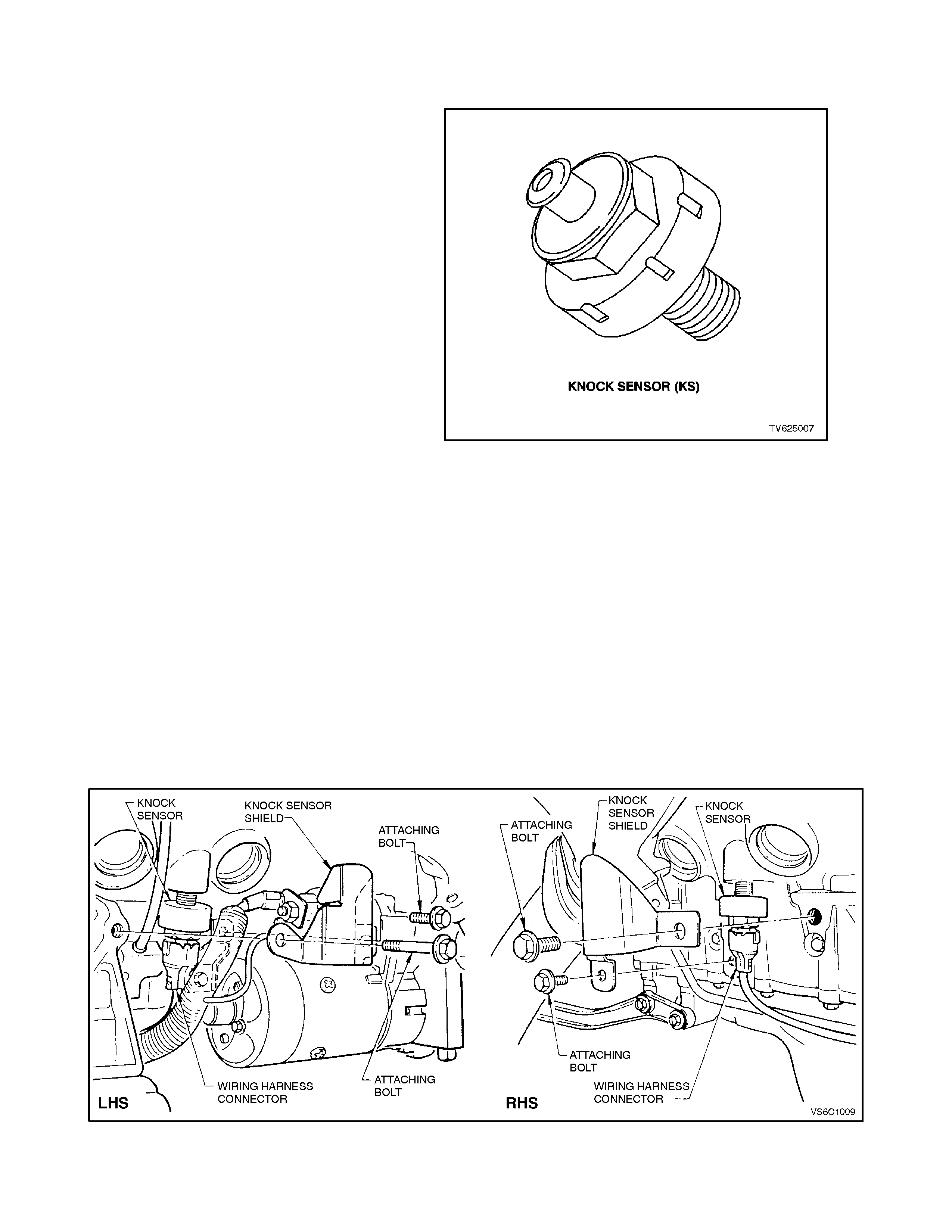
1.9 ELECTRONIC SPARK CONTROL (ESC) SYSTEM
PURPOSE
Varying octane levels in today's petrol may cause
detonation in some engines. Detonation is caused
by an uncontrolled pressure in the combustion
cham ber . This uncontrolled pr es sur e c ould produc e
a flam e f r ont oppos ite that of the normal flam e f r ont
produced by the spark plug.
The "rattling" sound normally associated with
detonation is the result of two or more opposing
pressures (flame fronts) colliding within the
combustion chamber. Though "light" detonation is
sometimes considered normal, "heavy" detonation
could result in engine damage. Light detonation
occurs when the point of maximum pressure has
been exceeded.
To control spark knock, a Knock Sensor (KS) is
used. This system is designed to retard spark
timing up to 15 degrees to reduce spark knock in
the engine. This allows the engine to use max imum
spark advance to improve driveability and fuel
economy.
OPERATION
The ESC system has two major components:
• Knock Sensor Module (part of PCM)
• Knock Sensors
Figure 6C1-1-123 Knock Sensor
The knock sensor detects abnormal mechanical
vibration (spark knocking) in the engine. There are
several calibrations of knock sensors because
each engine produces a different frequency of
mechanical noise. The knock sensor is specifically
chosen f or this engine to best detect engine knock ,
over all the other noises in the engine. T his engine
has two knock sens ors. Each sensor is mounted in
the engine block near each bank of cylinders to
better detect detonation.
Figure 6C1-1-124 Knock Sensor Locations
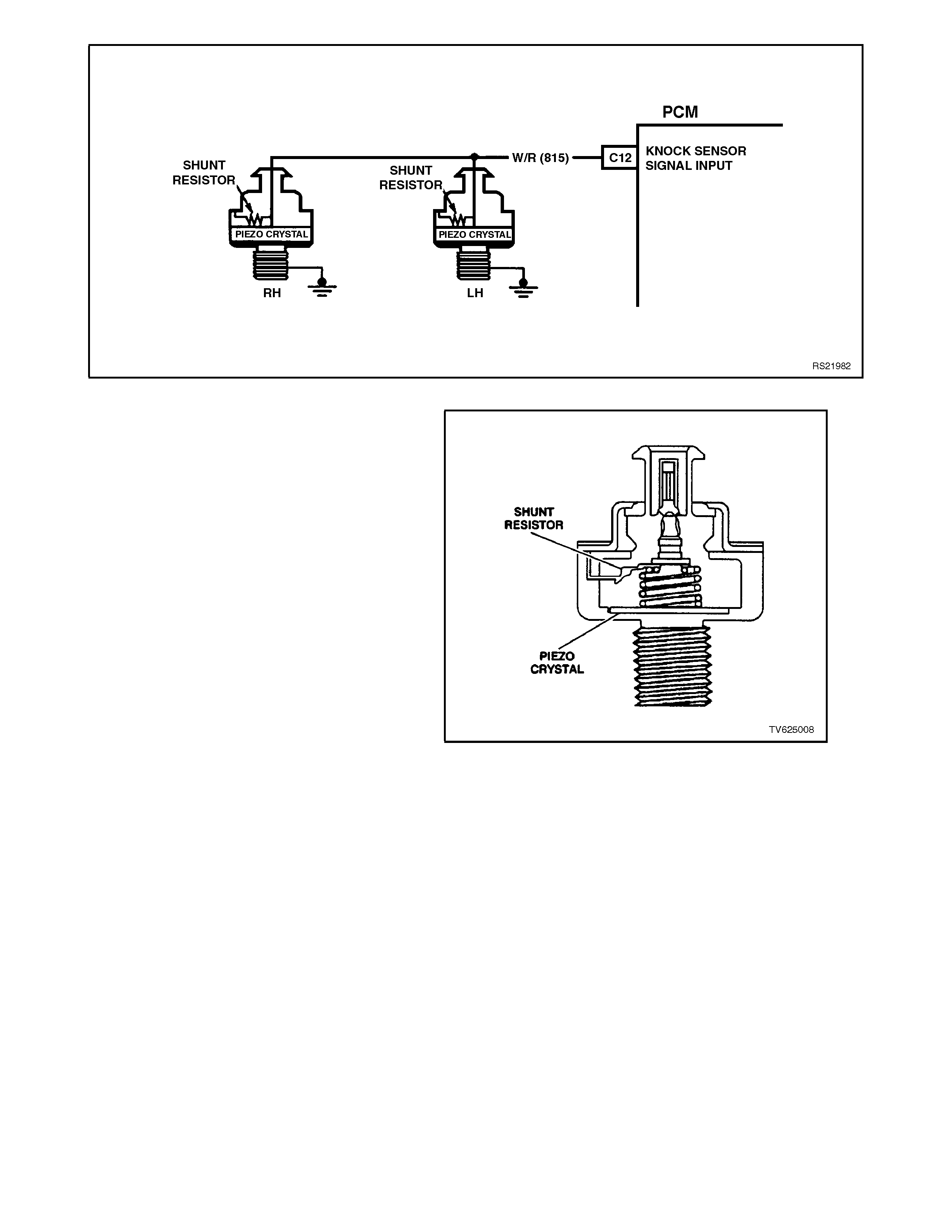
Figure 6C1-1-125 Knock Sensor Wiring
Under a no knock condition, the circuit should
measure about 32 mV AC. The knock sensor
produces an AC output voltage that increases with
the severity of the knoc k. T his signal voltage inputs
to the PCM. This AC signal voltage to the PCM is
processed by an analog signal to a Signal Noise
Enhancement Filter (SNEF) module. This SNEF
module is used to determine if the AC signal
com ing in is noise or actual detonation. This SNEF
module is part of the PCM and cannot be replaced.
The processed knock sensor signal is then
supplied to the PCM. The PCM then adjusts the
ignition control system to reduce the spark
advance. How much the tim ing is retarded is based
upon the amount of time knock is detected and is
limited to a maximum value of 15 degrees. After
the detonation stops, the tim ing will gradually return
to it's calibrated value of spark advance. The Knock
Sensor system will only retard timing after the
following conditions are met:
• Engine running longer than 5 seconds
• Battery voltage higher than 9.3 volts
• Engine speed above 550 RPM
• ECT greater than 45 degrees C
Figure 6C1-1-126 Knock Sensor Sectioned View

The Tech 2 scan tool has two data displays to
check for diagnosing this knock sensor circuit.
"KNOCK SIGNAL" is used to monitor the input
signal from the knock sensor. This position will
display "YES" when knock is being detected.
"KNOCK RETARD" is the indication of how much
the PCM is retarding the spark advance.
The Knock Sens or System has two DT C's to detec t
a failure in its system. DTC 43 is designed to
diagnose the knock sensor and wiring, so that
problems encountered with this circuit should set
the DTC. The PCM learns a minimum noise level
from the knock sensors.
• The actual noise level is determined as: Noise
level = Filtered noise - minimum noise
If the noise level is too low or too high then DTC 43
will be set.
The second DTC associated with the Knock
Sensor is DTC 93. DTC 93 indicates that the
engine has been detonating longer than normal.
The PCM monitors the output of the SNEF circuit.
When the SNEF output signal is s ignificantly longer
than the longest expected "normal": output it is
assumed that the SNEF circuitry has failed and
DTC 93 is set.
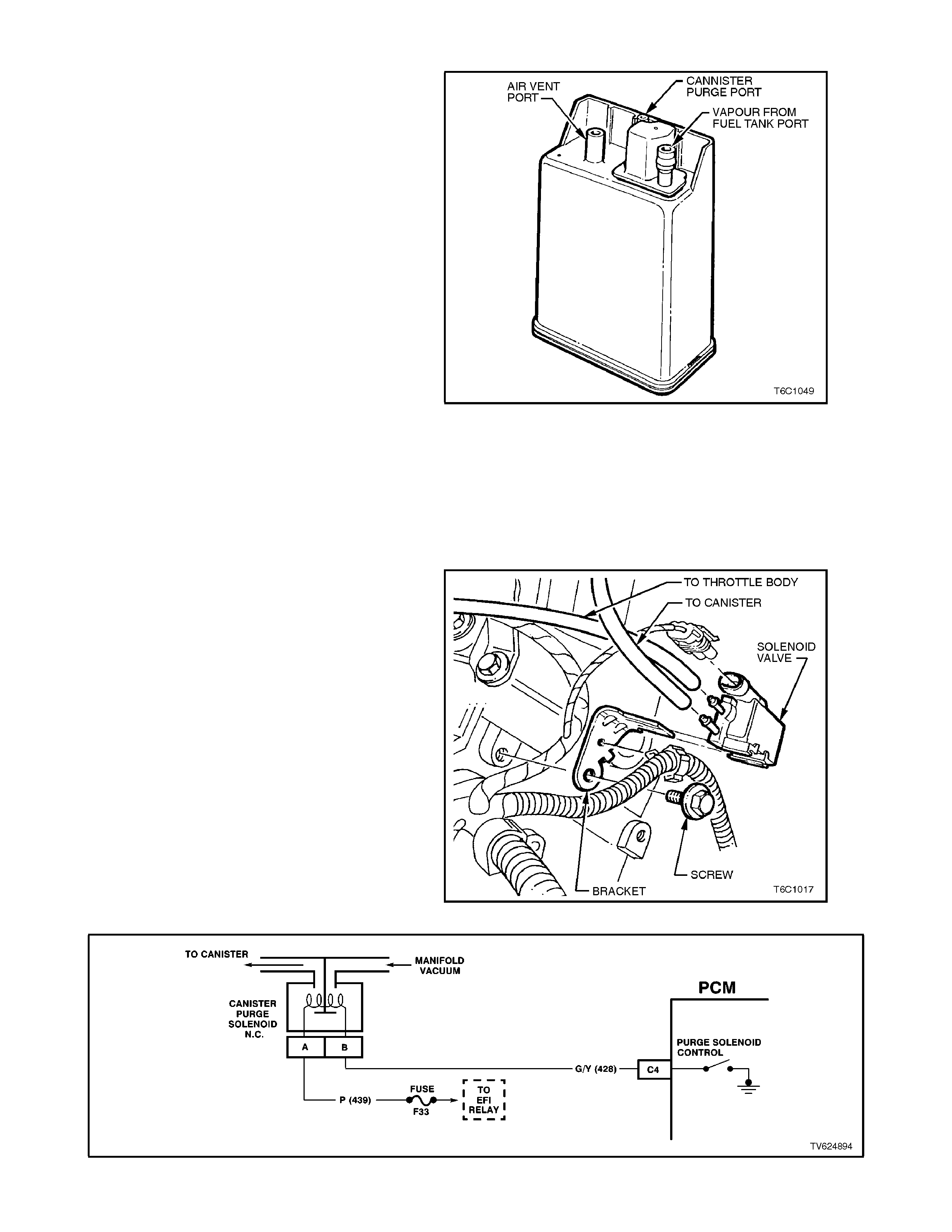
1.10 EVAPORATIVE EMISSION
The Evaporative Emission Control System (EECS)
used on this vehicle is the charcoal canister
storage method. T his method tr ansfers f uel vapour
from the fuel tank to an activated car bon (charcoal)
storage device (canister located under the rear of
the vehicle) to hold the vapours when the vehicle is
not operating. When the engine is running, the f uel
vapour is purged from the carbon element by intake
air flow and consumed in the normal combustion
process.
The EECS purge solenoid valve allows manifold
vacuum to purge the canister. The Powertrain
Control Module (PCM) supplies an earth signal to
energise the EECS purge solenoid valve (purge
“ON”). The EECS purge solenoid control is Pulse
W idth Modulated (PWM) or tur ned “ON” and “OF F”
several tim es a sec ond. T he PCM controlled PWM
output is commanded when the appropriate
conditions have been met:
• Engine coolant temperature above 80°C.
• Engine has been running longer than 3
minutes.
• Engine is not in Decel Fuel Cutoff Mode.
• Throttle opening is less than 92%.
• Engine is in Closed Loop mode.
Figure 6C1-1-127 Fuel Vapour Canister
EECS purge PWM duty cycle varies according to
operating conditions determined by mass air flow,
fuel trim and intake air temperature. The EECS
purge will be re-enabled when TP angle decreases
below 92%.
The canister (located under the rear of the vehicle)
cannot be repaired, and is serviced only as an
assembly. Periodically check the canister at the
time or distance intervals specified in the vehicle
Series Owners Handbook.
Figure 6C1-1-128 Canister Purge Solenoid Location
Figure 6C1-1-129 Canister Purge Solenoid Circuit
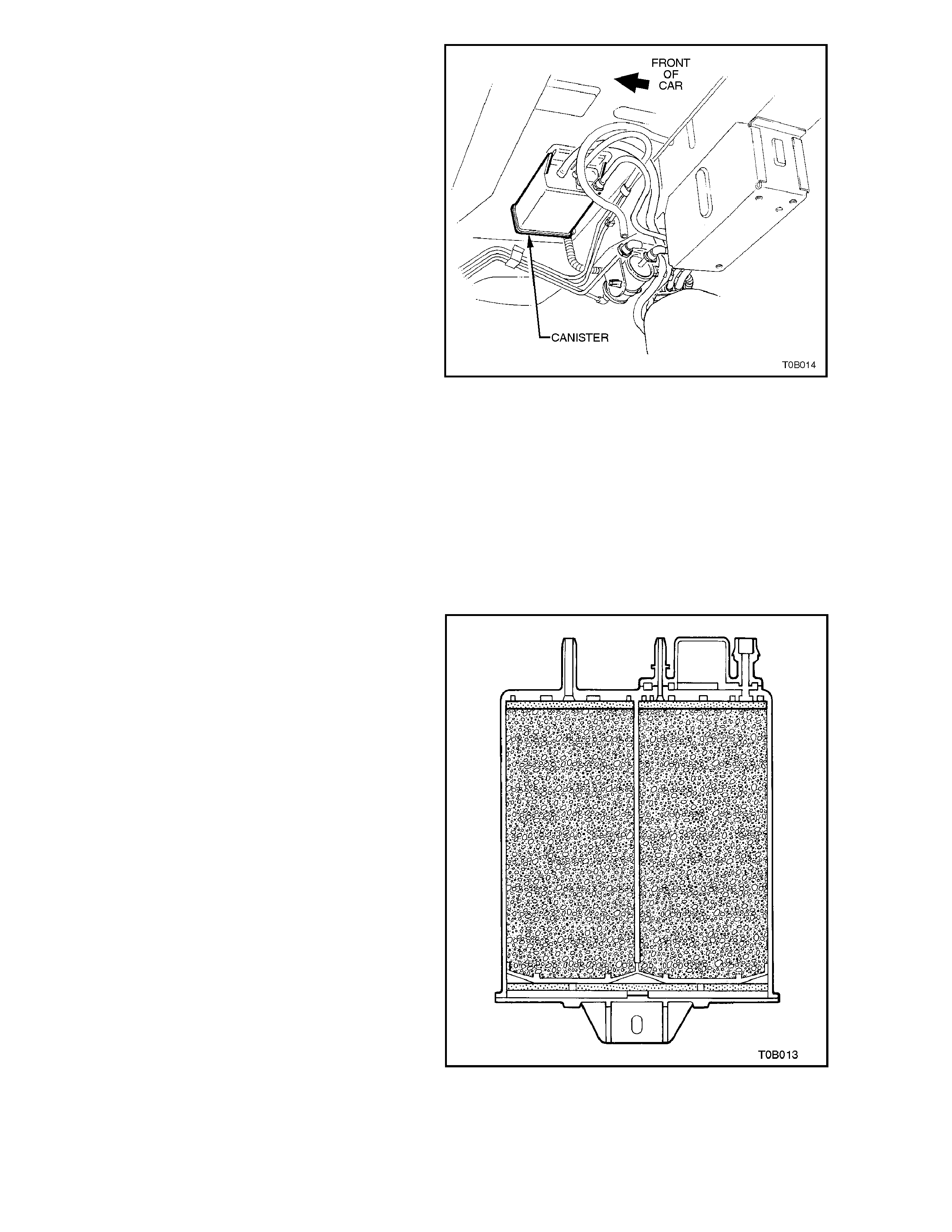
The fuel vapour canister is mounted in a bracket
underneath the vehicle, located by the fuel filter.
This canister is a three port design. T he f uel vapour
is absorbed by the charcoal within the canister.
When the engine is running at idle speed and
above idle, air is drawn into the canister through the
atmospheric port at the top of the canister
assembly. The air mixes with the fuel vapour and
the mix tur e is dr awn into the intak e manif old via the
canister purge line. Upperm ost port on the canister
is controlled by a PCM controlled canister purge
solenoid. The canister purge solenoid controls the
manif old vacuum signal from the throttle body. The
port below the canister purge port is the vapour
inlet from the fuel tank . The single of f centre por t is
open to the atmosphere.
Figure 6C1-1-130 Canister Location
RESULTS OF INCORRECT OPERATION
Poor idle, stalling and poor driveability can be
caused by:
• Inoperative canister purge solenoid
• Damaged canister.
• Hoses split, crac ked and/or not c onnec ted to the
proper tubes.
Evidence of fuel loss or fuel vapour odour can be
caused by:
• Liquid fuel leaking from fuel lines.
• Cracked or damaged canister.
• Disconnected, misrouted, kinked, deteriorated
or damaged vapour hoses, or control hoses.
If the solenoid is stuck open, or the control circ uit is
shorted to earth the canister will purge to the intak e
manifold all the time. This can allow extra fuel at
idle or during warm-up, which can cause rough or
unstable idle or a rich fuel operation.
If the canister purge solenoid is always closed, the
canister can become over loaded, with fuel
resulting in fuel odour.
A failure in the canister purge solenoid or circuit
may result in DTC 97.
Figure 6C1-1-131 Sectioned View of Canister
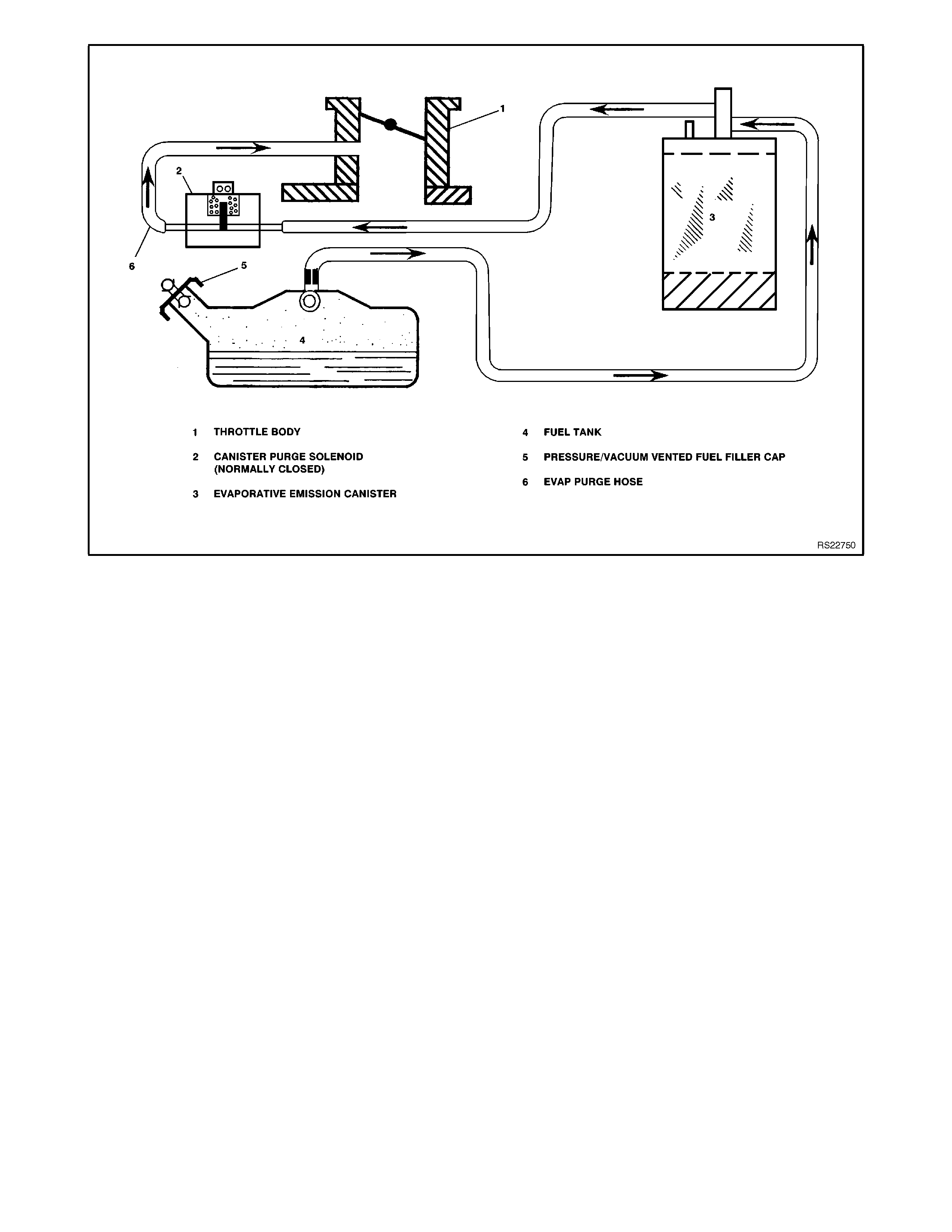
Figure 6C1-1-132 Typical Evaporative Emission Control Schematic
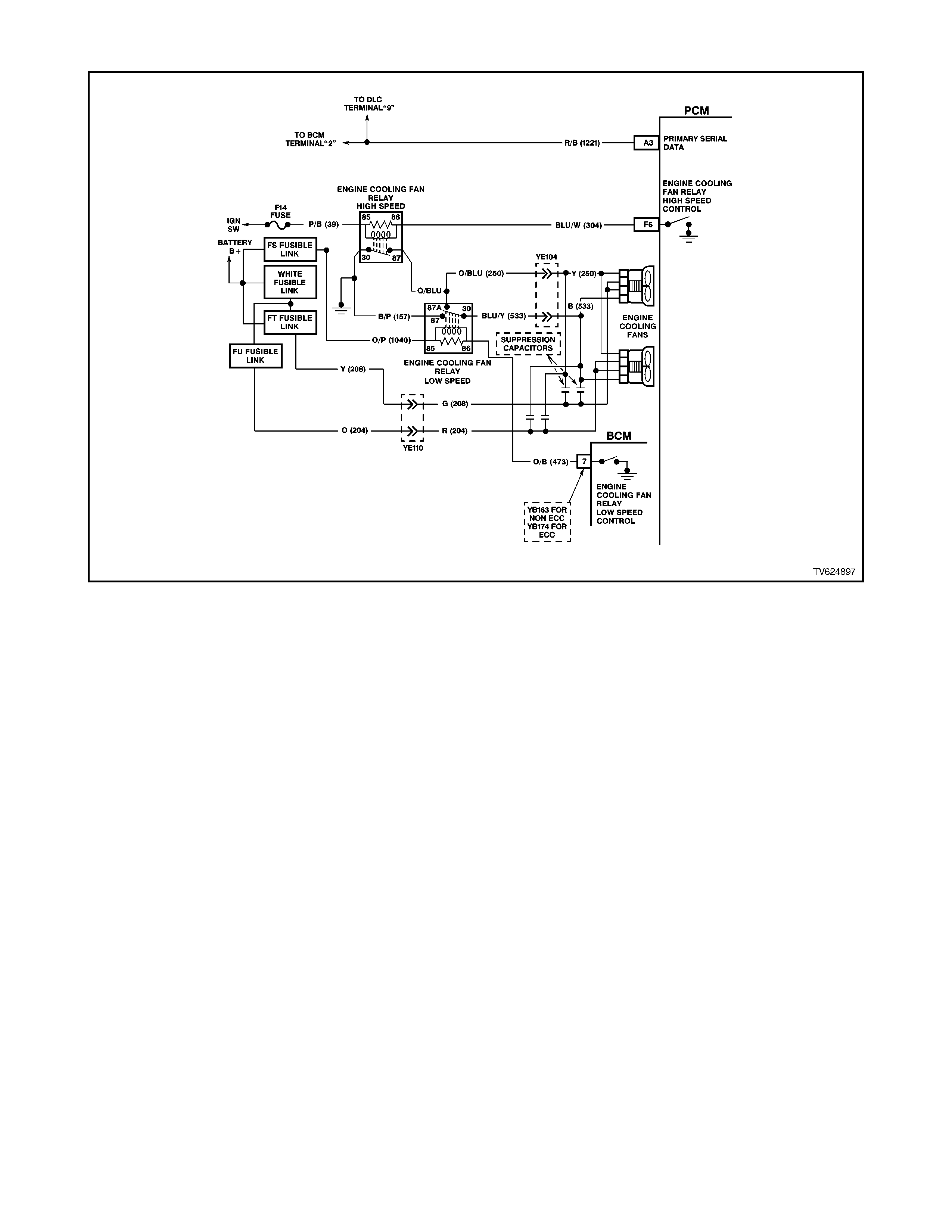
1.11 ELECTRIC COOLING FAN
Figure 6C1-1-133 Cooling Fan Circuit
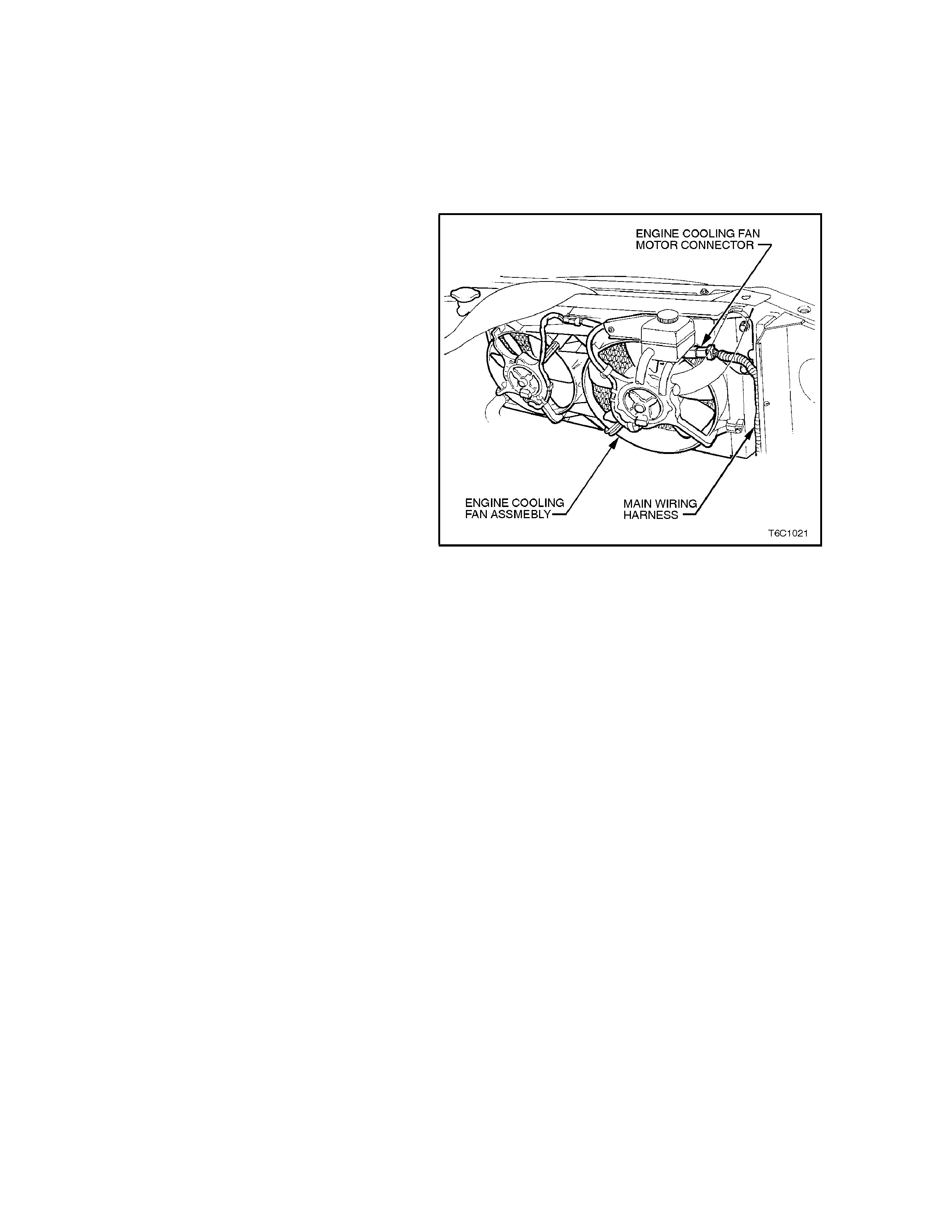
The V6 engine has two, two speed electric engine
cooling fan assembly that provides the primary
means of moving air through the engine radiator.
The two, two speed electric cooling fan are us ed to
cool engine coolant flowing through the radiator.
The two, two speed electric cooling fans are also
used to cool the ref rigerant flowing through the A/C
condenser (if fitted).
The each engine cooling fan motor has four
terminals, two negative and two positive terminals.
The two negative terminals are the relay controlled
circuits for fan operation. T he two positive term inals
are the direct power feed from a fusible link to the
fan motors. When a earth signal is applied to one of
the negative terminals, the fan motor will operate at
low speed. When a earth signal is applied to both
negative terminals, both fan will operate at high
speed.
The engine cooling fan high speed relay is
controlled by the PCM. T he PCM controls the earth
path for the engine cooling fan high speed relay.
The low speed of the electric fan is controlled by
the PCM through a special Data Com munication to
the BCM. The BCM controls the earth path for the
engine cooling fan low speed relay. The engine
cooling fan high speed relay and the engine
cooling fan low speed relay are used to contr ol the
earth signal to the electr ic mo tor that drives the f ive
bladed fan.
The PCM determines operation of the two, two
speed engine cooling fan based on A/C request,
engine coolant temperature, A/C Refrigerant
Pressure Sensor, and vehicle speed signal inputs.
There are also four (4) suppression capacitors
incorporated into the fan motor wiring circuits.
These suppression capacitors help eliminate fan
motor noise through the radio speakers. If these
capacitors are open, then noise will be present
through the radio speak ers. Is shorted to earth, the
fan motors could continuously run, or the fuse or
fusible link could fail.
Figure 6C1-1-134 Engine Cooling Fan Assembly
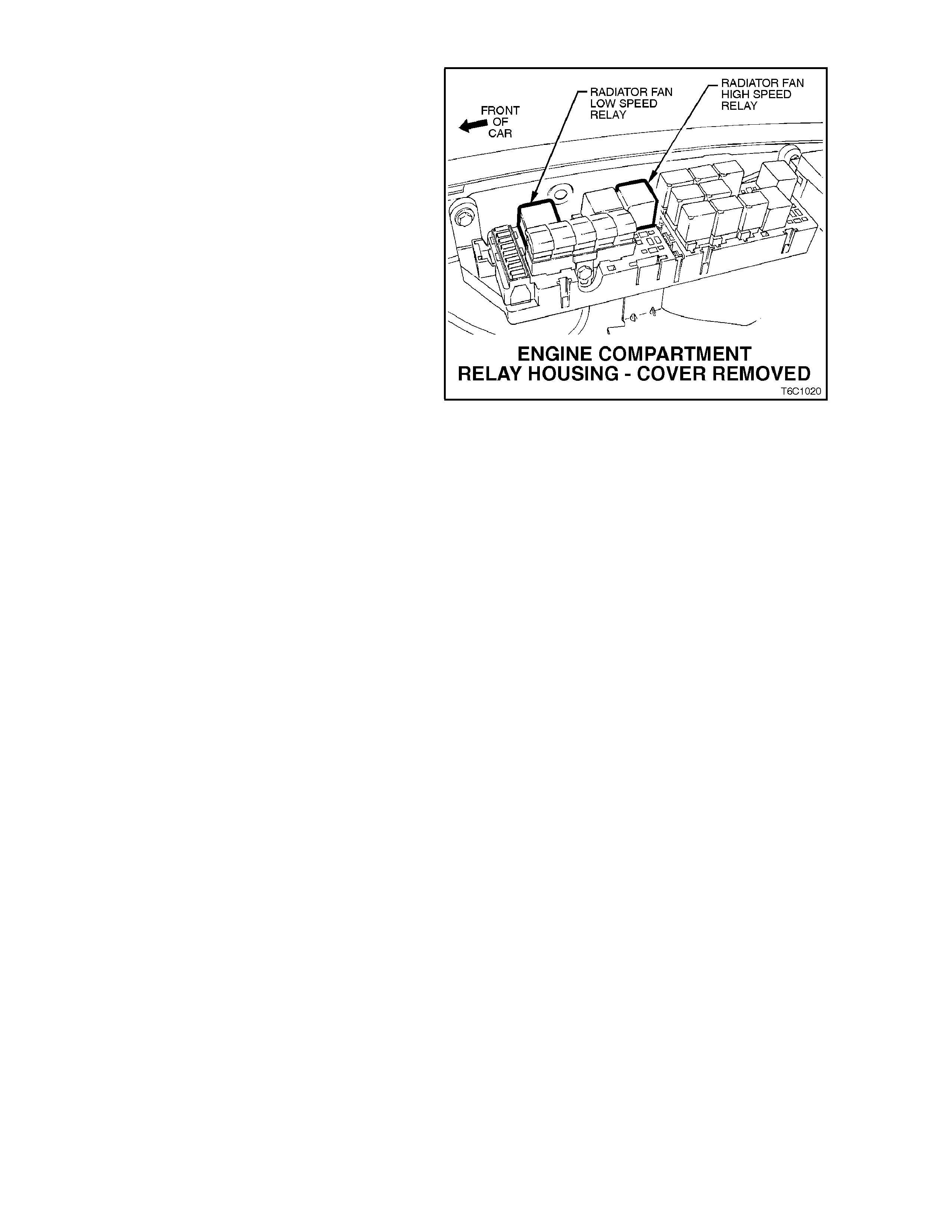
ENGINE COOLING FAN LOW SPEED
The engine cooling fan low speed relay is
energised by the BCM. The PCM determ ines when
to enable the low speed fan based on inputs from
the BCM serial data, Engine Coolant Temperature
(ECT) sensor and the Vehicle Speed Sensor
(VSS). The cooling fan low speed relay will be
turned "ON'' when:
• The A/C request indicated (YES) and either the
vehicle speed is less than 30 km/h
- OR -
• A/C pressure is greater than 1500 kPa
- OR -
• The coolant temperature is greater than 104
degrees C.
If the coolant temperature is greater than 117
degrees C when the ignition is switched off, the
relay is energised for up to approximately 4
minutes.
If an engine coolant temperature sensor fault is
detected, such as DTC 14, 15, 16, 17 or 91.
The cooling fan low speed relay will be turned
"OFF'' when any of the following conditions have
been met:
• The A/C request is not indicated (NO)
• The A/C request is indicated (YES) and the
vehicle speed is greater than 50 km/h and A/C
pressure is less than 1170 kPa.
Figure 6C1-1-135 Cooling Fan Low Speed Relay Location

ENGINE COOLING FAN HIGH SPEED
The engine c ooling f an high s peed relay is controlled by the PCM based on input from the Engine Coolant Tem per atur e
(ECT) sensor. The PCM will only turn "ON'' the engine cooling fan high speed relay fan if the engine cooling fan low
speed relay has been "ON" for 2 seconds and the following conditions are satisfied.
There is a BCM message response fault which will cause a DTC 92
An engine coolant temperature sensor fault is detected such as DTC 14,15,16,17.
Coolant temperature greater than 104 degrees C.
The engine cooling fan high speed relay can also be enabled by the A/C Refrigerant Pressure Sensor. W hen the A/C
Refrigerant Pressure Sensor determines the A/C system pressure is to high, greater than 2600 kPa, and this will
instruct the PCM to enable the high speed fan.
If the low speed f an was "OF F" when the cr iteria was met to tur n the high speed fan "ON", the high s peed f an will come
"ON" 5 seconds after the low speed fan is turned "ON". " If both the engine cooling fan relays are "ON", the PCM will
turn "OFF" the high speed relay when:
The engine coolant temperature is less than 99 degrees C.
A/C request not indicated (NO)
A/C request indicated (YES) and A/C pressure is less than 2300 kPa.

1.12 A/C CLUTCH CONTROL
A/C CLUTCH CONTROL WITH ECC
Figure 6C1-1-136 A/C Clutch Control With ECC
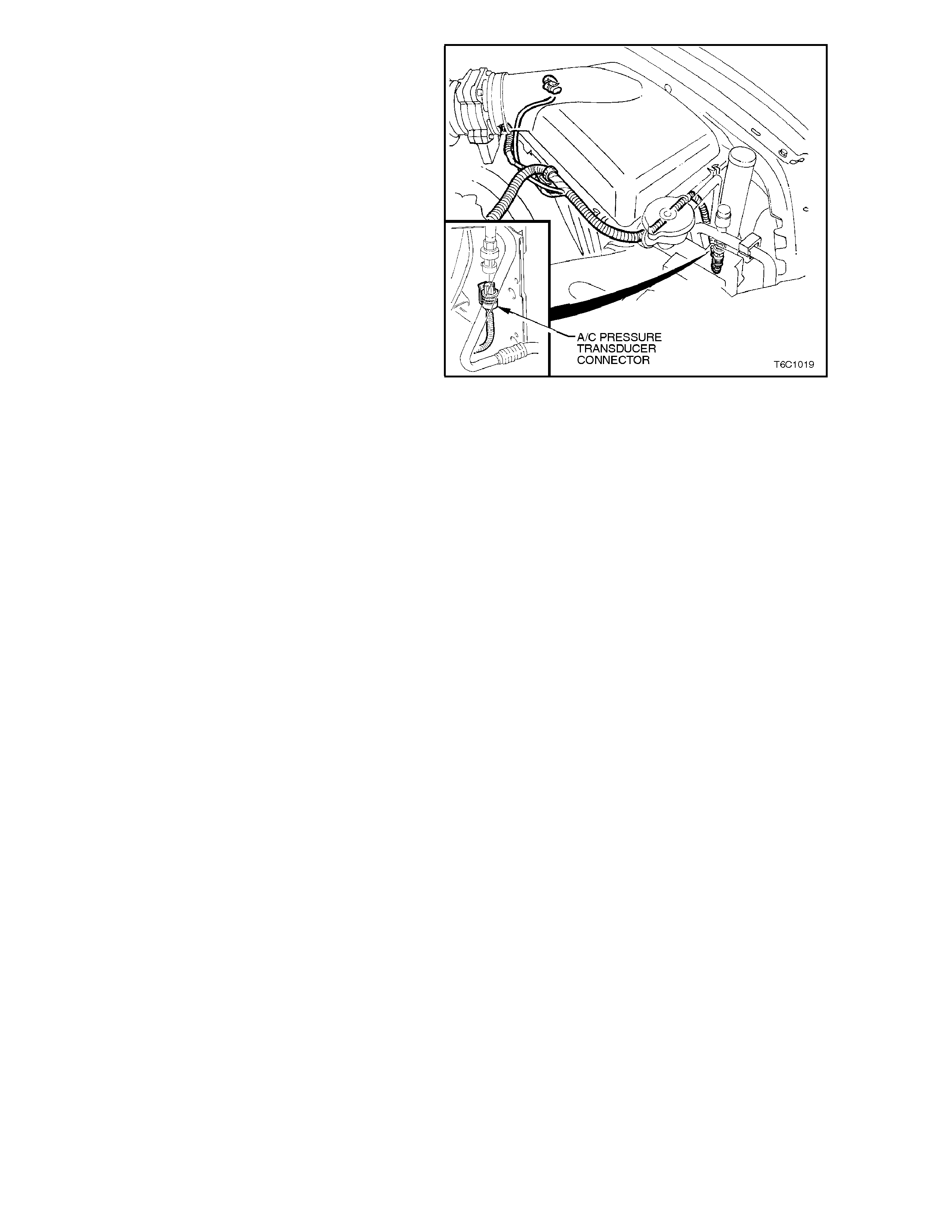
This vehicle uses two types of A/C clutch controls.
One type is standard A/C (Figure 6C1-1-139) and
the other uses a Electronic Climate Control (ECC)
module (Figure 6C1- 1-136).
With the ECC system, when the A/C is requested,
the Electronic Climate Control Module will supply a
signal to the BCM. The BCM will then send a serial
data request to the PCM. W hen the PCM receives
the serial data request on PCM terminal B12, it
indicates that air conditioning has been requested
and approximately 1/2 second after the PCM
receives this signal, it will energise the A/C control
relay. This serial data signal to the PCM is also
used to adjust the idle speed before turning "ON"
the A/C compressor relay. If this signal is not
available to the PCM, the A/C compressor will be
inoperative.
If there is a problem with the PCM A/C Relay
Control circuit, QDSM DTC 91 will set.
The BCM also supplies the earth signal from BCM
terminal "7" to the low speed cooling fan relay.
This A/C system also incorporates a A/C
Refrigerant Pressure Sensor. The A/C Refrigerant
Pressure Sensor signal indicates high side
refrigerant pressure to the PCM. The PCM uses
this infor mation to adj ust the idle air c ontrol valve to
compensate for the higher engine loads present
with high A/C refrigerant pressures. A fault in the
A/C Refrigerant Pressure Sensor signal will cause
DTC 96 to set.
Figure 6C1-1-137 A/C Refrigerant Pressure Sensor
Location
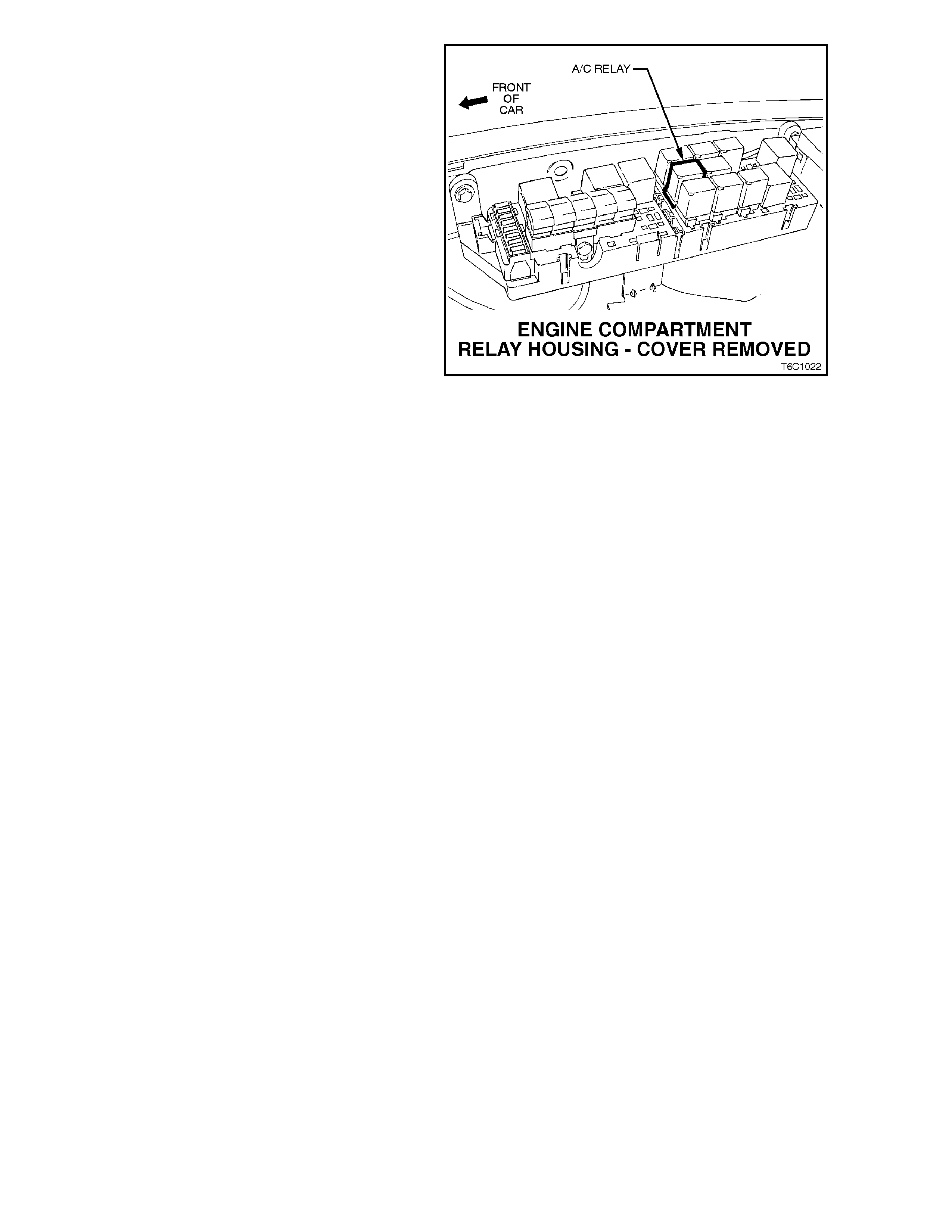
The PCM will NOT energise the A/C control
relay if any of the following conditions are
present:
• RPM more than 5,800. If de-energised because
of RPM, it can re-energised when RPM falls
below 5,400.
• Throttle is more than 99% open. When de-
energised during wide-open throttle, it will be re-
energised when the throttle is less than 93%
open.
On vehicles equipped with non-ECC systems the
power flow is different. With the blower fan
switched "ON", and the air conditioning switched
"ON," switched ignition voltage is supplied from
fuse F13 through the A/C master switch, and then
to the BCM. The BCM will then supply a serial data
signal to the PCM requesting A/C. If the BCM does
not receive a earth s ignal from the blower switch to
BCM terminal "3", the BCM will not supply the serial
data request for A/C. Once the PCM receives this
serial data signal, the PCM will energise the A/C
com pres sor relay. T he BCM also supplies the ear th
signal from BCM terminal "7" to the low speed
cooling fan relay.
This serial data signal to the PCM is also used to
adjust the idle speed before turning "ON" the A/C
compressor relay. If this signal is not available to
the PCM, the A/C compressor will be inoperative.
This system like on the ECC system also
incorporates a A/C Refrigerant Pressure Sensor.
The A/C Refrigerant Pressure Sensor signal
indicates high side r ef riger ant pr ess ur e to the PCM.
The PCM us es this inf orm ation to adj ust the idle air
control valve to compensate for the higher engine
loads present with high A/C refrigerant pressures.
A fault in the A/C Refrigerant Pressure Sensor
signal will cause DTC 96 to set.
Figure 6C1-1-138 A/C Relay Location
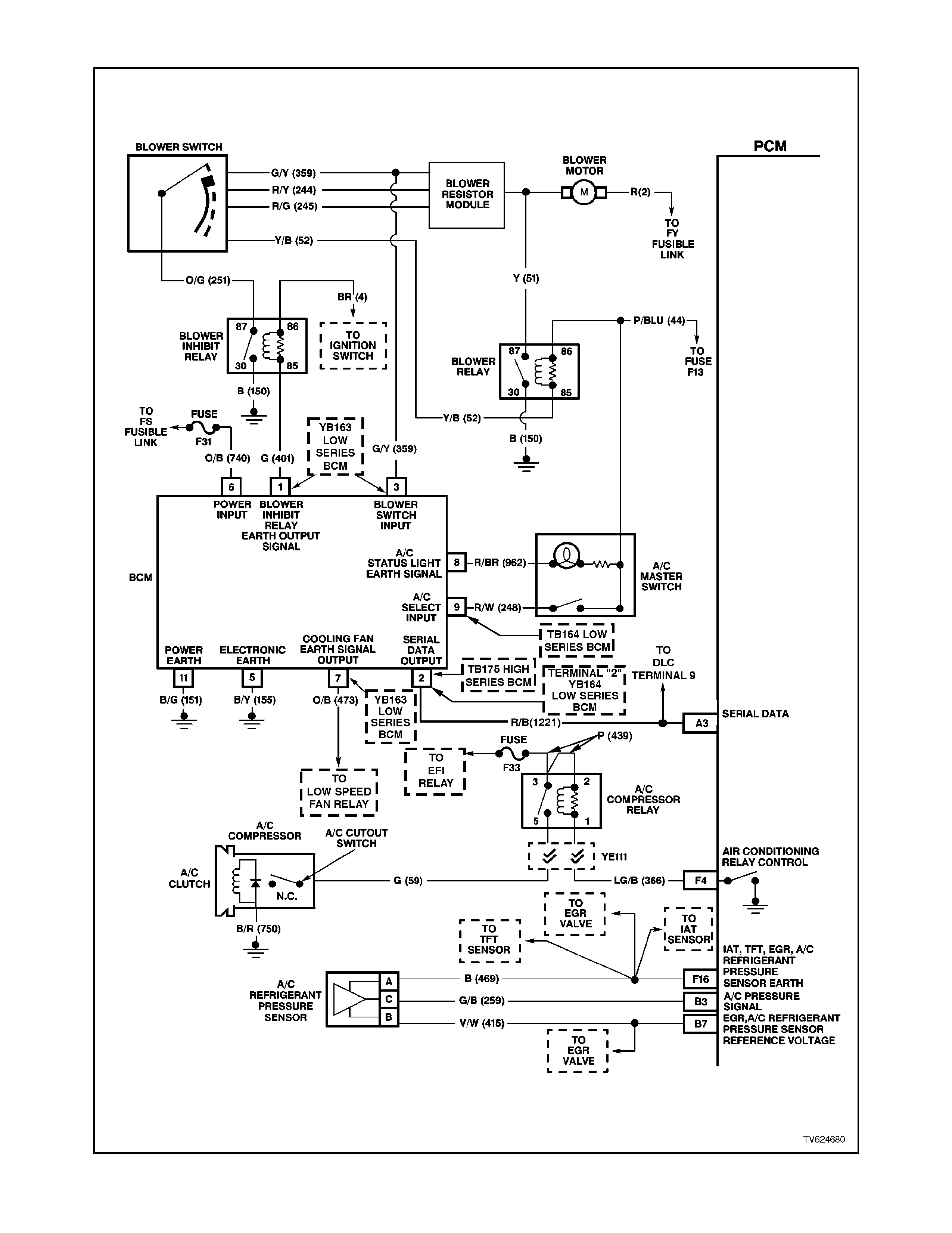
A/C CLUTCH CONTROL WITHOUT ECC
Figure 6C1-1-139 A/C Clutch Control Without ECC

1.13 S UP ERCHARGER SYSTEM
DESCRIPTION
The supercharger is a positive displacement pump that consists of two counter-rotating rotors in a housing with an inlet
port and an outlet port. The rotors are designed with three lobes and a helical twist. An air bypass circuit is built into the
housing. The rotors in the supercharger are designed to run at a minimal clearance, not in contact with each other or
the housing. The rotors ate timed to each other by a pair of precision spur gears which are pressed onto the rotor
shafts. The forward end of the rotors are held in position by deep groove ball bearings. The back end of the rotors are
supported by sealed roller bearings.
The gears and ball bearings are lubricated by a sy nthetic oil. The oil reservoir is self-contained in the supercharger and
does not rely on engine oil for lubrication.
The cover on the supercharger contains the input shaft which is supported by two deep groove ball bearings and is
coupled to the rotor drive gears. The pulley is pressed and keyed onto the input shaft. These bearings are lubricated by
the synthetic oil contained in the same reservoir as the gears and rotor bearings.
SUPERCHARGER OPERATION
The supercharger is designed to pump more air than the engine would normally use. This excess air creates a boost
pressure in the intake manifold. Maximum boost can range from 50 to 80 kPa (7 to 11 P.S.I.). Since the supercharger is
a positive displacement pump and is directly driven from the engine accessory drive system, boost pressure is available
at all driving conditions.
When boost is not desired, such as during idle and light throttle cruising, the excess air that the supercharger is
producing is routed through the bypass passage between the intake manifold and the supercharger inlet. This bypass
circuits regulated by a bypass valve which is similar to a throttle plate. The bypass valve is controlled by a vacuum
actuator which is connected to the vacuum signal between the throttle and the supercharger inlet. Spring force from the
actuator holds the valve closed to create boost and vacuum pulls the valve open when the throttle closes to decrease
boost. The open bypass valve reduces pumping loss thereby increasing fuel efficiency.
The Boost Control Solenoid valve is an electronically controlled valve. This valve, controlled by the PCM, determines
whether pressure from the manifold is routed to the bypass actuator or closed off. The solenoid allows pressure from
the manifold to open the bypass valve and regulate boost pressure during specific driving conditions.
BOOST CONTROL
The boost control system regulates induction boost pressure during rapid deceleration, under very high engine load
situations and anytime reverse gear is selected.
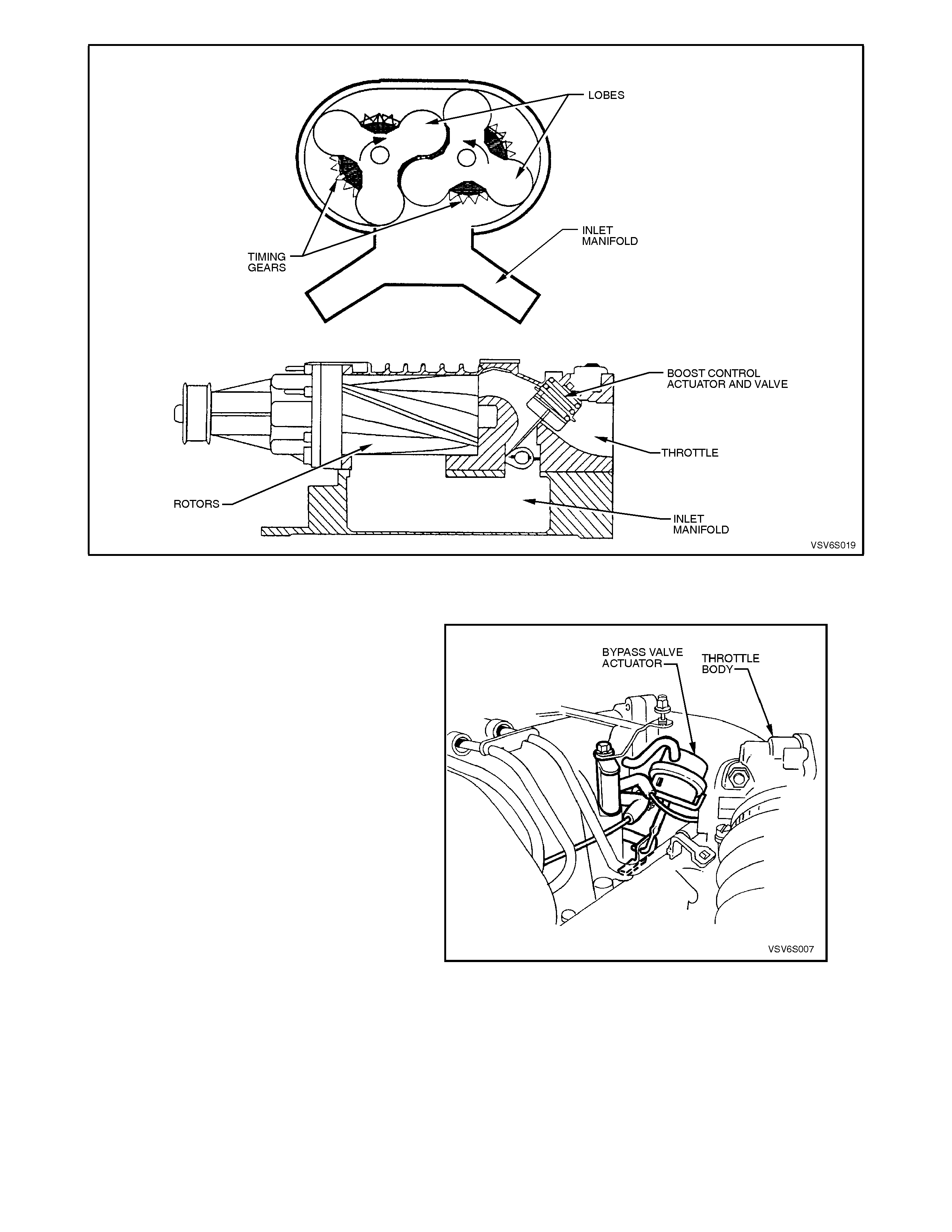
Figure 6C1-1-140 Supercharger Components
OPERATION
Under most conditions, the PCM commands the
Boost Control Solenoid to operate at 100% duty
cycle ("ON"), keeping the solenoid valve closed and
allowing only inlet vacuum to control the position of
the Bypass valve. At idle, full inlet vacuum is
applied to one side of the Bypass Valve Actuator
diaphragm counteracts spring tension to hold the
bypass valve open. As the engine load increases,
reduced vacuum acts upon the spring tension in
the Bypass Valve Actuator, causing the bypass
valve to close and increasing boost pressure.
W hen reduced boost pressure is desired, the PCM
commands the Boost Control Solenoid to operate
at 0% duty cycle ("OFF"). This opens the solenoid
valve and allows boost pressure from the intake
manifold to counteract the spring tension in the
Bypass Valve Actuator, opening the bypass valve
and recirculation excess boost pressure back into
the supercharger inlet. W ith reverse gear selected,
the PCM commands the Boost Control Solenoid to
operate at 0% duty cycle ("OFF") at all times. Figure 6C1-1-141 Bypass Valve Actuator
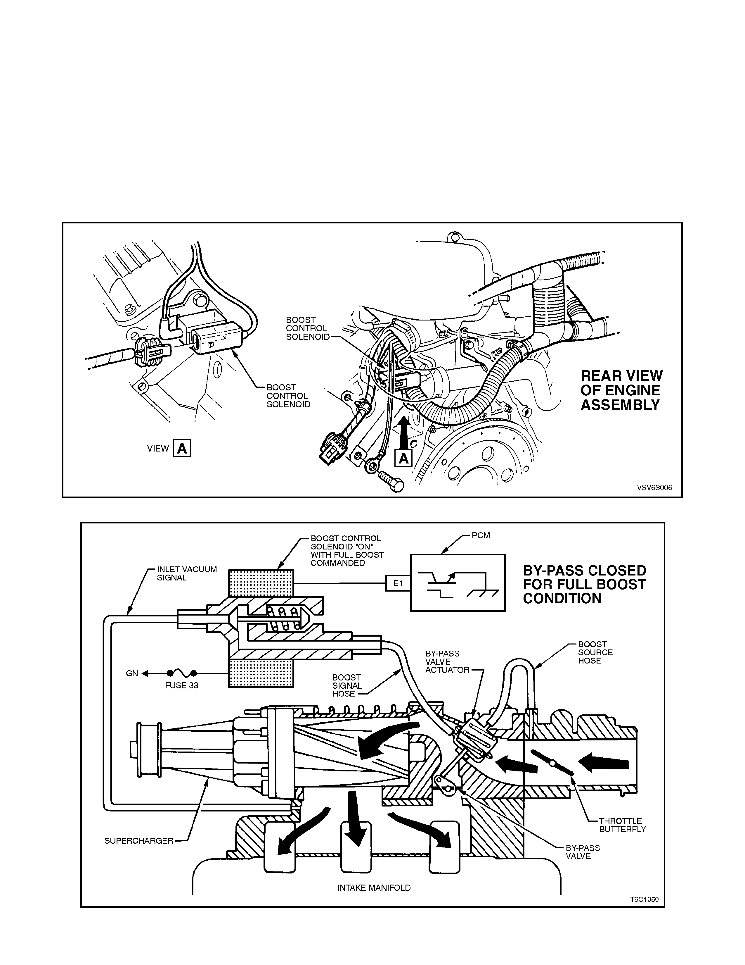
RESULTS OF INCORRECT OPERATION
An open Boost Control Solenoid driver circuit, ignition feed circuit, or Boost Control Solenoid valve stuck open will cause
reduced engine power, especially during wide open throttle operation.
The Boost Control Solenoid driver circuit shorted to earth, Boost Control Solenoid valve stuck closed or a restriction in
the boost source or signal hoses will cause full boost to be commanded at all times and a possible overboost condition
during high engine load situations.
A restriction in the vacuum signal hoses to the Bypass Valve Actuator or a stuck closed bypass valve will cause a rough
idle and reduced fuel economy.
DIAGNOSIS
The boost control system diagnosis is covered in Chart 2-11. For further information on the Supercharger and boost
control system, and on vehicle service, refer to 3.24 SUPERCHARGER SYSTEM.
Figure 6C1-1-142 Boost Control Solenoid Location
Figure 6C1-1-143 Boost Control System (Bypass Closed)
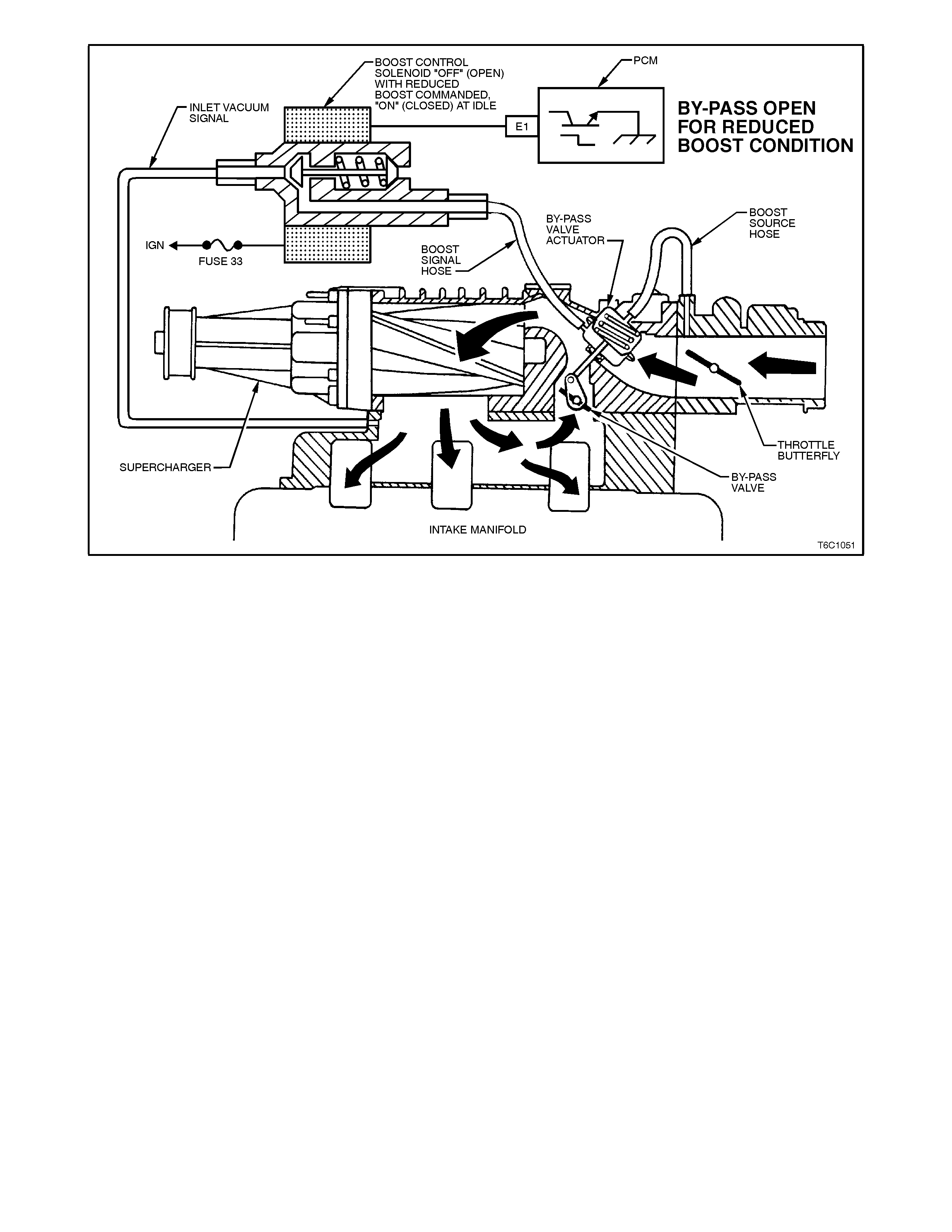
Figure 6C1-1-144 Boost Control System (Bypass Open)
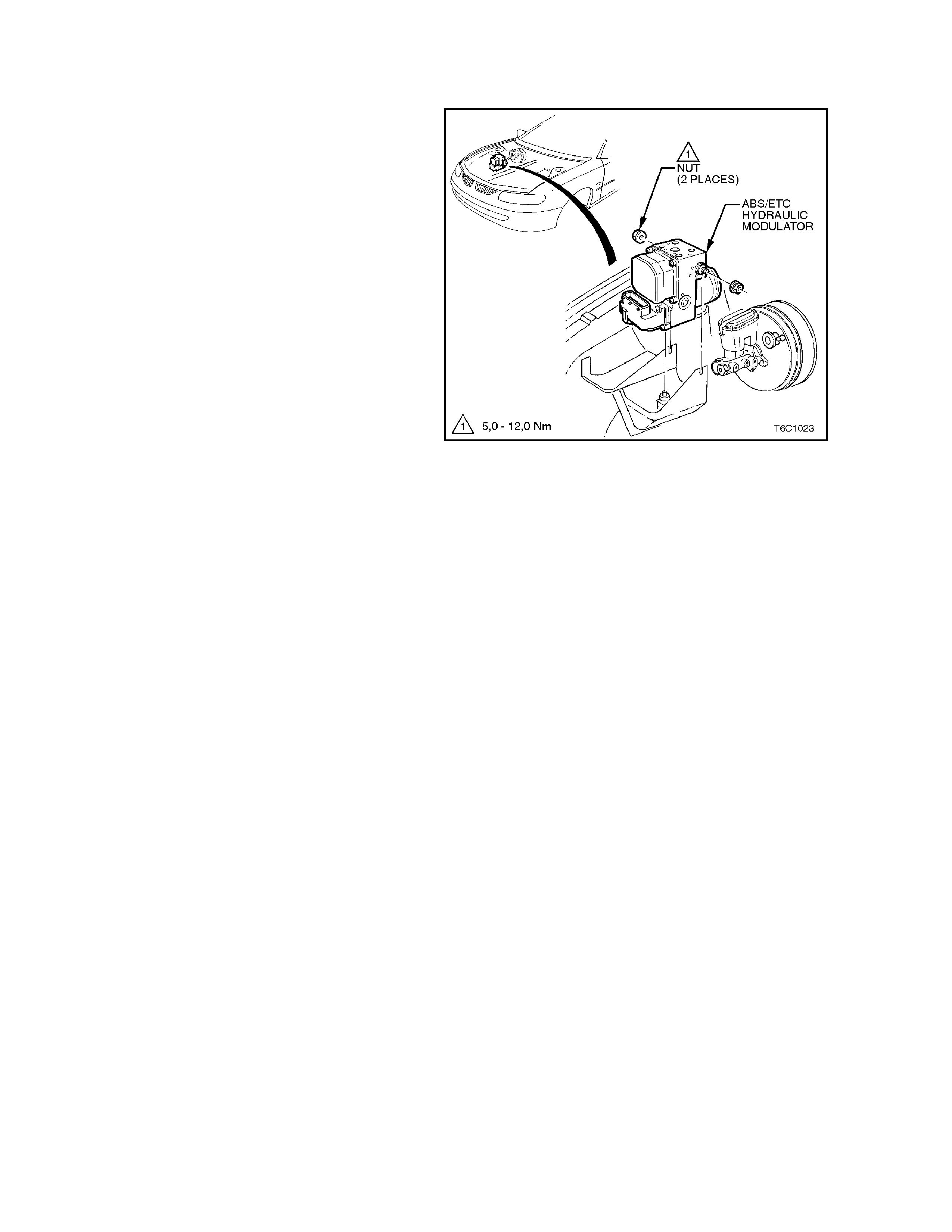
1.14 ELECTRONIC TRACTION CONTROL
PURPOSE
The Electronic Traction Control (ETC) system is
designed to maintain traction and reduce wheel
over spin at the drive wheels on slippery surfaces
during acceleration. This system is designed to
operate at all vehicle speeds and reduces wheel
slip by use of the engine torque management
system and Anti-Lock Brake (ABS) system.
The ABS/ET C module m onitors both front and rear
wheel speeds through the wheel speed sensors. If
at any time during acceleration the ABS/ETC
module detects drive wheel slip, it will request (on
the Torque Request circuit) the Powertrain Control
Module (PCM) to bring exc ess engine torque into a
specific range. This is accomplished via two high
speed Pulse Width Modulated (PWM) circuits
between the ABS/ETC module and the PCM. This
is displayed on the scan tool as a Nm number. T he
PCM will then adjust spark firing and air/fuel ratio,
altering boost duty cycle (Supercharger only), and
shutting "OFF" up to five (5) injectors (if
necessary), and report the modified torque value
(on the Torque Achieved circuit) back to the
ABS/ETC module in the form of a Nm number.
These Nm numbers should match closely when
traction control is being requested. Simultaneous
with engine torque management, the ABS/ETC
module will activate the ABS isolation valves, turn
on the ABS pump motor and s upply brak e pres s ure
to the over spinning wheel(s).
Figure 6C1-1-145 ABS/ETC Module Location

The isolation valves isolate the front brake
hydraulic circuits from the master cylinder and rear
brake hydraulic circuits. Once the rear brake
hydraulic circuits are isolated, pressure can be
applied to the rear wheels without affecting any
other brake hydraulic circuits. The ABS/ETC
module turns on the ABS pump motor to apply
pressure, and begins cycling the ABS assembly's
inlet and outlet valves.
The inlet and outlet valve cycling aids in obtaining
maximum road surface traction in the same
manner as the Anti-Lock Brake mode. The
difference between Electronic Traction Control and
Anti-Lock Brake mode is that brake fluid pressure
is increased to lesson wheel spin (Traction Control
mode), rather then reduced to allow greater wheel
spin (Anti-Lock Brake mode).
If at any time during Traction Control mode, the
brakes are manually applied, the brake switch
signals the ABS/ETC module to disable Traction
Control mode and allow manual braking.
If there is a malfunction with the Torque Request
PWM circuit between the ABS/ET C module and the
PCM, DTC 95 will set. If there is a malf unction with
the Torque Achieved circuit between the ABS/ET C
module and the PCM, a ABS/ECT DTC will set.
For further description on the Anti-Lock Brake
(ABS) system, and Electronic Traction Control
(ETC) system, refer to Section 12L ABS &
ABS/ETC for information on ABS/ETC operation
and DTC diagnosis.

1.15 ABBREVIATIONS AND GLOSSARY OF TERMS
Abbreviations used in this Volume are listed below in alphabetical order with an explanation of the abbreviation.
AC - ALTERNATING CURRENT - A current with varying magnitude.
A/C - AIR CONDITIONING
A/F - AIR/FUEL (A/F RATIO)
ANALOG SIGNAL - An electrical signal that varies in voltage within a given parameter.
BAROMETRIC PRESSURE- Atmospheric pressure. May be called BARO, or barometric absolute pressure.
BATTERY - Stores chemical energy and converts it into electrical energy. Provide DC current for the vehicles electrical
systems.
CAMSHAFT POSITION SENSOR - The PCM uses this signal to determine the position of the No.1 piston in its power
stroke. This signal is used by the PCM to calculate sequential fuel injection mode of operation.
CAT. CONV. - CATALYTIC CONVERTER - A muffler-shaped device fitted in the exhaust system, between the engine
and the muffler. It is the primary "workhorse" of the emission control sy stem, and the PCM's control of the air/fuel ratio
allows it to operate efficiently. It contains platinum, palladium and rhodium. It receives pollutants (HC, CO, and NOx)
emitted by the engine, and through a chemical reaction, converts these harmful pollutants into harmless water vapour,
carbon dioxide, and nitrogen. Maximum conversion efficiency of exhaust emissions is achieved with precise control of
the air/fuel ratio at 14.7-to-1.
CCP - CONVERTER CANISTER PURGE - A PCM controlled solenoid to purge the charcoal canister.
"CHECK POWERTRAIN" LAMP - Warning indicator with the outline of an engine. The "check powertrain lamp" is
located on the instrument panel, and is controlled by the PCM. "Check powertrain lamp" is illuminated by the PCM when
it detects a malfunction in the engine or transmission management system. "Check powertrain lamp" is on and when
the ignition is "ON" with the engine not running (bulb check).
CKT - CIRCUIT
CLOSED LOOP - A fuel control system mode of operation that uses the signal from the exhaust oxygen sensor, in
order to control the air/fuel ratio precisely at a 14.7 to 1 ratio, allowing maximum efficiency of the catalytic converter.
CO - CARBON MONOXIDE - One of the pollutants found in engine exhaust.
DC - DIRECT CURRENT - A current with a constant direction.
DTC - DIAGNOSTIC TROUBLE CODE - The PCM can detect malfunctions in the engine or transmission management
system. If a malfunction occurs, the PCM may turn on the "Check Powertrain" lamp, and a two-digit code number will
set in the PCM's memory. A diagnostic trouble code can be obtained from the PCM through the "Check Powertrain"
lamp, or with the Tech 2 scan tool. This DTC will indicate the area of the malfunction, and properly following the service
diagnostic procedures for the engine management system will locate the source of the problem.
NOTE:
DTC 12 is used to verify that the PCM's diagnostic ability is operational.
DIAGNOSTIC "TEST" ENABLE TERMINAL - A terminal of the Data Link Connector (DLC) earthed to obtain a
Diagnostic Trouble Code by flashing out the MIL "Check Powertrain Lamp".
DIGITAL SIGNAL - An electrical signal that is either one of two states, "ON" or "OFF" with no in between.
DLC - DATA LINK CONNECTOR - The 16 pin connector used at the assembly plant to evaluate the control module
system.
The connector is also used in service to flash the Malfunction Indicator Lamp (MIL) "Check Powertrain Lamp". This
connector is also used by the Tech 2 scan tool to make system checks.
DLC DATA STREAM - An output of the PCM, initiated by the Tech 2 scan tool sending a command to the PCM. This
output is a digital computer language signal, used by assembly plant test equipment and the Tech 2 scan tool. This
signal is transmitted to the data link connector.
DRIVER - An electronic device, usually a power transistor, that operates like a switch; that is, it turns something "ON" or
"OFF."
DUTY CYCLE - The measurement of the length of time, in percentage, that a circuit is "ON" versus "OFF" when
compared with a 100% full ON/OFF time factor.
DVM (10 Meg.) - Digital voltmeter with 10 million ohms per volt impedance - used for voltage and resistance
measurement in electrical/electronic systems.
EECS - EVAPORATIVE EMISSIONS CONTROL SYSTEM - Used to prevent petrol vapours in the fuel tank from
entering the atmosphere. Stores the vapours in a storage canister, located in the engine compartment. Canister
contains activated charcoal, and the vapours are "purged" by engine vacuum during certain operating conditions.
EEPROM - ELECTRICALLY ERASABLE PROGRAMMABLE READ ONLY MEMORY - Ty pe of read only memory
(ROM) that can be electrically programmed, erased and reprogrammed.

EMI OR ELECTRICAL NOISE - An unwanted signal interfering with another needed signal; like an electric razor upsets
a television picture, or driving under high voltage power lines upsets the AM radio in a vehicle.
EGR - EXHAUST GAS RECIRCULATION VALVE - A device that is used to lower Oxides of Nitrogen (NOx) emission
levels by recalculating exhaust gases back into the combustion chamber.
ENGINE COOLANT TEMPERATURE (ECT) SENSOR - Device that senses the engine coolant temperature, and
passes that information to the powertrain control module.
EPROM - ERASABLE PROGRAMMABLE READ ONLY MEMORY - Type of read only memory (ROM) that can be
erased with ultraviolet light and reprogrammed.
ESD - ELECTROSTATIC DISCHARGE - The discharge of static electricity, which has built up on an insulative material.
FIELD SERVICE MODE - A PCM mode of operation that is used during service. It is operational when the engine is
running and the DLC diagnostic "test" enable terminal is earthed.
FUSE - A thin metal strip that melts through when excessive current flows through it, thereby stopping current flow and
protecting a circuit from damage.
HC - HYDROCARBONS - One of the pollutants found in engine exhaust.
HIGH - A voltage more than a specific threshold such as earth or 0. In digital signals, high is "ON" and low is "OFF".
HYSTERESIS - Movement that does not follow the same path as it entered an area as it exits.
IAC - IDLE AIR CONTROL - Installed in the throttle body unit and controlled by the PCM to regulate idle air flow, and
thus idle RPM.
IAT - INTAKE AIR TEMPERATURE SENSOR - Senses intake manifold incoming air temperature, and passes that
information to the PCM.
IDEAL MIXTURE - The air/fuel ratio that provides the best performance, while maintaining maximum conversion of
exhaust emissions, typically 14.7 to 1 on petrol engines.
IGN - IGNITION
INPUTS - Information from sensors (MAF, TPS, etc.) and switches (A/C request, etc.) used by the PCM to determine
how to control it's outputs.
INTERMITTENT - Occurs now and then; not continuously. In electrical circuits, refers to occasional open, short, or
earth.
I.C. - INSTRUMENT CLUSTER
LOW - A voltage less than a specific threshold. Operates the same as an earth and may, or may not, be connected to
chassis earth.
MAF - MASS AIR FLOW SENSOR - A device that monitors the amount of air flow coming in the engine intake. The
MAF sensor sends a signal to the PCM.
MODE - A particular state of operation.
N.C. - NORMALLY CLOSED - Switch contacts that are connected, or together, when no outside forces (temperature,
pressure, position) are applied.
N.O. - NORMALLY OPEN - Switch contacts that are not connected, or not together, when no outside forces
(temperature, pressure, position) are applied.
NOx - NITROGEN OXIDES - One of the pollutants found in engine exhaust.
O2 - OXYGEN
OXYGEN SENSOR - Exhaust gas oxygen sensor, fitted in the exhaust manifold. Senses leftover oxygen after the
combustion process, and produces a very small electrical signal based on the amount of oxygen in the exhaust gas, as
compared to oxygen in the atmosphere.
OPEN LOOP - Describes PCM control of the fuel control system without use of oxygen sensor information.
OUTPUT - Functions, typically solenoids and relays, that are controlled by the PCM.
PCM - POWERTRAIN CONTROL MODULE. A metal cased box (located in passenger compartment) containing
electronic circuitry that electrically monitors and controls the transmission system and emission systems of the engine
management system. It also turns "ON" the "Check Powertrain" lamp when a malfunction occurs in the sy stem.
PCV - POSITIVE CRANKCASE VENTILA TION - Method of reburning crankcase fumes, rather than passing them
directly into the atmosphere.
PFI - PORT FUEL INJECTION - Method of injecting fuel into the engine. Places a fuel injector at each inlet port of a
cylinder head, directly in front of the intake valve, mounted in the intake manifold.
PROM - PROGRAMMABLE READ ONLY MEMORY - an electronic term used to describe the engine calibration unit.
A plug-in memory unit that instructs the PCM how to operate for a particular vehicle.

PULSE WIDTH MODULATED (PWM)- a digital signal turned "ON" and "OFF'" for a percentage of available on-plus-off
cycle time, such as 30% "on" and 70% "off" would be called a 30% "ON" PWM signal.
QUAD DRIVER - A "chip" device in the PCM, capable of operating four separate outputs. Outputs can be either "ON-
OFF" or pulse width modulated.
RAM - RANDOM ACCESS MEMORY - Is the microprocessors "scratch pad". The processor can write into, or read
from this memory as needed. This memory is volatile and needs a constant supply of voltage to be retained. If the
voltage is lost or removed, this memory is lost.
SERIAL DATA - Serial date is a series of rapidly changing voltage signals pulsed from high to low voltage. These
voltage signals are typically 5 volts (high) and 0 volts (low) and are transmitted through a wire often referred to as the
serial data line.
SEQUENTIAL FUEL INJECTION - A mode of injecting fuel into the engine on the intake stroke of each cylinder.
SOLENOID - An electromagnetic coil that creates a magnetic field when current flows through it and causes a plunger
or ball to move.
SUPPRESSION CAPACITORS - These capacitors are connected between the power and earth circuits of the cooling
fan motors. These capacitors are for controlling fan motor noise in the radio.
SWITCH - Opens and closes circuits, thereby stopping or allowing current flow.
TCC - TORQUE CONVERTER CLUTCH - PCM controlled solenoid in automatic transmission that positively couples
the transmission input shaft to the engine.
TECH 2 SCAN TOOL - A hand-held diagnostic tool, containing a microprocessor to interpret the PCM's DLC data
stream. A display panel displays the PCM input signals and output commands.
TP SENSOR - THROTTLE POSITION SENSOR - Device that tells the PCM the current throttle position, and, when it is
moving, the rate of throttle opening / closing.
VACUUM, MANIFOLD - Vacuum source in the engine.
VACUUM, PORTED - Vacuum soured from a small "port" in the throttle body. With the throttle closed, there would be
no vacuum measured, because the port is on the air cleaner side of the throttle blade, and is exposed to engine
vacuum only after the throttle is open.
VSS - VEHICLE SPEED SENDER (Vehicles with Manual Transmission) - Pulse generator mounted in the
transmission. The speedometer circuitry contains an electronic divider circuit that sends a signal to the PCM and, if so
equipped, the body control module or trip computer.
VSS - VEHICLE SPEED SENSOR (Vehicles with Automatic Transmission) - A permanent magnet type sensor
which produces AC voltage which is sent to the PCM to determine vehicle speed.
UART - UNIVERSAL ASYNCHRONOUS RECEIVE AND TRANSMIT - A method of communicating between two
electronic devices.
WOT - WIDE OPEN THROTTLE