
SECTION 6C1-2 DIAGNOSIS - V6 ENGINE
CAUTION
This vehicle will be equipped with a Supplemental Restraint System (SRS). A SRS
will consist of either seat belt pre-ten sioners and a driv er’s side air bag, or seat belt
pre-tensioners and a driver’s and front passenger’s side air bags. Refer to
CAUTIONS, Section 12M, before performing any service operation on or around SRS
components, the steering mechanism or wiring. Failure to follow the CAUTIONS
could result in SRS deployment, resulting in possible personal injury or
unnecessary SRS system repairs.
CAUTION
This vehicle may be equipped with LPG (Liquefied Petroleum Gas). In the interests
of safety, the LPG fuel system should be isolated by turning 'OFF' the manual
service valve and then draining the LPG service lines, before any service work is
carried out on the vehicle. Refer to the LPG leaflet included with the Owner's
Handbook for details or LPG Section 2 for more specific servicing information.
This is where to start all driveability and emissions diagnosis, once you have read and understood
Section 6C1-1, GENERAL INFORMATION. The beginning of Section 6C1-2A DIAGNOSIS CHARTS contains
reference material: wiring diagrams, control module terminal end views and normal voltages, and component
locations. Remember, this information is for reference. Always start diagnosis with "On-Board Diagnostic System
Check". This check first verifies that the diagnostic circuits are operating properly and then sends you to the correct
Section for diagnosis.
If the initial steps in the On-Board Diagnostic System Check reveal a problem, or if the engine does not start, you
will be using one or more "A" charts for diagnosis. Again, the On-Board Diagnostic System Check will send you to
the correct chart. These charts follow the On-Board Diagnostic System check and diagnose both fundamental PCM
diagnostics and problems that prevent the engine from starting.
If the On-Board Diagnostic System Check shows that diagnostic trouble codes have been stored, proceed to the
appropriate Diagnostic Trouble Code (DTC) diagnosis chart which also appear in Section 6C1-2A DIAGNOSIS
CHARTS. If more than one diagnostic trouble code has been stored, always start diagnostic trouble code diagnosis
with the lowest diagnostic trouble code number and work upward. Diagnostic trouble code diagnosis charts start
immediately after the "A" chart.
DIAGNOSTIC PRECAUTIONS
The following requirements must be observed when working on vehicles:
1. Before removing any PCM system component, disconnect the battery earth lead.
2. Never start the engine without the battery being solidly connected.
3. Never separate the battery from the on board electrical system while the engine is running.
4. When charging the battery, disconnect it from the vehicle's electrical system.
5. Never subject the PCM to temperatures above 80 degrees C i.e. paint oven. Always remove control unit first if
this temperature is to be exceeded.
6. Ensure that all cable harness plugs are connected solidly and that battery terminals are thoroughly clean.
7. The engine and transmission management system harness connectors are designed to fit in only one way;
there are indexing tabs and slots on both halves of the connector. Forcing the connector into place is not
necessary if it is being installed with the proper orientation. Failure to take care to match the indexing tabs and
slots to ensure the connector is being installed correctly can cause damage to the connector, the module, or
other vehicle components or systems.
8. Never connect or disconnect cable harness plug at the PCM when the ignition is switched "ON."
9. Before attempting any electric arc welding on the vehicle, disconnect the battery leads and the PCM
connectors.
10. When steam cleaning engines, do not direct the steam cleaning nozzle at PCM system components. If this
happens, corrosion of the terminals can take place.
11. Use only the test equipment specified in the diagnostic charts, since other test equipment may either give
incorrect results or damage good components.
12. All voltage measurements using a voltmeter must use a digital voltmeter with an internal impedance rating of at
least 10 million ohms per volt (10 megaohms)
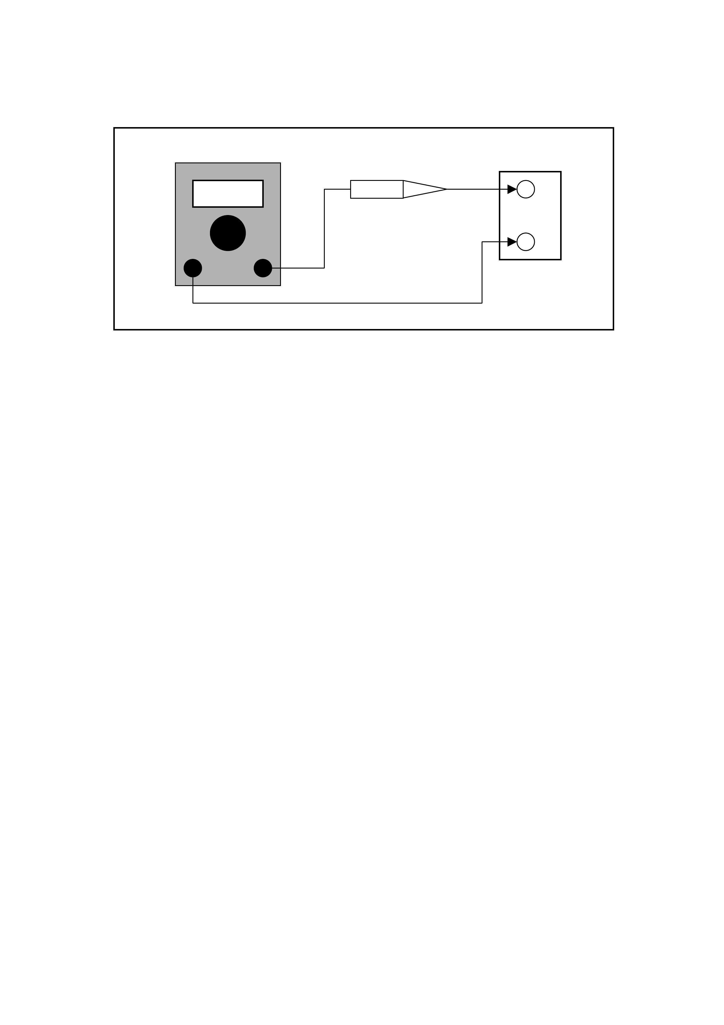
13. When a test light is specified, a "low-power" test light must be used. Do not use a high - wattage test light.
While a particular brand of test light is not suggested, a simple test on any test light will ensure it to be OK for
PCM circuit testing. Connect an accurate ammeter (such as the high-impedance digital multimeter) in series
with the test light being tested, and power the test light-ammeter circuit with the vehicle battery.
If the ammeter indicates less than 3/10 amp current flow (0.3 A or 300 ma), the test light is OK to use.
If the ammeter indicates more than 3/10 amp current flow (0.3 A or 300 ma), the test light is NOT OK to use.
DC AMPS +
-
BATTERY
TEST LIGHT

BLOCKING DRIVE WHEELS
The vehicle drive wheels always should be blocked and parking brake firmly set while checking the system.

VISUAL/PHYSICAL INSPECTION
A careful visual and physical inspection must be performe d as part of any diagnostic procedure or in
finding the cause of an emissions test failure.
This can often lead to fixing a problem without further steps. Inspect all electrical wires for correct routing, pinches,
cuts, or disconnection’s. Be sure to inspect wires that are difficult to see beneath the air cleaner, compressor,
generator, etc. Inspect all the wires in the engine compartment for proper connections, burned or chafed spots,
pinched wires, or contact with sharp edges or hot exhaust manifolds. This visual/phy sical inspection is very
important. It must be done carefully and thoroughly.

BASIC KNOWLEDGE AND TOOLS REQUIRED
To use this CD-ROM most effectively, a general understanding of basic electrical circuits and circuit testing tools is
required. You should be familiar with wiring diagrams, the meaning of voltage, ohms, amps, the basic theories of
electricity, and understand what happens in an open or shorted wire.
To perform sy stem diagnosis, the use of a Tech 2 scan tool is required. A test light, digital volt-ohmmeter with 10
megohms impedance, vacuum gauge, and jumper wires are also required. Please become acquainted with the
tools and their use before attempting to diagnose a vehicle. Special tools which are required for system service and
the ones described above are illustrated in Section 6C1-6 SPECIAL TOOLS .
ELECTROSTATIC DISCHARGE DAMAGE
Electronic components used in control systems are often designed to carry very low voltage, and are very
susceptible to damage caused by electrostatic discharge. It is possible for less than 100 volts of static electricity to
cause damage to some electronic components. By comparison, it takes as much as 4,000 volts for a person to
even feel the zap of a static discharge.
There are several ways for a person to become statically charged. The most common methods of charging are by
friction and by induction. An example of charging by friction is a person sliding across a car seat, in which a charge
of as much as 25,000 volts can build up.
Charging by induction occurs when a person with well insulated shoes stands near a highly charged object and
momentarily touches earth. Charges of the same polarity are drained off, leaving the person highly charged with the
opposite polarity. Static charges of either type can cause damage, therefore, it is important to use care when
handling and testing electronic components.
NOTE:
To prevent possible Electrostatic Discharge damage:
• Do Not touch the PCM connector pins or soldered components on the PCM circuit board.
• When handling a PROM, Do Not touch the component leads, and Do Not remove integrated circuit from carrier.

DIAGNOSTIC INFORMATION
The diagnostic charts and functional checks in this CD-ROM are designed to locate a faulty circuit or component
through logic based on the process of elimination. The charts are prepared with the requirement that the vehicle
functioned correctly at the time of assembly, that there are no multiple failures and that the problem currently exists.
The PCM performs a continual self-diagnosis on certain control functions. This diagnostic capability is
complemented by the diagnostic procedures contained in this CD-ROM. The PCM's language for communicating
the source of a malfunction is a system of Diagnostic Trouble Codes (DTCs). The diagnostic trouble codes are two
digit numbers that range from 12 to 97. When a malfunction is detected by the PCM, a diagnostic trouble code is
set and the Malfunction Indicator Lamp (MIL) "Check Powertrain" lamp is illuminated.
SELF-DIAGNOSTICS
The PCM performs system self diagnostics, and can detect and often isolate system failures. When a failure is
detected, the PCM sets a DTC that represents that failure, or it may turn "ON" the "Check Powertrain" Lamp.
MALFUNCTION INDICATOR LAMP (MIL) "CHECK POWERTRAIN" LAMP
This lamp is on the instrument panel and has the following functions.
• It is used as a bulb check, it will come "ON" with ignition "ON" and engine "OFF."
• It informs the driver that a problem has occurred and that the vehicle should be taken for service as soon as
reasonably possible.
• It displays Diagnostic Trouble Codes stored by the PCM by earthing a terminal in the Data Link Connector which
helps the technician diagnose system problems.
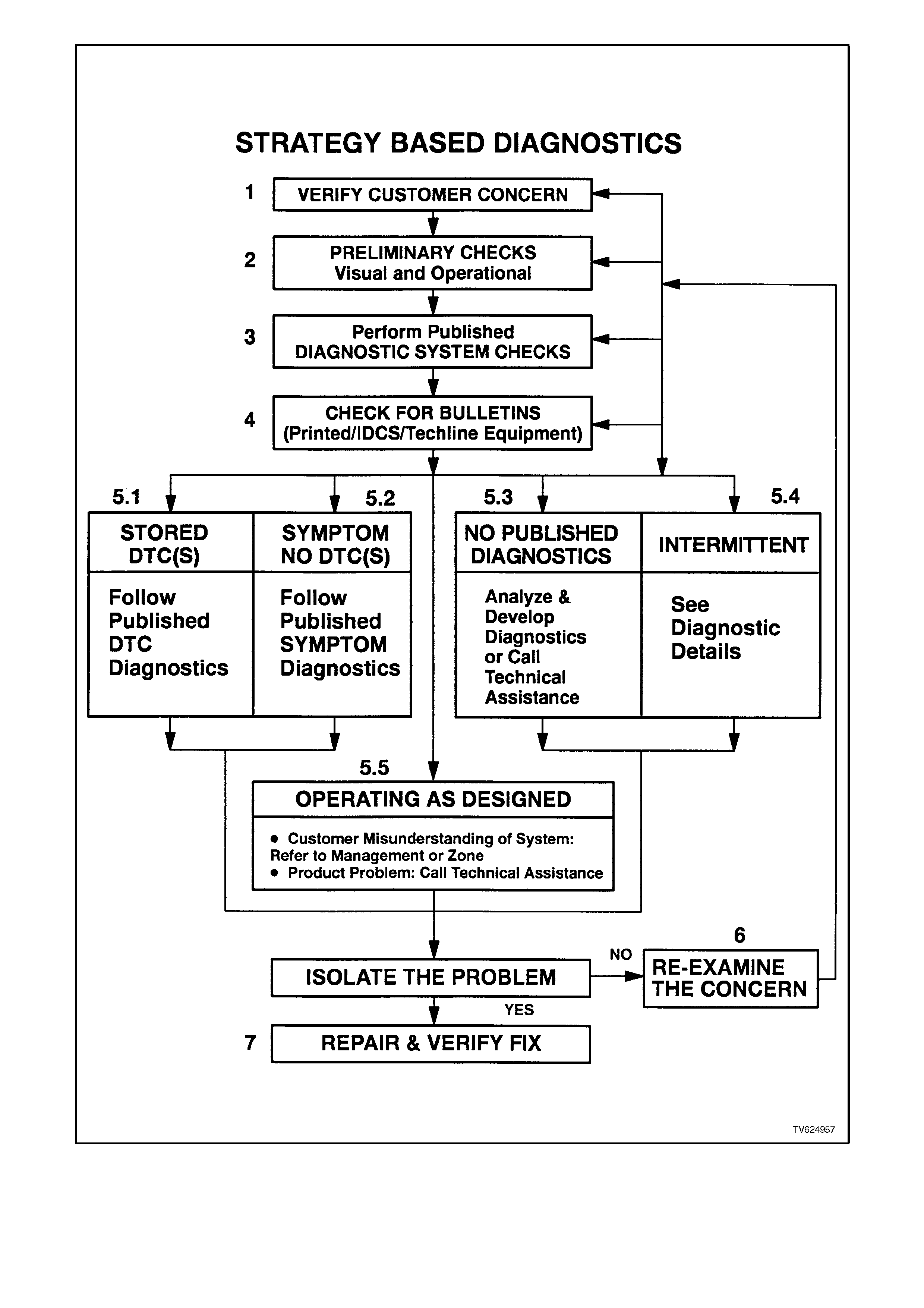
Figure 6C1-2-1 Strategy Based Diagnostic
As a bulb and system check, the Malfunction
Indicator Lamp (MIL) "Check Powertrain" lamp will
come "ON" with the ignition "ON" and the engine
not running. When the engine is started, the (MIL)
"Check Powertrain" lamp will turn "OFF." Not all
DTC's will enable the "Check Powertrain" Lamp. If
the (MIL) "Check Powertrain" lamp remains "ON,"
the self -diagnostic system has detected a problem.
If the problem goes away, the (MIL) "Check
Powertrain" lamp will go out in most cases after 10
seconds, but a diagnostic trouble code will remain
stored in the PCM.
W hen the (MIL) "Check Powertrain" lamp r emains
"ON" while the engine is running, or when a
malfunction is suspected due to a driveability or
emissions problem, a "On-Board Diagnostic
System Check" must be performed. The
procedures for these checks are given in
Section 6C1-2A DIAGNOSIS CHARTS. These
checks will expose malfunctions which may not be
detected if other diagnostics are performed
prematurely.
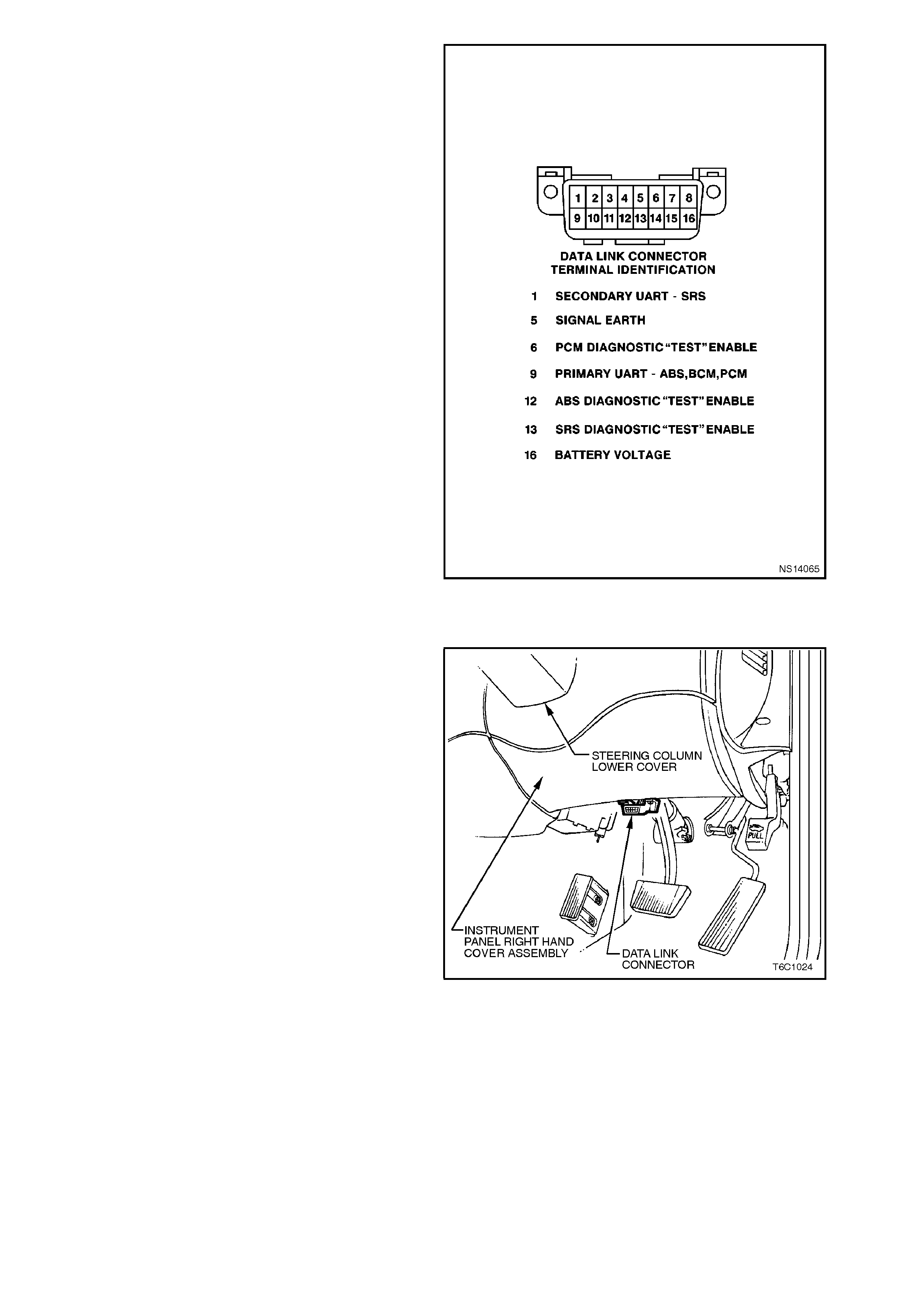
Figure 6C1-2-2 Data Link Connector (DLC)
INTERMITTENT (MIL) "CHECK POWERTRAIN" LAMP
In the case of an "intermittent" problem, the (MIL)
"Check Powertrain" lamp may light for ten (10)
seconds and then will go out. However, the
corresponding diagnostic trouble code will be
stored in the memory of the PCM. The DTC will
remain stored in the DTC history memory until the
Tech 2 scan tool erases it. When unexpected
diagnostic trouble codes appear during the
diagnostic trouble code reading process, one can
assume that these diagnostic trouble codes were
set by an intermittent malfunction and could be
helpful in diagnosing the system.
An intermittent diagnostic trouble code m ay or may
not re-set. If it is an intermittent failure, a Diagnos tic
Trouble Code Chart is not used. Consult the
"Diagnostic Aids" above the diagnostic chart
corresponding to the intermittent diagnostic trouble
code. The "Symptoms" section also covers the
topic of "Intermittents." A physical inspection of the
applicable sub-system most often will resolve the
problem. The Tech 2 scan tool also has several
features which can help with diagnosing
intermittents, such as "DTC History" and the
"Wiring Harness" integrity test.
Figure 6C1-2-3 Data Link Connector (DLC) Location

CURRENT DIAGNOSTIC TROUBLE CODES
A current diagnostic trouble code is one that is set in the vehicle at this time. The current diagnostic trouble code
can be flashed out on the "Check Powertrain" lamp by earthing the data link connector terminal "6". The diagnostic
trouble code can also be displayed on the Tech 2 scan tool by pressing the appropriate button at the appropriate
menu. When the diagnostic trouble code is displayed, a code descriptor will also be listed on the Tech 2 scan tool
screen. Use of the proper diagnostic trouble code chart will find the cause of the problem.

HISTORY DIAGNOSTIC TROUBLE CODE
A history Diagnostic Trouble Code (DTC) is one that was a current trouble code at some point previously, however,
the fault that caused the diagnostic trouble code to be logged is no longer present. The way to identify whether a
DTC is current or history is to look at the DTC history information parameter "IGN CYCLES" the number is 0 the
DTC is current, any other number means it's a history DTC. The history diagnostic trouble code can be flashed out
on the "Check Powertrain" lamp by earthing the data link connector terminal "6". The diagnostic trouble code can
also be displayed on the Tech 2 scan tool by pressing the proper button at the appropriate menu. Use of the
diagnostic trouble code charts to find the cause of the problem for the history diagnostic trouble code may lead to
replacement of good components. Whenever a history code is set refer to Section 6C1-2B SYMPTOMS section
and also look at the "Diagnostic Aids" listed above the diagnostic trouble codes for criteria to set the DTC. History
diagnostic trouble codes are usually caused by intermittent conditions.
HOW DTC HISTORY WORKS
When a DTC is set, up to ten (10) parameters will always be stored with it. The first four (4) parameters are:
1 Times occurred - number (#) of DTC occurrences.
2. "Ignition cycles" - since DTC last appeared.
3. "Engine speed" - RPM when DTC set and,
4. "Times from start" - how long the engine had been running when the DTC set.
Depending upon the DTC, up to 6 additional parameters that are related to this specific DTCs are also stored, for
example, if DTC 22 TP sensor signal voltage high were set, the variable parameters would be: TPS voltage, mass
air flow, battery voltage, reference voltage and RH LTFT.
HOW TO USE DTC HISTORY CODE INFORMA TION
Based upon this information that is stored in DTC history information, the technician can obtain the DTC criteria
when the DTC set and should be able to get the DTC to become current again by repeating the criteria.
READING DTC'S
The provision for communicating with the PCM is the Data Link Connector (DLC). It is attached to the instrument
panel lower right hand trim, directly beneath the steering column. It is used in the assembly plant to receive
information in checking that the engine and transmission are operating properly before they leave the plant. The
diagnostic trouble code(s) stored in the PCM's memory can be read either through a Tech 2 scan tool, (a handheld
diagnostic scanner plugged into the DLC), or by counting the number of flashes of the (MIL) "Check Powertrain"
lamp when the diagnostic "test" terminal of the DLC is earthed. The DLC terminal "6" (diagnostic "test" terminal) is
the sixth terminal from the right of the DLC top row. The diagnostic "test" terminal is most easily earthed by
connecting it to terminal "5" (internal PCM earth). The terminal "5" is to the left of terminal "6" on the top row of the
DLC.
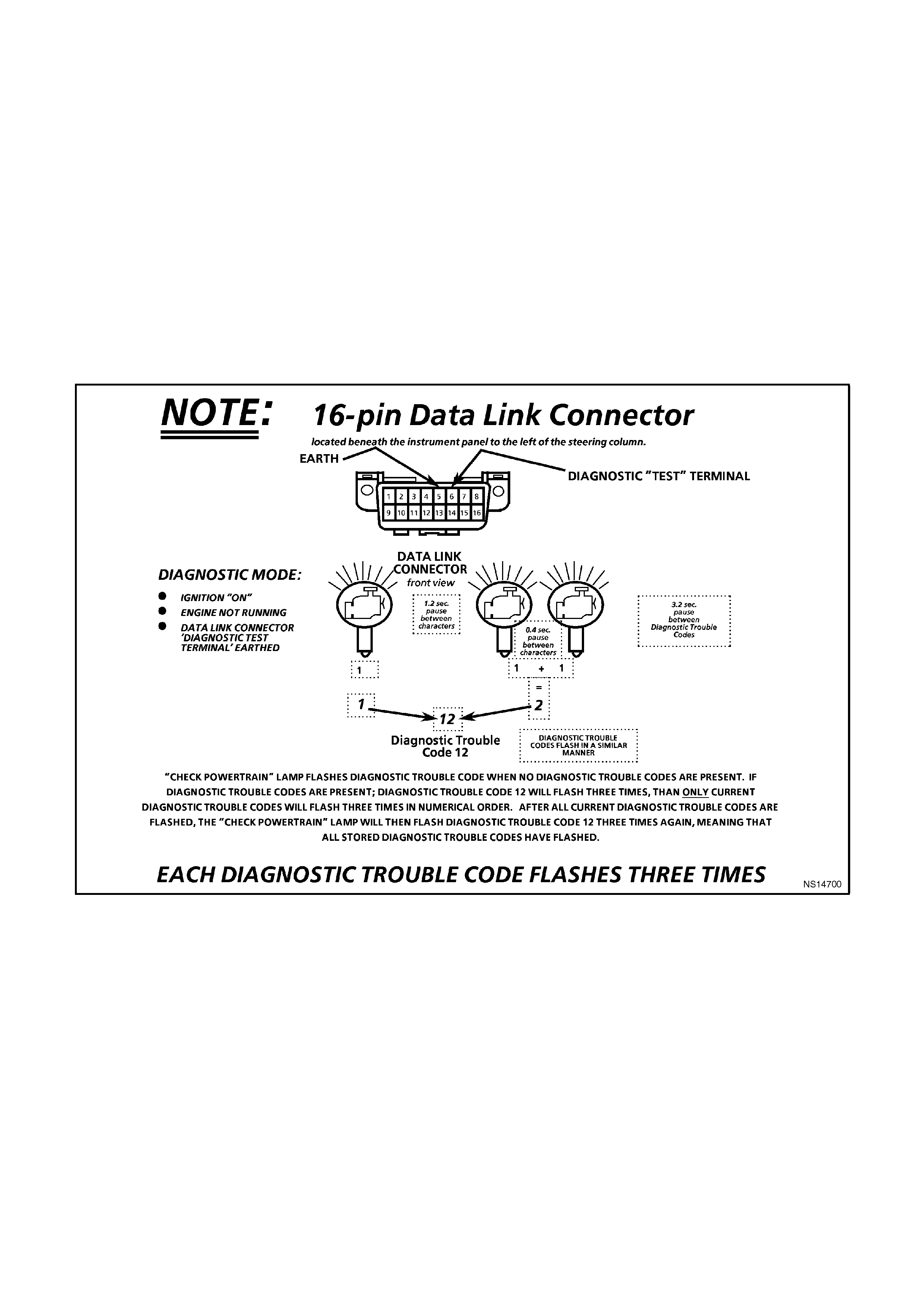
Once terminals "5" and "6" have been connected, the ignition switch must be moved to the "ON" position, with the
engine not running. At this point, the (MIL) "Check Powertrain" lamp should flash Diagnostic Trouble Code 12 three
times consecutively. This would be the following flash sequence: "flash, pause, flash flash, long pause, flash, pause,
flash-flash, long pause, flash, pause, flash flash." Diagnostic Trouble Code 12 indicates that are no reference
pulses coming to the PCM and that the PCM's diagnostic system is operating. If Diagnostic Trouble Code 12 is not
indicated, a problem is present within the diagnostic system itself, and should be addressed by consulting the "On
Board Diagnostic System Check" chart in this section.
Following the output of Diagnostic Trouble Code 12, the (MIL) "Check Powertrain" lamp will indicate a diagnostic
trouble code three times if a diagnostic trouble code is present, or it will simply continue to output Diagnostic
Trouble Code 12. If more than one diagnostic trouble code has been stored in the PCM's memory, the diagnostic
trouble codes will be output from the lowest to the highest, with each diagnostic trouble code being displayed three
times.

CLEARING DTCS
To clear the current diagnostic trouble code from the memory of the PCM, either to determine if the malfunction will
occur again or because repair has been completed, the PCM power feed must be disconnected for at least ten (10)
seconds. The PCM power feed can be disconnected by turning the ignition "OFF" and disconnecting the positive
battery terminal. The Tech 2 scan tool has a special mode that must be used to clear both history and current
diagnostic trouble codes.
NOTE:
To prevent PCM damage, the ignition must be "OFF" when disconnecting or reconnecting PCM power.
CLEARING DTC HISTORY
The Tech 2 scan tool is the only tool capable of clearing the DTC history. Disconnecting the battery or removing
fuse F31 will not erase DTC history, the Tech 2 scan tool sends a special message into the PCM to erase this
memory.
IGNITION CYCLE DEFAULT
If the ignition is cycled ("OFF" and "ON") 50 times without a particular fault reappearing, that DTC will be erased
from PCM memory and the ignition cycle counter in the PCM will be reset to zero.
PCM SLEEP TEST
After the ignition switch is turned "OFF," the PCM will continue to operate for several seconds. During this shut
down, the PCM will return the IAC back to a position to be used on the next startup, de-energizing all the solenoids
and relays, then the PCM will "go to sleep". The PCM can be checked for this sleep test by monitoring the voltage of
DLC terminal "6" it should go from 5 volts to 0 volts. The Tech 2 scan tool will display updated data until the sleep
mode is activated then the PCM will no longer send out serial data and the Tech 2 scan tool will display DLC DATA
LOST
DIAGNOSTIC MODE
When the diagnostic "test" terminal is earthed with the ignition "ON" and the engine stopped, the system will enter
what is called the Diagnostic Mode. In this mode the PCM will:
1. Display a Diagnostic Trouble Code 12 by flashing the (MIL) "Check Powertrain" lamp (indicating the system is
operating correctly).
2. Display any stored diagnostic trouble codes by flashing the (MIL) "Check Powertrain" lamp. Each code will be
flashed three times, then Diagnostic Trouble Code 12 will be flashed again.
FIELD SERVICE MODE
If the diagnostic "test" terminal is earthed with the engine running, the system will enter the Field Service mode. In
this mode, the (MIL) "Check Powertrain" lamp will flash once per second and ignition timing will be fixed."
While the system is in Field Service Mode, new DTCs cannot be stored in the PCM.
PCM LEARNING ABILITY
The PCM has a "learning" ability which allows it to make corrections for minor variations in the engine or
transmission system to improve driveability.
TRANSMISSION ADAPT FUNCTION
The HYDRA-MATIC 4L60-E uses a feedback line pressure control system which has the ability to adapt the
system's line pressure to compensate for normal wear of clutch fiber plates, seals, springs, etc. This "learning"
feature is similar to what is used for engine fuel control, short term fuel correction, long term fuel trim.
The HYDRA-MATIC 4L60-E transmission only uses the adapt function for the 1-2 upshift. The PCM monitors
engine speed to determine if the shift is occurring too fast (harsh) or too slow (soft) and adjust the pressure control
solenoid to maintain the correct shift feel. The line pressure can adapt to values ranging from 35 kPa below, to 70
kPa above normal line pressure.
If the battery is disconnected, to clear diagnostic trouble codes or for other repair, the "learning" process resets and
begins again. A change may be noted in the vehicle's performance. To "teach" the vehicle, reset the IAC valve and
ensure that the engine is at operating temperature. The vehicle should be driven at part throttle, with moderate
acceleration and idle conditions until normal performance returns.

ON-BOARD DIAGNOSTIC SYSTEM CHECK
After the visual/physical underhood inspection, the "On-Board Diagnostic System Check" is the starting point for all
diagnostic procedures or finding the cause of an emissions test failure.
All Diagnostic procedures must always begin with the "On-board Diagnostic System Check".
Diagnostic procedures must begin with the "On-Board Diagnostic System Check," which represents an organized
approach for identifying system problems.
The "ON-BOARD DIAGNOSTIC SYSTEM CHECK" makes an initial check of the system, then will direct the
technician to other charts in this Section. It must be used as a starting point for all procedures. The entire section is
set up in a specific order, that is, the "ON-BOARD DIAGNOSTIC SYSTEM CHECK" will lead the technician to other
charts, and those charts may lead to still other charts. THE SEQUENCE MUST BE FOLLOWED. The
engine/transmission control system uses many input signals and controls many output functions. If the correct
diagnostic sequence is not followed, incorrect diagnosis and replacement of good parts may happen.
Diagnostic charts incorporate diagnosis procedures using a Tech 2 scan tool where possible. This Tech 2 scan tool
is a small hand-held computer in itself. Its job is to give information to a technician about what is happening in the
engine/transmission management system.
The Data Link Connector (DLC) is used by the assembly plant to perform end of line tests. This connector can also
be used by technician to monitor certain inputs and output as seen by the electronic control module. The Tech 2
scan tool reads and displays the information (serial data) supplied to the data link connector from the Powertrain
Control Module (PCM).
The correct procedure to diagnose a problem is to follow three basic steps.
1. Are the On-Board Diagnostics working? This is determined by performing the "On-Board Diagnostic System
Check." Since this is the starting point for the diagnostic procedures or finding the cause of a failure, always
begin here.
If the On-Board Diagnostics aren't working, the "On-Board Diagnostic System Check" will lead to a diagnostic
chart in this section to correct the problem. If the On-Board Diagnostics are working correctly, the next step is:
2. Is there a Diagnostic Trouble Code stored? If a diagnostic trouble code is stored, go directly to the numbered
diagnostic trouble code chart in this Section. This will determine if the fault is still present. If no diagnostic
trouble code is stored, then:
3. Observe Serial Data transmitted by the PCM - This involves reading the information available on the Serial
Data Stream with a Tech 2 scan tool. Information on this tool and the meaning of the various displays can be
found in the succeeding paragraphs. Typical data readings under a particular operating condition can be found
on the "Tech 2 Scan tool Data".
Techline

CHART A V6 PCM
ON-BOARD DIAGNOSTIC SYSTEM CHECK
STEP ACTION VALUE YES NO
1. 1. Ignition "ON" engine "STOPPED".
2. Observe the "CHECK POWERTRAIN"
lamp (MIL).
Is the "CHECK POWERTRAIN" lamp
(MIL) "ON" steady?
Go to Step 2 If
No, "CHECK
POWERTRAIN" lamp, Go to
Chart A-1 in this Section
----------------------
If "CHECK
POWERTRAIN" lamp is
flashing DTC 12, Go to Step
10
2. Jumper Data Link Connector (DLC)
terminal "6" To "5".
Does "CHECK POWERTRAIN" lamp flash
DTC 12?
Go to Step 3 Go to Chart A-1 in this
Section
3. 1. Disconnect Data Link Connector
jumper.
2. Install scan tool to Data Link
Connector.
Does scan tool display PCM serial data.?
Go to Step 4 Go to Chart A-2 in this
Section
4. 1. Ignition "ON".
2. Using Tech 2 scan tool, check for DTC
31.
Is DTC 31 set?
Go to DTC 31
Chart Go to Step 5
5. Does engine crank? Go to Step 6 Go to
Chart A-4.0
6. 1. With Tech 2 scan tool, display DTC(s).
Are any Diagnostic Trouble Codes
displayed?
NOTE:
Check both Current and History codes.
Refer To
Applicable DTC
Chart.
Start with lowest
DTC
Go to Step 7
7. Does engine start? Go to Step 8 Go to Chart A-3.1 for
Non-Supercharged Engine
application or
Chart A-3.1-1 for
Supercharged Engine
application
in this Section
8. 1. Ignition "ON", engine "STOPPED".
2. Compare Tech 2 scan tool data with
typical values shown on scan data
chart.
Are values normal or within typical
ranges?
Go to Step 9 Refer to indicated
"Component(s)- System"
checks in this Section.
9. 1. Run engine until normal operating
temperature is reached.
2. Run engine at 1500 revolutions per
minute for 2 minutes, then idle engine.
3. Compare Tech 2 scan data with typical
values shown on "scan data" in this
Section.
Are values normal or within typical
ranges?
Refer to
"Symptom"
Diagnosis Charts"
in Section 6C1-2B
Refer to indicated
"Component(s)- System
"checks
10. Check for earthed diagnostic "TEST"
terminal circuit.
Was a problem found?
Verify Repair Go to Step 11
11. Replace PCM.
Is action complete ? Verify Repair
Figure 6C1-2-4 Example of On-Board Diagnostic System Check

DLC TECH 2 "SCA N" TOOL
The PCM can communicate a variety of information through DLC connector terminal "9". This data is transmitted at
a high frequency (8192 Baud Rate) which requires a Tech 2 scan tool for interpretation.

TECH 2 "SCAN" TOOL EXPLANATION
To explain how the Tech 2 scan tool works, let's think for a minute about how a television works. A television is an
electronic device that receives and processes information, and sends out information in a form that can be
understood by the person watching it. The television receives a signal (from a transmitting station) that is not usable
to the person.
The television processes it, then sends the signal to a screen. The person can then see the information that the
television transmitting station sent out. The Tech 2 scan tool is like the television because it also processes
information, sent to it by the PCM. The information is sent out of the PCM to the Data Link Connector (DLC)
terminal "9". The Tech 2 scan tool plugs into the data link connector, and the information is sent to the tool on its
cable. The Tech 2 scan tool processes the information, and "sends" the signal to a display screen on the tool. Just
like a television, you can select which "station" that you want to see. The difference is instead of seeing the picture
on a television, you "see" the display screen, and the "stations" that you can select on a Tech 2 scan tool are the
different input and output signals that are being processed by the PCM.
The Tech 2 scan tool cartridge for the VS Commodore has the ability to send messages back to the PCM to do
different things such as switch outputs "OFF" and "ON." This allows the technician to control the PCM. This control
only lasts as long as the Tech 2 scan tool is connected.

TECH 2 "SCAN" TOOL USES
The Tech 2 scan tool is a useful and quick way of comparing operating parameters of a poorly operating engine or
transmission with a known good one. For example, a sensor may shift its value but not set a DTC. Comparison with
a known good vehicle may uncover this problem.
The Tech 2 scan tool allows a quick check of sensors and switches which are inputs to the PCM. The PCM in the
vehicle sends out information to the Tech 2 scan tool at a very fast rate (8192 Baud Rate), and the display on the
tool can update quicker than a digital voltmeter. The Tech 2 scan tool allows a technician to manipulate wiring
harnesses or components under the vehicle while observing the Tech 2 scan tool readout. This can help in locating
intermittent connections.
After you enter the proper vehicle information, the first display on the Tech 2 will ask for what type of system to
select from. The following is a list of systems the Tech 2 will display:
F0: ENGINE
F1: TRANSMISSION
F3: CHASSIS
F4: BODY
After selecting F0: ENGINE, the scan tool will display:
DTC CHECK
V6
V6 SUPERCHARGE
V8
Once the proper engine has been selected, the Tech 2 scan tool will now have seven test modes for diagnosis and
service of the PCM system. The seven test modes are as follows:

MO DE F0: NORMAL MODE
In this test mode, the scan tool will display various engine and transmission data and vehicle information.

MO DE F1: DI AGNOSTIC TROUBLE CODES
In this test mode, DTC's stored by the PCM maybe displayed or cleared. When entering this mode there are four
mode:
F0. Read Current DTC
F1. Read History DTC
F2. Clear Current DTC
F4. Clear History DTC

MO DE F2: DATA DI SPLAY
In this test mode, the Tech 2 scan tool continuously monitors system data, such as: engine speed data, engine
coolant temperature etc. When entering this mode, there are three modes;
F0: All DataDisplays all engine input and output data.
F1: InputsDisplays all input data to the PCM.
F2: OutputsDisplays all output data from the PCM.

MODE F3: SNAPSHOT
In this test mode, the Tech 2 scan tool captures data before and after a snapshot triggering condition which may or
may not set a DTC

MODE F4: M I SC. TESTS
In this test mode, the Tech 2 scan tool performs software override commands of the PCM, to assist in problem
isolation during diagnostics.
F0: OUTPUT TESTS
F0: Fuel Pump
F1: Fuel Pump Speed (Supercharge)
F2: A/C Clutch
F3: CHK PTRN LMP (Check Powertrain Lamp)
F4: Hig h Fan
F5: Purge
F6: Starter Relay
F1: IAC SYSTEM
F0: RPM Control: used to control engine RPM from 600 RPM to 1675 RPM.
F1: IAC Reset: used to reset IAC if the IAC is lost or if IAC has been replaced.
F2: Base Idle: used to set the engine to base idle.
F2: EGR CONTROL
This test will allow for control of the EGR by increments of 10% to decrease or increase EGR flow up to 100% on
time.
F3: RESET CELLS
Resets all LT Fuel Trim values to 0%
F4: BYPASS SPARK
With the engine running, this command turns on the bypass control circuit.
F5: A/F RATIO
With the engine running, forces air fuel ratio from 11.7 to 17.7.

MO DE F5: FUNCTIONS
The Functions Tests mode performs functional tests on the PCM sy stem which help verify proper operation. In this
mode, fault conditions are automatically logged by the Tech 2 scan tool.
The Tech 2 scan tool also has the ability to send commands to the PCM, instructing the PCM to perform various
functions or tasks. This provides a quick way to determine if a device is operational or not.
In the F5 mode, the following tests can be performed:
F0: IAC CIRCUIT
Designed to confirm to IAC motor functions OK and is not losing track of position. Monitor the engine speed.
Repeatedly cycles the IAC motor in and out and then monitors the engine speed. If OK, then ignition "OFF" and
start repeatedly, then stabilize. If the value of final RPM - initial RPM is greater than a calibrated threshold, then the
IAC circuit has failed.
F1: O2 SENSOR
Designed to confirm oxygen sensor is functioning OK and not biased or slow responding. Monitors oxygen sensor
voltages and cross counts when in "Closed Loop" and forces rich/lean "Open Loop" operation.
F2: PWR (POWER) BALANCE
Designed to identify low power output from individual cylinders. Automatically cycles each injector "OFF" than "ON"
while monitoring and recording the RPM drop for each cylinder.
F3: WRNG ( WIRING) HA RNESS
Designed to confirm no intermittent open or short circuits exit in selected circuits. Engine is at idle in "N". Technician
should wiggle powertrain harness. The Tech-2 scan tool monitors inputs that should remain relatively static at idle
such as: ECT, IAT, TP Sensor, VSS, CAM signal present, 18X signal present, EST lines, injector voltage monitor,
battery, ignition. If discontinuity occurs, the Tech-1 scan tool logs failure and prompts technician to check
appropriate circuit.
F4: LOW FAN
Designed to confirm that the PCM will send a
command to the BCM to turn "ON" the low speed
fan.

MODE F6: FIELD SERVICE
In this test mode, With the ignition "ON" and the engine stopped, the Tech-2 scan tool will earth the diagnostic "test"
terminal. The system will display a Diagnostic Trouble Code 12 by flashing the (MIL) "Check Powertrain " lamp
(indicating the system is operating correctly). With the ignition "ON" and engine running, the 'Check Powertrain"
Lamp will indicate whether or not the engine system is in "Open Loop" or "Closed Loop". When the engine is in
"Closed Loop", the "Check Powertrain" Lamp will indicate a rich or lean condition by the amount of time the lamp is
"ON".

MO DE F7: STALL DATA
Designed to capture nine (9) particular data values, when the engine is in a stall condition. This is very similar to
snapshot mode. The PCM will store the first stall condition values, then count the number of stalls after the first.

TECH 2 "SCAN" TOOL USE WITH INTERMITTENCE
The Tech 2 scan tool allows manipulation of wiring harnesses or components under the bonnet with the engine not
running, while observing the Tech 2 scan tool readout.
The Tech 2 scan tool can be plugged in and observed while driving the vehicle under the condition when the "Check
Powertrain" lamp turns "ON" momentarily or when the engine driveability is momentarily poor. If the problem seems
to be related to certain parameters that can be checked on the Tech 2 scan tool, they should be checked while
driving the vehicle. If there does not seem to be any connection between the problem and any specific circuit, the
Tech 2 scan tool can be used to monitor each parameter, watching for a period of time to see if there is any change
in the readings that indicates intermittent operation.
The Tech 2 scan tool can capture and store data when the problem occurs, so it can be played back at a slower
rate to determine what happened to the system. This is called the "SNAPSHOT" mode.
The Tech 2 scan tool is an easy way to compare the operating parameters of a poorly operating engine with those
of a known good one. For example, a sensor may shift in value but not set a DTC. Comparing the sensor's readings
with those of a known good vehicle may uncover the problem.
The Tech 2 scan tool saves time in diagnosis and helps to prevent the replacement of good parts. The key to using
the Tech 2 scan tool successfully is the technician's ability to understand the system being diagnosed, as well as
understanding the Tech 2 scan tool operation and limitations. The technician should read the Tech 2 operators
instructions to become familiar with the Tech 2" Scan" tool operation.
With an understanding of the data which the tool displays, and knowledge of the circuits involved, the tool can be
very useful in obtaining information which would be more difficult or impossible to obtain with other equipment.
The Tech 2 scan tool does not make the use of diagnostic charts unnecessary, nor can it indicate exactly where a
problem is in a particular circuit. Diagnostic Charts incorporate diagnosis procedures that require the use of a Tech
2 scan tool.

TECH 2 "SCAN" TOOL LIMITATIONS
The Tech 2 scan tool must receive the signal from the PCM in order to display any usable information. If the PCM
sends no signals to the data link connector, or the connection to the Tech 2" Scan" tool is defective, the Tech 2
scan tool will only display, "WAITING FOR DATA - NO DATA RECEIVED FROM PCM." The "ON-BOARD
DIAGNOSTIC SYSTEM CHECK" instructs the technician what to do if this happens.
The Tech 2 scan tool has a few limitations. If the Tech 2 scan tool is displaying a PCM "output" function, it displays
only the command given by the PCM. That does not mean that the desired action took place. This is similar to the
automatic transmission dashboard gearshift indicator. Just because the gearshift pointer indicates the transmission
is in "drive" gear does not mean that the transmission is actually in that gear. To be sure, you must check the
linkage and adjustment at the transmission.
When using the Tech 2 scan tool to observe one of the PCM "output" functions, such as idle air control motor, TCC
solenoid, the technician must not assume the indicated is the same as the actual. If the Tech 2 scan tool is
displaying TCC solenoid as being "ON," but the wire to power it is disconnected or defective, the PCM in some
cases has no way of knowing it. The display may indicate the command is "ON," but the device may not be
operating!
The Tech 2 scan tool saves time in diagnosis and helps to prevent the replacement of good parts. The key to using
the Tech 2 scan tool successfully for diagnosis is the technician's ability to understand the system being diagnosed,
as well as an understanding of the Tech 2 scan tool's limitations.
With an understanding of the data the Tech 2 scan tool displays, and knowledge of the circuits involved, the Tech 2
scan tool is useful in getting information which is difficult or impossible to get with other methods.
The Tech 2 scan tool does NOT make using
diagnostic charts unnecessary, nor can it tell you
exactly where a problem is in a circuit. Most
diagnostic charts incorporate diagnosis procedures
that require the use of a Tech 2 scan tool.
DIAGNOSTI C CHARTS: INTRODUCTION
The diagnostic charts are designed to provide fast and efficient fault location for all engine and transmission
functions associated with the PCM. Each diagnostic chart uses; a diagnosis table with a section above containing
pertinent information, including diagnostic trouble code setting parameters and circuit diagrams. The table steps are
explained by the corresponding numbered paragraph.
It is essential that the charts be used correctly. When diagnosing any problem, ALWAYS BEGIN WITH THE ON-
BOARD DIAGNOSTIC SYSTEM CHECK! The On-Board Diagnostic System Check will lead you into the other
charts. DO NOT GO DIRECTLY TO A SPECIFIC CHART or false diagnosis and replacement of "good" parts
could result.
After a fault is corrected and all DTCs have been cleared, it is advisable to repeat the On-Board Diagnostic System
Check to insure that proper repairs have been made.
Each DTC displayed consists of a number of flashes representing the first digit followed by a short pause, then a
number of flashes representing the second digit, followed by a longer pause indicating the end of the DTC.
Each stored DTC is displayed three times before proceeding to the next DTC. After all DTCs stored in memory
have been displayed, the entire flashing sequence is repeated.
Figure 6C1-2-5 Flashing "Check Powertrain" Lamp Diagnostic Mode
The "A" Chart and the diagnostic trouble code diagnosis tables are constructed in a similar fashion. The box at the
top contains a wiring diagram showing the involved components and circuits. Immediately below the box is a brief
circuit description. Further down is a troubleshooting table for diagnosing conditions. Step numbers on the next to
the action boxes in this chart relate to the items in the Test Description. These items provide an explanation of each
test in the table.
The appropriate step in any of the troubleshooting table will instruct you either to make a specific repair or to
continue diagnosis. If further diagnosis is needed, the step will specify where to continue.
The "YES" or "NO" column in any diagnostic table will instruct you either to make a specific repair or to continue
diagnosis. If further diagnosis is needed, the "YES" or "NO" column will specific where to continue.
If the condition is intermittent, the troubleshooting table will direct you to the diagnostic aids above. This section
gives suggestions for diagnosing intermittent conditions and explains how some failures which can occur.
Remember, charts are for solving active conditions or diagnostic trouble codes, not intermittent conditions. Use
symptom diagnosis for solving intermittent conditions.
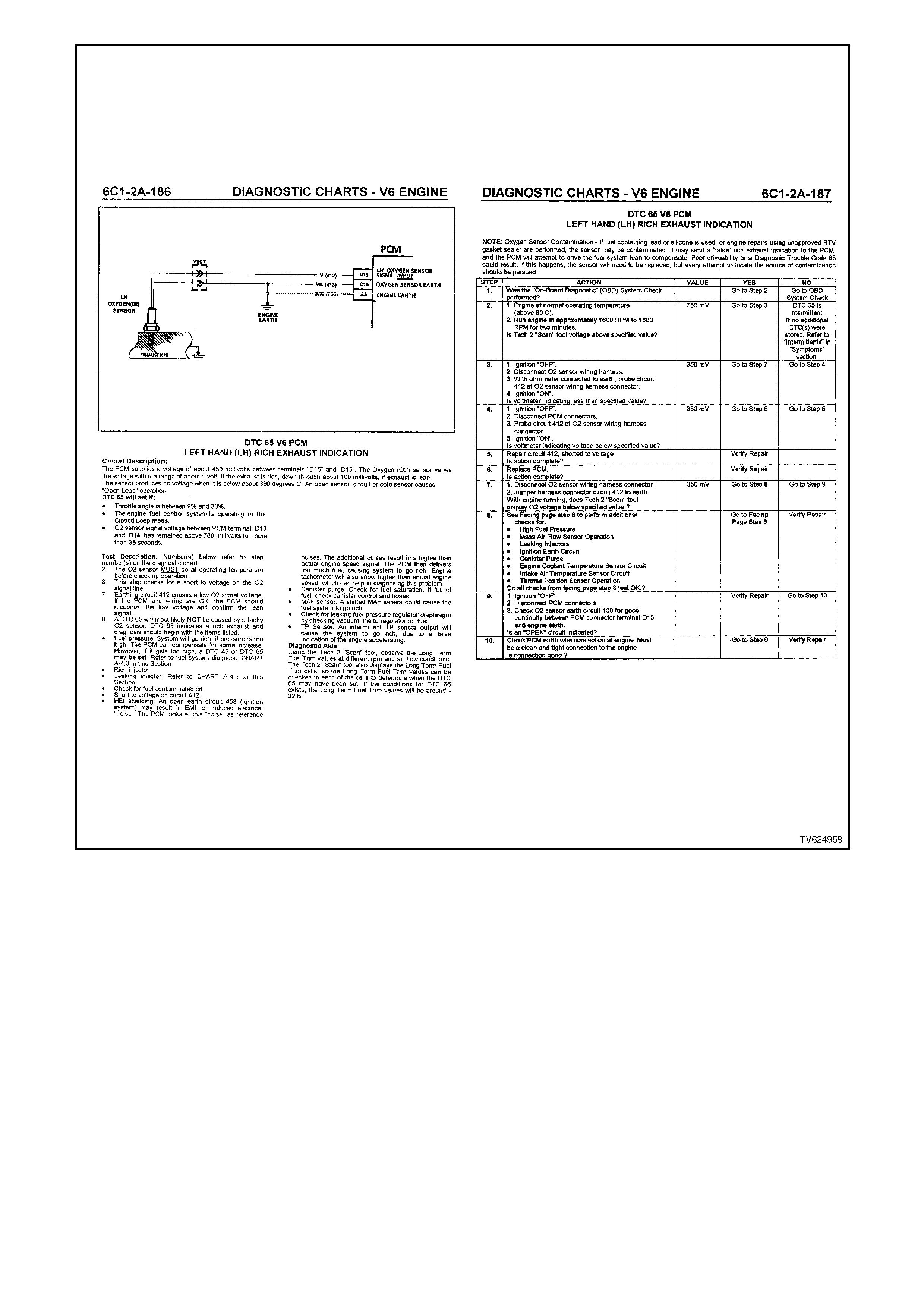
Figure 6C1-2-6 Diagnostic Flow Chart
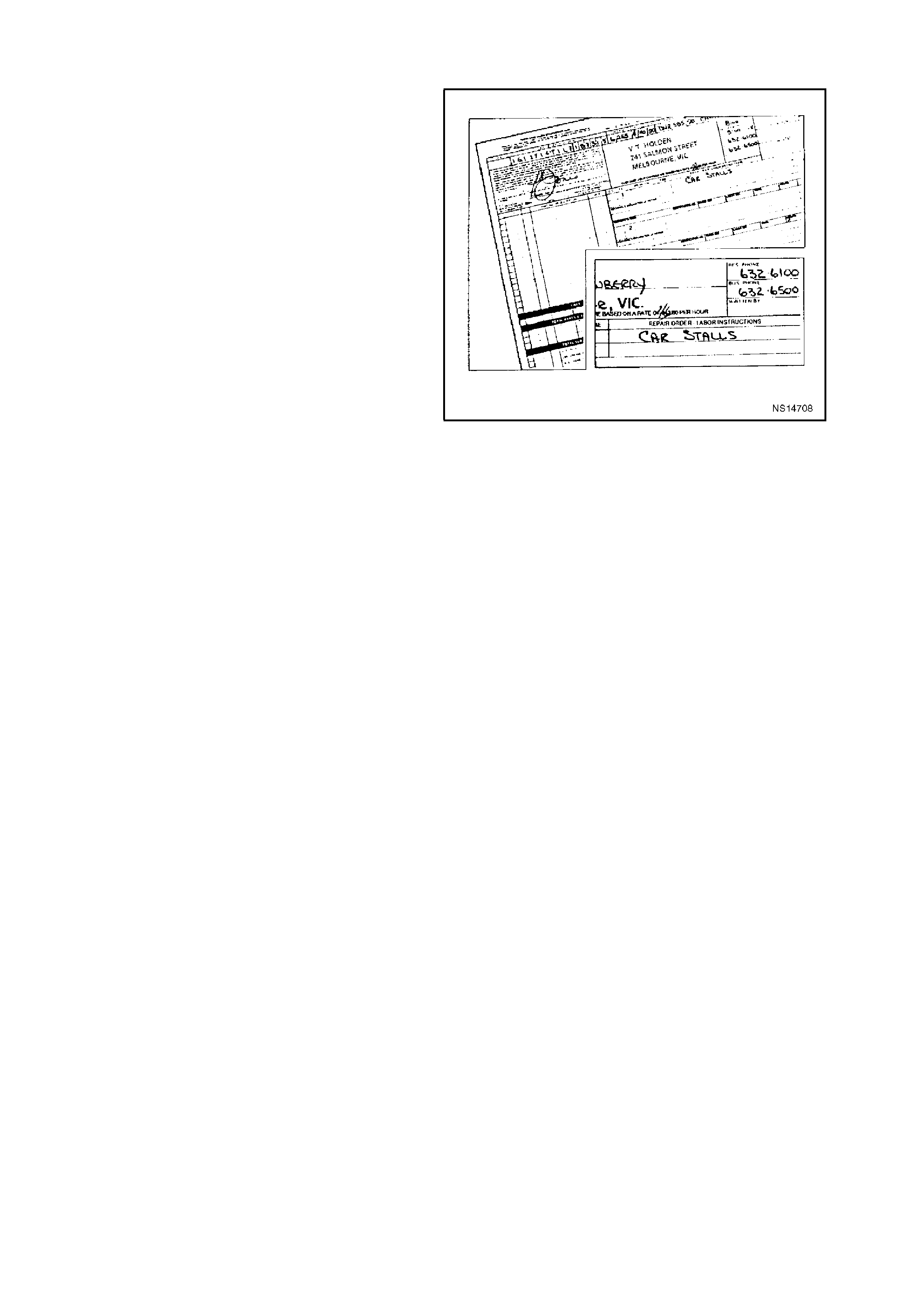
WRITING THE REPAIR ORDER
The repair order is one of the most important tools
a technician can have. Like other tools, the repair
order must be highly accurate to give the greatest
help.
It's up to the service advisor to supply the
technician with this highly accurate tool. Problems
begin for the technician when the repair order is
incomplete or incorrect.
An incomplete repair order doesn't provide the
technician with a good starting point for diagnosis.
consequently, the technician ends up wasting time,
using a shotgun approach to find the problem.
On the other hand, an incorrectly written repair
order can lead the technician down the wrong
diagnostic path, preventing him from finding the
problem.
Consequently, a repair order needs to be written as
accurate and complete as possible. This is
accomplished by asking the customer these
questions: W HO? W HAT? W HEN? W HERE? and
HOW?
Figure 6C1-2-7 An Incomplete Repair Order

"WHO"? QUESTIONS
"Who"? is the first question you need to ask. You need to find out who was driving the vehicle when the problem
occurred and talk directly to that person if at all possible.
This allows you to get first hand information on the problem, which is critical to diagnosing the problem. If you can't
talk directly to this person, get their name and phone number so that you can talk to the customer if needed.
"WHAT"? QUESTIONS
The nex t step is to find out "What"? the pr oblem is.
If it's a driveability problem, and it seems to be
complex, question the customer directly, so you
can get the information you need to help diagnose
the problem. Again, this is so you can get firsthand
knowledge of the problem.
If you don't talk with the customer, you need to
know if the "Check Powertrain" lam p is "ON" all the
time, coming "ON" and "OFF" during the same
ignition cycle, or is never "ON."
This is important because it tells you which
diagnostic direction to take; either the symptomatic
charts Figure 6C1-2-8 or the diagnostic tables
Figure 6C1-2-9.
As you can see, these charts are very different
from one another, so if you following the wrong
chart, a lot of time is wasted. So be sure to ask the
customer questions about the "Check Powertrain"
lamp.
Other good "What"? questions are: Under what
conditions did the problem occur? Were they
accelerating, decelerating, coasting? Were they
driving in the city or on the f reeway? What were the
environmental conditions? Was it raining?
snowing? hot? cold? you will need to duplicate
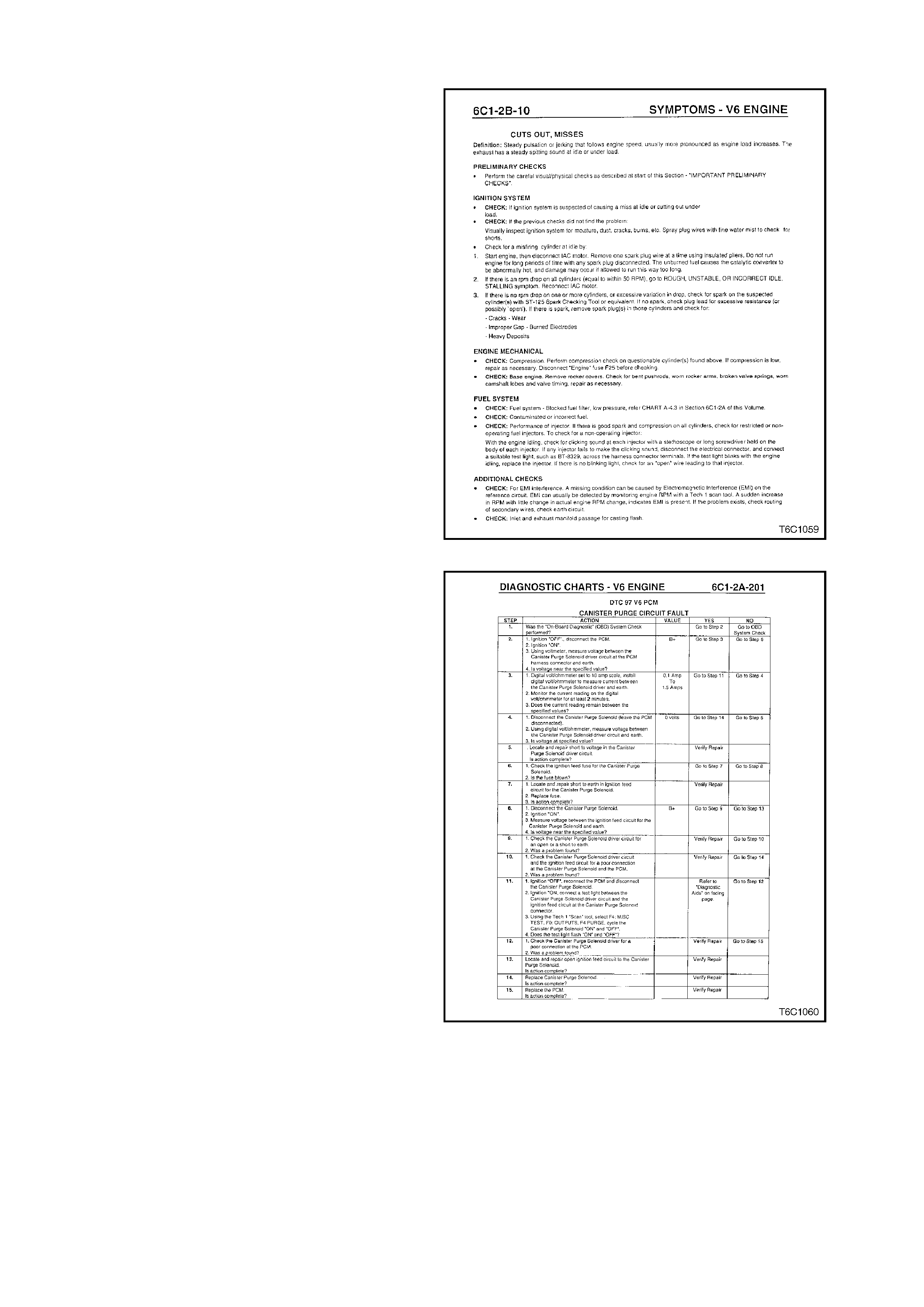
these conditions to find the cause of the problem. Figure 6C1-2-8 Typical Symptomatic Diagnostic Chart
Figure 6C1-2-9 Typical Diagnostic Chart

"WHEN"? QUESTIONS
"When"? questions are the next step. If the customer says the "Check Powertrain" lamp was "ON," you need to ask
when it came "ON" and how long it was "ON." Is it "ON" before or during starting, or when the engine is running?
More important, you need to ask when the problem first occurred. Maybe it began after the vehicle was serviced for
a related problem or for something that appears to be totally unrelated.
You also needs to know if the problem has gotten
worse as time goes on. This information may give
some clues as to what the problem may be.

"WHERE"? QUESTIONS
"Where"? is the next question. The location where the problem occurs may give an idea as to what may be
contributing to the problem, such as electromagnetic interference from overhead power lines.

"HOW"? QUESTIONS
To round out your questioning, you need to ask the customer "How"? often the problem occurs. This can give
direction as to what type of system may be causing the problem: electrical, mechanical, vacuum, etc.

SUMMARY
In summary, you need to obtain the following information from the customer:
• Who the principal driver is.
• What the problem is.
• When the problem began.
• Where the problem occurs.
• How often the problem occurs.
Complete answers to these questions will go a long way toward helping diagnose the problem. Answers to these
questions can be a great help.
VERIFYING THE COMPLAINT
ENGINE COMPARTMENT INSPECTION
The most important step in diagnosing a driveability
complaint is to verify the complaint. And this means
you have to duplicate the problem if at all possible.
Start by performing an engine compartment
inspection. Check the integrity of all the electrical
connections and vacuum hoses. Also, check the
wire routing for the possibility of Electromagnetic
Interference (EMI).
ENTERING THE DIAGNOSTIC MODE
If you didn't find the problem during your engine
compartment inspection, begin checking for stored
diagnostic trouble codes . Do this by using the T ech
2 scan tool "On-Board Diagnostic System Check"
for putting the sy stem into the diagnostic mode.
Don't mak e the mistake of bypassing the diagnostic
mode and sim ply connecting your Tech 2 s can tool
to check for s tor ed diagnostic tr ouble codes . This is
for a very good reason, you don't get the benefits of
putting the system in the diagnostic mode.
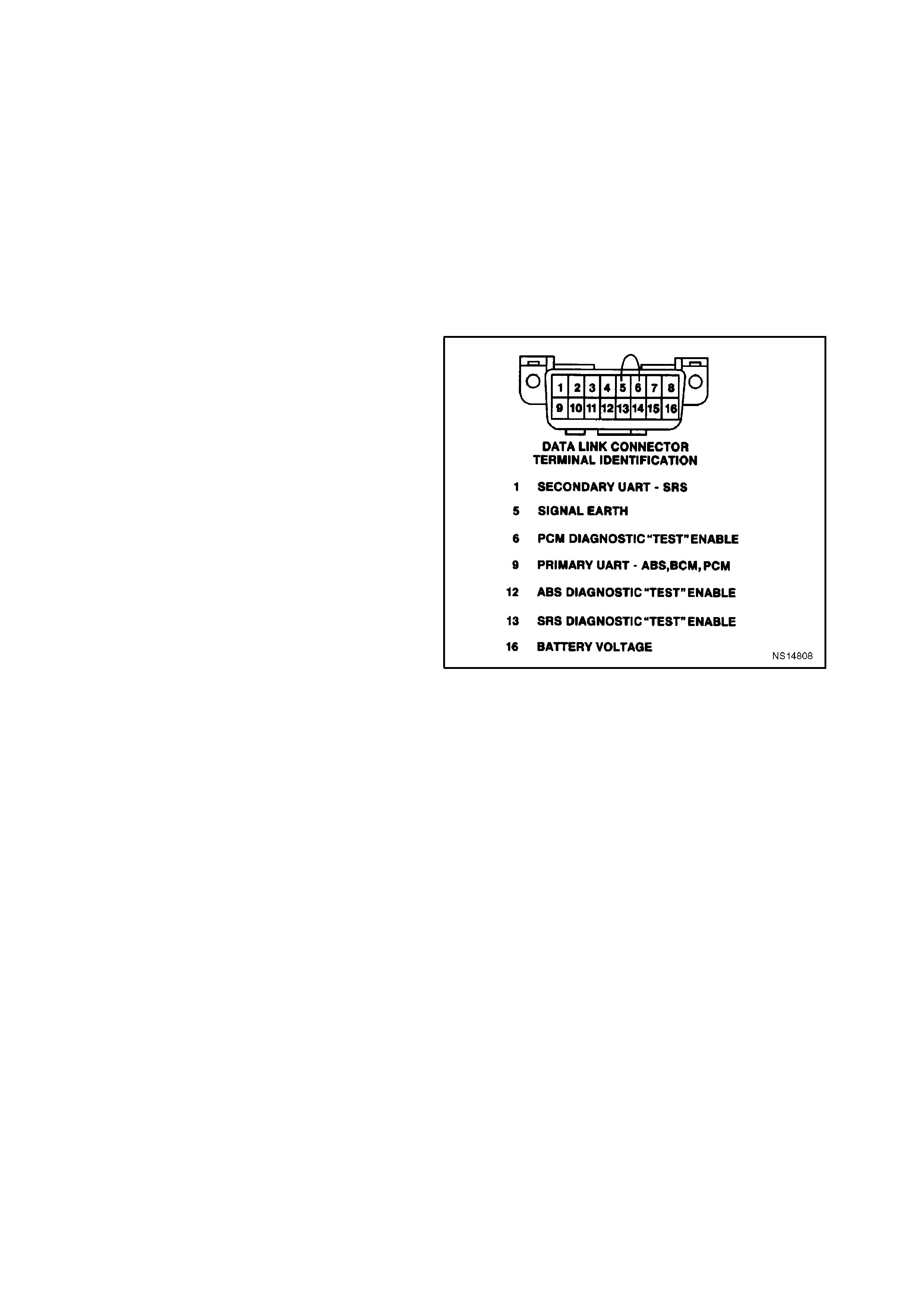
Figure 6C1-2-10 DLC Terminal Identification
TECH 2 SCAN TOOL INCOMPATIBILITY
If the PCM is equipped with the original PROM,
chances are the Tech 2 scan tool will be able to
read any stored diagnostic trouble codes and data
accurately.
However, if the PROM has an after market PROM
installed, totally incorrect data may result when
using a Tech 2 scan tool. This incorrect data may
include strangely inaccurate sensor values, such
as showing engine RPM at 2,000 when the engine
is really not running at all. This is due to a
mis m atch between the after m ar ket PROM and the
programmed information in the Tech 2 scan tool
cartridge.
As if this isn't enough, the "strange" data can
include numerous false or nonexistent diagnostic
trouble codes. This is where you can get into a lot
of trouble, diagnosing a problem that really doesn't
exist. Again, this is due to a mis matc h between the
original PROM and the af ter mar ket PRO M and the
values programmed into the Tech 2 scan tool
cartridge.
Fortunately, you can usually correct for this
mis match. To do this , first verify that the original or
updated PROM is correct for the vehicle.

CHECKING FOR STORED DIAGNOSTIC TROUBLE CODES
As you check for diagnostic trouble codes, keep in mind that intermittents may not store a diagnostic trouble code.
So the tip here is to proceed with verifying the complaint, even if no diagnostic trouble codes are stored.
If a diagnostic trouble code is stored, your best bet is to check for service bulletins for the particular vehicle you're
working on.
ROAD TESTING THE VEHICLE
This step is optional, dependent upon three things. If the repair order states the driveability problem is intermittent,
you didn't find any problems in the engine compartment, and no diagnostic trouble codes are stored, you need to
road test the vehicle and try to induce the problem.
This is a very important step because the problem has to be present in order for you to repair it.
However, all isn't lost. The good news is that most intermittent driveability problems are repeatable. That is what
road testing is all about.
Before you go out on your road test, you need to review the vehicle's service history. This information can give you
clues as to what may be causing the driveability problem and what you need to watch for.
Also, take time to read the repair order and think about what systems could possibly cause the problem. This is
essential to finding the problem. Think about how the system or sy stems in question work, what inputs are needed
and what could cause the problem.
Check all the inputs required for a circuit, whether the circuit actually has trouble or if you only suspect it. All inputs
are needed and must be within a "normal" range. You will want to pay special attention to these sy stems and
circuits both during and after your road test.
As you're road testing, make sure your Tech 2 scan tool is in the snapshot mode so you can capture system data
when the problem occurs.
Although you want to pay special attention to the systems you think may be causing the problem, don't discount all
the other information the Tech 2 scan tool snapshot mode can supply you with.
DON'T FORGET THE BASICS
Whether or not you find anything wrong during the road test, don't forget the basics.
Electrical connections such as power feeds and earths are vital to the operation of almost all vehicle systems.
And no matter how good the system is, it is still working in combination with the engine. If the engine isn't in good
condition, the computer system can't make up for it.
Also, it's always a good idea to compare performance problems, such as lack of power, with a comparable vehicle.
That way you'll know if the problem really is a problem or something that the customer doesn't have to worry about.
If you can't repeat the problem, and you need more information to diagnose it, call the customer who was driving the
vehicle when the problem occurred. This type of professionalism will probably help you diagnose the problem and
adds to customer enthusiasm.
PROMS
If a vehicle is just starting to have an intermittent driveability problem and it has accumulated more than 30,000
kilometers, chances are very good that the PROM is not at fault.
If the vehicle was running right for such a long period of time, the original PROM calibrations are not the problem
since PROM calibrations don't change, the chances of the PROM going bad are slim.
You can tell if the PROM was original to the PCM by comparing their broadcast codes. If the codes are the same,
odds are that they were originally installed on the vehicle and are not the cause of the problem. So you will need to
look elsewhere.